Embed Size (px)
Citation preview
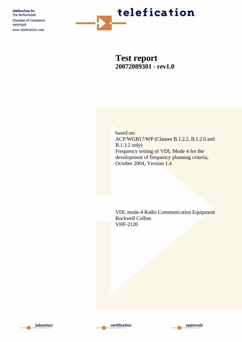
Test report 20072089301 - rev1.0
based on: ACP/WGB17/WP (Clauses B.1.2.2, B.1.2.6 and B.1.3.2 only) Frequency testing of VDL Mode 4 for the development of frequency planning criteria, October 2004, Version 1.4
VDL mode-4 Radio Communication Equipment Rockwell Collins VHF-2120

Report number: 20072089301
Contents
MAIN MODULE............................................................................................................................................3 1 INTRODUCTION ....................................................................................................................................3 2 PRODUCT .............................................................................................................................................4 3 TEST SCHEDULE ...................................................................................................................................4 4 OBSERVATIONS AND COMMENTS .........................................................................................................5 5 SUMMARY............................................................................................................................................8 6 CONCLUSIONS......................................................................................................................................9
TEST RESULTS MODULE .......................................................................................................................10 1 SQUELCH BREAK TEST (B.1.2.2) ........................................................................................................10
1.1 Test set up ................................................................................................................................10 1.2 Squelch break test ....................................................................................................................11 1.3 Squelch break test (cont’d).......................................................................................................12 1.4 Squelch break test (cont’d).......................................................................................................13
2 SIGNAL TO PULSE (S/P) TEST (B.1.2.6) ...............................................................................................14 2.1 Test set up ................................................................................................................................14 2.2 Signal to pulse (S/P) test ...........................................................................................................15 2.3 Signal to pulse (S/P) test (cont’d) .............................................................................................17 2.4 Signal to pulse (S/P) test (cont’d) .............................................................................................19
3 BER TEST (DSB-AM INTERFERER TO VDL MODE 4 LINK) (B.1.3.2)..................................................21 3.1 Test set up ................................................................................................................................21 3.2 BER test ...................................................................................................................................22 3.3 BER test (cont’d)......................................................................................................................24 3.4 BER test (cont’d)......................................................................................................................26
4 BER TEST (VDL MODE 4 INTERFERER TO VDL MODE 2 LINK) (B.1.3.2) ............................................28 4.1 Test setup .................................................................................................................................28 4.2 BER test ...................................................................................................................................29
5 BER TEST (VDL MODE 2 INTERFERER TO VDL MODE 4 LINK) (B.1.3.2) ............................................31 5.1 Test setup .................................................................................................................................31 5.2 BER test ...................................................................................................................................32
6 BER TEST (VDL MODE 4 INTERFERER TO VDL MODE 4 LINK) (B.1.3.2) ..........................................34 6.1 Test setup (RC VHF-2120 interferer to CNS VDL-4000 victim) ............................................34 6.2 Test setup (CNS VDL-4000 interferer to RC VHF-2120) .......................................................35 6.3 BER test ...................................................................................................................................36 6.4 BER test (cont’d)......................................................................................................................38
USED TEST EQUIPMENT MODULE .....................................................................................................40
PHOTOGRAPHS MODULE......................................................................................................................41
REVISION HISTORY ................................................................................................................................56
This report comprises of five modules. The total number of pages is: 56
Page: 3 of 56 Main module Report number: 20072089301
Main module
1 Introduction This report contains the result of tests performed by: Telefication B.V. Edisonstraat 12a 6902 PK Zevenaar The Netherlands Telefication complies with the accreditation criteria for test laboratories as laid down in ISO/IEC 17025:2005. The accreditation covers the quality system of the laboratory as well as the specific activities as described in the authorized annex bearing the accreditation number L021 and is granted on 30 November 1990 by the Dutch Council For Accreditation (RvA: Raad voor Accreditatie). The copyright of this test report is owned by Telefication bv and may not be reproduced except in full without the written approval of Telefication B.V.
Ordering party: Company name : Luftfartsverket Address : Vikboplan 11 Zipcode : SE-601 79 City/town : Norrköping Country : Sweden Date of order : 13 March 2008

Page: 4 of 56 Main module Report number: 20072089301
2 Product A sample of the following product was submitted for testing: Product category : VDL mode-4 Radio Communication Equipment Manufacturer : Rockwell Collins USA Trade mark : Rockwell Collins Type designation : VHF-2120 Hardware version : Test model Software version : Test model Serial number : 277RF
3 Test schedule Tests are carried out in accordance with the specification detailed in chapter 5 "Summary" of this report. Tests were carried out at the following location: • Rockwell-Collins France
6, avenue Didier Daurat 31701 Blagnac Cedex France
Tests are carried out between the following dates: • 14 January and 18 March 2008
Page: 5 of 56 Main module Report number: 20072089301
4 Observations and comments This report contains the results of tests of four different interferer to communication link configurations. 1. DSB-AM interferer to VDL mode 4 link.. Find below the information recorded for the labelling of each of the DSB -AM radio's radio which were used: Becker COMM 3200 system Serial number : 10200 LAB No. : 10.9111/76 FTZ No : LB 3939.83 TSO : C37c, C38c RTCA : DO 156 CL.C RTCA : DO 157 CL.4 RTCA : DO 160A FCC ID : 8548RSAR3201 ED14A Rockwell Collins VHF-700A PRN : 822-0693-020 Serial number : 12227 TSO : C37b, C38b FCC ID : AJK9URPN662-5219 DO-160-A : A2D2/JY Rockwell Collins VHF-2100E PRN : 822-2168-120 Serial number : 29PWD TSO : C128, C169 ETSO : 2C37e, 2C38e, 2C128 DO-160C : ENV CAT DO-178B : Level C/D 2. VDL mode 4 interferer to VDL mode 4 link This test was carried out by using two CNS Systems VDL4000 transceivers, one as the generator of the wanted signal and the other as the victim. The RC VHF-2120 was used to create the interferer.
Page: 6 of 56 Main module Report number: 20072089301
Find below the information recorded for the labelling of each of the CNS Systems VDL4000 radio's radio which were used: CNS Systems VDL4000 Serial number : 1025 PN : 4000-10-10 Software : SW4000-10-3.8 This radio was used to send the wanted VDL4 signal. CNS Systems VDL4000 Serial number : 1047 PN : 4000-10-10 Software : SW4000-40-1.0 This radio was used as the victim. The test was also carried out, by using a CNS VDL4000 radio as the interferer and the RC VHF-2120 as the victim. The communication link with the victim was established by a vector signal generator, type Agilent E4438C. RC VHF-2120 (victim) Serial number : 277RF PN : 822-2224-001 3. VDL mode 4 interferer to VDL mode 2 link This test was carried out, by using a VDL2 test bench containing a VHF-920 and a VHF-2100E transceiver, the first as the generator of the wanted signal and the second as the victim. The RC VHF-2120 was used to create the interferer. Rockwell Collins VHF-2100E (victim) PRN : 822-2168-120 Serial number : 29PWD TSO : C128, C169 ETSO : 2C37e, 2C38e, 2C128 DO-160C : ENV CAT DO-178B : Level C/D

Page: 7 of 56 Main module Report number: 20072089301
4. VDL mode 2 interferer to VDL mode 4 link This test was done, by using a RC VHF-2120 as an interferer and a RC VHF-2120 as a victim. The communication link with the victim was established by a vector signal generator, type Agilent E4438C. RC VHF-2120 (victim) Serial number : 277RF PN : 822-2224-001

Page: 8 of 56 Main module Report number: 20072089301
5 Summary The product is intended for use in the following application area:
• AIRBORNE DIGITAL COMMUNICATION EQUIPMENT The sample is tested according to the following specification:
• ACP/WGB17/WP (Clauses B.1.2.2, B.1.2.6 and B.1.3.2 only) Frequency testing of VDL Mode 4 for the development of frequency planning criteria, October 2004, Version 1.4

Page: 9 of 56 Main module Report number: 20072089301
6 Conclusions The results of the test as stated in this report are exclusively applicable to the product item as identified in this report. Telefication bv does not accept any responsibility for the results stated in this report, with respect to the properties of product items not involved in these tests. All tests are performed by: name : H.H. Lodewijk function : Test Engineer Radio/EMC signature : Review of test methods and report by: name : P.A. Suringa function : Senior Engineer Radio/EMC signature : The above conclusions have been verified by the following signatory: date : 9 April 2008 name : J.P. van de Poll function : Co-ordinator Test Group signature :

Page: 10 of 56 Test results module Report number: 20072089301
Test results module
1 Squelch break test (B.1.2.2)
1.1 Test set up
+DUTVDL4 Tx
DSB-AMRx
Signal generatorDSB-AM 1kHz, 30%
Pwr attn
Pwr attnOscilloscope
Page: 11 of 56 Test results module Report number: 20072089301
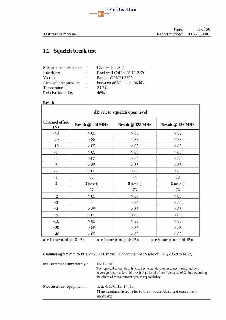
1.2 Squelch break test Measurement reference : Clause B.1.2.2 Interferer : Rockwell Collins VHF-2120 Victim : Becker COMM 3200 Atmospheric pressure : between 86 kPa and 106 kPa Temperature : 24 ° C Relative humidity : 46% Result:
dB rel. to squelch open level
Channel offset (N) Result @ 119 MHz Result @ 128 MHz Result @ 136 MHz
-40 > 85 > 85 > 85 -20 > 85 > 85 > 85 -10 > 85 > 85 > 85 -5 > 85 > 85 > 85 -4 > 85 > 85 > 85 -3 > 85 > 85 > 85 -2 > 85 > 85 > 85 -1 66 74 73 0 0 (note 1) 0 (note 2) 0 (note 3)
+1 67 76 76 +2 > 85 > 85 > 85 +3 84 > 85 > 85 +4 > 85 > 85 > 85 +5 > 85 > 85 > 85 +10 > 85 > 85 > 85 +20 > 85 > 85 > 85 +40 > 85 > 85 > 85
note 1: corresponds to -92 dBm note 2: corresponds to -94 dBm note 3: corresponds to -96 dBm Channel offset: N * 25 kHz, at 136 MHz the +40 channel was tested at +39 (136.975 MHz) Measurement uncertainty : +/- 1.6 dB The reported uncertainty is based on a standard uncertainty multiplied by a
coverage factor of k=1.96 providing a level of confidence of 95%, but excluding the effect of measurement system repeatability.
Measurement equipment : 1, 2, 4, 5, 6, 13, 14, 16
(The numbers listed refer to the module 'Used test equipment module'.)

Page: 12 of 56 Test results module Report number: 20072089301
1.3 Squelch break test (cont’d) Measurement reference : clause B.1.2.2 Interferer : Rockwell Collins VHF-2120 Victim : Rockwell Collins VHF-700A Atmospheric pressure : between 86 kPa and 106 kPa Temperature : 24° C Relative humidity : 46% Result:
dB rel. to squelch open level
Channel offset (N) Result @ 119 MHz Result @ 128 MHz Result @ 136 MHz
-40 > 85 > 85 > 85 -20 > 85 > 85 > 85 -10 > 85 > 85 > 85 -5 > 85 > 85 > 85 -4 > 85 > 85 > 85 -3 > 85 > 85 > 85 -2 > 85 > 85 > 85 -1 > 85 > 85 > 85 0 0 (note) 0 (note) 0 (note)
+1 > 85 > 85 > 85 +2 > 85 > 85 > 85 +3 > 85 > 85 > 85 +4 > 85 > 85 > 85 +5 > 85 > 85 > 85 +10 > 85 > 85 > 85 +20 > 85 > 85 > 85 +40 > 85 > 85 > 85
note: corresponds to -107 dBm Channel offset: N * 25 kHz, at 136 MHz the +40 channel was tested at +39 (136.975 MHz) Measurement uncertainty : +/- 1.6 dB The reported uncertainty is based on a standard uncertainty multiplied by a
coverage factor of k=1.96 providing a level of confidence of 95%, but excluding the effect of measurement system repeatability.
Measurement equipment : 1, 2, 4, 5, 6, 13, 14, 16
(The numbers listed refer to the module 'Used test equipment module'.)

Page: 13 of 56 Test results module Report number: 20072089301
1.4 Squelch break test (cont’d) Measurement reference : clause B.1.2.2 Interferer : Rockwell Collins VHF-2120 Victim : Rockwell Collins VHF-2100E Atmospheric pressure : between 86 kPa and 106 kPa Temperature : 24° C Relative humidity : 46% Result:
dB rel. to squelch open level
Channel offset (N) Result @ 119 MHz Result @ 127 MHz Result @ 136 MHz
-40 > 85 > 85 > 85 -20 > 85 > 85 > 85 -10 > 85 > 85 > 85 -5 > 85 > 85 > 85 -4 > 85 > 85 > 85 -3 > 85 > 85 > 85 -2 > 85 > 85 > 85 -1 > 85 > 85 > 85 0 0 0 0
+1 > 85 > 85 > 85 +2 > 85 > 85 > 85 +3 > 85 > 85 > 85 +4 > 85 > 85 > 85 +5 > 85 > 85 > 85 +10 > 85 > 85 > 85 +20 > 85 > 85 > 85 +40 > 85 > 85 > 85
Channel offset: N * 25 kHz, at 136 MHz the +40 channel was tested at +39 (136.975 MHz) Measurement uncertainty : +/- 1.6 dB The reported uncertainty is based on a standard uncertainty multiplied by a
coverage factor of k=1.96 providing a level of confidence of 95%, but excluding the effect of measurement system repeatability.
Measurement equipment : 1, 2, 4, 5, 6, 13, 14, 16
(The numbers listed refer to the module 'Used test equipment module'.)
Page: 14 of 56 Test results module Report number: 20072089301
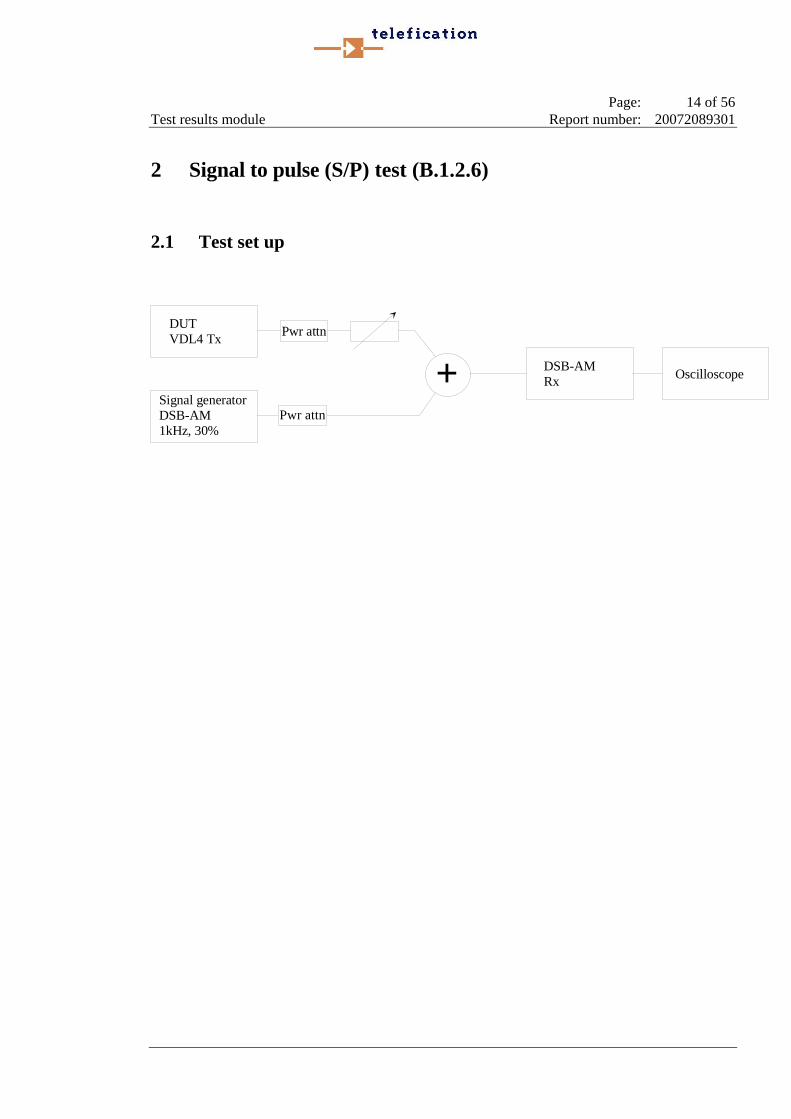
2 Signal to pulse (S/P) test (B.1.2.6)
2.1 Test set up
+DUTVDL4 Tx
DSB-AMRx
Signal generatorDSB-AM1kHz, 30%
Pwr attn
Pwr attn
Oscilloscope
Page: 15 of 56 Test results module Report number: 20072089301
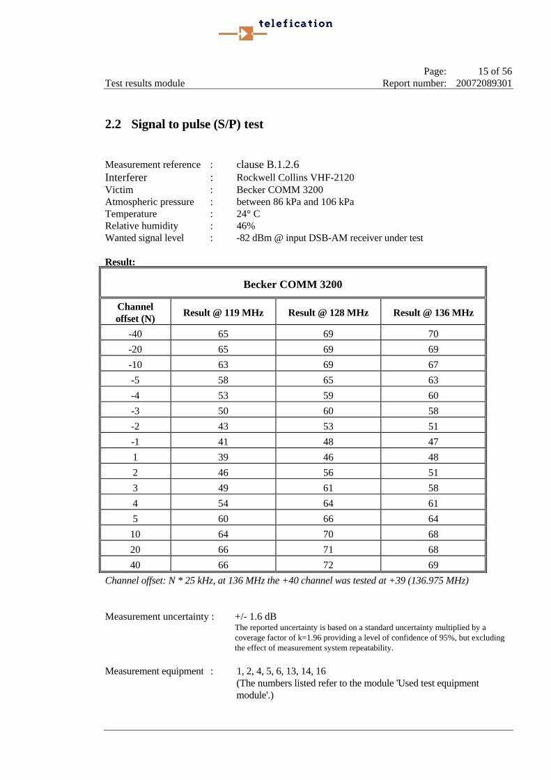
2.2 Signal to pulse (S/P) test Measurement reference : clause B.1.2.6 Interferer : Rockwell Collins VHF-2120 Victim : Becker COMM 3200 Atmospheric pressure : between 86 kPa and 106 kPa Temperature : 24° C Relative humidity : 46% Wanted signal level : -82 dBm @ input DSB-AM receiver under test Result:
Becker COMM 3200
Channel offset (N) Result @ 119 MHz Result @ 128 MHz Result @ 136 MHz
-40 65 69 70 -20 65 69 69 -10 63 69 67 -5 58 65 63 -4 53 59 60 -3 50 60 58 -2 43 53 51 -1 41 48 47 1 39 46 48 2 46 56 51 3 49 61 58 4 54 64 61 5 60 66 64
10 64 70 68 20 66 71 68 40 66 72 69
Channel offset: N * 25 kHz, at 136 MHz the +40 channel was tested at +39 (136.975 MHz) Measurement uncertainty : +/- 1.6 dB The reported uncertainty is based on a standard uncertainty multiplied by a
coverage factor of k=1.96 providing a level of confidence of 95%, but excluding the effect of measurement system repeatability.
Measurement equipment : 1, 2, 4, 5, 6, 13, 14, 16
(The numbers listed refer to the module 'Used test equipment module'.)
Page: 16 of 56 Test results module Report number: 20072089301
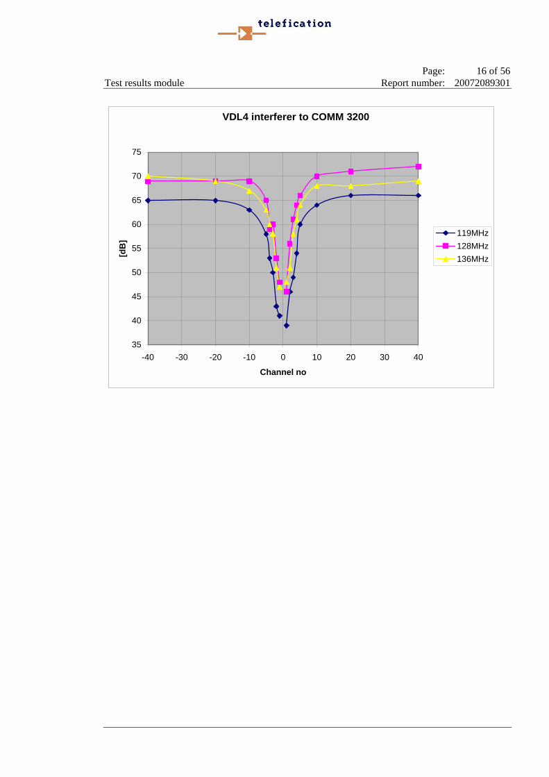
VDL4 interferer to COMM 3200
35
40
45
50
55
60
65
70
75
-40 -30 -20 -10 0 10 20 30 40
Channel no
[dB
]
119MHz128MHz136MHz

Page: 17 of 56 Test results module Report number: 20072089301
2.3 Signal to pulse (S/P) test (cont’d) Measurement reference : clause B.1.2.6 Interferer : Rockwell Collins VHF-2120 Victim : Rockwell Collins VHF-700A Atmospheric pressure : between 86 kPa and 106 kPa Temperature : 24° C Relative humidity : 46% Wanted signal level : -82 dBm @ input DSB-AM receiver under test Result:
Rockwell Collins VHF-700A
Channel offset (N) Result @ 119 MHz Result @ 128 MHz Result @ 136 MHz
-40 75 75 75 -20 73 75 75 -10 65 69 69 -5 58 66 62 -4 55 65 60 -3 52 61 56 -2 48 55 52 -1 46 50 48 1 45 51 49 2 47 58 54 3 52 62 56 4 53 65 62 5 59 67 66
10 62 73 71 20 70 75 75 40 75 75 75
Channel offset: N * 25 kHz, at 136 MHz the +40 channel was tested at +39 (136.975 MHz) Measurement uncertainty : +/- 1.6 dB The reported uncertainty is based on a standard uncertainty multiplied by a
coverage factor of k=1.96 providing a level of confidence of 95%, but excluding the effect of measurement system repeatability.
Measurement equipment : 1, 2, 4, 5, 6, 13, 14, 16
(The numbers listed refer to the module 'Used test equipment module'.)
Page: 18 of 56 Test results module Report number: 20072089301
VDL4 interferer to RC-700A
40
45
50
55
60
65
70
75
80
-40 -30 -20 -10 0 10 20 30 40
Channel no
[dB
] 119MHz128MHz136MHz

Page: 19 of 56 Test results module Report number: 20072089301
2.4 Signal to pulse (S/P) test (cont’d) Measurement reference : clause B.1.2.6 Interferer : Rockwell Collins VHF-2120 Victim ; Rockwell Collins VHF-2100E Atmospheric pressure : between 86 kPa and 106 kPa Temperature : 24 ° C Relative humidity : 46% Wanted signal level : -82 dBm @ input DSB-AM receiver under test Result:
Rockwell Collins VHF-2100E
Channel offset (N) Result @ 119 MHz Result @ 128 MHz Result @ 136 MHz
-40 62 60 61 -20 60 60 60 -10 60 60 60 -5 54 59 59 -4 50 59 54 -3 47 58 52 -2 42 48 49 -1 40 40 38 1 36 37 39 2 48 49 48 3 49 55 52 4 51 58 58 5 55 59 59
10 58 60 60 20 60 60 61 40 61 60 61
Channel offset: N * 25 kHz, at 136 MHz the +40 channel was tested at +39 (136.975 MHz) Measurement uncertainty : +/- 1.6 dB The reported uncertainty is based on a standard uncertainty multiplied by a
coverage factor of k=1.96 providing a level of confidence of 95%, but excluding the effect of measurement system repeatability.
Measurement equipment : 1, 2, 4, 5, 6, 13, 14, 16
(The numbers listed refer to the module 'Used test equipment module'.)

Page: 20 of 56 Test results module Report number: 20072089301
VDL4 interferer to VHF-2100E
30
35
40
45
50
55
60
65
70
-40 -30 -20 -10 0 10 20 30 40
Channel no
[dB
] 119MHz128MHz136MHz

Page: 21 of 56 Test results module Report number: 20072089301
3 BER test (DSB-AM interferer to VDL mode 4 link) (B.1.3.2)
3.1 Test set up DSB-AM inter
+
E4438C Vector signal generator
DUT VDL4 Rx
DSB-AM Tx
Pwr attn
Pwr attn

Page: 22 of 56 Test results module Report number: 20072089301
3.2 BER test Measurement reference : clause B.1.3.2 Interferer : Becker COMM 3200 Victim : Rockwell Collins VHF-2120 Atmospheric pressure : between 86 kPa and 106 kPa Temperature : 24 ° C Relative humidity : 46% Wanted signal level : -82 dBm @ input VDL4 receiver under test Result:
dB rel. (@ BER*) ≤ 1%) to wanted signal of - 82 dBm
Channel offset (N) Result @ 119 MHz Result @ 128 MHz Result @ 136 MHz
-40 64 64 63 -20 63 65 63 -10 66 68 65 -5 66 62 64 -4 59 59 59 -3 63 60 63 -2 58 54 63 -1 52 47 55 1 52 46 55 2 62 57 58 3 63 60 64 4 57 60 60 5 65 63 64
10 65 66 65 20 65 65 67 40 66 65 69*
*) Over 40960 bits Channel offset : N * 25 kHz, at 136 MHz the +40 channel was tested at +39 (136.975 MHz) Measurement uncertainty : +/- 1.6 dB The reported uncertainty is based on a standard uncertainty multiplied by a
coverage factor of k=1.96 providing a level of confidence of 95%, but excluding the effect of measurement system repeatability.
Measurement equipment : 1, 3, 4, 5, 6, 7, 8, 9, 10, 11, 12, 13, 14, 17.
(The numbers listed refer to the module 'Used test equipment module'.)

Page: 23 of 56 Test results module Report number: 20072089301
COMM 3200 interferer to VDL4
40
45
50
55
60
65
70
75
80
-40 -30 -20 -10 0 10 20 30 40
Channel no
[dB
] 119MHz128MHz136MHz

Page: 24 of 56 Test results module Report number: 20072089301
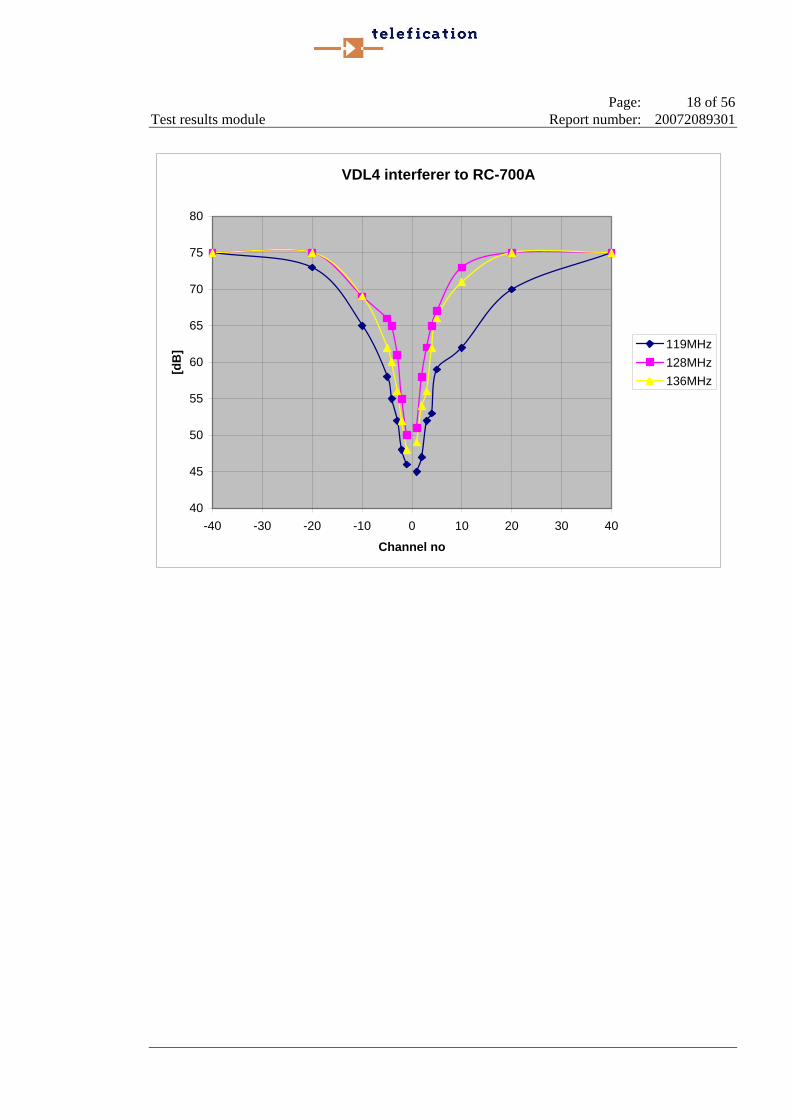
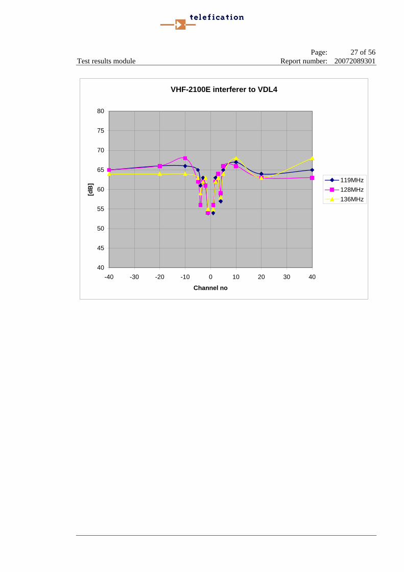
3.3 BER test (cont’d) Measurement reference : clause B.1.3.2 Interferer : Rockwell Collins VHF-700A Victim : Rockwell Collins VHF-2120 Atmospheric pressure : between 86 kPa and 106 kPa Temperature : 24 ° C Relative humidity : 46% Wanted signal level : -82 dBm @ input VDL4 receiver under test Result:
dB rel. to wanted signal of - 82 dBm
Channel offset (N) Result @ 119 MHz Result @ 128 MHz Result @ 136 MHz
-40 66 64 71 -20 64 68 67 -10 68 68 69 -5 69 67 68 -4 62 65 62 -3 58 60 64 -2 56 56 58 -1 51 51 53 1 50 51 52 2 52 55 62 3 61 61 64 4 57 55 58 5 61 63 66
10 66 67 69 20 64 66 69 40 61 65 69
Channel offset : N * 25 kHz, at 136 MHz the +40 channel was tested at +39 (136.975 MHz) Measurement uncertainty : +/- 1.6 dB The reported uncertainty is based on a standard uncertainty multiplied by a
coverage factor of k=1.96 providing a level of confidence of 95%, but excluding the effect of measurement system repeatability.
Measurement equipment : 1, 3, 4, 5, 6, 7, 8, 9, 10, 11, 12, 13, 14, 15.
(The numbers listed refer to the module 'Used test equipment module'.)
Page: 25 of 56 Test results module Report number: 20072089301
VHF-700A interferer to VDL4
40
45
50
55
60
65
70
75
80
-40 -30 -20 -10 0 10 20 30 40
Channel no
[dB
] 119MHz128MHz136MHz
Page: 26 of 56 Test results module Report number: 20072089301
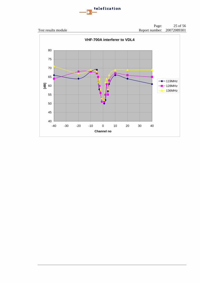
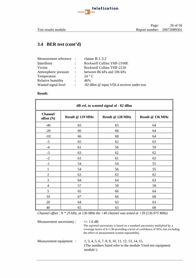
3.4 BER test (cont’d) Measurement reference : clause B.1.3.2 Interferer : Rockwell Collins VHF-2100E Victim : Rockwell Collins VHF-2120 Atmospheric pressure : between 86 kPa and 106 kPa Temperature : 24 ° C Relative humidity : 46% Wanted signal level : -82 dBm @ input VDL4 receiver under test Result:
dB rel. to wanted signal of - 82 dBm
Channel offset (N) Result @ 119 MHz Result @ 128 MHz Result @ 136 MHz
-40 65 65 64 -20 66 66 64 -10 66 68 64 -5 65 62 63 -4 61 56 59 -3 63 62 62 -2 61 61 63 -1 54 54 55 1 54 56 55 2 63 62 62 3 64 64 63 4 57 59 58 5 65 66 64
10 67 66 68 20 64 63 63 40 65 63 68
Channel offset : N * 25 kHz, at 136 MHz the +40 channel was tested at +39 (136.975 MHz) Measurement uncertainty : +/- 1.6 dB The reported uncertainty is based on a standard uncertainty multiplied by a
coverage factor of k=1.96 providing a level of confidence of 95%, but excluding the effect of measurement system repeatability.
Measurement equipment : 1, 3, 4, 5, 6, 7, 8, 9, 10, 11, 12, 13, 14, 15.
(The numbers listed refer to the module 'Used test equipment module'.)
Page: 27 of 56 Test results module Report number: 20072089301
VHF-2100E interferer to VDL4
40
45
50
55
60
65
70
75
80
-40 -30 -20 -10 0 10 20 30 40
Channel no
[dB
] 119MHz128MHz136MHz
Page: 28 of 56 Test results module Report number: 20072089301
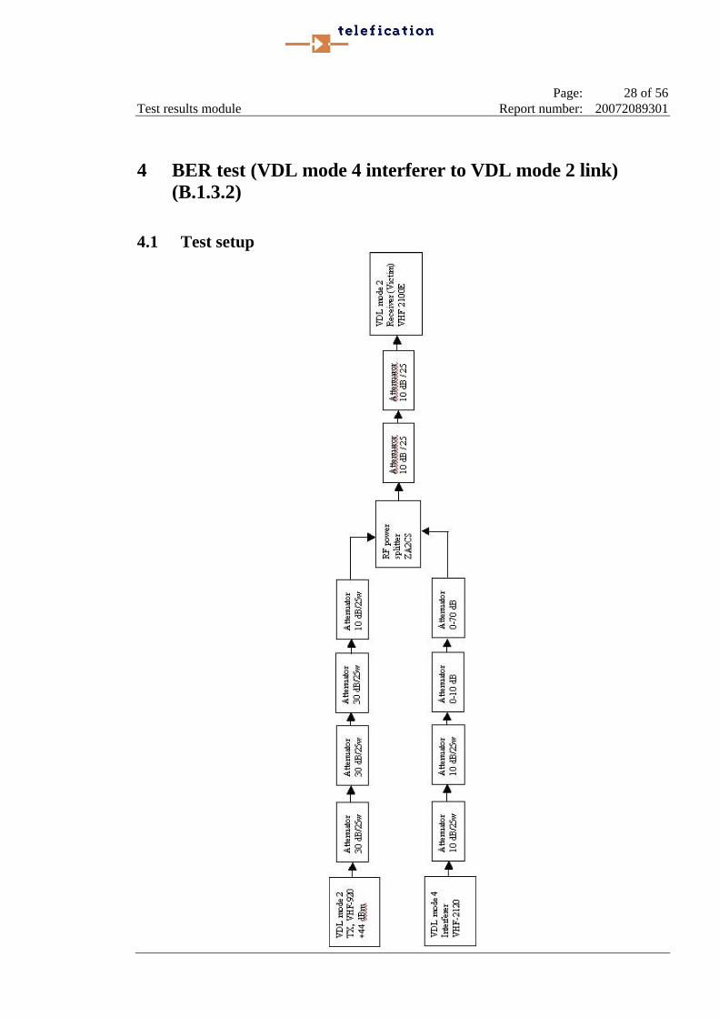
4 BER test (VDL mode 4 interferer to VDL mode 2 link) (B.1.3.2)
4.1 Test setup
Page: 29 of 56 Test results module Report number: 20072089301
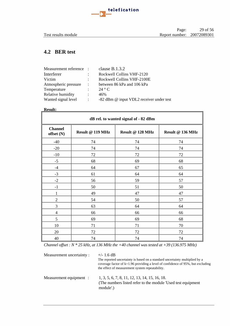
4.2 BER test Measurement reference : clause B.1.3.2 Interferer : Rockwell Collins VHF-2120 Victim : Rockwell Collins VHF-2100E Atmospheric pressure : between 86 kPa and 106 kPa Temperature : 24 ° C Relative humidity : 46% Wanted signal level : -82 dBm @ input VDL2 receiver under test Result:
dB rel. to wanted signal of - 82 dBm
Channel offset (N) Result @ 119 MHz Result @ 128 MHz Result @ 136 MHz
-40 74 74 74 -20 74 74 74 -10 72 72 72 -5 68 69 68 -4 64 67 65 -3 61 64 64 -2 56 59 57 -1 50 51 50 1 49 47 47 2 54 50 57 3 63 64 64 4 66 66 66 5 69 69 68
10 71 71 70 20 72 72 72 40 74 74 74
Channel offset : N * 25 kHz, at 136 MHz the +40 channel was tested at +39 (136.975 MHz) Measurement uncertainty : +/- 1.6 dB The reported uncertainty is based on a standard uncertainty multiplied by a
coverage factor of k=1.96 providing a level of confidence of 95%, but excluding the effect of measurement system repeatability.
Measurement equipment : 1, 3, 5, 6, 7, 8, 11, 12, 13, 14, 15, 16, 18.
(The numbers listed refer to the module 'Used test equipment module'.)
Page: 30 of 56 Test results module Report number: 20072089301
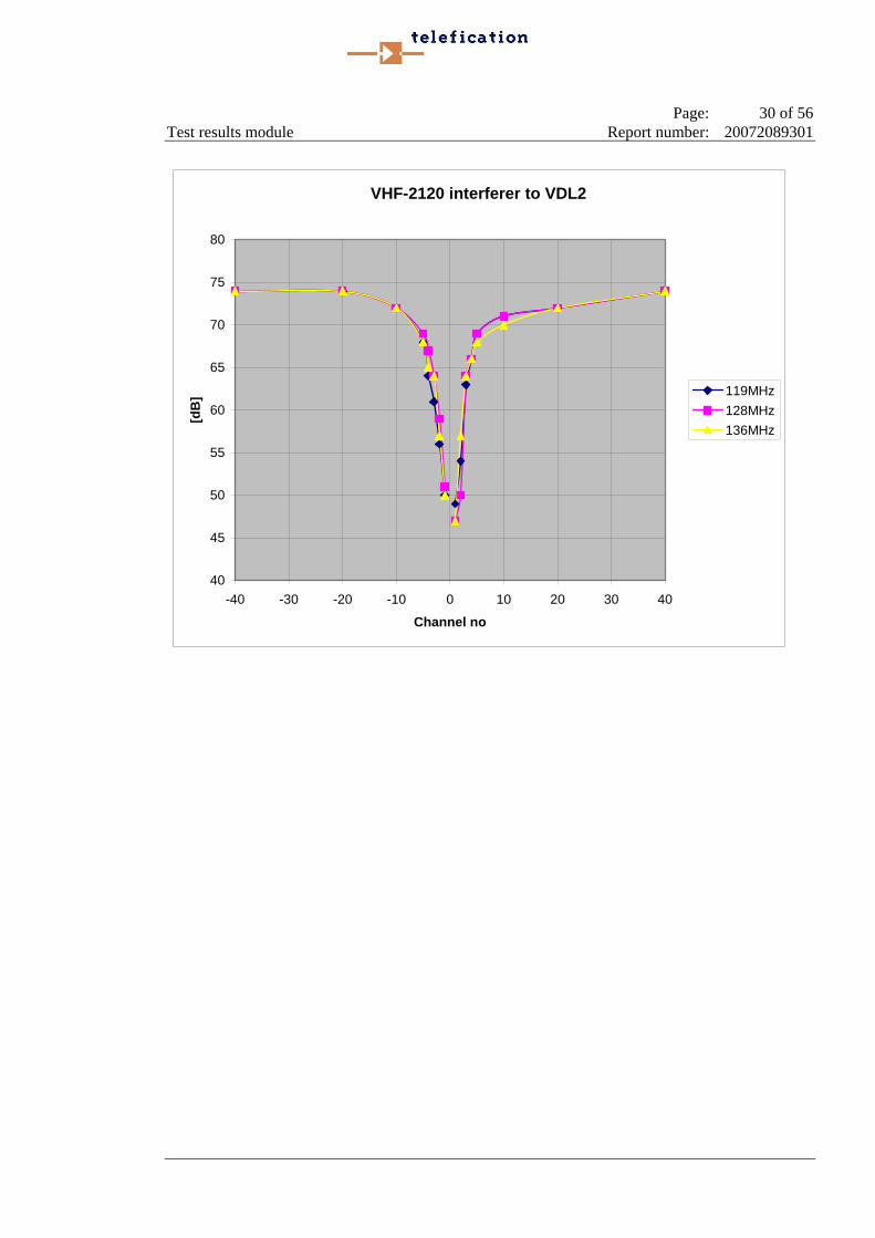
VHF-2120 interferer to VDL2
40
45
50
55
60
65
70
75
80
-40 -30 -20 -10 0 10 20 30 40
Channel no
[dB
] 119MHz128MHz136MHz
Page: 31 of 56 Test results module Report number: 20072089301
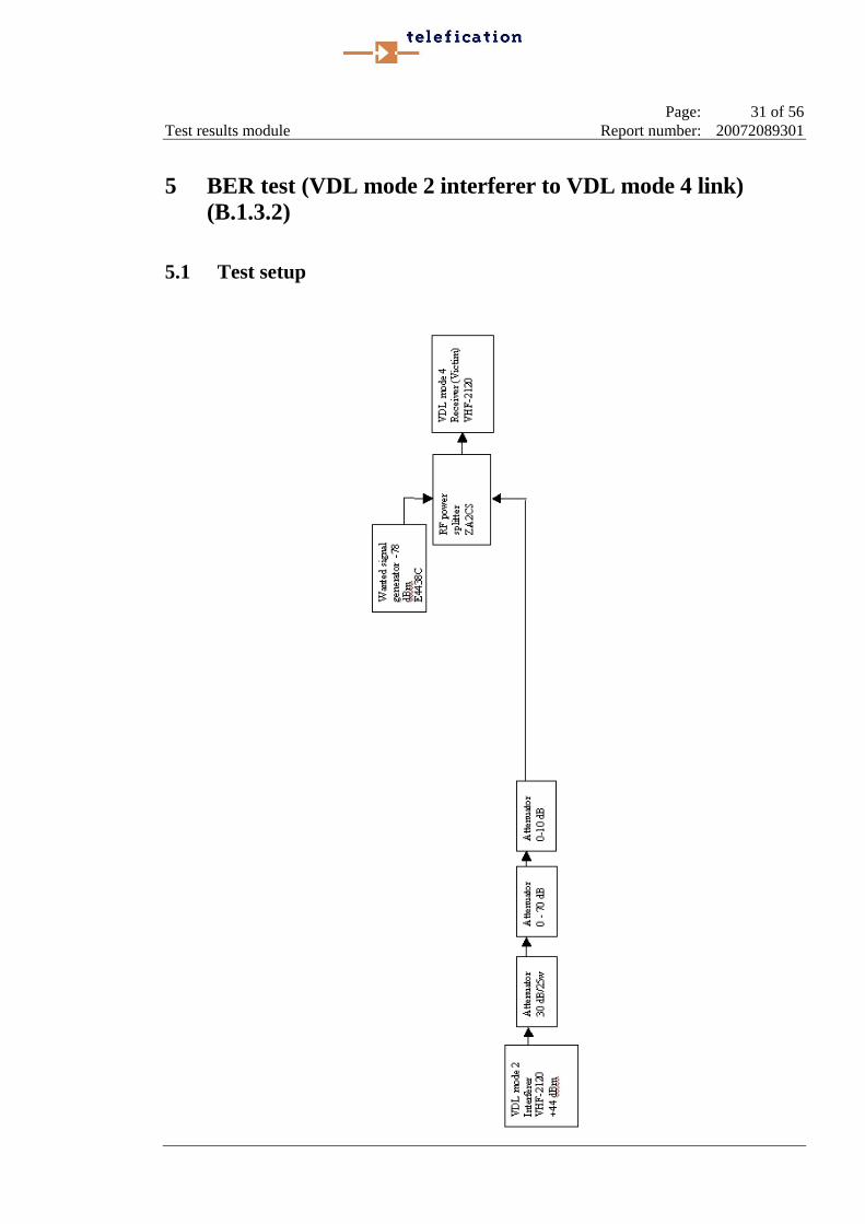
5 BER test (VDL mode 2 interferer to VDL mode 4 link) (B.1.3.2)
5.1 Test setup

Page: 32 of 56 Test results module Report number: 20072089301
5.2 BER test Measurement reference : clause B.1.3.2 Interferer : Rockwell Collins VHF-2120 Victim : Rockwell Collins VHF-2120 Atmospheric pressure : between 86 kPa and 106 kPa Temperature : 24 ° C Relative humidity : 46% Wanted signal level : -82 dBm @ input VDL4 receiver under test Channel loading : 75 msec burst per second Result:
dB rel. (@ BER*) ≤ 1%) to wanted signal of - 82 dBm
Channel offset (N) Result @ 119 MHz Result @ 128 MHz Result @ 136 MHz
-40 65 62 63 -20 63 62 62 -10 66 64 65 -5 65 63 65 -4 48 46 46 -3 58 57 59 -2 66 60 58 -1 45 43 44 1 44 39 42 2 63 62 58 3 59 59 61 4 47 44 38 5 65 66 64
10 68 67 67 20 60 62 62 40 62 63 71
*) Over 40960 bits Channel offset : N * 25 kHz, at 136 MHz the +40 channel was tested at +39 (136.975 MHz) Measurement uncertainty : +/- 1.6 dB The reported uncertainty is based on a standard uncertainty multiplied by a
coverage factor of k=1.96 providing a level of confidence of 95%, but excluding the effect of measurement system repeatability.
Measurement equipment : 1, 3, 5, 6, 13, 14, 16
(The numbers listed refer to the module 'Used test equipment module'.)

Page: 33 of 56 Test results module Report number: 20072089301
RC VHF-2120 interferer to RC VHF-2120
35
40
45
50
55
60
65
70
75
-40 -30 -20 -10 0 10 20 30 40
Channel no
[dB
] 119MHz128MHz136MHz
Page: 34 of 56 Test results module Report number: 20072089301
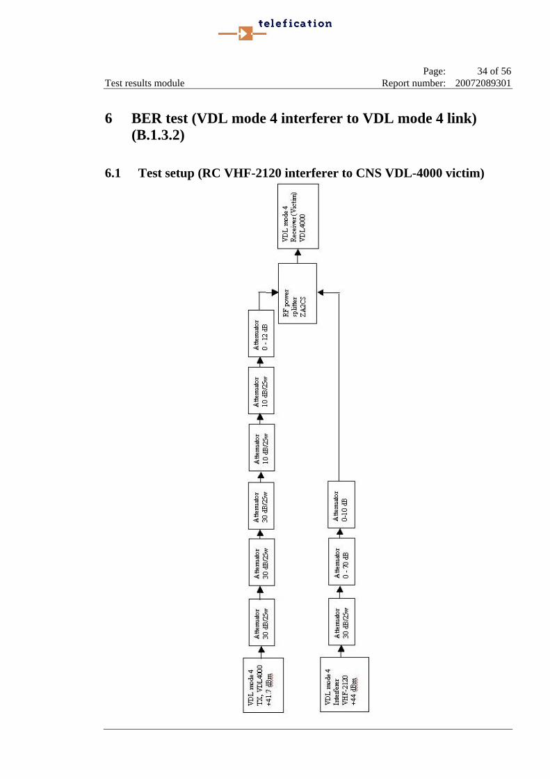
6 BER test (VDL mode 4 interferer to VDL mode 4 link) (B.1.3.2)
6.1 Test setup (RC VHF-2120 interferer to CNS VDL-4000 victim)

Page: 35 of 56 Test results module Report number: 20072089301
6.2 Test setup (CNS VDL-4000 interferer to RC VHF-2120)
Page: 36 of 56 Test results module Report number: 20072089301
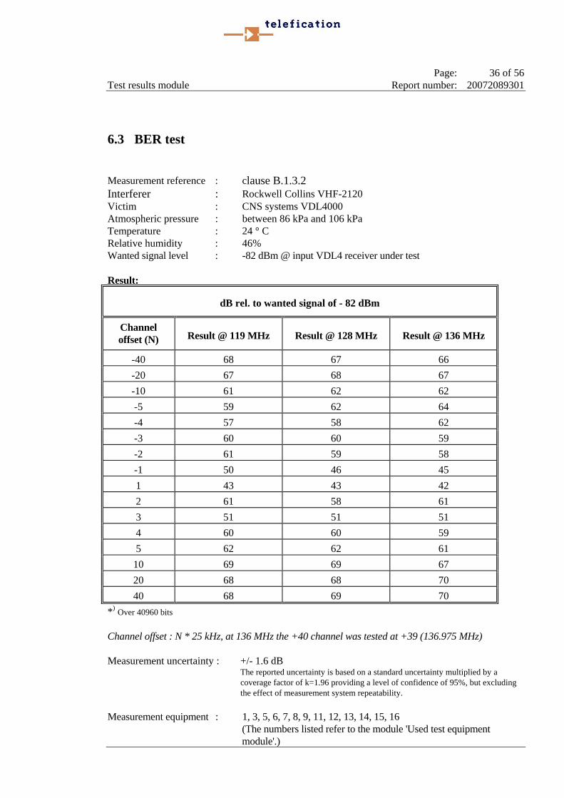
6.3 BER test Measurement reference : clause B.1.3.2 Interferer : Rockwell Collins VHF-2120 Victim : CNS systems VDL4000 Atmospheric pressure : between 86 kPa and 106 kPa Temperature : 24 ° C Relative humidity : 46% Wanted signal level : -82 dBm @ input VDL4 receiver under test Result:
dB rel. to wanted signal of - 82 dBm
Channel offset (N) Result @ 119 MHz Result @ 128 MHz Result @ 136 MHz
-40 68 67 66 -20 67 68 67 -10 61 62 62 -5 59 62 64 -4 57 58 62 -3 60 60 59 -2 61 59 58 -1 50 46 45 1 43 43 42 2 61 58 61 3 51 51 51 4 60 60 59 5 62 62 61
10 69 69 67 20 68 68 70 40 68 69 70
*) Over 40960 bits Channel offset : N * 25 kHz, at 136 MHz the +40 channel was tested at +39 (136.975 MHz) Measurement uncertainty : +/- 1.6 dB The reported uncertainty is based on a standard uncertainty multiplied by a
coverage factor of k=1.96 providing a level of confidence of 95%, but excluding the effect of measurement system repeatability.
Measurement equipment : 1, 3, 5, 6, 7, 8, 9, 11, 12, 13, 14, 15, 16
(The numbers listed refer to the module 'Used test equipment module'.)
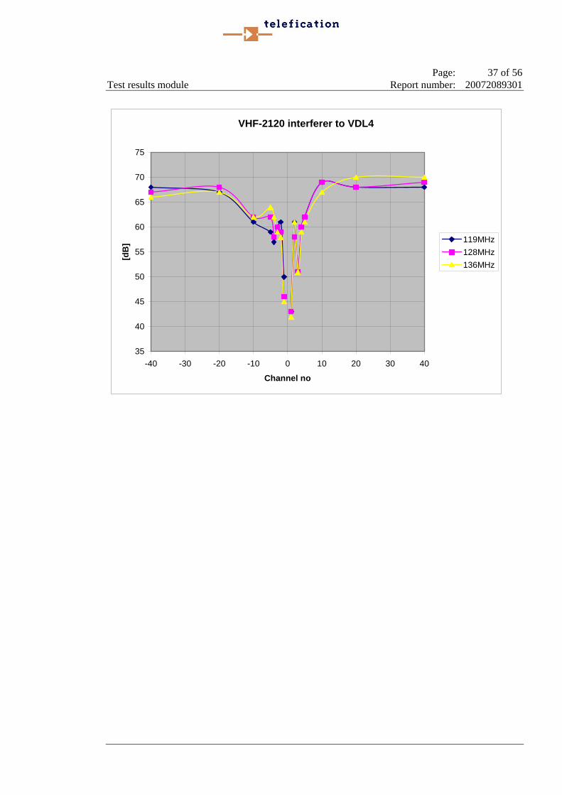
Page: 37 of 56 Test results module Report number: 20072089301
VHF-2120 interferer to VDL4
35
40
45
50
55
60
65
70
75
-40 -30 -20 -10 0 10 20 30 40
Channel no
[dB
] 119MHz128MHz136MHz
Page: 38 of 56 Test results module Report number: 20072089301
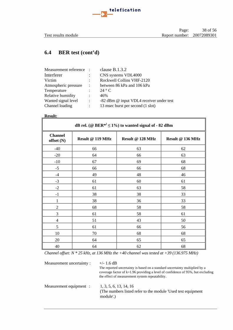
6.4 BER test (cont’d) Measurement reference : clause B.1.3.2 Interferer : CNS systems VDL4000 Victim : Rockwell Collins VHF-2120 Atmospheric pressure : between 86 kPa and 106 kPa Temperature : 24 ° C Relative humidity : 46% Wanted signal level : -82 dBm @ input VDL4 receiver under test Channel loading : 13 msec burst per second (1 slot) Result:
dB rel. (@ BER*) ≤ 1%) to wanted signal of - 82 dBm
Channel offset (N) Result @ 119 MHz Result @ 128 MHz Result @ 136 MHz
-40 66 63 62 -20 64 66 63 -10 67 69 68 -5 66 66 68 -4 49 48 46 -3 61 60 61 -2 61 63 58 -1 38 38 33 1 38 36 33 2 68 58 58 3 61 58 61 4 51 43 50 5 61 66 56
10 70 68 68 20 64 65 65 40 64 62 68
Channel offset: N * 25 kHz, at 136 MHz the +40 channel was tested at +39 (136.975 MHz) Measurement uncertainty : +/- 1.6 dB The reported uncertainty is based on a standard uncertainty multiplied by a
coverage factor of k=1.96 providing a level of confidence of 95%, but excluding the effect of measurement system repeatability.
Measurement equipment : 1, 3, 5, 6, 13, 14, 16
(The numbers listed refer to the module 'Used test equipment module'.)
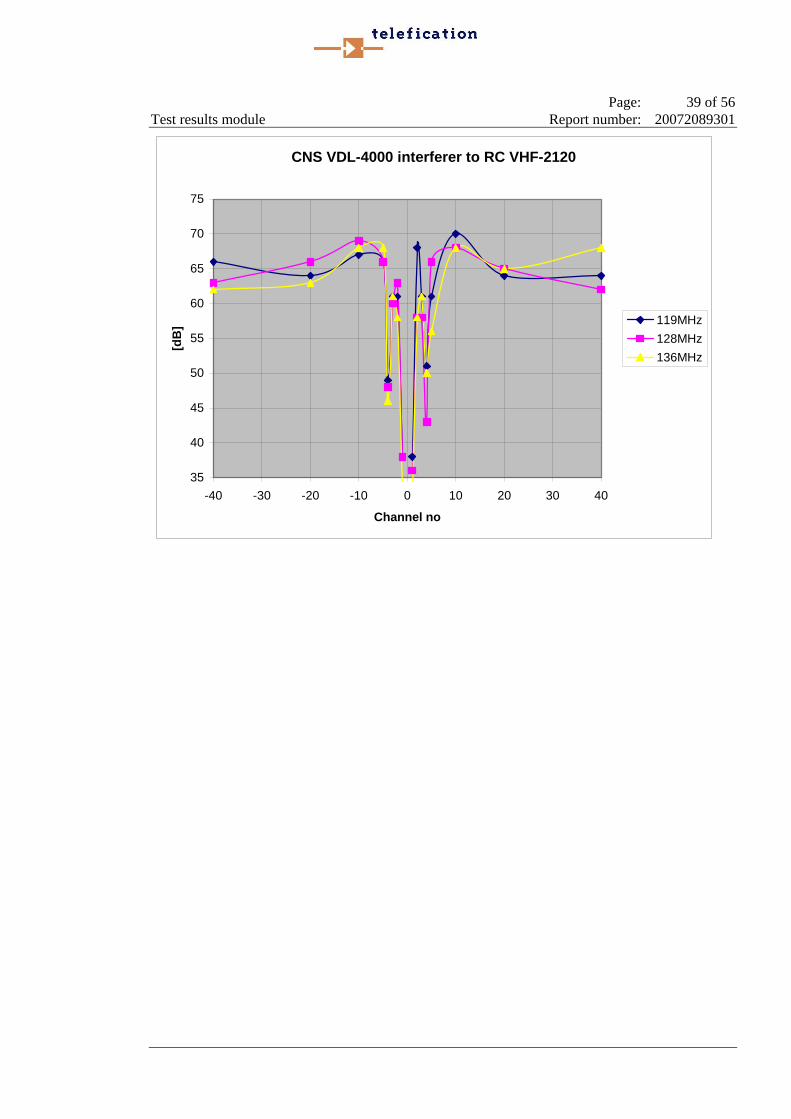
Page: 39 of 56 Test results module Report number: 20072089301
CNS VDL-4000 interferer to RC VHF-2120
35
40
45
50
55
60
65
70
75
-40 -30 -20 -10 0 10 20 30 40
Channel no
[dB
] 119MHz128MHz136MHz
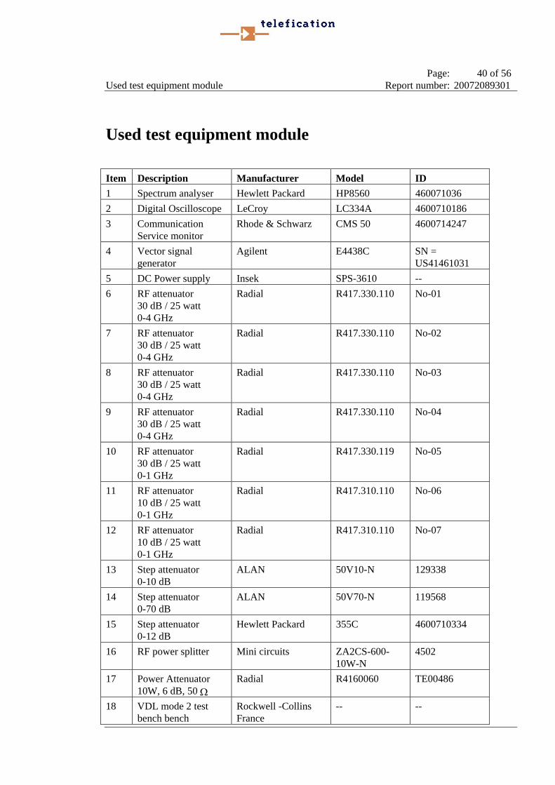
Page: 40 of 56 Used test equipment module Report number: 20072089301
Used test equipment module Item Description Manufacturer Model ID 1 Spectrum analyser Hewlett Packard HP8560 460071036 2 Digital Oscilloscope LeCroy LC334A 4600710186 3 Communication
Service monitor Rhode & Schwarz CMS 50 4600714247
4 Vector signal generator
Agilent E4438C SN = US41461031
5 DC Power supply Insek SPS-3610 -- 6 RF attenuator
30 dB / 25 watt 0-4 GHz
Radial R417.330.110 No-01
7 RF attenuator 30 dB / 25 watt 0-4 GHz
Radial R417.330.110 No-02
8 RF attenuator 30 dB / 25 watt 0-4 GHz
Radial R417.330.110 No-03
9 RF attenuator 30 dB / 25 watt 0-4 GHz
Radial R417.330.110 No-04
10 RF attenuator 30 dB / 25 watt 0-1 GHz
Radial R417.330.119 No-05
11 RF attenuator 10 dB / 25 watt 0-1 GHz
Radial R417.310.110 No-06
12 RF attenuator 10 dB / 25 watt 0-1 GHz
Radial R417.310.110 No-07
13 Step attenuator 0-10 dB
ALAN 50V10-N 129338
14 Step attenuator 0-70 dB
ALAN 50V70-N 119568
15 Step attenuator 0-12 dB
Hewlett Packard 355C 4600710334
16 RF power splitter Mini circuits ZA2CS-600-10W-N
4502
17 Power Attenuator 10W, 6 dB, 50 Ω
Radial R4160060 TE00486
18 VDL mode 2 test bench bench
Rockwell -Collins France
-- --

Page: 41 of 56 Photographs module Report number: 20072089301
Photographs module Photograph 1: Rockwell-Collins VHF-2120, enclosure .................................................................................42 Photograph 2: Rockwell-Collins VHF-2120, front .........................................................................................43 Photograph 3: Rockwell-Collins VHF-2120, label (top) ................................................................................44 Photograph 4: Rockwell-Collins VHF-2120, label with serial number..........................................................45 Photograph 5: Rockwell-Collins VHF-920, front ...........................................................................................46 Photograph 6: Rockwell-Collins VHF-920, label...........................................................................................47 Photograph 7: Rockwell-Collins VHF-700A, front ........................................................................................48 Photograph 8: Rockwell-Collins VHF-700A, label ........................................................................................49 Photograph 9: Becker COMM 3200, control unit ..........................................................................................50 Photograph 10: Becker COMM 3200, ............................................................................................................51 Photograph 11: CNS Systems, VDL 4000 (1), enclosure................................................................................52 Photograph 12: CNS Systems, VDL 4000 (1), label .......................................................................................53 Photograph 13: CNS Systems, VDL 4000 (2), enclosure................................................................................54 Photograph 14: CNS Systems, VDL 4000 (2), enclosure................................................................................55

Page: 42 of 56 Photographs module Report number: 20072089301
Photograph 1: Rockwell-Collins VHF-2120, enclosure

Page: 43 of 56 Photographs module Report number: 20072089301
Photograph 2: Rockwell-Collins VHF-2120, front
Page: 44 of 56 Photographs module Report number: 20072089301
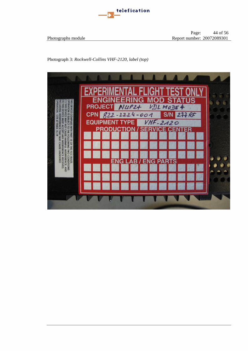
Photograph 3: Rockwell-Collins VHF-2120, label (top)
Page: 45 of 56 Photographs module Report number: 20072089301
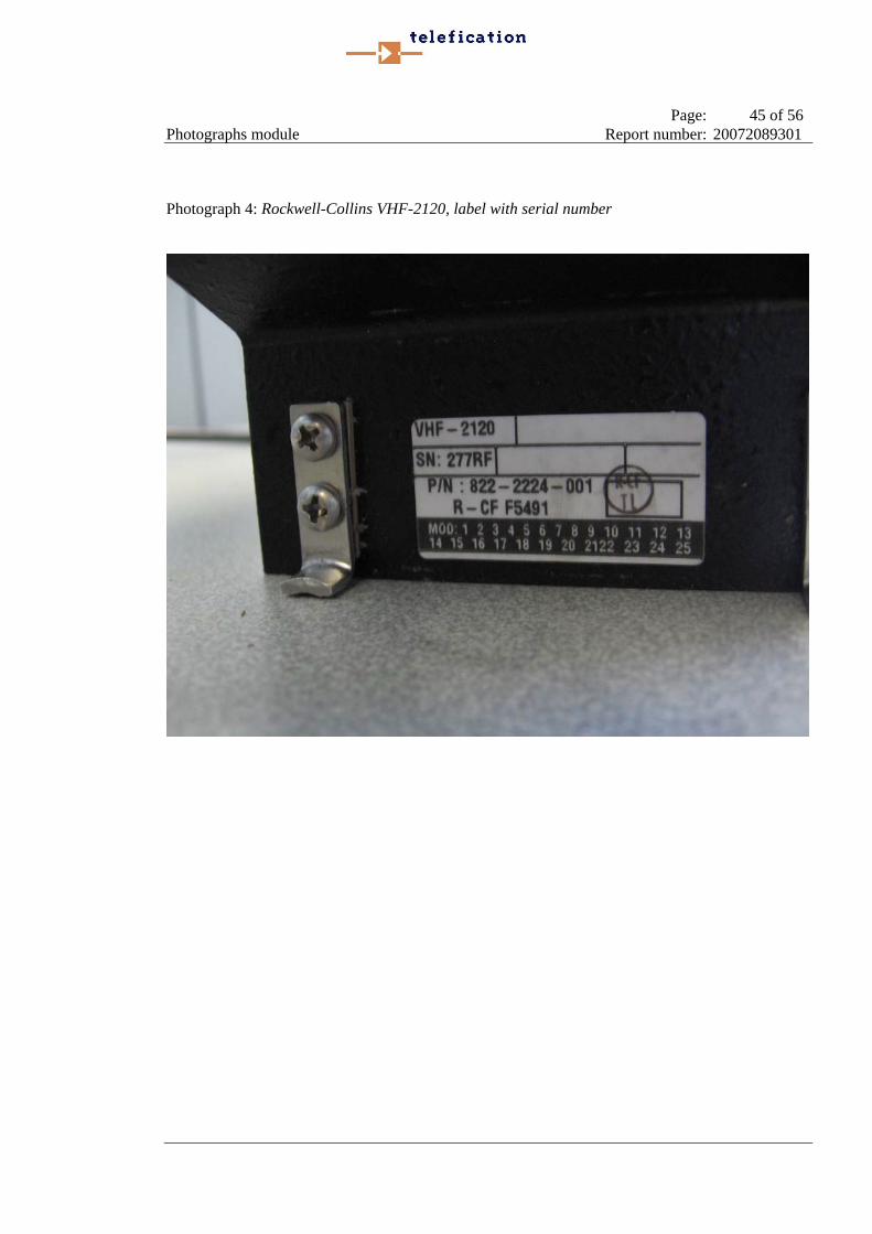
Photograph 4: Rockwell-Collins VHF-2120, label with serial number
Page: 46 of 56 Photographs module Report number: 20072089301
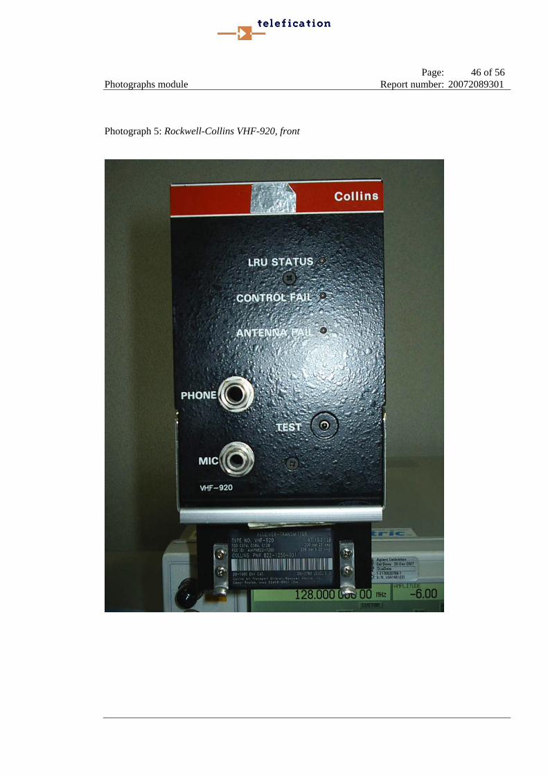
Photograph 5: Rockwell-Collins VHF-920, front

Page: 47 of 56 Photographs module Report number: 20072089301
Photograph 6: Rockwell-Collins VHF-920, label

Page: 48 of 56 Photographs module Report number: 20072089301
Photograph 7: Rockwell-Collins VHF-700A, front
Page: 49 of 56 Photographs module Report number: 20072089301
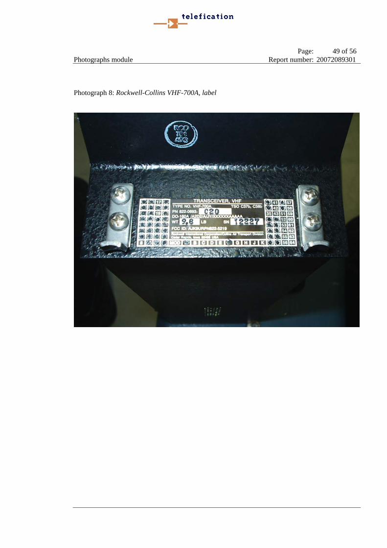
Photograph 8: Rockwell-Collins VHF-700A, label
Page: 50 of 56 Photographs module Report number: 20072089301
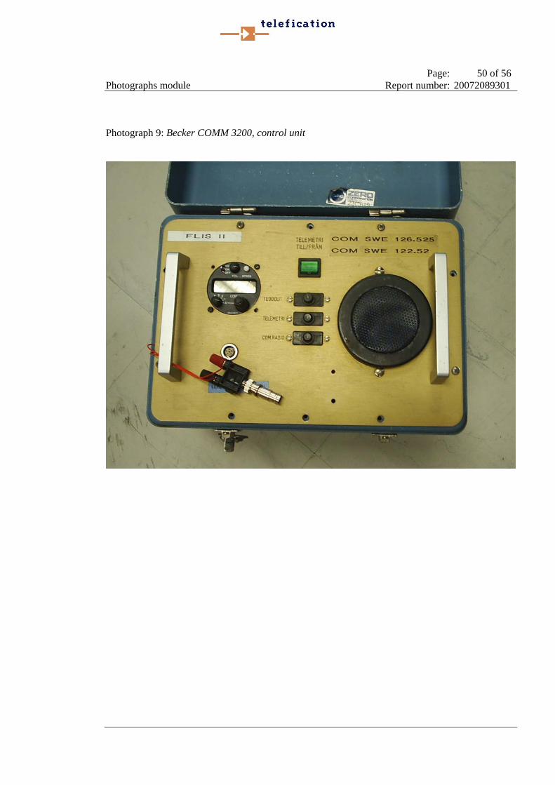
Photograph 9: Becker COMM 3200, control unit
Page: 51 of 56 Photographs module Report number: 20072089301
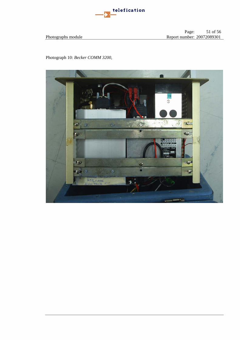
Photograph 10: Becker COMM 3200,
Page: 52 of 56 Photographs module Report number: 20072089301
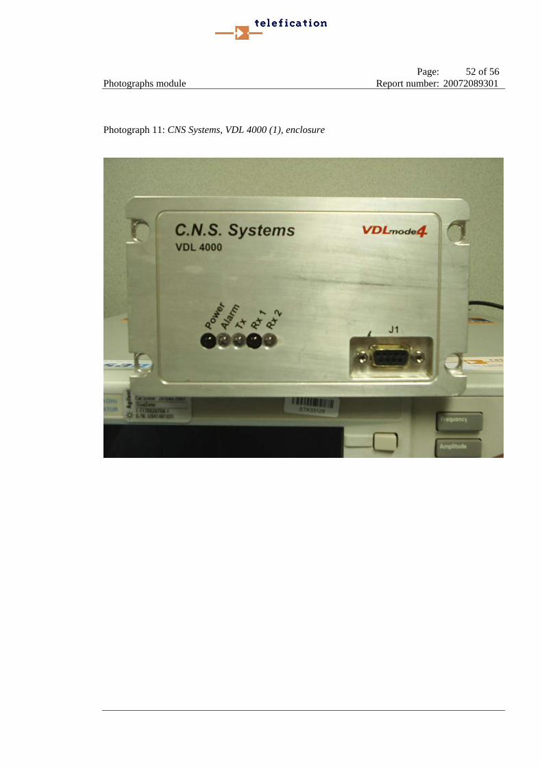
Photograph 11: CNS Systems, VDL 4000 (1), enclosure
Page: 53 of 56 Photographs module Report number: 20072089301
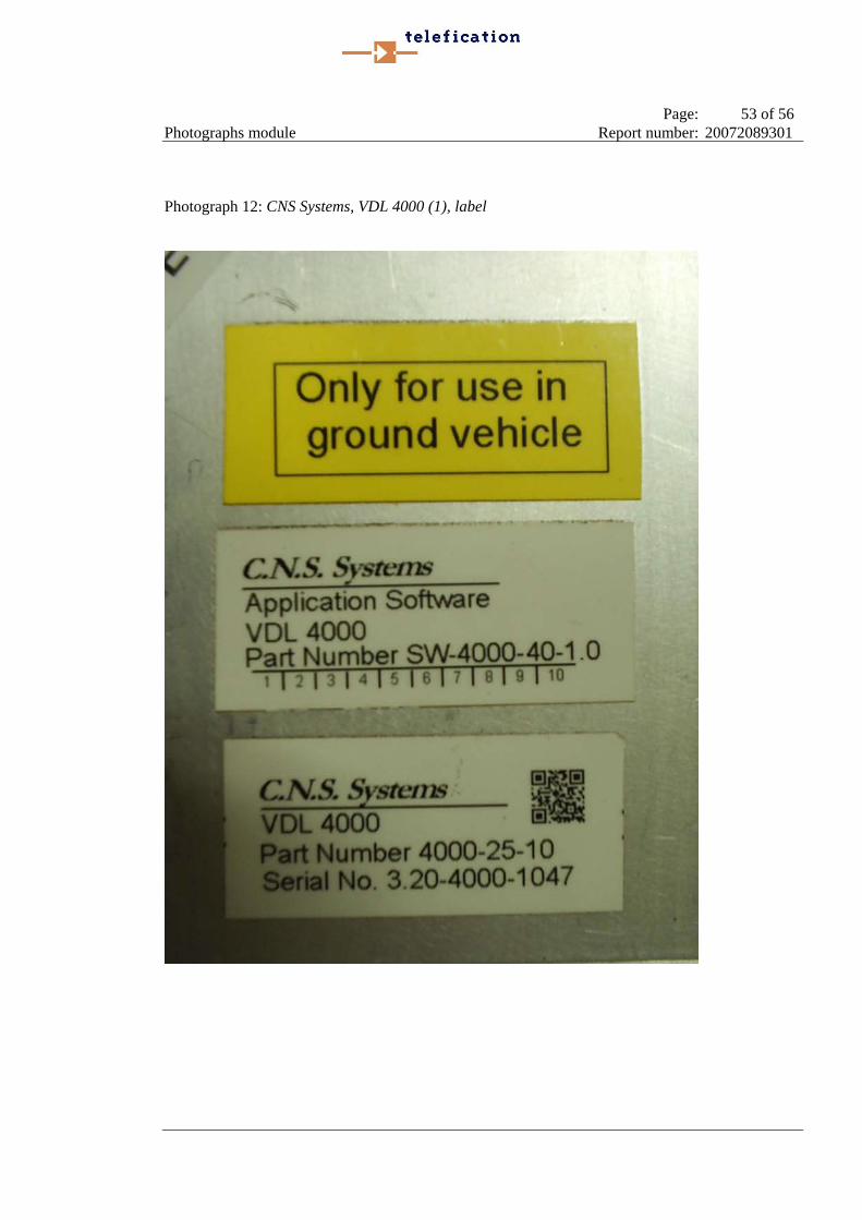
Photograph 12: CNS Systems, VDL 4000 (1), label
Page: 54 of 56 Photographs module Report number: 20072089301
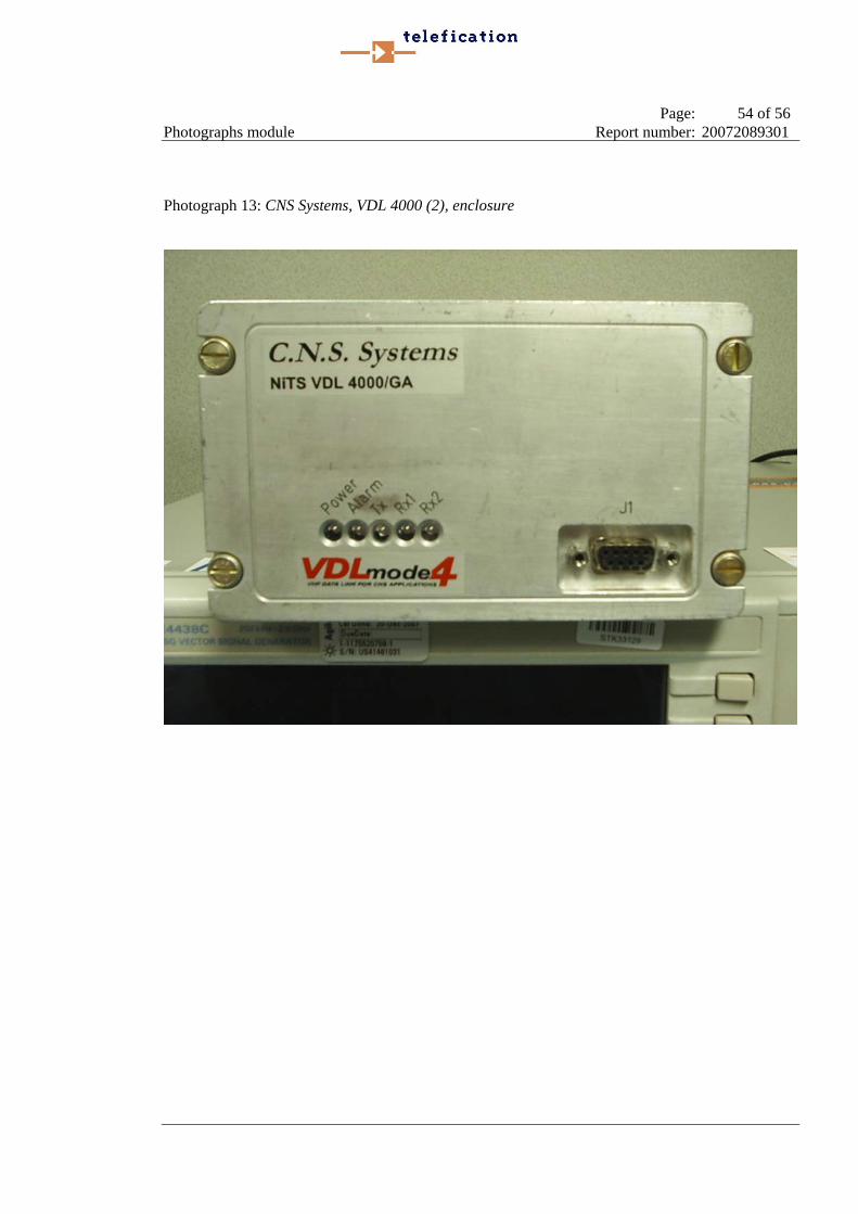
Photograph 13: CNS Systems, VDL 4000 (2), enclosure

Page: 55 of 56 Photographs module Report number: 20072089301
Photograph 14: CNS Systems, VDL 4000 (2), enclosure

Page: 56 of 56 Revision history Report number: 20072089301
Revision history
REVISION DATE REMARKS
1.0 25-03-08 Results of VDL mode 2 interferer to VDL mode 4 link added. Results of VDL mode 4 interferer to VDL mode 4 link extended.


