Embed Size (px)
Citation preview

MeasureIT
Web Tension SystemsP r e s s d u c t o r ® R a d i a l L o a d C e l l s
Tension measurement for web processes

A quality load cell system– f o r d e p e n d a b l e t e n s i o n m e a s u r e m e n t
Quality Tension MeasurementsABB’s PRT load cells come in four measurement
ranges and combine the convenience of shaft
mounting with exceptional overload tolerance and
drift-free operation.
A typical PRT system includes a pair of elec-
tromagnetic-type load cells linked to a tension
electronics that provides system outputs for
process control and operator instrumentation.
The compact load cells can be mounted in various
ways on machinery walls or pedestals, and can be
fitted to both live shaft and dead shaft assemblies.
For live shaft connections, the load cells accept a
wide range of bearing types and sizes.
A Pressductor trans-
ducer produces its
measurement signal
without requiring any
physical movement in
the transducer meas-
urement element. And it
generates a strong sig-
nal at comparatively
low stress levels. So
there is no possibility of
fatigue leading to drift
and deteriorating meas-
urement performance.
For measuring web tension with shaft-mounted
load cells, the Pressductor® Radial Load Cell System
(PRT System) is a high-quality system that provides
exceptional and long-lasting performance.
PRT load cells and tension electronics are
designed for medium-tension and light-tension
web processing machinery used in converting, print-
ing, plastic film production, nonwovens manufac-
turing, textile finishing, and other operations.
Easy to install and virtually maintenance-free,
PRT tension measurement makes a significant contri-
bution to more productive operations and improve-
ments in web product quality.
Changing process requirementsToday, web machinery is being equipped with
more process automation than ever before, includ-
ing closed-loop controls and recipe management.
A wider range of materials must be processed at
higher operating speeds – without sacrificing
product quality or risking downtime.
In most machinery applications, knowing
what the web tension actually is at various points
of the processing line has become a fundamental
requirement for successful operations. The result
is that the quality of tension measurements –
good or bad – is showing up more quickly than
ever before in both the product being processed
and the operating efficiency of the line.
Performance improvement goals are difficult
to achieve if your tension measurement load cells
require constant replacement, or if you feel you
cannot rely on the measured values. Furthermore,
tension measurement systems must not require
constant recalibration or replacement of compo-
nents to perform at their best.
2
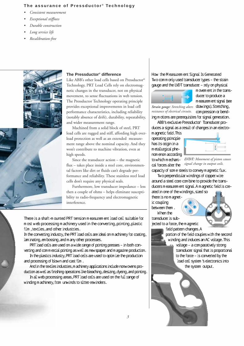
T h e a s s u r a n c e o f P r e s s d u c t o r ® Te c h n o l o g y
• Consistent measurement
• Exceptional stiffness
• Durable construction
• Long service life
• Recalibration-free
How the Measurement Signal Is Generated
Two commonly used transducer types – the strain
gauge and the LVDT transducer – rely on physical
movement in the trans-
ducer to produce a
measurement signal (see
drawings). Stretching,
compression or bend-
ing motions are prerequisites for signal generation.
ABB’s exclusive Pressductor® Transducer pro-
duces a signal as a result of changes in an electro-
magnetic field. This
operating principle
has its origin in a
metallurgical phe-
nomenon according
to which mechani-
cal forces alter the
capacity of some steels to convey magnetic flux.
Two perpendicular windings of copper wire
around a steel core combine to provide the trans-
ducers measurement signal. A magnetic field is cre-
ated in one of the windings, sized so
there is no magnet-
ic coupling
between them.
When the
transducer is sub-
jected to a force, the magnetic
field pattern changes. A
portion of the field couples with the second
winding and induces an AC voltage. This
voltage – a comparatively strong
transducer signal that is proportional
to the force – is converted by the
load cell system’s electronics into
the system output.
The Pressductor ® differenceLike ABB’s other load cells based on Pressductor®
Technology, PRT Load Cells rely on electromag-
netic changes in the transducer, not on physical
movement, to sense fluctuations in web tension.
The Pressductor Technology operating principle
provides exceptional improvements in load cell
performance characteristics, including reliability
(notably absence of drift), durability, repeatability,
and wider measurement range.
Machined from a solid block of steel, PRT
load cells are rugged and stiff, affording high over-
load protection as well as an extended measure-
ment range above the nominal capacity. And they
won’t contribute to machine vibration, even at
high speeds.
Since the transducer action – the magnetic
flux – takes place inside a steel core, environmen-
tal factors like dirt or fluids can’t degrade per-
formance and reliability. These stainless steel load
cells don’t require any physical seals.
Furthermore, low transducer impedance – less
then a couple of ohms – helps eliminate suscepti-
bility to radio-frequency and electromagnetic
interference.
There is a shaft-mounted PRT tension measurement load cell suitable for
most web processing machinery used in the converting, printing, plastic
film, textiles, and other industries.
In the converting industry, the PRT load cells are ideal on machinery for coating,
laminating, embossing, and many other processes.
PRT load cells are used on a wide range of printing presses – in both con-
verting and commercial printing as well as newspaper and magazine production.
In the plastics industry, PRT load cells are used to optimize the production
and processing of blown and cast film.
And in the textiles industries, machinery applications include nonwovens pro-
duction as well as finishing operations like bleaching, desizing, dyeing, and printing.
In all web processing areas, PRT load cells are used on the full range of
winding machinery, from unwinds to slitter-rewinders.
3
Strain gauge: Stretching altersresistance of electrical circuits.
LVDT: Movement of piston causessignal change in output coils.
4
Pressductor® Radial Load Cells– d e s i g n e d t o m e a s u r e w e b t e n s i o n o n m o s t t y p e s o f w e bp r o c e s s i n g m a c h i n e r y u s e d i n t h e c o n v e r t i n g , p l a s t i c f i l m ,p r i n t i n g , t e x t i l e s , a n d o t h e r i n d u s t r i e s .
The Pressductor Radial Load Cells are ideal for
applications on a wide range of web processing
machinery in the converting, plastic film, print-
ing, textiles, and other industries. The system’s
radial load cells mount directly on the roll shaft.
For live (rotating) shaft applications, PRT load
cells are available to fit a wide range of bearing and
shaft sizes. A simple, pre-assembled adapter equips
the load cells for use with dead (nonrotating) shafts.
The load cells are easily mounted on either the inside
or outside of machine walls. By using an adapter
bracket, they can also be mounted on pedestals.
Four sizes of load cell are available, with nomi-
nal load at 0.5, 1.0, 2.0, and 5.0 kN of force
(112, 225, 450 and 1125 lbs.). The PRT Model
C comes in three nominal loads and is intended
especially for applications where the roll requires a
large bearing but the load cell must measure low
web tension levels.
By relying on a unique “extended range” fea-
ture to measure peak loads, PRT load cells can be
precisely sized for the web’s normal tension range
while also accommodating occasional peak loads.
Extended-range operation provides reliable meas-
urements of tension levels up to 50 percent higher
than the nominal load. This feature facilitates the
versatile operation of web equipment with an
expanded range of materials and tension ranges.
All PRT load cells are exceptionally sturdy,
machined from a single block of stainless steel,
and display exceptionally high tolerance for over-
loads, shock and impact. The system can handle
overloads ranging up to 500 percent of nominal
load without affecting load cell calibration. The
high spring constant and low physical deflection
of PRT load cells result in accurate measurement
with no contribution to machine vibration. The
performance of the load cells is unaffected by
environmental factors like dust, corrosion, and
radio or electromagnetic interference.
Extended-Range
Operation
Beyond their nominal
capacity, PRT load cells
have an extended range
of measurement – so
they can be sized for
normal, as opposed to
maximum, tension lev-
els. As a result, they can
process a wider variety
of materials.
Flexible orientation
No matter what the
wrap angle or where the
measurement roll is
located on the machine,
the PRT load cell is sim-
ply rotated to pick up
the ideal measurement
force component.
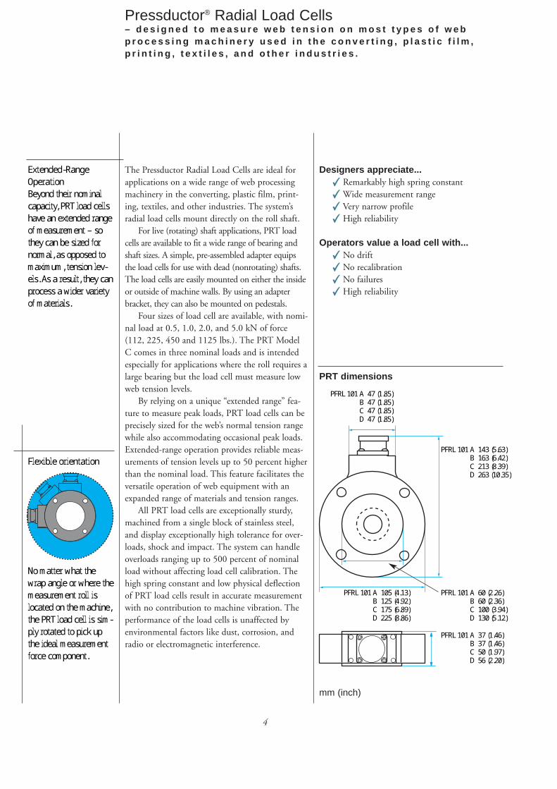
PFRL 101 A 47 (1.85)B 47 (1.85)C 47 (1.85)D 47 (1.85)
PFRL 101 A 143 (5.63)B 163 (6.42)C 213 (8.39)D 263 (10.35)
PFRL 101 A 60 (2.26)B 60 (2.36)C 100 (3.94)D 130 (5.12)
PFRL 101 A 37 (1.46)B 37 (1.46)C 50 (1.97)D 56 (2.20)
PFRL 101 A 105 (4.13)B 125 (4.92)C 175 (6.89)D 225 (8.86)
PRT dimensions
Designers appreciate... Remarkably high spring constant
Wide measurement range
Very narrow profile
High reliability
Operators value a load cell with... No drift
No recalibration
No failures
High reliability
mm (inch)
5
P e r f o r m a n c e d a t a
Four standard sizes
measure web tension
from 0.1 to 100 kN.
With its extended-
capacity feature, the
PRT load cell is capa-
ble of measuring ten-
sion reliably over a
30:1 range.
Superior
overload
character-
istics in all
force directions elimi-
nate overload failures
for all practical purpos-
es. Exceptionally high
spring constant virtu-
ally precludes load
cell contributions to
machine vibration,
even at very high
machinery speeds.
Low deflection con-
tributes to negligible
movement (stretching
or contraction) in the
PRT load cell, which is
particularly
valuable in
achieving
exceptional
web materi-
al registra-
tion.
Properties
Nominal load
(rated capacity)
Extended load1)
Overload2)
Measurement direction
Transverse to
measurement direction
Axial
Spring constant
Deflection3)
kN
Lbs.
kN
Lbs.
kN
Lbs.
kN
Lbs.
kN
Lbs.
kN/mm
1000 Lbs./inch
mm1/1000 inch
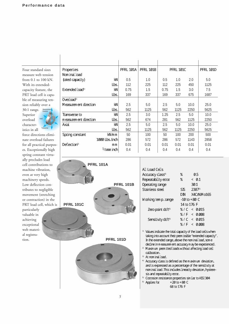
PFRL 101A
0.51120.75169
2.55622.55622.556250
2860.010.4
PFRL 101B
1.02251.5337
5.011253.06745.0
11251005720.010.4
0.51120.75169
2.55621.252812.556250
2860.010.4
1.02251.5337
5.011252.55625.0
11251005720.010.4
2.04503.0675
10.022505.0
112510.0225020011430.010.4
PFRL 101D
5.011257.5
1687
25.0562510.0225025.0562550028580.010.4
All Load Cells
Accuracy class4) % ±0.5
Repeatability error % <±0.1
Operating range 30:1
Stainless steel SIS 23875)
DIN X4CrNiMo165
Working temp. range -10 to +80°C
14 to 176°F
Zero point drift6) %/°C <±0.015
%/°F <±0.008
Sensitivity drift6) %/°C <±0.015
%/°F <±0.008
1) Values indicate the total capacity of the load cells whentaking into account their permissible “extended capacity”.In the extended range, above the nominal load, somedecline in measurement accuracy may be experienced.
2) Maximum permitted loads without affecting load cellcalibration.
3) At nominal load.4) Accuracy class is defined as the maximum deviation,
and is expressed as a percentage of the sensitivity atnominal load. This includes linearity deviation, hystere-sis and repeatability error.
5) Corrosion resistance properties similar to AISI 3046) Applies for +20 to +80°C
68 to 176°F
PFRL 101C
PFRL 101D
PFRL 101B
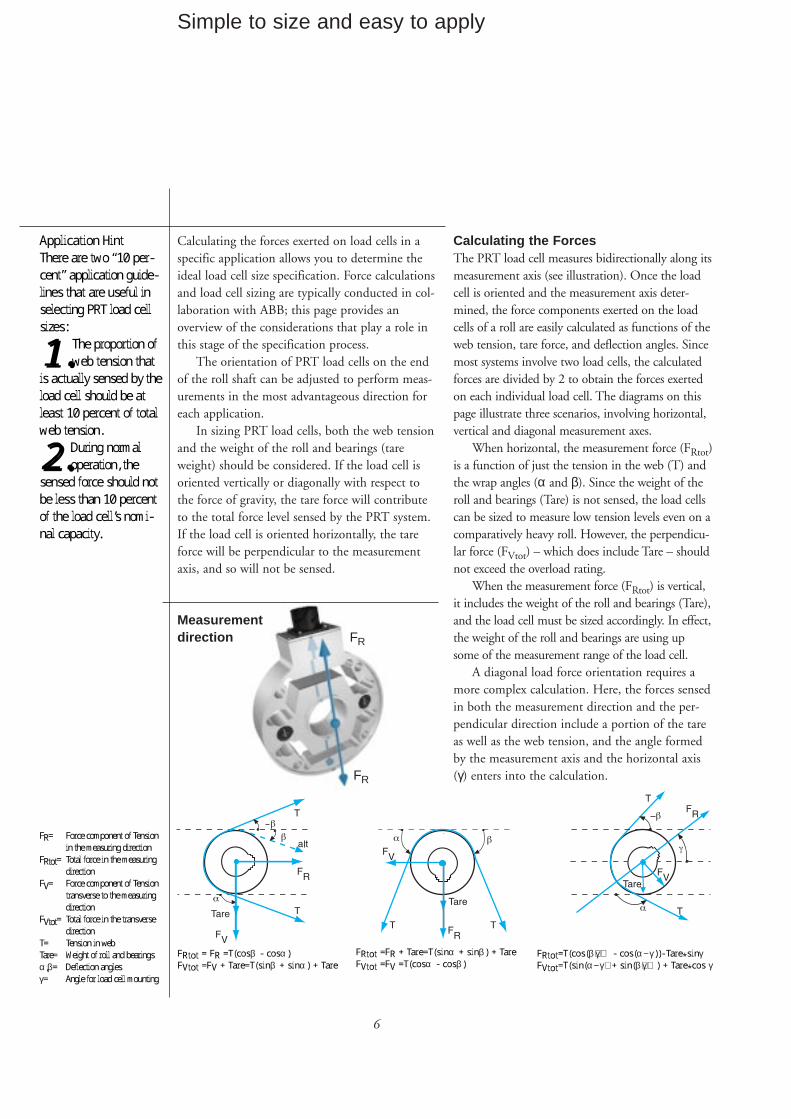
Measurement
Transverse
Axial
Direction
PFRL 101A
PFRL 101C
6
Simple to size and easy to apply
Calculating the forces exerted on load cells in a
specific application allows you to determine the
ideal load cell size specification. Force calculations
and load cell sizing are typically conducted in col-
laboration with ABB; this page provides an
overview of the considerations that play a role in
this stage of the specification process.
The orientation of PRT load cells on the end
of the roll shaft can be adjusted to perform meas-
urements in the most advantageous direction for
each application.
In sizing PRT load cells, both the web tension
and the weight of the roll and bearings (tare
weight) should be considered. If the load cell is
oriented vertically or diagonally with respect to
the force of gravity, the tare force will contribute
to the total force level sensed by the PRT system.
If the load cell is oriented horizontally, the tare
force will be perpendicular to the measurement
axis, and so will not be sensed.
Calculating the ForcesThe PRT load cell measures bidirectionally along its
measurement axis (see illustration). Once the load
cell is oriented and the measurement axis deter-
mined, the force components exerted on the load
cells of a roll are easily calculated as functions of the
web tension, tare force, and deflection angles. Since
most systems involve two load cells, the calculated
forces are divided by 2 to obtain the forces exerted
on each individual load cell. The diagrams on this
page illustrate three scenarios, involving horizontal,
vertical and diagonal measurement axes.
When horizontal, the measurement force (FRtot)
is a function of just the tension in the web (T) and
the wrap angles (α and β). Since the weight of the
roll and bearings (Tare) is not sensed, the load cells
can be sized to measure low tension levels even on a
comparatively heavy roll. However, the perpendicu-
lar force (FVtot) – which does include Tare – should
not exceed the overload rating.
When the measurement force (FRtot) is vertical,
it includes the weight of the roll and bearings (Tare),
and the load cell must be sized accordingly. In effect,
the weight of the roll and bearings are using up
some of the measurement range of the load cell.
A diagonal load force orientation requires a
more complex calculation. Here, the forces sensed
in both the measurement direction and the per-
pendicular direction include a portion of the tare
as well as the web tension, and the angle formed
by the measurement axis and the horizontal axis
(γ) enters into the calculation.
Application Hint
There are two “10 per-
cent” application guide-
lines that are useful in
selecting PRT load cell
sizes:
11.. The proportion of
web tension that
is actually sensed by the
load cell should be at
least 10 percent of total
web tension.
22.. During normal
operation, the
sensed force should not
be less than 10 percent
of the load cell’s nomi-
nal capacity.
FR= Force component of Tension
in the measuring direction
FRtot= Total force in the measuring
direction
FV= Force component of Tension
transverse to the measuring
direction
FVtot= Total force in the transverse
direction
T= Tension in web
Tare= Weight of roll and bearings
α,β= Deflection angles
γ= Angle for load cell mounting
FRtot=T(cos(β+γ) - cos(α−γ) )- Tare*sinγFVtot=T(s in(α−γ) + s in(β+γ)) + Tare*cos γ
FRtot = FR =T(cosβ - cosα )
FVtot =FV + Tare=T(sinβ + s inα ) + Tare
FRtot =FR + Tare=T(sinα + s inβ) + Tare
FVtot =FV =T(cosα - cosβ)
Measurementdirection FR
FR
7
M o u n t i n g o p t i o n s
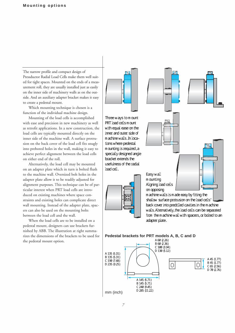
The narrow profile and compact design of
Pressductor Radial Load Cells make them well suit-
ed for tight spaces. Mounted on the ends of a meas-
urement roll, they are usually installed just as easily
on the inner side of machinery walls as on the out-
side. And an auxiliary adapter bracket makes it easy
to create a pedestal mount.
Which mounting technique is chosen is a
function of the individual machine design.
Mounting of the load cells is accomplished
with ease and precision in new machinery as well
as retrofit applications. In a new construction, the
load cells are typically mounted directly on the
inner side of the machine wall. A surface protru-
sion on the back cover of the load cell fits snugly
into prebored holes in the wall, making it easy to
achieve perfect alignment between the load cells
on either end of the roll.
Alternatively, the load cell may be mounted
on an adapter plate which in turn is bolted flush
to the machine wall. Oversized bolt holes in the
adapter plate allow it to be readily adjusted for
alignment purposes. This technique can be of par-
ticular interest when PRT load cells are intro-
duced on existing machines where space con-
straints and existing holes can complicate direct
wall mounting. Instead of the adapter plate, spac-
ers can also be used on the mounting bolts
between the load cell and the wall.
When the load cells are to be installed on a
pedestal mount, designers can use brackets fur-
nished by ABB. The illustration at right summa-
rizes the dimensions of the brackets to be used for
the pedestal mount option.
Three ways to mount
PRT load cells mount
with equal ease on the
inner and outer side of
machine walls. In loca-
tions where pedestal
mounting is required, a
specially designed angle
bracket extends the
usefulness of the radial
load cell.
Easy wall
mounting
Aligning load cells
on opposing
machine walls is made easy by fitting the
shallow surface protrusion on the load cells’
back cover into predrilled cavities in the machine
walls. Alternatively, the load cells can be separated
from the machine wall with spacers, or bolted to an
adapter plate.
Pedestal brackets for PRT models A, B, C and D
A 135 (5.31)B 135 (5.31)C 190 (7.48)D 235 (9.25)
A 60 (2.26)B 60 (2.36)C 100 (3.94)D 130 (5.12)
A 145 (5.71)B 145 (5.71)C 240 (9.45)D 285 (11.22)
A 45 (1.77)B 45 (1.77)C 65 (2.56)D 70 (2.76)
mm (inch)
8
Shaft sizes and bearing recommendations
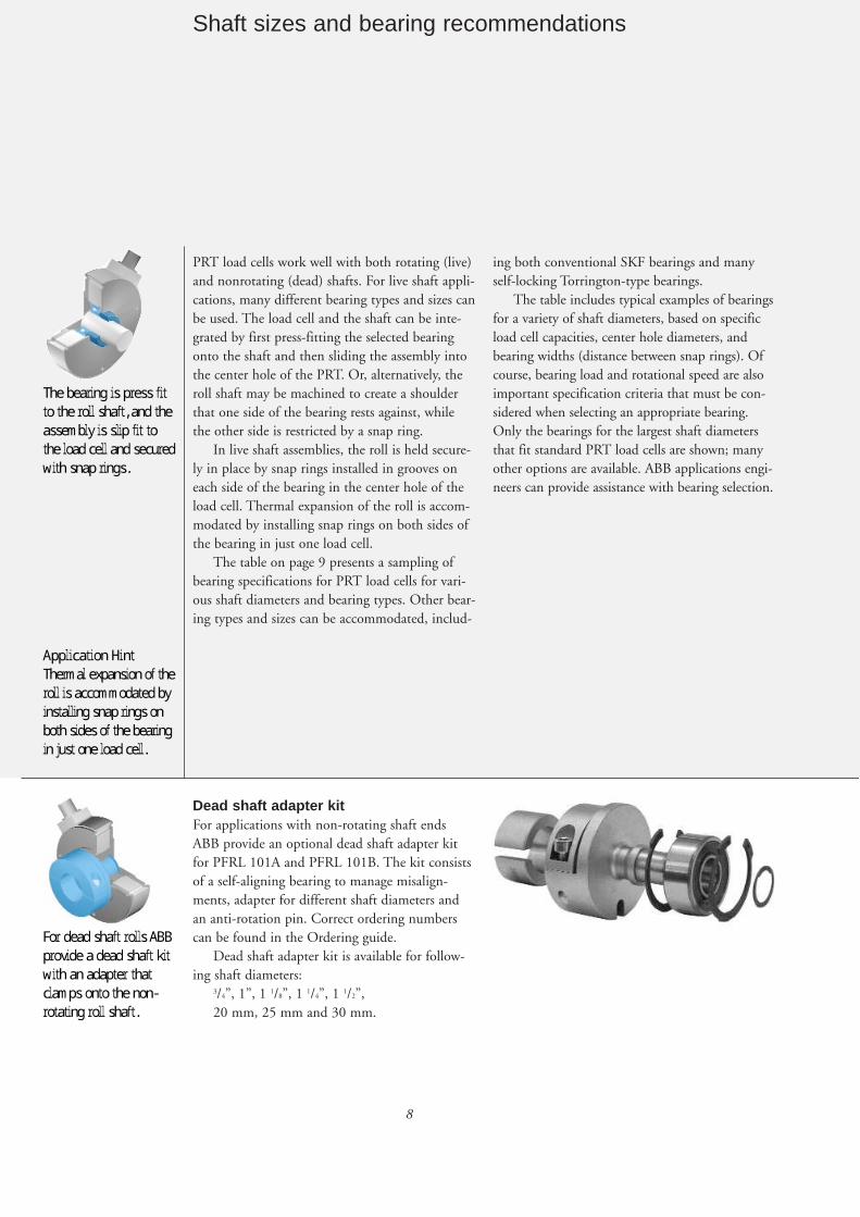
PRT load cells work well with both rotating (live)
and nonrotating (dead) shafts. For live shaft appli-
cations, many different bearing types and sizes can
be used. The load cell and the shaft can be inte-
grated by first press-fitting the selected bearing
onto the shaft and then sliding the assembly into
the center hole of the PRT. Or, alternatively, the
roll shaft may be machined to create a shoulder
that one side of the bearing rests against, while
the other side is restricted by a snap ring.
In live shaft assemblies, the roll is held secure-
ly in place by snap rings installed in grooves on
each side of the bearing in the center hole of the
load cell. Thermal expansion of the roll is accom-
modated by installing snap rings on both sides of
the bearing in just one load cell.
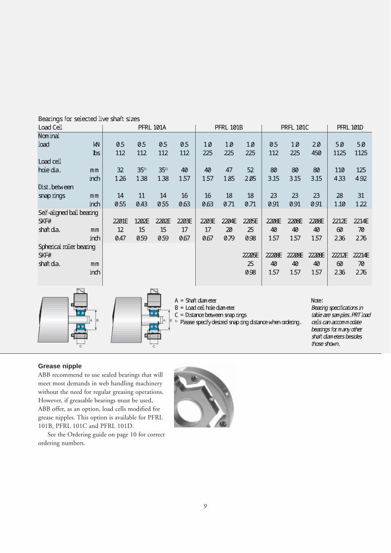
The table on page 9 presents a sampling of
bearing specifications for PRT load cells for vari-
ous shaft diameters and bearing types. Other bear-
ing types and sizes can be accommodated, includ-
ing both conventional SKF bearings and many
self-locking Torrington-type bearings.
The table includes typical examples of bearings
for a variety of shaft diameters, based on specific
load cell capacities, center hole diameters, and
bearing widths (distance between snap rings). Of
course, bearing load and rotational speed are also
important specification criteria that must be con-
sidered when selecting an appropriate bearing.
Only the bearings for the largest shaft diameters
that fit standard PRT load cells are shown; many
other options are available. ABB applications engi-
neers can provide assistance with bearing selection.
Application Hint
Thermal expansion of the
roll is accommodated by
installing snap rings on
both sides of the bearing
in just one load cell.
For dead shaft rolls ABB
provide a dead shaft kit
with an adapter that
clamps onto the non-
rotating roll shaft.
The bearing is press fit
to the roll shaft, and the
assembly is slip fit to
the load cell and secured
with snap rings.
Dead shaft adapter kitFor applications with non-rotating shaft ends
ABB provide an optional dead shaft adapter kit
for PFRL 101A and PFRL 101B. The kit consists
of a self-aligning bearing to manage misalign-
ments, adapter for different shaft diameters and
an anti-rotation pin. Correct ordering numbers
can be found in the Ordering guide.
Dead shaft adapter kit is available for follow-
ing shaft diameters:3/4”, 1”, 1 1/8”, 1 1/4”, 1 1/2”,
20 mm, 25 mm and 30 mm.
9
Bearings for selected live shaft sizes
Load Cell PFRL 101A PFRL 101B PRFL 101C PFRL 101D
Nominal
load kN 0.5 0.5 0.5 0.5 1.0 1.0 1.0 0.5 1.0 2.0 5.0 5.0
Ibs 112 112 112 112 225 225 225 112 225 450 1125 1125
Load cell
hole dia. mm 32 351) 351) 40 40 47 52 80 80 80 110 125
inch 1.26 1.38 1.38 1.57 1.57 1.85 2.05 3.15 3.15 3.15 4.33 4.92
Dist. between
snap rings mm 14 11 14 16 16 18 18 23 23 23 28 31
inch 0.55 0.43 0.55 0.63 0.63 0.71 0.71 0.91 0.91 0.91 1.10 1.22
Self-aligned ball bearing
SKF# 2201E 1202E 2202E 2203E 2203E 2204E 2205E 2208E 2208E 2208E 2212E 2214E
shaft dia. mm 12 15 15 17 17 20 25 40 40 40 60 70
inch 0.47 0.59 0.59 0.67 0.67 0.79 0.98 1.57 1.57 1.57 2.36 2.76
Spherical roller bearing
SKF# 22205E 22208E 22208E 22208E 22212E 22214E
shaft dia. mm 25 40 40 40 60 70
inch 0.98 1.57 1.57 1.57 2.36 2.76
A B
C
A B
C
Grease nippleABB recommend to use sealed bearings that will
meet most demands in web handling machinery
without the need for regular greasing operations.
However, if greasable bearings must be used,
ABB offer, as an option, load cells modified for
grease nipples. This option is available for PFRL
101B, PFRL 101C and PFRL 101D.
See the Ordering guide on page 10 for correct
ordering numbers.
A = Shaft diameterB = Load cell hole diameterC = Distance between snap rings1) Please specify desired snap ring distance when ordering.
Note:Bearing specifications intable are samples. PRT loadcells can accommodatebearings for many othershaft diameters besidesthose shown.
10
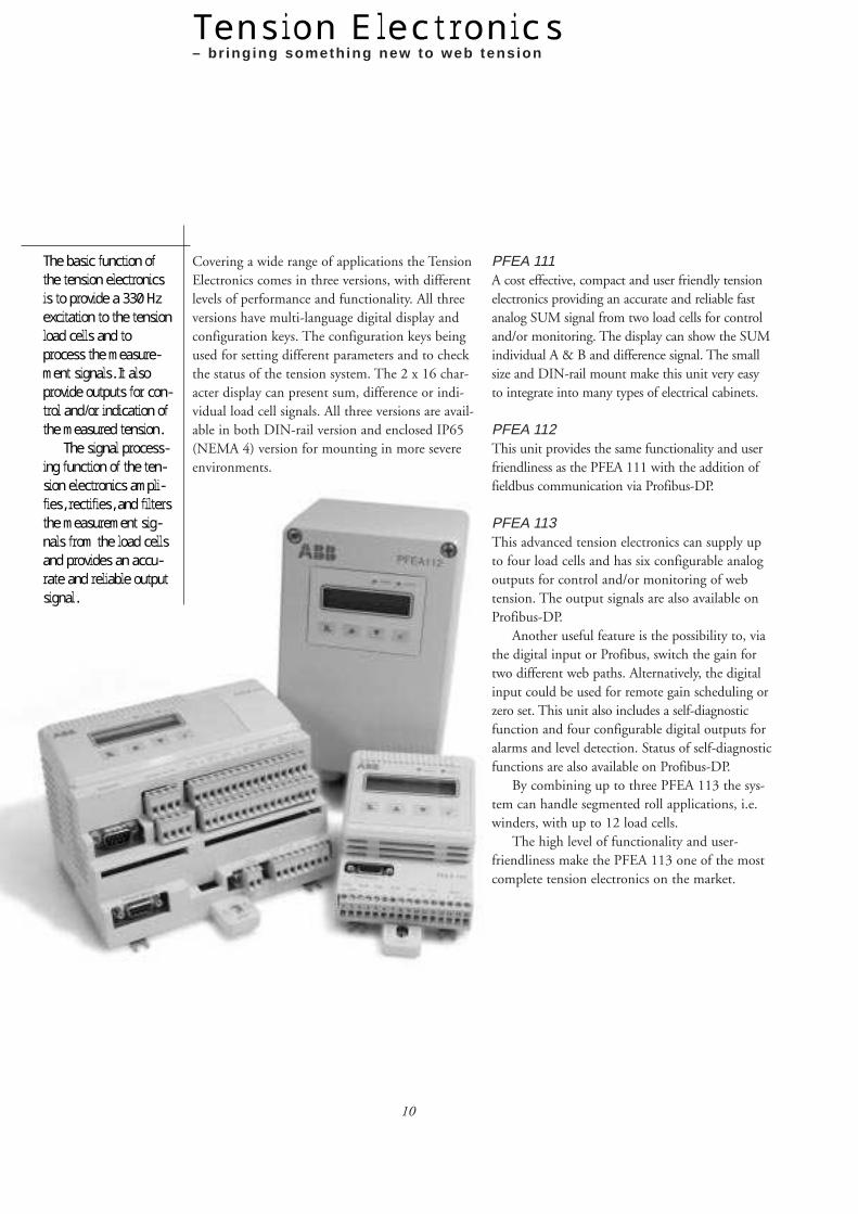
Tension Electronics– br ing ing someth ing new to web tens ion
The basic function of
the tension electronics
is to provide a 330 Hz
excitation to the tension
load cells and to
process the measure-
ment signals. It also
provide outputs for con-
trol and/or indication of
the measured tension.
The signal process-
ing function of the ten-
sion electronics ampli-
fies, rectifies, and filters
the measurement sig-
nals from the load cells
and provides an accu-
rate and reliable output
signal.
PFEA 111A cost effective, compact and user friendly tension
electronics providing an accurate and reliable fast
analog SUM signal from two load cells for control
and/or monitoring. The display can show the SUM
individual A & B and difference signal. The small
size and DIN-rail mount make this unit very easy
to integrate into many types of electrical cabinets.
PFEA 112This unit provides the same functionality and user
friendliness as the PFEA 111 with the addition of
fieldbus communication via Profibus-DP.
PFEA 113This advanced tension electronics can supply up
to four load cells and has six configurable analog
outputs for control and/or monitoring of web
tension. The output signals are also available on
Profibus-DP.
Another useful feature is the possibility to, via
the digital input or Profibus, switch the gain for
two different web paths. Alternatively, the digital
input could be used for remote gain scheduling or
zero set. This unit also includes a self-diagnostic
function and four configurable digital outputs for
alarms and level detection. Status of self-diagnostic
functions are also available on Profibus-DP.
By combining up to three PFEA 113 the sys-
tem can handle segmented roll applications, i.e.
winders, with up to 12 load cells.
The high level of functionality and user-
friendliness make the PFEA 113 one of the most
complete tension electronics on the market.
Covering a wide range of applications the Tension
Electronics comes in three versions, with different
levels of performance and functionality. All three
versions have multi-language digital display and
configuration keys. The configuration keys being
used for setting different parameters and to check
the status of the tension system. The 2 x 16 char-
acter display can present sum, difference or indi-
vidual load cell signals. All three versions are avail-
able in both DIN-rail version and enclosed IP65
(NEMA 4) version for mounting in more severe
environments.

11
Features and benefits
MountingTo provide flexibility of mounting, all three ver-
sions of the Tension Electronics are available in
two mounting alternatives. For mounting on a
standard DIN-rail the IP 20 and for wall mount-
ing the IP 65 (NEMA 4).
Floor cubicalFloor cubicle type MNS
Select is available for
housing of up to 24 pcs.
of PFEA 111/112 or 12
pcs. of PFEA 113 when
mounted on 19” plates.
Exact numbers depend
on the combination of
different tension elec-
tronics and the number
of optional units used.
• Interactive menu
The tension electronics has a unique interactive menu which guides the
commissioning step by step, eliminating the potential for making mistakes
and significantly reducing startup time. – An extremely helpful tool.
• Multi-language
display
The multi-language
display is a great
feature that helps to
eliminate mistakes,
during start-up
and/or operation of
the tension system.
• Load memory
The resetable load memory stores max. load
values. A useful tool for maintenance.
• Analog outputs
Individual scaling and filtering of all analog
outputs.
• Fieldbus communication
Versions PFEA 112 and PFEA 113 have field-
bus communication via Profibus-DP as stan-
dard. In contradiction to many other tension
systems the PFEA 112 and PFEA 113 provide
a scaled and zeroed tension output ready for
use in control or monitoring.
• PC-configurable
PFEA 113 can be
configured from a
PC via RS-232.
• Filter function
All units come with
a selectable filter
function for
removal of roll
unbalance, machine
vibrations and
other disturbances.
• Built-in self diagnostics
The electronics continuously supervise a num-
ber of important parameters and provides
error messages if something goes wrong.
• Commissioning without calibration weights
All Pressductor load cells are standard calibrat-
ed to the same sensitivity before delivery from
ABB factory. This means that the fastest and
most accurate way to commission a tension
system is to use a calculated value instead of
using calibration weights.
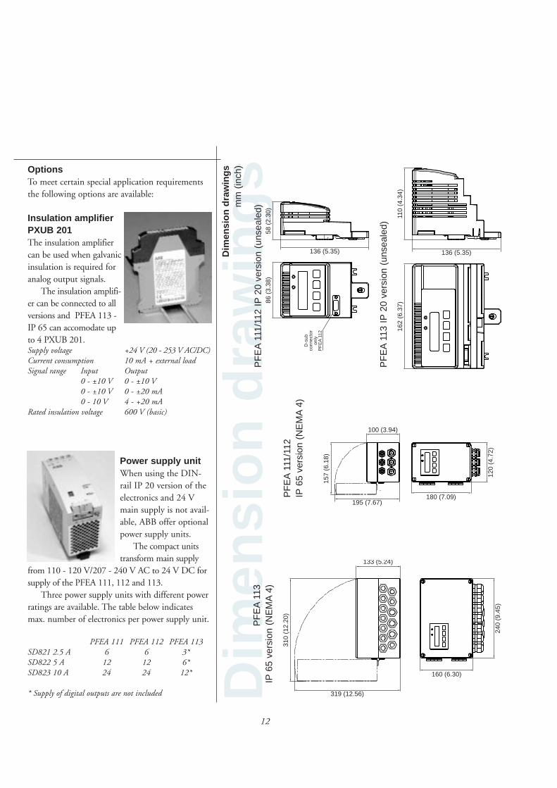
Dim
ensi
on d
raw
ings
86 (
3.38
)
136 (5.35)
D-s
ubco
nnec
tor
only
PF
EA
112
58 (
2.30
)
162
(6.3
7)
136 (5.35)
110
(4.3
4)
OptionsTo meet certain special application requirements
the following options are available:
12
Power supply unitWhen using the DIN-
rail IP 20 version of the
electronics and 24 V
main supply is not avail-
able, ABB offer optional
power supply units.
The compact units
transform main supply
from 110 - 120 V/207 - 240 V AC to 24 V DC for
supply of the PFEA 111, 112 and 113.
Three power supply units with different power
ratings are available. The table below indicates
max. number of electronics per power supply unit.
PFEA 111 PFEA 112 PFEA 113SD821 2.5 A 6 6 3*SD822 5 A 12 12 6*SD823 10 A 24 24 12*
* Supply of digital outputs are not included
Insulation amplifier PXUB 201The insulation amplifier
can be used when galvanic
insulation is required for
analog output signals.
The insulation amplifi-
er can be connected to all
versions and PFEA 113 -
IP 65 can accomodate up
to 4 PXUB 201.Supply voltage +24 V (20 - 253 V AC/DC)Current consumption 10 mA + external loadSignal range Input Output
0 - ±10 V 0 - ±10 V0 - ±10 V 0 - ±20 mA0 - 10 V 4 - +20 mA
Rated insulation voltage 600 V (basic)
Dim
ensi
on d
raw
ings
mm
(in
ch)
157
(6.1
8)
195 (7.67)
100 (3.94)
180 (7.09)12
0 (4
.72)
310
(12.
20)
240
(9.4
5)
133 (5.24)
319 (12.56)
160 (6.30)
PF
EA
111/
112
IP65
ver
sion
(N
EM
A4)
PF
EA
113
IP65
ver
sion
(N
EM
A4)
PF
EA
111/
112
IP20
ver
sion
(un
seal
ed)
PF
EA
113
IP20
ver
sion
(un
seal
ed)
13
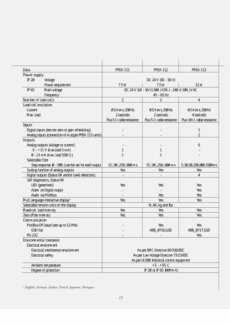
Data
Power supply
IP 20 Voltage
Power requirement
IP 65 Main voltage
Frequency
Number of load cells
Load cell excitation
Current
Max. load
Inputs
Digital inputs (remote zero or gain scheduling)
Analog inputs (connection of multiple PFEA 113 units)
Outputs
Analog outputs (voltage or current)
-5 - +11 V (max.load 5 mA)
0 - 21 mA (max. load 550 Ω)
Selectable filter
Step response (0 - 90%) can be set for each output
Scaling function of analog outputs
Digital outputs (Status OK and/or Level detectors)
Self diagnostics, Status OK
LED (green/red)
Alarm on Digital output
Alarm via Profibus
Multi language interactive display1)
Selectable tension units on the display
Maximum load memory
Zero offset memory
Communication
ProfiBus DP, baud rate up to 12 Mbit
GSD-file
RS-232
Environmental tolerance
Electrical environment
Electrical interference environment
Elecrtical safety
Ambient temperature
Degree of protection
PFEA 111
7.5 W
2
0.5 A rms, 330 Hz
2 load cells
Plus 5 Ω cable resistance
-
-
-
1
1
15, 90, 250, 800 ms
Yes
-
Yes
-
-
Yes
Yes
Yes
-
-
-
PFEA 113
12 W
4
0.5 A rms, 330 Hz
4 load cells
Plus 10 Ω cable resistance
1
2
6
-
-
5,30,90,250,800,1500 ms
Yes
4
Yes
Yes
Yes
Yes
Yes
Yes
Yes
ABB_0717.GSD
Yes
PFEA 112
DC 24 V (18 - 36 V)
7.5 W
DC 24 V (18 - 36 V) 100 (-15%) - 240 (+10%) V AC
45 - 65 Hz
2
0.5 A rms, 330 Hz
2 load cells
Plus 5 Ω cable resistance
-
-
-
1
1
15, 90, 250, 800 ms
Yes
-
Yes
-
Yes
Yes
N, kN, kg and Ibs
Yes
Yes
Yes
ABB_0716.GSD
-
As per EMC Directive 89/336/EEC
As per Low Voltage Directive 73/23/EEC
As per UL508 Industrial control equipment
+5 - +55°C
IP 20 or IP 65 (NEMA 4)
1) English, German, Italian, French, Japanese, Portugese
14
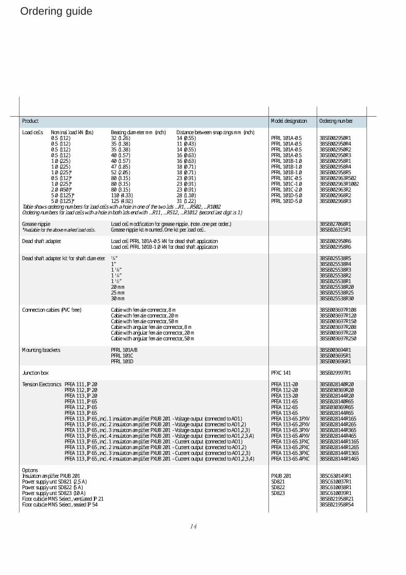
Ordering guide
Product
Load cells Nominal load kN (Ibs) Bearing diameter mm (inch) Distance between snap rings mm (inch)0.5 (112) 32 (1.26) 14 (0.55)0.5 (112) 35 (1.38) 11 (0.43)0.5 (112) 35 (1.38) 14 (0.55)0.5 (112) 40 (1.57) 16 (0.63)1.0 (225) 40 (1.57) 16 (0.63)1.0 (225) 47 (1.85) 18 (0.71)1.0 (225)* 52 (2.05) 18 (0.71)0.5 (112)* 80 (3.15) 23 (0.91)1.0 (225)* 80 (3.15) 23 (0.91)2.0 (450)* 80 (3.15) 23 (0.91)5.0 (1125)* 110 (4.33) 28 (1.10)5.0 (1125)* 125 (4.92) 31 (1.22)
Table shows ordering numbers for load cells with a hole in one of the two lids ...R1, ...R502, ...R1002Ordering numbers for load cells with a hole in both lids end with ...R11, ...R512, ...R1012 (second last digit is 1)
Grease nipple Load cell modification for grease nipple. (note. one per order.)*Available for the above marked load cells. Grease nipple kit mounted. One kit per load cell.
Dead shaft adapter Load cell PFRL 101A-0.5 kN for dead shaft applicationLoad cell PFRL 101B-1.0 kN for dead shaft application
Dead shaft adapter kit for shaft diameter 3/4”1”1 1/8”1 1/4”1 1/2”20 mm25 mm30 mm
Connection cables (PVC free) Cable with female connector, 8 mCable with female connector, 20 mCable with female connector, 50 mCable with angular female connector, 8 mCable with angular female connector, 20 mCable with angular female connector, 50 m
Mounting brackets PFRL 101A/BPFRL 101CPFRL 101D
Junction box
Tension Electronics PFEA 111, IP 20PFEA 112, IP 20PFEA 113, IP 20PFEA 111, IP 65PFEA 112, IP 65PFEA 113, IP 65PFEA 113, IP 65, incl. 1 insulation amplifier PXUB 201 - Voltage output (connected to AO1)PFEA 113, IP 65, incl. 2 insulation amplifier PXUB 201 - Voltage output (connected to AO1,2)PFEA 113, IP 65, incl. 3 insulation amplifier PXUB 201 - Voltage output (connected to AO1,2,3)PFEA 113, IP 65, incl. 4 insulation amplifier PXUB 201 - Voltage output (connected to AO1,2,3,4)PFEA 113, IP 65, incl. 1 insulation amplifier PXUB 201 - Current output (connected to AO1)PFEA 113, IP 65, incl. 2 insulation amplifier PXUB 201 - Current output (connected to AO1,2)PFEA 113, IP 65, incl. 3 insulation amplifier PXUB 201 - Current output (connected to AO1,2,3)PFEA 113, IP 65, incl. 4 insulation amplifier PXUB 201 - Current output (connected to AO1,2,3,4)
OptionsInsulation amplifier PXUB 201Power supply unit SD821 (2,5 A)Power supply unit SD822 (5 A)Power supply unit SD823 (10 A)Floor cubicle MNS Select, ventilated IP 21Floor cubicle MNS Select, sealed IP 54
Model designation
PFRL 101A-0.5PFRL 101A-0.5PFRL 101A-0.5PFRL 101A-0.5PFRL 101B-1.0PFRL 101B-1.0PFRL 101B-1.0PFRL 101C-0.5PFRL 101C-1.0PFRL 101C-2.0PFRL 101D-5.0PFRL 101D-5.0
PFXC 141
PFEA 111-20PFEA 112-20PFEA 113-20PFEA 111-65PFEA 112-65PFEA 113-65PFEA 113-65.1PXVPFEA 113-65.2PXVPFEA 113-65.3PXVPFEA 113-65.4PXVPFEA 113-65.1PXCPFEA 113-65.2PXCPFEA 113-65.3PXCPFEA 113-65.4PXC
PXUB 201SD821SD822SD823
Ordering number
3BSE002950R13BSE002950R43BSE002950R23BSE002950R33BSE002958R13BSE002958R43BSE002958R53BSE002963R5023BSE002963R10023BSE002963R23BSE002968R23BSE002968R3
3BSE027068R13BSE026315R1
3BSE002950R63BSE002958R6
3BSE025538R53BSE025538R43BSE025538R33BSE025538R23BSE025538R13BSE025538R203BSE025538R253BSE025538R30
3BSE003697R1083BSE003697R1203BSE003697R1503BSE003697R2083BSE003697R2203BSE003697R250
3BSE003694R13BSE003695R13BSE003696R1
3BSE029997R1
3BSE028140R203BSE030369R203BSE028144R203BSE028140R653BSE030369R653BSE028144R653BSE028144R1653BSE028144R2653BSE028144R3653BSE028144R4653BSE028144R11653BSE028144R12653BSE028144R13653BSE028144R1465
3BSC630149R13BSC610037R13BSC610038R13BSC610039R13BSE021958R213BSE021958R54
15
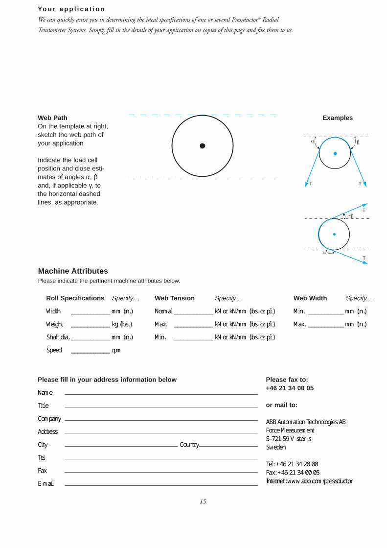
Yo u r a p p l i c a t i o n
We can quickly assist you in determining the ideal specifications of one or several Pressductor® Radial
Tensiometer Systems. Simply fill in the details of your application on copies of this page and fax them to us.
Web PathOn the template at right,sketch the web path ofyour application
Indicate the load cellposition and close esti-mates of angles α, βand, if applicable γ, tothe horizontal dashedlines, as appropriate.
Please fax to:+46 21 34 00 05
or mail to:
ABB Automation Technologies AB
Force Measurement
S-721 59 Västerås
Sweden
Tel: +46 21 34 20 00
Fax: +46 21 34 00 05
Internet: www.abb.com/pressductor
Please fill in your address information below
Name
Title
Company
Address
City Country
Tel
Fax
Machine AttributesPlease indicate the pertinent machine attributes below.
Roll Specifications Specify. . .
Width ____________ mm (in.)
Weight ____________ kg (lbs.)
Shaft dia. ____________ mm (in.)
Speed ____________ rpm
Web Tension Specify. . . Web Width Specify. . .
Normal ____________ kN or kN/mm (lbs. or pli) Min. ___________ mm (in.)
Max. ____________ kN or kN/mm (lbs. or pli) Max. ___________ mm (in.)
Min. ____________ kN or kN/mm (lbs. or pli)
Examples


