Embed Size (px)
Citation preview

Applied Composite Materials 1:93-113, 1994. 93 (~) 1994 Kluwer Academic Publishers. Printed in the Netherlands.
Temperature Effect on Fracture Behaviour of an Alumina Particulate-Reinforced 6061-Aluminium
Composite
M O H A M M A D JAFAR H A D I A N F A R D , J OS EPH HEALY and
Y I U - W I N G M A I * Centre for Advanced Materials Technology, Department of Mechanical and Mechatronic Engineering, University of Sydney, NSW 2006, Australia
(Received 15 April 1994; accepted 29 April 1994)
Key words: Metal matrix composites, Fracture toughness, Fracture mechanism, Elevated tempera- ture
Abstract. The effect of temperature on the fracture behaviour of a peak-aged alumina particulate 6061 aluminium composite was studied in the range of 25 to 180 ° C. The fracture toughness was found to be independent of test temperature. The role of the reinforcement phase was examined in detail at 180 ° C, and compared to observations at room temperature, by using an interrupted test methodology. Ductile fracture occurred at all temperatures. At room temperature the fractured particles acted as void nucleation sites and at 180°C both debonded and fractured particles were responsible for void nucleation. Large particles were found to be susceptible to fracture and nucleate microvoids earlier than small particles. A decrease in the range and size of the reinforcement phase would increase the fracture resistance for this MMC material.
Key words: Author! Please supply.
1. In troduc t ion
Metal matrix composi tes (MMCs) are now emerging as an important class of struc- tural materials [1-3]. They have been developed for use in demanding environments which require higher specific mechanical properties and durability at elevated tem- peratures. The re inforcement of light weight alloys with ceramic particles provides a material with high specific stiffness which is suitable for advanced engineering applications, such as in the aerospace and automotive fields. These applications require materials which are dimensional ly stable and maintain their mechanical strength when used at e levated temperatures. It has been demonstrated that metal matrix composi tes have special combinat ion of room temperature strength, modu-
lus and dimension stability [1-5]. In addition they are stronger, more creep-resistant [6-7] and more wear-resistant [8] at elevated temperatures than the corresponding unreinforced alloys. The main drawback of these materials is their limited ductility
* On leave at the Department of Mechanical Engineering, Hong Kong University of Science and Technology, Clear Water Bay, Kowloon, Hong Kong.

94 MOHAMMAD JAFAR HADIANFARD ET AL.
and crack growth resistance, therefore a large body of research has been focused on the effect of the reinforcement phase on failure mechanisms and fracture toughness of MMCs under various loading conditions and environments. For example, an investigation of the fracture mechanisms of an alumina reinforced aluminium alloy showed that favoured void nucleation sites changed from the interface with flat areas normal to the applied load to those exhibiting sharp comers in the direction of the loading axis with increasing test temperature [9]. Somerday et al. [10] reported that in a 2XXX aluminium alloy reinforced with silicon carbide (SIC) particles, the comers of particles provided preferred sites for microvoid nucleation, and that crack initiation was most likely to occur at the SiC/matrix interface at low tem- peratures and within the matrix adjacent to the particles at elevated temperatures, particularly above 200°C. Davidson [11] observed voids to nucleate from subgrain boundaries rather than from the matrix/particle (m/p) interface in a study of the room temperature fracture of a mechanically alloyed aluminium reinforced with silicon carbide particles.
This paper is an investigation into the effects of elevated temperature on the fracture behaviour of an alumina particulate-reinforced 6061 aluminium alloy and in particular on the role of the reinforcing particles in the fracture process.
2. Experimental Procedure
2.1. MATERIAL AND HEAT TREATMENT
The material used in this study was Duralcan-20%, a 6061 aluminium alloy matrix reinforced with 20% angular alumina particulates. It was produced by liquid met- allurgy and supplied by Comalco Research Centre, Thomastown, Australia, in the form of extruded rectangular plates, 25.5 mm thick and 75 mm wide. Figure 1 shows the microstructure of a polished and etched Duralcan-20% specimen. The results of an image analysis conducted on this surface indicated that 2.5% of the particles were already cracked in the as-received condition. Figures 2 and 3 show the size and aspect ratio distribution of particles on the polished surface of the as- received MMC material. The reinforcement phase consisted of alumina particles with lengths ranging from 1 to 45 #m, and an average length (L) of 18.7 #m. The aspect ratio (length/width = A) varied from 1,2 to 4.8 with an average A of 1.8.
Specimens were cut from the plates in L-T orientation and subjected to the following heat treatment, to obtain the peak hardness (T6) condition: (a) solution heat treated at 530°C for 1.5 h; (b) cold water quenched; (c) naturally aged for 24 h; and (d) age hardened at 175°C for 8 h.
2.2. TENSILE AND FRACTURE TOUGHNESS TESTS
Three repeat tensile tests were conducted in an 1195 Instron universal testing machine with a crosshead speed of 1 ram/rain at temperatures of 25, 100 and 180°C. Test specimens, with a cross-section of 11.5 by 12.5 ram, and a gauge

TEMPERATURE EFFECT ON FRACTURE BEHAVIOUR 95
Fig. 1. Scanning electron micrograph of the polished and etched microstructure of Duralcan- 20%.
4 5 .
4 0 .
O~ 3 5 - v
3 o .
" ~ 2 5 . -
O_ 2o.~
15 . ' : Z3
l O .
O. 0
Width Length
~ / / "" \\
\
. t1111 \\\\\ \ . ~ ~.. . .
I \ \
t i I I i i I i 1 1 [ j L i * 1 ~ i i i i h
10 20 30 40 50
Particulate Size (.m)
Fig. 2. Distribution of particulate size on the polished surface of the as-received material.

96 MOHAMMAD JAFAR HADIANFARD ET AL.
30
25
20
~3 15
10
< 5
Fig. 3. material.
Aspect Ratio (A) Distribution of particulate aspect ratio on the polished surface of the as-received
length of 50 mm were machined with the tensile axis parallel to the extrusion direction. Each specimen was heated to the required temperature in approximately 30 min and allowed to stabilize for another 20 min prior to testing. The load- elongation curves were recorded by a computer-based data acquisition system. The ultimate tensile strength (UTS), 0.2% offset yield and elongation to failure (cy) were obtained for all specimens.
Fracture toughness tests were carried out on compact tension (CT) specimens with a width of 50 mm, machined from an extruded plate in the L-T orientation, according to the ASTM standard E399. The test specimens were fatigue precracked at room temperature in a 1603 Instron electro-magnetic resonator. Three repeat tests, at each temperature of 25, 100 and 180°C with a crosshead speed of 0.5 ram/rain were conducted. The precracked specimens were heated in a similar way as the tensile test to allow the required test temperature to be equilibrated before testing.
2.3. INTERRUPTED FRACTURE TESTS
Two CT specimens were used to study the crack path and interaction of the crack tip with reinforcement particles at test temperatures of 25 and 180°C. The frac- ture toughness test was interrupted before complete fracture could occur and two sections were machined through the mid-thickness of the specimen as illustrated in Figure 4. These sections were polished and the crack path, in addition to the

TEMPERATURE EFFECT ON FRACTURE BEHAVIOUR 97
Section plane
I I I
Inspected area I 1
I I t
:11
i l J tJ IJ
I t
?
Fig. 4. Schematic diagram showing the sectioning technique used to examine the surface and mid-thickness areas around and ahead of the crack tip.
~. 4o0
o 3OO
-~, 200
i00
© 0 F-, f ,, I n
0 50 t00 15o 200
Temperature ( 6 )
Fig. 5. Variation of tensile properties with temperature.

98 MOHAMMAD JAFAR HADIANFARD ET AL,
30
25
20
© [.-,
15
L~
L~
Cr~
Fig. 6.
10
- f
0 50 1 0 150
Temperature (C) Variation of fracture toughness with temperature.
200
area ahem of the crack tip, on the surface and at the mid-thickness were examined by laser confocal microscopy, light microscopy and scanning electron microscopy. Optical and SEM micrographs were studied by means of a computer-controlled image analysis system to obtain the shape and size of damaged (i.e., debonded and/or fractured) particles. The average length and aspect ratio of both damaged and undamaged particles were calculated.
2.4. FRACTOGRAPHY AND IMAGE ANALYSIS
The fracture surfaces of CT specimens were examined with 505 Phillips and JSM Jeol scanning electron microscopes (SEM) with energy dispersive analysis X-ray (EDAX) capability. The micrographs obtained were subjected to image analysis to identify the fracture mechanisms. A computer-controlled image analyser was used to determine the void size distribution, the number of fractured and debond- ed particles, size distribution and area of reinforcement particles on the fracture surfaces. A minimum of 7 fields from different points on the fracture surface were examined, with approximately 250 particles measured for each specimen.
TEMPERATURE EFFECT ON FRACTURE BEHAVIOUR 99
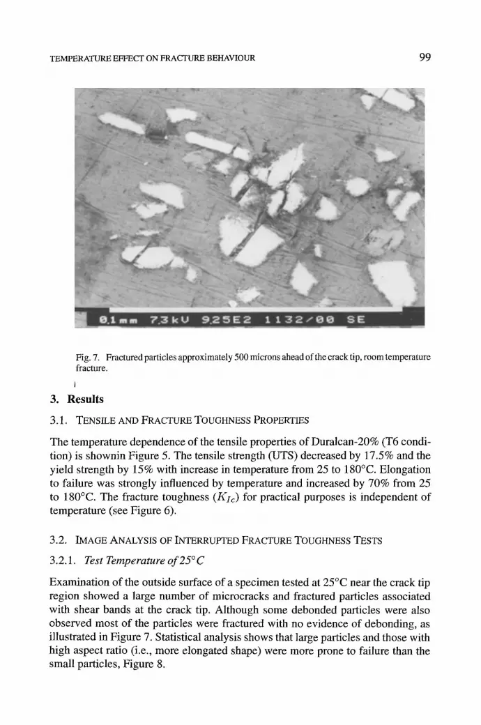
Fig. 7. Fractured particles approximately 500 microns ahead of the crack tip, room temperature fracture.
1
3. Results
3.1. TENSILE AND FRACTURE TOUGHNESS PROPERTIES
The temperature dependence of the tensile properties of Duralcan-20% (T6 condi- tion) is shownin Figure 5. The tensile strength (UTS) decreased by 17.5% and the yield strength by 15% with increase in temperature from 25 to 180°C. Elongation to failure was strongly influenced by temperature and increased by 70% from 25 to 180°C. The fracture toughness (Kic) for practical purposes is independent of temperature (see Figure 6).
3.2. IMAGE ANALYSIS OF INTERRUPTED FRACTURE TOUGHNESS TESTS
3.2.1. Test Temperature of 25°C
Examination of the outside surface of a specimen tested at 25°C near the crack tip region showed a large number of microcracks and fractured particles associated with shear bands at the crack tip. Although some debonded particles were also observed most of the particles were fractured with no evidence of debonding, as illustrated in Figure 7. Statistical analysis shows that large particles and those with high aspect ratio (i.e., more elongated shape) were more prone to failure than the small particles, Figure 8.
1 0 0 MOHAMMAD JAFAR HADIANFARD ET AL.
~" 4O
v
£ 30- o
O_
o
20- 14__
"6 c-
Cn C
5 q 0 c0
> ,<
S u r f a c e , ,
M i d - t h i c k n e s s - - & - -
0 400 800 1200 1600
Distance From Crack Tip ( /1 m)
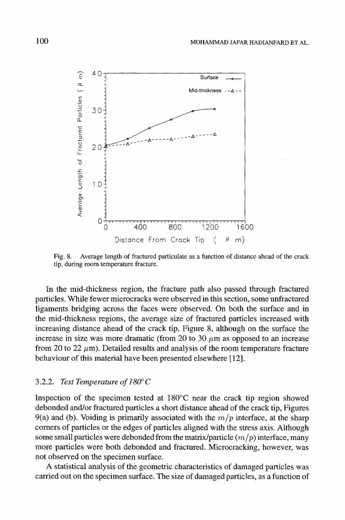
Fig. 8. Average length of fractured particulate as a function of distance ahead of the crack tip, during room temperature fracture.
In the mid-thickness region, the fracture path also passed through fractured particles. While fewer microcracks were observed in this section, some unfractured ligaments bridging across the faces were observed. On both the surface and in the mid-thickness regions, the average size of fractured particles increased with increasing distance ahead of the crack tip, Figure 8, although on the surface the increase in size was more dramatic (from 20 to 30 #m as opposed to an increase from 20 to 22 #m). Detailed results and analysis of the room temperature fracture behaviour of this material have been presented elsewhere [ 12].
3.2.2. Test Temperature of l80°C
Inspection of the specimen tested at 180°C near the crack tip region showed debonded and/or fractured particles a short distance ahead of the crack tip, Figures 9(a) and (b). Voiding is primarily associated with the m/p interface, at the sharp comers of particles or the edges of particles aligned with the stress axis. Although some small particles were debonded from the matrix/particle (m/p) interface, many more particles were both debonded and fractured. Microcracking, however, was not observed on the specimen surface.
A statistical analysis of the geometric characteristics of damaged particles was carried out on the specimen surface. The size of damaged particles, as a function of

TEMPERATURE EFFECT ON FRACTURE BEHAVIOUR 101
(a)
(b)
Fig. 9. Typical void nucleation sites ahead of the crack tip during fracture at 180°C ((a) approximately 400/zm and (b) approximately 600/zm ahead of the crack tip).

102 MOHAMMAD JAFAR HADIANFARD ET AL.
50
©
(D . m ~d o
" 0
0
E ©
D
25-
20.
15-
10-
5
0 0 i:i i !
I i [ i ~ i i
10 20 50 40 50 Length of Particulates ( / ~m)
Fig. 10. Size distribution of damaged particulates ahead of the crack tip on the specimen surface (A at crack tip, • 500 #m ahead of crack tip, O 1000/zrn ahead of crack tip) during fracture at 180°C.
distance from the crack tip, is given in Figure 10. The most popular size of damaged particles was between 15 and 21 #m around the crack tip, it increased to between 20 and 30 #m at a distance of 1000 #m ahead of the crack tip. The percentage of debonded particles was found to increase with increasing distance from the crack tip, Figure l l(a), while the percentage of fractured particles decreased. Figure 1 l(b) shows the size distribution of both fractured and debonded particles; larger particles (greater than 25 #m) are more susceptible to fracture while smaller particles (between 10 and 25 #m) are prone to debonding from the m/p interface.
In the mid-thickness region, the fracture path also passed through debonded and/or fractured particles. In addition, in this section some unfractured ligaments, similar to those reported at room temperature were observed to bridge the crack faces in the crack wake region. These bridging ligaments are illustrated in Figures 12(a) and (b). The size distribution of damaged particles did not markedly change with distance from the crack tip, Figure 13, though there was a slight increase in the percentage of damaged particulates for particle lengths greater than 15 #m. Particles longer than 20 microns were more likely to fracture, and particles with smaller size prefer to debond at the m/p interface, Figure 14.
A comparison of the results obtained on the surface and in the mid-thickness are shown in Figures 15(a) and (b). A similar trend to that observed at room temperature was found, with a larger increase in the damaged particle length on the

TEMPERATURE EFFECT ON FRACTURE BEHAVIOUR 103
100
8 o
v
6 0 ¸ t~ J
a . 4 0
20. tm
Y Z
l , l l l l , l , l l l l t , , , l l l , l l ~ l , l l l l l l l l l , 1 1 I
0 400 800 1200 1600
Distance From Crack Tip (~ m)
Fig. l la . Percentage of debonded and fractured particles on the specimen surface as a function of distance ahead of the crack tip during fracture at 180°C (A debonded particles and • fractured particles.
30:
5
-5
O_
5 ¸
O. 10 20 .30 40 50
Length of Particulotes (/1 m)
Fig. 1 lb. Size distribution of debonded and fractured particles on the specimen surface during fracture at 180 ° C (legend identical to Figure 1 l(a)).

104 MOHAMMAD JAFAR HADIANFARD ET AL.
(a) 1 0 0 ~tm ~ :
(b) ,~m ; ' ~;
Fig. 12. Briding ligaments associated with plane strain fracture at 180°C (a) behind the crack tip and (b) near the crack tip.

TEMPERATURE EFFECT ON FRACTURE BEHAVIOUR 105
TABLE I. Comparison of the average length of the alumina particulate in the as-received material with that of all damaged particles examined both on the surface and mid-thickness during fracture at 180°C.
Condition Average length Average length of Average length of of all particles debonded particles fractured particles
(#m) (#m) #m)
As-received 18.7 Surface 22.8 20.1 23.6
Mid- 21.9 19.7 22.9 thickness
surface with distance from the crack tip than in the mid-thickness region, Figure 15(a). The same trend was observed for the aspect ratio as a function of increasing distance from the crack tip, Figure 15(b). The percentage of all damaged particles, irrespective of their distance from the crack tip as a function of particle length is presented in Figure 16. The percentage of small damaged particles (under 4 #m in length) in the mid-thickness region is approximately three times greater than on the surface of the specimen, Figure 16. The average length of the damaged particles, regardless of their distance from the crack tip are given in Table I. A comparison of these results with those obtained from the polished surface in the as-received condition for all particles indicates that large particles are more prone to damage than small particles. Furthermore, the average size of damaged particles increased with distance from the crack tip, Figures 15(a) and (b). However, particles with small lengths at both the surface (< 4 #m) and mid-thickness (< 2 #m) regions approximately 500 #m ahead of the crack tip are rarely damaged and those with longer lengths are almost always damaged (see Figures 10 and 13).
3.3. FRACTOGRAPHY
A close examination of the CT fracture surfaces, shown in Figure 17, indicated that the material failed in a ductile manner at all test temperatures. A large amount of plastic deformation of the aluminium matrix can be observed. Essentially, the composite fractured by the coalescence of voids developed in the matrix during deformation. Most dimples were found to be associated with the alumina particles. The final fracture occurred by the link up of these voids leading to a dimples fracture surface. The fracture surfaces at all temperatures were found to contain two sets of dimples. The first set, which are large and deep, is related to the rein- forcing alumina particles, the size of this group of voids increases with increasing temperature. The second set of dimples, which are smaller and more spherical are associated with secondary particles in the matrix. They are formed in the ligament

106 MOHAMMAD JAFAR HADIANFARD ET AL.
50-
25-
20-
t~ 101 0~ E
5-
0 @
2
t }
21
: t
l l L I I I t t l l l l l ~ I I I I I I l l l ~ l l i l l ] ' L I I
10 20 30 40 50
Length of Particulates (~ m)
Fig. 13. Size distribution of damaged particulate ahead of the carck tip in the mid-thickness region (A at crack tip, • 500/zm ahead of crack tip, O 1000/~m ahead of crack tip) during fracture at 180°C.
Test Average particle Average void diameter Area of fractured Debonded
temperature length (/~m) particles particles (o c) (~m) (%) (%)
I II
25 21 19.8 4.3 11.2 26
100 20.9 20+3 3.8 10.4 33.2
180 20.5 21.4 3.2 9.8 45.6
between the primary voids. The frequency of these voids decreses with increasing tempermre.
The results of quantitative image analysis on the fracture surfaces of specimens tested at 25, 100, and 180°C are given in Table II. With increasing temperature there is a slight change in the average void diameter but a significant increase in the percentage of debonded particles. It appears that as the temperature is increased the strength of the m/p interface has decreased to allow easy interracial debonding.

TEMPERATURE EFFECT ON FRACTURE BEHAVIOUR ] 07
30
"-"25
m 20
g_
0 i ~ L L'"I i i , i i ' ~ ' l i ~ i i i i t i t i i i r
0 10 20 30 40 50 Length of Particulates (/1 m)
Fig. 14. Size distribution of debonded and fractured particles in the mid-thickness region during fracture at 180°C (lenged identical to Figure 11 (a)).
E ==L
0 0-
"0 ~0
0
E 0
C ]
12t
I l l
28:
26.
24-
22-
0 i 2 -_
18 i 0 200 400 600 800 1000 1200
Distance From Crack Tip (/1 m)
Fig. 15a. Average length of damaged particles as a function of distance ahead of the carck tip during fractmre at 180°C,

1 0 8 M O H A M M A D JAFAR HADIANFARD ET AL.
0o -62.8
© Ck
2.6 nD
CJ~ O
E2.4 O
E3
©2.2 ©
0
c~2. 0
Q_
1.8 co
C? L .
~1.6 <
~ Surface Mid-thickness
, , l ~ i ~ l l l l l r r ~ l i l ~ i l l l r , i i l l , l l k r E i J ~, i ~ l l i ~ I P i l , l , ' r ~ I I l r ~e
0 200 400 600 800 1000 1200 Distance From Crock Tip (u m)
Fig. 15b. Average aspect ratio of damaged particles as a function of distance ahead of the crack tip during fracture at 180°C.
4. Discussion
Metal matrix composites are two-phase materials consisting of hard, plastical- ly non-deformable particles embedded in a soft matrix. One basic strengthening mechanism is load transfer from the matrix to the particles by shear [13]. This transfer requires a strong interface which does not debond easily. Plastic deforma- tion in the matrix will occur when the applied stress rises sufficiently to enable bulk movement of dislocations [14]. Hard and brittle alumina particles within the plastic zone of the growing crack however provide a barrier to dislocation. This limits the amount of material that can plastically deform leading to inhomogenous deformation, and the development of extremely high local stresses at these points [15]. Particles in front of the crack and in those high stress fields can fracture or debond at the ra/p interface. With the soft matrix phase deforming plastically and the hard reinforcement phase deforming elastically, continuity at interface is essential. Consequently, the mechanical behaviour of the interface between alumi- na particles and the matrix plays an important role in determining the locations of void nucleation sites. The percentage of debonded particles increased significantly by 75% with an incerase in temperature from 25 to 180°C. While the interrupted fracture test results show the preferred nucleation sites for void formation at 25°C are fractured alumina particles, at 180°C both debonded and fractured particles

TEMPERATURE EFFECT ON FRACTURE BEHAVIOUR 109
30:
- - . 25
20
~ 1 0 "a.
5
o . . . . . . . . . . . . . . . . . . . . . . . . . . . . . . . . . . . . . . . . . . .
0 10 2O 30 40 5O Length of Particulates (.m)
Fig. 16. Average size distribution of damaged particulate on the surface and mid-thickness regions as a function of particle length during fracture at 180°C (A surface and • mid- thickness).
are the void nucleation sites. The increasing perentage of debonded particles with increasing distance ahead of the crack tip during fracture at 180°C (see Figure 1 l(a)) shows that void first nucleate at the debonded particles and then at the frac- tured particles. Nieh et al. [7], in a study of the fracture of an aluminium matrix alloy reinforced with SiC at elevated temperature, observed that the m/p interface was a preferential site for cavity initiation.
A weak m/p interface will produce debonding and a strong interface will promote particle fracture. Thus the properties of the m/p interface are influenced by testing at elevated temperature. Even though the time at elevated temperature was short (about 1 h) because of the high diffusion rate of elements in MMCs [16], reactions between matrix and particles are possible. This can result in a thick ra/p interface. Reactions in the solid state, between the matrix and the reinforcement phase have been observed by Suganuma et al. [17]. Also age hardening precipitates may lead to a weak m/p interface.
Although the fracture toughness (Kzc) results at crack initiation reported here satisfied all the size requirements of ASTM E399, it is clear that there are differences between the plane stress fracture at the surface and the plane strain fracture in the mid-thickness of the specimen at regions away from the crack tip. The presence of uncracked or bridging ligaments was only observed in the plane strain regions examined at both 25 and 180°C. It is not possible to determine the extent of these

1 10 MOHAMMAD JAFAR HADIANFARD ET AL.
(a)
(b)
Fig. 17. SEM micrographs of fracture surfaces of the CT specimens tested at (a) 25°C, (b) 100°C and (c) 180°C.

TEMPERATURE EFFECT ON FRACTURE BEHAVIOUR 111
a
C
b
lz,
g, ¢
cl
o f Fig. 18. Schematic diagram illustrating the sequence of fracture of Duralcan-20% at 180 ° C.
bridges through the thickness of the specimen. However this form of crack-interface bridging has also been reported in the fatigue of a 7XXX series SiC particulate reinforced composi te [18].

112 MOHAMMAD JAFAR HADIANFARD ET AL.
The average length of damaged particles in the plane strain and plane stress regions are similar (21.9 and 22.8 #m respectively) but there are many more small particles (around 4 #m) in the mid-thickness that are debonded and/or fractured in the early stages of straining, Figure 13. This indicates that the number of small "effective" particles which initiate voids is markedly larger in the mid-thickness. The different stress states between the surface and centre of specimen, together with different levels of residual stress due to quenching, have resulted in the different range of "effective" particles observed in the experiments.
The technique of interrupting a fracture toughness test prior to complete fracture and examining the particulate response ahead of the crack tip is a very useful way of gaining insight into the fracture process, and in particular the sequence of particle damage which is not obtainable from examination of the fracture surfaces. In this study it has been shown that at a test temperature of 180°C microvoids first nucleate at fractured and/or debonded particles. Then with further straining the microvoids near the crack tip expand into the adjacent matrix material and coalesce with other voids leading to final failure.
Image analysis results show that the average size of the damaged particles on the specimen surface is larger than the overall average particle size in the material (22.8 #m compared to 18.7#m). Therefore, large particles damage more easily than small ones. In addition the average size of fractured particles is larger than that of the debonded particles (23.6 #m compared to 20.1 #m) indicating that large particles are also more susceptible to fracture than debonding at the ra/p interface. The increasing average size of the damaged particles with distance from the crack tip shows that the large particles tend to fracture and/or debond in the early stages of straining. However, only large particles serve as effective sites for initial microvoid nucleation. The initiation of these microvoids must be a critical event in the fracture process. As the large and elongated particles tend to fail earlier during deformation, the probability of damage increases rapdily with increasing size and aspect ratio of the particles. Vanstone et al. [19] found the same phenomenon and reported that void nucleation in 2XXX and 7XXX series aluminium alloys occurred first at the largest particles, and progressed to smaller and smaller particles as loading was increased. In the present study those particles with a length greater than about 4 #m fracture earlier than other particles and may thus be considered as "effective" particles.
Figure 17 shows the sequence of failure in Duralcan-20% MMC at 180°C. This sequence has largely been reconstructed from observations made ahead of the crack tip in the interrupted fracture toughness test. Initial straining causes some previously undamaged alumina particles (a) to fracture and/or debond at the m/p interface (b), followed by more fracture and or debonding (c) and the onset of voiding and cracking in the matrix (d). These cracks and voids start to coalesce (e) before linking up with the main crack (f) resultingin fracture and catastrophic failure.

TEMPERATURE EFFECT ON FRACTURE BEHAVIOUR 113
5. Conclusions
The mechanical and fracture toughness properties of Duralcan-20% have been studied in the temperature range 25 to 180°C. The tensile and yield strengths decrease with temperature but there is a significant increase in elongation to failure. The fracture toughness (Kxc) is essentially constant over the same temperature range and the general fracture appearance is typical of ductile failure. At room temperature the fractured particles are the main sites for void nucleation. At 180°C both debonded and fractured particles act in concert as to form voids.
Larger and more elongated particles are more susceptible to fracture and nucle- ate microcracks earlier than smaller particles, thus reducing the fracture resistance of the MMC composite. Therefore decreasing the range and average size of the reinforcing particulate phase would improve the fracture toughness. Only those particles which nucleate voids early in the fracture process ahead of the crack tip may be considered to be effective particles.
Acknowledgements
The authors wish to thank the Australian Research Council (ARC) Small Grants Scheme for the continuing support of this project. M. J. Hadianford is supported by a Junior Research Fellowship funded by the ARC.
References
1. S. G. Fishman, J. Metals 38, 1986, 26. 2. S.V. Nair, J. K. Tien, and R. C. Bates, Int. Met. Rev. 30, 1985, 275. 3. A. H. M. Howes, J. Metals bf 38, 1986, 28. 4. A. P. Divecha, S. G. Fishman, and S. D. Karmarker, J. Metals, 33, 1981, 12. 5. Y. Flom and R. J. Arsenault, Mater. Sci. Eng. 77, 1986, 191. 6. D. L. McDanels, MetalL Trans. A, 16, 1985, 1105. 7. T. G. Nieh, K. Xia, and T. G. Landon, J. Eng. Mater. & Techn. 110, 1986, 77. 8. M. A. Martinez, A. Martin, and J. Llorca, Scripta MetalI. Mater 28, 1993, 207. 9. A. E Whitehouse and T. W. Clyne, Proceedings of ICCM/9 Madrid, 1993, 393.
10. B. R Somerday, Y.Leng, F. E. Wawner, and R. P. Gangloff, Advanced metal-matrix composites for elevated, temperature, ASM, Metal Park, Ohio, 1991, 167.
11. D. L. Davidson, Metall. Trans. A 18, 1987, 2115. 12. M .J. Hadianfard, J. Healy, and Y. W. Mai, J. Mater. Sci. 29, 1994, 2321. 13. C. Voituriez and I. W. Hall, J. Mater. Sci. 26, 1991, 4241. 14. W. S. Miller and F. J. Humphreys, Fundamental relationship between microstructure & mechani-
calproperties of metal-matrix composites, The Minerals, Metals & Materials Society, Warrendale, 1990, 517.
15. C. Zener, Fracturing of metals, ASM, Cleveland, Ohio, 1948, 3. 16. I. Dutta and D. L. Bourell, Acta Metall. Mater. 38, 1990, 2041. 17. K. Suganuma, T. Okamoto, T. Hayami, Y. Oku, andN. Suzuki J. Mater. Sci. 23, 1988, 1317. 18. J. K. Shang and R.O. Ritchie, Metall. Trans. A, 20, 1988, 897. 19. R. H. Vanston, R. H. Merchant, and J. R. Low, ASTMSTP 556, 1974, 93.


