Embed Size (px)
Citation preview
111111111111111111111111111111111111111111111111111=1111
SERVICING4110CONSTRUCT1011COMURDEVELOPMENTS
PTEMBER 1975 4.0
TE
NTRIll
STEP/.T11
RE OR FROM MONTREUXJUGFETS IN TV CIRCUITSSERVICING TV RECEIVERS

TRANSISTORS, ETC. Type Price (17 Type Price (£) Type Price 10 DIODES LINEAR DIGITAL ZENER DIODESBF241 0.22 MPSU56 1.26 2N3133 0.54 Type Price In INTE- INTE- 400mW 3.0-33V 12p each
Type Price (£) Type Price (E) RF244 0.18 MPSU55 1.26 2N3134 0.60 AA113 0.15 GRATED GRATED 1.3W 3.3-100V 18p eachAC107 0.35 BC177 0.20 BF254 0.45 0C26 0.38 2N3232 1.32 AAI 19 0.09 CIRCUITS CIRCUITS VOWS, PTC & NTCAC117 0.24 BC178 0.22 BF255 0.45 0C28 0.65 2N3235 1.10 AA129 0.20 Type Poce I 0 Type Price (£) RESISTORSAC126 0.25 BCI 78B 0.22 BF256 0.45 0C35 0.59 2N3250 1.02 AA143 0.10 CA3045 1.35 7400 0.20 Type Price (f) Type Price (()AC127 0.25 BC179 0.20 BF257 0.49 0C36 0.64 2N3254 0.28 AAZ13 0.30 CA3046 0.70 7401 0.20 E295ZZ E29900/P116-AC128 0.25 BC179B 0.21 BF258 0.66 0C42 0.55 2N3323 0.48 AAZ17 0.12 CA3065 1.90 7402 0.20 /01 14 P354 all 8AC141 0.26 BC182 L 0.11 BF259 0.93 0C44 0.25 2N3391 A 0.23 BA100 0.15 MC1307P 1.19 7404 0.24 E295ZZ VA1015 50AC141K 0.27 BC183 0.11 BF262 0.70 0C45 0.32 2N3501 6.99 BAI 02 0.25 MC1310P 2.94 7406 0.45 /02 14 VA1026 41AC142 0.20 BC183K 0.12 BF263 0.70 0070 0.32 2N3702 0.13 BA110U 0.30 MC 7408 0.25 E298CD VA1033 8AC142K 0.19 BC183L 0.11 BF273 0.16 0071 0.32 2N3703 0.15 BAI 15 0.12 1327PQ 1.01 7410 0.20 /A258 7 VA1034 8AC151 0.24 BC184L 0.13 BF336 0.35 0072 0.32 2N3704 0.15 BA141 0.17 MC1330P 0.76 7411 0.25 E298ED VA1040 8AC152 0.25 BC186 0.25 BF337 0.35 0073 0.51 2N3705 0.11 BAI 45 0.17 MC1351P 0.75 7412 0.28 /A258 6 VA1053 8AC153K 0.28 BC187 0.27 BF458 0.60 0075 0.25 2N3706 0.10 8A148 0.17 MC1352P 0.82 7413 0.50 /A260 8 VA1055S 10AC154 0.20 BC208 0.12 BF459 0.63 0076 0.35 2N3707 0.13 BA154 0.13 MC 7416 0.45 /A262 6 VA1077 12AC176 0.25 BC212L 0.12 BF596 0.70 0081 0.53 2N3715 2.30 BA155 0.16 1358PQ 1.85 7417 0.30 /A265 6 VA1104 35AC178 0.27 BC213L 0.12 BF597 0.15 0081D 0.57 2N3724 0.72 BAI 56 0.15 MC1496L 0.87 7420 0.20 /P268 6 VA8650 110AC187 0.25 BC214L 0.15 BFR39 0.24 0C139 0.76 2N3739 1.18 BA157 0.25 MC3051P 0.58 7425 0.37 E298ZZACI 87K 0.26AC188 0.25
BC238 0.12BC261A 0.28
BFR41 0.30BFR61 0.30
0C140 0.800C170 0.25
2N3766 0.992N3771 1.70_ .
BAXI 3 0.06BAX16 0.07
MFC400013 0.43
7430 0.207440 0.20
/05 7/06 6
AC188K 0.26 BC262A 0.18 BFR79 0.24 0C171 0.30 2N3772 1.90 BAY72 0.11 MFC 7441 0.85RESISTORSAC193K 0.30 BC263B 0.25 BFT43 0.55 0C200 1.30 2N3773 2.90 BB104 0.52 4060A 0.70 7445 1.95
AC194K 0.32 BC267 0.16 BFVV10 0.55 OCP71 0.92 2N3790 4.15 BB1058 0.52 MFC6040 0.91 7447 1.30 Carbon Film (5%) ea
ACY28 0.25ACY39 0.68
BC268C 0.14BC294 0.37
BFVVI 1 0.55BFVV16A 1.70
ON236A 0.65ORP12 0.55
2N3794 0.202N3819 0.35
BB105G 0.45661108 0.45
NE555 0.72NE556 1.34
7450 0.207451 0.20
IVV 5.6 0-330k CI(E12) 1.5P+W10 c1 -10M CI (E24) 1.5p
AD140 0.50 BC300 0.60 8FVV30 1.38 R2008B 2.05 2N3820 0.49 BR100 0.50 PA263 1.90 7454 0.20 1W 10 0-19M 01E12) 3pAD142 0.52 BC301 0.35 BFW59 0.19 R2010B 2.95 2N3823 1.45 BY100 0.22 SL414A 1.91 7460 0.20 2W 10 0-10M 0 (E6) 5pADI 43 0.51 BC303 0.60 BFVV60 0.20 TIC44 0.29 2N3866 1.70 BY103 0.22 SL901B 3.84 7470 0.33 WIREWOUND (5%)AD149 0.50 BC307B 0.12 8Fvv90 0.28 T1C46 0.44 2N3877 0.25 BY126 0.16 SL917B 5.12 7472 0.38 2-1W 0.22 0-270 a 15p eaAD161 0.48 BC308A 0.10 BFX16 2.25 TIC47 0.58 2N3904 0.16 BY127 0.17 SN 7473 0.44 5W 10 0-8.2k 0 13p eaAD162 0.48 BC309 0.15 BFX29 0.30 TIP29A 0.49 2N3905 0.18 BY133 0.23 76001N 1.45 7474 0.48 10W 10 0-25k 0 18p eaAFI 14 0.25 BC323 0.68 BFX30 0.35 TIP30A 0.58 2N3906 0.15 BY140 1.40 SN 7475 0.59 CAPACITORSAFI 15 0.25 BC377 0.22 BFX84 0.25 TIP31A 0.65 2N4032 0.43 BY164 0.55 76003N 2.92 7489 4.32AFI 16 0.25 BC441 1.10 BFX85 0.26 TIP32A 0.67 2N4033 0.54 BY176 1.68 SN 7490 0.65 Full range of 0280, 0296,AF117 0.20AF118 0.50
BC461 1.58BCY33 0.36
BFX86 0.26BFX87 0.28
TIP33A 0.99TIP34A 1.73
2N4036 0.522N4046 0.35
BY179 0.70BY206 0.31
76013N 1.95SN76013
7491 1.107492 0.75
tubular ceramic, pin-up cera-. . . .rum, miniature electrolytics,
AF121 0.32 BCY42 0.16 BFX88 0.24 TIP41A 0.80 2N4058 0.17 BYX10 0.15 ND 1.72 7493 0.65 mica, mixed dielectric and
AF124 0.25 BCY71 0.22 BFY18 0.53 TIP42A 0.91 2N4I23 0.13 0.30 SN 7494 0.85 TV electrolytics stocked. -AF125 0.25 BCY88 2.42
0.65BFY40 0.40 TIS43 0.30 2N4124 0.15
BYZ12FSV11A 0.45 76023N 1.95 7495 0.85
Please see catalogue.
AF126 0.25AF127 0.25AF139 0.35
BD115BD123 0.98BD124 0.80
BFY41 0.43BFY50 0.25BFY5I 0.23
TIS73 1.36TIS90 0.23TIS91 0.23
2N4126 0.202N4236 1.902N4248 0.12
FSV41A 0.400A10 0.20
SN76023ND 1.72
SN
7496 1.0074100 2.16
MASTHEAD AMPLIFIERSLabgear uhf group amplifier
AF147 0.35 BD130Y 1.42 BFY52 0.23 ZTX109 0.12 2N4284 0.190A47 0.07 74121 0.60 complete with mains power
0.45 BD131 0.45 BFY57 0.32 ZTX300 0.16 0A81 0.12 76033N 2.92 74122 0.80 unit CM6001/PU.AF149AF178 0.55 BDI32 0.50 BFY64 0.42 ZTX304 0.22
2N4286 0.19 0A90 0.08 SN 74150 1.44 Groups A, 8, or C/D
0.60 80135 0.40 0.31 ZTX310 0.102N4288 0.13 (24%91 0.07 76227N 1.46 74151 1.15 please specify £12.65AF179
AF180 0.55 80136 0.46BFY72BFY90 0.70 ZTX313 0.12
2N4289 0.20 0A95 0.07 SN 74154 1.66 Labgear CM6030 WB vhf/uhfAFI81 0.50 BD137 0.48 BLY15A 0.79 ZTX500 0.17
2N4290 0.14 0A200 0.10 76530P 1.05 74164 2.01 ultra wideband amplifier
AF186 0.40AF239 0.40
BD138 0.50BD139 0.55
BPX25 1.90BPX29 1.70
ZTX502 0.17ZTX504 0.42
2N4291 0.182N4292 0.202N4392 2.84
0,4202 0.100A210 0.29
SN76533N 1.20
74192 2.0574193 2.30
(channels 1-68). Completewith mains power unit
AF279 0.84AL100 1.10
80140 0.6280144 2.19
BPX52 1.908RC4443 0.68
ZTX602 0.242N525 0.86
2N48712N4902 1.30
0A2237 0.78S2M1 0.22TV20 1.85
SN76666N 0.90
TAA300 1.76
CM6001/PU £18.95Labgear CM6019 WB uhf
HARD -AL102 1.10 BD145 0.75 BRY39 0.47 2N696 0.23 2N5042 1.05 IN914 0.07 TAA320 0.94 WARE
wideband amplifier (channels
AL103 1.10 BD163 0.67 BRY56 0.40 2N697 0.15 2N5060 0.32 IN914E 0.06 TAA350A 2.02 BASES21-68). Complete with mains
AL113 0.95 BD183 0.56 BR101 0.47 2N706 0.12 2N5061 0.35 IN916 0.10 TAA435 0.85 Type Price ( f)power unit CM6020/PU £9.85
AU103 2.10AU110 1.90
BD222 0.78BD234 0.75
BSX19 0.13BSX20 0.19
2N706A 0.152N708 0.35
2N5064 0.45 IN1184 0.92 TAA450 2.70 DIL8 0.16 PATTERN GENERATORS
AU113 2.40BC107 0.12BC107A 0.13BC107B 0.14BC108 0.12
80410 1.65BD519 0.76BD520 0.76BD599 0.75BDX18 1.45
BSX76 0.15BSX82 0.52BSY19 0.52BSY41 0.22BSY54 0.50
2N744 0.302N914 0.192N916 0.202N918 0.422N930 0.35
2N5087 0.322N5294 0.352N5296 0.572N5298 0.582N5322 0.85
IN1185 1.101N4001 0.05IN4002 0.06IN4003 0.07TuningIN4004 0.08MOUNT-
TAA550 0.55TAA570 2.02TAA611A 1.70TAA61 I B 1.85
4.18TAA630Q
DIL14 0.1601L16 0.18
Labgear CM givingcrosshatch greyscaleand blank raster on 625 -lines.
can be preset foranywhere in Bands IV and V
601086 0.13 BDX32 2.55 BSY56 0.80 201164 3.60 205449 1.90 IN4005 0.09 TAA6305 4.18 ING KITS as well as Band III (for relays)
8C109 0.13BC109C 0.14
BDYI 8 1.78BDY20 0.99
BSY65 0.15BSY78 0.40
2N1304 0.212N1305 0.21
2N5457 0.302N5458 0.35
IN4006 0.11IN4007 0.14
TAA6618 1.32TAA700 4.18
T0-3 0.06TO -66 0.06
£58.80Labgear CM6038 DB Pocket
0.13 BF115 0.20 BSY91 0.28 2N1306 0.31 2N5494 0.85 IN4148 0.05 TAA840 2.02 size vhf/uhf generator. Out -
BC114 0.208C1140.20
BF117 0.45BF 1 20 0.55
BSY95A 0.27BT106 1.24
2N1307 0.222N1308 0.26
2N5496 1.052N6027 0.65
IN4448 0.10iN5400 0.15
TAA861A 0.49TAD100 2.66
puts as CM6004 PG above butcan be used either on mains
BC1150.20 BF121 0.25 BT116 1.20 2N1309 0.36
2N6178 0.71 IN5401 0.17 TBA120S 0.99 VALVES or battery E46.60BC116 2N6180 0.92 IN5402 0.20 TBA240A 2.97 Type Price (E)BC117 0.20 BF123 0.28 BU105/02 1.95 2N1613 0.34 2SC643A 1.36 IN5403 0.22 TBA281 2.28 DY87 0.39 COLOUR/BARBC119 0.29 BF125 0.25 BU108 3.25 2N1'711 0.45 2SC1172Y 2.80 IN5404 0.25 TBA480Q 1.90 EB91 0.30 GENERATORSBC125 0.22 8F127 0.30 BU126 2.99 2N1890 0.45 3N140 1.21 IN5405 0.27 TBA500 1.99 ECC82 0.41 Labgear CM6037/DB: DualBC126 0.20 BF158 0.25 BU204 1.98 2N1893 0.48 40250 0.60 IN5406 0.30 TBA500Q 2.00 EF80 0.41 standard band generator givesBC132 0.15 BF159 0.27 BU205 1.98 2N2102 0.51 40327 0.67 IN5407 0.34 TBA510 1.99 EFI 83 0.53 standard 8 band colour bars50134 0.20 BF160 0.22 BU207 3.00 20221 7 0.36BC135 0.19 BF161 0.45 BU208 3.15 2N2218 0.60 40361 0.48
40362 0.50IS44 0.0715310 0.45
TBA520Q 3.34TBA530 2.71
EF184 0.53EH90 0.55
. greyscale step wedge redraster centre cross i centre
BC136 0.20 BFI 62 0.45 BU209 2.55 20221 9 0.50 40429 0.80 15920 0.07 TBA530Q 2.71 PC86 0.67 dot i crosshatch dot pat-BC137 0.20 BF163 0.45 BUY77 2.50 2N222I A 0.41 40439 2.67 TBA540 3.21 PC88 0.76 tern blank raster. Sync out-BC138 0.20 BF167 0.25 BUY78 2.55 2N2222A 0.50801 42 0.30 BF 1 73 0.25 BUY79 2.85 2N2270 0.41 TBA540Q 3.21 PCC89 0.58 put alsoprovided £125.15
MATCHED VHF/UHF CONVERTERSBC143 0.35 BF177 0.30 D4ONI 0.45 2N2369A 0.42 TBA550Q 4.10 PCF80 0.47
BC147 0.13BCI48 0.12
BF178 0.33BF179 0.33
E1222 0.55E5024 0.20
2N2401 0.602N2484 0.41
PAIRSType Price ID
TBA560C ' 4.09TBA
PCF86 0.58PCF801 0.58
Labgear -Televertas" forDX-ing or single -standard
BC149 0.14 BF180 0.35 ME6001 0.16 2N2570 0.18 AC128/ Diodes can be 560CQ 4.10 PCF802 0.63 receiver use on relay systems.
BCI 52 0.25 BFI 81 0.33 ME6002 0.17 2N2646 0.53 AC176 0.52 supplied TBA570 1.17 PCL82 0.50 Type 6022/RA £15.90BC153 0.20 BF182 0.44 ME8001 0.18 2N2712 0.12 AC141K/ balanced at a TBA641 0.76 PCL84 0.54OUR NEW CATALOGUEBC154 0.20BC157 0.15
BF183 0.44BF184 0.26
MJE340 0.68MJE341 0.72
2N2894 0.772N2904 0.22
AC142K 0.56AC187/
supplement of5p per device(refundable).TBA673 2.28TBA700 2.59
PCL805/85 0.58 IS AVAILABLE AT 30p
BC158 0.13 BF185 0.26 MJE370 0.65 2N2904Ak0.26 AC188 0.60 - e.g. four TBA720Q 2.45 PCL86 0.58
BC159 0.15 BF194 0.15 MJE520 0.85 2N2905 0.26 AC187K/ balanced TBA750Q 2.33 PFL200 0.74 P. & P.: UK E0.12 per order.
BC161 0.48 BF195 0.15 MJE52 1 0.95 2N2905A 0.28 AC188K 0.61 0A91 would TBA800 1.75 PL36 0.80 Ove :At cost.
BC167B 0.15 BF196 0.15 MJE2955 1.20 2N2926G 0.13 AC19310 be £0.48 per TBA PL84 0.61 Please add VAT at 25% on all
BCI 68B 0.13 BF197 0.17 MJE3000 1.85 2N2926Y 0.12 AC194K 0.71 set. 810AS 1.75 PL504 0.80 items except test generators
BC169C 0.13 BF198 0.20 MJE3055 0.74 2N29260 0.12 AD161/TBA9200 4.23 PL508 0.95 which are at 8%
BC170 0.15BC171 0.15
BFI99 0.25BF200 0.35
MPF102 0.40MPS65660.21
2N2955 1.122N3012 0.91
AD162 0.95SC142/
TBA990 4.10TBA990Q 4.10
PL509 1.445.PY81/8000.4availability.
All prices subject to
BCI 72 0.14 BF218 0.35MPSA05 0.47 2N3019 0.75 BC143 0.70TCA270Q 4.18
1.25PY88 0.52Giro A/c 23 532 4000.
BCI 73 0.20 BF222 1.08 MPSA55 0.50 2N3053 0.21 TIS90M/ Variable ZN414
BC174B 0.26BC176 0.22
BF224J 0.15BF240 0.20
MPSUO5 0.66MPSUO6 0.76
2N3054- 0.552N3055 0.60
TIS91 M 0.50Any other tran-
capacitancediodes can be EAST CORNWALL
sistors can be supplied Please enquirematched at a matched at a for linear op. C 0 M P 0 N E N TS
Tel. Stoke Climsland Telex: 45457 (A,'B Mercury supplement of supplement of amps, 709, 710,105797) 439 Calgtor) 20p per pair. 3p per device. etc. CALLINGTON - CORNWALL

COPYRIGHT= IPC Magazines Limited, 1975. Copyright inall drawings, photographs and articlespublished in Television is fully protected andreproduction or imitation in whole or in partis expressly forbidden. All reasonableprecautions are taken by Television to ensurethat the advice and data given to readers arereliable. We cannot however guarantee it andwe cannot accept legal responsibility for it.Prices are those current as we go to press.
CORRESPONDENCEAll correspondence regarding advertisementsshould be addressed to the AdvertisementManager, "Television", Fleetway House,Farringdon Street, London EC4A 4AD. Allother correspondence should be addressedto the Editor, "Television", at the sameaddress.
BINDERS AND INDEXESBinders (E1.90) and Indexes (30p) can besupplied by the Post Sales Department, IPCMagazines Ltd., Carlton House, 66-68 GreatQueen Street, London WC2 5DD. Phone01-242 4477. For further details see page522. Prices include postage and VAT.
BACK NUMBERSWe regret that we are unable to supply backnumbers of Television. Readers arerecommended to enquire at a public library tosee copies. Requests for specific backnumbers of Television can be published inthe C Q Column of Practical Wireless bywriting to the Editor, "Practical Wireless",Fleetway House, Farringdon Street, LondonEC4A 4AD.
QUERIESWe regret that we cannot answer technicalqueries over the telephone nor supply servicesheets. We will endeavour to assist readerswho have queries relating to articlespublished in Television, but we cannot offeradvice on modifications to our publisheddesigns nor comment on alternative ways ofusing them. All correspondents expecting areply should enclose a stamped addressedenvelope.Requests for advice in dealing with servicingproblems should be directed to our QueriesService. For details see our regular feature"Your Problems Solved".
516
517
TelevisionSERVICINGVIDEOCONSTRUCTIONCOLOURDEVELOPMENTS
this month501 To Service or Not To Serve
Comment.
VOL. 25NO.11
ISSUE 299SEPTEMBER
1975
502 TeletopicsNews and Developments.
506 JUGFETs in Colour TV ReceiversOperation of the junction gate field effect transistorand its use in colour TV receiver circuitry.
508 Montreux ReportReport from the 9th International TelevisionSymposium and Exhibition at Montreux.
510 Watch out for the UnexpectedThe causes of TV set faults are not always whatyou expect: there is also the problem of butchery.
511 Cartoon
512 Videotape Recording, Part 2Video processing and servo techniques.
Readers' Letters
GEC Hybrid Colour Receivers: Fault GuideCommon faults and a guide to the layout andmore vulnerable circuitry.
520 Large -Screen TV Oscilloscope, Part 3 by D. Haley, C. Eng., M/EECircuitry and construction of the i.f. preamplifier board andthe input attenuator, preamplifier and sampling board.
523 Miller's Miscellany by Chas. E. MillerA light-hearted look at some servicing problems.
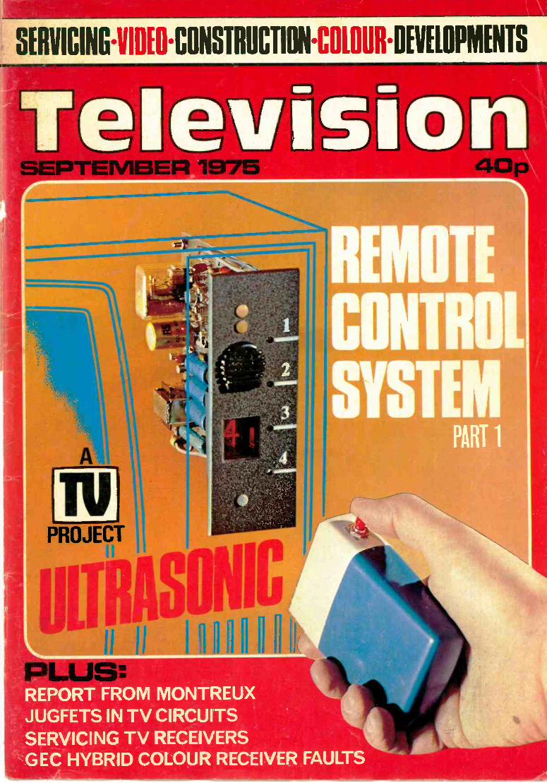
524 Ultrasonic Remote Control, Part 1 by A. WilcoxCircuit description of the control unit and receiver.
528 Servicing Television Receivers by L. Lawry -JohnsGeneral comments on the 21st anniversary of this feature.
530 CCTV, Part 18 by Peter GravesSimple studio facilities - mixing and cutting.
533 Next Month in Television
534 Service NotebookNotes on interesting faults and servicing techniques
536 Ceefax/Oracle Reception Techniques, Part 3Row and page addressing. Page detection and selec
541 Long -Distance TelevisionReports of DX reception and news from abroad.
544 Your Problems SolvedA selection from our Readers' Query Service.
547 Test Case 153Can you solve this servicing problem? Plus thesolution to last month's test case.
by S. George
by Philip Ross
by Steven Knowles
by Wilcox
by M. P. Riley
by John Coombes
by G. R. Wilding
by Steve A. Money,tion. T.Eng. (CEll
by Roger Bunney
OUR NEXT ISSUE DATED OCTOBER WILLBE PUBLISHED ON SEPTEMBER 15
TELEVISION SEPTEMBER 1975 497
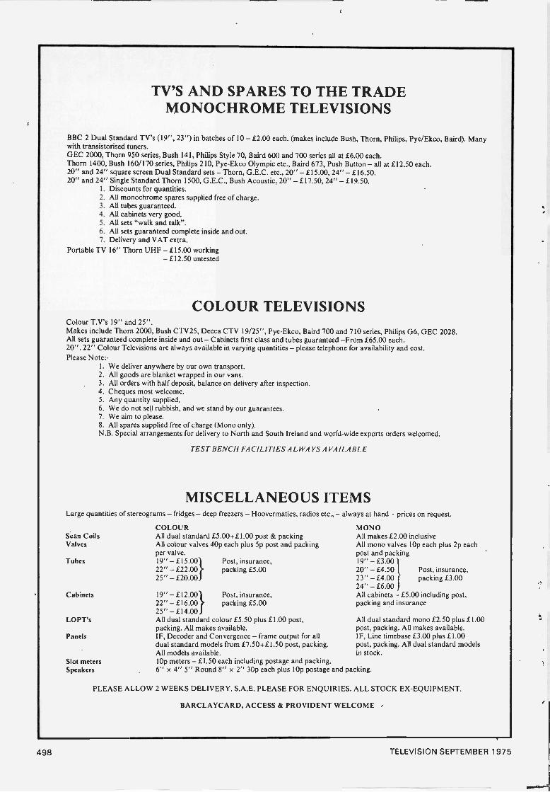
TV'S AND SPARES TO THE TRADEMONOCHROME TELEVISIONS
BBC 2 Dual Standard TV's (19", 23") in batches of 10 - £2.00 each. (makes include Bush, Thorn, Philips, Pye/Ekco, Baird). Manywith transistorised tuners.GEC 2000, Thorn 950 series, Bush 141, Philips Style 70, Baird 600 and 700 series all at £6.00 each.Thorn 1400, Bush 160/170 series, Philips 210, Pye-Ekco Olympic etc., Baird 673, Push Button - all at £12.50 each.20" and 24" square screen Dual Standard sets - Thorn, G.E.C. etc., 20" - £15.00, 24" - £16.50.20" and 24" Single Standard Thorn 1500, G.E.C., Bush Acoustic, 20" - £17.50, 24" - £19.50.
1. Discounts for quantities.2. All monochrome spares supplied free of charge.3. All tubes guaranteed.4. All cabinets very good.5. All sets "walk and talk".6. All sets guaranteed complete inside and out.7. Delivery and VAT extra.
Portable TV 16" Thorn UHF - £15.00 working-£12.50 untested
COLOUR TELEVISIONSColour T.V's 19" and 25".Makes include Thorn 2000, Bush CTV25, Decca CTV 19/25", Pye-Ekco, Baird 700 and 710 series, Philips G6, GEC 2028.All sets guaranteed complete inside and out - Cabinets first class and tubes guaranteed -From £65.00 each.20", 22" Colour Televisions are always available in varying quantities - please telephone for availability and cost.Please Note: -
1. We deliver anywhere by our own transport.2. All goods are blanket wrapped in our vans.3. All orders with half deposit, balance on delivery after inspection.4. Cheques most welcome.5. Any quantity supplied.6. We do not sell rubbish, and we stand by our guarantees.7. We aim to please.8. All spares supplied free of charge (Mono only).N.B. Special arrangements for delivery to North and South Ireland and world-wide exports orders welcomed.
TEST BENCH FACILITIES ALWAYS AVAILABLE
MISCELLANEOUS ITEMSLarge quantities of stereograms - fridges - deep freezers - Hoovermatics, radios etc., - always at hand - prices on request.
Scan CoilsValves
Tubes
Cabinets
LOPT's
Panels
Slot metersSpeakers
COLOURAll dual standard .£5.00+£1.00 post & packingAll colour valves 40p each plus 5p post and packingper valve.19" - £15.00 Post, insurance,22" - f22.00 packing £5.0025" - £20.00
19" - £12.00 Post, insurance,22" -£16.00 packing £5.0025" - 114.00All dual standard colour £5.50 plus £1.00 post,packing. All makes available.IF, Decoder and Convergence - frame output for alldual standard models from £7.50+f 1.50 post, packing.All models available.10p meters - £1.50 each including postage and packing.6" x 4" 5" Round 8" x 2" 30p each plus 10p postage and packing.
MONOAll makes £2.00 inclusiveAll mono valves 10p each plus 2p eachpost and packing19" - £3.0020" - £4.50 Post, insurance,23" - £4.00 packing £3.0024" - £6.00All cabinets - £5.00 including post,packing and insurance
All dual standard mono £2.50 plus £1.00post, packing. All makes available.IF, Line timebase £3.00 plus £1.00post, packing. All dual standard modelsin stock.
PLEASE ALLOW 2 WEEKS DELIVERY. S.A.E. PLEASE FOR ENQUIRIES. ALL STOCK EX -EQUIPMENT.
BARCLAYCARD, ACCESS & PROVIDENT WELCOME
498 TELEVISION SEPTEMBER 1975
THE UM4"COLOURBOOSTER"
UHF/625 LINE
CAN PRODUCEREMARKABLEIMPROVEMENTS INCOLOUR ANDPICTURE QUALITYIN FRINGE ORDIFFICULT AREASWITH SIGNIFICANTREDUCTION INNOISE (SNOW).
HIGH GAIN - VERY LOW NOISEFITTED FLY LEAD - INSTALLED IN SECONDSHIGHEST QUALITY COMPONENTSIVORY PLASTIC CASE 33 x x If CORK BASECHANNELS: Group A, Red code 21-33
Please Group B, Yellow code 39-51Specify Group C -D, Green code 52-68EQUALLY SUITABLE FOR BLACK AND WHITE
Also the M4 DUAL BAND VHF UNITBOOSTS ALL BAND III and ANY SPECIFIED
BAND I CHANNEL SIMULTANEOUSLYNOMINAL GAIN 16-18 DB BOTH BANDS
PRICES BOTH TYPES:Battery model £5.13 Mains version £7.81
Including VAT & postage.
TRANSISTOR DEVICES LIMITED6 ORCHARD GDNS., TE1GNMOUTH, DEVON
Telephone: Teignmouth 4757
TRAIN for SUCCESSStart training today and make sure you arequalified to take advantage of the many oppor-tunities open to the trained man. ICS canfurther your technical knowledge and providethe specialist training so essential to success.
ICS, the world's most experienced home studycollege, has helped thousands of ambitious mento move up into higher paid jobs - they can dothe same for you.
Fill in the coupon below and find out how!There is a wide range of courses to choose
from, including:CITY & GUILDS CERTIFICATESTelecommunications Technicians'Radio TV Electronics Technicians'Electrical Installations Technicians'Electrical Installation WorkRadio Amateurs'
MPT Radio Communications Cert.
EXAMINATION STUDENTS-GUARANTEED COACHINGUNTIL SUCCESSFUL
TECHNICAL TRAININGICS offer a wide choice of non -examcourses designed to equip you for a betterjob in your particular branch ofelectronics, including:Electronic Engineering & MaintenanceComputer Engineering/ProgrammingRadio. TV & Audio Engineering &
ServicingElectrical Engineering, Installations &
Contracting
COLOUR TV SERVICINGTechnicians trained in TV Servicing are in constant demand. Learn allthe techniques you need to serviceColour and Mono TV sets throughnew home study course approved by leading manufacturer.
POST THIS COUPON OR TELEPHONE FOR FREE PROSPECTUS
I am interested in
Name Age
AddressOccupation
Accreditedby CACC
Member of ABCC
To:Intornotiorsal Conospoodonco Schools,Dept 250D, Intertext House, LONDONSW8 4UJ or phone 01-622 9911 (all hours)
IN OM IN IN III III 1111 IN 1111 IN III NI
Black/White Televisions
Colour Televisions
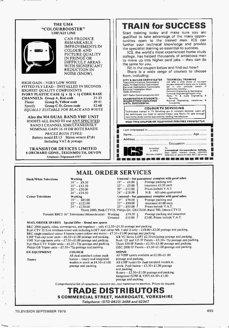
MAIL ORDER SERVICESWorking19" - £9.5023" - £12.5020" - £20.0024" - £24.50Working19" - £85.0022" - £125.0025" -£130.00
Untested - but guaranteed complete with good tubes19" - £4.00 Postage packing and23" - £5.00 insurance £3.50 each20" - £15.00 Prices include V.A.124" - £19.00 N.B. All tubes guaranteedUntested - but guaranteed complete with good tubes19" - £70.00 Postage packing and22" - £90.00 insurance £9.00 each.25" - £95.00 } Prices include V.A.T.
Thorn 2000, Bush CTV25, Philips G6, GEC2028, Baird 700, Decca CTV25Portable BBC2 16" Televisions (Monochrome) - Working £19.50 I Postage packing and insurance
Untested £15.00 I £3.00. Prices include V.A.T.
MAIL ORDER SPARES Special Offer - Brand new sparesBRC 2000 panels, video, convergence, and regulator- only £12.50441.50 postage and packing.Bush CTV 25 Line timebase-tower unit including LOPT and valves Mk. I and II only - £18.00+ £3.00 postage and packing.BRC single standard colour 4 button tuners colour and mono - £7.50+£1.00 postage and packing.UHF Vafi-cap tuner units - £6.50+£1.00 postage and packing.VHF Vari-cap tuner units -£7.50-441.00 postage and packing.Pye-Ekco CTV Tripler units -£6.25+75p postage and packing.Philips G8 Tripler units - £7.50 +75p postage and packing.
EX -EQUIPMENT
Tuners
COLOURAll dual standard colour pushbutton - rotary and integratedmodels in stock at £4.50+£1.00postage and packing.
KB VC Series LOPT £2.50 including postage and packing.Bush 125 and 135 IF Panels - £3.50+75p postage and packing.Thorn 850 IF Panels -£2.50+£1.00 postage and packing.GEC 2000 IF Panels - £3.50 +£1.00 postage and packing.
MONOAll VIHF tuners available at £2.00+£1.00postage and packing.All UHF tuners for dual standard models instock. Push button -£3.50+£1.00 postageand packing.Rotary - £2.50+£1.00 postage and packing.Integrated (UHF & VHF) £4.50+£1.00postage and packing.
Comprehensive list of capacitors, resistors etc., too numerous to mention. Prices on request.
TRADE DISTRIBUTORS5 COMMERCIAL STREET, HARROGATE, YORKSHIRE
Telephone: (STD 0423) 3498 and 6234 7
TELEVISION SEPTEMBER 1975 499
Our Aztec PA23 twin engine executive aircraft makessure dealers and service engineers get their spares fast andbrings dealers and engineers in touch with our compre-hensive range of vital electronic components held in stockfor immediate dispatch. Our unique "Fly -in" programme -doubled in capacity this year - brings you to thecomponents or vice -versa!It's the quickest way to save time all-round. When we say24 -hour service - we mean it! Our stocks and service willamaze you for speed, efficiency and technical excellence.
same -daydespatch is asnear as your
- telephone
We are stockists of genuine manufacturers spares for Rank Bush Murphy . . . CES PyePhilips . . . Invicta . . . Pam . Ekco . .. Ferranti BAC .. Ferguson . . . Ultra . . . MarconiHMV ... GEC ... Sobell Masteradio . . Stockists of TELEPART SPARES for Decca . KB
. . . RGD etc. Una output transformers . . . EHT rectifiers tray . . . Panels . . . Scan coilassemblies . . . Frame and sound outputs . . . Dropper sections . . Entertainment valvesTransistors and integrated circuits . . Components . . . Cathode ray tubes . . MetersTest equipment.
urjOra.'
05 IasiSoda.
fairt5'Ow" -
Free100 pagecatalogueby return
willow valeELECTRONICS LTD
SerVit6OLD HALL WORKS, ARBORFIELD ROAD, SHINFIELD,
READING 0734-884444 3 lines4 THE BROADWAY, HANWELL, LONDON W7
01-567 540074 MAXWELTON ROAD, PAISLEY, RENFREW
041-887 4949
seersoot
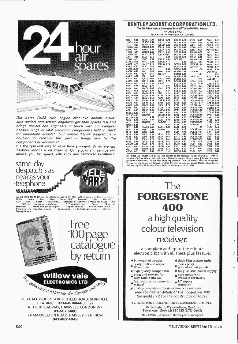
BENTLEY ACOUSTIC CORPORATION LTD.The Old Police Station, Gloucester Road, LITTLE HAMPTON, Sussex.
PHONE 6743ALL PRICES INCLUSIVE OF V.A.T. AT 25%
OB2 0.50 6K8G 0.5311331ST 0.59 6L6GC 0.682D21 0.53 6L7(M1 0.395R4GY 0.91 6N7GT 0.705U4G 0.47 6Q7G 0.595V4G 0.59 6Q7GT 0.39SY3GT 0.33 6R7G 0.70523 0.88 6SA7 0.325Z4G 0.53 6SG7 0.526/30L2 0.70 6V6G 0.206AC7 0.57 6V6GT 0.536AK5 0.47 6X4 0.476AM8A 0.64 6X5GT 0.53
30FL I 0.7830FL2 0.7830FL14 0.8230L15 0.8230L17 0.7630P12 0.7630P19/30P4
0.8830PL 1 1.0030PLI3 1.1130PL14 1.2935L6GT
0.18
ECC35 1.11ECC40 1.17ECC81 0.40ECC82 0.39ECC83 0.39ECC84 0.41ECC85 0.47ECC88 0.52ECC807
1.41
ECF80 0.33ECF82 0.33ECF86 0.88
EY88 0.47EZ40 0.59EZ41 0.64EZ80 0.33EZ81 0.34GY501 0.82GZ32 0.59GZ34 0.70HN309 1.76KT66 2.93KTW611.76KTW62
1.76
P1.84 0.47PL504 0.12PL508 1.10PL509 1.70
PY33/2 0.53PY81 0.41PY82 0.35PY83 0.45PY88 0.47PY500 1.11pm° 0.47PY801 0.47P230 0.50
6AN8 0.82 7Y4 0.18 35W4 0.59 ECH35 1.46 KTW63 QQV03/106AQ5 0.53 9D7 0.76 35Z4GT ECH42 0.82 1.17 2.056AR5 0.70 OF' CU 0.82 ECH8I 0.39 PABC80 R19 0.706AT6 0.53 OF18 0.64 5005 1.00 ECH83 0.52 0.45 UABC806AU6 0.35 0P13 0.88 5005 0.70 ECH84 0.52 PC86 0.70 0.476AV6 0.53 OP 14 2.34 50L6G-r ECL80 0.47 PC88 0.70 UAF42 0.756BA6 0.41 2A6 0.75 0.76 ECL82 0.50 PC97 0.55 UBC41 0.706BE6 0.41 2AC6 0.82 85A2 0.70 ECL83 0.82 PC900 0.47 UBCBI 0.606BH6 0.70 2AD6 0.76 807 1.17 ECL86 0.47 PCC84 0.35 UBF80 0.4761316 0.64 2AE6 0.76 5763 1.76 EF40 0.88 PCC85 0.32 UBF89 0.476BQ7A 0.64 2AT6 0.47 AZ31 0.70 EF41 0.12 PCC88 0.70 UC92 0.606BR7 1.17 2AU6 0.53 AZ4I 0.29 EF80 0.29 PCC89 0.60 UCC84 0.906BR8 1.25 2AV6 0.59 DAF96 0.59 EF83 1.17 PCC1890.36 UCC85 0.536BW6 0.94 2BA6 0.53 DF96 0.39 EF85 0.35 PCF80 0.47 UCF80 0.906BW7 0.82 2BE6 0.59 DK96 0.70 EF86 0.53 PCF82 0.47 UCH42 0.8116826 0.57 2BH7 0.39 DL96 0.64 EF89 0.35 PCF86 0.56 UCH81 0.476C4 0.47 2BY7 0.85 DY87/60.41 EF91 0.43 PCF2001.00 UCL82 0.456CB6A 0.47 2K5 1.17 DY802 0.41 EF92 0.59 PCF2011.05 UCL83 0446CD6G 1.46 2K7GT E88CC 1.20 EF98 0.94 PCF8010.65 UF41 0.126CG8A 0.88 0.39 EIBOF 1.17 EF183 0.35 PC F8020.65 UF80 OA 1
6CL6 0.76 2K8 1.17 EA50 0.32 EF184 0.41 PCF8051.10 UF85 0.326CU5 0.18 2Q7GT EABC80 EH90 0.53 PCF8060.59 up80 0.476DT6A 0.88 0.53 0.15 EL34 1.17 PCH200 UL4 1 0.756F1 0.88 9AQ5 0.59 EAF42 0.88 EL41 0.39 1.00 UL84 0.496F6G 0.59 9H1 2.34 EAF801 EL81 0.70 PCL82 0.45 UM80 0.606F14 0.88 20DI 070 0.80 EL84 0.36 PCL83 0.53 UY41 0.506F18 0.64 2011 1.29 EB91 0.23 EL506 1.05 PCL84 0.47 UY85 0.506F23 0.82 20P4 1.17 EBC41 0.88 EMBO 0.53 PCL86 0.55 U25 0.706F24 1.00 25L6G 0.70 EBC 81 0.41 EM81 0.76 PCL8050.70 U26 0.65
6E28 0.78 25Y5G 0.82 EBF80 0.46 EM84 0.47 PL36 0.70 U191 0.596H6GT 0.29 30A5 0.76 EBF83 0.30 EM87 0.1 P1.81 0.53 1.1251 0.946.150T 0.53 30C15 0.82 EBP89 0.38 EY51 0.30 PL81A 0.33 U404 0.75656 0.35 30017 0.94 EC92 0.53 EY83 0.70 PL82 0.43 0801 0.806K7G 035 30E5 0.88 ECC33 1.76 EY87/6 0.39 PL83 0.47 Z759 5.85
All goods are unused and boxed, and subject to the standard 90 -day guarantee. Terms ofbusiness: Cash or cheque with order only. Despatch charges: Orders below E10, add 25p extraper order. Orders over f 10 post free. Same day despatch. Terms of business available on request.Any parcel insured against damage in transit for only 5p extra per parcel. Pkase enclose S.A.E.with any enquiries. Please note: Export Orders - minimum accepted L3.00.
TheFORGESTONE
400a high quality
colour televisionreceiver.
a complete and up-to-the-minuteelectronic kit with all these plus features
*9 integrated circuits *thick film resistor units*ready -built and aligned glass epoxy
printed circuit panels*high quality components *fully isolated power supply
each module kitepalusygspaanndelsor ecmk eotvsaflo r
available separatelyfull technical construction *LT supply
T manual regulator* quality cabinets and basic cabinet kits available
send for further details of the Forgestone 400the quality kit for the constructor of today.
FORGESTONE COLOUR DEVELOPMENTS LIMITEDKetteringham, Wymondham, Norfolk
Telephone: Norwich 810453 (STD 0603)Mail Order -Access & Barclaycard accepted
500 TELEVISION SEPTEMBER 1975

EDITORLionel E. Howes
ASSISTANT EDITORJohn A. Reddihough
TECHNICAL EDITORGeoffrey C. Arnold
ART EDITORPeter Metalli
ADVERTS. MANAGERRoy Smith 01-634 4293
CLASSIFIED ADVERTS.Colin R. Brown 01-634 4301
wro:.copn
TO SERVICE OR NOTTO SERVE
The servicing policies of radio and TV retailers are many and varied. They range from flatrefusal to have anything at all to do with any equipment they have not sold recently underguarantee, to the small dealer who may do more servicing than retailing. Many dealersfeel that it is up to them and them alone to decide upon what their policy is to be, and upto a point this is right and proper. There does nevertheless seem to us to be a certainminimum of courtesy and helpfulness that should be observed in dealings with the public.
What we have in mind is the sort of organisation that will literally show you the doorif you present yourself with an interest in anything other than the latest luxury colour TVor quadraphonic audio system. Perhaps you may have gone in for a fuse or maybe even avalve, or to ask about the possibility of getting a faulty set looked at. It'll all be the same;out you go and don't dare come in again with ideas of spending less than £250.
We still vividly recall reading the numerous speeches made a few years ago by a pastpresident of the RTRA whose shop happened to be in our local high street. During histerm of office this gentleman was forever on about the excellent service provided by thetrade in spite of the many difficulties under which traders operated, and about theimportance of goodwill and the way in which traders and the public alike benefitted fromreputations deservedly established. Inspired by all this, we went into the shop one daywhen we happened to be short of an EF80 . . . and received the out you go old boytreatment. In our innocence, we'd thought that a radio and TV dealer would have hadvalves like you expect to be able to buy a light bulb at a mainly electrical shop.
Now this wasn't one of those shops that have nothing in sight but expensive wall-to-wall carpeting, concealed lighting, subtle wallpaper and maybe two or three luxury 26inTVs of Scandinavian origin displayed with great artistry. One might expect anorganisation of that type, probably presided over by a dolly bird, to be blissfully unawareof such things as fuses, soldering irons and bits of wire! No, this was a perfectly ordinary,rather ramshackle shop with the service department right next door, with valve cartonswell to the fore amidst the sets receiving attention. Maybe at some time in the past theservice manager might have been annoyed at salesmen depleting his stocks without lettinghim know so that he could re -order, leaving him in a tricky situation over a set he'dpromised to return the same day and resulting in a clamp down on valve sales. Somehowhowever we don't think that this was the case. What we do know is that we've never beenthrough that door since and it would be the last place we'd venture for anything howeverdesperate we were.
In an ideal world all dealers would be enthusiasts interested in the technicalities of thesubject as well as the business side, and anxious to please everyone who came to them forwhatever reason. Fantastically, some are. But you can't expect the ideal in the hard worldof everyday business.
There are some very sound reasons for laying down limits as to how far a firm shouldgo in providing service. It is unfair when you find the point of sale profits being taken bythe local discounter while you have to rely increasingly on repairs and the loyalty of adwindling number of customers you've dealt with over many years. Also, let's face it,there are customers who will take advantage of your goodwill, expecting you to go to a lotof trouble time and again and then being decidedly awkward when it comes to payinganything even remotely approaching an economic charge. There are also the less soundreasons for being selective about the service you provide: like those businesses that haveno idea of the cost of servicing but do know they will go broke if they do more than areluctant minimum, and others who simply won't pay what it costs to employ a capableengineer and provide him with the necessary stock and equipment.
One policy we've never understood is the "won't touch anything we've not soldourselves" one. Don't such dealers realise that many people have to move around thecountry for one reason or another, that some get given equipment or inherit it, and so on?
The least that should be expected is courtesy. If you don't want to handle it, say sopolitely, give a sensible reason and if possible suggest where the customer may be able toget his problem dealt with. A customer will generally understand when told that theeconomics of dealing with a set that is past it are unlikely to be worthwhile for you or him,that you only have the agency for certain brands, or whatever the situation is. As aminimum the customer should receive a considerate hearing and reasonable advice.
One thing is certain. With the present decline in new sales as a result of money being inshort supply and prices still rising, there will be an increased call for servicing - and anincreased opportunity to build up a reputation for helpfulness that will pay off when the
market turns up again.
TELEVISION SEPTEMBER 1975 501
New Thorn Chassis Presage End of ThermionicValve EraTHE introduction of a new solid-state, large -screenmonochrome TV chassis by Thorn - the 1600 chassis -brings home the fact that we are fast approaching the end ofthe era in which valves have been used in currentproduction TV sets. Amongst the UK colour set makers,only ITT and Decca still produce hybrid chassis, withvalves in the high -power sections. On the monochrome side,valves have now all but disappeared. So the days will notlong be with us when a look in the back of a faulty set gavea quick idea of what was wrong: soon it'll be the meter firstin every case. A pity maybe, but part of the price ofprogress. One unfortunate aspect will be the increasing costof keeping old sets going: the price of valves is already high,goodness knows what it will reach when they have becomea rarity.
The new 1600 chassis is certainly representative of thecurrent "state of the art". A three -stage transistor if. strip isfollowed by a TCA270SQ for detection and a.g.c., with avideo channel d.c.-coupled through to the c.r.t. cathode.I.C.s are used for the intercarrier and audio stages, andthere's a varicap tuner of course. The BU205 line outputtransistor is operated in an antiboost arrangement, i.e. the30V 1.t. line is derived from its emitter circuit, where thepower supply regulator is also to be found. A discretecomponent field oscillator drives an SN76033N-07 i.c.which acts as the field output stage.
There is also an export version of the chassis (coded1700) fitted with either a Fagor or Mullard multiband tuner.Which reminds us that those followers of Roger Bunneywho may be after a Mullard ELC2000S multiband tuner(see Long -Distance Television, April 1974) can now obtainthese from Forgestone Colour Developments Ltd.(Ketteringham, Wymondham, Norfolk) who keep them instock for the export versions of their colour receiver kit. Theprice of this tuner is about 14.
Thorn have also introduced a new chassis (1613) fortheir latest mains -battery monochrome portables. Thisdiffers from the previous 1612 chassis in having a newpower supply regulator circuit.
Colour Projection TV System Announced
A colour projection TV system which was first introducedin the USA some two years ago is to be made available inthe UK, with a price tag of around £3,500. This is the502
Advent videobeam system which provides a 69in picture.The equipment will operate with off -air signals or withinputs from a videotape recorder or camera. The projectorunit employs three special 3in screen projection tubes eachof which has its own built in Schmidt optical system. Thisgives an accurate colour display with minimum need forsetting up. The screen, which was developed by Kodak andis made by Advent under license, has a highly reflectivealuminium surface to overcome the lack of brightness thatwas commonly experienced with older projection systems.It is important to mount the screen at the exactly correctdistance, eight feet, from the projector: serious lack of focusoccurs if the screen is more than an inch or so out ofposition. The sound is also projected at the screen forreflection. All solid-state electronic circuitry mounted onplug-in boards is used.
IBC 76
The sixth International Broadcasting Convention - IBC 76- will be held in London at the Grosvenor House Hotel,Park Lane, on September 20th -24th, 1976.
New Decoder IC
The availability of an interesting new integrated circuit, typeCA3128Q, for use in colour receiver decoders has beenannounced by RCA Solid -State, Sunbury -on -Thames,Middlesex. The i.c. incorporates the complete chrominancechannel, with colour -killer, automatic chrominance controland an automatic chrominance overload reduction circuit,and the voltage -controlled reference oscillator together withits control loop and the burst detector. Along with this i.c.therefore all that is required for a complete decoder is aPAL switch, the chrominance synchronous detectors, andmatrixing circuits, all of which are available in i.c.s such asthe MC1327 or TCA800. This gives a two i.c. PALdecoder with the minimum of external components andadjustments. In fact the number of external componentsrequired by the CA3128Q is negligible: the referenceoscillator crystal of course, plus a handful of filteringcomponents.
To reduce the number of decoder adjustments - there isonly one in the CA3128Q's peripheral circuit, a trimmer toset up the reference oscillator - use is made of sample -and -
hold techniques in the burst detector and the a.c.c./colour-killer detector circuits. These compare the detected signalswith the quiescent circuit conditions, avoiding the need for
TELEVISION SEPTEMBER 1975
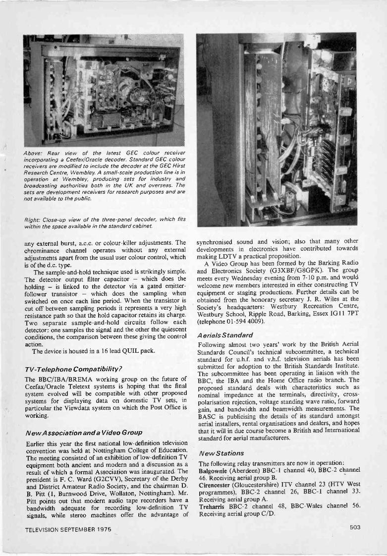
Above: Rear view of the latest GEC colour receiverincorporating a Ceefax1Oracle decoder. Standard GEC colourreceivers are modified to include the decoder at the GEC HirstResearch Centre, Wembley. A small-scale production line is inoperation at Wembley, producing sets for industry andbroadcasting authorities both in the UK and overseas. Thesets are development receivers for research purposes and arenot available to the public.
Right: Close-up view of the three -panel decoder, which fitswithin the space available in the standard cabinet.
any external burst, a.c.c. or colour -killer adjustments. Thechrominance channel operates without any externaladjustments apart from the usual user colour control, whichis of the d.c. type.
The sample -and -hold technique used is strikingly simple.The detector output filter capacitor - which does theholding - is linked to the detector via a gated emitter -follower transistor - which does the sampling whenswitched on once each line period. When the transistor iscut off between sampling periods it represents a very highresistance path so that the hold capacitor retains its charge.Two separate sample -and -hold circuits follow eachdetector: one samples the signal and the other the quiescentconditions, the comparison between these giving the controlaction.
The device is housed in a 16 lead QUIL pack.
TV -Telephone Compatibility?The BBC/IBA/BREMA working group on the future ofCeefax/Oracle Teletext systems is hoping that the finalsystem evolved will be compatible with other proposedsystems for displaying data on domestic TV sets, inparticular the Viewdata system on which the Post Office isworking.
New Association and a Video Group
Earlier this year the first national low -definition televisionconvention was held at Nottingham College of Education.The meeting consisted of an exhibition of low -definition TVequipment both ancient and modern and a discussion as aresult of which a formal Association was inaugurated. Thepresident is F. C. Ward (G2CVV), Secretary of the Derbyand District Amateur Radio Society, and the chairman D.B. Pitt (1, Burnwood Drive, Wollaton, Nottingham). Mr.Pitt points out that modern audio tape recorders have abandwidth adequate for recording low -definition TVsignals, while stereo machines offer the advantage of
synchronised sound and vision; also that many otherdevelopments in electronics have contributed towardsmaking LDTV a practical proposition.
A Video Group has been formed by the Barking Radioand Electronics Society (G3XBF/G8GPK). The groupmeets every Wednesday evening from 7-10 p.m. and wouldwelcome new members interested in either constructing TVequipment or staging productions. Further details can beobtained from the honorary secretary J. R. Wiles at theSociety's headquarters: Westbury Recreation Centre,Westbury School, Ripple Road, Barking, Essex IG11 7PT(telephone 01-594 4009).
Aerials StandardFollowing almost two years' work by the British AerialStandards Council's technical subcommittee, a technicalstandard for u.h.f. and v.h.f. television aerials has beensubmitted for adoption to the British Standards Institute.The subcommittee has been operating in liaison with theBBC, the IBA and the Home Office radio branch. Theproposed standard deals with characteristics such asnominal impedance at the terminals, directivity, cross -polarisation rejection, voltage standing wave ratio, forwardgain, and bandwidth and beamwidth measurements. TheBASC is publicising the details of its standard amongstaerial installers, rental organisations and dealers, and hopesthat it will in due course become a British and Internationalstandard for aerial manufacturers.
New StationsThe following relay transmitters are now in operation:Balgownie (Aberdeen) BBC -1 channel 40, BBC -2 channel46. Receiving aerial group B.Cirencester (Gloucestershire) ITV channel 23 (HTV Westprogrammes), BBC -2 channel 26, BBC -1 channel 33.Receiving aerial group A.Treharris BBC -2 channel 48, BBC -Wales channel 56.Receiving aerial group C/D.
TELEVISION SEPTEMBER 1975 503
Westwood (Wiltshire) BBC -1 channel 40, ITV channel 43(HTV West programmes), BBC -2 channel 46. Receivingaerial group B.
All these relay transmissions are vertically polarised.
FlywheelSyncTime-ConstantOur apologies for getting the bit about flywheel sync time-
constants wrong in the article about Rank's new I8incolour chassis (see circuit description on page 429 of theJuly issue). This was an editorial slip in preparing the copy.Let's put the record straight on this subject once and for all.
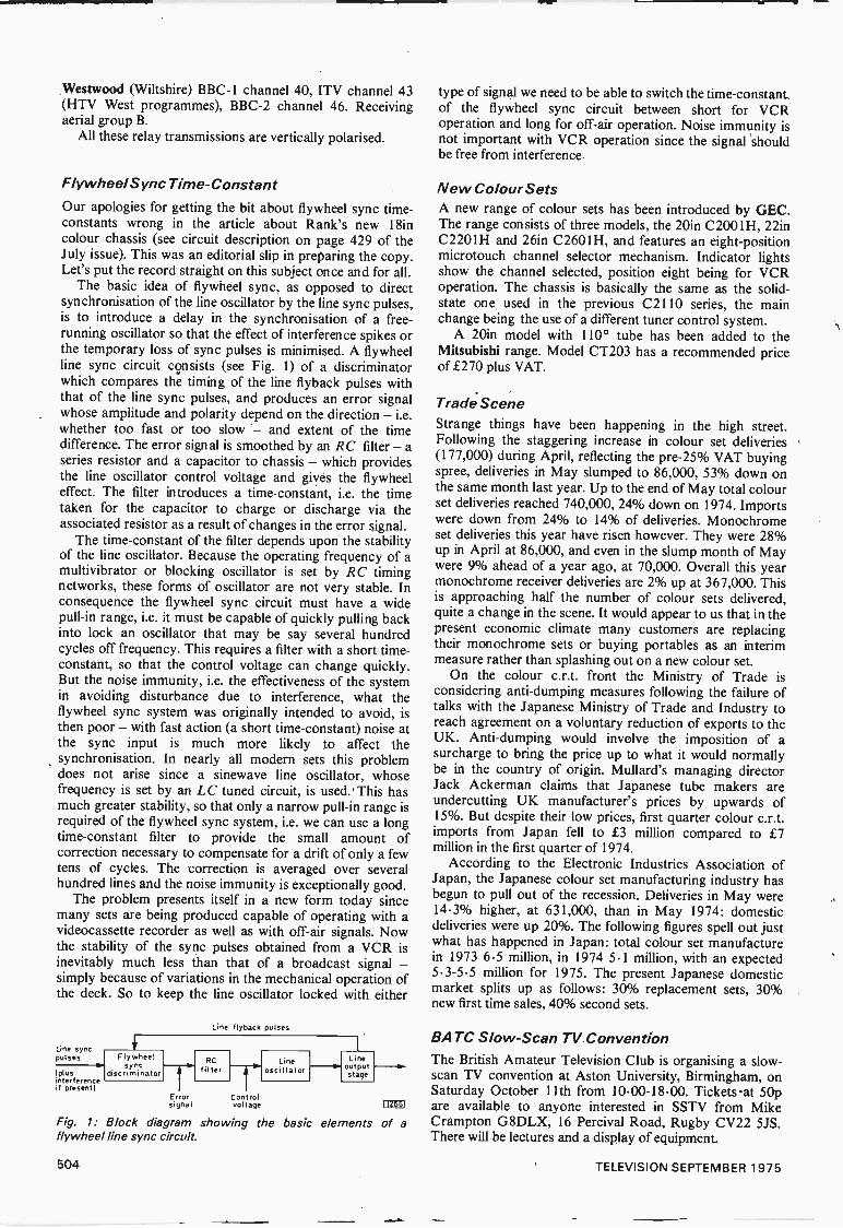
The basic idea of flywheel sync, as opposed to directsynchronisation of the line oscillator by the line sync pulses,is to introduce a delay in the synchronisation of a free -running oscillator so that the effect of interference spikes orthe temporary loss of sync pulses is minimised. A flywheelline sync circuit consists (see Fig. 1) of a discriminatorwhich compares the timing of the line flyback pulses withthat of the line sync pulses, and produces an error signalwhose amplitude and polarity depend on the direction - i.e.whether too fast or too slow - and extent of the timedifference. The error signal is smoothed by an RC filter -aseries resistor and a capacitor to chassis - which providesthe line oscillator control voltage and gives the flywheeleffect. The filter introduces a time -constant, i.e. the timetaken for the capacitor to charge or discharge via theassociated resistor as a result of changes in the error signal.
The time -constant of the filter depends upon the stabilityof the line oscillator. Because the operating frequency of amultivibrator or blocking oscillator is set by RC timingnetworks, these forms of oscillator are not very stable. Inconsequence the flywheel sync circuit must have a widepull -in range, i.e. it must be capable of quickly pulling backinto lock an oscillator that may be say several hundredcycles off frequency. This requires a filter with a short time -
constant, so that the control voltage can change quickly.But the noise immunity, i.e. the effectiveness of the systemin avoiding disturbance due to interference, what theflywheel sync system was originally intended to avoid, isthen poor - with fast action (a short time -constant) noise atthe sync input is much more likely to affect thesynchronisation. In nearly all modern sets this problemdoes not arise since a sinewave line oscillator, whosefrequency is set by an LC tuned circuit, is used. This hasmuch greater stability, so that only a narrow pull -in range isrequired of the flywheel sync system, i.e. we can use a longtime -constant filter to provide the small amount ofcorrection necessary to compensate for a drift of only a fewtens of cycles. The correction is averaged over severalhundred lines and the noise immunity is exceptionally good.
The problem presents itself in a new form today sincemany sets are being produced capable of operating with avideocassette recorder as well as with off -air signals. Nowthe stability of the sync pulses obtained from a VCR isinevitably much less than that of a broadcast signal -simply because of variations in the mechanical operation ofthe deck. So to keep the line oscillator locked with either
Line flyback pulses
Line sync ----Flywheel
syncdiscriminator
RCfilter
Lineoscillator
Lineoutputstage
pulsesla.
(plus.111
interferenceif present)
Error Con rolsignal voltage
Fig. 1: Block diagram showing the basic elements of aflywheel line sync circuit.
type of signal we need to be able to switch the time -constantof the flywheel sync circuit between short for VCRoperation and long for off -air operation. Noise immunity isnot important with VCR operation since the signal shouldbe free from interference.
New Colour SetsA new range of colour sets has been introduced by GEC.The range consists of three models, the 20in C 2001H, 22inC2201H and 26in C2601H, and features an eight -positionmicrotouch channel selector mechanism. Indicator lightsshow the channel selected, position eight being for VCRoperation. The chassis is basically the same as the solid-state one used in the previous C2110 series, the mainchange being the use of a different tuner control system.
A 20in model with 110° tube has been added to theMitsubishi range. Model CT203 has a recommended priceof £270 plus VAT.
Trade SceneStrange things have been happening in the high street.Following the staggering increase in colour set deliveries(177,000) during April, reflecting the pre -25% VAT buyingspree, deliveries in May slumped to 86,000, 53% down onthe same month last year. Up to the end of May total colourset deliveries reached 740,000, 24% down on 1974. Importswere down from 24% to 14% of deliveries. Monochromeset deliveries this year have risen however. They were 28%up in April at 86,000, and even in the slump month of Maywere 9% ahead of a year ago, at 70,000. Overall this yearmonochrome receiver deliveries are 2% up at 367,000. Thisis approaching half the number of colour sets delivered,quite a change in the scene. It would appear to us that in thepresent economic climate many customers are replacingtheir monochrome sets or buying portables as an interimmeasure rather than splashing out on a new colour set.
On the colour c.r.t. front the Ministry of Trade isconsidering anti -dumping measures following the failure oftalks with the Japanese Ministry of Trade and Industry toreach agreement on a voluntary reduction of exports to theUK. Anti -dumping would involve the imposition of asurcharge to bring the price up to what it would normallybe in the country of origin. Mullard's managing directorJack Ackerman claims that Japanese tube makers areundercutting UK manufacturer's prices by upwards of15%. But despite their low prices, first quarter colour c.r.t.imports from Japan fell to £3 million compared to £7million in the first quarter of 1974.
According to the Electronic Industries Association ofJapan, the Japanese colour set manufacturing industry hasbegun to pull out of the recession. Deliveries in May were14.3% higher, at 631,000, than in May 1974: domesticdeliveries were up 20%. The following figures spell out justwhat has happened in Japan: total colour set manufacturein 1973 6.5 million, in 1974 5.1 million, with an expected5.3-5.5 million for 1975. The present Japanese domesticmarket splits up as follows: 30% replacement sets, 30%new first time sales, 40% second sets.
BATC Slow -Scan TV. ConventionThe British Amateur Television Club is organising a slow-
scan TV convention at Aston University, Birmingham, onSaturday October 11th from 10.00-18.00. Tickets -at 50pare available to anyone interested in SSTV from MikeCrampton G8DLX, 16 Percival Road, Rugby CV22 5JS.There will be lectures and a display of equipment.
504 TELEVISION SEPTEMBER 1975
SENDZ COMPONENTS
BT 116MJE 2021SJE 5451BDY 55R 1039R 2009R 2029R 2030IN 4007I 53100AA 116AA 117ZW 13BZY 88C7V5IN 5337BF 121BF 264BA 182BC 161BF 127BF 180BF 181SN 76544SAA 570TAA 700
2 For £1.50
5 For £1.00
3 For £1.001 For 75p1 For 75p1 For 75p1 For 75p
20 For £1.0020 For £1.0025 For £1.0025 For £1.0020 For £1.0025 For £1.0020 For f1.00
4 For £1.004 For £1.005 For £1.005 For £1.005 For £1.005 For £1.005 For £1.002 For £1.002 For £1.00
1 For £1.00
EHT Rectifier Sticks X80/150D 10p
COLOUR TV COMPONENTSMANUFACTURERS DISCARDED
MATERIALSG8 Varicap V/Resistor PanelsVHF or UHF Varicap TunersLine 0/P PanelsDecoder PanelsG8 Type YokeFrame Panels
£1.20£1.20£1.20£1.00
50p75p
PLEASE ADD 25% VAT TO ALL ORDERS
PYE Transistor T/Unit VHF -UHF New £1.50
PHILIPS Transistor UHF Units New £1.50
PYE 4 Push Button UHF T -Unit New f3.50
ECL 1043/05 Varicap Tuners UHF New £3.50
TRIPLERS25kV 2.5 MA Silicone £1.50
25kV DECCA Selenium £1.30
TS25 11TAZG8 TriplerGEC T25 KC1-5DECCA 1730
£3.00£3.00£3.00£1.00
1000 + 2000100 + 200200 + 200 + 100200 + 100 + 50 + 100300 + 300 + 100 + 150200 + 200 + 100
MFD 35V325V325V325V350V350V
20p30p40p40p70p50p
100 W/W Resistors300 Mixed Condensers300 Mixed Resistors40 Mixed Pots20 Slider Pots
£1.00£1.00£1.00£1.00£1.00
220 MFD 40V22 MFD 315V10 MFD 250V180 PF 8Kv
1000 PF 8Kv160 M 25V470 M 40V
10p Each
400 M 40V220 M 63V 15p Each
Money returned if not completely satisfied.
SENDZ COMPONENTS2 Wood Grange Close, Thorpe Bay, Essex.
Reg. Office only - no personal callers thank you.
TELEVISION SEPTEMBER 1975 505
in COLOURTV Receivers
S. GEORGE
THE junction gate field effect transistor (JUGFET) is beingincreasingly used in colour television receivers in a varietyof applications where its characteristics are particularlysuitable. Since we have published little on this device in thepast we will start off by describing its mode of operationand summarising its characteristics.
Basic Operation
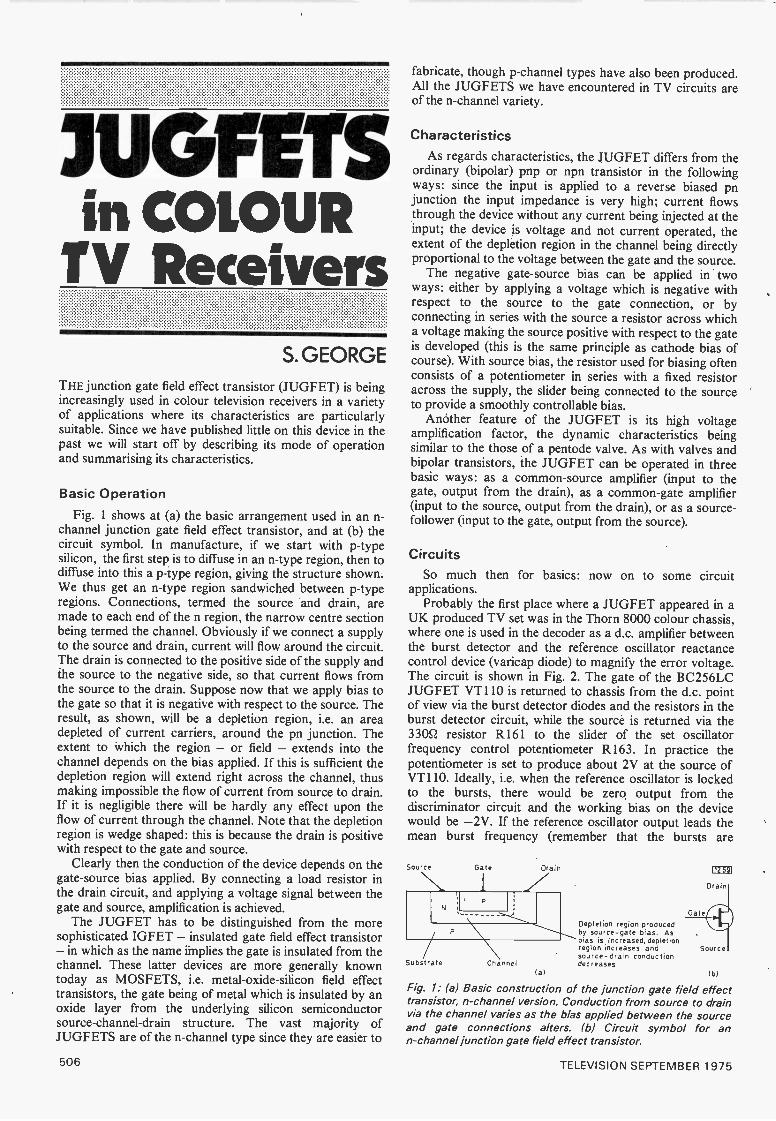
Fig. 1 shows at (a) the basic arrangement used in an n -
channel junction gate field effect transistor, and at (b) thecircuit symbol. In manufacture, if we start with p -typesilicon, the first step is to diffuse in an n -type region, then todiffuse into this a p -type region, giving the structure shown.We thus get an n -type region sandwiched between p -typeregions. Connections, termed the source and drain, aremade to each end of the n region, the narrow centre sectionbeing termed the channel. Obviously if we connect a supplyto the source and drain, current will flow around the circuit.The drain is connected to the positive side of the supply andthe source to the negative side, so that current flows fromthe source to the drain. Suppose now that we apply bias tothe gate so that it is negative with respect to the source. Theresult, as shown, will be a depletion region, i.e. an areadepleted of current carriers, around the pn junction. Theextent to which the region - or field - extends into thechannel depends on the bias applied. If this is sufficient thedepletion region will extend right across the channel, thusmaking impossible the flow of current from source to drain.If it is negligible there will be hardly any effect upon theflow of current through the channel. Note that the depletionregion is wedge shaped: this is because the drain is positivewith respect to the gate and source.
Clearly then the conduction of the device depends on thegate -source bias applied. By connecting a load resistor inthe drain circuit, and applying a voltage signal between thegate and source, amplification is achieved.
The JUGFET has to be distinguished from the moresophisticated IGFET - insulated gate field effect transistor- in which as the name implies the gate is insulated from thechannel. These latter devices are more generally knowntoday as MOSFETS, i.e. metal -oxide -silicon field effecttransistors, the gate being of metal which is insulated by anoxide layer from the underlying silicon semiconductorsource -channel -drain structure. The vast majority ofJUGFETS are of the n -channel type since they are easier to
Gate
Channel
fabricate, though p -channel types have also been produced.All the JUGFETS we have encountered in TV circuits areof the n -channel variety.
CharacteristicsAs regards characteristics, the JUGFET differs from the
ordinary (bipolar) pnp or npn transistor in the followingways: since the input is applied to a reverse biased pnjunction the input impedance is very high; current flowsthrough the device without any current being injected at theinput; the device is voltage and not current operated, theextent of the depletion region in the channel being directlyproportional to the voltage between the gate and the source.
The negative gate -source bias can be applied in twoways: either by applying a voltage which is negative withrespect to the source to the gate connection, or byconnecting in series with the source a resistor across whicha voltage making the source positive with respect to the gateis developed (this is the same principle as cathode bias ofcourse). With source bias, the resistor used for biasing oftenconsists of a potentiometer in series with a fixed resistoracross the supply, the slider being connected to the sourceto provide a smoothly controllable bias.
Another feature of the JUGFET is its high voltageamplification factor, the dynamic characteristics beingsimilar to the those of a pentode valve. As with valves andbipolar transistors, the JUGFET can be operated in threebasic ways: as a common -source amplifier (input to thegate, output from the drain), as a common -gate amplifier(input to the source, output from the drain), or as a source-
follower (input to the gate, output from the source).
So much then for basics: now on to some circuitapplications.
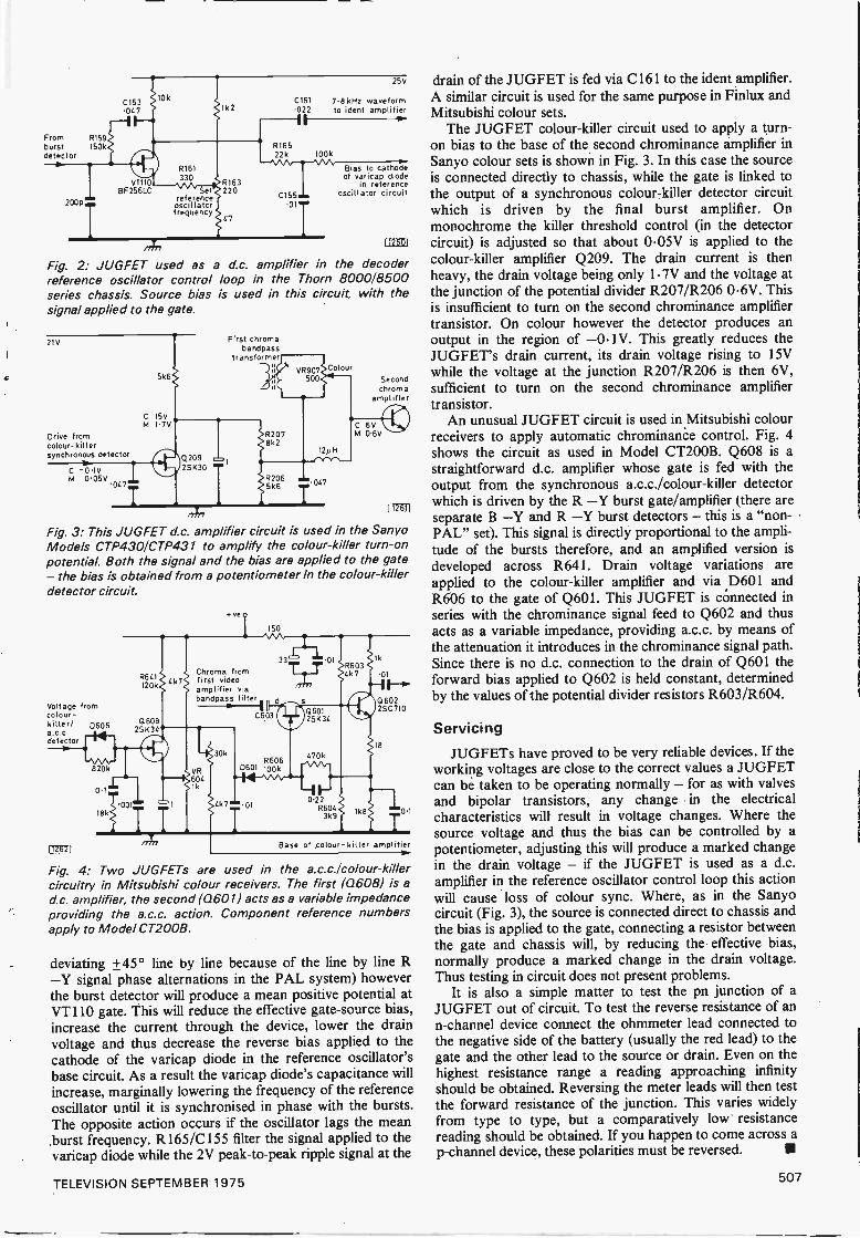
Probably the first place where a JUGFET appeared in aUK produced TV set was in the Thorn 8000 colour chassis,where one is used in the decoder as a d.c. amplifier betweenthe burst detector and the reference oscillator reactancecontrol device (varicap diode) to magnify the error voltage.The circuit is shown in Fig. 2. The gate of the BC256LCJUGFET VT110 is returned to chassis from the d.c. pointof view via the burst detector diodes and the resistors in theburst detector circuit, while the source is returned via the330Q resistor R161 to the slider of the set oscillatorfrequency control potentiometer R163. In practice thepotentiometer is set to produce about 2V at the source ofVT110. Ideally, i.e. when the reference oscillator is lockedto the bursts, there would be zero output from thediscriminator circuit and the working bias on the devicewould be -2V. If the reference oscillator output leads themean burst frequency (remember that the bursts are
Source
Substrate
Drain
Gate
Depletion region producedby source -gate bias. Asbias is Increased, depletionregion increases and Sourcesource -drain conductiondecreases
(al (b)
Fig. 1: (a) Basic construction of the junction gate field effecttransistor, n -channel version. Conduction from source to drainvia the channel varies as the bias applied between the sourceand gate connections alters. (b) Circuit symbol for ann -channel junction gate field effect transistor.
Dra
506 TELEVISION SEPTEMBER 1975
From R159burst 150kdetector
200p'
T
BF256LC
R161
Sereferenceoscillatorfrequency
2
R163220
4.
C161022-1
25V
7.8 kHz waveformto ident amplifier
R16522k 100k
Bias to cathodeof varicap diode
in referenceoscillator circuitC155
.011
Fig. 2: JUGFET used as a d.c. amplifier in the decoderreference oscillator control loop in the Thorn 8000/8500series chassis. Source bias is used in this circuit, with thesignal applied to the gate.
2IV
Drive fromcolour -killersynchronous detector
C -01VM 005V047
5k6
C 15VM I 7V
Q20925130
First chromabandpass
transformer
5k6
Secondchrom a
amplifier
112611
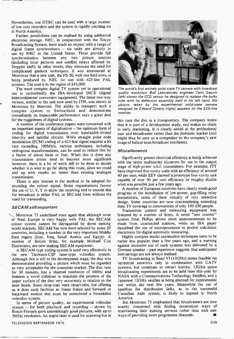
Fig. 3: This JUGFET d.c. amplifier circuit is used in the SanyoModels CTP4301CTP431 to amplify the colour -killer turn -onpotential. Both the signal and the bias are applied to the gate- the bias is obtained from a potentiometer in the colour -killerdetector circuit.
Volt age fromcolour -killer/ D606
detectorc--14iS820k
L12-621
1
18k
R64I120k
Q 60825K34
001"'
4k7
e ve
150
3= 01
Chroma fromfirst videoamplifier viabandpass filter
OR604
k
30k
C6031
R6060601 100k44-W.-0-
-1'-0.22
R6043k9
Q60125104
470k
k8
1k
01I0 6022 SC 710
18
0.1
Base of colour- killer amplifier
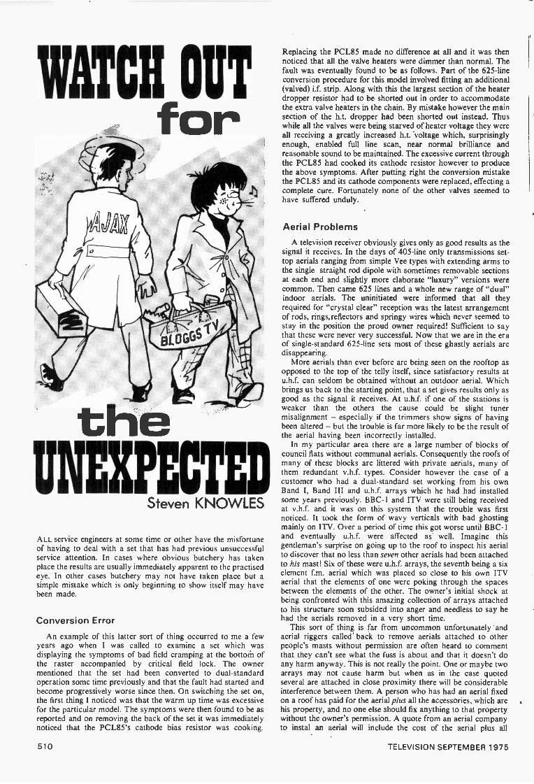
Fig. 4: Two JUGFETs are used in the a.c.c./colour-killercircuitry in Mitsubishi colour receivers. The first (Q608) is ad.c. amplifier, the second (0601) acts as a variable impedanceproviding the a.c.c. action. Component reference numbersapply to Model CT200B.
deviating ±45° line by line because of the line by line R-Y signal phase alternations in the PAL system) howeverthe burst detector will produce a mean positive potential atVT110 gate. This will reduce the effective gate -source bias,increase the current through the device, lower the drainvoltage and thus decrease the reverse bias applied to thecathode of the varicap diode in the reference oscillator'sbase circuit. As a result the varicap diode's capacitance willincrease, marginally lowering the frequency of the referenceoscillator until it is synchronised in phase with the bursts.The opposite action occurs if the oscillator lags the meanburst frequency. R165/C155 filter the signal applied to thevaricap diode while the 2V peak -to -peak ripple signal at the
drain of the JUGFET is fed via C161 to the ident amplifier.A similar circuit is used for the same purpose in Finlux andMitsubishi colour sets.
The JUGFET colour -killer circuit used to apply a turn -on bias to the base of the second chrominance amplifier inSanyo colour sets is shown in Fig. 3. In this case the sourceis connected directly to chassis, while the gate is linked tothe output of a synchronous colour -killer detector circuitwhich is driven by the final burst amplifier. Onmonochrome the killer threshold control (in the detectorcircuit) is adjusted so that about 0.05V is applied to thecolour -killer amplifier Q209. The drain current is thenheavy, the drain voltage being only 1.7V and the voltage atthe junction of the potential divider R207/R206 0.6V. Thisis insufficient to turn on the second chrominance amplifiertransistor. On colour however the detector produces anoutput in the region of -0.1V. This greatly reduces theJUGFET's drain current, its drain voltage rising to 15Vwhile the voltage at the junction R207/R206 is then 6V,sufficient to turn on the second chrominance amplifiertransistor.
An unusual JUGFET circuit is used in Mitsubishi colourreceivers to apply automatic chrominance control. Fig. 4shows the circuit as used in Model CT200B. Q608 is astraightforward d.c. amplifier whose gate is fed with theoutput from the synchronous a.c.c./colour-killer detectorwhich is driven by the R -Y burst gate/amplifier (there areseparate B -Y and R -Y burst detectors - this is a "non -PAL" set). This signal is directly proportional to the ampli-tude of the bursts therefore, and an amplified version isdeveloped across R641. Drain voltage variations areapplied to the colour -killer amplifier and via D601 andR606 to the gate of Q601. This JUGFET is connected inseries with the chrominance signal feed to Q602 and thusacts as a variable impedance, providing a.c.c. by means ofthe attenuation it introduces in the chrominance signal path.Since there is no d.c. connection to the drain of Q601 theforward bias applied to Q602 is held constant, determinedby the values of the potential divider resistors R603/R604.
ServicingJUGFETs have proved to be very reliable devices. If the
working voltages are close to the correct values a JUGFETcan be taken to be operating normally - for as with valvesand bipolar transistors, any change in the electricalcharacteristics will result in voltage changes. Where thesource voltage and thus the bias can be controlled by apotentiometer, adjusting this will produce a marked changein the drain voltage - if the JUGFET is used as a d.c.amplifier in the reference oscillator control loop this actionwill cause loss of colour sync. Where, as in the Sanyocircuit (Fig. 3), the source is connected direct to chassis andthe bias is applied to the gate, connecting a resistor betweenthe gate and chassis will, by reducing the effective bias,normally produce a marked change in the drain voltage.Thus testing in circuit does not present problems.
It is also a simple matter to test the pn junction of aJUGFET out of circuit. To test the reverse resistance of ann -channel device connect the ohmmeter lead connected tothe negative side of the battery (usually the red lead) to thegate and the other lead to the source or drain. Even on thehighest resistance range a reading approaching infinityshould be obtained. Reversing the meter leads will then testthe forward resistance of the junction. This varies widelyfrom type to type, but a comparatively low resistancereading should be obtained. If you happen to come across ap -channel device, these polarities must be reversed.
TELEVISION SEPTEMBER 1975 507

OivIONT11.2EUXQFPOLN
Philip Ross
IF topic number one amongst the 100 -plus UK delegates tothe 9th International Television Symposium and Exhibitionat Montreux was the disastrous rate of exchange, topicnumber two was undoubtedly that the event once againjustified its premier position as the market place forEuropean television. Although the number of registereddelegates was slightly down compared to the previousMontreux Symposium/Exhibition in 1973, neverthelesssome 1,500 or so, from over 50 countries, made thepilgrimage along with many hundreds of Exhibition visitorsand the sales representatives of about 130 European andAmerican firms.
Was it worth those costly Swiss francs? The answermust be "yes". Montreux gives a unique insight not onlyinto the latest nuts and bolts of broadcasting but also itstimbre. Here in 1975 one could feel the changedatmosphere that now predominates in television - the beliefthat new ideas and new products must not only offer thehighest standards of performance but must do so withinbudgets that are no longer sky high. As R. J. Clayton saidof space broadcasting, it is less a question of what istechnologically feasible than of what is needed. Televisionhas become increasingly economy -minded, and the price-
tags, though often in units of tens of thousands of pounds,are carefully scrutinised. It used to be said of the capitalgoods side of television that if you had to ask the price youwere in the wrong league: today however the prime sellingpoint for most equipment is that it costs less in relativeterms to buy or to operate than the previous generations ofproducts.
Picture origination
At least ten firms were showing broadcast cameras,though many of these turned out to be the latest versions ofwell -tried designs. It is claimed that it takes sales of 500 orso units to fully recover the development costs of acompletely new design. Most firms now concentrate on abasic camera family, offering studio versions with orwithout the data transmission facilities that providecontrol over a simple triax or coax cable, and an adapted"portable" design. Variations on this approach could beseen at the Marconi, RCA, Thomson-CSF, Bosch, Philips,Ampex and IVC stands. Link Electronics wereconcentrating on their 110 design while EMI seem, at leasttemporarily, to have lost interest in this area.
The increasing importance of "electronic newsgathering" or "electronic journalism" (i.e. using electronicrather than film cameras for news coverage) and also for"location drama" shooting was reflected in such cameras asthe RCA TK76, Ikegami HL33 and Bosch KCN. Anincreased number of portable microwave links - forexample by Microwave Associates and RCA - is anotherfacet of this trend.
The lead -oxide vidicon pickup tube continues todominate the broadcast camera field, and improved tubesproviding more uniform bias lighting were announced byEEV and Philips.
Siemens demonstrated their new single -tube Interplexcolour camera, offering better resolution possibilities thanprevious single -tube systems which have been limited toCCTV applications (see Television, June 1973).Unfortunately the demonstration camera did not seem to beproviding a very consistent picture; but one gathered that itwas an early prototype.
A future challenge to current practices is clearly loomingup in the form of charge -coupled -device technology (seeTelevision, October 1974) which offers a practicalapproach to the all solid-state camera. The engineers mostclosely concerned with this put the challenge as still somefive years away however. RCA demonstrated a CCDcolour camera though freely admitting that it still suffersfrom blemishes and is very insensitive in the blue region.The large CCD arrays required are really pushing at andover the present limits of solid-state technology: a numberof problems have still to be overcome, including absorptionloss in the blue spectrum. Theoretically this latter problemcan be overcome by thinning the chip, but this increasesfragility. During the Conference, M. F. Tompsett of the BellLaboratories announced the largest CCD array yetdeveloped, used in a black -and -white camera with 496vertically interlaced scan lines and 475 horizontal pictureelements. He believes that an effective news gatheringcamera could be developed by reducing the dark current,possibly by incorporating an internal cooling unit.
Telecines and VTRs
Amongst the new studio equipment attracting a lot ofinterest was the brand new Rank-Cintel Mark III flying -
spot telecine which features a new film transport systemand breaks new ground in providing interchangeable 16mmand 35mm facilities: this dual facility will allow studioengineers to reappraise the requirements of their technicalareas, and in addition underlines the versatility of modernflying -spot machines in catering for both 60 -field and 50-
field systems.There is no abatement yet in the introduction of new tape
formats for broadcast applications, though in practice theindustry is still dominated by 2in quadruplex machines.Challenges are mounting from Quad 2 formats which offertape economy and from a wide variety of helical -scanformats (yet one more appeared at Montreux, with a newfamily of Bosch machines based on lin tape with threeaudio/control tracks). The current generation of Quadmachines, represented by the Ampex AVR2 and the RCATR600, are significantly more economical' in capital coststhan earlier Quad machines of comparable performance.
Digital techniquesNew possibilities for using low-cost helical -scan
machines for such purposes as electronic news gatheringstem from the successful development of "digital timebasecorrectors" (DTBC). Several firms - including the Britishfirm Quantel - were demonstrating the remarkableeffectiveness of these units in providing a perfectly steadypicture from a low-cost cartridge helical -scan machine. TheDTBC works on the principle of writing and reading digitalsignals at different clock rates - the output rate beinglocked to the station sync pulses: they use electronic storesof quite modest dimensions, but the need for analogue-to -digital conversion means that they are not cheap units.
508 TELEVISION SEPTEMBER 1975
Nevertheless, one DTBC can be used with a large numberof low-cost recorders and the system is rapidly catching onin North America.
Further possibilities can be realised by using additionalelectronic storage. NEC, in conjunction with the TokyoBroadcasting System, have made an impact with a range ofdigital frame synchronisers - six units are already inuse by NBC in the United States. These provide fullsynchronisation between any two picture sources(including local pictures and satellite relays affected byDoppler shift). In other words, they eliminate the need forcomplicated genlock techniques. It was announced atMontreux that a new unit, the FS -20, with one field store, isbeing produced by NEC for use with 625 -line PALsystems. The cost is in the region of £45,000.
The most complex digital TV system yet in operationaluse is undoubtedly the IBA -developed DICE (digitalintercontinental conversion equipment). The latest two-wayversion, similar to the unit now used by ITN, was shown atMontreux by Marconi. The ability to transport such acomplex system to Switzerland and demonstrateimmediately its impeccable performance says a great dealfor the ruggedness of digital systems.
A number of the conference papers were concerned withan important aspect of digitalisation - the optimum form ofcoding for digital transmission over bandwidth -limitedintercity and satellite circuits. While straight pulse codemodulation (PCM) coding of a 625 -line signal requires a bitrate exceeding 100Mb/s, various techniques, includingorthogonal transformations, can be used to reduce this bya factor of about three or four. When this is done anytransmission errors tend to become more significanthowever: there is a lot of work still to be done to decide
end up with results no better than existing analoguetransmission.
There is also interest in the method to be adopted forencoding the colour signal. Some organisations favourthe use of U, V, Y to allow the receiving end to encode thisfor broadcast in either PAL or SECAM form without theneed for transcoding.
SECAM still important
Montreux 75 underlined once again that although mostof West Europe is very happy with PAL the SECAMcolour system cannot be disregarded by those seekingworld markets. SECAM has now been selected by some 20countries, including a number in the very important MiddleEast region (Iran, Iraq, Saudi Arabia and Egypt). Anumber of British firms, for example Michael CoxElectronics, are now making SECAM equipment.
A SECAM-type coding system is used very effectively inthe new Thomson-CSF laser -type videodisc system.Although this is still in the development stage, the disc wasdemonstrated providing a picture which must be regardedas very acceptable for the consumer market. The disc runsfor 30 minutes, has a claimed resolution of 4MHz andfeatures a novel stabiliser to maintain the position of theupper surface of the disc very accurately in relation to thelaser beam. Some drop -outs were observable, but offeringas it does such facilities as frame freeze and forward orbackward motion this must be considered a formidablevideodisc system.
In terms of picture quality, an experimental videodiscsystem - for both playback and recording - shown byBosch-Fernseh gave astonishingly good pictures, with up to5MHz resolution. An argon laser is used for scanning but in
The world's first entirely solid-state TV camera with broadcastquality resolution. Bell Laboratories engineer Carlo Sequin(left) shows the CCD sensor he designed to replace the bulkytube with its deflection assembly held in his left hand. Hispicture, taken by the experimental solid-state cameradesigned by Edward Zimany (right), appears on the 525 -linemonitor.
this case the disc is a transparency. The company statesthat it is part of a development study, and makes no claimto early marketing. It is clearly aimed at the professionaluser and broadcaster rather than the domestic market (andmight thus be seen as a competitor to the company's newrange of helical -scan broadcast machines).
Miscellaneous
Significantly greater electrical efficiency is being achievedwith the latest multicavity klystrons for use in the outputstage of high -power u.h.f. transmitters. For example, ITThave improved five -cavity units with an efficiency of around40 per cent, while EEV showed a prototype four -cavity unitcapable of over 50 per cent efficiency or roughly doublewhat was possible just a few years ago.
A number of European countries have clearly made goodprogress in the installation of low -power, gap -filling relaytransmitters, some of them visually of very attractivedesign. Some countries are now contemplating extendingtheir TV coverage to communities of only 150-250 people.
Transmitter control and measuring equipment wasfeatured by a number of firms. A novel "text inserter"system from Philips allows short announcements to bemade from unattended stations, while an IBA paperdescribed the use of microprocessor or pocket calculatorelectronics for digital automatic measuring.
Highly complex studio automation techniques seem to berather less popular than a few years ago, and a warningagainst excessive use of such systems was delivered by aGerman speaker - past experience suggests that anticipatedcost savings are not always realised.
TV broadcasting in Band VI (12GHz). seems feasible viaterrestrial networks only in combination with CATVsystems, but continues to attract interest. 12GHz spacebroadcasting experiments are to be held later this -year byNASA with a Communications Technology Satellite, and aJapanese 12GHz satellite is being planned for experimentaluse within the next few years. Meanwhile the use ofsatellites for distribution links, as in the successfulCanadian Anik system, is likely to expand in NorthAmerica.
But Montreux 75 emphasised that broadcasters are nowmainly concerned with finding economical ways ofmaintaining their existing services rather than with newways of providing more programme channels.
TELEVISION SEPTEMBER 1975 509
WATClif OUT
theIINEVECT
Steven KNOWLES
ALL service engineers at some time or other have the misfortuneof having to deal with a set that has had previous unsuccessfulservice attention. In cases where obvious butchery has takenplace the results are usually immediately apparent to the practisedeye. In other cases butchery may not have taken place but asimple mistake which is only beginning to show itself may havebeen made.
Conversion Error
An example of this latter sort of thing occurred to me a fewyears ago when I was called to examine a set which wasdisplaying the symptoms of bad field cramping at the bottoM ofthe raster accompanied by critical field lock. The ownermentioned that the set had been converted to dual -standardoperation some time previously and that the fault had started andbecome progressively worse since then. On switching the set on,the first thing I noticed was that the warm up time was excessivefor the particular model. The symptoms were then found to be asreported and on removing the back of the set it was immediatelynoticed that the PCL85's cathode bias resistor was cooking.
Replacing the PCL85 made no difference at all and it was thennoticed that all the valve heaters were dimmer than normal. Thefault was eventually found to be as follows. Part of the 625 -lineconversion procedure for this model involved fitting an additional(valved) i.f. strip. Along with this the largest section of the heaterdropper resistor had to be shorted out in order to accommodatethe extra valve heaters in the chain. By mistake however the mainsection of the h.t. dropper had been shorted out instead. Thuswhile all the valves were being starved of heater voltage they wereall receiving a greatly increased h.t. 'voltage which, surprisinglyenough, enabled full line scan, near normal brilliance andreasonable sound to be maintained. The excessive current throughthe PCL85 had cooked its cathode resistor however to producethe above symptoms. After putting right the conversion mistakethe PCL85 and its cathode components were replaced, effecting acomplete cure. Fortunately none of the other valves seemed tohave suffered unduly.
Aerial Problems
A television receiver obviously gives only as good results as thesignal it receives. In the days of 405 -line only transmissions set -
top aerials ranging from simple Vee types with extending arms tothe single straight rod dipole with sometimes removable sectionsat each end and slightly more elaborate "luxury" versions werecommon. Then came 625 lines and a whole new range of "dual"indoor aerials. The uninitiated were informed that all theyrequired for "crystal clear" reception was the latest arrangementof rods, rings, reflectors and springy wires which never seemed tostay in the position the proud owner required! Sufficient to saythat these were never very successful. Now that we are in the eraof single -standard 625 -line sets most of these ghastly aerials aredisappearing.
More aerials than ever before are being seen on the rooftop asopposed to the top of the telly itself, since satisfactory results atu.h.f. can seldom be obtained without an outdoor aerial. Whichbrings us back to the starting point, that a set gives results only asgood as the signal it receives. At u.h.f. if one of the stations isweaker than the others the cause could be slight tunermisalignment - especially if the trimmers show signs of havingbeen altered - but the trouble is far more likely to be the result ofthe aerial having been incorrectly installed.
In my particular area there are a large number of blocks ofcouncil flats without communal aerials. Consequently the roofs ofmany of these blocks are littered with private aerials, many ofthem redundant v.h.f. types. Consider however the case of acustomer who had a dual -standard set working from his ownBand I, Band III and u.h.f. arrays which he had had installedsome years previously. BBC -1 and ITV were still being receivedat v.h.f. and it was on this system that the trouble was firstnoticed. It took the form of wavy verticals with bad ghostingmainly on ITV. Over a period of time this got worse until BBC- Iand eventually u.h.f. were affected as well. Imagine thisgentleman's surprise on going up to the roof to inspect his aerialto discover that no less than seven other aerials had been attachedto his mast! Six of these were u.h.f. arrays, the seventh being a sixelement f.m. aerial which was placed so close to his own ITVaerial that the elements of one were poking through the spacesbetween the elements of the other. The owner's initial shock atbeing confronted with this amazing collection of arrays attachedto his structure soon subsided into anger and needless to say hehad the aerials removed in a very short time.
This sort of thing is far from uncommon unfortunately andaerial riggers called' back to remove aerials attached to otherpeople's masts without permission are often heard to commentthat they can't see what the fuss is about and that it doesn't doany harm anyway. This is not really the point. One or maybe twoarrays may not cause harm but when as in the case quotedseveral are attached in close proximity there will be considerableinterference between them. A person who has had an aerial fixedon a roof has paid for the aerial plus all the accessories, which arehis property, and no one else should fix anything to that propertywithout the owner's permission. A quote from an aerial companyto instal an aerial will include the cost of the aerial plus all
510 TELEVISION SEPTEMBER 1975

accessories: if the aerial is attached to someone else's structure itmeans that the bracket, pole and lashing wire, which have beenpaid for, have not been used. I don't intend to suggest that allaerial companies indulge in these practices, but there is no doubtthat some do. Perhaps it would not be a bad idea if managerstook a greater interest in the way their company's work is carriedout.
A Smoky Fault
A feature of the commonly encountered Thorn 900 and 950dual -standard chassis is a heat operated cut-out (fusible resistor)in the h.t. line. In the event of excessive h.t. current the cut-outoperates shutting off the h.t. supply and preventing furtherdamage. When the fault has been located and cleared, the clipshould be resoldered in place. In a case I recently came across thefusible resistor had simply been replaced with an ordinary 15Qone. The complaint was that on switching to, 405 lines the rasterhad collapsed and smoke had started to belch out of the back ofthe set. As the switched capacitors in the line output stages inthese chassis often give trouble our first step was to remove theline output stage screening cover, set the system switch to 625lines, and switch the set on. Sound and vision came on normallyafter a short while so with a cautious hand on the system switchand a beady eye on the line output stage we changed over to 405lines. There were no fireworks however and apart from faintsound 405 was dead. A good raster was still visible so the faultlay either in the i.f. strip or the v.h.f. tuner. It was then noticed, asit should have been earlier, that R2 (8.21(Q - 950 chassis) hadcompletely burnt out. Hence the smoke mentioned by the owner.This resistor is the centre one of three mounted at the rear of thechassis to the right of the sound output valve, and supplies h.t. tothe anode of the triode section (oscillator) of the v.h.f. tunerfrequency changer. With the set switched off, an ohmmeter checkfrom the tuner end of this resistor revealed a dead short tochassis. The meter was left in circuit and the PCF805 frequencychanger valve removed. The short-circuit reading persisted so therewas no internal short in the valve. A check with the circuit diagramindicated that the only possibility was a short-circuit in the associated0.001,tiF feedthrough capacitor: this proved to be the case. Themoral of this little story is not to be too hasty in condemning theline output stage in the event of an h.t. short-circuit.
Lack of ContrastWhilst on the subject of these chassis (900 and 950), a few
faults which are occurring more frequently as the sets age. Lackof contrast is commonly caused by R22 and R28 and in the 950chassis RI45. R22 and R145 are in series with the sliders of thecontrast control(s) while R28 is the second vision i.f. amplifier(PCF808/30FL14) anode feed resistor. On more than oneoccasion however the fault has been traced to the contrast controldeveloping an open -circuit track at one end.
Capacitors to Watch
In the line output stage the scan -correction capacitors C98(625 lines) and C99 (405 lines) and the width stabilising circuitpulse feedback capacitor C106 are the capacitors to watch. IfC 106 has to be replaced the width stabilising v.d.r. Z3 should alsobe checked as it can be damaged by a short in this capacitor.C 106 can also be responsible for the width control disappearingin a cloud of smoke.
Field Faults
In the field timebase Z1 - the v.d.r. in the PCL85 triode anodefeed circuit (height stabilisation) - can be responsible forintermittent variation in height. If on the other hand the symptomis loss of height with slight bottom cramping, critical field holdand a tendency towards field jitter at the slightest provocation, a
"What do the flesh tones look like now, Smithy?"
different kettle of fish has to be dealt with. With this faultcondition any attempt to increase the scan or correct the linearitydistortion by adjusting the preset controls will result in completeloss of field lock. If the usual checks (valve etc.) fail to reveal thecause of the trouble take a close look at the height stabilisingthermistor X2 which is mounted in series with the field scan coilson the deflection assembly. This commonly goes high -resistanceafter some years' use to produce the symptoms described. It is onthe right-hand side of the deflection yoke and as a quick test canbe shorted out.
Exploding Electrolytic
The sound output pentode cathode decoupling capacitor C77(50//F) has gone off with a bang on several occasions recently. Itseems that the bias resistor R96 (15052) changes value andeventually goes open -circuit. Since the cathode voltage then risesconsiderably C77 breaks down. The cathode current then flowsthrough C77 and it blows its top (literally). A check on thecondition of the bias resistor when the set is being serviced willprevent the trouble occurring at a later date.
A Clear Case of ButcheryFinally, another example relating to our original theme of
butchery. A set fitted with the Pye 169 chassis came in recentlywith the complaint no picture. No picture turned out to be noraster and from the fierce glow in the PL504 line output valve itwas obvious that no drive was forthcoming from the lineoscillator stage. This employs the commonly used PCF802 andour first check was on the valve which turned out to be in order.It was then noticed that the oscillator coil adjacent to the valvehad several layers of Sellotape wrapped round it. On furtherexamination the coil completely fell apart - it had been brokeninto two pieces with the Sellotape holding it together. The coil isthe only line hold adjustment on this chassis and is slug tuned. Itappeared that someone had at some time tried to adjust the linehold, probably with the wrong tool, had jammed the core and hadthen by the look of things set about trying to unjam it with ahammer! On questioning the owner he said that a friend hadtaken the set to cure "lines on the screen" and had returned itminus a picture of any sort. Whereupon it came the way of yourstruly.
Don't Take Anything for GrantedTo sum all this up then, the moral seems to be never to take
anything for granted. Be on the lookout for things that are not asthey should be; and if a set shows signs of having had abovenormal activity inside, tread warily.
TELEVISION SEPTEMBER 1975 511
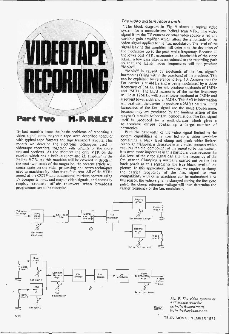
IIIN
Part Two M. R RILEYIN last month's issue the basic problems of recording avideo signal onto magnetic tape were described togetherwith typical tape formats and tape transport layouts. Thismonth we describe the electronic techniques used invideotape recorders, together with circuits of the moreunusual sections. At the moment the only VTR on themarket which has a built-in tuner and i.f. amplifier is thePhilips VCR. As this machine will be covered in depth inthe next two issues of the magazine, the present article willconcentrate on the video processing and servo techniquesused in machines by other manufacturers. All of the VTRsaimed at the CCTV and educational markets operate usingIV composite input and output video signals, and normallyemploy separate off -air receivers when broadcastprogrammes are to be recorded.
The video system record path',The block diagram in Fig. 9 shows a typical video
system for a monochrome helical scan VTR. The videosignal from the TV camera or other video source is fed to avariable gain amplifier which alters the amplitude of thevideo signal applied to tile f.m. modulator. The level of thesignal leaving this amplifier will determine the deviation ofthe modulator up to the peak white frequency. Because allthe lower cost VTRs economise on bandwidth of the videosignal, a low pass filter is introduced to the recording pathso that the higher video frequencies will not produce"Moire".
"Moire" is caused by sidebands of the f.m. signal'sharmonics falling within the passband of the machine. Thiscan be explained by reference to Fig. 10. Assume that thef.m. carrier is at 4MHz and is being modulated by a videofrequency of 3MHz. This will produce sidebands of 1MHzand 7MHz. The third harmonic of the carrier frequencywill lie at 12MHz, with a first lower sideband at 9MHz anda second lower sideband at 6MHz. This 6MHz informationwill beat with the carrier to produce a 2MHz pattern. Thirdharmonics of the f.m. signal are the most troublesome,because they are produced by the limiting action of theplayback circuits before f.m. demodulation. The f.m. signalitself is produced by a multivibrator which gives asquarewave output containing a large number ofharmonics.
With the bandwidth of the video signal limited to thesystem capabilities it is now fed to a video amplifiercontaining a black level clamp and peak white limiter.Although clamping is desirable in any video process whichrequires the d.c. component of the signal to be maintained,it is even more important in this particular case because thed.c. level of the video signal can alter the frequency of thef.m. carrier. Clamping is normally carried out on the lineback porch as this represents the true black level of thepicture. In this application, however, we require to clampthe carrier frequency of the f.m. signal so thatcompatibility with other machines can be maintained. Forthis reason the video signal is clamped during the line syncpulse, the clamp reference voltage will then determine thecarrier frequency of the f.m. modulator.
Recordampl
1
Video input1V d a p Video
inputampl
Low-passfilter
Clamp FMSet record current
pk wh clip .--41Pnmodulatorpre amp
Set videoinput level
0 Recordampl
2
Videoheadl
Videohead 2
Set record current
Headampl
1
Videohead 1
Set gain 1
N.Commonplayback
amplFM
limiterFM
demodDe -
emphasis
Videoprocessing
ampl Videooutput
1V d a pHeadampl
iVideohead 2
2 Set output levelSetequalisation
Fig. 9: The video system ofa videotape recorder.
Set gain 2 (a) In the RecordIN0661 mode./ ( Win the Playback mode.
512TELEVISION SEPTEMBER 1975

Gain
0 VTR passbind
A
2MHz A Freq.4u +1 MHz
I i , ...1 2 3 4 5 6 7 8 9 10 11 12 13fc fc fc 3rd harmonic fc
lower upper 1st lower 3rdsideband sideband sideband harmonic
3rd harmonic2nd lowersideband NO671
Fig. 10: The VTR spectrum and the production of "Moiré".
The maximum deviation frequency of the f.m. carriermust also be accurately set if machine compatibility is tobe maintained, and a peak white limiter is employed toprevent over modulation. Simple diode circuitry is used bymany manufacturers to carry out these two operations.True black level clamping is seldom used as it requires thecostly generation of clamp pulses: d.c. restoration normallysuffices. A circuit comprising a black level restorer andpeak white limiter is shown in Fig. 11. After this stage thesignal is pre -emphasised and then fed to the modulator.
Deviation of the f.m. carrier is typically 1.5MHz, and tosave bandwidth this modulation is normally in onedirection only, i.e. 3 to 4.5MHz. This large frequencychange required by the modulator (compared with thecarrier frequency) makes the use of the conventionalreactance controlled oscillator very difficult, and a newtechnique has to be employed. In broadcast VTRs, andsome helical scan machines, two crystal oscillators areused. One runs at a fixed frequency and is controlled by anaf.c. loop which sets the carrier frequency. A secondoscillator is run at the first oscillator frequency plus the f.m.carrier frequency, and is deviated by the video signal. Asthe frequency of the deviated oscillator is high, modulationwith a video signal is much easier. The outputs of bothoscillators are now mixed and the difference frequencyfiltered to produce the f.m. signal to be recorded. Becausethe carrier frequency of the signal is controlled by an a.f.c.loop a high degree of stability is maintained, andcompatibility between machines is greatly improved. Fig.12 shows the block diagram of such an arrangement withtypical frequencies.
This method of producing the f.m. signal is of coursevery expensive and is used in only a few helical scan VTRs.A much cheaper way of solving the problem is to use anastable multivibrator and alter its frequency by applyingthe video signal to the bases of the two transistors. Stabilityof the carrier frequency will now be determined by thedesign of the circuit, and great care must be taken to ensurethat as the frequency of the multivibrator changes themark -space ratio does not change. The circuit shown inFig. 13 is the modulator used in the Sony CV 2100 ACE,note the symmetry controls enabling the bias on the basesand collectors of the two transistors to be set veryaccurately.
If the VTR is of the two head variety then the f.m. signalfrom the modulator is split into two paths and fed toseparate record drive amplifiers. Because an f.m. signal hasa constant amplitude, the record current drive for eachhead is adjusted so that the tape is just being saturated by
+27V
1y.iFVideoinput
fromI. p.
filter
1k
40MHzXtalosc.
Videoinput
1.5k
151532
TSet fc
30iJF
3.6k
25C318A
750
151532
0-01pF
7377;Set pt OV
510
50}iF
1k
Fig. 11 : Deviation control circuitry.
A FC
1/11'Set fc
Deviatedosc
driver
Set Lt.f
Carrierosc
40MHz
Deviated05C
Mixer
45 - 50.5MHz
NO681
Differenceproduct f moutput 5-10. 5 MHz
Filter
Mixer products
Fig. 12: Two -oscillator method of f.m. generation.
FFi 0691
H T
1-2k
75
390
51pF
200
-1S151K.
15pr,,
-11-"
36pF
I t90
250629 2SC629
3.6k 3.6k 68
Ov
V,deo input
Fig. 13:A typical multiobratorfm. generator.
N070
the signal. This arrangement gives the maximum possibletransfer of energy from the head to the tape and thereforethe best possible signal to noise ratio.
TELEVISION SEPTEMBER 1975 513
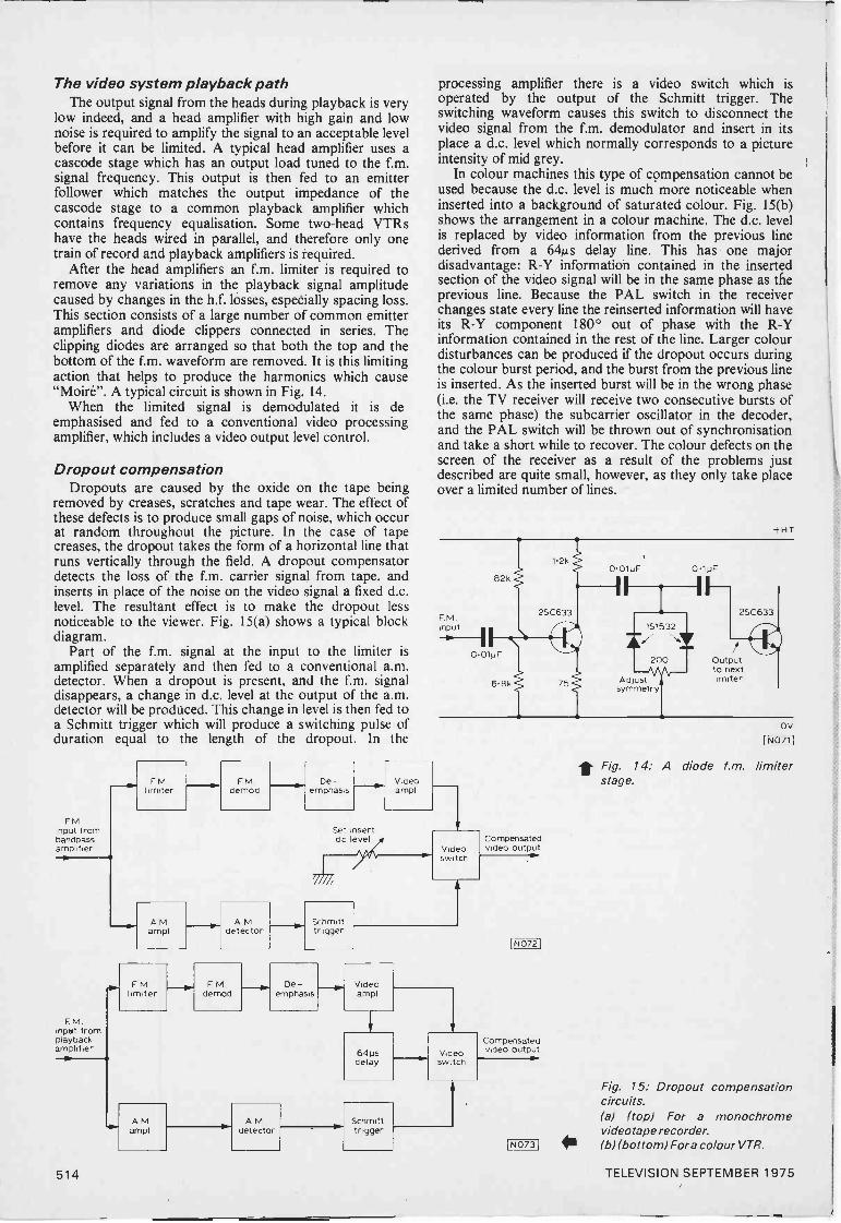
The video system playback pathThe output signal from the heads during playback is very
low indeed, and a head amplifier with high gain and lownoise is required to amplify the signal to an acceptable levelbefore it can be limited. A typical head amplifier uses acascode stage which has an output load tuned to the f.m.signal frequency. This output is then fed to an emitterfollower which matches the output impedance of thecascode stage to a common playback amplifier whichcontains frequency equalisation. Some two -head VTRshave the heads wired in parallel, and therefore only onetrain of record and playback amplifiers is required.
After the head amplifiers an f.m. limiter is required toremove any variations in the playback signal amplitudecaused by changes in the h.f. losses, espetially spacing loss.This section consists of a large number of common emitteramplifiers and diode clippers connected in series. Theclipping diodes are arranged so that both the top and thebottom of the f.m. waveform are removed. It is this limitingaction that helps to produce the harmonics which cause"Moire". A typical circuit is shown in Fig. 14.
When the limited signal is demodulated it is de-emphasised and fed to a conventional video processingamplifier, which includes a video output level control.
Dropout compensationDropouts are caused by the oxide on the tape being
removed by creases, scratches and tape wear. The effect ofthese defects is to produce small gaps of noise, which occurat random throughout the picture. In the case of tapecreases, the dropout takes the form of a horizontal line thatruns vertically through the field. A dropout compensatordetects the loss of the f.m. carrier signal from tape, andinserts in place of the noise on the video signal a fixed d.c.level. The resultant effect is to make the dropout lessnoticeable to the viewer. Fig. 15(a) shows a typical blockdiagram.
Part of the f.m. signal at the input to the limiter isamplified separately and then fed to a conventional a.m.detector. When a dropout is present, and the f.m. signaldisappears, a change in d.c. level at the output of the a.m.detector will be produced. This change in level is then fed toa Schmitt trigger which will produce a switching pulse ofduration equal to the length of the dropout. In the
FMinput frombandpassamplifier
F. M.'split fromplaybackamplifier
lox
processing amplifier there is a video switch which isoperated by the output of the Schmitt trigger. Theswitching waveform causes this switch to disconnect thevideo signal from the f.m. demodulator and insert in itsplace a d.c. level which normally corresponds to a pictureintensity of mid grey.
In colour machines this type of compensation cannot beused because the d.c. level is much more noticeable wheninserted into a background of saturated colour. Fig. 15(b)shows the arrangement in a colour machine. The d.c. levelis replaced by video information from the previous linederived from a 64µs delay line. This has one majordisadvantage: R -Y information contained in the insertedsection of the video signal will be in the same phase as theprevious line. Because the PAL switch in the receiverchanges state every line the reinserted information will haveits R -Y component 180° out of phase with the R -Yinformation contained in the rest of the line. Larger colourdisturbances can be produced if the dropout occurs duringthe colour burst period, and the burst from the previous lineis inserted. As the inserted burst will be in the wrong phase(i.e. the TV receiver will receive two consecutive bursts ofthe same phase) the subcarrier oscillator in the decoder,and the PAL switch will be thrown out of synchronisationand take a short while to recover. The colour defects on thescreen of the receiver as a result of the problems justdescribed are quite small, however, as they only take placeover a limited number of lines.
+HT
82k
F.M.nput
1.2k
2SC633
0.01uF
6.8k c 75
0.01pF 0.1uF
151532
A./zooms
Adji.71\r-symmetry
Outputto nextlimiter
OV
1, Fig. 14: A diode fm. limiterFM FM De - Video stage.
limiter demod emphasis ampl
AMampl
FMlimiter
tr- A Mdetecto
Set insertdc level
FMdemod
Schmitttrigger
Videoswitch
Compensatedvideo output
De -emphasis
Videoampl
64psdelay
Videoswitch
NO721
Compensatedvideo output
Fig. 15: Dropout compensationcircuits.
AM AM Schmitt (a) (top) For a monochromeampl detector trigger videotape recorder.
LN073i (b) (bottom) Fora colour VTR.
514 TELEVISION SEPTEMBER 1975
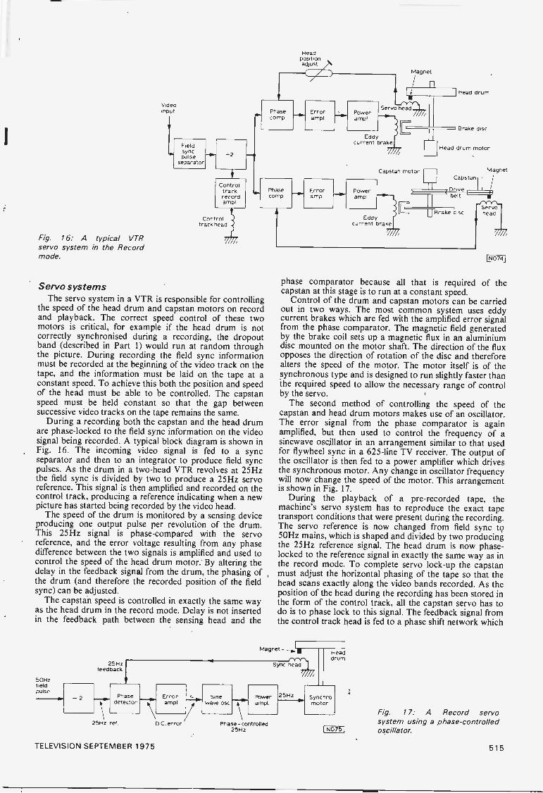
Videoinput
Fieldsyncpulse
separator
iControl
trackrecordampl
Controltrack head
Fig. 16: A typical VTRservo system in the Recordmode.
Headpositionadjust
Phasecomp
iL
Errorampl
Phase Errorcomp ampl
Servo systemsThe servo system in a VTR is responsible for controlling
the speed of the head drum and capstan motors on recordand playback. The correct speed control of these twomotors is critical, for example if the head drum is notcorrectly synchronised during a recording, the dropoutband (described in Part 1) would run at random throughthe picture. During recording the field sync informationmust be recorded at the beginning of the video track on thetape, and the information must be laid on the tape at aconstant speed. To achieve this both the position and speedof the head must be able to be controlled. The capstanspeed must be held constant so that the gap betweensuccessive video tracks on the tape remains the same.
During a recording both the capstan and the head drumare phase -locked to the field sync information on the videosignal being recorded. A typical block diagram is shown inFig. 16. The incoming video signal is fed to a syncseparator and then to an integrator to produce field syncpulses. As the drum in a two -head VTR revolves at 25Hzthe field sync is divided by two to produce a 25Hz servoreference. This signal is then amplified and recorded on thecontrol track, producing a reference indicating when a newpicture has started being recorded by the video head.
The speed of the drum is monitored by a sensing deviceproducing one output pulse per revolution of the drum.This 25Hz signal is phase -compared with the servoreference, and the error voltage resulting from any phasedifference between the two signals is amplified and used tocontrol the speed of the head drum motor. By altering thedelay in the feedback signal from the drum, the phasing ofthe drum (and therefore the recorded position of the fieldsync) can be adjusted.
The capstan speed is controlled in exactly the same wayas the head drum in the record mode. Delay is not insertedin the feedback path between the sensing head and the
50Hzfieldpulse
25Hzfeedback
25Hz ref
Powerampl
Magnet
n
Serva rre14.
Eddycurrent brake
Powerampl
Capstan motor
Eddycurrent brake
Head drum
i Brake disc
Head drum motor
Magnet
Drive
Capstan -
belt
Brake disc
[N074
phase comparator because all that is required of thecapstan at this stage is to run at a constant speed.
Control of the drum and capstan motors can be carriedout in two ways. The most common system uses eddycurrent brakes which are fed with the amplified error signalfrom the phase comparator. The magnetic field generatedby the brake coil sets up a magnetic flux in an aluminiumdisc mounted on the motor shaft. The direction of the fluxopposes the direction of rotation of the disc and thereforealters the speed of the motor. The motor itself is of thesynchronous type and is designed to run slightly faster thanthe required speed to allow the necessary range of controlby the servo.
The second method of controlling the speed of thecapstan and head drum motors makes use of an oscillator.The error signal from the phase comparator is againamplified, but then used to control the frequency of asinewave oscillator in an arrangement similar to that usedfor flywheel sync in a 625 -line TV receiver. The output ofthe oscillator is then fed to a power amplifier which drivesthe synchronous motor. Any change in oscillator frequencywill now change the speed of the motor. This arrangementis shown in Fig. 17.
During the playback of a pre-recorded tape, themachine's servo system has to reproduce the exact tapetransport conditions that were present during the recording.The servo reference is now changed from field sync to50Hz mains, which is shaped and divided by two producingthe 25Hz reference signal. The head drum is now phase-
locked to the reference signal in exactly the same way as inthe record mode. To complete servo lock -up the capstanmust adjust the horizontal phasing of the tape so that thehead scans exactly along the video bands recorded. As theposition of the head during the recording has been stored inthe form of the control track, all the capstan servo has todo is to phase lock to this signal. The feedback signal fromthe control track head is fed to a phase shift network which
Magnet -yinHeaddrum
Sync head
Error Sineampl wave osc .]"--.1
D C. error/
Powerampl
Phase - controlled25Hz
25Hz Synchromotor
I N0751
Fig. 17: A Record servosystem using a phase -controlledoscillator.
TELEVISION SEPTEMBER 1975 515

27.5V fromLT bridgerectifier
R69270
P5050
Horizontalshift
Reversinglinks
4.
+480V pulses to flyback syncand radial line convergence circuits
*Silicon diode in earlier production. See text.
R540390k
Drivefromlineosc
P5061M
R541120k
HT1
R54 4
560k
Set R 39EHT 1M
290V
Boost rail
VDR502E298ZZ/IwC52OE
8
Boostcapacitor
R551k5
C51R54 180p2k7 12kV
PV59L509TC
tApprox
2.7V
Overloadscut-outiMSD1241
L _1
L502Linearity
C531
110'33
Line coils,blue lateralconvergence
and pincushion
Width correctiontaps
Triple,earth return
52347 R529 Feed to CRT
100k Al controls
R526 Feed to560k height control
T52C519
01
Beam limiter
circuit (Fig. 4)
3
VDR500E29 BCD/A258
-65V pulse-convergence and
line flyback blankingR5782 -I8V pulse
to decoder
+I8V pulseR56 to CDA clamps
VDR52E298Z2/103
Focus
and decoder
EHTripler
R6710M
EHT
DWidthtaps
Focusvoltage
1 Depending on control settings 1 12 6 31
Fig. 2: Circuit diagram of the line output stage. In earlierproduction a silicon diode boost rectifier was used. The lineoutput valve's cathode decoupling electrolytic C529 ismounted near the beam limiting transistor Tr535 on thetimebase board (see Fig. 4).
when the case of the cut-out does not make contact tochassis. It is held to the chassis by two metal clips, but thebest way to overcome the problem is to screw a solder tagto the chassis and then solder a lead from this to the cut-out's control case.
No picture followed by smoking can be caused by thelead from the line output transformer (tag 12) to the top capof the line output valve. The lead passes through a metalplate via a grommet. The insulation breaks down, causing aminor burn up. This can also happen with the lead from tag11 of the transformer to the top cap of the boost diode.
Another line output stage cause of no picture is C51.The symptoms here include smoking from the back withslight arcing. Failure of C51 can also result in R55 goingopen -circuit.
The e.h.t. tripler gives its share of problems - anythingfrom arcing over to chassis to the corner blowing right offthe unit.
The feed resistor (R529) from the boost line to the c.r.t.first anode potentiometers can go high -resistance,producing a dim picture or no picture at all.
R539 can increase in value resulting in reduced width.Line output stage capacitors which can go short-circuit
to blow the mains fuse (FS 1) are the tuning capacitor C53
and the boost capacitor C523 which is returned to chassis(not to the h.t. line).
Poor Line Sync
Poor line sync is usually caused by R509 (5600) goingopen -circuit. This is the resistor which links the flywheelsync circuit to the triode grid (pin 9) of the PCF802 lineoscillator valve.
Focus TroublesFocus troubles should direct attention to the high -value
resistor R67 (10MQ) which is in series with the focuscontrol. This can go high -resistance.
Boost DiodeIn earlier sets fitted with a silicon diode boost rectifier the
heater chain is fed via a diode dropper (D503, type BY126or BY127). With the PY500A valve boost rectifier used inlater production the D503 position (timebase board) isshorted out and a 1300 resistor (R59) is added in serieswith the heater chain. This resistor is part of the mainsdropper assembly. R64 is then a separate component - it ispart of the dropper in versions with the BY147P boostdiode. It is important when making replacements to ensurethat the complete circuit is correct in these respects.
Field TimebaseThe field timebase works fairly well, the usual trouble
being simply that the PL508 field output valve loosesemission resulting in field collapse or lack of height. Othercauses of lack of height are R526 (560k0) which feeds the
TH503VA8650
TH502 TH501 Heater chain7 via 0503 or R59
depending onTH501/2 boost diodeCK1 - see text
.0001864
L12 Lit
FS1A .Sis
230-240VAC
Degaussingcoils
L52R62 TH50
en.C61 miC62x'01
6 VA1 04
1515
R64220 HT2
-*VC617 275V
100,1 5k6 HT4
051 C65 C661300
CRT heaters
S.477 R53 /R537,FrINI see Fig.4
o
C59
R611804
HT1
290VR63200 HT3
275V
R5847
C68 220V
50,1
C69 .---1C701501 1 01
20V
to decoder
C58 R71
2000T 12
to IF panel
20V
R69, see Fig. 2(horizontal shift circuit)
Fig. 3: The power supply circuit. HT1 feeds the line outputstage, the PCL84 colour -difference output stages and thePCL86 audio output stage. HT2 feeds the anode of the PL508field output valve via the vertical shift control taps, HT3 feedsthe sync separator, the line oscillator, the section of the fieldmultivibrator not fed from the boost rail, the PL802 luminanceoutput stage and the audio amplifier (triode) section of thePCL86. HT4 feeds the screen grid of the field output valve -thus if R65 goes open -circuit, the field will collapse giving ahorizontal white line. Where a valve boost diode is used theheater chain is fed via R59 (1300) which is part of the mainsdropper: where a silicon diode boost rectifier is used theheater chain is fed via a diode dropper- D503, type BY127.
518 TELEVISION SEPTEMBER 1975

height control going high in value, or a bad burn up causedby the associated decoupler C519 (0.01µF) going short-circuit and producing a large hole in the Paxolin board.
Power SuppliesNo sound or vision with the 3A mains fuse FS1 blown is
often due to one or other of the mains filter capacitors C61or C62 (both 0.1µF) being short-circuit.
A hum bar is a common fault which may be permanentor intermittent. The usual cause is the 20V 1.t. supplyreservoir and smoothing electrolytics, C59 (1,000µF) andC58 (2,000µF) respectively.
A common cause of no sound and vision is lack ofsupply to the valve heaters (except the c.r.t. which is fedfrom the 1.t. transformer). This is generally due to a break inthe three -lead, two-thermistor assembly TH501/TH502(type CK 1) which is mounted on the timebase board. Thecircuit arrangement is somewhat unusual and is shown inFig. 3. TH501 is the heater chain surge limiter thermistor.The other section of the double-thermistor assembly(TH502) is connected across the degaussing coils. Atswitch on the resistance of TH501 and TH502 is high, whilethe resistance of the positive temperature coefficientthermistor TH503 is low. Consequently the heater currentis reduced while considerable current flows via thedegaussing coils and TH503. TH501 quickly heats up, andsince it is combined with TH502 the resistance of both falls.Consequently the voltage across and the current throughthe degaussing coils decreases. The resistance of TH503increases, reducing the current in this side of the circuit tonegligible proportions, but the resistance of TH502remains low due to its connection with TH501 whichcontinues to carry the heater current.
Output PanelThere are three PCL84 colour -difference output/clamp
valves (V407, V408 and V409) on the output panel. Theseare prone to heater -cathode short circuits, producing all red(V407), all green (V408) or all blue (V409) picturesdepending on which valve is defective. They also loseemission, resulting in poor red, green or blue colour. Faultyc.r.t. first anode presents - P613 (red), P614 (green) andP615 (blue) - can also cause poor colours. Another cause ischange of value of the clamp triode load resistors - R4I7(red), R425 (green), R434 (blue), each 8.2MS2.
The PL802 luminance output valve (V402) is alsomounted on this panel. When it loses emission there is lackof brightness and poor colour. Often however the troublehere is the double -sided printed circuit, with dry -joints atthe valve base. If the PL802 is cut off the screen will beblank. This can occur if the flyback blanking circuit in itscathode lead is faulty. Should the protection diode D402(BA115) go short-circuit for example the bias to theblanking transistor will be removed and neither it nor thePL802 will pass any current.
The final valve on this panel is the PCL86 audioamplifier (V401). Naturally this can cause no or distortedsound. The usual fault however is that the valve becomesmicrophonic, producing noise as a result of mechanicalvibration or shock.
Tuner UnitsMost of these sets are fitted with push-button mechanical
tuners. Common faults are tuning drift or getting just aherring -bone pattern when a button is pressed. The usualcause is the mechanical parts sticking together due to thegrease on the moving parts.
+206
R534 R5331k5 47k
From PL 509cathode R536(Fig 2) lk
Tr 535 R532
C529 _200,1
13C148 47k
D5042E2
R5I5k6
-106
R3161k8
03061 8317
"T5k6
R54856
-20V
P420k
R53568k
R53IC527 0A91 33
25
DCrestorer
o
SW1
PL 802 (1/402)control gridcircuit
Brightne,s
D501
040612
D5020A91
R405270k
R53733
Fromtag 2, T51
(Fig -3)
rio51
Fig. 4: The brightness control, which sets the d.c. restorationlevel in the PL802 luminance output pentode's control gridcircuit, is connected across +20V and -20V lines. The beamlimiter acts on the brightness circuit: with excessive lineoutput valve cathode current Tr535 is driven into conduction,the increased current flowing through R533 reducing thepositive feed to the brightness control and thus theconduction of the luminance output pentode which is d.c.coupled to the c.r.t. cathodes. C529 is the line output valite'scathode decoupling capacitor. SW2 is coupled to SW1 whichcollapses the field scan - for grey -scale adjustment purposes.A -10V supply to bias the emitters of the R -Y (Tr321) and B-Y (Tr323) preamplifiers is provided by R3161R3171C306which are mounted on the decoder panel - there is no G -Ypreamplifier since the G -Y matrixing is carried out at highlevel in the anode circuits' of the co/our-difference outputvalves.
R547 C5282k2
The DecoderA trouble with the decoder panel is dry -joints, mainly
outside or inside the reference oscillator can (PC314).In cases of no colour check the voltage at the base of the
second chroma amplifier TR319 (BF194). If this is found tobe between 3V and 6V positive the colour killer circuit isworking. I have usually then found the fault to be the resultof the first chroma amplifier transistor TR318 (BF 194)having an open -circuit base -emitter junction.
To over -ride the colour killer, connect a 27152 resistorfrom the junction of R385/R386 to the 20V rail - aconvenient point is pin 4 of plug 6.
Another transistor which can be faulty on the decoderpanel is TR327 (BC148). This is the d.c. amplifier betweenthe burst detector circuit and the reference oscillator.When this transistor is defective the oscillator is not lockedto the bursts, i.e. the colour is not locked. Check whether itscollector voltage is between 11-14V and if not whether itcan be brought to this figure by adjusting the oscillatorfrequency control P302.
Insufficient colour has been traced to a faulty secondchroma amplifier transistor TR319.
Bad blinds, i.e. the PAL switch not operating, has beentraced to the switching diodes D309/D310 (type 0A47).The cause of this fault can lie outside the decoder however.In one case shorted turns on the line output transformerpulse winding resulted in very low amplitude trigger pulseswhich failed to drive the bistable circuit.
TELEVISION SEPTEMBER 1975 519

LARGE -SCREEN
OSCILLOSCOPEPROJECT PART 3 D.HALEY C.Eng MIEE
IN this third article the various circuits necessary to turn theinstrument into a servicing monitor are described. These includethe i.f. preamplifier and the a.f./v.f. preamplifier and attenuator.Also very important is the sample and hold circuit, so vital forchecking timebases or for the presence of the colour -burst signal.
I.F. preamplifierTo investigate signals in the LI stages of a receiver a high
impedance attenuating probe must be used to avoid loading ordetuning the circuits under test. To compensate for the loss ofsignal level in the high impedance probe an i.f. amplifier with again of approximately ten is required. The circuit for thisamplifier, built on a small piece of strip board, is shown in Fig. 7.An integrated circuit type CA3028A is used as the amplifier, withan emitter follower feeding the i.f. section of the oscilloscope. Fig.8 shows the component layout and board detail. Whencompleted, the amplifier should be mounted behind the frontpanel adjacent to the i.f. probe socket, using two small brackets.The component side of the board should face towards the left.
SKAIF
probe
2C1
0.01pF
7
L1 it
2pH R21k
IC1 6CA3028A
C20.01uF
R34 1k
R12k
C30.01pF
+15V
R410
R5150k
C533pF
Tr1BC182A
C6 mem0.01pF
C40.010 k -
Fig. 7: Circuit diagram of the I.F. Preamplifier.
R610
ToRLA1
C70.01p
R7330
[087
* Components listI.F. PREAMPLIFIER
Capacitors:C -- C4, C6, C7 0.01pFC5 33pF silvered mica
Resistors: (all +5%, 41N)R1 2k0 R5 150kR2, R3 lk0 R7 3300R4.136 100
Semiconductors:IC1 3028A (RCA) Tr1 BC182A
Miscellaneous:1-1 2pH coil with dust -iron core; Socket for IC1; Strip -
board 51 x 95 mm (2 x 31- in) 2 54 mm (0.1 in) matrix.(Strips parallel to shorter dimension); 13 wiring pins.
INPUT ATTENUATOR & PREAMPLIFIERCapacitors:
Cl 1pF 250VC2, C3 See Fig. 9C4 200pF
C5 0 OlpF
Resistors: (all ±5%,
C6, C7 100pF 25VC8 1 50pF polystyrene
W)R1 2M0 R8, R12 5 6k0R2 1 8M0 R9,R13 1 2k0R3 180k0 810 2700R4 22k0 R11, R14 2200R5 220k0 R15 47k0R6 1 MD 816 6800R7 1000
Variable Resistors:VR1 1k0 lin. potentiometer
Transistors:Trl, Tr2, Tr4, Tr5, Tr8 8C1824Tr3, Tr6, Tr7 BF244
Switches:Si 1 pole 3 way wafer switch32 2 pole 3 way wafer switchS3 SPDT min. toggle switchS4 SPOT min. toggle switch
Miscellaneous:Stripboard 98 x 65 mm (3Z x 276 in) 2,54 mm (0 1 in)matrix; 12 wiring pins.
520 TELEVISION SEPTEMBER 1975'
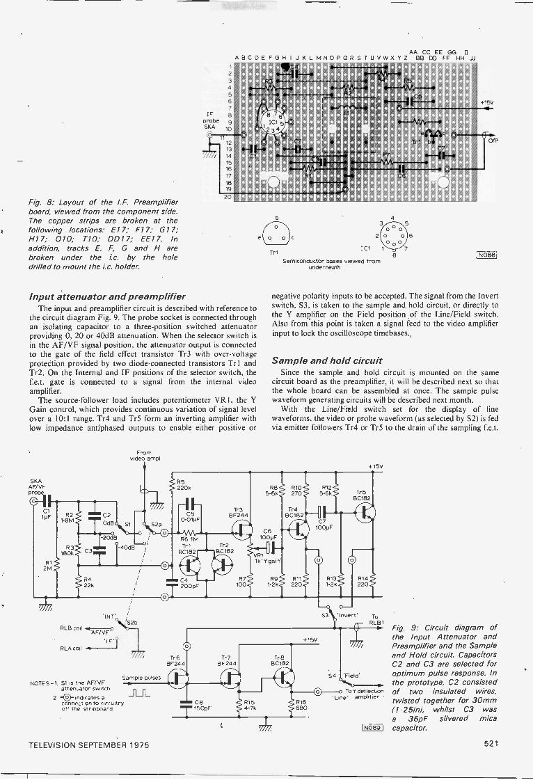
AA CC EE GG 11
ABCDE FGH I J K L MNOP OR S T U V WX YZ BB DD FF HH JJ=Num
rain
Fig. 8: Layout of the I.F. Preamplifierboard, viewed from the component side.The copper strips are broken at thefollowing locations: El 7; F17; G17;H17; 010; T10; DD17; EE17. Inaddition, tracks E, F, G and H arebroken under the ic. by the holedrilled to mount the i.c. holder.
Input attenuator and preamplifierThe input and preamplifier circuit is described with reference to
the circuit diagram Fig. 9. The probe socket is connected throughan isolating capacitor to a three -position switched attenuatorproviding 0, 20 or 40dB attenuation. When the selector switch isin the AF/VF signal position, the attenuator output is connectedto the gate of the field effect transistor Tr3 with over -voltageprotection provided by two diode -connected transistors Tr l andTr2. On the Internal and IF positions of the selector switch, thef.e.t. gate is connected to a signal from the internal videoamplifier.
The source -follower load includes potentiometer VR1, the YGain control, which provides continuous variation of signal levelover a 10:1 range. Tr4 and Tr5 form an inverting amplifier withlow impedance antiphased outputs to enable either positive or
SKAAFA/F
C110F R2
1.8mC2
TOdB S1
Fromvideo ampl.
-o/3
R3180k
R4
j:08B
22k
'INT'
RLB coil r-oAF/VF'
'1F1RLA coil
NOTES -1. St -is the AF/VFattenuator switch.
2. -0-indicates aconnection to circuitry 1110 C8 R15off the stripboard 7150pF 4.7k
S2b
Tr1
2
1C1
Semiconductor bases viewed fromunderneath
8
6
I N0881
negative polarity inputs to be accepted. The signal from the Invertswitch, S3, is taken to the sample and hold circuit, or directly tothe Y amplifier on the Field position of the Line/Field switch.Also from this point is taken a signal feed to the video amplifierinput to lock the oscilloscope timebases.
Sample and hold circuitSince the sample and hold circuit is mounted on the same
circuit board as the preamplifier, it will be described next so thatthe whole board can be assembled at once. The sample pulsewaveform generating circuits will be described next month.
With the Line/Field switch set for the display of linewaveforms, the video or probe waveform (as selected by S2) is fedvia emitter followers Tr4 or Tr5 to the drain of the sampling f.e.t.
R5220k
I--C5
0-01uFS2a o
R6 1MTr1 Tr2
BC182 BC182
CIOC4
Sample pulses
Tr3BF244
200pF
Tr5BF244
Tr7BF244
R7100
R8 R10 R125.6k 270 5.6k
C61000F
VR11k'Y gain'
S4 Field'
To Y deflection'Line' amplifier
ToRLB1
477;the Input Attenuator andPreamplifier and the Sampleand Hold circuit. CapacitorsC2 and C3 are selected foroptimum pulse response. Inthe prototype, C2 consistedof two insulated wires,twisted together for 30mm(1.25/n), whilst C3 wasa 36pF silvered mica
rivc-5-6.51 capacitor.
Fig. 9: Circuit diagram of
TELEVISION SEPTEMBER 1975 521
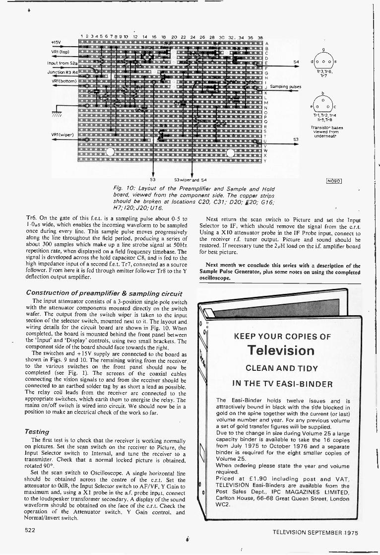
415V
VR1 (top)
Input from S2a
Junction R3 R4
VR1( bottom )
1 2 3 4 5 6 7 8 9 10 12 14 16 18 20 22 24 26 28 30 32. 34 36 38
- 5,
*ill
4/Z
'
VR1(wiper) It
r e
L .
ABC
DE S4
F0H
j Sampling pulses
4
S3V
S3wiper and S4
K
L
MN
OP
0
S
T
U
Vw
Y
Fig. 10: Layout of the Preamplifier and Sample and Holdboard, viewed from the component side. The copper stripsshould be broken at locationsH7; 120; J20; U16.
Tr6. On the gate of this f.e.t. is a sampling pulse about 0.5 to1.00 wide, which enables the incoming waveform to be sampledonce during every line. This sample pulse moves progressivelyalong the line throughout the field period, producing a series ofabout 300 samples which make up a line strobe signal at 50Hzrepetition rate, when displayed on a field frequency timebase. Thesignal is developed across the hold capacitor C8, and is fed to thehigh impedance input of a second f.e.t. Tr7, connected as a sourcefollower. From here it is fed through emitter follower Tr8 to the Ydeflection output amplifier.
Construction of preamplifier & sampling circuitThe input attenuator consists of a 3 -position single pole switch
with the attenuator components mounted directly on the switchwafer. The output from the switch wiper is taken to the inputsection of the selector switch, mounted next to it. The layout andwiring details for the circuit board are shown in Fig. 10. Whencompleted, the board is mounted behind the front panel betweenthe 'Input' and 'Display' controls, using two small brackets. Thecomponent side of the board should face towards the right.
The switches and + 15V supply are connected to the board asshown in Figs. 9 and 10. The remaining wiring from the receiverto the various switches on the front panel should now becompleted (see Fig. 1). The screens of the coaxial cablesconnecting the vision signals to and from the receiver should beconnected to an earthed solder tag by as short a lead as possible.The relay coil leads from the receiver are connected to theappropriate switches, which earth them to energise the relay. Themains on/off switch is wired into circuit. We should now be in aposition to make an electrical check of the work so far.
TestingThe first test is to check that the receiver is working normally
on pictures. Set the scan switch on the receiver to Picture, theInput Selector switch to Internal, and tune the receiver to atransmitter. Check that a normal locked picture is obtained,rotated 90°.
Set the scan switch to Oscilloscope. A single horizontal lineshould be obtained across the centre of the c.r.t. Set theattenuator to OdB, the Input Selector switch to AF/VF, Y Gain tomaximum and, using a X1 probe in the a.f. probe input, connectto the loudspeaker transformer secondary. A display of the soundwaveform should be obtained on the face of the c.r.t. Check theoperation of the Attenuator switch, Y Gain control. andNormal/Invert switch.
C20, C31; D20; 120; G16;
S3-1
Tr 3,Tr6,Tr7
Tr1,Tr2,Tr4Tr5,Tr8
Transistor basesviewed fromunderneath
I N0901
Next return the scan switch to Picture and set the InputSelector to IF, which should remove the signal from the c.r.t.Using a X10 attenuator probe in the IF Probe input, connect tothe receiver r.f. tuner output. Picture and sound should berestored. If necessary tune the 2 uH load on the if. amplifier boardfor best picture.
Next month we conclude this series with a description of theSample Pulse Generator, plus some notes on using the completedoscilloscope.
0
0
KEEP YOUR COPIES OF
TelevisionCLEAN AND TIDY
IN THE TV EASI-BINDER
The Easi-Binder holds twelve issues and isattractively bound in black with the title blocked ingold on the spine together with the current (or last)volume number and year. For any previous volumea set of gold transfer figures will be supplied.Due to the change in size during Volume 25 a largecapacity binder is available to take the 16 copiesfrom July 1975 to October 1976 and a separatebinder is required for the eight smaller copies ofVolume 25.When ordering please state the year and volumerequired.Priced at f 1.90 including post and VAT,TELEVISION Easi-Binders are available from thePost Sales Dept., IPC MAGAZINES LIMITED,Carlton House, 66-68 Great Queen Street, LondonWC2.
522 TELEVISION SEPTEMBER 1975
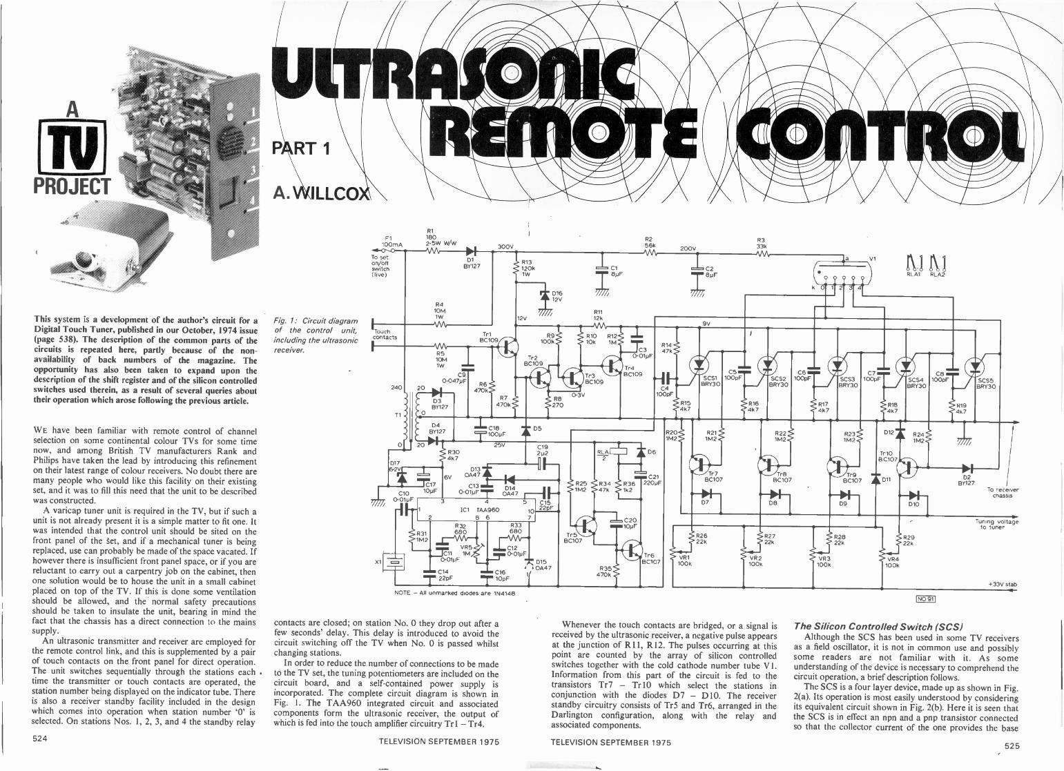
This system is a development of the author's circuit for aDigital Touch Tuner, published in our October, 1974 issue(page 538). The description of the common parts of thecircuits is repeated here, partly because of the non -availability of back numbers of the magazine. Theopportunity has also been taken to expand upon thedescription of the shift register and of the silicon controlledswitches used therein, as a result of several queries abouttheir operation which arose following the previous article.
WE have been familiar with remote control of channelselection on some continental colour TVs for some timenow, and among British TV manufacturers Rank andPhilips have taken the lead by introducing this refinementon their latest range of colour receivers. No doubt there aremany people who would like this facility on their existingset, and it was to fill this need that the unit to be describedwas constructed.
A varicap tuner unit is required in the TV, but if such aunit is not already present it is a simple matter to fit one. Itwas intended that the control unit should be sited on thefront panel of the §et, and if a mechanical tuner is beingreplaced, use can probably be made of the space vacated. Ifhowever there is insufficient front panel space, or if you arereluctant to carry out a carpentry job on the cabinet, thenone solution would be to house the unit in a small cabinetplaced on top of the TV. If this is done some ventilationshould be allowed, and the normal safety precautionsshould be taken to insulate the unit, bearing in mind thefact that the chassis has a direct connection to the mainssupply.
An ultrasonic transmitter and receiver are employed forthe remote control link, and this is supplemented by a pairof touch contacts on the front panel for direct operation.The unit switches sequentially through the stations eachtime the transmitter or touch contacts are operated. thestation number being displayed on the indicator tube. Thereis also a receiver standby facility included in the designwhich comes into operation when station number '0' isselected. On stations Nos. 1, 2, 3, and 4 the standby relay
Fig. 1: Circuit diagramof the control unit,including the ultrasonicreceiver.
F1100mA
To seton/offswitch(live)
R1
1802.5W W/W
Touchcontacts
300V
D1BY127
R410M1W
R13120k1W
12V
Tr1BC109 100k 10k 1M
1,016
12V
C1
8pF
R11
12k
240
T1
D17
47
C10. 0.010F
109F
R510M1W
C90.047pF
20
D3BY127
0
D4BY127
R6470k
2
X1
1717
R304k7
6V
R7470k
C18100pF
25V
R9 R10 R12
Tr2BC109
Ez4109gra Tr3 laPup l BC109
R256kMA,
C3
R8270
D5
0.01pF
0.3V
200VR333k
C2
7 8pFCOOY 2:a; 4
v)1
RL A1 RLA2
0130A47
C13
0.01pFmr
C19p2
e-C
3 4
IC1 TAA9608 6
D140A47 1-1
5 C1522pF0
7
R311M2
R32680
VR5
._711 1M0.01pF
C14
R33680
C12
om0.01pF.7D15,0A47
C16
mim 22pF T 109F
R251M2
Tr5BC107
RLA2
R34 R3647k 1k2
C20
R35470k
10p F
D6
C21220pF
Tr6BC107
NOTE - All unmarked diodes a e 1N4148
contacts are closed; on station No. 0 they drop out after afew seconds' delay. This delay is introduced to avoid thecircuit switching off the TV when No. 0 is passed whilstchanging stations.
In order to reduce the number of connections to be madeto the TV set, the tuning potentiometers are included on thecircuit board, and a self-contained power supply isincorporated. The complete circuit diagram is shown inFig. 1. The TAA960 integrated circuit and associatedcomponents form the ultrasonic receiver, the output ofwhich is fed into the touch amplifier circuitry Trl - Tr4.
R201M2
9V
R164k7
R211M2
Tr 7BC107
D7
SCS2BRY30
R221M2
Tr8BC107
D8
C6100pF
R174k7
SCS3BRY30
R231M2
C7100pF SCS4
BRY30
R184k7
D121 R241M2
Tr10BC107
'Tr9C1B07 D11
D9
C8100pF
R194k7
SCS5BRY30
D10
D2BY127
To receiverchassis
R2622k
VR1100k
,44
VR2100k
R2722k
R2822k
VR3 VR4100k 100k
R2922k
Tuning voltageto tuner
+33V stab
Whenever the touch contacts are bridged, or a signal isreceived by the ultrasonic receiver, a negative pulse appearsat the junction of R 11, R 12. The pulses occurring at thispoint are counted by the array of silicon controlledswitches together with the cold cathode number tube V 1.Information from this part of the circuit is fed to thetransistors Tr7 - Tr 10 which select the stations inconjunction with the diodes D7 - D10. The receiverstandby circuitry consists of Tr5 and Tr6, arranged in theDarlington configuration, along with the relay andassociated components.
I NO 911
The Silicon Controlled Switch (SCS)Although the SCS has been used in some TV receivers
as a field oscillator, it is not in common use and possiblysome readers are not familiar with it. As someunderstanding of the device is necessary to comprehend thecircuit operation, a brief description follows.
The SCS is a four layer device, made up as shown in Fig.2(a). Its operation is most easily understood by consideringits equivalent circuit shown in Fig. 2(b). Here it is seen thatthe SCS is in effect an npn and a pnp transistor connectedso that the collector current of the one provides the base
524 TELEVISION SEPTEMBER 1975 TELEVISION SEPTEMBER 1975 525

This view of the control unit shows the arrangement ofcomponents on the front panel.
current for the other. With the supply connected as shownand in the absence of any input to the cathode gate (Gk) orto the anode gate (Ga) the switch is effectively open circuit.
If a positive input in excess of 0.5V is applied to thecathode gate the npn transistor will start to conduct,supplying bias for the pnp transistor in the process.Collector current through the pnp transistor reinforces thebase current in the npn transistor, and both transistorsrapidly turn fully on. When the switch is in this conductingstate the input to the cathode gate can be removed, and theswitch will stay on due to the self maintaining biasarrangement. The device can also be triggered by anegative pulse applied to the anode gate, but in the presentapplication this connection is used as an output terminal toswitch to earth a cathode of the numicator valve.
In the conducting state the anode voltage ( Va) is about0.8 volts, and Vga is of the order of 0.1 volts or so, bothrelative to cathode. The only practical method of bringingthe SCS back to the non -conducting state is to reduce theanode current below a certain minimum value (holdingcurrent, /h) typically 0.5mA. This can be achieved byapplying a negative pulse to the anode, as in the presentcircuit, or a positive pulse to the cathode (k).
Numicator valvePerhaps an even less familiar device is the cold cathode
numerical indicator tube - used in the present circuit todisplay the station number.
Inside the gas -filled glass envelope is a single commonanode and ten separate cathodes shaped so as to form thedigits 0- 9 plus a decimal point. The anode requires asupply of at least +170V, and a series resistor is included tolimit the current to a few milliamps. If a return path isprovided via one of the cathodes the tube will strike, and aglow will surround that particular cathode, showingthrough the glass envelope. Due to the presence of chargedgas in the tube in this condition, a voltage of 20 - 60Vappears on the other cathodes. The voltage on anyparticular cathode depends upon its position in the tuberelative to whichever cathode is illuminated. Use is made ofthis voltage to operate the channel switching transistor.
Shift registerWhen the receiver is first switched on, the junction of
R13 and D16 rises rapidly to 12V as the reservoircapacitor Cl charges to 300V. Tr4 is normally off, and sothe voltage at the junction of R11, R12 (supply line to theSCSs) rises at the same rate. However, when it reachesabout '7 volts the potential on the cathode gate of SCSIexceeds the 0.5V required to cause it to switch on, and so itconducts, bringing down this supply line voltage to underIV.
In the meantime the anode voltage on V 1 has been risingcomparatively slowly as C2 charges via R2. When strikingpotential is reached, a return path is already provided bythe anode gate of the conducting SCS 1, via cathode 1 of thetube. As a result, number 1 in the tube is illuminated whenthe receiver is first switched on.
This state of affairs continues until a signal is picked upby the ultrasonic reciever, or the touch contacts arebridged. When this happens Tr4 switches on (as describedlater) effectively placing the uncharged capacitor C3 acrossthe supply line. The supply line voltage dropsinstantaneously to near zero as C3 begins to charge, andSCSI, now unable to receive sufficient holding current (/h),promptly switches off. The cathode circuit of V I is nowbroken and so the tube extinguishes, the cathode voltagerising rapidly as it does so. This rise is transferred via C5 tothe cathode gate of SCS2, enabling it to switch on when thesupply line voltage has risen exponentially (as C3 chargesvia R11 and Tr4) to just over IV. V I is then again able tostrike, and this time the return path is provided by theanode gate of SCS2 and cathode number 2. The figure 2 isnow illuminated in the tube. Once the command ceases,Tr4 switches off and C3 discharges via R12 to await thenext signal. Thus it is seen that each time a signal isreceived the position of the conducting SCS is shifted onestage along the line, or from SCS5 back to SCSI due toC4.
It is interesting to note that throughout the cycles ofoperation the supply line voltage is held down to about 1volt, and so the junction of the potential divider R14, RI5does not increase beyond 0.1 volts or so. This is insufficientto turn on SCSI and so the current through R14 is onlyeffective upon switch on.
To summarise then, only one SCS is on at any time, andthe cathode of VI to which it is connected is effectively atzero potential, whilst the other cathodes are at +20 -60V.
Cathodegate
4Va
Anode
Anodegate
Cathodegate(Gk)
Cathode
O
Fig. 2: The silicon controlled switch.(a) Internal construction.(b) Two transistor equivalent circuit.
Anodegate
(Ga)
IN0921
MILLER'S
CHAS. E. MILLER
The Missing Print ...
Not the introduction to a crime story this, but referring to aset which came in for repair last week, fitted with the Pye169 chassis. The fault was complete loss of line sync, muchas would be expected from failure of a diode in the flywheelline sync circuit. But in this chassis of course sync is takencare of by the multi -purpose TAA700 i.c. This was dulyreplaced, without any improvement. Wearily I did whatshould have been my first move and dragged the set over tomy strictly non -portable oscilloscope. The waveformsaround the i.c. proved to be reasonably correct, but aroundthe triode section of the PCF802 line oscillator valve theywere wild.
Then I noticed that the line whistle was breaking throughon to the sound output section. Aha I thought, faultydecoupling, since the PCF802 and the triode section of thePCL86 audio valve are fed from the same h.t. line. To mydisappointment however, bridging a 100µF electrolyticacross the smoothing capacitor concerned did nothing tohelp. After a lot of fruitless effort I stuck the test capacitordirectly on to an h.t. point near the PCF802. Bingo,perfectly locked pictures! Tracing the print along to thesmoothing block at the bottom of the chassis I discovered a3mm gap near the capacitor's tag. It hadn't burnt away dueto a short: as far as I could make out it had never beenthere! So how the set had managed to work for some threeyears until the fault developed is anyone's guess!
Pricey IC
Suppose that the line sync fault had been due to the i.c.packing up however. The trade price of the TAA700 is over£4, so the final cost to the customer, including time andtransport, would be around the £10 mark. Compared to thecost of a couple of discriminator diodes, or even a new syncseparator valve, it seems that progress is a costly luxury!
Grounds for Complaint
Whilst the above mentioned Pye set was in the van onits way back to the owner it was unfortunately scratcheddue to the carelessness of someone who shall remainnameless (because it was I). It was far too late to return tothe workshop to effect a repair and there was nothing in thevan in the way of wood dye or scratch remover, thoughthere was an ancient tin of clear wax polish. Then my part-time aerial erector came up with an idea.
"You've a jar of coffee in the lunch box: dip your fingerin and rub some in."
In desperation, I tried it. To my astonishment it workedperfectly: the coffee matches the unpolished cabinet woodexactly! A rub over with the clear wax, more to mask thecoffee smell than anything else, and the job was complete.For the record, it was Maxwell House. But be sparing, orwhen the set warms up you'll have that roasted freshflavour coming from it!
A Peep into the Past
One of the rewarding aspects of writing a column such asthis is the interesting correspondence it triggers off fromtime to time. Following my comments on early EMItelevision sets some time back I received a letter from a Mr.Easy of Brighton who actually owns one of these sets. I wasable to offer some suggestions towards putting it in serviceagain, after which Mr. Easy very kindly lent me his copy ofThe Broadcaster Trade Annual for 1937.
It makes fascinating and in many respects surprisingreading. For instance those who think of "hi-fi" as being acomparatively modern phrase will find that ShaftesburyMicrophones Ltd. offered "High Fidelity . . . amplifiers . . .
to any output", whilst Rola had a 12in. loudspeakeradvertised as "... a real High Fidelity unit".
In the chapter devoted to Patents we discover that push-pull amplifiers had first been put on the file back in 1915,amplified a.g.c. appeared in 1923, and in the early 30s Mr.A. T. Witts, in conjunction with Marconi's, patented aremote tuning system using a potentiometer to vary the pullof a solenoid which in turn operated the tuning capacitor!
Naturally space is given over to reviewing the vision(sic) sets of the day. Marconiphone and HMV both had 22or 23 valve sets giving 10 x 8in. pictures, with or withoutsound radio, at 120 and 95 guineas respectively. Thisprovides an interesting comparison of values with today'scolour sets at less than double the price.
Home demonstrations of EMI's early sets had to beattended by one of their own engineers, at a cost of threeguineas which was refundable if a sale resulted. As their twobrand names were nominally independent, an irresistiblemental picture is conjured up of these engineers carryingtwo sets of overalls in their van, each with an appropriatebadge! This is not so far-fetched however, for right on intothe 50s a request for spares for an HMV model from a non -dealer would be met by a blank refusal though if you tookthe trouble to order for the equivalent Marconiphone set theparts and information were freely forthcoming!
Out of Focus
A fault which was new to me occurred recently on a setfitted with the Thorn 3500 chassis. After running for aboutan hour the focus suddenly drifted right off. If the controlwas operated sharply back and forth the picture could oftenbe brought back to normal. I tried a different focus panelwithout effect, then a new tripler, but the fault persisted. A'phone call to Thorn's service department saved me furtherheartache. Apparently the spark gap on the tube basebetween the focus pin and earth is rather too narrow,allowing a slight corona discharge to occur. The cure is tofile it just a couple of mm wider and smear it with siliconegrease.
Road Safety Note
Falling from a cycle, Hertz.
528 TELEVISION SEPTEMBER 1975 TELEVISION SEPTEMBER 1975 523

* Components list
CErpacitors C. . 020304 - C8C9C 0 - 013C"4, 0150' 6
C' 80' 9C20
ResistP.R293R4, R5R6, R7, R35R8R9
` 0R. 1
21' 3R'4
8pF 350V electrolytic0 01pF polyesterlOOpF 160V ceramic or polystyrene0,0477iF L.V. disc ceramicOiOlpF L.V. disc ceramic22pF polystyrene10pF polystyreneI OpF "6V tantalum bead100pF 63V electrolytic2.2pF 35V tantalum bead10pF 25V tantalum bead22011F 40V p.c. electrolytic
rs: (all it 5%, iW unless otherwise stated)1800 2 5W WAN56k033k01OMO 1W470k02700100k010kQ12kC.),
IMO120k0 1W
R34 47k03`i5 R19, R30 4 7k0R20 - R25, 831 1 2M0R26- 829 22k O.R32, R33 680086 1 2k0
Capacitors:022, 023
Resistors:IRZ 7
8.1'8, R39R40, R41VP6
100DpF it 5% polystyrene
3 3k0 R42 10k03300 R43 220f)15k0 All ±5%1k0 min h itaj pre
RECEIVER
Variable resistors:- VR4 1 ()MO helical potentiometers
JR5 1 MO min. horizontal preset
Semiconductors:Tr1 - Tr4 80109Tr5 Tr1030S' SCS571
3233, 0435- D12313 - D15
.6'3'77Cl
80107BRY30 (Mulford)8Y127E Y127 or 1N4004EY127 or 1N40021 N4148 or similar silicon diode0A47 or similar germanium diodeEZY88 C12V 400mW itenerE ZY88 C6V2 400mW zererTAA960
Miscellaneous:V1 ZM 1080 (Mu lard) or Cold cathode number tube585-K0 (8.S. Cornocinrritsl; RLA 2p.c.o, 7000 27Vcoil IR S. Componontt, .T .`1)e :43); Ti 20-0-20V 30mAsub -miniature iR.S. Coriiponentsf; F1 100mA fuse andin- ine holder: X1 Ultrasonic transducer SE058-4(see no: -.e): Copper -clad laminate 135 x 122: 114-8 i l Aluminium, plastics for front panel.
NOTE The ultrasonic transducers areHa I Electronics, 48 Avondale Road, Leyton, Lon do
'7.00 per pair, including post, packing and VAT
TRANSMIT -ER
Channel selectionCathodes 1, 2, 3 and 4 are connected to the bases of
Tr7, Tr8, Tr9 and Tr10 respectively, and so one of these=ransisto7s will be biased to cut-off, while the other threewill be turned fully on. If for example station number 2 isselected Tr8 will be switched off, and whatever potentialPas been selected by the tuning potentiometer VR2 will bepassed on to the tuning line via D8. The voltages selectedby the other three potentiometers however will be bypassedto earth by their respective transistors, and the associateddiodes will be reverse biased.
Standby circuitOn stations 1, 2, 3 and 4 cathode 0 of V 1 is at 20 - 60V
potential., and so bias current flows through R25, turningon the Darlington pair and energising the standby relayRLA/2. When 'number 0' is selected, however, Tr5 willswitch off. Bias for Tr6 is still preserved for a second ortwo whilst C20 charges, and then Tr6 switches off,releasing the relay.
It is well known that considerably more current isrequired through a relay coil to attract the armature than isnecessary to hold it in thereafter. In order to reduce the
Semiconductors:Tr it - TO 3 90109
Miscellaneous:S1 Min. push -to -mal.o:SE)513-40T tsee note) Pocket toibattery (Ever Ready>: Copper. dor
cat1),:on
current demanded from the sub -miniature mainstransformer, use is made of this fact by the introduction ofR36 and C21. The relay holding current is set at only13mA by R36 and the coil resistance, while sufficient pull -in current is ensured by C21 as it initially charges whenTr6 is switched on.
When channel 0 is selected the tuning line would bedisconnected from the pots, leaving the reservoir capacitoron the tuner to discharge via R20. The result would be thatunpleasant off -station noise would occur while waiting forthe relay to drop out. In order to avoid this it is arranged .that station No. 4 remains selected at this time. This isachieved by removing bias from Tr10 via D2. The diodeD12 in the emitter of Tr 10 is introduced to ensure that thesum of the forward voltage drop of D2 and the Ga voltageof SCS5 does not exceed the voltage required to turn onTr10.
Touch circuitTransistors Tr 1 and Tr2 are normally off, and so Tr3 is
switched on by bias through R9. When the touch contacts
continued on page 540
TELEVISION SEPTEMBER 1975 527
SERVICINGTELEVISIONRECEIVERS.... COMES OFAGE!
L. LAWRY-JOHNS
It doesn't seem so long ago that we started this series ofarticles, and when all things are considered twenty-oneyears is not really a long time. The fact that our poor oldeyes are beginning to get a bit bleary when we look at someprinted panels has to be accepted however, and onpondering we can say that there have been a few changessince we were heaving those old Cossors and HMVsabout (if you think colour sets are heavy, you should havetried carrying the early TVs up the garden path).
What did we start with? Oh yes, it was the HMVModel 1807. We covered the 1803 and 1805 later in theseries, though these had been around much longer,principally because the 1807 was a much more widelydistributed model and had more common faults.
ResistorsHowever much things have changed, they have not
always changed for the better. Whilst the 1807 had its shareof faults, one thing it did have was a reliable mains dropper.Which sets in recent years have had one of these? Just lookback over the past ten years, say since dual -standard setsbecame common: almost every chassis has had a dropperthat fizzled out for some reason or another.
In the case of GEC/Sobell sets it is always the h.t. endthat goes - in fact about 80% of these receivers have hadnew dropper sections during their life. Similar remarksapply to Bush sets and to a lesser extent to those fromPhilips.
Look at Thorn receivers: the single -standard 1500chassis (probably the most widely used of all) has its shareof common faults but surely the most frequent one is failureof the R111 (14852) section of the dropper - this time theheater section. We always fit a 14052 RS section rather thana complete new dropper which would only fail in exactly thesame way after a time. Even the good old Pye 11U seriessuffered from the same defect (heater section failure), asdid the Philips 210 chassis. Isn!t it passing strange that thisitem, which was so reliable 25 years ago, has been so "costimproved" that its failure accounts for a good percentage ofour servicing income?
It may be said that all this is irrelevant in these days ofall -transistor colour sets, but what about the large 252wirewound resistor (R4) on the power supply module of theThorn 2000 chassis? You would think that an item of thissize would last forever, but we often find it open -circuit. 3owe are wondering about the latest 8500 chassis and itsvariants. Apparently Big is not necessarily Beautiful!
Mind you, set manufacturers have done a wonderful jobof keeping prices down. Television and radio receivers costno more now (almost anyway) than they did 40 years ago.With inflation ripping away at a frightening pace in acountry where people are paid not to work by the peoplewho do work and where (most likely) the same people arepaid to produce children by the people who sensibly restrictthe size of their families, this is a very good record.
What you gain on the swings you lose on theroundabouts: but would it have increased costs so much tohave used adequately rated components? Look at the 18162resistor used in the EH90 sound detector circuit in GECgroup dual -standard chassis. Early models used a wire -wound resistor which just didn't fail. Later models werefitted with a carbon type everycase, thereby causing other damage. What a pity. Look atR44 (47kS2) in the 1500 chassis (sync separator screen grid'feed resistor): it really does have to be changed for a largertype with every passing day.
CapacitorsIf you think we have gone on rather about resistors, what
about the capacitors used in certain makes? The majority ofthe little horrors that cause trouble are round and black andare not made in this particular island. They are mainlyelectrolytic, and are found in quite a few makes of receiver(not only TV sets). Philips don't (as yet) seem to use them,which probably accounts for the fact that you don't seem toget much capacitor trouble with these sets. Readers mayremember us saying a month or two ago that we had somevery intermittent trouble (loss of line timebase operationevery few weeks) on a Pye hybrid colour set. In the end thisturned out to be due to intermittent leakage in the PCF802line oscillator valve h.t. supply decoupling capacitor (16,a)which was a reliable type in early models but which waslater changed in type and became a black horror.
Speaking generally, we are experiencing more troublewith capacitors - electrolytic and otherwise - in allapplications than hitherto. Now to put one or twopotentially unreliable capacitors in a black and white set inorder to save a few pence per set is one thing: to put a largenumber in a colour set is another! We know that setdesigners are responsible to cost conscious accountants, butthey surely don't have to go bloody mad and get theircomponents from the cheapest source of supply every time.
Some of our manuals are now prettily decorated withlittle circles around capacitors which have been found to failregularly. They improve the appearance of the circuit no
n d !
528 TELEViSE0,*. ?I -EMBER 1975

Circuit DiagramsHave you noticed how easy it is to follow the circuit
diagram of a home produced set compared to those ofimported receivers? Surely it isn't just a matter of what onegets used to. It seems that although the designers of _foreignsets are quite regular chaps, the service sheet draughtsmenshould be detained for an unspecified period in the maze atHampton Court. Heaven forbid that our circuits shouldever be made to look like theirs for the sake of internationalstandardisation. We know that the Chinese are very good atpuzzles, but it appears that the puzzle inventors in Japanare all engaged in producing circuit diagrams which woulddefy the united endeavours of the whole CIA.
We have a cat by the name of Trog whose job it is to siton the bench and help us repair the sets. Her paws areconstantly on the go at the pictures on the screen of a testset, and she is very good at tennis. When we are trying totrace out a circuit however her paws are usually ahead ofour finger or screwdriver blade, and in the case of importedsets she stands a better chance of arriving at the right placethan we do!
A Better Deal for the DealerWe hear an awful lot about consumer protection
nowadays: the customer seems to be protected at every turnby this and that piece of legislation, the dealer beingresponsible for everything he sells. This is how it should beup to a point, and at least may help to curb the growingtrend for complicated electronic equipment to be sold insupermarkets, chemist shops, and so on.
The dealer does seem to get the raw end of the dealhowever as far as servicing recently sold equipment isconcerned. When the customer has had his new set for onlya few weeks he certainly does not expect to have to pay forservice, and most dealers would not charge anyway. But thejob still has to be done, sometimes at considerable expenseeven though the item that has to be replaced costs only afew pence. The expense is incurred in keeping stocks ofspares, some of which may never be required, loading thisstuff on to a van (which is no small item itself in the balancesheet), attending the customer's home where the fault mayor may not appear, tracing it when it does, putting it rightand then going on to the next non-paying job.
Contrary to the views of the majority of people, theaverage small dealer does care about his customers and hisreputation. Although the manufacturer issues a carefullyworded guarantee (which the customer never readsanyway) it is the dealer who smoothes out the troubledwaters and bears the brunt when all is not well, leaves thecustomer happy (we hope) - and the manufacturerblissfully unaware that his product has been the cause of aminor rumpus. Admittedly the dealer makes a fair profit atthe point of sale, but with margins being cut and overheadsshooting up in a frightening manner - due to nationalisedindustries which no matter how inefficient they are canalways fall back on the government to make up theirdeficits, political leaders whose only answer is to put uptaxes and thereby increase the cost of living still further,plus the antics of local and county councils - that profit isdifficult to find at the end of the accounting year (he saidhaving just returned from his accountant's office feeling abit gloomy).
With all this and VAT, it is no wonder that the smalldealer is a vanishing breed. So if you have one around you- assuming you are not one yourself - be kind to him. Hemay not be there much longer to help and advise you on
that piece of equipment you got from a discountwarehouse because it was a few pounds cheaper than thesame thing in his window.
Sorry to ramble on a bit: we don't do it very often.Having talked only about specific TV models all theseyears, and about putting them right when they go wrong, itmakes a change to have a general natter and a moan aboutthis and that. Once one has moaned and groaned abouteverything in general however, one realises one hasn'ttoo much to complain about really and feels rather better.
Let's Get Back to TVs
A snag about writing these articles is that having "dealt"with a particular model one immediately has a rush of thesesets coming in with a fault one didn't mention. Take forexample the Philips G6 colour chassis which was the lastone we went on about (July and August). Since then wehave had several suffering from the same fault which in thefirst case was awkward to track down because it wasintermittent.
The trouble was that the mains fuse FS1107 (top centre)kept blowing although no shorts could be recorded and theset would work for a time after the fuse was replaced. Witha fuse of higher rating fitted, the 1052 thermal fuseR1073/FS1115 sprung open to show that the fault was inthe line output stage. With the thermal fuse resoldered andthe correctly rated mains fuse fitted we removed the top capof the PY500 boost diode and the fuse blew straight away.With the line output stage screening box cover removed thefuse didn't blow. This took us to the line shift controlR1070 and its shunt capacitor C1024. Close examinationshowed that one end of this capacitor was tracking acrossits insulating sleeve to chassis. All that had to be done wasto release it from its clamp and reinsulate it. Since then wehave had three more with the same fault, each put right inminutes. Considering that the fault has started to occur onsets that have been in continuous use for over seven years,it serves to show how common faults can take some time toput in an appearance.
We have often wondered whether we should run a firstarticle on a particular chassis, say within two years of itsintroduction, and then follow this up after a further coupleof years with a re -run listing the faults we have encounteredsubsequently.- This is open to discussion of course, as is asuspicion that has recently been exercising our mind - thatsome of the common faults encountered in one part of thecountry are not necessarily experienced in other parts. Forexample, George Wilding has said that line outputtransformer failure is seldom the cause of receiverbreakdown. Now George lives in the west country (southwest to be more exact), but we in the south east have a veryhigh proportion of line output transformer failures. Could itbe the climate, or perhaps the more simple fact that ouraverage mains supply is over 240V whereas it could be alittle lower elsewhere? Even with unit audios of variousmakes we find that the mains transformer is inclined tosuffer from shorted turns on the primary winding. We havealways assumed that this is generally experiencedeverywhere, but perhaps this is not so? Setmakers' servicedepartments could possibly tell us more about possiblegeographical fault patterns or whether such a suggestion isnonsense.
Well, we've had our little luxury of a gossip and a moan,to make a change. Back to the bench now to root out allthose awkward faults to include in the more usual style ofservicing article. Cheers!
TELEVISION SEPTEMBER 1975 529
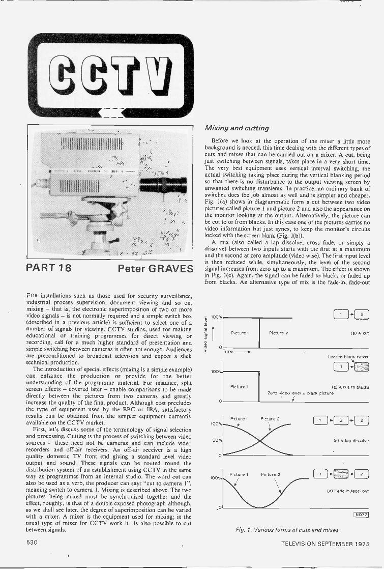
II 111 III Iii
PART 18 Peter GRAVES
FOR installations such as those used for security surveillance,industrial process supervision, document viewing and so on,mixing - that is, the electronic superimposition of two or morevideo signals - is not normally required and a simple switch box(described in a previous article) is sufficient to select one of anumber of signals for viewing. CCTV studios, used for makingeducational or training programmes for direct viewing orrecording, call for a much higher standard of presentation andsimple switching between cameras is often not enough. Audiencesare preconditioned to broadcast television and expect a slicktechnical production.
The introduction of special effects (mixing is a simple example)can, enhance the production or provide for the betterunderstanding of the programme material. For instance, splitscreen effects - covered later - enable comparisons to be madedirectly between the pictures from two cameras and greatlyincrease the quality of the final product. Although cost precludesthe type of equipment used by the BBC or IBA, satisfactoryresults can be obtained from the simpler equipment currentlyavailable on the CCTV market.
First, let's discuss some of the terminology of signal selectionand processing. Cutting is the process of switching between videosources - these need not be cameras and can include videorecorders and off -air receivers. An off -air receiver is a highquality domestic TV front end giving a standard level videooutput and sound. These signals can be routed round thedistribution system of an establishment using CCTV in the sameway as programmes from an internal studio. The word cut canalso be used as a verb, the producer can say: "cut to camera 1",meaning switch to camera 1. Mixing is described above. The twopictures being mixed must be synchronised together and theeffect, roughly, is that of a double exposed photograph although,as we shall see later, the degree of superimposition can be variedwith a mixer. A mixer is the equipment used for mixing; in theusual type of mixer for CCTV work it is also possible to cutbetween signals.
Mixing and cutting
Before we look at the operation of the mixer a little morebackground is needed, this time dealing with the different types ofcuts and mixes that can be carried out on a mixer. A cut, beingjust switching between signals, takes place in a very short time.The very best equipment uses vertical interval switching, theactual switching taking place during the vertical blanking periodso that there is no disturbance to the output viewing screen byunwanted switching transients. In practice, an ordinary bank ofswitches does the job almost as well and is simpler and cheaper.Fig. 1(a) shows in diagrammatic form a cut between two videopictures called picture 1 and picture 2 and also the appearance onthe monitor looking at the output. Alternatively, the picture canbe cut to or from blacks. In this case one of the pictures carries novideo information but just syncs, to keep the monitor's circuitslocked with the screen blank (Fig. 1(b)).
A mix (also called a lap dissolve, cross fade, or simply adissolve) between two inputs starts with the first at a maximumand the second at zero amplitude (video wise). The first input levelis then reduced while, simultaneously, the level of the secondsignal increases from zero up to a maximum. The effect is shownin Fig. 1(c). Again, the signal can be faded to blacks or faded up
the fade-in, fade-out
Picture 1 Picture 2
Time
100010)
0
100%
o
Picture
2
(a) A cut
Locked blank raster
(b) A cut to blacksZero video level = 'black' picture
1 2J
(c) A lap dissolve
2
(d) Fade.in fade- out
Fig. 1: Various forms of cuts and mixes.
530 TELEVISION SEPTEMBER 1975
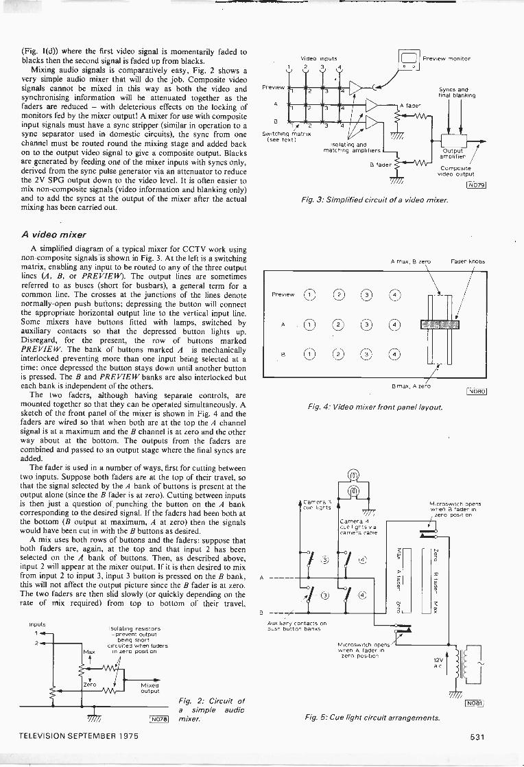
(Fig. 1(d)) where the first video signal is momentarily faded toblacks then the second signal is faded up from blacks.
Mixing audio signals is comparatively easy, Fig. 2 shows avery simple audio mixer that will do the job. Composite videosignals cannot be mixed in this way as both the video andsynchronising information will be attenuated together as thefaders are reduced - with deleterious effects on the locking ofmonitors fed by the mixer output! A mixer for use with compositeinput signals must have a sync stripper (similar in operation to async separator used in domestic circuits), the sync from onechannel must be routed round the mixing stage and added backon to the output video signal to give a composite output. Blacksare generated by feeding one of the mixer inputs with syncs only,derived from the sync pulse generator via an attenuator to reducethe 2V SPG output down to the video level. It is often easier tomix non -composite signals (video information and blanking only)and to add the syncs at the output of the mixer after the actualmixing has been carried out.
A video mixerA simplified diagram of a typical mixer for CCTV work using
non -composite signals is shown in Fig. 3. At the left is a switchingmatrix, enabling any input to be routed to any of the three outputlines (A, B, or PREVIEW). The output lines are sometimesreferred to as buses (short for busbars), a general term for acommon line. The crosses at the junctions of the lines denotenormally -open push buttons; depressing the button will connectthe appropriate horizontal output line to the vertical input line.Some mixers have buttons fitted with lamps, switched byauxiliary contacts so that the depressed button lights up.Disregard, for the present, the row of buttons markedPREVIEW. The bank of buttons marked A is mechanicallyinterlocked preventing more than one input being selected at atime: once depressed the button stays down until another buttonis pressed. The B and PREVIEW banks are also interlocked buteach bank is independent of the others.
The two faders, although having separate controls, aremounted together so that they can be operated simultaneously. Asketch of the front panel of the mixer is shown in Fig. 4 and thefaders are wired so that when both are at the top the A channelsignal is at a maximum and the B channel is at zero and the otherway about at the bottom. The outputs from the faders arecombined and passed to an output stage where the final syncs areadded.
The fader is used in a number of ways, first for cutting betweentwo inputs. Suppose both faders are at the top of their travel, sothat the signal selected by the A bank of buttons is present at theoutput alone (since the B fader is at zero). Cutting between inputsis then just a question of punching the button on the A bankcorresponding to the desired signal. If the faders had been both atthe bottom (B output at maximum, A at zero) then the signalswould have been cut in with the B buttons as desired.
A mix uses both rows of buttons and the faders: suppose thatboth faders are, again, at the top and that input 2 has beenselected on the A bank of buttons. Then, as described above,input 2 will appear at the mixer output. If it is then desired to mixfrom input 2 to input 3, input 3 button is pressed on the B bank,this will not affect the output picture since the B fader is at zero.The two faders are then slid slowly (or quickly depending on therate of mix required) from top to bottom of their travel,
InputsIsolating resistors- prevent output
being shortcircuited when faders
in zero position
Mixedoutput
[N0781
Fig. 2: Circuit ofa simple auditmixer.
Preview
A
B
Video inputs2 3 4
1/ 2
Switching matrix(see text)
A
B
1] Preview monitor
A fader
Isolating andmatching amplifiers
B fader
Syncs andfinal blanking
raOutput
amplifier
Compositevideo output
Fig. 3: Simplified circuit of a video mixer.
B max, A zero
Fig. 4: Video mixer front panel layout.
Camera 3cue lights
Auxiliary contacts onpush button banks
Camera 4cue lights viacamera cable
4
Microswitch openswhen A fader inzero position
I NO19j
Microswitch openswhen B fader in
zero position
12Vac
Fig. 5: Cue light circuit arrangements.
(Noes'
TELEVISION SEPTEMBER 1975 531

progressively increasing the amount of signal from the B bankwhile decreasing the signal selected on the A bank. Halfway alongthe fader travel there will be 50% of each picture visible and theywill appear to be superimposed. The faders can be stopped at anypoint in their travel to produce any desired degree ofsuperimposition. If a full mix (that is, faders go from one end tothe other) is carried out another mix can be carried out byselecting the next picture on the A bank buttons and returning thefaders to the top. Alternatively, the next picture can be cut to bypressing the correct button on whichever bank of buttons is inuse.
Cueing lightsStudio cameras are fitted with cueing lights so that the
performers can see that a particular camera or cameras is on -air,that is, switched to the output of the studio. Normally, a camerais fitted with two lights wired in parallel, one on the front of thecamera under a coloured cover and the other at the rear,alongside the camera monitor for the camera operator. The lightsare controlled automatically by auxiliary switches on the mixerbanks and also by microswitches operated by the faders so that,during a lap dissolve, both the cameras in use have their cue lightson. Power is supplied from a small transformer in the mixer (12Va.c. is typical) and the lamps are fed through the camera cable(Fig. 5).
The bank of buttons marked PREVIEW enables the mixeroperator to view any inputs without having to put them "on -air",in this way he can select and inspect the next picture needed.Normally the most important inputs have their own monitor sothat the production team face a bank of monitors carrying majorinputs, a preview monitor on which any input can be punched upand an output monitor to check the final signal.
To understand what an insert is, consider two photographs ofthe same size laid on top of each other with both pictures face up.In the top one a hole (rectangular for convenience) is cut so that
See text
A
(a) complete insert
Video A
Video B
Keysignal
\..
A B
(b) split screen
1N0821
gookiftw, Output
Relay coil
Video A ,Video B111
Video B ON
Video A ON
I NO831
Video A
Fig. 6: Two typesof insert andtheir appearanceon the screen.
Fig. 7:An elemen-tary split screeneffect generator.
Fig. 8: Keying in an insert at line frequency.
Outputvideo
Keysignal
I NO841
Sets position of Sets position .;1top 01 insert bottom of insert
RV1 RV2
Sets positionof left
side of insertVerticalsync. pulses -1111
Monostable Monostable2
RV3
Horizontalsync pulses
Gate Monostable3
Allows horizontalpulses through for durationof monostable 2 output
pulse
Monostable) triggers-off leading edge of i Period
pulse set by RV1
Sets positionof right
side of insert
y RV4
Monostable4
7Key signaloutput
Vertical sync. pulses
Monostable 1 output,trailingedge triggers monostable 2
Period set by RV2-liji Rs-Monostable 2 output
No key pulses duringthis period
Video A only ON
Set by RV3
Set by RV4Video A ON
Video B ON u
Gate output
Horizontal sync. pulses
Horizontal sync. pulses
Monostable 3 output
Monostable 4 outputkey signal (inverted - see
fig 8)
I N0851
Fig. 9: Generating the box insert of Fig. 6(a).
part of the lower one can be seen. Now, translate this intotelevision terms; suppose we are viewing a race picture A, Fig.6(a), and we also wish to view simultaneously a clock for timingpurposes. A second camera views the clock and that part of thepicture is "let into" the A picture electronically. Note thatalthough the cameras are synchronised together there is nosuperimposition of the two pictures, no part of the A pictureappears in the B area and vice versa. Part of the A picture and agreat deal of the B picture (in this case) is not used. A secondexample is the split screen effect, Fig. 6(b), useful for comparingtwo pictures on the same screen.
Key signalAs this is a simpler example its circuit requirements will be
considered first. An elementary way of achieving the effect isshown in Fig. 7; a key or switching signal is generated whichenergises the relay, changing over the contacts. Taking any line ofthe picture, the line starts and picture A is displayed; at somepoint (the same point on each line) the relay is energised andpicture B is displayed until the end of the line when the relay is de -energised during the line blanking period ready for the A pictureat the start of the following line. As the changeover takes placeonce every line (of 64µS duration on a standard 625 -line system)a mechanical relay is not practical as it cannot operate fastenough. Even a fast reed relay requires around a millisecond orabout 15 TV lines to change over! An electronic switch must be
532 TELEVISION SEPTEMBER 1975
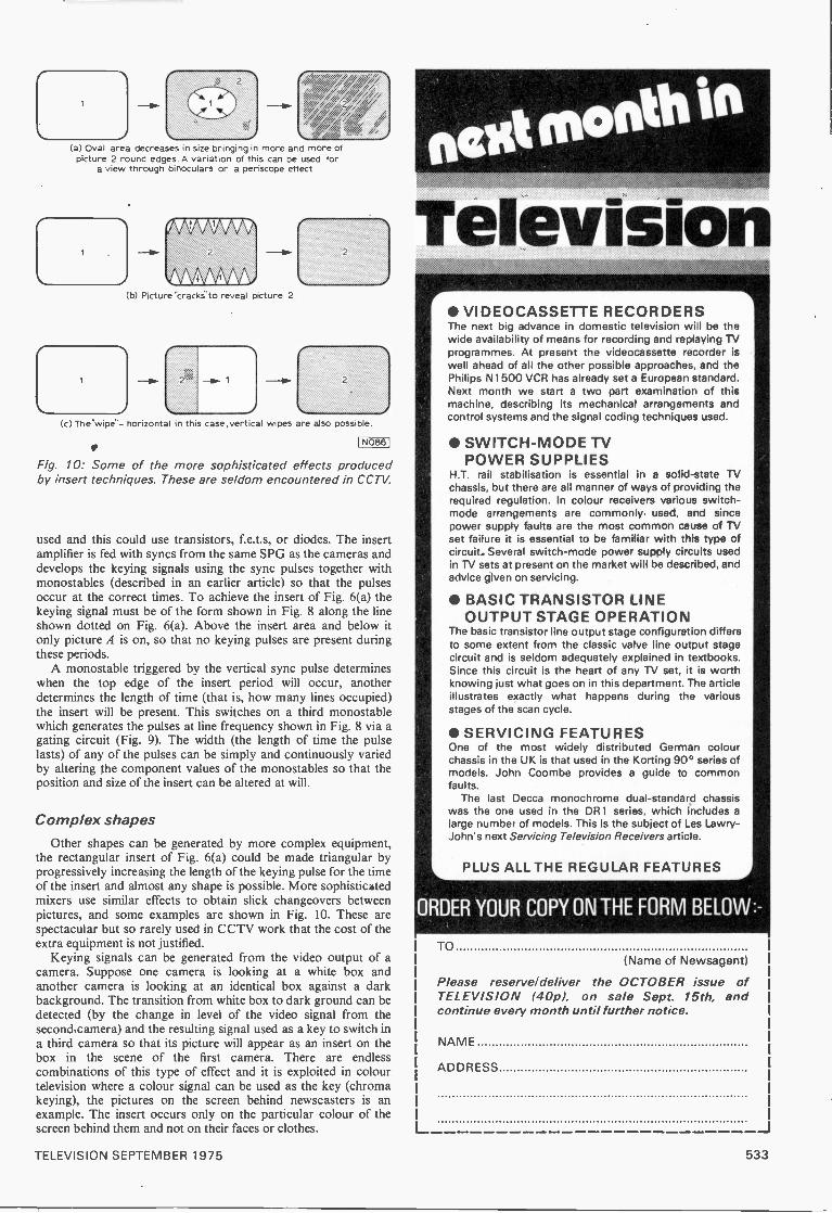
(a) Oval area decreases in size bringing in more and more ofpicture 2 round edges. A variation of this can be used for
a view through binoculars or a periscope effect
-(b) Picture ''crack' to reveal picture 2.
2
'3
1
(c) The"wipe"- horizontal in this case, vertical wipes are also possible.
a IN086 I
Fig. 10: Some of the more sophisticated effects producedby insert techniques. These are seldom encountered in CCTV.
used and this could use transistors, f.e.t.s, or diodes. The insertamplifier is fed with syncs from the same SPG as the cameras anddevelops the keying signals using the sync pulses together withmonostables (described in an earlier article) so that the pulsesoccur at the correct times. To achieve the insert of Fig. 6(a) thekeying signal must be of the form shown in Fig. 8 along the lineshown dotted on Fig. 6(a). Above the insert area and below itonly picture A is on, so that no keying pulses are present duringthese periods.
A monostable triggered by the vertical sync pulse determineswhen the top edge of the insert period will occur, anotherdetermines the length of time (that is, how many lines occupied)the insert will be present. This switches on a third monostablewhich generates the pulses at line frequency shown in Fig. 8 via agating circuit (Fig. 9). The width (the length of time the pulselasts) of any of the pulses can be simply and continuously variedby altering the component values of the monostables so that theposition and size of the insert can be altered at will.
Complex shapesOther shapes can be generated by more complex equipment,
the rectangular insert of Fig. 6(a) could be made triangular byprogressively increasing the length of the keying pulse for the timeof the insert and almost any shape is possible. More sophisticatedmixers use similar effects to obtain slick changeovers betweenpictures, and some examples are shown in Fig. 10. These arespectacular but so rarely used in CCTV work that the cost of theextra equipment is not justified.
Keying signals can be generated from the video output of acamera. Suppose one camera is looking at a white box andanother camera is looking at an identical box against a darkbackground. The transition from white box to dark ground can bedetected (by the change in level of the video signal from thesecond camera) and the resulting signal used as a key to switch ina third camera so that its picture will appear as an insert on thebox in the scene of the first camera. There are endlesscombinations of this type of effect and it is exploited in colourtelevision where a colour signal can be used as the key (chromakeying), the pictures on the screen behind newscasters is anexample. The insert occurs only on the particular colour of thescreen behind them and not on their faces or clothes.
fatmonth in
Television VIDEOCASSETTE RECORDERSThe next big advance in domestic television will be thewide availability of means for recording and replaying TVprogrammes. At present the videocassette recorder iswell ahead of all the other possible approaches, and thePhilips N1500 VCR has already set a European standard.Next month we start a two part examination of thismachine, describing its mechanical arrangements andcontrol systems and the signal coding techniques used.
SWITCH -MODE TVPOWER SUPPLIES
H.T. rail stabilisation is essential in a solid-state TVchassis, but there are all manner of ways of providing therequired regulation. In colour receivers various switch -mode arrangements are commonly. used, and sincepower supply faults are the most common cause of TVset failure it is essential to be familiar with this type ofcircuit.. Several switch -mode power supply circuits usedin TV sets at present on the market will be described, andadvice given on servicing.
BASIC TRANSISTOR LINEOUTPUT STAGE OPERATION
The basic transistor line output stage configuration differsto some extent from the classic valve line output stagecircuit and is seldom adequately explained in textbooks.Since this circuit is the heart of any TV set, it is worthknowing just what goes on in this department. The articleillustrates exactly what happens during the variousstages of the scan cycle.
SERVICING FEATURESOne of the most widely distributed German colourchassis in the UK is that used in the Korting 90° series ofmodels. John Coombe provides a guide to commonfaults.
The last Decca monochrome dual -standard chassiswas the one used in the DR 1 series, which includes alarge number of models. This is the subject of Les Lawry -John's next Servicing Television Receivers article.
PLUS ALL THE REGULAR FEATURES
ORDER YOUR COPY ON THE FORM BELOW
TO(Name of Newsagent)
Please reserve/deliver the OCTOBER issue ofTELEVISION (40p), on sale Sept. 15th, andcontinue every month until further notice.
NAME
ADDRESS
L _J
TELEVISION SEPTEMBER 1975 533

NAtficalx/Sparking NoisesThe trouble with a KB colour receiver fitted with the CVC5chassis really started some months ago with the overnightcooking of the Christmas turkey! The set was near the kitchendoor. and after being for several hours in conditions of very highhumidity it was found on switching on the following morning thatsparking noises came from inside the e.h.t. compartment.Fortunately it turned out to be only from the high -voltage 210pFcapacitor which decouples the focus supply, and on bending theleads of this component so that it was farther away from allmetalwork no further trouble was experienced. Until recentlythat is. when the owner complained of really severe sparkingfrom the same 3110.
On removing the e.h.t. cover we found that there was arcing.or more truly high -voltage tracking. from this 210pF capacitoralong the top side of the tripler unit to chassis. The capacitor issoldered to a tag bolted about half way along the top edge. Thistag is simply a holding point, the focus voltage being taken fromthe slider of the focus control. As a result of the extensive arcingand tracking the top edge of the tripler had become sticky andcarbonised. It wits impossible to wipe clean, so as the tripler itselfwas in order we snipped the top edge of the unit off hit by bitalong its length. A clean rag dipped in meths then removed thesticky feel from the main body of the tripler. and after doing thiswe mounted a small section of tagstrip inside the e.h.t. can toprovide a soldering point for a new 210pF capacitor and the leadfrom the focus control. We used ordinary tagstrip, but because ofthe high voltages involved made the connection to the fourth tagfrom the chassis end and removed the intermediary tags. Thisprovided a complete cure, and we don't expect any more trackingto des clop.
OverloadingA dual standard set fitted with the ITT. SIC VC4 chassis wasused on u.h.f. only. Ample sound was obtainable. thoughaccompanied by really excessive vision buzz. but any attempt totune in the picture produced only very dark modulation of theraster with neither line nor field sync. The contrast control wasfound to have no effect, this fact, together with the sound andvision symptoms. indicating that gross overloading was presentdue to non operation of the a.g.c. circuit.
Our first suspicion ryas that the PC F80 pentode nc separatormight he at fault. failing to produce the usual neg,ativ c grid biaswhich of course is used to provide the a.g.c. potential. Onremoving the aerial plug however a grainy but perfectly lockablepicture was obtained. with hurt free sound (the local transmitterwas only some three miles away). On studying the circuit diagramwe found that the sync separator's negative control grid voltage isapplied to the a.g.c. rail via a IMO resistor (R64). the negativevoltage being hacked off by a small positive potential from one orother of the contrast controls (separate controls being used for405 and 625). The resulting potential is then fed to the tuner via a2.2MI2 resistor and to the EF183 common vision and sound i.f.amplifier via another 2-2M(.1 resistor. the latter feed beingcontrollable by an a.g.c. preset control which is led from thecontrol grid circuit of the line output valve. Both the tuner and thei.f. a.g.c. feeds have clamp diodes shunted across them to preventthe rails going positive. and although such diodes on very rareoccasions go open -circuit if either had done so in this case a.g.c.would still have been applied to the other controlled stage.
G.R.WILDINGIn v icy., 'of the severity of the overload, probably caused by
complete absence of negative a.g.c. voltage, we decided to checkthe common 1M(.2 supply resistor R64 from the sync separatorcontrol grid. Even with the aerial plug still disconnected there wasalmost I8V at the control grid end of this resistor, but a slightpositive voltage at the other end. Then, on shunting the meteracross this resistor, normal contrast control was obtained and agood picture was still present when the aerial was reconnected.R64 was open circuit of course. due we found to one of the lead -out wires having been given an excessive pull, probably duringassembly.
Instances of lack of gain due to an open -circuit or increasedvalue resistor failing to apply sufficient back -off voltage to thea.g.c. rail from the contrast control(s) are common, but this is thefirst time we have come across a resistor applying the negativevoltage to the a.g.c. rail being at fault.
Transistor Working VoltagesAs with v :the voltages. transistor working voltages are of coursemean values. For example, although alternately cut-off and thensaturated for equal periods the transistors in a bistable circuit willshow collector voltage readings of roughly half the supply linevoltage. Sync separators and pulse amplifiers show high collectoroltage readings since they are cut off during most of the line
period, conducting only when the sync pulses are present. Somea.g.c. amplifiers which are fully conducting under no -signalconditions then show collector -emitter voltage readings of only afraction of a volt. Clearly therefore the collector -emitter voltagegiv es.va very good indication of how hard a transistor is beingdriven, since increasing the forward bias reduces the collectorvoltage and increases the emitter voltage - assuming of coursethat feed resistors are present in both circuits. Thus if transistorvoltages arc found to be incorrect, the direction or change showswhether the cause is increased or decreased forward base -emitterbias.
In the usual operating region. above the knee in thecharacteristic, quite large changes in supply line voltage produceonly small changes in collector current. The forward base -emitterbias for most signal amplifying stages is obtained from thejunction of a potential divider connected across the supply. Aspositive I.t. and h.t. rails are mainly used in TV sets the emitter ofan npn transistor will be returned to chassis. Its emitter voltagewill he loss therefore, its base voltage 0.5-0.6V higher, and itscollector voltage anything up to the rail potential depending onthe d.c. resistance of the load.
Where, as is usually the case, an emitter resistor is included inthe circuit, even really excessive forward bias will not undulyincrease the base emitter voltage since the heavy emitter currentwill result in a proportionate voltage being developed across theemitter resistor.
If the collector voltage is lower than specified. indicatingexcessive collector current, the cause could be abnormal leakagecurrent through the transistor. particularly if it is connected as acommon emitter amplifier since the leakage current is thenamplified as a result of the working current gain. For silicontransistors however.. excessive collector current, low collectorvoltage is much more likely to' be the result of excessive forwardbias. This in turn can he caused by one or more of the followingfaults: ( I ) a leaky base coupling capacitor where this is fed from apoint at higher voltage, (2) an open circuit or dry -jointed lower
34 TELEVISION SEPTEMBER 1975
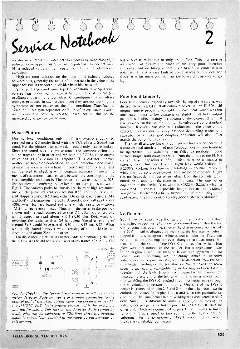
e"c3- 67-16 ?Y2'
5,cmidex-resistor in a potential divider network providing base bias; (3) areduced value upper resistor in such a potential divider network;(4) a reduced value emitter resistor or leaky shunt electrolyticcapacitor.
High collector voltages on the other hand indicate reducedforward bias, generally the result of an increase in the value of theupper resistor in the potential divider base bias network.
Sync separators and some types of oscillator develop a smallreverse bias under normal operating conditions of course (i.e.oscillators operating under class C conditions). The voltagechanges produced in such stages when they are not working aresymptoms of, not causes of, the fault condition. Thus lack ofvideo input to a sync separator, or failure of an oscillator to work,will reduce the collector voltage below normal due to theincreased collector current flowing.
Weak PictureDue to local conditions only v.h.f. transmissions could bereceived on a KB model fitted with the VC3 chassis. Sound wasgood, but the picture was so weak it could only just be locked.Since the sound was o.k. we assumed the common vision andsound stages to be in order and replaced the PCL84 video outputvalve and EF 184 vision i.f. amplifier. This did not improvematters, so suspicion centred on the vision detector diode which,as usual, is mounted in the final i.f. transformer can. External testscan be used to check it with adequate accuracy however, bymeans of resistance measurements between the control grid of thevideo amplifier and chassis. The circuit - drawn as it is in the 405 -line position but omitting the switching for clarity - is shown inFig. I. The various paths to chassis are the very high resistanceone via the pentode's grid leak resistor R53, and another via thegrid stopper resistor R50 and either D6 or its load resistors R47and R48 - disregarding the coils. A good diode will read about4005? when forward biased and a very high resistance - above!WI - when reverse biased. Thus with the meter in the positionshown and the leads connected so that D6 is forward biased onewould expect to read about 80051 (R50 plus D6), while onreversing the leads so that D6 is reverse biased a reading ofaround 31ffl would be expected (R50 plus R47 and R48). Whatwe actually found however was a reading of about I kS2 in onedirection and about 210.2 in the other.
On disconnecting the transformer leads and removing the canthe GD I2 was found to have a forward resistance of about 400S2
D6GDI2
Detector
rris-7)
R50
Vdeoarrpt.fier
Fig. 1: Checking the forward and reverse resistance of thevision detector diode by means of a meter connected to thecontrol grid of the video output valve. The circuit is as used inthe ITT/STC VC3 dual -standard chassis, with the switchingomitted for clarity. This test on the detector diode cannot bemade with the set switched to 625 lines since the detectordiode is capacitively coupled to the video output pentode onthis system.
2but a reverse resistance of only about 21(52. This low reverseresistance was clearly the cause of the very poor detectionefficiency, and on fitting a new diode first class contrast wasobtained. This is a rare fault to come across with a detectordiode: it is far more common for the forward resistance to gohigh.
Poor Field LinearityPoor field linearity, especially towards the top of the screen, wasthe trouble with a GEC 2040 colour receiver. A new PL508 fieldoutput pentode produced negligible improvement, which was notunexpected since a low -emission or slightly soft field outputpentode will affect mainly the bottom of the picture. One mustalways work on the assumption that the valves are up to standardhowever. Reduced bias due to a reduction in the value of thecathode bias resistor, a leaky cathode decoupling electrolyticcapacitor or a leaky grid coupling capacitor will also affectmainly the bottom of the raster.
The overall and top linearity controls - which are connected ina conventional anode -control grid feedback loop - were found tobe operational, but adjusting them failed to produce a goodvertical shape. Both contrdls are fed from the anode of the PL508via an 0.1/4F capacitor (C525), which must be a suspect incases of poor linearity. Even a slight leak would reduce thePL508's working bias however, resulting in bottom cramping,while if it had gone open -circuit there would be excessive height(i.e. no feedback) and loss of any effect from the controls. C525could be discounted therefore in this case. The only othercapacitor in the feedback network is C522 (0.0221/F) which isconnected to chassis to provide integration of the feedbackwaveform. This seemed a likely suspect, and after replacing it andreadjusting the preset controls a very good raster was obtained.
No RasterSound but no raster was the fault on a single -standard Bushmonochrome receiver. The presence of sound meant that the lineoutput stage was operative, since in the chassis concerned (A774)the -20V I.t. rail is obtained by rectifying the line scan waveformtapped from a winding on the line output transformer. There wasno e.h.t. at the c.r.t. cap however, though there was more thanusual a.c. at the anode of the DY802 e.h.t. rectifier. A faint blueglow was then noticed in the rectifier, but a replacement wasfound to glow in a similar manner. It was then apparent that theheater wasn't warming up, indicating either a defectivevalveholder, a dry -joint, or complete disconnection from the one -turn heater winding on the transformer. We removed the screwsecuring the rectifier valveholder to its housing and eased it out,together with the leads. Everything appeared to be in order. Onunsoldering one end of the heater winding however it was foundthat wobbling the DY802 resulted in contact being made throughthe valveholder at certain points only. One side of the DY802heater is connected to pins 2, 5 and 8 while the other side, also thecathode, is connected to pins I, 4, 6 and 9. In this particular setone end of the transformer heater winding was connected to pin 2only. Since it is difficult to make a good job of closing thevalveholder pin grips we linked pin 2 to pins 5 and 8 while theother end, which was connected to pins 1 and 9, was also linkedto pin 4. This ensured certain supply to the heater and onsubsequent testing no amount of DY802 wobbling about wouldbreak the valveholder connection.
TELEVISION SEPTEMBER 1975
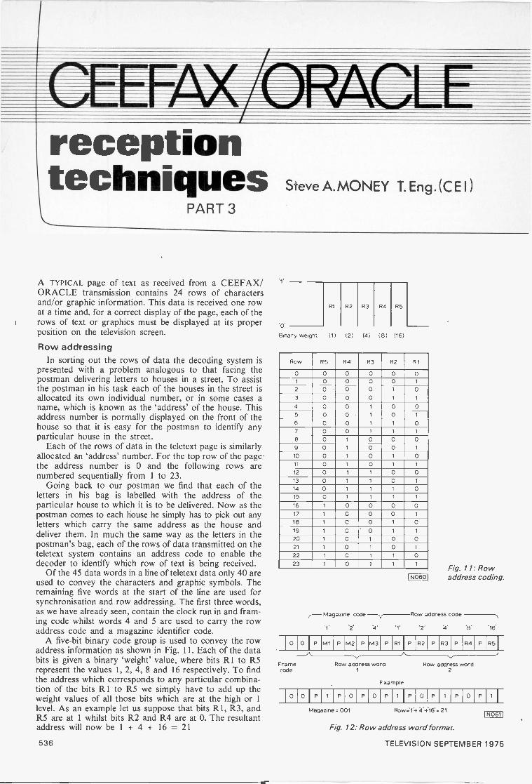
II 111 VA/LOIWOIreceptiontechniques Steve A.MONEY T. Eng. (C E I )
PART 3
A TYPICAL page of text as received from a CEEFAX/ORACLE transmission contains 24 rows of charactersand/or graphic information. This data is received one rowat a time and, for a correct display of the page, each of therows of text or graphics must be displayed at its properposition on the television screen.
Row addressingIn sorting out the rows of data the decoding system is
presented with a problem analogous to that facing thepostman delivering letters to houses in a street. To assistthe postman in his task each of the houses in the street isallocated its own individual number, or in some cases aname, which is known as the `address' of the house. Thisaddress number is normally displayed on the front of thehouse so that it is easy for the postman to identify anyparticular house in the street.
Each of the rows of data in the teletext page is similarlyallocated an `address' number. For the top row of the pagethe address number is 0 and the following rows arenumbered sequentially from 1 to 23.
Going back to our postman we find that each of theletters in his bag is labelled with the address of theparticular house to which it is to be delivered. Now as thepostman comes to each house he simply has to pick out anyletters which carry the same address as the house anddeliver them. In much the same way as the letters in thepostman's bag, each of the rows of data transmitted on theteletext system contains an address code to enable thedecoder to identify which row of text is being received.
Of the 45 data words in a line of teletext data only 40 areused to convey the characters and graphic symbols. Theremaining five words at the start of the line are used forsynchronisation and row addressing. The first three words,as we have already seen, contain the clock run in and fram-ing code whilst words 4 and 5 are used to carry the rowaddress code and a magazine identifier code.
A five -bit binary code group is used to convey the rowaddress information as shown in Fig. 11. Each of the databits is given a binary 'weight' value, where bits R 1 to R5represent the values 1, 2, 4, 8 and 16 respectively. To findthe address which corresponds to any particular combina-tion of the bits RI to R5 we simply have to add up theweight values of all those bits which are at the high or 1level. As an example let us suppose that bits RI, R3, andR5 are at 1 whilst bits R2 and R4 are at 0. The resultantaddress will now be 1 + 4 + 16 = 21
R3 R4 R5
Binary weight (1) (2) (4) (8) (16)
Row R5 R4 R3 R2 R1
0 0 0 0 0 01 0 0 0 0 1
2 0 0 0 1 03 0 0 0 1 1
4 0 0 1 0 05 0 0 1 0 1
6 0 0 1 1 07 0 0 1 1 1
8 0 1 0 0 09 0 1 0 0 1
10 0 1 0 1 0
11 0 1 0 1 1
12 0 1 1 0 013 0 1 1 0 1
14 0 1 1 1 015 0 1 1 1 1
16 1 0 0 0 017 1 0 0 0 1
18 1 0 0 1 019 1 0 ' 0 1 1
20 1 0 1 0 021 1 0 1 0 1
22 1 0 1 1 023 1 0 1 1 1
I N060
Fig. 11: Rowaddress coding.
(-Magazine code-firRow address code
'2' '4' '1' 4
0 ° I P M1 P M2 P M3 P R1 I P R2 P R3 P R4 PR5I
Frame Row address word Row address wordcode 1 2
Example
0 0 I P 0 P 0 P 1 I P 0 P P 0 P
Magazine = 001 Row;14 4.4:16.= 21
Fig. 12: Row address word format.
[N0611
536 TELEVISION SEPTEMBER 1975
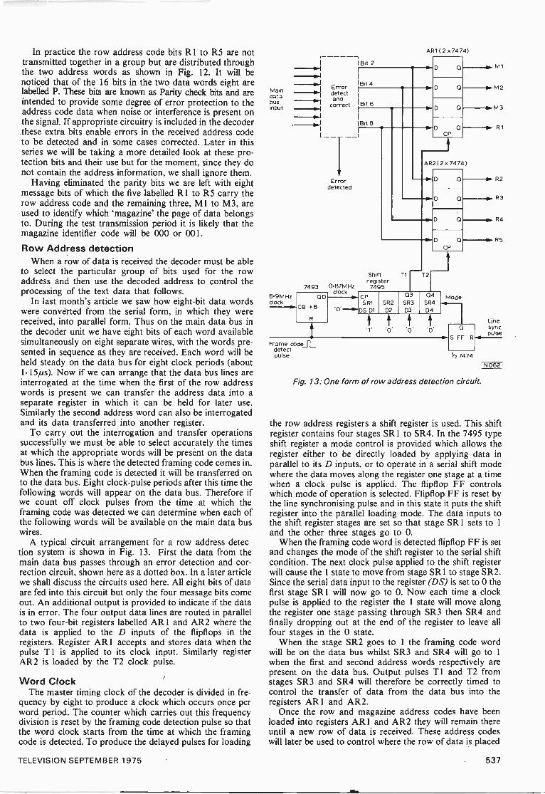
In practice the row address code bits R1 to R5 are nottransmitted together in a group but are distributed throughthe two address words as shown in Fig. 12. It will benoticed that of the 16 bits in the two data words eight arelabelled P. These bits are known as Parity check bits and areintended to provide some degree of error protection to theaddress code data when noise or interference is present onthe signal. If appropriate circuitry is included in the decoderthese extra bits enable errors in the received address codeto be detected and in some cases corrected. Later in thisseries we will be taking a more detailed look at these pro-tection bits and their use but for the moment, since they donot contain the address information, we shall ignore them.
Having eliminated the parity bits we are left with eightmessage bits of which the five labelled R1 to R5 carry therow address code and the remaining three, MI to M3, areused to identify which 'magazine' the page of data belongsto. During the test transmission period it is likely that themagazine identifier code will be 000 or 001.
Row Address detectionWhen a row of data is received the decoder must be able
to select the particular group of bits used for the rowaddress and then use the decoded address to control theprocessing of the text data that follows.
In last month's article we saw how eight -bit data wordswere converted from the serial form, in which they werereceived, into parallel form. Thus on the main data bus inthe decoder unit we have eight bits of each word availablesimultaneously on eight separate wires, with the words pre-sented in sequence as they are received. Each word will beheld steady on the data bus for eight clock periods (about1.15µs). Now if we can arrange that the data bus lines areinterrogated at the time when the first of the row addresswords is present we can transfer the address data into aseparate register in which it can be held for later use.Similarly the second address word can also be interrogatedand its data transferred into another register.
To carry out the interrogation and transfer operationssuccessfully we must be able to select accurately the timesat which the appropriate words will be present on the databus lines. This is where the detected framing code comes in.When the framing code is detected it will be transferred onto the data bus. Eight clock -pulse periods after this time thefollowing words will appear on the data bus. Therefore ifwe count off clock pulses from the time at which theframing code was detected we can determine when each ofthe following words will be available on the main data buswires.
A typical circuit arrangement for a row address detec-tion system is shown in Fig. 13. First the data from themain data bus passes through an error detection and cor-rection circuit, shown here as a dotted box. In a later articlewe shall discuss the circuits used here. All eight bits of dataare fed into this circuit but only the four message bits comeout. An additional output is provided to indicate if the datais in error. The four output data lines are routed in parallelto two four -bit registers labelled AR1 and AR2 where thedata is applied to the D inputs of the flipflops in theregisters. Register AR1 accepts and stores data when thepulse Ti is applied to its clock input. Similarly registerAR2 is loaded by the T2 clock pulse.
Word ClockThe master timing clock df the decoder is divided in fre-
quency by eight to produce a clock which occurs once perword period. The counter which carries out this frequencydivision is reset by the framing code detection pulse so thatthe word clock starts from the time at which the framingcode is detected. To produce the delayed pulses for loading
Maindatabusinput
6.9MHzclock
-I Bit 2
IBit 4Error-an detectand
correct
BB: 86
Errordetected
74 93
OD
CB 8
0.87MHzclock
AR1 ( 2 x7474)
D p M1
M2
CP
AR2(2 x 7474
D 0
s. M3
R1
O
0
Shift Tiregister7495
T2
D O
CP
6 CPSR1
0' S D1
SR2D2
03SR3D3
04SR404
Mode
.1,
Frame codeiLdetectpulse
0S FF R
R2
R3
R4
R5
Linesyncpulse
1/2 7474
111062
Fig. 13: One form of row address detection circuit.
the row address registers a shift register is used. This shiftregister contains four stages SR 1 to SR4. In the 7495 typeshift register a mode control is provided which allows theregister either to be directly loaded by applying data inparallel to its D inputs, or to operate in a serial shift modewhere the data moves along the register one stage at a timewhen a clock pulse is applied. The flipflop FF controlswhich mode of operation is selected. Flipflop FF is reset bythe line synchronising pulse and in this state it puts the shiftregister into the parallel loading mode. The data inputs tothe shift register stages are set so that stage SRI sets to 1and the other three stages go to 0.
When the framing code word is detected flipflop FF is setand changes the mode of the shift register to the serial shiftcondition. The next clock pulse applied to the shift registerwill cause the 1 state to move from stage SR 1 to stage SR2.Since the serial data input to the register (DS) is set to 0 thefirst stage SR 1 will now go to 0. Now each time a clockpulse is applied to the register the 1 state will move alongthe register one stage passing through SR3 then SR4 andfinally dropping out at the end of the register to leave allfour stages in the 0 state.
When the stage SR2 goes to 1 the framing code wordwill be on the data bus whilst SR3 and SR4 will go to 1when the first and second address words respectively arepresent on the data bus. Output pulses T1 and T2 fromstages SR3 and SR4 will therefore be correctly timed tocontrol the transfer of data from the data bus into theregisters AR1 and AR2.
Once the row and magazine address codes have beenloaded into registers AR1 and AR2 they will remain thereuntil a new row of data is received. These address codeswill later be used to control where the row of data is placed
TELEVISION SEPTEMBER 1975 537
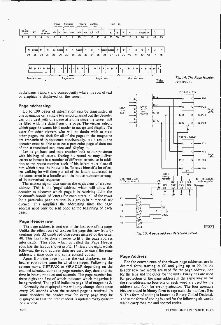
Page Minutes Hours Control Text -a.
Clcickrun in
ROwFC address PU PT MU MT HU HT C1 C2 C E E F A Space P 3
2 3 4 5 6 7 8 9 10 11 12 13 14 15 16 17 18 19 20 21 22 23
5 Space) M 0 n Space 4 Space A p Space Space 8 2 5 3 7
24 25 26 27 28 29 30 31 32 33 34 35 36 37 38 39 40 41 42 43 44 45
P R3 P R4 P P 2 P 4 P 8 P P 2 P 4 P 8 P P 2 P 4 P 8 P
Row address Page units Page tens
in the page memory and consequently where the row of textor graphics is displayed on the screen.
Page addressingUp to 100 pages of information can be transmitted in
one magazine on a single television channel but the decodercan only deal with one page at a time since the screen willbe filled with the data from one page. The viewer selectswhich page he wants his decoder to accept and display. Tocater for other viewers who will no doubt wish to viewother pages, the data for all of the pages in the magazineare transmitted in sequence continuously. As a result thedecoder must be able to select a particular page of data outof the transmitted sequence and display it.
Let us go back and take another look at our postmanwith his bag of letters. During his round he may deliverletters to houses in a number of different streets, so in addi-tion to the house number each of his letters must also tellhim which street the house is in. To save himself a lot of ex-tra walking he will then put all of the letters addressed tothe same street in a bundle with the house numbers arrang-ed in numerical sequence.
The teletext signal also carries the equivalent of a streetaddress. This is the 'page' address which will allow thedecoder to discover which page it is receiving. Like thepostman's bundle of letters for each street, all of the rowsfor a particular page are sent in a group in numerical se-'quence. This simplifies the addressing since the pageaddress need only be sent once at the beginning of eachpage.
Page Header rowThe page address is sent out in the first row of the page.
Unlike the other rows of text on the page this row (row 0)contains only 32 displayed characters instead of the usual40. This has to be done in order to fit in the page addressinformation. This row, which is called the Page Headerrow, has the layout shown in Fig. 14. Here the eight wordsfollowing the row address data are used to carry the pageaddress, a time code and some control codes.
Apart from the page number the text displayed on theheader row is the same for all of the pages. Following thesystem name, CEEFAX or ORACLE depending on thechannel selected, come the page number, day, date and thetime in hours, minutes and seconds. The page number hasthree digits the first of which indicates which magazine isbeing received. Thus p315 indicates page 15 of magazine 3.
Normally the displayed time will only change about onceevery 25 seconds when the selected page is received. Insome decoders the header row for every page may bedisplayed so that the time readout is updated every quarterof a second.
Maindatabus
Minutes units
_mil I
Error-0-1 detect
andI correct
I- I
0.87 MHz clock( 1.15ps period )
1N0631
Bit 2
Bit 4
Bit 6
Bit B
Fig. 14: The Page Headerrow layout.
PR1 ( 2x 7474 )
D
D
D
PU1
r PU2Pageunits
0CP
PR2( 2 x 7474 )
PU3
0 --10-PT1
0 --111. PT 2Pagetens
0 -1k.PT3
7495timingregister
CP
R1
R2
R3
R4
R5
01
G5
7404
TR1
D1
0 -II.RT4CP
02TR2D2
03TR3D3
To minute04 units register
TR4D4
HG6
-01- Mode
7430
Fig. 15: A page address detection circuit.
1 NO64 1
Page AddressFor the convenience of the viewer page addresses are in
decimal form starting at 00 and going up to 99. In theheader row two words are used for the page address, onefor the tens and the other for the units. Parity bits are usedfor protection of the page address in the same way as forthe row address, so four bits of each word are used for theaddress and four for error protection. The four messagebits are coded in binary form to represent the numbers 0 to9. This form of coding is known as Binary Coded Decimal.The same form of coding is used for the following six wordswhich carry the time and control codes.
538 TELEVISION SEPTEMBER 1975

In the decoder the page address words are extracted andcompared with the page number selected by the viewer.When the page address matches the selected page numberthe following 24 rows of data are accepted and stored bythe decoder and the corresponding text is then displayed. Insome decoders the time code may also be used to select thepages since some pages of information may only be sentout at certain times of the day.
Page detectionLet us now consider the process of decoding the page
address. A typical logic arrangement for this is shown inFig. 15. In some ways this arrangement is similar to thatused for selecting out the row addresses. As in the case ofthe row addresses the data is first of all passed via an errordetection and correction system which may well be thesame one that is dealing with the data for the row addressdetection.
Since the page address is only transmitted during row 0we must first of all detect when row 0 is received. A simpleNAND gate is fed with the row address bits R I to R5 fromthe row address registers AR1 and AR2. Since we need all
1 inputs to the NAND gate to produce an output the rowaddress inputs are inverted before they are applied to theNAND gate inputs. Now when row 0 occurs the bits R 1 toR5 will all be at 0 and the inputs to the NAND gate G6 willall be at 1 due to the action of the inverters G I to G5. Theoutput of G6 will go to 0 during row 0.
Having detected row 0, the next step is to select the twowords carrying the page address and transfer them into twoseparate registers for later use. A shift register is used fortiming in the same way as for the row address. The shiftregister is clocked by the same 1.15,us clock that drives therow detection timing shift register.
The row 0 signal from the output of gate G6 controls themode of operation of the timing shift register. Whenanother row address is detected the timing register is set forparallel loading and stage TR I is set to 1 whilst all theother stages are set at 0. When row 0 is detected the modechanges and the timing register now starts its right shiftoperation. The 1 state moves along the register one stage ata time as each clock pulse is applied. We can now pick offpulses from the outputs of the shift register to control thetransfer of the two page address words into the registersPR 1 and PR2. After the two words have been transferredto their appropriate registers they will remain there until thenext row 0 is detected. By extending the length of the timingregister and adding further storage registers the time andcontrol code words can also be selected and stored.
Page selectionHaving extracted and stored the page address the next
step is to see if the page being received is the one that theviewer has requested. Normally the viewer control willconsist of two ten -position thumbwheel switches, one for`tens' and the other for 'units' of the page number. Thebasic circuit arrangement for detecting a match betweenthe selected page and the one being received is shown inFig. 16.
Let us examine the action of the page units circuit. Thefour bits of the page units code are applied to the inputs ofa 7442 binary -to -decimal decoder device. This integratedcircuit has ten outputs labelled 0 to 9 and one of these goesto 0 according to the binary code applied at the input. Thusif the binary input code has the value 6 then output number6 will go to 0. Each of the ten outputs of the 7442 connectsto its corresponding pole on the units selector switch. Nowassuming the input is still 6 we can only get an output at the
131 7442
987 710
PU1 A 6-10-PU2 5 5
PU3 4-111.0-111.-DPU4 3--do
2 ---2P21
PT1
PT2PT3PT4
51page units
10
D2 7442
ABC
7402
Pagematch
1
010
D3 7442
M1 A 5B 4
MagazinematchM2
740454
C 3M3 53/magazine'2 ---032
ov
1 110
881)97 it)
6 6005 50
4 4 52 7400 74043 page tens2 2
Fig. 16: A page selection circuit.
Acceptdata
NO651
wiper of the switch when the switch is also set at position 6.In this way we will only get an output from the switch whenthe received address code is the same as the numberselected by the switch.
A second 7442 and decade switch are used to detect amatch between the 'tens' switch position and the received`tens' address code. The outputs from the units and tensswitches are gated together in a NOR gate so that only whenboth are matched correctly will there be a 1 output. When apage match condition is detected the following rows of textdata are accepted, stored and displayed.
Magazine selectionAlthough during the present trial period only one
magazine is likely to be transmitted on any one channel, itwould be possible in the future to have up to eight suchmagazines on a channel either by using extra lines for thedata signals or by increasing the delay time before theselected page can be accessed.
The magazine can be selected by adding a third bank tothe page selection switch to give effectively a hundredsposition. This is shown in Fig. 16 and it will be seen that themagazine address match is detected in much the same wayas a page address. The magazine match signal is gated withthe page match output to produce an overall dataacceptance signal which will control whether the data is tobe accepted and displayed or simply ignored. If there isonly one magazine on the channel however, there would beno need to fit a magazine code detection system.
Next monthIn this article we have seen how the row and page
addresses are dealt with to enable the decoder to decide if ithas to accept the received data or not. Next month we shalltake a look at the page memory which will store the page ofdata to be displayed.
TELEVISION SEPTEMBER 1975 539
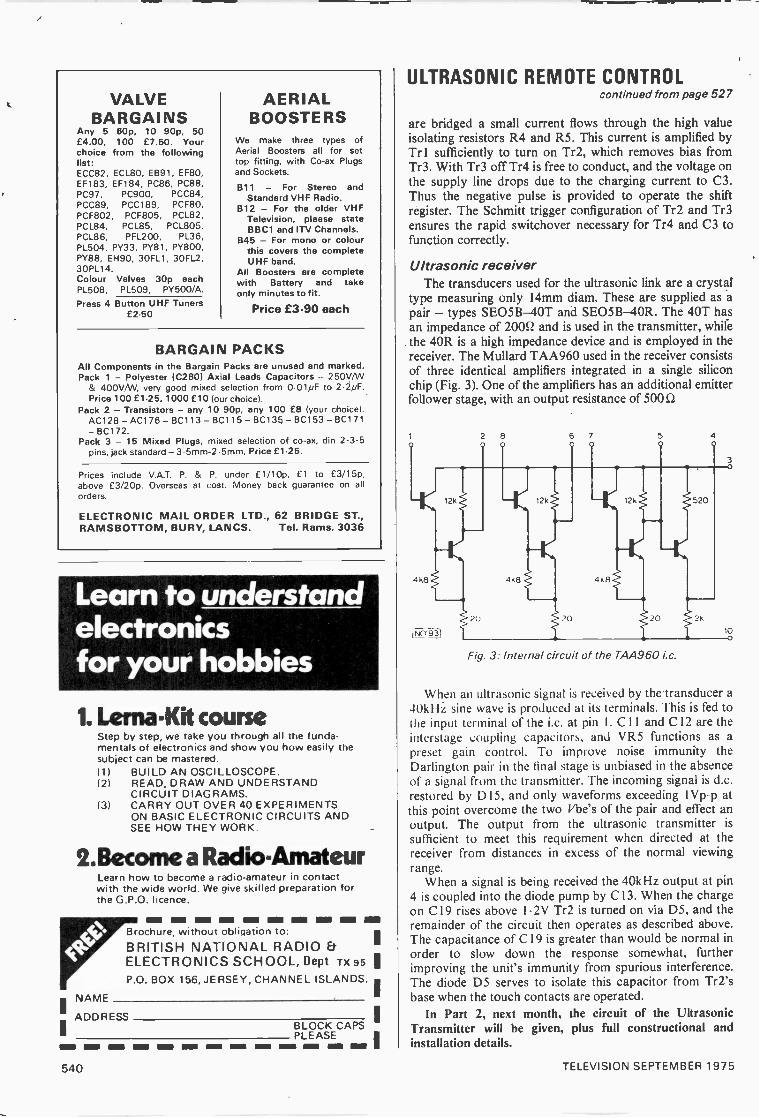
VALVEBARGAINS
Any 5 60p, 10 90p, 50£4.00, 100 £7.50. Yourchoice from the followinglist:ECC82, ECL80, EB91, EF80,EF183, EF184, PC86, PC88,PC97, PC900, PCC84,PCC89, PCC189, PCF80,PCF802, PCF805, PCL82,PCL84, PCL85, PCL805,PCL86, PFL200, PL36,PL504, PY33, PY81, PY800,PY88, EH90, 30FL1, 30FL2,30PL14.Colour Valves 30p eachPL508, PL509, PY500/A.
Press 4 Button UHF Tuners£2.50
AERIALBOOSTERS
We make three types ofAerial Boosters all for settop fitting, with Co -ax Plugsand Sockets.
811 - For Stereo andStandard VHF Radio.
812 - For the older VHFTelevision, please stateBBC1 and ITV Channels.
B45 - For mono or colourthis covers the completeUHF band.
All Boosters are completewith Battery and takeonly minutes to fit.
Price £3.90 each
BARGAIN PACKSAll Components in the Bargain Packs are unused and marked.Pack 1 - Polyester 1C280) Axial Leads Capacitors - 250V/W
& 400V/VV, very good mixed selection from 0.01pF to 2.2pF.Price 100 £1.25, 1000 £10 lour choice).
Pack 2 - Transistors - any 10 90p, any 100 £8 (your choice).AC128-AC176-BC113-BC115-BC135-BC153-BC171- BC172.
Pack 3 - 15 Mixed Plugs, mixed selection of co -ax, din 2-3-5pins, jack standard - 3.5mm-2.5mm. Price f1.25.
Prices include V.A.T. P. & P. under E1/10p. El to E3/15p,above f3/20p. Overseas at cost. Money back guarantee on allorders.
ELECTRONIC MAIL ORDER LTD., 62 BRIDGE ST.,RAMSBOTTOM, BURY, LANCS. Tel. Rams. 3036
Learn to understandelectronicsfor your hobbies
1. Lerna-Kit courseStep by step, we take you through all the funda-mentals of electronics and show you how easily thesubject can be mastered.111
12/
131
BUILD AN OSCILLOSCOPE.READ, DRAW AND UNDERSTANDCIRCUIT DIAGRAMS.CARRY OUT OVER 40 EXPERIMENTSON BASIC ELECTRONIC CIRCUITS ANDSEE HOW THEY WORK.
2. Become a RadioAmateurLearn how to become a radio -amateur in contactwith the wide world. We give skilled preparation forthe G.P.O. licence.
NAME
ADDRESS
NM I=Brochure, without obligation to:BRITISH NATIONAL RADIO EtELECTRONICS SCHOOL, Dept TX95P.O. BOX 156, JERSEY, CHANNEL ISLANDS.
BLOCK CAPS
n n no nn nn nn nin mm mm nn Eno mm mn nowPLEASE
ULTRASONIC REMOTE CONTROLcontinued from page 527
are bridged a small current flows through the high valueisolating resistors R4 and R5. This current is amplified byTr 1 sufficiently to turn on Tr2, which removes bias fromTr3. With Tr3 off Tr4 is free to conduct, and the voltage onthe supply line drops due to the charging current to C3.Thus the negative pulse is provided to operate the shiftregister. The Schmitt trigger configuration of Tr2 and Tr3ensures the rapid switchover necessary for Tr4 and C3 tofunction correctly.
Ultrasonic receiverThe transducers used for the ultrasonic link are a crystal
type measuring only 14mm diam. These are supplied as apair - types SEO5B-40T and SEO5B-40R. The 40T hasan impedance of 20052 and is used in the transmitter, whilethe 40R is a high impedance device and is employed in thereceiver. The Mullard TAA960 used in the receiver consistsof three identical amplifiers integrated in a single siliconchip (Fig. 3). One of the amplifiers has an additional emitterfollower stage, with an output resistance of 500 f2
Fig. 3: Internal circuit of the 7AA960 Lc.
When an ultrasonic signal is received by the transducer a-10kHz sine wave is produced at its terminals. This is fed tothe input terminal of the i.c. at pin I. C11 and C I2 are theinterstage coupling capacitors, and VR5 functions as apreset gain control. To improve noise immunity theDarlington pair in the final stage is unbiased in the absenceof a signal from the transmitter. The incoming signal is d.c.restored by D15, and only waveforms exceeding 1Vp-p atthis point overcome the two Vbe's of the pair and effect anoutput. The output from the ultrasonic transmitter issufficient to meet this requirement when directed at thereceiver from distances in excess of the normal viewingrange.
When a signal is being received the 40kHz output at pin4 is coupled into the diode pump by C 13. When the chargeon CI9 rises above 1.2V Tr2 is turned on via D5, and theremainder of the circuit then operates as described above.The capacitance of C 19 is greater than would be normal inorder to slow down the response somewhat, furtherimproving the unit's immunity from spurious interference.The diode D5 serves to isolate this capacitor from Tr2'sbase when the touch contacts are operated.
In Part 2, next month, the circuit of the UltrasonicTransmitter will be given, plus full constructional andinstallation details.
540 TELEVISION SEPTEMBER 1975

ROGER Bunnsp
Now that mid summer has come and gone it seems that SporadicE has similarly reached its peak and gone into a decline.Reception via this mode at the end of June has become lessfrequent, and there have been lapses of several days between goodopenings. Fortunately however several occurrences have morethan compensated for the decline in SpE conditions.
The most striking event has been the appearance of that longsought after exotic signal, Jordan channel E3 (Amman). Threedifferent people have seen it in the UK, on two dates!
Increased TropsThe prolonged heatwave over much of the UK brought with it
a fantastic increase in Tropospheric activity. Since this occurredat the end of June I have had no reports from others at the time ofwriting, but even in my valley location two new West Germanu.h.f. transmitters have been received and there have beensustained signals from the DFF (East German) transmitters onchannels E5 and E6.
Local ConditionsDue to the amount of material to pass on this month 1 must
unfortunately drop the reception log, but a brief summary of howthings have been here follows. Good SpE openings were noted onthe 1st, 2nd, 3rd, 5th, 6th, 7th, 8th, 11th, 15th, 16th and 24th(including TV R - Rumania). During the opening on the 24th RAI(Italy) was observed on test card on channels IA and IB. At 1015the ch. IB test card faded to be replaced by a feature film, the ch.IA signal continuing with the test card. There were excellentTropospheric conditions on the 25th and 26th. Apart from BandIII activity - including sustained East German Band III signals -many West German u.h.f. stations were received.
Reception of Jordan TVWe have received two letters from Andrew Papaeftychiou in
Cyprus. The first told us that Amman is using "European style"rather than the more expected Arab dressed announcers, and thatLebanon ch. E4 often comes on air early if there is a likelihood ofshooting and other troubles.
As if on cue, two letters arrived on the next post, one fromClive Athowe (near Norwich) and the other from Derek Waller(near Consett). Derek first received Amman at 1443 on the 18th,with Arabic music followed by a female announcer, the Koran at1510 and a fade out shortly after. At this time Clive returnedhome and on switching on was presented with a weak arab signal- a man in white head-dress, dark glasses and black robe.Subsequently the programme went to childrens' cartoons (inEnglish) and other programmes. The signal had faded by 1545(GMT). Clive mentioned that this could have been double -hopreception, with a bounce in Rumania. Well, incredible as it mayseem our Hungarian friend Hetesi Laszlo was also tuned in on the18th and he too during this same period noted Amman- earlierusing colour bars with an Arabic identification. So it appears that
Hetesi in Hungary saw Amman via single hop while our UKfriends saw the signal on its second hop! Clive's reception was incolour.
Over now to Hugh Cocks (Devon) who received Amman onthe 21st, again during the afternoon period and on test pattern,with the colour bars received by Hetesi.
All in all then it has been quite an exciting month for exoticsignal reception: our congratulations to the DXers concerned fortheir vigilance.
Matters ArisingClive Athowe has noted RTVE (Spain) using a new pattern
which consists of small black/white squares - as opposed to theusual checkerboard. Clive also received a programme in Frenchon ch. E2 on the 11th at 2000, from the south. Has anyone anyideas as to the possible origin of this? Programmes in Frenchwere noted last year on this channel.
Two enthusiasts have now seen the Marconi No. 1 test card onch. E2a/R1. The origin has been identified as ORF - since thecard was seen to change to the PM5544 pattern. Sweden has alsobeen noted using the PM5544 pattern, with a very smallidentification at the top - this can be confused as "TVE", so becareful!
Hetesi Laszlo tells us that Bulgarian TV is still using the oldtest card G. This is similar to test card C but has a largeconcentric white circle.
James Burton -Stewart (Buckingham) reports that NRK(Norway) is now superimposing the title and the name of ,thecomposer of the music which accompanies the test cardtransmitted prior to the commencement of programmes. He firstnoticed this on the 7th, at 1745, over the Fubk test card.
Transmitter Guide BookThe WTFDA (PO Box 163, Deerfield, Illinois, 60015, USA)
has announced the publication of a new transmitter list. This is avery comprehensive guide to all stations operating in North andCentral America, including coverage maps, call letters, networkand offset frequency data. Other details include licensing,location, whether originating or satellite, e.r.p., mast height andinformation on programme sources. The cost is $5 via surfacepost. The publication is comb bound and approximately 8-1 x1 lin. Sample bulletins for TV -DX information are available at75c.
Labgear A mplifierWe recently received for evaluation a Labgear CM6036/DA
amplifier. This is a very high gain unit, providing a gain of 30dBat v.h.f. and 28dB at u.h.f., with a quoted noise figure of only4.5dB. Despite the wide bandwidth (40-860MHz), the gain ismaintained within 1dB at v.h.f. and 2dB at u.h.f.
Initial results show that the unit is indeed well suited to DX -TVwork, though possibly with SpE signals, and when feeding into a
TELEVISION SEPTEMBER 1975 541
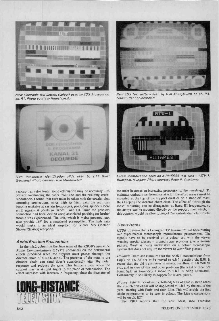
New electronic test pattern (colour) used by TSS Moscow onch. Al. Photo courtesy Hetesi Laszlo.
New transmitter identification slide used by DFF (EastGermany). Photo courtesy Ryn Muntjewerff.
varicap transistor tuner, some attenuation may be necessary - toprevent overloading the tuner front end and the resulting cross -modulation. I found that care must be taken with the coaxial plugscreening connections, since with its high gain the unit canbecome unstable at certain frequencies, producing spurious localu.h.f. signals at points in Bands I and III. Once the problemconnection had been located using associated patching no furthertrouble was experienced. The unit, which is mains powered, canalso provide 16V for a masthead preamplifier. The high gainwould make it an ideal amplifier for winter MS (MeteorShower/Scatter) reception.
Aerial Erection PrecautionsIn the v.h.f. column in the June issue of the RSGB's magazine
Radio Communications G3VVT comments on the detrimentaleffects produced when the support mast passes through thedirector chain of a u.h.f. aerial. The presence of the mast in thedirector chain can (and does!) considerably alter the polarresponse and reduces the gain. This happens even when thesupport mast is at right angles to the plane of polarisation. Theeffect increases with increase in frequency, since the diameter of
New TSS test pattern seen by Ryn Muntjewerff on ch. R3.Transmitter not identified.
Latest identification seen on a PM5544 test card - MTV -1,Budapest, Hungary. Photo courtesy Peter F. Vaarkamp.
the mast becomes an increasing proportion of the wavelength. Tomaintain optimum performance at u.h.f. therefore arrays must bemounted at the top of the support mast or on a stand-off mast,thus keeping the director chain clear. The effect of "through themast" mounting can be disregarded at Band III frequencies, sothe arrays can be mounted directly on the support mast which, inthis context, would be alloy tubing of 2in. outside diameter or less.
News ItemsUSSR: It seems that a Leningrad TV transmitter has been puttingout experimental stereoscopic monochrome programmes. Thesignals have to be received on a colour set, with the viewerwearing special glasses - monochrome receivers give a normalpicture. Work is being undertaken on a colour stereoscopicsystem that does not require the viewer to wear filter glasses.
Holland: There are rumours that the NOS -1 transmissions fromLopik on ch. E4 are to be moved to u.h.f., possibly ch. E30. Itseems that the old transmitter is ageing, resulting in harmonics,etc., and in view of this and other problems (the least of them notbeing SpE in summer!) a move to u.h.f. is being advocated.Fortunately it isn't likely to happen for several years.
France: Peter F. Vaarkamp (Holland) tells us that in some areasthe French first chain will be duplicated at u.h.f. by the end of theyear, starting with Paris and then Lille. This will enable the firstchain programmes to be seen in colour. The Lille transmissionswill be on ch. E27.
The EBU reports that the new Brest, Roc Tredulon
542 TELEVISION SEPTEMBER 1975
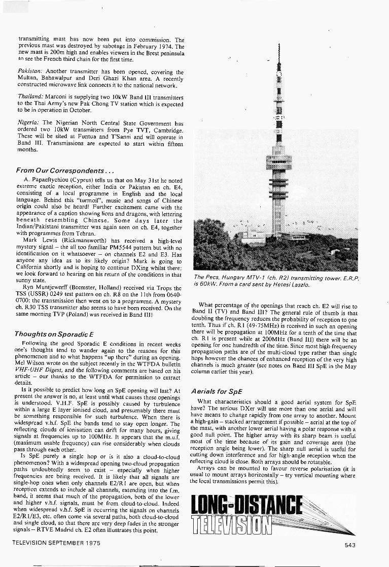
transmitting mast has now been put into commission. Theprevious mast was destroyed by sabotage in February 1974. Thenew mast is 200m high and enables viewers in the Brest peninsulato see the French third chain for the first time.
Pakistan: Another transmitter has been opened, covering theMultan, Bahawalpur and Deri Ghazi Khan area. A recentlyconstructed microwave link connects it to the national network.
Thailand: Marconi is supplying two 10kW Band III transmittersto the Thai Army's new Pak Chong TV station which is expectedto be in operation in October.
Nigeria: The Nigerian North Central State Government hasordered two 10kW transmitters from Pye TVT, Cambridge.These will be sited at Funtua and T'Sanni and will operate inBand III. Transmissions are expected to start within fifteenmonths.
From Our Correspondents...A. Papaeftychiou (Cyprus) tells us that on May 31st he noted
extreme exotic reception, either India or Pakistan on ch. E4,consisting of a local programme in English and the locallanguage. Behind this "turmoil", music and songs of Chineseorigin could also be heard! Further excitement came with theappearance of a caption showing lions and dragons, with letteringbeneath resembling Chinese. Some days later theIndian/Pakistani transmitter was again seen on ch. E4, togetherwith programmes from Tehran.
Mark Lewis (Rickmansworth) has received a high-levelmystery signal - the all too familiar PM5544 pattern but with noidentification on it whatsoever - on channels E2 and E3. Hasanyone any idea as to its likely origin? Mark is going toCalifornia shortly and is hoping to continue DXing whilst there:we look forward to hearing on his return of the conditions in thatsunny state.
Ryn Muntjewerff (Beemster, Holland) received via Trops theTSS (USSR) 0249 test pattern on ch. R8 on the 11th from 0640-0700: the transmission then went on to a programme. A mysterych. R30 TSS transmitter also seems to have been received. On thesame morning TVP (Poland) was received in Band III!
Thoughts on Sporadic EFollowing the good Sporadic E conditions in recent weeks
one's thoughts tend to wander again to the reasons for thisphenomenon and to what happens "up there" during an opening.Mel Wilson wrote on the subject recently in the WTFDA bulletinVHF -UHF Digest, and the following comments are based on hisarticle - our thanks to the WTFDA for permission to extractdetails.
Is it possible to predict how long an SpE opening will last? Atpresent the answer is no, at least until what causes these openingsis understood. V.H.F. SpE is possibly caused by turbulencewithin a large E layer ionised cloud, and presumably there mustbe something responsible for such turbulence. When there iswidespread v.h.f. SpE the bands tend to stay open longer. Thereflecting clouds of ionisation can drift for many hours, givingsignals at frequencies up to 100MHz. It appears that the m.u.f.(maximum usable frequency) can rise considerably when cloudspass through each other.
Is SpE purely a single hop or is it also a cloud -to -cloudphenomenon? With a widespread opening two -cloud propagationpaths undoubtedly seem to exist - especially when higherfrequencies are being received. It is likely that all signals aresingle -hop ones when only channels E2/R1 are open, but whenreception extends to include all channels, extending into the f.m.band, it seems that much of the propagation, both of the lowerand higher v.h.f. signals, must be from cloud -to -cloud. Indeedwhen widespread v.h.f. SpE is occurring the signals on channelsE2/R1/E3, etc. often come via several paths, both cloud -to -cloudand single cloud, so that there are very deep fades in the strongersignals - RTVE Madrid ch. E2 often illustrates this point.
The Pecs, Hungary MTV -1 (ch. R2) transmitting tower. E.R.P.is 60kW. From a card sent by Hetesi Laszlo.
What percentage of the openings that reach ch. E2 will rise toBand II (TV) and Band III? The general rule of thumb is thatdoubling the frequency reduces the probability of reception to onetenth. Thus if ch. R1 (49.75MHz) is received in such an openingthere will be propagation at 100MHz for a tenth of the time thatch. R1 is present while at 200MHz (Band III) there will be anopening for one hundredth of the time. Since most high -frequencypropagation paths are of the multi -cloud type rather than singlehops however the chances of enhanced reception of the very highchannels is much greater (see notes on Band III SpE in the Maycolumn earlier this year).
Aerials for SpEWhat characteristics should a good aerial system for SpE
have? The serious DXer will use more than one aerial and willhave means to change rapidly from one array to another. Mounta high -gain - stacked arrangement if possible - aerial at the top ofthe mast, with another lower aerial having a polar response with agood null point. The higher array with its sharp beam is usefulmost of the time because of its gain and coverage area (thereception angle being lower). The sharp null aerial is useful forcutting down interference and for high -angle reception when thereflecting cloud is close. Both arrays should be rotatable.
Arrays can be mounted to favour reverse polarisation (it isusual to mount arrays horizontally - try vertical mounting wherethe local transmissions permit this).
TELEVISION SEPTEMBER 1975 543

ouriiiriBLEMS
solvedRequests for advice in dealing with servicing problems must be
accompanied by an 11p postal order (made out to I PC Magazines Ltd.), thequery coupon from page 547 and a stamped addressed envelope. We candeal with only one query at a time. We regret that we cannot supply servicesheets nor answer queries over the telephone.
DECCA CTV19Initially, after switching on, the picture is fairly goodthough on the dark side. After the set has warmed uphowever the picture brightens and the colour becomesweak. The bottom of the picture is darker and there is adarker band across the middle. The contrast has to be fullyup at all times. The focus has been set to optimum and anew line output valve and transformer fitted.
It seems that the PL802 luminance output pentode isfaulty, so the first step should be to fit a new one. If thefault persists the black -level clamp in the control gridcircuit of this valve could be responsible: check the diodeand transistor in this circuit (D204, TR212), also the100,1/F electrolytic (C231). Another possibility is theblanking circuit connected to the cathode of the PL802:this can be checked simply by shorting across the collectorand emitter of the blanking transistor (TR205, BC108):
GEC 2028When the set was switched on it was found to hecompletely dead, with the 3A mains fuse blown. Onrenewing the fuse everything seemed normal but it was thennoticed that the PY500 boost diode was beginning tooverheat. This was followed by a puff of smoke from theline output transormer and the set went dead. Onexamination the line output transformer was found to haveburnt out.
The most likely cause of the trouble is that there is aninternal short in the PY500. It would be worth checking thePL509 line output valve's 1052, 3W cathode resistor (R61).If this is open -circuit, suspect that the line oscillator is notoperating or its output is incorrect.
FERGUSON 3713A case of no picture in one of these sets was traced to ashort-circuit BDX32 line output transistor. After replacingthis however the new transistor heated up and went short-circuit. The h.t. has been checked and found to be correct.We have tried replacing the line output transformer, e.h.t.tripler, timebase board, output stage tuning capacitor(C406), also the convergence board, using items from a setwhich is working normally, but whatever we do the lineoutput transistor goes short-circuit about 1-2 seconds afterswitching on and the line timebase starting up.
An intermittent open -circuit in the tuning capacitor
C406 is the most common cause of the line outputtransistor shorting, but you say you've replaced this. It isimportant to use an identical component. The onlypossibles left are the c.r.t. first anode supply rectifier W403,its reservoir capacitor C401, and the scan coils.Disconnecting each in turn should isolate the fault: whenthe defective component is disconnected the e.h.t. shouldreturn. (Thorn 8500 chassis.)
PHILIPS G24T230When the brightness is turned up a dark patch appears inthe middle of the screen. This eventually fills the entirescreen. The line output valve and efficiency diode have beenreplaced but this has made no difference.
The fault is due to low e.h.t. Replace the DY87 e.h.t.rectifier: if the fault persists, the line output transformer issuspect. (Philips 210 chassis.)
PVE CT205With the brightness control at a normal or high settingthere are about twenty lines across the screen, equallyspaced out and sloping upwards from the left to the right.The lines 'are not apparent when the brightness control isset slightly below normal. I assume that these are line scansgetting through during the field flyback blanking period. Ihave 'scoped the line and field flyback blanking pulseshowever and they appear to be correct.
The usual cause of poor field flyback blanking on thischassis is that the blanking transistor (VT28, BC107) in thecathode circuit of the PL802 luminance output valve isweak. It is possible in addition that the c.r.t. first anodepreset potentiometers are set a little too high. (Pye 697chassis.)
DECCA CS2631After the set has been on for about half an hour a blackband about an inch deep appears across the top of thepicture. The band remains there until the set is switched off.
We take it you have checked the field timebase valves(PCF80 and PL508) - by substitution. Check C407(4,7002/F) in the anode circuit of the PL508 - it is mountedon the power supply board. Check the operation of thevertical shift control (VR414), and that there is no dud spoton the height control (VR404). If the top of the picture isvery cramped when the fault is present the field outputtransformer could be the cause of the trouble. (Decca 30series chassis.)
544 TELEVISION SEPTEMBER 1975
GEC 2041The fault is intermittent expansion and contraction of thefield, either in the form of line bunching in small sections ofthe picture or the whole of the field expanding so that thereis excessive height - this does not affect the convergence.Sometimes the fault does not occur at all for an evening.The timebase panel has been changed, so the componentsin this area can be ruled out.
The first thing to do is to check electrolytics C68 (50µF)and C67 (100/4F) which smooth the h.t. supplies to the fieldoutput valve. If these are o.k. the field output transformeror the deflection yoke is probably faulty, assuming that thePL508 field output valve is up to standard.
DECCA CTV19When the test card is displayed the dummy's jacket in thecentre circle is blue instead of green: the buttons are thenormal yellow. Otherwise the colour is quite good, on bothtest card and pictures.
You should first set up the grey -scale tracking on amonochrome display. The blue jacket effect is due toabsence or lack of G -Y signal. First check the PCL84G -Y output/clamp valve V601. If the fault persists checkthe resistors and coupling capacitors around this stage,also the BC112 G -Y transistor preamplifier TR610.
PHILIPS 19TG156AThe trouble with this set is line drift. There is an excellentpicture for about fifteen minutes but after that the picturedrifts continuously and the line hold control settingbecomes critical.
The problem is associated with the two ECC82 valves(V403 and V404) on the timebase panel - one is the lineoscillator, the other the flywheel sync valve. The first stepshould be to replace them. If the fault persists check theanode load resistors connected to pins 1 and 6 in thefollowing order: R402 (27E2), R405 (220E2), R415(56E2) and R414 (22E2), also R417 (330E2) from grid pin7 of V404 to the h.t. rail. The multivibrator cross -couplingcapacitors could also be faulty, particularly C407 (56pF).
MARCONIPHONE 4715The colour, or monochrome reproduction, is very goodwhen the set is first switched on. After two or three minuteshowever the whole picture is tinted green, though withcolour showing through. After about five minutes the tintstarts to fade out and within ten minutes we are back tonormal, for about two hours. The colour then deteriorates abit, with a magenta tint. The picture remains like this untilthe set is switched off. With the fault present the c.r.t.voltages all seem to be roughly correct. I have also checkedthe clamp pulse amplitude control R230.
This sort of trouble is frequently caused by deteriorationof the electrolytic capacitors on the video board. Wesuggest you replace C227 (2,t/F) in the green channel clampcircuit, also C221 (1ffiF) which decouples the slider of theclamp pulse amplitude control and C222 (1i/F) whichdecouples the h.t. supply to the output transistors. Checkthe condition of the green drive control R260, and if thefault persists suspect the green output transistor VT212.(Thorn 3500 chassis.1
FERGUSON 3713We cannot get the dynamic blue convergence to line upwith the yellow (converged red/green). Red and greenconvergence is near perfect. The blue verticals will notconverge with yellow at each side. By moving the bluewidth control L503 we can get correct convergence on oneside, but this makes the convergence worse on the otherside of the screen. Reversing the connections to the bluelateral coil has been tried but this made matters worse. Theblue horizontals will not converge because the blue tiltcontrol does not give enough adjustment - another }inwould be perfect., In the manual it says that to obtainoptimum corner convergence the panel should be rockedslightly. It doesn't seem to move at all however. Is itfastened in some way?
Slight rotation of the convergence panel/coils is calledfor to equalise the blue lateral error. The coils are normallya friction fit on the c.r.t. neck. A firmer push is all that isrequired. When you have done this it will be necessary torepeat the red/green convergence. (Thorn 8500 chassis.)
DYNATRON TV100The set functioned perfectly one day but on the followingday gave only a very dull picture with increasing linetearing (to the right) setting in after a few minutes and withwavy verticals predominating. I have changed valveswithout improving matters. The set has not been used muchand gave a superb picture until the fault developed. Thesound remains excellent. The contrast does not appear tobe at fault and I suspect the main smoothing electrolyticblock.
We assume that the PFL200 video/sync valve wasreplaced. The fault is undoubtedly in this area, the primesuspects being R72 (12k.S2, 1W) and C70 (4fisF) whichsupply the screen grid of the video section and C69(200/4F) the cathode decoupler. A check of the electrodevoltages with a 201(Q/V meter should reveal any changedvalue resistors. (Pye 67 chassis.)
PHILIPS G25K502To get a good picture the focus control has to be tufnedright back anti -clockwise, also the brightness control.
The fault is common on this chassis and is due to anincrease in the value of one or more of the high -valueresistors in the focus potentiometer chain. You will have tocheck them all and replace as necessary. (Philips G6 u.,standard chassis.)
PYE CT201
The line output transformer in this set burnt out and wasreplaced. Since then there has been a smear across thescreen. It can take the form of light or dark bands whichare more noticeable on close-ups. The bands behind acaption are of the background colour but darker. Ifsomeone in a close-up raises or lowers their hand the lightcoloured band moves with it.
The problem is usually due to poor clamping, possiblythe result of an out of tolerance replacement line outputtransformer delivering a clamping pulse of insufficientamplitude. First however check the PL802 luminanceoutput pentode and the associated electrolytics, C353which decouples its screen grid and C352 in the anodecircuit. (Pye 697 chassis.)
TELEVISION SEPTEMBER 1975 545
DECCA CS2230With the slider of the set width/e.h.t. control VR451 hardover to the left (viewed from the rear) the test card sidecastellations cannot be seen. The control is operativehowever since moving the slider to the right increases thewidth of the picture. Is there a simple method of obtainingthe correct width?
The problem occasionally arises with this chassis andcan be eliminated by increasing the value of R452A, whichis connected to the slider of VR451, from 820k52 to 2.2MQor thereabouts - this modification is not, incidentally, anofficial one. An alternative approach is to add a 2.2MQ2W resistor in the feed to VR451 from pin 10 (boost rail) ofthe line output transformer. The cause of the trouble is anunfortunate combination of tolerances in the line outputstage components. (Decca 30 series chassis.)
PHILIPS G26K520101The set is o.k. at first after switching on. Then smokeappears from the timebase area and the two resistorsR4483 (15S2) and R4484 (12052) associated with thepincushion distortion correction transductor are both foundto be burning out. The transductor itself seems to be inorder, checked with an Avo Model 8, also the associatedcomponents. If plug H on the line scan unit, connecting tothe transductor, is left off there is a colour picture but withslightly impaired field scan. On replacing plug H the tworesistors start to burn out again.
It seems almost certain that the transductor has shortingturns. It would be as well however to check the associatedraster correction coil L4482 for continuity and theassociated integrating capacitor C4481 (0.04714F). (PhilipsG8 chassis.)
DEFIANT 3A 66The problem with this set is sound but no raster. The boostvoltage, checked at the tube base, is low at about 170V.The voltage at the screen grid of the PL500 line outputvalve is low at about 150V, though there is about -45Vdrive at the control grid and the oscillator can be heardoperating through interference on the radio. The e.h.t. isvery low - by holding a screwdriver at the PL500 top cap aspark of only about 1/16in. can be obtained. The linetimebase valves, the boost capacitor, the high -valueresistors in the width circuit and the 100tiF electrolyticwhich decouples the anode of the efficiency diode have allbeen replaced. I don't think the boost line is beingoverloaded since if the top cap of the DY87 is removed theboost voltage tends to fall a bit.
The line output transformer used in these sets commonlydevelops short-circuit turns resulting in the symptoms youdescribe. Replacement is the only cure. The less likelypossibility of faulty scan coils can be checked merely bydisconnecting them: if this restores the e.h.t., replace theyoke. (Plessey dual -standard chassis.)
PYE CT203The picture is OK when the set is first switched on but afterabout half an hour there is what looks like a foldover abouttwo inches deep at the top of the screen.
The trouble is likely to be due to change of Q of coil L61(NS phase control) in the pincushion distortion correctioncircuit. It is mounted in the middle of the convergencepanel: try shunting it with a IkS2 1W resistor. (Pye 697chassis.)
KB KV003There is a loud buzzing sound on 405 -line operation - it isnot present when the set is switched to 625. The buzz, orroar, is tunable. As the picture is tuned in the buzzincreases until at the point where it is loudest the picturestarts rolling. After tuning through this point the buzzdiminishes, the picture disappears in horizontal lines, thesound comes on loudest but the buzz then disappears. Withacceptable buzz, the sound is on the low side and there issound -on -vision. The buzz increases when the volume orcontrast controls are advanced.
The fact that the hum is tunable and present on 405 linesonly suggests that the effect is due to heater -cathodeleakage in one of the two valves in the v.h.f. tuner. Theseshould be checked by substitution. (ITT/STC VC 11chassis.)
KORTING TRANSMAREWhen this 26in. colour set is switched on from cold there issevere sparking from the e.h.t. cap. This dies down as theset warms up. The c.r.t. was quite dirty so the area aroundthe e.h.t. connector was cleaned with meths, but thesparking continued. The area was then sprayed withignition sealer (Holt's Wet Start) and this seems to havecured the trouble. Is there a more serious cause of thesparking?
Some colour sets are prone to this trouble - it dependson the air humidity. The procedure recommended is tothoroughly clean around the e.h.t. cap with meths, thenapply to the area a very thin layer of silicone grease. It isunlikely that the sparking is due to a fault in the set.
RGD 627The fault with this set is a two inch gap at the top andbottom of the screen. The PCL85 field timebase valve hasbeen replaced without improving the situation. The heightcontrol is at maximum.
There are two valves in the field timebase, the triodesection of V8 (PCF80) forming one half of the fieldoscillator. The trouble is more likely to be due to a fault inthe height circuit however. Check C75 (0.1fi/F) whichdecouples the slider of the height control - it has a habit ofleaking to give the symptom you describe - and then thehigh -value -1-W carbon resistors in the height controlnetwork. For correct height the voltage at pin 1 (triodeanode) of the PCL85 should be about 100V - this must bechecked with a meter having a 20k,g/V or better internalresistance. (KB WV05 series.)
PHILIPS 322When the contrast is at a reasonable level dark scenes aretoo black and light scenes too bright. I am thinkingtherefore of removing the black -level clamp. Can yousuggest how this should be done?
Having advocated the use of black -level clamping for somany years we could not in all conscience advise theremoval of a black -level clamp circuit. There isn't oneanyway in this chassis! The video signal is d.c. coupledfrom the detector to the TBA550 integrated circuit, thenvia the contrast control to the BF337 video outputtransistor and the c.r.t. cathode. If the soot and whitewasheffect cannot be removed at a lower setting of the contrastcontrol, there could be a fault in the video output stage.Check the voltages here - they will usually be incorrectwith this type of non-linear video response fault. Check thatthe preset brightness control R2252 is correctly set - forcorrect black level with the main brightness control atmid position. (Philips 320 chassis.)
546 TELEVISION SEPTEMBER 1975
GEC 2121The problem is field buzz on sound when the volumecontrol is set to a low level. The buzz varies as the field holdcontrol is adjusted.
The effect could be due to C121 (150µF) whichdecouples the 1.t. supply to pin 11 of the TBA120SQintercarrier sound i.c. being of low capacitance. In somecases it helps to fit a 150-400µF capacitor in place of C187(which decouples the same pin) on the sound module,reconnecting the original C187 (0.1µF) across the addedmpacitor but on the underside of the board. (GEC C2110aeries.)
COLOUR RECEIVER STRIATIONSI have been trying to find the cause of striations, i.e. verticallines on the left-hand side of the screen gradually fadingtowards the centre, in colour receivers. Have you anygeneral guidance?
Striations are caused by an inductive component in theline output stage ringing and causing velocity, i.e. intensity,
53 IEach month we provide an interesting case of television
servicing to exercise your ingenuity. These are not trickquestions but are based on actual practical faults.
A GEC Model C2041 operated normally so far asmonochrome and sound were concerned but had a colour
fault. The colour would sometimes resolve correctly afterinitial switch -on, but there was seemingly an even chance ofthe colouring being wrong due to severe blinds.
Tests were made on the decoder panel to establish thatthe ident signal was present at the bistable circuit, and allseemed to be well in this area at least. Furthermeasurements and oscilloscope analysis then revealed thatthe bistable had a sluggish switching characteristic. Once itwas switching, the stage would continue to switch line -by -
modulation of the c.r.t. beams. The usual cause of thetrouble is an open -circuit or high -resistance dampingresistor across the line linearity coil. Other causes are afaulty output stage tuning capacitor or misadjusted tuningcoil, or transformer ringing appearing on the luminancesignal due to a fault in the flyback blanking circuit.
" _,_IPPWWMWW1w_,QUERIES COUPON
This coupon is available until September 151975 and must accompany all Queries sentin accordance with the notice on page 544.Don't forget the 1 1 p (inc, VAT) postal
order!11
T I-EVISION SEPT, 1975
line to yield the half line frequency pulses for the PALswitch, but if for some reason the bistable ceased to switchit could not easily be started again.
While observing a colour picture it was noticed that aragged, vertical line of white light would sometimes appearat the left of the display, and that when this happened therewould be a momentary change of the colours in the picture.
It was next decided to remove the triggering pulses fromthe bistable circuit which of course then ceased to switchaltogether. A 'scope measurement of the pulses from sourcewas then made and it was discovered that the pulseamplitude was well below the manufacturer's stipulated18V (it requires a Y -calibrated oscilloscope to obtain anaccurate readout of pulse amplitude here).
What was the most likely cause of the symptom, andwhat were the clues available to the service technician toestablish the likely cause? See next month's Television forthe solution and for a further item in the Test Case series.
SOLUTION TO TEST CASE 152(Page 491 last month)
Disappearance of the luminance (Y) informationindicates that there is an open -circuit somewhere in the Ychannel, while lateral displacement of the luminanceinformation on the screen with respect to the colourinformation signifies a bandwidth or phase (timing) changeeither in the luminance or chrominance circuits. Since thetwo symptoms appeared to be related the most likely faultarea was the delay line in the luminance channel.
This was where the chief engineer made his examination.Having satisfied himself that all connections to and fromthe Y delay line were in good order, he replaced the line.This completely cleared the symptom. The delay line wassubsequently examined and it was found that there was anintermittent fault condition which gave either a short acrossthe line (thereby removing the delay and causing thedisplacement symptom) or a break in continuity (therebyopen -circuiting the Y channel).
Published on approximately the 22nd of each month by IPC Magazines Limited, Fleetway House, Farringdon Street, London EC4A 4AD. Filmsetting byPacesetters, London SE1. Printed in England by Carlisle Web Offset, Newtown Trading Estate, Carlisle. Sole Agents for Australia and New Zealand - Gordonand Gotch (A/sia) Ltd.; South Africa - Central News Agency Ltd. "Television" is sold subject to the following conditions, namely that it shall not, withoutthe written consent of the Publishers first having been given, be lent, resold, hired out or otherwise disposed of by way of Trade at more than therecommended selling price shown on the cover, excluding Eire where the selling price is subject to VAT, and that it shall not be lent, resold, hired out orotherwise disposed of in a multilated condition or in any unauthorised cover by way of Trade or affixed to or as part of any publication or advertising,literary or pictorial matter whatsoever.
TELEVISION SEPTEMBER 1975 547

TELEVISION CLASSIFIED ADVERTISEMENTSThe pre -paid rate for classified advertisements is 10p a word (minimum 12 words), box number 35p extra. Semi -displaysetting £5.50 per single column inch. All cheques, postal orders, etc., to be made payable to TELEVISION and crossed"Lloyds Bank Ltd." Treasury notes should always be sent registered post. Advertisements, together with remittance,should be sent to the Classified Advertisement Manager, TELEVISION IPC Magazines Ltd., Fleetway House, FarringdonStreet. London, EC4A 4AD, for insertion in the next available issue. (01-634 4451.)
EX RENTALTV's BARGAIN
23" & 19" 3 Channel with U.H.F. Tuner £3.5019" & 25" Colour from £50.0019" & 23" tubes guaranteed from £2.00
All sets complete.
EDWARDS & SONS103 Goldhawk Road, London, W.12.
Telephone: 743 6996.CALLERS ONLY
VALVES, RADIO/T.V. Transmitting industrial,1930 to 1975. 2,200 types stocked, many obsolete.TH4I - EN3I - 2P - N78 - EBLI - EBL2I -ECC31 - EL37 - T41 - MKT4 - PENDD 4020- PX4 - PX25 - X8IM - W61 - X101 - X109 -X145 - X147 - Z2I -Z319 - Z359 - 6F33 - 61BT- ACTP - EF22 - EL38 - KT44 - U801 - UBL21- 6LI - KT36 - KT33, etc. S.a.e. for quotation List20p. Postal export service. We wish to purchase alltypes of new and boxed valves. Cox Radio (Sussex)Ltd., The Parade, East Wittering, Sussex. West
Wittering 2023.
Electronically Tested TV ValvesDY86/7 15p PC97ECC82 15p PCL86EF183 15p PCF802EF184 15p PCL82PFL200 18p PCL84EY86 15p PCL805/85PC86 15p PL504PC88 15p 30PL I
Colour TypesPL508 30p PL509 40p PY500/A
15p15p15p0p1
10p18p18p15p
35p
Many others available, please send list of types requiredwith s.a.e. for quotation. All valves subject to availability.
P. & P. 6p per valve, over 10 3p per valve.Orders over f5 post free.
Moil order only
L. & D. COMPONENTS LTD.,71 Westbury Ave., London N22 6SA.
TURN YOUR SURPLUS capacitors, transistorsetc., into cash. Contact Coles -Harding & Co..P.O. Box 5, Frome. Somerset. Immediate cashsettlement.
SETS & COMPONENTS
T.E.S.T.PO BOX I, KIRKHAM, PRESTON, PR4 2RS
Tel. 077-48-2796.
Part exchange, ex -rental and repossessed colourtelevisions.Most makes including:
Decca, Bush/Murphy, Philips, etc.25 in. Non -workers 160Workers £85.
Fully serviced fitted reconditioned tube guaranteed 12months £110.All with nice cabinets, plus V.A.T. Other makes andsizes. S.A.E. details please.Colour TV spares for most makes including tubes andcabinets.Australian readers please contact our agent in N.S.W.Phil. Diggerman, East Bank Road, Coramba, N.S.W.2466.
VALVE BARGAINSANY 1-12p, 5-50p, 10-Np, 50-E3.30
ECC82, ECH84, EH90, DY86/7, EF80, EF183.EFI84, PC86, PC88, PCF80, PCF802, PCL82,PCL84, PCL85/805, PCL86, PY81, PY800,PY88, PL36. PL504, 6F28, 30PL14.
COLOUR VALVES 25p EACH
PY500/A, PL508, PL509.Postage & Packing 15p. no VAT.
VELCO ELECTRONICS9 Mandeville Terrace. Hawkshaw, Via Bury, Lancs
LARGE SUPPLIER OFSERVICE SHEETS
All at 50p eachIT.V., RADIO, TAPE RECORDERS,
RECORD PLAYERS, TRANSISTORS,STEREOGRAMS, RADIOGRAMS,
CAR RADIOS)"PLEASE ENCLOSE LARGE S.A.E.
WITH ALL ENQUIRIES & ORDERS"Otherwise cannot be attended to
(Uncrossed P.O.'s please. originalreturned if service sheets not available
PLEASE NOTEWe operate a by return of post' service. Anyclaims for non -delivery should be made within 7 -daysof posting your order.
C. CARANNA71 BEAUFORT PARKLONDON, NW11 6BX
We have the largest supplies of Service Sheets(strictly by return of post). Please state make
and model number alternative.Free T.V. fault tracing chart or T.V. list on
request with order.Mail order or phone 01-458 4882
No Overseas Mail Please
MAINS DROPPERS37-31-97-26-16811 50p25-35-97-59-301! 50p.1426-97-16052 50p.1426-9717312 50p.15-19-20-70-6328 631! 50p.
Post free. C.W.O.Durham Supplies
367 Kensington Street, Bradford, 8, Yorkshire
SERVICE SHEETS
MAKE 1975A BETTER VIEWING YEAR
Improve your colour and monochrome T.V.reception with a U.H.F. pre -amplifier of the typesupplied to the trade.We manufacture amplifiers of the following types:
Group Channel Typical GainA 21-34 18dBB 39-51 16dB
C/D 49-68 14dBWide Band 21-68 10dB
All the above units are supplied complete with anattractive mains power unit at the competitive price of£9.75 (U.K. only), V.A.T., post and packing inc.Trade enquiries welcome. For details of aenals andaerial accessories send S.A.E.Order direct from:
IMPACT ELECTRONICS,Unit 16, Storforth Lane Trading Estate,
Chesterfield, Derbyshire S41 OQQ.
250 New Resistors, well assorted, 4-2 Watts,Carbon -Hi -Stab Oxide, etc. f1.50 post free.
Whitsam Electrical, 33 Drayton Green Road,London. WI3.
BRC 2000, 3000, 3500, 8000, 8500Panel Repairs/Exchange-Singles or Bulk
All Details:MODULAR ELECTRONICS
160 Brabazon Road, Hounslow TW5 9LPTel. 01-897 0976
FOR SALE
AERIAL MAIL-ORDER BUSINESS. Completestock of 500 Aerial Material to clear. f250. 90,Ewhurst Road, Crawley 23885. Sussex.
"TELEVISION" COLOUR PROJECT. Completewith 15" Tube. All boards built. No Decoder orAudio Module. f30. Heathkit 10-18 Oscilloscope. f30.Telequipment S32AR Oscilloscope. DC-10MHz. £35.Heathkit RF-IU Generator £15. "Practical Tele-vision" from Vol. 11 (1960) to date. Plus Vols. 5 &6 (1954-6) f24. Wilson, 54 Chepstow Villas,Kensington, London W. I I.
SERVICE SHEETS, Radio, TV, etc., 10.000models. Catalogue 24p plus SAE with orders -enquiries, Telray. 154 Brook Street, Preston
PR I 7HP.SERVICE SHEETS for Radio, TV, Tape Recorders,Stereo, etc., with free fault-finding guide, 50p andS.A.E. Catalogue 20p and S.A.E. Hamilton Radio,47 Bohemia Road, St. Leonards, Sussex.
50 assorted Service Sheets f1.55 P. & P. 60pHamilton, 47 Bohemia Road, St. Leonards. Sussex.
'CAUSE & CURE' TV Manuals. Invaluable forprofessional and amateur. SAE details: Colis.33 Maple Avenue, Morecambe, Lancs. LA3 1HZ.
G. T. TECHNICAL INFORMATION SERVICE10 DRYDEN CHAMBERS, 119 OXFORD ST., LONDON W1R 1PA
MAIL ORDER ONLY
SERVICE SHEETS SERVICEFor Black and White TV, Radios, Record Players and Tape Recorders 45p
Please send large Stamped Addressed Envelope.COLOUR TV MANUALS
We can supply manuals for most makes of Colour Television Receivers.B.R.C.PYE EKCO PHILIPS ITT/KB SONY G.E.C. HITACHI BAIRD ULTRA INVICTA etc.
Please send a Stamped Addressed Envelope for a prompt reply.BOOKS BY J. McCOURT
Build yourself "THE COLOUR TV SIGNAL INJECTOR" Manual £1.30Manual with Printed Circuit £2.06 post paid
THE COMPREHENSIVE BLACK AND WHITE TV REPAIR MANUALVolumes 1, 2, 3 and 4 £3.20 each post paid
THE COMPREHENSIVE COLOUR TV REPAIR MANUALSend for Details of New Editions
548 TELEVISION SEPTEMBER 1975

EDUCATIONAL
TELEVISIONTRAINING
16 MONTHS' full-time practical andtheoretical training course in Radio & TVServicing (Mono & Colour) for beginnerswith GCE (or equivalent) in Maths. andEnglish.
13 WEEKS' full-time Colour TV Servicingcourse. Includes 100 hours practicaltraining. Mono revision if necessary. Goodelectronics background essential.
NEXT SESSION commences on September15th.
PROSPECTUS FROM:London Electronics College, Dept. TT 9,20 Penywern Road, London SW5 9SU.Tel. 01-373 8721.
WANTED
WANTED. 26" Colour Tube, Doric Colour TVPanels, Colour Bar Generator. All replies answered.Box 127.
NEW VALVES (pref. BVA) of popular types,PCL805, PFL200, PL504, etc. Cash waiting,Bearman, 6 Potters Road, New Barnet, Herts.Tel: 449 1934-5.
WANTED. Miniature CRT for standard SR-TV3AC.Lilley, 16 Benhall Ave., Cheltenham, Glos.
TOP PRICES PAID for NEWVALVES and TRANSISTORS
Popular T.V. and Radio typesKENSINGTON SUPPLIES (A)
367 Kensington Street, Bradford 8, Yorkshire.
MISCELLANEOUS
LOWEST COST IC SOCKETS. Use Solder -con IC socket pins for 8 to 40 pin DIL's,50p for strip of 100 pins, £1.50 for 3 x 100,£4 for 1,000, 10p P. & P. for orders under £2.Add 8% VAT. Instructions supplied - sendSAE for sample. SINTEL, 53d Aston Street,Oxford. Tel: 0865 43203.
COLOUR TV'sSPECIAL SUMMER OFFER
GEC piped (wired) sets make ideal monitors orslaves for your TV tennis game, complete andwith tested tube, £40.Non -workers from £15. Conversion kit for theabove (to aerial specs.) £15.Bush CTV25 and Baird's also available, fewonly.
All prices subject to VAT.Open 7 days a week.
COLOURCARE, ARDEN STREET,COVENTRY(0203) 79400
COINMECHS SLOT METERS. Reconditioned andguaranteed working. 10p metal front £1.95 each.10p Bakalite front £1.50 each. State on order samelock or different. Keys 40p each. Over 5 p&p free.Under 5 add 10p each Meter. Cash or chequewith order. Send to Bosworth, 5 Eastholme Croft,Colwick Park, Nottingham. Telephone (0602) 241618or 333731.
Build the Mullard C.C.T.V. CameraKits are now available with comprehensiveconstruction manual (also available separatelyat 80p).Send 5" x 7" S.A.E. for details to:
CROFTON ELECTRONICS124 Coins Road, Twickenham, Middlesex TW2 60S.
SITUATIONS VACANT
THE VIDEO UNIT at Studio 3 requires someonewith experience of Transistor Electronics to helpservice Video Equipment. 01-435 0314.
COULD YOUTEACH
TELEVISION?
Due to expansion London ElectronicsCollege will require an additionalInstructor to teach the theory andpractice of Mono TV Servicing com-mencing September 1975. Teacherssalaries with generous holidays.
Apply:
London Electronics College,20 Penywern Road, Earls Court,
London SW59SU
T.V.TRANSFORMER SUPPLIESSPECIAL SPARES WHOLESALERS TO THE TV SERVICE ENGINEER
3 Green Parade, Whitton Road, Hounslow, Middx. TW3 2ENTelephone 01-898 408310210
SPECIAL OFFER: BT106 Pack of 5 g. 85p eachMAINS DROPPERS each TAA 630 £3.82 TBA 750 £1.24 SN 76013N £1.93 LOPT'S COLOUR eachBRC 1400 48p TAA 700 £3.80 TBA 7500 £1.34 TBA 120A 65p BUSHBRC 1500 48p TAA 840 £1.84 TBA 920 £3.88 CTV 25 Mk 3 £6.28BRC 3500 32p TAD 100 £1.85 TBA 920Q £3.90 LOPT'S MONO each CTV 162 £6.28BRC 8000 44p TBA 480Q £1.84 TBA 990 £3.89 PHILIPS CTV 167 (not Mk 1BRC 8500 48p TBA 5000 £2.42 TBA 990Q £3.89 170 Series £5.52 or 21 £6.28PHILIPS 210 (pr) 68p TBA 510Q £2.42 TCA 2700 £4.26 210 Series £5.37 CTV 174 £6.26BUSH colour S/S TBA 520Q £3.07 TCA 1608 £2.07 BUSH CTV 1825 £7.7356ohm 68ohm 40p TBA 530 £2.60 TCA 160C £2.23 141 to 178 £5.91 CTV 184S £7.73PHILIPS G8 31p TBA 530Q £2.62 SAA 570 £1.27 KB Chassis No. CTV 1 87CS £7.73GEC 2000 36p TBA 540 £2.99 TAA 611 £1.93 VC2NC3 £5.52 DECCAGEC 2028 36p TBA 5400 £3.00 TBA 800 £1.75 VC4NC 5 1 £5.52 CS 2220 £7.74BUSH 161 ser 34p TBA 550 £4.14 SN 76013ND £1.75 VC52/VC53 £5.52 CS 2225 £7.74
TBA 5500 £4.24 SN 76666 £2.25 VC100 £5.52 CS 2227 £7.74I.C.'S. each TBA 560C £4.14 RCA 3065 £1.55 VC1 £5.52 CS 2520 £7.74TAA 350 £1.85 TBA 560CQ £4.24 BRC 1 330 55p VC11 featheriight £5.69TAA 300 £1.61 TBA 570 £1.41 MC 1327Q £2.35 GEC 2000/2064 £5.58
25% VAT TO BE ADDEDTO ALL ITEMS.
TAA 310A £1 38TAA 320 £1.25TAA 350A £1.20
TBA 5700TBA 673TBA 690Q
£1.48£2.07£2.23
76530PSN 76227NSN 76013N
£2.45C1.30£2.45
BUSH S/SPrinted Cir.PYE P/C
£6.44
TAA 550 60p TBA 7000 £2.23 SN 76544N £2.29 160 161 150 £5.69 MINIMUM ORDER f3TAA 570 £2.20 TBA 720AQ £2.38 SN 76003N £2.56 151 155 156 £5.69 POST FREE.
WE HAVE MANY MORE LINES IN STOCK. CAPACITORS, VALVES, EHT TRAYS MONO AND COLOUR. THERMALCUT-OUTS. SERVICE AIDS. HEAT SINK COMPOUND. AMBERSIL. ELECTROLUBE. SERVISOL PRODUCTS.
ASK FOR FREE CATALOGUE. STOCK ITEMS SAME DAY DISPATCH.
TELEVISION SEPTEMBER 1975 549

AERIALS
Prices include carriage and VAT. We keep a goodrange of Jaybeam Aerials and accessories.Multibeam High Gain UHF Aerials: MBM 28£5.80, M8 M 48 E9.20, MBM 70 Gp B £10.00, LBM2 E7.50. Stiareobesm High Gain FM Aerials: SBM4 £6.00, SBM 6 £7.58, FM9S £19.00. AerialRotators: AR 30 £31.25, AR 40 £37.50, CD 44E75.00 Rotator cable 20p/m. Low loss cable 12p/m.Standard 8p/m. Cassettes: Low noise, screw fixingcases C60 35p, C90 55p
J. & A. TWEEDY (Electronic Supplies) LTD.79 Chatsworth Rd., Chesterfield, S40 2AP
Tel. Chesterfield 34987
GENUINE FULL SIZE18 element TV aerialas used by leadingTV companiesFOP ONLY
P'1.55
+513gelli
ITVBBC1
&2 B/W& Colour
Guaranteed
Perfect Pictures.Save Us. We supply
this genuine U.H.F. aerialfar only f 2.55, can be fitted
outside or inside. Quality madetechnically advanced design. Precis-
ion grid reflector eliminatei ghosting.Complete with clamp, instructions, advice.
Money Beck Refund. Wall/Caravan Bracket25p. Best Cable 12P per yard. Plug 10P8
FREE with order maps & channel reference orRadio & TV Transmitters. Send direct toDept PT10 219 Mansfield Rd, Nottingham
,$) IMPERIAL TRADING Al Rik s,LTD.
NEWHIGH GAIN 4 ELEMENT VHF/FM
RADIO AERIALStereo or mono!Increase volume, qualityand sensitivityof any VHF/FM Radioor Hi-Fi, stereo or mono, withthisgenuine aeriant's a necessityif you want the best out of yourequipment, whether a small radio or expensive stereo. Don'tup with poorreception any longer. Send now. hear for y 'urself.
IncVat
put
Ideal for the do-it-yourself enthusiast. Suppliedwith clamp, instructions and advice. Use insideor out. FREEwithordermapsandchannel E 4 949reference of Radio and TV Transmitters!
NL
Money back refund, send to Dept. TVR + 65p carr219 Mansfield Rd., Nottingham. Best cablel2p yd.
IMPERIALTRADING(AERiaLs)LTD.the quality Aerial Specialists
WRIGHT'S AERIALSUHF aerials: all Jaybeam and Antiference products.Antiference Trucolour TC 10 £4.63, TC 18 £6.14.Jaybeam High Gain MBM30 £5.96, MBM48 £7.10.MBM70 £15.34, MBM88 £16.85, Antiference ExtraGain XG8 £9.14, XG 14 £16.20, XG2 I £21.99. Statetransmitter/channel group if known. Labgear UHFmasthead amps. with mains power unit: CM6000(grouped) or CM6019 (wideband) £14.59. Prices incl.25% VAT. Coax. semi air -spaced low -loss 12p/yd. Allprices incl. mainland P/P. Band 111 High Gain andwideband arrays: Jaybeam and Antiference.Large SAF for lists, stating particular interest please.
3 Cheltenham Rise, Scewsby, Doncaster, S. Yorks.
REBUILT COLOUR TUBESALL SIZES AVAILABLE
Full range of rebuilt mono tubes available,Rimband and Twin Panel.
* Complete new gun fitted to every tube.* 12 months' guarantee.* 18 years' experience in tube rebuilding.* Trade enquiries welcomed.
Standard,
N.G.T. ELECTRONICS LTD.20, Southbridge Road, Croydon, Surrey
Telephone: 01-681 7848/9
PHILIP H. BEARMAN6 POTTERS ROAD, NEW BARNET, HERTS.
Tel: 01-449 1934/5
We offer one of the finest ranges of new or rebuilt tubes in the country; tubestested before despatch and usually ex stock and despatched daily securelypacked. Deliveries arranged World Wide, prices on application.
COLOUR TUBES. Guaranteed.Carriage £2.30 extra
MONO TUBES. 2 year guarantee in most cases.Carriage £1 extra
17" A44/27IX £62.00 11" A28/I4W ... £15.00
19" A49/11X and 12" CMEI201 ... £12.50
A49/120X £62.00 12" MW31/74 ... £3.50
20" 510CKB22 £58.00 12" A31-120 f15.0022" A55/14X £58.00 CME1220 f22" A56/120X £58.00 14" Types except 110° £5.13
25" A63/I IX and 340ZB4 £15.00A63/120X £80.00 17" 110° except A44/120W £6.35
26" A66/120X £75.00 19" A47/14W £12.5020" A50/120W £15.0023" A59/15W £12.50
Also 110° Types 23" A59/23W £17.00sames prices 140X. 24" A61/120W £19.00
Occasional seconds available, cheaper, enquiries welcomed.Prices include VAT.
All prices subject to alteration due to circumstances beyond our control.
COLOUR TUBES
STANDARDTUBES
METAL BANDTUBES
TWIN PANELTUBES
Rebuilt with new ElectronGuns to British Standard415/1/1967.
SUFFOLK TUBES
LIMITED
261 CHURCH ROAD
MITCHAM, SURREY CR4 3611
01-640 3133/4/5
Britain's Largest IndependentTV Tube Rebuilder
REBUILT TUBES!YOURE SAFE WHEN YOU
BUY FROM RE -VIEW!
HERE IS WHAT YOU PAY:
MONO9", II", 13",
14", 16"19"21"23"
£6.50£5.50£6.50£7.50
RIMBAND & TWIN PANEL19" £7.5020" £8.5023" £9.5024" £10.50Carriage £1.00
COLOUR19" £26.0022" £29.0025" £32.0026" £35.00Exchange Basis
(carriage -ins. £2.00)Guarantee I year
Cash or cheque with order,or cash on delivery
Add V.A.T. to all orders
RE -VIEW ELECTRONIC TUBES237 LONDON ROAD,
WEST CROYDON, SURREYTel. 01-689 7735
550 TELEVISION SEPTEMBER 1975
LINE IT UP WITH A BI-PRE-PAK MARK 2
battery1
off
tonsynch.
°
el -PRE -Mk LTD.
cenplitu
videooutput
Cross hatch generator
* 4 -PATTERN SELECTOR SWITCH* SIZE 3" x 5+" x 3" (76 x 133 x 76mm)* OPERATES FROM 3 SELF-CONTAINED
U.2 TYPE BATTERIES* FUNCTIONS TO PROFESSIONAL STANDARDS
TV SIGNALSTRENGTHMETER
As described in this journal. A finelydesigned instrument of enormous value to theTV engineer, etc. Complete kit of guaranteed
parts, and as specified £19.50 + 40ppostage & packing + V.A.T. at 8%.
IS/1`) -
These TV instruments are two examples of the manyattractive items sold by Bi-Pre-Pak. For catalogue of theseand audio modules, semi -conductor bargains, books, etc.,send large S.A.E. envelope with 10p stamp.
BI-PRE-PAK LTD(Reg. No. 6209191
Dept. X, 222-224 WEST ROAD
WESTCLIFF-ON-SEA, ESSEX SSO 9DFTelephone: Southend (0702146344
CROSS HATCHGENERATORIN KIT FORM OR READY -BUILT
Based on the design originally published in "TELEVISION" thisunit is invaluable to industrial and home users alike. Improvedcircuitry assures reliability and still better accuracy. Generates fourdifferent line patterns to facilitate lining -up, etc., at the turn of thepattern selector switch. Very compact; self-contained. Robustly built.Widely used by TV rental and other engineers. In strong re-inforced fibre -glass case, instructions, but less batteries. INDIS-PENSABLE FOR COLOUR.
In Kit form £7.93
Ready built and tested £9.93add 8% for V.A.T. to total value of order plus 30p for postage andpacking (in U.K.)
MIEN NM MINI MIN ME NM IONI BI-PRE-PAK LTD. 222 West Rd., Westclift, Essex SSO 90F
U
I
Please send X -Hatch Generator Kit BuiltOTV Signal Strength Meterfor which I enclose f inc. V.A.T. & post & packing.
NAME
ADDRESS
Ma MI IM =I1=
TV LINE OUTPUT TRANSFORMERS
ALL MAKES SUPPLIED PROMPTLY by our
RETURN OF POST MAIL ORDER SERVICE
All Lopts at the one price
£5.63 TRADE £6.25 R ETA I L (V.A.T. INCLUDED)
ExceptBUSH MODELS TV53 to TV101.EKCO MODELS TC208 to TV417FERGUSON 11,100ELS 305 to 438, 506 to 546.FERRANTI MODELS 1084 to 1092
Postage and Packing 45p COD 50pHMV MODELS 1876 to 1878, 1890 to 1896, FR 20MURPHY MODELS V280 to V330, V420, V440, 653X to 789 OIL FILLED.REGENTONE MODELS 10 4 to 10 21,1718, R2, R3, 191, 192RGD 519 -621, 710, 711
ALL AT £3.1 3 45p P&P
EHT TRAYS SUPPLIED -MONO & COL.All Lopts NEW and GUARANTEED for SIX MONTHS
E. J. PAPWORTH AND SON Ltd.,80 MERTON HIGH ST., LONDON, S.W.19
01-540 395501-540 3513
TELEVISION SEPTEMBER 1975 551

TELEVISION TUBE
SHOP
NEW TUBES AT CUT PRICES
A28 -14W Equivalent £15.00A31-20 £19.50A47-11W/A47-18W £11.00A47 -26W £13.50AW47-91/CME1903 £9.50AW59-91/CME2303 £12.00CME1201/A31-18W £13.50CME1202/A31-181W £13.50CME1220/A31-120W £14.95CME1420/A34-100W £15.50CME1520/A38-160W £16.50CME1601/A40-11W £12.50CME1602/A40- I 2W £13.50CME1713/A44-120 £17.50CME1906/A47-13W £12.50*CME1905/CME1907 £9.50*CME1908/A47-14W £9.50CME2013/A50-120 £12.95CME2306/A59-13W £13.50*CME2308/A59-15W £12.00CME2313/A59-23W £16.00CME2413/A61-120W £16.50TSD217/TSD282 £7.50
JAPANESE/USA TUBES9AGP4 Equivalent £15.00190AB4 7,, £14.00240AB4A 9r £9.50230DB4/CT468 9" £15.00280TB4 ' 11" £9.95CT507 11" £16.50310DMB4 121" £11.503 IODGB4 21-1" £11.50340AB4 14" £15.50340RB4 14" £15.50
*Types marked thus are fully rebuilt.
NEW COLOUR TUBESA49-191X/120X £45.00A56 -120X £60.00A63 -120X £68.00A66 -120X £75.00
NEW SCRATCHED COLOURTUBES20", 22", 26" from £35.
All tubes guaranteed for 12 months.
Carriage/insurance £1 mono,1.50 colour. (Northern Ireland £2.50)
Add 25% VAT to all prices.
TELEVISION TUBE SHOP46/48 BATTERSEA BRIDGE RD.,
LONDON, SW11. Tel. 228 6859.
WE GIVE GREEN SHIELD STAMPS
PHILIP H. BEARMAN(VALVE SPECIALISTS) SUPPLIERS TO
HAL GOVT. Ete.
NEW valves by Mullard, Mazda, Telefunken, TungsramIMMEDIATE POSTAL DESPATCH. LISTS SAE, DISCOUNT PRICES
NOTE: VAT ALTERA110N, ADD 169CTO PRICES QUOTED
PRICES FROM MARCH 1975 (INCL. V.A.T.@ CURRENT RATE)
DY86/7 40p PCC84 45p PD500 £1.60 6F23 95p ENQUIRIESDY802 42p PCC89 52p PFL200 74p 6F28 80p
ECC81 38p PCC189 58p PL36 fiClp 20P4 88p WELCOMED
ECC82 42p PCF80 50p PL84 60p 3001 5flp ONECL80 60p PCF86 62p PL504 85p 30C 17 95p
EF80 36p PCF200 84p PL509 £1.45 30FL I 82p OUR
EF183 57p PCF801 52p PL802 £1.20 30FL2 82p VASTEF184 57p PCF802 64p PY8 1 40p 30L15 98p
EH90 56p PCF805 95p PY800 45p SOLI 7 90p RANGE
EY51 66p PCF8138 95p PY801 45p 30P12 95p
EY86/7 34p PCH200 96p PY500(A) 98p 30PL I 98p
GY501 70p PCL82 47p U25 80p 30PL13 f 1.10 BY100/127 etc.
PC86 72p PCL83 52p U26 90p 30PL14 £1.25 all 17p each
PC88 72p PCL84 46p 6/30L2 95p 30PL15 f 1.10 with IOW
PC97 42p PCL805/85PCL86
60p58p
6BW7 74p ETC., ETC. resistor.
Sec separate Component. CRT and Transistor Lists. Many obsolete types available.SAE with enquiries please. Please verify current prices
Overseas Post a Cost. U.K. Post Sp per valve under £8.00. (mar. 40p1
(Adjacent to Post Office) 6 POTTERS RD., NEW BARNETSTOP PRESS. PC92/9a. HERTS. Tel: 499/1934-5 any time.PL95, P1519 available!
COLOUR TV'sBush 25" tube Always in stock.
Many other makes.GEC 19" tube Working sets from £45.
Plenty ofBaird 25" tube non -workers.
Large variety of B/W TV's in stock, workingand non -working at competitive prices. Untested sets from50p to callers.Trade welcome, open all week except Wednesday p.m. andSunday.
COLORCARE TV1532 Pershore Road, Stirchley
BIRMINGHAM B30 2NW. Tel. 021-458 2208(Main A441 road from City centre)
SOUTHERN VALVE COMPANYP.O. Box 144, BAR NET, Herts.
Telephone 01-440 8641. Mail order only. Most leading makes.ALL NEW & BOXED VALVES (subject to availability)
AZ31 72P 1M84 49p PCL83 55p UCH42 80p '301-15
DY86/7 40p EY51 52p PCL84 52p LICI181 46p 301.17 80p
DY802 46p EY86/7 40p PCL85 64p UCL82.4Z
30P12 gap
6B91i9; EZ40/1 59p PCL805 64p LICL83 30PI9 80p
ECC81 EZ80 38p PCL86 55p UF4It41;
30PL I 80pECC8: EZ8 I 33p PCL200 1: 1.25 UF89 30PLI3 87p
ECC83 .3;P GY501 87p PD500 £1.85 UL4 1 80p 30PL 14 92pECC85GZ3044p 44p PFL200 81p UL84 48p 30PLI5 92p
ECC88 PC86 70p PL36 67p UY85 37p 30P4MR 99p
ECH42ECH8I
80p34P
PC88PC97
70p44p
PL8 IPL8IA
55p60p
U251126
80p,76p
ECH83ECH84
90p57p
PC900PCC84
47p44p
PL82PL83
42pSip
UI916/30L2
80p80p
ECL80 570 PCC85 48p PL84 51p 6BW7 75P We oiler return tit
ECL82ECL83
Sip PCC88PCC89
69p48p
PL500PL504
83p83p
6F236F28
80P75p
post service.
ECL86 46p PCC 189 58p PL508 92p 6V6EF80EF85
33p41p
PCF80PCF82
44p55p
PL509PL802
1:1.66£1.72
10F120L1
75pItems in stock at time
EF86 PCF86 64p PY33 57p 20P4 98p of going to press butEF89 35P PCF200 98p PY81/3 4 I p 1001 subject to possible marketEF183EF184EH906134
:IP62P
PCF801PC F802PC F805PCF806
55p57p86p60p
PY88PY800PY801PY500
45p45p45p.
f 1.04
3001530C173001830F5
gips
8:P
fluctuations ifunavoidable.
EL4 IEL84
64p38p
PC F808PCH200
87p86p
PY500AUBF89
£1.0444p
30FL I30FL2
1478p Post free over f 10.
EL90/1 45p PCL82 41p UCC85 51p SOLI 44p
One valve post 6p, each extra valve 5p. (maximum 35p) LISTS s.a.e. please.
552. TELEVISION SEPTEMBER 1975
COLOUR, UHF & TELEVISION SPARES
CROSS HATCH UNIT KIT, NEW AERIAL INPUT TYPE. INCLUDEST.V. SYNC AND UHF MODULATOR. BATTERY OPERATED. CANBE USED FOR ANY SET £11.00 + 45p pp T.V. PROJECT CROSSHATCH KIT £3.60 pp 20p. DEM-MODELS ON VIEW."TELEVISION" CONSTRUCTOR'S SIGNAL STRENGTH METER.WORKING DEMONSTRATION MODELS ON SHOW. ALLPARTS AVAILABLE PHILIPS G8 SURPLUS VIS. SELECT.PANEL 25p, VIS. GAIN PANEL 25p, MULLARD ELC 1043 NEWVARICAP TUNER £4.20 pp 25p, etc. FULL KITE 16.30 pp 50p.*CRT REACTIVATOR PROJECT FULL KIT £17.48 pp 50p MAINSTRANSFORMER FOR ABOVE £4.00 pp 50p.*"TELEVISION" CONSTRUCTOR'S COLOUR SET PROJECT.NEW MARK II DEMONSTRATION MODEL WITH LATESTIMPROVEMENTS. TWO SETS WORKING AND ON VIEW AT172 WEST END LANE, N.W.6. TREMENDOUS RELIABILITYSUCCESS OVER 2 YEARS. CALL, PHONE OR WRITE FORUP-TO-DATE COLOUR LISTS.SPECIAL OFFER I.F. Panel, leading British maker, similar design to"Television" panel. Now in use as alternative incl. circuit, and connectiondata, checked and tested on colour £12.80 p.p. 50p. Also DECODERpanel checked and tested on colour, full details, £14.00 p.p. 55p."FIVE in ONE" PANEL replaces Tuner IF, Decoder, RGB, and soundboards of original project. Tested on colour, with all data. £25.00 p.p. 80p.MAINS TRANSFORMER 280W, for "Television" Colour Set. Insuccessful use for over a year in completed sets £11.50 p.p. 90p.P.C. BOARDS. Convergence 3 for £2.75 p.p. 45p. Time Base £1.25,Power £1.50 p.p. 40p. R.G.B. Varicap, C.R.T. Base 75p p.p. 25p.PACKS (Incl. p.p.). No. 2 £4.62, No. 5 £1.05, No. 9 49p, No. 12 37p,No. 13 35p, No. 14 £11.00, No. 15 £2.48, No. 16 £10.55, No. 17 £3.25,No. 19 £2.70, No. 21 £9.75, No. 22 £2.20, C.R.T. Shields £2.10 p.p. 75p,Pack No. 23 £3.05. Pack No. 24 £1.40. ELC 1043 £4.20 p.p. 25p. AE Isol30p, TAA55050p p.p. 10p. New type Audio Unit £2.60 p.p. 20p.PACK No. 18, Components £8.00 p.p. 45p, also "add-on" Stabiliser UnitKit for either 40V or 20V £2.80 p.p. 25p.Fine & Line Blanking Mod. Kit 30p, Beam Limited Mod. Kit £1.30.Line Osc. Coil 50p. 500 ohm Contrast 25p, 100 ohm W.W. 25p,250 ohm 25W 30p, Al Slide Switches (Break before make) 3 for 48p.Ident Coil 50p. p.p. 12p. 100 + 200 + 200uF 350V f 1.00 p.p. 25p.G.E.C. 2040 decoder panels suitable for DL20, crystal, indent coil.etc., £3.50. Field/line T.B. panel £1.00 p.p. 50p.PYE 697 Line T.B. for "Television" set parts £1.50 p.p. 45p.MULLARD ATI 023/05 convergence yoke. New £2.50 p.p. 45p.MULLARD DUE delay line. New £1.25 p.p. 30p.PHILIPS G6 single standard convergence panel, incl. 16 controls, switcheswtc., and circuits £3.75 p.p. 45p, or incl. Yoke £5.00. PHILIPS G8 decoderpanel part complete £2.50 p.p. 45p. Field and Line Osc. Panels for spares75p p.p. 35p.VARICAP/VARACTOR tuner £4.20 p.p. 25p. Varicaptuners salvaged VHF or UHF £1.50 p.p. 25p. Control units. 3PSN £1.25,4PSN £1.80, 5PSN £2.30 p.p. 20p.UHF/625 Tuners, many different types in stock. Lists available. UHFtuners transistd. £2.85, incl. s/m drive, indicator £3.85; 6 position, or4 position pushbutton £4.20 p.p. 45p. Integrated tuners BUSH, DECCA6 position pushbutton or PHILIPS Rotary £4.50 p.p. 60p.MURPHY 600/700 series UHF conversion kits in cabinet plinth assembly.can be used as separate UHF receiver £5.50 p.p. 75p.PHILIPS 625 I.F. panel incl. cct 50p p.p. 40p.FIREBALL TUNERS Ferg., HMV, Marconi, New f 1.00 p.p. 25p.TURRET TUNERS, KB "Featherlight" VC II, Philips 170 series, GEC2010 £2.50. PYE-PAM, Invicta, Miniature, increm. £1.00 p.p. 45p.TBA "Q" I.C.s. 520, 530, 540, £2.70, 550, 560C, 920, 990 £3.80 p.p. 15p.LINE OUTPUT TRANSFORMERS. New guar. p.p. 50p.
BUSH 105 to 186SS, etc £5.60DECCA DR95, 101/606, DRI
2, 3, 121/123, 20/24, 2000 £5.40EKCO, FERR. 418, 1093 series f5.40FERG., HMV, MARCONI,PHILCO, ULTRA, THORN
850, 900.950,1400, 1500 series £4.90GEC 302 to 456, 2000 series £5.40KB VC 1/9 51, 52, 53, 100, 200 f5.40MURPHY 849 to 2417, etc. £5.60P/SCOTT 960, COSSOR 1964 f 4.70PHILIPS 19TG121 to 19TG156 £5.40PHILIPS 19TG I70, 210, 300 £5.40PYE 11U, 20, 30, 40, 67. 169.
368, 569, 769 series £5.40PAM, INVICTA, EKCO,FERRANTI equivalents £5.40SOBEL 1000 series £5.40STELLA 1043/2149 £5.40
SPECIAL OFFERSBUSH TV53/86 £1.00BUSH TV95/99 £2.50EKCO 380 to 390 £1.00EKCO 407/417 £1.00FERR. 1057 to 1068 £1.00FERR. 1084/1092 £1.00FERG. 506 to 546 £1.00HMV 1890 to 1896 £1.00KB/RGD 003, VC 11 £2.75P/SCOTT 1419 to1725, 733 to 738 £1.00REG 10-6, 10-17 £1.00REG 191/2, 17-18 £1.00RGD 519 to 620 £1.00PHILCO 1010/21 £1.00PHILIPS 1768 £2.90SOBELL 195/282/8 £2.50
COLOUR LOPTS p.p. 55pBUSH CTV 182 Ser £6.60GEC 2028, 2040 £7.85PYE 697 P.C. £8.50MULLARD AT2055 £3.90
THORN 850 Time Base Panel, Dual Standard 50p p.p. 45p.MULLARD Scan Coils Type AT1030 for all standard mono 110°models, Philips, Stella, Pye, Ekco, Ferranti, Invicta £2.00 p.p. 45p.PHILIPS G8 Tripler (1174/31) £5.00. GEC 2040 series £1.75 p.p. 45p.
CALLERS WELCOME AT SHOP PREMISES
MANOR SUPPLIES172 WEST END LANE, LONDON, N.W.6.(Near W. Hampstead tube stn: 28, 59, 159 Bus 01/(11B11) 01-794 8751
Mail Order: 64 GOLDERS MANOR DRIVE, LONDON, N.W.11.PLEASE ADD 25% VAT TO ALL PRICES (EXCEPT 8%)
111
"I MADE IT MYSELF"Imagine the thrill you'll feel ! Imagine how impressedpeople will be when they're hearing a programme on amodern radio you made yourself.
Now! Learn the secrets of radioand electronics by building your
own modern transistor radio!Practical lessons teach you sooner
than you would dream possible.
What a wonderful way to learn - and pave the way to anew, better -paid career! No dreary ploughing through pageafter page of dull facts and figures. With this fascinatingTechnatron Course, you learn by building!
You build a modern TransistorRadio . .. a Burglar Alarm. You learnRadio and Electronics by doing actualprojects you enjoy - making thingswith your own hands that you'll beproud to own! No wonder its so fastand easy to learn this way. Becauselearning becomes a hobby! And what aprofitable hobby. Because oppor-tunities in the field of Radio andElectronics are growing faster thanthey can find people to fill the jobs!
No soldering - yet youlearn faster than youever dreamed possible.Yes! Faster than you can imagine, youpick up the technical know how youneed. Specially prepared step-by-steplessons show you how to: read circuits- assemble components -build things -experiment. You enjoy every minuteof it!
You get everything you need. Tools.Components. Even a versatile Multi -meter that we teach you how to use.All included in the course AT NOEXTRA CHARGE! And this is acourse anyone can afford.
So fast, so easy,this personalised coursewill teach you even ifyou don't know a thingtoday!No matter how little you know now,no matter what your background oreducation, we'll teach you. Step bystep, in simple easy -to -understandlanguage, you pick up the secrets ofradio and electronics.
You become a man who makesthings, not just another of the millionswho don't understand. And you couldpave the way to a great new career,to add to the thrill and pride youreceive when you look at what youhave achieved. Within weeks youcould hold in your hand your owntransistor radio. And after the courseyou can go on to acquire high-powered technical qualifications,because our famous courses go rightup to City & Guilds levels.
Send now for FREE76 page book - see howeasy it is - read whatothers say!Find out more now! This is the gate-way to a thrilling new career, or awonderful hobby you'll enjoy foryears. Send the coupon now. There'sno obligation.
POST
TODAY FOR
FREE BOOK
To' ALDERMASTON COLLEGEDEPT CTV09 READING RG7 4PF CTV09
Also at our London Advisory Office. 4 Fore Street Avenue.Moorgate, London EC2Y 5EJ. Tel:, 01-628 2721Yes, I'd like to know more about your course. Please sendme free details - plus your big, 76 -page book that tellsabout all your courses.
r,
NAME
ADDRESS
POST CODE 1BIETHOME OF BRITISH INSTITUTE OF ENGINEERING TECHNOLOGY
iii

\o
J
LINE OUTPUT MONO TRANSFORMERTRANSFORMERS VAT
(DISCOUNT TO TRADE)
(No Extra for Carriage)
a 25%TA, TOTAL
£6.50ea
1.63£8.13
SAVE PRECIOUS TIME! BUSH, MURPHY, BAIRD, and variousother Transformers are complete with EHT valveholder
SAVE PRECIOUS LIFE! Our Plastic Encased Overwinds, self extinguishing grade, afford extra safety
BUSHTV102C TV128 TV183 or DTV103 or D TVI 34 TV183STV105 or D TV135 or R TV183SSTVIO5R TV138 or R TV185STV106 TV139 TV186 or DN107 TV141 11/186STV108 TVI 45 TV186SSTV109 TV148 TV191DTV112C TV161 TV191STV113 TV165 TV193DTV115orC -rv166 TV 193STVII 5R TV171 TV198TV118 TV175 TV307TV123 TV176 TV313TV124 TV178 TV315TV125 orU TV181 or S
DECCADR1 DM35 DR 123DR2 DM36 DR202DM3 DM39 DR303DR3 DR41 DR404DR20 DM45 DR505DR21 DR49 DR606DR23 DM55 666TV-SR'GDR24 DM56 777TV-SRGDR29 DR61 M51700DR30 DR71 MS2000DR31 DR95 MS2001DR32 DR100 MS2400DR33 DR101 MS2401DR34 DR121 MS2404
DR122 MS2420
MURPHYV843...ay models toV979
V153V159V173V179V1910V1913V1914v2014 or SV2015DV2015SV2015SSV2016S
PHILIPS17TG100u 197G170a .. 21TG106u177G102u all models to 217G107u17TG106u 19TG179a 217G109u17TG200u G19T210a17TG300u G19T211a 237G111a17TG320u G19T212a all models to
G19T214a 23TG164a19TG108u .. G19T215aall models to 237G170a19TG164a G20T230a .. all models to
all models to 237G 176a0201328
G24T230a217G100u all models m21TG102u G24T32q
PYEllu 40F 58 64 81 93 99 16131F 43F 59 68 83 94 '150 17032F 48 60 75 84 95/4 151 17036 49 61 76 85 96 155 17'37 50 62 77 86 97 156 1
39F 53 63 80 92 98 160
'GECBT454BT4558T455DST
2000DST .all models to2044
2047..all models to2084
2104 (11 '
2105 or
KB -ITTBy Chassis:VC1 VC52VC2 VC52 1VC3 VC100VC4 VC100.VC1 1 VC200VC51 VC300Or quote model
No.
V2017SV2019V2023V2027V2310V2311CV2414DV2415DV241 5SV2415SSV24160V2416SV2417SV2419V2423
PLEASE QUOTE PART NO.NORMALLY FOUND ON TX. BASE
PLATE; 4121, 4123, 4140 OR 4142BAIRD600 628 662 674602 630 663' 675604 632 664 676606 640 665 ' 677608 642 666 681610 644 667 682612 646 668 683622 648 669 685624 652 671 687625 653 672 688626 ' 661 673
SOBELLST196 or DSST197ST290ST297
10000S ...all models to1102
THORN GROUPFerguson, H.M.V. Marconi, Ultra
By Chassis: -, 800, 850, 900.950/1. 950,2950/3. 960, 970. 980. 981.1400, 1500, 15001241.1580. 1590. 1591.
Or quote model No.
IN DE S IT
20EGB2.1EGF1
MOST OTHER MAKES AND MODELS STOCKED, SAE PLEASE
E.H.T. RECTIFIER TRAYS(MONOCHROME) COLOUR TV LINE OUTPUT TRANSFORMERS
(Price on application, SAE please)THORN B.R.C.MONOCHROME
ORDERRef
980, 981', 982911, 950/1, 960950/2. 1400-5 stick1400 Portable -3 stick1500 20" 3 stick1 500 24" 5 stick1580 Portable -2 stick1590, 1591
RT1RT2RT3RT3ART4RT5RT16RT17
£3.86£4.20£4.56£4.20£4.20£4.56£4.20£1.52
DECCACTV19, CTV25(Valve EHT Rec.lPri. Coil only
CTVI9, CTV25ID/S EHT Triplerl
CTVI9. CTV25(S/S EHT Triplet-)
CS1730CS1830CS1910CS2000
CS22I 1CS2030
BUSHCTV25 Mk. 1 & 2CTV25 Mk. 3CTV162CTV167 Mk. 1 & 2CTV167 Mk. 3CTV174DCTV182SCTV184SCTV187CSCTV194SCTV197CCTV199SCTV1026
PYECT70CT71CT72CT73CT78CT79CT152CT153CT154CT200CT201CT202CT203CT205CT212CT216CT2 184212/H
MURPHYCV1912CV1916SCV2210CV2212CV2213CV2214CV2510 Mk .1 & 2CV2510 Mk .3CV2511 Mk 1 & 2CV2511 Mk 3CV2516SCV2610CV2611CV2614
EKCOCT102CT103CT104CT105CT106CTI 07CT1O8CT109C7111CT120CT121CT122CT252CT253CT2545CT25CT262CT266
E.H.T. RECTIFIER TRAYS (COLOUR)
MAKECHASSISCOLOUR
DECCADECCADECCADECITT -KBPHILIPSPYEPYEBUSH MURPHYBUSH MURPHYTHORN BRCTHORN BRCTHORN BRCTHORN BRCGECPYE
RECTIFIER PRICES
CTV19. CTV25CS1910.CS2213CS1730Dual & Single std. Valve TypeCVC-1. 2, 3G8 510-550 Series691, 692, 693.697713 CT200Single std plug-inDual standard2000300080008500Solid State 90°CT262 & 266 731 Chassis
INCLUDE V.A.T. & CARRIAGE
£9.36£9.36£6.80£7.90£8.40£8.40£7.90£7.50£9.36
£11.40£9.36£8.30£5.00£8.20£9.90£8.66
CS2213CS2220CS2225CS2227CS2230CS2233CS2236CS2520CS2611CS2630CS2631
THORN (BRC)2000 ChassisScan 0/P Tx.EHT 0/P Tx.
3000 ChassisScan 0/P Tx.EHT 0/P Tx.
8000 Chassis
8500 Chassis
GECDual StandardSingle Standard90° Single Std.
PHILIPSG6 Chassis D/SG6 Chassis VSG8 ChassisK70 Chassis
KB -ITTC, L. I
CVC2CVC5CVC8
All items new and guaranteed. Good stocks normally available.Contact your nearest depot for service by -return. Callers welcome. Please phone before calling.
Tidman Mail Order Ltd., (Dept. NA.) Hamond Components (Midland) Ltd., (Dept. NA.) -236 Sandycombe Road, 80-90 Meriden Street,Richmond, Surrey. Birmingham B5 5LR.
Phone: 01-948 3702 Phone: 021-643 2148IVION - FRI 9 am to 12.30 pm 1.30prn to 4.30pm NION - FRI 9 am to 1 pm 2 pm to 5.30 pm
SAT 10 am to 12 noon SAT 9 an, to 12 noon
iv


