Embed Size (px)
Citation preview
W= COMPANY CONFIDENTIAL PARTS INFORMATION
(WHERE TO LOCATE - HOW TO DO) THE CONTEMS OF THIS CATALOG ARE FOR THE EXCLUSIVE USE OF TEKTRONI x EMPLOYEES. !h' UNGUTHORIZED USE M4Y CONSTITUTE A THEFT,
PURPOSEANDUSE Th is c a t a l o g i s n o t intended t o be a s p e c i f i c a t i o n document by i n - c l u d i n g a l l c h a r a c t e r i s t i c s of the p a r t s l i s t e d . I t i s a c a t a l o g w i t h p a r t s arranged i n an o rder determined by t h e pr ime charac te r - i s t i c .
Par ts n o t l i s t e d h e r e i n a r e e i t h e r n o t t o be used i n new des ign o r a r e so new t h a t t h e i r c h a r a c t e r i s t i c s may y e t be changed. We sug- g e s t you c a l l t h e appropr ia te Component Engineer and/or check t h e component s p e c i f i c a t i o n f o r complete d e t a i l s on any p a r t be fo re making a d e c i s i o n on i t s use. S p e c i f i c a t i o n s can be ob ta ined f rom Reprographics 58-038, e x t . 1658, o r viewed a t any o f the s a t e l l i t e aper tu re ca rd l o c a t i o n s .
CORRECTIONS & SUGGESTIONS Cor rec t ions o r suggest ions a r e encouraged a t any time. C a l l e x t , 2585 o r m a i l t o d e l i v e r y s t a t i o n 78-567. Specia l forms f o r t h i s purpose a re a l s o inc luded a t t h e f r o n t o f the ca ta log .
UPDATES AND NOTES We have inc luded pages throughout t h e c a t a l o g e n t i t l e d UPDATES AND NOTES f o r your use.
HOW TO ORDER CATALOGS C a l l e x t . 2591 o r w r i t e t o P a r t s Cataloging, 78-567. We w i l l need your name, p a y r o l l code, d e l i v e r y s t a t i o n and respons ib i 1 i t y - c o s t cen te r .
USING CATALOGS FOR PARTS REPLACEMENT
No e f f o r t has been made t o c o r r e l a t e t h e p a r t s i n t h i s c a t a l o g w i t h those p a r t s wh ich a r e a v a i l a b l e f o r replacement i n t h e f i e l d . Some o f t h e p a r t s l i s t e d h e r e i n a r e n o t a v a i l a b l e f o r use as replacement p a r t s . Order ing such p a r t s w i l l o n l y s low your o r d e r and impede t h e general e f f i c i e n c y o f t h e p a r t s o r d e r i n g process. A l l rep lace- ment p a r t s a r e l i s t e d i n the NPR (Numerical Par ts Record).
COST CODE (CC COLUMN)
% VALUE I % VALUE ( ICODE II :j:VAhLUE I nn s u f f i x w i t h t
1 0 11 $22 1 $25 1 53% 1 NOTE: Costs may vary from o r d e r t o o r d e r
due t o o r d e r q u a n t i t i e s , vendor, e t c .
NEW FEATURES IN THIS CATALOG
MICROCIRCUIT COVER LIDS - SECTION 3. TEK ALUMINA INSULATORS d HEAT SINKS (WASHERS, TUBES & RODS)
- SECTION 5.
CATALOG DISTRIBUTION NOT AUTOMATIC We have spec ia l r o u t i n g l i s t s t o announce new ca ta logs . A response t o those n o t i c e s i s necessary each t ime t o r e c e i v e t h e n e x t e d i t i o n o f a ca ta log . C a l l Ext. 2591 t o have your name added t o t h e m a i l i n g l i s t .
- BILL OF MATERIALS - Component I tem Sequence Report (P400-02) - 55-139, Ex t . 3584
- BUYER INFORMATION:
1. For a g iven p a r t number - Use IMS - IMINQRT2. 2. General re fe rence - See i n s i d e back cover o r c a l l Ext . 2727.
- CENTRAL STORES PARTS - 71-555, Ex t . 1182.
- COMPONENT ENGINEER f o r a p a r t i s ? - See Pages 0-46 t h r u 0-57.
- COMPONENT INFORMATION SYSTEM (CIS) - A v a i l a b l e on CYBER B Machine.
1. On- l i ne quer ies and da ta e n t r y o f purchased colnponent in fo rmat ion . 2. P r i n t e d repor ts o f purchased component in fo rmat ion . 3. C a l l CISOG a t E x t ' s . 2520, 2583 o r 2587 f o r more in fo rmat ion .
- COMPONENT NEWS ( p u b l i c a t i o n ) - 58-122, Ext . 1762 f o r copies.
COMPONENT RELIABILITY - 58-061, Ex t . 1605.
- CORPORATE RELIABILITY INFORMATION SERVICES - 53-114, Ext. 8004-MR.
1. Component f i e l d and p l a n t f a i l u r e r a t e s . 2. Product f a i l u r e exper ience. 3. R e l i a b i l i t y o n - l i n e i n f o r m a t i o n system. 4. Component f i e l d f a i l u r e r e p o r t s .
COST: - 1. Of a p a r t - 55-640, Ex t . 3246. 2. Of an ins t rument - 55-640, Ext. 3246. 3. How a cos t was a r r i v e d a t - 55-640, Ext . 3246.
DESCRIPTION OF A PART - ( I n I tem Master) , Ex t . 2220.
ENVIRONMENTAL TEST LAB (1 .0 . ) - 50-132, Ext . 4788.
ENVIRONMENTAL TEST LAB ( I .D.O.) - 63-076, Ext. 3987-W.
. NETTING REPORT (requirements) - Ext . 3268
YPR - (Numerical Par ts Record) - Par ts Research, 73-848, Ex t . 2156. - PARTS RESEARCH - (Customer Serv ice ) - 73-848, Ext. 2156.
PPL - (Par ts P r i c e L i s t ) - Par ts Research, 73-275, Ext . 1951. - PPRL - (Par ts P r i c e & Replacement L i s t ) - Par ts Research, 73-275, Ext. 1951. - RESERVES on a p a r t - Ext. 3268.
SALVAGE: (Fur ther quest ions c a l l Ex t . 4241. )
1. Paper and o l d ca ta logs - Send t o 02-001. 2. Chemicals w i t h precious meta ls - 10-000. 3. Precious metals bear ing scrap - 68-000.
(There i s a p rec ious meta ls t r a n s f e r form a v a i l a b l e - #000-8855-00)
SOURCES on a purchased p a r t : - 1. PISL (Purchased I tem Source L i s t ) - At tached t o each p a r t s p e c i f i c a t i o n . 2. PISL o n - l i n e on t h e Component In fo rmat ion System on CYBER B Machine ( S e e
CIS above). Users manual f o r CIS i s a v a i l a b l e f rom 78-584. 3. Buyer - See i n s i d e back cover o r c a l l Ex t . 2741.
SPECIFICATION DOCUMENT f o r a p a r t :
1. Aperature card f i l e and v i e w e r - p r i n t e r . a. Reprographics, 58-038, Ex t . 1658 ( g e n e r a l l y same day serv ice , 24 hours) . b. B u i l d i n g s 19, 39, 50, 63, 78 and 92.
2 . Aperature ca rd f i l e and v iewer on ly : a. B u i l d i n g s 02, 19, 51, 53, 55, 58, 60, 70, 73 and 94.
STATUS o f a p a r t - IMS - IMINQRT2 - To order A NEW PURCHASED PART:
1. For t r i a l use: Specia l purchase r e q u i s i t i o n (Form #000-1165-00). 2. For permanent use: PPIF (Form q000-1704-00) t o 78-584.
To o rder PARTS FROM STOCK - Refer t o M a t e r i a l s Order ing E Planning Process Manual
To o rder PRINTED FORMS - Use R e q u i s i t i o n Review Log Sheets (Form 1000-5930-00) and send i t t o 70-697, Ex t . 4166.
To o r d e r TEK INSTRUMENT MANUALS:
1. From the f i e l d - Use TEKNET. 2. I n t e r n a l - Use R e q u i s i t i o n Review Log Sheet and process i t l i k e a p a r t o r d e r .
(NOTE: Manuals cannot be o rderd by ins t rument number; t o g e t manual numbers, c a l l Ext . 2208. )
To o rder TEK PRODUCT CATALOGS - 76-131, Ext. 2248
To o rder THESE CATALOGS - 78-567, Ex t . 2591. Inc lude your name, p a y r o l l code, d e l i v e r y s t a t i o n , e x t . and r e s p o n s i b i l i t y c o s t center .
To o rder UNNUMBERED PARTS SAMPLES - Specia l purch. req. t o eng ineer ing buyer.
NNUMBEREO PARTS AND WHO HAS THEM - Check w i t h engineer ing buyer o r component e v a l u a t i o n engineer.
VENDOR COMPONENT CATALOGS (NOW IN DIVISIONS)
COM OIV 627-1336 ID 627-2858 DAD 629-1452 COM DIV 627-1369 IDD 685-3966 TECH 627-6017
WHERE A PART I S USED ( Ins t rument o r K i t ) :
1. 78-608, Ex t . 2200 2. Use B i l l o f M a t e r i a l s (Component I tem Sequence p o r t i o n . 3. F i r s t used on: Ext. 2220.
Cowri(lht Ql982 by Tdttmnix, Inc., BmvaMn, O m . Printed in tho Unind Sum of Amria . All ri(lhts am rravd. Conmm of this prMiation may not be reprodud in my twm without permimian of Tdttronix. Inc.

PURCHASED PART INITIATION FORM The PPIF i s shown below. The form was revised t o add spaces f o r sa fe ty requirements, and space t o l i s t second source.
Please salvage the o l d forms and order new ones from the warehouse (PIN 000-1704-00).
ORIGINATOR - F i l l as c m p l e t e l y as poss ib le . Attach two copies o f manu- f a c t u r e r ' s data sheet o r two Tek drawings. I n t he event o f a mod, a copy o f t he mod proposal. Send a l l s i x copies o f t he PPIF and attachments t o Oocumentation Coordination, 78-584.
C. E. - Oocumentation Coordinator (Ext. 2586 & 2578) w i l l assign par ts coord inat ion number f o r t rack ing. C. E. Engineer w i l l complete t h i s sect ion.
BASE DATA MANAGEMENT OEPT. - Assigns Tek p a r t number and descr ip t ion .
FIRST PARTS DISTRIBUTION - Used t o reserve stock f o r mod. I f a new p a r t i n new instrument, Engineering Stock pa r t s may be se t up.
PURCHASING - Completed i n i t i a l purchase order.
a t t ime o f
JRCHASED PART INITIATION FORM FOR TEK PN
I I I I I I I I (Dale) (Protot~w Support TmhWPn) (Phone) Idel am) (Dale) MOD Coordmator (Phone) (do1 ata)
D E X R l e E PART *eEDED. ATTACH 2 CWlES DF LPDAlF3 WG DATA SmT CI) TGi OWG. 4' lTEU NAMf R
~EBCRIPTION
MANUFACTURER MFORT PIN
MANUFACTURER MFORT PIN
PROJECT/MOD NO. INSTRUMENT OTYIINSTR INSTR PER 1ST YEAR
SUPPLIER NAME AN0 PART NUMBER INITIAL COST EST SOURCE RATING1 11
I tA=approved N=not approved O=qualllymg E=emergency
hss part (has) (has not) beon avalualul Part lor Spec Re~ulred
mllclpatd Buyer NO Engr Stock Yea -No- Yes -No-
I Dale) IComponmt Eveluallon Englnwr) I (Phone) I (del sta,
Parts Coord~nalor No
EM MASTER NAME
ESCRlFllON
I NAME I DEL STA (WHEN NEEDED I ACCOUNT NUMBER I OLANTITY
DATE DUE STOCK UNIT ORDER NO
MATERIAL CLASS INITIAL COST ESTIMATE
Lead Time
WHAT IS THE COMPONENT INFORMATION SYSTEM?
The Component In format ion System (CIS) i s a computerized database system which ac ts as a cen t ra l i zed source o f in format ion on purchased components. CIS contains the f o l l ow ing types o f services: on- l ine data en t r y & the o r i i na to rs o f t he data, on - l i ne queries by any CYBER B computer user using a use r - f r i end l y i n t e r a c t i v e program, and standard and customized r e p o x h E r r s - i e d by the user. The database c u r r e n t l y contains in format ion on 59,000 purchased and 7,000 Tek-manufactured components. Most o f the in format ion contained i n the system i s re l a ted t o " f i t ness f o r use". CIS now contains in format ion on purchased p a r t descr ip t ions, buyers, costs, c o n t r o l l i n g documents, o f f i c i a l sources f o r parts. Component Engineering and R e l i a b i l i t y Engineering comnents on purchased par ts , Product Safety generated in format ion about sa fe ty-cont ro l led parts, and parametr ic in format ion (on ly f o r memories a t t h i s t ime). CIS c u r r e n t l y contains in format ion on purchased p a r t documentation ( cu r ren t l y ex i s t i ng i n Dorothy Smith's Documentation Coordination System).
EIA DATE CODE
EIA DATE CODE
What and why:
The product ion l o t date o f many, if n o t most, of Our purchased e l e c t r i c a l par ts are i d e n t i f i e d by us ing t he EIA date code system. I n o ther words, t he EIA date code i s used t o i d e n t i f y the date o f product ion f o r a pa r t .
How does t he date code work?
The l a s t two d i g i t s o f t he product ion year p lus t he number of the week of t h a t year are used. A hypothet ica l example o f the use of t he EIA date code would be: two d i g i t s f o r the year - such as "82" and another two d i g i t s f o r the week o f t he year. Thus, t he date code might be: 8206 which would represent "82" f o r 1982, the product ion year, and "06" f o r the week o f February 4-10, the product ion week. (The f i r s t week o f t he year i s t h a t calendar week i n which the f i r s t Thursday f a l l s . )
I f a component manufacturer i s unable t o use the f o u r - d i g i t da te code, an a l t e rna te t h ree -d ig i t code may be used by t ak ing on l y the l a s t d i g i t o f the year. The above example would then become: 206.
improvement, please t e l l us' a t once. YOU w i l l be do ing us a g rea t f a v o r i f you c a l l a problem t o our a t t e n t i o n .
Your Name Address Phone
ERRORS, OMISSIONS, SUGGESTIONS:
S E N D T O D O R O T H Y S M I T H , 7 8 - 5 6 7 ,
. . . . . . . . . . . . . . . . . . . . . . . . . . . . . . . . . . We want t h i s t o be the FINEST - MOST USEFUL p r i n t i n g you have ever seen. I f we have s l ipped-up and you f e e l t he re i s room f o r improvement, p lease t e l l us a t once. You w i l l be doing us a g r e a t f avo r i f you c a l l a problem t o our a t t e n t i o n .
Your Name Address Phone
ERRORS, OMISSIONS, SUGGESTIONS:
S E N D T O D O R O T H Y S M I T H , 7 8 - 5 6 7 ,
We want t h i s t o be t h e FINEST - MOST USEFUL p r i n t i n g you have ever seen. I f we.have s l ipped-up and you f e e l t h e r e i s room f o r improvement, p lease t e l l us a t once. You w i l l be do ing us a g rea t f avo r i f you c a l l a problem t o our a t t e n t i o n .
Your Name Address Phone
ERRORS, OMISSIONS, SUGGESTIONS :
S E N D T O D O R O T H Y S M I T H , 7 8 - 5 6 7 ,
We want t h i s ever seen. improvement, g rea t f avo r
Your Name
ERRORS, OMISSIONS, SUGGESTIONS:
t o be the FINEST - MOST USEFUL p r i n t i n g you have f we have s l iooed-UD and vou f e e l t he re i s room f o r p lease t e l l u s ' a t once. You w i l l be do ing us a
i f you c a l l a problem t o our a t t e n t i o n .
Address Phone
-
S E N D T O D O R O T H Y S M I T H , 7 8 - 5 6 7 ,
We want t h i s t o be the FINEST - MOST USEFUL p r i n t i n g you have ever seen. I f we have s l ipped-up and,you f e e l t h e r e i s room f o r improvement, p lease t e l l us a t once. You w i l l be do ing us a g rea t f a v o r i f you c a l l a problem t o ou r a t t e n t i o n .
Your Name Address Phone -
ERRORS, OMISSIONS, SUGGESTIONS:
S E N D T O D O R O T H Y S M I T H , 7 8 - 5 6 7 ,
. . . . . . . . . . . . . . . . . . . . . . . . . . . . . . . . s . . . . . . . . . . . .
We want t h i s t o b e , t h e FINEST - MOST USEFUL p r i n t i n g you have ever seen. I f we have s l ipped-up and you f e e l t h e r e i s room f o r improvement, p lease t e l l us a t once. You w i l l be do ing us a g r e a t f a v o r i f you c a l l a problem t o our a t t e n t i o n .
Your Name Address Phone
EPRORS, OMISSIONS, SUGGESTIONS:
-
-
S E N D T O D O R O T H Y S M I T H , 7 8 - 5 6 7 ,
We want t h i s t o be t h e FINEST - MOST USEFUL p r i n t i n g you have ever seen. I f we have s l ipped-up and you f e e l t he re i s room f o r improvement, p lease t e l l us a t once. You w i l l be do ing us a g rea t f a v o r i f you c a l l a problem t o our a t t e n t i o n .
Your Name Address Phone -
ERRORS, OMISSIONS, SUGGESTIONS:
S E N D T O D O R O T H Y S M I T H , 7 8 - 5 6 7 ,
We want t h i s ever seen. improvement, g rea t f a v o r
Your Name
ERRORS, O M I S S I O N S , SUGGESTIONS:
. . . . . . . . . . . . . . . . . . . . . . . . . . . t o be t h e FINEST - MOST USEFUL p r i n t i n g you have f we Have s l ipped-up and you f e e l t h e r e i s room f o r p lease t e l l us a t once. You w i l l be do ing us a f you c a l l a problem t o our a t t e n t i o n .
Address Phone
S E N D T O D O R O T H Y S M I T H , 7 8 - 5 6 7 ,
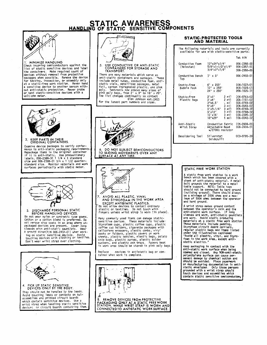
1. MINIMIZE HANDLING Check incoming semiconductors aga ins t t he l i s t o f s t a t i c s e n s i t i v e devices and l abe l the conta iners . Make requ i red count o f devices wi thout removal f rom p r o t e c t i v e ~ackages when poss ib le . Remove the device f o r t es t i ng , inspect ion, o r assembly on l y n t a s t a t i c - f r e e work s t a t i o n . Never hand 3 sens i t i ve device t o another person w i t h - ~ u t a n t i - s t a t i c p ro tec t i on . Never probe Jr t e s t s t a t i c - s e n s i t i v e devices w i t h a tolt-ohm meter.
STATIC AWARENESS NG OF STATIC SENSITIVE COMPONENTS m
5. USE CONDUCTIVE OR ANTI-STATIC CONTAINERS FOR STORAGE A N D TRANSPORT.
There are many ma te r i a l s which serve as a n t i - s t a t i c conta iners and packages. These inc lude metal tubes, conductive foam, a n t i - s t a t i c v i a l s , me ta l l i zed packages, metal f o i l , carbon impregnated p l a s t i c , and p ink po ly . Tekt ron ix now stocks many sizes o f p ink po ly bags, f rom 2" x 4" t o 18" x 29". The l i s t changes con t i nua l l y so contac t
Glen Johnson ext.2453 fo r the l a t e s t p a r t numbers and sizes.
2. KEEP PARTS I N THEIR ORIGINAL CONTAINERS
1
Examine dev ice packages t o v e r i f y confor - I
mance t o an t i - s ta t i c -packag ing requirements. 6 , D O NOT SUBJECT SEMICONDUCTORS Repackage items i n t he o r i g i n a l conta iner i f i t i s a n t i - s t a t i c . Use precaut ionary I TO SLIDING MOVEMENTS OVER A N Y
labe ls , 006-2388-00 1 1/4 x 3 standard SURFACE AT ANY TIME.
s i ze and 006-2388-01 3/4 x 1 112 quar ter - standard s i ze . Monitor ma te r i a l s and work surfaces p e r i o d i c a l l y w i t h s t a t i c meter.
3. DISCHARGE' PERSONAL STATIC BEFORE HANDLING DEVICES.
Do not wear ny lon o r synthet ic type gowns. Cotton o r a co t t on blend i s pre fer red. Do not remove shop coats i n an area where un- packaged devices are present. Cover long sleeves w i t h a n t i - s t a t i c qaunt le ts . Wear a ground strap(P/N 006-2404-01) when work-
i ng on s t a t i c sens i t i ve devices. Avoid touchinq devices w i t h c l o t h i n g O r textiles. Don ' t wear w r i s t s t r ap over c l o th i ng .
4 PICK UP STATIC SENSITIVE DEVICES ONLY BY THE BODY.
They should no t be handled by the leads. Avoid touching leads o r contacts on sub- assemblies and p r i n t e d c i r c u i t boards which conta in s e n s i t i v e devices. Use a
7 . AVOID ALL PLASTIC, VINYL A N D STYROFOAM I N THE WORK AREA EXCEPT ANTISTATIC PLASTICS.
Do no t a l l o w devices t o contac t ord inary p l a s t i c o r t e x t i l e s . Do no t touch w i t h f i nge rs unless w r i s t s t r ap i s worn ( i n p lace) .
Many comnonly used items can damage s t a t i c - s e n s i t i v e devices. These ma te r i a l s inc lude: Styrofoam cups, p l a s t i c co f f ee cups, p l a s t i c co f f ee cup ho lders , c i g a r e t t e packages w i t h cel lophane wrappers, p l a s t i c combs, v i n y l books o r f o l de rs , p l a s t i c covers on work sheets, p l a s t i c b o t t l e s , p l a s t i c bags, po ta to ch ip bags, p l a s t i c purses, p l a s t i c so lder suckers, and p l a s t i c ash t r ays . Papers kept i n work area should be s tored i n p ink po ly bags
Replace devices i n a n t i s t a t i c bag o r con- t a i n e r when work i s complete.
3 . REMOVE DEVICES FROM PROTECTIVE 'ACKAGING ONLY AT A STATIC FREE WORK ITATION, WHILE WRIST STRAP IS W O R N A N L :ONNECTEDTO ANTISTATIC WORK SURFACE.
STATlC:PROTECTED TOOLS AND MATERIAL
The f o l l o w i n g ma te r i a l s and t o o l s are cu r ren t l y a v a i l a b l e f o r use w i t h s t a t i c - s e n s i t i v e par ts :
Tek P/N
Conductive Foam 12"x24"~1/4" 006-2356-O( (Ve los ta t ) 5/8"x1-1/2";1/4" 3 /4 "x2 "~1 /4 006-2357-O(
006-2358-OC
Conductive Bench 3 ' x 8 ' 006-2403-01 TOP
Sta t ic -Free 6" x 250' 006-1 523-01 Bubble Pack 12" x 250' 006-1 524-01
24" x 250' 066-1 525-01
Sta t ic -Free Z"x4" 2 m i l 006-0763-02 P l a s t i c Bags 3"x4" 2 m i l 006-i151-02
3"x6.5" L m i l 006-0769-02 5"x5" 3 m i l 006-0343-02 5"x9-114" 3 m i l 006-0764-02 9"x12" 3 m i l 006-0768-0: 12"x16" 3 m i l 006-2395-02 18"x29" 6 m i l 006-0342-02
A n t i - S t a t i c Conductive Fabric 006-2404-0( Wr is t Strap Ad jus tab le Bead 006-2404-01
w/270Kn r e s i s t o r
Oesoldering Tool S i l v e r s t a t 003-0795-O( Soldapul l t
1 V A T I C FREE WORK STATION I A s t a t i c f r e e work s t a t i o n i s a work bench which has been covered w i t h a sheet o f a n t i - s t a t i c ma te r i a l . A metal b o l t grounds t he mater ia l t o a metal t a b l e support. NOTE: Table tops should no t be connected t o hard ground ( b u i l d i n g ground). There should always be a minimum o f 200K ohms and a max- imum o f 500K ohms between the operator and hard ground.
A w r i s t s t r ap makes ground contact between the ope ra to r ' s sk i n and the a n t i - s t a t i c work surface. I f long sleeves a re worn, a n t i - s t a t i c gaunt lets a re worn. Avoid s t a t i c producing ma te r i a l s a t a s t a t i c f r e e work s ta t i on These ma te r i a l s i nc l ude padding, Styrofoam c i r c u i t board ca r r i e r s , r egu la r p l a s t i c bags and items l i s t e d y d e r t he i l l u s t r a t i o n captioned Avoid a l l p l a s t i c , v i n y l , and Styro-
foam i n t he work area, except a n t i - s t a t i c p l a s t i c s . "
Keep packaging i n contac t w i t h t he a n t i - s t a t i c work surface when being opened and closed. Any NON-anti-static po lyethy lene sur face can cause per- manent damage by chemical ac t i on and should be avoided. Place papetwork o r manufactur ing documentation i n a n t i - s t a t i c envelopes. Only those persons grounded w i t h a w r i s t s t r ap should touch devices and assemblies which conta in s t a t i c s e n s i t i v e s e m l c o n d u c ~


S E C T I O N S 1 T H R U 4
CATALOG WRITER: NANCY K I N G , EXT. 2582.
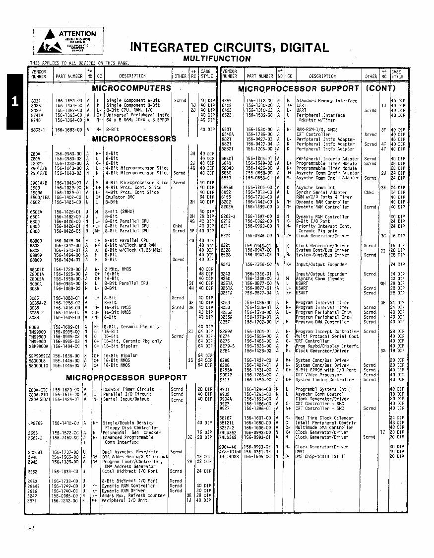
DIGITAL INTEGRATED ClRCUlTS,
** PART NUMBER NO CC 3ESCRIPTION
SOCESSOR SUPPORT
THIS APPLIES TO ALL DEVICES ON THIS PAGE.
- -
[ P 1 P IP P P
P
P P P P P
P P P P P
P P P P
P P P P P
P P P P P
Y
3
3
Y
Y
Y
Y
1
> >
> > >
I
)
)
I
VENDOR NUMBER
1 4289 6402 6402 6522
6531 6545A 6821 6821 68B21
68821 6840 68840 6850 6850
68850 6852 81 55 8202 82OZA
8203-3 8212 821 4
8224
8224 8228 8228
8243
8243 8250 8251A 8251A 8251A
8253 8253 8255A 8255A 8257
8259A 8274 18275 8279-5 '8284
8288 8288 B755A 9007P 9513
9901 9902 9904A 9927 9927
581 67 681 21 L 8237-2 74LS362 74LS362
9904-40 AY3-10151 19-14038
-
MULTIFUNCTION
P I
h
II
OTHEF - - (0
Scrnd
Scrnd
Scrnd
Scrnd Scrnd
Scrnd
Chkd
Scrnd
k r n d
j c r n d
Scrnd
jc rnd i c r n d
i c r n d i c r n d i c r n d jc rnd
k r n d
k r n d k r n d k r n d jcrnd
k r n d
ic rnd
-
t i CASE RC
S i n g l e Component 8-Bi t S i n g l e Component % - B i t % - B i t CPU, RAM, r/O Universa l Per iphera l I n t f c 64 x 8 RAM; 1024 x 8 EPROM
VENDOR NUMBER STYLE
Scrnd M Standard Memory I n t e r f a c e K t UART L - UART L Per iohera l I n t e r f a c e
Adapter w/Timer
I 803 1 8035 8039 8741A 8748
6803-1
Z80A Z80A 18020 2901A/B 2901AlB
2901A/B 2909 2909A 6500/1 EA 6502
6502A 6504 6800 6800 6800
68800 6802 6808 68809 68809
58B09E Z8001A Z8002A 3080A 3085
3085 3085A-2 3086 3086-2 1088
3088 'MS9900 'MS9900 'MS9900 iBP9900A
tBP9989C~ 18000L8 18000L10
80A- CTC BOA-PI0 'BOA-SIO/
PB765
653 661-2
C2681 940 942
952
953 9648 966 242 37 1
- -2
' **
NT)
1J
3F
4F 4F
25
3E
36
21
9H
3E
36
I J
N- RAM-ROM- I/O, NMOS CRT C o n t r o l l e r
L- Per iphera l I n t f c Adapter K Per iphera l I n t f c Adapter K Per iphera l I n t f c Adapter
CC PART NUMBER
40 O I I 40 O I I 40 DI I 40 DI I
40 DIf 40 O I I 40 O I f 40 OII 40 011
40 D I I 28 D I I 28 O I f 24 DI I 24 D I i
24 D I i 24 OIf 40 OIf 40 OIf 40 OIF
40 O I F 24 OIF 24 DIF
16 OIF
16 O I F 28 OIF 28 DIF
24 OIF
24 OIL 40 OIF 28 DIF 28 OIF 28 OIF
24 DIP 24 DIP 40 DIP 40 OIF 40 DIP
28 DIP 40 DIP 40 DIP 40 DIP 18 DIP
20 DIP 20 DIP 40 DIP 40 DIP 40 DIP
40 DIP 18 DIP 20 DIP 40 DIP 40 DIP
24 DIP 48 DIP 40 DIP 20 DIP 20 DIP
20 DIP 40 DIP 20 DIP
40 DI 40 01 40 DI 40 01 40 DI
40 01 40 DI 40 01 64 01 40 01
40 DI 28 01 40 01 40 DI 40 DI
40 DI 40 DI 40 01 40 01 40 DI
40 DI 48 DII 40 Dl 40 011 40 DII
40 011 40 011 40 OII 40 011 40 DII
40 DI I 54 D I I 54 D I I 54 DIf 54 O I I
54 O I F 54 011 54 DIF
28 DIF 40 DIF 40 DIF
40 DIP
16 DIP 28 DIP
28 DIP 22 DIP
24 DIP
40 DIP 20 DIP 28 DIP 40 DIP
-
ND
Per iphera l I n t e r f c Adapter L+ Programable Timer Module K+ Programmable Timer Module J+ Asynchr C o m I n t f c Adapter M- Asynchr Corn I n t f c Adapter
DESCRIPTION
8-Bi t 4-Bi t Microprocessor Sl icc 4 - B i t Microprocessor Sl icc Scrnd
Scrnd
Chkd Scrnd
Scrnd
Scrnd
Scrnd
Scrnd
OTHER
4 - B i t Microprocessor S l i c t 4 - B i t Prcs. Cont. S l i c e 4 - B i t Prcs. Cont S l i c e Emulator OVC % - B i t
K Asynchr Comm I n t L Synchr S e r i a l Adapter
RAM w/I/O Por ts & Timer N+ Dynamic RAM C o n t r o l l e r N+ Dynamic RAM C o n t r o l l e r
tt RC
N Dynamic RAM C o n t r o l l e r K t 8 - B i t 110 P o r t M- P r i o r i t y I n t e r u p t Cont,
Ceramic Pkg o n l y J t Clock Generator/Dr iver
CASE STYLI
8-Bi t 8 - B i t P a r a l l e l CPU % - B i t P a r a l l e l CPU % - B i t P a r a l l e l CPU
% - B i t P a r a l l e l CPU % - B i t w/Clock and RAM 8 - B i t w/Clock (1.25 MHz) % - B i t 8-81 t
K Clock Generator/Oriver L System Cont/Bus D r i v e r M- System Cont/Bus D r i v e r
K+ I n p u t l o u t p u t Expander I 2 MHz, HMOs 1 6 - B i t Input /Outpu t Expander
M Asynchr. Corn Element L USART L t USART K t USART
1 6 - B i t 5 - B i t P a r a l l e l CPU 3-Bi t
3-Bi t 3-Bi t 16-B i t NMOS 16-B i t NMOS 3-Bi t
M Program I n t e r v a l Timer M+ Program I n t e r v a l Timer L- Program Per iphera l I n t f c
Program Per iphera l I n t f c M Program DMA C o n t r o l l e r
3-Bit, Ceramic Pkg o n l y 16-Bi t 16-Bi t
N- Program I n t e r p t C o n t r o l l e r 0 M u l t i Pro toco l S e r i a l Cont 0- CRT C o n t r o l l e r M Prog Keybd/Oisplay I n t e r f c M- Clock Genera tor IDr iver
1 6 - B i t , Ceramic Pkg o n l y 16-Bi t B i p o l a r
6 - B i t B i p o l a r 6-Bi t NMOS 6-Bi t NMOS
M+ System Cont/Bus D r i v e r N- System Cont/Bus D r i v e r O+ 8 - B i t EPROM w i t h 110 P o r t
CRT Video Processor N+ System Timing C o n t r o l l e r MICROPROCESSOR SUPPORT
Scrnd Scrnc Scrnc
Scrnd
k r n d
k r n d k r n d k r n d
-
Counter Timer C i r c u i t P a r a l l e l 110 C i r c u i t S e r i a l Input/Output
L Programbl Systems I n t f c L Asynchr Corn Cont ro l
Clock Generator/Dr iver 0- CRT C o n t r o l l e r - SMC N+ CRT C o n t r o l l e r - SMC
Y- Real Time Clock Calendar 3 I n t e l 1 Per iphera l C o n t r l r 3- Mu1 timode OMA C o n t r o l l e r K t Clock Generator/Oriver 4 Clock Generator/Oriver
156-1412-00 1 1 1 k N t Single/Oouble Dens i ty Floppy Disc C o n t r o l l e r
156-1572-00 A IN
I Polynomial Gen Checker 156-3460-01: A N- Enhanced Proaramnable
Dual Asynchr. Rcvr/Xmtr OMA Addrs Gen w/3 S t Output Program Timer/Control l e r , DMA Address Generator
Octal B i d i r e c t 1/0 P o r t
% - B i t B i d i r e c t 1/0 P o r t N t Dynamic RAM C o n t r o l l e r K t Dynamic RAM D r i v e r K t Addrs Mux, Refresh Counter M+ Per iphera l 1/0 U n i t
INTEGRATED CIRCUITS, DIGITAL (CONT) MULTIFUNCTION
** #bfii@i PART NUMBER I ND 1 CC
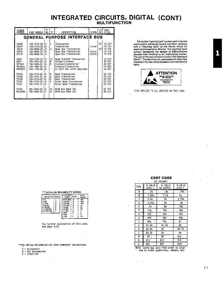
GENERAL PUF DESCRIPTION
DOSE INTERFA(
Transceiver Transceiver Quad Bus Transceiver Quad Bus Transceiver Quad Bus Transceiver
Quad 3-State Transceiver Tal ker/Listener Protocol/Control l e r Protocol/Controller Hi Perf Bus I n t f c Register
Data Transceiver Data Transoeiver Data Transceiver Octal Gate Transceiver Octal Gate Transceiver
SPIB Bus Mgmt Ckt GPIB Bus Mgmt Ckt
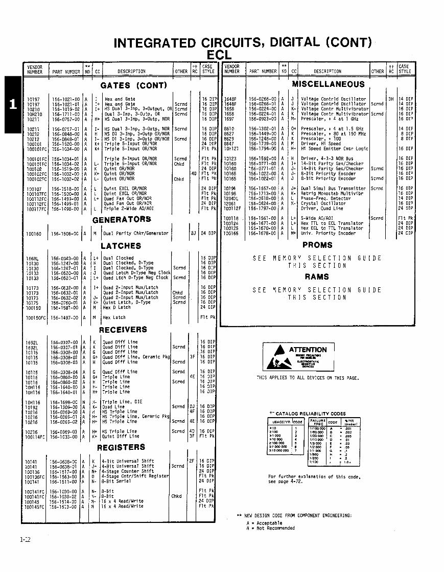
tt CATALOG RELIABILITY CODES
01 - .01 = 0 5
For fur ther explanation o f t h i s code, see page 4-72.
**NEW DESIGN RECOMMENDATION FROM COMPONENT ENGINEERING:
E BUS
Scrnc
Scrnc Scrnd
-
16 DIP 16 D I P 16 D I P 16 DIP 16 DIP
16 DIP 40 D I P 40 DIP 40 DIP 40 DIP
20 D I P 20 D I P 20 DIP 20 D I P 20 DIP
22 D I P 48 DIP
-
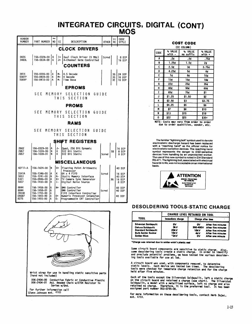
The fami1iar"lightning bolt" symbol used to denote electrostatic discharge hazard has been replaced with a "reaching h a n d as the official notice for electrostatic-sensitive devices. The reaching hand symbol represents the danger to ESD-sensitive devices from handling by an unprotected worker. The use of this new symbol is noted in EIA Standard RS-471. The lightning bolt, associated with electrical hazards tolife, was notacceptableonan international basis.
o w w t P ~ ~ C ~ U T I O ~ ~ S
ELECTROSTATIC SENSITIVE
THIS APPLIES TO ALL DEVICES ON THIS PAGE.
COST CODE f C C CDLUMNl
A = Acceptable N = Not Reconended U = Undefined
. - - - - - - ,
NOTE: Costs may vary from order to order due t o order quanti t ies, vendoh etc.
A
B
% VALUE no s u f f i x
.5d 1.56
% VALUE wi th -
.2d 1.256
% VALUE wi th +
.75(
26

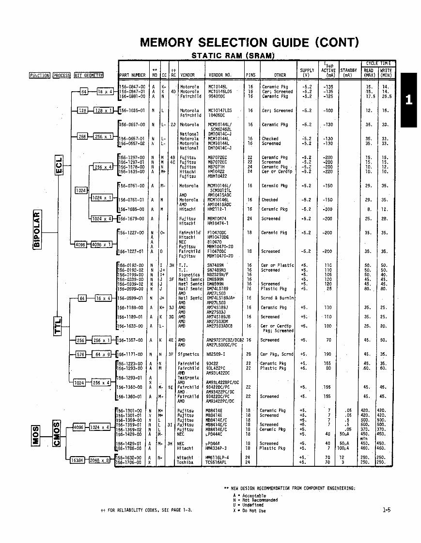
MEMORY SELECTION GUIDE THIS APPLIES TO ALL DEb,CtS ON THIS PAGE
DYNAMIC RAM (DRAM)
VENDOR I VENDOR NO. I PINS
m SUPPLY
PACKAGE -1 1-1 R READ I WRITE
(MAX nS) (MIN nS)
Mostek Mostek Mostek
I TT NEC I TT NEC NEC H i t ach i I n t e l Hi t ach i
H i tach i
Elec Oesi
PART NUMBER
Ceramic +5, + I2 Ceramic r5, +12
+5, + I2
Ceramic
** ND
Ceramic Screened Ceramic Ceramic
r
P l a s t i c
Cer o r Cerdip
LCC on Substr A
NON-VOLATILE RAM
FUNCTION PROCESS BIT GEOMETRY P
F u,_(1024 x 11-
FA
PART NUMBER
XR - PINS - -
24
24
2 4 24 24 24 24
24 24 24 24 24 24 24 24 24 24
24 24 24 24 24 24 24
24
24
24
24 -
0 - 0
-'
PROGl
VENDOR
Signet ics
AM0
AM I AM I Motorola Gen I n s t r Motor01 a
Synertek' S ignet ics T.I . T. I . Motorola Na t l Semic Synertek Synertek E A E A
Mostek Mostek Mostek Mostek NEC Synertek Motorola
Na t l Semic
Na t l Semic
l o t o r o l a
S igne t i c s -
READ ACCES
TIME(n - - 7 5
400
450 450 550 850 750
450 450 450 450 350 450 450 450 450 450
250 250 300 300 450 450 250
600
350
450 -
STORE/RECALL
1 0mS/1 50011s
mW - TANDB -
35 35 35 35
55
-
SUPPLY REAO/WRITE PINS PACKAGE 0 ) ( ns )
18 Ceramic +5. 300/300
PART NUMBER
156-1654-00
POWEl - ACTIVE =
850
1W
300 300
200
750 400 400 400 400
1000 750 750 750 750
220 220 220 220 750 650 270
525
-
SUPPLY PACKAGE
** NO
A
VENOOR NO. PROCESS BIT GEOMETRY
512 x 8
1024 x 8
cc
M+
Ceramic
Ceramic Its.
tt RC
P l a s t i c Ceramic
Cerami c 1 +5.
VENDOR
XICOR
+5. Cer o r P l a s t i c +5. Cer o r Cerdip +5. Ceramic +5. P l a s t i c +5.
VENDOR NO
X2201
Ceramic +5. Cer o r Cerdip I+5.
Cer o r Cerdip +5. P l a s t i c +5. Cer o r Cerdip +5. Cer o r P l a s t i c +5. Cer o r Cerdip +5. Cer o r Cerdip +5. Cer o r Cerdip +5.
Cer o r ~ l a s t i c l t 5 .
Cer o r P l a s t i c
Cer o r Cerdip
P l a s t i c (+5.
MEMORY SELECTION GUIDE (CONT) AM)
PINS - - 16 16 16
16
16
16 16
22 22 24 24
16
16
16
24
18
18
16 16 16 16 16 16
16
16
16
16
16
28
22 22
22
22
18 18 18 18 18 18
18 18
24 24 -
S 1
VENDOR
Motorola Motorola F a i r c h i l
Motorol a F a i r c h i l
Motorola
Nat ional Motorola Motorola Nat ional
F u j i t s h F u j i t s u F u j i t s u H i t ach i F u j i t s u
Motorol a
AMD Motorola AMD H i tach i
TIC RAM I
! -. -.
1
I
I
F u j i t s u H i t ach i
H
F I I I I I I
J I I
; I I I
: I I
: I
F F E 1 P
: F P F A
F F F F F N
I N H
H T -
- SUPPL' (V) -
-5.2 -5.2 -5.2
-5.2
-5.2
-5.2 -5.2
-5.2 -5.2 -5.2 -5.2
-5.2
-5.2
-5.2
-5.2
-5.2
-5.2
+5. +5. +5. +5. +5. +5.
+5.
+5.
+5.
+5.
+5.
+5. +5.
+5.
+5.
+5. +5. +5. +5. +5. +5.
+5. +5.
+5. +5. -
- Isup
ACTIY td =
-135 -135 -125
-100
-130
-1 30 -130
-200 -200 -200 -220
-150
-150
-200
-200
-200
-200
110 110 105 120 120 25
110
110
100
70
190
155 80
155
155
7 7 7 7
40
40 7
70 70 -
- CYCLE TIM l -
READ (MAX - - 15. 15. 17.'
12.
35.
35. 35.
15. 15. 10. 10.
29.
29.
8.
25.
35.
35.
50. 50. 50. 45. 45. 80.
35.
35.
25.
45.
45.
45. 60.
45.
45.
20. 20. DO. 30. 70. 50. i n 50. 50.
50. 50. -
- lRIT (MIN - - 14. 14. 25.
15.
33.
33. 33.
15. 15. 12. 10.
35.
35.
12.
28.
35.
35.
50. 50. 40. 45. 45. 80.
25.
25.
20.
50.
35.
35. 50.
15.
15.
10. '0. 10. 10. '0. 0.
0. 0.
0. 0. -
IFUNCTIONI IPROCESSI -1 ART NUMBE VENDOR NO.
MC10145L MC10145LDS 95400DC
OTHER
Ceramic Pkg Cer; Screened Ceramic Pkg
Cer; Screened
Ceramic Pkg
Checked Screened
Ceramic Pkg Screened Ceramic Pkg Cer o r Cerdip
Ceramic Pkg
Checked
Ceramic Pkg
Screened
Fa i r ch i l c Hi t ach i NEC F u j i t s u Fa i r ch i l c F u j i t s u
T. I . T. I. Signet icr Yatl Semi Yatl Semi Yatl Semi MD Yatl Semi 3MD MD \MD \MD \MO \MO
WD MD
i i gne t i cs
' a i r ch i l d ' a i r c h i l d IMO .ek t ron ix IMO ' a i r c h i l d IMD a i r c h i l d ,MD
u j i t s u u j i t s u u j i t s u u j i t s u u j i t s u EC
EC i tach i
i t a c h i oshiba -
Ceramic Pkg
Screened
Cer o r P las t i c Screened
Screened P l a s t i c Pkg
Scrnd & BurnIn
Ceramic Pkg
Screened
Cer o r Cerdip Pkg; Screened
Screened
Cer Pkg, Scrnd
:eramic Pkg ' l a s t i c Pkg
Screened
:eramic Pkg jcreened
icreened :eramic Pkg
icreened ' l a s t i c Pkg
** NEW DESIGN RECOMMENDATION FROM COMPONENT ENGINEERING:
A = A c c e ~ t a b l e N = Not Recomnended U = Undeftned X = Do Not Use tt FOR RELIABILITY CODES. SEE PAGE 1-3.
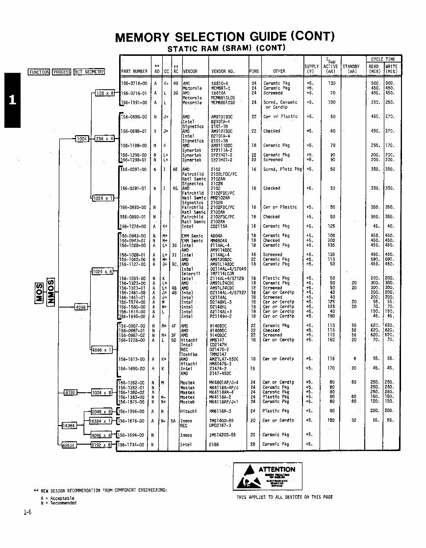
MEMORY SELECTION GUIDE (CONT)
** NEW DESIGN RECOMMENDATION FROM COMPONENT ENGINEERING:
STATIC RAM (SRAM) (CONTI
RC VENDOR L 46 AM1
Motorola 36 AM1
Motorola Motor01 a
AMD I n t e l
I,,netics
I n t e l S ignet ics AM0 Synertek Synertek Synertek
4E AMD F a i r c h i l d Nat l Semi S ignet ics
46 AMD F a i r c h i l d Nat l Semi, S ignet ics F a i r c h i l d Nat l Semi( F a i r c h i l d Na t l Semi1 I n t e l
EMM Semic EMM Semic
36 I n t e l AMD
31 I n t e l
I n t e l
I n t e l AM0
!B AMD 10 I n t e l
I n t e l I n t e l I n t e l I n t e l I n t e l
IF AM0 AMD
IF AM0 iD H i t ach i
I n t e l NEC Toshi ba AMD H i tach i I n t e l AMD
Mostek Mostek Mostek Mostek Mostek
Hi t ach i
A Inmos NEC
Inmos
I n t e l
VENDOR NO.
AM9101 BDC B2101A-4 2101-IN AM91 01 BDC
2101-IN AM91 11 DDC SY2111A-2
I
IN! - - 24 24 24
24
22
22
18
22 22
16
16
16
16
16
18 18 18
18 22 18
18 18 18 18 18 18 18 18 18
?2 ?2 22 18
18
8
!4 !4 !4 !4 !4
!4
!O
!O
!8 I
OTHER
Ceramic Pkg Ceramic Pkg Screened
Scrnd , Ceramic o r Cerdip
Cer OF P l a s t i c
Checked
Ceramic Pkg
Ceramic Pkg Screened
Scrnd, P l s t c Pk!
Checked
Cer o r P l a s t i c
Checked
Ceramic Pkg
Ceramic Pkg Checked Ceramic Pkg
Screened Ceramic Pkg Ceramic Pkg
P l a s t i c Pkg Ceramic Pkg Screened Cer o r Cerdip Screened Cer o r Cerdip Cer o r Cerdip Cer o r Cerdip Cer o r Cerdip
Ceramic Pkg Checked Screened Cer o r Cerdip
Cer o r Cerdiv
Cer. o r Cerdi p Ceramic Pkg Ceramic Pkg P l a s t i c Pkg Ceramic Pkg
P l a s t i c Pkg
Cer o r Cerdip
Ceramic Pkg
Ceramic Pkg
- CYCLl -
READ (MINI - - 500. 450. 450.
250.
450.
450.
250.
200. 200.
350.
350.
350.
350.
45.
450. 450. 450.
450. 690. 450.
200. 300. 300. 200. 200. 55. 70.
150. 45.
620. 620. 620. 70.
55.
45.
250. 250. 250. 150. 120.
200.
55.
- TIME - WRITE (MINI - - 500. 450. 450.
250.
270.
270.
170.
200. 200.
350.
350.
350.
350.
40.
450. 450. 450.
450. 690. 450.
200. 300. 300. 200. 200. 55. 70.
150. 45.
620. 620. 520. 70.
55.
45.
!50. !50. ?50. 150. 120.
200.
55.
A = Acceptable N = Recomnended
THIS APPLIES TO ALL DEVICES ON THIS PAGE
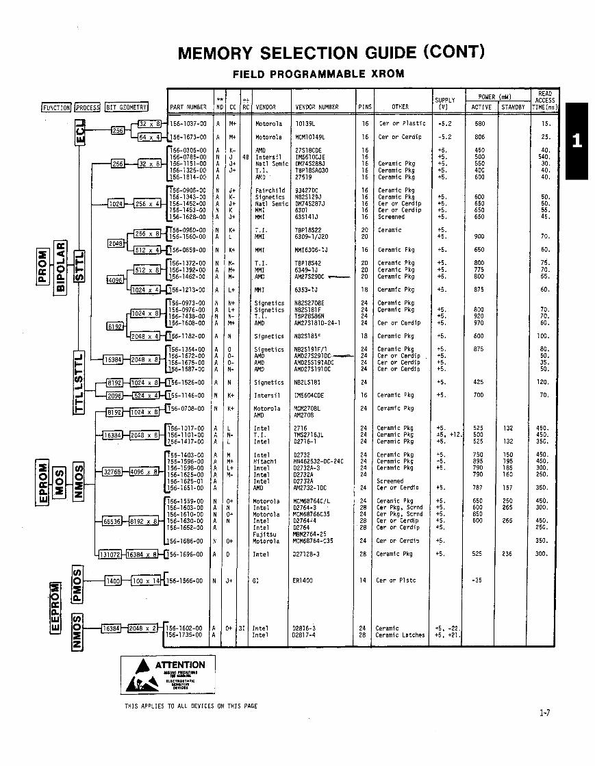
MEMORY SELECTION GUIDE (CONT) FIELD PROGRAMMABLE XROM
- PIN! - - 16
16
16 16 16 16 16
16 16 16 16 16
20 20
16
20 20 20
18
24 24 24 24
18
24 24 24 24
24
16
24
24 24 24
24 24 24 24
24
24 28 24 28 28
24
28
14
24 28 -
- SUPPLY (V)
-5.2
-5.2
+5. +5. +5. +5. +5.
+5. +5. +5. +5.
+5. +5.
+5.
+5. +5. +5.
4.5.
+5. +5. +5.
+5.
+5. +5. +5. +5.
+5.
+5.
+5. *5, +I2 +5.
+5. +5. +5.
+5.
+5. +5. +5. +5. +5.
+5.
+5.
+5, -22 15, +21 -
- READ
ACCES .IME(n - -
15.
25.
40. 540. 30. 40. 40.
50. 50. 55. 45.
70.
60.
75. 70. 55.
60.
70. 70. 60.
100.
80. 50. 35. 50.
120.
70.
450. 450. 350.
450. 450. 300. 250.
350.
450. 300.
450. 250.
350.
300.
POWE
ACTIVE - - 580
806
450 500 550 400 600
600 650 650 650
900
650
800 775 800
875
800 920 970
600
875
425
700
525 500 525
750 895 790 790
787
650 600 850 600
525
-35
VENDOR VENDOR NUMBER
101 39L
MCM10149L
27S18CDE IM561 OCJE DM74S288J TBP18SA030 2751 9
OTHER
Motorola
Motorola
AMD I n t e r s i l Nat l Semi T.I. AMD
F a i r c h i l d S ignet ics Nat l Semi, MM I MMI
T.I. MMI
MM I
T. I. MMI AMD
m I
Signet ics S ignet ics T . I . AMD
Signet ics
S ignet ics AMD AMD AM0
Signet ics
I n t e r s i l
Motorola AMD
I n t e l T.I. I n t e l
I n t e l ii tach i I n t e l I n t e l I n t e l WO
l o t o r o l a I n t e l I o to ro la I n t e l [ n t e l ' u j i t s u I o to ro la
[ n t e l
;I
n t e l n t e l
Cer o r P l a s t i c
Cer o r Cerdip
Ceramic Pkg Ceramic Pkg Ceramic Pkg
Ceramic Pkg Ceramic Pkg Cer o r Cerdip Cer o r Cerdip Screened
Ceramic
Ceramic Pkg
Ceramic Pkg Ceramic Pkg Ceramic Pkg
Ceramic Pkg
Ceramic Pkg "eramic Pkg
Cer o r Cerdip
:eramic Pkg
:eramic Pkg :er o r Cerdip :er o r Cerdip :er o r Cerdip
AMD27S291 DG-- AMD25S191 ADC AMD27S1910C
:eramic Pkg
:eramic Pkg
:eramic Pkg :eramic Pkg :eramic Pkg
:eramic Pkg :eramic Pkg :eramic Pkg
kreened :er o r Cerdip
:eramic Pkg :er Pkg, Scrnd :er Pkg, Scrnd :er o r Cerdip :er o r Cerdip
:er o r Cerdip
:eramic Pkg
:er o r P l s t c
eramic eramic Latches
THIS APPLIES TO ALL DEVICES ON THIS PAGE
PART NUMBER
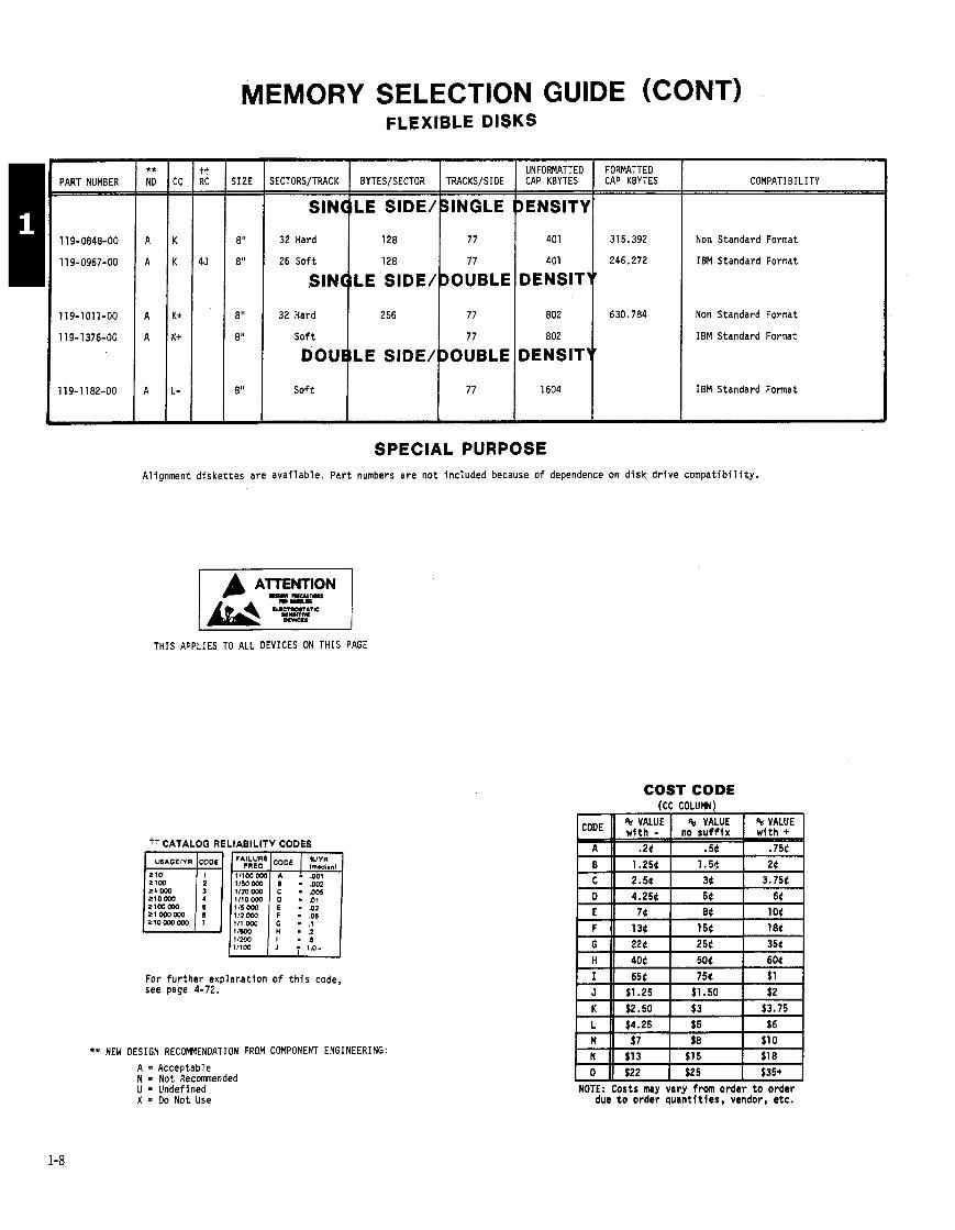
MEMORY SELECTION GUIDE (CONT) FLEXIBLE DISKS
- SIZE - -
8"
8"
8"
8"
8"
-
UNFORMATTED IECIORS/TRACK I BITES/SECTOR I TRACKS/SIDE 1 CAP KBYTES
So f t 1
FORMATTED CAP KBYTES COMPATIBILITY
Non Standard Format
IBM Standard Format
Non Standard Format
IBM Standard Format
IBM Standard Format
SPECIAL PURPOSE Alignment d i ske t t es are ava i lab le . Pa r t numbers are no t inc luded because o f dependence on d i sk d r i v e compa t i b i l i t y .
LF~P" 1 THIS APPLIES TO ALL DEVICES ON THIS PAGE
COST CODE ICC COLUM)
tt CATALOG RELIABILITY CODES
For f u r t h e r explanat ion o f t h i s code, see page 4-72.
** NEW DESIGN RECOMMENDATION FROM COMPONENT ENGINEERING: A = Acceptable N = Not Recmended U = Undeflned X = Do Not Use
I - " --- ] $25 I $35+ (
NOTE: Costs m y vary from order t o order due t o order quan t l t t es , vendor, etc.
--
CODE
A
B
% VALUE n o s u f f i x
.54 1 .5 t
5 VALUE w i t h -
2 4 1.256
5 VALUE w i t h +
.754
26
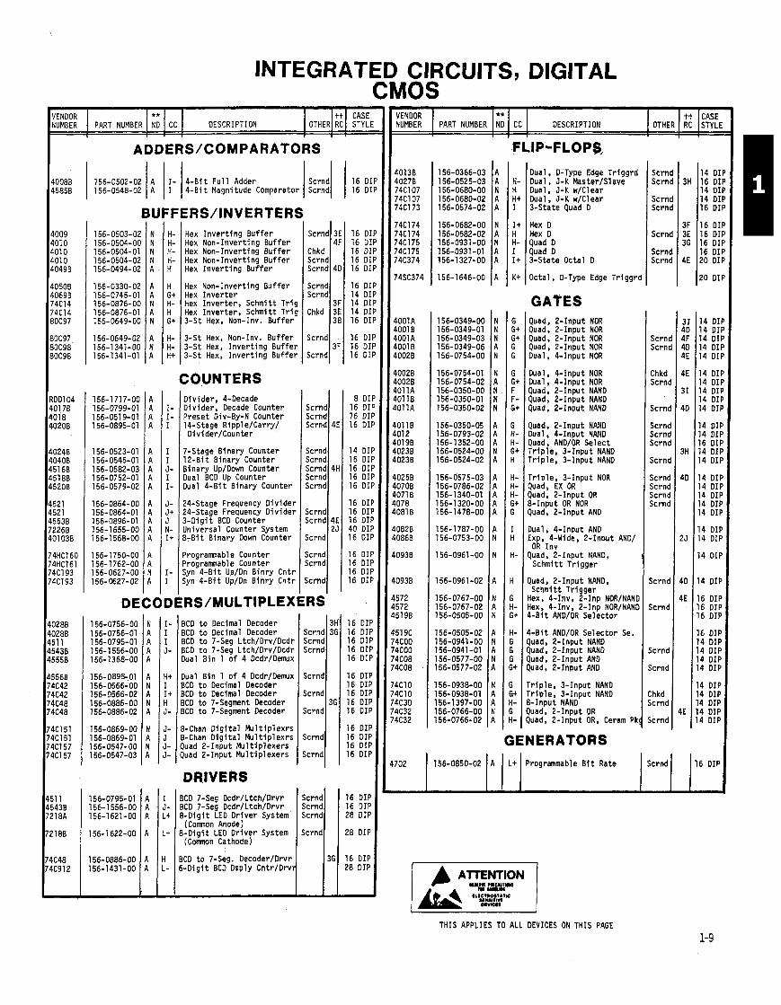
INTEGRATED CIRCUITS, DIGITAL CMOS
VENDOR ** tt CASE NUMBER PART NUMBER NO CC DESCRIPTION OTHER RC STYLI
,
I- 4-B i t F u l l Adder 156-0502-02 1 A 1 I / I Scrndl 156-0548-02 A 4 - B i t Magnitude Comparator Scrnd
BUFFERS/INVERTERS
VENDOR NUMBER
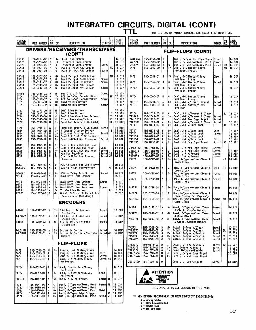
Dual, D-Type Edqe Tr iggrd Dual, J-K Master/Slave Dual, J-K w/Clear Dual, J-K w/Clear 3-State Quad D
I 8 1 .
CC
Scrnd Scrnd
Scrnd Scrnd
Scrnd
Scrnd Scrnd
Scrnd Scrnd
Chkd Scrnd
Scrnd
Scrnd Scrnd Scrnd
Scrnd
Scrnd Scrnd Scrnd Scrnd
Scrnd
Scrnd
jc rnd
jcrnd I
PART NUMBER
Hex I n v e r t i n g Buffer Scrnd 3E 16 DI Hex Non-Invert ing Buf fer 4F 16 Dl Hex Non-Invert ing Bu f fe r Chkd 16 Dl Hex Non-Invert ing Buf fer Scrnd 16 DI Hex I n v e r t i n g Buf fer Scrnd 4D 16 D l
** ND DESCRIPTION
Hex D Hex D Quad D Quad D 3-State Octal D
St CASE OTHER RC STYLI
Dctal , 0-Type Edge Tr iggrd 1 Hex Non-Invert ing Buffer 1 ~ c r n d l 1 16 Dl
Hex I n v e r t e r Hex I nve r te r , Schmitt T r i g 1 scrnd13Fl i: i! Hex Inve r te r . Schmitt T r i a Chkd 3E 14 DI
GATES 13-St Hex, on-1nv. ~ u f f e r " 1 136) 16 Dl Quad, 2-Input NOR
Quad, 2-Input NOR Quad, ?-Input NOR Quad, 2-Input NOR Dual, 4-Input NOR
3-St Hex, Non-Inv. Bu f f e r 3-St Hex, I n v e r t i n g Bu f fe r 3-St Hex, I n v e r t i n g Buf fer
Dual, 4-Input NOR Dual, 4-Input NOR Quad, 2-Input NAND Quad, 2-Input NAND Quad, 2-Input NAND
14 DI 14 D l 14 DI 14 DI 14 DII
14 DII 14 DII 16 DII 14 DII 14 DII
14 DII 14 DII 14 Dl1 14 DII 14 DII
14 DII 14 DII
14 DII
14 DI!
16 DIF 16 DIF 16 DIF
16 DIF 14 OIF 14 DIF 14 DIP 14 DIP
14 DIP 14 DIP 14 DIP 14 DIP 14 DIP
8 DI
Scrnd
Div ider , 4-Decade Div ider , Decade Counter Preset Div-By-N Counter 14-Stage R ipp le lCa r r y l D i v i de rKoun te r
Quad. 2-Input NAND Dual, 4-Input NAND Quad, AND/OR Select T r i p l e , 3-Input NAND T r i p l e , 3-Input NAND
Scrnd 14 011 Scrnd 16 DII Scrnd 4H 16 DII Scrnd 16 DII
7-Stage Binary Counter 12-B i t Binary Counter Binary Up/Down Counter Dual BCD Up Counter Dual 4 -B i t Binary Counter
T r i p l e . 3-Input NOR Quad. EX OR Quad, ?-Input OR &Input OR NOR Quad, 2-Input AND
krnci/ 1 ;; ;I; Scrnd 16 DII 24-Stage Frequency D i v i de r 24-Stage Frequency D i v i de r 3-Dig i t BCD Counter Universal Counter System 3-B i t Binary Down Counter
Scrnd 4E 16 DII
/ 2 i /
40 011 Scrnd 16 DII
Dual, 4 - I I l ~ u t AND Exp, 4-Wide, 2-Input AND/ OR Inv
Quad, 2-Input NAND, Schmi tt Tr igger
'rogramnabl e Counter 'rogramnable Counter jyn 4 -B i t Up/Dn B inry Cntr jyn 4 -B i t Up/Dn B in ry Cntr
Scrnd 16 DIf Scrnd 16 DIf
16 DIf Scrnd 16 DI I Quad, 2-Input NAND,
Schmi tt Tr igger Hex, 4-Inv, 2-Inp NOR/NAND Hex, 4-Inv, 2-Inp NOWNAND Wit AND/OR Selector
I
DECOD I- BCD t o Decimal Decoder I BCD t o Decimal Decoder I BCD t o 7-Seg Ltch/Drv/Dcdr J- BCD t o 7-Seg Ltch/Orv/Dcdr
Dual Bin 1 o f 4 Dcdr/Demux
31 Scrnd 31 Scrnd Scrnd
Scrnd
Scrnd 3(
Scrnd
Scrnd
Scrnd
16 DIF 16 DIF 16 DIF 16 DIF 16 OIF
16 DIP 16 DIP 16 DIP 16 DIP 16 DIP
16 DIP 16 DIP 16 DIP 16 DIP
16 DIP 16 DIP 28 DIP
28 DIP
16 DIP 28 DIP
-
4-Bit AND/OR Selector Se. Juad, 2-Input NAND Juad, 2-Input NAND luad, ?-Input AN0 luad, 2-Input AND
H+ Dual B in 1 o f 4 Dcdr/Demux I BCD t o Decimal Decoder I + BCD t o Decimal Decoder H BCD t o 7-Segment Decoder J- BCD t o 7-Segment Decoder
r r i p l e , 3-Input NAND r r i p l e , 3-Input NAND 3-Input NAND Scrnd bad, 2-Input OR b d . &Input DR. Ceram Pk 1 Scrnd chkd
J- 8-Chan D i g i t a l Mu l t i p l ex rs J 8-Chan D i g i t a l Mu l t i p l ex rs J- Quad 2-Input Mu1 t i p l e x e r s J- Quad 2-Input Mu1 t i p l e x e r s
GENERATORS
Programmable B i t Rate Scrnd 116 DIP
DRIVERS Scrnd Scrnd Scrnd
Scrnd I BCD 7-Seg Dcdr/Ltch/Drvr BCD 7-Seg Dcdr/Ltch/Drvr & D i g i t LED Dr i ve r System
(Comnon Anode) & D i g i t LED Dr i ve r System
( C m n Cathode)
H BCD t o 7-Seg. Decoder/Drvr L- 6 -D ig i t BCO Dsply Cnt r /Drv~
THIS APPLIES TO ALL DEVICES ON THIS PAGE
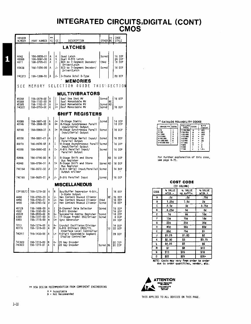
INTEGRATED CIRCUITS,DIGITAL (CONT) CMOS
LATCHES
H Quad Latch I Scrnd K Dual 4 -B i t Latch
16 DIP 24 DIP 16 DIP
16 DIP
20 DIP
OTHER VENDOR NUMBER
** ND PART NUMBER
J- 13-State Octal D-Type I 1 . MEMORIES
I
tt RC
I
J-
S E E M E M O R Y S E L E C T I O N G U I D E T H I S - S E C T I C
CC CASE STYLE
:;:%; 1 156-0578-02 1 A 1 1 Dual 'one Shot MV 1 sCrnd 14E 1 16 DIP 156-1152-00 N Dual Monostable MV
45380 156-1 152-01 A I+ Dual Monoatable MV Scrnd 40
DESCRIPTION
BCD t o 7-Segment Decoder/ Driver/Latch
BCD t o 7-Segment Decoder/ Dr iver /Latch
7&%1 1 156-0750-02 ( A I I + 10ual Monostable MV I ~ c r n d ( 1 16 DIP
Chkd
Scrnd
SHIFT REGISTERS 14 DIP 16 DIP
16 DIP
16 DIP
16 DIP
16 DIP
16 DIP
16 DIP
14 DIP
16 DIP
16 DIP
16 DIP 16 DIP 16 DIP
16 DIP 16 DIP 16 DIP 8 DIP
24 DIP
14 DIP !2 DIP
!8 DIP
?O DIP ?O DIP -
J+ H+
I +
tt CATALOG RELIABILITY CODES 18-Stage S t a t i c 8-Stage Synchronous Pa ra l l
Input /Ser ia l Output 8-Stage Synchronous Pa ra l l
Input /Ser ia l Output
For f u r t h e r exp lanat ion o f t h i s code, see page 4-72.
Scrnd
Scrnd
Dual 4-Stage S e r i a l Input / Paral l e l Output
&Stage Asynchronous Paral 1 Input /Ser ia l Output
4 -B i t Pa ra l l e l Input / P a r a l l e l Output
I 8-Stage S h i f t and Store 4C Bus Register
I + I&Staqe S h i f t and Store lScrnd 140
Scrnd
Scrnd
Scrnd
I- 8 B i t P a r a l l e l I npu t l ~ c r n d 1 I -
I +
COST CODE (CC COLUR)
Bus f iegister 8 - B i t Se r i a l I npu t /Pa ra l l e l Scrnd
Output w/Clear I 1 MISCELLANEOUS
156-1274-00 A K- Crys ta l Osc i l l a to r /D i v i de r 156-1319-00 I A I M I & B i t B iD i rec t CMWTTL I
Chkd Scrnd
I
I
I :- I- 0+
I I I In te r f ace Level C o n t r o l l e r 156-1430-00 A L+ 4-Digi t Expandable Segment
Display Con t ro l l e r
Bus/Buffer Separator 4-Bit , 3-State Output
Hex Contact Bouncd E l imn t r Hex Contact Bouncd E l imn t r Hex Contact Bouncd E l imn t r
156-1279-00 A
156-0763-00 A 156-0763-01 N 156-0763-02 A
156-1215-00 IN IK- 120 Key Encoder 156-1215-01 A K 20 Key Encoder I Scrnd
N
J- J- J-
&Channel Data Se lec tor 8-Bi t Encoder Successive Approx Regis ter 17-Stage Prgmbl OSC/Driver Sync Generator
NOTE: Costs may vary from order t o o rde r due t o order quan t l t l es , vendor, e tc .
Scrnd
Scrnd Scrnd
AlTENTlON tUCTK).TA?K
YWIW M V I U *
THIS APPLIES TO ALL DEVICES ON THIS PAGE.
** NEW DESIGN RECOMMENDATION FRLm COMPONENT ENGINEERING
A = Acceptable N = Not Recomnended
ATENTION UYIU n I W U I D I I
M * W W
INTEGRATED CIRCUITS, THIS APPLIES TO ALL DEVICES ON THIS PAGE. ECL
DIGITAL
ADDERS
VENDOR ** NUMBER PART NUMBER NO CC DESCRIPTION
Scrnd
1
FLIP-FLOPS OTHER
16 DI 16 01 16 Dl 16 01 16 DII
16 DII 16 DII 16 DII 16 011 16 DII
16 DII 16 DII 16 DII 16 DII 16 DII
16 011 16 DII F l t PI 24 DII F l t PI
F l t Pk
16 DIF 16 DIF
16 DIP 16 DIP 16 DIP 16 DIP 16 DIP
16 DIP 16 DIP 16 DIP 16 DIP 16 DIP
16 DIP 16 DIP 16 DIP 16 DIP 16 DIP
16 DIP 16 DIP 16 DIP 16 DIP 16 DIP
16 DIP 16 DIP 16 DIP 16 DIP 16 DIP
16 DIP 16 DIP 16 DIP 6 DIP
tt CASE RC STYLE
24 D: F l t I 24 D: 24 0:
16 Dl 16 Dl 16 Dl 16 Dl 16 Dl
16 Dl 24 Dl F l t F
46 46
D-Type M-S (650 MHz) 0-Type M-S (275 MHz) Dual D-Type M-S (150 MHz) Dual D-Type M-S (150 MHz) Dual 0-Type M-S (250 MHz)
Scrnd
156-0543-00 A I Hex Bu f fe r 156-0543-01 A I + Hex Bu f fe r 156-0542-00 A I- Hex I n v e r t e r 156-0542-01 A I + Hex I n v e r t e r 156-0630-00 A I Hex Inver ter /Buf fer
Dual D-Type M-S (250 MHz) Dual J-K. MasterISlave Dual J-K, Master/Slave Hex D-Type, Master/Slave Hex D-Type, Master/Slave
Scrnd
Scrnd
Scrnd
Scrnd
Scrnd
Scrnd
COMPARATORS
40
Hex D-Type, Master/Slave Hex 0-Type, Master/Slave Hex D-Type, M-S w/Reset Hex D-Type, M-S w/Reset Dual D-Type M-S (225 MHz)
Dual AID 5-Bi t Magnitude 9-Bi t Quad TTL t o ECL Quad TTL t o ECL
Quad TTL t o ECL Quad TTL t o ECL
Scrnd Scrnd
Scrnd
Dual 0-Type M-S (225 MHz) Dual D-Type M-S. Ceramic Pk T r i p l e 0-Type Hex D-Type Hex 0-Type Scrnd
Scrnd
Scrnd
3D
3F
GATES
Scrnd Scrnd
4E
4C
jcrnd
jcrnd
jcrnd
icrnd icrnd icrnd icrnd
k r n d
k r n d e r n d c r n d
c r n d
crnd
crnd
crnd
crnd
crnd crnd
crnd crnd
:rnd
Dual 5-4-Input OR/NOR
S
7 P
? ?
R
3b 3 t
4G 25
25
4E
5E
36
4E
4D
3F
2 I
Dual 4-Input ORINOR Dual 4-Input OR/NOR, Ceramic Pkg on l y CONVERTORS
!
!
I I I I
I
S s S
S
S
S
S
S
S S
Sl SI
Sc
156-0316-00 A H+ Quad 2-Input ECL t o TTL 156-0316-02 A I Quad ?-Input ECL t o TTL,
Ceramic Pkg on l y 156-0316-03 A I Quad &Input ECL t o TTL 156-0316-04 A I + Quad &Input ECL t o TTL
Scmd Scrnd Scrnd
Dual 4-Input ORINOR Quad 2-Input NOR Quad 2-Input NOR Quad 2-Input NOR 2K Inpu t Quad 2-Input OR
I
!
Scrnd Scrnd
Quad 2-Input OR T r i p l e 2-Input EX/OR Ouad 2-Inout NOR w / ~ t r o b e
COUNTERS 16 011
Scrnd 3F 16 DII 3H 16011
Scrnd 4D 16 011 36 16 DII
Scrnd 16 011 16 DII
Scrnd 16 DII F l t PI
~ u a d 2-Input C m n OR/NOI Quad ?- Input Comnon OR/NOI
156-1038-01 A K- ~ i n a $ Counter 156-0641-00 A K Universal Hexadecimal I I l l Quad 2-Input Comnon OR/NOI
Quad 2-Input Common OR/NOI Quad ORINOR Quad OR/NOR quad 2-Input NOR
luad .?-Input NOR Juad 2-Input AND )uad 2-Input AND luad 2-Input OR luad 2-Input OR
16 DIF 16 DIF
Scrnd 16 DIF Scrnd 16 DIF
16 DIF
Scrnd 16 DIF 16 OIF
21 16 DIF 16 DIF
Scrnd 16 DIP
Scrnd 16 DIP 16 DIP 16 DIP
Scrnd 16 DIP 16 DIP
Scrnd 16 DIP Scrnd
F l t Pk 24 DIP F l t Pk
24 DIP k r n d F l t Pk
24 DIP
Dual Mux w/Latch Quad 2-Input Non-Invt h x Quad 2-Input Non-Invt Mux Mu1 t i p l e x e r Binary t o 1-8
!-Input Quad AND !-Input Quad AND luad ?-Input AND l r i p l e 2-3-2 Input ORINOR l r i p l e 2-3-2 Input OR/NOR
Binary t o 1-8 1 o f 8 (Act ive High I npu t ) 8-Line Mu l t i p l exe r 8-Line Mu1 t i p l e x e r &Line Mu l t i p l exe r
l r i p l e 2-3-2 Input OR/NOR ; r i p l e 2-3-2 Input OR/NOR r i p l e 2-3-2 I npu t ORINOR
' r i ~ l e 4-3-3 Input NOR
Dual 8-Line Mu l t i p l exe r Dual 1-of-4 Decoder/Demux Dual Binary t o 1-4 Dual Binary t o 1-4 Dual 4-1 Mu l t i p l exe r
' r i p l e 4-3-3 Input NOR ' r i p l e &Input EX DR/NOR ' r i p l e 2-Input EX ORINOR ' r i p l e 2-Input EX ORINOR ha1 4-5 Input OR/NOR
6 DIP 6 DIP 6 DIP 6 DIP 6 DIP
6 DIP 6 DIP 6 DIP 6 DIP 6 DIP
Dual 4-1 Mu l t i p l exe r Dual 4-1 Mu l t i p l exe r Quad Mux w/Latch Quad Mux w/Latch Mul t ip lexer , 16-Input
lual 4-5 Input OR/NOR lual 4-5 Input ORINOR lual 3-Input, 3-Output, OR u a l 3-Input, 3-Output, OR lual 3-Input, 3-Output, NO1
Mul t ip lexer , 16 I npu t Dual &Input Mux Univ Demux/Decoder Univ Demux/Decoder T r i p l e 4-Input Mux wIEnablc T r i p l e 4-Input Mux wIEnablc
uad, EX OR uad, EX OR ua l , 2-Wd, 2-3 Inp ORIAND ua l , 2 Wd, 3 Input ORIAND
F l t Pk 24 DIP F l t Pk
INTEGRATED CIRCUIT DIGITAL (CONT) ECL
VENDOR NUMBER
I % I658 1658 1697
861 0 8627 8629 8647 10H121
10123 10160 10160 10165 10165
1 01 94 10198 12040 L 12061 100112F
100118 1001 24 1001 25 100165
I **I I DESCRIPTION PART NUMBER ND CC
MISCELLANEOUS GATES (CONT) J Vol tage Cont r ld Osci 11 a t o r J Voltage Cont r ld Osci 1 l a t o r Scrnd K- Voltage Contr Mu1 t i v i b r a t o r K Voltage Contr M u l t i v i b r a t o r Scrnd M- Prescaler, i 4 a t 1 GHz
I
F l t Pk F l t Pk 24 DIP F l t Pk F l t Pk
24 DIP F l t Pk F l t Pk 24 DIP F l t Pk
24 DIP
16 DIP 16 DIP
1 16 DIP 16 DIP
1 16 DIP
16 DIP 16 DIP 16 DIP 16 DIP 24 DIP
F l t Pk
Scrnd Scrnd Scrnd
Scrnd
Scrnd
Scrnd :hkd
4D :hkd
Hex and Gate 16 DIP 16 DIP 16 DIP 16 DIP 16 DIP
16 DIP 16 DIP 16 DIP 24 DIP F l t Pk
14 DIP 14 DIF 16 OIF 16 DIF 16 DIF
14 DIP 8 011 8 DIF
16 DIF
16 O I F 16 DIF 16 OIF 16 O I F 16 DIF
16 DIF 16 DIF 14 DIF 16 DIF ?4 OIF
-1 t Pk ?4 DIF !4 DIF ?4 DIF
Hex and Gate HS Oual 3-Inp, 3-Output, 0 Oual 3-Inp, 3-Outp, OR HS Dual 3-Inp, 3-Outp, NOR
HS Dual 3-Inp, 3-Outp, NOR HS Dl 3-Inp, 3-Outp OR/NOR HS D l 3-Inp, 3-Outp OR/NOR T r i p l e 5- Input OR/NOR T r i p l e 5- Input OR/NOR
O+ Prescaler, i 4 a t 1.5 GHz K Prescaler, i 80 a t 150 MHz K Prescaler, i 100 M Dr iver , H i Speed Ht Hi Speed Em i t t e r Cnt r Logic
T r i p l e 5- Input OR/NOR T r i p l e 5- Input OR/NOR Q u i n t OR/NOR Q u i n t OR/NOR Q u i n t OR/NOR
H Dr iver , 4-3-3 NOR Bus I + 14-B i t P a r i t y Gen/Checker J- 14-Bi t P a r i t y Gen/Checker Scrnd J- & B i t P r i o r i t y Encoder J & B i t P r i o r i t y Encoder Scrnd
J+ Dual Simul Bus Transmi t te r Scrnd K- R e t r i g Monostab M u l t i v i b r L Phase-Freq. Detector K- Crys ta l O s c i l l a t o r
Dr iver , Quad L ine
Q u i n t EXCL OR/NOR Q u i n t EXCL OR/NOR Duad Fan Out OR/NOR &ad Fan Out ORINOR T r i p l e 2-Wide AO/AOI
L+ 5-Wide AO/AOI Scrnd L+ Hex TTL t o ECL T rans la to r L Hex ECL t o TTL T rans la to r M+ Univ. P r i o r i t y Encoder
GENERATORS A M Dual P a r i t y Chkr/Generator I I
PROMS LATCHES L t Dual Clocked' H Dual Clocked, D-Type I Dual Clocked, D-Type J Quad Latch D-Type Neg Clock L t Quad L t ch 0-Type Neg Clock
S E E M E M O R Y S E L E C T I O N G U I D E T H I S S E C T I O N
RAMS
S E E M E M O R Y S E L E C T I O N G U I D E T H I S S E C T I O N
Scrnd
Scrnd
:hkd Scrnd Scrnd
Scrnd
Scrnd
Scrnd
Scrnd
Scrnd
Scrnd
Scrnd
I+ Quad 2- Input Mux/Latch Quad & Inpu t Mux/Latch
J- Quad 2- Input Mux/Latch K t Q u i n t Latch, D-Type M H e x D L a t c h
R I M I Hex Latch
16 DIP 16 DIP .16 DIP 16 DIP 16 DIP
16 DIP 16 DIP 16 DIP 16 DIP
K Quad D i f f L ine K Quad D i f f L ine G Quad O i f f L ine G+ Quad D i f f L ine, Ceramic Pk H Quad D i f f L i ne
i&'2sN 1 THIS APPLIES TO ALL DEVICES ON THIS PAGE.
G Quad D i f f L ine G+ T r i p l e L ine H T r i p l e L i n e H- T r i p l e L ine Ht T r i p l e L i ne 16 DIP
16 DIP 16 DIP 16 DIP 16 DIP
16 DIP F l t Pk
16 DIP 16 DIP 24 DIP F l t Pk 24 DIP
F l t Pk F l t Pk 24 DIP F l t Pk
156-1698-00 I N I H- / T r i p l e Line. DIE
156-1309-00 A K- Quad L ine t+ CATALOG RELIABILITY CODES 156-0369-00 A HS T r i p l e L i ne
H t HS T r i p l e Line, Ceramic Pk 156-0369-01 1 A I I 156-0369-02 A H+ HS T r i p l e L i ne
21 OM) 1/20 ox z10ox 1110000 + l W m 115 W(I . n,
156-0369-03 A H+ HS T r i p l e L i ne 156-1033-00 11 I K t l a u i n t D i f f L ine
. .
REGISTERS
K 4 -B i t Un iversa l S h i f t 21 J+ 4- it Universa l S h i f t Scrnd N+ &Stage Counter S h i f t 0 4-Stage C n t r / S h i f t Reg is ter N- & B i t S e r i a l
For f u r t h e r exp lanat ion o f t h i s code, see page 4-72.
Chkd
** NEW DESIGN CODE FROM COMPONENT ENGINEERING:
A = Acceptable N = Not Recomnended
INTEGRATED CIRCUITS, DIGITAL (CONT) TTL FOR LISTING BY FAMILY NUMBERS, SEE PAGES 1-22 THRU 1-25.
BUFFERS/INVERTERS (CON
VENDOR NUMBER
4 -B i t , F u l l Adder 4F 16 DI 4 -B i t , F u l l Adder Chkd 16 01 4 -B i t , F u l l Adder Scrnd 16 DI 4-B i t , Magnitude Comparator 4F 1 6 0 1 4-B i t , Magnitude Comparator Chkd 16 DI
> '
> '
) :
) :
) : I '
1 .
1 '
I -
' t
VENDOR NUMBER
w
: - -
P P P P P
P P P
P P P P P
P P P
24 DIP 24 DIP 20 DIP 24 DIP
H- Quad 2-Input NAND B u f f e r Chkd w/oc Outputs
Quad 2- Input NAND Bu f f e r Scrnd w/OC Outputs
G+ Quad 2-Input NAND Bu f f e r Scrnd w/OC Outputs
PART NUMBER
B 4
I
1
14 OIF
14 DII
14 OII
14 OII
14 DII 14 DIF 14 DIF
14 OIF 14 DIF 14 DIF 20 OIF 20 OIF
20 OIF 20 DIF 20 DIF 20 DIF
?O DIF !O DIF !O DIF !O DIF 14 DIF
14 DIF 14 DIF 14 DIP 14 DIP 14 DIP
!O DIP !O DIP ?O DIP
16 DIP 6 DIP 16 DIP
6 DIP
6 DIP
6 DIP
6 DIP 4 DIP !O DIP 10 DIP !O DIP
10 DIP 4 DIP 14 DIP
PART NUMBER
)
I
I
1
1
14 DIP 14 DIP 14 DIP 14 DIP
G ]Quad 2-Input NAND Bu f f e r l ~ c r n d
** ND
I
I
E
E E E E E
8 8 2
4-Bit , Magnitude Comparator 4 -B i t , Magnitude Comparator 4 -B i t , Magnitude Comparator
** NO
IT) '
4
4
5
5
3
4
5 5
w/OC outputs F+ Dual 4-Input NAND Bu f f e r F+ Dual 4 - Input NAND Bu f f e r Chkd G- Dual 4-Input NAND Bu f f e r Scrnd
CC
7 7 7 7 7
7 - I
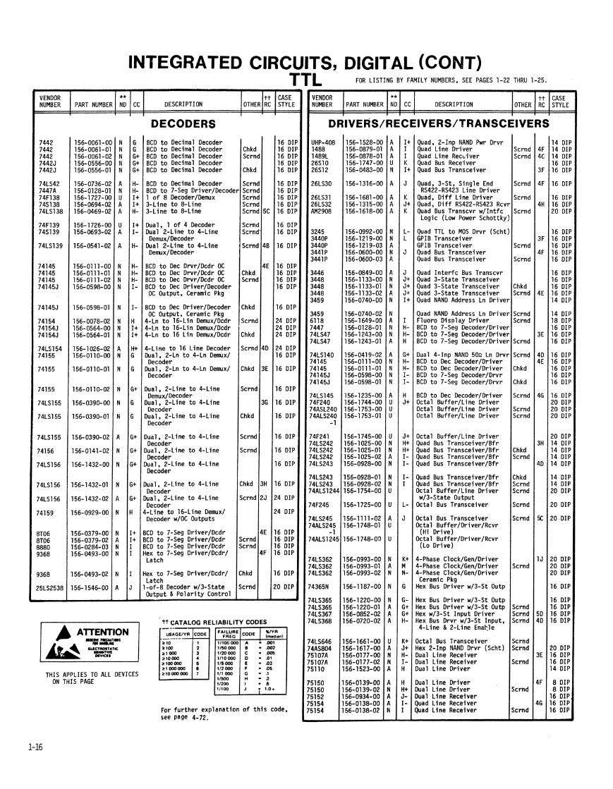
4 -B i t B inary Adder & B i t B inary Adder $ - B i t B inary Adder ? - B i t B inary Adder l u a l F u l l Adder
CC
Scrnd 16 D l 16 01
Scrnd 16 01 Scrnd 16 D l
3E 16 DI
DESCRIPTION
H- Quad Bus B f r w/3-St Output Scrnd H Quad 2-Input NOR B u f f e r Scrnd G+ Quad 2-Input NOR Bu f f e r Chkd J+ Octal I nv B u f f e r w/3-St Out J+ Octal Bu f f e r / L i ne D r i ve r
DESCRIPTION
l ua l F u l l Adder ? - B i t I d e n t i f y Comparator & B i t Equal t o Comparator
OTHER
16 011 :::::I 1 1 6 011 Scrnd 20 011
OTHER
K Octal I nv Bu f f e r w/3-St Out Scrnd I Octal I n v B u f f e r w/3-St Out Scrnd
Octal Bu f f e r / L i ne D r i ve r Scrnd Octal Bu f f e r I L i ne D r i ve r Scrnd
(High D r i ve )
tt RC
CASE STYLE
tt RC
CASE STYLE
ARITHMETIC LOGIC UNITS J+ Octal Bu f f e r I L i ne D r i ve r J+ Octal Bu f f e r w/3-State Out K Octal Bu f f e r w/3-State Out Scrnd I- Octal B f r w/3-State Out Scrnd I + Octal B f r /Or iver /Rece iver
ALU ALU ALU ALU
N A N U
N N N N U
A A N N N
N A A
N
N
N
N N 4 N N
Y Y Y Y
1
\
i
I I I I I
I , I
-
I + Octal Buf fe r /Or iver /Rcvr Chkd H+ Octal Buf fe r /Dr iver /Rcvr Scrnd I- Octal Buf fe r /Dr iver /Rcvr I- Octal Buf fe r /Dr iver /Rcvr Chkd I Octal Buf fe r /Dr iver /Rcvr Scrnd
Scrnd Scrnd
Scrnd
I + J- K- M-
BUI Kt G F+ F+ H-
G+ G F+ G G
H G G
G
G+
H-
G G+ H G- G
G G H- H- G
G
G
F+
F+ G- G- G- F+
F+ G G
H-
Hex I n v e r t e r (D ie Only) Hex I n v e r t e r Hex I n v e r t e r Hex I n v e r t e r Hex I n v e r t e r
Scrnd
Chkd Scrnd
Scrnd 51 Scrnd 51
Chkd Scrnd
Scrnd Scrnd Scrnd 4[
Chkd
Scrnd 4(
Scrnd
Scrnd jc rnd jc rnd 4C jc rnd
:hkd jcrnd
:hkd k r n d
k r n d
icrnd
:hkd 46 c r n d
hkd
h kd c rnd c rnd
14 DIf 14 D I I 14 OIF 14 DIF 14 OIf
14 OIF 14 DIF 14 DIF 14 DIF 14 DIF
14 OIF 14 DIF 14 DIP
14 DIP
14 DIP
14 DIP
14 DIP 14 DIP 14 DIP 14 DIP 14 DIP
14 DIP 14 DIP 14 DIP 14 DIP 14 DIP
14 DIP
14 DIP
4 DIP
I Octal Buf fe r w/3-State Out Scrnd L- Octal Buf fe r /Dr iver /Rcvr J Octal Buf fe r /Dr iver /Rcvr Scrnd
Octal Buf fe r /Dr iver /Rcvr (Lo Dr ive)
Hex I n v e r t e r Hex I n v e r t e r Hex I n v e r t e r w/OC Outputs Hex I n v e r t e r w/OC Outputs Hex I n v e r t e r w/OC Outputs Octal Buf fe r /Dr iver /Rcvr
(H i Dr ive) 3-St Hex I nve r t e r /Bu f f e r 3-St Hex I n v e r t e r I B u f f e r Scrnd Hex 3-St B f r Cwnm Disb l
(Schot tky)
Hex I n v e r t e r w/OC Outputs Hex I nve r t e r w/OC Outputs Hex I n v e r t e r w/OC O u t ~ u t s
I + HS Hex 3-St B f r , Separable Disable (Schot tky)
I HS Hex 3-St B f r . Separable Scrnd Disable (Schot tky)
I + HS Hex 3-St I nv (Schot tky)
Hex I n v e r t e r Buf fe r /Or iver w/OC Outputs
Hex I n v e r t e r Buf fe r /Or iver w/OC Outputs
Hex I n v e r t e r I HS Hex 3-St I n v (Schot tky) Scrnd H- Quad, 2-Inp, 3-St Bu f f e r Scrnd I + Octal , 3-State Scrnd I + Octal , 2-Inp, 3-St Bu f f e r Scrnd I Octal I n v Bu f f e r , 3-State
Hex Bu f f e r w/OC HV Outputs Hex Inv, Schmit t T r i gge r Hex Inv, Schmit t T r i gge r Hex Bu f f e r w/OC Outputs Hex Bu f f e r w/OC Outputs
I Octal I nv Bu f f e r , 3-State Scrnd 5 Hex Inv , I n t e r f a c e Gate
10-B i t Bus Bu f f e r Scrnd Hex Bu f f e r w/OC Outputs Hex Bu f f e r w/OC HV Outputs {ex Bu f f e r w/OC HV Outputs i ex Bu f f e r w/OC HV Outputs luad 2-Input NOR B u f f e r ' N I + BCD t o B inary Converter
N I + BCD t o B inary Converter Chkd N J+ BCD t o B inary Converter Scrnd N J+ B inary t o BCO Converter N J+ B inary t o BCD Converter Chkd
16 DIP 16 DIP 16 DIP
I 16 DIP 16 DIP
16 DIP L )uad 2-Input NOR B u f f e r w/OC outputs
juad 2- Input NOR B u f f e r w/OC Outputs
luad 2- Input NAND B u f f e r
156-0345-02 N K- B inary t o BCD Converter Scrnd juad 2-Input NAND B u f f e r juad 2-Input NAND B u f f e r )uad 2-Input NAND B u f f e r luad 2-Input NAND B u f f e r )uad 2-Input NAND B u f f e r
4 DIP
: :i:l !uad 2-Input NAND B u f f e r luad 2-Input NAND B u f f e r luad 2-Input NAND B u f f e r w/OC Outputs uad 2-Input NAND Bu f f e r W/ OC Outputs
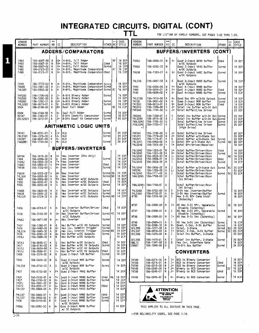
THIS APPLIES TO ALL DEVICES ON THIS PAGE.
ttFOR RELIABILITY CODES, SEE PAGE 1-16.
INTEGRATED CIRCUITS, DIGITAL (CONT)
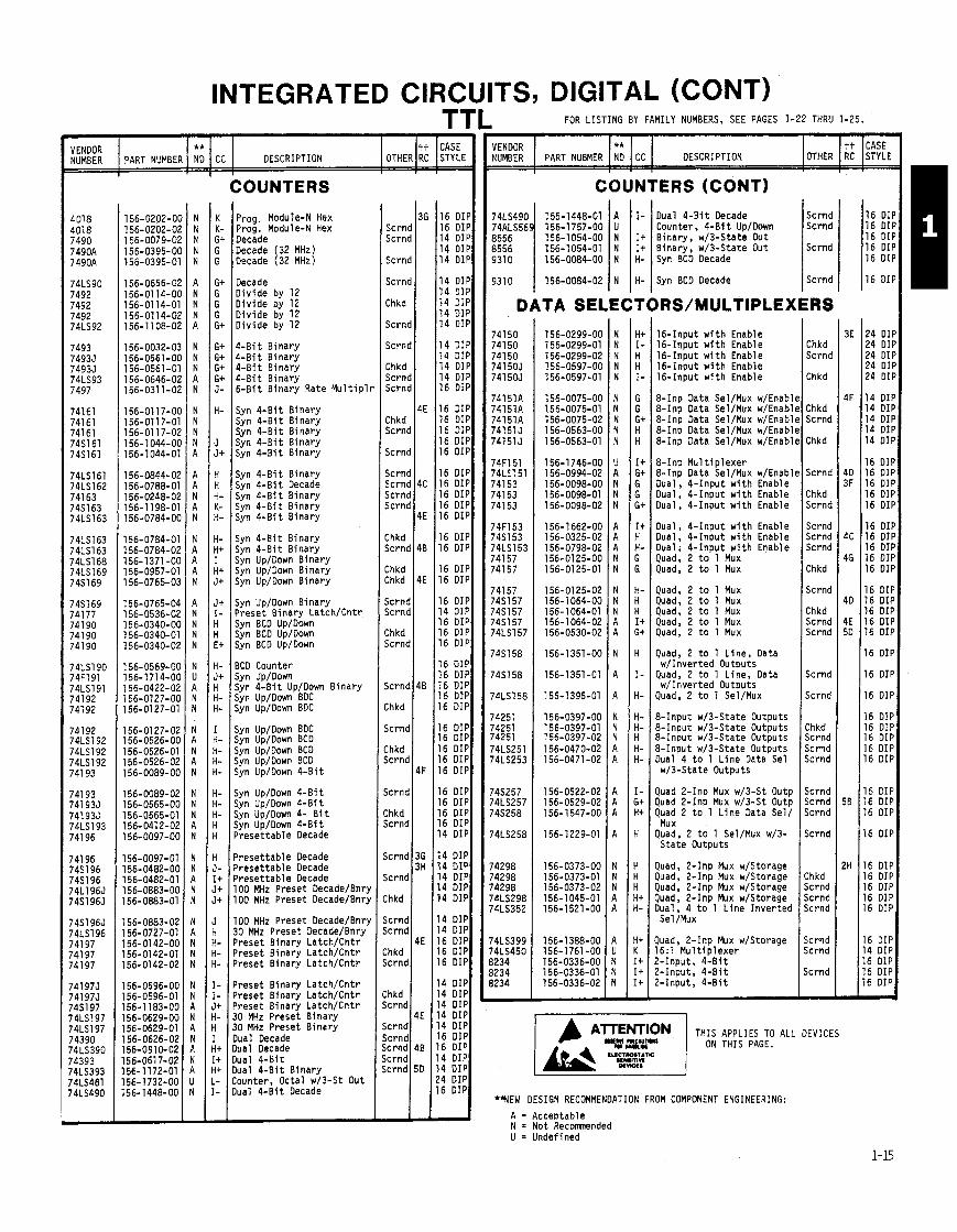
COUNTERS
VENDOR ** NUMBER PART NUMBER NO CC DESCRIPTION
Prog. Module-N Hex PPO~ . Module-N Hex Decade Decade (32 MHz Decade (32 MHz1
Decade Div ide by 12 D iv ide by 12 D iv ide by 12 D iv ide by 12
I
OTHER
4 -B i t B inary 4 -B i t B inary 4 -B i t Binary 4 -B i t Binary 6 -B i t B inary Rate M u l t i p l l
tt RC
Syn 4 - B i t B inary Syn 4 -B i t B inary Syn 4 -B i t Binary Syn 4 - B i t B inary Syn 4 -B i t B inary
CASE STYLE
Syn 4 -B i t B inary Syn 4 -B i t Decade Syn 4 - B i t B inary Syn 4 - B i t B inary Syn 4 - B i t B inary
Syn 4 -B i t B inary Syn 4 - B i t B inary Syn Up/Down B inary Syn Up/Down B inary Syn Up/Down B inary
jyn Up/Down B inary ' reset Binary Latch/Cntr Syn BCD Up/Down jyn BCD Up/Down jyn BCD Up/Down
3CD Counter jyn Up/Down jyn 4 -B i t Up/Down B inary jvn UoIDown BDC $n ~ b / ~ o w n BDC
jyn Up/Down BDC iyn Up/Down BCD jyn Up/Down BCD jyn Up/Down BCD ;yn Up/Down 4-B i t
;yn Up/Down 4 - B i t jyn Up/Down 4-Bi t iyn Up/Down 4- B i t iyn Up/Down 4 -B i t ' reset tab le Decade
Yeset tab le Decade ' reset tab le Decade ' reset tab le Decade 00 MHz Preset Decade/Bnry 00 MHz Preset DecadelBnry
00 MHz Preset Decade/Bnry 10 MHz Preset DecadelBnry ' reset Binary Latch/Cntr ' reset Binary Latch/Cntr ' reset Binary Latch/Cntr
I reset Binary Latch/Cntr ' reset Binary Latch/Cntr I reset Binary Latch/Cntr :O MHz Preset B inary 0 MHz Preset B inary lual Decade lual Decade u a l 4 -B i t lual 4 -B i t B lnary ounter, Octal w/3-St Out ,la1 4-B i t Decade
Scrnd Scrnd
Scrnd
Scrnd
Chkd
Scrnd
Scrnd
Chkd Scrnd Scrnd
Chkd Scrnd
Scrnd
Scrnd Scrnd Scrnd Scrnd
Chkd Scrnd
Chkd Chkd
Scrnd Scrnd
Chkd Scrnd
Scrnd
:hkd
Scrnd
:hkd jcrnd
jcrnd
:hkd k r n d
jcrnd
jcrnd
:hkd
ic rnd ic rnd
:hkd ;crnd
:hkd k r n d
;crnd ;crnd k r n d c r n d c r n d
FOR LISTING BY FAMILY NUMBERS, SEE PAGES 1-22 THRU 1-25.
1 3G
4E
4C
4E
48
4E
4B
4F
36 3H
4E
4E
4B
50
I
VENDOR I I** I I DESCRIPTION NUMBER PART NUBMER NO CC
16 DIP 16 DIP 14 DIP 14 DIP 14 DIP
14 DIP 14 DIP 14 DIP 14 DIP 14 DIP
14 DIP 14 DIP 14 DIP 14 DIP 16 DIP
16 DIP 16 DIP 16 DIP 16 DIP 16 DIP
16 DIP 16 DIP 16 DIP 16 DIP 16 DIP
16 DIP 16 DIP
16 DIP 16 DIP
16 DIP 14 DIP 16 DIP 16 DIP 16 DIP
16 DIP 16 DIP 16 DIP 16 DIP 16 DIP
16 DIP 16 DIP 16 DIP 16 DIP 16 DIP
16 DIP 16 DIP 16 DIP 16 DIP 14 DIP
14 DIP 14 DIP 14 DIP 14 DIP 14 DIP
14 DIP 14 DIP 16 DIP 16 DIP 16 DIP
14 DIP 14 DIP 14 DIP 14 DIP 14 DIP 16 DIP 16 DIP 14 DIP 14 DIP 24 DIP 16 DIP
COUNTERS (CONT)
Scrnd Scrnd
I-
I + It H-
Scrnd
Dual 4 -B i t Decade Counter, 4 -B i t Up/Down Binary, w/3-State Out Binary, w/3-State Out Syn BCD Decade
9310 1 156-0084-02 I N I H- ( Syn BCO Decade 1 Scrnd
DATA SELECTORS/MULTIPLEXERS
16-Input w i t h Enable 16-Input w i t h Enable 16-Input w i t h Enable 16-Input w i t h Enable 16-Input w i t h Enable
8-Inp Data Sel/Mux w/Enablt 8-Inp Data Sel/Mux w/Enabli 8-Inp Data Sel/Mux w/Enabl~ 8-Inp Data Sel/Mux w/Enabll 8-Inp Data Sel/Mux w/Enabll
8-Inp Mu1 t i p l e x e r 8-Inp Data Sel/Mux w/Enabl~ Dual. 4 - Inout w i t h Enable Dual; 4-1nput w i t h Enable Dual, 4 - Input w i t h Enable
Dual, 4 - Input w i t h Enable Dual, 4 - Input w i t h Enable Dual, 4 - Input w i t h Enable Quad, 2 t o 1 Mux Quad, 2 t o 1 Mux
Quad, 2 t o 1 Mux Quad, 2 t o 1 Mux Quad, 2 t o 1 Mux Quad, 2 t o 1 Mux Quad, 2 t o 1 Mux
Quad, 2 t o 1 L ine , Data w/Inverted Outputs
Quad, 2 t o 1 Line, Data w/Inverted Outputs
Quad, 2 t o 1 Sel/Mux
8- Input w/3-State Outputs 8- Input w/3-State Outputs 8-Input w/3-State Outputs 8- Input w/3-State Outputs Dual 4 t o 1 L ine Data Sel w/3-State Outputs
Quad 2-Inp Mux w/3-St Outp Quad 2-Inp Mux w/3-St Outp Quad 2 t o 1 L i ne Data Sel/
Mu x Quad, 2 t o 1 Sel/Mux w/3-
S ta te Outputs
Quad, 2-Inp Mux w/Storage Quad, 2-Inp Mux w/Storage Quad, 2-Inp Mux w/Storage Quad, 2-Inp Mux w/Storage Dual, 4 t o 1 L ine Inver ted Sel /Mux
Quad, 2-Inp Mux w/Storage 16: l Mu l t i p l exe r ?-Input, 4 - B i t ?-Input, 4 -B i t ?-Input, 4 -B i t
Chkd Scrnd
Chkd
Chkd Scrnd
Chkd
Scrnd
Chkd Scrnd
Scrnd Scrnd Scrnd
Chkd
Scrnd
Chkd Scrnd Scrnd
Scrnd
Scrnd
Chkd Scrnd Scrnd Scrnd
Scrnd Scrnd Scrnd
Scrnd
Chkd Scrnd Scrnd Scrnd
Scrnd Scrnd
Scrnd
- THIS APPLIES TO ALL DEVICES
ON THIS PAGE.
*HEW DESIGN RECOMMENDATION FROM COMPONENT ENGINEERING:
A = A c c e ~ t a b l e N = Not Recomended U = Undefined
16 DIF 16 DIF 16 DIF 16 DIF 16 DIF
16 DIF
24 DIF 24 DIF 24 DIF 24 DIF 24 DIF
14 DIF 14 DIF 14 DIF 14 DIF 14 DIF
16 DIP 16 DIP 16 DIF 16 DIF 16 DIF
16 DIF 16 DIF 16 DIF 16 DIP 16 DIP
16 DIP 16 DIP 16 DIP 16 DIP 16 DIP
16 DIP
16 DIP
16 DIP
16 DIP 16 DIP 16 DIP 16 DIP 16 DIP
16 DIP 16 DIP 16 DIP
16 DIP
16 DIP 16 DIP 16 DIP 16 DIP 16 DIP
16 DIP 14 DIP 16 DIP 16 DIP 16 DIP -
INTEGRATED CIRCUITS, DIGITAL (CONT)
VENDOR I I * * I I DESCRIPTION NUMBER PART NUMBER NO CC VENDOR ** NUMBER PART NUMBER NO CC DESCRIPTION
GATES GATES (CONT)
OTHER
Scrnd
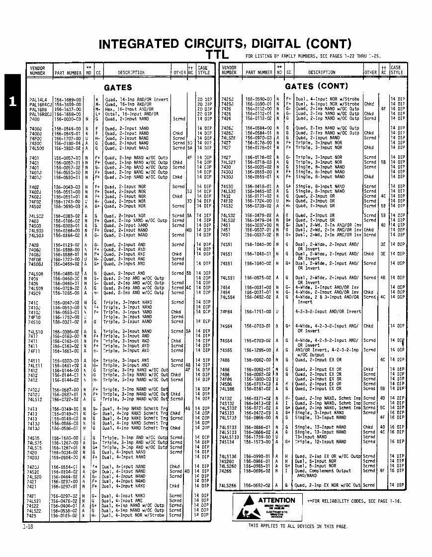
Dual, 4 - Input NOR w/Strobe Dual, 4 - Input NOR w/Strobe Quad, 2-Inp NAND w/OC Outp Quad. 2-Inp NAND w/OC Outp Quad, 2-Inp NAND w/OC Outp
tt RC
Quad, 14-Inp AND/OR Inve r t Ouad. 16-Ino AND/OR
.CASE STYLE
20 DI 20 01 20 DI 20 DI 14 DI
14 DI 14 01 14 D l 14 DI 14 DI
14 01 14 01 14 DI 14 01 14 DIN
14 DII 14 DII 14 DII 14 DII 14 DII
14 DII 14 DII 14 DII 14 DII 14 DII
14 DII 14 DII 14 DI I
14 DIf
14 DI I 14 DIF 14 DIF 14 D I I 14 DIF
14 DIF 14 DIF 14 DIP
14 DIF
14 DIF 14 DIF 14 DIF 14 DIF 14 DIF
14 DIF 4 DIP 4 DIP 4 DIP
4 DIP
4 DIP 4 DIP 4 DIP
4 DIP 4 DIP 4 DIP 4 DIP 4 DIP
4 DIP 4 DIP 4 DIP 4 DIP 4 DIP
4 DIP 4 DIP 4 DIP 4 DIP 4 DIP
14 DIP 14 DIP 14 DIP 14 DIP 14 DIP
14 DIP 14 DIP 14 DIP 14 DIP 14 DIP
14 DIP 14 DIP 14 DIP 14 DIP 14 DIP
14 DIP 14 DIP 14 DIP 14 DIP 14 DIP
14 DIP 14 DIP 14 DIP 14 DIP 14 DIP
14 DIP
14 DIP
14 DIP
14 DIP
14 DIP 14 DIP 14 DIP
14 DIP
l4 14 DIP
14 DIP
14 DIP 14 DIP 14 DIP 14 DIP 14 DIP
14 DIP 14 DIP 14 DIP 16 DIP 16 DIP
16 DIP 16 DIP
16 DIP
4 DIP 4 DIP 4 DIP 6 DIP
4 DIP -
Chkd
Chkd Scrnd
Chkd Scrnd
Chkd
Scrnd Scrnd Scrnd
Chkd
Scrnd Scrnd Scrnd Scrnd Scrnd
Scrnd Scrnd
Chkd Scrnd
Chkd
Scrnd
Scrnd
Chkd Scrnd
:hkd
jc rnd
jc rnd
:hkd jcrnd k r n d k r n d k r n d
jcrnd k r n d jcrnd k r n d
:hkd k r n d ic rnd k r n d
jcrnd ic rnd ic rnd ic rnd
k r n d -
ex, .16-input AND/OR Octal , 16- Input AND/OR Quad, 2-Input NAND
Quad, 2-Inp NAND w/OC Outp Quad, 2-Inp NAND w/OC Outp Quad, 2- Input NAND T r i p l e , 3 - Input NOR T r i p l e , 3 - Input NOR
Quad, 2- Input NAND Quad, 2- Input NAND Quad, 2-Input NAND Quad, 2-Input NAND Quad, 2- Input NAND
Chkd Scrn' Scrn Scrn
Chkd Sc rn~
Chkd
S c r n ~
Chkd
Scrnc
Scrnc Scrnc Scrnc
Scm(
jcrnc
:hkd jcrnc Scrnc
k r n c
jcrnc icrnc jcrnc
k r n c
:hkd icrnd icrnd
icrnd
Lhkd icrnd icrnd
icrnd k r n d
'hkd ~ r n d
hkd c rnd
h kd c rnd
hkd
c rnd c rnd c rnd c rnd
T r i p l e , 3 - Input NOR T r i p l e , 3 - Input NOR Single. & Inpu t NAND Single, 8 - Input NAND Sing le , & Inpu t NAND
Quad, 2-Inp NAND w/OC Outp Quad, 2-Inp NAND w/OC Outp Quad, 2-Inp NAND w/OC Outp Quad, 2-Inp NAND w/OC Outp Quad, 2-Inp NAND w/OC Outp
Single, 8 - Input NAND Sing le , & Inpu t NAND Quad, 2- Input OR Quad, 2-Input OR Quad, 2- Input OR
Quad, 2-Input NOR Quad, 2- Input NOR Quad, 2- Input NOR Quad, 2-Input NOR Quad, 2-Input NOR
Quad, 2-Input NOR Quad, 2-Inp NAND w/OC Outp Quad, & Inpu t NAND Quad, 2-Input NAND Quad, 2-Input NAND
Quad, & Inpu t OR Quad, 2- Input OR Dual, 2-Wd, 2 - I n AND/OR I n \ Dual, 2-Wd, 2- In AND/OR In ) Dual, 2-Wd, 2 - I n AND/OR Ink
Quad, 2- Input AND Quad, 2-Input AND Quad, 2-Input AND Quad, 2-Input AND Quad, 2-Input AND
Dual, &Wide, 2-Input AND/ OR I n v e r t
Dual. 2-Wide, 2 - Input AND/ OR I n v e r t
Dual, 2-Wide, 2 - Input AND/ OR I n v e r t
Quad, & Inpu t AND Quad, 2-Inp AND w/OC Outp Quad, 2-Inp AND w/OC Outp Quad, 2-Inp AND w/OC Outp quad, 2-Inp AND w/OC Outp
Dual, 2-Wide, 2 - Input AND/ OR I n v e r t
4-Wide, 2 - Input AND/OR I n v 4-Wide. 2 - Input AND/OR I n v 4-Wide, 2 & 3 - Input AND/OR
I n v e r t Tr ip le , 3 - Input NAND Tr ip le , 3 - Input NAND Tr ip le , 3 - Input NAND Tr ip le , 3 - Input NAND Tr ip le , 3 - Input NAND
4-2-3-2-Input AND/OR I n v e r t
4-Wide, 4-2-3-2-Input AND/ OR I n v e r t r r i p l e , 3 - Input NAND
r r i p l e , 3 - Input AND r r i p l e , 3 - Input AND r r i p l e , 3 - Input AND r r i p l e , 3 - Input AND
OR I n v e r t AND/OR Inve r t , 4-2-3-2-Inp w/OC Output
Quad, 2- Input EX OR r r i p l e , 3 - Input AND r r i p l e , 3 - Input AND r r i p l e , 3-Inp NAND w/OC Out r r i p l e , 3-Inp NANO w/OC Out r r i p l e , 3-Inp NAND w/OC Out
Quad, 2- Input EX OR luad, 2-Input EX OR Quad, 2-Input EX OR luad, 2 - Input EX OR &ad, 2- Input EX OR r r i p l e , 3-Inp NAND w/OC Out
r r i p l e , 3-Inp NAND w/OC Out ' r i p l e , 3-Inp NAND w/OC Out luad, 2-Inp NAND, Schmt Inp
luad, 2-Inp NAND, Schmt Inp &ad, 2-Inp NAND, Schmt Inp Single, 3 - Input NAND Single, 13-Input NAND
1ua1, 4-Inp NAND Schmit Trg h a l , 4-Inp NAND Schmit Trg lual , 4-Inp NAND Schmit Trg lual , 4- Inp NAND Schmi t Trg lual, 4-Inp NAND Schmit T r 4 Single. 13-Input NAND
j i ng l e , 13-Input NAND 13-Input NAND T r i p l e , 12-Input NAND
' r i p l e , 3-Inp AND w/OC Out ' r i p l e , 3-Inp AND w/OC Out ' r i p l e , 3-Inp AND w/OC Out lual, 4 - Input NAND lual, 4 - Input NAND i luad, 2-Inp EX OR w/OC Outp
I ua l , 5 - Input NOR l ua l , 5 - Input NOR h a d , Complement Output AND/NAND
ua l , 4 - Input NAND u a l , 4-Input NAND ua l , 4-Input NANO ua l , 4 - Input NAND ua l , 4 - Input NAND
Scrnd Scrnd I chkd
luad, 2-Inp EX NOR w/DC'Out 1 Chkd
4 DIP 4 DIP 4 DIP 4 DIP 4 DIP -
ual, 4- Input NAND ua l , 4 - Input AND ua l , 4-Inp NAND w/OC Outp ua l , 4-Inp NAND w/OC Outp ual , 4 - Input NOR w/Strobe
ttFOR RELIABILITY CODES, SEE PAGE 1-16. Scrnd Scrnd S c r n d ~ Scrnd Scrnd
THIS APPLIES TO ALL DEVICES ON THIS PAGE.
INTEGRATED CIRCUITS, DIGITAL (CONT) TTL FOR LISTING BY FAMILY NUMBERS, SEE PAGES 1-22 THRU 1-25
VENDOR ** NUMBER PART NUMBER ND CC DESCRIPTION
I
GENERATORS
VENDOR NUMBER
4 Chkd Scrnd
3
Chkd
Scrnd
Chkd
Scrnd
Scrnd
Scrnd Scrnd
OTHER
14 Dl 14 Dl 14 DI 16 01
16 DI
16 D l
16 D l
16 Dl
16 D I
14 DI
14 DI 24 D l 14 D l
16 01
16 01
16 D l
16 D l
16 D l
16 DII
16 DII
16 DII
!4 DII
!4 DII 4 DII 4 DII
4 DI I
4 OII
4 DIF
6 DIP 6 DIF 6 DIF 6 DIF 0 DIF 0 DIF D OIF
0 DIF 0 DIP 6 DIP 6 DIP
20 DIP 20 DIP 20 DIP 24 DIP 28 DIP
?8 DIP -
PART NUMBER
Oual, Re t r i g Monostable Dual. Re t r i g Monostable Dual, Voltage Control l e d S ing le , Monostable w/
Schmit t Tr igger Inputs
tt RC
8 -B i t , Odd/Even Gen/Chrk 8-Bi t, Odd/Even Gen/Chrk 8-Bi t, OddlEven Gen/Chrk Lookahead Carry Generator,
P l a s t i c Pkg
CASE STYLI
** ND
16 DI 16 DI 14 DI 14 DI
14 Dl
14 DI
14 Dl
14 D l
14 DI
16 D l
I d [I
16 Dl
16 Dl
16 DI
16 DI
16 Dl
16 Dl
16 Dl
14 DI
14 DI 14 DI 16 DII
16 DII
6 011
6 DII
6 DII
I
Scrnc
Scrnc
Chkd
Scrnd
Chkd
Scrnd
Chkd
Scrnd
Chkd
Scrnd
jc rnd
jcrnd
jc rnd
:hkd jcrnd
Zhkd
k r n d
icrnd
I
CC
I Lookahead Carry Generator, P l a s t i c Pkg
I Lookahead Carry Generator, P l a s t i c Pkg
It Lookahead Carry Generator, Ceramic Pkg
Single, Monostable; Ceramic Pkg on l y
Single, Monostable; Ceramic Pkg on ly
Single, Ret r igger w/Clear Monostable
DESCRIPTION
I+ Lookahead Carry Generator, Ceramic Pkg
5 - Lookahead Carry Generator, Ceramic Pkg
It 9 -B i t OddIEven P a r i t y Gen/Chrk
tt CASE OTHER RC STYLE
S ing le , Ret r igger w/Clear Monostable
S ing le , Ret r igger w/Clear Monostable
Dual, Monostable w/Clear Schmit t Tr igger I npu t
I % B i t OddIEven Gen/Chrk M- 4 -B i t , ALUIFctn Generator J t 8 -B i t , P a r i t y GenIChrk
Oual, Monostable w/Clear Schmi tt Tr igger I npu t
Dual, Monostable w/Clear Schmit t Tr igger I npu t
Dual Monostable Ret r igger LATCHES Dual, Monostable w/Clear
Schmit t Tr igger I npu t Dual, Monostable w/Clear
Schmit t Tr igger I npu t Dual, Monostable w/Clear
S c h i t t T r igger I npu t
Quad Latch w/STD & 3-Stat ' Output
Quad Latch w/STD & 3-Stat, Scrnc
Chkd
Scrnc
Chkd
Scrnd
Scrnd Scrnd
Chkd
:hkd
jc rnd jcrnd jcrnd jcrnd
jcrnd
ic rnd k r n d icrnd
Output 4 - B i t B i s t ab le Complement
Outputs Dual, Monostable w/Clear
Schmit t Tr igger I npu t Oual, Monostable w/Clear Schmit t Tr igger Input
One Shot
4 -B i t B i s t ab le Complement Outputs
4 -B i t B i s t ab le Complement Outputs
4 -B i t B i s t ab le Complement One Shot One Shot Dual, Retr iggerable, Re- se t t ab le - One Sheet
Dual, Retr iggerable, Re- se t t ab le - One Sheet
Outputs
4 -B i t B i s t ab le Complement Outputs
4-B i t B i s t ab le Complement Outputs
0 -B i t Latch Dual, Retr iggerable, Re-
se t tab le , One Shot Dual, Retr iggerable, Re- se t tab le , Monostable
Oual, Retr iggerable, Re- se t t ab le - One Sheet
PROMS
& B i t Latch ' reset B inary Cntr /Latch ' reset Decade, B inary Cntr Latch
' reset Decade, B inary CenterILatch
' reset Decade, B inary Center/Latch
' reset Decade, B inary Center/Latch
& B i t Addressable Latch H i t Addressable Latch )uad S-R Latch )uad S-R Latch k t a l "DM Tran Latch k t a l "DM Tran Latch k t a l "D" Tran Latch
S E L E C T I O N G U I D E S E E M E M O R Y T H I S S E C T I O N
RAMS S E E M E M O R Y S E L E C T I O N G U I D E
T H I S S E C T I O N
10-B i t Register 9 -B i t Register, 3-State
24 DIP 24 DIP
Scrnd
Chkd
Scrnd -
k t a l "D" Tran Latch l c t a l "0" Tran Latch I -B i t B i s t ab le Latch I-Bi t Addressable REGISTER FILES
4 x 4 Register F i l e w/3- S ta te Output
4 x 4 Register F i l e wI3- S ta te Output
4 x 4 Register F i l e
116 DIP LOGIC ARRAYS ALlOL8 156-1801-00 A I 1 1 1 Logic Array AL16L2 156-1808-00 A Logic Array AL16L8 156-1809-00 A Logic Array ALl2LlO 156-1802-00 A Los ic Array
I16 DIP
2 ~ 1 0 0 1 156-1269-00 IA IN- (16-x 48 x 8 FPLA w/3-State
THIS APPLIES TO ALL DEVICES ON THIS PAGE.
2s107 1 FPLA w/3-State Output
** NEW DESIGN RECOMMENDATION FROM COMPONENT ENGINEERING:
A = Acceptable N = Not Recomnded U = Undefined
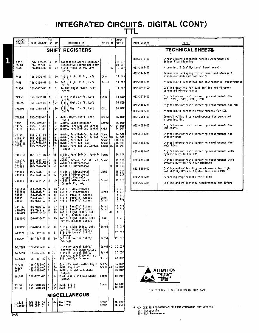
- VENDOR NUMBER =
2 502 25L04 7495
7495
7495
74955
74955
74LS95
74LS95
74LS95
7496 74164 74164
74164 74LS164 74165 74LS165 74166
74LS166
74LS173 741 94 7451 94
745194 74S194
7451 94
74LS194 74LS194 741 95 741 95 741 95
7451 95 74LS195 74LS295
74LS295
74LS295
74S299
745299
74LS299
74LS299
74LS322
74F399 32570 3551
36LS62
33L28 33L28
INTEGRATED ClRCU T '
Successive Approx Registe Successive Approx Registe 4 -B i t R ight S h i f t , L e f t
S h i f t
J
4 -B i t R ight S h i f t , L e f t
** PART NUMBER ND CC DESCRIPTION
S h i f t 4 -B i t R ight S h i f t , L e f t
S h i f t 4 i . .B i t R ight S h i f t , L e f t S h i f t
SHIFT REGISTERS
OTHER
4 -B i t R ight S h i f t , L e f t S h i f t
4 -B i t R ight Sh i f t , L e f t S h i f t
4 -B i t R ight S h i f t , L e f t S h i f t
$ - B i t R ight S h i f t , L e f t S h i f t
5-61 t, S h i f t Register 3-Bit, Para l le l -Out Seria: 3-Bit, Para l le l -Out Ser ia
tt RC
3-Bit, Para l le l -Out Seria ' 3-Bit, Para l le l -Out Ser ia ' 3-Bit, Pa ra l l e l Load 3-Bi t, Paral l e l Load 3-Bit, Pa ra l l e l - I n , Ser ia ' Output
CASE STYLE
3-Bit, Pa ra l l e l - I n , Ser ia i Output
!-Bit, D-Type, 3-St Outpul I - B i t B i -D i rec t i ona l I - B i t B i -D i rec t i ona l
! -B i t B i -D i rec t i ona l I - B i t B i -D i rec t iona l , Ceramic Pkg on ly
I - B i t B i -D i rec t i ona l Ceramic Pkg on l y
I - B i t B i -D i rec t iona l I -Bi t B i -D i rec t i ona l I -B i t , Pa ra l l e l Access I-Bi t, P a r a l l e l Access Hit, Paral l e l Access
I -B i t , Pa ra l l e l Access I-Bi t, Paral l e l Access I -B i t , Right Sh i f t , L e f t Sh i f t , 3-State Output I -B i t , R ight S h i f t , L e f t Sh i f t , 3-State Output
.-Bi t , Right S h i f t , L e f t S h i f t , 3-State Output I-Bi t Universal S h i f t / storage I -B i t Universal S h i f t / Storage
! -B i t Universal S h i f t / Storage w/3-State Output , -B i t Universal S h i f t / Storage w/3-State Output - B l t w/Sign Extender
uad. 2-Input, 4 -B i t Regis - B i t Register -B i t , D-Type w/3-State output ua l Rank 8 - B i t w/3-State output
ua l , 8 -B i t ua l , 8 -B i t
MISCELLANEOUS
Chkd
Scrnc
:hkd
:hkd
icrnc
;crnl
:hkd
icrnd icrnd icrnd icrnd icrnd
icrnd
;crnd
:hkd
~ c r n d
crnd
h kd crnd
crnd crnd
h kd
crnd
crnd
crnd
crnd
crnd
crnd crnd
crnd
:rnd
TS, DIGITAL (CONT) 'L
;
16 DIP 24 DIP 14 DIP
14 DIP
14 DIP
14 DIP
14 DIP
16 DIP
16 DIP
16 DIP
16 DIP 14 DIP 14 DIP
14 DIP 14 DIP 16 DIP 16 DIP 16 DIP
16 DIP
16 DIP 16 DIP 16 DIP
16 DIP 16 DIP
16 DIP
16 DIP 16 DIP 16 DIP 16 DIP 16 DIP
16 DIP 16 DIP 14 DIP
14 DIP
14 DIP
20 DIP
20 DIP
20 DIP
20 DIP
20 DIP
16 DIP 14 DIP 16 DIP
18 DIP
16 DIP 16 DIP
C i r c u i t Board Standards Marking Adherence and Solder Flux Cleaning
M i c r o c i r c u i t Qua1 i t y Level Requirements
P ro tec t i ve Packaging f o r shipment and storage o f s t a t i c - s e n s i t i v e m ic roc i r cu i t s
M i c r o c i r c u i t mechanical and environmental requirement
Out l ine drawings f o r dual i n - l i n e and f l a tpack purchased m i c r o c i r c u i t s
D i g i t a l m i c r o c i r c u i t screening requirements f o r TTL, STTL, LSTTL, HTTL, LTTL.
D i g i t a l m i c r o c i r c u i t screening requirements f o r MOS
M i c r o c i r c u i t screening requirements f o r ECL
General r e l i a b i l i t y requirements f o r purchased m ic roc i r cu i t s .
D i g i t a l m i c r o c i r c u i t screening requirements f o r MOS DRAMS.
D i g i t a l m i c r o c i r c u i t screening requirements f o r B ipo la r RAMS
D i g i t a l m i c r o c i r c u i t screening requirements f o r NMOS ROMs
D i g i t a l m i c r o c i r c u i t screening requirements w i t h dynamic burn- in f o r MOS
D i g i t a l m i c r o c i r c u i t screening requirements w i t h dynamic burn- in (72 hour minimum)
Q u a l i t y and r e l i a b i l i t y requirements f o r h igh r e l i a b i l i t y MOS and B ipo la r RAMS and MROMs
Screening requirements f o r EPROMs
Q u a l i t y and r e l i a b i l i t y requirements f o r EPROMs
PART NUMBER
THIS APPLIES TO ALL DEVICES ON THIS PAGE
- TITLE
TECHNICAL SHEE.T$
** NEW DESIGN RECMMENDATION FROM COMPONENT ENGINEERING: A = Acceptable
kl N = Not Recommended
16 DIP 16 DIP
Scrnd Scrnd
Dual VCO Dual VCO
5- I
N A
'45124 '4LS629
156-1584-00 156-0861-01

++ CATALOG RE
NOTES
COST CODE
.LIABILITY CODES
- .05 111 000 115W I l2W l l l W 1.OI
For f u r t h e r explanation o f t h i s code, see page 4-72.
NOTE: Costs may vary from order t o order due t o order q u a n t l t i e s , vendor, e t c .
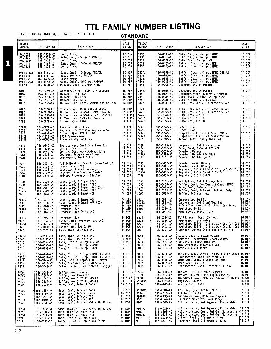
TTL FAMILY NUMBER LISTING FOR LISTING BY FUNCTION, SEE PAGES 1-14 THRU 1-20. STANDARD VENDOR NUMBER
PALlOL8 PAL12L6 PAL12L20 PAL1 4L4 PAL16L2
PART NUMBER
156-1801-XX 156-1677-XX 156-1802-XX 156-1669-XX 156-1808-XX
DESCRIPTION
Logic A r ray Gate, Hex, 12-Input AND/OR Logic A r ray Gate, Quad, 14-Input AND/OR Logic Ar ray
Gate, Quad, 16-Input AND/OR Gate. 1 6 - I n ~ u t AND/OR ~ o ~ i c A r ray Gate, Octa l , 16-Input AND/OR Dr i ve r , Quad, 2-Input NAND
Decoder/Driver, BCD t o 7 Segment Dr iver , Quad, Bus Dr iver , Dual L ine Dr iver , Dual L ine Dr iver , Dual Line, Comunica t ion L i ne
Transceiver, Quad Bus, 3-State Buf fe r , Hex, 3-State Com Disable Buf fe r , Hex, 3-State, Sep. Disable Buf fe r , Hex, 3-State, I n v e r t e r Dr iver , Quad L ine
Receiver, Quad L i ne Reg is ter , Successive Approximate Dr iver , Quad TTL t o MOS GPIB Transce iver Transceiver, Quad Bus
Transceiver, Quad I n t e r f a c e Bus Dr iver , Quad L ine Dr iver , Quad NAND Address L ine Counter. Proaram Mod-N Hex
M u l t i v i b r a t o r , Dual Vol tage-Control Latch, Quad (OC) Detector, PhaselFrequency Decoder, Non-Inverter 1-of-8 Dr iver , Fluorescent D isp lay
Gate, Quad, ?- Input NAND Gate, Quad, 2- Input NAND Gate, Quad, 2- Input NAND (OC) Gate, Quad, 2-Input NAND Gate, Quad, 2- Input NOR
;ate, Quad, 2- Input NOR ;ate, Quad, 2-Input NOR (OC) I nve r t e r , Hex I nve r t e r , Hex I nve r t e r , Hex (5.5V OC)
I nve r t e r , Hex 3uf fe r , Hex I n v e r t e r (30V OC) I nve r t e r , Hex 3uf fe r , Hex 2/O-C, HV ;ate, Quad, 2- Input AND
;ate, Quad, ? - I npu t AND ;ate, Quad, 2- Input AND ;ate, T r i p l e , 3-Input NAND ;ate, T r i p l e , 3 - Input NANO ;ate, T r i p l e , 3 - Input AND
;ate, T r i p l e , 3 - Input NAND ( 5 . 9 OC) ;ate, T r i p l e , 3 - Input NAND ( 5 . 9 OC) ;ate, Dual, 4 - Input NAND Schmit t iate, Dual 4 - Input NAND Schmit t ;a te / Inver ter , Hex, Schmit t T r i gge r
l u f f e r , Hex I n v e r t e r l u f f e r , Hex I n v e r t e r l u f f e r , Hex (15V OC, 40mA) l u f f e r , Hex (15V OC, 40mA) iate, Dual, 4 - Input NAND
,ate, Dual. 4 - Input NANO a te , Oual, 4 - Input NAND a te , Oual, 4 - Input AND a te , Dual, 4 - Input AND ate, Dual, 4 - Input NOR w i t h Strobe
ate, Oual, 4 - Input NOR w i t h Strobe ate, Quad, 2- Input NAND ate, Quad, 2- Input NAND ate , T r i p l e , 3 - Input NOR uf fe r , Quad, 2-Input NOR (48mA)
- CASE STYLE - - 20 DI 20 DI 20 D l 20 Dl 20 01
20 Dl 20 D l 20 DI 20 DI 14 D l
16 D l 14 D l 16 D l 14 DII 14 DII
16 DI! 16 DII 16 DII 16 DII 14 DII
14 DII 16 DII 16 DII 16 DII 16 DII
16 DIF 14 DIF 14 D I I 16 DIF 16 DIF
14 DIF 14 DIF 14 DIP 16 DIF 18 DIF
14 DIF 14 DIF 14 DIF 14 DIF 14 DIF
14 DIF 14 DIP 14 DIP 14 DIP 14 DIP
14 DIP 14 DIP 14 DIP 14 DIP 14 DIP
14 DIP 14 DIP 14 DIP 14 DIP 14 DIP
14 DIP 14 DIP 14 DIP 14 DIP 14 DIP
14 DIP 14 DIP 14 DIP 4 DIP 4 DIP
4 DIP 4 DIP 4 DIP 4 DIP 4 DIP
4 DIP 4 DIP 4 DIP 4 DIP 4 DIP -
- VENDOR NUMBER
7430 74305 7432 7433 7437
74375 7438 74385 7440 7442
74425 7447 7451 7454 7472
7473 74735 7474 74F74 74743
7475 74755 7476 74765 7483
7485 7486 7490 7490A 7492
7493 74935 7495 74955 7496
7497 3090 3092 3094 3097
3130 31 36N 3201 3202 3224
3234 3271 32736 I2748 1290
I551 1556 I654 1BL12 181 5
183 1 B33 1836 1837 I838
1856 1863 1880 300PC 304
31 OPC 334 368PC 401 601
601 DC 602 602DC 61 4 61 5 7
PART NUMBER DESCRIPTION STYLE
Gate, Single, 8 - Input NAND 14 DIP Gate, S ing le , 8-Input NAND 14 DIP Gate, Quad, 2-Input OR 14 DIP Buf fe r , Quad, 2-Input NOR 14 DIP Buf fe r , Quad, 2- Input NAND 14 DIP
Buffer, Quad, 2- Input NAND (48mA) Buf fe r , Quad, 2- Input NAND Buf fer , Quad, 2-Input NAND Buffer, Dual, 4-Input NAND Decoder, BCD-to-Decimal
F l ip -F lop, Dual, J-K Master/Slave F l ip-Flop, Dual, J-K Master/Slave F l ip -F lop, Dual D F l ip -F lop, Dual D F l ip -F lop, Dual D
14 DIP 14 DIP 14 DIP 14 DIP 16 DIP
Decoder, BCD-to-Decimal Decoder/Driver, BCD-to-7 Segment Gate, Dual, 2-Wide, 2 - Input A01 Gate, 4-Wide, 2 - Input A01 F l ip -F lop, Dual, J-K M a s t e r b l a v e
14 DIP 14 DIP 14 DIP 14 DIP 14 DIP
16 DIP
14 DIP 14 DIP 14 DIP
Latch, Quad 116 DIP Latch, Quad F l ip -F lop, Dual, J-K Master/Slave F l i ~ - F l o o , Dual. J-K MasterISlave ~ d d e r , & B i t ~ i n a r y Gate ~ u l l I16 DIP
Comparator, 4 -B i t Magnitude Gate, Quad, 2-Input EXCL-OR Counter, Decade Counter, Decade (32 MHz) Counter, Divide-by-12
14 DIP 14 DIP 14 DIP 14 DIP 14 DIP
Counter, & B i t Binary Counter, 4 -B i t Binary Reg is ter , 4 -B i t R igh t -Sh i f t , L e f t - S h i f t Register, 4 -B i t Par-ACS S h i f t Reg is ter , 5 - B i t S h i f t
14 DIP 14 DIP 14 DIP 14 DIP 16 DIP
M u l t i p l i e r , 6 -B i t B inary Rate Buffer, Quad, Inv/Dual, 2 - Input NAND Gate, Dual, 5-Input NAND Buffer, Quad, 2-Input, 3-State Output Buf fe r , 3-State, Hex
16 DIP 16 DIP 16 DIP 16 DIP 16 DIP
Comparator, 10-Bi t Comparator, 6-Bi t U n i f i e d Bus Buf fe r / Inver ter , Dual, 5 -B i t I n v I npu t Reg is ter , 10-B i t Generator/Driver, Clock
Latch, Quad, 3-State Output Counter, Programed DecadelBinary Dr iver , 8-Output D isp lay Hex I nve r t e r , I n t e r f ace Gate Gate, Dual, 4-Input
24 DIP 16 DIP 24 DIP 24 DIP 16 DIP
Mu l t i p l exe r , Quad, 2- Input Register, 4 -B i t S h i f t Reg is ter , S h i f t , 10-B i t , Ser-In, Par-Out Register, S h i f t , 10-Bit , Par-In, Ser-Out Counter, Decade (Selected f o r 55 MHz)
16 DIP 16 DIP 18 DIP 14 DIP 14 DIP
16 DIP 16 DIP 16 DIP 16 DIP 14 DIP
Dr iver , Quad, S ing le End-Dual D i f f I npu t Transceiver, Quad, U n i f i e d Bus Receiver, Quad, 2- Input NOR Bus Receiver, Hex Bus Transceiver, Quad, U n i f i e d Bus I nv .
16 DIP 16 DIP 14 DIP 16 DIP 16 DIP
Dr iver , LED, BCD-to-7 Segment Dr iver , MOS t o LED 8 -D ig i t D isp lay Oecoder/Driver, BCD-to-7 Segment (DD700) Register, 4 -B i t Adder, Dual, F u l l
16 DIP 18 DIP 16 DIP 16 DIP 16 DIP
Counter, Sync Decade (74160) Latch, 8 - B i t Addressable Decoder/Driver, BCD-to-7 Segment GeneratorKhecker, Redundancy Yul t i v i b r a t o r , Retr iggered, Monostable
16 DIP 16 DIP 16 DIP 14 DIP 14 DIP
Yul t i v i b r a t o r , Retr iggered, Monostable Y u l t i v i b r a t o r , Dual, Ret r ig , Monostable Y u l t i v i b r a t o r , Dual, Ret r ig , Monostable ) r i ve r . Dual D i f f e r e n t i a l L i ne qeceiver, Dual D i f f e r e n t i a l L ine
14 DIP 14 DIP 14 DIP 16 DIP 16 DIP
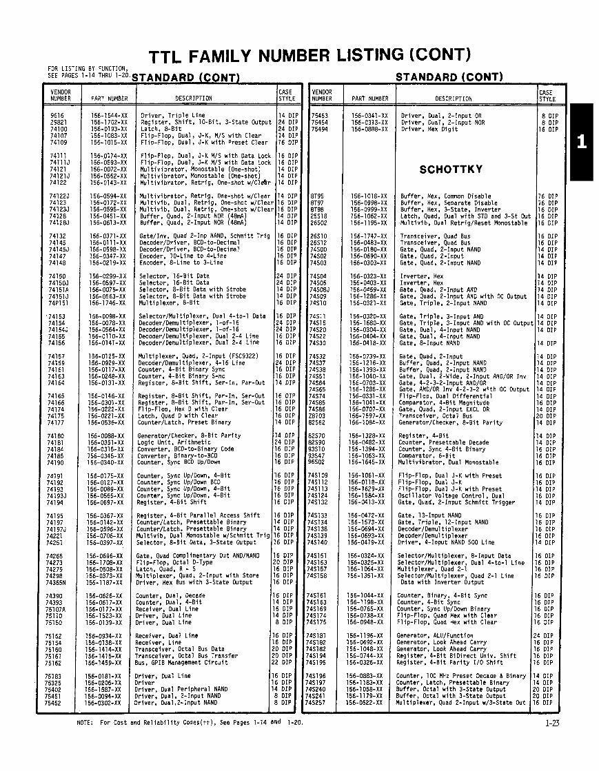
TTL FAMILY NUMBER LISTING (CONT) iTANDARD (CONT)
DESCRIPTION
FOR LISTING BY FUNCTION, SEE PAGES 1-14 THRU 1-20 TANDARD (CONT)
CASE DESCRIPTION STY Lt
- VENDOR NUMBER
961 6 29821 74100 741 07 741 09
741 11 741115 741 21 74121 J 74122
741225 74123 741235 74128 741285
741 32 74145 741455 74147 74148
741 50 741 505 74151A 741 51 J 74P151
741 53 74154 741545 741 55 74156
74157 74159 74161 741 63 74164
741 65 74166 74174 741 75 74177
74180 74181 741 84 74185 741 90
741 91 741 92 741 93 741935 741 94
74195 74197 741 975 74221 74251
14265 74273 74279 '4298 '4365N
'4390 '4393 :5107A 5110 '51 50
'5152 '5154 51 60 '5161 51 62
- VENDOR NUMBER
- CASE STYLE - - 8 DII
PART NUMBER PART NUMBER
Dr iver , T r i p l e Line (14 DI Register, S h i f t , 10-Bit , 3-State Output 24 DI
Dr iver , Dual, 2-Input OR Driver, Dual, 2-Input NOR Dr iver . Hex D i g i t Latch, & B i t
F l i p - F l o p , D u a l , J - K , M / S w i t h C l e a r Fl ip-Flop, Dual, 5-K w i t h Preset Clear
F l ip -F lop, Dual, 5-K M/S w i t h Data Lock 16 Dl F l ip -F lop, Dual, 5-K M/S w i t h Data Lock 16 DI M u l t i v i b r a t o r , Monostable (One-shot) 14 01 M u l t i v i b ra to r , Monostable (One-shot) 14 DI M u l t i v i b r a t o r , Ret r ig , One-shot w/Cl&r 14 DI
SCHOTTKY
M u l t i v i b r a t o r , Retr ig, One-shot w/Clear 14 D l Mu l t i v i b , Dual, Retr ig. One-shot w/Clear 16 DI Mu l t i v i b , Dual, Ret r ig , One-shot w/Clear 16 DI Buffer, Quad, 2-Input NOR (48mA) 14 D l Buf fer , Quad, 2-Input NOR (48mA) 14 D l
Buf fer , Hex, Comnon Disable Buffer, Hex, Separate Disable Buf fer . Hex. 3-State. I nve r te r
16 DII 16 DII 16 DII 16 DIf 16 DII
16 DIf 16 DIF 14 DIF 14 DIF 14 DIF
14 DIF 14 DIF 14 DIF 14 DIF 14 DIF
14 DIF 14 DIP 14 DIP
4 DIP
4 DIP 4 DIP 4 DIP 4 DIP 4 DIP 4 DIP 4 DIP 6 DIP 4 DIP '0 DIP 4 DIP
4 DIP 4 DIP 6 DIP 6 DIP 6 DIP
6 DIP 6 DIP 4 DIP 6 DIP 4 DIP
6 DIP 6 DIP 6 DIP 6 DIP 4 DIP
6 DIP 6 DIP 6 DIP 5 DIP
5 DIP 5 DIP 5 DIP 5 DIP 5 DIP
I DIP i DIP i DIP i DIP i DIP
I DIP DIP
I DIP I DIP
,IP J
~ a t c h , . ~ u a d ; Dual w i t h STD and 3-St OL Mu l t i v i b , Dual Retr ig/Reset Monostable
Gate/Inv, Quad 2-Inp NAND, Schmitt T r i g 116 D l Decoder/Driver, BCD-to-Decimal
Transceiver, Quad Bus Transceiver, Quad Bus Gate, Quad, 2-Input NAND Gate, Quad, 2-Input Gate, Quad, 2-Input NAND
16 DI 16 DI 16 D l 16 DI
24 DI 24 DII 14 DII 14 DII 16 DII
16 DII 24 DII 24 DII 16 DII 16 DII
16 DII 24 DII 16 DII 16 DI I 14 DIf
16 OIF 16 DIF 16 DIF 16 DIF 14 DIF
14 DIF 24 DIP 16 DIP 16 DIP 16 DIP
16 DIP 16 DIP 16 DIP 16 DIP 16 DIP
16 DIP 14 DIP 14 DIP 16 DIP 16 DIP
16 DIP !O DIP 16 DIP 16 DIP 6 DIP
6 DIP 4 DIP 6 DIP 4 DIP 8 DIP
6 DIP 6 DIP 0 DIP 0 DIP 2 DIP
6 DIP 6 DIP 4 DIP B DIP 8 DIP
~ e c o d e r j ~ r i v e r , BCD-to-Decimal Encoder, 10-Line t o 4-Line Encoder, 8-Line t o 3-Line
Selector, 16 -B i t Data Selector, 16-Bi t Data Selector, 8 - B i t Data w i t h Strobe Selector, 8 -B i t Data w i t h Strobe Mul t ip lexer , & B i t
I nve r te r , Hex I nve r te r , Hex Gate, Quad, 2-Input AND Gate, Quad, 2-Input AND w i t h OC Output Gate, T r i p l e , 2-Input NAND
Selec tor /Mul t ip lexer , Dual 4-to-1 Data Decoder/Dernul t i p l exe r . 1-of-16 Decoder/Demul t i p l exe r , 1-of-16 Decoder/Demultiplexer, Dual 2-4 Li.ne Decoder/Dernultiplexer, Dual 2-4 L ine
Gate, T r i p l e , 3-Input AND Gate, T r i p l e . 3- Input AND w i t h OC Outp Gate, Dual, 4-Input NAND Gate, Dual, 4-Input NAND Gate, 8-Input NAND
Mu1 t i p l e x e r , Quad, 2-Input (FSC9322) Decoder/Demul t i p l exe r , 4-16 L ine Counter, 4 -B i t Binary Sync Counter, 4 -B i t Binary S-nc Register, 8 -B i t S h i f t , Ser-In, Par-Out
Gate, Quad, 2-Input Buf fer , Quad, 2- Input NAND Buffer, Quad, 2-Input NAND Gate, Dual, 2-Wide. 2-Inout AND/OR Inv Gate, 4-2-3-2-input AND/OR Gate, AND/OR Inv 4-2-3-2 w i t h OC Outpu Fl io-Floo. Dual D i f f e r e n t i a l Register, 8 - B i t S h i f t , Par-In, Ser-Out
7egister, 8 -B i t S h i f t , Par-In, Ser-Out :l ip-Flop, Hex D w i t h Clear .atch, Quad D w i t h Clear :ounter/Latch, Preset Binary
ate, Quad, 2-Input ~ X C L OR Transceiver, Octal Bus GeneratorKhecker, 8 -B i t P a r i t y
;enerator/Checker, & B i t P a r i t y .ogic Un i t , Ar i thmet ic :onverter, BCD-to-Binary Code :onverter, Binary-to-BCD :ounter, Sync BCD Up/Down
Register, 4 -B i t Counter, Presettable Decade Zounter, Sync 4 -B i t Binary :omparator, 6-Bi t t u l t i v i b r a t o r , Dual Monostable
:ounter, Sync Up/Down, 4-B i t ;ounter, Sync Up/Down BCD :ounter, Sync Up/Down, 4-B i t :ounter. Sync Up/Down, 4 -B i t Legister, 4 -B i t Sh i f t
= l ip -F lop, Dual J-K w i t h Preset :l ip-Flop, Dual J-K = l ip -F lop, Dual J-K w i t h Preset l s c i l l a t o r Voltage Control , Dual ;ate, Quad, 2-Input Schmitt Tr igger
!egister, 4 -B i t Pa ra l l e l Access S h i f t :ounter/Latch, Presettable Binary :ounter/Latch, Preset tab le Binary l u l t i v i b , Dual Monostable w/Schmitt T r i g ,elector, & B i t Data, 3-State Output
;ate, 13-Input NAND ;ate, T r i p l e , 12-Input NAND )ecoder/Demul t i p 1 exer kcoder/Demul t i p l e x e r ) r i ve r , 4-Input NAND 500 Line
!ate, Quad Complimentary Out AND/NAND l ip -F lop, Octal D-Type
;elector/Mult ip lexer, & Input Data ;elector/Mul t i p l e x e r , Dual 4-to-1 L ine l u l t i p l e x e r , Quad 2-1 ie lec tor /Mul t ip lexer , Quad 2-1 Line Data w i t h I nve r te r Output
atch, ~ u a d , R - S u l t i p l e x e r , Quad, 2-Input w i t h Store r i v e r , Hex Bus w i t h 3-State Output
ounter. Dual, Decade ounter, Dual, 4 -B i t eceiver, Dual L ine r i v e r . Dual L ine r i v e r , Dual L ine
:ounter, Binary, 4 -B i t Sync :ounter, 4 -B i t Sync :ounter, Sync Up/Down Binary ' l ip -F lop, Quad Hex w i t h Clear ' l ip -F lop, Quad Hex w i t h Clear
eceiver, Dual L ine eceiver, Line ransceiver, Octal Bus Data ranscelver. Octal Bus Transfer us, GPIB M a n a g ~ e n t C i r c u i t
Generator, ALU/Function Generator, Look Ahead Carry Generator, Look Ahead Carry Register, 4 -B i t B iD i rec t Univ. S h i f t Register, 4 -B i t P a r i t y 1/0 S h i f t
Counter, 100 MHz Preset Decade I Binary Counter, Latch, Preset tab le Binary Buffer, Octal w i t h 3-State Output Buf fer , Octal w i t h 3-State Output Mul t ip lexer , Quad 2-Input w/3-State Out
r i ve r , Dual Line r i v e r r i ve r , Dual Peripheral NAND r iver . Dual, 2-Input NAND "iver, Dual,2-Input NAND
NOTE: For Cost and R e l i a b i l i t y Codes(t t) , See Pages 1-14 and 1-20.

TTL FAMILY NUMBER LISTING (CONT)
VENDOR NUMBER PART NUMBER
Selector/Mul t i p l e x e r , Quad 2-to-1 L ine 16 D l Gate, Dual, 5 - Input NOR 14 DI Generator/Checker 14 D I 4 -B i t B inary Adder 16 DI Regulator, & B i t Univ. Sh i f t /S to re 20 D l
Latch. Octa l D-Type 20 DII F l ip -F lop, Octal, D-Type w i t h Enable 20 Dl1 Generator, ALU/Function 20 DII Register, 4 -B i t Quad 16 DII Dr iver , Hex, 2-Input NOR 20 DII
16 x 48 x 8 FLPA w/OC Output FLPA w i t h 3-State Output 10 -B i t Bus Buffer I 28 DII
28 DII 24 DII
LOW POWER SCHOTTKY
Buf fer , Octa l , 3-State Output Buf fe r , Octa l , & Input , 3-State Output Buf fe r , Octal , 3-State, I n v e r t e r Dr iver , Quad, 3-State, Angle End Receiver, Quad D i f f e r e n t i a l
Dr iver , Quad D i f f e r e n t i a l Transceiver, Quad Bus w i t h I n t f c Logic Address Con t ro l l e r , 4 -B i t Gate, Quad, &Input NAND Gate, Quad, & Inpu t NOR
Gate, Quad, .?-Input NAND Inve r t e r , Hex I nve r t e r , Hex w i t h OC Output Gate, Quad, 2-Input AND Gate, Quad, ,?-Input AND w i t h OC Output
Gate, T r i p l e , 3 - Input NAND ate; ~ r i p l e , 3 - Input AND Gate, T r i p l e , 3 - Input NAND w/OC Output Gate. Dual, NAND, Schmit t T r i s .
Gate, T r i p l e , 3-Input NAND w/OC Output Gate, Dual, 4-Input NAND Gate, Oual, 4 - Input AND Gate, Dual, & Inpu t NAND (OC) Buf fe r , Quad, 2- Input NAND
Gate, T r i p l e , 3 - Input NOR Gate, & Inpu t NAND Gate, Quad, 2-Input OR Buf fer , Quad & Inpu t NOR w/OC Output Buf fe r , Quad, & Inpu t NAND
Buffer, Quad, 2- Input NAND w/OC Output Decoder, BCD-to-Decimal BCD t o 7 Segment Decoder/Driver Gate, Dual, &Wide, & Inpu t A01 Gate, 4-Wide, 2 4 3- Input A01
F l i ~ - F l o o . Dual J-K lib- lob; Dual D Latch, 4 l B i t B i s t ab le F l ip -F lop, Dual, J-K M/S w i t h C lear Comparator, 4-Bi t Magnitude
Gate, Quad, 2-Input EXCL OR Counter, Decade Counter, Divided by 12 Counter, 4 -B i t B inary Register, 4 -B i t R ight S h i f t , L e f t S h i f t
qegister, 5 -B i t S h i f t 3u f fe r , 8, 3-State j u f f e r , 8, 2-Input, 3 -Sta te 3uffer, Octal I nve r t e r , 3 -Sta te l eg i s t e r , Dual Rank. 8 - B i t w/3-St Outpt
?ul t i v i b r a t o r , Dual Re t r i g , Reset tab le . l ip -F lop , Dual, J-K w/Preset, C lear : l ip-Flop, Dual, J-K Neg Edge T r i gge r :I ip-Flop, Dual, J-K Neg Edge T r i gge r bl t i v i b r a t o r , Dual, Ret r iggered
20 DIF 20 DIF 20 DIF 16 DIF 16 DIF
16 DIP 20 DIF 28 DIF 14 DIF 14 DIF
14 DIF 14 DIF 14 DIF 14 DIP 14 IDP
14 DIP 14 DIP 14 DIP 14 DIP 14 DIP
14 DIP 14 DIP 14 DIP 14 DIP 14 DIP
14 DIP 14 DIP 14 DIP 14 DIP 14 DIP
14 DIP 16 DIP 16 DIP 14 DIP 14 DIP
14 DIP 14 DIP 16 DIP 16 DIP 16 DIP
14 DIP 4 DIP 4 DIP 4 DIP 6 DIP
10 DIP 10 DIP 10 DIP
6 DIP 4 DIP 6 DIP
- VENDOR NUMBER
74LS124 74LS126 74LS132 74LS133 74LS136
74LS138 74LS139 74LS145 74LS147 74LS148
74LS151 74LS153 74LS154 74LS155 74LS156
74LS157 74LS158 74LS161 74LS162 74LS163
74LS164 74LS165 74LS166 74LS169 74LS168
74LS170 74LS173 74LS174 74LS175 74LS181
74LS190 74LS191 74LS192 74LS193 '4LS194
74LS195 74LS196 '4LS197 '4LS221
'4LS240 '4LS241 '4LS242 :4LS243 4LS244
'4LS245 '4LS251 '4LS253
'4LS257
'4LS258 '4LS259 '4LS260 '4LS266 '4LS273
4LS279 4LS280 4LS283 4LS295
4LS298 4LS299 4LS322 4LS348
4LS352 4LS362 4LS365 4LS366 4LS367
4LS368
4LS373 4LS374 4LS375 -
LOW POWER SCHOTTKY (CONT)
PART NUMBER DESCRIPTION
O s c i l l a t o r , Voltage Con t ro l l e r , Oual Buf fe r , Quad Bus w/3-State Output Gate, Quad, 2- Input NAND, Schmit t T r i g . Gate, 13-Input NAND Gate, Quad, 2- Input EX OR w/OC Output
Decoder, 3-Line t o &Line Decoder/Demul t i p l e x e r , Dual 2-4 Line Transceiver, Dcdr/Drvr BCD-to-7 Segment Encoder, 10-to-4 L ine P r i o r i t y Encoder 8 - t o 4 L i ne
Selector/Mul t i p l e x e r , 8 - Input w/Enable Se lec tor /Mul t ip lexer , Dual 4-to-1 L ine Demultiplexer/Decoder, 4-to-16 Line Decoder, Demult ip lexer, Dual 4-to-2 Line Decoder, Dual 2-to-4 L i ne
Mu1 t i p l e x e r , Quad, 2- Input Se lec tor /Mul t ip lexer , Quad 2-to-1 Counter, 4 -B i t B inary Sync Counter, 4 -B i t Sync w i t h Sync Clear Counter, 4 - B i t B inary Sync
Reg is ter , & B i t Par-cut Ser ies S h i f t Register, & B i t P a r a l l e l Load S h i f t Reg is ter , 8 -B i t P a r a l l e l Input , Ser out^ Counter, Sync Up/Down B inary Counter, Sync Up/Down Decade
Reg is ter , 4 x 4 F i l e w i t h OC Output Reg is ter , 4 -B i t D-Type 3-State Output Latch, Hex w i t h Clear Latch, Quad w i t h C lear ALU
Counter, BCD Counter, Up/Down Sync B inary Counter, 4 -B i t Up/Down, Dual Clock Counter, 4-Bi t Up/Down Sync Reg is ter , B i d i r e c t Un iversa l S h i f t
Reg is ter , 4 -B i t P a r a l l e l 1/0 S h i f t Cntr/Lch, 30MHz Preset Decade o r B inary Counter, 30MHz Preset B inary M u l t i v i b r a t o r , Dual Monostable w i t h
Schmit t Tr iggered I npu t
I nve r t e r /Bu f f e r , Octa l w/3-State Output Buf fe r , Octal w i t h 3-Sta te Output Transceiver, Quad Bus Transceiver, Quad Bus Buf fe r , Octal w/3-State Output
Transceiver, Octal Bus Se lec tor , & Inpu t Data w/3-State Output Selector, Dual 4-to-1 L i ne Date w i t h
3-State Output Mu l t i p l exe r , Quad 2- Input w/3-State Out
Mu l t i p l exe r , Quad, 2-1, w/3-State Output Latch, & B i t Addressable Gate, Dual, 5 - Input NOR Gate, Quad ,?-Input EXCL NOR w/OC Output F l ip -F lop, Octal D-Type w i t h Clear
Latch, Quad S h i f t Reg is ter Generator/Chckr, 9 - B i t Odd/Even P a r i t y Rdder, 4 -B i t B inary Register, 4 -B i t R igh t S h i f t , L e f t S h i f t w i t h 3-State Output
Yul t i p l e x e r , Quad, & Inpu t w/Storage Register, 8 - B i t Univ. Sh i f t /S torage Register, 8-Bi t w i t h Sign Extender Encoder, 3 4 0 - 3 L i ne P r i o r i t y w i t h 3-Sta te Output
~ e l e c t o r / M u l t i p l e x e r , Dual 4-to-1 L ine ,lock/Generator/Driver, 4-Phase l r i v e r , Hex Bus, w i t h 3-State Output I nve r t e r , Hex Bu f f e r w i t h 3-State Output l r i v e r , Hex w i t h 3-State I npu t .
l r i v e r , Hex 4-to-2 L i ne Enable w i t h 3-Sta te Output
.atch, Octal D-Type -1 ip-Flop, Octal D-Type w/Enable .atch, 4 -B i t B i s t ab le
- CASE STYLE - - 16 DIP 14 DIP 14 DIP 16 DIP 14 DIP
16 DIP 16 DIP 16 DIP 16 DIP 16 DIP
16 DIP 16 DIP 24 DIP 16 DIP 16 DIP
16 DIP 16 DIP 16 DIP 16 DIP 16 DIP
14 DIP 16 DIP 16 DIP 16 DIP 16 DIP
16 DIP 16 DIP 16 DIP 16 DIP 24 DIP
16 DIP 16 DIP 16 DIP 16 DIP 16 DIP
16 DIP 14 DIP 14 DIP 16 DIP
!O DIP !O DIP 14 DIP 14 DIP !O DIP
!O DIP 16 DIP 16 DIP
16 DIP
16 DIP 16 DIP 14 DIP 14 DIP !O DIP
16 DIP 14 DIP 16 DIP 14 DIP
16 DIP !O DIP !O DIP 16 DIP
16 DIP !O DIP 16 DIP 16 DIP 6 DIP
6 DIP
!O DIP !O DIP 6 DIP -
1-24 NOTE: FOR COST CODES AND RELIABILITY CODES (tt), SEE PAGES 1-14 AND 1-20.
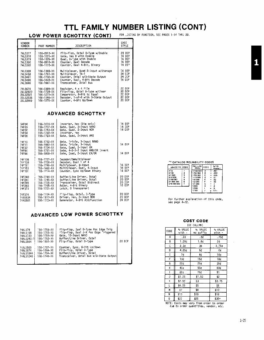
VENDOR NUMBER
TTL FAMILY NUMBER LISTING (CONT)
F l ip-Flop, Octal D-Type w/Enable Gate, Hex 0 w i t h Enable Quad, D-Type w i t h Enable Counter, Dual Decade Counter, Dual 4 - B i t , B inary
156-1661-XX I ~ r a n s c e i v e r , Octal Bus
156-1388-XX 156-1761-XX 156-1732-XX 156-1448-XX
Mu1 t i p l e x e r , Quad 2- Input w/Storage M u l t i p l e x e r , 16: l Counter, Octal w/3-State Output Counter. Dual, 4 - B i t Decade
ADVANCED SCHOTTKY
156-0989-XX 156-1729-XX 156-1273-XX 156-1546-XX 156-1375-XX
Reg is te r , 4 x 4 F i l e F l ip -F lop , Octal D-Type w/Clear Comparator, & B i t t o Equal Decoder, 1-of-8 w i t h 3-State Output Counter, 4-Bi t Up/Down
I n v e r t e r , Hex (D ie o n l y ) Gate, Quad, & I n p u t NAND Gate, Quad, 2-Input NOR I n v e r t e r , Hex Gate, Quad, 2 - Input AND
LOW POWER SCHOTTKY (CONT) FD"L'TING
Gate, T r i p l e , 3 - Input NAND Gate, T r i p l e , 3 - Input Gate, Quad, 2 - Input OR Gate, 4-2-3-2 I n p u t AND/OR I n v e r t Gate, Quad, 2-Input EX/OR
Decoder/Oemul t i p 1 exer Decoder, Dual 1 of 4 M u l t i p l e x e r , 8 - Input M u l t i p l e x e r , Dual, 4 - Input Counter, Sync Up/Down B inary
CASE STYLE
.
B u f f e r / L i n e Dr iver , Octa l B u f f e r / L i n e Dr iver , Octal Transceiver, Octal B i d i r e c t Adder, 4 - B i t B inary Latch, 0 Transparent
-
PART NUMBER
F l ip -F lop , Octa l , D-Type D r i v e r , Hex, 2 - Input NOR Generator, 4 - B i t ALU/Function
DESCRIPTION
20 DIP 16 DIP 16 DIP 16 DIP 14 DIP
16 DIP 24 DIP 24 DIP 16 DIP
20 DIP 22 DIP 20 DIP 20 DIP 20 DIP
14 DIP 14 DIP 14 DIP
14 DIP
14 DIP
16 DIP 16 DIP 16 DIP
20 DIP 20 DIP 20 DIP 16 DIP
20 DIP 20 DIP 24 DIP
ADVANCED LOW POWER SCHOTTKY
F l i p - F l o p , Dual D-Type Pos Edge T r i g F l ip -F lop , Dual J-K Pos Edge Tr iggered Gate, 13-Input NAND Buffer/Line Dr iver , Octa l F l ip -F lop , Octal D-Type
Counter, Sync, 4-Bi t Up/Down F l ip -F lop , Octal D-Type B u f f e r / L i n e Dr iver , Octa l Transceiver, Octal Bus w/3-State Outpu
20 DIP
BY FUNCTION, SEE PAGES 1-14 THRU 20.
tt CATALOG RELIABILITY CODES
For f u r t h e r exp lanat ion o f t h i s code, see page 4-72.
COST CODE (CC COLUMN)
N 11 $13 1 $15 I $18
0 11 $22 I $25 1 $35+ NOTE: Costs may vary f rom order t o o r d e r
due t o o rder q u a n t i t i e s , vendor, e t c .

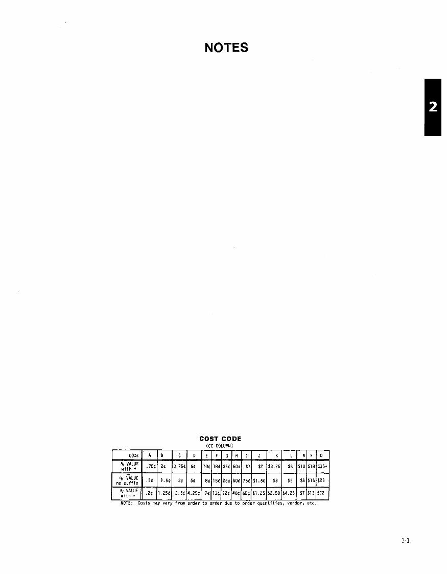
NOTES
COST CODE (CC COLUMN)
:i:tLuE (1 .2t (1.25t( 2.5tI4.25tI 7t(13t~22t(40t~65~l$l.25~$2.50~$4.25~ $71$131$22
NOTE: Costs may vary frm order t o order due t o order quan t i t i e s , vendor, e t c .

STAT l C SENSITIVE INTEGRATED CIRCUITS, SPECIAL FUNCTION
THIS APPLIES TO ALL DEVICES ON THIS PAGE.
* ADC0801
TDC1001 TDClD07
1 0 - B i t
8701
1 2 - B i t
ADC80-12
ADC1211
One-chip
ICL7106
ICL7107
MC14433
Two-chip
LDl lO
L D l l l A
L D l l l A
LD120
LD121
ICL8052
ICL8053
3-Bit IAC-08
IAC-08
iD558
1C1408
IE5018
iM6080
D7523
D7524
-
VENDOR NUMBER
156-1 533-OC
156-1 590-00 156-1345-OC
156-1595-00
156-1307-00
156-1571-00
VM Systems
156-1483-00
156-1435-00
156-1 118-00
VM Systems
156-0476-00
156-1268-OD
156-1268-01
156-1306-00
156-1305-00
156-0909-00
156-0908-00
156-1255-00
156-1255-01
56-1623-00
56-0509-00
56-1311-00
56-1555-00
156-1366-00
156-1367-00
** i t CASE PART NUMBER ND CC DESCRIPTION OTHER RC STYL
/D CONVERTERS I I I I
1 0 0 ~ 5 , up compatible, CMOS, SAR
400pS, s h o r t cycle, SAR 4DuS, ECL outputs, Para l -
l e l f l a s h conver te r
h s , Latches, CMOS, Mono- l i t h i c , up compat ib le
25uS, s h o r t cycle, D iscre te Modual, i n t e r n a l r e f
loops, 1 0 - b i t l i n e a r
3-1/2 d i g i t , LC0 d i s p l a y d r i v e r s , CMOS Auto zero, 1pA i n p u t c u r r e n t
3-1/2 d i g i t , LED d i s p l a y d r i v e r s , CMOS Auto zero, 1pA i n p u t c u r r e n t
3-112 d i g i t , BCD outpu ts , CMOS, No d i s p l a y d r i v e r s
3-1/2 d i g i t , D i g i t a l sec- t i o n , 2KH2 t o 250KHz c lock use w i t h L D l l l A o r LD120
3-1/2 d i g i t , Analog sec- t i o n , use w i t h LDl lO
3-1/2 d i g i t , Analog sec- t i o n , spec ia l no ise se lec- t i o n . use w i t h LDl lO
4-1 /2 .d ig i t , Analog sec- t i o n , use w i t h LD121 o r ID110
4 I i / 2 - d i g i t , D i g i t a l sec- t i o n , 50KH7 t o 250KH.7, use w i t h LD12O o r L D l l l A
3-112 d i g i t , Analog s i g n a l c o n d i t i o n e r , use w i t h ICL8053 o r 71C03
3-1/2 d i g i t , Auto zero swi tch network, use w i t h ICL8052
D/A CONVERTERS
Complimentary c u r r e n t o u t - pu t , 135nS max, M u l t i p l y - ing , 9 - b i t accurate, Mono- l i t h i c B i p o l a r , No-ref
Complimentary c u r r e n t o u t - pu t , 135nS max, M u l t i p l y - i n g , 9 - b i t accurate, Moao- l i t h i c B i p o l a r , No-ref
Vol tage output, 1.5uS max, up compat ib le band gap r e f , Latches
Current output, 300nS max, Mu1 t i p l y i n g , .19% accur- ate, No-ref
Vol tage output, 2~15, L a t - ches, Ref, b u r n - i n per MIL-STD-883
Complimentary c u r r e n t o u t - put , 160nS, Latches, Mul- t i p l y i n g , up compat ib le, No-ref
Current ou tpu t , l5OpS, CMOS, M u l t i p l y i n g , No-ref
Zurrent output, 150pS, CMOS, M u l t i p l y i n g , L a t - ches, up compat ib le, No-ref
L '* NEW DESlGh RECOMMEflDATIOh FROM COMPONEhT ENGII
c rnd
20 D
18 D 6A D
24 D
32 D
24 D
40 D
40 D
24 D
16 Dl
16 Dl
16 Dl
16 01
18 DI
4 DI
4 D l
16 01
16 DI
16 D l
16 DI
!2 D I
!O DI
6 DII
6 DI I
VENDOR I I I I t i ICASE DESCRIPTION 1 OTHER 1 RC STYLE
1 8 ' I I
1 0 - B i t
DAC 10
DACl 00
DAC331 C
AD561 TD1016
TD1016
MC3410
MC3410
AD7533
AD7533
DAC60-12
IAC8OI
lAC80ZI
IAC80V
lAC80V
lAC80- CCO- I
IAC80- CCO-I
i0565A
)AC1200
is3120
iM6012
lP7612
& B i t
IAC71- I
IAC71-I
D/A CONVERTERS (CONT
Compl imentary c u r r e n t o u t - p u t , l5OnS rnax, No- re f , Mu1 t i p l y i n g
Cur ren t ou tpu t , 375nS, 2-chip Hybr id , Ref
Cur ren t ou tpu t , 1.5uS, CMOS, M u l t i p l y i n g , No-ref
Cur ren t ou tpu t , 250uS, Ref Cur ren t ou tpu t , ZSnS, ECL, TTL/ECL i n p u t B u f f e r s , No-ref
Cur ren t o u t p u t , 25nS, ECL, TTL/ECL i n p u t B u f f e r s , No-ref
Current ou tpu t , 250nS, No-ref
Cur ren t ou tpu t , 250nS, No-ref
Current ou tpu t , 500nS, CMOS, Mu1 t i p l y i n g , No-ref
Current ou tpu t , 500nS CMOS, Mu1 t i p l y i n g , No-ref
Current o u t p u t , 150nS, Dis- c r e t e Modual c o n s t r u c t i o n
Current aurput, 30DnS, 114 LSD D i f f L i n e a r i t v Ref, H y b r i d
Current ou tpu t , 300nS, 1/4 LSD D i f f L i n e a r i t v Ref. W i l l work w/ l2v . ;upplies
Vol tage o u t p u t , 5pS, Hybr id, Ref
Voltage ou tpu t , 5uS, Hybr id, Ref
Current ou tpu t , 300nS, Coded decimal i n p u t , Hybr id, Ref
Current ou tpu t , 300uS, Coded decimal i n p u t , Hybr id, Ref
h r r e n t ou tpu t , 20016, Mono l i t h i c , Ref
:urrent ou tpu t , 1.511S, V o l t age ou tou t . 2 . 5 ~ s . Ref 3- c h i p ~ y b r i d
:urrent ou tpu t , 500nS, Buf- fe rs , M u l t i p l y i n g , up com- p a t i b l e , No-ref
h r r e n t ou tou t . 250nS. ~ u l t i p l y i n g , segmented, No-ref
h r r e n t o u t p u t , ~ L I S , CMOS,
:u r ren t ou tpu t , 1 ilS, 4 - d i g i BCO i n p u t , Ref
:u r ren t ou tpu t , luS, 4 - d i g i BCD i n p u t , Ref
Scrnl:
Scrnc
Scrnc
Scrnc
Scrnc
18 DII
16 Dl1
16 011 16 DIf
40 DIf
40 DIf
16 DIf
16 DIF
16 DIF
16 DIF
!8 DIF
!4 DIP
!4 DIP
!4 DIP
!4 DIP
!4 DIP
!4 DIP
!4 DIP
!4 DIP
!8 DIP
'0 DIP
8 DIP
4 DIP
4 DIP
RMS TO DC CONVERTER M+ M o n o l i t h i c t r u e RMS t o DC 36A 1 156-1259-00 I A I I I I 4 H I 1 4 D I P
conver te r , 0.5% max e r r o r approx 2OOKHz Band Width
M o n o l i t h i c t r u e RMS t o DC conver te r , 0.5% max e r r o r aoorox. 200KHz Band Width I I
A = Acceptable N = Not Recommended
36A 156-1457-02 N ~ o h b l i t h i c t r u e RMS t o OC conver te r , 0.5% max e r r o r approx. 20DKHz Band Width
Scrnd
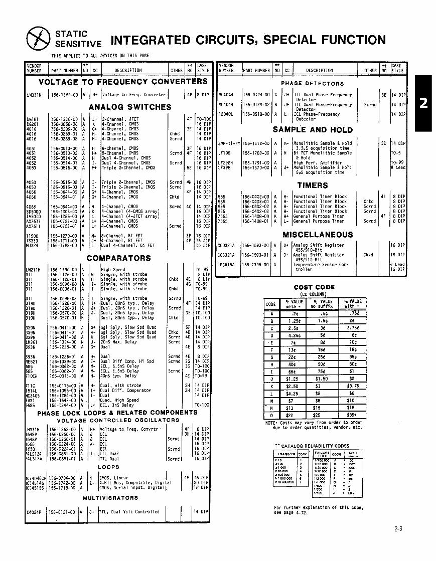
STATIC SENslTlVE INTEGRATED CIRCUITS, SPECIAL FUNCTION
THIS APPLIES TO ALL DEVICES ON THIS PAGE
VENDOR ** tt CASE NUMBER PART NUMBER ND CC DESCRIPTION OTHER RC STYLE
1 1 ' I
ENDOR tt CASE UMBER I PART NUMBER IN*; 1 CC I DESCRIPTION I OTHER I RC I STYLI
PHASE D E T E C T O R S
M331N 1 156-1362-00 A H t Vol tage t o Freq. Converter I 1 4F 18 DI l I I I MC4044 156-0124-00 A J+ TTL Dual Phase-Frequency 3E 14 DIF Detec tor
MC4044 156-0124-02 N J+ TTL Dual Phase-Frequency Scrnd 14 OIF Detec tor
12040L 156-0518-00 A L ECL Phase-Frequency 14 O I F Detec tor
ANALOG SWITCHES L t 2-Channel, JFET K 4-Channel, CMOS C i t 4-Channel, CMOS H- 4-Channel, CMOS H- 4-Channel, CMOS
GI 81 6201 01 6 01 6 316
051 051 052 052 353
153 353 366 166
166 I5000 3501 0 1751 1 1751 1
1508 3333 JX24
1211H I1 I1 I1 11
I I 9 D 9 D 9H
9 H
19N l9N 19N 1361 13N
13N '521 15 15 OCH
1 C 114L 3405 3 1 185
PH
Chkd Scrnd
Scrnd
Scrnd
Scrnd Scrnd
Chkd
Scrnd
Scrnd
SAMPLE AND HOLD
SMP-11 -FY Ii56-l312-OO 1 A I K- IMonol i t h i c Samole & Hold 3E 14 DIF
0-5
0- 99 8 Lead I
4E 8 DIP 8 DIP 8 DIP 8 DIP
4F 8 DIP 8 DIP
H &Channel, CMOS H+ %-Channel, CMOS H Dual 4-Channel, CMOS I- Dual 4-Channel, CMOS Ht T r i p l e 2-Channel, CMOS
I I l l 3.5pS a c q u i s i t i o n t ime .F198 156-1789-00 A N B i FET M o n o l i t h i c Sample
& Hold .F298H 156-1791-00 A I I l l ~ i g h - p e r f . A m p l i f i e r .F398 156-1370-00 A J+ M o n o l i t h i c Sample & Hold
6uS a c q u i s i t i o n t ime
TIMERS I- T r i p l e 2-Channel , CMOS I- T r i p l e 2-Channel, CMOS G t 4-Channel, CMOS G+ 4-Channel, CMOS H- Func t iona l Timer Block
H- Func t iona l Timer Block H- Func t iona l Timer Block H- Func t iona l Timer B l o c k H t General Purpose Timer L- General Purpose Timer
Chkd Scrnd Scrnd
Scrnd
H 4-Channel, CMOS K 4-Channel (4-DMOS a r r a y ) L 4-Channel (4-JFET a r r a y ) L t 4-Channel, CMOS L t 4-Channel, CMOS
Y- &Channel, B i FET It 4-Channel, B i FET - Dual 4-Channel, B i FET
MISCELLANEOUS 16 DIP
455/910-Bit 16 DIP
4551910-Bit Temperature Sensor Con- 4 Lead
t r o l l e r 16 DIP
COMPARATORS High Speed
G Single, w i t h s t r o b e H S ing le , w i t h s t robe I- Sing le , w i t h s t r o b e I Single, w i t h s t r o b e
Chkd
Chkd
Scrnd
Scrnd
Chkd
Chkd Scrnd Scrnd
jc rnd jc rnd
jc rnd
ON1
COST CODE (CC COLUMY)
NOTE: Costs may vary f rom order t o o rder due t o o rder q u a n t i t i e s , vendor, e t c .
46 TO-99 TO-99
TO-99 4F 14 DI
14 01 3E TO-10
TO-1 0
5F 14 DI 4D 14 DI 4D 14 DI
14 DI 4E 8 DI
4E 8 DI 36 14 DI 36 TO-101
TO- 101 4E TO-99
3H 14 DII 3H 14 DII
14 DII
TO-1 0(
NTS
I Single, w i t h s t r o b e I + Dual, 80nS typ. , Delay J+ Dual, 80nS typ. , Delay J - Dual, 80nS typ. , Delay
Dual, 80nS t y p . , Oelay
G+ Sgl Sply, Slow Spd Quad H- Sgl Sply, Slow Spd Quad H Sgl Sply, Slow Spd Quad J- 20nS Max. Delay Gt Dual
H- Oual It Dual O i f f Comp. H i Spd M- ECL. 6.5nS Delay M- ECL, 6.5nS Delay H- 40nS typ . Delay
156-01 16-00 A 156-1056-00 A 156-1 284-00 A 156-1647-00 A 156-1344-00 A
SE LOCK L
H- Dual, w i t h s t r o b e It Dual O i f f . Comparator I- Dual
Quad, High Speed L+ ECL, 3nS Delay
IOPS & RELATED COM VOLTAGE CONTROLLED OSCILLATORS
IZEtage t o Freq. Convrtr 4F 8 DII 3H 14 DI I
Scrnd 14 DI I 16 D I I
Scrnd 16 D I I 16 D I I
Scrnd 16 D I I TTL Dual TTL Oual
tt CATALOG RELIABILITY CODES
112oWO . ,005 +lo000 1110000 . .01 Ll00WO 115000 - .02 - 05
IIZW - .5
L O O P S
H CMOS, L inear L - 4 - B i t Bus, Compatible, D i g i t a l
CMOS, S e r i a l i n p u t , D i g i t a l 1 I For f u r t h e r exp lanat ion o f t h i s code, see page 4-72. 4024P 1156-0121-00 (A 1 J+ J T ~ , Oual V o l t C o n t r o l l e d I 1 114 DIP

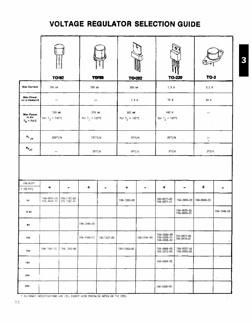
VOLTAGE REGULATOR SELECTION GUIDE
Max Current
Max Power on a Heatsink
1 5 0 mW
for TJ = 100°C
3 7 0 mW
for TJ = 125'C
3 8 0 mW
f o r TJ = 100°C
460 I4
f o r TJ = 100°C Max Power
In Air TA = 70°C
+ TOLERANCF S P E C I F I C A T I O N S ARE 45:;. EXCEPT WHEN
7-r]
NOTED ON THE SPEC.
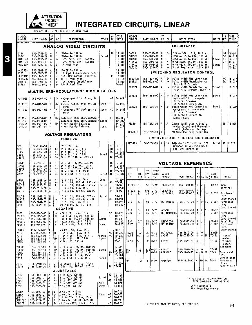
AlTENTlON 1 I INTEGRATED CIRCUITS, LINEAR THIS APPLIES TU ALL DEVICES ON THIS PAGE
VENDOR ** tt CASE NUMBER PART NUMBER ND CC DESCRIPTION OTHER RC STYL
VENDOR ** NUMBER PART NUMBER NO CC DESCRIPTION
ADJUSTABLE r s Scrnd
2.5 t o 37V, .5 A, 10.8 W 25 TO-66 h15V o r +8 t o 23V. 100 mA 36 1 4 D I I 115V o r *8 t o 23V, 100 mA Scrnd 3E 14 DI I 0 t o *32V, 150 mA, 900 mW 3F 14 DI I 0 t o r32V, 150 mA, 900 mW Scrnd 14 011 Shunt Regulator, 2.5 - 36V TO 92
Video A m p l i f i e r Video A m p l i f i e r T.V. Vert . D e f l . System T.V. Vert . Def l . System I F A m p l i f i e r
14 0 14 D 12 0 12 D 8 D
14 D 14 0 8 D
TO- 1 I 14 0 TO-9!
I FM-IF A m p l i f i e r I I F Amp1 & Quadrature D e t c t H T.V. H o r i z o n t a l Processor I - RF-IF A m p l i f i e r J- T.V. Croma Demodulator I- RF-IF A m p l i f i e r
NG REGULATOR CONTROL
1C 16 D I I 3G 16 DIF
16 OIF
18 OIF
18 OIF
IE 16 DIF
J+ Pulse w i d t h Mod Contr Ckt K t Pulse w i d t h Modulat ion w/
Push-Pull Outputs L- Pulse w i d t h Modulat ion w/
Push-Pull Outputs, Burn- in Scrnd
Scrnd
5crnd
MULTIPLIERS N- Pulse w i d t h Mod Contr Ckt
w/Push-Pull totem-pole Outputs; Screened, Selected & Burned- in
N- Pulse w i d t h Mod Contr Ckt w/Push-Pul 1 totem-pole Outputs; Screened, Selected & Burned- in w/Heat Sink
J- 1 4-Ouadrant Mu1 t i p 1 i e r , 4% 1 1 4F e r r o r
J - 14- iuadrant M u l t i p l i e r . 4% IChkd I e r r o r
4-Quadrant M u l t i p l i e r , 4% Scrnd e r r o r
Balanced Modul ator/Oemodul r Balanced Modul ator/Demodul r Scrnd
J Gated O s c i l l a t o r w/Single- ended Output and U n c o m i t - t e d High-Current Op Amp
SW Mode Pwr Supp Contr Ckt
Ht Mixer Doubly Balanced I Mixer Doubly Balanced
VOLTAGE REGULATORS OVERVOLTAGE PROTECTOR CIRCUITS POSITIVE
C3423U 156-1266-00 A I + Ad jus tab le T r i p Po in t ; SCR Scrnd 4D 8 DIP Crowbar Dr ive ; 2.5V Band- gap Ref; Burned- in
Scrnd
Scrnd
Ch kd
Scrnd
Scrnd
VOLTAGE REFERENCE - TOL c % - - 2.
2. 1.
1.
2. 1.
2.7 1.
.2 5.
3 .
.3
.3
.05
- TC
PPM /"C - - 50
100 25
40
25 25
65 25
25 2
2
8.5 30
5
- TEM
R!NG C - -
0-70
0-70 0-70
0-70
0-70 0-70
0-70 0-70
3-70 3-70
1-70
1-70 1-70
1-70
VENDOR NUMBER
CASE STYLE I NOTES PART NUMBER
TO-52 TWO- Terminal
8 DIP Purchased Pre-
Condi t ione 8 DIP Purchased
Pre- Condi t i o n e
TO-52
Scrnd
Scrnd
Condi t i o n e TO-99 Metal Pkg 8 DIP Purchased
Pre- Condi t i one,
TO-52 I n t e r n a l 'Ip 1
Heater TO-52 I n t e r n a l
Scrnd Scrnd
Heater, Screened
TO-99 TO-5 Purchased
Pre- Condi t ionec
TO-5 Purchased Pre-
cond i t ioned
Scrnd
Scrnd
Selected -15.3 t o -14.8V -15V + 5%, 100 mA, 625 mW
ADJUSTABLE TO- 1 OC TO- 1 OC 14 DIP
** NEW DESIGN RECOMMENDATION FROM COMPONENT ENGINEERING
14 DIP 14 DIP A = Acceptable
N = Note Recomnended !3C 1 156-0071-02 ) A I H 12 t o 3 7 ~ ; 600 mW 1 Scrnd 14E
156-0699-00 N I- 2 t o 37V, 412 mW / 156-0699-01 IN 1;- 1 2 t o 37V, 412 mW 1 Scrnd I4E 4317 156-1161-00 A 1.2 t o 37V. 1.5 A, 15 W 4E
TO- 100 TO- 100 TO-220 TO-99 TO-220 - .I+ FOR RELIABILITY CODES, SEE PAGE 3-5.
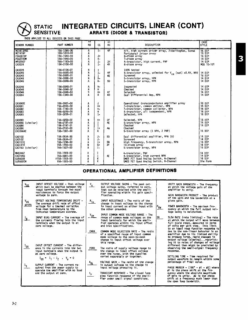
STATIC INTEGRATED CIRCUITS, LINEAR (CONT) SENSITIVE ARRAYS (DIODE & TRANSISTOR)
TH'tS APPLIES TO A
VENDOR NUMBER
CA3060E CA3081 CA3082 CA3083 CA3083
CA3083 CA3086 (s im i la r ) CA3086 CA3086 CA3096AE
CA3lO2 CA3102 CA3127E CA3141E CA3183 (s im i la r )
LL DEVICES ON THIS PAGl
PART NUMBER
156-1245-00 156-1810-00 156-1 540-00 156-1545-00 156-1 163-00 156-01 06-00
DESCRIPTION
HIV. high current d r i ve r array, 7-darlington, Scrnd Peripheral Driver Array &diode array 7-diode array 4- t rans is tor , high current, PNP 6-diode array
100% tested 5- t rans is tor array, selected f o r Vce ( sa t ) <0.4V, NPD Screened 5- t rans is tor array, NPN 5- t rans is tor array, NPN
Inspected Checked Selected Oual D i f f e r e n t i a l Amp, NPN
Operational transconductance ampl i f ier array 7- t rans is tor , comnon emitter, NPN 7- t rans is tor , comnon co l lec to r , NPN 5- t rans is tor , a l l independent, NPN Selected, NPN
Selected , NPN 5- t rans is tor array, NPN Checked Checked 5- t rans is tor array (3 NPN, 2 PNP)
Oual d i f f e r e n t i a l ampl i f ier , NPN (6) Screened High frequency, 5- t rans is tor array, NPN 10-diode array 5- t rans is tor array, NPN
4- t rans is tor , PNP 4- t rans is tor , high current NPN DMOS FET Quad Analog Switch, N-Channel DMOS FET Quad Analog Switch, N-Channel
OPERATIONAL AMPLIFIER DEFINtTIONS
'k
vos d r i f t -
I B
Ios -
I s -
INPUT OFFSET VOLTAGE - That voltage which must be appl ied between the input terminals through two equal resistances t o force the output voltage t o zero.
OFFSET VOLTAGE TEMPERATURE DRIFT - The average d r i f t ra te o f o f f se t voltage f o r a thermal var ia t ion from room temperature t o the indicated temperature extreme.
INPUT BIAS CURRENT - The average o f the currents f lowing i n t o the input terminals when the output i s a t zero voltage.
INPUT OFFSET CURRENT - The d i f f e r - ence i n the currents i n t o the two input terminals when the output i s a t zero voltage.
IOS - I1 - I2 , Vo = 0
SUPPLY CURRENT - The current re- quired from the power supply t o operate the amp l i f i e r wi th no load and the output a t zero.
CASE STYLE
16 DIP 16 DIP 16 DIP 14 DIP 14 DIP MOO TO-101
14 DIP 16 DIP 14 DIP 14 DIP
14 DIP 14 DIP 14 DIP 14 DIP
16 DIP 16 DIP 16 DIP 16 DIP 16 DIP
16 DIP 14 DIP 14 DIP
16 DIP
14 DIP 14 DIP 16 DIP 16 DIP 16 DIP
14 DIP 14 DIP 16 DIP Die Form
UNITY GAIN BANDWIDTH - The frequency a t which the voltage gain o f the ampl i f ier i s un i ty .
Vo OUTPUT VOLTAGE SWING - The peak out- - put voltage swing, re ferred t o zero, tha t can be obtained w i t h the ampli- f i e r operating w i t h i n i t s gain speci- f i ca t ion .
INPUT RESISTANCE - The r a t i o o f the - Rin change i n input voltage t o the change i n input current on e i t h e r input w i th the other grounded.
VcM INPUT COEMON MODE VOLTAGE RANGE - The -- range o f comnon mode voltages on the input tenninals f o r which the ampli- f i e r operates w i th in i t s input o f f s e t and bias specif icat ions.
CMRR COMMON MODE REJECTION RATE - The r a t i o - of a speci f ied range of input c m n mode voltage t o the peak-to-peak change i n input o f f s e t voltage over t h i s range.
PSRR The r a t i o o f supply voltage range t o - the change i n input o f f s e t voltaqe over the ranqe, w i t h the supplies varied separately o r together.
AOL VOLTAGE GAIN - The r a t i o o f the change - i n output voltage t o the change i n input voltage producing i t.
tr TRANSIENT RESPONSE - The closed loop - step funct ion response o f the ampli-
f i e r under small s ignal conditions.
GAIN BANDWIDTH PRODUCT - The product of the gain and the bandwidth a t a given gain.
PB,, - POWER BANDWIDTH - The maximum f re - quency a t which the f u l l output vo l - tage swing i s maintained.
SLEW RATE (rate l i m i t i n g ) - The ra te a t which the output w i l l move betweer f u l l scale stops, measured i n t e r m of vo l ts per u n i t time. This li.mit t o an ideal step funct ion response i s due t o the non-linear behavior i n an ampl i f ier due t o I t s l i m i t e d a b i l i t y t o produce large, rap id changes i n output voltage (slewing). . . r e s t r i c t - ing i t t o rates o f changes o f voltage d i f fe ren t than might be predicted by observing the small-signal frequency response.
SETTLING TIME - Time required f o r output waveform t o remain w i t h i n s m percentage o f f i n a l value.
PHASE MARGIN - (180" - 61 - 62) where d l i s the phase s h i f t a t the f re - quency where the absolute magnitude o f gain i s unfty. 62 i s the phase s h i f t a t a frequency much lower than the open loop bandwidth.
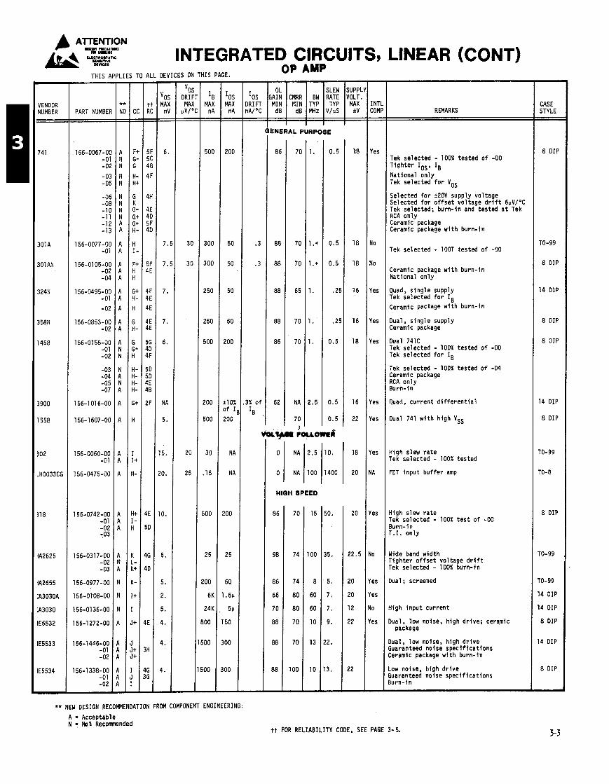
ATTENTION C ,, u y?zp INTEGRATED CIRCUITS, LINEAR (CONT) THIS APPLIES TO ALL DEVICES ON THIS PAGE. -
I 8 MAX
n A - -
500
300
300
250
250
500
!OO
500
30
15
100
25
00
6K
24K
DO
00
00
-
INTI COMl - -
Yes
Yo
Yo
les
les
les
les
les
'es
I A
'es
10
'es
'es
10
e s
- CASE STYLE - -
8 DIP
TO-99
8 DIP
14 DIP
8 DIP
8 DIP
14 DIP
8 DIP
TO-99
TO-8
8 DIP
ro-99
ro-99
14 DIP
14 DIP
8 DIP
14 DIP
8 DIP
-
- VENDOR NUMBER
741
301A
301AN
324N
358N
1458
3900
1558
302
.H0033CG
11 8
lA2625
lA2655
:A303DA
:A3030
lE5532
lE5533
E5534
-
- 10s MAX
n A - -
200
50
50
50
50
200
t10% 3 f I
200
N A
N A
!OO
25
60
.6u
5u
50
00
00
-
vo5 DRIF
MA) uV/< - -
30
30
20
25
REMARKS PART NUMBEF
156-0067-OC -01 -01
- 02 -05
-06 -oe -1 C -1 1 -12 -13
156-0077-06 -01
156-01 05-00 -02 - 04
156-0495-00 -01
-02
156-0853-00 -02
156-01 58-00 -01 -02
-03 - 04 -05 -07
156-1 016-00
156-1 607-00
156-0060-00 -01
156-0475-00
l56-O742-OO -01 -02 :03
156-0317-00 -02 -03
156-0977-00
156-0108-00
156-0136-00
156-1272-00
156-1446-00 -01 -02
156-1338-00 -01 -02
ENERAL PURPOSE
Tek selected - 100% tes ted o f -00 T igh te r IOS, IB National on l y Tek selected f o r VOS
Selected f o r +20V supply vol tage Selected f o r o f f s e t vo l tage d r i f t 6uVIoC Tek selected; burn- in and tested a t Tek RCA on l y Ceramic package Ceramic package w i t h burn- in
Tek selected - lOOT tested o f -00
Ceramic package w i t h burn- in Nat ional on l y
Quad, s i ng le supply Tek selected f o r IB Ceramic package w i t h burn- in
Oual, s i ng le supply Ceramic package
Oual 741C Tek selected - 100% tes ted o f -00 Tek selected f o r IB
Tek selected - 100% tes ted o f -04 Ceramic package RCA on l y Burn-in
luad, cu r ren t d i f f e r e n t i a l
Dual 741 w i t h h igh VSS
i i g h slew r a t e Tek selected - 100% tes ted
-ET i npu t bu f f e r amp
i i g h slew r a t e rek selected - 100% t e s t o f -00 3urn-in r.1. on l y
Jide band width r i gh te r o f f s e t vol tage d r i f t Tek selected - 100% burn- in
h a 1 ; screened
{ i gh i npu t cur rent
h a 1 package , low noise, h igh dr ive ; ceramic
Iual , low noise, h igh d r i v e iuaranteed noise spec i f i ca t i ons .eramlc package w i t h burn- in
.ow noise, high d r i v e iuaranteed noise spec i f i ca t i ons lu rn- in
** NEW DESIGN RECOMENDATIDN FROM COMPONENT ENGINEERING: A a Acceptable N = Not Recomnended
tt FOR RELIABILITY CODE, SEE PAGE 3- 5.
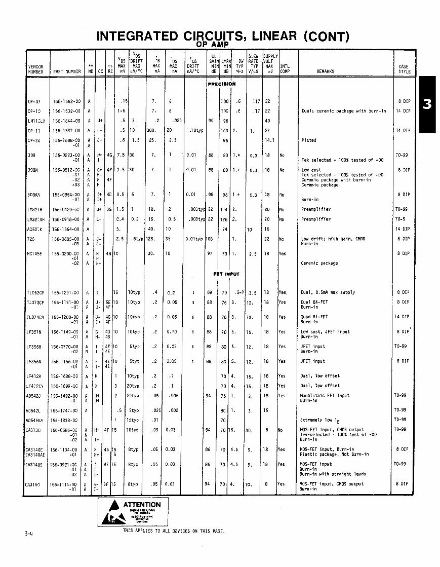
- Ios
DRIFT nA/OC - -
.IOty
0.01
0.01
0.01
.OO3 t
.OO3 t
1.Olty
5
5
5
5
5
5
- IENDOR {UMBER -
IP-07
IP-10
.MI1 CLH
IP- 11
IP-20
108
08N
08AN
M321H
M321AH
D521 K
25
C1456
LO62CP
LO72CP
L074CN
-351 N
-356H
-356N
-41 2A
-412CN
15425
1542L
)545KH
d l 3 0
13140E t3 140AE
,31405
31 60
-
- vos
DRIF MAX
uV/" - -
3
10
1.5
30
l 0
5
1
0.2
.6t)
O ~ Y P
O ~ Y P
O~YP
3typ
S ~ Y P
jtYP
I~Y P
I~YP
ItY P
i t y P
itYP
'tY P
tY P
tY P
tY P
- IE
MA) r l P - -
7.
7.
.2
00.
25.
7.
7.
7.
18.
15.
40.
25.
30.
.4
.2
.2
.2
.2
.2
.2
.2
.05
.02
.01
.05
.05
.05
.05
- Ios MAX
n A - -
6
6
. Oi !O
2.5
1
1
1
2
0.5
0
5
0
0.2
3.05
I. 05
1.10
1.05
1.'05
1
1
.005
.002
.03
.03
.03
.03
- J.lPPLI 'OLT MAX
av - -
22
22
40
22
14.1
18
18
18
20
20
15
22
18
18
18
18
8
8
8
8
8
8
5
8
8
- NTL :OMP - -
0
0
0
0
0
0
es
es
?S
?S
2s
?S
?S
?S
2s
?S
I
!S
s
s -
- CASE STYLE - -
8 DIP
14 DIP
14 DIP
TO-99
8 DIP
8 DIP
TO-99
TO-5
14 DIP
8 DIP
8 DIP
8 DIP
8 DIP
14 DIP
8 DIP'
r0-99
8 DIP
'0-99
'0-99
'0-99
'0-99
8 DIP
0-99
8 DIP -
G;:; dB dB MH: PART NUMBEI REMARKS
Dual; ceramic package w i t h burn- in
P la ted
Tek se lec ted - 100% tes ted o f -00
Low cos t Tek se lec ted - 100% tes ted o f -00 Ceramic package w i t h bu rn - i n Ceramic package
Burn- in
Preamp1 i f i e r
P reamp l i f i e r
Low d r i f t ; h igh gain, CMRR Burn- in .
Ceramic package
Dual. 0 . m max supply
Dual Bi-FET Burn-i n
Quad Bi-FET Burn-in
Low cost, JFET i npu t Burn-in
IFET i n p u t 3urn- in
IFET i n p u t
l ua l , low o f f s e t
l ua l , low o f f s e t
lonol i t h i c FET i npu t 3urn-in
:xtremely low lB
40s-FET input , CMOS output rek-selected - 100% t e s t o f -00 l u rn - i n
IOS-FET Input . Burn- in ' l a s t i c package, Not Burn- in
IOS-FET i n p u t lu rn- in Lurn-in w i t h s t r a i g h t leads
IOS-FET input . CMOS output lu rn- in
THIS APPLIES TO ALL DEVICES ON THIS PAGE.

VENDOR NUMBER -
LMl OCN
A01 71 J
STK457
vA727
MC1436CC
2030H
CA3060H
:A3080
:A3080A
:A3080AE
;A3080E
-
PART NUMBER
INTEGRATED CIRCUITS, LINEAR (CONT) 9
vos MAX mV - -
4.
26.
2.
12.
20.
5.
5.
5.
2.
5.
9
- vos
IRIFT MAX
lV/"C - -
5
.6
3
- I B
MAX n A - -
30
12
90
2000
5000
5K
5000
5K
5000
-
- I05 MAX
n A - -
2
2.5
25.
200
000
600
600
600
600
-
- -
OP AMP
GAIN CMRR BW RATE ::N! MIN lTyp 1'::; dB dB MHz V/uS
7.7 mnho
7.7 mnho
6.7 mnho
Op Pinp and Voltage Reference
High vol tage: 140V
Dual power a m p l i f i e r hyb r i d
D i f f e r e n t i a l output, i n t . temp con t ro l l e d
High vol tage: 60V
Monol i th ic power a m p l i f i e r
Transconductance
Va rh , low leakage, h igh Zo Burn- in
SUPPLY VOLT MAX
+V
45
140
26
18
30
18
18
18
18
18
18
Transconductance
INTL COMP
Yes
Yes
No
No
Yes
No
Yes
Yes
Yes
Yes
Yes Transconductance Burn- in
8 DIP
B r i ck
B r i ck
TO-99
TO-99
50-220
16 DIP
TO-99
TO-5
8 DIP
8 DIP
THIS APPLIES TO ALL DEVICES ON THIS PAGE.
COST CODE tcc COLUFH)
tt CATALOG RELIABILITY CODES
USAGEIYR CODE
For fu r ther explanat ion o f t h i s code. see page 4-72.
** NEW DESIGN RECOMENDATION FROM COMPONENT ENGINEERING:
A = Acceptable N = Not Recomnended
NOTE: Costs my vary from order t o order due t o order quantlt les. vendor, etc.
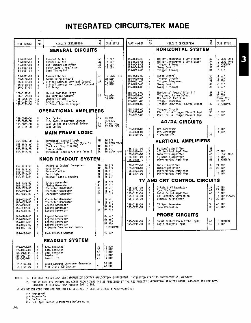
INTEGRATED CIRCUITS,TEK MADE
PART NUMBER I ii I CIRCUIT DESCRIPTION / ii 1 CASE STYLE PART NUMBER I 1 I I
I ' HORIZONTAL SYSTEM
Channel Switch Channel Switch Dual Output Ampl i f ie r Power Supply Regulator Quad Timing U n i t
GENERAL CIRCUIT&
** NO
16 DIP 16 DIP 16 DIP 16 DIP
16 LEAD TO- 24 DIP 40 DIP 40 DIP
40 DIP 16 DIP
M i l l e r I n teg ra to r & Dly P i cko f f M i l l e r I n teg ra to r & Oly P i cko f f Tr igger & Sweep Sweep Control Tr igger & Sweep
I
CIRCUIT DESCRIPTION
10 LEAD TO-5 10 LEAO TO-5 16 MINIPAC 20 DIP 16 DIP
Sweep Control Tr igger C i r c u i t T r i gge r Subsystem Sweep Control Sweep & P i cko f f
tt RC
Channel Switch Normal iz ing C i r c u i t O i g i t a l Storage Ve r t i ca l Control O i g i t a l Storage Hor izonta l Control LED Array
CASE STYLE
16 DIP 16 DIP 16 DIP 16 DIP 16 DIP
16 DIP 20 DIP Power Pkg 20 DIP 16 MINIPAC
16 DIP 16 DIP
Hor izonta l Preampl i f ie r P-P T r i g Amp, Source Se lec t Hor izonta l Amp l i f i e r T r i gge r Generator Tr igger Ampl i f i e r , Source Select
Photo t rans is tor Array 7L5 V e r t i c a l Control Channel Switch System Logic I n te r f ace Hi Speed Schmitt Tr igger
Tr igger C i r c u i t P l r t Inv. & Tr igger P i cko f f Ampl P l r t Inv. & Tr igger P i cko f f Ampl
OPERATIONAL AMPLIFIERS
AD/DA CIRCUITS D/A Converter D/A Converter 4 Oecade DVM
P P A P
16 DIP 16 DIP
46
3H 36
Quad Op Amp 2 Op Amps, 2 Current Sources Dual Op Amp and Channel Switch Quad Op Amp
MAIN FRAME LOGIC
16 DIP PLASTIC 17 MINIPAC 17 DIP CER
VERTICAL AMPLIFIERS ft Double Amp l i f i e r 423 Ve r t i ca l Amp l i f i e r Gain Tr im Amp l i f i e r f t Double Amp l i f i e r D i f f /Va r / I nv Amp l i f i e r
A A A P A 20 DIP
12 LEAO TO-8 16 DIP 16 MINIPAC
24 DIP 20 DIP 14 DIP 14 DIP
4H
4E 4F 4C
Hor izonta l Lockout Logic Chop D i v i de r & Blanking (Type 3 ) Clock and Chop Blanking Z Axis Logic Hor izonta l Chop & A l t B in (Type 2)
KNOB READOUT SYSTl
16 DIP 10 LEAD TO- 16 DIP 16 DIP 10 LEAD T0-
Analog t o Decimal Converter Data Switch Oecade Counter Zero Logic Decimal Po in t & Spacing
16 DIP 16 DIP 16 DIP 16 DIP 16 DIP
16 DIP 16 DIP 16 DIP 16 DIP 16 DIP
16 DIP 16 DIP 20 DIP 20 DIP 20 DIP
20 DIP 20 DIP 20 DIP 20 DIP 16 MINIPAC
10 DIP
Output Amp l i f i e r Output M p l i f i e r D i f f /Va r / I nv Amp l i f i e r D i f f /Va r / I nv Amp l i f i e r
9ND CRT CONTROL CIRCUITS Output Assembler Timing Generator Character Generator Character Generator Character Generator
A Z-Axis & HV Regulator P Sync S t r i ppe r P Pulse Output Amp l i f i e r P CRT Geometry Correc t ion P Disp lay Mu l t i p l exe r Character Generator
Character Generator Legend Generator Legend Generator Legend Generator
3H 4F 4E
46
TV Sync Generator Tape Con t ro l l e r
20 DIP 16 DIP 1 6 0 I P 16 DIP PLASTC 20 DIP
3H 40 DIP 3E 40 DIP I I
PROBE CIRCUITS Legend Generator Legend Generator Legend Generator Legend Generator 4 Oecade Counter and Memory
I npu t Pro tec t ion ti Probe Logic 1 :" "IPAC Logic Analysis I npu t
Knob Readout Counter
READOUT SYSTEM 31 31 31
31 116 DIP
16 DIP 16 DIP 16 DIP
155-0004-01 155-0005-00 55-0006-01 55-0007-01 55-0008-01
16 DIP 31 140 DIP
X X X X X
55-01 14-00 55-0119-00
NOTES: 1. FOR COST AN0 APPLICATION INFORMATION CONTACT APPLICATION ENGINEERING, INTEGRATEO CIRCUITS MANUFACTURING, 627-1037.
2. THE RELIABILITY INFORMATION COMES FROM REPORT 449-35 PUBLISHED BY THE RELIABILITY INFORMATION SERVICES GROUP, 643-8006 AN0 REFLECTS INFORMATION RECEIVED FROM PERIODS 204 TO 303.
** NEW DESIGN CODE FROM APPLICATION ENGINEERING, INTEGRATEO CIRCUITS MANUFACTURING:
Beta Computer Beta Computer Beta Computer Readout I Readout I 1
P = Pre fer red A = Acceptable X = Do Not Use C = Ca l l App l ica t ion Engineering before us ing
A X
Seven Segment Character Generator F ive D i g i t BCD Counter
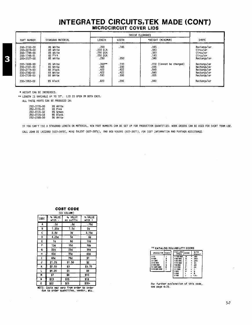
INTEGRATED CIRCUITS,TEK MADE (CONT) MICROCIRCUIT COVER LIDS
200- 1608-00 I 85 White 200-2181-00 85 White 200-21 14-00 85 Black 200-21 82-00 85 White
PART NUMBER
200-21 83-00 200-2274-00 200-1 748-00 200-1 748-01 200-2027-00
200-21 38-00 I 85 White
200-1 953-00 85 Black
.010 (Cannot be changed)
.045
.040
.040
.055
STANDARD MATERIAL
85 White 85 White 85 White 85 Pink 85 White
Rectangular Rectangular Rectangular Rectangular Rectangular
Rectangular
HEIGHT CAN BE INCREASED.
** LENGTH IS VARIABLE UP TO 12". LID IS OPEN ON BOTH ENDS.
ALL THESE PARTS CAN BE PRODUCED IN:
252-0115-00 85 White 252-0115-01 85 Pink 252-01 15-02 85 Green
SHAPE
Rectangular C i r c u l a r C i r c u l a r C i r c u l a r Rectangular
INSIDE CLEARANCE
252-01 15-03 85 Black 252-0168-00 96 White
LENGTH
.200 ,230 DIA .250 DIA ,250 DIA
.250
I F YOU CAN'T USE A STANDARD LENGTH OR MATERIAL, NEW PART NUMBERS CAN BE SET UP FOR PRODUCTION QUANTITIES: WORK ORDERS CAN BE USED FOR SHORT TERM USE.
CALL JOHN D l LAZZARO (627-3972), MIKE EHLERT (627-3975)s AND BOB ROGERS (627-3971), FOR COST INFORMATION AND FURTHER ASSISTANCE.
WIDTH
. I85
.250
COST CODE ICC COLUrn)
*HEIGHT (MINIMUM)
.045
.050
.060
. I 40
.045
tt CATALOG RELIABILITY CODES
'''' I A 1 B 1
1/30 OM) 21 am 1/20 MO
- --
NOTE: Costs may vary from order t o order
w i t h - I n o - s u f f i x
-24 1 .% 1.256 1 1 .5d
For f u r t h e r exp lanat ion o f t h i s code, see page 4-72.
w i t h + .754 26
due t o order q u a k l t l e s , vendor. e tc .
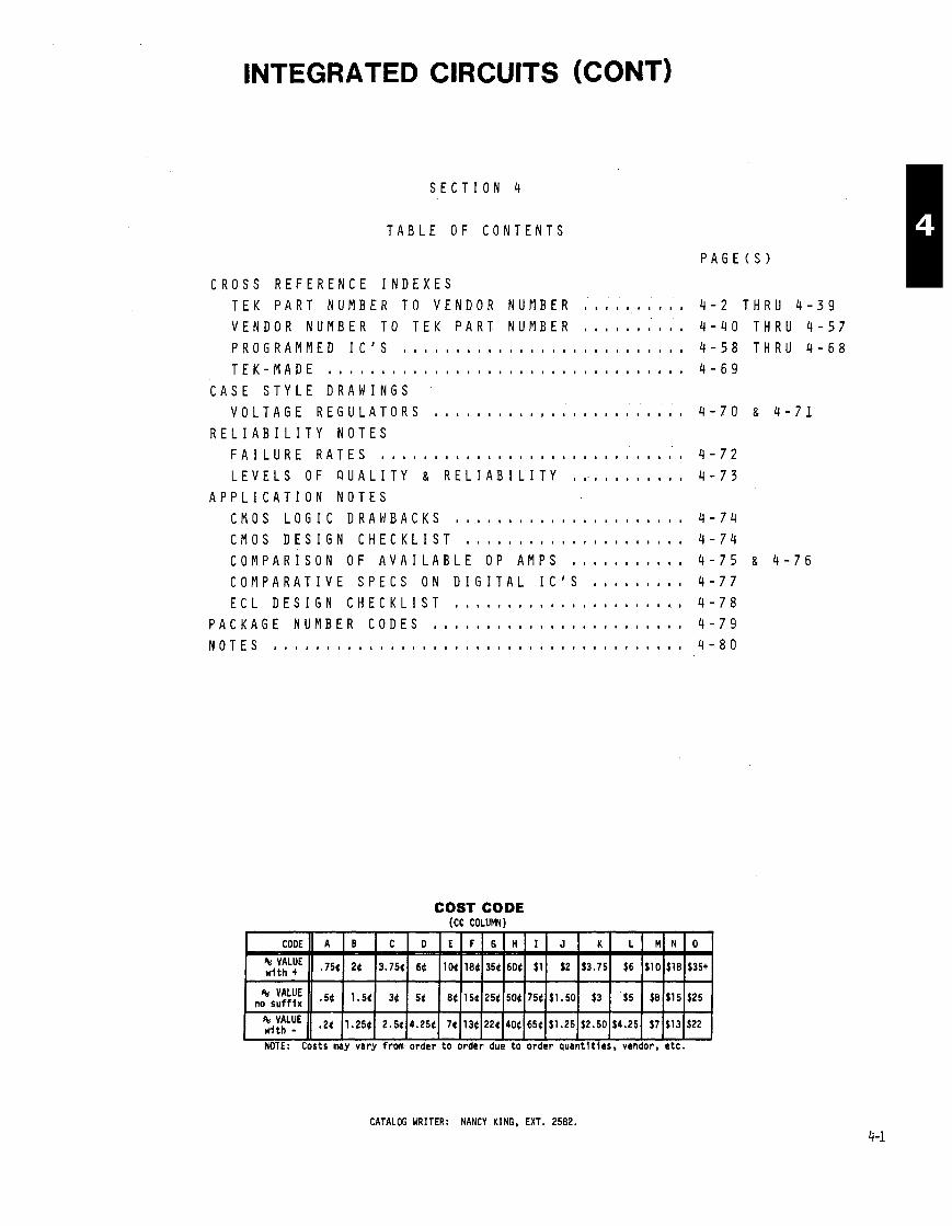
INTEGRATED CIRCUITS (CONT)
S E C T I O N 4
T A B L E O F C O N T E N T S
P A G E ( S )
C R O S S R E F E R E N C E I N D E X E S T E K P A R T N U M B E R T O V E N D O R N U M B E R , , , , , , . . , , 4 - 2 T H R U 4 - 3 9
V E N D O R N U M B E R T O T E K P A R T N U M B E R , , , , , , a , , , 4 - 4 0 T H R U 4 - 5 7
P R O G R A M M E D I C ' S , , , , , , , , , , , , , , , , , , , , , , 4 - 5 8 T H R U 4 - 6 8
T E K - M A D E 8 ~ ~ ~ ~ ~ ~ ~ ~ 8 ~ ~ ~ 8 ~ ~ ~ m ~ ~ ~ ~ ~ ~ ~ ~ ~ ~ ~ ~ ~ a m ~ 4 - 6 9
C A S E S T Y L E D R A W I N G S V O L T A G E R E G U L A T O R S n 8 m a 8 a , , , , , m m a s a a # , 4 - 7 0 & 4 - 7 1
R E L I A B I L I T Y N O T E S
F A I L U R E R A T E S a , , m , , , , , t , , , , , , , , a , , , e , a u m n , 4 - 7 2
L E V E L S O F Q U A L I T Y & R E L I A B I L I T Y , , . , , , . , , , , , 4 - 7 3
A P P L I C A T I O N N O T E S C M O S L O G I C D R A W B A C K S a n a , , , , , , , , , 4 - 7 4
C M O S D E S I G N C H E C K L I S T . . . . . . . . . . . . . . . . . . . . . 4 - 7 4 C O M P A R I S O N O F A V A I L A B L E O P A M P S , , , , a 4 a m , a , 4 - 7 5 8 4 - 7 6
C O M P A R A T I V E S P E C S O N D I G I T A L I C ' S , , , , n a n 4 - 7 7 E C L D E S I G N C H E C K L I S T , , a a , , 4 - 7 8
P A C K A G E N U M B E R C O D E S , , , , , , , , , 4 - 7 9 N O T E S a ~ ~ ~ ~ ~ ~ ~ ~ ~ ~ ~ ~ ~ ~ ~ ~ ~ ~ , ~ ~ ~ ~ ~ ~ ~ ~ ~ 8 ~ ~ ~ . ~ ~ ~ ~ ~ 4 - 8 0
COST CODE (CC COLUMNl
CATALOG WRITER: NANCY KING, EXT. 2582.

INTEGRATED CIRCUIT PART NUMBER INDEX TEK PART NUMBER TO VENDOR NUMBER - *
PAGE NO -
2-3
1-18
1-18
1-18
1-15
3-1
PART NUMBER - 062-231 8-00 062- 2985-00 062-3448-00 062-3728-00 062-3798-00
062-391 9-00 062-3924-00 062-3942-00 062-3953-00 062-4099-00
062-41 13-00 062-41 70-00 062-41 71 -00 062-41 71-01 062-41 72-00
062-41 73-00
062-41 74-00 062-41 75-00 062-41 76-00
062-41 77-00 062-41 78-00 062-41 79-00 062-41 80-00 062-4181-00
062-4182-00
062-4182-01 062-41 88-00 062-4325-00
062-4325-01 062-4385-00 062-4385-01 062-4497-00
062-4499-00 062-4501-00
062-4502-00 062-4503400
062-4503-01 062-4504-00 062-4558-00 362-4576-00 362-4584-00
362-4585-00 162-4586-00 362-4587-00 162-4588-00
362-4589-00 162-4590-00 162-4591 -00 164-4592-00 162-4593-00
162-4654-00 162-4670-00 162-4670-01 162-5456-00 162-5457-00
162-5549-00 162-5549-01 62- 5863-00 162-5875-00 162-5876-00
162-5879-00
i
VENDOR VENDOR NC TYPE PAGE * NO. PART NUMBER
156-0001 -00 156-0002-00 156-0003-00 156-0004-00 156-0005-00
156-0006-00 156-0007-00 156-0008-00 156-0009-00 156-001 0-00
156-001 1-00 156-0012-00 156-0013-00
156-001 4-00
156-001 5-00
156-001 6-00 156-001 7-00 156-0018-00
156-001 9-00 156-0020-00 156-0021-00 156-0021 -01 156-0022-00
156-0023-00 156-0024-00 156-0025-00 156-0025-01 156-0026-00
56-0027-00 56-0028-00
56-0029-00 '56-0030-00
56-0030-01 56-0030-02 56-0030-03
56-0031 -00
56-0031 -01
56-0031 -02
56-0032-00
56-0032-01 56-0032-02
56-0032-03
56-0033-00 56-0033-01 56-0034-00
VENDOR NO. TYPE
Spec Funct
L inear
L inear
L inear
L inear
TTL TTL
TTL TTL TTL
TTL
TTL
TTL
TTL
TTL TTL
TTL
L inear Linear TTL
VENDOR
Tech Sheet Tech Sheet Tech Sheet Tech Sheet Tech Sheet
F a i r c h i l d Motorola Motorola Motorola F a i r c h i l d
Motorola Motorola Motorola
Tech Sheet Tech Sheet Tech Sheet Tech Sheet Tech Sheet F a i r c h i l d
1-20 1-20 1-20 1-20 1-20
Fa l r ch i l d F a i r c h i l d F a i r c h i l d Na t l Semic Teledyne
Tech Sheet Mem Sel Guide Mem Sel Guide Mem Sel Guide
S ignet ics I 2632FN
1-20 1-4 1-4 1-4
Mem Sel Guide
Mem Sel Guide
Mem Sel Guide Mem Sel Guide Mem Sel Guide
Mem Sel Guide Mem Sel Guide Mem Sel Guide Mem Sel Guide Mem Sel Guide
Motorol a Elec Array Motorola AM0 Signet ics
F a i r c h i l d Raytheon Fa i r ch i l d RCA Motorol a
Motorola S ignet ics S ignet ics Motorola Gen I n s t r
Motorola Motorola Motorola Motorola Motorola
Texas I n s t t Motorola Texas Pnstr
Motorola Motorola Motorola Motorola
MClOOlP MC1004P MClOlOP MClOlO
Mem Sel Guide Tech Sheet Mem Sel Guide Mostek 1 MK36OOOP/J-4
Mostek I MK36000N-4
Mem Sel Guide Tech Sheet Tech Sheet Mem Sel Guide
Nat l Semic Motorola Fa i r ch i l d F a i r c h i l d Nat l Semic 8NEC America S ignet ics Texas I n s t r
Elec Arrays EA43356 Elec Arrays EA43357 Elec Arrays EA4000
h r Micro 54264 Yat l Semic 52415 Natl Semic MI452145 h e r Micro 54216 rlostek MK36000P/J-5
Mem Sel Guide Mem Sel Guide
Mem Sel Guide Mem Sel Guide
Mem Sel Guide Mem Sel Guide Mem Sel Guide Mem Sel Guide M u l t i Funct
Texas I n s t r Texas I n s t r F a i r c h i l d Nat l Semic S ignet ics Texas I n s t r
h t e k I MK36OOON-5 l o t o r o l a MCM68A332 jynertek SYC2316A [ n t e l C8316A
6531 '
Fa i r ch i l d Nat l Semic S ignet ics Texas I n s t r l a t l Semic 1 MM5214
;en I n s t r Jat l Semic Jat l Semic lexas Ins t t
Mem Sel Guide Mem Sel Guide Mem Sel Guide Mem Sel Guide F a i r c h i l d
Na t l Semic S ignet ics Texas I n s t r F a i r c h i l d Nat l Semic S ignet ics Texas I n s t r
1-4 1-4
i i gne t i cs i a t l Semic b t o r o l a l a t l Semic i i gne t i cs
l a t l Semic I MM52132
Mem Sel Guide Mem Sel Guide Mem Sel Guide Mem Sel Guide Mem Sel Guide
1-4
1-4 1-4
Nat l Semic S ignet ics F a i r c h i l d Nat l Semic S ignet ics Texas I n s t r
Mem Sel Guide Mem Sel Guide Mern Sel Guide Mem Sel Guide Mem Sel Guide
iynertek SYC2333 iynertek SYC2333 IEC America I UP023640
1-4 1-4 1-4 1-4 1-4 iynertek I SYC2364
: lec Arrays : lec Arrays
Mem Sel Guide Mem Sel Guide Tech Sheet Tech Sheet Tech Sheet
RCA RC A F a i r c h i l d Yatl Semic Signet ics rexas I n s t r
o t o r o l a Mem Sel Guide
NEW DESIGN RECOMMENDATION FROM COMPONENT ENGINEERING: A = Acceptable N = Not Recomnended U = Undeflned X = Do Not Use
1-4
MemSel Guide MemSel Guide Mem Sel Guide Mem Sel Guide Mern Sel Gulde
1-8 1-8 1-8 1-8 1-8
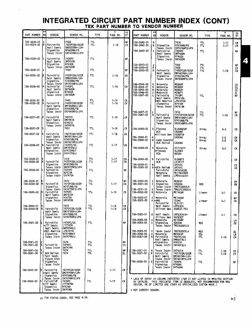
INTEGRATED CIRCUIT PART NUMBER INDEX (CONT) TEK PART NUMBER TO VENDOR NUMBER
PART NUMBER F __$ VENOOR NO. VENOOR TYPE *
PAGE NO. - 'ART NUMBER I I TYPE VENOOR NO. *
PAGE NO - F a i r c h i l d 7420PCQR/OCQR Na t l Semic OMEOZONA+/JA+ S ione t i c s I N7420NB/FB 7420
l-rL TTL
TTL
TTL
TTL
TTL
TTL TTL
TTL
TTL
TTL
l l L
TTL r r L
TTL
TTL 'TL
'TL
'TL 'TL
TL
N N S ignet ics
Texas I n s t r X F a i r c h i l d
Na t l Semic S ignet ics Texas I n s t r
1 2 3
3 1 3 3 3
I !
1
!
I
)
!
I I
I
I
TTL TTL
TTL
TTL TTL TTL
TTL
TTL TTL
exa as I n s t r ~ ~ 7 4 2 0 N b 3 / ~ ~ 4 I F a f r c h i l d 7430PC Na t l Semic OM7430N Sionet ics 1 N7430A X
N N F a i r c h i l d
N a t l Semic S ignet ics Texas I n s t r
~ e i a s I n s t r I SN7430N
F a i r c h i l d 743OPCQR/OCQR Na t l Semi c OM8030NA+/JA+ S ignet ics N7430NB/FB Texas I n s t r SN7430NP3/JP4 Fa i r ch i 1 d 7440PC Nat l Semic DM7440N Signet ics N7440A Texas I n s t r SN7440N
N Motorola N Motorola N Motorola X Motorola X F a i r c h i l d
Na t l Semic -NEC America S igne t i c s Texas I n s t r
7440 F a i r c h i I d 7440PCQR/OCQR Na t l Semi c OM7440NA+/JA+ S ignet ics N7440NB/F8 Texas I n s t r SN7440NP3/JP4
N F a i r c h i l d I Na t l Semic F a i r c h i l d Na t l Semic S ignet i cs Texas I n s t r I Signet ics
Texas I n s t r
A Plessey
b ~ i c o n Gen
Array
Array Array
Array
MOS
L inear
L i nea r
L i nea r
MOS
MOS ECL TTL
TTL TTL
F a i r c h i l d Na t l Semic S ignet ics Texas I n s t r F a f r c h i l d Na t l Semic S ignet ics Texas I n s t r
N Comp Concpt A I DCA Rel iab
Plessey
7472 F a i r c h i l d 7472PCQR/OCQR Signet ics N7472NB/FB Texas I n s t r SN7472NP3/JP4 Fa i r ch i l d 7473PC Signet ics N7473A Texas I n s t r SN7473N
N F a i r c h l l d
N 1 RCA SLOE871 CA741CT UA74l C UA741C UA741 HCQR MC1741CGDS LM741 CH/A+
N -DCA Rel iab Fa i r ch i l d Motorola N a t l Semic
X Motorola X S ignet ics
Texas I n s t r X Texas I n s t r N Motorola
F a i r c h i l d S ignet ics Texas I n s t r F a i r c h i l d Na t l Semic S ignet ics Texas I n s t r
F a i r c h i l d N a t l Semic S i l i c o n Gen
56-0040-01 N 7475 56-0040-02 N F a i r c h i l d 7475PCQR/OCQR
Na t l Semic OM7475NA+/JA+ S ignet ics N7475NB/FB Texas I n s t r SN7475NP3/JP4
4 Na t l Semic S i l i c o n Gen
X Motorola L( S igne t i c s
Texas I n s t r F a i r c h i l d
4 T T Semic Na t l Semic
-NEC America S ignet ics Texas I n s t r
K Texas I n s t r 1 Motorola 1 F a i r c h i l d
N a t l Semic 4 i g n e t i c s
Texas I n s t r 56-0041-01 1 17474 56-0041-02 N F a i r c h i l d 7474PC
Texas I n s t r SN7474N 56-0041-03 X 7474
TTL TTL
TTL TTL
TTL
'TL
I Texas I n s t r I 1 F a i r c h i l d 56-0041-04 X OCA Rel iab
Na t l Semic Nippon Elec S ignet ics Texas I n s t r
Na t l Semic Texas I n s t r
( F a i r c h i l d S igne t i c s Texas I n s t r L 56-0041-05 N F a i r c h i l d t Nat l Semic
S ignet ics Texas I n s t r
56-0042-00 N F a i r c h i l b ACK OF ENTRY I N COLUMN INDICATES ITEM I S NOT LISTED I N MFR/TEK SECTION F CATALOG. THIS INOICATES ITEM I S OBSOLETE, NOT RECOWENDED FOR NEW ESIGN, OR OF LIMITED USE (SUCH AS SPECIALIZED CUSTOM MASK.)
OT CURRENT VENDOR.
-In Semic ITT7476N Signet ics N7476B Texas I n s t r SN7476N I I I
$ 5 FOR STATUS CODES, SEE PAGE 4-39.
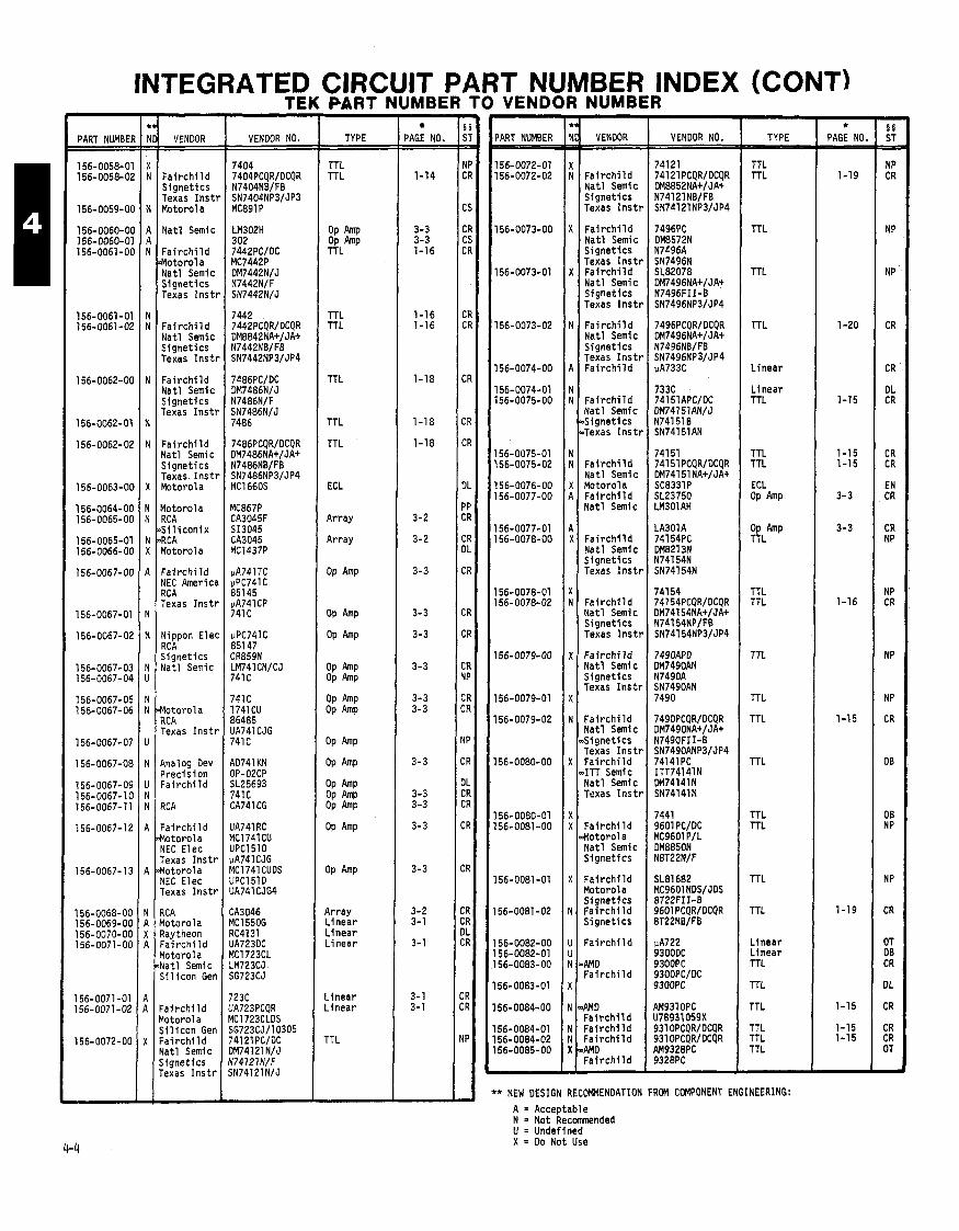
INTEGRATED CIRCUIT PART NUMBER INDEX (CONT) TEK PART NUMBER TO VENDOR NUMBER
PART NUMBEfi
156-0058-01 156-0058-02
VENDOR
F a i r c h i l d S ignet ics Texas I ns t r Motorola
Nat l Semic
F a i r c h i l d a o t o r o l a Nat l Semic S ignet ics Texas I n s t r
F a i r c h i l d Nat l Semic S ignet ics Texas I n s t r
F a i r c h i l d Nat l Semic S ignet ics Texas I n s t r
F a i r c h i l d Na t l Semic S ignet ics Texas I n s t r Motorola
Motorola RC A 6 i l i c o n i x 8CA Motorola
F a i r c h i l d NEC America RCA Texas I n s t r
Nippon Elec RC A S ignet ics Nat l Semic
Motoro la RCA Texas I n s t r
Analog Dev Prec is ion Fa i r ch i I d
RCA
F a i r c h i l d Motorola NEC Elec Texas I n s t r Motorola NEC Elec Texas I n s t r
RCA Motorola Raytheon F a i r c h i l d Motorola Nat l Semic S i 1 icon Gen
F a i r c h i l d Motor01 a S i l i c o n Gen F a i r c h i l d Nat l Semic Signet ics Texas I n s t r
VENDOR NO.
pPC741C 85147 CR859N LM741CNICJ 741 C
741 C 1741 CU 86485 UA741 CJG 741 C
AD741 KN OP-02CP SL25693 741C CA741CG
UA741 RC MCl74lCU UPCl5lO pA741CJG MC1741CUOS UPCl5lD UA741 CJG4
CA3046 MC1550G RC4131 UA723DC MC1723CL LM723CJ SG723CJ
TYPE
TTL TTL
OP Amp OP Amp TTL
TTL TTL
TTL
TTL
TTL
ECL
Array
Array
OP Amp
OP Amp
OP Amp OP Amp
OP Amp OP Amp
OP Amp
OP Amp
OP Amp OP Amp OP Amp
Array L inear L inear L inear
L inear L inear
TTL
PAGE NO.
1-14
3-3 3-3 1-16
1-16 1-16
1-18
1-18
1-18
3-2
3-2
3-3
3-3
3-3
3-3
3-3 3-3
3-3
3-3 3-3
3-3
3-3
3-2 3-1
3-1
3-1 3-1
PART NUMBER
156-0072-01 156-0072-02
156-0073-00
156-0073-01
156-0073-02
156-0074-00
156-0074-01 156-0075-00
156-0075-01 156-0075-02
156-0076-00 156-0077-00
156-0077-01 156-0078-00
156-0078-01 156-0078-02
156-0079-00
156-0079-01
156-0079-02
156-0080-00
156-0080-01 156-0081 -00
156-0081 -01
56-0081-02
156-0082-00 156-0082-01 56-0083-00
56-0083-01
56-0084-00
56-0084-01 56-0084-02 56-0085-00
VENDOR
F a i r c h i l d Na t l Semic S ignet ics Texas I n s t r
F a i r c h l l d Na t l Semic S ignet ics Texas I n s t r F a i r c h i l d Na t l Semic S ignet ics Texas I n s t r
Fai r c h i l d Na t l Semic S ignet ics Texas I n s t r F a i r c h i l d
F a i r c h i l d Na t l Semic ~ S i g n e t i cs .Texas I n s t r
Fa i r ch i l d Nat l Semlc Motorola F a i r c h i l d Nat l Semic
F a i r c h i l d Na t l Semic S ignet ics Texas I n s t r
F a i r c h i l d Na t l Semic S ignet ics Texas I n s t r
F a i r c h i l d Nat l Semic S ignet ics Texas I n s t r
F a i r c h i l d Na t l Semic & igne t i cs Texas I n s t r F a i r c h i l d dTT Semic Nat l Semic Texas I n s t r
Fa i r ch i l d Ho to ro la Nat l Semic S ignet ics
F a i r c h i l d Motorola S ignet ics F a i r c h i l d S i gnet ics
F a i r c h i l d
AMD F a i r c h i l d
bMD F a i r c h i l d F a i r c h i l d Fa i r ch i l d AMD F a i r c h i l d
VENDOR NO.
74121 741 21 PCQRIDCQR DM8852NA+/JA+ N74121 NBIFB SN74121NP3lJP4
8T22FI 1-0 9601 PCQRIDCQR 8T22NB/FB
AM931 OPC U7B931059X 931 OPCQRIDCQR 931 OPCOR/DCOR
- TYPE
TTL TTL
TTL
TTL
TTL
L inear
L inear TTL
TTL TTL
ECL OP
$LAm~
TTL TTL
TTL
TTL
TTL
TTL
TTL TTL
TTL
TTL
L inear L inear TTL
TTL
TTL
TTL TTL TTL
'* NEW DESIGN RECOMMENDATION FROM COMPONENT ENGINEERING:
A = Acceptable N = Not Recommended U = Undefined X = Do Not Use
* PAGE NO.
1-19
1-20
1-15
1-15 1-15
3-3
3-3
1-16
1-15
1-19
1-15
1-15 1-15
-
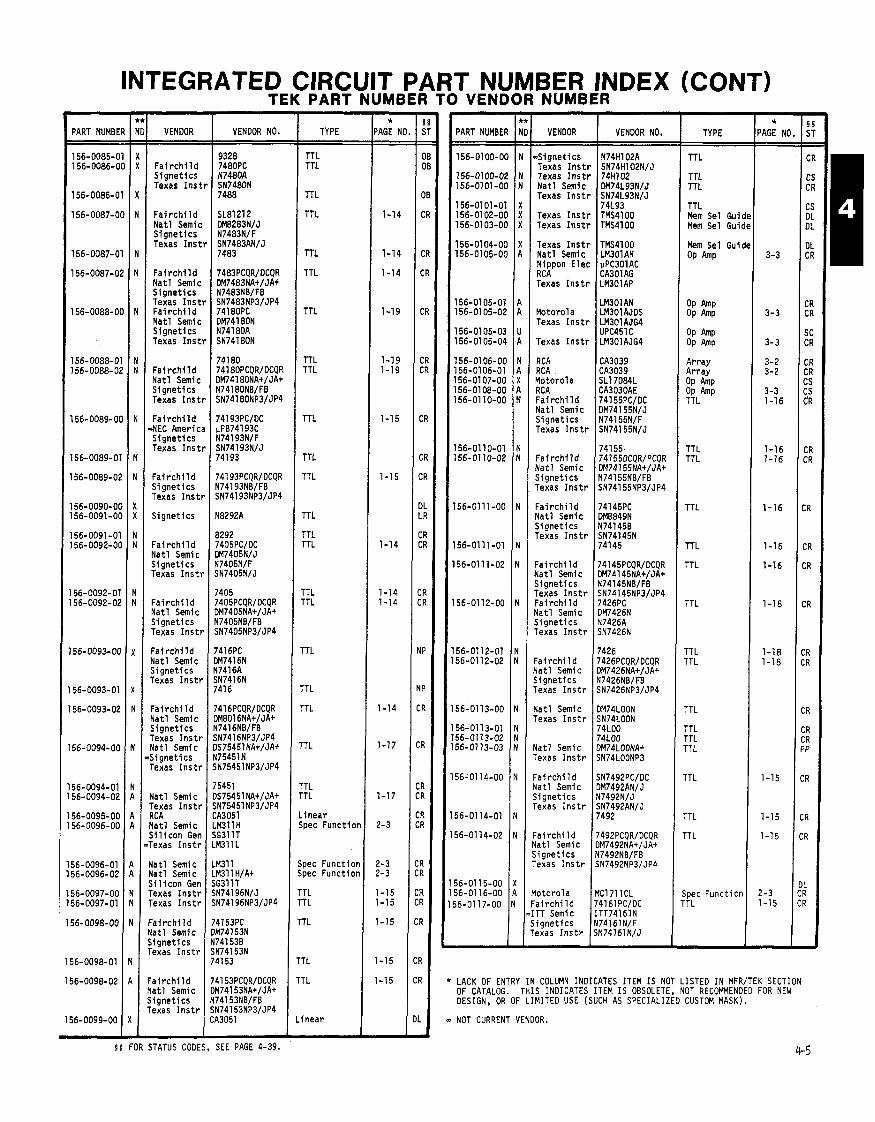
INTEGRATED CIRCUIT PART NUMBER INDEX (CONT) -
TEK PART NUMBER TO VENDOR NUMBER - * 'AGE N - -
1-14
1-14
1-14
1-19
1-19 1-19
1-15
1-15
1-14
1-14 1-14
1-14
1-17
1-17
2-3
2-3 2- 3
1-15 1-15
1-15
1-15
1-15
- -
VENDOR NO. PART NUMBE
156-0085-0 156-0086-0
156-0086-0
156-0087-0
156-0087-0
156-0087-0
156-0088-01
156-0088-0 156-0088- 0:
156-0089- 01
156-0089-0'
156-0089-0;
56-0090-O( 56-0091-O(
56-0091-01 56-0092-O(
56-0092-01 56-0092-02
56-0093-OC
56-0093-01
56-0093-02
56-0094-00
56-0094-01 56-0094-02
56-0095-00 56-0096-00
56-0096-01 56-0096-02
56-0097-00 56-0097-01
56-0098-00
VENDOR
Fai r c h i 1 d S igne t i c s Texas I n s t
F a i r c h i l d Na t l Semic S igne t i c s Texas I n s t
F a i r c h i l d Na t l Semic S igne t i c s Texas I n s t F a i r c h i l d Na t l Semic S igne t i c s Texas I n s t
F a i r c h i l d Na t l Semic S igne t i c s Texas I n s t
F a i r c h i l d 4EC h e r i c S ignet ics Texas I n s t
F a i r c h i l d S igne t i cs Texas I n s t l
S ignet ics
F a i r c h i l d Na t l Semic S ignet ics Texas Ins t1
F a i r c h i l d Na t l Semic S ignet ics Texas Ins t1
F a i r c h i l d Na t l Semic S ignet ics Texas I n s t r
F a i r c h i l d Nat l Semic S ignet ics Texas I n s t r Nat l Semic S ignet ics Texas I n s t r
Yatl Semic Texas I n s t r 7CA Yatl Semic ji 1 i con Gen lexas I n s t r
l a t l Semic l a t l Semic j i l i con Gen lexas I n s t r rexas I n s t r
' a i r c h i l d l a t l Semic ~ i g n e t i c s exas I n s t r
a i r c h i l d l a t l Semic i g n e t i c s exas I n s t r
TYPE PART NUMBER
156-0100-00
156-0100-02 156-01 01 -00
156-0101 -01 156-0102-00 156-01 03-00
156-0104-00 156-01 05-00
156-0105-01 156-01 05-02
156-01 05-03 156-01 05-04
156-0106-00 156-01 06-01 156-01 07-00 156-0108-00 156-0110-00
156-01 10-01 156-01 10-02
156-01 11-00
156-01 11 -01
56-01 11-02
56-0112-00
56-01 12-01 56-01 12-02
56-01 13-00
56-01 13-01 56-0113-02 56-01 13-03
56-01 14-00
56-01 14-01
56-0114-02
56-01 15-00 56-01 16-00 j6-0117-00
1
VENDOR
~ S i g n e t i c s Texas I n s t Texas I n s t N a t l Semic Texas I n s t ~
Texas Inst1 Texas Ins t1
Texas Ins t1 Na t l Semic Nippon Elec RCA Texas I n s t r
Motorola Texas I ns t1
Texas I n s t t
RCA RC A Motorola RC A F a i r c h i l d Nat l Semic S ignet ics Texas I n s t r
F a i r c h i l d Yat l Semic S ignet ics Texas I n s t r
F a i r c h i l d Yatl Semic S ignet ics Texas I n s t r
: a i r c h i l d (a t1 Semic j i gne t i c s [exas I n s t r . a i r c h i l d i a t l Semic j i gne t i c s rexas I n s t r
' a i r c h i l d l a t l Semic , i gne t i c s 'exas I n s t r
l a t l Semic .exas I n s t r
tat1 Semic exas I n s t r
a i r c h i l d a t 1 Semic i g n e t i c s exas I n s t r
a i r c h i l d a t1 Semic i g n e t i c s exas I n s t r
o t o r o l a a i r c h i l d TT Semic i gne t i c s exas I n s t r
VENDOR NO. TYPE
TTL
TTL TTL
TTL Mem Sel Gui Mem Sel Gui
Mem Sel Gui OP Amp
OP Amp OP Amp
OP Amp OP Amp
Ar ray Array OP Amp OP Amp TTL
TTL TTL
TTL
TTL
TTL
TTL
TTL TTL
TTL
TTL TTL TTL
TTL
TTL
TTL
ipec Funct i 01 TL
JAG: No. 1 i, TTL TTL
TTL
TT L
TTL
TTL
TTL
TTL TTL
TTL
TTL
TTL
TTL
TTL TTL
TTL TTL
rTL
rTL
TTL
rTL
'T L 'TL
. inear ;pet Funct ion
pec Funct ion pec Funct ion
TTL
L inear
LACK OF ENTRY IN COLUMN INDICATES ITEM IS NOT LISTED IN MFRITEK SECTION OF CATALOG. THIS INDICATES ITEM IS OBSOLETE, NOT RECOMMENDED FOR NEW DESIGN, OR OF LIMITED USE (SUCH AS SPECIALIZED CUSTOM MASK).
NOT CURRENT VENDOR.
5 5 FOR STATUS CODES, SEE PAGE 4-39.
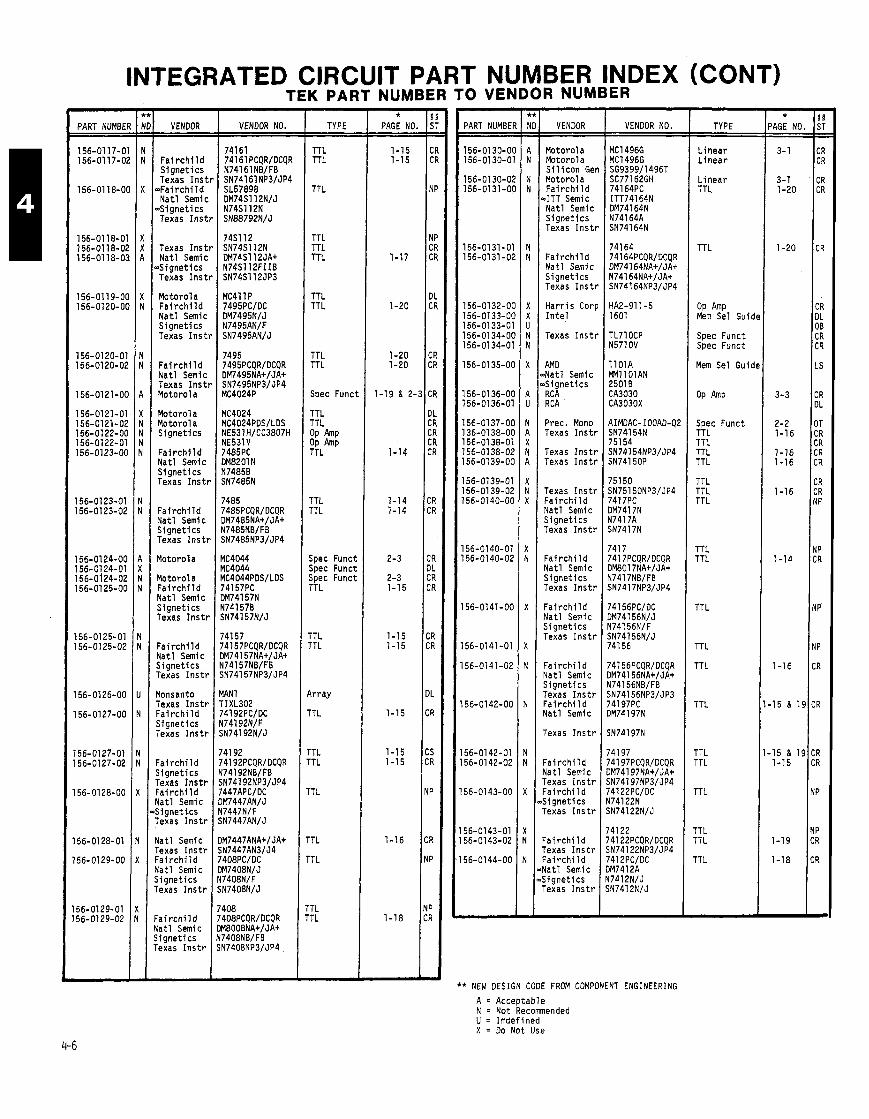
INTEGRATED CIRCUIT PART NUMBER INDEX (CONT) TEK PART NUMBER TO VENDOR NUMBER
PART NUMBER
156-0117-01 156-0117-02
156-01 18-00
156-01 18-01 156-0118-02 156-01 18-03
VENDOR
F a i r c h i l d S igne t i c s Texas I n s t r
= F a i r c h i l d Na t l Semic
=Signet i cs Texas I n s t r
Texas I n s t Na t l Semic
W g n e t i c s Texas I n s t
Motorola F a i r c h i l d Na t l Semic S igne t i c s Texas I n s t
F a i r c h i l d Na t l Semic Texas I n s t Motorola
Motorola Motor01 a S ignet ics
F a i r c h i l d Na t l Semic S igne t i c s Texas I n s t
F a i r c h i l d Na t l Semic S ignet ics Texas I n s t
Motorola
Motorola F a i r c h i l d N a t l Semlc S ignet ics Texas Inst1
F a i r c h i l d Na t l Semic S ignet ics Texas I n s t )
Monsanto Texas I ns t r F a i r c h i l d S ignet ics Texas I n s t r
F a i r c h i l d S ignet ics Texas I n s t r F a i r c h i l d Nat l Semic S ignet ics Texas I n s t r
Yatl Semic Texas I n s t r p a i r c h i l d Yatl Semic j i gne t i c s rexas I n s t r
: a i r c h i l d i a t l Semic i i gne t i c s lexas I n s t r
VENDOR NO.
MAN 1 TIXL302 741 92PC/DC N74192N/F SN74192N/J
- TYPE
TTL TTL
TTL
TTL TTL TTL
TTL TTL
TTL TTL
Spec Funct
TTL TTL OP Amp OP Amp TTL
TTL TTL
Spec Funct Spec Funct Spec Funct TTL
TTL TTL
k r a y
TTL
1TL .T L
'T L
'TL
'T L
TL TL
- * PAGE NO.
1-15 1-15
1-17
1-20
1-20 1-20
1-19 & 2-.
1-14
1-14 1-14
2-3
2-3 1-15
1-15 1-15
1-15
1-15 1-1 5
1-16
1-18
- PART NUMBER
156-0130-00 156-01 30-01
156-01 30-02 156-0131-00
156-0131-01 156-0131-02
156-0132-00 156-0133-00 156-0133-01 156-0134-00 156-0134-01
156-01 35-00
156-01 36-00 156-0136-01
156-0137-00 136-01 38-00 156-01 38-01 156-0138-02 156-0139-00
156-0139-01 156-01 39-02 156-0140-00
156-0140-01 156-0140-02
156-0141-00
156-0141-01
56-0141-02
56-01 42-00
56-0142-01 56-0142-02
56-0143-00
56-01 43-01 56-01 43-02
56-0144-00
VENDOR
Motorola Motorola S i l i c o n Ger Motorola F a i r c h i l d
.ITT Semic Na t l Semic S ignet ics Texas I n s t r
F a i r c h i l d Na t l Semic S ignet lcs Texas I n s t r
Ha r r i s C o r ~ I n t e l
Texas I n s t r
AM0 ~ N a t l Semic ~ S i g n e t i c s RC A R CA
Prec. Mono Texas I n s t r
Texas I n s t r Texas I n s t r
Texas I n s t r F a i r c h i l d Na t l Semic S igne t i c s Texas I n s t r
F a i r c h i l d Na t l Semic S ignet ics Texas I n s t r
F a i r c h i l d Na t l Semic S ignet ics Texas I n s t r
F a i r c h i l d Nat l Semic S ignet ics Texas I n s t r F a i r c h i l d Yat l Semic
Texas I n s t r
' a i r c h i l d Yatl Semic rexas I n s t r : a i r c h i l d j i g n e t i c s rexas I n s t r
' a i r ch i l d rexas I n s t r : a i r c h i l d l a t l Semic i i g n e t i c s lexas I n s t r
VENDOR NO.
AIMOAC- IOOAD-Q2 SN74154N 751 54
* NEW DESIGN CODE FROM COMPONENT ENGINEERING
A = Acceptable N = Not Recommended U = Imdef ined X = Do Not Use
TYPE
L inea r L i nea r
L i nea r TTL
TTL
OP Amp Mem Sel Guid
Spec Funct Spec Funct
Mem Sel Guid
Spec Funct TTL TTL TTL TTL
TTL TTL TTL
TTL TTL
TTL
TTL
TTL
TTL TTL
TTL
- * 'AGE NO. - -
3-1
3-1 1-20
1-20
3-3
2-2 1-16
1-16 1-16
1-16
1-14
1-16
15 & 19
15 & 19 1-15
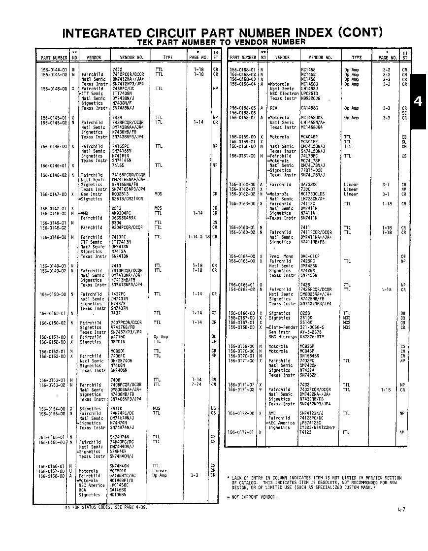
INTEGRATED C TEK
PART NUMBEI
156-0144-0 156-0144-0;
156-0145-01
156-0145-0' 156-0145-0;
156-0146-01
156-01 46-0'
156-0146-02
156-0147-O(
156-0147-01 156-0148-0t
156-0148-01 156-0148-02
156-0149-Ot
156-01 49-01 156-0149-02
156-01 50-OC
156-0150-01
156-0150-02
156-0151-00 156-0152-00
156-0152-01 156-0153-00
156-01 53-01 156-0153-02
156-0154-00 156-0155-00
156-0155-01 156-0156-00
156-01 56-01 156-0157-00 156-01 58-00
VENDOR
F a i r c h i l d N a t l Semic Texas I n s t F a i r c h i l d
4TT Semic N a t l Semic S i g n e t i c s Texas I n s t
F a i r c h i l d N a t l Semic S i g n e t i c s Texas I n s t
F a i r c h i l d N a t l Semic S i g n e t i c s Texas Inst1
Fa i r c h i 1 d N a t l Semic S i g n e t i c s Texas I n s t l Gen I n s t r $S ignet ics
'AMD F a i r c h i l d
F a i r c h i l d
F a i r c h i l d ITT Semic N a t l Semic S i g n e t i c s Texas I n s t t
F a i r c h i l d N a t l Semic S i g n e t i c s Texas I n s t r
F a i r c h i l d N a t l Semic S i g n e t i c s Texas I n s t r
F a i r c h i l d S ignet ics Texas I n s t r F a i r c h i l d S ignet ics
F a i r c h i l d Mat1 Semic S ignet ics Texas I n s t r
F a i r c h i l d Yatl Semic S ignet ics rexas I n s t r
j i g n e t i c s - a i r c h i l d I a t l Semic Signet ics rexas I n s t r
: a i r c h i l d i a t l Semic i i g n e t i c s 'exas I n s t r
l o t o r o l a ' a i r c h i l d l o t o r o l a IEC America LC A , i g n e t i c s
STATUS COO
VENDOR NO.
SEE PAGE 4-35
TYPE
TTL TTL
TTL
TTL TTL
TTL
TTL
MOS
MOS TTL
TTL TTL
TTL
TTL TTL
TTL
TTL
TTL
OP Amp TTL
TTL TTL
TT L TTL
MOS TTL
TTL TTL
TTL L i n e a r OP Amp
T PART b UMBER TO VE
IUMBER NDOR NUMB
PART NUMBEF
156-01 58-01 156-01 58-02 156-01 58-03 156-01 58-04
156-0158-05 156-01 58-06 156-01 58-07
156-01 59-00 156-0159-01 156-0160-00
156-0161 -00
156-0162-00 156-0162-01 156-0162-02
156-0163-00
156-0163-01 156-01 63-02
56-01 64-00 I 56-0165-00
56-0165-01 56-0165-02
56-0166-00 56-01 67-00 56-01 67-01 56-01 68-00
56-01 69-00 56-01 70-00 56-01 70-01 56-01 71-00
56-01 71-01 56-0171-02
56-01 72-00
56-01 72-01
NDEX (CONT)
.Motorola MC1458U N a t l Semic LM1458J NEC E l e c t r o n UPC251D Texas I n s t r N99320JG
RCA 1 ~ ~ 1 4 5 8 ~
Motor01 a MC1458UDS N a t l Semi c LM1458N/A+ Texas I n s t r MC1458JG4
Motorola MC4048P MC4048P
N a t l Semic DM74L20N/J Texas I n s t r SN74L20N/J , F a i r c h i l d 74L78PC M o t o r o l a MC74L78P N a t l Semic DM74L78N/J 6 i g n e t i c s 77811-000 Texas I n s t r SN74L78NIJ
Fa i r c h i l d I U A ~ ~ ~ D C
Motoro la MC1733CLOS Nat1 Semic 1 ::;:3CN/A+ F a i r c h i l d 7411PC N a t l Semic DM7411N S i g n e t i c s N7411A Bexas I n s t r SN7411N
7411 Fai r c h i l d 741 1 PCQR/DCQR N a t l Semic DM741 lNA+/JA+ Stqnet ics N741 lNB/FB
Prec. Mono F a i r c h i l d N a t l Semic S i g n e t i c s Texas I n s t r
F a i r c h i l d N a t l Semic S i g n e t i c s Texas I n s t r
S i g n e t i c s 8228 S i g n e t i c s 2510K
2510K Clare-Pendar 321-0056-6 Gen I n s t r AY-5-2376 SMC Microsys KR2376-STP
Motorola MC836P Motorola , MC846P
SN15646N F a i r c h i i d 7432PC N a t l Semic DM7432N S i g n e t i c s N7432A Texas I n s t r SN7432N
7432 F a i r c h i l d 7432PCQR/DCQR Nat l Semic DM7432NA+/JA+ S i g n e t i c s N7432NB/FB Texas I n s t r SN7432NP3/JP4
4MD SN74123N/J F a i r c h i l d 74123PC/DC VEC America uPB74123C S ionet ics CY323/N74123N/F
TYPE
OP M P OP OP M P OP M P
OP Amp
OP
TTL TTL TTL
TTL
L i n e a r L i n e a r L i n e a r
TTL
TTL TTL
TTL
TTL TTL
TTL MOS MOS MOS
TTL
TTL TTL
TTL
TTL
* PAGE NC
3-3 3-3 3-3 3-3
3 -3
3-3
3-1
3-1
1-18
1-18 1-18
1-18
1-18
LACK OF ENTRY I N COLUMN INDICATES ITEM I S NOT LISTED I N MFR/TEK SECTION OF CATALOG. THIS INDICATES ITEM I S OBSOLETE, NOT RECOMMENDED FOR NEW DESIGN, OR OF LIMITED USE (SUCH AS SPECIALIZED CUSTOM MASK. )
NOT CURRENT VENOOR.
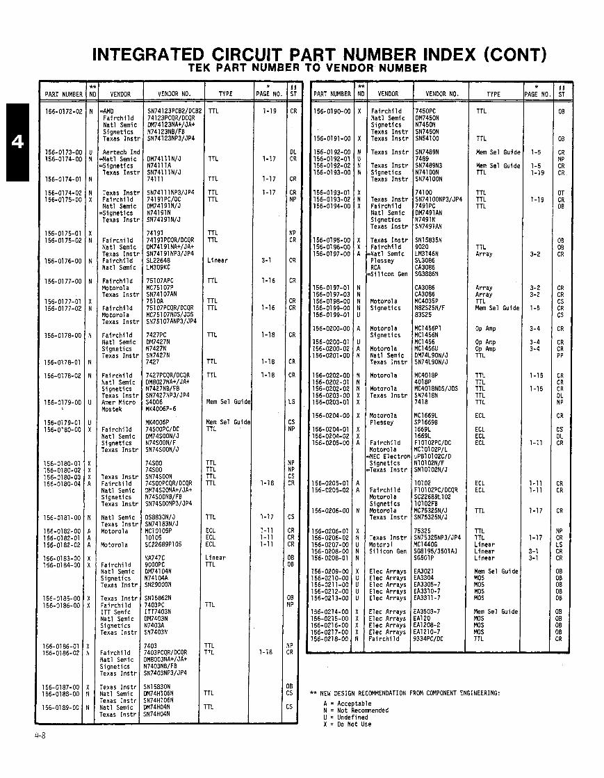
- PART NUMBEI
156-01 72-0,
156-01 73-01 156-0174-01
156-01 74-0'
156-0174-0; 156-01 75-O(
156-01 75-0' 156-01 75-0;
156-01 76-O(
156-01 77-O(
156-0177-01 156-01 77-0:
156-0178-O(
156-0178-01
156-01 78-02
156-0179-O(
156-01 79-01 156-0180-OC
156-0180-01 156-01 80-02 156-01 80-0: 156-0180-04
156-0181-OC
156-0182-OC 156-0182-01 156-0182-02
156-0183-00 156-01 84-00
156-0185-00 156-0186-00
56-01 86-01 56-0186-02
56-0187-00 56- 01 83-00
56-01 89-00 -
INTEGRATED CIRCUIT PART NUMBER INDEX (CONT) TEK PARTNUMBER TOVENDOR NUMBER -
VENDOR
4MD F a i r c h i l d Na t l Semfc S igne t i c s Texas I n s t
Aertech I n ~ N a t l Semic ~ S i g n e t i c s Texas I n s t
Texas I n s t F a i r c h i l d Na t l Semic
4 i g n e t i c s Texas I n s t
F a i r c h i l d N a t l Semic Texas I n s t F a i r c h i l d Na t l Semic
F a i r c h i l d Motorola Texas I n s t
F a i r c h i l d Motorola Texas I n s t
F a i r c h i l d Na t l Semic S igne t i c s Texas I n s t l
F a i r c h i l d N a t l Semic S igne t i cs Texas I n s t l Amer Micro Mos tek
F a i r c h i l d Na t l Semic S ignet ics Texas I n s t l
Texas I n s t l F a i r c h i l d Na t l Semic S ignet ics Texas I n s t l
Na t l Semic Texas I ns t r Motorola
Motorola
F a i r c h i l d Na t l Semic S ignet ics Texas I n s t r
Texas I n s t r F a i r c h i l d ITT Semic Nat l Semic S ignet ics Texas I n s t r
' a i r c h i l d Yatl Semic j i gne t i c s rexas I n s t r
rexas I n s t r l a t l Semic rexas I n s t r i a t l Semic rexas I n s t r
VENDOR NO. TYPE
TTL
TTL
TTL
TTL TTL
TTL TTL
L inear
TTL
TTL TTL
TTL
TTL
TTL
Mem Sel Guid
Mem Sel Guid TTL
TTL TTL TTL TTL
TTL
ECL ECL ECL
L inear TTL
TTL
1TL TTL
'T L
'TL
- * 'AGE NO =
1-19
1-17
1-17
1-17
3-1
1-16
1-16
1-18
1-18
1-18
1-18
1-17
1-11 1-11 1-11
1-18
-
- PART NUMBEF
156-01 90-OC
156-0191-OC
156-01 92-OC 156-01 92-01 156-01 92-02 156-01 93-OC
156-01 93-01 156-01 93-02 156-01 94-06
156-0195-00 156-01 96-00 156-01 97-00
156-01 97-01 156-01 97-03 156-01 98-00 156-01 99-00 156-01 99-01
156-0200-00
156-0200-01 156-0200-02 156-0201 -00
56-O2O2-OO 56-0202-01 56-0202-02
'56-0203-00 56-0203-01
56-0204-00
56-0204-01 56-0204-02 56-0205-00
56-0205-01 56-0205-02
56-0206-00
56-0206-01 56-0206-02 56-0207-00 56- 0208-00 56-0208-01
56-0209-00 56-021 0-00 56-0211-00 56-021 2-00 56-021 3-00
56-0214-00 56-0215-00 56-0216-00 56-021 7-00 56-0218-00
- VENDOR
F a i r c h i l d Na t l Semic S igne t i c s Texas I n s t l Texas I n s t l
Texas I ns t1
Texas I n s t l S i gne t i c s Texas I n s t l
Texas I ns t1 Fa i r ch i l d Na t l Semic S igne t i c s Texas I n s t r
Texas I n s t r F a i r c h i l d Na t l Semic Plessey RCA Si 1 i con Ger
Motorola S ignet ics
Yotorola S ignet ics
Yotorola Vat1 Semic Texas I n s t r
Yotorola
r lotorola Texas I n s t r
l o t o r o l a Jlessey
' a i r c h i l d l o t o r o l a IEC E lec t r o j i g n e t i c s rexas I n s t r
' a i r ch i 1 d r lotorola S ignet ics b t o r o l a rexas I n s t r
rexas I n s t r lo to ro ' l iil i con Gen
I l e c Arrays I l e c Arrays I l e c Arrays i l e c Arrays I l e c Arrays
: lec Arrays I l ec Arrays : lec Arrays : lec Arrays ' a i r c h i l d
VENDOR NO. TYPE
TTL
TTL
Mem Sel Gui dc
Mem Sel Guidc TTL
TTL TTL TTL
TTL Array
Array Arrav TTL - Mem Sel Guidc
TTL TTL TTL TTL TTL
ECL
ECL ECL ECL
ECL ECL
TTL
TTL TTL L i nea r L inear L i nea r
Mem Sel Guide MOS MOS MOS MOS
Mem Sel Guide MOS MOS MOS TTL
* NEW DESIGN RECOMMENDATION FROM COMPONENT ENGINEERING:
A = Acceptable N = Not Recomnended U = Undefined X = Do Not Use
- * AGE N( - -
1-5
1-5 1-19
1-19
3-2
3-2 3-2
1-5
3-4
3-4 3-4
1-15
1-15
1-11
1-11 1-11
1-17
1-17
3-1 3-1
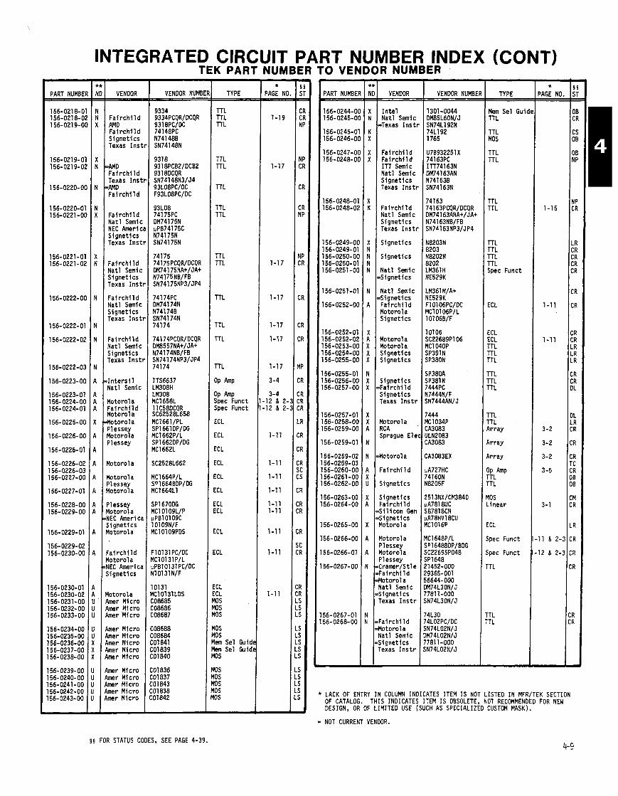
PART NUMBEI
156-0218-0 156-0218-0: 156-0219-01
156-0219-0' 156-0219-01
156-0220-O(
156-0220-01 156-0221 -0L
156-0221-01 156-0221-0;
156-0222-O(
156-0222-01
156-0222-02
156-0222-OC
156-0223-0C
156-0223-01 156-0224-OC 156-0224-01
156-0225-OC
156-0226-00
156-0226-01
156-0226-02 156-0226-03 156-0227-00
156-0227-01
156-0228-00 156-0229-00
156-0229-01
156-0229-02 156-0230-00
56-0230-01 56-0230-02 56-0231-00 56-0232-00 56-0233-00
56-0234-00 56-0235-00 56-0236-00 56-0237-00 56-0238-00
56-0239-00 56-0240-00 56-0241-00 56-0242-00 56-0243-00
INTEGRATED CIRCUIT PART NUMBER INDEX (CONT) TEK PART NUMBER TO VENDOR NUMBER
VENDOR
F a i r c h i l d AMD F a i r c h i l d S ignet ics Texas Ins1
M D Fa i r ch i l d Texas I n s i 4MD Fa i r ch i l d
F a i r c h i l d Nat l Semic NEC Americ S ignet ics Texas I n s t
F a i r c h i l d Na t l Semic S ignet ics Texas I n s t
F a i r c h i l d Nat l Semic S ignet ics Texas I n s t
Fai r c h i l d Na t l Semic S ignet ics Texas I n s t
I n t e r s i l Nat l Semic
Motorola F a i r c h i l d Motorola Motorola Plessey Motorola Plessey
Motorol a
l lo toro la Plessey Yotorol a
Plessey l o t o r o l a YEC h e r i c i Signet ics l o t o r o l a
: a i r ch i l d l o t o r o l a IEC Americi Signetics
l o to ro la h e r Micro h e r Micro h e r Micro
h e r Micro h e r Micro imer Micro imer Micro imer Micro
uner Micro mr Micro mr Micro mr Micro mr Micro
VENDOR NUMBE TYPE
TTL TTL TTL
TTL TTL
TTL
TTL TTL
TTL TTL
TTL
TTL
TTL
TTL
OP Amp
OP Amp Spec Funct Spec Funct
ECL
ECL
ECL
ECL
ECL
ICL
ICL ICL
.CL
:CL
:CL :CL 10s 10s 10s
10s DS lem Sel Guidc iem Sel Guidt 10s
0s 0s 0s 0s 0s
* PAGE NO.
1-19
1-17
PART NUMBE
156-0244-0 156-0245-0
156-0245-0 156-0246-0
156-0247-01 156-0248-01
156-0248-0' 156-0248-0;
156-0249-01 156-0249-0' 156-0250-O( 156-0250-0' 156-0251-O(
156-0251-0;
156-0252-O(
56-0252-01 56-0252-Oi 56-0253-O( 56-0254-O( 56-0255-O(
56-0255-01 56-0256-Ot 56-0257-O(
56-0257-01 56-0258-OC 56-0259-OC
56-0259-01
56-0259-02 56-0259-03 56-0260-OC 56-0261-00 56-0262-00
56-0263-00 56-0264-00
56-0265-00
56-0266-00
56-0266-01
56-0267-00
56-0267-01 56-0268-00
LACK OF ENTRY OF CATALOG. 1 DESIGN, OR OF
VENDOR
I n t e l Nat l Semic
.Texas I n s t r
F a i r c h i l d F a i r c h i l d ITT Semic Nat l Semic S ignet ics Texas I n s t r
F a i r c h i l d Nat l Semic S ignet ics Texas I n s t r
S ignet ics
S ignet ics
Nat l S m i c ~S igne t i cs
Nat l Semic ~S igne t i cs F a i r c h i l d Motorola S ignet ics
Motorol a Motorol a S ignet ics S ignet ics
S ignet ics Fa i r ch i 1 d S ignet ics Texas I n s t r
Motorola RCA Sprague Elec
Motorola
Fa i r ch i l d
S ignet ics
S ignet ics F a i r c h i l d S i l i c o n Gen S ignet ics Motorol a
Yotorola Plessey Yotorola Plessey Cramer/Stle Fa i rch i l d Yotorola Yatl Semic j i gne t i cs rexas I n s t r
: a i r ch i l d l o to ro la ta t1 Semic Signet ics lexas I n s t r
VENDOR NUMBE
1301-0044 DM85L60N/J SN74L192N 74L192 1765
TYPE
Mem Sel Guid TTL
TTL MOS
TTL TTL
TTL TTL
rTL rTL rTL TTL Spec Funct
ICL
.CL ICL TTL rTL TTL
rrL rTL 7 L
'TL 'TL \ r r ay
i r r ay
i r r ay
!;LA"p
TL
10s i nea r
CL
pec Funct
pec Funct
TL
TL TL
- * 'AGE NO - -
1-15
1-11
1-1 1
3-2
3-2
3-2
3-5
3-1
11 & 2-.
12 & 2-:
IN COLUMN INDICATES ITEM I S NOT LISTED IN MFR/TEK SECTION 'HIS INDICATES ITEM IS OBSOLETE, NOT RECOMMENDED FOR NEW LIMITED USE (SUCH AS SPECIALIZED CUSTOM MASK). - NOT CURRENT VENDOR.
5 5 FOR STATUS CODES, SEE PAGE 4-39.

INTEGRATED CIRCUIT PART NUMBER INDEX (CONT)
PART NUMBEI
156-0268-0' 156-0269-O(
156-0269-01 156-0270-O( 156-0271-O( l56-0272-O( 156-0272-01
156-0273-O( 156-0274-O(
156-0274-01 156-0275-O(
156-0275-01 156-0276-OC 156-0277-OC
156-0277-01
156-0278-00 156-0279-00 156-0279-01
156-0280-00
156-0281 -00
l56-O282-OO
156-0282-01
156-b282-02
156-0284-00
156-0284-01
156-0284-02 156-0284-03 156-0285-00
156-0285-01
156-0285-02
156-0286-00 156-0287-00
156-0288-00 156-0289-00
156-0289-01 156-0289-02
156-0290-00 156-0291-00
156-0291 -01
VENDOR
~ F a i r c h i l d &tor01 a 4 a t l Semic ~ S i g n e t i c s Texas Inst1
S ignet ics S ignet ics S ignet ics
S igne t i cs .AM0 Fa i r ch i l d F a i r c h i l d
.AM0 F a i r c h i l d
F a i r c h l l d Texas I n s t l F a i r c h i l d Motorola Nat l Semic
F a i r c h i l d Motorola Pl essey S ignet ics
~ F a i r c h i l d b lo toro la Nat l Semic
d i g n e t i c s Texas I n s t r
Motorol a RCA Motorola Plessey Motorola
Motorola Plessey Beckman Nat l Semic
Na t l Semic Fa l r ch i l d Motorola Na t l Semic ~S igne t i cs
F a i r c h i l d Motorol a Na t l Semic S i l i c o n Gen
Nat l Semic RCA
Nat l Semic RC A
AM0 F a i r c h l l d I n t e l I n t e r s i l Nat l Semic S ignet ics
4MD F a i r c h i l d I n t e l I n t e r s l l Yatl Semic Signet lcs
TEK PART NUMBER TO VENDOR NUMBER
VENDOR NO.
74L02 74H183PC/OC 56644-000 5821 0-000 7781 1-000 SN74H183NIJ
'Bl 2CU
TYPE
TTL TTL
TTL
TTL TTL
TTL TTL
TTL TTL
TTL TTL L inear
L inear
ECL MOS MOS
TTL
Array
ECL
ECL
ECL
TTL
TTL
TTL TTL L inear
L inear
L inear
OP Amp
L inear Spec Funct
Spec Funct Spec Funct
TTL Mem Sel Guidt
Yem Sel Guide
- * 'AGE NO, - -
1-17 1-17
1-17 1-17
1-17
3-1
3- 1
3-2
1-11
1-11
1-11
1-1 6 3-1
3-1
3-1
2-3
2-3 2-3
1-6
1-6
-
PART NUMBEI
156-0292-O(
156-0292-01 156-0293-O(
156-0293-01 156-0293-0: 156-0294-O( 156-0294-01 156-0294-02
156-0294-0: 156-0295-O(
156-0295-01 156-0295-02 156-0296-O( 156-0296-01 156-0297-OC
156-0297-01 156-0297-02
156-0298-OC 156-0298-01
156-0299-OC
156-0299-01 I56-O2W-O2
l56-O3OO-OO l56-O3Ol-OO
156-0301 -00 156-0301-02
156-0302-00
56-0302-01 56-0302-02
56-0303-00
56-0303-01
56-0304-00
56-0304-01
56-0304-02
56-0305-00
VENDOR
~ K i e r u l f f Na t l Semic Texas I n s t ~
Elec Array!
Elec Array!
Motorol a 0NEC Americi
Motor01 a Elec Array!
F a i r c h i l d S ignet ics
Fa i r ch i l d S ignet ics S ignet ics
F a i r c h i l d ITT Semic Nat l Semic S ignet ics Texas I n s t i
F a i r c h i l d Na t l Semic S ignet ics Texas I ns t r
S ignet ics F a i r c h i l d Na t l Semic S ignet ics Texas I ns t r
F a i r c h i l d Nat l Semic S ignet ics Texas I n s t r
F a i r c h i l d Na t l Semic Texas I n s t r
F a i r c h i l d Na t l Semic Texas I n s t r
F a i r c h i l d Na t l Semic S ignet ics Texas I n s t r F a i r c h i l d Nat l Semic S ignet ics Texas I n s t r
F a i r c h i l d Na t l Semic S ignet ics Texas I n s t r
F a i r c h i l d Na t l Semic S ignet ics Texas I n s t r AMD
VENDOR NO. TYPE
TTL
TTL MOS
MOS MOS MOS MOS MOS
MOS ECL
ECL ECL Mem Sel Guidi
TTL
TTL TTL
TTL TTL
TTL
TTL TTL
MOS TTL
TTL TTL
TTL
TTL TTL
TTL
TTL
TTL
TTL
TTL
Yem Sel Guide
* NEW DESIGN RECOMMENDATION FROM COMPONENT ENGINEERING:
A = Acceptable N = Not Recomnended U = Undefined X = Do Not Use
- * 'AGE NO - -
1-11
1-11
1-18
1-18 1-18
1-15
1-15 1-15
1-20
1-17
1-17
1-18
1-18
1-7 -
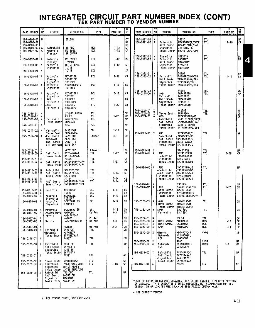
PART NUMBE - 156-0305-0 156-0305-0 156-0305-0 156-0306-0 156-0307-0
156-0307-0
156-0308-0
156-0308-0
156-0308-0
156-0308-0
156-0308-0
156-0309-0
156-0310-0
156-0310-0 156-0310-0; 156-0311-01
156-0311-0
156-0311-01
156-0312-01
156-0312-0' 156-0313-O(
156-0313-0' 156-0313-01
156-0314-O( 156-0315-O(
156-0315-01 56-0315-02
56-031 6-Ot 56-0316-01 56-0316-02
56-031 6-03
56-0316-04 56-0317-OC
56-0317-01 56-0317-02
56-0317-03 56-031 8-00
56-0318-01
56-0320-00
56-0320-01
56-0320-02 56-0320-03
56-0321-00
INTEGRATED CIRCUIT PART NUMBER INDEX (CONT) TEK PART NUMBER TO VENDOR NUMBER
VENOOR - F a i r c h i l d Motorola Plessey
Motorola Plessey Motorola S ignet ics
Motorola Plessey S ignet ics Motorola S ignet ics
Motorola S ignet ics AM0 F a i r c h i l d AMD F a i r c h l l d
F a i r c h i l d Texas Ins1
F a i r c h i l d Texas l n s t F a i r c h i l d Yotorola Nat l Semic S i l i c o n GE
Yatl Semic Texas I n s t
Yatl Semic Texas I n s t
: a i r ch i l d Yatl Semic rexas I n s t
l a t l Semic Texas . I n s t
l o t o ro l a
l o t o ro l a i i gne t i c s l o t o ro l a i i gne t i c s
l o t o ro l a rnalog Dev~ l a r r i s
l a r r i s
' a i r c h i l d lo toro la exas I n s t l
a i r c h i l d a t1 Semic i g n e t i c s exas I n s t t
exas I ns t r a i r c h i l d i gne t i c s exas I n s t r a i r c h i l d a t1 Semic i gne t i c s exas I n s t r
VENDOR NO.
27LS08
MClO115L SPl 01 l5E
TYPE
MOS ECL
ECL
ECL
ECL
ECL
ECL
ECL
TTL
TTL
TTL TTL TTL
TTL
TTL
L inear
L inear TTL
TTL TTL
TTL TTL
TTL TTL
ECL ECL ECL
ECL
ECL 3~ Amp
3~ Amp 3~
IP Amp TTL
TTL
TTL
'TL
'TL 'TL
'TL
- * PAGE NO
1-13 1-12
1-12
1-12
1-12
1-12
1-12
1-20
1-20
1-15
3-1
1-17
1-57
1-14
1-14 1-14
1-11
1-11
1-11
1-11 3-3
3-3
3-3
PART NUMBE
156-0321-0 156-0321 -0,
156-0322-01 156-0323-01
156-0323-0' 156-0323-0;
156-0323-0: 156-0324-O(
156-0324-01 156-0324-02 156-0324-0:
56-0325-OC
56-0325-01 56-0325-02
56-0326-00
56-0326-01 56-0326-02
56-0326-03
56-0327-00
56-0327-01 56-0328-00 56-0328-01 56-0329-00
56-0330-00
56-0330-01 56-0330-02
56-0331-00
56-0331 -01
VENDOR
F a i r c h l l d Na t l Semic S igne t i c s Texas I n s t r
S ignet ics F a i r c h i l d Na t l Semic S igne t i c s Texas I n s t r
F a i r c h i l d Na t l Semic S igne t i c s Texas I n s t r
AMD Fa i r ch i l d Na t l Semic S ignet ics Texas I n s t r
Texas l n s t r AMD F a i r c h i l d Na t l Semic S igne t i c s Texas I n s t r
AMD F a i r c h i l d Na t l Semic S ignet ics Texas I n s t r
AM0 F a i r c h i l d S igne t i cs Texas I n s t r
AMD Fa i r ch l l d Na t l Semic S ignet ics Texas I n s t r
RMD Nat l Semic S ignet ics Texas I n s t r
WO Yatl Semic Texas I n s t r 4MD - a i r c h i l d
l a t l Semic l a t l Semic WD
i a r r i s b t o r o l a ICA
l o to ro l a KA
: a i r c h i l d
i i g n e t i c s exas I n s t r
VENOOR NO. I TYPE
TTL TTL
TTL TTL
TTL TTL
TTL n'L
TTL ITL
TTL
rTL 'TL
'TL
'TL 'TL
'TL
TL
TL 0s 0s 0s
MOS
MOS MOS
TL
r L
PAGE NO
1-18
1-14
1-15
1-20
1-13
1-13
1-9
.ACK OF ENTRY IN COLUMN INDICATES ITEM I S NOT LISTED IN MFR/TEK SECTION )F CATALOG. THIS INDICATES ITEM I S OBSOLETE, NOT RECOMMENDED FOR NEW )ESIGN, OR OF LIMITED USE (SUCH AS SPECIALIZED CUSTOM MASK)
5 5 FOR STATUS CODES, SEE PAGE 4-39.
- NOT CURRENT VENDOR.
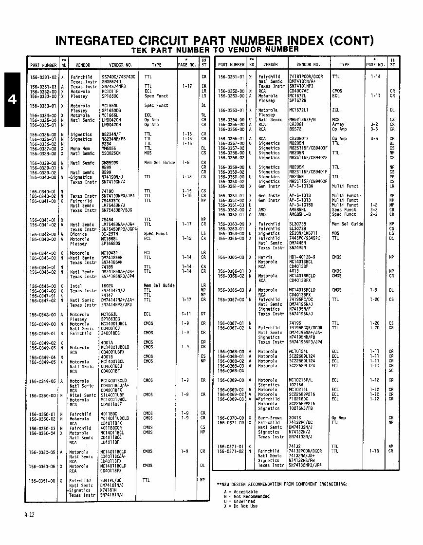
PART NUMBEF
156-0331-02
156- 0331 -03 156-0332-00 156-0333-00
156-0333-01
156-0334-00 156-0335-00 156-0335-01
156-0336-00 156-0336-01 156-0336-02 156-0337-00 156-0338-00
156-0339-00 156-0339-01 156-0339-02 156-0340-00
156-0340-01 156-0340-02 156-0341-00
156-0341 -01 156-0341-02
156-0342-00 156-0343-00
156-0344-00 156-0345-00
156-0345-01 156-0345-02
156-0346-00 l56-D347-OO 156-0347-01 156-0347-02
156-0348-00
156-0349-00
156-0349-01
156-0349-02 156-0349-03
156-0349-04 156-0349-05
156-0349-06
156-0350-00
156-0350-01 156-0350-02
156-0350-03 156-0350-04
156-0350-05
156-0350-06
156-0351-00 ,
INTEGRATED CIRCUIT PART NUMBER INDEX (CONT) TEK PARTNUMBERTOVENDOR NUMBER
VENDOR
Fa i r ch i l d Texas I n s t r Texas I n s t r Motorola Plessey
Motorola Plessey Motorola Na t l Semic
S ignet ics S ignet ics
Mono Mem Na t l Semic
Na t l Semic
Na t l Semic & igne t i cs Texas I n s t r
Texas I n s t r F a i r c h i l d Na t l Semic Texas I n s t r
Na t l Semic Texas I n s t r Dionics Motorola Plessey
Motorola ~ N a t l Semic Texas I n s t r
Nat l Semic Texas I n s t r
I n t e l Texas I n s t r
Na t l Semic Texas I n s t r
Motorol a Plessey Motorol a Na t l Semic F a i r c h i l d
Motorola RC A
Motorola Nat l SEmic RC A
Motorola Na t l Semic RC A Mite1 Semic Motorola RC A
F a i r c h i l d Motorola RC A F a i r c h i l d Motorola Na t l Semic
Motorol a Na t l Semic RC A Motorol a RC A
F a i r c h i l d l a t l Semic i i gne t i cs 'exas I n s t r
VENDOR NO.
9S74DC/74S74DC SN38624J SN74S74NP3 MClOllP SP165OC
YC1663L jP1663DG 1C14001 UBCL 34001 CJ 34001 BDC
lOOlA IC14001 UBCLD XJ4001UBFX $001 B IC14001 BCL :D4001 BCJ :D4001BF
1C14001 BCLD :D4001 BCJ/A+ :D4001 BFX jIL4011UBF ICl4Oll UBCL :D4011UBF
101 1 BDC IC14011 UBCLD XI401 1BFX LO1 1 BDCOR
:04011 BCJ :D4011 BF
IC14011 BCLD :04011 BCJA+ :D4011 BFX IC14011 BCLD :D4011 BFX
TYPE
TTL
TTL ECL Spec Funct
Spec Funct
TTL TTL TTL TTL MOS
Mem Sel Guidt
TTL
TTL TTL TTL
TTL TTL
Spec Funct ECL
ECL TTL
TTL TTL
Mem Sel Guide TTL TTL TTL
ECL
CMOS
CMOS
CMOS CMOS
CMOS CMOS
CMOS
CMOS
CMOS CMOS
CMOS CMOS
CMOS
CMOS
TTL
- * AGE NO =
1-17
1-15 1-15 1-15
1-5
1-15
1-15 1-15
1-17
1-12
1-14
1-14 1-14
1-17
1-11
1-9
1-9
1-9
1-9
1-9
1-9 1-9
1-9
PART NUMBEF
156-0351 -01
156-0352-OC 156-0353-OC
156-0353-01
156-0354-OC 156-0355-OC 156-0356-OC
156-0356-01 156-0357-OC 156-0357-02 156-0358-OC 156-0358-02
156-0359-OC 156-0359-09 156-0360-OC 156-0360-02 156-0361 -0C
156-0361-01 156-0361-02 156-0361-03 156-0362-OC 156-0362-01
156-0363-OC 156-0363-01 156-0364-OC 156-0365-06
156-0366-00
; ;;:gg::; 156-0366-03
156-0367-06
156-0367-01 156-0367-02
156-0368-00 156-0368-01 156-0368-02 156-0368-03 156-0368-04
156-0369-00
156-0369-01 156-0369-02 156-0369-03
l56-O37O-OO 156-0371 -00
156-0371-01 156-0371-02
VENDOR
F a i r c h i l d Nat l Semic Texas I n s t r RCA Motorol a Plessey
Motorola Plessey Nat l Semic RCA RCA
RCA Signet ics S ignet ics S ignet ics S ignet ics
S ignet ics S ignet i cs S ignet ics S ignet ics Gen I n s t r
Gen I n s t r Gen I n s t r
AMD AM0
F a i r c h i l d F a i r c h i l d S ignet ics F a i r c h i l d Nat l Semic Texas I n s t r
Ha r r i s Motorol a RC A
Motorola RCA
Motorola RCA Fai r c h i 1 d Nat l Semic S ignet ics Texas I n s t r
F a i r c h i l d Nat l Semic S igne t i cs Texas I n s t r
Motorola Motorola Motorol a Motorol a
Motorola S ignet ics Motorola Motorola F a i r c h i l d Motorola S ignet ics
Burr-Brown F a i r c h i l d Nat l Semic S ignet ics Texas I n s t r
Fa i rch i l d Vat1 Semic S ignet i cs Texas I n s t r
VENDOR NO. TYPE
TTL
CMOS ECL
ECL
MOS Array OP Amp
OP h P TTL
TTL
TTL
TTL
M u l t i Funct
Mu1 t i Funct M u l t i Funct Mu1 t i Funct Spec Funct Spec Funct
Mem Sel Guidc
MOS TTL
CMOS
CMOS CMOS
CMOS
TTL
TTL TTL
ECL ECL ECL ECL
ECL
ECL ECL ECL
OP TTL
r r L TTL
'*NEW DESIGN RECOMMENDATION FROM COMPONENT ENGINEERING:
A = Acceptable N = Not Recomnended U = Undefined X = Do Not Use
- * 'AGE NO. -
1-14
1-1 1
3-2 3-5
3-5
1-2 2-3 2-3
1-9
1-20
1-20 1-20
1-11 1-11 1-11 1-11
1-12
1-12 1-12 1-12
1-18
-
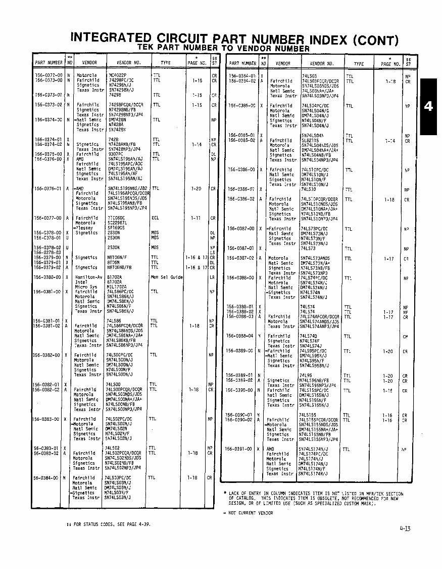
INTEGRATED CIRCUIT PART I TEK PART NUMBER TO VEN
JMBER IR NUMBER INDEX (CONT) - VENDOR
Motoro la F a i r c h i l d S i g n e t i c s Texas Ins1
F a i r c h i l d S i g n e t i c s Texas I n s t
~ N a t l Sernic S i g n e t i c s Texas I n s t
S i g n e t i cs Texas I n s t F a i r c h i l d AMD F a i r c h i l d N a t l Semic S i g n e t i c s Texas l n s t
QAMD F a i r c h i l d Motorola S i g n e t i c s Texas I n s t
F a i r c h i l d Motor01 a .Pl essey S i g n e t i c s
S i g n e t i c s
S i g n e t i c s
Hami 1 ton-At I n t e l M ic ro Sys F a i r c h i l d Motorola N a t l Semic S i g n e t i c s Texas I n s t 1
F a i r c h i l d Motorola N a t l Semlc S i g n e t i c s Texas I n s t r
F a i r c h i l d Yotoro la Nat l Semic S ignet ics Texas I n s t r
F a i r c h i l d l o t o r o l a l a t l Semic j i g n e t i c s lexas I n s t r
: a i r c h i l d b t o r o l a l a t l Sernic i i g n e t i c s rexas I n s t r
' a i r c h i l d l o t o r o l a , i g n e t i c s 'exas I n s t r
a i r c h i l d
- PART NUMBER
156-0372-00 156-0373-00
156-0373-01
- *
PAGE NO. - 1-15
1-15
1-15
1-14
TYPE
TTL TTL
TTL
TTL TTL
TTL
TTL
TTL
TTL
TTL
rTL
1TL
7 L 'TL 'TL
'TL
TL
TL TL
TL
TL ,.,
- 5 5 ST -- -- CR CR
CR
CR
NP
NP CR
DL NP
:R
:R
)L IP
iP .S :R IL :R
R
NP
NP CR
NP
NP CR
NP
NP CR
CR
-
- *
PAGE N( - 1-18
1-14
1-18
1-17
1-17 1-17
1-20
1-20 1-20
1-16
1-16 1-16
#
- -
'
1
1
1 1 1
1
1
1 1
1
l ! I !
I!
- NOT
TYPE
TTL TTL
TTL
TTL
TTL
TTL TTL
TTL TTL
PART NUMBE, VENDOR NO. VENDOR 1 VENDOR NO.
F a i r c h i l d Motorola N a t l Semic Texas I n s t r
exa as I n s t r S N ~ ~ L S O ~ N / J I
74LS03 74LS03PCQR/DCQF SN74LS03NDS/JDS 74LS03NA+/JAt SN74LS03NP3/JP4
F a i r c h i l d Motorola N a t l Semic S i o n e t i c s
74LS04PC/OC SN74LS04N/G DM74LS04N/J N74LS04NlF
S i g n e t i c s N ~ ~ L S O ~ N B / ~ Texas I n s t r SN74LS04NP3/JP4 I F a i r c h i l d Motorola N a t l Semic
SN74LS04N SL82115 SN74LS04NDS/JDS DM74LS04NA+/JA+
TTL
ECL
YOS YOS
YOS
rTL TTL rTL
km Sel Gui
'TL
TL 'TL
TL
TL TL
F a i r c h i l d N a t l Semic S i g n e t i c s Texas I n s t r
74LSlOPC/DC DM74LSlON/J N74LSlON/F SN74LSlON/J 74LS10
F a i r c h i l d Motorola N a t l Semic S i g n e t i c s Texas I n s t r
Motorola N a t l Semic S i g n e t i c s Texas I n s t r F a i r c h i l d Motoro la N a t l Semic S i g n e t i c s Texas I n s t r
74LSlOPCQR/DCQR SN74LSlONDS/JOS DM74LSlONAt/JA+ N74LSlONB/FB SN74LSlONP31JP4
> F a i r c h i 1 d N a t l Semic S i g n e t i cs Texas I n s t r
74LS73PC/DC DM74LS73N/J N74LS73N/F SN74LS73N/J 74LS73
Fa i rch f l d Motorola Texas I n s t r
74LS74 74LS74 74LS74APCQR/DCQf SN74LS74ANDS/JDI SN74LS74ANP3/JP1
F a i r c h t l d S ignet lcs Texas I n s t r Fai r c h i l d Mat1 Semic S ignet ics Texas I n s t r
74LS74D N74LS74F SN74LS74J 74LS95PCIDC OM74LS95N/J N74LS95N/F SN74LS95BN/J
S ignet ics Texas I n s t r = a i r c h i l d l a t l Semic j i g n e t i c s Texas I n s t r
74L95 N74LS96NB/FB SN74LS95NP3/JP4 74LS155PC/OC DM74LS155NIJ N74LS155N/F SN74LS155N/J
TTL
T TIL : a i r c h i l d
l o t o r o l a i a t l Semic i i g n e t i c s 'exas I n s t r
IMD ' a i r c h i l d b t o r o l a l a t l Semic , i g n e t l c s 'exas I n s t r
N a t l Semic -S lgnet ics
74LS155 74LS155PCQR/DCQR SN74LS155NDS/JDS DM74LS155NAtIJAt N74LS155NB/FB SN74LS155NP3/JP4
SN74LS174N/J 74LS174PC/DC 74LS174N/J DM74LS174N/J N74LS174N/F SN74LS174N/J
LACK OF ENTRY I N COLUMN INDICATES ITEM I S NOT LISTED I N MFR/TEK SECTION OF CATALOG. THIS INDICATES ITEM IS OBSOLETE, NOT RECOMMENDED FOR NEW DESIGN, OR OF LIMITED USE (SUCH AS SPECIALIZED CUSTOM MASK).
CURRENT VENDOR
5 5 FOR STATUS CODES, SEE PAGE 4-39.
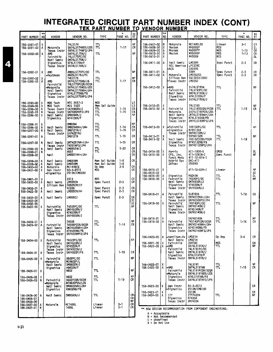
INDEX (CO - PART NUMBEI
156-0391-01 156-0391-0;
156-0392-O(
156-0392-01
156-0392-02 156-0392-0:
156-0393-OC 156-0394-OC 156-0395-OC 156-0395-01 156-0396-OC
156-0396-01 156-0396-02 156-0397-06
156-0397-01
156-0397-02
156-0398-00 156-0398-01 156-0398-02
156-0399-00 156-0399-02 156-0400-00 156-0401-00
156-0901-01 156-0402-00
156-0402-01 156-0402-02
156-0402-03 156-0402-04 56-0402-05
156-0403-00
56-O4O3-Ol 56-0403-02
56-0404-00
56-0404-01
56-0405-00
56-0405-01
56-0405-02 56-0405-03
56-0406-00 56-0406-01 56-0406-06 56-0407-00 56-0407-01
- VENDOR
Motorola Texas I n s t AMD F a i r c h i l d Na t l Semic S ignet ics Texas Inst1
AM0 -Raytheon
AMD F a i r c h i l d
.Motor01 a Na t l Semic S ignet ics Texas I n s t l
MOS Tech MOS Tech Texas I n s t l Texas I n s t i Na t l Semic S ignet ics
Na t l Semic Na t l Semic Texas I n s t t
Nat l Semic Texas I ns t r Na t l Semic
Na t l
Na t l Semic Na t l Semic Motorola Gen I n s t r 6 i g n e t i c s
Na t l Semic S i 1 i con Ger
Na t l Semic
Na t l Semic
F a i r c h l l d Na t l Semic S ignet ics Texas I n s t r
F a i r c h l l d Na t l Semic S ignet ics Texas I n s t r
F a i r c h i l d Nat l Semlc S ignet ics Texas I n s t r Texas I n s t r
F a i r c h i l d Motorola Na t l Semic S ignet lcs
F a l r c h l l d Yotorola Nat l Semic Signet ics
Nat l Semic
Yotorola
TEK
VENDOR NO.
74LSl74 SN74LS174NDS/JI SN74LS174NP3/JI
MTC 2517-3 MCS 1020
ART NI - TYPE
TTL TTL
TTL
TTL
TTL TTL
MOS Mem Sel Guic TTL TTL TTL
TTL TTL TTL
TTL
rTL
rTL ITL
lem Sel Guid lem Sel Guid
I;, 10s ipec Funct
ipec Funct ipec Funct
ipec Funct
'T L
'T L 'TL
TL
TL
TL
TL
TL TL
TL
fnear tnear
* PAGE NO - -
1-17
1-17
1-15 1-15
1-14 1-15
1-15
1-15
1-20
1-5 1-5 3-5
2-3
2-3 2-3
2-3
1-14
1-18
1-19
3-1 3-1
-
YENDB PART NUMBEI
156-0407-01 156-0408-01 156-0409-01 156-0410-01 156-0410-0'
156-041 1-01
156-0411-0' 156-041 1-0;
156-0412-01
156-0412-0; 156-0412-01
156-041 3-O(
156-0473-01 156-041 3-02
156-0414-Ot 156-041 5-OC
156-0415-01 156-0415-02 156-041 6-OC 156-0418-OC
156-041 8-01
156-0419-00
156-041 9-01 156-0419-02
156-0420-00
56-0421-00 56-0422-00
56-0422-01 56-0422-02
56-0423-00
56-0423-01 56-0424-00
IUMBEI VENDOR
Motorola Mostek Mostek Mostek
Na t l Semic NEC Americ 3RCA
Motorola S i l i c o n Ge >Texas I n s t
aAMD Fa i r ch i 1 d Na t l Semic S ignet ics Texas I n s t
F a i r c h i l d Motorola Na t l Semic S ignet ics Texas I n s t
~ F a i r c h i l d ~S igne t l cs Texas I n s t ,
Na t l Semic S ignet ics Texas Inst1
Ha r r i s CPS, Inc. Funct Mods Hybr id Sys Zel t ex
S ignet ics F a i r c h i l d Nat l Semic S ignet ics Texas Ins t1
F a i r c h i l d Na t l Semic Texas Ins t1 Fa i r ch i l d Nat l Semic S ignet ics Texas I ns t r
F a i r c h i l d Na t l Semic S ignet ics Texas I ns t r
Hami 1 ton-A\ Nat l Semic F a i r c h i l d RMD Fa i r ch i l d Nat l Semic S lgnet ics Texas I n s t r
4MD F a i r c h l l d Yotorola Signet ics Texas I n s t r
;en I n s t r Signet ics
ITT j i gne t i cs rexas I n s t r
INDAl
VENDOR NO.
'ION FROM
TYPE
L inear MOS MOS MOS MOS
Spec Funct
Spec Funct Spec Funct
TTL
TTL TTL
TTL
TTL TTL
CMOS Spec Funct
.inear
TTL rTL
rTL
TTL
r rL TTL
)P
10s 'TL
'TL 'TL
'T L
COMPONENT ENGINEERING:
) A = Acceptable N = Not Recomnended U = Undefined X = Do Not Use
- * PAGE NC
3-1
1-13 1-1 3
2-3
2-3 2-3
1-15
1-18
1-18
1-16
3-4
1-15
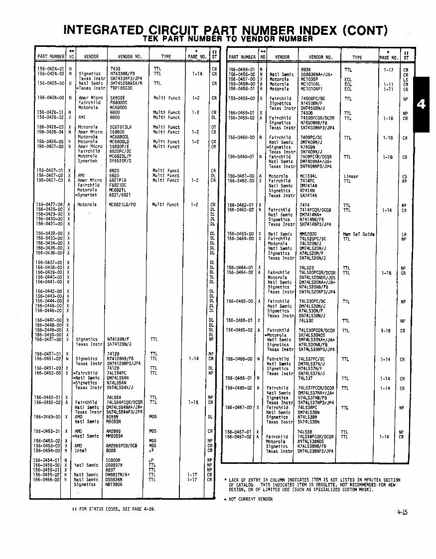
INTEGRATED CIRCUIT PART NUMBER INDEX (CONT) TEK PART NUMBER TO VENDOR NUMBER
VENDOR VENDOR NO.
,
1 1
1 1
1 1
1
1
1
1
l1
I!
l!
I! l!
I
*
w
1% ST
CR CR
CR
CR
CR DL
DT CR
CR CR
:R IL :R
:R )L )L )L IL
IL )L IL IL IL
L IL L L L
L L L L L
L L L L P
P 7
>
> 1
1
I
! I
TYPE ( * PAGE NC 3 :
VENDOR
Natl Semic Motorola Motorola Motorola
F a i r c h i l d S ignet ics Texas I n s t
F a i r c h i l d S ignet ics Texas I n s t
Fai r c h i 1 d Na t l Semic S ignet ics Texas I n s t Fa i rch i l d Nat l Semic Texas I n s t
Motorola F a i r c h i l d Nat l Semic S ignet ics Texas I n s t
Fa i rch i l d Vat1 Semic Signet ics Texas Inst1
Yatl Semic : a i r ch i l d l o to ro la Yatl Semic j i gne t i cs rexas I ns t r
:a i rch i l d b t o r o l a i a t l Semic j i gne t i cs rexas I ns t r
: a i r ch i l d l a t l Semic i i gne t i cs 'exas I n s t r
' a i r c h l l d lo toro la l a t l Semic i gne t i cs exas I n s t r
a i r c h i l d a t1 ~ e m i c i gne t i cs exas I n s t r
a i r c h i l d a t1 Semic i gne t l cs exas I n s t r a l r c h i l d a t1 Semic i gne t l cs exas I n s t r
a i r c h i l d o toro la i gne t i cs exas I n s t r
VENDOR NO.
8836 DS8836NA+/JA+ MC1035P MC10104L MC10104P1
- NOT
PART NUMBER
156-0456-01 156-0456-02 156-0457-00 156-0458-00 156-0458-01
TT L TTL I 1-14
TTL
ECL ECL ECL
TTL
S ignet ics Texas I n s t r Na t l Semic
.Texas I n s t r TTL
M u l t i Funct Amer Micro Fa i r ch i l d Motorola
M u l t i Funct M u l t i Funct
TTL TT L
M u l t i Funct M u l t i Funct
Motorola Amer Micro Motorola Motorol a Amer Micro F a i r c h i l d Motorol a Synertek
TTL M u l t i Funct M u l t i Funct
TTL
M u l t l Func M u l t i Func M u l t i Func,
M u l t i Funci
AM1 Amer Micro F a i r c h i l d Motorol a 6yner tek
L inear TTL
Motorola I
TTL TTL
Mem Sel Guidc TTL
TTL TTL
TTL
TTL
TTL
TTL
TTL
TTL
TTL
j i gne t i cs rexas I n s t r
TTL
TTL TTL
r r L r r L
rTL TTL
i i gne t i cs rexas I ns t r
:a i rch i l d 74LS54PC l a t l Semic DM74LS54N i i gne t i cs N74LS54N 'exas I n s t r SN74LS54N/J
' a i r c h i l d !at1 Semic exas I n s t r ,MD a t 1 Semic
MOS
MOS
MOS MOS UP
UP TTL TTL TTL TT L
MD a t1 Semic
TTL TTL
MD AM2855PCB/DCB n t e l 1 8008
IC8008 a t1 Semic DS8837N
8837 a t1 Semic DM8837NIAt a t1 Semic DS8836N i gne t i cs N8T380A
LACK OF ENTRY IN COLUMN INDICATES ITEM IS NOT LISTED IN MFR/TEK SECTION OF CATALOG. THIS INDICATES ITEM IS OBSOLETE, NOT RECOMMENDED FOR NEW DESIGN, OR OF LIMITED USE (SUCH AS SPECIALIZED CUSTOM MASK).
CURRENT VENDOR
5 5 FOR STATUS CODES, SEE PAGE 4-39.

INTEGRATED CIRCUIT PART NUMBER INDEX (CONT) TEK PART NUMBER TO VENDOR NUMBER - *
PAGE NO. -
1-18
1-18
1-15
1-15 1-16
-16 & 1'
-16 & 1;
1-9
3-3
3-3 3-3
-
- * PAGE N( - -
1-16
1-15
1-15
1-18
3-3 2-2
1-18
1-18
PART NUMB1
156-046&( 156-0468-( 156-0469-(
156-0469-( 156-0469-(
156-0470-C
156-0470-C 156-0470-0
156-0471-0
156-0471-0 156-0471-0
56-0472-0 ,
56-0472-0
56-0472-0
56-0473-01
56-0473-0' 56-0473-0: 56-0474-01 56-0475-01 56-0476-01
56-0477-01 56-0478-01
56-0478-0' 56-0478-0;
56-0479-O(
56-0479-01
56-0479-02
56-0479-03
j6-0479-04
VENDOR VENOOR NO. I TYPE PART NUMBE VENOOR I VENOOR NO. TYPE
TTL
TTL TTL
TTL
TTL TTL
TTL
TTL TTL
OP MOS MOS TTL
TTL
TTL TTL
TTL
TTL
TTL
TTL
YgS
40s TTL TTL TTL
:MOS
ZMOS
:Mos
)P Amp
)P Amp )P
Texas I n s t r
AM0 F a i r c h i l d Na t l SEmic S ignet ics Texas I n s t r
.AM0 F a i r c h i l d Motorol a
SN74LS83N TTL 74LS38 TTL SN74LS138N TTL 74LS138PC M74LS138N
Fa i r c h i 1 d Motorola Nat l Semic S ignet ics Texas I n s t r
TTL TTL
TTL
TTL TTL
TTL
TTL TTL
TTL
TTL
TTL
TTL
TTL rTL
)P M P ipec Funct
. inear 'T L
'TL 'TL
TL
TL
TL
TL
TL
74LS08PC/DC SN74LS08NIJ DM74LS08N/J N74LS08N/F SN74LS08N/J
Fai r c h i l d .Motorola Nat l Semic S ignet ics Texas I n s t r
S ignet ics Texas I n s t r
.AM0 F a i r c h i l d Motorola Na t l Semic
6 i g n e t i c s Texas I n s t
.AM0 F a i r c h i l d Motorol a Texas I n s t
AMD F a i r c h i l d Nat l Semic S ignet ics Texas I n s t
AMD F a i r c h i l d Motorol a Na t l Semic S ignet ics Texas I ns t l
F a i r c h i l d Na t l Semic S ignet ics Texas Inst1
Fa i r ch i l d Nat l Semic S ignet ics Texas 1nst1 Nat l Semic
Nat l Semic Amperex Nat l Semic S i 1 i con i x
S i l i c o n i x F a i r c h i l d Nat l Semic Signet ics Texas I n s t r
Fa i rch i l d Yotorola Nat l SEmic Signet ics rexas I n s t r
= a i r c h i l d l a t l Semic j i gne t i cs rexas I n s t r
' a i r c h i l d l o to ro la l a t l Semic i i gne t i cs 'exas I n s t r
lo toro la 'exas I n s t r ' a i r c h i l d lo toro la 'exas I n s t r
74LS08 74LS08PCQR/OCQR SN74LS08NDS/JOS DM74LSO8NA+/JA+ N74LS08NB/FB SN74LS08NP3/JP4
Fa i r ch i l d 1 7 4 ~ ~ 1 ~ P C / D C Motorola Nat l Semic S ignet ics Texas I n s t r
exa as I n s t r S N ~ ~ L S ~ l N b 3 / ~ ~ 4 I
S N ~ ~ L S I IN/J DM74LSllN/J N74LSl lN/F SN74LSllN/J
Fai r c h i l d Motorol a Na t l Semic S ianet ics
, T- - , , 74LS11 PCQR/OCQR SN74LS1 lNOS/JOS DM74LS1 lNA+/JA+ N74LSllNB/FB
AM0 Nat l Semic S ignet ics
Na t l Semi c ~ S i g n e t i cs .Texas I n s t r Nat l Semic AMD
AM0 IAM96~02p~ Fa i r ch i l d 96L02PC
DM74S196N/J N82S90N SN74S196N/J DM74Sl96NA+/JA+ AM26S1 2APC
AM0 Fai r c h i l d Nat l Semic
Na t l Semic Motorol a
Motorola
96L02 SN96L02N.32 96L02PCQR/DCQR DM96L02NAt
AM0 Fa i r ch i l d
Texas I n s t r Nat l Semic
MC2259L Fa i r ch i 1 d 1 9368OC
93L22PC 93L22PC 93L22 SN74L193N OM74L42AN
Motorola RCA
Motorola I M C ~ ~ O ~ ~ U B C L D
9368PC MC14049UCBL CD4049UBF
Fai r c h i 1 d Ha r r i s Motorola RC A
RCA I CD4049UBFX
34049BCD HE1 -404986-9 MC14049UBCL CD4049UBF 4049
Nat l Semic LM324N NEC America UPC3246 RCA I CA324G Texas I n s t r LM324N I
LS324N Yotorola SC73198L Yatl Semic LM324JlAt S i l i c o n Gen Texas I n s t r
C NEW DESIGN RECOMMENDATION FROM COMPONENT ENGINEERING:
A = Acceptable N = Not Recmended U = Undefined X = Do Not Use
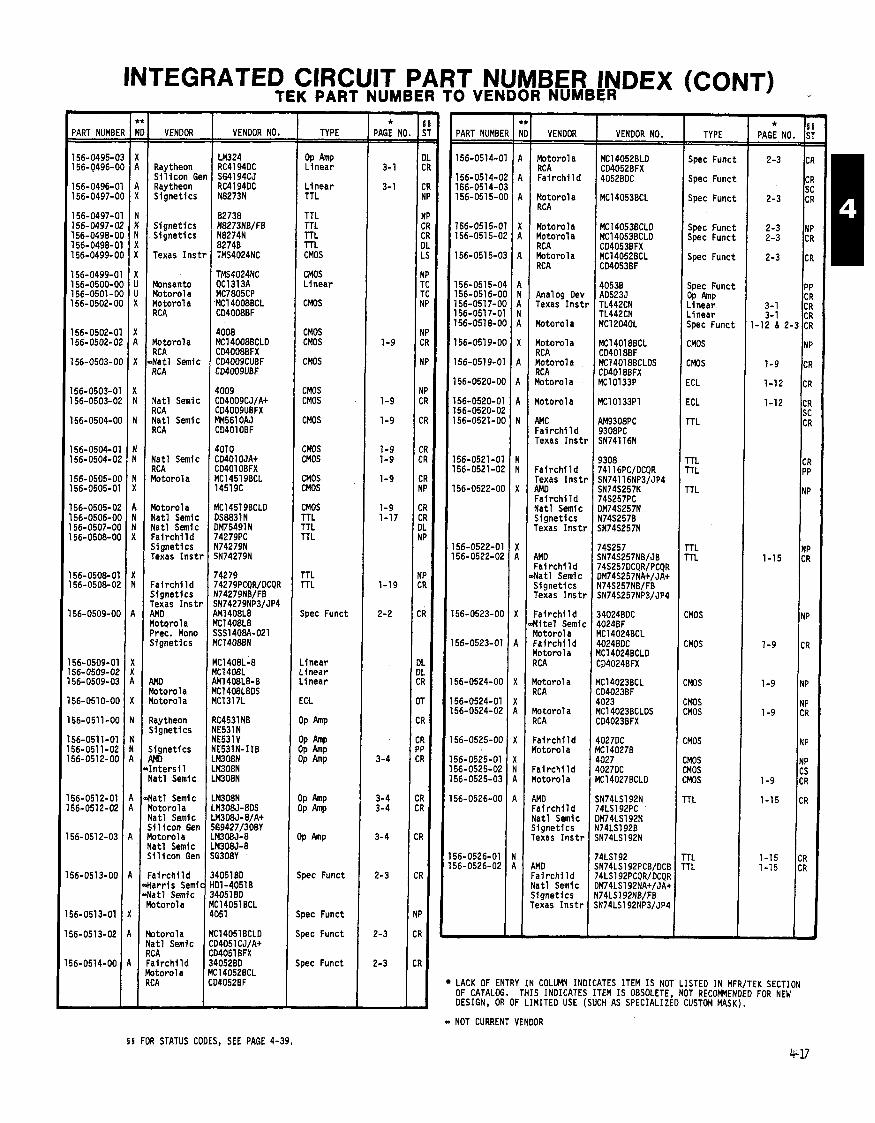
INTEGRATED ClRCl TEK PART
IIT PART NUMBER INDEX WMBER TO VENDOR NUMBER -
PART NUMB1
156-0495-( 156-0496-(
156-0496-( 156-0497-(
156-0497-( 156-0497-( 156-0498-C 156-0498-C 156-0499-C
156-0499-C 156-0500-C 156-0501-C 156-0502-0
156-0502-0 156-0502-0
156-0503-0
156-0503-0 156-0503-0
156-0504-0
156-0504-0 156-0504-0
156-0505-0 156-0505-0
56-0505-0 56-0506-0 56-0507-01 56-0508-01
56-0508-0 56-0508-01
56-0509-01
56-0509-0' 56- 0509- 0; 56-0509-0:
56-051 0-O(
56-0511-O(
56-051 1-01 56-0511-02 56-0512-OC
56-0512-01 56-0512-02
56-051 2-03
56-0513-00
- Spec Func
Spec Func,
Spec Func,
Spec Func' Spec Funci
Spec Funci
Spec Funcl OP h P L inear L inear Spec Funcl
TYPE * I
PAGE NO. S'
2-3 CI
CI S(
2-3 CI
2-3 NF 2-3 CF
2-3 CF
PF CF
3-1 CR 3-1 CR
-12 8 2-3 CR
- 8 8
PAGE NO. ST
OL CR
CR NP
NP CR CR DL LS
Y P TC TC Y P
Y P :R
YP
IP :R
:R
:R :R
:R IP
R :R 1L P
P R
R ,
L L R
T
I R
I ? I ' I ?
I I ?
( 1
( I
h '
c b
C
VENDOR I VENDOR NO.
1
1 1
1
1 1 1
1
1 1
1 PART NUMBE
156-0514-0
156-0514-0 156-0514-0 156-051 5-0
156-0515-0 156-051 5-0
156-0515-0
156-0515-0 156-051 6-0 156-051 7-01 156-051 7-0 156-0518-01
156-0519-01
156-051 9-0
156-0520-O(
156-0520-0' 156-0520-0; 156-052l-O(
156-0521 -01 156-0521-0;
156-0522-O(
156-0522-01 156-0522-02
156-0523-06
156-0523-01
156-0524-00
156-0524-01 156-0524-02
56-0525-00
56-0525-01 56-0525-02 56-0525-03
56-0526-00
56-0526-01 56-0526-02
- L
VENDOR VENDOR NO.
OP Amp Linear
L inear TTL
TTL TTL TTL TTL CMOS
CMOS L inear
CMOS
CMOS CMOS
CMOS
CMOS CMOS
CMOS
CMOS CMOS
CMOS CMOS
CMOS TTL TTL TTL
TTL TTL
Spec Funct
.inear
. Inear
.inear
:CL
)P Amp
$ )P Amp )P Amp
IP Amp IP
P h P
pec Funct
Motorol a MC14052BLD RCA I CO4052BFX Fa i r ch i l d 4052BDC
Raytheon S i l i c o n GI Ray theon S i gnet ics
S ignet ics S ignet ics
Texas I n s l
Monsanto Motorol a Motorola RCA
Motorola RCA l a t l Semic RCA
Nat l Semic RCA Natl Semic RC A
Nat l Semic RCA Motorola
Motorola Nat l Semic Nat l Semic F a i r c h i l d S ignet ics Texas I n s t
F a i r c h i l d S ignet ics Texas I n s t RMD Yotorola Prec. Mono Signet ics
Motor01 a MC14053BCL RCA
Motorola MC14053BCLD MCl4053BCLO CD4053BFX MC14052BCL CD4053BF
Motorol a RCA Motorola RCA
Analog Oev Texas I n s t
Motorola
Motorola RC A Motorola RCA r lotorola
l o t o r o l a
4MC Fai rch i 1 d rexas Inst1
: a i r ch i l d rexas Inst1 WO 'a i rch i l d Ja t l Semfc j i gne t i cs rexas I ns t1
\MD : a i r c h i l d l a t l Semic i i gne t i cs iexas I n s t r
'a i rch i l d H t e l Semic !otorola a i r ch f I d lo toro la 'CA
lo toro l a C A
lo toro la C A
a i r c h i l d o to ro la
a i r c h i l d o t o r o l a
MD a i r c h i l d a t1 Semic i g n e t i c s exas I n s t r
MO a i r c h i l d at1 Semlc i gne t i cs axas I n s t r
-
CMOS
CMOS
ECL
ECL
TTL
TTL TTL
TTL
TTL TTL
CMOS
CMOS
:ms :MOs LMOS
:MOS
:MOS NOS :MOS
rTL
'TL 'TL
4009 CO4009CJ/A+ C04009UBFX FM561 OAJ CD4010BF
4010 CD401 OJA+ CD401 OBFX MC14519BCL 14519C
' 1 E o r o l a : Motorola
Raytheon S ignet ics
1 S ignet ics 1 AMD
-Inters11 Nat l Semic
, 4 a t l Semic Motorola Na t l Semic S i l i c o n Gen Motorola Nat l Semic S i l i c o n Gen
L L
I s
A F a i r c h i l d 3 -Ha r r i s Semic H -Natl Semic 3 Motorola M
X 4
4051BD 01-40516 4051 BD C14051 BCL 051
C14051BCLO D4051 CJ/A+ D4051BFX o052BD .14052BCL 14052BF
Spec Funct
Spec Funct R Motorola Nat l Semic RC A
4 F a i r c h i l d Motorola
Spec Funct
LACK OF ENTRY IN COLUMN INDICATES ITEM IS NOT LISTED IN MFR/TEK SECTION OF CATALOG. THIS INDICATES ITEM IS OBSOLETE, NOT RECWENOED FOR NEW DESIGN. OR OF LIMITED USE (SUCH AS SPECIALIZED CUSTOM MASK). - NOT CURRENT VENDOR
§ § FOR STATUS CODES, SEE PAGE 4-39,

INTEGRATED CIRCUIT PART NUMBER INDEX (CONT) TEK PART NUMBERTO VENDOR NUMBER I
-- -.
? i j 1
? '
t I
I
I
i !
1
1
1
1 1 1
1 1
1 1
1 P T
T T
E IC1 0189P ECL 0189N 01 88N X22689P188 01 88NBIFB
I
I
- *
PAGE NC - - 3- 1
3- 1
1-15
1-15
1-17
3-5
3-2 3-2
-15 & 1
1-18
1-16
1-11 1-11
1-11 1-11
I
5 S' - - CI
C I C I
NI cr: Cr: NP NF
CF C! C! C! C!
c: C' CS C' CS
C' C' C' C' cs CS CS CR CR CS
E: :s CS 3
:s :s :R :R :s :s :s :s :s :s
:R
IL :R IP
IP :R
:R
:R
:R
-- -
VENOOR
Fa i r ch i l d Motorola RC A Burr-Brown Har r i s Semi Na t l Semic
Na t l Semic Na t l Semic Motorola
Motor01 a Texas I n s t r
Texas I n s t r
Texas I n s t r
Texas I n s t r
Texas I n s t r
Texas I n s t r
Texas I n s t r
Texas I n s t r
Texas I n s t r
Texas I n s t r
Texas I n s t r
Texas I n s t r
Texas I n s t r
Texas I n s t r
Texas I n s t r
Texas I n s t r
Texas I n s t r
Ha r r i s Na t l Semic
Na t l Semic F a i r c h i l d Motorola Na t l Semic S ignet ics Texas I n s t r
F a i r c h i l d Motorola Nat l Semic S ignet ics Texas I n s t r
F a i r c h i l d Yotorola F a i r c h i l d Yotorola 4MO C a i r c h i l d Yatl Semic j i g n e t i c s Texas I n s t r
- - - -.
VENDOR NO.
--
TYPE VENOOR NO. TYPE PART NUMBER NI
156-0545-01 A
==+
* PAGE Nt PART NUMBE
156-0527-C
156-0527-C
156-0528-0 156-0529-0
156-0529-0 156-0529-0
156-0530-0
156-0530-0
156-0530-0
156-0531-0 156-0531-0 156-0531-0
156-0532-01 156-0533-01 156-0534-01 156-0534-0 156-0535-01
156-0535-0 156-0535-0; 156-0536-01
156-&36-0'
156-0536-0;
156-0537-01 156-0537-0' 156-0538-01
156-0538-0' 156-0538-01
156-0539-01 156-0539-01
156-0539-02 156-0540-O( 156-0541-O(
156-0541-01 156-0541-02
156-0542-00 156-0542-01
156-0543-00 156-0543-01
I 56-0544-00
56-0544-01 56-0544-02 56-0545-00
VENDOR
.Hami 1 ton-At Motorola S i l i c o n Gel Texas I n s t i
Nat l Semic -AMD F a i r c h i l d Motoro la Na t l Semic S ignet ics Texas I ns t r
aAMD F a r i c h i l d Motorola Texas I n s t r
AMD F a i r c h i l d Na t l Semic Texas I n s t r
M D F a i r c h i l d Motorola Texas I n s t r Na t l Semic
Na t l SEmic
Analog Dev
RCA RC A Na t l Semic
Na t l Semic F a i r c h i l d Texas I n s t r
F a i r c h i l d Texas I n s t r Nat l Semic Nat l Semic F a i r c h i l d Nat l SEmic S ignet ics Texas I n s t r
Nat l Semic Texas I n s t r Nat l Semic Nat l Semic
Yatl Semic 4MD ' a i r c h i l d Yatl SEmic j i gne t i cs lexas I n s t r
: a i r ch i l d l o to ro la j i gne t l cs lexas I n s t r
; ignet ics l o to ro la i i gne t i cs i i gne t l cs lo toro la i l gne t i cs
IMD ' a i r c h i l d
a i r c h l l d ' a i r c h i l d lo toro l a
Linear
Linear
Mem Sel Gui TTL
TTL TTL
TTL
TTL
TTL
TTL TTL TTL
3~ Amp lTL l r r a y k r a y rTL
TTL TTL r rL
TTL
rTL
'TL 'TL 'TL
'TL 'T L
'TL 'T L
'T L 10s TL
TL TL
CL
CMOS
L inear CMOS
CMOS CMOS CMOS CMOS CMOS
CMOS TTL TTL TTL TTL
TTL TTL TTL TTL TTL
TTL TTL TTL TTL TTL
TTL TTL TTL TTL TTL
TTL TT L TTL TTL TTL
TTL TTL TTL TTL rTL
TTL TTL lTL lTL TTL
:MOS
:MOS :MOS TTL
rTL 'T L
:MOS
:MOS
'TL
ECL ECL
TTL
TTL TTL CMOS * NEW DESIGN RECOMMENDATION FROM COMPONENT ENGINEERING:
A = Acceptable N = Not Reconended U = Undefined X = Do Not Use

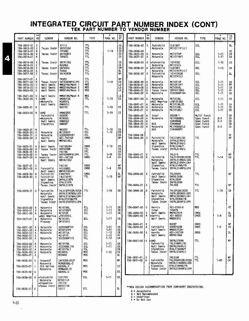
INTEGRATED CIRCUIT PART NUMBER INDEX (CONT) TEK PART NUMBER TO VENDOR NUMBER
PART NUMBEl
156-0612-0 156-061 3-01 156-0613-0' 156-0614-01 156-0614-0'
156-061 5-01 156-0615-0' l56-0616-O( 156-0616-0' 156-0617-O(
156-0617-01 156-061 7-01 156-061 8-O( 156-0619-O( 156-0620-O(
156-0621-O( 156-0622-O(
156-0622-01
156-0623-O(
156-0623-01 156-0624-OC 156-0624-01 156-0625-OC
156-0625-01 156-0626-OC 156-0626-01 156-0626-02 156-0627-06
156-0627-01 156-0k27-02
156-0628-00 156-0629-00
156-O629-Ol
156-0630-00 156-0630-01 156-0631-00
156-0631-01
156-0631-02 156-0631-03 156-0632-00 156-0632-01 156-0632-02
156-0633-00 156-0633-01 156-0633-02 156-0634-00 156-0634-01
156-0635-00
156-0635-01
156-0635-02
156-0636-00
156-0636-01
VENDOR
Texas Ins t1
Texas I n s t t
Texas I n s t t
Texas I n s t r
Texas I n s t r
Texas I n s t r Na t l Semic Na t l Semic Nat l Semic
Na t l Semic DAMD .Motor01 a Na t l Semic
-AM0 F a i r c h i l d
.Motorola Na t l Semic S ignet ics
Motorola Motorola Ha r r i s Na t l Semic
Na t l Semic Texas I n s t r
Texas I n s t r .Harris Na t l SEmic
F a i r c h i l d Na t l Semic F a i r c h i l d F a i r c h i l d Na t l Semic S ignet ics Texas I n s t r
F a i r c h i l d Motorola Na t l Semic S ignet ics Texas I n s t r
Motorola Motorol a Motorola ,NEC America Motorola Pl essey
Motorola Motorola Motorola
Motorola
Motorola Motorola Motorola Motorola
I n t e r s i l Motorol a OCA Rel iab Motorola
F a i r c h i l d Yotorola S ignet ics Texas I n s t r
VENDOR NO.
SN74175J MJUMKJ SN744OJ 74405 SN74393N
Oll lPC IClOl lLP O l l l N N lO l l lN 01 11
TTL TTL TTL TTL
TTL TTL TTL TTL TTL
TTL TTL MOS MOS MOS
MOS TTL
TTL
TTL
TT L ECL ECL CMOS
CMOS TTL TTL TTL CMOS
CMOS CMOS
CMOS TTL
TTL
ECL ECL ECL
ECL
ECL ECL ECL ECL ECL
ICL ICL ECL 10s 10s
10s
10s
10s
:CL
:CL
- * PAGE NO
1-14
1-15
1-19
1-19
1-19
1-19 1-12
7-10
1-15 1-9
1-9
1-15
1-15
1-11 1-11 1-11
1-11
1-11 1-11 1-12 1-12 1-12
1-11 1-11
1-13
1-11
- PART NUMBEK VENDOR
F a i r c h i l d Motorol a
Motorola Motorol a
,Fa i rch i ld Motorola ~ F a i r c h i l d Motorola F a i r c h i l d Motorola
Motorola Motorola Motorola Texas I n s t r Motorola
Motorola >NEC America Motorola Motorol a Motorola
I n t e l Motorola
RC A Motorola RC A
F a i r c h i l d Motorol a Nat l Semic S ignet ics Texas I n s t r
F a i r c h i l d Motorola Na t l Semic S i gnet ics Texas I n s t r
Fai r c h i l d Nat l Semic S ignet ics Texas I n s t r
Fa i r ch i l d Motorola Nat l Semic S ignet ics Texas I n s t r
Ha r r i s I n t e l Nat l Semic Ha r r i s Na t l Semic
F a i r c h i l d Nat l Semic Ha r r i s Nat l Semic
AMD F a i r c h i l d Nat l Semic S ignet ics Texas I n s t r
[ a i r c h i l d l o t o r o l a j i g n e t i c s Texas I n s t r
VENDOR NO.
SL81661 MClO111 PI /L1
MC10174P MC10174Pl
10141DC MC10141L SL81651 MC10141Pl/Ll 101 41 OCQR MC10141L1
MCl 01 lOP MCl 01 1 OPl MC10164L SN74S139N3 SC22689P164
TYPE
ECL
ECL ECL
ECL
ECL
ECL
ECL ECL ECL ECL ECL
ECL
ECL ECL ECL
M u l t i Funct Spec Funct Spec Funct Spec Funct Spec Funct
TTL
TTL TTL
TTL
TTL
TTL
10s
:MOS :MOS
:MOS ZMOS
:MOS
TTL
'TL 'TL
**NEW DESIGN RECOMMENDATION FROM COMPONENT ENGINEERING:
A = Acceptable N = Not Recomnended U = Undefined X = Do Not Use
- * 'AGE NO - -
1-1 1 1-11
1-12
1-12
1-11 1-11 1-11 1-11 1-11
1-11
1-11 1-11 1-11
2-3 2-3
2-3
1-14
1-15
1-9
1-9
1-20
-
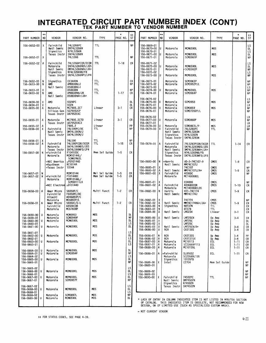

I INDEX (CONTI RT b I VENI 7
'ART NUMBEF
MBEl NUMB
VENOOR
TE VENDOR NO.
IER - PART NUMBE
I * ID. -.
AMD Fa i r ch i l d Na t l Semic S igne t i cs Texas I n s t l
I
( \
[ I
[ I
I
I E
E
l
m
I
I
I I !
- * 'AGE N =
1-18 1-18
2-3
1-1 1
1-19 1-19
1-19
1-18
1-7
1-6
1-6
1-18
2-2
2-2
1-16
1-18
-
VENDOR TYPE
TTL TTL TTL
TTL
TTL TTL
TTL TTL
TTL TTL
TTL
TTL TTL
rTL
rTL rTL
!em Sel Guic lem Sel Guid 'TL T L .TL
'TL
'T L lem Sel Guid
lem Sel Guid
inear
* 'AGE NC - -
1-18
1-14
1-19
1-19 1-19
1-16
1-16
1-18
1-20
1-6
1-6
3-1 3- 1
1-14
VENOOR NO. TYPE
TTL TTL Texas I n s t
F a i r c h i l d Na t l Semic S igne t i cs Texas I n s t
-Almac-Stro Monol i t h i c Texas I n s t
Monol i t h i c Texas I n s t
=Fa i rch i I d Monol i t h i c
d a t l Semic S igne t i cs Texas I n s t
Monol i t h i c S igne t i cs Texas I n s t AMD F a i r c h i l d Na t l Semic S igne t i cs Texas I n s t '
F a i r c h i l d S ignet ics Texas I n s t r Motorol a
Motorola Motorola Plessey Texas I n s t r
Texas I n s t r F a i r c h i l d Na t l SEmic S ignet ics Texas I n s t r
Fa i r ch i l d Nat l Semic S ignet ics Texas I n s t r
AMD $ I n t e l Motorola ~ N a t l Semic I n t e l
Gen I n s t r I n t e l Elec Arrays Motorol a
Motorol a Motorola Motorola
Motorol a
Motorola h e r Micro Motorol a AM I Motorola
Analog Oev F a i r c h i l d Nat l Semic S ignet ics Texas I n s t r
F a i r c h i l d Motorola S ignet ics Texas I n s t r
Analog Dev Micro Sys Nat l Semic F a i r c h i l d Nat l Semic Texas I n s t r
Fa i rch i l d Yotorola Texas I n s t r Fa i rch i l d Yatl Semic Signet ics Texas I n s t r
= a i r c h i l d l o t o r o l a Vat1 Semic j i gne t i cs rexas I n s t r
Spec Funct
Spec Funct ECL
TTL TTL
TTL TTL
TTL TTL TTL
Mem Sel Guid
MOS
MOS
MOS MOS
MDS
MOS
MOS
AM0 F a i r c h i l d Na t l Semic S ignet ics TExas I n s t l
AMD F a i r c h i l d Na t l Semic S ignet lcs Texas I n s t r
S ignet ics
Texas I n s t r
Texas I n s t r
Nat l Semic S ignet ics Texas I n s t r
AM0 ' I n t e l 'Signet ics
AMD I n t e l S ignet ics F a i r c h l l d F a i r c h i l d Nat l Semic S l l i c o n Gen
Na t l Semic S ignet ics RC A AMD Nat l Semic S ignet ics Texas I n s t r
Nat l Semic Texas I n s t r Yat l Semic Texas I n s t r F a i r c h i l d Yatl Semic j i g n e t i c s rexas I n s t r
SN74S138N 74S138PC OM74S138N N74S138N SN74S138N
74S138 SN74S138JB 74S138DCQR DM74S138JA+ N74S138FB SN74S138JP4
2606-01 26060-1 SN74265N 74265 SN74265JP4
OM741 94N N74194N SN74194N 741 94 AM9101BPC B2101A-4 2101-IN
AM9101 BOC B2101A-4 2101-IN 723HM UA723HMQB LM723H/883 SG723T
LM74l H UA741T CA741S AM74S251N DM74S251 N N74S251B SN74S251 N
Mem Sel Guidt
Mem Sel Guidt
L inear TTL
TTL TTL TTL
Spec Funct
Spec Funct TTL e
L Linear TTL
TTL
TTL
TTL
TTL ** NEW DESIGN RECOMMENDATION FROM COMPONENT ENGINEERING:
A = Acceptable N = Not Recomnended U = Undefined X = Do Not Use

INTEGRATED CIRCUIT PART NUMBER INDEX (CONT) TEK PART NUMBER TO VENDOR NUMBER -
PART NUMB - 156-0721-1 156-0721-1 156-0722-1
156-0722-1 156-0722-1
156-0723-(
156-0723-( 156-0724-(
156-0724-( 156-0724-(
156-0725-C 156-0726-C 156-0727-C
156-0727-0
156-0728-0
56-0728-0
56-0728-0
56-0729-01 56-0729-0
56-0730-O(
56-0730-0' 56-0730-0;
56-0731 -O(
56-0731-01
56-0731-02
PART NUMBE
156-0733-0;
156-0733-0, 156-0734-01
156-0734-0' 156-0734-0;
156-0735-01
156-0735-01 156-0735-0;
'56-0736-Ot
56-0736-01
56-0736-02
56-0737-00 56-0738-00
56-0738-01
56-0738-02
56-0738-03
* I 5 VENDOR VENDOR NO. TYPE PAGE NO. ST
I e
VENOOR
TTL TTL TT L
Motorola Texas I n s t r Texas I n s t r F a i r c h i l d Na t l Semic S igne t i cs Texas I n s t r
SN74LS221NDSlJDS TTL SN74LS221N31J4 SN74LS221NlJ TTL 74LS295PCIDC TTL DM74LS295NIJ N74LS295NIF SN74LS295NIJ
F a i r c h i l d Nat l Semi S ignet ics Texas I ns
Motorola Na t l Semi Texas I ns Analog Oe
F a i r c h i l d Motorol a Nat l Semi1 S ignet ics Texas Ins,
F a i r c h i l d Motorola Na t l Semic S igne t i cs Texas Ins1
Na t l Semic Na t l Semic F a i r c h i l d Nat l Semic S ignet ics Texas Ins1
F a i r c h i l d AM0 Motorola S ignet ics Texas I n s t
F a i r c h i l d Nat l Semic S igne t i cs Texas I n s t
F a i r c h i l d Motorol a Texas I n s t Nat l Semic Nat l Semic
airc child Yotorola Nat l Semic S ignet ics Texas I n s t )
: a i r c h i l d Yotorola j i gne t i cs rexas Inst1
l o t o r o l a l a t l Semic i i gne t f cs rexas I n s t t
l o to ro la l a t l Semfc i i gne t i cs 'exas I n s t r : a i r c h i l d l a t l Semic , i gne t l cs 'exas I n s t r
o t o r o l a a t 1 Semic exas I n s t r
Spec Funct
Spec Funct TTL
TTL TTL
MOS MOS TTL
TTL
TTL
TTL
TTL
TTL TTL
TTL
TTL TTL
TTL
TTL
TTL
TTL
'T L T L
'TL
i 1 Fa i r ch i 1 d 1 ~ ~ L S ~ ~ ~ A P C Q R / O C ( R ~ T T L S ignet ics N74LS295BNBIFB Texas I n s t r SN74LS295BNPe/JP4 . -. . - - . . . - -. - - - - . . . . - . .
( 1 Nat l Semic 1 0 ~ 7 4 ~ ~ 7 5 ~ ~ T T L 1 s i g n e t i c s 1 ~ 7 4 ~ ~ 7 4 ~ Texas I n s t r SN74LS75N I
74LS75 TTL SN74LS75NDSlJOS TTL 1 lN74LS75NA+lJA+ N74LS75NBIFB SN74LS75NP31JP4
Motorola Na t l Semic S ignet ics Texas I n s t ~
Fa i r ch i l d Na t l Semic S ignet lcs Texas Ins t1
74LS42PCQRlOCQR TTL SN74LS42NDSlJDS DM74LS42NA+/JA+ N74LS42NBIFB SN74LS42NP31JP4
Fa i r ch i l d Motorola Na t l Semic S ignet ics Texas Ins t ,
Nat l Semic AMD F a l r c h i l d Texas I n s t r
Mem Se1 Guide SN74S174N 9S174/74S174PC SN74S174N
TTL
TTL
TTL
TTL TTL
TTL
TTL
TTL TTL
TTL TTL
TTL OP &P
OP &P OP M P
ECL ECL
TTL
TTL TTL
TTL TTL CMOS
WD Signet ics WD j i gne t i cs rexas I n s t r
!exas I n s t r . a i r c h i l d j i gne t i cs rexas I n s t r
: a i r c h i l d i i gne t i cs 'exas I n s t r l o to ro la
IMD ' a i r c h i l d ' a i r c h i l d l a t l Semic 'exas I n s t r
a t 1 Semic exas I n s t r o t o r o l a o t o r o l a
MD a i r c h i l d
, exas I n s t r
Texas I n s t r Texas I n s t r F a i r c h i l d Motorola RCA
] LACK OF ENTRY IN COLUMN INDICATES ITEM IS NOT LISTED IN MFRITEK SECTION OF CATALOG. THIS INDICATES ITEM IS OBSOLETE, NOT RECOmENOED FOR NEW DESIGN, OR OF LIMITED USE (SUCH AS SPECIALIZED CUSTOM MASK). - NOT CURRENT VENOOR.
5 5 FOR STATUS CODES, SEE PAGE 4-39.
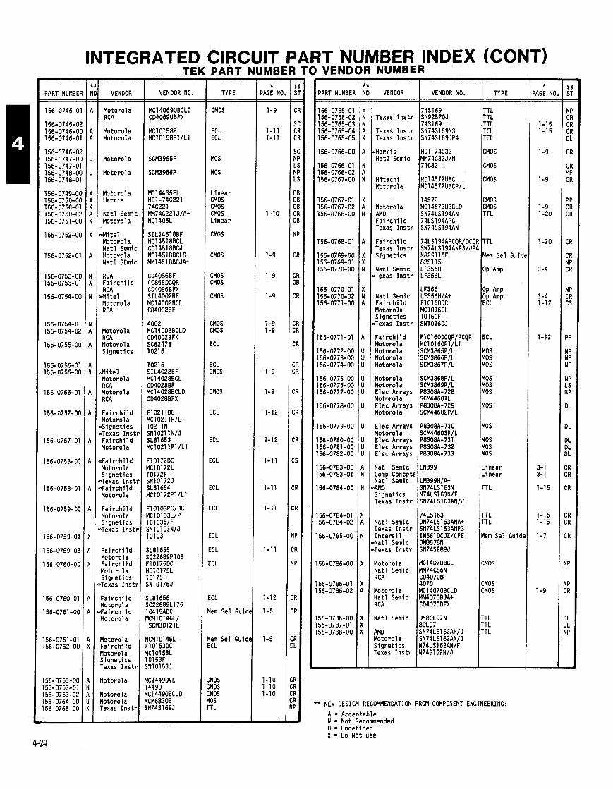
INTEGRATED CIRCUIT PART NUMBER INDEX (CONT)
PART NUMBE
156-0745-0
156-0745-0 156-0746-0 156-0746-0
156-0746-0 156-0747-0 156-0747-0 156-0748-0 156-0748-0
156-0749-0 156-0750-0 156-0750-0 156-0750-0 156-0751-01
156-0752-01
156-0752-0
156-0753-01 156-0753-0
156-0754-01
156-0754-0' 156-0754-0;
156-0755-01
156-0755-0' 156-0756-O(
156-0756-0'
l56-W57-O(
156-0757-01
156-0758-O(
156-0758-01
156-0759-O(
156-0759-01
156-0759-02
156-0760-Ot
l56-O76O-Ol
156-0761-OC
156-0761-01 156-0762-00
156-0763-00 156-0763-01 156-0763-02 156- 0764-00 156-0765-00
VENDOR
Motorola RC A
Motorola Motorola
Motorola
Motorol a
Motorola Ha r r i s
Na t l Semic Motorol a
.Mi t e l Motorola Na t l Semic Motorola Na t l SEmic
RC A F a i r c h i l d RC A
.Mi t e l Motorol a RCA
Motorola RCA Motorola S ignet ics
M t e l Motorola RCA Motorol a RCA
F a i r c h i l d Motorola ~ S i g n e t i c s >Texas I n s t F a i r c h i l d Motorol a
T a i r c h i l d Motorola S ignet ics )Texas I n s t ,Fa i r ch i l d Motorol a
F a i r c h i l d Motorola S ignet ics 'Texas Inst1
Fa i r ch i l d Motorola F a i r c h i l d Motorola S ignet ics Texas I n s t t
F a i r c h i l d Motorola F a i r c h i l d Motorola
Motorol a Fa i r ch i l d Yotorola S ignet ics Texas I n s t r
Yotorola
Yotorola Yotorola rexas I n s t r
TE
VENDOR NO. TYPE
CMOS
ECL ECL
MOS
MOS
L inear CMOS CMOS CMOS L inear
CMOS
CMOS
CMOS CMOS
CMOS
CMOS CMOS
ECL
ECL CMOS
CMOS
ECL
ECL
ECL
ECL
ECL
ECL
ECL
ECL
ECL
lem Sel Guid
lem Sel Guid iCL
:MOS :MOS :MOS 10s 'TL
- *
PAGE NO. PART NUMBER
156-0765-01 156-0765-02 156-0765-03 156-0765-04 156-0765-05
156-0766-00
156-0766-01 156-0766-02 156-0767-00
156-0767-01 156-0767-02 156-0768-00
156-0768-01
156-0769-00 156-0769-01 156-0770-00
156-0770-01 156-0770-02 156-0771-00
156-0771-01
156-0772-00 156-0773-00 156-0774-00
156-0775-00 156-0776-00 156-0777-00
156-0778-00
156-0779-00
156-0780-00 156-0781 -00 156-0782-00
156-0783-00 156-0783-01
156-0784-00
156-0784-01 156-0784-02
156-0785-00
156-0786-00
56-0786-01 56-0786-02
56-0786-00 56-0787-01 56-0788-00
VENDOR VENDOR NO. TYPE
74S169 TTL Texas I n s t r SN92570J TTL
74S169 TTL Texas Ins tr SN74S169N3 TTL Texas I n s t r SN74S169JP4 TTL
,Harris HD1-74C32 CMOS Na t l Semic MM74C32JIN
74C32 . lcMOs Hi tach i HO14572UBC CMOS Motorola IMCl4572UBCP/L I
14572 CMOS Motorola MC14572UBCLD CMOS AMD SN74LS194AN TTL Fai r c h i 1 d 74LS194APC Texas I n s t r SN74LS194AN
Fai r c h i 1 d 1 7 4 ~ ~ 1 ~~APCQRIOCQR TTL Texas I n s t r SN74LS194ANP3IJP4 I S ignet ics N82S1 15F Mem Sel Guid
Na t l Semic 182s115 LF356H ' lop Amp )Texas I n s t r LF356L
Motorol a ~ i g n e t i c s 10160F Texas l n s t r lSNlOl6OJ I Fa i r ch i l d F10160OCQR/PCQR ECL Motorola MC10160Pl/Ll Motorola SCM3865PlL Motorola SCM3866PlL
I Motorola SCM3867PlL
Motorola SCM3868PIL Motorola SCM3869PlL Elec Arrays P8308A-720 Motor01 a SCM44601 L Elec Arrays P8308A-729 Motorola SCM44602PlL
Elec Arrays P8308A-730 Motor01 a SCM44603PlL Elec Arrays P8308A-731 Elec Arrays P8308A-732 Elec Arrays P8308A-733
Na t l Semic LM399 Comp Concpts Na t l Semic LM399H/A+ AM0 SN74LS163N S igne t i cs N74LS163NlF Texas I n s t r SN74LS163ANlJ
74LS163 Na t l Semic DM74LS163ANAt Texas I n s t r SN74LS163ANP3 I n t e r s i l IM561OCJElCPE Nat l Semic DM8578N Texas I n s t r SN74S288J
Motorola Nat l Semic RCA
Yotorola Nat l Semic RCA
Natl Semic
4Mo Yotorola S ignet ics rexas I n s t r
MOS MOS MOS
MOS MOS MOS
MOS
MOS
MOS MOS MOS
L inear L inear
TTL
TTL TTL
Mem Sel Guide
CMOS
CMOS CMOS
TTL TTL TTL
* NEW DESIGN RECOMMENDATION FROM COMPONENT ENGINEERING:
A = Acceptable N = Not Recomnended U = Undefined X = Do Not use
- *
'AGE NO
1-15 1-15
1-9
1-9
1-9 1-20
1-20
3-4
3-4 1-12
1-12
3-1 3-1
1-15
1-15 1-15
1-7
1-9
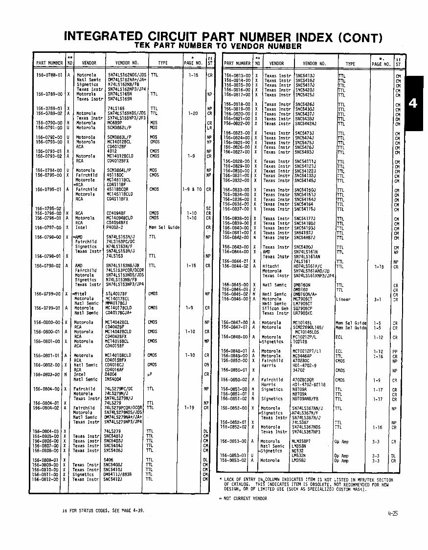
INTEGRATED CIRCUIT PART NUMBER INDEX (CONT) TEK PART NUMBER TO VENDOR NUMBER
No. i! - . 5 T - - ,
R
P
P R
R R
P P
> P
Y
>
1
. t I '
L .
' 1
I
,
DL CM CM CM CM
PART NUMBE
156-0813-C 156-0814-C 156-0815-C 156-0816-0 156-081 7-0
156-0818-0 156-081 9-0 156-0820-0 156-0821 -0 156-0822-0
156-0823-0 156-0824-0 156-0825-0 156-0826-0 156-0827-0
156-0828-0 156-0829-0 156-0830-0 156-0831-01 156-0832-01
156-0833-01 156-0834-01 156-0835-01 156-0836-01 156-0837-01
156-0838-01 156-0839-01 156-0840-01 156-0841-O( 156-0842-01
156-0843-01 56-0844-O(
'56-0844-01 56-0844-02
56-0845-O( 56-0845-01 56-0845-02 56-0846-OC
56-0847-00 56-0847-01
56-0848-00
56-0848-01 56-0849-00 56-0850-00
56-0850-01
56-0850-02
56-0851 -00 56-0851 -01 56-0851 -02
56-0852-00
56-0852-01 j6-0852-02
a
.
1
1 1
1 1
1 1 1 1
1 1
1
1 1 1
1
1'
l1 1' I!
I !
I! I!
l!
1 I I t - * LACK OF ENTRY IN COLUMN INDICATES ITEM IS NOT LISTED IN MFRITEK SECTION
OF CATALOG. THIS INDICATES ITEM IS OBSOLETE, NOT RECOMMENDED FOR NEW DESIGN, OR OF LIMITED USE (SUCH AS SPECIALIZED CUSTOM MASK).
-
VENDOR VENDOR NO. TYPE .
PAGE NO. PART NUMBER
156-0788-01
156-0789-00
VENDOR
Motorol a Na t l Semic S i gnet ics Texas I n s t Motorola Texas I n s t
Motorola Texas I n s t Motorol a Motorola
Motorola Motorola RCA
Motorola RCA
Motorola F a i r c h i l d Motorola RCA Fa i r ch i l d Motorol a RC A
RCA Yotorola RCA I n t e l
wo - a i r c h i l d j i gne t i cs rexas I n s t l
WO :a i r ch i l d l o to ro la j i gne t l cs rexas I n s t t
l i t e l l o to ro la l a t l Semic lo toro la l a t l Semic
lo toro la !C A lo toro l a ICA lo toru l a C A
o t o r o l a C A a t 1 Semic .CA n t e l a t1 Semic
a i r c h i l d o to ro la exas I n s t r
VENDOR NO. I TYPE I - -
Texas Texas Texas Texas Texas
Texas Texas Texas
TTL
TTL
I n s t r SNC5413J I n s t r SNC5416J I n s t r SNC5417J Ins tr SNC5420J I n s t r SNC5425J
I n s t r SNC5426J I n s t r SNC5430J I n s t r SNC5437J
r SNC5438J r SNC5442AJ
r r r r r
P
. <
. < . < . I
I ( . <
Texas I n s t Texas I n s t
Texas Inst1 Texas l n s t ~ Texas Inst1 Texas Inst1 Texas Inst1
Texas I n s t l Texas I n s t l Texas I n s t l Texas I n s t t Texas I n s t t
Texas I ns t r Texas I n s t t Texas I n s t t Texas I n s t r Texas I n s t r
Texas I n s t r Texas I n s t r Texas I n s t r Texas I n s t r Texas I n s t r
Texas I n s t r MO Texas I n s t r
ii tach i l o to ro la lexas I n s t r
rlatl Semic
l a t l Semic l o to ro l a l a t l Semic i i l i c o n Geh lexas I n s t r
l o to ro l a lo toro la
lo toro l a Lignet ics
lo toro la lo toro la a i r c h i l d l a r r i s
a i r c h i l d a r r i s i gne t i cs
i gne t i cs
o to ro la i gne t i cs exas I n s t r
o t o r o l a exas I n s t r
SCM3863L/P MC14012BCL CD4012BF 401 2 MC1401 2BCLO CD4012BFX
SCM3864L/P 451 1 BDC MC14511BCL CD4511 BF 451 1 BOCQR MC14511 BCLD CD45ll BFX
MOS CMOS
CMOS CMOS
MOS CMOS
CMOS
CMOS CMOS
lem Sel Guidc
SNC541505 TTL SNC54151 J TTL SNC54154J TTL SNC54164 TTL SNC54175J TTL
TTL
TTL
1TL
:MOS
:Mas
MOS
MOS
MOS
MOS
MOS
P
TL
TL rL
r L rL rL 1L 'L
'L 'L 'L 'L 'L
jNC5400J TTL jN74LS161N TTL jN74LS161AN 74LS161 TTL 1074LS161P/C TTL jN74LS161ANO/JD jN74LS161ANP3/JP4
TTL TTL
Linear
Mem Sel Guic Mem Sel Guid
ECL
ECL TTL CMOS
CMOS
CMOS
TTL TTL TTL
Fa i r ch i l d Motorol a Nat l Semic Texas I n s t r TTL
TTL
OP Amp
OP M P OP M P
Texas I n s t r Texas I n s t r rexas I n s t r rexas I n s t r
rexas I n s t r rexas I n s t r i i gne t i cs lexas I n s t r
Motorola Nat l Semic S ignet ics
Yotorola
- NOT CURRENT VENDOR
5 5 FOR STATUS CODES, SEE PAGE 4-39.
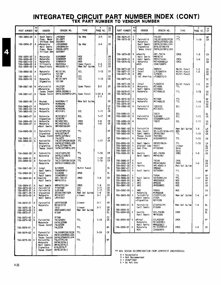
INTEGRATED CIRCUIT PART NUMBER INDEX (CONT) TEK PART NUMBER TO VENDOR NUMBER
I
-- --
n
1
I
I I
I I
I I
I I
I : 91 30A
a i r c h i l d 74LS259PC o to ro la SN74LS259N exas I n s t r 74LS259N
74LS259
- * PAGE NO - -
3-4
3-4
2-3 1-7
1-12
1-12
2-3
1-20 & 2-3
1-11
1-11
1-9 1-9
1-17
1-18
1-18 1-18
1-9
1-9 1-11 1-11 1-4 3-1
3- 1
3-1
1-19
1-19
-
- * 'AGE NI - -
1-18
1-9
1-9
1-2 1-2
1-2
1-16
1-16
1-1 1
1-11
1-1 1
1-5
1-15
1-1 5
1-15
1-9
1-9
1-1 7
1-6
1-6
1-9 -
PART NUMBE
156-0854-0
156-0854-0
156-0855-01 156-0856-01 156-0857-01 156-0858-01 156-0859-01
156-0860-01
156-0860-0 156-0860-0;
156-0861-01
156-0861-0'
156-0862-O(
156-0862-0' 156-0862-0; 156-0863-O(
156-0863-0'
156-0864-O! 156-0864-0
156-0865-O(
156-0865-01 156-0865-02
h
156-0866-OC
156-0866-01 156-0866-02
156-0867-OC
156-0868-00
156-0869-00
156-0869-01 156-0870-00 156-0870-01 l56-O87l-OO 156-0872-00
156-0872-01
156-0872-02 156-0873-00 156-0873-01
156-0873-02 1 56-0874-00
156-0874-01
156-0874-02
156-0875-00
VENDOR
Na t l Semic Prec. Mono S i l i c o n Gel Motoro la Na t l Semic Prec. Mono S i l i c o n Gel
Motorola Motorol a Motorol a S i l i c o n i x Mono l i t h i c
Motorola S ignet ics
Motorola S ignet ics
F a i r c h i l d Motorol a Texas I n s t t Texas I n s t t
Mostek Motorola
Motorola Notorola
Yotorola S ignet ics Yotorol a Motorola Yatl Semic
F a i r c h i l d Signet ics rexas I n s t r
: a i r ch i l d l o t o r o l a j i g n e t i cs Texas I n s t r
: a i r ch i l d l o to ro la
: a i r ch i l d l o to ro l a
I n t e l i a t l Semic I n te l l a t l Semic i a r r i s l a t l Semic
!at1 Semic , a i r c h i l d : a i r c h i l d ~ i i gne t i cs lo toro la l a t l Semic
' a i r c h i l d IotoroJ a
IMD
VENDOR NO. TYPE
OP
OP Amp
MOS MOS MOS Spec Funct Mem Sel Guid
ECL
ECL ECL
Spec Funct
Spec Funct
Mem Sel Guid
ECL
ECL
CMOS CMOS
TTL
TTL TTL
rTL
TTL TTL
l u l t i Funct
NOS
:MOS
:MOS iCL :CL !em Sel Guide . inear
. inear
.I near lem Sel Guide
'TL
TL
TL
TL
PART NUMBEI
156-0875-01 156-0875-02
156-0876-OC
156-0876-01 156-0876-02
156-0877-00 156-0877-01 156-0877-02
156-0877-03
156-0877-04 156-0878-00
156-0878-01 156-0878-02
156-0879-00 156-0879-01 156-0879-02 156-0880-00
156-0880-01 156-0880-02
156-0880-03 156-0880-04
56-0881-00 156-0882-00 56-0883-00
56-0883-01
56-0883-02 56-0884-00 56-0885-02 56-0885-03 56-0886-00
56-0886-01 56-0886-02 56-0887-00 56-0887-01 56-0888-00
56-0888-01 56-0888-02 56-0889-00 56-0890-00 56-0891 -00
56-0892-00
56-0893-00
56-0893-01
56-0893-02 56-0894-00
I
56-0895-00
56-0895-01
VENOOR
F a i r c h i l d Motorola Na t l Semic S ignet ics Texas I n s t r
.Harris Na t l Semic Na t l Semic Motorola
0RCA
I n t e l I n t e l AM0 NEC America
I n t e l Motorola Na t l Semic Motorola
Motorola Motorola
Fa i r ch i l d Motorola
F a i r c h i l d Motorola
F a i r c h i l d Gen I n s t r Na t l Semic Texas I n s t r Motorola
Na t l Semic D i g i t a l Cm Gen Elec
Ha r r i s Na t l Semic
Na t l Ha r r i s
Na t l Semic
Na t l Semic AM0 AM0 AM0
AM0 Motorola F a i r c h i l d Na t l Semic S igne t i cs
F a i r c h i l d Na t l Semic
Ha r r i s Nat l Semic
Y i t e l Yotorol a Yat l Semic Yotorola RCA
VENOOR NO. TYPE
TTL TTL
CMOS
CMOS CMOS
M u l t i Funct M u l t i Funct Mu1 t i Funct
Mu l t i Funct TTL
TTL
TTL TTL
ECL
ECL ECL
ECL
Mem Sel Guide MOS TTL
TTL
JM74S196JAt KEVl 1 41 lAX940
TTL Linear O D ~ O opt0 CMOS
CMOS CMOS Yem Sel Guide
TTL
F l 001 ODC SL81658 2516N/CM2159N YC7912CT -M7912CT
YOS
Yem Sel Guide
lem Sel Guide
a l r c h i l d o to ro la exas I n s t r a i r c h i l d o to ro la a t1 Semlc i gne t i cs exas I n s t r * NEW DESIGN RECOMMENDATION FROM COMPONENT ENGINEERING:
A = Acceptable N = Not Recommended U = Undefined X = Do Not Use
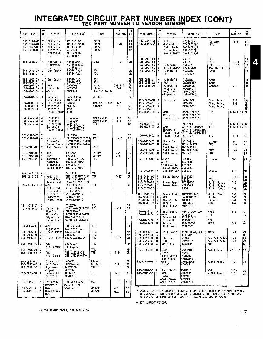
INTEGRATED CIRCUIT PART NUMBER INDEX (CONT) TEK PART NUMBER TO VENDOR NUMBER -
TYPE
%LhP
TTL TTL ECL Mem Sel Gui CMOS
CMOS CMOS L i n e a r
Spec Funct Spec Funct Spec Funct
TTL
TTL rTL
TTL
. inear :MOS
ZMOS 10s
. inear
. inear
'TL 'TL l u l t i Funct l u l t i Funct l u l t i Funct
l u l t i Funct IP i n e a r nos
MOS TL
TL MOS
MOS
em Sel Guid em Sel Guid 0s
u l t i Funct
u l t i Funct
DS ~ l t i Funct
- 3:
isR '4
I
IS '
'4 .
1 R 1
S
4
T
~ 7 4 ~ ~ 2 8 0 ~ TT L 4LS280 TTL N74LS280N3/J4 TTL
-
- * PAGE NO
1-9
1-9
3-2 & 5 3- 1
1-7 3- 1
- PART NUMBE
* 6 PAGE NO. S'
3-4 CI CI
CF 1-14 MF 1-12 L!
DL OE
LF 08
3-1 CR
2-2 CR 2-2 DL
CR PP
-14 & 16 CR
-14 & 16 NP -14 & 16 CR
PART NUMBE VENDOR VENDOR NO. TYPE
Motoro la Motoro la Motoro la F a i r c h i l d Motoro la RC A
F a i r c h i l d Motoro l a RCA Gen I n s t r
Gen I n s t r
RCA Motoro l a > I n t e l
H a r r i s S i g n e t i c s F a i r c h i l d Motoro la Motoro la Texas I n s t
I n t e r s i l I n t e r s i l F a i r c h i l d Motoro la Texas I n s t
F a i r c h i l d Motoro l a Texas I n s t N a t l Semic
RCA RCA F a i r c h i l d Motorola S i g n e t i c s Texas I n s t
r lotorol a S ignet ics Texas I n s t ~ WD - a i r c h i l d rlonol i t h i c l o t o r o l a j i g n e t i c s rexas I n s t !
' a i r c h i l d lonol i t h i c l o t o r o l a t i g n e t i c s 'exas I n s t r
IMO , i g n e t i c s exas I n s t r
exas I n s t
NO a t 1 Semic
MD a t 1 Semic
CMOS CMOS CMOS CMOS
CMOS
MOS MOS
MOS MOS Ar ray L inear Mem Sel G u i ~
OP Amp
Mem Sel Guic L inear
Spec Funct Spec Funct TTL
TTL TTL
CMOS
OP OP Amp TTL
TTL TTL
TTL
'TL 'TL
'T L
RC A CA3140TX nFai r c h i 1 d 74H05PC/DC N a t l Semi c DM74HD5NIJ S i a n e t i c s N74H05NlF exa as I n s t r ~ ~ 7 4 ~ 0 5 ~ 1 ~ I
74H05 74H05
Motoro la MC1697P Texas I n s t r TMS4051 JL
.Fairchi l d 4085BDC RC A CD4085BF
F a i r c h i l d 4085BDC RCA CD4085BFX F a i r c h i l d uA7824UC Motor01 a MC7824CT aNatl Semic LM340T-24 S i g n e t i c s pA78HV24CU
Motorola MC341 0CL MC3410 MC341 DCLD
AMD AM74LS243NIJ Motor01 a SN74LS243NIJ Texas I n s t r SN74LS243N/J
74LS243 AMD SN74LS243NBIJB Motoro la SN74LS243NOSIJD Texas I n s t r SN74LS243NP3/JP8 Texas I n s t r SN74159
Motoro la 1 ~ ~ 7 5 0 1 2 ~ H a r r i s HD1-74C175 N a t l Semic m74C175J N a t l Semi c MM74C175JAt N a t l Semic MM5243
Exar 13524CN
S i l i c o n Gen ~ ~ 9 9 7 6 I Texas I n s t r SN75152
741 52 T xas I n s t r TMS9900J Texas I n s t r MP9534JL
9900
Texas I n s t r TMS9900-40J ?C A CA3080ASl5 4nalog Dev AD580LH i a r r i s HD1-74C10 Yat l S mic m74C10J
l a t l Semic MM74ClONA+/JA+ WO 93L2BPC : a i r c h i l d 93L28PC/DC , - [ n t e r s i l 5 2 ~ 0 4 6 i a r r i s HD1-74C00 i a t l Semic MM74COOJ
i a t l Semi c MM74COOJA+/NA+ MC1391P
I l e c Mem 4804A IMM EMM4804A l o t o r o l a MC8505P TTL
TTL TTL
\MD AM8224D n t e l 108224 l a t l Semic DP8224J IEC M i c r o pPBB224D IMD I AM8224DCB S i g n e t i c s
N a t l Semic Raytheon S i g n e t i c s F a i r c h i l d Motorola
F a i r c h i l d Motorol a RCA OCA Re1 i a b RCA
L inear OP Amp TTL
ECL
ECL
OP Amp OP Amp
n t e l ( ~ 0 8 2 2 4
l a t l Semic MM5321N IMD AM8228D n t e l 08228 'a t1 Semic DPB228J EC M i c r o pPB82280
LACK OF ENTRY I N COLUMN INDICATES ITEM I S NOT LISTED I N MFRITEK SECTION OF CATALOG. THIS INDICATES ITEM I S OBSOLETE, NOT RECOMMENDED FOR NEW DESIGN, OR OF LIMITED USE (SUCH AS SPECIALIZED CUSTOM MASK). - NOT CURRENT VENDOR.
5 5 FOR STATUS CODES, SEE PAGE 4-39.
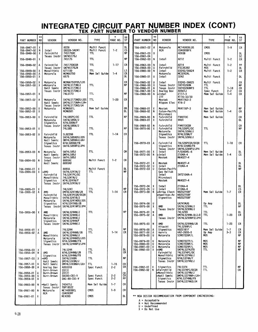
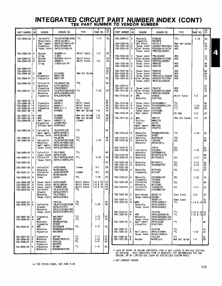
INTEGRATED CIRCUIT PART NUMBER INDEX (CONT) TEK PART NUMBER TO VENDOR NUMBER -
TYPE
- * PAGE NO - -
1-17
1-2
1-2
1-18
1-6
1-6 1-6
1-19
1-18
3-1
3- 1
1-16
-2 & 16 -2 d 16 -2 & 16
1-15
1-17 1-17
1-17
1-17 1-14 1-14
- * 'AGE NO.
1-14
1-2
1-19 1017
3-3
1-7
1-14
1-12
1-1 1
1-12 1-12
1-12
1-12
1-1 1
2-2
14 & 16
14 8 16 14 1 16
1-16
PART NUMBEI VENDOR VENDOR NO. PART NUMBEI VENDOR VENDOR NO. TYPE
F a i r c h i l d Mono1 i t h i c Na t l Semic S ignet ics Texas Ins1
Mostek Z i 1 og Mostek Mostek z i 1 og
AMD 'Signet ics S ignet ics
F a i r c h i l d Motorola S ignet ics F a i r c h i l d Motorol a S ignet ics
S ignet ics S ignet ics S ignet ics AMD
AMD AMD Nat l Semic S ignet ics S i l i c o n Ge
F a i r c h i l d Nat l Semic Texas I n s t
Fa i r ch i l d Yotorola Nat l Semic rexas I n s t
Fai r c h i l d Texas I n s t ! ' a i r c h i l d rexas I n s t l
: a i r ch i l d l o to ro la . a i r c h i l d l o to ro la Lntel
rexas I n s t l rexas I ns t r rexas I n s t l : a i r c h i l d { i t ach i l o to ro l a 'exas I n s t r
: a i r c h i l d l i t a c h i lo toro la 'exas I n s t r
i g n e t i c s 31D lo toro la i g n e t i c s MD o t o r o l a i gne t i cs
i gne t i cs o to ro la o t o r o l a i gne t i cs i gne t i cs o to ro l a
TTL
M u l t i Funct
Mu l t i Funct Mu l t i Funct
Mem Sel Gui
TTL
TTL
TTL M u l t i Funct M u l t i Funct M u l t i Funct Mem Sel Gui,
Mem Sel Gu i~ Mem Sel G u i ~ Linear
TTL
TTL TTL
TTL
TTL
.inear
.inear
r rL
l u l t i Funct f u l t i Funct l u l t i Funct T L
1 L TL
'TL TL
TL
TL TL rL
Motorola S igne t i cs NEC Micro Texas I ns t r
-Elec Arrays Texas I ns t r
Texas I n s t r -Elec Arrays Texas I n s t r Texas I n s t r Texas I n s t r
Texas I n s t r Texas I n s t r Texas I n s t r
mElec Arrays Texas I n s t r
Texas I n s t r nElec Arrays Texas I n s t r AMD Motorol a
Texas I n s t r Texas I n s t r S ignet ics Texas I n s t r Nat l Semic
AHD F u j i t s u I n t e l
~ N a t l Semic ~Syne r tek
Motorola S ignet ics Motorola F a i r c h i l d Motorola
Fa i r ch i l d Motorola Motorola Motorola
Motorola Motorola
Motorola S ignet ics
Motorola S ignet ics F a i r c h i l d Motorol a F a i r c h i l d Motorola
Burr-Brown Da te l - I n te r !
tAMD Motorola Texas I n s t r
AMD Motorola Texas I n s t r Na t l Semic S ignet ics
Na t l Semic Texas I n s t r
Mostek
TTL
Mem Sel Guid~ MOS MOS
MOS MOS
MOS MOS
MOS MOS MOS MOS
MOS MOS
M u l t i Funct
TTL TTL TTL
OP h P
Mem Sel Guidt
TTL
TTL ECL
ECL ECL
ECL
ECL ECL
ECL
ECL
ECL
ECL
Spec Funct
Spec Funct rTL '4LS151
4LS151 PCQRIDCQR ID74LS151 PIC N74LS151 NDSIJDS N74LS151NP31JP4
'TL 'TL
'TL lem Sel Guide
LACK OF ENTRY IN COLUMN INDICATES ITEM IS NOT LISTED IN MFRITEK SECTION OF CATALOG. THIS INDICATES ITEM IS OBSOLETE, NOT RECOMMENDED FOR NEW DESIGN, OR OF LIMITED USE (SUCH AS SPECIALIZED CUSTOM MASK).
NOT CURRENT VENDOR
4-29 5 5 FOR STATUS CODES, SEE PAGE 4-39.
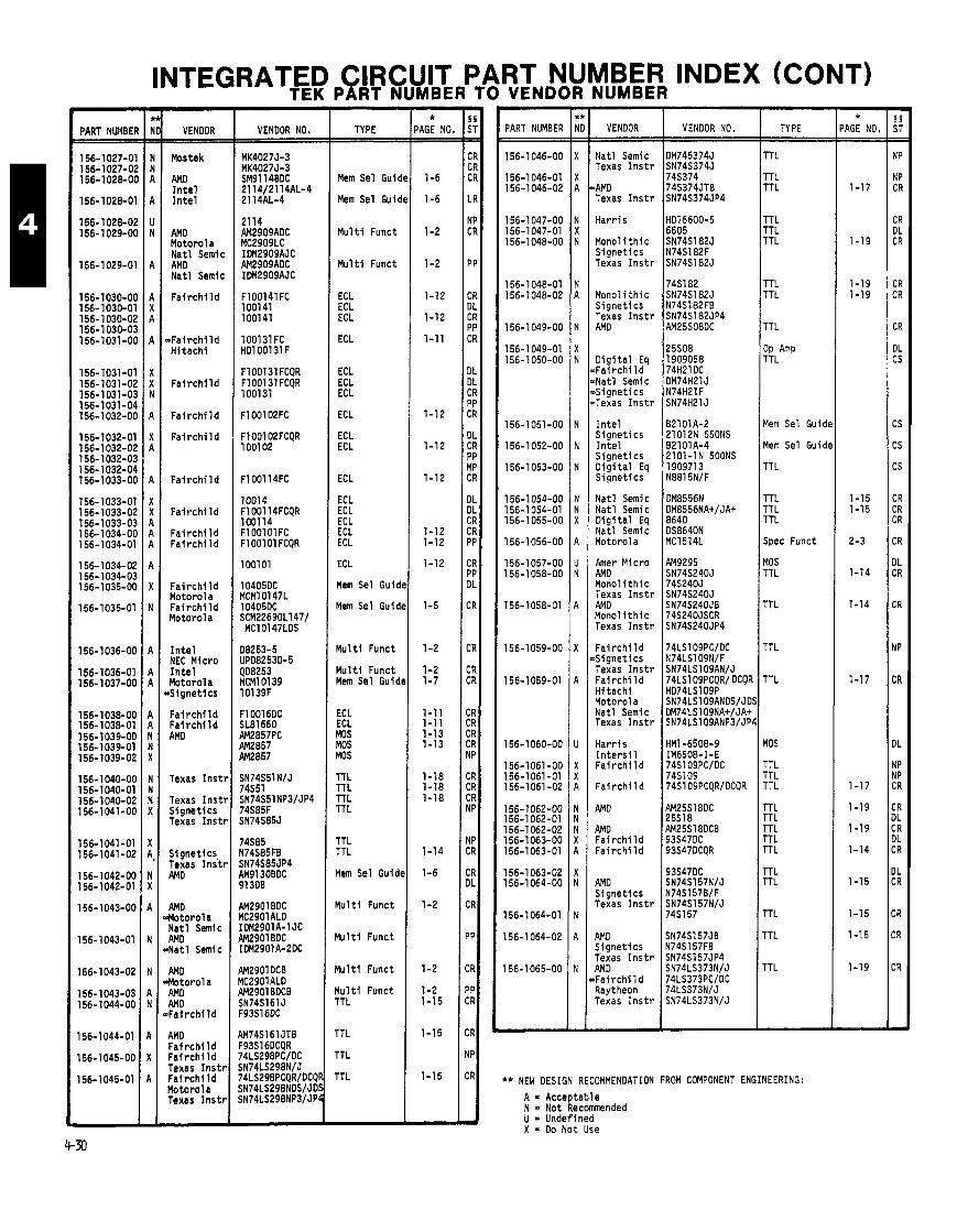
INTEGRATED CIRCUIT PART NUMBER INDEX (CONT) TEK PART NUMBER TO VENDOR NUMBER -
PART NWBEl
- VENDOR
Mostek
AMD I n t e l I n t e l
AMD Motorola Na t l Semic AM0 Na t l Semic
F a i r c h i l d
$Fa i r ch i l d H i t ach i
F a i r c h i l d
F a i r c h i l d
F a i r c h i l d
F a i r c h i l d
F a i r c h l l d
F a i r c h i l d F a i r c h i l d
Fa i r ch i l d Motorol a Fa i r ch i l d Motorola
I n t e l NEC Micro I n t e l Motorola S igne t i cs
F a i r c h i l d F a i r c h i l d AMD
Texas I n s t r
Texas I n s t r S ignet ics Texas I n s t r
Signet ics, Texas I n s t r AM0
AMD Motorola Na t l Semic AM0 Na t l Semic
AM0 Motorola AMD AMD Fa i r ch i I d
AMD F a i r c h l l d Fa i r ch i l d Texas I n s t r F a i r c h l l d Motorola Texas I n s t r
VENDOR NO.
FlOOl3l FCQR F100131 FCQR 100131
1001 4 F100114FCQR 100114 F l 001 01 FC F l 001 01 FCQR
AM2901BOC MC2901 ALD IDM2901A-1 JC AM2901BOC IDM2901A-2OC
AM2901 DCB MC2901ALD AM2901 BDCB SN74S161 J F93S16DC
4M74Sl6l JTB F93S16OCQR 74LS298PC/DC SN74LS298NIJ 74LS298PCQR/DCQl SN74LS298NOS/JD! SN74LS298NP3/JPl
TYPE
Mem Sel Guic
Mem Sel Guic
M u l t i Funct
M u l t i Funct
ECL ECL ECL
ECL
ECL ECL ECL
ECL
ECL ECL
ECL
ECL ECL ECL ECL ECL
ECL
Mem Sel Guic
Mem Sel Guic
M u l t i Funct
M u l t i Funct Mem Sel Guid
ECL ECL MOS MOS MOS
TTL TTL TTL TTL
TTL TTL
Mem Sel Guid
M u l t i Funct
M u l t i Funct
M u l t i Funct
M u l t i Funct TTL
TTL
TTL
TTL
- *
'AGE NC - -
1-6
1-6
1-2
1-2
1-12
1-12
1-11
1-12
1-12
1-12
1-12 1-12
1-12
1-5
1-2
1-2 1-7
1-11 1-11 1-13 1-13
1-18 1-18 1-18
1-14
1-6
1-2
1-2
1-2 1-15
1-15
1-15
'ART NUMBER
56-1 046-00
56-1 046-01 56-1 046-02
56-1047-00 56-1047-01 56-1 048-00
56-1 048-01 56-1 048-02
56-1 049-00
56-1 049-01 56-1 050-00
56-1051-00
56-1 052-00
56-1 053-00
56-1 054-00 56-1054-01 56-1 055-00
56-1056-00
56-1057-00 56-1 058-00
56-1058-01
56-1 059-00
56-1 059-01
56-1 060-00
56-1061-00 56-1061 -01 56-1061 -02
56-1062-00 56-1 062-01 56-1 062-02 56-1 063-00 56-1 063-01
56-1 063-02 56-1 064-00
56-1 064-01
56-1 064-02
56-1065-00
VENDOR
Nat l Semic Texas I n s t r
>AM0 Texas I n s t r
Har r is
Monol i t h i c S ignet ics Texas I n s t r
Mono l i t h i c S igne t i cs Texas I n s t r AM0
D i g i t a l Eq +a i r ch i l d ~ N a t l Semic 6 i g n e t i c s >Texas I n s t r
I n t e l S ignet ics I n t e l S ignet ics O i g i t a l Eq S ignet ics
Nat l Semic Nat l Semic D i g i t a l Eq Na t l Semic Motorola
h e r Micro AM0 Mono l i t h i c Texas I n s t r AM0 Monol i t h i c Texas I n s t r
F a i r c h i l d 6 i g n e t i c s Texas I n s t r F a i r c h i l d Hi t ach i Motorol a Na t l Semic Texas I n s t r
Ha r r i s I n t e r s i l F a i r c h i l d
F a i r c h i l d
AM0
AMD F a i r c h i l d Fa i r ch i l d
AMD Signet ics Texas I n s t r
AMD Signet ics Texas I n s t r AMD ~ F a i r c h i 1 d Raytheon Texas I n s t r
VENDOR NO. TYPE
TT L
TT L TTL
TTL TTL TTL
rTL TTL
TTL
JP b P TTL
4em Sel Gu id~
4em Sel Guidc
TTL
TTL TTL TTL
Spec Funct
10s TTL
TTL
TTL
TTL
10s
TTL TTL TTL
TTL TTL TTL TTL TTL
TTL TTL
TTL
TTL
TTL
** NEW DESIGN RECOMMENDATION FROM COMPONENT ENGINEERING:
A = Acceptable N = Not Recomnended U = Undefined X = Do Not Use
- * AGE NO. -
1-17
1-1 9
1-19 1-19
1-15 1-15
2-3
1-14
1-14
1-17
1-17
1-19
1-19
1-14
1-15
1-15
1-15
1-19
-
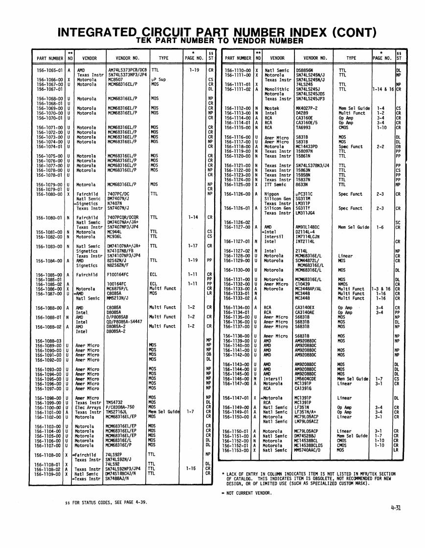
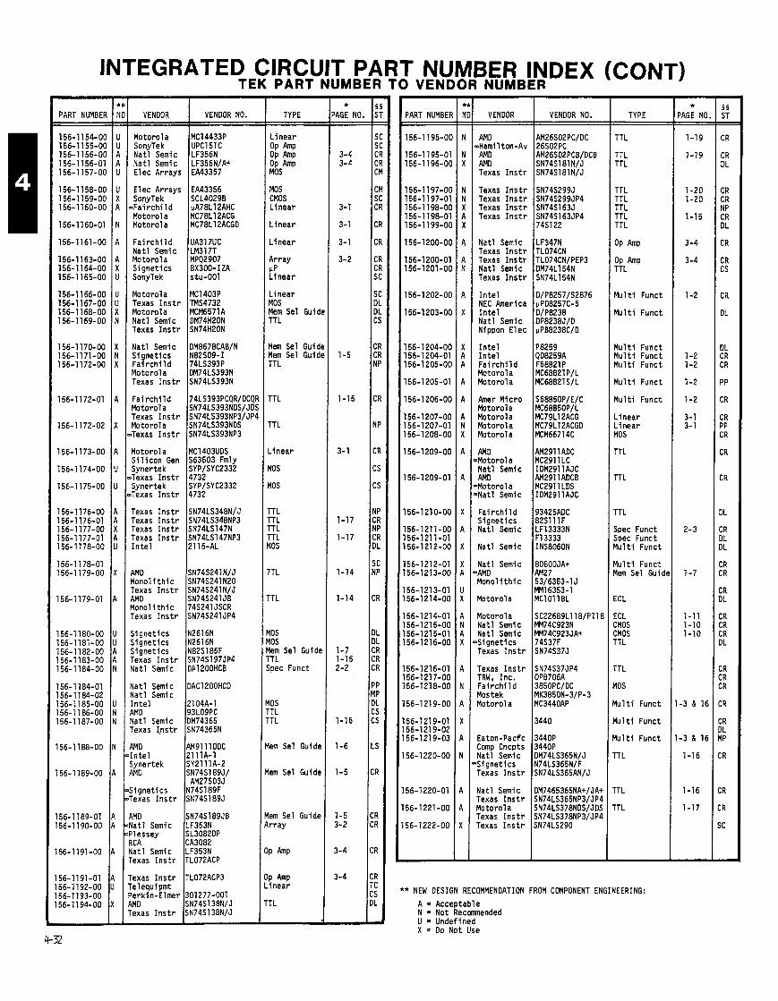
INTEGRATED CIRCUIT PART NUMBER INDEX (CONT) TEK PART NUMBER TO VENDOR NUMBER
PART NUMBER VENDOR VENDOR NO.
Motorola SonyTek Na t l Semic Na t l Semic Elec Arrays
Elec Arrays EA43356 SonyTek SCL40298
~ F a i r c h i l d uA78L12AHC Motorola MC78L12ACG Motorola MC78L12ACGD
F a i r c h i l d UA317UC Na t l Semic LM317T Motorola MPQ2907 S ignet ics 8x300-IZA SonyTek stu-001
Motorola MC1403P Texas I n s t r TMS4732 Motorola MCM6571A Na t l Semic DM74H20N Texas I n s t r SN74H20N
Na t l Semi c I D M ~ ~ ~ ~ C A B / N Signet ics N82S09-I Fa i r ch i l d 74LS393P Motorola I DM74LS393N ... . - Texas I n s t r 1 ~ ~ 7 4 ~ ~ 3 9 3 ~
Fai r c h i l d 74LS393PCQR/DCQR Motorola SN74LS393NDS/JDS Texas I n s t r SN74LS393NPVJP4 Motorola SN74LS393NDS ,Texas I n s t r SN74LS393NP3
Motor01 a MC1403UDS S i l i c o n Gen 563503 Fmly Synertek SYP/SYC2332 >Texas I n s t r 4732 Synertek SYP/SYC2332 )Texas I n s t r I 4732
Texas I n s t r Texas I n s t r Texas I n s t r Texas I n s t r I n t e l
AM0 SN74S241N/J Mono1 i t h i c SN74S241N20 Texas I n s t r SN74S241N/J AMD SN74S241JB Monol i t h i c 74S24l JSCR Texas I n s t r SN74S241JP4
Signet ics N2616N Signet ics N2616N Signet ics N82S185F Texas I n s t r SN74S197JP4 Nat l Semic DA1200HCB
Nat l Semic DAC1200HCD Nat l Semic I n t e l 21 04A- 1 AMD 93L09PC Natl Semic DM74365 Texas 1,nstr SN74365N
4MD IAM9111 DDC I n t e l 2111A-1 Synertek SY2111A-2 4MD SN74S189Jl
j i gne t i cs N74S189F rexas I n s t r SN74S189J
WO SN74S189JB Vat1 Semic LF353N 'lessev SL3082DP KA CA3082 I a t l Semic LF353N rexas I n s t r TL072ACP
lelequipmt
TYPE
L inear OP Amp OP Amp OP Amp MOS
MOS CMOS L inear
L inear
L inear
Array vp L inear
Linear Y 0s Yem Sel Guid TTL
lem Sel Guid lem Sel Guid rTL
rTL
TTL
. inear
10s
10s
'T L T L 'T L 7 L 10s
'TL
'T L
10s 10s lem Sel Guidc TL pec Funct
0s TL TL
em Sel Guide
em Sel Guide
em Sel Guide r r a y
1
I Amp lnear
rL
116; No. 1:
A
PART NUMBEI
156-1 1 95-Ol
156-1 195-0' 156-1196-O(
156-1 197-O( 156-1 197-01 156-1 198-O( 156-1 198-01 156-1199-O(
156-1200-O(
156-1200-01 156-1201-O(
156-1 202-Ot
156-1203-Ot
156-1 204-OC 156-1204-01 156-1 205-O(
156-1 205-01
156-1206-OC
156-1207-OC 156-1 207-01 156-1208-OC
156-1 209-OC
156-1209-01
156-1210-OC
156-1211-00 156-121 1-01 156-1212-00
156-1212-01 156-1213-00
56-1213-01 56-1214-00
56-1214-01 56-1215-00 56-1215-01 56-1216-00
56-1216-01 56-121 7-00 56-1218-00
56-1219-00
56-121 9-01 56-1219-02 56-1219-03
56-1220-00
56-1 220-01
56-1 221-00
56-1222-00
VENDOR I VENDOR NO.
I AM0 AM26S02PC/DC >Hamil ton-Av 26S02PC AMD AM26S02PCB/DCB AMD SN74S181N/J Texas I n s t r SN74S181N/J
Texas I n s t r SN74S299J Texas I n s t r SN74S299JP4 Texas I n s t r SN74S163J Texas I n s t r SN74S163JP4
745122
Na t l Semic LF347N Texas I n s t r TL074CN Texas I n s t r TL074CN/PEP3 Na t l Semi c DM74L154N Texas I n s t r SN74L154N
I n t e l D/P8257/S2876 NEC America uPO8257C-5 I n t e l DIP8238 Na t l Semic DP8238JID Nippon Elec uPB8238C/D
I n t e l 1~8259 I n t e l 1 ~ ~ 8 2 5 9 ~ F a i r c h i l d F68821P Motorola MC68821P/L Motorola MC68B21S/L
h e r Micro 1 ~ 6 8 ~ 5 0 ~ / E / C Motorola ~ ~ 6 8 8 5 0 k ' l ~ Motorola MC79L12ACG Motorola MC79L12ACGD Motorola MCM66714C
AMD I ~ ~ 2 9 i i ADC
Motorola MC29ll LDS Na t l Semic IDM29llAJC I Fa i r ch i 1 d 93425ADC Signet ics 82S l l l F Nat l Semic LF13333N
F13333 Nat l Semic INS8060N
Nat l Semic 1 ~ O ~ O D J A +
Motorola I F I c i O i i 8 ~ '
Motor01 a SC22689L118/P118 Nat l Semic MM74C923N Nat l Semi c MM74C923JAt S ignet ics 74S37F Texas I n s t r SN74S37J
Texas I n s t r 1 ~ ~ 7 4 ~ 3 7 ~ ~ 4 TRW, Inc. OP8706A Fa i r ch i l d 3850PC/DC Mostek MK3850N-31P-3
I Motorol a MC3440AP
Eaton-Pacfc 3440P Cano C n c ~ t s I 3440P ~ a t i ~em' ic OM74LS365N/J Signet ics N74LS365N/F Texas I n s t r SN74LS365AN/J
Yatl Semic rexas I n s t r Yotorola rexas I n s t r Texas I n s t r
TYPE
TTL
TTL TTL
TT L TTL TTL TT L TTL
OP Amp TTL
M u l t i Funct
M u l t i Funct
M u l t i Funct M u l t i Funct M u l t i Funct
M u l t i Funct
M u l t i Funct
L inear L inear MOS
TTL
TTL
Spec Funct Spec Funct M u l t i Funct
M u l t i Funct Mem Sel Guidc
ECL
TTL
MOS
M u l t i Funct
M u l t i Funct
M u l t i Funct
TT L
TTL
TT L
* NEW DESIGN RECOMMENDATION FROM COMPONENT ENGINEERING:
A = Acceptable N = Not Recommended U = Undefined X = Do Not Use
- *
'AGE NO - 1-19
1-19
1-20 1-20
1-15
3-4
3-4
1-2
1-2 1-2
1-2
1-2
3- 1 3-1
2-3
1-7
1-11 1-70 1-10
-3 & 16
-3 & 16
1-16
1-16
1-1 7

INTEGRATED CIRCUIT PART NUMBER INDEX (CONT) lR NUMBER PART I
TYPE
Mem Sel Guic
Spec Funct
Spec Funct Spec Funct Spec Funct
Spec Funct
Mem Sel Guid
k m Sel Guid
Mem Sel Guid
l-rL
rTL
l u l t i Funct l u l t i Funct l u l t i Funct l u l t i Funct l u l t i Funct
T L
ipec Funct
. inear
inear
MOS
MOS 0s
u l t i Funct
TL
TL
inear
r ray
JMBE - * PAGE NO. -
I VENC - PART NUMBE
156-1250-0
156-1251-0 156-1 252-0 156-1252-0
156-1 253-0 156-1 254-0 156-1255-0
156-1255-0
156-1255-01 156-1256-01
156-1257-01 156-1257-0' 156-1 258-01
156-1258-0'
156-1259-O( 156-1 260-O(
56-1261-O(
56-1261-01 56-1261-02 56-1 262-Ot
56-1263-O(
56-1264-01
56-1 265-OC
56-1 266-06 56-1266-01 56-1267-00
56-1 267-01
56-1268-00 56-1268-01
56-1269-00 56-1270-00
56-1271-00 56-1 272-00
56-1273-00 56-1 273-01 56-1 274-00 56-1275-00
- * AGE N - -
1-19
1-20 1-17
1-19 2-2
2-2
2-3
1-3
1-17
2-2 3-1
3-1
3-1 3-1
3-1
3- 1
3-1
1-18
1-18
2-2 2-2
1-19 2-3
3-3
1-14 1-10
1-14
1-6 1-10
VENDOR I VENDOR NO. VENDOR VENOOR NO. TYPE
F a i r c h i l d 93422 d a t l Semic SL42367 Motorola MC7086C Na t l Semic LM393N Signet ics LM393N
TTL
TTL TTL TTL
Mu l t i Funct TTL Spec Funct
Spec Funct
Spec Funct
M u l t i Funct
TTL
TTL
Spec Funct Linear
Linear
Linear Linear Linear
Linear
.inear
.f near
.inear TTL
'TL
ipec Funct ipec Funct
'TL ipec Funct
inear IP Amp
TL TL MOS TL
TL TL
TL
AM0 Texas I n s t r Na t l Semic Texas I n s t r Texas I n s t r
Na t l Semi c LM393N/A+ LH393
AMD AM3190 Na t l Semic LM319J S ignet ics LM319FH
AM74S373NB/JB SN74S373NP3/JP4 DM86LS62JAt SN74LS148NP3 SN74LS148NP3/JP
AMD LM319D/883B Na t l Semic LM319J/A+ .Fa i rch i ld F10470DC
Motorola S ignet ics
oAMD Motorol a Prec. Mono
~ S i g n e t i c s
.AMD I DAC-08HQ8 Motorol a DAC-08HQDS Prec. Mono DAC-081569
68800 N82S107I OACOEHQ DAC08HQ DACDBHQ NE5009F
F u j i t s u MBM10470-20 Hi t ach i HM10470DG NEC America 010470
F a i r c h i l d F104700C F u j i t s u MBM10470-20 H i t ach i HM6147
I n t e r s i l .Natl Semic
I n t e l I 0 8 2 9 1 ~
IH5010CJD/CDD AM971 0CN
I n t e l Motoro la MCM2147C70 NEC America I D2147D-2. CD2i47H 70NS
Motorola Na t l Semic Texas I n s t r
Motorol a Na t l Semic Texas I n s t r Analog Dev Motorola Na t l Semic
SN74LS112N/J OM74LS112N/J SN74LS112N/J
2147 'AMD SN74LS258N Signet ics N74LS258ANIF Texas I n s t r SN74LS258N/J Fa i r ch i l d 74LS258PCQR/OCl Nat 1 Semi c DM74LS25BNAW JJ S ignet ics N74LS258NBIFB Texas I n s t r SN74LS258NP3/JI
S ignet ics N8T32-001P Signet ics N8T32-002P Signet ics N8T32-003P Signet ics N8T32-004P Si gnet i cs NBT32-005P
F a i r c h i l d Motorola
Motorola Na t l Semic Texas I n s t r
vA78L15AWC MC78L15ACP 78L15ACP MC78L15ACPO LM34lP-15.OTB uA78M15CKF
S i l i con i x DG181BA Optron, I nc 0PB4428 Spectronics SPX 1874-2 TRW, Inc. 0PB4428
Na t l Semic Texas I n s t r Na t l Semfc Texas I n s t r Nippon Elec
LM314P-5.OTB pS78M05CKF LM79M12CPTB uA79M12CKF UPC458C
Ben Elec H21A2 ;en Elec Hl lCX604 ioneywel 1 SC511 C6 lonsanto MCS2400 jynertek C41087/SYP2332
Motorol a Motorola Motorola Nat l Semic Texas I n s t r
F a i r c h i l d 1 ~ ~ 8 2 5 8 9
SC77ll3LH SC71196LH SN74LS1 5NDS/JDS DM74LS15NA+/JA+ SN74LS15NP3/JP4
Yotorola SN74LS15NOS/JDS Texas I n s t r SN74LS15NP3/JP4 S i l i c o n i x LDl l lACJ S i l i c o n i x 1 ~ 0 1 1 1 ~
(at1 Semic DM74LS47N 'exas I n s t r SN74LS47N I a t l Semic OM74LS47NA+/JA+ 'exas I n s t r SN74LS47NPWJP4 l o to ro la MC78L08ACG l a t l Semic LM78L08ACH
Signet ics Yatl Sernic Vec. Mono l o t o r o l a I xa r j i gne t i cs
N82S100I LF11508D MUX08FQ MC1410 XR5532CN NE5532FE-IIB
lo toro la 1 ~ ~ 1 4 1 3 ~ ~ ~ 1 A1
WD \MO [ n t e r s i l i i g n e t i c s rexas I n s t r
;Prague Elec ULN2003AP b t o r o l a SC80909L lo toro la MC6848BLD a i r c h i l d 1 101300C
AM25LS2521PC 25LS125PCBZ/DCB2 ICM213IPO N74LS96N SN74LS96N
M u l t i Funct M u l t i Funct ECL
i i gne t i cs 'exas I n s t r l o to ro la l a t l Sernic
lo toro la i gne t i cs
a i r c h i l d o to ro la i gne t i cs lessey nalog Oev
MO exas I n s t r MO on01 i t h i c exas I n s t r
'exas I n s t r SN74LS13N/J I ECL 74LS13
IMD AM81 LS95NBIJB a t 1 Semi c OM81 LS95NA+/JA+ n t e l CD2115A C A CP018570
TTL TTL
ECL Linear Mem Sel Guide
CMOS TTL i
* LACK OF ENTRY IN COLUMN INDICATES ITEM I S NOT LISTED IN MFR/TEK SECTION OF CATALOG. THIS INDICATES ITEM IS OBSOLETE, NOT RECOFMENDED FOR NEW DESIGN, OR OF LIMITED USE (SUCH AS SPECIALIZED CUSTOM MASK). - NOT CURRENT VENDOR.
§ § FOR STATUS CODES, SEE PAGE 4-39.

INTEGRATED CIRCUIT PART NUMBER INDEX (CONT)
PART NUMBEF VENDOR
RC A I n t e l Motor01 a RCA
F a i r c h l l d Motorola Fa i r ch i l d S ignet ics Texas I n s t t
S ignet ics Texas I n s t r F a i r c h l l d Motorola S lgnet ics
Texas I n s t r Texas I n s t r
Texas I n s t AMD F a i r c h i l d AMD Plessey RCA
Texas I n s t r Texas I n s t r F u j i t s u F u j i t s u Synertek
Synertek
F u j i t s u F u j i t s u
Plessey Plessey Semi Process S ignet ics Semi Process
Motorola Texas I n s t r S i l i c o n i x S i l i c o n i x
Burr-Brown Raytheon S i l i c o n Gen
F a i r c h i l d
Harr is I n t e r s i l I n t e r s i l
Signet ics
Jrec. Mono b t o r o a a rexas I n s t r l o to ro la WD Ja t l Semic rexas I n s t r
WD l a t l Semlc l o to ro la i i gne t i cs 'exas I n s t r
ICA lo toro la IC A l yb r i d Sys inalog Oev
TEK PART NUMBER TO VENDOR NUMBER
VENDOR NO.
N74S09NB/FB SN74S09N3/J4 101 OOPC MClOl OOP Nl 01 OOB
M u l t i Funct Mem Sel Guic CMOS
L inear Spec Funct TTL
TTL
ECL
MOS MOS MOS OP Amp TTL
TTL Mem Sel Guid
Mem Sel Guid Array
M u l t i Funct M u l t l Funct Mem Sel Guid Mem Sel Guid Mem Sel Guid~
Mem Sel Guid~ STTL TTL Yem Sel Guid~ Yem Set Guid~
ECL ECL Spec Funct
Spec Funct
Spec Funct Spec Funct
Spec Funct .inear
.inear
.CL
l u l t i Funct
l u l t i Funct l u l t i Funct ipec Funct
;pet Funct 'TL
'TL 'TL
'TL
TL
MOS MOS
pec Funct i nea r
- *
PAGE NO =
1-2 1-6 1-10
3-1 2-3 1-18
1-18
1-11
3-4 1-14
1-14 1-5
1-5 3-2
1-2 1-2 1-5 1-5 1-6
1-6
1-5 1-5
1-12 2-3 & 3-
2-2 2-2
2-2
1-12
1-2
1-2 2-2
2-3 1-20
1-16
1-16
1-19
1-10 1-9
2-2 3- 1
-
PART NUMBEF VENOOR
AM0 AMD Na t l Semic Texas I n s t r AM0 Texas I n s t r
Na t l Semic Na t l Semic S ignet ics Analog Dev
F a i r c h i l d
Na t l Semic Na t l Semic Na t l Semic S ignet ics Texas I n s t r
S iqnet ics Exar S ignet ics Texas I n s t r S ignet ics
Motorola RC A Motorola RCA F a i r c h i l d Na t l Semic
F a i r c h i l d Nat l Semic h e r Micro Fa i r ch i l d Yotorola
h e r Micro F a i r c h i l d Yotorola S ignet ics Plessey
TRW, Inc. Fa i r ch i l d Yatl Semic Yatl Semic ?CA
?C A
wo Signet ics rexas I n s t r
l a t l Semic j i gne t i cs rexas I n s t r
l a t l Semic IC A
los tek i ippon Elec
j i gne t i cs
\MD lo to ro la \MO ' n t e l IEC Micro l ippon Elec
VENOOR NO.
MC14071 BCL CD4071BF MC14071 BCLO C04071 BFX F40098BDC MM80C98J
TYPE
Mem Sel Guid Mem Sel Guid Spec Funct Mem Sel Guid TTL
CMOS CMOS TTL ~p;c Funct TTL
TTL TTL TTL TTL TTL
M u l t i Funct M u l t i Funct CMOS OP Amp
Spec Funct
CMOS
CMOS
CMOS
CMOS
M u l t i Funct
Mu1 t i Funct
Mem Sel Guidr Spec Funct
Spec Funct MOS TTL L inear Array
Array TTL TTL
TTL
CMOS
Yem Sel Guide
Yem Sel Guide
Yul t i Funct
NEW DESIGN RECOMMENDATION FROM COMPONENT ENGINEERING:
A = Acceptable N = Not Recomnended U = Undefined X = Do Not Use
- *
'AGE NO - - 1-6 1-6 2-3 1-7 1-17
1-9
1-20 2-2
1-19
1-2
1-10 3-3
3-3 3-3
2-3
1-9
1-9
1-9
1-2
1-2
1-7 2-3
2-2 1-1 3 1-14 3-1 3-2
1-15
1-15
1-9
1-4
1-7
1-2
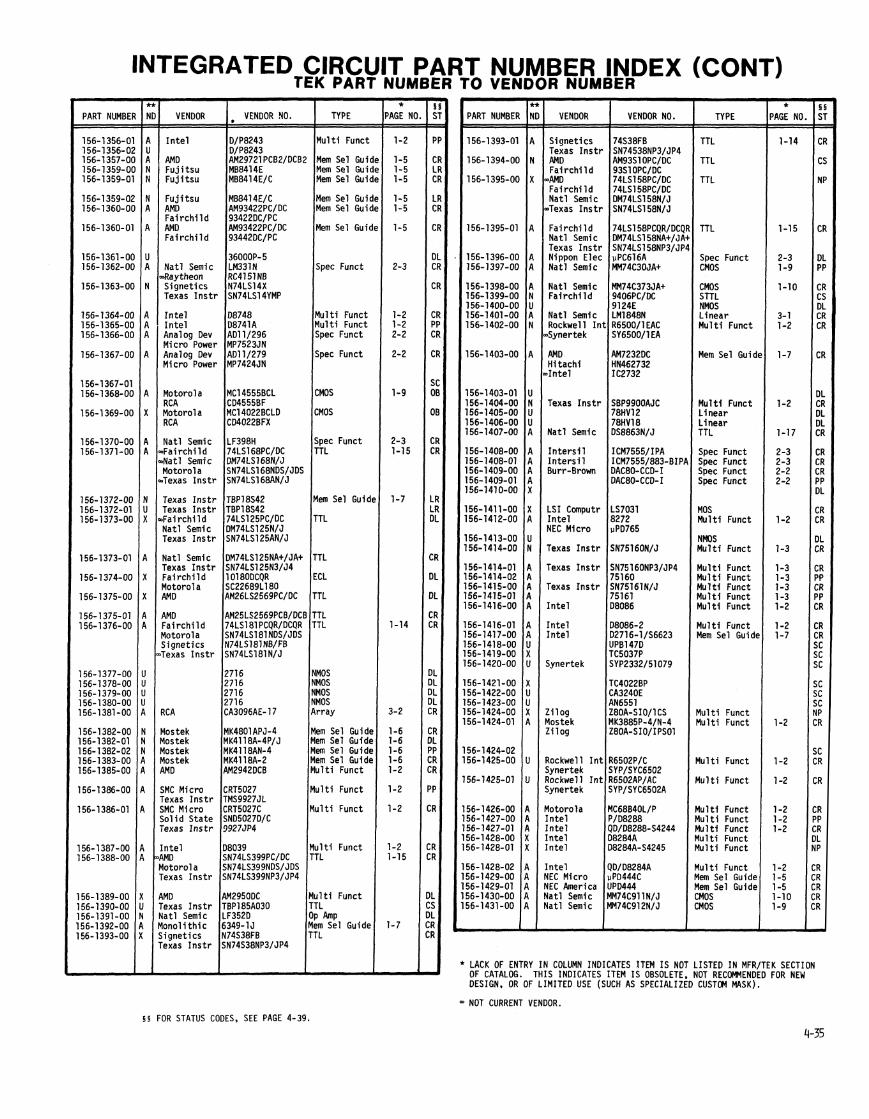

INTEGRATED ClRCUl
PART NUMBEf
156-1432-O(
156-1432-01
156-1432-02
156-1433-Ot
156-1434-OC 156-1435-OC 156-1436-O( 156-1437-O(
156-1 438-OC 156-1439-OC 156- 1440-OC 156-1441-OC 156-1441-01
156-1442-OC 156-1443-OC 156-1 444-OC 156-1444-01 156-1444-02
156-1445-OC 156-1445-01 156-1445-02 156-1446-OC 156-1446-01
156-1 446-02
156- 1447-OC 156-1448-OC
156-1448-01 156-1 449-00 156-1450-06 156-1451-OC 156-1452-06
156-1453-OC 156-1454-OC 156-1454-01 156-1 455-OC
156-1 456-OC
156-1457-OC 156-1457-02 156-1458-00 156-1458-01 156-1459-00
156-1460-00 156-1461-00
156-1461-01 156-1461-02
156-1462-00 156-1463-00 156- 1464-00 156-1465-00 156-1466-00
156-1467-00 156-1468-00 156-1 469-00 156-1470-00 156-1471-00
156-1472-00 156-1473-00 156-1474-00 156-1475-00 156- 1476-00
VENOOR
F a i r c h i l d Motorola S igne t i c s Texas I n s t r
F a i r c h i l d Motorola S igne t i c s Texas I n s t r Na t l Semic
I n t e l I n t e r s i 1 Motorola Motorol a Prec. Mono
Texas I n s t r Motorola Gen Elec TRW LSI Pro Texas I n s t r
I n t e l Burr-Brown Texas I n s t r Texas I n s t r Texas I n s t r
Motorola Motorola
S igne t i c s S igne t i c s
Exar S ignet ics SonyTek F a i r c h i l d Texas I n s t r
F a i r c h i l d Plessey RC A Na t l Semic Na t l Semic
Mono l i t h i c Na t l Semic Na t l Semic I n t e l Na t l Semic
AM0 I n t e r s i l Na t l Semic Analog Oev
Motorola
Texas I n s t r
S ignet ics F a i r c h i l d I n t e l I n t e l
4MO '
Ha r r i s
Har r is Har r is
S ignet ics 'rec. Mono
7CA
1MO
l o t o r o l a
VENDOR NO. TYPE
TTL
TTL
TTL
MOS
M u l t i Funct Spec Funct L i nea r L i nea r
Mem Sel Gu id~ L i nea r
Spec Funct Spec Funct
M u l t i Funct Spec Funct M u l t i Funct M u l t i Funct M u l t i Funct
M u l t i Funct
M u l t i Funct OP &P OP Amp
TTL
TTL ECL Array L inear Mem Sel Guidt
Mem Sel Guidc TTL TTL M u l t i Funct
TTL
Spec Funct Spec Funct MOS MOS Mu1 t i Funct
M u l t i Funct Mem Sel Guidt
Mem Sel Guidf
Mem Sel Guide ECL MOS TTL TTL
MOS L inear L inear L inear L inear
Linear ZMOS TTL 40s ECL
' P MBE - * 'AGE NO - -
1-16
1-16
1-16
1-13
1-2 2-2 3-1 3-1
1-7 3-1
2-2 2-2
1-2 2-2
1-3 1-3
1-2
1-2 3-3 3-3
3-3
1-15
1-15 1-12 3-2 3-1 1-7
1-7 1-17 1-17
-2 & 1:
1-20
2-2 2-2 1-13 1-13 1-3
1-2 1-6
1-6
1-7
-
LRT NUMBER INDEX (CONT) R NUMBER
PART NUMBER
156-1477-00 156-1478-00
156-1478-01
156-1 479-00
156-1 479-01
156-1 480-00
156-1481-00
156-1482-00
156-1 483-00 156-1 484-00 156-1 485-00 156-1486-00
156-1487-00 156-1488-00 156-1489-00 156-1490-00 156-1491-00
156-1492-00 156-1492-01 156-1 493-00 156-1 494-00
156-1494-01
156-1495-00
156-1 495-01 156-1496-00
156-1 496-01 156-1 497-00
156-1498-00
156-1499-00
156-1 499-01
156-1 500-00
156-1 500-01 156-1501-00
156-1501-01 156-1502-00
156-1503-00 156-1 504-00
156-1 505-00
156-1506-00
156-1507-00
156-1508-00
VENDOR
Motorola RCA Motorola RC A
AMD Na t l Semic AMD Na t l Semic Motorola Na t l Semic RCA
AMD Fa i r ch i l d Texas I n s t r MOS Tech Rockwell Synertek
I n t e r s i l EMM M ic ro E lec Motorola RC A
Motorola Micro E lec Micro Elec I n t e r s i l Gen Elec
Analog Oev Analog Oev Prec. Mono AMD Amer M i c ro Motorola
Amer M i c ro Motorola F a i r c h i l d Motorol a S igne t i c s
Fa i r ch i l d S igne t i c s
Fa i r ch i l d S igne t i cs
F a i r c h i l d S igne t i c s F a i r c h i l d S igne t i c s
F a i r c h i l d S igne t i c s
F a i r c h i l d S igne t i c s
F a i r c h i l d S igne t i c s
F a i r c h i l d S igne t i c s F a i r c h i l d S igne t i c s
F a i r c h i l d S igne t i c s F a i r c h i l d S igne t i c s Fa i r ch i l d S igne t i c s
VENOOR NO.
TL494 MC14081 BCL C04081 BF MC14081BCLOS CD4081 BFX
TYPE
L inea r CMOS
CMOS
TTL
TTL
CMOS
TTL
M u l t i Funct
Spec Funct Mem Sel Gu id~ OP Amp TTL
TTL OP &P OP Amp L inear
OP Amp OP Amp L inea r M u l t i Funct
M u l t i Funct
ECL
ECL
ECL
ECL
ECL
ECL
ECL
ECL
ECL
L inear ECL
ECL
ECL
ECL
ECL
** NEW DESIGN RECOMMENDATION FROM COMPONENT ENGINEERING:
A = Acceptable N = Not Recomnended X = Undefined u = DO ~ o t Use
- * 'AGE NO,
1-9
1-14
1-14
1-20
1-2
2-2
1-1 0
3-1
3-4 3-4
1-2
1-2
1-11
1-11
1-12
1-12
1-12
1-1 2
1-12
1-11
1-11
3-1 1-11
1-11
1-12
1-11
1-11
-
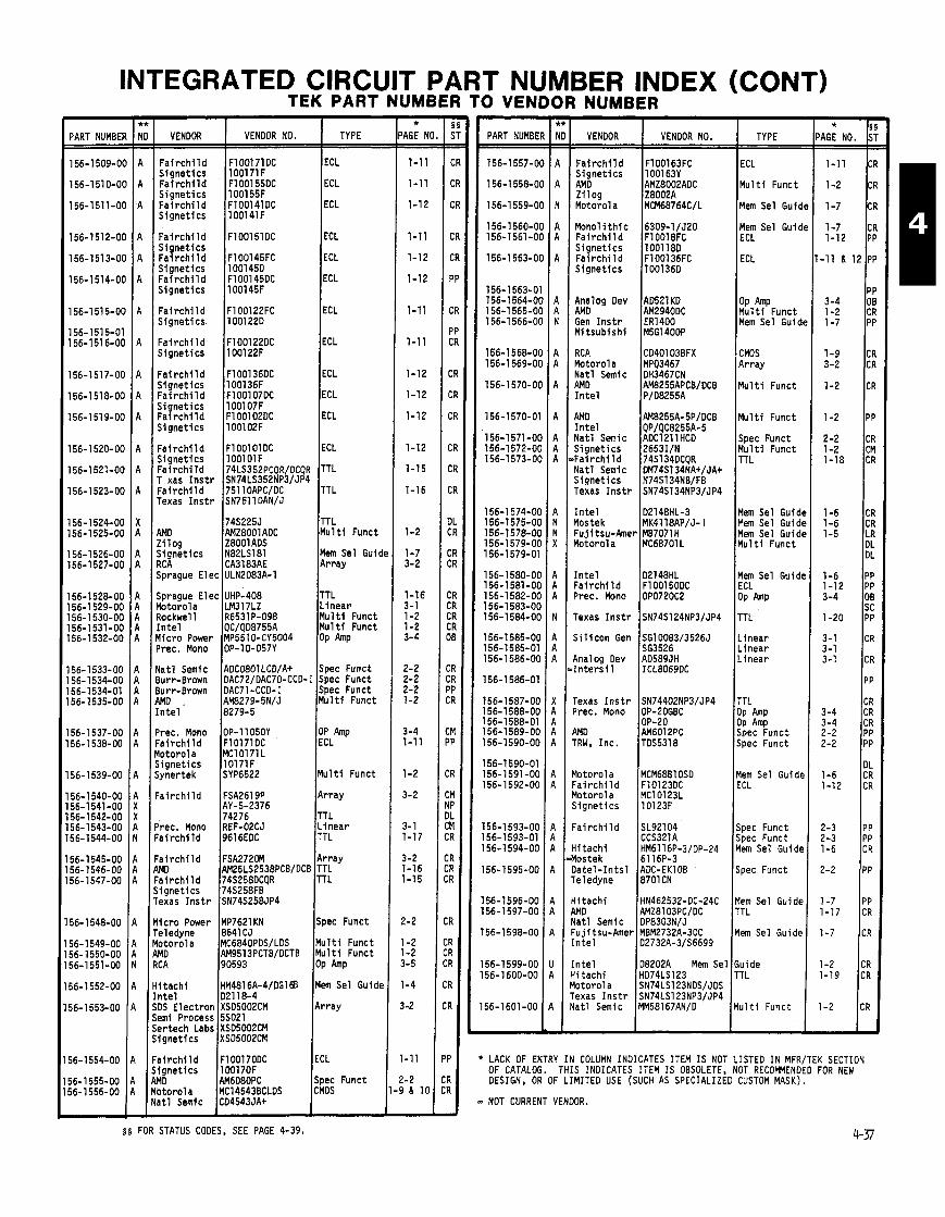
INTEGRATED ClRCU TEK PART I
T PART NUMBER INDEX (CONT) 'UMBER TO VENDOR NUMBER - *
AGE NC - - 1-11
1-11
1-12
1-11
1-12
1-12
1-11
1-11
1-12
1-12
1-12
1-12
1-15
1-16
1-2
1-7 3-2
1-16 3-1 1-2 1-2 3-4
2-2 2-2 2-2 1-2
3-4 1-11
1-2
3-2
3- 1 1-17
3-2 1-16 1-15
!-2
1-2 1-2 3-5
1-4
1-2
-11
- 2 11 10
A
PART NUMBEF
156-1 509-Ot
156-1510-Ot
156-1511-OC
156-1512-OC
156-1 51 3-OC
156-1514-06
156-1 51 5-00
156-1515-01 156-1516-00
156-1517-00
156-1518-00
156-1 51 9-00
156-1520-00
156-1521-00
156-1523-00
156-1524-00 156-1525-00
156-1 526-00 156-1 527-00
156-1528-00 56-1 529-00 56-1 530-00 56-1531-00 56-1532-00
56-1533-00 56- 1534-00 56-1 534-01 56- 1535-00
56-1 537-00 56-1538-00
56-1539-00
56-1 540-00 56-1541-00 56-1542-00 56-1 543-00 56-1 544-00
56-1545-00 56- 1546-00 56-1547-00
56- 1548-00
56-1 549-00 56- 1550-00 56-1551-00
56-1 552-00
56-1 553-00
56-1554-00
56-1 555-00 56-1 556-00
VENDOR 1 VENDOR NO. 1 TYPE PART NUMBE
156-1 557-0
156-1558-0
156-1559-0
156-1 560-0 156-1561-0
156-1 563-0
156-1 563-0 156-1564-0 156-1 565-0 156-1566-01
156-1 568-01 156-1 569-01
156-1 570-01
156-1570-0
156-1571-01 156-1572-01 156-1573-01
156-1 574-01 156-1575-01 156-1578-01 156-1579-01 156-1579-0'
156-1 580-01 156-1 581 -O( 156-1 582-O( 156-1583-O( 156-1584-O(
156-1585-O( 156-1585-01 156-1 586-O(
156-1586-01
156-1587-Ot 156-1588-OC 156-1588-01 156-1 589-OC 156-1 590-OC
156-1590-01 156-1591-OC 156-1592-06
156-1 593-00 156-1593-01 156-1 594-00
156-1595-00
156-1596-00 56-1 597-00
56-1598-00
56-1599-00 56-1 600-00
56-1601 -00
M u l t i Funct
Mem Sel Guidc
ECL
ECL
ECL
ECL
ECL
ECL
F a i r c h i l d F100171DC Signet ics 100171 F F a i r c h i l d F100155DC
F a i r c h i l d I ~ 1 0 0 1 6 3 ~ ~
Z i l oa Z80D2A
Mono1 i t h i c 6309-1/J20 F a i r c h i l d F10018FC Signet ics 1001 18D Fa i rch i 1 d F100136FC
I&; Sel Guidc F a i r c h i l d F1001510C Signet ics F a i r c h i l d F100145FC ECL
%1ZPFunct Mem Sel Guidt
S ignet ics 1001450 F a i r c h i l d F100145DC Signet ics 100145F
Analog Dev AD521KO AMD AM2940DC Gen l n s t r ER1400 Mi tsub ish i M5G1400P
F a i r c h i l d F100122FC Signet ics 100122D lECL Fai r ch i l d F100122DC Signet ics 100122F I CMOS
Array
M u l t i Funct
M u l t i Funct
RC A CD40103BFX Motor01 a MPQ3467 Nat l Semic DH3467CN AMD AM8255APCBlDCB I n t e l P/D8255A
F a i r c h i l d F100136DC ECL Signet ics 100136F Fa i r ch i l d F100107DC ECL Signet ics 100107F F a i r c h i l d F100102DC ECL AMD AM8255A-5P/DCB
I n t e l QPlQC8255A-5 Nat l Semic ADClLllHCD Signet ics 2653IlN + a i r c h i l d 74S134DCQR Na t l Semic DM74S134NAtIJAt S iqnet ics N74S134NBIFB Texas l n s t r SN74S134NP31JP4
Spec Funct M u l t i Funct TTL
F a i r c h i l d S ignet ics F a i r c h i l d T xas I n s t r F a i r c h i l d Texas I n s t r
ECL
TTL
TTL
I n t e l D2148HL-3 Mos tek MK411BAP/J- I Fu.ii t s u - h e r MB7071H
Mem Sel Guide Yem Sel Guide Mem Sel Guide M u l t i Funct
AMD IAMZ~OO~ADC Zi log Z8001 ADS Signet ics N82LS181 RC A CA3183AE
Mem Sel Guidt Array
I n t e l D2148HL Fa i r ch i l d F100150DC Prec. Mono OP0720C2
Mem Sel Guide ECL OP h P
TTL
Linear Linear L inear
Sprague Elec UHP-408 TTL Motorola LM317LZ L inear Rockwell R6531P-098 M u l t t Funct I n t e l QClQD8755A M u l t i Funct Micro Power MP5510-CY5004 Op h p Prec. Mono OP-10-057Y
Texas I n s t r SN74S124NP31JP4 I S i l i c o n Gen SG10083/3526J
563526 Analog Oev AO589JH I n t e r s i 1 ICL8069DC Na t l Semic ADC0801LCD/A+ Spec Funct
Burr-Brown DAC72lDAC70-CCD-I Spec Funct Burr-Brown DAC71 -CCD- I Spec Funct AMD . AM8279-5NlJ M u l t i Funct I n t e l 8279-5
TTL OP Amp
$ePFunct Spec Funct
Texas I n s t r SN74402NP31JP4 Prec. Mono OP-20GBC
OP-20 AMD AM6012PC TRW, Inc . TDS5318
Prec. Mono OP-11050Y OP Amp F a i r c h i l d F10171DC ECL Yotorola MC10171 L Signet ics 10171F Synertek SYP6522 Mu l t t Funct Mem Sel Guide
ECL Motorola MCM68B1 OSD Fa i r ch i l d F10123DC Motorola MC10123L S ignet ics 10123F
Fa i r ch i l d FSA2619P Array AY-5-2376 74276 TTL
?rec. Mono REF-O2CJ L inear ' a i r ch i l d 9616EDC TTL
Fa i r ch i l d SL92104 Spec Funct CCS321A Spec Funct
H i t ach i HM6116P-3/DP-24 Mem Sel Guide Mostek 6116P-3 Da te l - I n t s l ADC-EKlOB Spec Funct Teledyne 8701CN
:ai r c h i 1 d FSA2720M Array WO AM25LS2538PCBlDCB TTL 'ai r c h i 1 d 74S258DCQR TTL j i gne t i cs 74S258FB rexas I n s t r SN74S258JP4 H i t ach i HN462532-DC-24C Mem Sel Guide
4MD AMZ8103PClDC TTL Yatl Semic OP8303N/J l i c r o Power 1 ~ ~ 7 6 2 1 KN ~ S D ~ C Funct
reiedyne 8641CJ lo toro la MC6840PDSlLDS M u l t i Funct MD AM9513PCTB/OCTB Mu1 ti Funct 1C A /g05g3 lop Amp
~ ~ ~ 2 7 3 2 ~ - 3 0 ~ Mem Sel Guide I n t e l D2732A-3156699 I I n t e l D8202A Mem Sel Guide ii tach i HD74LS123 TTL l o to ro la SN74LS123NDSlJDS rexas I n s t r SN74LS123NP3/JP4 l a t l Semic MM58167ANlD M u l t i Punct 1
H tach i HM4816A-4/DGl@ Men Sel Guide n t e l ~ D ~ I I B - ~ ;DS Elec t ron XSD5002CM Array ;em1 Process 55021 iertech Labs XSD5002CM i ignet ics XSD5002CM I I 'a i r ch i l d FlD0170DC igne t i cs 100170F MD AM608OPC Funct I * LACK OF ENTRY IN COLUMN INDICATES ITEM I S NOT LISTED IN MFRITEK SECTION
OF CATALOG. THIS INDICATES ITEM IS OBSOLETE, NOT RECOMMENDED FOR NEW DESIGN, OR OF LIMITED USE (SUCH AS SPECIALIZED CUSTOM MASK).
b&ol a 1 ~ ~ 1 4 5 4 3 6 ~ ~ ~ ~ a t1 Semic CD4543JAt lcMM I J - NOT CURRENT VENDOR.
4-37 5 5 FOR STATUS CODES, SEE PAGE 4-39.

- PART NUBMER = 156-1602-00 156-1603-00 156-1604-00
156-1 605-00
156- 1606-00
156-1 607-00
156-1608-00 156- 1609-00 156-1609-01 156-1610-00 156-1611-00
156-161 2-00
156-1613-00
156-1614-00 156-1615-00
156-1616-00 156-1 61 7-00
156-1618-00 156-1 619-00
156-1 620-00
156-1621-00 156-1 622-00 156- 1623-00
156- 1624-00 156-1'625-00 156-1625-01 156-1626-00
156-l627-OO
156-1628-00 156-1629-00
156-1 630-00 156-1631-00
156-1 632-00
156-1 633-00 156-1 634-00
156-1635-00
156-1636-00 156-1637-00
156-1638-00 156-1639-00
156-1639-01 156-1640-00 156-1640-01 156-1641-00 156- 1641-01
156-1642-00 156-1642-01 156-1 643-00 156-1 644-00
INTEGRATED CIRCUIT PART NUMBER INDEX (CONT) TEK PART NUMBER TO VENDOR NUMBER
VENDOR NO.
I n t e l 102816-3 1n te l 02764-3 Fa i r ch i l d UA79M12AHC Nat l Semi c LM79M12CH D i g i t a l Eq DC01019.14038
AMD AM951 7A-5DC I n t e l C/D8237A-5 ) F a i r c h i l d UA1558RM Motoro la MC1558U RC A CAI 558G Texas I n s t r MC1558JG
AMD AM27S181D-24-1 RC A D8088
08088-2 Motorola MCM68766C35 Fa i r ch i 1 d 74F74PC/OC
Mostek MK3881N-4/P-4MK Z i l og ZBOA-PI0 AMD AM21 L47-55D-C ~ i t a c h i ~ ~ 6 1 4 7 ~ - 3 I n t e l ID21 47HL-3
I n t e l D2114AL-3 INMOS IMS1400-55 NEC America UPO2167-3 Fa i r ch i l d HL78937 Texas I n s t r SN74AS804N/J
AMD AM2908OCB/PCB Fa i r ch i l d 74LS126PCQR/OCQi Motor01 a SN74LS126NOS/JD: Nat l Semic DM74LS126NA+/JA. S ignet ics N74LS126NWFB
Mostek MK3882N-41 P-4MK Z i l og Z80ACTC I n t e r s i l ICM7218AIJI I n t e r s i l ICM7818BIPI Analog Oev AD41201
D i g i t a l Eq KEF11-A I n t e l D2732A I n t e l D2732A Hi t ach i HM4864-3DC
1 ~ 2 1 6 4 ~ - 2 0 I n t e l
F a i r c h i l d 1 ~ ~ 4 9 4 ~ ~ Motor01 a TL494CN Texas I n s t r TL594CN Monol i th ic 63S141J/D (SHRP: Nat l Semic DM74S113NAt JA+ i l g n e t i c s N~~s I I~NBIFB Texas I n s t r SN74S113NP3/JP4
I n t e l 02764-4 F a i r c h i l d UA431WC Texas I n s t r TL431C-LP Hi t ach i HM6116LP-4 Toshi ba TC5516AP
4MO AM27S03ADCB 4MD AM25S09PCB/DCB Fai rch i l d 74F399PCQR/DCQR F u j i t s u MBM10422 i i t a c h i HM10422
Texas I n s t r SBP9989CJ-1 l o n o l i t h i c PAL16R6CN/CJ l a t l Semic PAL16R6 'rec. Mono DAClOGX l o t o r o l a MClOH131LlP
l o to ro la MC1 OH131LD/PO lo to ro la MClOHl16L/P l o to ro la MClOH116LO/PO lo to ro la MClOHl02L/P l o to ro la MC1 OH1 OZLD/PD
lo to ro la MClOH1 O5L/P l o to ro la MC1 OHlO5LD/PD I n t e l D8087 i o to ro la LMl lCLH l a t l Semic LMllCLH
TYPE
Mem Sel Guid Mem Sel Guid Linear
M u l t i Funct
M u l t i Funct
OP Amp
Yem Sel Guid~ Mu l t i Funct Mu l t i Funct Mem Sel Guidc TTL
Y u l t i Funct
Yem Sel Guidc
Yem Sel Guidc Yem Sel Guidc
TTL TTL
TTL TTL
l u l t i Funct
:MOS :MOS Spec Funct
10s lem Sel Guide lem Sel Guide lem Sel Guide
. inear
!em Sel Guide 'T L
!em Sel Guide . inear
\em Sel Guide
lem Sel Guide 'TL
lem Sel Guide
l u l t i Funct TL
pec Funct CL
CL CL CL CL CL
CL CL 0s P Amp
- *
'AGE NO = 1-7 1-7 3- 1
1-2
1-2
3-3
1-7 1-2 1-2 1-7 1-17
1-2
1-6
1-6 1-6
1-14 1-16
1-16 1-14
1-2
1-9 1-9 2-2
1-13 1-7 1-7 1-4
3-1
1-7 1-17
1-7 3-1
1-5
1-5 1-20
1-5
1-2 1-18
2-2 1-1 1
1-11 1-12 1-12 1-11 1-11
1-11 1-11 1-13 3-4
-
PART NUMBER
156-1 645-00 156-1646-00 156-1647-00
156-1 649-00
156-1 650-00
156-1651-00 156-1 652-00
156-1653-00 156-1654-00 156-1655-00 156-1656-00 156-1657-00
156-1 658-00 156-1659-00 156-1 660-00 156-1661-00 156-1 662-00
156-1 663-00 156-1664-00 156-1666-00 156-1667-00 156-1668-00
156-1669-00
156-1 670-00 156-1 671 -00 156-1672-00 156-1673-00
156-1 674-00 156-1675-00 156-1 676-00 156-1678-00
156-1679-00
156-1680-00 156-1681-00 156-1682-00 156-1 683-00 156-1 684-00
156-1685-00 156-1 686-00 156-1687-00 156-1 688-00
156-1690-00
156-1691-00 156-1 692-00 156-1 693-00
156-1693-01 156-1694-00 156-1 695-00 156-1696-00 156-1697-00
156-1 698-00 156-1699-00
156-1 702-00 156-1 703-00
156-1 704-00 156-1 705-00 156-1 706-00 156-1707-00 156-1 708-00
VENDOR VENDOR NO.
Fa i r c h i 1 d 96S02PCQR/DCQR Mi t e l MC74SC374AC Motorola MC3431LlP Nat l Semic OS3651J/N Exar XR6118 Sprague UDN-6118A F a i r c h i l d l lCOlFC Motorola SC63501F AMD AM2732-IOC I n t e l 02764 F u j i t su MBM2764-25 I Sanyo STK457 XICOR X2201 I n t e r s i l ICM7226BIPL In te l l C/D8274 Motorola MC10194PD/LD I Mono l i t h i c PAL16R8CJ/CN Mono1 i t h i c PAL16R4CJ/CN Motorola MC68121L
74LS646 Fa i r ch i l d 74F153PCQR/OCQR
74F l l 74ALS574
F a i r c h i l d 96LS488DC Motorola MC1 OH164LDlP Motor01 a MC1 OH1 01 LO/PO
Mono1 i t h i c PAL14LCNlCJ Nat l Semic PAL14L4NlJ Fa i r ch i l d F100125DC
1001 24 AM0 AMO27S291DC Motorola MCM10149L
Motorola MC1 OH1 04LOlPD AM0 AMO25S191ADC Motorola MC10107LO/PO F a i r c h i l d F100165DC Hi t ach i HD100165C F u j i t s u MBM10474 Hi t ach i HM10474-1
7451 5 AMD AM26LS310CB Motorola MClOH109LO/PD Motor01 a MC6803-GI /L1 I n t e l CI/DI8031
H i t ach i HM2112-1 Motorola I MCM68764-C35 AM0 AMD27S191 OC Na t l Semic LF412ACN Texas I n s t r TL287CP
AM0 21 47-450C I n t e l 2147H-2
74ALS564 Texas I n s t r TIM9904AJL SGS TDA1170
TOAll7O Inmos IMS1420S-55 I n t e l P21149H-2 I n t e l 027128-3
10H116 Na t l Semic LF412CN Texas I n s t r TL288CP
29821
74F374 74F283
Toshi ba TC5516APL 74FOO 74273
TYPE
TTL CMOS Spec Funct
TTL
ECL
Mem Sel Guide Mem Sel Guidc
OP Amp Mem Sel Guide CMOS M u l t i Funct ECL
TTL TTL M u l t i Funct TTL
TTL TTL M u l t i Funct ECL ECL
TTL
ECL ECL Mem Sel Guidc Mem Sel Guide
ECL Mem Sel Guide ECL ECL
Mem Sel Guide
TTL TTL ECL M u l t i Funct M u l t i Funct
Mem Sel Guide Mem Sel Guide Mem Sel Guide OP Amp
Plem Sel Guide
TTL M u l t i Funct L inear
L inear Mem Sel Guide Mem Sel Guide M& ~ e 1 Guide M u l t i Funct
ECL OP Amp
TTL TTL
TTL TTL Mem Sel Guide TTL TTL
TION FROM COMPONENT ENGINEERING:
- *
'AGE NO. = 1-19 1-9 2-3
1-16
1-11
1-7 1-7
3-5 1-4 1-9 1-2 1-12
1-18 1-18 1-2 1-16 1-15
1-18 1-17 1-3 1-11 1-11
1-18
1-12 1-12 1-7 1-7
1-11 1-7 1-11 1-12
1-5
1-18 1-16 1-11 1-2 1-2
1-5 1-7 1-7 3-4
1-6
1-17 1-2 3-1
3-1 1-6 1-6 1-7 1-2
1-12 3-4
1-19 -14 & 19
1-17 1-14 1-5 1-18 1-17 -

INTEGRATED CIRCUIT PART NUMBER INDEX (CONT) TEK PART NUMBER TO VENDOR NUMBER -
PART NUMBE
- VENDOR
- PAGE NO - -
1-19
1-19 3-2 2-2 3-1 1-4
1-7
3-4
1-2 1-14
-
* PAGE NO.
3-1 1-11 1-12 1-11 1-12
1-15 1-9 2-3 3-5 1-2
1-19 1-14 1-18 1-18
1-14 & I t
1-16 1-16 1-17 1-2 1-15
1-11 1-6 1-7
1-3 & 19 1-2
1-2 1-12 1-2 3-4 2-3
1-18 1-14 & 16 1-14 & 16
1-15 1-16
-14 & 16 -14 & 16
1-2 1-9 1-18
1-18 -14 & 16 -14 & 16 1-16 1-17
1-17 I
1-15 1-17 1 1-18 3-5
1-15 1-9 1-2 1-2 1-5
1-9
2-3
VENDOR NO. TYPE
Linear ECL ECL ECL ECL
TTL CMOS Spec Funct OP Amp M u l t i Funct
TTL TTL TT L TTL TTL
TTL TTL TTL M u l t i Funct TTL
ECL Mem Sel Guid~ Mem Sel Guidl M u l t i Funct Mu1 ti Funct
M u l t i Funct ECL M u l t i Funct OP Amp Spec Funct
TTL TTL TTL TTL TTL
TTL TTL i l u l t i Funct ,MOS TTL
PART NUMBER
156-1804-00 156-1805-00 156-1806-00 156-1807-00 156-1808-00
156-1 809-00 156-1810-00 156-1811-00 156-1 812-00 156-1813-00
156-1814-00 156-1815-00 156-1816-00 156-1817-00 156-1818-00
156-1819-00 156-1820-00 156-1821-00 156-1822-00 156-1 823-00
156-1824-00 156-1825-00 156-1 826-00 156-1827-00 156-1828-00
156-1829-00 156-1830-00 156-1831-00 156-1832-00 156-1833-00
156-1 834-00 156-1835-00 156-1836-00 156-1837-00 156- 1838-00
156-1 839-00 156-1840-00 156-1841-00 156-1 842-00 56-1843-00
VENDOR
I l e c Design
\MD
VENDOR NO.
HALl OLE HALl6R8 HALl 6L8 HAL16L2 PAL1 6L2
TYPE
Motorola Motorol a Motorola Motorol a Motorola
Motorol a Nat l Semic
F a i r c h i l d
Motorola I n t e l I n t e l
4MD 4nalog Dev Yotorola
Fa i rch i l d
l i t a c h i
lo toro la !C A l a t l Semic Irec Mono
l a t l Semic i l i c o n Gen a t 1
i tach1
I
MC1350P MClOHl17PD/LD MCl OH21 0
Array Array Array Array TTL
74F191 ROD1 04 MC145155P LMl OCN 68B09E
TTL Array Spec Funct L inear Mem Sel Guide
Mem Sel Guidt
CMOS CMOS
CMOS CMOS CMOS CMOS CMOS
CMOS CMOS CMOS CMOS CMOS
CMOS CMOS CMOS
Linear
Linear L inear L inear L inear OP
M u l t i Funct TTL
CMOS OP Amp
TTL TTL TTL TTL TTL
§ 5 STATUS CODES
CR Current Product ion s EN Engineering
PP Pre-Prod 6 CS C u s t m r Service SNP Non-Prod 6 CL Cancel l e d 8DL Deleted 608 Obsolete Instrument CM Custom Mod Instrument
'T L :MOS l u l t i Funct l u l t i Funct lem Sel Guide
SDS D i g i t a l Systems 6 OT Obsolescent Instrument MP Modi f ied Pa r t LR Last Supply Current LS Last Supply Custciner Service VN Vendor TC Telequlpment Current Prod. IN I n te rna t i ona l SC SonvITek Current Prod.
ipec Funct
~pec Funct
pec Funct THE STATUS I N THIS CATALOG WAS CORRECT AT THE TIME I T WAS WBLISHED. BUT I T IS SUBJECT TO CHANGE.
pec Funct TL 0s
' TO USE A PART WITH THIS STANS ON A NEW INSTRUMENT REWIRES THAT A NEW PURCHASED PART INITIATION FOM (PPIF) BE INITIATED.
(A GLOSSARY OF TEMS FOR THESE STATUS CODES CAN BE FWND ON PAGE 0-44).
em Sel Guide I
Linear 1 F: * LACK OF ENTRY IN COLUMN INDICATES ITEM I S NOT LISTED IN MFR/TEK SECTION OF CATALOG. THIS INDICATES ITEM I S OBSOLETE, NOT RECOMMENDED FOR NEW DESIGN, OR OF LIMITED USE (SUCH AS SPECIALIZED CUSTOM MASK).
Array l TTL I - NOT CURRENT VENDOR.
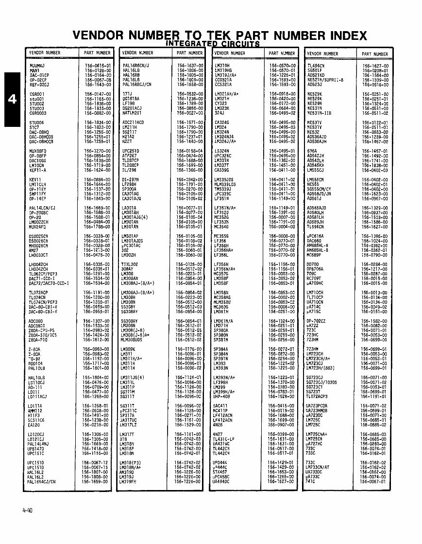
PART VENDOR NUMBER
MJUMKJ MAN1 DAC-01 CP OP-O2CP REF-O2CJ
CGROO 1 stuOOl STU002 STU003 CGR0003
STU004 STC7 DAC-OBHQ DAC-08HQDS DAC- 08HQQB
MUXO8FQ OP-08FP DACl OGX LMl OCN KEF11 -A
KEVll LMl 1 CLH OP-11EY SMPll FY OP-14EP
TL072ACP TL074CN TL074CN/PEP3 DAC-80-CBI-V DAC-80-CBI-V
ADC080 ADC0801 Z80A-CPU-PS ZBOA-SIOIlCS ZBOA-PI0
Z-80A Z-80A TO-92 RDD104 PAL1 OLE
HAL1 OLE LDl 1 OCJ RO-111 LDll 1 LDlllACJ
.D111A 4MM112 41 1 F3 5CSll C6 EA120
.Dl 2OCJ
.0121CJ 'AL14L4NJ JPB147D JPC151C
JPC151 D JPC1 51 D iAL16L2 'AL16L2 'AL16R4CJ/CN
PART NUMBEI VENDOR NUMBER
ADC2l 1 HCD LMPllH SG2l l T H21A2 H22T
LM3Ol AP LM3Ol AJDS pPC301AC 302 LM302H
1 PART NUMBEI - 156-1637-0 156-1806-0 156-1805-0 156-1 809-0 156-1658-0
156-0532-0 156-1236-0 156-1 789-0 156-0858-0 156-0027-0
156-1571-01 156-1790-01 156-1790-01 156-1237-0 1 56- 1440-01
156-01 58-0' 156-0474-01 156-1688-01 156-1 699-01 156-1 366-01
156-0342-01 156-1791-01 156-0270-01 156-0105-01 156-0105-01
156-0077-0' 156-0077-01 156-01 05-01 156-0105-01 156-0105-0'
156-0105-O( 156-01 05-0; l56-OlO5-O( 156-0060-01 156-0060-O(
156-01 26-O( 156-0512-02 156-0223-01 156-0854-O( 156-0854-01
156-0854-02 156-0223-Ot 156-0512-Ot 156-0512-0: 156-0854-Ot
156-0854-01 156-0512-01 156-0512-02 156-0512-02 156-051 2-02
156-01 76-OC 156-0096-01 156-0096-OC 156-0096-01 156-0096-02
156-1126-01 156-0096-00 156-1126-00 156-1126-00 156-0096-00
156-0096-02 156-1126-00 156-0271 -00 156-1161-00 156-1529-00
156-1161-00 156-0742-03 156-0742-00 156-0742-00 156-0742-01
VENDOR NUMBER
IN27 'L431 C-LP IA431 WC 'L442CN 'L442CN
PART NUMBER
156-0570-06 156-0570-01 156-1 226-01 156-1 593-00 156-1593-00
156-0918-00 l56-O42O-OO 156-0172-00 156-0684-00 156-0495-02
156-0495-00 156-0495-03 156-0495-00 156-0495-02 156-0495-02
156-0495-01 156-0495-00 156-1 362-00 156-1451 -00 156-041 1-00
156-041 1-02 156-041 1-00 156-041 1-01 156-041 1-00 156-1149-00
156-1 149-01 156-1391-00 156-0007-00 156-1191-00 156-0004-00
156-0008-00 156-0770-01 156-0770-00 156-0770-02 156-0770-00
156-1156-00 156-1 156-01 156-0003-00 156-0853-02 156-0853-01
156-0853-00 156-0002-00 156-0853-02 156-0006-00 156-0251-00
156-1 324-00 156-0251 -01 156-0255-01 156-0255-00 156-0256-00
156-0272-01 156-0272-00 156-0254-00 156-1225-02 156-1225-00
156-1225-01 156-1 370-00 156-0783-00 156-0783-01 156-1 528-00
156-0415-00 156-01 19-00 156-1688-00 156-1699-00 156-0907-00
156-0399-00 156-1631-00 156-1631-00 156-0517-00 156-051 7-01
156-1429-01 156-1 429-00 156-1653-00 156-1265-00 156-1627-00
VENDOR NUMBER
.M71DCH rL71 OCP JA71 OCN 1A714C 1A715C
PART NUMBER
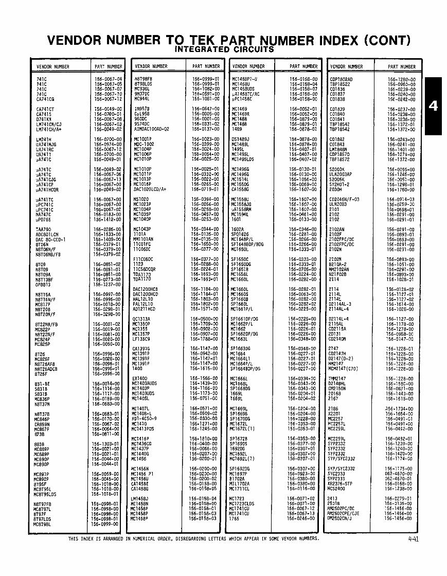
VENDOR NUMBER TO TEK PART NUMBER INDEX (CONT) INTEGRATED CIRCUITS
VENDOR NUMBER
741C 741 C 741 C 741C CA741CG
CA74l CT CA741 S D741 KN LM741 CN/CJ LM741 CH/A+
LM741 H UA741MJG UA741 RC UA741T uA741 C
pA741 C pA741C pA741 CJG uA741 CP pA741 HCQR
TAA790 AOC801 LCN DAC 80-CCD-1 8T06N
PART NUMBER VENDOR NUMBER
N8T98FB
MClOOlP MOC-1002 MC1004P MC1006P MClOl OP
MClOlOP MClOllP MC1013P
OAC1200HCB OAC1200HCO HAL12L10 PALlPLlO AD1 21 1 HCD
PART NUMBEI
156-0999-01 156-0999-01 156-1 082-O( 156-0591 -0t 156-1081-O(
156-0647-OC 156-0005-OC 156-0001 -0C 156-0331-02 156-0137-OC
156-0023-OC 156-0399-00 156-0024-00 156-0054-00 156-0025-00
156-0025-01 156-0332-00 156-0022-00 156-0265-00 156-0719-01
156-0394-00 156-0056-00 156-0258-00 156-0457-00 156-0253-00
156-0344-00 156-0135-00 156-0135-00 156- 1650-00 156-0377-00
156-0377-00 156-0288-00 156-0224-01 156-1693-00 156-1 693.01
156-1184-00 156-1 184-01 156-1803-00 156-1802-00 156-1571-00
156-0500-00 156-1 709-00 156-0902-00 156-0907-00 156-1 788-00
156-1147-00 156-0942-00 156-1 147-01 156-1147-00 156-161 5-00
156-1 566-00 156-1439-00 156-1 166-00 156-1173-00 156-0751-00
156-0571-00 156-0509-02 156-0330-00 156-1271-00 156-1245-00
156-1810-00 156-0400-00 156-0066-00 156-0207-00 156-0200-01
l56-O2OO-OO 156-0200-00 156-0200-02 156-01 58-00 156-0158-05
156-0158-04 156-01 58-00 156-01 58-01 156-01 58-03 156-01 58-03
VENDOR NUMBER
MC1458P1-U MC1458U MC1458UOS uA1458TCIRC uPC1458C
PART NUMBEI
156-0158-01 156-01 58-04 156-0158-0: 156-01 58-01 156-01 58-01
- THIS INDEX IS ARRANGED IN NUMERICAL ORDER, DISREGARDING LETTERS WHICH APPEAR IN SOME VENOOR NUMBERS.
VENOOR NUMBER
-- -
PART NUMBER

VENDOR NUMBER TO TEK PART NUMBER INDEX (CONT) INTEGRATED CIRCUITS
I VENDOR NUMBER PART NUMBE VENDOR NUMBER
AM2857 AM2857PC 52876 TBP28S86N AM2901 BOC
AM2901 BDC AM2901 BDCB AM2901 DCB IDM2901A-2DC IDM2901A-1 JC
IDM2909AJC AM2909ADC AM3909ADC MC2909LC AM291 ODC
YC291OL M2911ADCB 4M2911ADC IDM29ll AOC IDM29ll AJC
PART NUMBER
156-1 625-01 156-1598-00 156-1598-00 156-14O3-OO 156-1 460-00
156-0329-00 156-0453-03 156-0453-01 156-0453-03 156-1039-01
156-1 039-02 156-1039-00 156-1 202-00 156-1 438-00 156-1043-00
156-1 043-01 156-1043-03 156-1043-02 156-1043-02 156-1043-00
156-1 043-00 156-1043-02 156-1163-00 156-1 61 8-00 156- 1029-00
156-1 029-01 156-1 029-00 156-1029-01 156-1029-00 156-1355-00
156-1355-00 156-1209-01 156-1 209-00 156-1209-00 156-1209-01
156-12O9-OO 156-1 565-00 156-1 385-00 l56-l389-OO 156-1839-00
156-1 738-00 156-1 749-00 156-1 740-00 156-0017-00 156-0209-00
156-0033-00 156-0033-01 156-0136-00 156-01 08-00 156-0136-02
156-01 06-00 156-01 06-01 156-0065-00 156-0065-01 156-0065-00
156-0048-00 156-0048-01 156-0048-00 156-0068-00 156-0048-00
156-0095-00 156-0099-00 ~ 156-1349-00 ' 156-1349-01 156-0901-00
156-0936-00 156-091 2-00 156-0912-01 156-0356-01 156-0355-00
156-1190-00 156-1 190-00 156-0259-00 156-0259-01 156-0259-02
- -
VENDOR NUMBER
- PART NUMBEF
156-0197-01 156-0197-03 156-0197-00 156-0197-00 156-0512-03
156-1381-00 156-0534-00 156-0534-01 156-1294-00 156-1294-00
156-0686-00 156-0686-01 156-0686-02 156-1134-00 156-1 134-01
156-0921-00 156-0921-01 156-0921 -02 156-1450-00 156-1114-00
156-1114-01 156-0197-00 156-1527-00 156-1012-00 156-1 009-00
156-1010-00 156-1422-00 156-1001-00 156-1002-00 156-0965-01
156-0965-02 156-0965-00 156-0965-00 156-1003-00 156-1004-00
156-0992-00 156-0495-00 156-0210-00 156-0421 -00 156-1346-00
156-0370-00 156-0277-00 156-1284-00 156-1263-00 156-0927-00
156-0927-01 156-0927-02 156-1 799-00 156-1266-01 156-0546-00
156-1647-00 156-121 9-01 156-1219-03 156-1219-00 156-0600-01
l56-O6OO-O2 156-0600-03 156-0300-00 156-0600-00 156-0849-00
156-1 133-01 156-1133-02 156-1133-00 156-0652-03 156-0740-02
156-0740-00 156-0740-01 156-0634-01 156-0634-00 156-1569-00
156-1 569-00 156-0208-00 156-1 173-00 156-0933-00 156-0933-00
--
VENDOR NUMBER
S C M ~ ~ ~ ~ P / L SCM3869P/L F3871 EPC
EA4000 $001 A $001 B lOOlCJ :D4001 BCJ
:A4001 BCJ/A+ :04001 BF :04001 BFX :D4001 CJ :04001CJ
:04001 UBFX IA4001 1002 10028 :D40028F
PART NUMBER
156-1585-01 156-1585-00 156-0279-00 156-0853-00 156-1647-00

VENDOR NUMBER TO TEK PART NUMBER INDEX (CONT) INTEGRATED CIRCUITS
I VENDOR NUMBER
401 0 C0401 OBF CD40108FX C04Ol OCJ CD4010JA+
C04011 BF CO4Oll UBF C04011UBFX CD4011 UBFX SIL4011UBF
PART NUMBER
MC4048P 4049 CD4049UBF CO4049UBF CO4049UBFX
4050 CO4050BFX CO4050BFX 4051 4051 80
4051 BCL C04051 BFX CD4051CJA+ TMS4051 JL 4052BOC
F4052BOC CO4052BF CD4052BFX 4053 40538
CO4053BF CD4054BF CO4053BFX C04066AE C04066BF
PART NUMBER
- -- -
VENOOR NUMBER
4076BOCQR CO4078BFX CD4081 BF CD4081 BFX CO4082BFX
MCI4082BCLO 4085BCO 4085BOC 4085OCQR CD4085BF
CD4085BFX 4086BOCQR CO4086BF CD4086BFX 4093
CO4093BF CO4093BFX MC4093 C04094BF CO40948FX
TMS4lOO TMS4100 TMS4100 0441 0-2 RC4131
RC4151NB 41 6-2 pP04160-3 RC41940C RC41940C
RM41940 RM41940 SG4194CJ 5641 945 S4241
S4242 54243 54244 54264 54264
54264 54289 UPC4359C S4393 OPE4428
4490 451 1 BOC 451 1 BOCQR ED451 1BF CO45ll BFX
ED451 2BFX 451 6BOC 0516OCQA J4516BFX :04520BF
:04520BFX j4525 15280 1528OCQR lC4531NB
- PART NUMBEF
156-0786-02 156-0786-02 156-1340-06 156-1480-06 156-1480-06
156-0574-02 156-1320-06 156-1478-00 156-1478-01 156-1 787-06
156-1 787-00 156-0925-00 156-0925-01 156-0925-02 156-0925-00
156-0925-02 156-0753-01 156-0753-00 156-0753-01 156-0961-03
156-0961-00 156-0961-02 156-0961-01 156-0796-00 156-0796-01
156-01 02-00 156-01 03-00 156-01 04-00 156-1000-00 156-0070-00
156-1 362-00 156-0968-00 156-1353-00 156-0496-00 156-0496-01
156-1 308-00 156-1 308-01 156-0496-00 156-1308-00 156-0947-02
156-1204-01 156-1036-01 156-1427-01 156-1 288-00 156-1 289-00
156-1 290-00 156-1113-00 156-1 81 6-00 156-1416-00 156-1237-00
156-0763-02 156-0795-00 156-0795-01 156-0795-00 156-0795-01
156-1486-00 156-0582-00 156-0582-03 156-0582-02 156-0579-00
156-0579-02 156-0945-01 156-0578-00 156-0578-02 156-051 1-00
156-0122-00 156-1282-00 156-1368-00 156-0898-00 156-0898-01
156-0850-00 156-0850-02 156-1 174-00 156-1175-00 156-1001-00
---- --
PART NUMBER
THIS INDEX IS ARRANGED IN NUMERICAL ORDER, DISREGARDING LETTERS WHICH APPEAR I N SOME VENDOR NUMBERS.
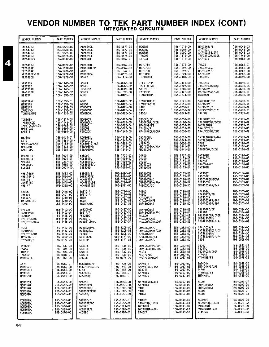
VENDOR NUMBER TO TEK PART NUMBER INDEX (CONT) INTEGRATED CIRCUITS
VENOOR NUMBER PART NUMBEI
156-0823-01 156-0824-01 156-0825-01 156-0826-01 156-0842-01
156-0827-01 156-1632-01 156-1 706-01 156-1 272-01 156-1272-01
156-1446-01 156-1446-0; 156-1446-0' 156-1446-0; 156-1 338-0;
156-1338-0' 156-1338-O( 156-1338-O( 156-1 338-01 156-1 338-0;
156-1 81 7-O( 156-1 146-O( 156-0785-O( 156-0504-O( 156-0364-O(
156-0134-01 156-1461-O( 156-1 153-O( 156-1433-O( 156-1 589-O(
156-1 024-O( 156-1024-01 156-0337-OC 156-1 555-OC 156-0001-OC
156-1632-OC 156-1 594-OC 156-1 649-OC 156-1 649-06 156-1 228-00
l?16-O486-OO 156-0401-00 156-1310-02 156-1310-00 156-1402-00
156-1402-00 156-1402-01 156-1 425-00 156-1 425-00 156-1 425-01
156-1 482-00 156-1482-00 156-1482-00 156-1 060-00 156-0427-00
156-1 539-00 156-1 785-00 156-1423-00 156-0887-01 156-1168-00
156-0950-01 156-0950-00 156-0952-00 156-0952-01 156-0660-00
156-0661-00 156-0662-00 156-0663-00 156-0664-00 156-0665-00
156-0666-00 156-0667-00 156-0668-00 156-0669-00 156-0670-00
VENDOR NUMBER
MCM6590L MCM6590L MCM6590L MCM6590L MCM6604
68B09D/E S68809D/E MCM6810S MCM6810LOS MCM6881 OSD
PART NUMBEI
156-0671 -O( 156-0672-O( 156-0673-O( 156-0674-O( 156-0862-01
156-0862-O( 156-0862-0; 156-1047-01 156-0573-O( 156-1417-O(
156-0965-O( 156-0965-02 156-0223-OC 156-1 598-OC 156-0426-01
156-0426-02 156-0426-04 156-0426-OC 156-0426-04 156-0426-04
156-0426-OC 156-0426-05 156-0426-04 156-0426-OC 156-1342-OC
156-1 342-OC 156-1342-06 156-1 683-00 156-1 342-01 156-1 342-01
156-1 720-00 156-1494-00 156-1 494-00 156-1 494-01 156-1494-00
156-1 494-01 156-1494-00 156-071 6-00 156-071 6-01 156-1 591-00
156-0716-00 156-0716-01 156-0427-01 156-0427-02 156-0427-02
156-0427-00 156-0427-03 156-0427-03 156-0427-03 156-0427-04
156-1205-00 156-1 205-01 156-1 205-00 062-41 71-00 062-41 71 -01
156-1 135-00 156-1136-00 156-1137-00 156-1 138-00 156-0776-00
156-1 426-00 156-1 549-00 156-1458-00 156-1 246-01 156-0658-01
156-0658-00 156-0658-00 156-1 206-00 156-1 206-00 156-0658-00
156-0658-01 156-0658-00 156-1013-00 156-1 086-00 156-0996-00
VENOOR NUMBER PART NUMBEF
156-1018-00 156-0998-00 156-0999-00 156-1 115-00 156-141 1-00
156-1 578-00 156-1 297-00 156-1297-01 156-1 224-00 156-1483-00
156-1435-00 156-1 127-00 156-1281-00 156-1420-00 156-1274-00
156-1621-00 156-1655-00 156-0030-01 156-0030-02 156-0549-01
156-0030-00 156-01 80-04 156-0030-03 156-0030-00 156-0030-03
1 56-0030-00 156-0549-00 156-0030-00 156-0941 -01 156-0941 -00
156-1 707-00 156-01 13-01 156-01 13-02 156-01 13-00 156-01 13-04
156-01 13-00 156-01 13-03 156-0180-00 156-01 80-04 156-0180-00
156-0180-01 l56-Ol8O-O2 156-0180-00 156-01 80-04 156-0180-00
l56-Ol8O-O3 156-0180-04 156-0382-01 156-0382-00 156-0382-02
156-0382-00 156-0382-02 156-0382-00 156-0382-02 156-0382-00
156-0382-02 156-0382-02 156-O55O-Ol 156-0057-00 156-0057-02
156-0057-00 156-0057-02 156-0057-00 156-0057-00 156-0057-01
156-0057-02 156-0550-00 156-0043-01 156-0043-02 156-0551-01
156-0043-00 156-0043-03 156-0043-00 156-0043-03 156-0043-00
VENDOR NUMBER PART NUMBER
156-0043-03
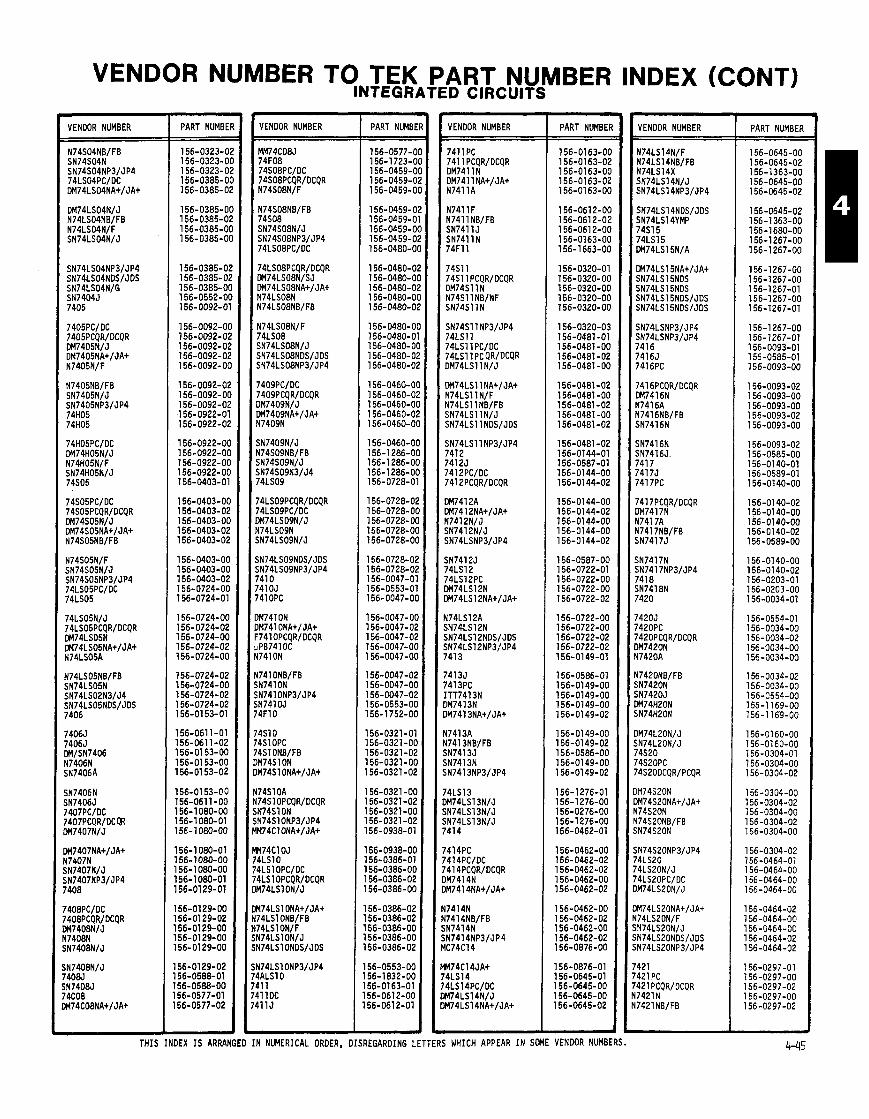
VENDOR NUMBER TO TEK PART NUMBER INDEX (CONT) INTEGRATED CIRCUITS
VENDOR NUMBER PART NUMBEf VENOOR NUMBER
'41 0 '41 OJ '41 OPC
PART NUMBE VENOOR NUMBER PART NUMBEI
156-0163-O( 156-01 63-02 156-01 63-OC 156-0163-02 156-0163-OC
156-0612-OC 156-061 2-02 156-061 2-OC 156-0163-OC 156-1663-OC
156-0320-01 156-0320-00 156-0320-00 156-0320-00 156-0320-00
156-0320-03 156-0481-01 156-0481 -00 156-0481 -02 156-0481 -00
156-0481-02 156-0481 -00 156-0481-02 156-0481 -00 156-0481-02
156-0481 -02 156-0144-01 156-0587-01 156-0144-00 156-0144-02
156-0144-00 156-0144-02 156-0144-00 156-01 44-00 156-01 44-02
156-0587-00 156-0722-01 156-0722-00 156-0722-00 156-0722-02
156-0722-00 156-0722-00 156-0722-02 156-0722-02 156-0149-01
156-0586-01 156-0149-00 156-0149-00 156-0149-00 156-01 49-02
156-01 49-00 156-0149-02 156-0586-00 156-0149-00 156-0149-02
156-1 276-01 156-1276-00 156-0276-00 156-1276-00 156-0462-01
156-0462-00 156-0462-02 156-0462-02 156-0462-00 156-0462-02
156-0462-00 156-0462-02 156-0462-00 156-0462-02 156-0876-00
156-0876-01 156-0645-01 156-0645-00 156-0645-00 156-0645-02
VENOOR NUMBER - -
PART NUMBER
THIS INDEX IS ARRANGED IN NUMERICAL ORDER, DISREGARDING LETTERS WHICH APPEAR IN SOME VENOOR NUMBERS.

VENDOR NUMBER TO TEK PART NUMBER INDEX (CONT) INTEGRATED CIRCUITS
VENDOR NUMBER
74LS21 PC 74LS21 PCQRIDCQR DM74LS21 N
PART NUMBEF VENDOR NUMBER PART NUMBEI
156-0035-01 156-0035-01 156-0350-01 156-0035-01 156-0035-0;
156-0035-O( 156-0035-0; 156-0555-01 156-1397-O( 156-0267-0'
156-0267-O( 156-0267-O( 156-0418-O( 156-0418-O( 156-041 8-0'
156-0418-O( 156-0418-O( 156-041 8-01 156-0465-01 156-0465-O(
156-0465-O( 156-0465-01 156-0465-O( 156-0465-O( 156-0465-0;
156-0465-02 156-0171 -01 156-01 71 -0C 156-0171-02 156-0171-OC
156-0171-02 156-0171 -0C 156-0171-05 156-0171-OC 156-0171-02
156-0766-01 156-0766-02 156-1724-OC 156-0766-OC 156-0739-OC
156-0739-01 156-0739-02 156-0739-00 156-0739-02 156-0739-00
156-0739-02 156-0479-01 156-0479-04 156-0479-00 156-0479-04
156-0479-02 156-0479-00 156-0479-02 156-0479-00 156-0479-02
156-0479-04 156-0479-04 156-0479-00 156-0479-02 156-0479-03
156-0479-03 156-0479-02 156-0479-04 156-0424-01 156-0424-00
156-0424-00 156-0424-02 156-0424-00 156-0424-02 156-0730-01
156-0730-00 156-0730-02 156-0730-00 156-0730-00 156-0730-00 -
VENDOR NUMBER PART NUMBER
156-0730-02 l56-O73O-O2 156-0150-01 156-0591 -01 156-01 50-00
156-01 50-02 156-01 50-00 156-01 50-02 156-0150-00 156-0591-00
156-0150-02 156-0150-00 156-0591 -00 156-0591-00 156-0591-00
156-1216-00 156-1216-00 156-1216-01 156-0466-01 156-0466-00
156-0466-02 156-0466-00 156-0466-02 156-0466-00 156-0466-00
156-0466-00 156-0466-02 156-0145-01 156-0592-01 156-0592-02
156-0145-00 156-0145-00 156-0145-00 156-01 45-00 156-0145-02
156-01 45-00 156-01 45-02 156-01 45-00 156-0145-02 156-0592-00
156-1393-01 156-1393-00 156-1393-00 156-0468-01 156-0467-01
156-0467-00 156-0467-00 156-0467-00 156-0467-00 156-0467-02
156-0467-02 156-0036-01 156-061 6-01 156-0036-00 156-0036-02
156-0036-00 156-0036-02 156-0036-00 156-0036-02 156-061 6-00
156-0036-00 156-0036-02 156-01 56-00 156-01 56-00 156-01 56-00
156-0156-01 156-01 56-00 156-01 56-00 156-0080-01 156-0061 -01
156-0556-01 156-0061 -00 156-0061 -02 156-0061 -00 156-0556-00
VENDOR NUMBER
SN7450N 7451 7451 PC 7451 PCQRIDCQR DM7451N
74LS51 PCQRIDCQR DM74LS51NIJ OM74LS51 NA+/JA+
PART NUMBER

VENDOR NUMBER TO TEK PART NUMBER INDEX (CONT) INTEGRATED CIRCUITS
, THIS INOE
- PART NUMBEI
156-0031-0; 156-0452-0' 156-0452-01 156-0452-0; 156-0452-O(
156-0452-0; 156-0452-O( 156-0452-O( 156-0452-01 156-1751-O(
156-0703-01 156-0703-O( 156-0703-02 l56-O7O3-Ot 156-0703-Ot
156-0703-02 156-0703-OC 156-0703-02 156-1332-OC 156-1285-06
156-1 285-00 156-1 285-00 156-1285-00 156-1 285-00 156-0038-01
156-0038-00 156-0038-02 156-0383-00 156-0038-00 156-0038-00
156-0038-02 156-0038-00 156-0038-02 156-0280-00 156-0280-00
156-0039-01 156-0557-01 156-0039-00 156-0039-02 156-0039-00
156-0039-02 156-0039-00 156-0039-02 156-0557-00 156-0387-01
156-0387-00 156-0387-00 156-0387-00 156-0387-02 l56-O387-OO
156-0387-02 156-0387-02 156-0041-01 156-0041-02 156-0041-03
156-0041-04 156-0558-01 156-0041 -00 156-0041-00 156-0041-05
156-0041-00 156-0041-00 156-0558-00 156-0041-00 156-0041-05
156-0041-00 156-1611-00 156-01 55-00 156-01 55-00 157-0155-00
156-01 55-01 156-0331-01 156-0331-00 I56-O33l-O2 l56-O33l-OO
ARRANG
VENOOR NUMBER
N74S74N/F SN74S74N/J SN74S74NP3 74LS74 74LS74
PART NUMBEI
156-0331-01 156-0331 -01 156-0331-0. 156-0388-0' 156-0388-01
156-0388-01 156-0388-01 156-0388-0: 156-0388-01 156-0388-Ot
156-0388-01 156-0388-O( 156-0388-0: 156-0388-0: 156-1756-01
156-0040-01 156-0559-0; 156-0040-O( 156-0040-0; 156-0040-O(
156-0040-Oi 156-0040-Ot 156-0040-Oi 156-0040-Ot 156-0559-Ot
156-0040-Oi 156-0735-01 156-0735-Ot 156-0735-02 156-0735-OC
156-0735-OC 156-0735-02 156-0735-02 156-0042-01 156-0560-01
156-0042-06 156-0042-06 156-0042-00 156-0042-02 156-0042-00
156-0560-00 156-0042-02 156-0731-01 156-0731 -00 156-0731-02
156-0731 -00 156-0731-02 156-0731 -00 156-0731 -00 156-0731-02
156-0161-00 156-0161-00 156-01 61 -00 156-0161-00 156-0086-00
156-0086-00 156-0086-00 156-0087-01 156-0087-00 156-0087-02
156-0087-00 156-0087-02 156-0087-00 156-0087-02 156-0087-00
156-0087-02 156-0468-00 156-0123-01 156-0123-00 156-0123-02
156-0123-02 156-01 23-00 156-0123-02 156-0123-00 156-01 23-02
VENOOR NUMBER
74S85
PART NUMBEI:
156-1041-01 156-1041-Ot 156-1041-0; 156-1041-Oi 156-1 041 -Ot
156-0953-01 156-0953-Ot 156-0953-02 156-0953-Ot 156-0953-02
156-0953-OC 156-0953-0: 156-0953-02 156-0953-02
156-0953-03 156-0062-01 156-0062-00 156-0062-02 156-0062-00
156-0062-02 156-0062-00 156-0062-02 156-0062-02 156-0062-00
156-0786-00 156-1800-00 156-0707-01 1564707-02 156-0707-00
156-0707-03 156-0707-00 156-0707-03 156-1331-00 156-0707-00
156-0707-03 156-0707-00 l56-O7O7-OO 156-0707-03 156-0381 -01
156-0381-00 156-0381 -02 156-0381-00 156-0381 -02 156-0381 -00
156-0381 -02 156-0381-00 156-0381 -02 156-0381 -02 156-0318-01
156-061 4-01 156-061 4-00 156-0318-00 156-0086-01 156-1 109-00
156-01 92-00 156-0192-00 156-01 92-00 156-0894-00 156-0079-01
156-0079-00 156-0079-02 156-0079-00 156-OOF9-00 156-0079-00
156-0079-02 156-0395-00 156-0201 -00 8 56-0201 -00 56-0656-01
56-0656-00 56-0656-02 56-0656-00 56-0656-00 56-0656-02
NUMERICAL ORDER, DISREGARDING LETTERS WHICH APPEAR IN SOME VENDOR NUMBERS.
VENDOR NWBER
SN74LS90NP3/JP4 7491 PC OM7491AN N7491 N SN7491AN
PART NUMBER

VENDOR NUMBER TO TEK PART NUMBER INDEX (CONT) INTEGRATED CIRCUITS
MC79L15ACPO MC79L15ACP OM8000N/J AMZ8001 ADC AMZBOOZAOC
PART NUMBEF
156-0719-01 156-1366-OC 156- 1367-OC 156-1815-OC 156-071 9-OC
156-0291-OC 156-1 408-00 156-1 548-00 156-0501-00 156-0277-00
VENOOR NUMBER PART NUMBE
156-1558-0 156-0186-0 156-0153-0 156-0454-0 156-0129-0
156-0129-0 156-0454-0 156-01 63-01 l56-13O7-OI 156-0094-0
156-0140-0: 156-0034-01 156-0035-01 156-1 684-01 156-1 434-01
156-1387-01 156-1 187-01 156-1212-01 156-1212-01 156-1212-0'
156-1586-01 156-1490-01 156-0954-0' 156-0954-01 156-0954-01
156-1087-01 156-1 088-01 156-1088-O( 156-1 088-0' 156-1088-0;
156-1416-O( 156-1 643-O( 156-1 793-O( 156-1609-O( l56-0406-O(
156-0473-01 156-0473-O( 156-0473-0; 156-0396-01 l56-O396-O(
156-0396-02 156-0535-01 l56-O649-O( 156-0649-02 156-0535-O(
156-0787-01 156-0787-OC 156-0535-02 156-1341-O( 156-1341-01
l56-0729-Ot 156-0729-01 156-1 597-OC 156-0397-01 156-0537-01
156-0537-OC 156-0539-01 156-0539-OC 156-0539-02 156-1730-00
156-1 255-01 156-0845-01 156-0845-00 156-0845-02 156-0423-00
156-1 277-00 156-1277-00 156-0208-00 l56-O9l6-Ol 156-0916-02
156-091 6-00 156-091 6-02 156-1479-Ol 156-1479-00 l56-l479-Ol 156-1479-00
VENOOR NUMBER PART NUMBEF
156-1479-01 156-0601 -01 156-0123-00 156-01 52-01 156-0601-00
156-01 52-00 156-0250-01 156-1442-00 156-1599-00 156-0250-00
156-0249-01 156-0249-00 156-0262-00 156-0357-00 156-0358-00
156-0359-00 156-0360-00 156-1171-00 156-0962-00 156-0078-00
156-0963-00 156-0533-00 156-0945-00 156-0945-01 156-0945-00
156-0945-00 156-0945-01 156-0945-00 156-0945-01 156-0199-00
156-01 66-00 156-0947-01 156-0947-00 156-0947-02 156-0947-00
156-0947-00 156-0947-00 156-0336-00 156-0336-01 156-1203-00
156-1203-00 156-1203-00 156-0322-00 156-0416-00 156-1356-00
156-1 356-01 156-1356-00 156-1428-00 156-1336-00 156-1 336-01
156-0877-00 156-0877-04 156-0877-04 156-0877-01 156-0877-02
156-0877-02 156-1 036-01 156-1570-00 156-1 570-00 156-1202-00
156-1204-01 156-1 204-00 156-1 084-00 156-1 084-00 156-1 328-00
156-0919-00 156-0919-00 156-1412-00 156-0497-00 156-0497-02
156-0498-01 156-1656-00 156-0498-00 156-1455-00 156-1455-00
VENOOR NUMBER PART NUMBER

VENDOR NUMBER TO TEK PART NUMBER INDEX (CONT) INTEGRATED CIRCUITS
I VENDOR NUMBER )
I AM91 01 BPC 9 ~ 1 0 9 ~ c / o c AM91 11 DOC
PART NUMBER
l56-O5O6-OC 156-0531 -01 156-0531-02 156-0531 -00 156-0456-01
156-0456-00 156-0456-02 156-0455-00 156-0455-01 156-0455-02
156-0653-00 156-0653-02 156-0653-00 156-0653-01 156-0653-02
156-0061-02 156-0111-00 156-0081 -00 156-0072-02 156-11 10-00
VENDOR NUMBER
AM931 OPC AM93S1 OPC/DC 93S1 OPC/DC 93L14 93L14DC
PART NUMBEI
156-0521 -01 156-0521-O( 156-0521-0; 156-0220-0' 156-022O-O(
156-0220-O( 156-1 186-O( 156-0084-O( 156-0084-01 156-0084-01
156-0084-Ot 156-1394-Ot 156-1394-OC 156-0327-01 156-0327-Ot
156-0741-01 156-0741 -0C 156-0741-OC 156-1 044-0C 156-1044-01
156-0219-01 156-0219-02 156-0219-00 156-0314-00 156-0488-01
156-0488-00 156-0654-01 156-0654-00 156-0085-01 156-0085-00
156-031 0-02 156-031 0-00 156-0939-00 156-0085-00 156-0218-01
156-0218-00 156-021 8-02 156-0544-01 156-0544-00 156-0544-02
156-0351-00 156-0365-00 156-1063-00 156-1063-01 156-1063-02
156-0493-00 156-0493-01 156-0493-02 156-01 30-01 156-0969-01
156-0969-00 156-0969-02 156-1399-00 156-051 2-02 156-0081 -01
156-0622-01 156-0081-00 156-0081 -02 156-0622-00 156-0081-00
156-0081 -02 156-0622-00 156-0405-01 156-0405-02 156-0623-00
56-0623-02 56-0623-00 56-0405-00 56-0405-03 56-0405-00
56-0405-03 56-0405-03 56-0405-00 56-0405-03 56-0487-01
VENDOR NUMBER
101 OOPC IC101OOP 101 01 iPlOlOE
PART NUMBER
156-0487-02 156-0487-00 156-0487-02 156-0487-02 156-0623-00
156-0623-00 156-1335-00 156-1645-00 156-0275-00 156-0275-01
156-0275-01 156-0274-00 156-0274-01
156-0274-00
156-1 544-00 156-1 344-00 156-1256-00 156-0495-02 156-0935-02
156-1404-00 156-0935-00 156-0935-03 156-0935-01 156-1296-00
156-1295-00 156-1692-00 156 - 1444-00 156-1444-01 156-1444-00
156-1 444-02 156-1444-02 156-1441-01 156-1 386-01 156-1386-00
156-0933-01 156-0016-00 156-0870-00 156-1038-00 156-1532-00
156-1287-00 156-1287-00 156-1287-00 156-0631-01 156-0631 -01
156-1631 -00 156-0631 -03 156-0631-00 156-1 668-00 156-1 733-00
156-0205-01 156-0205-02 156-0205-00 156-0205-00 156-0205-00
156-0205-02 156-0205-00 156-1641-00 156-1641-01 156-0205-00
156-0759-01 156-0759-00 156-0759-00 156-0759-00 156-0759-00
156-0458-00 156-0458-01 156-1674-00 156-0182-01 156-0182-00
156-1642-00 156-1 642-01 156-0252-01 156-0252-00 156-0252-00
1 VENDOR NUMBER
uPBlOlO9C MClOH109LD/RD MCl 01 1 OP 10111 l O l l l N
1OlllPC MClOlllP MClOl l lP l /L l MClOll lPl SNlOll lN
MCl 01 1 5Pl MCl(rll5Pl 10116 10116F 10116N
MCl 01 l 6L MC10116P1 MC1 OH1 16L/P MClOH116LD/PD 10H116
MClOH131LP MClOH131 LD/LP MC10133P MCl 01 33Pl MC10134P/L
PART NUMBER
THIS INDEX IS ARRANGED IN NUMERICAL ORDER, DISREGARDING LETTERS WHICH APPEAR IN SOME VENDOR NUMBERS.

VENDOR NUMBER TO TEK PART NUMBER INDEX (CONT) INTEGRATED CIRCUITS
VENDOR NUMBER
MC10137L MC10138L MC10138Ll 10139F MCW 01 39
PART NUMBEF
156-051 0-O( 156-0642-O( 156-0642-01 156-1 037-O( 156-1037-OC
156-D638-02 156-0638-OC 156-0638-OC 156-0638-01 156-0638-02
156-0657-02 156-0657-01 156-0657-01 156-0657-02 156-0657-06
156-0657-00 156-0657-02 156-0847-00 156-0847-01 156-0761 -00
156-0761-00 156-1 035-01 156-1 035-01 156-1035-00 156-1673-00
156-0762-00 156-0762-00 156-0762-00 156-0762-00 156-0746-00
156-0746-01 156-1 706-00 156-0771-00 156-0771-00 156-0771-00
156-0771-00 156-0771-01 156-0771-00 156-0920-00 156-0920-01
156-0920-00 156-0920-01 156-1495-00 156-1 495-00 156-1495-00
156-0640-00 156-1667-00 156-1 022-01 156-1 022-00 156-1022-00
156-1 023-00 156-1 023-01 156-1023-00 156- 1538-00 156-1 538-00
156-1 538-00 156-0758-01 156-0758-00 156-0758-00 156-0758-00
156-0758-00 156-0632-01 156-0632-00 156-0637-00 156-0637-01
156-1795-00 156-0760-00 156-0760-00 156-0760-00 156-0760-00
156-0633-00 156-0633-02 156-1 71 2-00 156-1374-00 156-0863-01
VENDOR NUMBER
I1 1 CX570 F115n8D M l l CX604 I1 lAX940 C12040L
PART NUMBER VENDOR NUMBER -
MC1400U6 MC14008BCLD MC14008UBAL MCl4Ol 1 BCLD MC14011 BCLD
MCl4Oll CL MC14011 UBCL MC14011UBCLO MCl4OlZBCL MC14012BCLD
MCl4Ol3BCL MC14013BCLD MC140138CLD MC14014BCL MC14015BCL
NC14020BCLD 14021A MC14021 BCL MCl402l BCLD MC14022BCLD
MC14023BCL MC14023BCLDS MC14024BCL MC14024BCLD 14025
YC14046CP YC14046CP YC14049UBCL YC14049UCBL YC14049BCLD
YC14050BCLD YC14050BCLD YC14051 BCLD YC14051BCL HD1-40526
YC14052BCL YC14052BLD YC14053BCL YC14053 K14053BCLD
IC14066BCL IC14066BCLO IC14069UBCL IC14069UBCLO :14070DC
IC14070BCL IC14070BCLD 14071 :Dl4071 BFX IC14071 BCL
IC14071 BCLO 1C14075BCLDS IC14078BCLDS ICl4O8l BCL IC14081BCLOS
PART NUMBEF VENDOR NUMBER
AM1 408L8 AM1 408L8-B MC1408-L8 MC1408-L8 MC1408-EN
MC1408-L8DS MC14093BCL MC14093BLDS MC14094BCLD MC14433PO
MC14433P MC14435FL 14490 MC14490VL MC14490BCLD
MC14504BCLO MC145088CL MCl45ll BCLD MCl45ll BCL MC14512BCLO
MC14521 BCL MCM14521 BCLD MM14521BCJAt
- PART NUMBEF
156-0509-00 156-0509-03 l56-O5O9-OO 156-0509-01 156-0509-00
156-0509-03 156-0961 -00 156-0961 -02 156-0796-01 156-1118-00
156-1 154-00 156-0749-00 156-0763-01 156-0763-00 156-0763-02
156-1487-00 156-0897-00 156-0795-01 156-0795-00 156-1486-00
156-0582-01 156-0582-00 156-0582-02 156-0582-03 156-0751-01
156-0752-01 156-0752-00 156-0752-00 156-0752-00 156-0505-01
156-0505-00 156-0505-02 156-0579-01 156-0579-00 156-0579-02
156-0864-00 156-0864-01 156-0864-01 156-0578-01 156-0578-00
156-0578-02 156-1282-00 156-1152-00 156-1 152-01 156-0896-00
156-0896-01 156-1368-00 156-0898-00 156-0898-00 156-0898-01
156-0583-01 156-0583-02 156-0583-00 156-0583-00 156-0583-03
156-0767-01 156-0767-02 156-0766-02 156-0767-00 156-0767-02
156-0876-02 156-0548-00 156-0548-02 156-0850-00 156-01 70-01
156-01 87-00 156-01 95-00 156-1 124-00 156-1123-00 156-1120-00
156-01 85-00 156-1 122-00 156-0107-00 156-0941 -00 156-0577-00

VENDOR NUMBER TO TEK PART NUMBER INDEX (CONT) INTEGRATED CIRCUITS
VENDOR NUMBER I
PART NUMBEl
156- 0938-O( 156-0876-O( 156-0766-O( 156-0566-O( 156-0886-O(
156-0894-O( 156-1390-O( l56-0425-O( 156-1 325-O( 156-0649-O(
156-0960-O( 156-001 0-O( 156-0012-O[ 156-001 1-O( 156-1 237-OC
156-1437-OC 156-1 527-OC 156-0698-OC 156-1298-OC 156-0698-00
156-1 052-00 156-1185-00 156-0972-00 156-0972-02 156-0972-03
156-0972-04 156-0972-05 156-1 188-00 156-1 188-00 156-1 685-00
156-1 461-00 156-1614-00 156-1461 -00 156-1281-00 156-0968-00
156-0968-02 156-1552-00 156-1 350-00 156-1228-00 156-1690-00
156-1613-00 156-1574-00 156-1615-00 156-0053-00 156-0013-00
156-01 62-00 156-01 76-00 156-0631-02 156-0759-02 156-0182-02
156-0252-02 156-0229-01 156-0639-01 156-0636-02 156-0687-01
156-0308-03 156-0860-02 156-1214-01 156-0368-01 156-0368-03
156-0316-04 156-0316-03 156-0369-02 156-0369-02 156-1 247-01
156-0230-02 56-0520-01 56-0688-01 56-0641-01 56-0642-01
56-0638-01 56-0746-01 56-0771-01 56-0640-02 56- 1022-01
VENOOR NUMBER PART NUMBER
156-1 023-01 156-0758-01 156-0632-02 156-0637-01 156-0760-01
156-0633-01 156-1374-00 156-0743-01 156-0543-01 156-0542-01
156-1021-01 156-1 01 9-01 156-0757-01 156-0848-01 156-0880-02
156-0847-00 156-0847-01 156-1035-00 156-0266-01 156-0624-01
156-0377-00 156-0285-00 156-0077-00 156-0274-00 156-0275-00
156-1613-00 156-1 273-01 156-0393-00 156-0392-01 156-0392-01
156-1675-00 156-0067-09 156-1681-00 156-1315-00 156-0986-00 156-0986-02 156-1460-00 156-1315-00 156-1417-00 156-1672-00 156-1 687-00
'56-1 598-00 56-0305-01 56-1814-00 56-1 603-00 56-1 630-00
56-0602-00 56-1 735-00 56-1283-00 56-01 84-00 56-0132-00
56-0599-00 56-1357-00 56-1 702-00 56-1736-00 56- 1840-00
56-0657-02 56-0363-00 56-0363-01 56-0761 -00 56-0361-03
56-1811-00 56-0147-00 56-0882-00 56-021 1-00 56-0212-00
56-0423-00 56-021 3-00 56-0349-01 56-0628-00 56-0285-00
56-0285-02 56-0312-00 56-0988-00 56-0523-00 56-0926-00
VENDOR NUMBER PART NUMBEl
156-0575-0; 156-0580-01 156-0494-O( 156-0513-01 156-0514-O(
156-1262-O( 156-1348-O( 156-0850-0' 156-0402-O( 156-0402-0;
156-0575-0; 156-021 4-O( 156-1 484-O( 156-0964-O( 156-0971 -O(
l56-0903-O( 156-0903-0: 156-1310-O( 156-0676-01 156-0978-O(
156-0979-O( 156-0980-O( 156-0981 -O( 156-0331-02 l56-O983-O[
156-1 620-OC 156-1831-OC 156-1830-O( 156-0797-O( 156-1829-OC
156-0317-OC 156-1828-OC 156-0649-02 156-1341-OC 156-1 319-OC
156-1827-OC 156-1826-OC 156-1825-OC 156-1824-00 156-1823-OC
156-0627-02 156-1249-00 156-1822-00 156-1112-00 156-1027-00
156-1027-01 156-1027-02 156-0972-0;) 156-0972-01 156-0972-02
156-1821 -00 156-1820-00 156-1819-00 156-1322-00 156-1818-00
156-1 174-00 156-1259-00 156-1239-00 156-0415-00 156-0415-01
156-1353-00 156-0968-00 156-0968-00 156-0968-01 156-1576-00
156-1575-00 156-1383-00 156-1382-02 156-1382-01 156-1382-00
156-1457-00 156-1330-00 156-1623-00 156-0296-00 156-071 1-00 -
VENDOR NUMBER
SL42367 HM4334P- 3
PART NUMBER
- -
THIS INDEX IS ARRANGED IN NUMERICAL ORDER, DISREGARDING LETTERS WHICH APPEAR I N SOME VENOOR NUMBERS.
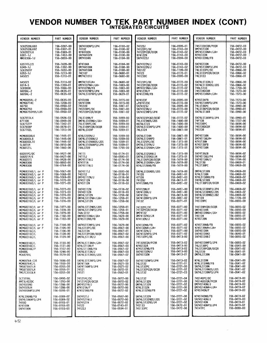
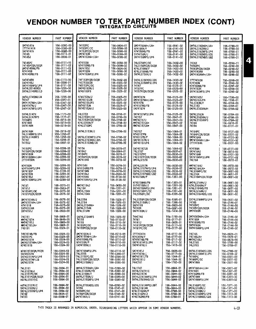
VENDOR NUMBER TO TEK PART NUMBER INDEX (CONT) INTEGRATED CIRCUITS
VENDOR NUMBER PART NUMB1
156-0080-( 156-0080-( 156-0080-( 156.0111-( 156-0598-(
156-01 1 I-( 156-0111-C 156-01 11-C 156-01 11-C 156-01 11-C
156-0111-C 156-0598-C 156-01 11-0 156-1235-0 156-1 235-0
156-1235-0 156-0347-0 156-0347-0 156-0347-0 156-0347-0
156-1 177-0 156-1177-0 156-021 9-0 156-O219-O 156-0219-0
156-0219-0 156-1252-0 156-1 252-01 156-0299-0 156-0597-0
156-0299-01 156-0299-0; 156-0299-01 156-0299-0: 156-0299-01
156-0299-01 156-0299-0; 156-0139-01 156-0299-O( 156-0597-O( 156-0299-Oi
156-0075-01 156-0563-01 156-0075-O( 156-0075-02
156-0075-O( 156-0075-02 156-0075-OC 156-0075-OC 156-0563-0C
156-0869-01 156-0648-OC 156-0869-06 156-0869-01 156-0324-01
156-0324-03 156-0324-00 156-0324-00 156-0324-03 156-0324-00
156-0344-03 156-0324-00 156-0324-03 156-0324-03 56-0324-00
56-0994-01 56-0994-00 56-0994-00 56-0994-01 56-0994-00
56-0994-02 56-0994-00 56-0994-02 56-0934-01 56-0098-01
VENDOR NUMBER PART NUMBE
156-0604-0 156-0098-0 156-0098-0 156-0098-0 156-0098-0
156-0098-0 156-0098-0 156-0604-0 156-0098-0 156-0098-0
156-1662-01 156-0325-0: 156-0325-01 156-0325-01 156-0325-0:
l56-0325-O( 156-0325-01 156-0325-0; 156-0325-0' 156-0325-O(
156-0798-0' 156-0798-O( 156-0798-01 156-0798-O( 156-0798-01
156-0798-0(
156-0798-02 156-0798-01 156-0798-01
156-0078-01 156-0564-01 156-0078-01 156-0078-02 156-0078-02
156-0078-OC 156-0078-02 156-0078-OC 156-0564-OC 156-0138-00 156-0138-02
156-0650-00 156-1201-01 156-1201-00 156-1 201 -00
156-1026-01 156- 1026-03 156-1 026-02 156-1026-00 156-1 026-00
56-1026-02 56-0110-01 56-01 10-02 56-01 10-00 56-01 10-02
56-01 10-00 56-0110-02 56-01 10-02 56-01 10-00 56-01 10-00
56-01 10-02 56-0390-01 56-0390-00 56-0390-02 56-0390-00
56-0390-02 56-0390-02 56-0390-00 56-0390-00 56-0390-02
56-0390-02 56-0141 -01 56-0141-00 56-0140-02 56-0141 -00
VENDOR NUMBER
DM741 56NA+/JA+ N74156N/F N74156NB/FB SN74156N/J SN74156NP3/JP4
iN74161 J iN74161N/J LM74Sl6l JTB iN74Sl6l J '4HC161
PART NUMBEI
156-01 41 -0: 156-0141 -O( 156-0141-01 156-0141 -O( 156-01 41 -01
156-1432-O( 156-1432-02 156-1432-O( 156-1432-02 156-1432-O(
156-1 432-02 156-1432-02 156-01 25-01 156-01 25-OC 156-0125-02
156-0125-OC 156-0125-02 156-01 25-OC 156-01 25-02 156-0125-OC
156-01 25-02 156-0547-01 156-0547-06 156-0547-02 156-0547-03
156-1064-01 1 56-1 064-02 156-1064-00 156- 1064-00 156-1064-02
156-1 064-02 156-0530-01 156-0530-00 156-0530-02 156-0530-00
156-0530-00 156-0530-02 156-0530-02 156-0530-02 156-1351-00
156-1351-01 156-1351-00 156-1351-01 156-1351-00 156-1395-00
156-1395-01 156-1395-00 156-0929-00 156-0261-00 156-1414-00
156-1 750-00 156-01 17-01 156-0605-01 156-01 17-02 156-01 17-00
156-01 17-00 156-01 17-00 156-01 17-02 156-01 17-02 156-1 415-00
156-0605-00 156-01 17-00 156-1044-01 156-1 044-00 156-1762-00
156-0844-01 156-0844-02 156-0844-00 156-0844-02 156-0844-02
156-0844-02 156-0844-00 156-0788-00 156-0788-00 156-0788-01
VENDOR NUMBER
DM74LS162NA+/JA+ SN74LS162AN/J
PART NUMBER
156-0788-01 156-0788-00 156-0788-01 156-0788-01 156-0788-01
156-0248-01 156-0248-00 156-0248-02 156-0248-00 156-0248-02
156-0248-00 156-0248-00 156-0248-02 156-0248-00 156-0248-02
156-1 198-00 156-1 198-01 156-O784-OO 156-0784-01 156-0784-02
156-0784-00 156-0784-00 156-0784-02 156-0610-01 156-0131 -01
156-0131 -00 156-0131-02 156-0131-00 156-0131-02 156-0131 -00
156-0131-00 156-0610-00 156-0131-00 156-0131 -02 156-0572-01
156-0572-00 156-0572-02 156-0651 -00 156-0651-01 156-0651 -02
156-0651 -00 156-0651-00 156-0651 -02 156-0651-00 156-0651-02
156-0651 -02 156-0146-01 156-0146-00 156-0146-02 156-01 46-00
156-0146-02 156-0146-00 156-0146-02 156-0146-00 156-0146-02
156-0626-01 156-0626-01 156-0625-00 156-0789-00 156-0789-01
156-0789-02 156-0789-02 156-0301 -00 156-0301 -02 156-0301 -00
156-0301 -02 156-0301 -00 156-0301 -02 156-0301 -00 156-0301 -02
156-1371-00 156-1371-00 156-1371-00 156-1313-00 156-1313-00
THIS INDEX IS ARRANGED IN NUMERICAL ORDER, DISREGARDING LETTERS WHICH APPEAR IN SOME VENDOR NUMBERS.
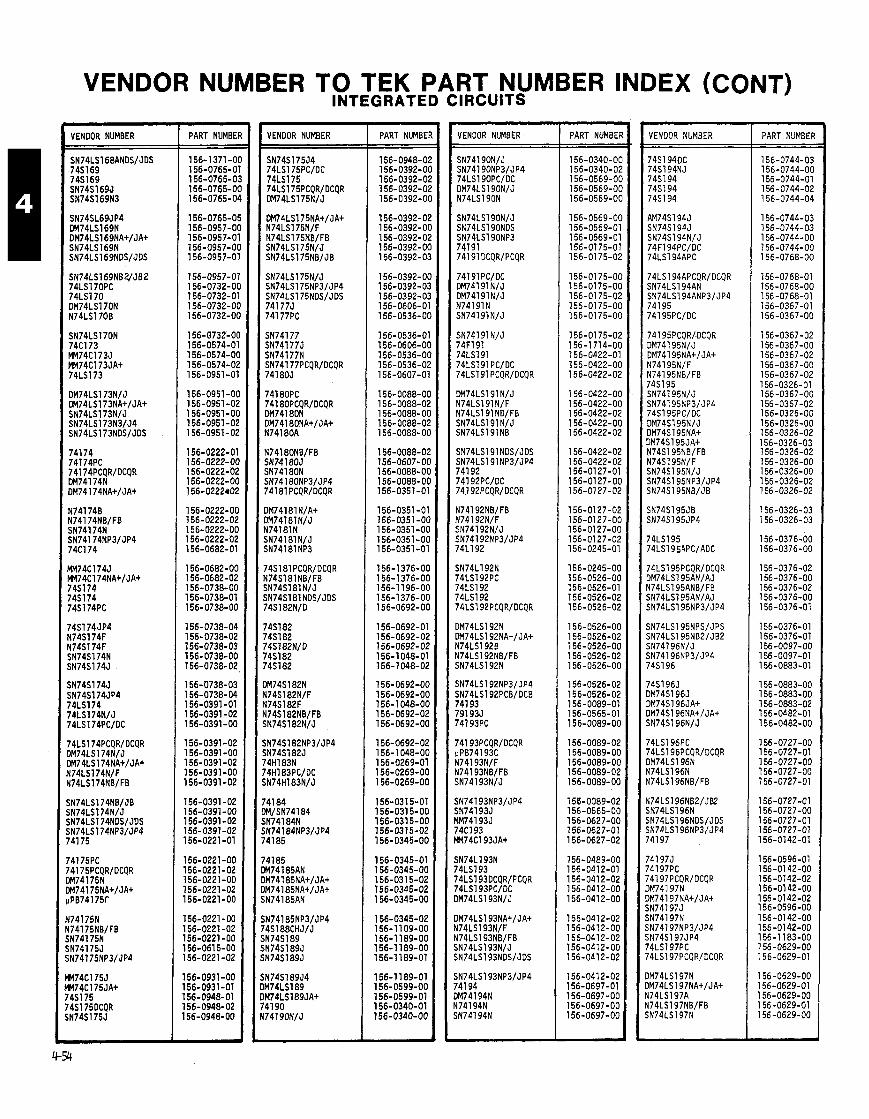
VENDOR NUMBER TO TEK PART NUMBER INDEX (CONT) INTEGRATED CIRCUITS
VENDOR NUMBER PART NUMBEI
156-1371-01 156-0765-0 156-0765-0: 156-0765-01 156-0765-01
156-0765-O! 156-0957-O( 156-0957-0' 156-0957-O( 156-0957-0'
156-0957-01 156-0732-O( 156-0732-01 156-0732-O( l56-0732-O(
156-0732-O[ 156-0574-01 156-0574-O( 156-0574-02 156-0951-01
156-0951 -0C 156-0951 -02 156-0951-OC 156-0951 -02 156-0951-02
156-0222-01 156-0222-06 156-0222-02 156-0222-00 156-0222r02
156-0222-00 156-0222-02 156-0222-00 156-0222-02 156-0682-01
156-0682-00 156-0682-02 156-0738-00 156-0738-01 156-0738-00
156-0738-04 156-0738-02 156-0738-03 156-0738-00 156-0738-02
156-0738-03 156-0738-04 156-0391-01 156-0391 -02 156-0391-00
156-0391-02 156-0391-00 156-0391-02 156-0391-00 156-0391-02
156-0391-02 156-0391-00 156-0391-02 156-0391-02 156-0221-01
156-0221-00 156-0221-02 156-0221 -00 156-0221-02 l56-O22l-OO
l56-O22l-OO 156-0221 -02 156-0221 -00 156-0615-00 156-0221-02
156-0931-00 156-0931-01 156-0948-01 156-0948-02 156-0948-00 -
VENOOR NUMBER PART NUMBE VENOOR NUMBER PART NUMBE
156-0340-01 156-0340-01 156-0569-Ol 156-0569-01 156-0569-01
156-0569-01 156-0569-0' 156-0569-0' 156-01 75-0' 156-0175-01
156-0175-01 156-0175-01 156-0175-01 156-0175-01 156-0175-01
156-0175-0: 156-1714-01 156-0422-0' 156-0422-01 156-0422-0;
156-0422-01 156-0422-01 156-0422-0; 156-0422-01 156-0422-0;
156-0422-0; 156-0422-0; 156-0127-0' 156-0127-O( 156-0127-0;
156-0127-0; 156-0127-O( 156-0127-O( 156-0127-02 156-0245-01
156-0245-O( 156-0526-O( 156-0526-01 156-0526-02 156-0526-02
l56-0526-O( 156-0526-02 156-0526-O( 156-0526-02 156-0526-O(
156-0526-02 156-0526-02 156-0089-01 156-0565-01 l56-OO89-O(
156-0089-02 156-0089-O( 156-0089-Ot 156-0089-02 156-0089-OC
156-0089-02 156-0565-OC 156-0627-OC 156-0627-01 156-0627-02
156-0489-OC 156-0412-01 156-041 2-02 156-0412-06 156-041 2-06
156-0412-02 156-0412-00 156-0412-02 156-0412-00 156-0412-02
156-0412-02 156-0697-01 156-0697-00 156-0697-00 156-0697-00
VENOOR NUMBER PART NUMBEF
156-0744-03 156-0744-OC 156 -0744-01 156-0744-02 156-0744-04
156-0744-03 156 -0744-03 156-0744-00 156-0744-00 156-0768-00
156-0768-01 156-0768-00 156-0768-01 156-0367-01 156-0367-00
156-0367-02 156-0367-00 156-0367-02 156-0367-00 156-0367-02 156-0326-01 156-0367-00 156-0367-02 156-0326-00 156-0326-00 156-0326-02 156-0326-03 156-0326-02 156-0326-00 156-0326-00 156-0326-02 156-0326-02
156-0326-03 156-0326-03
156-0376-00 156-0376-00
156-0376-02 156-0376-00 156-0376-02 156-0376-00 156-0376-01
156-0376-01 156-0376-01 156-0097-00 156-0097-01 156-0883-01
156-0883-00 156-0883-00 156-0883-02 156-0482-01 156-0482-00
156-0727-00 156-0727-01 156-0727-00 156-0727-00 156-0727-01
156-0727-01 156-0727-00 156-0727-01 156-0727-01 156-0142-01
156-0596-01 156-01 42-00 156-0142-02 156-01 42-00 156-0142-02 156-0596-00 156-0142-00 156-01 42-00 156-1 183-00 156-0629-00 156-0629-01
156-0629-00 156-0629-01 156-0629-00 156-0629-01 156-0629-00
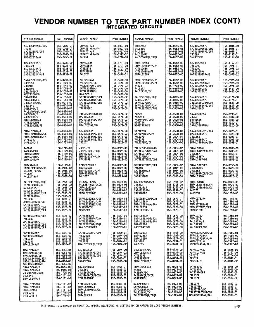
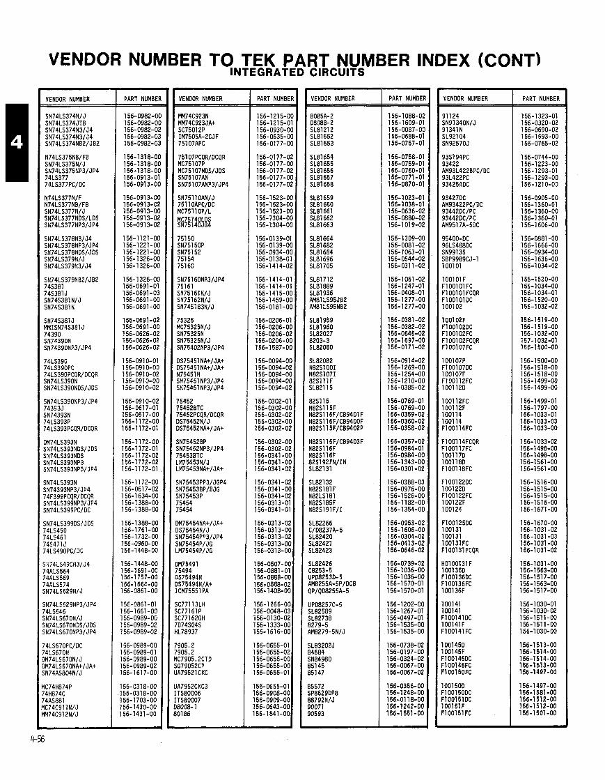
VENDOR NUMBER TO TEK PART NUMBER INDEX (CONT)
VENOOR NUMBER PART NUMBE VENOOR NUMBER
)M75491 '5494 15754941 )S75494N/A+ CM75551 PA
tC77113LH X77161 P L77162GH 'D74S04S lL78937
905.2 905.2 lC7905.2CTO G79052CP A79521 CKC
A7952CKC3 TS80006 TS80007 8008- 1 01 86
PART NUMBEF VENDOR NUMBER PART NUMBEl
156-1 088-02 156-1609-01 156-0087-O( 156-0688-01 156-0757-01
156-0758-01 156-0759-01 156-0760-01 156-0771 -01 156-0870-01
156-1 023-01 156-1 038-01 156-0636-02 156-0880-02 156-1019-02
156-1309-OC l56-OO8l-O2 156-1063-01 156-0544-02 156-031 1-02
156-1061-02 156-1247-01 156-0408-01 156-1277-OC 156-1277-OC
156-0381 -02 156-0382-02 156-0645-02 156-1697-OC 156-0171-02
156-091 4-02 156-1 269-OC 156-1254-OC 156-1210-0C 156-0385-02
156-0769-01 156-0769-OC 156-0359-02 156-0360-02 156-0358-02
156-0357-02 156-0984-01 156-0984-00 156-1 343-00 156-0301-02
156-0388-03 156-0976-06 156-1 526-00 156-1 182-OC 156-1354-OC
156-0953-02 156-1606-OC 156-0304-02 156-0413-02 156-0646-02
156-0739-02 156-1036-00 156-1036-00 156-1570-01 156-1570-01
156-1202-00 156-1 267-01 156-0497-01 156-1535-00 156-1535-00
156-0738-02 156-01 97-00 156-0324-02 156-0067-00 156-0067-02
156-0356-00 156-1 248-00 156-01 18-00 156-1242-00 156-1551-00
VENOOR NUMBER
lO0lOlF F l 001 01 FC F l 001 01 FCQR FlOOl OlDC 1001 02
1001 02F F1001020C F100102FC F100102FCQR F100107FC
1001 07P F100107DC 1001 07F F100112FC 1001120
1001 12FC 100112F 100114 100114 F1001 l4FC
F100114FCQR F100117FC 1001 170 1001180 F100118FC
F1001220C 1001 220 F100122FC 1001 22F 1001 24
F1001250C 1001 31 100131 100131FC F100131 FCQR
HD100131F 1001 360 F100136OC F100136FC 1001 36F
1001 41 100141 FlOOl4l DC 100141F FlOOl4l FC
1001 450 1001 45F F100145DC F100145FC F100150FC
1001 50D F1001500C F1001510C 1001 51 F FlOOl5l FC
PART NUMBER
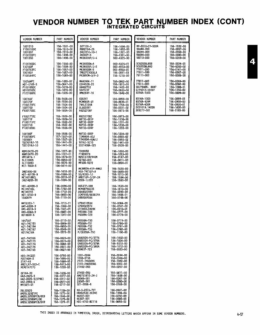
VENDOR NUMBER TO TEK PART NUMBER INDEX (CONT) INTEGRATED CIRCUITS
VENOOR NUMBER PART NUMBE
156-1501-0 156-1510-0 156-1510-0 156-1496-0 156-1496-0
156-1 506-0 156-1506-0 156-1557-0 156-1 557-0 156-1085-01
156-1085-0; 156-0647-01 156-1678-01 156-1 678-01 156-1 505-01
156-15O5-Ol 156-1554-01 156-1 504-01 156-1504-O( 156-1 554-O(
156-1 509-O( 156-1 509-O( 156-1 502-O( 156-1502-O( 156- 1508-O(
156-1 508-O( 157-1507-OC 156-1 507-OC 156-1441 -0C 156-1441-OC
156-1227-OC 156-1227-01 156-1679-OC 156-0850-02 156-0576-06 156-0414-00
156-1615-00 156-0366-00 156-051 9-00 156-1 694-00
156-0494-00 156-1742-00 156-1718-00 156-0850-00 56-1119-00
56-1213-01 56- 1060-00 56-1301-01 56-0887-00 56-1047-00
56-0710-00 56-0869-00 56-0650-00 56-0549-00 56-0572-00
56-0625-00 56-0574-00 56-0682-00 56-0931 -00 56-0627-00
56-0750-00 56-1 695-00 56-1690-00 56-161 3-00 56-1228-00
56-1626-00 56-031 7-00 56-031 7-02 56-0977-00 56-071 7-00
56-1729-00 56-1273-00 j6-1546-00 56-1375-00
VENDOR NUMBER PART NUMBE
156-1696-C 156-1652-0 156-1321-0 156-1361-0 062-4325-0
VENOOR NUMBER PART NUMBER
THIS INDEX IS ARRANGED IN NUMERICAL ORDER, DISREGARDING LETTERS WHICH APPEAR IN SOME VENOOR NUMBERS.
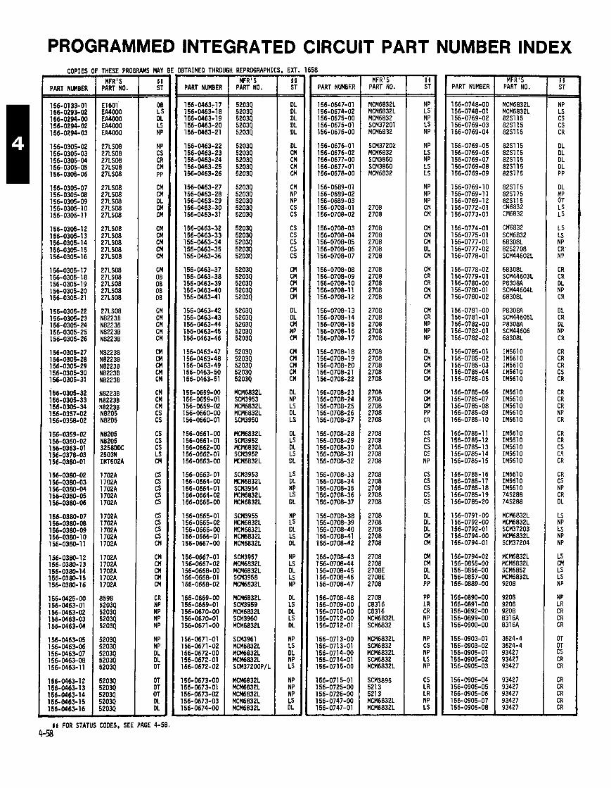
COPIES
PART NUMBER
THESE PRO - MFR'S
PART NO.
E l 601 EA4000 EA4000 EA4000 EA4000
27LS08 27LS08 27LS08 27LS08 27LS08
27LS08 27LS08 27LS08 27LS08 27LS08
27LS08 27LS08 27LS08 27LS08 27LS08
27LS08 27LS08 27LS08 27LS08 27LS08
27LS08 N82238 N82238 N8223B N82238
N82238 N8223B N82238 N82238 N82238
N82238 N82238 N8223B N8205 N8205
N8205 N8205 32580DC 25031 INT602A
1702A l7O2A 1702A 1702A l7O2A
l7O2A l7O2A 1702A 1702A 1702A
1702A 1702A 1702A 1702A 1702A
8598 5203Q 52039 52039 52039
52039 52039 52039 52039 52034
5203Q 52034 5203Q 52039 52039
rMS MAY - SJi ST - - OB LS DL LS NP
NP CS CR CM PP
CM CM DL CM CM
CM CM CM CM CM
CM 08 08 08 08
CM CM CM CM CM
CM CM CM CM CM
CM CM CM CS CS
CS CS CS LS cn cs CS CS CS CS
cs cs CS CS CM
CM CM CM CM CM
CR NP NP NP NP
NP NP DL DL OT
OT OT OT DL DL -
BTAINED THRO
PART NUMBER
I REPROGRAPH'
MFR'S PART NO.
, EXT. 1658
PART NVMBSR MFR'S
PART NO.
MCM6832L MCM6832L MCM6832 SCM37201 MCM6832
SCM3720d MCM6832 SCM3860 SCM3860 MCM6832
2708 2708
2708 2708 2708 2708 2708
2708 2708 2708 2708 2708
2708 2708 2708 2708 2708
2708 2708 2708 2708 2708
2708 2708 2708 2708 2708
2708 2708 2708 2708 2708
2708 2708 2708 2708 2708
2708 2708 2708 2708 2708
2708 2708 2708E 2708E 2708
2708 C83l6 C8316 MCM6832L SCM6832
MCM6832L SCM6832 MCM6832L SCM6832 MCM6832L
SCM3895 521 3 5213 MCM6832L MCM6832L
PART NUMBER
156-0748-00 156-0748-01 156-0769-02 156-0769-03 156-0769-04
156-0769-05 156-0769-06 156-0769-07 156-0769-08 156-0769-09
156-0769-10 156-0769-11 156-0769-1 2 156-0772-01 156-0773-01
156-0774-01 156-0775-01 156-0777-01 156-0777-02 156-0778-01
156-0778-02 156-0779-01 156-0780-00 156-0780-01 156-0780-02
156-0781-00 156-0781-01 156-0782-00 156-0782-01 156-0782-02
156-0785-01 156-0785-02 156-0785-03 156-0785-04 156-0785-05
156-0785-06 156-0785-07 156-0785-08 156-0785-09 156-0785-1 0
156-0785-1 1 156-0785-12 156-0785-13 156-0785-14 156-0785-1 5
156-0785-16 156-0785-17 156-0785-1 8 156-0785-1 9 156-0785-20
156-0791 -00 156-0792-00 156-0792-01 156-0794-00 156-0794-01
156-0794-02 156-0855-00 156-0856-00 156-0857-00 156-0889-00
l56-O89O-OO 156-0891 -00 156-0892-00 156-0899-00 l56-O9OO-OO
156-0903-01 156-0903-02 156-0905-01 156-0905-02 156-0905-03
156-0905-04 156-0905-05 156-0905-06 156-0905-07 156-0905-08
MFRIS PART NO.
I I FOR STATUS CODES. SEE PAGE 4-58.
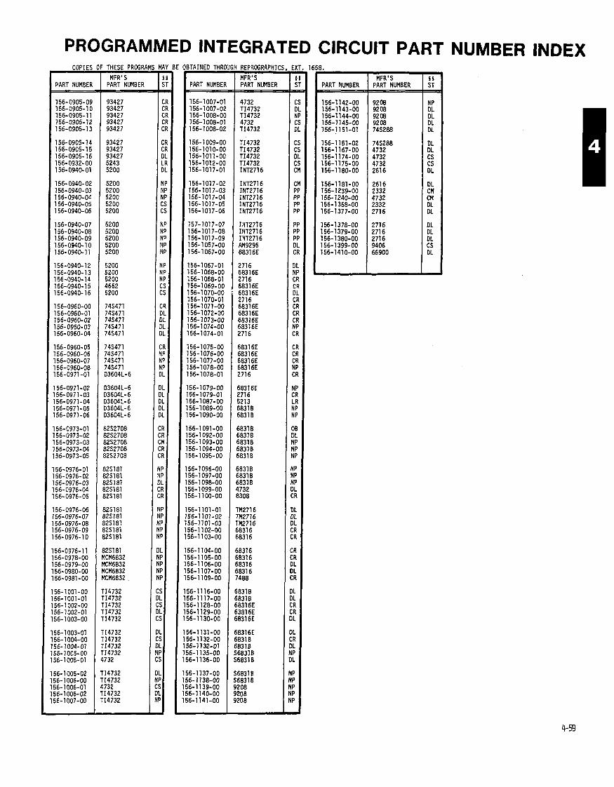
PROGRAMMED INTEGRATED CIRCUIT PART NUMBER INDEX COPIES
PART NUMBER - 156-0905-09 156-0905-1 0 156-0905-11 156-0905-12 156-0905-1 3
156- 0905- 14 156-0905-1 5 156-0905-16 156-0932-00 156-0940-01
156-0940-02 156-0940-03 156-0940-04 156-0940-05 156-0940-06
156-0940-07 156-0940-08 156-0940-09 156-0940-1 0 156-0940-1 1
156-0940- 12 156-0940- 13 156-0940-14 156-0940- 15 156-0940-16
156-0960-00 156-0960-01 756-0960-02 156-0960-03 156-0960-04
156-0960-05 156-0960-06 156-0960-07 156-0960-08 156-0971-01
156-0971-02 156-0971-03 156-0971-04 156-0971 -05 156-0971-06
156-0973-01 156-0973-02 156-0973-03 156-0973-04 156-0973-05
I 56-0976-01 156-0976-02 56-0976-03 I 56-0976-04 56-0976-05
56-0976-06 56-0976-07 56-0976-08 56-0976-09 56-0976-1 0
56-0976-11 56-0978-00 56-0979-00 56-0980-00 56-0981 -00
56-1 001 -00 56-1001-01 56-1 002-00 56-1002-01 56-1 003-00
56-1003-01 56-1004-00 56- 1004-01 56- 1005-00 56-1 005-01
56-1 005-02 56- 1006-00 56-1006-01 56-1 006-02 56-1007-00
THESE PROGRAMS MA MFR I s I s
PART NUMBER / S
ITAINED THRC
PART NUMBER
REPROGRAPHIC
MFR' S
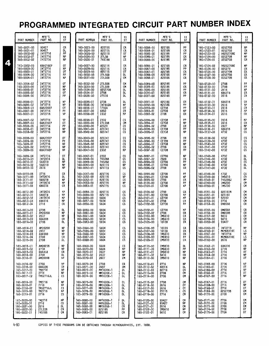
PROGRAMMED INTEGRATED CIRCUIT PART NUMBER INDEX
PART NUMBER MFR'S
PART NO. PART NUMBER
160-0023-00 160-0024-00 160-0025-00 160-0026-00 160-0026-01
160-0027-00 160-0028-00 160-0029-00 160-0030-00 160-0031-00
160-0032-00 160-0033-00 160-0034-00 160-0034-01 160-0035-00
160-0035-01 160-0036-00 160-0036-01 160-0037-00 160-0038-00
160-0038-01 160-0039-00 160-0040-00 160-0041 -00 160-0042-00
160-0043-00 160-0044-00 160-0045-00 160-0046-00 160-0047-00
160-0047-01 160-0048-00 160-0049-00 160-0050-00 160-0050-01
160-0051-00 160-0052-00 160-0052-01 160-0053-00 160-0053-01
L60-0054-00 160-0055-00 160-0056-00 160-0057-00 160-0058-00
160-0059-00 160-0060-00 160-0061-00 160-0062-00 160-0063-00
160-0064-00 160-0065-00 160-0066-00 160-0067-00 60-0068-00
60-0069-00 60-0070-00 60-0070-01 60-0070-02 60-0070-03
60-0070-04 60-0071 -00 60-0072-00 60-0073-00 60-0074-00
60-0075-00 60-0076-00 60-0077-00 60-0078-00 60-0079-00
60-0080-00 60-0081-00 60-0082-00 60-0083-00 60-0083-01
MFR'S PART NO.
8251 15 8251 15 82Sl l5 27L08 74S188
82S115 82S115 8251 15 27LS08 27LS08
27LS08 27LS08 82S2708 2708 27S18
2708 INT602A 1702A 6850 2332
2332 27LS08 82523 82S141 8251 41
825141 825141 8251 41 82S141 2332
2332 74S288 745288 8251 15 82Sll5
8251 15 82S115 8251 15 82S115 82S115
82Sll5 8251 15 5604 5604 5604
5604 5604 5604 5604 5604
5604 5604 5604 5604 5604
5604 5604 2607 2607 !607
!708 !607 1M16306-1 Ml63O6- 1 M16306-1
1M16306- 1 Ml63O6- 1 M I 6306-1 1M16306-1 M16306-1
lM16306-1 lM16306-1 M16306-1 125185 l2Sl85
PART NUMBER
160-0084-00 160-0084-01 160-0085-00 160-0085-01 160-0086-00
160-0086-01 160-0087-00 160-0087-01 160-0088-00 160-0088-01
160-0089-00 160-0089-01 160-0090-00 160-0090-01 160-0091 -00
160-0091 -01 160-0092-00 160-0093-00 160-0093-01 160-0093-02
160-0094-00 160-0094-01 160-0094-02 160-0095-00 160-0095-01
160-0095-02 160-0096-00 160-0096-01 160-0096-02 160-0097-00
160-0097-01 160-0097-02 160-0098-00 160-0098-01 160-0098-02
160-0099-00 160-0099-01 160-0099-02 160-0100-00 160-0100-01
160-01 00-02 160-0101-00 160-0101-01 160-0101 -02 160-01 02-00
160-01 02-01 160-01 02-02 160-0103-00 160-01 04-00 160-0105-00
160-0106-00 160-0107-00 160-01 08-00 160-01 09-00 160-01 09-01
160-01 10-00 160-01 11 -00 160-01 11 -01 160-0111-02 160-01 12-00
160-01 12-01 160-01 12-02 160-01 12-03 160-0113-00 160-01 14-00
160-01 15-00 160-01 16-00 160-01 17-00 160-01 16-00 160-01 19-00
160-01 20-00 160-0121-00 160-0121-01 160-01 22-00 160-0122-01
MFR'S PART NO.
82S185 82.51 85 82S185 8251 85 82S185
82S185 82S185 825185 8251 85 8251 85
82S185 82S185 8251 85 8251 85 825185
82S185 825185 C2708 C2708 2708
C2708 C2708 2708 C2708 C2708
2708 C2 708 C2708 2708 C2708
C2708 2808 C2708 C2708 2708
C2708 C2708 2708 C2708 C2708
2708 C2708 C2708 2708 C2708
C2708 2708 IM5610 IM5610 101 39
10139 10139 IM5610 IM5910 IM5610
IM5610 IM5610 IM5610 561 0 IM5610
2716 5831 6 32716 !708 !708
!708 !616 !616 !S115 !716
33427 33427 !616 (M5610 5610
PART NUMBER MFR'S
PART NO.
8252708 82S2708 N82S2708E 82S2708 8252708
N82S2708E 825278 82S2708 82S2708 8252708
2708 2708 2616 68A316 2616
68A316 261 6 2616 261 6 2616
2616 2616 2607 68A316 4732
4732 4732 4732 4732 4732
4732 4732 4732 4732 4732
4732 IM5610 7452885 IM5200 IM5200
82S181N 825181 52030 2716 OM8598
OM8598 OM8598 5610 561 0 93427
INT2716 MCM68316E INT2716 MCM68316E 2616
68A3l6 2716 2716 2716 2716
2716 2716 2716 2716 2716
2716 2716 2716 8252708
2708
2708 2708 2708 2708 2708
4-60 COPIES OF THESE PROGRAMS CAN BE OBTAINED THROUGH REPROGRAPHICS, EXT. 1658.
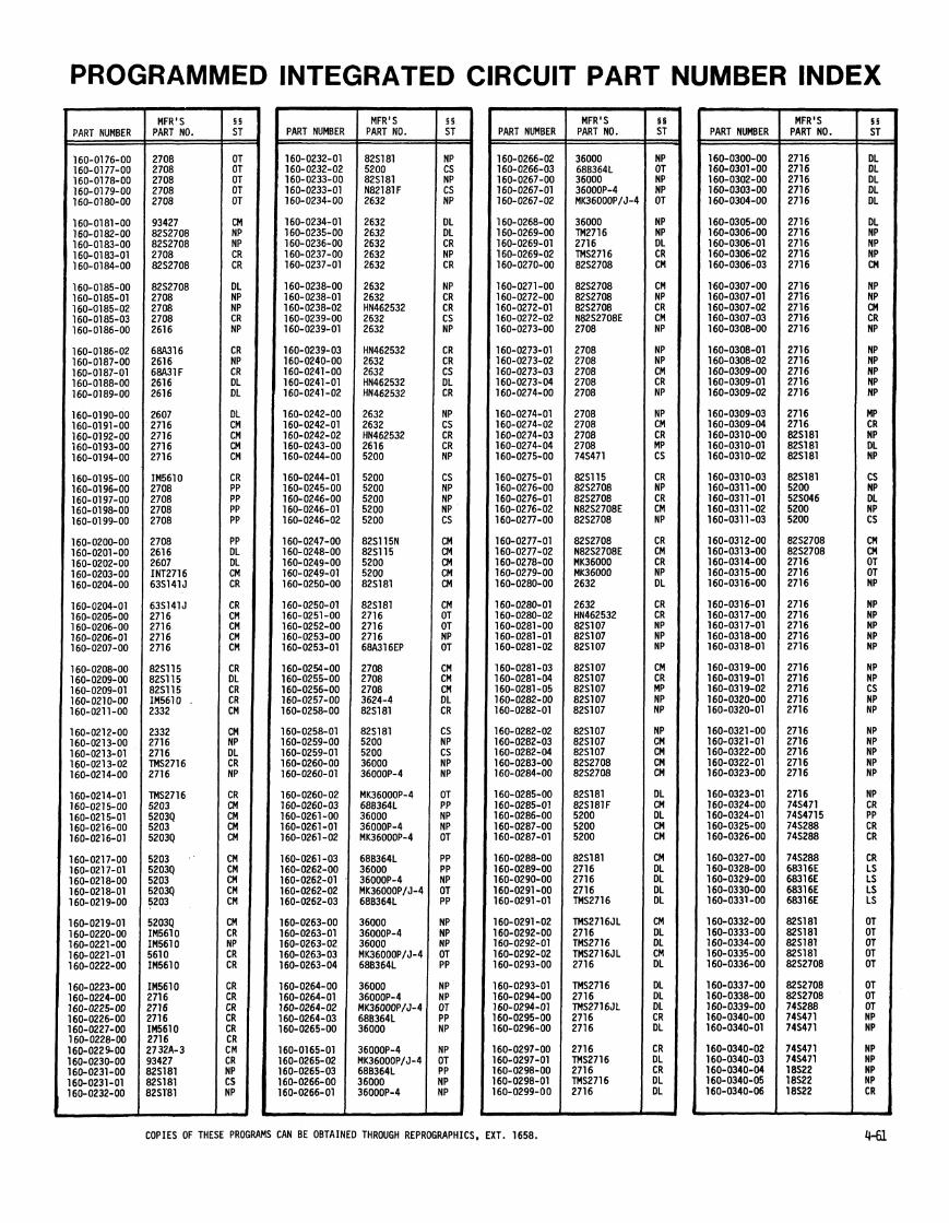

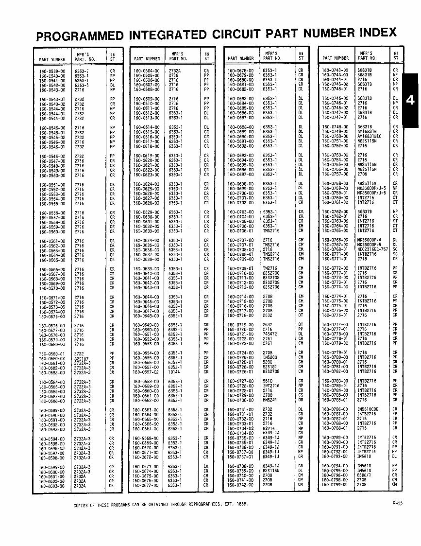
U
I
I
37
W
\\
om
l
mm
z
zz
ra
n
I IU
n
nw
w
w
w
w
w
w
w
w
w
W
-.-m
mm
m
m
m
m
mm
-
mm
m
oo
ww
w
ww
o
ow
-
- .- - 7
- 7
e
7
-- - -
-m
m7
-
-
00
-0
-
0-N
O.-
0
00
00
0
00
00
0
07
00
0
-0
00
0
0-0
-
07
0-0
-0
-0
.-
0-0
-0
-0
-0
0
0-0
0-
00
-0
7
00
00
0
00
00
0
oo
oy
o
oo
oo
o
oo
oo
o
oo
oo
o
oo
oo
o
oo
oo
o
oo
oo
o
oo
oo
o
oo
oo
o
oo
oo
o
00
04
4
OO
OO
O
oo
oo
o
oo
oo
o
oo
oo
o
11
,
1 I
II
II
,
11
11
,
11
11
I
,,
,,
I
II
II
1
1l
11
,
,I
ll
I
II
II
,
,,
I1
I
,,
1
11
11
1
11
11
1
,1
11
,
11
11
m
uu
mm
w
ww
hh
m
mo
-N
m
~m
wh
m
mm
o-
NN
~U
~
wh
m--
NN
~~
U
um
mw
w
hh
mm
m
mo
o-
N
mm
om
m
wh
h
uu
ue
u
ue
eu
u
ut
mm
m
mm
mm
m
mm
mw
w
ww
ww
w
ww
wb
h h
~h
hh
h
hh
hh
r
-h
~r
-h
h
mm
mm
m
mm
mm
rn
cocoE
3g
%!2
~%
!2
S,Z
gg
Z
hbhhh
hh
hh
h
hhhhh
hh
hh
h
hhhhh
hh
hh
h
hhhhh
hh
hh
h
hhhhh
hhhhh
hh
hh
h
hh
hh
h
hh
hh
h
hh
hh
h
hh
hh
h
00
00
0
00
00
0
00
00
0
00
00
0
00
00
0
00
00
0
00
00
0
00
00
0
00
00
0
00
00
0
00
00
0
00
00
0
00
00
0
00
00
0
00
00
0
11
11
I
II
I,
I
oo
oo
o
oo
oo
o
&&
&&
A
&&
A&
&
&&
&&
A
&A
&&
&
&&
&A
&
&&
A&
&
&&
&A
&
&&
&&
A
&A
&&
&
A&
&&
&
&A
&&
&
&&
A&
&
&&
&&
A
ww
ww
w
ww
ww
w
ww
ww
w
ww
ww
w
ww
ww
w
ww
ww
w
ww
ww
w
ww
ww
w
ww
ww
w
ww
ww
w
ww
ww
w
ww
ww
w
ww
ww
w
ww
ww
w
ww
ww
w
---r-
----- ---,-- F
-F
-7
-
----- -.----- --..---
----- ---7
-
C-C--
----- ----.-
C
C---
-7
---
-----
ID
w
ww
m
mm
m
--
-
7-
7
-
-7
- -
-
-7
-
- 7
-
wo
o0
0
N
m
0
-0
-
373373 7Z
11
11
1
It
II
I
II
II
I
II
II
I
II
II
I
Illlh
h
P
-h
-h
hh
h
h
0
mh
h
u
.------- -m
101
1 I
I I
I I-
mm
mm
m
mm
mm
m
mm
mm
m
mm
mm
m
mm
mm
m
mm
mm
~ W
NW
NN
~
NN
NN
c
om
mm
~ N
WU
--
N
O-N
O
N~
~N
N
N~
--
mm
mm
mm
m
-m
mm
m
mm
mm
m
mm
mm
m
mm
mm
m
mm
mm
m
mm
mm
m
mm
mm
-c
n-w
lwl
~m
wlw
lwl O
OO
O~
m
-m
ww
o
mo
wlw
l om
m
m-
-h
uo
oc
cu
6
wlo
oo
82883 ~8~~~ ~a~~~
38888 ~~~~8 sza8F
&E
EE
E
EN
NN
N
hh
hh
"
Wh
Uh
h
hE
NN
N
WZ
hh
h
hh
hN
mm
mm
mm
m
Nh
hh
e
mm
mm
N
NN
NN
N
N-N
N
N-m
mm
m
-N
NS
N
NN
wm
ww
ww
ww
w
mN
NN
00
00
0
00
00
0
00
00
0
00
00
0
00
00
0
00
00
-
0-0
-0
~
00
00
0
00
00
0
00
00
0
0-0
-
00
-0
0
0~
0-N
00
-0
0.-
00
00
0
00
00
0
00
00
0
00
00
0
00
00
0
00
00
0
00
00
0
00
00
0
00
00
0
00
00
0
00
00
0
00
00
0
00
00
0
00
00
00
00
00
0
00
00
0
,1
11
1
1,
11
1
,,
I,
,
1,
11
1
1,
11
1
11
11
,
,,
Il
l
,,
Il
l
II
II
I
,1
11
1
11
11
1
11
11
1
11
11
11
11
11
,
1,
01
1
mm
o-N
m
em
wh
m
mo
-N
m
om
wh
m
mo
-N
m
cm
ww
h
hm
mm
m
o-
~m
um
wh
m
mo
-~
m u
mm
ww
h
mm
mo
-
.-
~m
bu
mm
wh
h
mm
o-N
h
wm
mm
m
mm
mm
m
mm
mm
m
mm
mm
m
mo
oo
o
oo
oo
o
oo
oo
o
--F
-
----- Y
NN
NN
N
NN
NN
N
NN
N~
m
mm
mm
mm
mm
mm
m
m-to
o
IDw
wG
w
WtD
kD
tOW
W
-w
Ww
W
ww
UW
ID
Wh
hh
hhhhh
hhhhh
hh
hh
h
hh
hh
h
hh
hh
h
hhhhh
hh
hh
h
hh
hh
hh
hh
hh
h b
hh
hh
0
00
00
0
00
00
0
00
00
0
00
00
0
00
00
0
00
00
0
00
00
0
00
00
-7-r-
----- 7
-P
-7
----- ----- -----
-P
C--
----- ----- ----- ----- 7
----
---.-.------- 7
----
00
00
0
00
00
0
00
00
0
00
00
0
00
00
0
00
00
0
00
00
0
00
00
0
00
00
0
00
00
0
OO
OO
N
00
00
0
00
00
0
00
00
0
00
00
0
00
00
0
00
00
0
00
00
0
00
00
0
00
00
0
00
00
0
00
00
0
00
00
0
00
00
0
00
00
0
00
00
0
00
00
0
00
00
0
00
00
0
00
00
0
,1
11
,
I1
11
,
*m
m-m
m
o-N
m
&&
&A
&
&&;&A &
&&
A&
&
&:&
A
&&
&A
&
&&
:&A
&
&&
A&
&
&;&
A
&&
&L
A
&&
A;&
&
&&
&A
&
&&
LA
A
&A
AA
o
oo
oo
o
----
--.--- -N
NN
N
NN
NN
N
~m
mm
m
mm
mm
m
m6
66
o o
uu
uu
u
mm
mm
m
mm
mm
m
mw
ww
w
ww
ww
w
wh
hh
h
hh
hh
w
ww
ua
w
ww
ww
w
ww
ww
w
ww
ww
w
ww
ww
w
ww
ww
w
ww
ww
w
ww
ww
w
ww
ww
w
ww
ww
w
ww
ww
w
ww
ww
w
ww
ww
w
ww
ww
w
ww
ww
w
oo
oo
o
oo
oo
o
oo
oo
o
oo
oo
o
oo
oo
o
oo
oo
o
oo
oo
o
oo
oo
o
oo
oo
o
oo
oo
o
oo
oo
o
oo
oo
o
oo
oo
o
mo
oo
o o
oo
oo
A
&&
&&
&
&&
A&
&
&&
A&
&
A&
&&
&
&A
&&
&
&&
.A&
&
&&
A&
&
&&
&A
&
&&
&A
&
&&
&A
&
A&
&&
&
&&
A&
&
&A
&&
&
&&
&A
&
&&
&A
w
ww
ww
w
ww
aw
w
ww
ww
w
ww
ww
w
ww
ww
w
ww
ww
w
ww
ww
w
ww
ww
w
ww
ww
w
ww
ww
w
ww
ww
w
ww
ww
w
ww
ww
w
ww
ww
w
ww
ww
----- ----- -..---- ---.---
7-7
-F
-----
7-r
-C
7
7-F
-
-7
7-7
----- ----- ----- -----
--7
7-
-7
7-F
..
..
I
,,
,
m. O
<&
A
, 4
.2&
&&
&
&&
A&
&
&&
A&
&
&<
a<
m
mm
mw
N
NW
NN
~
NN
~N
~
ww
ww
w
wa
ww
w
ww
ww
w
ww
ww
w
ww
ww
w
ww
ww
w
ww
ww
N
-N
NN
N
NN
NN
N
NN
NN
N
NN
NN
N
NN
NN
m
mm
m-
mm
-m
m
-m
m-m
m
----
----- ----- ----- ----- 7-r--
--v
--
mm
mm
m
mm
mm
m
mm
mm
m
mm
mm
m
mm
mm
m
mm
mm
,. h
hh
hh
h
hh
hh
h
hh
hh
hhhhh
hbhhh
hhhP
-I.
hh
hh
h
hh
hh
h
hhhhh
hN
hh
h h
hh
hh
h
hh
hh
hhhhh
hhhhh
ww
ww
N
NN
NN
N
NN
NN
N
NN
NN
N
NN
NN
N
NN
NN
N
NN
NN
N
NN
NN
N
NN
NN
N
NN
NN
N
NW
NN
N
NN
NN
N
NN
NN
N
NN
NN
N
NN
NN
N
00
00
0
-N
O-N
0
-N
O-
N
O0
00
0
00
00
0
00
00
0
00
00
0
00
00
0
00
00
0
00
00
-N
o0
0
00
00
0
00
00
0
00
00
0
00
00
0
00
00
0
00
00
0
00
00
0
00
00
0
00
00
0
00
00
0
00
00
0
00
00
0
00
00
0
00
00
0
00
00
0
00
00
0
00
00
0
00
00
0
00
00
0
II
II
I
m0
-N
"
$,A&
&&
A
&&
&&
&
A&
&&
A
&A
&A
&
A&
&&
:&
A&
&
&A
&&
&
A&
A&
A
&:&
&A
&
&:&
A
&&
&LC
& &&
;&A
&
&&
A&
&&;&A
OO
~U
C *U
U*O
u
uo
uu
u
eu
um
m
mm
mm
m
mm
mw
w
ww
ww
w
ww
wh
h
hh
hh
h
hh
hm
m
mm
mm
m
mm
mc
a
mm
mm
m
mm
mm
m
mo
oo
o
l',mm
mm
m
mm
mm
m
mm
mm
m
mm
mm
m
mm
mm
m
mm
mm
m
mm
mm
m
mm
mm
m
mm
mm
m
mm
mm
m
mm
mm
m
mm
mm
m
mm
mm
m
mm
mm
m
ww
ww
0
00
00
0
00
00
0
00
00
0
00
00
0
00
00
0
00
00
0
00
00
0
00
00
0
00
00
0
00
00
a
00
00
0
00
00
0
00
00
0
00
00
0
00
00
1
,1
11
I
,,
,,
I
,,
,,
,
,,
I,
0
00
00
0
00
00
0
00
00
0
00
00
&
&&
A&
&
A&
&&
A
&&
&&
&
&&
A&
d
&A
&A
A
&&
&&
&
&&
A&
&
&A
&&
&
&A
&&
A
&&
&&
&
&&
&A
w
ww
ww
w
ww
ww
w
ww
ww
w
aw
ww
w
ww
ww
w
ww
ww
w
ww
ww
w
ww
ww
w
ww
ww
w
wa
ww
w
ww
ww
w
ww
ww
w
ww
ww
w
ww
ww
w
ww
ww
----- -----
F-c
-7
----.--
-7
-7
-
----- 7
--7
-
--c--
----,.- 7
--7
-
--7
-7
-c-c-
7-7
--
7--7
-
-7
7-7
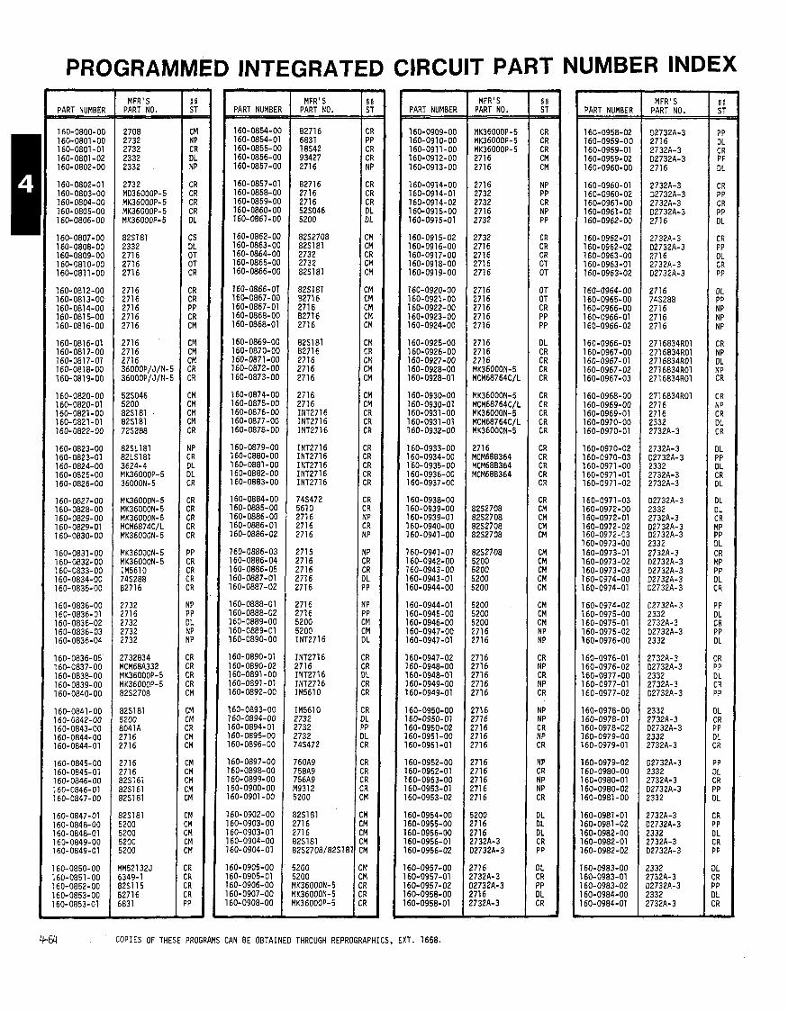
PROGRAMMED INTEGRATED CIRCUIT PART NUMBER INDEX
PART NUMBER - MFR' S PART NO. PART NUMBEF
160-0854-OC 160-0854-01 160-0855-OC 160-0856-00 160-0857-00
160-0857-01 160-0858-00 160-0859-00 160-0860-00 160-0861-00
160-0862- 00 160-0863-00 160-0864-00 160-0865-00 160-0866-00
160-0866-01 160-0867-00 160-0867-01 160-0868-00 160-0868-01
160-0869-00 160-0870-00 160-0871-00 160-0872-00 160-0873-00
160-0874-00 160-0875-00 160-0876-00 160-0877-00 160-0878-00
160-0879-00 160-0880-00 160-0881-00 160-0882-00 160-0883-00
160-0884-00 160-0885-00 160-0886-00 160-0886-01 160-0886-02
160-0886-03 160-0886-04 160-0886-05 160-0887-01 160-0887-02
160-0888-01 160-0888-02 160-0889-00 160-0889-01 160-0890-00
160-0890-01 l6O-O89O-O2 160-0891 -00 160-0891 -01 160-0892-00
60-0893-00 '60-0894-00 60-0894-01 60- 0895-00 60-0896- 00
60-0897-00 60-0898-00 60-0899-00 60-0900-00 60-0901 -00
60-0902-00 60-0903-00
MFR'S PART NO. PART NUMBER
160-0909-00 160-0910-00 160-091 1-00 160-0912-00 160-0913-00
16O-O914-OO 160-0914-01 160-0914-02 160-0915-00 160-0915-01
160-0915-02 160-091 6-00 160-091 7-00 160-0918-00 160-0919-00
160-0920-00 160-0921 -00 160-0922-00 160-0923-00 160-0924-00
160-0925-00 160-0926-00 160-0927-00 160-0928-00 160-0928-01
160-0930-00 160-0930-01 160-0931-00 l6O-O93l-Ol 160-0932-00
160-0933-00 160-0934-00 160-0935-00 160-0936-00 160-0937-00
160-0938-00 160-0939-00 160-0939-01 l6O-O94O-OO 160-0941-00
160-0941-01 160-0942-00 160-0943-00 160-0943-01 160-0944-00
160-0944-01 160-0945-00 160-0946-00 160-0947-00 160-0947-01
160-0947-02 160-0948-00 160-0948-01 160-0949-00 160-0949-01
160-0950-00 '60-0950-01 60-0950-02 60-0951 -00 60-0951 -01
60-0952-00 60-0952-01 60-0953-00 60-0953-01 60-0953-02
60-0954-00 60-0955-00 60-0956-00 60-0956-01 60-0956-02
MFR' S PART NO.
MK36000P-5 MK36000P-5 MK36000P-5 271 6 2716
271 6 2732 2732 2716 2732
2732 2716 2716 2716 2716
2716 271 6 271 6 271 6 2716
2716 2716 2716 MK36000N-5 MCM68764ClL
MK36000N-5 MCM68764CIL MK36000N-5 MCM68764C/L MK36000N-5
2716 MCM68B364 MCM68B364 MCM68B364
82S2708 8252708 82S2708 82S2708
82S2708 5200 5200 5200 5200
5200 5200 5200 2716 2716
271 6 2716 2716 271 6 2716
271 6 2716 2716 ?716 ?716
271 6 2716 271 6 2716 ?716
5200 !716 !716 !732A-3 12732A-3
?716 !732A-3 32732A-3 !716 !732A-3
PART NUMBER
160-0958-02 160-0959-00 160-0959-01 160-0959-02 160-0960-00
160-0960-01 160-0960-02 160-0961 -00 160-0961 -02 160-0962-00
160-0962-01 160-0962-02 160-0963-00 160-0963-01 160-0963-02
160-0964-00 160-0965-00 160-0966-00 160-0966-01 160-0966-02
160-0966-03 160-0967-00 160-0967-01 160-0967-02 160-0967-03
160-0968-00 160-0969-00 160-0969-01 160-0970-00 160-0970-01
l6O-O97O-O2 l6O-O97O-O3 160-0971 -00 160-0971 -01 160-0971 -02
160-0971-03 160-0972-00 160-0972-01 160-0972-02 160-0972-03 160-0973-00 160-0973-01 160-0973-02 160-0973-03 160-0974-00 160-0974-01
160-0974-02 160-0975-00 16O-O975-Ol 160-0975-02 160-0976-00
160-0976-01 160-0976-02 160-0977-00 160-0977-01 160-0977-02
160-0978-00 160-0978-01 160-0978-02 l6O-O979-OO 160-0979-01
160-0979-02 160-0980-00 160-0980-01 160-0980-02 160-0981-00
l6O-O98l-Ol 160-0981 -02 160-0982-00 l6O-O982-Ol 160-0982-02
'60-0983-00 /60-0983-01 60-0983-02 60-0984-00 60-0984-01
MFR'S PART NO.
D2732A-3 2716 2732A-3 D2732A-3
2716
2732A-3 02732A-3 2732A-3 02732A-3 271 6
2732A-3 D2732A-3 2716 2732A-3 02732A-3
2716 745288 271 6 2716 271 6
271 6834R01 271 6834R01 2716834R01 271 6834R01 271 6834R01
271 6834R01 2716 2716 2332 2732A-3
2732A-3 D2732A-3 2332 2732A-3 2732A-3
02732A-3 2332 2732A-3 D2732A-3 D2732A-3 2332 2732A-3 02732A-3 D2732A-3 02732A-3 D2732A-3
02732A-3 2332 2732A-3 02732A-3 2332
2732A-3 D2732A-3 2332 2732A-3 D2732A-3
2332 2732A-3 D2732A-3 2332 2732A-3
D2732A-3 2332 2732A-3 02732A-3 2332
2732A-3 D2732A-3 2332 2732A-3 D2732A-3
2332 2732A-3 02732A-3 2332 2732A-3
4 6 4 COPIES OF THESE PROGRAMS CAN BE OBTAINED THROUGH REPROGRAPHICS, EXT. 1658.

PROGRAMMED INTEGRATED CIRCUIT PART NUMBER INDEX MFR' S
PART NO.
D2732A-3 2332 2732A-3 D2732A-3 2332
2732A-3 D2732A-3 2332 2732A-3 D2732A-3
2332 2732A-3 027 32A-3 2332 2732A-3
D2732A-3 2332 2732A-3 2332 2732A-3
2332 2732A-3 D2732A-3 2332 2732A-3
D2732A-3 2332 2732A-3 D2732A-3 2332
2732A-3 D2732A-3 2332 273263 D2732A-3
2332 2732A-3 02732A-3 2332 2732A-3
D2732A-3 2332 2732A-3 D2732A-3 2332
2732A-3 02732A-3 2332 2732A-3 D2732A-3
2332 2732A-3 02732A-3 2332 2732A-3
02732A-3 2332 2732A-3 02732A-3 2332
2732A-3 2732A-3 2332 2732A-3 D2732A-3
2332 2732A-3 32732A-3 2332 2732-3
32732A-3 ?332 !732A-3 12732A-3 ?332
PART NUMBER
160-1010-01 160-1010-02 160-1011-00 160-1011-01 160-1011-02
160-1012-00 160-1012-01 160-1012-02 160-1012-03 160-1 01 3-00
160-1013-01 160-1 01 3-03 160-1 01 4-00 160-1015-00 160-1016-00
160-1017-00 160-1018-00 160-1019-00 160-1 020-00 160-1021-00
160-1023-00 160-1 023-01 160-1023-02 160-1024-00 169-1 025-00
160-1025-01 160-1025-02 160-1026-00 160-1 026-01 160-1027-00
160-1 027-01 160-1027-02 160-1027-03 160- 1028-00 160-1 028-01
160-1029-00 160-1030-00 160-1 030-01 160- 1030-02 160-1 030-03 160-1 031 -00 160-1031-01 160-1031-02 160-1031-03 160-1032-00 160-1033-00
160-1 034-00 160-1035-00 160-1 036-00 160-1 037-00 160-1038-00
160-1039-00 160-1 040-00 160-1041-00 160-1042-00 160-1043-00
160-1 044-00 160-1045-00 160-1046-00. 160-1 047-00 160- 1048-00
60-1 049-00 160-1050-00 60-1 050-01 60-1051-00 60-1051-01
60-1 052-00 60-1 052-01 60-1 053-00 60-1053-01 60-1 054-00
60-1 054-01 60-1 055-00 60-1 055-01 60-1 056-00 60-1057-00
MFR' S PART NO. PART NUMBER
160-1058-00 160-1 059-00 160-1060-00 160-1061-00 160-1062-00
160-1063-00 160-1 064-00 160-1 065-00 160-1066-00 160-1 067-00
160-1 068-00 160-1069-00 160-1069-01 160-1 070-00 160-1 070-01
160-1071-00 160-1 071-01 160-1 072-00 160-1072-01 160-1073-00
160-1 073-01 160-1 073-02 160-1 074-00 160-1 074-01 160-1074-02
160-1075-00 160-1 076-00 160-1 076-01 160-1 076-02 160-1077-00
160-1 078-00 160-1 078-01 160-1 079-00 160-1 079-01 160- 1080-00
160-1081-00 160-1081-01 160-1 082-00 160-1 082-01 160-1 083-00
160-1 083-01 160-1 084-00 160-1 085-00 160-1 086-00 160-1086-01
160-1 086-02 160-1 087-00 160-1 088-00 160-1 089-00 160-1 090-00
160-1091-00 160-1 091 -01 160-1 092-00 160-1 092-01 160-1093-00
160-1093-01 160-1093-02 160- 1094-00 160-1094-01 160-1 094-02
160-1 095-00 160-1096-00 160-1 097-00 160-1 098-00 160-1 099-00
160-1 100-00 160-1101-00 160-1102-00 160-1103-00 160-1 104-00
160-1 105-00
160-1 106-00 160-1107-00 160-1108-00
MFR'S PART NO.
MFR'S
:OPIES OF THESE PROGRAMS CAN BE OBTAINED THROUGH REPROGRAPHICS, EXT. 1658.

PROGRAMMED INTEGRATED CIRCUIT PART NUMBER INDEX
PART NUMBE
160-1165-0 160-1166-0 160-1167-0 160-1168-0 160-1169-0
160-1169-0 160-1170-0 160-1171-0 160-1172-0
160-1 173-01
160-1174-01 160-1175-01 160-1176-01
160-1 176-0 160-1 176-0: 160-1176-0: 160-1176-Od 160-1177-01
160-1178-01 160-1179-01 160-1180-01 160-1181-01 160-1 182-01
160-1183-01 160-1 184-01 160-1185-O( 160-1186-O( 160-1 187-O(
160-1 188-O( 160-1189-O( 160-1 lgO-O( 160-1191-O(
160- 11 92-O( 160- 1 193-O( 160-1194-O( 160-1195-O( 160-1 196-O(
160-1 l97-OC 160-1 198-O( 160-1199-Ot 160-1200-OC 160-1201-OC
160-1202-OC 160-1 203-OC 160-1204-OC 160-1 205-OC 160-1 206-OC
160-1207-06 160-1207-01 160-1207-02 160- 1208-OC 160-1209-00
160-1210-00 160-1211-00 160-1211-01 160-1211-02 160-1212-00
60-1213-00 60-1 214-00 60-1215-00
60-1216-00 60-1217-00
60-1218-00 60-1219-00 60-1 220-00 60-1221-00 60- 1222-00
60-1223-00 60-1224-00 60-1225-00 60-1 226-00 60-1227-00
MFR'S PART NO. 1:: PART NUMBER
MFR ' S PART NO.
8251 91 82S191 8251 91 8251 91 8251 91
8251 91 82S191 74S288 74S288 745288
745288 745288 745288 2716 MK36000N-5
AM2732-IDC AM2732- IDC 2716 2716 MK36000N-5
68766C35 MK36000N-5 68766C35 MK36000N-5 68766C35
MK36000N-5 6876605 MK36000N-5 68766C35 MK36000N-5
68766C35 MK36000N-5 68766C35 MK36000N-5 68766C35
MK36000N- 5 68766C35 MK36000N-5 68766C35 MK36000N-5
68766C35 MK36000N-5 68766C35 MK36000N-5 2732
MK36000P-4 MK36000P-4 MK36000P-4 MK36000P-4 MK36000P-4
YK36000P-4 YK36000P-4 YK36000P-4 YK36000P-4 YK36000P-4
YK36000P-4 YK36000P-4 qK36000P-4 9K36000P-4 IK36000P-4
IK36000P-4 1K36000P-4 IK36000P-4 IK36000P-4 IK36000P-4
1K36000P-4 IK36000P-4 IK36000P-4 IK36000P-4 IK36000P-4
IK36000P-4 IK36000P-4 IK36000P-4 IK36000P-4 IK36000P-4
PART NUMBER MFR'S
PART NO. PART NUMBER MFR ' S
PART NO.
11-66 COPIES OF THESE PROGRAMS CAN BE OBTAINED THROUGH REPROGRAPHICS, EXT. 1658.
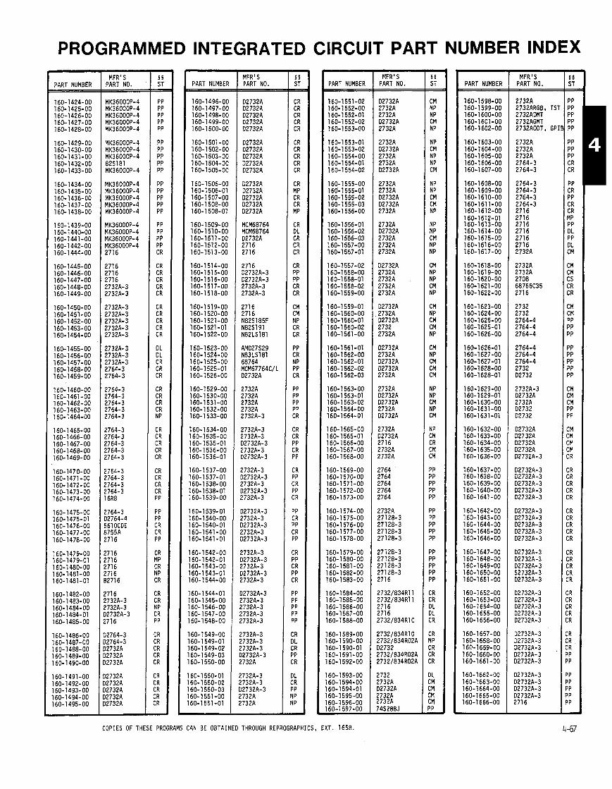
PROGRAMMED INTEGRATED CIRCUIT PART NUMBER INDEX
1 PART NUMBER MFR'S
PART NO. PART NUMBER MFR'S PART NO. PART NUMBER
160-1551-02 160-1 552-00 160-1 552-01 160-1 552-02 160-1 553-00
160-1553-01 160-1 553-02 160-1 554-00 160-1 554-01 160-1554-02
160-1 555-00 160-1 555-01 160-1 555-02 160-1 555-03 160-1 556-00
160-1 556-01 160-1 556-02 160-1556-03 160-1 557-00 160-1 557-01
160-1 557-02 160-1 558-00 160-1 558-01 160-1 558-02 160-1 559-00
160-1559-01 160-1560-00 160-1 560-01 160-1 560-02 160-1561-00
160-1561-01 160-1562-00 160-1562-01 160-1562-02 160-1 562-03
160-1 563-00 160-1 563-01 160-1 563-02 160-1 564-00 160-1 564-01
160-1 565-00 160-1 565-01 160-1566-00 160-1 567-00 160-1568-00
160-1569-00 160-1570-00 160-1571-00 160-1572-00 160-1573-00
160-1 574-00 160-1 575-00 160-1 576-00 160-1577-00 160-1 578-00
160-1579-00 160-1 580-00 160-1 581-00 160-1 582-00 160-1 583-00
160-1 584-00 160-1585-00 6 0 - 1 586-00 6 0 - 1 587-00 60-1 588-00
60-1 589-00 60-1 590-00 60-1 590-01 60-1 591-00 60-1592-00
60-1 593-00 60-1 594-00 60-1 594-01 60-1595-00 60-1596-00 60-1 597-00
MFR'S PART NO.
02732A 2732A 2732A D2732A 2732A
2732A D2732A 2732A 2732A D2732A
2732A 2732A D2732A 02732A 2732A
2732A D2732A 2732A 2732A 2732A
02732A 2732A 2732A 2732A 2732A
D2732A 2732A 02732A 2732 2732A
02732A 2732A D2732A D2732A 2732A
2732A D2732A 02732A 2732A D2732A
2732A D2732A 2716 2732A 2732A
2764 2764 2764 2764 2764
2732A 27128-3 27128-3 27128-3 27128-3
27128-3 27128-3 27 128-3 271 28-3 2716
2732/834Rll 2732/834R11 2716 271 6 ?732/834RlO
!732/834R10 !732/834R02A 12732 !732/834R02A !732/834R02A
!732 !732A 32732A !732A !732A 74S288J
PART NUMBER
160-1 598-00 160-1 599-00 160-1 600-00 160-1601-00 160-1 602-00
160-1 603-00 160-1 604-00 160-1605-00 160-1 606-00 160-1 607-00
160-1 608-00 16O-16O9-OO 160-1610-00 160-161 1-00 160-1612-00 16O-l612-Ol 160-1613-00 160-1614-00 160-1615-00 160-1 61 6-00 160-1617-00
160-1618-00 160-1 61 9-00 160-1 620-00 160-1621-00 160-1622-00
160-1 623-00 160-1 624-00 160-1 625-00 160-1625-01 160-1626-00
160-1626-01 160-1627-00 160-1627-01 160-1628-00 160-1 628-01
160-1 629-00 160-1629-01 160-1 630-00 160-1631 -00 160-1631-01
160-1632-00 160-1633-00 160-1634-00 160-1635-00 160-1636-00
160-1637-00 160-1638-00 160-1639-00 160-1 640-00 160-1641 -00
160-1642-00 160-1 643-00 160-1644-00 160-1645-00 160-1 646-00
160-1 647-00 160-1 648-00 160-1 649-00 160-1650-00 160-1651 -00
160-1652-00 160-1653-00 160-1654-00 160-1655-00 160-1 656-00
160-1657-00 160-1658-00 160-1659-00 160-1660-00 160-1661-00
160-1662-00 160-1663-00 160-1664-00 160-1665-00 160-1666-00
MFR ' S PART NO.
COPIES OF THESE PROGRAMS CAN BE OBTAINED THROUGH REPROGRAPHICS, EXT. 1658.
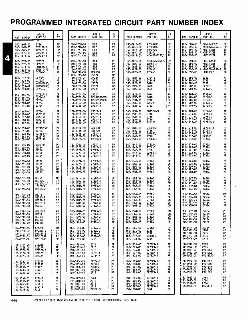
PROGRAMMED INTEGRATED CIRCUIT NUMBER INDEX
PART NUMBER
160-1667-00 160-1668-00 160-1 669-00 160-1670-00 160-1671-00
160-1672-00 160-1673-00 160- 1674-00 160-1675-00 160-1676-00
160-1 677-00 160-1 678-00 160-1679-00 160-1679-01 160-1679-02
160-1680-00 160-1681-00 160-1682-00 160-1683-00 160-1684-00
160-1685-00 160-1686-00 160-1 687-00 160-1 688- 00 160-1689-00
160- 1690-00 160-1691-00 160-1692-00 160-1 693-00 160-1694-00
160-1695-00 160-1 696-00 160-1697-00 160-1698-00 160-1699-00
160- 1700-00 160-1701-00 160-1 702-00 160-1 703-00 160-1 704-00
160-1705-00 160-1706-00 160-1707-00
160-1708-00
160-1709-00 160-1710-00 160-1711-00 160-1712-00 160-1713-00
160-1714-00 160-1715-00 160-1716-00 160-1717-00 160-1718-00
160-1719-00 160-1720-00 160-1721-00 160-1 722-00 160-1723-00
160-1 724-00 160-1725-00 160-1 726-00 160-1727-00 160- 1728-00
160-1729-00 160-1 730-00 160-1731-00 160-1732-00 160- 1733-00
160-1734-00 160- 1735-00 160-1 736-00 160- 1737-00 160- 1738-00
- MFR'S
PART NO.
2716 D2716A-3 D2732A-3 D2732A-3 D2732A-3
D2732A D2732A HN462532 IMS61 OCPE 02764-3
02732A D2732A MCM68764C/I MCM68764C/I 68764C/L
D2732A-3 D2764-3 02764 D2764 02764
D2764 N82S191 N82S191 N82S191 N82S191
DM74S288J D2764 D27364-4 N82S191 N82S191
N82S191 02764 D2764 D2764 02764
D2764 D2764 D2764 D2732A 02764
D2764 D2732A D2732A-3/ D2732A
D2732A-3
8271 6 D2764-3 02764-3 12716-1 82SlO7
PAL16R6 32764 D2732A 12732A 12732A
.M1 OCN 32732A-3 32732A-3 ICM10149 ICM10149
74S288 '25288 32732A-3 32732A-3 32732A
!7S291 !7S291 13427 33427 13427
!764-3 !764-3 1764-3 1764-3 2L6
PART NUMBER MFR'S
PART NO. PART NUMBER
PART MFR ' S
PART NO. PART NUMBER
160- 1889-00 160-1 890-00 160-1891 -00 160-1892-00 160-1 893-00
160-1894-00 160-1895-00 160-1896-00 160-1897-00 160-1898-00
160-1 899-00 160-1 900-00 160-1901-00 160-1902-00 160-1903-00
160-1 904-00 , 160-1 905-00 160-1 906-00 160-1 907-00 160-1 908-00
160-1 909-00 160-1 91 0-00 160-1911-00 160-1 91 2-00 160-1 91 3-00
160-1 91 4-00 160-1915-00 160-1 91 6-00 160-1 91 7-00 160-1 918-00
160-1 91 9-00 160-1 920-00 160-1921-00 160-1 922-00 160-1923-00
160-1 924-00 160-1 925-00 160-1 926-00 160-1 927-00 160-1928-00
160-1929-00 160-1930-00 160-1931-00 160-1932-00 160-1933-00
160- 1934-00 160-1935-00 160-1 936-00 160-1937-00 160-1938-00
160-1939-00 160-1 940-00 160-1941-00 160-1 942-00 160-1943-00
160-1944-00 160-1 945-00 160- 1946- 00 160-1947-00 60-1 948-00
60 - 1949- 00 60-1950-00 60-1 951-00
8 60-1 952-00 '60-1953-00
60-1954-00 60-1 955-00 60-1956-00 60-1 957-00 60-1958-00
60-1 959-00 60-1 960-00 60-1961-00 60-1962-00
MFR'S PART NO.
OPIES OF THESE PROGRAMS CAN BE OBTAINED THROUGH REPROGRAPHICS, EXT. 1658.
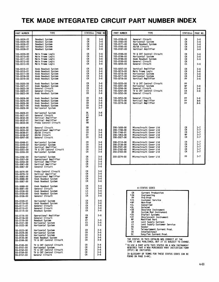
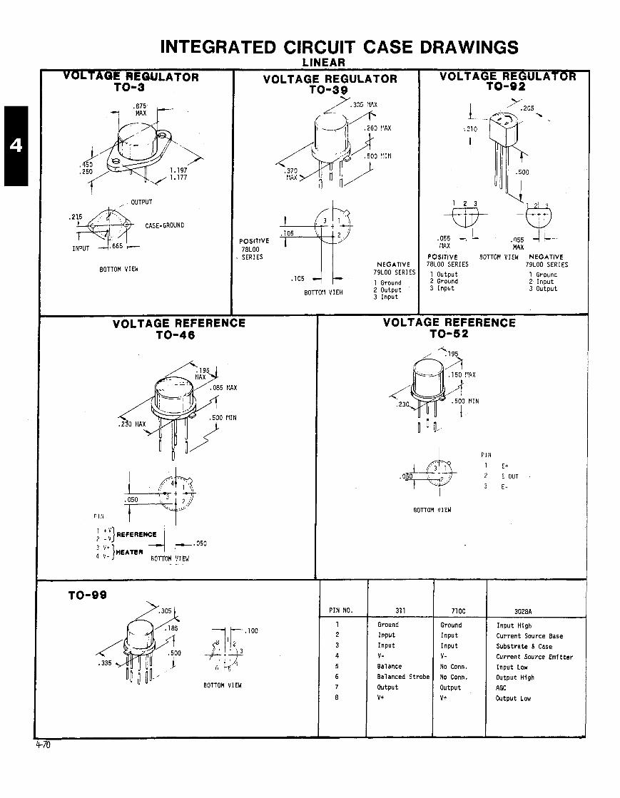
INTEGRATED CIRCUIT CASE DRAWINGS VOLTAGE REQULATOR
OUTPUT
CASE-GROUND
BOTTOM VIEW
VOLTAGE REFEREN 1 0 - 4 6
LINEAR VOLTAGE REGULATOR
1 0 - 3 9 7 . 3 3 5 r t l x 5,+ 6 - ~ .260 'IAX
POSITIVE 78LOO SERIES
BOTTOM VIEH
1 0 - 9 9
BOTTOM VIEW
NEGATIVE 79L00 SERIES
1 Ground 2 Output 3 Input
VOLTAGE REGULATOR TO-02
.055 4 . Q55 l l A X MAX
POSITIVE BOTTOM VIEW NEGATIVE 78L00 SERIES 79L00 SERIES
1 Output 1 Ground 2 Ground 2 I npu t 3 I npu t 3 Output
VOLTAGE REFERENCE 1 0 - 5 2
I P I N
1 E+ 2 E OUT . 3 E-
BOTTOM VIEW
Ground
Inpu t
I npu t
v- Balance
Balanced Strobe
Output
v+
PIN NO.
Ground
Inpu t
i I npu t v- No Conn.
No Conn.
Output V t
--
I npu t High
Current Source Base
Substrate 8 Case
Current Source Em1 t t e r
I npu t Low
Output High
AGC
Output Low
31 1 71 OC 3028A

LM171
Input High
Bias
Ref. Voltage
Curr. Source Bias
Ground
Curr. Source Base
Input Low
Output High
Biastap
Output Low
INTEGRATED CIRCUIT CASE DRAWINGS (CONT) LINEAR
319 529
Output 1 Input 1
Ground Input 2
+ Input 1 V-
- Input 1 Strobe 2
v- Output 2
Output 2 Ground
Ground 2 Output 1
+ Input 2 Strobe 1
- Input 2 Vcc V + v+
SUBSTRATE AN0 CASE
BOTTOM VIEW
SCR (Without Tab)
723C 733
Current Sense Input
I nve r t i ng Input Input
Non-Invtg Input Gain Sel
V Ref Gain Sel
Ground V - V Out Output 2
" c Output 1
v cc v+ Freq. Compnsatn Gain Sel
Current L i m i t Gain Sel
1496 1 68534
+ Signal I n I V+ I Gain Adjust
Gain Ad jus t
- Signal I n
Bias
+ Output
+ Carr. Outpt
- Carr. Input
- Output
Non-Inv. I n p t
I n v e r t . l npu t
Latch Enable
V - NC
0 0 Ground 2
Ground 1
,147 I I
. I39 Dia.
.045
.012
"-; POSITIVE .045 7800 .020
SERIES PIN . I10
1 INPUT .090
2 GROUND 3 OUTPUT
NEGATIVE 7900 SERIES PIN 1 GROUND 2 INPUT 3 OUTPUT
DESOLDERING TOOLS-STATIC CHARGE
I CHARGE LEVEL RETAINED ON TOOL 1 TOOL I Immediate chrrpe 1 Cherpe #her time 1
Some c i r c u i t board components a re s e n s i t i v e t o s t a t i c charge. Also some deso lder ing t o o l s c reate a s t a t i c charge. I n order t o i d e n t i f i and preclude p o t e n t i a l problems, we have tes ted t he var ious desolder- I n g t o o l s ava i l ab le f o r use a t Tek.
S i l vmu t Soldepullt Deluxe Soldapullt Standard Soldewllt Bulb Solder Sucku Solda.Wick
A c i r c u i t board was used, w i t h components removed. t o determine s t a t i c l eve l s . Each device was t es ted t en t imes. The deso lder ing t o o l s were checked fo r imnedlatr charge r e t e n t i o n and f o r t he charge he ld a f t e r f i v e minutes.
Each o f t h e t o o l s except t he S i l v e r s t a t So ldapu l l t , l e f t a s t a t i c charge on t h e c i r c u i t board and re ta ined a charge (see cha r t ) . The S i l v e r s t a t So ldapu l l t , a model w i t h a me ta l l i zed surface. l e f t no charae and a l so
*Chrrgl w n retain& due to soldu.wi&'a plat ic ml
OV 3kV
ZokV l o k V *ZkV
re ta ined no charge. Therefore, i t I s t he pre fer red t o o l , it has been assigned p a r t number 003-0795-00.
OV A h u five minuta 300400V After fiw minuta
lOkV After five minuta 4kV A h u f i r r minutm OV A h u o m minun
For more in format ion on these deso lder ing t oo l s , contac t Herb Zajac, ex t . 4759.
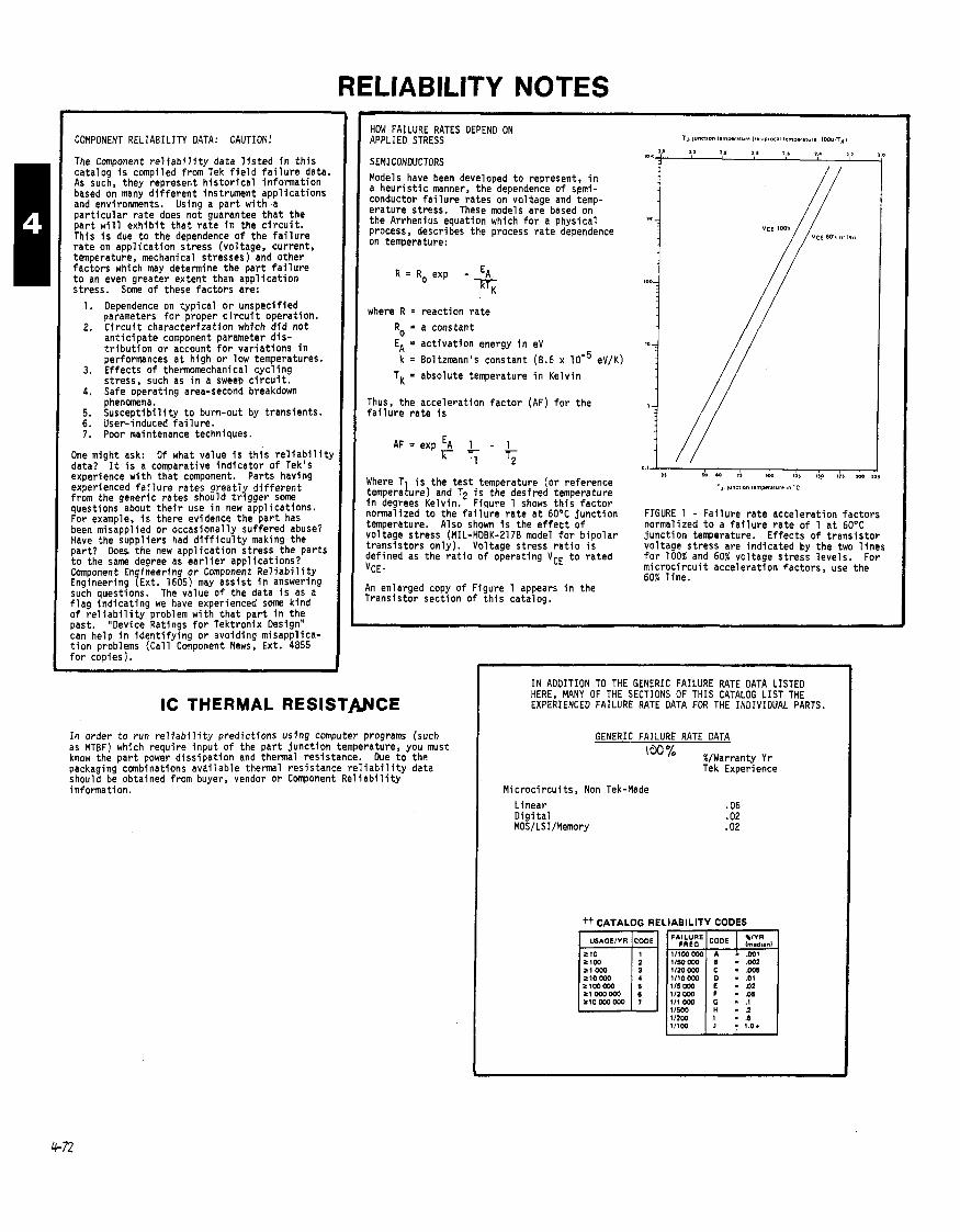
RELIABILITY NOTES
COMPONENT RELIABILITY DATA: CAUTION!
The Component r e l i a b i l i t y data l i s t e d i n t h i s ca ta log i s compiled from Tek f i e l d f a i l u r e data. As such, they represent h i s t o r i c a l in format ion based on manv d i f f e r e n t instrument a ~ ~ l i c a t i o n s and env i ronnk t s . Using a p a r t w i t h ' a p a r t i c u l a r r a t e does no t guarantee t h a t t he p a r t w i l l e x h i b i t t h a t r a t e i n t he c i r c u i t . This i s due t o t he dependence o f t he f a i l u r e r a t e on app l i ca t i on s t ress (vol tage, cur rent , temperature, mechanical s t resses) and o ther f ac to rs which may determine t he p a r t f a i l u r e t o an even greater ex tent than a p p l i c a t i o n s t ress . Some o f these f ac to rs are:
1. Dependence on t y p i c a l o r unspec i f ied parameters f o r proper c i r c u i t operat ion.
2 . C i r c u i t cha rac te r i za t i on which d i d no t a n t i c i p a t e component parameter d i s - t r i b u t i o n o r account f o r va r i a t i ons i n performances a t h igh o r low temperatures.
3. E f f ec t s o f thermomechanical c y c l i n g s t ress , such as i n a sweep c i r c u i t .
4. Safe operat ing area-second breakdown phenomena.
5. S u s c e p t i b i l i t y t o burn-out by t rans ients . 6. User-induced f a i l u r e . 7. Poor maintenance techniques.
One might ask: Of what value i s t h i s r e l i a b i l i t y data? It i s a comparative i n d i c a t o r o f Tek's experience w i t h t h a t component. Par ts having experienced f a i l u r e ra tes g r e a t l y d i f f e r e n t from the generic ra tes should t r i g g e r some questions about t h e i r use i n new app l ica t ions. For example, I s there evidence the p a r t has been misappl ied o r occas iona l ly su f fered abuse? Have the supp l ie rs had d i f f i c u l t y making t he p a r t ? Does the new app l i ca t i on s t ress the pa r t s t o the same degree as e a r l i e r app l i ca t i ons? Component En i nee r i ng o r Component R e l i a b i l i t y Engineering q ~ x t . 1605) may a s s i s t i n answering such questions. The value o f the data i s as a f l a g i n d i c a t i n g we have experienced some k i n d o f r e l i p b i l i t y problem w i t h t h a t p a r t i n t he past. Device Ratings f o r Tekt ron ix Design" can help i n i d e n t i f y i n g o r avo id ing misappl ica- t i o n problems (Cal l Component News, Ext. 4855 f o r copies).
HOW FAILURE RATES DEPEND ON APPLIED STRESS
SEMI CONDUCTORS Models have been developed t o represent, i n a heur i s t 1 c manner, the dependence o f sgmi - conductor f a i l u r e ra tes on vol*age and temp- era ture stress. These models are based on the Arrhenius equation which f o r a phys ica l process, describes the process r a t e dependence on temperature:
R = R, exp - k T ~
where R = react ion r a t e
Ro = a constant
EA = a c t i v a t i o n energy i n eV
k = Boltzmann's constant (8.6 x eV/K) TK = absolute temperature i n Ke lv in
Thus, t he acce lera t ion f a c t o r (AF) f o r the f a i l u r e r a t e i s
AF = exp E~ 1 - 1 7 T;
Where T i s the t e s t temperature ( o r re ference temperalure) and Tp i s t he des i red temperature i n degrees Kelvin. Figure 1 shows t h i s f a c t o r normalized t o t he f a i l u r e r a t e a t 60°C j u n c t i o n temperature. Also shown i s the e f f e c t o f vo l tage s t ress (MIL-HDBK-2178 model f o r b i p o l a r t r a n s i s t o r s on ly ) . Voltage s t ress r a t i o i s def ined as the r a t i o o f operat ing VCE t o ra ted "CE.
An enlarged copy o f Figure 1 appears i n the Trans is tor sect ion of t h i s catalog.
FIGURE 1 - Fa i l u re r a t e acce lera t ion f ac to rs normal ized t o a f a i l u r e r a t e o f 1 a t 60°C j unc t i on temperature. E f f ec t s o f t r a n s i s t o r vo l tage s t ress are i nd i ca ted by the two l i n e s f o r 100% and 60% vo l tage s t ress l eve l s . For m i c r o c i r c u i t acce lera t ion f ac to rs , use the 60% l i n e .
IC THERMAL RESISTMCE
I n order t o run r e l i a b i l i t y pred ic t ions us ing computer programs (such as MTBF) which requ i re i npu t o f the p a r t j u n c t i o n temperature, you must know the p a r t power d i ss i pa t i on and thermal res is tance. Due t o t he packaging combinations ava i l ab le thermal res is tance r e l i a b i l i t y data should be obtained from buyer, vendor o r Component R e l i a b i l i t y information.
IN ADDITION TO THE GENERIC FAILURE RATE DATA LISTED HERE, MANY OF THE SECTIONS OF THIS CATALOG LIST THE EXPERIENCED FAILURE RATE DATA FOR THE INDIVIDUAL PARTS.
M ic roc i r cu i t s , Non Tek-Made L inear D i g i t a l MOSILSIIMemory
tt CATALOG RELIABILITY CODES
. .Ol - 0 2

INTEGRATED CIRCUITS. APPLICATION NOTES (CONT) INTEGRATED CIRCUIT QUALITY AND RELIABILITY
QUALITY AND RELIABILITY are terms o f t e n mistakenly used interchangeably. QUALITY i s an i n d i c a t i o n o f the p ropo r t i on o f de fec t i ve devices e x i s t i n g i n a given l o t a t a g iven inspect ion po in t . RELIABILITY i s a measure- ment o f t he p r o b a b i l i t y t h a t an i n i t i a l l y good p a r t w i l l remain good over a given t ime period.
RELIABILITY SCREENS
Re1 f a b i l i t y screening o f m i c r o c i r c u i t s can reduce f i e l d f a i l u r e rates, sometimes by up t o a f a c t o r o f 10. The s i ng le most e f f e c t i v e r e l i a b i l i t y screen, high-temperature burn-in, removes weak ( i n f a n t m o r t a l i t y ) pa r t s and i s espec ia l l y recommended i f j unc t i on temperature o f 75'C o r h igher i s encountered i n the p a r t app l i ca t i on
Some Tek p a r t numbers are ava i l ab le w i t h 100% burn- in. See index pages f o r those p a r t numbers.

INTEGRATED CIRCUITS APPLICATION NOTES (CONT)
Checklist for CMOS design CMOS has what appears to be the most ideal
set of characteristics for a logic family: low power, high noise immunity, wide supply voltage range, snd high input impedance. With all this going for CMOS, what are the drawbacks?
One drawback is operating speed. To increase speed you can increase the supply voltage. But, at higher speeds and higher supply voltages, power dissipation can exceed that of equivalent TTL.
The other potential way of increasing speed is CMOS on a synthetic substrate. Manufacturers have had problems with this proces however, and only a limited number of products are available.
The high input impedance has two drawbacks: noise susceptibility ina high AC noise environment, and AC fan-out. DC fan-out on most CMOS is specified at 50. AC fan-out is much lower, with supply voltage and operating speed becoming the deciding factors.
The output specs of the early CMOS gates are further complicated since the gates have series and parallel MOS transistors in the output.
The buffered CMOS introduced by Fairchild and since introduced by others, has largegeometry output devices that give more output drive and uniform specs from device to device.
High input impedance increases the chance of damage by static discharge. Damage by static may cause complete failure of a part or degradation of p&ormance such as increased input current.
Some basic handling procedures will prevent most static damage. Avoid using plastic Containers, Styrofoam, etc. for transporting CMOS. Use a grounded soldering iron and discharge the static charge on yourself before handling CMOS. All unused inputs on CMOS should be connected to a supply to prevent them from floating due to leak- ages, internal capacitive coupling and system noise.
All CMOS now has protection diodes on the input to help with the static problem. The diodes are the subject of new problems. Specifications vary and are vague -
RCA says, "Input current should be limited to the microampere level."
Fairchild states that "currents must be limited to 10 mA."
Motorola further says, "It is necessary to limit the input current to+ 10 mA per package pin. This 10 mA rating also applies to the Vdd and VSs pins.
Therefore, i f any device has four inputs which may be forward biased, they should be limited at 2.5 mA each."
Texas Instruments also claims a 10 mA maxi- mum, but we have found the input protection diode current on one gate will affect input current on other gates in that package. According to the TI CMOS program manager, Tim Smith, "The phenomenon you see is normal."
One final comment about Fairchild CMOS - Fairchild CMOS is specified to run at 18 volts maximum. According to an internal memo, they recommend running their CMOS at something iess than 18 volts.
Their CMOS hasa typical breakdown of 22volts which is normally a catastrophic breakdown. Also. Fairchild states their reliability to be iess at the higher supply potentials.
RCA and Motorola told me that their parts had a typical breakdown of 27 volts and that 18 volts was conservative.
CMOS has many characteristics which differ from other logic families. The following design checklist is intended to point out those differences and remind design engineers of inherent CMOS limitations.
OK Pouible Trouble
'Have you taken adequate precautions to avoid static electricity damage?
+Have you protected signal inputs against overvoltage spikes? Overvoltage spikes can damage clamp diodes or cause latchup.
*Have you considered the design dif- ferences between buffered and non- buffered parts? They are not inter- changable in some circuits, such as typical two-gate oscillators.
"Is the output load within the device's specification?
'Does the manufacturer specify para. meters at the power supply voltage you're using? Some vendors list power supply voltages at which there are no specs.
'Does the operating frequency exceed 500 kHz? The power consumption of a CMOS gate exceeds that of a low. power Schottky TTL gate between 500 kHz and 2 MHz, depending on supply voltage level. Low-power Schottky may be a better choice for some applications.
'Have you used analog switches? Ex- cessive current through analog switches results in latching and destructive breakdown. Protective circuitry is essential.
'Is the power supply switched on before applying signal inputs? Damage can occur i f the diode between input and VDD is forward biased.
'Do input rise and fall times exceed 15 p.ec? You could exceed the max- imum power dissipation of the device, especially when using high currents and supply voltages.
OK Possible Trouble
'Have you terminated all inputs?
*Have you used CMOS gates as linear amplifiers? This practice destroys buffer gates, fails to operate below 4 volts and makes vendor interchange- ability more problematical.
*Have you used flip-flops with trans. mission gate inputs driven above and below the supply voltages? I f you have, they can malfunction when inter- facing other logic families from distant boards.
'Have you used one.shots? Most vend- or one-shots are not truly resettable; although reset shuts off the timing cycle, they do not start immediately on another cycle (3 to 4 msec output risetimes have been observed.
*Have you considered energy ,noise levels? Using 5 volt supply levels, CMOS has an order of magnitude less noise margin than TTL (about 0.4 nJ for CMOS and 4.0 nJ for standard TTL). ,
*Have you used "wire-or" configura- tions? The outputs of a McMOS device cannot be connected as a "wire-or" because of the complementary pair configuration.
*Have you used typical values in the design? Because of the large part-to- part process variations, you cannot afford to assume that the units you receive will operate at the values listed as typical.
P l a s t i c has a p r i c e advantage over ceramic; but, the same p l a s t i c i s much more suscept ib le t o f a i l u r e i n h igh humidi ty (above 50 percent) cond i t ions.
For further CMOS information, contact Wilton Hart, Component Evaluation, ext. 2572.

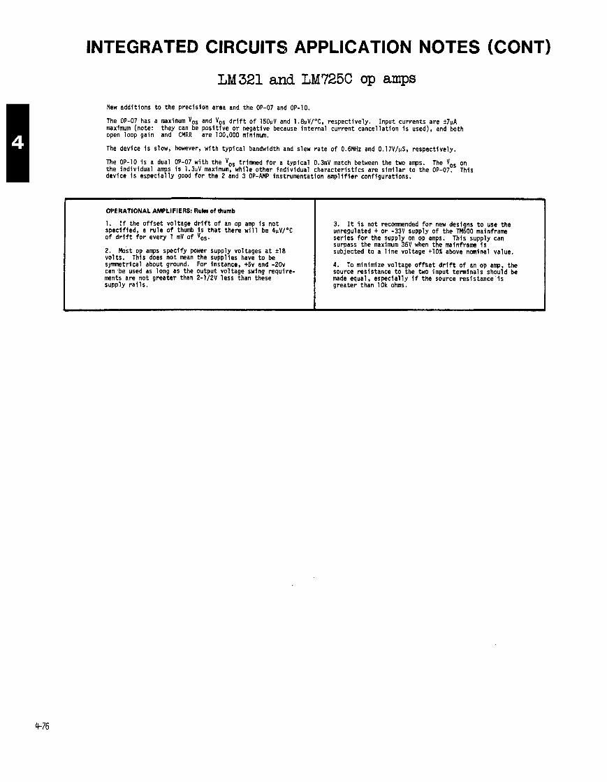
INTEGRATED CIRCUITS APPLICATION NOTES (CONT)
LM 321 and LM725C op amps
New addit ions t o the precision area and the OP-07 and OP-10.
The OP-07 has a maximum VOS and Vos d r i f t o f 150pV and 1.8vV/OC, respectively. Input currents are k7uA maximum (note: they can be pos i t i ve o r negative because in ternal current cancel lat ion i s used), and both open loop gain and CMRR are 100,000 minimum.
The device i s slow, however, wi th t yp ica l bandwidth and slew ra te o f 0.6MHz and 0.17V/pS, respectively.
The OP-10 i s a dual OP-07 wi th the voS t r i m d f o r a t yp ica l 0.3mV match between the two amps. The Vos on the ind iv idual amps i s 1 . W maximum, while other ind iv idual character is t ics are s im i la r t o the OP-07. This device i s especia l ly good for the 2 and 3 OP-AMP instrumentation ampl i f ier configurations.
OPERATIONAL AMPLIFIERS: R u k of thumb
1. I f the o f f s e t voltage d r i f t o f an op amp i s not specified, a r u l e of thumb i s tha t there w i l l be 4uV/OC o f d r i f t f o r every 1 mV o f Vos.
2. ~ o s t op amps specify power supply voltages a t k18 vo l ts . This does not mean the supplies have t o be symnetrical about ground. For instance, +5v and -20v can be used as long as the output voltage swing require- ments are not greater than 2-1/2V less than these supply r a i l s .
3. It i s not reconmended f o r new designs t o use the unregulated + o r -33V supply o f the TM500 mainframe series f o r the supply on op amps. This supply can surpass the maximum 36V when the mainframe i s subjected t o a l i n e voltage +lo% above nominal value.
4. To minimize voltage o f f s e t d r i f t o f an op amp, the source resistance t o the two input terminals should be made equal, especial ly i f the source res is tance ' i s greater than 10k ohms.

INTEGRATED CIRCUITS APPLICATION NOTES (CONT)
Digital MC specs
VIH(MIN)
VIL(MAX)
VOH(MIN)
VOL(MAX)
I jH (MAX)
IIL(MAX)
IOH(MAx)
IOL(MAX)
FANOUT (TO ITSELF)
AVEWGE PROP DELAY
AVERAGE POWER DISSIPATION PER GATE
SPEED-POWER PRODUCT
MIN NOISE IMUNITY
OIL - VOL) LOW
(VIH - VOH) HIGH
INPUT CAPACITANCE
standardt
2v
.8V
2.4V
.4v
40uA
- 1 . m
-400pA
16mA
10
1 OnS
lanw
1 OOpJ
.4v
.4v
---
CMOS
1 OPA ~ Y P
~OPA ~ Y P
IDP* = -.12mA
ION* = . 1 m
50 OC
3 AC 10 MHz 35nS i n t o 15pF typ.
.O1 t o .5uW Quiescent
IDP = Output d r i ve current, P-channel (source)
ION = Output d r i v e current, N-channel (sink)
Output currents are not standardized among the CMOS log ic family. Check spec sheets f o r pa r t i cu la r IC.
ECL
-1.105
-1.475
-0.98
-1.850
265pA
.5pA
tYP
35uA
70 OC only 7 AC 150 MHz 2nS
I DRIVEN DEVICE
( 1 Pull-up res is to r on act ive output devices o r open co l lec to r TTL i s recomnended f o r d r i v ing CMOS.
( 2 ) These values vary according t o the CMOS dr i v ing device. Check the s ink and source current specs f o r the device under
consideration. (Increased sink-current capab i l i t y o f CMOS gates can be achieved by pa ra l l e l i ng input and output connections.)
( 3 ) Only the 4049 and the 4050 buf fers can d r i ve TTL d f r e c t l y .
g L.
& g
t SHOULD NOT BE USED IN NEW DESIGN.
74
74L
74LS
74s
CMOS
NMOS
74
10
2
5
12
o(a)
2
745
8
1
4
10
0(3)
1
74L
40
20
40
100
2(2)
20
74LS
20
10
20
50
1(2)
10
CMOS
5d1)
50(11
50(l)
5 0 ( ~ )
50
50
NMOS
50
50
50
50
50
50
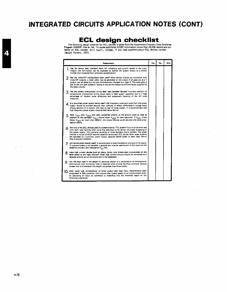
INTEGRATED CIRCUITS APPLICATION NOTES (CONT)
ECL design checklist The fol lowing design checklist for ECL devices is taken f rom the Governmentl lndustry Data Exchange
Prwram (GIDEP) files a t Tek. To access additional GlDEP information (more than 35,000 reports are cur. ren j ly on file), contact B i l l S n e l l , 1253WR. I f you have questions about ECL devices, contact
Joseph Paren t , 2573.
I 7. H y L h e w t h n checked? Born AC limitations and current needed in the tranr rnluton ime termination can be expected to restrict the system fanout to a smaller number than expected from simplistic considerations.
H a Iha whd-OR configuration h n uwd? When several circutts are connected with 2' wired.0R outputs, a noise spike may be generated on the output if all gates are at a 1 output, and ail gates but one are simultaneously changed to a iog~c 0. The noise spike i s due to the one gate suddenly having to source the output current previously supplied by the other circuits.
I Has Iha correct innrconnscr wiring h n uwd bbmwo devices? Incorrect selection of 3' conventional interconnect wiring could result in false system operation due to a high percentage of incident pulse reflections and subsequent lowering of the AC noise immunitv.
b a low-noise p o w r arppiy being uwd? High frequency noise and ripple from the power 4' supply should be avoided because they produce, in effect, differences in voltage levels among sections of a system. and l e d to l ou of noise margin. I t is recommended that high.fraquency power supply noise be held below 60 mV.
5. Haw VCC, 'md VCCZ pins h e n c o n n r n d d imr l y ro the ground plans as clops as posr~bla to Lha p r k w ? VCCl should equal VCC2 for best operation. If VCCl drops below VCC2 by more than 200mV, the output devices could saturate and cause prop- agation delays.
A n only a few ECL devim uwd i n a pndominanrly TTL sysnm? Care must be exercised 6' with both logic families when using this technique to be certain of proper bypassing of
the power wpply. This prevents coupling of noise between circuit families. The safest method is to use a O.01pF ceramic capacitor ErOSS adh ECL device. When larger systems are operated on a common power wpply, separate pdwer buses to each l q i c family help to prevent problems.
I A n doubla-idad boards uwd? A ground plane is recommended on one side of the board. If a ground plane is not pouible. a ground bur must be used as part of the layout on the board to provide a low inductance VCC line.
I Haw hioh curmnr devices arch as nlayc, lmnpr, c o n d r i w n bbM incorwnmd on Iha 8' rn board w Lha logic circuits? These high current circuits should be connected to a
separate ground bus on the board and in the backplane.
I Am f l~pf lops umd In Lhc dosign? A damping resistor or a combination of series/parailel 9. terminbtions with microstrip lines is required when driving flip.flops whenever fanouts exwed four and whencver line lengths are greater than three inches.
I Haw w r s r cso combinations o f driwr oulpur and load inpur characmrisrics been 70' compurad? A 35% overshoot limit ensures *,at system speed is not compromised either
by saturating an input on overshoot or extending into the threshold region on the following undershoot.
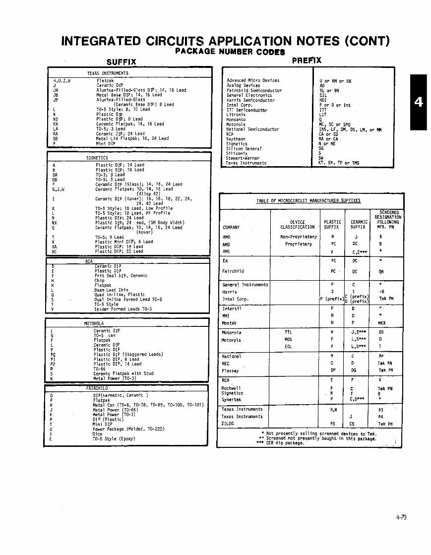
INTEGRATED CIRCUITS APPLICATION NOTES (CONT) PACKAGE NUMBER CODES
SUFFIX TEXAS INSTRUMENTS
H,U.Z,W F la tpak Advanced.Micro Devices Analog Devices F a i r c h i l d Semiconductor General E l e c t r o n i c s H a r r i s Semiconductor I n t e l Corp. ITT Semiconductbr L i t r o n i x Monsanto Motor01 a Nat iona l Semiconduc'tor RCA Raytheon S ignet ics S i l i c o n General S i l i c o n i x Stewart-Warner Texas Instruments
U o r AM o r SN AD SL o r 9N SIL HDI
Ceramic DIP A lumina-F i l led-Glass DIP; 14, 16 Lead Metal Base DIP; 14, 16 Lead Alumina-Fi l led-Glass
(Ceramic Base DIP) 8 Lead TO-5 S t y l e ; 8, 10 Lead
P o r D o r I n t ITT L IT N P l a s t i c DIP
ND P l a s t i c DIP; 8 Lead FA Ceramic Flatpak; 14, 16 Lead LA TO-5; 3 Lead R A Ceramic DIP; 24 Lead SB Metal L i d F la tpak ; 16, 24 Lead P M i n i DIP
Q MC, SC o r SPQ INS, LF, DM, DS, LM, o r CA o r CD RA o r CA N o r NE SG S SW KT, SN, TP o r TMS
SIGNETICS
A P l a s t i c DIP; 14 Lead B P l a s t i c DIP; 16 Lead D A TO-3: 3 Lead DB TO-5; 3 Lead F Ceramic DIP (Glass); 14, 16, 24 Lead G,J,W Ceramic F la tpak ; 10, 14, 16 Lead
( A l l o v 42)
TABLE OF MICROCIRCUIT MANUFACTURER SUFFIXES Ceramic DIP ( ~ o v a i ) ; 12, 16, 18, 22, 24, 28, 40 Lead
TO-5 S t y l e ; 10 Lead, Low P r o f i l e TO-5 Sty le ; 10 Lead, H i P r o f i l e P l a s t i c DIP: 24 Lead DESIGNATIO
COMPANY DEVICE
CLASSIFICATION P l a s t i d Dip; 24 sad, (SM Body Width) Ceramic F la tpak ; 10, 14, 16, 24 Lead
(Kovar) TO-5; 9 Lead P l a s t i c M i n i DIP; 8 Lead
AMD I Non-Propr ietary
X A P l a s t i c DIP; 18 Lead XC P l a s t i c DIP; 22 Lead
EA
F a i r c h i l d
- RC A
D Ceramic DIP E P l a s t i c DIP F F r i t Seal DIP, Ceramic
Chip F la tpak Beam Lead chi^
I
General Instruments
H a r r i s I n t e l Corp. I Quad i n - l i n e , ' P l a s t i c
Dual I n l i n e Formed Lead TO-5 TO-5 S t y l e Soider Formed Leads TO-5 I n t e r s i 1
blM I
'lostek
' lo to ro la TTL
b t o r o l a MOS ECL
Yat ional
YEC
'lessey
I MOTOROLA 1 Ceramic DIP TO-5 can F la tpak Ceramic DIP P l a s t i c DIP P l a s t i c DIP Leads) (Staggered
8 Lead 14 Lead
N J A+
c 1 1 Tek PN DP Tek PN
P l a s t i c DIP, P l a s t i c DIP, TO-66
I s ceramic F l a t ~ a k w i t h Stud I
toc kwel 1 i i g n e t i c s i y n e r t e k
K Metal Power (TO-3) J FAIRCHILD
D DIP(Hemetic, Ceramic )
Tek PN
P4
Tek PN
I H' Fla tpak Metal Can (TO-8, TO-78, TO-99, TO-100, TO-101) 1 Metal power (TO-66) Metal Power (TO-3) D l P ( P l a s t i c ) M i n i DIP Power Package (Molded, TO-220)
'exas Ins t ruments
IILOG
* Not p r e s e n t l y s e l l i n g screened devices t o Tek. ** Screened n o t p r e s e n t l y bought i n t h i s package.
*** CER d i p package.
Dice TO-5 S t y l e (Epoxy)

NOTES
COST CODE (CC COLUMN)
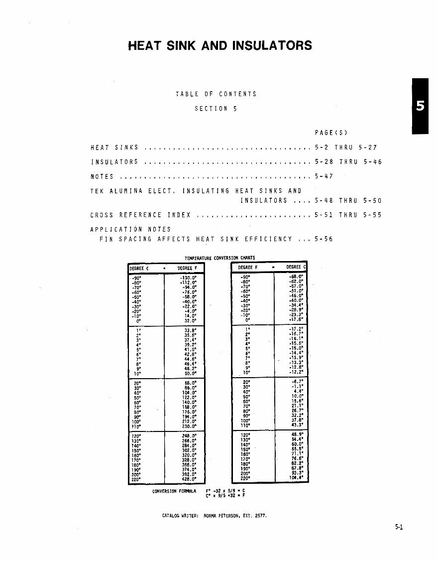
HEAT SINK AND INSULATORS
T A B L E O F C O N T E N T S
S E C T I O N 5
H E A T S I N K S . . . . . . . . . . . . . . . . . . . . . . . . . . . . . . . . . . . 5 - 2 T H R U 5 - 2 7
T E K A L U M I N A E L E C T , I N S U L A T I N G H E A T S I N K S A N D
I N S U L A T O R S , , , , 5 - 4 8 T H R U 5 - 5 0
C R O S S R E F E R E N C E I N D E X 5 - 5 1 T H R U 5 - 5 5
A P P L I C A T I O N N O T E S
F I N S P A C I N G A F F E C T S H E A T S I N K E F F I C I E N C Y 5 - 5 6
TEMPERATURE
CONVERSION FOrWllLA F' - C0 r
CONVER SION CHARTS
OEGREE F = OEGREE C
CATALOG WRITER: NORMA PETERSON, EXT. 2 5 7 7 .
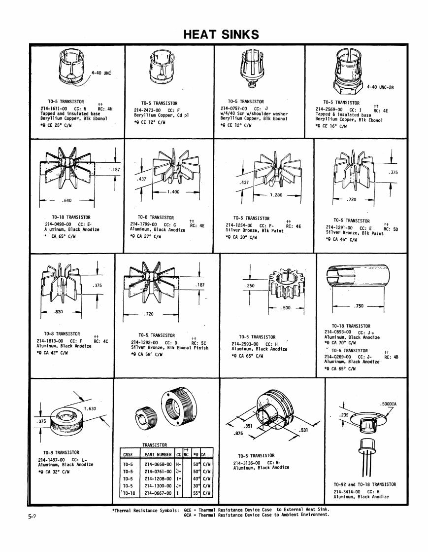
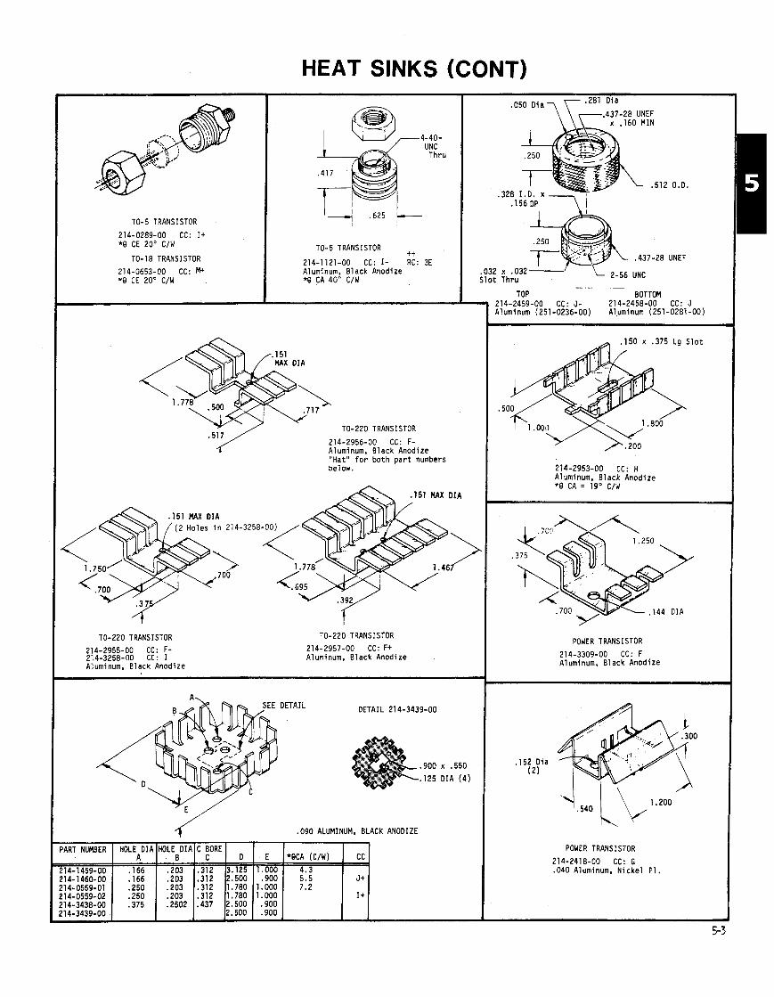
HEAT SINKS (CONT)
TO-5 TRANSISTOR
214-0289-00 CC: I + *O CE 20" C/W
TO- 18 TRANS I STOR
214-0653-00 CC: M+ *Q CE 20" C/W
-4-40- UNC Thru
TO-5 TRANSISTOR tt
214-1121-00 CC: I- RC: 3E Aluminum, Black Anodize *O CA 40" C/W
?"/ TO-220 TRANSISTOR 214-2956-00 CC: F- Aluminum. Black Anodize at" f o r b o t h p a r t numbers below.
.050 D ia \y;. Oi a 437-28 UNEF
x . I60 MIN
.032 S l o t
,437-28 UNEF
UNC
TO-220 TRANSISTOR TO-220 TRANSISTOR
214-2955-00 CC: F- 214-2957-00 CC: F+ 214-3258-00 CC: I Aluminum, Black Anodize Aluminum, Black Anodize
DETAIL 21 4-3439-00
.900 x .550
. I 2 5 DIA (4 )
./ .090 ALUMINUM, BLACK ANODIZE
.-
TOP BOTTOM 214-2459-00 CC: J- 214-2458-00 CC: J Aluminum (251-0236-00) Alyminum (251-0281 -00)
. I 5 0 x .375 Lg S l o t
.50
214-2953-00 CC: H Aluminum, Black Anodize *O CA = 19' C/W
POWER TRANSISTOR
214-3309-00 CC: F Aluminum, Black Anodize
POWER TRANSISTOR
214-2418-00 CC: G .040 Aluminum, N i c k e l P I .

HEAT SINKS (CONT)
TO-220 TRANSISTOR
214-1967-00 CC: F- Aluminum, Black Anodize
TO-220 TRANSISTOR
214-1692-01 CC: H One Hole G Includes Dotted
Aluminum, I *Q CA 21' 1
TO-3 TRANSISTOR 214-2954-00 CC: G+ Aluminum. Black Anodize *Q CA = 7.5' C/W
! 069 MX DIA TO-220 TRANSISTOR
'14-2518-00 CC: G r i c t i o n f i t over mounting tab luminum, Black Anodize *Q CA 20' C/W
TO-92 TRANSISTOR 214-3057-00 CC: G- Phosphor Bronze
*Thermal Resistance Svmbols: QCE = 5-4 QCA =
A r d :k Anodize
. TO-220 TRANSISTOR
214-1914-00 CC: F .040 Aluminum, Black Anodize *Q CA 21' C/W
TO-3 TRANSISTOR 214-2613-00 CC: K- A1 Ext rus ion (251-0072-00) 214-2613-01 * Hole Moved CC: J+
DIMPLE . I 50 DIA
TO-220 TRANSISTOR 214-2518-01 CC: F F r i c t i o n f i t over mounting Tab Aluminum, Black Anodize *8 CA 20' C/W
. I 50 DI A HIGH
TO-22b TRANSISTOR
214-2811-00 CC: E F r i c t i o n f i t over mounting tab Aluminum, Black Anodize *Q CA 28' C/W
4-40 UNC-20 Thru
(2 ) TO-202 TRANSISTORS
214-2867-00 CC: K A1 uminum Ext rus ion, Black Anodize (251 -1 580-00)
ermal Resistance Device Case t o Externa l Heat Sink. ermal Resistance Device Case t o Ambient Environment.
TO-5 TRANSISTOR 214-2496-00 CC: E Aluminum, Chromate Conversion *Q CA 60' C/W
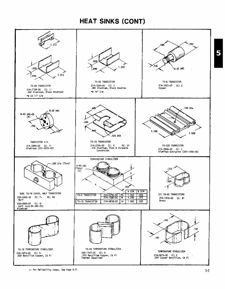
HEAT SINKS (CONT)
TRANSISTOR H. S.
214-2944-00 CC: J- Aluminum (251-0223-00)
DUAL 10-18 COVER, HALF TRANSISTOR I r; 200-0945-00 CC: 'F- RC: 5A
H a l f
200-0945-01 CC: E- H a l f (w/2-56 UNC-20)
( TO-18 TEMPERATURE STABILIZER
I 200-1673-00 CC: D- .009 Bery l l lum Copper, Cd PI
I I tt For R e l i a b i l i t y Codes, See Page 5- 6.
TO-66 TRANSISTOR
214-1504-00 CC: I .062 Aluminum, Black Anodize
*0 14' C/W
TO-39 TRANSISTOR
214-2746-00 CC: K RC: 3F .016 Aluminum, Etch & Chromate
Conversion
TEMPERATURE STABILIZER
TO-18 TEMPERATURE STABILIZER
200-1167-00 CC: H .010 B e r y l l i u m Copper, Cd P I T h e m 1 E q u a l i z e r
\(, A DIM B DIM
TO-8 TRANSISTOR
214-1651-01 CC: E Copper
'0-5 TRANSISTOR
'0-18 TRANSISTOR
TO-220 TRANSISTOR
214-2948-00 CC: I Aluminum E x t r u s i o n (251-1598-00)
1.250 1.250
1.000
(2) TO-92 TRANSISTORS
214-1916-00 CC: B+ Brass
.375
.375
.200
, 214-0798-00 214-1580-00
214-0818-00
TEMPERATURE STAEIL IZER
214-0973-00 CC: C .007 Copper Bery l l ium, Cd PI
M- M
K t
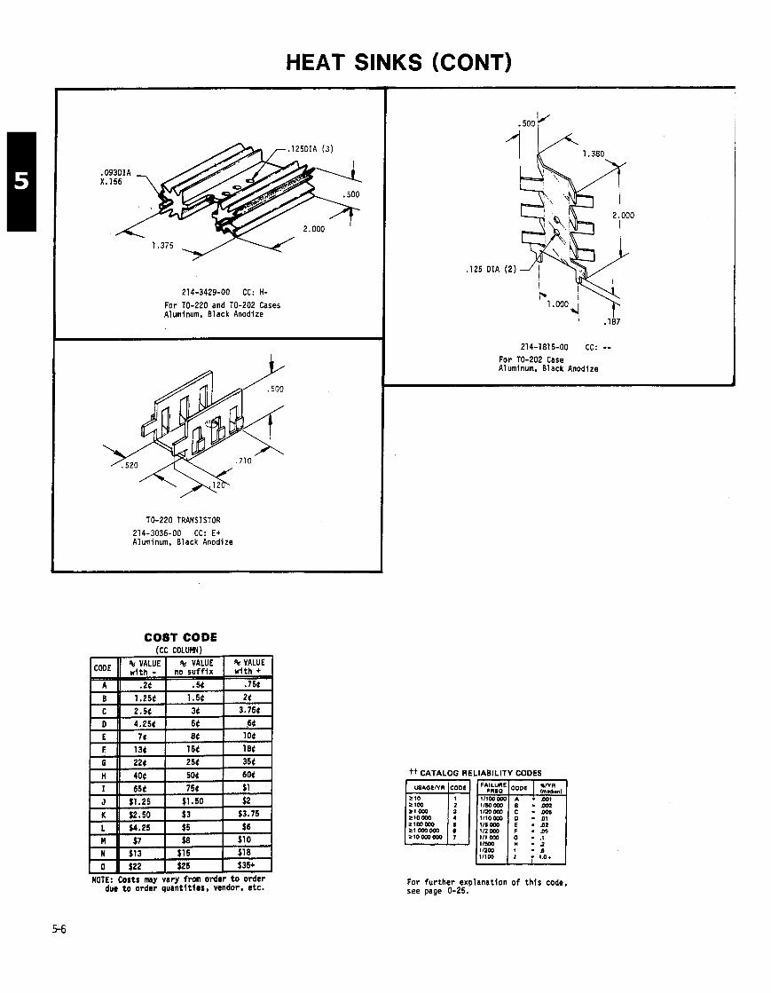
HEAT SINKS (CONT)
214-3429-00 CC: H-
For TO-220 and TO-202 Cases Aluminum, Black Anodize
TO-220 TRANSISTOR 214-3036-00 CC: E+ Aluminum, Black Anodize
125 DIA
214-1815-00 CC: -- For TO-202 Case A1 uminum, Black Anodize
COST CODE
tt CATALOG RELIABILITY CODES
- 0 6
For fur ther explanatfon o f th is code, see page 0-25.
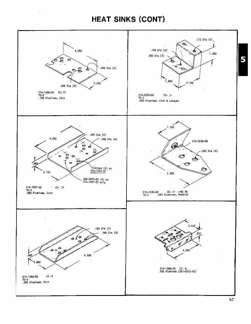
HEAT SINKS (CONT)
214-1598-00 CC- I+ 10-3 , 1 2 5 Aluminum. Etch
.240 Oia (4 )
1 . 2 6 6 Dia
355-0075-00 (8) on 214-1557-01 o n l y
21 4-1 557-00 CC- I+ TO-3 .080 Aluminun. Etch
D ia ( 2 )
,266 Oia
214-1 550-00 CC- H TO-3 ,080 Aluminum. Etch
. I72 Oia ( 2 )
,156 D ia (2 )
,250 Oia (2 )
2.105
214-2224-00 CC- I - TO-3 .080 Aluminum, Etch 6 Lacquer
214-1536-00 CC- It ttRC 4E TO- 3 .063 Aluminum, Anodlze
214-1388-00 CC: K- ,125 Aluminum (251-0072-XX)'
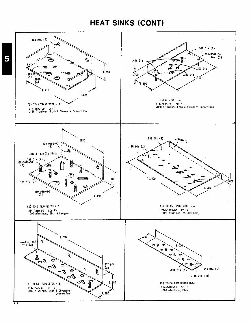
HEAT SINKS (CONT)
(2) TO-3 TRANSISTOR H.S.
214-1599-00 CC: J "4'
.I25 Aluminum, Etch & Chromate Conversion
129-01 (2) 6 0 - O O ~
.I88 x .625 (2) S lots
. (2) TO-3 TRANSISTOR H.S.
214-1860-00 CC: K- .090 Aluminum, Etch & Lacquer
214-1649-02 CC: K-
(5) TO-66 TRANSISTOR H.S.
.090 Aluminum. Etch & Chromate Convers ion
.I87 Dia (2 )
355-0061 -00 Stud (3)
TRANSISTOR H.S.
214-2280-00 CC: J .050 Aluminum, Etch & Chromate Conversion
.I56 Dia (6) .1aa
(4) TO-66 TRANSISTOR H.S.
214-1795-00 CC: K t .I25 A1 uminum (251 -0036-00)
240 Dla ( 5 )
.I56 Dia (10)
(5) TO-66 TRANSISTOR H.S,
214-1649-00 CC: H .080 Aluminum, Etch
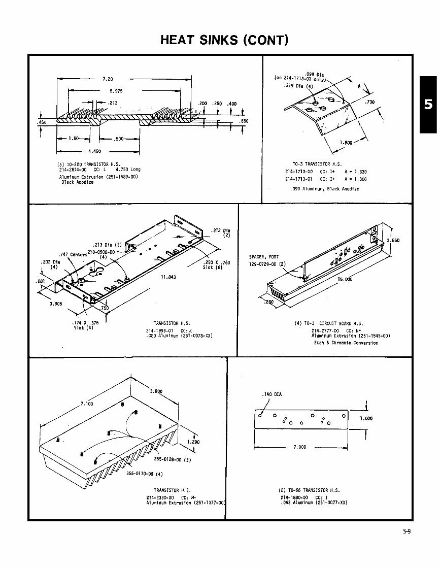
HEAT SINKS (CONT)
(5 ) TO-220 TRANSISTOR H.S. 214-2874-00 CC: L 4.750 Long
Aluminum Ext rus ion (251-1589-00) Black Anodize
.213 D ia (2) d >a''
. 1 7 4 X . 3 7 5 ' S l o t ( 4 )
TRANSISTOR H.S.
214-1999-01 CC: K .080 Aluminum (251-0078-XX)
TRANSISTOR H.S.
214-2330-00 CC: M- Aluminum E x t r u s i o n (251-1377-0C
TO-3 TRANSISTOR H.S.
214-1713-00 CC: I + A = 1.330
214-1713-01 CC: I + A = 1.300
090 A1 uminum. Black Anodize
(4) TO-3 CIRCUIT BOARD H.S.
214-2777-00 CC: N+ Aluminum Ext rus ion (251-1545-00)
Etch 8 Chromate Conversion
,140 DIA
(2 ) TO-66 TRANSISTOR H.S. 214-1880-00 CC: I .063 Aluminum (251-0077-XX)
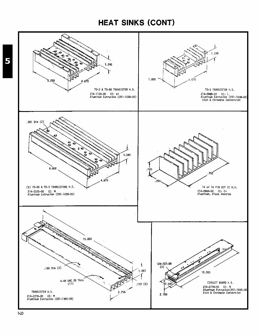
HEAT SINKS (CONT)
TO-3 & TO-66 TRANSISTOR H.S.
214-1130-00 CC: K t Aluminum E x t r u s i o n (251-1038-00)
(3 ) TO-66 8 TO-3 TRANSISTORS H.S.
214-2225-00 CC: M Aluminum E x t r u s i o n (251-1038-00)
TO-3 TRANSISTOR H.S.
214-2888-00 CC: L Aluminum E x t r u s i o n (251-1038-01
Etch & Chromate Conversion
TRANSISTER H.S.
14 o r 16 P I N DIP I C H.S. 214-2868-00 CC: E+ Aluminum, Black Anodize
214-2276-00 CC: M Aluminum E x t r u s i o n (251-1365-00)
CIRCUIT BOARD H.S.
214-2778-00 CC: N Aluminum Extrusion(251-1545-0 Etch & Chromate Conversion
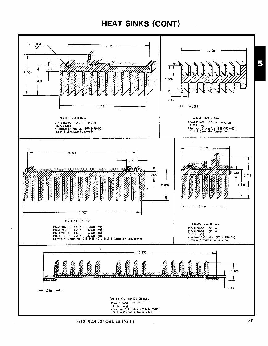
HEAT SINKS (CONT)
CIRCUIT BOARD H.S.
214-2612-00 CC: N ttRC 3F 8.000 Long
Aluminum Ext rus ion (251-1479-00) Etch 8 Chromate Conversion
POWER SUPPLY H.S.
214-2509-00 CC: N- 8.000 Long 214-2890-00 CC: N 5.000 Long 214-3291-00 CC: F+ 8.000 Long 214-2611-02 CC:N 8.000Long Aluminum Extrusion (251 -1455-00), Etch 8 Chromate Conversion
CIRCUIT BOARO H.S.
214-2801-00 CC: Mt t t R C 2H . . . - - . . 7.700 Long
Aluminum Ext rus ion (251 -1550-00) Etch 8 Chromate Conversion
CIRCUIT BOARO H.S.
214-2508-00 CC: M t 214-2508-01 CC: Mt 6.983 Long
Aluminum Ext rus ion (251-1454-00) Etch I Chromate Conversion
(2 ) TO-220 TRANSISTOR H . S . 214-2516-00 CC: M+ 4.800 Long
Aluminum Ext rus ion (251-1457-00) Etch 8 Chromate Conversion
tt FOR RELIABILITY CODES, SEE PAGE 5-6. 5%

HEAT SINKS (CONT)
(6) TO-3 TRANSISTOR H.S.
214-2049-01 CC: 0 t t R C 36 Aluminum Extrusion (251-1 320-00:
Etch & Chromate Conversion
POWER SUPPLY H.S. 214-281 5-00 3.125 Long Etch 6 Lacquer
214-2540-02 CC: M .500 Long Etch 6 Chromate Conversion 214-3109-00 CC: M 6.375 Long Etch 6 Chromate Conversion Aluminum Extrusion (251-1377-00)
POWER SUPPLY H.S. 214-1958-00 CC: N-
6.430 Long Aluminum Extrusion (251-1 199-00)
Etch & Chromate Conversion
POWER SUPPLY H.S.
214-2348-00 CC: Ot 22.000 Long
Aluminum Extrusion (251-1366-00) Etch 6 Lacquer
(4) TO-3 TRANSISTOR H.S.
Aluminum Extrusion (251-1048-00) Vinyl Enamel
PART NUMBER 214-1766-00 214-1 781-00 214-1956-00 214-1666-00
tt FOR RELIABILITY CODES, SEE PAGE 5-6.
Etch 6 Lacquer
CC
0 N 0 N
LENGTH
6.410 Black) 5.000 ITv G r a j
12.000 (TV Graj 1 .a29
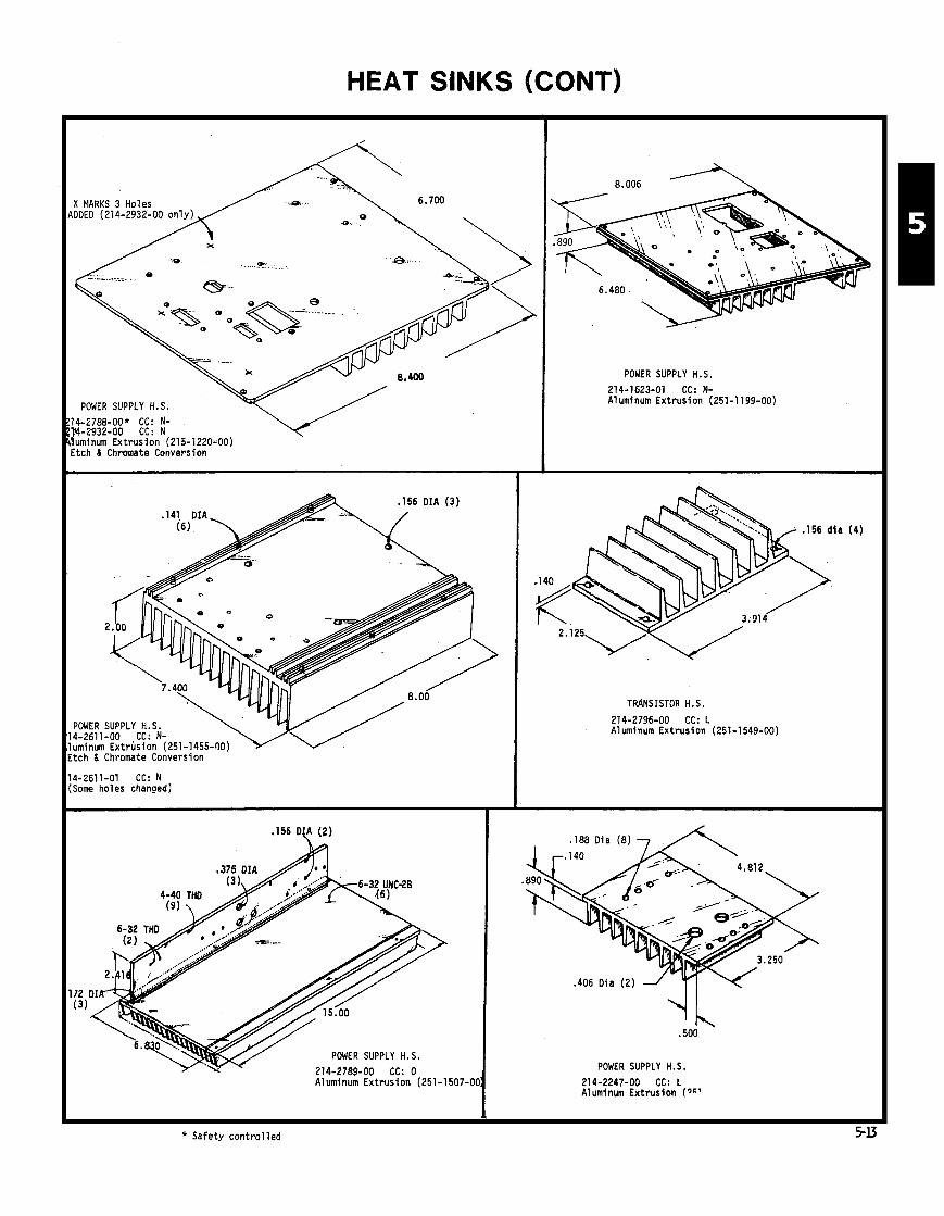
HEAT SIN <S (CONT)
POWER SUPPLY H.S.
Etch L Chromate Conversion
14-2611-01 CC: N (Some holes changed)
r
,156 DLA (2)
v/ POWER SUPPLY H.S.
POWER SUPPLY H.S. 214-1623-01 CC: N- Aluminum Extrusion (251-1199-00)
TRANSISTOR H.S.
214-2796-00 CC: L Aluminum Extrusion (251-1549-00)
POWER SUPPLY H.S. 214-2247-00 CC: L Aluminum Extrusion (?C'
* Safety controlled
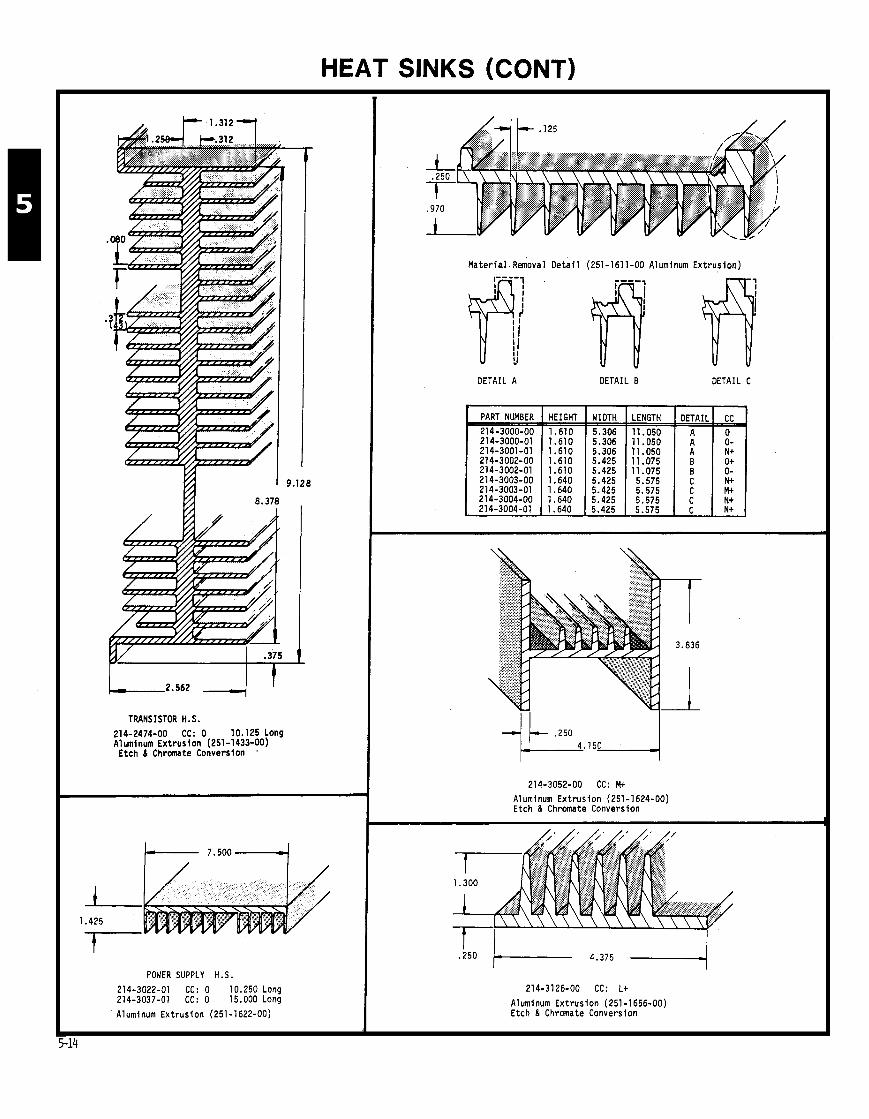
HEAT SINKS (CONT)
TRANSISTOR H. S.
214-2474-00 CC: 0 10.125 Long Aluminum Ext rus ion (251 -1433-00)
Etch 6 Chromate Conversion '
POWER SUPPLY H.S
214-3022-01 CC: 0 10.250 Long 214-3037-01 CC: 0 15.000 Long
Aluminum Ext rus ion (251 -1622-00)
Ma te r i a l Removal D e t a i l (251-1611-00 Aluminum Extrusion)
DETAIL A DETAIL B DETAIL C
214-3052-00 CC: M+ Aluminum Ext rus ion (251-1624-00) Etch & Chromate Conversion
PART NUMBER
214-3000-00 214-3000-01
214-3126-00 CC: L+
Aluminum Ext rus ion (251-1656-00) Etch & Chrmate Conversion
HEIGHT
1.610 1.610
WIDTH
5.306 5.306
LENGTH
11.050 11.050
DETAIL
A A
CC 0 ' O-

HEAT SINKS (CONT)
I TO-3 DIODE
214-2731-00 CC: I- .080 A1 uminum (251 -0078-00)
MICRO CIRCUIT H.S.
214-2342-00 CC: N- A1 uminum (251 -001 5-00)
.156 Dia - A '15' D f a
MICROCIRCUIT H.S.
214-2416-00 CC: J- Aluminum (251-0073-XX)
Etch & Chromate Conversion
.090 Dia ( 2)
/ Not include
.090 Di'a (2)
L . 1 0 0 x .750 S lo t (2)
MICROCIRCUIT H.S. FOR 14 o r 16 PIN DIP
214-3334-00 CC: I + A1 uminum, Hard Anodi ze
DIODE H.S. 214-2322-00 CC: J- A1 uminum (251-0005-00)
Etch & Chromate Conversion
DIODE H.S.
214-2951-00 CC: I Aluminum (251-0071-XX)
Etch & Chromate Conversion
TRANSISTOR H.S.
214-3315-00 CC: J Aluminum, B l k Anodize
MICROCIRCUIT H.S.
214-1990-00 CC: I- Aluminum (251-0076-XX) Hard Anodize', Black
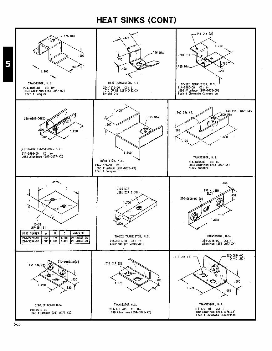
HEAT SINKS (CONT)
Y TRANSISTOR, H.S.
214-1845-01 CC: O+ .063 Aluminum (251-0077-00) Etch & Lacquer
(2) TO-202 TRANSISTOR, H.S. 214-2995-00 CC: H+ .063 Aluminum (251-0077-XX)
CIRCUIT BOARD H.S.
214-2712-00 ,063 Aluminum (251-0077-XX)
TO-5 TRANSISTOR, H.S.
214-1519-00 CC: I . O l O CU-BE (251-0462-XX) B r igh t Dip
,125 Oia
I , TRANSISTOR, H.S.
214-1671-00 CC: H- .050 A1 uminum (251 -0073-XX) Etch & Lacquer
.I25 D I A
.281 OIA C BORE
TO-202 TRANSISTOR, H.S. 214-3015-00 CC: H+ Aluminum (251 -0087-00)
.218 DIA (2)
1.375
TRANSISTOR H.S. 214-1731-00 CC: G+ .040 Aluminum (251-0076-XX)
r.141 Oia (2)
TO-220 TRANSISTOR, H.S. I 214-2980-00 CC: I- .050 A1 uminum (251-0073-00) Etch & chromate conversion.
TRANSISTOR, H.S.
214-1882-00 CC: K- .063 Aluminum (251-0077-XX) Black Anodize
TRANSISTOR. H.S.
214-2215-00 CC: H A1 uminum (251 -0077-XX)
TRANSISTOR. H.S.
214-1731-01 CC: I .040 Aluminum (251-0076-XX) Etch & Chromate Conversion
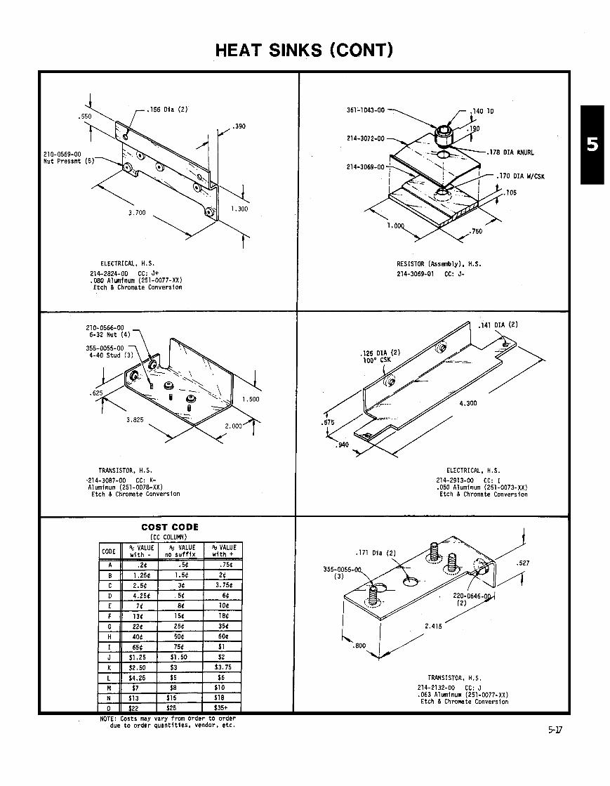
HEAT SINKS (CONT)
ELECTRICAL, H.S.
214-2824-00 CC: J+ .080 Aluminum (251-0077-XX) E tch & Chromate Conversion
TRANSISTOR, H.S.
~214-3087-00 CC: K- Aluminum (251-0078-XX)
E tch & Chromate Conversion
COST CODE
due t o o rder q u a n t i t i e s , vendor, e t c .
RESISTOR (Assembly), H.S.
214-3069-01 CC: J-
ELECTRICAL, H.S. 214-2913-00 CC: I .050 Aluminum (251-0073-XX) Etch & Chromate Conversion
TRANSISTOR, H.S. 214-2132-00 CC: J .063 Aluminum (251-0077-XX) Etch & Chromate Conversion
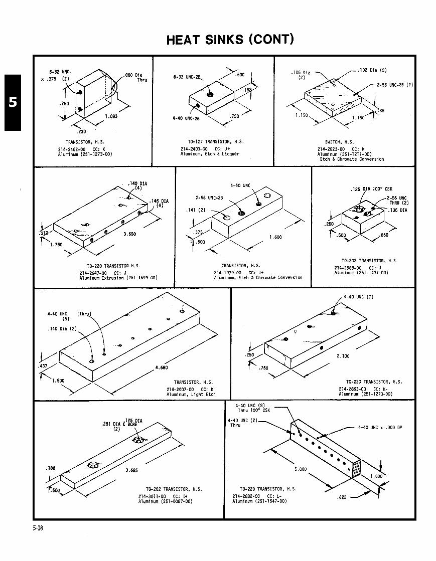
HEAT SINKS (CONT)
TRANSISTOR, H.S.
214-2462-00 CC: K Aluminum (251-1 273-00)
TO-220 TRANSISTOR H.S.
214-2947-00 CC: J Aluminum E x t r u s i o n (251-1599-00)
TO-127 TRANSISTOR, H.S.
214-2403-00 CC: J+ Aluminum, Etch 8 Lacquer
. I25 D i a . I 0 2 Oia (2)
1.150
SWITCH, H.S.
214-2823-00 CC: K Aluminum (251-1211-00)
E t c h 8 Chromate Conversion
TRANSISTOR, H.S. 214-1979-00 CC: J+ Aluminum, Etch 6 Chromate Conversion
(5 )
. I 4 0 Dia (2 )
-0
214-2007-00 CC: K Aluminum, L i g h t Etch
/ TRANSISTOR, H.S.
TO-202 TRANSISTOR, H. S.
214-3011-00 CC: I + A1 uminum (251-0087-00)
,125 DJA 100' CSK
TO-202 TRANSISTOR, H.S.
214-2988-00 CC: J Aluminum (251 -1437-00)
/ 4-40 UNC (7)
TO-220 TRANSISTOR, H.S.
214-2863-00 CC: K- Aluminum (251-1273-00)
4-40 UNC (2) Thru 4-40 UNC x .300 OP
0
5.000
TO-220 TRANSISTOR, H.S.
214-2882-00 CC: L- .625 Aluminum (251-1 547-00)

HEAT SINKS (CONT)
DIODE, H.S.
214-2013-00 CC: It .090 Aluminum (251-0070-XX)
TRANSISTOR 8 DIODE, H.S.
214-2549-00 CC: J .080 Aluminum (251-0078-XX)
TO-39 HEAT SINK
TO-5 TRANSISTOR, H.S.
214-1612-01 CC: G .063 Aluminum (251-0180-XX) E tch & Chromate Conversion
214-2572-00 CC: I + ttRC: 36 ,063 Aluminum (251-0077-XX) Etch 8 Chromate Conversion
I
188 O I A
6-32 UNC
.700
214-3313-00
.090 Aluminum (251-0070-XX)
I
-
-
TO-202 TRANSISTOR, H. S. 214-2744-00 CC: I + ,063 Aluminum (251-0077-XX) Etch & Lacquer -
POWER SUPPLY, H.S.
PART NUMBER C C A DIM.
214-2343-00 J t 3.661 214-2344-00 J+ 4.173 .065 Copper (251-0416-XX)

. I25 Dia (2 ) Dia (2)
TRANSISTOR, H.S.
214-2407-00 CC: F t .063 Aluminum (251-0180-XX) Etch & Lacquer
CIRCUIT BOARD, H.S.
214-2592-00 CC: H- . I00 A1 umi num Etch & Chromate Conversion
HEAT SINKS (CONT)
(2) TO-202 TRANSISTOR, H.S.
214-2733-00 CC: I .063 Aluminum (251-0180-XX) Etch & Lacquer
TRANSISTOR, H.S.
214-1917-00 CC: Gt .040 Aluminum (251-0076-00) Etch & Chromate Conversion
DIODE, H.S.
214-1872-00 CC: I- .090 Aluminum (251-0070-XX) Etch & Chromate Conversion
. I56 Oia
RECTIFIER, H.S.
214-1804-00 CC: H .063 Aluminum (251-0180-XX) Etch & Chromate Conversion
Dia
DIODE, HEAT SINK
214-1525-00 CC: 1- .063 A1 uminum (251 -0077-XX) Etch & Chromate Conversion
DIODE, H.S.
214-1873-00 CC: I- .063 Aluminum (251-0077-XX) Etch & Chromate Conversion
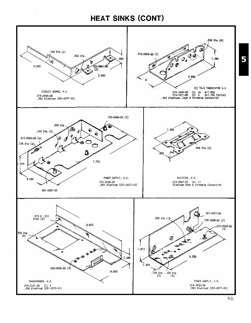
HEAT SINKS (CONT)
CIRCUIT BOARD, H.S.
214-2495-00 .063 A1 uminum (251-0077-XX)
POWER SUPPLY, H.S.
21 4-2636-00 .063 Aluminum (251-0077-XX)
I 210-0508-00 (6 )
TRANSFORMER, H.S.
I 214-2301-00 CC: K .090 Aluminum (251-0070-XX)
.266 D i a (6)
-4-v (2 ) TO-3 TRANSISTOR H.S
214-1624-00 CC: J+ Ae1.628 214-1871-00 CC: J Az1.755 (Scrnd)
.063 Aluminum. Etch & Chromate Conversion
RESISTOR, H.S.
214-2597-00 CC: H+ Aluminum Etch & Chromate Conversion
POWER SUPPLY, H.S.
214-2493-00 ,063 A1 uminum (251 -0077-XX)
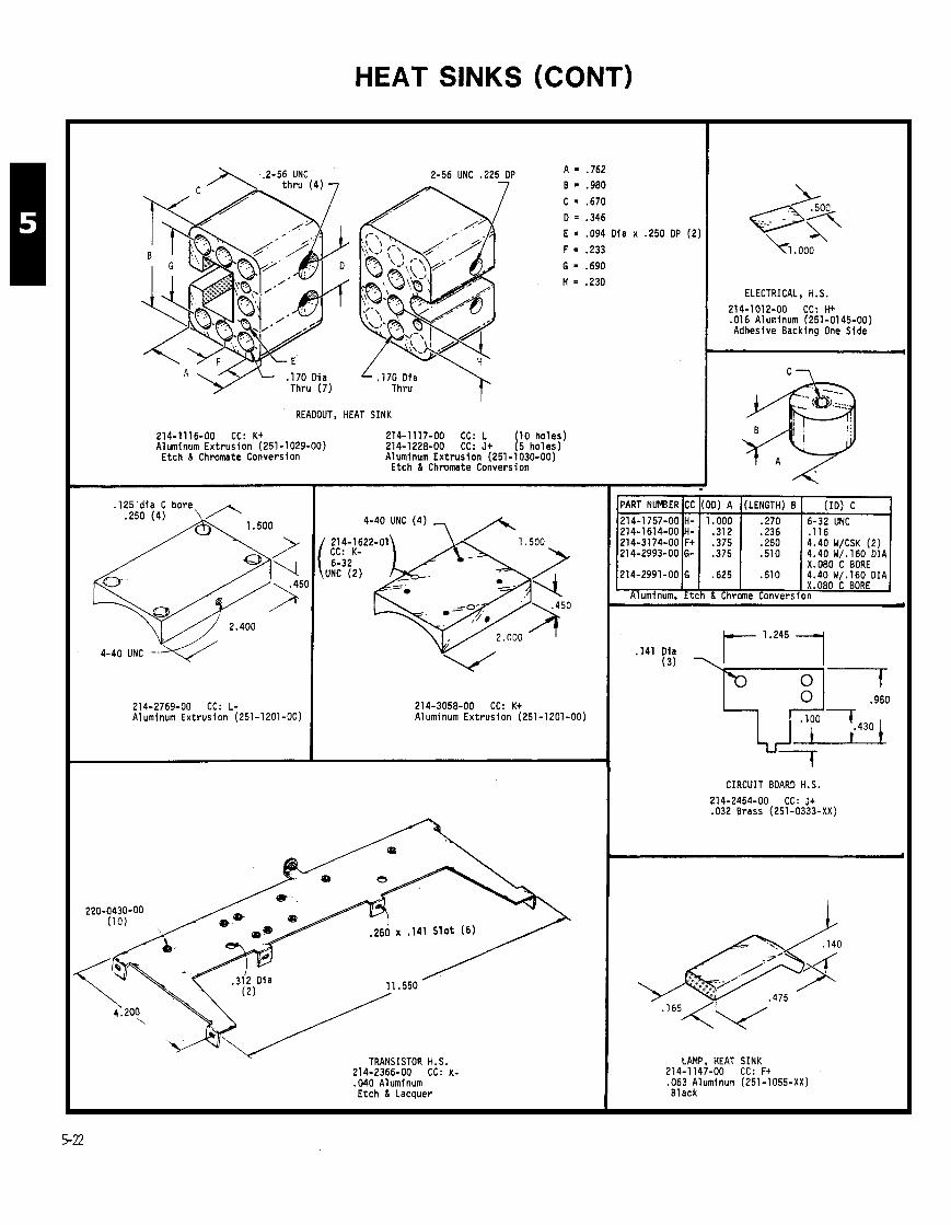
HEAT SINKS (CONT)
2-56 UNC .225 DP -
READOUT, HEAT SINK
A = .762
B .980
C = .670
0 = .346
E = .094 Dia x .250 DP (2)
F = .233
G = .690
H = .230
214-1116-00 CC: Kt 214-1117-00 CC: L 10 ho les) Aluminum Ext rus ion (251-1029-00) 214-1228-00 CC: J* 15 ho les)
Etch & Chromate Conversion Aluminum Ext rus ion (251-1030-00) Etch 6 Chromate Conversion
214-2769-00 CC: L- Aluminum Extrusion (251-1201-00)
4-40 UNC (4 ) 7 A
214-3058-00 CC: Kt Aluminum Ext rus ion (251-1201-00)
TRANSISTOR H.S. 214-2366-00 CC: K- .040 Aluminum Etch & Lacquer
ELECTRICAL, H.S.
214-1012-00 CC: ti+ .Dl6 Aluminum (251-0145-00) Adhesive Backing One Side
. . . . 1.000 .270 6-32 UNC
.312 .236 .I16
X.080 c BORE 214-2991-00 G .625 .510 4.40 W/.160 DIA
X.080 C BORE Aluminum. Etch & Chrome Conversion
. I41 Dla I I
CIRCUIT BOARD H.S.
214-2454-00 CC: J+ .032 Brass (251-0333-XX)
LAMP, HEAT SINK 214-1147-00 CC: F+ ,063 Aluminum (251-1055-XX) Black
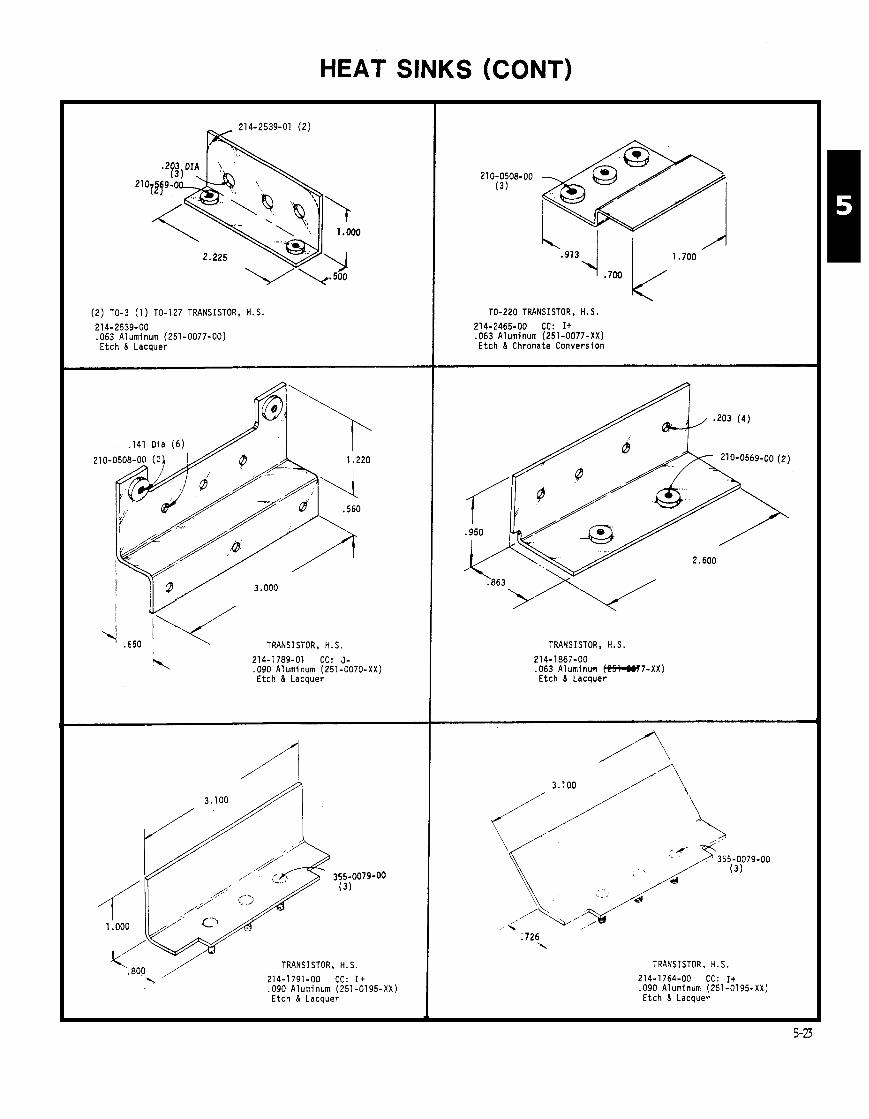
HEAT SINKS (CONT)
(2 ) TO-3 (1) TO-127 TRANSISTOR, H.S.
214-2539-00 ,063 Aluminum (251-0077-00) E tch 8 Lacquer
. I41 Dia (6) A\
TRANSISTOR, H.S.
214-1789-01 CC: J- .090 Aluminum (251-0070-XX) Etch 8 Lacquer
355-0079-00 (31
TRANSISTOR, H.S.
214-1791-00 CC: I + .090 Aluminum (251-0195-XX) Etch & Lacquer
TO-220 TRANSISTOR, H.S.
214-2465-00 CC: I+ .063 Aluminum (251-0077-XX) Etch & Chromate Conversion
TRANSISTOR, H.S.
214-1867-00 .063 Aluminum m 7 - X X ) Etch & Lacquer
TRANSISTOR, H.S.
214-1764-00 CC: It .090 Aluminum (251-0195-XX) Etch & Lacquer

HEAT SINKS (CONT)
2BX.500 MIN
DIODE (DO-4) H.S. 214-3302-00 CC: J+ .SO0 X .75O Aluminum (251-1355-00)
E tch & Chromate Conversion
.272 \ OIA(2) 10-32 UNF-2B X .500 MIN
DIODE H.S
214-3244-00 CC: K .SO0 X 1.000 Aluminum (251-0286-00)
E t c h & Chromate Conversion
. I 2 5 OIA X .050 MIN (2)
MICROCIRCUIT H.S. 214-2543-00 CC: K 250 X 1.500 Aluminum (251-1211-00)
Etch & Chromate Conversion
TRANSISTOR H.S.
214-3243-00 CC: L 1.000 Sq. Aluminum (251-1602-00)
Etch & Chromate Conversion
4-40 UNC W/.160
DIA C'BORE ?
TRANSISTOR H. S.
214-3178-00 CC: J+ .250 X .SO0 Aluminum (251-0016-00)
Etch & Chromate Conversion
4-40 UNC-2B THRU
DIODE H.S. 214-3231-00 CC: J+ .SO0 X 1.000 Aluminum (251 -0286-00)
E tch & Chromate Conversion
. I 5 6 DIA (3 ) --,
4-40 UNC-28 X.250 MIN
4-40UNC-2B THRU (2)
TRANSISTOR H.S.
214-3269-00 CC: L- Aluminum E x t r u s i o n (251-1706-00)
Etch & Lacquer
8-32 UNC x ,312 l f IN (2 ) .250-28 UNF w/6-32 UNC x . I 8 8 IIIN FARSIDE (2)
FARSIOE (2)
2.225
DIODE H.S.
214-3257-00' CC: L t Aluminum E x t r u s i o n (251-1728-00)
TRANSISTOR H.S.
214-3216-00 CC: G ,080 Aluminum (251 -101 9-XX)
Etch & Chromate Conversion
,156 OIA (2)
3.150
214-3144-00 CC: H .080 Aluminum (251-0078-XX)
E tch & Chromate Conversion
4-40 UNC-2B THRU (3 4-40 UNC-2B THRU CSK ( 2
4-40 UNC-20, .250 MIN (3)
. I 2 5 OIA THRU ( 8 )
AMPLIFIER CIRCUIT BOARD H.S.
214-3153-00 CC: L+ .250 X .625 Aluminum (251-01 09-00)
Etch & Chromate Conversion

HEAT SINKS (CONT)
10-32 UN6 (2)
,141 Dia CSK 7
&-An l l N r (2) . .296 Dia (2)
2-56 UNC
- ; 050 Groove
4-40 UNC X .310
214-3175-00 CC: G
.375 OIA Aluminum (251-0023-00)
r 4-40 UNC (6)
TO-61 TRANSISTOR H.S.
214-2972-00 CC: K- 214-2972-01 CC: K- Aluminum Ext rus ion (251-1609-00)
Etch & Lacquer
(2) TO-220, (2 ) DIODE H.S.
214-2857-00 CC: J + Aluminum Ext rus ion (251-0226-00) ~ t c h 6 Chromate Conversion
COST CODE (CC COLUMN)
due t o order quan t i t i es , vendor, e tc .

HEAT SINKS (CONT)
3 / / - .201 OIA (3)
/ / 361-0732-00 4-40 UNC (
214-2837-00 CC: L- Aluminum Ext rus ion (251-1575-00)
Etch & Chromate Conversion
214-1557-01 CC: J+
.080 Aluminum (251-1019-XX) E tch o n l y
.063 Aluminum (251 -0077-XX) Etch & Chromate Conversion
214-2928-00 CC: K
.090 Aluminum (251-0070-XX) E tch & Chromate Conversion
.266 OIA (4 )
7 . 0 9 4 DIA (2 )
214-3140-00 CC: H+ .090 Aluminum (251-0070-XX)
Etch & Chromate Conversion
,600 214-3070-00 CC: J
.090 Aluminum (251-0070-XX) Etch & Chromate Conversion
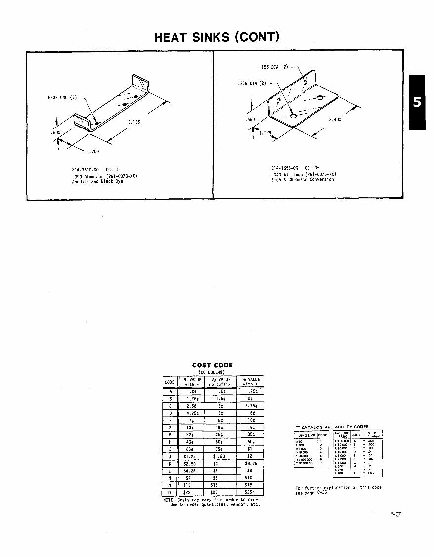
HEAT SINKS (CONT)
214-3300-00 CC: J-
.090 Aluminum (251 -0070-XX) Anodize and Black Dye
214-1653-00 CC: G+
.040 Aluminum (251-0076-XX) Etch & Chromate Conversion
COST CODE
tt CATALOG RE1
JlW000
210000000
NOTE: Costs m y vary from o rde r t o o rde r due t o order q u a n t i t i e s , vendor, e t c .
.IABILITY CODES
Imcdenl
05 I l l 000 115W - .5 . 1 0 1
For f u r t h e r exp lanat ion o f t h i s code, see page 0-25.
5-27
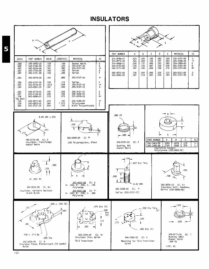
INSULATORS
I M A ) I PART NUMBER I OD(B) I LENGTH(C1 I MATERIAL
.030 1 342-0050-00 1 . I 2 5 1 . I00 1 Aceta l Resin
.045 342-01 60-00 . I 5 7 .340 255-0127-00 0 4 1 342-0304-00 1 1 6 1 1 .560 1 255-0127-00 .047 342-0122-00 . I 6 2 . I 5 0 T e f l o n ,047 1 342-0101-00 1 . I 6 2 1 .325 1 T e f l o n
.052 342-0147-00 . I 2 0 . I15 T e f l o n 0 5 2 1 342-0318-00 1 5 1 2:: I 255-0127-00 .054 342-0381-00 255-0127-00
.063
.081
. l o 6 Ea End) . I 5 6 .228 .266
255-0028-00 Po lys ty rene B lack Polycar
PART NUMBER
4-40 UNC x.200
942-0172-00 CC: G I n s u l a t o r , T r a n s f o r ~ r Aceta l Resin
.020 Polypropylene, B lack
/ ,075 D ia ( 4 )
,050 x ,015 Op ' ,) 342-0324-00 CC: 8+ .200 Oia l n s u l a t o r Disc, Ny lon
342-0356-00 CC: 0 TO-5 T r a n s i s t o r I n 5 u l a t o r P la te , M i c r o c i r c u i t (10 ~ e a d s )
Nylon
MATERIAL I CC
PART NUMBER A B C CC 342-0107-00 CC: '342-0463-00 .2265 .0575 .075 I - Bushing, BNC ,342-0386-00 .2155 .0595 .075 I - Aceta l Resin I n s u l a t i o n Contact
342-0263-00 CC: G t
I n s u l a t o r , Var iab le R e s i s t o r Black Nylon
342-0034-04 CC: G A: .346, B: .220, C : . I 4 5
Po ly imide
342-0421-OQ CC: F- A: .240, B: .230, C : ,089
Poly i rn ide
6-32 UNC
342-0298-00 CC: 1-
T e f l o n (255-0127-00)
Po lys ty rene (255-0663-00)
- .030 Oia Thru ( 5 )
\
, 3 7 5
,062 Oia ( 4 )
Mount ing f o r TO-5 T r a n s i s t o r Ny lon
342-0474-00 CC: E + I n s u l a t o r H a l f , Feedthru O e l r i n (254-0998-00)
342-0117-00 CC: C Bushing (BNC) Aceta l Resin .504 OD

INSULATORS (CONT) SHOULDERED WASHERS -
FINISH MATERIAL PART NUMBER
Po lys ty rene Po lys ty rene Ny 1 on F i b e r F iber
Black
Black
Black
Gray
Black
Black/
Acetal Ny 1 on Nylon w/
F iberg lass Acetal
A1 Anadoze F i b e r Acetal D e l r i n
F i b e r D e l r i n Ny 1 on Tef 1 on P l a s t i c
F iber F i b e r Polyphenyl N y l a f i l Acetal
F i b e r F i b e r
PLAIN WASHERS
OD I THICK 1 MATERIAL I OTHER PART NUMBER
.067 .015 Poly imide
.500 ,005 Mica
.203 .0025 Mica
.242 ,030 T e f l o n ,565 .002 Mica
Mica Mica S i l i c o n e Rubber Mica Polyethylene
.281 ,046 T e f l o n
.625 .005 Mica
.625 ,002 S i l i c o n e R u b b e r Thermal Cond i t ion ing 1.000 ,005 Mica ,715 .010 Acetate Buty ra te .855 .003 Mica
FOR OTHER WASHERS SEE MECHANICAL CATALOG, Sect ion 4, Pages 4-2 t h r u 4-4.
tt For R e l i a b i l i t y Code, See Page 5-27.
A
.300
.312
.312
.470
.562
.470
.562
.562
.562 ,625
.630
.630 ,650 ,860
B
.425
.312 ,473 .685 ,687
.565
.687
.688
.795
.675
.855
.855
.904 1.310
THICK
,002 ,002 .012 .002 .010
,002 .012 ,002 .002 ,002
.012
.012 ,010 ,010
MATERIAL
Mica Mica S i l i c o n e Rubber Mica S i l i c o n e Rubber w/Fiberglass
Mica S i l i c o n e Rubber Thermal F i l m Kapton Mica
S i l i c o n e Rubber S i l i c o n e Rubber S i l i c o n e Rubber Po lyes ter
HOLE DATA
. I 1 6 d i a
. I 2 6 d i a ,093 d i a For TO-220 ( T I ) . I41 d i a
. I 1 6 d i a
. I 2 5 d i a
,115 d i a . I 1 6 d i a
.093 d i a
. I 2 5 d i a
. I 4 1 d i a
. I25 d i a
PART NUMBER
342-0224-00 342-0166-00 342-0363-00 342-0202-00 342-0563-00
342-0586-00 342-0355-00 342-0322-00 342-0451-00 342-0163-00
342-0354-00 342-0354-01 342-0630-00 342-0321-00
C C
8 A+
A- D+
G- D F B- A+
D F- G I +
T T
R C
5A 5A
?[-TI L
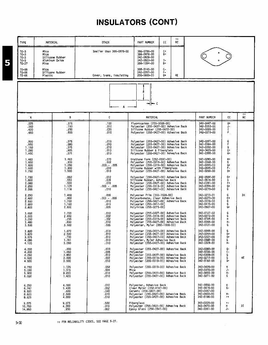
INSULATORS (CONT)
.225
.360
.430
.650
.900
.950 1.150 1 .28O 1.400
1.463 1.600 1.600 1.600 1.750
1.750 1. BOO 2.060 2.250 2.266
2.290 2.400 2.500 2.800 2.800
3.000 3.000 3.250 3.460 3.500
tt FOR RELIABILITY CODES, SEE PAGE 5-27.
TYPE MATERIAL
TO-3 Mica TO-3 Mica TO-3 S i l i c o n e Rubber TO-3 Aluminum Oxide TO-37 Mica
TO-66 Mica TO-66 S i l i cone Rubber TO-66 P l a s t i c
MATERIAL
Fluorocarbon (255-0028-00) Po lyester (255-0427-00) Adhesive Back S i l i cone Rubber (255-0472-00) Po lyester (255-0427-00) Adhesive Back
CC
C+ B+
I- B+
C- F- G+
Polyester (255-0427-00) Adhesive Back Polyester (255-0427-00) Adhesive Back Po lyester (255-0427-00) Adhesive Back S i l i cone Rubber & F iberg lass Po lyester (255-0427-00) Adhesive Back
t t RC
4E
OTHER
Smaller than 385-0978-00
Cover, t rans, i nsu la t i ng
Urethane Form (252-0591-00) Po lyester (255-0319-00) Adhesive Back Po lyester (255-0319-00) Adhesive Back S i l i cone Rubber w i t h F iberg lass Po lyester (255-0427-00) Adhesive Back
PART NUMBER
386-0786-00 386-0978-00 342-0629-00 342-0523-00 386-1094-00
386-0143-00 342-0357-00 200-0669-00
Po lyester (255-0427-00) Adhesive Back S i l i cone Rubber, Adhesive Back Po lyester (255-0427-00) Adhesive Back Po lyester (255-0319-00) Adhesive Back Po lyester (255-0427-00) Adhesive Back
Po lyester F i lm (002-1028-00) Polycarbonate, Clear Adhesive Back Po lyester (255-0427-00) Adhesive Back Po lyester (255-0417-00) Polyimide (255-0275-00)
Po lyester (255-0427-00) Adhesive Back Po lyester (255-0319-00 Adhesive Back Po lyester (255-0319-001 Adhesive Back Po lyester (255-0427-00) Adhesive Back Polyester, Mylar (002-1028-00)
Po lyester (255-0427-00) Adhesive Back Po lyester (255-0427-00) Adhesive Back Po lyester (255-0427-00) Adhesive Back Polyester, Mylar Adhesive Back Po lyester (255-0427-00) Adhesive Back
Po lyester (255-0427-00) Adhesive Back Po lyester Po lyester (255-0427-00) Adhesive Back Po lyester (255-0319-00) Adhesive Back Po lyester (255-0319-00) Adhesive Back
Po lyester (255-0319-00) Adhesive Back Mica Po lyester (255-0427-00) Adhesive Back Po lyester (255-0427-00) Adhesive Back
Po lyester , Adhesive Back Clear Mvlar (002-0147-00) ceramic- (204-0831-00) Po lyester (255-0427-00) Adhesive Back Po lyester (255-0427-00) Adhesive Back
F iberg lass Po lyester (255-0427-00) Adhesive Back Epoxy Glass (254-0541 -00)
PART NUMBER
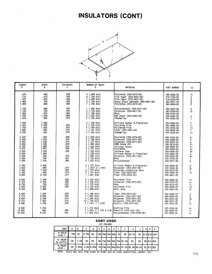

INSULATORS (CONT)
342-0330-00 .010 Po lyes ter (255-0427-00)
CC- H-
THICKNESS
342-0297-00 .010 P o l y e s t e r (255-0417-00)
CC- c t
,010 Po lyes ter
,002 Po lyes ter w/Adhesive Back I
I I I I
MATERIAL
Po lyes ter (255-0417-00) Po lyes ter (255-0427-00) Po lyes ter (255-0427-00) Po lyes ter (255-0319-00) Po lyes ter (255-0427-00)
Po lyes ter Epoxy Glass Laminate Po lyes ter (255-0319-00 Po lyes ter (255-0319-001
PART NUMBER
342-0109-00 .007 Nomex (252-0633-00)
CC- F
342-01 28-00 ,010 P o l y e s t e r (255-0427-00)
CC- F t
CC
342-0293-00 .010 P o l y e s t e r (255-0417-00)
CC- E t
tt RC
342-031 7-00 .007 Po ly imide (252-0633-00)
CC- J
342-0096-00 .010 C e l l u l o s e Acetate
(255-0224-00) CC- 0
342-0248-00 ,002 P o l y e s t e r (255-0319-00)
CC- G-
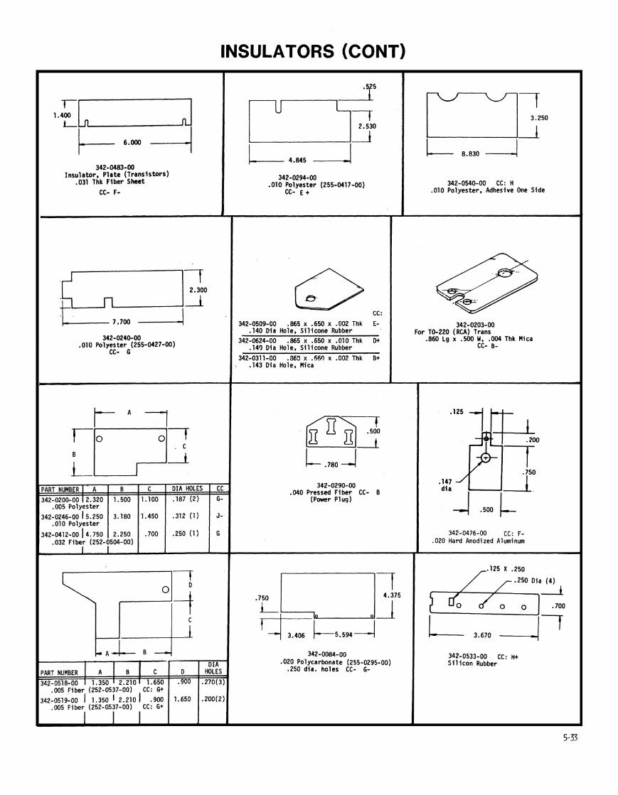
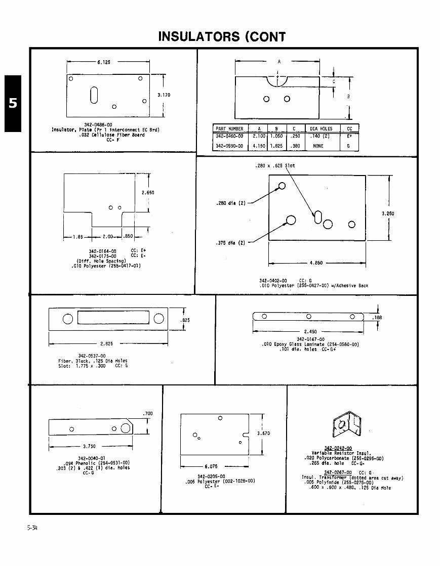
INSULATORS (CONT
342-0486-00 Insulator, Plate (Pr 1 interconnect EC Brd)
.032 Cellulose Fiber Board CC- F
342-0164-00 CC: E+ 342-0175-00 CC: E-
(Oiff. Hole Spacing) .010 Polyester (255-0417-01)
342-0537-00 Fiber, Black, .I25 Dia Holes Slot: 1.775 x .300 CC: G
342-0040-01 ,094 Phenol ic (254-0531-00)
.203 (2) 8 .422 (1) dla. holes CC- G
/ 342-0590-00 ( 4.150 1 1.825 1 .380 1 NONE I G I
- - -
PART NUMBER
342-0460-00
.280 x .625 Slot \
,280 dla (2)
.375 dia (2)
A
2.100
342-0402-00 CC: G ,010 Polyester (255-0427-00) w/Adhesive Back
1 : "ti"
B 1 .050
342-0167-00 ,010 Epoxy Glass Laminate (254-0580-00)
.I01 dia. holes CC-G4
- 6.075 4 342-0205-00
,005 Polyester (002-1 028-00) CC- E-
C
.250
Variable Resistor Insul. ,020 Polycarbonate (255-0295-00) .265 dia. hole CC- G-
342-0267-00 CC: G. Insul. Transformer dotted area cut away) ,005 Polyimide (25:-0275-00) ,600 x ,600 x .480, .I25 Oia Hole
DIA HOLES
.I40 (2)
CC
E+
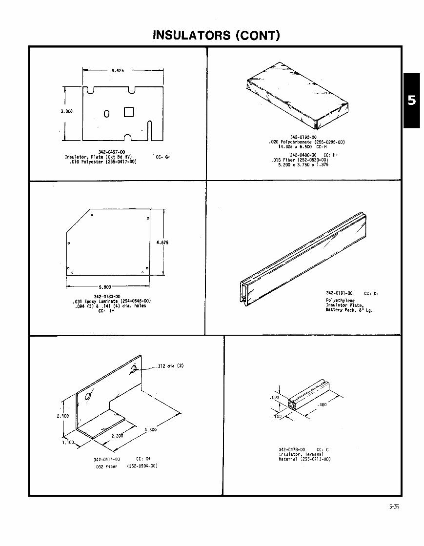
INSULATORS (CONT)
342-0192-00 .020 Polycarbonate (255-0295-00)
14.325 x 6.500 CC-H
342-0480-00 CC: H+ .015 Flber (252-0523-00)
5.200 x 3.750 x 1.375
342-01 83-00 .031 Epoxy Laminate (254-0546-00) .094 (3) 6 . I41 ( 4 ) dla. holes
CC- I+
342-0191-00 CC: C- Polyethylene Insulator Plate, Battery Pack. 6" Lg.
342-0478-00 CC: C Insulator, Terminal Material (255-0713-00)

INSULATORS (CONT)
1.030-4 1 - 5 . 2 4 1 4 - 1 . 4 2 0
342-0239-00 .010 Polyester (255-0417-00)
CC-G+
1.000 d i a
0
342-0393-00 CC: H- .032 Fiber (252-0504-00)
.625 dla
7.125
,280 d i a (2)
342-0394-00 CC: G- .032 FIBER (352-0504-00)
342-0238-00 .002 Polyimide (255-0535-00)
CC- I-
.375 d i a
.250 d i a ( 2 )
342-0400-00 CC: G .031 FIBER (252-0564-00)
342-0377-00 CC: F+ .OlO CAB (255-0224-00)
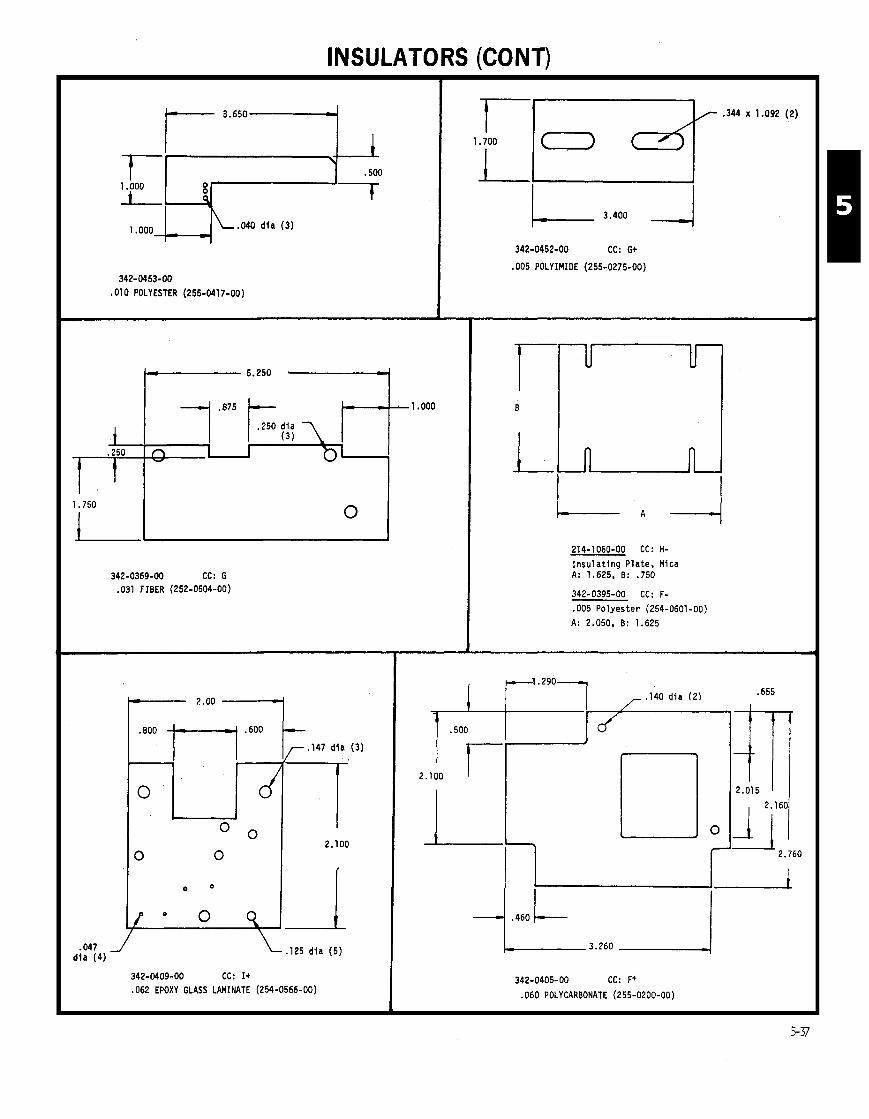
INSULATORS (CONT)
342-0369-00 CC: G .031 FIBER (252-0504-00)
I .
.O47 d id ( 4 ) 0 342-0409-00 CC: I+
.062 EPOXY GLASS LAMINATE (254-0566-00)
. I47 d i a (3 )
0
O 0 2.100
0 0
,125 d l a ( 5 )
342-0452-00 CC: G+
.005 POLYIMIDE (255-0275-00)
214-1060-00 CC: H- Insulat ing Plate , Mica A: 1.625, B: .750
342-0395-00 CC: F- .OO5 Polyester (254-0601 -00) A: 2.050. B: 1.625
342-0405-00 CC: F+
.060 POLYCARBONATE (255-0200-00)

INSULATORS (CONT) -
--
--
--
342-0481-00 I n s u l a t o r , Swi tch
,060 Polycarbonate, C lear (255-0200-00)
CC- G+
.055 DIA > -240 .530 DIA
. I 6 0 DIA ,
(4 )
1 .O62
342-0413-00 -005 THICK POLYIMIOE FILM (255-0275-00)
CC- A
342-0097-00 .020 FISH PAPER CC- C
,281 OIA
1.615
342-0132-01 CC- C .005 THICK POLYESTER SHEET
342-01 32-00 .005 THICK POLYESTER SHEET
CC- B-
342-0360-00 CC- G ,030 FIEER SHEET (252-0504-00)
. I 2 5 Dia (2)
342-0458-00 I n s u l a t o r , P la te , T r a n s i s t o r ,
Mica I CC- C-
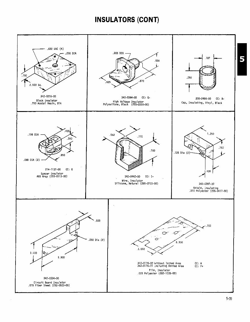
INSULATORS (CONT)
,- ,632 UNC (4)
Block Insulator .750 Acetal Resin, Bl k
214-1137-00 CC: G Spacer Insulator
ABS Gray (255-01 13-00)
I Circuit Board Insulator .015 Fiber Sheet (252-0523-00)
,203 DIA J /f
342-0384-00 CC: G- High Voltage Insulator
Polysulfone, Black (255-0330-00)
342-0442-00 CC: I- Wire, Insulator
Silicone. Natural (255-0700-00)
.600
Oia (2)
200-2486-00 CC: B- Cap, Insulating, Vinyl, Black
342-0397-00 Shield, Insulating
.010 Polyester (255-0417-00)
342-0176-00 Without Dotted Area 342-01 76-01 Including Dotted Area
CC: H CC: F+
Film, Insulator ,005 Polyester (002-1028-00)
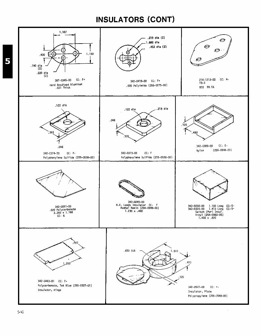
INSULATORS (CONT)
.220 d i a (2 )
Hard Anodized Aluminum .021 Thick
. I22 d i a
342-0374-00 CC: F-
Polyphenylene Su l f i de (255-0538-00)
342-0051-00 ,020 Polycarbonate
2.250 x 1.188 CC- G
342-0443-00 CC: F- Polycarbonate, Tek Blue (255-0527-01)
Insu la tor , Hinge
.453 d i a (2 )
342-0419-00 CC: F+ .005 Polyimide (255-0275-00)
122 di_a , .218 d i a
342-0373-00 CC: F
Polyphenylene Su l f i de (255-0538-00)
342-0245-00 H.V. Leads I n s u l a t o r CC- F
Acetal Resin (254-0998-00) 1.230 x .490
214-1213-00 CC: N- TO-3
342-0389-00 CC: E-
Nylon (255-0548-00)
342-0250-00 1.100 Long CC- G- 342-0320-00 1.413 Long CC- G-
Switch (Pwr) I nsu l . V iny l (254-0960-00)
1.400 x .820
CC: H-
I nsu la to r , P la te
Polypropylene (255-0568-00)

INSULATORS (CONT)
\.I25 DIA
214-0781-01 CC: B Insulator, Circuit Board Mount Polypropylene (254-0985-00)
.220 DIA
342-0499-00 CC: F+ Insulator, Sleeve Teflon (255-0140-00)
342-0575-00 CC: D+
Insulator, Plate, Pot.
Polyurethane (255-0621-01 )
342-0510-00 CC: F Insulator, Bushing
Polysulfone, Black (255-0330-00)
342-0075-00 Insulating Washer CC- I
255-0438-00 ~/255-0553-00 .640 ID. 3.430 OD
.019 DIA
.038 DIA x .255
:I25 DIA
342-0262-00 CC: G Bushing. Insulator Polyethylene (255-0071-00)
342-0488-01 CC: E Spacer, Trans1 stor Polyphenylene Sulfide (255-0538-00)
.224 x , 0 5 0 7 ,.365 RAD (3)
342-0535-00 CC: F Insulator, Plate
Polyphenylene Sulfide (255-0538-00)
342-0444-00 Insulated Switch Handle
Gray Vinyl CC- D
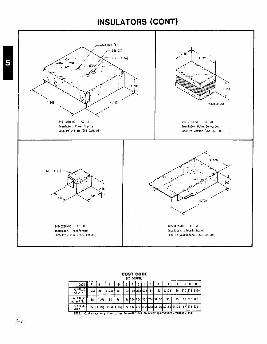
INSULATORS (CONT) -
, .203 OIA (5)
PA[ .r .312 .266 DIA ,I, (4)
342-0210-00 CC: J
I nsu la to r , Power Supply .005 Polyimide (255-0275-01)
342-0268-00 CC: H I nsu la to r , Transformer .005 Polyimide (255-0275-00)
342-0188-00 CC: J+
I n s u l a t o r (L ine Converter) .005 Po lyester (254-0601-00)
342-0225-00 CC: J
Insu la to r , C i r c u i t Board .030 Polycarbonate (255-0371-00)
COST CODE (CC COLUMN)

INSULATORS (CONT)
.020 OIA ( 2 )
342-0568-00 CC: E-
I n su l a to r , Contact
Polyurethane (255-0655-00)
.566 . I35 DIA ( 2 )
.099 DIA (16)
0- 2.468
214-0890-00 CC: K I n su l a to r , Readout
.016 Aluminum (251-0145-00)
342-0565-00 CC: E-
I n su l a to r , Contact
Polyurethane (255-0655-00)
342-0536-00 CC: Et ttRC: 5B In su l a to r , T rans i s t o r (TO-220)
Polysulfone (255-0330-00, Black o r 255-0719-00, Natural )
/<, . I41 DIA ( 2 )
342-0026-00 CC: D-
I n su l a to r , T rans i s t o r
Type 66 Nylon

.048 DIA (2)
.I43 DIA (4)
342-0489-00 CC: G- Insulation, Transistor (TO-3) ,005 Polyimide (255-0780-XX)
INSULATORS (CONT)
342-0491-00 CC: I- Insulator, Plate Polyphenylene (255-0538-00)
342-0564-00 CC: I Insulator, Plate .020 Phenolic Impreg. Fiber Sheet
.250 DIA
,,r .450 x 3.100
342-0608-00 CC: H-
Insulator, Plate .010 Polyester, Adhesive One Side
.500 DIA
.I88 DIA (6)
342-0506-00 CC: H- Insulator, Circuit Board .010 Pol yes ter (255-041 7-00)
342-0539-00 CC: Gt Insulation, Cable .020 Fiber Sheet (252-051 4-00)
342-0275-00 CC: H Insulation (H.V.) ,010 Mylar (255-0417-00)

INSULATORS (CONT)
Adhesive Backing
342-0559-00 CC: H
Insu la tor , P la te .010 Polyester
Score Lines
4 0
214-0857-00 CC: D Insu la tor , S l i de Contacts Paper (252-0538-00)
214-0769-00 CC: F
Insu la tor , P la te .020 F ish Paper (252-0514-00)
342-0587-00 CC: F Insu la tor , Power Switch .010 Polyester
342-0596-00 CC: H-
Insu la tor , Capacitor .031 F ibe r Sheet (252-0504-00)
r . I25 RAD
DIA
342-0615-00 CC: F
Insu la tor . P la te .O31 F ibe r Sheet
, .125 DIA (2)
342-0492-00 CC: H
I nsu la to r , F i lm Bracket .005 Polyimide
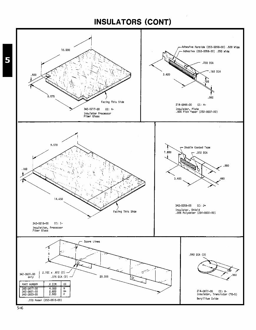
INSULATORS (CONT)
Insulator Processor Fiber Glass
,-Adhesive Farside (253-0058-00) .500 Wide
Adhesive (253-0058-00) .250 Wide
Insulation, Processor Fiber Glass
Insulator, Plate .005 Fish Paper (252-0537-00)
\I\ Double Coated Tape
Insulator, Shield .005 Polyester (254-0601 -00)
,010 Paper (252-0515-00)
.040 DIA (3)
214-0817-00 CC: H- Insulator, Transistor (TO-5)
Beryllium Oxide
NOTES
COST CODE (CC COLUMN)
NOTE: Costs may vary from order to order due to order quantities, vendor, etc.

TEK ALUMINA ELECTRICALLY INSULATING HEAT SINKS AND FLAT INSULATORS
LENGTH I WIDTH (A) ( 6 )
THICKNESS (C) STANDARD MATERIAL
96 White 96 White 96 White 85 White 85 White
96 White 96 White 96 White 96 White 96 White
96 White 96 White 96 White 96 White 96 White
85 White 96 White 96 White
PART NUMBER * MAXIMUM THICKNESS
* DIFFERENT THICKNESS OR MATERIALS ARE AVAILABLE FOR SHORT RUN OR PRODUCTION QUANTITIES. CONTACT HCM MATERIALS AND COMPONENT ENGINEERING: John O i Lazzaro, Ext. 3975; Bob Rogers, Ex t . 3971; Mike E h l e r t , Ext . 3972, FOR FURTHER ASSISTANCE
1.625 1.480
1.350 1.325
1.000 .750 .750
5-48 ** COST INFORMATION AVAILABLE ON REQUEST
PART NUMBER
342-0546-00 204-0460-00 204-0503-01 342-0461-00 342-0449-00
* MAXIMUM THICKNESS
,100 ,150 . I25 .150
.800 1.020
.912 1.000
1.000 .600 ,600
** CC
HOLES 0 (DIA)
3 ( . I301
THICKNESS ( c )
.025
LENGTH (A)
2.900
tt RC
36
STANDARD MATERIAL
96 White
WIDTH (6)
.950
.160
.060
.045
.040
.040
. I 0 0
. O N
.060 10 (.062) 96 White ,097 2 ( . 1 5 6 ) 3 ( . 0 4 4 ) 3 ( . 0 3 8 ) 9 6 W h i t e .060 1 (.225 96 White .045 1 2 1 . 1 5 6 1 1 8 5 W h i t e
2.600 2.000 1.980 1.880
1.525 1.000 . I980
.900
2 (.188) 3 (.070) 1 ( .125)
6 (.030) 2 ( .066)
4 (.094) 1 ( . I46 1 1.1251
96 White 96 White
96 White 96 White
96 White 85 White 96 White
342-0597-00 204-0603-00
204-0486-02 204-0651 -00
204-0604-00 342-0420-00 342-0328-00
. I 5 0
,125
. l o 0 ,125 ,125
40 4E

TEK ALUMINA ELECTRICALLY INSULATING HEAT SINKS AND FLAT INSULATORS
342-0555-00 ttRC: 48
M a t e r i a l : 96 White * Maximun Thickness: . I 5 0
M a t e r i a l : 96 White Maximum Thickness: .250
.a62 D I A (3 ) \
M a t e r i a l : 96 White ,060 Thick * Maximum Thickness: . I 0 0
204-0602-00
M a t e r i a l : 85 White * Maximum Thickness: . I 5 0
tt CATALOG RELIABILITY CODES
For f u r t h e r exp lanat ion o f t h i s code, see page 0-25.
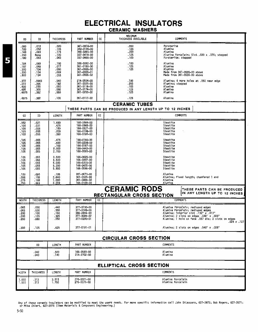
ELECTRICAL INSULATORS
THICKNESS
361 -0818-00 342-01 26-00
.069 358-0265-00 None 337-0419-00
.043 337-0985-00
CERAMIC WASHERS MAXIMUM
THICKNESS AVAILABLE
. I25
CERAMIC TUBES
COMMENTS
Fo rs te r i t e Alumina Alumina Alumina Porcelain; S l o t .030 x .075; stepped Fo rs te r i te; stepped
A1 umina A1 umi na A1 umi na Made from 361-0555-00 above Made from 361-0555-00 above
Alumina; 4 more holes a t .050 near edge A1 umina; stepped Alumina A1 umina A1 umi na
A1 umi na
(THESE PARTS CAN BE PRODUCED IN ANY LENGTH UP TO 12 INCHES ] LENGTH
166-0564-00 .475 166-0568-00
.055 166-0527-00
.055 166-01 98-00
.055 .350 166-01 65-00
COMMENTS
S t e a t i t e S t e a t i t e S t e a t i t e S t e a t i t e S t e a t i t e
S t e a t i t e S t e a t i t e S t e a t i t e S t e a t i t e S t e a t i t e
S t e a t i t e S t e a t i t e S t e a t i t e S t e a t i t e S t e a t i t e
Alumina Alumina; f i x e d length ; chamfered 1 end Alumina Alumina 1 . . . - . . . . . -
CERAMIC RODS [ THESE PARTS CAN BE PRODUCED
RECTANGULAR CROSS SECTION IN ANY LENGTH UP TO 12 INCHES
WIDTH I THICKNESS I LENGTH I PART NUMBER 1 CC I COMMENTS
CIRCULAR CROSS SECTION OD LENGTH PART NUMBER COMMENTS
.065
.065
.ZOO
.ZOO
.250
.300
Alumina Alumina
.440 ,550 . I50 .325 .350
.030 ,030 . I00 . I25 .080
ELLIPTICAL CROSS SECTION
. I25
WIDTH I THICKNESS 1 LENGTH I PART NUMBER I COMMENTS
377-01 50-00 377-0048-00 386-2894-00 377-0089-02 377-0290-01
- --
Alumina Porce la in Alumina Porce la in
Alumina Porcelain; radiused edges Alumina Porcelain; r a d i used edges Alumina; i n t e r i o r s l o t .130" x .013" Alumina; 2 s l o t s on edges .048" x .028" Alumina; 1 ho le on face .057 d ia ; 2 s l o t s on edges
.028 x .12
.625
Any o f these ceramic i nsu la to rs can be modified t o meet the users needs. For mare s p e c i f i c in format ion c a l l John OiLazzaro, 627-3972; Bob Rogers, 627-3971; o r Mike Eh ler t , 627-3975 ( I tem Mater ia ls & Component Engineering.)
5-50
377-0191-01 Alumina; 2 s l o t s on edges .048" x .028"
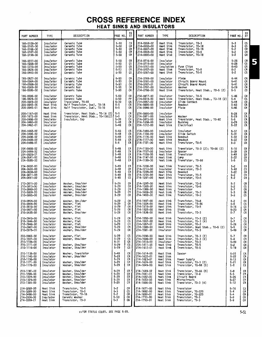
CROSS REFERENCE INDEX HEAT SINKS AND INSULATORS
I PART NUMBER TYPE
I n s u l a t o r I n s u l a t o r I n s u l a t o r I n s u l a t o r l n s u l a t o r
I n s u l a t o r I n s u l a t o r I n s u l a t o r I n s u l a t o r I n s u l a t o r
I n s u l a t o r I n s u l a t o r I n s u l a t o r I n s u l a t o r I n s u l a t o r
l n s u l a t o r I n s u l a t o r I n s u l a t o r Heat Sink Heat Sink
Heat Sink Heat Sink I n s u l a t o r I n s u l a t o r I n s u l a t o r
I n s u l a t o r I n s u l a t o r I n s u l a t o r I n s u l a t o r I n s u l a t o r
I n s u l a t o r l n s u l a t o r I n s u l a t o r I n s u l a t o r I n s u l a t o r
I n s u l a t o r I n s u l a t o r I n s u l a t o r I n s u l a t o r I n s u l a t o r
I n s u l a t o r I n s u l a t o r I n s u l a t o r I n s u l a t o r I n s u l a t o r
I n s u l a t o r I n s u l a t o r I n s u l a t o r I n s u l a t o r I n s u l a t o r
I n s u l a t o r I n s u l a t o r I n s u l a t o r I n s u l a t o r I n s u l a t o r
l n s u l a t o r [ n s u l a t o r [ n s u l a t o r [ n s u l a t o r [ n s u l a t o r
[ n s u l a t o r [ n s u l a t o r / n s u l a t o r . n s u l a t o r ' n s u l a t o r
n s u l a t o r n s u l a t o r n s u l a t o r n s u l a t o r n s u l a t o r
teat Sink leat Sink leat Sink n s u l a t o r leat Sink
DESCRIPTION
Ceramic Tube Ceramic Tube Ceramic Tube Ceramic Tube Ceramic Tube
Ceramic Tube Ceramic Tube Ceramic Tube Ceramic Tube Ceramic Tube
Ceramic Tube Ceramic Tube Ceramic Tube Ceramic Rod Ceramic Tube
Ceramic Tube Ceramic Tube T r a n s i s t o r , TO-66 H a l f T r a n s i s t o r , Dual, TO-18 H a l f T r a n s i s t o r , Dual, TO-18
T r a n s i s t o r , Heat Stab., TO-18 (2 T r a n s i s t o r , Heat Stab., TO-106(2 I n s u l a t o r , Cap
Washer, Shoulder Washer, Shoulder Washer, Shoulder Washer, Shoulder Washer, Shoulder
Washer, Shoulder Washer, F l a t Washer, F l a t Washer, F l a t Washer, Shoulder
Washer, F l a t Washer, F l a t Washer, F l a t Washer, Shoulder Washer, Shoulder
Washer, F l a t Washer, Shoulder
Washer, Shoulder Washer, Shoulder
Washer, T r a n s i s t o r Washer, Shoulder
dasher, Shoulder dasher, Shoulder
dasher, Shoulder dasher, Shoulder lasher, Shoulder lasher, Shoulder lasher, Shoulder
I r a n s i s t o r , TO-5 r r a n s i s t o r , TO-5 r r a n s i s t o r , TO-18 :erami c Washer r rans is to r , TO-3
- 'AGE N - - 5-50 5-50 5-50 5-50 5-50
5-50 5-50 5-50 5-50 5-50
5-50 5-50 5-50 5-50 5-50
5-50 5-50 5-30 5-5 5-5
5-5 5-5 5-39 5-48 5-48
5-48 5-48 5-48 5-48 5-4
5-48 j-48 5-48 5-48 5-48
5-49 5-48 5-48 5-48 5-48
i-29 i-29 i-29 i-29 i-29
1-29 1-29 1-29 1-29 8-29
-29 -29 -29 -29 -29
- 29 -29 -31 -29 -29
-49 -29 -29 -29 -29
-29 -29 -29 - 29 -29
- 2 - 3 -2 -50 - 3 -
- -
PART NUMBER
21 4-0559-02 214-0653-00 214-0667-00 214-0668-00 21 4-0693-00
214-0716-00 21 4-071 9-00 214-0751-00 21 4-0757-00 214-0761-00
21 4-0769-00 214-0781 -00 214-0781-01 214-0791-00 214-0798-00
214-0817-00 21 4-081 8-00 214-0857-00 214-0890-00 21 4-0946-00
214-0950-00 214-0971-00 21 4-0973-00 214-1 008-00 21 4-1 01 2-00
214-1060-00 214-1108-00 214-11 16-00 214-1117-00 214-1121-00
214-1 130-00 214-1 137-00 214-1138-00 214-1147-00 214-1 199-00
214-1208-00 214-1213-00 214-1228-00 214-1254-00 214-1291-00
214-1292-00 214-1300-00 21 4-1 388-00 214-1459-00 ?14-1460-00
!14-1497-00 !14-1504-00 !14-1519-00 !14-1525-00 !14-1536-00
!14-1550-00 !14-1557-00 !14-1557-01 !14-1580-00 !14-1581-00
!14-1598-00 !14-1599-00 !14-1610-00 !14-1611-00 !14-1612-01
!14-1614-00 !14-1622-01 '14-1623-01 '14-1624-00 '1 4-1 649-00
14-1649-02 14-1651-01 14-1652-00 14-1653-00 14-1 666-00
14-1671-00 14-1692-00 14-1 692-01 14-1713-00 14-1713-01
TYPE
Heat Sink Heat Sink Heat Sink Heat Sink Heat Sink
I n s u l a t o r I n s u l a t o r I n s u l a t i o r Heat Sink Heat Sink
I n s u l a t o r I n s u l a t o r I n s u l a t o r I n s u l a t o r Heat Sink
I n s u l a t o r Heat Sink I n s u l a t o r I n s u l a t o r I n s u l a t o r
I n s u l a t o r I n s u l a t o r Heat Sink I n s u l a t o r Heat Sink
I n s u l a t o r I n s u l a t o r Heat Sink Heat Sink Heat Sink
Heat Sink I n s u l a t o r Heat Sink Heat Sink Heat Sink
Heat Sink I n s u l a t o r Heat Sink Heat Sink Heat Sink
Heat Sink Heat Sink Heat Sink Heat Sink Heat Sink
Heat Sink Heat Sink Heat Sink Heat Sink Heat Sink
Heat Sink Heat Sink Heat Sink Heat Sink I n s u l a t o r
Heat Sink Heat Sink I n s u l a t o r Heat Sink Heat Sink
Heat Sink Lleat Sink i e a t Sink +eat Sink {eat Sink
i e a t Sink {eat Sink {eat Sink i e a t Sink {eat Sink
{ea t Sink {eat Sink {eat Sink {eat Sink iea t Sink
DESCRIPTION
T r a n s i s t o r . TO-3 T r a n s i s t o r , TO-18 T r a n s i s t o r , TO-18 T r a n s i s t o r , TO-5 T r a n s i s t o r , TO-18
Fuse C l i p s T r a n s i s t o r , TO-5 Trans is to r , TO-5
P l a t e C i r c u i t Board Mount C i r c u i t Board Mount Washer T r a n s i s t o r , Heat Stab., TO-5 (2 )
T r a n s i s t o r , TO-5 T r a n s i s t o r , Heat Stab., TO-18 (2 S l i d e Contact Readout P l a t e
Washer T r a n s i s t o r , Heat Stab., TO-92 Bushing E l e c t r i c a l
I n s u l a t o r S l i d e Swi tch Readout Readout T r a n s i s t o r , TO-5
T r a n s i s t o r , TO-3 (2 ) ; TO-66 ( 2 ) Spacer T r a n s i s t o r Lamp T r a n s i s t o r , TO-66
T r a n s i s t o r , TO-5 Trans is to r . TO-3 Readout T r a n s i s t o r , TO-5 T r a n s i s t o r , TO-5
Trans is to r , TO-5 T r a n s i s t o r , TO-5 T r a n s i s t o r T r a n s i s t o r , TO-3 T r a n s i s t o r , TO-3
T r a n s i s t o r , TO-8 T r a n s i s t o r , TO-66 T r a n s i s t o r , TO-5 Diode Trans is to r , TO-3
T r a n s i s t o r , TO-3 ( 2 ) ~ r a n s i s t o r ; TO-3 (4 ) T r a n s i s t o r , TO-3 T r a n s i s t o r , Heat Stab., TO-5 (2 ) Trans is to r , TO-3
T r a n s i s t o r , TO-3 (2 ) T r a n s i s t o r , TO-3 (2 ) T r a n s i s t o r , TO-3 T r a n s i s t o r , TO-5 Trans is to r . TO-5
Spacer
Power Supply T r a n s i s t o r , TO-3 (2 ) Trans is to r , TO-66 (5 )
T r a n s i s t o r , TO-66 (5 ) Trans is to r . TO-8 C i r c u i t Board M i c r o c i r c u i t T rans is to r , TO-3 (4 )
T r a n s i s t o r Trans is to r , TO-220 T r a n s i s t o r , TO-220 Trans is to r . TO-3 Trans is to r , TO-3
- PAGE NI - 5-3 5-3 5-2 5-2 5-2
5-28 5-28 5-43 5-2 5-2
5-44 5-41 5-41 5-29 5-5
5-46 5-5 5-44 5-43 5-46
5-28 5-29 5-5 5-29 5-22
5-37 5-31 5-22 5-22 5-3
5-10 5-39 5-49 5-22 5-5
5-2 5-40 5-22 5-2 5-2
5-2 5-2 5-7 5-3 5-3
5-2 5-5 5-16 5-20 5-7
5-7 5-7 5-26 5-5 5-49
5-7 5-8 5-49 5-2 5-19
5-22 5-22 5-13 5-21 5-8
5-8 5.5 5-26 5-27 5-12
5-16 5-4 5-4 5-9 5-9
- $ 5 FOR STATUS CODES, SEE PAGE 5-55.

CROSS REFERENCE INDEX (CONT)
PART NUMBER
214-1729-00 214-1731-00 214-1731-01 214-1757-00 214-1759-00
21 4-1764-00 214-1766-00 214-1781-00 214-1 789-01 214-1791-00
214-1795-00 21 4-1 799-00 214-1 804-00 214-1813-00 214-1815-00
214-1845-00 214-1845-01 21 4-1 860-00 214-1867-00 214-1871-00
214-1872-00 214-1873-00 21 4-1 880-00 214-1882-00 214-1914-00
214-1916-00 214-1917-00 214-1956-00 214-1958-00 214-1967-00
214-1979-00 214-1990-00 214-1999-01 21 4-2007-00 !14-2013-00
!14-2045-00 !14-2049-01 !14-2132-00 !14-2213-00 !14-2215-00
!14-2224-00 !I 4-2225-00 !14-2247-00 !14-2250-00 !14-2276-00
11 4-2280-00 11 4-2299-00 '14-2301-00 '1 4-2322-00 11 4-2330-00
!14-2342-00 11 4-2343-00 !74-2344-00 '14-2348-00 '1 4-2366-00
14- 2403-00 14-2407-00 14-2416-00 14-2418-00 14-2454-00
14-2458-00 14-2459-00 14-2462-00 14-2465-00 14-2473-00
14-2474-00 14-2493-00 14-2495-00 14-2496-00 14-2508-00
14-2508-01 14-2509-00 14-251 5-00 14-2516-00 14-2518-00
- --
TYPE
Heat Sink Heat Sink Heat Sink Heat Sink Heat Sink
Heat Sink Heat Sink Heat Sink Heat Sink Heat Sink
Heat Sink Heat Sink Heat Sink Heat Sink Heat Sink
Heat Sink Heat Sink Heat Sink Heat Sink Heat Sink
Heat Sink Heat Sink Heat Sink Heat Sink Heat Sink
Heat Sink Heat Sink Heat Sink Heat Sink Heat Sink
Heat Sink Heat Sink Heat Sink Heat Sink Heat Sink
Heat Sink Heat Sink Heat Sink Heat Sink Heat Sink
Heat Sink Heat Sink Heat Sink I nsu la to r Heat Sink
Heat Sink Heat Sink Heat Sink Heat Sink Heat Sink
Heat Sink Heat Sink Heat Sink Heat Sink Heat Sink
Heat Sink Heat Sink Heat Sink Heat Sink Heat Sink
Heat Sink Heat Sink Heat Sink Heat Sink Heat Sink
tieat Sink i e a t Sink +eat Sink i e a t Sink i e a t Sink
{eat Sink {eat Sink {eat Sink {eat Sink ieat Sink
DESCRIPTION
T rans i s to r T rans i s to r M i c r o c i r c u i t Diode
T rans i s to r Trans is tor , TO-3 (4) Trans is tor , TO-3 (4) T rans i s to r T rans i s to r
Trans is tor , TO-66 (4) Trans is tor , TO-8 R e c t i f i e r Trans is tor , TO-8 Trans is tor , TO-202
T rans i s to r T rans i s to r Trans is tor , TO-3 (2) T rans i s to r Trans is tor , TO-3 (2 )
Oiode Diode Trans is tor , TO-66 (2 ) T rans i s to r Trans is tor , TO-220
Trans is tor , TO-92 (2 ) T rans i s to r Trans is tor , TO-3 (4) Power Supply Trans is tor , TO-220
Trans is tor M i c r o c i r c u i t T rans i s to r Trans is tor Diode
Trans is tor Trans is tor , TO-3 (6) T rans i s to r Trans is tor , TO-3 Trans is tor
Trans is tor , TO-3 Trans is tor , TO-3 (3) ; TO-66 (1: Power Supply
Trans is tor
Trans is tor Power Supply Transformer Oiode Trans is tor
M i c r o c i r c u i t Power Supply Power Supply Power Supply Trans is tor
Trans is tor , TO-1 27 Trans is tor M i c r o c i r c u i t Transistor, Power C i r c u i t Board
Trans is tor Trans is tor Trans is tor Trans is tor , TO-220 Transistor, TO-5
Trans is tor Power Supply C i r c u i t Board Transistor. TO-8 C i r c u i t Board
C i r c u i t Board Power Supply Power Supply Transistor, TO-220 (2 ) Transistor, TO-220
- PAGE I - - 5-25 5-16 5-16 5-22
5-23 5-12 5-12 5-23 5-23
5-8 5-2 5-20 5- 2 5-6
5-16 5-8 5-23 5-21
5-20 5-20 5-9 5-16 5-4
5-5 5-20 5-12 5-12 5-4
5-18 5-14 5-9 5-18 5-19
5-25 5-12 5-17
5-16
5-7 5-10 5-13 5-31 5-10
5-8
5-21 5-1 5 5-9
5-15 5-19 5-19 5-12 5-22
5-18 5-20 5-15 5-3 5-22
5-3 5-3 5-18 5-23 5-2
5-14 5-21 5-21 5-4 5-1 1
5-11 5-11
5-11 5-4 -
TYPE
Heat Sink Heat Sink Heat Sink Heat Sink Heat Sink
Heat Sink Heat Sink Heat Sink Heat Sink Heat Sink
Heat Sink Heat Sink Heat Sink Heat Sink Heat Sink
Heat Sink Heat Sink Heat Sink Heat Sink Heat Sink
Heat Sink Heat Sink Heat Sink Heat Sink Heat Sink
Heat Sink Heat Sink Heat Sink Heat Sink Heat Sink
Heat Sink Heat Sink Heat Sink Heat Sink Heat Sink
Heat Sink Heat Sink Heat Sink Heat Sink Heat Sink
Heat Sink Heat Sink Heat Sink Heat Sink Heat Sink
Heat Sink Heat Sink Heat Sink Heat Sink Heat Sink
Heat Sink Heat Sink Heat Sink Heat Sink Heat Sink
Heat Sink Heat Sink Heat Sink Heat Sink i e a t Sink
i e a t Sink i e a t Sink i e a t Sink {eat Sink {eat Sink
{eat Sink {eat Sink i ea t Sink {eat Sink ieat Sink
{eat Sink {eat Sink leat Sink {eat Sink leat Sink
DESCRIPTION
Trans is tor , TO-220 Trans is tor . TO-3 (21: TO-127 (1 . ,. Power suppiy M i c r o c i r c u i t T rans i s to r & Diode
Trans is tor , TO-5 Trans is tor , TO-39 C i r c u i t Board Trans is tor , TO-5 Res is tor
Power Supply Power Supply Power Supply C i r c u i t Board Trans is tor , TO-3
Trans is tor , TO-3 Trans is tor , TO-220 (3) Trans is tor , TO-220 (2) Power Supply Ceramic Rod
C i r c u i t Board Oiode, TO-3 Trans is tor , TO-202 (2) Trans is tor , TO-202 Trans is tor , TO-39
Power Supply O s c i l l a t o r Diode, DO-4 (2 ) C i r c u i t Board, TO-3 (4) C i r c u i t Board
Power Supply Power Supply T rans i s to r C i r c u i t Board Trans is tor , TO-220
Power Supply Switch E l e c t r i c a l T rans i s to r Diode, TO-220 (2 )
Trans is tor , TO-220 Trans is tor , TO-202 (2) IC, 14 o r 16 P in Dip Trans is tor , TO-220 (5) Trans is tor , TO-220
Trans is tor , TO-3 Power Supply E l e c t r i c a l Power Supply Power Supply
T rans i s to r Trans is tor , TO-220 Trans is tor , TO-220 Diode TO-220
Trans is tor , TO-3 Trans i s t o r , TO-220 Trans is tor . TO-220 Trans is tor . TO-220 Trans is tor , TO-61
Transistor, TO-61 Trans is tor , TO-220 Transistor, TO-202 r rans i s to r . TO-220 r rans i s to r , TO-220
Transistor, TO-202 (2 )
- PAGE N
5-4 5-23 5-12 5-24 5-19
5-2 5-1 9 5-20 5-2 5-21
5-13 5-13 5-1 1 5-1 1 5-4
5-4
5-21 5-50
5-16 5-15 5-20 5-19 5-5
5-22 5-16 5-9 5-10
5-13 5-13 5-13 5-1 1 5-4
5-12 5-18 5-17 5-26 5-25
5-18 5-4 5-10 5-9 5-18
5-10 5-1 1 5-17 5-26 5-13
5-5 5-18 5-5 5-15 5-3
5-4 5-3 5-3 5- 3 5-25
5-25 5-16 5-18 5-22 5-22
5-16 5-14 5-14 5-14 5-14
5-14 5-14 5-14 5-14 5-14 -

PART NUMBER TYPE
Heat Sink Heat Sink Heat Sink Heat Sink Heat Sink
Heat Sink Heat Sink Heat Sink Heat Sink Heat Sink
Heat Sink Heat Sink Heat Sink Heat Sink Heat Sink
Heat Sink Heat Sink Heat Sink Heat Sink Heat Sink
Heat Sink Heat Sink Heat Slnk Heat Sink Heat Sink
Heat Slnk Heat Sink Heat Sink Heat Sink Heat Sink
Yeat Sink Heat Sink Heat Sink Heat Sink
Heat Sink Heat Sink Heat Sink Heat Sink Heat Sink
Heat Sink Insulator Insulator Insulator Insulator
Insulator Insulator Insulator Insulator Insulator
Insulator Insulator Insulator Insulator [nsulator
[nsulator [nsulator [nsulator [nsulator Insulator
nsulator 'nsulator nsulator nsulator nsulator
nsulator nsulator nsulator nsulator nsulator
nsulator nsulator nsulator nsulator nsulator -
CROSS REFERENCE INDEX (CONT)
DESCRIPTION -, - Transistor, TO-202 Transistor. TO-202 Power Supply Transistor, TO-220 Power Supply
Transistor Transistor, TO-92 Oscillator Resistor Assembly Transistor
Transis tor Diode Power Supply Transistor Transistor, TO-5
Transistor, TO-3 Circuit Board Circuit Board Transistor, TO-220 Transistor, TO-220
Transistor, TO-220 Transistor Diode Microcircuit Transistor, TO-220
Diode Diode Transistor, TO-220 Diode Power. Supply
Transistor. TO-220 Diode Transistor, Power Transistor, TO-220
Transistor Microcircuit Transistor, TO-92 & TO-18 Transistor, TO-220 Transistor
Transistor Ceramic Rod Ceramic Rod Ceramic Tube
Ceramic Washer Ceramic Washer Connector Transistor Bushing
Plate Plate Pad Washer Variable Resistor
Terminal Pin Plate Elec. Shield dasher
)late )late )late jhield 'ush Switch
:onnector ileeve 'ower Supply 'late Iushing
:i rcui t Board lushlng ;l eeve ~leeve bunting Frame
;INK!
PAGE N
5-18 5-16 5-14 5-6 5-14
5-14 5-4 5-22 5-17 5-26
5-17 5-16 5-12 5-14 5-2
5-26 5-24 5-24 5-22 5-25
5-24 5-24 5-24 5-15 5-24
5-24 5-24 5-3 5-24 5-11
5-27 5-24 5-3 5-19
5-15 5-15 5-2 5-6 5-3
5- 3 5-50 5-50 5-50 5-48
5-50 5-40 5-30 5-43 5-28
5-31 5-34 5-31 5-29 5-28
5-28 5-40 5-30 5-41 5-48
5-33 5-31 5-30 5-30 5-32
5-38 5-28 5-31
TORS - TYPE
lnsulator Insulator Insulator Insulator Insulator
Insulator Insulator Insulator Insulator Insulator
Insulator Insulator Insulator Insulator Insulator
Insulator Insulator Insulator Insulator Insulator Insulator Insulator Insulator Insulator Insulator Insulator
Insulator Insulator Insulator Insulator Insulator
Insulator Insulator Insulator Insulator Insulator
Insulator Insulator Insulator Insulator Insulator
Insulator Insulator Insulator Insulator Insulator
Insulator Insulator Insulator Insulator Insulator
Insulator Insulator Insulator Insulator Insulator
Insulator Insulator Insulator Insulator Insulator
[naul ator [nsulator [nsulator lnsulator lnsul ator
[nsulator Insulator Insulator nsulator nsulator
nsulator nsulator nsulator nsulator nsulator -
DESCRIPTION
Power Supply HV Power HV Power Plate Circuit Board
Circuit Board Washer Washer Bushing Bushing
Transistor HV Film Transistor Circuit Board Sleeve
Sleeve Bushing Transformer HV Plate
Plate Plate, Shield CRT Line Connector Battery Pack
Battery Pack Power Supply Transistor Transistor Push Switch
Side Panel Zircuit Board )late, Bus Bar rransistor rransistor
:ircui t Board rransi stor )ewer Supply
:ircui t Board
bwer Supply rransistor lisplay :use Block )rocessor
'rocessor 'ransistor :ircuit Board '1 ate 'ush Switch
'ower Supply 'ower Supply 'ransistor 'ransistor :ircuit Board
lower Supply :ircuit Board :ircuit Board 'ariable Resistor IV Leads
hield V Chassis V Shield witch leeve
isk V Transformer V Lead hield ushing
ariable Resistor V Shield asher hield ransl stor
PAGE N(
5 5 FOR STATUS CODES, SEE PAGE 5-55.
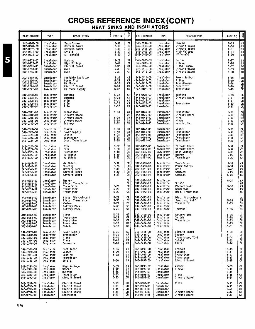
CROSS REFERENCE INDEX (CONT)
PART NUMBER
342-0268-00 342-0269-00 342-0270-OC 342-0271-00 342-0272-00
342-0273-00 342-0275-00 342-0281-00 342-0283-00 342-0285-00
342-0289-00 342-0290-00 342-0293-00 342-0294-00 342-0297-00
342-0298-00 342-0304-00 342-0308-00 342-0309-00 342-0310-00
342-031 1-00 342-0312-00 342-0315-00 342-031 6-00 342-0317-00
342-0318-00 342-0320-00 342-0321-00 342-0322-00 342-0324-00
342-0326-00 342-0327-00 342-0328-00 342-0329-00 342-0330-00
342-0341-00 342-0343-00 342-0345-00 342-0350-00 342-0351-00
342-0352-00 342-0353-00 342-0354-00 342-0354-01 342-0355-00
342-0356-00 342-0357-00 342-0358-00 342-0360-00 342-0361-00
342-0362-00 342-0353-00 342-0364-00 342-0365-00 342-0368-00
342-0369-00 342-0370-00 342-0373-00 342-0374-00 342-0376-00
142-0377-00 142-0380-00 342-0381-00 142-0382-00 342-0383-00
142-0384-00 142-0385-00 142-0386-00 142-0389-00 142-0390-00
142-0391 -00 142-0392-00 142-0393-00 142-0394-00 142-0395-00 -
TYPE
Insulator Insulator Insulator Insulator Insulator
Insulator Insulator Insulator Insulator Insulator
Insulator Insulator Insulator Insulator Insulator
Insulator Insulator Insulator Insulator Insulator
Insulator Insulator Insulator Insulator Insulator
Insulator Insulator Insulatbr Insulator Insulator
Insulator Insulator Insulator Insulator Insulator
Insulator Insulator Insulator Insulator Insulator
Insulator Insulator Insulator Insulator Insulator
Insulator Insulator Insulator Insulator Insulator
Insulator Insulator Insulator Insulator Insulator
Insulator Insulator Insulator Insulator Insulator
Insulator Insulator Insulator Insulator Insulator
Insulator Insulator Insulator Insulator Insulator
Insulator [nsulator Insulator [nsulator [nsulator -
HEAT SINKS AND INSuLATORS
DESCRIPTION
Transformer Circuit Board Ci rcui t Board Shield CRT Shield
Bushing High Voltage Circuit Board Oven Oven
Variable Resistor Power Plug HV Plate Circuit Board HV Power Supply
Bushing Bushing Film Film Film
Transistor Circuit Board Circuit Board Circuit Board Battery
Sleeve Power Supply Shield Transistor Disc, Transistor
Film Film Transistor HV Shield HV Shield
HV Shield Bushing Battery Pack Circuit Board Circuit Board
Washer Plate, Transistor Transistor Transistor Transistor
Plate, Microcircuit Plate, Transistor Washer Battery Pack Battery Pack
Plate Transistor Transistor Transistor Shield
Power Supply Transistor Plate Plate Connector
Oscillator Washer Bushing Transistor Shield
High Voltage Washer Bushing Transistor Circui t Board
Circuit Board Circuit Board Circui t Board Circuit Board Attenuator
- PAGE NI
5-42 5-30 5-30 5-30 5-30
5-28 5-44 5-30 5-30 5-30
5-31 5-33 5-32 5-33 5-32
5-28 5-28 5-30 5-32 5-32
5-33
5-30 5-30 5-32
5-28 5-40 5-29 5-29 5-28
5-32 5-30 5-48 5-30 5-32
5-32 5-28 5-31 5-30 5-31
5-29 5-29 5-29
5-28 5-30 5-29 5-38 5-30
5-31 5-29 5-30 5-30 5-30
5-36 5-30 5-40 5-40 5-28
5-36 5-29 5-28
5-30
5-39 5-29 5-28 5-40 5-30
5-30 5-30 5-36 5-36 5-37 -
PART NUMBER I TYPE
Insulator Insulator Insulator Insulator Insulator
Insulator Insulator Insulator Insulator Insulator
Insulator Insulator Insulator Insulator Insulator
Insulator Insulator Insulator Insulator Insulator
Insulator Insulator Insulator Insulator Insulator
Insulator Insulator Insulator Insulator Insulator
Insulator Insulator Insulator Insulator Insulator
Insulator Insulator Insulator Insulator Insulator
Insulator Insulator Insulator Insulator Insulator
Insulator Insulator Insulator Insulator Insulator
Insulator Insulator Insulator Insulator Insulator
Insulator Insulator Insulator Insulator Insulator
Insulator Insulator Insulator Insulator Insulator
Insulator Insulator lnsulator Insulator Insulator
Inusl ator Insulator Insulator [nsulator Insulator -
DESCRIPTION
Shield Ci rcui t Board Circuit Board High Voltage HV Shield
Cables Sleeve Plate, Comp. Circuit Board Circuit Board
Power Switch Fi 1 ter Transformer Capacitor Transistor
Bushing Circuit Board
Transistor
Transistor Circuit Board Wire Hinge Handle, Sw.
Washer Transistor Transistor Transistor Transistor
Circuit Board Circuit Board High Voltage Washer Transistor
Transistor Power Switch Coi 1 Contact Contact
Shield Microcircuit Connector Disc. Transistor
Disc, Microcircuit Feedthru, Half Transistor
Terminal
Battery Set Switch Transistor
Circuit Board Spacer Transistor. TO-3 Shield Plate
Bracket Bushing Transistor Transistor Circuit Board
dasher Sleeve
'late :ircuit Board
31 ate
:ircui t Board :i rcui t Board
PAGE NI
5-39 5-36 5-31 5-34 5-30
5-37 5-28 5-37 5-33 5-38
5-35 5-30 5-46 5-40 5-48
5-28 5-31 5-31 5-30 5-31
5-38 5-30 5-39 5-40 5-41
5-30 5-48 5-49 5-31 5-29
5-37 5-37 5-30 5-29 5-30
5-38 5- 34 5-48 5-29 5-28
5-31
5-32 5-30
5-28 5-33
5-35
5-35 5-38 5-33 5-43 5-31
5-34 5-41 5-44 5-32 5-44
5-45 5-41 5-31 5-31 5-35
5-29 5-41 5-49 5-45 5-44
5-30 5-33 5-41 5-31 5-32 -
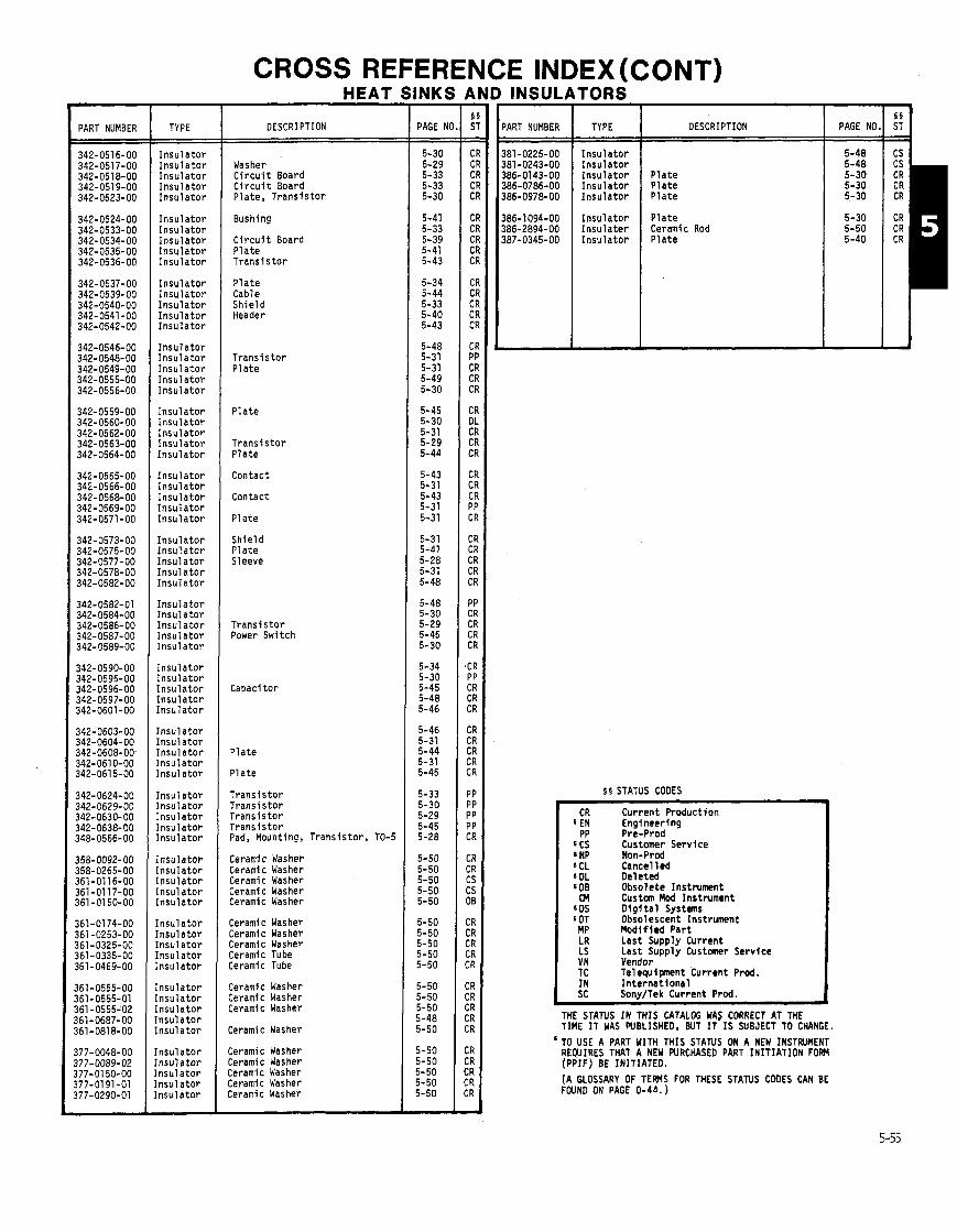
CROSS REFERENCE INDEX (CONT)
PART NUMBER TYPE
Insulator Insulator Insulator Insulator Insulator
Insulator Insulator Insulator Insulator Insulator
Insulator Insulator Insulator Insulator Insulator
Insulator Insulator Insulator Insulator Insulator
Insulator Insulator Insulator Insulator Insulator
Insulator Insulator Insulator Insulator Insulator
Insulator Insulator Insulator Insulator Insulator
Insulator Insulator Insulator Insulator Insulator
Insulator Insulator Insulator Insulator [nsulator
[nsulator [nsulator [nsulator [nsulator [nsul ator
[nsulator [nsulator [nsulator [nsulator [nsulator
[nsulator Insulator Insulator Insulator Insulator
:nsulator 'nsulator :nsul ator 'nsulator nsulator
nsulator nsulator nsulator nsulator nsulator
nsulator nsulator nsulator nsul ator nsulator
HEAT
DESCRIPTION
Washer Circuit Board Circuit Board Plate, Transistor
Bushing
Circuit Board Plate Transistor
Plate Cable Shield Header
Transistor Plate
Plate
Transistor Plate
Contact
Contact
Plate
Shield Plate Sleeve
Transistor Power Switch
Plate
Plate
Transistor Transistor Transistor Transistor Pad, Mounting, Transistor, TO-5
Ceramic Washer Ceramic Washer Ceramic Washer Ceramic Washer Ceramic Washer
Ceramic Washer Ceramic Washer Ceramic Washer Ceramic Tube Ceramic Tube
Ceramic Washer Ceramic Washer Ceramic Washer
Ceramic Washer
Ceramic Washer Ceramic Washer Ceramic Washer Ceramic Washer Ceramic Washer
INK! - PAGE h - - 5-30 5-29 5-33 5-33 5-30
5-41 5-33 5-39 5-41 5-43
5-34 5-44 5-33 5-40 5-43
5-48 5-31 5-31 5-49 5-30
5-45 5-30 5-31 5-29 5-44
5-43 5-31 5-43 5-31 5-31
5-31 5-41 5-28 5-31 5-48
5-48 5-30 5-29 5-45 5-30
5-34 5-30 5-45 5-48 5-46
5-46 5-31 5-44 5-31 5-45
5-33 5-30 5-29 5-45 5-28
5-50 5-50 5-50 5-50 5-50
5-50 5-50 5-50 5-50 5-50
5-50 5-50 5-50 5-48 5-50
5-50 5-50 5-50 5-50 5-50 -
INSULATORS
)ART NUMBER
381-0225-00 381 -0243-00 386-01 43-00 386-0786-00 386-0978-00
TYPE I DESCRIPTlON I PAGE NO.1 :: I
5 5 STATUS CODES
Insulator Insulator Insulator Insulator Insulator
Insulator Insulater Insulator
CR Current Production 6 EN Engineering PP Pre-Prod
6 CS Customer Service SNP Non-Prod 6CL Cancelled 6DL Deleted 800 Obsolete Instrument CM Custan Mod Instrument
'DS Digital Systems 60T Obsolescent Instrument MP Modified Part LR Last Supply Current LS Last Supply Customer Service VN Vendor TC Telequipnent Current Prod. IN International SC Sony/Tek Current Prod.
THE STATUS IN THIS CATALOG WAS CORRECT AT THE TIME IT WAS WBLISHED. BUT IT IS SUBJECT TO CHANGE. TO USE A PART WITH THIS S T A N S ON A NEW INSTRVMENT REWIRES THAT A NEW PURCHASED PART INITIATION FOB4 (PPIF) BE INITIATED.
Plate Plate Plate
Plate Ceramic Rod Plate
(A GLOSSARY OF T E N S FOR THESE STATUS CODES CAN BE FOUND ON PAGE 0-44. )
5-48 5-48 5-30 5-30 5-30
5-30 5-50 5-40
I CS CS CR CR CR
CR CR CR

HEAT SINKS (CONT)
FIN SPACING AFFECTS HEAT SINK EFFICIENCY
V e r t i c a l l y o r i en ted mu l t i - f i nned heat s inks a re comnonly used f o r removing waste heat from e lec t ron i c instruments. I n se lec t i ng a heat s i nk f o r use i n a na tu ra l convect ion environment, t he design engineer must be aware t h a t f i n spacing can d i r e c t l y i n f l uence the e f f i c i e n c y o f t he heat sink.
An increase i n t h e number o f f i n s on a heat s i nk does no t necessar i ly correspond t o an increase i n t he coo l i ng c a p a b i l i t i e s o f t he sink. I n f a c t , a reduct ion t n t he coo l i ng e f f i c i e n c y o f t he heat s i nk can r e s u l t . Tek's Thermal Ana lys is group r e c e n t l y examined the e f f e c t s o f two f i n spactngs f o r several heat s i nk he ights (see Figure 1 ) .
W = Width
H = Height
L = F in length
FIGURE 1 - S = F i n spacing
A reduct ion i n f i n spacing ( increas ing number o f f l n s ) increases t he area ava i l ab le f o r heat t r ans fe r . However, t h i s increase can be o f f s e t by a decrease i n t he e f f i c i e n c y o f na tu ra l convect ion and r a d i a t i o n heat t r ans fe r . Choking o f a i r f l o w through the f i n s can occur w i t h c l ose l y spaced f l n s . Also, r a d i a t i o n t r a n s f e r i s a f f ec ted by adjacent f i n sh ie ld ing. For a g iven f i n length, there i s an optimum f i n spacing t h a t mx im izes heat t r ans fe r .
TEST RESULTS
Comnon stock extruded heat s i nk mater ia l was used t o ca l cu la te t heo re t i ca l r e s u l t s and conduct t he ac tua l t es t s . The ma te r i a l was 3.8 inches wide, and had t h i r t e e n equa l ly spaced f i n s . A t y p i c a l f i n spacing o f 0.23-inch was measured. Removing every o the r f i n increased t h e t y p i c a l f i n spacing t o 0.54-inch. These two spacings were used i n con junct ion w i t h a f i n l eng th o f one-inch f o r t es t i ng .
F i r s t , t heo re t i ca l thermal resistances and power d i ss i pa t i ons were tabulated. Results showed t h a t i n 16 o f t he 24 cases con- sidered, the heat s i nk w i t h f i n spacing o f 0.54-inch would d i ss ipa te more power, i.e., would have a lower thermal res is tance. For t he cases considered here, t he imp l i ca t i ons were obvious. I f a design engineer had selected a s i nk w i t h 0.23-inch spacing, s/he would have chosen a heat s ink t h a t provided no add i t i ona l coo l i ng b e n e f i t and had an increased cost and weight.
Next, l i m i t e d empi r ica l t e s t i n g was conducted f o r v e r i f i c a t i o n o f t he t h e o r e t i c a l r esu l t s . Two s i x - i nch samples having f i n spacings o f 0.23- and 0.54-inch were selected f o r t he t es t i ng . Each sample was suspended i n a p ro tec t i ve shroud t o r e s t r i c t s t r ay room a i r cur rents . Several thermocouples were s i t ua ted on t he heat s i nk t o ob ta in a good average sur face temperature. Power d i s s i p a t i o n was by s i x un i formly d i s t r i b u t e d TO-220 t r a n s i s t o r packages. Two surface cond i t ions were considered: bare aluminum (em iss i v i t y approximately 0.1 ) , and the s i nk pa in ted b lack (em iss i v i t y approximately 0.8).
The t e s t s were conducted f o r temperature r i s e s o f approximately 10°C, 25% and 50°C. The r e s u l t s are p l o t t e d i n Figures 2 and 3. Good agreement was obtained between actua l and t h e o r e t i c a l r e s u l t s f o r t he cond i t ions tes ted. As i nd i ca ted by theory and supported by experiment, both heat s inks have very s i m i l a r coo l i ng c a p a b i l i t i e s .
:// Actual Theoret ica l r e s u l t s r e s u l t s
10 A Bare a1 uminum .Black p a i n t
I 0 1 0 2 O J O 4 0 W
Power (watts )
FIGURE 2 - COMPARISON OF RESULTS FOR FIN SPACING 0.23 INCH
// Theoret ica l r esu l
Lo/ / Actual r e s u l t s
C a 4J
POW& (wat ts )
FIGURE 3 7
COMPARISON OF RESULTS FOR FIN SPACING 0.54 INCH.
From the examples presented here, i t i s ev ident t h a t f i n spacing should be a major concern when designing o r se lec t i ng a m u l t i - f inned heat sink f o r use i n a na tu ra l convect ion environment.
The Thermal Analysis group i s ava i l ab le f o r design support and consu l t a t i on f o r a l l types o f heat s i nk re l a ted problems. Contact Gordon E l l i s o n o r Lar ry Haroun a t ex t . 7887, o r d e l i v e r y s t a t i o n 50-132.
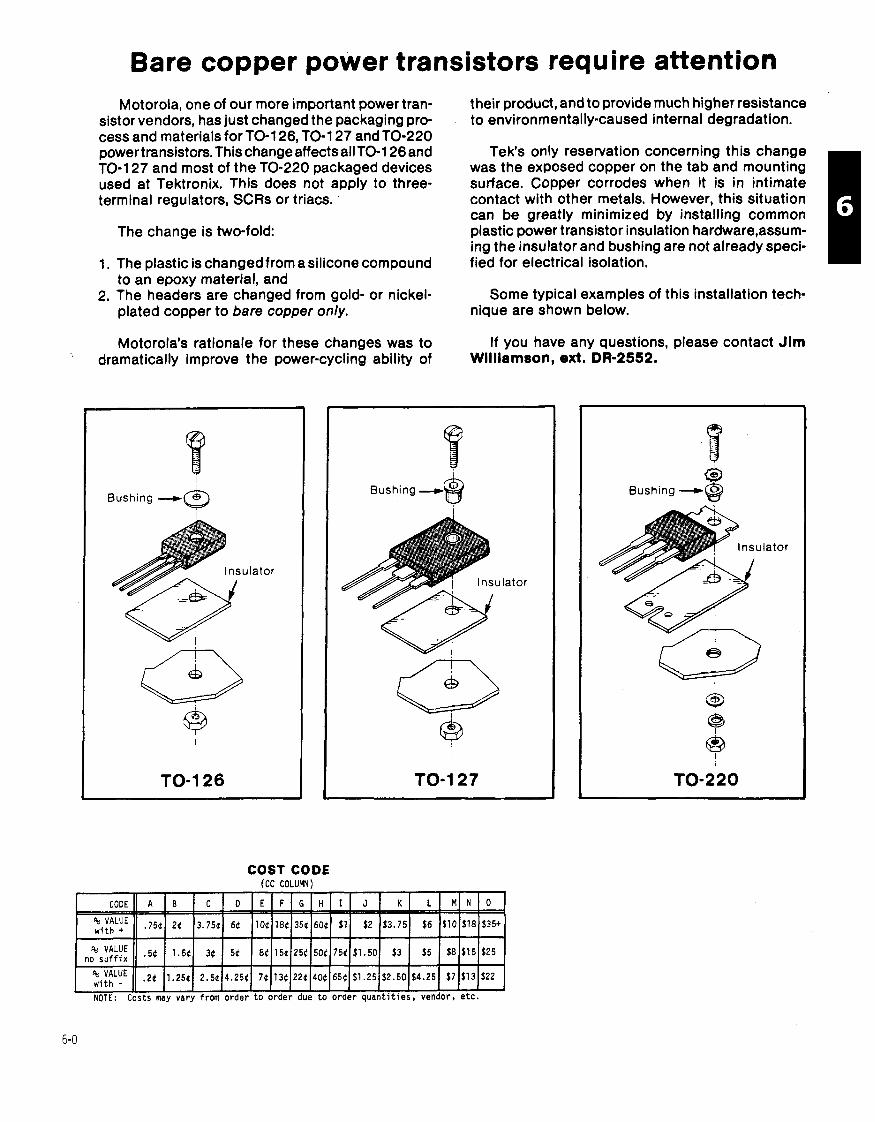
Bare copper power transistors require attention Motorola, one of our more important power tran-
sistor vendors, has just changed the packaging pro- cess and materials for TO-1 26, TO-1 27 and TO-220 power transistors. Thischange affects allTO-126 and TO-1 27 and most of the TO-220 packaged devices used at Tektronix. This does not apply to three- terminal regulators, SCRs or triacs.
The change is two-fold:
1. The plastic is changed from a silicone compound to an epoxy material, and
2. The headers are changed from gold- or nickel- plated copper to bare copper only.
Motorola's rationale for these changes was to
their product, and to provide much higher resistance to environmentally-caused internal degradation.
Tek's only reservation concerning this change was the exposed copper on the tab and mounting surface. Copper corrodes when it is in intimate contact with other metals. However, this situation can be greatly minimized by installing common plastic power transistor insulation hardwarelassum- ing the insulator and bushing are not already speci- fied for electrical isolation.
Some typical examples of this installation tech- nique are shown below.
If you have any questions, please contact Jim dramatically improve the power-cycling ability of ~i l l iamson, ext. DR-2552.
Bushing --., a Bushing - $
COST CODE (CC CoLUm)
Bushing .--, Gb 8
TRANSISTORS
T A B L E O F C O N T E N T S
S E C T I O N S 6 T H R U 9
P A G E ( S )
L I S T I N G S A R R A Y S ~ ~ ~ ~ ~ ~ ~ ~ ~ ~ ~ ~ ~ ~ ~ ~ ~ ~ ~ ~ ~ ~ ~ ~ s ~ ~ , , ~ ~ ~ ~ ~ ~ m ~ ~ ~ 6 - 2 3
F I E L D E F F E C T ( S I N G L E ) . . . . . . . . . . . . . . . . . . . . . . . 7 - 2 8 7 - 5
F I E L D E F F E C T ( D U A L & P A I R ) , , , , , , , , , , , , , , , , , , , 7 - 6 T H R U 7 - 8
R E F E R E N C E ' O N L Y L I S T ( N O T F O R N E W D E S I G N ) , , , 7 - 1 0 8 7 - 1 1 P O W E R , S I L I C O N , N P N 8 P N P , , , , , , , , 4 , , n , , , , , n , a 6 - 2 0 8 6 - 2 1
R E F E R E N C E O N L Y L I S T ( N O T F O R N E W D E S I G N ) , a , 6 - 2 2 M O U N T I N G P O W E R T R A N S I S T O R S , , , , , , n , , , n , t , n 6 - 0
T H Y R I S T O R S 8 a B a n , n , , , , n , u , , , , , , , , , , , , , I I I I I I I I 8 - 0 8 8 - 1 S M A L L S I G N A L ( S A T U R A T E D S W I T C H E S ) n , , n 8 , n 6 - 2
S M A L L S I G N A L ( A M P L I F I E R S W I T C H ) , , , , , , , , , , , , , , 6 - 3
S M A L L S I G N A L ( H I G H B E T A ) , , , , , , , , , , , , . , , , , , B . n 6 - 4
S l l A L L S I G N A L ( H I G H S P E E D A M P L I F I E R ) , ~ o ~ a ~ 8 a v B 6 - 5
S M A L L S I G N A L ( H I G H V O L T A G E ) , , , , , , , , , , , , , , , 8 t o 6 - 6
S M A L L S I G N A L ( V E R Y H I G H F R E Q U E N C Y ) , , 6 - 7 S M A L L S I G N A L ( M E D I U M F R E R U E N C Y - L O W B E T A ) a 6 - 8
S M A L L S I G N A L ( D A R L I N G T O N ) , , , , , , , , , , , , , , , , , t , t 6 - 9
S l l A L L S I G N A L ( D U A L S ) , , , , , , , , , , , , , , , , , , , , , m a n , 6 - 1 0 S M A L L S I G N A L S I L I C O N S I N T O T A L F, O R D E R , , , a 8 # 6 - 1 2 T H R U 6 - 1 6
R E F E R E N C E O N L Y L I S T ( N O T F O R N E W D E S I G N ) * , . 6 - 1 7 T H R U 6 - 1 9
S E L E C T E D ( T E K ) , , , , , , , , , , , . , , n , , , , . 8 , , , ~ n u , , , , 8 - 2 T H R U 8 - 2 0 M A T C H E D 8 C H E C K E D ( T E K ) , 8 - 2 1 T H R U 8 - 2 3
N O T E S o ~ ~ ~ ~ ~ ~ ~ ~ ~ ~ ~ ~ ~ ~ ~ m ~ ~ ~ ~ ~ ~ ~ ~ 8 ~ ~ ~ m ~ ~ ~ ~ ~ ~ ~ ~ 8 ~ ~ ~ 6 - 1 1 & 7 - 1 I L L U S T R A T I O N S O F A L L C A S E S T Y L E S 8 9 T H R U 9 - 8 C R O S S R E F E R E N C E I N D E X , , n , , 8 8 , , , , . , n o . 9 - 9 T H R U 9 - 2 5
J E D E C T O T E K P A R T N U M B E R , . 9 - 1 9 II 9 - 2 0 M F G T O T E K P A R T N U M B E R , , t , , , , , , , , 8 , , , , n , , , 9 - 2 1 T H R U 9 - 2 5
T E K P A R T N U M B E R T O V E N D O R N U M B E R a , 8 , , , 8 a a 8 . 8 a 9 - 9 T H R U 9 - 1 8
S T A T I C S E N S I T I V E N O T E S . . . . . . . . . . . . . . . . . . . . . . . . . 6 - 1 8
R E L I A B I L I T Y N O T E S n 8 a , , , , , a 8 a 8 n 9 - 2 7 & 9 - 2 8
U S I N G S E L E C T E D C O M P O N E N T S , , , , , , , , , , , , , , , , , , , , , , 9 - 3 2
A P P L I C A T I O N N O T E S , , , , , , , , , , , , , , , , , , , , , , , , , , , , , , 9 - 2 9 T H R U 9 - 3 4 P O W E R T R A N S I S T O R S P A C K A G I N G P R O B L E M , , , , , , , , , 6 - 0
T O - 2 2 0 M O U N T I N G S Y S T E M F E A T U R E S H I G H V O L T A G E W I T H S T A N D C A P A B I L I T Y , 9 - 3 4
NOTE: Small-signal t r a n s i s t o r i s i d e n t i f i e d as a device t h a t does n o t r e q u i r e "bolt-down" mounting.
CATALOG WRITER: NORMA PETERSON, EXT. 2577.
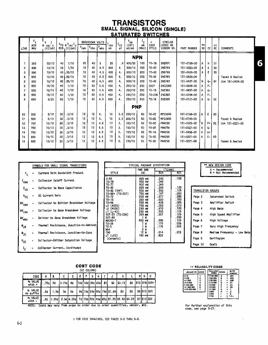
TRANSISTO SMALL SIGNAL, SlLlCl
3s IN (SINGLE) HES
SIMILAR JEOEC OR VENDOR NO.
(SAT m V / d (MAX)
NPN 400/50 100
500/10 200 500/10 200
500/10 200
500/10 200 250/10 200 250/10 200
250/10 200 250/10 200
Y U t
CASE STYLE - -
TO-1 8
TO-92
TO-92 TO-92
TO-92
CHIP TO-18
TO-236
TO-18
TO-92
TO-92 TO-92
TO-92
TO-18
TO-92 TO-92
m
MIN @ ce/ c (V) (mA) -- - -
e
DOWN - vcbo - -
40
40
40 40
40
40 40
40
40
12
12
12 12
12
12
12
=
ILTS - 'ebo - -
5
4.5
4.5
4.5
4.5
4.5 4.5
4.5 4.5
4.
4.
4.5 4.5
4.5
4.5 4.5
=
PART NUMBER COMMENTS MHz - - 350
400 500
500
500
500 500
500
650
500
500
700 700 700
900
900
R
Taped & Reeled
Use 151 -0424-00
Taped & Reeled Use 151-0221-00
Taped & Reeled
SYMBOLS FOR SMALL SIGNAL TRANSISTORS
- Current Gain Bandwidth Product
- Co l l ec to r Cu to f f Current
- Co l l ec to r t o Base Capacitance
- OC Current Gain
- Co l l ec to r t o Emi t ter Breakdown Voltage
- Co l l ec to r t o Base Breakdown Voltage
- Emi t t e r t o Base Breakdown Voltage
- Thermal Resistance. Junction-to-Ambient
- Thermal Resistance, Junction-to-Case
- Col lec tor -Emi t ter Saturat lon Voltage
- Co l l ec to r Current. Continuous
iL PACKAGE DISSIPATION I ** NEW DESIGN COOE A = R e c m n d e d N a Not Recomnended 1 PWR AMB
(W)
625 mW 500 mW 500 mW 625 mW 500 mW 750 mW 9 0 0 mW 350 mW 500 mW 700 mW 290 mW 250 mW 350 mW
1 W 500 mW
1 W I W 2 W
12 W 150 mW
STYLE
X-55 TO- 78 TO-77 TO-92 TO-92 (VHF) TO-92+ (TO-237) TO-72 TO- 18 TO-46 vX (#320 . uX (M1001 LJT (v-43) SOT-23 (TO-236) SOT-89 MACRO-T TO-39 TO-5
/ TRANSISTOR GROUPS
Page 2 Saturated Switch
Page 3 h p l i f i e r Switch
Page 4 High Beta
Page 5 High Speed Amp l i f i e r
Page 6 High Voltage
Page 7 Very High Frequency
Page 8 Medium Frequency - Low Beta
Page 9 Dar l ing ton
Page 10 Duals
W54 T90 KT ( ~ 2 3 ) (Ceramic)
COST CODE (CC COLUMN)
tt RELIABILITY CODES
t i t i e s , vendor, e t c .
COOE e
:i:fLyE
For f u r t h e r exp lanat ion of t h i s code, see page 9-27.
A
.754
'VALUE no s u f f i x
:i:tLyE
t FOR CASE DRAWINGS, SEE PAGES 9-2 THRU 9-8.
B
24
NOTE: Costs may vary from order t o order du
.54
.24
C
3.754
1.54
1.254
D
64
34
2.54
104
54
4.254
E F G
184
74
354
8 4 1 5 6 2 5 4
134 224
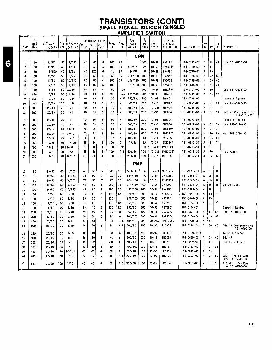
TRANSISTORS (CONT) SMALL SIGNAL, SILICON (SINGLE)
H SIMILAR
JEDEC OR VENDOR NO.
2N2192
92PU01A
2N4895
2N3053
2N3053
MPSA06
2N2219A
2N4401
2N4401
2N3947
2N3904
2N3904
2N3904
2N3904
2N2219A
2N2222A
2N3725
2N3724A
MMBTH24
MMBC1321
MPSHO5
92PU51A
2N4036S
2N4036S
2N4890
2N4890S
MPS3702
MPSA55
Q5T2907
KT2907 2N2907A
2N2905A
YMBT3906
2N3906
2N3906 2N3251
!N3251
!N3251
rlPSH55
!N3906
!N3906
NIT( - t
CASE STYLE - -
TO-39
TO-921
TO-39
TO-39
TO-39
TO-92
TO-39
TO-92
TO-92
TO-1 8
TO-23E
TO-92
TO-92
TO-92
TO-39
TO-18
TO-39
TO-39
TO-236
TO-236
TO-92
TO-92+
TO-39 TO-39
TO-39
TO-39
TO-92
TO-92
TO-92
TO-92 TO-18
TO-39
TO-236
ro-92
TO-92
ro-18
r0-18
r0-18
r0-92
r0-92
r0-92
-
- LINE - -
1
2
3 4
5
6 7 8 9
10
11
12
13
14
15
16
17
18
19
20
21
22
23
24
25
26
27
28
29
30 3 1
32
33
34
35
36
37
38
39 40
41 -
PART NUMBEI;
151-0183-00
151-0710-00
151 -0290-00
151 -01 36-00
151-0136-03
151-0645-00
151-0121-00
151 -0736-00
151-0736-01
l5l-O46O-OO
151 -0706-00
151-0190-00
151 -0190-09
151-0224-00
151-01 03-00
151-0302-00
151 -0604-00
151 -0260-00
151-0730-00
151-0731-00
151-0637-00
151-0622-00
151-0208-02
151-0208-00
151-0235-00
151-0389-00
151-0641 -00
151-0646-00
151-0164-00
151-0164-01 151-0301-00
151-0134-00
151-0700-00
151-0188-00
151-0188-05
151-0459-00
151-0289-00
151-0133-00
151 -0640-00
151-0220-03
151 -0220-00
'OLT - I
ebo -
5
5
6
4
4
4 4
6
5
6
6
6
6
6
6
6
6
5
4
4 4
5
7
7
5
5
5
4
5
5 5
5
5
5
5
5
5
5
4
5
5
OWC - cbc - -
6C
5C
120
60
80
80
80
60
60
60
60
60
60
60
60
75
80
60
40
30 80
50
90
90
60
60
40
60
40
40 60
60
40
40
40
50 50
50
30
10
10
COMMENTS MHz - -
40
50
50
100
100
100
150
250
250
300
300
300
300
300
300
300
300
250
400
600
600
50
60
60
100
100
100
100
100
100 200
200
250
250
250
300
300
300
400
600
600 -
Use 151 -01 36-00
Use 151 -0103-00
Taped & Reeled
Use 151 -0190-00
5dB NF Complement t o 151-0188-00
Taped & Reeled
Use 151 -01 90-00
Use 151 -0736-00
vbe Match
PNP
Taped & Reeled Use 151-0164-00
4dB NF Complement t o 151 -0190-00
Taped & Reeled
6db NF
Use 151-0133-00
6dB NF rb1Cc<50ps Use 151-0188-00
5dB NF rb1Cc<50ps Use 151 -0188-00
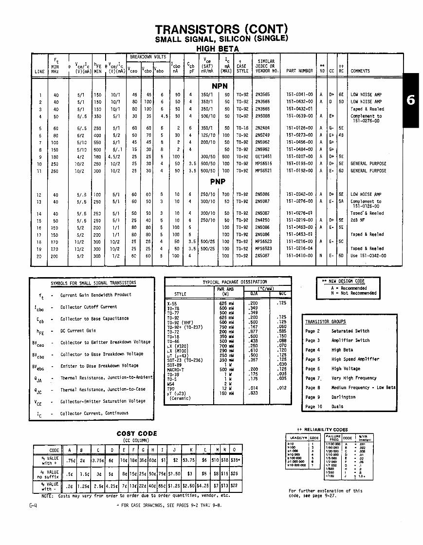
TRANSISTORS (CONT) SMALL SIGNAL, SILICON (SINGLE)
HIGH BE1
-. -.
\ - t
CASE STYLE - -
TO-92 TO-92
TO-92
TO-92
TO-18
TO-92 TO-92
TO-92
TO-92 TO-92
TO-92
TO-92 TO-92
TO-92
TO-92 TO-92
TO-92 TO-92
TO-92 TO-92
-
- LINE - -
1 2
3
4
5 6
7
8
9
10 11
12 13
14 15
16 17 18
19
20 -
- cbo nA - -
50 50
50
50
2
30 2
2
100 50 50
10 10
10 10
100
100 50
50
100
-
1 h~~ @ Vce/lc
BREAKDOWN VOLTS
MIN - -
SIMILAR JEDEC OR VENDOR NO
2N3565 2N3565
2N3565
2N5088
2N2484
215249 215962
215962
GET3451 MPS6515
MPS6521
2N5086 215087
2N5087 2N4250
2N5086
2N5086 MPS6523
MPS6523
215087
( V ) ( d - -
L
-
COMMENTS (k I(;) mV/mA
NPN 350/1 50
350/1 50
350/1 50
500/10 50
350/1 50
125/10 100 200/10 50
50 300/50 500
500/50 100
500/50 100
PNP
- ebo - -
6
6
6
4.!
6
5 8
8 5 4
4
5 3
3 5
5 5 4
4
5
-
- I ceo - -
45
80
80 30
60
50 45
15 25
25 25
60 50
50 25
80
80 25
25
60
-
PART NUMBER
LOW NOISE AMP LOW NOISE AMP
Taped & Reeled
Complement t o 151-0276-00
GENERAL PURPOSE
GENERAL PURPOSE
LOW NOISE AMP Complement t o
151 -01 26-00 Taped' & Reeled 2dB NF
Taped & Reeled
Taped & Reeled
Use 151-0342-00
** NEW DESIGN CODE 1 -
TYPICAL PACKAGE DISSIPATION SYMBOLS FOR SMALL SIGNAL TRANSISTORS
- Current Gain Bandwidth Product
- Co l l ec to r Cuto f f Current
- Co l l ec to r t o Base Capacitance
- DC Current Gain
- Co l l ec to r t o Emi t ter Breakdown Voltage
- Col lec tor t o Base Breakdown Voltage
- Emi t ter t o Base Breakdown Voltage
- Thermal Resistance, Junct i on-to-Ambient
- Thermal Resistance, Junction-to-Case
- Col lec tor -Emi t ter Saturat ion Voltage
- Co l l ec to r Current, Continuous
= Not Recomnended L i z z l l PWR AMB
X-55 TO-78 TO-77 TO-92 TO-92 (VHF) TO-92+ (TO- TO-72 TO-18 TO-46 pX (#320) pX (M100) PT (u-43) SOT-23 (TO- SOT-89 MACRO-T TO-39 TO-5
("C/mW)
TRANSISTOR GROUPS
Page 2 Saturated Switch
Page 3 h p l i f i e r Switch
Page 4 High Beta
Page 5 High Speed Amp l i f i e r
Page 6 High Voltage
Page 7. Very High Frequency
Page 8 Medium Frequency - Low Bet1
Page 9 Dar l ing ton
Paae 10 Duals
STYLE (w) QJA 1
w54 2 W T90 pT (1~23 )
(Ceramic)
COST CODE ICC COLUMN)
tt RELIABILITY CODES
CODE - ,
' VALUE 11 .2( 11.25tI 2.5tI4.25(I 71113t1221140(165$I$l .25~$2.50~$4.251 $7l$ l3 l$22 I NOTE: Costs may vary from order t o order due t o order quan t i t i es , vendor, e t c .
For f u r t h e r explanat ion o f t h i s code, see page 9-27.
G4 t FOR CASE DRAWINGS, SEE PAGES 9-2 THRU 9-8.
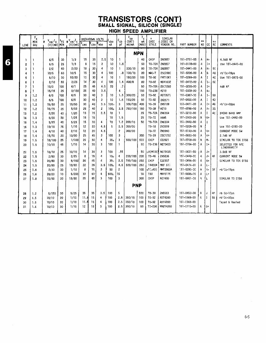
TRANSISTORS (CONT) SMALL SIGNAL, SILICON (SINGLE)
- LINE - -
1
2
3
4
5
6
7 8
9
10
11
12
13
14
15
16 17
18 19
20
21
22
23
24
25
26
27
28
29 30
31 -
GHz - -
1
1
1
1
1
1
1 1
1.2
1.2
1.2
1.2
1.2
1.3
1.4
1.3
1.4
1.4
1.5
1.5
1.5
1.5
1.5
1.5
1.6
1.6
1.8
1.2
1.5 1.5
1.6
-
BREA - Ice, - -
15
8
18
15
15
14
25
25
30
30
30
25
13
15
15
12
12
25
25
14
14 8
26
22
8
33
25
35
ll.! ll.! 12
-
)LiS
ebo - -
2
2
4
4
4
4
4
3. 3
3
3.
2
2.
4
4.
4.
3
4
3
3
4
4
3.
3
4
3
3.
4 4
3
-
HIGH - cbo n A - -
10
10
10
100
10
100
20
10
10
1 oou
1oou
10
10
10
5
100
35u 100
100
1 Ou
35u loop
50
500u
100
100
00
00
00
-
PEED AMPLIFIER
NPN
PNP
t CASE STYLE - -
CHIP
TO-721
TO-721
MAC-T
TO-92
TO- 92
TO- 72A TO-236
TO-92
TO-92
TO-39
TO-39
TO-72A
TO-72
TO-72A
TO-18
TO-72
TO-39
CHIP
TO-236
X(M100
TO-46
CHIP
144004
r (u43) T90
CHIP
ro-39
ro-92
ro-92 ro-236
-
SIMILAR JEDEC OR VENDOR NO
2N2857
2N2857
2N2857
2SC288C
FMT1061
NE41632
2SC1260 A210
A5T3571
2N3571 2N5109
A210
2N6304
A485
2N6304
2N3959
2N3960
2SC1252
CD3921
NE73433
NE73435
215836
C02357
MRF 511
MMT3960A MRF5175
NE7400
2N5583
45T4260
45T4260 YMBT4260
PART NUMBER COMMENTS
4.5dB NF
Use 151 -0441 -00
rb iCc< l 5ps
Use 151-0472-00
BROAD BAND AMP
Use 151-0442-00
Use 151-0193-00
CURRENT MODE SW
2.7dB NF
SIMILAR TO TEK 01
SELECTED FOR hFE LINEARARITY
3.5dB NF
CURRENT MODE SW
SIMILAR TO TEK 0156
SIMILAR TO Dl56
rb'Cc<lOps
rb1Cc<50ps
Taped & Reeled
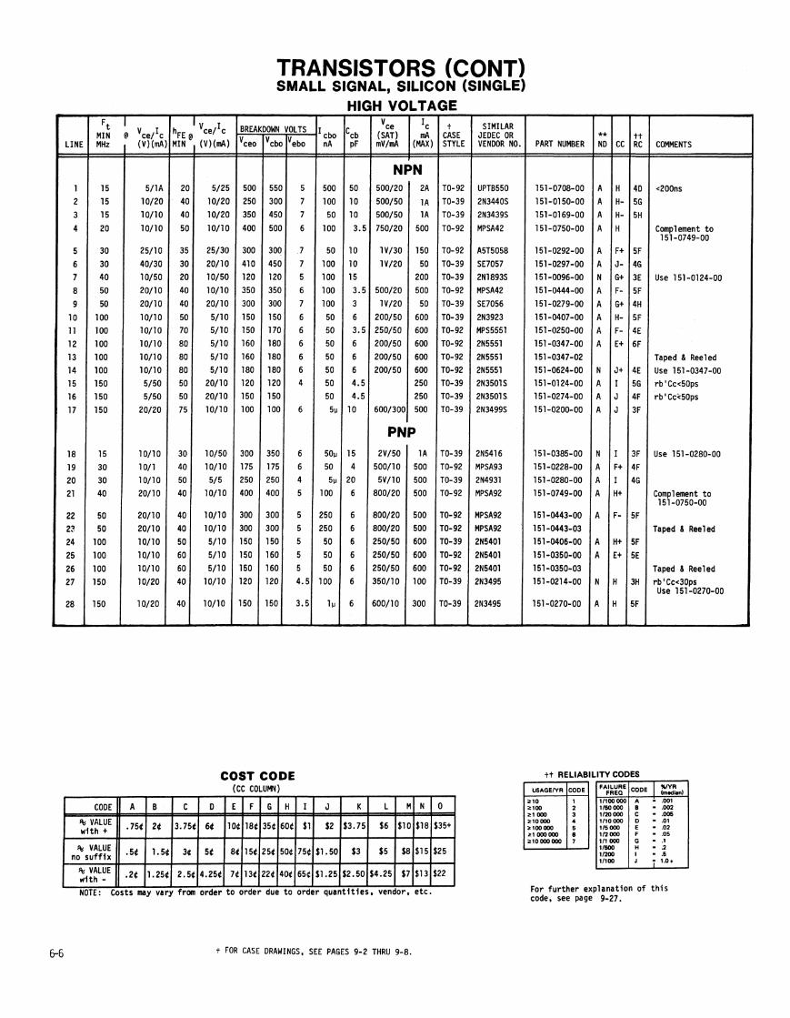
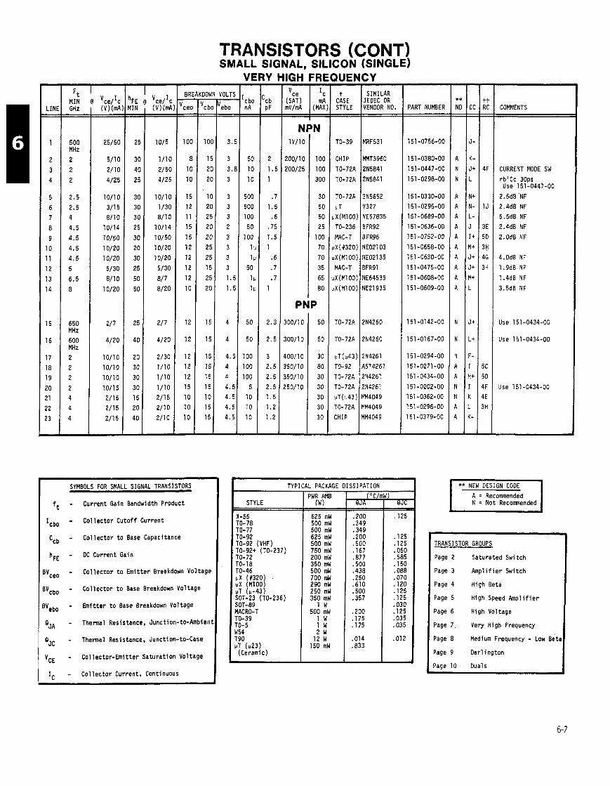
TRANSISTORS (CONT) SMALL SIGNAL, SILICON (SINGLE)
VERY HIGH FRE %p m V / d (MAX
- SIMILAR
JEDEC OR VENDOR NO.
- 'cb PF - -
2
I.! 1
I
1.L . f
.71
1.5
1
. €
.7
. 7 1
2.3
2.5
3
2.5
2.5
2.5 1.5
1.2
1.2
-
t CASE STYLE
TO-39
CHIP
TO-72P
TO-72)
TO-72A
IJT uX(M100
TO-236
MAC-T
uX(#320 uX (MI 00
MAC-T
uX (MI 00 uX(M100
TO-72A
TO-72A
uT(u43 TO- 92
TO-72A
TO-72A
uT(u43 TO-72A
CHIP
-
PART NUMBER
151 -0756-00
151 -0380-00
151-0447-00
151-0298-00
151-0330-00
151-0295-00
151-0689-00
151 -0636-00
151-0752-00
151 -0658-00
151 -0630-00
l5l-O475-OO
151 -0608-00
151-0609-00
151 -0142-00
151-0167-00
151-0294-00
151-0271-00
151-0434-00
151 -0202-00
151 -0362-00
l5l-O296-OO
151 -0379-00
COMMENTS - -
500 MHz
2
2
2
2.5
2.5 4
4.5
4.5
4.5
4.5
5
6.5
8
650 MHz
600 MHz
2
2
2
2
4 4
4
-
CURRENT MODE SW
rblCc 30ps Use 151 -0447-00
2.5d8 NF
2.4dB NF
5.5dB NF
2.4dB NF
2.0d8 NF
PNP Use 151-0434-00
Use 151-0434-00
Use 151 -0434-00
- --
SYMBOLS FOR SMALL SIGNAL TRANSISTORS
- Current Gain Bandwidth Product
- C o l l e c t o r C u t o f f Current
- C o l l e c t o r t o Base Capacitance
- DC Current Gain
- C o l l e c t o r t o E m i t t e r Breakdown Vo l tag t
- C o l l e c t o r t o Base Breakdown Vol tage
- E m i t t e r t o Base Breakdown Vol tage
- Thermal Resistance, Junc t i on-to-Ambien
- Thennal Resistance, Junction-to-Case
- Co l lec to r -Emi t te r Satura t ion Vol tage
- C o l l e c t o r Current, Continuous
TYPICAL PACKAGE DISSIPATION ** NEW DESIGN CODE
A = Recomnded N = Not Recomnended
PWR AMB STYLE (w)
TO-78 TO-77 TO-92 TO-92 (VHF) TO-92+ (TO-237) TO-72 TO-1 8 TO-46 IJX (#320 pX (M100/ PT (u-43) SOT-23 (TO-236) SOT-89 MACRO-T TO-39 TO- 5 W54 T90 VT (1123)
(Ceramic)
TRANSISTOR GROUPS
Page 2 Saturated Switch
Page 3 Ampl i f ie r Switch
Page 4 High Beta
Page 5 High Speed A m p l i f i e r
Page 6 High Vol tage
Page 7 , Very High Frequency
Page 8 Medium Frequency - Low Bet
Page 9 Oar l ing ton
Page 10 Duals
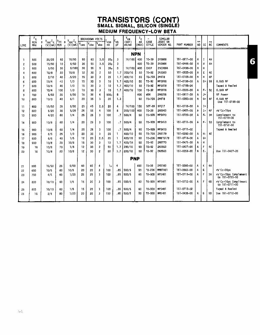
TRANSISTORS (CONT) SMALL SIGNAL, SILICON (SINGLE) MEDIUM FREQUENCY-LOW BETA
OWN - c bo - -
60
55
55
30
30
30
30
30
36
35
4 5
55
25
25
25
35
20
30
30
30
60
20
25
20
20
20
-
- 'cbo n A - -
2011
20u
35v 50
25
10
10
10
500v
20
20
100
100
100
100
20
20
10
50
50
1 v 100
100
100
100
100
-
NPN 1V/100 400
400
lV/lOO 400
200/10 50
400/10 50
400/10 50
400/10 50
400/10 100
400
50
1V/100 150
200/100 400
500/4 50
500/4 50
500/4 50
400/10 50
400/10 50
400/10 50
200/10 50
200/10 50
PNP
500/5
500/5
500/5
- t
CASE STYLE - -
TO-39
TO-39
CHIP
TO-92
TO-72A
TO-92
TO-92
TO-92
W54
TO-72A
SOT-89
TO-39
TO-928
TO-926
TO-920
TO-72A
TO-236
TO-92 TO-92
TO-92
TO-39
TO-236
TO-920
TO-920
TO-928
TO-928
-
SIMILAR JEOEC OR VENDOR NO.
2N3866
2N3866
2NC3866
2N3563
2N918
MPS918
MPS918
MPS918
2N6256
2N918
BFQl7
215943
MPSHlO
MPSHlO
MPSHlO
2151 79
MMBT5179
2N5770 2N3563
2N3563
2N5160
MMBTH81
MPSH81
MPSH81
MPSH8l
MMSHBl
-- -
PART NUMBER COMMENTS
6.0dB NF
Taped & Reeled
6.0dB NF
RF Power
4.5dB NF Use 151 -0198-00
rb1Cc<15ps
Complement t o 151-0719-00
Compl emen t t o 151-0712-00
Taped & Reeled
Use 151-0427-00
rbaCc<30ps
rb1Cc<15ps Complement t o 151-0720-00
rbiCc<lOps Compliment t o 151-0711-00
Taped & Reeled
Use 151-0712-00

TRANSISTORS (CONT) SMALL SIGNAL, SILICON (SINGLE)
- Icbo nA - -
1 oii 100
100
100
100
100
-
- - BREAKDOWN VOLTS F E D Vce/lc IIN ( v ) ( ~ A ) 'ceo
' --- -
SIMILAR JEOEC OR VENDOR NO. PART NUMBER
-
COMMENTS
- 'ebo - -
5
12
12
12
12
8
-
(SAT) I .A CASE mV/mA (MAX) STYLE
- cbo - -
100
60
40
40
25
30
-
<1.5ss
Taped & Reeled
PNP I
SYMBOLS FOR SMALL SIGNAL TRANSISgRS I
ft - Icbo - Ccb - h~~ -
"ceo - '"cbo - "ebo - 'JA - 'JC - 'CE -
I c -
A = Recommended N = Not Recomnended
SIPATION -p TYPICAL PACKAGE I
PWR AMB STYLE ( W) Current Gain Bandwidth Product
Co l l ec to r Cuto f f Current
Co l l ec to r t o Base Capacitance
DC Current Gain
Co l l ec to r t o Emi t ter Breakdown Voltage
Co l l ec to r t o Base Breakdown Voltage
Emi t ter t o Base Breakdown Voltage
Thermal Resistance, Junction-to-Ambien
Thermal Resistance, Junction-to-Case
Col lec tor -Emi t ter Saturat ion Voltage
Co l l ec to r Current, Continuous
TRANSISTOR GROUPS
Page 2 Saturated Switch
Page 3 Amp l i f i e r Switch
Page 4 High Beta
Page 5 High Speed k p l i f i e r
Page 6 High Voltage
Page 7 Very High Frequency
Page 8 Medium Frequency - Low Bet,
Page 9 Oar l ing ton
Paae 10 Duals
TO-92 (VHF) I 500 mW TO-92+ (TO-237) 750 mW TO-72 200 mW
SOT-89 1 W MACRO-T I 500 mW . - - - TO- 5 W54 T90 iiT ( ~ 2 3 )
(Ceramic)
tt CATALOG RE !LIABILITY CODES
lmedmnl
111 OW 11500 - .2 - .5 1'100 - 1 0 1
COST CODE (CC COLUMN)
NOTE: Costs may vary from order t o order due t o order quan t i t i es , vendor, e t c . For f u r t h e r explanat ion o f t h i s code, see page 9-27.
t FOR CASE DRAWINGS, SEE PAGES 9-2 THRU 9-8.

TRANSISTORS (CONT) SMALL SIGNAL, SILICON
DUAL
NPN
- LINE - -
1
2
3
4
5
6
7
8
9
10
11
12
13
14
15
16
17
18
19
20
21
-
7 FE D 'ce/'c IIN (V)(mA - - - -
t CASE STYLE - -
TO-78
TO-78
TO-78
TO-78
TO-78
TO-78
TO-78
TO- 78
TO-78
TO-78
TO-78
TO- 78
TO-99
TO-78
TO-78
TO-78
TO-78
TO-78
TO-78
TO-78
BREAKDOWN VOLTS SIMILAR JEDEC OR VENDOR NO.
IT120
IT1 21
2N2484
2N2484
2N2484
2N2222A
2N2222
2N918
2N3959
2N2857
A485
LM394
SL360
2N3808
2N3808
2N3808
ITS1 200
2N2907 2N4258
2N4261
TO702
I cbo - -
50
25
40
40
50
50
60
20
30
30
30
40
15
60
45
45
2 5
45
10
15
40
PART NUMBER
151-0236-00
151-0353-00
151-0308-00
151-0232-00
151 -0104-00
151-0176-00
151 -0309-00
151 -0139-00
151-0461 -00
151 -0267-00
151-0268-00
151-0619-00
151-0725-00
151-0178-00
151-0261-00 151-0261-01
151-0354-00
151-0307-00
151 -0467-00
151-0272-00
151-0361-00
COMMENTS
3.0dB NF MONOLITHIC
4.8dB NF MONOLITHIC
4.0nV/HZ NF
3.0dB NF
LOG AMP
ULTRA MATCHED
1.5dB NF 1K
YONOLITHIC
IPN/PNP PLASTIC
TYPICAL PACKAGE DISSIPATION ** NEW DESIGN CODE
A = R e c m n d e d N = Not Recomnended n SYMBOLS FOR SMALL SIGNAL TRANSISTORS
- Current Gain Bandwidth Product
- Co l l ec to r Cuto f f Current
- Co l l ec to r t o Base Capacitance
- DC Current Gain
- Co l l ec to r t o Emi t ter Breakdown Voltagt
- Co l l ec to r t o Base Breakdown Voltage
- Emi t ter t o Base Breakdown Voltage
- Thermal Resistance, Junct i on-to-Ambien
- Thermal Resistance, Junction-to-Case
- Col lec tor -Emi t ter Satura t ion Voltage
- Co l l ec to r Current, Continuous
PWR AMB (W)
625 mW 500 mW 500 mW 625 mW 500 mW 750 mW 200 mW 350 mW 500 mW 700 mW 290 mW 250 mW 350 mW
1 W 500 mW
1 W 1 W 2 W
12 W 150 mW
STYLE
X-55 TO-78 TO-77 TO- 92 TO-92 (VHF) TO-92+ (TO-237) TO-72 TO-18 TO-46
TRANSISTOR GROUPS
Page 2 Saturated Switch
I Page 3 Amp l i f i e r Switch I vX (1320
vT (u-43) SOT-23 (TO-236) SOT-89 MACRO-T TO-39 TO-5 W54 T90 vT ( ~ 2 3 )
(Ceramic)
I Page 4 High Beta I Page 5 High Speed A m p l i f i e r
Page 6 High Voltage
Page 7 Very High Frequency
Page 8 Medium Frequency - Low Bet
Page 9 Dar l ing ton
Page 10 Duals
i. FUk CASE DRAWINGS. SEE PAGES 9-2 THRU 9-8.
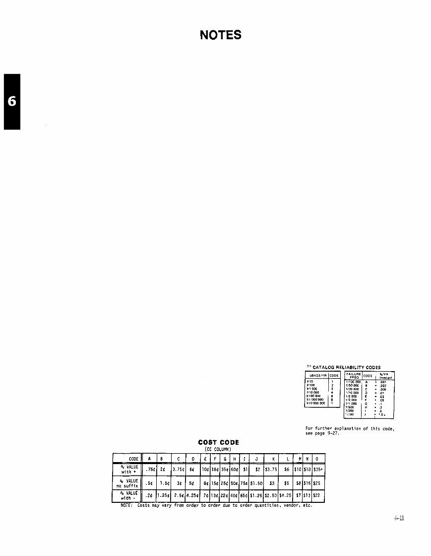
NOTES
t+ CATALOG RELIABILITY CODES
For further explanation of this code, see page 9-27.
COST CODE (CC COLUMN)
NOTE: Costs may vary from order to order due to order quantities, vendor, etc.

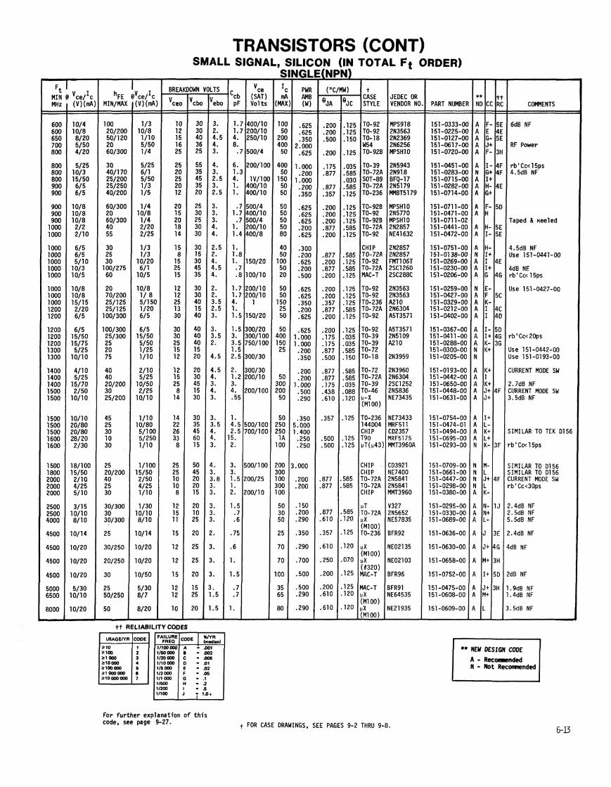
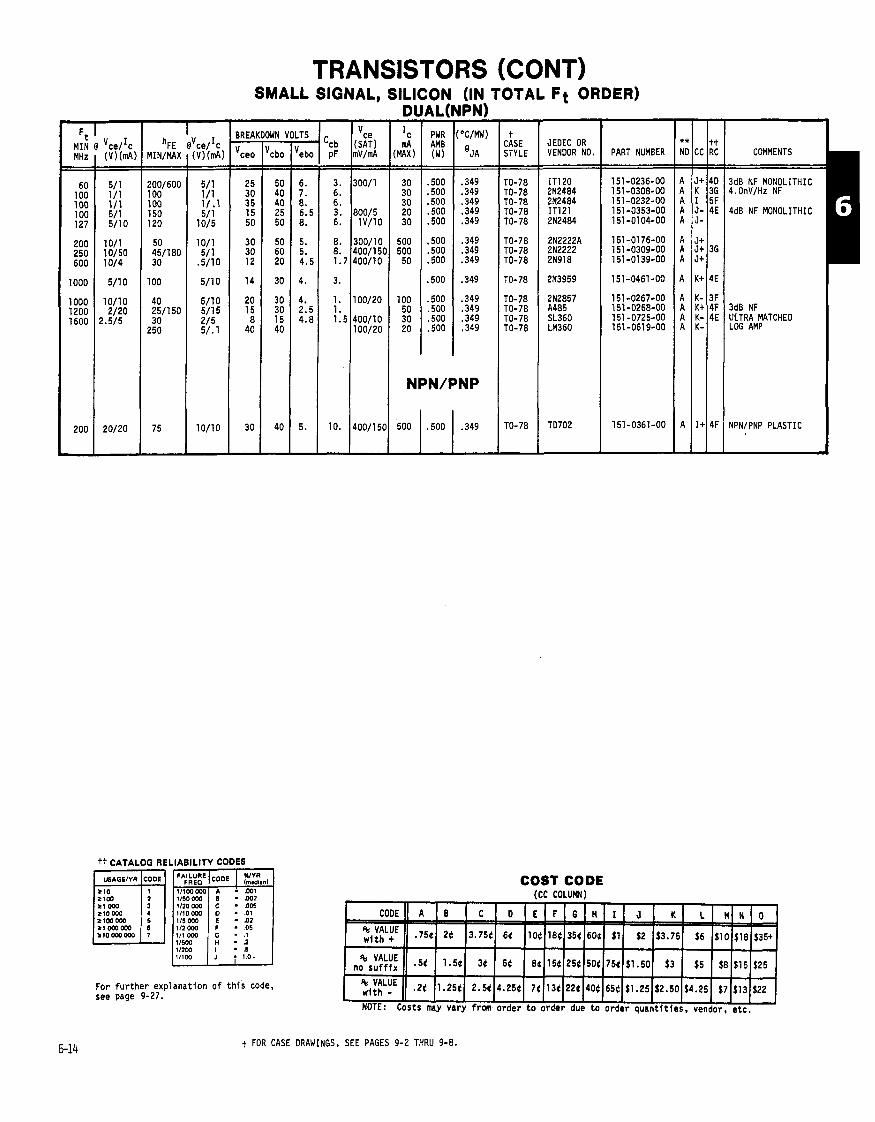
MIN MHz - -
60 100 100 100 127
200 250 600
1000
1000 1200 1600
200
-
TRANSISTORS (CONT) SMALL SIGNAL, SILICON (IN TOTAL Ft ORDER)
For f u r t h e r exp lanat ion o f t h i s code, see page 9-27.
t CASE STYLE
TO-78 TO-78 TO-78 TO-78 TO-78
TO-78 TO-78 TO-78
TO-78
TO-78 TO-78 TO-78 TO-78
TO-78
-
JEDEC OR VENDOR NO.
IT1 20 2N2484 2N2484 IT121 2N2484
2N2222A 2N2222 2N918
2N3959
2N2857 A485 SL360 LM360
TD702
COST CODE icc COLUFN)
PART NUMBER
t FOR CASE DRAWINGS, SEE PAGES 9-2 THRU 9-8.
** NO
A A A A A
A A A
A
A A A A
A
CC
J+ K I J- J-
J t J t J+
K t
K- K t K- K-
I +
tt RC
40 36 5F 4E
36
4E
3F 4F 4E
4F
COMMENTS
3dB NF MONOLITHIC 4.0nV/Hz NF
4dB NF MONOLITHIC
3dB NF ULTRA MATCHED LOG AMP
NPN/PNP PLASTIC
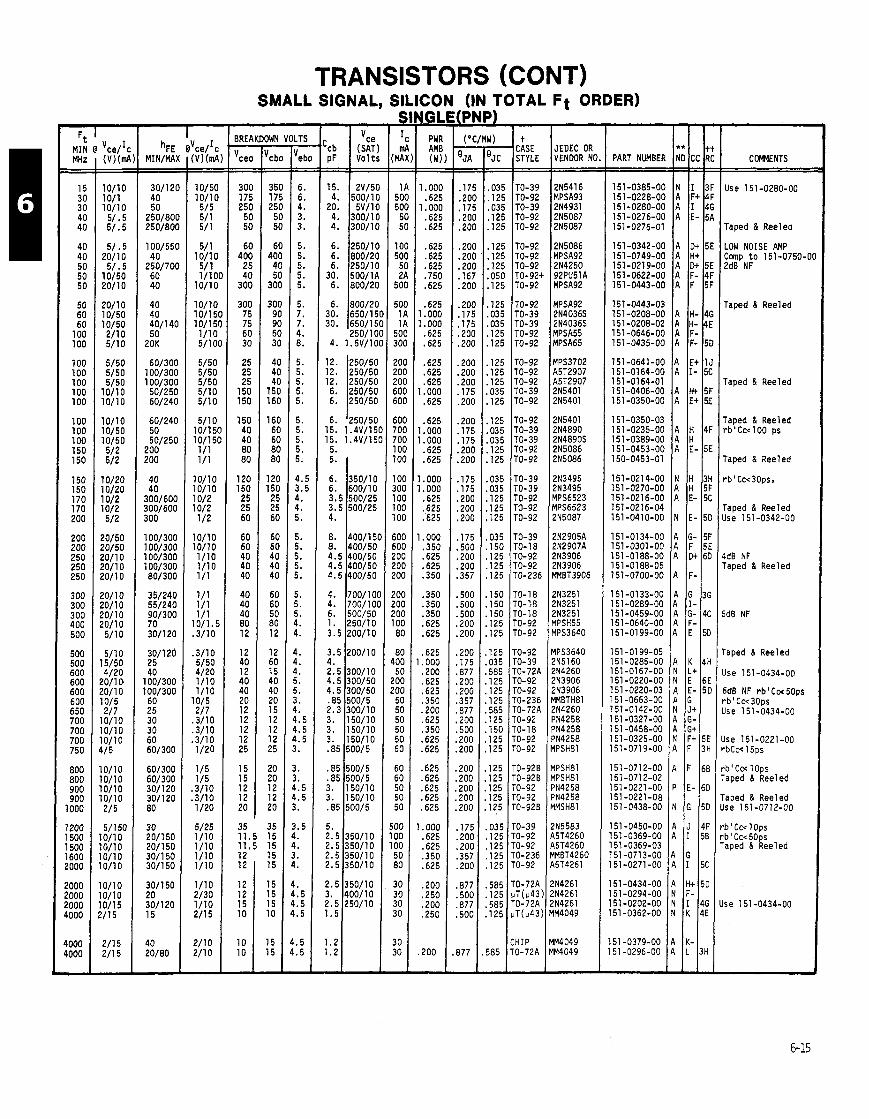
TRANSISTORS (CONT) SMALL SIGNAL, SILICON (IN TOTAL Ft ORDER)
MHz (V)(rrJ1 -- --
< 1
i 1
1
1
1
i i
1
E 2 1
1 1 1 4
1 1 1 1
1 1 1 1
1 1 1 2
-
PWR A M ( W ) - -
1. OOC .625
1 . 000 .625 .625
.625
.625
.625
.750
.625
.625 1 .ooo 1 .ooo
.625
.625
.625
.625
.625 1 .ooo
.625
.625 1.000 1.000 .625 .625
1 . 000 1 .ooo .625 .625 :625
1 .ooo .350 .625 .625 .350
.350
.350
.350
.625 ,625
,625 . 000 .200 .625 .625 .350 .200 .625 .350 .625 .625
,625 ,625 .625 .625 .625
. 000
.625 ,625 .350 .625
.zoo
.250
.zoo
.250
200 -
4 STYLE
TO-39 TO-92 TO-39 TO-92 TO-92
TO-92 TO-92 TO-92 TO-92+ TO-92
TO-92 TO-39 TO-39 TO-92 TO- 92
TO-92 TO-92 TO-92 TO-39 TO-92
TO- 92 TO-39 TO-39 TO-92 TO-92
TO-39 TO-39 TO-92 TO-92 TO-92
TO-39 TO-18 TO-92 TO-92 TO-236
TO-18 TO-'r8 TO- 18 TO-92 TO-92
TO-92 TO-39 TO- 72A TO-92 TO-92 TO-236 TO-72A TO-92 ro-18 ro-92 ro-92
ro-928 IO-92B ro-92 ro-92 ro-928
ro-39 r0-92 r0- 92 r0-236 r0-92
r0-72A !T(u43) 0-72A
lT(v43)
:HIP '0-72A
-
-~ -
JEDEC OR VENDOR NO
2N5416 MPSA93 2N4931 2N5087 2N5087
215086 MPSA92 2N4250 92PU51A MPSA92
MPSA92 2N4036S 2N4036S YPSA55 YPSA65
YPS3702 45T2907 45T2907 ?N5401 2N5401
?N5401 2N4890 ?N4890S ?N5086 !N5086
!N3495 !N3495 IPS6523 1PS6523 !N5087
!N2905A !N2907A !N3906 !N3906 IMBT3906
!N3251 ?N3251 ?N3251 1PSH55 1PS3640
lPS3640 !N5160 !N4260 !N3906 1N3906 IMBTH81 IN4260 IN4258 IN4258 IN4258 IPSH81
lPSH8l IPSH81 IN4258 'N4258 IMSH81
N5583 ,5T4260 ,5T4260 MET4260 5T4261
N4261 N4261 N4261 M4049
M4049 M4049
PART NUMBER 1;; ICC 1:; I CWENTS I
151-0133-00 A G 3G 151-0289-00 A I - 151-0459-00 A G- 4C 151-0640-00 I ! ! A F-
Use 151-0280-00
Taped & Reelea
Taped 8 Reeled
Taped & Reeled
Taped & Reeled rb'Ccc100 ps
Taped & Reeled
r b ' C c c 3 0 ~ s ,
Taped & Reeled Use 151 -0342-00
4dB NF Taped & Reeled
Taped & Reeled
Use 151-0434-00
6dB NF rb iCw50ps r b ' Cc<30ps Jse 151-0434-00
Jse 151-0221-00 -bCc< 15ps
-b' Ccc l o p s raped & Reeled
raped 8 Reeled Ise 151-0712-00
.b ' Cc< 1 Ops ,b ' Ccc 50ps 'aped & Reeled
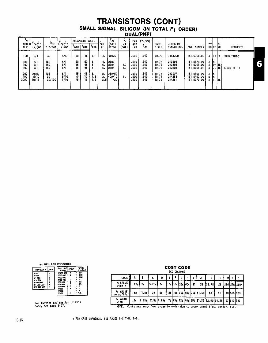
TRANSISTORS (CONT) SMALL SIGNAL, SILICON (IN TOTAL F i ORDER)
D I BREAKDOWN VOLTS 'ce I c
'cb (SAT) mA MHz ( (V)(mA) MIN/MAX , (V)(nJ\) 'ceo lvcbo lvebo pF mV/d (MAX)
.ITY CODES
For f u r t he r explanat ion code. see page 9-27.
o f t h i s
I AL - PWR AM8 (W) - -
.500
.500
.500
.500
.500
.500
.500
-
STYLE
TO-78
TO-78 TO-78 TO-78
TO-78 TO-78 TO-78
JEOEC OR VENDOR NO.
ITS1200
2N3808 2N3808 213808
2N2907 214258 2N4261
PART NUMBER I ND **I CC Itt RC COMMENTS
MONOLITHIC
1.5d8 NF 1 K
COST CODE (CC COLUW)
t FOR CASE DRAWINGS. SEE PAGES 9-2 THRU 9-8.

TRANSISTORS (CONT) SMALL SIGNAL, SILICON (FOR REFERENCE ONLY)
DO NOT USE IN NEW DESIGN - IC
(MAX) AMPS
- PWR AM8 (W) = .I50 . I80 .050 .250 .080
. I 5 0
. I20
.083
. I20 ,080
.050
. I 5 0
.250
.250
.030
,030 .250 .180 .075 . l o o
.200
. l oo
.083
.075
.075
. I 5 0
. I 5 0
. I 5 0
. I 5 0
.250
. I50
.080
.080
.080
. I 5 0
.250
. I 5 0
.150
.050
.050 ,150 .600
.600 ,750 ,050 . I 5 0 .zoo
-
- CASE STYLE - - TO-40 TO-22 TO-22 TO-7 TO-33
TO-5 TO-9 TO-7 TO-9 TO-7
TO- 1 TO-5 TO- 9 TO-9 TO- 1
TO-1 TO-25 TO-22 TO- 17
TO-5 TO-1 TO-7 TO-1 7 OV-5
TO-5 TO-31 TO-26 TO-9 TO-5
TO-5 TO- 5 TO-5 TO-18 TO-7
TO-40 ro- 1 ro-9 r0-9 ro-5
r0-9 X-46
r0-9 ro-5 i0- 5
'0-5 '0- 5 '0-18 '0-5 '0-7
-
Ft MIN @I- 'FE -
I I N = 65 50 10 50 97
24 35 20 20 60
70 25 40 70
35 30 15 80
40 50 20 25 34
70 00 00 00 27
20 20 95 25 80
80 40 35 40 20
35
50 20 20
40 3
20 30 36
-
@ - MAX =
100 30
140
5
105 60 30
100 150
200
21 0
300 330
300
170
200
120
250
370
-
BRE - cbo =
20 40 18 25 24
25 90 20 25 25
15 45 30 30
15 30 40
bs 25 36
15 25 20 18 25
15 30 75 25 25
25 30 12 15 34
34 34 20 30 30
20 20 25
105 40
30 120 15 60 70
-
DOWN VOL
ceo =
18 25 18
cex 25
cex 24
c e r 32 cev 24
cex 32
ces 40 ces 20
18
ces 15 cex 40
25 20
15 25
c e r 32 15
c e r 25
75 c e r 15 c e r 25
25 25 12
ces 15
15 ces 20
10
15 c e r 15
20 ces 105
20
c e r 30 c e r 120
8 ces 60
70
-
JEDEC OR VENDOR NO.
- ebo =
2.5 10
5 12
1
12 20
.5 20
.5
10 45 20
.5
.5
10 .2
12
2 12
.5 3 5
20 70 25 15
25 25
7 3.5 1.5
.5
.5 15 20 20
15 10 2
50 5
5 .6
2 3
.5
-
'ART NUMBER OTHER -
MHz - .01(
4. . l o (
30
4 1
70 3
30
.70( 9 3
10 120
100 .40C . I 0 1
500 1.2
8 2
70 5 0
9
7 10
.700 15 2
3 3 3
100 45
45 45 17 3 4
17 1
75 1
.400
40 60 80 70 25
2N407 2N214 2N212 2N270 2N544
2N404 CT1200 2N1516 2N3137 Fml, 21373
2N591 2N447A 21597 21599 21499
2N588 2N2375 2N1102 2N700 Fmly 2N204
ZN478 21647 2N1517 2N695 Fmly 2N169A
ZNl592 ZN601 2N675 2N636 2N1381
2N1302 211 303 211 378 ZN705 211637s
!N1631 !N1632 !N636 !N1478 !N394
?N636 ?N469A !N1754 Fmlj !N398A r1483
tT5204 33430 3S2590 ;A1 392 !N2207
PNP Germanium NPN Germanium NPN Germanium PNP Germanium PNP Germanium
PNP Germani um NPN Germanium PNP Germanium NPN Germanium PNP Germanium
PNP Germanium NPN Germanium PNP Germanium PNP Germanium PNP Germanium
PNP Germanium PNP Germanium NPN Germanium PNP Germanium PNP Germanium
NPN S i l i c o n NPN Germani um PNP Germanium PNP Germanium NPN Germanium
NPN S i l i c o n PNP Germanium PNP Germanium NPN Germanium PNP Germanium
NPN Germanium PNP Germanium PNP Germanium PNP Germanium PNP Germanium
'NP Germanium JNP Germanium YNP Germanium YNP Germanium 'NP Germanium
YNP Germanium 'NP Germanium 'NP Germanium YNP Germanium IPN S i l i c o n (AS)
IPN S i l i c o n (AS) IPN S i l i c o n (HV) YNP Germanium IPN Germanium YNP Germanium
TRANSISTOR GROUPS
SS Saturated Switches AS A m p l i f i e r Switch HE High Beta HV High Vol tage
HSA Hiah Speed A m p l i f i e r
YFLB ~ e d i u m Frequency -- Low Beta OAR Oar1 f ngton
IUAL Duals G Germanium

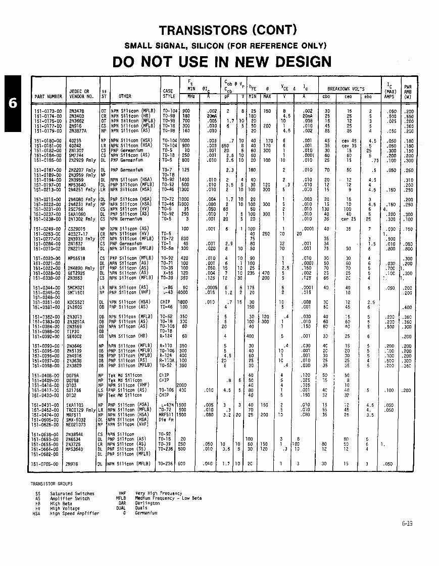
TRANSISTORS (CONT) SMALL SIGNAL, SILICON (FOR REFERENCE ONLY)
DO NOT USE IN NEW DESIGN - I c
(MAX AMPS - -
.051
.50l
.02!
.051
.05( -0% .30( .201 .TO(
.05(
.15C
.15C 4.
.20C
.30C
.03C 1.
.50C
.01C
.800
,030 .700 . l o o
1.
.050
.ZOO ,200 .500
.200 ,100 ,100 .500 .200
. l o o
,050 ,050
.050
- PWR AMB ( W ) - - .zoo .550 .zoo .360 .200
. I 8 0
. I 8 0
. I 5 0
- - -
BREAKDOWN VOLTS CASE STYLf - -
- ebo - -
2 5 3 5 4
4.5 5
25 5
.7
.5
4.5 4 4.5
3 4.5 6 5
25
7
3 1.5 6
4 6 5 5 4
6
2.5 6
5 5 5
6
5 5 5 4 5
5
4.5 4. 3.5
5 6 4
3
PART NUMBEl - MIA - 7
25 18C
2C 5C 2C
40 40 60 50 20
180
40 30
100
20 100 50
100 20
100 40 75 80 50
90 00 25 !35
75 20
30 50
30 00 40
00
30 40 60 25 30
40 50 40 80 40
10 70 25
- MAX - - 150
200
17( 170 3CO
100
120 300
300
300
250
470 200
120 300
150
!OO
50 20
-
- cbo - - 30 25 18 45 85
45 35 30 60 25
70
20 12 15
20 15
130 40 35
40
35 34 75
30 50 70 25 65
40
30 60
40 60 80
30
40 20 30 25 35
50 15
40 32
15 55 35
80 12
30
ceo
15 25 12 25 85
cev 45 cev 35
15 60 15
50
12 12 9
15 10
100 40
c e r 25
35
50
30 50 70 2 5 20
40 10
12 45
15 60 40
2 5
15 20 30 25 3 5
50 8
10 40 32
12 45 25
80 50 12
15 1
- - . 00; 26nl . OO! .01t .01(
. 00:
.oo:
.001
.001
.01C
.01C .01C .010
.004
.080 ,050 .010 .001
.001
.001
.020
.OlQ
.001 ,050 .004 . I 2 5
. oool
.015
,010
-01 0
,005 .010 .080
.050
.010
,040 -
1 2N3478 OT NPN S i l i c o n (MFLB) TO-1C 1 2N3403 CR NPN S i l i c o n HB) TO-9E 1 2N3662 OT NPN ~ i l i c o n I w B ) TO-96 1 2N916 CS NPN S i l i c o n MFLB) TO-1E 1 2138771 NP NPN S i l i c o n (AS) TO-9E
TO- 1 C TO- 1 C TO-5 TO- 18 TO-5
TO-7 TO-18 TO-92 TO-92 TO-46
TO-72 TO-46 TO-5 TO-92 TO-5
TO-5 TO-72 TO-1 TO-5m
TO-92 TO-71 TO- 39
X-55 TO-39
11-86 11-43
:HIP ro-46
r0-52 ro- 18 -0- 105 '0-18 1-1 24
!-110 '0- 106 !-I24 1-llOA '0- 52
HIP HIP
0-106 HIP
p-43N 0-72 RF511 i e Fm
0- 92 0-18 0-39 0-236
1-236 -
40235 NP NPN S i l i c o n (HSA) 40242 I LR I NPN S i l i c o n (HSA)
2N2207 Fmly IOL IPNP Germanium 213959 k l y INP 1 2N3959 DL NPN S i l i c o n HSA) MPS3640 DL PNP S i 1 i c o n MFLB) 2 ~ 4 2 5 1 - ~ m l ~ I LR ~ N P N S i l i c o n (HSA)
2N4080 Fmly DL PNP S i l i c o n HSA 2N4251 R l y NP NPN S i l i c o n I H s J 2SC756
2N1302 Fmly CS NPN Germanium
CS29015 NP NPN S i l i c o n (AS) 40327-17 CR NPN S i l i c o n (HV) 2N3933 Fmly OT NPN S i l i c o n (MFLB) 2N1637 CS PNP Germanium 2N2219A DL NPN S i l i c o n (MFLB)
2N4890 Fmly OT PNP S i l i c o n AS GET2925 DL NPN S i l i c o n 2N3553 CS NPN S i l i c o n (MFLB)
LR NPN S i l i c o n (AS) NP PNP S i l i c o n (VHF) I I DL NPN S i l i c o n (HSA) OB PNP S i l i c o n (AS) I I OB NPN S i l i c o n (MFLB) OB PNP S i l i c o n (AS) OB NPN S i l i c o n (AS) 08 0B NPN S i l i c o n (HE)
NP NPN S i l i c o n (MFLB) 08 PNP S i l i c o n (MFLB) OB PNP S i l i c o n (MFLB) OB PNP S i l i c o n (AS) OB PNP S i l i c o n (MFLB)
INP l ~ e k Md S i l i c o n NP Tek Md S i l i c o n NP NPN S i l i c o n (VHF) I LS I PNP S i l i c o n (AS) INP l ~ e k Md S i l i c o n '
KA1103 NP PNP S i l i c o n (HSA) RC0129 Fmly LR NPN S i l i c o n (MFLB) IRF511 I NP I NPN S i l i c o n (HSA] . . . . - . . MX-5032 DL NPN ~ i l i c o n 'HSA) I021073 l i p INPN S i l i c o n I v H r )
N3854A CS NPN S i l i c o n N6534 DL PNP S i l i c o n (AS) N3725 CR NPN S i l i c o n (AS) PS3640 DL PNP S i l i c o n (SS)
DL PNP S i l i c o n (MFLB)
N918 1 DL JNPN S i l i c o n (MFLB)
TRANSISTOR GROUPS
SS Satura ted Switches VHF Very High Frequency AS A m p l i f i e r Switch MFLB Medium Frequency - Low Beta HB High Beta DAR Dar l i n g t o n HV High Vol tage DUAL Duals
HSA High Speed A m p l i f i e r G Germanium

TRANSISTORS (CONT) POWER, SILICON (NPN - PNP)
- I c (A) MAX - -
.5 .5 .5 .5 .5
.5 1. 1. 1. 1.
1. 1. 1.5 1.5 1.5
2. 2. 2. 2. 2.
2. 2. 2.5 3. 3.
3. 3. 3. 3. 3.
3. 3. 3. 3.5 3.5
3.5 4. 4. 4. 4.
4. 4. 4. 4. 4.
4. 4. 4. 4. 4.
5 . 5. 5 . 5. 0
5 . 5 .
5. 5 .
6. 6. 8. 8. 8.
10. 10. 10. 10. 10.
G20
- t
CASE STYLE - - TO-202 TO-126 TO-202 TO-202 TO-202
TO- 126 TO-202 TO-220 TO-202 TO-220
TO-66 TO-220 TO-202 TO-220 77-03
X-81 X-81 TO-202, TO-66 TO-66
TO-66 TO-220 TO-3 TO-2021 TO-2021
TO-220 TO-220 TO-126 TO-220 TO-66
TO-66 TO-218 TO-3 TO-3 TO- 3
TO-3 TO-66 TO-126 TO-220 TO-220
TO-66 TO- 126 TC-220 TO-220 TO-1 26
TO-220 TO-66 TO-66 TO-220 TO-220
TO- 3 ro-127 ro-127 ro- 3 ro-3
ro-220 ro- 3
ro- 3 r0-3
ro- 3 r0-3 .o- 3 r0-220 '0-220
'0-220 '0-127 '0- 3 '0- 3 .O-3
- PWR (
Tj= 25OC
W - - 6.
20. 10. 10. 10.
20. i 6.2
30. 10. 40.
20. 40. 10. 25. 40.
10. 10. 8.
35. 35.
35. 30. 75. 12. 12.5
30. 40. 25. 40. 25.
20. 00. 00. 00. 00.
00. 25. 40. 27. 30.
25. 15. 30. 30. 40.
36. 20. 25. 40. 75.
30. 70. 70. 00. 10.
80. 50.
00. 00.
50. 50.
75. 80.
50. 90. 50. 50.
-
- "CE
( s a t - - 1.5
.7 1.5 1.8
.5
.7
.8 1.
.9 1. 1.5 1.
.3
1.5 1.5 1.
1. 1. 1.5 1.5
.5
1. 1.2
1.2 1.
2.5 1.5
. 8
.5
5. 1.5
.3
.5
.5
1.5 2.5
. 5
. 5 1.8
1. 2.5
.6
.5 1.
1.5 2.8 2.5 2.5 1.25
2. 1.
1.5 1.5
1. 1. 3. 4.
.7
.25
1. 2.
h~~ (t4DP - - 40kt 30 40 40 25
20 50 40 40 30
20 30 l O k t 30 5
1 5 k t 15k+ 10 25 25
30 40
5 20 20
500 25 25 25 2 5'
40 30 15 30 30
30 25 40 .40 40
25 40 40 00
1 k t .
30 20 30 3 5 10
40 5 0 t t 5044 20
7.5 5
2 5 20
0 0 i r 8
40 2 5 50 001 r 00 -
JEDEC OR MFR. NO.
D40C5 Fmly MJE340 Fmly
216558 2N6559
ME340 Fmly
TIP29C 2N6591 TIP47
213585 Fmly TIP50/2SC233 D40K2 2SC2336BR MJE13003 Fml
MPSU45
D40E7 2N3584 Fmly 2N3584 Fmly
2N4240 D44T4 Fmly MJ12002 Fmly D42C9
2SC1983 TIP3lA ME520 Fmly TIP3lC 213441 Fmly
2N3739 TIP52 DTS721 Fmly OTS411 Fmly 2N3902 Fmly
DTS402 Fml y 40250 Fmly MJE521 Fmly
D44C6 Fmly
40250111 MJE224 D44C9 D44C8 MJE800 Fmly
2N5294 Fmly 213767 Fmly
MJE13005
2 N 4 l l l MJEl 101 MJEllO2 2N5239 2N6308 Fmly
MJE8503 BU208/2SD348
Fmly YJ12004 YJ12004 Fmly
EN5758
r l J lO0 l l !N6044 YJE13007
344H3 Fmly IJE2801 Fmly
ITS1010
JEDEC OR YFG. NO. PART NUMBER
151-0331-00 151-0311-01
151 -061 5-00 151 -0693-00
151-0613-00
151 -0464-00 151-0728-00 151-0497-00
151 -0241-00 151-0423-00 151-0496-00 151-0697-00 151 -0634-00
151 -0390-00
151 -0439-00 151-0316-00 l5l-O2lO-OO
151 -0251 -00 151 -0358-00 151 -0346-00 l5l-O365-OO
151-0671-00 151-0478-00 151 -0334-00 151 -0476-00 151 -0149-00
151 -0201-00 151-0623-00 151 -0468-00 151-0256-00 151-0266-00
151-0314-00 151-0148-00 151-0323-00
151 -0352-00
151-021 7-00 151 -0466-00 151-0473-00 151 -0743-00 151 -0405-00
151-0262-00 151 -0226-00
151-0678-00
151-0239-00 151 -0425-00 151-0415-00 151 -0315-00 151-0368-00
151 -0707-00 151 -0449-00
151 -0760-00 151-0747-00
151-0485-00
151-0759-00 151 -0656-00 151-0632-00
151-0621-00 151-0349-00
151 -0454-00
PART NUMBEI
151 -0698-01 151-061 2-01
151 -0694-O(
151 -0440-O( 151-0462-O(
151 -0696-O(
151 -0391-O( 151 -0463-O(
151 -0364-Ot
151-0335-Ot 151 -0482-O(
151 -0324-OC 151 -0366-OC
151 -0465-OC
151-0429-OC
151 -0227-OC 151 -0647-OC
151-0414-00
151-0419-00
151 -0657-00
5 1 -0373-00 5 1 -0644-00 5 1 -0495-00
WE350 YDS60 Fmly
YOS60 Fmly
141 E Fmly TIP30C
!SA1006BR
IPSU95 141 E7
143C8
IJE370 Fmly rIP32C
IJE371 345C6 Fmly
1JE234
1JE700 Fmly
!N3741 :T417B
IJElO92
!N6227
IN6041
IJE2901 'N3791 152500
*SAFETY CONTROLLED.

TRANSISTORS (CONT) POWER, SILICON (NPN - PNP)
NPN I PNP - 'CE
( s a t ) - - 1. 1. 1.
. 8
1. 2. 1.8 2.
1.5 3. 2. 3. 1.1
1.1 1.1 1.8 1.1 1.4
5. 4. 4. 2. 3.
- t
CASE STYLE - - TO-3 TO-220 TO-220 TO-3 TO-127
TO-218 TO-218 TO-220 TO-220 TO-3
TO-61 TO-220 TO-3 TO-3 TO-3
TO-3 TO-3 TO-127 TO-3 TO-3
TO-3 TO-21 8 TO-218 TO-3 TO-3
TO-3 -
- I C
(A) MAX - -
10. 10. 10. 10. 10.
10. 10. 10. 10. 10.
10. 12. 15. 15. 15.
15. 15. 15. 15. 16.
!O. !5. !5. 30. 30.
10. -
- PWR
Tj: 25 C
W - - 50. 50.
150. 90.
80. 125. 60. 60.
117.
125. 100. 100. 87.
115.
115. 115. 90.
120. 150.
140. 125. 125. 150. 250.
100.
-
JEDEC OR ** MFR. NO. ND
-
PART NUMBER
151 -0625-00
151 -0607-00 151 -0745-00
l5l-O258-OO
151-0616-00 151 -0651 -00
1 k N (MHz) OJA
151-0218-00 J 151-0426-00 I + 4H D45Hll 151-0426-01 I + 40 Selected 151-0633-00 J 151-0436-00 H+ 5F
2N6586 Fmly NE13009 1 i 554208
2N3055H Fmly A 2N3055H Fmly A MJE1661 Fmlv A
1743-0620 Fmly I A
COST CODE (CC COLUrn)
IC - Co l l ec to r Current
BVCEO - Co l l ec to r t o Emi t ter Breakdown Voltage
BVCBO - Co l l ec to r t o Base Breakdown Voltage
ft - Un i t y Current Gain o r Bandwidth Product
hFE - Forward Current Transfer Rat io
'CE - ~ o l l ' e c t o r - ~ m i t t e r Satura t ion Voltage (SAT 1 QJA - Junction-to-Ambient Thermal Resistance
QJC - Junction-to-Case Thermal Resistance .
For f u r t h e r explanat ion o f t h i s code, see page 9-27.
NOTE: Costs may vary from order t o order due t o order quan t i t i es , vendor, etc. SOA - Safe Operating Area
** Component Evaluat ion Engineering Recomnendation New Design Code: A - Acceptable N - Not R e c m n d e d
A USE THE ABOVE SOA (SAFE OPERATING AREA) CLASSIFICATIONS AS GUIDELINES ONLY. DEFINITIVE SOA GRAPHS CAN BE FOUND I N THE TEKTRONIX SPECIFICATION FOR EACH INDIVIDUAL PART NUMBER. SEE PAGE 9-28 FOR GUIDELINE GRAPHS.
t FOR CASE DRAWINGS, SEE PAGES 9-2 THRU 9-80
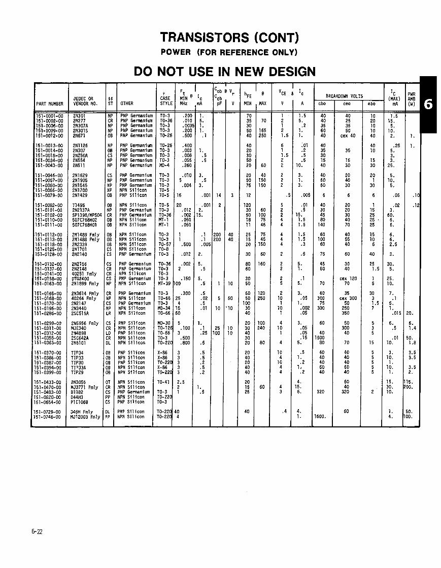
PART NUMBER 1 151-0001-00
151-0002-00 151-0006-00 151-0009-00 151-0012-00
151-0013-00 151-0014-00 151-0018-00 151-0034-00 151-0043-00
151-0046-00 151 -0057-00 151-0060-00 151-0066-00 151-0079-00
151-0082-00 151-0101-00 151-0102-00 151-0110-00 151-0111-00
151-0112-00 151-0113-00 151-0118-00 151-0125-00 151-0128-00
151-0132-00 151-0137-00 151-0141-00 151-0158-00 151-0163-00
151-0165-00 151-0168-00 151-0170-00 151-0196-00 151-0286-00
151 -0299-00 151-0311-00 151-0312-00 151-0355-00 151-0363-00
151-0370-00 151-0386-00 151-0387-00 151-0394-00 151-0399-00
151-0433-00 151-0470-00 151-0483-00 151-0620-00 51-0654-00
51-0729-00 51-0746-00
JEDEC OR VENDOR NO.
2N301 2N277 2N307A 2N301S 2N671
211126 21307 2N250A 2N554 2N5l l
2N1529 2N1905 2N1545 2N1700 2N1429
TI495 2N2137A SP1398/MP504 507C768H02 507C768H01
2N1489 Fmly 2N1488 Fmly 2N2339 2N1701 2N2140
2121 56 2N2148 40251 Fmly OTG2400 2N1899 Fmly
2N3614 Fmly 40264 Fmly 2N2147 2N3440 2SC515A
2N5956 Fmly ME340 2N4898 2SC642A 2N6101
TIP34 TIP33 TIP30 TIP33A TIP29
2N3055 MJ3771 Fmly 81182 D44H3 P I ClO68
145H Fmly 1512003 Fmly
TRANSISTORS (CONT) POWER (FOR REFERENCE ONLY)
DO NOT USE IN NEW DESIGN
OTHER
PNP Germaniun PNP Germaniun PNP Germaniun PNP Germaniun PNP Germaniun
PNP Germaniun PNP Germaniun PNP Germaniun PNP Germaniun PNP Germanium
PNP Germanium PNP Germanium PNP Germanium NPN S i l i c o n PNP S i l i c o n
NPN S i l i c o n PNP Germanium PNP Germanium NPN S i l i c o n NPN S i l i c o n
NPN S i l i c o n NPN S i l i c o n NPN S i l i con NPN S i l i con PNP Germanium
PNP Germanium PNP Germanium NPN S i l i con PNP Germanium NPN S i l i con
PNP Germanium YPN S i l i con DNP Germanium YPN S i l i con YPN S i l i c o n
YNP S i l i c o n IPN S i l i c o n YNP S i l i c o n IPN S i l i c o n IPN S i l i c o n
'NP S i l i c o n IPN S i l i c o n )NP S i l i con IPN S i l i con IPN S i 1 icon
IPN S i l i c o n IPN S i l i c o n 'NP Germanium IPN S i l i c o n INP S i l i c o n
'NP S i l i c o n IPN S i l i con
t CASE STYLE - - TO-3 TO-36 TO-3 TO-3 TO-26
TO-26 TO-3 TO-3 TO-3 MD-4
TO-3 TO-3 TO-3 TO- 5 TO-5
TO-5 TO-3 TO-36 MT-1 MT- 1
TO-3 TO-3 TO-57 TO-8 TO-3
TO-36 TO-3 TO- 3 TO-3 MT-39
TO-3 TO-66 TO-3 MO-34 TO-66
MD-30 TO-126 TO-66 TO-3 TO-220
X-86 X-86 TO-220
TO-22
ro-3 ro-22 r0-3
7 MIN @ IC
MHz - -
.20l
. O l I . 00:
.20l
.SO(
.40I . 00:
.001
.05! .26(
.01( 5
.004
16
!O .012 .002 .05C .05C
1 1
.500
.012
.002 2
.150 I0
.300 5 4 5 0
5 . I00
3 .500 .800
3 3 3 3 3
2.5 2 1
3
h~~ MIN - -
70 35 30 50 40
40 20 30 50 20
20 50 75
12
120 30 50 18 11
25 15 20
30
80 60
30 50
60 50
100 30 40
20 30 40 30 20
20 40 20 40 40
20 15 25
40
@
MAX - -
70
165 250
60
40 150 150
60 100 75 46
75 45
150
60
160
120 250
100 240
80
60
BRI - cbo - - 40 40 35 60 40
40 35 30 15 40
40 60 60
6
40 30 45 80
140
60 100 60
75
45 60
70
60 300 75
300
60
40 500 80
40 40 40 60 40
320
600.
-
(DOWN VOL'
ceo
40 25 35 50
cex 40
35
16 30
20 40 30
6
20 20 30 40 70
40 55 40
60
30 40
cex 120 70
35 cex 300
50 250 350
50 300 40
70
40 40 40 60 40
60 40
320
60
- ebo - -
10 20 10 10 40
40 10
15 30
20 1
30
6
1 15 25 25 . 25
15 10 6
40
25 1.5
1 5
30 3 1.5 7
5 3 5
15
5 5 5 5 5
2
-
- PWR AMB (W) - -
1.
1.
1
.1
10.
6. 1.4
0 . 1.8
3.5 3.5
3.5 2.
5. 0.
0. 0. -

TRANSISTORS (CONT)
VENDOR NUMBER
CA3083 CA3083 CA3086 ( s i m i l a r ) CA3086 CA3086
CA3096AE CA3102 CA3102 CA3127E CA3183 ( s i m i l a r )
PART NUMBER
COST CODE (CC COLUM)
NOTE: Costs m y vary from order t o order due t o order quant i t ies , vendor, e tc .
ARRAYS I
H/V, h i gh cu r ren t d r i v e r array, 7-darl ington. Screened 4- t rans is tor , h igh current, PNP 5 - t r ans i s to r ar ray , selected f o r Vce ( sa t ) s0.4V. NPD Screened 5 - t r ans i s to r array, NPN
tt RC
5 - t rans i s to r array, NPN Inspected Checked Selected Dual D i f f e r e n t i a l Ampl i f ie rs , NPN
DESCRIPTION
2 1
5 - t r ans i s to r a r ray (3 NPN. 2 PNP) Dual d i f f e r e n t i a l amp l i f i e r , NPN (6 ) Screened High frequency, 5- t rans is tor array. NPN 5 - t rans i s to r array. NPN (High Voltage CA3083)
Screened Operat ional transconductance a m p l i f i e r ar ray 7 - t r ans i s to r , comnon emi t ter , NPN 7- t rans is tor , comnon co l l ec to r , NPN 5- t rans is tor , a1 1 independent, NPN
3F 4E
4H
Selected, NPN Selected, NPN 5 - t rans i s to r array. NPN Checked Checked
** NEW DESIGN RECOMMENDATION FROM COMPONENT ENGINEERING:
A = Acceptable N = Not Recomnended
3F 48
t t RELIABILITY CODES
4 - t rans i s to r , PNP. High Current, Dr ivers 4 - t r ans i s to r , h i gh cu r ren t NPN DMOS FET Ouad Analog Switch, N-Channel Screened DMOS FET Quad Analog Switch, N-Channel
For f u r t h e r explanat ion o f t h i s code, see page 9- 27.
CASE STYLE
16 DIP 14 DIP 14 DIP 16 DIP 14 DIP
14 DIP 14 DIP 14 DIP 14 DIP 14 DIP
14 DIP 16 DIP 16 DIP 16 DIP 16 DIP
16 DIP 16 DIP 14 DIP 14 DIP
16 DIP 14 DIP 14 DIP 16 DIP 16 DIP
14 DIP 14 DIP 16 DIP
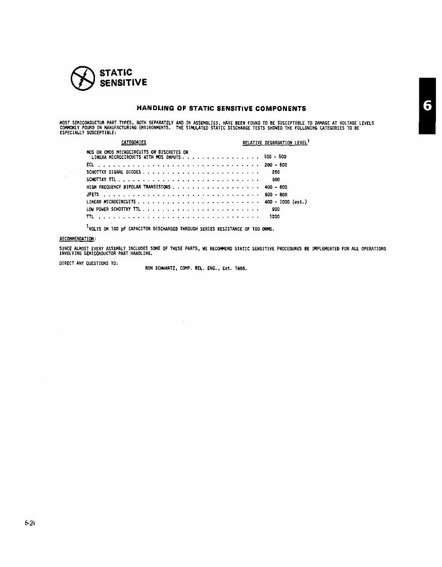
STATIC SENSITIVE
HANDLING OF STATIC SENSITIVE COMPONENTS
MOST SEMICONDUCTOR PART TYFES, BOTH SEPARATELY AN0 I N ASSEMBLIES. HAVE BEEN FOUNO TO BE SUSCEPTIBLE TO DAMAGE AT VOLTAGE LEVELS C W L Y FOUNO I N MANUFACTURING ENVIRONMENTS. THE SIMULATED STATIC DISCHARGE TESTS SHOWED THE FOLLOWING CATEGORIES TO BE ESPECIALLY SUSCEPTIBLE:
CATEGORIES RELATIVE DEGRADATION LEVEL^ MOS OR CMOS MICROCIRCUITS OR DISCRETES OR
LINEAR MICROCIRCUITS WITH MOS INPUTS. . . . . . . . . . . . . . . . 1 0 0 - 5 0 0
ECL . . . . . . . . . . . . . . . . . . . . . . . . . . . . . . . . . 2 0 0 - 5 0 0 SCHOTTKY SIGNAL DIODES . . . . . . . . . . . . . . . . . . . . . . . . 2 5 0
SCHOTTKY TTL . . . . . . . . . . . . . . . . . . . . . . . . . . . . . 5 0 0
HIGH FREQUENCY BIPOLAR TRANSISTORS . . . . . . . . . . . . . . . . . . 4 0 0 - 6 0 0 . . . . . . . . . . . . . . . . . . . . . . . . . . . . . . . . . JFETS 6 0 0 - 800
. . . . . . . . . . . . . . . . . . . . . . . . . LINEAR MZCROCIRCUITS 4 0 0 - 1000 (est . ) . . . . . . . . . . . . . . . . . . . . . . . . LOW POWER SCHOTTKY TTL 9 0 0
. . . . . . . . . . . . . . . . . . . . . . . . . . . . . . . . . TTL i 2 0 0
VOLTS ON 100 p~ CAPACITOR DISCHARGED THROUGH SERIES RESISTANCE OF 100 OHMS.
RECOMMENDATION:
SINCE ALMOST EVERY ASSEMBLY INCLUDES SOME OF THESE PARTS. WE RECOmENO STATIC SENSITIVE PROCEDURES BE IMPLEMENTED FOR ALL OPERATIONS INVOLVING SEMICONDUCTOR PART HANDLING.
DIRECT ANY QUESTIONS TO: RON SCHWARTZ. COMP. REL. ENG., Ex t . 1605.

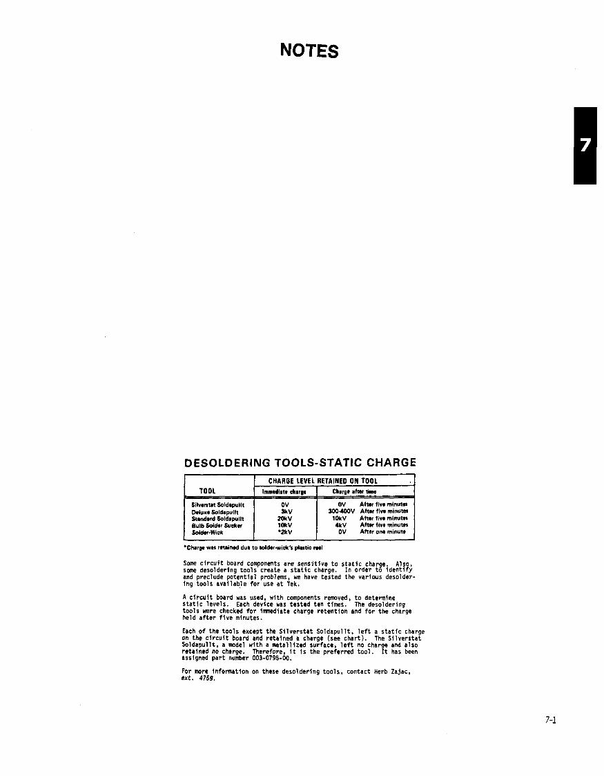
NOTES
DESOLDERING TOOLS-STATIC CHARGE
*Chrrp w n retained due to tolder-wick's plastic ml
TOOL
Silverstat Soldepullt Deluxe Soldrpullt Standard Soldawllt Bulb Solder Sudter SoldwWick
Some c i r c u i t board components are sensi t ive t o s t a t i c charge. Also. some desoldering too ls create a s t a t i c charge. I n order t o i d e n t i f y and preclude potent ia l problems, we have tested the various desolder- ing too ls avai lab le f o r use a t Tek.
A c i r c u i t board was used, wi th components removed, t o determine s t a t i c levels. Each device was tested ten times. The desolderfng too ls were checked f o r imnediate charge retent ion and f o r the charge held a f t e r f i v e minutes.
CHARGE LEVEL RETAINED ON TOOL
Each o f the too ls except the S i l ve rs ta t Soldapul l t , l e f t a s t a t i c charge on the c i r c u i t board and retained a charge (see chart). The Si lverstat Soldapul l t , a model w i th a meta l l ized surface, l e f t no charge and also retained no charge. Therefore, i t i s the preferred too l . It has been assigned par t number 003-0795-00.
Immediate ch~mrge
OV 31rV
20kV lOkV O2kV
For more inforination on these desoldering too ls , contact Herb Zajac. ext. 4759.
Charge aher time
OV After tive minuta 300400V After five minutes
lOkV After five minutes 4kV A f t n five minutm OV After om minute

TRANSISTORS (CONT) STATE
JUNCTION FETS (SINGLE) SENSITIVE
N-CHANNEL THIS APPLIES TO ALL DEVICES ON THIS PAGE
- -- [ 3 I 2. I 6. I 5. 2000 I 15 I IDSS [ 100 1 15 1 2 1 i 0 I TO-92 I A I F+ I 5G I 151-1005-00 I 151-1005-03 Taped & Reeled
- LINE
L
1
2
4
IDSS RANGE
5
'P MAX (V)
8.
4.
MIN mA
1.
.5
5.
6
7
- -
( 10 1 2. 1 6. 1 1 6 1 2000 1 15 1 IDSS 1 100 ( 15 1 2 1 50 1 TO-92 ( N I H- I ( 151-1026-00 ( V,-2.5 t o 3V w/ V,, =
MAX mA
6.
3.
5.
9
( 11 112. 1 50. 1 10. M *4OOn ( 1 1 75 1 1.175 ( TO-5 I N 1 L I 1 151-1028-00 Sing le Source
C ISS
C RSS
(pF)
8 - 2
6 - 2
15.
I 8 125. 1 75. ( 4. 1 *80n ( I ( I I 1 40 1 TO-18C I A I H- 1 40 1 151-1022-00 I
2.
25.
--
13 1. 3.6 3.5 7 1000 10 IDSS 50 TO-72C A H 36 151-1068-00 - 3 10 10
14 5. 75. 3.5 14 *90n 40 TO-92 A G 4c , 151-1078-00 - 3.5 1 100 20
15 .03 .09 1.8 3 70 40 TO-72C A J+ 151-1085-00 - 1.5 10 IDSS 1.0 20
15.
5.
8.
6.
150.
,,MHOS %I @ V ~ ~ 8 1 ~
6.
15.
0
* R ~ ~
1000
1000
6 - 2
6.
10.
'G @ 'DG & ID
4 - .8
6.
'DG
20
50
( v )
10
15
2500
6 - 2
14 - 5
IOSS
IDSS
MA
IDSS
IDSS
1611
4500
4.5 - 1
t
b l r E
TO-72
TO-92
PA
.010
100
100
15
2000
*30n
('4
10
15
15
15
4500
N
A
IDSS
15
IDSS
15
CC
I +
G
100
100
IDSS
1
100
100
IDSS
tt RC
40
15
15
100
100
500
10
20
100
100
PART NUMBER
151-1002-00
151-1004-00
5
15
15
20
COMMENTS
Sing leSource
5
12
20
50
2
30
5
TO-92
50
40
TO-72C
30
A
TO-72C
TO-18C
A
TO-92
G
A
A
I-
A
4H
H
G+
151-1006-00
4F
Gt
46
4E
151-1012-00
5G
--
151-1015-00
151-1021-00
151-1025-00
Metal Can vers ion o f 151-1005-00
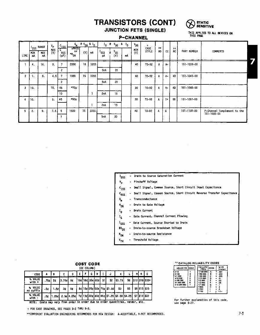
COST CODE (CC COLUMN)
I lDss - Drain t o Source Saturat ion Current
Vp - Pinchoff Voltage
CISS - Small Signal, Conmon Source. Short C i rcu i t Input Capacitance
CRSS, - Small Signal, Cannon Source, Short C i rcu i t Reverse Transfer Capacitance
G,,, - Transconductance
VDG - Drain t o Gate Voltage
ID - Drain Current
IG - Gate Current, Channel Current Flowing
IGSS ' Gate Current, Source Shorted t o Drain
BVDS - Drain-to-source Breakdown Voltage
RON - Drain-to-source Resistance
VTH - Threshold Voltage
t FOR CASE DRAWINGS, SEE PAGES 9-2 THRU 9-8.
*'COMPONENT EVALUATION ENGINEERING RECOWENDS FOR NEW DESIGN: A-ACCEPTABLE. N-NOT RECOMMENDED.
tt CATALOG RE i
2 loo
LIABILITY CODES
Irn .dwl
112000 - .05 111 000 11503 .2 1/200 . .5 11100 - 1 0 1
For fur ther explanation o f t h i s code, see page 9-27.
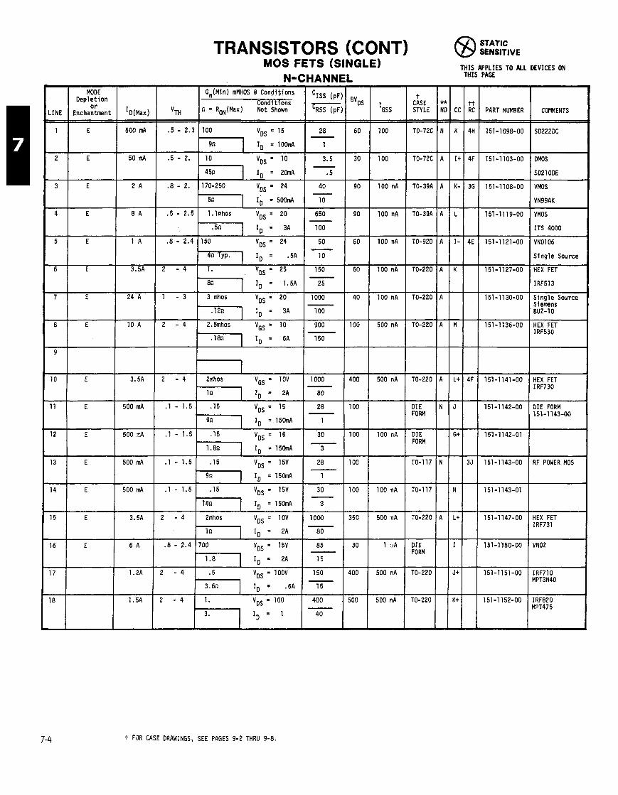
TRANSISTORS (CONT) STATIC SENSITIVE
THIS APPLIES TO ALL DEVICES ON THIS PAGE
MOS FETS (SINGLE) N-CHANNI -
t CASE STYLE
TO-72C
MODE Deple t ion
o r Enchantment
E
Gm(Min) mMHOS @ Conditions
Condit ions n = RON(Max) Not Shown PART NUMBER COMMENTS
SO222DC
OMOS
SO21 ODE
VMOS
VN99AK
-- - 5n lo = 506RA 10
4 E 8 A .5 - 2.5 1. lmhos VoS = 20 650 - .5n 1 ID = 3A 100
VMOS
ITS 4000
VN0106
S ing le Source
HEX FET
IRF513
S ing le Source Siemens BUZ-10
HEX FET IRF530
I
24 A 1 - 3 3 mhos VoS = 20 1000
.12n 1 I, = 3~ l o o
HEX FET IRF730
- -
I1 E 500 mA .1 - 1.5 .15 VoS = 15 28
9n lo = 150114 1
12 E 500 ~ I A .1 - 1.5 .15 V,, = 15 30
'DIE FORM
DIE FORM
TO-117
- TO-1 17
DIE FORM 151-1143-00
RF POWER MOS
TO-220
DIE FORM
TO-220
TO-220
HEX FET IRF731
VNOZ
+ FOR CASE DRAWINGS, SEE PAGES 9-2 THRU 9-8.
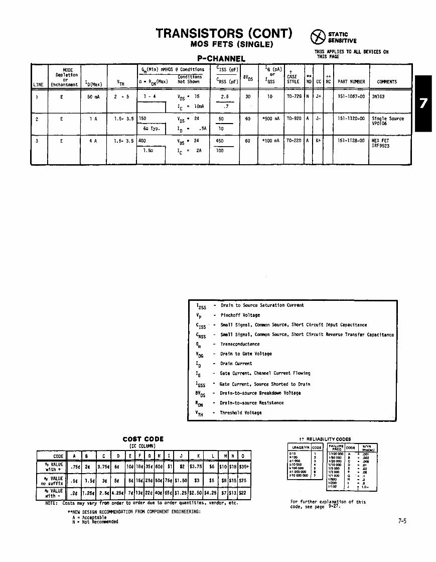
TRANSISTORS (CONT) @ STATIC
MOS FETS (SINGLE) SENSITIVE
P-CHANNEL
I G,(Min) MHOS @ Conditions 'ISS (pF) Con i t i o n s -
V,,, n = RnN(Mu) NotdShan I ' ~ s s 1 B v ~ s
THIS APPLIES TO ALL DEVICES ON THIS PAGE
Or CASE ** tt IGSS STYLE ND cc RC PART NUMBER COMMENTS
10 TO-72G N Jt 151 -1 067-00 3N163
'500 nA TO-920 A J- 151-1120-00 Single Source VP0106 I
- Drain t o Source Saturat ion Current
- Pinchoff Voltage
- Small Signal. Comnon Source, Short C i rcu f t Input Capacitance
- Small Signal, Comnon Swrce, Short C i r c u i t Reverse Transfer Capacltanc~
- Transconductance
- Drain t o Gate Voltage
- Drain Current
- Gate Current, Channel Current Flowing
- Gate Current, Source Shorted t o Drain
- Drain-to-source Breakdown Voltage
- Drain-to-swrce Resistance
- Threshold Voltage
COST CODE I C C COLUM)
tt RELIABILITY CODES
1160000 - nos 21 000 11m 000 210000
- .W6 1110000
21mOW - .Ol
116000 - .02
210000000
For fu r the r explanation o f t h i s code, see page 9-27.
**NEW DESIGN RECOMENOATION FROM COMPONENT ENGINEERING: A 8 Acce tab le N a Not gecomnended

TRANSISTORS (CONT) FIELD EFFECT (DUALS AND PAIRS)
1000 t o 3000 vMHOS
4 pF MAX 'RSS 1.2 pF MAX
STATIC SENSITIVE
THIS APPLIES TO ALL DEVICES ON THIS PAGE
I J
GROUP
B
5
N Channel, JFETs.
Family Type: 213822 Typ'cal IOSS 2 t o 10 Ma Specs : vp 10VMAX
% 3000 t o 6500 vMHOS
'ISS 6 pF MAX 'RSS 3 pF MAX
CC
J+
K-
Kt
J
a
1 - 5
-
IG OFFSET @ CONDITIONS
loss VP G, (MINI o r DRIFT
LINE (mA) MAX uMHOS IGSS
I
IG (PA) o r
*'GSS Gm (MINI vMHOS
1000
1000
1000
1000
2 2 - 1 2 6 2000 500n Totem Pol Configurat ion
St RC
3F
46
3G
46
VP MAX
6
6
4.5
3
LINE
1
2
3
4
3.5
8 2 - 5 6 1500 40 500n Totem Po11
OFFSET @ CONDITIONS
DRIFT IDSS (in41
1.5-7
1.5-7
.5-5
1.3MIN
t CASE ** STYLE ND
TO-71 A
TO-71 A
TO-71 A
TO-71 A
TO-71 A
TO-71 A
TO-71 A
TO-71 A
100 ID - 1 m A
ID = 1 mA
50 = .2 mA
100 = 1 mA
PART NUMBER
151-1007-00
151-1037-00
151-1047-00
151-1049-00
1000
CC 1 1 PAFT NUMBER I COWENTS
CASE STYLE COMENTS
J+ 3H 151-1081-00 MONOLITHIC
** ND
TO-71
TO-71
TO-71
TO-71
*500 ID = .8 in4
t FOR CASE DRAWINGS. SEE PAGES 9-2 THRU 9-8. tt FOR RELIABILITY CODES. SEE PAGE 7-9. 7-6
A
A
A
A
TO-71 A I + 46 151-1054-00 FOR TO-7% CASE USE 151-1054-01

TRANSISTORS (CONT) FIELD EFFECT (DUALS AND PAIRS)
STATIC SENSITIVE
GROUP
C
THIS APPLIES TO ALL DEVICES ON THIS PAGE
/aJ1 PART NUMBER COMMENTS
N Channel, JFETs.
Family Type: 2N4393
k h ) = l B O l H z
Typlcal IDSS 5 to 35 Ha Specs: Vp 3.5 V MAX
% 7.5 to 20MHOS 'ISS 14 pF MAX 'RSS 3.5 pF MAX
Famtly Type: 214416
4500 to 7500 vMHOS = 250 MHz 4 pF MAX
PART NUMBER COMMENTS ++
'G
or *'GSS
100
200
-
100
* I00
*I 00
* I00
Gm (MINI uMHOS
10000
10000
10000
6500
100
LINE
1
2
3
4
5
I
5H 151-1042-00 MATCHED PAIR
--- -
151-1070-00 MATCHED PAIR
IG & G~~ a l s o I 1 . k k d
OFFSET @ CONDITIONS DRIFT
ID = 2 n J \
Ioss (mA)
5 - 3 0
1 0 - 3 0
5 - 3 0
7 - 2 0
7 - 2 5
IG
or *IGSS
100
* I00
* lo0
*95
50
$, (MINI uMHOS
4500
4500
4500
3600
4500
LINE
1
2
3
4
5
I 151-1144-00 1 2i4:i: MATCHED
VP MX
3.5
3
3
5
3.5
153-0559-00 MATCHED PAIR OF IJ'?
t CASE STYLE
TO-71
TO-71
TO-71
CHIP
CHIP
OFFSET @ CONDITIONS DRIFT
ID 5 mA
IDSSMATCHED
TO .5 mA VGD = 15 V
IDSSMATCHEO
TO .5 mA VGD = 15 V
50mV
ID = 5 mA
I DSS (M)
6 - 1 5
10 - 15
- -
5.5-15
5.2-11.8
10 - 15
** NEW DESIGN RECOMMENDATION FROM COMPONENT EVALUATION ENGINEERING: A = ACCEPTABLE N = NOT RECOMENDED
VP MAX
6
6
-
6
6
10
** NO
A
A
A
A
A
CC
K t
K
L
J+
H+
CC
K
H
I
K-
C,
t CASE STYLE
TO-71
TO-92
TO-92
DIE FORM
TO-72C
** ND
A
A
A
A
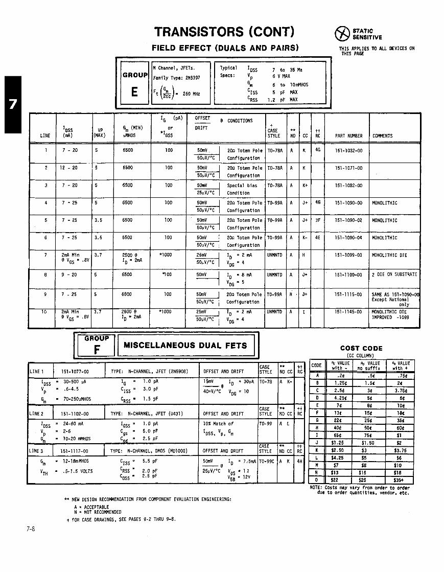
TRANSISTORS (CONT) STATIC SENSITIVE
FIELD EFFECT (DUALS AND PAIRS) THIS APPLIES TO ALL DEVICES ON THIS PAGE
I, 6 t o 10rblHOS
= 260 MHz 5 pF WX 'RSS 1.2 pF MAX
- -
6
7
8
cc
K
K
K+
J+
J+
3.5
3.7
5
- -
7 - 2 5
2mA Min @ VGS = .8V
9 - 2 0
9
10
GROUP IM'SCELLANEolJS DUAL FETS COST CODE
i (CC COLUMN)
Gm (MINI VMHOS
6500
6500
6500
6500
6500
VP (MAX
5
- 5
5
5
3.5
LINE
1
2
3
4
5
5
3.7
7 - 2 5
2mA Min @ VGs = .8V
tt RC
46
46
3F
IDSS ( m ~ )
7 - 20
- 1 2 - 2 0
7 - 2 0
7 - 2 5
7 - 2 5
6500
2500 @ ID = 2mA
6500
'G (pA)
o r
*IGSS
100
100
loo
100
loo
6500
2500 @ ID = 2mA
NOTE: Costs may vary from order t o order due t o order quan t i t i es , vendor, etc.
** NEW DESIGN RECOF(MEN0ATION FROM COMPONENT EVALUATION ENGINEERING:
A = ACCEPTABLE N = NOT RECOMMENDED
t FOR CASE DRAWINGS, SEE PAGES 9-2 THRU 9-8.
% VALUE w i t h -
. 2 t 1.254 2.54
4.254
74
134 224
404
654 $1.25
$2.50
$4.25
$7
$13 $22
CODE
A
B C
0
E F G
H
I J
K L
, M N 0
PART NUMBER
151-1032-00
151-1 071 -00
151-1082-00
151-1090-00
151-1090-02
100
*I000
CASE TYPE: N-CHANNEL, JFET (2N5908) OFFSET AND DRIFT STYLE
IDSS = 30-500 PA IG = 1.0 pA 15mV ID = 30vA TO-78 - @ Vp = '6-4.5 CISs = 3.0 pF 4O=V/OC VDG = 10
Gm = 70-250uMHOS CRSS= 1 .5pF
CASE OFFSET AN0 DRIFT STYLE
COMMENTS
MONOLITHIC
MONOLITHIC
OFFSET @ CONDITIONS DRIFT
200 Totem Pole
20n Totem Pole 1 Conf igura t ion
Special b i as 1 Condi t ion
20n Totem Pole
con f i gu ra t i on
20n Totem Pole &I Conf igura t ion
100
* lo00
% VALUE no s u f f i x
.5t 1.54
34
54
84
154 254 504
754 $1.50
$3
$5
$8 $15
$25
** - ND CC --- A K-
--- ** NO CC --- A L
--- ** ND CC
A K
IDSS = 24-60 mA IGSS = 1.0 pA 10% Match o f
Vp = 2-6 Cgs = 5 . 0 p F IDSS, 'p, Gm
C A S E LINE 3 151-1117-00 TYPE: N-CHANNEL, OMOS (MD1000) OFFSET AN0 DRIFT
Gm = 12-18mMHOS CISS = 5.5 pF 5cknV ID = 7.5mA - @
VTH = .5-1.5 VOLTS 'RSS = 2.0 pF 25uV/"C VDs = 1 1 CoSs = 2.5 pF v5B = 12V
20n Totem Pole Ek-] cont i gu ra t f on
ID = 2 mA - v,=4
% VALUE w i t h + -
.754
24 3.754
64
104 184 354
604
$1
$2 $3.75
$6
$10 $18 $35+
RC
tt RC
tt RC
4H -
TO-99
STYLE
TO-99C
t CASE STYLE
TO-78A
TO-78A
TO-78A
TO-99A
TO-99A
ID = 8 mA
20n Totem Pole '&i Conf igura t ion
= 2 mA
** ND
A
A
A
A
A
TO-99A
UNMNTD
UNMNTD
TO-99A
UNMNTD
A
A
A
N
A
K-
H
J+
J+
I
4E
151-1100-00
151-11 15-00
151-1145-00
2 DIE ON SUBSTRATE
151-1090-04
151-1 099-00
SAME AS 151-1090-01 Except Nat ional on l y
MONOLITHIC DIE IMPROVED -1099
MONOLITHIC
MONOLITHIC DIE
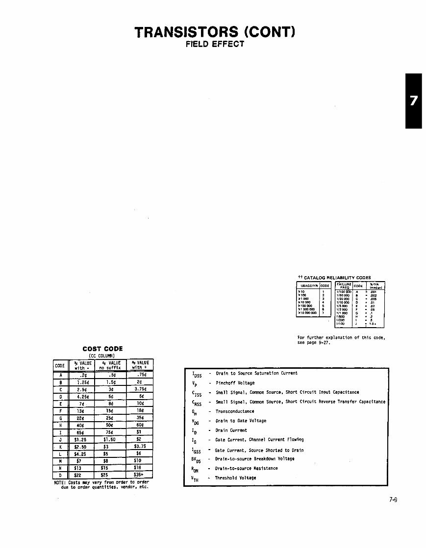
TRANSISTORS (CONTI FIELD EFFECT
tt CATALOG RE
ztomo 5100000
210mowo
iLlABlLlTY CODES
- --
For further explanation of this code, see page 9-27.
COST CODE
NOTE: Costs may vary from order to order due to order quantities, vendor, etc.
- Drain to Source Saturation Current
- Pinchoff Voltage
- Small Signal, Comnon Source, Short Circuit Input Capacitance
- Small Signal. C m n Source. Short Circuit Reverse Transfer Capacitance
- Transconductance
- Drain to Gate Voltage
- Drain Current
- Gate Current, Channel Current Flowing
- Gate Current. Source Shorted to Drain
- Drain-to-source Breakdown Voltage
- Drain-to-source Resistance
- Threshold Voltage

TRANSISTORS (CONT) FIELD EFFECT (FOR REFERENCE ONLY)
DO NOT USE IN NEW DESIGN
7-10 THE LISTING OF FETS WHICH ARE RECOMENDEO FOR USE ARE FOUND ON PAGES 7-2 THRU 7-6.
OTHER
FETS singles, N-channel junct ion
N-channel, MOS/OP
FET, dual L pair, N- channel, junct ion
FET, dual & pair, N- channel, junct ion
FET,dua lLpa i r ,N- channel, junct ion
FET, single, N-channel
FET, N-channel
FET, single, N-channel
FET, dual L pai r , N- channel, junct ion
FET,dua lLpa i r ,N-
FETS, single, N-channel, junct ion
FETS, single, N-channel , junct ion
MoS FET, N-channel
Dual I pair , N-channel, junct ion
MOS FET, N-channel
Dual L pai r , N-channel
FET, single, P-channel . junct ion
MOS FET, N-channel
Dual h pai r , P-channel. junct ion
Dual L pai r , N-channel, junct ion
FET, single, N-channel, junct ion
Oual 6 pai r , P-channel, junct ion
MOS FET, N-channel
PNP germanium
FET, N-channel
DMOS FET, N Channel
FET, dual, N-channel
ST
NP
CS
CS
CS
CS
CS
DL
LR
CS
NP
LR
CR
CR
DL
CR
DL
CR
OT
CR
CR
DL
EN
OB
LS
LR
DL
NP
CS
CR
PART NUMBER
151-1001-00
151 - 1003-00
151-1008-00
151-1009-00
151-1013-00
151-1014-00
151-101 6-00
151-1017-00
151 -1 01 9-00
151-1020-00
151-1023-00
151-1024-00
151-1030-00
151 -1 033-00
151-1034-00
151-1035-00
151-1040-00
151-1044-00
151-1048-00
151-1055-00
151-1060-00
151-1061-00
151-1065-00
51-1072-00
51-1079-00
51-1083-00
51-1101-00
51-1 104-00
51-1105-00
VENDOR #
U274A
SU-2080
O/UC 210
D/UC 210
SU-2181
2N4220
2N4304Fmly
F1333
SU-2235
FN-7428
2N4417
2N4352Fmly
2N138
2N6027
D/2N4417
D/2N4416
2N140
UC400Fmly
3N159
D/UC 4001
E421
2N4800
D/UC 400
MEM660/BK
MP3731, SP2597
2N5565
SD220
STYLE
, TO-89
TO-71
TO-78
TO-71
TO-71
TO-72C
TO-72
p23B
TO-71
TO-71
P i l l u-23B
uT
TO-72E
TO-980
CC-6
TO-72F
TO-71
TO-106
TO-72F
TO-71
R-165
TO-106
TO-71
TO-72C
TO-3
TO-71
TO-39B
TO-78
'P
N I X (v)
3.
4.
4.
4.
4.
4.
8.
5.
5.
6.
6.
3.
6.
4.
4.5
4.
3.
3.
6.
40.
5.
IDSS
MIN 'PA
1.
1.
4.
5.5
1.
.5
5.
1.5
2.5
5.
5.
5.
5.
.5
4.
5.
6.
1.
7.
'ISS
'RSS (PF)
3.2 7
18.
7. 2 7
k- 25.
k- 6. 2-7
k- %- %? 3.5
4. Br
%
%
- 8. 3.
7 %
h %
k k
28.
5. l-3
RANGE
N I X 'PA
3.
3.5
12.
12.
6.
3.
15.
8.
8.
15.
15.
15.
7 12.
30.
5.
16.
30.
30.
10.
.5
10.uA
20.
6, ' uMHOS
1000
1500
4500
3500
1300 1000
1000
1000
1000
1200
1500
4500
4500
6
3500
6
1000
10
1000
4500
1000
30n
15
200-15
7000
VOG
MIN ('4
20
50
50
35
30
50
50
50
50
50
30
30
40
30
25
30
--
10
@ V D G L I D
(V)
10
10
12
2.5 15
15
15
20
20
20
15
15
12
15
14
14
5
10
5
6
3
10
in4
loss
.7
5.
.3
DSS
IDSS
.35
1.
2.
loss
IDSS
10.
10.
5.
1.
6.
1 0 7 -
5.
lo
. 'PA
1.
.7
4.
5.
.300
IoSS
5.
1.
1.
IoSS
.250
5.
.025
2.
IG @
IGSS @
PA
@
.500
.050 77552r
,100 7-65
.500 T5iib
100. 100.15.
# .
.I00
.I50
lOmA 721ZT.
m.
.I00
InA
56T
- 5.
1nA
.25.035
500. 5mK
.25.035
lOnA
320.
100.
VOG @
'G (;)
12.5
10.
15. T S
+? 2.5 2 - 3
15.
15. T5:
56:
20.
20.
20.
2'K
7.
Fx
5.
10. l3T
5.
320.
15.

TRANSISTORS (CONT) FIELD EFFECT (FOR REFERENCE ONLY)
DO NOT USE IN NEW DESIGN G, @ VDG ID IG @ VDG @ ID
IDSS RANGE 'ISS uMHOS v~~
V~ MIN CASE MIN ' wx 'RSS *Ror (v ) m~ IGSS @ 'GS , m~
PART NUMBER VENDOR d ST OTHER STYLE mA mA ( V ) (PF) ON PA ( V ) (V)
151-1107-00 2N4391 CR FET, s i n g l e TO-46

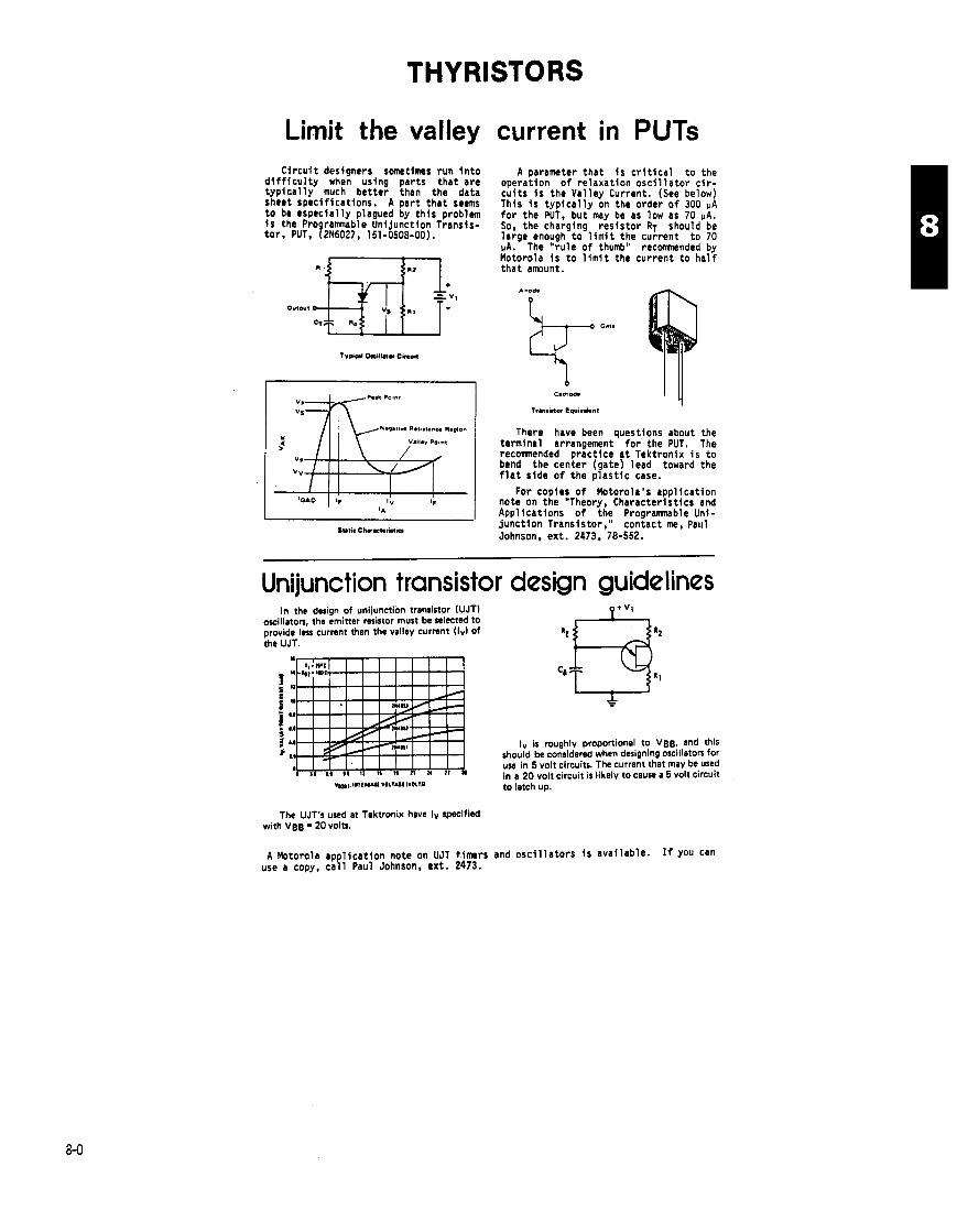
THYRISTORS
Limit the valley current in PUTS Ci rcu i t designers sometimes run i n t o
d i f f i c u l t y when using parts tha t are t y p i c a l l y much bet ter than the data sheet specif icat ions. A par t t h a t seems t o be especial ly plagued by t h i s problem i s the Pro r a m b l e Unijunction Transis- to r , PUT, f2~6027, 151-0508-00).
A parameter tha t i s c r i t i c a l t o the operation o f re laxat ion o s c i l l a t o r c i r - cu i t s i s the Val ley Current. (See below) This i s t y p i c a l l y on the order o f 300 UA f o r the WT, but may be as low as 70 PA. So, the charging res is to r RT should be large enough t o l i m i t the current t o 70 vA. The " ru le o f thumb" recomnded by Motorola i s t o l i m i t the current t o h a l f t ha t amount.
1 I There have been wes t ions about the I -: 111 \ Y.l l *vp~int I terminal arrangement' f o r the PUT. The
recomnended p r i c t i c e a t Tektronix i s t o bend the center (gate) lead toward the f l a t side o f the p l a s t i c case.
I I For copies o f Motorola's appl icat ion
I V IF I note on the "Theory. Characterist ics and 14 I Applicat ions o f t h f Programnable Uni-
SUIO~ ckrrt.,itim junct ion Transistor, contact me, Paul Johnson, ext. 2473, 78-552.
Unijunction transistor design guidelines In the design of unijunction transistor (UJT)
oscillaton, the emitter resistor must be telectcd to provide In, current than the valley current ( I d of the UJT.
IV is roughly proportional to VBB, and this should be considered when designing oscillators for use in 5 volt circuits. The current that may be used in a 20 volt circuit is likely to cause a 5 volt circuit
V,~~.HI~UUI V O L V M ~ I V O L ~ ~ ~ to latch up.
The UJT's used at Tektronix have Iv specified with VBB = 20 volts.
A Motorola appl icat ion note on UJT t.imers and o s c i l l a t o r s i s avai lable. If you can use a copy, c a l l Paul Johnson, ext . 2473.

THYRISTORS SCR -
I HOLI MAX mA - -
5. 5. 5. 3. 5.
20.
40. 30. 30.
50.
50. 40. 70.
100.
70. -
- t
CASE STYLE
TO-18 TO- 92 TO-92 TO-202 MU47 TO-66
MU-10 TO-220 TO-220
TO-3
TO-3 TO-220 SC-18 TO-48
TO-65
FORWARD CURRENl MAX AMPS
RMS O.C.
.5 .8 .8
2.7 4. 2.6 5. 1.7
8. 8. 8.
12.5 8.
12.5 8. 16. 35. 22. 35.
63. 40.
FOR. + REV. BREAKOVER MIN VOLTS
200. 30.
150. 200. 600. 200.
50. 200. 200.
200. REV. 600. ROR.
600. 50.
100. 1200.
50.
JEOEC OR I OTHER
Anode Lead Temperature 25'C
Screened 24 hr . , 100°C, 200V peak AC
IDRM o r IRRM = lOOuA Max. w i t h VORM o r VVRM = 1200V
- -. QUADRANTS I 8 I 1 1
MAXIMUM CURRENT I HOLD GATE TRIGGER AMPS BREAKOVER MAX 12T I MAX V MAX CASE RMS MIN VOLTS d IM (V) STYLE
JEOEC OR VENDOR NUMBER PART NUMBER OTHER
:il I P r e s s f i t w i t h brass bracket f o r crowbar c i r c u i t use only, no t f o r power.
JEDEC OR
UNl JUNCTION
** NEW DESIGN CODE
PROGRAMMABLE
I v mA (MINI
2.
4. (Vv-2V) 4. 6.
V ~ 2 ~ l MAX.
35.
35. 35. 35.
ANODE CURRENT
40.V 40. V
A = Acceptable N = Not Recomnended
Blank = No Recommendation
0 @ 10V
.56-.75
.70-.85
.70-.85 -70-.85
IG MAX mA
DISCHARGE ENERGY MAX.
tt RELIABILITY CODES
F MAX KHz (MIN)
100.
100. 100. 100.
IP uA (MAX)
2.
2. 2.
.4
V ~ 2 ~ V
30.
30. 30. 30.
COST CODE ICC COLUrnI
IE RMS
MAX.
50.
50. 50. 50.
F MAX
I
NOTE: Costs may vary from order t o order due t o order quan t i t i es , vendor, e tc .
Rbb @ 3v9 v B 2 ~ 1
4.7 t o 9.1 k
4.7 t o 9.1 k 4.7 t o 9.1 k 4.7 t o 9.1 k
250 uJ 250 UJ
1 5 m 150mA
For f u r t h e r explanat ion o f t h i s code, see page 9-27.
2A 2A
t FOR CASE DRAWINGS, SEE PAGES 9-2 THRU 9-8.
POWER AMB. mW
300.
300. 300. 300.
POWER AMB. mW
50. 50.
t CASE STYLE
TO-72H
TO-72H TO-72H TO-72H
t CASE STYLE
JEDEC OR VENDOR NO.
100 kHz 100 kHz
PART NUMBER
300. 300.
** NO
TO-98 TO-98
CC tt RC
2N6027 2N6027
151-0508-00 151-0508-01
A N
G H-
5F 4E
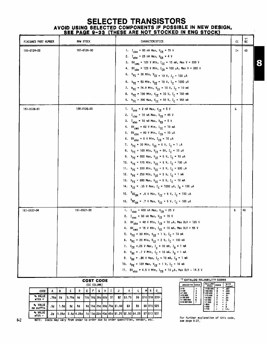
COMPONENTS IF POSSIBLE IN NEW DESIGN,
RAW STOCK
COST CODE (CC COLUMN)
ESE ARE NOTSTOCKED IN ENG STOCK)
CHARACTERISTICS
1. Icbo = 50 nA Max. VCB = 75 V
2. Iebo = 25 nA Max, VEB = 4 V
3. BV,,, = 120 V Min, ICE = 10 mA, Max V = 200 V
4. BVCbo = 120 V Mln, ICB = 100 PA, Max V = 200 V
5. h~~ = 35 VCE = 10 V, rC = 100 PA
6. hFE = 50 Min, VCE = 10 V, IC = 1000 uA
7. hFE = 74.9 Min, VCE = 10 V, IC = 10 mA
8. hFE = 100 Min, VCE = 10 V, IC = 150 mA
9. hFE = 300 Max, VCE = 10 V, IC = 150 mA
1. Ices = 2 nA Max, VCE = 5 V
2. Icbo = 10 nA Max, VCB = 45 V
3. Iebo = 10 nA Max, VEB = 5 V
4. BVceo = 60 V Min, ICE = 10 mA
5. BVcbo = 60 V Min, ICB = 10 UA
6. BVebo = 6 V Min, IEB = 10 pA
7. hFE = 30 Min. VCE = 5 V, IC = 1 uA
8. hFE = 100 Min. VCE = 5V. IC = 10 PA
9. hFE = 500 Max, VCE = 5 V. IC = 10 pA
10. hFE = 175 Min, VCE = 5 V, IC = 100 UA
11. hFE = 200 Mln, VCE = 5 V, IC = 500 UA
12. hFE = 250 Min, VCE = 5 V. IC = 1 mA
13. hFE = 800 Max, VCE = 5 V, IC = 10 mA
14. VCE = .35 V Max, IC = 1000 pA, IB = 100 pA
15. 'BEON = .5 V Min, VCE = 5 V, IC = 100 UA
16. 'BEON = .7 V Max. VCE = 5 V, IC = 100 uA
1. Icbo = 400 nA Max, VCB = 20 V
2. Ices = 50 nA Max, VCE = 15 V
3. BVcbo = 40 V Min, ICE a 10 PA, Max DLV = 120 V
4. BV,,, = 15 V Mln, ICE = 10 mA. Max DLV = 55 V
5. hFE = 50 Min, VCE = 1 V, IC = 10 mA
6. hFE = 20 Min, VCE = 2 V, IC = 100 mA
7. VCE =.25 V Max. I = 10 mA, IB = 1 mA C
8. VBE = .7 V Min. IC = 10 mA. IB = 1 mA
9. VBE = .85 V Max, IC = 10 mA, IB = 1 mA
10. hFE = 120 Max, VCE = 1 V, IC = 10 mA
11. BVebo = 4.5 V Min, IEB = 10 Max DLV - 14.5 V
++ CATALOG RE iLlABlLlTY CODES
111 000 - .os Ill 000 - 3 11200 11100
For f u r t h e r explanat ion o f t h i s code, see page 9-27.
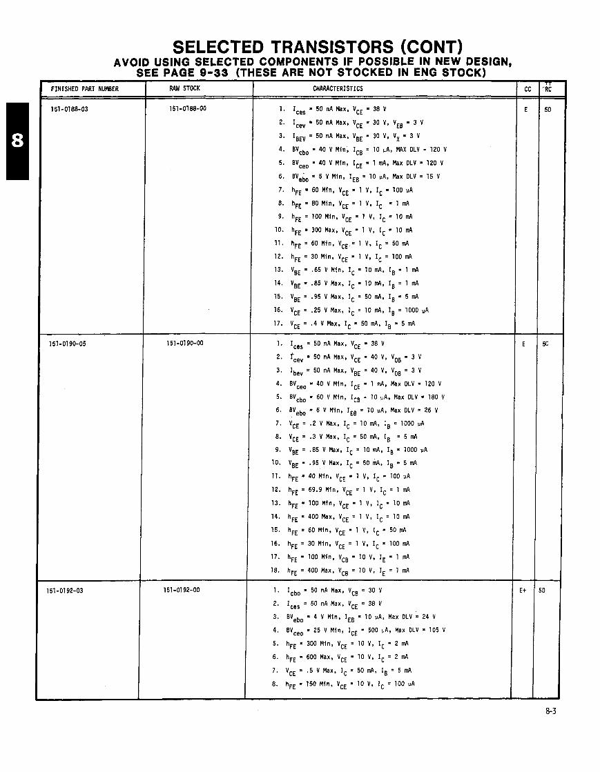
SELECTED TRANSISTORS (CONT) AVOID USING SELECTED COMPONENTS IF POSSIBLE IN NEW DESIGN,
SEE PAGE 9-33 (THESE ARE NOT STOCKED IN ENG STOCK) FINISHED PART NUMBER RAW STOCK CHARACTERISTICS
1. I,,, = 50 nA Max, VCE = 38 V
2. I,,, = 50 nA Max, VCE = 30 V, VEB = 3 V
3. IBEv = 50 nA Max, VBE = 30 V, V X = 3 V
4. BVcbo = 40 V Min, ICB = 10 PA, MAX DLV - 120 V
5. Woo = 40 V Min. ICE = 1 mA. Max DLV = 120 V
6. BV,bo = 5 V Mln , IEB = 10 PA, Max DLV = 15 V
7. hFE = 60 Min , VCE = 1 V. IC = 100 PA
8. hFE = 80 Min, VCE = 1 V, IC = 1 mA
9. hFE = 100 Min, VCE = 1 V, IC = 10 mA
10. hFE = 300 Max, VCE = 1 V, IC = 10 m4
11. h F E = 6 0 M i n , V C E = l V, I C = 5 0 m 4
12. hFE = 30 Min , VCE = 1 V, IC = 100 m4
13. VBE = .65 V Min , IC = 10 mA, IB = 1 m4
14. VBE = '85 V Max. IC = 10 mA, IB = 1 mA
15. VBE = '95 V Max. Ic = 50 m4, Is = 5 m4
16. VCE = '25 V Max, IC = 10 m4, IB = 1000
17. VCE = .4 V Max, IC = 50 m4, IB = 5 mA
1. I,,, = 50 nA Max, VCE = 38 V
2. fcev = 50 nA Max, VCE = 40 V, VOB = 3 V
3. Ibev = 50 nA Max, VBE = 40 V, VOB = 3 V
4. BVceo = 40 V Min, ICE = 1 mA, Max OLV = 120 V
5. BVcbo = 60 V Min, ICE - 10 PA, Max OLV = 180 V
6. BYebo = 6 V Min, IEB = 10 vA, Max DLV = 26 V
7. VCE = '2 V Max, IC = 10 mA, IB = 1000 uA
8. VCE = .3 V Max, IC = 50 mA, IB = 5 m4
9. VBE = '85 V Max, IC = 10 m4, IB = 1000 PA
10. VBE = '95 V Max, Ic = 50 m4, IB = 5 m4
11. hFE = 40 Mfn, VCE = 1 V, IC = 100 uA
12. hFE = 69.9 Min, VCE = 1 V, IC = 1 m4
13. hFE = 100 Min, VCE = 1 V, IC = 10 m4
14. hFE = 400 Max. VCE = 1 V, IC = 10 m4
15. hFE = 60 Min, VCE = 1 V, IC = 50 m4
16. hFE = 30 Min, VCE = 1 V, IC = 100 m4
17. hFE = 100 Min , VCB = 10 V, IE = 1 m4
18. hFE = 400 Max, VCB = 10 V, IE = 1 mA
1. Icbo = 50 nA Max, VCB = 30 V
2. Ices = 50 nA Max, VCE = 38 V
3. ENebo = 4 V Min. IEB = 10 uA, Max OLV = 24 V
4. BVceo = 25 V Min , ICE = 500 vA, Max DLV = 105 V
5. hFE = 300 Min , VCE = 10 V, IC = 2 m4
6. hFE = 600 Max, VCE = 10 V, IC = 2 mA
7. VCE = .5 V Max, IC = 50 m4, IB = 5 m4
8. hFE = 150 Min , VCE = 10 V. IC = 100 uA

SELECTED TRANSISTORS (CONT) AVOID USING SELECTED COMPONENTS IF POSSIBLE IN NEW DESIGN,
SEE PAGE 9-33 (THESE ARE NOT STOCKED IN ENG STOCK) pp -
RAW STOCK CHARACTERISTICS
1. Icbo = 10 nAMax, VCB = 15 V
2. BVcbo = 30 V Mln, ICB = 1 vA, Max OLV = 110 V
3. BVebo = 3 V Min, IEB = 10 PA, Max OLV = 23 V
4. hFE = 40 Min, VCE = 1 V, IC = 3 m4
5. VBE = 1 V Max. IC = 10 mA, IB = 1 m4
6. BV,,, = 15 V Min, ICE = 3 mA, Max OLV = 55 V
7. VCE = '40 V Max, IC = 10 mA, IB = 1 m4
8. I c e s = 1 0 n A M a x , V C E = 2 5 V
1. I,,, = 10 nA Max, VCE a 10 V
2. BV,,, = 12 V Min, ICE = 10 m4, Max DLV = 52 V
3. BV,,, = 12 V Min, ICE = 100 PA, Max DLV = 52 V
4. BVcbo = 12 V Min, ICB = 100 PA, Max OLV = 52 V
5. BVebo = 4 V Min, IEB = 100 PA, Max OLV = 14 V
6. VCE = .2 V Max, IC = 10 mA, IB = 1 m4
7. VCE = .6 V Max, IC = 50 m4, IB = 50 m4
8. VBE = .75 V Min, IC = 10 m4. IB = 500 pA
9. VBE = '95 V Max. IC = 10 m4, IB = 500 PA
10. VBE = .8 V Min, IC = 10 m4, IB = 1 m4
11. VBE = 1 V Max, IC = 10m4, IB = 1 m4
12. VBE = 1.5 V Max. Ic 50 m4, IB = 5 m4
13. hFE = 30 Min, VCE = .3 V, IC = 10 mA
14. hFE = 120 Max, VCE a .3 V, IC = 10 mA
15. hFE = 20 Min, VCE 1 V, IC = 50 m4 9
1. Cob s 30 pF, VcB = 10 V
2. CIb r 110 pF, VEB = .5 V
3. BVcbo r 90 V r 130 V, ICB = 100 VA
4. BVebo r 7 V r 17 V, IEB = 100 pA
5. BV,,, 2 8 5 V r 105 V, ICE = 20m4, V x = 1.5 V
6. BV,,, = r 85 V, ICE = 20 m4. RX =' .2 k
7. BVceo = r 75 V r 95 V, ICE = 20 m4
8. VCE = s -65 V, IC = 150 mA, IB = 15 mA
9. Icbo = r 20 nA, VCB = 60 V
10. I c e o = r 5 0 0 n A , V C E = 3 3 V
11. Iebo = 5 20 nA, VEB = 5 V
12. I + hFE IB = 5 VA Max, VCB = 10 V, IE = 100 pA
13. hFE = r 40, VCE = 10 V, IC = 150 mA
14. hFE = r 140.2, VCE = 10 V, IC = 150 m4
15. hFE = r 20, VCE = 10 V, IC = 500 m4
tt FOR RELIABILITY CODES, SEE PAGE 8-2.

SELECTED TRANSISTORS (CONT) AVOID USING SELECTED COMPONENTS IF POSSIBLE IN NEW DESIGN,
SEE PAGE 9-33 (THESE ARE NOT STOCKED IN ENG STOCK)
FINISHED PART NUMBER RAW STOCK CHARACTERISTICS
1. Iebo 5 100 nA, VEB = 3 V
2' Icbo s 10 nA, VCB = 50 V
3. Ices s 100 nA, VCE = 50 V
4. Iceo s 1 uA, VCE = 28 V
5. VCE(sat) 5 .5 V, IC = 50 mA. IB = 5 mA
6. hFE 2 50, IC = 50 m4, VCE = 5 V
7. hFE 5 150, IC = 50 mA, VCE = 5 V
8. VCE(sat) 2 .1 V, IC = 50 m4. IB = 5 m4
9. VBE(sat) 5 .6 V, IC 50 mR, IB = 5 m4
10. Power Stress Test = 35 V @ 100 mA s 5 sec.
1. Icbo = 50 nA Max, VCB = 20 V
2. BVebo = 4 V Min, IEB = 10 PA, Max DLV = 24 V
3. hFE = 150 Min, VCE = 10 V, IC = 100 uA
4. BVceo = 25 V Min, ICE = 500 MA, Max DLV = 105 V
5. hFE = 600 Max, VCE = 10 V, IC = 2 mA
6. hFE = 300 Min, VCE = 10 V, IC = 2 m4
7. VCE = .5 V Max, IC = 25 m4, IB = 2.5 in4
8. Ices = 50 nA Max, VCE = 23 V L
1. Cob = s 4 . 5 pF. VcB = 5 V
2. CIB = 5 8 pF, VEB = .5 V
3. BVcbo = 2 40 V s 60 V, ICE = 10 PA
4. BVces 5 40 V s 60 V, ICE = 10 uA
5. BVceo = 2 40 V s 60 V, ICE = 10 mA
6. BVebo 2 5 V s 15 V, IEB = 10 uA
7. Ices = 5 25 nA. VCE = 30 V
8. Ices = s 50 nA, VCE = 38 V
9. I + hFE I = "666 nA, VCB = 1 V, IE = 100 PA
10. Dx = hFE 60 min t e s t s IC, 11 ABS r a t i o const .I00 V
11. hFE = 2 80, VCE = 1 V, IC = 1000 uA
12. hFE = 2 100, VCE = 1 V, IC = 10 mA
13. hFE = 1 300, VCE = 1 V, IC = 10 mA
14. hFE 2 30, VCE = 1 V, IC = 50 mA
15. VCE = '13 V Max. IC = 1000 MA. IB = 100 VA
16. VCE = '14 V Max. IC = 10 m4. Is = 1000 PA
17. VCE = .3 V Max. IC = 50 mA, IB = 5 mA
18. VBE = '75 V Max, IC = 1000 MA, IB = 100 uA
19. VBE = .7 V Max, IC = 10 mA. IB = 1000 PA
20. VBE = .9 V Max. IC = 10 m4, IB = 1000 PA
21. VBE= 1.1 V Max, IC = 50mA, IB = 5mA
1. Burn-in f o r 72 hours
2. 100% e l e c t r i c a l (same as 151-0220-04)
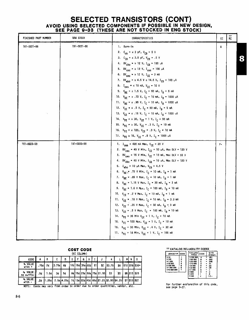
SELECTED TRANSISTORS (CONT) USING SELECTED C E PAGE 9-33 (THEI
RAW STOCK
COST CODE (CC COLUMN)
MPONENTS IF POSSIBLE IN NEW DESIGN, ARE NOT STOCKED IN ENG STOCK)
CHARACTERISTICS
1. Ice, = 400 nA Max, VCE = 20 V
2. BVce, = 40 V Min. ICE = 10 PA, Max DLV = 120 V
3. BVceo = 15 V Min, ICE = 10 m4, Max DLV = 55 V
4. BVcbo = 40 V Min. ICB = 10 PA. Max DLV = 120 V
5. Iebo = 10 !,A Max, VEB = 4.5 V
6. VBE,= -72 V Min, IC = 10 m4, IB = 1 mA
7. VBE = .85 V Max. IC = 10 in4, IB = 1 mA
8. VBE = 1.15 V Max, IC = 30 mA, IB = 3 m4
9. VBE = 1.6 VMax, I C = 100mA. I B = 10mA
10. VCE = '2 V Max, IC = 10 mA, IB = 1 m4
11. VCE = .18 V Max, IC = 10 m4, IB = 3.3 na4
12. VCE = '25 V Max, IC = 30 mA, IB =,3 in4
13. VCE = .5 V Max, IC = 100 m4, IB = 10 mA
14. hFE = 35 Min VCE = 1 V, IC = 10 mA
15. hFE = 120 Max, VCE = 1 V, IC = 10 mA
16. hFE = 30 Min, VCE = .4 V, IC = 30 m4
17. hFE = 18 Min, VCE = 1 V, IC = 100 m4
NOTE: Costs may vary from order t o order due t o order quan t i t i es , vendor, e t c .
f t CATALOG RELIABILITY CODES
For f u r t h e r e x ~ l a n a t i o n o f t h i s code, see page 9-27.
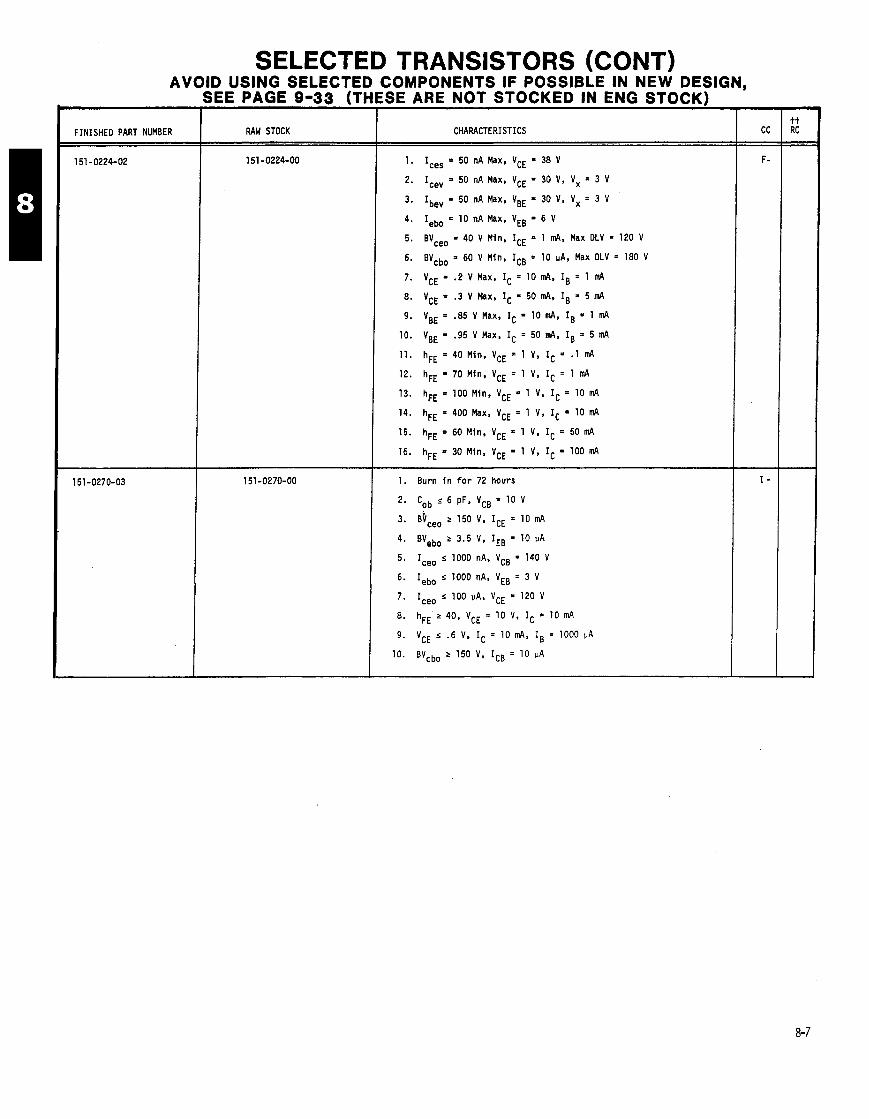
SELECTED TRANSISTORS (CONT) AVOID USING SELECTED COMPONENTS IF POSSIBLE IN NEW DESIGN,
SEE PAGE 9-33 (THESE ARE NOT STOCKED IN ENG STOCK)
FINISHED PART NUMBER I RAW STOCK CHARACTERISTICS
1 . I,,, = 50 nA Max, VCE = 38 V
2. I,,, = 50 nA Max. VCE = 30 V. Vx = 3 V
3. Ibev = 50 nA Max. VBE = 30 V. Vx = 3 V
4. Iebo = 10 nA Max, VEB = 6 V
5. BV,,, = 40 V Min, ICE = 1 m4. Max OLV = 120 V
6. BVcbo = 60 V Min, ICB = 10 uA, Max DLV = 180 V
7. VCE = . 2 V Max, IC = 10 mA, IB = 1 mA
8. VCE = '3 V Max, IC = 50 mA, IB = 5 mA
9. VBE = '85 V Max, IC = 10 mA, IB = 1 mA
10. VBE = '95 V Max, Ic = 50 m4, IB = 5 m4
11. hFE = 40 Min. VCE = 1 V. IC = .1 m4
12. hFE = 70 Mfn, VCE = 1 V, IC = 1 m4
13. hFE = 100 Min, VCE = 1 V, IC = 10 m4
14. hFE = 400 Max. VCE = 1 V, IC = 10 mA
15. hFE = 60 Min. VCE = 1 V. IC = 50 mA
16. hFE = 30 Min. VCE = 1 V, IC = 100 m4
1. Burn i n f o r 72 hours
2. Cob s 6 pF, VcB = 10 V
3. &,,, 2 150 V, ICE = 10 mA
4. BVebo 2 3.5 V, IEB = 10 PA
5. I,,, s 1000 nA. VCB = 140 V
6. Iebo s 1000 nA, VEB = 3 V
7. I,,, s 100 PA, VCE = 120 V
8. hFE 2 40, VCE = 10 V, IC = 10 mA
9. VCE s 6 V, IC = 10 m4, IB = 1000 uA
10. BVcbo 2 150 V, ICB = 10 uA

SELECTED TRANSISTORS (CONT) COMPONENTS IF POSSIBLE IN NEW DESIGN, USING SELECTED
E PAGE 9-33 (TH
RAW STOCK CHARACTERISTICS
ESE ARE NOT STOCKED IN ENG STOCK)
I I. Burn-in f o r 72 hours
2. C o b = s 4 . 5 p F , V c B = 4 0 V
3. BVcbo = > 150 V s 170 V, ICB = 100 uA
4. BVceo = 2 150 V s 170 V, ICE = 10 mA
5. Icbo = s 50 nA, VCB = 40 V
6. hFE a 5 50, VCE = 20 V. IC = 10 mA
7. Iebo = s 50 nA, VEB = 3.5 V
1. Precondit ioning 48 hours @ + 250 V
2. VCED(sus) 2 300 V, IC = 5 mA
3. hFE 2 20, VCE = 20 V, IV = 1 mA
4. hFE 2 40. VCE = 20 V. IC = 10 mA
5. hFE 2 40, VCE a 20 V, IC = 30 mA
6' sat) s 1 v, Ic = 20 mA, IB = 2 mA
7. VBE(sat) s .85 V, IC = 20 mA, IB = 2 n
8. BVcbo 2 300 V, IC = 100 uA
9. B V e b o > 7 V , I E = l O O p A
10. Icbo s 100 nA, VCB = 200 V
11. Iebo s 100 nA, VBE = 6 V
1. Iebo = LOO nA Max, VEB = 6.5 V
2. I c b o = IOOnAMax, V C B = 2 5 0 V
3. Iceo = 1 uA Max, VCE = 250 V
4. BVceo = 300 V Min, ICE = 5 mA, Max OLV = 550 V
5. BVceo = 550 V Max, ICE = 5 mA. Max DLV = 560 V
6. hFE = 20 Min, VCE = 20 V, IC = 1 mA
7. hFE = 40 Min, VCE = 20 V, IC = 10 mA
8 . hFE = 40 Mln, VCE = 20 V, IC = 30 mA
9. hFE = 240 Max, VCE = 20 V, IC = 30 m4
10. hFE = 15 Min, VCE = 20 V, IC = 100 mA
11. VBE = '65 V Mln, IC = 20 mA, IB ; 2 mA
12. VBE = .8 V Max, IC = 20 mA. IB = 2 mA
13. VCE = 1 V Max, IC = 20 mA, IB = 2 mA
1. Icbo s 10 nA, VCB - 50 V
2. Ices s 10 nA, VcE m 50 V
3. VCE(sat) s -5 V, IC c 50 mA, IB 5 m4
4. I e b o s l O n A , V E B - 3 V
5. hFE 2 50, IC = 50 m4, VCE = 5 V
6. hFE s 150, IC = 50 mA, VCE = 5 V
7. VBE(sat) s 1 V s IC 50 mA. Is = 5 m4
8. VBE(sat) > .6 V s IC 50 mA, IB 5 nd
9. Iceo s 100 nA. VCE r 28 V
10. Power Stress Test - 35 V + 100 mA. s 6 sec.
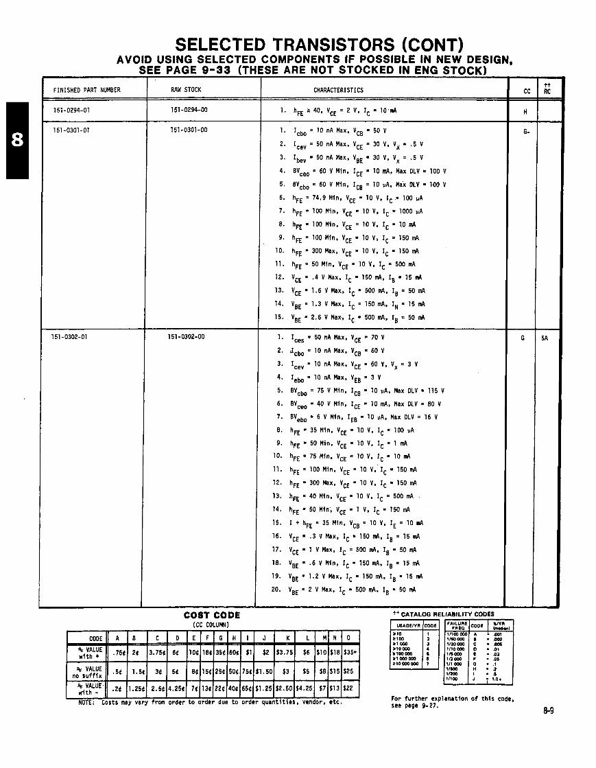
FINISHED PART NUMBER
SELECTED TRANSISTORS (CONT) AVOID USING SELECTED COMPONENTS IF POSSIBLE IN NEW DESIGN,
SEE PAGE 9-33 (THESE ARE NOT STOCKED IN ENG STOCK) c RAW STOCK CHARACTERISTICS
COST CODE (CC COLUW)
1. Icbo = 10 nA Max, VCB = 50 V
2. Ice, = 50 nA Max, VCE = 30 V, Vg = .5 V
3. Ibev = 50 nA Max, VBE = 30 V, Vx = .5 V
4. BYceo = 60 V Min. ICE a 10 mA, Max DLV = 100 V
5. BVcbo = 60 V Min, ICE = 10 PA, Max DLV = 100 V
6. hFE = 74.9 Min, VCE = 10 V, IC = 100 uA
7. hFE = 100 Min, VCE = 10 V, IC = 1000 pA
8. hFE = 100 Min. VCE = 10 V, IC = 10 m4
9. hFE = 100 Min, VCE = 10 V, IC = 150 m4
10. hFE = 300 Max. VCE = 10 V, IC = 150 m4
11. hFE = 50 Min, VCE = 10 V, IC = 500 mA
12. VCE = .4 V Max, IC = 150 mA, IB = 15 m4
13. VCE = 1.6 V Max, IC = 500 m4. IB = 50 m4
14. VBE = 1.3 V Max, Ic = 150 m4, I,, = 15 m4
15. VBE = 2.6 V Max, IC = 500 m4, IB = 50 m4
1. I,,, = 50 nA Max, VCE = 70 V
2. Jcbo = 10 nA Max, VCB = 60 V
3. Ice, = 10 nA Max, VCE = 60 V, Vx = 3 V
4. Iebo = 10 nA Max, VEB = 3 V
5. BVcbo = 75 V Min, ICB = 10 pA, Max DLV = 115 V
6. BVceo = 40 V Min. ICE = 10 mA, Max OLV = 80 V
7. B V e b o = 6 V M i n , I E B = 1 0 p A , M a x D L V = 1 6 V
8. hFE = 35 Min. VCE = 10 V, IC = 100 uA
9. hFE = 50 Min, VCE = 10 V, IC = 1 m4
10. hFE = 75 Min, VCE = 10 V, IC = 10 m4
11. hFE = 100 Mln, VCE = 10 V. IC = 150m4
12. hFE = 300 Max. VCE = 10 V, IC = 150 m4
13. hFE = 40 Min, VCE = 10 V, IC = 500 m4
14. hFE = 50 Min, VCE = 1 V, IC = 150 m4
15. 1 + hFE = 35 Mln, VCB = 10 V, IE = 10 m4
16. VCE = .3 V Max, IC = 150 m4. IB = 15 mA
17. VCE = 1 V Max, IC = 500 mA, IB = 50 m4
18. VBE = - 6 V Min, IC = 150 m4. IB = 15 m4
19. VBE = 1.2 V Max, IC = 150 m4, IB * 15 m4
20. VBE = 2 V Max, IC = 500 m4. Is = 50 m4
++ CATALOG RELIABILITY CODES
For fu r the r erplsnation o f t h i s code, see page 9-27.
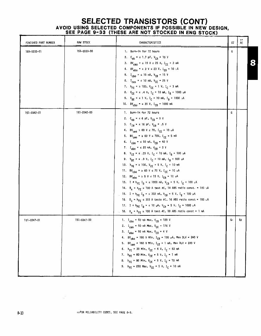
SELECTED TRANSISTORS (CONT) AVOID USING SELECTED COMPONENTS IF POSSIBLE IN NEW DESIGN,
SEE PAGE 9-33 (THESE ARE NOT STOCKED IN ENG STOCK)
RAW STOCK CHARACTERISTICS
1. Burn-in f o r 72 hours
2. Cob = s 1.7 pF, VcB = 10 V
3. BYceo = 2 15 V s 25 V, ICE = 3 mA
4. BVebo = r 3 V s 23 V, IEB = 10 uA
5. Icbo = r 10 nA, VCB = 15 V
6. Ices = r 10 nA, VCE = 25 V
7. hFE = > 100, VCE = 1 V, IC = 3 mA
8. VCE = s .4 V, IC = 10 mA, IB = 1000 PA
9. VBE = s 1 V, IC = 10 mA, IB = 1000 UA
10. BVcbo = r 30 V, IcB = 1000 mA
1. Burn-in f o r 72 hours
2. Cob = r 6 pF, VcB = 5 V
3. CIB = s 16 pF, VEB = .5 V
4. BVces 2 60 V s 70, ICE = 10 uA
5. BVceo = r 60 V s 70V, ICE = 5 mA
6. Icbo = s 10 nA, VCB = 40 V
7. Iebo = L 20 nA, VEB = 3 V
8. VCE = 5 . 5 V, IC = 10 mA, IB = 500 uA
9. VBE = s .9 V. IC = 10 mA, IB = 500 uA
10. hFE = 2 100, VCE = 5 V, IC = 10 mA
11. BVcbo = r 60 V s 70 V, ICE = 10 PA
12. BYebo= r 5 V s 15 V, IEB = 10 uA
13. I r hFE IB = r 1000 nA, VCB = 5 V, IE = 100 uA
14. Bx = hFE "00 A t e s t #C, 14 ABS r a t i o const. = 100 uA
15. I + hFE IB = 2 333 nA, VCB = 5 V, IE = 100 PA
16. Ox = hFE s 303 A tes t s #C, 16 ABS r a t i o const = 100 UA
17. I + hFE IB = r 10 uA, VCB = 5 V, IE = 1000 uA
18. Ox = hFE 2 100 A t e s t #C, 18 ABS r a t i o const = 1 mA
1. Icbo = 50 nA Max, VCB = 120 V
2. Ices = 50 nA Max, VCE = 175 V
4. BVcbo = 180 V Min, ICB = 100 uA, Max DLV = 240 V
5. BVceo = 160 V Min, ICE = 1 mA, Max OLV = 200 V
6, hFE = 30 Min, VCE = 5 V, IC = 50 nA
7. hFE = 80 Min. VCE = 5 V. IC = 1 nA
8. hFE = 80 Min, VCE = 5 V, IC = 10 m4
9. hFE = 250 Max. VCE = 5 V, IC = 10 mA
ttFOR RELIABILITY CODES, SEE PAGE 8-9.

SELECTED TRANSISTORS (CONT) AVOID USING SELECTED COMPONENTS IF POSSIBLE IN NEW DESIGN,
SEE PAGE 9-33 (THESE ARE NOT STOCKED IN ENG STOCK)
FINISHED PART NUMBER RAW STOCK
l5l-O349-OO 1. Burn-in f o r 72 hours
2. BVceo = 2 60 V, s 80 V, ICE = 200 in4
3. BVcbo = 2 75 V s 95 V, ICB = 100 PA
4. Icbo = s 100 PA, VCB = 60 V
5. I e b o = s 1 0 ~ A , V C E = 4 V
6. hFE = 2 25, VCE = 2 V. IC = 3 A
7 . hFE = 5 100, VCE = 2 V, IC = 3 A
8. VBE(ON) s 1.4, VCE = 2 V, IC = 3 A
1. Icbo = 50 nA Max, VCB = 120 V
2. Ices = 100 nA Max, VCE = 120 V
3. Iebo = 50 nA Max, VEB = 3 V
4. BVcbo = 160 V Min, ICE = 100 PA, Max DLV = 200 V
5. 8Vceo = 150 V Min, ICE = 1 in4, Max OLV = 1000 A
6. hFE = 50 Min, VCE = 5 V, IC = 1 in4
7. hFE = 60.1 Min, VCE = 5 V. IC = 10 m4
8. hFE = 240 Max, VCE = 5 V, IC = 10 in4
9. hFE = 50 Min, VCE = 5 V. Ic = 50 in4
1. Wceo = 350 V Min, ICE = 100 mA, Max DLV = 450 V
2. VCE = 1 V Max, IC = 500 m4, IB = 50 m4
3. VBE = 1.2 V Max, IC = 500 m4, IB = 50 in4
4. Ices = 1000 PA Max, VCE = 500 V
5. hFE = 75 Min, VCE = 10 V, IC = 500 in4
6. hFE = 175.1 Max. VCE = 10 V, IC = 500 in4
7. hFE = 40 Min, VCE = 10 V. IC = 50 m4
8. Iebo = 10 VA Max, VEB = 5 V
1. Burn- in f o r 72 hours
2. 100% e l e c t r i c a l (same as 151-0405-03)
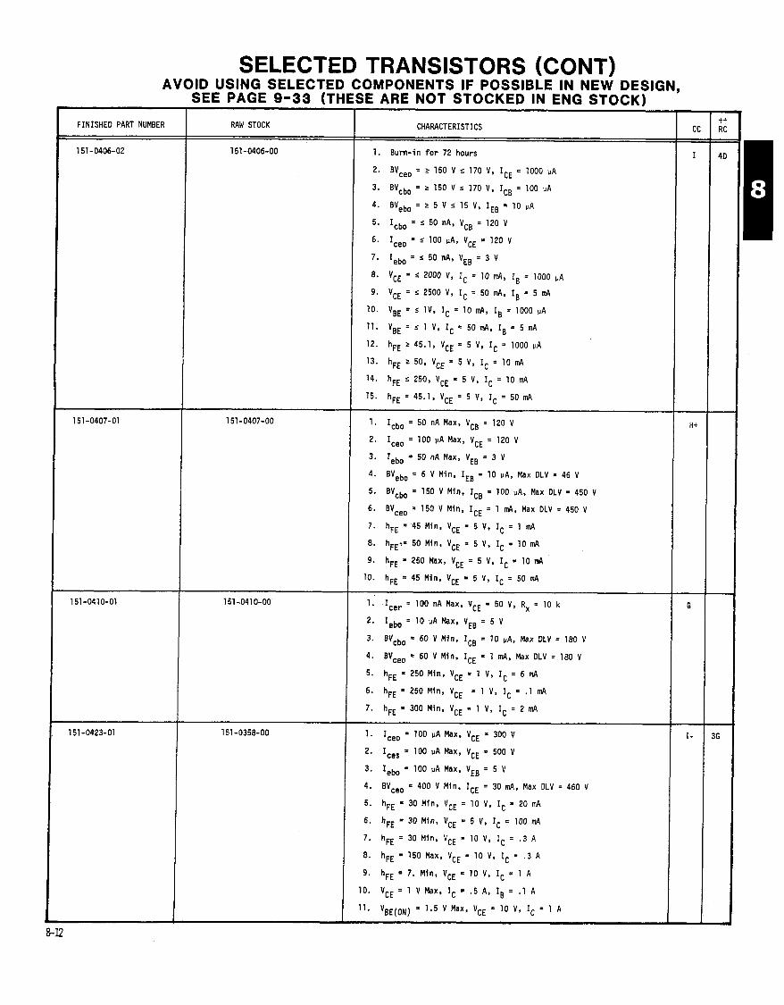
SELECTED TRANSISTORS (CONT) AVOID USING SELECTED COMPONENTS IF POSSIBLE IN NEW DESIGN,
SEE PAGE 9-33 (THESE ARE NOT STOCKED IN ENG STOCK)
RAW STOCK
151-0406-00
CHARACTERISTICS
1. B u r n - i n f o r 72 h o u r s
2. BVceo = r 150 V s 170 V, ICE = 1000 u A
3. BVcbo = r 150 V J 170 V, ICB = 100 PA
4. BYebo = 2 5 V s 15 V, IEB = 10 UA
5. Icbo = s 50 nA, VC8 = 120 V
6. I,,, = J 100 IIA, VCE = 120 V
7. Iebo = s 50 nA, VEB = 3 V
vCE = s 2000 v, Ic = 70 d, IB = 1000 u A
9. VCE = J 2500 V, IC = 50 m4, IB = 5 m4
10. VBE = J 1 V ' IC = 10 mA, IB = 1000 p A
11. VBE = s 1 V, Ic = 5om4, IB = 5 mA
12. hFE 2 45.1, VCE = 5 V, IC = 1000 u A
13. hFE 2 50, VCE = 5 V, IC = 10 mA
14. hFE s 250, VCE = 5 V, IC = 10 mA
15. hFE = 45.1, VCE = 5 V, IC = 50 mA
1. Icbo = 50 n A Max, VCB = 120 V
2. I,,, = 100 p A Max, VCE = 120 V
3. Iebo = 50 n A Max, VEB = 3 V
4. 8Vebo = 6 V M i n , IE8 = 10 PA, Max OLV = 46 V
5. BYcbo = 150 V M i n , ICE = 100 PA, Max DLV = 450 V
6. BV,,, = 150 V M i n , ICE = 1 m4, Max OLV = 450 V
7. hFE = -45 M i n , VCE = 5 V. IC = 1 mA
8. hFE?= 50 M i n , VCE = 5 V, IC = lo mA 9. hFE = 250 Max, VCE = 5 V, IC = lo m4
10. hFE = 45 M i n , VCE = 5 V, IC = 50 m4
1. Icer = 100 n A Max, VCE = 50 V, Rx = 10 k
2. Iebo = 10 UA Max, VEB = 5 V
3. BVcbo = 60 V M i n , ICE = 10 uA, M a x DLV = 180 V
4. BVceo = 60 V M i n , ICE = 1 m4, Max DLV = 180 V
5. hFE = 250 M i n , VCE = 1 V, IC = 6 m4
6. hFE = 250 M i n , VCE = 1 V. IC = .1 m4
7. hFE = 300 M i n , VCE = 1 V, IC = 2 mA
1. Iceo = 100 PA Max, VCE = 300 V
2. I,,, = 100 PA Max, VCE = 500 v
3. Iebo = 100 p A Max, VEB = 5 V
4. BV,,, a 400 V M i n , ICE = 30 m4, Max DLV = 460 V
5. hFE = 30 M i n , VCE = 10 V. IC = 20 mA
6. hFE = 30 M i n , VCE = 5 V, IC = 100 m4
7. hFE = 30 M i n . VCE = 10 V. IC = .3 A
8. hFE = 150 Max, VCE = 10 V, IC = .3 A
9. hFE = 7. M i n , VCE = 10 V, IC = 1 A
10. VCE 1 V Max, IC = .5 A, Is = .l A
11. VBE(ON) = 1.5 V M a x , VCE = 10 V, IC = 1 A

SELECTED TRANSISTORS (CONT) AVOID USING SELECTED COMPONENTS IF POSSIBLE IN NEW DESIGN,
SEE PAGE 9-33 (THESE ARE NOT STOCKED IN ENG STOCK)
FINISHED PART NUMBER RAW STOCK CHARACTERISTICS -
1. Ices = 400 nA Max, VCE = 20 V
2. Icbo = 400 nA Max, VCB = 20 V
3. Iebo = 1 pA Max, VEB = 4.5 V
4. BVcbo = 40 V Min, ICB = 10 pA, Max OLV - 120 V
5. VCE =.ZOO0 V Max, IC = 10 mA, IB = 1 mA
6. VBE = .7 V Min, IC = 10 mA, IB = 1 d
7. VBE = .85 V Max, IC = 10 mA, IB = 1 d
8. hFE = 30 Min, VCE = .4 V, IC = 30 mA
9. hFE = 40 Min. VC. = .35 V, IC = 10 m4
10. hFE = 120 Max. VCE = .35 V, IC = 10 mA
1. Precondit ioning 48 hours @ + 15 V
2. hFE 2 70, VCE = 1 V, IC = 8 d
3. BVcbo 2 30 V, IC = 100 pA
4. BVebo > 2 V, IE = 10 pA
5. Icbo ' 50 nA, VCB = 15 V
6. VCE(sat) s .2 V, IC = 10 mA. IB = 1 m4
7. VBE(sat) ' .9 V, IC = 10 mA. IB = 1 d
8. VcEo(sus) 2 12 V. Ic = 3 mA -
1. Precondit ioning 48 hours @ + 15 V
2. hFE 5 25. VCE = 1 V. IC = 1 mA
3. I c b o ~ l O O n A , V C B = l O V
4. Ice, ' 3 PA. VCE = 10 V
5. Iebo 5 500 nA, VEB = 2 V
6. hFE 2 30, VCE = 1 V, IC = 10 mA
7. v(BR),~, 4 V, = 10 UA
8. hFE "50, VCE = 1 V. IC = 10 mA
9. h F E 2 2 0 , V C E = 2 V , I C = 3 0 d
10. VCE(sat) 5 .15 V, IC = 1 mA, IB = 1 mA
11. V(BR),,, 2 12 V, = 10 m~
12. VCE(sat) I .35 V, IC = 10 d, IB = 1 d
tt FOR RELIABILITY CODES, SEE PAGE 8-14.
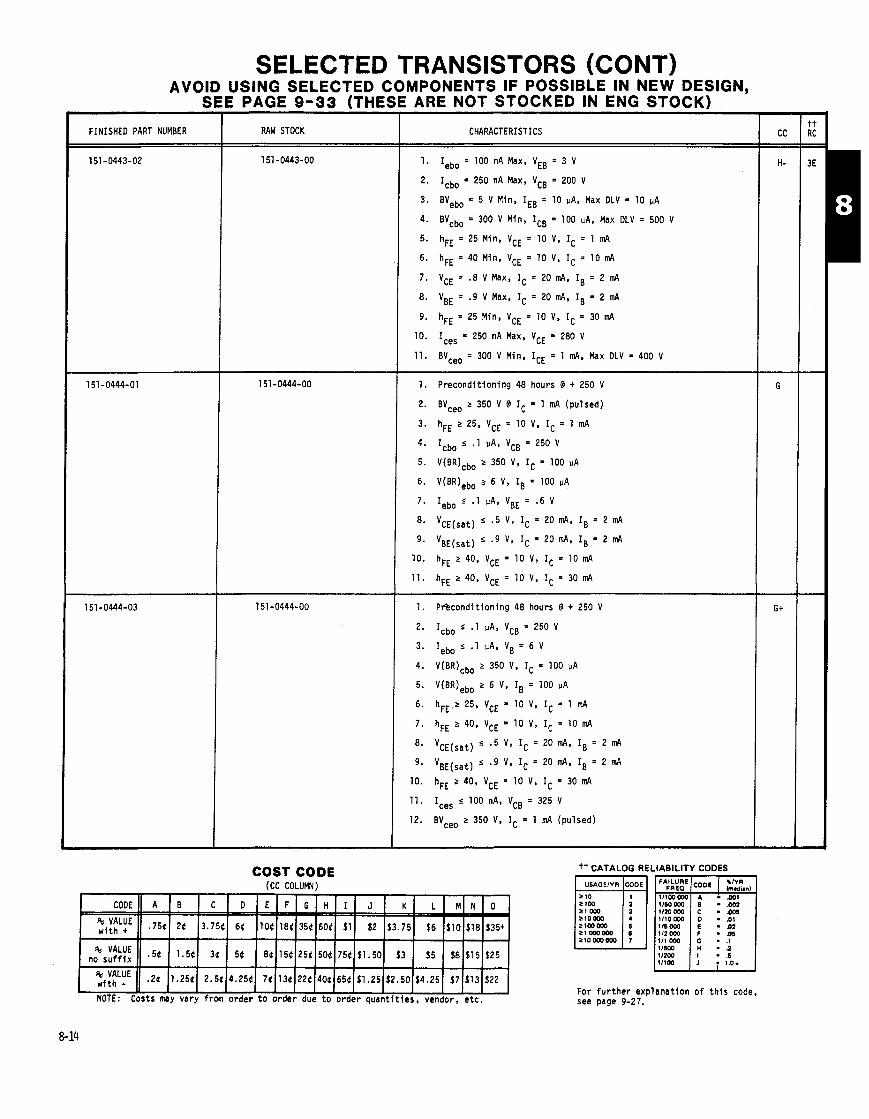
SELECTED TRANSISTORS (CONT) AVOID USING SELECTED COMPONENTS IF POSSIBLE IN NEW DESIGN,
SEE PAGE 9-33 (THESE ARE NOT STOCKED IN ENG STOCK)
RAW STOCK CHARACTERISTICS
1. Iebo = 100 nA Max, VEB = 3 V
2. Icbo = 250 nA Max, VCB = 200 V
3. BVebo = 5 V Min, IEB = 10 vA, Max DLV = 10 pA
4. BVcbo = 300 V Min, ICB = 100 PA, Max DLV = 500 V
5. hFE = 25 Min. VCE = 10 V, IC = 1 mA
6. hFE = 40 Min, VCE = 10 V, IC = 10 mA
7. VCE = .8 V Max, IC = 20 mA. IB = 2 nd
8. VBE = .9 V Max, IC = 20 mA, IB = 2 mA
9. hFE = 25 Min, VCE = 10 V, IC = 30 mA
10. Ices = 250 nA Max. VCE = 280 V
11. BVceo = 300 V Min, ICE = 1 mA, Max DLV = 400 V
1. Precondi t ion ing 48 hours @ + 250 V
2. BVceo 2 350 V @ IC = 1 mA (pulsed)
3. hFE r 25, VCE = 10 V, IC = 1 mA
4. Icbo s .l PA, VCB = 250 V
5. V(BR)cbo z 350 V, IC = 100 VA
6. V(BR)ebo r 6 V, IB = 100 UA
7 . Iebo s .I PA, VBE = .6 V
8. VCE(sat) 5 .5 V, IC = 20 mA, IB = 2 mA
9. VBE(sat) s .9 V ' IC = 20 mA, IB = 2 mA
10. hFE z 40, VCE = 10 V, IC = 10 mA
11. hFE 2 40, VCE = 10 V, IC = 30 in4
1. P r k o n d i t i o n i n g 48 hours @ + 250 V
2. Icbo s - 1 vA. VCB = 250 V
3. Iebo s .1 PA, VB = 6 V
4. V(BR)cbo r 350 V. IC = 100 PA
5. V(BR)ebo r 6 V, IB = 100 VA
6. hFE z 25, VCE = 10 V. IC = 1 mA
7. hFE 2 40, VCE = 10 V, IC = 10 mA
8. VCE(sat) "5 V, IC = 20 mA, IB = 2 mA
9. VBE(sat) 5 .9 V, IC = 20 in4, IB = 2 mA
-
COST CODE (CC COLUMN)
- - --
--
NOTE: Costs may vary from order t o order due t o order quan t i t i es , vendor, e t c .
+t CATALOG RELIABILITY CODES
*
For f u r t h e r exp lanat ion o f t h i s code, see page 9-27.
10. hFE 2 40, VCE = 10 V, IC = 30 mA
11. Ices s 100 nA, VCB = 325 V
12. BVceo r 350 V, IC = 1 mA (pulsed)
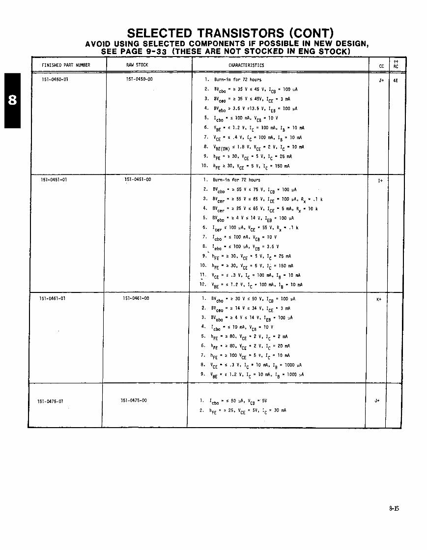
SELECTED TRANSISTORS (CONT) AVOID USING SELECTED COMPONENTS IF POSSIBLE IN NEW DESIGN,
SEE PAGE 9-33 (THESE ARE NOT STOCKED IN ENG STOCK)
I.
-
1 rINISHED PART NUMBER
151-0450-01
151 -0451 -01
151-0461-01
151-0475-01
CHARACTERISTICS
1. Burn-in f o r 72 hours
2. BVcbo = r 35 V s 45 V, ICB = 100 uA
3. BVceo = r 35 V r 45V, ICE = 3 mA
4. BVebo r 3.5 V ~ 1 3 . 5 V, IEB = 100 uA
5. Icbo = "00 nA, VCB = 10 V
6. VBE = s 1.2 V. IC = 100mA. IB = 10mA
7. VCE = s ' 4 V. IC = 100 mA. IB = 10 mA
8. VBE(ON) s 1.8 V, VCE = 2 V, IC = 10 mA
9. hFE = r 30, VCE = 5 V. IC = 25 mA
10. hFE 2 30, VCE = 5 V, IC = 150 mA
1. Burn-in f o r 72 hours
2. BVcba = r 55 V r 75 V, ICB = 100 uA
3. BVcer = r 55 V s 65 V, ICE = 100 PA, R, = .1 k
4. BVcer = r 25 V r 65 V, ICE = 5 mA, Rx = 10 k
5. BVebo = fl V r 14 V, IEB = 100 uA
6. Icer s 100 uA. VCE = 55 V, Rx = .1 k
7. Icbo = "00 nA, VCB = 10 V
8. Iebo = s 100 MA, VEB = 3.5 V L
9. hFE = r 30, VCE = 5 V, IC = 25 mA
10. hFE = 2 30, VCE = 5 V, IC = 150 mA
11. VCE = s .3 V, Ic = 100 Id, IB = 10 mA - 12. VBE = s 1.2 v. Ic = 100 nd, IB = 10 mA
1. BVcbo ' > 30 V s 50 V, ICB = 100 uA
2. BVceo = r 14 V r 34 V. ICE = 3 nd
3. B V e b o = ~ V s 1 4 V , I E B = l O O u A
4. I c b o = ~ l O n A . V c B = l O V
5. hFE = '80, VCE = 2 V, IC = 2 mA
6. hFE = r 80, VCE = 2 V, IC = 20 mA
7. hFE = r 100 VCE = 5 v, IC = 10 mA
8. VCE = s . 3 V. IC = 10 mA. IB = 1000 vA
9. VBE = s 1.2 V, IC = 10 nd, IB = 1000 PA
1. Icbo = s 50 MA, VCB = 5V
2. hFE = 2 25, VCE = 5V, IC = 30 mA
-
RAW STOCK
151 -0450-00
151-0451-00
151 -0461 -00
151-0475-00
. CC
J+
I +
K+
J+
RC tt
4E
.

FINISHED PART NUMBER
SELECTED TRANSISTORS (CONT) AVOID USING SELECTED COMPONENTS IF POSSIBLE IN NEW DESIGN,
SEE PAGE 9-33 (THESE ARE NOT STOCKED IN ENG STOCK)
I RAW STOCK CHARACTERISTICS
1. Burn- in f o r 72 hours
2. BVceo = r 60 V s 70 V, ICE = 30 mA
3. Iceo = slOOO uA, VCE = 30 V
4. Ices = s 700 PA, VCE = 60 V
5. Iebo = ' 1000 PA, VE8 = 5 V
6. hFE > 25, VCE = 4 V, IC = 1500 mA
7. hFE 2 10. VCE = 4 V, IC = 15 A
8. hFE s 50, VCE = 4 V, IC = 15 A
9. VBE(ON) s 2 V, VCE = 4 V, IC = 15 A
10. VCE ' 1.8 V, IC = 15 A, IB = 1500 m4
1. Precond i t ion ing 48 hour @ + 50 V
2. hFE 2 10, VCE = 4 V, IC = 3 A (pulsed)
3. VBE 2 1.8 V @ VCE - 4 V, IC = 3 A (pulsed)
4. VCE(sat) s 1.2 V @ IC - 3 A, IB = 375 mA (pulsed)
5. CE z 25, VCE = 4 V, IC = 1 A
90 s .3 mA, VcE = 30 V
7. l , , o s 1 m A , B v E = 5 v
8. VBceo 2 60 V, IC = 30 mA
9. Ice, s .2 mA, VCE = 60 V
Precond i t ion ing 48 hours @ + 250 V + 50 V
Y(BR),,, 2 250 V @ I, = 30 mA (pulsed)
hFE 2 10, VCE = 10 V, IC = 1 A
VCE(;at) s 1 V, IC = 1 A, IB = 200 mA
hFE 2 30, VCE = 10 V, IC = 300 mA
hFE s 150, VCE = 10 V, IC = 300 mA
Ice, s 1 mA, VcE = 150 V
Ices s 1 mA, VcE = 350 V
Iebo ' 1 mA, VEB = 5 v
hFE z 30, VCE = 10 V, IC = 300 mA
Burn- in f o r 72 hours
BVcbo = 2 300 V s 320 V, ICB = 100 IIA
BVceo = 2 300 V s 320 V. ICE = 1000 uA
BVebo = 2 5 V s 15 V, IEB = 100 PA
Icbo = s 200 nA, VCB = 200 V
Iebo = s 100 nA. VEB = 3 V
VBE(,,) s .85 V. VcE = 10 V, Ic = 30 mA
VCE = s .75 V, IC = 30 m4. IB = 3 m4
hFE z 25, VCE = 10 V, IC = 1000 PA
hFE 2 40, VCE = 10 V, IC = 30 mA
hFE s 180.2, VCE = 10 V, IC = 30 m4
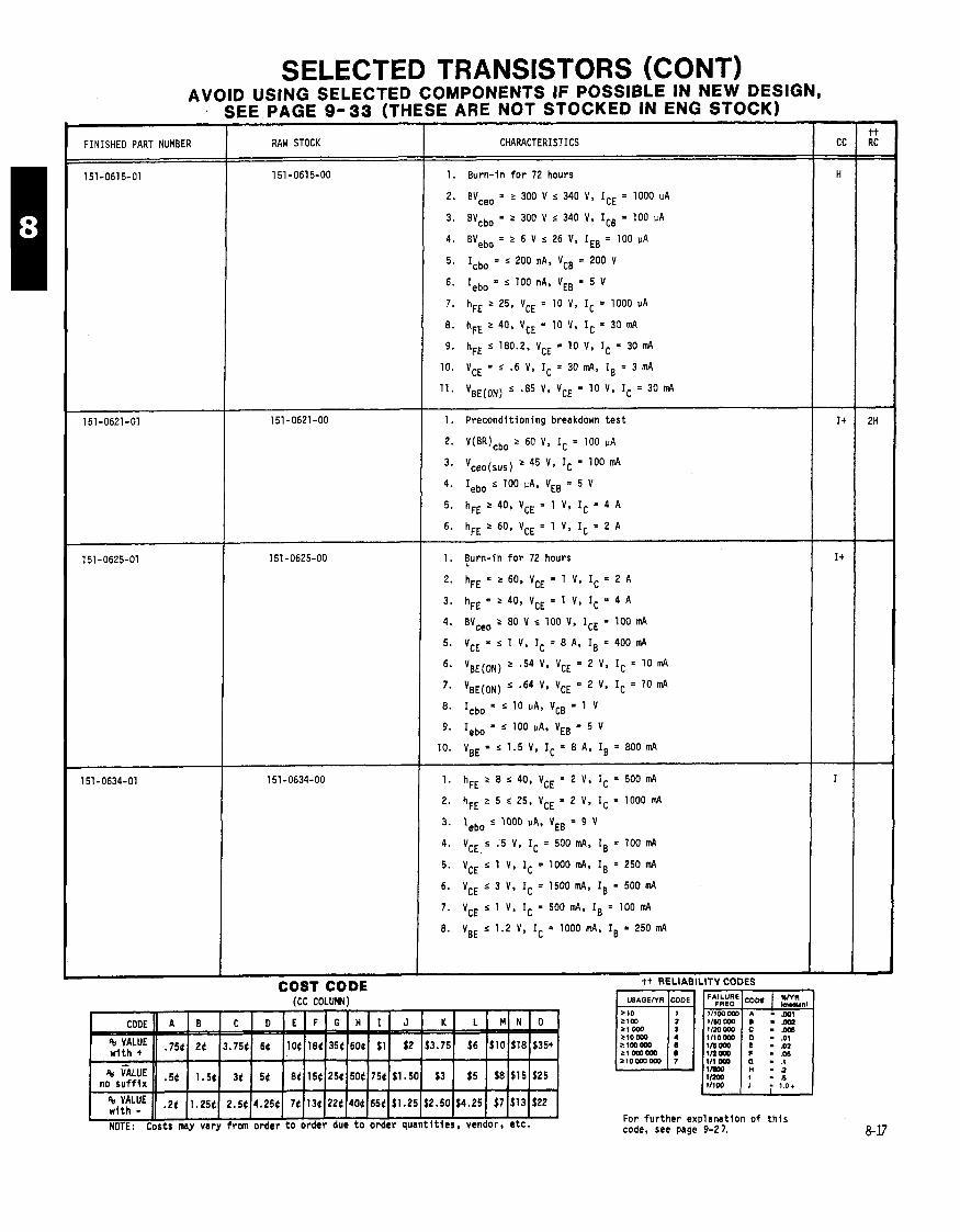
SELECTED TRANSISTORS (CONT) AVOID USING SELECTED COMPONENTS IF POSSIBLE IN NEW DESIGN,
SEE PAGE 9-33 (THESE ARE NOT STOCKED IN ENG STOCK)
FINISHED PART NUMBER RAW STOCK
151-0615-00
(CC COLUMY)
CHARACTERISTICS -
1. Burn-in f o r 72 hours
2. BVceo = r 300 V 5 340 V. ICE = 1000 PA
3. BYcbo = z 300 V s 340 V, ICB = 100 PA
4. BVebo = r 6 V s 26 V. IEB = 100 PA
5. Icbo = s 200 nA, VCB = 200 V
6. Iebo = s 100 nA, VEB = 5 V
7, hFE 2 25. VCE = 10 V, lC = 1000 vA
8. hFE 2 40, VCE = 10 V, = 30 mA
9. hFE s 180.2, VCE = 10 V, IC = 30 mA
10. VCE = < .6 V, IC = 30 mA, IB = 3 mA
11. VBE(ON) s .85 V, VCE = 10 V, IC = 30 m4
1. Precondit ioning breakdown t e s t
2. V(BR)cbo r 60 V, IC = 100 PA
3. Vceo(sus) r 45 V, IC = 100 mA
4. Iebo s 100 PA. VEB = 5 V
5 . hFE 2 40. VCE = 1 V, IC = 4 A
6. hFE r 60, VCE = 1 V. IC = 2 A
1. !urn-in f o r 72 hours
2. hFE = r 60, VCE = 1 V, IC = 2 A
3. hFE = 2 40, VCE = 1 V, IC = 4 A
4. BYceo 2 80 V s 100 V, ICE = 100 mA
5. VCE = s 1 V, IC = 8 A, IB = 400 m4
6. VBE(ON) 2 .54 V, VCE = 2 V, IC = 10 mA
7. VBE(ON) < '64 V, VCE = 2 V, IC = 10 m4
8. ICb0 = ' 10 PA, VCB = 1 V
9. Iebo = s 100 IIA. VEB = 5 V
10. VBE = s 1.5 V, IC = 8 A, IB = 800 m4
t t RELIABILITY CODES
For f u r t h e r explanst lon o f t h i s code, see page 9-2 7.
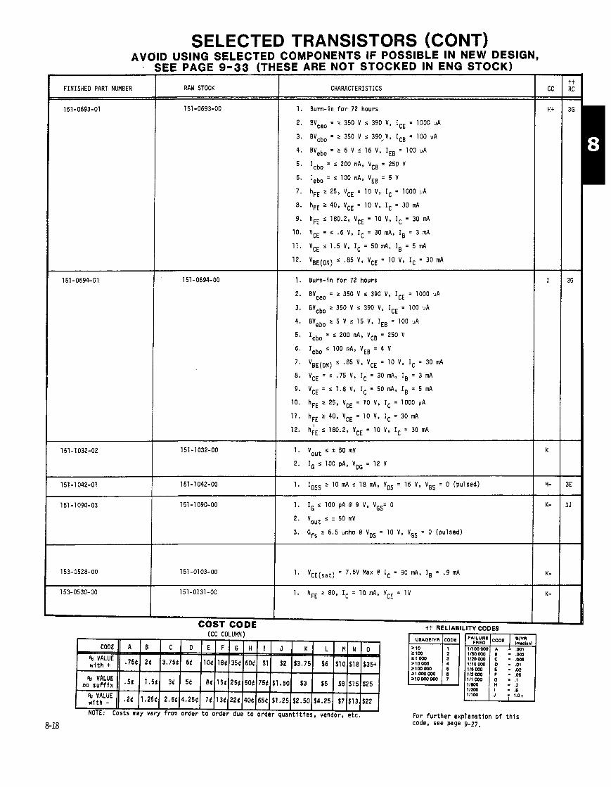
:SE ARE NOT STOCKED IN ENG STOCK)
RAW STOCK
151 -0693-00
CHARACTERISTICS
1. Burn- in f o r 72 hours
2. BVceo = r 350 V s 390 V, ICE = 1000 PA
3. BVcbo = 5 350 V r 390,V, ICB = 100 vA
4. BVebo = 2 6 V r 16 V, IEB = 100 PA
5. Icbo = s 200 nA, VCB = 250 V
6. Iebo = r 100 nA, VEB = 5 V
7. hFE 5 25, VCE = 10 V, IC = 1000 PA
8. hFE 2 40, VCE = 10 V, IC = 30 mA
9. hFE r 180.2, VCE = 10 V, IC = 30 mA
10. VCE = s ' 6 V, IC = 30 mA, IB = 3 mA
11. VCE r 1.5 V, IC = 50mA, IB = 5 d
12. VBE(ON) s .85 V, VCE = 10 V, IC = 30 mA
1. Burn- in f o r 72 hours
2. BYceo = 2 350 V r 390 V, ICE = 1000 uA
3. BYcbo 2 350 V s 390 V, ICE = 100 PA
4. BVebo 2 5 V s 15 V, IEB = 100 PA
5. Icbo = r 200 nA, VCB = 250 V
6. Iebo s 100 nA, VEB = 4 V
7. VBE(ON) < .85 V, VCE = 10 V. IC = 30 mPI
8. VCE = s ' 7 5 V, IC = 30 mA, IB = 3 mA
9. VCE = s 1.8 V, IC = 50 mA, IB = 5 mA
10. hFE 2 25, VCE = 10 V, IC = 1000 PA
11. hFE 2 40, VCE = 10 V, IC = 30 d
12. h;E s 180.2, VCE = 10 V, IC = 30 mA
- -
1. IDSS r 10 mA s 18 mA, VDS = 15 V, VGS = 0 (pulsed)
1. I G s 1 0 0 p A @ 9 V , V G S = 0
2. Vout 5 ' 50 mV
3. Gfs 2 6.5 vmho 13 VDS = 10 V, VGS = 0 (pulsed)
1. VCE(sat) = 7.5V Max @ IC = 90 mPI, IB = .9 mA
For f u r t h e r exp lanat ion o f t h i s code, see page 9-27,
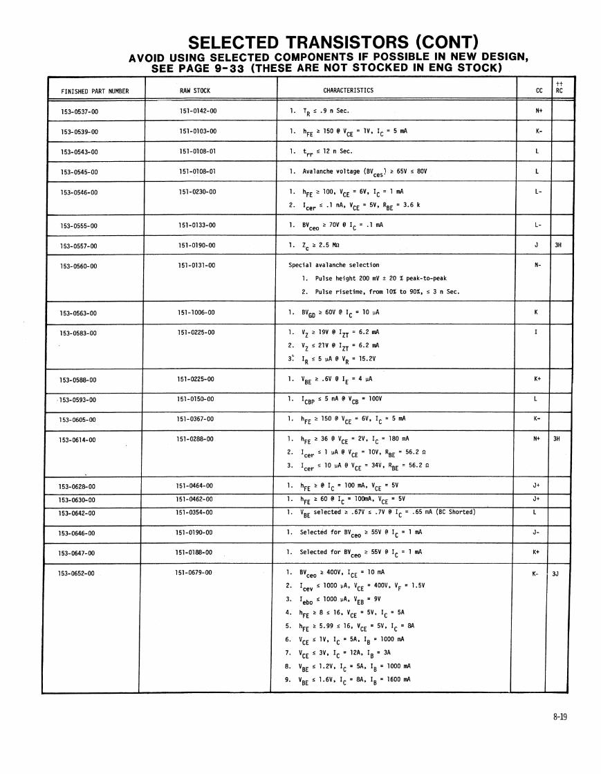
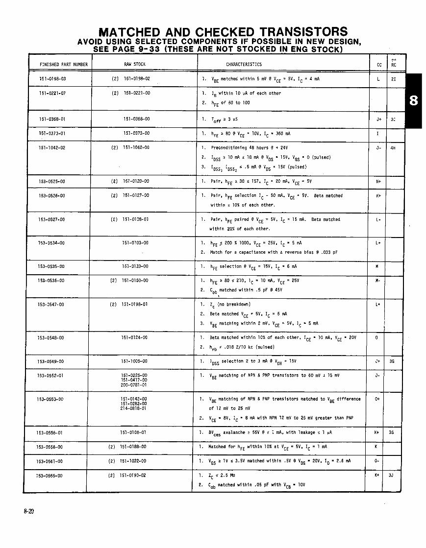
I CHARACTERISTICS
1. VBE matched w i t h i n 5 mV @ VCE = 5V, IC = 4 mA
1. IB w i t h i n 10 VA o f each o ther
2. hFE o f 50 t o 100
1. hFE r 80 @ VCE = 10V, IC = 360 mA
1. Precondi t ion ing 48 hours @ + 24V
2. IDSS "0 mA s 18 mA @ VDS = 15V, VGS = 0 (pulsed)
3. IDSS, IDSS, s .5 mA @ VDS = 15V (pulsed)
1. Pair , hFE r 30 s 157, IC = 20 mA, VCE = 5V -- --
1. Pair , hFE se lec t i on IC - 50 mA, VCE = 5V. Beta matched
w i t h i n + 10% o f each o ther .
1. Pair , hFE pa i red @ VCE = 5V, IC = 15 mA. Beta matched
w i t h i n 20% o f each o ther .
1. hFE 200 % 1000, VCE = 25V, IC = 5 mA
2. Match f o r a capacitance w i t h A reverse b ias @ .033 pF
FINISHED PART NUMBER
15 1-01 98-03
151-0221-07
151-0368-01
151-0373-01
151-1042-02
153-0525-00
153-0526-00
153-0527-00
153-0534-00
153-0535-00
153-0536-00
153-0547-00
153-0548-00
153-0549-00
153-0552-01
153-0553-00
153-0556-01
153-0558-00
153-0561 -00
1. hFE se lec t i on @ VCE = 15V, IC = 6 mA
2. Cob matched w i t h i n . 5 pF @ 45V
AVOID USING SELECTED COMPONENTS IF POSSIBLE IN NEW DESIGN, SEE PAGE 9-33 (THESE ARE NOT STOCKED IN ENG STOCK)
1. Zc (no breakdown)
2. Beta matched VcE = 5V, IC = 5 mA
3. VBE matching w i t h i n 2 mV, VCE = 5V, IC = 5 mA
RAW STOCK
(2 ) 151-0198-02
(2 ) 151-0221-00
1. Beta matched w i t h i n 10% o f each other. ICE = 10 mA, VCE = 20V
-. -,
-.
7-
2. hrb s '018 2/10 kc (pulsed)
1. IDSS selec t i on 2 t o 3 mA @ VDX = 15V
151 -0368-00
151 -0373-00
(2 ) 151-1042-00
(2 ) 151-0120-00
(2) 151-0127-00
(2) 151-0108-01
151-0103-00
151-0133-00
(2) 151-0150-00
(2 ) 151-0198-01
151 -01 24-00
151-1005-00
151 -0225-00 151-041 7-00 200-0781 -01
151 -0142-00 151-0282-00 21 4-081 8-01
151-0108-01
(2 ) 151-0188-00
(2) 151-1022-00
1. VBE matching o f NPN & PNP t r a n s i s t o r s t o 60 mV + 15 mV
-- --
-- --
A-
--
--
--
--
--
-- --
--
-- -- --
1. VBE matching o f NPN & PNP t r a n s i s t o r s matched t o VBE d i f f e rence
o f 12 mV t o 25 mV
2. VCE = 8V. IC 8 mA w i t h NPN 12 mV t o 25 mV greater than PNP
1. BVce, avalanche r 55V @ s 1 mA, w i t h leakage 5 1 VA
1. Matched f o r hFE w i t h i n 10% a t VCE = 5V, IC = 1 mA
153-0565-00 (2) 151-0190-02 1. Zc 5 2.5 Mn
2. Cob matched w l t h i n .05 pF w l t h VCB 1DV


MATCHED AND CHECKED TRANSISTORS (CONT) AVOID USING SELECTED COMPONENTS IF POSSIBLE IN NEW DESIGN,
SEE PAGE 9-33 (THESE ARE NOT STOCKED IN ENG STOCK)
FINISHED PART NUMBE
153-0606-00
153-0607-00
RAW STOCK CHARACTERISTICS CC
I I
I 1. Beta matching, VcE = 6V, It = 15 m~
151-1032-00 I 1. ID selec t i on 11.5 mA t o 14.25 mA i n a 20n totem po le c i r c u i t 1 N+
I w i t h VOG = 9V
(2 ) 151-0271-00 I 1. VBE matched w i t h i n 5 mV @ VCE = 4V, IC = 6 mA
1. hFE 2 80, VCE = 4V, IC = 8 mA
2. hFE s 180. VCE = 4V. IC = 8 mA
3. VBE matched w i t h i n 5 mV @ IC = 10 mA, VCE = 4V
( 2 ) 151-0221-06 w i t h 214-0973-00
1. h F E 2 7 0 s 1 0 0 , V C E = 4 V , I C = 8 m A
2. VBE matching w i t h i n 5 mV @ VCE = 4V, IC = 8 mA
1. hFE 2 70 s 100
2. VBE matching w i t h i n 5 mV
(2) 151-0436-00 1. hFE matching @ VCE = 15V, IC = 100 mA M-
151-01 92-00 151-0410-00
Set o f 4 200-0945-03 200-0945-04 211-0001-00
1. VBE matching w i t h i n 5 mV @ VCE = 5V, IC = 1 mA
2. V e r i f i c a t i o n check
1. hFE range 2 100 s 400
2. VBE matched w i t h i n 5 mV @ VCE = 5V, IC = 5 mA
(2) 151-0108-01 1. BVces avalanche 2 70V s 90V @ 20 UA matched w i t h i n 2V O+
of'each o ther
151-1025-00 1. I D S S 2 8 m A ~ 1 0 m A @ V o G = 6 V J+
151-1078-00 1. r o S S > 1 2 m A @ V o G = 6 V J+
(2 ) 151-0484-00 1. Matching base cu r ren t w i t h i n 20 nA o f each other, K
IC = 100 PA, VCE = 8V
I 2) 151-0223-00 1. V e r i f y i n special c i r c u i t t o * .7V L+ 1 ) 151-0271-00
1. Beta matched w i t h i n 10% o f each o ther
2. VBE matched w i t h i n 5 mV @ IC = 8 mA, VCE = 4V
(2) 151-0462-00 1. hFE 2 40 @ IC = 200 mA, VCE = 5V matched w i t h i n 10% o f L-
I each o ther . I (2) 151-0410-00 1. VBE w i t h i n 10 mV. VCB = 5V, IBE = 150 UA J
151-0441-00 1. IB matched w i t h i n 10 uA @ VCE = 3V, IC = 5 mA L
(2) 151-0282-00 1. V(BR)ced r 21V w i t h a d i f f e rence o f r 2V @ IC = 1 mA and K t
Ic = 10 mA
151-0426-01 1. Storage t ime se lec t i on o f 650 nS Max., matched w i t h i n M-
100 nS o f each other.
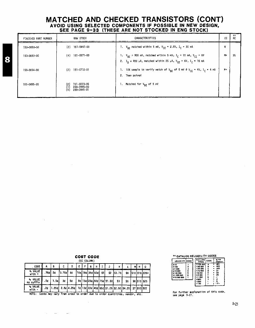
MATCHED AND CHECKED TRANSISTORS (CONT) AVOID USING SELECTED C
SEE PAGE 9-33 (THE:
I FINISHED PART NUMBER RAW STOCK
COST CODE (CC COLUMN)
bMPONENTS IF POSSIBLE IN NEW DESIGN, I ARE NOT STOCKED IN ENG STOCK)
CHARACTER1 STICS
1. VBE matched w i t h i n 5 mV, VCE 2.5V. IC = 30 mA
1. VBE 900 mV, matched w i t h i n 5 mV, IC = 15 mA, VCE = 6V
2. IB s 400 uA, matched w i t h i n 25 PA, VCE = 6V, IC = 15 mA
1. 10% sample t o v e r i f y match o f VBE o f 5 mV @ VCE = 4V, IC = 4 mA
2. Then aired
1. Matched f o r VBE o f 5 mV
tt CATALOG RE i
LIABILITY CODES
For fur ther exp lanat ion o f t h i s code, see page 9-27.

S E C T I O N 9
T A B L E O F C O N T E N T S
C A S E D R A W I N G S , a m a s s n B o 8 n , & 9 - 2 T H R U 9 - 8
C R O S S R E F E R E N C E I N D E X , , , a , 0 a , n , n . 8 , * , a a a , 9 - 9 T H R U 9 - 2 5
T E K P A R T N U M B E R T O V E N D O R N U M B E R , ' , , # , , , , , , . 9 - 9 T H R U 9 - 1 8 J E D E C T O T E K P A R T N U M B E R ~~~~~n~~~~~~~ , , , , , , 9 - 1 9 & 9 - 2 0
M F G , T O T E K P A R T N U M B E R a a 8 , , n n , , , , , , , * , 9 - 2 1 T H R U 9 - 2 5
N O T E S , , ~ t ~ ~ ~ 8 ~ , ~ ~ q ~ ~ ~ ~ ~ r ~ a t , o t , t , ~ a ~ ~ t 8 ~ ~ ~ ~ ~ ~ 9 - 2 6
R E L I A B I L I T Y N O T E S , , , , , , , , , , , , , , , , , , , , , , , , , , , 9 - 2 7 & 9 - 2 8
A P P L I C A T I O N N O T E S , , , , , , , B a n a , , , , I I I 9 - 2 9 T H R U 9 - 3 3
S A F E O P E R A T I N G A R E A & S E C O N D B R E A K D O W N 9 - 2 9 a 9 - 3 0
T O - 2 2 0 H A N D L I N G P R E C A U T I O N S , , , , , , , , , , , , , , , . 9 - 3 1 S T O R A G E T I M E S 8 S A T U R A T I O N V O L T A G E S , , , , , , , , 9 - 3 2
A V O I D U S I N G S E L E C T E D P A R T S , , , , , , , , , , , , , , , , , 9 - 3 3
T O - 2 2 0 M O U N T I N G S Y S T E M F E A T U R E S H I G H V O L T A G E
W I T H S T A N D C A P A B I L I T Y , , , , , , , , , , , , , 9 - 3 4
COST CODE i cc COLUFNl
CATALOG WRITER: NORMA PETERSON, EXT. 2577.
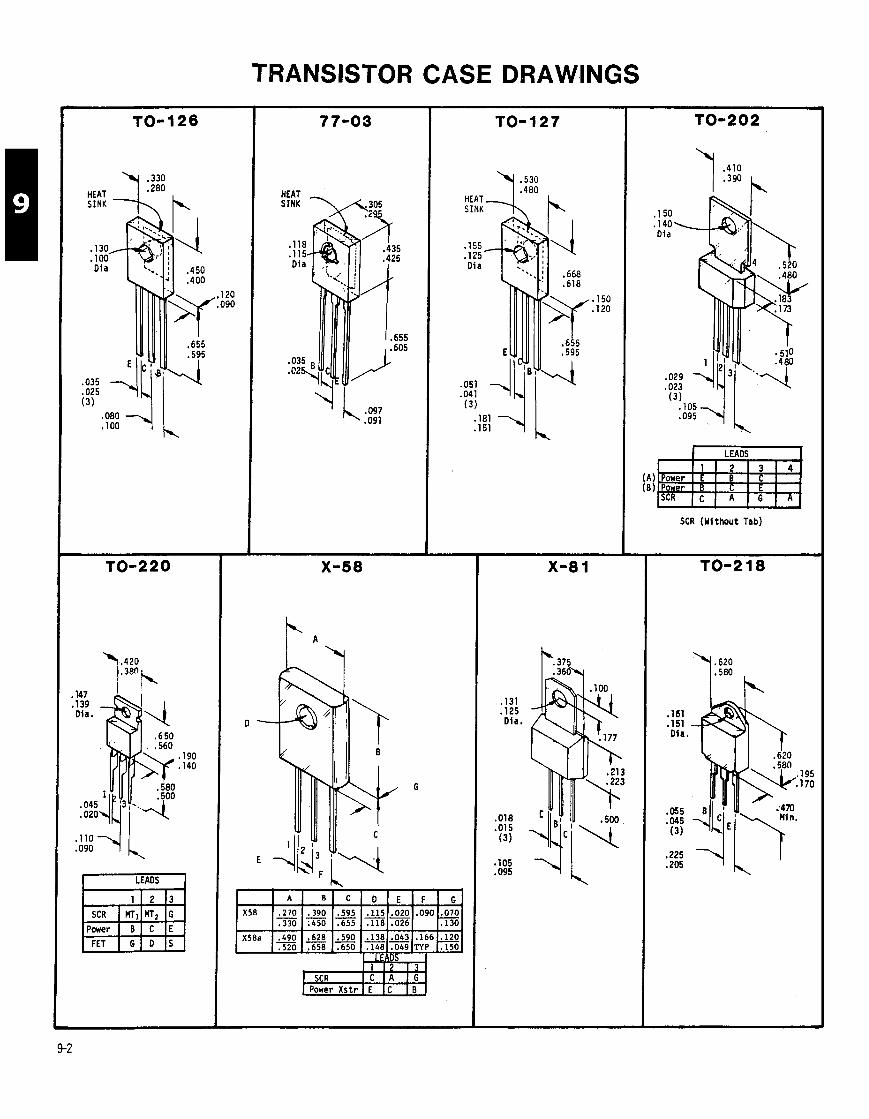
TRANSISTOR CASE DRAWINGS
HEAT ,, S I N K
.I30
.I00 Dia
,120 .090
.035
.025 (3)
,147 .I39 Dia.
.I90
.I40
.045 ,020
1 LEADS I
G D S
HEAT SINK
.I55
.I25 Di a
.05!
.04a (3)
.043 .I66 -120
.049 TYP .I50
,, - 1-1 Power Xstr E
,131 .I25 Dia.
.018
.015 (3)
SCR (Without Tab)
,161 ,151 Dia.
,055 .045 (3 )

TRANSISTOR CASE DRAWINGS (CONT)
BOTTOM VIEW
BOTTOM VIEW
LP;31. has 10-32 tapred munting
holes
BOTTOM VIEW
LEADS
I 1 1 2 1 CASE SCR I C I G I A

TRANSISTOR CASE DRAWINGS (CONT)
B O ~ M VIEW
TO-5C has 4th lead to case TO-5H has metal Header
TO- 18
BOTTOn V I E W
,250-28 UNF 2A
BOTTOn VIEW
4 .050
BOTTOn VIEW
LEADS I BOTTOM V I E W
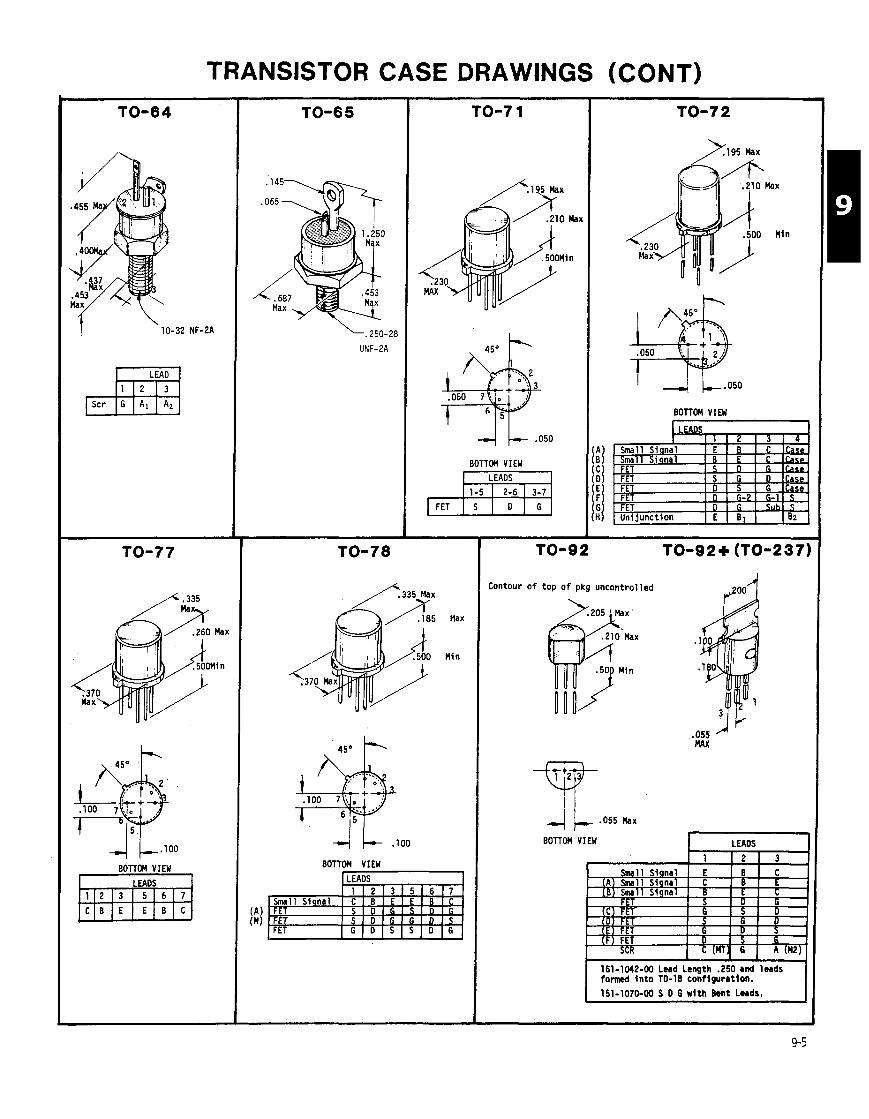
TRANSISTOR CASE DRAWINGS (CONT)
, FJ Scr G Al A2
BOllOM VIEW
\. 250-28
UNF-PA
4 .050
BOTTOM VIEW LEADS , FET ml
I 4 k . 0 5 0
BOTTOM VIEW
LEADS I 1 1 9 1 7 1 A
r
1 151-1070-00 S D 6 with h n t L u d r .
Contour o f top o f pkg uncontrolled 2 0 0 1
, I
BOTTOM VIEW LEADS
b 1 1 2 1 3
151-1042-00 Lwd Length .250 and leads fonned fnto TO-18 conflguratlon.
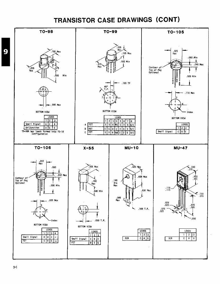
TRANSISTOR CASE DRAWINGS (CONT)
)/190 Max
.SO0 Min I UU, ;
BOTTOM V I M
h a l l Signal E C B
- --
TO-98A has leads formed i n t o TO- Conf igura t ion
ontour o f op o f Pkg p t i ona l
TO- 106
Ma:
+ + ,055 Max * Index
BOTTOM VIEW
BOTTOM VIEW
I LEADS 1
X-55
A 0 5 Max
4 .050 T.P.
BOTTOM VIEW
,148 Dia Max
,049 Max
LEADS
Small S igna l E B C
MU- 10
TO- 105
Max Contour o f Top o f Pkg Opt iona l
. I10 Max
Index I
BOTTOM VIEW
LEADS ,YE1
,166 T.P.
LEADS 7bl LEADS [*I

TRANSISTOR CASE DRAWINGS (CONT)
)/ 8-32 UNC
MICRO T (MICRO 2 3 )
MACRO T
METRIC DIMENSIONS (4
,400 D i a
MICRO X (M100)
METRIC DIMENSIONS
LEADS
MICRO T (MICRO 4 3 )
, 0 1 6 Max
LEADS
MICRO X ( + 3 2 0 )
METRIC DIMENSIONS (mn)
LEADS
C E B

TRANSISTOR CASE DRAWINGS (CONT)
METRIC DIMENSIONS (mn)
.595 Dia
.531 Seating Plane
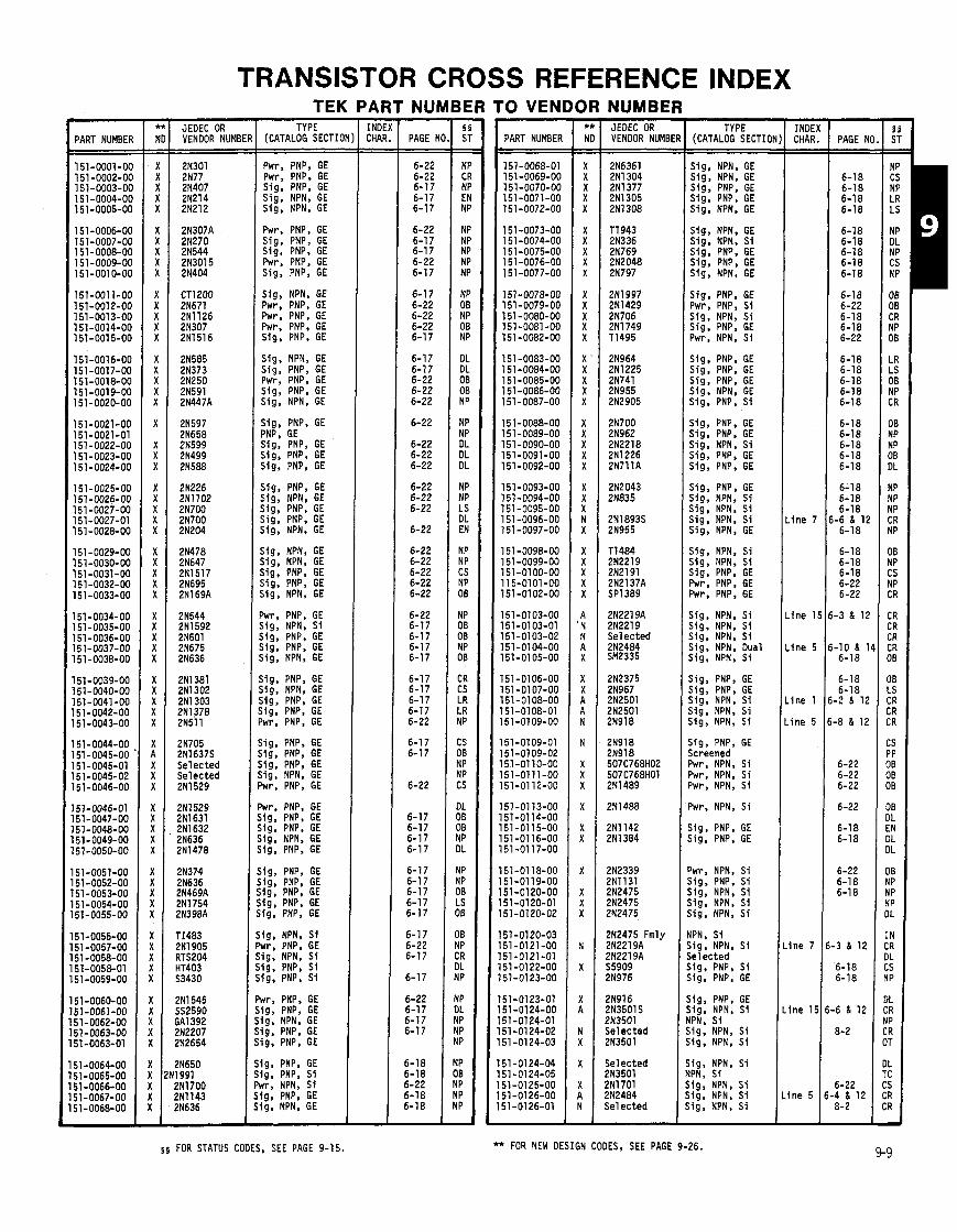
TRANSISTOR CROSS REFERENCE INDEX - PART NUMBER
151-0001-00 151 -0002-00 151-0003-00 151 -0004-00 151-0005-00
151-0006-00 151-0007-00 1 51 - 0008-00 151-0009-00 151-0010-00
151-0011-00 151-0012-00 151-0013-00 151-0014-00 151-0015-00
151-0016-00 151-0017-00 151-0018-00 151-0019-00 151-0020-00
151-0021-00 151-0021-01 151-0022-00 151 -0023-00 151 -0024-00
151-0025-00 151-0026-00 151-0027-00 151-0027-01 151-0028-00
151 -0029-00 151-0030-00 151-0031-00 151-0032-00 151-0033-00
151-0034-00 151-0035-00 151-0036-00 151-0037-00 151-0038-00
151-0039-00 151-0040-00 151-0041-00 151-0042-00 151-0043-00
151-0044-00 151 -0045-00 151-0045-01 151-0045-02 151-0046-00
151-0046-01 51-0047-00 51-0048-00 I 51-0049-00 51-0050-00
51-0051-00 51-0052-00 51 -0053-00 51 -0054-00 51-0055-00
51-0056-00 51 -0057-00 51 -0058-00 51-0058-01 51-0059-00
51-0060-00 51-0061-00 51-0062-00 51-0063-00 51-0063-01
51 -0064-00 51-0065-00 51-0066-00
21705 2N1637S Selected Selected 211 529
2N1529 2N1631 2N1632 2N636 2N1478
TEK PARTNUMBERTO VENDOR NUMBER
(CATALOG. SECTIC
Pwr. PNP. GE ~ w r ; PNP; GE Sig, PNP, GE Sig, NPN, GE Sig, NPN. GE
Pwr, PNP, GE Sig, PNP, GE Sig, PNP. GE Pwr. PNP. GE
Sig, NPN, GE Pwr, PNP, GE Pwr, PNP, GE Pwr, PNP, GE Sig, PNP, GE
Sig, NPN, GE Sig, PNP, GE Pwr. PNP, GE Sig, PNP, GE Sig, NPN, GE
Sig, PNP, GE PNP, GE Sig, PNP, GE Sig, PNP, GE Sig, PNP, GE
Sig, PNP, GE Sig, NPN, GE j ig , PNP. GE j ig , PNP, GE j i g , NPN, GE
j i g , NPN, GE j i g , NPN, GE j ig , PNP, GE j ig , PNP, GE j i g , NPN, GE
Lr, PNP, GE j ig, NPN. Si j ig, PNP, GE i lg , PNP, GE i i g , NPN, GE
i i g , PNP, GE ;ig, NPN. GE i ig, PNP, GE ;ig. PNP, GE 'wr, PNP, GE
~ i g , PNP. GE ,ig, PNP, GE ~ i g . PNP, GE tig, NPN, GE wr, PNP, GE
wr. PNP, GE ig , PNP, GE i g , PNP, GE lg . NPN, GE ig , PNP, GE
ig , PNP, GE ig, PNP, GE ig , PNP. GE i g , PNP. GE ig , PNP, GE
ig . NPN, S i w r , PNP. GE ig, NPN, S i ig. PNP, S i ig, PNP, S i
w , PNP, GE ig, PNP, GE ig, NPN, GE ig, PNP. GE 19. PNP, GE
lg, PNP, GE lg. PNP, S i rr , NPN, S i lg, PNP, GE 19, NPN, GE
s s FOR STATUS CODES, SEE PAGE 9-15.
- PAGE N1
6-22 6-22 6-17 6-17 6-17
6-22 6-17 6-17 6-22 6-17
6-17 6-22 6-22 6-22 6-17
6-17 6-17 6-22 6-22 6-22
6-22
6-22 6-22 6-22
6-22 6-22 6-22
6-22
6-22 6-22 6-22 6-22 6-22
6-22 6-17 6-17 6-17 6-17
6-17 6-17 6-17 6-17 6-22
6-1 7 6-17
6-22
6-17 6-17 6-17 6-17
6-17 6-17 6-17 6-17 6-17
6-17 6-22 6-17
6-17
6-22 6-17 6-17 6-17
6-18 6-18 6-22 6-18 6-18
PART NUMBER
151-0068-01 151-0069-00 151-0070-00 151-0071-00 151-0072-00
151-0073-00 151-0074-00 151-0075-00 151-0076-00 151-0077-00
151-0078-00 151-0079-00 151-0080-00 151-0081-00 151-0082-00
151 -0083-00 151-0084-00 151-0085-00 151-0086-00 151 -0087-00
151-0088-00 151-0089-00 151 -0090-00 151-0091-00 151-0092-00
151-0093-00 151-0094-00 151-0095-00 151 -0096-00 151 -0097-00
151-0098-00 151-0099-00 151-0100-00 11 5-0101-00 151-0102-00
151-0103-00 151-0103-01 151-0103-02 151-0104-00 151-0105-00
151-0106-00 151 -0107-00 151-0108-00 151-01 08-01 151-0109-00
151-0109-01 151 -0109-02 151-0110-00 151-0111-00 151-01 12-00
151-0113-00 151-0114-00 151-0115-00 151-0116-00 151-0117-00
151-01 18-00 151-0119-00 151-0120-00 151-0120-01 151-0120-02
51-0120-03 51-0121-00 51-0121-01 51 -01 22-00 51-0123-00
51-0123-01 51-0124-00 51-0124-01 51-01 24-02 51 -01 24-03
51-0124-04 51-0124-05 51-01 25-00 51-01 26-00 51-0126-01
2N964 2N1225 2N741 2N955 212905
2N700 2N962 2N2218 2N1226 2N711A
2N2043 2N835
2N1893S 2N955
T1484 2N2219 2N2191 2N2137A SP1389
2N2219A 2N2219 Selected 2N2484 SM2335
2N2475 Fmly 2N2219A ?N2219A j5909
?N916 ?N3501S !N3501 ie lec ted !N3501
ie lec ted ?N3501 !NIT01 !N2484 i e l ected
TYPE (CATALOG SECT101
Sig, NPN, GE Siq, NPN, GE sis; PNP; GE Sig, PNP, GE Sig. NPN. GE
Sig, NPN. GE Sig. NPN. Si Sig, PNP, GE Sig, PNP, GE Sig, NPN, GE
Sig, PNP, GE Pwr, PNP, Si Sig, NPN, S i Sig, PNP, GE Pwr, NPN. Si
Sig, PNP, GE Sig, PNP, GE Sig, PNP, GE Sig, NPN, GE Sig, PNP, Si
Sig. PNP. GE Sig, PNP, GE Sig. NPN, Si Sig, PNP, GE Sig, PNP, GE
Sig. PNP, GE Slg, NPN, S i Slg, NPN, Si Sig, NPN, Si Sig, NPN, GE
Sig, NPN, Si Sig, NPN, Si Sig, PNP, GE Pwr, PNP, GE Pwr, PNP. GE
Sig, NPN, Si Sig. NPN, Si Sig, NPN, S i Sig. NPN, Dual Sig, NPN, S i
Sig, PNP, GE Sig, PNP, GE Sig, NPN, Si Sig, NPN, Si Sig, NPN, Si
Sig, PNP. GE Screened Pwr, NPN, S i Pwr, NPN, S i Pwr, NPN, Si
Pwr, NPN, Si
j i g , PNP, GE j i g , PNP. GE
'wr, NPN, Si j i g , PNP. S i j ig , NPN, Si j ig . NPN. S i j ig , NPN, S i
iPN, Si i i g . NPN, Si ie lec ted i i g . PNP, Si i i g , PNP, GE
i i g , PNP, GE i ig . NPN, S1 IPN, Si i ig. NPN. Si ;ig. NPN, S i
; ig, NPN. S i IPN, S i ~ i g , NPN, S i ~ i g , NPN, Si , ig , NPN, Si
** FOR NEW DESIGN CODES, SEE PAGE 9-26.
- INOE CHAR - -
i n e 7
i ne 1
i n e 5
i n e 1
i ne 5
lne 7
ine I !
- PAGE N( - - 6-1 8 6-18 6-18 6-18
6-18 6-18 6-18 6-1 8 6-18
6-18 6-22 6-18 6-18 6-22
6-18 6-18 6-18 6-18 6-18
6-18 6-18 6-18 6-18 6-18
6-1 8 6-18 6-18
-6 & 12 6-18
6-18 6-18 6-18 6-22 6-22
-3 1 12
-10 & 11 6-18
6-18 6-18
-2 & 12
.8 1 12
6-22 6-22 6-22
6-22
6-18 6-18
6-22 6-18 6-18
3 1 12
6-18 6-18
6 1 12
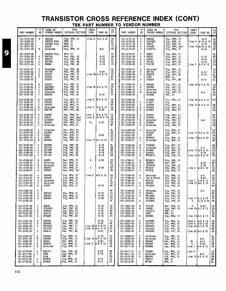
TRANSISTOR CROSS REFERENCE INDEX (CONT)
PART NUMBEF
151-0127-O( 151-0127-01 151-0127-02 151-0127-02 151-0127-04
151-0127-05 151-0128-00 151-0129-00 151-0130-00 151-0131-00
151-0131-01 151-0132-00 151-0133-00 151-0133-01 151-0133-02
151-0133-03 151-0134-00 151-0134-01 151-0134-02 151-0135-00
151-0136-00 151-0136-01 151-0136-02 151-0136-03 151-0137-00
151-0138-00 151-0139-00 151-0139-01 151-0140-00 151-0140-01
151-0140-02 151-0140-03 151-0141-00 151-0141-01 151-0142-00
151-0143-00 151-0144-00 151-0145-00 151-0146-00 151-0147-00
151-0148-00 151-0148-01 151-0148-02 151-0149-00 151-0149-01
151-0150-00 151-0150-01 151-0150-02 151-0150-03 115-0151-00
151-0152-00 151-0153-00 151-0154-00 151-0155-00 151-0156-00
151-0157-00 151-0158-00 151-0159-00 151-0160-00 151-0161-00
151-0162-00 151-0163-00 151 -0164-00 151-0164-01 151-0165-00
51-0166-00 151-0167-00 51-0168-00 51-0169-00 51-0169-01
51-0170-00 51-0171-00 51-0172-00 51-01 73-00 51-0174-00
JEDEC OR VENDOR NUMBE
2N2369 2N2369 Fmly 2N2369 Fmly BSXZO Selected
2N2369 Fmly 212140 2N2207 211 195 21964
Selected 2N2156 2N3251 2N3251 2N3251
2N3251 2N2905A 2N2905A Selected 2N2635
2N3053 2N3053 2N3053 Selected 2N2148
2N2857 2N918 DIm918 2N3055 Selected
Selected 2N3055 40251 40251 214260
2N2996 2N1743 2N1744 2N1745 2N1747
40250 Selected Selected 2N3441 2N3441
2N3440 213440 Selected Selected 2N929
2N2923 2N2924 2N2925
40232 DTG2400 2N3605 2N3137 2N3284
?N3324 !N1899 25T2907 \5T2907 !N3614
!N2923 ?N4260 I0264 !N3439 i e l ec ted
!N2147 :444 lC36 !N3478 !N3403
TEK I TYPE
(CATALOG SECTIC
Sig, NPN, S i NPN, S i NPN. S i NPN; S i Sig, NPN, S i
NPN, S i Pwr, PNP, GE Sig, PNP, GE Sig, PNP, GE Sig, PNP, GE
Sig, PNP, GE Pwr, PNP, GE Sig, PNP, S i Sig, PNP, S i Sig, PNP, S i
Sig, PNP, S i Sig, PNP, S i Sig, PNP, Sf Slg, PNP, S i Sig, PNP, GE
Sig, NPN, S i Sig, NPN, S i Sig, NPN, S i Sig, NPN. S i hr, PNP, GE
Slg. NPN, S i Sig, NPN, Dual Sig, NPN, Dual Pwr, NPN, S i Pwr, NPN. S i
Mr. NPN, S i Jwr, NPN, S i Dwr, NPN, S i 'wr, NPN, S i j ig , PNP, S i
j ig , PNP, GE j ig , PNP, GE 119, PNP, GE ,ig, PNP, GE j ig. PNP, GE
'wr, NPN, S i 'wr, NPN, S i 'wr, NPN. S i 'wr, NPN, S i %r, NPN, Sel
i i g , NPN, St ;ig, NPN, S i ;ig. NPN, S i ; ig, NPN, S i 39, NPN, S i
i g , NPN, S i ,ig, NPN, S i i g , NPN, S i
i g , NPN, S i wr, PNP, GE ig , NPN, S i i g , NPN, S i i g , PNP, GE
i g , PNP, GE wr, NPN, S i !g, PNP, Sf i g , PNP, S i wr, PNP, GE
ig , NPN, S i ig, PNP. S i M r . NPN, S i ig, NPN, S i lg , NPN, S i
rr, PNP. GE lg, NPN. S i YP. GE
1 PI I S' P I . Sig, NPN, S i Sig, NPN, S i
\RT - INDE) CHAR. - -
Line I
L ine 3
L ine 3
.ine 4
.ine 5
.ine 2
.ine 8
15.
. ine I !
4.
3.
i n e 2
i ne 29 i ne 30
Ine 16
lne 3
-
WME - PAGE N(
6-2 & 1:
8- 2
6-22 6-18 6-18 6-18
6-22 6-3 & 15
6-3 & 15
6-18
6-3 & 12
6-3 & 12 6-22
6-5 & 13 6-10 & 1
6-21
6-22
5-7 & 15
6-18 6-18 6-18 6-18 6-18
6-20
6-20
i-6 & 12
6-18
6-18 6-18 6-18
6-18 6-22 6-18 6-18 6-18
6-18 6-22
-3 & 15 -3 & 15
6-22
6-18 -7 & 15 6-22
-6 & 12
6-22 6-18
6-19 6-19 -
1 VEND4
PART NUMBER
3 NUMBER JEOEC OR VENDOR NUMBEF
Selected SM7744 2N2929 ST64 2112207
2N3906 2N3906 Selected Selected 2N3906
2N3904 TE3904 Selected 2N3904 Selected
Selected 2N3904 25301 MPS6521 Selected
TPS6521 Selected 2N3960 2N3959 YPS6515
Selected Ckd & Mtchd rlPS918 ZN3640 YPS3640
Selected 2N3640 YPS3640 rlPS3640 ?N3499S
ie lec ted ie lec ted !N3442 !N3584 !N3866
TYPE (CATALOG SECTIOA
Sig, NPN, S i Sig, NPN. S i Sig, NPN, S i Sig, PNP, Dual Sig, NPN, S i
Sig, NPN, S i Sig, NPN, S i Sig, NPN. S i Sig, PNP, GE Sig, NPN, S i
Sig, NPN, S i S ig , NPN, S i Sig, PNP, GE NPN. S i
Sig, PNP, S i Sig, PNP, S i Sia. PNP. S i
Siq, PNP, S i S i g Sig, NPN, S i Sig, NPN, S i Sig, NPN, S i
Sig, NPN, S i Sig, NPN, S i Sia, NPN, S i si;; NPN; S i Sig, NPN, S i
Sig, NPN, S i Sig, NPN, S i NDN ... .. Sig, NPN, S i Sig, NPN, S i
Sig, NPN, S i Sig, NPN, S i Sig, NPN, S i Sig, NPN, S i Sig, NPN, S i
Sig, NPN, S i Pwr, NPN Sig , PNP, S i Sig, NPN, S i Sig, NPN, S i
Sig, NPN. S i Sig, NPN, S i Sig, NPN, S i Sig, PNP. S i Sig, PNP, S i
Sig, PNP, Sf Sig, PNP, S i Sig, PNP, S i S!g. PNP, S i Sig, NPN, S i
Pwr, NPN. S i Sig, PNP, S i PNP. S i PNP, S i Sig, NPN, S i
Sig, NPN, S i Sig, NPN, S! Sig, PNP, S i Sig, PNP, S i Sig, PNP, S i
Sig, PNP, S i Sig, PNP, S i Pwr, NPN, S i Pwr, NPN, S i Sig. NPN, S i
Sig, NPN, S i Sig, NPN, S i Sig, NPN, S i YPN, S i YPN, S i
CHAR. INDEX I PAGE NO
6-19 L i ne 6 6-10 & 1
6-19 L i ne 14 6-10 & 1
6-19
6-19 6-19 6-19
L i ne 1 6-3 & 12
6-19 6-19
6-19
L i ne 34 6-3 & 15
8-3
L i ne 35 6-3 & 15
L i ne 12 6-3 & 12
i n e 23 6-3 & 15
8-4 10. 6-21
2. 6-20 i n e 1 6-8 & 12
i n e 4
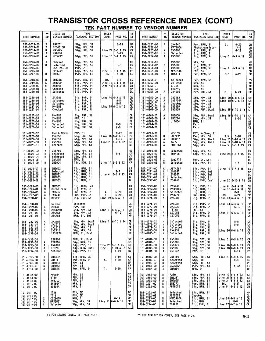
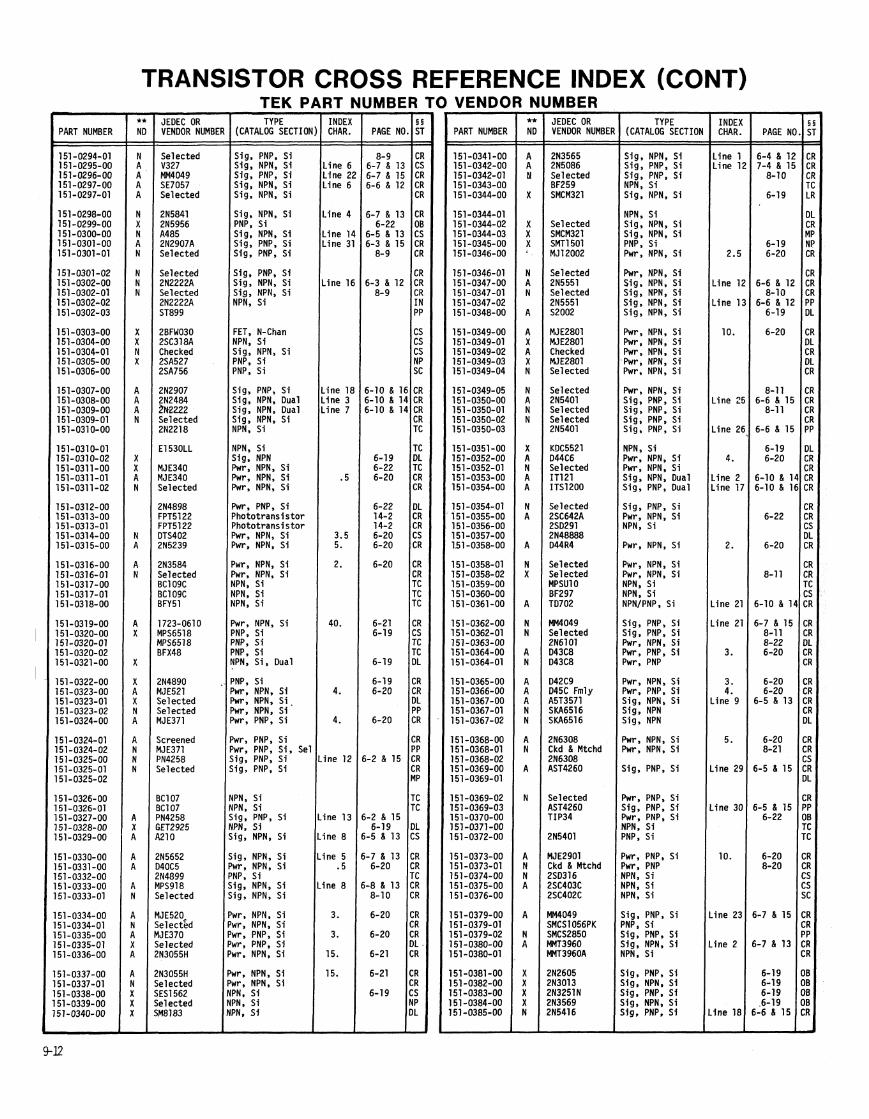
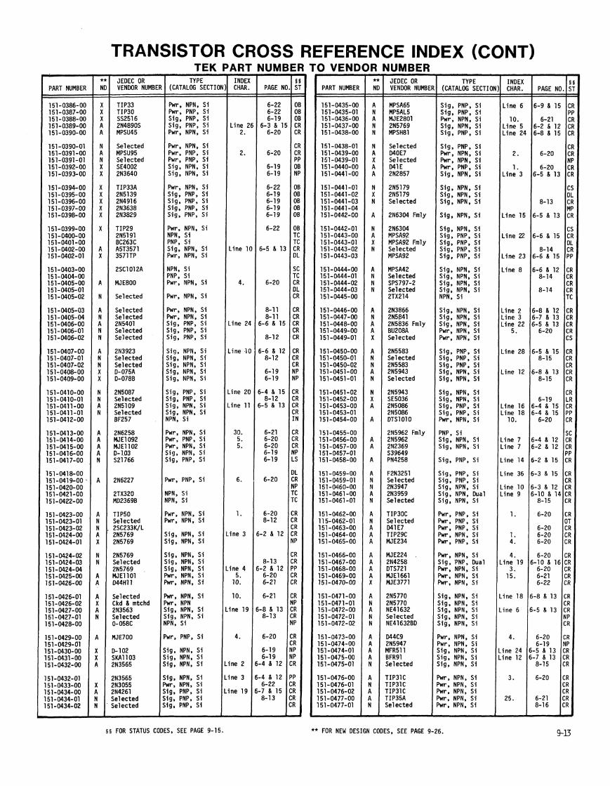
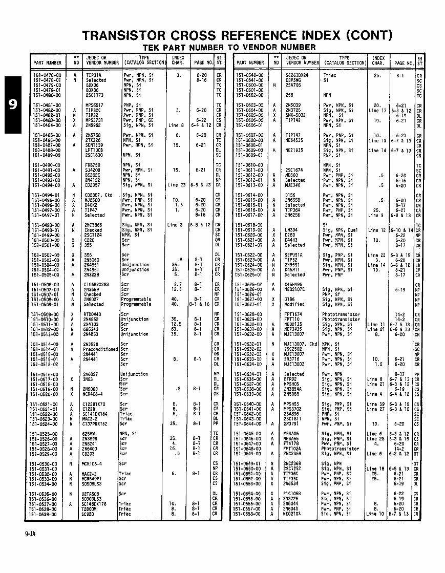
TRANSISTOR CROSS REFERENCE INDEX (CONT)
PART NUMBEf
151-0478-O( 151-0478-01 151-0479-OC 151-0479-01 151~-048o-Oc
151-0481-OC 151-0482-00 151-0482-01 151-0483-00 151-0484-00
151-0485-00 151-0486-00 151-0487-00 151 -0488-00 151-0489-00
151-0490-00 151-0491-00 151-0492-00 151-0493-00 151-0494-00
151-0494-01 151-0495-00 l5l-O496-OO 151-0497-00 151-0497-01
151-0498-00 151-0498-01 151-0499-00 151-0500-00 151-0501-00
151-0502-00 151-0503-00 151-0504-00 151-0504-01 151-0505-00
51-0506-00 51-0507-00 51-0507-01 51-0508-00 51-0508-01
51-0509-00 51-0510-00 51-0511-00 51-0512-00 51-0513-00
51-0514-00 51-0514-01 51-0515-00 51-0515-01 51-0515-02
51-0516-00 51-0517-00 51-0518-00 51-0519-00 51-0520-00
51-0521-00 51-0521-01 51-0522-00 51-0523-00 51-0524-00
51 -0525-00 51 -0526-00 51-0527-00 51-0528-00 51-0529-00
51-0530-00 51-0531-00 51-0532-00 51-0533-00 j1-0534-00
51-0535-00 i1-0536-00 jl-0537-00 11-0538-00 i1-0539-00
TEK JEDEC OR TYPE VENDOR NUMBER (CATALOG SECTIOI
TIP3lA Selected BOX36 BOX36 2SC1173
MPS6517 TIP32C TIP32 MPS3731 2N5962
215758 2TX326 SENT1 39 LPTlOOB 2SC1630
FRB750 SJ4208 BC202C 2N4122 C02357
CD2357, Ckd MJ2500 WOK2 TIP47 Selected
2NC3866 Checked 2SC1124 C220 355
356 !N5060 !N4851 !N4851 !N3228
:106B2X283 iN3669 .hecked !N6027 ielected
IT00440 !N4852 !N4103 85343 !N4853
I Pwr, NPN, Si h, NPN, S i NPN. Si
NPN, Si INPNi PNP, Si Pwr, PNP, S i h. PNP. Si
I ~ w r ; PNP; GE Sig, NPN, Si
Pwr, NPN, Si NPN, S i Pwr, NPN, Si
NPN, S i Pwr, NPN, Si NPN, S i NPN, S i Sig, NPN, Si
Sig, NPN, Si Pwr, PNP, S i Pwr, NPN, Si Pwr, NPN, Si Pwr, NPN, Si
Sig, NPN, Si Sig, NPN, Si NPN. S i Scr Scr
Scr Uni junct ion Uni junct ion
Scr Scr Scr Programnabl e Programnable
Scr Uni j unc t i on Scr Scr Uni j unc t i on
Uni j unc t i on Scr Scr Scr Scr
Scr Scr Tr iac Tr iac Scr
NPN, Si Scr Scr Scr Sc r
Scr
Tr iac Scr Scr
Scr
Triac Tr i ac Trlac
'ART INDEX CHAR. - -
3.
3.
Line 8
6.
15.
15.
L ine 2:
10. 1.5 1.
Line 3
.8 35. 35.
5.
2.7 12.5
40. 40.
35. 12.5 63. 35.
8.
.8
8. 8. 6.
35.
35. 4.
16. .5
6.
10. 8. 8. -
JUM
PAGE P - - 6-20 8-16
6-20
6-22 5-4 & 1
6-20
6-21
6-21
i-5 & 1
6-20 6-20 6-20 8-16
- 8 & 1
8- 1 8- 1 8- 1 8-1
8- 1 8- 1
8- 1 -1 & 11
8- 1 8- 1 8- 1 8- 1
8-1
8- 1
8- 1 8- 1 8- 1
8- 1
8- 1 8- 1 8- 1 8-1
8- 1
8- 1 8- 1 8- 1 -
3 VEND lR NUMBER
PART NUMBER
151-0540-00 151-0541-00 151-0600-00 l5l-O6Ol-OO 151-0602-00
151-0603-00 151 -0604-00 151 -0605-00 151-0606-00 151-0606-01
151-0607-00 151-0608-00 151-0608-01 151-0609-00 151 -0609-01
151-0610-00 151-0611-00 151 -061 2-00 151-0612-01 151-0613-00
151 -061 4-00 151-0615-00 151-0615-01 151 -061 6-00 151 -061 7-00
151-0618-00 151-0619-00 151-0620-00 151 -0621 -00 151-0621-01
151 -0622-00 l5l-O623-OO 151-0624-00 151-0625-00 151 -0625-01
151-0625-02 151 -0626-00 151 -0626-01 151-0627-00 151-0627-01
151 -0628-00 151 -0629-00 l5l-O63O-OO 151-0631-00 151 -0632-00
151 -0632-01 151 -0632-02 151-0632-03 151-0633-00 151 -0634-00
151 -0634-01 5 1 -0636-00 51-0637-00 51-0638-00 51-0639-00
51 -0640-00 51-0641-00 51-0642-00 51 -0643-00 51-0644-00
51 -0645-00 51 -0646-00 51 -0647-00 51 -0648-00 51 -0649-00
51 -0649-01 51 -0650-00 51 -0651 -00 51-0652-00 51-0653-00
51-0654-00 51-0655-00 51 -0656-00 51-0657-00 51-0658-00
JEOEC OR VENDOR NUMBE
2SC1674 MDS60 Selected MJE340
01 56 2N6558 Selected TIP36A 2N6256
LM394 0180 044H3 Selected
92PU51A TIP52 2N5551 045Hll Selected
0186 Modif ied
FPT1674 FPTl 10 NE02135 NE73435 MJE13007
MJE13007, Ckd 2SC2502
Selected BFR92
MPSA06 MPSA55 FT4178 FPTl O2A 2NC2369
2NC2369 2SC1252 TIP36C TIP35C 216534
PIC1068 2N3725 2N6044 ZN6041 YE02103
TYPE (CATALOG SECTION
T r i ac S i
NPN
Pwr, NPN, Si Sig, NPN, Si NPN, Si Pwr, NPN, Si NPN, Si
Pwr. PNP, Si Sig, NPN, Si NPN, Si Sig, NPN, Si PNP, S i
NPN. Si NPN, Si Pwr, PNP, S i Pwr. NPN, Si Pwr, NPN, Si
Pwr, NPN, Si Pwr. NPN, Si Pwr, NPN, Si Pwr, PNP, S i Pwr, NPN, Si
S i Sig, NPN, Dual Pwr, NPN, Si Pwr, NPN, Si Pwr, NPN, Si
Sig, PNP, S i Pwr, NPN. Si Sig, NPN, S i Pwr. PNP, S i Fwr, PNP
Sig, NPN, Si PNP, S i Sig, NPN. Si Sig. NPN, Si
Phototransistor Phototransistor Sig, NPN, Si Sig, NPN, S i Jwr, NPN, Si
YPN, Si YPN, Si 'wr, NPN. Si Jwr, NPN, Si Jwr, NPN, S i
'wr, NPN j ig , NPN, Si zig, NPN, Si ~ i g , NPN, S i j ig , NPN. Si
j ig, PNP, Si j ig , PNP, S i 'NP, S i lPN, S i 'wr, PNP, S i
i i g , NPN, Si ;ig, PNP, S i 'wr, PNP, S i 'hotot rans is tor i i g , NPN, Si
;ig, NPN ;ig, NPN, Si Iwr, PNP, Si 'wr, NPN, Si big, PNP, S i
'wr, NPN, Si ~ i g , NPN, Si Iwr, NPN. Si 'wr, PNP, Si ~ i g , NPN, Si
- INDEX CHAR. - - 25.
20. .ine 17
10.
10. .ine 13
.ine 14
.5
.5
.5.
25. .ine 9
.ine 12
10.
i n e 22 3.
i n e 14 10.
i ne 11 i n e 21
8.
10. 1.5
i ne 8 i ne 21
Ine 4
ine 39 ine 27
10.
ine 6 fne 28
4.
Ine 6
ine 18 25. 25.
8. 8.
Ine 10 -
I PAGE NO. !
8-1 C < C S 7
6-21 C 6-3 & 1 2 C
6-19 E 6-21 C
C
6-21 C 6-7 & 13 C
C 6-7 1 13 C
C
T S
6-20 C 8-16 C 6-20 C
C 6-20 C 8-17 C 6-21 C
6 - 8 & 1 3 C
T 6-10 & 14 C
6-22 N 6-20 C 8-17 CI
6-3 8 15 Cl 6-20 Cl
6 -68 12 CI 6-21 CI 8-17 CI
CI 6-19 NI
NI NI NI
14-2 C I 14-2 CI
5-7 & 13 C I 5-5 8 13 Cf
6-20 Cf
CF S( NF
6-21 CF 6-20 CF
8-17 PF i-7 & 13 CF i-3 & 12 CS
6-19 CS i-4 & 12 CS
i-3 & 15 CS i-3 & 15 CS
SC SC
6-20 CS
i-3 & 12 CR 1-3 6 15 CS
6-20 CR 14-2 CR
1-2 & 12 OT
OT 1-5 1 13 CR
6-21 CR 6-21 CR 6-19 DL
6-22 CS 6-19 CR 6-20 CR
.6-20 CR -7 & 13 CR
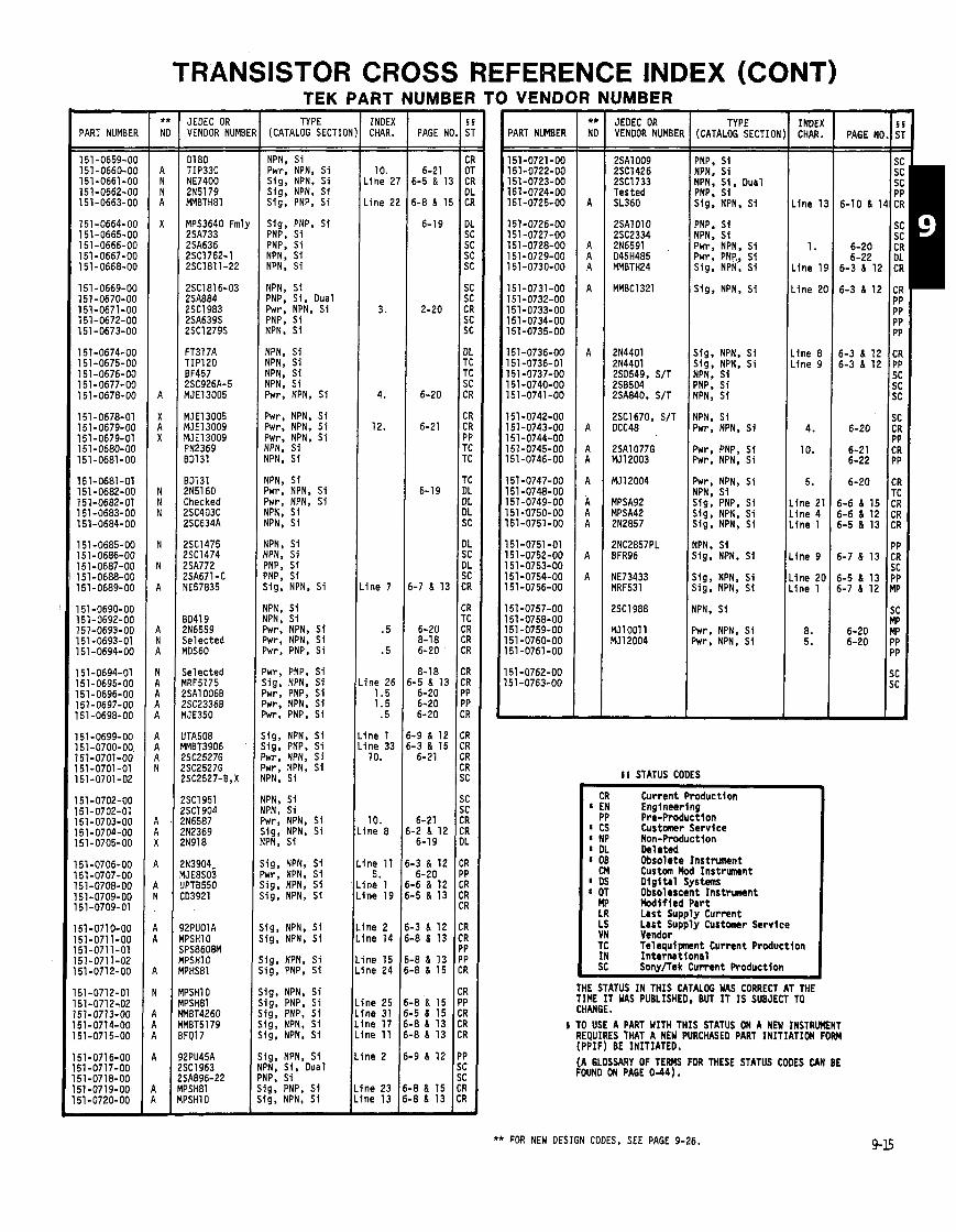
TRANSISTOR CROSS REFERENCE INDEX (CONT) TEK PART NUMBER TO VENDOR NUMBER -
INOEX CHAR. - - 10.
Line 2:
Line 21
3.
4.
12.
i n e 7
.5
.5
i n e 26 1.5 1.5
.5
i n e 1 i ne 33 10.
10. lne 8
lne 11 5.
lne 1 ine 19
ine 2 lne 14
me 15 ne 24
ne 25 ne 31 ne 17 ne 11
I
- PAGE Nl
6-21 6-5 8 1:
6-8 8 I!
6-19
2-20
6-20
6-21
6-19
i-7 8 13
6-20 8-18 6-20
8-18 -5 8 13
6-20 6-20 6-20
-9 8 12 -3 8 15 6-21
6-21 -2 8 12 6-19
-3 8 12 6-20
-6 & 12 -5 8 13
-3 8 12 -8 & 13
-8 8 13 -8 8 15
4 8 15 .5 (1 15 .8 8 13 4 8 13
- INOEX CHAR. - -
Line 1:
1.
L ine 19
L ine 20
Line 8 L ine 9
4.
10.
5.
.ine 21
.ine 4
.ine 1
.ine 9
.ine 20
.ine 1
8. 5.
-
PART NUMBER
151-0659-00 151-0660-00 151-0661-00 151-0662-00 151-0663-00
151-0664-00 151-0665-00 151-0666-00 151-0667-00 151-0668-00
151-0669-00 151-0670-00 151-0671-00 151-0672-00 151-0673-00
151-0674-00 151-0675-00 151-0676-00 151-0677-00 151-0678-00
151 -0678-01 151-0679-00 151-0679-01 151-0680-00 151-0681-00
151-0681-01 151-0682-00 151-0682-01 151 -0683-00 151-0684-00
151-0685-00 151-0686-00 151-0687-00 151-0688-00 151-0689-00
151-0690-00 151-0692-00 151-0693-00 151-0693-01 151-0694-00
151-0694-01 151-0695-00 151-0696-00 151-0697-00 151 -0698-00
51-0699-00 51-0700-00, 51-0701-00 51-0701-01
51-0701-02
51-0702-00 51-0702-01 51 -0703-00 51-0704-00 51-0705-00
51-0706-00 51-0707-00 51-0708-00 51-0709-00 51-0709-01
51-0710-00 51-071 1-00 51-0711-01 51-0711-02 51-0712-00
51-0712-01 51-071 2-02 51-0713-00 51-0714-00 51-0715-00
51-0716-00 51-0717-00 51-0718-00 51-0719-00 51-0720-00
JEDEC OR VENOOR NUMB
01 80 TIP33C NE7400 2N5l79 MMETH8l
MPS3640 Fml, 2SA733 2SA636 2SC1762-1 2SC1811-22
2SC1816-03 2SA884 2SC1983 2SA639S 2SC1279S
FT317A TIP120 BF457 2SC926A-5 MJE13005
MJE13005 MJE13009 MJE13009 PN2369 001 31
B0131 2N5160 Checked 2SC403C 2SC634A
ZSC1475 ZSC1474 2SA772 ZSA671 - C YE57835
3041 9 !N6559 Selected IDS60
Selected IRF5175 !SA1006B !SC2336B IJE350
lTA508 !MET3906 ?SC2527G 'SC2527G 'SC2527-B,X
'SC1951 'SC1904 IN6587 IN2369 'N918
N3904- IJE8S03 PT8550 03921
2PUOlA PSHlO PS8608M PSHl 0 PHs81
PSHlO PSH81 MET4260 MBT51 79 FQ17
2PU45A SCl963 SA896-22 PSH81 PSHlO
TYPE (CATALOG SECTION PART NUMBER
151-0721-00 151-0722-00 151-0723-00 151-0724-00 151-0725-00
151-0726-00 151-0727-00 151-0728-00 151-0729-00 151-0730-00
151-0731-00 151-0732-00 151-0733-00 151 -0734-00 l5l-O735-OO
151-0736-00 151-0736-01 151-0737-00 151-0740-00 151-0741-00
151-0742-00 151-0743-00 151-0744-00 151-0745-00 151-0746-00
151-0747-00 151-0748-00 151-0749-00 151-0750-00 151-0751 -00
151-0751-01 151-0752-00 151-0753-00 151-0754-00 51-0756-00
'51-0757-00 51-0758-00 51 -0759-00 51 -0760-00 51-0761-00
51 -0762-00 51 -0763-00
JEOEC OR VENOOR NUMBEI
TYPE (CATALOG SECTION
NPN, Si 2SA1009 2SC1426 2SC1733 Tested SL360
PNP, S i NPN. S i ~ w r , NPN, S i
Sig, NPN, Si Sig, NPN, Si Sig, PNP, S i
NPN; S i , Dual PNP, S i Sig, NPN. S i
Sig, PNP, S i PNP, Si PNP, Si NPN, Sf NPN, Si
PNP, S i NPN, S i Pwr, NPN. Si Pwr, PNR, Sf Sig, NPN. S i
NPN, Si PNP, Si, Dual Pwr, NPN, SS PNP, Si NPN, S i
Sig. NPN, S i
NPN. S i NPN, Si
Sig. NPN, Sf Sig. NPN, S i NPN, Si PNP, S i NPN, S i
NPN; Si NPN, Si Pwr, NPN, S i
Pwr, NPN, S i Pwr, NPN, S i Pwr, NPN, Si YPN, S i YPN, S i
NPN. S i Pwr, NPN, S i
Pwr, PNP, S i Pwr, NPN, Si
YPN. S i Jwr, NPN, S i Jwr, NPN. S i VPN. Si
Pwr, NPN, Si NPN. S i Sig; PNP, Si Sig, NPN, S i Sig, NPN, Si
(PN, Si IPN, S i 'NP. Si
NPN, Si Sig, NPN, S i
'NP; Si i i g , NPN, S i
Sig, NPN, Si Sig, NPN. S i
IPN, S i IPN, Si 'wr, NPN, S i 'wr, NPN, Si 'wr, PNP, Si
NPN, S i
Pwr, NPN, S i hrr, NPN, Si
'wr, PNP, S i jig, NPN, S i wr, PNP, Si Iwr, NPN, S i wr, PNP, Si
ig , NPN, S i i g , PNP, Si wr, NPN, S i wr. NPN. Si
I S STATUS CODES --
Current Product ion Engineering Pre-Production Customer Service Non-Production Deleted Obsolete Instrument Custm Hod Instrument D i g i t a l Systems Obsolescent Instrument I k d l f l e d Pa r t Last Supply Current Last Supply Customr Service Vendor Telequipnant Current Production In te rna t i ona l Sow/Tek Current Production
PN, Si PN, S i wr, NPN, Si i g , NPN, S i PN, Si
i g , NPN, S i w r , NPN, S i i g , NPN, S i i g , NPN, S i
i g , NPN, S i ig, NPN, S i
ig, NPN, S i ig, PNP, Si
THE STATUS I N THIS CATALOG WAS CORRECT AT THE TIME IT WAS PUBLISHED. BUT I T IS SUBJECT TO CHANGE.
ig, NPN, S i ig, PNP, Si ig, PNP, S i ig, NPN, Si lg, NPN, S i
i TO USE A PART WITH THIS STATUS ON A NEW INSTRUMENT REQUIRES THAT A NEW PURCHASED PART INITIATION FORM (PPIF) BE INITIATED.
ig. NPN, Si 'N, Si, Dual IP. Si g , PNP, S1 g, NPN, S i
L ine 2
L ine 23 L ine 13
(A GLOSSARY OF TERMS FOR THESE STATUS CODES CAN BE FOUND ON PAGE 0-44).
** FOR NEW DESIGN CODES, SEE PAGE 9-26.
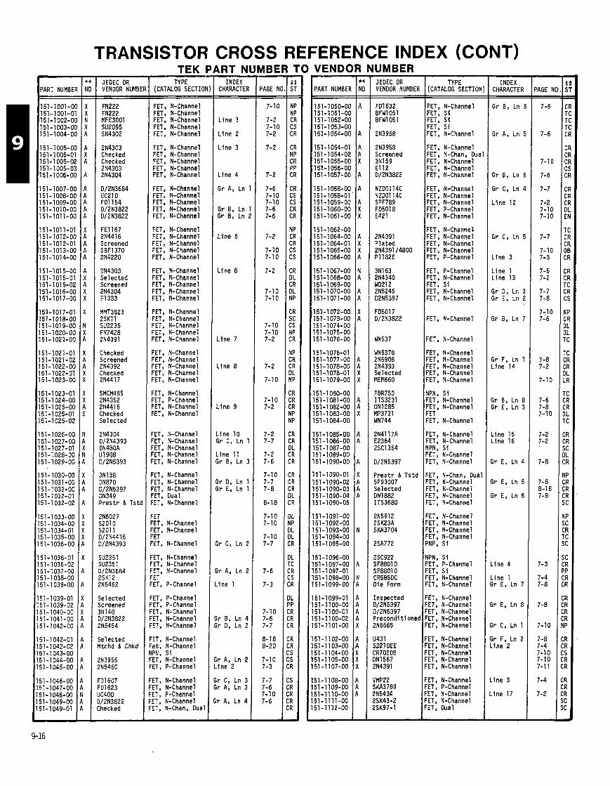
TRANSISTOR CROSS REFERENCE INDEX (CONT) JEDEC OR VENDOR NUMB[
2N4303 Checked Checked 2N4303 2N4304
FE1167 2N4416 Screened SBFl37O 2N4220
2N4303 Se lec ted Screened 2N4304 F1333
Checked Screened 2N4392 Checked 2N4417
SMCM485 214352 2N4416 Checked Se lec ted
3N138 ON870 D/2N5397 DN349 P r e s t r & Tstc
Selected Screened 3N140 3/2N3822 ?N5454
Selected I t c h d & Chkd
TEK I TYPE
(CATALOG SECTIOI
FET, N-Channel FET, N-Channel FET, N-Channel FET, N-Channel FET, N-Channel
FET, N-Channel FET, N-Channel FET, N-Channel FET, N-Channel FET, N-Channel
FET, N-Channel FET, N-Channel FET, N-Channel FET, N-Channel FET, N-Channel
FET, N-Channel FET, N-Channel FET, N-Channel FET, N-Channel FET, N-Channel
FET, N-Channel FET, N-Channel FET. N-Channel FET, N-Channel FET, N-Channel
FET, N-Channel FET, N-Channel FET. N-Channel FET, N-Channel FET, N-Channel
FET, N-Channel FET, N-Channel CET, N-Channel =ET, N-Channel :ET, N-Channel
:ET, N-Channel :ET, N-Channel :ET. N-Channel :ET, Dual :ET, N-Channel
:ET 'ET, N-Channel 'ET, N-Channel 'ET
'ET, N-Channel ET, N-Channel ET, N-Channel ET ET, P-Channel
ET, P-Channel ET, P-Channel ET, N-Channel ET, N-Channel ET, N-Channel
ET, N-Channel e t , N-Channel PN. S i ET; N-Channel ET, P-Channel
ET. N-Channel ET, N-Channel ET, P-Channel ET, N-Channel ET, N-Chan, Dual
\RT N - INDEX
CHARACTER
L i n e 1
L i n e 2
L i n e 3
L i n e 4
Gr A, Ln
Gr B, Ln Gr 8, Ln I
L i n e 5
L i n e 6
L i n e 7
L i n e 8
L ine 9
- i n e 10
r A, Ln 2 i n e 2
JlBE - PAGE N( - -
7-10
7-2 7-10 7-2
7-2
7-2
7-6 7-10 7-10 7-6 7-6
7-2
7-10 7-10
7-2
7-10 7-10
7-10 7-10 7-2
7-2
7-10
7-10 7-2
7-2 7-7
7-2 7-6
7-10 7-7 7-8
8-18
7-10 7-10
7-1 0 7-7
7-6
7- 3
7-1 0 7-6 7-7
8-18 8-20
7-10 7-3
7-7 7-6 7-10 7-6
-
VENDOR NUMBER - - - - -
PART NUMBER
151-1050-00 151-1051-00 151 -1 052-00 151-1053-00 151-1054-00
151-1054-01 151 -1054-02 151-1055-00 151-1056-00 151-1057-00
151-1058-00 151-1058-01 151-1059-00 151-1060-00 151-1061-00
FD1632 BFW1051 BFW1051
2N3958
2N3958 Screened 3N159 El12 D/2N3822
NZD01 l4C NZD0114C SPF789 FD5018 E421
2N4391 P l a t e d 2N439114800 P1182E
3N163 2N4340 WD212 2N5245 D2N5397
FD5017 Dl2N3822
WN537
WN537B 2N5908 2N4393 Selected MEM660
FBR750 ITS3231 ON1 285 MP3731 WN744
2N4117A E2364 2SC1364
112N5397
JEDEC OR VENDOR NUMBER
FET, N-Channel FET, S i FET, S i FET, S i FET, N-Channel
TYPE (CATALOG SECTIOP
FET, N-Channel FET, N-Chan, Dua FET, N-Channel FET, N-Channel FET, N-Channel
I
FET, N-Channel FET, N-Channel FET, N-Channel FET, P-Channel FET, N-Channel
FET, N-Channei FET, N-Channel FET, N-Channel FET, N-Channel FET, P-Channel
FET, P-Channel FET, N-Channel FET, S i FET, N-Channel FET, N-Channel
FET, N-Channel
FET, N-Channel FET, N-Channel FET, N-Channel FET, N-Channel FET, N-Channel
NPN, S i FET, N-Channel FET, N-Channel FET FET, N-Channel
I FET, N-Channel FET, N-Channel NPN; s i FET, N-Channel FET, N-Channel
D r e s t r & T s t d SF93007 Selected DN1882 ITS3680
FET, N-Chan, Dua FET. N-Channel FET, N-Channel FET, N-Channel FET, N-Channel
2N5912 !SK23A SKA3704
!SA772
Inspected 1/2N5397 )/2N5397 ' recondi t ionc !N5565
1431 lD2l OEE :R702DB IN1567 !N4391
IMP22 iKA3789 IN5434 !SK43-2 ISK97-1
FET, N-Channel FET, N-Channel FET, N-Channel FET, N-Channel PNP, S i
!SC922 SF8801 0 SF8801 0 :R585DC l i e Form
NPN, S i FET, P-Channel FET, S i FET, N-Channel FET, N-Channel
FET, N-Channel FET, N-Channel FET, N-Channel FET, N-Channel FET, N-Channel
!d
FET, N-Channel FET, P-Channel FET, N-Channel FET, N-Channel FET, Dual
FET, N-Channel FET, N-Channel FET, N-Channel FET, N-Channel FET, N-Channel
INDEX CHARACTER
Gr B, L n !
Gr A, Ln E
Gr B, Ln e
Gr C, Ln 4
L i n e 12
Gr C, Ln 5
L i n e 3
L i n e 1 L i n e 13
Gr 0, Ln 3 Gr E, Ln 2
Gr B, Ln 7
Gr F, Ln 1 L i n e 14
Gr 8, Ln 8 Gr E, Ln 3
L i n e 15 L i n e 16
G r E, Ln 4
Gr E, Ln 5
G r E, Ln 6
- i n e 4
Line 1 ;r E, Ln 7
;r E, Ln 8
;r C, Ln 1
;r F, Ln 2 .ine 2
. ine 3
. ine 17
- 'AGE Nl =
7-6
7-6
7-1 0
7-6
7-7
7-2 7-10 7-10
7-7
7-10 7-3
7-5 7-2
7-7 7-8
7-10 7-6
7-8 7-2
7-10
7-6 7-8 7-10
7-2 7-2
7-8
7-8 8-18 7-8
7-3
7-4 7-8
7-8
7-10
7-8 7-4 7-10 7-10 7-1 1
7-4
7-2
-

TRANSISTOR CROSS REFERENCE INDEX (CONT) - PART NUMBER
151-1112-01 151-1113-00 151-1114-00 151-1115-00 151-1116-00
151-1117-00 151-1118-00 151-1118-01 151-1119-00 151-1120-00
151-1121-00 151-1122-00 151-1123-00 151-1124-00 151-1125-00
151-1125-01 151-1126-00 151-1127-00 151-1128-00 151-1129-00
151-1130-00 151-1131-00 151-1132-00 151-1133-00 151-1134-00
151-1135-00 151-1136-00 151-1137-00 151-1138-00 151-1139-00
51-1140-00 151-1141-00 51-1142-00 51-1142-01 51-1143-00
51-1143-01 51-1144-00 51-1 145-00 51-1146-00 51-1146-01
51-1147-00 51-1148-00 51-1 149-00 51-1150-00 51-1151-00
51-1152-00 51-1 153-00 51-1154-00 51-1155-00 51-1 156-00
JEDEC OR VENDOR NUMBER
MDl 000 SU2603 SU2603 ITS4000 VPOlO6
NH0167C 90421 7 2N4416 DIE 2N4416, P l t d
U310 2SK121-3 VNOZ . I RF7101MPT3N40
TEK I 1 TYPE (CATALOG SECTIOh
FET, N-Channel FET, N-Channel FET FET, N-Channel FET, N-Channel
FET, N-Channel FET, N-Channel FET, N-Channel FET, N-Channel FET, P-Channel
FET, N-Channel FET, N-Channel FET, N-Channel FET, N-Channel FET, N-Channel
FET, N-Channel FET, N-Channel FET, N-Channel FET, P-Channel NPN, S i
FET, N-Channel FET, N-Channel FET, N-Channel FET. N-Channel FET, N-Channel
FET, N-Channel FET, N-Channel FET, N-Channel FET, N-Channel FET, Oual
NPN, S i FET, N-Channel FET, N-Channel FET. N-Channel FET, N-Channel
FET, N-Channel FET, N-Channel FET, N-Channel FET, N-Channel FET. N-Channel
FET, N-Channel FET, N-Channel FET
:ET, N-Channel :ET, N-Channel :ET, N-Channel :ET, N-Channel IPN, Si
r r STATUS CODES
4RT Nl INDEX
CHARACTER
MBEI - PAGE NC
Gr E, L n !
Gr F, L n :
L ine 4 L ine 2
L ine 5
L ine 18
L ine 6 L ine 3
L ine 7
L ine 8
L ine 10 L ine 11 L ine 12 L ine 13
L ine 14 G r 0, Ln 4 G r E, Ln 1 L ine 19
L ine 15 Line 20
Line 16 .ine 17
.ine 18
- -
. .
IN l n t e h a t i o n a l SC Sony/Tek Current Product ion
THE STATUS IN THIS CATALOG WAS CORRECT AT THE TIME I T UAS PUBLISHED. BUT I T I S SUBJECT TO
Current Product ion Engineering Pre-Production Customer Service Non-Production Deleted Obsolete Instrument C u s t a Hod Instrument D i g i t a l Systms Obsolescent Instrument Hodi f led Pa r t Last Supply Current Last Supply C u s t w r Service Vendor Tel e n u l m n t Current Product ion
i TO USE A PART WITH THIS STATUS ON A NEW INSTRUMENT REQUIRES THAT A NEW PURCHASED PART INITIATION FORM (PPIF) ,BE INITIATED.
0 GLOSSARY OF TERMS FOR THESE STATUS CODES CAN BE FOUND ON PAGE 0-44).
VENDC
PART NUMBER
153-0501-00 153-0502-00 153-0503-00 153-0504-00 153-0505-00
l53-O5O6-OO 153-0507-00 l53-O5O8-OO 153-0509-00 153-0510-00
53-0568-00 53-0569-00 53-0570-00 53-0571 -00 53-0573-00
FOR NEW DE
UMBER BASE P.N.1 VENDOR NUMBE
TYPE (CATALOG SECTION
Selected
Selected
Selected Selected
Matched & Checkec Matched & Checkec
Matched & Checkec Matched & Checkec Selected
Selected
Selected Selected Matched & Checkec Matched & Checkec
Matched & Checkec Selected Matched & Checkec Selected
Selected Selected Selected Selected
Selected Matched & Checked Matched & Checked Matched & Checked Matched & Checked
Matched & Checked
Matched & Checked
Selected Yatched & Checked Selected
qatched L Checked CET (Oual & P r ) Selected latched & Checked
Selected
b t c h e d & Checked latched & Checked
Ctched & Checked latched & Checked
latched L Checked
1-26.
INDEX CHARACTER
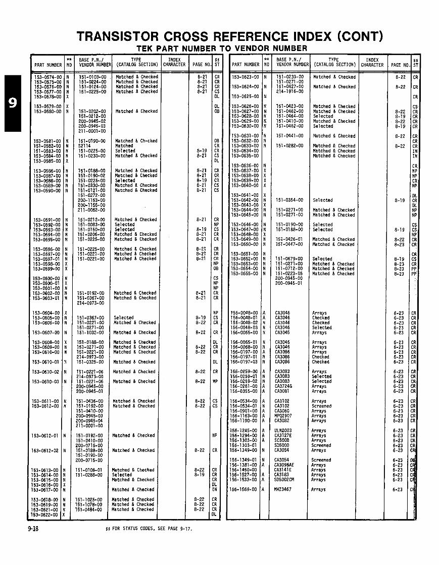
TRANSISTOR CROSS REFERENCE INDEX (CONT)
PART NUMBE
153-0574-0 153-0575-01 153-0576-0 153-0577-01 153-0578-01
153-0579-01 153-0580-01
153-058l-O( 151-0582-01 151-0583-O( 153-0584-O( 153-0585-O(
153-0586-O( 153-0587-O( 153-0588-O( 153-0589-O( 153-0590-O(
153-0591-O( 153-0592-O( 153-0593-01 153-0594-OC 153-0595-OC
153-0596-OC 153-0597-OC 153-0597-01 153-0598-OC 153-0599-OC
153-0600-00 153-0600-01 l53-O6Ol-OO 153-0602-00 153-0603-01
l53-O6O4-OO 153-0605-00 153-0606-00
153-0607-00
153-0608-00 153-0609-00 53-0610-00
53-0610-01
53-0610-02
53-0610-03
53-061 1-00 53-061 2-00
53-061 2-01
53-0612-02
53-0613-00 53-0614-00 53-061 5-00 53-0616-00 53-061 7-00
53-0618-00 53-061 9-00 53-0621-00 53-0622-00
BASE P.N./ VENDOR NUMB1
151-0103-00 151-0224-00 151-0124-00 151-0225-00
151-0202-00 151-0212-00 200-0945-02 200-0945-03 211-0001-00
151 -01 90-00 521 14 151-0225-00 151-0230-00
151-0188-00 151-01 90-02 151-0225-00 151-0330-00 151-0121-00 151-0272-00 200-1 153-00 200-1155-00 211-0062-00
151-0212-00 151-0083-00 151-0150-00 151 -0206-00 151-0225-00
151-0225-00 151-0221-00 151-0221-00
151-0192-00 151-0367-00 214-0973-00
151 -0367-00 151-0221-00 151-0271-00 151-1032-00
151-0188-00 151-0271-00 151-0221-00 21 4-0973-00 151-0325-00
151-0221-06 !14-0973-00 151-0221-06 !OO-0945-00 !OO-0945-01
151-0436-00 151-0192-00 151-0410-00 !OO-0945-03 !OO-0945-04 !11-0001-00
51-0192-00 51-0410-00 '00-071 5-00 51-0188-00 51-0190-00 '00-071 5-00
51-0108-01 51 -0288-00
51-1025-00 51-1078-00 51-0484-00
TEK PART NUMBER TO VENDOR NUMBER TYPE
(CATALOG SECTION
Matched 8 Checkel Matched & Checkel Matched & Checkel Matched & Checkel
Matched & Checkec
Matched & Ch-ckec Matched Selected Matched 8 Checkec
Matched & Checkec Matched & Checkec Selected Matched & Checkec Matched & Checkec
Matched & Checkec Selected Selected Matched & Checked Matched & Checked
Matched & Checked Matched & Checked Yatched & Checked
Yatched & Checked Yatched & Checked
Selected (atched & Checked
latched & Checked
latched 8 Checked latched & Checked latched & Checked
latched & Checked
latched & Checked
latched & Checked
latched & Checked latched 8 Checked
latched & Checked
atched 8 Checked
atched & Checked e lected atched & Checked
atched & Checked
atched & Checked atched & Checked atched & Checked
- INDEX
CHARACTE
5 5 FOR STATUS CODES, SEE PAGE 9-17.
- PAGE \ - 7
8-21 8-21 8-21 8-21
8-19 8-21
8-21 8-21 8-19 8-21 8-21
8-21
8-19 8-21 8-21
8-21 8-21 8-21
8-21 8-21
8-19 8-22
8-22
8-22 8-22
8-22
8-22
8-22 8-22
8-22
8-22 8-19
8-22 8-22 8-22 -
PART NUMBER
153-0623-00
153-0624-00
153-0625-00
153-0626-00 153-0627-00 153-0628-00 153-0629-00 153-0630-00
153-0631-00 153-0632-00 153-0633-00 153-0634-00 153-0635-00
153-0636-00 153-0637-00 153-0638-00 153-0639-00 153-0640-00
153-0641 -00 153-0642-00 153-0643-00 153-0644-00 153-0645-00
153-0646-00 153-0647-00 153-0648-00 153-0649-00 153-0650-00
53-0651-00 153-0652-00 53-0653-00 53-0654-00 153-0655-00
56-0048-00 56-0048-01 56-0048-02 56-0048-03 56-0065-00
56-0065-01 56-0068-00 56-01 97-00 56-01 97-01 56-0197-03
56-0259-00 56-0259-01 56-0259-02 56-0281-00 56-0355-00
56-0534-00 56-0534-01 56-0901-00 56-1 163-00 56-1 190-00
56-1 245-00 56-1294-00 56-1 303-00 56-1 303-01 56-1349-00
56-1 349-01 56-1381-00 56-1450-00 56-1527-00 56-1 533-00
56-1 569-00
- -
BASE P.N.1 VENDOR NUMB1
151-0233-00 151 -0271 -00 151 -0427-00 214-1916-00
151 -0423-00 151-0462-00 151-0464-00 151-0410-00 151-0462-00
151-0441-00
151-0282-00
151-0354-00
151-0271-00 151-0271-00
151-01 90-00 151-0188-00
151-0426-01 151-0447-00
151 -0679-00 151-0271-00 151-0712-00 151-0223-05 200-0945-00 200-0945-01
CA3046 CA3046 CA3046 CA3046 CA3045
CA3045 CA3046 CA3086 CA3086 CA3086
CA3083 CA3083 CA3083 CA3724G CA3081
CA3102 CA3102 CA3060 MPQ2907 CA3082
ULN2003 CA3l 27E SC5000 SD5000 CA3054
CA3054 CA3096AE CA3141E CAN 83 SO5002CM
YHZ3467
TYPE (CATALOG SECTION:
Matched & Checkec
Matched & Checkec
Matched & Checked Matched & Checked Selected Matched & Checked Selected
Matched & Checked
Matched & Checked Matched & Checked Matched & Checked
Selected
Matched & Checked Matched & Checked
Selected Selected
Matched & Checked Matched & Checked
Selected Matched & Checked Matched & Checked Matched & Checked
Arrays Checked Checked Selected Arrays
Arrays Arrays Arrays Checked Checked
Arrays Selected Selected Arrays Arrays
Arrays Screened Rrrays Rrrays airrays
4rrays b r a y s b r a y s Screened 4rrays
Screened b r a y s l r rays b r a y s l r rays
i r rays
INDEX CHARACTEI
- PAGE Nl - -
8-22
8-22
8-22 8-1 9 8-22 8-1 9
8-22
8-22
8-19
8-19
8-22 8-23
8-1 9 8-23 8-23 8-23
6-23 6-23 6-23 6-23 6-23
6-23 6-23 6-23 6-23 6-23
6-23 6-23 6-23 6-23 6-23
6-23 6-23 6-23 6-23 6-23
6-23 6-23 6-23 6-23 6-23
6-23 6-23 6-23 6-23 6-23
6-23
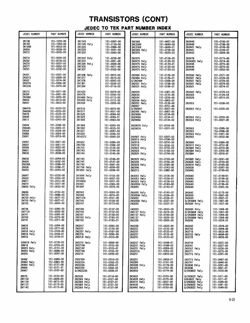
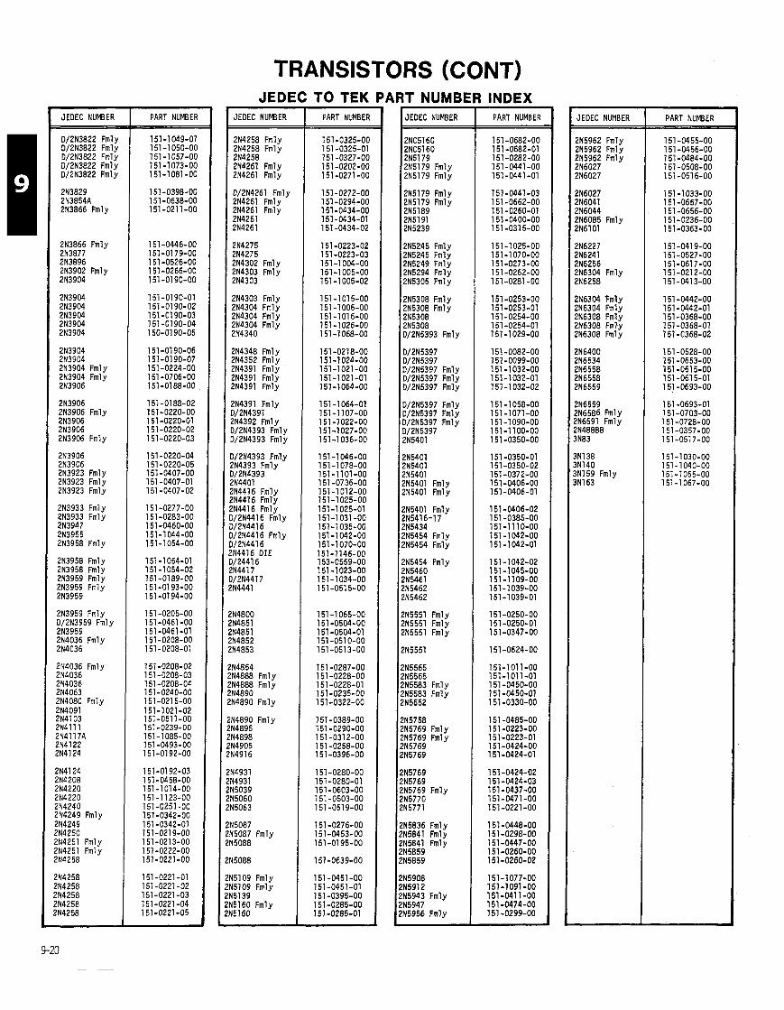
TRANSISTORS (CONT)
JEOEC NUMBER
0/2N3822 Fmly D/2N3822 Fmly 0/2N3822 Fml v ~ / 2 ~ 3 8 2 2 ~ m l i D/2N3822 Fmly
2N3829 2N3854A 2N3866 Fmly
2N3866 Fmly 2N3877 2N3896 2N3902 Fmly 2N3904
2N3904 213904 2N3904 2N3904 2N3904
2N3904 2N3904 2N3904 Fmly 2N3904 Fmly 2N3906
2N3906 2N3906 Fmly 2N3906 2N3906 213906 Fmly
2N3906 2N3906 2N3923 Fmly 2N3923 Fmly 2N3923 Fmly
2N3933 Fmly 2N3933 Fmly 2N3947 2N3955 2N3958 Fmly
2N3958 Fmly 2N3958 Fmly 2N3959 Fmly 2N3959 Fmly 2N3959
2N3959 Fmly 0/2N3959 Fmly 2N3959 2N4036 Fmly 2N4036
2114036 Fmly 2N4036 2N4036 2N4063 2N4080 Fmly 2N4091 ZN4103 2N4111 2N4117A 2N4122 !N4124
!N4240 !N4249 Fmly !N4249 ?N4250 !N4251 Fmly !N4251 Fmly !N4258
PART NUMBER JEOEC NUMBER
2N4258 Fmly 2N4258 Fmly 2N4258 2N4261 Fmly 2N4261 Fmly
0/2N4261 Fmly 2N4261 Fmly 2N4261 Fmly 2N4261
2N4275 2N4275 2N4302 Fmly 2N4303 Fmly 2N4303
2N4303 Fmly 2N4304 Fmly 2N4304 Fmly 2N4304 Fmly 2N4340
2N4348 Fmly 2N4352 Fmly 2N4391 Fmlv 2N4391 ~ m l i 2N4391 Fmly
2N4391 Fmly 0/2N4391 2N4392 Fmlv 0/2N4393 ~ i l ~ 0/2N4393 Fmly
0/2N4393 Fmly 2N4393 Fmly 0/2N4393 2N4401 2N4416 Fmly 214416 Fmly 2N4416 Fmly 0/2N4416 Fmly 0/2N4416 0/2N4416 Fmly 0/2N4416 2N4416 DIE 0/24416 2N4417 D/2N4417 214441
?N4854 !N4888 Fmly ?N4888 Fmly ?N4890 !N4890 Fmly
!N4890 Fmly !N4895 !N4898 !N4905 'N4916
N5087 N5087 Fmly N5088
N5109 Fmly N5109 Fmly N5139 N5160 Fmly N5160
TO TEK PART NUMBER
ART NUMBI 7
JEOEC NUMBER
2NC5160 2NC5160 2N5179 2N5179 Fmly 2N5179 Fmly
1 2 ~ 5 1 7 9 Fmlv
12N5245 Fmlv 2N5245 ~ m l y 2N5249 Fmly 2N5294 Fmly 2N5305 Fmly
2N5308 Fmly 2N5308 Fmly 2N5308 2N5308 0/2N5393 Fmly
0/2N5397 0/2N5397 0/2N5397 Fmly 0/2N5397 Fmly 0/2N5397 Fmly
2N5401 2N5401 2N5401 2N5401 Fmly 2N5401 Fmly
I 2N5401 Fmly 2N5416-17 2N5434 2N5454 Fmly 2N5454 Fmly
12N5454 Fmlv
2N5551 Fmly 2N5551 Fmly 2N5551 Fmly
215565 2N5565 215583 Fmly 2N5583 Fml v
I 2N5758 215769 Fmly 215769 Fmlv
12~5769 2N5769 2N5769 Fmly 215770 2N5771
I 2N5836 Fmly 2N5841 Fmlv
2N5908 2N5912 215943 Fmly 2N5947
I INDEX PART NUMBER JEOEC NUMBER
2N5962 Fmly 2N5962 Fmly 2N5962 Fmly 2N6027 216027
2N6027 2N6041 2N6044 2N6085 Fmly 2N6lOl
2N6227 2N6241 216256 216304 Fmly 2N6258
2N6304 Fmly 2N6304 Fmly 2N6308 Fmly 2N6308 Fmly ZN6308 Fmly
2N6400 2N6534 2N6558 2N6558 2N6559
2N6559 2N6586 Fmly 2N6591 Fmly 2N48888 3N83
3N138 3N140 3N159 Fmly 3N163
PART NUMBER
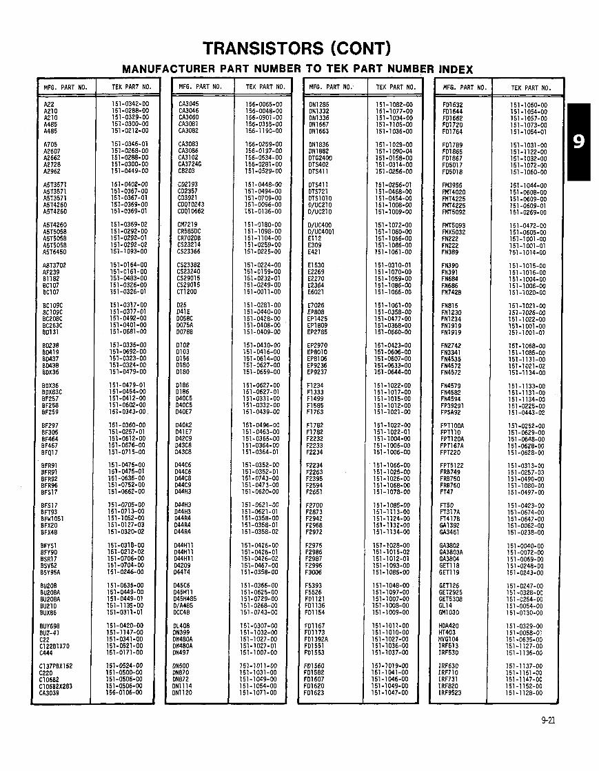
MFG. PART NO.
TRANSISTORS (CONT) MANUFACTURER PART NUMBERTO TEK PARTNUMB R INDEX
TEK PART NO. ==I 151-0342-00
MFG. PART NO. TEK PART NO. MFG. PART NO. TEK PART NO. MFG. PART NO
FD1632 FDl644 FD1662 FD1720 FD1764
FD1789 F01865 FD1867 FD5017 FD5018
FM3955 FMr4020 FMT4225 FMT4225 FMT5092
FMl5093 FMX5032 FN222 FN222 FN389
FN390 FN391 FN684 FN686 FN742B
FN815 FN1230 FN1234 FN1919 FN1919
FN2742 FN3341 FN4535 FN4572 FN4572
FN4579 FN4582 FN4594 FP39291 FPSA92
FPTl OOA FPTl 10 FPTl ZOA FPT167A FPT220
FPT5122 FR8749 FR8750 FR8750 FT47
FT50 FT317A FT4178 GA1392 GA3461
GA3802 GA3803A GA3804 GET1 18 GET1 l 9
TEK PART NO.


MFG. PART NO.
TRANSISTORS (CONT) MANUFACTURERPART NUMBERTOTEK PARTNUMBER INDEX TEK PART NO. TEK PART NO. MFG. PART NO.
SKA8899 SKB8899 SKB3334 SK85574 SKM1029
SKM1103 SL63 Fmly SL63 Fmly SL4049
SL6073A SL41341 SL03733 SL03760 SL04217
SLS363 SM04 SM24 SM483 SM628
SM1307 SM1478 SM1527 SM2218 SM2335
SM2572 3M2602 3M3155 3M3195 3M5801
TEK PART NO. MFG. PART NO. TEK PART NO.
151 -01 09-00 151-0184-00 151 -01 67-00 151 -0121 -00 151 -0124-00
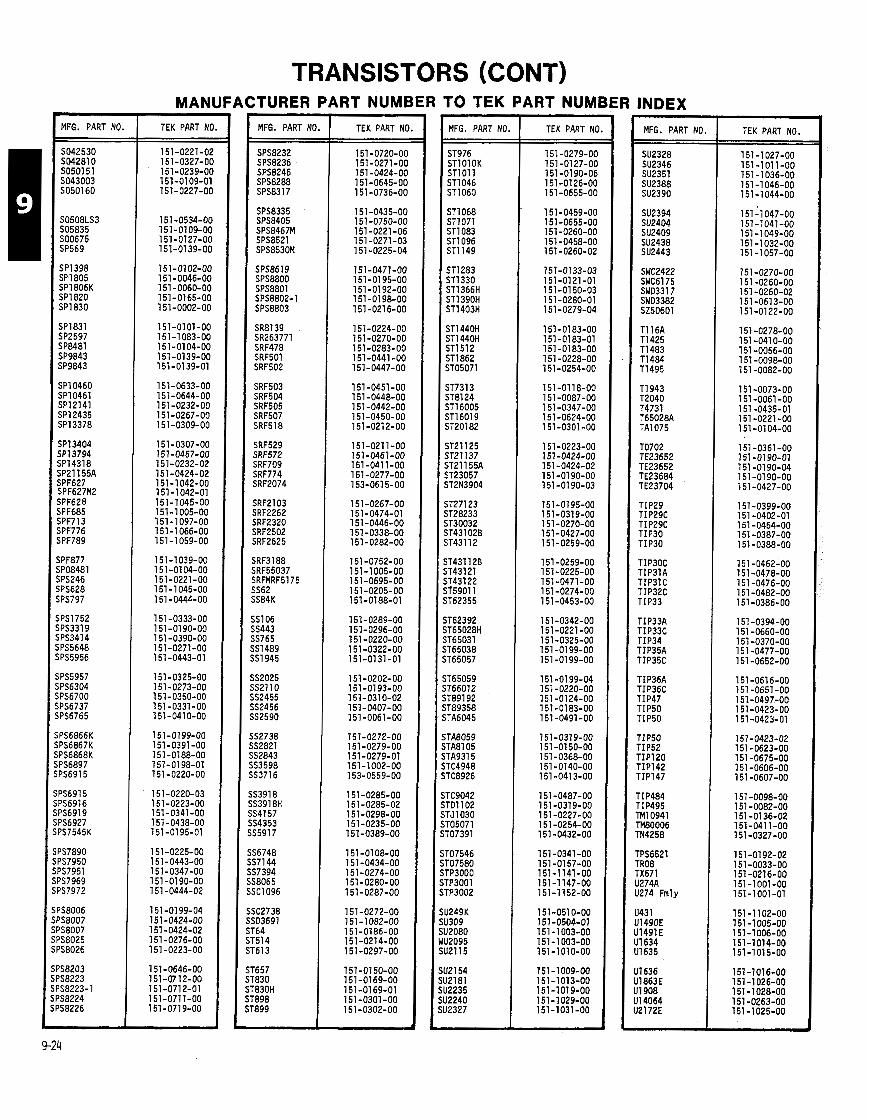
M F G . PART NO.
SO42530 SO4281 0 SO50151 SO43003 SO501 60 t=
TRANSISTORS (CONT) MANUFACTURER PART NUMBER TO TEK PART NUMB
TEK PART NO. M F G . PART NO, TEK PART NO. M F G . PART NO.
ST976 STlOlOK ST1 01 1 ST1 046 ST1060
TEK PART NO.
151 -051 O-OO 151-0504-01 151-1003-00 151-1003-00 151-1010-00
M F G . PART NO.
TO702 TE23652 TE23652 TE23684 TE23704
TIP29 TIP29C TIP29C TIP30 TIP30
TIP30C TIP3lA TIP3lC TIP32C TIP33
TIP33A TIP33C TIP34 TIP35A TIP35C
TIP36A TIP36C TIP47 TIP50 TIP50
TIP50 TIP52 TIP120 TIP142 TIP147
TIP484 TIP495 TM10941 m o o 0 6 TN4258
TPS6521 TR08 TX671 U274A U274 Fmly
U431 U1490E U1491E Ul634 U1635
TEK PART NO.
151 -0278-00 151 -041 O-OO 151 -0056-00 151 -0098-00 151 -0082-00
151 -0073-00 151 -0061 -00 151 -0435-01 151 -0221 -00 151 -01 04-00
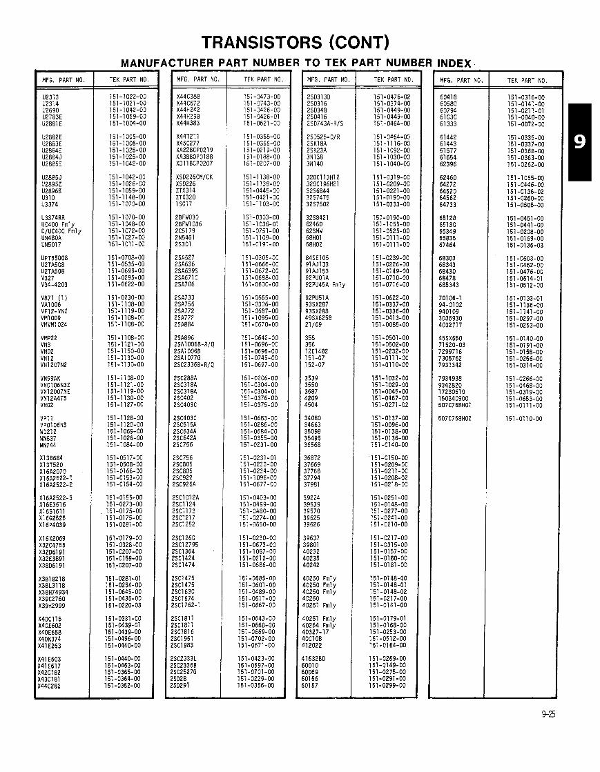
MFG. PART NO.
U3374RR UC400 Fmly DlUC400 Fmly UN480A
TRANSISTORS (CONT) MANUFACTURER PART NUMBER TO TEK PARTNUME
TEK PART NO. MFG. PART NO.
X44C388 X44C672 X44H242 X44H298 X44H383
X44T211 X45C277 XA22BCP0219 XA38BOP0188 XDl l BCP0207
XSD226CM/CK XSD226 ZTX3l4 ZTX32O 1 SO1 7
2BFW030 ZBFW1036 2C5l79 2N5461 2S301
2SA527 2SA636 2SA639S 2SA671 C ZSA706
!SA733 !SA756 %A772 !SA772 !SA884
!SA896 !SA10068-R/Q !SA1006B !SA1077G !SC2336B-R/Q
!SC288A !SC318A !SC318A !SC402 !SC403C
!SC403C ISC515A ISC634A ISC642A 'SC756
SC756 SC805 SC805 SC922 SC926A
SC1012A SCl l24 SC1173 SC1217 SC1252
SC1260 SC12795 SC1364 SC1424 SC1474
SC1475 SC1475 SC1630 SC1674 SC1762-1
3C1811 3C1811 X I 8 1 6 3C1951 iCl983
iC2333L iC2336B iC2527G iD28 iD291
TEK PART NO. MFG. PART NO
84SE105 91AJ133 91AJ153 92PU01A 92PU45A Fmly
0250 Fmly 0250 Fmly 0250 Fmly 0250 0251 Fmly
0251 Fmly 0264 Fmly 0327-1 7 OCl OB 12022
TEK PART NO. MFG. PART NO. TEK PART NO.
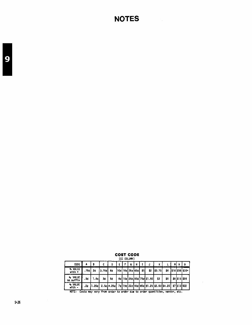
NOTES
COST CODE (CC COLUMN)
NOTE: Costs may vary from order t o order due t o order quant i t ies , vendor, etc.
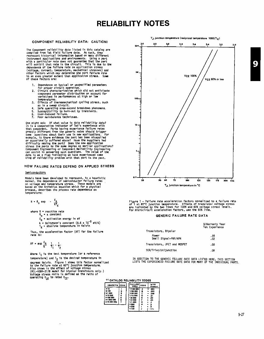
RELIABILITY NOTES
COMPONENT RELIABILITY DATA: CAUTlONl
The Component r e l i a b i l i t y data 1 i s t e d i n t h i s catalog are compiled from Tek f i e l d f a i l u r e data. As such, they represent h i s t o r i c a l information based on many d i f f e r e n t instrument appl icat ions and environments. Using a pa r t wi th a pa r t i cu la r ra te does not guarantee tha t the pa r t w i l l e x h i b i t t ha t ra te i n the c i r c u i t . This i s due t o the dependence o f the f a i l u r e ra te on appl icat ion stress (voltage, current, temperature, mechanical stresses) and other factors which may determine the pa r t f a i l u r e ra te t o an even greater extent than appl icat ion stress. Some o f these factors are:
1. Dependence on t yp ica l o r unspecified parameters f o r proper c i r c u i t operation.
2. C i r c u i t characterizat ion which d id not ant ic ipate component parameter d i s t r i b u t i o n o r account f o r var ia t ions i n performances a t high o r low temperatures.
3. Ef fects o f t h e m e c h a n i c a l cyc l ing stress, such as i n a sweep c i r c u i t .
4. Safe operating area-second breakdown phenomena. 5. Susceot ib i l i t v t o burn-out bv transients. 6. user-induced i a i l u r e . 7. Poor maintenance technizues.
One might ask: Of what value i s t h i s r e l i a b i l i t y data? It i s a comparative ind icator o f Tek's experience wi th tha t component. Parts having experience f a i l u r e rates great ly d i f f e r e n t from the generic rates should t r i gger some questions about t h e i r use i n new appl icat ions. For example, i s there evidence the pa r t has been misapplied o r occasionally suffered abuse? Have the suppl iers had d i f f i c u l t y making the par t? Does the new appl icat ion stress the par ts t o the same degree as e a r l i e r appl icat ions? Component Engineering o r Component R e l i a b i l i t y Engineering can ass is t i n answering such questions. The value o f the data i s as a f l a g ind icat ing we have experienced some kind o f r e l i a b i l i t y problem wi th tha t pa r t i n the past.
HOW FAILURE RATES DEPEND ON APPLIED STRESS
Semi conductors
Models have been developed t o represent, i n a heur i s t i c manner, the dependence o f semiconductor f a i l u r e rates on voltage and temperature stress. These models are based on the Arrhenius equation which for a physical process, describes the process ra te dependence on temperature:
R = R, exp - E~ m~
where R = reaction ra te Ro a constant EA = act ivat ion energy i n eV k = Boltanann's constant (8.6 x eV/K) TK = absolute temperature i n Kelvin
Thus, the accelerat ion factor (AF) f o r the f a i l u r e ra te i s :
AF = exp E~ 1 1 " T;-q
TJ, junction temperature (reciprocal temperature 1 WO/TK)
TJ, junction temperature in OC
Figure 1 - Fai lure ra te accelerat ion factors normalized t o a f a i l u r e ra te of 1 a t 60°C junct ion temperature. Ef fects o f t rans is to r voltage stress are indicated by the two l i nes f o r 100% and 60% voltage stress levels. For m ic roc i r cu i t accelerat ion factors, use the 60% l i ne .
GENERIC FAILURE RATE DATA
%/Warranty Year Tek Experience
Transistors, Bipolar
Power .05 Small Signal-PNP/NPN .02
Transistors, JFET and MOSFET .08
IN ADDITION TO THE GENERIC FAILURE RATE DATA LISTED HERE, THIS SECTION LISTS THE EXPERIENCED FAILURE RATE DATA FOR MANY OF THE INOIVIDUAL PARTS.
Where TI i s the tes t temperature (or a reference temperature) and T2 i s the desired temperature i n
degrees Kelvin. Figure 1 shows t h i s factor normalized t o the f a i l u r e ra te a t 60°C junction temperature. Also shown i s the e f fec t o f voltage stress (MIL-HDBK-2170 model f o r b ipo lar t rans is tors only.) Voltage stress r a t i o i s defined as the r a t i o o f operating VCE t o rated VcE.
tt CATALOG RELIABILITY CODES
. .08

RELIABILITY NOTES Reliability xreenlng for semicduc tor devices
When is it recommended?
Distributions
Semiconductor parameters such as leakage currents, break- down voltages, current gain, threshold voltage, junction capacitances usually are found to be distributed normally (also called Gaussian) if a significant sample is tested.
What about the life of a semiconductor device? Some say that the life is unlimited. However, let's hypothesize that life is a measurable parameter just as any electrical parameter. Would it not be reasonable to exDect the life bf a semiconductor device to also have a normal distribution?
Semiconductor Life Distributions
Experiments have shown that the lives of semiconductors (for a constant junction temperature) are normally distributed as shown in Figure 1. Notice the horizontal scale is the log of time---not a linear function of time.
FIG 1 Life distribution of a typical part (Test temperature of 15O0C T j ) Median life = lo4 hours Standard deviation = 1.5
Multiple Distributions
In the course of some experiments to determine semiconductor device life, multiple distributions are often found (see Figure 2). The secondary distribution that occurs earlier than the main distribution is sometimes called a "freak" distribution when the failure mechanism is the same as failures from the matn distribution.
I 1
Main Distribution
Freak Distribution
101'
FIG 2 Log Normal Distribution
Accelerated life testing is used in order to obtain the necessary data for the log-normal distribution (i.e. the median life and the standard deviation).
In order to establish the presence and position of the freak and main distributions, tests must be continued until approximately 50% of the' units on test fail (failure is defined as not complying with the part specification). This means that life teats are usually performed at or above the maximum junction temperature referred to in the specification. For example, transistor life tests are usually between 150 and 250°c.
Once the median life and standard deviation is found at an elevated temperature, the projected failure rate in a normal use condition can be derived (see Component News No. 236). This projected failure rate can be used to compare the reliability of several vendors or to indicate what benefits would accrue from screening (burn-in).
Application to Part Screening
Component reliability screening can be of significant benefit when :
1. The part type in question has been found by life testing to have a significant freak proportion (over 1%) and,
2. the application calls for junction temperatures of about 75'C or higher ( at 25' C ambient), or when,
3. lowest possible failure rates are needed (out to 10,000 or more hours of instrument operation).
The reason for this is that the freak population is responsible for determining the component failure rate (except for application voltage overstress or user abuse) during the bulk of the instrument useful life. Figure 3 illustrates a typical transistor (151-0103-00, vendor T) failure rate curve for two different junction temperatures. Results are also applicable to the 151-0302-00 because the same chip is used in both part types.
Accelerated life tests showed that thosz parts had a "freak" population of about 5% of the sample with a freak median life of 20 hours. The main population had a median life of 900 hours at the test temperature (245'C)
Instrument Failure Rate for TI 151~0103~00. 151.0302.00
1 & 1 o4 1 66 167 Operating time in hour3
Note the effect of removing the freaks becomes significant only at the higher junction temperature because the useful life of most Tek instruments is probably only about 20,000 hours of actual use (except for TV products which may be up to 100,000 hours). To remove the freaks, a high temperature burn-in is necessary.
Sumary
Component Reliability Engineering can, by using accelerated life tests techniques:
1. Determine whether any significant reliability performance difference exists among vendors in order to qualify vendors with higher reliability (and disqualify those with inferior reliability) or merely to provide a reliability related input to a vendor rating system.
2. Identify the proportion of infant mortality or "freak" devices existing in lots of a particular part so that the positive effects of screening out those weak parts can be estimated and cost-benefit trade-offs measured.
3. Estimate the expected in-use failure rates so that application problems may be identified more easily.
4. Determine the inherent part reliability so that requirements reflecting this level may be added to part specifications and prov- isions added for lot reliability acceptance tests at incoming inspec- t ion.
High reliability'versions of many Tek part numbered transistors already exist. If your application may benefit from use of these parts, contact Component Reliability Eng. Ext 1605 for further information.,
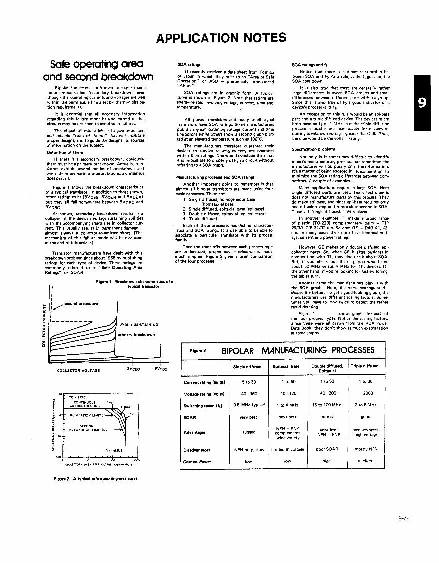
APPLICATION NOTES
Safe operating area SOA ratings SOA ratings and 11
( I recently received a data sheet from Toshiba of Japan in which they refer to an "Area of Safe Operation" or AS0 - presumably pronounced "Ah.so.")
Notice that there is a direct relationship be. tween SOA and ft. As a rule, as the f t goes up, the SOA goes down.
I t is also true that there are generally rather large differences between SOA groups and small differences between different parts within a group. Since this is also true of ft, a good indicator of a device's process is its ft.
and second breakdown Bipolar transistors are known to experience a
fa~lure mode called "secondary breakdown" even though the uperating currents and voltages are well within the permissible limits set by therm..! dissipa- tion require met::^.
SOA ratings are in graphic form. A typical &we is shown in Figure 2. Note that ratings are energy-related involving voltage, current, time and temperature.
It is assentla1 that all necessary information regarding this failure m 0 d ~ be understood so that circuits may be designed to avoid such failures.
An exception to this rule would be an epi-base part and a triple diffused device. The devices might both have an f t of 4 MHz, but the triple diffusion process is used almost exlusively for devices re. quiring breakdown voltage qreater than 200. Thus, the clue would be the volta~ rating.
Ail power transistors and many small signal transistors have SOA ratings. Some manufacturers publish a graph outlining voltage, current and time limitations while othen show a second graph plot- ted at an elevated temperature such as 1 W°C.
The object of this article is t u give important and reliable "rules of thumb" that will facilitate proper designs, and to guide the designer to sources of information on the subject. The manufacturers therefore guarantee their
devices to survive as long as they are operated within their ratings. One would.conclude then that i t is impossible to properly design a circuit without referring to a SOA graph.
Specification problems Definition of terms
I f there is a secondary breakdown, obviously there must be a primary breakdown. Actually, tram sistors exhibit several modes of breakdown and while there are various interpretations, a consensus does prevail.
Not only is it sometimes difficult to identify a pan's manufacturing process, but sometimes the manufacturer will purposely omit the information. It's a matter of being engaged in "specsmanship" to minimize the SOA rating differences between com- petitors. A couple of examples - Manufacturing proaaMI and SOA ratings
Another important point to remember is that almost all bipolar transiston are made using four basic processes. Thew are:
1. Single diffused, homogeneous base (hornetaxial base)
2. Single diffused, epitaxial base (epi-base) 3. Double diffused, epitaxial (epicollector~ 4. Triple diffused
Figure 1 shows the breakdown characteristics of a typical transistor. In addition to those shown, other ratings exist (BVCES, BVcER and BVCEX) but they all fall somewhere between BVCEO and BVCBO.
As shown, secondary breakdown results in a collapse of the device's voltage sustaining abilities with the accompanying sharp rise in collector cur- rent. This usually results in permanent damage - almost always a collector-to-emitter short. (The mechanism of this failure mode will be discussed at the end of this article.)
Many applications require a large SOA. Here single diffused parts are best. Texas Instruments does not manufacture parts by this process. They do make epi-base, and since epbbase requires only one diffusion step and runs a close second in SOA, TI calls it "single diffused." Very clever.
In another example, TI makes a broad range of plastic (TO-2201 complementary pain - TIP 29/30, TIP 31/32 etc. So does GE - 040, 41.42, etc. In many cases their parts have identical volt- age, current and power ratings.
Each of these processes has distinct character. istics and SOA ratings. I t is desirable to be able to associate a particular transistor with in process family.
Once the trade-offs between each procets type are understood, proper device selection is made much simplier. Figure 3 gives a brief comparison of the four processes. '
However, GE makes only double diffused, epi. collector parts. So, when GE is after business in competition with TI, they don't talk about SOA. But, if you check out their ft, you would find about 50 MHz versus 4 MHz for TI'S devices. On the other hand, if you're looking for fast switching, the tables turn.
Transistor manufacturers have dealt with this breakdown ~ rob lem since about 1956 bv ~ublishine ratings for 'each type of device. ~hese' ratings ar i commonly referred to as "Safe Operating Area Ratings" or SOAR.
Figure 1 Breakdown charactaristics of a typical transistor.
Another game the manufacturers play is with the SOA graphs. Here, the more rectangular the shape, the better. To get a good-looking graph, the manufacturers use different scaling factors. Some- times you have to look twice to detect the rather rapid derating.
Figure 4 shows graphs for aach of the four process types. Notice the scaling factors. Since these were all drawn from the RCA Power Data Book. thev don't show as much exasseration
I
BVCEO ISUSTAININGI
primary breakdown --
as some graphs.
~ iw r .3 BIPOLAR MANUFACTURING PROCESSES
Double diffused, Epitaxial
1 to 50
Triple diffused Singla diffused Epitaxial Bare COLLECTOR VOLTAGE BvCEO ~vcE4l
1 to 50
40.120
1 to 4 MHz
next best
NPN - PNP complements, wide variety
limited in voltage
low
1 to 30
2000
2 to 5 MHz
good
medium speed, high voltage
mostly NPN
medium
Currant rating (amps)
Voltage rating (volts)
Switching spmd ( f t l
SOAR
5 to 30
40 - 160
0.6 MHz typical
very best
15 to 100 MHz
poorest
very fast, NPN - PNP Advantages 1 rugged
Didvantagas NPN only, slow poor SOAR
high Cwt vs. Power
Figura 2 A typical safsopsratinprna cuwa.
low
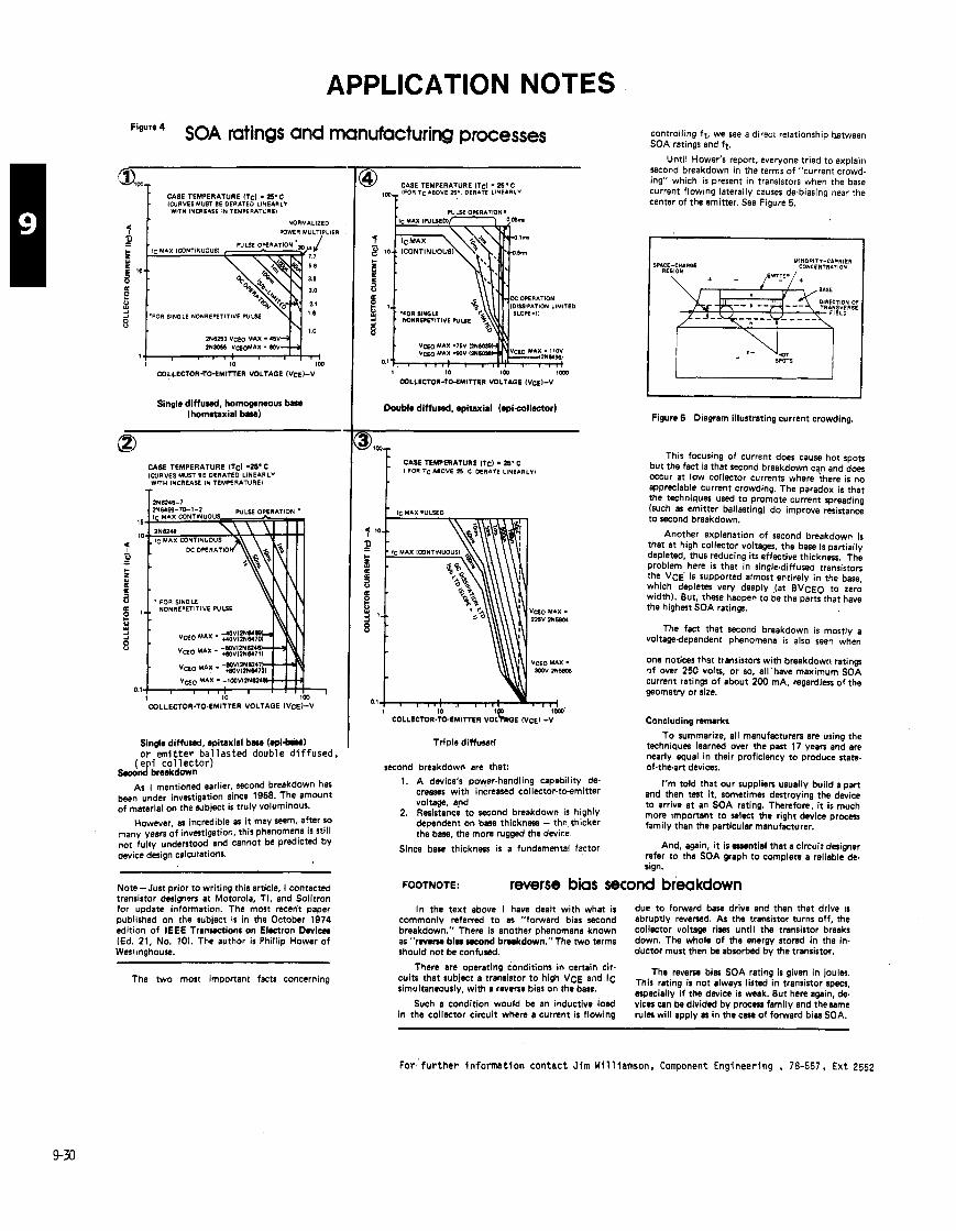
APPLICATION NOTES Figure 4 SOA ratings and manufacturing processes
1 CASE TEMPERATURE ITc) = 25'C IWRVES MUST BE OERATED LINEARLY WITH INCREASE IN TEMPERATURE1
1 NORMALIZED
4 1 POWER MULTIPLIER
COLLECTOR-TO-EMITTER VOLTAGE IVCEI-V
Single d i f f u d , homogeneous bae (homaaxial bae)
CASE TEMPERATURE lTcl -25.C ICVRVES MUST BE OERATED LINEARLY WITH INCREASE IN TEMPERATURE1
T
NONREPETITIVE PULSE
1 I 0 COLLECTOR-TO-EMITTER VOLTAGE 1VCE)-V
Single diffursd, epitaxial base (Wl-bro o r em i t t e r ba l l as ted double d i f fused, e i co l l ec to r )
S A J b r erkdown
As I mentioned earlier, second breakdown has ,
been under investigation since 1958. The amount of material on the subject is truly voluminous.
However, as incredible as it may seem, after so many yean of investigation, this phenomena is still not fully understood and cannot be predicted by device design calculations.
Note- Just prior to writing this article, I contacted transistor designers at Motorola, TI, and Solitron for update information. The most recent paper published on the subject is in the October 1974 edition of IEEE Tranmions on Electron Dwicas (Ed. 21, No. 101. The author is Phillip Hower of West~nghouse.
The two most important facts concerning
@ CASE TEMPERATURE ITc) - 2S.C IFOR TcABOVE 25.. DERATE LINEARLY1
COLLECTOR-TO-EMITTER VOLTAGE IVCEI-V
Double diffusad, spitaxial (epicollector)
CASE TEMPEUATUUE ITc) - 25. C I FOR TC ABOVE n c DERATE LINEARLYI
Triple diffused
second breakdown are that: 1. A device's power-handling capability de-
creases with increased collector-to-emitter voltage, and
2. Resistance to second breakdown is highly dependent on bare thickness - the,thicker the base, the more ~ g g e d the device.
Since base thickness is a fundamental factor
controlling ft, we see a direct relat~onship hetween SOA ratings and ft.
Until Hower's report, everyone tried to explain second breakdown in the terms of "current crowd- ing" which is present in transistors when the base current flowing laterally causes de-biasing near the center of the emitter. See Figure 5.
SPICE-CHARGE YINDRITY-CARRIER RE
I
Figure 5 Diagram illustrating current crowding.
This focusing of current does cause hot spots but the fact is that second breakdown can and does occur at low collector currents where ;here is no appreciable current crowding. The paradox is that the techniques used to promote current spreading (such as emitter ballastingl do improve resistance to second breakdown.
Another explanation of second breakdown is that at high collector voltages, the base is partially depleted, thus reducing its effective thickness. The problem here is that in single-diffused transiston the VCE is supported almost entirely in the base, which depletes very deeply (at BVCEO to zero width). But, these happen to be the parts that have the highest SOA ratings.
The fact that second breakdown is mostly a voltagedependent phenomena is also seen when
one notices that transistors with breakdowrt ratings of over 250 volts, or so, all'have maximum SOA current ratings of about 200 mA, regardless of the geometry or size.
Concluding nrnsrkr
To summarize, all manufacturers are using the techniques learned over the past 17 yean and are nearly equal in their proficiency to produce state- of-the-art devices.
I'm told that our supplien usually build a pan and then test it, sometimes denroving the device to arrive at an SOA rating. Therefore, it is much more Important to select the right device process family than the particular manufacturer.
And, again, i t is enential that a circuit designer refer to the SOA graph to complete a reliable de- sign.
FOOTNOTE: reverse bias second breakdown In the text above I have dealt with what is due to forward base drive and than that drive IS
commonly referred to as "forward bias second abruptly reverxrd. As the transistor turns off, the breakdown." There is another phenomena known collector voltage rises until the transistor breaks as " r w e ~ bi.) recond brnkdown."The two terms down. The whole of the energy stored in the in- should not be confused. ductor must then be absorbed by the transistor.
There are operating conditions in certain cir- The revem bir SOA rating is given in joules, cuia that subject a transistor to high WE slid IC This rating is not always li,ted in specs, simultaneously, with a reverse bias on the base. especially if the device is weak. But here again, de-
Such a condition would be an inductive load vices can be divided by process family and themme in the collector circuit where a current is flowing rules will apply w in the c m of forward bias SOA.
~ o r ' f u r t h e r i n fo rma t i on contac t J im Wil l iamson, Component Engineering , 78-557, Ext 2552

APPLICATION NOTES
I-
-
*Chargo war rmtainrd due to wlder-wick': p l r t ic ml
CHARGE LEVEL RETAINED ON TOOL Immndiatm charam I Charma mfMr cinn
Silverstat So!dmpullt h l u x r SolLpullt Standard Sold.pullt Bulb Solder Sucker Solder-Wick
Some c i r c u i t board components are sensit ive t o s t a t i c charge. Also. some desoldering too ls create a s t a t i c charge. I n order t o i d e n t i f y and preclude potent ia l problems, we have tested the various desolder- ing too ls avai lab le f o r use a t Tek.
A c i r c u i t board was used, w i th components removed, t o determine s t a t i c levels . Each device was tested ten times. The desoldering too ls were checked f o r innediate charge retent ion and f o r the charge he ld 'a f te r f i v e minutes.
OV 3kV
2OkV lOkV ' ZkV
Each o f the too ls except the Si lverstat Soldapul l t , l e f t a s t a t i c charge on the c i r c u i t board and retained a charge (see char t ) . The S i l v e r s t s t Soldapul l t , a model wi th a metal l ized surface, l e f t no charge and a lso retained no charge. Therefore, i t I s the preferred too l . It has been assigned par t number 003-0795-00.
OV Atnr fiva minuta 30a400V Aftw f i w minuta
1OkV Ahrr five minutes 4kV A f t u ti- minutes OV A h r OM minute
Handling precautions for TO - 220's
We all know that electrical stresses must be maintained within specified limits to assure reliable performance and long device life. What we often neglect to recognize though is that the limitation of mechanical stresses during handling and mwnt. ing of devices is equally important to reliable field performance.
GE presents the following recommendations for the handling of TO-220 plastic power pacs. These suggestions apply to all vendor's devices.
load forming and bending
1. point of bend a 118" from plastic peckqe 2. provide stress relief between bending point
and package during bending 3. do not allow stress-relief tool to contact the
plastic part of the package 4, avoid repeated bendings
screw mounting of device
1, maximum screw size: UNF 440 or Metric M3 2. screw head: Phillips or hex socket head cap
preferred so mounting tool does not con. tact or press against the plastic pan of the package
3. a flat round or rectangular washer against the top of the device flange is recommended to spread the mwnting force - Wnher dimensions must be such that i t docr not contact the plmtic pan of the peck*
4. lubricate screw threads and top of device flange around mounting hole with thermal compound
5. maximum mwnting torque: s 6 in-lbs. 6. i f a minimum interface thermal impedance is
important, observe the following: a. minimum mwntingtorque: 3 in4bs. b. use thermal compound such i G E M 2
mounting sur f la type and prepention
1. flatness: s .002 inlinch 2. maximum diameter of hole: 5 .I40 inch -
This must include any countersinking. chamfering or cupping around hole
3. edge of hole must be clean with no burrs or ridge
possible damage
Damage to these devices from improper hand. ling and/or mounting manifests itself as excenive current leakage or an electrical short in the device's brinciple current path.
For funher discussions related to mounting practices as they affect interface thermal imped- anca, reference GE application note 200.55 en. titled "Handling and Thermal Considerations for GE Plastic Power Devices."
Contact Jim Williamson, Component Engineering, 78-557, Ext. 2552 f o r more information.
For more information on these desoldering tools. contact Herb Zajac, ext. 4759..
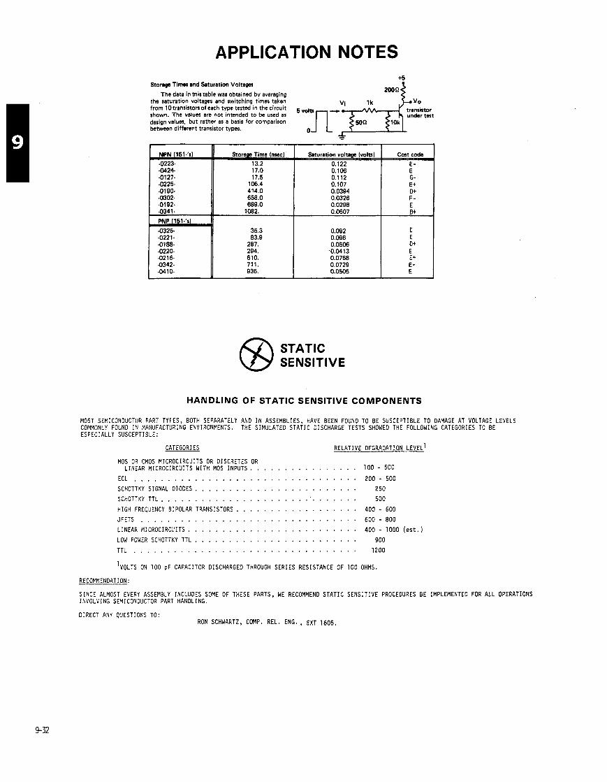
APPLICATION NOTES
S t o w Timer and Saturation Voltagea
The data in this table war obtained by averaging the saturation voltages and switching times taken y o from 1 0 transistors of each type tested in the circuit tramistor shown. The valuer are not intended to be used as under test design values, but rather as a basis for comparison between different transistor types.
PNP 151-'S -1 - 0 2 2 1 - -0325- 35.3 83.9
STATIC SENSITIVE
HANDLING OF STATIC SENSITIVE COMPONENTS
MOST SEMICONOUCTOR PART TYPES, BOTH SEPARATELY AND I N ASSEMBLIES, HAVE BEEN FOUND TO BE SUSCEPTIBLE TO DAMAGE AT VOLTAGE LEVELS COMMONLY FOUND I N MANUFACTURING ENVIRONMENTS. THE S I M U L A T E 0 S T A T I C DISCHARGE TESTS SHOWED THE FOLLOWING CATEGORIES TO BE ESPECIALLY SUSCEPTIBLE:
CATEGORIES RELATIVE DEGRADATION LEVEL^ MOS OR CMOS MICROCIRCUITS OR OISCRETES OR
. . . . . . . . . . . . . . . L I N E A R MICROCIRCUITS W I T H MOS I N P U T S . 1 0 0 - 5 0 0
ECL . . . . . . . . . . . . . . . . . . . . . . . . . . . . . . . . . SCHOTTKY S IGNAL D I O D E S . . . . . . . . . . . . . . . . . . . . . . . . SCHOTTKY T T L . . . . . . . . . . . . . . . . . . . . . . . . . . . . . H I G H FREQUENCY B IPOLAR TRANSISTORS . . . . . . . . . . . . . . . . . . J F E T S . . . . . . . . . . . . . . . . . . . . . . . . . . . . . . . .
. . . . . . . . . . . . . . . . . . . . . . . . . L I N E A R MICROCIRCUITS
LOW POWER SCHOTTKY T T L . . . . . . . . . . . . . . . . . . . . . . . . T T L . . . . . . . . . . . . . . . . . . . . . . . . . . . . . . . . .
2 0 0 - 5 0 0
2 5 0
5 0 0
4 0 0 - 6 0 0
6 0 0 - 8 0 0
4 0 0 - 1 0 0 0 ( e s t . )
9 0 0
1 2 0 0
RECOMMENDATION:
S I N C E ALMOST EVERY ASSEMBLY INCLUDES SOME OF THESE PARTS, WE RECOMMEND S T A T I C S E N S I T I V E PROCEDURES BE IMPLEMENTED FOR A L L OPERATIONS I N V O L V I N G SEMICONOUCTOR PART HANDLING.
D I R E C T ANY QUESTIONS TO: RON SCHWARTZ, C O W . REL. ENG. , EXT 1 6 0 5 .
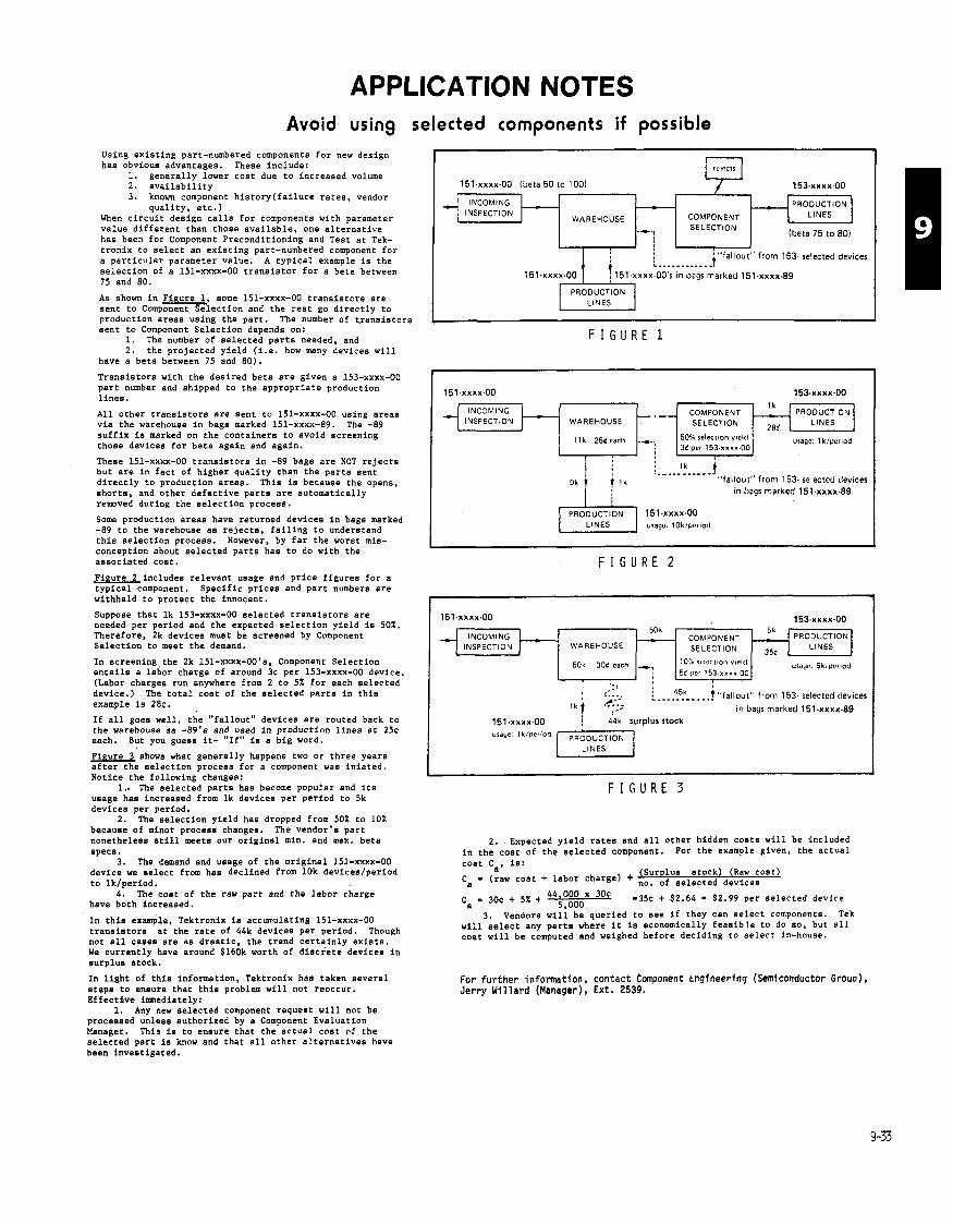
APPLICATION NOTES Avoid using selected components if possible
Using existing part-numbered components for new design has obvious advantages. These include:
1. generally lower cost due to increased volume 2. availability 3. known component history(fai1ure rates, vendor
quality, etc.) When circuit design calls for components with parameter value different than those available, one alternative has been for Component Preconditioning and Test at Tek- tronix to select an existing part-numbered component for a particular parameter value. A typical example is the selection of a 151-xxxx-00 transistor for a beta between 75 and 80.
As shown in Figure 1, some 151-xxxx-00 transistors are sent to Component Selection and the rest go directly to production areas using the part. The number of transistors sent to Component Selection depends on:
1. The number of selected parts needed, and 2. the projected yield (1.e. how many devices will
have a beta between 75 and 80).
Transistors with the desired beta are given a 153-xxxx-00 part number and shipped to the appropriate production lines.
All other transistors are sent to 151-xxxx-00 using areas via the warehouse in bags marked 151-xxxx-89. The -89 suffix is marked on the containers to avoid screening those devices for beta again and again.
These 151-xxxx-00 transistors in -89 bags are NOT rejects but are in fact of higher quality than the parts sent directly to production areas. This is because the opens, shorts, and other defective parts are automatically rewved during the selection process.
Some production areas have returned devices in bags marked -89 to the warehouse as rejects, failing to understand this selection process. However, by far the worst mis- conception about selected parts has to do with the associated cost.
Figure 2 includes relevant usage and price figures for a typical component. Specific prices and part numbers are withheld to protect the innocent.
Suppose that lk 153-xxxx-00 selected transistors are needed per period and the expected selection yield is 50%. Therefore, 2k devices must be screened by Component Selection to meet the demand.
In screening the 2k 151-xxxx-OO's, Component Selection entails a labor charge of around 3~ per 153-xxxx-00 device. (Labor charges run anywhere from 2 to 5% for each selected device.) The total cost of the selected parts in this example is 2 8 ~ .
If all goes well, the "fallout" devices are routed back to the warehouse as -89's and used in production lines at 2% each. But you guess it- "If" is a big word.
Figure lshows what generally happens two or three years after the selection process for a component was iniated. Notice the following changes:
1.. The selected parts has become popular and its usage has increased from lk devices per period to 5k devices per period.
2. The selection yield has dropped from 50% to 10% because of minot process changes. The vendor's part nonetheless still meets our original min. and max. beta specs.
3. The demand and usage of the original 151-xxxx-00 device we select from has declined from 10k deviceelperiod to lklperiod.
4. The cost of the raw part and the labor charge have both increased.
In this example, Tektronix is accumulating 151-xxxx-00 transistors at the rate of 44k devices per period. Though not all cases are as drastic, the trend certainly exists. We currently have around S160k worth of discrete devices in surplus stock.
In light of this information, Tektronix has taken several steps to ensure that this problem will not reoccur. Effective immediately:
1. Any new selected component request will not be processed unless authorized by a Component Evaluation Manager. This is to ensure that the actual cost of the selected part is know and that all other alternatives have been Investigated.
F I G U R E 1
151.xxxx-00 (beta 50 to 1001 153.xxxx.00
INCOMING PRODUCTION WAREHOUSE SELECTION 1 -1 cOMpONENT I+[ LINES I
INCOMING INSPECTION
: lk ! ----- - - - - - - j
"fallout" from 153 selected devices in bags marked 151.xxxx.89
LINES usage lOk!pur~orl
F I G U R E 2
151~xxxx.00
. r
COMPONENT SELECTION
WAREHOUSE
' "fallout" from 153. selected devices : ....-...... .! ' j 15lrxx~OO's in bans marked l5l.xxxx.88
I..
I ::::. i---::~-----j "fallout" from 153 selected device! ."'I; in bags marked 151.xxxx.89
151~xxxx~OO ; d4k surplus stock a : i o
LINES
PRODUCTION LINES
,
PRODUCTION LINES
151.xxxx.00 153.xxxx.00
F I G U R E 3
(beta 75 to 80)
INCOMING INSPECTION
2. .Expected yield rates and all other hidden costs will be included in the cost of the selected component. For the example given, the actual
'a - 3 0 ~ + 5% + 44;000000X 30C -3% + $2.64 - $2.99 per selected device 3. Vendors will be queried to see if they can select components. Tek
will select any parts where it is economically feasible to do so. but all coat will be computed and weighed before deciding to select in-house.
WAREHOUSE
50k 30d cach
For fur ther information, contact Component tngineering (Semiconductor Grouo), Jerry Wi l lard (Manager), Ext. 2539.
- !
- CO~WONENT SELECTION
10'0 r u l c r ~ ~ o n vtrl<l 5d ~ l e r 163 x x x x 00
50k -
-, 1
5L. - - PRODUCTlON 35d LINES
usdy? Sk,per(od

TO-220 mounting system features high voltage withstand capability
A new integrated TO-220 transistor mounting system has been developed by TV Products Mech-
I anical Engineering, in cooperation with Analog Component Engineering. The system features very high breakdown voltage capability, with attention given to variations in device mounting torque.
The mounting system consists of two parts: a purchased Chomerics "Cho-therm R 1674 silicon rubber insulator, and a Tek-made polysulfone shoulder washer. A special heat-sink counterbore detail is also required. Figure 1 shows an exploded view of this system. Electrical characteristics -
This new system was developed to accommo- date the Hi-Pot requirement for UL instrument certification. Common methods used for TO-220 package mounting were not adequate for the 1500 volt specification. What was desired was a long- stemmed shoulder washer and a relatively tight- fitting insulator - both not commerciallyavailable. Thus, the need to develop our own system became apparent.
The results of breakdown voltage testing (both initial and repeated "strikes") are shown in Table 1.
Tr(8l# L8fgWt hob Sm8lk.t bola (.ill In.) (.131 In.)
1 (initial breakdown) 1500V l850V 2 1400V 1800V
' 3 (repeated break- 1400V 1 QOOV 4 down8 with 1400V 1550V 5 -me inrulator) 1400V 1550V 6 1400V 18OOV
Table 1 - ~ 1 - 6 o t test re8ulta
The manufacturer's electrical ratings are:
Volume resistivity (per ASTM D257) 2 x 1 01 Qn/cm(typ)
Dielectric constant (per ASTM D l 50) 4 @ 1 MHz(typ)
Breakdown voltage (per ASTM D l 49) 1 500V (min)
Mechanical 'considerations The polysulfone (yellow or black) shoulder wash-
er (Tek P/N 342-0536-00) acts like a spring washer with TO-220 device case styles. It is expressly designed for a #4-40 UNC 29-type screw, with a nominal applied torque range of 4 to 5 in-lbs. As mounting screw torque is increased, the washer expands contact with the top of the device tab and begins to apply pressure toward the heat sink with the special counterbore detail that must be used (see Figure 1).
342-0536-00
TO-220 Device
I n s u l a t o r
342-0563-00
Special Counterbore 60 +. 005 -. 000
/ Heat S ink shown i s round f o r
/ i l l u s t r a t i v e purposes on ly .
/
I . /
.040 i ,010 Rad ( A l l Around)
I;/// L .080 i .005 D e ~ t h S ~ e c i a l Counterbore D e t a i l
FIGURE 1 - TYPICAL INSTALLATION FOR NEW TO-220 TRANSISTOR MOUNTING SYSTEM.
On the underside of the shoulder washer a circular recess prevents stress-cracking of the washer, and prevents the device tab from being forced into the region around the counterbore. If the tab were forced into the detail it would distort, thereby reducing contact area, increasing device operating temperature and causing possible die fracture.
Thermal attributes The maximum recommended transistor case op-
erating temperature is 125"C, although 150°C can be used for brief periods. At this temperature some elastic characteristics of the polysulfone spring shoulder washer will be lost, but not to the extent that it will cause device failure.
The average RBCS of this system is 1.47"C/W. The thermal resistance between tab and heat sink will decrease somewhat between 1 Oand 100 hours of operation. This occurs because the insulator material will "cold-flow" intovoid areas and increase the effective contact area.
One final caution - do not use any heat sink "grease" with this insulator material. Compounds currently used (e.g., Dow #4 and Thermalcote) contain solvents that will attack the silicon rubber insulator material.
FOR MORE INFORMATION, CONTACT JIM WILLIAMSON, EXT. 2552 OR ED JOSTE, TV PRODUCTS MECHANICAL ENGINEERING, EXT. 1330.
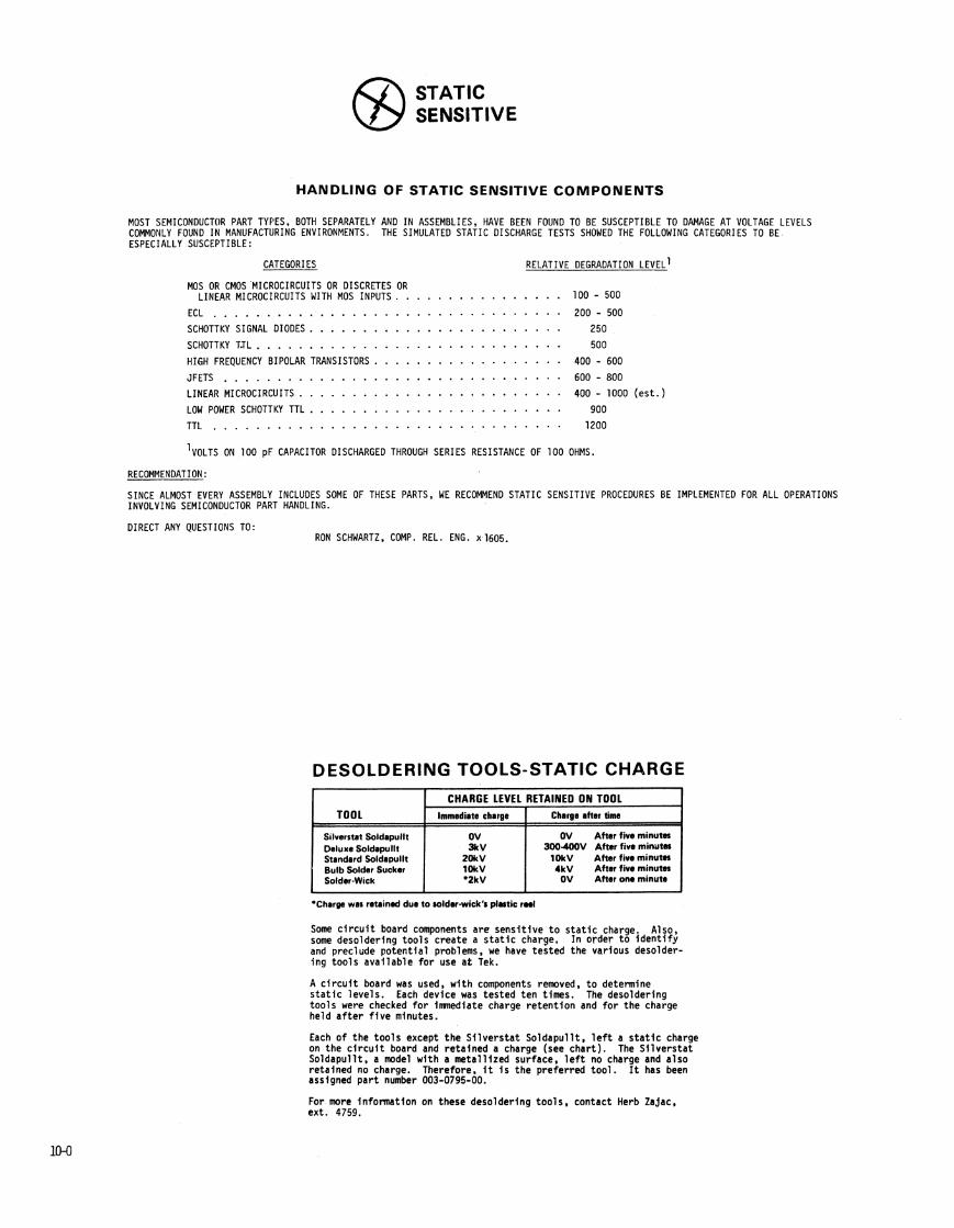
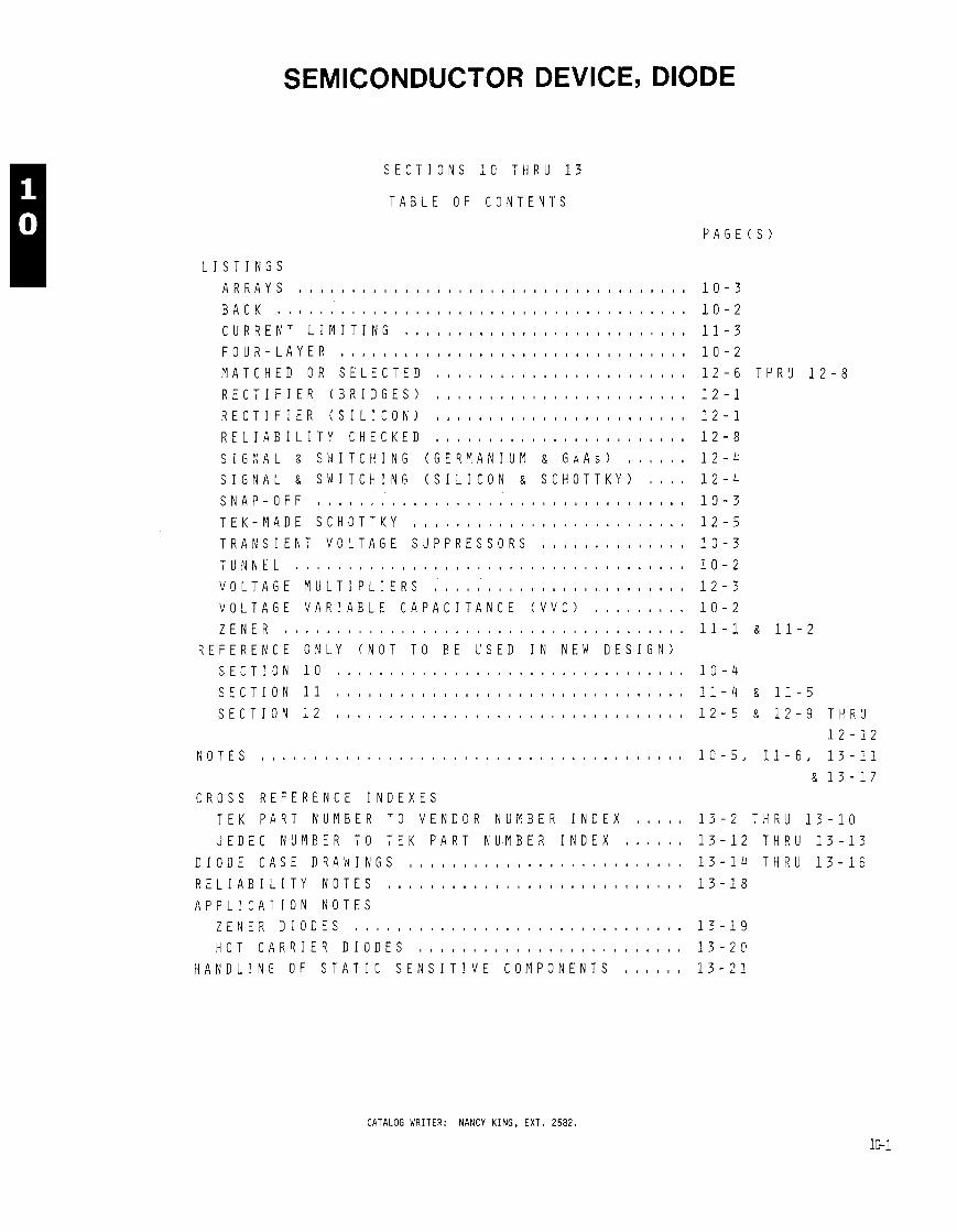
SEMICONDUCTOR DEVICE, DIODE
S E C T I O N S 1 0 T H R U 1 3
T A B L E O F C O N T E N T S
C R O S S R E F E R E N C E I N D E X E S
T E K P A R T N U M B E R T O V E N D O R N U M B E R I N D E X , , , , ,
J E D E C N U M B E R T O T E K P A R T N U M B E R I N D E X
D I O D E C A S E D R A W I N G S , ,
R E L I A B I L I T Y N O T E S 8 , , , , , , , , , , , , , , , , , , , , t t , , , , ,
A P P L I C A T I O N N O T E S
Z E N E R D I O D E S , , , , , , , . . . . . . . . . . . . . . . . . . . . . . . .
H O T C A R R I E R D I O D E S , , , , , , o , , , , , , , , , , , , , , , , , ,
H A N D L I N G O F S T A T I C S E N S I T I V E C O M P O N E N T S , , , , , ,
1 0 - 3
1 0 - 2
1 1 - 3
1 0 - 2
1 2 - 6 T H R U 1 2 - 8
1 2 - 1
1 2 - 1
1 2 - 8
1 2 - 4
1 2 - 4
1 0 - 3
1 2 - 5
1 0 - 3
1 0 - 2
1 2 - 3
1 0 - 2
11-1 8 1 1 - 2
1 0 - 4
1 1 - 4 8, 1 1 - 5
1 2 - 5 8 1 2 - 9 T H R U
1 2 - 1 2 1 0 - 5 , 1 1 - 6 , 1 3 - 1 1
& 1 3 - 1 7
1 3 - 2 T H R U 1 3 - 1 0
1 3 - 1 2 T H R U 1 3 - 1 3
1 3 - 1 4 T H R U 1 3 - 1 6
1 3 - 1 8
CATALOG WRITER: NANCY K ING, EXT. 2582.
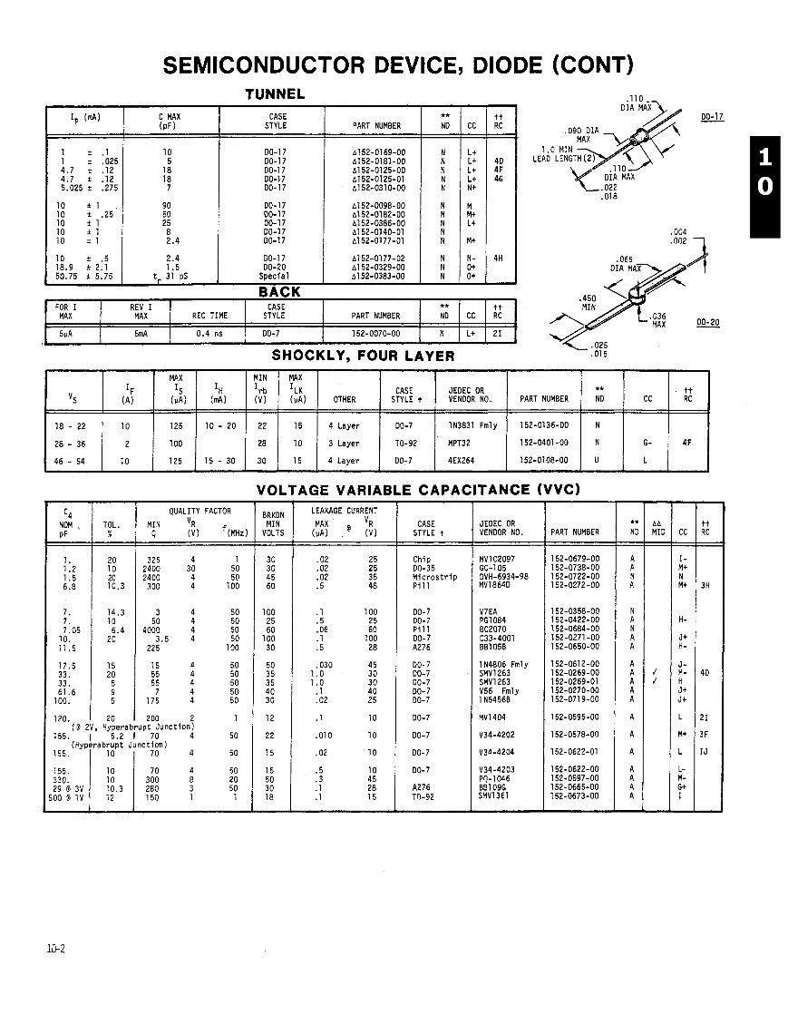
SEMICONDUCTOR DEVICE, DIODE (CONT) TUNNEL
CASE STYLE I PART NUMBER
DO-17 A 1 52-0177-02 DO-20 A1 52-0329-00
BACK
VOLTAGE VARIABLE CAPACITANCE (VVC) - C4
NOM , PF
1. 1.2 1.5 6.8
7. 7. 7.05
10. 11.5
17.5 33. 33. 61.6
100.
"S
18 - 22
28 - 36
46 - 54
QUALITY FACTOR
TOL 1 M i l 'R % Q ( v ) f ( ~ ~ z )
SHOCKLY, FOUR LAYER
CASE STYLE
DO-7
REC TIME
0.4 ns
. FOR I MAX
5uA
IH (mA)
1 0 - 2 0
1 5 - 3 0
ND MID ==I=
REV I MAX
5mA
IF (A)
10
2
10
CASE STYLE t
PART NUMBER
152-0070-00
MIN
It-b (V)
22
28
30
MAX
IS (PA)
125
100
125
JEDEC OR VENDOR NO. PART NUMBER
** ND
N
MAX
ILK (PA)
15
10
15
Chip 00-35 M i c r o s t r i p P i l l
DO-7 DO-7 P i l l DO-7 A276
CC
L+
OTHER
4 L a y e r
3 Layer
4 L a y e r
DO- 7 DO-7 DO-7 DO- 7 DO-7
tt RC
21 A
1 N4806 Fml y SMVl263 SMV1263 V56 Fmly 1 N5456B
MV1404
V34-4202
V34-4204
V34-4203 PQ-1046 BE1 09G SMV1361
120. I 20 1 200 2 1 ( D 2V, Hyperabrupt Junc t ion)
155. 1 5.2 1 70 4 50 (Hyperabrupt Junc t ion)
155. 1 10 1 70 4 50
CASE STYLE t
DO-7
TO-92
DO-7
PART NUMBER
152-0136-00
152-0401 -00
152-0108-00
JEDEC OR VENDOR NO.
IN3831 Fmly
MPT32
4EX264
** ND
N
N
U
CC
G-
L
tt RC
4F
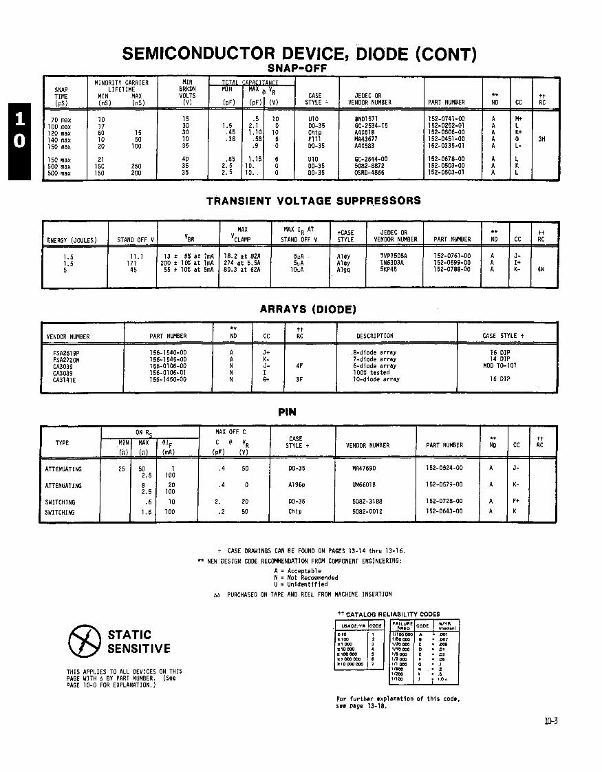
SEMICONDUCTOR DEVICE, DIODE (CONT) SNAP-OFF
SNAP TIME (PS I
70 max 1 00 max 120 max 140 max 150 max
TRANSIENT VOLTAGE SUPPRESSORS
MINORITY CARRIER LIFETIME
MIN MAX (ns ) (ns)
150 max 500 max 500 max
10 17 60 15 10 50 20 100
MIN BRKDN VOLTS
( v )
21 150 250 150 2 DO
ENERGY (JOULES)
ARRAYS (DIODE)
15 30 30 10 3 5
-
Aley A1 ey Algq
40 35 3 5
STAND OFF v
8-diode a r ray 7-diode a r ray 6-diode a r ray 100% tes ted 10-diode a r ray
TOTAL CAPACITANCE
1.5 .45 .38
TVP1505A 1 N63D3A 5KP45
VENDOR NUMBER
16 DIP 14 DIP
MOD TO-1 01
16 DIP
CASE STYLE t
MIN
(PF)
.85 2.5 2.5
'BR
PIN
MAX @ v~ ( ~ ~ 1 1 (IV)
I
.5 2.1 1.10
.58
.9
152-0761-00 152-0599-00 152-0788-00
PART NUMBER
JEDEC OR VENDOR NUMBER
1.15 10. 10.
MAX
'CLAMP --
A J- A I + A K- 4H
t CASE DRAWINGS CAN BE FOUND ON PAGES 13-14 t h r u 13-16.
** NEW'DESIGN CODE RECOmENDATION FROM COMPONENT ENGINEERING:
10 0
10 6 0
** NO
A = Acceptable N = Not Recmended U = U n i d e n t i f i e d
AA PURCHASED ON TAPE AND REEL FROM MACHINE INSERTION
PART NUMBER
6 0 0
MAX 'R AT
STAND OFF v
STATIC SENSITIVE
** ND
U10 DO-35 Chip F l l l DO-35
CC
ISWITCHING I 1 1 . 6 1 1 0 0 1 .2 50 1 Chip 1 5082-0012 1 152-0643-00 1 A I K I
PART NUMBER
1 52-0524-00
152-0579-00
152-0728-00
TYPE
ATTENUATING
ATTENUATING
SWITCHING
THIS APPLIES TO ALL DEVICES ON THIS PAGE WITH A BY PART NUMBER. (See PAGE 10-0 FOR EXPLANATION.)
U10 DO-35 DO-35
tCASE STYLE
** ND CC RC
tt
A J-
A K-
A F+
MAX OFF C
C @ VR
(PF) (V)
.4 50
.4 0
2. 20
For f u r t h e r exp lanat ion o f t h i s code, see page 13-18.
END1 571 GC-2534-15 A4X618 MA43677 A4X583
tt RC
ON RS
GC-2544-00 5082-8872 QSRD-4866
JEDEC OR VENDOR NUMBER
CASE STYLE t
DO-35
A196p
DO-35
152-0741-00 152-0252-01 152-0506-00 152-0451-00 152-0335-01
DESCRIPTION
VENDOR NUMBER
MA47690
UM66018
5082-3188
@IF (mA)
1 100
20 100
10
MIN
(i7)
25
A A A A A
152-0678-00 152-0503-00 152-0503-01
PART NUMBER
CASE STYLE t
MAX
(n)
50 2.5
8 2.5
.6
A A A
*t tt ND cc RC
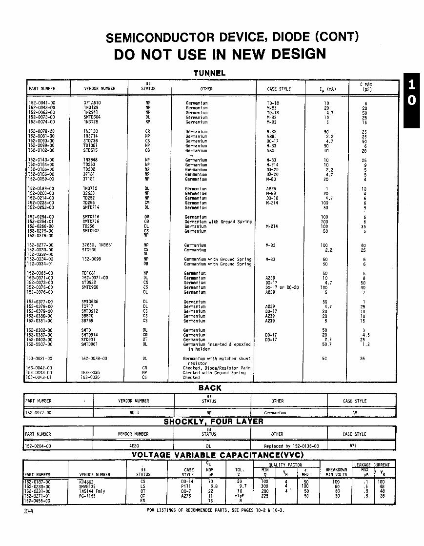
SEMICONDUCTOR DEVICE, DIODE (CONT)
SMTD SMT0914 STD931 SMTO961
152-0078-00
153-0036 153-0036
PART NUMBER
I
DO NOT USE IN NEW DESIGN
VENDOR NUMBER 5 5
STATUS OTHER
Germanium Germanium Germanium Germanium Germanium
Germanium Germanium Germanium Germanium Germanium - Germanium Germanium Germanium Germanium Germani um
Germanium Germanium Germanium Germanium Germanium
Germanium Germanium w i t h Ground Spring Germanium Germanium
Germanium Germanium
Germanium w i t h Ground Spring Germanium w i t h Ground Spring
Germanium Germanium Germanium Germanium Germanium
Germanium Germanium Germanium Germanium Germanium
Germanium Germanium Germanium Germanium inse r ted & epoxied
i n ho lder
Germanium w i t h matched shunt r e s i s t o r
Checked, Diode/Resistor Pa i r Checked w i t h Ground Spring Checked
BACK
CASE STYLE
A239 DO-17 DO- 17 o r 00-20 A239
C MAX (PF)
-- -
PART NUMBER
152-0077-00 I 00-1
I
VOLTAGE 'VARIABLE C A P A C ~ T A N C E ( ~ C ) a
J
I I I § VENDOR NUMBER STATUS
NP Germanium I I A8
PART NUMBER
152-0204-00
-- -
FOR LISTINGS OF RECOMMENDED PARTS, SEE PAGES 10-2 d 10-3.
I SHOCKLY. FOUR LAYER
-
OTHER
VENDOR NUMBER
4E20
CASE STYLE
- -
5 5 STATUS
DL
OTHER
Reolaced bv 152-01 36-00
- - -
CASE STYLE
A7 1
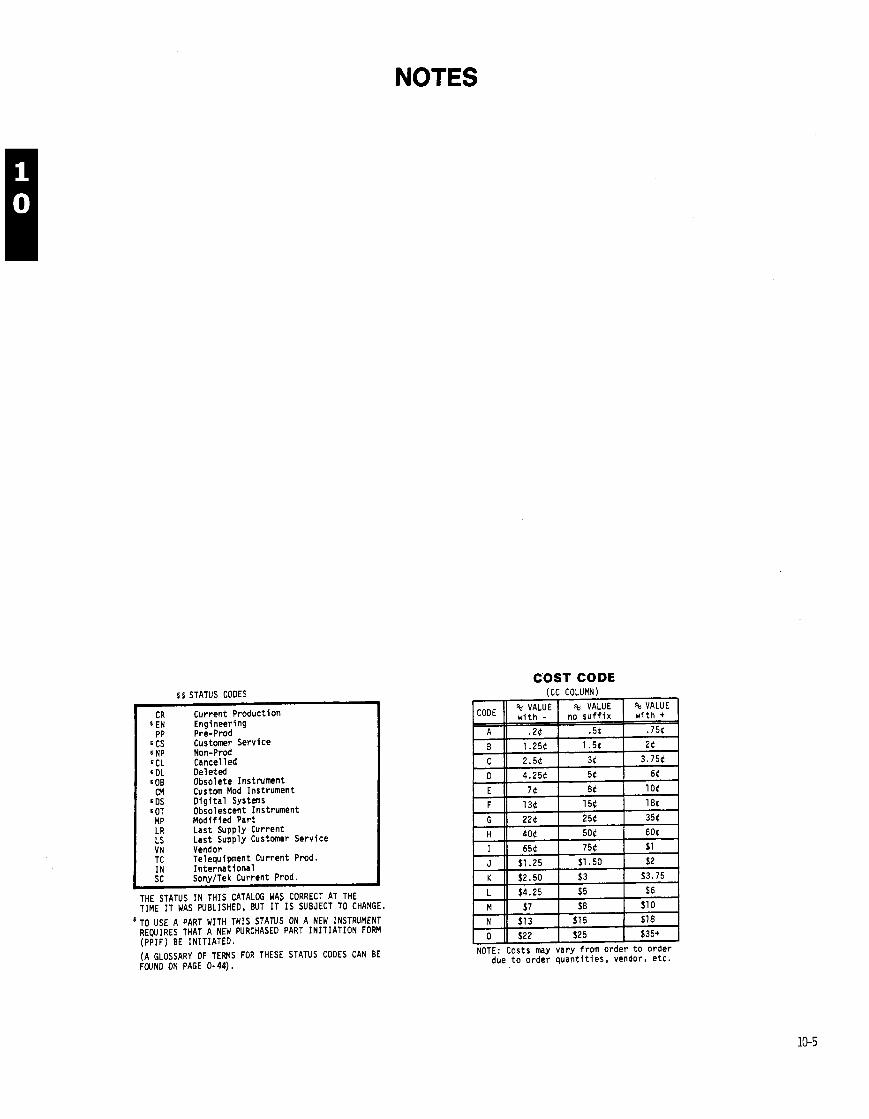
NOTES
COST CODE r r STATUS CODES
Current Product ion Engineering Pre-Prod Customer Service Non-Prod Cancel 1 ed Deleted Obsolete Instrument Custom Mod Instrument D i g i t a l Systems Obsolescent Instrument Modif ied Part Last Supply Current Last Supply Customer Service
VN Vendor TC Telequipment Current Prod. IN I n te rna t i ona l sc SonyITek Current Prod.
THE STATUS IN THIS CATALOG WAS CORRECT AT THE TIME I T WAS PUBLISHED, BUT I T I S SUBJECT TO CHANGE.
TO USE A PART WITH THIS STATUS ON A NEW INSTRUMENT REWIRES THAT A NEW PURCHASED PART INITIATION FORM (PPIF) BE INITIATED.
(A GLOSSARY OF TEWS FOR THESE STATUS CODES CAN BE FOUND ON PAGE 0- 44).
(CC COLUMN)
NOTE: Costs may vary from order t o order due t o order quan t i t i es , vendor, e tc .
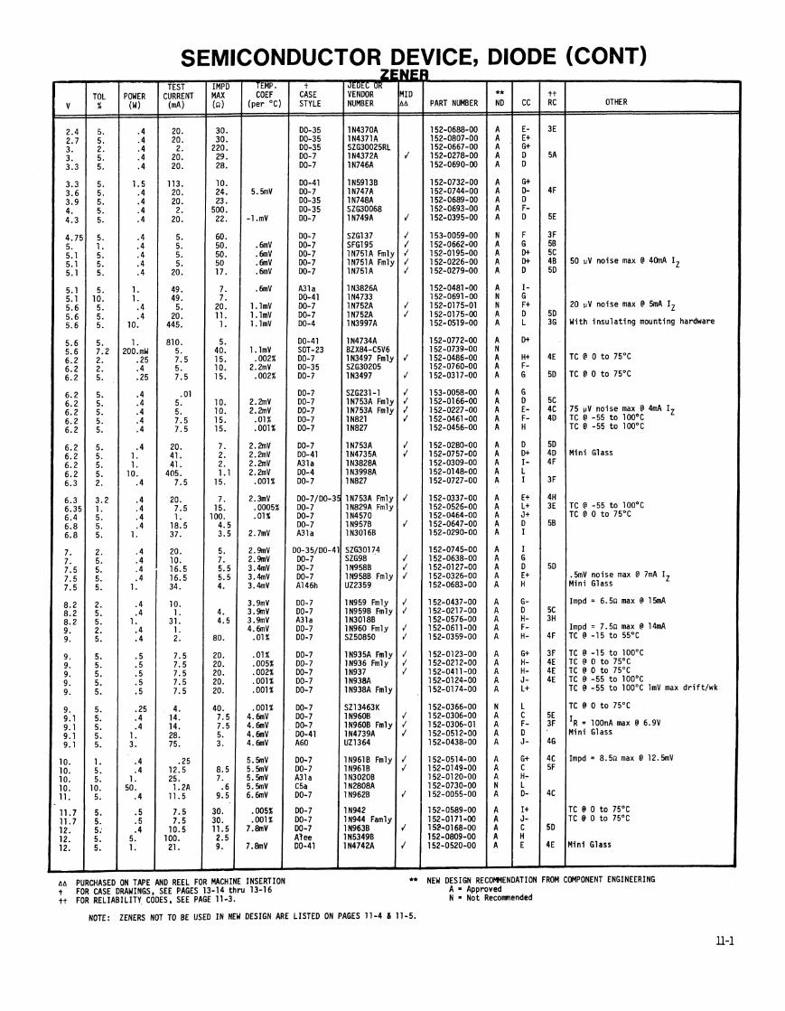
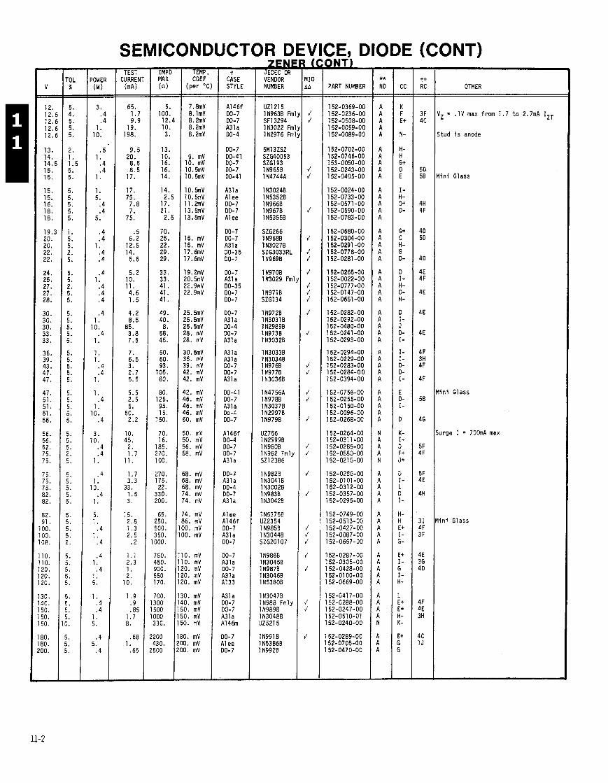
- POWER
(W) - - 3.
. 4
. 4 1.
10.
. 5 1.
.4
.4 1.
1. 5.
.4
.4 5.
.4 .4
1. .4 . 4
. 4 1.
.4
.4
.4
.4 1.
10. .4
1.
1. 1.
.4
.4 1.
1. .4
1 . 10.
.4
3. 10.
.4
. 4 1.
. 4 1.
10. .4
1.
5. 1.
.4 1.
. 4
. 4 1.
. 4 1. 5.
1. .4 .4
1. 5.
. 4 5.
. 4
SEMICONDUCTOR DE 'ICE, DIODE (CONT) - TEST
CURREN' (mA - - 65.
1.7 9.9
19. 198.
9.5 20.
8.5 8 .5
17.
17. 75.
7.8 7.
75.
.5 6.2
12.5 14.
5.6
5.2 10. 11. 4.6 1 .5
4.2 8.5
85. 3.8 7.5
7. 6.5 3. 2.7 5.5
5.5 2.5 5.
50. 2.2
10. 45.
2. 1.7
11.
1.7 3.3
33. 1.5 3.
15. 2.8 1.3 2.5
.2
1.1 2.3 1. 2.
10.
1.9 .9 .85
1 .7 8.
.68 1.
.65
-
- IMPD MAX ( a ) 7 -
5. 100. 12.4 10. 3.
13. 10. 16. 16. 14.
14. 2.5
17. 21.
2.5
70. 25. 22. 29. 29.
33. 33. 41. 41. 41.
49. 40. 8.
58. 45.
50. 60. 93.
105. 80.
80. 125. 95. 15.
150.
70. 16.
185. 270. 100.
270. 175. 22.
330. 200.
65. 250. 500. 350. 000.
750. 450. 900. 550 170.
700. 300 500 000 330.
- TEMP. COEF
(per OC
7 . w 8. lmV 8. h V 8.2mV 8.2mV
9. mV 10. mV 10.5mv 10.5mv
10.5nv 10.5mv 1 1 . h V 13.5mV 13.5mV
15. mV 15. mV 17.6mV 17.6mV
1 9 . h V 20.5mv 22.9mV 22.9mV
25.5mV 25.5mV 25.5mV 28. mV 28. mV
30. 6mV 35. mV 39. mV 42. mV 42. mV
42. mV 46. mV 46. mV 46. mV 50, mV
50. mV 50. mV 56. mV 58, mV
58. mV 58. mV 58. mV 74. mV 74. mV
'4. mV 36. mV 10. mV 10, mV
0. mV 0. mV '0. mV '0. mV 0. mV
0. mV 0. mV 0. mV 0. mV 0. mV
0. mV 0. mV 0. mV
t CASE STYLE
UZ1215 1N963B Fm SF1 3294 IN3022 Fm IN2976 Fm
5M13ZS2 SZG40053 SZG193 1 N9658 1 N4744A
1130248 1 N5352B 1 N966B 1 N967B IN53558
SZG266 1 N968B 1 N3027B SZG3033RL 1 N969B
1 N970B IN3029 Fm'
1 N971 B 526134
1 N972B 1 N3O3l B 1 N2989B 1N973B 1 N3032B
1 N3033B 1 N3034B 1 N976B 1 N977B 1 N3036B
1 N4756A 1 N978B 1 N3O37B 1 N2997B 1 N979B
UZ756 1N2999B 1 N980B IN982 Fmly 521 2386
IN9820 1 N3O4l 8 1 N3002B 1 N983B 1 N3O42B
IN53758 U22354 1 N985B 1 N3044B SZG20107
1 N986B IN30450 1 N987B 1 N3046B 1 N53808
1 N3047B IN988 Fmly 1 N9898 1 N3O48B UZ5215
IN9918 1 N5386B 1 N992B
' V k MID A A - -
J J
J J
J
J
J J
J
J J J
J
J
J J
J J
J
J J
J
J
J J J
J
J
J J
J
-
PART NUMBER OTHER
IZ = .1V max from 1.7 t o 2.7mA IZT
itud i s anode
l i n i Glass
l i n i Glass
urge I = 7 0 h A max
i n i Glass
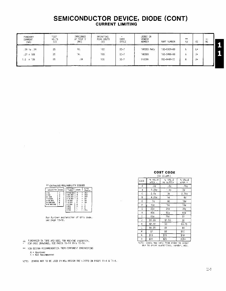
SEMICONDUCTOR DEVICE, DIODE (CONT) CURRENT LIMITING
COST CODE (CC COLUMN)
tt CATALOG RELIABILITY CODES
21 OW I l l 0 DW - ,005 210 000 1/10 WO - .o 1 2 1 0 0 m . .02 21WO000 112 OW 05 210 WO OW
112W - 5
L
PINCHOFF CURRENT
(MA)
.05 t o . 3 0
.27 i 10%
1 .2 i 10%
F o r f u r t h e r e x p l a n a t i o n o f t h i s code, see page 73-18.
TEST VOLTS
( v )
2 5
25
25
aa PURCHASED ON TAPE AND REEL FOR MACHINE INSERTION t FOR CASE DRAWINGS, SEE PAGES 13-14 t h r u 13-16.
IMPEDANCE AT TEST V
(Mn)
10.
14.
. 64
** NEW DESIGN RECOMMENDATION FROM COMPONENT ENGINEERING
JEDEC OR VENDOR NUMBER
1 N5283 Fmly
1 N5285
IN5299
ppy-+pj $22 $25 $35+
NOTE: C o s t s may v a r y f r o m o r d e r t o o r d e r due t o o r d e r q u a n t i t i e s , vendor , e t c .
OPERATING PEAK VOLTS
( v )
100
100
100
A = Approved N = No t Recommended
PART NUMBER
152-0328-00
152-0490-00
152-0460-00
i CASE STYLE
DO-7
DO-7
DO-7
NOTE: ZENERS NOT TO BE USED I N NEW DESIGN ARE LISTED ON PAGES 11-4 & 11-5.
** NO
N
N
N
CC
L+
J +
J t
t i RC
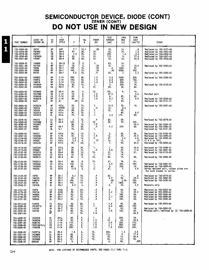
SEMICONDUCTOR DEVICE, DIODE (CONT)
PART NUMBER JEOEC OR VENDOR NO.
1 N707 1 N2995 112971 1 N2985A 1 N2991
1 N466B 1N718A 1 N986 1 N988 1 N753
1 N3820 IN3816 11381 4 1 N3042A IN30048
1 N29848 1137988 1 N38048 1 N3807B 5622
1 N3027A 1 N961 A 1 N3029 1 N3031A 1N3041A
IN4372 1 N3008B 1 RS5651 1 N982 1 N483
IN3037 1 N3800A 1 N3Ol6A 1 N2620 1 N3033A
1N3033A 1 N968A 1 N3001 8 1 N3024A 1 N29978
1 N3001 B 1 N3044A 1 N3042A IN3016
1 N751 1 N972A 1N991A 4M140 1N753A
1 N976 1N970A 1 N980A 1 N977A 1 N98OA
113032 1M105Z10 1 N976A 1 N979A
lN30428 1 N38008 IN38148 I N3816B Fml) l N3820B
I N2971 8 l N29858 IN29918 IN29958 ;REA35
ZENER (CONTI
DO NOT USE WNEW DESIGN -
t CASE STYLE - A62 00-4 00-4 DO-4 00-4
00-13 DO-7 DO- 7 00-7 DO-7
C-14 C-14 C-14 A31a 00-4
00-4 C-14 C-14 C-14 A 1
A31a A3989 A31a A31a A31a
DO-7 DO-4
00-7 G- 1
A31a C-14 A31a A3la A31a
A31a 00-7 00-4 A31a 00-4
00-4 A31 a A31a A31a
00-7 00-7 DO-7 DO- 7 00-7
A398 A398 00-7 00-7 DO-7
A31a A31a 00-7 00-7
A31 a C-14 C-14 C-14 C-14
00-4 00-4 DO-4 00-4 DO- 7 -
- TOL
% - - 12.7 20. 20. 10. 20.
5. 5.
10. 10. 10.
20. 20. 20. 10. 5.
5. 5. 5. 5.
10.
10. 10. 20. 10. 10.
10. 5.
10. 20. 20.
10. 10. 10. 5.
20.
20. 10. 10. 10. 5.
5. 10. 10. 2.
10. 10. 10. 10 5.
20. 10. 10. 10. 10.
20. 10. 10. 10. 10.
5. 5. 5. 5. 5.
5. 5. 5. 5. 5. -
POWER ( W
.25 10. 10. 10. 10.
1. .25 .25 .25 .4
1.5 1.5 1.5 1.
10.
10. 1.5 1.5 1.5
1. .4
1. 1. 1.
.4 10. 1.5
.4 1.
1. 1.5 1.
.75 1.
1. .4
10. 1.
10.
10. 1. 1. 2.
.4 .4 .4 .4 .4
.4
.4
.4
.4 .4
1. 1.
.4
.4 1.8
1. 1.5 1.5 1.5 1.5
10. 10. 10. 10.
TEST CURRENT (d
IMPD MAX In)
10. 14.
1.3 5.
10.
14. 13.
1000. 2000.
7.
1000. 600. 300. 200. 35.
4.
45. 75. 50.
22. 8.5
25. 40.
175.
29. 75.
270.
90. 25. 3.5
15. 50.
50. 29. 18. 14. 15.
18. 350. 200.
7.
17. 49.
2.2k 1300.
10.
93. 33.
185. 105. 185.
45. 400.
93. 150.
200. 25.
300. 550.
1000.
1.3 5.
10. 14. 40.
NOTE: FOR LISTINGS OF RECOMMENDED PARTS, SEE PAGES 11-1 THRU 11-3.
- TEMP COEF
(mV/"C)
.6 7.2 3.4
17.6 30.6
10.5 91.
140. 2.2
200. 140. 10. 74. 82.
15. 5.5
39. 9.6
15.
8.5 68.
120. 30.6 68.
45. 25.5 2.8
.01 30.6
30.6 17.6 61.
46.
61. 100. 74.
5.4
.6 25.5
180. 140.
2.2
39. 19.2 56. 42. 56.
28. 105. 39. 54. 22.9
74. 25.5
110. 140. 200.
3.4 17.6 30.6 42.
.005
OTHER
Replaced by 152-0127-00 Replaced by 152-0303-00 Repl aced by 152-0300-00 Repl aced by 152-0301 -00 Replaced by 152-0302-00
Replaced by 152-0243-00
Replaced by 152-0280-00
Replaced by 152-0299-00
Replaced by 152-0135-00
Matched p a i r
Repl aced by 152-0264-00 Replaced by 152-0141 -01
Repl aced by 152-0291 -00
Replaced by 152-0278-00
Replaced by 152-0294-00 Repl aced by 152-0286-00 Repl aced by 152-01 01 -00
Repl aced by 152-01 50-00 Replaced by 152-0296-00 Repl aced by 152-0290-00 TC @ 0 t o 75'C Repl aced by 152-0296-00
Replaced by 152-0296-01 Replaced by 152-0281-00 Repl aced by 152-0133-00
Repl aced by 152-0096-00
Replaced by 152-0087-00 Replaced by 152-0295-00 Series matched pa i r , values given are f o r both diodes i n series.
Repl aced by 152-0279-00 Repl aced by 152-0282-00 Repl aced by 152-0289-00
Motorola only
Replaced by 152-0283-00 Replaced by 152-0265-00 Replaced by 152-0285-00 Repl aced by 152-0284-00 Replaced by 152-0285-00
Replaced by 152-0293-00
Replaced by 152-0283-00 Matched p a i r ; replaced by (2) 152-0268-00
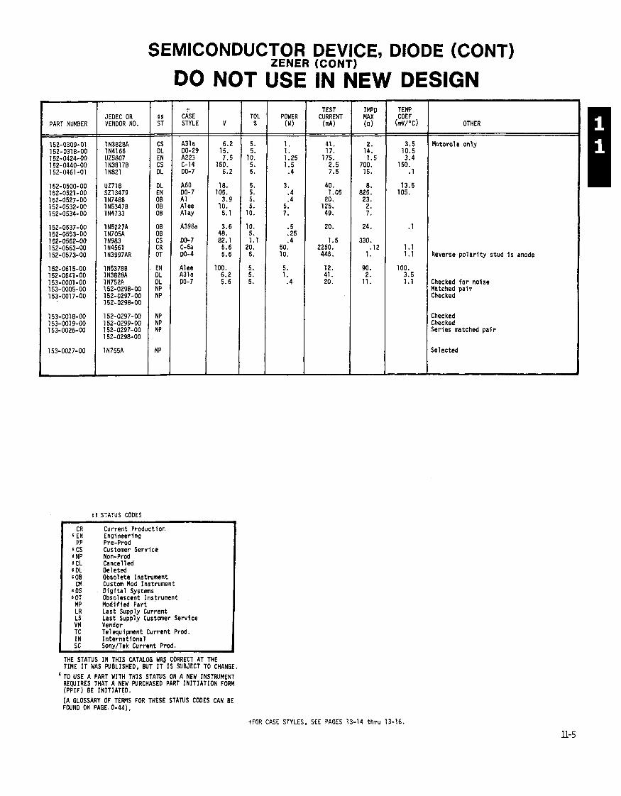
I PART NUMBER JEDEC OR VENDOR NO.
5 5 STATUS CODES
SEMICONDUCTOR DEVICE, DIODE (CONT) ZENER (CONTI
DO NOT USE IN NEW DESIGN -
t CASE STYLE
A31a DO-29 A223 C-14 DO- 7
A60 DO- 7 A1 A1 ee A1 ay
A398a
DO- 7 C-5a DO-4
A1 ee A31a DO-7
-
Current Product ion Engineering Pre-Prod Customer Service Non-Prod Cancel l e d Deleted Obsolete Instrument Custom Mod Instrument D i g i t a l Systems Obsolescent Instrument Modif ied Par t Last Supply Current Last Supply Customer Service . . - Vendor Telequlpnent Current Prod. I n te rna t i ona l SonvITek Current Prod.
THE STATUS IN THIS CATALOG WAS CORRECT AT THE TIME I T WAS WBLISHED, BUT I T IS SUBJECT TO CHANGE. ' TO USE A PART WITH THIS STANS ON A NEW INSTRUMENT
REWIRES THAT A NEW PURCHASED PART INITIATION FORM (PPIF) BE INITIATED. (A GLOSSARY OF TEMS FOR THESE STANS CODES CAN BE FWND ON PAGE. 0-44).
- TOL
% - -
5. 5.
10. 5. 5.
5. 5. 5. 5.
10.
10. 5. 1.1
20. 5.
5. 5. 5.
POWER (W)
1. 1. 1.25 1.5
.4
3. .4 .4
5. 7.
.5 .25 .4
50. 10.
5. 1.
.4
TEST CURRENT
(mA)
41. 17.
175. 2.5 7.5
40. 1.05
20. 125. 49.
20.
1.5 2250. 445.
12. 41. 20.
- IMPD MAX (n)
2. 14. 1.5
700. 15.
8. 825. 23. 2. 7.
24.
330. .12
1.
90. 2.
11.
TEMP COEF
( ~ v / o c )
3.5 10.5 3.4
150. 1
13.5 105.
.1
1.1 1.1
100. 3.5 1.1
OTHER
Motor01 a on l y
Reverse p o l a r i t y s tud i s anode
Checked f o r no ise Matched p a i r Checked
Checked Checked Series matched p a i r
Selected
+FOR CASE STYLES, SEE PAGES 13-14 t h r u 13-16.

NOTES
COST CODE
NOTE: Costs may vary from order to order due to order quantities, vendor, etc.
ILITY CODES
FOR FURTHER EXPLANATION OF THIS CODE, SEE PAGE 13-18.
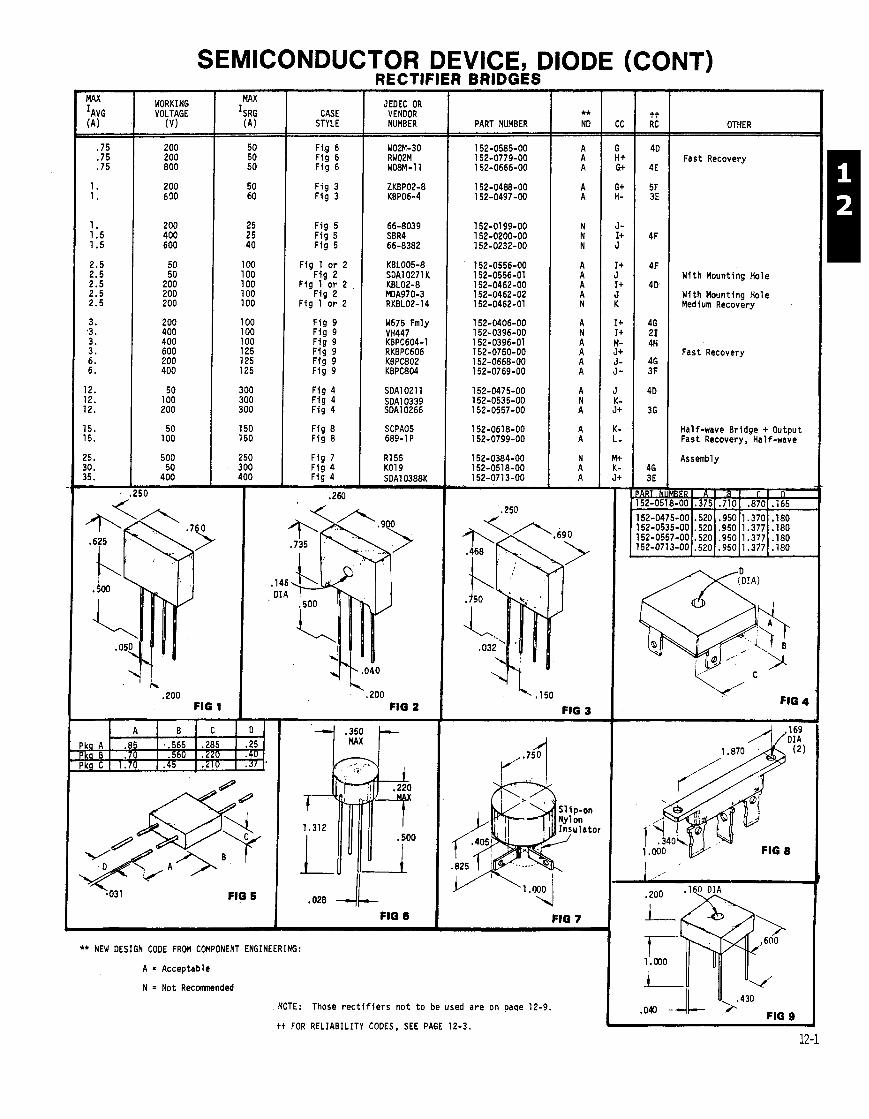
SEMICONDUCTOR DEVICE, DIODE (CONT) RECTIFIER BRIDGES -
MAX IAVG (A)
.75
.75
.75
1. 1.
1. 1.5 1.5
2.5 2.5 2.5 2.5 2.5
3. ,3. 3. 3. 6. 6.
12. 12. 12.
15. 15.
25. 30. 35.
WORKING VOLTAGE
JEDEC OR VENDOR NUMBER
CASE STYLE RC +* I OTHER PART NUMBER
40 1 Fast Recovery 4E
F i g 6 F ig 6 F ig 6
F i g 3 F ig 3
F i g 5 F i g 5 F i g 5
F i g 1 o r 2 4F With Mounting Hole
4D With Mounting Hole Medium Recovery
F ig 2 F i g 1 o r 2
F ia 2 F ig 1-or 2
F i g 9 F ig 9 F i g 9 F ig 9 F i g 9 F i g 9
W675 Fmly VH447 KBPC604-1
Fast Recovery
F ig 4 F i g 4 F i g 4
F ig 8 F ig 8
F ig 7 F ig 4 F ig 4
.260
SDAl 021 1 SDAlO339 SDA10266
Half-wave Bridge + Output Fast Recovery, Half-wave
. ' h .zoo
FIG 1 I 'v- FIG 4 ,200 FIG 2
,150
FIG 3
Sl ip-on Nylon Insu la tor
'4 FIG 7
** NEW DESIGN CODE FROM COMPONENT ENGINEERING:
A = Acceptable
N = Not Recmended
NOTE: Those r e c t i f i e r s no t t o be used a re on paqe 12-9.
tt FOR RELIABILITY CODES, SEE PAGE 12-3.
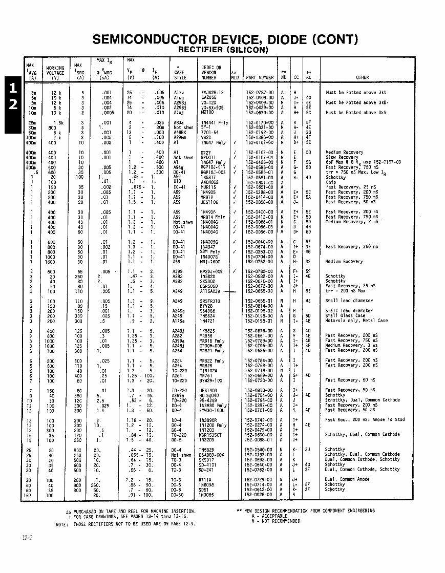
SEMICONDUCTOR DEVICE, DIODE (CONT) - IAX
[AV( (A; - - 3n 5n 5n
1 al 1 al
2 8 36r 5 h om I O h
I O h loor loan i O h
1 1 1 1 1 1
1 1 1 1 1
1 1 1 1 1
2 3 3 3 3
3 3 3 3 3
3 3 3 3 5
5 5 6 6 7
7 8
10 12 12
12 12 12 15 15
!5 !5 10 10 I0
I0 i0 i0
- WORKING VOLTAGE
(V)
12 k 10 k 12 k 5 k
10 k
1.5k 800
5 k 2 k
400
400 400 400 600 600
20 100 150 200 200 400
400 400 400 400 400
600 800 800
1000 1600
600 20 40 50
100
100 150 200 200 200
400 600
1000 1000 100
200 600 100 100 100
150 40 30
100 100
100 100 300 3 5
100
20 40 20 3 5 40
100 40 3 5
7
MAX
ISRG (A) - -
5 3 3 3 2
3 5 3 3
10
10 10 10 30 30
100
35 30 3 0 20
3 0 30 40 40 50
50 30 50 3 0 30
65 250 80 80
110
110 80
150 300 300
125 100 100 125 300
300 110 40
400 80
80 380 120 200 200
200 200 200 120 250
800 250 500 600 500
250 800 800
-
.005
.005 ,005 ,010 .010
.025 3 all
,050 . I00 .400
.400
.400 ,400 .so0 .so0
RECTIFIER (SILICON)
t CASE STYLE
A1 zv Alug A2983 A2983 A l x j
A83a Not shwn A48BK A298m A1
A1 Not shwn A1 A949 DO-41 A59 U10 DO-41 A59 A59 A59
A59 A59 - Not shwn DO-41 00-41
00-41 DO-41 DO-41 DO-41 A59
A399 A282 A282
A249
A249
A2499 A249 A1 79a
A248j A282 A399a A248j A264
4264 A264 10-220 4264 TO-220
TO-220 4399a TO-220 10-4 10-4
10-4 10-4 10-4 ro-220 M-5
10-4 l o t shwn '0-3 10-4 '0-3
'0-3 10- 5 10- 5 10-30
JEDEC OR VENDOR NUMBER -- ESJA25-12 SA2055 VG-1 2X VG-5X-905 MXl 00
IN4441 Fml, SF-1 7701-54 V820 IN647 Fmly
6727 GPDOll IN647 Fml RGPIOJ-017 RGP10J-005 1 N58l7 A4D4002 MUR115 114935 MR812 UES1106
1 N4936 MR814 Fmly 1 N4004G 1 N4004G 1 N4004G
1 N4005G 1 N4947 S8M Fmly 1 N4007G MRI-1600
GP2OJ-009 IN5820 SKSOO2 DSR5050 A115AX39 - SRSFR3lO BYV28 554986 1 N5624 1 N4721
1 N5625 MR856 MR918 Fmly GP30M-008 MR821 Fmly
MR822 Fmly MR826 lIRlO2A MR751 BYW29-100
UES1403 50 SQ040 95-4269 IN3890 Fmly 3YW30-10ou
I N3890R IN1200 Fmly I N1203 IBR1535CT 1 N3209
I N5829 ISAD83-004 iKSOl7 3D-4101 iD-241
V l l A I N6098 iD51 I N3085
PART NUMBER
152-O787-OO 1 52-0408-00 152-0409-00 152-0429-00 152-0639-00
152-0170-00 152-0331 -00 152-01 92-00 152-0385-00 152-01 07-00
152-01 07-03 152-01 07-04 152-0426-00 152-0586-00 152-0586-01 152-0581 -00 l52-O8Ol-OO 152-0601 -00 152-0398-00 152-041 4-00 152-0808-00
l52-O4OO-OO 1 52-0413-00 152-0066-01 152-0066-03 152-0066-00
152-0040-00 152-0674-00 152-0353-00 152-0704-00 152-0752-00
152-0782-00 152-0582-00 l52-O67O-OO 152-0672-00 152-0655-00
152-0655-01 152-081 4-00 152-01 98-02 152-0198-00 152-0198-01
152-0676-00 152-0661 -00 152-0789-00 152-0706-00 152-0686-00
152-0784-00 152-0768-00 152-071 8-00 152-0659-00 152-0720-00
152-081 0-00 152-0754-00 152-0794-00 152-0397-00 152-0721 -00
152-0742-00 152-0274-00 152-0479-00 152-0600-00 152-0088-01
152-0540-00 152-0793-00 152-0692-00 52-0640-00 52-0762-00
52-0729-00 52-0714-00 52-0642-00 52-0028-00
OTHER - - - -
Must be Potted above 3kV
Must be Potted above 3k8,
Must be Potted above 3kV
Medium Recovery Slow Recovery 6pF Max @ 8 VR use 152-0107-03 Fast Recovery, 750 nS trr = 750 nS Max, Low IR Schottky Chip Fast Recovery, 25 nS Fast Recovery, 200 nS Fast Recovery, 750 nS Fast Recovery, 50 nS
Fast Recovery, 200 nS Fast Recovery, 750 nS Medium Recovery, 2 uS %
Fast Recovery, 250 nS
Medium Recovery
Schottky Schottky Fast Recovery, 25 nS trr = 200 nS Max
Small lead diameter
Small lead diameter Small Glass Case Motorola on ly , Metal Case
Fast Recovery, 200 nS Fast Recovery, 750 nS Medium Recovery, 3 us Fast Recovery, 200 nS
Fast Recovery, 200 nS Fast Recovery, 200 nS
Fast Recovery, 50 nS
Fast Recovery, 50 nS Schottky Schottky, Dual, Comnon Cathode Fast Recovery, 200 nS Fast Recovery, 50 nS
Fast Rec., 200 nS; Anode i s Stud
Schottky, Dual, Comnon Cathode
Schottky Schottky, Dual, Comnon Cathode Dual, C m o n Cathode, Schottky Schottky Dual, Comnon Cathode, Schottky
Dual, C m o n Anode Schottky Schottky
AA PURCHASED ON TAPE AND REEL FOR MACHINE INSERTION. t FOR CASE DRAWINGS, SEE PAGES 13-14 t h ru 13-16.
NOTE: THOSE RECTIFIERS NOT TO BE USED ARE ON PAGE 12-9.
** NEW DESIGN RECOMMENDATION FROM COMPONENT ENGINEERING A - ACCEPTABLE N - NOT RECOMMENDED

(MAXIMUM) (AC, P-P)
SEMICONDUCTOR DEVICE, DIODE (CONT) VOLTAGE MULTIPLIERS
NOM WORKING VOUT
COST CODE
SERIES R
(n)
7.8 M
15.0 M 1.5 M 1.5 M
3.0 M 1.5 M 6.0 M 1.0 M
1.5 M 1.5 M 1.0 M
20.0 k 1.5 M
1.0 M 1.0 M 1.0 M 1.0 M
510.0 k
1.0 M 510.0 k
10.0 k 100.0 M
10.2 M 10.0 M 10.0 M
L x W x H
(INCHES)
MOUNTING
Studs ( D r i l l e d & Tapped)
Threaded Studs Threaded Studs Wire Terminals
Wire Terminals Wire Terminals Threaded Studs Wire Terminals
Threaded Studs Threaded Studs Wire Terminals Threaded Studs Studs (Tapped)
Special Wire Terminals Threaded Studs Wire Terminals Threaded Studs
Wire Terminals Threaded Studs
Threaded Studs Threaded Studs
Threaded Studs Threaded Studs Threaded Studs
HV CONNECTION
S t r a i g h t
S t r a i g h t R i g h t Angle Special Spade
Terminal
R i g h t Angle S t r a i g h t R i g h t Angle Special Spade
T e n i n a l
S t r a i g h t Wire Lead R igh t Angle TV s t r a i g h t
Special R i g h t Angle R igh t Angle S t r a i g h t R igh t Angle
S t r a i g h t R i g h t Angle
TV S t r a i g h t
R igh t Angle R i g h t Angle R i g h t Angle
+t CATALOG RE
21 000 210000 2 1 m m
rlo000000
PART NUMBER
!LIABILITY CODES
For f u r t h e r exp lanat ion o f t h i s code, see page 13-18.
NOTE: Costs may vary from order t o o rder due t o o rder q u a n t i t i e s , vendor, e t c .

MIN MAX MAX MAX I
BKN AVG IR V R ~ V~ @ IF '
v m~ V A @ V v m~
. 2 5 - 3
15 .1 - 10
I )
I
)
)
7 I 7 I 9
! I
)
1 )
I )
1 I
I
I ' I
I I I I I
I I I I
I
1 1
1 1 2 2 2
2,
I v I t FOR CASE ORAUINGS. SEE PAGES 13-14 THRU 13-16.
M MACHINE INSERTABLE DIODE. E = trp TEST: I CURRENT trr TEST: S SPECIAL TEST CIRCUIT.
NOTE: SIGNAL 6 SWITCHING DIODES NOT TO BE USE0 ARE ON PAGE 12-11.
SEMICONDUCTOR DEVICE DIODE SIGNAL A ~ p SWITCHI~G -
t CASE STYLE - -
C132
00-35 00-35 00-35 00-35 DO-35
00-35 00-35 00-35 00-35 00-35 M709
SOT-2: SOT-2:
Chip Chip Chip Chip
A330 A330
A330 A330t
M W g M491g M491 g Chip
P 1 P 1 P1 OG-7 00-35
00-35 00-35 00-35 00-7 00-7
00-7 00-35 00-7 DO-7 F l i p Chip
Chip 00-35 TO-92 SOT-23 SOT-23
SOT-23 DO-7 TO-92
SOT-23 DO-35 10-35 30-35 10-7
10-7
)O-7 10-7 11
10-7 -
(CONT) --
JEOEC OR VENDOR NUMBER
REVERSE RECVRY
r r IF - IR PART NUMBER
General Purpose, Low R,, 4V SMVl110 NO4973
5082-281 0 5082-2068 5082-2800
A2X1518 MA4Ell9 MA4E145 MA4E145M2 MA4E145M4 NO4121K3G
mavi 01 MMBO5Ol
5082-0087 MBOC5Ol MA4E424 MA4E278
HP9645 DM6777
QSCH-1608 QSCH-5806
05847A 5082-6878 NO487C2-3P MA40487
11538 MA49338 MA4934B F07003 ZS142
IN4152 Fmly IN41 52 IN4152 Fmly OA2740 OE140
DE102 OEl 01 DElO3 OE133 MMCFO914
FOC3600 IN4610 Fmly SSD2405 BAW56 Fmly BAV70
BAV99 FOH 1986 SSOl 1 50
MB0914 WG1308 FOH2161 Fmlj PV120 1N486A Fmly
TDl34l9
50561200
ED2007 Fmly S 6 6 r12G o r lN34A Fmly
IN634
General Purpose, 15V Matched Set o f 16 General Purpose, Hi Conduct. General Purpose, 25V General Purpose, 70V
High Speed High Speed High Speed High Speed, Matched P a i r High Speed, Matched Quad High Speed, Matched P a i r High Speed, Matched P a i r
Chip, 15V Chip, 5OV Chip, low C Chip. Special Spec.
Beam Leads Beam Leads. Low IR
Beam Leads, 70V Beam Leads, Series P a i r
Ring Quad Ring Quad Ring Quad, Crossover Ring Quad. Beam Leads
(SILICON) H.F. Mixer, KA Band H.F. Mixer, KU Band H.F. Mixer. K Band
Special Forward Recovery Spe
No markings on case
Chip
Mono l i t h i c Pr. Comnon Anode Pai r . Comnon Anode Pai r , C m n Cathode
Series P a i r
Mono l i t h i c Pr. C m n Cathodc
G a A d
HANIUM)
STATIC SENSITIVE
PAGE 10-0 FOR EXPLANATION.)
Tnrs APPLIES TO ALL DEVICES ON THIS PAGE WITH A BY PART NUBER: (SEE
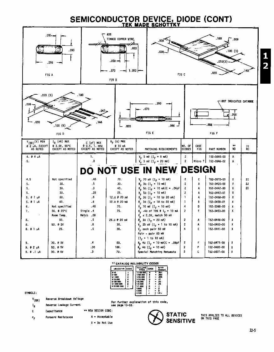
1 \ TINNED COPPER WIRE,
FIG A
YDOT INDICATES CATWE
L ,020
FIG E -4
FIG D FIG F
@ O.V, 1. mHz NO. OF CASE MATCHING REQUIREMENTS DIODES I FIG I PART NUMBER
V(,,)(V) MIN IR (nA) MAX @ 2 PA, EXCEPT @ 3.OV, 55OC
AS NOTED EXCEPT AS NOTE1
1. VF 5 mV ( I F = 5 mA) 2 152-0646-00 .8 V, 5 mV ( I F = 20 mA) 2 Micro T 152-0646-02 - - - L
DO NOT USE-IN NEW DESIGN .45 .5 .3 .28 .6 . 6 .45
Single .4 Match .08
.5
.8
.5
.4
.30
.3
70. VF 70 mV ( I F = 10 d) 30. 9 3n ( r F = 10 mA) 1 40. RF 5n ( I F = 10 tn4)C = .04pf 25. $ 5n ( l F = 10 mA)
12.n d 20 m4 RF 3n ( I F = 10 t o 20 mA) 12.n @ 20 mA RF 3n ( I F = 10 t o 20 mA)
70. VF 70 mV ( I F = 10 mA) 75. R~ -4n o f 10% @ I~ = 10 m~
V i 2.OV. match 50 mV F
25.n e 20 IM RF 3n ( I F = 20 mA)
30. VF 25 mV ( I F = 1 t o 10 mA) 30. VF each p a i r 50 mV
Pa i r - p a i r 60 mV
( I F = 1 t o 10 mA)
60. RF 4n (IF = 10 mA)C = .08pF loo. 9 4n ( I ~ = 10 mA) 70. Special Matching Requests
tt CATALOG RELIABILITY CODES
Not spec i f ied 30. 30. 30.
60. 60.
Not specif ied 50. @ 25OC Room Temp.
50.
50. @ 2V 25.
SYMBOLS:
V(BR) Reverse Breakdm Vol tage
IR Reverse Leakage Current For fu r the r explanatlon o f t h i s code, see page 13-18,
C Capacl tanct +r NEW DESIGN CODE:
rF Fomard Resistance A = Acceptable
X = Do Not Use
STATIC THIS APPLIES TO ALL DEVICES
SENSITIVE ON THIS PAGE
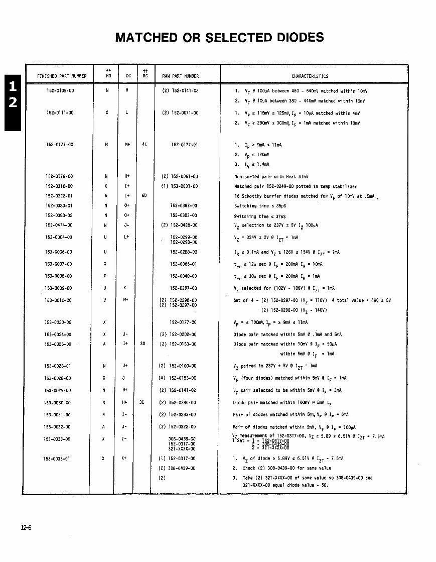
MATCHED OR SELECTED DIODES
FINISHED PART NUMBER RAW PART NUMBER CHARACTERISTICS
1. VF @ lOOpA between 460 - 54hV matched w i t h i n l h V
2. VF @ lOpA between 380 - 44OmV matched w i t h i n lOmV
1. VF 2 115mV r 125mV, IF = lOpA matched w i t h i n 4mV
2. VF r 28hV s 30hV, IF = ImA matched w i t h i n l h V
1. I p ~ 9 m A s l l m A
2. vp r 1 2 a l l v
3. IV s 1.4mA
Non-sorted p a i r w i t h Heat Sink
Matched p a i r 152-0249-00 pot ted i n temp s t a b i l i z e r
16 Schottky b a r r i e r diodes matched f o r VF o f 1 h V a t .5mA ,
Switching t ime s 35pS
Switching t ime s 37pS
VZ se lec t i on t o 237V i 5V IZ lOOuA
vz = 334v t 2v @ IZT = lmA
IR s O.lmA and V Z r 126V r 154V @ IZT = 1mA
trr s 12p sec @ IF = 2 0 h A IR = l h A
trr r 30p sec @ IF = 2OhA IR = 1mA
VZ se lec ted f o r (102V - 108V) @ IZT = 1mA
Set of 4 - (2) 152-0297-00 (VZ = 1lOV) 4 t o t a l value = 490 + 5V
(2) 152-0298-00 (Vz - 140V)
Diode p a i r matched w i t h i n 5mV @ .lmA and 5fnA
Diode p a i r matched w i t h i n l h V @ IF = 50pA
w i t h i n 5mV @ IF = 1mA
VZ pa i red t o 237V * 5V @ IZT = 1mA
VF ( f o u r diodes) matched w i t h i n 5mV @ IF = 1mA
VF p a i r se lec ted t o be w i t h i n 5mV @ IF = 3mA
Diode p a i r matched w i t h i n 1 0 h V @ 5mA IZ
P a i r o f diodes matched w i t h i n 5mV, VF @ IF = 6mA
P a i r o f diodes matched w i t h i n 5mV, VF @ I, = lOOuA
VZ measurement o f 152-0317-00, VZ r 5.89 s 6.51V @ IZT = 7.5M
set - i : ii!&#j 1. V Z o f diode r 5.89V s 6.51V @ IZT - 7.5mA
2. Check (2) 308-0439-00 f o r same value
3. Take (2) 321-XXXX-00 o f same value so 308-0439-00 and 321-XXXX-00 equal diode value - 50.
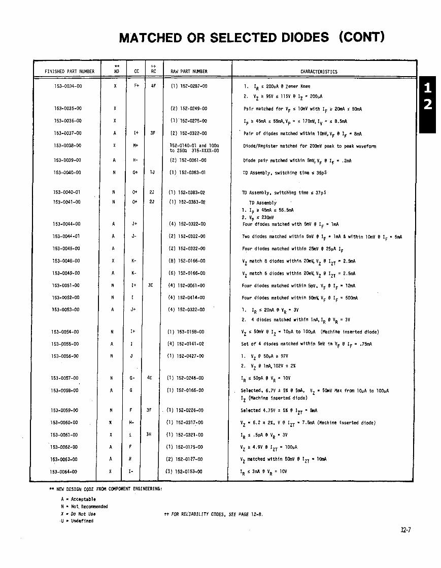
FINISHED PART NUMBER &
153-0034-00
153-0035-00
153-0036-00
153-0037-00
153-0038-00
153-0039-00
153-0040-00
153-0040-01
153-0041-00
153-0044-00
153-0044-01
153-0045-00
153-0048-00
153-0049-00
153-0051 -00
153-0052-00
153-0053-00
153-0054-00
153-PO55-00
153-0056-00
153-0057-00
153-0058-00
153-0059-00
153-0060-00
153-0061 -00
153-0062-00
153-0063-00
153-0064-00
** NEW DESIGN CODE FROM COMPONENT ENGINEERING:
A = Acceptable N - Not, Reconmended X = D o Not Use
.U = Undefined
RAW PART NUMBER
(2) 152-0249-00
(1 ) 152-0275-00
(2) 152-0322-00
152-01 40-01 and 1 OOn t o 250n 315-XXXX-00
(2) 152-0061-00
(1 ) 152-0383-01
CHARACTERISTICS
1. IR s200pA @ Zener Knee
2. VZ 2 95V s 115V @ IZ * 200pA
Pa i r matched f o r VF r l h V w i t h IF r 2RnA s 5RnA
Ip 2 45mA r 55m4,Vp = s 17hV, Iv = r 8 . M
Pa i r o f diodes matched w i t h i n lhV,VF @ IF = 8mA
Oiode/Register matched f o r 20hV peak t o peak waveform
Diode p a i r matched w i t h i n 5mV, VF @ IF = .2mA
TO Assembly, swi tch ing t ime s 35pS,
TO Assembly, swi tch ing t ime r 37pS
TO Assembly 1. Ip 2 45mA s 5 6 . M 2. Vp s 23hV Four diodes matched w i t h 5mV @ IF = lm4
Two diodes matched w i t h i n 5mV @ IF = 1mA 6 w i t h i n l h V @ IF = 5mA
Four diodes matched w i t h i n 25mV @ 25pA IF
VZ match 8 diodes w i t h i n 2hV, VZ @ IZT = 2 . M
V Z match 6 diodes w i t h i n 20mV, V Z @ IZT = 2 . W
Four diodes matched w i t h i n 4 V , VF @ IF = 12mA
Four diodes matched w i t h i n 5 h X VF @ IF = 5OanA
1. IR r 20nA @ VR = 3V
2. 4 diodes matched w i t h i n InA, IR @ VR = 3V
VZ s 5 h V @ I, = lOpA t o lOOuA (Machine inser ted diode)
Set o f 4 diodes matched w i t h i n 5mV i n VF @ IF = .75mA
1. VZ @ 50pA r 97V
2. V Z @ l m q 1 0 2 V * 2 %
IR s 50pA @ VR = 10V
Selected, 6.7V * 5% @ 5m4, V Z a 5 h V Max from lOpA t o lOOpA IZ (Machine i nse r ted diode)
Selected 4.75V * 5% @ IZT = M
VZ = 6.2 i 2%, V @ IZT = 7 . W (Machine inser ted diode)
IR s .5pA @ VR = 3V
VZ 2 4.9V @ IZT = lOOuA
VZ matched w i t h i n 5 h V @ IZT = lW
IR s 3nA @ VR = 10V
tt FOR REL'IABILITY CODES, SEE PAGE 12-8.
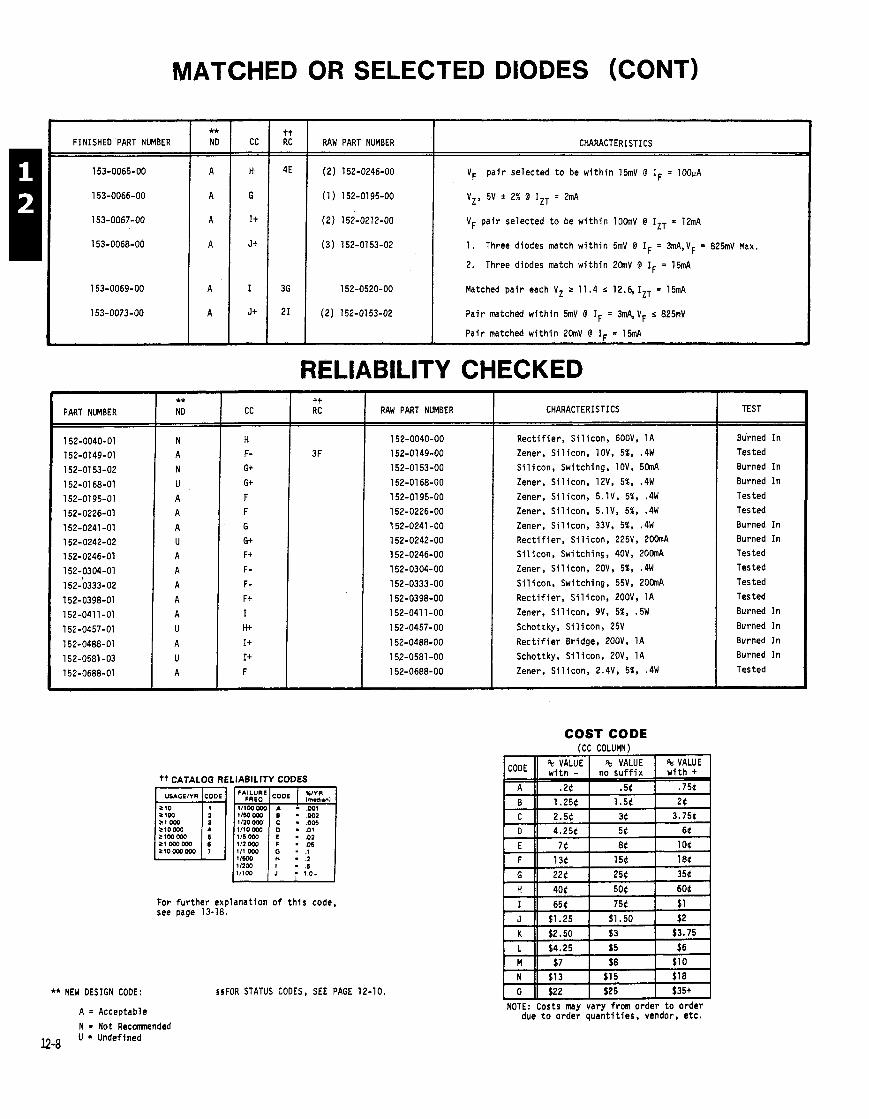
MATCHED OR SELECTED DIODES (CONT)
FINISHED PART NUMBER
4E I (2) 152-0246-00 I VF p a i r selected t o be w i t h i n 15mV @ IF = 100~A
tt RC
** ND
1. Three diodes match w i t h i n 5mV @ IF = 3mA,VF = 825mV Max.
2. Three diodes match w i t h i n 2 h V @ IF = 15mA
RAW PART NUMBER CC
(1 ) 152-01 95-00
(2) 152-0212-00
l52-O52O-OO I Matched p a i r each V Z 2 11.4 .g 12.6,1ZT = 15mA
CHARACTERISTICS
VZ, 5V * 2% @ I,, = 2mA
VF p a i r selected t o be w i t h i n 10hV @ IZT = 12mA
21 1 (2) 152-0153-02 I Pa i r matched w i t h i n b V @ IF = 3m4,VF r 825nV
Pa i r matched w i t h i n 2(hV @ IF = 15mA
RELlABlLlTY CHECKED -
PART NUMBER 1 CC I I RAW PART NUMBER
** NEW DESIGN CODE:
'+ CATALOG RE iLIABILITY CODES
lmldoanl
.05 111 WO
- 1.0t
For f u r t he r explanat ion o f t h i s code. see page 13-18.
A = Acceptable
N Not Reconended
124 U = Undefined
§#FOR STATUS CODES, SEE PAGE 12-10.
- CODE - -
A - B - C - D - E - F - G - H - I - J - K - L - M - N - 0
NOTE:
CHARACTERISTICS
R e c t i f i e r . S i l i con , 600V, 1A
Zener, S i l i con , 10V, 51, .4W
S i l i con , Switching, 10V, 5 h A
Zener, S i l i con , 12V, 5%. .4W
Zener, S i l i con , 5.1V, 5%, .4W
Zener, S i l i c o n , 5.1V, 5%, .4W
Zener, S i l i con , 33V, 5%, .4W
R e c t i f i e r , S i l i c o n , 225V, 20hA S i l i con , Switching, 40V, 20hA
Zener, S i l i con , 20V, 5%, .4W
S i l i con , Switching, 55V, 2OhA
R e c t i f i e r , S i l i con , 200V, 1A
Zener, S i l i c o n , 9V, 5%, .5W
Schottky, S i l i con , 25V
R e c t i f i e r Bridge, 200V, 1A
Schottky, S i l i con , 20V, 1A
Zener, S i l i con , 2.4V, 5%, .4W
COST CODE ICC COLUMN)
TEST
Burned I n
Tested
Burned I n
Burned I n
Tested
Tested
Burned I n Burned I n
Tested
Tested
Tested
Tested
Burned I n
Burned I n
Burned I n
Burned I n
Tested
%VALUE I % VALUE I %VALUE 1
-- ~
654 754 $1 $1.25 $1.50 $2
$2.50 $3 $3.75
$4.25 $5 $6
$7 $8 $1 0 $1 3 $1 5 $1 8
$22 $25 $35+
:osts IMV varv from order t o order . - .
due t o orde; quan t i t i es . vendor, e t c .
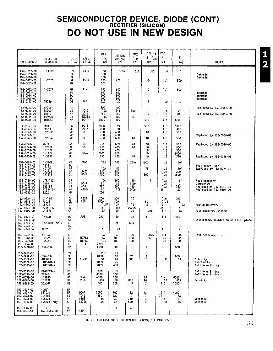
SEMICONDUCTOR DEVICE, DIODE (CONT) RECTIFIER (SILICON)
DO NOT USE IN NEW DESIGN -
5 5 STATU - -
CS DL DL NP NP
NP DL DL DL OB
NP CS NP CR NP
CS DL NP NP NP
NP DL 08 OB DL
CS DL NP NP DL
CR NP NP NP NP
CS CR OT DL CR
DL CS CR DL 08
CR CR CR DL NP
CS DL CR OB 00
- CASE STYLE - - A31 a
A38AH
A1 es
A46
00-5 00-3 MI 76a 00-4
00-4 DO- 7 DO- 1
00-1
DO- 1 00-1
00-4
00-5
A-21 00-1
00-7 A50 A48BJ
A224 A89
498
11 76a 11 76a -0- 5
11 79c
0-4 0-5
0- 1 0- 3 282 179c
- MAX
IAV: (d,
100 500 500 750 500
750 500 500 500 120
500 10A
750 3A
3000
3000 400 750 750 750
750 750
1500 3000
750
15A
10A 200
1600
5A 50
750 20
250
200 1500
1.5 5 3A
1000
5
3A 3A
.5 1600 1500
JEOEC OR VENDOR NO. PART NUMBER OTHER
Tekmade Tekmade
Tekmade Tekmade Tekmade
Replaced by 152-0047-00
Repl aced by 152-0066-00
Repl aced by 152-0066-01
Replaced by 152-0040-00
Replaced by 152-0066-01
Unselected P a i r Replaced by 152-0274-00
Fast Recovery Germanium Repl aced by 152-0040-00 Replaced by 152-0408-00
Medi um Recovery
Fast Recovery, 200 nS
114936
752-0384 Fmly
H345
SRT936 1 N4999 1 N5000
552-634
Unselected, mounted on an alum. p l a t e
Fast Recovery, 1 US
Schottky Matched P a i r F u l l Wave Bridge
MOA902A-2 VH148 1 N388O 1 N5832 SCAJ6F
40891 021 03s 1 N4785 1 N5821 IN5824 Fmly
3L05 152-0066-00
F u l l Wave Bridge F u l l Wave Bridge
Schottky
Schottky Schottky
NOTE: FOR LISTINGS OF RECOMMENDED PARTS, SEE PAGE 12-2.
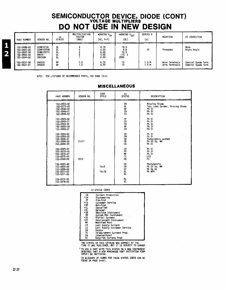
PART NUMBER VENDOR NO. I
SEMICONDUCTOR DEVICE, DIODE (CONT) VOLTAGE MULTIPLIERS
DO NOT USE IN NEW DESIGN
NOTE: FOR LISTINGS OF RECOMENDEO PARTS. SEE PAGE 12-3.
MISCELLANEOUS
MULTIPLICATION WORKING VIN WORKING VOUT 5 5 FACTOR
STATUS (MAX) (AC, P-P) (DC)
PART NUMBER
SERIES R
h)
- --
VENDOR NO. STYLE STATUS
5 5 STATUS CODES --
CR Current Production 6 EN Engineering
PP Pre-Prod SCS Customer Service SNP Non-Prod SCL Cancel l e d SDL Deleted SOB Obsolete Instrument CM Custom Mod Instrument
SDS D i g l t a l Systems 80T Obsolescent Instrument MP Modif ied Part LR Last Supply Current LS Last Supply Customer Service VN Vendor TC Telequipnent Current Prod.
Threaded
MOUNTING
None Right Angle
HV CONNECTION
DESCRIPTION
Wire Terminals Wire Terminals
Missing Diode Tab, Lead Spider, Missing Diode Ph Si Ph Si Ph Si
Special Spade Term. Special Spade Term.
Ph Si Ph Si Photo-optic potted Ph 20 Sq. MM Ph Si
Ph Si Ph Si Ph S i LED Ph
Photometric Ph 20 Sq. MM Ph Ga As Ph WPN
IN Internat ional SC SonylTek Current Prod. L
THE STATUS IN THIS CATALOG WAS CORRECT AT THE TIME IT WAS WBLISHED, BUT IT IS SUBJECT TO CHANGE.
'TO USE A PART WITH THIS STATUS ON A NEW INSTRUMENT REQUIRES THAT A NEW PURCHASED PART INITIATION FOW (PPIF) BE INITIATED.
(A GLOSSARY OF TEMS FOR THESE STATUS CODES CAN BE FOUND ON PAGE 0-44).

SEMICONDUCTOR DEVICE, DIODE (CONT)
DO NOT USE IN MEW DESIGN
CASE STYLE
00-7 DO- 7
A22
00-7 00-35 DO- 7 00-35
00-7
00-35 DO- 7 00-7 00-35 00-35 on l y
00-7 onl, P- 3
- MIN BKN v - -
125
25
15 30 40
40
15 200 40
40
40
100
50 35
50 30
coo 100
5
6 75
10 10
6
i
- MAX V~ v - -
1. 1. 1. 1.
1. 1. 1.5
.55
.55 1 .o
1. 1. 1.
.55
.55
.5
.5 1. 1. 1. 2
1. 1.3
1.3 1.3
.25 1.
LEVERSE RECOVERY
'rr IF - IR
ns mA OTHER
MAX IR @ VRF u A V
(suconj JEOEC OR VENDOR NO, PART NUMBEI
T13G 1 N662A IN914 H05000 1 N3258
F0613 H05004 1 N625 1 N36O5 114152 Fml
1 N4l52 1 N999
152-0141-C
HP5082 IN3579 Fml 1 N999 1 N4152 1 N4152
CD8204 IN4160
IN4150
1 N82A Fmly CG8l H 114442 OH01 25 Tek Made
1 N78BMR
YHG9008 FSA1480
DEl 01 FSA1544 ' -PE100
\2S100 IN5297
JM6601A I N3O7O 152-0026-O(
5-6778-94
N91 '1 36
16- 100 N281
01841 02007
N87A 01872G
N198
Trimned, Gold PI Leaf
w/Cl ipped Leads
Non-sorted p a i r i n temp. s t a b i l i z e r
Hot Ca r r i e r
Use 152-0141-02
HF Mixer S Band HF Mixer HF Mixer X Band
HF Mixer, 1 GHz
A90 P3A
DO- 7
00-35 A1 59
Pl 8
00-7 TO-72
00-35 TO-18
Chip 00-7
A398
A330
00-3 A 1 DO- 7 00-7 00-7
DO- 7 DO- 7 00-7 00-7 00-7
A2 1
Series p a i r i n temp, s t a b i l i z e r
Yatched P a i r 4F Mixer KU Band
Series pa i r , case i so la ted
:ase i so la ted . ight Emi t t ing Diode (atched Pa i r jot Car r i e r
'hoto Diode w/Red LEO f l l t e
(atched P a i r w/Heat Sink
latched Pa i r Ctched Pa i r latched Pa i r
learn Leads
5OMz MAX
NOTE: FOR LISTINGS OF RECMENOEO PARTS, SEE PAGES 12-4 1 12-5.
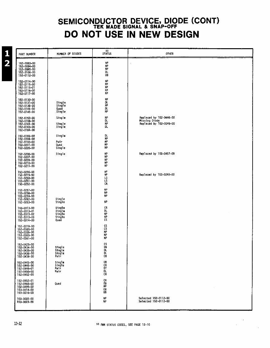
PART NUMBER
SEMICONDUCTOR DEVICE, DIODE (CONT) TEK MADE SIGNAL & SNAP-OFF
DO NOT USE IN NEW DESIGN
NUMBER OF DIODES
Single Single Quad Single
Single
Single Single
Single
Pa i r Quad Single
Single
Single Single
Single Single Single Single Quad
Single Single Single Pai r
Single Single Pai r Pai r
Quad
5 5 STATUS OTHER
Repl aced by 152-0446-00 Missing Diode Repl aced by 152-0249-00
Repl aced by 152-0457-00
Repl aced by 152-0249-00
Selected 152-01 12-00 Selected 152-01 12-00
8 ' FBR STATUS CODES. SEE PAGE 12-10

SEMICONDUCTOR DEVICE, DIODE
S E C T I O N 1 3
T A B L E O F C O N T E N T S
P A G E ( S )
C R O S S R E F E R E N C E I N D E X E S I
T E K P A R T N U M B E R T O V E N D O R N U M B E R I N D E X 1 3 - 2 T H R U 1 3 - 1 0 J E D E C N U M B E R T O T E K P A R T N U M B E R I N D E X n m , , , , 1 3 - 1 2 & 1 3 - 1 3
D I O D E C A S E D R A W I N G S , , , , , , , t , n , , s 8 8 , 1 3 - 1 4 T H R U 1 3 - 1 6 R E L I A B I L I T Y N O T E S , ~ ~ ~ , ~ ~ ~ 8 ~ , , , , , , , , , , 1 3 - 1 8
A P P L I C A T I O N N O T E S Z E N E R D I O D E S . . . . . . . . . . . . . . . . . . . . . . . . . . . . . . . 1 3 - 1 9
H O T C A R R I E R D I O D E S , s , , , , B , , t , m , , , , 1 3 - 2 0
H A N D L I N G O F S T A T I C S E N S I T I V E C O M P O N E N T S 1 3 - 2 1 N O T E S , , 1 3 - 1 1 & 1 3 - 1 7
COST CODE (CC CoLurn)
, , NOTE: Costs may vary from order t o order due t o order q u a n t i t i e s , vendor, e t c .
CATALOG WRITER: NANCY KING. EXT. 2582.
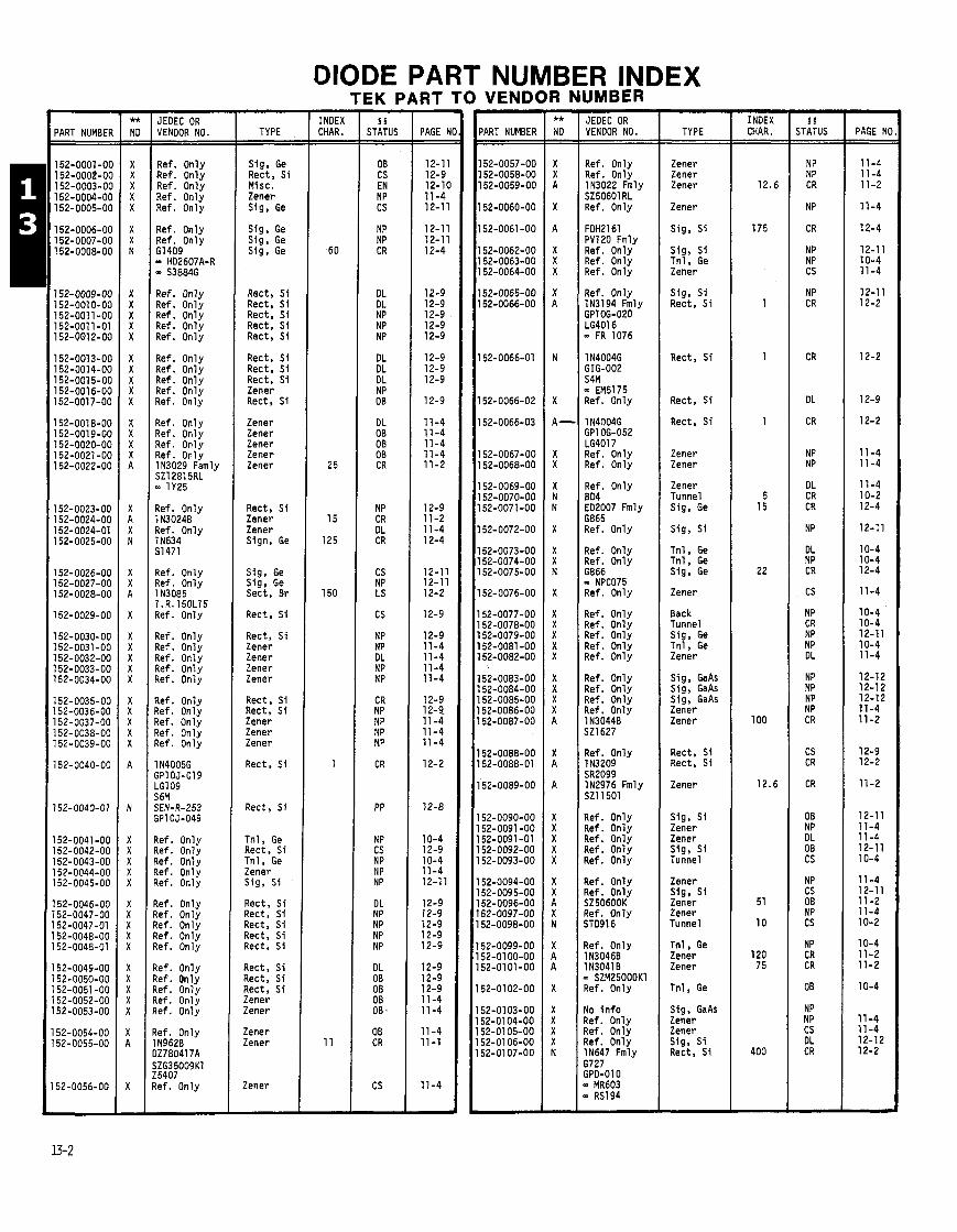
DIODE PART NUMBER INDEX TEK PART TO VENDOR NUMBER
PART NUMBER
152-0001-00 152-0002-00 152-0003-00 152-0004-00 152-0005-00
152-0006-00 152-0007-00 1 52-0008-00
152-0009-00 152-001 0-00 152-001 1-00 152-001 1-01 152-001 2-00
152-0013-00 152-0014-00 152-0015-00 152-001 6-00 152-0017-00
152-0018-00 152-0019-00 152-0020-00 152-0021 -00 152-0022-00
152-0023-00 152-0024-00 152-0024-01 152-0025-00
152-0026-00 152-0027-00 152-0028-00
152-0029-00
152-0030-00 152-0031-00 152-0032-00 152-0033-00 152-0034-00
152-0035-00 152-0036-00 152-0037-00 152-0038-00 152-0039-00
152-0040-00
152-0040-01
152-0041 -00 152-0042-00 152-0043-00 152-0044-00 152-0045-00
152-0046-00 152-0047-00 152-0047-01 152-0048-00 152-0048-01
152-0049-00 152-0050-00 152-0051-00 152-0052-00 152-0053-00
52-0054-00 52-0055-00
52-0056-00
JEDEC OR VENDOR NO.
Ref. Only Ref. Only Ref. Only Ref. Only Ref. Only
Ref. Only Ref. Only GI 409 - HD2607A-R
Ref. Only Ref. Only Ref. Only Ref. Only Ref. Only
Ref. Only Ref. Only Ref. Only Ref. Only Ref. Only
Ref. Only Ref. Only Ref. Onlv Ref. 0nl; IN3029 Famly SZ12815RL - 1Y25
Ref. Only 1 N3024B Ref. Only 1 N634 GI471
Ref. Only Ref. Only IN3085 l.R.150L15 Ref. Only
Ref. Only Ref. Only Ref. Only Ref. Only Ref. Only
Ref. Only Ref. Only Ref. Only Ref. Only Ref. Only
1 N4005G GPlOJ-019 LG109 S6M SEN-R-253 3P1 OJ-049
Ref. Only Ref. Only Ref. Only Ref. Only Pef. Only
?ef. Only ?ef. Only 2ef. Only 2ef. Only 2ef. Only
?ef . Only Ief . Only ?ef. Only ?ef . Only l e f . Only
tef . Only 1 N962B 3278041 7A iZG35009K1 I5407 le f . Only
TYPE
Sig, Ge Rect, S i Misc. Zener Sig, Ge
Sig, Ge Sig, Ge Sig, Ge
Rect, S i Rect, S i Rect, S i Rect, S i Rect, S i
Rect, S i Rect, S i Rect, S i Zener Rect, S i
Zener Zener Zener Zener Zener
Rect, S i Zener Zener Sign, Ge
Sig, Ge Sig, Ge Sect, Br
Rect, S i
Rect, S i Zener Zener Zener Zener
Rect, S i Rect, S i Zener Zener Zener
Rect, S i
Rect, S i
Tnl, Ge Rect, S i Tnl, Ge Zener Sig, S i
Rect, S i Rect, S i Rect, S i Rect, S i 1 Rect, S i
Rect, S i Rect, S i Rect, S i Zener Zener
Zener Zener
Zener
- INDEX CHAR. - -
60
2 5
15
125
150
1
11
- 5 5
STATUS - - - PAGE - -
12-1 12-5 12-1 11 -4 12-1
12-1 12-1 12-4
12-9 12-9 12-9 12-9 12-9
12-9 12-9 12-9
12-9
11-4 11 -4 11-4 11-4 11-2
12-9 11-2 11 -4 12-4
12-1 12-1 12-2
12-9
12-9 11-4 11-4 11-4 11 -4
12-9 12-9 11 -4 11-4 11 -4
12-2
12-8
10-4 12-9 10-4 11 -4 12-1
12-9 12-9 12-9 12-9 12-9
12-9 12-9 12-9 11 -4 11-4
11-4 11 -1
11 -4
-
ART NUMBER
52-0057-00 52-0058-00 52-0059-00
52-0060-00
52-0061-00
52-0062-00 52-0063-00 52-0064-00
52-0065-00 52-0066-00
52-0066-01
52-0066-02
52-0066-03
52-0067-00 52-0068-00
52-0069-00 52-0070-00 52-0071 -00
52-0072-00
52-0073-00 52-0074-00 52-0075-00
52-0076-00
52-0077-00 52-0078-00 52-0079-00 52-0081 -00 52-0082-00
52-0083-00 52-0084-00 52-0085-00 52-0086-00 52-0087-00
52-0088-00 52-0088-01
52-0089-00
52-0090-00 52-0091 -00 52-0091-01 52-0092-00 52-0093-00
52-0094-00 52-0095-00 52-0096-00 i2-0097-00 i2-0098-00
i2-0099-00 i2-0100-00 i2-0101-00
i2-0102-00
i2-0103-00 i2-0104-00 i2-0105-00 i2-0106-00 i2-0107-00
- NO. - -
0
1 1
1
1 1
1
d
JEDEC OR VENDOR NO.
Ref. Only Ref. Only 1N3022 Fmly SZ50601 RL Ref. Only
1 1 1
1 1
FDH2161 PV120 Fmly Ref. Only Ref. Only Ref. Only
p
P =
1
I !
l1 1 ' 1 '
11 1 !
1 !
I !
1 !
1 ! l!
1 ' 1 ! 1 !
1 !
1 ! 1 ! l !
l !
1 ! 1 ! 1 ! 1 ! 1 !
I ! 1 ! 1 ! 1 ! 1 !
I! 1 !
1 !
1 ! 1 ! 1 ! l! 1 !
I t 1 ! 15 11 I f
1 E 1 ! 1 f
1 E
1E 1 E 1 E 1 E 1:
m
Ref. Only IN3194 Fmlv
1 N4004G GIG-002 S4M - EM5175 Ref. Only
1 N4004G GP1 OG-052 LG4017 Ref. Only Ref. Only
Ref. Only BD4 ED2007 Fmly 6865 Ref. Only
Ref. Only Ref. Only 6866 - NPC075 Ref. Only
Ref. Only Ref. Only Ref. Only Ref. Only Ref. Only
Ref. Only Ref. Only Ref. Only Ref. Only 1 N3044B SZ1627
Ref. Only 113209 SR2099 IN2976 Fmly 521 1501
Ref. Only Ref. Only Ref. Only Ref. Only Ref. Only
Ref. Only Ref. Only SZ50600K Ref. Only STD916
Ref. Only 1 N3046B 1 N3041 B - SZM25000Kl Ref. Only
No i n f o Ref. Only Ref. Only Ref. Only IN647 Fmly 6727 GPD-010 - MR603 0 RS194
INDEX TYPE I CHAR.
Zener Zener Zener
Zener
Sig, S i
Sig, S i Tnl, Ge Zener
Sig, S i Rect, S i
Rect, S i
Rect, S i
Rect, S i
Zener Zener
Zener Tunnel Sig, Ge
Sig, S i
Tnl, Ge Tnl, Ge Sig, Ge
Zener
Back Tunnel Sig, Ge Tnl, Ge Zener
Sig, GaAs Sig, GaAs Sig, GaAs Zener Zener
Rect, s i I Rect, S i
Zener
Sig, S i Zener Zener Sig, S i Tunnel
Zener Sig, S i Zener Zener Tunnel I Tnl, Ge Zener Zener
Tnl, Ge I Sig. Gals 1 Zener Zener Sig, S i Rect, Si
- 5 5
STATUS
NP NP CR
NP
CR
NP NP CS
NP CR
CR
DL
CR
NP NP
DL CR CR
NP
DL NP CR
CS
NP CR NP NP DL
NP NP NP NP CR
CS CR
CR
OB NP DL OB CS
NP CS 08 NP CS
NP CR CR
OB
NP NP CS DL CR
-
- PAGE NI - - 11-4 11-4 11-2
11-4
12-4
12-11 10-4 11 -4
12-11 12-2
12-2
12-9
12-2
11 -4 11 -4
11-4 10-2 12-4
12-11
10-4 10-4 12-4
11-4
10-4 10-4 12-11 10-4 11 -4
12-12 12-1 2 12-1 2 11-4 11-2
12-9 12-2
11-2
12-11 11-4 11 -4 12-11 10-4
11 -4 12-11 11 -2 11-4 10-2
10-4 11 -2 11-2
10-4
11 -4 11-4 12-12 12-2
-
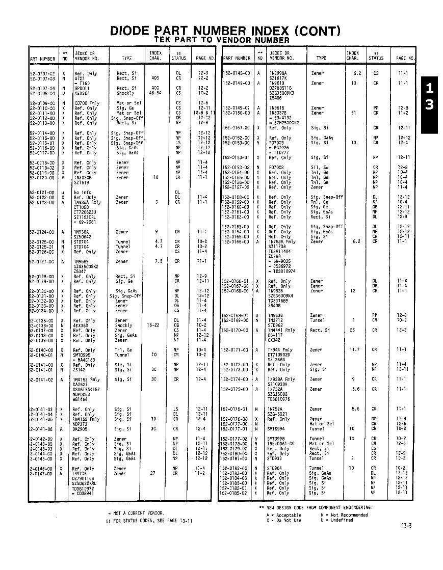
DIODE PART NUMBER INDEX (CONT) TEK PARTTO VENDOR NUMBER -
ART NUMBE JEDEC OR VENDOR NO.
Ref. Only 6727 - TI60 GPO01 1 4EX264
CD700 Fmly Ref. Only Ref. Only Ref. Only Ref. Only
Ref. Only Ref. Only Ref. Only Ref. Only Ref. Only
Ref. Only Ref. Only Ref. Only 1N3020B SZ1619
Yo i n f o 7ef. Only 1N935A Fmly IT1 050 lT720623U jZ11530RL
69-9061
I N938A $250642 5TD704 ST0704 l e f . Only
I N958B iZG35009K2 !5347 l e f . Only l e f . Only
l e f . Only l e f . Only Lef. Only Lef. Only Lef. Only
Lef. Only 1EX363 !ef. Only !ef. Only lef . Only
!ef. Only 1MT0995 s MA4C163 lef . Only 5142
ti4152 Fmly lA2527 IS06TRS4152 OP0263 'GI464
e f . Only e f . Only N4152 Fmly DP373 A2905
e f . Only e f . Only e f . Only e f . Only e f . Only
e f . Only N971B 27901 168 Z50622KRL 03810972 CD38941
TYPE
Rect, S i Rect, S i
Rect, S i Shockly
Mat o r SI Sig, Ge Mat o r SI
Sig, Snap-( Rect, S i
Sig, Snap4 Sig, Snap4 Sig, Snap-C
Sig, GaAr Sig, GaA!
Zener Zener Zener Zener
Zener Zener
Zener
Tunnel Tunnel Zener
Zener
Rect, Si Sig, Ge
Sig, GaAs ; ig, Snap-0.
Zener Zener Zener
Zener Shockly Zener Sig, GaAs Zener
Tn l , Ge Tunnel
Sig, S i Sig, Si
Sig, S i
Sig, Si Sig, S i Sig, S i
S ig , Si
Zener Sig, s i s i g , s1 Sig, GaAs Sig, GaAs
Zener Zener
- INDEX CHAR.
400
400 46-54
- NOT A CURRENT VENDOR.
- 5 5
STATUS - - DL CR
CR CS
cs cs CS OB NP
NP NP LS NP NP
NP NP NP CR
DL DL CR
CR
CR CR cs
CR
NP CR
NP DL DL 08 CS
DL OB cs NP NP
NP CR
NP NP
CR
LS DL CR
CR
NP NP DL DL NP
NP CR
- PAGE
12-9 12-2
12-2 10-2
12-6 12-1
12-6 & 12-1; 12-9
12-1; 12-1; 12-11 12-1; 12-11
11 -4 11-4 11-4 11-1
11 -4 11 -1
11 -1
10-2 10-2 11 -4
11-1
12-9 12-11
12-12 12-12 11 -4 11 -4 11-4
11-4 10-2 11 -4 12-12 11 -4
10-4 10-2
12-11 12-4
12-4
12-1 1 12-11 12-4
12-4
11-4 12-11 12-11 12-12 12-12
11-4 11-2
ART NUMBER
52-01 48-00
52-0149-00
52-0149-01 52-01 50-00
52-01 51-00
52-01 52-00 52-01 53-00
52-0153-01
52-01 53-02 52-0154-00 52-01 55-00 52-01 56-00 52-01 57-00
i2-0158-00 2 - 0 1 59-00 i2-0160-00 i2-0161-00 i2-0162-00
i2-0163-00 2-01 64-00 i2-0165-00 i2-0166-00
12-0166-01 12-0167-00 12-01 68-00
2-0168-01 2-01 69-00
2-0170-00
2-0171-00
2-0172-00 2-0173-00
2-01 74-00
2-01 75-00
2-01 75-01
2-0176-00 2-0177-00 2-0177-01
?-0177-02 2-01 78-00 ?-0179-00 ?-0180-00 !-0181-00
!-0182-00 !-0183-00 !-0184-00 !-0185-00 ?-0185-01 !-0185-02
- NO. 3
1- 2
! ! ? ! !
JEDEC OR VENDOR NO.
IN9618 IN30378 - 69-4132 - SZM25OOOK2 Ref. Only
1 1
Ref. Only F07003 - PG7026 - TI0777 Ref. Only
- P e
1
1
I !
1 !
I ! I !
1 !
1 ! l! 1 ! 1 ! l!
I t I! I! 1: I t
1 E I t 1 E 1 E
1 E 15 15
15 15
15
15
15 15
15
15
15,
15, 151 15;
15; 15: 15; 15; 15;
15; 151 15; 151 15; 152
.I
FD7003 Ref. Only Ref. Only Ref. Only Ref. Only
Ref. Only Ref. Only Ref. Only Ref. Only Ref. Only
Ref. Only Ref. Only Ref. Only 1N753A Fmly 521 1738 TD3811404 25784 = 69-9035 - CD36972
TD3810974
Ref. Only Ref. Only 1 N963B SZG35009K4 TO331 689 25408
1 N963B IN3712 ST0962 IN4441 Fmly 36-117 .X342
IN944 Fmly IT71 0902D jZ13464 l e f . Only 7ef. Only
IN938A Fmly jZ10930H I N752A jZG35008 rD3810976
lN752A iZG-5021 Lef. Only
iFITD994
iMT0998 52-0061-00
!ef. Only !ef. Only ;Ti3933
;TO964 lef . Only le f . Only lef . Only :e f . Only e f . Only
TYPE
Zener
Zener
Zener Zener
Sig, S i
Sig, GaAs Sig, S i
Sig, S i
S i l , sw Tn l , Ge Tnl , Ge Tn l , Ge Zener
Sig, Snap-Ofi Tnl, Ge Sig, Ge Sig, GaAs Rect, S i
Sig, Snap-Of1 Sig, GaAs Sig, S i Zener
Zener Zener Zener
Zener Tunnel
Rect, S i
Zener
Zener Sig, Si
Zener
Zener
Zener
Zener Mat o r Sel Tunnel
Tunnel Mat o r Sel Rect, S i Rect, S i Tunnel
Tunnel Sig, GaAs Sig, GaAs s ig , s i Sig, s i s i g , S i
- 5 5
STATUS - CS
CR
PP CR
CR
NP CR
NP
CR NP NP NP NP
DL NP 08 NP DL
DL NP CR CR
DL OB CR
PP CR
CR
CR
NP NP
CR
CR
CR
NP CR CR
CR CR CS CR CR
CR DL NP NP NP NP -
** NEW DESIGN CODE FROM COMPONENT ENGINEERING:
A = Acceptable N = Not Recmended X - Do Not Use U = Undefined
- PAGE N =
11 -1
11 -1
12-8 11-2
12-11
12-12 12-4
12-11
12-8 10-4 10-4 10-4 11-4
12-12 10-4 12-11 12-12 12-9
12-12 12-12 12-11 11-1
11-4 11-4 11-1
12-8 10-2
12-2
11 -1
11 -4 12-11
11-1
11-1
11-1
11-4 12-6 10-2
10-2 12-6
12-9 10-2
10-2 12-12 12-12 12-11 12-11 12-11 -
$ 5 FOR STATUS CODES, SEE PAGE 13-11

PART NUMBER
152-0186-00 152-0187-00 152-0188-00 152-01 89-00 152-01 90-00
1 52-01 91 -00 152-01 92-00 152-01 93-00 152-01 94-00 152-0195-00
152-01 95-07 152-0196-00 152-0197-00 152-01 98-00 152-01 98-01
152-0198-02
152-01 99-00
152-0200-00
l52-O2Ol-OO 152-0202-00
152-0203-00 152-0204-00 152-0205-00 152-0206-00 152-0207-00
152-0208-00 152-0209-00 152-021 0-00 l52-O2ll-OO 152-021 2-00
152-0213-00 152-0214-00 152-021 5-00
152-021 6-00
152-021 7-00
152-0218-00 152-0219-00 152-0220-00 152-0221-00 152-0222-00
52-0223-00 152-0224-00 152-0225-00 52-0226-00
52-0226-01 52-0227-00
JEDEC OR VENDOR NO.
Ref. Only Ref. Only Ref. On1 y Ref. Only Ref. On1 y
Ref. Only 7701 -54 Ref. Only Ref. Only 1N751A Fmly SZ11755RL TD332125 - 69-65112 m TO3810978
Ref. Only Ref. Only IN5624 1 N4721
SEN-R-235 SS4986 - 3SM2 66-8039 - SBEA2 - MDA942-3 - SDA10074
66-8038 SAY 72 - SBR4 Ref. Only Ref. Only
Ref. Only Ref. Only Ref. Only Ref. Only Ref. Only
Ref. Only Ref. Only Ref. Only Ref. Only IN936 Fmly DT770120F SZ50646RL m 69-9062
65454
Ref. Only Ref. Only 69-3530 521 2386 Ref. Only
lN756A Fmly SZG20 1D3810979 0 69-6560
CD331882
l e f . Only l e f . Only l e f . Only ID2026 tef. Only
IM15Z10 tef. Only te f . Only IN751A Fmly ;Z1 2262RL TD3810980
CD332912
N753A Fmly jZ13903 D3810981 CD331212
- I
-- -. -- -.
Rect, S i Sig, GaAs Sig, Sw Rect. S i Rect, S i
TYPE
Sig, Si VVC Rect, S i Tunnel Zener
Zener Rect, S i Sig, GaAs Sig, Si Zener
Zener Sig, Si Sig, S i Rect, S i Rect, Si
Rect, Si
Rect, Br
Rect, Br
Sig, GaAs Sig, Sl
Tunnel Shockly Sig, GaAs Sig, GaAs Sig, GaAs
Rect, S i Sig, GaAs Sig, GaAs Sig, GaAs Zener
Zener Tunnel Zener
Sig, GaAs
Zener
Zen, S i Rect, St Tnl, Ge Zener I Zener Zener
- INDEX CHAR. - -
§ s STATUS
CS OB NP DL NP
DL CR NP CS CR
CR DL CS CR CR
CR
CR
CR
NP LS
NP DL NP NP NP
NP NP NP NP CR
CS NP CS
NP
CR
NP NP NP IN NP
IN CS CM CR
PP CR
-
PAGE Nl = 12-11 10-4 12-9 10-4 11-4
11-4 12-2 12-1 2 12-1 1 11-1
12-8 12-1 1 12-11 12-2 12-2
12-2
12-1
12-1
12-12 12-11
10-4 10-4 12-12 12-12 12-12
12-9 12-12 12-12 12-12 11-1
11-4 10-4 11-2
12-12
11 -1
12-9 12-12 12-1 1
12-9
12-9 10-4 11-1
12-8 11-1
iER I NDOR - ART NUMBER
52-0228-00 52-0229-00
52-0230-00 52-0231 -00
52-0232-00
52-0233-00
52-0234-00 52-0235-00 52-0236-00
52-0237-00 52-0238-00 52-0239-00 52-0240-00 52-0241-00
52-0241-01 52-0242-00
52-0242-01 52-0242-02 52-0243-00
52-0244-00 52-0245-00
52-0246-00
52-0246-01 52-0247-00
52-0248-00 52-0249-00
52-0250-00 %?-O25l-OO 52-0252-00 52-0252-01 52-0253-00
52-0254-00 i2-0254-01 52-0255-00
i2-0256-00 i2-0257-00 52-0258-00 i2-0259-00 i2-0260-00
i2-0261-00 i2-0262-00 52-0263-00 i2-0264-00
JEDEC OR VENDOR NO.
Ref. Onlv 1130348 " - SZM25000K3 Ref. Only Ref. Only
Ref. Only Ref. Only 1N963B Fmly SZ13553RL TD333881 - 69-6636
Ref. Only Ref. Only UZ5215 1 N973B DZ780511A SZG35009K5
1 N486A Fmly FDH5004 MT5129 NDP341 - 3065
1 N486A 1 N9658 S213203 TD3810983 2541 2
No i n f o DA2740 NDP539 - CD61165 - PG2310
DE140 WG1537HR - CD12676 - FDH5227 - NDP0533
1 N9898 SZG275K1 RL Ref. Only Ref. Only
Ref. Only Ref. Only Ref. Only GC-2534-15 Ref. Only
Ref. Only Ref. Only 1 N978B 0278041 70 SZG35009K7
TD3810985
Ref. Only Ref. Only Ref. Only Ref. Only Ref. Only
No i n f o Ref. Only Ref. Only 4112756-2
TYPE
Zener Zener
VVC VVC
Rect, S i
Sig, S i
Zener Zener Zener
Rect, S i Sig, S i Sig, S i Zener Zener
Zener Sig, Si
Matched Rect, Si Zener
Sig, Si
Sig. Si
Si, Sw Zener
Rect, S i Rect, S i
i g , Snap-Of ig . Snap-Of ig , Snap-Of i g , Snap-Of Tunnel
Tunnel Tunnel Zener
Sig, S i Sig. GaAs Sig, GaAs Sig, GaAs Rect, S i
Zen, Si i g , Snap-Of i g , Snap-Of Zener
- INDEX CHAR.
39
6.5
1.5
80
12.5
150 33
225
15
40
40
150
100
51
56
-
- PAGE - -
11-4 11 -2
10-4 10-4
12-1
12-4
11-4 11-4 11 -2
12-1' 12-1' 11-2 11-2
12-8 12-4
12-8 11 -2
12-4
12-4
12-8 11-2
12-9 12-11
12-12 12-12 12-12 10-3 10-4
10-4 10-4 11-2
12-11 12-12 12-12 12-12 12-9
12-12 12-12 11 -2
-
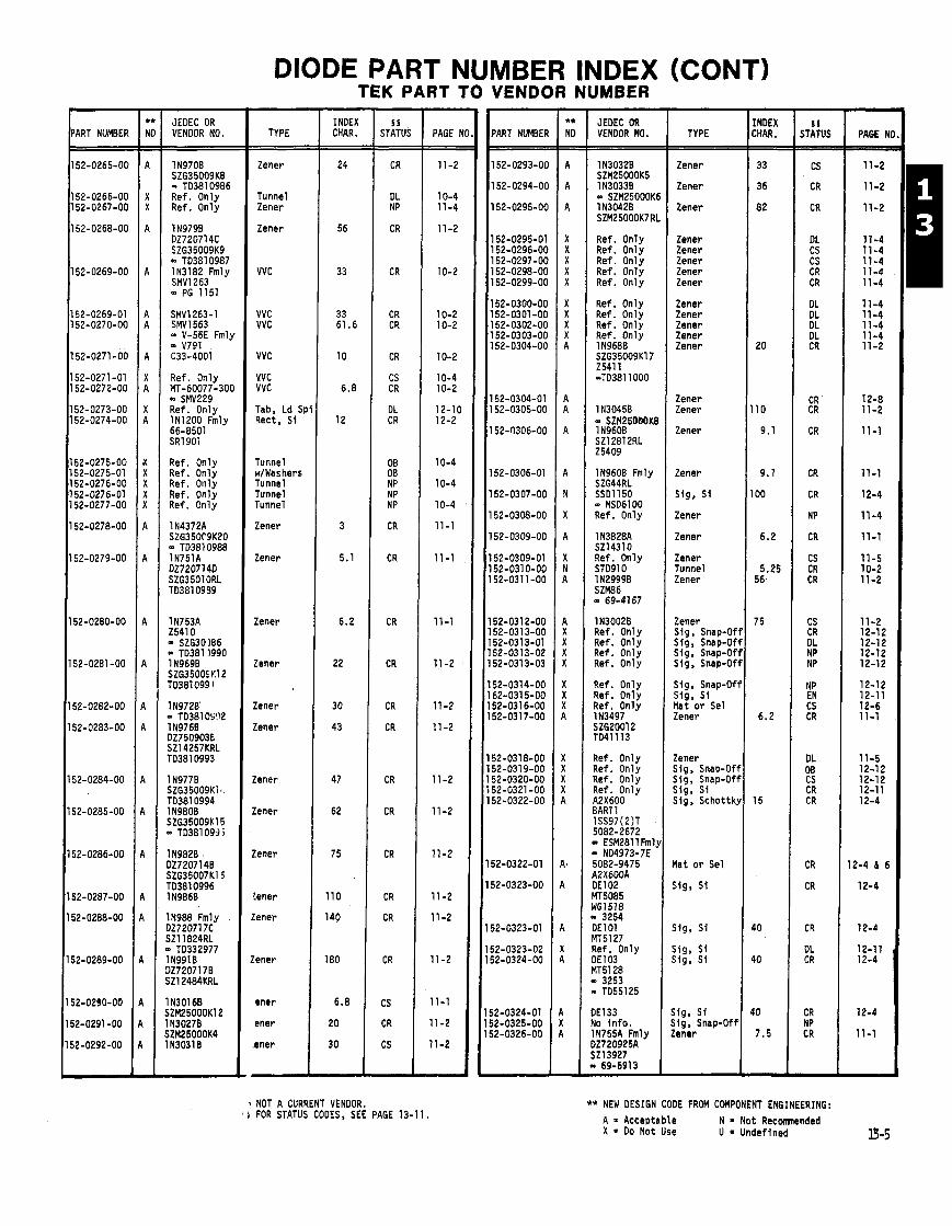
DIODE PART NUMBER INDEX (CONT)
'ART NUMBER
152-0265-00
152-0266-00 152-0267-00
152-0268-00
152-0269-00
52-0269-01 152-0270-00
52-0271-00
52-0271-01 52-0272-00
52-0273-00 52-0274-00
52-0275-00 52-0275-01 52-0276-00 52-0276-01 52-0277-00
52-0278-00
52-0279-00
52-0280-00
52-0281 -00
52-0282-00
52-0283-00
52-0284-00
52-0285-00
52-0286-00
52-0287-00
52-0288-00
2-0289-00
52-0290-00
i2-0291-00
i2-0292-00
-
JEDEC OR VENDOR NO.
IN9708 SZG35009K8 - TD3810986 Ref. Only Ref. Only
1 N979B DZ720714C SZG35009K9 - TD3810987 IN3182 Fmly SMV1263 - PG 1151
SMV1263-1 SMV1563 - V-56E Fmly - V791 C33-4001
Ref. Only MT-60077-300 - SMV229 Ref. Only IN1200 Fmly 66-8501 SR1901
Ref. Only Ref. Only Ref. Only Ref. Only Ref. Only
IN988 Fmly 1272071 7C 521 1824RL 0 TD332977 IN9918 1272071 78 iZ12484KRL
TYPE
Zener
Tunnel Zener
Zener
VVC
VVC VVC
VVC
VVC VVC
Tab, Ld Sp Rect, S i
Tunnel w/Washers Tunnel Tunnel Tunnel
Zener
Zener
Zener
Zener
Zener
!ener
!ener
lener
lener
:ener
:ener
ener
ener
ener
ener
- INDEX CHAR. - 24
56
33
33 61.6
10
6.8
12
3
5.1
6.2
22
30
43
47
62
75
110
140
180
6.8
20
30
-
TEK PART TO VENDOR NUMBER
NOT A CURRENT VENDOR. i FOR STATUS CODES, SEE PAGE 13-1 1.
- PAGE b - - 11-2
10-4 11-4
11 -2
10-2
10-2 10-2
10-2
10-4 10-2
12-10 12-2
10-4
10-4
10-4
11 -1
11 -1
11-1
11-2
11-2
11 -2
11 -2
11 -2
11-2
11 -2
11-2
11 -2
11-1
11 -2
11-2
-
'ART NUMBEI
52-0293-01
52-0294-01
52-0295-O(
52-0295-0' 52-0296-01 52-0297-O( 52-0298-O( 52-0299-01
52-0300-O( 52-0301 -01 52-0302-01 52-0303-O( 52-0304-O(
52-0304-01 52-0305-OC
52-0306-OC
52-0306-01
52-0307-OC
52-0308-00
52-0309-00
52-0309-01 52-031 0-00 52-031 1-00
52-031 2-00 52-0313-00 52-0313-01 52-0313-02 i2-0313-03
i2-0314-00 i2-0315-00 i2-0316-00 12-031 7-00
12-0318-00 12-0319-00 12-0320-00 12-0321 -00 12-0322-00
2-0322-01
2-0323-00
2-0323-01
2-0323-02 2-0324-00
2-0324-01 2-0325-00 2-0326-00
JEDEC OR VENDOR NO.
1130328 SZM25000K5 1 N3033B = SZM25000K( 1 N3042B SZM25000K7 RI
Ref. Only Ref. Only Ref. Only Ref. Only Ref. Only
Ref. Only Ref. Only Ref. Only Ref. Only 1 N968B SZG35009K17 Z54l 1 -TO381 1000
1 N3045B - SZM250bbK8 1 N960B SZ12812RL 25409
IN9600 Fmly SZG44RL SSOll50 - MS06100 Ref. Only
1 N382BA SZ14310 Ref. Only ST091 0 1 N29998 SZM86 = 69-4167
1N3002B Ref. Only Ref. Only Ref. Only Ref. Only
Ref. Only Ref. Only Ref. Only IN3497 SZG2001 2 TO41113
Ref. Only Ref. Only Ref. Only Ref. Only A2X600 BAR1 1 1SS97(2)T 5082-2672
ESM2811 Fml. ND4973-7E
5082-9475 42X600A DE102 V5085 dG1518
3254 DEl 01 rlT5127 Ref. Only lE103 ulT5128 0 3253
TO55125
)El33 l o i n f o . IN755A Fmly 32720925A Z l3927 8 69-6913
TYPE
Zener
Zener
Zener
Zener Zener Zener Zener Zener
Zener Zener Zener Zener Zener
Zener Zener
Zener
Zener
Sig, S i
Zener
Zener
Zener Tunnel Zener
Zener Sig , Snap-Off Sig, Snap-Off Sig , Snap-Off Sig, Snap-Off
Sig, Snap-Off Slg, S i Mat o r Sel Zener
Zener Sig, Snap-Off Sig, Snap-Off Sig, S i Sig, Schottky
t a t o r Sel
j ig , S i
j ig, S i
i i g , S i i i g , S i
i lg , Sf i ig, Snap-Off :ener
- INDEX CHAR. - - 33
36
82
20
110
9.1
9.1
100
6.2
5.25 56
7 5
6.2
15
40
40
40
7.5
-
- I 5
STATUS - - CS
CR
CR
DL CS CS CR CR
DL DL DL DL CR
CR CR
CR
CR
CR
NP
CR
CS CR CR
CS CR DL NP NP
NP EN CS CR
DL OB CS CR CR
CR
CR
CR
DL CR
CR NP CR
- ** NEW DESIGN CODE FROM COMPONENT ENGINEERING:
A = Acceptable N = Not Recomnended X = Do Not Use U = Undefined
- PAGE N - 11-2
11-2
11-2
11-4 11-4 11-4 11-4 11-4
11-4 11-4 11-4 11-4 11-2
12-8 11-2
11-1
11-1
12-4
11-4
11-1
11-5 10-2 11-2
11-2 12-12 12-12 12-12 12-12
12-12 12-1 1 12-6 11-1
11-5 12-12 12-12 12-11 12-4
2-4 6 6
12-4
12-4
12-11 12-4
12-4
11-1
-
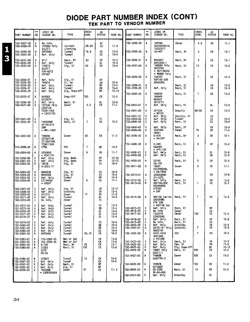
DIODE PART NUMBER INDEX (CONT)
JEDEC OR VENDOR NO. - --
No i n f o . 115283 Fmly SCLOl 1 SMTO892 Ref. Only
SF-1 Ref. Only 1 N46lO DJ2011 FDH-6012 NDP261
Ref. Only 1 N46l D Ref. Only Ref. Only Ref. Only
A4X583 GC20279 Ref. Only 1N753A Fmlv
1N983B DZ720719E SZ12461 KRL TO381 1004 V7EA
SZ50850 - DC41174 Ref. Only Ref. Only 1 N53B 5-0053-77
MA4933B MA4934A Ref. Only SZ13463K - GREA7
Ref. Only Ref. Only UZ1215 Ref. Only No i n f o .
Ref. Only Ref. Only Ref. Only Ref. Only Ref. Only
Ref. Only Ref. Only Ref. Only Ref. Only SMTO898
STD927 Ref. Only Ref. Onlv Ref. on l y IN30368
SZM25000K9
TYPE
Current L i m i t i n g Tunnel Tunnel
Rect, S i Tunnel Sig, S i
Sig, S i Si , Sw Tunnel Tunnel Sig, Snap-Of
Snap-Off
Rect, S i Zener
Sig, S i Rect, S i
Zener
VVC
Zener
Sig. GaAs Sig, GaAs Sig, S i
s ig . S i Sig, S i Tunnel Zener
Sig, S i Schottky Zener Tunnel Zener
Tunnel Tunnel Tunnel Tunnel Tunnel
Tunnel Tunnel Tunnel Tunnel Tunnel
Mat o r Sel Mat o r Sel Rect, Br Rect, S i
runnel runnel ?ect, S i j i g , S i Zener
TEK PART TO VENDOR NUMBER - I!
STATUS - SC CS
CR CS
CR DL CR
CR CR NP OB NP
CR
DL CR
TC CR
CR
OB
CR
NP NP CS
CS CS NP CS
CR CR CR DL TC
CS OB DL DL DL
CS OB OB DL CR
CR CR CR CR
CR CR NP NP CR
-
PAGE N(
11-3
10-2 10-4
12-2 10-4 12-4
12-8 10-4 10-4 12-12
10-3
12-9 11-1
12-2
11 -2
10-2
11-1
12-12 12-1 2 12-4
12-4 12-4 10-4 11 -1
12-11 12-5 11-2 10-4
10-4 10-4 10-4 10-4 10-4
10-4 10-4 10-4 10-4 10-2
12-6 12-6 12-1 12-2
10-2 10-4
11- 2
'ART NUMBER JEDEC OR VENDOR NO.
SR1976K - DR710903A - MR880 Fmly
Ref. Only
1 N4936 1 N4944 MB2501 SR1977K Ref. Only
SPT32K - MPT32 Ref. Only Ref. Only Ref. Only
Ref. Only 1N4744A 26041 W-675 - VH-247
H-345 SA2055 - VF5-12X Ref. Only Ref. Only
Ref. Only RGP10G-022 SR2046KRL UTR307
RGPl OD Serie!
UTR 308 - RGPlOG Ser Ref. Only No i n f o
SZM20065 Ref. Only. No i n f o . Ref. Only 04787-91 Fmlj MAZE1 45 A201 -4302 SMVl264 - PG1084' Ref. Only Ref. Only Ref. Only IN647 Fmly 62017-1 1 N985B SZG275K-3
1 N987B SZ13202 SA-3282 VG-5X-905 Ref. On1 y
TYPE
Zener
Rect, Br
Rect, Br
Rect, S i
Rect, S i
Rect, S i Rect, S i
Rect, S i
Rect, S i
Shockly
Shockly, S i Tunnel Rect, S i
Rect, S i Zener
Rect. Br
Rect, S i
?ect, S i Zect. S1
Zect, S i
Zener
Zener
Zect, S i I ec t , S i
Iec t , S i
l ec t , S i !ener !ener
k t , S i tect, S i i chot tky jchot tky
IVC
tect. S i !en, S i i ig , Snap-Off lect, S i
:ener
:ener
lect, S i
c h o t t k y
- INDEX :HAR. - -
4.3
3
3
12
1
1
18-36
15
3
5
5
9
1
1
30
7
7
I 0
I 0
!O
10
-
5 5 STATUS -
CR
CR
CR
CR
CR
CR CR
CR
DL
CR
CS CS CS
CR CR
CR
CR
DL OB
CR
CR
CR
CR CR
CR
NP CS CS
CR CS CR CR
CR
CR EN OB CR
CR
CR
CR
CS
-
PAGE Nt

DIODE PART
ART NUMBER
52-0434-00 52-0435-00 52-0436-00 52-0437-00
52-0438-00
52-0439-00 52-0440-00 52-0441 -00
52-0442-00 52-0442-01 52-0443-00 52-0444-00 52-0445-00
52-0446-00 52-0446-01 52-0448-00 52-0449-00 52-0450-00
52-0451-00 52-0452-00 52-0452-01 52-0453-00 52-0454-00
52-0455-00 52-0456-00
52-0457-00
52-0457-01
52-0458-00 52-0458-01 52-0459-00 i2-0460-00
i2-0461-00
i2-0461-01 i2-0462-00
12-0462-01
12-0462-02
2-0463-00
82-0464-00
2-0465-00 2-0470-00 2-0471 -00
2-0471-01 2-0474-00 2-0475-00 2-0476-00 2-0478-00
2-0479-00
2-0480-00 2-0481-00
2-0482-00 2-0486-00,
2-0488-00
JEDEC OR VENDOR NO.
Ref. Only Ref. Only Ref. Only 11959 Fmly SZG14K TD332679
69-7519 - TO3811008
SZ 9.1 UZ1364 Ref. Only Ref. Only Ref. Only
Ref. Only Ref. Only Ref. Only Ref. Only Ref. Only
Ref. Only Ref. Only No i n f o 1 S205 Ref. Only
W43677 Ref. Only Ref. Only Ref. Only Ref. On1 y
?ef. Only 1 N827 SZG25002Kl 5082-2068
MDO 28 ID028
?ef. Only 7ef. Only Zef. Only 1 N5299 XL072
IN821 0 C041089 tef. Only QL02-8 iDA10228 1 MOA970-3
!KBLO2-14 B 652-1 083 IOA970-3 1 652-1085 lef. Only
N4570 8ZG25002K3 lef. Only ti9928 e f . Only
W6786-98
OA10211 o i n f o e f . Only
N1203 0-0182 R2117 N29898 N3826A MZ25000K10
ef. Only N3497 Fmly ZG20008 14 1099 KBP02-08 Fa200 )A31 7 I255 Fmly TSKl l-000
TYPE
s ig , Snap-Of1 ,Sig, Snap-Oft Sig. Snap-Oft Zener
Zener
Sig, Snap-Off Zener Schottky
Schottky Schottky Sig, Snap-Off Rect, Si Sig, Snap-Off
Schottky Sig, Snap-Off Zener Sig. s i Sig, Snap-Off
Snap-Off Sig, Snap-Off Sig, Snap-Off Schottky Sig, S i
VVC Zener
Sig, Schottky
Schottky
Schottky Schottky Sig, Si Current L im i t i ng
Zener
Zener Rect, Br
Rect. Br
Rect, Br
Schottky
Zener
Sig, Snap-Off Zener Schottky
Sig, Schottky Mat o r Sel Rect. Br Rect, S i Rect, Si
Rect, S i
Zener Zener I
Schottky Zener
tect, Br
TE - INDEX CHAR. =
8.2
9.1
140
6.2
2.5
1.2
6.2
2.5
2.5
2.5
6.4
PA1 - I §
STATUS - r T( -
PAGE - 12-1 12-1 12-1 11-1
11 -1
12-1 11 -5 12-5
12-5 12-5 12-1, 12-9 12-1 1
12-5 12-1;
12-1;
10-3 12-1: 12-11 12-5. 12-1
10-4 11 -1
12-4
12-8
12-5 12-5 12-11 11-3
11-1
11-5 12-1
12-1
12-1
12-5
11-1
12-12 11-2 12-5
12-4 12-6 12-1
12-9
12-2
11-2
- NOT A CURRENT VENDOR. 5 8 FOR STATUS CODES, SEE PAGE 13-1 1
PART NUMBEl
152-0488-0' 152-0489-01 152-0490-O(
152-0491-Ol 152-0492-O(
152-0493-O(
152-0495-O(
152-0495-01
52-0496-O( 152-0497-ot
52-0498-Ot 52-0499-Ot 52-0500-Ot 52-0501 -OC
52-0502-OC 52-0503-00
52-0503-01
52-0505-00 52-0506-00
52-0507-00
52-0508-00 52-0509-00
52-051 0-01
52-0512-00
52-0513-00
52-0514-00
52-051 6-00 52-0518-00 52-051 9-00 52-0520-00
52-0521 -00 52-0524-00
52-0525-00
52-0526-00
52-0527-00 52-0528-00 52-0529-00
i2-0530-00 52-0531 -00 52-0532-00 i2-0533-00 i2-0534-00
i2-0535-00
i2-0536-00 i2-0537-00 i2-0538-00
JEDEC OR VENDOR NO.
Diode Assy. IN5285 SCL083K Ref. Only Ref. Only
CMX114 - SCMA10114 CMX294 MH974801 - SCMA10622 CMXl3l
31257 Fmly KBPO6-4 SOA3 18 - A1423MX67
Ref. Only Ref. Only Ref. Only SS02405 - MSD6150
Ref. Only 114756 Fmly 5082-8872 MA43685 QSRO-4866
Ref. Only A4X618 CVB-10300 - A4S375 Ref. Only
SZ13294RL AM1 408L8 MC1408L8 SSSl408A-02l CMX115
1 N3048B 1 MI 50ZS5 1 N4739A TO334328 UZ8709 261 24
lN4763A UZ2354 - UZ8791 1N961B Fmly SZGl 5RL
Ref. Only KO1 9 1 N3997A 1 N4742A HW12B UZ8712 26033
Ref. Only 5082-1 779 MA47690 ND4121M-3G
SMR32B
1N829A Fmly SZG20054 ?ef. Only ?ef. Only ?ef. Only
?ef. Only ?ef. Only i e f . Only Zef. Only ?ef. Only
iDA10339 MOA980-2
iMVl 1 10 le f . Only le f . Only
TYPE
Rect, Br Tnl, Ge Current L i m i t i n g
Rect. S i Rect, Si
V. M u l t r
V. M u l t r
V. M u l t r
Rect, S i Rect, Br
V. Mu l t r Sig, Snap-Of Zener Sig, S i
Rect, S i Snap-Off
Snap-Off
Sig, s i Snap-Off
Tnl, Ge
Zener V. M u l t r
Zener
Zener
Zener
Zener
Sig, Si Rect, Br Zener Zener
Zener P in
Sig, Schottky
Zener
Zener Sig. S i Rect, S i
Rect. Si Rect, Si Zener Rect, S i Zener
Rect, Br
Sig, Schottky Zener Rect, S i
- INDEX CHAR. - -
1
.2:
7
2
2
1
70
500
500
120
12.6 6
150
9.1
91
10
30 5.6
12
10
6.35
12
-
- s I
STATUS - - CR CR cs CS DL
CR
CR
CS
cs CR
DL NP DL CR
CR CR
CR
NP CR
DL
CR CR
CR
CR
CR
CR
NP CR CR CR
EN CR
CR
CR
OB CS 08
OB 08 OB OB OB
CR
CR OB 08 -
** NEW DESIGN CODE FROM COMPONENT ENGINEERING:
A - Acceptable U = Not Recomnended X = Do Not Use U = Undefined
- PAGE N - -
12-8
11-3
12-9 12-9
12-3
12-3
12-3
12-1
12-10 12-1 2 11-5 12-4
12-9 10-3
10-3
12-11 10-3
10-4
11-2 12-3
11 -2
11-1
11-2
11-1
12-11 12-1 11-1 11-1
11-5 10-3
12-4
11-1
11 -5
12-9
12-9 12-9 11-5 12-9 11-5
12-1
12-4 11-5 12-9 - l3-7
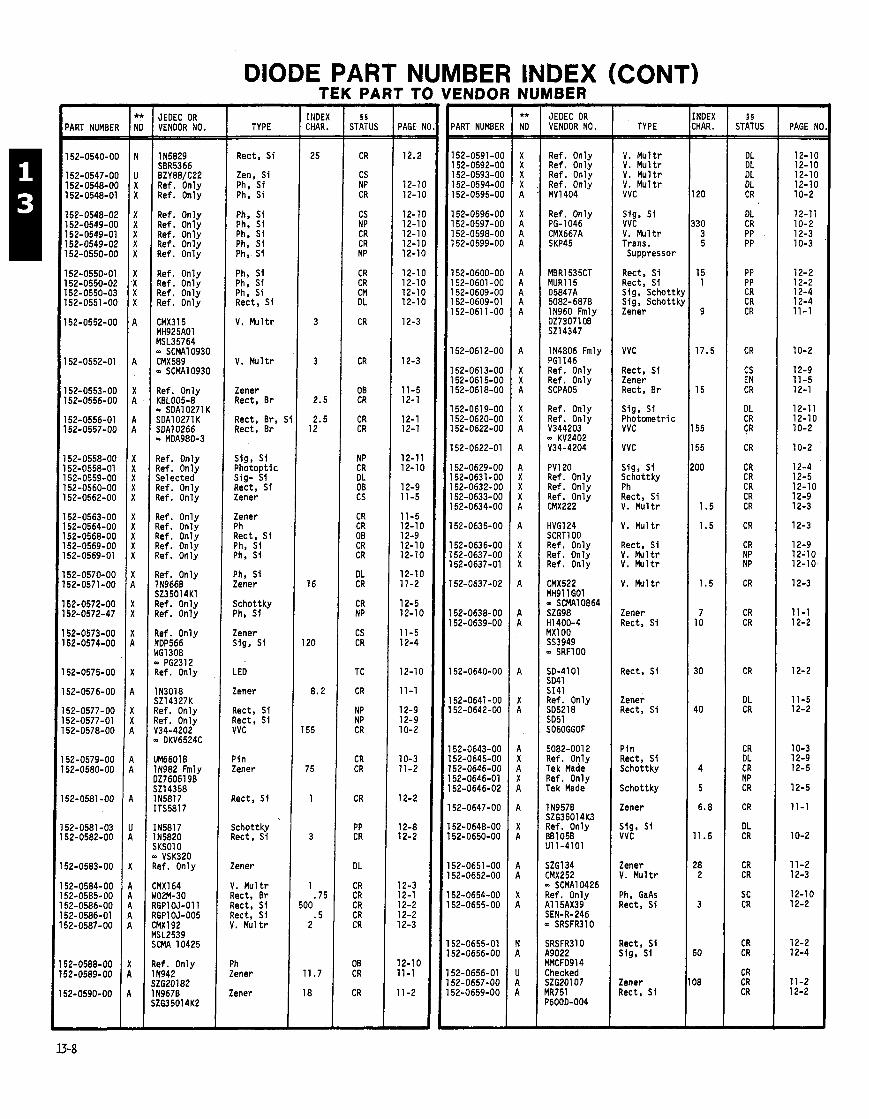
DIODE PART NUMBER INDEX (CONT) TEK PART TO VENDOR NUMBER -
PAGE h - - 12-1C 12-1C 12-lC 12-76 10-2
12-11 10-2 12-3 10-3
12-2 12-2 12-4 12-4 11-1
10-2
12-9 11-5 12-1
12-1 1 12-10 10-2
10-2
12-4 12-5 12-10 12-9 12-3
12-3
12-9 12-10 12-10
12-3
11-1 12-2
12-2
11 -5 12-2
10-3 12-9 12-5
12-5
11-1
10-2
11-2 12-3
12-10 12-2
12-2 12-4
11-2 12-2
-
- INDEX CHAR. =
25
3
3
2.5'
2.5 12
16
2 0
8.2
55
75
1
- 5 5
STATUS
CR
CS NP CR
CS NP CR CR NP
CR CR CM DL
CR
CR
OB CR
CR CR
NP CR DL 08 CS
CR CR 08 CR CR
DL CR
CR NP
CS CR
TC
CR
NP NP CR
CR CR
CR
PP CR
DL
CR CR CR CR CR
08 CR
CR
-
- PAGE I - - 12.2
12-1( 12-1(
12-1( 12-1( 12-1( 12-11 12-1(
12-1( 12-1t 12- I t 12-1(
12-3
12-3
11-5 12-1
12-1 12-1
12-11 12-10
12-9 11-5
11-5 12-10 12-9 12-10 12-10
12-10 11-2
12-5 12-10
11-5 12-4
12-1 0
11-1
12-9 12-9 10-2
10-3 11-2
12-2
12-8 12-2
12-3 12-1 12-2 12-2 12-3
12-10 11-1
11-2
-
- INDEX CHAR. =
120
330 3 5
15 1
9
17.5
15
155
155
!OO
1.5
1.5
1.5
7 10
30
40
4
5
6.8
11.5
28 2
3
50
08
- 5 5
STATUS - DL DL DL DL CR
DL CR PP PP
PP PP CR CR CR
CR
CS EN CR
DL CR CR
CR
CR CR CR CR CR
CR
CR NP NP
CR
CR CR
CR
DL CR
CR DL CR NP CR
CR
DL CR
CR CR
SC CR
CR CR
CR CR CR
-
1 JEDEC OR ' VENDOR NO. TYPE
Rect, S i
Zen, S i Ph, S i Ph, Si
Ph, S i Ph, S i Ph, Si Ph, S i Ph, S i
Ph, S i Ph. S i Ph, Si Rect, S i
V. Mu l t r
V. Mu l t r
Zener Rect, Br
Rect, Br, ! Rect, Br
PART NUMBEI
152-0591-01 152-0592-01 152-0593-01 152-0594-01 152-0595-01
152-0596-01 152-0597-01 152-0598-01 152-0599-01
l52-O6OO-Ol 152-0601 -01 152-0609-01 152-0609-0 152-061 1-01
152-061 2-01
152-0613-O( 152-061 5-01 152-0618-01
152-0619-O( 152-0620-O( l52-O622-O(
152-0622-0'
52-0629-O( 52-0631-O( 52-0632-O( 52-0633-01 52-0634-O(
52-0635-O(
52-0636-01 52-0637-Ot 52-0637-01
52-0637-02
52-0638-Ot 52-0639-OC
52-0640-OC
52-0641 -0C 52-0642-00
52-0643-00 52-0645-00 52-0646-00 52-0646-01 52-0646-02
52-0647-00
52-0648-00 52-0650-00
52-0651 -00 52-0652-00
52-0654-00 52-0655-00
52-0655-01 52-0656-00
52-0656-01 52-0657-00 52-0659-00
JEOEC OR VENDOR NO. TYPE PART NUMBE -
152-0540-01
152-0547-01 152-0548-01 152-0548-0
152-0548-0; 152-0549-01 152-0549-0' 152-0549-0; 152-0550-01
152-0550-0' 152-0550-0; 152-0550-0: 152-0551 -O(
152-0552-O(
152-0552-01
152-0553-01 l52-0556-O(
152-0556-01 152-0557-Ot
152-0558-OC 152-0558-01 152-0559-OC 152-0560-OC 152-0562-OC
152-0563-OC 152-0564-OC 152-0568-OC 152-0569-OC 152-0569-01
152-0570-00 152-0571-00
152-0572-00 152-0572-47
152-0573-00 152-0574-00
52-0575-00
152-0576-00
52-0577-00 52-0577-01 52-0578-00
52-0579-00 52-0580-00
52-0581 -00
52-0581 -03 52-0582-00
52-0583-00
1 N5829 SBR5366 BZY88/C22 Ref. Only Ref. Only
Ref. Only Ref. Only Ref. Only Ref. Only MV1404
V. M u l t r V. Mu l t r V. M u l t r V. M u l t r VVC
Ref. Only Ref. Only Ref. Only Ref. On1 y Ref. Only
Ref. Only PG-1046 CMX667A SKP45
Sig, S i VVC V. Mu l t r Trans. Suppressor
Ref. Only Ref. Only Ref. Only Ref. Only
MBR1535CT MUR115 D5847A 5082-6878 IN960 Fmly DZ730710B S214347
Rect, S i Rect, S i Sig, Schottk Sig, Schottk Zener
IN4806 Fmly PG1146 Ref. Only Ref. Only SCPAO5
VVC
Rect. S i Zener Rect, Br Ref. Only
KBL005-8 - SDA10271 K SDA10271K SDA10266 - MDA980-3
Ref. Only Ref. Only Selected Ref. Only Ref. Only
Ref. On1 y Ref. Only Ref. Only Ref. Only Ref. Only
Ref. On1 y 1 N966B 523501 4K1 Ref. Only Ref. Only
Ref. Only NDP566 WG1308 - PG2312 Ref. Only
IN3018 SZ14327K Ref. Only Ref. Only V34-4202 - OKV6524C
UM66018 11982 Fmly DZ760519B S214358 IN5817 ITS5817
I N58l7 115820 SKSO10
VSK320 Ref. Only
tMX164 102M-30 7GP1 OJ-011 7GP1 OJ-005 :MX192 i(SL2539 XMA 10425
l e f . Only 1 N942 jZG20182 119670 iZG35014K2
Ref. Only Ref. Only V344203 - KV2402 V34-4204
Sig. S i P h o t m e t r i c VVC
VVC Sig, S i Photopt ic Sig- S i Rect, S i Zener
Zener Ph Rect. S i Ph, S i Ph, S i
Ph, Si Zener
Schottky Ph, Sf
Zener Sig, Si
LED
Zener
Rect, S i Rect, S i VVC
PV120 Ref. Only Ref. Only Ref. Only CMX222
Sig, S i Schottky Ph Rect, S i V. Mu l t r
HVG124 SCRTl 00 Ref. Only Ref. Only Ref. Only
V. Mu l t r
Rect. S i V. M u l t r V. Mu l t r
V. Mu l t r
Zener Rect. Si HI 400-4
MXlOO SS3949 - SRFlOO
SO-41 01 SD41 SI41 Ref. Only SO5218 SO51 SO6OGGOF
Rect, S i
Zener Rect, S i
5082-001 2 Ref. Only Tek Made Ref. Only Tek Made
Pin Rect, S i Schottky
Schottky
Zener
Sig, Si VVC
Zener V. Mu l t r
Ph, GaAs Rect. Si
P in Zener
Rect, S i
Schottky Rect, Si
Zener
V. Mu l t r Rect. Br Rect, S i Rect, Si V. Mu l t r
1 N957B SZG35014K3 Ref. Only BB105B 911-4101
ZMX252 SCMA10426
?ef. Only 41 15AX39 SEN-R-246 0 SRSFR3lO
Rect, Si Sig, S i
Zener Rect, Si
Ph Zener
Zener

DIODE PART NUM TEK PART TO
;ER INDEX (CONT) ENDOR NUMBER -
PAGE N(
12-3 12-1
12-2 12-4
12-3
12-11
12-2
10-2
12-2 12-2
10-2
12-4 12-4
11-1
10-3
12-2
11-1 12-4
11-1 11 -2
12-4 12-4
10-2 11-1 12-4
10-3
12-2
11-1 11 -1
11-2
12-4 12-4 11-2
12-1 12-4 12-2
12-4 12-2
12-4 11-2
11-1
11-1
10-3
- INDEX CHAR. - -
1.5 3 5
70 29
.7 3 6
120
3
3
500
1
4
3
150
1
19.3
1
7.5
7.OE 7 0
5
5
2.4
3.9 3.3 5.1
3 0
4
13
2
1 80
- § §
STATUS - - OT CR CR NP CR
CR CR CR CR
CR
CR
CR
CR
CR
DL CR
DL
CR PP CR CR CR
CS CR
CR
DL CR CR
CR
CR
PP
CR CR CS CR
CR CR
CR CR
CR
CR CS CR
CR
DL DL DL I
- PAGE - -
12-3 12-2 11 -1 12-1 10-2
12-1 11-1 12-1 11 -2
12-2
12-2
10-2
12-2
12-4
12-2
12-1(
10-3
10-2
11 -2
12-3
11-1
10-2 12-4 12-2
12-3
11 -1
12-8
11-1 11-1 11 -1 12-2
11-1 12-4
11-2
12-3
12-2 11-2 12-2
12-4
- NDEX MR. - - 3
3 5
50
7
5
6
00
7 12
1.5
5 20
6.3
30
10 7 0
3.3 15 30 7 0 70
1 .2 5.6 4
7 0
12
3.6 7
14
50 5
32
3 i 5 1
3 8
7 .7
6.2
6.2
1.5
1
- 5 §
STATUS
CR CR
CR CR
CR
DL DL PP
CR
CR CR
CR
CR CR
CR
CR
CR
CS CR
CR CR DC CR CR TC
CR DL DL
CR
CR
TC CR CR
CR
PP CR CR
CR CR CR
CR CR
CR CR
CR SC
SC CR
CR
I -
JEOEC OR VENOOR NO. TYPE 'ART NUMBEI
JEDEC OR VENOOR NO. TYPE PART NUMBER
l5Z-O66O-OO l52-O66l-OO 152-0662-00 152-0664-00 152-0665-01
152-0666-00 152-0667-00 152-0668-00 152-0669-00
152-0670-00
152-0672-00
152-0673-00
152-0674-00
152-0675-00
152-0675-01 152-0676-00
152-0677-00
152-0678-00 152-0678-01 152-0679-00 152-0679-01 152-0680-00
152-0681 -00 152-0682-00
152-0683-00
152-0684-00 152-0685-00 152-0686-00
152-0687-00
152-0688-00
152-0688-01
152-0689-00 152-0690-00 152-0691-00 152-0692-00
52-0693-00 152-0701 -00
52-0701 -01 52-0702-00
52-0703-00
52-0704-00 52-0705-00 52-0706-00
52-0710-00
52-0710-01 52-071 1-00 52-0711-01 1
V. M u l t r Rect , S i Zener S ig , Schottb vvc
Rect, Br Zener Rect , B r Zener
Rect, S i
Rect, S i
VVC
Rect, S i
S ig , Schot tk
Schot tky , S i Rect, S i
Ph, WPN
Snap-Off Step Rec VVC VVC, S i Zener
Rect , S i V. M u l t r
Zener
VVC Sig, Schottk: Rect, S i
I. M u l t r
Zener
Zener
!ener lener !ener ?ec t , S i
!ener j i g , S i
jw, H i Spd Iener
I . M u l t r
tect , S i
V. Mu1 tr Rect, Br
Rect, S i S ig , Schot tky
CMX387A - SCMA10784 Ref. Only Ref. Only PRl 00 - TIR102A
Sig, S i Schot tky , S i Rect, S i
VVC
Rect, S i Rect, S i
VVC
S ig , Schot tky Sig, Schot tky
Zener
Ref. Only 1 N5625 41 15DX112 SEN-R-247 Ref. Only
P i n
Rect, S i
Zener S ig , S i
Zener Zener Sig, S i Sig, S i Sig, S i Rect, S i
?C-2544-00 Inspec ted YV1 C2097 Inspec ted TO381 1018 526266
IN59138 1N5352B MMBD914 BAW56 Fmly BAV70 BYX36
VVC Zener Sig, Schot tky BAT- 17
MMBVlOl MMD-835-001 Snao-Off ND1571 Chip - 5082-0008 - CVBlO15A
Rect, S i
No i n f o 1 N747A SZG3Ol74 Z7.0V 2%
Zener Zener
Zener
S ig , Schot tky Sig, Schottky Zener
Rect, Br S ig , S i Rect, S i
Sig, GaAs Rect, S i
Schot tky , S i Zener
Zener
082-0097 25097 e f . Only e f . Only ? f . O n l y I
i g , Schot tky
c h o t t k y , S i ener ?ner I
Zener
Trans. Suppressor
- NOT A CURRENT VENOOR. § § FOR STATUS CODES, SEE PAGE 13-1 1
** NEW DESIGN CODE FROM COMPONENT ENGINEERING: A = Acceptable N = Not R e c m e n d e d X = 00 Not Use U = Undef ined
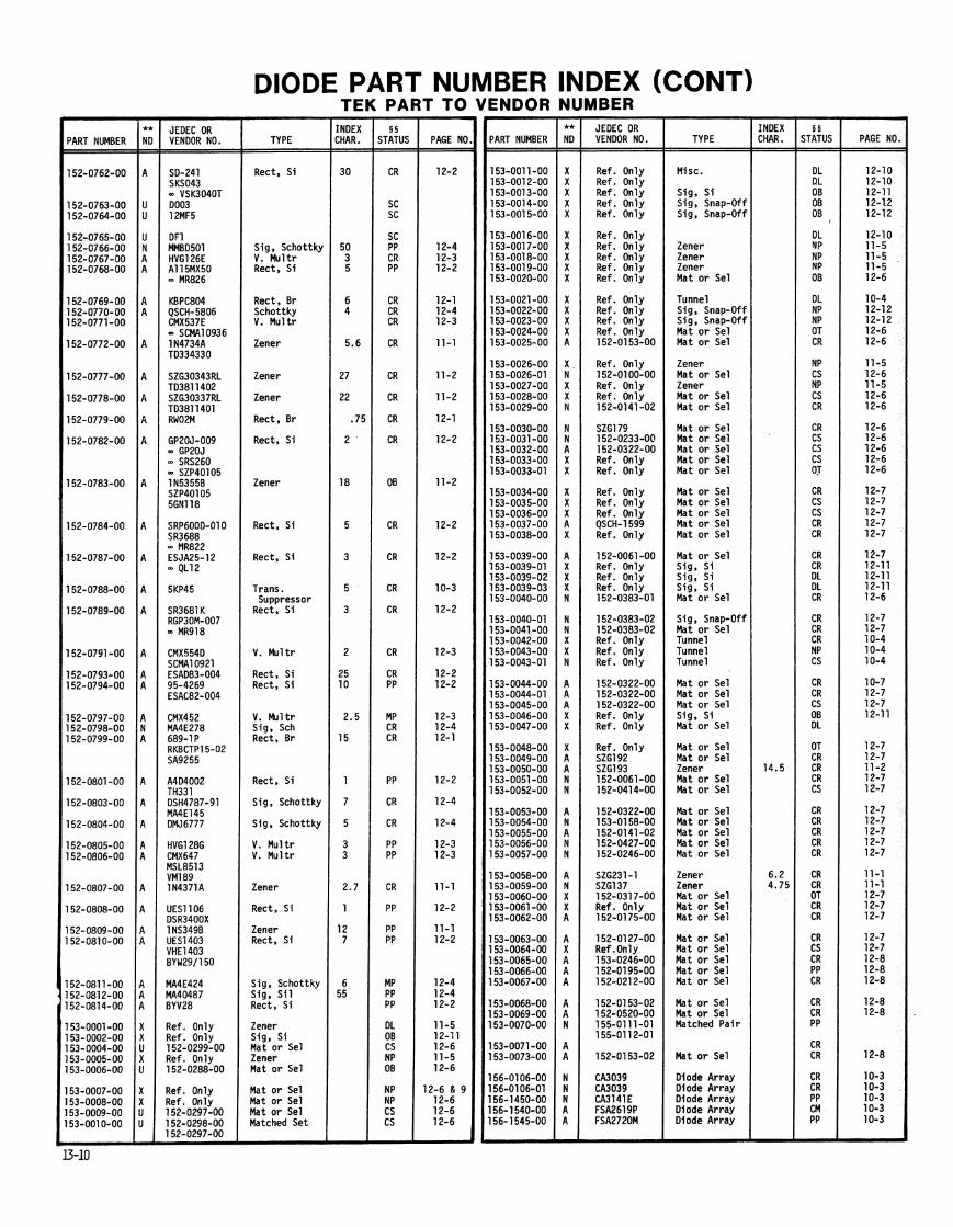

NOTES
r 5 STATUS CODES
CR . 'EN
PP ' CS NP
'CL 8 DL ' OB 04
6 DS ' OT MP LR LS VN TC IN SC
Current Production Engineering Pre-Prod C u s t w r Service Non-Prod Cancelled Deleted Obsolete l n s t n t m n t Custom Mod Instrument D i g i t a l Systms Obsolescent Instrument Modifled Part Last Supply Current Last Supply C u s t w r Service Vendor Telequipmnt Current Prod. Internatlonal Sony/Tek Current Prod.
THE STATUS IN THIS CATALOG WAS CORRECT AT THE TIME IT WAS WBLISHEO, BUT I T IS SUBJECT TO CHANGE.
'TO USE A PART WITH THIS STANS ON A NEW INSTWMENT REWIRES THAT A NEW PURCHASED PART INITIATION FDW (PPIF) BE INITIATED.
- NOT A CURRENT VENDOR.
** NEW DESIGN CODE FROM COMPONENT ENGINEERING:
A = Acceptable N = Not Recomnended
X = Do Not Use U = Undefined
(A GLOSSARY OF TEWS FOR THESE STATUS CODES CAN BE FOUND ON PAGE 0-44.)
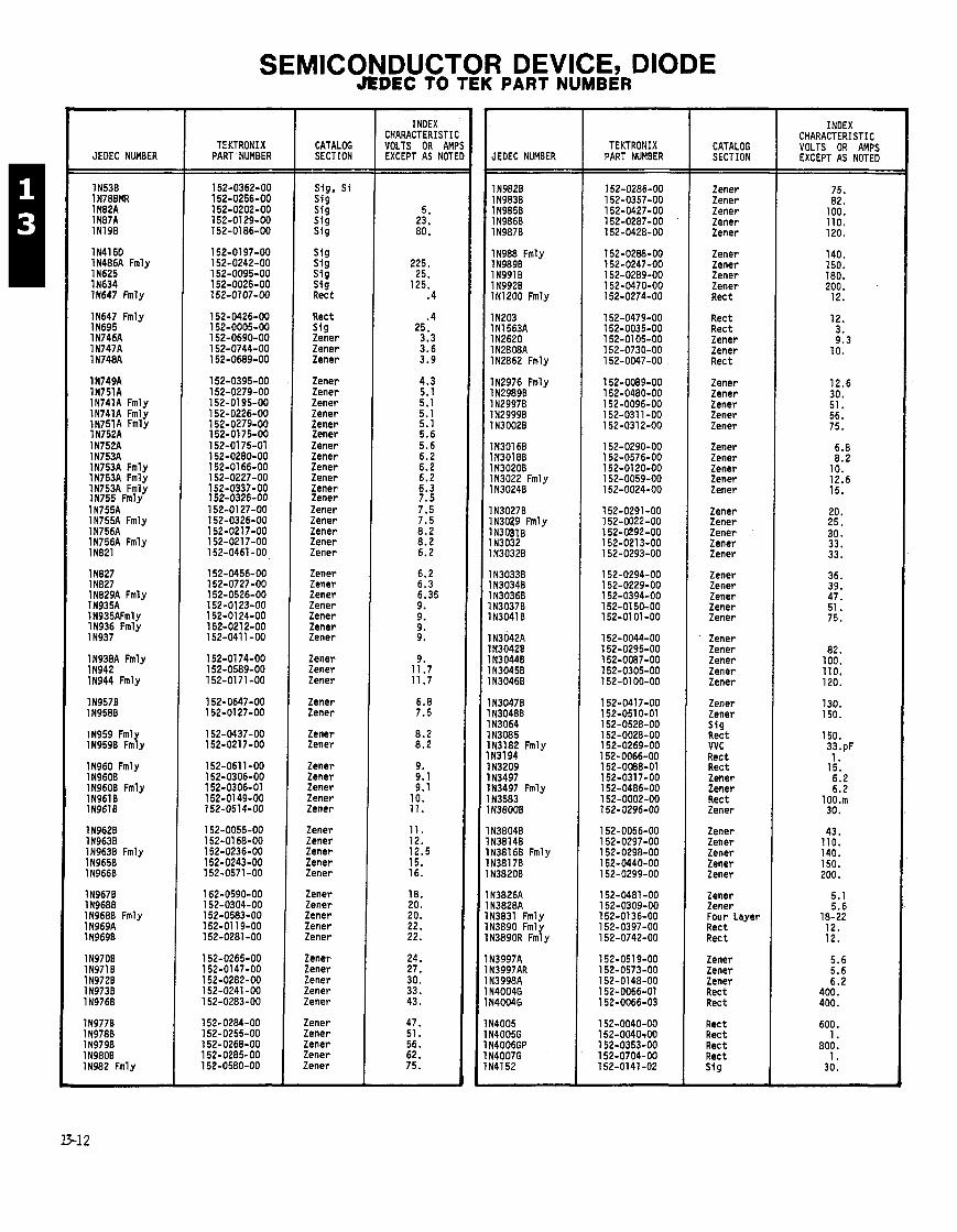
JEOEC NUMBER
IN41 50 1N486A Fmly IN625 IN634 11647 Fmly
IN647 Fmly 1 N695 1N746A 1 N747A 1 N748A
1N749A 1N751A 1N741A Fmly 1N741A Fmly 1N751A Fmly 1N752A 1N752A 1 N753A 1N753A Fmly 1N753A Fmlv 1N753A ~ m l i IN755 Fmly 1 N755A . . . . - - . . 1N755A Fmly 1 N756A 1N756A Fmly IN821
IN827 1 ~ 8 2 7 1N829A Fmly 1 N935A 1 N935AFmly IN936 Fmly 11937
1N938A Fmly 1 N942 11944 Fmly
IN959 Fmly IN9590 Fmly
IN960 Fmly 1 N96OB IN9600 Fmly IN9610
1 N962B 1N963B IN9638 Fmly 1 N965B IN9660
1 N968B Fmly 1 N969A IN9690
1N977B 1 N978B IN9790 1 N98OB IN982 Fmly
TEKTRONIX PART NUMBER
CATALOG SECTION
Sig, S i S ig s i g Sf9 s i g
S ig S ig s i g
2% Rect S ig Zener Zener Zener
Zener Zener Zener Zener Zener Zener Zener Zener Zener Zener Zener Zener Zener Zener Zener Zener Zener
Zener Zener Zener Zener Zener Zener Zener
Zener Zener Zener
Zener Zener
Zener Zener
Zener Zener Zener Zener Zener
Zener Zener Zener Zener Zener
Zener Zener Zener
Zener Zener Zener Zener Zener
Zener Zener Zener Zener Zener
INDEX CHARACTERISTI VOLTS OR AM EXCEPT AS NOT JEOEC NUMBER
IN988 Fmly IN9890 1 N99l B 1 N992B IN1200 Fmly
1 N203 IN1 563A IN2620 1N2808A IN2862 Fmly
IN2976 Fmly 1 N2989B 1 N2997B 1N2999B 1 NJOOZB
1 N3016B 1 N3018B 1 N3020B IN3022 Fmly 1 N3024B
IN30278 113029 Fmly IN30310 1 N3O32 1 N3032B
1 N3033B 1 N3034B 1 N3036B 1N3037B 1 N3041 B
1 ~ 3 0 4 2 ~ 1 N3042B 1 N3044B 1 N3O45B 1 N3046B
IN30478 1 N304BB 1 N3064 1 N3085 IN3182 Fmly 1 N3l94 1 N3209 1 N3497 IN3497 Fmly 1 N3583 I N3800B
1 N3804B 1138140 IN38160 Fmly I N3817B I N3820B
I N3826A N3828A N3831 Fmly N3890 Fmly N3890R Fmly
N3997A N3997AR N3998A N4004G N4004G
N4005 N4005G N4006GP N4007G N4l52
TEKTRONIX PART NUMBER
CATALOG SECTION
Zener Zener Zener Zener Zener
Zener Zener Zener Zener Rec t
Rect Rect Zener Zener Rec t
Zener Zener Zener Zener Zener
Zener Zener Zener Zener Zener
Zener Zener Zener Zener Zener
Zener Zener Zener Zener Zener
' Zener Zener Zener Zener Zener
Zener Zener
2t VVC Rect Rect Zener Zener Rect Zener
Zener Zener Zener Zener Zener
Zener Zener Four Layer Rec t Rec t
Zener Zener Zener Rect Rec t
Rect Rect Rec t Rec t
g
INDEX CHARACTERISTIC VOLTS OR AMPS EXCEPT AS NOTED

I JEOEC NUMBER
IN4152 Fmly 1 14152 1N4370A 1N4371A
I 1 N4372A IN4441 Fmly IN4561
IN4610 Fmly I IN4721 1NA733
1 N4744A I IN4756 Fmlr
I 1N4756A 1N4763A 114806 Fmly
I IN5000 1 N5O6O IN5283 Fmly IN5285
115625 1 N58l7 IN5820 IN5821 1 N5823
IN5824 Frhly 1 N5829 IN5832 1N5913B 1 N6098 1 N63038 3N255 Fmly 3N257 Fmly
SEMICONDUCTOR DEVICE, DIODE JEDEC TO TEK PART NUMBER
TEKTRONIX PART NUMBER
CATALOG SECTION
S i g S i g S fg s i g Zener Zener
Zener Rect Zener Zener Sig, S i Rect Zener Zener Zener Zener Zener
Zener Snap Zener Zener vvc
Rect Rect Rect Rect Rec t
Rect Rec t Rect Cur. Ref. Cur. Ref.
See IN5299 See 1N5299 Cur. Ref. Zener Zener Zener Zener Zener Zener VVC Rec t
Rect Rec t Rect Rect Rect
Rect Rect Rect Zener Rect
#am. V Supp. Rec t Rect
INDEX CHARACTERISTI( VOLTS OR AMF EXCEPT AS NOTE
COST CODE (CC COLUMN)
YOTE: Costs may vary f rom order t o o rder due t o o r d e r q u a n t i t i e s , vendor, e t c .
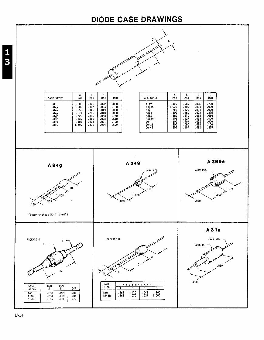
DIODE CASE DRAWINGS
D I CASE STILE I X 1 X 1 X MI,
A1 Alay Alee Aley A1 9q A1 xb A l x j Alzu
(Shown w i t h o u t DO-41 S h e l l )
PACKAGE A R -
STYLE
A146h A1 96p
.035 CIA
CASE STYLE A
MAX B
MAX C
MAX D
MIN

DIODE CASE DRAWINGS (CONT)
. 2 5 0 - 2 8 UNF-LA
ALL DIMENSIONS MAXIMUM EXCEPT WHERE NOTED.
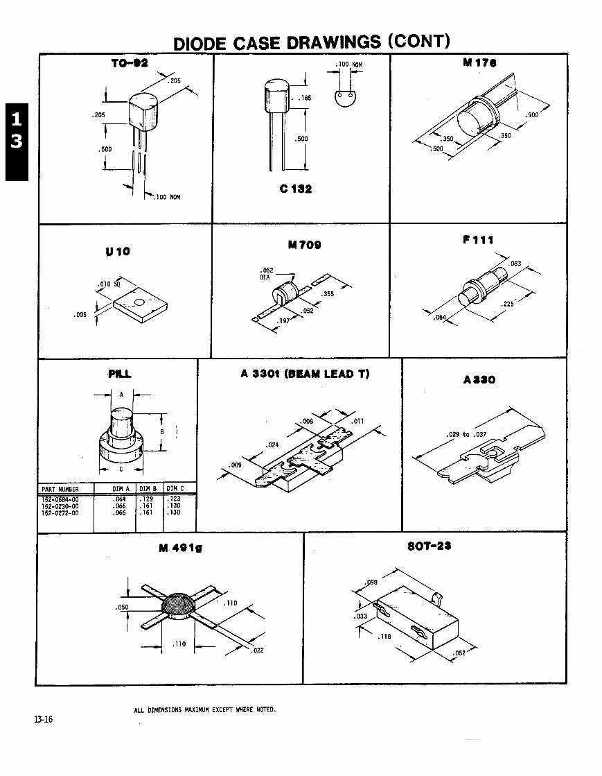
CASE DRAWINGS (CONT)
'I L l O O NOM
PART NUMBER 152-0684-00 152-0230-00 152-0272-00
A 3301 (BEAM LEAD T)
ALL DIMENSIONS MAXIMUM EXCEPT WHERE NOTED. U-16
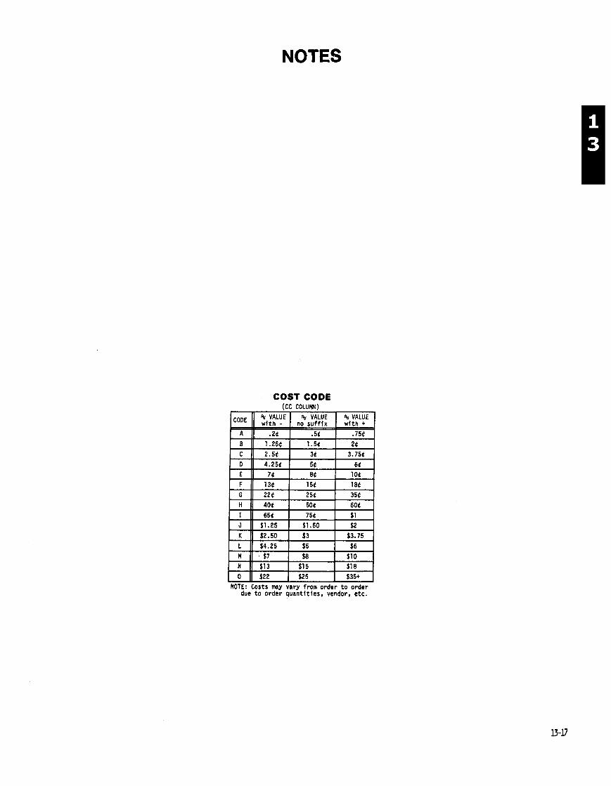
NOTES
COST CODE (CC COLUMN)
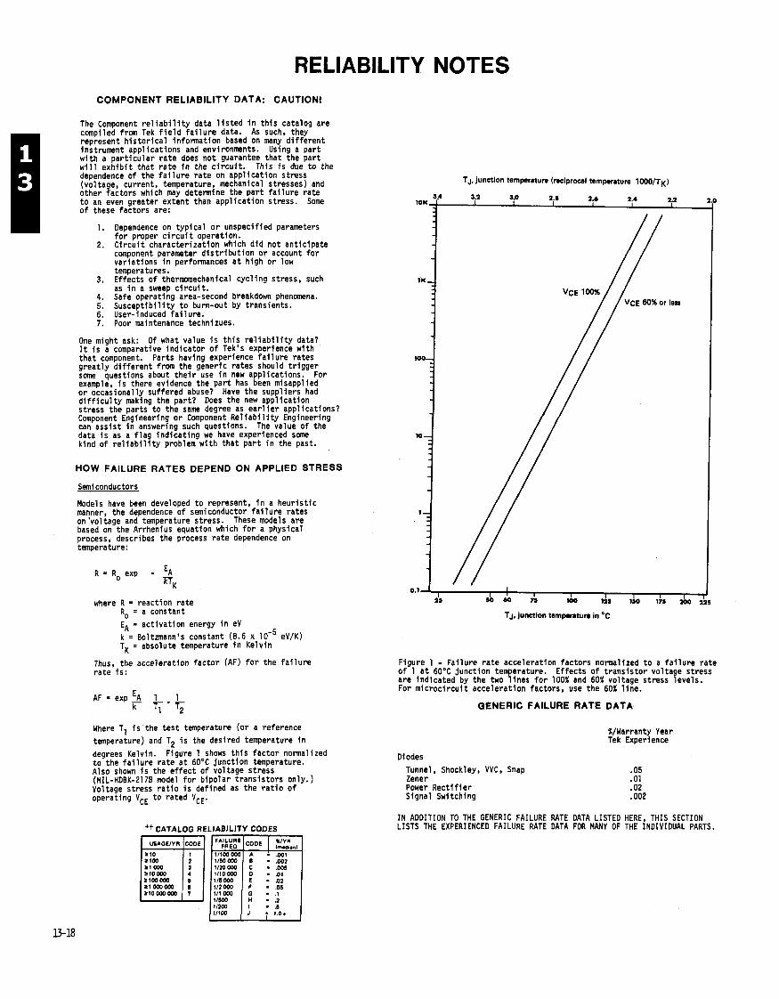
RELIABILITY NOTES COMPONENT RELIABILITY DATA: CAUTlONl
The Component r e l i a b i l i t y data l i s t e d i n t h i s catalog are
E compiled from Tek f i e l d f a i l u r e data. As such, they represent h i s t o r i c a l information based on many d i f f e r e n t instrument appl icat ions and environments. Using a par t w i th a pa r t i cu la r r a t e does no t guarantee tha t the pa r t w i l l e x h i b i t t ha t ra te i n the c i r c u i t . This i s due t o the dependence o f the f a i l u r e ra te on appl icat ion stress (voltage, current, temperature, mechanical stresses) and other factors which may determine the pa r t f a i l u r e ra te t o an even greater extent than appl icat ion stress. Some o f these factors are:
1. Dependence on t yp ica l o r unspecified parameters f o r proper c i r c u i t operation.
2. C i r c u i t character izat ion which d id not ant ic ipate component parameter d i s t r i b u t i o n o r account f o r var ia t ions i n performances a t high o r low temperatures.
3. Effects o f t h e m e c h a n i c a l cyc l ing stress, such as i n a sweep c i r c u i t .
4. Safe operating area-second breakdown phenomena. 5. Suscep t ib i l i t y t o burn-out by transients. 6. User-induced f a i 1 ure. 7. Poor maintenance technizues.
One might ask: O f what value i s t h i s r e l i a b i l i t y data? It i s a comparative ind ica to r o f Tek's experience wtth tha t component. Parts having experience f a i l u r e rates great ly d i f f e r e n t from the generic ra tes should t r i gger some questions about t h e i r use i n new appl icat ions. For example, i s there evidence the p a r t has been misapplied o r occasionally suffered abuse? Have the suppl iers had d i f f i c u l t y making the pa r t? Does the new appl icat ion stress the parts t o the same degree as e a r l i e r appl icat ions? Component Engineering o r Component R e l i a b i l i t y Engineering can ass is t i n answering such questions. The value o f the data i s as a f l a g ind ica t ing we have experienced some kind o f r e l i a b i l i t y problem w i th tha t p a r t i n the past.
HOW FAILURE RATES DEPEND ON APPLIED STRESS
Semiconductors
Models have been developed t o represent, i n a heur i s t i c manner, the dependence o f semiconductor f a i l u r e rates on 'voltage and temperature stress. These models are based on the Arrhenius equation which f o r a physfcal process, describes the process ra te dependence on temperature:
R = R, exp - E~
m~ where R = reaction ra te
R, = a constant
E; = act ivat ion energy i n eV k = Boltmann's constant (8.6 x eV/K) TK = absolute temperature i n Kelv in
Thus, the accelerat ion fac to r (AF) f o r the f a i l u r e ra te i s :
AF = exp 3 I 1 k f ; -T ;
Where T, i s the tes t temperature (o r a reference temperature) and T2 i s the desired temperature i n
degrees Kelvin. Figure 1 shows t h i s fac to r normalized t o the f a i l u r e ra te a t 60°C junct ion temperature. Also shown i s the e f f e c t o f voltage stress (MIL-HOBK-2178 model f o r b ipo lar t rans is to rs only.) Voltage stress r a t i o i s defined as the r a t i o o f operating VCE t o rated VCE.
tt CATALOG RELIABILITY CODES
1/20 000 r t o w t~ loom - .ot ltooom 116 000 - a2 a1 000000 112 om - .05 ZlOom000
TJ, junction temperature (reciprocal temperature 1000/T~)
TJ, junction tarnpmture in 'C
Figure 1 - Fai lure r a t e accelerat ion factors normalized t o a f a i l u r e ra te o f 1 a t 60°C junct ion temperature. Ef fects of t rans is to r voltage stress are indicated by the two l i nes f o r 100% and 60% voltage stress levels. For m ic roc i r cu i t accelerat ion factors, use the 60% l i ne .
GENERIC FAILURE RATE DATA
Diodes Tunnel, Shockley, VVC, Snap Zener Power R e c t i f i e r Signal Switching
%/Warranty Year Tek Experience
IN ADDITION TO THE GENERIC FAILURE RATE DATA LISTED HERE, THIS SECTION LISTS THE EXPERIENCED FAILURE RATE DATA FOR MANY OF THE INDIVIDUAL PARTS.

APPLICATION NOTES
Zener diodes Graphs are representative of weram zener characteristics
Forward current. IF
1 Reverse current. .IR Zener current, IZ Zener current near breakdown knee. IZK Maximum DC zener current (powar dissipation limited1 IZM Zener t a t current. IZT
Ambient temperature. T A Junction temperature. TJ
Fomerd voltage. VF Reverse T a t voltaoe. V n
7 . .. Normal zener voltage. VZ
- - - - - - - - - - - Reverse Characterntic Zener impedance. ZZ
VR IVoltsl 0 VF IVolul Zener impedance near breakdown knes (nmsured el 1 2 ~ ) . ZZK
Zener impdmcl, at test current (IzT). ZZT
Forward characteristics of a non-temperature compensated zener diode are equivalent to those of a normal diode. VF is often specified at some IF.
MAX
Izr ' 7.5 mPI
-0.08
MAX
2.0 3.0 4.0 5.0 6.0 7.0 8.0 8.0 I 0 11 12 0 2 4 6 8 10 12 14 VZ Zener Vdtrpl IVoltrl Zeyr V d t w Vdo
Note that between 3 and 8 volts, current has an effect on TC aside from self-heating.
Temperature compensated diodes are made by selecting zener diodes and normal silicon diodes which have equal and opposite TC's. They are then encapsulated in one package. Example: *
Note: A TC'ed diode is temperature compensated only at the specified test current. Any other current will yield a higher temperature coefficient than specified.
. .
The slope of the Vz . 12 curve fin breakdown) $ is defined as zener impedance or resistance. The measurement is generally done with a 60 Hz current ' 70
variation whose value is 10% in rms of the DC value of the current, i.e.,
change in iz peak to peak = 0.282 12
This is really not a small signal measurement 't 7.0 but is convenient to use and gives repeatable re- 0 5.0 TA = 25% S U ~ S . 3 3.0 Izlxl . 0.1 IZldcl
Capacitance in a zener diode decreases with in. 1 ; . - I
creasing reverse bias voltage as in any p.n junction 2.0 3.0 5.0 7.0 10 20 JO so 70 100 rm diode until the Zener breakdown region is reached vz Zonw vd tw lvolu)
where CZ becomes essentially constant. Vz Z*MI lmmdlnm ITyp iu l I Versus Zamr V o l w
For more information, contact Gary Sar@ant, ext. 2540.
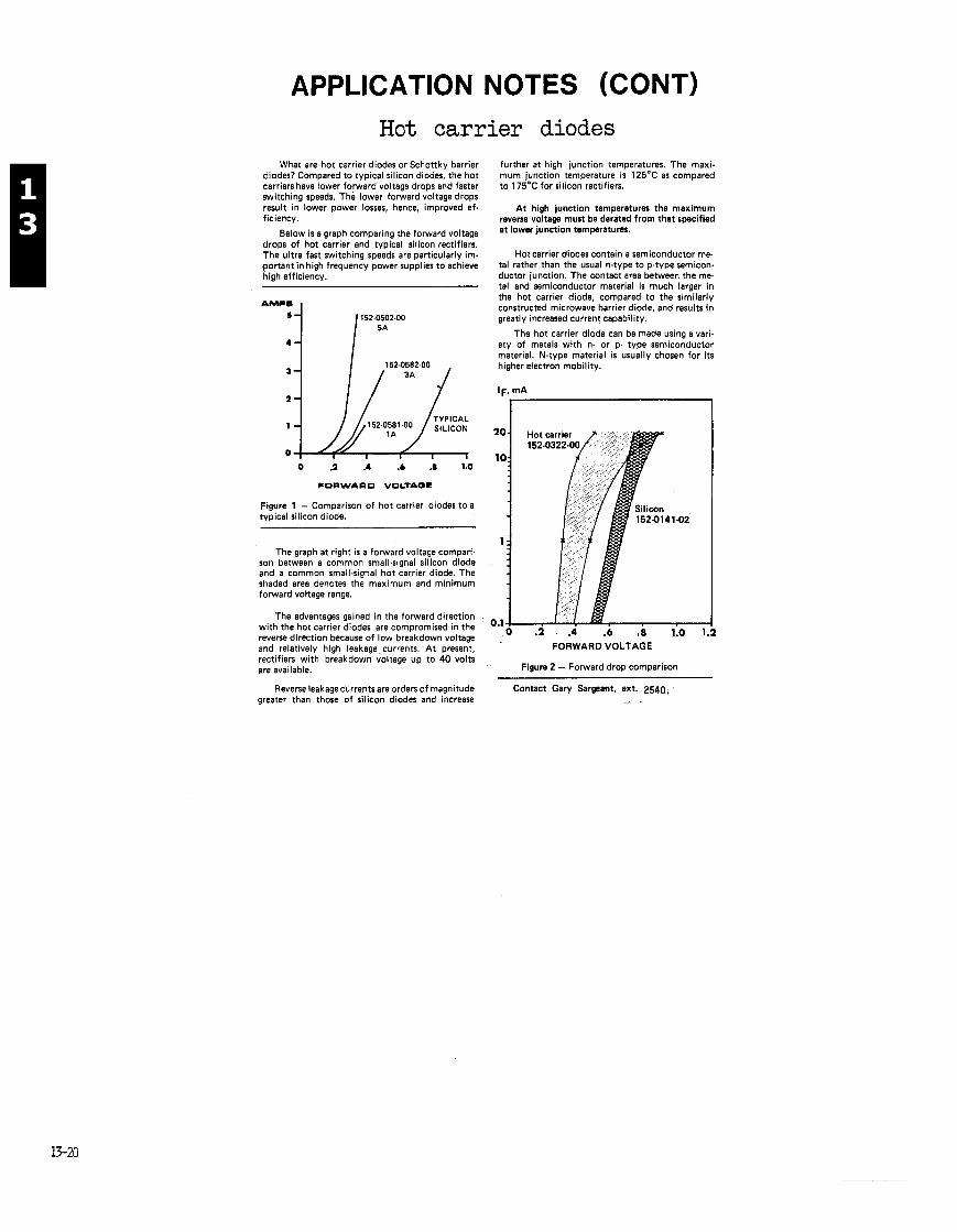
APPLICATION NOTES (CONT)
What are hot carrier diodes or Schottky barrier diodes? Compared to typical silicon diodes, the hot carriers have lower forward voltage drops and faster switching speeds. The lower forward voltage drops result in lower power losses, hence, improved ef- ficiency.
Below is a graph comparing the forward voltage drops of hot carrier and typical silicon rectifiers. The ultra fast switching speeds are particularly im- portant in high frequency power supplies to achieve high efficiency.
Figure 1 - Comparison of hot carrier diodes to a typical silicon diode.
The graph at right is a forward voltage compari- son between a common small-signal silicon diode and a common small4gnal hot carrier diode. The shaded area denotes the maximum and minimum forward voltage range.
The advantages gained in the forward direction with the hot carrier diodes are compromised in the reverse direction because of low breakdown voltage and relatively high leakage currents. A t present, rectifiers with breakdown voltage up to 40 volts are available.
Reverse leakaae currents are orders of maanitude
further at high junction temperatures. The maxi- mum junction temperature is 125'C as compared to 175°C for silicon rectifiers.
At high junction temperatures the maximum reverse voltage must be derated from that specified at lower junction temperatures.
Hot carrier diodes contain a semiconductor me- tal rather than the usual n-type to p-type semicon- ductor junction. The contact area between the me- tal and semiconductor material is much larger In the hot carrier diode, compared to the similarly constructed microwave barrier diode, and results in greatly increased current capability.
The hot carrier diode can be made using a vari- ety of metals with n- or p- type semiconductor material. N-type material is usually chosen for its higher electron mobility.
Hot carr ier diodes
greater than th&e of silicon diodes and increase
FORWARD VOLTAGE
Figure 2 - Forward drop comparison -- -
Contact Gary Sargeant, ext. 2540,
STATIC SENSITIVE
HANDLING OF STATIC SENSITIVE COMPONENTS
MOST SEMICONDUCTOR PART TYPES, BOTH SEPARATELY AND I N ASSEMBLIES, HAVE BEEN FOUND TO BE SUSCEPTIBLE TO DAMAGE AT VOLTAGE LEVELS COMMONLY FOUND I N MANUFACTURING ENVIRONMENTS. THE SIMULATED S T A T I C DISCHARGE TESTS SHOWED THE FOLLOWING CATEGORIES TO BE ESPECIALLY SUSCEPTIBLE:
CATEGORIES RELATIVE DEGRADATION LEVEL^ MOS OR CMOS MICROCIRCUITS OR DISCRETES OR . . . . . . . . . . . . . . . LINEAR MICROCIRCUITS WITH MOS I N P U T S . 1 0 0 - 5 0 0
ECL . . . . . . . . . . . . . . . . . . . . . . . . . . . . . . . . . 2 0 0 - 5 0 0 . . . . . . . . . . . . . . . . . . . . . . . . SCHOTTKY SIGNAL DIODES 2 5 0
. . . . . . . . . . . . . . . . . . . . . . . . . . . . . SCHOTTKY TTL 5 0 0 . . . . . . . . . . . . . . . . . . H I G H FREQUENCY BIPOLAR TRANSISTORS 4 0 0 - 6 0 0
. . . . . . . . . . . . . . . . . . . . . . . . . . . . . . . . JFETS 6 0 0 - 8 0 0 . . . . . . . . . . . . . . . . . . . . . . . . . LINEAR MICROCIRCUITS 4 0 0 - 1 0 0 0 (es t . )
LOW POWER SCHOTTKY T T L . . . . . . . . . . . . . . . . . . . . . . . . 9 0 0
T T L . . . . . . . . . . . . . . . . . . . . . . . . . . . . . . . . . 1 2 0 0
RECOMMENDATION:
S INCE ALMOST EVERY ASSEMBLY INCLUDES SOME OF THESE PARTS, WE RECOMMEND S T A T I C S E N S I T I V E PROCEDURES BE IMPLEMENTED FOR A L L OPERATIONS INVOLVING SEMICONDUCTOR PART HANDLING.
DIRECT ANY QUESTIONS TO: RON SCHWARTZ, COMP. REL. ENG. EXT. 1 6 0 5 .


OPTOELECTRONIC DEVICES
S E C T I O N 1 4
T A B L E O F C O N T E N T S
COST CODE (CC C0LU)IY)
NOTE: Costs m y vary from order t o order due t o order quant i t ies , vendor, e tc .
CATALOG WRITER: NORMA PETERSON, EXT. 2577.
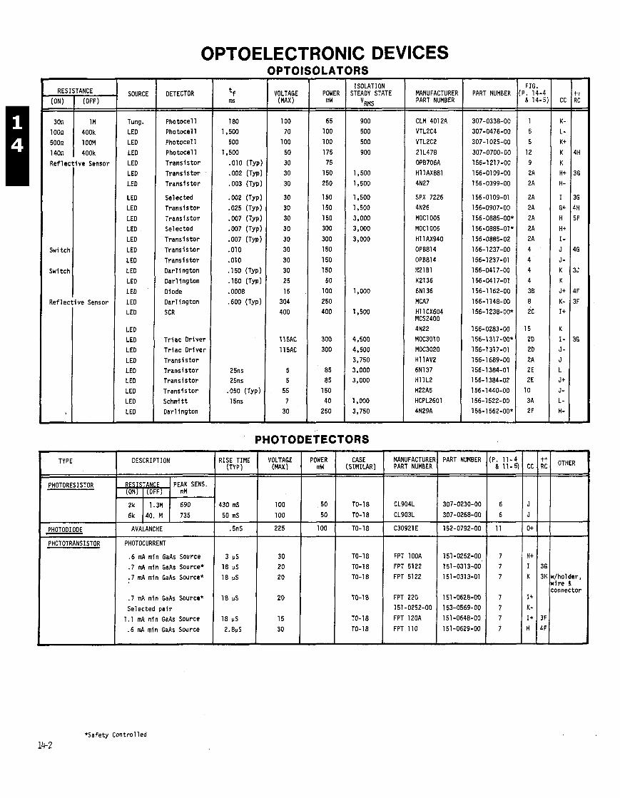
OPTOELECTRONIC DEVICES OPTOISOLATORS
30n
1 OOn 500n
140n Ref 1 ec
Switch
Switch
Ref 1 ec
, -
1 M 400k
1 OOM
400k ve Sensor
ve Sensor
SOURCE
Tung. LED LED
LED
LED LED
LED
LED LED
LED LED
LED
LED
LED
LED LED
LED
LED LED
LEO LEO LED
LED LEO LED LED LED
LED -
DETECTOR
Photocel l Photoce l l
Photoce l l
Photocel l T rans i s to r
T r a n s i s t w T rans i s to r
Selected T rans i s to r
T rans i s to r Selected
T rans i s to r T rans i s to r
T rans i s to r Dar l i ngton
Dar l i ng ton
Diode
Dar l ing ton
SCR
T r i a c D r i ve r
T r i ac D r i ve r T rans i s to r T rans i s to r T rans i s to r
T rans i s to r
Schmi tt Darl ing ton
VOLTAGE (MAX)
100
70 100
50
30 30
30
30 30
30 30
30 30
30
30 25
15
304 400
11 5AC
11 5AC
5 5
55
7 30
- POWER mW - 65
100
100
175 75
150
250
150 150
150 300
300 150
150
150 50
100
250 400
300
300
85 85
150
40 250 7
ISOLATION STEADY STATE
V~~~
900
500 500
900
1,500
1,500
1,500
1,500
3,000 3,000
3,000
1.000
1,500
4,500 4,500 3,750 3,000 3,000
1,000
3,750
MANUFACTURER PART NUMBER
CLM 4012A VTL2C4 VTL2C2
21 L478
OPB706A Hl lAX881
4N27
SPX 7226 4N26
MOC1005
MOClOO5
Hl lAX940 OPB814
OPB81 4
H21B1 K2136
6N136 MCA7
H l l CX604 MCS2400 4N22
MOC3010 MOC3020 Hl lAV2 6N137 H l l L2
H22A5 HCPL2601 4N29A
PART NUMBER
PHOTODETECTORS
PART NUMBER
- FIG.
P. 14-4 & 14-5 - 1 5
5
12 9 2A
2A
2A
2A
2A
2A 2A
4 '
4 4
4
38
8 2c
15 20
2D 2A 2E 2E
10
3A 2F
MANUFACTURE PART NUMBER
CL904L
CL903L
C30921 E
FPT lOOA FPT 5122 FPT 5122
FPT 220 151 -0252-00
FPT 120A
FPT 110
TYPE
PHOTORESISTOR
PHOTODIODE
PHOTOTRANSISTOR
*Safety Cont ro l led
14-2
ii
36 3H
3F
4F
CASE (SIMILAR)
TO-18
TO-18
TO- 18
TO-18 TO-18 TO-18
TO-1 8
TO- 18
TO-1 8
OTHER
w/holder, w i re & connector
VOLTAGE (MAX)
100
100
225
30 20
20
20
15
30
RISE TIME (Typ)
430 mS
50 mS
.5nS
3 US 18 IJS 18 US
18 pS
18 IJS
2.8pS
POWER mW
50
50
100
DESCRIPTION
PEAK SENS. RM
690
735
RESISTANCE ,
AVALANCHE
PHOTOCURRENT
.6 mA min GaAs Source
.7 mA min GaAs Source*
.7 mA min GaAs Source*
.7 mA min GaAs Source*
Selected p a i r
1.1 mA min GaAs Source
.6 mA min GaAs Source
(ON)
2k
6k
(OFF)
1.3M
40. M

OPTOELECTRONIC DEVICES (CONT) INFRARED EMITTERS
SPX3188-004 820 150 1.5 100 13 .765 .500 .689 .437 150-1 104-00
For further explanation of this code, see page 0-25.
COST CODE (CC COLUbN)
NOTE: Costs m y vary fran order to order due to order quantities, vendor, etc.
CC
I +
G-
o+
tt RC OTHER
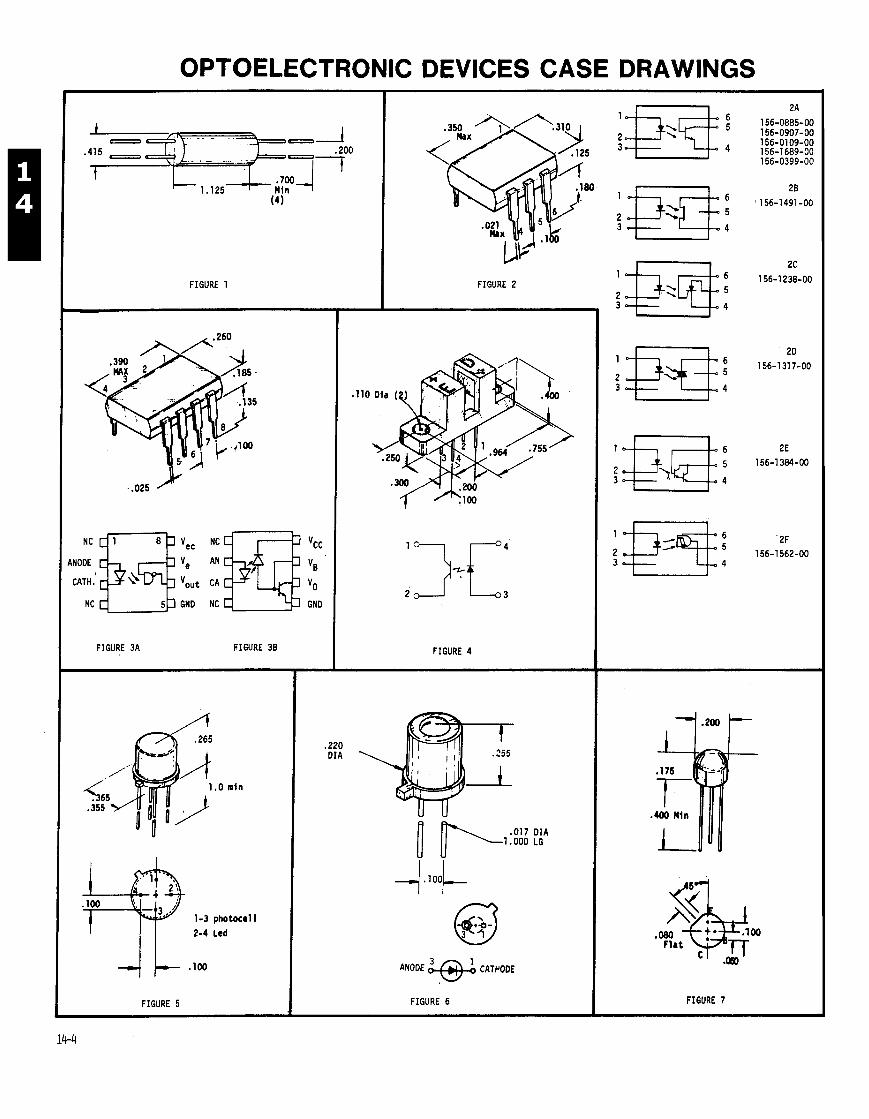
OPTOELECTRONIC DEVICES CASE DRAWINGS
FIGURE 1
:ATH.
NC GND
FIGURE 3A FIGURE 38
FIGURE 5
. 2 2 0 D I A
FIGURE 2
FIGURE 4
. 0 1 7 D I A 1 .000 LG
ANODE CATPODE
FIGURE 6 FIGURE 7

OPTOELECTRONIC DEVICES CASE DRAWINGS
1 . Anode 2. Catme I LED 3. Collector 1 Detector 4. Emitter
FIGURE 8
. 2 1 0 D I A
. 0 1 8 D I A . 9 5 0 LG
ANODE FIGURE 1 1
FIGURE 1 4
3. Anode 4. Cathode
FIGURE 9
FIGURE 12
BOTTffl V I E W
FIGURE 1 5
FIGURE 13

COLOR VENDOR NUMBE
Red Red
Red Red
Red
Red
Red
Red
Red Red Red
Red Red
Red
Red Red Red
Red
Red Red Red Red Red
Red Red
Red
Red Red
HLMP- 1301 SBR3431 558-0101-003
HLMP-2620 RL-50 MV- 50 TIL209A
57642 LD468 RL4480-1 LL2Ol R MV-5074C XC2090
Org/Grn CQX95 Yellow QLMP-0449 I
Red Red/Grn Red/Grn
Yellow ~ ~ ~ ~ 1 4 0 1 Yellow MV5374C I
555-2007 MV5774C 521-9178 XC5491
Yellow MV5352 5082-4558
Yellow 5082-4150
Yellow 558-0301-003 I Ye1 low
Ye1 low
XC-5569-Y MV5353 550-0305-804
Green
kreen
- MAIN
SPECTRU LINE nm -
690. 690
665. 655.
635.
655.
655.
635/660
660. 660. 655.
635. 650.
650.
635. 650. 650.
660.
650. 655. 650. 635. 635.
655. 655.
635.
635. 650. 635.
695/555. 690/565.
630/560. 583.
585. 585.
585.
583. 585.
580.
585.
580.
565.
572.
565.
562. 560.
560.
560.
560.
555. 565. 565. 565. 565. 660. -
XC556-62 MV64530 QLMP-0549
Green
;reen ;reen
TY I NT - mcd - - 1. 1.
2. .8
2.
.8
.8
7.
3. 2. 1.5
10. 1.4
. 5 mi n 2.5
.5 1.5
2.5
1.5 1.2
.8 4. 3.
.81
.8
4.
4. .6
5. 1.5 1.8
6. 1.8 mi n 4. 4.
5.
2. 4.
1.5
5.
5.
3.
1.6 n i n 3.
?. 5. n i n 1.5
HLMP1502 SPG3931 54643 559-0201 -003
LAMP, LED CASE
A B LENGTH
MAX MIN -. - -
FOR RELIABILITY CODES, SEE PAGE 14-3.
EE PAGE 1 I S C
THK MAX
.013 .090 .090
.027 ,200 . I50
.020 . I25
- ,150
. I50
.015 .ZOO
.025 . I85
.020 .zoo
.025 .250
.400 .010
.024 ,130
.018 . I25
.007 .087
.020 . I25
.014 . I25
.015 .250
.020 . I25 .250
.008 ,075
.312
.020 . I85
.016 .ZOO ,017 .200 .014 . I30 .020 . I87 .025 .200
.019 . I 97 ,017 .295
.014 . I 30
.014 . I30
,020 .zoo ,008 .075 ,020 .250
. I 50
,025 .ZOO
,020 . I85
,016 .ZOO
017 ,295
020 . I25
018 ,125 025 .250
,150
,150
025 .250
01 95.205 014 . I 30
. I30 008 .075
. I85
NOM NOM MAX $& q- ibove? PART NUMBER
: Red D = Di f fused : Yellow C = Clear
?n F = Fresnel t e U = Unt in ted
-- - - OTHER
Notch cathode W/wires , connectors,
ho lder & housing F l a t o r notkh cathode W/Berg connectors
Short l ead cathode
W/connectors, b l k l ead cathode
W/2 Berg connectors
F l a t o r shor t LD cathode
F l a t o r notch cathode F l a t s ide cathode + s i gn anode
4 element l i g h t ba r Cross bar cathode
F l a t s ide cathode
Short lead cathode I n - l i n e package F l a t o r notch cathode
F l a t side'cathode
W/holder ( r i g h t angle) Mtg. hdwr. i s n o t supp l i t Short lead cathode Rectangular
Short lead cathode, R ight angle PCB mount
+ s i gn anode F l a t s i de cathode T r i -S ta te T r i -S ta te
T r i -S ta te
Short lead cathode F l a t s ide cathode
F l a t s ide cathode
Rectangular
6" leads, red & b lack , (cathode)
F l a t s ide cathode
Short l ead cathode
F l a t s ide cathode
Short l ead cathode
Short lead cathode 6:' leads, r ed & b lack
(cathode) 6" leads, red & b lack
(cathode) ~ j 2 Berg connectors
Short lead cathode
F l a t s ide cathode F l a t s ide cathode W/wires, conn & housing
R, angle, PCB mount Die Chip
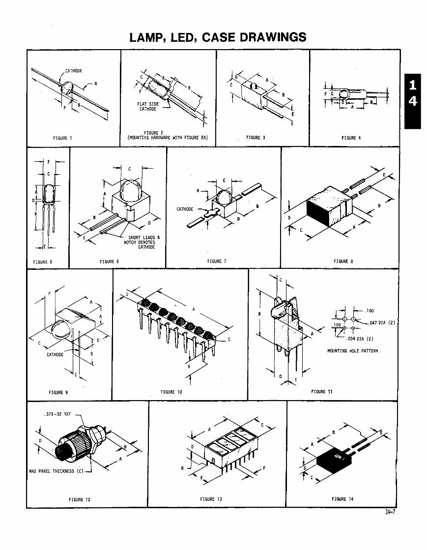
LAMP, LED, CASE DRAWINGS
FIGURE 2 (MOUNTING HARDWARE WITH FIGURE 2 A )
FIGURE 5
FIGURE 9
CATHODE
FIGURE 6
FIGURE 3
FIGURE 7
FIGURE 1 0
-r
FIGURE 4
FIGURE 8
. 0 3 4 D I A (2)
MOUNTING HOLE PATTERN
1 FIGURE 12 I FIGURE 1 3
FIGURE 11
FIGURE 1 4
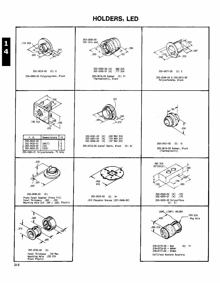
HOLDERS, LED
352-0419-00 CC: 0
254-0990-00 Polypropylene, Black
1 352-0433-03 (SCD) I G I 255-0565-01 Polycarbonate, TV Gray
P. N. 352-0433-00 352-0433-01
b352-0433-02
352-0699-00 CC:
Front Panel Adapter (Press F i t ) Panel Thickness .060 - .250 Mounting Hole DIA .265 5 .003. P l a s t i c
352-0700-00 CC:
Panel Thickness . I25 Max. Mounting Hole .25O DIA Black P l a s t i c
Nomenclature
(WAIT) (CD)
352-0360-00 (A) .082 DIA 352-0360-01 (A) .I17 DIA
CC F G G
255-0616-00 Rubber CC: F t Thermoplastic, Black
352-0361-00 (A) .080 MAX DIA 352-0367-00 (A) .129 MAX DIA 352-0358-00 (A) . I87 MAX DIA
255-0010-00 Acetal Resin, Black CC: G+
352-0535-00 CC: G+
.010 Phosphor Bronze (251-0448-00)
352-0477-00 CC: E
255-0504-00 & 255-0613-00 Polycarbonate, Black
352-0451-00 CC: G-
255-061 6-00 Rubber, Black (Thermoplas t i c )
352-0522-00 (A) . I00 352-0522-01 (A) . I75
255-0330-00 Po lysu l fone CC: E-
LENS. LIGHT: HOLDER
,250 DIA Mtg Hole
378-0175-00 - Red CC: F t 378-0176-00 - h b e r 378-0177-00 - Green Cel lu lose Acetate Butyrate
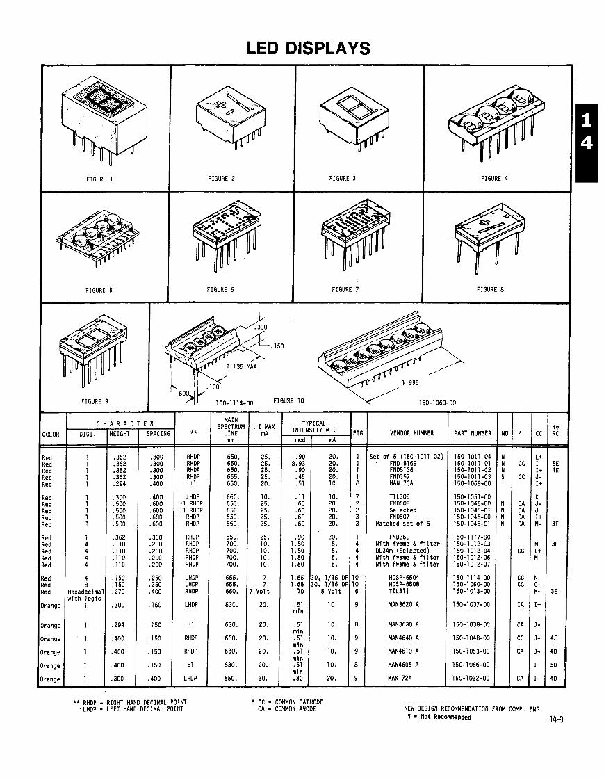
LED DISPLAYS
FIGURE 2 FIGURE 3 FIGURE 4 FIGURE 1
FIGURE 5 FIGURE 6 FIGURE 7 FIGURE 8
FIGURE 9
VENDOR NUMBER
- ILOR
- - 'd !d d d d
d d d d d
d d d d d
d d d
ange
ange
ange
mge
mge
mge 7
- **
RHDP RHDP RHDP RHDP
i 1
LHDP i 1 RHOP i 1 RHDP
RHDP RHDP
RHDP RHDP RHDP RHDP RHDP
LHDP LHDP RHDP
LHDP
i 1
RHDP
RHDP
i 1
LHDP -
- . I MAX
mA
25. 25. 25. 25. 20.
10. 25. 25. 25. 25.
25. 10. 10. 10. 10.
7. 7.
' Yo1 t
20.
20.
20.
20.
20.
30. -
MAIN SPECTRUM
LINE nm
650. 650. 650. 665. 660.
660. 650. 650. 650. 650.
650. 700. 700. 700. 700.
655. 655. 660.
630.
630.
630.
630.
630.
650.
ICAL ITY @ I
mA
20. 20. 20. 20. 10.
10. 20. 20. 20. 20.
20. 5. 5. 5. 5.
30, 1/16 Dl 30, 1/16 Dl
5 V o l t
10.
10.
10.
10.
10.
20.
C H A R A C T E R T INTE - mcd - - .90
8.93 .90 .45 .51
.ll
.60
.60
.60
.60
.90 1.50 1.50 1.50 1.50
1.65 1.65
.10
.51 min
.51 mi n .51 min .51 mi n .51 mi n .30 -
DIGIT HEIGHT PART NUMBER
j e t o f 5 (150-1011-02) FND 5169 FND5136 FND357 MAN 73A
TIL305 FN0508 Selected FND507
Matched s e t o f 5
FND360 With frame L f i l t e r DL34m (Selected) With frame 6 f i l t e r With frame 6 f i l t e r
4 ' . I 50 8 . I 50
Hexadecimal .270 w i t h l o g i c
1 .300
MAN 72A
** RHDP RIGHT HAND DECIMAL POINT LHDP = LEFT HAND DECIMAL POINT
* CC = COMMON CATHODE CA = C H O N ANODE NEW DESIGN RECOMMENDATION FROM COMP. ENG.
N = Not R e c m n d e d
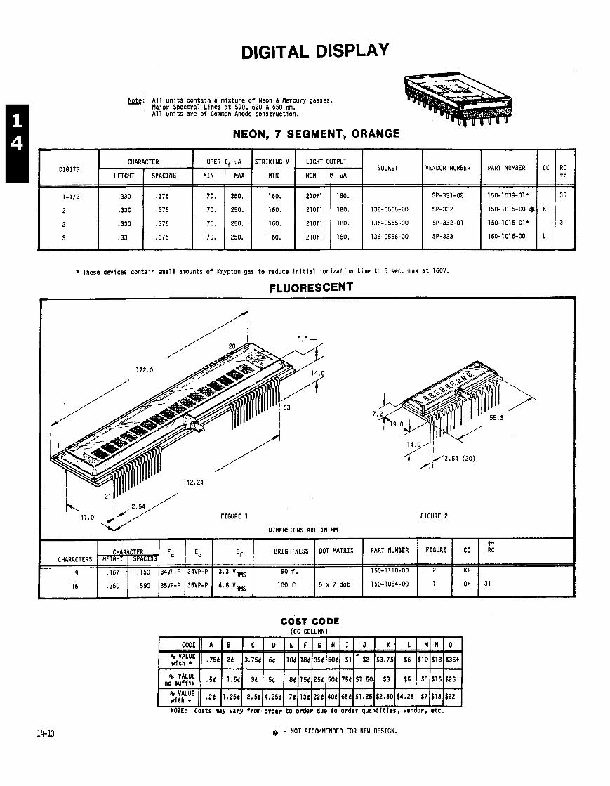
DIGITAL DISPLAY
* These devices conta in smal l amounts o f Krypton gas t o reduce i n i t i a l i o n i z a t i o n t ime t o 5 sec. max a t 160V.
FLUORESCENT
Note: A l l u n i t s conta in a mix ture o f Neon & Mercury gasses. -
1, Major Spectral Lines a t 590, 620 & 650 nm. A l l u n i t s are o f Comnon Anode construct ion.
NEON, 7 SEGMENT, ORANGE
FIGURE 1
DIMENSIONS ARE IN W
FIGURE 2
DIGITS
1-1/2
2
2
3
*
SOCKET
136-0565-00
136-0565-00
136-0556-00
COST CODE ICC COLUMN) .~~ - - - .
NOTE: Costs may vary f r om o rde r t o o rde r due t o order quan t i t i es , vendor, e tc .
CHARACTER
b - NOT RECOMMENDED FOR NEW DESIGN.
RC tt
36
3
VENDOR NUMBER
SP-331-02
SP-332
SP-332-01
SP-333
HEIGHT
.330
.330
.330
.33
J
PART NUMBER
150-1110-00
150-1084-00
SPACING
.375
.375
.375
,375
OPER If uA
Eb
34VP-P
35VP-P
Ec
34VP-P
35VP-P
CHARACTERS
9
16
STRIKING V
MIN
160.
160.
160.
160.
PART NUMBER
150-1039-Ol*
150-1015-00 Q.
150-1015-Ol*
150-101 6-00
MIN
70.
70.
70.
70.
FIGURE
. 2
1
CC
K
L
MAX
250.
250.
250.
250.
Ef
3.3 VMs
4.8 VMs
CHARACTER
LIGHT OUTPUT
NOM @ PA
CC
K+
O+
HEIGHT
.I67 .
.350
210f l
210fl
210f l
210fl
tt RC
31
BRIGHTNESS
90 f L
100 f L
SPACING
. I50
,590
180.
180.
180.
180.
DOT MATRIX
5 x 7 do t
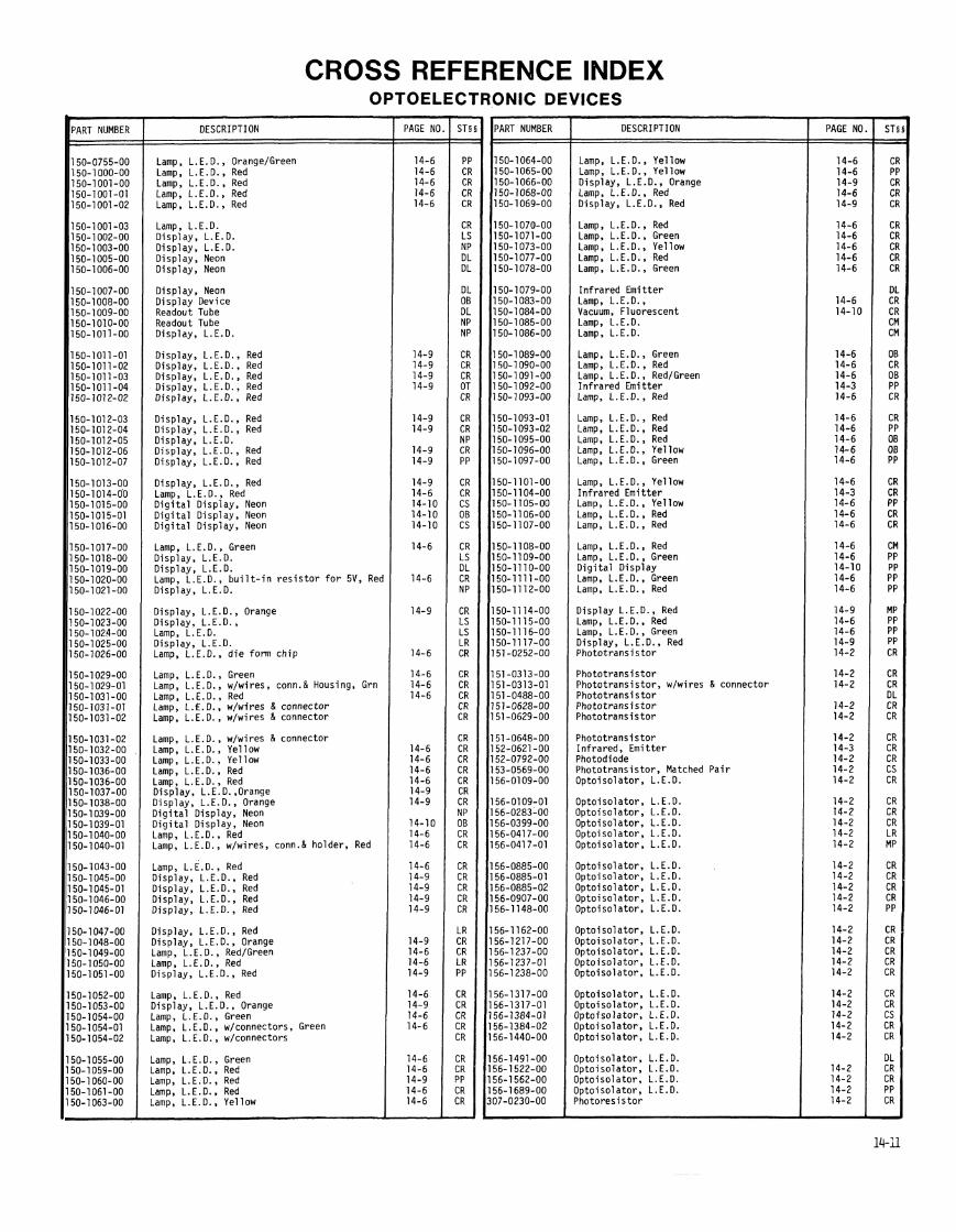
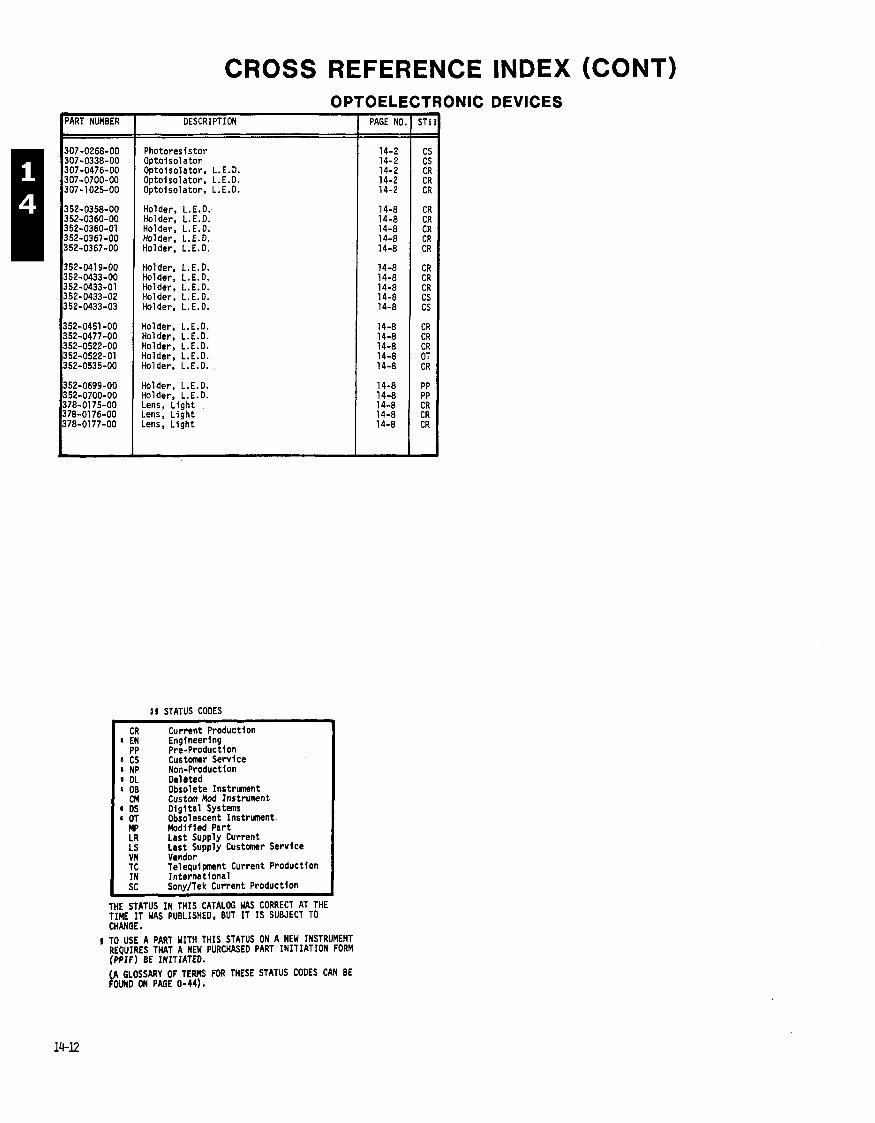
CROSS REFERENCE INDEX (CONT) OPTOELECTRONIC DEVICES
DESCRIPTION
Photoresistor Optolsolator Optolsolator, L. E.D. Optoisolator, L.E.O. Optoisolator, L.E.D.
Holder, L.E.O. Holder, L.E.D. Holder, L.E.D. Holder. L.E.D. Holder, L.E.D.
Holder, L.E.D. Holder. L.E.O. Holder, L.E.D. Holder, L.E.O. Holder, L.E.O.
Holder, L.E.D. Holder, L.E.D. Holder, L.E.O. Holder, L.E.D. Holder, L.E.D.
Holder, L.E.O. Holder, L.E.D. Lens, L ight Lens, L igh t Lens, L igh t
5 5 STATUS CODES
Current Productlon Engineering Pre-Production Customer Service Non-Production Deleted Obsolete Instrument Custom Mod Instrument D i g l t a l Systems Obsolescent Instrument Modified Part Last Supply Current Last Supply Customer Service
I VN Vendor TC Telequi pnent Current Production IN In ternat ional SC SonvITek Current Production I
THE STATUS IN THIS CATALOG WAS CORRECT AT THE TIME IT WAS PUBLISHED, BUT IT IS SUBJECT TO CHANGE.
I TO USE A PART WITH THIS STATUS ON A NEW INSTRUMENT REQUIRES THAT A NEW PURCHASED PART INITIATION FORM ( P P I F ) BE INITIATED. . .
(A GLOSSARY OF TERMS FOR THESE STATUS CODES CAN BE FOUND DN PAGE 0-44).
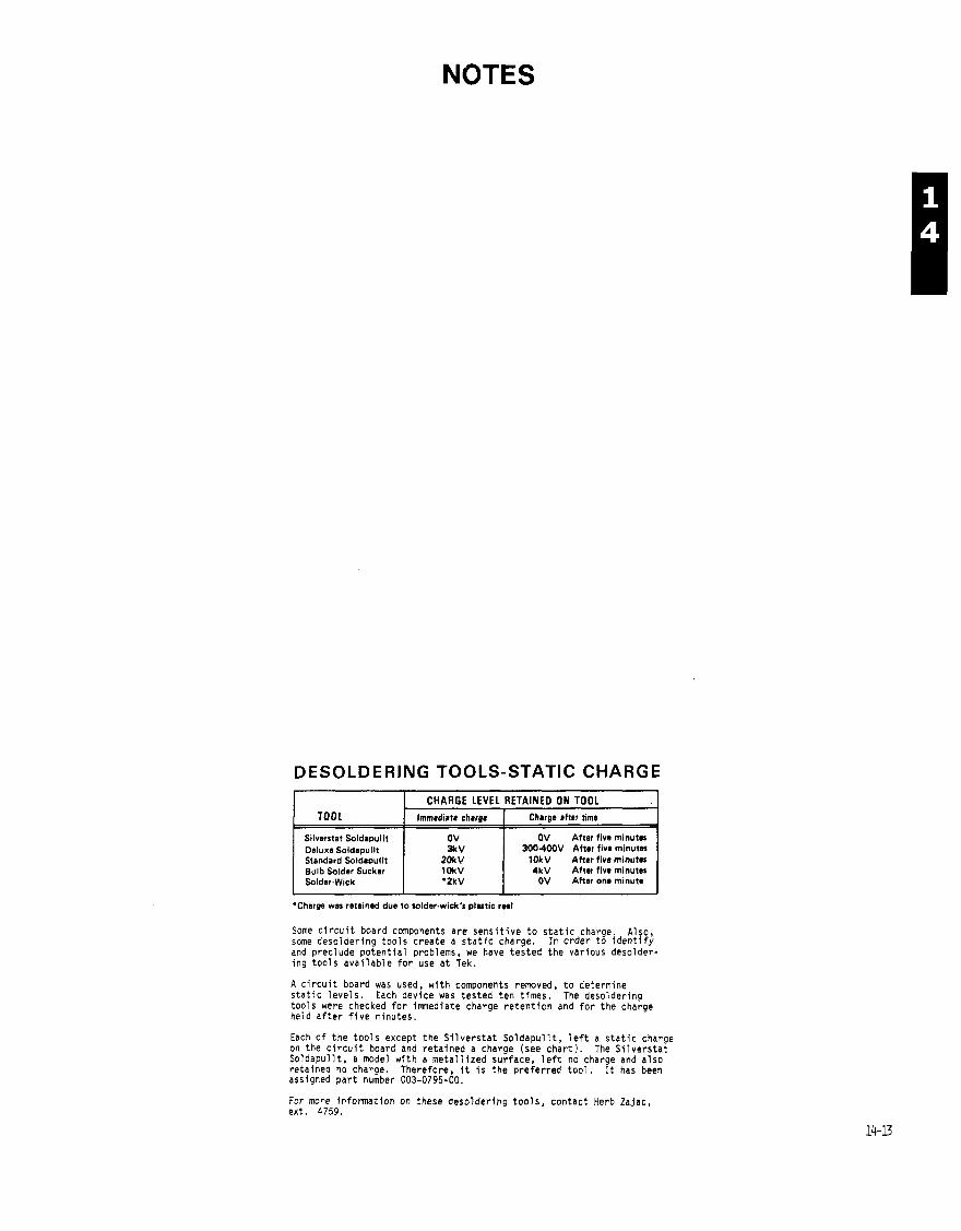
NOTES
DESOLDERING TOOLS-STATIC CHARGE
TOOL
Some c i r c u i t board components a re s e n s i t i v e t o s t a t i c charge Also some deso lder lng t o o l s c reate a s t a t i c charge. I n order t o j d e n t i f i and preclude p o t e n t i a l problems, we have t es ted t he var ious desolder- i n g t o o l s a v a i l a b l e f o r use a t Tek.
CHARGE LEVEL RETAINED ON TOOL Immediate chrroe I Chrror after time
Silverstat Soldapullt Deluxe Soldapullt Standard Soldapullt Bulb Solder Sucker Solder.Wick
A c i r c u i t board was used, w i t h components removed, t o determine s t a t i c l e v e l s . Each device was t es ted t e n t imes. The desolder ing t oo l s were checked f o r lmnediate charge r e t e n t i o n and f o r t he charge held a f t e r f i v e minutes.
Each o f t he t o o l s except t he S i l v e r s t a t So ldapu l l t , l e f t a s t a t i c charge on the c i r c u i t board and re ta i ned a charge (see c h a r t ) . The S i l v e r s t a t So ldapu l l t , a model w i t h a me ta l l i zed surface, l e f t no charge and a l so re ta ined no charge. Therefore, i t i s t he p re fe r red t o o l . It has been assigned p a r t number 003-0795-00.
*Charpe war rotainad due to rolder.wick'r pl-tic rae1
OV 3kV
2Ok V lDkV *2kV
For more i n f o rma t i on on these deso lder lng t o o l s , contac t Herb Zajac, ext . 4759.
OV Attar five minuter 3004WV After five minuter
1OkV After five minute8 4kV After five minute8
OV After one minute
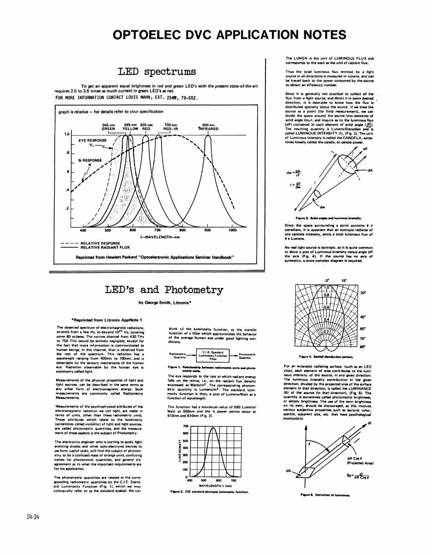
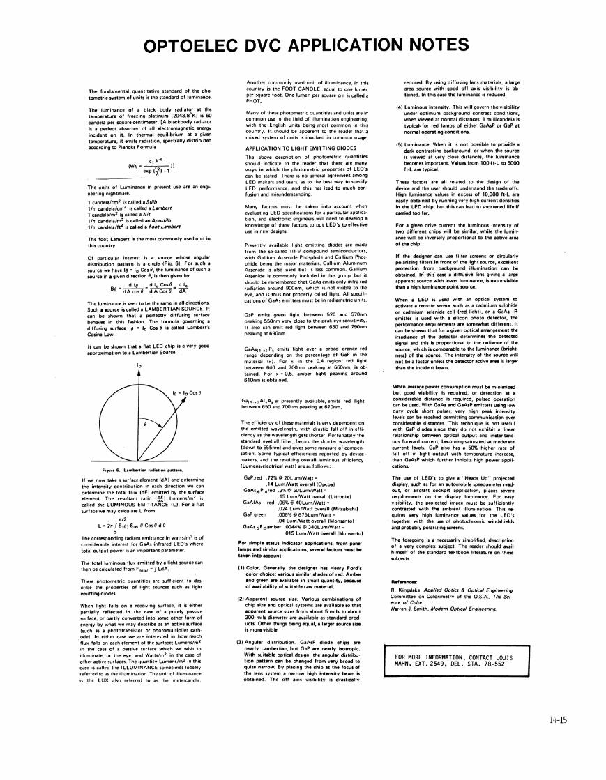

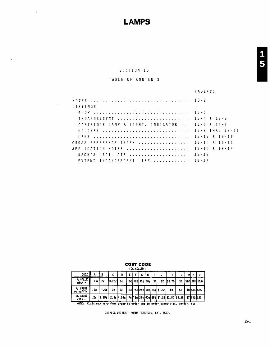
LAMPS
S E C T I O N 1 5
T A B L E O F C O N T E N T S
COST CODE (CC COLUMN)
::tLUE (1 .2( 11 .25t ) 2.5((4.25(( 7 ( ( 1 3 ( ( 2 2 t ~ 4 0 t ~ 6 5 ~ ~ $ 1 . 2 5 ~ $ 2 ~ 5 0 ( ~ 4 . 2 5 ( $7I$131$22
NOTE: Costs my vary from order t o order due t o order quantit ies. vendor, etc.
CATALOG WRITER: NORMA PETERSON, EXT. 2577.

NOTES
5 s STATUS COOES
Current Production Engineering Pre-Production Customer Service Non-Production Deleted Obsolete I n s t n w n t Custom Mod I n s t r m n t D i g i t a l Systems Obsolescent I n s t r m n t Modified Par t Last Supply Current Last Supply C u s t m r Service . . - Vendor Telequipnent Current Production In ternat ional ~onv/Tek Current Production
THE STATUS IN THIS CATALOG WAS CORRECT AT THE TIME IT WAS PUBLISHED, BUT IT IS SUBJECT TO CHANGE.
1 TO USE A PART WITH THIS STATUS ON A NEW INSTRUMENT REQUIRES THAT A NEW PURCHASED PART INITIATION FORM (PPIF) BE INITIATED. ' (A GLOSSARY OF TERMS FOR THESE STATUS CODES CAN BE FOUND ON PAGE 0-44).
COST CODE (CC COLUMN)
tt RELIABILITY CODES
210 1 r i m z 21 om 3 +loom 4 21mom 6 ztomom 0 ZlOomom 7
For fu r the r explanation o f t h i s code, see page 0-25.
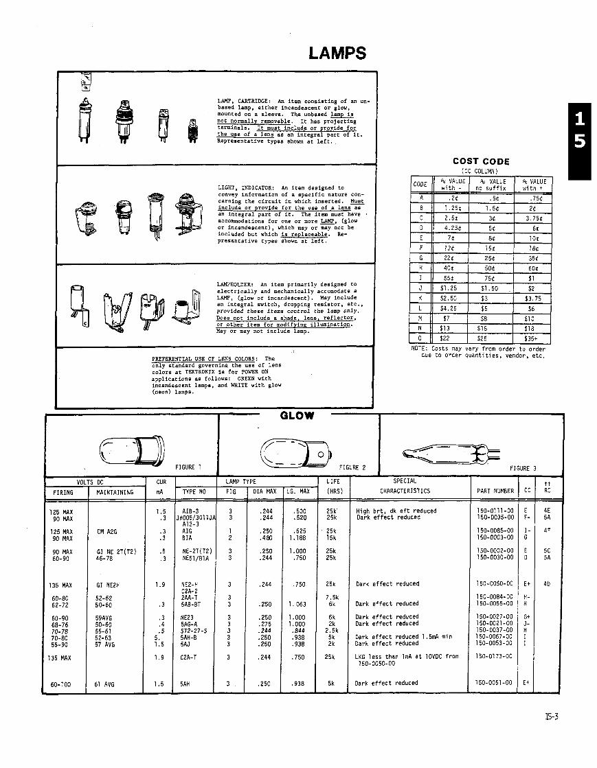
LAMPS
LAMP, CARTRIDGE: An item consisting of an un- based lamp, either incandescent or glow, mounted on a sleeve. The unbased lamp is not normally removable. It has projecting terminals. It must include or provide for the use of a lens as an integral part of it. Representative types shown at left.
LIGHT. INDICATCR: An item desinned to convey information of a specific nature con- cerning the circuit in which inserted. = include or provide for the use of a lens as an integral part of it. The item must have . accommodations for one or more w, (glow or incandescent), which may or may not be included but which is replaceable. Re- presentative types shown at left.
LAMPHOLDER: An item primarily designed to
4 electrically and mechanically accomodate a LAMP, (glow or incandescent). Hay include an integral switch, dropping resistor, etc., provided these items control the lamp only. Does not include a shade, lens, reflector, or other item for modifying illumination. May or may not include lamp.
- VOI
FIRING
125 MAX 90 MAX
125 MAX 90 MAX
90 MAX 60-90
135 MAX
60-80 62-72
60-90 68-76 70-78 70-80 55-90
135 MAX
5 DC
MAINTAINING
GI NE2H
52-62 50-60
59AVG 50-60 55-61 52-63 57 AVG
61 AVG
PREFERENTIAL USE OF LENS COLORS: The only standard governing the use of lens colors at TEKTRONIX is for POWER ON - - - ~ - -~
applications as follows: GREEN with incandescent lamps, and WHITE with glow (neon) lamps.
CUR I LAMP TYPE mA TYPE NO I FIG I DIA MAX I LG. MAX
COST CODE (CC COLUMN)
due to ord& q u a n t i t i e s , vendor, e t c .
I
I LIFE I SPECIAL
(HRS) I CHARACTERISTICS
25k High b r t , dk e f t reduced 25k I Dark e f f e c t reduced
25k 25k
25k Dark e f f e c t reduced
I Dark e f f e c t reduced
6 1 1 Dark e f f e c t reduced 2k Dark e f f e c t reduced
'iZk 1 Dark e f f e c t reduced 1.511~4 mi n 2k Dark e f f e c t reduced
25k I LKG l e s s than 1nA a t lOVDC from 150-0050-00
5k Dark e f f e c t reduced
PART NUMBER
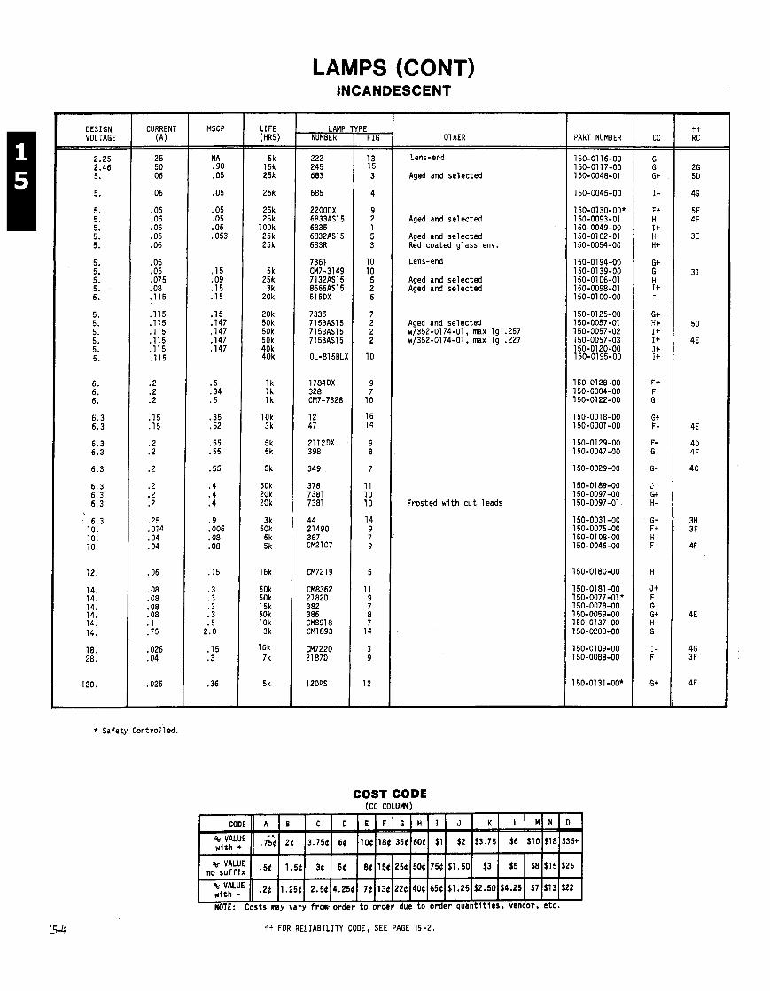
LAMPS (CONT) INCANDESCENT
DESIGN VOLTAGE
CURRENT (A)
MSCP
N A .90 .05
.05
.05 .05 .05 .053
.15
.09
.15
.15
.15
. I47
. I47
. I47
. I47
.6
.34
.6
.35
.52
.55
.55
.55
.4
.4
.4
.9
.006
.08
.08
.15
.3
.3
.3 .3 .5
2.0
. I 5
.3
.36
LAMP NUMBER OTHER
Lens-end
Aged and se lec ted
Aged and se lec ted
Aged and se lec ted Red coated glass env.
Lens-end
Aged and se lec ted Aged and se lec ted
Aged and se lec ted ~1352-0174-01, max l g .257 ~1352-0174-01, max l g .227
Frosted w i t h c u t leads
PART NUMBER
* Safety ~ o n t r o l ' l e d .
COST CODE (CC COLUMN)
ti FOR RELIABILITY CODE, SEE PAGE 15-2.
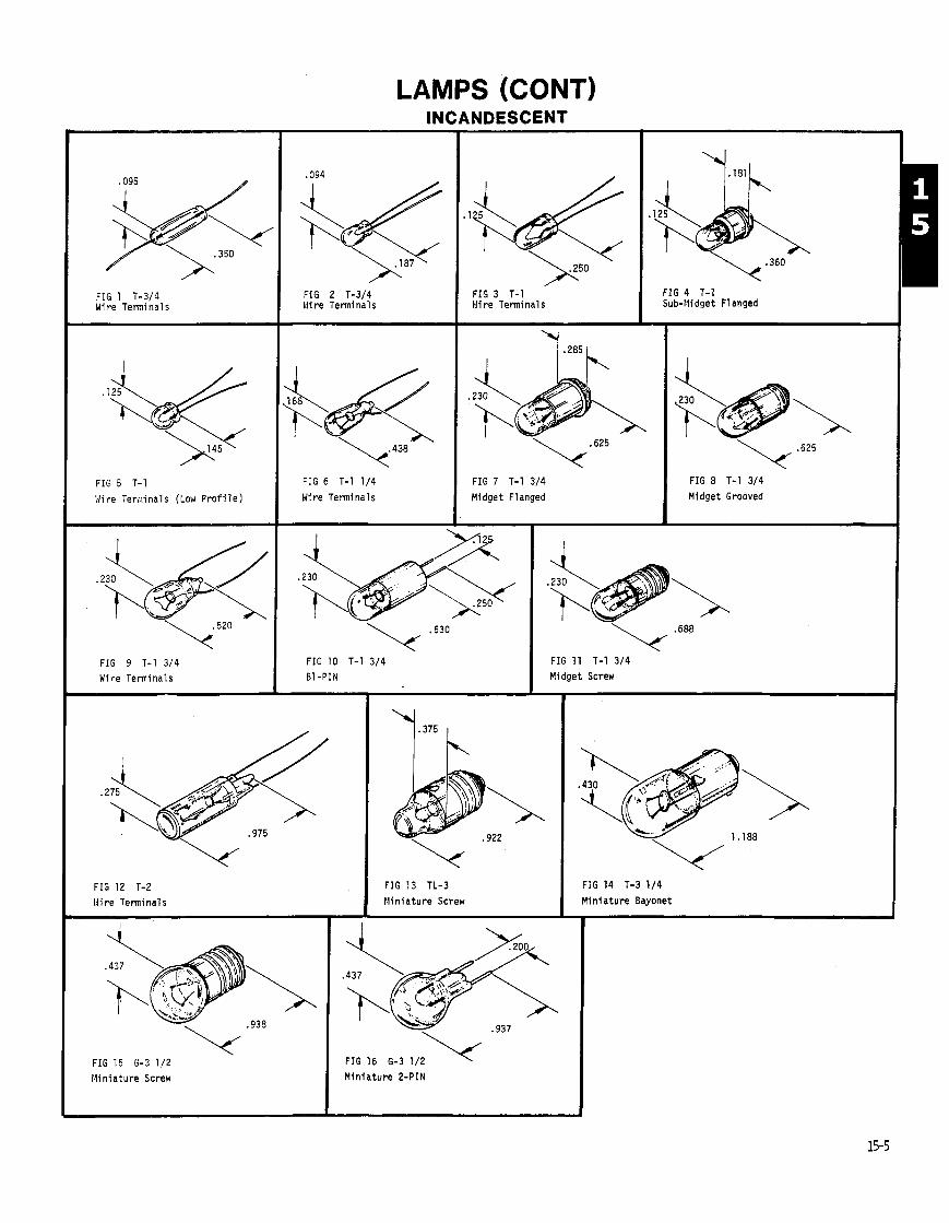
LAMPS (CONT) INCANDESCENT
FIG 4 T-1 Sub-Widget Flanged
FIG 2 T-3/4 Wire Terminals
FIG 3 T-1 Wire Terminals
FIG 1 T-3/4 Wire Terminals
FIG 7 T-1 3/4
Midget Flanged FIG 6 T-1 1/4
H i r e Terminals
FIG a T-I 314
Midget Grooved FIG 5 T-1
Wire Terclinals (Low P r o f i l e )
FIG 10 T-1 314 FIG 9 T-1 3/4
'Y
Wire Terminals
FIG 11 T-1 3/4 Midget Screw
FIG 13 TL-3
M in i a tu re Screw
FIG 14 T-3 1/4
M in i a tu re Bayonet FIG 12 T-2 N i re Terminals
FIG 16 6-3 1/2 M in i a tu re 2-PIN
FIG 15 6-3 1/2 Min ia ture Screw
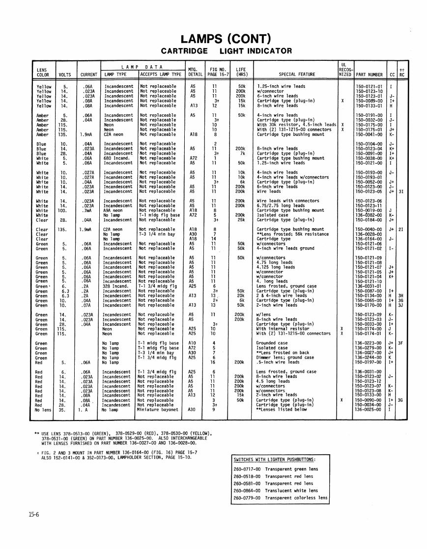
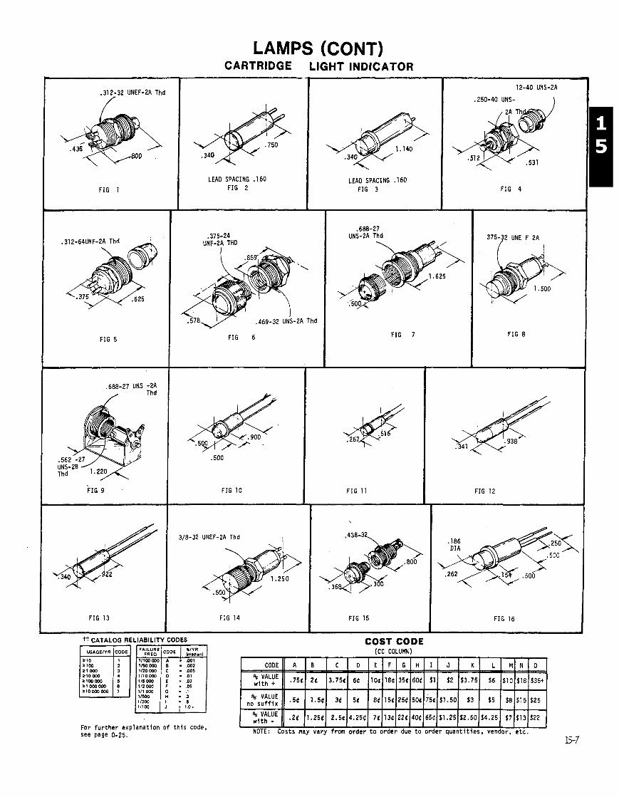
LAMPS (CONT) CARTRIDGE LIGHT INDICATOR
- - - --- -
.312-32 UNEF-LA Thd
FIG 1
FIG 5
.688-27 UNS -2A Thd
FIG 9
FIG 13
LEAD SPACING . I60 FIG 2
,375-24 UNF-LA THD
LEAD SPACING . I60 FIG 3
. \
.469-32 UNS-2A Thd
FIG 6
FIG 10
3/8-32 UNEF-2A Thd I
FIG 14
.250-40 UNS- 1
FIG 4
.688-27 UNS-2A Thd
FIG 7
tt CATALOG RELIABILITY CODES
FIG 11
375-32 UNE F 2A
FIG 8
For f u r t h e r exp lanat ion o f t h i s code, see page 0-25.
I FIG 15
FIG 12
FIG 16
COST CODE (CC COLUMN)
NOTE: Costs may vary f rom order t o o r d e r due t o o rder q u a n t i t i e s , vendor, e t c .
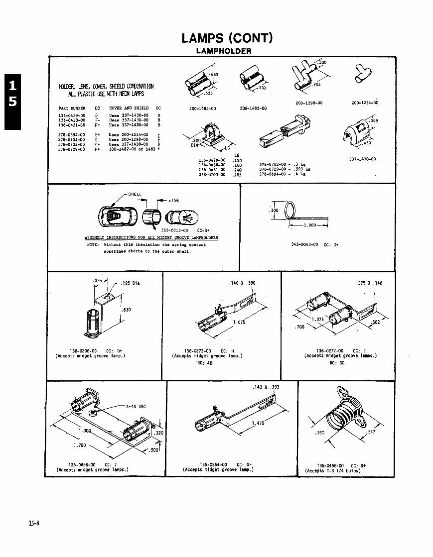
LAMPS (CONT) LAMPHOLDER
ttU€R, LENS, UMR SHIELD COBINATICN W. PIASTIC USE WITH NEON M
2QO-1298-00 200-1254-00 PART NUMBER CC COVER AND SHIELD CC 200-148340 200-1482-00.
Uses 337-1430-00 B Uses 337-1430-00 B Uses 337-1430-00 B
Uses 200-1254-00 E Uses 200-1298-00 Uses 337-1430-00 k 200-1482-00 or 1483 F
ASSEMBLY INSTRUCTIONS FOR ALL MIDGET GROOVE LAWHOLDERS
NDTE: Without this insulation the spring contact
sometimes shorts to the outer shell.
'F5 1, .I25 Oia
136-0396-00 CC: G+ (Accepts midget groove lamp.)
136-0273-00 CC:. H . (Accepts midget groove lamp.)
RCi'4D' '
136-0456-00 CC: I I 136-0264-00 CC: G+ (Accepts midget groove lamps.) (Accepts midget groove lamp.)
136-0277-00 CC: I (Accepts midget groove lamps. )
RC: 36
136-0458-00 CC: G+ (Accepts T-3 1/4 bulbs)

LAMPS (CONT)
136-0445-00 CC: J- (Accepts 3 midget groove lamps.)
Wire Lead
136-0112-00 CC: E+ (Accepts m i n i a t u r e boyonet lamp.) I 136-0035-00 CC: G
(Accepts m i n i a t u r e bayonet lamp.)
352-0084-00 CC: O+ 352-0084-01 CC: E- 352-0084-02 CC: l- ttRC: 4E
(Accepts T-2 o r smal le r d i a , unbased lamp.)
Used w i t h lenses; 378-0541-00, 378-0541-01, 378-0541-02, o r 378-0600-00.
136-0349-00 (Accepts 5 midget groove lamps. )
136-0001-00 (Accepts m i n i a t u r e bayonet lamp.)
Cover 200-0935-00 ---,
352-0157-00, White CC: E 352-0157-01, B lack CC: E
(Accepts T-1 o r smal le r d i a . unbased lamp.)
Used w i t h lenses; 378-0602-00, 378-0602-01, o r 378-0602-02.
COST CODE (CC COLUMN)
For f u r t h e r exp lanat ion o f t h i s code, see page 0-25.
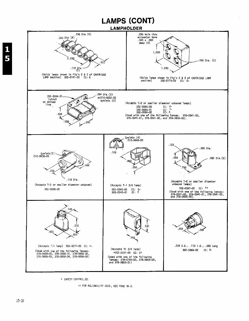
LAMPS (CONTI LAMPH(
1 .296 Oia (4 ) I
(Holds lamps shown i n F i g ' s 2 & 3 o f CARTRIDGE LAMP sect ion) 352-0141-00 CC: G
ILDER .296 hole t h r u w/counter bore .343 x .080 deep (4)
. I56 Oia. ( 2 )
(Holds lamps shown i n F ig ' s 2 & 3 o f CARTRIOGE LAMP sect ion) 352-0173-00 CC: G-
~/210-0632-00
(Accepts T-2 o r smal ler diameter unbased lamps) 352-0064-00 CC: H-
21 0-0638-00
. l l 8 Dia.
( (Accepts T-2 o r smal ler diameter unbased) I
(Accepts T-1 lamp) 352-0277-00 CC: F-
I (Used w i t h one o f the f o l l ow ing lenses: 378-0690-00, 378-0690-01, 378-0690-02, 378-0690-03, 378-0690-04, 378-0690-05) I
(Accepts T-1 3/4 lamp)
352-0340-00 CC: G- 352-0340-01 CC: D
(Accepts T-1 3/4 lamp) *352-0331-00 CC: C+
(Used w i t h one o f t he f o l l ow ing 1 enses : 378-0745-00, 378-0803-00, and 378-0803-01 )
.380 Dia.
.656
(Accepts T-2 o r smal ler diameter unbased lamps)
352-0067-00 CC: Ff (Used w i t h one o f t he f o l l ow ing lenses: 378-0541 -00, 378-0541 -01 , 378-0541 -02, and 378-0600-00).
.234 O.O., . I10 I.O., .280 Long
352-0366-00 CC: 6-
* SAFETY CONTROLLED.
tt FOR RELIABILITY CODE, SEE PAGE 15-2
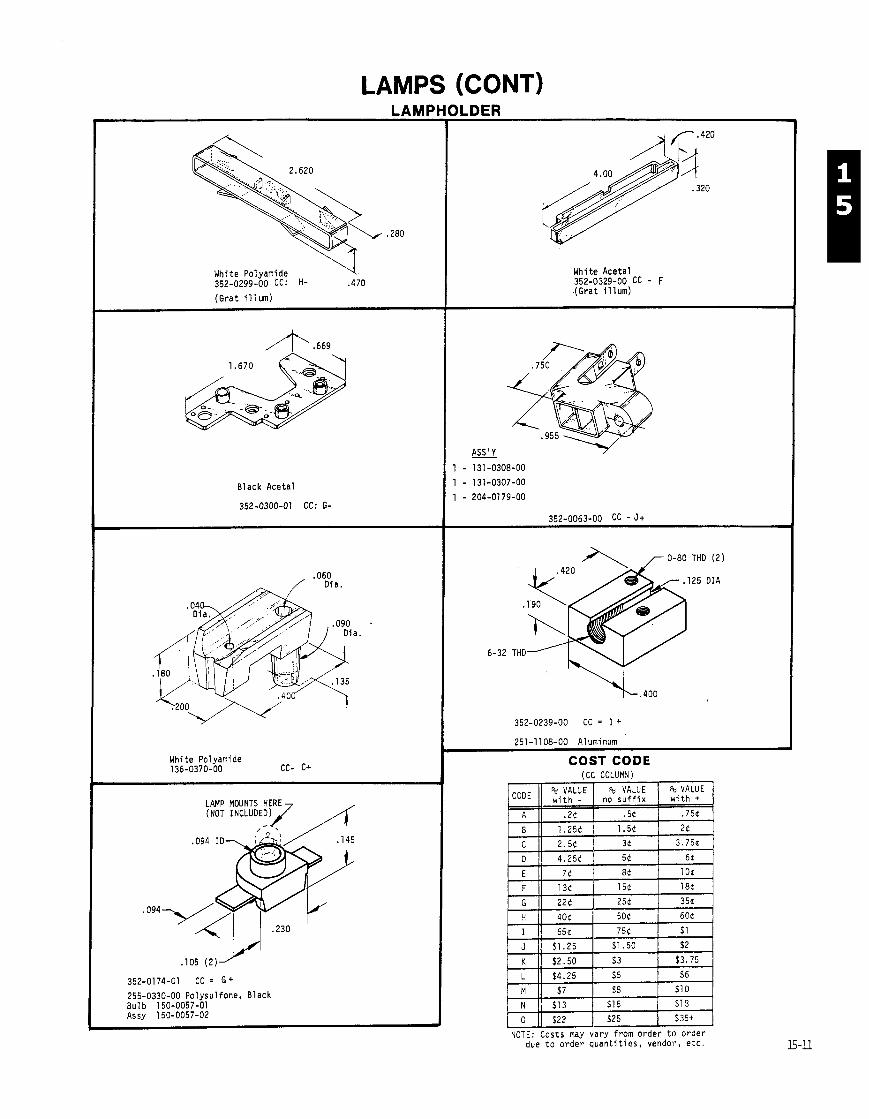
LAMF f
White Polyamide 352-0299-00 CC: H- .470
(Gra t i l l u m )
Black Aceta l
352-0300-01 CC: G-
White Polyamide 136-0370-00 CC- C+
352-0174-01 C C = G+
255-0330-00 Polysul fone, Black Bulb 150-0057-01 Assy 150-0057-02
White Acetal 352-0329-00 cc - F ,(Grat il lum)
ASS ' Y -
r 0-80 THD (2 )
352-0239-00 CC = I +
251-1108-00 Aluminum
COST CODE
due t o o r d e r q u a n t i t i e s , vendor, e t c .
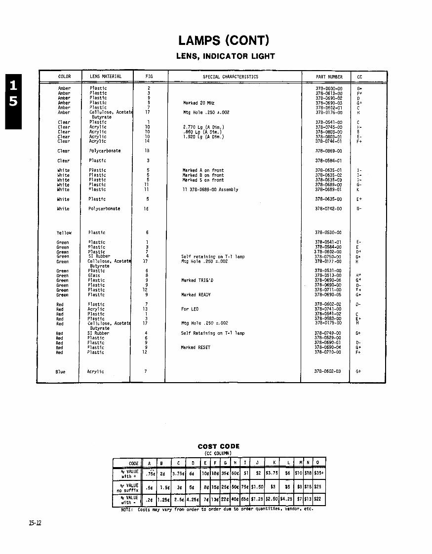
LAMPS (CONT)
COLOR
Amber Amber Amber Amber Amber Amber
Clear Clear Clear Clear Clear
Clear
Clear
White White White White White
White
White
Yellow
Green Green Green Green Green
Green Green Green Green Green Green
Red Red Red Red Red
Red Red Red Red Red
81 ue
LENS MATERIAL
P l a s t i c P l a s t i c P l a s t i c P l a s t i c P l a s t i c Cel lulose. Aceta Butyra te
P l a s t i c A c r y l i c Acry 1 i c A c r y l i c A c r y l i c
Polycarbonate
P l a s t i c
P l a s t i c P l a s t i c P l a s t i c P l a s t i c P l a s t i c
P l a s t i c
Polycarbonate
P l a s t i c
P l a s t i c P l a s t i c P l a s t i c S I Rubber Cel lulose, Acetat
Butyra te P l a s t i c Glass P l a s t i c P l a s t i c P l a s t i c P l a s t i c
P l a s t i c A c r y l i c P l a s t i c P l a s t i c Cel lulose, Acetat Butyra te
S I Rubber P l a s t i c P l a s t i c P l a s t i c P l a s t i c
A c r y l i c
LENS, INDICATOR LIGHT
Marked 20 MHz
Mtg Hole .250 k.002
FIG
2.770 Lg (A Dim.) .860 Lg (A Dim.) 1.920 Lg (A Dim.)
SPECIAL CHARACTERISTICS
Marked A on f r o n t Marked 8 on f r o n t Marked S on f r o n t
11 378-0689-00 Assembly
S e l f r e t a i n i n g on T-1 lamp Plrg Hole .250 k.002
Marked TRIG 'D
Marked READY
For LED
Mtg. Hole .250 +. 002
S e l f Reta in ing on T-1 lamp
Marked RESET
PART NUMBER
COST CODE rcc COLUMN1
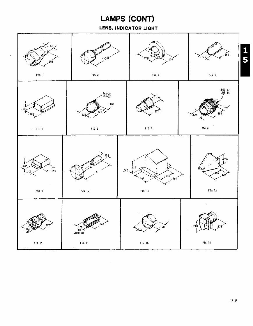
F I G 1
LAMPS (CONT) LENS, INDICATOR LIGHT
F I G 2
F I G 6
F I G 3
F I G 10
F I G 7
F I G 4
F I G 8
F I G 11 F I G 12
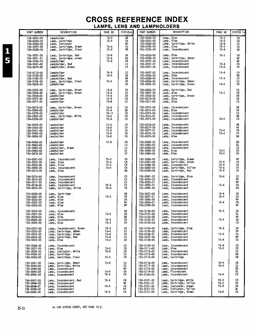
CROSS REFERENCE INDEX LAMPS, LENS AND LAMPHOLDERS
PART NUMBER DESCRIPTION
Lampholder Lamp. Car t r idge Lamp, I n d i c a t o r Lamp, Cartr idge, Green Lamp, Cartr idge, Clear
Lamp, Cartr idge, Red Lamp, Cartr idge, Green Lampholder Lam~holder, Red amph holder, Green
Lampholder Lampholder Lampholder, Red Lamp, Cartr idge, Clear Lampholder
Lamp, Car t r idge, Green Lamp, Cartr idge. Green Lampholder Lampholder Lampholder
Lamp, Cartr idge, Green Lampholder Lampholder Lamp, Cartr idge, White Lampholder
Lampholder Lamphol der Lampholder Lamphol der Lampholder
Lampholder Lampholder Lampholder, Green Lampholder Lampholder
Lamp, Incandescent Lamp, Glow Lamp, Glow Lamp, Incandescent Lamp. Glow
Lamp, Incandescent Lamp, Incandescent Lamp, Incandescent Lamp, Incandescent Lamp, Cartr idge, White
Lamp, Car t r idge Lamp, Glow Lamp, Glow Lamp. Glow Lamp, Glow
Lamp, Incandescent Lamp, Glow Lamp, Glow Lamp, Incandescent Lamp, Glow
Lamp, Incandescent. Green Lamp, Cartr idge, Amber Lamp, Cartr idge, Green Lamp, Cartr idge, Red Lamp, Glow
Lamp, Incandescent Lamp, Glow Lamp, I nd i ca to r , White Lamp, Car t r idge Lamp, Cartr idge, Clear
Lamp, Cartr idge, Amber Lamp, Cartr idge, White Lamp, Incandescent Lamp, Incandescent Lamp, Incandescent
Lamp, Incandescent, Red Lamp, Incandescent Lamp. Incandescent Lamp, Incandescent Lamp, Incandescent
- PAGE NO
15-9 15-6
15-6 15-6
15-6 15-6 15-9
15-9 15-9
15-6
15-6 15-6 15-8 15-8 15-8
15-6 15-9 15-1 1 15-6 15-8
15-8 15-8 15-8 15-9 15-8
15-8
15-4 15-3 15-3 15-4
15-4 15-6
15-3
15-3
15-4 15-3
15-4 15-6 15-6 15-6 15-3
15-3 15-6
15-6
15-6
15-4 15-4
15-4
15-4
15-4
- STATUS - -
OB CR NP CS OB
OB 08 CR LS LR
CS OB OB CR CS
CR CS CR CR CS
CR OB CR CR CR
CR CR CR CR CR
CR LS LS DL OT
CR CR CR CR OB
CS CS CS CS CR
OB CR EN NP NP
OB CR 08 CR CR
CR CS CR CS CR
CS CR CR CS CR
CS CS NP CR CR
CR NP CR NP CR -
PART NUMBER
150-0050-00 150-0051-00 150-0052-00 150-0053-00 150-0054-00
150-0055-00 150-0056-00 150-0057-00 150-0057-01 150-0057-02
l5O-OO57-O3 150-0058-00 150-0059-00 150-0065-00 150-0065-00
150-0066-00 150-0067-00 150-0068-00 150-0070-00 150-0071-00
150-0072-00 150-0073-00 150-0074-00 150-0074-01 150-0075-00
150-0076-00 150-0077-00 150-0077-01 150-0078-00 150-0079-00
150-0080-00 150-0082-00 150-0083-00 150-0084-00 150-0085-00
150-0086-00 150-0087-00 150-0088-00 150-0089-00 150-0090-00
150-0091-00 150-0092-00 150-0093-01 150-0093-01 50-0094-00
50-0097-00 50-0097-01 50-0098-00 50-0098-01 50-0099-00
50-01 00-00 50-01 01 -00 50-0102-00 50-0102-01 50-01 03-00
50-01 04-00 50-01 06-00 50-01 06-01 50-0107-00 50-01 08-00
50-0109-00 50-01 11 -00 50-01 12-00 50-0113-00 50-01 14-00
50-01 16-00 50-01 17-00 50-0118-00 50-0119-00 50-01 20-00
50-01 21 -00 50-0121-01 50-0121-02 50-0121-03 50-01 21 -04
DESCRIPTION
Lamp, Glow Lamp, Glow Lamp, Cartr idge, White Lamp, Glow Lamp, Incandescent
Lamp, Glow Lamp, Cartr idge, Amber Lamp, Incandescent Lamp, Incandescent Lamp, Incandescent
Lamp, Incandescent Lamp, Glow Lamp, Incandescent Lamp, Cartr idge, Amber Lamp, Cartr idge, Green
Lamp, Cartr idge, Red Lamp, Glow Lamp, Cartr idge, Green Lamp, Glow Lamp, Glow
Lamp, Incandescent Lamp, Glow Lamp, Incandescent Lamp, Incandescent Lamp, Incandescent
Lamp, Incandescent Lamp, Incandescent Lamp, Incandescent Lamp, Incandescent Lamp. Glow
Lamp, Incandescent Lamp, Incandescent Lamp, Incandescent Lamp, Glow Lamp, Glow
Lamp, Cartr idge, Green Lamp, Cartr idge, Green Lamp, Incandescent Lamp, Cartr idge, Yellow Lamp, Cartr idge, Red
Lamp, Cartr idge, Blue Lamp, Incandescent Lamp, Incandescent Lamp, Incandescent Lamp, Incandescent
Lamp, Incandescent Lamp, Incandescent Lamp, Incandescent Lamp. Incandescent Lamp, Incandescent
Lamp, Incandescent Lamp, Incandescent Lamp, Incandescent Lamp, Incandescent Lamp, Incandescent
Lamp, Cartr idge, Blue Lamp, Incandescent Lamp, Incandescent Lamp, Incandescent Lamp, Incandescent
Lamp. Incandescent Lamp, Glow Lamp. Incandescent Lamp, Incandescent Lamp, Car t r idge
Lamp, Incandescent Lamp, Incandescent Lamp, Incandescent Lamp, Fluorescent Lamp, Incandescent
Lamp, Cartr idge, White Lamp. Cartr idge. Ye1 low Lamp, I nd i ca to r , Green Lamp, I nd i ca to r , Yellow Lamp. Car t r idge, Green
- PAGE NO
15-3 15-3 15-6 15-3 15-4
15-3
15-4 15-4
15-4
15-4
15-6
15-3
15-4
15-4 15-4
15-3 15-3
15-6 15-4 15-6 15-6
15-6
15-4
15-4 15-4
15-4
15-4
15-4
15-6
15-4
15-4
15-4 15-3
15-4 15-4
15-4
15-6 15-6 15-6
15-6
- STATUS -
CR CS CS CR 08
CR NP NP CR CR
CR OB CR CS CR
CS CR OB OB CS
OB OB CS 08 CR
08 NP CR PP OB
08 DL CS CR CR
NP CR CR CR CR
CS NP NP CR EN
CR CR NP CR NP
CR DL NP CR LR
CR NP CS NP CS
CR CR CS OB OB
CR CS 08 DL cs
CR CR CR DL CR -
5 5 FOR STATUS CODES, SEE PAGE 15-2.
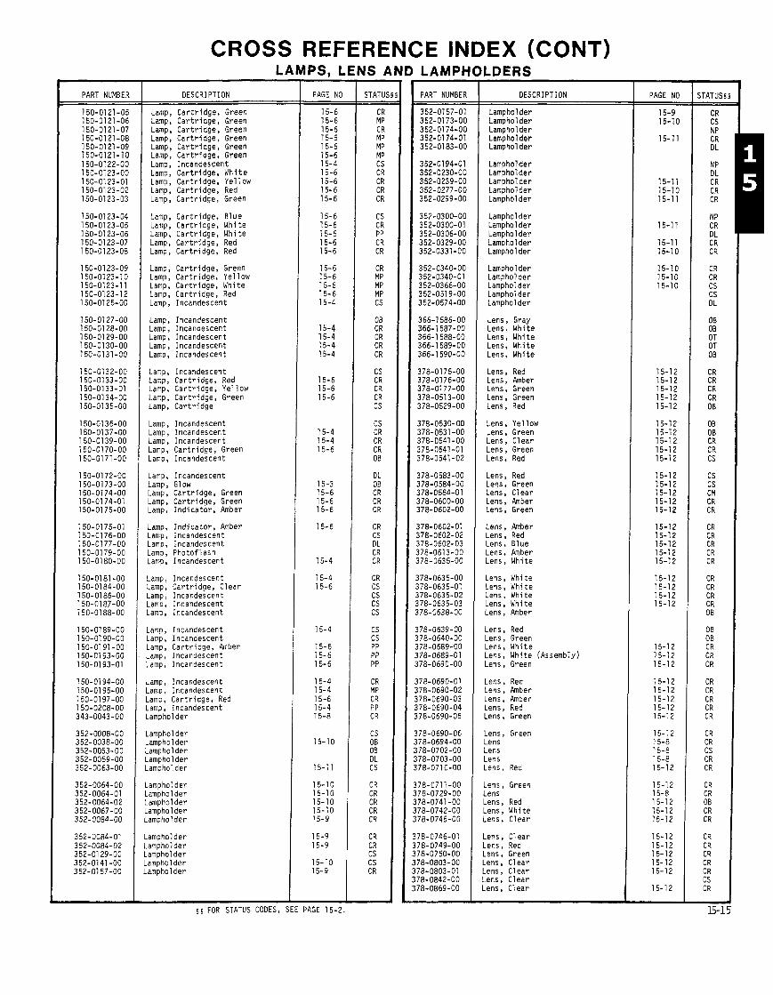
CROSS REFERENCE INDEX (CONT) LAMPS. LENS I
PART NUMBES OESCRIPTION
Lamp, C a r t r i d g e , Green Lamp, C a r t r i d g e , Green Lamp, C a r t r i d g e , Green Lamp, C a r t r i d g e , Green Lamp, C a r t r i d g e , Green Lamp, C a r t r i d g e , Green Lamp, Incandescen t Lamp, C a r t r i d g e , W h i t e Lamp, C a r t r i d g e , Ye l low Lamp, C a r t r i d g e , Red Lamp, C a r t r i d g e , Green
Lamp, C a r t r i d g e , B l u e Lamp, C a r t r i d g e , Wh i te Lamp, C a r t r i d g e , Wh i te Lamp, C a r t r i d g e , Red Lamp, C a r t r i d g e , Red
Lamp, C a r t r i d g e , Green Lamp, C a r t r i d g e , Ye l low Lamp, C a r t r i d g e , Wh i te Lamp, C a r t r i d g e , Red Lamp, Incandescent
Lamp, Incandescent Lamp, Incandescent Lamp, Incandescent Lamp, Incandescent Lamp, Incandescent
Lamp, Incandescent Lamp, C a r t r i d g e , Red Lamp, C a r t r i d g e , Ye l low Lamp, C a r t r i d g e , Green Lamp, C a r t r i d g e
Lamp, Incandescent Lamp, Incandescent Lamp, Incandescent Lamp, C a r t r i d g e , Green Lamp, Incandescent
Lamp, Incandescent Lamp, Glow Lamp, C a r t r i d g e , Green Lamp, C a r t r i d g e , Green Lamp, I n d i c a t o r , Amber
Lamp, I n d i c a t o r , Amber Lamp, Incandescent Lamp, Incandescent Lamp, P h o t o f l a s h Lamp, Incandescent
Lamp, Incandescent Lamp, C a r t r i d g e , C l e a r Lamp, Incandescent Lamp, Incandescent Lamp, Incandescent
Lamp, Incandescent Lamp, Incandescent Lamp, C a r t r i d g e , Amber Lamp, Incandescent Lamp, Incandescent
Lamp, Incandescent Lamp, Incandescent lamp, C a r t r i d g e , Red -amp, Incandescent -ampholder
-ampholder .amphol der .amphol der .ampholder .ampholder
Lamphol d e r Lampholder Lamphol d e r L a m h o l d e r
PAGE NO
2 PAGE 15-2.
- STATU! - -
LAMPH
PART NUMBER
LDERS
OESCRIPTION
Lampholder Lampholder Lampholder Lampholder Lamphol d e r
Lampholder Lampholder Lampholder Lampholder Lampholder
Lampholder Lamphol d e r Lamphol d e r Lamphol d e r Lamphol d e r
Lampholder Lampholder Lampholder Lampholder Lampholder
Lens, Gray Lens, Whi te Lens, Whi te Lens, Whi te Lens, Whi te
Lens, Red Lens, Amber Lens, Green Lens, Green Lens, Red
Lens, Ye l low Lens, Green Lens, C lear Lens, Green Lens, Red
Lens, Red Lens, Green Lens, C l e a r Lens, Amber Lens, Green
Lens, Amber Lens, Red Lens, B l u e Lens, Amber Lens, Whi te
Lens, Whi te Lens, Wh i te Lens, Whi te Lens, Whi te Lens, Amber
Lens, Red Lens, Green Lens, Wh i te Lens, Whi te (Assembly) Lens, Green
Lens, Red Lens, Amber Lens, Amber Lens, Red Lens, Green
Lens, Green Lens Lens Lens Lens, Red
Lens, Green Lens Lens, Red Lens, Whi te Lens, C lear
Lens, C lear Lens, Red Lens, Green Lens, C l e a r Lens, C lear Lens, C lear Lens, C lear
PAGE NO
15-9 15-10
15-11
15-1 1 15-10 15-11
15-11
15-11 15-10
15-10 15-10 15-10
15-12 15-12 15-1 2 15-12 15-12
15-12 15-1 2 15-12 15-1 2 15-12
15-12 15-12 15-12 15-12 15-12
15-1 2 15-12 15-12 15-12 15-12
15-12 15-12 15-12 15-12
15-12 15-12 15-12
15-12 15-12 15-12 15-12 15-12
15-12 15-8 15-8 15-8 15-12
15-12 15-8 15-12 15-12 15-12
15-12 15-12 15-12
I 1 5 5 FOR STATUS CODES, S
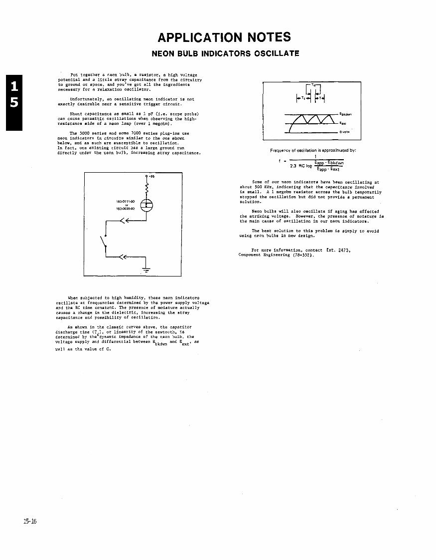
APPLICATION NOTES NEON BULB INDICATORS OSCILLATE
Put together a neon bulb, a resistor, a high voltage potential and a little stray capacitance from the circuitry to ground or space, and you've got all the ingredients necessary for a relaxation oscillator.
Unfortunately, an oscillating neon indicator is not exactly desirable near a sensitive trigger circuit.
Shunt capacitance as small as 1 pF (i.e. scope probe) can cause parasitic oscillations when observing the high- resistance side of a neon lamp (over 1 megohm).
The 5000 series and some 7000 series plug-ins use neon indicators in circuits similar to the one shown below, and as such are susceptible to oscillation. In fact, one existing circuit has a large ground run directly under the neon bulb, increasing stray capacitance.
When subjected to high humidity, these neon indicators oscillate at frequencies determined by the power supply voltage and the RC time constant. The presence of moisture actually causes a change in the dielectric, increasing the stray capacitance and possibility of oscillation.
As shown in the classic curves above, the capacitor discharge time (T ) , or linearity of the sawtooth, is determined by theddynamic impedance of the neon bulb, the voltage supply and differential between Ebkdm and E
ext' as well as the value of C.
Frequency of oscillation is approximated by: 1
Some of our neon indicators have been oscillating at about 500 KHz, indicating that the capacitance involved is small. A 1 megohm resistor across the bulb temporarily stopped the oscillation but did not provide a permanent solution.
Neon bulbs will also oscillate if aging has affected the striking voltage. However, the presence of moisture is the main cause of oscillation in our neon indicators.
The best solution to this problem is simply to avoid using neon bulbs in new design.
For more information, contact E x t . 2473, Component Engineering (78-552).
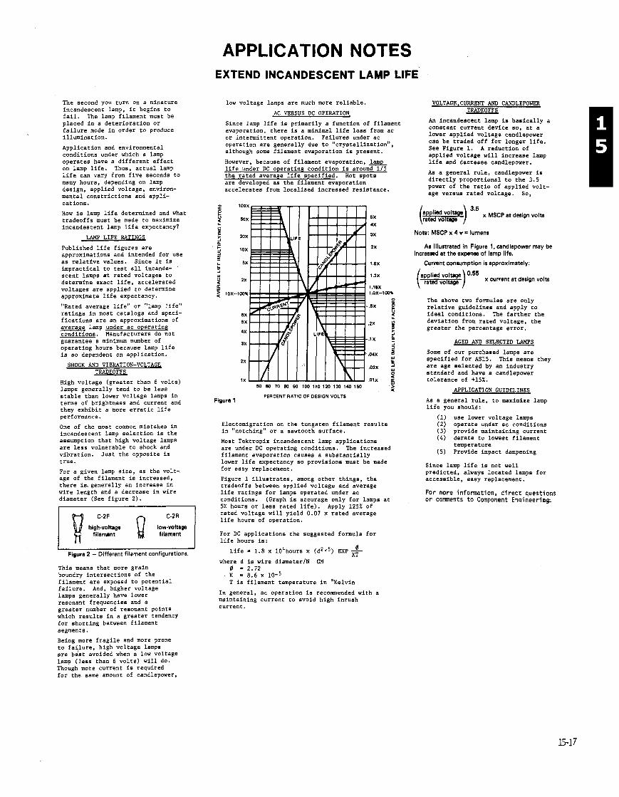
APPLICATION NOTES EXTEND INCANDESCENT LAMP LIFE
The second you turn on a minature incandescent lamp, it begins to fail. The lamp filament must be placed in a deterioration or failure mode in order to produce illumination.
Application and environmental conditions under which a lamp operates have a different effect on lamp life. Thus, actual lamp life can vary from five seconds to many hours, depending on lamp design, applied voltage, environ- mental constrictions and appli- cations.
How is lamp life determined and what tradeoffs must be made to maximize incandescent lamp life expectancy?
LAMP LIFE RATINGS
Published life figures are approximations and intended for use as relative values. Since it is impractical to test all incande- scent lamps at rated voltages to determine exact life, accelerated voltages are applied to determine approximate life expectancy.
"Rated average life" or "lamp life" ratings in most catalogs and speci- fications are an a~oroximations of . . average lamp under ac operating conditions. Manufacturers do not guarantee a minimum number of operating hours because lamp life is so dependent on application.
SHOCK AND VIBRATION-VOLTAGE TRADEOFFS
High voltage (greater than 6 volts) lamps generally tend to be less stable than lower voltage lamps in terms of brightness and current and they exhibit a more erratic life performance.
One of the most comon mistakes in incandescent lamp selection is the assumption that high voltage lamps are less vulnerable to shock and vibration. Just the opposite is true.
For a given lamp size, as the volt- age of the filament is increased, there hgenerally an increase in wire length and a decrease in wire diameter (See figure 2).
r I C-2R
low-voltage filament
Figure 2 - Different filament configurations. This meana that more grain boundry intersections of the filament are exposed to potential failure. And, higher voltage lamps generally have lower resonant frequencies and a greater number of resonant points which results in a greater tendency for shorting between filament segments.
low voltage lamps are much more reliable.
AC VERSUS DC OPERATION
Since lamp life is primarily a function of filament evaporation, there is a minimal life loss from ac or intermittent operation. Failures under ac operation are generally due to "crystallization", although some filament evaporation is present.
However, because of filament evaporation, lamp life under DC operating condition is around 115 the rated average life specified. Hot spots are developed as the filament evaporation accelerates from localized increased resistance.
W W 70 0U EU 100 110 120 130 140 1W 5 PERCENT RATIO OF DESIGN VOLTS
Figure 1
Electomigration on the tungsten filament results in "notching" or a sawtooth surface.
Most Tektropix incandescent lamp applications are under DC operating conditions. The increased filament evaporation causes a substantially lower life expectancy so provisions must be made for easy replacement.
Figure 1 illustrates, among other things, the tradeoffs between applied voltage and average life ratings for lamps operated under ac conditions. (Graph is accurage only for lamps at 5K hours or less rated life). Apply 125% of rated voltage will yield 0.07 x rated average life hours of operation.
For DC applications the suggested formula for life hours is:
Life = 1.8 x l0%ours x (d2.'5) EXP KT
where d is wire diameterlN CM 0 - 2.72 K - 8.6 x T is filament temperature in O~elvin
In general, ac operation is recommended with a maintaining current to avoid high inrush current.
VOLTAGE,CURRENT AND CANDLEPOWER TRADEOFFS
An incandeacent lamp is basically a constant current device so, at a lower applied voltage candlepower can be traded off for longer life. See Figure 1. A reduction of applied voltage will increase lamp life and decrease candlepower.
As a general rule, candlepower is directly proportional to the 3.5 power of the ratio of applied volt- age versus rated voltage. So,
(-) x MSCP et design volts
Note: MSCP x 4 r = lumens
As illustrated in Figure 1, candlepower may be increamd at the expense of lamp life.
Current consumption is approximately:
x current at design volts
The above two formulas are only relative guidelines and apply to ideal conditions. The farther the deviation from rated voltage, the greater the percentage error.
AGED AND SELECTED LAMPS
Some of our purchased lamps are specified for AS15. This means they are age selected by an industry standard and have a candlepower tolerance of +15%.
APPLICATION GUIDELINES
As a general rule, to maximize lamp life you should:
(1) use lower voltage lamps (2) operate under ac conditions ( 3 ) provide maintaining current ( 4 ) derate to lowest filament
temperature (5) Provide impact dampening
Since lamp life is not well predicted, always located lamps for accessible, easy replacement.
For more information, direct questions or comnents to Component Enaineerins
Being more fragile and more prone to failure, high voltage lamps are b&t avoided when a low voltage lamp (less than 6 volts) will do. ~hough more current is required for the same amount of candlepower,

MANUFACTURER'S LOGO LIST, RELIABILITY NOTES, TEK PART NUMBER SYSTEM, PRODUCT SAFETY AND
EVALUATION ENGINEER & BUYER LIST
S E C T I O N 0
T A B L E O F C O N T E N T S
P A G E ( S 1
L O G O L I S T ~ , , , , , 8 , , 8 , , , , , , , , . 8 . 8 , , , , . B v 8 , ~ 0 - 2 T H R U 0 - 1 8
L O G O I N D E X , 8 8 8 , 8 . , , , , , , , . , . , , , B 8 u 8 , , n 8 8 a 8 0 - 1 9 T H R U 0 - 2 1
N O T E S s ~ ~ u t ~ ~ ~ ~ 8 ~ 8 ~ ~ 8 ~ ~ , , , , , , ~ ~ ~ . ~ ~ ~ 8 ~ ~ u . ~ 0 - 2 2 T H R U 0 - 3 1 R E L I A B I L I T Y N O T E S , , 0 - 2 3 T H R U 0 - 3 0 P R O D U C T S A F E T Y , , , , , , , , , , . , , , , , , , , 0 - 3 2 T H R U 0 - 3 5 T E K P A R T N U M B E R S Y S T E M I N D E X . Q a u n a s 8 8 0 - 3 6 T H R U 0 - 4 0
( A L P H A B E T I C A L )
T E K P A R T N U M B E R S Y S T E M I N D E X 0 - 4 1 T H R U 0 - 4 3 ( N U P I E R I C A L ) , . , , , , , , , , , , , . , , , , , .
G L O S S A R Y O F T E R M S F O R S T A T U S C O D E S 0 - 4 4
C O N V E R S I O N T A B L E ( I N C H T O M M ) , n a 8 8 0 n u 0 - 4 5
E V A L U A T I O N E N G I N E E R & B U Y E R L I S T B v a a 8 v a a n 0 - 4 6 T H R U 0 - 5 6
CATALOG WRITER: NORMA PETERSON. EXT 2577.
MFR LOGO REF LIST
PURPOSE
WE HAVE HAD SEVERAL REQUESTS FOR A MANUFACTURER LOGO INDEX SO THAT THE SOURCE OF A PART CAN B E
IDENTIFIED WHEN IT IS MARKED WITH A LOGO, THIS IS AN ATTEMPT TO FILL THAT NEED,
CONTENT ORGANIZATION
THE SHAPES SECTION (PAGE 3 THRU 6) CONTAINS THOSE LOGOS WHICH HAVE NO ALPHA OR NUMERIC DATA
3 I N WHICH SUCH MAY B E SOMEWHAT OBSCURE, ME HAVE ATTEMPTED TO ORGANIZE I T SO THAT S I M I L A R SHAPES
ARE GENERALLY TOGETHER,
THE ALPHA SECTION PAGE 7 THRU 17) HAS THE LOGOS IN ALPHABETICAL ORDER WITHOUT REGARD TO THE
MANUFACTURER'S NAME,
THE NUMERIC SECTION (PAGE 18) HAS THE PARTS IDENTIFIERS IN NUMERICAL ORDER WITHOUT REGARD TO
THE MANUFACTURER'S NAME 8
THE S I Z E S OF THE LOGOS L I S T E D H E R E I N ARE I N NO WAY RELATED TO ACTUAL PRACTICE, AND I N FACT
THE LOGOS ARE OFTEN USED IN A NUMBER OF SIZES, ALSO, MANY ARE OFTEN USED IN JUST THE OPPOSITE
BLACK AND WHITE R E L A T I O N S H I P TO WHAT WE HAVE SHOWN,
/ANY OF THE MANUFACTURERS USE T H E I R F U L L NAME A S WELL AS THE LOGOS L I S T E D , WHERE WE FOUND THEY
DO NOT USE A LOGO, WE HAVE USUALLY SHOWN THE NAME THEY USE TO L E T YOU KNOW THAT WE HAVE NOT J U S T
MISSED THEM,
TABLE OF CONTENTS
SHAPES , , 4 , , , , , , , , , , , , , , , 0-3 THRU 0-6
ALPHABETICAL 8 , , , , , , , , , , , , , 0-7 THRU 0-17 NUMERICAL * , , * 8 , , 4 8 , , , , 0-18 INDEX (IN MANUFACTURER ORDER) , , , , , , 0-19 THRU 0-21
CONFIDENTIALITY
AS FAR AS WE CAN TELL, A L L OF THOSE LOGOS AND NAMES ARE REGISTERED,
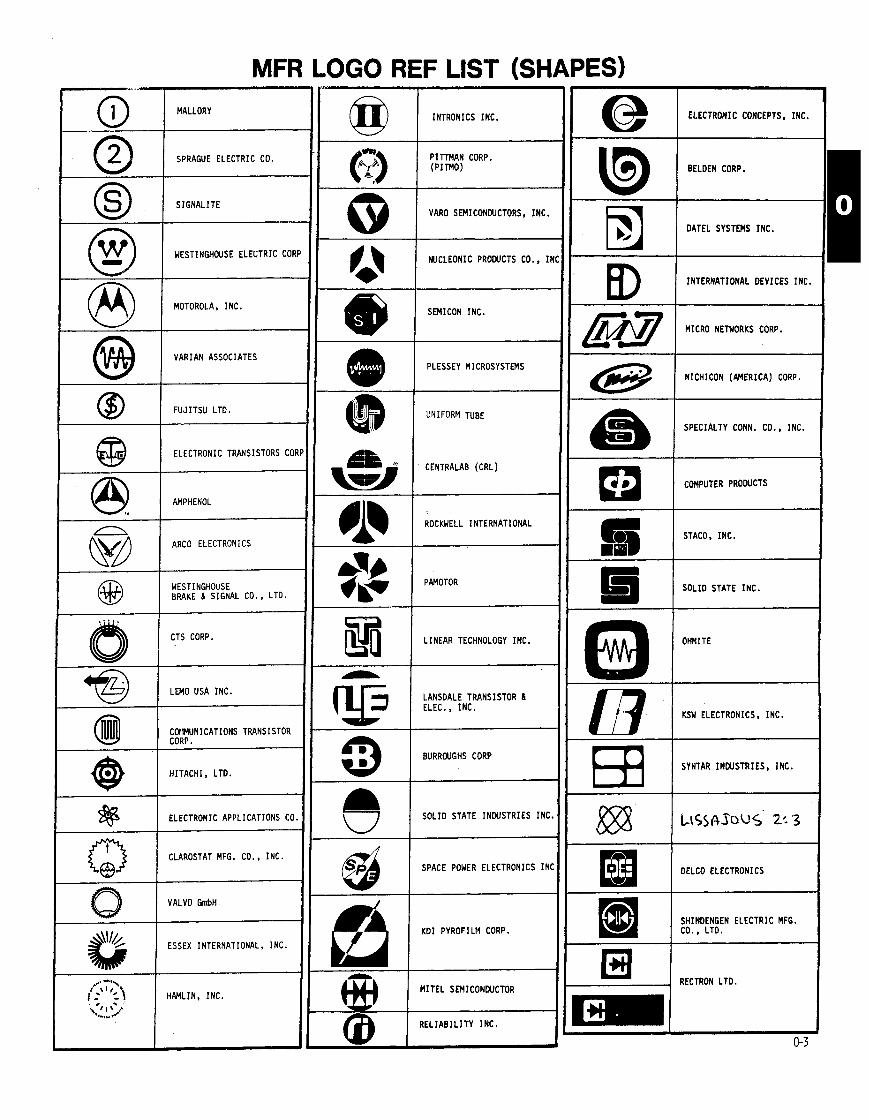
@ I INTRONICS INC. M A L L O W
SPRAGUE ELECTRIC CO.
ELECTRONIC CONCEPTS, INC. I BELDEN CORP.
DATEL SYSTEMS INC. I S I G N A L I T E 0 0 1 VARO SEMICONDUCTORS, INC.
I W C L E O N I C PRODUCTS CO.. I N
INTERNATIONAL DEVICES INC. I SEMICON INC. c MICRO NETWORKS CORP.
PLESSEY MICROSYSTEMS VARIAN ASSOCIATES
1 F U J I T S U LTD.
NICHICON (AMERICA) CORP.
SPECIALTY CONN. CO.. INC.
COMPUTER PRODUCTS
STACO. INC.
UNIFORM TUBE
ELECTRONIC TRANSISTORS COR CENTRALAB (CRL)
k!dl I
AMPHENOL
ROCKWELL INTERNATIONAL @A!! I ARC0 ELECTRONICS
#!!$ 1 PAMOTOR
--
S O L I D STATE INC. WESTINGHOUSE BRAKE 6 SIGNAL CO., LTD.
-
CTS CORP. E I LINEAR TECHNOLOGY INC. OHMITE
LANSDALE TRANSISTOR 6 @ 1 E L E C I N C .
L M O USA INC.
COIMUNI CATIONS TRANSISTOR CORP.
H I T A C H I , LTD.
ELECTRONIC APPLICATIONS CO.
CLAROSTAT MFG. CO. , INC.
VALVO CmbH t
KSW ELECTRONICS, INC.
SYNTAR INDUSTRIES, INC. 1 ' . '
BURROUGHS CORP
S O L I D STATE INDUSTRIES INC.
a I SPACE POWER ELECTRONICS I N C DELCO ELECTRONICS
K D I PYROFILM CORP.
M I T E L SEMICONWCTOR
SHINDENGEN ELECTRIC MFG. CO., LTD.
ESSEX INTERNATIONAL, I N C .
HAMLIN, INC.
RECTRON LTD.
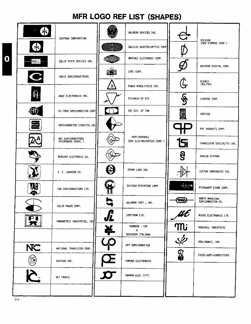
MFR LOGO REF LIST (SHAPES)
WALBERN DEVICES INC. .t::sv
- -
COGIE SEMICONOUCTEURS
AMEX ELECTRONICS INC.
HI-TRON SEMICONOUCTOR CORP
SEMICONDUCTOR C I R C U I T S I N C
-
EASTRON CORPORATION DICKSON (NOW SIEMENS CORP.)
I I I
-
S O L I D STATE DEVICES INC.
-
-
- IC
-
AMPEREX ELECTRONIC CORP. -
-
-
-
-
-
-
-
P
- -
WESTERN D I G I T A L CORP. -
- U P 1 SEMICONCUCTOR I
-
COD1 CORP.
-
-
A a
POWER MONOLITHICS INC.
GLENCO (GULTON)
- -
SYLVANIA OF GTE 0 -
1 - -
4 -
-
h
Sr
SIEMENS CORP
-
BECKMAN INST.. INC.
SEMITRON LTD.
I R C O I V . OF TRY
- -
- -
-
-
* THOMSON - CSF 6
SESCOSEM I T A L I A N A
SEMICOA
PPC PRODUCTS CORP.
I HART/ADVANCE
(OAK ELECTRO/NETICS CORP. ) KMC SEMI CONDUCTORS (MICROWAVE ASSOC. )
TRANSISTOR SPECIALTYS INC.
ANALOG SYSTEMS
CUSTOM COMPONENTS INC.
MERCURY ELECTRONIC CO.
@ I OPANP LABS INC.
- -
E. F. JOHNSON CO.
TAG SEMICONDUCTORS LTD.
NORTH AMERICAN SEMICONWCTOR CO.
8 S O L I D POWER CORP.
CHICAGO MINIATURE LAMP
~ --
4 MICRO ELECTRONICS LTD.
-
PARAMETRIC INDUSTRIES, I h I MARSHALL I N W S T R I E S
KOOLTRONIC , INC. 1 NATIONAL TRANSISTOR CORP.
@ ( KERTRON INC. I= POMONA ELECTRONICS
SILEC-SEMI-CONDUCTEURS
IC KEY TRONIC Dl CANNON ELEC ( I T T )

MFR LOGO REF LIST (SHAPES)
Q I OIOOE TRANSISTOR CO., A@ AMERICAN MICRO-SYSTEMS, I N C
MI (AM11
SOLID STATE SYSTEMS
1 ;;WF?ISTOR INTERNATIONI MULLARD LTO.
-
MATSUO ELECTRONICS P H I L I P S ELECTRONIC LTO,
MALCO (MICROOOT)
STANDARD REFERENCE LABS & INC.
MONOLITHIC MEMORIES INC.
MALCO (MICRODOT)
FERRANTI LTO. a. 1 HARRIS SEMICONDUCTOR MICROPAC INDUSTRIES INC.
GHZ OEVICES INC.
PETERSON RADIO (PR CRYSTALS) ALPHA I N W S T R I E S I N C . BECKMAN INST.. INC.
I TEXAS INSTRUMENTS
- - -
BOWAR INC. ELECTRONIC ARRAYS
--
HYBRID SYSTEMS CORP.
EPITEK ELECTRONICS LTD.
Q I OEUTSCH FASTENER CORP. F A I R C H I L D INDUSTRIES, I N C ( N o t F a i r c h i l d
S e m i c o n d u c t o r s )
( i STACKPOLE COMPONENTS CO. TRW
ROOAN INDUSTRIES
SEALECTRO 0 -
LITTON SYSTEMS, INC.
QOTRON INC.
INITRODE
NATIONAL SEMICONWCTOR CORP.
ELCO INDUSTRIES, INC.
TWO L I N E S EXTENDING FROM THE SHANK UNDER THE HEAD E-SYSTEMS
(MEMCOR ELECTRONIC COMP)
-
ULTRONIX , INC.
AMERICAN POWER DEVICES, I N EXAR INTEGRATED SYSTEMS INC.
SEMI, INC., A D I V . OF E.M.LM. CORP. SEMITRONICS CORP.
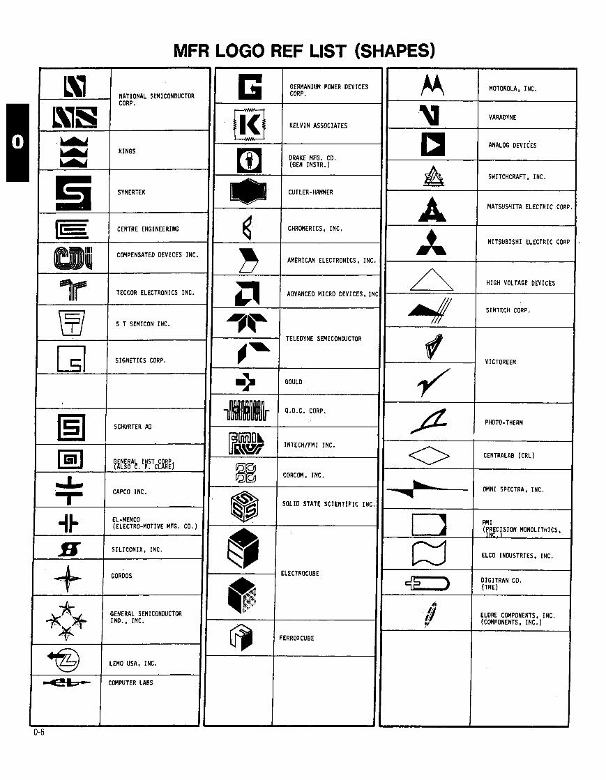
MFR LOGO REF LIST (SHAPES)
G 1 MZNIUU POMER DEVICES MOTOROLA, I NC. NATIONAL SEMICONDUCTOR CORP.
1 K E L V I N ASSOCIATES VARADYNE
KINGS DRAKE MFG. CO. (GEN INSTR.)
-
SWITCHCRAFT, INC.
SYNERTEK
MATSUSHITA ELECTRIC COR
CENTRE ENGINEERING 4 1 CHROMERICS, INC.
M I T S U B I S H I ELECTRIC COR
COMPENSATED DEVICES INC. B I AMERICAN ELECTRONICS. I N - -
H I G H VOLTAGE DEVICES
ADVANCED MICRO DEVICES, I 1 TECCOR ELECTRONICS INC.
-
S T SEMICON INC.
SEMTECH CORP.
3=l TELEDYNE SEMICONDUCTOR
S I G N E T I C S CORP. VICTOREEN
> GOULD
I Q.D.C. CORP.
/ PHOTO-THERM SCHURTER AG
Fp& I I N T E C H I F M I I N C .
0 I CENTRALAB (CRL) ENERAL I N S T CORP
?ALSO C. P. CLAREJ
CAPCO INC.
@ I CORCOM, I N C .
+-I OMNI SPECTRA, I N C .
@ S O L I D STATE S C I E N T I F I C I N (
EL-MENCO (ELECTRO-MOTIVE MFG. CO. ) PFI I
(PRECISION MONOLITHICS, I N C .
S I L I C O N I X , INC. €LCD INDUSTRIES. INC.
GDRDOS
$7) 1 !:;:;RAN CO.
ELDRE COMPONENTS. INC. (COMPONENTS, I N C . )
GENERAL SEMICONDUCTOR IND. , INC.
FERROXCUBE
LEMO USA, INC.
COMPUTER LABS
MFR LOGO REF LIST
(ALPHA)
PAGES 7 THRU 17
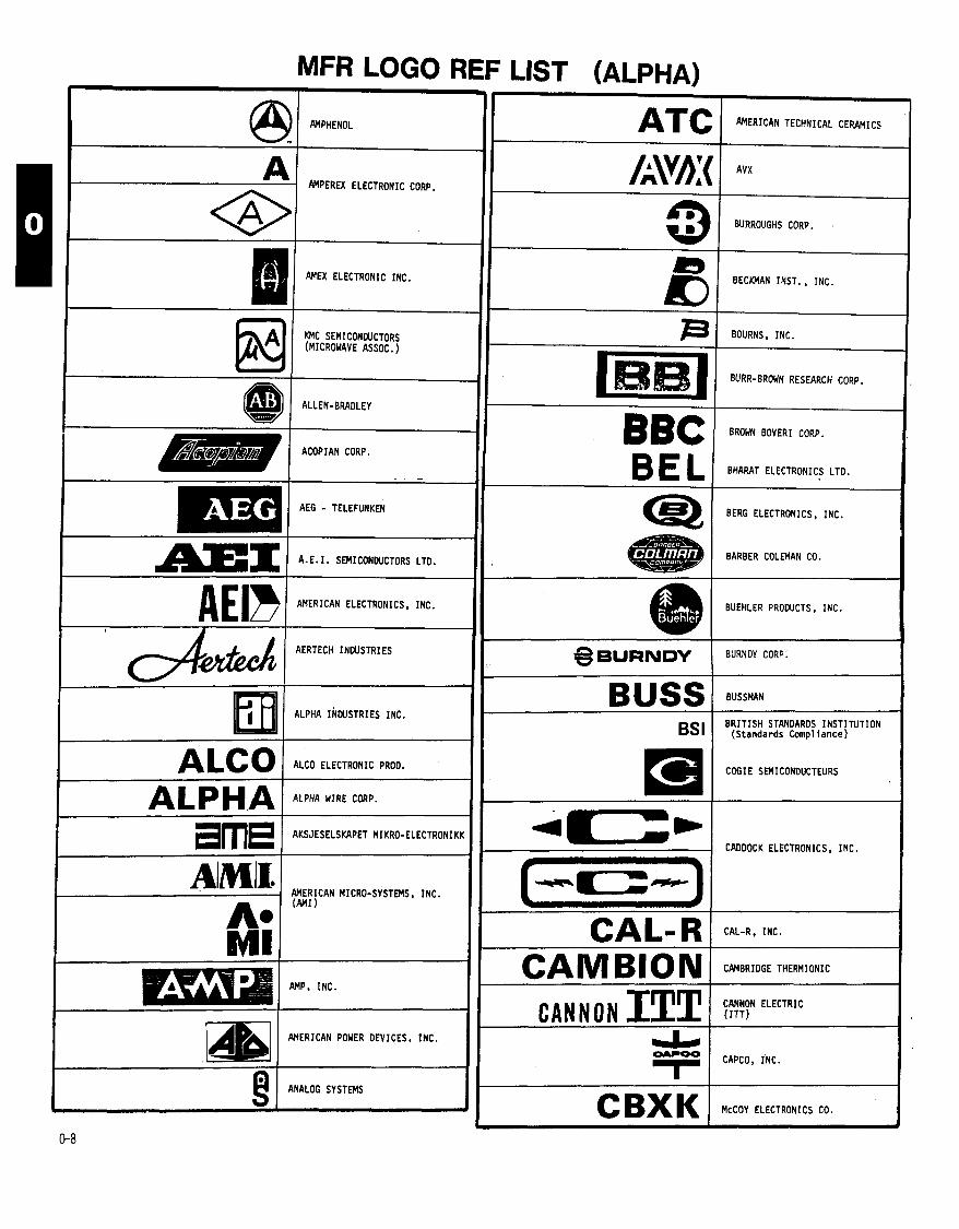
AVX
BURROUGHS CORP.
BECKMAN INST. , INC.
BOURNS, INC.
BURR-BROWN RESEARCH CORP.
BROW BOVERI CORP.
BEL BHARAT ELECTRONICS LTD. -
AEG - TELEFUNKEN BERG ELECTRONICS, INC.
BARBER COLEMAN CO. 1 1 A. E. I. SEMI CONDUCTORS LTD.
AMERICAN ELECTRONICS, INC. BUEHLER PROWCTS, INC.
AERTECH INDUSTRIES
ALPHA INDUSTRIES INC.
BURNDY CORP:
BUSS B R I T I S H STANDARDS I N S T I T U T I O N
( S t a n d a r d s Compl l a n c e )
COGIE SEMICDNOUCTEURS
CADDOCK ELECTRONICS. INC.
AIMII. AMERICAN MICRO-SYSTEMS, INC.
A. (MI
MI CAL-R CAL-R, INC.
:AMBRIDGE THERMIONIC
:ANNON ELECTRIC ( I T T )
CAMBION I CANNON ITT wl AnERICAN POWER DEVICES, INC.
:APCO, INC. I
I @ I ANALOG SYSTEMS
CBXK k C O Y ELECTRONICS CO.
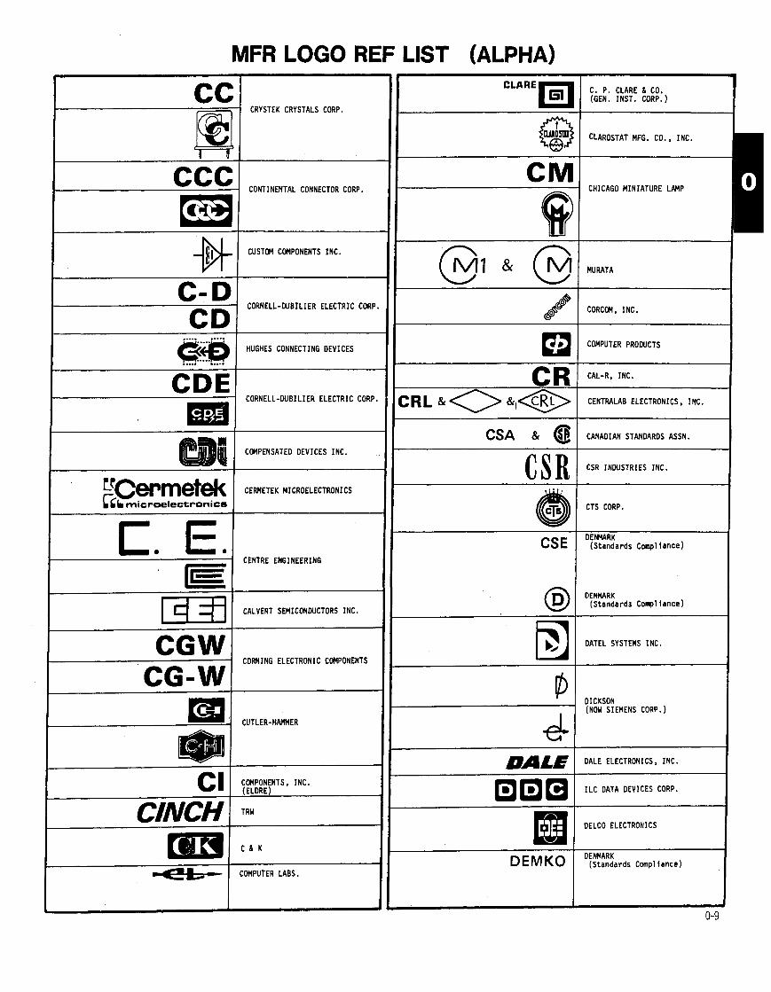
MFR LOGO REF LIST (ALPHA) C. P. CLARE 6 CO. (GEN. INST. CORP.)
P CRYSTEK CRYSTALS CORP.
CONTINENTAL CONNECTOR CORP. # CHICAGO MINIATURE LAMP
# I CUSTOM COMPONENTS INC.
MURATA u CORNELL-DUBILIER ELECTRIC CORP CORCOM, INC.
HUGHES CONNECTING DEVICES
..... .-..a
COMPUTER PRODUCTS
CR CRL
CDE CORNELL-WBILIER ELECTRIC CORP
CAL-R, INC.
CENTRALAB ELECTRONICS, INC.
CSA & CANADIAN STANDARDS ASSN.
C S R CSR INDUSTRIES INC.
CTS CORP.
C. E CENTRE ENGINEERING
DEHYARK ( S t a n d a r d s C o m p l i a n c e ) CSE
DENMARK ( S t a n d a r d s Compl l a n c e )
1 d fl 1 CALVERT SEMICDtfDUCTORS INC.
DATEL SYSTEMS INC. - -
I CORNING ELECTRONIC COMPONENTS
CG-WI OICKSON (NOW SIEMENS CORP.)
I Em CUTLER-HAMMER e- DALE DALE ELECTRONICS, INC.
CI ( COMPONENTS, INC. (ELDRE) 0 0 0 1 1LC DATA DEVICES CORP.
CINCH I TRw HI DELCO ELECTRONICS
DENMARK D EM KO ( S t a n d a r d s ~ o m p l l a n c e ) CMPUTER LABS.
MFR LOGO REF LIST (ALPHA) * ELM STATE ELECTRONICS INC. INTERNATIONAL DEVICES INC.
D I A L I G H T
DIODE TRANSISTOR CO. , INC.
@ I ELECTRONIC TRANSISTORS CORP.
1 UNION CARBIOE C O W . '
DYNAMIC MEASUREMENTS CORP.
CENTRALAB ELECTRONICS D I V . DRU
F A I R C H I L D SEMICONDUCTOR ( F A I R C H I L D CAMERA 6
1 NSTRUMENT CORP. )
VDE & GERMANY
( S t a n d w d s C o m p l i a n c e )
E R I E TECHNICAL PRODUCTS, INC.
w F A I R C H I L D INDUSTRIES, INC.
( N o t F a i r c h i l d S e m i c o n d u c t o r s
E P I T E K ELECTRONICS L I D .
@'"I FERROXCUBE
181 C I R C L E F INDUSTRIES el ELECTRONIC CONCEPTS
- 1 F A I R C H I L D SEMICONDUCTOR FAIRCHILD ( F A I R C H I L D CAMERA
FENWAL ELECTRONICS E CI I ELDRE CCWPONENTS, INC.
rh\St: ( INTECH/FMl INC.
@ I F U J I T S U LTD. EMI EL-MENCO (ELECTRO-MOTIVE MFG. CO. )
91 E R I E TECHNICAL PRODUCTS. INC.
E-SYSTEMS (MEMCOR ELECTRONIC COMPONENTS)
MFR LOGO REF LIST (ALPHA)
GERMANIUM POWER DEVICES CORP.
HEYMAN MFG. CO. (HEYCO)
(T& GATES ENERGY PRODUCTS, I N C . -1 @ G.E.
(GENERAL ELECTRIC) HEWLETT-PACKARO
HYBRID SEMICONDUCTORS b ELECTRONIC I N C .
' GHz DEVICES
GENERAL INSTRUMENT CORP. H I -TRON SEMICONDUCTOR CORP.
HUBBELL HUBBELL (HARVEY HUBBELL, I N C . ) GLENCO
(GULTON)
H I G H VOLTAGE DEVICES. I N C .
HVD GENERAL RADIO CO (GR)
GRAYHILL , I N C .
S I L I C O N I X , I N C .
GENERAL TRANSISTOR CORP. I N T E L CORP.
GTE GENERAL TELEPHONE & ELECTRIC
INTERNATIONAL DEVICES I N C .
HART/ADVANCE (OAK ELECTRO/NETICS CORP.)
IEC INTERNATIONAL ELECTRONICS
H A R R I S SEMICONDUCTOR INTERNATIONAL R E C T I F I E R
HUGHES CONNECTING D E V I C E S [RC D I V . OF TRW
ITT & ITT I T T SEMICONDUCTORS HUNTINGTON ELECTRIC I N C .
3 E C W N INSTRUMENTS, I N C . I T W HELITRIM I N C . \ DIV. OF E.M.hM. CORP.
( U P S I D E DOWN)
MFR LOGO REF LIST (ALPHA) BUSSMAN
E. F. JOHNSON CO. LANSDALE TRANSISTOR 6 ELECTRONICS, I N C . JOHNSON
JETL JAPANESE ELECTRICAL TEST LAB ( S t a n d a r d s C o m p l i a n c e )
L INEAR TECHNOLOGY INC.
KSW ELECTRONIC, INC.
KELVIN ASSOCIATES
MINNESOTA M I N I N G 6 MFG. CO.
MULLARD LTD.
KSC SEMICONDUCTOR CORP.
S l L I C O N TRANSISTOR CORP
MONSANTO KEYTRONIC
MATSUO ELECTRONICS
KERTRON INC.
-- -
UNION CARBIDE CORP.
CENTRE ENGINEERING
K E M E T , @ I M I T E L SEMICONDUCTOR
MUCON (REPUBLIC ELECTRONICS CORP. ) KL~XON I TEXAS INSTRUMENTS. INC.
KMC 1 KMC SEMICONDUCTORS (MICROWAVE ASSOCIATES) 1 METHODE ELECTRONICS, INC.
I
MOLEX, INC.
MOTOROLA, I N C .
@ OPAMP LABS INC.
L I L I T R O N I X , . INC.
1 LEMO USA, 1NC.
MALCO (MICRO-DOT) mi L I T T O N SYSTEMS, I N C .
B RODAN INDUSTRIES, I N C .
MICROPAC INDUSTRIES INC.
MIDWEST MICROWAVE
MFR LOGO REF LIST (ALPHA)
SEMICON 2 0 0 0
MALLORY MICROWAVE SEMICONWCTOR CORP.
MAGNACRAFT M S I ELECTRONICS
MICRO COMPONENTS CORP. MOLEX, I N C .
NEMCO 8 @ NORWAY ( S t a n d a r d s C o m p l i a n c e ) McCOY ELECTRONICS CO.
(OAK I N D . , I N C . ) .
MICROWAVE DIODE CORP.
MODULAR DEVICES I N C .
NATEL ENGINEERING CO., I N C .
NORTH M E R I C A N SEMICONOUCTOR CO
NATIONAL COMPONENTS I N C .
MEPCO/ELECTRA, I N C .
NEC MICROCOMPUTERS, I N C . ( N I P P O N ELECTRIC CO., LTO.) M I L L E R ELECTRIC
WARD-LEONARD N I C H I C O N (AMERICA) CORP.
MARSHALL I N D U S T R I E S
NEW JERSEY SEMICONDUCTOR PRODUCTS CO., I N C .
MICROSMICONOUCTOR CORP.
MICRO SWITCH
MICROSWITCH N E W A R K E T TRANSISTOR LTO.
J. W. M I L L E R NUCLEONIC PRODUCTS CO., I N C .
mi MONOLITHIC MEMORIES, I N C .
8 1 M I L ELECTRONICS I N C
NATIONAL SEMICONDUCTOR CORP.
cr I MICRO NETWORKS CORP. NSLi NATIONAL TRANSISTOR CORP.
NYTRONICS COMPONENTS GROUP, INC NYT /
OPAMP LABS INC. c
MFR LOGO REF LIST (ALPHA)
RODAN INDUSTRIES I N C .
L I T T O N SYSTEMS, INC. 1 OPTICAL ELECTRONICS INC. a&,, ROTRON, I N C .
OMNI SPECTRA, INC.
RAYTHEON
OVE & @ AUSTRIA ( S t a n d a r d s Compl l a n c e ) RAY
RCA (RADIO CORP. OF AMERICA)
PPC PRODUCTS CORP.
RCL
PAKTRON PAKTRON D I V . OF I L L I N O I S TOOL WORKS
RAOIO MATERIALS CO.
R-OHM CORP.
PD 1 E, INC.
POMONA ELECTRONICS
K D I PYROFILM
rpc RPC
PHILCO RADIO TELEVISAO LTDA.
P H I L I P S ELECTRONIC LTD.
PARAMETRIC INDUSTRIES, INC.
SENSITRON SEMICONDUCTORS
R.T.C. LaRADIOTECHNIQUE-COMPELE
PITTMAN CORP. (THE)
UNDERWRITERS LABS. COMPONENT RECOGNITION
PRECISION MONOLITHICS, INC. ( P M I
PETERSON RADIO CO., INC. (PR CRYSTALS)
ANALOG SYSTEMS (UPSIDE DOWN)
a1 BERG ELECTRONICS INC.
SEV & @I SWITZERLAND ( S t a n d a r d s Compl l a n c e )
@ I R E L I A B I L I T Y I N C . SEMKO s @ I SWEDEN ( S t a n d a r d s Compl l a n c e )
MFR LOGO REF LIST (ALPHA) 4
SWITCHCRAFT, INC.
SEMICOA
SPECIALTY CONNECTOR CO. . INC.
-
-
-
-
-
-
-
-
-
-
-
-
-
-
-
*
5 & # ( SIGNETICS CORP.
@ 1 SIGNALITE
S C I E N T I F I C COMPONENTS INC. 1 SCHURTER AG
SCOTCH 3M (MINNESOTA M I N I N G 6 MFG. )
SEMI, INC., A DIV. OF E.M.6M. CORP.
s SOLID POWER CORP, F U J I T S U LTD.
bhiI SOLID STATE INDUSTRIES INC.
S I L I C O N GENERAL. INC.
9 SEMITRONICS CORP.
SGS-ATES COMPONENT1 ELETTRONICI
SHALL-X SHALLCROSS RESISTOR PROD. (CUTLER-HAMMER)
L I SIGNETICS CORP.
5 SYNERTEK
SIEMENS CORP.
S I L I C O N I X , INC.
STACO. I N C .
SOLITRON DEVICES, INC.
S I L I C O N TRANSISTOR CORP.
SYNTAR INDUSTRIES INC.
SEMICON INC.
9 SEMICON 2 0 0 0
SIGMA INSTRUFIENTS, I N C . SIGMA 1 @ I CANADIAN STDS. ASSN. - -
SEMITRON LTO.
I TOKYO SANYO S A N YO I ELECTRIC CO.. LTD. I 6 SPACE POWER ELECTRONICS INC. ra I SEMICONWCTOR CIRCUITS INC.
MFR LOGO REF LIST (ALPHA)
@ TAG SEMICONWCTORS LTD.
@ I ELECTRONIC TRANSISTORS CORP.
81 SILEC-SEMI-CONWCTEURS
TECNETICS INC.
ml SOLID STATE DEVICES INC. I i TEKTRONIX. INC.
SOLID STATE SYSTEMS I AEG - TELEFUNKEN
SSS SOLID STATE S C I E N T I F I C TEPRO TEPRO OF FLORIDA, I N C .
TEXTOOL
TFK
-- -
AEG - TELEFUNKEN
T H I C K F I L M SYSTEMS, INC.
RAYCHEM
ml S I L I C O N TRANSISTOR CORP.
THM THERMALLOY, I N C .
!mr I SEMICONDUCTOR TECHNOLOGY I N C . TEXAS INSTRUMENTS, INC.
SW & I STEWART Y R N E R
sx I SHALLCROSS RESISTOR PROD. (CUTLER-HAMMER)
TRANSISTOR INTERNATIONAL CORP.
TRANSMAGNETI CS I NC .
T I TECCOR ELECTRONICS INC.
TRIMPOT BOURNS, INC.
3USSMAN
--
TECHNICAL WIRE PRODUCTS, INC.
TRW
1RANSISTOR SPECIALTYS INC. Ell THEMALLOY, I N C .
MFR LOGO REF LIST (ALPHA)
> VITRAHON. I N C . I MICROWAVE ASSOCIATES INC.
U CC ( UNION CARBODE CORP. WESTINGHOUSE BRAKE 6 SIGNAL CO., LTO. I
Fl MICRO ELECTRONICS LTO. @ WESTINGHOUSE ELECTRIC CORP.
I ULTRONIX. INC.
@ 1 UNDERWRITERS L A B M T O R I L . I) WALBERN DEVICES INC.
WESTINGHOUSE BRAKE 6 SIGNAL CO., LTD.
WARD LEONARD
U P 1 SEMICONWCTOR
1 UNDERMRITERS LABS.. INC.
i COMPONENT RECOGNITION
SEMI, INC. A D I V . OF E.M.W. CORP. (UPSIDE-DOWN)
UNI-TRAN SEMICONWCTOR CORP.
WATKINS-JOHNSON CO.
EXAR INTEGRATED SYSTEMS INC.
VARADYNE
-- -
VICTOREEN
NATEL ENGINEERING CO., INC.
(SIDEHAYS) V I T W O N , INC.
ZELTEX, INC. VARIAN
VALVO
VIKING V I K I N G
VDE & & I
GERMANY ( S t a n d a r d s Compl l a n c e )
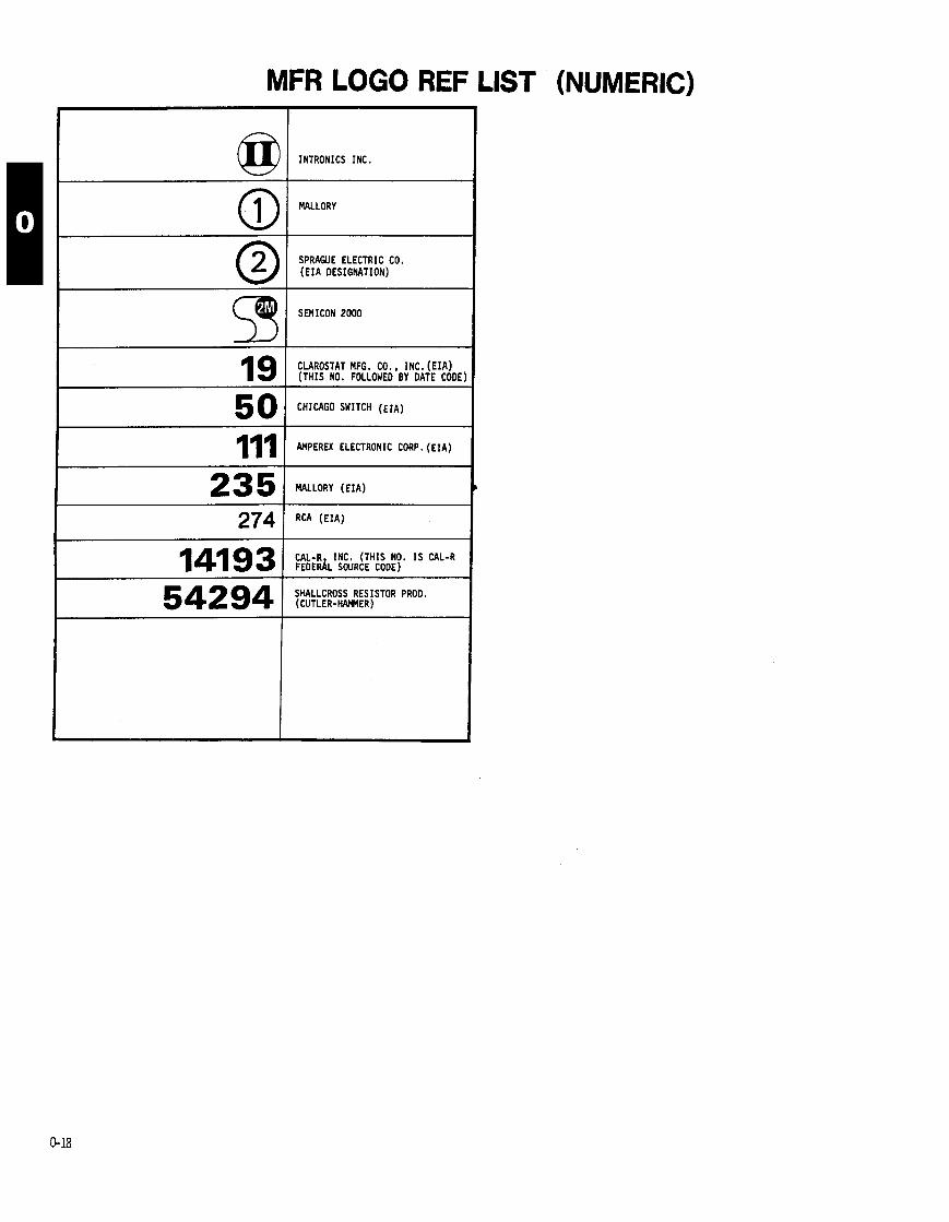
MFR LOGO REF LIST (NUMERIC)
01 INTRONICS I N C .
SPRAGVE ELECTRIC CO. ( E I A DESIGNATION)
*I SEMICON 2 0 0 0
CLAROSTAT MFG. CO. , I N C . ( E I A ) ( T H I S NO. FOLLOWED BY DATE CODE
14193 I CAL-R, I N C . ( T H I S NO. I S CAL-R FEDERAL SOURCE CODE)
I 54294 1 SHALLCROSS RESISTOR PROD. ( C U T L E R - H E R )

MFR LOGO REF LIST (INDEX) MANUFACTURER'S NAME
ACORPIAN CORP.
ADVANCE0 MICRO DEVICES, INC.
AEG - TELEFUNKEN A. E. I. SEMICONDUCTORS LTD.
AERTECH INDUSTRIES
AKSJESELSKAPET MIKRO- ELECTRONIKK
ALCO ELECTRONIC PROD.
ALLEN-BRADLEY
ALPHA INDUSTRIES. INC.
ALPHA WIRE CORP.
AMERICAN ELECTRONICS, INC.
AMERICAN MICRO-SYSTEMS. INC.
AMERICAN POWER DEVICES, INC.
AMERICAN TECHNICAL CERAMICS
AMEX ELECTRONICS, INC.
AM1
AMPEREX ELECTRONIC CORP.
AMPHENOL
AMP, INC.
ANALOG DEVICES
ANALOG SYSTEMS
ARC0 ELECTRONICS. INC.
AUSTRIA (STOS COMPLIANCE)
AVX
BARBER COLEMAN CO.
BECKMAN INSTRUMENT, INC.
BELDEN CORP. BERG ELECTRONICS, INC. BHARAT ELECTRONICS LTD.
BOURNS, INC.
BOWMAR. INC.
B R I T I S H STDS. INSTITUTE BROWN BOVERI CORP.
BUEHLER PROOUCTS, INC.
BURNDY CORP. BURR-BROWN RESEARCH CORP.
BURROUGHS CORP.
BUSSMAN
I CADOOCK ELECTRONICS, INC.
CAL-R, INC.
CALVERT SEMICONDUfTORS, INC.
CAMBRIDGE THERMIONIC
CANADIAN STANDARDS ASSN.
CANNON ELECTRIC
CAPCO. INC.
CENTRALAB ELECTRONICS, INC.
I CENTRE ENGINEERING
CHERRY ELEC. PROOUCTS CORP.
CHICAGO MINIATURE LAMP
CHICAGO SyfTCH
CHROMERICS, INC.
CINCH
CIRCLE F INDUSTRIES
C 8 K
CLAROSTAT MFG. CO. , INC.
COO1 CORP.
MANUFACTURER'S NAME
COMMUNICATIONS TRANSISTOR CORP.
COMPENSATED DEVICES. INC.
COMPONENTS. INC.
COMPUTER LABS
COMPUTER PRODUCTS
CONTINENTAL CONNECTOR CORP . CORCOM. INC.
CORNELL-WBLIER ELECTRIC CORP.
CORNING ELECTRONIC COMPONENTS C. P. CLARE 6 CO.
CRL
CRYSTEK CRYSTALS CORP.
CSR INDUSTRIES, INC.
CTS CORP.
CUSTOM COMPONENTS, INC.
C U T L E R - W E R
DALE ELECTRONICS, INC.
OATEL SYSTEMS. INC.
OELCO ELECTRONICS
OENMARK (STDS. COMPLIANCE)
OEUTSCH FASTENER CORP.
OIALIGHT
OICKSON
OIGITRAN CO. DIODE TRANSISTOR CO.. INC.
DRAKE MFG. CO.
DYNAMIC MEASUREMENTS CQRP . EASTRON CORPORATION
EOAC. INC.
E. F. JOHNSON
ELCO INDUSTRIES. INC.
ELDRE COMPONENTS, INC.
ELECTROCUBE
ELECTRO-MOTIVE MFG. CO.
ELECTRONIC APPLICATIONS CO. ELECTRONIC ARRAYS
ELECTRONIC CONCEPTS. INC.
lLECTRONIC TRANSISTORS CORP.
ILECTONIC DEVICES, INC.
:L-MENCO
ILM STATE ELECTRONICS, INC.
HCO
I. M. 6 M. CORP.
:NGLEMANN MICROWAVE CO.
'P ITEK ELECTRONICS, INC.
R I E TECHNICAL PROOUCTS. INC.
SSEX INTERNATIONAL, INC.
-SYSTEMS
XAR INTEGRATED SYSTEMS, INC.
AIRCHILD INDUSTRIES. INC.
AIRCHILO SEMICONDUCTOR
ENWAL ELECTRONICS
ERRANT1 LTO.
ERROXCUBE
YC SEMICONOUCTOR INDUSTRIES, INC.
11, INC.
JJ ITSU LTO.
PAGE NO.
0 - 3
0 - 6 6 9
0 - 9 6 1 0
0 - 6 6 9
0 - 3 8 9
0 - 9
0 - 6 6 9
0- 9
0- 9
0 - 6 6 9
0 - 3 6 6
0 - 9
0- 9
0 - 3 6 9
0 - 4 8 9
0 - 6 6 9
0 - 9
0 - 3 6 9
0 - 3 6 9
0- 9
0- 5
0-10 0 - 4 6 9
0 - 6 0 - 5 6 10
0 - 6
0-10
0 - 4 0-10
0-4, 1 0 6 12
0 - 5 6 6
0-6. 9 6 10
0 - 6 6 10
0 - 6
0 - 3 6 10 0 - 5 6 10 0 - 3 6 10
0-3. 10 6 1 6
0-10
0 - 6 6 10
0-10 0-10
0-5, 10 6 11 6 1 5
0-10 0 - 5 6 10
0-10
0 - 3 6 1 6
0 - 5 6 10 0 - 5 6 17 0 - 5 6 10 0 - 5 6 1 0
0 - 1 0
0- 5 0 - 6 6 10 0-10
0-5. 6 6 10
- -
MANUFACTURER'S NAME
GALILEO ELECTRO-OPTICS CORP.
GATES ENERGY PRODUCTS, INC.
G. E. (GENERAL ELECTRIC)
GENERAL INSTRUMENT CORP.
GENERAL RADIO CO.
GENERAL SEMICONDUCTOR IND.. INC.
GENERAL TELEPHONE 6 ELECTRIC
GENERAL TRANSISTOR CORP.
GERMANIUM POWER DEVICES CORP.
G E M Y (STDS. COHPLIANCE)
GHZ DEVICES, INC.
GLENCO
GORDOS
G W L D
GR
GRAYHILL. INC.
GULTON
HAMLIN. INC.
HARRIS SEMICONDUCTOR
HART/ADVANCE
HEWLETT-PACKARD
H E Y M N MFG. CO. (HEYCO)
HIGH VOLTAGE DEVICES, INC.
HITACHI , LTD.
HI-TRON SEMICONDUCTOR CORP.
HOLLAND (STDS. COMPLIANCE)
HUBBELL
HUGHES CONNECTING DEVICES
HUNTINGTON ELECTRIC, INC.
HYBRID SEMICONDUCTORS 6 ELECTRONIC. INC.
HYBRID SYSTEMS CORP. I L C DATA DEVICES CORP.
I L L I N O I S TOOL WORKS
INTECH/FMI, INC.
INTEL CORP.
INTERNATIONAL DEVICES. INC.
INTERNATIONAL ELECTRONICS
INTERNATIONAL RECTIFIER
INTERSIL
INTRONICS, INC.
I RC
1 1 7
IAPAN (STDS. COMPLIANCE)
1. W. MILLER
(01 PYROFILM CORP.
(ELVIN ASSOCIATES
(ERTRON , I NC . :EY TRONIC
3NGS
NC SEMICONDUCTORS
:DOLTRONIC, INC.
:SC SEMICONOUCTOR CORP.
5W ELECTRONICS, INC.
ANSDALE TRANSISTOR 6 ELEC., INC.
EM0 USA, INC.
PAGE NO.
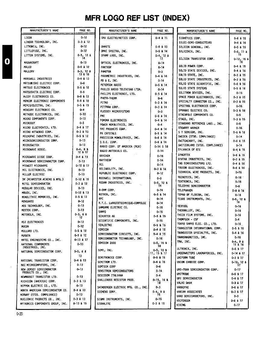
MFR LOGO REF LIST (INDEX) - --
MANUFACTURER'S NAME
LICON
LINEAR TECHNOLOGY, INC.
LITRONIX. INC.
LITTLEFUSE, INC.
L ITTON SYSTEMS, INC.
MAGNACRAFT
MALCO
MALLORY
I
I
I
I
I I I I
F F P
F
M M
M
M N
N
N
N,
N
N 1
Nl
MARSHALL INDUSTRIES
MATSUBISHI ELECTRIC CORP.
MATSUO ELECTRONICS
MATSUSHITA ELECTRIC CORP.
McCOY ELECTRONICS CO.
MEMCOR ELECTRONIC COMPONENTS
MEPCO/ELECTRA, INC.
MERCURY ELECTRONIC CO.
METHOOE ELECTRONICS. INC.
MICRO COMPONENTS CORP.
MICRODOT
MICRO ELECTRONICS, LTO.
MICRO NETWORKS CORP.
MICROPAC INOUSTRIES, INC.
MICROSEMICONDUCTOR CORP.
MICROSWITCH
MICROWAVE ASSOC.
MICROWAVE OIOOE CORP.
MICROWAVE SEMICONDUCTOR CORP.
MIDWEST MICROWAVE
M I L ELECTRONICS. INC.
MILLER ELECTRIC
3M (MINNESTOR M I N I N G 6 MFG. ) YITEL SEMICONOUCTOR
IOOULAR DEVICES, INC.
MLEX, INC.
fONOLITHIC MEMORIES, INC.
lONSANTO
K)S TECHNOLOGY, INC.
IOSTEK CORP.
OTOROLA, I NC.
IS1 ELECTRONICS
IUCON
IULLARO LTO.
IURATA ATEL ENGINEERING CO.. INC.
ATIONAL COMPONENTS , INOUSTRIES, INC.
ATIONAL SEMICONOUCTOR CORP.
AT1 ONAL TRANS ISTOR CORP.
EC MICROCOMPUTERS,, I NC.
EW JERSEY SEMICONDUCTOR PROOUCTS CO., INC.
EWMARKET TRANSISTOR LTD.
ICHICON (AMERICA) CORP.
IPPON ELECTRIC CO., LTD.
IRTH AMERICAN SEMICONOUCTOR CO.
)RWAY (STOS. COMPLIANCE)
JCLEONIC PROOUCTS CO. , INC.
'TRONICS CCMPONENTS GROUP. INC.
PAGE NI
0 - 1 2
0 - 3 6 1i
0 - 1 2
0 - 1 2
0-5, 1 2 1 4
0 - 1 3
0 - 5 6 1 2
0-3, 1 2 1 3 6 1 8
0 - 4 6 1 3
0- 6
0 - 5 6 1 2
0- 6
0-8 6 1 3
0 - 5 6 10
0 - 5 6 1 3
0- 4
0-10 0 - 1 3
0- 5
0 - 4 6 1 7
0 - 3 6 1 3
0-5 6 1 2
0 - 1 3
0 - 7 3
0-4. 8 6 1 2 6 1 7
0 - 4 6 1 3
0 - 1 3 0 - 1 2 6 1 7
0 - 1 3
0 - 1 3
0 - 1 2 6 1 5
0-3 6 1 2
0 - 1 3
1-12 6 1 3
1-5 6 1 3
0 - 1 2
0 - 1 3
0 - 1 3
)-3, 6 6 1 2
0 - 1 3
0 - 1 2
1-5 6 1 2
- 9 6 1 2
- 1 3 6 1 7
0 - 1 3
-5. 6 6
1 3
- 4 6 1 3
0 - 1 3
0 - 1 3
MANUFACTURER' S NAME
OAK ELECTRO/NETICS CORP.
OHMITE
.OMNI SPECTRA, INC.
OPAMP LABS, INC.
OPTICAL ELECTRONICS, INC.
PAKTRON
PAMOTOR
PARAMETRIC INOUSTRIES, INC.
PD 6 E, INC.
PETERSON RADIO
PHILCO RAOIO TELEVISAO LTOA.
P H I L I P S ELECTRONIC, LTO.
PHOTO-THEW
PITMO ,
PITTMAN CORP.
PLESSEY MICROSYSTEMS
PMI
POMONA ELECTRONICS
POWER MONOLITHICS, INC.
PPC PROOUCTS CORP.
PR CRYSTALS
3RECISION MONOLITHICS. INC.
1.D.C. CORP.
I A O I O CORP. OF AMERICA (RCA)
?A010 MATERIALS CO.
MYCHEM
NYTHEON
ICL
E L I A B I L I T Y , INC.
EPUBLIC ELECTRONIC CORP.
OCKWELL INTERNATIONAL
ODAN INOUSTRIES, INC.
-OHM CORP.
OTRON, INC. PC
.T.C. LaRADIOTECHNIQUE-CWELEC
ANGAMO ELECTRIC CO.
9NY 0
CHURTER AG
: I E N T I F I C COMPONENTS. INC.
IALECTRO
3 I C O A
NICONWCTOR CIRCUITS, INC.
MCONDUCTOR TECHNOLOGY. INC.
lMICON 2 0 0 0
:MI, INC.
:MITRONICS CORP.
'MITRON LTO.
MTECH CORP
NSITRON SEMICONDUCTORS
SCOSEM I T A L I A N A
ALLCROSS RESISTOR PROD.
INOENGEN ELECTRIC MFG. CO., I N C
EMENS CORP.
PAGE NO.
0 - 4 6 11
0 - 6 6 1 3
0 - 6 6 1 4
0-4, 1 2 6 1 3
0 - 1 4
0 - 1 4
0 - 3
0 - 4 6 1 4
0 - 1 4
0 - 5 6 1 4
0 - 1 4
0 - 5 6 1 4
0- 6
0 - 3 6 1 4
0 - 3 6 1 4
0- 3
0 - 6 6 1 4
0 - 4 6 1 4
0 - 4
0 - 4 6 1 4
0 - 5 6 1 4 0 - 6 6 1 4
0 - 6 6 1 4
0 - 1 4 1 1 8
0 - 1 4
0 - 1 6
0 - 1 4
0 - 1 4
0 - 3 6 1 4
0 - 1 2
0- 3
0-5 , 1 2 6 1 4
0 - 1 4
0 - 5 6 1 4 0 - 1 4
0 - 1 4
0 - 1 5
0 - 1 5
0 - 6 6 1 5
0 - 1 5
0 - 5 6 1 5
0 - 4 6 1 5
0 - 4 6 1 5
0 - 1 6
0-5 , 1 5 6 18
0 - 5 , 1 0 6 , 1 5 6 1 7
0 - 5 6 1 5
0 - 4 6 1 5
0 - 6
0 - 1 4
0- 4
0-15, 1 6 6 18
0- 3
0-4 , 9 6 1 5
0 - 1 5
0 - 3 6 1 5
MANUFACTURER'S NAME
SIGNETICS CORP.
SILEC-SEMI-CONDUCTEURS
S I L I C O N GENERAL, INC.
S I L I C O N I X , INC.
S I L I C O N TRANSISTOR CORP.
SOLIO POWER CORP.
SOLIO STATE DEVICES, INC.
SOLIO STATE, INC.
SOLIO STATE INDUSTRIES, INC.
SOLID STATE SCIENTIFIC, INC.
SOLIO STATE SYSTEMS
SOLITRON DEVICES, INC.
SPACE POWER ELECTRONICS. INC.
SPECIALTY CONNECTOR CO., INC.
SPECTROL ELECTRONICS CORP.
SPRAGUE ELECTRIC CO.
STACKPOLE COMPONENTS CO.
STACO, INC.
STANDARD REFERENCE LABS., INC.
STEWART WARNER S T SEMICON, INC.
iWEOEN (STOS. COMPLIANCE)
;WITCHCRAFT. INC.
iWITZERLAND (STOS. COMPLIANCE)
iYLVANIA OF GTE
1YNERTEK IYNTAR INDUSTRIES. INC.
'AG SEMICONOUCTORS LTO.
'ECCOR ELECTRONICS, INC.
ECHNICAL WIRE PRODUCTS, INC.
ECNETICS, INC. EKTRONIX, INC.
ELEDYNE SEMICONOUCTOR
ELEFUNKEN EPRO OF FLORIDA, INC.
EXAS INSTRUMENTS, INC.
EXTOOL
HERMALLOY , I NC . H I C K F I L M SYSTEMS, INC.
HOMPSON - CSF
OKYO SANYO ELEC. CO., LTO.
RANSISTOR INTERNATIONAL CORP.
RANSISTOR SPECIALTYS, INC.
RANSMGNETICS. INC. RW. INC.
LTRONIX. INC.
NOERWRITERS LABORATORIES. INC.
YIFORM TUBE
YION CARBIDE CORP.
!I-TRAN SEMICONOUCTOR CORP.
Y ITROOE
'I SEMICONDUCTOR
4LVO GmbH
MADYNE
\RIAN ASSOCIATES
\RO SEMICONOUCTORS, INC.
CTOREEN
KING
- PAGE NO
0 - 6 6 1 5
0 - 4 6 1 6
0 - 5 6 1 5
0-6 , 1 1 8 1 5
0-12. 1 5 1 6
0 - 4 6 1 5
0 - 4 6 1 6
0 - 3 6 1 5
0 - 3 6 1 5
0 - 6 6 1 6
0 - 5 6 1 6
0 - 1 5
0 - 3 6 1 5
0-3 6 1 5
0 - 1 6
0 - 3 6 1 8
0 - 5
0 - 3 6 1 5
0 - 5 0 - 1 6
0 - 6 6 1 6
0 - 1 4
0 - 6 6 1 5
0 - 1 4
0-4, 6 1 5
0 - 6 6 1 5 0 - 3 6 1 5 0 - 4 6 1 6
0 - 6 6 1 6
0 - 1 6
0 - 1 6 '
0 - 1 6
0 - 6
0 - 8 6 1 6
0 - 1 6 0-5, 12 6
1 6
0 - 1 6 0 - 1 6 '
0 - 1 6
0 - 4
0-15 ,
0 - 5 6 1 6
0 - 4 6 1 6
0 - 1 6 0-4, 9 6 11 6 1 6
0 - 5 6 1 7
0 - 1 4 6 1 7
0 - 3 6 1 7
0-10. 1 2 6 1 7
0 - 1 7
0 - 5 6 1 7
0 - 4 6 1 7
0 - 3 6 1 7
0 - 6 6 1 7
0 - 3 6 1 7
0 - 3
0-6 6 1 7
0 - 1 7
MANUFACTURER'S NAME
VITRAMON, I N C .
WALBERN DEVICES, I N C .
WARD LEONARD
WATKINS-JOHNSON CO.
WESTERN D I G I T A L CORP.
WESTINGHOUSE BRAKE 8 SIGNAL CO., LTD.
WESTINGHOUSE ELECTRIC CORP.
ZELTEX, I N C .
Z I L O G
PAGE NO.
0 - 1 7
0 - 4 8 17
0 - 1 3 8 1 7
0 - 1 7
0 - 4
0 - 3 8 1 7
0 - 3 8 1 7
0 - 1 7
0 - 5 8 1 7
MFR LOGO REF LIST (INDEX)

NOTES
ENGINEERING SERVICES 'RELIABILITY GROUPS" COnPfflENT RELIABILITY ENGINEERING Component Re l iab l l i t y Engineering has been formed c ~ c i f i c a ! ? ~ t o address canponent r e l i a b i l i t y problems. This group provides f a c i l i t i e s procedures t o measure and assure the r e l i a b i l i t y of semiconductor components procured f o r use i n Tektronix products. Sune o f the techniques u t i l i z e d t o provide t h i s function are:
1 . r, lua t ing r e l ~ a b l l l t y o f components f o r the purpose o f se lect ing vendor. part, o r process on' the basis o f r e l l a b i l l t y . 2. ~e tenn in ing t e s t procedures t o assure the r e l i a b i l i t y o f par ts before accepted and warehoused; se t t i ng acceptable
r e l i a b i l i t y levels. 3. Detenninlng optimum cost-effect ive component screening procedures t o meet a given r e l i a b i l i t y goal. 4. Performing f a i l u r e analysis on fa i l ed components returned frm f i e l d o r f ran instrument r e l i a b i l i t y tests. 5. Providing generic cmponent r e l i a b i l i t y data based on resul ts o f r e l i a b i l i t y tests .
For spec i f i c information, contact Ron Schwartz, ext. 1605.
RELIABILITY INFORMATION SERVICES (How i n the corporate Mkts. 6 Service Group, 53-114) Infonnation on fa i l u res occurr ing during m u f a c t u r e and f i e l d use i s avai lab le by request. Regularly scheduled' repor ts are intended to give appropriate persons ins ight t o trends i n r e l i a b i l i t y . The data base 1s maintained on a rov ing year basis. His tory data i s avai lab le from 1970 t o date.
Information may be requested by c a l l i n g Brenda Humes. 8004 MR. A "menu" of data displays and descr ip t ion o f the data base I s avai lab le a lso by c a l l i n g Brenda Huines, ext. 6(WtR.
Our group, a t t h i s pr in t ing, consists of:
C l a i r Gruver, Manager 624-8006 Brenda Humes, Production Coordinator, 624-8004 Rosalyn Neuberger, Project Leader, 624-8007 Jim Hosford, Documentation, 624-801 2 Jerry Kryszek, Information Analyst, 624-8907 Jim Blohm, Information Analyst, 624-8907 Me1 Christensen, Programing. 624-8003 Judy Schonhard, Programing, 624-8007 Mary Sel ls, Clerk, 624-8012
Test Lab:
Warren Col l ier , Manager, Ext 5298 Jack S to l l , Corp. Rel. Engineering. Ext 5298 Tom Louie, Eng. Assistant, Ext 5527
GLOSSARY OF RELIABILITY TERMS RATED TEST - A tes t i n which the appl ied stress level i s chosen t o exceed tha t stated i n the reference condit ions i n order t o shorten tk t ~ m
T W u i r e d t o observe the stress res raue of the iu. o r u g n l f y the response I n a given t i r . To be val id , u s t not a l t e r the basic pd.~ and mechanisms o f f a i l u r e and t h e i r r e l a t i v e Prevalence i n a use s i tuat ion. fIEC 271)
URN-IN SCREEN - Perfonned f o r the purpose o f el iminating marginal devlces, those w i th inherent defects o r defects resu l t i ng f r a n manufacturing ' aberrations whlch are evidenced as t i n e and stress dependent fa l l u res . Burn-in i s u s u a l l ~ pcrfotmed by a ~ ~ l y l n s maxlnucn rated. o ~ c r a t l n a condit lons - . - . . - - - . f o r a speci f ied tlme period. (MIL-STD-883A. method 1015)
ELECTRICAL TESTS AT ELEVATED TEWERATURE - Usually a DC e lec t r i ca l and f u l l functional t e s t performed a t a temperature above ambient (Typica l ly 70°C o r maxiaun rated o ~ e r a t l n a tem~erature f o r IC's, and 125'C f o r t rans is tors tested a t Tektronix on the hot track).
he i n a b f i i t y of-an l iein t o perform wi th in previously speci f ied l i m i t s . (MIL-STO-790C) FAILURE ACTIVATING CAUSE - The stresses/forces, such as shock o r vtbrat ion, whlch induce o r act ivate a f a i l u r e m h a n i u . (MIL-STD-79OC) FAILURE ANALYSIS - The process o f examining parts t o determine the cause o f var ia t ions o f perfomance character is t ics outside o f previously established
l i m i t s w i t h the end resu l t that f a i l u r e modes, f a i l u r e mechanism and f a i l u r e ac t i va t ing causes w i l l be Iden t i f i ed . (MIL-STD-790C) FAILUR HECHANI - The physical process by whlch the degradation proceeded t o the po in t o f fa i l u re , i den t i f y ing q u a l l t y defects ( including the o r i g i n a l
de:ect whici?inltiated the devlce fa i l u re ) , In ternal , s t ructura l , o r e l e c t r i c a l weaknesses and. where applicable, the nature o f external ly appl ied stresses which led t o fa i l u re . (MIL-STD-883A)
FAILURE WOE - The cause f o r re jec t ion o f any f a i l e d device as defined i n t e r n o f the spec i f i c e lect r ica l /phys lca l requirement whlch It f a i l e d to m e t f~ll-STd-rn3A 1 ,..--
FUNCTlfflA TESTS - Defined as go, no-go tests which s uen t ia l l y e x e ~ i S e a funct ion ( t ru th ) tab le o r I n whlch the device i s operated as a p a r t o f m exterhal c i r c u i t and c i r c u i t operation I s tested,%1L-S~~-083~)
HIGH TEMPERATURE REVERSE BIAS - (HTRB) - A reverse bias. less than breakdown voltage, I s appl ied to one o r both t rans is to r junctions a t elevated t e q - erature t a arumte i n fan t fa i lures. - . - - - . - - - . - - - -
plGH TEMPERATURE STORAGE ~ S T A B I L ~ Z A T ~ W BAKE) - The purpose o f t h f s t e s t i s t o d e t e n i n e the e f f e c t on micro-electronic devices o f storage a t elevated temperiture. .This t e s t i s p r imar i l y use for device s t a b i l i z a t i o n and the detect ion o f parameter d r i f t . It also i s usefu l I n accelerat ing temper- ature dependent f a i l u r e mechanisms such as those resu l t i ng from chenlcal react ion o r d i f fus ion. (MIL-STD-883A, Method 1008)
INTERMITTENT LIFE (OR POWER CYCLING) - P e r f o d f o r the purpose O f determining a representat ive f a i l u r e r a t e f o r micro-electronic devices o r dcmonstra- t l n g qua l l t y o r r e l l a b l l l t y o f devices subjected t o the speci f ied conditions. It i s intended f o r appl icat ions where the devices are exposed t o c y c l i c var ia t ions i n e lec t r l ca l stresses and power consumption between the "onm and * o f f " condl t lon and resul tant c y c l l c var ia t lons i n device and case temperature. The tes t can be performed under various condlt ions ranging from DC reverse bias t o operation under high parcr conditions. (MIL-STD-883A. Method 1006)
OBSERVED FAILURE RATE - For a stated period i n the l i f e o f an item, the r a t i o o f the t o t a l number o f f a l l u r e s i n a sample t o the c w l a t l v e observed -e...to be associated w i th articular and stated t i n e in te rva ls and w i t h stated condit lons fIEC 271) . . . . . . . . . . . - . . -. POWER CYCLING - see 7 n t e k l t t e n t - l i f e . PRECONDITIONING - The appl icat ion o f stress t o a group o f components which i s done p r i o r t o screening (100% test ing). Thls t reatacnt I s Intended t o
promote the f a i l u r e o f Intrinsically weak devices so they can be detected by screening. UALlTY - The de ree o f conformance t o appl icable speci f icat ions and workmenship standards a t the t ime o f the qua l i t y inspection. OR The percentage o f
b e c t l v e un&s (e i the r dead-on -a r r i va l o r out-of-spec) furnished by the suppl ier t o the user. RELIABILITY - The p robab i l i t y o f a devlce performing I t s purpose adequately f o r the period o f tlme intended under the s p e d f l e d operating condltions. RELIABILIWASSURAI~CE - The managaent and technical in tegrat ion o f the r e l i a b i l i t y a c t i v i t i e s essential I n maintaining r e l i a b i l i t y achievcncnts, Inclu-
ding design. production and product assurance. (MIL-STD-790C) SAnPL - A random select ion of un i t s frm a l o t f o r the purpose o f evaluatlng the character ls t lcs o r accep tab i l i t y o f the l o t . d EN N6 - A test , o r combination o f tests, ( p e r f o m d on 100% o f a group o f pa r t s ) intended t o r m ~ ~ v e unsatisfactory item o r those ' l i k e l y t o e x h i b l t
fa i lures. (IEC 271) AK - See high tmper r tu re storage.
-@#!parer, temperature, o r t h e m 1 e n v i w m n t a l condlt ions dur ing conponent tes t ing o r usage which a f f e c t the f a i l u r e rate, md hence the r e l l a b i l l t y o f the parts.
TEMPERATURE CYCLING - This t e s t i s conducted t o determine the resistance o f the pa r t t o exposures a t extremes o f high and low temperatures. R m n e n t changes I n operating character ls t lcs and physical damage r e s u l t frol var ia t ions i n the physical proper t ies and dimensions during test. Thls t e s t i s often used t o screen f o r devices w i th weak mechanical propert ies. (MIL-STD-BBJA, Method 1010)
THERMAL SHOCK - The purpose o f t h i s t e s t I s t o determine the resistance o f the device , t o sudden, e x t r e m chnges I n temperature. It i s useful f o r evaluating I f I i S ~ t c h e ~ i n t h e m 1 time constants and expansion c o e f f i c i e n t between various device materials. (MIL-STO-WAS Cbtkod 1011)
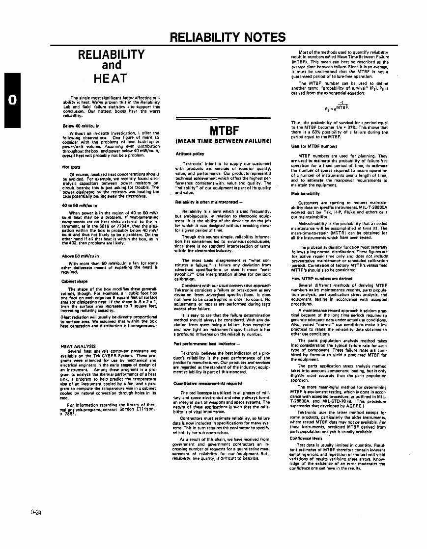
RELIABILITY NOTES RELIABILITY
and HEAT
The single most.siynificant factor affecting reli. ability is heat. We've proven this in the Reliability Lab and field failure statistirs also support this conclusion. Our hottest box- have the worst reliability.
Without an in-depth investiyation, I offer the following observations: One figure of merit to consider with the problems of lieat build.up is powerlunit volume. Assuming wen distr~bution throughout the box. and power below 40 mWlcu.in, overall h u t will probably not be a problem.
Hot spot,
Of course, localized heat concentrations should be avoided. For example, we recently found elec- trolytic capacitors ktween power resistors on circuit boards; this is just asking for trouble. The
' power dissipated by the resistors was heating the w p l potentially boiling away the electrolyte.
When power is in the region of 40 to 50 mW1 w.in heat may be a problem. I f heat-generating components are on heat sinks external to the in. strumant. as in the 6618 or 77WA. then the dissi- pation within the box is probably below 40 mW1 cu.in and thus not likely to be a problem. On the other hand i f all that haat is within the box, as in the 432. then problems are likely.
Above 60 mW/cu In
With more than 50 mW/cu.in a fan (or some other deliberate means of expell~ng the heat) is nguirsd.
Wmt shap
T h $hap of the box modifies these generali- zatim, though. For example, a 1 cubic foot box one foot on each edge has 6 square feet of surface area for dissipating heat. I f the sham is .5 x 2 x 1, tnen the surface area increases to 7 quare feet, increasing radiating capacity.
(Hen radiation will usually be d~rectly proportional to surfax area. We rrwrned that within the box heat generation and distribution is homogeneous.)
HEAT ANALYSIS Several heat analysis computer programs are
available on the Tek CYBER System. These pro- grams wen intended for use by mechanical and electrical engineers in the early stages of design of an instrument. Among these programs is a pro. gram to analyze the thermal performance of a heat sink, a program to help predict the temperature vise of m instrument cooled by a fan. and a pro- gram to compute the temperature vise in o cabinet cooled by natural convection through holes in its Use.
For information regarding the library of ther- mal analysis programs, contact Gordon E l 11 son, x 7887.
MTBF (MEAN TIME BETWEEN FAILURE)
Attitude policy
Tektronix' intent is to supply our customers with products and services of superior quality, value, end performance. Our products represent a technical achievement which offers the highest per- formance consistent with. value and quality. The "reliability" of our equipment is part of its quality and value.
Relirbility is often misinterpreted - Reliability is a term which is used frequently,
but ambiguously. In relation to electronic equip- ment, i t is the ability of the device to do the job for which i t waz designed without breaking down for a given period of time.
Though this rounds simple, reliability informa- tion has sometimes led to erroneous conclusions, since there is no standard interpretation of terms within the elictronics industry.
The most basic disagreement Is "what con- stitutes a failure." Is failure m y deviation from advertised specifications or does i t mean "cata- strophic?" One interpretation allows for periodic calibration.
Consistent with our usual conservative approach Tektronix considers a failure or breakdown as m y deviation from advertised specifications. I t does not have to be catastrophic in order to count. No adjustments or repairs are performed during t e n except after failure.
I t is easy to see that the failure determination method should always be considered. With any de- viation from specs being a failure, how complete and how tight an instrument's specification is h a a profound influence on the reliability number.
Past performance: bast i nd iho r - Tektronix believes the best indicator of a pro-
duct's reliability is the past performance of the product's manufacturer. Our products and services are regarded as the standard of the industry; equip- ment reliability is pan of this standard.
Quantitative masunmant, mquind
The or i l lorope is utilized in all p h m of mill- tary and space electronics and nearly always forms an integral part of weapons and space systems. The nature of these applications is such that the relis. bility is of vital importance.
Contractors must estimate reliabilitv. so failure data is now included in specifications fir'many syr. tems. This in turn requires tKe contractor to specify reliability for subcontractors.
As a result of this chain, we have received from government and government contractors an in. creasing number of requests for a quantitative me* surement of reliability for our 'equipment. But. reliability, like quality, is difflcult to de#rlbe.
Most of the methods used to quantify reliability result in numbers called Mean Time Between Failure (MTBF). This mean can best be described as the average time between failure. Since i t is an average, i t must be understood that the MTBF is not a guarantaed period of failure-free operation.
The MTBF number can be used to define another term: "probability of survival" (PI). PS is derived from the exponential equation:
Thus, the probability of survival for a period equal to the MT BF becomes l l e - 37%. This shows that there is a 63% possibility of a failure during the period equal to the MTBF.
Uses for MTBF numbers
MTBF numbers are used for planning. They are used to estimate the probability of failure.free operation for a fixed period of time, to estimate the number of spares required to insure operation of a number of instruments over a length of time, and to atimata the manpower requirements to maintain the equipment.
Maintainability
Customers are starting to request maintain- ability data on specific instruments. MIL-T-288WA worked out by Tek, H-P, Fluke and others calls out maintainability.
Maintainability is the probability that a needed maintenance will be accomplished in time (tl: The mean-tima-to-repair (MTTRI can be obtained for all the instruments which have been tested.
The probability density function most generally follom a log-normal distribution. These figures are for active repair time only and does not include preventative maintenance or scheduled calibration periods. Correlation of factory MTTR's versus field MTTR's should also be considered.
How MTBF numbers are derived
Several different methods of deriving MTBF numbers exist: maintenance records, parts popula- tion analysis, part application stress analysis, and equipment testing in accordance with accepted procedures.
A maintenance record approach is seldom prac. tical because of the long time periods required to generate adequate data under actual use conditions. Also, varied "normal" use conditions make i t im- practical to relate the reliability data obtained to other use conditions.
The parts population analysis method takes into consideration the typical failure rate for each type of component. These failure rates are com- bined by formula to yield a predicted MTBF for the equipment.
The parts application stress analysis method takes into account component loading, but is only slightly more accurate than the parts population approach.
The more meaningful method for determining MTBF is equipment testing, which is done in rccor- dance with accepted procedure, as outlined in MIL- T.288WA and MIL.STD.781B. (This procedure supercedes that developed by AGREE.)
Tektronix uses the latter method except for some products, particularly the older instruments, where tested MTBF data may not be available. For these instruments, predicted MTBF derived from parts population analysis is usually available.
Confidence levels
Test data is usually limited in quantity. Resul. tant + n a t e s of MTBF therefore contain inherent sampling errors, and repetition of the test will yield variations of results verifying these errors. Know- ledge of the existence of an error moderates the confidence one can have in the results.
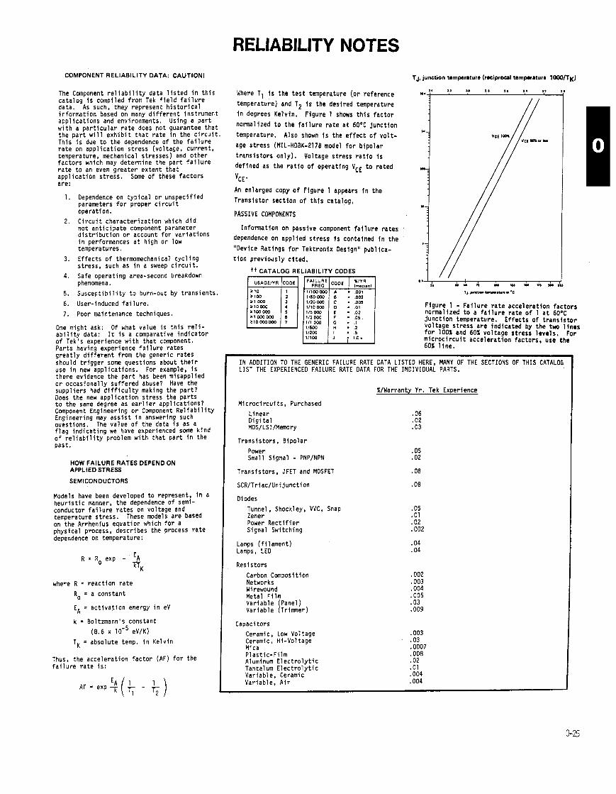
RELIABILITY NOTES COMPONENT RELIABILITY DATA: CAUTlONl
The Component r e l i a b i l i t y da ta l i s t e d i n t h i s c a t a l o g i s compi led f rom Tek f i e l d f a i l u r e data. As such, they represent h i s t o r i c a l i n f o r m a t i o n based on many d i f f e r e n t ins t rument a p p l i c a t i o n s and environments. Us ing a p a r t w i t h a p a r t i c u l a r r a t e does n o t guarantee t h a t t h e p a r t w i l l e x h i b i t t h a t r a t e i n t h e c i r c u i t . Th is i s due t o t h e dependence o f t h e f a i l u r e r a t e on a p p l i c a t i o n s t r e s s (vo l tage, c u r r e n t , temperature, mechanical s t resses) and o t h e r f a c t o r s which may determine t h e p a r t f a i l u r e r a t e t o an even g r e a t e r e x t e n t t h a t a p p l i c a t i o n s t r e s s . Some o f these f a c t o r s are:
1. Dependence on t y p i c a l o r u n s p e c i f i e d parameters f o r p roper c i r c u i t opera t ion .
2. C i r c u i t c h a r a c t e r i z a t i o n which d i d n o t a n t i c i p a t e component parameter d i s t r i b u t i o n o r account f o r v a r i a t i o n s i n performances a t h i g h o r low temperatures.
3. E f f e c t s o f thermomechanical c y c l i n g s t ress , such as i n a sweep c i r c u i t .
4. Safe o p e r a t i n g area-second breakdown phenomena.
5 . S u s c e p t i b i l i t y t o burn-out by t r a n s i e n t s .
6. User-induced f a i l u r e .
7. Poor maintenance techniques.
One might ask: Of what va lue i s t h i s r e l i - a b i l i t y data: I t i s a comparat ive i n d i c a t o r o f Tek's exper ience w i t h t h a t component. P a r t s having exper ience f a i l u r e r a t e s g r e a t l y d i f f e r e n t f rom t h e gener ic r a t e s shou ld t r i g g e r some ques t ions about t h e i r use i n new a p p l i c a t i o n s . For example, i s t h e r e evidence t h e p a r t has been misapp l ied o r o c c a s i o n a l l y s u f f e r e d abuse? Have t h e s u p p l i e r s had d i f f i c u l t y making t h e p a r t ? Does t h e new a p p l i c a t i o n s t r e s s t h e p a r t s t o t h e same degree as e a r l i e r a p p l i c a t i o n s ? Component Engineer ing o r Component R e l i a b i l i t y Engineer ing may a s s i s t i n answering such quest ions. The va lue o f t h e data i s as a f l a g i n d i c a t i n g we have exper ienced some k i n d o f r e l i a b i l i t y problem w i t h t h a t p a r t i n t h e pas t .
HOW FAILURE RATES DEPEND ON APPLIED STRESS
SEMICONDUCTORS
Models have been developed t o represent, i n a h e u r i s t i c manner, t h e dependence o f semi- conductor f a i l u r e r a t e s on vo l tage and temperature s t ress . These models a r e based on t h e Arrhenius equat ion which f o r a p h y s i c a l process, descr ibes t h e process r a t e dependence on temperature:
where R = r e a c t i o n r a t e
Ro = a cons tan t
EA = a c t i v a t i o n energy i n eV
k = Bol tzmann's cons tan t
(8.6 x lo- ' eV/K)
TK = abso lu te temp. i n K e l v i n
Thus, t h e a c c e l e r a t i o n f a c t o r (AF) f o r the f a i l u r e r a t e i s :
Where T1 i s t h e t e s t temperature [or reference
temperature) and T2 i s t h e des i red temperature
i n degrees Ke lv in . F igure 1 shows t h i s f a c t o r
normal ized t o the f a i l u r e r a t e a t 60°C j u n c t i o n
temperature. A lso shown i s the e f f e c t o f v o l t -
age s t r e s s (MIL-HDBK-2178 model f o r b i p o l a r
t r a n s i s t o r s o n l y ) . Vol tage s t r e s s r a t l o i s de f ined as the r a t i o o f opera t ing VCE t o r a t e d
'CE'
An enlarged copy o f F igure 1 appears i n t h e
T r a n s i s t o r s e c t i o n o f t h i s ca ta log ,
PASSIVE COMPONENTS
I n f o r m a t i o n on passive component f a i l u r e r a t e s
dependence on a p p l i e d s t r e s s i s contained i n t h e
"Device Rat ings f o r Tek t ron ix Designu pub l ica-
t i o n p r e v i o u s l y c i t e d .
t t CATALOG RELIABILITY CODES
F i g u r e 1 - F a i l u r e r a t e a c c e l e r a t i o n f a c t o r s normal ized t o a f a i l u r e r a t e o f 1 a t 60°C j u n c t i o n temperature. E f f e c t s o f t r a n s i s t o r v o l t a g e s t r e s s a r e i n d i c a t e d by t h e two l i n e s f o r 100% and 60% v o l t a g e s t r e s s l e v e l s . For m i c r o c i r c u i t a c c e l e r a t i o n f a c t o r s , use t h e 60% l i n e .
I N ADDITION TO THE GENERIC FAILURE RATE DATA LISTED HERE, MANY OF THE SECTIONS OF THIS CATALOG LIST THE EXPERIENCED FAILURE RATE DATA FOR THE INDIVIDUAL PARTS.
%/Warranty Yr. Tek Experience
M l c r o c i r c u i t s , Purchased
L inear D i g i t a l MOS/LSI/Memory
T r a n s i s t o r s , B i p o l a r
Power Small S igna l - PNP/NPN
T r a n s i s t o r s , JFET and MOSFET .08
Diodes
Tunnel, Shockley, VVC, Snap Zener Power R e c t i f i e r S igna l Swi tch ing
Lamps ( f i l a m e n t ) Lamps, LED
R e s i s t o r s
Carbon Canpos i t ion Networks Wirewound Metal F i l m V a r i a b l e (Panel ) Var iab le (Tr imner)
Capaci tors
Ceramic, Low Vol tage Ceramic, H i -Vo l tage Mica P l a s t i c - F i l m Aluminum E l e c t r o l y t i c Tantalum E l e c t r o l y t i c Var iab le , Ceramic Var iab le , A i r

I RELIABILITY NOTES MTBF (continued)
The degree of confidence applicable to test data (of the asrumed constant failure rate variety) is a function of the total test time, as measured in multiples of the resulting MTBF.
For contractural commitments, instruments are run for a cumulative number of operating hours divided by the acceptable MTBF for the most gen. erally sccepted 90% lower confidence level.
The instruments must operate for a given period of time with no more than a certain number of failures. I f this number of failures is exceeded, the instruments do not mee! the MTBF requirements. Two alternatives prevail: lower the MTBF number or redo the test with possible circuit or part im- prwements.
The 90% lower confidence level has two per- spectives. One is that the vendor has a confidence that his product will have a greater than 90 percent chance of meeting or exceeding the quoted 90% level. The other viewpoint is that a customer has a 10% chance of having his instrument fail more often than the MTBF indicates.
An example of the relationship of reliability data follows. Suppose four instruments were run for 50M) hours each, or a total of 20k operating hours, and 37 failures occurred. The exhibited MTBF would be 540 hours. Chi-square tables indi. cats that the 90% lower confidence limit MTBF would be 445 hours.
The reliability or probability of success for a 4O.hour work week is:
In other words, there is an 8.6% chance an in st^. ment will fail during the 4Bhour work week.
R e p s t n q u a a for MTBF nurnb.n
I f a customer has received MTBF information on a given product. and he has a requirement for the same data on the same product at a later date, i t will be necessary to rehquire. We are regularly testing our equipment. The latest data provides the most murate number for current production instruments. The reliability of a product, typically, improves war its lifetime.
Symrn MTBF f i p m
We should note here that MTBF's for equip ment tobe combined in a system can be determined by different methods and still be combined to get a total MTBF for a rack or system. Should a cus. tomer have a calculated MTBF figure for most of his system, there is no problem combining i t with test& MTBF da:a. The formula for combination is: . .
1 - 1 1 - - 1 - - M T B F ~ + M T B F ~ + ... M T B F ~
SUMMARY:
Tektronix's intent is to give the customer the m a t for his instrument dollar. Part of this commit. ment is to produce reliable eauipment and promote reliability through servlce.
Thecustomer should view our past performance a the number one indicator of our product's relia- bility.
Should e customer require an MTBF number to meet a contractual commitment, Tektronix will supply the best number available. Test results and predicted MTBF's based on part populations4if tests have been completed).
MTBF numbers are useful for reliability plan. ning.
This information is of a confidential nature, so customers should be encouraged to live with past performance, the number one indicator, unless there is a contractural requirement. The Field Engineer is responsible for the security of this information.
Procedural Policy
MTBF figures for individual Tektronix products may be obtained, if available, by contacting the appropriate Marketing Manager. I f the Field Engi- neer decides to give an MTBF figure at the 90% lower confidence limit to a customer in writing ratherthanverbally, the form illustrated on Page R- 3.6 should be used to insure that customers have a consistent and comprehensive explanation of fig. urea after the Field Engineer has left.
Some customers will be content with MTBF prediction of an instrument derived by a parts pop. ulation count This method uses MIL.R.26474 or the R.A.D.C. failure rate equation. This equation auigns a basic failure rate to each type of compo. ment. The number of components is then multiplied by this failure rate to give a sub.equation total. There sub.totals are then added algebraically to yield an instrument bit failure rate. l h e reciprocal of thisnumber IS then taken to arrive at the oredict. ed MTBF. No confidence levels are impli& with this figure. The modes of failure are of catastrophic nature only, i.e.. no internal adjustment failures are considered.
Any MTBF contractural agreement between Tektronix and the customer should be negotiated as a modified product.
The following MTBF data applies at this time. We are regularly testing so we encourage you to re. inquire should you need this same information at a later date.
N o . of were tested in accordance with accelerated life test for hours each, a total test time of hours.
The results of these tests show an MTBF of h o u r s . The lower 90% confidence limit is h o u r s .
We believe that MTBF figures derived from ac. celereted test methods are the best quantitative indicators of equipment reliability. We also believe that your prior experiencewith TEKTRONIX equip- ment is a better indicator of reliability than is the MTBF number. Among MTBF methods, actual test. ing bean more relationship to the quality of design and workmanship than does either parts population analysis or parts application stress analysis methods.
The statistical nature of MTBF information makes i t impossible to be sure that any given ins. trument or group of Instruments will exhibit relia- bility identical to the figures quoted above. There. fore, we cannot warrant our MTBF number as we do a catalog specification. Exceptions to this will be made upon conditional contractural MTBF qual. ification testing for MTBF.
The information contained hereirl was obtained for our internal engineering use and is considered confidential by TEKTRONIX. We will appreciate your treating i t with discretion.
For additional information, contact Jack Stoll at ext. 5298.
DESIGNING FOR RELIABILITY
In designing for reliability, the designer has two powerful tools at his disposal - one is relia. bility analysis applied at all stages of the design. the other is the derating of components.
Reliability analysis is the calculation of the system's or equipment's reliability from the failure rates of the components ured. These calculations are done by Jack Stoll in our Reliability Lab. By properly applying reliability analysis, the design can be broken up into modules, assemblies, units, or subsystems, and reliability apportionments can be made to these so that the over.all reliability target is met.
When some components are inherently not reliable enough, derating techniques must be used. The derating of components in reliability design is a standard technique - it means operating corn.
ponents at only one-half or even less of their rated values of voltage, wattage, temperature, etc. Spec- tacular increases in component and equipment re- liability can be achieved in this way. Sometimes only one of these stress parameters needs to be reduced to bring the component failure rate down to the required level. But there are also instances where even extreme derating does not help, and the component failure rate is still too high. Redun- dancy techniques must then be used, in th* of parallel or stand-by components. However, re. dundancy increases size, weight, and possibly, main. tenance as well. Therefore, every effort should be made to avoid redundancy if single components of high reliability can be obtained and when derating techniques can be used.
Because the reliability of electronic systems is mostly a series reliability with very little or no redundancy used, the derating of components be- comes an absolute must for the achievement of high reliabilities. And because the reliability of a series system is determined by the sum of the com- ponent failure rates, design simplification is another important tool for reliab!e design. Simplification means a reduction of the number of components is a sound approach to system reliability. Thus, the an of reliability design does not consist of design- ing highly sophisticated systems but rather of de. signing them to be simple as possible.
The designer has certain tools for reliable design at his disposal. He can
Simplify the design to a minimum of pans with- out degrading performance.
Insure that design reliability reviews are per- formed at the preliminary stage and at the final stage of design. This is being done by w r A p plication Engineen.
Apply component derating techniques to the best possible advantage to reduce failure rates and to increase component life.
Reduce the operating temperature of corrpo- nenu in the equipment by providing heat sinks. appropriate packaging, and i f necessary, good cooling.
Use the Reliability Engineering Department to specify reliability and establish burn-in require- ments.
Use the Reliability Lab for instrument testing.
The specification of component nliabllities. component burn-in requirements, and instrument tasting is necessary to insure that the reliability tasting is necessary to insure that the reliability achieved by the design will be maintained in pro- duction and will not be degraded by the infiltra. tion of substandard specimens into the equipment or by poor assembly tecnhiques which cause early failures. These requirements will alert incoming irm- pection, quality control, and manufacturing engirie- ering to do their part in the over-all reliability con. trol program.

RELIABILITY NOTES equipment failure rate
The total failure rate of an lmtrument, whether predicted by par6 stress analysis or parts count, b:
Asquip ' )bl + )by + )b, +.. . )bT where
AsqUlp is the equipment failure rate (usually expressed as failuredlO6 houn) A,, . A,, . A,,. . . . hPT is the individual failure rat- of all components
Mean Time Between Failure or MTBF - (&,ip )"
environmental factors
The environment the i m t ~ m e n t is to be used In has quite an effect on the failure rates experienced In the field. Th re a n primarily t h m environmental fecton ( n ~ ) that spply to Tektronlx products:
Ground, benign
Ground, fixed
Ground, mobile (and portable)
Symbol nE Nominal Environmental Conditions
Nearly zero environmental stress with optimum engineering opera. tlon and maintenance.
Conditions lar than ideal to include Installation in permanent racks with sdequate cooling air, maintenance by military personnel and possible installation in unheated buildings.
Condltions more severe than those for GF, mostly vibration and hock. Cooling air supply may also be more limited, and main. tenance leu uniform.
DISCRETE SEMICONDUCTORS O m ( c f r l lun nar
Discretesemiconducton (non-plstlc encapsulated) are normalized to an NPN silicon transistor with n~ GB
TRANSISTORS (JAN p r 6 ) Sl NPN Sl PNP Ge PNP Ge NPN FET Unijunction
DIODES (JAN prtd Si General Purpose Ge General Purpose Zener and Avalanche Thyristor Sl microwave detector Ge microwave detector Sl microwave mixer Ge microwave mixer Varactor, Step Recovery, 1
Valid only for electrical stress, S t 0.3 M defined In MIL-HDBK.2170.
Application F m o n
Tramiston Diodes, gonenl prpora Linear 1 Small signal s 500 mA 1 Logic switch x 0.5 Logic Switch x 0.6 High frequency ( > 400 MHz) x 3.33 Power Rectifier > 500 mA x 1.5
HV Stecks, Vmax j 6OOv x 2.5/junction
r , ~ Voltage S t n u Facton
Tnmiston Dlodn. g ~ e r a l purpor
s2 . IpplIed volte~a 100% rated voltage
Failures Increaa by approximately 1.34 times for ' Failure rate Is constant for $2 5 60%. Failurn In. W h 10% increment of 52 above 52 - 20%. crease approximately 1.1 t lmn for each 10% i n c n
ment of s~ abwe 60%.
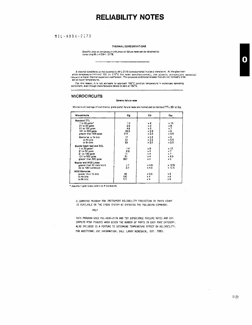
RELIABILITY NOTES
THERMAL CONSIDERATIONS
Specific data on temperature influence on failure rates can be obtained by consulting MiL.HD8K. 2178.
A thermal consideration not covered by MIL-2178 is encountered in plastic transistors. A t the glass tram sition temperature(ar0und 150 t o 170'~ f o r most manufacturers), the p l a s t i c encapsulant m a t e r i a l
takee on a higher thermal expansion coeffecient. This produces additional stresses that are not noticably prer ent at lower temperatures.
For this reason, i t is not advisable t o approach 150°C junction temperature in worstcase operating conditions, even though manufacturers derate to zero at 150°C.
MICROCIRCUITS Generic failure n t m
Microcircuit (average of commercial grade parts) failure rates are normalized to standard TTL SSI at Gg.
Standard TTL 1 to 2 0 gates' 21 to 5 0 gates 5 1 to lWgates 1 0 1 to 5 0 0 gates greater than 5 W gates
Memories s l k bits to 4k bits to 8k bits
Bipolar beam load and ECL 1 to 20 gates' 2 1 to 5 0 gates 5 1 to 1 0 0 gates 1 0 1 t o 5 0 0 gates greater than 5 0 0 gates
Bipolar end MOS Linear greater than 32 transistors 33 to 1 W transistors
MOS Memories greater than l k bits to 4k bits t o 8k bits
Assume 1 gate is equivalent to 4 transistors
A COMPUTER PROGRAM FOR INSTRUMENT R E L I A B I L I T Y PREDICTION BY PARTS COUNl
I S AVAILABLE ON THE CYBER SYSTEM BY ENTERING THE FOLLOWING COMMANDS:
RELY
T H I S PROGRAM USES MIL -HDBK-2178 AN0 TEK EXPERIENCE FAILURE RATES AN0 CAN
COMPUTE MTBF FIGURES UHEN GIVEN THE NUMBER OF PARTS I N EACH PART CATEGORY.
ALSO INCLUDED I S A FEATURE TO DETERMINE TEMPERATURE EFFECT ON R E L I A B I L I T Y .
FOR ADDIT IONAL USE INFORMTION. CALL LARRY MENEGHIN, EXT. 7283.
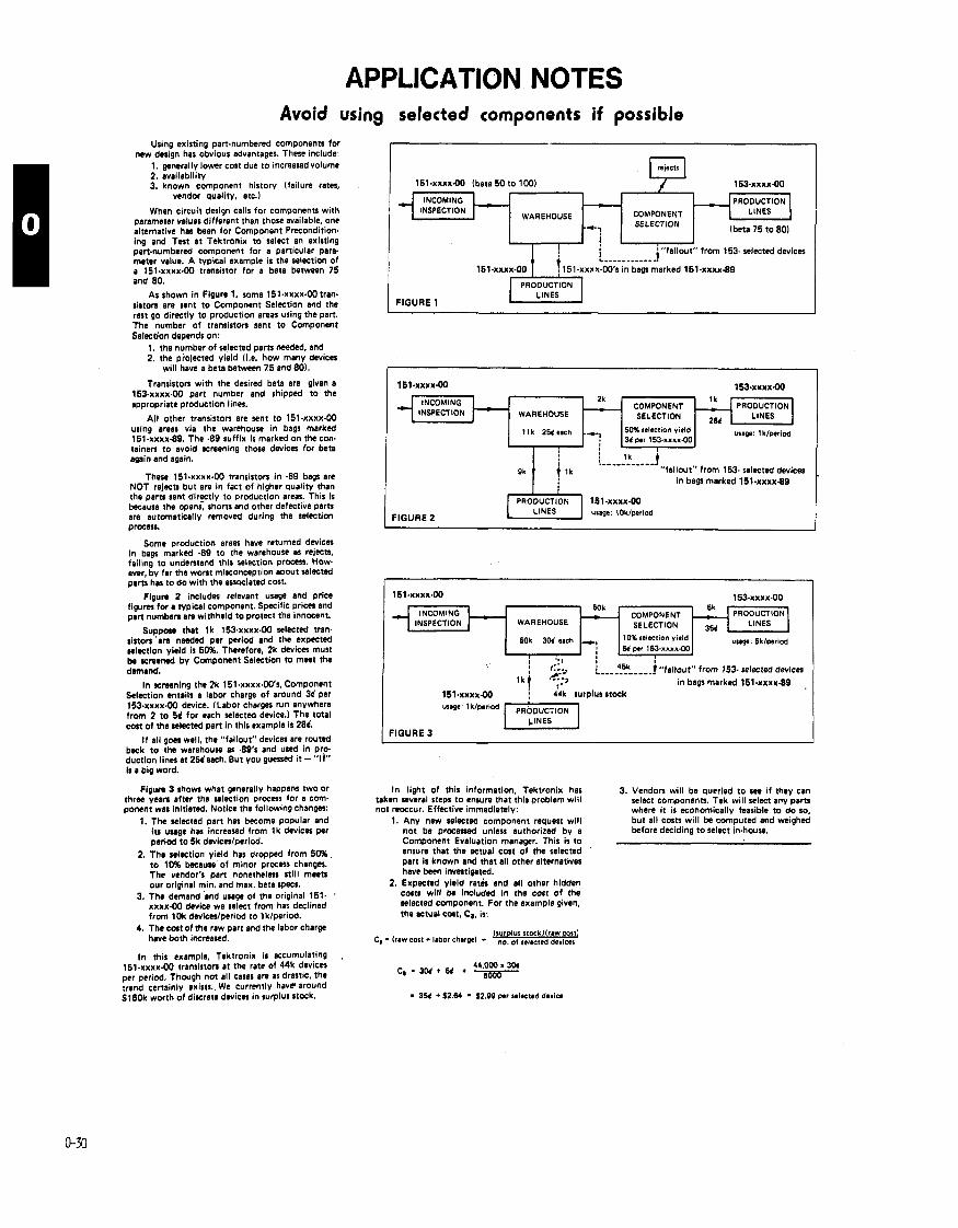
APPLICATION NOTES Avoid using selected components if possible
Using existing panmrnbered components for new design has obvious advantages. These include:
1. generally lower c a t due to increasedvolume 2, availability 3. known component history (failure rates,
vendor quality, etc.)
When circuit design calls for components with parameter values different than those available, one alternative hat been for Component Precondition. ing and Test at Tektronix to select an existing part-numbered component for a particular para meter value. A typical example is the selection of a 151.xxxx.00 transistor for a beta between 75 and 80.
As shown in Figure 1, some 151.xxxx-00 tran. siston are sent to Component Selection and the rest go directly to production areas using the pan. The number of transiston sent to Component Selection depends on:
1. the number of selected pam needed, and 2. the piojected yield 1i.e. how many devices
will have a beta between 75 and 801.
Transiston with the desired beta are given a 153-xxxx.00 part number and shipped to the appropriate production lines.
All other transiston are sent to 151-xxxx-W using areas via the warehouse in bags marked 151.xxxx-89. The -89 suffix is marked on the con- tainen to avoid screening those devices for beta again and again.
These 15l~xxxx-W transiston in -89 bags a n NOT rejects but are in fact of higher quality than the pam sent d i e t l y to production areas. This is because the opens, shorts and other defective pam are automatically removed during the selection praess.
Some production areas have returned devices in bags marked -89 to the warehouse as rejects, failing to understand this selection process. How. ever, by far the wont misconception abwt selected pans has to do with the associated cost.
Fipum 2 includes relevant usage and price figum for a cyplcal component. Specific prices and pan numben a n withheld to protect the innocent.
Supporr that l k 153~xxxx.W selected tram siston 'am needed per period and the expected selection yield is 50%. Therefore, 2k devices must ba screened by Component Selection to meet the dmuld .
In screening the 2k 151.xxxx.O0's, Component Selection entails a labor charge of around 3d per 153.xxxx.W device. (Labor charges run anywhere from 2 to 5d for each selected device.) The total c a t of the selected pan in this example is 28d.
I f all goes well, the "fallout" devices a n routed back to the warehouse as 49's and used in pro- duction lines at 25desch. But you guessed i t - "If" is a big word.
Figum 3 shows what generally happens two or three yean after the selection process for a com- ponent was initiated. Notice the following changer:
1. The selected pan has become popular and its usage h n increased from l k devices per period to 5k dwiceslperiod.
2. The selection yield has dropped from 50% to 10% because of minor process changes. The vendor's part nonetheless still w r original min. and max, beta specs.
3. The demand imd usage of the original 151. ' xxxx-00 dwice we select from has declined from 1Ok deviceslperiod to lklperiod.
4. The cost of the raw part and the labor charge have both increased.
In this example. Tektronix is eccumulating . 1 5 1 . ~ ~ ~ ~ 9 0 transistors at the rate of 44k devices per period. Though not all cases are as drastic, the trend certainly exists. We currently have around Sl8Ok worth of discrete dwices in surplus stock.
I U '"fallout" from 153- selected devices . . . . . . . . . . . -1
in bags marked 15l.xxxx-89
151-xxxx00 (beta 50 to 100) 153-xxxx-00
2k COMPONENT PRODUCTION
WAREHOUSE LINES
11k 2EJc1ch . 50% selection yield wag: 1 k/p.riod -7 34 per 153.xxxx.00
INCOMING INSPECTION
WAREHOUSE
"fallout" from 153 selected devices in bags marked 151.xxxx-89
LINES FIGURE 2
usage: tOk/period
PRODUCTION
COMPONENT LINES
-&? lbeta 75 to 80)
; 1 45k 1 "fallout" from 153- selected devices
in bags marked 151.xxxx.89 ,
. 44k surplus stock
INCOMING - INSPECTION
In light of this information, Tektronix has 3. Vendon will be queried to see if they can taken several steps to ensure that this problem will select components. Tek will select any parts not reoccur. Effective immediately: where i t is economically feasible to do so.
1. Any new selectd component request will but all c a n will be computed and weighed not be processed unless authorized by a before deciding to select in-house. Component Evaluation manager. This is to ensure that the actual c a t of the selected part is known and that all other alternatives have been investigated.
2. Expected yield ratis and all other hidden costs will b included in the cost of the selected component. For the example given, the actual Cut, Ca, is:
- 3% + S2.M - S2.0B p.r selected device
WAREHOUSE
H)k 3M each
5ok - COMPONENT
10% selcct~on yield
-i EJ p.r 1 5 ~ . x x x x ~ 0 , uugm Sk/wr~cd

NOTES

PRODUCT SAFETY There i s a corporate comnittment f o r t h i r d par ty c e r t i f i c a t i o n o f a l l Tek products. This comnittment has resul ted i n a concerted e f f o r t by Product Safety t o provide a complete evaluation o f each product i n order t o be able t o produce a s ing le product tha t i s acceptable under any codes, ordinances, laws o r regulat ions anywhere i n the world. This requires careful a t ten t ion from the concept phase onward through the design process.
I n the concept phase o f new product introduction, engineering must ca re fu l l y consider product use and misuse and the r e s u l t i n g safety impl icat ions.
I Product Safety w i l l provide guidance f o r engineering i n tes t ing designs f o r safety features, and formatt ing the documented t e s t data f o r the c e r t i f y i n g lab. And, f i n a l l y , manufacturing has a continuing respons ib i l i t y t o b u i l d products according t o safety standards and t o contro l approved materials.
Most o f us th ink o f "UL" when we th ink o f safety c e r t i f y i n g agencies. But Underwriters Laboratories i s n ' t the only organization Tektronix regu la r l y deals with. I n fact , there are fou r basic kinds o f ce r t i f i ca t ion :
FIRST-PARTY CERTIFICATION (Se l f - ce r t i f i ca t ion ) . Whether a product i s I n compliance w i t h a standard i s determined by the manufacturer o f the product.
SECOND-PARTY CERTIFICATION. Product compliance w i th a standard i s determined by the purchaser ( a t Tektronix, by the Incoming Inspection Group).
THIRD-PARTY CERTIFICATION. Compliance w i th a standard i s determined by a group not connected w l th e i t h e r the manufacturer o r the purchaser. Underwriters Laboratories, Inc.. Factory Mutual, and CSA (Canadian Standards Association), are examples. There are a lso various European c e r t i f y i n g agencies.
MANDATED CERTIFICATION. Compliance w l th a standard I s required by a regulatory agency, e i the r U.S. o r fore ign.
Product Safety (PS) plays an overview r o l e i n acquir ing c e r t i f i c a t i o n f o r Tektronix instruments. PS's a c t i v i t i e s include reviewing the i n i t i a l design f o r safety features, supporting engineering e f f o r t s t o t e s t each design f o r safety requirements, format t ing t e s t data f o r submission t o the c e r t i f y i n g agency, and support ing follow-up inspections o f products manufactured.
PS also plays an important educational r o l e because product safety i s a new d isc ip l i ne and few engineers have received any fonnal t r a i n i n g i n designin! f o r safety. So, PS comnunicated c e r t i f i c a t i o n requirements t o design engineers and i s determined t o impress them w i t h the f a c t t h a t seeking c e r t i f i c a t i o n can add a l o t o f time t o the new product in t roduct ion schedule (especial ly i f the device has t o be redesigned t o include neglected safety features). The Product Safety guidebook i s an important source o f information.
Once the product has been designed, Product Safety reviews the i n i t i a l model. At t h i s time. PS helps the p ro jec t manager detemine which c e r t i f i c a t i o n ! w i l l be required f o r the product; these c e r t i f i c a t i o n s are included i n the EIS. As soon as tha t decision has been made. PS w i l l begin t o ass is t i n developing the safety c e r t i f i c a t i o n program f o r t h a t product.
The safety c e r t i f i c a t i o n program out l ines the information tha t must be supplied f o r each c e r t i f i c a t i o n submittal. Every c e r t i f i c a t i o n submittal has three main segments:
- descr ip t ion o f some o f the components i n unl imited c i r c u i t s ( c i r c u i t s i n which there i s a voltage higher than 42.4 v o l t s peak, o r i n which the avai lab le power exceeds 150 watts, o r i n which the maximum current can exceed 8 amperes).
- physical descr ip t ion and iden t i f i ca t ion o f materials used, w i t h special emphasis on f l a m b l e insu la t ion systems.
- resul ts o f tes ts demonstrating resistance t o shock, f i r e , etc.
Underwriters Laboratories "L is ts" M n y Tektronix products af ter tes t ing them against UL standards. I n general, UL "L is t ing" indicates tha t the Tektronix product has met UL requirements as a stand-alone item. Also, UL "Recognizes" many Tektronix products as "components" o f larger products o r vstems, made by o r ig ina l equipment manufacturers (OEM's). Some Tektronix products have both L i s t i n g and Recognition.
The fo l lowing l i s t contains the organizations and c lass i f icat ions w i t h which we are current ly working. From time t o time organizations and class- f f i ca t ions w i l l be added t o t h i s l i s t :
THIRD-PARTY CERTIFICATION:
UNDERWRITERS LABORATORIES, INC. (UL)
FACTORY MUTUAL RESEARCH CORP.
CANADIAN STANDARD'S ASSOCIATION (CSA)
ASSOCIATION OF GERN4N ELECTRICAL ENGINEERS (VDE)
FIRST-PARTY ( s e l f ) CERTIFICATION:
INTERNATIONAL ELECTRO-TECHNICAL ComISSION (KC)
AMERICAN NATIONAL STANDARDS INSTITUTE (ANSI )
L is ted Equlpment o r Recognized Component. E lec t r i ca l and Elect ronic Measuring and Testing Equipment, UL 1244.
L i s ted Equipment o r Recognized Component, Medical and Dental Equipment. UL 544.
L i s ted Equipment o r Recognized Component, O f f i ce Appliances and Business Equipment, E lec t r i c , UL 114.
L is ted Equipment o r Recognized Component, Data Processing Units 6 Systems, Electronic, UL 478.
Class i f ied E lec t r i ca l and Elect ronic Measuring and Testing Equipment, IEC 348.
Class i f ied Safety o f Data Processing Equipment, IEC 435.
Factory Mutual E l e c t r i c a l U t i l i z a t i o n Equlpment Approval Standard, FM 3820.
Category C e r t i f i e d Elect ronic Development and Test Equipment, CSA E lec t r i ca l B u l l e t i n 5568.
Category Cer t i f i ed Data Processing Equipment. CSA Standard C22.2 No. 154-1975.
VDE Regulation f o r E lect ronic Measuring Instruments, VDE 0411.
C e r t i f i e d by Tektronix t o conply w i th appropriate IEC Standard.
IEC 348, Safety Requirements f o r E lect ronic Measuring Apparatus.
IEC 380, E lec t r i ca l Safety o f O f f i ce Machines.
IEC 435, Safety o f Data Processing Equipment.
IEC 601-1. General Requirements for Safety o f E l e c t r i c a l Equipment used i n Medical Practice.
C e r t i f i e d by Tektronix t o comply wi t h appropriate ANSI Standard.

PRODUCT SAFETY (CONT) MILITARY SPECIFICATION C e r t i f i e d by Tekt ron ix t o meet the appropr ia te spec i f i ca t i on .
BRITISH TELECOM/AUSTRALIA TELECOM Licensing o f RS232 devices t h a t are attached t o telephone system.
MANDATED CERTIFICATION:
BUREAU OF RADIOLOGICAL HEALTH (BRH) Complies w i t h X- rad ia t ion requirements o f Federal Standard f o r Te lev i s i on Receivers.
FOOD h DRUG ADMINISTRATION (FDA) Complies w i t h Good Manufacturing Pract ice (GMP) as per the Medical Device Amendments o f 1975 t o t he Federal Food, Drug. and Cosmetic Act.
RADIATION PROTECTION BUREAU (Canada) Complies w i t h Radiat ion Emi t t ing Devices Act.
MINISTER OF LABOUR, HEALTH 8 Type approval and l i cense f o r i nc i den ta l X- rad ia t ion devices. SCIENCE MATTERS NRW. FEDERAL REPUBLIC OF GERMANY
FCC (U.S.), FTZ (GERMANY) Licensing t o m e t EM1 requirements.
Engineering groups are responsible f o r t e s t i n g t h e i r own designs f o r sa fe ty features, bu t PS does prov ide support f o r these e f f o r t s . Engineering cont ro l o f t he t e s t s ensures the qu ickest turnaround f o r the t e s t data, and thus shortens the c e r t i f i c a t i o n schedule. Engineering c o l l e c t s t he t e s t r esu l t s onto data sheets f o r PSIS review.
Unl ike many o ther t es t s t h a t eva luat ion and design groups perform, safe ty t e s t s must be f u l l y documented. Everything must be w r i t t e n down - procedures as wel l as resu l t s .
PS has r e s p o n s i b i l i t y f o r a l l Tekt ron ix products. There are PS representa t ives i n Beaverton, Walker Road and Wi l sonv i l l e f a c i l i t i e s . PS i s responsible f o r mods as we l l as new instruments.
The product engineering group begins t he product c e r t i f i c a t i o n process by g i v i ng ca re fu l cons idera t ion t o product safety and c e r t i f i c a t l o n requirements du r i n the concept phase o f new product i n t r oduc t i on . Product Safe ty 's r o l e i s t o support engineering e f f o r t s t o prov ide t e s t data and t o g i ve t h a t data !in proper format) t o t he c e r t i f i c a t i o n organ izMion. I n some product categories, t he c e r t i f y i n g organ izat ion has delegated f u l l r e s p o n s i b i l i t y f o r c e r t i f i c a t i o n t o PSE, whereby PSE performs a l l the organ izat ion a c t i v i t i e s and suppl ies a l l the paperwork and product samples f o r ve r i f ! ca t i on o f performance.
SAFETY CERTIFICATION PROCESS D C'
Conducts safe ty tes t ing, Evaluates and responds researches components,
completion, and def ines 1 i s t e d parts. const ruc t ion data. develops sa fe t y gathers const ruc t ion data Wri tes the sub- c e r t i f i c a t i o n and provides samples f o r mi t t a l r e p o r t
4 t o 6 weeks 6 t o 12 weeks 4 t o 6 weeks up t o 12 weeks
PRODUCT SAFETY ENQINEERINQ PRODUCT SAFETY CERTIFICATION AGENCY
CP T CERTIFICATION PROGRAM DEVELOPED RQ 3. CERTIFICATION REPORT QENERATED
CT T CERTIFICATION TESTINQ COMPLETED LC - LISTINQ COMPLETED
The above Safety C e r t i f i c a t i o n Process w i l l be i n i t i a t e d and ca r r i ed out on a l l new products. Th is process should begin w i t h the i n i t i a l concept phase o f each product. The formal C e r t i f i c a t i o n Process should be scheduled i n t ime f o r CP,to co inc ide w i t h DC. Once we have obtained t h i r d pa r t y c e r t i f i c a t i o n , we are al lowed t o a t tach o r imp r i n t on the product the f a m i l i a r UL, FM, and/or CSA markings w i t h appropr ia te add i t i ona l i d e n t i f i c a t i o n .
-- i d e n t i f i e s Underwri ters Laborator ies l i s t e d products.
@ -- i d e n t i f i e s Canadian Standards Assoc ia t ion c e r t i f i e d products.
@ -- i d e n t i f i e s Factory l l l t u a l Approval on products.
-- i d e n t i f i e s t he German t e s t l a b Verbands Oeutscher E lec t r t echn i ke r (VOE) on products.
We purchase many c e r t i f i e d components f o r use i n our products. This p r i o r eva lua t i on g r e a t l y s i m p l i f i e s our process o f approval.
Component considerat ions f o r UL-Listed components a re usua l ly marked UL 0 UL-recognized components are found i n the "Recognized Component Index" publ ished by UL, c o m n l y known as the "Yel low Book".
UL-recognized components should be marked
The German t e s t l ab Verbands Deutscher E lec t r t echn i ke r (VOE) on components should be marked
CSA-cert i f ied components are usua l ly marked
-
CSA components are a lso found i n the " L i s t o f C e r t i f i e d E l e c t r i c a l Equipment" pub l ished by CSA.
PRODUCT SAFETY (CONT) Uork doesn't stop even a f t e r we have c e r t i f i e d the instrument. UL, M, CSA and VOE make unannounced inspections o f Tektronix manufacturing and tes t ing f a c i l i t i e s t o check f o r compliance w i t h the o r i g i n a l submittal. For the C i t y o f Los Angeles, we annually submit a current sample f o r t h e i r review. Manufacturing has a continuing respons ib i l t t y t o make sure a l l required warning labels are attached and t o maintain contro l o f a l l approved par ts (unapproved subst i tu t ions may void the c e r t i f i c a t i o n ) .
I n addit ion, Product Safety wi 11 be making unannounced inspections o f instrument manufacturing and t e s t f a c i l i t i e s t o insure Tek's maintenance o f
I certi f i ca t ion . These in te rna l inspections are also required by CSA t o maintain our Category C e r t i f i c a t i o n Authorizat ion.
We are t r y i n g hard not t o b u i l d obstacles t o C e r t i f l c a t i o n i n t o wr products. We get the best resu l t s when we s t a r t w i th C e r t i f i c a t i o n i n mind, r i g h t a t the concept and design phase. Many do l la rs and hours w i l l be saved whi le assuring Tektronix a f r o n t seat i n the marketplace.
The fo l lowing items are included w i t h t h i s a r t i c l e t o serve as helpfu l h in ts t o those pursuing c e r t i f i c a t i o n :
OPERATING TEMPERATURES:
Recoqnition: The operating temperature o f a component i s not j u s t the ambient temperature. It includes the temperatures a t a l l points on the canponent. For instance, under mounted components such as resistors, t rans is tors and heat sinks. Remember, c i r c u i t boards are also components! Therefore, components w i t h recogni t ion a t high temperatures are desirable t o a l low as much design freedom as possible.
I n instruments, low temperatures are most desirable from both the c e r t i f y i n g organization aspect and fo r r e l i a b i l i t y .
One o f the c r i t i c a l areas i n our products, as f a r as c e r t i f i c a t i o n i s concerned, i s the primary o r powerlfne c i r c u i t . Here we s t r i v e t o use UL-Recognized o r Listed, and CSA c e r t i f i e d power cables. switches, fuseholders, fans, motors, counters, 1 ine f i l t e r s , c i r c u i t boards, connections, wire, etc.
So f a r as we have been able t o determine, any pa r t w i t h UL Recognition i s so noted i n t h i s catalog.
L i s t i ng :
Primary c i r c u i t s :
OTHER CIRCUITS:
Further, Tek uses UL and CSA wire types i n v i r t u a l l y a l l i n t e r i o r wir ing, not j u s t the primaries o f our products.
C i r c u i t boards w i l l general ly have t o be UL-Recognized and f l amnab i l i t y rated. Check w i th Product Safety f o r exceptions.
A Tektronix standard (062-1778-00) i s avai lab le de f in ing the UL c i r c u i t board recognit ion program. The standard w i l l include materials and vendors which are recognized, what t o do when changes are considered, layout pat tern l im i ta t i ons , etc.
CATHODE RAY TUBES:
CRT products are contro l led devices i n the United States, Canada and Germany because they are inc identa l X-radiat ion generators.
CRT's are e l i g i b l e f o r UL recogni t ion a f t e r extensive implosion and X-ray tests .
For CRT's w i t h a maximum screen dimension exceeding s i x inches (16 an) ins ide measure, UL induces an implosion $nd measures the distance tha t the glass t ravels . (Tests are based on a l l -g lass construct ion.)
Implosion i s not considered t o be a hazard for CRT's w i t h faceplates smaller than s i x inches. And, we bel ieve tha t implosion i s not a problem f o r ceramic-funnel CRT1s.
UL also measures CRT's f o r X-ray exposure according t o government requirements imposed on the' te lev i s ion industry ( less than 0.5 mR/hour). These measurements are taken f i ve centimeters away f r a n the CRT faceplate and along the ceramic funnel.
i ek t ron ix has an osci l loscope X-radiat ion standard (062-1860-00) tha t sets new instrument l i m i t s f o r X-ray exposure under "operating", servicing" and "worst case display" modes t o 0.1 mR/hour, 0.2 mR/hour and 0.3 mR/hour, respectively.
X-ray transmission can be l i m i t e d by the thickness and type o f glass used i n the faceplate. For example, iso-exposure data ind icates tha t PPG3459 glass must be a t least 0.294 inch th i ck t o meet wr X-radiat ion l i m i t s f o r the 7904 and 7844. (Reference Technical Memo M-008.)
X-ray exposure along the ceramic funnel must a lso be l imi ted. t o below the 0.1 mR/hour acceptable l i m i t .
A good X-ray attenuating ceramic mater ia l can reduce the rad ia t ion level
Implosion and X-ray tests can be performed i n our Environmental Labs (50-132). Further information on the X-ray at tenuat ion propert ies o f glass and ceramic mater ia ls I s avai lab le fm Ron Petersen. Extension 5475.
AFTER LISTING OR RECOGNITION
Br ie f l y , Tek agrees t o pay the expense of having UL. FM and CSA representat ives v e r i f y our compliance wi th the process l i m i t s o f our Cer t i f icat ion, Recognition o r L i s t i ng . The representat ive c a l l s pe r iod ica l l y on an unannounced basis. He brings w i t h him a set o f notes about what we're supposed t o be doing to make the product safe.
For example, we are required design and process 1 im i t s .
make our production c i r c u i t boards from the same materials used i n the Recognition t e s t samples and w i th in the same
For t h i s reason, any changes t o Cert i f ied, L i s ted and Recognized instruments o r Recognized processes must f l r s t be checked out w i t h Product Safety. Some changes w i l l then have t o be approved by the t e s t lab p r i o r t o implementation i n order f o r us t o maintain our c e r t i f i c a t i o n .
Many Tek people are involved i n the c e r t i f i c a t i o n e f f o r t . Everyone has t o be a l e r t t o see tha t the c e r t i f i e d components, the manufacturing processes, and the safety features tha t went i n t o products don ' t get changed inadver tent ly so tha t we might lose our Thi rd Par t Cer t i f i ca t ion .

PRODUCT SAFETY (CONT)
I WHO ARE PRODUCT SAFETY ENGINEERS? HOV CAN THEY HELP ME? Th is informat ion, serv ing as t h e ' y e l l o w pagesr1, can h e l p p u t you on t h e r i g h t t rack :
CATEGORY 1 INDIVIDUAL 1 EXTENSION I DELIVERY STATION I-- I
I Pete Perkins I 627-1815 1 78-531
ACCIDENTS INVOLVING PRODUCTS
CIRCUIT BOARDS
COMMUNICATIONS DIVISION PRODUCT CERTIFICATION
I CORPORATE PRODUCT SAFETY ENGINEER I Rich Nute I 627-181 1 I 78-531
I DESIGN AUTOMATION DIVISION PRODUCT CERTIFICATION
Pete Perkins
Pete Perkins
Don Hanson
George C lark Bob Ep l ing Bob Wallace
I GUIDEBOOK (PRODUCT SAFETY) I Pete Perkins I 627-181 5 I 78-531
627-1815
627-181 5
627-1822
78-531
78-531
58-243
I INTERNATIONAL POWER CORDS
I
I Rich Nute
INTERNATIONAL PRODUCT SAFETY
INFORMATION DISPLAY DIVISION PRODUCT CERTIFICATION
MANDATORY REPORTING I Pete Perkins I 627-1815 I 78-531
627-1811
Bob Randall
INSTRUMENT DIVISION PRODUCT CERTIFICATION
78-531
Henry Jones Stan Foss Orv Olson
Test and Measuring Products
627-1810
Wal ly House Jim A v e r i l l Vaughn Weidel
MARKINGS
MEDICAL PRODUCTS
NATIONAL-INTERNATIONAL STANDARDS ACTIVITIES
I Rich Nute 1 627-1811
78-531
685-3959 685-31 58 685-3231
Data Processing; O f f i c e Equipment I 0 r v 0 lson I 685-3231 1 63-203
63-203 63-203 63-203
627-7374 627-3104 627-3106
Jim A v e r i l l
Henry Jones
Medical Products I Henry Jones 1 685-3959 I 63-203
47-640 47-640 47-640
627-31 04
685-3959
47-640
63-203
I PLASTICS, TEK NANUFACTUREO
PRODUCT SAFETY LIABILITY POLICIES AND PROCEDURES
I WIRE AND CABLES
X-RADIATION REPORTING
Bob Randal 1
Pete Perk ins
Bob Randall
Rich Nute
627-7374
627-1815
-
78-531
78-531
627-7374
627-1815
78-531
78-531
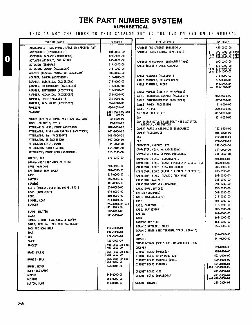
TEK PART NUMBER SYSTEM ALPHABETICAL
T H I S I S N O T T H E I N D E X T O T H I S C A T A L O G B U T T O T H E T E K P N S Y S T E M I N G E N E R A L
TYPE OF PARTS
ACCESSORIES - SEE PROBE, CABLE OR SPECIFIC PART
ACCESSORIES (SPECTROMETER) ACCESSORY PACKAGE (INSTRUMENT) ACTUATOR ASSEMBLY. CAM SWITCH ACTUATOR (GENERAL) ACTUATOR, W R A (ACCESSORY)
ADAPTER (GENERAL PARTS, NOT ACCESSORY)
AOAPTER, CAMERA (ACCESSORY)
ADAPTER, ELECTRICAL (ACCESSORY)
WAPTER, GR CONNECTOR (ACCESSORY)
ADAPTER, INSTRUMENT (ACCESSORY)
ADAPTER, MECHANICAL (ACCESSORY)
ADAPTER, PROBE (ACCESSORY)
ADAPTER, RACK MOUNT (ACCESSORY)
ADHESIVE
ALUMINUM
ANGLES (SEE ALSO FRAME AN0 FRAME SECTIONS)
ANVIL (SOLENOID. ETC. ATTENUATION HEAD, PROBE (ACCESSORY) ATTENUATOR. FIXEO AND VARIABLE (ACCESSORY) ATTENUATOR, Jmn (ACCESSORY) ATTENUATOR, GR (ACCESSORY) ATTENUATOR STRIP, DUMY ATTENUATOR, TURRET SWITCH ATTENUATOR, PROBE HEAD (ACCESSORY)
BAFFLE, A IR BANANA JACK (SEE JACK OR PLUG)
VAN0 (CIARKING) BAR (OTHER THAN BULK)
BASE
BATTERY
BEARING
BELTS (PULLEY, POSITIVE DRIVE, ETC.)
BEZEL (ACCESSORY) BEZEL BINDER, LOAD BLADDER
BLADE, SHUTTER
BLOCK
BOARD, CIRCUIT (SEE CIRCUIT BOARO) B M O . TERMINAL (SEE TERMINAL BOARD) BODY bND BODY HALF BOLT
BOX BRACE
BRACKET
BRASS (BULK)
BRMZE (BULK)
BRUSH, MOTOR
BULB (SEE LAW) BUMPER
BUSHING BUTTON, PLUG
CATEGORY
016-1000-00
020-0000-00 263-1000-00 214-0000-00
016-0200-00
103-0000-00
016-0200-00
0 1 3-0000-00
0 1 7-0000-00
015-0000-00
014-0000-00
0 1 5-0000-00
016-0000-00
006-0000-00
251-0000-00 ant 251-1000-00
334-0000-00
381 -0000-00
432-0000-00
146-0000-00
401 -0000-00
214-0000-00
014-0000-00 200-0000-00 214-0000-00 214-0000-00 and 341 -0000-00 122-0000-00
391-0000-00
202-0000-00
122-0000-00
I 406-0000-00 and 407-0000-00
I 251 -0300-00 and 258-0300-00
I 251 -0300-00 and 258-0300-00
TYPE OF PARTS
CABINET AND CABINET SUBASSEMBLY CABINET PARTS (SIDES, TOPS, ETC.)
CABINET WRAPAROUND (INSTRUMENT TYPE)
CABLE (BULK) 6 CABLE ASSEMBLY
CABLE ASSEMBLY (ACCESSORY)
CABLE ASSEMBLY, GR (ASSEMBLY)
CABLE ASSEMBLY, PROBE
CABLE HARNESS (SEE WIRING HARNESS)
CABLE, ELECTRODE ADAPTER (ACCESSORY)
CABLE, INTERCONNECTING (ACCESSORY)
CABLE, POWER (PROCESSED)
CABLE, NIPPLE
CALIBRATION FIXTURES
CAM CAM SWITCH ACTUATOR ASSEMBLY (SEE ACTUATOR
ASSEMBLY, CAM SWITCH) CAMERA PARTS I ASSEMBLIES (PURCHASED) CAMERA ACCESSORIES CAN CAP CAPACITOR, CHECKED, ETC.
YPACITOR, COUPLING (ACCESSORY) YPACITOR, FIXED CERAMIC OIELECTRIC
APACITOR. FIXEO, ELECTROLYTIC :APACITOR, FIXED (GLASS 6 PORCELAIN OIELECTRIC)
:APACITOR, FIXEO, MICA OIELECTRIC :APACITOR, FIXED (PLASTIC 6 PAPER OIELECTRIC)
XPACITOR. FIXEO, PLASTIC (TEK-MADE)
:APACITOR, VARIABLE :APACITOR WINDINGS ( TEK-MADE)
:APACITORS, MATCHED
:ARTON (SHIPPING) ARTS (OSCILLOSCOPE)
:ASE ASE . CARRYING
:ASE, TRANSISTOR :ASTER
:ATCH ATHOOE RAY TUBE
:ERAMIC MATERIAL (BULK) :ERAMIC STRIP (SEE TERMINAL STRIP, CERAMIC)
:HAIN
LHASS I S HA5SIS-TRACK (SEE SLIDE, RM AND GUIDES RM)
HOPPER IRCUIT BOARO (UNWIREO)
IRCUIT BOARO ( 2 o r MORE 670-1
IRCUIT BOARO ASSEMBLY (WIRED) IRCUIT BOARO ASSEMBLY
IRCUIT BOARO KITS
IRCUIT BOARD SUBASSEMBLY
IRCUIT BREAKER
CATEGORY
437-0000-00
390-0000-00 (ne and 386-0000-00 01 and 387-0000-00 101
390-0000-00
I 175-0000-00 and 175-0499-00 and 175-1000-00
012-0000-00
175-0000-00 [and 175-1000-00
l22-O5OO-OO 016-0200-00 202-0000-00
200-0000-00 295-0000-00
0 1 1 -0000-00 281 -0500-00
290-0000-00 285-0000-00 283-0500-00 285-0500-00
291 -0000-00
281 -0000-00
291 -0200-00
295-0000-00 004-0000-00 016-0000-00
202-0000-00 016-0000-00 202-0000-00 401 -0000-00 105-0000-00
154-0000-00
256-0000-00
214-0000-00 441 -0000-00
119-0000-00
388-0500-00 672-0000-00 670-0000-00
675-0000-00 and 700-0000-00
675-0000-00
673-0000-00 and 678-0000-00
260-0000-00
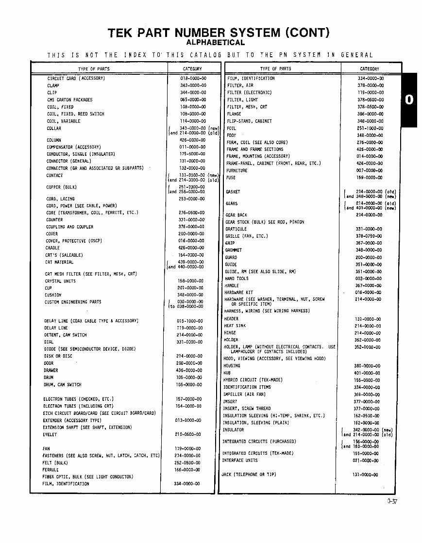
TEK PART NUMBER SYSTEM (CONT) ALPHABETICAL
T H I S I S N O T T H E I N D E X T O ' T H I S C A T A L O G B U T T O T H E P N S Y S T E M I N G E N E R A L
TYPE OF PARTS
C I R C U I T CAR0 ( ACCESSORY)
CLAMP
C L I P
CMS CARTON PACKAGES
COIL, F IXEO
COIL , F IXEO, REED SWITCH
COIL , VARIABLE
COLLAR
C O L U M
COMPENSATOR (ACCESSORY)
CONOUCTOR. S INGLE (INSULATED)
CONNECTOR (GENERAL)
CONNECTOR (GR AND ASSOCIATED GR SUBPARTS)
CONTACT
COPPER (BULK)
CORO, LACING
CORO, POWER (SEE CABLE, POWER)
CORE (TRANSFORMER, C O I L , FERRITE, ETC.)
COUNTER
COUPLING AND COUPLER
COVER
COVER, PROTECTIVE (OSCP)
CRADLE
CRT'S (SALEABLE)
CRT MATERIAL
CRT MESH F I L T E R (SEE F ILTER, MESH, CRT)
CRYSTAL UNITS
CUP
CUSHION
CUSTOM ENGINEERING PARTS
OELAY L I N E (COAX CABLE TYPE 6 ACCESSORY)
OELAY L I N E
OETENT, CAM SWITCH
D I A L
DIODE (SEE SEMICONDUCTOR DEVICE, DIODE)
D I S K OR D I S C
DOOR
DRAWER
ORUM
ORUM, CAM SWITCH
ELECTRON TUBES (CHECKED. ETC.)
ELECTRON TUBES ( INCLUDING CRT)
ETCH C I R C U I T BOARO/CARO (SEE C I R C U I T BOARO/CARO)
EXTENDER (ACCESSORY TYPE)
EXTENSION S M F T (SEE SHAFT, EXTENSION)
EYELET
FAN
FASTENERS (SEE ALSO SCREW, NUT. LATCH, CATCH, ETC)
FELT (BULK)
FERRULE
FIBER OPTIC, BULK (SEE L IGHT CONDUCTOR) F ILM, IDENTIFICATION
-
CATEGORY
1 1 4 - 0 0 0 0 - 0 0
1 3 4 3 - 0 0 0 0 - 0 0 ( n l a n d 2 1 4 - 0 0 0 0 - 0 0 (o
4 2 6 - 0 0 0 0 - 0 0
0 1 1 - 0 0 0 0 - 0 0 1 7 5 - 5 0 0 0 - 0 0
1 3 1 - 0 0 0 0 - 0 0
1 3 2 - 0 0 0 0 - 0 0
1 3 1 - 0 0 0 0 - 0 0 ( n ~ a n d 2 1 4 - 0 0 0 0 - 0 0 ( 0
2 5 1 - 0 3 0 0 - 0 0 a n d 2 5 8 - 0 3 0 0 - 0 0
2 5 3 - 0 0 0 0 - 0 0
2 7 6 - 0 5 0 0 - 0 0
3 3 1 - 0 0 0 0 - 0 0 3 7 6 - 0 0 0 0 - 0 0
2 0 0 - 0 0 0 0 - 0 0
0 1 6 - 0 0 0 0 - 0 0
4 2 6 - 0 0 0 0 - 0 0
1 5 4 - 0 0 0 0 - 0 0
4 3 9 - 0 0 0 0 - 0 0 3nd 4 4 0 - 0 0 0 0 - 0 0
158-OWO-00
2 0 1 - 0 0 0 0 - W
3 4 8 - 0 0 0 0 - 0 0 I 0 3 0 - 0 0 0 0 - 0 0 t o 0 3 8 - 0 0 0 0 - 0 0
0 1 5 - 1 0 0 0 - 0 0
1 1 9 - 0 0 0 0 - 0 0
2 1 4 - 0 0 0 0 - 0 0
3 3 1 - 0 0 0 0 - 0 0
2 1 4 - 0 0 0 0 - 0 0
2 0 0 - 0 0 0 0 - 0 0
4 3 6 - 0 0 0 0 - 0 0
1 0 5 - 0 0 0 0 - 0 0
1 0 5 - 0 0 0 0 - 0 0
1 5 7 - 0 0 0 0 - 0 0
1 5 4 - 0 0 0 0 - 0 0
0 1 3 - 0 0 0 0 - 0 0
2 1 0 - 0 6 0 0 - 0 0
1 1 9 - 0 0 0 0 - 0 0
2 1 4 - 0 0 0 0 - 0 0
2 5 2 - 0 5 0 0 - 0 0
1 6 6 - 0 0 0 0 - 0 0
3 3 4 - 0 0 0 0 - 0 0
TYPE OF PARTS
FILM, I D E N T I F I C A T I O N
FILTER, A I R
F I L T E R (ELECTRONIC)
F ILTER, L I G H T
F ILTER, MESH, CRT
FLANGE
FLIP-STAND, CABINET
F O I L
FOOT
FORM, COIL (SEE ALSO CORE)
FRAME AND F M E SECTIONS
FRAME, MOUNTING (ACCESSORY)
FRAME-PANEL, CABINET (FRONT. REAR. ETC.)
FURNITURE
FUSE
GASKET
GEARS
GEAR BACK
;EAR STOCK (BULK) SEE ROO, P I N I O N
SRATICULE
;RILLE (FAN, ETC.)
;RIP
%OFMET
U A R O
XJIOE
iUIOE. RM (SEE ALSO SLIDE, RM)
{AND TOOLS IANOLE
IAROWARE K I T IAROWARE (SEE WASHER. TERMINAL. NUT, SCREW
OR S P E C I F I C ITEM) IARNESS, WIRING (SEE WIRING HARNESS)
EAOER EAT S I N K
INGE
OLOER
OLOER, LAFlP (WITHOUT ELECTRICAL CONTACTS. US1 LAMPHOLDER I F CONTACTS INCLUDED)
0 0 0 , VIEWING (ACCESSORY, SEE VIEWING HOOD)
OUSING
UB
VBRIO C I R C U I T (TEK-MADE)
DENTIFICATION ITEMS
IPELLER ( A I R FAN)
ISERT
ISERT, SCREW THREAD
ISULATION SLEEVING (HI -TEMP, SHRINK, ETC.)
ISULATION, SLEEVING ( P L A I N )
ISULATOR
ITEGRATEO C I R C U I T S (PURCHASED)
TEGRATEO CIRCUITS (TEK-MADE)
TERFACE U N I T S
CK (TELEPHONE OR T I P )
{ a n d %:!:: [% ( 214-,0000-00 ( o l d
a n d 401-0WO-00 ( n m
3 4 2 - 0 0 0 0 - 0 0 (new) a n d 2 1 4 - 0 0 0 0 - 0 0 ( o l d )
1 5 6 - 0 0 0 0 - 0 0 a n d 1 6 0 - 0 0 0 0 - 0 0
1 5 5 - 0 0 0 0 - 0 0
0 2 1 -0000-00
CATEGORY I 3 3 4 - 0 0 0 0 - 0 0
0 1 4 - 0 0 0 0 - W
1) 1)
1) 1)

TEK PART NUMBER SYSTEM (CONT) ALPHABETICAL
T H I S I S N O T T H E I N D E X T O T H I S C A T A L O G B U T T O T H E T E K P N S Y S T E M I N G E N E R A L
TYPE OF PARTS
KEY (CONNECTOR AN0 LOCK)
KITS, COMBINATION ASSEMBLIES
KITS, CRT SHIELD
KITS, DELAY L INE
KITS, FAN MOTOR KITS, F 6 I KITS, FINAL
KITS, FRAME PLATE KITS, HIGH VOLTAGE POWER
KITS. LOW VOLTAGE POWER
KITS, MISCELLANEOUS
KITS, MISCELLANEOUS AMPLIFIER CHASSIS
KITS, MISCELLANEOUS CHASSIS
KITS, MISCELLANEOUS PLATES
KITS, MISCELLANEOUS SHIELD
KITS. MISCELLANEOUS SIGNAL 6 TRIGGER KITS, MODIFICATION (CS)
KITS, MODULAR KITS, MOUNTING BRACKET KITS, PARTS REPLACEMENT (CS) KITS. PLUG-IN HOUSING KITS, POWER PLUG 6 SOCKETS KITS, RECTIFIER BRACKET KITS. SHIPPING
KITS, SPECIAL EXCHANGE KITS. SPECIAL REPLACEMENT KITS, SUBPANEL
!ITS, SWEEP, DELAY SWEEP KITS, TEST
KITS, TUBE KITS, VERTICAL AMPLIFIER
KNOB KNOB-DIAL ASSEMBLY
KNOB SKIRT (SEE RING, KNOB SKIRT)
LABELS (IDENTIFICATION) LAMPS 6 LIGHTS
LAMP, LEO (LIGHT EMITTING DIODES)
LEAD. SINGLE CONOUCTOR ( INSULATED) LEADS (FORMED, SETS, SPL PATTERNS, ETC. ) LIGHT CONDUCTOR
LINOLEUM
W U A L , TECHNICAL
METER HICROCIRCUIT (TEK-MADE)
MICROCIRCUIT (PURCHASED) MICROCIRCUIT ( P R O G R W B L E MEMORIES)
MOTORS
NOSE, PROBE
NUT
NUT BAR
OFFICE SUPPLIES
WERATING SUPPLIES
W T I C CWONENTS
CATEGORY
214-0000-00
644-0000-00
626-0000-00
636-0000-00
635-0000-00 624-0000-00 602-0000-00
630-0000-00 621-0000-00
620-0000-00
650-0000-00
616-0000-00
610-0000-00
6 3 1 -0000-00
627-0000-00 660-0000-00 040-0000-00
655-0000-00 640-0000-00 050-0000-00
634-0000-00 643-0000-00 637-0000-00 608-0000-00 046-0000-00 045-0000-00 614-0000-00
619-0000-00 606-0000-00
604-0000-00 615-0000-00
366-0000-00 366-0500-00
334-0000-00
150-0000-00 150-1000-00
175-5000-00 195-0000- 0 0
253-0000-00
252-0500-00
070-0000-00 149-0000-00 155-0000-00
156-0000-00 160-0000-00
147-0000-00
206-0000-00
220-0400-00 n d 210-0400-00
220-0400-00
002-0000-00 006-0000-00
122-0500-00
TYPE OF PARTS
OSCILLATORS
OSCILLOSCOPE CART
PA0
PAINT (BULK) PANEL (ETCH & ANODIZED) (FRONT, REAR, ETC.)
PANEL (NOT ANODIZED) (REAR, SUB-, ETC. )
PAPER (BULK) PARTITION
PART REPLACEMENT KITS
PHOTO COMPONENTS
PIGMENT, PLASTIC MOLDING MATERIAL
PIN, CONNECTING (SEE TERMINAL P I N )
P I N PINION ROO (SEE ROO, PINION)
PIVOT ART PLASTIC SHEET AND STRIP, ROO, MOLDING MATERIAL
(ALL BULK) PLATE (IDENTIFICATION AN0 INSTRUCTIONS)
PLATE (MISCELLANEOUS)
PLUG (TELEPHONE OR T I P )
PLUNGER, SOLENOID POINTER POST (ELECTRICAL AN0 MECHANICAL) POT (SEE RESISTOR. VARIABLE) POWER SUPPLY (HV) INTERNAL INST. COMPONENT POWER SUPPLY (ACCESSORY)
PRECIOUS METALS PRINTED MTTER
PROBE PROBE HEADS PROBE PACKAGE
PULLEY (SEE ALSO SPROCKET WHEEL)
PUSHBUTTON/PUSHBUTTON ASSEMBLY
RACK
RAIL RECEPTACLE (CONNECTOR) RECEPTACLE (MECHANICAL ONLY)
RECTIFIER (SELENIUM) RECTIFIER (SEMICONDUCTOR, GENERAL)
RECTIFIER (SEMICONDUCTOR, SELECTED, ETC.)
REDUCER REFLECTOR RELAY RELAY COMPONENTS (TEK-MADE) RELAY, MAGNETIC REEO (SEE ALSO SWITCH, MAG REEO)
REPLACEMENT PARTS FOR PURCHASING ASSEMBLIES
RESILIENT MOUNT RESISTOR (ATTENUATOR STRIPS)
RESISTOR, FIXED, F ILM (CARBON 0.5W)
RESISTOR, FIXEO. F ILM (CARBON 1 .OW)
RESISTOR, FIXEO, F ILM (CARBON 1 .OW)
RESISTOR, FIXEO, F ILM (CARBON 0.125W. 1%)
RESISTOR, FIXED, COMP. (0.125W. 5%) RESISTOR, FIXEO, F ILM (CARBON 0.25W. BELOW 5%)
RESISTOR, FIXEO, COMP. (0.25W, 5%)
CATEGORY
367-0000-00 254-0500-00
and 255-0000-00 334-0000-00 386-0000-00
a n d 387-0000-00
134-0000-00 119-0000-00
331-0000-00 129-0000-00
119-0000-00 016-0000-00
257-0000-00 000-0000-00
010-0000-00 010-0300-00 0 1 0-0000-00
214-0000-00 ( o l d ) and 401-0000-00 (new]
336-0000-00

TEK PART NUMBE ALPHA1
R SYSTEM (CONT) ETICAL
T H I S I S N O T T H E I N D E X T O T H I S C A T A L O G B U T T O T H E T E K P N S Y S T E M I N G E N E R A L -
TYPE OF PARTS
RESISTOR, FIXEO, CWP. (0.25W. 10%)
RESISTOR, FIXED, COMP. (0.5W, 5%)
RESISTOR, FIXED, COMP. (0.5W. 10%)
RESISTOR, FIXED, COMP. (l.OW, 5%) RESISTOR, FIXED, COW. (1.OW. 10%)
RESISTOR, FIXEO, COMP. (2.OW. 5%)
RESISTOR, FIXED, C W . (2.OW, 10%)
RESISTOR, FIXEO, HV (SEE 307-)
RESISTOR - KNOB, MATCHED
RESISTOR (FIXED-MATCHED, SELECTED, SETS. ETC AT TEI RESISTOR. FIXEO, F ILM (METAL F ILM 0.125W. 1% OR
LESS, STANDARD RES. VALUES) RESISTOR, FIXEO, F ILM (METAL F ILM 0.125W. 1% OR
LESS, SPECIAL VALUES) RESISTOR, FIXED. F ILM (METAL F ILM 0.125W. 1% OR
LESS, STANOARD RES. VALUES) RESISTOR, FIXEO, F ILM (METAL F ILM 0.25W. 1% OR
LESS, STANOARD RES. VALUES)
RESISTOR, FIXEO, F I L M (METAL F ILM 0.25WS 1% OR LESS. SPECIAL VALUES)
RESISTOR, FIXEO. F ILM (METAL F ILM 0.25W. 1% OR LESS, STANOARD RES. VALUES)
RESISTOR, FIXEO, F ILM (METAL F I L M 0.5W. 1% OR LESS, STANDARD RES. VALUES)
RESISTOR, FIXED, F ILM (METAL F ILM 0.5W. 1% OR LESS, SPECIAL VALUES)
RESISTOR, FIXED. F ILM (METAL F ILM 0.5W. 1% OR LESS, STANDARD RES. VALUES)
RESISTOR, FIXED, F ILM (METAL F ILM 1 .OW, 1 % OR LESS, STANDARD RES. VALUES)
RESISTOR. FIXED, F ILM (METAL FILM. 1 .OW, 1% OR LESS, SPECIAL VALUES)
RESISTOR, FIXEO. F ILM (METAL F ILM 1.OW. BELOW 1%. STANOARD RES. VALUES)
RESISTOR. FIXEO, F ILM (METAL FILM-MISC. NOT F ITT ING I N 321- THRU 324- CATEGORIES)
RESISTOR, FIXED, F ILM (ALL F ILM NOT F ITT ING I N ANY PRECEDING CATEGORIES)
RESISTOR. FIXEO. FOIL RESISTOR, FIXEO. THICK F ILM RESISTOR. FIXED, WIREWOUND
RESISTOR. VARIABLE RESISTOR, VARIABLE (SELECTED FROM 311- RES. )
RETAINER
RING RING, KNOB SKIRT
RING, RETAINING
RING, TRIM
RIVET
ROD (MISCELLANEOUS)
ROO, PINION'
ROTATING MECHANICAL PARTS ROTOR, VARIABLE RESISTOR
RUBBER (BULK)
SCALE SCREEN SCREW (UP THRU 5-40) SCREW (6 -32 AND SMALLER)
SCREW (8-32) SCREW (10-24. 10-32. 12-24 6 12-32)
SCREW (ABOVE 12-32 6 TAPPING. SETSCREWS. ETC.) SEMICONDUCTOR DEVICE, DIODE
CATEGORY TYPE OF PARTS
SEMICONDUCTOR DEVICE, DIODE (CHECKED, ETC.)
SETSCREW
SHAFT, EXTENSION 6 SPACING
SHAFT (OTHER) SHEET, NON-METALLIC (PAPER, FELT, LINOLEUM,
PLASTIC)
SHELF
SHELL (GENERAL)
SHELL, KNOB SHIELD (ELECTRICAL AND MECHANICAL) SHIELD, IMPLOSION SHIELDING GASKET, ELECTRICAL SHIM
SHIPPING SUPPLIES SHOCKMOUNT SHUTTER (CAMEM)
SILICON WAFERS SLEEVE (MARKING) SLEEVE, SPACER SLIDE
SLIDE, RM SLIDE, GUIDE, RM (ASSEMBLY) SLUG (CORE)
SOCKET
SOLDER (BULK)
SOLDER LUG (SEE TERMINAL, LUG) SOLENOID SPACER (THREADED) SPACER (UNTHREADED)
SPARES LISTS. INTERNATIONAL SPECIAL PRINTED ITEMS
SPRING
SPROCKET WHEEL STAINLESS STEEL (BULK) STANOAROIZERS (ACCESSORY)
STEEL (BULK) STEM ST1 FFENER
STOP STRAIN RELIEF (SEE BUSHING)
STRAP
STRIKE STRIP (CERAMIC TRIM, FELT, TRIM METAL. RUBBER* ETC-
STUD
SUBPANEL
SUBSTRATE
SUPPORT
SWITCH, PURCHASED SWITCH, MAGNETIC REED
SWITCH (WIRED)
SWITCHES, TEK-MOEI OTHER THAN CAM (OPTICAL, M8S PANCAKE AND TURRET)
SWITCH ASSEMBLY, TEK-MADE, OTHER THAN CAM (OPTICAL MBS, PANCAKE AND TURRET
SWITCHES , TEK-MDE s CAM SWITCH ASSEMBLY, TEK-MDE , SYSTEM PARTS
CATEGORY
153-0000-00
3 8 6 - 0 0 0 0 4 0 and 387-0000-00
204-0000-00 386-0000-00 m d 387-0000-00
260-0000-00 260-0000-00
262-OOW-00 263-0000-00
263-0000-00
263-1000-00 163-1600-00 339-0000-00
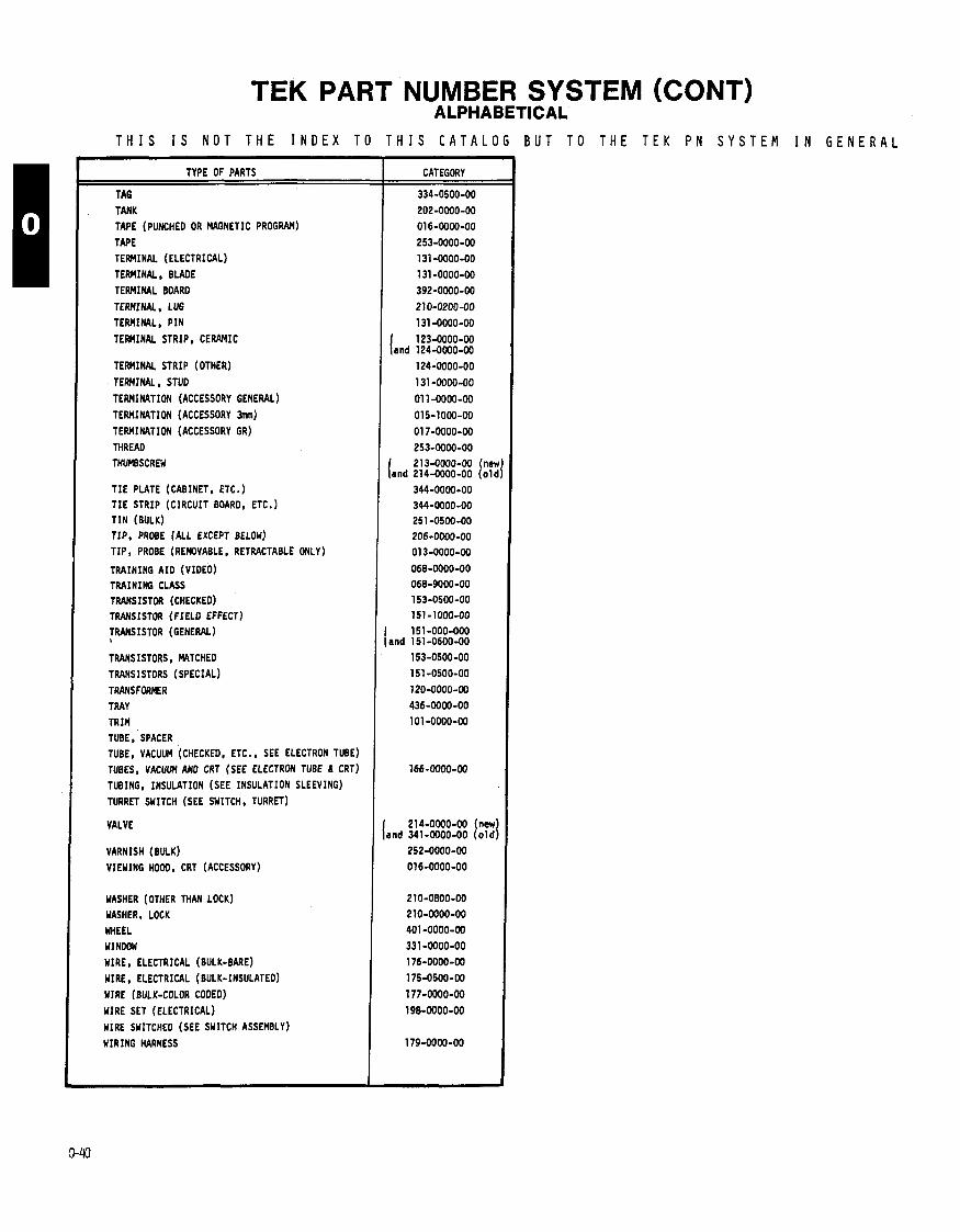
TEK PART NUMBER SYSTEM (CONT) ALPHABETICAL
T H I S I S N O T T H E I N D E X T O T H I S C A T A L O G B U T T O T H E T E K P N S Y S T E M I N G E N E R A L
TYPE OF PARTS
TA6
TANK TAPE (PUNCHED OR MAGNETIC PROGRAM)
TAPE TERMINAL (ELECTRICAL) TERMINAL. BLADE
TERMINAL BOARD
TERMINAL. LUG TERMINAL, P I N
TERWINAL STRIP, CEWIMIC
TERMINAL STRIP (OTHER)
TERMINAL, STUD
TERMINATION (ACCESSORY GENERAL)
TERMINATION (ACCESSORY 3mn) TERMINATION (ACCESSORY GR)
THREAD THW8SCRM
T I E PLATE (CABINET, ETC.) T I E STRIP (CIRCUIT BOARD, ETC.) T I N (BULK) TIP, PROBE (ALL EXCEPT BELOW) TIP, PROBE (REMOVABLE, RETRACTABLE ONLY)
TRAINING A ID (VIDEO) TRAINING CLASS TRANSISTOR (CHECKED) TRANSISTOR (FIELD EFFECT) TRANSISTOR (GENERAL) , TRANSISTORS, MATCHED TRANSISTORS (SPECIAL)
TRANSFORMER TRAY TRIM TUBE, SPACER TUBE, VACUUM (CHECKED, ETC., SEE ELECTRON TUBE)
TUBES, VACUUM AN0 CRT (SEE ELECTRON TUBE 6 CRT) TUBING, INSULATION (SEE INSULATION SLEWING)
TURRET SWITCH (SEE SWITCH, TURRET)
VALVE
VARNISH (BULK) V I EWING HOW. CRT (ACCESSORY)
WASHER (OTHER M A N LOCK) WASHER, LOCK
WHEEL WINDOW WIRE, ELECTRICAL (BULK-BARE)
WIRE, ELECTRICAL (BULK-INSULATED) WIRE (BULK-COLOR COOED)
WIRE SET (ELECTRICAL) WIRE SWITCHED (SEE SWITCH ASSEMBLY)
WIRING HARNESS
CATEGORY
334-0500-00
202-0000-00 016-0000-00
253-0000-00
131 -0000-00
131-0000-00 392-0000-00
210-0200-00
131 -0000-00
[and ~ k ? ~ ~ : ~ 124-0000-00
131 -0000-00
01 1-0000-00
015-1000-00
01 7-0000-00
253-0000-00 ( 213-0000-00 (ner and 214-0000-00 ( o l c
344-0000-00 344-0000-00 251-0500-00 206-0000-00 01 3-0000-00
068-0000-00 068-9000-00 153-0500-00 151-1000-00 151 -000-000
and 151 -0600-00
153-0500-00
151 -0500-00
120-0000-00 436-0000-00 101 -0000-00
214-0000-00 new' m d 341-0000-00 [ o l d :
252-0000-00
016-0000-00
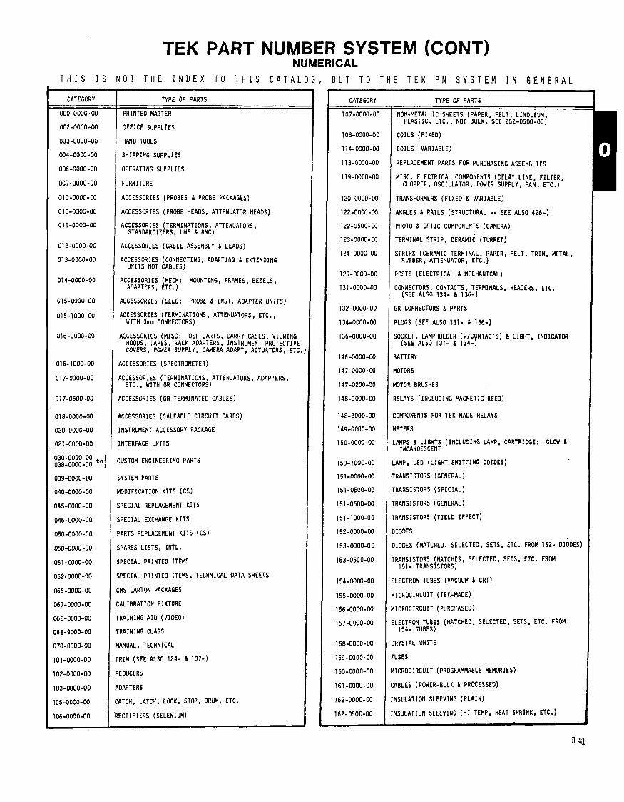
TEK PART NUMBER SYSTEM (CONT) NUMERICAL
T H I S I S N O T T H E I N D E X T O T H I S C 4 T A L O G , B U T T O T H E T E K P N S Y S T E M I N G E N E R A L ----
CATEGORY
- -
TYPE OF PARTS
PRINTED MATTER
OFFICE SUPPLIES
HAND TOOLS
SHIPPING SUPPLIES
OPERATING SUPPLIES
FURNITURE
ACCESSORIES (PROBES I PROBE PACKAGES)
ACCESSORIES (PROBE HEADS, ATTENUATOR HEADS)
ACCESSORIES (TERMINATIONS, ATTENUATORS, STANOARDIZERS. UHF I BNC)
ACCESSORIES (.CABLE ASSEMBLY I LEADS)
ACCESSORIES (CONNECTING, ADAPTING I EXTENDING UNITS NOT CABLES)
ACCESSORIES ( M E W : MOUNTING, FRAMES, BEZELS, AOAPTERS, ETC . )
ACCESSORIES (ELEC: PROBE I INST. ADAPTER U N I T S )
KCESSORIES (TERMINATIONS, ATTENWTORS, ETC., WITH 3mn CONNECTORS)
KCESSORIES (MISC: OSP CARTS, CARRY CASES, VIEWING HOODS, TAPES, RACK ADAPTERS, INSTRUMENT PROTECTIVE COVERS, POWER SUPPLY, CAMERA ADAPT, ACTUATORS, ETC.
KCESSORIES (SPECTROMETER)
KCESSORIES (TERMINATIONS, ATTENUATORS , ADAPTERS, ETC., WITH GR CONNECTORS)
\CCESSORIES (GR TERMINATED CABLES)
CCESSORIES (SALEABLE C I R C U I T CARDS)
NSTRUMENT ACCESSORY PACKAGE
NTERFACE UNITS
USTOM ENGINEERING PARTS
YSTEM PARTS
D O I F I C A T I O N K I T S (CS)
P E C I A L REPLACEMENT K I T S
PECIAL EXCHANGE K I T S
ARTS REPLACEMENT K I T S (CS)
PARES L I S T S , I N T L .
PECIAL PRINTED ITEMS
PECIAL PRINTED ITEMS, TECHNICAL DATA SHEETS
MS CARTON PACKAGES
RLIBRATION FIXTURE
RAINING A I D (V IDEO)
RAINING CLASS
4NUAL. TECHNICAL
I I M (SEE ALSO 1 2 4 - 6 1 0 7 - 1
IDUCERS
IAPTERS
ITCH, LATCH, LOCK, STOP. DRUM, ETC.
XTIFIERS (SELENIUM)
CATEGORY
1 0 7 - 0 0 0 0 - 0 0
1 0 8 - 0 0 0 0 - 0 0
1 1 4 - 0 0 0 0 - 0 0
1 1 8 - 0 0 0 0 - 0 0
1 1 9 - 0 0 0 0 - 0 0
1 2 0 - 0 0 0 0 - 0 0
1 2 2 - 0 0 0 0 - 0 0
1 2 2 - 0 5 0 0 - 0 0
1 2 3 - 0 0 0 0 - 0 0
1 2 4 - 0 0 0 0 - 0 0
1 2 9 - 0 0 0 0 - 0 0
1 3 1 - 0 0 0 0 - 0 0
1 3 2 - 0 0 0 0 - 0 0
1 3 4 - 0 0 0 0 - 0 0
1 3 6 -0000-00
1 4 6 - 0 0 0 0 - 0 0
1 4 7 - 0 0 0 0 - 0 0
1 4 7 - 0 2 0 0 - 0 0
1 4 8 - 0 0 0 0 - 0 0
1 4 8 - 3 0 0 0 - 0 0
1 4 9 - 0 0 0 0 - 0 0
1 5 0 - 0 0 0 0 - 0 0
1 5 0 - 1 0 0 0 - 0 0
1 5 1 - 0 0 0 0 - 0 0
1 5 1 - 0 5 0 0 - 0 0
1 5 1 - 0 6 0 0 - 0 0
1 5 1 - 1 0 0 0 - 0 0
1 5 2 - 0 0 0 0 - 0 0
1 5 3 - 0 0 0 0 - 0 0
l53-O5OO-OO
1 5 4 - 0 0 0 0 - 0 0
1 5 5 - 0 0 0 0 - 0 0
1 5 6 - 0 0 0 0 - 0 0
TYPE OF PARTS
NON-METALLIC SHEETS (PAPER, FELT, LINOLEUM. PLASTIC, ETC., NOT BULK. SEE 2 5 2 - 0 5 0 0 - 0 0 )
COILS ( F I X E D )
COILS (VARIABLE)
REPLACEMENT PARTS FOR PURCHASING ASSEMBLIES
MISC. ELECTRICAL COMPONENTS (DELAY L I N E , F I L r E R , CHOPPER, OSCILLATOR. POWER SUPPLY, FAN. ETC. )
TRANSFORMERS ( F I X E D 6 VARIABLE)
ANGLES I R A I L S (STRUCTURAL -- SEE ALSO 4 2 6 - )
PHOTO 6 OPTIC COMPONENTS (CAMERA)
TERMINAL STRIP, CERAMIC (TURRET)
STRIPS (CERAMIC TERMINAL, PAPER, FELT, TRIM, METAL, RUBBER. ATTENUATOR, ETC. )
POSTS (ELECTRICAL 6 MECHANICAL)
CONNECTORS, CONTACTS. TERMINALS, HEADERS. ETC. (SEE ALSO 1 3 4 - 6 1 3 6 - )
;R CONNECTORS 6 PARTS
'LUGS (SEE ALSO 1 3 1 - 6 1 3 6 - )
jOCKET, LAMPHOLDER (WKONTACTS) 6 LIGHT, INDICATOR (SEE ALSO 1 3 1 - 6 1 3 4 - )
IATTERY
IOTORS
MTOR BRUSHES
IELAYS (INCLUOING MAGNETIC REED)
:OMPONENTS FOR TEK-MADE RELAYS
IETERS
AMPS 6 L IGHTS ( INCLUOING LAMP, CARTRIDGE: GLOW h INCANDESCENT
AMP, LEO ( L I G H T E M I T T I N G DOIDES)
RANSISTORS (GENERAL)
RANSISTORS (SPECIAL)
RANSISTORS (GENERAL )
RANSISTORS ( F I E L D EFFECT)
IOOES
IOOES (MATCHED, SELECTED, SETS, ETC. FROM 1 5 2 - DIODES)
RANSISTORS (MATCHES, SELECTED, SETS, ETC. FROM 1 5 1 - TRANSISTORS)
LECTRON TUBES (VACUUM 6 CRT)
ICROCIRCUIT (TEK-MADE)
ICROCIRCUIT (PURCHASED)
ELECTRON TUBES (MATCHED, SELECTED, SETS. ETC. FROM 1 5 4 - TUBES)
CRYSTAL UNITS
FUSES
YICROCIRCUIT (PROGRAMMABLE MEMORIES)
LABLES (POWER-BULK 6 PROCESSED)
INSULATION SLEEVING ( P L A I N )
INSULATION SLEEVING ( H I TEMP, HEAT SHRINK, ETC.)
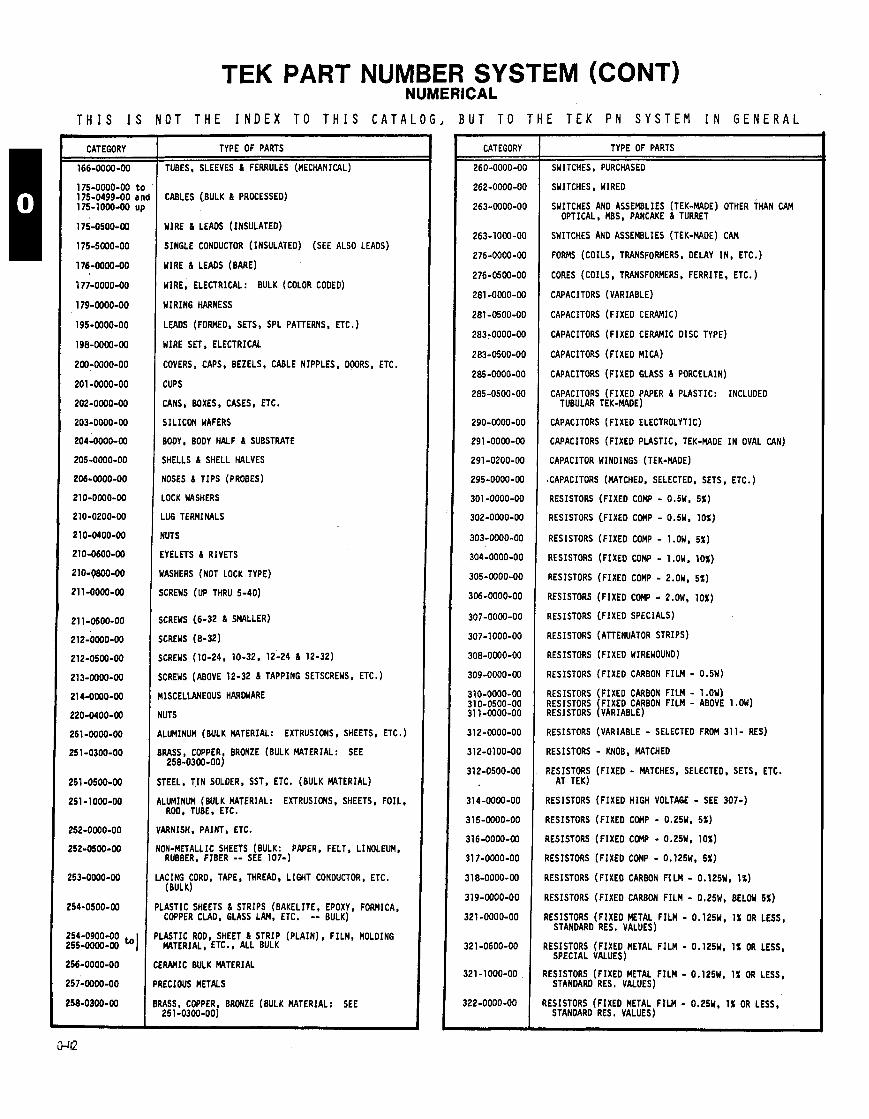
TEK PART NUMBER SYSTEM (CONT) NUMERICAL
T H I S I S N O T T H E I N D E X T O T H I S C A T A L O G , B U T T O T H E T E K P N S Y S T E M I N G E N E R A L
CATEGORY
166-0000-00
175-0000-00 t 175-0499-00 a 175-1000-00 u
TYPE OF PARTS
TUBES, SLEEVES 6 FERRULES (MECHANICPIL)
CABLES (.BULK 6 PROCESSED)
WIRE 6 LEADS (INSULATED)
SINGLE CONDUCTOR (INSULATED) (SEE ALSO LEADS)
WIRE 6 LEADS (BARE)
WIRE, ELECTRICAL: BULK (COLOR CODED)
WIRING HARNESS
LEADS (FORMED, SETS, SPL PATTERNS, ETC.)
WIRE SET, ELECTRICAL
COVERS, CAPS, BEZELS, CABLE NIPPLES. DOORS, ETC.
CUPS
CANS, BOXES, CASES, ETC.
SIL ICON WAFERS
BODY, BODY HALF 6 SUBSTRATE
SHELLS 6 SHELL HALVES
NOSES 6 T IPS (PROBES)
LOCK WASHERS
LUG TERMINALS
NUTS
EYELETS 6 RIVETS
JASHERS (NOT LOCK TYPE)
XREWS (UP THRU 5-40)
;CREWS (6 -32 6 SMALLER)
;CREWS (8-32)
;CREWS (10-24, 10-32, 12 -24 & 12-32)
;CREWS (ABOVE 12-32 6 TAPPING SETSCREWS, ETC.)
IISCELLANEOUS HARDWARE
IUTS
iLUMINUM (BULK MTERIAL : EXTRUSIONS, SHEETS. ETC.)
IRKS , COPPER, BRONZE (BULK MATERIAL: SEE 258-0300-00)
TEEL, T I N SOLDER, SST, ETC. (BULK MATERIAL)
LUMINUM (BULK MATERIAL: EXTRUSIONS, SHEETS, FOIL, ROD, TUBE, ETC.
ARNISH. PAINT, ETC.
NON-METALLIC SHEETS (BULK: PAPER, FELT, LINOLEUM, RUBBER, FIBER -- SEE 107-1
I LACING CORD, TAPE, THREAD, LIGHT CONDUCTOR, ETC. (BULK)
PLASTIC SHEETS 6 STRIPS (BAKELITE, EPOXY, FORMICA, COPPER CLAD, GLASS LAM, ETC. -- BULK)
'LASTIC ROD, SHEET 6 STRIP (PLAIN) , FILM, MOLDING MTERIAL , ETC., ALL BULK
X W I C BULK MATERIAL
'RECIOUS METALS
IRASS, COPPER, BRONZE (BULK MATERIAL: SEE 251-0300-00)
CATEGORY
260-0000-00
262-0000-00
263-0000-00
263-1000-00
276-0000-00
276-0500-00
281 -0000-00
2 8 1 -0500-00
283-0000-00
283-0500-00
285-0000-00
285-0500-00
290-0000-00
291 -0000-00
291 -0200-00
295-0000-00
301 -0000-00
302-0000-00
303-0000-00
304-0000-00
305-0000-00
306-0000-00
307-0000-00
307-1000-00
308-0000-00
309-0000-00
310-0000-00 3 1 0-0500-00 3 1 1-0000-00
312-0000-00
312-0100-00
312-0500-00
3 1 4-0000-00
315-0000-00
316-0000-00
3 1 7-0000-00
3 1 8-0000-00
319-0000-00
3 2 1 -0000-00
3 2 1 -0600-00
-
TYPE OF PARTS
SWITCHES. PURCHASED
SWITCHES, WIRED
SWITCHES AND ASSEMBLIES (TEK-MADE) OTHER ~ H A N CAM OPTICAL, M S . PANCAKE 6 TURRET
SWITCHES AND ASSEMBLIES (TEK-MADE) CAM
FORMS (COILS. TRANSFORMERS, DELAY IN , ETC.)
CORES (COILS, TRANSFORMERS, FERRITE, ETC. )
CAPACITORS (VARIABLE)
CAPACITORS (FIXED CERAMIC)
CAPACITORS (FIXED CERAMIC DISC TYPE)
CAPACITORS (FIXED MICA)
CAPACITORS (FIXED GLASS 6 PORCELAIN)
CAPACITORS (FIXEO PAPER 6 PLASTIC: INCLUDED TUBULAR TEK-MADE)
CAPACITORS (FIXED ELECTROLYTIC)
CAPACITORS (FIXED PLASTIC, TEK-MADE I N OVAL CAN)
CAPACITOR WINDINGS (TEK-MADE)
.CAPACITORS (MATCHED, SELECTED, SETS, ETC.)
RESISTORS (FIXED COMP - 0.5W. 5%)
RESISTORS (FIXED CGMP - 0.5W, 10%)
RESISTORS (FIXED COMP - 1 .OW, 5%)
RESISTORS (FIXED COM? - 1.OW. 10%)
RESISTORS (FIXED COMP - 2.0w, 5%)
RESISTORS (FIXED COMP - 2.OW. 10%)
RESISTORS (FIXEO SPECIALS)
RESISTORS ( ATTENUATOR STRIPS)
RESISTORS (FIXED WIREWOUND)
RESISTORS (FIXED CARBON F ILM - 0 . 5 ~ )
RESISTORS (FIXED CARBON F I L M - 1.OW) RESISTORS FIXED CARBON F ILM - ABOVE 1 .OW) REs IsToRs IvARIABLE)
RESISTORS (VARIABLE - SELECTED FROM 311 - RES)
RESISTORS - KNOB, MATCHED
RESISTORS (FIXED - MATCHES, SELECTED, SETS, ETC. AT TEK)
RESISTORS (FIXED HIGH VOLTAGE - SEE 307-)
RESISTORS (FIXED COnP - 0.25W. 5%)
?ESISTORS (FIXEO COMP - 0.25W, 10%)
IESISTORS (FIXEO CGMP - 0.125W. 5%)
IESISTORS (FIXEO CARBON F I L M - 0.125W. 1%)
IESISTORS (FIXED CARBON FILM - o a w , BELOW 5%)
I
I
I
f
RESISTORS (FIXED METAL F ILM - 0.125W, 1% OR LESS, SPECIAL VALUES)
{ESISTORS (FIXEO METAL F ILM - 0.125W. 1% OR LESS, STANDARD RES. VALUES)
RESISTORS (FIXED METAL F I L M - 0.125W. 1% OR LESS, STANDARD RES. VALUES)
RESISTORS (FIXED METAL F ILM - 0.25W. 1% OR LESS, STANDARD RES. VALUES)
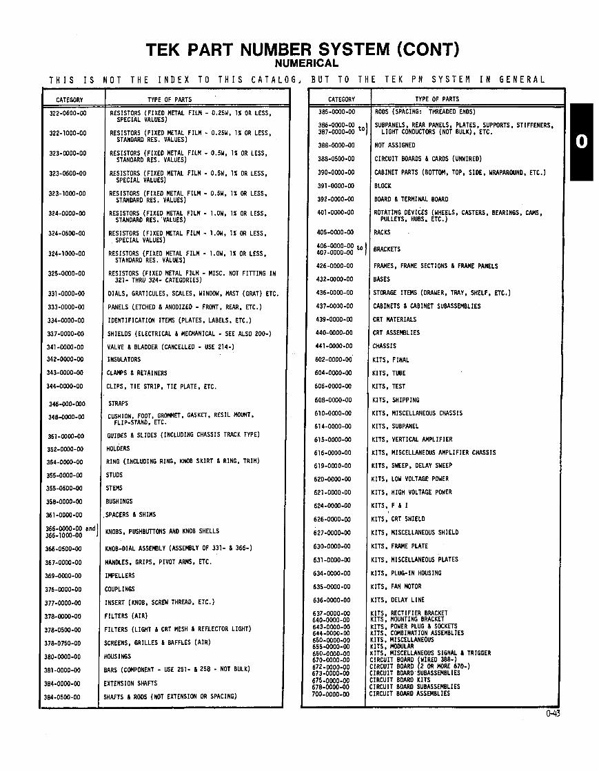
TEK PART NUMBER SYSTEM (CONT) NUMERICAL
T H I S I S N O T T H E I N D E X T O T H I S C A T A L O G , B U T T O T H E T E K P N S Y S T E M I N G E N E R A L
CATEGORY
166-0000-00 and 1 166-1000-00 I
TYPE OF PARTS
RESISTORS (FIXED METAL F ILM - 0.25W. 1% OR LESS, SPECIAL VALUES)
RESISTORS (FIXED METAL F ILM - 0.25W. 1% OR LESS, STANDARD RES. VALUES)
RESISTORS (FIXED METAL F ILM - 0.5W, 1% OR LESS, STANOARD RES . VALUES)
RESISTORS (FIXED METAL F I L M - O.5W. 1% OR LESS, SPECIAL VALUES)
RESISTORS (FIXED METAL F ILM - 0.5W. 1% OR LESS. STANDARD RES . VALUES)
RESISTORS (FIXED METAL F ILM - 1.OW. 1% OR LESS, STANDARD RES. VALUES)
RESISTORS (FIXED METAL F ILM - 1 .OW, 1% OR LESS, SPECIAL VALUES)
RESISTORS (FIXED METAL F I L M - 1 .OW, 1% OR LESS, STANOARD RES. VALUES)
RESISTORS (FIXED METAL FI'LM - MISC. NOT F ITT ING I N 321- THRU 324- CATEGORIES)
BIALS, GRATICULES, SCALES, WINDOW, MAST (GRAT) ETC.
JANELS (ETCHED 6 ANODIZED - FRONT, REAR, ETC.)
[DENTIFICATION ITEMS (PLATES. LABELS, ETC.)
SHIELDS (ELECTRICAL 6 MECHANICAL - SEE ALSO 200-)
fALVE 6 BLADDER (CANCELLED - USE 214-)
:NSULATORS
:LAMPS 6 RETAINERS
,LIPS, T I E STRIP, T I E PLATE, ETC.
STRAPS
iUIDES 6 SLIDES (INCLUDING CHASSIS TRACK TYPE)
IOLDERS
I N G [INCLUDING RING. KNOB SKIRT 6 RING, TRIM)
TUDS
T EMS
USH INGS
PACERS 6 SHIMS
NOBS, PUSHBUTTONS AND KNOB SHELLS
MOB-DIAL ASSEMBLY (ASSEMBLY OF 331- 6 366-)
RNDLES, GRIPS, PIVOT ARMS. ETC.
WELLERS
IUPLINGS
VSERT (KNOB, SCREW THREAD, ETC. )
[LTERS ( A I R )
[LTERS (LIGHT 6 CRT MESH 6 REFLECTOR LIGHT)
:REENS, GRILLES 6 BAFFLES ( A I R )
)USINGS
IRS (COMPONENT - USE 251- 6 2 5 8 - NOT BULK)
(TENSION SHAFTS
IAFTS 6 RODS (NOT EXTENSION OR SPACING)
CATEGORY
385-0000-00
386-0000-00 387-0000-00 t'
388-0000-00
388-0500-00
390-0000-00
391-0000-00
392-0000-00
401 -0000-00
405-0000-00
406-0000-00 t o 407-0000-00
426-0000-00
432-0000-00
436-0000-00
437-0000-00
439-0000-00
440-0000-00
4 4 1 -0000-00
602-0000-00
604-0000-00
606-0000-00
608-0000-00
610-0000-00
6 1 4-0000-00
615-0000-00
616-0000-00
619-0000-00
620-0000-00
621 -0000-00
624-0000-00
626-0000-00
627-0000-00
630-0000-00
6 3 1 -0000-00
634-0000-00
635-0000-00
636-0000-00
637 -0000-00 640-0000-00 643-0000-00 644-0000-00 650-0000-00 655-0000-00 660-0000-00 670-0000-00 672-0000-00 573-0000-00 575-0000-00 578-0000-00 r o o - 0 0 0 0 - w
TYPE OF PARTS
RODS (SPACING: THREADED ENDS)
SUBPANELS , REAR PANELS, PLATES, SUPPORTS, STIFFENERS, LIGHT CONDUCTORS (NOT BULK), ETC.
NOT ASSIGNED
CIRCUIT BOARDS 6 CARDS (UNWIRED)
CABINET PARTS (BOTTOM, TOP, SIDE, WRAPAROUND, ETC.)
BLOCK
BOAR0 6 TERMINAL BOARD
ROTATING DEVICES (WHEELS, CASTERS, BEARINGS, CAMS, PULLEYS, HUBS, ETC. )
RACKS
BRACKETS
FRAMES, FRAME SECTIONS 6 FRAME PANELS
BASES
STORAGE ITEMS (DRAWER, TRAY, SHELF, E X . )
CABINETS 6 CABINET SUBASSEMBLIES
CRT MTERIALS
CRT ASSEMBLIES
CHASSIS
KITS, FINAL
KITS, TUBE
(ITS, TEST
KITS. SHIPPING
(ITS. MISCELLANEOUS CHASSIS
(ITS, SUBPANEL
(ITS, VERTICAL AMPLIFIER
(ITS, MISCELLANEOUS AMPLIFIER CHASSIS
:ITS, SWEEP, DELAY SWEEP
(ITS. LOW VOLTAGE POWER
:ITS, HIGH VOLTAGE POWER
:ITS, F 6 I
(ITS, CRT SHIELD
:ITS, MISCELLANEOUS SHIELD
:ITS, FRAME PLATE
:ITS. MISCELLANEOUS PLATES
:ITS, PLUG-IN HOUSING
:ITS. FAN MOTOR
:ITS, DELAY L INE
, ITS RECTIFIER BRACKET . ITS : MOUNTING BRACKET , ITS POWER PLUG 6 SOCKETS ITS: COMBINATION ASSEMBLIES ITS. MISCELLANEOUS ITS , MODULAR ITS , MISCELLANEOUS SIGNAL 6 TRIGGER IRCUIT BOARD WIRED 388-1 IRCUIT BOARD 1 2 OR MORE 670-) IRCUIT BDARD SUBASSEMBLIES IRCUIT BOARD K ITS IRCUIT BOARD SUBASSEMBLIES IRCUIT BOARD ASSEMBLIES

PARTS AND PRODUCTS STATUS CODES
The fo l lowing de f in i t i ons apply t o the status and source codes presently being
Current Production Engineering Pre-Production Customer Service Non-Production Deleted Obsolete Custom Mod Vendor
input i n t o the Data Base:
Telequipnent Current Production In ternat ional D i g i t a l Systems SonylTek Current Production Obsolescent Modified Par t Last Supply Current Last Supply Customer Service
Current Production (CR) : 1. A f inished product, which has "turned regular" and i s cu r ren t l y being produced i n Beaverton. 2. A component current ly being purchased o r produced i n Beaverton f o r use on a current production f i n i shed product.
Engineering (EN) : An item used exclusively by Engineering which i s not being used on a f in ished product. The i tem may be picked up f o r use i n f u t u r e product.
Pre-Production (PP) : 1. A f in ished product p r i o r t o " turn regular".
2. A component used on an instrument not yet i n current production, o r a component going i n t o a current product v ia an IRS (mod).
Customer Service (CS) : -- A replacement item, not used i n a current production instrument, supported by Customer Service and e i the r stocked i n Customer Service, b u i l t o r supplied f o r them on demand.
Non-Production (NP) : An i tem which i s no longer produced o r purchased and which has replacement.
Deleted (DL) : An item t h a t i s no longer produced o r purchased and which &IS= replacement.
Obsolete (00) : 1. A component which has matured throu h the Lon T e n Product Su o r t Program. The usage has been out o f production f o r 12
years (sometimes l e s s , ~ e d d ) ~ d t ~ a y c o n f ~ n ~ supported through Obsolete Parts Notice 126.
2. An Instrument which i s no longer produced and which has completed the instrument phase-out program.
Custom Mod (CM) : -- 1. An instrument modified t o meet customer speci f icat ions. 2. A component e x c l u s i v e l ~ i n a custom modified instrument.
Vendor (VN) : - A Tek-made o r purchased i tem which requires a vendor operation somewhere i n the processing sequence.
Telequipnent (TC) : An i tem purchased or produced by Telequipnent for use exc lus ive ly T e l e q u i m n t production.
In ternat ional (IN) : An i tem purchased o r produced by Guernsey or Heerenveen f o r use exc lus ive ly i n t h e i r production.
D ig i ta l Systems (DS): An i tem purchased o r produced and usedexc lus ive ly by D i g i t a l Systems.
Sony/Tek (St) : An item purchased or produced by SonylTek for use exc lus ive ly i n Sony/Tek production.
Obsolescent (OT) : An instrument no longer produced which i s i n the process o f saing throu h the Cor orate Instrument Phase-Out Pro ram. Upon canplet ion o f the program, (when the B i l l o f Materials has been pu&thes& c ange t o s &nterim s t i t u s used t o i d e n t i f y the backlog o f products being cleaned up on the new Phase-Out ProgFam. It %l :: be needed once the backlog has been completed.
Modified Par t (MP): -- Number picked up f o r MODS.
Last Supply Current (LR): - NO more parts w i l l be purchased a f t e r these are gone.
Last Supply Customer (LS): - No more parts w i l l be purchased a f t e r these are gone.
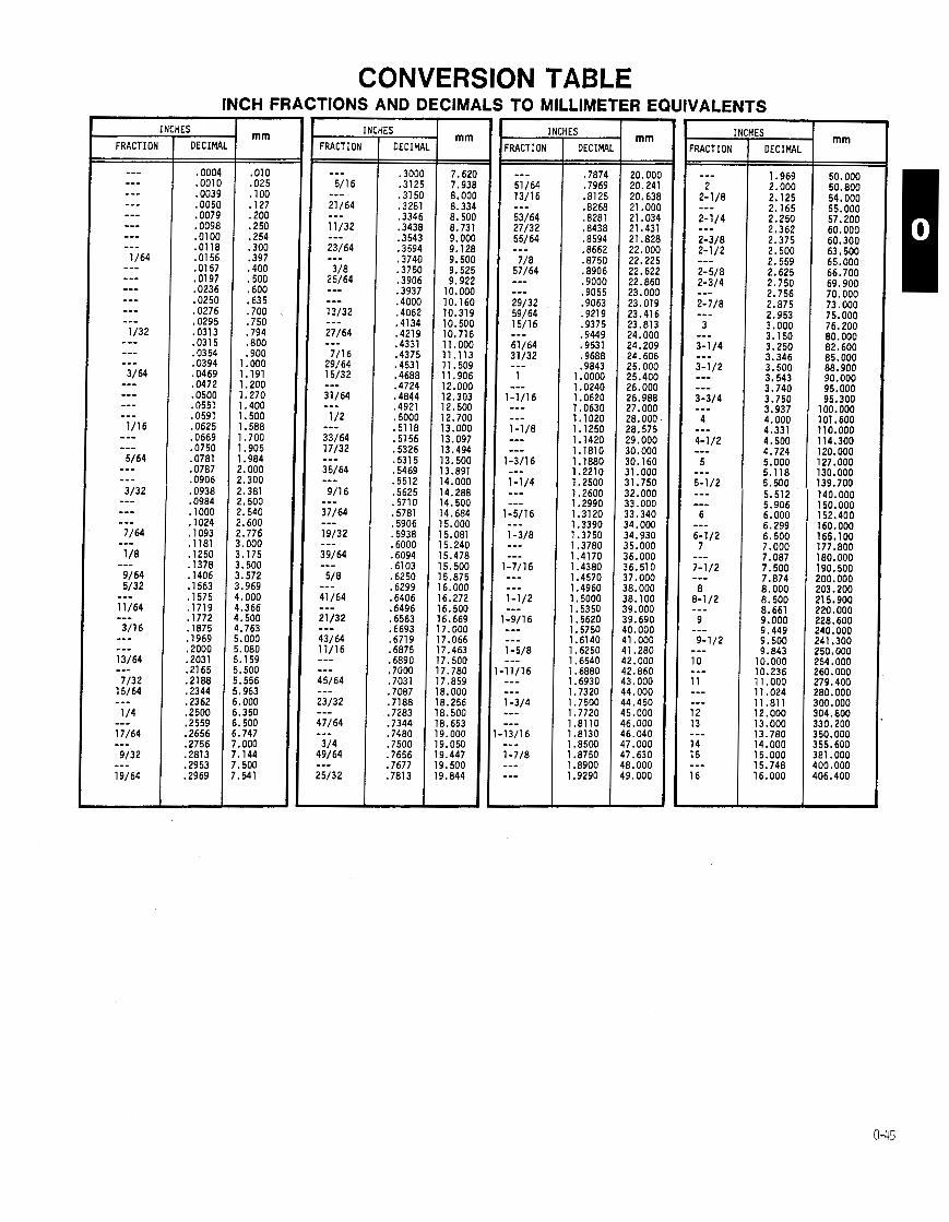
CONVERSION TABLE INCH FRACTIONS AND DECIMALS TO MILLIMETER EQUIVALENTS
FRACTION + IES
DECIW
.300C
.3125
.3lSO ,3281 .3346 .3438 .3543 .3594 .3740 .3750 .3906 .3937 .4000 ,4062 -41 34 .4219 .4331 ,4375 .4531 .4688 .4724 .4844 .4921 .5000 .5118 ,5156 ,5326 .53 l5 .5469 .55 l2 ,5625 .5710 .5781 ,5906 .5938 .6000 .6094 .6103 .6250 .6299 .6406 ,6496 ,6563 .6693 ,6719 .6875 ,6890 ,7000 .7031 .7087 .7188
, .7283 .7344 .7480 .7500 ,7656 .7677 .78 l3
-
ES
OECIMA
.7874
.7969
.a125
.a268 .8281 ,8438 ,8594 .a662 ,8750 ,8906 ,9000 .go55 .go63 .9219 ,9375 .9449 .9531 .9688 .9843
1.0000 1.0240 1.0620 1.0630 1.1020 1 . I250 1.1420 1.1810 1.1880 1.2210 1.2500 1.2600 1.2990 1.3120 1.3390 7.3750 1 ,3780 1 .d l70 1.4380 1.4570 1.4960 1.5000 1.5350 1.5620 1.5750 1.6140 1.6250 1.6540 1 ,6880 1.6930 1.7320 1.7500 1.7720 1.8110 1 .a130 1 .a500 1 .a750 1.8900 1.9290
-
IES
DECIMAL
1.969 2.000 2.125 2.165 2.250 2.362 2.375 2.500 2.559 2.625 2.750 2.756 2.875 2.953 3.000 3.150 3.250 3.346 3.500 3.543 3.740 3.750 3.937 4.000 4.331 4.500 4.724 5.000 5.118 5.500 5.51 2 5.906 6.000 6.299 6.500 7.000 7.087 7.500 7.874 8.000 8.500 8.661 9.000 9.449 9.500 9.843
10.000 10.236 11.000 11 . O N 11.811 12.000 13.000 13.780 14.000 15.000 15.748 16.000

EVALUATION ENGINEER - BUYER LIST
I COMPONENT I COMPONENT ENGINEER I EXT. I PART NUMBER(S) I DIVISION
ABSORBERS, RF
ACTUATOR ASSEMBLIES, PUSHBUTTON
P h i l Lee
Jim Deer
I Katherine Dennett 1 2314 1 006-0000-00 1 DAD
ADAPTERS, ELECTRICAL, GR CONNECTORS, PROBES
2474
2484
ANGLES
ALUMINUM
BAFFLES, AIR
348-0000-00
263-0000-00 I
ATTENUATORS
BANDS, MARKING
DAD
DAD
010-0000-00 01 3-0000-00 132-0000-00
P h i l Lee
Katherine Dennett
BARS, METAL
BATTER1 ES
Central Electro-Mechanical DAD
2474
P h i l Lee
BEARINGS
2314
BELTS (PULLIES)
Be1 l a Geotina 1 2315
2474
122-0000-00
Be l l a Geotina 1 2315 1 381-0000-00 1
DAD
251-0000-00
01 1-0000-00 01 5-0000-00 017-0000-00
John Thomas
Be1 l a Geotina
EMCM, Beaverton
Central Electro-Mechanical DAD
2466
231 5
I I 1
I IDD
Byron W i t t
I I I
John Thomas
378-0000-00
334-0000-00
1 2466 1 214-0000-00 Central Electro-Mechanical I DAD I DD
Central Electro-Mechanical DAD
Central Electro-Mechanical DAD I DD
Central Electro-Mechanical DAD
John Thomas
Central Electro-Mechanical DAD
2479 146-0000-00
2466
BEZELS (~CESSORIES)
BLADDERS
BLADES, SHUTTER
BLOCKS
BOARDS, TERMINAL
BOOY (CONNECTORS)
401-0000-00
BOLTS
Dennis Johnson
John Thomas
Katherine Dennett
Byron W i t t
P h i l Lee
Joe Reshey
BOXES
BRACES
K e l l y Cushing
I I
2471
2466
2314
2479
2474
2313
Byron W i t t
Katherine Dennett
--
BRASS
BRONZE
BRUSHES, MOTOR
BUMPERS
2461
DAD BRACKETS
I I I I
014-0000-00 200-0000-00
214-0000-00 341-0000-00
122-0000-00
39 i -0000-00
392-0000-00
204-0000-00
2479
2314
Be1 l a Geotina
Be l l a Geotina
John Thomas
K e l l y Cushing
I I 1 I
Cent ra l Electro-Mechanical DAD
214-0000-00
John Thomas
Central Electro-Mechanical DAD
I I I 1
I I I VCM, vancouver
DAD EMCM, Beaverton
202-0000-00
122-0000-00
2315
231 5
2466
2461
358-0000-00 BUSHINGS
Central Electro-Mechanical DAD
CABLE ASSEMBLIES (BULK & WIRE)
BUYER I
DAD
2466
134-0000-00 BUTTONS, PLUG
DAD
A l l s t o t t , Ron
E l l i o t t , Dave
406-0000-00 407-0000-00
251-0000-00
2580000-00
147-0000-00
348-0000-00
John Thomas
386-0000-00 387-0000-00
CABINET PARTS
El izabeth D o o l i t t l e
Strand, Karel 05, 1P E l l i o t t , Dave 1 3y
EMCM, Beaverton
EMCM, Beaverton
DAD
Central Electro-Mechanical DAD
2466
K e l l y Cushing
A l l s t o t t , Ron
A l l s t o t t , Ron
Fink, Dennis 06, 3A
2461
Katherine Dennett
1751
Strand, Karel 05, 1P E l l i o t t , Dave 1 3y
2314
E l l i o t t , Dave
390-0000-00
175-0000-00
Webb, Sharon
Stanton, Doug
Central Electro-Mechanical DAD
Webb, Sharon E l l i o t t , Dave
E l l e , Dave
Wacha, V i ck i
E l l e , Dave A1 l s t o t t . Ron Stanton, Doug
__ii_
E l l i o t t . Dave
A l l s t o t t , Ron C o l l i e r , Bob
A l l s t o t t , Ron d Fink, Dennis 06, 3A
I
A l l s t o t t , Ron
E l le , Dave 24, IF. 3 A1 l s t o t t , Ron
A l l s t o t t , Ron
3H
I
E l l i o t t , Dave Gardner, Don 08, 2R
E l le , Dave A l l s t o t t , Ron
24, IF , 3 3H

EVALUATION ENGINEER = BUYER LIST
BUYER BUYER NO. COMPONENT COMPONENT ENGINEER -
EXT. - - 2474
PART NUMBER(S) I DIVISION
I Phi l Lee 01 2-0000-00 Central Electro-Mechanical DAD
CABLES, GPIB Strand, Karel ' 1 ;;, 1P E l l i o t t . Oave
Phi l Lee 175-0000-00 Central Electro-Mechanical 1 OAO Strand, Karel 05, 1P E l l i o t t , Oave Gardner, Don I 08, 2R
CABLES, RF
I VCM, Vancouver I
CABLES, ELECTRICAL ADAPTERS Phi l Lee 01 2-0000-00 Central Electro-Mechanical
161-0000-00 Central Electro-Mechanical
Strand, Dare1 E l l i o t t , Oave
I
CABLES, POWER Dennis Johnson
-
CABLES, NIPPLE I Jim Oeer
CAMS John Thomas
CANS Byron W i t t
CAPS Kelly Cushing
CAPACITORS Aluminum, Tantal um Ceramic
Harry Taniel ian Ray Powell
290-0000-00 Central, Passive Component! 281 -0000-00 DAD 283-0000-00 290-0000-00 281 -0000-00 283-0000-00
Frank, Har r ie t Ware. Donna
Film, E lec t ro l y t i c Variable, Mica
Harry Taniel fan Louis Mahn
Tek-Made (Capaci to rs ) Jim Manuel
CASES Byron W i t t
291-0000-00
202-0000-00 DAD
01 6-0000-00 EMCM. Beaverton, S ~ M
A l l s t o t t , Ron
Pearce, Chuck CASES, CARRYING Byron Witt
CASTERS Kel ly Cushing 401 -0000-00 Central Electro-Mechanical Webb, Sharon Hoffmeister, Marg
CATCHES I 105-0000-00 Central Electro-Mechanical E l le , Oave Hoffmeister, Marg
CERAMIC. BULK & MATERIALS Katherine Oennett
CERAMIC PARTS Bob Rodgers
256-0000-00 1 Technology Group Stucki. Ken
166-0000-00 Techno1 ogy Group 204-0000-00 214-0000-00 307-0000-00 342-0000-00
Perkins, Kathy
CHAINS John Thomas
CHEMICALS Katherine Oennett
I
214-0000-00 Central Electro-Mechanical DAD
Elle. Oave Hoffmeister, M a y Stanton, Ooug
006-0000-00 1 EMCM, Beaverton B a l s i l l i e , Ooug
CIRCUIT BREAKERS Paul Johnson
;LAMPS Paul Johnson
260-0000-00
343-0000-00 Central Electro-Mechanical
344-0000-00 Central Electro-Mechanical
E l l i o t t , Oave
El le , Oave Hoffmei ster, Margc
:LIPS Paul Johnson El le , Oave Hoffmeister, Margc
006-0000-00 EMCM, Beaverton 252-0000-00 256-0000-00 439-0000-00
B a l s i l l i e , Ooug
108-0000-00 I 00 114-0000-00 276-0000-00 Central El ectro-Mechani cal
DAD
Purchased I John Thomas Wetzler, Ron
Tek-Made I Doug Gordon Webb, Sharon E l l i o t t , Oave
I
:OLLARS, CABLE I Jim Deer
:ONNECTORS Phi l Lee Joe Reshey Kel ly Cushing
131 -0000-00 Central Electro-Mechanical 132-0000-00
Strand. Karel E l l i o t t , Oave

EVALUATION ENGINEER - BUYER LIST
I COMPONENT ENGINEER 1 EXT. I PART NUMBER(S) I DIVISION
I CONTACTS I P h i l Lee Central Electro-Mechanical Joe Reshey 214-0000-00 1 DAD Ke l l y Cushing
BUYER
Strand, Karel 05, 1P E l l i o t t , Dave
- - I Be l l a Geotina 251-0000-00 I EMCM, Beaverton I Fink, Dennis I 06, 3A 1 2315 1 258-0000-00
CORDS, LACING Be1 l a Geotina
COUPLINGS Jim Deer I
COVERS Byron W i t t
EMCM, Beaverton, S ~ M
EMCM, Beaverton, S ~ M
331-0000-00
Central Electro-Mechanical
2479 1 016-0000-00 I EMCM, Beaverton, S ~ M 200-0000-00
Pearce, Chuck 19, 1G
E l l i o t t , Dave
Pearce. Chuck 19, 1G
CRT' s John Thomas 2466 154-0000-00 IDD DAD
CRYSTALS Byron W i t t 2479 158-0000-00
Wetzler, Ron E l 1 i o t t , Dave
CUPS Byron W i t t 2479 201 -0000-00
CUSHIONS Katherine Oennett 231 4 348-0000-00 Central Electro-Mechanical E l l e , Dave 24, IF , EMCM, Beaverton, S ~ M Pearce, Chuck 19, 1G
DELAY LINES Byron W i t t 2479 01 5-0000-00 Central , Passive Components Ross, Glenn 03, 10 11 9-0000-00 Central , Passive Components Webb, Sharon 25 175-0000-00 DAD Ware, Donna 32
Dennis Johnson 2471 331 -0000-00 Central , Passive Components DAD Ware, Donna 32
DIE CASTINGS, FRAMES, FRONT PANELS Katherine Dennett 2314 1 426-0000-00 I DO I DAD EMCM, Beaverton
DIODES
Optoelectronics (See LEO'S) Alan Lava l i e 231 7 150-0000-00 DAD High Frequency Steve F i e r r o 2308 152-0000-00 4-Payer Paul Johnson 2473 153-0000-00 A l l Others Steve F i e r r o 2308 156-0000-00
Wacha, V i ck i A l l s t o t t , Ron C o l l i e r , Bob
Ware, Donna -7- I K e l l y Cushing I 2461 I ' 214-0000-00 Central Electro-Mechanical E l l e , Dave I :!. I E l l i o t t , Dave
1 DGLAYS I Alan LaVal le 1 2317 1 150-0000-00 1 DAD 1 Ware, Donna 1 32
I DOORS I Paul Johnson
DRUMS Paul Johnson
2473 200-0000-00 Central Electro-Mechanical E l l e , Dave 24, IF , DAD A l l s t o t t , Ron 3H
2473 105-0000-00 Central Electro-Mechanical E l l e , Dave 24, IF , :
I ELECTRIC COMPONENTS, MISCELLANEOUS Jim Deer
Computer 8 Per iphera ls
Wetzler, Ron
Seed, Jim lH, 4H I I I I I I
EXTENSION SHAFTS Jim Deer 2484 384-0000-00 Central Electro-Mechanical E l l e , Dave 24, IF, : I DO Wacha. V i ck i 46 DAD A l l s t o t t , Ron 3H
EYELETS K e l l y Cushing 2461 21 0-0000-00 Central Electro-Mechanical E l l e , Dave 24, IF , : DAD Hoffmeister, Marge 39
FANS John Thomas 2466 119-0000-00 Central Electro-Mechanical Webb, Sharon 25, 3V, : DAD E l l i o t t , Dave 3Y
FASTENERS I Kel1,y Cvshing 1 2461 ( 214-0000-00 Central Electro-Mechanical E l l e , Dave 1 24, IF , : I OAD I H o f f m i r t e r . Marqe 39
FELT (BULK) Katherine Oennett 2314 252-0000-00 EMCM, Beaverton, S ~ M Pearce, Chuck 19, 1G
FERRITES (CORES) Be1 l a Geotina 2315 276-0000-00 EMCM, Beaverton, S ~ M Pearce, Chuck 19, 1G
FET1s Je r r y W i l l a r d 2538 151-0000-00 Technology Group Stuck i , Ken 20
FIBER OPTICS Louis Mahn 2549 253-0000-00
FILM, ID Be1 1 a Geoti na 231 5 334-0000-00
FILM, PLASTIC Be l l a Geotina 2315 255-0000-00 EMCM, Beaverton, S ~ M Pearce, Chuck 19, 1G VCM, Vancouver Lader. B i l l i e 24, 2P

EVALUATION ENGINEER - BUYER LIST
I COMPONENT COMPONENT ENGINEER EXT. PART NUMBER(S) DIVISION BUYER BUYER NO
C r y s t a l & Saw L i g h t L i n e
FILTERS
A i r Byron Witt 2479 Lou is Mahn Dennis Johnson 1 1 119-000000
John Thomas EMCM, Beaverton, S ~ M Pearce, Chuck 19, 1G C e n t r a l E lec t ro -Mechan ica l Webb, Sharon 25, 3V, : Cent ra l E lec t ro -Mechan ica l E l l e , Dave 24, l F , : Cent ra l , Passive Components Lemas, Dave 03, 10 DAD E l l i o t t , Dave 3Y
DAD H o f f m e i s t e r , Marge 39
C e n t r a l E lec t ro -Mechan ica l E l l e , Dave 24, I F , : DAD A l l s t o t t , Ron 3H
FLANGES
FLIP-STANDS, CAB
I, Be1 l a Geot ina
2466 378-0000-00
Ka ther ine Dennett
Ka ther ine Dennet t
I 2315 1 006-0000-00 252-0000-00 256-0000-00
2314
2314
EMCM, Beaverton B a l s i l l i e , Doug
214-0000-00 I C e n t r a l E lec t ro -Mechan ica l E l l e , Dave 1 2466 1 401-0000-00 I :!, I F , 3
IDD I i t a n t o n , Doug
386-0000-00
348-0000-00
29, 3K, 1
FOOT
FRAME & FRAME SECTION/PANELS
FRONT PANELS (ANODIZED)
FUSES & FUSE HOLDERS
GASKETS
K e l l y Cushing
Ka ther ine Dennett
Ka ther ine Dennett
Dennis Johnson
Ka ther ine Dennet t
I GPlB CABLES I I I I I I
--
GRILLES (FANS, ETC. )
GRIPS
2461
2314
2314
2471
2314
GROMMETS
GUARDS
GUIDES
HAND GRIPS
HAND TOOLS
HANDLES
C e n t r a l E lec t ro -Mechan ica l DAD
012-0000-00 P h i l Lee
John Thomas
Paul Johnson
HARDWARE (WASHERS, NUTS, SCREWS)
HEADERS
I HOLDERS I Joe Reshey 1 2313 1 352-0000-00 1 DAD I A l l s t o t t , Ron I 3H
348-0000-00
014-0000-00 426-0000-00
426-0000-00
159-0000-00
214-0000-00 348-0000-00
2474
K e l l y Cushing
John Thomas
John Thomas
Paul Johnson
K e l l y Cushing
Paul Johnson
HEAT SINKS
- HINGES
1 HOLDERS, LAMPS
St rand , Kare l E l l i o t t , Dave
2466
2473
K e l l y Cushing
K e l l y Cushing
1 2484 / 352-0000-00 C e n t r a l E lec t ro -Mechan ica l Strand, Kare l I DAD 1 E l l i o t t , Dave
EMCM, Beaverton, S ~ M
DAD
DAD
C e n t r a l E lec t ro -Mechan ica l DAD
C e n t r a l E lec t ro -Mechan ica l I DD
05, 1P 3Y
2461
2466
2466
2473
2461
2473
J i m Wi l l i amson
Byron Witt
I HOUSINGS I John Thomas 1 2466 1 380-0000-00 1 I I
378-0000-00
367-0000-00
2461
2461
1 John Thmas 1 2466 1 401-0000-00 1 1 I
Pearce, Chuck
A l l s t o t t , Ron
A l l s t o t t , Ron
S t rand , Kare l E l l i o t t , Dave
E l l e , Dave Stanton, Douq
348-0000-00
200-0000-00
351-0000-00
367-0000-00
003-0000-00
367-0000-00
2552
2479
I IMPELLERS (AIR, FAN) I John Thomas 1 2466 1 369-0000-00 1
19, 1G
3H
3H
05, 1P 3Y
24, l F , 3 35
C e n t r a l E lec t ro -Mechan ica l DAD
C e n t r a l E lec t ro -Mechan ica l DAD
214-0000-00
131-0000-00
I John Thomas I 2466 1 108-0000-00 C e n t r a l , Passive Components Lemas, Dave I DAD I E l l i o t t , Dave
EMCM, Beaverton, S ~ M C e n t r a l E lec t ro -Mechan ica l DAD
C e n t r a l E lec t ro -Mechan ica l DAD
DAD
C e n t r a l E lec t ro -Mechan ica l DAD
DAD
C e n t r a l E lec t ro -Mechan ica l DAD
214-0000-00 342-0000-00
214-0000-00
E l l e , Dave H o f f m e i s t e r , Marge
E l l e , Dave A l l s t o t t , Ron
C e n t r a l E lec t ro -Mechan ica l DAD
C e n t r a l E lec t ro -Mechan ica l Technology Group
24, I F , 3 39
24, I F , 3 3H
Pearce, Chuck E l l e , Dave H o f f m e i s t e r , Marge
E l l e , Dave A l l s t o t t , Ron
A l l s t o t t , Ron
E l l e , Dave A l l s t o t t , Ron
Hoffmei s t e r , Marge
E l l e , Dave A1 l s t o t t , Ron
C e n t r a l E lec t ro -Mechan ica l EMCM, Beaverton
C e n t r a l E lec t ro -Mechan ica l DAD I DD
INSERTS
19, 1G 24, I F , 3 39
24, I F , 3 3H
3H
24, I F , 31 3H
39
24, I F , 31 3H
E l l e , Dave H o f f m e i s t e r , Marge
S t rand , Kare l S t u c k i , Ken
24, I F , 31 39
05, 1P 20
E l l e , Dave F i n k , Dennis
E l l e , Dave A l l s t o t t , Ron Stanton, Douq
K e l l y Cushing
24, I F , 31 06, 3A
24, I F , 3E 3H 3 5
2461 377-0000-00 C e n t r a l Electro-Mechanical DAD
E l l e , Dave 24, I F , 3E A l l s t o t t , Ron 3H
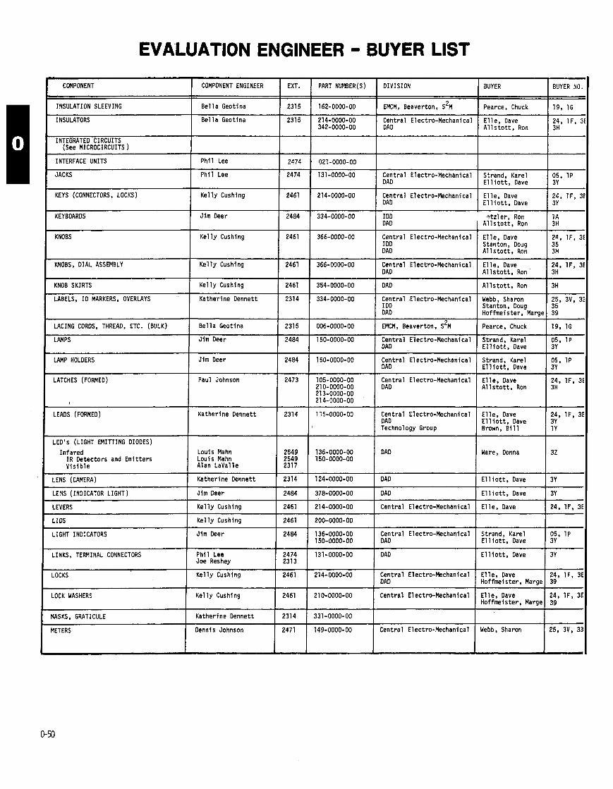
EVALUATION ENGINEER - BUYER LIST
COMPONENT COMPONENT ENGINEER EXT. PART NUMBER(S) DIVISION I I I I
INSULATION SLEEVING
KEYS (CONNECTORS, LOCKS) I Gushing 1 2461 1 214-0000-00 Central Electro-Mechanical 1 DAD
INSULATORS
INTEGRATED CIRCUITS (See MICROCIRCUITS )
INTERFACE UNITS I I I
Be l l a Geotina
231 5
2474
Be1 l a Geotina
P h i l Lee
JACKS
KNOBS
I I I I
K e l l y Cushing
2315
214-0000-00 342-0000-00
021-0000-00
P h i l Lee
KEYBOARDS
1 2461 ( 366-0000-00 I $ral Electro-Mechanical
162-0000-00 I EMCM, Beaverton, S'M
Central El ectro-Mechani ca l DAD
KNOBS, DIAL ASSEMBLY
2474 131-0000-00
Jim Deer
1 2461 1 366-0000-00 Central Electro-Mechanical I DAD
Central Electro-Mechanical DAD
KNOB SKIRTS ( K e l l y Cushing 1 2461 ( 354-0000-00 1 DAD
2484 334-0000-00
LABELS, ID MARKERS, OVERLAYS
IDD DAD
I I I I
LATCHES (FORMED)
Katherine Dennett
LACING CORDS, THREAD, ETC. (BULK)
LAMPS
LAMP HOLDERS
Paul Johnson
Be l l a Geotina 231 5 006-0000-00 I EMCM, Beaverton. S ~ M
I 2473 I 105-0000-00 Central Electro-Mechanical 21 0-0000-00 213-0000-00 21 4-0000-00 / OAD
2314
Jim Deer
Jim Deer
- - - -
LEADS (FORMED) I Katherine Dennett 1 2314 1 135-0000-00 Central Electro-Mechanical I DAD
334-0000-00
2484
2484
Central Electro-Mechanical I DD DAD
I I I
LENS (CAMERA) I Katherine Dennett 1 2314 1 124-0000-00 I DAD
150-0000-00
150-0000-00
LED'S (LIGHT EMITTING DIODES)
I n fa red IR Detectors and Emi t ters V i s i b l e
LENS (INDICATOR LIGHT) I Jim Deer 1 2484 1 378-0000-00 1 DAD
Central Electro-Mechanical DAD
Central Electro-Mechanical DAD
Louis Mahn Louis Mahn Alan LaVal le
LINKS, TERMINAL CONNECTORS
LEVERS
LIDS
LIGHT INDICATORS
P h i l Lee I :2;: I 131-0000-DO I Joe Reshey 1 OAD
2549 2549 2317
Ke l l y Cushing
K e l l y Cushing
Jim Deer
.OCK WASHERS
136-0000-00 150-0000-00
1 I I I
I K e l l y Cushing
Technology Group
DAD
2461
2461
2484
LOCKS
1 2461 1 210-0000-00 I Cent ra l Electro-Mechanical
I I I I
IASKS, GRATICULE I Katherine Dennett 1 2314 ( 331-0000-00 I
214-0000-00
200-0000-00
136-0000-00 150-0000-00
Central Electro-Mechanical
Cent ra l Electro-Mechanical DAD
Central Electro-Mechanical DAD
K e l l y Cushing
BUYER BUYER NO
I I I I
Pearce, Chuck 1 19, 1G
2461
IETERS
E l l e , Dave 24, IF , A l l s t o t t . Ron I IH
214-0000-00
I
Strand, Karel 05, 1P E l l i o t t , Dave 3Y
E l l e , Dave 24, IF , E l l i o t t , Dave
Cent ra l Electro-Mechanical Dennis Johnson
? t z l e r , Ron A l l s t o t t , Ron I !A E l l e , Dave 24, IF , . Stanton, Doug A l l s t o t t , Ron
2471
E l l e , Dave I I F , : A l l s t o t t , Ron
149-0000-00
A l l s t o t t , Ron
Webb, Sharon 25, 3V, : Stanton, Doug Hoffmeister, Marge 39
Pearce, Chuck 19, 1G
Strand, Karel 05, 1P E l l i o t t , Dave
Strand, Karel 05, 1P E l l i o t t , Dave +- Elle. Dave 24. IF , : A l l s t o t t , Ron
E l l e , Dave I IF , 2 E l l i o t t , Dave Brown, B i l l
Ware, Donna I 3z
E l l i o t t . Dave
E l l i o t t , Dave
E l l e , Dave + I
Strand, Karel 05, 1P E l l i o t t , Dave 3Y
E l l i o t t , Dave I 3y
E l l e , Dave 24, IF , 3
Webb, Sharon 25, 3V, 3
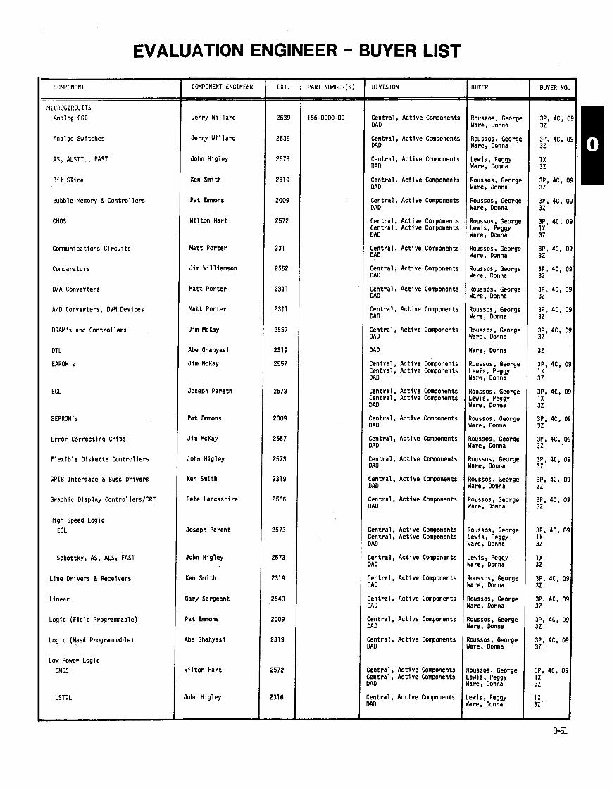
EVALUATION ENGINEER - BUYER LIST
COMPONENT ENGINEER
Je r r y W i 11 ard
Je r r y W i 11 ard
John Hig ley
Ken Smith
Pat Emnons
Wi l ton Har t
Matt Por ter
Jim Wil l iamson
Matt Por ter
Matt Por ter
J im McKay
Abe Ghahyasi
J im McKay
Joseph Paretn
Pat Emnons
Jim McKay
John Hig ley
Ken Smith
Pete Lancashire
Joseph Parent
John Hig ley
Ken Smith
Gary Sargeant
Pat Emnons
Abe Ghahyasi
d i l t o n Har t
lohn Hig ley
- EXT.
2539
2539
2573
2319
2009
2572
231 1
2552
231 1
2311
2557
231 9
2557
2573
2009
2557
2573
231 9
2566
2573
2573
231 9
2540
2009
2319
2572
231 6
-
- -
PART NUMBER(S) DIVISION
Central , Ac t ive Component! DAD
Central , Ac t ive Component! DAD
Central ; Act ive DAD
Components
Central . Act ive Components DAD
Central , Ac t ive Components DAD
Central , Ac t ive Components Central. Ac t i ve Components DAD
Central , Ac t ive Components DAD
Central , Ac t ive Components DAD
Central , DAD
Act ive Components
Central , Ac t ive Components DAD
Central , Ac t ive Components DAD
DAD
Central , Ac t ive Components Central , Ac t ive Components DAD
Central Central DAD
Central DAD
Central DAD
Central DAD
Act ive Components Act ive Components
Act ive Components
Act ive Components
Act ive Components
Central, Ac t ive Components DAD
Central . Ac t ive Components DAD
Central, Ac t ive Corponents Central, Ac t i ve Components DAD
Central, Ac t ive Components )AD
:entral , Act ive )AD
Components
:entral . Act ive Components )AD
:entral , Ac t ive Components )AD
:ent ra l . Ac t i ve Components )AD
:entral , Ac t i ve Components :ent ra l , Ac t i ve Components I A0
:ent ra l , Ac t i ve Components IAD
BUYER
Roussos , Georg~ Ware, Oonna
Roussos , Georg~ Ware, Donna
Lewis, Peggy Ware. Oonna
Roussos, Georg~ Ware, Donna
Roussos , Georg~ Ware, Donna
Roussos , Georgc Lewis, Peggy Ware, Donna
Roussos. Georgt Ware. Donna
Roussos , George Ware, Oonna
Roussos, George Ware, Donna
Roussos , George Ware, Donna
Roussos , George Ware, Donna
Ware, Donna
Roussos , George Lewis, Peggy Hare, Donna
Roussos , George Lewis, Peggy Ware, Donna
Roussos. George dare. Donna
?oussos , George dare. Donna
7oussos, George Jare. Donna
3oussos. George Jare, Donna
toussos , George lare, Donna
toussos, George .ewis, Peggy lare. Donna
.ewis, Peggy lare, Donna
loussos, George tare, Donna
loussos , George lare, Donna
loussos, George lare. Donna
loussos . George lare, Donna
oussos, George ewis, Peggy are. Donna
ewis, Peggy are. Donna
BUYER NO
-- 3P, 4C, I 32
3P, 4C. t 32
1 X 32
3P. 4C. ( 32
3P. 4C. ( 32
3P, 4C. C 1X 32
3P, 4C, C 32
3P. 4C. 0 32
3P, 4C, 0 32
3P. 4C, 0 32
3P, 4C. 0 32
32
3P, 4C. 0 1 X 32
3P, 4C. 0 1X 32
3P. 4C. 0 32
3P, 4C. 0' 32 .
3P, 4C. O! 32
3P, 4C, O! 32
3P, 4C. O! 32
3P, 4C. O! 1 X 32
1 X 32
3P, 4C, 0s 32
3P, 4C. 0s 32
3P, 4C, 09 32
3P, 4C. 09 32
3P. 4C. 09 1 X 32
1 X 32
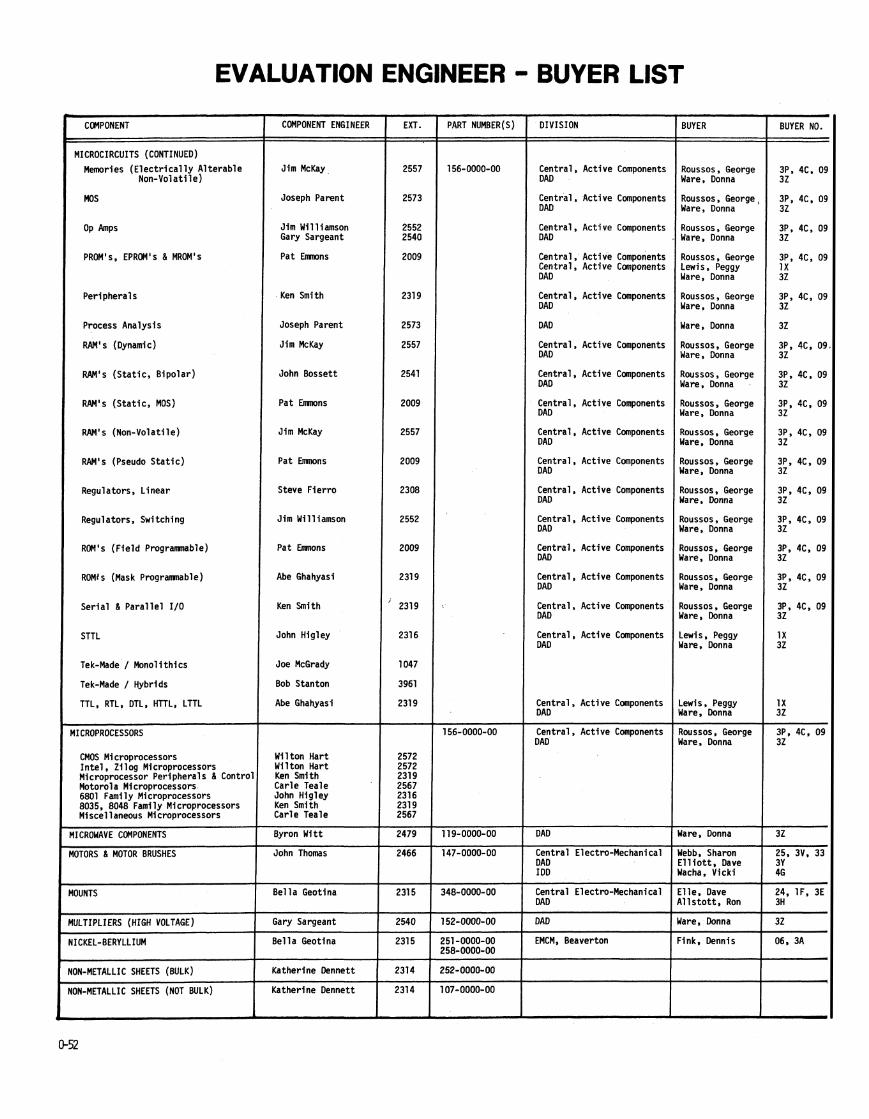
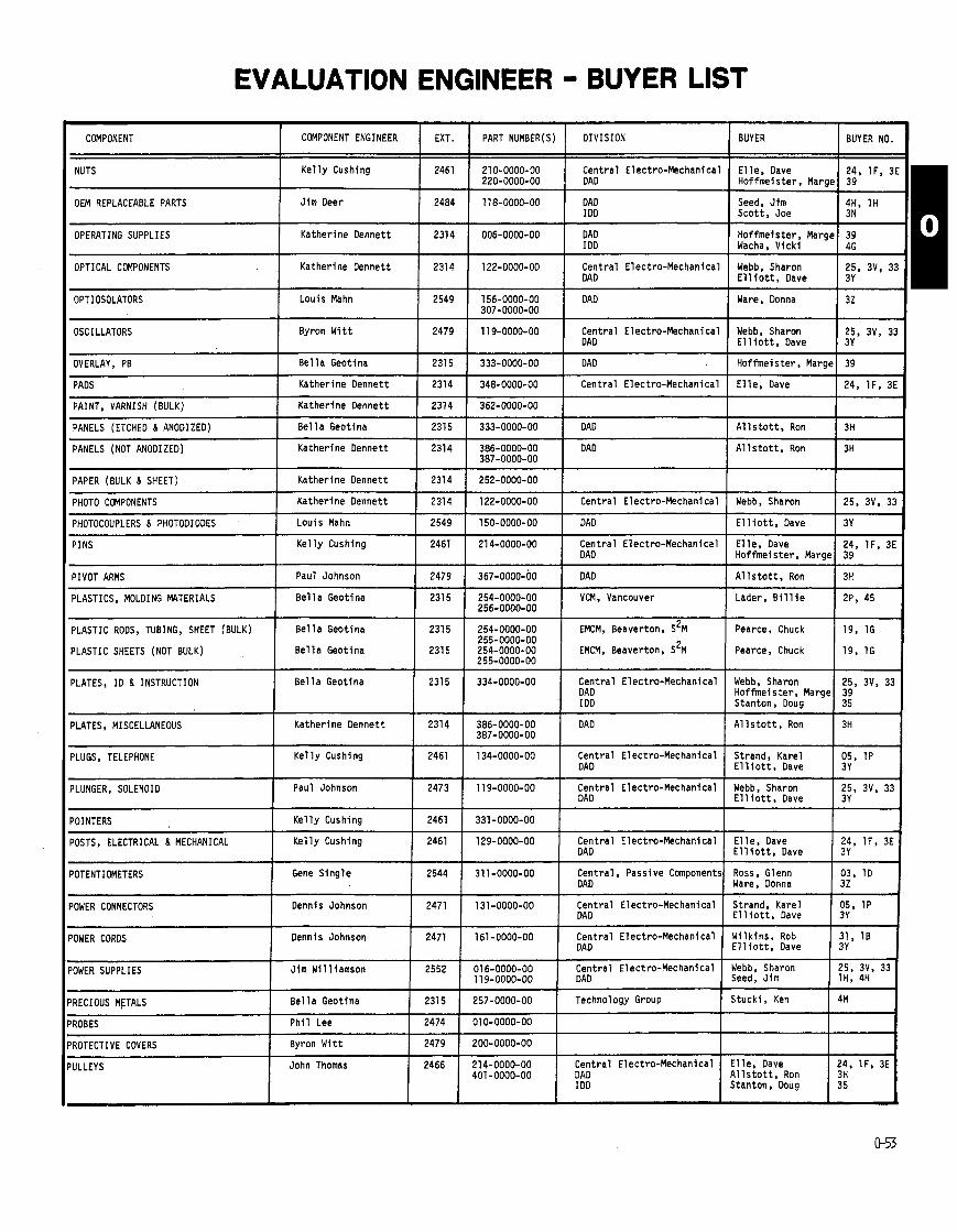
EVALUATION ENGINEER - BUYER LIST
OEM REPLACEABLE PARTS
OPTICAL COMPONENTS
OPERATING SUPPLIES
I Katherine Dennett 1 2314 ( 122-0000-00 Central Electro-Mechanical Webb, Sharon 1 DAD I E l l l o t t , Dave
Jim Deer
OPTIOSOLATORS I LouisMahn I 2549 1 156-0000-DO I DAD 1 Ware, Donna 307-0000-00
I I I I I I
Katherine Dennett
2484
OVERLAY, PB I Be l l a Geotina
2314
I I I I - -. - - - - - -
118-0000-00
006-0000-00
Webb, Sharon 25, 3V, 33 E l l i o t t , Dave 3Y
OSCILLATORS
PADS
DAD I DD
Katherine Dennett
PANELS (ETCHED & ANODIZED)
PANELS (NOT ANODIZED)
Seed, Jim 4H, 1H Scot t , Joe 3N
DAD IDD
2315
231 4
PAINT, VARNISH (BULK) 1 Katherine Dennett
Be1 l a Geotina
Katherine Dennett
Hoffmeister, Marge 39 Wacha, V i ck i 46
Byron W i t t
2314
2315
11 9-0000-00 2479
333-0000-00
348-0000-00
I I I I
Central Electro-Mechanical DAD
362-0000-00
333-0000-00
PAPER (BULK & SHEET)
PHOTO COMPONENTS
DAD . Central Electro-Mechanical
2314
PHOTOCOUPLERS & PHOTODIDOES
PINS
DAD
A l l s t o t t , Ron
Katherine Dennett
Katherine Dennett
BUYER BUYER NO.
E l l e , Dave 24, IF , 3E Hoffmeister. Marge 39
Hoffmeister, Marge
E l l e . Dave
386-0000-00 387-0000-00
3H
Louis Mahn
Ke l l y Cushing
-- -
PIVOT ARMS
PLASTICS, MOLDING MATERIALS
1
- - - - - - - - - - -
DIVISION
Central Electro-Mechanical DAD
COMPONENT
NUTS
39
24, IF , 3E
A l l s t o t t . Ron
DAD
2314
2314
PLASTIC RODS, TUBING, SHEET (BULK)
PLASTIC SHEETS (NOT BULK)
PLATES, MISCELLANEOUS I Katherine Dennett I 2314 I 386-0000-OD I DAD I A l l s t o t t , Ron 387-0000-00 I 3H
3H
2549
2461
Paul Johnson
Be l l a Geotina
PLATES, ID & INSTRUCTION
COMPONENT ENGINEER
Ke l l y Cushing
252-0000-00
122-0000-00
Be l l a Geotina 2315 254-0000-00 EMCM, Beaverton, S ~ M 255-0000-00
Be l l a Geotina ( 2315 1 254-0000-00 1 EMCM, Beaverton, S ~ M 255-0000-00
150-0000-00
21 4-0000-00
2479
231 5
Be l l a Geotina
I I I I I I
POINTERS I Ke l l y Cushing 1 2461 1 331-0000-00 1 I 1
EXT.
2461
Central Electro-Mechanical
Pearce, Chuck
Pearce, Chuck
PLUGS, TELEPkONE
PLUNGER, SOLENOID
- -
POSTS, ELECTRICAL & MECHANICAL I Ke l l y Cushing 1 2461 1 129-0000-OD Central Electro-Mechanical E l l e , Dave I DAD 1 g;, IF , 3E I E l l i o t t . Dave
PART NUMBER(S)
210-0000-00 220-0000-00
DAD
Central Electro-Mechanical DAD
367-0000-00
254-0000-00 256-0000-00
19, 1G
19, 1G
231 5
Webb, Sharon
Ke l l y Cushing
Paul Johnson
)OWER CORDS
25, 3V, 33
E l l i o t t . Dave
E l l e , Dave Hoffmeister, Marge
DAD
VCM, Vancouver
334-0000-00
POTENTIOMETERS
)OWER CONNECTORS
1 Dennis Johnson 1 2471 1 161-0000-00 Central Electro-Mechanical I DAD
3Y
24, IF , 3E 39
2461
2473
A l l s t o t t . Ron
Lader, B i l l i e
Central Electro-Mechanical DAD I OD
Gene S ing le
Dennis Johnson
-- -
3H
2P, 45
134-0000-00
11 9-0000-00
I I I I I I
Webb, Sharon Hoffmei s te r , Marge Stanton, Doug
2544
2471
I I I I
25, 3V, 33 39 35
Central Electro-Mechanical DAD
Central Electro-Mechanical DAD
Central Electro-Mechanical Webb, Sharon 25, 3V, 33 DAD Seed, Jim lH, 4H
'ROBES
'ROTECTIVE COVERS
'ULLEYS
31 1-0000-00
131-0000-00
'OWER SUPPLIES
'RECIOUS METALS I Bel la Geotina
Strand, Karel E l l i o t t , Dave
Webb, Sharon E l l i o t t , Dave
2552 Jim Will iamson
1 Stucki , Ken Technology Group
Ph i l Lee
Byron W i t t
John Thomas
05, 1P 3Y
25, 3V, 33 3Y
Central , Passive Components DAD
Central Electro-Mechanical DAD
01 6-0000-00 11 9-0000-00
4M
2474
2479
2466
Ross. Glenn Ware. Donna
Strand, Karel E l l i o t t , Dave
03. 1D 32
05, 1P 3Y
010-0000-00
200-0000-00
21 4-0000-00 401-0000-DO
Central Electro-Mechanical DAD I DD
I
E l l e , Dave A l l s t o t t , Ron Stanton, Doug
24. IF. 3E 3H 35
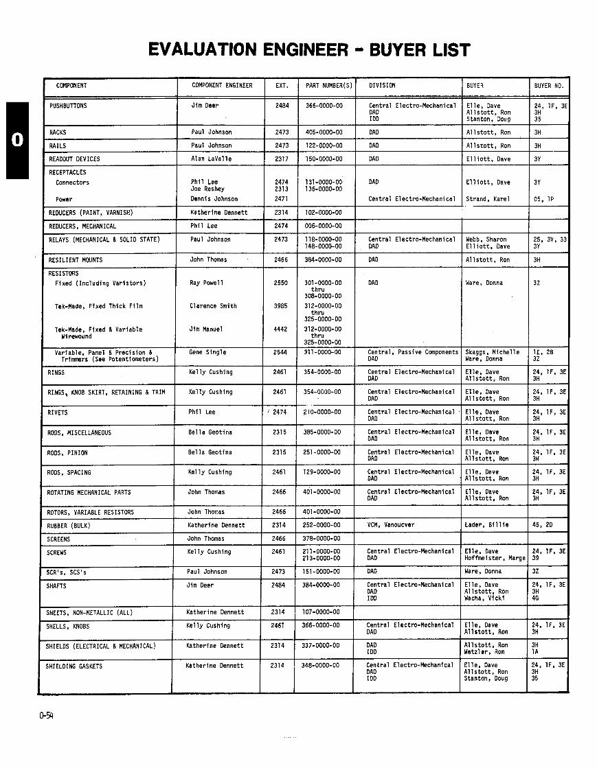
EVALUATION ENGINEER - BUYER LIST
COMPONENT 1 COMPONENT ENGINEER 1 EXT. ( PART NUMBER(S) I DIVISION I BUYER
PUSHBUTTONS I Jim Deer 1 2484 1 366-0000-00 Central Electro-Mechanical E l l e , Dave I DAD I A l l s t o t t . Ron
P w e r 1 Dennis Johnson 1 2471
RACKS
RAILS
READOUT DEVICES
RECEPTACLES
Connectors
I I RESILIENT MOUNTS I John Thomas 1 2466
Paul Johnson
Paul Johnson
Alan LaVal le
P h i l Lee Joe Reshey
REDUCERS (PAINT, VARNISH)
REDUCERS, MECHANICAL
RELAYS (MECHANICAL & SOLID STATE)
Stanton, -0oug
A l l s t o t t , Ron
I DD
2473 405-0000-00 DAD
2473 122-0000-00 DAD
2317 150-0000-00 DAD
2474 131-0000-00 DAD 231 3 136-0000-00
A l l s t o t t , Ron
E l 1 i o t t . Dave
Katherine Dennett
P h i l Lee
Paul Johnson
E l l i o t t , Dave
2314
2474
2473
RESISTORS Fixed ( I nc lud ing Va r i s to r s ) I
118-0000-00 148-0000-00
384-0000-00
Tek-flade, Fixed Thick F i lm
Tek-Made, Fixed & Var iab le W i rewound
Central Electro-Mechanical DAD
DAD
Variable, Panel & Prec is ion & Trimners (See Potent iometers)
Webb, Sharon E l l i o t t , Dave
A l l s t o t t , Ron
Ray Powell
Clarence Smith
Jim Manuel
301 -0000-00 t h r u
308-0000-00 312-0000-00
t h r u 325-0000-00
DAD
Gene S ing le
RINGS
RINGS, MOB SKIRT, RETAINING & TRIM
RIVETS
RODS, MISCELLANEOUS
RODS, PINION
RODS, SPACING
2544
I I I
I I I
SCREENS I John Thomas 1 2466 1 378-0000-00 1
K e l l y Cushing
K e l l y Cushing
P h i l Lee
Be l l a Geotina
Be1 l a Geotina
K e l l y Cushing
ROTORS, VARIABLE RESISTORS
RUBBER (BULK)
t h r u 325-0000-00
31 1-0000-00
E l l e , Dave A l l s t o t t , Ron
2461
2461
2474
231 5
2315
2461
Central Electro-Mechanical DAD
ROTATING MECHANICAL PARTS
John Thomas
Katherine Dennett
I I
Central , Passive Components DAD
SCR's, SCS's
SHAFTS
SHEETS, NON-METALLIC (ALL)
Skaggs, M iche l l e Ware, Donna
John Thomas
2466
2314
E l l e , Dave Hof fmeis ter , Marge
I I I I I
BUYER NO.
24, IF , 3E 3H 3 5
3H
3H
3Y
3Y
05, 1P
25, 3V, 33 3Y
3H
32
1E. 28 32
24, IF, 3E 3H
24, IF , 3E 3H
24, IF, 3E 3H
24, IF , 3E 3H
24, IF , 3E 3H
24, lF , 3E 3H
24, IF, 3E 3H
45, 2D
24. IF , 3E 39
32
24, IF , 3E 3H 46
24. IF. 3E 3H
3H 1 A
24, IF , 3E 3H 35
E l l e , Dave A1 l s t o t t , Ron
E l l e , Dave A1 1 s t o t t . Ron
E l l e , Dave A l l s t o t t , Ron
E l l e , Dave A l l s t o t t , Ron
E l l e , Dave A1 1 s t o t t , Ron
E l l e , Dave A l l s t o t t , Ron
354-0000-00
354-0000-00
210-0000-00
385-0000-00
251 -0000-00
129-0000-00
Central Electro-Mechanical DAD
SCREWS
Paul Johnson
Jim Deer
Katherine Dennett
jHIELDS (ELECTRICAL & MECHANICAL)
iHIELDING GASKETS
Central Electro-Mechanical DAD
Central Electro-Mechanical DAD
Central Electro-Mechanical DAD
Central Electro-Mechanical DAD
Central Electro-Mechanical DAD
Central Electro-Mechanical DAD
2466
401-0000-00
252-0000-00
E l l e , Dave A l l s t o t t . Ron
401 -0000-00
K e l l y Cushing
2473
2484
2314
Central Electro-Mechanical DAD
Katherine Dennett
Katherine Dennett
VCM, Vanoucver
SHELLS, MOBS
Lader, B i l l i e
2461
151 -0000-00
384-0000-00
107-0000-OD
2461 K e l l y Cushing
2314
21 1-0000-OD 21 3-0000-00
366-0000-00
DAD
Central Electro-Mechanical DAD I DD
337-0000-00
Ware, Donna
E l l e , Dave A l l s t o t t , Ron Wacha, V i ck i
2314 , 348-0000-00
DAD I DD
A l l s t o t t , Ron Wetzler, Ron
Central Electro-Mechanical DAD I DD
E l l e , Dave A l l s t o t t , Ron Stanton, Doug
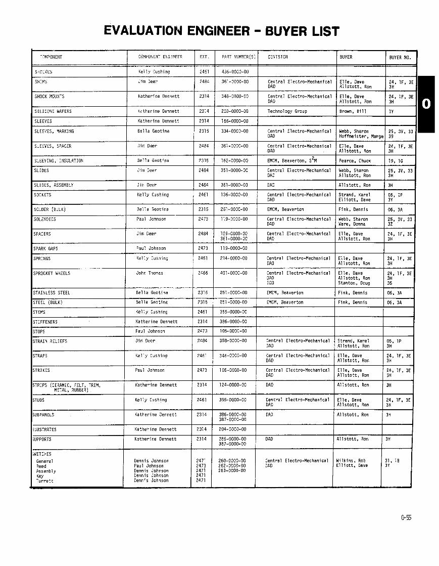
PART NUMBER(S) DIVISION BUYER BUYER NO. COMPONENT ENGI?IEER EXT.
Kelly Cushing
Jim Deer 2484
'OMPONENT
SHELVES
361-0000-00 Central Electro-Mechanical Elle, Dave DAD Allstott, Ron 3H
348-0000-00 Central Electro-Mechanical Elle, Dave 24, IF, 3E DAD Allstott, Ron 3H
SHIMS
SHOCK MOUNTS Katherine Dennett
- -
203-0000-00 Technology Group Brown, Bill 1 Y
166-0000-00
334-0000-00 Central Electro-Mechanical Webb, Sharon 25, 3V. 33 I SILICONE WAFERS Katherine Oennett
Katherine Dennett
Bella Geotina 231 5
SLEEVES
SLEEVES, MARKING I DAD I Hoffrneister, Margel 39 1 I I I
361-0000-00 Central Electro-Mechanical Elle, Dave 24, lF, 31 DAD Allstott, Ron 3H
SLEEVES, SPACER Jim Oeer
Bella Geotina
Jim Oeer
-- --
162-0000-00 1 EMCM, Beaverton, S ~ M I Pearce, Chuck 1 19, ld SLEEVING, INSULATION
Central Electro-Mechanical Webb. Sharon DAD I Allstott. R o n v
SLIDES
SLIDES, ASSEMBLY
SOCKETS
Jim Deer 1 2484 361-0000-00 1 DAD I Allstott, Ron I 3H Kelly Cushing 1 2461 Central Electro-Mechanical Strand, Karel
DAD I Elliott, Dave SOLDER (BULK) Bella Geotina
Paul Johnson
251-0000-00 1 EMCM, Beaverton IFink,Dennis 106,3A I I I
119-0000-00 Central Electro-Mechanical Webb, Sharon 25, 3V, 32 DAD Ware, Donna 32
Jim Oeer Central Electro-Mechanical El le, Dave 1 IFv 3E DAD I Allstott, Ron
;PARK GAPS
iPRINGS
Paul Johnson 1 2473
Kelly Cushing 214-0000-00 Central Electro-Mechanical Elle, Dave I DAD 1 ::, IF9 3E
Allstott, Ron
;PROCKET WHEELS John Thomas 401 -0000-00 Central Electro-Mechanical El le, Dave I DAD Allstott, Ron I DD Stanton, Doug I is' IF' 3E
-
STAINLESS STEEL
,TEEL (BULK)
Bella Geotina I 2315 251-0000-00 1 EMCM, Beaverton I Fink, Dennis 1 06, 3A Bella Geotina 1 2315 251 -0000-00 1 EMCM, Beaverton I Fink, Dennis 1 06, 3A
-
TEMS Kelly Cushing
Katherine Oennett TIFFENERS
TOPS Paul Johnson 2473
Jim Deer 1 2484
105-0000-00
358-0000-00 Central Electro-Mechanical Strand, Karel 05, 1P DAD Allstott, Ron 3H
TRAIN RELIEFS + Kelly Cushing TRAPS Central Electro-Mechanical Elle, Dave 1 IF, 3E DAD I Allstott, Ron
TRIKES Paul Johnson I 2473 Central Electro-Mechanical Elle, Dave 1 IF3 3E DAD I Allstott, Ron
TRIPS (CERAMIC, FELT, TRIM, METAL. RUBBER)
Katherine Dennett 1 2314 124-0000-00 DAD Allstott, Ron 3H + Kelly Cushing TUDS Central Electro-Mechanical DAD
I
Katherine Dennett 2314 -
DAD 1 Allstott, Ron i;" UBPANELS
UBSTRATES
JPPORTS
Katherine Dennett 1 2314
Katherine Dennett 386-0000-00 DAD Allstott, Ron 3H 387-0000-00
dITCHES General Reed Assembly Key Turrett
Dennis Johnson 2471 Paul Johnson 2473 Dennis Johnson 2471 Dennis Johnson 2471 Dennis Johnson 2471
260-0000-00 Central Electro-Mechanical Wil kins, Rob 31, 10 262-0000-00 DAD Elliott, Dave 3Y 263-0000-00
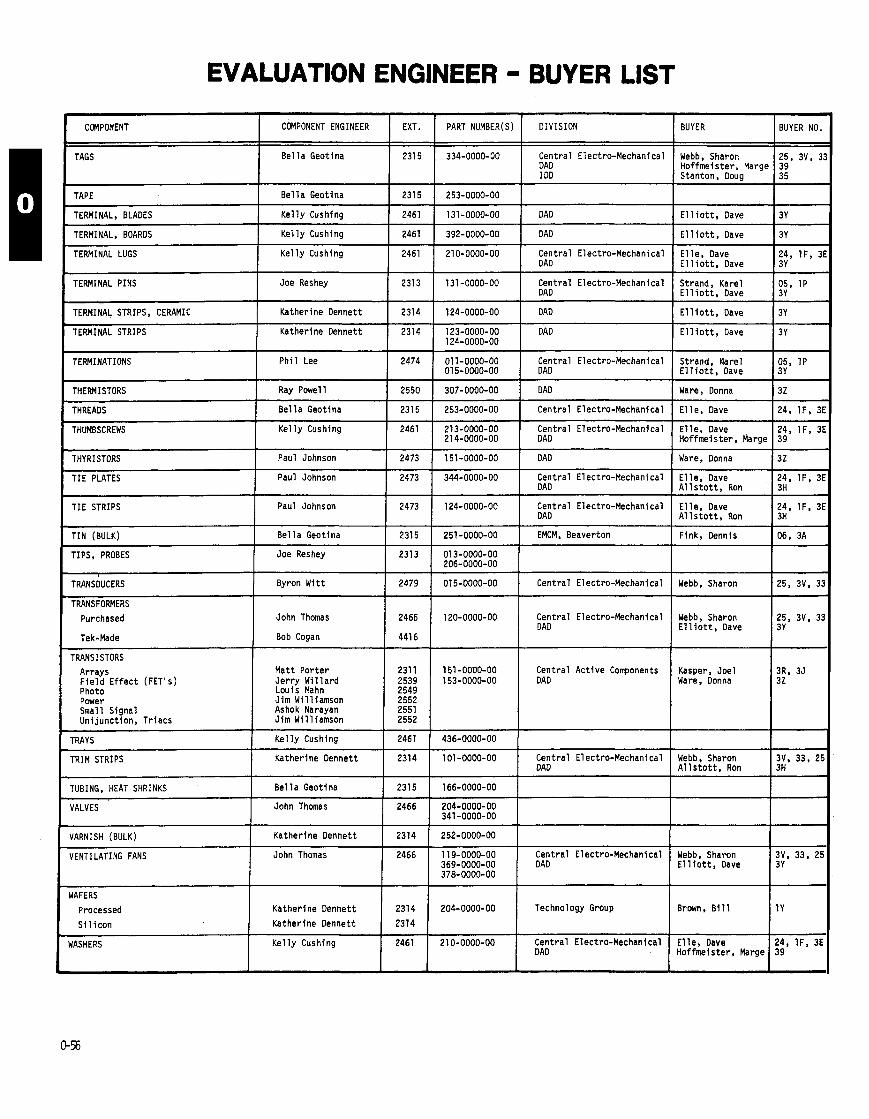
COMPONENT COMPONENT ENGINEER EXT. PART NUMBER(S) DIVISION BUYER I BUYER NO.
Webb, Sharon 25, 3V, 3 I Be l l a Geotina -
334-0000-90 Central Electro-Mechanical I DAD TAGS
-
253-0000-00
131-0000-00 DAD
TAPE Be l l a Geotina 2315 I E l 1 i o t t , Dave 3Y TERMINAL, BLADES 1 Ke l l y Cushing 1 2461
TERMINAL, BOARDS I Ke l l y Cushing 1 2461
TERMINAL LUGS Ke l l y Cushing 21 0-0000-00 Central Electro-Mechanical I DAD E l l e , Oave E l 1 i o t t , Dave
- -
TERMINAL PINS ( Joe Reshey 131 -0000-00 Central Electro-Mechanical I DAD Strand, Karel E l l i o t t , Dave
TERMINAL STRIPS, CERAMIC Katherine Dennett
TERMINAL STRIPS Katherine Dennett 123-0000-00 DAD 124-0000-00
E l l i o t t , Oave I 3Y
Strand. Rare1 05, 1P E l l i o t t , Dave
TERMINATIONS 1 ph i1 ~ e e 01 1-0000-00 Central Electro-Mechanical 015-0000-00
Be l l a Geotina
307-0000-00 1 DAD Ware, Donna 1 32
253-0000-00 1 Central Electro-Mechanical E l l e , Dave 124, I F , 3
213-0000-00 ( Central Electro-Mechanical 21 4-0000-00 DAD
E l l e , Dave 24. IF , 3 Hoffmeister, h r g e 1 39
I
THYRISTORS Paul Johnson Ware, Donna 132
TIE PLATES Paul Johnson 344-0000-00 Central Electro-Mechanical 1 DAD E l l e , Dave A l l s t o t t , Ron
124-0000-00 I Central Electro-Mechanical DAD
E l l e , Dave 24. IF , 31 A l l s t o t t , Ron
TIE STRIPS
TIN (BULK) 251-0000-00 1 EMCM, Beaverton
TIPS, PROBES Joe Reshey
TRANSDUCERS Byron W i t t
TRANSFORMERS
Purchased John Thomas
Tek-Made Bob Cogan
Webb, Sharon E l l i o t t , Oave
120-0000-00 Central Electro-Mechanical I DAD
-
TRANS1 STORS 151 -0000-00 Central Act ive Components 153-0000-00 DAD
Kasper, Joel 3R, 35 Ware. Donna 32
Mat t Por ter Je r r y W i l l a rd Louis Mahn Jim Wil l iamson Ashok Narayan Jim Wil l iamson
Arrays F i e l d E f f e c t (FET's) Photo Power Small Signal Un i junct ion, Tr iacs
TRAYS K e l l y Cushing 436-0000-00
101 -0000-00 Central Electro-Mechanical DAD A l l s t o t t , Ron
TRIM STRIPS I Katherine Dennett
I
TUBING, HEAT SHRINKS I Be l l a Geotina --
166-0000-00
204-0000-00 341 -0000-00
252-0000-00
11 9-0000-00 Cent ra l Electro-Mechanical 369-0000-00 DAD 378-0000-00
VALVES I
VARNISH (BULK) Katherine Dennett
E l l i o t t , Dave VENTILATING FANS John Thomas
WAFERS
Processed
S l l i con
UASHERS
204-0000-00 Technology Group
21 0-0000-00 Central Electro-Mechanical
Brown, B i l l I ly
Katherine Dennett
Katherine Dennett
K e l l y Cushing I
E l l e , Dave 24, I F , 3E

EVALUATION ENGINEER - BUYER LIST
COMPONENT COMPONENT ENGINEER EXT.
WHEELS Kel ly Cushlng 2461
PART NUMBER(S)
401 -0000-00
331-0000-00
175-0000-00
176-0000-00 177-0000-00
177-0000-00
108-0000-00
WINDOWS
WIRE, ELECTRICAL, STRIPE
WIRE, BULK
YOKES
>
DIVISION
Central Electro-Mechanical DAD ----
VCM, Vancouver DAD
EMCM, Beaverton, S ~ M
VCM, Vancouver
DAD I DD
Bella Geotina
Elizabeth Do01 i t t l e
Elizabeth D o o l i t t l e
John Thomas
BUYER BUYER NO.
Webb, Sharon
Gardner, Don E l l i o t t , Dave
Pearce, Chuck
Gardner. Don
E l l i o t t , Dave 3Y Wetzler. Ron 1A
2315
2309
2309
2466

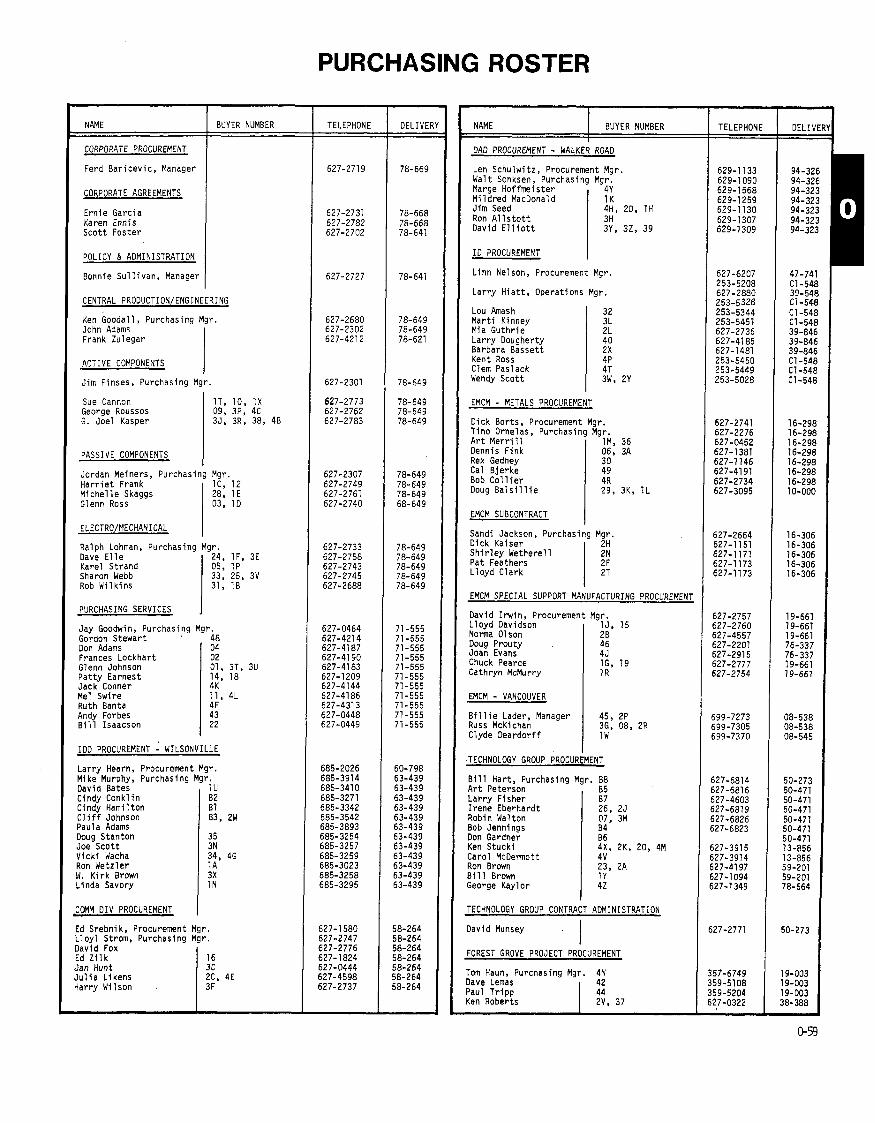
PURCHASING ROSTER -
OELIVE
78-669
78-668 78-668 78-641
78-641
78-649 78-649 78-621
78-649
78-649 78-649 78-649
78-649 78-649 78-649 68-649
78-649 78-649 78-649 78-649 78-649
71-555 71-555 71-555 71-555 71-555 71-555 71-555 71-555 71-555 71-555 71-555
60-798 63-439 63-439 63-439 63-439 63-439 63-439 63-439 63-439 63-439 63-439 63-439 63-439
58-264 58-264 58-264 58-264 58-264 58-264 38-264
TELEPHONE TELEPHONE NAME DELIVER - 94-326 94-326 94-323 94-323 94-323 94-323 94-323
BUYER NUMBER NAME I BUYER NUMBER I I
CORPORATE PROCUREMENT
Ferd B a r i c e v i c , Manager
DAD PROCUREMENT - WALKER ROAD
Len Schu lw i tz , Procurement Mgr. Walt Sonksen, Purchasing Mgr. Marge Hof fme is te r 4Y M i l d r e d MacDonald I 1K
CORPORATE AGREEMENTS
Ern ie Garcia Karen Ennis S c o t t Fos ter
J im Seed 4H, 20, 1H Ron A l l s t o t t David E l l i o t t 3Y, 32, 39
I D PROCUREMENT POLICY & ADMINISTRATION
Bonnie S u l l i v a n , Manager L i n n Nelson, Procurement Mgr.
L a r r y H i a t t , Operat ions Mgr. CENTRAL PROOUCTION/ENGINEERING
Ken Goodal l , Purchasing Mgr. John Adams Frank Zulegar I
Lou Amash M a r t i Kinney Mia G u t h r i e L a r r y Dougherty Barbara Bassett Kent Ross Clem Paslack Wendy S c o t t
ACTIVE COMPONENTS I Jim Finses, Purchasing Mgr.
Sue Cannon George Roussos G. Joel Kasper
EMCM - METALS PROCUREMENT
PASSIVE COMPONENTS
Jordan Meiners, Purchasir H a r r i e t Frank M i c h e l l e Skaggs Glenn Ross
Dick Borts, Procurement Mgr. T ino Ornelas, Purchasing Mgr.
Mgr. lC, 12 28, 1E 03, 10
A r t M e r r i l l Dennis F ink Rex Gedney Cal B je rke Bob C o l l i e r Doug B a l s i l l i e
EMCM SUBCONTRACT I
lM, 36 06, 3A 30 49 4R 29, 3K, 1L
Sandi Jackson, Purchasing Mgr Dick Kaiser 2H S h i r l e y Wetherel l Pa t Feathers L l o y d C lark
Ralph Lohman, Purchasing Dave E l l e Karel Strand Sharon Webb Rob W i l k i n s
EMCM SPECIAL SUPPORT MANUFACTURING PROCUREMENT PURCHASING SERVICES
David I r w i n , Procurement Mgr. L l o y d Davidson 1J. 15
EMCM - VANCOUVER
Norma Olson Doug Prouty Joan Evans Chuck Pearce Cathryn McMurry
Jay Goodwin, Purchasing Mgr. Gordon Stewart 48
B i l l i e Lader, Manager Russ McKichan Clyde Deardor f f
2 B 46 45 lG, 19 1 R
Don Adams Frances Lockhar t Glenn Johnson P a t t y Earnest Jack Conner Me! Swire Ruth Banta Andy Forbes B i 11 Isaacson
IDD PROCUREMENT : WILSONVILLE
04 02 01, 3T, 3U 14, 18 4K 11, 4L 4F 43 22
Lar ry Hearn, Procurement Mgr. Mike Murphy, Purchasing Mgr.
JOMM DIV PROCUREMENT I
David Bates Cindy Conk1 i n Cindy Hami 1 t o n C l i f f Johnson Paula Adams Doug Stanton Joe S c o t t V i c k i Wacha Ron Wetzler W . K i r k Brown Linda Savory
B i l l Hart , Purchasing Mgr. B8
TECHNOLOGY GROUP CONTRACT ADMINISTRATION
1 U 82 B 1 83, 2W
35 3N 34, 46 1 A 3X 1 N
A r t Peterson L a r r y F isher I r e n e Eberhardt Robin Walton Bob Jennings Don Gardner Ken Stuck i Carol McDermott Ron Brown 811 1 Brown George Kay 1 o r
David Munsey I
B5 B7 26, 25 07, 3M 84 86 4X, 2K, 20, 4M 4V 23, 2A 1 Y 42
FOREST GROVE PROJECT PROCUREMENT
Ed Srebnik, Procurement Mgr. L l o y l Strom, Purchasing Mgr.
Toin Haun, Purchasing Mgr. 4N lave Lemas 42 'aul T r i p p ten Roberts
David Fox Ed Z i l k Jan Hunt J u l i a Likens Harry Wilson
16 3C 2C, 4E 3 F
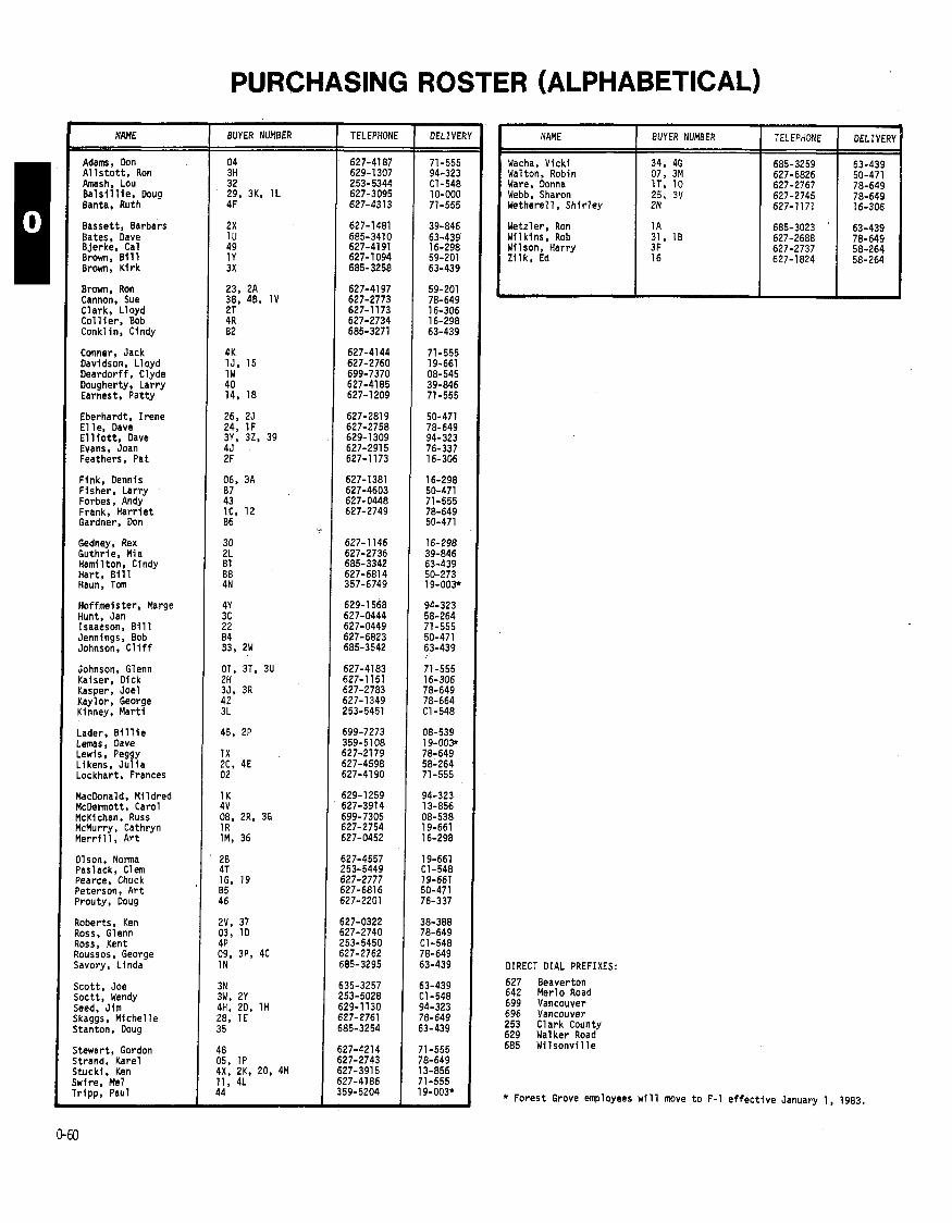
PURCHASING ROSTER (ALPHABETICAL)
BUYER NUMBER
Wacha, V i ck i 34, 46 685-3259 63-439 Wal ton, Robin 07, 3M 627-6826 50-471 Ware, Donna 627-2767 78-649 Webb, Sharon 25, 3V 627-2745 78-649 Wetherell, Sh i r l ey 627-1171 16-306
- DELIVE NAME BUYER NUMBER
Adams, Don A l l s t o t t , Ron h a s h , Lou B a l s i l l i e , Doug Banta, Ruth
Bassett , Barbars Bates, Dave Bjerke, Cal Brown, B i l l Brown, K i r k
Wetzler, Ron Wilk ins, Rob Wilson, Harry Z i l k , Ed
Brown, Ron Cannon, Sue Clark, L loyd C o l l i e r , Bob Conklin, Cindy
Conner, Jack Davidson. Lloyd Deardorf f , Clyde Dougherty, Lar ry Earnest, Pat ty
Eberhardt, I r ene E l 1 e, Dave E l l i o t t , Dave Evans, Joan Feathers, Pat
Fink, Dennis Fisher, Lar ry Forbes, Andy Frank, H a r r i e t Gardner, Don
Gedney, Rex Guthr ie, Mia Hami 1 ton, Ci ndy Hart , 8111 Haun, Tom
Hoffmeister, Marge Hunt, Jan Isaacson, B i l l Jennlngs, Bob Johnson, C l i f f
Johnson, Glenn Kaiser, Dick Kasper, Joel Kaylor, George Kinney, Mar t i
Lader, B i l l i e Lemas, Dave Lewis, Peggy Likens. J u l i a Lockhart , Frances
MacDonald. M i l d red McDennott, Carol McKichan, Russ McMurry, Cathryn M e r r i l l , A r t
Olson, Norma Paslack, Clem Pearce, Chuck Peterson, A r t Prouty, Doug
Roberts, Ken Ross. Glenn Ross, Kent Roussos, George Savory, Linda
Scott, Joe Soctt, Wendy Seed. Jim jkaggs, Miche l le j tanton, Doug
j tewart, Gordon i t rand, Karel i t uck f , Ken iwfre, Me1 r i pp , Paul
DIRECT DIAL PREFIXES:
627 Beaverton 642 Merlo Road 699 Vancouver 696 Vancouver 253 Clark County 629 Walker Road 685 W i 1 sonvi 11 e
* Forest Grove employees w i l l move t o F-1 e f f e c t i v e January 1, 1983.

PURCHASING ROSTER (NUMERICAL)
BUYER NUMBER
51 82 83 84 85
86 87 88 01 02
03 04 05 06 07
08 09 1 A 18 1 C
1 D 1 E 1 F 1G 1 H
1 J 1 K 1 L 1 M 1 N
1 P 1 R 1 T 1 u 1 v
1W 1 X 1 Y 10 11
12 14 15 16 18 . 19 2A 28 2C 20
2F 2H 25 2 K 2L
2N 2P 2R 2T 2v
2W 2X 2Y 20 22
23 24 2 5 26 28
2 9 3A 3C
3 F
BUYER
Hamil ton, Cindy Conk1 i n , Cindy Johnson, C l i f f Jennings, Bob Peterson, A r t
Gardner, Don F isher , L a r r y Har t , B i l l Johnson, Glenn Lockhart , Frances
Ross, Glenn Adams, Don Strand, Karel F ink, Dennis Walton, Robin
McKichan, Russ Roussos, George Wetz ler , Ron Wi l k ins , Rob Frank, H a r r i e t
Ross, Glenn Skaggs, M i c h e l l e E l l e , Dave Pearce, Chuck Seed, J i m
Davidson, L l o y d MacDanold, M i l d r e d B a l s i l l i e , Ooug M e r r i l l , A r t Savory, L inda
Strand, Karel McMurry, Carhryn Ware, Donna Bates, Oave Cannon, Sue
Oeardor f f , Clyde Lewis, Peggy Brown, B i l l Ware, Donna Swire, Me1
Frank, H a r r i e t Earnest, P a t t y Davidson, L l o y d Z i l k , Ed Earnest, P a t t y
Pearce, Chuck Brown, Ron Olson, Norma Likens, J u l i a Seed, J im
Feathers, Pat Ka ise r , D ick Eberhardt , I r e n e S tuck i , Ken Guthr ie, Mia
Wetherel l , S h i r l e y Lader, B i l l i e YcKichan, Russ C la rk , L l o y d Roberts, Ken
Johnson, C l i f f Basset t , Barbara Sco t t , Wendy S tuck i , Ken Isaacson, B i l l
Brown, Ron E l l e , Dave Webb, Sharon Eberhardt , I r e n e Skaggs, M i c h e l l e
B a l s i l l i e , Doug Fink, Dennis Hunt, Jan
Wilson, Har ry
TELEPHONE DELIVERY
63-439 63-439 53-439 50-471 50-471
50-471 50-471 50-273 71-555 71-555
78-649 71-555 78-649 16-298 50-471
08-538 78-649 63-439 78-649 78-649
78-649 78-649 78-649 19-661 94-323
19-661 94-323 10-000 16-298 63-439
78-649 19-661 78-649 63-439 78-649
08-545 78-649 59-201 78-649 71-555
78-649 71-555 19-661 58-264 71-555
19-661 59-201 19-661 58-264 94-323
16-306 16-306 50-471 13-856 39-846
16-306 08-538 08-538 16-306 38-388
63-439 39-846 Cl-548 13-856 71 -555
59-201 78-649 78-649 50-471 78-649
10-000 16-298 58-264
58-264
BUYER NUMBEf
3G 311 35 3K 3 L
3M 3N 3P 3R 35
3 v 3W 3X 3Y 3 2
30 3 1 32 33 34
35 36 37 38 39
4B 4C 4E 4F 46
4H 4J 4 K 4L 4M
4N 4P 4R 4T 4v
4X 4Y 42 40
43 44 45
3 49
BUYER
McKichan, Russ A1 l s t o t t , Ron Kasper, Joe l B a l s i l l i e , Doug Kinney, M a r t i
Walton, Robin Sco t t , Joe Roussos, George Kasper, Joel Johnson, Glenn
Webb, Sharon Sco t t , Wendy Brown, K i r k E l l i o t t , Dave E l l i o t t , Dave
Gedney, Rex W i l k i n s , Rob Amash, Lou Webb, Sharon Wacha, V i c k i
Stanton, Doug M e r r i 11, A r t Roberts, Ken Cannon, Sue E l l i o t t , Oave
Cannon, Sue Roussos , George L ikens, J u l i a Banta, Ruth Wacha, V i c k i
Seed, J i m Evans, Joan Conner, Jack Swire, Me1 S t u c k i , Ken
Haun, Tom Ross, Kent C o l l i e r , Bob Paslack, Clem McDermott, Carol
S t u c k i , Ken Hof fmei s t e r , Marge Kaylor , Georgw Dougherty, L a r r y
Forbes, Andy T r ipp , Paul Lader, B i 11 i e Prouty, Ooug Stewart , Gordon
B je rke , Cal
TELEPHONE DELIVERY
DIRECT DIAL PREFIXES:
627 Beaverton 642 Mer lo Road 699 Vancouver 696 Vancouver 629 Walker Road 685 W i l s o n v i l l e 253 C l a r k County
* F o r e s t Grove employees w i l l move t o F-1 e f f e c t i v e January 1, 1983.
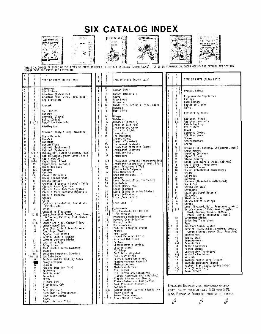
SIX CATALOG INDEX
THIS IS A COMPOSITE INDEX OF THE TYPES OF PARTS INCLUDED IN THE SIX CATALOGS (SHOWN ABOVE). I T IS IN ALPHABETICAL ORDER GIVING THE CATALOG AN0 SECTION NUMBER THAT THE PARTS ARE LISTED IN.
TYPE OF PARTS (ALPHA LIST)
Adhesives A i r F i l t e r s Aluminum Extrusion) Aluminum [Bar, Wire, F l a t , Tube) Angle Brackets
Array*
Back Diodes Bat te ry Bearing (Sleeve) B e l t s (Dr ive) Bery l l ium Mater ia ls
Binding Post
Bracket (Angle & Comp. Mounting)
Brass Mater ia l Bumpers Bushings Button Plugs Cabinet ( Instrument) Cabinet ( fasteners) Cables RF. Special Purpose, F l a t ) c a b l e 2 L s , Power Cords, Ext. ) Cable ~ i p p l k Capacitors, Fixed Caoacitors, Var iable c a r t r i d g e Lamp Casters Catches Ceramic Mater ia ls Ceramic Substrates Chains (Dr ive) Chemical Elements d Symbols Table C i r c u i t Board E jec tors C i r c u i t Board Interconn System C i r c u f t Board Laminate Mater ia ls C i r c u i t Breakers Clamps C l i p s Coatings ( I n s u l a t i v e , Res is t i ve ,
Paints, etc.) Coi 1 s Conductive Elastomers Connectors (Ckt Board, Coax, Power
D Series. Pe l to la , F l a t Cable) Contacts Copper and Misc. Cbpper A l loys Copper-Beryl 1 ium Core (For C o i l s & Transformers) Coup1 ings, Shaft Crys ta l O s c i l l a t o r s Crys ta l Un i ts & Holders Current L i m i t i n g Diodes Cushioning Pads Delay Lines D i a l (Knob & Turns Counting) Diodes D iscre te Comoonent Car r ie rs EIA Date code Environ and R e l i a b i l i t y Notes Epoxy Preforms Eyelets Fan and Impe l le r ( A i r ) Fasteners F e l t M a t e r i a l Ferrules FET'S F i l t e r s (RFI) F l i ~ s t a n d s , Cab Flux Foot (Cabinet) Form (Co i l & Transformer) Four Layer Diodes Fuses Fuseholder and C l ips
TYPE OF PARTS (ALPHA LIST)
Gasket (RFI)
Gasses (Mater ia l ) Gears Glow Lamps Grommets Guide (Pin, Ckt Ed & I n s t r . Cabnt) Handles Heat Sinks
Hinaes ~ o l i e r s Holders (Bat te ry ) Imoel l e r ( A i r Fan) lnkandescent Lamps I n d i c a t o r L igh ts Inductors I n k (Marking) I n s e r t (Knob) I n s e r t (Threaded) Instrument Cabinets I n s u l a t i n g Mater ia ls (Bulk) I n s u l a t i n g S l e w i n g I n s u l a t o r Pos t . I n s u l a t o r s
In tegra ted C i r c u i t s ( M i c r o c i r c u i t s Interconn System (For C i r c u i t Bds) Jack (Telephone & T i p ) Knob & Knob Subparts Knob With Shaft Knob Design Data Lacquer Lamp (Incand, &low, I n d i c a t o r ) Lamphol der Latch (Door, e t c . ) Leads (Formed) LED'S ( L i g h t Emi t t ing Diodes) Lens ( I n d i c a t o r )
Logo L i s t
Lubr icants Lug Terminals (Solder and
Solder less) Magnetic Sh ie ld ing Mater ia l Marker, I d e n t i f i c a t i o n M i c r o c i r c u i t s Microprocessors Modular Packaginq System Motors Neon Lamps Nickel Mater ia l (Bulk) Nuts and Nut Block OP Amps Optoelectronic Devices Ootoisolators "0" Rings O s c i l l a t o r ( C r y s t a l ) Pad (Cushioning) Pa in t & Pa in t Add i t i ves Phosphor-Bronze Mater ia l Photoconductors Photo t rans is to rs P in (Guide) P i n (Spr ing and Retaining) P l a s t i c Mater ia ls (Bulk Molding) P l a s t i c (Shapes and Sheets) P l a t e ( Indent and I n s t r u c t i o n ) Post (Threaded Spacers) Pot Cores Potentiometer (Var iab le ~ e s i s t o r ) Power Supplies Power Trans is to rs Press Mount Hardware
TYPE OF PARTS (ALPHA LIST)
Product Safety
Programnable Thyr is to rs Pul leys Push Buttons R e c t i f i e r Oiodes Re1 ay
Re1 i a b i l i t y Notes
Resistor, Fixed Resistor, Var iable Retaining Ring RFI F i l t e r s R ive t Schottky Diodes SCR Thvr is to rs screw; Semiconductors Shafts
Shields (RFI Gaskets, Ckt Boards, et t . ) Shock Mounts Shockley (Diodes) Signal Diodes Sleeve Bearing S l i d e (Ckt Board & I n s t r . Cabinet) Small Signal Trans is to rs Snap-Off Diodes Socket ( E l e c t r i c a l Components) Solder Solenoids Solvents' Spacers (Threaded & Unthreaded) Spark Gap Sorino [He l ica l 1 sbrociets Stainless Steel Mater ia l Standoffs Steel Mater ia l S t r a i n R e l i e f Bushings Straps Stud (Threaded, Weld, Pressmount, e t c . ) Switch (Lever, S l ide , Push, Toggle,
Reed, Thermo , Rocker, Rotary, Power, Logic, Thumbwheel, etc.)
Switching Diodes Switching Trans is to rs Tape Tek Par t Number System Termina! (Lug, Block, Grnding, Studs,
Ceramic S t r i p , Quick Disc, Feedthwj Thumbscrews Tools, Small Transformers Trans is to rs Tr iac Thyr is to rs Tunnel Diodes Un i junc t ion Thyr is to rs Var iable Resistors Varnish Voltage M u l t i p l i e r s (Diodes) Voltage Selectors (Fuse) Washer ( F l a t , Lock, Spr ing Shldr) Wire ( E l e c t r i c a l ) Zener Diodes
EVALUATION ENGINEER LIST, PREVIOUSLY ON BACK
COVER, CAN BE FOUND ON PAGES 0-79 MRU 0-73, PLso, PURCMSING ROSTER ON INSIDE OF THIS COVER


