Embed Size (px)
Citation preview

TechnicalPublications
Direction 2243479-100Revision 2
LOGIQ 700 Expert/Pro SeriesCONFORMANCE STATEMENTfor DICOM V3.0
Copyright 1999 By General Electric Co.Do not duplicate
g GE Medical Systems

LOGIQ 700 EXPERT/PRO SERIES VERSION R2.0GE MEDICAL SYSTEMS CONFORMANCE STATEMENTDIRECTION 2243479-100 REV 2
THIS PAGE LEFT INTENTIONALLY BLANK

LOGIQ 700 EXPERT/PRO SERIES VERSION R2.0GE MEDICAL SYSTEMS CONFORMANCE STATEMENTDIRECTION 2243479-100 REV 2
i
TABLE OF CONTENTS
1. INTRODUCTION ............................................................................................................... 1–1
1.1 OVERVIEW......................................................................................................................................................... 1–1
1.2 OVERALL DICOM CONFORMANCE STATEMENT DOCUMENT STRUCTURE .................................... 1–2
1.3 INTENDED AUDIENCE ..................................................................................................................................... 1–4
1.4 SCOPE AND FIELD OF APPLICATION .......................................................................................................... 1–5
1.5 IMPORTANT REMARKS .................................................................................................................................. 1–5
1.6 REFERENCES..................................................................................................................................................... 1–6
1.7 DEFINITIONS ..................................................................................................................................................... 1–6
1.8 SYMBOLS AND ABBREVIATIONS ................................................................................................................. 1–6
2. NETWORK CONFORMANCE STATEMENT.................................................................... 2–1
2.1 INTRODUCTION................................................................................................................................................ 2–1
2.2 IMPLEMENTATION MODEL .......................................................................................................................... 2–1
2.3 AE SPECIFICATIONS........................................................................................................................................ 2–5
2.4 COMMUNICATION PROFILES ..................................................................................................................... 2–13
2.5 EXTENSIONS / SPECIALIZATIONS / PRIVATIZATIONS.......................................................................... 2–14
2.6 CONFIGURATION ........................................................................................................................................... 2–14
3. ULTRASOUND (US) INFORMATION OBJECT IMPLEMENTATION............................... 3–1
3.1 INTRODUCTION................................................................................................................................................ 3–1
3.2 US IOD IMPLEMENTATION............................................................................................................................ 3–1
3.3 US ENTITY-RELATIONSHIP MODEL............................................................................................................ 3–1
3.4 IOD MODULE TABLE....................................................................................................................................... 3–3
3.5 INFORMATION MODULE DEFINITIONS...................................................................................................... 3–4
4. SC INFORMATION OBJECT IMPLEMENTATION ............................................................ 4-1
4.1 INTRODUCTION................................................................................................................................................. 4-1

LOGIQ 700 EXPERT/PRO SERIES VERSION R2.0GE MEDICAL SYSTEMS CONFORMANCE STATEMENTDIRECTION 2243479-100 REV 2
ii
4.2 SC IOD IMPLEMENTATION............................................................................................................................. 4-1
4.3 SC ENTITY-RELATIONSHIP MODEL............................................................................................................. 4-1
4.4 IOD MODULE TABLE........................................................................................................................................ 4-3
4.5 INFORMATION MODULE DEFINITIONS....................................................................................................... 4-4
5. PRINT MANAGEMENT SOP CLASS DEFINITION........................................................... 5–1
5.1 INTRODUCTION................................................................................................................................................ 5–1
5.2 BASIC PRINT MANAGEMENT META SOP CLASSES ................................................................................. 5–1
5.3 PRINT MANAGEMENT SOP CLASS DEFINITIONS ..................................................................................... 5–2
5.4 PRINT MANAGEMENT IODS .......................................................................................................................... 5–4
5.5 INFORMATION MODULE DEFINITIONS...................................................................................................... 5–5
6. MODALITY WORKLIST INFORMATION MODEL DEFINITION .................................... 6–11
6.1 INTRODUCTION.............................................................................................................................................. 6–11
6.2 MODALITY WORKLIST INFORMATION MODEL DESCRIPTION......................................................... 6–11
6.3 MODALITY WORKLIST INFORMATION MODEL ENTITY-RELATIONSHIP MODEL ...................... 6–12
6.4 INFORMATION MODEL MODULE TABLE ................................................................................................ 6–14
6.5 INFORMATION MODEL KEYS ..................................................................................................................... 6–15

LOGIQ 700 EXPERT/PRO SERIES VERSION R2.0GE MEDICAL SYSTEMS CONFORMANCE STATEMENTDIRECTION 2243479-100 REV 2
1–1
1. INTRODUCTION
1.1 OVERVIEW
This DICOM Conformance Statement is divided into Sections as described below:
Section 1 (Introduction), which describes the overall structure, intent, andreferences for this Conformance Statement
Section 2 (Network Conformance Statement), which specifies the GEMSequipment compliance to the DICOM requirements for the implementation ofNetworking features.
Section 3 (Ultrasound Information Object Implementation), which specifiesthe GEMS equipment compliance to DICOM requirements for theimplementation of a Ultrasound Information Object.
Section 4 (Secondary Capture Information Object Implementation), whichspecifies the GEMS equipment compliance to DICOM requirements for theimplementation of a Secondary Capture Information Object.
Section 5 (Basic Print Meta SOP Class Information ObjectImplementation), which specifies the GEMS equipment compliance toDICOM requirements for the implementation of Basic Print Meta SOPClasses(Gray and Color).
Section 6 (Modality Worklist Information Model), which specifies theGEMS equipment compliance to DICOM requirements for the implementationof the Modality Worklist service.

LOGIQ 700 EXPERT/PRO SERIES VERSION R2.0GE MEDICAL SYSTEMS CONFORMANCE STATEMENTDIRECTION 2243479-100 REV 2
1–2
1.2 OVERALL DICOM CONFORMANCE STATEMENT DOCUMENTSTRUCTURE
The Documentation Structure of the GEMS Conformance Statements and theirrelationship with the DICOM v3.0 Conformance Statements is shown in the Illustrationbelow.

LOGIQ 700 EXPERT/PRO SERIES VERSION R2.0GE MEDICAL SYSTEMS CONFORMANCE STATEMENTDIRECTION 2243479-100 REV 2
1–3
Introduction to theIntegrated
DICOM/Networkv3.0 (ID/Net v3.0)
ConformanceStatement
Direction: 2118780
CT AdvantageConformance
StatementDirection:
MR AdvantageConformance
StatementDirection:
LOGIQ 700 ExpertSeries
ConformanceStatementDirection:
2243479-100
...... Conformance
StatementDirection:
......
DICOM V 3.0
Part 4
DICOM V 3.0
Part 3
DICOM V 3.0
Part 2
DICOM V 3.0
Part 1
DICOM V 3.0
Part 14
ID/Net v3.0
APPLICATION ENTITY SPECIFICATION(SERVICE CLASSES, INFORMATION OBJECTS, MESSAGE EXCHANGES, ETC.)
DICOM STANDARD
ProductImplementation:
StandardSpecification:
This document specifies the DICOM v3.0 implementation. It is entitled:
LOGIQ 700 Expert/Pro Series Version R2.0

LOGIQ 700 EXPERT/PRO SERIES VERSION R2.0GE MEDICAL SYSTEMS CONFORMANCE STATEMENTDIRECTION 2243479-100 REV 2
1–4
Conformance Statement for DICOM v3.0Direction 2243479-100
This DICOM Conformance Statement documents the DICOM v3.0 ConformanceStatement and Technical Specification required to inter-operate with the GEMSnetwork interface. Introductory information, which is applicable to all GEMSConformance Statements, is described in the document:
Introduction to the Integrated DICOM/Network v3.0 (ID/Net v3.0)Conformance StatementDirection: 2118780.
This Introduction familiarizes the reader with DICOM terminology and generalconcepts. It should be read prior to reading the individual products' GEMSConformance Statements.
The GEMS Conformance Statement, contained in this document, also specifies theLower Layer communications which it supports (e.g., TCP/IP). However, the TechnicalSpecifications are defined in the DICOM v3.0 Part 8 standard.
For more information including Network Architecture and basic DICOM concepts,please refer to the Introduction.
For the convenience of software developers, there is "collector" Direction available. Byordering the collector, the Introduction described above and all of the currentlypublished GEMS Product Conformance Statements will be received. The collectorDirection is:
ID/Net v3.0 Conformance StatementsDirection: 2117016
For more information regarding DICOM v3.0, copies of the Standard may be obtainedby written request or phone by contacting:
NEMA Publication1300 North 17th StreetSuite 1847Rosslyn, VA 22209USAPhone: (703) 841-3200
1.3 INTENDED AUDIENCE
The reader of this document is concerned with software design and/or system integrationissues. It is assumed that the reader of this document is familiar with the DICOM v3.0Standards and with the terminology and concepts which are used in those Standards.
If readers are unfamiliar with DICOM v3.0 terminology they should first refer to thedocument listed below, then read the DICOM v3.0 Standard itself, prior to reading thisDICOM Conformance Statement document.
Introduction to the Integrated DICOM/Network v3.0 (ID/Net v3.0)Conformance Statement

LOGIQ 700 EXPERT/PRO SERIES VERSION R2.0GE MEDICAL SYSTEMS CONFORMANCE STATEMENTDIRECTION 2243479-100 REV 2
1–5
Direction: 2118780
1.4 SCOPE AND FIELD OF APPLICATION
It is the intent of this document, in conjunction with the Introduction to the IntegratedDICOM/Network v3.0 (ID/Net v3.0) Conformance Statement, Direction: 2118780, toprovide an unambiguous specification for GEMS implementations. This specification,called a Conformance Statement, includes a DICOM v3.0 Conformance Statement andis necessary to ensure proper processing and interpretation of GEMS medical dataexchanged using DICOM v3.0. The GEMS Conformance Statements are available tothe public.
The reader of this DICOM Conformance Statement should be aware that differentGEMS devices are capable of using different Information Object Definitions. Forexample, a GEMS CT Scanner may send images using the CT Information Object, MRInformation Object, Secondary Capture Object, etc.
Included in this DICOM Conformance Statement are the Module Definitions whichdefine all data elements used by this GEMS implementation. If the user encountersunspecified private data elements while parsing a GEMS Data Set, the user is welladvised to ignore those data elements (per the DICOM v3.0 standard). Unspecifiedprivate data element information is subject to change without notice. If, however, thedevice is acting as a "full fidelity storage device", it should retain and re-transmit all ofthe private data elements which are sent by GEMS devices.
1.5 IMPORTANT REMARKS
The use of these DICOM Conformance Statements, in conjunction with the DICOMv3.0 Standards, is intended to facilitate communication with GE imaging equipment.However, by itself, it is not sufficient to ensure that inter-operation will besuccessful. The user (or user's agent) needs to proceed with caution and address atleast four issues:
• Integration - The integration of any device into an overall system of interconnecteddevices goes beyond the scope of standards (DICOM v3.0), and of this introductionand associated DICOM Conformance Statements when interoperability with non-GE equipment is desired. The responsibility to analyze the applicationsrequirements and to design a solution that integrates GE imaging equipment withnon–GE systems is the user's responsibility and should not be underestimated. Theuser is strongly advised to ensure that such an integration analysis is correctlyperformed.
• Validation - Testing the complete range of possible interactions between any GEdevice and non–GE devices, before the connection is declared operational, shouldnot be overlooked. Therefore, the user should ensure that any non–GE provideraccepts full responsibility for all validation required for their connection with GEdevices. This includes the accuracy of the image data once it has crossed theinterface between the GE imaging equipment and the non–GE device and thestability of the image data for the intended applications.
Such a validation is required before any clinical use (diagnosis and/or treatment) isperformed. It applies when images acquired on GE imaging equipment areprocessed/displayed on a non-GE device, as well as when images acquired on non-GE equipment is processed/displayed on a GE console or workstation.

LOGIQ 700 EXPERT/PRO SERIES VERSION R2.0GE MEDICAL SYSTEMS CONFORMANCE STATEMENTDIRECTION 2243479-100 REV 2
1–6
• Future Evolution - GE understands that the DICOM Standard will evolve to meetthe user's growing requirements. GE is actively involved in the development of theDICOM v3.0 Standard. DICOM v3.0 will incorporate new features andtechnologies and GE may follow the evolution of the Standard. The GEMS protocolis based on DICOM v3.0 as specified in each DICOM Conformance Statement.Evolution of the Standard may require changes to devices which have implementedDICOM v3.0. In addition, GE reserves the right to discontinue or make changesto the support of communications features (on its products) reflected on bythese DICOM Conformance Statements. The user should ensure that any non–GE provider, which connects with GE devices, also plans for the future evolution ofthe DICOM Standard. Failure to do so will likely result in the loss of functionand/or connectivity as the DICOM Standard changes and GE Products are enhancedto support these changes.
• • To be informed of the evolution of the implementation described in thisdocument, the User is advised to regularly check the GE Internet Server,accessible via anonymous ftp (GE Internet Server Address: ftp.med.ge.com,192.88.230.11).
• Interaction - It is the sole responsibility of the non–GE provider to ensure thatcommunication with the interfaced equipment does not cause degradation of GEimaging equipment performance and/or function.
1.6 REFERENCES
A list of references which is applicable to all GEMS Conformance Statements isincluded in the Introduction to the Integrated DICOM/Network v3.0 (ID/Net v3.0)Conformance Statement, Direction: 2118780.
The information object implementation refers to DICOM PS 3.3 (Information ObjectDefinition).
1.7 DEFINITIONS
A set of definitions which is applicable to all GEMS Conformance Statements isincluded in the Introduction to the Integrated DICOM/Network v3.0 (ID/Net v3.0)Conformance Statement, Direction: 2118780.
1.8 SYMBOLS AND ABBREVIATIONS
A list of symbols and abbreviations which is applicable to all GEMS ConformanceStatements is included in the Introduction to the Integrated DICOM/Network v3.0(ID/Net v3.0) Conformance Statement, Direction: 2118780.

LOGIQ 700 EXPERT/PRO SERIES VERSION R2.0GE MEDICAL SYSTEMS CONFORMANCE STATEMENTDIRECTION 2243479-100 REV 2
2–1
2. NETWORK CONFORMANCE STATEMENT
2.1 INTRODUCTION
This section of the DICOM Conformance Statement specifies the compliance to DICOMconformance requirements for the relevant Networking features on this GEMS product.Note that the format of this section strictly follows the format defined in DICOMStandard PS 3.2 (Conformance). Please refer to that part of the standard while readingthis section.
The LOGIQ 700 is a sophisticated ultrasound scanning device that provides the userwith the capability to archive images on an MOD. The archiving feature has beenexpanded to allow transfer of digital ultrasound images over a LAN to remote devicesfor archiving and/or printing, using DICOM.
LOGIQ 700 DICOM is an optional software product which supports DICOM v3.0 andpermits interoperability across equipment produced by different vendors that also utilizeDICOM v3.0 services. On any given network, LOGIQ 700 can send images to multiplearchive/review stations (PACS) and printers. The network is easily configured at anytime, but is normally done at software installation by a GEMS Field Engineer. LOGIQ700 has one application entity (AE) that provides all DICOM services that are requiredto support the ‘send’, ‘print’, ‘modality worklist’, and ‘verify’ services.
2.2 IMPLEMENTATION MODEL
2.2.1 Application Data Flow Diagram
The Basic and Specific Application models for this device are shown in the followingIllustration :

LOGIQ 700 EXPERT/PRO SERIES VERSION R2.0GE MEDICAL SYSTEMS CONFORMANCE STATEMENTDIRECTION 2243479-100 REV 2
2–2
Association InitiationImageStore/Print
ModalityWorklistQuery
LOGIQ 700DICOM
Manager
RemoteStorage
SCP
RemotePrint SCP
RemoteWorklist
SCP
DICOMStandardInterface
Verify
DICOMTASK
1
DICOMTASK
2
DICOMTASK
3
VERIFYSCP
TASK
There are four local real-world activities that occur in the LOGIQ 700 - Image Send,Image Print, Modality Worklist Query, and Remote Verification. Verification of remoteDICOM devices is manually performed by the user from the console.
All DICOM Image transfers are handled in a queued manner by one AE, running on thescanner. If the scanner is removed from the network for some reason (i.e., a portableexam), any images sent to a remote device will be placed into the “Holding” queue forthe user to manually send once reconnected. This manual process simply involves goingto the DICOM Status page, selecting the jobs to send, then pressing the “Send” button.
The proper method of transferring images to a remote device is for the user to first select“New Pt”/Yes. This is to generate a proper Study UID. If the patient is selected fromthe Worklist Page, then the proper Study UID is taken from what the Worklist Brokergave us for that Patient. Next, the user will begin to take images. All images are firstsend to the “Queue” for the mapped device. If the network is not connected the imageswill go directly to the “Holding Queue”. Once the user has finished the study for thepatient, they should push the “End Exam” button on the front panel. This button willbring up a secondary softmenu asking the user to confirm the end of exam. If the userselects “yes”, the LOGIQ 700 will close any open associations and force any partialprints.
Each active DICOM device the LOGIQ 700 is connected to, will have its own taskrunning on the LOGIQ 700. There can be up to ten active printers or storage devices,along with one worklist. This means that, if one device is down, no other images areheld up waiting for that device to time out. Images are placed in the mapped activedevice task’s queue. These images may be moved from one device’s queue to another;even if the two devices are different(i.e. printer to storage, storage to printer).

LOGIQ 700 EXPERT/PRO SERIES VERSION R2.0GE MEDICAL SYSTEMS CONFORMANCE STATEMENTDIRECTION 2243479-100 REV 2
2–3
The images may be configured to be stored on the hard disk, as well, for later DICOMuse. If this is the case, the user would simply take the images, then go to the Archivemenu, select all images to be sent, then choose a device. Once this is done, the user maysee their jobs in the selected destination device’s queue on the DICOM Status page.
Aside from the 2 local real-world activities already mentioned, there is one other calledVerification Diagnostics which exists for the purpose of performing basiccommunication checks between the scanner and other network devices. A DICOMverification test can be initiated at any time by the user to check the current status of anynetwork device that has been configured on the scanner. The current status of allconfigured devices is displayed on the DICOM Status page. The VerificationDiagnostics also query the printer devices for their services and display those as well.Also running, is a separate task for Verify SCP. This will allow other DICOM devicesto verify the LOGIQ 700.
The LOGIQ 700 also supports Modality Worklist Query SCU. The user can specify aset of fields to query the Worklist Broker. Once the user has configured a set of queryfields, they can perform a query to bring back a list of patients that meet the defined setof criteria. The user may select any patient from the received list. If any required “NewPt” field is missing, a warning message will appear at the bottom of the screen statingwhich field is missing.
2.2.2 Functional Definition of AE's
The LOGIQ 700 has multiple tasks running under one Application Entity. These tasksoperate independently for sending image data from the scanner to a remote DICOMdevice.
• The DICOM task initiates a DICOM association to send images to a StorageDevice.
• A task configured for Storage may be configured to automatically choose an IOD ormay be configured to force a particular IOD.
• The DICOM task initiates a DICOM association to print images
• Automatically determines printer type (color/gray-scale/both) and properties (imageformat, medium type, destination, magnification type)
• Manual initiation of a DICOM verification to assist in network diagnostics
• Responds to DICOM verification request from other devices.
• The DICOM task initiates a DICOM association for Modality Worklist Query.
2.2.3 Sequencing of Real-World Activities
Image Store:
• The DICOM task initiates a DICOM association with the selected archive deviceAE when the operator requests an image be sent

LOGIQ 700 EXPERT/PRO SERIES VERSION R2.0GE MEDICAL SYSTEMS CONFORMANCE STATEMENTDIRECTION 2243479-100 REV 2
2–4
• Unless specifically configured to force a particular type of IOD, the AE selects theappropriate Abstract and Transfer Syntax from those accepted by the remote archivedevice AE. Logic to select accepted Storage Abstract Syntax:
• Use US IOD SOP Class 1.2.840.10008.5.1.4.1.1.6.1 if accepted
• Use US IOD SOP Class 1.2.840.10008.5.1.4.1.1.6. (Retired US IOD) if first notaccepted
• Use SC IOD SOP Class 1.2.840.10008.5.1.4.1.1.7 if Retired US IOD is notaccepted
• The AE uses the C-STORE command to 'push' the image to the remote archivedevice
Image Print:
• The DICOM task's AE initiates a DICOM association with the selected printer AEwhen the operator presses a configured print button
• The AE selects the appropriate Abstract and Transfer Syntax from those acceptedby the remote archive device AE
• The AE uses the N-CREATE to create a Basic Film Session SOP Instance
• The AE uses the N-CREATE to create a Basic Film Box SOP Instance
• The AE uses the N-SET to update the Basic Image Box IOD
• The AE uses the N-ACTION (PRINT, Film Session Sop Instance) command toprint the image
• The AE uses the N-DELETE to delete the Film Box SOP Instance
• N-EVENTS are not handled and may cause jobs to be sent to the Holding Queuewithout printing.
Verification Test:
• Each active DICOM task’s AE initiates a DICOM association with it’s respectedremote device.
• The AE selects the appropriate Abstract and Transfer Syntax from those acceptedby the remote AE
• The AE uses the C-ECHO to verify the communication path to a remote AE
• If the remote device is a printer, then an N-GET is performed to receive status aboutthe printer.
Modality Worklist Query:

LOGIQ 700 EXPERT/PRO SERIES VERSION R2.0GE MEDICAL SYSTEMS CONFORMANCE STATEMENTDIRECTION 2243479-100 REV 2
2–5
• The DICOM task initiates a DICOM association with the remote AE which isconfigured for modality worklist query server when the operator requests to retrievethe worklist information.
• The AE selects the appropriate Abstract and Transfer Syntax from those acceptedby the remote AE
• The AE uses the C-FIND command to query and retrieve the worklist information.
2.3 AE SPECIFICATIONS
This Application Entity provides Standard Conformance to the following DICOM V3.0SOP Classes as an SCU:
SOP Class Name SOP Class UID
Ultrasound Image Storage 1.2.840.10008.5.1.4.1.1.6.1
Ultrasound Image Storage (Retired) 1.2.840.10008.5.1.4.1.1.6
Secondary Capture Image Storage 1.2.840.10008.5.1.4.1.1.7
Basic Grayscale Print Management Meta SOP Class 1.2.840.10008.5.1.1.9
Basic Color Print Management Meta SOP Class 1.2.840.10008.5.1.1.18
Verification SOP Class 1.2.840.10008.1.1
Modality Worklist Information Model - FIND 1.2.840.10008.5.1.4.31
This Application Entity provides Standard Conformance to the following DICOM V3.0SOP Classes as an SCP :
SOP Class Name SOP Class UID
Verification SOP Class 1.2.840.10008.1.1
2.3.1.1 Association Establishment Policies
2.3.1.1.1 General
The DICOM Application Context Name (ACN), which is always proposed, is:
Application Context Name 1.2.840.10008.3.1.1.1
The Maximum Length PDU negotiation is included in all association establishmentrequests.
The maximum length PDU for an association initiated by each active LOGIQ 700DICOM task is:

LOGIQ 700 EXPERT/PRO SERIES VERSION R2.0GE MEDICAL SYSTEMS CONFORMANCE STATEMENTDIRECTION 2243479-100 REV 2
2–6
Maximum Length PDU 16384 bytes
The SOP Class Extended Negotiation is not supported.
The maximum number of Presentation Context Items that will be proposed is 10. Notethat the same Abstract Syntax may be offered multiple times with different TransferSyntax’s.
The user information Items sent by this product are :
• Maximum PDU Length
• Implementation UID
2.3.1.1.2 Number of Associations
The AE will initiate up to two DICOM association at a time to perform an image store,print or verify, plus one for Modality Worklist. If “Live Imaging” is turned on, theassociation remains open until the user presses the “End Exam” button or “NewPt”/”Yes”. Given that, it is possible to have up to ten open associations, but only twoare active at one given moment in time.
2.3.1.1.3 Asynchronous Nature
Asynchronous mode is not supported. All operations will be performed synchronously.
2.3.1.1.4 Implementation Identifying Information
No change has been made to the Implementation UID. The Implementation UID forthis DICOM v3.0 Implementation is:
LOGIQ 700 Implementation UID 1.2.840.113619.6.21
2.3.1.2 Association Initiation Policy
The AE attempts to establish a new association with a remote device due to six Real-World Activities:
• A. “Manual/Auto Send” initiated by the operator for a specific image or group ofimages.
• B. “Manual/Auto Print” initiated by the operator for a specific image or group ofimages
*Manual refers to the user selecting images from the “Archive” menu to send to a remote DICOM device.
• C. “Verification” which verifies application level communication between peerDICOM AE’s for service purposes.

LOGIQ 700 EXPERT/PRO SERIES VERSION R2.0GE MEDICAL SYSTEMS CONFORMANCE STATEMENTDIRECTION 2243479-100 REV 2
2–7
• D. Manual Modality Worklist Query where the user pushes the “Search” button toobtain a Modality Worklist Query.
• E. Time-outs configured on the Device Configuration page for each devicedescribes the number of seconds to perform the action DICOM action. In otherwords for Storage SCU, the time-out describes the number of seconds whileperforming a C-STORE. Similar behavior for Print SCU(number of seconds totime-out when performing the actual send to printer). For Modality Worklist, itdescribes the number of seconds to time-out on a C-FIND.
2.3.1.2.1 Real-World Activity - A (‘Store’ Operation)
Although there are two different ways for the operator to initiate an image transmission,the DICOM initiation and transfer process is identical.
2.3.1.2.1.1 Associated Real-World Activity
Upon a request by the operator (manual or automatic), an image will be sent to aDICOM Storage SCP. If an error occurs during the transmission, the currentassociation is released and a new association initiated. The maximum number of retriesis configured per device on the device’s associated “Device Configuration” menu. Allimages remain on the local hard disk of the scanner until the image has beensuccessfully transferred, so in the event of complete retry failure, the images can betransferred manually by the operator to another device. If a warning occurs during atransmission, no retries are performed and the image remains on the hard disk. In botherror and warning states of an image, the retained image can be found in the “HoldingQueue” for resending to either the same device or another device.
There are two ways in which an image is sent to the a Storage SCP. This is referred toas “Live Imaging”. If “Live Imaging” is turned on(Configured on a per device basisfrom the “Device Configuration” menu), then one association is opened for that deviceat the time of the first image transfer. That association remains open until the userpresses the “End Exam” button or “New Pt.” button and answers “Yes”. If “LiveImaging” is turned off, then one association is opened and closed per image transfer.
2.3.1.2.1.2 Proposed Presentation Context Table
Presentation Context Table - Proposed
Abstract Syntax Transfer Syntax Role Extended
Name UID Name List UID List Negotiation
Ultrasound Image Storage 1.2.840.10008.5.1.4.1.1.6.1 Implicit VR LittleEndian
1.2.840.10008.1.2 SCU None
Ultrasound Image Storage
(Retired)
1.2.840.10008.5.1.4.1.1.6 Implicit VR LittleEndian
1.2.840.10008.1.2 SCU None
Secondary Capture 1.2.840.10008.5.1.4.1.1.7 Implicit VR LittleEndian
1.2.840.10008.1.2 SCU None

LOGIQ 700 EXPERT/PRO SERIES VERSION R2.0GE MEDICAL SYSTEMS CONFORMANCE STATEMENTDIRECTION 2243479-100 REV 2
2–8
Verification SOP Class 1.2.840.10008.1.1 Implicit VR LittleEndian
1.2.840.10008.1.2 SCU None
Basic Grayscale PrintManagement Meta SOP Class
1.2.840.10008.5.1.1.9 Implicit VR LittleEndian
1.2.840.10008.1.2 SCU None
Basic Color Print ManagementMeta SOP Class
1.2.840.10008.5.1.1.18 Implicit VR LittleEndian
1.2.840.10008.1.2 SCU None
Basic Worklist ManagementSOP Class
1.2.840.10008.5.1.4.31 Implicit VR LittleEndian
1.2.840.10008.1.2 SCU None
2.3.1.2.1.2.1 SOP Specific DICOM Conformance Statement for all Storage SOPClasses
Following are the status codes that are more specifically processed when receivingmessages from Storage SCP equipment :
ServiceStatus
StatusCodes
Further Meaning Application Behavior When receivingStatus Codes
Refused A7xx Out of resources No action
0122 SOP Class not Supported No action
Error A9xx Data Set does not matchSOP Class
No action
Cxxx Cannot Understand No action
Warning B000 Coercion of Data Elements No action
B007 Data Set does not matchSOP Class
No action
B006 Elements Discarded No action
Success 0000
2.3.1.2.2 Real-World Activity - B (‘Print’ Operation)
Although there are two different methods for the operator to initiate a print, the DICOMassociation initiation and transfer process is identical. When a remote device is

LOGIQ 700 EXPERT/PRO SERIES VERSION R2.0GE MEDICAL SYSTEMS CONFORMANCE STATEMENTDIRECTION 2243479-100 REV 2
2–9
configured to have images sent automatically to it, the images are sent immediately asthey are acquired by the operator. When the remote device is configured in manualmode, the operator selects one or more images from the list of saved images andtransfers them to the printer as a group.
2.3.1.2.2.1 Associated Real-World Activity
Upon a request by the operator (manual or automatic), an image will be sent to aDICOM Print SCP. If an error occurs during the transmission, the current association isreleased and a new association initiated. The maximum number of retries is configuredper device on the device’s associated “Device Configuration” menu. All images remainon the local hard disk of the scanner until the image has been successfully transferred,so in the event of complete retry failure, the images can be transferred manually by theoperator to another device. If a warning occurs during a transmission, no retries areperformed and the image remains on the hard disk. In both error and warning states ofan image, the retained image can be found in the “Holding Queue” for resending toeither the same device or another device.
2.3.1.2.2.2 Proposed Presentation Context Table
The Device Configuration page is a User Interface that allows the user to program adevice to be a printer. Furthermore, it allows the user to select if that device is a color ora gray device. Depending on whether the device was configured to be either color orgray will determine which Abstract syntax to use. Only one is negotiated.
Presentation Context Table - Proposed
Abstract Syntax Transfer Syntax Role Extended
Name UID Name List UID List Negotiation
Basic Grayscale PrintManagement Meta SOP Class
1.2.840.10008.5.1.1.9 Implicit VR LittleEndian
1.2.840.10008.1.2 SCU None
Basic Color Print ManagementMeta SOP Class
1.2.840.10008.5.1.1.18 Implicit VR LittleEndian
1.2.840.10008.1.2 SCU None
2.3.1.2.2.2.1 SOP Specific DICOM Conformance Statement for all Print SOPClasses
Following are the status codes that are more specifically processed when receivingmessages from Print SCP equipment :
ServiceStatus
StatusCodes
Further Meaning Application Behavior When receivingStatus Codes
Refused A7xx Out of resources No action
0122 SOP Class not Supported No action

LOGIQ 700 EXPERT/PRO SERIES VERSION R2.0GE MEDICAL SYSTEMS CONFORMANCE STATEMENTDIRECTION 2243479-100 REV 2
2–10
Error A9xx Data Set does not matchSOP Class
No action
Cxxx Cannot Understand No action
Warning B000 Coercion of Data Elements No action
B007 Data Set does not matchSOP Class
No action
B006 Elements Discarded No action
Success 0000
2.3.1.2.2.2.1.1 SOP Specific Conformance for- Basic Grayscale Print Management
Standard conformance is provided to the DICOM Basic Grayscale Print ManagementMeta SOP Class as an SCU. All mandatory elements for film sessions, basic film boxesand basic grayscale images boxes are provided by the AE.
2.3.1.2.2.2.1.2 SOP Specific Conformance for - Basic Color Print Management
Standard conformance is provided to the DICOM Basic Color Print Management MetaSOP Class as an SCU. All mandatory elements for film sessions, basic film boxes andbasic color images boxes are provided by the AE.
2.3.1.2.3 Real-World Activity - C (Verification)
Verification Service Class is used as a diagnostic and informative tool on the LOGIQ700 to provide information to the user regarding status of network devices (PACS,printers) that have been configured on the scanner. If the active, configured device is aprinter, then a N-GET is performed to retrieve Printer Status(2110, 0010) and PrinterStatus Info(2110, 0020). This information is displayed next to the corresponding devicein the “Status” and “Info” field, respectively.
2.3.1.2.3.1 Associated Real-World Activity
The user may initiate a DICOM Verify by selecting a device to verify, then by pressingthe “Verify” button on the DICOM Status menu When selected, each of the active,selected, configured network devices will be tested with a DICOM C-ECHO. Theresults of the C-ECHO are displayed on the screen.
Associations will be released upon the receipt of each C-ECHO confirmation.

LOGIQ 700 EXPERT/PRO SERIES VERSION R2.0GE MEDICAL SYSTEMS CONFORMANCE STATEMENTDIRECTION 2243479-100 REV 2
2–11
2.3.1.2.3.2 Proposed Presentation Context Table
Print SOP’s are only offered when verifying a printer.
Presentation Context Table - Proposed
Abstract Syntax Transfer Syntax Role Extended
Name UID Name List UID List Negotiation
Verification SOP Class 1.2.840.10008.1.1 Implicit VR LittleEndian
1.2.840.10008.1.2 SCU None
Basic Grayscale PrintManagement Meta SOP Class
1.2.840.10008.5.1.1.9 Implicit VR LittleEndian
1.2.840.10008.1.2 SCU None
Basic Color Print ManagementMeta SOP Class
1.2.840.10008.5.1.1.18 Implicit VR LittleEndian
1.2.840.10008.1.2 SCU None
2.3.1.2.3.2.1 SOP Specific DICOM Conformance Statement for Verify SOP Class
The AE provides standard conformance to the Verification SOP Class as an SCU.
2.3.1.3 Association Acceptance Policy
The AE accepts an association only when the LOGIQ 700 scanner receives aVerification Request from another network device.
2.3.1.3.1 Real-World Activity - Verification Request
2.3.1.3.1.1 Associated Real-World Activity
An incoming Verification Request will cause the AE to accept the association andrespond with a Verification Response.
2.3.1.3.1.2 Accepted Presentation Context Table
Presentation Context Table - Accepted
Abstract Syntax Transfer Syntax Role Extended
Name UID Name List UID List Negotiation
Verification SOP Class 1.2.840.10008.1.1 Implicit VR LittleEndian
1.2.840.10008.1.2 SCP None

LOGIQ 700 EXPERT/PRO SERIES VERSION R2.0GE MEDICAL SYSTEMS CONFORMANCE STATEMENTDIRECTION 2243479-100 REV 2
2–12
2.3.1.3.1.2.1 SOP Specific DICOM Conformance Statement for Verify SOP Class
The AE provides standard conformance to the Verification SOP Class as an SCP.
2.3.1.3.1.3 Presentation Context Acceptance Criterion
No criterion.
2.3.1.3.1.4 Transfer Syntax Selection Policies
Only Little Endian transfer syntax is supported and there is no priority selection policy.
2.3.1.3.2 Real-World Activity - D (‘Modality Worklist’ Operation)
In order to perform a search on a Worklist Broker, the user should go to the Worklistmenu associated with the New Patient menu. Once at the Worklist menu, the user willpress the “Search” button. This will open an association with the configured WorklistSCP and send C-FIND with the configured keys. Once the results are returned, theassociation is closed.
2.3.1.3.2.1 Associated Real-World Activity
Modality Worklist requires a two step configuration before using it on the LOGIQ700.The first step is to configure the network and general DICOM information for aWorklist broker on the Device Configuration menu. The second step is to configure thewhat keys you would like in your query. This is done on the Worklist Setup menu.Once that is complete the user simply has to go to the Worklist menu and push the“Search” button for the query to actually take place.
2.3.1.3.2.2 Proposed Presentation Context Table
Presentation Context Table - Proposed
Abstract Syntax Transfer Syntax Role Extended
Name UID Name List UID List Negotiation
Basic Worklist ManagementSOP Class
1.2.840.10008.5.1.4.31 Implicit VR LittleEndian
1.2.840.10008.1.2 SCU None
Ultrasound Image Storage 1.2.840.10008.5.1.4.1.1.6.1 Implicit VR LittleEndian
1.2.840.10008.1.2 SCU None
Ultrasound Image Storage
(Retired)
1.2.840.10008.5.1.4.1.1.6 Implicit VR LittleEndian
1.2.840.10008.1.2 SCU None
Secondary Capture 1.2.840.10008.5.1.4.1.1.7 Implicit VR LittleEndian
1.2.840.10008.1.2 SCU None

LOGIQ 700 EXPERT/PRO SERIES VERSION R2.0GE MEDICAL SYSTEMS CONFORMANCE STATEMENTDIRECTION 2243479-100 REV 2
2–13
Verification SOP Class 1.2.840.10008.1.1 Implicit VR LittleEndian
1.2.840.10008.1.2 SCU None
Basic Grayscale PrintManagement Meta SOP Class
1.2.840.10008.5.1.1.9 Implicit VR LittleEndian
1.2.840.10008.1.2 SCU None
Basic Color Print ManagementMeta SOP Class
1.2.840.10008.5.1.1.18 Implicit VR LittleEndian
1.2.840.10008.1.2 SCU None
2.3.1.3.2.2.1 SOP Specific DICOM Conformance Statement for the ModalityWorklist Information Model - FIND SOP Class
Following are the status codes that are more specifically processed when receivingmessages from a Modality Worklist SCP equipment :
ServiceStatus
StatusCodes
Further Meaning Application Behavior When receivingStatus Codes
Refused A700 Out of resources Receiving process of the matches isterminated without any warnings anderrors. The matches which are receivedbefore this code are stored normally.
Failed A900 Identifier does not matchSOP Class
Receiving process of the matches isterminated without any warnings anderrors. The matches which are receivedbefore this code are stored normally.
Cxxx Unable to process Receiving process of the matches isterminated without any warnings anderrors. The matches which are receivedbefore this code are stored normally.
Success 0000 Matching is complete - Nofinal identifier is supplied
Pending FF00 Matches are continuing -Current Match is suppliedand any Optional Keys weresupported in the samemanner as Required Keys.
Receiving process of the matchescontinues
FF01 Matches are continuing -Warnings that one or moreOption Keys were notsupported for existence ofthis identifier.
Receiving process of the matchescontinues without any warnings orerrors.

LOGIQ 700 EXPERT/PRO SERIES VERSION R2.0GE MEDICAL SYSTEMS CONFORMANCE STATEMENTDIRECTION 2243479-100 REV 2
2–14
2.3.1.3.2.2.2 SOP Specific DICOM Conformance Statement for Basic ModalityWorklist Management SOP Class
The AE provides standard conformance to the Basic Modality Worklist ManagementSOP Class as an SCU.
2.3.1.3.2.3 Transfer Syntax Selection Policies
Only Little Endian transfer syntax is supported.
2.4 COMMUNICATION PROFILES
2.4.1 Supported Communication Stacks (PS 3.8, PS 3.9)
DICOM Upper Layer (Part 8) is supported using TCP/IP over Ethernet v2.0.
2.4.2 OSI Stack
OSI stack is not supported.
2.4.2.1 International Standardized Profile (ISP)
ISP not supported
2.4.2.2 API
Not applicable to this product.
2.4.2.3 Physical Media Support
There are no physical media dependencies beyond Ethernet v2.0 requirements.
2.4.3 TCP/IP Stack
The TCP/IP stack is inherited from pSOS/pNA Operating System which the LOGIQ 700application is built on.
2.4.3.1 API
Not applicable to this product.
2.4.3.2 Physical Media Support
Ethernet v2.0, IEEE 802.3.
2.4.4 Point-to-Point Stack
Not applicable to this product.

LOGIQ 700 EXPERT/PRO SERIES VERSION R2.0GE MEDICAL SYSTEMS CONFORMANCE STATEMENTDIRECTION 2243479-100 REV 2
2–15
2.5 EXTENSIONS / SPECIALIZATIONS / PRIVATIZATIONS
2.5.1 Standard Extended /Specialized/Private SOPs
Not applicable for this product.
2.6 CONFIGURATION
2.6.1 AE Title/Presentation Address Mapping
The Local AE Title is configurable and is normally configured by a GEMS ServiceEngineer during DICOM software installation. It can also be modified by the user if theneed arises. The AE Title is set from the system configuration menu as part of the userinterface. It may also be set via Insite over a modem line.
2.6.2 Configurable Parameters
The following fields are configurable for this AE (local):
• Local AE title
• Listening TCP/IP port (port 104 is the default port number)
• Local IP Address
• Local IP Netmask
• Local routing table information
The following fields are configurable for remote DICOM storage and print AE’s:
• Remote AE title
• Responding TCP/IP port (port 104 is the default port number)
• Remote IP Address
• Remote host name
• Retry - Number of times the LOGIQ 700 will attempt to send an imageafter receiving an error status.
• Retry Interval - Number of seconds between retries.
• C-ECHO on/off
• Color/Grayscale
Note: All configurations must be performed by a GE Service Engineer or through Insite.

LOGIQ 700 EXPERT/PRO SERIES VERSION R2.0GE MEDICAL SYSTEMS CONFORMANCE STATEMENTDIRECTION 2243479-100 REV 2
3–1
3. ULTRASOUND (US) INFORMATION OBJECT IMPLEMENTATION
3.1 INTRODUCTION
This section specifies the use of the DICOM US Image IOD to represent the informationincluded in US images produced by this implementation. Corresponding attributes areconveyed using the module construct. The contents of this section are:
3.2 - IOD Description
3.3 - IOD Entity-Relationship Model
3.4 - IOD Module Table
3.5 - IOD Module Definition
3.2 US IOD IMPLEMENTATION
3.3 US ENTITY-RELATIONSHIP MODEL
The Entity-Relationship diagram for the US Image interoperability schema is shown inIllustration 3.3-1. In this figure, the following diagrammatic convention is established torepresent the information organization :
• each entity is represented by a rectangular box
• each relationship is represented by a diamond shaped box.
• the fact that a relationship exists between two entities is depicted by linesconnecting the corresponding entity boxes to the relationship boxes.
The relationships are fully defined with the maximum number of possible entities in therelationship shown. US and US Retired IOD are the same.

LOGIQ 700 EXPERT/PRO SERIES VERSION R2.0GE MEDICAL SYSTEMS CONFORMANCE STATEMENTDIRECTION 2243479-100 REV 2
3–2
ILLUSTRATION 3.3-1US IMAGE ENTITY RELATIONSHIP DIAGRAM
Patient
Study
isthe subject
of
contains
spatiallydefines
creates
Equipment
US Image
Frame of Reference contains
Series
0,999
1 1 11,999
0, 999
1
1
1
1
3.3.1 ENTITY DESCRIPTIONS
Please refer to DICOM Standard Part 3 (Information Object Definitions) for adescription of each of the entities contained within the US Information Object.
3.3.1.1 Patient Entity Description
Patient Entity defines the characteristics of a Patient who is the subject of medicalStudies which produce medical images. A Patient is diagnosed by one or more Studies.
3.3.1.2 Study Entity Description
A Study Entity defines a medical Study performed on a Patient. A Study is a collectionof one or more Series of medical images which are logically related to each other for thepurpose of diagnosing a Patient. Each Study can be associated with one, and only onePatient.

LOGIQ 700 EXPERT/PRO SERIES VERSION R2.0GE MEDICAL SYSTEMS CONFORMANCE STATEMENTDIRECTION 2243479-100 REV 2
3–3
3.3.1.3 Series Entity Description
A Series Entity defines the attributes which identify distinct logical sets of images. Onekey criteria is used to group images into a Series. All Series within a Study are of thesame modality type. The LOGIQ 700 does not increment the Series. In other words, theLOGIQ 700 supports one series per study.
3.3.1.4 Equipment Entity Description
The Equipment Entity describes the imaging hardware which produced a particularSeries of images. A single piece of Equipment may produce one or more Series within aStudy.
The Equipment Entity does not describe the data acquisition and/or image creationattributes used to generate the medical images within a Series. The description of theimage acquisition and creation parameters are specified in the Image Entity.
3.3.1.5 Frame of Reference Entity Description
The Frame of Reference Entity uniquely identifies the spatial coordinate system whichhas been used to produce an Image. An Image is related to one, and only one, Frame ofReference.
3.3.1.6 US Image Entity Description
The Image Entity defines the attributes which fully describe the pixel data of anUltrasound image. The pixel data which was either generated as a direct result ofUltrasound scanning or derived from the pixel data of other US images (DEFF filesstored on MODs).
3.3.2 LOGIQ 700 Mapping of DICOM entities
TABLE 3.3-1MAPPING OF DICOM ENTITIES TO LOGIQ 700 ENTITIES
DICOM LOGIQ 700 Entity
Patient Patient
Study Exam
Series Series
Image Image
Curve not used
3.4 IOD MODULE TABLE
Within an entity of the DICOM v3.0 US IOD, attributes are grouped into related set ofattributes. A set of related attributes is termed a module. A module facilitates theunderstanding of the semantics concerning the attributes and how the attributes arerelated with each other. A module grouping does not infer any encoding of informationinto datasets.

LOGIQ 700 EXPERT/PRO SERIES VERSION R2.0GE MEDICAL SYSTEMS CONFORMANCE STATEMENTDIRECTION 2243479-100 REV 2
3–4
Table 3.4-1 identifies the defined modules within the entities which comprise theDICOM v3.0 US IOD. Modules are identified by Module Name.
See DICOM v3.0 Part 3 for a complete definition of the entities, modules, and attributes.
The LOGIQ 700 single frame US Image IOD is defined by the following table.
TABLE 3.4-1 US IMAGE IOD MODULES
Entity Name Module Name Reference
Patient Patient 3.5.1.1
Study General Study 3.5.2.1
Patient Study 3.5.2.2
Series General Series 3.5.3.1
Frame of Reference Frame of Reference not used
US Frame of Reference not used
Equipment General Equipment 3.5.4.1
Image General Image 3.5.5.1
Image Pixel 3.5.5.2
Contrast/Bolus not used
Palette Color Lookup Table not used
US Region Calibration 3.5.7.1
US Image 3.5.7.2
Overlay Plane not used
VOI LUT not used
SOP Common 3.5.6.1
Curve Curve Identification not used
Curve not used
Audio not used
SOP Common not used
The Image and Curve IEs are mutually exclusive. Each SOP Instance using this IODshall contain exactly one of these IODs. Curve entities are not created by thisimplementation.
3.5 INFORMATION MODULE DEFINITIONS
Please refer to DICOM v3.0 Standard Part 3 (Information Object Definitions) for adescription of each of the entities and modules contained within the US InformationObject.

LOGIQ 700 EXPERT/PRO SERIES VERSION R2.0GE MEDICAL SYSTEMS CONFORMANCE STATEMENTDIRECTION 2243479-100 REV 2
3–5
The following modules are included to convey Enumerated Values, Defined Terms, andOptional Attributes supported. Type 1 & Type 2 Attributes are also included forcompleteness and to define what values they may take and where these values areobtained from. It should be noted that they are the same ones as defined in the DICOMv3.0 Standard Part 3 (Information Object Definitions).
3.5.1 Common Patient Entity Modules
3.5.1.1 Patient Module
This section specifies the Attributes of the Patient that describe and identify the Patientwho is the subject of a diagnostic Study. This Module contains Attributes of the patientthat are needed for diagnostic interpretation of the Image and are common for all studiesperformed on the patient.
TABLE 3.5-1 PATIENT MODULE ATTRIBUTES
Attribute Name Tag Type Attribute Description
Patient's Name (0010,0010) 2 User Interface/Worklist Broker, Last Name:17 alpha-numeric displayed, up to 64 retrievedfrom worklist; First Name: 10 alpha-numericdisplayed, up to 64 retrieved from worklist;Middle Name: 1 alpha-numeric displayed.
Patient ID (0010,0020) 2 User Interface/Worklist Broker, 14 alpha-numeric displayed.
Patient's Birth Date (0010,0030) 2 User Interface/Worklist Broker, Y2KCompliant
Patient's Sex (0010,0040) 2 User Interface/Worklist Broker, F-Female M-Male
Referenced Patient Sequence (0008,1120) 3 Not Used
>Referenced SOP Class UID (0008,1150) 1C
>Referenced SOP Instance UID (0008,1155) 1C
Patient's Birth Time (0010,0032) 3 May be entered from User Interface(pediatricsexam only)
Other Patient IDs (0010,1000) 3 Not Used
Other Patient Names (0010,1001) 3 Not Used
Ethnic Group (0010,2160) 3 Not Used
Patient Comments (0010,4000) 3 Not Used
3.5.2 Common Study Entity Modules
The following Study IE Modules are common to all Composite Image IODs whichreference the Study IE. These Module contain Attributes of the patient and study that areneeded for diagnostic interpretation of the image.

LOGIQ 700 EXPERT/PRO SERIES VERSION R2.0GE MEDICAL SYSTEMS CONFORMANCE STATEMENTDIRECTION 2243479-100 REV 2
3–6
3.5.2.1 General Study Module
This section specifies the Attributes which describe and identify the Study performedupon the Patient.
TABLE 3.5-2GENERAL STUDY MODULE ATTRIBUTES
Attribute Name Tag Type Attribute Description
Study Instance UID (0020,000D) 1 Machine generated. If patient was receivedfrom Worklist broker, then this attribute maybe filled from Worklist broker.
Study Date (0008,0020) 2 Study begin date
Study Time (0008,0030) 2 Study begin time
Referring Physician's Name (0008,0090) 2 May be entered from the User Interface
Study ID (0020,0010) 2 Internal value which is incremented when theUser defines a New Patient.
Accession Number (0008,0050) 2 May be entered through the User Interface orWorklist
Study Description (0008,1030) 3 Not Used
Physician(s) of Record (0008,1048) 3 Not Used
Name of Physician(s) Reading Study (0008,1060) 3 Not Used
Referenced Study Sequence (0008,1110) 3 Not Used
>Referenced SOP Class UID (0008,1150) 1C
>Referenced SOP Instance UID (0008,1155) 1C
3.5.2.2 Patient Study Module
This section defines Attributes that provide information about the Patient at the time theStudy was performed.
TABLE 3.5-3PATIENT STUDY MODULE ATTRIBUTES
Attribute Name Tag Type Attribute Description
Admitting Diagnoses Description (0008,1080) 3 Not Used
Patient's Age (0010,1010) 3 Calculated from DOB entered from UserInterface or Worklist.
Patient's Size (0010,1020) 3 May be entered from User Interface(VascularExams only)
Patient's Weight (0010,1030) 3 May be entered from User Interface(VascularExams only)
Occupation (0010,2180) 3 Not Used
Additional Patient’s History (0010,21B0) 3 Up to 50 alpha-numeric characters may beentered from User Interface
LOGIQ 700 EXPERT/PRO SERIES VERSION R2.0GE MEDICAL SYSTEMS CONFORMANCE STATEMENTDIRECTION 2243479-100 REV 2
3–7
3.5.3 Common Series Entity Modules
The following Series IE Modules are common to all Composite Image IODs whichreference the Series IE.
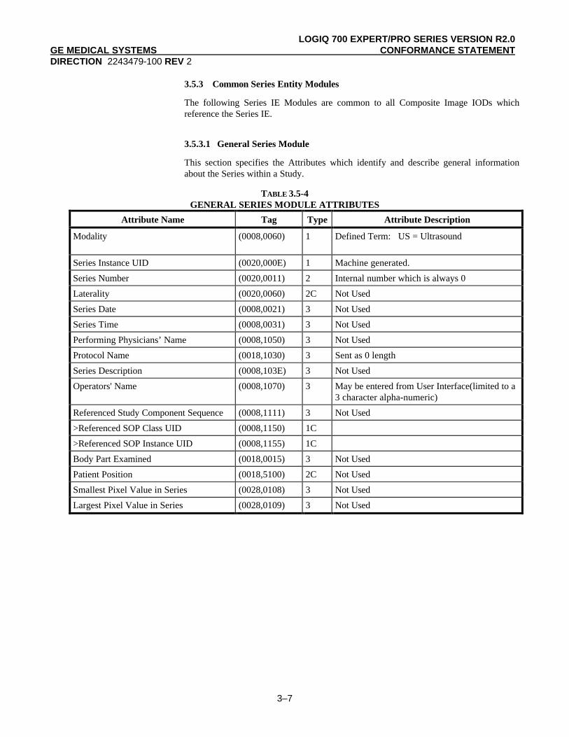
3.5.3.1 General Series Module
This section specifies the Attributes which identify and describe general informationabout the Series within a Study.
TABLE 3.5-4GENERAL SERIES MODULE ATTRIBUTES
Attribute Name Tag Type Attribute Description
Modality (0008,0060) 1 Defined Term: US = Ultrasound
Series Instance UID (0020,000E) 1 Machine generated.
Series Number (0020,0011) 2 Internal number which is always 0
Laterality (0020,0060) 2C Not Used
Series Date (0008,0021) 3 Not Used
Series Time (0008,0031) 3 Not Used
Performing Physicians’ Name (0008,1050) 3 Not Used
Protocol Name (0018,1030) 3 Sent as 0 length
Series Description (0008,103E) 3 Not Used
Operators' Name (0008,1070) 3 May be entered from User Interface(limited to a3 character alpha-numeric)
Referenced Study Component Sequence (0008,1111) 3 Not Used
>Referenced SOP Class UID (0008,1150) 1C
>Referenced SOP Instance UID (0008,1155) 1C
Body Part Examined (0018,0015) 3 Not Used
Patient Position (0018,5100) 2C Not Used
Smallest Pixel Value in Series (0028,0108) 3 Not Used
Largest Pixel Value in Series (0028,0109) 3 Not Used

LOGIQ 700 EXPERT/PRO SERIES VERSION R2.0GE MEDICAL SYSTEMS CONFORMANCE STATEMENTDIRECTION 2243479-100 REV 2
3–8
3.5.4 Common Equipment Entity Modules
The following Equipment IE Module is common to all Composite Image IODs whichreference the Equipment IE.
3.5.4.1 General Equipment Module
This section specifies the Attributes which identify and describe the piece of equipmentwhich produced a Series of Images.
TABLE 3.5-5GENERAL EQUIPMENT MODULE ATTRIBUTES
Attribute Name Tag Type Attribute Description
Manufacturer (0008,0070) 2 Implementation defined string “G.E. MedicalSystems”
Institution Name (0008,0080) 3 May be entered from User Interface. Default:“G.E. Medical Systems”
Institution Address (0008,0081) 3 Not Used
Station Name (0008,1010) 3 Network host name entered from User Interface
Institutional Department Name (0008,1040) 3 Not Used
Manufacturer's Model Name (0008,1090) 3 Implementation defined string “LOGIQ 700”
Device Serial Number (0018,1000) 3 Implementation defined machine serial number
Software Versions (0018,1020) 3 Implementation define string “R2.0”
Spatial Resolution (0018,1050) 3 Not Used
Date of Last Calibration (0018,1200) 3 Not Used
Time of Last Calibration (0018,1201) 3 Not Used
Pixel Padding Value (0028,0120) 3 Not Used
3.5.5 Common Image Entity Modules
The following Image IE Modules are common to all Composite Image IODs whichreference the Image IE.
3.5.5.1 General Image Module
This section specifies the Attributes which identify and describe an image within aparticular series.
TABLE 3.5-6GENERAL IMAGE MODULE ATTRIBUTES
Attribute Name Tag Type Attribute Description
Image Number (0020,0013) 2 Internal value which is incremented for eachcaptured image within a series (within a study)
Patient Orientation (0020,0020) 2C Sent as zero length.
Image Date (0008,0023) 2C Sent as zero length
Image Time (0008,0033) 2C Sent as zero length

LOGIQ 700 EXPERT/PRO SERIES VERSION R2.0GE MEDICAL SYSTEMS CONFORMANCE STATEMENTDIRECTION 2243479-100 REV 2
3–9
Image Type (0008,0008) 3 See 3.5.5.1.1.1.
Acquisition Number (0020,0012) 3 Not Used
Acquisition Date (0008,0022) 3 Not Used
Acquisition Time (0008,0032) 3 Not Used
Referenced Image Sequence (0008,1140) 3 Not Used
>Referenced SOP Class UID (0008,1150) 1C
>Referenced SOP Instance UID (0008,1155) 1C
Derivation Description (0008,2111) 3 Not Used
Source Image Sequence (0008,2112) 3 Not Used
>Referenced SOP Class UID (0008,1150) 1C
>Referenced SOP Instance UID (0008,1155) 1C
Images in Acquisition (0020,1002) 3 Not Used
Image Comments (0020,4000) 3 Not Used
Lossy Image Compression (0028,2110) 3 Not Used
3.5.5.1.1 General Image Attribute Descriptions
3.5.5.1.1.1 Image Type
Value 1 shall have the following Enumerated Values:
− ORIGINAL - identifies an Original Image when the image has been created bythe LOGIQ 700.
Value 2 shall have the following Enumerated Values:
− PRIMARY - identifies a Primary Image when the image has been created bythe LOGIQ 700.
See 3.5.7..1.1 for defined terms used for Value 3. Value sent with zero length if imageis not created by the LOGIQ 700.
3.5.5.2 Image Pixel Module
This section specified the Attributes that describe the pixel data of the image.
TABLE 3.5-7IMAGE PIXEL MODULE ATTRIBUTES
Attribute Name Tag Type Attribute Description
Samples per Pixel (0028,0002) 1 Value of ‘1’ when Photometric Interpretationelement value = ‘MONOCHROME2’;
Value of ‘3’ when Photometric Interpretationelement value = ‘RGB’
Photometric Interpretation (0028,0004) 1 Defined Values used:
MONOCHROME2RGB

LOGIQ 700 EXPERT/PRO SERIES VERSION R2.0GE MEDICAL SYSTEMS CONFORMANCE STATEMENTDIRECTION 2243479-100 REV 2
3–10
Rows (0028,0010) 1 Value always = 480d in 60Hz
Value always = 562d in 50Hz
Columns (0028,0011) 1 Value always = 640d in 60Hz
Value always = 768d in 50Hz
Bits Allocated (0028,0100) 1 Value always = 0008H
Bits Stored (0028,0101) 1 Value always = 0008H
High Bit (0028,0102) 1 Value always = 0007H
Pixel Representation (0028,0103) 1 Defined Value ‘0’ - unsigned integer
Pixel Data (7FE0,0010) 1
Planar Configuration (0028,0006) 1C Enumerated value 0001H, color-by-plane, isdefined by the LOGIQ 700.
Pixel Aspect Ratio (0028,0034) 1C Not Used because ratio is 1:1
Smallest Image Pixel Value (0028,0106) 3 Not Used
Largest Image Pixel Value (0028,0107) 3 Not Used
Red Palette Color Lookup TableDescriptor
(0028,1101) 1C Not used since (0028, 0004) value is neverPALETTE_COLOR or ARGB
Green Palette Color Lookup TableDescriptor
(0028,1102) 1C Not used since (0028, 0004) value is neverPALETTE_COLOR or ARGB
Blue Palette Color Lookup TableDescriptor
(0028,1103) 1C Not used since (0028, 0004) value is neverPALETTE_COLOR or ARGB
Red Palette Color Lookup Table Data (0028,1201) 1C Not used since (0028, 0004) value is neverPALETTE_COLOR or ARGB
Green Palette Color Lookup Table Data (0028,1202) 1C Not used since (0028, 0004) value is neverPALETTE_COLOR or ARGB
Blue Palette Color Lookup Table Data (0028,1203) 1C Not used since (0028, 0004) value is neverPALETTE_COLOR or ARGB

LOGIQ 700 EXPERT/PRO SERIES VERSION R2.0GE MEDICAL SYSTEMS CONFORMANCE STATEMENTDIRECTION 2243479-100 REV 2
3–11
3.5.6 General Modules
The SOP Common Module is mandatory for all DICOM IODs.
3.5.6.1 SOP Common Module
This section defines the Attributes which are required for proper functioning andidentification of the associated SOP Instances. They do not specify any semantics aboutthe Real-World Object represented by the IOD.
TABLE 3.5-8SOP COMMON MODULE ATTRIBUTES
Attribute Name Tag Type Attribute Description
SOP Class UID (0008,0016) 1 “1.2.840.10008.5.1.4.1.1.6.1” or“1.2.840.10008.5.1.4.1.1.6”
SOP Instance UID (0008,0018) 1 Machine generated.
Specific Character Set (0008,0005) 1C Not used as expanded or replacementcharacter sets not used
Instance Creation Date (0008,0012) 3 Not Used
Instance Creation Time (0008,0013) 3 Not Used
Instance Creator UID (0008,0014) 3 Not Used

LOGIQ 700 EXPERT/PRO SERIES VERSION R2.0GE MEDICAL SYSTEMS CONFORMANCE STATEMENTDIRECTION 2243479-100 REV 2
3–12
3.5.7 US Modules
This Section describes US Series, Equipment, and Image Modules. These Modulescontain Attributes that are specific to US Image IOD.
3.5.7.1 US Region Calibration Module
This section contains IOD Attributes that describe an ultrasound region calibration.
TABLE 3.5-9US REGION CALIBRATION MODULE ATTRIBUTES
Attribute Name Tag Type Attribute Description
Sequence of Ultrasound Regions (0018,6011) 1 Object always contains 4 regions, but may nothave data in each region.
>Region Location Min x0 (0018,6018) 1 Varies with scanning mode.
Values = 0, 10, 320
>Region Location Min y0 (0018,601A) 1 Varies with scanning mode.
Values = 0, 10, 252
>Region Location Max x1 (0018,601C) 1 Varies with scanning mode.
Values = 0, 319, 625
>Region Location Max y1 (0018,601E) 1 Varies with scanning mode.
Values = 0, 251, 319, 445
>Physical Units X Direction (0018,6024) 1 Enumerated Values supported:
0003H cm0004H seconds
>Physical Units Y Direction (0018,6026) 1 Enumerated Values supported:
0003H cm0004H seconds
0005H hertz(seconds-1 )0007H cm/sec
>Physical Delta X (0018,602C) 1 Varies with scanning mode
>Physical Delta Y (0018,602E) 1 Varies with scanning mode
>Reference Pixel x0 (0018,6020) 3 Varies with scanning mode
>Reference Pixel y0 (0018,6022) 3 Varies with scanning mode
>Ref. Pixel Physical Value X (0018,6028) 3 Value always = ‘0’
>Ref. Pixel Physical Value Y (0018,602A) 3 Value always = ‘0’
>Region Spatial Format (0018,6012) 1 Enumerated Values supported:0001H 2D
0002H M-Mode
0003H Spectral
>Region Data Type (0018,6014) 1 Enumerated Values supported:
0001H Tissue0006H Doppler Mode Trace

LOGIQ 700 EXPERT/PRO SERIES VERSION R2.0GE MEDICAL SYSTEMS CONFORMANCE STATEMENTDIRECTION 2243479-100 REV 2
3–13
>Region Flags (0018,6016) 1 Bit 1 Scaling Protection usedBit 2 Doppler Scale Type used
>Pixel Component Organization (0018,6044) 1C pixel component calibration data does not existfor any region.
>Pixel Component Mask (0018,6046) 1C Not used since Pixel Component Organization isnot used
>Pixel Component Range Start (0018,6048) 1C Not used since Pixel Component Organization isnot used
>Pixel Component Range Stop (0018,604A) 1C Not used since Pixel Component Organization isnot used
>Pixel Component Physical Units (0018,604C) 1C Not used since Pixel Component Organization isnot used
>Pixel Component Data Type (0018,604E) 1C Not used since Pixel Component Organization isnot used
>Number of Table Break Points (0018,6050) 1C Not used since Pixel Component Organization isnot used
>Table of X Break Points (0018,6052) 1C Not used since Pixel Component Organization isnot used
>Table of Y Break Points (0018,6054) 1C Not used since Pixel Component Organization isnot used
>Number of Table Entries (0018,6056) 1C Not used since Pixel Component Organization isnot used
>Table of Pixel Values (0018,6058) 1C Not used since Pixel Component Organization isnot used
>Table of Parameter Values (0018,605A) 1C Not used since Pixel Component Organization isnot used
>Transducer Frequency (0018,6030) 3 Hexadecimal value of current probe frequency,scaled by 16 bits
>Pulse Repetition Frequency (0018,6032) 3 Value always = ‘0’
>Doppler Correction Angle (0018,6034) 3 Not Used
>Steering Angle (0018,6036) 3 Not Used
>Doppler Sample Volume X Position (0018,6038) 3 Not Used
>Doppler Sample Volume Y Position (0018,603A) 3 Not Used
>TM-Line Position x0 (0018,603C) 3 Not Used
>TM-Line Position y0 (0018,603E) 3 Not Used
>TM-Line Position x1 (0018,6040) 3 Not Used
>TM-Line Position y1 (0018,6042) 3 Not Used

LOGIQ 700 EXPERT/PRO SERIES VERSION R2.0GE MEDICAL SYSTEMS CONFORMANCE STATEMENTDIRECTION 2243479-100 REV 2
3–14
3.5.7.2 US Image Module
This section specifies the Attributes that describe ultrasound images.
TABLE 3.5-10US IMAGE MODULE ATTRIBUTES
Attribute Name Tag Type Attribute Description
Samples Per Pixel (0028,0002) 1 Value of ‘1’ when Photometric Interpretationelement value = ‘MONOCHROME2’;
Value of ‘3’ when Photometric Interpretationelement value = ‘RGB’
Photometric Interpretation (0028,0004) 1 Defined Terms supported:
MONOCHROME2RGB
only values supported
Bits Allocated (0028,0100) 1 Value always = 0008H
Bits Stored (0028,0101) 1 Value always = 0008H
High Bit (0028,0102) 1 Value always = 0007H
Planar Configuration (0028,0006) 1C Enumerated value 0001H, color-by-plane.
Pixel Representation (0028,0103) 1 Always 0000H = unsigned integer.
Frame Increment Pointer (0028,0009) 1C Absent since image is single frame
Image Type (0008,0008) 2 See 3.5.7.2.1.1.
Lossy Image Compression (0028,2110) 1C Not Used
Number of Stages (0008,2124) 2C Value always = ‘1’
Number of Views in Stage (0008,212A) 2C Value always = ‘1’
Ultrasound Color Data Present (0028,0014) 3 Not Used
Referenced Overlay Sequence (0008,1130) 3 Not Used
>Referenced SOP Class UID (0008,1150) 1C
>Referenced SOP Instance UID (0008,1155) 1C
Referenced Curve Sequence (0008,1145) 3 Not Used
>Referenced SOP Class UID (0008,1150) 1C
>Referenced SOP Instance UID (0008,1155) 1C
Stage Name (0008,2120) 3 Field sent with NULL value
Stage Number (0008,2122) 3 Value always = ‘0’
View Number (0008,2128) 3 Value always = ‘0’
Number of Event Timers (0008,2129) 3 Not Used
Event Elapsed Time(s) (0008,2130) 3 Not Used
Event Timer Name(s) (0008,2132) 3 Not Used
Anatomic Region Sequence (0008,2218) 3 Not Used
>Code Value (0008,0100) 1C
>Coding Scheme Designator (0008,0102) 1C
>Code Meaning (0008,0104) 3

LOGIQ 700 EXPERT/PRO SERIES VERSION R2.0GE MEDICAL SYSTEMS CONFORMANCE STATEMENTDIRECTION 2243479-100 REV 2
3–15
>Anatomic Region Modifier Sequence (0008,2220) 3 Not Used
>>Code Value (0008,0100) 1C
>>Coding Scheme Designator (0008,0102) 1C
>>Code Meaning (0008,0104) 3
Primary Anatomic Structure Sequence (0008,2228) 3 Not Used
>Code Value (0008,0100) 1C
>Coding Scheme Designator (0008,0102) 1C
>Code Meaning (0008,0104) 3
>Primary Anatomic Structure ModifierSequence
(0008,2230) 3 Not Used
>>Code Value (0008,0100) 1C
>>Coding Scheme Designator (0008,0102) 1C
>>Code Meaning (0008,0104) 3
Transducer Position Sequence (0008,2240) 3 Not Used
>Code Value (0008,0100) 1C
>Coding Scheme Designator (0008,0102) 1C
>Code Meaning (0008,0104) 3
> Transducer Position Modifier Sequence (0008,2242) 3 Not Used
>>Code Value (0008,0100) 1C
>>Coding Scheme Designator (0008,0102) 1C
>>Code Meaning (0008,0104) 3
Transducer Orientation Sequence (0008,2244) 3 Not Used
>Code Value (0008,0100) 1C
>Coding Scheme Designator (0008,0102) 1C
>Code Meaning (0008,0104) 3 Not Used
> Transducer Orientation ModifierSequence
(0008,2246) 3 Not Used
>>Code Value (0008,0100) 1C
>>Coding Scheme Designator (0008,0102) 1C
>>Code Meaning (0008,0104) 3 Not Used
Trigger Time (0018,1060) 3 Not Used
Nominal Interval (0018,1062) 3 Not Used
Beat Rejection Flag (0018,1080) 3 Not Used
Low R-R Value (0018,1081) 3 Not Used
High R-R Value (0018,1082) 3 Not Used
Heart Rate (0018,1088) 3 Not Used
Output Power (0018,5000) 3 Not Used
Transducer Data (0018,5010) 3 Not Used
Transducer Type (0018,6031) 3 Not Used

LOGIQ 700 EXPERT/PRO SERIES VERSION R2.0GE MEDICAL SYSTEMS CONFORMANCE STATEMENTDIRECTION 2243479-100 REV 2
3–16
Focus Depth (0018,5012) 3 Not Used
Preprocessing Function (0018,5020) 3 Not Used
Mechanical Index (0018,5022) 3 Not Used
Bone Thermal Index, (0018,5024) 3 Not Used
Cranial Thermal Index (0018,5026) 3 Not Used
Soft Tissue Thermal Index (0018,5027) 3 Not Used
Soft Tissue-focus Thermal Index (0018,5028) 3 Not Used
Soft Tissue-surface Thermal Index (0018,5029) 3 Not Used
Depth of Scan Field (0018,5050) 3 Not Used
Image Transformation Matrix (0018,5210) 3 Not Used
Image Translation Vector (0018,5212) 3 Not Used
Overlay Subtype (60xx,0045) 3 Not Used
3.5.7.2.1 US Image Attribute Descriptions
3.5.7.2.1.1 Image Type
The following Defined Terms for Value 3 are created:
VASCULAR OBSTETRICAL
SMALL PARTS PEDIATRIC

LOGIQ 700 EXPERT/PRO SERIES VERSION R2.0GE MEDICAL SYSTEMS CONFORMANCE STATEMENTDIRECTION 2243479-100 REV 2
4-1
4. SC INFORMATION OBJECT IMPLEMENTATION
4.1 INTRODUCTION
This section specifies the use of the DICOM SC Image IOD torepresent the information included in SC images produced by thisimplementation. Corresponding attributes are conveyed using themodule construct. The contents of this section are:
4.2 - IOD Description
4.3 - IOD Entity-Relationship Model
4.4 - IOD Module Table
4.5 - IOD Module Definition
4.2 SC IOD IMPLEMENTATION
4.3 SC ENTITY-RELATIONSHIP MODEL
The Entity-Relationship diagram for the SC Image interoperabilityschema is shown in Illustration 4.3-1. In this figure, the followingdiagrammatic convention is established to represent the informationorganization :
• each entity is represented by a rectangular box
• each relationship is represented by a diamond shaped box.
• the fact that a relationship exists between two entities is depictedby lines connecting the corresponding entity boxes to therelationship boxes.
The relationships are fully defined with the maximum number ofpossible entities in the relationship shown.

LOGIQ 700 EXPERT/PRO SERIES VERSION R2.0GE MEDICAL SYSTEMS CONFORMANCE STATEMENTDIRECTION 2243479-100 REV 2
4-2
ILLUSTRATION 4.3-1SC IMAGE ENTITY RELATIONSHIP DIAGRAM
Patient
Study
isthe subject
of
contains
creates
Equipment
SC Image
contains
Series
0,999
1 11,999
1
1
1
1
4.3.1 ENTITY DESCRIPTIONS
Please refer to DICOM Standard Part 3 (Information ObjectDefinitions) for a description of each of the entities contained withinthe SC Information Object.

LOGIQ 700 EXPERT/PRO SERIES VERSION R2.0GE MEDICAL SYSTEMS CONFORMANCE STATEMENTDIRECTION 2243479-100 REV 2
4-3
4.3.1.1 Series Entity Description
4.3.1.2 Equipment Entity Description
4.3.1.3 SC Image Entity Description
4.3.1.4 Overlay Entity Description
4.3.1.5 VOI Lookup Table Entity Description
4.3.2 LOGIQ 700 Mapping of DICOM entities
TABLE 4.3-1MAPPING OF DICOM ENTITIES TO LOGIQ 700 ENTITIES
DICOM LOGIQ 700 Entity
Patient Patient
Study Exam
Series Series
Image Image
Frame Not Applicable
4.4 IOD MODULE TABLE
Within an entity of the DICOM v3.0 SC IOD, attributes are groupedinto related set of attributes. A set of related attributes is termed amodule. A module facilitates the understanding of the semanticsconcerning the attributes and how the attributes are related with eachother. A module grouping does not infer any encoding of informationinto datasets.
Table 4.4-1 identifies the defined modules within the entities whichcomprise the DICOM v3.0 SC IOD. Modules are identified by ModuleName.
See DICOM v3.0 Part 3 for a complete definition of the entities,modules, and attributes.

LOGIQ 700 EXPERT/PRO SERIES VERSION R2.0GE MEDICAL SYSTEMS CONFORMANCE STATEMENTDIRECTION 2243479-100 REV 2
4-4
TABLE 4.4-1 SC IMAGE IOD MODULES
Entity Name Module Name Reference
Patient Patient 4.5.1.1
Study General Study 4.5.2.1
Patient Study 4.5.2.2
Series General Series 4.5.3.1
Equipment General Equipment 4.5.4.1
SC Equipment 4.5.8.1
Image General Image 4.5.5.1
Image Pixel 4.5.5.2
SC Image 4.5.8.2
Overlay Plane Not Used
Modality LUT Not Used
VOI LUT Not Used
SOP Common 4.5.7.1
4.5 INFORMATION MODULE DEFINITIONS
Please refer to DICOM v3.0 Standard Part 3 (Information ObjectDefinitions) for a description of each of the entities and modulescontained within the SC Information Object.
The following modules are included to convey Enumerated Values,Defined Terms, and Optional Attributes supported. Type 1 & Type 2Attributes are also included for completeness and to define what valuesthey may take and where these values are obtained from. It should benoted that they are the same ones as defined in the DICOM v3.0Standard Part 3 (Information Object Definitions).

LOGIQ 700 EXPERT/PRO SERIES VERSION R2.0GE MEDICAL SYSTEMS CONFORMANCE STATEMENTDIRECTION 2243479-100 REV 2
4-5
4.5.1 Common Patient Entity Modules
4.5.1.1 Patient Module
This section specifies the Attributes of the Patient that describe andidentify the Patient who is the subject of a diagnostic Study. ThisModule contains Attributes of the patient that are needed fordiagnostic interpretation of the Image and are common for all studiesperformed on the patient.
TABLE 4.5-1 PATIENT MODULE ATTRIBUTES
Attribute Name Tag Type Attribute Description
Patient's Name (0010,0010) 2 User Interface/Worklist Broker, Last Name:17 alpha-numeric displayed, up to 64 retrievedfrom worklist; First Name: 10 alpha-numericdisplayed, up to 64 retrieved from worklist;Middle Name: 1 alpha-numeric displayed, butcan store up to 64(retrieved from worklist)
Patient ID (0010,0020) 2 User Interface/Worklist Broker, 14 alpha-numeric
Patient's Birth Date (0010,0030) 2 User Interface/Worklist Broker, Y2KCompliant
Patient's Sex (0010,0040) 2 User Interface/Worklist Broker, F-Female M-Male
Referenced Patient Sequence (0008,1120) 3 Not Used
>Referenced SOP Class UID (0008,1150) 1C
>Referenced SOP Instance UID (0008,1155) 1C
Patient's Birth Time (0010,0032) 3 May be entered from User Interface(pediatricsexam only)
Other Patient IDs (0010,1000) 3 Not Used
Other Patient Names (0010,1001) 3 Not Used
Ethnic Group (0010,2160) 3 Not Used
Patient Comments (0010,4000) 3 Not Used
4.5.2 Common Study Entity Modules
The following Study IE Modules are common to all Composite ImageIODs which reference the Study IE. These Module contain Attributesof the patient and study that are needed for diagnostic interpretation ofthe image.

LOGIQ 700 EXPERT/PRO SERIES VERSION R2.0GE MEDICAL SYSTEMS CONFORMANCE STATEMENTDIRECTION 2243479-100 REV 2
4-6
4.5.2.1 General Study Module
This section specifies the Attributes which describe and identify theStudy performed upon the Patient.
TABLE 4.5-2GENERAL STUDY MODULE ATTRIBUTES
Attribute Name Tag Type Attribute Description
Study Instance UID (0020,000D) 1 Generated using GEMS UID + LOGIQ700implementation UID + device serial number +study date + study time + study ID
Study Date (0008,0020) 2 Study begin date
Study Time (0008,0030) 2 Study begin time
Referring Physician's Name (0008,0090) 2 May be entered from User Interface
Study ID (0020,0010) 2 Internal value which is incremented when userdefines a New Patient
Accession Number (0008,0050) 2 May be entered from User Interface orWorklist
Study Description (0008,1030) 3 Not Used
Physician(s) of Record (0008,1048) 3 Not Used
Name of Physician(s) Reading Study (0008,1060) 3 Not Used
Referenced Study Sequence (0008,1110) 3 Not Used
>Referenced SOP Class UID (0008,1150) 1C
>Referenced SOP Instance UID (0008,1155) 1C
4.5.2.2 Patient Study Module
This section defines Attributes that provide information about thePatient at the time the Study was performed.
TABLE 4.5-3PATIENT STUDY MODULE ATTRIBUTES
Attribute Name Tag Type Attribute Description
Admitting Diagnoses Description (0008,1080) 3 Not Used
Patient's Age (0010,1010) 3 Calculated from DOB entered from UserInterface or Worklist
Patient's Size (0010,1020) 3 May be entered from User Interface(vascularexam only)
Patient's Weight (0010,1030) 3 May be entered from User Interface(vascularexam only)
Occupation (0010,2180) 3 Not Used
Additional Patient’s History (0010,21B0) 3 May be entered from User Interface

LOGIQ 700 EXPERT/PRO SERIES VERSION R2.0GE MEDICAL SYSTEMS CONFORMANCE STATEMENTDIRECTION 2243479-100 REV 2
4-7
4.5.3 Common Series Entity Modules
The following Series IE Modules are common to all Composite ImageIODs which reference the Series IE.
4.5.3.1 General Series Module
This section specifies the Attributes which identify and describegeneral information about the Series within a Study.
TABLE 4.5-4GENERAL SERIES MODULE ATTRIBUTES
Attribute Name Tag Type Attribute Description
Modality (0008,0060) 1 Defined term is “US”
Series Instance UID (0020,000E) 1 Generated using GEMS UID + LOGIQ700implementation UID + device serial number +study date + study time + study ID + series ID
Series Number (0020,0011) 2 Internal number which is always 0
Laterality (0020,0060) 2C Not Used
Series Date (0008,0021) 3 Not Used
Series Time (0008,0031) 3 Not Used
Performing Physicians’ Name (0008,1050) 3 Not Used
Protocol Name (0018,1030) 3 Not Used
Series Description (0008,103E) 3 Not Used
Operators' Name (0008,1070) 3 May be entered from User Interface - 3characters, alpha-numeric
Referenced Study Component Sequence (0008,1111) 3 Not Used
>Referenced SOP Class UID (0008,1150) 1C
>Referenced SOP Instance UID (0008,1155) 1C
Body Part Examined (0018,0015) 3 Not Used
Patient Position (0018,5100) 2C Not Used
Smallest Pixel Value in Series (0028,0108) 3 Not Used
Largest Pixel Value in Series (0028,0109) 3 Not Used

LOGIQ 700 EXPERT/PRO SERIES VERSION R2.0GE MEDICAL SYSTEMS CONFORMANCE STATEMENTDIRECTION 2243479-100 REV 2
4-8
4.5.4 Common Equipment Entity Modules
The following Equipment IE Module is common to all CompositeImage IODs which reference the Equipment IE.
4.5.4.1 General Equipment Module
This section specifies the Attributes which identify and describe thepiece of equipment which produced a Series of Images.
TABLE 4.5-5GENERAL EQUIPMENT MODULE ATTRIBUTES
Attribute Name Tag Type Attribute Description
Manufacturer (0008,0070) 2 Implementation defined string “G.E. MedicalSystems”
Institution Name (0008,0080) 3 May be entered from User Interface. Default:“G.E. Medical Systems”
Institution Address (0008,0081) 3 Not Used
Station Name (0008,1010) 3 Network host name entered from User Interface
Institutional Department Name (0008,1040) 3 Not Used
Manufacturer's Model Name (0008,1090) 3 Implementation defined string “LOGIQ 700”
Device Serial Number (0018,1000) 3 Implementation defined machine serial number
Software Versions (0018,1020) 3 Implementation define string “R2.0”
Spatial Resolution (0018,1050) 3 Not Used
Date of Last Calibration (0018,1200) 3 Not Used
Time of Last Calibration (0018,1201) 3 Not Used
Pixel Padding Value (0028,0120) 3 Not Used
4.5.5 Common Image Entity Modules
The following Image IE Modules are common to all Composite ImageIODs which reference the Image IE.
4.5.5.1 General Image Module
This section specifies the Attributes which identify and describe animage within a particular series.
TABLE 4.5-6GENERAL IMAGE MODULE ATTRIBUTES
Attribute Name Tag Type Attribute Description
Image Number (0020,0013) 2 Internal value which is incremented for eachcaptured image within a series (within a study)
Patient Orientation (0020,0020) 2C Sent as zero length.
Image Date (0008,0023) 2C Sent as zero length

LOGIQ 700 EXPERT/PRO SERIES VERSION R2.0GE MEDICAL SYSTEMS CONFORMANCE STATEMENTDIRECTION 2243479-100 REV 2
4-9
Image Time (0008,0033) 2C Sent as zero length
Image Type (0008,0008) 3 See 4.5.5.1.1.1.
Acquisition Number (0020,0012) 3 Not Used
Acquisition Date (0008,0022) 3 Not Used
Acquisition Time (0008,0032) 3 Not Used
Referenced Image Sequence (0008,1140) 3 Not Used
>Referenced SOP Class UID (0008,1150) 1C
>Referenced SOP Instance UID (0008,1155) 1C
Derivation Description (0008,2111) 3 Not Used
Source Image Sequence (0008,2112) 3 Not Used
>Referenced SOP Class UID (0008,1150) 1C
>Referenced SOP Instance UID (0008,1155) 1C
Images in Acquisition (0020,1002) 3 Not Used
Image Comments (0020,4000) 3 Not Used
Lossy Image Compression (0028,2110) 3 Not Used
4.5.5.1.1 General Image Attribute Descriptions
4.5.5.1.1.1 Image Type
Value 1 shall have the following Enumerated Values:
− ORIGINAL - identifies an Original Image when the imagehas been created by the LOGIQ 700
Value 2 shall have the following Enumerated Values:
− PRIMARY - identifies a Primary Image when the image hasbeen created by the LOGIQ 700
Value sent with zero length if image not created by the LOGIQ 700.
4.5.5.2 Image Pixel Module
This section specifies the Attributes that describe the pixel data of theimage.
TABLE 4.5-7IMAGE PIXEL MODULE ATTRIBUTES
Attribute Name Tag Type Attribute Description
Samples per Pixel (0028,0002) 1 Value of ‘1’ when Photometric Interpretationelement value = ‘MONOCHROME’;
Value of ‘3’ when Photometric Interpretationelement value = ‘RGB’
Photometric Interpretation (0028,0004) 1 Defined Values used:
MONOCHROME2RGB

LOGIQ 700 EXPERT/PRO SERIES VERSION R2.0GE MEDICAL SYSTEMS CONFORMANCE STATEMENTDIRECTION 2243479-100 REV 2
4-10
Rows (0028,0010) 1 Value always = 480d in 60Hz
Value always = 562d in 50Hz
Columns (0028,0011) 1 Value always = 640d in 60Hz
Value always = 768d in 50Hz
Bits Allocated (0028,0100) 1 Value always = 0008H
Bits Stored (0028,0101) 1 Value always = 0008H
High Bit (0028,0102) 1 Value always = 0007H
Pixel Representation (0028,0103) 1 Defined Value ‘0’ - unsigned integer
Pixel Data (7FE0,0010) 1
Planar Configuration (0028,0006) 1C Enumerated value 0001H, color-by-plane, isdefined by the LOGIQ 700. Color-by-pixel maybe configured.
Pixel Aspect Ratio (0028,0034) 1C 1/1
Smallest Image Pixel Value (0028,0106) 3 Not Used
Largest Image Pixel Value (0028,0107) 3 Not Used
Red Palette Color Lookup TableDescriptor
(0028,1101) 1C Not used since (0028, 0004) value is neverPALETTE_COLOR or ARGB
Green Palette Color Lookup TableDescriptor
(0028,1102) 1C Not used since (0028, 0004) value is neverPALETTE_COLOR or ARGB
Blue Palette Color Lookup TableDescriptor
(0028,1103) 1C Not used since (0028, 0004) value is neverPALETTE_COLOR or ARGB
Red Palette Color Lookup Table Data (0028,1201) 1C Not used since (0028, 0004) value is neverPALETTE_COLOR or ARGB
Green Palette Color Lookup Table Data (0028,1202) 1C Not used since (0028, 0004) value is neverPALETTE_COLOR or ARGB
Blue Palette Color Lookup Table Data (0028,1203) 1C Not used since (0028, 0004) value is neverPALETTE_COLOR or ARGB

LOGIQ 700 EXPERT/PRO SERIES VERSION R2.0GE MEDICAL SYSTEMS CONFORMANCE STATEMENTDIRECTION 2243479-100 REV 2
4-11
4.5.6 Common Overlay Modules
4.5.6.1 Overlay plane module
Not used in this implementation.
4.5.7 General Modules
The SOP Common Module is mandatory for all DICOM IODs.
4.5.7.1 SOP Common Module
This section defines the Attributes which are required for properfunctioning and identification of the associated SOP Instances. Theydo not specify any semantics about the Real-World Object representedby the IOD.
TABLE 4.5-8SOP COMMON MODULE ATTRIBUTES
Attribute Name Tag Type Attribute Description
SOP Class UID (0008,0016) 1 1.2.840.10008.5.1.4.1.1.7
SOP Instance UID (0008,0018) 1 Generated using GEMS UID + LOGIQ700implementation UID + device serial number +study date + study time + study ID + series ID+ image ID
Specific Character Set (0008,0005) 1C Not used, as expanded or replacementcharacter sets not used.
Instance Creation Date (0008,0012) 3 Not Used
Instance Creation Time (0008,0013) 3 Not Used
Instance Creator UID (0008,0014) 3 Not Used

LOGIQ 700 EXPERT/PRO SERIES VERSION R2.0GE MEDICAL SYSTEMS CONFORMANCE STATEMENTDIRECTION 2243479-100 REV 2
4-12
4.5.8 SC Modules
This Section describes SC Equipment, and Image Modules. TheseModules contain Attributes that are specific to SC Image IOD.
4.5.8.1 SC Equipment Module
This Module describes equipment used to convert images into aDICOM format.
TABLE 4.5-9SC IMAGE EQUIPMENT MODULE ATTRIBUTES
Attribute Name Tag Type Attribute DescriptionConversion Type (0008,0064) 1 Defined term DI = Digital Interface used
Modality (0008,0060) 3 Defined value “US” used
Secondary Capture Device ID (0018,1010) 3 Not Used
Secondary Capture Device Manufacturer (0018,1016) 3 Implementation defined string “G.E. MedicalSystems”
Secondary Capture DeviceManufacturer's Model Name
(0018,1018) 3 Implementation defined string “LOGIQ 700”
Secondary Capture Device SoftwareVersion
(0018,1019) 3 Implementation defined string “R2.0”
Video Image Format Acquired (0018,1022) 3 Not Used
Digital Image Format Acquired (0018,1023) 3 Not Used
4.5.8.2 SC Image Module
The table in this Section contains IOD Attributes that describe SCimages.
TABLE 4.5-10SC IMAGE MODULE ATTRIBUTES
Attribute Name Tag Type Attribute DescriptionDate of Secondary Capture (0018,1012) 3 Study begin date
Time of Secondary Capture (0018,1014) 3 Study begin time

LOGIQ 700 EXPERT/PRO SERIES VERSION R2.0GE MEDICAL SYSTEMS DICOM CONFORMANCE STATEMENTDIRECTION 2243479-100 REV 2
5–1
5. PRINT MANAGEMENT SOP CLASS DEFINITION
5.1 INTRODUCTION
This section of the DICOM Conformance Statement specifies the supported PrintManagement SOP and Meta SOP Classes, the optional attributes and service elementssupported, the valid range of values for mandatory and optional attributes, and the statuscode behavior.
5.2 - Basic Print Management Meta SOP Classes
5.3 - Print Management SOP Class Definitions
5.4 - Print Management IODs
5.5 - IOD Module Definition
5.2 BASIC PRINT MANAGEMENT META SOP CLASSES
The Basic Print Management Meta SOP Classes correspond with the minimumfunctionality that an implementation of the Print Management Service Class shallsupport.
The LOGIQ 700 supports the Basic Grayscale Print Management Meta SOP Class andthe Basic Color Print Management Meta SOP Class. These are defined in Table 5.2.1-1and Table 5.2.2-1.
5.2.1 Basic Grayscale Print Management Meta SOP Class
The Basic Grayscale Print Management Meta SOP Class is defined by the following setof supported SOP Classes.
TABLE 5.2.1-1 BASIC GRAYSCALE PRINT MANAGEMENT META SOP CLASS
SOP Class Name Usage SCU/SCP Reference
Basic Film Session SOP Class M/M see 5.3.1
Basic Film Box SOP Class M/M see 5.3.2
Basic Grayscale Image Box SOP Class M/M see 5.3.3.1
Printer SOP Class M/M see 5.3.4
5.2.2 Basic Color Print Management Meta SOP Class
The Basic Color Print Management Meta SOP Class is defined by the following set ofsupported SOP Classes

LOGIQ 700 EXPERT/PRO SERIES VERSION R2.0GE MEDICAL SYSTEMS DICOM CONFORMANCE STATEMENTDIRECTION 2243479-100 REV 2
5–2
TABLE 5.2.2-1 BASIC COLOR PRINT MANAGEMENT META SOP CLASS
SOP Class Name Usage SCU Reference
Basic Film Session SOP Class M see 5.3.1
Basic Film Box SOP Class M see 5.3.2
Basic Color Image Box SOP Class M see 5.3.3.2
Printer SOP Class M see 5.3.4
5.3 PRINT MANAGEMENT SOP CLASS DEFINITIONS
5.3.1 Basic Film Session SOP Class
The Basic Film Session IOD describes the presentation parameters which are commonfor all the films of a film session. The DIMSE services that are applicable to the IODare shown in Table 5.3.1-1..
TABLE 5.3.1-1 DIMSE SERVICE GROUP
DIMSE Service Element Usage SCU Reference
N-CREATE M see 5.3.1.1.1
N-SET U see 5.3.1.1.2
N-DELETE U see 5.3.1.1.3
N-ACTION U see 5.3.1.1.4
5.3.1.1 DIMSE Service Group
5.3.1.1.1 N-CREATE
The N-CREATE DIMSE Service is used by the LOGIQ 700 to request that the SCP(printer) create a Film Session SOP Instance. Table 5.4.2-1 defines the Basic FilmSession Presentation Module attributes used in this request.
5.3.1.1.2 N-SET
Not used in this implementation.
5.3.1.1.3 N-DELETE
Not used in this implementation.
5.3.1.1.4 N-ACTION
Not used in this implementation
5.3.2 Basic Film Box SOP Class
The Basic Film Box IOD is an abstraction of the presentation of one film of the filmsession. The DIMSE services that are applicable to the IOD are shown in Table 5.3.2-1.

LOGIQ 700 EXPERT/PRO SERIES VERSION R2.0GE MEDICAL SYSTEMS DICOM CONFORMANCE STATEMENTDIRECTION 2243479-100 REV 2
5–3
TABLE 5.3.2-1 DIMSE SERVICE GROUP
DIMSE Service Element Usage SCU Reference
N-CREATE M see 5.3.2.1.1
N-ACTION M see 5.3.2.1.2
N-DELETE U see 5.3.2.1.3
N-SET U see 5.3.2.1.4
5.3.2.1 DIMSE Service Group
5.3.2.1.1 N-CREATE
The N-CREATE DIMSE Service is used by the LOGIQ 700 to request that the SCPcreate a Film Box SOP Instance. Table 5.4.2-1 defines the Basic Film Box PresentationModule attributes used in this request.
5.3.2.1.2 N-ACTION
The N-ACTION DIMSE Service is used by the LOGIQ 700 to request the SCP (printer)to print the number of copies configured by the user to a film of the film session.
5.3.2.1.3 N-DELETE
The N-DELETE DIMSE Service is used by the LOGIQ 700 to request the SCP (printer)to delete the complete Film Box. The root Film Box Instance UID is sent to the SCP toaccomplish this.
5.3.2.1.4 N-SET
Not used in this implementation.
5.3.3 Image Box SOP Class
5.3.3.1 Basic Grayscale Image Box SOP Class
The Basic Grayscale Image Box IOD is an abstraction of the presentation of an imageand image related data in the image area of a film. The DIMSE services that areapplicable to the IOD are shown in Table 5.3.3-1.
TABLE 5.3.3-1 DIMSE SERVICE GROUP
DIMSE Service Element Usage SCU Reference
N-SET M see 5.3.3.1.1
5.3.3.1.1 DIMSE Service Group (N-SET)
The N-SET DIMSE Service is used by the LOGIQ 700 to update the Basic GrayscaleImage Box SOP Instance. Table 5.5.2-5 defines the Basic Image Box PresentationModule attributes used.

LOGIQ 700 EXPERT/PRO SERIES VERSION R2.0GE MEDICAL SYSTEMS DICOM CONFORMANCE STATEMENTDIRECTION 2243479-100 REV 2
5–4
5.3.3.2 Basic Color Image Box SOP Class
The Basic Color Image Box IOD is an abstraction of the presentation of an image andimage related data in the image area of a film. The DIMSE services that are applicableto the IOD are shown in Table 5.3.3-2.
TABLE 5.3.3-2 DIMSE SERVICE GROUP
DIMSE Service Element Usage SCU Reference
N-SET M see 5.3.3.2.1
5.3.3.2.1 DIMSE Service Group (N-SET)
The N-SET DIMSE Service is used by the LOGIQ 700 to update the Basic Color ImageBox SOP Instance. Table 5.5.2-5 defines the Basic Image Box Presentation Moduleattributes used.
5.3.4 Printer SOP Class
The Printer IOD is an abstraction of the hard copy printer and is the basic InformationEntity to monitor the status of the printer. The DIMSE services that are applicable to theIOD are shown in table 5.3.4-1.
5.3.4.1 DIMSE Service Group
TABLE 5.3.4-1 DIMSE SERVICE GROUP
DIMSE Service Element Usage SCU Reference
N-EVENT-REPORT M see 5.3.4.1.1
N-GET U see 5.3.4.1.2
5.3.4.1.1 N-EVENT_REPORT
The LOGIQ 700 confirms the N-EVENT-REPORT initiated by the SCP (printer).
5.3.4.1.2 N-GET
Used by the LOGIQ 700 to request the SCP to get a Printer SOP Instance. Table 5.5.2-6defines the Printer Module attributes.
5.4 PRINT MANAGEMENT IODS
Within an entity of a DICOM v3.0 Print Management, attributes are grouped into arelated set of attributes. A set of related attributes is termed a module. A modulefacilitates the understanding of the semantics concerning the attributes and how theattributes are related with each other. A module grouping does not infer any encodingof information into datasets.
Table 5.4.1-1, Table 5.4.2-1, Table 5.4.3-1, and Table 5.4.4-1 identify the definedmodules within the entities which comprise the DICOM v3.0 Print Management ServiceIODs. Modules are identified by Module Name.
See DICOM v3.0 for a complete definition of the entities, modules and attributes.

LOGIQ 700 EXPERT/PRO SERIES VERSION R2.0GE MEDICAL SYSTEMS DICOM CONFORMANCE STATEMENTDIRECTION 2243479-100 REV 2
5–5
5.4.1 Film Session IOD Module
TABLE 5.4.1-1 FILM SESSION IOD MODULES
Module Name Reference Module Description
Error! Reference source notfound.
Error!Referencesource not
found.
Contains SOP Common information
Basic Film SessionPresentation Module
5.5.2.1 Contains Film Session presentationinformation
Basic Film SessionRelationship Module
5.5.2.2 References to related SOPs
5.4.2 Basic Film Box IOD Module Table
TABLE 5.4.2-1 BASIC FILM BOX IOD MODULES
Module Name Reference
Error! Reference source not found. Error! Referencesource not found.
Basic Film Box Presentation Module 5.5.2.3
Basic Film Box Relationship Module 5.5.2.2
5.4.3 Basic Image Box IOD Module Table
TABLE 5.4.3-1 BASIC IMAGE BOX IOD MODULES
Module Name Reference
Error! Reference source not found. Error! Referencesource not found.
Image Box Pixel Presentation Module 5.5.2.5
Image Box Relationship Module not used
5.4.4 Printer IOD Module Table
TABLE 5.4.4-1 PRINTER IOD MODULES
Module Name Reference
Error! Reference source not found. Error! Referencesource not found.
Printer Module 5.5.2.6
5.5 INFORMATION MODULE DEFINITIONS
Please refer to DICOM v3.0 Standard Part 3 (Information Object Definitions) for adescription of each of the entities and modules that comprise the Print Management.

LOGIQ 700 EXPERT/PRO SERIES VERSION R2.0GE MEDICAL SYSTEMS DICOM CONFORMANCE STATEMENTDIRECTION 2243479-100 REV 2
5–6
The following modules are included to convey Enumerated Values, Defined Terms, andOptional Attributes supported.
5.5.1 General Modules
5.5.2 Print Management Modules
5.5.2.1 Basic Film Session Presentation Module
This section defines the Attributes which are common for all films of a film session. Theattributes described in table 5.5.2-1 apply when the N-CREATE DIMSE service is used.
TABLE 5.5.2-1 BASIC FILM SESSION PRESENTATION MODULE ATTRIBUTES
Attribute Name Tag USAGE(SCU)
Attribute Description
Number of Copies (2000,0010) U Defined Terms used (user configurable):
default is 1, Maximum is 99.
Print Priority (2000,0020) U Defined Terms used (user configurable):
HIGH - default
MEDIUM
LOW
Medium Type (2000,0030) U Defined Terms used (user configurable):
PAPER
BLUE FILM
CLEAR FILM
Film Destination (2000,0040) U Defined Terms used (user configurable):
MAGAZINE - default
PROCESSOR
Film Session Label (2000,0050) U 58 alpha-numeric characters. Entered on aper device basis on the User Interface.Default is 0 length.
Memory Allocation (2000,0060) U Not Used
5.5.2.2 Basic Film Session Relationship Module
TABLE 5.5.2-2 BASIC FILM SESSION RELATIONSHIP MODULE ATTRIBUTES
Attribute Name Tag USAGE(SCU)
Attribute Description
Referenced Film Box Sequence (2000,0500) U Not used
>Referenced SOP Class UID (0008,1150) U
>Referenced SOP Instance UID (0008,1155) U

LOGIQ 700 EXPERT/PRO SERIES VERSION R2.0GE MEDICAL SYSTEMS DICOM CONFORMANCE STATEMENTDIRECTION 2243479-100 REV 2
5–7
5.5.2.3 Basic Film Box Presentation Module
The attributes described in table 5.5.2-3 apply when the N-CREATE DIMSE service isused.

LOGIQ 700 EXPERT/PRO SERIES VERSION R2.0GE MEDICAL SYSTEMS DICOM CONFORMANCE STATEMENTDIRECTION 2243479-100 REV 2
5–8
TABLE 5.5.2-3 BASIC FILM BOX PRESENTATION MODULE ATTRIBUTES
Attribute Name Tag USAGE(SCU)
Attribute Description
Image Display Format (2010,0010) U Enumerated values used (user configurable):
STANDARD\1,1 - default
STANDARD\2,1
STANDARD\2,2
STANDARD\2,3
STANDARD\2,4
STANDARD\3,2
STANDARD\3,3
STANDARD\3,4
STANDARD\3,5
STANDARD\4,2
STANDARD\4,3
STANDARD\4,4
STANDARD\4,5
STANDARD\5,3
STANDARD\5,4
Annotation Display Format ID (2010,0030) U Sent as zero length.
Film Orientation (2010,0040) U Defined Terms used (user configurable):
PORTRAIT - default
LANDSCAPE
Film Size ID (2000,0050) U Defined Terms used(user configurable) :
8INX10IN - default
10INX12IN
10INX14IN
11INX14IN
14INX14IN
14INX17IN
24CMX24CM
24CMX30CM
Magnification Type (2010,0060) U Defined Terms Used (user configurable) :
REPLICATE - default
BILINEAR
CUBIC
NONE
Smoothing Type (2010,0080) U 9 alpha-numeric characters entered on a perdevice basis on the User Interface

LOGIQ 700 EXPERT/PRO SERIES VERSION R2.0GE MEDICAL SYSTEMS DICOM CONFORMANCE STATEMENTDIRECTION 2243479-100 REV 2
5–9
Border Density (2010,0100) U Defined Terms Used (user configurable) :
BLACK
WHITE
FIFTY = 195 (FIFTY is what appears inUI. 195 is the actual Border Density value)
Empty Image Density (2010,0110) U Defined Terms Used (user configurable):
BLACK
WHITE
FIFTY = 195 (FIFTY is what appears inUI. 195 is the actual Border Density value)
Min Density (2010,0120) U 0 - 999, entered on a per device basis on theUser Interface
Max Density (2010,0130) U 0 - 999, entered on a per device basis on theUser Interface
Trim (2010,0140) U Enumerated Values Used:
YES
NO
Configuration Information (2010,0150) U 58 alpha-numeric characters. Entered on aper device basis on the User Interface
5.5.2.4 Basic Film Box Relationship Module
This section defines the attributes which describe the common parameters which applyfor all images on a given sheet of film.
TABLE 5.5.2-4 BASIC FILM BOX RELATIONSHIP MODULE ATTRIBUTES
Attribute Name Tag USAGE(SCU)
Attribute Description
Referenced Film SessionSequence
(2010,0500) U
>Referenced SOP Class UID (0008,1150) U 1.2.840.10008.5.1.1.1
>Referenced SOP Instance UID (0008,1155) U provided by SCP (printer)
Referenced Image Box Sequence (2010,0510) U Not used
>Referenced SOP Class UID (0008,1150) U
>Referenced SOP Instance UID (0008,1155) U
Referenced Basic AnnotationSequence
(2010,0520) U Not used
>Referenced SOP Class UID (0008,1150) U
>Referenced SOP Instance UID (0008,1155) U

LOGIQ 700 EXPERT/PRO SERIES VERSION R2.0GE MEDICAL SYSTEMS DICOM CONFORMANCE STATEMENTDIRECTION 2243479-100 REV 2
5–10
5.5.2.5 Image Box Pixel Presentation Module
The attributes described in apply when the DIMSE Service N-SET is used.

LOGIQ 700 EXPERT/PRO SERIES VERSION R2.0GE MEDICAL SYSTEMS DICOM CONFORMANCE STATEMENTDIRECTION 2243479-100 REV 2
5–11
TABLE 5.5.2-5 IMAGE BOX PIXEL PRESENTATION MODULE ATTRIBUTES
Attribute Name Tag USAGE
(SCU)
Attribute Description
Image Position (2020,0010) M Based on the image display format.
Polarity (2020,0020) U Defined term, NORMAL
Magnification Type (2010,0060) U Defined Terms Used (user configurable):
REPLICATE
BILINEAR
CUBIC
NONE
Smoothing Type (2010,0080) U User defined 9 alpha-numeric
Requested Image Size (2020,0030) U Not sent
Preformatted Grayscale ImageSequence
(2020,0110) M
>Samples Per Pixel (0028,0002) M Value = ‘1’
>Photometric Interpretation (0028,0004) M Defined Term MONOCHROME2 used
>Rows (0028,0010) M Value always = 480d in 60Hz
Value always = 562d in 50Hz
>Columns (0028,0011) M Value always = 640d in 60Hz
Value always = 768d in 50Hz
>Pixel Aspect Ratio (0028,0034) MC Not sent
>Bits Allocated (0028,0100) M Value always = 0008H
>Bits Stored (0028,0101) M Value always = 0008H
>High Bit (0028,0102) M Value always = 0007H
>Pixel Representation (0028,0103) M Defined Value ‘0’ - unsigned integer
>Pixel Data (7FE0,0010) M
Preformatted Color ImageSequence
(2020,0111) M
>Samples Per Pixel (0028,0002) M Value = ‘3’
>Photometric Interpretation (0028,0004) M Defined Term RGB used
>Rows (0028,0010) M Value always = 480d in 60Hz
Value always = 562d in 50Hz
>Columns (0028,0011) M Value always = 640d in 60Hz
Value always = 768d in 50Hz
>Pixel Aspect Ratio (0028,0034) M 1\1
>Bits Allocated (0028,0100) M Value always = 0008H
>Bits Stored (0028,0101) M Value always = 0008H
>High Bit (0028,0102) M Value always = 0007H
>Pixel Representation (0028,0103) M Defined Value ‘0’ - unsigned integer
>Pixel Data (7FE0,0010) M

LOGIQ 700 EXPERT/PRO SERIES VERSION R2.0GE MEDICAL SYSTEMS DICOM CONFORMANCE STATEMENTDIRECTION 2243479-100 REV 2
6–12
Planar Configuration (0028, 0006) M 0001H
5.5.2.6 Printer Module
This section defines the attributes that are used to monitor the status of the printer. Theattributes described in Table 5.5.2-6 apply when the DIMSE Service N-GET is used.
TABLE 5.5.2-6 PRINTER MODULE ATTRIBUTES
Attribute Name Tag USAGE(SCU)
Attribute Description
Printer Status (2110,0010) U Used on DICOM Status menu to display thestatus for a chosen printer.
Printer Status Info (2110,0020) U Used on DICOM Status menu to displayinformation for a chosen printer.
Printer Name (2110,0030) U Not used
Manufacturer (0008,0070) U Not used
Manufacturer Model Name (0008,1090) U Not used
Device Serial Number (0018,1000) U Not used
Software Versions (0018,1020) U Not used
Date Last Calibration (0018,1200) U Not used
Last Calibration (0018,1201) U Not used
6. MODALITY WORKLISTINFORMATION MODEL DEFINITION
6.1 INTRODUCTION
This section specifies the use of the DICOM Modality Worklist Information Model usedto organize data and against which a Modality Worklist Query will be performed. Thecontents of this section are:
6.2 - Information Model Description
6.3 - Information Model Entity-Relationship Model
6.4 - Information Model Module Table
6.5 - Information Model Keys
6.2 MODALITY WORKLIST INFORMATION MODEL DESCRIPTION

LOGIQ 700 EXPERT/PRO SERIES VERSION R2.0GE MEDICAL SYSTEMS DICOM CONFORMANCE STATEMENTDIRECTION 2243479-100 REV 2
6–13
6.3 MODALITY WORKLIST INFORMATION MODEL ENTITY-RELATIONSHIP MODEL
The Entity-Relationship diagram for the Modality Worklist Information Model schemais shown in Illustration 6.3-2. It represents the information that composes a WorklistItem. In this figure, the following diagrammatic convention is established to representthe information organization :
• each entity is represented by a rectangular box
• each relationship is represented by a diamond shaped box.
• the fact that a relationship exists between two entities is depicted by linesconnecting the corresponding entity boxes to the relationship boxes.
• In the event that a duplicate Study Instance UID is received, only the last record ofthe duplicate will be displayed.

LOGIQ 700 EXPERT/PRO SERIES VERSION R2.0GE MEDICAL SYSTEMS DICOM CONFORMANCE STATEMENTDIRECTION 2243479-100 REV 2
6–14
ILLUSTRATION 6.3-2MODALITY WORKLIST INFORMATION MODEL E/R DIAGRAM
ScheduledProcedure Step
RequestedProcedure
contained in
requested for
Patient
done for
Imaging ServiceRequest
1
1
1
Visit
is included
0,1
WorklistItem
6.3.1 ENTITY DESCRIPTIONS
Please refer to DICOM Standard PS 3.3. (Information Object Definitions) and PS 3.4(Service Class Specifications) for a description of each of the Entities contained withinthe Modality Worklist Information Model.
6.3.1.1 Scheduled Procedure Step
Schedule Procedure Step is implemented in a basic form to allow for the user to retrievea subset of attributes.

LOGIQ 700 EXPERT/PRO SERIES VERSION R2.0GE MEDICAL SYSTEMS DICOM CONFORMANCE STATEMENTDIRECTION 2243479-100 REV 2
6–15
6.3.1.2 Requested Procedure Entity Description
Requested Procedure Step is implemented in a basic form to allow for the user toretrieve a subset of attributes.
6.3.1.3 Imaging Service Request Entity Description
Image Service is implemented in a basic form to allow for the user to retrieve a subset ofattributes.
6.3.1.4 Visit Entity Description
Visit Entity is not implemented on the LOGIQ 700
6.3.1.5 Patient Entity Description
Patient Entity Description is implemented in a basic form to allow for the user toretrieve a subset of attributes.
6.3.2 LOGIQ 700 Mapping of DICOM entities
TABLE 6.3-1MAPPING OF DICOM ENTITIES TO LOGIQ 700 ENTITIES
DICOM LOGIQ 700 Entity
Scheduled Procedure Step
Requested Procedure Exam
Imaging Service Request Exam
Visit
Patient Patient
6.4 INFORMATION MODEL MODULE TABLE
Within an entity of the DICOM v3.0 Modality Worklist Information Model, attributesare grouped into related set of attributes. A set of related attributes is termed a module.A module facilitates the understanding of the semantics concerning the attributes andhow the attributes are related with each other. A module grouping does not infer anyencoding of information into datasets.
Table 6.4-1 identifies the defined modules within the entities which comprise theDICOM v3.0 Modality Worklist Information Model. Modules are identified by ModuleName.
See DICOM v3.0 PS 3.3 and PS 3.4 for a complete definition of the entities, modules,and attributes.

LOGIQ 700 EXPERT/PRO SERIES VERSION R2.0GE MEDICAL SYSTEMS DICOM CONFORMANCE STATEMENTDIRECTION 2243479-100 REV 2
6–16
TABLE 6.4-1MODALITY WORKLIST INFORMATION MODEL MODULES
Entity Name Module Name Reference
Scheduled ProcedureStep
SOP Common Not Used
Scheduled Procedure Step 6.5.2.1
Requested Procedure Requested Procedure 6.5.3.1
Imaging ServiceRequest
Imaging Service Request 6.5.4.1
Visit Visit Identification 6.5.5.1
Visit Status Not Used
Visit Relationship Not Used
Visit Admission Not Used
Patient Patient Relationship Not Used
Patient Identification 6.5.6.1
Patient Demographic 6.5.6.2
Patient Medical Not Used
6.5 INFORMATION MODEL KEYS
Please refer to DICOM Standard PS 3.3. (Information Object Definitions) and PS 3.4(Service Class Specifications) for a description of each of the Entities contained withinthe Modality Worklist Information Model.
The following Module descriptions are included to specify what data elements aresupported and what type of matching can be applied. It should be noted that they are thesame ones as defined in the DICOM v3.0 Standard PS 3.4 (Service ClassSpecifications).
6.5.1 Supported Matching
Following are the types of matching that can be request by the implementation :
− Single Value matching
− Wild Card Matching
− Range of date
For any field selected for matching, if the user enters data for defined wild card fields, awild card is automatically appended. For any field selected for matching, if the user does notenter data then the matching key will be sent as 0 length, thereby asking for all informationaccording to the DICOM standard.

LOGIQ 700 EXPERT/PRO SERIES VERSION R2.0GE MEDICAL SYSTEMS DICOM CONFORMANCE STATEMENTDIRECTION 2243479-100 REV 2
6–17
6.5.2 Scheduled Procedure Step Entity
6.5.2.1 Scheduled Procedure Step Module
TABLE 6.5-2 SCHEDULED PROCEDURE STEP MODULE ATTRIBUTES
Attribute Name Tag ExpectedMatchingKey Type
ExpectedReturnedKey Type
Mappedinto theImage
Matching
Scheduled Procedure StepSequence
(0040,0100) R 1 No
>Scheduled Station AE Title (0040,0001) R 1 No Matching is supported. This field isdynamically configurable by the user. A “WildCard” (*) is appended to this field.
>Scheduled Procedure Step StartDate
(0040,0002) R 1 No Matching is supported. This field isdynamically configurable by the user. Range issupported through the user interface.Maximum range is +/- 9 days.
>Modality (0008,0060) R 1 No Matching is supported. This field isdynamically configurable by the user.
>Scheduled Procedure StepDescription
(0040,0005) O 1C No Matching is supported. This field isdynamically configurable by the user. A “WildCard” (*) is appended to this field.
>Scheduled Station Name (0040,0010) O 2 No Matching is supported. This field isdynamically configurable by the user. A wildcard(‘*’) is appended to this field.
>Scheduled Procedure StepLocation
(0040,0011) O 2 No Matching is supported. This field isdynamically configurable by the user. A wildcard(‘*’) is appended to this field.
6.5.3 Requested Procedure Entity
6.5.3.1 Requested Procedure Module
TABLE 6.5-3 REQUESTED PROCEDURE MODULE ATTRIBUTES
Attribute Name Tag ExpectedMatchingKey Type
ExpectedReturnedKey Type
Mappedinto theImage
Matching
Requested Procedure ID (0040,1001) O 1 No Matching is supported. This field isdynamically configurable by the user. A wildcard(‘*’) is appended to this field.
Requested Procedure Description (0032,1060) O 1C No Matching is supported. This field isdynamically configurable by the user. A “WildCard” (*) is appended to this field.

LOGIQ 700 EXPERT/PRO SERIES VERSION R2.0GE MEDICAL SYSTEMS DICOM CONFORMANCE STATEMENTDIRECTION 2243479-100 REV 2
6–18
Study Instance UID (0020,000D) O 1 Yes This attribute is always requested, and is theonly attribute not listed on the user interface.
6.5.4 Imaging Service Request Entity
6.5.4.1 Imaging Service Request Module
TABLE 6.5-4 IMAGING SERVICE REQUEST MODULE ATTRIBUTES
Attribute Name Tag ExpectedMatchingKey Type
ExpectedReturnedKey Type
Mappedinto theImage
Note
Accession Number (0008,0050) O 2 Yes Matching is supported. This field isdynamically configurable by the user. A wildcard(‘*’) is appended to this field.
No truncation
6.5.5 Visit Entity
6.5.5.1 Visit Identification
TABLE 6.5-5 VISIT IDENTIFICATION MODULE ATTRIBUTES
Attribute Name Tag ExpectedMatchingKey Type
ExpectedReturnedKey Type
Mappedinto theImage
Note
Admission ID (0038,0010) O 2 No Matching is supported. This field isdynamically configurable by the user. A wildcard(‘*’) is appended to this field.
6.5.6 Patient Entity
6.5.6.1 Patient Identification
TABLE 6.5-6 PATIENT IDENTIFICATION MODULE ATTRIBUTES
Attribute Name Tag ExpectedMatchingKey Type
ExpectedReturnedKey Type
Mappedinto theImage
Note

LOGIQ 700 EXPERT/PRO SERIES VERSION R2.0GE MEDICAL SYSTEMS DICOM CONFORMANCE STATEMENTDIRECTION 2243479-100 REV 2
6–19
Patient's Name (0010,0010) R 1 Yes Matching is supported. This field isdynamically configurable by the user. A wildcard(‘*’) is appended to this field.
Truncation only for patient middle name. Themiddle name is truncated to first initial.
Patient ID (0010,0020) R 1 Yes Matching is supported. This field isdynamically configurable by the user. A wildcard(‘*’) is appended to this field.
Truncation occurs after 14 characters.
6.5.6.2 Patient Demographic
TABLE 6.5-7 PATIENT DEMOGRAPHIC MODULE ATTRIBUTES
Attribute Name Tag ExpectedMatchingKey Type
ExpectedReturnedKey Type
Mappedinto theImage
Note
Patients Birth Date (0010,0030) O 2 Yes Matching is supported. This field isdynamically configurable by the user.
Patient's Sex (0010,0040) O 2 Yes Matching is supported. This field isdynamically configurable by the user.Supported values to be saved on the image are:‘M’ - male and ‘F’ - female


