Embed Size (px)
Citation preview

1.0.1
T-Win Manual
T-Series ECU configuration software manual

T-Win Manual2
© 2022 DTAFast Ltd
Table of Contents
Introduction 5
What's New ........................................................................................................................................... 5
Getting Started ..................................................................................................................................... 6
Software Installation ............................................................................................................................ 9
Definition of Terms ............................................................................................................................... 9
Map Editing Keys ................................................................................................................................ 10
Menu 12
File ..................................................................................................................................................... 13
Open from File .................................................................................................................................................................................. 13
Lock ECU ............................................................................................................................................................................................ 13
Update ECU Firmware ..................................................................................................................................................................... 13
Save .................................................................................................................................................................................................... 13
Edit ..................................................................................................................................................... 13
Cut ...................................................................................................................................................................................................... 13
Copy ................................................................................................................................................................................................... 13
Paste .................................................................................................................................................................................................. 14
Real Time Mapping ............................................................................................................................ 14
Open/Close Real Time .................................................................................................................................................................... 14
Views ................................................................................................................................................................................................. 15
Tables ........................................................................................................................................................................................... 15
Graphs ......................................................................................................................................................................................... 15
Live Data ...................................................................................................................................................................................... 15
Settings ........................................................................................................................................................................................ 15
Open (Folder Icon) .............................................................................................................................. 15
Save (Disc Icon) .................................................................................................................................. 15
Lock ECU (Padlock Icon) ..................................................................................................................... 15
Navigation 16
Diagnostic Information ........................................................................................................................ 16
Dashboard ......................................................................................................................................................................................... 16
Diagnostic Display ............................................................................................................................................................................ 16
Real Time Chart ................................................................................................................................................................................ 19
Crankshaft Oscilloscope ................................................................................................................................................................ 20
Alarm Recording .............................................................................................................................................................................. 24
ECU Diagnostics ............................................................................................................................................................................... 24
ECU Configuration .............................................................................................................................. 24
Map Configuration ........................................................................................................................................................................... 25
Inputs ................................................................................................................................................................................................. 25
Outputs .............................................................................................................................................................................................. 26
Flexible Analogues .......................................................................................................................................................................... 27
Flexible Outputs ............................................................................................................................................................................... 27

3Contents
© 2022 DTAFast Ltd
CAN Setup ......................................................................................................................................................................................... 29
Engine Configuration .......................................................................................................................... 31
Engine Settings ................................................................................................................................................................................ 31
Engine Protection ............................................................................................................................................................................ 36
Ignition Settings ............................................................................................................................................................................... 38
Injection Settings ............................................................................................................................................................................. 44
Sensor Configuration .......................................................................................................................... 46
Air Temperature .............................................................................................................................................................................. 46
Water Temperature ......................................................................................................................................................................... 47
Oil Temperature ............................................................................................................................................................................... 49
Inlet Manifold Pressure .................................................................................................................................................................. 49
Exhaust Manifold Pressure ........................................................................................................................................................... 50
Oil Pressure ...................................................................................................................................................................................... 51
Fuel Pressure ................................................................................................................................................................................... 52
Throttle Stops .................................................................................................................................................................................. 53
Gear Potentiometer ........................................................................................................................................................................ 53
Lambda Sensor ................................................................................................................................................................................ 54
Wheel Speed ..................................................................................................................................................................................... 57
Gear by Shaft .................................................................................................................................................................................... 57
Ethanol Compensations ................................................................................................................................................................. 58
Engine Control .................................................................................................................................... 58
Main Fuel/Ignition Map .................................................................................................................................................................... 59
Start Fuelling Map ............................................................................................................................................................................ 59
Injector Angle Map .......................................................................................................................................................................... 61
Idle Control ....................................................................................................................................................................................... 62
Idle Parameters ............................................................................................................................................................................. 62
Idle Maps ...................................................................................................................................................................................... 65
Throttle Transients ......................................................................................................................................................................... 66
Lambda Settings .............................................................................................................................................................................. 67
Lambda Target Map ...................................................................................................................................................................... 67
Turbo Control ................................................................................................................................................................................... 67
Turbo Parameters ......................................................................................................................................................................... 67
Turbo Base PWM .......................................................................................................................................................................... 70
Turbo Target Pressure ................................................................................................................................................................. 70
Camshaft Control ............................................................................................................................................................................ 70
VTEC Parameters ......................................................................................................................................................................... 72
VVT Control Parameters .............................................................................................................................................................. 73
Base PWM Maps .......................................................................................................................................................................... 74
Cam Target Maps ......................................................................................................................................................................... 75
Motorsport Functions .......................................................................................................................... 75
Launch Control Settings ................................................................................................................................................................ 75
Launch by Elapsed Time ................................................................................................................................................................ 78
Traction Control Settings ............................................................................................................................................................... 78
Shift Cut Settings ............................................................................................................................................................................. 80
Paddle Shift Settings ....................................................................................................................................................................... 83
Twin Injector Blend Map ................................................................................................................................................................. 86
Pit Lane Speed Limiter ................................................................................................................................................................... 87
Map 2 Settings .................................................................................................................................................................................. 87
Map 2/Anti-Lag Setup ................................................................................................................................................................... 87
Fuel/Ignition Map 2 ........................................................................................................................................................................ 89
Turbo 2 Parameters ...................................................................................................................................................................... 89
Turbo 2 Base PWM ....................................................................................................................................................................... 89
Turbo 2 Target Pressure .............................................................................................................................................................. 89
T-Win Manual4
© 2022 DTAFast Ltd
Drive by Wire ...................................................................................................................................... 89
Setup .................................................................................................................................................................................................. 89
Pedal Translation Maps .................................................................................................................................................................. 91
Options ............................................................................................................................................... 91
User Options ..................................................................................................................................................................................... 91
Support Documents 92
Crank/Cam Sensor Clearance Gaps .................................................................................................... 92
Flywheel Mode 26 ............................................................................................................................... 92
Rover K-Series Flywheel Modes ......................................................................................................... 99
PID Control Loops ............................................................................................................................. 100
Dyno Box .......................................................................................................................................... 101
PWM Frequencies ............................................................................................................................. 102
T-Flash Tool ...................................................................................................................................... 102
Guide to Start Fuelling ...................................................................................................................... 102

5Introduction
© 2022 DTAFast Ltd
1 Introduction
Welcome to the DTAFast T-Series ECU user manual. TEST
This manual covers all the features and functions available for the T-Series ECUs.
· What's New
· Getting Started
· Software Installation
· Definition Of Terms
· Map Editing Keys
1.1 What's New
DTA T-Win is a major new release of our control software to match the new T-series ECU’s. It
can only be used with T-series ECUs.
There are thousands of improvements which you will find in use. People already familiar with
the old DTASwin software will have no difficulty in adapting to the new product.
Notes· ECU communication with PC is now USB only. The serial port is just for the dyno control
box and does not require a connection to the PC
· ECUs must be on firmware 2.xx to communicate with T-Win software
· ECUs mapped on T-Beta will require Throttle Stops to be re-set
· ECUs can be easily firmware-upgraded using the T-Flash tool.
Changes from S-Win· Re-organisation of settings
· Soft RPM limit replaced with cut-patterns
· Coil dwell time replaced with Dwell Table (important for alternator-less cars)
· Injector dead time replaced with Dead Time Table (important for fuel compensations, start
fuelling and alternator-less cars)
· Ignition and Injection pages now combine many previously separated settings
· Engine Protection page combines previously separated settings
5
6
9
9
10
101
53
38 44
36

6 T-Win Manual
© 2022 DTAFast Ltd
· Analogue Inputs no longer tied to specific Outputs
· Throttle Stop voltages can be set manually or captured
· Real Time Mapping has many new usability changes
· Compensations are now part of Sensor Configurations
· Real Time Chart now captures data at 15Hz, all data items are recorded and can be
shown/hidden at will.
New· Fully assignable inputs and outputs
· Individually testable outputs
· Pinouts and Support Documents in the manual
· Flexible Analogues
· Flexible Outputs
· Real-time PC logging using the Real Time Chart
· 1000Hz ECU Logging
1.2 Getting Started
Software/FirmwareThe T-Win software requires ECUs to have a minimum of version 2.14 firmware installed.
Updating firmware can be done from the Desktop using the "T-Flash" shortcut or from the file
menu in the T-Win software. You will be notified of any available software updates when the
program opens. There may be times when a software update also requires a firmware update
due to added features.
Before updating firmware, we always recommend saving a copy of the current map first.
ECU RequirementsAt a minimum, the ECU requires the following to run an engine:
· "Crank" Sensor with a minimum of 12 teeth on the trigger wheel
· Load Sensor (i.e. Throttle Position Sensor or Manifold Pressure Sensor)
· Resistor Spark Plugs Fitted (some engine will run fine with non-resistor plugs but it is not
recommended and in extreme cases can damage the ECU)
· Ignition Coil
25 26
53
14
46
19
92
27
27
19
7Introduction
© 2022 DTAFast Ltd
· Permanent 12v
· Switched (ignition) 12v
· Earth (ground) to cylinder head
We always recommend fitting as many sensors as you can, both as an aid to running and as an
aid to tuning and diagnostics. Ensure that any temperature sensors you plan to use have a
resistance vs temperature scale available for them. If in doubt, use one of the sensors listed in
the software under Sensor Configuration . Most pressure sensors will have a linear 0-5v scale
that is either supplied with them or written on them. Again, if in doubt, use a sensor listed in the
software.
Water TemperatureAt temperatures other than "operating temperature", the engine will have different fuel
requirements. This is especially true of cold starting, where the engine requires considerably
more fuel to be able to start and run smoothly. Similarly, it can be useful to add more fuel when
the engine gets too hot to help with cooling and dull the performance to indicate to the driver
that something is wrong (should they have no gauges). The ECU can also be set to reduce the
RPM limit based on water temperature (see Engine Protection )
Air TemperatureThe density of the fuel mixture will vary with air temperature. Hot air temperatures can induce
knock. Having a sensor fitted allows for fuel and ignition compensations to be applied to the
base map values.
Oil Temperature and PressureLess useful to the engine running than water or air temperature but still useful for logging
purposes and can also be used for Engine Protection
Fuel PressureUseful for setup and diagnostics work.
Inlet Manifold Pressure (normally aspirated engines)Generally not required unless the engine will experience extremes of altitude. However, can be
useful on engines that use an idle control valve as the fuel requirements can be compensated
for based on pressure.
Throttle Position (forced induction engines)Useful for throttle transients, shift-cut and overrun when using a MAP sensor as load.
Ethanol SensorAllows an engine to run on fuel with varying concentrations of ethanol, allowing the same base
map to be used with compensations based on the sensor output. Note: E5 requires 3% more
fuel injection quantity than E0. E10, 6%, E85, 54%.
46
36
36

8 T-Win Manual
© 2022 DTAFast Ltd
Lambda SensorAll T-Series ECUs have a built-in Bosch wideband lambda sensor controller designed for the
Bosch LSU 4.9 lambda sensor. We strongly recommend always fitting a lambda sensor, even on
a race engine as it can be constantly logged and is a vital diagnostic tool. It also makes tuning
the fuel table much quicker (go to the cell, hit enter, next).
TuningCommunicating with a T-Series ECU is done via USB only. The serial port maintains
compatibility with the dyno box only.
Start by loading a base map. If one does not exist for the specific engine, try and find one close
in type and specification or use the map shipped with the ECU, which is usually a good starting
point.
Set the size of your main fuel and ignition tables then set the table axis, in Map
Configuration . Ensure the load and rpm axis are set correctly for the engine you are
mapping. It is often useful/necessary to have smaller increments at the lower end of the scale
than at the top. Keep the main map table size as small as necessary. A full 32x32 map can be
difficult to work with on a smaller screen.
Setup your Inputs and Outputs .
Set the crank sensor type. All 2-pin sensor are VR. 3-pin sensors can be VR or Hall Effect. If you
are unsure, the Crankshaft Oscilloscope can help.
Ensure the flywheel mode is correct and the tooth and missing tooth counts are correct in
Engine Settings . The gap tooth factor must also be set correctly.
A critical piece of information required by the ECU to run the engine is the crank sensor position
in relation to TDC. If this value is not set correctly, the engine may run poorly or not at all.
Instruction for measuring the angle accurately can be found in the Engine Settings section.
Always ensure this value is correct before attempting to map the engine. Adjusting this value
after an engine has been mapped will require adjustments to the ignition map.
Run through the rest of the Engine Settings , followed by Engine Protection , Ignition
Settings and Injection Settings .
Ensure all the sensors the engine uses are accurately setup in Sensor Configuration .
Try starting the engine. If it does not fire after a couple of attempts, remove a spark plug and
check the condition. If it's wet, remove fuel from the Main Fuel Map . If it's dry, add fuel. You
can also make adjustments to the Start Fuelling Map , using the shipped map on the ECU as a
guide. However, the start fuelling map should not be fully tuned until the Main Fuel Map is
correctly setup at the engines operating temperature.
101
25
25 26
20
31
31
31 36
38 44
46
59
59
87

9Introduction
© 2022 DTAFast Ltd
Once the engine starts, get it up to temperature, and adjust the Main Fuel and Ignition Maps
at idle. Ideally the engine should idle at the desired RPM, at operating temperature, with no
intervention from the ECU. If individual throttle bodies are fitted, ensure they provide enough
air when closed for the engine to idle at the desired RPM, at operating temperature, with no
less than 8° of ignition advance.
Once the engine is happily idling at operating temperature, tune the Main Fuel and Ignition
Maps . For fully variable cam engines, keep the fulling quite rich until the camshaft map(s) are
setup correctly. If a lambda sensor is fitted, closed loop fuelling can make the process of fuel
and cam tuning much quicker. Whilst tuning the main maps, you should also tune the hot
Throttle Transients .
Only once the engine is fully mapped should you then tune the Start Fuelling Map and Idle
Control settings fully. Idle control should be tuned first, whilst making manual adjustments to
fuelling (either with the Dyno Box or in Real Time Mapping using the Map Editing Keys
). Once you are happy with Idle Control, the Start Fuelling can be tuned. See the Guide to Start
Fuelling . During the start fuelling tuning process, you should also take time to tune the cold
Throttle Transients .
1.3 Software Installation
Download the latest version of the software from the Downloads section of the website here:
http://www.dtafast.co.uk/downloads/
Simply run the T-Win installer file, and follow the instructions. After that the software will check
for update automatically each time it is launched.
NOTE: In order to facilitate easy firmware upgrades, the main installer will also ask if you want
to install additional software components (such as Memtool).
1.4 Definition of Terms
CALIBRATION UNITS USED
Temperature degrees Centigrade °C
Injection ms injection pulse length in milli-
seconds
ms
Engine speed revs. per minute RPM
Engine turns rotations since synchronisation Plain Number
Advance Degrees degrees of ignition before TDC°
Throttle percentage of throttle opening %
59
59
66
59
62
101 14 10
102
66

10 T-Win Manual
© 2022 DTAFast Ltd
Dwell ignition coil charge time in
microseconds
µs
Pressure kPa of inlet pressure kPa
Lambda Current AFR divided by
stoichiometric AFR
Lambda
Frequency Number of times per second
something occurs
Hz
Duty Cycle Percentage of "on-time" over a
given frequency
%
GENERAL
Load site A table cell
Traced cell A table cell that has been saved or "mapped" in software but not yet sent to
the ECU
Dyno control cox A wired controller used to directly control the ECU while mapping
Synchronisation Occurs once the ECU has recognised the crankshaft/camshaft trigger
patterns
1.5 Map Editing Keys
General Keys
F1 Displays help manual relevant to the section of software you are currently in
F4 Store changes to engine
F5 Manipulate selected cells
Alt+R Switch between current view and real time mapping
Ctrl+C Copies selected
Ctrl+X Copy and remove (cut) selected
Ctrl+V Paste cut/copied cells
Ctrl+O Open a map file
Ctrl+S Save map to file

11Introduction
© 2022 DTAFast Ltd
In Main Maps
Alt+Up Arrow Fine adjust cell to higher value
Alt+Down Arrow Fine adjust cell to lower value
Alt+Page Up Coarse adjust cell to higher value
Alt+Page Down Coarse adjust cell to lower value
Other Keys
Cursor Keys Move about maps
Space Bar Select the currently highlighted cell
Enter Select/de-select current cell
In Real Time Mapping

12 T-Win Manual
© 2022 DTAFast Ltd
Ctrl+Tab Switch between the open windows
Enter* When the Real Time Values window is selected, pressing Enter will add the
current adjustment(s) to the map as a traced cell. Cell will turn brown but
will not be applied to ECU map until F6 is pressed.
Ctrl+P Dyno control box on/off*
Ctrl+D Dyno control box coarse/fine
Ctrl+B Change left dyno control box knob to Turbo Valve PWM
Ctrl+Q Change left dyno control box knob to Injection Angle
Ctrl+K Stop engine*
Ctrl+I Interpolation on/off
Ctrl+L Closed Loop Lambda on/off
Ctrl+T Clear Traced Cells
Ctrl+M Position trails
Ctrl+N Clear position trails
F6 Send traced cells to ECU. Brown traced cells will turn green to indicate the
values are now "in-use" by the ECU.
F7 Change left dyno control box knob to Cam 1 target
F8 Change right dyno control box knob to Cam 2 target
*These all function in the same way as using the dyno control box
2 Menu
The toolbar menu is located near the top of the window.
If you right-click in an empty area of the toolbar, a context menu appears. Clicking customise
allows you to change icon sizes and allows you to edit the items in the toolbar or even create a
custom toolbar. Custom toolbars can contain any menu item you like and can be dragged and
docked with either the top, bottom, left or right side of the main window. They can also be
dragged into the main window and persist as a floating toolbar.
To add commands to a toolbar, open the customise dialog and drag a command to the
toolbar. To remove a command, drag it out of the toolbar and release.

13Menu
© 2022 DTAFast Ltd
2.1 File
This section covers all the items found in the File Menu section.
2.1.1 Open from File
NOTE: Opening a map file when connected to an ECU will automatically upload the map to the
ECU. Ensure you have taken a backup of the map on the ECU first by using the save option first.
When opening a map, the comment for that map is displayed in the right hand panel. Clicking
on any map in the available list will display its comment. Double clicking will open the map.
2.1.2 Lock ECU
Lock ECU is a way to ensure that no unintentional changes are applied to the map.
Due to the frequency of people forgetting PIN codes, we do not recommend using them unless
absolutely necessary.
2.1.3 Update ECU Firmware
ECU firmware can be updated from here. Requires Memtool to be installed (which usually gets
installed with the T-Win software unless specifically denied).
2.1.4 Save
Save the current map to disk.
2.2 Edit
This section covers all the items found in the Edit Menu section.
2.2.1 Cut
The cut function can be found under the Edit menu. Ctrl+X or right-click > cut can also be used.
The cut function copies and removes data. To use the cut function, select the area you wish to
cut, then select cut or use the keyboard shortcut.
2.2.2 Copy
The copy function can be found under the Edit menu. Ctrl+C or right-click > copy can also be
used.
To use the copy function, select the area you wish to copy, then select copy or use the keyboard
shortcut.

14 T-Win Manual
© 2022 DTAFast Ltd
2.2.3 Paste
The Paste function can be found under Edit. Alternatively Ctrl+P or right-click > paste can be
used.
When you wish to place the item(s) you have cut or copied, select Paste or use the keyboard
shortcut.
You can copy and paste the entire contents of a table. Click the top left cell you wish to paste
into, select Paste and the rest of the table will fill with the copied values.
Similarly, if you only copied a section of a table, select where you would want the top left cell
of the copied group to start and then paste.
2.3 Real Time Mapping
The real time mapping view has a huge amount of flexibility when it comes to organising the
layout of the information you want displayed whilst mapping.
There are two main ways of displaying data; floating windows and tab groups. By default, all
tables, charts and data views will open as floating windows that you can arrange and resize
however you like. However, you can also dock these views to the left, right, top and bottom of
the screen, which turns them into tab groups. You can have multiple tab groups and even dock
tab groups to other tab groups. Each tab group can have one or multiple tabs displaying
anything you like from the real time mapping menu.
However you choose to display the views, everything can be resized and the contents will scale
to fit the size of the container it's in.
To resize a floating window, hover over a corner or an edge of the window and the mouse
cursor icon will change from an arrow to a double arrow. Left-click, hold and drag to resize.
Resizing a tab group is similar but you can only resize one edge at a time, not a corner.
To create a tab group from a floating window, left-click and hold the window title and start
dragging it toward where you want it to be docked and a docking icon will appear. When the
mouse pointer is on the docking icon, release left-click and the floating window will dock as a
tab group.
Within a tab group, you can pin one or more tabs to the left-hand side of the group by right-
click the tab and selecting "pin". Pinned tabs can be re-ordered by left-clicking and dragging.
Non-pinned tabs cannot be dragged into the pinned tabs. If you drag a pinned tab into non-
pinned tabs, it becomes unpinned.
2.3.1 Open/Close Real Time
Click to open or close the real time mapping view. This can also be done using the keyboard
shortcut, Alt+R

15Menu
© 2022 DTAFast Ltd
2.3.2 Views
Contains all the tables, graphs and data views available for display in real time mapping
2.3.2.1 Tables
Select from the list of data tables to be displayed in real time mapping
2.3.2.2 Graphs
Select from the list of graphs to be displayed in real time mapping
2.3.2.3 Live Data
Select from the list of live data views to be displayed in real time mapping
2.3.2.4 Settings
Battery LimitWhen voltage is below this value, a warning will display
Acceptable Load/RPM Deviation (Crosshairs)These settings define when the crosshairs turn green during Real Time Mapping. When
interpolation is off, the deviation settings define how far away from the middle of the cell the
crosshairs can move before they are no longer green. When interpolation is on, these settings
define how far into the cell (from the top-left corner of the cell), the crosshairs can go before
they are no longer green.
2.4 Open (Folder Icon)
NOTE: Opening a map file when connected to an ECU will automatically upload the map to the
ECU. Ensure you have taken a backup of the map on the ECU first by using the save option.
When opening a map, the comment for that map is displayed in the right hand panel. Clicking
on any map in the available list will display its comment. Double clicking will open the map.
2.5 Save (Disc Icon)
Saves the current map to disk and allows you to enter a comment for the map. Note: you no
longer have to press Ctrl+Enter for a new line in the comment box, just hit enter.
2.6 Lock ECU (Padlock Icon)
If you have been viewing a map offline and then connect an ECU, the ECU will not attempt to
download the current map into the software until you click this button. Clicking this button will
clear the offline map from the software.

16 T-Win Manual
© 2022 DTAFast Ltd
3 Navigation
The treeview menu is located on the left-hand side of the main window.
· Diagnostic Information
· ECU Configuration
· Engine Configuration
· Sensor Configuration
· Engine Control
· Motorsport Functions
· Drive by Wire
· Options
3.1 Diagnostic Information
· Dashboard
· Diagnostic Display
· Real Time Chart
· Crankshaft Oscilloscope
· Alarm Recording
· ECU Diagnostics
3.1.1 Dashboard
Displays various gauges displaying current engine data.
3.1.2 Diagnostic Display
Engine Statistics
RPM RPM shows the current revolutions per minute of the engine. If the engine is not running this
should read 0.
Crank Rotation Time (ms)Crank Rotation time is the time for one revolution of the engine in milliseconds.
Time ECU OnThis shows how long the ECU has been switched on (in total) since its initial production along
with the date of production (these cannot be reset by the user).
16
24
31
46
58
75
89
91
16
16
19
20
24
24

17Navigation
© 2022 DTAFast Ltd
Total Running TimeThis shows the total time the ECU has run an engine for.
Time Above 75% RPMThe accrued time spent above 75% engine speed is displayed here.
Time Above 75% TPSThe accrued time spent above 75% throttle opening is displayed here.
Time Above 75% BOTHThe accrued time spent above both 75% engine speed and throttle opening is displayed here.
Run Time Last ResetThe date which the Total Running Time was last reset.
Lowest and HighestThis shows the highest and lowest values seen by the ECU since it was last reset.
Coil Driver C (coil temperature) is only shown on the T2 and T2i models.
Crank/Cam Sensor Errors
Rejected Crank PulsesSignals received from the crankshaft sensor that the system does not recognise, based on the
information entered in Engine Settings . Signals may also be rejected because they represent
over 20,000 rpm, are from electrical interference (from the HT leads for example), an off-center
crank wheel or loose/damaged crank sensor.
Crank Wheel Teeth ErrorsThis value increments when an unexpected cam pulse is received based on the current crank
tooth. This value only increments in flywheel mode 5, 6, 8 or 10. Usual cause of this error is
electrical noise/interference.
Cam Sensor ErrorsOnly important when running unequal firing, coil on plug or sequential injection. Checks that the
correct ratio of crank to camshaft pulses are received.
Synthetic Tooth ErrorsThese are manifestations of a combination of the above errors. Missing teeth are reconstructed
by the ECU to ensure correct timing. These are called synthetic teeth. Errors during this process
are recorded here.
Re-SynchronisationsIf the ECU receives an incorrect crank or cam tooth count it will attempt to re-synchronise and
increment this value.
31

18 T-Win Manual
© 2022 DTAFast Ltd
Rejected Cam PulsesRejected cam pulses are signals received from the cam shaft sensor that the system does not
recognise based on the information entered in engine settings. Signals may be rejected
because they represent over 20,000 rpm, are from electrical interference (from the HT leads for
example) or you have an off-centre cam wheel or loose/damaged cam sensor.
Starting InformationWhen the engine is stopped the message “Engine Not Turning” is displayed at the bottom of
this box in RED. If the engine reads as turning it is likely their is a fault with the crank sensor or
the wiring.
When the engine starts to crank the message “Turning – Attempting to Synchronise” appears in
RED.
If this message is displayed the engine will not start. The injectors and coils will not fire until the
ECU is synchronised.
If the message remains this implies a problem with the Engine Settings (most likely flywheel
mode, gap tooth factor or tooth count). Refer to the chapter on the Crankshaft Oscilloscope
to try to resolve the issue.
When synchronisation is achieved this box displays the message “Synchronised – Attempting to
Start” in GREEN.
If the message “Synchronised – Attempting to Start” is displayed and the engine will not start,
this suggests a fuel or timing issue, a problem with your coils or injectors or the unit is
incorrectly wired.
Coils and Injectors can be tested in the Outputs section.
Start SyncsIn order for the engine to run, the ECU must synchronise it's operations with the crank angle of
the engine. This value increments on every successful synchronisation.
Turns Before SynchronisationNumber of engine revolutions before synchronisation was achieved. This does not automatically
reset. If the engine takes longer than 2 turns to synchronise, you may have a wiring, sensor or
mechanical issue.
Total Teeth Before SyncNumber of teeth counted before synchronisation was achieved. This does not automatically
reset.
31
20
26

19Navigation
© 2022 DTAFast Ltd
Total Attempted StartsTotal number of attempted and/or successful engine starts since the diagnostic data was last
reset.
Sensor StateDisplays the number of intermittent sensor errors and whether the sensor is currently functional.
Note: unused sensors may display a high intermittent count.
Lambda InformationDisplays diagnostic information from the on-board lambda controller(s).
Current ValuesDisplays the current values of the listed items.
3.1.3 Real Time Chart
Shows, in real time, charts of data recorded by the PC from the ECU.
You can select which data charts are displayed by pressing the "add/remove items" button.
Items can be added or removed at any time, it will not effect the recording as all data is
recorded.
To start recording data press "Start". To review the data, press "Pause".
Charts can easily be saved but only the selected data is saved. Ensure you have all the data
items you may need selected before closing the software.
NavigationThe displayed data can be zoomed in and out and scrolled through.
To Zoom In, you can:
o Scroll up (on mouse wheel or trackpad)
o Shift+Left-Click
o Shift_Left-Click and Drag to zoom into a specific region of a selected chart
To Zoom Out, you can
o Scroll down (on mouse wheel or trackpad)
o Alt+Left-Click
20 T-Win Manual
© 2022 DTAFast Ltd
To reset the zoom, press Ctrl+Z
To move back and forth through the chart, you can:
o Click and drag the charts left/right
o Click and drag the scroll bar at the bottom of the window
o Ctrl+Left/Right Arrow
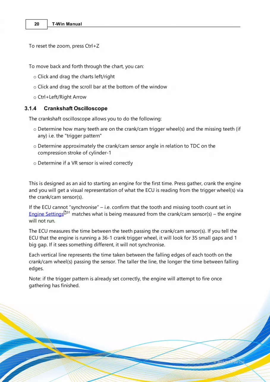
3.1.4 Crankshaft Oscilloscope
The crankshaft oscilloscope allows you to do the following:
o Determine how many teeth are on the crank/cam trigger wheel(s) and the missing teeth (if
any) i.e. the "trigger pattern"
o Determine approximately the crank/cam sensor angle in relation to TDC on the
compression stroke of cylinder-1
o Determine if a VR sensor is wired correctly
This is designed as an aid to starting an engine for the first time. Press gather, crank the engine
and you will get a visual representation of what the ECU is reading from the trigger wheel(s) via
the crank/cam sensor(s).
If the ECU cannot “synchronise” – i.e. confirm that the tooth and missing tooth count set in
Engine Settings matches what is being measured from the crank/cam sensor(s) – the engine
will not run.
The ECU measures the time between the teeth passing the crank/cam sensor(s). If you tell the
ECU that the engine is running a 36-1 crank trigger wheel, it will look for 35 small gaps and 1
big gap. If it sees something different, it will not synchronise.
Each vertical line represents the time taken between the falling edges of each tooth on the
crank/cam wheel(s) passing the sensor. The taller the line, the longer the time between falling
edges.
Note: if the trigger pattern is already set correctly, the engine will attempt to fire once
gathering has finished.
31

21Navigation
© 2022 DTAFast Ltd
Determine the Trigger PatternBelow is an example of a 60-2 wheel on a 4-cylinder, 4-stroke, flat plane crankshaft engine (i.e.
two pistons reach TDC at the same time per rotation and there are 2 compression strokes per
rotation):
Above you can see the oscilloscope has identified that for every 360° rotation of the crank
trigger, the time measured between the falling edge of the 58th tooth and the falling edge of
the next tooth is much longer. Relative to the other measurements, it is double the length so the
vertical line has been coloured blue to represent a double missing tooth gap. The line after it
will be a representation the measured time between the falling edge of the first tooth after the
gap and the falling edge of the second tooth. Note: The first blue line will (almost) always have
an incorrect count. This is normal as the count starts as soon as the engine turns and the first
count could be anywhere on the trigger wheel. The rest of the blue lines are counted relative to
each other.
Between the blue lines, you will see two peaks in the measured gap times. These represent the
slowest point in the engines rotation, which is usually TDC on the compression stroke. The
higher the compression, the higher the peaks will be.
In summary, the number on top of the tallest line is essentially how many physical teeth the
trigger wheel has. The colour of the line represents how many missing teeth the trigger has. The
ECU needs to know how many teeth in total. 58 actual plus 2 missing (60). It also needs to know
how many missing teeth (2). This is set in Engine Settings .
Determine Crank Sensor PositionIn order to determine the sensor position in relation to TDC on the compression stroke:
o Set the trigger teeth count to an incorrect value in Engine Settings to prevent the engine
attempting to fire once gathering has finished.
31
31

22 T-Win Manual
© 2022 DTAFast Ltd
o Remove all spark plugs except cylinder-1
o Fully open the throttle
o Click gather and crank the engine
Below is an example of a 4-cylinder engine, 60-2 trigger with only cylinder-1 spark plug
installed:
Each blue line (representing a double tooth gap) is 360° of crank rotation from the next. If you
count the falling edge times measured, starting with missing tooth line, up to and including the
longest measured time, that will give an approximate location for the crank sensor in relation to
TDC on the cylinder-1 compression stroke.
In this case, there are 13 times measured. We know the trigger wheel has 60 teeth in total (58
actual, 2 missing). Each tooth represents 6° of crank rotation (360÷60=6). Therefore the
approximate sensor position before TDC is 13x6°=78°. Note: it is always best practice to
confirm this with a timing light as the actual figure could be +/- 1 tooth. In this case, the actual
position could be anywhere from 72°-84°. However, as this was an OEM trigger setup (and
OEMs usually line the sensor up with a falling edge of a trigger tooth), the figure of 78° is
accurate and was verified with a timing light.
Note: this method is also useful for determining on which stroke a cam sensor pulse is received.
Determine if VR (magnetic) Sensor is Wired CorrectlyBelow is an example of the same engine and trigger, with its VR (magnetic) sensor connected
the wrong way round:

23Navigation
© 2022 DTAFast Ltd
Note that the missing tooth gap appears as a single (green line) and the next gap after it is
nearly as tall. This is due to the sensor being wired backwards. You may also see pink lines,
representing "additional teeth".
Sending an Oscilloscope Capture to DTAWe may ask you to email us a crankshaft oscilloscope picture to aid in remotely debugging
your installation. To do this generate the picture as we ask you (either running or cranking).
Press the Save button and save it to somewhere like the Desktop. Email it as an attachment to
24 T-Win Manual
© 2022 DTAFast Ltd
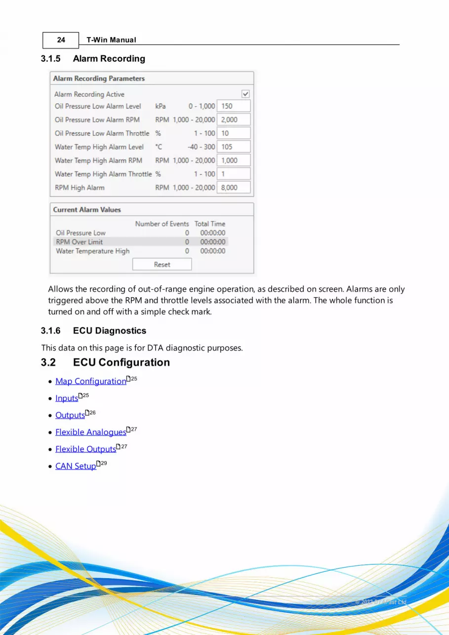
3.1.5 Alarm Recording
Allows the recording of out-of-range engine operation, as described on screen. Alarms are only
triggered above the RPM and throttle levels associated with the alarm. The whole function is
turned on and off with a simple check mark.
3.1.6 ECU Diagnostics
This data on this page is for DTA diagnostic purposes.
3.2 ECU Configuration
· Map Configuration
· Inputs
· Outputs
· Flexible Analogues
· Flexible Outputs
· CAN Setup
25
25
26
27
27
29

25Navigation
© 2022 DTAFast Ltd
3.2.1 Map Configuration
In this page, you can define table axis parameter and select the strategy used for calculating
engine load.
Main Map AxesHere you define the axis parameters for the fuel and ignition tables. By default, main maps are
usually 20x14 but you can define how much or little detail you need for the map here. The
number of rows relates to RPM and the columns relates to load. It is recommended to define
these parameters before anything else.
Other Map AxesHere you define the axis parameters for "other" tables, such as: lambda target maps, PWM target
maps, injection angle maps, start fuelling maps, compensation tables etc.
Map LoadHere you select the load calculation strategy. Alpha-N uses throttle position vs engine RPM to
calculate load. Speed Density uses manifold pressure vs engine RPM to calculate load.
3.2.2 Inputs
The inputs pages allows you to configure and monitor the thermistor, analogue and digital
inputs.
Thermistor InputsThese are specifically for 2-pin NTC temperatures sensors. Polarity is generally not important.
These inputs have a built-in 1kOhm pull-up resistor.
Analogue InputsThese are generally for 0-5v output sensors but resistance based sensors (such as some fuel
senders or NTC sensors) can be used with a pull-up resistor to 5v.
Digital InputsThese are for switches and buttons. A digital input is activated when it is shorted to sensor
ground.
Internal Pull UpsAnalogue 1 and 2 have switchable internal 1kOhm pull-up resistors, allowing them to be used for
either 0-5v output sensor or resistance based sensors with no wiring changes.
26 T-Win Manual
© 2022 DTAFast Ltd
Current ValuesShows the current values of the listed items. Note: unused analogue inputs will generally show
around 21mV, unused thermistor inputs will show around 4998mV. This can also be an indication
of a failed sensor or bad wiring.
Set to DefaultThis sets the inputs to their default configuration.
3.2.3 Outputs
The outputs page allows you to assign and individually tests all available outputs. Note: pinout
tables are available in the Pinouts section.
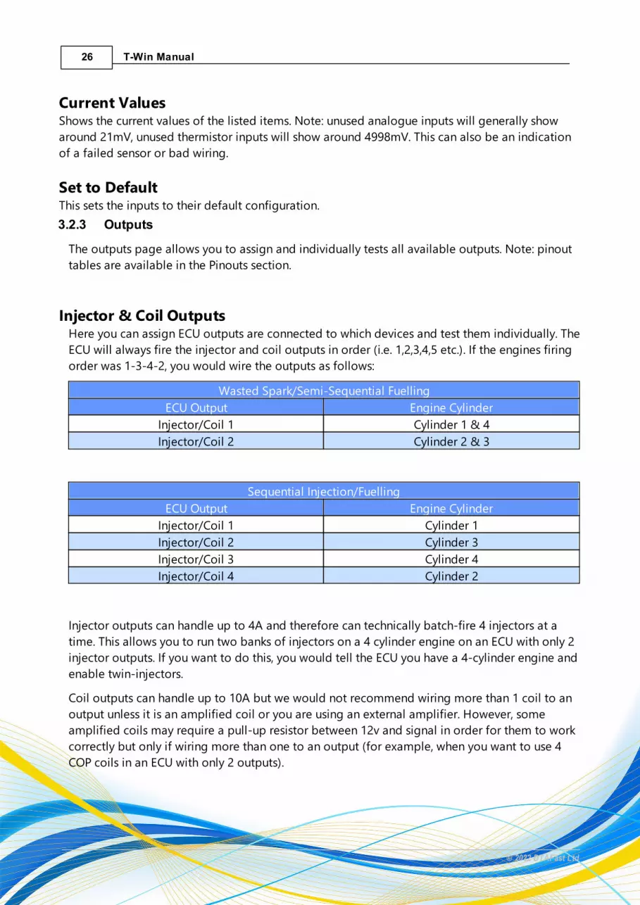
Injector & Coil OutputsHere you can assign ECU outputs are connected to which devices and test them individually. The
ECU will always fire the injector and coil outputs in order (i.e. 1,2,3,4,5 etc.). If the engines firing
order was 1-3-4-2, you would wire the outputs as follows:
Wasted Spark/Semi-Sequential Fuelling
ECU Output Engine Cylinder
Injector/Coil 1 Cylinder 1 & 4
Injector/Coil 2 Cylinder 2 & 3
Sequential Injection/Fuelling
ECU Output Engine Cylinder
Injector/Coil 1 Cylinder 1
Injector/Coil 2 Cylinder 3
Injector/Coil 3 Cylinder 4
Injector/Coil 4 Cylinder 2
Injector outputs can handle up to 4A and therefore can technically batch-fire 4 injectors at a
time. This allows you to run two banks of injectors on a 4 cylinder engine on an ECU with only 2
injector outputs. If you want to do this, you would tell the ECU you have a 4-cylinder engine and
enable twin-injectors.
Coil outputs can handle up to 10A but we would not recommend wiring more than 1 coil to an
output unless it is an amplified coil or you are using an external amplifier. However, some
amplified coils may require a pull-up resistor between 12v and signal in order for them to work
correctly but only if wiring more than one to an output (for example, when you want to use 4
COP coils in an ECU with only 2 outputs).

27Navigation
© 2022 DTAFast Ltd
Output TestingClicking the "lightning" icon next to the output you want to test will open the testing window.
For coils and injectors, you set an RPM for them to be fired at. For PWM outputs, you can set
both frequency and duty cycle, making it easier to tune your PWM Frequencies . If you have a
mechanical relay connected to the output, ensure the duty is set to 100, that way the frequency
is irrelevant and the output is simply switched "on".
Set to DefaultThis sets all output assignments to the DTA default, as listed in the wiring diagrams.
3.2.4 Flexible Analogues
Flexible analogues allow you to add fuel and ignition compensations based on an analogue
voltage. They also allow the voltages to be assigned a meaningful value.
3.2.5 Flexible Outputs
The behaviour of the low-side, PWM capable outputs can be configured here. Outputs are able to
function even when the ignition is turned off, so long as the ECU has a permanent 12v feed.
SettingsOutput ActiveIf this is checked, the output will operate according to the configuration on it's page. If it is not
checked, it will not operate.
Turn on with Map 2If this is checked, the output will only operate once the Map 2 input is switched on. Once
switched, it will operate according to the rest of the configuration on it's page.
Output NameGive the output a meaningful name that summarises its purpose
Output FrequencyFor PWM output type only, sets the frequency of the PWM duty cycle. See: PWM Frequencies .
Switched OutputIf this is selected, the output will act purely as an on/off switch, pulling whatever is connected to
it to ground. This mode is ideal for grounding a mechanical relay coil, a Vtec solenoid etc.
Variable OutputIf this is selected, the output can act either as a PWM output with a fixed frequency or a
Frequency output with a fixed 50% duty.
102
102
28 T-Win Manual
© 2022 DTAFast Ltd
Output TypeA PWM output allows you to vary the duty cycle of the output for a given frequency. For
example, a 50% duty cycle @ 100Hz would mean that every 10ms, the output is on for 5ms and
off for 5ms.
A Frequency output allows you to vary the frequency of the output with a fixed 50% duty cycle.
This is useful for things like tachometers, where the duty needs to be a fixed 50% but the
frequency needs to increase with RPM.
Primary/Secondary TriggerIf a secondary trigger is set, the output will only turn "on" once both primary and secondary
conditions are met. Set the secondary trigger to "none" if you are not specifically using it.
TriggerSelect an input from which to trigger the output. Triggers can be voltages, temperatures,
speeds, pressures, even wheel slip %
Turn On AtSwitched output mode only. Set the value at which the output is pulled to ground. The on value
must be less than the off value. Once the value drops below the "on" value, less the hysteresis
value, the output will stop pulling to ground.
Turn Off AtSwitched output mode only. Set the value at which the output stops pulling to ground after it has
been pulled to ground. This value must be higher than the "on" value. If the output needs to
stay "on" until the trigger value drops below the "on" value, set the "off" value to something
that cannot be archived. E.g. for an electronic thermostat, you may want the output to turn on at
82°C but only turn off below that. In that case you could set the "off" value to the maximum
300°C
HysteresisSwitched output mode only. If an output is triggered and then quickly falls below it's "on" point,
turns "off" and then quickly rises past the "on" point, it can cause premature wear to the
component being turned "on". By adding a hysteresis value, the output will continue to stay
"on" until it reaches a value that is less the the trigger value, minus the hysteresis value. For
example, a coolant fan may turn on at 93°C but quickly fall below and then turn off. By adding a
5°C hysteresis, the fan will stay on until the temperature drops below 88°C.
TPS TriggerIn addition to the primary and secondary triggers, you can also set the the output to only
trigger above a certain throttle percentage. This should be set to 0 unless you are specifically

29Navigation
© 2022 DTAFast Ltd
using it as the output will only turn "on" once all primary, secondary and TPS trigger conditions
are met.
3.2.6 CAN Setup
This page allows you to activate one of a selection of CANBUS data streams.
The standard CAN stream can be configured to the requirements of the receiving device.
If your receiving device has a DTAFast preset, the configuration will be as follows:
10Hz sample rate, 1Mbit data rate, Extended IDs on.
All Data Values 16 Bit Signed Sent LSB First (Little Endian)
The following items are available in the standard CAN stream:
CAN ID Pos Bytes Sign Name Unit Scale Offset Description
0x2000 0 2 1 RPM rpm 1 0 RPM
0x2000 2 2 1 TPS % 1 0 ThrottlePosition
0x2000 4 2 1 WaterTemp
°C 1 0 WaterTemperatu
re
0x2000 6 2 1 Air Temp °C 1 0 AirTemperatu
re
0x2001 0 2 1 MAP Kpa 1 0 ManifoldAbsolutePressure
0x2001 2 2 1 Lambda Lambda 0.001 0 Lambda
0x2001 4 2 1 KPH kph 0.1 0 KilometersPer Hour
0x2001 6 2 1 OilPressure
Kpa 1 0 OilPressure
0x2002 0 2 1 FuelPressure
Kpa 1 0 FuelPressure
0x2002 2 2 1 Oil Temp °C 1 0 OilTemperatu
re
0x2002 4 2 1 Voltage V 0.1 0 Voltage
0x2002 6 2 1 Fuel Con.Distance
L/100km 0.1 0 FuelConsumpti
on Per100KM
0x2003 0 2 1 Gear Gear 1 0 GearPosition
0x2003 2 2 1 Advance ° 0.1 0 Degreeesof IgnitionAdvance

30 T-Win Manual
© 2022 DTAFast Ltd
0x2003 4 2 1 Injection ms 0.01 0 Injectoropening
time
0x2003 6 2 1 Fuel Con.Time
L/Hour 0.1 0 FuelConsumpti
on PerHour
0x2004 0 2 1 Analogue 1 mV 1 0 Analogue 1Voltage
0x2004 2 2 1 Analogue 2 mV 1 0 Analogue 2Voltage
0x2004 4 2 1 Analogue 3 mV 1 0 Analogue 3Voltage
0x2004 6 2 1 CamAdvance
° 0.1 0 Camshaft 1Advance
0x2005 0 2 1 Cam Target ° 0.1 0 Camshaft 1Target
0x2005 2 2 1 Cam PWM % 0.1 0 Camshaft 1Solenoid
Duty
0x2005 4 2 1 CrankErrors
1 0 Crankshaftsensor
signal errorcount
0x2005 6 2 1 Cam Errors 1 0 Camshaft 1sensor
signal errorcount
0x2006 0 2 1 Cam 2Advance
° 0.1 0 Camshaft 2Advance
0x2006 2 2 1 Cam 2Target
° 0.1 0 Camshaft 2Target
0x2006 4 2 1 Cam 2PWM
% 0.1 0 Camshaft 2Solenoid
Duty
0x2006 6 2 1 5v V 1 0 Measurement of ECU5v output
0x2007 0 2 1 InjectorDuty
% 1 0 Capactiy ofinjector
0x2007 2 2 1 LambdaPID Target
Lambda 1 0 TargetLambda forclosed loop
fuelling
0x2007 4 2 1 LambdaPID Adj
Lambda 1 0 Currentadjustment
of closed
31Navigation
© 2022 DTAFast Ltd
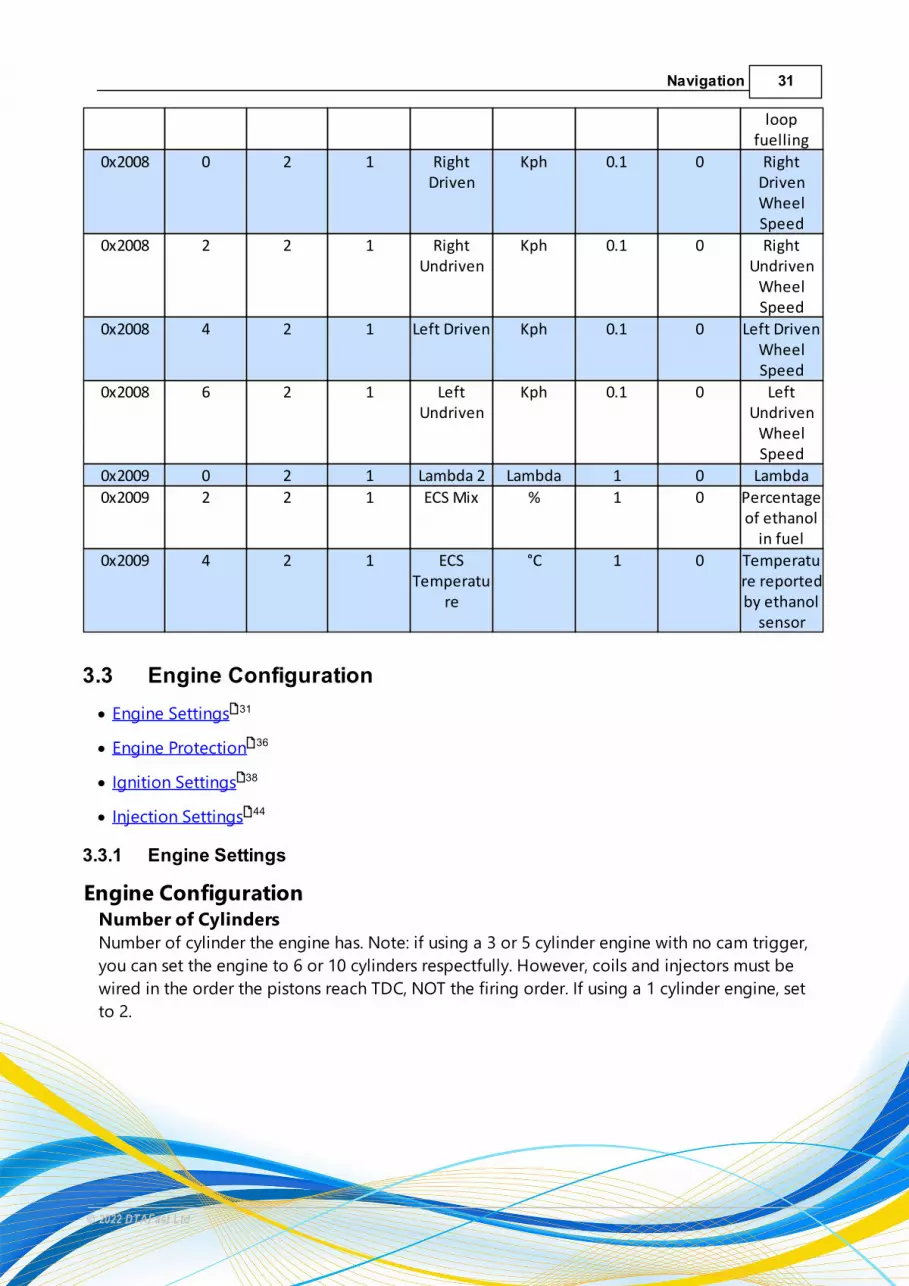
loopfuelling
0x2008 0 2 1 RightDriven
Kph 0.1 0 RightDrivenWheelSpeed
0x2008 2 2 1 RightUndriven
Kph 0.1 0 RightUndriven
WheelSpeed
0x2008 4 2 1 Left Driven Kph 0.1 0 Left DrivenWheelSpeed
0x2008 6 2 1 LeftUndriven
Kph 0.1 0 LeftUndriven
WheelSpeed
0x2009 0 2 1 Lambda 2 Lambda 1 0 Lambda
0x2009 2 2 1 ECS Mix % 1 0 Percentageof ethanol
in fuel
0x2009 4 2 1 ECSTemperatu
re
°C 1 0 Temperature reportedby ethanol
sensor
3.3 Engine Configuration
· Engine Settings
· Engine Protection
· Ignition Settings
· Injection Settings
3.3.1 Engine Settings
Engine ConfigurationNumber of CylindersNumber of cylinder the engine has. Note: if using a 3 or 5 cylinder engine with no cam trigger,
you can set the engine to 6 or 10 cylinders respectfully. However, coils and injectors must be
wired in the order the pistons reach TDC, NOT the firing order. If using a 1 cylinder engine, set
to 2.
31
36
38
44
32 T-Win Manual
© 2022 DTAFast Ltd
Transition From CrankingThis is the speed at which the engine is recognised as successfully running. This should be at
least 100RPM below the lowest idle speed you expect to see. If set too high, the engine can
struggle to transition on cold start. If too low, lightweight engines, for example motor bike
engines, can "kick back". Once this transition has taken place the engine remains in running
mode until the speed drops below 500 rpm when cranking mode is resumed. Note: until the
engine has "transitioned" it will be using fixed timing and variable dwell (based on the "Firing
Tooth on Start Up" and "No. of Teeth Coils On When Cranking" settings in Ignition Settings)
and idle control will not work.
Tacho Pulses Per RevThis sets number of pulses per revolution of the tachometer output. It must be set to the
number of pulses the tachometer you are using expects to see per revolution. For wasted spark
engines, this is usually half the number of cylinders.
Use 3 or 5 Cylinder Tacho PatternIf running a 3 or 5 cylinder engine, you must check this box for the tachometer to work correctly.
This overrides the Tacho Pulses Per Rev setting and ensure the tacho reads correctly when no
cam sensor is used and the number of cylinders set does not match the actual number of
cylinders.
Crank Sensor SetupCrank Sensor TypeThis sets which type of crank sensor the engine is using, Hall Effect or Variable Reluctance
(magnetic). 2-pin sensors are always VR. 3-pin sensors with no lead are always Hall Effect and
require either a 5v or 12v supply. Some Hall Effect sensors are very sensitive to whether 5v or
12v is used but most can use either. 3-pin sensors with a lead are usually VR, with the 3rd pin
being a connection to the cable shield. However, they can also be Hall Effect. If you measure no
resistance between any of the 3 pins, the sensor is Hall Effect. If two of the 3 pins have
resistance in one direction, it should be Hall Effect. If two of the 3 pins have resistance in both
directions, it could be Hall or VR - there is no definitive way to tell, aside from cutting open the
cable and checking for a shield (Hall Effect sensors won't have a shield).
Number of Teeth on Wheel inc. MissingCount the number of teeth on your trigger wheel and then add the number of missing teeth. For
example, may Ford engines use a trigger wheel with 35 actual teeth a 1 missing, referred to as a
36-1 (thirty six minus one). You would set it to 36 in this case. Similarly, many Vauxhall engines
use a trigger with 58 actual teeth and 2 missing, 60-2 (sixty minus two). You would set 60.
Number of Missing TeethThe number of missing teeth on your trigger wheel.
38
33Navigation
© 2022 DTAFast Ltd
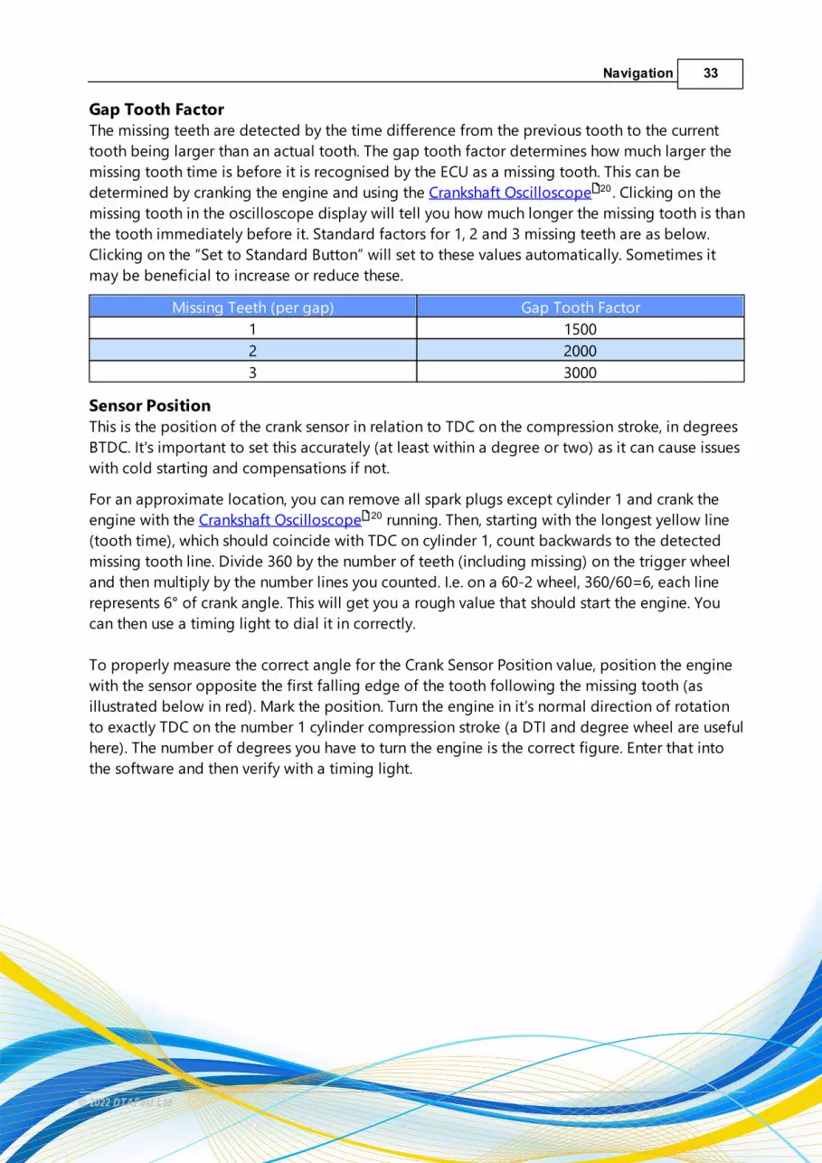
Gap Tooth FactorThe missing teeth are detected by the time difference from the previous tooth to the current
tooth being larger than an actual tooth. The gap tooth factor determines how much larger the
missing tooth time is before it is recognised by the ECU as a missing tooth. This can be
determined by cranking the engine and using the Crankshaft Oscilloscope . Clicking on the
missing tooth in the oscilloscope display will tell you how much longer the missing tooth is than
the tooth immediately before it. Standard factors for 1, 2 and 3 missing teeth are as below.
Clicking on the “Set to Standard Button” will set to these values automatically. Sometimes it
may be beneficial to increase or reduce these.
Missing Teeth (per gap) Gap Tooth Factor
1 1500
2 2000
3 3000
Sensor PositionThis is the position of the crank sensor in relation to TDC on the compression stroke, in degrees
BTDC. It's important to set this accurately (at least within a degree or two) as it can cause issues
with cold starting and compensations if not.
For an approximate location, you can remove all spark plugs except cylinder 1 and crank the
engine with the Crankshaft Oscilloscope running. Then, starting with the longest yellow line
(tooth time), which should coincide with TDC on cylinder 1, count backwards to the detected
missing tooth line. Divide 360 by the number of teeth (including missing) on the trigger wheel
and then multiply by the number lines you counted. I.e. on a 60-2 wheel, 360/60=6, each line
represents 6° of crank angle. This will get you a rough value that should start the engine. You
can then use a timing light to dial it in correctly.
To properly measure the correct angle for the Crank Sensor Position value, position the engine
with the sensor opposite the first falling edge of the tooth following the missing tooth (as
illustrated below in red). Mark the position. Turn the engine in it’s normal direction of rotation
to exactly TDC on the number 1 cylinder compression stroke (a DTI and degree wheel are useful
here). The number of degrees you have to turn the engine is the correct figure. Enter that into
the software and then verify with a timing light.
20
20

35Navigation
© 2022 DTAFast Ltd
Either way, a timing light and an accurate TDC mark are essential for verifying the sensor
position. We would recommend having a 0° and 10° mark on your engine to help with
verification.
To verify with a non "dial back" timing light, when the engine open Real Time Mapping and set
the advance to 10°. Adjust the sensor position value until the TDC mark on the crank pulley lines
up with the 10° mark on the engine. You can sometimes do this at 0° but not all engines like to
idle at 0° and not all timing lights flash consistently at 0°.
If you only have a 0° mark and cannot add a 10° mark, you can use a "dial back" timing light. If
you have a wasted spark engine and your "dial-back" timing light supports "wasted spark" or
"two stroke" modes, set the ignition timing to 10° in Real Time Mapping, set the timing light to
10° and adjust the sensor position value until the 0° marks on the crank pulley and engine line
up. If your "dial-back" light does not support "wasted spark" or "two stroke" modes, you must
set the timing light to double the ignition timing. E.g. if you've set the timing to 10°, set the
timing light to 20° and then adjust the sensor position value until the 0° TDC marks line up.
Common factory sensor positions (starting point only, always check with timing light):
Engine Position
Vauxhall/Opel 4 Cylinder (e.g. C20XE) 117°
Ford Zetec/Duratec/ST170 90°/80°/80°
Porsche 6 Cylinder 83°
BMW S50/S54/M52/M54 80°/86°/80°/325°
VAG 1.8T 20v 84°
Hayabusa 100°
Rover K-Series (Mode 2/3) 286°/349°
Honda K-Series 320°
Honda F20C (Gen1/Gen2) 340°/320°
Toyota 2JZ (Non-VVT/VVT) 5°/155°
Toyota 1UZ (Non-VVT/VVT) 5°/125°
Toyota 2ZZ 215°
Nissan CA/SR/RB (CAS) 110°
It's also important to have the right amount of clearance between the sensor and the trigger
wheel. See Crank/Cam Sensor Clearance Gaps .
Flywheel ModeThis setting tells the ECU what to expect in terms of the engine's trigger setup.
There's a huge variety of different crank/cam sensor trigger setups, many popular setups are
listed in the dropdown box. Flywheel mode 0 is for simple trigger patterns, such as 36-1 or 60-2,
92

36 T-Win Manual
© 2022 DTAFast Ltd
with or without a single tooth cam trigger. Flywheel mode 26 is for a simple crank trigger
with a more complex cam trigger. All other modes are engine specific.
There's a more detailed support document for the Rover K-Series engine.
General SettingsAdvance Compensations in Degrees not %Ignition advance compensations, coming from air temp, water temp, manifold pressure and
flexible analogues, are by default a percentage of the current advance figure. This check mark
allows these to all be in degrees. Note: they are either all percentage or all degrees.
3.3.2 Engine Protection
RPM LimitsUltimate RPM LimitThis is the hard rev limit. If the engine reaches this RPM, injector and coil output are turned off
until the RPM drops back below the hard limit.
Gear Change LightSet the RPM at which the shift light Output is activated.
Soft Cut Patterns
Hard limits alone can damage engine internals if the limit is breached regularly. Soft Limit Cut
Patterns allow you do define whether you want fuel, spark or both cut and how they are cut. This
92
99
26

37Navigation
© 2022 DTAFast Ltd
allows you to tailor the cut to the engine and slow it down gradually before it reaches the hard
limit.
Cut FuelIf checked, the injector outputs will be turned off according to the defined patterns.
Cut SparkIf checked, the coil outputs will be turned off according to the defined patterns.
Cut Pattern RPM (1-5)Set the RPM at which the corresponding cut pattern is activated.
Cut Pattern (1-5)The cut patterns are a set of 16 check marks. Each check mark represents an ignition/injection
event. For a 4-cylinder engine, 4 check marks would represent a single revolution of the engine
and therefore, you could define how that pattern behaved over 4 revolutions. It's best practice
to alternate the cylinders which are cut per revolution. For example, in a 4-cylinder engine, if
you wanted to cut 1 event per rotation, in blocks 1-4 you would tick 1, in blocks 5-8 you would
tick 6, 9-12 tick 11 and 13-16 tick 16. This would give you a 25% cut that moves to the next
cylinder on each revolution.
Sensor DefaultsHere you set the desired "default" value that the ECU will use if a sensor fails. Note: it's best to
think of the worst case scenario rather than drivability. E.g. if the TPS fails at high load and high
RPM, the default value should in the 85-100% range to prevent engine damage. However, if the
engine is unlikely to see regular and constant high load/high RPM (i.e. a road car), a value in the
15-30% range may be more suitable to allow for "limp-home".
Oil Pressure ShutdownIf the oil pressure drops below the Lower Warning Level value set in Sensor Scaling for the oil
pressure sensor, you can set the ECU to kill the engine here. Requires an oil pressure sensor to
be connected to the ECU and scaled correctly.
Oil Pressure Shutdown ActiveActivates the feature when checked.
No Oil Pressure Shutdown Below RPMThis sets the minimum RPM at which the engine will shut down if the oil pressure drops below
the Lower Warning Level. Below this RPM, no shutdown will occur. Useful for engines with low
"hot idle" oil pressure.
Oil Pressure Shutdown DelayThis delays the shutdown event by the specified time.
51

38 T-Win Manual
© 2022 DTAFast Ltd
Low Temperature RPM LimitHere you can limit the engine RPM based on oil or water temperature. Requires a water/coolant
temperature sensor and/or oil temperature sensor to be connected to the ECU and scaled
correctly.
RPM ReductionThis reduces the Ultimate RPM Limit by the defined amount. E.g. if the Ultimate limit was
8500RPM, setting this value to 5000 would reduce the Ultimate Limit to 3500RPM. Set to 0 to
deactivate.
Water/Oil Temperature ThresholdThe temperature up until which the RPM limit will be in effect. Set to -40 to ignore a specific
sensor.
Fan ControlThis triggers the low side Output assigned to Fan Control when the defined conditions are
met. Requires a coolant temperature sensor to be connected to the ECU and scaled correctly.
Fan Control OnSelect to activate the feature.
Fan On AtSet the desired coolant temperature at which the fan control output is triggered.
Fan Switch HysteresisIf the output is triggered and then quickly falls below it's "on" point, turns "off" and then quickly
rises past the "on" point, it can cause premature wear to the component being turned "on". By
adding a hysteresis value, the output will continue to stay "on" until it reaches a value that is less
the the trigger value, minus the hysteresis value. For example, a coolant fan may turn on at 93°C
but quickly fall below and then turn off. By adding a 5°C hysteresis, the fan will stay on until the
temperature drops below 88°C
3.3.3 Ignition Settings
Coil SettingsExternal Coil AmplifiersActivating this setting changes the coil driver mode from IGBT (low-side charge) to TTL (high-
side charge).
This is a setting you must be extremely careful with. If you turn this setting on with a non-
amplified (dumb/passive) coil, it can damage the ECU because the coil will be in a permanent
46
26
47

39Navigation
© 2022 DTAFast Ltd
state of "charging", drawing more and more current. If you do not activate this setting with an
amplified (smart) coil, the ECU will be fine but the coils will get very warm (with ignition on and
engine not running) and will eventually fail.
Coils that have a single trigger per output, a 12v supply and no ground pin (e.g. Bosch/Valeo 4-
cyl and 6-cyl wasted spark, or 2-pin COPs) are non-amplified. A coil that has 2 ground pins is
usually amplified (e.g. VAG 4-pin COP). However, a coil that has 1 ground pin can be either
amplified or non-amplified - if in doubt, contact us.
Coils in Two Stroke ModeActivate this setting if the engine is either a 2-stroke or a rotary engine.
No. of Teeth Coils On When CrankingThis sets the coil dwell time under cranking conditions using crank trigger teeth as a time
reference. The length of dwell time will vary depending on how quickly the engine is rotating.
This helps the coils to fire correctly under low voltage conditions.
Examples:
On a 36-1 trigger, each tooth is 10°. Setting this to 2 would mean the coils are charging for 20°
of crank rotation, which at 300RPM would be 11ms and at 200RPM would be 16ms. In this case,
1 tooth would be sufficient.
On a 60-2 trigger, each tooth is 6°. Setting this to 2 would mean the coils charging for 12° of
crank rotation, which at 300RPM would be 6.5ms and at 200RPM would be 10ms. In this case, 2
teeth would be sufficient.
For a 360 tooth trigger, the ECU converts it to 36, so setting to 1 tooth should be sufficient.
Note: excessive dwell can lead to increased current draw and wear on the coil. As a general rule,
keep below 10ms when cranking.
Firing Tooth On StartupThis sets the ignition advance during the "attempting to start" phase.
On a 36-1 trigger, each tooth is 10° so setting this to 2 would mean the coils are firing is 20°
BDTC
On a 36-1 trigger, each tooth is 6° so setting this to 3 would mean the coils are firing is 18°
BDTC
For a 360 tooth trigger, the ECU converts it to 36, so a setting of 2 should be sufficient.
Twin SparkThis section allows the ECU to fire two coil outputs at the same time. This is mainly for engines
with two spark plugs per cylinder but is also useful for running engines without a cam sensor on
individual "COP" coils in a wasted spark arrangement and for engines with dual distributors.
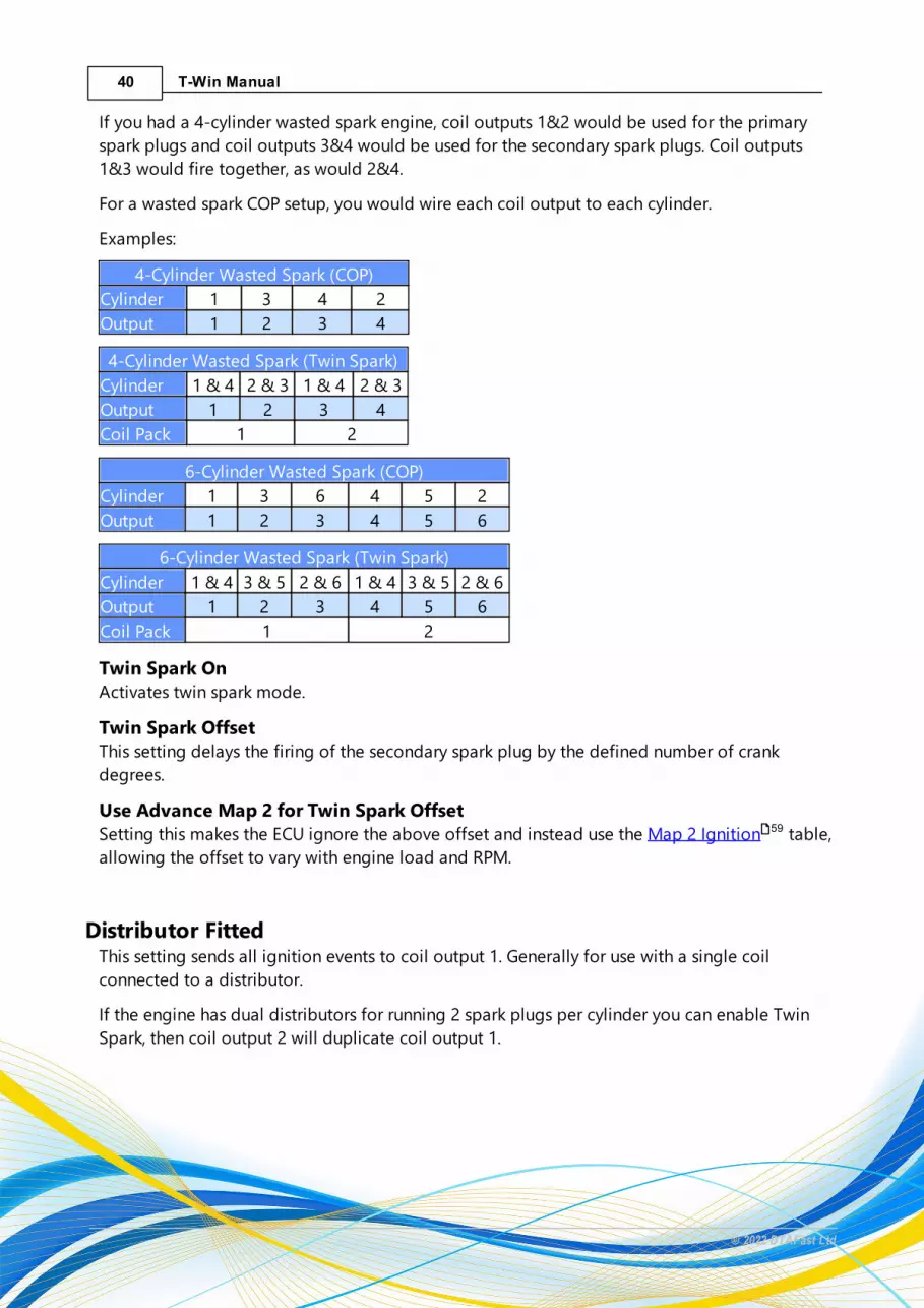
40 T-Win Manual
© 2022 DTAFast Ltd
If you had a 4-cylinder wasted spark engine, coil outputs 1&2 would be used for the primary
spark plugs and coil outputs 3&4 would be used for the secondary spark plugs. Coil outputs
1&3 would fire together, as would 2&4.
For a wasted spark COP setup, you would wire each coil output to each cylinder.
Examples:
4-Cylinder Wasted Spark (COP)
Cylinder 1 3 4 2
Output 1 2 3 4
4-Cylinder Wasted Spark (Twin Spark)
Cylinder 1 & 4 2 & 3 1 & 4 2 & 3
Output 1 2 3 4
Coil Pack 1 2
6-Cylinder Wasted Spark (COP)
Cylinder 1 3 6 4 5 2
Output 1 2 3 4 5 6
6-Cylinder Wasted Spark (Twin Spark)
Cylinder 1 & 4 3 & 5 2 & 6 1 & 4 3 & 5 2 & 6
Output 1 2 3 4 5 6
Coil Pack 1 2
Twin Spark OnActivates twin spark mode.
Twin Spark OffsetThis setting delays the firing of the secondary spark plug by the defined number of crank
degrees.
Use Advance Map 2 for Twin Spark OffsetSetting this makes the ECU ignore the above offset and instead use the Map 2 Ignition table,
allowing the offset to vary with engine load and RPM.
Distributor FittedThis setting sends all ignition events to coil output 1. Generally for use with a single coil
connected to a distributor.
If the engine has dual distributors for running 2 spark plugs per cylinder you can enable Twin
Spark, then coil output 2 will duplicate coil output 1.
59

41Navigation
© 2022 DTAFast Ltd
If the engine has dual distributors and 1 spark plug per cylinder, you should still use twin spark
but you must set the offset to 90° and the number of cylinders in Engine Settings to half that
of the actual number.
Example:
Rolls Royce dual distributor 90° V8, firing order 1-3-7-2-6-5-4-8
ECU Output Cylinders
Coil 1 1, 7, 6, 4 (distributor 1)
Coil 2 3, 2, 5, 8 (distributor 2)
In this case, the number of cylinders would be set to 4 and Coil 1 would fire every 180°. You
would enable Twin Spark and set the offset to 90°. Coil 2 would then fire 90° after Coil 1. This
also allows factory alignment marks on the distributor to be used.
Unequal Firing OptionsThis section allows you to define the crank angle at which the ignition coils should fire, if the
order in which the cylinders reach TDC is not in equal steps.
By default, the ECU assumes the firing angle will be 720 divided by the number of cylinders.
However, if you have a V engine and the V angle is not equal to the default firing angle, you will
need to use unequal firing angles in order for the engine to run.
For example, in most 6 cylinder engines, the pistons reach TDC every 120° and the ECU would
fire at 0°, 120°, 240°, 360°, 480° and 600°. The Cosworth/Opel 2.5 V6 DTM engine fires the first 2
cylinders 75° apart but then rotates 165° to fire the next two 75° apart. I.e 0°, 75°, 240°, 315°,
480° and 535°.
In general, the odd firing cylinders (i.e. first to fire, third to fire etc.) should fire at an angle apart
from each other that is equal to 720 divided by half the number of cylinders. In the case of the
V6 above, this would be 720/3=240, so the first cylinder to fire would fire at 0°, the third
cylinder to fire would be at 240° and the fifth cylinder to fire would be at 480°. The even firing
cylinders should then fire at an angle equal to the previous firing cylinder plus the angle of the
V. So in the case of this 75° V6, second to fire is 0°+75°, fourth to fire is 240°+75°, sixth to fire is
480°+75°.
There are of course exceptions to this; engines with offset crank pins, like the VR6 for instance.
However, the above method should allow you to work out the firing angles for most cross plane
and flat plane V engines.
Note: angles must be entered in firing order. Coil 1 is the first cylinder to fire, Coil 2 the second
etc.
31

42 T-Win Manual
© 2022 DTAFast Ltd
Dwell Compensations (Coil On Time)The ignition coil's dwell time (charge time) will be supplied by the table. The Coil Dwell table
allows you to define different dwell times (in microseconds) for different battery voltages. This
is especially useful for engines that do not run an alternator or to safeguard against an
alternator failing. In general, most coils will require more dwell time to maintain the same
output at lower voltages.
Examples:

43Navigation
© 2022 DTAFast Ltd
Bosch 3-pin 4 cylinder wasted
spark coil pack
Bosch 4-pin 6 cylinder wasted
spark coil pack
Voltage 7A Draw
Dwell (µs)
10A Draw
Dwell (µs)
Voltage 7A Draw
Dwell (µs)
10A Draw
Dwell (µs)
8.0 6700 12000 8.0 6600 11600
8.5 6175 10750 8.5 6075 10375
9.0 5650 9500 9.0 5550 9150
9.5 5125 8250 9.5 5025 7925
10.0 4600 7000 10.0 4500 6700
10.5 4325 6525 10.5 4250 6250
11.0 4050 6050 11.0 4000 5800
11.5 3775 5575 11.5 3750 5350
12.0 3500 5100 12.0 3500 4900
12.5 3325 4825 12.5 3325 4650
13.0 3150 4550 13.0 3150 4400
13.5 2975 4275 13.5 2975 4150
14.0 2800 4000 14.0 2800 3900
14.5 2700 3825 14.5 2700 3725
15.0 2600 3650 15.0 2600 3550
15.5 2500 3475 15.5 2500 3375
16.0 2400 3300 16.0 2400 3200
16.5 2325 3200 16.5 2300 3075
17.0 2250 3100 17.0 2200 2950
17.5 2175 3000 17.5 2100 2825
Note:
Whilst a 10A draw will give you the full 45kV and 90mJ output of these coils, most 4 cylinder
normally aspirated engines run fine with a fixed 3000µs dwell. The 7A draw will give around
35kV and 60mJ.
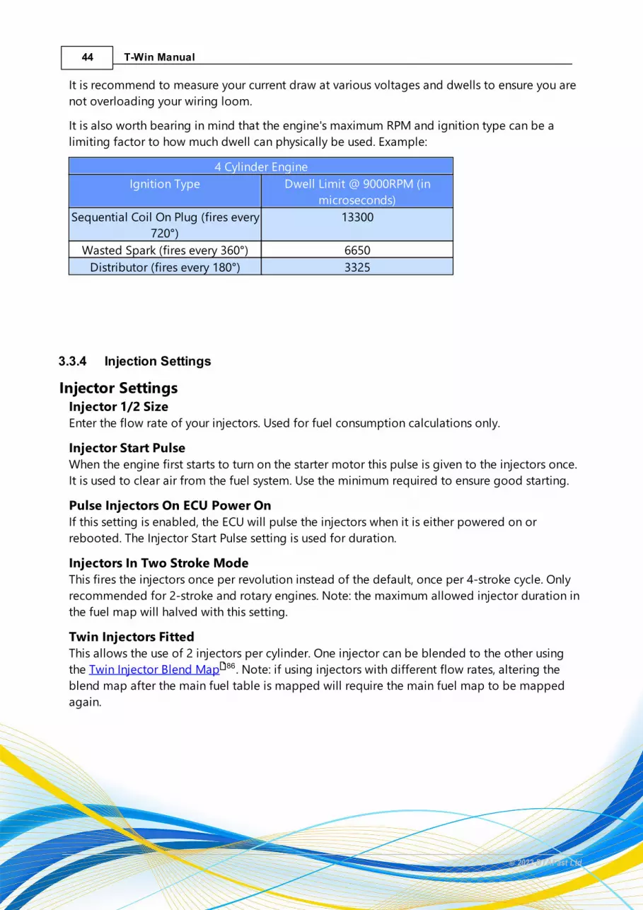
44 T-Win Manual
© 2022 DTAFast Ltd
It is recommend to measure your current draw at various voltages and dwells to ensure you are
not overloading your wiring loom.
It is also worth bearing in mind that the engine's maximum RPM and ignition type can be a
limiting factor to how much dwell can physically be used. Example:
4 Cylinder Engine
Ignition Type Dwell Limit @ 9000RPM (in
microseconds)
Sequential Coil On Plug (fires every
720°)
13300
Wasted Spark (fires every 360°) 6650
Distributor (fires every 180°) 3325
3.3.4 Injection Settings
Injector SettingsInjector 1/2 SizeEnter the flow rate of your injectors. Used for fuel consumption calculations only.
Injector Start PulseWhen the engine first starts to turn on the starter motor this pulse is given to the injectors once.
It is used to clear air from the fuel system. Use the minimum required to ensure good starting.
Pulse Injectors On ECU Power OnIf this setting is enabled, the ECU will pulse the injectors when it is either powered on or
rebooted. The Injector Start Pulse setting is used for duration.
Injectors In Two Stroke ModeThis fires the injectors once per revolution instead of the default, once per 4-stroke cycle. Only
recommended for 2-stroke and rotary engines. Note: the maximum allowed injector duration in
the fuel map will halved with this setting.
Twin Injectors FittedThis allows the use of 2 injectors per cylinder. One injector can be blended to the other using
the Twin Injector Blend Map . Note: if using injectors with different flow rates, altering the
blend map after the main fuel table is mapped will require the main fuel map to be mapped
again.
86

45Navigation
© 2022 DTAFast Ltd
Over Run Fuel Cut Off SettingThis section defines whether the injectors are turned off during over run, i.e. the vehicle is
braking, engine RPM is dropping and there is no throttle input. Note: this can have detrimental
effects to engine braking and will prevent anti-lag from working.
RPM To Turn Fuel Back OnIf the engine enters over run condition, this setting defines when the injectors will be turned
back on based on RPM. Generally, you would want to do this a few hundred RPM above the
maximum idle speed. Set to 0 to disable overrun fuel cut.
Throttle To Turn Fuel Back OnIf the engine enters an over run condition, this setting defines when the injectors will be turned
back on based on throttle position. Regardless of the above RPM, if the engine is over running
and the throttle position changes to a value equal or higher than this setting, the injectors will
be turned back on. 2-3 is usually fine for this.
Unequal Injection AnglesSee: Unequal Firing Angles in Ignition Settings .
Injector TrimsThis allows injectors to be individually trimmed to compensate for variations in port flow. For
trimming individual cylinders, you would need the ability to measure the AFR on each exhaust
runner. You may also be able to trim the cylinders based on measured exhaust runner
temperature. This is also useful for trimming a bank of cylinders in a V engine. In most
circumstances, this table is set to 0. Note: injectors are listed in the order they fire, not the
cylinders they are fitted to. I.e. if you wanted to trim cylinder 4 on a 1-3-4-2 firing engine, you
would trim "Injector 3".
Injector Compensations (Dead Times)This must be setup before mapping the engine.
Injectors have a small amount of lag before they open and also when they close, referred to as
"dead time". In most cases, it is not critical to set the dead time accurately and setting the dead
time table to 1ms for all voltages is usually fine - although accurate dead times allow sensor
compensations, start fuelling and closed-loop lambda adjustments to remain accurate during
voltage changes. In applications where an alternator is not fitted or a failed alternator would
not necessarily lead to the vehicle being stopped, the table should be filled in accurately as an
injectors dead time will increase as battery voltage drops and this will lead to leaner fuel ratios
if not compensated for. A typical dead time is 0.77ms @ 13.5v and 3bar but this can increase to
over 5ms at voltages as low as 6v. It's also important to note that dead time will vary with fuel
38

46 T-Win Manual
© 2022 DTAFast Ltd
pressure, i.e. a higher pressure will slightly increase dead time. Note: the dead time settings
apply to all fuel injectors connected to the ECU. There are no additional settings for twin
injectors, so if dead time is important for your application, ensure all injectors have the same
dead time.
3.4 Sensor Configuration
· Air Temperature
· Water Temperature
· Oil Temperature
· Inlet Manifold Pressure (MAP)
· Exhaust Manifold Pressure (EMP)
· Oil Pressure
· Fuel Pressure
· Throttle Stops
· Gear Potentiometer
· Lambda Sensor
· Wheel Speed
· Gear by Shaft
· Ethanol Compensation
3.4.1 Air Temperature
Sensor ConfigurationFor the sensor to provide meaningful information, its characteristics must be defined here.
Never assume base maps have accurate scalings unless specifically mentioned in the comments.
You can either use a sensor that has a built-in preset in the software or define the scale yourself.
Temperature sensors are usually 2-pin NTC sensors whose resistance value changes with
changes in temperature.
NTC sensors should use "Thermistor" Inputs . Thermistor inputs have a 1kOhm pull-up resistor
to 5v built in. Analogue 1 and 2 can also be used as Thermistor inputs with their switchable pull-
ups turned on.
46
47
49
49
50
51
52
53
53
54
57
57
58
25

47Navigation
© 2022 DTAFast Ltd
If you do not have a scale for your sensor, measure the resistance at 3 temperatures (freezing,
room and boiling) and send us the measurements along with the part number of the sensor and
it's usual application.
Note: when measuring resistance, the temperature should be constant and you must wait until
the resistance value settles. NTC sensors are slow to fully respond to large changes in
temperatures.
Warnings Active and Upper/Lower Warning LevelHere you can set and enable warnings for values you define as too high or too low.
Warnings are displayed during Real Time Mapping , via the CANBUS and also via the shift
light.
Warnings are only active above the transition from cranking RPM in Engine Settings .
Filter ValueThis allows electrical noise that could interfere with the sensor reading to be filtered. If you do
not see any random variations then leave the value set to 1. If you do then increase the filter
value until the noise is gone.
Sensors are read every 1ms (1000Hz). The filter value is the number of samples that the sensor
value is averaged over.
Setting the value to 20 would mean the sensor value that is displayed (and used by the ECU) has
been averaged over the last 20 samples (20ms). Therefore it would update 50 times a second
(50Hz).
Sensor CompensationsThis table allows you to modify the fuel injection quantity and ignition advance according to air
temperature.
The Set to Standard button sets the compensations to a universally accepted standard.
Note: compensations will only work correctly when a) the injector dead times are correctly
defined in Injection Settings and b) the sensor is mounted in an appropriate location,
measuring the actual temperature of air entering the engine and not a temperature that may
have been compromised by heat soak or stagnant air.
3.4.2 Water Temperature
Sensor ConfigurationFor the sensor to provide meaningful information, its characteristics must be defined here.
Never assume base maps have accurate scalings unless specifically mentioned in the comments.
You can either use a sensor that has a built-in preset in the software or define the scale yourself.
14
31
44

48 T-Win Manual
© 2022 DTAFast Ltd
Temperature sensors are usually 2-pin NTC sensors whose resistance value changes with
changes in temperature.
NTC sensors should use "Thermistor" Inputs . Thermistor inputs have a 1kOhm pull-up resistor
to 5v built in. Analogue 1 and 2 can also be used as Thermistor inputs with their switchable pull-
ups turned on.
If you do not have a scale for your sensor, measure the resistance at 3 temperatures (freezing,
room and boiling) and send us the measurements along with the part number of the sensor and
it's usual application.
Note: when measuring resistance, the temperature should be constant and you must wait until
the resistance value settles. NTC sensors are slow to fully respond to large changes in
temperatures.
Warnings Active and Upper/Lower Warning LevelHere you can set and enable warnings for values you define as too high or too low.
Warnings are displayed during Real Time Mapping , via the CANBUS and also via the shift
light.
Warnings are only active above the transition from cranking RPM in Engine Settings .
Filter ValueThis allows electrical noise that could interfere with the sensor reading to be filtered. If you do
not see any random variations then leave the value set to 1. If you do then increase the filter
value until the noise is gone.
Sensors are read every 1ms (1000Hz). The filter value is the number of samples that the sensor
value is averaged over.
Setting the value to 20 would mean the sensor value that is displayed (and used by the ECU) has
been averaged over the last 20 samples (20ms). Therefore it would update 50 times a second
(50Hz).
Sensor CompensationsThis table allows you to modify the fuel injection quantity and ignition advance according to
water (coolant) temperature.
Note: compensations will only work correctly when a) the injector dead times are correctly
defined in Injection Settings and b) the sensor is mounted in an appropriate location (usually
thermostat housing), measuring the actual temperature of coolant leaving/circulating the
cylinder head and not a temperature that may have been compromised by heat soak, stagnant
flow or by measuring inlet flow from the radiator.
25
14
31
44

49Navigation
© 2022 DTAFast Ltd
3.4.3 Oil Temperature
Sensor ConfigurationFor the sensor to provide meaningful information, its characteristics must be defined here.
Never assume base maps have accurate scalings unless specifically mentioned in the comments.
You can either use a sensor that has a built-in preset in the software or define the scale yourself.
Temperature sensors are usually 2-pin NTC sensors whose resistance value changes with
changes in temperature.
NTC sensors should use "Thermistor" Inputs . Thermistor inputs have a 1kOhm pull-up resistor
to 5v built in. Analogue 1 and 2 can also be used as Thermistor inputs with their switchable pull-
ups turned on.
If you do not have a scale for your sensor, measure the resistance at 3 temperatures (freezing,
room and boiling) and send us the measurements along with the part number of the sensor and
it's usual application.
Note: when measuring resistance, the temperature should be constant and you must wait until
the resistance value settles. NTC sensors are slow to fully respond to large changes in
temperatures.
Warnings Active and Upper/Lower Warning LevelHere you can set and enable warnings for values you define as too high or too low.
Warnings are displayed during Real Time Mapping , via the CANBUS and also via the shift
light.
Warnings are only active above the transition from cranking RPM in Engine Settings .
Filter ValueThis allows electrical noise that could interfere with the sensor reading to be filtered. If you do
not see any random variations then leave the value set to 1. If you do then increase the filter
value until the noise is gone.
Sensors are read every 1ms (1000Hz). The filter value is the number of samples that the sensor
value is averaged over.
Setting the value to 20 would mean the sensor value that is displayed (and used by the ECU) has
been averaged over the last 20 samples (20ms). Therefore it would update 50 times a second
(50Hz).
3.4.4 Inlet Manifold Pressure
Sensor ConfigurationFor the sensor to provide meaningful information, its characteristics must be defined here.
Never assume base maps have accurate scalings unless specifically mentioned in the comments.
25
14
31
50 T-Win Manual
© 2022 DTAFast Ltd
You can either use a sensor that has a built-in preset in the software or define the scale yourself.
Pressure sensors are usually a 3-pin sensor with a 0-5v output. We do not recommend the use of
any other type (such as those that ground through the engine).
Most pressure sensors have a linear scale. If you do not have a scale for your sensor but can
measure the voltage at a known high and low pressure, you can generally just Interpolate
(Shift+F5) between the measured values and the rest will be correct.
Enter your lowest pressure at the top and highest at the bottom. Click the lowest value and drag
down to the highest. Then press Shift+F5. Do the same for voltage and that should be correct.
Warnings Active and Upper/Lower Warning LevelHere you can set and enable warnings for values you define as too high or too low.
Warnings are displayed during Real Time Mapping , via the CANBUS and also via the shift
light.
Warnings are only active above the transition from cranking RPM in Engine Settings .
Filter ValueThis allows electrical noise that could interfere with the sensor reading to be filtered. If you do
not see any random variations then leave the value set to 1. If you do then increase the filter
value until the noise is gone.
Sensors are read every 1ms (1000Hz). The filter value is the number of samples that the sensor
value is averaged over.
Setting the value to 20 would mean the sensor value that is displayed (and used by the ECU) has
been averaged over the last 20 samples (20ms). Therefore it would update 50 times a second
(50Hz).
Sensor CompensationsThis table allows you to modify the fuel injection quantity and ignition advance according to
intake manifold pressure.
The Set to Standard button sets the compensations to a universally accepted standard.
Note: compensations will only work correctly when a) the injector dead times are correctly
defined in Injection Settings and b) the sensor is mounted in an appropriate location -
ideally between the intake valves and the butterfly.
3.4.5 Exhaust Manifold Pressure
Sensor ConfigurationFor the sensor to provide meaningful information, its characteristics must be defined here.
Never assume base maps have accurate scalings unless specifically mentioned in the comments.
You can either use a sensor that has a built-in preset in the software or define the scale yourself.
5
14
31
44

51Navigation
© 2022 DTAFast Ltd
Pressure sensors are usually a 3-pin sensor with a 0-5v output. We do not recommend the use of
any other type (such as those that ground through the engine).
Most pressure sensors have a linear scale. If you do not have a scale for your sensor but can
measure the voltage at a known high and low pressure, you can generally just Interpolate
(Shift+F5) between the measured values and the rest will be correct.
Enter your lowest pressure at the top and highest at the bottom. Click the lowest value and drag
down to the highest. Then press Shift+F5. Do the same for voltage and that should be correct.
Warnings Active and Upper/Lower Warning LevelHere you can set and enable warnings for values you define as too high or too low.
Warnings are displayed during Real Time Mapping , via the CANBUS and also via the shift
light.
Warnings are only active above the transition from cranking RPM in Engine Settings .
Filter ValueThis allows electrical noise that could interfere with the sensor reading to be filtered. If you do
not see any random variations then leave the value set to 1. If you do then increase the filter
value until the noise is gone.
Sensors are read every 1ms (1000Hz). The filter value is the number of samples that the sensor
value is averaged over.
Setting the value to 20 would mean the sensor value that is displayed (and used by the ECU) has
been averaged over the last 20 samples (20ms). Therefore it would update 50 times a second
(50Hz).
Sensor CompensationsThis table allows you to modify the fuel injection quantity and ignition advance according to
exhaust manifold pressure.
Note: compensations will only work correctly when a) the injector dead times are correctly
defined in Injection Settings and b) the sensor is mounted in an appropriate location -
usually between the exhaust valves and a turbo.
3.4.6 Oil Pressure
Sensor ConfigurationFor the sensor to provide meaningful information, its characteristics must be defined here.
Never assume base maps have accurate scalings unless specifically mentioned in the comments.
You can either use a sensor that has a built-in preset in the software or define the scale yourself.
Pressure sensors are usually a 3-pin sensor with a 0-5v output. We do not recommend the use of
any other type (such as those that ground through the engine).
5
14
31
44
52 T-Win Manual
© 2022 DTAFast Ltd
Most pressure sensors have a linear scale. If you do not have a scale for your sensor but can
measure the voltage at a known high and low pressure, you can generally just Interpolate
(Shift+F5) between the measured values and the rest will be correct.
Enter your lowest pressure at the top and highest at the bottom. Click the lowest value and drag
down to the highest. Then press Shift+F5. Do the same for voltage and that should be correct.
Warnings Active and Upper/Lower Warning LevelHere you can set and enable warnings for values you define as too high or too low.
Warnings are displayed during Real Time Mapping , via the CANBUS and also via the shift
light.
Warnings are only active above the transition from cranking RPM in Engine Settings .
Note: warning levels are also used for engine shutdown in the Engine Protection settings.
Filter ValueThis allows electrical noise that could interfere with the sensor reading to be filtered. If you do
not see any random variations then leave the value set to 1. If you do then increase the filter
value until the noise is gone.
Sensors are read every 1ms (1000Hz). The filter value is the number of samples that the sensor
value is averaged over.
Setting the value to 20 would mean the sensor value that is displayed (and used by the ECU) has
been averaged over the last 20 samples (20ms). Therefore it would update 50 times a second
(50Hz).
3.4.7 Fuel Pressure
Sensor ConfigurationFor the sensor to provide meaningful information, its characteristics must be defined here.
Never assume base maps have accurate scalings unless specifically mentioned in the comments.
You can either use a sensor that has a built-in preset in the software or define the scale yourself.
Pressure sensors are usually a 3-pin sensor with a 0-5v output. We do not recommend the use of
any other type (such as those that ground through the engine).
Most pressure sensors have a linear scale. If you do not have a scale for your sensor but can
measure the voltage at a known high and low pressure, you can generally just Interpolate
(Shift+F5) between the measured values and the rest will be correct.
Enter your lowest pressure at the top and highest at the bottom. Click the lowest value and drag
down to the highest. Then press Shift+F5. Do the same for voltage and that should be correct.
Warnings Active and Upper/Lower Warning LevelHere you can set and enable warnings for values you define as too high or too low.
5
14
31
36
5

53Navigation
© 2022 DTAFast Ltd
Warnings are displayed during Real Time Mapping , via the CANBUS and also via the shift
light.
Warnings are only active above the transition from cranking RPM in Engine Settings .
Filter ValueThis allows electrical noise that could interfere with the sensor reading to be filtered. If you do
not see any random variations then leave the value set to 1. If you do then increase the filter
value until the noise is gone.
Sensors are read every 1ms (1000Hz). The filter value is the number of samples that the sensor
value is averaged over.
Setting the value to 20 would mean the sensor value that is displayed (and used by the ECU) has
been averaged over the last 20 samples (20ms). Therefore it would update 50 times a second
(50Hz).
3.4.8 Throttle Stops
This section defines the voltages the Throttle Position Sensor reads when the throttle is fully
open and fully closed. The ECU interpolates between these values to determine the percentage
of throttle position.
Ensure the throttle butterfly/slide/barrel is in the fully closed position (aside from idle
requirements) and click the Closed button. Then open fully (wide open throttle) and click the
Open button. Hit F4 to save changes to the ECU.
Reverse TPS MovementIf the TPS is incorrectly connected, that is 5v and Sensor Ground are the wrong way round, then
the correct approach is to correct the wiring. In situations where this cannot be done, this setting
will reverse the throttle position so that 0% before 100% etc.
3.4.9 Gear Potentiometer
If you have a sequential gearbox with a gear potentiometer and want to either display your
gear number on a dashboard, or use the potentiometer for Shift Cut or Paddle Shift , you
can set it up here.
Fill the values in, matching the sensor mV of the gear you are in to the gear number.
Once you run out of gears, just fill the remaining fields with increasingly higher values (which
the potentiometer will not be able to output).
Note: the whole table MUST be filled in and voltage must go from low in reverse to high in top
gear.
14
31
80 83

54 T-Win Manual
© 2022 DTAFast Ltd
3.4.10 Lambda Sensor
All DTA T-Series ECUs include at least 1 on-board Bosch CJ125 wideband lambda controller,
compatible with LSU 4.9 sensors. However, you can also use external wideband controllers.
Narrowband sensors are not supported.
Sensor ConfigurationInternal Sensor 1/2Enables the internal wideband controller. No scaling is required.
External Sensor 1/2Allows a 0-5v output from an external wideband controller to be used instead of the internal
wideband controller. Scaling must be defined in the External Sensor Configuration.
External Sensor ConfigurationThis section allows you to define the scaling for the external wideband lambda controller
output. Select one of the presets, use the output voltage documentation provided with your
controller or if the controller allows, define your own scale and then enter it here.
Most wideband controllers output a linear voltage, where low voltage is rich and high voltage is
lean. Some use the whole voltage range, others leave a few hundred mV at either end to act as
voltages that report the state of the sensor (error, warm up etc.). When filling out the table, it is
usually sufficient to enter the low voltage at the top, high voltage at the bottom and interpolate
(Shift+F5) between them. Same for the corresponding lambda values.
If you have a controller with a display, it is important to ensure the display and the ECU display
the same values - sometimes wiring issues can cause a voltage offset.
Some controllers may require being connected to the ECUs sensor ground but you must take
care to ensure this doesn't allow the ECU sensor ground to then connect to power ground (with
ECU connectors unplugged).
Closed Loop SettingsClose loop fuelling allows the ECU to use one or two lambda sensors to adjust fuelling
automatically, based on the parameters set here and the Lambda Target Map . Closed loop
fuelling can be used as an aide to speed up fuel mapping (set lambda target, turned closed
loop on, move from cell to cell in Real Time Mapping hitting enter). Note: closed-loop
fuelling is not a substitute for mapping.
Closed Loop Fuelling OnEnables/disables closed loop fuelling.
67
14

55Navigation
© 2022 DTAFast Ltd
Main Sample RateThe number of times per second (Hz) the lambda sensor/controller voltage is sampled by the
ECU. A Bosch LSU 4.9 sensor can respond to changes in air/fuel ratio in under 50ms. Setting this
to 20Hz is usually sufficient, however some controllers may be slower by design and increasing
the sample rate from say 5Hz to 20Hz may make little difference.
Minimum Water TemperatureSet the minimum coolant temperature at which closed loop fuelling is active.
Delay Lambda ControlSet the amount of time to wait before close loop fuelling is enabled, once the engine
transitions from "cranking" to "running". This is mainly to allow externally controlled sensors
time to heat up. For an LSU 4.9 this is usually around 20 seconds. If using the on-board
controller, control is automatically delayed until the sensor has warmed up so there's not need
to set this delay unless using you are using it for another reason, such as (very) cold starts, where
the target lambda may need to be higher than specified for the engine to idle correctly.
PID FactorsSee PID Control Loops .
Maximum Percentage Increase/Decrease In FuelA properly mapped engine should need very little in the way of fuel adjustment during its life.
To allow adjustment but ensure adjustments cannot get out of control, you can set the
maximum percentage the fuel can be increased or decreased by when closed loop fuelling is
enabled.
If you plan to use closed loop during Real Time Mapping , you must ensure these values
allow enough adjustment for the application.
Use MAP for Lambda 3D Target Map when Alpha-NThis allows you to use Alpha-N (RPM vs TPS) fuel and ignition tables but use Speed Density
(RPM vs MAP) for the Lambda target table. This is mainly for forced induction engines.
Enable Lambda SwitchYou can use one of the digital Inputs to turn closed loop fuelling on/off. Enable the switch
here.
Suspend Close Loop if Sensor Voltage Below 100mVThis will depend on the (external) Lambda controller used and its scaling. If you can set your
controller so that voltages below 100mV are the result of an error or delayed warm up phase
and then scale the output appropriately, this setting will ensure closed loop is turned off when
that occurs. The on-board controller suspends closed loop automatically on sensor error or
warm up.
Use modified PIDAlternative to the regular PID control method. This removes the Integral, leaving just
Proportional and Differential.
100
14
25
56 T-Win Manual
© 2022 DTAFast Ltd
Turn Control Off Above RPM/TPSThese allows you to use closed loop fuelling but then disable it above a certain RPM or throttle
position. Set to an unreachable value to disable.
Idle SettingsThese settings define whether the closed loop control uses the Main Sample Rate or the Idle
Sample Rate and under which conditions to switch between them.
Idle Sample RateSets the sample rate to be used during idle, in seconds. During idle, exhaust gasses flow more
slowly so changes in fuelling take longer to detect. If the sample rate is too quick, the ECU
may add too much fuel because it is not seeing a change. This can then lead to an oscillating
over-fuel/under-fuel situation.
Idle Maximum Throttle/RPMAbove these values, the main sample rate is used.
Overrun SettingsOverrun is a condition where there is little-to-no throttle input and the momentum of the
vehicle is maintaining the engine RPM and/or reducing its ability to decelerate as quickly as it
normally would. During overrun, a lambda sensor will generally read lean but this does not
mean the engine is actually running lean. Therefore, closed-loop fuelling should be temporarily
disabled during overrun and the settings below define how and when that happens.
Overrun Throttle Position/RPMBelow these values, closed loop is disabled. We recommend setting these to a few hundred
RPM above idle speed and 2-3% above idle throttle position.
Overrun Lock TimeThis is the amount of time closed loop remains disabled once the engine is no longer in an
overrun condition.
Throttle Reduction LockoutSimilar to overrun. When throttle input is reduced but not so much to enter an overrun
condition, a lambda sensor will generally read lean, regardless of how well tuned the
Transients are and therefore closed loop fuelling should be temporarily disabled.
Throttle Reduction To LockSets how much of a reduction in throttle position is required to disable closed loop fuelling.
Throttle Reduction Lock TimeSets how long closed loop fuelling remains disabled after the throttle position has increased.
66

57Navigation
© 2022 DTAFast Ltd
Twin Lambda SettingsIf you have two lambda sensors, here you can define which injector outputs are associated with
which lambda sensor. Ideal for V engines.
3.4.11 Wheel Speed
Wheel Speed Sensor SettingsNumber of Undriven Wheel SensorsSelect how many wheel speed sensors are fitted to wheels that are not driven by the engine.
Note: you must have at least 1 undriven wheel speed sensor for traction control.
Undriven/Driven Pulses per RevHow many "teeth" are on the sensor trigger.
Left/Right Undriven/Driven Wheel Sensor TypeSelect the sensor type for the relevant sensor or "none" if not fitted/used.
Tyre SettingsUndriven/Driven Tyre CircumferenceMeasure the circumference of the tyre, fitted to a wheel, properly inflated and enter it here.
Gear Distance SettingsFor setups that use only 1 wheel speed sensor, you can use engine RPM to act as "driven" wheel
speed, providing you know the gear and final drive ratios.
Distance per Engine Rev in Gear xMultiply your gear ratio by your final drive ratio, then divide your driven tyre circumference by
that number. E.g. 2.4:1 1st gear ratio, a 4.1:1 final drive and a tyre circumference of 1806mm
would be ((2.4 x 4.1)/1806) = 184mm
3.4.12 Gear by Shaft
Gear Position By RPMThis allows you to create a "virtual" gear position sensor based on the ratio of engine speed to
shaft speed. The shaft speed should be taken from either the differential input shaft or the

58 T-Win Manual
© 2022 DTAFast Ltd
crown-wheel of the differential. It should not be taken by the output of the differential (i.e. a
wheel speed sensor). Many modern gearboxes use an electronic speed sensor that is ideal for
this. Alternatively a mechanical speed output can sometimes be connected to a rotary encoder
for a similar effect.
Enable Gear By RPMEnables the function.
Highest GearThe number of forward gears the gearbox has.
Number of Teeth on Target WheelThe number of teeth/pulses per revolution of the shaft.
RatiosEnter the ratios recorded by the ECU in Current Values for the gear you are in.
Note: if you are using Traction Control with 2 driven wheel speed sensors, you cannot use
Gear by Shaft.
Note: on T2i/T2/T4/T4+ ECUs you can only use a hall effect sensor connected to a Digital
Input .
3.4.13 Ethanol Compensations
An Ethanol sensor detects the percentage of Ethanol content in the fuel. If you plan to run fuels
with higher Ethanol content than the engine was mapped on, or you plan to switch between
fuels, an Ethanol sensor should be fitted as Ethanol has a higher stoichiometric ratio than
gasoline and therefore, more fuel is required to achieve the same lambda value.
The Set Fuel Compensations to Standard button will fill the table with compensations based on
the stoichiometric value of Ethanol. These can be adjusted if required but should be left as
standard. You can also add increase ignition advance as the Ethanol content increases, should
the engine allow.
3.5 Engine Control
· Main Fuel/Ignition Map
· Start Fuelling Map
· Injector Angle Map
· Idle Control
· Throttle Transients
· Lambda Settings
78
25
59
59
61
62
66
67

59Navigation
© 2022 DTAFast Ltd
· Turbo Control
· Camshaft Control
3.5.1 Main Fuel/Ignition Map
The cell values in the map table are colour coded. Green for a small value, red for a large value
and a sliding scale/gradient between.
Injector values are in milliseconds of opening and represent the "base" opening time, i.e. the
injection time with dead time and compensations removed. It is crucial to re-check the fuel map
after any dead time or compensation modification.
Ignition values are in degrees before TDC (advance). Therefore a negative value would
represent degrees after TDC (retard). These also represent the "base" timing.
By default, the sizes of these maps is 20 RPM rows by 14 load (TPS or MAP) columns. This can
be changed in the Main Map Axes settings under Map Configuration .
Table cells can be manipulated in groups, either arithmetically or by interpolation. For example:
To add 10% to a section, click the starting cell then drag to the finishing cell. Press F5, select
Change by Percent, enter 10 and click ok. The selected values will then be increased by 10%.
You can also use negative values and use the keyboards arrow keys and shift button to select
cells.
Similarly, you can interpolate between a starting cell and finishing cell by selecting the cells
and clicking Shift+F5. Interpolation allows you to take two values and "fill in the blanks"
between them in a linear fashion.
You can also copy a cell or groups of cells (Ctrl+C or Edit > Copy) and paste (Ctrl+V or Edit >
Paste) over other cells.
In addition to the map table is a 3D map graph that allows you to visualise the map more easily
and spot any potential irregularities.
3.5.2 Start Fuelling Map
When an engine is running, injected fuel atomises with the air to form the air-fuel mixtures but a
portion of this mixture condenses on to the walls of the intake runners and ports. This is
generally referred to as "wall wetting". There is a constant cycle of wetting and evaporation.
When the engine first starts, regardless of the temperature, the walls are dry and that portion of
mixture will initially be "lost" to the walls and not enter the combustion chamber. At hot
temperatures, this is less of an issue as the condensed fuel will evaporate and enter the
combustion chamber quite quickly. However, at cold temperatures, evaporation is slower and
the mixture defined when mapping the hot engine will tend to be much leaner as a result. In the
67
70
10

60 T-Win Manual
© 2022 DTAFast Ltd
days of carburettors, this was compensated for by using a "choke", which would lower the air
pressure around the venturi and richen the mixture. In fuel injected engines, a start fuelling map
is required to compensate.
The start fuelling map allows you to add a percentage of fuel (based on the current base
injection amount set in the Main Fuel Map), depending on the number of turns of the engine
(since synchronisation) and water temperature.
The map is 20 rows of engine turns by 14 rows of water temperature. The table axes can be set
to your requirements however in most cases, start fuelling should not be required beyond 1000
turns and after that point, water temperature compensations can be used. It's also
recommended to have the first 100 turns start with 1 and go to 100 in 10 turn steps as some
engines require a large initial increase but then quickly require a smaller increase (usually when
injectors are closer to the valves). Engines can run very rough and/or foul spark plugs if the
mixture is too rich for too long.
The map can be manipulated the in the same way as the main fuel/ignition maps and a graph is
provided for visualisation.
When in Real Time Mapping , the compensations provided by this map are shown against the
Throttle row of the live data panel. If you blip the throttle during start fuelling, the Throttle
Transient values will be added/subtracted.
For more information, see the Guide to Start Fuelling .
Note: A lambda sensor will generally require 100-200 turns of the engine to warm up safely so
the first 100-200 turns can be a bit of guesswork. If using an external lambda controller, you can
preheat the sensor before starting (use a separate power supply or it may reset under cranking
when the voltage drops) but this can damage the sensor and reduce its lifespan. It's often useful
to target a richer measure mixture than you generally would - by that we mean, if you're having
to add 50% more fuel to maintain lambda 1.00, add 60% instead and have the map maintain
lambda 0.90. This will make for a smoother idle during very cold starts. For that reason, we'd
also recommend turning closed loop lambda off below 60° if your target is lambda 1.00 when
hot.
Note2: your idle control strategy will have a large influence on the start fuelling map, especially
in cold start condition. An engine with an idle control valve or drive-by-wire idle strategy will
have more airflow when cold (to raise the RPM) so will require considerably more fuel. Tuning
the start fuelling map can be more difficult with drive by wire idle control as the base fuel
quantity in the main map will move around with the throttle opening.
Below is an example of a 1.8L Zetec which uses an idle control valve, mapped down to 0°:
14
66
102

61Navigation
© 2022 DTAFast Ltd
3.5.3 Injector Angle Map
The injector angle is the point, in relation to TDC (on compression stroke), at which the injection
event starts or stops.
Whether this map effects the start or stop of the injection event is defined under Injection
Settings .
The map can be manipulated the in the same way as the main fuel/ignition maps and a graph is
provided for visualisation.
The Dyno Box can be used to manipulate the injection angle during Real Time Mapping by
pressing Ctrl+Q. This will set left knob (normally fuel) to injector angle.
44
101

62 T-Win Manual
© 2022 DTAFast Ltd
3.5.4 Idle Control
· Idle Parameters
· Idle Maps
3.5.4.1 Idle Parameters
Idle control enables the ECU to maintain a specific engine RPM when the throttle is closed. It is
most useful for increasing the RPM during cold start situations, where an engine may naturally
idle as much as 500rpm lower than it would when hot. The most effective method is generally
an idle control valve but for best results, this should be paired with a MAP sensor with fuelling
compensations. Drive-by-wire motors can be used for idle control but depending on their size,
they can be a bit "all or nothing", like using a sledge hammer to tap in a nail. The other option
is ignition timing and it generally works very well but depending on your base timing, it can
only do so much with the air available to the engine. Some engines are happy idling with close
to zero advance or even slight retard at idle when hot and this would allow the more advance
during cold start phases. However, running less than 8° of base timing can lead to very hot
exhaust manifold temperatures and risk damaging exhaust valves.
Idle Control StrategyIdle Control OnNot all engines require idle control so it can be enabled/disabled as necessary. It is often useful
and/or necessary to disable it when tuning the engine.
StrategiesYou can use either an idle control vale, ignition advance or drive-by-wire throttle to control the
idle speed. Each strategy has it's own specific settings. Note: all three strategies will share some
values but the type of value (i.e. degrees, duty, position) will change. If changing from one
strategy to another, ensure all values are corrected as necessary.
Max Throttle/RPM for Idle ControlBoth engine RPM and throttle position must be below the value defined here for idle control to
be active. If either goes above these values, idle control is disabled.
Ignition Advance StrategyThis uses ignition advance to control idle RPM. You can use either a 3D ignition advance map,
closed loop PID control or a combination of both (recommended).
Ignition Control SettingsUse 3D Ignition TableUses the Idle Ignition Map for ignition timing at idle.
62
65
65
63Navigation
© 2022 DTAFast Ltd
Max/Min Idle AdvanceSets the global limits for idle control. Regardless of what is set anywhere else, when idle
control is active the timing will not go below the minimum or above the maximum. We
recommend not allowing the advance to drop too low as it can cause excessive exhaust gas
temperatures. 5-10° of advance is generally a good minimum.
Air Con/Fan UpliftIf closed loop PID control is not enabled, you can set a fixed amount of advance to be added
when the cooling fan is activated and/or when an Air Conditioning "on" signal is received.
Idle Air Control Valve StrategyThis uses a PWM duty cycle to operate an idle control valve which allows more air into the
engine. You can use either a 3D valve PWM map, closed loop PID control or a combination of
both (recommended).
Idle Valve Control SettingsUse 3D Base Duty CycleUses the Idle Valve PWM Map for controlling the idle valve base duty cycle.
Use Bosch 3-Pin Idle ValveIf you have an idle valve which requires a PWM signal on 1 pin and the inverse of that signal
on another, check this box.
Idle Valve FrequencySets the frequency of the PWM duty cycle. See: PWM Frequencies .
Max/Min Duty CycleSets the global limits for PWM control. Regardless of what is set anywhere else, when idle
control is active the idle valve duty cycle will not go below the minimum or above the
maximum. These values can help reduce current draw and also allow for smoother PID
control.
Air Con/Fan UpliftIf closed loop PID control is not enabled, you can set a fixed amount of PWM duty to be
added when the cooling fan is activated and/or when an Air Conditioning "on" signal is
received.
EnrichmentAn idle valve essentially allows "un-metered" air into the engine. Because of this the engine
will run lean, so to compensate, the enrichment table allows you to add a percentage increase
in fuel against the PWM duty.
65
102

64 T-Win Manual
© 2022 DTAFast Ltd
Drive-by-Wire StrategyThis uses a throttle percentage to allow more/less air into the engine using the throttle motor.
You can use either a 3D throttle position map, closed loop PID control or a combination of both
(recommended). Note: this method can make start fuelling setup more involved as the base fuel
quantity will change according to the main fuel map as the throttle position changes.
DBW Control SettingsUse 3D Throttle TableUses the Idle DBW Map for controlling the throttle position at idle.
Max/Min Throttle OpeningSets the global limits for throttle position. Regardless of what is set anywhere else, when idle
control is active the throttle position will not go below the minimum or above the maximum.
Air Con/Fan UpliftIf closed loop PID control is not enabled, you can set a fixed amount of throttle position to be
added when the cooling fan is activated and/or when an Air Conditioning "on" signal is
received.
Closed Loop SettingsUse PID LoopEnables closed loop control.
PID FactorsSee PID Control Loops .
Control Loop DelayThis value restricts the frequency of changes that the PID loop can make. E.g. allowing the loop
to make a change every 0.1 seconds may cause the engine RPM to oscillate rapidly. However,
setting it to 2 seconds may cause the RPM to drop too low and generate a slow oscillation.
Max PID AdjustmentThis value restricts how much adjustment (positive or negative) the PID loop is able to provide.
No matter how large this value, the adjustment will never be allowed to exceed the global
limits set above. Note: this value changes type depending on strategy (degrees, PWM duty or
throttle position).
Closed Loop Idle Target RPMIf PID Loop enabled, regardless of which strategy is used, the idle target RPM must be set. The
target is matched against water temperature. You can set a high target for low temperatures
and a lower target for regular operating temperatures. As these values are in a table, you can
interpolate between them with Shift+F5.
65
100

65Navigation
© 2022 DTAFast Ltd
3.5.4.2 Idle Maps
A 20x14 map allowing you to set either the idle ignition timing, the base PWM duty of an idle
control valve or throttle position against engine RPM and coolant temperature, depending on
which idle control strategy is selected in Idle Parameters . Note: all three strategies share the
same map. If switching from one strategy to another, ensure the map has relevant values.
The map axes can be modified to suit your requirements. For convenience, the axes can be
arithmetically modified (F5) or interpolated (Shift+F5), as can the table.
A graph is provided for data visualisation along with relevant live data values.
Below is an example of an idle control valve map from our 1.8L Zetec map:
62
66 T-Win Manual
© 2022 DTAFast Ltd
3.5.5 Throttle Transients
Transients add or subtract a percentage of fuel for a limited time as the throttle is opened or
closed quickly. This is generally very difficult to quantify, often varying even between individual
engines of the same type and capacity. If there is any hesitation or uncertainty when opening
the throttle quickly, the transients will most likely need adjusting. If you have a very fast wide
band sensor you can set the data log to 100Hz and record the percentage increase or reduction
as it is happening, against throttle position, RPM and lambda. The object is to keep the lambda
value as close to constant as possible through the transient condition.
There are four different RPM bands to which transients can be applied. Generally, you will need
a higher percentage of fuel increase/decrease for a longer time at lower pedal speeds in the
lower RPM bands and possibly nothing at all in the higher bands.
The pedal speed column is the percentage of throttle movement recorded during the Pedal
Speed Measuring Time. If in doubt start at 5 for the lower bands increasing to 25/30 in the
higher bands.
A very low figure will cause the transient compensations to occur even with very slow
movements of the pedal and values above 50 will mean they will probably never come into
operation at all depending on the pedal speed measuring time. Careful use of fast logging will
help to identify the engine requirements.
The current percentage change being generated by the transients can be seen in real time
mapping screen to the right of the throttle percentage in the sensor data panel. Note: this
position is also used for start fuelling and the two values are combined during the start fuelling
phase.
It is recommended that closed loop fuelling and idle control be disabled prior to transient
tuning. The engine should also have finished the start fuelling phase or have the table zeroed
out.
Tip InThese values are used when the throttle is opened. Without a sufficient increase in fuelling, the
engine will run lean and hesitate.
Tip OutThese values are used when the throttle is closed. Without a sufficient reduction in fuel, the
engine will run rich and may "bog down" when the throttle is re-applied. Note: The effect on
closing the throttle completely on the overrun makes for lambda readings which indicate the
engine is very lean. This is not the case and it should be ignored.
Pedal Speed Measuring TimeThis is the time in ms over which the pedal movement is measured. 10 – 20 ms is a reasonable
figure.

67Navigation
© 2022 DTAFast Ltd
Turn Transients Off Above ThrottleAbove this throttle position, transients will be disabled.
Switch to Hot Map AtGenerally, an engine will need more transient fuelling when cold. We would normally switch
maps at 45-60°C.
Disabling Transients For MappingTransients can interfere with mapping steady state. In Real Time Mapping there is a toggle
switch at the bottom of the window to turn them off. Remember to turn them back on after
steady state mapping is finished.
3.5.6 Lambda Settings
· Lambda Target Map
3.5.6.1 Lambda Target Map
A 20x14 map allowing you to set the target lambda value for a given engine speed and load.
This map is only used when specified in the Lambda Sensor Configuration.
A graph is provided for data visualisation along with relevant live data. The table can be
arithmetically modified (F5) or interpolated (Shift+F5).
3.5.7 Turbo Control
· Turbo Parameters
· Turbo Base PWM
· Turbo Target Pressure
3.5.7.1 Turbo Parameters
Turbo SettingsTurbo Control OnActivates the control strategy.
Turbo Valve FrequencyThe frequency of the PWM duty cycle. See: PWM Frequencies .
Turbo Max PressureAbove this value, injection and ignition will be disabled to protect the engine from
overpressure.
Min/Max Duty CycleSets the global limits for PWM control. Regardless of what is set anywhere else, when turbo
control is active the turbo valve duty cycle will not go below the minimum or above the
maximum set here.
14
67
54
67
70
70
102

68 T-Win Manual
© 2022 DTAFast Ltd
Reverse Valve OperationThis inverts the PWM signal to the valve. With some valves a lower PWM duty gives more
pressure. Many prefer to have higher duty give more pressure. Turning this feature on achieves
this. Note this purely a matter of preference and is not required.
Use 3D Base PWM MapEssential that you use this. The base settings can be arrived at by using the alternate function of
the left hand dyno box knob in real time mapping. Run the engine at the required speed and
load and swing the knob until the desired pressure is achieved, press enter just are you would
do with fuel and ignition adjustment. This is a lot safer when the engine is running closed loop
fuelling so there is no chance of the engine being damaged by incorrect mixture.
Use Gear/Speed Based PWM ModifierOnce you have set the base PWM map, you can modify it based on vehicle speed or gear
position. This can help with traction issues. At least one un-driven Wheel Speed Sensor is
required for speed. Gear position can be either from a Gear Position Sensor or Gear by
Shaft .
Use MAP for PWM X AxisAllows the use of manifold pressure as load (instead of TPS) on the X (horizontal) axis in the
base PWM map.
Closed Loop ControlClosed loop control relies on the Turbo Target Pressure map being set correctly.
Closed Loop OnEnables PID loop control.
PID FactorsSee PID Control Loops .
Control Loop TimeThis value restricts the frequency of changes that the PID loop can make, to allow time for the
engine to react properly to the change before more changes are attempted. E.g. allowing the
loop to make a change every 0.1 seconds may cause boost to oscillate rapidly around the
target. However, setting it to 2 seconds may cause the boost to lag behind the target. Heavily
dependant on the plenum, turbo and engine capacity.
Max PID AdjustmentThis value restricts how much adjustment (positive or negative) the PID loop is able to provide.
No matter how large this value, the adjustment will never be allowed to exceed the global
limits set above. Note: this value changes type depending on strategy (degrees, PWM duty or
throttle position).
101
54
57
53
57
70
100

69Navigation
© 2022 DTAFast Ltd
Electric Blow Off SettingsElectric Blow Off Valve FittedEnables the control strategy.
Blow Off TimeThe maximum amount of time the valve will stay open after activation. If the throttle is pressed,
the valve will close regardless of any time remaining.
Pedal Sensor MovementThe amount of reduction in throttle position required to activate the electric blow off valve. This
setting uses the Pedal Speed Measuring Time defined in Throttle Transients .
Blanking TimeThis is a period of time, after the blow off valve activation finishes, in which no further activation
can take place.
Blow Off LimitBelow this pressure value, the blow off valve will not be activated.
Mapping a Turbo EngineYou have a choice with a turbo engine to map with manifold pressure as load or TPS as load,
using manifold pressure compensations.
Using pressure as load will mean that only a very limited number of cells can be calibrated on
the dyno, the rest will need to be estimated.
Using TPS as load with manifold pressure compensations allows many more cells to be
calibrated accurately and the manifold pressure compensations will ensure that, regardless of
boost pressure, the engine is still correctly fuelled.
If using TPS as load, It is essential that MAP compensations are set before mapping
commences. The software removes the compensation adjustment when mapping to make the
map independent of manifold pressure, dead time or any other compensations.
Air temperature compensations must always be used, whichever method you are using. High
inlet temperatures without compensation will cause the engine to run rich. Note: ensure the
sensor is placed in the flow of the intake charge and not somewhere that air can stagnate or
somewhere the sensor will be susceptible to heat soak, otherwise the engine can run lean.
Air pressure and temperature compensation maps have a “Set to Standard” button. Whilst the
standard compensations are based on established science and are very accurate, they do
require the injector dead times to be set correctly, otherwise they will not work.
66
49

70 T-Win Manual
© 2022 DTAFast Ltd
3.5.7.2 Turbo Base PWM
A 20x14 map allowing you to set the base PWM duty value of the turbo pressure control valve
for a given engine speed and load. This map is only used when specified in the Turbo
Parameters .
A graph is provided for data visualisation along with relevant live data. The table can be
arithmetically modified (F5) or interpolated (Shift+F5).
3.5.7.3 Turbo Target Pressure
A 20x14 map allowing you to set the target boost pressure value for a given engine speed and
load. Closed Loop boost control relies on this map being set correctly.
A graph is provided for data visualisation along with relevant live data. The table can be
arithmetically modified (F5) or interpolated (Shift+F5).
3.5.8 Camshaft Control
· VTEC Parameters
· VVT Control Parameters
Camshaft ControlSophisticated variable camshaft control is becoming an ever more present aspect of modern
engines.
Some of the control aspects for these are very simple, such as the Honda VTEC or Audi 1.8T
system. Simple switching systems like this can always be used via the VTEC output .
Continuously variable angle systems are more complex and usually requires us to have
developed a solution especially for that engine. T-Series ECUs can control the vast majority of
VVT systems available. The list is extensive but below is an example of the more popular ones:
o Audi 4.2 V8
o BMW M54 Twin VANOS
o BMW S50B30 Single VANOS
o BMW S50B32 Twin VANOS
o BMW S54B32 Twin VANOS
o BMW S65 Quad VANOS
o BMW S85 Quad VANOS
o Ford ST170
67
67
72
73
26
71Navigation
© 2022 DTAFast Ltd
o Honda K20A i-VTEC
o Honda K24 i-VTEC
o Mazda Duratec
o Nissan 350Z
o Nissan 370Z (except variable lift)
o Porsche VarioCAM
o Rover K-Series VVC
o Toyota 2ZZ
The internal differences required to handle these various systems is effectively selected when
the relevant flywheel mode is selected in Engine Settings .
The cam control system is made up of several maps to control up to four camshafts. The
parameter map is shared and common between the cams and each pair of cams has its own
cam target map
and base PWM map. When four cams are being controlled on a V engine then Cams 1 & 3 are
linked and 2 & 4 are linked, that is for example, 1 & 3 are the inlets, 2 & 4 are the exhausts. Note
that the
base PWM map is not used for the following engines:
o Rover VVC
o BMW S50/S54
and is set to a fixed value for:
o Honda K20A i-VTEC
o Toyota 2ZZ
o Ford ST170
o Nissan 350Z
o Nissan 370Z
31

72 T-Win Manual
© 2022 DTAFast Ltd
Setting The CamshaftsAs with all the engine variables we control, the cam position must be optimized. This can be
done in real time mapping using the dyno-box. By pressing F7 when in real time mapping the
left hand knob of the dyno-box adjusts the target cam angle. This can then be rotated to find
maximum power in real time just as you would with the advance and fuel knobs. This operation
is safest when the engine is being run with closed-loop lambda. When the optimum angle has
been found, pressing the enter button will record the current fuel and advance as normal and
the cam target will also be recorded.
Pressing F8 will make the knob control cam 2 target position.
Once mapped, the cam position must accurately follow the target. This can be verified to be
happening using the real time chart with the Cam Adavance and Cam Target options checked.
This should
result in the kind of picture below. The actual cam advance (blue line) follows the cam target
(yellow line) closely:
3.5.8.1 VTEC Parameters
VTEC ParametersVTEC Control OnEnables the use of a simple on/off camshaft adjustment solenoid
Switch to Map 2 on VTECSwitches to the second fuel/ignition map when VTEC is activated.

73Navigation
© 2022 DTAFast Ltd
Use Cam 2 Advance MapFor variable lift and duration engines, such as the Honda K20A, you can use Cam 1 advance
when VTEC is off and Cam 2 advance when VTEC is on with this setting.
VTEC RPMSet the RPM at which VTEC kicks in, yo.
VTEC ThrottleVTEC will only activate when throttle position is greater than this value and the above RPM.
Minimum Oil/Water TemperatureBelow these values, VTEC will not be activated. NOTE: it is best to use this feature in
combination with a temperature based RPM limit (Engine Protection ) or Map 2 as the
fuelling at the RPMs where VTEC is normally active will be very different when it is not active.
3.5.8.2 VVT Control Parameters
Variable Cam Control SettingsCam Control OnActivates cam control strategy
Use 3D Base PWM MapDepending on the type of VVT system you have, this option is either very useful or essential. In
setups such as BMW Vanos, where a certain amount of PWM is required to get the valve to a
"mid-point" between starting to open and starting to close, the base PWM map is essential. In
other BMW Vanos implementations, such as the S54, the base map is not required as it uses 2
separate valves but it is useful to prevent the PID loop working too hard. It can also be useful
for VTEC-style setups where a cam may need to turn on, then off.
Use Cam 1 Target advance for both cams (V Engine)When enabled, cam outputs 1 and 3 will use the same advance map (i.e. two inlet cams on a v-
engine).
Reverse Cam OperationOn some engines, inlet cams and exhaust cams operate in the opposite way to each other.
These settings enable support for that.
Control Valve FrequencySee PWM Frequencies .
Min/Max Valve Duty CycleSets the global limits for PWM control. Regardless of what is set anywhere else, when cam
control is active, the cam valve duty cycle will not go below the minimum or above the
maximum. These values allow for smoother PID control.
Control Delay After StartUseful for delaying cam control until oil pressure is built up.
36 87
102

74 T-Win Manual
© 2022 DTAFast Ltd
Cam 1/2/3/4 Static PositionPosition of the camshaft in relation to TDC on Cyl-1 compression stroke.
Minimum Water/Oil TempWater and Oil temperatures must be equal or higher than these values before cam control will
activate. NOTE: it is best to use this feature in combination with a temperature based RPM limit
(Engine Protection ) or Map 2 as the fuelling at the RPMs where cam control is normally
active will be very different when it is not active.
Variable Cam PID SettingsUse PID LoopRequired for engines that need to use the base PWM map.
Use Modified PIDThis ignores the Integral value in the PID factors. Required by most Denso-based systems
(Honda, Toyota, ST170 etc,)
PID FactorsSee PID Control Loops
Control Loop DelayThis value restricts the frequency of changes that the PID loop can make. E.g. allowing the loop
to make a change every 0.1 seconds may cause the cam angle oscillate rapidly. However,
setting it to 2 seconds may cause the cam angle to change too slowly, generating a slow
oscillation.
Max PID Duty CycleThis value restricts how much adjustment (positive or negative) the PID loop is able to provide.
No matter how large this value, the adjustment will never be allowed to exceed the global
limits set above.
Cam Static Offset TableVariable camshafts can move by themselves as the engine RPM changes. In order to ensure the
Target cam advance tracks correctly with the Actual cam advance, it may be necessary to
disconnect the cam solenoid(s) and log the cam position(s) in Real Time Chart , across a low
ramp rate power run, using closed loop fuelling to compensate for the cam not operating.
3.5.8.3 Base PWM Maps
For systems that require it (see Camshaft Control ), the cam valve PWM can be mapped here.
For most VVT applications, the whole map should be the same value. If you have a simple VTEC
style system, you can define how it is activated more granularly here.
36 87
100
19
70

75Navigation
© 2022 DTAFast Ltd
For systems that use a single valve to advance and retard the cam, this map should be filled with
a PWM duty that is half way between:
· The duty required to start advancing the cam (starting from 0 and working your way up
gradually), e.g. 87%
· The duty required to start retarding the cam (starting from 100 and working you way back down
gradually), e.g. 83%
Which would mean a duty of 85% was required across the map.
For systems that use 2 valves per camshaft (e.g. BMW S50/S54, Rover K-Series), the base map is
not used.
3.5.8.4 Cam Target Maps
This map allows you to define a target cam advance vs load and RPM.
3.6 Motorsport Functions
· Launch Control Settings
· Launch by Elapsed Time
· Traction Control Settings
· Shift Cut Settings
· Paddle Shift Settings
· Twin Injector Blend Map
· Pit Lane Speed Limiter
3.6.1 Launch Control Settings
Launch control is a feature that prevents excessive wheel spin off the start line by reducing
engine torque. The aim being to get the best possible traction off the start line.
There are three scenarios for using launch control:
1. Launch by RPM only. In this scenario, the button is pressed, held and then released with the
clutch. Whilst the button is held, the engine RPM will not exceed the Start Line RPM.
2. Launch by Elapsed Time. In this scenario, the button is pressed, held and then released with
the clutch. Whilst the button is held the engine RPM will not exceed the Start Line RPM. After
the button is released, the engine RPM limit will be maintained according to the Launch By
Elapsed Time table for the specified duration.
3. Launch by target slip. In this scenario, the button is pressed to activate launch control. An un-
driven wheel speed sensor is used to detect vehicle movement. When the vehicle begins to
move, the ECU will dynamically reduce engine torque to maintain a defined difference in
75
78
78
80
83
86
87
78

76 T-Win Manual
© 2022 DTAFast Ltd
wheel speed between the driven and un-driven wheels (slip) up until a defined speed. To do
this, the ECU calculates a target engine RPM. If this RPM is below the Start Line RPM, the Start
Line RPM is used. If the calculated RPM is greater than the Start Line RPM, the calculated
RPM is used. Note: Distance per Engine Rev must be set accurately.
Launch Control ParametersLaunch Control EnabledEnables the feature.
Flash Shift Light When ActiveWhen checked, this will cycle the Shift Light Output on and off rapidly. Can be used with
Scenario 1,2 and 3.
Use Launch by Elapsed TimeEnables use of Launch by Elapsed Time table.
Start Line RPM SettingsSet Launch RPM When Button PressedThis allows the Start Line RPM to be set to whatever the engine RPM is when the Launch Button
input is shorted to sensor ground, usually by means of a momentary push button. Can be used
for Scenario 1 and 3.
Set Launch RPM Using PotentiometerThis allows the Start Line RPM to be set based on a linear 0-5v input voltage, usually by means
of a 0-5v rotary potentiometer. Can be used for Scenario 1, 2 and 3.
Only Limit RPM When Button PressedFor use when no wheel speed sensor is fitted. RPM will be limited to Start Line RPM whilst
button is held. Must be used for Scenario 1 and 2.
Start Line RPMThis sets the maximum RPM the engine will be allowed to reach whilst either the launch button
is held (Scenario 1) or the calculated wheel slip is greater than the target wheel slip (Scenario
3).
Potentiometer Low/High RPMWhen using Set Launch RPM Using Potentiometer, the lowest and highest output voltage from
the potentiometer can be assigned a corresponding RPM.
26
78

77Navigation
© 2022 DTAFast Ltd
Start Line BoostFor turbocharged engines only. Allows boost pressure to build whilst vehicle is stationary by
retarding the ignition timing.
Start Line Ignition RetardThe amount of ignition timing removed from the base ignition timing in the Main Ignition
Map . E.g. if the base timing is 10° BTDC and you set this to 20, the timing with be 10° ATDC.
Set to 0 to disable.
Start Line Ignition Retard RPMThis value is deducted from the Start Line RPM value to give a starting point for the retard to
ramp up from. E.g. if Start Line RPM is 5000 and this value is 1000, the ECU will begin to retard
the ignition at 4000, ramping up to full retard at 5000 RPM.
Launch Control SettingsDistance Per Engine RevThe distance a driven wheel will travel, per engine rotation, in the starting gear. See: Gear
Distance Settings in Wheel Speed Configuration
Target SlipThis is the percentage increase in driven wheel speed allowed vs un-driven wheel speed. I.e. if
set to 20, the driven wheels will be allowed to rotate up to 20% faster than the un-driven. This
should be high enough so as not to let the engine "bog down" but low enough that the engine
isn't stuck at the Start Line RPM for too long.
Minimum RPMDuring a "launch", if the RPM drops below this value all limits and retardation of timing will be
paused until the engine RPM increases back above this value. This helps prevent the engine
"bogging down" as the traction increases.
Speed To Turn OffOnce above this speed, Launch Control will deactivate. This is based on the Distance Per Engine
Rev setting and would generally be set to a speed just below the shift point of your starting
gear.
Maximum Ignition RetardThis is the maximum amount of ignition retard allowed during the launch phase. This does not
override the Start Line Ignition Retard.
PID SettingsSee: PID Control Loops . The control loop frequency is the amount of times per second the
PID loop will attempt to correct the "error".
59
57
100
78 T-Win Manual
© 2022 DTAFast Ltd
Cut Pattern SettingsThese are the same cut patterns as set under Soft Cut Patterns in Engine Protection . However,
for Launch Control they only begin to come into effect either once the Start Line RPM has been
breached or if the calculated target RPM is breached.
Cut Pattern 1-5 RPM Diff From Target RPMHere you set how many RPMs above the target RPM are required for the cut pattern to activate.
E.g. Pattern 1 is set to 20, the target RPM is 4750, the pattern would activate if the RPM reached
4770 etc.
3.6.2 Launch by Elapsed Time
This table can be enabled in Launch Control Settings . This table allows you to define a target
engine RPM against a combination of Elapsed Time (since the Launch Button was released) and
Voltage (usually from a potentiometer).
The table axis can be configured to individual requirements. If a potentiometer is not fitted
(and not enabled), the first voltage column will be used, regardless of its value.
Note: when this table is used, the first row is the Start Line RPM, regardless of any other settings.
3.6.3 Traction Control Settings
The traction control feature limits the difference in speed between the driven wheels and un-
driven wheels using a percentage slip target - i.e. how much more the driven wheels are
allowed to turn compared to the un-driven wheels. Once the target slip is exceeded, the ECU
will reduce engine torque to regain traction.
There are 3 scenarios for enabling traction control:
1. Using 2 driven wheel speed sensors and 1 or 2 un-driven wheel speed sensors (T8 and
above)
2. Using Left Driven wheel speed sensor (acting as "shaft speed") and Left Un-driven wheel
speed sensor (T4 and above). Note: in this scenario the shaft speed should be taken from
either the differential input shaft or the crown-wheel of the differential. It should not be
taken from the output of the differential (i.e. a wheel speed sensor). Many modern
gearboxes use an electronic speed sensor that is ideal for this. Alternatively a mechanical
speed output can sometimes be connected to a rotary encoder for a similar effect. T4/T4+
ECUs must use a Digital Input and a hall effect sensor for "shaft speed".
3. Using Left Un-driven wheel speed sensor only (T4 and above)
Two complete sets of parameters are available to be set, to allow for differing surface
conditions (T8 and above only). These are controlled by the Traction Wet/Dry Switch Input . If
no switch is used then the dry settings are used. In addition to the wet/dry switch, there is also
an on/off switch and the option to use a 0-5v "aggression" potentiometer.
36
75
25
25
79Navigation
© 2022 DTAFast Ltd
Note: on T4/T4+ ECUs, wet/dry and on/off switches are not used. Instead, to activate the
feature, an "aggression" potentiometer must be connected to an Analogue Input . The
traction control will be active at voltages below 4850mv. Therefore the "aggression" range is
reduced slightly. A special 12-way, detented position switch with a 0-5v output is available from
DTA.
Traction control is dependant on the Wheel Speed Configuration being accurately set for all
scenarios.
Traction SetupTraction ActiveAllows the use of the traction control feature
Use Un-driven Wheel Speed and Gear Distance SettingsThis configures that traction control feature to use the gear/distance settings in Wheel Speed
Configuration , to act as a "virtual" driven wheel speed sensor, alongside the left un-driven
wheel speed sensor (Scenario 3).
Use Analogue to Set Aggression / No Analogue Input SetA 0-5v potentiometer can be used to instantly vary the "aggression" of the traction control
whilst in use. See: Excess Slip to Hard Cut (Aggression). A spare Analogue Input must be
assigned to Traction Aggression.
Stopped Time To ResetThe ECU uses the un-driven wheel speed sensors to calculate vehicle speed. The Traction
Control feature requires a minimum speed to activate. If the speed drops below this, Traction
Control will deactivate. It will activate again once the required vehicle speed, engine RPM and
throttle position are present. However, this re-activation will be delayed according to the Delay
After Start setting. In the event of the un-driven wheels locking up under braking, a delay can be
added to prevent the Traction Control feature being instantly deactivated. The prevents re-
activation delay issues when the brake lock-up was brief.
Traction SettingsMinimum Speed/RPM/Throttle to ActivateTraction Control will only be active above these values. If any one value drops below, the
feature is deactivated.
Balance to Faster Driven WheelThis setting determines how the speed is averaged between driven wheels. It is the percentage
of the difference between the faster and slower wheels that is then added to the slower wheel
speed, resulting in the overall "driven speed". E.g. the slower wheel has a speed of 50kph, the
faster wheel a speed of 100kph. If this value is set to 100%, the driven wheel speed will be
100kph. If it is set to 50%, the driven wheel speed will be 75kph. 0%, 50kph etc. An "open"
25
57
57
25

80 T-Win Manual
© 2022 DTAFast Ltd
differential vehicle should be set closer to 100%. A welded differential vehicle should be set
closer to 0%.
Target SlipThis is the percentage increase in driven wheel speed allowed vs un-driven wheel speed. I.e. if
set to 20, the driven wheels will be allowed to rotate up to 20% faster than the un-driven.
Excess Slip to Hard Cut (Aggression)If Target Slip is exceeded, this value can be set to allow a percentage of slip where a "soft cut"
occurs, before the eventual "hard cut". This is termed as "aggression" because a low number will
result in a "hard cut" happening very quickly once the target slip has been exceeded, whilst a
high number will allow more slip to happen for longer before the "hard cut". During "soft cut",
the ECU will perform rolling ignition cut which varies in intensity depending on the percentage
of excess slip. During "hard cut", ignition is cut according to the Maximum Ignition Cut
Percentage setting.
Analogue Minimum/Maximum AggressionThese settings assign the minimum and maximum analogue voltages to corresponding
"aggression" values. The low voltage should have a low percentage (high aggression) value and
vice versa. Note: on a T4/T4+, you cannot use a voltage higher than 4850mv, otherwise Traction
Control will deactivate.
Maximum Ignition Cut PercentageThe maximum percentage of ignition cut allowed during "soft/hard cut".
Note: if using Launch Control , Traction Control will not activate until after the Launch Control
phase completes.
3.6.4 Shift Cut Settings
Shift Cut SettingsShift cut allows for full throttle gear changes. This is primarily for dog-engaged gearboxes
where a reduction in engine torque is required to allow the dogs on the gear to disengage
during a shift.
Shift Cut OnActivates the feature.
Minimum ThrottleBelow this throttle position, shift cut is not active. Used to allow gear selection when vehicle is
stationary without cutting the engine.
Number of GearsThe number of forward gears in the gearbox.
75

81Navigation
© 2022 DTAFast Ltd
Time OutThe amount of time before a "shift" is considered failed and cut is terminated. A count of these
events is kept and displayed on the right hand side of the screen.
Start/End Cut WithAllows you to select how a cut starts and ends. For sequential gearboxes. the recommendation
is to always use a gear potentiometer. If one is already in use with another system, a dual output
version may be available. For H-Pattern gearboxes, you could have a switch mounted to the
gear knob that is pressed during the shift but that would be the only way unless you have a
transverse gearbox and use something like an SQS shifter.
Potentiometer SettingsGear Filter DepthThe gear potentiometer voltage is sampled every 1ms. This setting allows you to average the
voltage, providing a "smoothing" effect. A starting figure of 10 is recommended, this would
mean the voltage used by shift cut is the average of the last 10 samples.
Shift Cut Start VoltageThe shift cut start voltage is the number of mV after the "in-gear voltage" at which to trigger the
cut. E.g. The gearbox is in 2nd, voltage is 2000mV. 3rd gear is 3000mV. The start voltage is set to
50mV. As the gear lever is pulled to shift up to 3rd, the voltage increases. When it reaches
2050mV the cut is started. The cut ends using the same value. In this case it would end at
2950mV. Think of this voltage as a buffer either side of the in-gear voltage.
Throttle Blip BandThis is a voltage detection band used for triggering a throttle blip on downshift. On downshift,
the voltage decreases. Once the in-gear voltage drops below the start cut "buffer", the blip will
be triggered. E.g. 3rd is 3000mV, the cut start voltage is 50mV and the blip band is 200mV.
When downshifting to 2nd, when the voltage is detected between 2950mV to 2750mV, a blip
will be triggered. However, due to varying speeds of downshifting, setting this to a small value
could lead to a blip not being triggered if the shift was very quick and the detection band was
passed before the ECU could detect it. 200mV should be sufficient.
Use Switch to Enable PotThis allows the gear potentiometer to be enabled/disabled via the Shift Cut Switch Digital
Input . In some gearboxes, the selector mechanism that the gear pot reads from can have a
significant amount of "free play" or "lash", making the in-gear voltage erratic, leading to false
cut/blip detections. A workaround for this is having a switch on the lever that only enables the
pot (and thus the shift cut feature) when the switch is "on". Then, once the shift has completed,
the pot will be disabled again until the next switch activation. Alternatively, the switch can be
use as a fail safe to protect against a failing pot, allowing it to be disabled and for the vehicle
to continue on without shift-cut.
25

82 T-Win Manual
© 2022 DTAFast Ltd
Switch SettingsBlanking Window (Debounce)This is the length of time, after the switch is pressed, that further switch presses will be ignored
for. When a switch is pressed, the contacts inside can oscillate for a period of time, which to an
electronic controller may look like a very rapid on/off/on/off cycle. To ignore that oscillation, a
blanking window is used. 250ms should be sufficient.
Load Cell SettingsLoad Cell Trigger VoltageSet the voltage at which the load cell will trigger a cut.
Delay SettingsDelay TimeThe time in milliseconds, after the shift cut start signal ends, to continue the cut. This is
essentially the maximum amount of time it takes the gearbox to successfully complete a shift.
Consult gearbox manufacturer for a suitable figure. If in doubt, 150ms is usually a good starting
point. Note: setting this time too short can damage the gearbox. not every gear will have the
same shift time, either set this value to the longest time or fill out the Gear Dependant settings.
Torque Reduction StrategyRetard/Cut IgnitionSelect the method of torque reduction. Retard is recommended for normally aspirated engines,
cut may be required for forced induction engines to prevent an "anti-lag" situation occurring
from excessive retard.
Retard SettingsIgnition RetardThe current ignition timing value will be retarded by this amount.
Retard Ramp-In TimeRetardation of the current ignition value will happen gradually over this time.
Cut SettingsAlso Cut FuelAllows fuel to be cut in addition to spark.

83Navigation
© 2022 DTAFast Ltd
Post Cut Fuel IncreaseThis is similar to cold start fuelling, in that the fuel on walls of the intake and ports will
evaporate very quickly on a high revving, hot engine and when the fuel is cut, they may dry out
completely, meaning an extra amount of fuel will be required to "wet" the walls again,
otherwise the mixture will run lean. The only way to fill this value in accurately is with logging.
Start with a very rich increase and review the logs to determine how much should be removed
to maintain the lambda target. Note: log at the actual engine shift point, not at lower speeds as
these will require different fuelling.
Post Cut Fuel Increase TimeThe amount of time additional fuel is injected for, after the cut. Use logging to determine best
value.
Gear DependentThe gear dependant settings allow specific gear-based ramp-out retards and ramp-out times to
be set. If using delay to end the cut, a specific delay for each gear can be set also.
Post Shift OptionsRetard After ShiftOnce a shift has completed, this setting allows the ignition to retard and then advance back of a
period of time (ramp out) to the base timing. This prevents damage to the gearbox and can
help reduce wheelspin.
Retard Ramp Out TimeThe duration over which the retard amount advances back to the base timing.
Last 20 ShiftsThis is a record of the last 20 shifts. Not the up and down times will only be an accurate
representation of a shift if a position sensor is used. This is a diagnostic tool for setup work.
Click the "Get Last 20" button to populate/update the table.
3.6.5 Paddle Shift Settings
The paddle shift system is designed to work in conjunction with the shift cut system and both
need to run closed loop, i.e. Pot to Start, Pot To Finish in shift cut settings. The system expects to
see an up paddle switch, a down paddle switch and a neutral button. Outputs are provided for
an up valve, a down valve, a throttle blipper and a neutral interlock valve.
Any movement of gears below 1st requires the neutral button to be pressed e.g. 1st to N, N to R,
R to N, N to 1st.
26

84 T-Win Manual
© 2022 DTAFast Ltd
Paddle Shift SettingsPaddle Shift System OnTurns on the Paddle Shift system. Note: Shift Cut must be enabled and working in closed
loop.
Gear OrderAllowable values are 0, 1 and 2. The gear layout these correspond to are on the screen. Note:
Full Step means the full throw of the lever engages neutral. Half step means that neutral is
between two gears and requires half a throw of the lever (usually on motorcycle gearboxes).
Upshift TimeoutLength of time before an attempted upshift is abandoned if the next gear has not been
successfully reached. If Upshift Retries are enabled, the shift will be attempted again. Otherwise
another pull on the paddle is required. Make this the same as shift-cut timeout in Shift Cut
Settings .
Upshift RetriesThe number of retries allowed on a failed upshift.
Downshift TimeoutLength of time before an attempted downshift is abandoned if the next gear has not been
successfully reached. If Downshift Retries are enabled, the shift will be attempted again.
Otherwise another pull on the paddle is required.
Downshift RetriesThe number of retries allowed on a failed downshift.
Delay Before Shift RetryAfter a failed shift, if retries are enabled, this delay allows the valves to relax to their non-
operative positions. 100ms should be enough but it can be quite difficult to test as failed shifts
should be very rare.
Downshift Max RPMIf the engine RPM is above this value, a downshift request will be blocked and the attempt
recorded in the status frame under Downshoft RPM Refusals
Downshift Throttle Blip TimeLength of time that the throttle blip valve is open for. Found by experiment on the vehicle.
Around 50ms is a good starting point.
Downshift Throttle Blip PercentOnly applies if you are using Drive-By-Wire . This is the maximum throttle angle that will be
achieved on blip.
80
80
89

85Navigation
© 2022 DTAFast Ltd
Downshift Throttle Blip DelayIf this number is negative then after the down paddle is activated, the blip valve is activated for
this length of time before the down valve goes active. If it is positive then the down valve is
activated first before the blip. A negative value is normal.
Half Step SettingsHalf Step PWM Gear Up/DownA pneumatic valve cannot inherently do a half length step for engaging neutral on some
gearboxes. By pulsing the valves the selection process can be slowed down such that the ECU
can stop the action when neutral is reached. Too low a value and the change does not happen,
too high a value and neutral will be bypassed and the next full step gear reached. Just
experiment until the most suitable level is reached.
Half Step PWM FrequencyA good starting point is 20Hz. See: PWM Frequencies .
Ignition SettingsDownshift Advance UpliftDuring the blip the ignition advance can optionally be increased. This may help to unload the
gearbox dogs. This is not often required.
Anti Push Cut/Retard TimeThis will cut or retarded (depending on the choices in Shift Cut Settings ) the ignition after a
downshift has completed for the defined length of time. This may be required to stop the car
“pushing on” after a downshift.
Downshift Ignition Cut TimeThis will cut the ignition after the down paddle has been pulled but before the down valve is
actuated. Some gearboxes require this when the throttle is closed to allow the dogs to
disengage. 40-50ms of cut is normally sufficient.
Error SettingsGear Pot Failure Low/HighThis will disable Shift Cut and Paddle Shift if the gear position sensor reads too low or too high
in voltage. Set these settings to values that your sensor cannot output in normal use.
Auto Up Change SettingsAuto Up Change EnabledEnables automatic upshifts. Note: for the ECU to upshift automatically you must pull and hold
the up paddle.
102
80
86 T-Win Manual
© 2022 DTAFast Ltd
Auto Up Change RPMSets the RPM at which an upshift occurs.
Full Throttle Downshift SettingsWARNING - THIS CAN DAMAGE A GEARBOX. CONSULT THE GEARBOX MANUFACTURER
BEFORE USING.
Full Throttle DownshiftThis enables downshifts to occur when accelerating - for instance when the driver did not
downshift enough under braking.
Full Throttle Downshift Max ThrottleThis prevents a downshift happening above a defined throttle percentage.
STATUS PANEL
Most of these are self explanatory and show obvious error situations and counters. A few odd
ones are listed below.
State Machine StateInternal number used by DTA during development, not of any interest to the end user.
Indicated Gear ValidShows if the gear position sensor is currently within the acceptance band of a gear centre as
defined in Shift Cut Settings . If it is not, then it indicates the gear pot may not be functioning
correctly and therefore retries are suspended. This does not stop you pulling for another gear
but the system will go open loop effectively in this situation.
Note: the down paddle MUST be released between changes. Continuous down changes are not
allowed for safety reasons.
3.6.6 Twin Injector Blend Map
Second Injector Blend MapAllocates a percentage of the current fuel pulse to the second injector. 0% means all the fuel is
from the first (usually inner) injector, 100% means that all the fuel is from the second, usually
outer injector.
If this map contains the value of 30% and the current fuel pulse is 10ms then 7ms pulses are
given to the first injector and 3ms pulses are given to the second injector. If ,however, there is
only 6ms available for a fuel pulse (this occurs naturally at 20000 rpm in a four stroke engine)
then 6ms will be given to the first injector and 4ms to the second.
Note that any active Injector Dead Time is added to both injector pulses.
80

87Navigation
© 2022 DTAFast Ltd
3.6.7 Pit Lane Speed Limiter
The pit lane speed limiter uses the Cut Patterns defined in Ignition Settings to stop the
engine exceeding a defined speed or RPM
Each cut pattern can be applied to a specific speed or RPM.
3.6.8 Map 2 Settings
· Map 2/Anti-Lag Setup
· Fuel/Ignition Map 2
· Turbo 2 Parameters
· Turbo 2 Base PWM
· Turbo 2 Target Pressure
3.6.8.1 Map 2/Anti-Lag Setup
Map 2 SettingsMap 2 EnabledEnables the use of Map 2 and/or ALS
Always Switch to Map 2When the Map 2 switch is used, the ECU will immediately switch to using Map 2 settings.
Use Anti-LagWhen the Map 2 switch is used, the ECU will switch between Map 1 and Map 2 automatically,
depending on the ALS settings below. The ALS Output will be activated when Map 2 is
38
87
89
89
89
89
26

88 T-Win Manual
© 2022 DTAFast Ltd
active, to allow the use of an air-bypass valve or throttle blipper. Drive-by-wire can also be
used.
WARNING:- TURBO ANTI LAG WILL RAISE THE EXHAUST VALVE, MANIFOLD AND
TURBINE TEMPERATURES TO VERY HIGH VALUES. THIS MAY BE DETRIMENTAL TO THEIR
LIFE. USE WITH CARE.
ALS SettingsAlways Use TPS as Load when ALS ActiveThis forces the Map 2 load axis to use TPS (Alpha-N). Useful if Map 1 is using MAP (Speed
Density) for load.
Maximum Throttle to ActivateBelow this value and above the Minimum RPM to Active setting, ALS is active.
Minimum RPM to ActivateBelow this value, ALS is not active.
Min Air/Water Temperature to ActivateBelow these values, ALS is not active.
Max Air/Water Temperature to ActivateAbove these values, ALS is not active.
Maximum Time for ALSThe maximum continuous time the ALS system is allowed to be active.
Penalty Time for ALSIf the conditions for ALS activation are met for longer than the Maximum Time for ALS, the ALS
system will be deactivated and will not be allowed to activate again until this Penalty Time has
elapsed.
Throttle Uplift When Using DBWOpens the throttle motor by this amount when the pedal position is below Maximum Throttle to
Activate.
Alternative ALSSometimes referred to as "Group N" ALS. If an air bypass valve or drive-by-wire cannot be used,
this mode allows you to still use ALS. To do this you must mechanically ensure the throttle
butterfly cannot close fully, leaving it "jacked open".

89Navigation
© 2022 DTAFast Ltd
Alternative ALS OnTo prevent an excessively high idle RPM when Map 1 is active (due to the partially always-open
throttle), this mode uses the Minimum RPM to Activate setting as an RPM limit. This RPM limit is
active when the throttle position is below the Maximum Throttle to Activate setting. When the
throttle position is above the Maximum Throttle to Activate value, the regular RPM limit is used.
ALS InformationReal time information for ALS setup.
3.6.8.2 Fuel/Ignition Map 2
Duplicate of Main Fuel/Igntion Map
3.6.8.3 Turbo 2 Parameters
Duplicate of Turbo Parameters .
Note: Turbo Control On and Reverse Valve Operation can only be set in the main Turbo
Parameters .
3.6.8.4 Turbo 2 Base PWM
Duplicate of Turbo Base PWM .
3.6.8.5 Turbo 2 Target Pressure
Duplicate of Turbo Target Pressure
3.7 Drive by Wire
· Setup
· Pedal Translation Maps
3.7.1 Setup
General SettingsMotor 1/2 FittedEnable the relevant Drive-By-Wire settings
Use Pedal Translation 1/2Enable the Pedal Translation Map(s)
Switch Pedal TranslationEnable switching between Pedal Translation Map 1 and 2 using a digital Input .
Pedal/Butterfly ModeRefer to the wiring diagram or contact us for the correct mode.
59
67
67
70
70
89
91
91
25

90 T-Win Manual
© 2022 DTAFast Ltd
Dead BandWithin this percentage of motor position, the PWM will not change. This prevents oscillation.
Recommended setting is 0.2%
Pedal SettingsDrive-by-wire requires two pedal position sensors. The off-throttle (closed) and full throttle
(open) position voltages must be set correctly here. The current values for the sensors are shown
on the far right, providing they have been correctly assigned in the Inputs section.
Motor 1/2 SettingsMotor FrequencyThis sets the PWM frequency for the motor. See PWM Frequencies for more information.
Butterfly 1/2 Open/ClosedSimilar to the pedal settings. Drive-by-wire requires two butterfly position sensors (TPS). To set
the open and closed voltages correctly, you must click the "Disable Motor(s)" button and fully
open or fully close the butterfly by hand.
Closed Loop SettingsPID Pro/Int/DiffSee PID Control Loops for further information.
PID Max Increase/DecreaseThis limits the amount of adjustment the PID loop can make beyond the base PWM settings. Set
these as low as possible to avoid unwanted oscillating behaviour.
PID DelayThis is the time delay between each completion of the control loop. The lower the value, the
faster the response rate of the control loop. However, this can lead to oscillation.
Map ColumnsThis table allows you to set both your pedal map sites and the motor PWM duty required for a
given pedal position. The more accurate this table, the less work the PID loop will have to do
and the less chance of oscillating behaviour.
Current ValuesDisplays all the current sensor values, motor current draw and the calculated position
percentages as used by the ECU maps.
25
102

91Navigation
© 2022 DTAFast Ltd
Diagnostic ValuesThis gives you a quick visual check of any errors. If an error occurs, the drive-by-wire system will
enter "limp" mode. This will reduce the RPM limit to 2000RPM, preventing unintended
acceleration. The errors can be quickly reset using the "Reset Errors" button.
3.7.2 Pedal Translation Maps
By default, the throttle pedal and butterfly motor will have a 1:1 correlation. The pedal translation
map allows you to adjust that correlation. This can be useful for engines with a very large, single
throttle body where even small amounts of throttle can make slow speed driving difficult. Some
engines may prefer slightly less than 100% butterfly opening at certain loads. You can also use it
as a rev limiter, preventing the engine from accelerating beyond a certain point regardless of the
pedal input.
The X axis is the requested throttle.
The Y axis is the engine RPM
The values in the table are what the ECU will use as requested throttle.
Map 1 is used by default. You can switch to Map 2 using a digital Input .
3.8 Options
· User Options
3.8.1 User Options
User options is where you can set your units of measurement, font size and themes.
Note: the system units only apply to how values are displayed in the software. They will be
stored in the map as default (i.e. celcius, lambda etc.)
25
91

92 T-Win Manual
© 2022 DTAFast Ltd
4 Support Documents
· Crank/Cam Sensor Clearance Gaps
· Flywheel Mode 26
· Rover K-Series Flywheel Modes
· PID Control Loops
· Dyno Box
· PWM Frequencies
· T-Flash Tool
· Guide to Start Fuelling
4.1 Crank/Cam Sensor Clearance Gaps
For Hall Effect sensors, 1mm (0.040") should be sufficient, regardless of trigger wheel diameter.
For VR sensors, the gap should be set as follows:
Trigger Wheel Diameter Gap
138mm+ 0.50-1.00mm (0.020-0.040")
100mm 0.25-0.70mm (0.010-0.030")
50mm 0.10-0.20mm (0.002-0.008")
4.2 Flywheel Mode 26
This mode is designed to be used with any crank trigger wheel or flywheel with missing teeth
(24 - 1, 36 – 1, 60 – 2, etc), and a cam trigger pattern with multiple teeth.
Note: there must be at least 1 unique count of crank teeth between at least 2 (consecutive) cam
pulses.
In this example, we’re setting up an engine with a 60 – 2 crank pattern, and a 6 tooth cam
pattern, that looks like this:
92
92
99
100
101
102
102
102

93Support Documents
© 2022 DTAFast Ltd
There are unevenly spaced teeth on the cam, so we can easily pick out a single tooth to use as a
reference point.
This is what the Crankshaft Oscilloscope looks like:
The 6 cam teeth are clearly visible, and occur for every two rotations of the crankshaft.
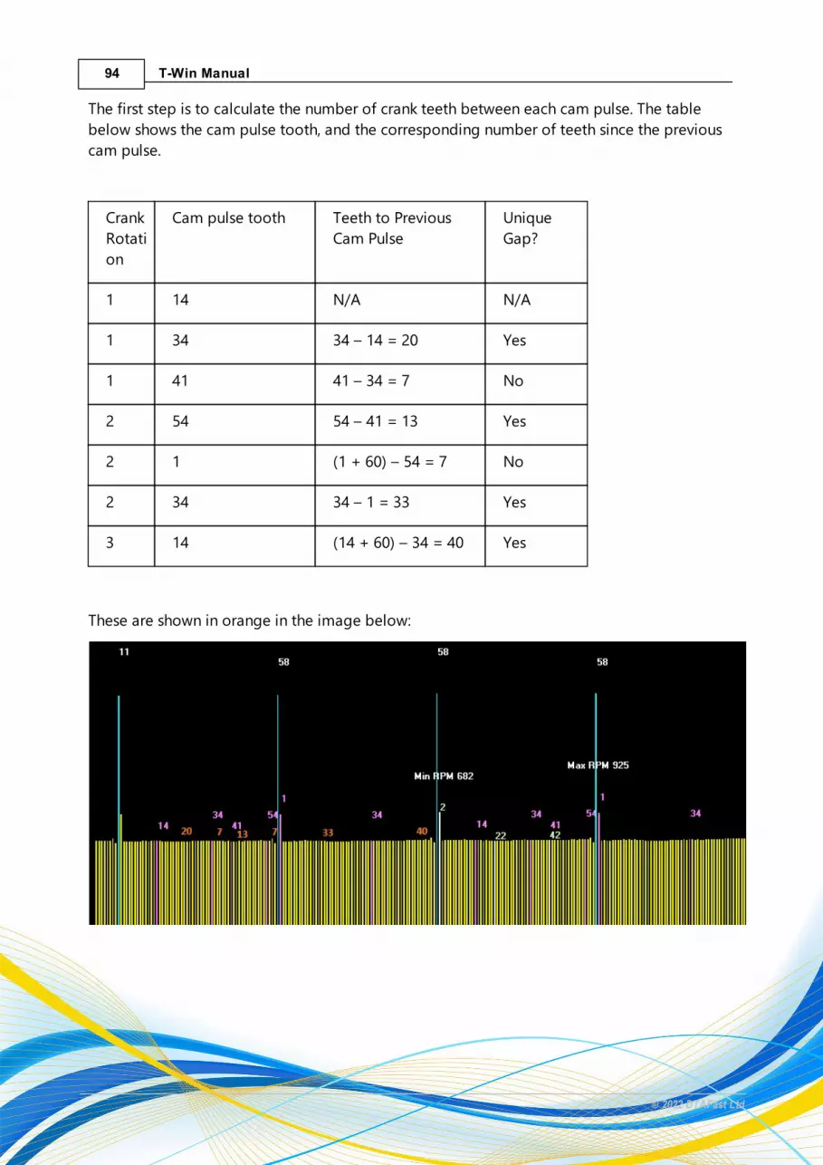
94 T-Win Manual
© 2022 DTAFast Ltd
The first step is to calculate the number of crank teeth between each cam pulse. The table
below shows the cam pulse tooth, and the corresponding number of teeth since the previous
cam pulse.
Crank
Rotati
on
Cam pulse tooth Teeth to Previous
Cam Pulse
Unique
Gap?
1 14 N/A N/A
1 34 34 – 14 = 20 Yes
1 41 41 – 34 = 7 No
2 54 54 – 41 = 13 Yes
2 1 (1 + 60) – 54 = 7 No
2 34 34 – 1 = 33 Yes
3 14 (14 + 60) – 34 = 40 Yes
These are shown in orange in the image below:

95Support Documents
© 2022 DTAFast Ltd
Flywheel Mode 26 works by looking for a specific, unique number of crank teeth between each
cam pulse. In this example, there are four options to choose from; 13, 20, 33 and 40. For this
example we will use 40 (highest unique count is generally best), which is the cam pulse
occurring on crank tooth 14. The other gaps of 13, 20 and 33 crank teeth will work in exactly the
same way.
Make sure Flywheel Mode 26 is selected in General Engine Settings. Press F4 to update the map
if you have to change this.
Open the Coil Per Plug Settings screen. It will look something like this:
The boxes labelled Lower Crank Pulses Limit Between Crank Pulses and Upper Crank Pulses Limit
Between Cam Pulses define the number of crank pulses the ECU will look for to pick out the cam
pulse we have selected.
Ideally the actual number of teeth would be specified. However, the cam pulse can move
between teeth, so a window has to be provided. This window must also ensure none of the
other pulses are picked up.
The next lowest is number of crank teeth between cam pulses is 33, and there no higher values,
which is what makes this a good choice. The window should therefore be from 36 to 44.

96 T-Win Manual
© 2022 DTAFast Ltd
The easiest way to calculate this is to take the highest number of crank teeth between cam gaps
(40), subtract the next highest number (33) and then divide by two. You can then add or subtract
this number from the highest number of teeth to use as the upper or lower limit. E.g. (40-33)/2
= 3.5 – in this case, we need to round the number up (4) or down (3). It’s generally better to
round up, so long as the upper/lower value doesn’t become too close to the tooth count of the
next highest/lowest gap.
Now the correct cam angle needs to be calculated. This is the angle between TDC and the cam
pulse when the cam is at it’s static (usually most retarded) position.
For this particular engine, the crank sensor angle is 61 degrees (see manual for calculating this
figure), which means TDC is on crank tooth 10. This is because the crank trigger disc has 60

97Support Documents
© 2022 DTAFast Ltd
teeth, which means each tooth represents 6 degrees of rotation. 61 degrees divided by 6
degrees/tooth = 10 teeth. Even if TDC was not exactly on tooth 10, maybe halfway between, it
does not matter as the upper/lower limit will account for that.
From the above graph (page 2), the cam pulse is on tooth 14.
This means the cam pulse must either be 4 teeth after the TDC crank pulse on tooth 10, which is
24 degrees, or it must be 56 teeth before the TDC crank pulse on tooth 10, which is -336
degrees. The minus signifies the cam pulse is before TDC.
To verify which is the correct value, remove all spark plugs except those in cylinder 1. Re do the
crank scope, and this will show which rotation crank rotation the TDC firing stroke is in.
This clearly shows the cam pulse is 4 teeth after TDC (highest point on graph), and the correct
value to be entered in Sequential Injection -> Cam Sensor Position is 24 degrees.

98 T-Win Manual
© 2022 DTAFast Ltd
The other three gaps would be calculated in the same way. Care must be taken, as there are two
cam pulses occurring on tooth 34. These cam pulses have a different amount of crank teeth
between them and the previous cam pulse, shown below:

99Support Documents
© 2022 DTAFast Ltd
If the 20 tooth gap was to be used, the correct angle would be 24 teeth x 6 degrees = 144
degrees. 24 because it’s a 20 tooth gap + 4 teeth from TDC.
The 33 tooth gap would be slightly different, as this angle is negative. This is the cam pulse
occurring on crank tooth 34. The maximum number of teeth the cam pulse can be from TDC is
60 teeth, one complete crank rotation. This means we need to use the cam pulse which is before
TDC, meaning the angle is negative.
To complicate matters further, this cam pulse has the gap in the crank between it and TDC, so
the number of crank teeth isn’t as obvious. To calculate this, we add the crank teeth either side
of the gap. TDC is 10 teeth after the gap, and the cam pulse is on tooth 34, which is 26 teeth
before the gap (60 – 34).
The angle would be (10 + 26) x 6 degrees, giving an angle of -216 degrees.
The engine should now run in sequential mode.
4.3 Rover K-Series Flywheel Modes
All of the Rover K series flywheels have trigger teeth set at 10° this means a total of 36 teeth.
However a number of these trigger teeth will be missing and which teeth are missing defines
the flywheel type. The diagrams below show the three types of flywheel.
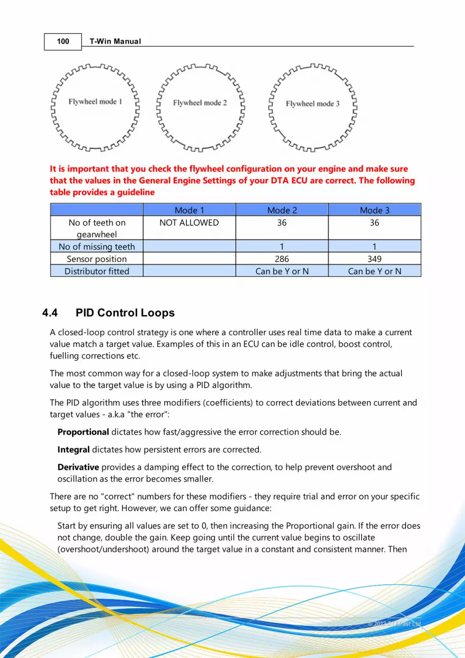
100 T-Win Manual
© 2022 DTAFast Ltd
It is important that you check the flywheel configuration on your engine and make sure
that the values in the General Engine Settings of your DTA ECU are correct. The following
table provides a guideline
Mode 1 Mode 2 Mode 3
No of teeth on
gearwheel
NOT ALLOWED 36 36
No of missing teeth 1 1
Sensor position 286 349
Distributor fitted Can be Y or N Can be Y or N
4.4 PID Control Loops
A closed-loop control strategy is one where a controller uses real time data to make a current
value match a target value. Examples of this in an ECU can be idle control, boost control,
fuelling corrections etc.
The most common way for a closed-loop system to make adjustments that bring the actual
value to the target value is by using a PID algorithm.
The PID algorithm uses three modifiers (coefficients) to correct deviations between current and
target values - a.k.a "the error":
Proportional dictates how fast/aggressive the error correction should be.
Integral dictates how persistent errors are corrected.
Derivative provides a damping effect to the correction, to help prevent overshoot and
oscillation as the error becomes smaller.
There are no "correct" numbers for these modifiers - they require trial and error on your specific
setup to get right. However, we can offer some guidance:
Start by ensuring all values are set to 0, then increasing the Proportional gain. If the error does
not change, double the gain. Keep going until the current value begins to oscillate
(overshoot/undershoot) around the target value in a constant and consistent manner. Then
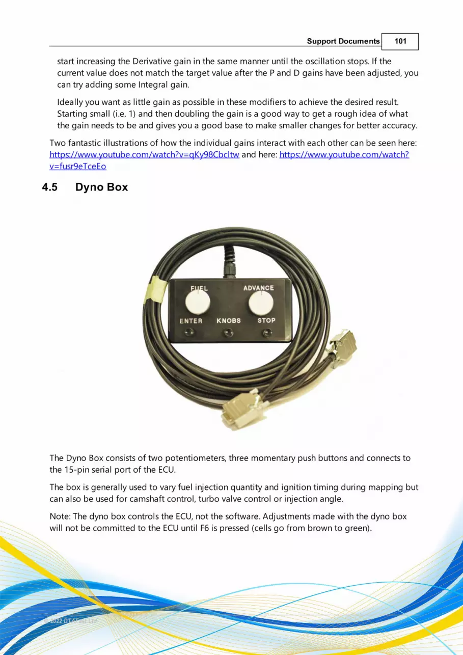
101Support Documents
© 2022 DTAFast Ltd
start increasing the Derivative gain in the same manner until the oscillation stops. If the
current value does not match the target value after the P and D gains have been adjusted, you
can try adding some Integral gain.
Ideally you want as little gain as possible in these modifiers to achieve the desired result.
Starting small (i.e. 1) and then doubling the gain is a good way to get a rough idea of what
the gain needs to be and gives you a good base to make smaller changes for better accuracy.
Two fantastic illustrations of how the individual gains interact with each other can be seen here:
https://www.youtube.com/watch?v=qKy98Cbcltw and here: https://www.youtube.com/watch?
v=fusr9eTceEo
4.5 Dyno Box
The Dyno Box consists of two potentiometers, three momentary push buttons and connects to
the 15-pin serial port of the ECU.
The box is generally used to vary fuel injection quantity and ignition timing during mapping but
can also be used for camshaft control, turbo valve control or injection angle.
Note: The dyno box controls the ECU, not the software. Adjustments made with the dyno box
will not be committed to the ECU until F6 is pressed (cells go from brown to green).

102 T-Win Manual
© 2022 DTAFast Ltd
4.6 PWM Frequencies
Some fan and fuel pump controllers can be in the 100Hz range. Some solenoids can be 50hz.
Drive-by-wire motors can be 10kHz. If the item you are trying to control has OE origins, try and
measure the control frequency using an oscilloscope on a factory setup. A lower frequency can
reduce control accuracy at low duties. A high frequency will increase accuracy in these situations
but too high a frequency can result in a narrow range of adjustment.
As a rule of thumb, use the lowest frequency you can while maintaining good control accuracy.
4.7 T-Flash Tool
The T-Flash tool is a firmware updater script. It asks you for the relevant firmware file, launches
Memtool to flash the new firmware to the ECU and then reboots the ECU. You can then re-
connect to the ECU with T-Win, without having to power-cycle the ECU.
Note: always make a backup copy of your map before upgrading firmware..
4.8 Guide to Start Fuelling
For best results, anything relating to the intake of air (idle cam timing, idle control valve. drive by
wire opening, variable intake etc.) must be tuned fully before tuning Start Fuelling. Otherwise it is
like chasing a moving goal.
Having a lambda sensor fitted is vital to proper tuning of the start fuelling.
First, setup the table axis. In most cases, you should not need more than 500 engine turns for the
start fuelling process. The rest of the cold engine fuelling requirements can be handled by the the
water temperature compensations. However, setting the last row to 10000 turns and 1% fuel will
allow you to log the turns for about 10 minutes
Regardless of the engine temperature, the engine will always need a large initial amount of fuel
to get started as most of the fuel will attach itself to the walls of the intake ports. When the
engine is cold, the fuel evaporates more slowly and droplets form, which are difficult to combust.
This is why cold engines must run significantly richer than hot engines. Once the engine is hot, fuel
evaporates quickly and is not "lost" to "wetting" the walls. However, even a hot engine must "wet"
the walls initially but it's a process that doesn't need to last a long as when it's cold.
Start by tuning the Start Fuelling at operating temperature. The Real Time Chart is very useful
here. You can log everything related to cold starting and monitor it all live. The first 100-200 turns
of the engine will be guesswork as a lambda sensor needs time to heat up. If you heat up a
lambda sensor too quickly or heat it up before a cold engine has started and condensation hits it,
the sensor can be damaged and become useless very quickly. You could use an external lambda
controller and pre-heat the sensor at the risk of damage. This would take a large chunk of the
guesswork out of tuning the first 20-200 turns.
19

103Support Documents
© 2022 DTAFast Ltd
The first 10-20 turns, however, are primarily going to be guesswork. As a rough guide, you may
want 100-150% more fuel for the first 1-5 turns, 50-75% for 5-10 turns, 30-50% for 10-20 turns and
then decreasing amounts thereafter. At operating temperature, you should need start fuelling for
no more than 100 turns.
The colder the engine. the higher those values will need to be and the longer the start fuelling
period will be. For example, at 0°C (32F), the engine may want 300% more fuel for the first 10
turns, then 100% for the next 40 turns, then drop down to something a bit more reasonable like
30% up to around 100 turns, and then start decreasing gradually to nothing by around 200 to 500
turns, where the water temp compensations take over.
When tuning start fuelling, err on the rich side. If it's too rich but still idles, you can go back
through the logs and calculate the adjustment. If it's too lean and stalls, you've lost an
opportunity. If you have closed loop lambda on from cold, you can log the correction factor
against engine turns and temperature.
Note: there are three ways to adjust the fuelling of a running engine: the Dyno Box , Map
Editing Keys or Closed Loop Lambda
101
10 54


