Embed Size (px)
Citation preview

Systems guide Equipment, controls and servicesfor integrated HVAC-R solutions
in commercial and industrial markets

Who We AreIngersoll Rand creates and sustains safe, comfortable and efficient environments. We are a $14 billion company whose
people, and market-leading brands work together to enhance the quality and comfort of air in homes and buildings,
transport and protect food and perishables, secure homes and commercial properties, and increase industrial productivity
and efficiency. We are committed to sustainable business practices within our company and for our customers, enabling them
to create progress and a positive impact in their world.
Our CommitmentWe inspire progress by unleashing the potential of people and technologies. Our people, products, systems and services
make everyday living healthier, safer, more energy efficient, productive and comfortable—enabling our customers to achieve
real progress and create a positive impact in their world.
Creating a Better Environment Through Innovation
From energy efficient compressed-air, air-conditioning and refrigeration systems to electric-powered golf cars with near-
zero emissions, Ingersoll Rand offers products and services that enable businesses around the world to reduce energy
consumption and costs and decrease harmful environmental emissions
Our BusinessesOur strong foundation include businesses with powerful brands, solid reputation and market leading positions. Those
business are aligned along four global operations: Climate Solutions, Industrial Technologies, Residential Solutions and
Security Technologies. Each one of these is comprised of one or more of our leading brands. Our roster of brands includes
well-known names, such as those listed here, and dozens of highly regarded regional brands serving a variety of market
segments.
Creating The Perfect Climate For Your Business And HomeA leader in sustainable HVAC and building system solutions, Trane offers a collective systems knowledge-base with the
applications expertise to create truly comprehensive solutions. With our broad product and service offerings, we can help
customers achieve their business objectives from start-up to system upgrades. Our integrated solutions help reduce energy
use and costs while meeting the high levels of comfort and performance critical to our customer’s business operations.
2 Systems guide

HVA
C sy
stem
sCh
iller
sH
eat p
umps
Air s
ide
prod
ucts
DX
unita
ry
syst
ems
HVA
C an
d bu
ildin
g co
ntro
lsBu
ildin
g se
rvic
es
HVAC systems
ChillersAir-cooled chillers, water-cooled chillers, heat rejection devices
Heat pumpsAir-to-water reversible heat pumps, water-to-water heat pumps
Air side productsAir handling units, water terminals, air terminals
DX unitary systemsRooftops, condensing units, close control units
HVAC and building controls
Building services
Contents
3

New from TraneAquaStream 3G: The quietest, high efficiency scroll chiller and heat pump ever
For the first time ever you can have the best of both worlds: high energy efficiency
and low-sound levels. The new AquaStream 3G gives you Energy Efficiency Ratings
higher than 3.1 in cooling operation (EER) and 3.2 in heating (COP) and an operating
sound level of as low as 76 dB(A). The chiller (model CGAM) and heat pump (model
CXAM) are certified Eurovent “Class A”. What’s more, they meet all global green
initiatives and ASHRAE energy efficiency standards.
Learn more at: www.aquastream3g.com
Trane’s model RTWD water-cooled chiller was designed with built-in reliability,
including the proven reliability of the Trane helical-rotary compressor, so building
users can benefit from the utmost of trouble-free operation throughout the entire
life-cycle. It is equipped with a unique, patented evaporator design helps achieve high
efficiencies of up to 5.6 EER (Energy Efficiency Ratio). It is certified Class A in the
Eurovent LCP program.
What’s more, the chiller incorporates a double circuit – a valued back-up system to
ensure you have a continuous supply of chilled water.
Learn more at: www.trane-rtwd.com
Trane now offers you a total of six different versions of its model RTAC
air-cooled chiller: 3 efficiency versions and 2 sound level versions that
will help ensure you get the exact answer to your cooling, floor space
and sound requirements, whatever your specific application.
The 2 latest developments are the “extra high efficiency” and “extra
high efficiency for sound sensitive applications” which achieve Class A
performance according to Eurovent standards.
*Eurovent, the European Association of Air Handling and Refrigerating Equipment Manufacturers, certifies the performance ratings of air conditioning and refrigeration products according to European and international standards. The objective is to build customer confidence by increasing the integrity and accuracy of industrial performance ratings.
4 Systems guide

Trane expands its terminal portfolio with active chilled beams with integrated Trane
ZN controller, model BAC. Chilled beams remain an adaptable and cost-efficient way
to provide effective cooling, or cooling and heating, in a variety of applications while
achieving significant energy savings. Factory-installed controls allow you to benefit
from a fast, trouble-free set-up and the peace of mind that comes from knowing your
system will always operate at its best.
When you turn to Trane high efficiency water terminals as part of your total
HVAC solution, you benefit from innovative EC (Electronically Commutated) fan
motor technology, which, together with Trane’s unique ZN controls, provides a
unique combination of optimum low energy use and improved comfort.
Trane offers a chilled water cassette (model CWE) and 2 concealed ductable water
terminals (model FED and model FEU) with EC fan motors.0
14,000
12,000
10,000
8,000
6,000
4,000
2,000
908070605040302010
Energy Savings
Energy consumption – AC motor
Load/airflow requirement (%)
Annual fan energy usage for a 2 kW water terminal (Wh)
Energy consumption – EC motor
At Trane, we recognize the importance of supplying our customers with Air Handling
Systems that meet and exceed environmental standards while focusing on green-build
initiatives that contribute to a more sustainable work environment.
The model HRCU is an extremely compact and energy efficient Trane air handling unit.
Standard features include heat recovery and factory-mounted controls. A DX cooling
module is also available as an option.
Specially designed for industry processes and healthcare applications, the fully
customizable model CCEB is VDI 6022 design certified.
5

Trane Extended Start is the best way to validate proper installation
and assure the highest level of performance during that all-important
first year of operation. Trane Extended Start goes above and beyond the
warranty and includes five essential services and three optional services
which will create a system baseline to build a strong high performance
building foundation.
Trane Intelligent Services combine the power of our advanced remote
monitoring facility with the knowledge of Trane Technical Specialists.
It’s an effective and affordable way to look after your HVAC and other
critical systems connected to your Building Automation System 24 hours
a day, 7 days a week.
New from Trane
Trane now offers an array of energy saving options on its range
of Voyager™ packaged rooftops. Benefit from heat recovery
modules, using either a plate heat exchanger or heat recovery wheel
technologies, which boast 50-65% efficiency levels and allow the
overall installation to be more efficient and cost-effective.
A modulating gas burner, where the gas heater condenses when at
operation below 62% of load, is also available. Compared to a staged
burner, the rooftop will run most of the time at part load with high
efficiency, resulting in reduced gas consumption and better comfort.
Finally, Trane’s new dual fuel rooftop: a reversible heat pump unit with
a gas burner for auxiliary heat. When the heating requirement cannot
be fully satisfied with mechanical heating, the unit automatically
switches to gas heat, resulting in lower overall energy consumption,
increased COP and reduced carbon emission.
6 Systems guide
At Trane we believe in creating high performance buildings and make controls one of the keystones to making a building
work better for life. Whether you manage one or multiple facilities, a Trane Building Automation System can be scaled to
your needs.
•Tracer™ SC controller is a BAS with a web-based interface to streamline facility management including climate control,
lighting, and energy consumption. It is flexible, can grow with your building and adapt to your changing needs, and is a
cost-effective choice.
•Tracer ES™ control software is specially designed to manage multiple facilities as one. It gives you an online, enterprise-
wide view and control over all of your buildings and systems.
•Tracer ES™ express software is perfectly suited to smaller scale
installations needing cost-effective online accessibility.
Trane has also developed new Tracer™ equipment controllers: UC400
multi-purpose controllers for air side equipment and the model UC800
for centrifugal chillers. They come pre-loaded with standard software
applications, support factory and field mount, graphical programming
and BACnet® protocol.
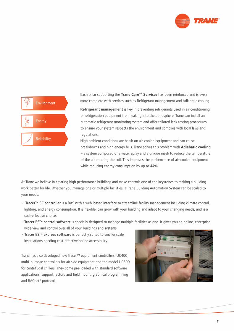
Each pillar supporting the Trane CareTM Services has been reinforced and is even
more complete with services such as Refrigerant management and Adiabatic cooling.
Refrigerant management is key in preventing refrigerants used in air conditioning
or refrigeration equipment from leaking into the atmosphere. Trane can install an
automatic refrigerant monitoring system and offer tailored leak testing procedures
to ensure your system respects the environment and complies with local laws and
regulations.
High ambient conditions are harsh on air-cooled equipment and can cause
breakdowns and high energy bills. Trane solves this problem with Adiabatic cooling
– a system composed of a water spray and a unique mesh to reduce the temperature
of the air entering the coil. This improves the performance of air-cooled equipment
while reducing energy consumption by up to 44%.
Environment
Energy
Reliability
77

Proven performance to make buildings work betterBusinesses around the world are being challenged to improve energy efficiency. According to the World Business Council
for Sustainable Development, buildings worldwide account for 40% of global energy consumption. Of that amount,
between 45% and 65% is used by HVAC systems that keep building environment comfortable and healthy. The slightest
inefficiencies in cooling and heating equipment create a huge energy drain and the financial impact is significant.
Trane captures emerging technologies when designing products, and develop with energy efficiency, and low operating
costs in mind, to allow building owners to manage energy better. Whether it is a chiller rated Class A in the Eurovent*
certification program – or water terminals equipped with an EC fan motor - saving the customer energy costs is one of
Trane’s priorities.
The proof is in the testingThe testing process starts in research and development. We look at environmental performance, acoustic characteristics,
operating longevity, and overall operating efficiency.
At Trane, computer selection programs predict equipment performance based on laboratory testing.
Factory performance tests confirm that the actual Trane product performance matches the predicted performance and the
results serve as a benchmark during the commissioning process.
We are committed to the highest level of design and manufacturing
accuracy to make sure that your products performs as expected.
Trane European testing facilities and laboratories fully comply with
European Standard EN 14511, meaning that procedures, measurements
and conditions are respected to provide our customers with trustable and
certified performances.
After an extensive and rigorous inspection process conducted by Eurovent,
Trane’s test stands in Charmes, France are approved for conducting
Eurovent certification tests for air-cooled chillers above 600 kW,
recognizing the right to Trane to test air-cooled chillers up to 1,500 kW in
his own facilities as part of the certification program.
The Eurovent certification brings clarity and transparency. It also shows the
Trane commitment to deliver systems with high levels of performance and
reliability.
*Eurovent, the European Association of Air Handling and Refrigerating Equipment Manufacturers, certifies the performance ratings of air conditioning and refrigeration products according to European and international standards. The objective is to build customer confidence by increasing the integrity and accuracy of industrial performance ratings.
8 Systems guide

Trane HVAC Systems Every building has a purpose, whether it’s to nurture inventions,
house masterpieces, cultivate learning or even to host birthday parties. A true high performance heating, ventilating and air conditioning (HVAC) system is one that makes
your building work better for life.

10 Systems guide
HVA
C sy
stem
s
Reaching for perfection
Maintaining a high and consistent level of comfort is
critical in the lodging industry. Hotels succeed or fail based
on their ability to put “heads in beds” at profitable rate
levels. The prime influence on this occupancy rate is guest
satisfaction. A room that is noisy, stuffy, hot or clammy
creates a powerful negative impression. Trane has both
experience and a portfolio of products to help operators of
hotels attract and retain guests.
Trane has decades of experience working with the lodging
industry, from individual hotels to global chains. Energy
is the second-highest operating cost component in the
lodging industry. We know that from 50 to 80 percent of
the energy costs in lodging are related to HVAC system
operation and have the solutions to keep your energy
costs to a minimum with efficient equipment and high
performance building management systems.
Trane solutions for the lodging industry

11
HVA
C sy
stem
s
Control systems improve comfort, simplify maintenance and optimize operation
Within your lodging facility, there are areas with varying
requirements. Guest rooms, lobby areas, dining areas
and recreation zones all have different environmental
requirements. Food preparation areas need extensive
ventilation and to be kept separate from other areas.
Pools and gymnasiums also have special temperature
requirements and need effective dehumidification year
round. Part of the solution is quality equipment, properly
sized, and correctly installed. The other part is a control
system that can keep all areas operating in harmony.
A control system also makes it possible to optimize
equipment operation. For example, in a chilled beams
system, the primary air conditions (temperature/humidity)
can be reset according to the most demanding zone.
Comfort systems and the bottom line
Trane’s international organization appreciates that different
regions have varying comfort needs, building codes,
and engineering practices. Our vast local sales and service
support teams, with their extensive local experience and
customer relationships, add value to your plans.
Regardless of the size or scale of your lodging business,
we’re ready to help.
Building operation at your fingertips
With Trane web-based BMS solutions, the overall building
operation can be monitored and managed from anywhere.
Alarms and events are routed to operators’ smartphones and
computers, wherever they sit, no matter how many users
there are.
1 2
3
45
6
1 = Chilled water plant: 2 AquaStream 3G scroll chillers with factory-mounted CH5302 = Fresh air control: AHU with Trane factory mounted-control (MP581/UC400/UC600)3 = Room comfort: FCU with EC fan motor and Trane factory-mounted control (ZN525/UC400)4 = Humidity air control for gym and swimming pool: AHU with MP5815 = Building systems operations and management: Trane Tracer ES™ and Tracer™ SC web-based solutions6 = Access and room booking systems integration: through standard BACnet® protocol

12 Systems guide
HVA
C sy
stem
s
Creating the perfect atmosphere
From simple stores to modern shopping complexes, Trane
has experience in the retail business. We know that the
temperature, humidity and ventilation management needs
of stores are different than for other buildings.
Leveraging our experience, we can help you identify
specific areas for energy and comfort improvement and
keep your buildings operating at their design levels.
And with contingency planning and our thousands of
equipment and controls technicians, we can help you
reduce the risk of sales lost due to comfort system failure.
Delivered system
Trane’s light commercial BMS only requires a few settings to
be implemented on an application. Thanks to the capability
of any Trane HVAC equipment to communicate over a
network, the BMS manages to identify these equipment
linked together, builds the corresponding database and
automatically offers to the end user predefined functions
such as time-of-day schedule, automatic setpoint reset,
zone management or alarming menu, with almost no labor
required.
Trane solutions for retail businesses
If you want to customize your interface, convenient
software is available to do this. The system is compact and
convenient to install and wire up. Trane’s equipment uses
an open standard protocol, called LonTalk®, which is often
present retail buildings, and contractors perfectly master this
kind of bus topology installation.

13
HVA
C sy
stem
s
The advantage of single sourcing
Trane’s delivered system offers an additional perspective,
since every piece of the puzzle comes from the same
manufacturer. It is far easier to coordinate equipment
delivery, commissioning and fine tuning, since only one
contact is involved for this. On top of this, Trane personnel
are well trained for the entire system components, ensuring
efficiency in commissioning, and fast response.
Energy savings
Various pre-engineered tactics, such as setpoint reset, time-
of-day scheduling and duty cycle, have been implemented
in the system to improve system energy efficiency, without
altering system comfort management capability. Trane’s
system is easy to install, set up and use. This means that
system updates, daily operations and maintenance can be
done by operation personnel very easily, requiring very little
training. Trane’s system also has the capability to control
ancillary equipment, such as lights, parking lots, energy
meters, and any equipment controlled by to a time-of-day
schedule. Trane’s delivered BMS for commercial applications
is a powerful answer to customers who want a very easy-
to-use system, capable of simplifying their life all along the
project life cycle.
1 = Space temperature and humidity control: Voyager™ rooftop units with factory-mounted control: ReliaTel™2 = Lighting control: either through Trane dedicated I/O controller (MP581, UC400, UC600) or by integrating a specific lighting control
system through standard protocol (BACnet® to DALI as an example)3 = Building systems operations and management: Trane Tracer ES™ and Tracer™ SC web-based solutions4 = Cold aisle retrieval: AHU with Trane factory-mounted controls (MP581, UC400, UC600)5 = Air curtains: FCU with EC fan motor and Trane factory-mounted control (ZN525/UC400)6 = Office space comfort: FCU with EC fan motor and Trane factory-mounted control (ZN525/UC400)7 = Retail store comfort: VAV with Trane factory-mounted control (VV550/UC400)8 = Energy metering and monitoring: meters integrated through communication protocol, and data presented as graphs on the Trane
Tracer™ SC/Tracer ES™ custom web pages

14 Systems guide
HVA
C sy
stem
s
Reliable Trane systems your industry can count on
Trane has a wide experience in industrial control
applications, starting from simple chillers to complex
systems that are optimized for improved efficiency.
One of the highest priorities of Trane engineers when
designing an industrial application is to ensure a system
that is reliable. Trane proposes systems that can revert to
a safe standalone running mode should any issue such as
communication troubles arise, continuing to deliver cooling
capacity until the issue has been analyzed and fixed.
In addition, Trane always proposes simple-to-use user
interfaces which offer just the right amount of information
about system status and running conditions. Since every
piece of equipment is hooked up to a network, the user can
access system and units information at any time, allowing
for easy diagnosis, and easy understanding of system
reactions.
Trane solutions for industries
Chiller Plant Management
Application is a pre-engineered function within Trane
controllers, as to deliver a consistent, reliable and repeatable
performance from project to project, with a minimum
commissioning time.

15
HVA
C sy
stem
s
Personalized optimization
Piping arrangement, chiller technology, unit sizes
arrangement are analyzed so you get the best result of their
installation, according to their system load profile. Chiller
Plant sequencing is a powerful pre-engineered function that
only requires parameters to be able to drive the installation
at its highest level of optimization.
Consulting services
Trane has developed the capacity of offering you full
support, beginning with customer’s technical service. Trane
proposes its simulation and solution evaluation software.
Using this tool, you can easily evaluate the best alternative
for solving a problem, by viewing the solutions from
different angles, such as economical aspects, technical
aspects, safety and reliability.
One point of contact
Once your project has been fulfilled, it is easy to get
assistance from Trane in concluding a maintenance and
service contract including HVAC and BMS equipment/
software. This way, system fluctuations, fine tuning etc …
can be done by people working in sync with those teams
that have originally developed the application. This ensures
service continuity as well as efficiency in answering any
request of system improvement or adaptation.
1 = Critical systems monitoring - Electrical power: MP5812 = System water flow control - Variable frequency pump control: VarioTrane TR2003 = Chiller condenser operation - Cooling towers control: MP5814 = Chiller Plant Control: 3 RTWD helical-rotary chillers with factory-mounted CH530, Twin pump control for each chiller: BCU5 = System monitoring and control - Supervision: Tracer Summit™

16 Systems guide
HVA
C sy
stem
s
Adapted to your evolving requirements
In addition to HVAC application solutions for large scale
building projects, Trane has developed one of the most
open Building Management System solutions available on
the market. Trane’s BMS caters to office building comfort
applications with fully optimized functions.
These functions offer several unique advantages to you
along the project cycle.
Trane’s BMS is a highly flexible system that offers ease of
(re)configuration. This allows the system to be adapted at
every step of a project. Large buildings regularly require
space rearrangements (open space) and Trane’s system is
fully capable of managing space reconfiguration, thanks
to advanced master/slave capabilities of terminal unit’s
controller, perfectly fitted in the global BMS.
Trane’s BMS is based on the latest web technologies,
allowing for a high performance User Interface, as well as
full flexibility with regards to accessing the system. Using
a simple web brower software on any PC connected to
the customer network, users can monitor and manage the
assets, from wherever they are.
Trane solutions for office buildings
The system then allows multiple users to access the system
simultaneously, improving the overall productivity in the
asset management team.
Building its own electronic components was a choice that
Trane made as to perfectly master the complete product
life cycle, from development, engineering, manufacturing,
up to maintenance, support and upgrade. This means
that Trane’s solution is reliable and offers full equipment
integration and system interoperability.

17
HVA
C sy
stem
s
System efficiency
Trane has developed pre-engineered functions within Tracer
Summit™ that allow a high level of system efficiency which
can be seen from different angles:
Efficient commissioning - Minimum programming is required
to set up these functions and the BMS project engineers
can spend more time in fine-tuning the system rather than
developing the applications from scratch.
Perfect equipment coordination – Each piece of Trane HVAC
equipment comes with its own factory-mounted controller.
All these controllers have been developed keeping in mind
their possible association within a system and thus, their
interaction is possible within Trane’s BMS.
Fine-tuning- Trane’s BMS allows operations managers to get
a customized report of the current system status, by the
simple click of a mouse.
Total comfort
Trane’s excels in developing HVAC equipment.
Trane’s engineers go further to consider the equipment
in their global environment. This means that on top
of ensuring equipment safeties and running condition
efficiency, care has been taken to ensure low sound
levels, energy savings, etc. Through the use of Trane’s
BMS, these aspects of equipment running conditions are
further improved. As an example, a VAV box can be driven
according to pressures and running conditions of the AHU
that is serving it. Or the AHU that delivers primary air to a
chilled beam system would shift from air-economizer mode
to mechanical dehumification if the outside air becomes too
humid. The equipment exchanges data in order to align the
respective working conditions to deliver the optimum service
to the end user.
11
1 = Weather information: MP5032 = Chilled water plant: 2 RTAC helical-rotary chillers with factory-mounted CH530: BCU3 = Primary air control: AHU with factory-mounted MP5814 = Open space comfort: BAC chilled beams with factory-mounted ZN523 controller5 = Environmental comfort: Lighting control: EXL, Sunblind control: EXB6 = Tenant interface: Setpoint and room conditions information: Web Server7 = Workstation: Building Systems Management, operation and diagnosis: Tracer Summit™8 = Variable air flow control AHU and VariTrane™ valves: MP581+VV5509 = Hot water plant: boiler plant control: BCU10 = Electrical Power monitoring: MP58111 = Interoperability: Access control system monitoring: BACnet®+ LonTalk®
18 Systems guide
HVA
C sy
stem
s
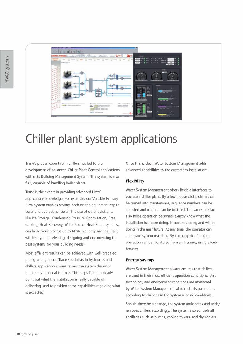
Trane’s proven expertise in chillers has led to the
development of advanced Chiller Plant Control applications
within its Building Management System. The system is also
fully capable of handling boiler plants.
Trane is the expert in providing advanced HVAC
applications knowledge. For example, our Variable Primary
Flow system enables savings both on the equipment capital
costs and operational costs. The use of other solutions,
like Ice Storage, Condensing Pressure Optimization, Free
Cooling, Heat Recovery, Water Source Heat Pump systems,
can bring your process up to 60% in energy savings. Trane
will help you in selecting, designing and documenting the
best systems for your building needs.
Most efficient results can be achieved with well-prepared
piping arrangement. Trane specialists in hydraulics and
chillers application always review the system drawings
before any proposal is made. This helps Trane to clearly
point out what the installation is really capable of
delivering, and to position these capabilities regarding what
is expected.
Chiller plant system applications
Once this is clear, Water System Management adds
advanced capabilities to the customer’s installation:
Flexibility
Water System Management offers flexible interfaces to
operate a chiller plant. By a few mouse clicks, chillers can
be turned into maintenance, sequence numbers can be
adjusted and rotation can be initiated. The same interface
also helps operation personnel exactly know what the
installation has been doing, is currently doing and will be
doing in the near future. At any time, the operator can
anticipate system reactions. System graphics for plant
operation can be monitored from an Intranet, using a web
browser.
Energy savings
Water System Management always ensures that chillers
are used in their most efficient operation conditions. Unit
technology and environment conditions are monitored
by Water System Management, which adjusts parameters
according to changes in the system running conditions.
Should there be a change, the system anticipates and adds/
removes chillers accordingly. The system also controls all
ancillaries such as pumps, cooling towers, and dry coolers.

19
HVA
C sy
stem
s
6
Reliability
Chilled water production is crucial for your process and
Trane’s system ensures continuous delivery of chilled water.
Every chiller is equipped with its own electronic controller
embedded with an adaptive control algorithm.
Each controller is fully compatible with the Building
Management System and communicates over a standard
protocol, sharing all its running conditions. This allows
the management system to not only turn on/off chillers
according to temperatures or temperature differences, but
also consider current running conditions of chillers, such as
maximum capacity reached, limit conditions, and so on, in
order to know system capacity at all times.
Interoperability/integration
Trane systems are fully capable of communicating with any
equipment and/or management system through the use
of open standard protocols, such as BACnet®, or LonTalk®.
Modbus is also supported allowing for a wide range of
integration and data sharing with ancillaries, such as pumps,
sensors or PLC’s. Trane systems are capable of integrating
either standard LonTalk® profiles (SCC, DAC) or Generic
Lon Devices (GLD), as well as BACnet® MS/TP or IP-based
devices.
Protection
Trane systems offer a high level of protection against
unexpected system operation. Operators can be authorized
to monitor data only, write setpoint and other parameters,
create graphics or just view them, modify system layout,
and so on. Every action on the system is recorded in an
event log. Events can then be monitored, filtered by date/
operator/device, etc. Events can be seen either at the PC
level, or from a local touch screen available in the plant
room.
Assistance
Trane systems allow for system remote monitoring.
After commissioning, Trane personnel can get connected to
the system and monitor/fine tune parameters to adapt the
overall system performance. Alarms can also be forwarded
to that remote workstation. If an IP address is available, a
web server can be installed and allow for remote access to
the system through a simple web browser. Trends, event log,
system status can be accessed this way from any location
where an access to the Internet/intranet is possible.
1 = Data and system functions management: Tracer™ SC or Tracer™ BCU2 = Ancillaries control (pumps, cooling towers, etc ...) field-programmable controllers
(MP581, UC400, UC600)3 = Plant control panel monitoring: field-programmable controllers (MP581, UC400, UC600)4 = Water flow control: VarioTrane VFD’s (TR200 series)5 = User interface: local touchscreen PC, or any PC connected through web browser, web pages served by Trane Tracer™ SC6 = 3 RTHD helical-rotary chillers with factory-mounted CH530
20 Systems guide
HVA
C sy
stem
s
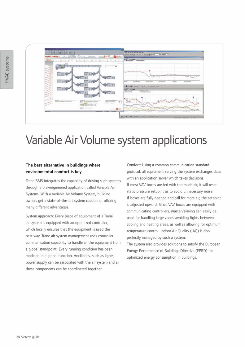
The best alternative in buildings where environmental comfort is key
Trane BMS integrates the capability of driving such systems
through a pre-engineered application called Variable Air
Systems. With a Variable Air Volume System, building
owners get a state-of-the-art system capable of offering
many different advantages.
System approach: Every piece of equipment of a Trane
air system is equipped with an optimized controller,
which locally ensures that the equipment is used the
best way. Trane air system management uses controller
communication capability to handle all the equipment from
a global standpoint. Every running condition has been
modeled in a global function. Ancillaries, such as lights,
power supply can be associated with the air system and all
these components can be coordinated together.
Variable Air Volume system applications
Comfort: Using a common communication standard
protocol, all equipment serving the system exchanges data
with an application server which takes decisions.
If most VAV boxes are fed with too much air, it will reset
static pressure setpoint as to avoid unnecessary noise.
If boxes are fully opened and call for more air, the setpoint
is adjusted upward. Since VAV boxes are equipped with
communicating controllers, master/slaving can easily be
used for handling large zones avoiding fights between
cooling and heating areas, as well as allowing for optimum
temperature control. Indoor Air Quality (IAQ) is also
perfectly managed by such a system.
The system also provides solutions to satisfy the European
Energy Performance of Buildings Directive (EPBD) for
optimized energy consumption in buildings.

21
HVA
C sy
stem
s
Savings
Dynamically adjusting airflow in the duct system leads to
energy savings by reducing fan consumption. Occupancy
schedules also participate in energy savings. Start/stop
optimization, by monitoring of outdoor air conditions,
building inertia and occupancy profiles are also a very
powerful tool. Control of IAQ also is an important asset for
energy savings. Only the right amount of fresh air is handled
by the system reducing unnecessary ventilation.
Ease of use
Trane systems can be run through an intuitive genuine
web interface at avery level of the system. The use of an
advanced password system allows the use of filtering screens
so that users only have access to what they really need.
End users can also use their standard PC to operate the
system, by surfing on their dedicated web pages for setpoint
adjustment, for example. Alarms are also monitored by the
system and can be forwarded to the appropriate recipient
via e-mail. Reports are accessible through couple of mouse
clicks, no engineering, no programming being required.
Time of day schedules, setpoints and system statuses can be
accessed, for reading and reading/writing, depending on the
password given.
1 = Open space comfort: AHU with factory-mounted control MP581 or UC400 or UC6002 = Variable air volume valve: VariTrane™+ VV550 or UC400

22 Systems guide
HVA
C sy
stem
s
Water terminal units and chillers are Trane core products.
Understanding how this equipment is being used together
is part of Trane know-how that has been converted into a
Management System. Other equipment serving building
comfort system is also under Trane system, control such as
air handling units, exhaust fans, water treatment, but also
ancillaries such as lights, power distribution panels, and
so on. The system that Trane offers covers key points for a
project to be successful.
Comfort
Trane has developed advanced electronic controllers that
offer individual comfort at each terminal unit level.
• Temperatures are monitored and controlled to stay within
limits each user can adjust wall sensors or web pages.
• Sound level is maintained at its minimum value and air
movement reduced as much as possible by the control of
fan speed. Trane’s offer also includes chilled beams which
operate without a fan guaranteeing very low sound levels.
Water system applications• Comfort is maintained year-round; cooling/heating modes
are controlled automatically and intelligently, change over
being totally transparent to the occupant.
• Comfort for the operation manager is also ensured.
Master/slaving is now very easy to set up and reconfigure.
Open space re-design can be done in very short period of
time.
• Indoor Air Quality (IAQ) is also one of the advantages
of a Trane system which is capable of monitoring and
maintaining IAQ within optimum limits.
Ease of use
Trane systems communicate through open protocols
(LonTalk® BACnet®). The system handles several types of
user interfaces, so that every user can have access to the
information he needs.
• Terminal units can be equipped with wall sensors
embedding indications such as setpoint, timed override,
and temperature values. This information can be adjusted
within pre-determined limits.

23
HVA
C sy
stem
s
1 = Open space comfort: UniTrane™ fan coil with factory-mounted ZN controller2 = Ancillaries control: Lighting control: EXL, Sunblind control: EXB3 = Open space comfort: UniTrane™ fan coil with factory-mounted ZN523, ZN525, or UC400 controllers4 = Tenant interface: Setpoint and room conditions information: Zone Sensor (ZSM 10.1, ZSM 10.2, ZSM 11)
• Operation managers can have access to system status by
using an advanced graphical interface running on a PC.
This status can be filtered and organized according to the
use. Software interfaces integrate a user-friendly graphical
interface allowing authorized users to change/create
graphics to optimize them for their own use.
• Operation engineers can have access to system
information in the different technical locations in the
building by the use of VGA touch screens, on which local
data are presented.
• Time-of-day (TOD) scheduling offers a very convenient
interface for TOD adjustment, group/zone creation or
modifications.
• Every single piece of equipment in the system can be
focused on. It can be overridden in any state as for
maintenance or test purposes.
• Equipment or system alarms can be monitored and
broadcasted on the system so that the best recipient can
get a notice for this particular event and react in the most
efficient manner.
• A web server allows for system performances monitoring
from a PC equipped with a simple browser.
Savings
Through the coordination of all equipment within the
building, it is quite simple for the management system to
optimize energy consumption. Savings also are available at
system design and system commissioning phases.
• Water system management can be organized, so that
either chilled water or hot water production is handled in
the most efficient way.
• Equipment schedules integrate a function of optimization,
which determines building inertia and adjusts start/stop
time according to temperatures/relative humidity and
building occupancy.
• Each Trane piece of equipment is delivered with factory-
mounted controls which are ready to work when the
equipment leaves the factory.
Coordination of production (cooling/heating) and use (fan
coils, air handling units, chilled beams…) is one of the best
approaches to optimize system operation.
Communication is the key factor for this to be efficient.
Communication is also an essential factor for some HVAC
systems, such as chilled beams in which indoor terminals rely
on the primary air AHU for zone humidity control. All Trane
equipment integrates a standard protocol interface.

24 Systems guide
Notes

2525
Chillers Trane sees buildings in terms of the critical comfort needs of the people and the things
in the building. More than half of the large buildings in the world today have a Trane chiller at their core. Not only do our chillers help create comfort, they also help reduce your cost of operation, provide energy efficiency and minimize environmental impact.

26 Systems guide
Chill
ers
Customer benefits • Space saving: particularly slim design. The unit can be
installed directly on a balcony, rooftop or ground without
the need to have a plant room
• Contemporary appearance: blends in with the surrounding
environment
• Quiet operation: low sound fans and components to
achieve its low sound level
Main features• Designed to couple with fan coil units and air handling
units for residential or small commercial air conditioning
applications
• Scroll compressor(s), plate type evaporator, finned-
copper tube and aluminum condenser, axial fan assembly,
expansion valve, indoor cold/warm control switch, water
flow switch, filter dryer, sight-glass, integral water pump,
galvanized sheet metal housing with powder paint, factory
mounted control.
Options• Pressurized water tank system
• Condenser with blue fins corrosion protection
Control• LCD Microprocessor-based Adjustable Water Temperature
Control: Precise temperature control of inlet chilled water,
operation modes and system protection are provided by
the long-range controller.
• Password can be set and any abnormal condition will
be monitored and captured to facilitate quick repair and
normal operation.
• Interlocking function of the two-way valve is available.
CGAKAir-cooled scroll chiller
This description may not include all options and accessories available. For full technical information, download documentation at: http://doc.trane-eur.com

27
Chill
ers
CGAK 0505F 0605A 0755D 1005F 1505D 1505FNet cooling capacity (1) (kW) 13.1 15.6 19.5 26.2 39.0 38.0Total power input in cooling (1) (kW) 4.4 5.6 6.8 8.6 13.7 13.4EER 2.98 2.77 2.87 3.05 2.85 2.8Number of refrigerant circuits 1 1 1 2 2 1Number of compressors 1 1 1 2 2 1Sound power level (2) (dB(A)) 62 61 63 64 66 70Weights and dimensions (operating)Length (mm) 950 950 1290 1290 1990 1290Width (mm) 393 393 500 500 500 500Height (mm) 1285 1285 1900 1900 1900 1900Operating weight (kg) 170 170 290 404 490 470Clearance A (mm) 300 300 300 300 300 300Clearance B (mm) 1500 1500 1500 1500 1500 1500Clearance C (mm) 300 300 300 300 300 300Clearance D (mm) 500 500 500 500 500 500Electrical dataMaximum amps - cooling (A) 13.0 16.7 19.6 25.8 40.8 39.9Start-up amps (A) 65.5 101.0 95.0 65.5 x 2 95.0 x 2 198.0
(1) At 12/7°C entering/leaving water temperature and 35°C ambient air temperature(2) With 1pW Reference Sound Power, according to ISO9614
Operating outdoor air temperature range (Min/Max) (1) (°C) +18 / +43Leaving water temperature range (Min/Max) (1) (°C) +5 / +15Power supply (V/Ph/Hz) 400/3/50

28 Systems guide
Chill
ers
Customer benefits • Packaged hydraulic module (VGA) for easier and quicker
installation
• Low sound version for sensitive environment: a high level
of acoustic comfort
• Minimum maintenance requirements save time and money
Range descriptionCGA: Without hydraulic module
VGA: With hydraulic module
Main features• Scroll compressor(s) featuring sound-proofing, protection
of motor winding, crankcase heater, thermo-magnetic
circuit breaker
• Axial fan(s) with completely integrated low noise level
• Stainless steel water heat exchangers equipped with
heating resistors
• Black epoxy-coated aluminum fins with copper tubes
• Cooling circuit(s) with thermostatic expansion valve(s),
liquid line filter drier(s), high and low pressure cut-outs,
factory oil and refrigerant charges
• Disconnect switch
• Flow switch
• Low ambient speed controller
Options• Water outlet low temperature (-5°C to -10°C)
Accessories• Remote control module
• High and low pressure gauges
ControlMicroprocessor control module featuring:
• Control of return water temperature
• Liquid crystal display indicating return water temperature,
codes of any faults
• Control of operating parameters
• Possibility of remote fault signaling on 24V indicator light
• Antifreeze protection of evaporators
• 24V dry contacts for remote signaling of on/off and
general fault
CGA VGAAir-cooled scroll chiller
This description may not include all options and accessories available. For full technical information, download documentation at: http://doc.trane-eur.com
29
Chill
ers
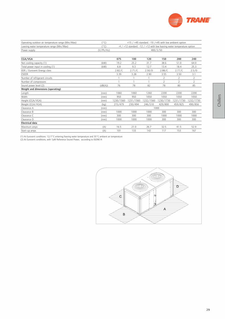
CGA/VGA 075 100 120 150 200 240Net cooling capacity (1) (kW) 19.2 25.2 31.7 38.6 51.0 64.0Total power input in cooling (1) (kW) 6.8 9.3 12.7 13.4 18.4 25.3EER / Eurovent Energy class 2.82/C 2.71/C 2.50/D 2.88/C 2.77/C 2.5/DESEER 3.39 3.28 2.90 3.55 3.50 3.1Number of refrigerant circuits 1 1 1 2 2 2Number of compressors 1 1 1 2 2 2Sound power level (2) (dB(A)) 76 78 82 78 80 85Weight and dimensions (operating)Length (mm) 1060 1060 1260 2200 2200 2200Width (mm) 950 950 1050 1050 1050 1050Height (CGA/VGA) (mm) 1230/1560 1231/1560 1232/1560 1230/1730 1231/1730 1232/1730Weight (CGA/VGA) (kg) 215/479 230/494 246/510 429/800 459/825 490/856Clearance A (mm) 1000Clearance B (mm) 1000 1000 1000 300 300 300Clearance C (mm) 300 300 300 1000 1000 1000Clearance D (mm) 1000 1000 1000 300 300 300Electrical dataMaximum amps (A) 16.5 21.0 26.7 32.5 41.5 52.9Start-up amps (A) 101 133 142 117 153 167
(1) At Eurovent conditions: 12/7°C entering/leaving water temperature and 35°C ambient air temperature(2) At Eurovent conditions, with 1pW Reference Sound Power, according to ISO9614
Operating outdoor air temperature range (Min/Max) (°C) +15 / +45 standard. -10 /+45 with low ambient optionLeaving water temperature range (Min/Max) (°C) -4 / +12 standard. -12 / +12 with low leaving water temperature optionPower supply (V/Ph/Hz) 400/3/50

30 Systems guide
Chill
ers
Customer benefits • Life cycle effectiveness
• Efficiency and sound level without compromise
• All year round operation
• Extreme reliability and durability
• Wide application flexibility for comfort and process
applications to fit the exact requirements
• Ease of installation and serviceability
Main features• 2 efficiency levels: high or standard
• 3 acoustic versions: Standard, Low noise or
Comprehensive acoustic package treatment
• High efficiency Scroll compressors
• Trane design low sound level fans mounted on hinges
• Electronic expansion valve
• Brazed plates heat exchangers
• Disconnect switch/transformer
• Water strainer and flow switch
• Powder coated components
Options• Integrated hydraulic module with or without buffer tank
• Single or double pump package
• Variable frequency drive for pump flow rate adjustment
• Freeze protection control
• Black epoxy condenser coil coating
• Architectural louvered panels
Accessories• Neoprene isolators
• Grooved pipe connection kit
Tracer™ CH530 ControlAdaptive Control™ microprocessor featuring:
• Easy-to-use operator interface panel
• External Auto/Stop
• External interlock
• Chilled water pump control
• Ice-making card (optional)
• Chilled water and current-limit remote setpoint
card(optional)
• LonTalk®, Modbus®, BACnet® communication capabilities
CGAMAir-cooled scroll chiller AquaStream 3G
This description may not include all options and accessories available. For full technical information, download documentation at: http://doc.trane-eur.com
Energy saving options
• Total heat recovery with up to 80% recovery
• Partial heat recovery (desuperheater)

31
Chill
ers
Operating outdoor air temperature range (Min/Max) (1) (°C) -18/+46Leaving water temperature range (Min/Max) (2) (°C) -12/+18Power supply (V/Ph/Hz) 400/3/50
CGAM Standard Efficiency Compact 020 023 026 030 035 039 045 050 040 046 052
Net cooling capacity (3) (kW) 55.9 63.6 70.7 80.2 92.1 110.8 123.1 134.7 111.5 128.7 144.5
Total power input (3) (kW) 20.6 22.6 25.6 30.1 34.5 40.0 44.6 50.8 41.1 44.1 51.2
EER / Eurovent Energy class 2.7/C 2.8/C 2.8/C 2.7/C 2.7/C 2.8/C 2.8/C 2.7/C 2.7/C 2.9/C 2.8/C
ESEER 3.4 3.5 3.6 3.7 3.8 3.7 3.8 3.7 3.3 3.5 3.7
Number of refrigerant circuits 1 1 1 1 1 1 1 1 2 2 2
Number of compressors 2 2 2 2 2 2 2 2 4 4 4
Sound power level (4) (dB(A)) 89 89 88 89 89 91 91 92 92 92 92
Sound pressure level (5) (dB(A)) 57 57 56 57 57 59 59 60 60 59 59Dimensions and weight (operating)
Length (mm) 2908 2908 2908 2908 2908 3822 3822 3822 2905 2905 2905
Width (mm) 1301 1301 1301 1301 1301 1301 1301 1301 2266 2266 2266
Height (mm) 2153 2153 2153 2153 2153 2153 2153 2153 2150 2150 2150
Weight (kg) 837 854 858 960 973 1129 1189 1248 1485 1526 1552
Clearance A (mm) 1200 1200 1200 1200 1200 1200 1200 1200 1200 1200 1200
Clearance B (mm) 600 600 600 600 600 600 600 600 1000 1000 1000
Clearance C (mm) 800 800 800 800 800 800 800 800 800 800 800
Clearance D (mm) 1000 1000 1000 1000 1000 1000 1000 1000 1000 1000 1000Electrical data
Maximum amps (A) 48.3 53.3 58.3 65.5 76.5 90.9 102.4 113.9 95.5 105.5 115.5
Start-up amps (A) 170.2 186.2 191.2 206.8 251.8 266.2 311.2 322.7 217.4 238.4 248.4
CGAM Standard Efficiency Compact 060 070 080 090 100 110 120 140 150 160 170
Net cooling capacity (3) (kW) 160.7 188.1 223.6 250.3 276.0 298.5 329.5 383.2 409.6 436.7 463.4
Total power input (3) (kW) 59.3 68.4 79.8 88.8 101.1 107.1 111.1 131.0 143.8 152.1 157.1
EER / Eurovent Energy class 2.7/C 2.8/C 2.8/C 2.8/C 2.7/C 2.8/C 3.0/B 2.9/B 2.8/C 2.9/B 3.0/B
ESEER 3.8 3.9 3.8 3.9 3.8 3.9 4.3 4.1 4.2 4.1 4.2
Number of refrigerant circuits 2 2 2 2 2 2 2 2 2 2 2
Number of compressors 4 4 4 4 4 4 4 6 6 6 6
Sound power level (4) (dB(A)) 92 93 94 94 94 96 94 94 94 95 95
Sound pressure level (5) (dB(A)) 60 60 62 62 62 63 61 62 62 63 63Dimensions and weight (operating)
Length (mm) 2905 2905 3819 3819 3819 3647 3647 4230 4230 4230 5145
Width (mm) 2266 2266 2266 2266 2266 2273 2273 2273 2273 2273 2273
Height (mm) 2150 2150 2150 2150 2150 2344 2344 2344 2344 2344 2344
Weight (kg) 1734 1775 2034 2165 2283 2475 2597 3035 3063 3153 3407
Clearance A (mm) 1200 1200 1200 1200 1200 1200 1200 1200 1200 1200 1200
Clearance B (mm) 1000 1000 1000 1000 1000 1000 1000 1000 1000 1000 1000
Clearance C (mm) 800 800 800 800 800 1000 1000 1000 1000 1000 1000
Clearance D (mm) 1000 1000 1000 1000 1000 1000 1000 1000 1000 1000 1000Electrical data
Maximum amps (A) 129.9 152.0 181.4 204.3 227.2 240.6 254.0 313.5 329.6 349.8 363.2
Start-up amps (A) 271.2 327.2 356.6 413.1 436.0 502.7 516.1 522.3 538.4 611.9 625.3
(1) With low ambient option(2) With process cooling options(3) At Eurovent conditions: 12/7°C entering/leaving water temperature and 35°C ambient air temperature(4) At Eurovent conditions, with 1pW Reference Sound Power, according to ISO9614(5) At 10m in free field, calculated from the above sound power level according to the formula Lp = Lw-10logS

32 Systems guide
Chill
ers
CGAM Standard Efficiency Super Quiet 020 023 026 030 035 039 045 050 040 046 052
Net cooling capacity (3) (kW) 54.5 62.9 69.3 78.8 90.7 109.0 121.3 132.6 108.6 126.9 142.1
Total power input in cooling (3) (kW) 20.1 22.1 25.3 30.0 34.4 39.7 44.4 50.9 40.1 43.5 50.6
EER / Eurovent Energy class 2.7/C 2.8/C 2.8/C 2.6/C 2.6/D 2.8/C 2.7/C 2.6/D 2.7/C 2.9/B 2.8/C
ESEER 3.8 3.8 3.9 3.9 4.0 4.0 4.0 3.9 3.8 3.8 3.9
Number of refrigerant circuits # 1 1 1 1 1 1 1 1 2 2 2
Number of compressors # 2 2 2 2 2 2 2 2 4 4 4
Sound power level (4) (dB(A)) 85 85 85 85 86 88 88 88 88 88 88
Sound pressure level (5) (dB(A)) 53 53 53 53 54 56 56 56 56 56 56Dimensions and weight (operating)
Length (mm) 2908 2908 2908 2908 2908 3822 3822 3822 2905 2905 2905
Width (mm) 1301 1301 1301 1301 1301 1301 1301 1301 2266 2266 2266
Height (mm) 2153 2153 2153 2153 2153 2153 2153 2153 2150 2150 2150
Weight (kg) 837 854 858 960 973 1129 1189 1248 1485 1526 1552
Clearance A (mm) 1200 1200 1200 1200 1200 1200 1200 1200 1200 1200 1200
Clearance B (mm) 600 600 600 600 600 600 600 600 1000 1000 1000
Clearance C (mm) 800 800 800 800 800 800 800 800 800 800 800
Clearance D (mm) 1000 1000 1000 1000 1000 1000 1000 1000 1000 1000 1000Electrical data
Maximum amps - cooling (A) 50.1 55.1 60.1 67.3 78.3 93.6 105.1 116.6 99.1 109.1 119.1
Start-up amps (A) 172.0 188.0 193.0 208.6 253.6 268.9 313.9 325.4 221.0 242.0 252.0
CGAM Standard Efficiency Super Quiet 060 070 080 090 100 110 120 140 150 160 170
Net cooling capacity (3) (kW) 157.5 185.3 219.4 246.8 271.4 293.2 323.5 376.6 401.9 426.8 456.7
Total power input in cooling (3) (kW) 59.3 68.5 79.1 88.1 100.9 107.9 112.5 132.6 146.1 154.8 158.5
EER / Eurovent Energy class 2.7/C 2.7/C 2.8/C 2.8/C 2.7/C 2.7/C 2.9/B 2.8/C 2.8/C 2.8/C 2.9/C
ESEER 4.0 4.1 4.0 4.1 4.0 4.1 4.3 4.3 4.4 4.2 4.4
Number of refrigerant circuits # 2 2 2 2 2 2 2 2 2 2 2
Number of compressors # 4 4 4 4 4 4 4 6 6 6 6
Sound power level (4) (dB(A)) 88 89 91 91 90 92 91 91 90 92 92
Sound pressure level (5) (dB(A)) 56 57 59 59 58 60 59 59 58 59 60Dimensions and weight (operating)
Length (mm) 2905 2905 3819 3819 3819 3647 3647 4230 4230 4230 5145
Width (mm) 2266 2266 2266 2266 2266 2273 2273 2273 2273 2273 2273
Height (mm) 2150 2150 2150 2150 2150 2344 2344 2344 2344 2344 2344
Weight (kg) 1734 1775 2034 2165 2283 2475 2597 3035 3063 3153 3407
Clearance A (mm) 1200 1200 1200 1200 1200 1200 1200 1200 1200 1200 1200
Clearance B (mm) 1000 1000 1000 1000 1000 1000 1000 1000 1000 1000 1000
Clearance C (mm) 800 800 800 800 800 1000 1000 1000 1000 1000 1000
Clearance D (mm) 1000 1000 1000 1000 1000 1000 1000 1000 1000 1000 1000Electrical data
Maximum amps - cooling (A) 133.5 155.6 186.8 209.7 232.6 246.0 259.4 320.7 335.0 357.0 370.4
Start-up amps (A) 274.8 330.8 362.0 418.5 441.4 508.1 521.5 529.5 543.8 619.1 632.5
(1) With low ambient option(2) With process cooling options(3) At Eurovent conditions: 12/7°C entering/leaving water temperature and 35°C ambient air temperature(4) At Eurovent conditions, with 1pW Reference Sound Power, according to ISO9614(5) At 10m in free field, calculated from the above sound power level according to the formula Lp = Lw-10logS
Operating outdoor air temperature range (Min/Max) (1) (°C) -18/+46Leaving water temperature range (Min/Max) (2) (°C) -12/+18Power supply (V/Ph/Hz) 400/3/50
33
Chill
ers
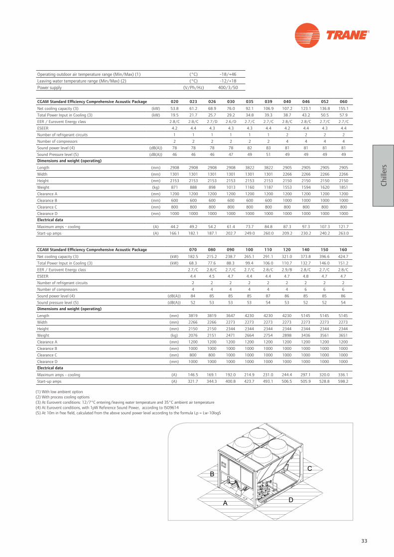
CGAM Standard Efficiency Comprehensive Acoustic Package 020 023 026 030 035 039 040 046 052 060
Net cooling capacity (3) (kW) 53.8 61.2 68.9 76.0 92.1 106.9 107.2 123.1 136.8 155.1
Total Power Input in Cooling (3) (kW) 19.5 21.7 25.7 29.2 34.8 39.3 38.7 43.2 50.5 57.9
EER / Eurovent Energy class 2.8/C 2.8/C 2.7/D 2.6/D 2.7/C 2.7/C 2.8/C 2.8/C 2.7/C 2.7/C
ESEER 4.2 4.4 4.3 4.3 4.3 4.4 4.2 4.4 4.3 4.4
Number of refrigerant circuits 1 1 1 1 1 1 2 2 2 2
Number of compressors 2 2 2 2 2 2 4 4 4 4
Sound power level (4) (dB(A)) 78 78 78 78 82 83 81 81 81 81
Sound Pressure level (5) (dB(A)) 46 46 46 47 49 51 49 49 49 49Dimensions and weight (operating)
Length (mm) 2908 2908 2908 2908 3822 3822 2905 2905 2905 2905
Width (mm) 1301 1301 1301 1301 1301 1301 2266 2266 2266 2266
Height (mm) 2153 2153 2153 2153 2153 2153 2150 2150 2150 2150
Weight (kg) 871 888 898 1013 1160 1187 1553 1594 1620 1851
Clearance A (mm) 1200 1200 1200 1200 1200 1200 1200 1200 1200 1200
Clearance B (mm) 600 600 600 600 600 600 1000 1000 1000 1000
Clearance C (mm) 800 800 800 800 800 800 800 800 800 800
Clearance D (mm) 1000 1000 1000 1000 1000 1000 1000 1000 1000 1000Electrical data
Maximum amps - cooling (A) 44.2 49.2 54.2 61.4 73.7 84.8 87.3 97.3 107.3 121.7
Start-up amps (A) 166.1 182.1 187.1 202.7 249.0 260.0 209.2 230.2 240.2 263.0
CGAM Standard Efficiency Comprehensive Acoustic Package 070 080 090 100 110 120 140 150 160
Net cooling capacity (3) (kW) 182.5 215.2 238.7 265.1 291.1 321.0 373.8 396.6 424.7
Total Power Input in Cooling (3) (kW) 68.3 77.6 88.3 99.4 106.0 110.7 132.7 146.0 151.2
EER / Eurovent Energy class 2.7/C 2.8/C 2.7/C 2.7/C 2.8/C 2.9/B 2.8/C 2.7/C 2.8/C
ESEER 4.4 4.5 4.7 4.4 4.4 4.7 4.8 4.7 4.7
Number of refrigerant circuits 2 2 2 2 2 2 2 2 2
Number of compressors 4 4 4 4 4 4 6 6 6
Sound power level (4) (dB(A)) 84 85 85 85 87 86 85 85 86
Sound pressure level (5) (dB(A)) 52 53 53 53 54 53 52 52 54Dimensions and weight (operating)
Length (mm) 3819 3819 3647 4230 4230 4230 5145 5145 5145
Width (mm) 2266 2266 2273 2273 2273 2273 2273 2273 2273
Height (mm) 2150 2150 2344 2344 2344 2344 2344 2344 2344
Weight (kg) 2076 2151 2471 2664 2754 2898 3436 3561 3651
Clearance A (mm) 1200 1200 1200 1200 1200 1200 1200 1200 1200
Clearance B (mm) 1000 1000 1000 1000 1000 1000 1000 1000 1000
Clearance C (mm) 800 800 1000 1000 1000 1000 1000 1000 1000
Clearance D (mm) 1000 1000 1000 1000 1000 1000 1000 1000 1000Electrical data
Maximum amps - cooling (A) 146.5 169.1 192.0 214.9 231.0 244.4 297.1 320.0 336.1
Start-up amps (A) 321.7 344.3 400.8 423.7 493.1 506.5 505.9 528.8 598.2
(1) With low ambient option(2) With process cooling options(3) At Eurovent conditions: 12/7°C entering/leaving water temperature and 35°C ambient air temperature(4) At Eurovent conditions, with 1pW Reference Sound Power, according to ISO9614(5) At 10m in free field, calculated from the above sound power level according to the formula Lp = Lw-10logS
Operating outdoor air temperature range (Min/Max) (1) (°C) -18/+46Leaving water temperature range (Min/Max) (2) (°C) -12/+18Power supply (V/Ph/Hz) 400/3/50

34 Systems guide
Chill
ers
Operating outdoor air temperature range (Min/Max) (1) °C -18/+52Leaving water temperature range (Min/Max) (2) °C -12/+18Power supply V/Ph/Hz 400/3/50
CGAM HE Compact 020 023 026 030 035 040 046 052 060Net cooling capacity (3) (kW) 58.7 64.3 74.2 84.7 97.7 113.9 129.4 144.5 164.9Total power input in cooling (3) (kW) 18.4 20.5 23.9 27.1 32.0 36.1 41.2 47.0 52.6EER / Eurovent Energy class 3.2/A 3.1/A 3.1/A 3.1/A 3.1/A 3.1/A 3.1/A 3.1/A 3.1/AESEER 4.3 4.3 4.5 4.3 4.3 4.2 4.3 4.4 4.4Number of refrigerant circuits 1 1 1 1 1 2 2 2 2Number of compressors 2 2 2 2 2 4 4 4 4Sound power level (4) (dB(A)) 86 86 86 88 88 89 89 89 91Sound pressure level (5) (dB(A)) 54 54 54 55 56 57 57 57 58Dimensions and weight (operating)Length (mm) 2908 2908 2908 3822 3822 2905 2905 2905 3819Width (mm) 1301 1301 1301 1301 1301 2266 2266 2266 2266Height (mm) 2153 2153 2153 2153 2153 2150 2150 2150 2150Weight (kg) 870 874 896 1131 1149 1540 1571 1582 2041Clearance A (mm) 1200 1200 1200 1200 1200 1200 1200 1200 1200Clearance B (mm) 600 600 600 600 600 1000 1000 1000 1000Clearance C (mm) 800 800 800 800 800 800 800 800 800Clearance D (mm) 1000 1000 1000 1000 1000 1000 1000 1000 1000Electrical dataMaximum amps - cooling (A) 167.6 183.6 188.6 204.2 251.3 212.2 233.2 243.2 266.0Start-up amps (A) 45.7 50.7 55.7 62.9 76.0 90.3 100.3 110.3 124.7
CGAM HE Compact 070 080 090 100 110 120 140 150 160Net cooling capacity (3) (kW) 194.8 225.7 256.0 284.4 313.3 334.0 393.8 421.9 446.2Total power input in cooling (3) (kW) 62.9 72.3 80.2 90.1 97.8 107.5 125.3 133.4 142.5EER / Eurovent Energy class 3.1/A 3.1/A 3.2/A 3.2/A 3.2/A 3.1/A 3.1/A 3.2/A 3.1/AESEER 4.3 4.4 4.6 4.3 4.4 4.5 4.5 4.5 4.5Number of refrigerant circuits 2 2 2 2 2 2 2 2 2Number of compressors 4 4 4 4 4 4 6 6 6Sound power level (4) (dB(A)) 91 91 91 92 92 93 93 94 94Sound pressure level (5) (dB(A)) 59 59 59 60 60 61 61 61 62Dimensions and weight (operating)Length (mm) 3819 3647 3647 4230 4230 4230 5145 6060 6060Width (mm) 2266 2273 2273 2273 2273 2273 2273 2273 2273Height (mm) 2150 2344 2344 2344 2344 2344 2344 2344 2344Weight (kg) 2078 2378 2503 2804 2821 2821 3403 3881 3881Clearance A (mm) 1200 1200 1200 1200 1200 1200 1200 1200 1200Clearance B (mm) 1000 1000 1000 1000 1000 1000 1000 1000 1000Clearance C (mm) 800 1000 1000 1000 1000 1000 1000 1000 1000Clearance D (mm) 1000 1000 1000 1000 1000 1000 1000 1000 1000Electrical dataMaximum amps - cooling (A) 326.2 348.8 405.3 432.4 499.1 512.5 516.1 539.0 609.9Start-up amps (A) 151.0 173.6 196.5 223.6 237.0 250.4 307.3 330.2 347.8
CGAM HE Super Quiet 020 023 026 030 035 040 046 052 060Net cooling capacity (3) (kW) 58.4 64.3 74.2 82.6 97.4 113.6 129.4 144.5 165.3Total power input in cooling (3) (kW) 18.5 20.5 23.8 26.5 32.1 36.3 41.2 47.0 52.8EER / Eurovent Energy class 3.2/A 3.1/A 3.1/A 3.1/A 3.1/A 3.1/A 3.1/A 3.1/A 3.1/AESEER 4.3 4.3 4.5 4.3 4.3 4.2 4.2 4.4 4.3Number of refrigerant circuits 1 1 1 1 1 2 2 2 2Number of compressors 2 2 2 2 2 4 4 4 4Sound power level (4) (dB(A)) 81 81 81 82 84 84 84 84 85Sound pressure level (5) (dB(A)) 49 49 49 50 52 52 51 52 53Dimensions and weight (operating)Length (mm) 2908 2908 2908 3822 3822 2905 2905 2905 3819Width (mm) 1301 1301 1301 1301 1301 2266 2266 2266 2266Height (mm) 2153 2153 2153 2153 2153 2150 2150 2150 2150Weight (kg) 870 874 896 1131 1149 1540 1571 1582 2041Clearance A (mm) 1200 1200 1200 1200 1200 1200 1200 1200 1200Clearance B (mm) 600 600 600 600 600 1000 1000 1000 1000Clearance C (mm) 800 800 800 800 800 800 800 800 800Clearance D (mm) 1000 1000 1000 1000 1000 1000 1000 1000 1000Electrical dataMaximum amps - cooling (A) 183.6 167.6 188.6 204.2 251.3 212.2 233.2 243.2 263.9Start-up amps (A) 50.7 45.7 55.7 62.9 76.0 90.3 100.3 110.3 122.6
(1) With low ambient option(2) With process cooling options(3) At Eurovent conditions: 12/7°C entering/leaving water temperature and 35°C ambient air temperature(4) At Eurovent conditions, with 1pW Reference Sound Power, according to ISO9614(5) At 10m in free field, calculated from the above sound power level according to the formula Lp = Lw-10logS

35
Chill
ers
CGAM HE Super Quiet 070 080 090 100 110 120 140 150 160Net cooling capacity (3) (kW) 194.4 226.4 256.0 285.2 313.3 334.0 393.8 422.3 445.8Total power input in cooling (3) (kW) 63.0 71.6 79.9 89.6 97.7 107.4 125.1 133.9 142.3EER / Eurovent Energy class 3.1/A 3.2/A 3.2/A 3.2/A 3.2/A 3.1/A 3.1/A 3.2/A 3.1/AESEER 4.4 4.5 4.7 4.4 4.5 4.5 4.7 4.6 4.5Number of refrigerant circuits 2 2 2 2 2 2 2 2 2Number of compressors 4 4 4 4 4 4 6 6 6Sound power level (4) (dB(A)) 87 88 88 88 89 90 90 89 90Sound pressure level (5) (dB(A)) 55 56 56 56 57 58 57 57 58Dimensions and weight (operating)Length (mm) 3819 3647 3647 4230 4230 4230 5145 6060 6060Width (mm) 2266 2273 2273 2273 2273 2273 2273 2273 2273Height (mm) 2150 2344 2344 2344 2344 2344 2344 2344 2344Weight (kg) 2078 2378 2503 2804 2821 2821 3403 3791 3881Clearance A (mm) 1200 1200 1200 1200 1200 1200 1200 1200 1200Clearance B (mm) 1000 1000 1000 1000 1000 1000 1000 1000 1000Clearance C (mm) 800 1000 1000 1000 1000 1000 1000 1000 1000Clearance D (mm) 1000 1000 1000 1000 1000 1000 1000 1000 1000Electrical dataMaximum amps - cooling (A) 326.2 348.8 405.3 432.4 499.1 512.5 516.1 539.0 609.9Start-up amps (A) 151.0 173.6 196.5 223.6 237.0 250.4 307.3 330.2 347.8
CGAM HE Comprehensive Acoustic Package 020 023 026 030 035 040 046 052 060Net cooling capacity (3) (kW) 57.3 65.8 74.2 81.2 95.3 112.5 127.6 148.7 165.3Total power input in cooling (3) (kW) 18.4 21.1 23.6 26.8 32.5 36.3 41.9 46.8 53.4EER / Eurovent Energy class 3.1/A 3.1/A 3.1/A 3.0/B 2.9/B 3.1/A 3.1/A 3.2/A 3.1/AESEER 4.5 4.7 4.5 4.5 4.6 4.4 4.5 4.6 4.6Number of refrigerant circuits 1 1 1 1 1 2 2 2 2Number of compressors 2 2 2 2 2 4 4 4 4Sound power level (4) (dB(A)) 78 78 79 80 81 81 81 82 83Sound Pressure level (5) (dB(A)) 46 46 47 48 49 49 49 50 50Dimensions and weight (operating)Length (mm) 2908 2908 3822 3822 3822 2905 2905 3819 3819Width (mm) 1301 1301 1301 1301 1301 2266 2266 2266 2266Height (mm) 2153 2153 2153 2153 2153 2150 2150 2150 2150Weight (kg) 904 926 1053 1168 1187 1631 1639 1888 2131Clearance A (mm) 1200 1200 1200 1200 1200 1200 1200 1200 1200Clearance B (mm) 600 600 600 600 600 1000 1000 1000 1000Clearance C (mm) 800 800 800 800 800 800 800 800 800Clearance D (mm) 1000 1000 1000 1000 1000 1000 1000 1000 1000Electrical dataMaximum amps - cooling (A) 166.1 182.1 188.4 204.0 249.0 209.2 230.2 242.9 265.7Start-up amps (A) 44.2 49.2 55.5 62.7 73.7 87.3 97.3 110.0 124.4
CGAM HE Comprehensive Acoustic Package 070 080 090 100 110 120 140 150 160Net cooling capacity (3) (kW) 191.3 227.1 257.0 282.7 304.1 333.7 393.4 416.7 436.0Total power input in cooling (3) (kW) 64.1 69.4 78.3 90.0 97.3 104.9 123.1 135.0 145.0EER / Eurovent Energy class 3.0/B 3.3/A 3.3/A 3.1/A 3.1/A 3.2/A 3.2/A 3.1/A 3.0/BESEER 4.7 5.0 5.0 4.8 4.7 4.8 4.9 4.8 4.7Number of refrigerant circuits 2 2 2 2 2 2 2 2 2Number of compressors 4 4 4 4 4 4 6 6 6Sound power level (4) (dB(A)) 84 83 83 84 85 86 85 85 86Sound pressure level (5) (dB(A)) 52 50 51 51 52 54 53 53 54Dimensions and weight (operating)Length (mm) 3819 4230 4230 4230 5145 5145 6060 6060 6060Width (mm) 2266 2273 2273 2273 2273 2273 2273 2273 2273Height (mm) 2150 2344 2344 2344 2344 2344 2344 2344 2344Weight (kg) 2168 2596 2804 2918 3172 3279 3941 4035 4035Clearance A (mm) 1200 1200 1200 1200 1200 1200 1200 1200 1200Clearance B (mm) 1000 1000 1000 1000 1000 1000 1000 1000 1000Clearance C (mm) 800 1000 1000 1000 1000 1000 1000 1000 1000Clearance D (mm) 1000 1000 1000 1000 1000 1000 1000 1000 1000Electrical dataMaximum amps - cooling (A) 321.7 344.3 403.5 426.4 493.1 509.2 511.3 534.2 600.9Start-up amps (A) 146.5 169.1 194.7 217.6 231.0 247.1 302.5 325.4 338.8
(1) With low ambient option(2) With process cooling options(3) At Eurovent conditions: 12/7°C entering/leaving water temperature and 35°C ambient air temperature(4) At Eurovent conditions, with 1pW Reference Sound Power, according to ISO9614(5) At 10m in free field, calculated from the above sound power level according to the formula Lp = Lw-10logS
Operating outdoor air temperature range (Min/Max) (1) °C -18/+52Leaving water temperature range (Min/Max) (2) °C -12/+18Power supply V/Ph/Hz 400/3/50

36 Systems guide
Chill
ers
Customer benefits • Reliability: Trane helical-rotary compressor with only
3 moving parts
• Ease of installation: wide choice of hydraulic modules
Main features• Competitive physical footprint
• Single power connection
• Low sound levels
• Star-delta starter
• Exact load matching
• Application flexibility
Options• High ambient operation (up to 52°C)
• Low ambient operation (down to -18°C)
• Low noise version equipped with low-speed fans and
compressor sound attenuating
• High efficiency version
• Power disconnect switch
• Condenser protection or complete unit protection
• Night noise setback to reduce sound levels at night
• High and low pressure gauges
• Hydraulic module - single or dual pump with water
strainer
• 60 Hz unit
Accessories• Neoprene isolators
• Grooved pipe connection kit
• Flow switch
UCM-CLD ControlAdaptive Control™ microprocessor featuring:
• Unit control module with Clear Language Display
• External Auto/Stop
• External interlock
• Chilled water pump control
• Alarm indication contacts
• Ice-making card (optional)
• LonTalk® or Modbus® communication capabilities
• Chilled water and current limit remote setpoint card
(optional)
RTADAir-cooled helical-rotary chiller Series R™
This description may not include all options and accessories available. For full technical information, download documentation at: http://doc.trane-eur.com
Energy saving options
• High efficiency version, heat recovery, free-cooling
37
Chill
ers
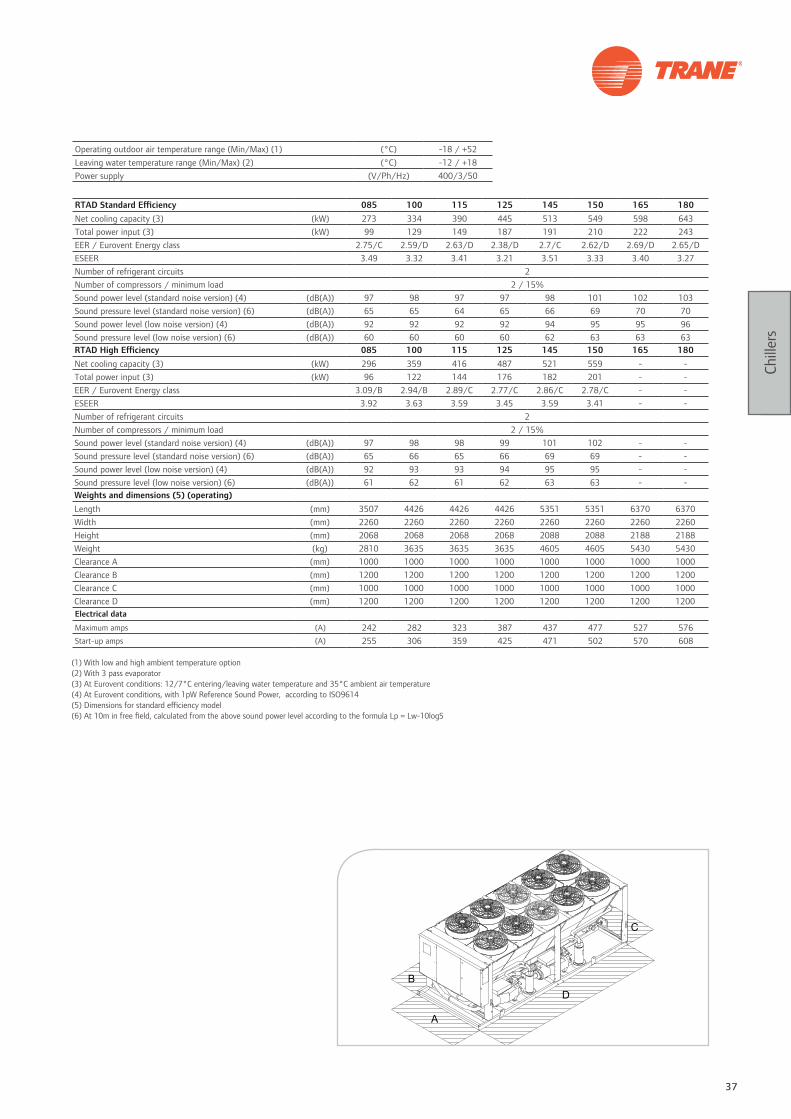
RTAD Standard Efficiency 085 100 115 125 145 150 165 180Net cooling capacity (3) (kW) 273 334 390 445 513 549 598 643Total power input (3) (kW) 99 129 149 187 191 210 222 243EER / Eurovent Energy class 2.75/C 2.59/D 2.63/D 2.38/D 2.7/C 2.62/D 2.69/D 2.65/DESEER 3.49 3.32 3.41 3.21 3.51 3.33 3.40 3.27Number of refrigerant circuits 2Number of compressors / minimum load 2 / 15%Sound power level (standard noise version) (4) (dB(A)) 97 98 97 97 98 101 102 103Sound pressure level (standard noise version) (6) (dB(A)) 65 65 64 65 66 69 70 70Sound power level (low noise version) (4) (dB(A)) 92 92 92 92 94 95 95 96Sound pressure level (low noise version) (6) (dB(A)) 60 60 60 60 62 63 63 63RTAD High Efficiency 085 100 115 125 145 150 165 180Net cooling capacity (3) (kW) 296 359 416 487 521 559 - -Total power input (3) (kW) 96 122 144 176 182 201 - -EER / Eurovent Energy class 3.09/B 2.94/B 2.89/C 2.77/C 2.86/C 2.78/C - -ESEER 3.92 3.63 3.59 3.45 3.59 3.41 - -Number of refrigerant circuits 2Number of compressors / minimum load 2 / 15%Sound power level (standard noise version) (4) (dB(A)) 97 98 98 99 101 102 - -Sound pressure level (standard noise version) (6) (dB(A)) 65 66 65 66 69 69 - -Sound power level (low noise version) (4) (dB(A)) 92 93 93 94 95 95 - -Sound pressure level (low noise version) (6) (dB(A)) 61 62 61 62 63 63 - -Weights and dimensions (5) (operating)Length (mm) 3507 4426 4426 4426 5351 5351 6370 6370Width (mm) 2260 2260 2260 2260 2260 2260 2260 2260Height (mm) 2068 2068 2068 2068 2088 2088 2188 2188Weight (kg) 2810 3635 3635 3635 4605 4605 5430 5430Clearance A (mm) 1000 1000 1000 1000 1000 1000 1000 1000Clearance B (mm) 1200 1200 1200 1200 1200 1200 1200 1200Clearance C (mm) 1000 1000 1000 1000 1000 1000 1000 1000Clearance D (mm) 1200 1200 1200 1200 1200 1200 1200 1200Electrical data
Maximum amps (A) 242 282 323 387 437 477 527 576Start-up amps (A) 255 306 359 425 471 502 570 608
(1) With low and high ambient temperature option(2) With 3 pass evaporator(3) At Eurovent conditions: 12/7°C entering/leaving water temperature and 35°C ambient air temperature(4) At Eurovent conditions, with 1pW Reference Sound Power, according to ISO9614(5) Dimensions for standard efficiency model(6) At 10m in free field, calculated from the above sound power level according to the formula Lp = Lw-10logS
Operating outdoor air temperature range (Min/Max) (1) (°C) -18 / +52Leaving water temperature range (Min/Max) (2) (°C) -12 / +18Power supply (V/Ph/Hz) 400/3/50

38 Systems guide
Chill
ers
Customer benefits • Reliability: Trane helical-rotary compressor with only 3
moving parts
• Efficiency: 3 efficiency levels, to fit your requirements
• Certified Eurovent Class A
Main features• Competitive physical footprint
• Single power connection
• Exact load matching
• Low sound levels
• Falling film evaporator - high COP and reduced refrigerant
charge
• Factory-mounted star-delta starter panel
• Close spacing installation - 1.2 m side clearances
Options• High ambient operation (up to 52°C)
• Low ambient operation (down to -18°C)
• Low noise version equipped with low-speed fans and
compressor sound attenuating enclosure
• High efficiency version
• Power disconnect switch
• Night noise setback to reduce sound levels at night
• Unit edge grooved pipe connections
• Extra-pass and specific tubes for low water temperature
applications (down to -12°C)
• Black epoxy-coated aluminium fins for corrosive
environments
• Copper fins
• Condenser protection or complete unit protection
• High and low pressure gauges
Accessories• Neoprene isolators
• Grooved pipe connection kit
• Flow switch
Tracer™ CH530 ControlAdaptive Control™ microprocessor featuring:
• Easy-to-use operator interface panel
• External Auto/Stop
• External interlock
• Chilled water pump control
• Ice-making card (optional)
• Chilled water and current-limit remote setpoint
card(optional)
• LonTalk®, Modbus®, BACnet® communication capabilities
RTACAir-cooled helical-rotary chiller Series R™
This description may not include all options and accessories available. For full technical information, download documentation at: http://doc.trane-eur.com
Energy saving options
• High efficiency and extra high efficiency versions

39
Chill
ers
RTAC Standard Efficiency 140 155 170 185 200 230 240 250 275 300 350 375 400
Net cooling capacity (3) (kW) 492 537 585 648 714 770 858 851 947 1077 1192 1322 1451
Total power input (3) (kW) 170 188 206 225 244 263 294 293 331 370 419 459 498
EER / Eurovent Energy class 2.9/B 2.86/C 2.84/C 2.89/C 2.93/B 2.93/B 2.93/B 2.9/B 2.87/C 2.91/B 2.85/C 2.88/C 2.91/B
ESEER 3.68 3.68 3.61 3.43 3.67 3.94 4.17 3.82 3.86 3.94 4.10 4.14 4.18
Number of refrigerant circuits
Number of compressors / minimum load 2 / 15% 3 / 10% 4 / 8%
Sound power level (standard noise version) (4) (dB(A)) 97 98 99 100 100 99 99 99 101 102 101 102 103
Sound pressure level (standard noise version) (5) (dB(A)) 65 66 66 67 68 67 67 67 68 69 68 69 70
Sound power level (low noise version) (4) (dB(A)) 90 91 92 92 93 92 92 92 94 95 95 95 96
Sound pressure level (low noise version) (5) (dB(A)) 58 59 59 60 60 59 59 59 61 62 62 62 63Weights and dimensions (operating)
Length (mm) 5041 5041 5041 5960 5960 7133 7133 9138 9138 10056 10406 11325 12244
Width (mm) 2240 2240 2240 2240 2240 2250 2250 2250 2250 2250 2250 2250 2250
Height (mm) 2411 2411 2411 2411 2411 2530 2530 2530 2530 2530 2530 2530 2530
Weight (kg) 4580 4760 4895 5470 5590 7875 8255 7890 8690 9380 10735 11355 11930
Clearance A (mm) 1000 1000 1000 1000 1000 1200 1200 1000 1000 1000 1200 1200 1200
Clearance B (mm) 1200 1200 1200 1200 1200 1200 1200 1200 1200 1200 1200 1200 1200
Clearance C (mm) 1000 1000 1000 1000 1000 1200 1200 1200 1200 1200 1200 1200 1200
Clearance D (mm) 1200 1200 1200 1200 1200 1200 1200 1200 1200 1200 1200 1200 1200Electrical data
Maximum amps (A) 386 426 465 514 562 606 668 668 747 844 930 1027 1124
Start-up amps (A) 424 460 490 557 594 629 677 677 738 813 851 955 1030
Operating outdoor air temperature range (Min/Max) (1) (°C) -18 / +52Leaving water temperature range (Min/Max) (2) (°C) -12 / +18Power supply (V/Ph/Hz) 400/3/50
(1) With low and high ambient temperature option(2) With 3 pass evaporator(3) At Eurovent conditions: 12/7°C entering/leaving water temperature and 35°C ambient air temperature(4) At Eurovent conditions, with 1pW Reference Sound Power, according to ISO9614(5) At 10m in free field, calculated from the above sound power level according to the formula Lp = Lw-10logS

40 Systems guide
Chill
ers
RTAC High Efficiency 120 130 140 155 170 185 200 250 275 300 350 375 400
Net cooling capacity (3) (kW) 422 466 513 557 604 670 740 877 979 1112 1228 1364 1501
Total power input (3) (kW) 138 151 166 183 200 219 239 290 321 360 407 447 487
EER / Eurovent Energy class 3.07/B 3.08/B 3.10/A 3.05/B 3.02/B 3.06/B 3.10/A 3.03/B 3.05/B 3.09/B 3.02/B 3.05/B 3.09/B
ESEER 3.8 3.82 3.83 3.84 3.74 3.53 3.8 3.84 4 4.08 4.09 4.13 4.18
Number of refrigerant circuits 2
Number of compressors / minimum load 2 / 15% 4 / 8%
Sound power level (standard noise version) (4) (dB(A)) 97 98 98 99 99 100 100 100 102 102 102 103 103
Sound pressure level (standard noise version) (4) (5) (dB(A)) 65 66 66 67 67 68 68 67 69 69 69 70 70
Sound power level (low noise version) (4) (dB(A)) 90 91 91 92 92 93 93 93 95 95 95 96 96
Sound pressure level (low noise version) (4) (5) (dB(A)) 58 58 59 59 60 60 60 60 62 62 62 63 63Weights and dimensions (operating)
Length (mm) 5041 5041 5041 5960 5960 6879 6879 9138 10975 11894 12244 13163 14082
Width (mm) 2240 2240 2240 2240 2240 2240 2240 2250 2250 2250 2250 2250 2250
Height (mm) 2411 2411 2411 2411 2411 2411 2411 2530 2530 2530 2530 2530 2530
Weight (kg) 4461 4519 4529 5180 5431 6005 6117 8359 9718 10258 11973 12507 13185
Clearance A (mm) 1000 1000 1000 1000 1000 1000 1000 1000 1000 1000 1200 1200 1200
Clearance B (mm) 1200 1200 1200 1200 1200 1200 1200 1200 1200 1200 1200 1200 1200
Clearance C (mm) 1000 1000 1000 1000 1000 1000 1000 1200 1200 1200 1200 1200 1200
Clearance D (mm) 1200 1200 1200 1200 1200 1200 1200 1200 1200 1200 1200 1200 1200Electrical data
Maximum amps (A) 324 359 393 433 472 521 569 675 754 851 944 1041 1138
Start-up amps (A) 358 404 431 467 497 564 601 684 745 820 865 969 1044
Operating outdoor air temperature range (Min/Max) (1) (°C) -18 / +52Leaving water temperature range (Min/Max) (2) (°C) -12 / +18Power supply (V/Ph/Hz) 400/3/50
(1) With low and high ambient temperature option(2) With 3 pass evaporator(3) At Eurovent conditions: 12/7°C entering/leaving water temperature and 35°C ambient air temperature(4) At Eurovent conditions, with 1pW Reference Sound Power, according to ISO9614(5) At 10m in free field, calculated from the above sound power level according to the formula Lp = Lw-10logS

41
Chill
ers
RTAC Extra Efficiency 120 130 140 155 170 185 200 250 275 300 350 375 400
Net cooling capacity (3) (kW) 427 475 521 566 633 680 747 899 998 1128 1290 1388 1517
Total power input (3) (kW) 135 150 165 180 199 216 236 284 319 357 409 445 482
EER / Eurovent Energy class 3.16/A 3.17/A 3.16/A 3.15/A 3.19/A 3.15/A 3.16/A 3.17/A 3.13/A 3.17/A 3.16/A 3.12/A 3.15/A
ESEER 3.92 3.86 3.92 3.84 4.07 3.95 3.9 3.95 4.01 4.13 4.15 4.22 4.23
Number of refrigerant circuits 2
Number of compressors / minimum load 2 / 15% 4 / 8%
Sound power level (standard noise version) (4) (dB(A)) 98 98 98 99 99 100 100 100 102 102 102 103 103
Sound pressure level (standard noise version) (5) (dB(A)) 66 66 66 67 67 68 68 67 69 69 69 70 70
Sound power level (low noise version) (4) (dB(A)) 91 91 91 92 92 93 93 93 95 95 95 96 96
Sound pressure level (low noise version) (5) (dB(A)) 59 58 59 59 60 60 60 60 62 62 62 63 63Weights and dimensions (operating)
Length (mm) 5041 5041 5041 5960 6879 6879 6879 10056 10975 11894 12244 13163 14082
Width (mm) 2240 2240 2240 2240 2240 2240 2240 2250 2250 2250 2250 2250 2250
Height (mm) 2411 2411 2411 2411 2411 2411 2411 2530 2530 2530 2530 2530 2530
Weight (kg) 4775 4712 4613 5351 5842 6307 6497 9484 10180 10795 12217 13092 13784
Clearance A (mm) 1000 1000 1000 1000 1000 1000 1000 1000 1000 1000 1200 1200 1200
Clearance B (mm) 1200 1200 1200 1200 1200 1200 1200 1200 1200 1200 1200 1200 1200
Clearance C (mm) 1000 1000 1000 1000 1000 1000 1000 1200 1200 1200 1200 1200 1200
Clearance D (mm) 1200 1200 1200 1200 1200 1200 1200 1200 1200 1200 1200 1200 1200Electrical data
Maximum amps (A) 324 362 393 436 485 524 569 675 761 858 962 1041 1138
Start-up amps (A) 358 407 431 470 537 567 601 684 752 827 908 969 1044
Operating outdoor air temperature range (Min/Max) (1) (°C) -18 / +52Leaving water temperature range (Min/Max) (2) (°C) -12 / +18Power supply (V/Ph/Hz) 400/3/50
(1) With low and high ambient temperature option(2) With 3 pass evaporator(3) At Eurovent conditions: 12/7°C entering/leaving water temperature and 35°C ambient air temperature(4) At Eurovent conditions, with 1pW Reference Sound Power, according to ISO9614(5) At 10m in free field, calculated from the above sound power level according to the formula Lp = Lw-10logS
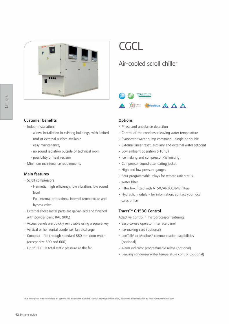
42 Systems guide
Chill
ers
Customer benefits • Indoor installation:
- allows installation in existing buildings, with limited
roof or external surface available
- easy maintenance,
- no sound radiation outside of technical room
- possibility of heat reclaim
• Minimum maintenance requirements
Main features• Scroll compressors
- Hermetic, high efficiency, low vibration, low sound
level
- Full internal protections, internal temperature and
bypass valve
• External sheet metal parts are galvanized and finished
with powder paint RAL 9002
• Access panels are quickly removable using a square key
• Vertical or horizontal condenser fan discharge
• Compact - fits through standard 860 mm door width
(except size 500 and 600)
• Up to 500 Pa total static pressure at the fan
Options• Phase and unbalance detection
• Control of the condenser leaving water temperature
• Evaporator water pump command - single or double
• External linear reset, auxiliary and external water setpoint
• Low ambient operation (-10°C)
• Ice making and compressor kW limiting
• Compressor sound attenuating jacket
• High and low pressure gauges
• Four programmable relays for remote unit status
• Water filter
• Filter box fitted with A150/AR300/M8 filters
• Hydraulic module - for information, contact your local
sales office
Tracer™ CH530 ControlAdaptive Control™ microprocessor featuring:
• Easy-to-use operator interface panel
• Ice-making card (optional)
• LonTalk® or Modbus® communication capabilities
(optional)
• Alarm indicator programmable relays (optional)
• Leaving condenser water temperature control (optional)
CGCLAir-cooled scroll chiller
This description may not include all options and accessories available. For full technical information, download documentation at: http://doc.trane-eur.com

43
Chill
ers
CGCL 200 250 300 350 400 450 500 600Net cooling capacity (1) (kW) 51.0 62.0 75.0 88.0 102.0 112.0 128.0 153.0Total power input (1) (kW) 22.2 27.2 34.9 38.4 47.0 56.0 60.4 73.9EER / Eurovent Energy class 2.30/C 2.28/D 2.15/D 2.29/D 2.17/D 2.0/E 2.1/D 2.1/DESEER 3.25 3.51 2.98 3.72 3.46 3.1 3.0 2.8Number of refrigerant circuits 1 1 1 1 1 1 2 2Number of compressors 2 2 2 3 3 3 4 4Sound power level (2) (dB(A)) 88 84 87 89 91 95 90 94Weights and dimensions (operating)Length (mm) 2268 2268 2268 3230 3230 3230 3230 3230Width (mm) 866 866 866 866 866 866 1216 1216Height (mm) 1997 1997 1997 1997 1997 1997 1997 1997Weight (kg) 710 830 890 1080 1140 1200 1380 1500Clearance A (mm) 800Clearance B (mm) 800 800 800 800 800 800 1200 1200Clearance C (mm) 800Clearance D (mm) 800Electrical dataMaximum amps (A) 48.0 61.0 77.0 86.0 102.0 118.0 121.0 151.0Start-up amps (A) 148 205 219 232 243 260 265.0 295.0
(1) At Eurovent conditions: 12/7°C entering/leaving water temperature and 35°C ambient air temperature(2) At Eurovent conditions, with 1pW Reference Sound Power, according to ISO9614
Operating outdoor air temperature range (Min/Max) (°C) -5 / +40Leaving water temperature range (Min/Max) (°C) -12 / +12Power supply (V/Ph/Hz) 400/3/50

44 Systems guide
Chill
ers
Customer benefits • Very low sound level installation: superior acoustic comfort
• Indoor installation: easy maintenance
• Minimum maintenance requirements
Range descriptionCGWH: Packaged chiller
CCUH: Condenserless chiller
Main features• High efficiency hermetic Scroll compressors with low
vibration and sound levels and full internal overheating
protection
• External sheet metal parts are galvanized and finished
with powder paint RAL 9002
• Access panels are quickly removable using a square key
• Designed for indoor installation
• Maximum condenser leaving water temperature: 50°C
Options• 380, 400 and 415V power voltage
• Phase and unbalance detection
• 400 / 220V transformer for the control
• Compressor sound attenuating jackets
• High and low pressure gauges
• Evaporator water pump command - single or double
• Water filter
• Hydraulic module - for information, contact your local
sales office
Tracer™ CH530 ControlAdaptive Control™ microprocessor-based control featuring:
• Easy to use operator interface
• External linear reset, auxiliary and external water setpoint
• Compressor kW limiting (optional)
• Alarm indicator programmable relays (options)
• Ice making controls (optional)
• LonTalk® or Modbus® communication interface (optional)
• Leaving condenser water temperature control (optional)
CGWH CCUHWater-cooled packaged and condenserless scroll chillers
This description may not include all options and accessories available. For full technical information, download documentation at: http://doc.trane-eur.com

45
Chill
ers
CGWH/CCUH 115 120 125 225 230 235 240 250Net cooling capacity CGWH (1) (kW) 51.8 64.9 78 92.1 104.5 117.4 129.7 157.1Total power input CGWH (1) (kW) 13.8 17.6 21.3 24.3 27.9 31.3 35 41.9EER / Eurovent energy class CGWH 3.75/E 3.69/E 3.66/E 3.79/E 3.75/E 3.75/E 3.71/E 3.75/EESEER CGWH 4.57 4.85 4.56 4.77 4.44 4.28 4.06 3.86Net cooling capacity CCUH (kW) 51.3 64.3 77.3 91 103.2 115.4 128.4 154.7Total power input CCUH (kW) 14.2 17.9 21.7 25 28.8 32.6 35.9 43.5EER CCUH 3.61 3.59 3.56 3.64 3.58 3.54 3.58 3.56Refrigerant R407CNumber of refrigerant circuits 1 1 1 2 2 2 2 2Number of compressors 2 2 2 3 3 3 4 4Sound power level (3) (dB(A)) 75 79 81 81 82 83 82 84Weights and dimensions CGWH (operating)Length (mm) 1001 1001 1001 2002 2002 2002 2002 2002Width (mm) 800 800 800 800 800 800 800 800Height (mm) 1545 1545 1545 1545 1545 1545 1545 1545Weight (kg) 412 444 476 668 702 739 803 873Clearance A (mm) 800Electrical data CGWHMaximum amps (A) 41 52 63 72 83 94 103 125Start-up amps (A) 140 194 204 212 222 232 241 261
(1) At Eurovent conditions: 12/7°C entering/leaving chilled water temperature and 30/35°C entering/leaving condenser temperature (2) At 12/7°C entering/leaving chilled water temperature, 45°C condensing temperature and 5K saturated subcooling.(3) At Eurovent conditions, with 1pW Reference Sound Power, according to ISO9614
Condenser leaving water temperature (min/max) (°C) 20/50Condenser saturated discharge temperature (min/max) (°C) 25/55Evaporator leaving water temperature range (min/max) (°C) -12 / +12Power supply (V/Ph/Hz) 400/3/50

46 Systems guide
Chill
ers
Customer benefits • Compact design and packaged hydraulic module (available
as an option) for easier installation: saving of time
• Wide application flexibility for comfort and process
applications: fits your exact requirements
• State of the art control to guarantee superior
dependability: low cost for owners
Range descriptionCGWN: Packaged chiller
CCUN: Condenserless chiller
Main features• High efficiency hermetic Scroll compressors with low
vibration and sound levels and full internal overheating
protections
• External sheet metal parts are galvanized and finished
with powder paint RAL 9002
• Access panels are quickly removable using a square key
and mounted handles
• Designed for indoor and outdoor installation
• Maximum condenser leaving water temperature: 60°C
(R410A)
• 380, 400 and 415V power voltage
• 400 / 110V transformer for the control
Options• High Efficiency version
• Soft Starter
• Phase & unbalanced detection
• Evaporator + water pump command - single or double
• Condenser + water pump command - single or double
• Compressor sound attenuating jackets
• High and low pressure gauges
• Hydraulic module including :
- single or dual evaporator pump including water filter
and pressure tabs
- speed inverter condenser pumps including flow
control, condenser return and leaving water
temperature
- combinations of hydraulic modules available:
evaporator only, condenser only or both
Tracer™ CH530 ControlAdaptive Control™ microprocessor-based control featuring:
• Easy to use operator interface
• External linear reset, auxiliary and external water setpoint
• Compressor kW limiting (optional)
• Alarm indicator programmable relays (options)
• Ice making controls (optional)
• LonTalk®, Modbus®, BACnet® communication interface
(optional)
• Leaving condenser water temperature control (optional)
CGWN CCUNWater-cooled packaged and condenserless scroll chillers
This description may not include all options and accessories available. For full technical information, download documentation at: http://doc.trane-eur.com

47
Chill
ers
CGWN/CCUN 205 205HE 206 206HE 207 207HE 208 209 210 211Net cooling capacity CGWN (1) (kW) 182.5 193.3 217 227.4 251.7 262.4 283.1 312.1 341.9 373.7Total power input CGWN (1) (kW) 42.5 40.1 50.2 47.9 57.7 55.7 61.5 70.1 78.2 85.9EER / Eurovent energy class CGWN 4.29/C 4.82/B 4.32/C 4.75/B 4.36/C 4.71/B 4.60/C 4.45/C 4.37/C 4.35/CESEER CGWN 5.96 6.39 6.04 6.36 6.06 6.39 6.28 5.81 5.79 5.9Net cooling capacity CCUN (kW) 166.3 175 198.1 206.7 230.4 239.1 257.7 281.9 311.4 343.8Total power input CCUN (kW) 45.6 45.6 53.8 53.8 62 62 69.8 77.7 86.4 95.1EER CCUN 3.65 3.84 3.68 3.84 3.72 3.86 3.69 3.63 3.60 3.62Refrigerant R410ANumber of refrigerant circuits 2Number of compressors 4Sound power level (3) (dB(A)) 82 82 82 82 83 83 83 84 84 84Weights and dimensions CGWN (operating)Length (mm) 2520 2520 2520 2520 2520 2520 2520 2520 2520 2520Width (mm) 880 880 880 880 880 880 880 880 880 880Height (mm) 1842 1842 1842 1842 1842 1842 1842 1842 1842 1842Weight (kg) 1360 1360 1300 1300 1420 1420 1500 1650 1710 1790Clearance A (mm) 1000Clearance B (mm) 800Electrical data CGWNMaximum amps (A) 144 144 163 163 187 187 210 233 250 263Start-up amps (A) 274 274 338 338 395 395 418 441 512 525
Condenser leaving water temperature (min/max) (°C) 25/55Condenser saturated discharge temperature (min/max) (°C) 25/55Evaporator leaving water temperature range (min/max) (°C) -12 / +15Power supply (V/Ph/Hz) 400/3/50
CGWN/CCUN 212 213 214 215Net cooling capacity CGWN (1) (kW) 398.5 431.3 465.9 506.4Total power input CGWN (1) (kW) 97 106.4 117.3 125.5EER / Eurovent energy class CGWN 4.11 / D 4.05 / D 3.97 / D 4.04 / DESEER CGWN 5.46 5.53 5.32 5.41Net cooling capacity CCUN (kW) 385.6 417.3 450.4 486.9Total power input CCUN (kW) 99 108.5 120.5 131.1EER CCUN 3.89 3.85 3.74 3.71Refrigerant R407CNumber of refrigerant circuits 2Number of compressors 5 6 6 6Sound power level (3) (dB(A)) 87 88 88 90Weights and dimensions CGWN (operating)Length (mm) 2810 2810 2810 2810Width (mm) 880 880 880 880Height (mm) 1950 1950 1950 1950Weight (kg) 2130 2340 2420 2500Clearance A (mm) 1000Clearance B (mm) 800Electrical data CGWNMaximum amps (A) 311 337 370 400Start-up amps (A) 563 588 621 655
(1) At Eurovent conditions: 12/7°C entering/leaving chilled water temperature and 30/35°C entering/leaving condenser temperature(2) At 12/7°C entering/leaving chilled water temperature, 45°C condensing temperature and 5K saturated subcooling.(3) At Eurovent conditions, with 1pW Reference Sound Power, according to ISO9614
Condenser leaving water temperature (min/max) (°C) 25/60Condenser saturated discharge temperature (min/max) (°C) 25/60Evaporator leaving water temperature range (min/max) (°C) -12 / +15Power supply (V/Ph/Hz) 400/3/50
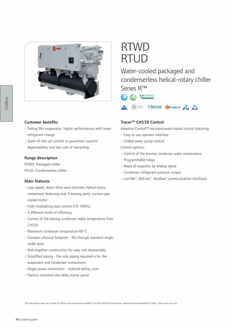
48 Systems guide
Chill
ers
Customer benefits • Falling film evaporator: higher performances with lower
refrigerant charge
• State-of-the-art control to guarantee superior
dependability and low cost of ownership
Range descriptionRTWD: Packaged chiller
RTUD: Condenserless chiller
Main features• Low-speed, direct-drive semi-hermetic helical rotary
compressor featuring only 3 moving parts, suction-gas-
cooled motor
• Fully modulating load control (15-100%)
• 3 different levels of efficiency
• Control of the leaving condenser water temperature from
CH530
• Maximum condenser temperature 60°C
• Compact physical footprint - fits through standard single-
width door
• Bolt-together construction for easy unit disassembly
• Simplified piping - the only piping required is for the
evaporator and condenser connections
• Single power connection - reduced wiring costs
• Factory-mounted star-delta starter panel
Tracer™ CH530 ControlAdaptive Control™ microprocessor-based control featuring:
• Easy to use operator interface
• Chilled water pump control
Control options:
• Control of the leaving condenser water temperature
• Programmable relays
• Reset of setpoints by analog signal
• Condenser refrigerant pressure output
• LonTalk®, BACnet®, Modbus® communication interfaces
RTWD RTUDWater-cooled packaged and condenserless helical-rotary chiller Series R™
This description may not include all options and accessories available. For full technical information, download documentation at: http://doc.trane-eur.com

49
Chill
ers
RTWD/RTUD 60HE 70HE 80HE 90HE 100HE 110HE 120HE 130HE 140HENet cooling capacity RTWD (kW) 236 278 319 366 392 419 455 491 534Total power input RTWD (kW) 45 53 62 70 74 79 86 93 101EER / Eurovent energy class RTWD 5.24/A 5.23/A 5.17/A 5.22/A 5.27/A 5.33/A 5.30/A 5.26/A 5.30/AESEER RTWD 6.72 7.00 6.49 6.86 6.90 6.88 6.56 6.59 6.96Cooling capacity RTUD (kW) 209 250 284 323 346 372 401 430 474Total power input RTUD (kW) 55 66 75 85 91 96 104 110 120EER RTUD 3.79 3.80 3.77 3.78 3.80 3.86 3.88 3.91 3.94Refrigerant R134aNumber of refrigerant circuits 2Number of compressors 2Sound power level RTWD (3) (dB(A)) 90 90 97 99 99 99 98 96 96Weights and dimensions RTWD (operating)Length (mm) 3320 3320 3320 3320 3320 3320 3320 3380 3380Width (mm) 890 890 890 890 890 890 890 1090 1090Height (mm) 1950 1950 1950 1960 1960 1960 1960 1950 1950Weight (kg) 2588 2596 2673 3835 2908 2946 3136 3709 3740Clearance A (mm) 914Clearance B (mm) 914Electrical dataMaximum amps (A) 102 124 142 161 176 192 209 227 244Start-up amps (4) (A) 152 177 192 206 242 254 291 304 346
RTWD/RTUD 220HE 250HE 160PE 180PE 200PE 160SE 170SE 190SE 200SENet cooling capacity RTWD (kW) 769 841 601 662 712 566 625 703 773Total power input RTWD (kW) 147 159 107 119 130 127 142 153 166EER / Eurovent energy class RTWD 5.24/A 5.27/A 5.61/A 5.57/A 5.46/A 4.45/C 4.41/C 4.6/C 4.66/CESEER RTWD 6.82 6.87 7.24 7.25 7.05 5.39 5.63 5.83 6.06Cooling capacity RTUD (kW) 682 748 - - - 530 584 637 -Cooling power input RTUD (kW) 175 190 - - - 142 157 171 -EER RTUD 3.90 3.94 - - - 3.73 3.71 3.72 -Refrigerant R134aNumber of refrigerant circuits 2Number of compressors 2Sound power level RTWD (3) (dB(A)) 101 101 97 101 101 100 101 101 101Weights and dimensions RTWD (operating)Length (mm) 3470 3470 3830 3830 3470 3480 3480 3480 3480Width (mm) 1130 1130 1120 1120 1130 1120 1120 1120 1120Height (mm) 2010 2010 2010 2010 2010 1960 1960 1960 1960Weight (kg) 3835 3835 4330 4330 3835 3835 3835 3835 3835Clearance A (mm) 914Clearance B (mm) 914Electrical dataMaximum amps (A) 343 374 261 286 311 286 311 343 374Start-up amps (4) (A) 473 497 349 391 410 391 410 473 497
(1) At Eurovent conditions: 12/7°C entering/leaving chilled water temperature and 30/35°C entering/leaving condenser temperature(2) At 12/7°C entering/leaving chilled water temperature, 45°C condensing temperature and 5K saturated subcooling.(3) At Eurovent conditions, with 1pW Reference Sound Power, according to ISO9614(4) Inrush current in star connection
Condenser leaving water temperature (min/max) RTWD (°C) 20/60Condenser saturated discharge temperature (min/max) RTUD (°C) 20/67Evaporator leaving water temperature range (min/max) (°C) -8 / +18Power supply (V/Ph/Hz) 400/3/50

50 Systems guide
Chill
ers
Customer benefits • Falling film evaporator: higher performances with lower
refrigerant charge
• State-of-the-art control to guarantee superior
dependability and low cost of ownership
• Trane helical-rotary compressor - designed to perform,
built to last: superior reliability and low cost of ownership
Main features• Low-speed, direct-drive semi-hermetic helical rotary
compressor featuring only 3 moving parts, suction-gas-
cooled motor
• Fully modulating load control (25-100%)
• Compact physical footprint - fits through standard
double-width doors
• Bolt-together construction for easy unit disassembly
• Factory-mounted star-delta starter panel
• Simplified piping - the only piping required is for the
evaporator and condenser grooved pipe connections
• Single power connection - reduced wiring costs
Options• Insulation on evaporator, water boxes, suction line, motor
housing
• Fused or non-fused power disconnect switch
• Under/over voltage protection
Accessories• Outside air temperature sensor
• Condenser valves
Tracer™ CH530 ControlAdaptive Control™ microprocessor-based control featuring:
• Easy to use operator interface
• Chilled water pump control
• Alarm indicator programmable relays
Control options:
• Reset of setpoints by analog signal
• Ice making control
• Condenser refrigerant pressure output
• LonTalk®, BACnet®, Modbus® communication interfaces
RTHDWater-cooled packaged helical-rotary chiller Series R™
This description may not include all options and accessories available. For full technical information, download documentation at: http://doc.trane-eur.com
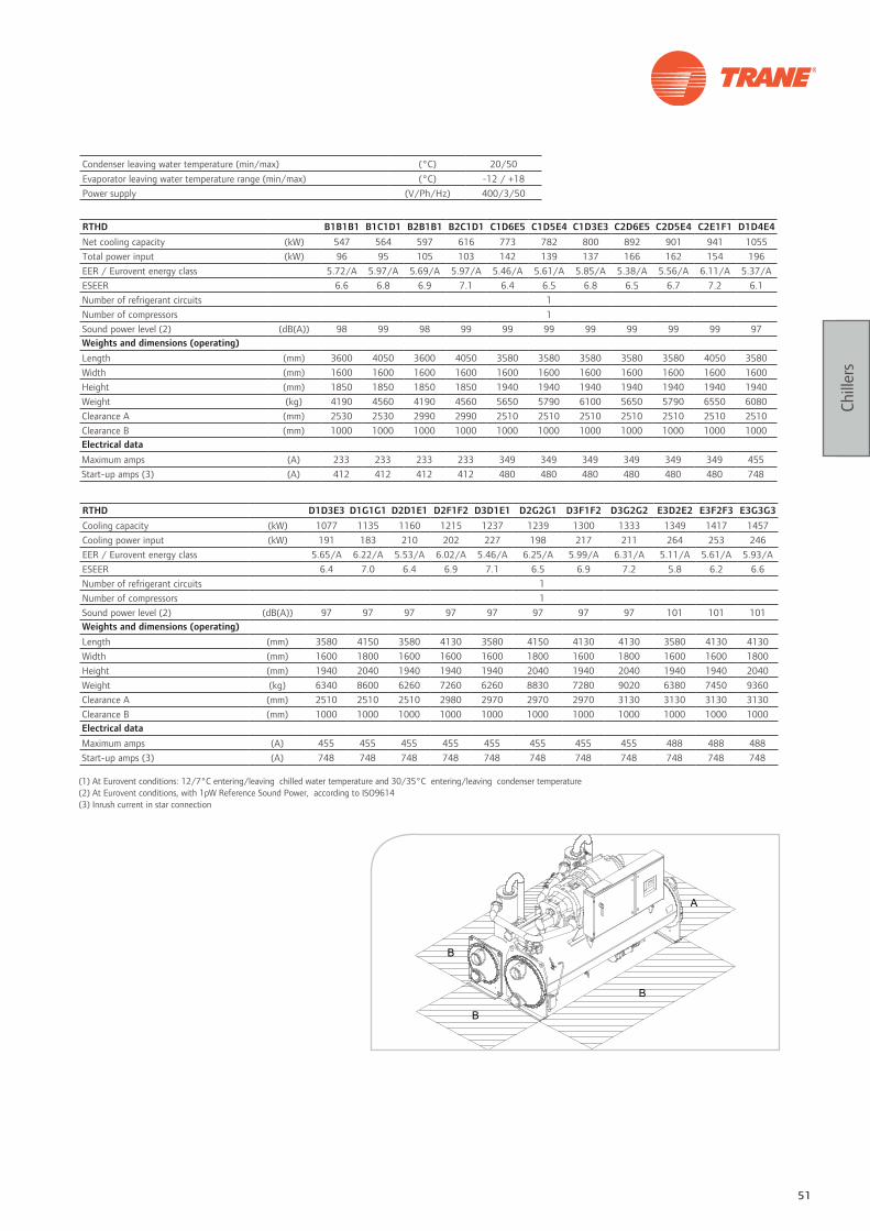
51
Chill
ers
RTHD B1B1B1 B1C1D1 B2B1B1 B2C1D1 C1D6E5 C1D5E4 C1D3E3 C2D6E5 C2D5E4 C2E1F1 D1D4E4Net cooling capacity (kW) 547 564 597 616 773 782 800 892 901 941 1055Total power input (kW) 96 95 105 103 142 139 137 166 162 154 196EER / Eurovent energy class 5.72/A 5.97/A 5.69/A 5.97/A 5.46/A 5.61/A 5.85/A 5.38/A 5.56/A 6.11/A 5.37/AESEER 6.6 6.8 6.9 7.1 6.4 6.5 6.8 6.5 6.7 7.2 6.1Number of refrigerant circuits 1Number of compressors 1Sound power level (2) (dB(A)) 98 99 98 99 99 99 99 99 99 99 97Weights and dimensions (operating) Length (mm) 3600 4050 3600 4050 3580 3580 3580 3580 3580 4050 3580Width (mm) 1600 1600 1600 1600 1600 1600 1600 1600 1600 1600 1600Height (mm) 1850 1850 1850 1850 1940 1940 1940 1940 1940 1940 1940Weight (kg) 4190 4560 4190 4560 5650 5790 6100 5650 5790 6550 6080Clearance A (mm) 2530 2530 2990 2990 2510 2510 2510 2510 2510 2510 2510Clearance B (mm) 1000 1000 1000 1000 1000 1000 1000 1000 1000 1000 1000Electrical dataMaximum amps (A) 233 233 233 233 349 349 349 349 349 349 455Start-up amps (3) (A) 412 412 412 412 480 480 480 480 480 480 748
RTHD D1D3E3 D1G1G1 D2D1E1 D2F1F2 D3D1E1 D2G2G1 D3F1F2 D3G2G2 E3D2E2 E3F2F3 E3G3G3Cooling capacity (kW) 1077 1135 1160 1215 1237 1239 1300 1333 1349 1417 1457Cooling power input (kW) 191 183 210 202 227 198 217 211 264 253 246EER / Eurovent energy class 5.65/A 6.22/A 5.53/A 6.02/A 5.46/A 6.25/A 5.99/A 6.31/A 5.11/A 5.61/A 5.93/AESEER 6.4 7.0 6.4 6.9 7.1 6.5 6.9 7.2 5.8 6.2 6.6Number of refrigerant circuits 1Number of compressors 1Sound power level (2) (dB(A)) 97 97 97 97 97 97 97 97 101 101 101Weights and dimensions (operating)Length (mm) 3580 4150 3580 4130 3580 4150 4130 4130 3580 4130 4130Width (mm) 1600 1800 1600 1600 1600 1800 1600 1800 1600 1600 1800Height (mm) 1940 2040 1940 1940 1940 2040 1940 2040 1940 1940 2040Weight (kg) 6340 8600 6260 7260 6260 8830 7280 9020 6380 7450 9360Clearance A (mm) 2510 2510 2510 2980 2970 2970 2970 3130 3130 3130 3130Clearance B (mm) 1000 1000 1000 1000 1000 1000 1000 1000 1000 1000 1000Electrical dataMaximum amps (A) 455 455 455 455 455 455 455 455 488 488 488Start-up amps (3) (A) 748 748 748 748 748 748 748 748 748 748 748
(1) At Eurovent conditions: 12/7°C entering/leaving chilled water temperature and 30/35°C entering/leaving condenser temperature (2) At Eurovent conditions, with 1pW Reference Sound Power, according to ISO9614(3) Inrush current in star connection
Condenser leaving water temperature (min/max) (°C) 20/50Evaporator leaving water temperature range (min/max) (°C) -12 / +18Power supply (V/Ph/Hz) 400/3/50
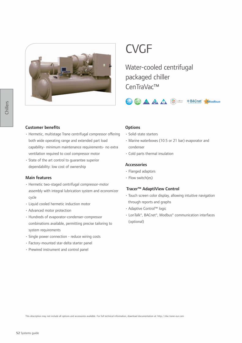
52 Systems guide
Chill
ers
Customer benefits • Hermetic, multistage Trane centrifugal compressor offering
both wide operating range and extended part load
capability- minimum maintenance requirements- no extra
ventilation required to cool compressor motor
• State of the art control to guarantee superior
dependability: low cost of ownership
Main features• Hermetic two-staged centrifugal compressor-motor
assembly with integral lubrication system and economizer
cycle
• Liquid cooled hermetic induction motor
• Advanced motor protection
• Hundreds of evaporator-condenser-compressor
combinations available, permitting precise tailoring to
system requirements
• Single power connection - reduce wiring costs
• Factory-mounted star-delta starter panel
• Prewired instrument and control panel
Options• Solid-state starters
• Marine waterboxes (10.5 or 21 bar) evaporator and
condenser
• Cold parts thermal insulation
Accessories• Flanged adaptors
• Flow switch(es)
Tracer™ AdaptiView Control• Touch screen color display, allowing intuitive navigation
through reports and graphs
• Adaptive Control™ logic
• LonTalk®, BACnet®, Modbus® communication interfaces
(optional)
CVGFWater-cooled centrifugal packaged chiller CenTraVac™
This description may not include all options and accessories available. For full technical information, download documentation at: http://doc.trane-eur.com

53
Chill
ers
CVGF 400 500 650 800 1000Minimum cooling capacity (1) (kW) 1250 1300 2000 2000 2300Maximum cooling capacity (1) (kW) 2000 2000 2800 3450 3750Minimum power input (1) (kW) 219 239 351 346 392Maximum power input (1) (kW) 355 333 479 558 584Minimum EER 5.71 5.44 5.62 5.78 5.87Maximum EER 6.15 6.10 6.21 6.23 6.48Number of refrigerant circuits 1Number of compressors 1Sound pressure level at 1 m (2) (dB(A)) 82 82 83 81 81Dimensions
Length (mm) 4720 4720 4810 4950 4950Width (mm) 1990 1990 2090 2310 2310Height (mm) 2100 2100 2270 2520 2520Electrical data
Maximum amps (A) 604 604 855 964 1100Start-up amps (3) (A) 975 975 1343 1878 1878
(1) At 12/7°C entering/leaving chilled water temperature and 30/35°C entering/leaving condenser temperature(2) With 1pW Reference Sound Power, according to ISO9614(3) Inrush current in star connection
Condenser leaving water temperature (min/max) (°C) 15/50Evaporator leaving water temperature range (min/max) (°C) -2 / +6Power supply (V/Ph/Hz) 400/3/50

54 Systems guide
Chill
ers
Customer benefits • Sustainable, reliable and efficient operation- only one
moving part - a single rotating shaft supported by two
aircraft-turbine-rated bearings- direct-drive concept
minimizes the chance of failure by reducing the number
of critical parts; no gear boxes, couplings, extra shafts, or
shaft seals
• Economically and environmentally sound- proven track
record as literally the world’s most efficient, lowest
emissions chiller. A portion of the product line is
selectable at an unmatched efficiency level of
7.33 kW /kW (or 0.48 kW/Ton), at standard ARI rated
conditions - the lowest total refrigerant emissions in the
industry
Range descriptionCVHE = Three-stage single compressor, 50-60 Hz
CVHF = Two-stage single compressor, 60 Hz
CVHG = Three-stage single compressor, 50 Hz
CDHG = Dual compressor, 50 Hz
CDHF = Dual compressor, 60 Hz
Main features• Tracer™ AdaptiView control strategies
• Low-pressure operation that minimizes the chance for
outward refrigerant leaks
• Hermetically sealed and precision cooled by liquid
refrigerant that keeps the motor, drive, and equipment
room temperatures controlled, monitored and predictable
by design. Protects against motor-destroying elements
such as dust, grit, metal shavings, high humidity, high
ambient operating temperatures, and process liquids or
gases.
• On-line tolerance for quick changes in refrigerant loop
conditions, variable pumping strategies, and other atypical
operating requirements.
• Two-stage or single stage economizer
• High efficiency purge system with automatic regeneration
capability
• Entering condenser water temperature down to 10°C
maintaining 0.2 bars differential pressure
• Motor control and compressor protection
• Hot water control and ice-making control
• Not suitable for installation within the European Union
CVHE CVHF CVHG CDHG CDHFWater-cooled centrifugal packaged chillers CenTraVac™
The CenTraVac™ centrifugal chiller product line provides more than 200,000 individual unit selections over a capacity range of 600-9800 kW. Chiller selections and performance data can be obtained through the use of the CenTraVac™ chiller selection program available from your local Trane sales office. This program can provide a list of chiller selections optimized to closely match specific project requirements.

55
Chill
ers
Options• Medium-voltage (up to 13.8 kV/60Hz or 11 kV/50Hz)
compressor motor
• Variable speed drives to increase part load efficiency when
condenser water temperature relief is possible
• Complete line of factory-installed compressor motor
starters
• Marine water boxes for evaporators and condensers
• High-pressure (21 bars) water side construction
• Energy saving free-cooling, heat-recovery, or auxiliary
condenser
• Special tubing: smooth bore; CuNi; various tube wall
thickness; and internally enhanced
• Refrigerant monitor
• Leaving water temperature down to to 1.2°C without
glycol
• Chiller break apart (disassembly)
• Special paint and controls for outdoor use or corrosive
environments
• Industrial paint
• Industrial electrical packaging of controls and electrical
wiring
Tracer™ AdaptiView Control• Touch screen color display, allowing intuitive navigation
through reports and graphs
• Adaptive Control™ logic
• LonTalk®, Modbus®, BACnet communication interfaces
available
4000
3950
kW
Tons
CVHE = Three-stage single compressor, 50/60 HzCVHF = Two-stage single compressor, 60 HzCVHG = Three-stage single compressor, 50 HzCDHG = Dual compressor, 50 HzCDHF = Dual compressor, 60 Hz
CVHE
CVHG
CDHG
CVHF
CDHF

56 Systems guide
Chill
ers
Using efficient systems is a first step towards environmental
protection, but benefitting from using free or wasted energy
is a supplementary action to reduce your CO2 footprint.
Instead of transferring condenser energy to the outside air,
while cooling, this energy is transferred somewhere else
in the system where it is needed. Heat Recovery, whether
you choose Partial or Total Heat Recovery, is a smart way
to make use of energy when there are simultaneous needs
for cooling and heating to satisfy (i.e. heating sanitary hot
water, dehumidifying coil, etc).
On the other hand, there are times of the year when a
system can use advantageous outdoor conditions to cool the
building or process using the standard cooling components
to distribute its cooling effect. This is called free-cooling.
Energy Savings
Trane air-cooled chillers models RTAD and CGAM offer this
energy saving means as factory-fitted options.
Trane provides assistance in running extensive load
simulations which will determine whether you can benefit
from the savings generated from the installation of Trane
equipment with the heat recovery or free-cooling option.
Partial heat recovery
Total heat recovery
Free cooling
C°
Reducing CO2 footprint by taking advantage of unused wasted energy

57
Chill
ers
Trane heat recovery solutions
Customer benefits• Reduced operating cost
• Pre-heat sanitary water (for commercial buildings) or
kitchen and laundries water (in hotels and resorts)
• Reduced carbon footprint
Availability• CGAM air-cooled scroll chiller: all efficiencies and
acoustical versions
• RTAD air-cooled helical-rotary chiller: all efficiencies and
acoustical versions
Trane free-cooling solutions
Customer benefits• Reduced operating cost
• Reduced carbon footprint
• Sustainability: less compressor work and wear
Availability• RTAD air-cooled helical-rotary chiller: all efficiencies and
acoustical versions
Potential for recovery
Enthalpy
Heat rejected (condenser)
Absorbed heat (cooling effect)
Pres
sure

58 Systems guide
Chill
ers
EnthalpyEnthalpy
Heat rejected (condenser)
Heat rejected (condenser)
Partial Recovery Total Recovery
Absorbed heat (cooling effect)
Absorbed heat (cooling effect)
Pres
sure
Pres
sure
Total heat recovery - model RTAD
Unit power input (1)Cooling capacity in
cooling (1)Heating capacity (2) Heat recovered (2)
Maximum hot water temperature
Unit size (kW) (kW) (kW) (%) (°C)85 217.6 269.9 217.6 81 60100 252.1 313.0 252.1 81 60115 309.1 380.3 309.1 81 60125 368.1 452.2 368.1 81 60145 394.8 486.9 394.8 81 60150 426.9 524.1 426.9 81 60
Total heat recovery - model CGAM HE compact
Unit power input (1)Cooling capacity in
cooling (1)Heating capacity (2) Heat recovered (2)
Maximum hot water temperature
Unit size (kW) (kW) (kW) (%) (°C)40 36.6 113.6 81.5 72 6046 41.8 129.4 88.8 69 6052 47.6 144.2 106.8 74 6060 53.3 164.6 115.7 70 6070 63.8 194.4 146.1 75 6080 73.1 225.4 169.6 75 6090 81 255.6 182.2 71 60100 91 284.1 193.7 68 60110 98.8 312.9 218.5 70 60120 108.6 333.7 228.2 68 60140 126.6 393.4 271.1 69 60150 134.7 421.2 282.0 67 60160 143.9 445.5 311.4 70 60
Partial heat recovery - model RTAD
Unit power input (1)Cooling capacity in
cooling (1)Heating capacity (2) Heat recovered (2)
Maximum hot water temperature
Unit size (kW) (kW) (kW) (%) (°C)85 95.9 297.45 47.4 16 60100 122.2 360.39 57.6 16 60115 144.2 418.05 89.4 21 60125 176.1 489.78 112.4 23 60145 182.9 524.59 115.4 22 60150 201.6 562.91 129.2 23 60
(1) At Eurovent conditions: 12/7°C entering/leaving water temperature and 35°C ambient air temperature(2) At 40/45°C entering/leaving water temperature

59
Chill
ers
Partial heat recovery - model CGAM HE compact
Unit power input (1)Cooling capacity in
cooling (1)Heating capacity (2) Heat recovered (2)
Maximum hot water temperature
Unit size (kW) (kW) (kW) (%) (°C)60 53.5 164.6 48.8 30 6070 64.0 194.1 59.3 31 6080 74.3 224.7 60.6 27 6090 82.3 254.9 75.4 30 60100 92.4 283.4 77.4 27 60110 100.3 312.2 89.2 29 60120 110.2 332.6 101.5 31 60140 128.6 392.4 115.1 29 60150 136.8 420.5 116.2 28 60160 146.2 444.4 127.4 29 60
Partial heat recovery - model CXAM HE compact
Unit power input (1)Cooling capacity in
cooling (1)Heating capacity (2) Heat recovered (2)
Maximum hot water temperature
Unit size (kW) (kW) (kW) (%) (°C)20 18.6 58.0 15.8 27 6023 21.3 64.3 18.8 29 6026 24.1 75.6 19.5 26 6030 27.2 80.9 23.2 29 6035 32.4 94.6 28.5 30 6040 36.8 112.9 31.3 28 6046 42.3 126.2 37.1 29 6052 48.3 149.8 39.1 26 6060 54.5 164.2 46.7 28 6070 65.2 193.4 57.6 30 6080 72.9 231.0 56.3 24 6090 84.5 256.7 70.4 27 60100 96.3 293.6 81.1 28 60110 105.9 311.2 93.6 30 60120 116.5 332.3 104.4 31 60140 136.6 379.0 120.8 32 60150 148.6 402.6 132.9 33 60160 159.4 423.3 143.9 34 60
(1) At Eurovent conditions: 12/7°C entering/leaving water temperature and 35°C ambient air temperature(2) At 40/45°C entering/leaving water temperature
(1) At Eurovent conditions: 12/7°C entering/leaving water temperature and 35°C ambient air temperature(2) At 11°C leaving water temperature and 0°C entering condenser air temperature
Free-cooling - model RTAD
Free-cooling mode
Cooling capacity (1)
Compressor mode power input (1)
EfficiencyCooling capacity
(2)Compressor mode power input (2)
Efficiency
Unit size (kW) (kW) (kW) (kW)RTAD 85 284 101.5 2.80 220 14.6 15.1RTAD 100 340 123.2 2.76 294 20.5 14.3RTAD 115 397 156.6 2.54 315 19.3 16.3RTAD 125 462 192.5 2.40 325 25.2 12.9RTAD 145 502 197 2.55 399 26.7 14.9RTAD 150 535 219 2.44 398 30 13.3

60 Systems guide
Chill
ers
Air-cooled condensers• Horizontal or V-type design
• To operate with Trane model CCUH, CCUN or RTUD
condenserless chillers, either with R407C, R410A or
R134a depending on the type
• Available with various fan-speed combinations to meet the
most severe acoustical requirements
• Including different levels of unit mounted control options
to optimize the performances of the entire system
Dry coolers• Horizontal or V-type design
• To operate with Trane model CGWH, CGWN, RTWD or
RTHD chillers
• Available with various fan-speed combinations to meet the
most severe acoustical requirements
• Including different levels of unit mounted control options
to optimize the performances of the entire system
Heat rejection systems
Cooling towers• Open or closed type
• With axial or centrifugal fans
• To operate with Trane model CGWH, CGWN, RTWD, RTHD,
CVGF or CVHF/G chillers
• Available with different levels of acoustic packages to
meet the most severe acoustical environments
Contact your local Trane Sales Office to support you in
the selection of the most appropriate solution for your
application.
Trane customized solutions
To complete your chiller system, Trane proposes different types of heat rejection solutions. You clearly benefit – from the design
phase to installation of your system – when you partner with a single-source supplier.

6161
Heat pumps In response to growing initiatives regarding heat pumps, reflecting our recognition of the technology as a key heat provider, through the use of renewable energy sources,
and as a low carbon technology, Trane is proud to offer a full range of air-to-water and water-to-water heat pumps.

62 Systems guide
Hea
t pum
ps
Customer benefits • Energy savings and environmental protection
• Space saving: particularly slim design. The unit can be
installed directly on a balcony, rooftop or ground without
the need to have a plant room
• Contemporary appearance: blends in with the surrounding
environment
• Quiet operation: low sound fans and components to
achieve its low sound level
Main features• High efficiency in both heating and cooling mode
• Designed to couple with fan coil units and air handling
units for residential or small commercial air conditioning
applications
• Hot water leaving temperature up to +50°C
• Scroll compressor(s), plate type evaporator, finned-
copper tube and aluminum condenser, axial fan assembly,
expansion valve, indoor cold/warm control switch, water
flow switch, filter dryer, sight-glass, integral water pump,
galvanized sheet metal housing with powder paint, factory
mounted controls
Options• Pressurized water tank system
• Condenser with blue fins corrosion protection
Control• LCD Microprocessor-based Adjustable Water Temperature
Control: Precise temperature control of inlet chilled water,
operation modes and system protection are provided by
the long-range controller.
• Password can be set and any abnormal condition will
be monitored and captured to facilitate quick repair and
normal operation.
• Interlocking function of the two-way valve is available.
CGARReversible air-to-water heat pump
This description may not include all options and accessories available. For full technical information, download documentation at: http://doc.trane-eur.com

63
Hea
t pum
ps
CGAR 0505F 0605A 0755D 1005F 1505D 1505FNet heating capacity (1) (kW) 14.5 17.7 22.2 30.0 42.4 40.0Total power input in heating (kW) 4.7 5.9 7.2 9.0 13.8 14.0COP 3.09 3.00 3.08 3.33 3.07 2.86Net cooling capacity (2) (kW) 13.1 15.6 19.5 26.2 39.0 38.0Total power input in cooling (kW) 4.4 5.6 6.8 8.6 13.7 13.4EER 2.98 2.77 2.87 3.05 2.85 2.8Number of refrigerant circuits 1 1 1 2 2 1Number of compressors 1 1 1 2 2 1Sound power level (3) (dB(A)) 62 61 63 64 66 69.5Weight and dimensions (operating)Length (mm) 950 950 1290 1290 1990 1290Width (mm) 393 393 500 500 500 500Height (mm) 1285 1285 1900 1900 1900 1900Weight (kg) 170 170 290 404 490 470Clearance A (mm) 300Clearance B (mm) 1500Clearance C (mm) 300Clearance D (mm) 500Electrical dataMaximum amps (A) 13.0 16.7 19.6 25.8 40.8 39.9Start-up amps (A) 65.5 101.0 95.0 65.5 x 2 95.0 x 2 198.0
(1) At 40/45°C entering/leaving water temperature and 7°C/50% RH ambient air temperature(2) At 12/7°C entering/leaving water temperature and 35°C ambient air temperature(3) With 1pW Reference Sound Power, according to ISO9614
Heating mode operating outdoor air temperature range (min/max) (°C) +5 / +15Heating mode leaving water temperature range (min/max) (°C) +30 / +50Cooling operating outdoor air temperature range (min/max) (1) (°C) +18 / 43Cooling leaving water temperature range (min/max) (2) (°C) -10 / 24Power supply (V/Ph/Hz) 400/3/50

64 Systems guide
Hea
t pum
ps
Customer benefits• Packaged hydraulic module (VXA) for easier and quicker
installation
• Low sound version for sensitive environment: a high level
of acoustic comfort
• Minimum maintenance requirements save time and money
Range descriptionCXA: Without hydraulic module
VXA: With hydraulic module
Main features• Scroll compressor(s) featuring sound-proofing, protection
of motor winding, crankcase heater, thermo-magnetic
circuit breaker
• Hot water leaving temperature up to +50°C
• Axial fan(s) with completely integrated low noise level
• Stainless steel water heat exchangers equipped with
heating resistors
• Black epoxy-coated aluminum fins with copper tubes
• Cooling circuit(s) with thermostatic expansion valve(s),
liquid line filter drier(s), high and low pressure cut-outs,
factory oil and refrigerant charges
• Disconnect switch
• Flow switch
Options• Water outlet low temperature in cooling (-5°C to -10°C)
Accessories• Remote control module
• High and low pressure gauges
ControlMicroprocessor control module featuring:
• Control of return water temperature
• Liquid crystal display indicating return water temperature,
codes of any faults
• Control of operating parameters
• Possibility of remote fault signaling on 24V indicator light
• Antifreeze protection of evaporators
• 24V dry contacts for remote signaling of on/off and
general fault
CXA VXAReversible air-to-water heat pump
This description may not include all options and accessories available. For full technical information, download documentation at: http://doc.trane-eur.com

65
Hea
t pum
ps
CXA/VXA 075 100 120 150 200 240Net heating capacity (1) (kW) 19.0 26.0 32.0 39.0 52.0 64.0Total power input in heating (kW) 6.67 9.22 13.20 13.40 18.30 25.10COP/Eurovent energy class 2.85/C 2.82/C 2.42/E 2.92/C 2.85/C 3/BNet cooling capacity (2) (kW) 19.4 25.5 31.3 39.1 51.4 64.8Total power input in cooling (kW) 7.1 9.6 13.8 13.9 19.7 26.1EER/Eurovent energy class 2.72/C 2.65/D 2.27/F 2.81/C 2.61/D 2.5/EESEER 3.00 3.01 2.50 3.24 3.21 2.9Number of refrigerant circuits 1 1 1 2 2 2Number of compressors 1 1 1 2 2 2Sound power level (3) (dB(A)) 76 78 82 78 80 85Weight and dimensions (operating)Length (mm) 1060 1060 1260 2200 2200 2200Width (mm) 950 950 1050 1050 1050 1050Height (CXA/VXA) (mm) 1230/1560 1231/1560 1232/1560 1230/1730 1231/1730 1232/1730Operating weight (CXA/VXA) (kg) 215/479 230/494 246/510 429/800 459/825 490/856Clearance A (mm) 1000Clearance B (mm) 1000 1000 1000 300 300 300Clearance C (mm) 300 300 300 1000 1000 1000Clearance D (mm) 1000 1000 1000 300 300 300Electrical dataMaximum amps (A) 16.7 21.2 26.9 32.6 41.6 53.0Start-up amps (A) 101 133 142 117 153 167
(1) At Eurovent conditions: 40/45°C entering/leaving water temperature and 7°C/50% RH ambient air temperature(2) At Eurovent conditions: 12/7°C entering/leaving water temperature and 35°C ambient air temperature(3) At Eurovent conditions, with 1pW Reference Sound Power, according to ISO9614
Heating mode operating outdoor air temperature range (min/max) (°C) -15 / +20Heating mode leaving water temperature range (min/max) (°C) +30 / +50Cooling operating outdoor air temperature range (min/max) (°C) +15 / +45
Cooling leaving water temperature range (min/max) (°C)-4 / +12 standard. -12 / +12 with low
leaving water temperature option
Power supply (V/Ph/Hz) 400/3/50

66 Systems guide
Hea
t pum
ps
Customer benefits• Life cycle effectiveness
• Efficiency and sound level without compromise
• All year round operation
• Extreme reliability and durability
• Wide application flexibility for comfort and process
applications to fit the exact requirements
• Ease of installation and serviceability
Main features• 2 efficiency levels: High or Standard
• 3 acoustic versions: Standard, Low noise or
Comprehensive acoustic package treatment
• High efficiency Scroll compressors
• Hot water leaving temperature up to +55°C
• Patented refrigerant circuit
• Trane design low sound level fans mounted on hinges
• Electronic expansion valve
• Brazed plates heat exchangers
• Powder coated components
• Disconnect switch/transformer
• Water strainer and flow switch
Options• Integrated hydraulic module with or without buffer tank
• Single or double pump package
• Variable frequency drive for pump flow rate adjustment
• Freeze protection control
• Black epoxy condenser coil coating
• Architectural louvered panels, access guards
Accessories• Neoprene isolators
• Grooved pipe connection kit
Tracer™ CH530 ControlAdaptive Control™ microprocessor featuring:
• Easy-to-use operator interface panel
• Smart defrost management
• External Auto/Stop
• External interlock
• Chilled water pump control
• Ice-making card (optional)
• Chilled water and current-limit remote setpoint card
(optional)
• LonTalk®, Modbus®, BACnet® communication capabilities
CXAMReversible air-to-water heat pump
This description may not include all options and accessories available. For full technical information, download documentation at: http://doc.trane-eur.com
Energy saving options• Partial heat recovery (desuperheater)

67
Hea
t pum
ps
Heating mode operating outdoor air temperature range (Min/Max) (°C) -10/+20Heating mode leaving water temperature range (Min/Max) (°C) +20/+55Cooling operating outdoor air temperature range (Min/Max) (1) (°C) -10/+46Cooling leaving water temperature range (Min/Max) (2) (°C) -10/+20Power supply (V/Ph/Hz) 400/3/50
CXAM SE Compact 020 023 026 030 035 039 045 050 040 046 052Net heating capacity (3) (kW) 61.9 69.3 78.1 87.6 100.9 112.5 124.5 133.6 125.9 141.3 160.0Total power input in heating (kW) 21.1 23.6 26.1 29.4 35.4 39.2 43.5 48.0 42.5 46.5 51.4COP/Eurovent energy class 2.9/C 2.9/C 3.0/B 3.0/B 2.9/C 2.9/C 2.9/C 2.8/C 3.0/B 3.0/B 3.1/BNet cooling capacity (4) (kW) 55.9 61.9 70.0 78.1 95.3 110.4 121.7 131.5 112.9 126.9 144.5Total power input in cooling (kW) 19.5 22.2 24.2 28.3 32.9 38.3 44.0 49.9 39.1 44.7 48.9EER 2.9 2.8 2.9 2.8 2.9 2.9 2.8 2.6 2.9 2.8 3.0ESEER 3.5 3.6 3.8 3.8 3.8 3.9 3.8 3.7 3.4 3.4 3.8Number of refrigerant circuits 1 1 1 1 1 1 1 1 2 2 2Number of compressors 2 2 2 2 2 2 2 2 4 4 4Sound power level (5) (dBA) 89 88 88 89 91 91 91 91 92 92 92Sound pressure level (6) (dBA) 57 57 57 57 59 59 59 59 60 59 59Dimensions and weight (operating)Length (mm) 2908 2908 2908 2908 3822 3822 3822 3822 2905 2905 2905Width (mm) 1301 1301 1301 1301 1301 1301 1301 1301 2266 2266 2266Height (mm) 2153 2153 2153 2153 2153 2153 2153 2153 2150 2150 2150Weight (kg) 917 921 946 1042 1272 1283 1342 1389 1665 1697 1746Clearance A (mm) 1200 1200 1200 1200 1200 1200 1200 1200 1200 1200 1200Clearance B (mm) 600 600 600 600 600 600 600 600 1000 1000 1000Clearance C (mm) 800 800 800 800 800 800 800 800 800 800 800Clearance D (mm) 1000 1000 1000 1000 1000 1000 1000 1000 1000 1000 1000Electrical dataMaximum amps (A) 170.2 186.2 191.2 206.8 255.2 266.2 311.2 322.7 217.7 238.7 248.7Start-up amps (A) 48.3 53.3 58.3 65.5 79.9 90.9 102.4 113.9 95.8 105.8 115.8
CXAM SE Compact 060 070 080 090 100 110 120 140 150 160 170Net heating capacity (3) (kW) 177.2 203.2 227.5 251.4 271.1 286.9 301.7 360.7 374.8 427.9 442.7Total power input in heating (kW) 58.5 70.8 78.9 87.5 95.3 102.6 109.2 136.4 144.5 157.1 164.7COP/Eurovent energy class 3.0/B 2.9/C 2.9/C 2.9/C 2.9/C 2.8/C 2.8/C 2.7/D 2.6/D 2.7/D 2.7/DNet cooling capacity (4) (kW) 162.1 192.3 224.7 248.9 277.4 296.4 318.6 378.7 401.5 434.9 453.2Total power input in cooling (kW) 56.9 67.8 76.9 88.2 95.4 104.4 114.8 138.4 150.4 156.1 165.6EER 2.8 2.8 2.9 2.8 2.9 2.8 2.8 2.7 2.7 2.8 2.7ESEER 3.9 3.6 3.9 3.9 4.0 4.0 4.2 3.9 3.8 3.8 3.7Number of refrigerant circuits 2 2 2 2 2 2 2 2 2 2 2Number of compressors 4 4 4 4 4 4 4 6 6 6 6Sound power level (5) (dBA) 92 94 94 94 93 93 94 95 95 96 96Sound pressure level (6) (dBA) 60 62 62 62 61 61 61 63 63 63 63Dimensions and weight (operating)Length (mm) 2905 3819 3819 3819 4230 4230 4230 5145 5145 6062 6062Width (mm) 2266 2266 2266 2266 2273 2273 2273 2273 2273 2273 2273Height (mm) 2150 2150 2150 2150 2344 2344 2344 2344 2344 2344 2344Weight (kg) 1928 2196 2247 2358 2808 2808 2835 3500 3618 4005 4005Clearance A (mm) 1200 1200 1200 1200 1200 1200 1200 1200 1200 1200 1200Clearance B (mm) 1000 1000 1000 1000 1000 1000 1000 1000 1000 1000 1000Clearance C (mm) 800 800 800 800 1000 1000 1000 1000 1000 1000 1000Clearance D (mm) 1000 1000 1000 1000 1000 1000 1000 1000 1000 1000 1000Electrical dataMaximum amps (A) 271.5 334.3 356.9 413.4 443.1 509.8 523.2 529.4 552.3 625.8 639.2Start-up amps (A) 130.2 159.1 181.7 204.6 234.3 247.7 261.1 320.6 343.5 363.7 377.1
(1) With low ambient option(2) With process cooling options(3) At Eurovent conditions: 40/45°C entering/leaving water temperature and 7°C/50% RH ambient air temperature(4) At Eurovent conditions: 12/7°C entering/leaving water temperature and 35°C ambient air temperature(5) At Eurovent conditions, with 1pW Reference Sound Power, according to ISO9614(6) At 10m in free field, calculated from the above sound power level according to the formula Lp = Lw-10logS

68 Systems guide
Hea
t pum
ps
CXAM SE Super quiet 020 023 026 030 035 039 045 050 040 046 052Net heating capacity (3) (kW) 60.8 67.9 77.0 86.1 99.5 110.8 122.4 131.2 123.4 138.5 157.5Total power input in heating (kW) 19.5 22.1 24.8 28.1 33.4 37.2 41.4 46.0 39.4 43.5 48.9COP/Eurovent energy class 3.1/B 3.1/B 3.1/B 3.1/B 3.0/B 3.0/B 3.0/B 2.9/C 3.1/B 3.2/A 3.2/ANet cooling capacity (4) (kW) 54.9 60.5 68.9 76.7 93.9 108.3 119.2 128.0 110.4 124.1 142.4Total power input in cooling (kW) 19.0 22.0 24.0 28.2 32.2 38.1 44.2 50.5 38.0 44.1 48.4EER 2.9 2.8 2.9 2.7 2.9 2.8 2.7 2.6 2.9 2.8 2.9ESEER 3.8 3.8 4.0 4.0 4.1 4.1 4.1 3.9 3.9 3.8 4.0Number of refrigerant circuits 1 1 1 1 1 1 1 1 2 2 2Number of compressors 2 2 2 2 2 2 2 2 4 4 4Sound power level (5) (dBA) 85 85 85 85 87 88 88 88 88 88 88Sound pressure level (6) (dBA) 53 53 53 53 55 56 56 56 56 56 56Dimensions and weight (operating)Length (mm) 2908 2908 2908 2908 3822 3822 3822 3822 2905 2905 2905Width (mm) 1301 1301 1301 1301 1301 1301 1301 1301 2266 2266 2266Height (mm) 2153 2153 2153 2153 2153 2153 2153 2153 2150 2150 2150Weight (kg) 917 921 946 1042 1272 1283 1342 1389 1665 1697 1746Clearance A (mm) 1200 1200 1200 1200 1200 1200 1200 1200 1200 1200 1200Clearance B (mm) 600 600 600 600 600 600 600 600 1000 1000 1000Clearance C (mm) 800 800 800 800 800 800 800 800 800 800 800Clearance D (mm) 1000 1000 1000 1000 1000 1000 1000 1000 1000 1000 1000Electrical dataMaximum amps (A) 172.0 188.0 193.0 208.6 257.9 268.9 313.9 325.4 221.3 242.3 252.3Start-up amps (A) 48.3 53.3 58.3 65.5 79.9 90.9 102.4 113.9 95.8 105.8 115.8
CXAM SE Super quiet 060 070 080 090 100 110 120 140 150 160 170Net heating capacity (3) (kW) 174.8 199.0 224.0 246.8 267.9 283.0 300.6 351.3 366.0 415.9 431.1Total power input in heating (kW) 56.1 66.3 74.7 83.4 92.1 99.6 108.9 130.3 138.5 149.7 157.3COP/Eurovent energy class 3.1/B 3.0/B 3.0/B 3.0/B 2.9/C 2.8/C 2.8/C 2.7/D 2.6/D 2.8/C 2.7/DNet cooling capacity (4) (kW) 159.3 188.1 220.8 243.3 273.5 290.8 318.2 372.7 393.4 428.3 445.5Total power input in cooling (kW) 56.9 67.2 76.7 88.7 95.5 105.5 114.8 139.8 152.8 156.8 167.1EER 2.8 2.8 2.9 2.8 2.9 2.8 2.8 2.7 2.6 2.7 2.7ESEER 4.1 3.9 4.2 4.2 4.2 4.2 4.1 4.1 4.0 4.0 4.0Number of refrigerant circuits 2 2 2 2 2 2 2 2 2 2 2Number of compressors 4 4 4 4 4 4 4 6 6 6 6Sound power level (5) (dBA) 88 90 91 91 89 90 91 91 92 93 93Sound pressure level (6) (dBA) 56 58 59 59 57 58 59 59 59 60 60Dimensions and weight (operating)Length (mm) 2905 3819 3819 3819 4230 4230 4230 5145 5145 6062 6062Width (mm) 2266 2266 2266 2266 2273 2273 2273 2273 2273 2273 2273Height (mm) 2150 2150 2150 2150 2344 2344 2344 2344 2344 2344 2344Weight (kg) 1928 2196 2247 2358 2808 2808 2925 3500 3618 4005 4005Clearance A (mm) 1200 1200 1200 1200 1200 1200 1200 1200 1200 1200 1200Clearance B (mm) 1000 1000 1000 1000 1000 1000 1000 1000 1000 1000 1000Clearance C (mm) 800 800 800 800 1000 1000 1000 1000 1000 1000 1000Clearance D (mm) 1000 1000 1000 1000 1000 1000 1000 1000 1000 1000 1000Electrical dataMaximum amps (A) 275.1 339.7 362.3 418.8 450.3 517.0 530.4 538.4 561.3 636.6 650.0Start-up amps (A) 130.2 159.1 181.7 204.6 217.6 231.0 247.1 302.5 325.4 338.8 -
(1) With low ambient option(2) With process cooling options(3) At Eurovent conditions: 40/45°C entering/leaving water temperature and 7°C/50% RH ambient air temperature(4) At Eurovent conditions: 12/7°C entering/leaving water temperature and 35°C ambient air temperature(5) At Eurovent conditions, with 1pW Reference Sound Power, according to ISO9614(6) At 10m in free field, calculated from the above sound power level according to the formula Lp = Lw-10logS
Heating mode operating outdoor air temperature range (Min/Max) (°C) -10/+20Heating mode leaving water temperature range (Min/Max) (°C) +20/+55Cooling operating outdoor air temperature range (Min/Max) (1) (°C) -10/+46Cooling leaving water temperature range (Min/Max) (2) (°C) -10/+20Power supply (V/Ph/Hz) 400/3/50

69
Hea
t pum
ps
CXAM SE Comprehensive Acoustic Package 020 023 026 030 035 039 040 046 052 060Net heating capacity (3) (kW) 60.1 67.9 75.2 85.1 97.4 107.9 121.7 136.4 153.3 171.6Total power input in heating (kW) 17.9 20.4 22.4 26.9 30.8 34.6 36.3 40.3 45.3 54.0COP/Eurovent energy class 3.4/A 3.3/A 3.4/A 3.2/A 3.2/A 3.1/B 3.4/A 3.4/A 3.4/A 3.2/ANet cooling capacity (4) (kW) 53.4 59.8 68.9 76.7 90.4 103.0 107.2 119.5 135.0 155.4Total power input in cooling (kW) 18.6 21.1 25.1 28.2 32.6 39.6 37.1 44.1 49.9 56.4EER 2.9 2.8 2.8 2.7 2.8 2.6 2.9 2.7 2.7 2.8ESEER 4.4 4.5 4.5 4.4 4.5 4.5 4.4 4.3 4.4 4.4Number of refrigerant circuits 1 1 1 1 1 1 2 2 2 2Number of compressors 2 2 2 2 2 2 4 4 4 4Sound power level (dBA) 78 78 78 80 82 83 81 81 81 83Sound pressure level (6) (dBA) 46 46 46 48 49 51 49 49 49 51Dimensions and weight (operating)Length (mm) 2908 2908 3822 3822 3822 3822 2905 2905 2905 3819Width (mm) 1301 1301 1301 1301 1301 1301 2266 2266 2266 2266Height (mm) 2153 2153 2153 2153 2153 2153 2150 2150 2150 2150Weight (kg) 951 976 992 1267 1317 1328 1733 1765 1814 2221Clearance A (mm) 1200 1200 1200 1200 1200 1200 1200 1200 1200 1200Clearance B (mm) 600 600 600 600 600 600 1000 1000 1000 1000Clearance C (mm) 800 800 800 800 800 800 800 800 800 800Clearance D (mm) 1000 1000 1000 1000 1000 1000 1000 1000 1000 1000Electrical dataMaximum amps (A) 166.1 182.1 187.1 204.0 249.0 260.0 209.5 230.5 240.5 266.0Start-up amps (A) 44.2 49.2 54.2 62.7 73.7 84.8 87.6 97.6 107.6 124.7
CXAM SE Comprehensive Acoustic Package 070 080 090 100 110 120 140 150 160Net heating capacity (3) (kW) 195.8 218.3 244.0 262.7 278.8 296.4 352.3 387.8 402.2Total power input in heating (kW) 61.6 69.6 79.6 87.7 94.9 103.7 122.7 131.4 139.1COP/Eurovent energy class 3.2/A 3.1/B 3.1/B 3.0/B 2.9/C 2.9/C 2.9/C 3.0/B 2.9/CNet cooling capacity (4) (kW) 181.1 208.9 240.5 264.8 285.2 310.1 365.0 394.1 408.9Total power input in cooling (kW) 67.3 79.5 83.5 96.7 105.7 112.3 137.1 151.3 163.3EER 2.7 2.6 2.9 2.7 2.7 2.8 2.7 2.6 2.5ESEER 4.5 4.5 4.8 4.5 4.5 4.6 4.7 4.6 4.5Number of refrigerant circuits 2 2 2 2 2 2 2 2 2Number of compressors 4 4 4 4 4 4 6 6 6Sound power level (dBA) 84 86 83 84 85 86 85 85 86Sound pressure level (6) (dBA) 52 53 51 51 52 54 53 53 54Dimensions and weight (operating)Length (mm) 3819 3819 4230 4230 5145 5145 6062 6062 6062Width (mm) 2266 2266 2273 2273 2273 2273 2273 2273 2273Height (mm) 2150 2150 2344 2344 2344 2344 2344 2344 2344Weight (kg) 2286 2337 2884 3012 3266 3356 4034 4159 4159Clearance A (mm) 1200 1200 1200 1200 1200 1200 1200 1200 1200Clearance B (mm) 1000 1000 1000 1000 1000 1000 1000 1000 1000Clearance C (mm) 800 800 1000 1000 1000 1000 1000 1000 1000Clearance D (mm) 1000 1000 1000 1000 1000 1000 1000 1000 1000Electrical dataMaximum amps (A) 322.0 344.6 403.8 426.7 496.1 509.5 511.6 534.5 601.2Start-up amps (A) 146.8 169.4 195.0 217.9 234.0 247.4 325.7 339.1 -
(1) With low ambient option(2) With process cooling options(3) At Eurovent conditions: 40/45°C entering/leaving water temperature and 7°C/50% RH ambient air temperature(4) At Eurovent conditions: 12/7°C entering/leaving water temperature and 35°C ambient air temperature(5) At Eurovent conditions, with 1pW Reference Sound Power, according to ISO9614(6) At 10m in free field, calculated from the above sound power level according to the formula Lp = Lw-10logS
Heating mode operating outdoor air temperature range (Min/Max) (°C) -10/+20Heating mode leaving water temperature range (Min/Max) (°C) +20/+55Cooling operating outdoor air temperature range (Min/Max) (1) (°C) -10/+46Cooling leaving water temperature range (Min/Max) (2) (°C) -10/+20Power supply (V/Ph/Hz) 400/3/50
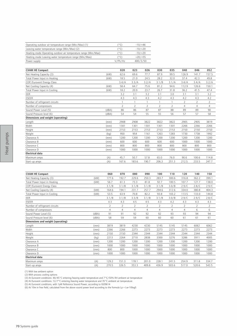
70 Systems guide
Hea
t pum
ps
Operating outdoor air temperature range (Min/Max) (1) (°C) -10/+46Leaving water temperature range (Min/Max) (2) (°C) -10/+20Heating mode Operating outdoor air temperature range (Min/Max) (°C) -10/+20Heating mode Leaving water temperature range (Min/Max) (°C) +20/+55Power supply V/Ph/Hz 400/3/50
CXAM HE Compact 020 023 026 030 035 040 046 052Net Heating Capacity (3) (kW) 62.6 69.6 77.7 87.9 99.5 126.9 141.7 157.5Total Power Input in Heating (kW) 18.5 21.0 24.5 28.2 32.0 37.4 42.3 49.8COP/Eurovent Energy Class 3.4/A 3.3/A 3.2/A 3.1/B 3.1/A 3.4/A 3.4/A 3.2/ANet Cooling Capacity (4) (kW) 58.4 64.7 75.6 81.2 94.6 112.9 126.6 150.1Total Power Input in Cooling (kW) 18.2 20.9 23.7 26.7 31.8 36.2 41.5 47.4EER 3.2 3.1 3.2 3.1 3.0 3.1 3.1 3.2ESEER 4.3 4.3 4.3 4.2 4.3 4.2 4.3 4.2Number of refrigerant circuits 1 1 1 1 1 2 2 2Number of compressors 2 2 2 2 2 4 4 4Sound Power Level (5) (dBA) 86 86 87 87 88 89 89 90Sound Pressure level (6) (dBA) 54 54 55 55 56 57 57 58Dimensions and weight (operating)Length (mm) 2908 2908 3822 3822 3822 2905 2905 3819Width (mm) 1301 1301 1301 1301 1301 2266 2266 2266Height (mm) 2153 2153 2153 2153 2153 2150 2150 2150Weight (kg) 950 954 1161 1263 1283 1730 1738 1992Clearance A (mm) 1200 1200 1200 1200 1200 1200 1200 1200Clearance B (mm) 600 600 600 600 600 1000 1000 1000Clearance C (mm) 800 800 800 800 800 800 800 800Clearance D (mm) 1000 1000 1000 1000 1000 1000 1000 1000Electrical dataMaximum amps (A) 45.7 50.7 57.8 65.0 76.0 90.6 100.6 114.8Start-up amps (A) 167.6 183.6 190.7 206.3 251.3 212.5 233.5 247.7
(1) With low ambient option(2) With process cooling options(3) At Eurovent conditions: 40/45°C entering/leaving water temperature and 7°C/50% RH ambient air temperature(4) At Eurovent conditions: 12/7°C entering/leaving water temperature and 35°C ambient air temperature(5) At Eurovent conditions, with 1pW Reference Sound Power, according to ISO9614(6) At 10m in free field, calculated from the above sound power level according to the formula Lp = Lw-10logS
CXAM HE Compact 060 070 080 090 100 110 120 140 150Net Heating Capacity (3) (kW) 177.6 192.7 229.6 250.3 283.7 300.6 316.8 362.2 399.1Total Power Input in Heating (kW) 56.7 61.3 73.3 81.8 92.7 100.5 107.7 127.7 138.0COP/Eurovent Energy Class 3.1/B 3.1/B 3.1/B 3.1/B 3.1/B 3.0/B 2.9/C 2.8/C 2.9/CNet Cooling Capacity (4) (kW) 164.6 194.1 231.7 257.7 294.6 312.6 334.0 380.8 404.3Total Power Input in Cooling (kW) 53.5 63.9 70.8 82.2 93.8 103.2 113.5 133.0 144.8EER 3.1/B 3.1/B 3.3/B 3.1/B 3.1/B 3.0/B 2.9/C 2.9/C 2.8/CESEER 4.3 4.3 4.5 4.5 4.3 4.2 4.3 4.3 4.3Number of refrigerant circuits 2 2 2 2 2 2 2 2 2Number of compressors 4 4 4 4 4 4 4 6 6Sound Power Level (5) (dBA) 91 91 92 92 92 93 93 94 94Sound Pressure level (6) (dBA) 58 59 59 60 60 60 61 61 61Dimensions and weight (operating)Length (mm) 3819 3819 4230 4230 5145 5145 5145 6062 6062Width (mm) 2266 2266 2273 2273 2273 2273 2273 2273 2273Height (mm) 2150 2150 2344 2344 2344 2344 2344 2344 2344Weight (kg) 2213 2264 2710 2838 3300 3276 3286 3911 4005Clearance A (mm) 1200 1200 1200 1200 1200 1200 1200 1200 1200Clearance B (mm) 1000 1000 1000 1000 1000 1000 1000 1000 1000Clearance C (mm) 800 800 1000 1000 1000 1000 1000 1000 1000Clearance D (mm) 1000 1000 1000 1000 1000 1000 1000 1000 1000Electrical dataMaximum amps (A) 129.2 151.3 178.1 201.0 228.1 241.5 254.9 311.8 334.7Start-up amps (A) 270.5 326.5 353.3 409.8 436.9 503.6 517.0 520.6 543.5

71
Hea
t pum
ps
CXAM HE Super Quiet 020 023 026 030 035 040 046 052Net Heating Capacity (3) (kW) 62.2 69.3 77.4 87.6 99.2 126.6 141.3 156.1Total Power Input in Heating (kW) 18.5 20.9 24.2 28.2 31.8 37.2 42.2 49.3COP/Eurovent Energy Class 3.4/A 3.3/A 3.2/A 3.1/B 3.1/B 3.4/A 3.4/A 3.2/ANet Cooling Capacity (4) (kW) 58.0 64.3 75.2 80.9 94.2 112.9 126.2 149.1Total Power Input in Cooling (kW) 18.3 21.0 23.9 26.8 32.0 36.3 41.7 47.7EER 3.2 3.1 3.2 3.0 3.0 3.1 3.0 3.1ESEER 4.3 4.3 4.3 4.3 4.4 4.2 4.2 4.2Number of refrigerant circuits 1 1 1 1 1 2 2 2Number of compressors 2 2 2 2 2 4 4 4Sound Power Level (5) (dBA) 81 81 82 82 84 84 84 85Sound Pressure level (6) (dBA) 49 49 50 50 52 52 52 53Dimensions and weight (operating)Length (mm) 2908 2908 3822 3822 3822 2905 2905 3819Width (mm) 1301 1301 1301 1301 1301 2266 2266 2266Height (mm) 2153 2153 2153 2153 2153 2150 2150 2150Weight (kg) 950 954 1161 1263 1283 1730 1738 1992Clearance A (mm) 1200 1200 1200 1200 1200 1200 1200 1200Clearance B (mm) 600 600 600 600 600 1000 1000 1000Clearance C (mm) 800 800 800 800 800 800 800 800Clearance D (mm) 1000 1000 1000 1000 1000 1000 1000 1000Electrical dataMaximum amps (A) 45.7 50.7 57.8 65.0 76.0 90.6 100.6 114.8Start-up amps (A) 167.6 183.6 190.7 206.3 251.3 212.5 233.5 247.7
CXAM HE Super Quiet 060 070 080 090 100 110 120 140 150Net Heating Capacity (3) (kW) 176.9 200.4 229.6 250.3 282.7 300.3 317.1 362.2 397.3Total Power Input in Heating (kW) 56.4 63.5 73.0 81.4 92.2 100.1 107.2 127.5 137.0COP/Eurovent Energy Class 3.1/B 3.2/A 3.2/A 3.1/B 3.1/B 3.0/B 3.0/B 2.8/C 2.9/CNet Cooling Capacity (4) (kW) 163.9 193.0 232.1 258.1 295.0 312.6 334.4 381.1 405.0Total Power Input in Cooling (kW) 53.7 64.3 70.4 81.8 93.3 102.8 113.0 132.4 144.2EER 3.1 3.0 3.3 3.2 3.2 3.1 3.0 2.9 2.8ESEER 4.3 4.4 4.6 4.5 4.4 4.3 4.4 4.4 4.3Number of refrigerant circuits 2 2 2 2 2 2 2 2 2Number of compressors 4 4 4 4 4 4 4 6 6Sound Power Level (5) (dBA) 85 88 89 88 88 89 90 90 89Sound Pressure level (6) (dBA) 53 55 56 56 56 57 58 57 57Dimensions and weight (operating)Length (mm) 3819 3819 4230 4230 5145 5145 5145 6062 6062Width (mm) 2266 2266 2273 2273 2273 2273 2273 2273 2273Height (mm) 2150 2150 2344 2344 2344 2344 2344 2344 2344Weight (kg) 2213 2264 2710 2838 3300 3276 3286 3911 4005Clearance A (mm) 1200 1200 1200 1200 1200 1200 1200 1200 1200Clearance B (mm) 1000 1000 1000 1000 1000 1000 1000 1000 1000Clearance C (mm) 800 800 1000 1000 1000 1000 1000 1000 1000Clearance D (mm) 1000 1000 1000 1000 1000 1000 1000 1000 1000Electrical dataMaximum amps (A) 129.2 151.3 178.1 201.0 228.1 241.5 254.9 311.8 334.7Start-up amps (A) 270.5 326.5 353.3 409.8 436.9 503.6 517.0 520.6 543.5
(1) With low ambient option(2) With process cooling options(3) At Eurovent conditions: 40/45°C entering/leaving water temperature and 7°C/50% RH ambient air temperature(4) At Eurovent conditions: 12/7°C entering/leaving water temperature and 35°C ambient air temperature(5) At Eurovent conditions, with 1pW Reference Sound Power, according to ISO9614(6) At 10m in free field, calculated from the above sound power level according to the formula Lp = Lw-10logS
Operating outdoor air temperature range (Min/Max) (1) (°C) -10/+46Leaving water temperature range (Min/Max) (2) (°C) -10/+20Heating mode Operating outdoor air temperature range (Min/Max) (°C) -10/+20Heating mode Leaving water temperature range (Min/Max) (°C) +20/+55Power supply V/Ph/Hz 400/3/50

72 Systems guide
Hea
t pum
ps
CXAM HE Comprehensive Acoustic Package 020 023 026 030 040 046 052Net Heating Capacity (3) (kW) 61.2 68.9 76.7 86.5 124.5 139.6 155.4Total Power Input in Heating (kW) 17.5 20.6 23.0 26.4 35.3 41.4 46.4COP/Eurovent Energy Class 3.5/A 3.3/A 3.3/A 3.3/A 3.5/A 3.4/A 3.4/ANet Cooling Capacity (4) (kW) 56.6 65.1 73.1 80.9 110.4 130.4 148.0Total Power Input in Cooling (kW) 18.2 20.4 23.0 26.8 36.1 40.8 46.2EER 3.1 3.2 3.2 3.0 3.1 3.2 3.2ESEER 4.6 4.6 4.7 4.6 4.5 4.5 4.7Number of refrigerant circuits 1 1 1 1 2 2 2Number of compressors 2 2 2 2 4 4 4Sound Power Level (5) (dBA) 78 79 79 80 81 82 82Sound Pressure level (6) (dBA) 46 47 47 48 49 50 50Dimensions and weight (operating)Length (mm) 2908 3822 3822 3822 2905 3819 3819Width (mm) 1301 1301 1301 1301 2266 2266 2266Height (mm) 2153 2153 2153 2153 2150 2150 2150Weight (kg) 984 1183 1207 1317 1798 2052 2102Clearance A (mm) 1200 1200 1200 1200 1200 1200 1200Clearance B (mm) 600 600 600 600 1000 1000 1000Clearance C (mm) 800 800 800 800 800 800 800Clearance D (mm) 1000 1000 1000 1000 1000 1000 1000Electrical dataMaximum amps (A) 44.2 50.5 55.5 62.7 87.6 100.3 110.3Start-up amps (A) 166.1 183.4 188.4 204.0 209.5 233.2 243.2
(1) With low ambient option(2) With process cooling options(3) At Eurovent conditions: 40/45°C entering/leaving water temperature and 7°C/50% RH ambient air temperature(4) At Eurovent conditions: 12/7°C entering/leaving water temperature and 35°C ambient air temperature(5) At Eurovent conditions, with 1pW Reference Sound Power, according to ISO9614(6) At 10m in free field, calculated from the above sound power level according to the formula Lp = Lw-10logS
Operating outdoor air temperature range (Min/Max) (1) (°C) -10/+46Leaving water temperature range (Min/Max) (2) (°C) -10/+20Heating mode Operating outdoor air temperature range (Min/Max) (°C) -10/+20Heating mode Leaving water temperature range (Min/Max) (°C) +20/+55Power supply V/Ph/Hz 400/3/50

73
Hea
t pum
ps
CXAM HE Comprehensive Acoustic Package 060 070 080 090 100 110 120Net Heating Capacity (3) (kW) 174.4 196.9 224.3 245.8 276.4 301.3 320.0Total Power Input in Heating (kW) 53.7 60.6 68.8 77.7 87.7 96.4 103.6COP/Eurovent Energy Class 3.3/A 3.3/A 3.3/A 3.2/A 3.2/B 3.1/B 3.1/BNet Cooling Capacity (4) (kW) 160.7 186.7 227.5 251.8 287.6 312.2 334.0Total Power Input in Cooling (kW) 53.4 65.9 72.0 82.7 95.5 100.9 111.5EER 3.0 2.8 3.2 3.1 3.0 3.1 3.0ESEER 4.6 4.6 4.9 5.0 4.7 4.6 4.6Number of refrigerant circuits 2 2 2 2 2 2 2Number of compressors 4 4 4 4 4 4 4Sound Power Level (5) (dBA) 83 85 83 83 84 85 86Sound Pressure level (6) (dBA) 50 52 51 51 52 53 54Dimensions and weight (operating)Length (mm) 3819 3819 4230 5145 5145 6062 6062Width (mm) 2266 2266 2273 2273 2273 2273 2273Height (mm) 2150 2150 2344 2344 2344 2344 2344Weight (kg) 2303 2354 2851 3199 3414 3787 3800Clearance A (mm) 1200 1200 1200 1200 1200 1200 1200Clearance B (mm) 1000 1000 1000 1000 1000 1000 1000Clearance C (mm) 800 800 1000 1000 1000 1000 1000Clearance D (mm) 1000 1000 1000 1000 1000 1000 1000Electrical dataMaximum amps (A) 124.7 146.8 172.1 195.0 220.6 236.7 250.1Start-up amps (A) 266.0 322.0 347.3 403.8 429.4 498.8 512.2
(1) With low ambient option(2) With process cooling options(3) At Eurovent conditions: 40/45°C entering/leaving water temperature and 7°C/50% RH ambient air temperature(4) At Eurovent conditions: 12/7°C entering/leaving water temperature and 35°C ambient air temperature(5) At Eurovent conditions, with 1pW Reference Sound Power, according to ISO9614(6) At 10m in free field, calculated from the above sound power level according to the formula Lp = Lw-10logS
Operating outdoor air temperature range (Min/Max) (1) (°C) -10/+46Leaving water temperature range (Min/Max) (2) (°C) -10/+20Heating mode Operating outdoor air temperature range (Min/Max) (°C) -10/+20Heating mode Leaving water temperature range (Min/Max) (°C) +20/+55Power supply V/Ph/Hz 400/3/50

74 Systems guide
Hea
t pum
ps
Customer benefits• Very low sound level installation: superior acoustic comfort
• Indoor installation: easy maintenance
• Minimum maintenance requirements
Main features• High efficiency hermetic Scroll compressors with low
vibration and sound levels and full internal overheating
protection
• Hot water leaving water temperature up to +50°C
• External sheet metal parts are galvanized and finished
with powder paint RAL 9002
• Access panels are quickly removable using a square key
• Designed for indoor installation
Options• 380, 400 and 415V power voltage
• Phase and unbalance detection
• 400 / 220V transformer for the control
• Compressor sound attenuating jackets
• High and low pressure gauges
• Evaporator water pump command - single or double
• Water filter
• Hydraulic module - for information, contact your local
sales office
Tracer™ CH530 ControlAdaptive Control™ microprocessor-based control featuring:
• Easy to use operator interface
• Leaving hot water temperature control
• External linear reset, auxiliary and external water setpoint
• Compressor kW limiting (optional)
• Alarm indicator programmable relays (options)
• LonTalk® or Modbus® communication interface (optional)
CGWHWater-to-water heat pump
This description may not include all options and accessories available. For full technical information, download documentation at: http://doc.trane-eur.com

75
Hea
t pum
ps
CGWH 115 120 125 225 230 235 240 250Net heating capacity (1) (kW) 63 79.2 95.4 111.6 127 142.7 158.1 190.7Total heating power input (1) (kW) 17.5 22.1 26.7 30.6 35 39.2 44 52.3COP 3.60 3.58 3.57 3.65 3.63 3.64 3.59 3.65Refrigerant R407CNumber of refrigerant circuits 1 1 1 2 2 2 2 2Number of compressors 2 2 2 3 3 3 4 4Sound power level (2) (dB(A)) 75 79 81 81 82 83 82 84Weight and dimensions (operating)Length (mm) 1001 1001 1001 2002 2002 2002 2002 2002Width (mm) 800 800 800 800 800 800 800 800Height (mm) 1545 1545 1545 1545 1545 1545 1545 1545Weight (kg) 412 444 476 668 702 739 803 873Clearance A (mm) 800Electrical dataMaximum amps (A) 41 52 63 72 83 94 103 125Start-up amps (A) 140 194 204 212 222 232 241 261
(1) At 40/45°C entering/leaving hot water temperature and 12/7°C entering/leaving evaporator water temperature(2) With 1pW Reference Sound Power, according to ISO9614
Hor water leaving water temperature (min/max) (°C) 20/50Evaporator leaving water temperature range (min/max) (°C) -12/12Power supply (V/Ph/Hz) 400/3/50

76 Systems guide
Hea
t pum
ps
Customer benefits• Compact design and packaged hydraulic module (available
as an option) for easier installation: saving of time
• Wide application flexibility for comfort and process
applications: fits your exact requirements
• State of the art control to guarantee superior
dependability: low cost for owners
Main features• High efficiency hermetic Scroll compressors with low
vibration and sound levels and full internal overheating
protections
• Hot water leaving water temperature up to +60°C
• Control of the condenser leaving water temperature
• External sheet metal parts are galvanized and finished
with powder paint RAL 9002
• Access panels are quickly removable using a square key
and mounted handles
• Designed for indoor and outdoor installation
• Full factory refrigerant and oil charge
• 380, 400 and 415V power voltage
• 400 / 110V transformer for the control
Options• High Efficiency version
• Soft Starter
• Phase & unbalanced detection
• Water pumps command - single or double
• Compressor kW limiting
• Compressor sound attenuating jackets
• High and low pressure gauges
• Hydraulic module including :
- single or dual evaporator pump including water filter
and pressure tabs
- speed inverter condenser pumps including flow
control, water filter and pressure tabs for winter freeze
protection
- combinations of hydraulic modules available:
evaporator only, condenser only or both
Tracer™ CH530 ControlAdaptive Control™ microprocessor-based control featuring:
• Easy to use operator interface
• External linear reset, auxiliary and external water setpoint
• Compressor kW limiting (optional)
• Alarm indicator programmable relays (options)
• LonTalk®, BACnet®, or Modbus® communication interface
(optional)
CGWNWater-to-water heat pump
This description may not include all options and accessories available. For full technical information, download documentation at: http://doc.trane-eur.com

77
Hea
t pum
ps
CGWN 205 205HE 206 206HE 207 207HE 208 209 210 211Net heating capacity (1) (kW) 210.7 217.9 251.0 258.1 292.0 298.9 324.2 356.7 395.0 434.9Total heating power input (1) (kW) 51.1 49 60.9 59.1 71.4 68.9 75.2 85.4 95.4 103.4COP 4.12 4.45 4.12 4.37 4.09 4.34 4.31 4.18 4.14 4.21Refrigerant R410ANumber of refrigerant circuits 2Number of compressors 4Sound power level (2) (dB(A)) 82 82 82 82 83 83 83 84 84 84Weight and dimensions (operating)Length (mm) 2520 2520 2520 2520 2520 2520 2520 2520 2520 2520Width (mm) 880 880 880 880 880 880 880 880 880 880Height (mm) 1842 1842 1842 1842 1842 1842 1842 1842 1842 1842Weight (kg) 1360 1360 1300 1300 1420 1420 1500 1650 1710 1790Clearance A (mm) 1000Clearance B (mm) 800Electrical data (V/Ph/Hz) 400/3/50Maximum amps (A) 144 144 163 163 187 187 210 233 250 263Start-up amps (A) 274 274 338 338 395 395 418 441 512 525
Hot water leaving water temperature (min/max) (°C) 25/55Evaporator Leaving water temperature range (min/max) (°C) -12/15Power supply (V/Ph/Hz) 400/3/50
CGWN 212 213 214 215Net heating capacity (1) (kW) 472.3 516.0 557.0 598.6Total heating power input (1) (kW) 123.5 135.9 147.8 155.4COP 3.82 3.80 3.77 3.85Refrigerant R407CNumber of refrigerant circuits 2Number of compressors 5 6 6 6Sound power level (2) (dB(A)) 87 88 88 90Weight and dimensions (operating)Length (mm) 2808 2808 2808 2808Width (mm) 878 878 878 878Height (mm) 1950 1950 1950 1950Weight (kg) 2128 2337 2420 2500Clearance A (mm) 1000Clearance B (mm) 800Electrical dataMaximum amps (A) 311 337 370 400Start-up amps (A) 563 588 621 655
(1) At 40/45°C entering/leaving hot water temperature and 12/7°C entering/leaving evaporator water temperature (2) With 1pW Reference Sound Power, according to ISO9614
Hot water water temperature (min/max) (°C) 25/60Evaporator water temperature range (min/max) (°C) -12/15Power supply (V/Ph/Hz) 400/3/50

78 Systems guide
Hea
t pum
ps
Customer benefits• Falling film evaporator: higher performances with lower
refrigerant charge
• State-of-the-art control to guarantee superior
dependability and low cost of ownership
Main features• Low-speed, direct-drive semi-hermetic helical rotary
compressor featuring only 3 moving parts,
suction-gas-cooled motor
• Fully modulating load control (15-100%)
• 3 different levels of efficiency
• Control of the hot water leaving water temperature from
CH530
• Maximum condenser temperature 60°C
• Compact physical footprint - fits through standard single-
width door
• Bolt-together construction for easy unit disassembly
• Single power connection - reduced wiring costs
• Factory-mounted star-delta starter panel
Tracer™ CH530 ControlAdaptive Control™ microprocessor-based control featuring:
• Easy to use operator interface
• Water pump control
Control options:
• Programmable relays
• Reset of setpoints by analog signal
• Condenser refrigerant pressure output
• LonTalk®, BACnet®, Modbus® communication interfaces
RTWDWater-to-water heat pump
This description may not include all options and accessories available. For full technical information, download documentation at: http://doc.trane-eur.com

79
Hea
t pum
ps
RTWD 60HE 70HE 80HE 90HE 100HE 110HE 120HE 130HE 140HENet heating capacity (1) (kW) 260 311 354 402 431 462 497 533 585Total heating power input (kw) 57 68 78 89 94 100 107 114 125COP 4.59 4.55 4.52 4.53 4.57 4.62 4.65 4.68 4.68Refrigerant R134aNumber of refrigerant circuits 2Number of compressors 2Sound power level (2) (dB(A)) 90 90 97 99 99 99 98 96 96Weight and dimensions (operating)Length (mm) 3320 3320 3320 3320 3320 3320 3320 3380 3380Width (mm) 890 890 890 890 890 890 890 1090 1090Height (mm) 1950 1950 1950 1960 1960 1960 1960 1950 1950Operating weight (kg) 2588 2596 2673 2866 2908 2946 3136 3709 3740Clearance A (mm) 914Clearance B (mm) 1067Electrical dataMaximum amps - cooling (A) 102 124 142 161 176 192 209 227 244Start-up amps (3) (A) 152 177 192 206 242 254 291 304 346Power supply (V/Ph/Hz) 400/3/50
Unit size 220HE 250HE 160PE 180PE 200PE 160SE 170SE 190SE 200SENet heating capacity (1) (kW) 846 925 655 719 775 644 709 794 871Heating power input (kw) 182 197 135 150 164 154 170 184 199COP 4.66 4.71 4.85 4.79 4.73 4.18 4.17 4.32 4.38Refrigerant R134aNumber of refrigerant circuits 2Number of compressors 2Sound Power level (2) 101 101 97 101 101 100 101 101 101Weight and dimensions (operating)Length (mm) 3470 3470 3830 3830 3470 3480 3480 3480 3480Width (mm) 1130 1130 1120 1120 1130 1120 1120 1120 1120Height (mm) 2010 2010 2010 2010 2010 1960 1960 1960 1960Weight (kg) 4442 4517 4110 4346 4563 3812 3987 4024 4063Clearance A (mm) 914Clearance B (mm) 1067Electrical dataMaximum amps - cooling (A) 343 374 261 286 311 286 311 343 374Start-up amps (3) (A) 473 497 349 391 410 391 410 473 497
(1) At 40/45°C entering/leaving hot water temperature and 12/7°C entering/leaving evaporator water temperature (2) With 1pW Reference Sound Power, according to ISO9614(3) Inrush current in star connection
Hot water leaving water temperature (min/max) (°C) 20/60Evaporator leaving water temperature range (min/max) (°C) -8/18Power supply (V/Ph/Hz) 400/3/50

Notes
80 Systems guide

8181
Air side productsIncorporating the right airside products into your HVAC system is a critical part of
creating world-class performance and reducing overall energy consumption.By helping you select the right airside components, Trane can help address indoor air
quality issues such as temperature and humidity, ventilation, mold, bacteria,other particulate matter, and noise.

82 Systems guide
Air s
ide
prod
ucts
Customer benefits • Designed to meet quality and flexibility needs for
commercial and hospital applications
• Unit construction available with Air Leakage Class A
or B (as per DW 144) to meet your Indoor Air Quality
requirements
• Easy on-site installation and assembly of the units via
semi-modular construction
• Easily removable components for simplified maintenance
Main features• Units manufactured from totally enclosed extruded
aluminium profile with reinforced nylon corner pieces
• 25 mm or 50 mm thick CFC-free foam injected double
skin panels
• Galvanized steel coated with ivory coloured paint
• 160 mm high unit base frame
• Inclined drain trays on all cooling coil and humidifier
sections
• Access doors fitted with 3-way adjustable hinges
• Available sections: mixing box, panel filters, bag filters,
carbon filters, absolute filters (HEPA), cooling and heating
coils, electric heaters, silencers, forward and backward
curved fans, plug fans, run around coils, plate heat
exchangers, rotary heat wheels, indirect gas fired heat
modules, steam humidifiers
Options• CO4/HTM 03-01 compliant construction including motor
out of air stream, washed-down section with either dagger
plates or isolating dampers, low leak dampers, Melinex
lined silencers, removable stainless steel drain pans
• Factory witness tests
• Outdoor units complete with either flat or inclined
weatherproof roof, louver or hood
Accessories• Manometers, differential pressure switches, differential
pressure dial
• Double glazed inspection windows
• Fully wired bulkhead light and switch, motors isolators
• Flange or flexible connections
Controls (available in certain countries only)• Factory-engineered controls featuring designing, selecting,
mounting, wiring and testing of all control devices such
as damper actuators, control valves, pressure sensors,
temperature sensors, relays and controllers
• Power wiring to all devices such as fan motors, frequency
inverters, electric heaters and humidifiers
• Factory pre-commissioning
CLCEAir handling unit
This description may not include all options and accessories available. For full technical information, download documentation at: http://doc.trane-eur.com

83
Air s
ide
prod
ucts
Airflow (m3/s) at coil face velocity (m/s)
Airflow (m3/h) at coil face velocity (m/s) Dimensions (mm) (3)
CLCE 2.5 3.0 3.5 2.5 3.0 3.5 Width Height03 02 (2) 0.20 0.24 0.29 720 864 1044 603 588 (1)03 03 0.35 0.42 0.49 1260 1512 1764 603 763 (1)04 02 (2) 0.31 0.37 0.43 1116 1332 1548 778 588 (1)04 03 0.53 0.64 0.74 1908 2304 2664 778 763 (1)04 04 0.80 0.95 1.11 2880 3420 3996 778 938 (1)05 02 (2) 0.41 0.49 0.57 1476 1764 2052 953 588 (1)05 03 0.70 0.84 0.98 2520 3024 3528 953 763 (1)05 04 1.05 1.26 1.47 3780 4536 5292 953 938 (1)05 05 1.34 1.61 1.88 4824 5796 6768 953 1113 (1)06 03 0.88 1.06 1.23 3168 3816 4428 1128 763 (1)06 04 1.32 1.58 1.85 4752 5688 6660 1128 938 (1)06 05 1.69 2.02 2.36 6084 7272 8496 1128 1113 (1)06 06 2.05 2.46 2.87 7380 8856 10332 1128 1288 (1)07 05 2.01 2.42 2.82 7236 8712 10152 1303 111307 06 2.45 2.94 3.43 8820 10584 12348 1303 128807 07 2.89 3.47 4.04 10404 12492 14544 1303 146308 04 1.80 2.16 2.52 6480 7776 9072 1478 93808 05 2.30 2.76 3.22 8280 9936 11592 1478 111308 06 2.80 3.36 3.92 10080 12096 14112 1478 128808 07 3.30 3.96 4.62 11880 14256 16632 1478 146308 08 3.90 4.68 5.46 14040 16848 19656 1478 163809 04 2.06 2.47 2.88 7416 8892 10368 1653 93809 05 2.63 3.15 3.68 9468 11340 13248 1653 111309 06 3.20 3.83 4.47 11520 13788 16092 1653 128809 07 3.77 4.52 5.27 13572 16272 18972 1653 146309 08 4.45 5.34 6.23 16020 19224 22428 1653 163809 09 5.02 6.03 7.03 18072 21708 25308 1653 181310 05 2.97 3.57 4.16 10692 12852 14976 1828 111310 06 3.62 4.34 5.06 13032 15624 18216 1828 128810 07 4.26 5.12 5.97 15336 18432 21492 1828 146310 08 5.04 6.05 7.05 18144 21780 25380 1828 163810 09 5.68 6.82 7.96 20448 24552 28656 1828 181310 10 6.33 7.59 8.86 22788 27324 31896 1828 198811 05 3.30 3.96 4.62 11880 14256 16632 2003 111311 06 4.01 4.81 5.62 14436 17316 20232 2003 128811 07 4.73 5.68 6.62 17028 20448 23832 2003 146311 08 5.59 6.71 7.83 20124 24156 28188 2003 163811 09 6.31 7.57 8.83 22716 27252 31788 2003 181311 10 7.02 8.43 9.83 25272 30348 35388 2003 198811 11 7.74 9.29 10.84 27864 33444 39024 2003 216312 06 4.43 5.32 6.20 15948 19152 22320 2178 128812 07 5.23 6.27 7.32 18828 22572 26352 2178 146312 08 6.18 7.41 8.65 22248 26676 31140 2178 163812 09 6.97 8.36 9.76 25092 30096 35136 2178 181312 10 7.76 9.31 10.86 27936 33516 39096 2178 198812 11 8.55 10.26 11.97 30780 36936 43092 2178 216312 12 9.50 11.40 13.30 34200 41040 47880 2178 233814 07 6.11 7.33 8.55 21996 26388 30780 2528 146314 08 7.22 8.66 10.10 25992 31176 36360 2528 163814 09 8.14 9.77 11.40 29304 35172 41040 2528 181314 10 9.06 10.88 12.69 32616 39168 45684 2528 198814 11 9.99 11.99 13.99 35964 43164 50364 2528 216314 12 11.10 13.32 15.54 39960 47952 55944 2528 233814 14 12.95 15.54 18.13 46620 55944 65268 2528 268816 08 8.35 10.02 11.69 30060 36072 42084 2878 163816 09 9.43 11.31 13.20 33948 40716 47520 2878 181316 10 10.49 12.59 14.69 37764 45324 52884 2878 198816 11 11.57 13.88 16.19 41652 49968 58284 2878 216316 12 12.85 15.42 17.99 46260 55512 64764 2878 233816 14 14.99 17.99 20.99 53964 64764 75564 2878 268818 10 11.92 14.31 16.69 42912 51516 60084 3228 198818 11 13.28 15.93 18.59 47808 57348 66924 3228 216318 12 14.60 17.52 20.44 52560 63072 73584 3228 233818 14 17.21 20.65 24.09 61956 74340 86724 3228 268820 14 19.25 23.10 26.95 69300 83160 97020 3578 268822 14 21.29 25.55 29.80 76644 91980 107280 3928 2688
(1) Assumes drain pans, if no drain pans are present then base can be removed and overall height reduced.(2) Unit sizes only available as selections from the factory.(3) With 25 mm panels - to obtain dimensions with 50 mm panels, add 50 mm.
Energy saving options• High efficiency heat recovery devices
• Variable speed thermal wheel, sensible or hygroscopic
• Plate heat exchanger with fresh air bypass damper
• Run around coils
• High efficiency direct driven plug fans
• Eff1 AC motors
• Advanced controls strategies
• Variable frequency drives
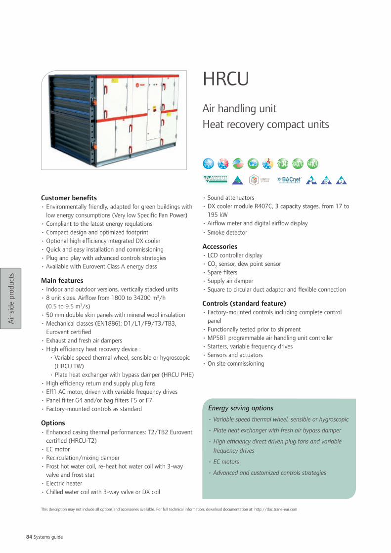
84 Systems guide
Air s
ide
prod
ucts
Customer benefits• Environmentally friendly, adapted for green buildings with
low energy consumptions (Very low Specific Fan Power)• Compliant to the latest energy regulations• Compact design and optimized footprint• Optional high efficiency integrated DX cooler• Quick and easy installation and commissioning• Plug and play with advanced controls strategies• Available with Eurovent Class A energy class
Main features• Indoor and outdoor versions, vertically stacked units• 8 unit sizes. Airflow from 1800 to 34200 m3/h
(0.5 to 9.5 m3/s)• 50 mm double skin panels with mineral wool insulation• Mechanical classes (EN1886): D1/L1/F9/T3/TB3,
Eurovent certified• Exhaust and fresh air dampers• High efficiency heat recovery device :
• Variable speed thermal wheel, sensible or hygroscopic (HRCU TW)
• Plate heat exchanger with bypass damper (HRCU PHE)• High efficiency return and supply plug fans• Eff1 AC motor, driven with variable frequency drives• Panel filter G4 and/or bag filters F5 or F7• Factory-mounted controls as standard
Options• Enhanced casing thermal performances: T2/TB2 Eurovent
certified (HRCU-T2)• EC motor• Recirculation/mixing damper• Frost hot water coil, re-heat hot water coil with 3-way
valve and frost stat• Electric heater • Chilled water coil with 3-way valve or DX coil
• Sound attenuators• DX cooler module R407C, 3 capacity stages, from 17 to
195 kW• Airflow meter and digital airflow display• Smoke detector
Accessories• LCD controller display• CO2 sensor, dew point sensor• Spare filters• Supply air damper• Square to circular duct adaptor and flexible connection
Controls (standard feature)• Factory-mounted controls including complete control
panel• Functionally tested prior to shipment• MP581 programmable air handling unit controller• Starters, variable frequency drives• Sensors and actuators• On site commissioning
HRCU Air handling unit Heat recovery compact units
Energy saving options
• Variable speed thermal wheel, sensible or hygroscopic
• Plate heat exchanger with fresh air bypass damper
• High efficiency direct driven plug fans and variable frequency drives
• EC motors
• Advanced and customized controls strategies
This description may not include all options and accessories available. For full technical information, download documentation at: http://doc.trane-eur.com

85
Air s
ide
prod
ucts
DX cooler module size 085 165 260 380 440 530 740 875Nominal cooling capacity (kW) 17.80 34.00 53.60 79.10 94.20 117.30 150.80 183.50Nominal air volume (m3/s) 0.85 1.65 2.60 3.80 4.40 5.50 7.40 8.75Nominal air volume (m3/h) 3060 5940 9360 13680 15840 19800 26640 31500Fresh air (°C/%) 28°C/50%Return air (°C/%) 24°C/50%Suction temperature (°C) 7°CCondensation temperature (°C) 52°CEER 3.08 3.14 3.28 3.44 3.51 3.31 3.28 3.30Number of circuit 1 1 1 1 1 1 1 1Number of cooling steps 3 3 3 3 3 3 3 3Cooling capacity step 1 (33%) (kW) 5.9 11.3 17.9 26.4 31.4 39.1 50.3 61.2Cooling capacity step 2 (66%) (kW) 11.9 22.7 35.7 52.7 62.8 78.2 100.5 122.3Cooling capacity step (100%) (kW) 17.80 34.00 53.60 79.10 94.20 117.30 150.80 183.50Power input (kW) 6.15 10.77 14.64 21.54 28.71 38.70 51.30 63.60Sound power level (compressors) (dB(A)) 70.70 74.70 77.70 78.70 79.70 84.70 87.70 89.70Module length (mm) 1220 1220 1220 1373 1373 1525 1525 1525Module width (mm) 1015 1320 1625 1930 2235 2235 2540 2998Module height (mm) 1095 1400 1705 2010 2010 2315 2640 2740Module weight (kg) 389 480 600 853 978 1149 1634 1842
The DX cooler is available with the evaporator on the lower part only. Not available with HRCU-PHE.
HRCU with plate heat exchanger 085 PHE
165 PHE
260 PHE
380 PHE
440 PHE
530 PHE
740 PHE
875 PHE
Nominal air volume (m3/s) 0.85 1.65 2.60 3.80 4.40 5.30 7.40 8.75Nominal air volume (m3/h) 3060 5940 9360 13680 15840 19080 26640 31500External static pressure return/supply (Pa) 200Length (mm) 2265 2875 3028 3485 3485 3943 4248 4248Width (mm) 1015 1320 1625 1930 2235 2235 2540 2998Height (mm) 1115 1420 1725 2080 2080 2385 2690 2690Weight (kg) 409 609 931 1329 1598 1961 2901 3397Return air winter (°C/%RH) 20°C/50%Fresh air winter (°C/%RH) -5°C/90%Sensible efficiency winter (%) 53.2 51.6 50.8 52.0 52.0 50.4 54.0 54.0Supply Air temperature winter (°C) 8.3 7.9 7.7 8.0 8.0 7.6 8.5 8.5Capacity recovery winter (kW) 13.7 25.6 39.7 59.5 69 80.6 120.5 142.7Return air summer (°C/%RH) 24°C/50%Fresh air summer (°C/%RH) 32°C/40%Sensible efficiency summer (%) 48.7 46.2 46.2 47.5 47.5 46.2 48.7 48.7Supply air temperature summer (°C) 28.1 28.3 28.3 28.2 28.2 28.3 28.1 28.1Capacity recovery summer (kW) 4.0 7.5 11.6 17.4 20.2 25.5 35.2 41.7Power input return air fan (kW) 0.77 1.81 2.75 4.41 4.84 5.13 7.25 9.53Power input supply air fan (kW) 0.81 1.87 2.86 4.54 5.01 5.27 7.53 9.89Total specific fan power (w/m3/s) 1859 2230 2158 2355 2239 1962 1997 2219Airborn sound pressure level @ 1m dB(A) 43 48 48 50 49 48 46 49Sound pressure level @ 1m inlet dB(A) 70 75 76 79 78 78 76 80Sound pressure level @ 1m outlet dB(A) 80 86 86 89 88 87 86 89Max airflow for SFP=1800 w/m3/s with 250 Pa ESP. including F5 & F7 filters frost coil. re-heat coil and 4 rows wet cooling coil (clean filters)
(m3/s) 0.75 1.35 2.10 3.00 3.60 4.80 6.60 7.10
Return air stream: F5 bag filter/plate heat exchanger/return plug fan with Eff1 motor/exhaust air damperSupply air stream: Fresh air damper/F7 bag filter/hygroscopic thermal wheel/supply plug fan with Eff1 motor
HRCU with thermal wheel 085 TW
165 TW
260 TW
380 TW
440 TW
530 TW
740 TW
875 TW
Nominal air volume (m3/s) 0.85 1.65 2.60 3.80 4.40 5.30 7.40 8.75Nominal air volume (m3/h) 3060 5940 9360 13680 15840 19080 26640 31500External static pressure return/supply (Pa) 200Length (mm) 2113 2570 2570 3028 3028 3333 3638 3638Width (mm) 1015 1320 1625 1930 2235 2235 2540 2998Height (mm) 1115 1420 1725 2080 2080 2385 2690 2690Weight (kg) 431 624 873 1246 1437 1699 2500 2756Return air winter (°C/%RH) 20°C/50%Fresh air winter (°C/%RH) -5°C/90%Sensible efficiency winter (%) 72.8 72.4 71.6 73.2 70.4 71.2 69.6 70.8Latent efficiency winter (%) 49.7 49 47.9 49.9 46.1 47.1 44.8 46.2Supply air temperature winter (°C) 13.2 13.1 12.9 13.3 12.6 12.8 12.4 12.7Total capacity recovery winter (kW) 26.7 51.5 80.0 119.7 132.8 161.7 219.7 264.2Return air summer (°C/%RH) 24°C/50%Fresh air summer (°C/%RH) 32°C/40%Sensible efficiency summer (%) 72.5 72.5 71.2 72.5 70.0 71.2 70.0 70.0Supply air summer (°C/%RH) 26.2/56 26.2/56 26.3/56 26.2/56 26.4/55 26.3/56 26.4/55 26.4/55Capacity recovery summer (kW) 6.2 11.89 18.55 27.6 30.91 37.56 51.34 61.5Power input return air fan (kW) 0.83 1.73 2.66 4.2 4.77 5.47 7.12 9.29Power input supply air fan (kW) 0.84 1.77 2.75 4.31 4.92 5.65 7.35 9.60Total specific fan power (w/m3/s) 1965 2121 2081 2239 2202 2098 1955 2159Airborn sound pressure level @ 1m (dB(A)) 44 48 48 51 50 49 46 49Sound pressure level @ 1m inlet (dB(A)) 71 76 77 80 79 79 77 80Sound pressure level @ 1m outlet (dB(A)) 81 85 86 89 88 88 86 89Max airflow for SFP=1800 w/m3/s with 250 Pa ESP. including F5 & F7 filters frost coil. re-heat coil and 4 rows wet cooling coil (clean filters)
(m3/s) 0.68 1.36 2.10 3.00 3.55 4.40 6.20 7.00
Return air stream: F5 bag filter/hygroscopic thermal wheel/return plug fan with Eff1 motor/exhaust air damperSupply air stream: Fresh air damper/F7 bag filter/hygroscopic thermal wheel/supply plug fan with Eff1 motor

86 Systems guide
Air s
ide
prod
ucts
Customer benefits• Extreme flexibility in construction and dimensions to fit
your exact requirements• Easy installation via modular construction and easy
module connection system• Low energy consumptions with high efficiency
components• Cleanable and enhanced casing design for higher indoor
air quality (CCTB)• Available with Eurovent Class A energy class
Main features CCTA • 30 standard unit sizes for airflow from 1000 to
140000 m3/h. Indoor and outdoor versions• Casing thermal performances: D1/L1/F9/T3/TB3
(Casing CCTA 50 mm PU) Eurovent certified• Strong casing framework manufactured with extruded
anti-corrosion aluminium profiles, fitted with nylon fibre glass stiffened angles
• Double sealing system to provide optimal casing air leakage
• Exclusive panel fixing system, with screwless panel-lock system, providing a neat external finishing
• 25 or 50 mm thick sandwich-type panels made of galvanised steel inside and white pre-painted steel outside
• Panel insulation made of CFC-free injected polyurethane foam
• Filters fitted on self compressive rail system• Coil mounted on rails for easy removal • Available components: panel and bag filters, HEPA filters,
activated carbon filters, auto-roll filter, FC/BI/Aerofoil centrifugal fans, plug fans, water coils, DX coil, electric, heaters, steam coils, condensing coils, air washers, steam humidifiers, evaporative humidifiers, atomizing
humidifiers, plate heat exchangers, thermal wheels, run around coils, silencers, mixing chambers, multi-zone sections
Main features CCTB• Same flexibility as CCTA range, with:• Aluminium frame work with integrated plastic thermal
break• 40 mm thick panels with integrated thermal break,
Polyurethane foam insulation• Enhanced casing thermal performances: D1/L1/F9/T2/
TB2 Eurovent certified • Smooth internal walls
Options• High density Rockwool insulation (80 kg/m3)• 60 mm thick panels (CCTB)• Inner / outer skins made of peraluman, stainless steel 304
or 316 metal sheet
Accessories• Inspection windows and wired lights• Manometers and pressure switches• Flexible connections, weather louvers, intake hoods, sand
trap louvers
Controls (available in certain countries only)• Factory-mounted controls including complete control
panel• Functionally tested prior to shipment• MP581 programmable air handling unit controller• Advanced and customized controls strategies• Starters, variable frequency drives• Sensors and actuators• On site commissioning
CCTA CCTBAir handling units
This description may not include all options and accessories available. For full technical information, download documentation at: http://doc.trane-eur.com

87
Air s
ide
prod
ucts
Airflow (m3/s) at coil face velocity (m/s)
Airflow (m3/h) at coil face velocity (m/s) Dimensions (mm) (1)
CCTA/CCTB 2.5 3.0 3.5 2.5 3.0 3.5 Width (2) HeightSingle fan air handling units
4 0.30 0.36 0.42 1080 1296 1512 690 5905 0.45 0.54 0.63 1620 1944 2268 790 6407 0.63 0.76 0.88 2268 2722 3175 890 6909 0.79 0.95 1.10 2835 3402 3969 1040 79012 1.08 1.30 1.51 3888 4666 5443 1090 89015 1.28 1.54 1.80 4617 5540 6464 1240 99018 1.55 1.86 2.17 5589 6707 7825 1440 99023 1.90 2.28 2.66 6831 8197 9563 1440 104025 2.15 2.57 3.00 7722 9266 10811 1590 114030 2.54 3.04 3.55 9126 10951 12776 1590 114035 3.04 3.65 4.25 10935 13122 15309 1640 134040 3.38 4.05 4.73 12150 14580 17010 1790 134044 3.71 4.46 5.20 13365 16038 18711 1990 134050 4.21 5.05 5.89 15147 18176 21206 1990 144055 4.59 5.51 6.43 16524 19829 23134 2140 144062 5.13 6.16 7.18 18468 22162 25855 2140 159074 6.27 7.52 8.78 22572 27086 31601 2580 163083 6.93 8.32 9.70 24948 29938 34927 2580 163090 7.56 9.07 10.58 27216 32659 38102 2780 1630105 8.80 10.56 12.32 31671 38005 44339 2930 1780115 9.72 11.66 13.61 34992 41990 48989 3080 1780121 10.50 12.60 14.70 37800 45360 52920 3080 1780135 11.34 13.61 15.88 40824 48989 57154 3530 1780146 12.35 14.82 17.29 44469 53363 62257 3430 1940173 14.40 17.28 20.16 51840 62208 72576 3580 2130187 15.75 18.90 22.05 56700 68040 79380 3880 2130211 17.76 21.31 24.86 63936 76723 89510 4080 2280243 20.40 24.48 28.56 73440 88128 102816 4630 2280280 23.51 28.22 32.92 84645 101574 118503 5130 2300333 27.80 33.35 38.91 100062 120074 140087 5830 2360
Double fan air handling units4 0.30 0.36 0.42 1080 1296 1512 790 5405 0.45 0.54 0.63 1620 1944 2268 890 5407 0.60 0.72 0.84 2160 2592 3024 1090 5909 0.77 0.92 1.07 2754 3305 3856 1140 64012 1.04 1.24 1.45 3726 4471 5216 1440 64015 1.26 1.51 1.76 4536 5443 6350 1490 69018 1.50 1.80 2.10 5400 6480 7560 1540 79023 1.89 2.27 2.65 6804 8165 9526 1690 84025 2.16 2.59 3.02 7776 9331 10886 1890 84030 2.55 3.06 3.57 9180 11016 12852 1990 89035 2.97 3.56 4.16 10692 12830 14969 2090 94040 3.42 4.10 4.79 12312 14774 17237 2190 99044 3.69 4.43 5.17 13284 15941 18598 2390 99050 4.29 5.15 6.01 15444 18533 21622 2540 104055 4.62 5.54 6.47 16632 19958 23285 2540 114062 5.18 6.21 7.25 18630 22356 26082 2640 119074 6.24 7.49 8.74 22464 26957 31450 2980 128083 6.96 8.35 9.74 25056 30067 35078 3280 128090 7.52 9.03 10.53 27081 32497 37913 3330 1380105 8.80 10.56 12.32 31671 38005 44339 3830 1380115 9.60 11.52 13.44 34560 41472 48384 3580 1530121 10.20 12.24 14.28 36720 44064 51408 3680 1530135 11.25 13.50 15.75 40500 48600 56700 4130 1530146 12.29 14.74 17.20 44226 53071 61916 4280 1580173 14.49 17.39 20.29 52164 62597 73030 4580 1730187 15.70 18.84 21.98 56511 67813 79115 4930 1730211 17.63 21.15 24.68 63450 76140 88830 5080 1830243 20.28 24.34 28.39 73008 87610 102211 5580 1880280 23.52 28.22 32.93 84672 101606 118541 5980 2030333 27.97 33.56 39.15 100683 120820 140956 6030 2330
(1) With 25 mm panels units until 062 size and 50 mm panels units for bigger units. Unit height does not include feet or continuous base frame. Height of feet or base frame is 150 mm. Overall cross dimensions can vary according to casing option and components.(2) The width of the units can be adjusted in steps of 50 mm to suit project specifications.
Energy saving options• High efficiency heat recovery devices
• Variable speed thermal wheel, sensible or hygroscopic
• Plate heat exchanger with fresh air bypass damper
• Run around coils
• High efficiency direct driven plug fans
• Eff1 AC motors
• Advanced controls strategies
• Variable frequency drives

88 Systems guide
Air s
ide
prod
ucts
Customer benefits• Easy on-site installation and assembly via modular
construction
• High casing thermal performances (50 mm panels with
thermal break): T2/TB2 according to EN 1886
Main features• Innovative closed box extruded aluminium section
framework, with reinforced nylon corners
• Eurovent-certified units in accordance with EN 1886- 25
mm panels: 2/A/F9/T3/TB3(F9: with back loading filter
frame)- 50 mm TB panels: 2A/B/F9/T2/TB2(F9: with
back loading filter frame)
• Modular 25 or 50 mm double skin panels insulated with
CFC-free polyurethane foam
• Casing panels are held firmly in place onto the framework
by the means of a self-locking wedge mechanism
• Outer skin with oven baked polyester powder painting
• Non-hydroscopic gasket compressed between the panels
and the framework
• 120 mm-high unit base frame
• Access panels are easily and quickly removed for
maintenance and cleaning
• 2-way sloping drain trays on all cooling coils and
humidifier sections
• Available sections: panel filters, bag filters, rigid bag filters,
activated carbon filters, absolute (HEPA) filters, cooling
and heating coils, electric heaters, silencers, forward-
curved fans, backward curved fans, run around coil loops,
plate heat exchangers, thermal wheels, steam humidifiers
Options• Unique integral thermal breaks, providing a cold bridge
free construction (available on 50 mm panel unit only)
• Hinged access doors mounted into a specially designed
double skinned insulated door frame
• Panel skin material: 0.4 mm standard with optional
0.89 mm-thick skins
• Delivery in sections using break points
Accessories• Manometers/magnehelic gauges
• Inspection windows
• Service light and switch
• Motors isolators
• Inverters
• Stainless steel drain pans
Controls (available in certain countries only)• Factory-mounted controls including complete control
panel
• Functionally tested prior to shipment
• MP581 programmable air handling unit controller
• Advanced and customized controls strategies
• Starters, variable frequency drives
• Sensors and actuators
• On site commissioning
CLCPAir handling unit
This description may not include all options and accessories available. For full technical information, download documentation at: http://doc.trane-eur.com

89
Air s
ide
prod
ucts
Airflow (m3/s) at coil face velocity (m/s)
Airflow (m3/h) at coil face velocity (m/s) Dimensions (mm) (1)
CLCP 2.0 2.55 3.0 2.0 2.55 3.0 Width Height (2)003 0.48 0.61 0.72 1722 2196 2584 748 868004 0.80 1.02 1.20 2880 3672 4320 1058 868006 1.14 1.45 1.71 4094 5220 6141 1368 868008 1.46 1.86 2.19 5252 6696 7878 1678 868010 1.80 2.30 2.71 6494 8280 9741 1368 1178012 2.32 2.96 3.48 8358 10656 12536 1678 1178014 2.84 3.62 4.26 10221 13032 15332 1988 1178016 3.18 4.05 4.76 11435 14580 17153 1678 1488020 3.90 4.97 5.85 14033 17892 21049 1988 1488025 4.84 6.17 7.26 17421 22212 26132 1988 1798030 5.80 7.40 8.71 20894 26640 31341 1988 2108035 6.86 8.75 10.29 24706 31500 37059 2298 2108040 7.94 10.12 11.91 28574 36432 42861 2608 2108045 9.00 11.48 13.51 32414 41328 48621 2918 2108050 10.08 12.85 15.12 36282 46260 54424 3228 2108060 11.90 15.17 17.85 42833 54612 64249 3228 2418065 13.16 16.78 19.74 47379 60408 71068 3538 2418070 14.42 18.39 21.64 51925 66204 77887 3848 2418080 15.70 20.02 23.55 56527 72072 84791 4158 2418085 16.96 21.62 25.44 61045 77832 91567 4468 2418090 18.22 23.23 27.33 65591 83628 98386 4778 2418095 19.56 24.94 29.34 70419 89784 105628 5088 2418
(1) With 50 mm panels. Unit sizes 003 up to and including size 050 also available with 25 mm panels. For 25 mm panels, remove 50 mm in the width and in the height.(2) Overall height includes 120 mm continuous base frame.

90 Systems guide
Air s
ide
prod
ucts
Customer benefits• High build quality and reliability, designed for the most
demanding applications
• High flexibility to provide customized solutions
• Clean concept construction, designed to meet highest
hygienic requirements
• Use the finest technologies available to provide the lowest
specific fan power and energy consumptions
• Quick and easy installation and maintenance
• Available with Eurovent Class A energy class
• Compliant to EN 15 053 and VDI 6022 certified (hygienic
requirements for hospitals)
Main features• Modular casing construction, Indoor and outdoor versions
• Vertically staked, in line, side by side, L-shaped
configuration
• 54 standard unit sizes. Airflows from 1000 to
140 000 m3/h (0.3 to 38 m3/s)
• Bigger unit sizes to cover airflows up to 200 000 m3/h
upon request
• 50 mm double skin panels with mineral wool insulation
• Inner skin: galvanised steel, outer skin: PVC coated, white
color
• High casing air leakage: Class C according to BS/DW144
& Eurovent 2/2 (0.42l/s/m² @ 2000 Pa)
• Mechanical classes (EN1886): D1/L1/F9/T3/TB3,
Eurovent certified
• Smooth internal walls, minimized dust traps, easy to clean.
• Available components: panel and bag filters, HEPA
filters, activated carbon filters, auto-roll filter, FC/BI/
aerofoil centrifugal fans, plug fans, water coils, DX coil,
electric, heaters, steam coils, condensing coils, air washers,
steam humidifiers, evaporative humidifiers, plate heat
exchangers, thermal wheels, run around coils, silencers,
mixing chambers, multi-zone sections
Options• Enhanced casing thermal performances: T2/TB2 Eurovent
certified (CCEB-T2)
• EC motor
• ATEX certified construction; group II, category 2 and 3
• Panel material: galvanized steel, PVC coating, Peraluman,
stainless steel
• All internal parts coated or made in stainless steel
• Flat packed/kit form delivery
• Inclined floor and anti-bacteriologic seals
• All components fitted on rails for easy removal
• Vertical units
Accessories• Inspection windows and wired lights
• Manometers and pressure switches
• Flexible connections, weather louvers, intake hoods,
sand trap louvers
• Motor lifting beam, adjustable legs
CCEBCustom air handling unit
This description may not include all options and accessories available. For full technical information, download documentation at: http://doc.trane-eur.com

91
Air s
ide
prod
ucts
Controls (available in certain countries only)• Factory-mounted controls including complete control
panel
• Functionally tested prior shipment
• MP581 programmable air handling unit controller
• Advanced and customized controls strategies
• Starters, variable frequency drives
• Sensors and actuators
• On site commissioning
Air volume (m3/s) at coil face velocity (m/s)
Air volume (m3/h) at coil face velocity (m/s) Overall width Overall height
CCEB 2.0 2.5 3.0 2.0 2.5 3.0 (mm) (mm)0.5 0.3 0.3 0.4 950 1188 1426 710 4350.75 0.4 0.5 0.6 1331 1663 1996 710 587.50.75F 0.4 0.5 0.7 1577 1971 2365 1015 4351 0.5 0.6 0.7 1711 2138 2566 710 7401F 0.6 0.8 0.9 2203 2754 3305 1320 4351.125 0.6 0.8 0.9 2208 2759 3311 1015 587.51.5 0.8 1.0 1.2 2838 3548 4257 1015 7401.5F 0.9 1.1 1.3 3084 3856 4627 1320 587.52 1.1 1.4 1.7 3966 4957 5949 1320 7402.25 1.2 1.5 1.8 4324 5405 6486 1015 10452.5 1.4 1.8 2.1 5093 6367 7640 1625 7403 1.7 2.1 2.6 6169 7711 9253 1320 10453.75 2.2 2.8 3.3 7923 9904 11884 1625 10454 2.3 2.9 3.4 8249 10311 12374 1320 13504.5 2.6 3.3 4.0 9495 11869 14243 1930 10455 3.0 3.7 4.5 10752 13441 16129 1625 13506 3.6 4.5 5.4 12887 16108 19330 1930 13506.25 3.7 4.6 5.6 13375 16718 20062 1625 16557 4.3 5.3 6.4 15390 19238 23085 2235 13507.5 4.6 5.7 6.9 16537 20671 24805 1930 16558 5.0 6.2 7.5 17893 22367 26840 2540 13708.75 5.4 6.8 8.1 19440 24300 29160 2235 16559 5.5 6.8 8.2 19669 24586 29503 1930 196010 6.3 7.8 9.4 22602 28253 33903 2540 167510.5 6.5 8.2 9.8 23490 29363 35235 2235 196011.25 7.2 8.9 10.7 25764 32206 38647 2845 167512 7.6 9.5 11.4 27311 34139 40967 2540 198012.25 7.7 9.6 11.5 27540 34425 41310 2235 226512.5 8.0 10.0 12.1 28927 36158 43390 3150 177513.5 8.6 10.8 13.0 31132 38915 46698 2845 198014 8.9 11.1 13.3 32020 40025 48030 2540 228515 9.7 12.1 14.6 34953 43691 52430 3150 208015.75 10.1 12.7 15.2 36500 45625 54750 2845 228516 10.1 12.6 15.1 36197 45247 54296 2540 259016.5 10.8 13.4 16.1 38712 48389 58067 3455 208017.5 11.4 14.2 17.1 40980 51224 61469 3150 238518 11.3 14.2 17.0 40794 50992 61191 2845 259018F 11.8 14.8 17.7 42595 53244 63893 3760 208019.25 12.6 15.8 18.9 45386 56732 68079 3455 238519.5 12.9 16.1 19.3 46354 57942 69530 4065 208020 12.7 15.9 19.1 45801 57251 68701 3150 269021 13.9 17.3 20.8 49939 62424 74909 3760 238522 14.1 17.6 21.1 50725 63407 76088 3455 269022.75 15.1 18.9 22.6 54346 67932 81518 4065 238524 15.5 19.4 23.3 55814 69768 83722 3760 269024.5 15.4 19.2 23.0 55296 69120 82944 4370 238526 16.9 21.1 25.3 60739 75924 91109 4065 269026.25 16.5 20.6 24.8 59443 74304 89165 4675 238528 18.2 22.8 27.4 65664 82080 98496 4370 269030 19.6 24.5 29.4 70589 88236 105883 4675 269031.5 20.2 25.2 30.2 72576 90720 108864 4370 299532 21.0 26.2 31.5 75514 94392 113270 4980 269033.75 21.7 27.1 32.5 78019 97524 117029 4675 299536 23.2 29.0 34.8 83462 104328 125194 4980 2995
Energy saving options • High efficiency heat recovery devices:
• Variable speed thermal wheel, sensible or
hygroscopic
• Plate heat exchanger with fresh air bypass damper
• Run around coils
• High efficiency direct driven plug fans
• Eff1 AC motors, EC motors
• Advanced controls strategies
• Variable frequency drives

92 Systems guide
Air s
ide
prod
ucts
Customer benefits• Silent operation: high level of acoustic comfort
• Low cost of ownership: low energy consumption
• Nice integration: easy to install and excellent appearance
Range descriptionFCC: Horizontal cabinet fan coil
FCK: Vertical concealed fan coil
FVC: Vertical cabinet fan coil
Main features• Efficient water exchanger
• Multi-speed efficient fan motor factory set from customer
request
• Shielded bar heater inserted into coil fin stack for efficient
airflow heat balance
• Cleanable EU3 filter
Options• Large choice of electric heater capacities per unit size
• Factory-mounted 2 and 3-way water valves with thermal
or modulating actuators
• High external static pressure available
• Right/left end water and control access sides
• Factory-mounted feet
• Epoxy coated aluminum fins
• Fresh air intake connection
Accessories• Auxiliary drain pan
• Condensate pump for vertical fan coils
• Flexible hose
• Wall-mounted thermostats delivered with each individual
unit
• 0-33% manual fresh air damper
Controls• Large choice of wall thermostats to cover all standalone
unit applications
• Factory-mounted LonMark™ Trane ZN523 controller
providing enhanced acoustical and thermal comfort
lowering the energy consumption for great efficiency
operation
• Integration to the Trane Building Management System via
ZN523
• Full range of user interfaces for ZN controller to fit all
customer needs for utilization of their installations and
equipments with ZSM-10 and ZSM-11
• Fuse protection with external access from the control box
FCC-FCK-FVCUniTrane™ fan coil water terminals
This description may not include all options and accessories available. For full technical information, download documentation at: http://doc.trane-eur.com
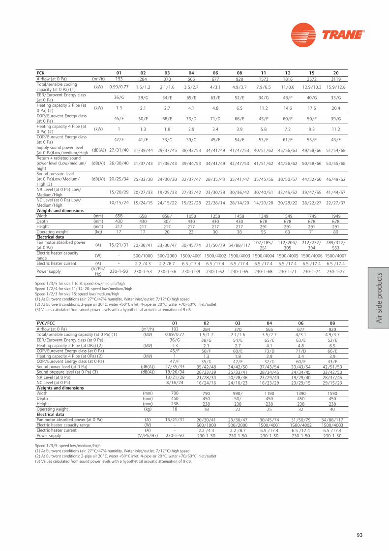
93
Air s
ide
prod
ucts
FCK 01 02 03 04 06 08 11 12 15 20Airflow (at 0 Pa) (m3/h) 193 284 370 565 677 920 1573 1816 2572 3119Total/sensible cooling capacity (at 0 Pa) (1) (kW) 0.99/0.77 1.5/1.2 2.1/1.6 3.5/2.7 4/3.1 4.9/3.7 7.9/6.5 11/8.6 12.9/10.3 15.9/12.8
EER/Eurovent Energy class (at 0 Pa) 36/G 38/G 54/E 65/E 63/E 52/E 34/G 48/F 40/G 33/G
Heating capacity 2 Pipe (at 0 Pa) (2) (kW) 1.3 2.1 2.7 4.1 4.8 6.5 11.2 14.6 17.5 20.4
COP/Eurovent Energy class (at 0 Pa) 45/F 50/F 68/E 73/D 71/D 66/E 45/F 60/E 50/F 39/G
Heating capacity 4 Pipe (at 0 Pa) (2) (kW) 1 1.3 1.8 2.9 3.4 3.9 5.8 7.2 9.3 11.2
COP/Eurovent Energy class (at 0 Pa) 47/F 41/F 33/G 39/G 45/F 54/E 53/E 61/E 55/E 43/F
Supply sound power level (at 0 Pa)Low/medium/High (dB(A)) 27/31/40 31/39/44 29/37/45 38/43/53 34/41/49 41/47/53 40/51/62 45/56/63 49/58/66 51/54/68
Return + radiated sound power level (Low/medium/high)
(dB(A)) 26/30/40 31/37/43 31/36/43 39/44/53 34/41/49 42/47/53 41/51/62 44/56/62 50/58/66 53/55/68
Sound pressure level (at 0 Pa)Low/Medium/High (3)
(dB(A)) 20/25/34 25/32/38 24/30/38 32/37/47 28/35/43 35/41/47 35/45/56 38/50/57 44/52/60 46/49/62
NR Level (at 0 Pa) Low/Medium/High 15/20/29 20/27/33 19/25/33 27/32/42 23/30/38 30/36/42 30/40/51 33/45/52 39/47/55 41/44/57
NC Level (at 0 Pa) Low/Medium/High 10/15/24 15/24/15 24/15/22 15/22/28 22/28/14 28/14/20 14/20/28 20/28/22 28/22/27 22/27/37
Weights and dimensionsWidth (mm) 658 658 858/ 1058 1258 1458 1349 1549 1749 1949Depth (mm) 430 430 30/ 430 430 430 678 678 678 678Height (mm) 217 217 217 217 217 217 291 291 291 291Operating weight (kg) 17 17 20 23 30 38 55 63 71 80Electrical dataFan motor absorbed power (at 0 Pa) (A) 15/21/31 20/30/41 23/30/47 30/45/74 31/50/79 54/88/117 107/185/
251112/204/
305212/272/
394289/322/
553Electric heater capacity range (W) - 500/1000 500/2000 1500/4001 1500/4002 1500/4003 1500/4004 1500/4005 1500/4006 1500/4007
Electric heater current (A) - 2.2 /4.3 2.2 /8.7 6.5 /17.4 6.5 /17.4 6.5 /17.4 6.5 /17.4 6.5 /17.4 6.5 /17.4 6.5 /17.4
Power supply (V/Ph/ Hz) 230-1-50 230-1-53 230-1-56 230-1-59 230-1-62 230-1-65 230-1-68 230-1-71 230-1-74 230-1-77
FVC/FCC 01 02 03 04 06 08Airflow (at 0 Pa) (m3/h) 193 284 370 565 677 920Total/sensible cooling capacity (at 0 Pa) (1) (kW) 0.99/0.77 1.5/1.2 2.1/1.6 3.5/2.7 4/3.1 4.9/3.7EER/Eurovent Energy class (at 0 Pa) 36/G 38/G 54/E 65/E 63/E 52/EHeating capacity 2 Pipe (at 0Pa) (2) (kW) 1.3 2.1 2.7 4.1 4.8 6.5COP/Eurovent Energy class (at 0 Pa) 45/F 50/F 68/E 73/D 71/D 66/EHeating capacity 4 Pipe (at 0Pa) (2) (kW) 1 1.3 1.8 2.9 3.4 3.9COP/Eurovent Energy class (at 0 Pa) 47/F 35/G 42/F 32/G 60/E 43/FSound power level (at 0 Pa) (dB(A)) 27/35/43 35/42/48 34/42/50 37/43/54 33/43/54 42/51/59Sound pressure level (at 0 Pa) (3) (dB(A)) 18/26/34 26/33/39 25/33/41 28/34/45 24/34/45 33/42/50NR Level (at 0 Pa) 13/21/29 21/28/34 20/28/36 23/29/40 19/29/40 28/37/45NC Level (at 0 Pa) 8/16/24 16/24/16 24/16/23 16/23/29 23/29/15 29/15/23Weights and dimensionsWidth (mm) 790 790 990/ 1190 1390 1590Depth (mm) 450 450 50/ 450 450 450Height (mm) 238 238 238 238 238 238Operating weight (kg) 18 18 22 25 32 40Electrical dataFan motor absorbed power (at 0 Pa) (A) 15/21/31 20/30/41 23/30/47 30/45/74 31/50/79 54/88/117Electric heater capacity range (W) - 500/1000 500/2000 1500/4001 1500/4002 1500/4003Electric heater current (A) - 2.2 /4.3 2.2 /8.7 6.5 /17.4 6.5 /17.4 6.5 /17.4Power supply (V/Ph/Hz) 230-1-50 230-1-50 230-1-50 230-1-50 230-1-50 230-1-50
Speed 1/3/5 for size 1 to 8: speed low/medium/highSpeed 1/2/4 for size 11; 12; 20: speed low/medium/highSpeed 1/2/3 for size 15: speed low/medium/high(1) At Eurovent conditions (air: 27°C/47% humidity, Water inlet/outlet: 7/12°C) high speed(2) At Eurovent conditions: 2-pipe air 20°C, water +50°C inlet; 4-pipe air 20°C, water +70/60°C inlet/outlet(3) Values calculated from sound power levels with a hypothetical acoustic attenuation of 9 dB.
Speed 1/3/5: speed low/medium/high(1) At Eurovent conditions (air: 27°C/47% humidity, Water inlet/outlet: 7/12°C) high speed(2) At Eurovent conditions: 2-pipe air 20°C, water +50°C inlet; 4-pipe air 20°C, water +70/60°C inlet/outlet(3) Values calculated from sound power levels with a hypothetical acoustic attenuation of 9 dB.
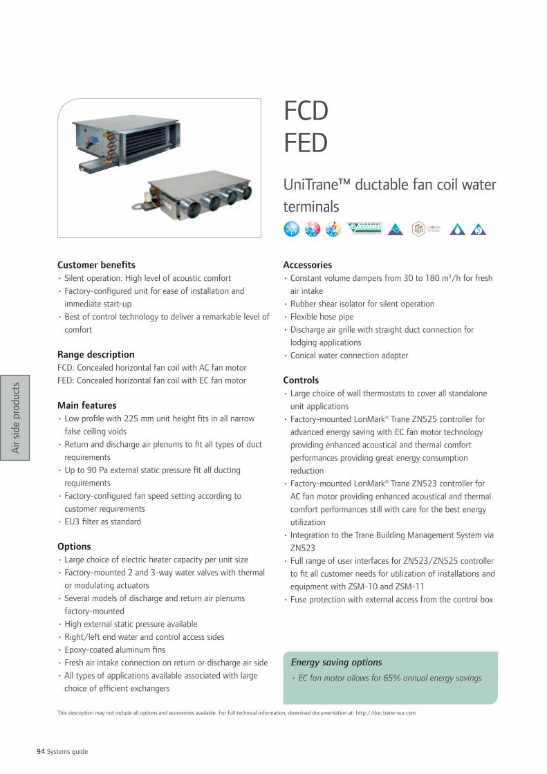
94 Systems guide
Air s
ide
prod
ucts
Customer benefits• Silent operation: High level of acoustic comfort• Factory-configured unit for ease of installation and
immediate start-up• Best of control technology to deliver a remarkable level of
comfort
Range descriptionFCD: Concealed horizontal fan coil with AC fan motorFED: Concealed horizontal fan coil with EC fan motor
Main features• Low profile with 225 mm unit height fits in all narrow
false ceiling voids• Return and discharge air plenums to fit all types of duct
requirements• Up to 90 Pa external static pressure fit all ducting
requirements• Factory-configured fan speed setting according to
customer requirements• EU3 filter as standard
Options• Large choice of electric heater capacity per unit size• Factory-mounted 2 and 3-way water valves with thermal
or modulating actuators • Several models of discharge and return air plenums
factory-mounted• High external static pressure available• Right/left end water and control access sides• Epoxy-coated aluminum fins• Fresh air intake connection on return or discharge air side• All types of applications available associated with large
choice of efficient exchangers
Accessories• Constant volume dampers from 30 to 180 m3/h for fresh
air intake• Rubber shear isolator for silent operation• Flexible hose pipe• Discharge air grille with straight duct connection for
lodging applications• Conical water connection adapter
Controls• Large choice of wall thermostats to cover all standalone
unit applications• Factory-mounted LonMark® Trane ZN525 controller for
advanced energy saving with EC fan motor technology providing enhanced acoustical and thermal comfort performances providing great energy consumption reduction
• Factory-mounted LonMark® Trane ZN523 controller for AC fan motor providing enhanced acoustical and thermal comfort performances still with care for the best energy utilization
• Integration to the Trane Building Management System via ZN523
• Full range of user interfaces for ZN523/ZN525 controller to fit all customer needs for utilization of installations and equipment with ZSM-10 and ZSM-11
• Fuse protection with external access from the control box
FCD FEDUniTrane™ ductable fan coil water terminals
This description may not include all options and accessories available. For full technical information, download documentation at: http://doc.trane-eur.com
Energy saving options
• EC fan motor allows for 65% annual energy savings

95
Air s
ide
prod
ucts
Speed 1/3/5: speed low/medium/high (1) At Eurovent conditions (air: 27°C/47% humidity, Water inlet/outlet: 7/12°C) high speed(2) At Eurovent conditions: 2-pipe air 20°C, water +50°C inlet; 4-pipe air 20°C, water +70/60°C inlet/outlet(3) Values calculated from sound power levels with a hypothetical acoustic attenuation of 9 dB.
Speed 1/3/5: speed low/medium/high (1) At Eurovent conditions (air: 27°C/47% humidity, Water inlet/outlet: 7/12°C) high speed(2) At Eurovent conditions: 2-pipe air 20°C, water +50°C inlet; 4-pipe air 20°C, water +70/60°C inlet/outlet(3) Values calculated from sound power levels with a hypothetical acoustic attenuation of 9 dB.
FCD 101 103 203 204 304 306 406 508 512 408 612 716 616 724
Airflow (at 0 Pa) (m3/h) 188 271 321 415 438 642 642 1110 1329 1004 1411 1880 1890 2491Airflow (at 50 Pa) (m3/h) 145 152 425 419 565 614 902 912 1233 1281 1973Total/sensible cooling capacity (at 0 Pa) (1) (kW) 1.3/0.97 1.7/1.3 1.6/1.3 1.9/1.6 2.8/2.1 3.7/2.8 4.1/3.1 4.9/3.8 5.5/4.4 5.5/4.3 8.8/6.6 10.5/7.9 10.6/8.2 12.9/10
EER/Eurovent Energy class (at 0 Pa) 50/F 53/E 45/F 45/F 53/E 58/E 65/E 50/F 33/G 58/E 49/F 49/F 51/E 39/GHeating capacity 2 Pipe (at 0 Pa) (1) (kW) 1.5 1.9 2.3 2.8 3.5 4.8 5.2 6.8 7.8 7.3 10.2 13.3 12.7 16.5COP/Eurovent Energy class (at 0 Pa) 55/E 59/E 66/E 63/E 67/E 75/D 78/D 64/E 45/F 72/D 54/E 61/E 58/E 49/FHeating capacity 4 Pipe (at 0 Pa) (1) (kW) 1.1 1.3 1.7 1.9 2.4 2.9 3.1 6 6.5 3.7 7.9 9.1 8.6 10COP/Eurovent Energy class (at 0 Pa) 57/E 48/F 60/E 59/E 70/E 52/E 55/E 66/E 42/F 43/F 50/F 47/F 45/F 33/G
Sound power level (at 0 Pa) (dB(A)) 28/32/ 42
40/47/ 54
41/47/ 54
39/49/ 56
38/47/ 53
43/53/ 59
46/55/ 61
45/56/ 61
52/59/ 64
45/54/ 60
50/58/ 63
53/59/ 64
60/63/ 65
60/65/ 69
Sound pressure level (at 0 Pa) (3) (dB(A)) 19/23/ 33
31/38/ 45
32/38/ 45
30/40/ 47
29/38/ 44
34/44/ 50
37/46/ 52
36/47/ 52
43/50/ 55
36/45/ 51
41/49/ 54
44/50/ 55
51/54/ 56
51/56/ 60
NR Level (at 0 Pa) 17/17/ 25
28/34/ 40
29/34/ 40
27/37/ 43
25/34/ 40
30/41/ 47
34/43/ 48
32/43/ 48
36/45/ 51
31/40/ 46
35/43/ 49
38/45/ 50
46/49/ 51
46/51/ 55
NC Level (at 0 Pa) 16/15/ 23
26/33/ 39
27/33/ 39
26/35/ 41
23/32/ 39
29/39/ 45
32/41/ 46
30/41/ 46
35/44/ 49
29/38/ 44
34/41/ 47
37/44/ 49
45/47/ 50
44/49/ 54
Total/sensible cooling capacity (at 50 Pa) (1) (kW) 0.81/
0.641.1/ 0.81
2.6/ 2
2.9/ 2.1
3.7/ 2.7
3.3/ 2.4
4.3/ 3.3
6.3/ 4.5
7.8/ 5.8
7.7/ 5.6
10.7/ 8.1
EER/Eurovent Energy class (at 50 Pa) 24/E 31/D 29/D 28/D 47/C 45/C 42/C 53/C 51/C 47/C 45/C
Heating capacity 2 Pipe (at 50 Pa) (1) (kW) 1.2 1.3 3.3 3.5 4.5 4.2 5.7 6.9 8.9 9.5 13.5
COP/Eurovent Energy class (at 50 Pa) 32/D 34/D 33/D 32/D 58/C 56/C 53/C 61/B 59/C 56/C 54/C
Heating capacity 4 Pipe (at 50 Pa) (1) (kW) 1.2 1.5 1.7 2.3 1.8 2.5 2 2.9 4.4 4.3 5.3
COP/Eurovent Energy class (at 50 Pa) 41/C 49/C 42/C 45/C 37/D 54/C 42/C 49/C 52/C 49/C 35/D
Supply sound power level (dB(A)) (speed 2/3/5) (dB(A)) 39/45/
4738/46/
4745/50/
5442/48/
5142/49/
5246/53/
5750/54/
5847/50/
5454/55/
5652/54/
5655/57/
58Return sound power level (dB(A)) (speed 2/3/5) (dB(A)) 42/48/
5043/49/
5147/52/
5545/50/
5340/47/
5151/56/
5953/56/
5950/53/
5656/57/
5959/61/
6357/58/
61Radiated sound power level (dB(A)) (speed 2/3/5) (dB(A)) 31/40/
4431/40/
4333/42/
4733/41/
4742/48/
5342/48/
5344/48/
5344/49/
5352/52/
5451/52/
5452/53/
54
NR Level (at 50 Pa., high speed) 31/40/ 44
31/40/ 43
33/42/ 47
33/41/ 47
42/48/ 53
42/48/ 53
44/48/ 53
44/49/ 53
52/52/ 54
51/52/ 54
52/53/ 54
NC Level (at 50 Pa., high speed) 20/25/ 27
18/25/ 27
24/31/ 34
24/31/ 34
22/30/ 34
27/33/ 36
31/34/ 37
27/30/ 33
34/35/ 36
37/39/ 40
35/37/ 39
Weights and dimensionsWidth (mm) 704 704 854 854 1084 1084 1234 1334 1334 1234 1634 1634 1634 1634Depth (mm) 558 558 558 558 558 558 558 704 704 558 704 796 704 796Height (mm) 225 225 225 225 225 225 225 225 225 225 225 225 225 277Operating weight (kg) 13 13 16 15 20 21 24 30 32 25 41 47 42 47Electrical data
Fan motor absorbed power (at 0 Pa) (A) 11/16/ 27
18/25/ 40
19/26/ 41
23/37/ 54
26/42/ 61
36/58/ 82
36/59/ 82
53/87/ 124
118/139/ 164
53/87/ 118
119/145/ 171
154/187/ 221
157/189/ 222
252/294/ 346
Fan motor absorbed power (at 50 Pa) (A) 21/42/
5024/47/
5636/73/
9036/73/
9052/100/
12052/101/
122105/131/
143105/132/
143128/147/
171130/151/
175224/272/
299
Electric heater capacity range (W) - 500 500/ 750
500/ 1000
500/ 1500
500/ 2000
500/ 2000
1500/ 3000
1500/ 4000
1500/ 4001
1500/ 4002
1500/ 4003
1500/ 4004
1500/ 4005
Electric heater current (A) - 2.2 2.2 /3.3 2.2 /4.3 2.2 /6.5 2.2 /8.7 2.2 /8.7 6.5 /13 6.5 /17.4 6.5 /17.4 6.5 /17.4 6.5 /17.4 6.5 /17.4 6.5 /17.4
Power supply (V/Ph/Hz) 230-1-50
FED 100 200 300 400
Airflow (at 0 Pa) (m3/h) 310 441 609 924Airflow (at 50 Pa) (m3/h) 145 152 425 419Total/sensible cooling capacity (at 0 Pa) (kW) 1.4/1.1 1.9/1.6 3.3/2.5 4.9/3.8EER/Eurovent Energy class (at 0 Pa) 186/B 185/B 174/B 191/BHeating capacity 2 Pipe (at 0Pa) (kW) 3.2 4.5 7.3 10.7COP/Eurovent Energy class (at 0 Pa) 393/A 189/B 301/A 436/AHeating capacity 4 Pipe (at 0Pa) (kW) 1.2 1.8 2.3 3.4COP/Eurovent Energy class (at 0 Pa) 195/B 221/B 164/B 164/BSound Power Level (at 0 Pa) (dB(A)) 32/41/49 35/45/53 37/52/61 43/53/60Sound Pressure Level (at 0 Pa) (dB(A)) 23/32/40 26/36/44 28/43/52 34/44/51NR Level (at 0 Pa) 21/28/36 22/31/40 24/38/49 33/40/47NC Level (at 0 Pa) 19/27/34 20/30/38 22/37/47 32/39/46Total/sensible cooling capacity (at 50 Pa) (kW) 0.81/0.64 1.1/0.81 2.6/2 2.9/2.1EER/Eurovent Energy class (at 50 Pa) 24/E 31/D 29/D 28/DHeating capacity 2 Pipe (at 50 Pa) (kW) 1.2 1.3 3.3 3.5COP/Eurovent Energy class (at 50 Pa) 32/D 34/D 33/D 32/DHeating capacity 4 Pipe (at 50 Pa) (kW) 1.2 1.5 1.7 2.3COP/Eurovent Energy class (at 50 Pa) 41/C 49/C 42/C 45/CSupply Sound Power Level (dB(A)) (speed 2/3/5) (dB(A)) 39/45/47 38/46/47 45/50/54 42/48/51Return Sound Power Level (dB(A)) (speed 2/3/5) (dB(A)) 42/48/50 43/49/51 47/52/55 45/50/53Radiated Sound Power Level (dB(A)) (speed 2/3/5) (dB(A)) 31/40/44 31/40/43 33/42/47 33/41/47NR Level (at 50 Pa, speed 3) 31/40/44 31/40/43 33/42/47 33/41/47NC Level (at 50 Pa, speed 3) 20/25/27 18/25/27 24/31/34 24/31/34Weights and dimensionsWidth (mm) 704 854 108 123Depth (mm) 558 558 /55 /55Height (mm) 225 225 225 225Operating weight (kg) 14 16 21 25Electrical dataFan motor absorbed power (at 0 Pa) (A) 3.3/5.8/12 3.7/8.7/19 4.8/18/43 8.9/23/54Fan motor absorbed power (at 50 Pa) (A) 21/42/50 24/47/56 36/73/90 36/73/90Electric heater capacity range (W) - 500 500/750 500/1000Electric heater current (A) - 2.2 2.2 /3.3 2.2 /4.3Power supply (V/Ph/Hz) 230-1-50 230-1-50 230-1-50 230-1-50

96 Systems guide
Air s
ide
prod
ucts
Customer benefits• Silent operation: maximum acoustic comfort
• Flexibility: customized system to fit your exact
requirements
• Easy commissioning: saving of time and money
• Easy maintenance due to side access to motors and coils
and maintenance done outside the occupied space
• Low energy consumption
Range descriptionFCU: U-line fan coil unit with AC fan motor
FEU: U-line fan coil unit with EC fan motor
Main features• Unit specially designed for office applications with corridor
installation
• Use of 1 mm thick galvanized steel
• High performance water coil (aluminium fins/copper
tubes)
• Hot and/or chilled water coil
• ½” water connections ISO R7 gas (screw connections)
• Multi-speed motor with internal thermal protection
• Use of plastic fan housings and large diameter wheels for
low sound levels
• Air inlet and outlet connections diameter 200 mm or
250 mm
• 50 Pa to 200 Pa static pressure available for ducts and
diffusers
• Electric and hydraulic connections accessible on the same
side to save space
Options• Several electric heater capacities per unit size
• Modulating and on/off 3-way/4-port or 2-way/2-port
valve for cooling and/or heating coils for better control
• Fresh air intake with fixed or adjustable controller
• Condensate pump
• Easily accessible and cleanable EU3 filter
• Right- or left-hand connections
• Fuse protection
• Spigot arrangement
• Factory-wired fan speeds combination according to
customer requirements
Accessories• Flexible hose connections
Controls• Large choice of wall thermostats to cover all standalone
unit applications
• Remote on/off controls on fan, valve and/or electric
heater
• Factory-mounted LonMark™ Trane ZN523 control,
providing enhanced acoustical and thermal comfort, and
energy saving solutions
• Full range of user interfaces (ZSM-10, ZSM-11) and
wireless remote control (IRC)
FCU FEUUniTrane™ ductable fan coil water terminals
This description may not include all options and accessories available. For full technical information, download documentation at: http://doc.trane-eur.com
Energy saving options
• EC fan motor allows for 80% annual energy savings

97
Air s
ide
prod
ucts
FCU 100 FEU 100Airflow (at 50 Pa) (m3/h) 378 335Total/sensible cooling capacity (at 50 Pa) (1) (kW) 2.9/2.1 2.4/1.7EER/Eurovent Energy class (at 50 Pa) 17/E 88/AHeating capacity 2 Pipe (at 50 Pa) (2) (kW) 3.6 3.1COP/Eurovent Energy class (at 50 Pa) 20/E 112/AHeating capacity 4 Pipe (at 50 Pa) (2) (kW) 2 2.5COP/Eurovent Energy class (at 50 Pa) 0.045/5.8 0.058/8.7Supply sound power level (speed 2/3/5) (dB(A)) 42/47/53 36/42/51Return sound power level (speed 2/3/5) (dB(A)) 39/45/51 34/40/48Radiated sound power level (speed 2/3/5) 42/48/53 36/42/51NR Level (at 50 Pa, high speed) 28 41.2NC Level (at 50 Pa, high speed) 26 20Weights and dimensions (operating)Width (mm) 1055 1055Depth (mm) 797 797Height (mm) 225 225Weight (kg) 31 31Electrical dataFan motor absorbed power (at 50 Pa) (A) 106/146/211 7.7/27/156Electric heater capacity range (W) 500/1500 500/1500Electric heater current (A) 2.2 /6.5 2.2 /6.5Power supply (V/Ph/Hz) 230-1-50 230-1-50
Speed 1/3/5: speed low/medium/high(1) At Eurovent conditions (air: 27°C/47% humidity, Water inlet/outlet: 7/12°C) high speed(2) At Eurovent conditions: 2-pipe air 20°C, water +50°C inlet; 4-pipe air 20°C, water +70/60°C inlet/outlet

98 Systems guide
Air s
ide
prod
ucts
Customer benefits• Wide capacity range with large static pressure capabilities
• Very easy installation of accessories on site
Main features• 3-speed direct drive centrifugal fan motor
• Reinforced aluminum foiled insulation
• Supporting brackets
• Access from the bottom to fan motor and filter
• Return air filter assembly on back or to the bottom side of
the unit
• Self-contained condensate tray include location for
centrifugal drain pump accessory
Options• Duct connections
• Additional heat processes
Accessories• Return and supply duct plenum with round spigots
• EU2 and EU4 return air filter box
• Electric heater box
• Hot water coil box
• 3-way motorized water valve for main coil and hot water
coil
• Centrifugal condensate pump
• Changeover thermostat for 2-pipe application
ControlsSuitable connection to all kinds of controls for standalone
applications with a large choice of wall thermostats, or to all
Building Management System controls including the Trane
Tracer™ LonTalk® ZN523 with ZSM-10 and ZSM-11 user
interfaces
FWDDuctable water terminal
This description may not include all options and accessories available. For full technical information, download documentation at: http://doc.trane-eur.com

99
Air s
ide
prod
ucts
FWD 8 12 20 30 45Airflow (at 50 Pa) (m3/h) 694 1467 2149 3025 5474Total/sensible cooling capacity (at 50 Pa) (1) (kW) 4.6/3.5 7.6/6.2 14.4/11 18.9/14.7 34.2/26.7EER 33 24 26 21 32Heating capacity (at 50 Pa) (2) (kW) 5.5 10.6 17.9 21.3 44.2COP 40 33 32 24 41Global sound power level (speed 1/2/3) (dB(A)) 57/63/65 58/65/72 64/72/76 66/72/78 73/76/79Weights and dimensionsWidth (mm) 890 109 129 129 129Depth (mm) 600 710 820 970 109Height (mm) 250 300 350 450 650Operating weight (kg) 32 46 61 76 118Electrical dataFan motor absorbed power (at 50 Pa) (A) 115/136/213 250/328/447 415/569/713 720/928/1196 902/1202/1570Electric heater capacity (W) 2/4 8 10 12 12Electric heater current (A) 2.9/5.8 11.5 14.4 17.3 17.3Power supply (V/Ph/Hz) 230-1-50 230-1-50 230-1-50 230-1-50 230-1-50
(1) At conditions (Air: 27°C/47% humidity, Water inlet/outlet: 7/12°C) medium speed (speed 2)(2) At conditions: 2-pipe air 20°C, water +50°C inlet

100 Systems guide
Air s
ide
prod
ucts
Customer benefits• Silent operation: high level of acoustic comfort
• 4-way air diffusion with excellent Coanda effect
• Factory-configured unit for ease of installation for
immediate start-up
• Best of control technology to deliver a remarkable level of
comfort
Range descriptionCWS: Cassette with AC fan motor
CWE: Cassette with EC fan motor
Main features• Low profile with 296 or 329 mm unit height fits in all
narrow false ceiling voids
• Standard AC or advanced EC fan motor technology
• 3 factory-set fan speeds
• Factory-mounted centrifugal drain pump
• Adjustable discharge louvers
• Fresh intake connections on three sides
• Discharge air connections on two sides
• Return air sensor with infrared remote or electronic user
interface controls
Options• Factory-mounted electric heater
• All type of applications available associated with large
choice of efficient exchangers
• Tracer LonTalk® controls with water valves and thermal or
modulating water valves
• Infrared remote control to be mounted on site
Accessories• On/off 2 and 3-way water valve with thermal actuators
• Fresh air spigots
Controls• Large choice of wall thermostats to cover all standalone
unit applications
• Factory-mounted LonMark® Trane ZN525 controller for
advanced energy saving with EC fan motor technology
providing enhanced acoustical and thermal comfort
performances providing great energy consumption
reduction
• Factory-mounted LonMark® Trane ZN523 controller for
AC fan motor providing enhanced acoustical and thermal
comfort performances still with care for the best energy
utilization
• Integration to the Trane Building Management System via
ZN523
• Full range of user interfaces for ZN523/ZN525 controller
to fit all customer needs for utilization of installations and
equipment with ZSM-10/ZSM-11
• Fuse protection with external access from the control box
with Trane Tracer Lontalk® ZN controllers
• Group control up to 20 units using Infrared remote
control or the wall-mounted user interface ETN/ECM with
ambient sensor
CWS CWE4-way cassette water terminals
This description may not include all options and accessories available. For full technical information, download documentation at: http://doc.trane-eur.com
Energy saving options
• EC fan motor allows for 60% annual energy savings

101
Air s
ide
prod
ucts
CWS 2 Pipe 00-2P 01-2P 02-2P 03-2P 04-2P 05-2P 06-2P
Airflow (m3/h) 610 520 710 880 1140 1500 1820Total/sensible cooling capacity (1) (kW) 1.98/1.64 2.68/2.04 4.33/3.18 5.02/3.74 6.16/4.59 9.51/6.94 11.1/8.25EER/Eurovent Energy class 49/E 72/D 82/C 78/D 114/C 114/C 102/CHeating capacity (2) (kW) 2.6 3.4 5.2 6.2 7.8 11.7 8.3COP/Eurovent Energy class 63/E 88/D 95/D 93/D 139/C 134/C 121/CSound power level (dB(A)) 49 45 53 59 48 53 58Sound pressure level (dB(A)) 40 36 44 50 39 44 49NR Level 24 24 30 34 27 26 34NC Level 22 22 28 33 26 25 32Weight and dimensionsLength (mm) 575 575 575 575 820 820 820Width (mm) 575 575 575 575 820 820 820Height (mm) 275 275 275 275 303 303 303 Operating weight (kg) 25 27 27 27 42 45 45Electrical dataFan motor absorbed power (W) 57 44 68 90 77 120 170Electric heater capacity (W) 0.75 1.5 2.5 2.5 3.0 3.0 3.0Electric heater current (A) 3.3 6.5 10.9 10.9 13.0 13.0 13.0Power supply (V/Ph/Hz) 230-1-50 230-1-50 230-1-50 230-1-50 230-1-50 230-1-50 230-1-50
CWE 2 Pipe 01-2P 02-2P 03-2P 04-2P 05-2P
Airflow (m3/h) 535 710 880 1165 1770Total/sensible cooling capacity (1) (kW) 2.75/2.09 4.33/3.18 5.02/3.74 6.33/4.72 10.75/7.94EER/Eurovent Energy class 308/A 319/A 221/A 347/A 293/AHeating capacity (2) (kW) 3.4 5.2 6.2 8.0 12.7COP/Eurovent Energy class 375/A 370/A 260/B 425/A 331/ASound power level (dB(A)) 47 54 60 48 57Sound pressure level (dB(A)) 38 38 38 38 38NR Level 22 27 34 22 30NC Level 21 25 32 21 28Weight and dimensionsLength (mm) 575 575 575 820 820Width (mm) 575 575 575 820 820Height (mm) 275 275 275 303 303 Operating weight (kg) 25 27 27 27 42Electrical dataFan motor absorbed power (W) 16 31 62 33 108Electric heater capacity (W) 1.5 2.5 2.5 3 3Electric heater current (A) 6.5 10.9 10.9 13 13Power supply (V/Ph/Hz) 230-1-50 230-1-50 230-1-50 230-1-50 230-1-50
CWS 4 Pipe 00-4P 01-4P 02-4P 03-4P 04-4P 05-4P 06-4P
Airflow (m3/h) 610 520 710 880 1140 1500 1820Total/sensible cooling capacity (1) (kW) 2.33/1.9 2.7/1.98 3.34/2.56 3.81/2.97 6.34/4.69 7.71/5.83 8.89/6.84EER/Eurovent Energy class 59/D 73/D 66/D 62/D 114/C 96/C 85/CHeating capacity (2) (kW) 401.0 464.0 574.0 655.0 1090.0 1326.0 6.8COP/Eurovent Energy class 76/D 95/D 86/D 81/D 163/B 137/C 122/CSound power level (dB(A)) 14.5 10.8 16.6 20.5 21.4 29.9 38.8Sound pressure level (dB(A)) 50 45 53 59 48 53 58NR Level 24 24 30 34 27 26 34NC Level 22 22 28 33 26 25 32Weight and dimensionsLength (mm) 575 575 575 575 820 820 820Width (mm) 575 575 575 575 820 820 820Height (mm) 275 275 275 275 303 303 303 Operating weight (kg) 25 27 27 27 42 45 45Electrical dataFan motor absorbed power (W) 41 36 44 50 39 44 49Electric heater capacity (W) 0.75 1.5 2.5 2.5 3.0 3.0 3.0Electric heater current (A) 3.3 6.5 10.9 10.9 13.0 13.0 13.0Power supply (V/Ph/Hz) 230-1-50 230-1-50 230-1-50 230-1-50 230-1-50 230-1-50 230-1-50
CWE 4 Pipe 01-4P 02-4P 03-4P 04-4P 05-4P
Airflow (m3/h) 476 676 779 1120 1697Total/sensible cooling capacity (1) (kW) 2.08/2.77 2.95/3.93 3.46/4.53 4.83/6.54 7.4/9.87EER/Eurovent Energy class 226/A 213/A 148/B 256/A 196/AHeating capacity (2) (kW) 311.0 288.0 326.0 805.0 818.0COP/Eurovent Energy class 406/A 273/A 182/A 507/A 280/ASound power level (dB(A)) 47 54 60 48 57Sound pressure level (dB(A)) 38 38 38 38 38NR Level 22 27 34 22 30NC Level 21 25 32 21 28Weight and dimensionsLength (mm) 575 575 575 820 820Width (mm) 575 575 575 820 820Height (mm) 275 275 275 303 303 Operating weight (kg) 25 27 27 27 42Electrical dataFan motor absorbed power (W) 16 31 62 33 108Electric heater capacity (W) 1.5 2.5 2.5 3 3Electric heater current (A) 6.5 10.9 10.9 13 13Power supply (V/Ph/Hz) 230-1-50 230-1-50 230-1-50 230-1-50 230-1-50
(1) At Eurovent conditions: 27/19°C return air temperatures and 7/12°C inet and outlet water temperatures(2) At Eurovent conditions: 2-pipe air 20°C, water +50°C inlet; 4-pipe air 20°C, water +70/60°C inlet/outlet

102 Systems guide
Air s
ide
prod
ucts
Customer benefits• Air distribution through perfect Coanda effect for a high
level of comfort
• Silent operation: high level of acoustic comfort
• Factory-configured unit controls for ease of installation
and immediate start up
• Best of control technology to deliver a remarkable level of
comfort
• Excellent air filtering with the louvered return air grill
design which frees up 100% of opening space to the filter
Main features• Low profile with 306 mm unit height fits in all narrowed
false ceiling voids
• Louvered linear return air grill with 45° pitch angle avoid
mix of supply and return air
• Supply air round dampers with 4 jaws sized to optimize
the air throw with perfect Coanda effect at all fan speed
• 3 fan speeds factory set, adjustable on site
• Fresh intake connections on two return air sides
Options• Raised plenum version increases the condensate gravity
drainage capability up to 160 mm
• G0 or EU3 filter factory-mounted
• 2 fan speeds factory set for perfect capacity and sound fit
to air-conditioning load
• Factory-mounted electric heater, drain pump, 2 and 3-way
water valves
• Factory-mounted controls for standalone, master/slave
and Building Management System applications
Accessories• Constant volume dampers from 30 to 180 m3/h
associated with Ø 99 or Ø124 mm spigot
• Auxiliary drain pan for left or right hand
• On/off 2 and 3-way water valve with thermal actuators
• Large selection of thermostats
Controls• Large choice of wall thermostats to cover all standalone
unit applications
• Up to 20 units group control with infrared or wall-
mounted thermostat interface
• Factory-mounted LonMark™ Trane ZN523 controller
for enhanced ambient temperature and sound comfort
minimizing energy consumption to be connected to the
Trane Building Management System
• Full range of user interfaces for ZN523 controller with
ZSM-10 and ZSM-11
• Fuse protection with external access from the control box
with Trane Tracer Lontalk® ZN523 controller
CFAS1-way cassette water terminal
This description may not include all options and accessories available. For full technical information, download documentation at: http://doc.trane-eur.com

103
Air s
ide
prod
ucts
CFAS High Efficiency 2 Pipe 16 26 36Low Medium High Low Medium High Low Medium High
Airflow (m3/h) 180 245 280 230 360 445 335 505 600Total/sensible cooling capacity (1) (kW) 1.2/0.9 1.5/1.2 1.7/1.3 1.7/1.2 2.6/1.9 3.1/2.3 2.5 /1.8 3.5/2.6 4.0/3.0EER/Eurovent Energy class 55/D 61/D 53/EHeating capacity (2) (kW) 1.4 1.9 2.1 2.0 3.1 3.8 2.9 4.2 4.8COP/Eurovent Energy class 65/E 72/D 62/ESound power level (dB(A)) 41 49 52 36 48 48 41 52 55Sound pressure level (dB(A)) 32 40 43 27 39 39 32 43 46NR Level (medium speed) 34 33 37NC Level (medium speed) 33 31 35Weights and dimensionsLength (mm) 592 970 1192Width (mm) 309 309 309Height (mm) 592 592 592Operating weight (kg) 18 35 45Electrical dataFan motor absorbed power (A) 49 57 78Electric heater capacity (W) 0.55 0.9 1.4Electric heater current (A) 2.4 3.9 6.1Power supply (V/Ph/Hz) 230-1-50 230-1-50 230-1-50
CFAS Standard Efiiciency 4 Pipe 16 26 36Low Medium High Low Medium High Low Medium High
Airflow (m3/h) 180 245 280 230 360 445 335 505 600Total/sensible cooling capacity (1) (kW) 1.0/0.8 1.3/1.0 1.5/1.18 1.6/1.1 2.4/1.7 2.81/2.13 2.4/1.7 3.4/2.5 3.7/2.8EER/Eurovent Energy class 55/D 61/D 53/EHeating capacity (2) (kW) 1.1 1.3 1.5 1.7 2.3 2.7 2.5 3.3 3.6COP/Eurovent Energy class 65/E 72/D 62/ESound power level (dB(A)) 41 49 52 36 48 57 41 52 52Sound pressure level (dB(A)) 32 40 43 27 39 54 32 43 43NR Level 40 39 43NC Level 34 33 37Weights and dimensionsLength (mm) 593 971 1193Width (mm) 366 366 366Height (mm) 592 592 592Operating weight (kg) 3.6 2.6 5.1Electrical dataFan motor absorbed power (A) 49 57 78Electric heater capacity (W) 0.55 0.9 1.4Electric heater current (A) 2.4 3.9 6.1
Power supply (V/Ph/Hz) 230-1-50 230-1-50 230-1-50
(1) At Eurovent conditions 7/12°C water 27°/19°C air (50% RH)(2) At Eurovent conditions: 2-pipe air 20°C, water +50°C inlet; 4-pipe air 20°C, water +70/60°C inlet/outlet

104 Systems guide
Air s
ide
prod
ucts
Customer benefits• Attractive cabinet models or concealed types for wall,
ceiling and floor installations
• Silent operation: good acoustic comfort
• Flexibility: customized system to fit your exact
requirements
• Easy commissioning: saving of time and money
• Low height, which means no difficulty in fitting tight
ceiling applications
Range descriptionHFCE: Horizontal concealed fan coil
HFXE: Horizontal exposed fan coil
VFCE: Vertical concealed fan coil
VFXE: Vertical exposed fan coil
Main features• Low noise permanent split capacitor motor with
permanently lubricated sealed sleeve bearings
• Metal fan wheel both statically and dynamically balanced
• Threaded connection, match up duct collars and keyholes
for hangers shorten installation time
• One unit provides total comfort requirements: both
cooling and heating
Options• Left-hand or right-hand connections
• Heating by hot water coil or electric sheathed element
• Back or bottom return air plenum- adapts to a variety of
return air direction
• Nylon or aluminum filters
• Stainless steel drain pan - no seams or joints for maximum
security from leaks
Controls• Control valve package- valve, controller, thermostat and
zone sensor to meet individual site requirements
HFCE/HFXE VFCE/VFXEFan coil water terminals
This description may not include all options and accessories available. For full technical information, download documentation at: http://doc.trane-eur.com

105
Air s
ide
prod
ucts
(1) At conditions 7/12°C water 27°/19°C air (50% RH)(2) At Eurovent conditions: 2-pipe air 20°C, water +50°C inlet; 4-pipe air 20°C, water +70/60°C inlet/outlet
HFCE/HFXE/VFCE/VFXE 03 04 06 08
Low Medium High Low Medium High Low Medium High Low Medium HighAirflow (at 0 Pa) (m3/h) 300 350 400 443 530 640 620 765 870 810 970 1080Total/sensible cooling capacity (at 0 Pa) (1) (kW) 1.9/1.4 2.2/1.6 2.4/1.8 2.9/1.2 3.3/2.5 3.8/2.9 4.1/3.0 4.8/3.5 5.2/3.9 4.6/3.6 5.3/4.2 5.8/4.6Heating capacity (at 0Pa) (2) (kW) 4.7 5.4 6.0 7.1 8.1 9.5 9.7 11.4 12.7 12.4 14.3 15.5Sound power level (dB(A)) 45 42 50 44 47 50 47 51 52 51 54 57Sound pressure level (dB(A)) 36 39 41 35 38 41 38 42 43 42 45 48NR Level (medium speed) 33 32 36 39NC Level (medium speed) 31 30 34 37Weights and dimensionsLength (mm) 680 930 1065 1350Width (mm) 595 595 595 595Height (mm) 265 265 265 265Operating weight (kg) 23 30 33 41Electrical dataFan motor absorbed power (medium speed) (A) 30 36 59 72Electric heater capacity (W) 1000 1400 1800 2800Electric heater current (A) 4.3 6.1 7.8 12.2Power supply (V/Ph/Hz) 230-1-50/230-1-60 230-1-50/230-1-60 230-1-50/230-1-60 230-1-50/230-1-60
HFCE/HFXE/VFCE/VFXE 10 12 16 20
Low Medium High Low Medium High Low Medium High Low Medium HighAirflow (at 0 Pa) (m3/h) 950 1120 1260 1150 1380 1560 2770 2960 3100 3100 3300 3480Total/sensible cooling capacity (at 0 Pa) (1) (kW) 5.7/4.4 6.5/5.0 7.2/5.5 7.4/5.5 8.5/6.4 9.2/7.0 13.5/10.7 14.0/11.2 14.4/11.6 15.7/12.3 16.3/12.9 16.8/13.3Heating capacity (at 0Pa) (2) (kW) 14.6 16.6 18.3 17.8 20.7 22.7 34.7 36.3 37.4 39.7 41.4 43.0Sound power level (dB(A)) 49 52 56 52 54 58 74 76 77 76 78 79Sound pressure level (dB(A)) 40 43 47 43 45 49 65 67 68 67 69 70NR Level (medium speed) 37 39 61 63NC Level (medium speed) 35 37 59 61Weights and dimensionsLength (mm) 1520 1770 1090 1245Width (mm) 595 595 595 595Height (mm) 265 265 395 395Operating weight (kg)Electrical dataFan motor absorbed power (medium speed) (A) 85 104 560 655Electric heater capacity (W) 3200 4000 6000/2000 6000/2000Electric heater current (A) 13.9 17.4 26.1/8.7 26.1/8.7Power supply (V/Ph/Hz) 230-1-50/230-1-60 230-1-50/230-1-60 230-1-50/230-1-60 230-1-50/230-1-60
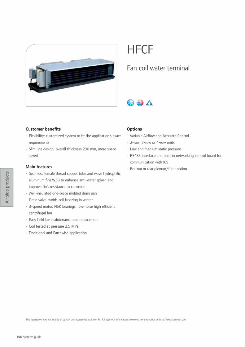
106 Systems guide
Air s
ide
prod
ucts
Customer benefits• Flexibility: customized system to fit the application’s exact
requirements
• Slim line design, overall thickness 230 mm, more space
saved
Main features• Seamless female thread copper tube and wave hydrophilic
aluminum fins W3B to enhance anti-water splash and
improve fin’s resistance to corrosion
• Well-insulated one-piece molded drain pan
• Drain valve avoids coil freezing in winter
• 3-speed motor, NSK bearings, low-noise high efficient
centrifugal fan
• Easy field fan maintenance and replacement
• Coil tested at pressure 2.5 MPa
• Traditional and Earthwise application
Options• Variable Airflow and Accurate Control
• 2-row, 3-row or 4-row units
• Low and medium static pressure
• RS485 interface and built-in networking control board for
communication with ICS
• Bottom or rear plenum/filter option
HFCFFan coil water terminal
This description may not include all options and accessories available. For full technical information, download documentation at: http://doc.trane-eur.com
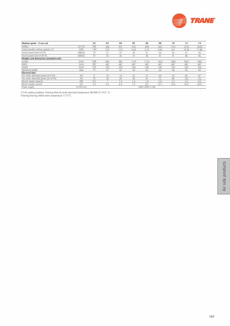
107
Air s
ide
prod
ucts
(1) At cooling condition: Entering flow dry bulb/wet bulb temperature DB/WB 27/19.5 °C; Entering/leaving chilled water temperature 7/12°C
Medium speed - 4 row coil 02 03 04 05 06 08 10 12 14Airflow (m3/h) 240 340 451 610 649 920 1141 1510 1620Total/sensible cooling capacity (1) (kW) 1.84 2.91 3.52 4.64 5.23 6.64 8.4 10.39 11.88Sound power level at 0 Pa (dB(A)) 25 21 27 34 31 36 35 41 43Sound power level at 60 Pa (dB(A)) 35 33 35 37 38 41 41 46 46Weights and dimensions (standard unit)Length (mm) 648 883 983 1103 1153 1433 1683 1853 1983Width (mm) 487 487 487 487 487 487 487 487 487Height (mm) 230 230 230 230 230 230 230 230 230Operating weight (kg) 15 21 22 24 25 33 38 42 44Electrical dataFan motor absorbed power (at 0 Pa) (A) 9 10 19 25 27 49 54 85 97Fan motor absorbed power (at 50 Pa) (A) 26 30 29 38 47 72 86 120 132Electric heater capacity (W) 0.5 1 1.4 1.6 1.8 2.8 3.2 3.6 4.6Electric heater current (A) 2.3 4.5 6.4 7.3 8.2 12.7 14.5 16.4 20.9Power supply (V/Ph/Hz) 220V-240V/1/60

108 Systems guide
Air s
ide
prod
ucts
Customer benefits• Air distribution though perfect Coanda effect for a high
level of comfort
• High level of Indoor Air Quality with a large amount of
fresh brought by the primary air
• Silent operation without fan noise emissions
• Long maintenance intervals without filter to clean and
moving parts
Main features• Low profile integrate easily in narrowed ceiling voids
• Perfect fit to all ceiling tile structures
• Primary air connections on both unit sides
• Plugged unused primary air connections from factory,
adjustable on site
Options• Shielded factory-mounted electric heater with double
safety devices
• 2 and 3-way water valves factory-mounted
• Primary air connection available on end side
• Suitable for T bar and fine line ceiling tiles
• Left or right-hand configurations
Controls• Factory-mounted and configured control with Tracer
LonTalk® ZN523
• Condensation free control module
• Master/slave beam control offering for price efficiency
BACActive chilled beams
This description may not include all options and accessories available. For full technical information, download documentation at: http://doc.trane-eur.com
Energy savings
• Efficient operation without electrical power consumption

109
Air s
ide
prod
ucts
BAC 980 1270 1570 2170 2770Minimum primary airflow (m3/h) 20 25 30 50 60Primary air pressure loss* (Pa) 64/36 61/34 53/29 75/46 73/43Maximum primary airflow (m3/h) 80 100 130 180 210Primary air pressure loss* (Pa) 204/111 162/90 184/101 187/103 146/80Minimum capacity (1) (W) 220 245 242 514 619Water flow/pressure loss (l/h / kPa) 90/0.9 80/0.8 70/0.6 200/6.7 180/6.8Maximum capacity (2) (W) 978 1084 1246 1833 1958Water flow/pressure loss (l/h / kPa) 150/2.1 140/1.9 130/2.1 300/13.4 320/17.7Minimum heating capacity (3) (W) 517 537 563 967 1020Maximum heating capacity (3) (W) 1531 1689 1875 2870 3209Electric heater capacity (W) 750 980 1200 1500 1960Weights and dimensionsWidth T bar (mm) 300/600Width fine line (mm) 625/675Casing length T Bar (mm) 1200 1500 1800/2100 2400/2700 3000/3300/3600Casing length fine line (mm) 1250/1350 1875/2025 2500/2700 3125/3375Coil active length (mm) 980 1270 1570 2170 2770Weight (kg) 20 27 37 46 56Sound power level mini (LwA) 29 26 26 27 29Sound power level max (LwA) 44 44 51 49 49NR level mini (4) (dB(A)) 16 16 16 17 16NR level max (5) (dB(A)) 26 26 32 29 32NC level mini (4) (dB(A)) 14 14 14 15 14NC level max (5) (dB(A)) 24 24 30 27 30
* Pitch 20 mm / pitch 15 mm(1) Primary air versus return air temperature delta T 8°C and Return air versus mean water temperature delta T of 8.5°C(2) Primary air versus return air temperature delta T 10°C and Return air versus mean water temperature delta T of 11°C(3) Water heating capacity only, positive or negative impact of primary air not added(4) Given for minimum primary airflow and maximum pressure drop(5) Given for Maximum primary airflow and minimum pressure drop

110 Systems guide
Air s
ide
prod
ucts
Customer benefits
• Optimal building occupant comfort
• Highly flexible range for easy adaptation to building
evolutions
• High performance
• Low energy consumption
Range description
VCCF: Single duct cooling-only
VCWF: Single duct with hot water coil
VCEF: Single duct with electric heater
VCDF: Dual duct
VPCF: Parallel fan powered cooling-only
VPWF: Parallel fan powered with hot water coil
VPEF: Parallel fan powered with electric heater
VSCF: Series fan powered cooling-only
VSWF: Series fan powered with hot water coil
VSEF: Series fan powered with electric heater
LPCF: Low height parallel fan powered cooling-only
LPWF: Low height parallel fan powered with hot water coil
LPEF: Low height parallel fan powered with electric heater
LSCF: Low height series fan powered cooling-only
LSWF: Low height series fan powered with hot water coil
LSEF: Low height series fan powered with electric heater
Main features
• Capable of varying the amount of air in an unlimited
number of zones
• 0 to 3.8 m3/s
• Simple and rugged design
• Interlocking panel design
• Metal encapsulated edges
• Low height units
• Proven flow ring
• Linear flow response in controller logic
Options
• Series or parallel terminal fan
• Hot water coil
• Electric terminal reheat
• Foil face insulation
• Double-wall insulation
• Choice of factory-mounted controls
• Outlet plenum
Controls• UCM-DDC controller, pressure independent
• VV550-Lonmark® DDC controller, pressure independent
VariTrane™ Variable air volume systems
This description may not include all options and accessories available. For full technical information, download documentation at: http://doc.trane-eur.com
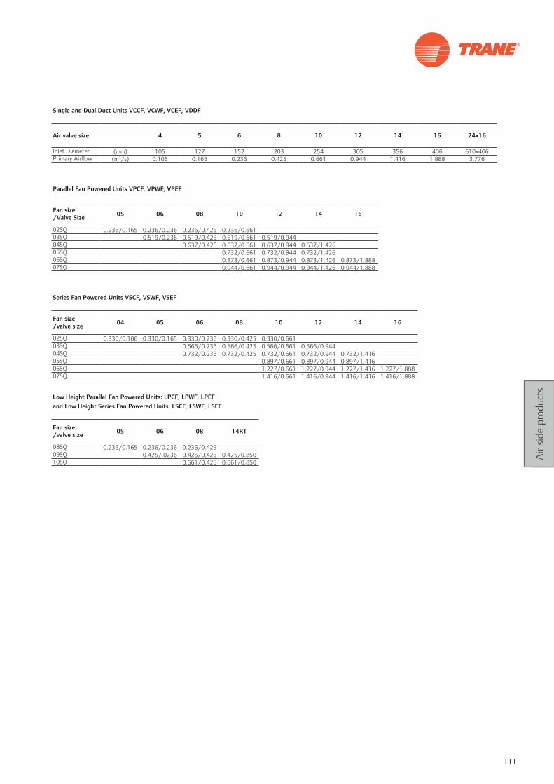
111
Air s
ide
prod
ucts
Single and Dual Duct Units VCCF, VCWF, VCEF, VDDF
Air valve size 4 5 6 8 10 12 14 16 24x16
Inlet Diameter (mm) 105 127 152 203 254 305 356 406 610x406Primary Airflow (m3/s) 0.106 0.165 0.236 0.425 0.661 0.944 1.416 1.888 3.776
Parallel Fan Powered Units VPCF, VPWF, VPEF
Fan size /Valve Size 05 06 08 10 12 14 16
02SQ 0.236/0.165 0.236/0.236 0.236/0.425 0.236/0.66103SQ 0.519/0.236 0.519/0.425 0.519/0.661 0.519/0.94404SQ 0.637/0.425 0.637/0.661 0.637/0.944 0.637/1.42605SQ 0.732/0.661 0.732/0.944 0.732/1.42606SQ 0.873/0.661 0.873/0.944 0.873/1.426 0.873/1.88807SQ 0.944/0.661 0.944/0.944 0.944/1.426 0.944/1.888
Series Fan Powered Units VSCF, VSWF, VSEF
Fan size /valve size 04 05 06 08 10 12 14 16
02SQ 0.330/0.106 0.330/0.165 0.330/0.236 0.330/0.425 0.330/0.66103SQ 0.566/0.236 0.566/0.425 0.566/0.661 0.566/0.94404SQ 0.732/0.236 0.732/0.425 0.732/0.661 0.732/0.944 0.732/1.41605SQ 0.897/0.661 0.897/0.944 0.897/1.41606SQ 1.227/0.661 1.227/0.944 1.227/1.416 1.227/1.88807SQ 1.416/0.661 1.416/0.944 1.416/1.416 1.416/1.888
Low Height Parallel Fan Powered Units: LPCF, LPWF, LPEF and Low Height Series Fan Powered Units: LSCF, LSWF, LSEF
Fan size /valve size 05 06 08 14RT
08SQ 0.236/0.165 0.236/0.236 0.236/0.42509SQ 0.425/.0236 0.425/0.425 0.425/0.85010SQ 0.661/0.425 0.661/0.850

112 Systems guide
Air s
ide
prod
ucts
Customer benefits• Deliver conditioned air using the Coanda effect: no drafts,
no cold spots and no discomfort
• Blend into room’s décor
• Flexible range: for supply and exhaust applications,
heating and cooling modes, constant or variable air
volume
• Easy installation: saving of time
• Low sound levels: unmatched in the market place
• Easy integration: saving of space
Main features• Adjustable vane slots on supply diffusers
• Compatible with most ceiling styles including T-bar,
plasterboard and fine line
• Available in sizes ranging from 600 to 1800 mm
• Can be linked end-to-end to make a single diffusion line
• Hanging brackets
• Extruded aluminum profiles with an epoxy paint finish
RAL 9010 (50% brilliance)
• Available with one to four slots to ensure a perfect match
with occupancy and room design
• ø160, 200 or 250 mm air inlet connections
Options• Optional patented airflow adjustment system: an easily
adjustable damper and integrated airflow measurement
system
• Optional push-pull opening system
• Integrated G2, G3 or G4 filters on return diffusers
• Acoustic insulation, balancing damper, flow meter,
DLEALinear slot diffusers
Unit model and type Number of slots Length (1) Airflow Minimum throw Maximum throw Pressure drop (2)
(mm) (m3/h) (m) (m) (Pa)DLEA Supply 2 900 306 1.4 4.6 21DLEA Supply 3 900 408 1.6 5.3 17DLEA Supply 4 900 560 2.2 6.1 18DLEA Return 1 900 200 25DLEA Return 2 900 300 17DLEA Return 3 900 400 20DLEA Return 4 900 600 21DLEA Supply 2 1200 408 1.8 5.8 21DLEA Supply 3 1200 544 2.0 6.7 17DLEA Supply 4 1200 748 2.8 7.7 18DLEA Return 1 1200 200 19DLEA Return 2 1200 400 18DLEA Return 3 1200 400 17DLEA Return 4 1200 600 15DLEA Supply 2 1800 612 2.3 7.3 21DLEA Supply 3 1800 815 2.6 8.6 17DLEA Supply 4 1800 1121 3.5 9.8 18DLEA Return 1 1800 400 18DLEA Return 2 1800 600 14DLEA Return 3 1800 700 17DLEA Return 4 1800 1000 15
(1) Other lengths available(2) Pressure drop of diffuser and plenum without filter
This description may not include all options and accessories available. For full technical information, download documentation at: http://doc.trane-eur.com
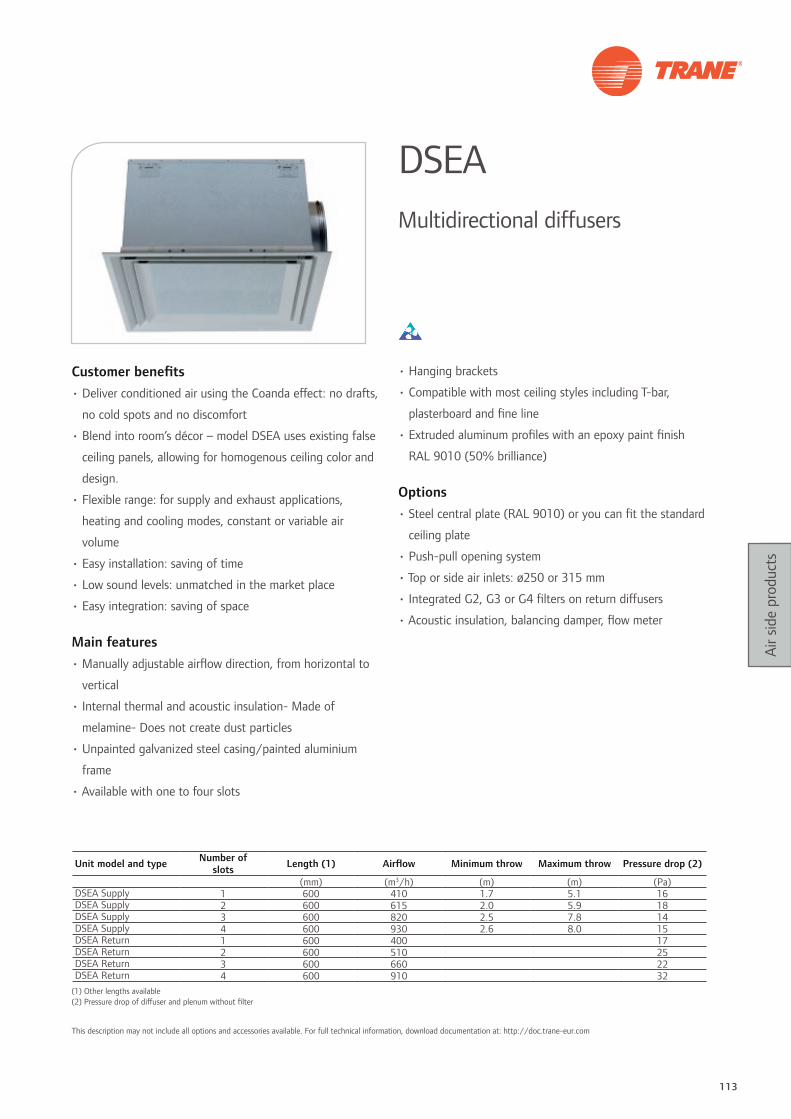
113
Air s
ide
prod
ucts
Customer benefits• Deliver conditioned air using the Coanda effect: no drafts,
no cold spots and no discomfort
• Blend into room’s décor – model DSEA uses existing false
ceiling panels, allowing for homogenous ceiling color and
design.
• Flexible range: for supply and exhaust applications,
heating and cooling modes, constant or variable air
volume
• Easy installation: saving of time
• Low sound levels: unmatched in the market place
• Easy integration: saving of space
Main features• Manually adjustable airflow direction, from horizontal to
vertical
• Internal thermal and acoustic insulation- Made of
melamine- Does not create dust particles
• Unpainted galvanized steel casing/painted aluminium
frame
• Available with one to four slots
• Hanging brackets
• Compatible with most ceiling styles including T-bar,
plasterboard and fine line
• Extruded aluminum profiles with an epoxy paint finish
RAL 9010 (50% brilliance)
Options• Steel central plate (RAL 9010) or you can fit the standard
ceiling plate
• Push-pull opening system
• Top or side air inlets: ø250 or 315 mm
• Integrated G2, G3 or G4 filters on return diffusers
• Acoustic insulation, balancing damper, flow meter
DSEAMultidirectional diffusers
Unit model and type Number of slots Length (1) Airflow Minimum throw Maximum throw Pressure drop (2)
(mm) (m3/h) (m) (m) (Pa)DSEA Supply 1 600 410 1.7 5.1 16DSEA Supply 2 600 615 2.0 5.9 18DSEA Supply 3 600 820 2.5 7.8 14DSEA Supply 4 600 930 2.6 8.0 15DSEA Return 1 600 400 17DSEA Return 2 600 510 25DSEA Return 3 600 660 22DSEA Return 4 600 910 32
(1) Other lengths available(2) Pressure drop of diffuser and plenum without filter
This description may not include all options and accessories available. For full technical information, download documentation at: http://doc.trane-eur.com

Notes
114 Systems guide

115115
DX unitary systems Unitary systems combine heating, cooling, and fan sections all in one or a few assemblies and are used in most classes of buildings, from schools to offices to
retail, particularly where low initial cost and simplified installation are important. Our commercial unitary systems feature integrated controls engineered to create the best
possible comfort environment for your investment.

116 Systems guide
DX
unita
ry
syst
ems
Customer benefits
• Single packaged air/air unit : simple installation
• High performance: lowest energy consumption
• High reliability: low maintenance costs
Range description
• TSD/YSD/WSD: Downflow air discharge and intake
• TSH/YSH/WSH: Horizontal flow air discharge and intake
• TSD/TSH: Cooling-only unit
• YSD/YSH: Cooling-only unit with gas heat
• WSD/WSH: Reversible heat pump unit
Main features
• Eurovent certified performances
• High efficiency in cooling and heating
• Single-side access for easy service
• Pitched/removable drain pan
• Corrosion-resistant cabinet with epoxy-coated condenser
coil and hail guard as standard
Options
• Electric heater (TSD/TSH/WSD/WSH)
• Hot water coil with 3-way-valve (TSD/TSH/WSD/WSH)
• Gas burners, compatible with G20, G25 and G31 gas
(YSD/YSH)
• Fresh air intake for air quality and/or energy savings
(free cooling) through advanced comparative enthalpy
economizer
• Fresh air volume controlled by remote potentiometer,
CO2 sensor or communication interface
• Fire thermostat/smoke detector
• Clogged filter sensor/fan failure switch
Accessories
• Adjustable or non-adjustable roofcurbs
• Electronic (THS03) and programmable (THP03) zone
sensor modules
ReliaTel™ Controls
• 24 V easy-to-start and service microprocessor controls
• Built-in conventional thermostat interface
• Remote on/off input
• LonTalk®, Modbus®, BACnet® communication capabilities
Voyager™ IPackaged rooftop
This description may not include all options and accessories available. For full technical information, download documentation at: http://doc.trane-eur.com

117
DX
unita
ry
syst
ems
TSD/TSH YSD/YSH 060 072 090 102 120Net cooling capacity (1) (kW) 17.2 21.8 24.9 28.7 31.7Total power input (1) (kW) 5.6 7.18 8.64 9.99 11.84EER / Eurovent Energy class (1) 3.07 / A 3.04 / A 2.88 / B 2.87 / B 2.68 / COutdoor sound power level (3) (dB(A)) 79 81 81 83 79Indoor sound power level (2) (dB(A)) 71 68 70 78 80Nominal airflow (m3/h) 3400 4080 5100 5780 6800Operating outdoor air temperature range - cooling (min/max) (°C) -18 / 50Indoor temperature range - cooling (min/max) (°C) 18 / 33Indoor temperature range-heating - (min/max) (°C) +5 / +25Auxiliary gas heating capacity for gas fired units / Efficiency 24.6kW / 93% 41.3kW / 93% 41.3kW / 93% 51.9kW / 93% 51.9kW / 93%Auxiliary electric heating capacity (kW) 12 18 18 25 25Weights and dimensions (Operating)
Length (mm) 1775 2251 2251 2251 2251Width (mm) 1124 1353 1353 1353 1353Height (mm) 921 1038 1038 1190 1190Weight (without/with gas burner) (kg) 240/264 355/383 374/401 415/447 426/459Clearance A (mm) 1219Clearance B (mm) 914Clearance C (mm) 914Clearance D (mm) 914Electrical data
Power supply (V/Ph/Hz) 400/3/50Nominal amps (A) 18 23 26 28 30Start-up amps (A) 76 103 120 88 93
WSD/WSH 060 072 090Net cooling capacity (1) (kW) 17.2 21.8 24.9Total power input (1) (kW) 5.6 7.18 8.64EER / Eurovent Energy class (1) 3.07 / A 3.04 / A 2.88 / BNet heating capacity (1) (kW) 15.3 20.6 25.7COP / Eurovent Energy class (1) 3.50 / A 3.56 / A 3.83 / AOutdoor sound power level (3) (dB(A)) 79 81 81Indoor sound power level (2) (dB(A)) 71 68 70Nominal airflow (m3/h) 3400 4080 5100Operating outdoor air temperature range - cooling (min/max) (°C) -18 / 50Indoor temperature range - cooling (min/max) (°C) 18 / 33Operating outdoor air temperature range - heating (min/max) (°C) -15 / +20Indoor temperature range - heating - (min/max) (°C) +10 / +25Auxiliary electric heating capacity (kW) 12 18 18Weights and dimensions (Operating)
Length (mm) 1775 2251 2251Width (mm) 1124 1353 1353Height (mm) 921 1038 1038Weight (kg) 256 337 379Clearance A (mm) 1219Clearance B (mm) 914Clearance C (mm) 914Clearance D (mm) 914Electrical data (4)
Power supply (V/Ph/Hz) 400/3/50Nominal amps (A) 18 23 26Start-up amps (A) 76 103 120
(1) At Eurovent conditions EN-14511: indoor: 27°C/19°C, outdoor: 35°C (cooling)Indoor: 20°C, outdoor 7°C/6°C DB/WB (heating)(2) Supply + return level(3) Level in free field(4) Electrical data given without electric heater and exhaust fan option

118 Systems guide
DX
unita
ry
syst
ems
Customer benefits• Single packaged air/air unit : simple installation
• High performance: lowest energy consumption
• High reliability: low maintenance costs
• Eurovent certified performances
Range description• TKD/YKD/WKD/DKD: Downflow air discharge and intake
• TKH/YKH/WKH/DKH: Horizontal flow air discharge and
intake
• TKD/TKH: Cooling-only unit
• YKD/YKH: Cooling-only unit with gas heat
• WKD/WKH: Reversible heat pump unit
• DKD/DKH: Reversible heat pump unit with gas heat
Main features• High efficiency in cooling and heating
• Single-side access for easy service
• Pitched drain pan
Options• Electric heater (TKD/TKH/WKD/WKH)
• Hot water coil with 3-way-valve (TKD/TKH/WKD/WKH)
• Gas burners, compatible with G20, G25 and G31 gas
(YKD/YKH/DKD/DKH)
• Advanced comparative enthalpy economizer
• Fresh air volume controlled by remote potentiometer, CO2
sensor or communication interface
• Fire thermostat/smoke detector
• Clogged filter/fan failure switch
Accessories• Adjustable or non-adjustable roofcurbs
ReliaTel™ Control• 24 V easy-to-start and service microprocessor controls
• LonTalk®, Modbus®, BACnet® communication capabilities
Voyager ™ IIPackaged rooftop
Energy saving options
• Dedicated downflow/horizontal flow Energy Recovery Module
• Plate heat exchanger version (efficiency from 40 to 60%)
• Heat recovery wheel version (efficiency from 65 to 85%)
• Dual fuel (DKD/DKH) unit • Switch automatically from mechanical heating
to gas heat when efficiency of the heat pump is decreasing in cold ambient temperatures
This description may not include all options and accessories available. For full technical information, download documentation at: http://doc.trane-eur.com

119
DX
unita
ry
syst
ems
TKD / TKH YKD / YKH 155 175 200 250 265* 290* 340*Net cooling capacity (1) (kW) 43.5 50.6 55.2 66.4 73.8 85.7 95.2Total power input (1) (kW) 14.8 17.3 18.1 22.1 25 28.8 34EER / Eurovent Energy class (1) 2.93 / B 2.93 / B 3.05 / A 3.01 / A 2.95 / B 2.98 / B 2.8 / BOutdoor sound power level (3) (dB(A)) 85 86 86 89 87 89 90Indoor sound power level (2) (dB(A)) 74 77 77 82 83 83 85Nominal airflow (m3/h) 8500 9850 11210 14100 14400 16200 18000Operating outdoor air temperature range - cooling (min/max) (°C) -18 / +50Indoor temperature range - cooling (min/max) (°C) 18 / 33Indoor temperature range - heating (min/max) (°C) +5 / +25Auxiliary gas heating capacity for gas fired units / Efficiency 69kW / 90% 69kW / 90% 69kW / 90% 69kW / 90% - - -Auxiliary electric heating capacity (kW) 25 25 38 38 38 38 38Weights and dimensions (Operating)Length (mm) 2726 2726 3107 3107 3107 3987 3987Width (mm) 1811 1811 2167 2167 2154 2154 2154Height (mm) 1273 1273 1372 1372 1704 1704 1704Weight (without/with gas burner) (kg) 590 / 665 623 / 698 747 / 826 772 / 852 869 / - 1140 / - 1148 / -Clearance A (mm) 1800Clearance B (mm) 1220Clearance C (mm) 1000Clearance D (mm) 1300Electrical dataPower supply (V/Ph/Hz) 400/3/50Nominal amps (A) 33 41 44 47 51 59 66Start-up amps (A) 107 117 171 172 179 198 241
WKD / WKH DKD / DKH 125 155 200 265 290 340Net cooling capacity (1) (kW) 36.9 44.8 62.4 71.6 78.7 88.4Total power input (1) (kW) 11.6 15.4 21.8 25.5 28.6 34EER / Eurovent Energy class (1) 3.17 / A 2.9 / B 2.86 / B 2.81 / B 2.75 / C 2.6 / CNet heating capacity (1) (kW) 34.7 45.3 55.9 65.8 75.4 84.2COP / Eurovent Energy class (1) 3.54 / A 3.47 / A 3.26 / B 3.26 / B 3.35 / B 3.2 / BOutdoor sound power level (3) (dB(A)) 85 85 89 87 89 90Indoor sound power level (2) (dB(A)) 79 74 81 83 83 85Nominal airflow (m3/h) 8500 9850 11210 14100 14400 16200Operating outdoor air temperature range - cooling (min/max) (°C) -18 / +50Indoor temperature range - cooling (min/max) (°C) 18 / 33Operating outdoor air temperature range - heating (min/max) (°C) -15 / +20Indoor temperature range heating - (min/max) (°C) 10 / 25Auxiliary gas heating capacity for gas fired units / Efficiency 48.2kW/91% 69.3kW/90% 69.3kW/90% 69.3kW/90% 77.4kW/91% 77.4kW/91%Auxiliary electric heating capacity (kW) 25 25 38 38 38 38Weights and dimensions (Operating)Length (mm) 2726 2726 3107 3107 3987 3987Width (mm) 1811 1811 2167 2154 2154 2154Height (mm) 1273 1273 1372 1704 1400 1400Weight (Without / With gas burner) (kg) 629 / 699 646 / 721 802 / 881 889 / 968 1175 / 1260 1183 / 1268Clearance A (mm) 1800Clearance B (mm) 1220Clearance C (mm) 1000Clearance D (mm) 1300Electrical data (4)Power supply (V/Ph/Hz) 400/3/50Nominal amps (A) 30 36 47 52 63 70Start-up amps (A) 107 121 172 181 202 244
(1) At Eurovent conditions EN-14511: indoor: 27°C/19°C, outdoor: 35°C (cooling)Indoor: 20°C, outdoor 7°C/6°C DB/WB (heating)(2) Supply + return level(3) Level in free field(4) Electrical data given without electric heater and exhaust fan option* for TKD/H only

120 Systems guide
DX
unita
ry
syst
ems
Customer benefits• Single packaged air/air unit: simple installation
• High performance: lowest energy consumption
• High reliability: low maintenance costs
• Eurovent certified performances
Range description• TKD/YKD/WKD/DKD: Downflow air discharge and intake
• TKH/YKH/WKH/DKH: Horizontal flow air discharge and
intake
• TKD/TKH: Cooling-only unit
• YKD/YKH: Cooling-only unit with gas heat
• WKD/WKH: Reversible heat pump unit
• DKD/DKH: Reversible heat pump unit with gas heat
Main features• High efficiency in cooling and heating
• Adjustable pulley and drive kit
• Single-side access for easy service
• Pitched drain pan
Options• Electric heater (TK*/WK*)
• Hot water coil with 3-way-valve (TK*/WK*)
• Gas burners: Staged Low/High capacity (YK*/DK*) or
modulating (YK*)
• Advanced comparative enthalpy economizer
• Fresh air volume controlled by remote potentiometer, CO2
sensor or communication interface
• Fire thermostat/smoke detector
• Clogged filter sensor/fan failure switch
Accessories• Adjustable or non-adjustable roofcurbs
ReliaTel™ Control• 24 V easy-to-start and service microprocessor controls
• LonTalk®, Modbus®, BACnet® communication capabilities
Voyager ™ IIIPackaged rooftop
Energy saving options• Dedicated downflow/horizontal flow Energy Recovery
Module
• Plate heat exchanger version (efficiency from 40 to 60%)
• Heat recovery wheel version (efficiency from 65 to 85%)
• Dual fuel unit (DKD/DKH)
• Switch automatically from mechanical heating to gas heat when efficiency of the heat pump is decreasing in cold ambient temperatures
• Modulating /condensing gas burner (YKD/YKH)
• High efficiency gas burner (up to 105% efficiency) fully modulating from 30 to 100% heat output
This description may not include all options and accessories available. For full technical information, download documentation at: http://doc.trane-eur.com

121
DX
unita
ry
syst
ems
TKD / TKH YKD / YKH 275 300 350 400 500 600Net cooling capacity (1) (kW) 80.3 85.3 91.9 119.7 131.0 155.9Total power input (1) (kW) 25.1 27.9 30.2 39.9 46.8 58.2EER / Eurovent Energy class (1) 3.20 / A 3.06 / A 3.04 / A 3.00 / A 2.80 / B 2.68 / COutdoor sound power level (3) (dB(A)) 91 93 92 93 93 91Indoor sound power level (2) (dB(A)) 84 84 85 87 87 88Nominal airflow (m3/h) 13600 15300 17000 20400 24600 29500Operating outdoor air temperature range - cooling (min/max) (°C) -18 / +52 -18 / +52 -18 / +52 -18 / +49 -18 / +49 -18 / +52
Indoor temperature range - cooling (min/max) (°C) 16 / 33Indoor temperature range - heating - (min/max) (°C) 18/25Auxiliary gas heating capacity/Efficiency - low heat 69.3kW/93% 77.4kW/93%Auxiliary gas heating capacity/Efficiency - high heat 117.5kW/93% 154.8kW/93%Auxiliary gas heating capacity/Efficiency - mod. heat 46.3kW/105% - 145kW/93.5%Auxiliary electric heating capacity (kW) 25 25 38 38 38 38Weights and dimensions (Operating) (kW)Length TK*/YK* low heat/YK* high heat (mm) 4580 / 4580 / 5285 5200 / 5900 / 5900Width (mm) 2302Height (mm) 1821 1821 1821 1996 1996 2268Weight (no heat/with gas burner low heat / high heat) (kg) 1599 / 1642 /
18351603 / 1658 /
18451650 / 1709 /
18952021 / 2135 /
21912080 / 2193 /
22502241 / 2494 /
2551Clearance A (mm) 2440Clearance B (mm) 1220Clearance C (mm) 1220Clearance D (mm) 1830Electrical data (4)Power supply (V/Ph/Hz) 400/3/50Nominal amps (A) 76 81 95 115 130 152Start-up amps (A) 209 248 261 324 392 414
WKD / WKH DKD / DKH 400 500 600Net cooling capacity (1) (kW) 112.3 134.6 154.7Total power input (1) (kW) 39.3 50.8 63.1EER / Eurovent Energy class (1) 2.86 / B 2.65 / C 2.45 / DNet heating capacity (1) (kW) 103.4 145.6 172.1COP / Eurovent Energy class (1) 3.30 / B 3.27 / B 3.28 / BOutdoor sound power level (3) (dB(A)) 87 89 90Indoor sound power level (2) (dB(A)) 83 83 85Nominal airflow (m3/h) 20400 24600 29500Operating outdoor air temperature range - cooling (min/max) (°C) -18 / +52Indoor temperature range - cooling (min/max) (°C) 18 / 33Operating outdoor air temperature range - heating (min/max) (°C) -15 / +20Indoor temperature range heating - (min/max) (°C) 10 / 25Auxiliary gas heating capacity / efficiency - low heat 77.4kW / 93%Auxiliary gas heating capacity / efficiency - high heat 154.8kW / 93%Auxiliary electric heating capacity (kW) 63 75 75Weights and dimensions (Operating)Length WK* / DK* (mm) 5200 / 5900Width (mm) 2302Height (mm) 1996 2268 2268Weight (no heat/with gas burner low heat / high heat) (kg) 2047 / 2161 / 2217 2282 / 2395 / 2452 2297 / 2550 / 2607Clearance A (mm) 2440Clearance B (mm) 1220Clearance C (mm) 1220Clearance D (mm) 1830Electrical data (4)Power supply (V/Ph/Hz) 400/3/50Nominal amps (A) 113 145 159Start-up amps (A) 288 354 421
(1) At Eurovent conditions EN-14511: indoor: 27°C/19°C, outdoor: 35°C (cooling)Indoor: 20°C, outdoor 7°C/6°C DB/WB (heating)(2) Supply + return level(3) Level in free field(4) Electrical data given without electric heater and exhaust fan option

122 Systems guide
DX
unita
ry
syst
ems
Customer benefits• Flexibility: customized system to fit the application’s exact
requirements
Main features• Scroll compressors –hermetic, high efficiency, low
vibration, low sound
• Full internal overheating protections
• Access panels are quickly removable using a square key
• Disconnect switch and transformer
• Discharge and liquid line service valves
• Evaporator temperature sensor
• External sheet metal parts are galvanized and finished
with powder paint RAL 9002
Options• Low ambient operation (down to -18°C)
• 380, 400 and 415V power voltage
• Black epoxy-coated aluminium fins
• Copper fins
• Compressor sound attenuating jackets
• High and low pressure gauges
• Auxiliary card to validate auxiliary temperature setpoint
with a remote contact
• Phase reversal protection
• Factory-mounted LonTalk® serial link allowing you to:
• Modify temperature setpoint
• Start or stop the unit
• Monitor air temperature setpoint, ambient air
temperature, condensing unit operation, fans,
compressors alarms
Trane Tracer™ CH530 ControlAdaptive Control™ microprocessor featuring:
• Easy-to-use operator interface panel
• External Auto/Stop
• Remote contact to start and stop each compressor
• Cooling and current-limit remote setpoint card (optional)
• LonTalk® communication card (optional)
• Programmable fault card 4 relays (optional)
RAULCondensing unit
This description may not include all options and accessories available. For full technical information, download documentation at: http://doc.trane-eur.com
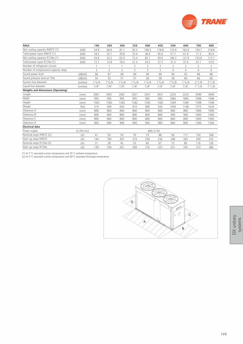
123
DX
unita
ry
syst
ems
RAUL 190 260 300 350 400 450 500 600 700 800Net cooling capacity R407C (1) (kW) 54.8 66.6 81.1 95.3 108.3 118.8 133.0 162.0 194.7 218.8Total power input R407C (1) (kW) 18.2 25.1 29.8 33.4 38.4 45.6 51.7 61.0 71.3 83.9Net cooling capacity R134a (1) (kW) 43.8 53.2 63.9 75.4 85.1 93.6 106.3 127.9 153.8 172.7Total power input R134a (1) (kW) 12.1 15.8 18.5 21.3 24.3 27.7 31.5 37.0 47.1 53.9Number of refrigerant circuits 1 1 1 2 2 2 2 2 2 2Number of compressors/capacity steps 2 2 2 3 3 3 4 4 6 6Sound power level (dB(A)) 86 87 89 89 90 90 90 92 98 98Sound pressure level at 10m (dB(A)) 54 55 57 57 58 58 58 60 66 66Suction line diameter (inches) 1"5/8 1"5/8 1"5/8 1"5/8 1"5/8 1"5/8 1"5/8 1"5/8 2"1/8 2"1/8Liquid line diameter (inches) 7/8" 7/8" 7/8" 7/8" 7/8" 7/8" 7/8" 7/8" 1"1/8 1"1/8Weights and dimensions (Operating)Length (mm) 2061 2061 2061 2921 2921 2921 2225 2225 3090 3090Width (mm) 995 995 995 995 995 995 1865 1865 1948 1948Height (mm) 1582 1582 1582 1582 1582 1582 1584 1584 1598 1598Weight (kg) 514 584 650 810 900 926 1040 1168 1575 1634Clearance A (mm) 800 800 800 800 800 800 800 800 1000 1000Clearance B (mm) 800 800 800 800 800 800 900 900 1000 1000Clearance C (mm) 800 800 800 800 800 800 800 800 1000 1000Clearance D (mm) 900 900 900 900 900 900 800 800 1300 1300Electrical dataPower supply (V/Ph/Hz) 400/3/50Nominal amps R407C (2) (A) 41 50 59 70 79 88 99 117 150 168Start-up amps R407C (A) 144 199 207 219 228 236 248 265 299 316Nominal amps R134a (2) (A) 31 38 45 53 60 67 75 89 116 130Start-up amps R134a (A) 139 194 201 209 216 223 231 245 272 286
(1) At 7°C saturated suction temperature and 35°C ambient temperature(2) At 5°C saturated suction temperature and 60°C saturated discharge temperature

124 Systems guide
DX
unita
ry
syst
ems
Customer benefits• Flexibility: customized system to fit the application exact
requirements
Main features• Phase loss/reversal/low voltage monitor
• Factory-installed discharge and liquid line service valves
• Passive manifolding for 3-D Scroll compressors
• Standard ambient operating range 4°C to 52°C
(46°C max ambient for evaporator)
• Heavy gauge galvanized steel frame
• Louvered panels for coil protection
• Slate gray air-dry paint finish (exceeds 672 hour salt spray
test in accordance with ASTM B117)
Options• Remote chiller evaporator with field installation kit
• Non-fused disconnect (C20 to C60 models)
• Low ambient option
• Hot gas bypass to the evaporator inlet
• Suction service valve
• Pressure gauges
• Return air sensor
• Copper finned condenser coil
• Unit spring isolators
• Neoprene-in-shear isolators
• Not CE compliant
• UL approval on 60 Hz version
• Extended Compressor Warranty
• Special coil coating for corrosion resistance
• Constant volume, VAV, and no controls options on C20 to
C60 models, VAV and no controls options on C80 to D12
models
ControlIn addition to the “no system control” option, Trane offers
three system control options on C20 to C60 units and two
system control options on the C80 to D12 units, each using
solid-state electronics.
These options allow the unit to be ordered with the
controls needed, saving field installation costs.
Coil Frost Protection: Trane offers Frostat™ with the VAV
system control option Frostat™ is the industry’s most
reliable method of coil frost protection and assures that your
system will provide energy efficient comfort at part load
conditions.
RAUJCondensing unit
This description may not include all options and accessories available. For full technical information, download documentation at: http://doc.trane-eur.com

125
DX
unita
ry
syst
ems
RAUJ C20 C25 C30 C40 C50 C60 C80 D10 D12Net cooling capacity R410A (1) (kW) 77.5 94.2 115.3 156.4 194.3 222.9 316.1 385.8 466.9Total power input R410A (1) (kW) 22.6 26.9 35.0 46.1 59.5 67.3 103.6 119.6 142.0Number of refrigerant circuits (kW) 1 1 1 2 2 2 2 2 2Number of compressors / capacity steps (kW) 2 2 2 4 4 4 6 6 6Suction line diameter (inches) 1"5/8 1"5/8 1"5/8 1"5/8 1"5/8 1"5/8 2"5/8 2"5/8 2"5/8Liquid line diameter (inches) 7/8" 7/8" 7/8" 7/8" 7/8" 7/8" 1"1/8 1"1/8 1"1/8Weights and dimensions (Operating)Length (mm) 2242 2242 2242 2242 2891 2891 4477 5772 5772Width (mm) 1527 1527 1527 2242 2242 2242 2242 2242 2242Height (mm) 1886 1886 1886 2013 2013 2013 2013 2013 2013Weight (kg) 732 754 761 1194 1316 1345 2291 2622 2798Clearance A (mm) 1829 1829 1829 1829 1829 1829 2438 2438 2438Clearance B (mm) 1067 1067 1067 1067 1067 1067 1219 1219 1219Clearance C (mm) 1829 1829 1829 1829 1829 1829 2438 2438 2438Clearance D (mm) 1067 1067 1067 1067 1067 1067 1219 1219 1219Electrical data (2)Minimum circuit ampacity at 200/3/60 (A) 102 119 141 193 236 267 411 480 574Minimum circuit ampacity at 230/3/60 (A) 89 107 123 168 215 232 358 425 515Minimum circuit ampacity at 460/3/60 (A) 46 52 63 87 102 120 174 207 255Minimum circuit ampacity at 575/3/60 (A) 39 44 57 73 86 107 139 166 204Minimum circuit ampacity at 400/3/50 (A) 46 52 63 86 101 119 173 206 253
(1) Performances given at 35°C outdoor ambiant and 7°C satured suction temperature(2) Minimum circuit ampacity (MCA) is 125 percent of the RLA (Rated Load Amp) of one compressor motor plus the total RLA of the remaining motors.

126 Systems guide
DX
unita
ry
syst
ems
Customer benefits• Compact design: space savings in plant rooms
• Accuracy: accurate temperature and humidity control for
any size of application
• High performance: lowest energy consumption. EC fan
motor (option)
Range descriptionUnit with AC motor and forward curved fan
JDCC: Chilled water downflow
JUCC: Chilled water upflow
JDAC: Air-cooled direct expansion downflow
JUAC: Air-cooled direct expansion upflow
JDWC: Water-cooled direct expansion downflow
JUWC: Water-cooled direct expansion upflow
Unit with EC motor and backward curved fan
JDCV: Chilled water downflow
JUCV: Chilled water upflow
JDAV: Air-cooled direct expansion downflow
JUAV: Air-cooled direct expansion upflow
JDWV: Water-cooled direct expansion downflow
JUWV: Water-cooled direct expansion upflow
Main features• Designed for environments in which high-tech equipment
is the predominant heat source and comfort applications
(offices…)
• Front access for total unit maintenance
• Double inlet galvanized steel centrifugal fans with forward
curved blades
Options• Electric reheat / hot water reheat
• High pressure centrifugal fans
• Electrode boiler humidifier
• High efficiency filters
• Fresh air module with filter
• Air suction from the front, rear or base (upflow
configuration only)
Accessories• Dirty filter alarm (differential pressure switch)
• Temperature and humidity sensor
• Base frames and plenums (intake or discharge) for easier
integration
• External sensors for high ambient temperature and
humidity alarm signals
• Fire and/or smoke detector
• Water leak detector with one sensor
• Excess pressure damper
Control
mP40 microprocessor control module with easy-to-use LCD
graphic display
• Temperature and humidity control and recording system
• Complete alarm signaling and recording system
• Automatic restart
• Remote auto off function
• On-site language selection
• Connectivity with the most common communication
protocols (BACnet®/LonTalk®/Modbus®/...) or local
RS485 network
JupiterClose control unit
This description may not include all options and accessories available. For full technical information, download documentation at: http://doc.trane-eur.com

127
DX
unita
ry
syst
ems
Chilled water units
JDCC / JDCV / JUCC / JUCV 0020 0025 0030 0040 0060Net cooling capacity (total/sensible) (1) (kW) 7.2 / 6.6 9.9 / 8.9 10.9 / 10.0 13.7 / 13.0 22.3 / 20.5Supply airflow (m3/h) 1610 2280 2305 3265 5035Maximum external static pressure (Pa) 191 59 37 144 82Sound pressure level at 2m (downflow version) (dB(A)) 49 50 50Weights and dimensions (Operating)Length (mm) 550 850 850 850 1200Width (mm) 450 450 450 450 450Height (mm) 1740 1740 1740 1740 1740Weight (kg) 105 135 135 145 220Electrical dataPower supply (V/Ph/Hz) 200/1/50 - 400/3/50
Direct expansion air-cooled units
JDAC / JDAV / JUAC / JUAV 0115 0125 0133 0135 0150 0160Net cooling capacity (total/sensible) (2) (kW) 6.2 / 5.8 7.6 / 6.3 10.1 / 10.1 12.7 / 11.4 16.8 / 15.5 18.1 / 16.1Total power input (indoor+outdoor unit) (kW) 2.4 3.0 3.7 4.7 5.7 6.3
Direct expansion water-cooled units
JDWC / JDWV / JUWC / JUWV 0115 0125 0133 0135 0150 0160Net cooling capacity (total/sensible) (3) (kW) 6.4 / 5.8 8.2 / 6.5 10.4 / 10.4 13 / 11.5 17.4 / 15.6 18.4 / 16.1Total power input (kW) 2.4 3.0 3.7 4.7 5.7 6.3
(1) Based on 24°C/50% relative humidity (return air), intake water temperature: 7°C, outlet water temperature: 12°C, glycol: 0%(2) Based on 24°C/50% relative humidity (return air), outdoor air temperature: 35°C(3) Based on 24°C/50% relative humidity (return air), intake water temperature: 30°C, leaving water temperature 35°C, glycol: 30%
General data - Direct expansion unitsNumber of refrigerant circuits 1 1 1 1 1 1Number of compressors / capacity steps 1 1 1 1 1 1Supply airflow (m3/h) 1645 1731 3205 3440 4500 5202Maximum external static pressure (Pa) 193 155 178 123 153 40Weights and dimensions - Direct expansion unitsLength (mm) 550 850 850 850 1200 1200Width (mm) 450 450 450 450 450 450Height (mm) 1740 1740 1740 1740 1740 1740Weight (kg) 105 135 135 145 220 220Electrical data - Direct expansion unitsPower supply (V/Ph/Hz) 200/1/50 - - - -Power supply (V/Ph/Hz) 400/3/50

128 Systems guide
DX
unita
ry
syst
ems
Customer benefits• Flexibility: customized system to fit the application’s exact
requirements• Accuracy: accurate temperature and humidity control for
demanding applications• Sound level: one of the best acoustic comfort levels
available in the market place
Range descriptionUnit with AC motor and backward curved fanEDCB: Chilled water downflowEUCB: Chilled water upflowEDAB: Air-cooled direct expansion downflowEUAB: Air-cooled direct expansion upflowEDWB: Water-cooled direct expansion downflowEUWB: Water-cooled direct expansion upflowUnit with EC motor and backward curved fanEDCV: Chilled water downflowEUCV: Chilled water upflowEDAV: Air-cooled direct expansion downflowEUAV: Air-cooled direct expansion upflowEDWV: Water-cooled direct expansion downflowEUWV: Water-cooled direct expansion upflow
Main features• Designed for environments in which high-tech equipment
is the predominant heat source• Front access for total unit maintenance• High pressure centrifugal plenum fans with backward
curved blades
Options• Electric reheat/enhanced electric reheat
• Hot water/hot gas reheat• Variable speed EC fans motor• Electrode boiler humidifier• Air filters• Fresh air module• Air suction from the front, rear or base (upflow
configuration only)• Front discharge floor stand• Different acoustic linings for the panels of the unit casing• Electronic expansion valve
Accessories• Condensate drain pump• Humidifier condensate drain pump• External sensors for high ambient temperature and
humidity alarm signals• Fire and/or smoke detector• Water leak detector• Base frames and plenums (intake or discharge) for easier
integration
ControlmP40 microprocessor control module with easy-to-use LCD graphic display• Temperature and humidity control• Complete alarm signaling and recording system• Automatic restart• Remote auto off function• On-site language selection• Connectivity with the most common communication
protocols (BACnet®/LonTalk®/Modbus®/...) or local RS485 network
MercuryClose control unit
This description may not include all options and accessories available. For full technical information, download documentation at: http://doc.trane-eur.com

129
DX
unita
ry
syst
ems
Direct expansion air-cooled units
EDAB / EDAV / EUAB / EUAV 1105 1106 2107 2207 2109 2209 2111 2211 2113 2213 2216 2218 2222 4222 2225 4225 4228 4233
Cooling capacity (total/sensible) (2) (kW) 20.9 /
19.823.3 /
2125.8 / 25.8
25.8 / 25.8
34.6 / 30.3
34.6 / 30.3
40.6 / 39
40.6 / 39
45.9 / 42.8
45.9 / 42.8
62.3 / 55.2
66.9 / 57
80.7 / 80.7
81.7 / 81.7
92.6 / 87.6
91.2 / 87.6
95.9 / 91
105 / 94
Chilled water units
EDCB / EDCV / EUCB / EUCV 0070 0100 0120 0170 0200 0250 0270 0340 0400 0430Cooling capacity (Total/ Sensible) (1) (kW) 27 /
25.433.9 / 33.2
43.6 / 41.4
57.2 / 55.1
69.3 / 67
87.6 / 81.5
97.9 / 88.7
111 / 103
126 / 114
164 / 137
Supply airflow (m3/h) 6060 10200 10420 14920 18680 18680 18725 24777 25193 28444Weights and dimensions (Operating)Length (mm) 1010 1010 1310 1721 2172 2172 2170 2580 2580 2580Width (mm) 750 865 865 865 865 865 865 865 865 865Height (mm) 1960 1960 1960 1960 1960 1960 1960 1960 1960 1960Operating weight (kg) 220 306 314 395 443 458 502 702 740 820Electrical dataPower supply (V/Ph/Hz) 400/3/50
(1) Based on 24°C/50% relative humidity (return air), intake water temperature: 7°C, outlet water temperature: 12°C, glycol: 0%
(1) Based on 24°C/50% relative humidity (return air), saturated condensing temperature: 45°C(2) Based on 24°C/50% relative humidity (return air), Outdoor air temperature: 35°C(3) Based on 24°C/50% relative humidity (return air), intake water temperature: 30°C, Leaving water temperature 35°C, glycol: 30%(4) Size 0430 only available in downflow version: EDCB/EDCV* Size available in direct expansion air-cooled units only. Water-cooled version not available.
General data - Direct expansion air-cooled and water-cooled units
Unit size 1105* 1106 2107* 2207* 2109 2209* 2111* 2211* 2113 2213* 2216 2218 2222* 4222 2225* 4225 4228 4233
Number of refrigerant circuits 1 1 1 2 1 2 1 2 1 2 2 2 2 2 2 2 2 2
Number of compressors/capacity steps
1 1 2 2 2 2 2 2 2 2 2 2 2 4 2 4 4 4
Supply airflow (m3/h) 5750 5750 8530 8530 8530 8530 12895 12895 12895 12895 16590 16590 21635 21635 22835 22835 23210 23210Weights and dimensions (Operating)Length (mm) 1010 1010 1310 1310 1310 1310 1721 1721 1721 1721 2172 2172 2582 2582 2582 2582 2582 2582Width (mm) 750 750 865 865 865 865 865 865 865 865 865 865 865 865 865 865 865 865Height (mm) 1960 1960 1960 1960 1960 1960 1960 1960 1960 1960 1960 1960 2175 2175 2175 2175 2175 2175Operating weight (kg) 280 310 430 447 430 447 548 559 575 585 714 714 910 910 918 930 1040 1098Electrical data
Power supply (V/Ph/Hz) 400/3/50
Direct expansion water-cooled units
EDWB / EDWV / EUWB / EUWV 1106 2109 2113 2216 2218 4222 4225 4228 4233
Cooling capacity (total/sensible) (3) (kW) 23.2 /
19.234.1 /
3046 / 43.3
60 / 53
66.1 / 54.5
90 / 89.2
99.3 / 88.8
102.6 / 93.9
110 / 94.6

Notes
130 Systems guide

HVAC and building controlsTrane controls are the keystone to making a building work better for life. They are
engineered to be user-friendly and help building owners efficiently achieve their desired temperature, humidity and ventilation whatever the building’s purpose.

132 Systems guide
HVA
C an
d bu
ildin
g co
ntro
ls
Trane’s controls product portfolio offers a full range
of devices that have been developed within Trane and
Ingersoll Rand engineering and Centers of Excellence
around the world.
Trane HVAC controls products were developed by (and
for) HVAC systems specialists. This unique approach takes
into account the system design requirements for both the
HVAC application and the HVAC equipment. In this way,
consideration is given both to the individual controlled
equipment AND also to the functionality of the Building
Management System (BMS), as well as to the SYSTEM
overall performance. The field controllers are
pre-programmed, pre-tested and factory-mounted on
our HVAC equipment. This ensures a highly reliable and
efficient equipment, while the commissioning process is
reduced to its simplest tasks, thus saving valuable time and
resources on site, while ensuring high performance and
reliability of the controls.
Trane field controllers have advanced equipment HVAC
embedded application libraries which have been developed
over 100 years of experience. This provides our equipment
with the best life cycle and the best efficiencies. All
Trane HVAC applications are designed to improve the
commissioning and maintenance processes and also to
reduce overall operating cost.
Trane controls offer
Having the best performing HVAC equipment controls
is not enough to make sure the system delivers the best
efficiency.
At the process level, Trane has in depth technical
knowledge on complex HVAC system applications such
as Chilled Water Variable Primary Flow, Ice Storage, Free
Cooling, Variable Air Systems, etc. Each process focuses
on different customer requirements such as space comfort,
chilled water supply temperature/flow accuracy, indoor air
quality, energy efficiency.
Trane supports you by selecting, designing and processing
the best solutions for your HVAC system. Our Building
and HVAC controls solutions include pre-engineered
applications, such as Chiller Plant Control, Variable Air
System control, Automatic Ventilation and IAQ control.
On top of their total focus on HVAC expertise, Trane BMS
solutions, offer full flexibility by natively supporting the
latest IT technologies, such as IP networking, as well as
Web Services support.
TracerTM SC
TracerTM UC
Sensors
Tracer Summit + BCU + WebOps
TracerTM Zn + MP family
Wall Sensors
Tracer Summit New Tracer products
Building
Equipment
Occupant Spaces
Enterprise Tracer Summit Enterprise edition Tracer ESTM

133
HVA
C an
d bu
ildin
g co
ntro
ls
Trane offers an open and secure controls Building
Management architecture. The use of native open protocols
allows for easy commissioning and facilitates maintenance
as well as ensures a scalable and flexible system that can
evolve to various controls products. It also allows the
integration of third party equipment and BMS systems to
the network.
For system level communications, which imply large
quantities of data management, BACnet®/IP is used for
its high speed and bandwidth communication capacity
and ease of implementation – almost EVERY building has
Ethernet TCP/IP network architecture.
For field-level communications, Trane solutions supports
standard protocols such as LonWorks™, Modbus® and
BACnet® MS/TP, offering a wide range integration solutions
of Trane and other 3rd party equipment and devices
controls.
Open and secure architecture
All system level controllers, such as Tracer™ SC or Tracer
BCU’s optimize the overall performance of the entire system
they are in charge of. They store and execute system wide
sequences of operations, coordinate all the system level
functions across the entire project, and allow for remote
communication through either Web services, or mail and
text messages services.
This system level is also in charge of backup and restore
functionalities, as well as data collection for data logging.
For large systems presenting several system-level controllers,
Tracer ES™, an enterprise-wide management server can be
applied as to standardize the overall system look and feel,
even with non-Trane BACnet® system controllers, as well
as extend the overall system archiving capability, by using
server-based technologies.

134 Systems guide
HVA
C an
d bu
ildin
g co
ntro
ls
Tracer™ SC architecture perfectly fits today’s requirements
of Building Management systems for small and medium
sized buildings:
It embeds latest Web technologies which allow the users to
navigate throughout the system features, from whereever
they are. TracerTM SC licensing being based on the number of
devices in the system, there are virtually no limits in terms of
number of users that can access web pages at a given time.
This provides full flexibility to the asset managers in defining
the various team members access profiles, no matter how
many people have to interact with the system.
Tracer SC architecture uses natively embedded open
standard protocols like BACnet®/IP, BACnet® MS/TP and
LonTalk® so that the integration of equipment and systems
from other manufacturers is simple and seamless. This
approach allows the system to expand as the needs for the
building grow, supporting future modifications and upgrades
and therefore ensures a reliable and sustainable long-term
investment.
The technology trends shows that BACnet® protocol is
taking a larger market share in today’s projects. Trane
system perfectly supports this approach by proposing an
architecture that supports this protocol at field and system
The solution for small and medium buildings: Tracer™ SC
level, allowing the integration of controllers through either
IP or MS/TP, with the exact same set of features and
functionalities.
Trane has always proposed pre-engineered applications
within its BMS solutions, so that customers get reliable,
sustainable and repeatable solutions. With this approach,
there is no compromise on development time of these
applications: they are already there!
Pre-engineered applications also enable the use of advanced
energy conservation functions like:
- Chiller Plant Control, including pre-programmed Variable
Primary Flow, or series chillers
- Demand limiting: power consumption setpoint
management for all Trane chillers.
- Random start: on fan coils to limit consumption peaks.
- Optimizer: Maintenance can implement standard functions
to optimize the start and/or stop times and to minimize
the run time of HVAC Units.
- Custom Duty cycling: A strategy can be implemented
based on consumption limitation.
- Variable Air Systems: capable of handling the totality of a
Variable Air Installation, including ventilation optimization,
flow control and Indoor Air Quality Management.
High Density I/O
User 1 Web Browser
User N Web Browser
Lighting
Ethernet WAN/LAN BACnet/IP
LonTalk® FTT10
BACnet® MS/TP Chillers and Chiller Plant
BCI-C comm cardsChillers and Chiller Plant LCI-C comm cards
Multi-Purpose Tracer MP581
Multi-Purpose Tracer UC400w/XM30
AHU Tracer MP581 AHU
UC400-UC600CWT
Zn523/525
Building controlTracer TM SC architecture

135
HVA
C an
d bu
ildin
g co
ntro
ls
Main features
Full web capable system: HTML web pages for system
information, custom graphics, dashboards and project
related information.
Wizard technology: guides the user throughout the
various steps required to achieve a task
Customizable navigation tree: full fl exibility to navigate
throughout the system
User’s profi les: allows for segregation of the areas of the
system which users have access to, based on their profi le
Flexibility: System licensing is based on the number of
fi eld devices, and does not restrict the number of users
Alarm and event log: Email notifi cation of system failures
across multiple systems
Reports: Standard way of presenting system live data
Trend Viewer: Easily create and archive trended data.
Trend logs are automatically create at system setup, with
most common data
Intuitive manual overrides: Simple, easy to understand
manual auto control functions
Standard and custom graphics: 3D equipment graphics
are included. Customized graphics for each site can be
easily created.
Graphic library: Standard 3D graphic elements are
available for customized use
Time-of-day schedule: Save energy by running
equipment only when needed and easily modify schedules
for exceptions and holidays
Area control: Logical organization and control of
equipment to building layout
Timed override: Ability to override equipment schedule
Variable-air-volume air system (VAS) control: Control
the AHU and VAV boxes as one system
Static pressure and ventilation: dedicated to comfort
level management while ensuring maximum energy savings
Chiller Plant Control: Advanced chiller plant automation
for system safety and energy performance
Graphical programming: Flexible site-specifi c
programming capabilities
System alarms forwarded via e-mail

136 Systems guide
HVA
C an
d bu
ildin
g co
ntro
ls
With Tracer ES™, you have direct computer access to every
BACnet® system in every building you manage. You have
complete control at your fingertips to make global schedule
changes, answer alarms and diagnose problems instantly,
from anywhere.
That’s the power of Tracer ES™…a front-end system that
lets operators of multiple facilities manage all their buildings
as a single enterprise. No more running from building to
building, or campus to campus. Tracer ES™ brings it all to
you. Just log on. And manage your buildings – and your
business – better!
Trane delivers a complete, single-source approach to all
your building automation, equipment, service, parts and
environmental needs. No more settling for half the answer.
No more proprietary systems that don’t play well with
others, or lock you into their technology with expensive
upgrades.
Tracer ES™ gives you complete freedom. The freedom of a
system that’s easy to integrate, operate and maintain – and
makes it easy to better manage and reduce your operating
costs.
The solution for large systems: Tracer ES™
Tracer ES™ takes you far beyond turning lights off and
on and setting temperatures. With Tracer ES™, you get
total control of all your buildings taking energy savings,
diagnostics and scheduling efficiencies to a whole new level.
You’ll save time, money and headaches by being able to
immediately respond to alarms and send the right service
people with the right equipment to make the repair…or in
many cases you can solve the problem yourself, right from
your computer.
In addition, Tracer ES™ gives you the ability to collect and
analyze energy and operating data from multiple sources. So
you can compare and contrast your “best of class” buildings
with those that are not top performers to help raise them to
a higher level – and wring out extra savings.
With Tracer ES™, you get a system that not only allows
you to work more efficiently; it allows you to buy more
efficiently. Tracer ES™ features a unique modular and
scalable design that lets you purchase only the components
you need, and gives you the freedom to add other value-
added modules as you need them – plus, it easily connects
with your Trane or non-Trane systems.

137
HVA
C an
d bu
ildin
g co
ntro
ls
Main features
• Online facility management
• Daily operator functionality
• Central, server-based software
• Remote access from any secure PC on the network
• Front-end system that works with both Trane and qualified
non-Trane BACnet® systems
• Data collection and analysis tool
Tracer ES™ helps customer’s make better decisions:
• Views and analyzes information about all their facilities as
one enterprise
• Supports a proactive approach: makes users more efficient
and better at what they already do
• Provides historical energy usage data for multiple facilities
and systems
• Provides historical operational information for multiple
systems and equipment
Energy cost savings
Building owners and managers want to better understand
how they use energy, and how to make smart decisions
about their energy usage and resources. Tracer ES™ gives
the ability to collect and analyze energy and operational
data from multiple sources. Data can be compared and
contrast the “best of class” buildings with those that are not
top performers to help raise them to a higher level—and
wring out extra savings.
Easy integration and compatibility
Tracer ES™ integrates with existing IT infrastructure and
other qualified non-Trane BACnet® building systems. Its
standard technologies makes it the ideal IT citizen—
peacefully residing on IT network while going about its
business.
Superior performance
• Dramatically streamlines daily facility management
activities
• Instantly pinpoints alarms at their source and diagnoses
problems from any computer
• Bundles repetitive tasks to reduce time spent making
changes across many buildings
• Reduces training needs by providing a highly intuitive user
experience

138 Systems guide
HVA
C an
d bu
ildin
g co
ntro
ls
Customer benefits • Full control of building components
• Full access to historical data and energy savings strategies
• Building asset management from any place
• Easy daily operation through fully customized graphical
interface
Description• Embedded standard communication capability
• User access security
• Embedded energy savings pre-engineered applications
(Chiller Plant Control)
• Full BMS basic features (Scheduling – Trending –
Archiving – Reporting)
• Full Web capability
• IT-friendly components
Building Management SystemsBuilding efficiency at your fingertips
Tracer ES™ Tracer™ SC Tracer™ BCU Tracer Summit™Multibuilding capability X - - XEmbedded web services X X - -STAR functionality (**) X X X XEnergy savings embedded strategies X X X XLonTalk® protocol support - X X -BACnet® - IP protocol X X X XBACnet® – MS/TP protocol - X X -Server-based operations X - - -High speed remote connectivity X X x XArchiving capacity Large - unlimited 6 months(*) 1 month(*) Large
(*) Average. Heavily depends on number of logs and sampling time.(**) STAR = Scheduling, Trending, Archiving, Reporting
This description may not include all options and accessories available. For full technical information, download documentation at: http://doc.trane-eur.com

139
HVA
C an
d bu
ildin
g co
ntro
ls
Customer benefits • Integration platform for heterogeneous BACnet® –IP based
Building Management Systems
• Global access and commands to scattered buildings and
systems
• Easy view and analysis of remote buildings performances
from one single seat
• Historical data management
• System access from anywhere through web infrastructure
Description• Embedded standard communication capability
• User access security
• Embedded energy savings pre-engineered applications
(Chiller Plant Control)
• Full BMS basic features (Scheduling – Trending –
Archiving – Reporting)
• Full Web capability
• IT-friendly components
Tracer ESTM
Enterprise level management Building management solution
Category Requirement when using SQL Express Requirement when using Full SQL ServerLicensing By Connected System BACnet® Panel By Connected System BACnet® PanelMaximum of Connected BACnet® Panels 5 10
Client Browsers SupportedServer
Microsoft Internet Explorer 6, SP1 (or higher); Mozilla Firefox 3.0 (or higher); Apple Safari 1.2 (or higher)
Microsoft Internet Explorer 6, SP1 (or higher); Mozilla Firefox 3.0 (or higher); Apple Safari 1.2 (or higher)
Server Type Tower Tower or rack-mountProcessor Dual Core Processor Quad Core ProcessorMemory 4 GB Memory 4 GB MemoryHard Drive Minimum 25 GB Minimum 73 GBRAID No RAID minimum RAID 5 minimumConfiguration Combined Multiple OptionsOperating System Microsoft Server 2003/2008 Microsoft Server 2003/2008Internet Information Services (IIS) IIS 6.0 (or higher) IIS 6.0 (or higher)Software Requirements Microsoft SQL Express 2005 Microsoft SQL Database 2005/2008Remote AccessWeb UI Via IP Connection Via IP ConnectionServer Via IP Connection (VPN Recommended) Via IP Connection (VPN Recommended)Network Topology Ethernet/IP Ethernet/IPNetwork Utilization Low Low Protocols Supported BACnet® (ASHRAE Std 135-2004) BACnet® (ASHRAE Std 135-2004)
Database Supported Microsoft SQL Express 2005 (4 GB maximum database size allowed)
Microsoft SQL Database 2005/2008 (unlimited database size allowed)
Security SSL and Tracer ES™ controlled security with encrypted passwords
SSL and Tracer ES™ controlled security with encrypted passwords
Number of Users 30 concurrent users 100 concurrent usersTechnology Platform .NET Framework 3.5 .NET Framework 3.5Languages Supported English – French – Spanish - German English – French – Spanish - German
Customer PC
Local area network, or intranet
Firewall
BACnet/IP
BACnet system
BCU
BACnet/IP
Tracer SC
Gateway
Other, proprietary
BACnet/IP
BACnet/IPServer Class Machine
Windows Server
SQL Database
Tracer ES Software
This description may not include all options and accessories available. For full technical information, download documentation at: http://doc.trane-eur.com

140 Systems guide
HVA
C an
d bu
ildin
g co
ntro
ls
Customer benefits• Acts as the central communication and application
coordinator for all individual equipment devices in a Tracer BMS.
• Web-based interface provides an easy and convenient way for building operators to access their BMS.
Description• Access available from any PC that meets system
requirements, even from remote locations.• Network security by managing 2 separate network access
ports• Embeds all Trane pre-engineered applications (CPC, VAS,
Schedules,...)
Tracer™ SCWeb-based all-in-one BMS solution
Application / features Number of communicating field devices 30, 60 or 120 Based on licenced type
CommunicationsBACnet® IP
10BASE-T/100BASE-TX dedicated Ethernet (ISO/IEC 8802-3) or Transmission Control Protocol/Internet Protocol (TCP/IP) compatible network
BACnet® MS/TP ENV-1805-1/ENV-13321-1LonTalk® Communications based on the EIA-709.1 (LonTalk) standard
Interface HTML pages Standard pages and customizable pages
Variable Air Systems Ventilation reset optimization - Area management - Timed override
Chiller Plant Control Variable Primary Flow control – series chillers – cooling tower optimization 25 chillers max per CPC, 4 CPC per Tracer Sc
Supported browserInternet Explorer 7.0 and higherMozilla Firefox 3.0 and higher
Time of Day scheduling Standard agenda - Exception schedule
Certification
BAcnet® BTL Listed product (BOWS)
LEEDAchieve points toward Leadership in Energy and Environmental Design (LEED) certification (Site commissioning report – Energy data collection – IAQ management and Energy performance optimization)
Computer
Browser requirements Internet Explorer™ Version 7.0 or higher, or Mozilla Firefox™ Version 3.0 or higherSoftware requirements • Java™ SE Runtime Environment (JRE) Version 5.0 (preferred: Version 6 Update 10 or higher)
• Adobe Flash™ player• Internet Explorer™ Version 7.0 or higher or Mozilla Firefox Version 3.0 or higher• USB driver—For service tool connection and for direct access to Tracer SC Web pages
Tracer SC system controller
Power requirements • Nominal rating: 120/230 Vac; 50 or 60 Hz; 1 pH • Maximum current: 6.0 A at 120 Vac dedicated circuit breaker
Operating environment • Temperature: From –40°F to 122°F (–40°C to 50°C) • Relative humidity: From 10% to 90%, non-condensing
Storage environment • Temperature: From –40°F to 158°F (–40°C to 70°C) • Relative humidity: From 5% to 95%, non-condensing
Enclosure (optional) NEMA-1 - Weight = 14 lb (6.5 kg)UL listing • UL -916-PAZX—energy management
• CUL -C22.2—signal devices—CanadaFCC FCC part 15, Class A CE • Emissions EN61326:1998 Class B
• Immunity EN61326:1998 Commercial• Safety EN61010-1:2001
Processor PowerPC405 CoreMemory FLASH 500 MB / SDRAM 256 MB
Battery No battery required. The clock is maintained for a minimum of three days by the super capacitor. All other programs are backed up by nonvolatile memory.
System Communication
BACnet® Tracer building automation systems communicates with BACnet® devices that support:• Communications based on the BACnet® ASHRAE/ANSI 135 standard• ENV-1805-1/ENV-13321-1• 10BASE-T/100BASE-TX dedicated Ethernet (ISO/IEC 8802-3) or Transmission Control Protocol/Internet Protocol (TCP/IP) compatible network
LonTalk® Tracer building automation systems communicates with LonTalk devices that support:• Communications based on the EIA-709.1 (LonTalk) standard• LonTalk standard network variable types (SNVTs)• FTT-10A or FT-X1 transceivers• Twisted-pair physical media (Level 4 wiring)
This description may not include all options and accessories available. For full technical information, download documentation at: http://doc.trane-eur.com
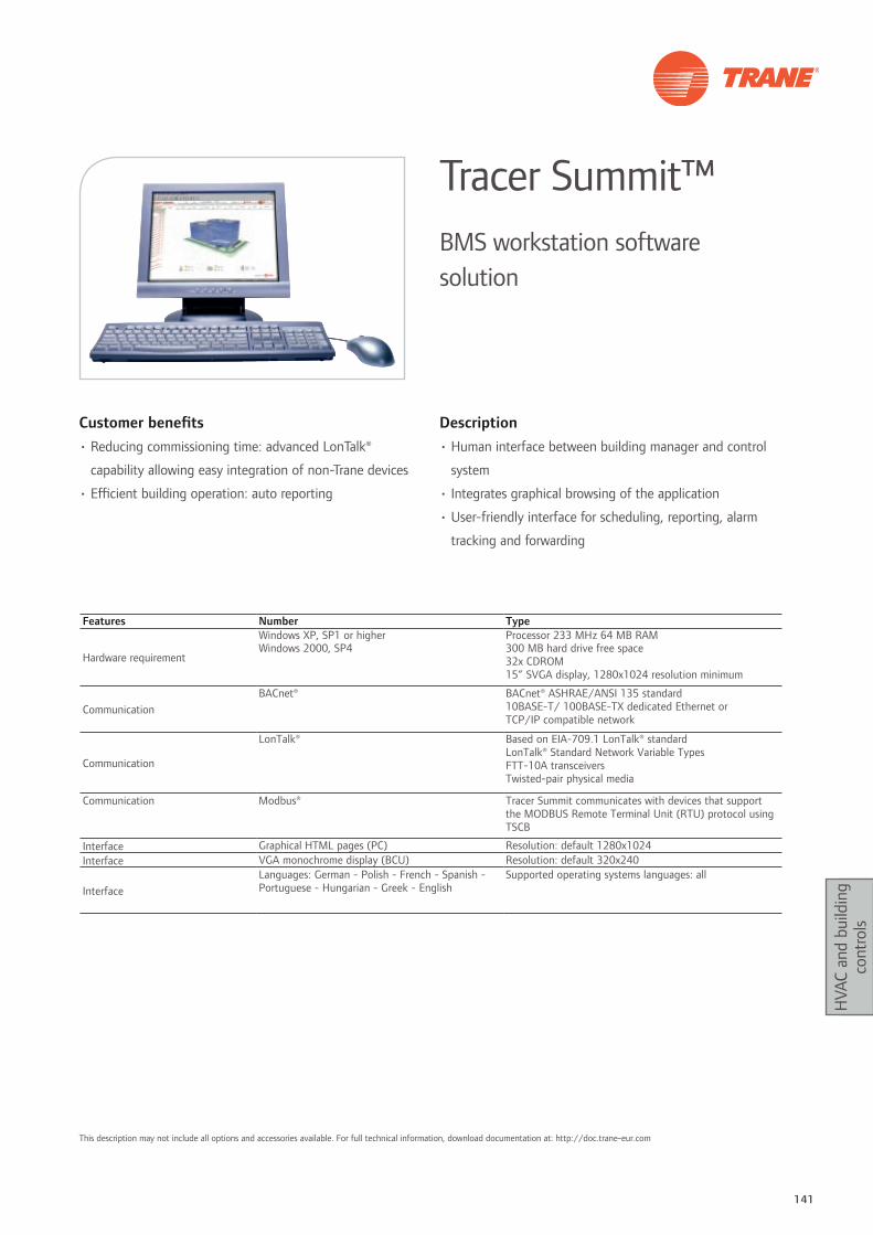
141
HVA
C an
d bu
ildin
g co
ntro
ls
Customer benefits• Reducing commissioning time: advanced LonTalk®
capability allowing easy integration of non-Trane devices
• Efficient building operation: auto reporting
Description• Human interface between building manager and control
system
• Integrates graphical browsing of the application
• User-friendly interface for scheduling, reporting, alarm
tracking and forwarding
Tracer Summit™BMS workstation software solution
Features Number Type
Hardware requirement
Windows XP, SP1 or higher Processor 233 MHz 64 MB RAMWindows 2000, SP4 300 MB hard drive free space
32x CDROM15” SVGA display, 1280x1024 resolution minimum
CommunicationBACnet® BACnet® ASHRAE/ANSI 135 standard
10BASE-T/ 100BASE-TX dedicated Ethernet or TCP/IP compatible network
Communication
LonTalk® Based on EIA-709.1 LonTalk® standard LonTalk® Standard Network Variable Types FTT-10A transceivers Twisted-pair physical media
Communication Modbus® Tracer Summit communicates with devices that support the MODBUS Remote Terminal Unit (RTU) protocol using TSCB
Interface Graphical HTML pages (PC) Resolution: default 1280x1024Interface VGA monochrome display (BCU) Resolution: default 320x240
InterfaceLanguages: German - Polish - French - Spanish - Portuguese - Hungarian - Greek - English
Supported operating systems languages: all
This description may not include all options and accessories available. For full technical information, download documentation at: http://doc.trane-eur.com
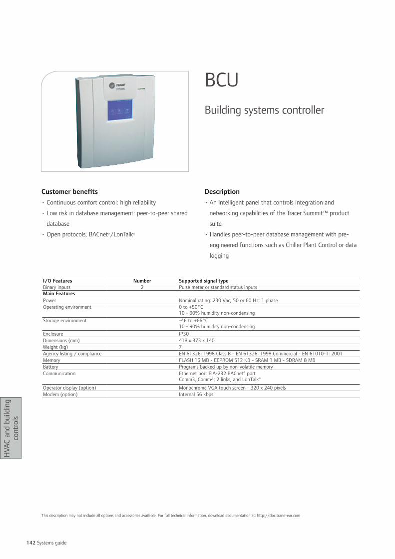
142 Systems guide
HVA
C an
d bu
ildin
g co
ntro
ls
Customer benefits• Continuous comfort control: high reliability
• Low risk in database management: peer-to-peer shared
database
• Open protocols, BACnet®/LonTalk®
Description• An intelligent panel that controls integration and
networking capabilities of the Tracer Summit™ product
suite
• Handles peer-to-peer database management with pre-
engineered functions such as Chiller Plant Control or data
logging
BCUBuilding systems controller
I/O Features Number Supported signal typeBinary inputs 2 Pulse meter or standard status inputsMain FeaturesPower Nominal rating: 230 Vac; 50 or 60 Hz; 1 phaseOperating environment 0 to +50°C
10 - 90% humidity non-condensingStorage environment -46 to +66°C
10 - 90% humidity non-condensingEnclosure IP30Dimensions (mm) 418 x 373 x 140Weight (kg) 7Agency listing / compliance EN 61326: 1998 Class B - EN 61326: 1998 Commercial - EN 61010-1: 2001Memory FLASH 16 MB - EEPROM 512 KB - SRAM 1 MB - SDRAM 8 MBBattery Programs backed up by non-volatile memoryCommunication Ethernet port EIA-232 BACnet® port
Comm3, Comm4: 2 links, and LonTalk®
Operator display (option) Monochrome VGA touch screen - 320 x 240 pixelsModem (option) Internal 56 kbps
This description may not include all options and accessories available. For full technical information, download documentation at: http://doc.trane-eur.com

143
HVA
C an
d bu
ildin
g co
ntro
ls
Customer benefits • Dedicated high performance control algorithm
• Embedded energy savings functions
• In factory pre-installed controllers
• Standard communication protocol support: LonTalk® –
BACnet®- MS/TP
Description• Application specific controllers designed for dedicated
applications such as fan coil unit, chilled beams, variable
air volume, user interface, air handling units.
HVAC equipment controllersHigh performance equipment
Equipment / Functionality ZN523 ZN525 ZSMxx VV550 UC400 AH541 UC400UCM III/IV MP581 UC600
FCU X XChilled beams X XAHU X XVAV single duct X XVAV dual duct XWall interface X
Communication LonTalk® LonTalk®LonTalk®
ProprietaryBACnet® MSTP LonTalk® BACnet® MSTP
Factory-fitted X X option X X X X
This description may not include all options and accessories available. For full technical information, download documentation at: http://doc.trane-eur.com
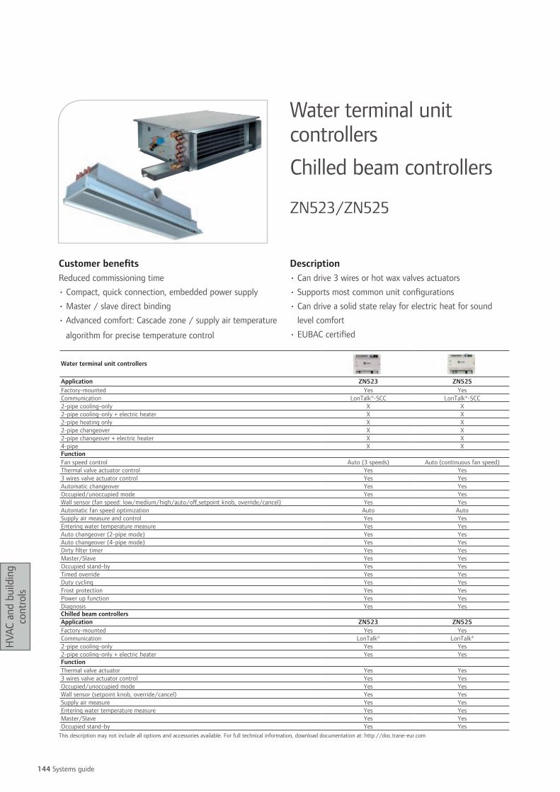
144 Systems guide
HVA
C an
d bu
ildin
g co
ntro
ls
Customer benefitsReduced commissioning time
• Compact, quick connection, embedded power supply
• Master / slave direct binding
• Advanced comfort: Cascade zone / supply air temperature
algorithm for precise temperature control
Description• Can drive 3 wires or hot wax valves actuators
• Supports most common unit configurations
• Can drive a solid state relay for electric heat for sound
level comfort
• EUBAC certified
Water terminal unit controllers Chilled beam controllers
ZN523/ZN525
Water terminal unit controllers
Application ZN523 ZN525Factory-mounted Yes YesCommunication LonTalk®-SCC LonTalk®-SCC2-pipe cooling-only X X2-pipe cooling-only + electric heater X X2-pipe heating only X X2-pipe changeover X X2-pipe changeover + electric heater X X4-pipe X XFunctionFan speed control Auto (3 speeds) Auto (continuous fan speed)Thermal valve actuator control Yes Yes3 wires valve actuator control Yes YesAutomatic changeover Yes YesOccupied/unoccupied mode Yes YesWall sensor (fan speed: low/medium/high/auto/off,setpoint knob, override/cancel) Yes YesAutomatic fan speed optimization Auto AutoSupply air measure and control Yes YesEntering water temperature measure Yes YesAuto changeover (2-pipe mode) Yes YesAuto changeover (4-pipe mode) Yes YesDirty filter timer Yes YesMaster/Slave Yes YesOccupied stand-by Yes YesTimed override Yes YesDuty cycling Yes YesFrost protection Yes YesPower up function Yes YesDiagnosis Yes YesChilled beam controllersApplication ZN523 ZN525Factory-mounted Yes YesCommunication LonTalk® LonTalk®2-pipe cooling-only Yes Yes2-pipe cooling-only + electric heater Yes YesFunctionThermal valve actuator Yes Yes3 wires valve actuator control Yes YesOccupied/unoccupied mode Yes YesWall sensor (setpoint knob, override/cancel) Yes YesSupply air measure Yes YesEntering water temperature measure Yes YesMaster/Slave Yes YesOccupied stand-by Yes Yes
This description may not include all options and accessories available. For full technical information, download documentation at: http://doc.trane-eur.com
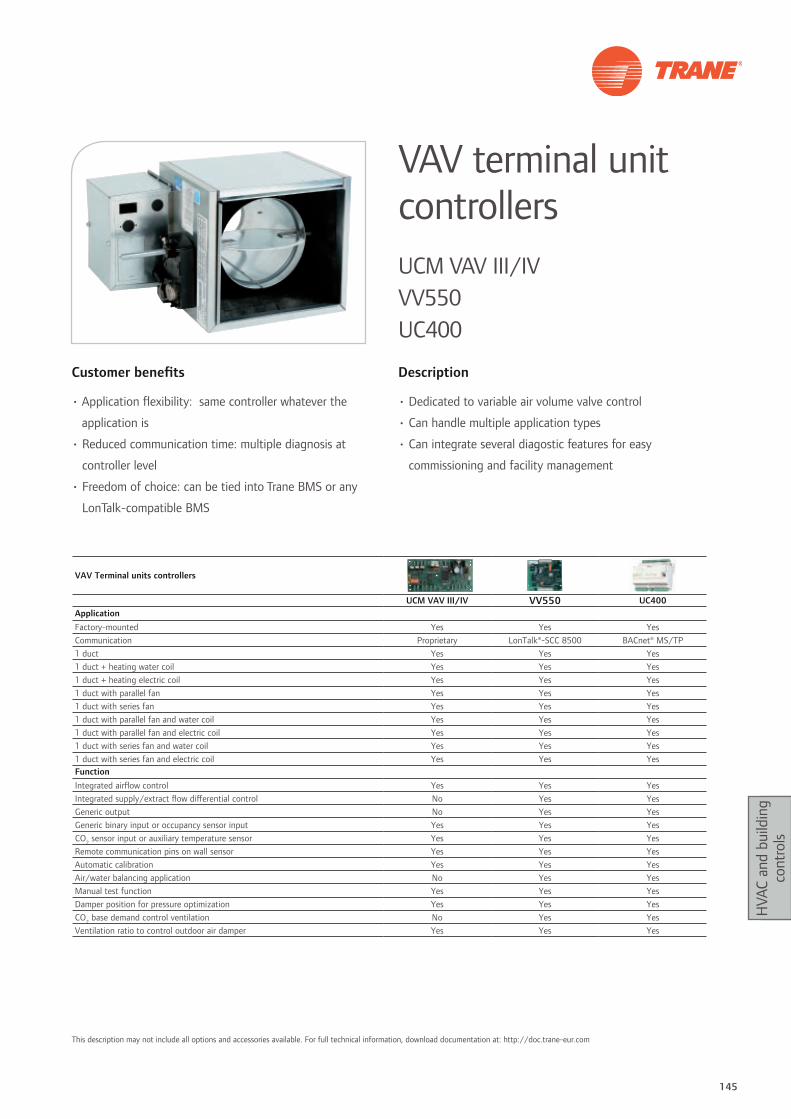
145
HVA
C an
d bu
ildin
g co
ntro
ls
Customer benefits
• Application flexibility: same controller whatever the
application is
• Reduced communication time: multiple diagnosis at
controller level
• Freedom of choice: can be tied into Trane BMS or any
LonTalk-compatible BMS
Description
• Dedicated to variable air volume valve control
• Can handle multiple application types
• Can integrate several diagostic features for easy
commissioning and facility management
VAV terminal unit controllersUCM VAV III/IV VV550 UC400
VAV Terminal units controllers
UCM VAV III/IV VV550 UC400ApplicationFactory-mounted Yes Yes Yes Communication Proprietary LonTalk®-SCC 8500 BACnet® MS/TP1 duct Yes Yes Yes1 duct + heating water coil Yes Yes Yes1 duct + heating electric coil Yes Yes Yes1 duct with parallel fan Yes Yes Yes1 duct with series fan Yes Yes Yes1 duct with parallel fan and water coil Yes Yes Yes1 duct with parallel fan and electric coil Yes Yes Yes1 duct with series fan and water coil Yes Yes Yes1 duct with series fan and electric coil Yes Yes YesFunctionIntegrated airflow control Yes Yes YesIntegrated supply/extract flow differential control No Yes YesGeneric output No Yes YesGeneric binary input or occupancy sensor input Yes Yes YesCO2 sensor input or auxiliary temperature sensor Yes Yes YesRemote communication pins on wall sensor Yes Yes YesAutomatic calibration Yes Yes YesAir/water balancing application No Yes YesManual test function Yes Yes YesDamper position for pressure optimization Yes Yes YesCO2 base demand control ventilation No Yes YesVentilation ratio to control outdoor air damper Yes Yes Yes
This description may not include all options and accessories available. For full technical information, download documentation at: http://doc.trane-eur.com

146 Systems guide
HVA
C an
d bu
ildin
g co
ntro
ls
Customer benefits• Reduced commissioning by the use of application libraries
for AH541
• Reduced programming time by use of Trane Graphical
Programming and re-use of existing application libraries
for AH541
Description• Pre-engineered or fully programmable controller for AHU
applications.
• Support LonMark® Space
• Comfort Controller (SCC 8500) or Discharge Air Controller
(DAC 8610) profiles.
Air handling unit controllersAH541 MP581 UC400 UC600
- Not Available * Screen Display point X Hardware point No display capability for UC400
Air Handling Units - AHU controller AH541 MP581 UC400 UC600Factory-mounted Yes Yes Yes YesCommunication LonTalk® LonTalk® BACnet® MS/TP BACnet® MS/TPAnalog inputsReturn / supply / outdoor air temperature sensor X / X / X X / X / X X / X / X X / X / XAmbient / mixed air temperature sensor X / X X / X X / X X / XTemperature setpoint adjustment X X X XDuct static pressure X X X XDifferential pressure X X X XReturn / supply / outdoor air humidity sensor X / - / - X / X / X X / X / X X / X / XAmbient air humidity sensor - X X XHumidity setpoint adjustment - X X XCO2 sensor / CO2 setpoint - / X X / X X / X X / XAir quality / IAQ setpoint - / X X / X X / X X / XBinary inputsFrost thermostat X X X XDifferential filter pressure switch X X X XLow air pressure switch X X X XMotor(s) default(s) X X X XElectrical heater default X X X XDamper end switch X X X XOn/off contact X X X XOccupancy mode X X X XTimed override X X X XCommunication bus terminals 2 2 2 2Analog OutputPre-heating / cooling / heating valves X / 0-10 V/3 wires X / 0-10 V/3 wires X / 0-10 V/3 wires X / 0-10 V/3 wiresSignal damper X X X XElectrical heater X X X XVariable speed supply air / return air motor X X X XSignal humidifier X X X XTemperature * * X XHumidity * * X XPressure * * X XPosition damper * * X XBinary outputSupply air motor command X X X XExtract air motor command X X X XDamper command X X X XHumidifier command X X X XDefault Signal X X X X
This description may not include all options and accessories available. For full technical information, download documentation at: http://doc.trane-eur.com

147
HVA
C an
d bu
ildin
g co
ntro
ls
This description may not include all options and accessories available. For full technical information, download documentation at: http://doc.trane-eur.com
Customer benefits• Open systems: supports reliable and highly supported
Modbus® RTU / TCP protocol
• Straight commissioning: auto binding with LonTalk-
compatible units
• Highly reliable solution
• Factory-mounted option
Description• Dedicated to Modbus® interfacing between Trane and
non-Trane systems
• Compact interface
Protocol gatewayInterface between Trane equipment and third-party BMS
Modbus type RTU RTU or TCPModbus function codes 02; 04; 05; 06; 15;16 01; 02; 04; 05; 06; 15;16Baud rate Up to 57600 Up to 115200
MODBUS RTU =
MODBUS RTU =
MODBUS RTU =
PIC +
BCU
PIC +
LON Card
PIC +
COM 3 Card
Jenesys +
BCU
MODBUS RTU or TCP =

148 Systems guide
HVA
C an
d bu
ildin
g co
ntro
ls
Customer benefits• Easy commissioning: easy to set up Modbus® data table• Easy operation and diagnosis: compact device with
diagnosis indicator (Leds)
Customer benefits• Easy commissioning: auto-commissioning/auto binding
supported• Compatible with all Trane equipment• Easy operation and diagnosis: terminal port and status
light indicators
Description• BACnet® to Modbus® gateway• Dedicated to Tracer Summit applications
Description• Trane proprietary or LonTalk® protocols to Modbus®/RTU
gateway
JenesysTracer Summit communication bridge
PICTracer Summit communication bridge
I/O Features Supported signal typeConnection 1 RJ 45 IEA-232; 1 screw terminal EIA-485; 1 10 BaseT RJ 45 EthernetMain featuresPower 24 Vac 50/60 Hz 1phase, 1A; 9-30 V DC, 1AOperating environment 0 to +60°C 10 - 90% humidity non-condensing
Storage environment -46 to +66°C 10 - 90% humidity non-condensingProtection class IP 30Dimensions (mm) 110 x 90 x 45Agency listing / compliance CE EN 55022 Class BLED 9 active LED for: Transmit, receive, Ethernet link, power OK, bridge running, configuration error, node offline, comm error, system errorSoftware Software and driver compatibility: BACnet® (Ethernet or IP) Modbus® RTU
I/O Features Supported signal typeConnection 1 IEA-232
1 EIA-485Main featuresPower 12 - 30 VDC/VAC, 50/60 Hz, 1phaseOperating environment 0 to +60°C 10 - 90% humidity non condensingStorage environment -46 to +66°C 10 - 90% humidity non condensingProtection class IP 30Agency listing / compliance CE 89/336/EECLED Active LED for: Transmit , receive, power OK.Software Modbus® RTU, slave mode 1200 to 57600 bps
This description may not include all options and accessories available. For full technical information, download documentation at: http://doc.trane-eur.com
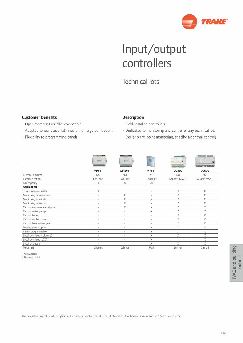
149
HVA
C an
d bu
ildin
g co
ntro
ls
Customer benefits• Open systems: LonTalk®-compatible
• Adapted to real use: small, medium or large point count
• Flexiblilty to programming panels
Description• Field-installed controllers
• Dedicated to monitoring and control of any technical lots
(boiler plant, point monitoring, specific algorithm control)
Input/output controllersTechnical lots
MP501 MP503 MP581 UC400 UC600Factory-mounted NO NO NO NO NOCommunication LonTalk® LonTalk® LonTalk® BACnet® MS/TP BACnet® MS/TPI/O capacity 4 8 20 23 18ApplicationSingle loop controller X - X X XMonitoring temperature - X X X XMonitoring humidity - X X X XMonitoring pressure - X X X XControl mechanical equipment - X X X XControl water pumps - - X X XControl boilers - - X X XControl cooling towers - - X X XControl heat exchangers - - X X XDisplay screen option - - X X XFreely programmable - - X X XLocal overrides (software) - - X X XLocal overrides (LCD) - - X XLocal language - - X X XMounting Cabinet Cabinet Wall Din rail Din rail
- Not Available X Hardware point
This description may not include all options and accessories available. For full technical information, download documentation at: http://doc.trane-eur.com
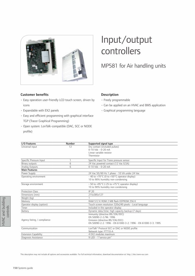
150 Systems guide
HVA
C an
d bu
ildin
g co
ntro
ls
Customer benefits• Easy operation user-friendly LCD touch screen, driven by
icons
• Expandable with EX2 panels
• Easy and efficient programming with graphical interface
TGP (Tracer Graphical Programming)
• Open system: LonTalk-compatible (DAC, SCC or NODE
profile)
Description• Freely programmable
• Can be applied on an HVAC and BMS application
• Graphical programming language
Input/output controllersMP581 for Air handling units
I/O Features Number Supported signal typeUniversal input 12 Dry contact (included pulses)
0-10 Vdc - 0-20 mALinear variable resistorThermistor
Specific Pressure Input 1 Specific Input for Trane pressure sensorBinary outputs 6 24 Vac powered contact (12 Vac 0,5A)Analog Outputs 6 0-10 Vdc - 0-20 mAMain FeaturesPower Supply 24 Vac 50/60 Hz 1 phase - 10 VA under 24 VacOperating environment - 40 to +70°C (0 to +50°C operator display)
10 to 90% humidity non-condensing
Storage environment - 50 to +95°C (-25 to +75°C operator display)10 to 90% humidity non-condensing
Protection Class IP 20Dimensions (mm) 215x385x127Weight (kg) 1Memory RAM 512 K ROM 2 MB flash EEPROM 256 KOperator display (option) Touch screen resolution 320x240 pixels - Local languageTimer Included in the operator displayBattery Dynamic data/time: high capacity backup (7 days)
Agency listing / compliance
Immunity (directive 89/336/EEC)EN 50090-2-2/96: 1996Emission (directive 89/336/EEC)EN 50090-2-2: 1996 - EN 61000-3-2: 1996 - EN 61000-3-3: 1995
Communication LonTalk® Protocol SCC or DAC or NODE profileNetwork type: FTT10-A
Extension Capability 4 EX2 modules maximumDiagnosis Assistance 9 LED - 1"service pin"
This description may not include all options and accessories available. For full technical information, download documentation at: http://doc.trane-eur.com

151
HVA
C an
d bu
ildin
g co
ntro
ls
Customer benefits• Low cost expansion panels• Easy installation• Compact enclosure• Flexible installation: EX2 is linked to the master panel over
a communication bus for remote installation
Description• Field-installed expansion module for MP581 freely-
programmable controller• Allows MP581 to monitor and control I/O points at
remote locations, by driving these expansion panels over a simple RS485 communication bus
EX2MP581 I/O expansion module
I/O Features Number Supported signal typeUniversal input 6 Dry contact binary - 0-20 mA - 0-10 Vdc - RTD - ThermistorBinary outputs 4 24 Vac powered contact (12 Vac 0,5A)Analog Outputs 4 0-10 Vdc - 0-20 mAMain FeaturesPower Supply 24 Vac 50/60 Hz - 60 VA maximumOperating environment - 40 to +70°C
5 to 90% humidity non-condensingStorage environment - 40 to +85°C
5 to 95% humidity non-condensingDimensions (mm) 175 x 137 x 51Weight (kg) 1Agency listing / compliance Emission (directive 89/336/EEC)
EN 50081-1: 1992 - EN 50090-2-2: 1996 - EN 61326-1: 1997Immunity (directive 89/336/EEC)EN 50082-1: 1997 - EN 50082-2: 1995 - EN 50090-2-2: 1996- EN 61326-1: 1997
Communication Communicates with MP 581 on an IEEE-485 link
This description may not include all options and accessories available. For full technical information, download documentation at: http://doc.trane-eur.com
Customer benefits• Can be conveniently installed directly in building tenant
spaces• Supports local languages• Easy diagnosis: shows point overrides, alarms, etc..
Description• Intuitive LCD interface with high resolution graphical
touch screen• Attractive casing• Allows for easy point monitoring, overriding, scheduling
and troubleshooting
MP581 Operator display
I/O Features Supported signal typePower Supply No power supply: gets its power from the panel it is connected toOperating environment 0 to +50°C 10 to 90% humidity non-condensingDimensions (mm) 260 x 222 x 58Touch screen VGA backlit crystal display with touch-screen Viewable area: 115 mm x 86 mm
Resolution of 320 x 240 pixels

152 Systems guide
HVA
C an
d bu
ildin
g co
ntro
ls
Customer benefits• Reduced commissioning by the use of application libraries
for UC400
• Reduced control cabinet cost
Description• Multi-purpose, programmable device. • Field- or factory-installed
• Designed to control : • single- and dual-duct variable-air-volume (VAV) units • fan coils • unit ventilators • multi-pump systems • cooling towers and dry coolers • small air handlers
Input/output controllersUC400 /UC600 freely programmable controllers
UC400 UC600
Connection Number Number Type
Analog input 5Temperature 10 kΩ thermistorSetpoint 0 Ω to 1,000 ΩResistive 200 Ω to 20 Kω
Universal input 2 8
Linear 0–20 mALinear 0–10 VdcResistive * Refer to analog input connection for ranges and types aboveBinary Solid state open collector
Binary input 3 24 Vac detectBinary output 3 2 Relay 2.88 A @24 Vac pilot dutyBinary output(a) 6 TRIAC 0.5 A max @24-277 Vac, resistive and pilot duty
Analog output/binary 2 6Linear output 0–20 mALinear output 0–10 VdcBinary input Dry contact
Pressure inputs 2 3-wire 0–5 in H2OStorageTemperature -48°F to 203°F (-55°C to 95°C)Relative humidity Between 5% to 95% (noncondensing)OperatingTemperature -40°F to 158°F (-40°C to 70°C)Humidity Between 5% to 95% (noncondensing)Power 20.4–27.6 Vac (24 Vac, ±15% nominal) 50–60 Hz 24 VAMounting weight of controller Mounting surface must support .80 lb. (.364 kg)Environmental rating (enclosure) NEMA 1 (IP20-IP30)Altitude 6,500 ft maximum (1,981 m)Installation UL 840: Category 3Pollution UL 840: Degree 2
Wiring/Transformer
16 AWG (recommended) copper wire• UL Listed, Class 2 power transformer 20.4–27.6 Vac (24 Vac, ±15% nominal)• The transformer must be sized to provide adequate power to the UC400 controller (12 VA) and outputs (maximum 12 VA per
binary output)
Agency Compliance
• UL916 PAZX- Open Energy Management Equipment• UL94-5V Flammability• CE Marked• FCC Part 15, Subpart B, Class B Limit• AS/NZS CISPR 22:2006• VCCI V-3/2008.04• ICES-003, Issue 4:2004• Communications BACnet® MS/TP, supports BACnet® protocol ASHRAE 135-2004 and meets BACnet® Testing Laboratory (BTL)
as an Application Specific Controller (ASC) profile device
This description may not include all options and accessories available. For full technical information, download documentation at: http://doc.trane-eur.com
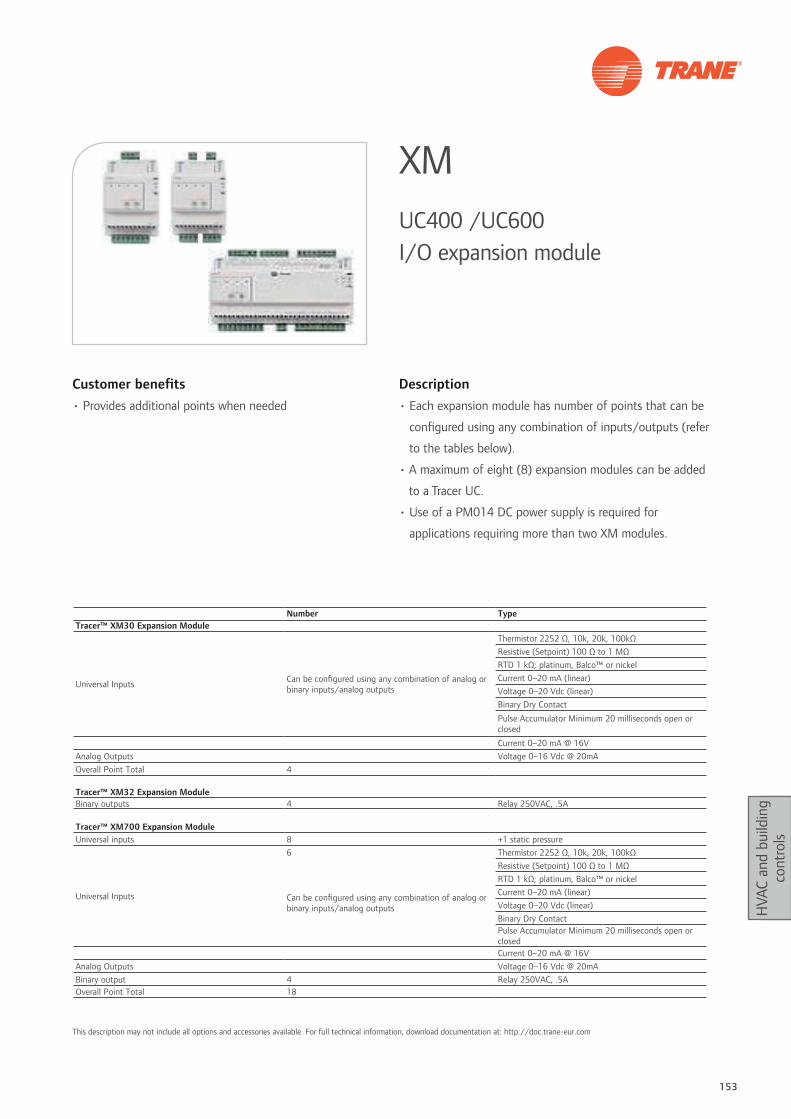
153
HVA
C an
d bu
ildin
g co
ntro
ls
Customer benefits• Provides additional points when needed
Description• Each expansion module has number of points that can be
configured using any combination of inputs/outputs (refer
to the tables below).
• A maximum of eight (8) expansion modules can be added
to a Tracer UC.
• Use of a PM014 DC power supply is required for
applications requiring more than two XM modules.
XMUC400 /UC600 I/O expansion module
Number TypeTracer™ XM30 Expansion Module
Universal Inputs Can be configured using any combination of analog or binary inputs/analog outputs
Thermistor 2252 Ω, 10k, 20k, 100kΩResistive (Setpoint) 100 Ω to 1 MΩRTD 1 kΩ; platinum, Balco™ or nickelCurrent 0–20 mA (linear)Voltage 0–20 Vdc (linear)Binary Dry Contact
Pulse Accumulator Minimum 20 milliseconds open or closed
Current 0–20 mA @ 16VAnalog Outputs Voltage 0–16 Vdc @ 20mAOverall Point Total 4
Tracer™ XM32 Expansion ModuleBinary outputs 4 Relay 250VAC, .5A
Tracer™ XM700 Expansion ModuleUniversal inputs 8 +1 static pressure
Universal Inputs
6 Thermistor 2252 Ω, 10k, 20k, 100kΩ
Can be configured using any combination of analog or binary inputs/analog outputs
Resistive (Setpoint) 100 Ω to 1 MΩRTD 1 kΩ; platinum, Balco™ or nickelCurrent 0–20 mA (linear)Voltage 0–20 Vdc (linear)Binary Dry ContactPulse Accumulator Minimum 20 milliseconds open or closedCurrent 0–20 mA @ 16V
Analog Outputs Voltage 0–16 Vdc @ 20mABinary output 4 Relay 250VAC, .5AOverall Point Total 18
This description may not include all options and accessories available. For full technical information, download documentation at: http://doc.trane-eur.com

154 Systems guide
HVA
C an
d bu
ildin
g co
ntro
ls
Customer benefits• Optimized commissioning: compact, factory-mounting
available, pre-commissioned
• Flexibility: same controller for several application types
(hot wax / 3 wires / …)
• Error-less interface wiring: RJ9 connector for quick and
reliable communication with wall interface
Description• Compact configurable controller
• Flexible and optimized for comfort and energy saving
control
• One controller for 20+ application variations
ZN523/ZN525Terminal unit controller
I/O Type Index Signal Type I/O useBinary inputs BI1 Dry contact Occupancy
BI2 Dry contact Window contact
Analog inputs AI1 thermistor Return air temperature
AI2 thermistor Entering water temperature
AI3 thermistor Discharge air temperature
Analog outputs AO1 0-10Vdc Motor speed control (ZN523: NA)
Binary outputs
BO1 relay 230 Vac / 3A NO High fan speed (ZN525: Fan motor power supply)BO2 relay 230 Vac / 3A NO Medium fan speed (ZN525: NA)BO3 relay 230 Vac / 3A NO Low fan speed (ZN525: NA)BO4 triac 230 Vac, 5 A Heat valve open, electric heat (solid state relay)BO5 triac 230 Vac, 5 A Heat valve closeBO6 triac 230 Vac, 5 A Cool valve openBO7 triac 230 Vac, 5 A Cool valve closeBO8 relay 230 Vac / 10A NO Electric heat (relay)
Main featuresPower 230 Vac 50/60 Hz 1phase
Operating environment 0 to +60°C5 - 95% humidity non-condensing
Storage environment - 40 to +85°C5 - 95% humidity non-condensing
Protection class IP 20Dimensions (mm) 132 x 120 x 44
Agency listing / compliance Immunity (directive 89/336/EEC)EN 50082-1: 1997 - EN 50082-2: 1995 Emissions EN 50081-1: 1992
Communication LonTalk® protocol SCC 8501 profileNetwork type: FTT10-A
Diagnosis interface 3 LED / "Service pin" 1 push button
This description may not include all options and accessories available. For full technical information, download documentation at: http://doc.trane-eur.com
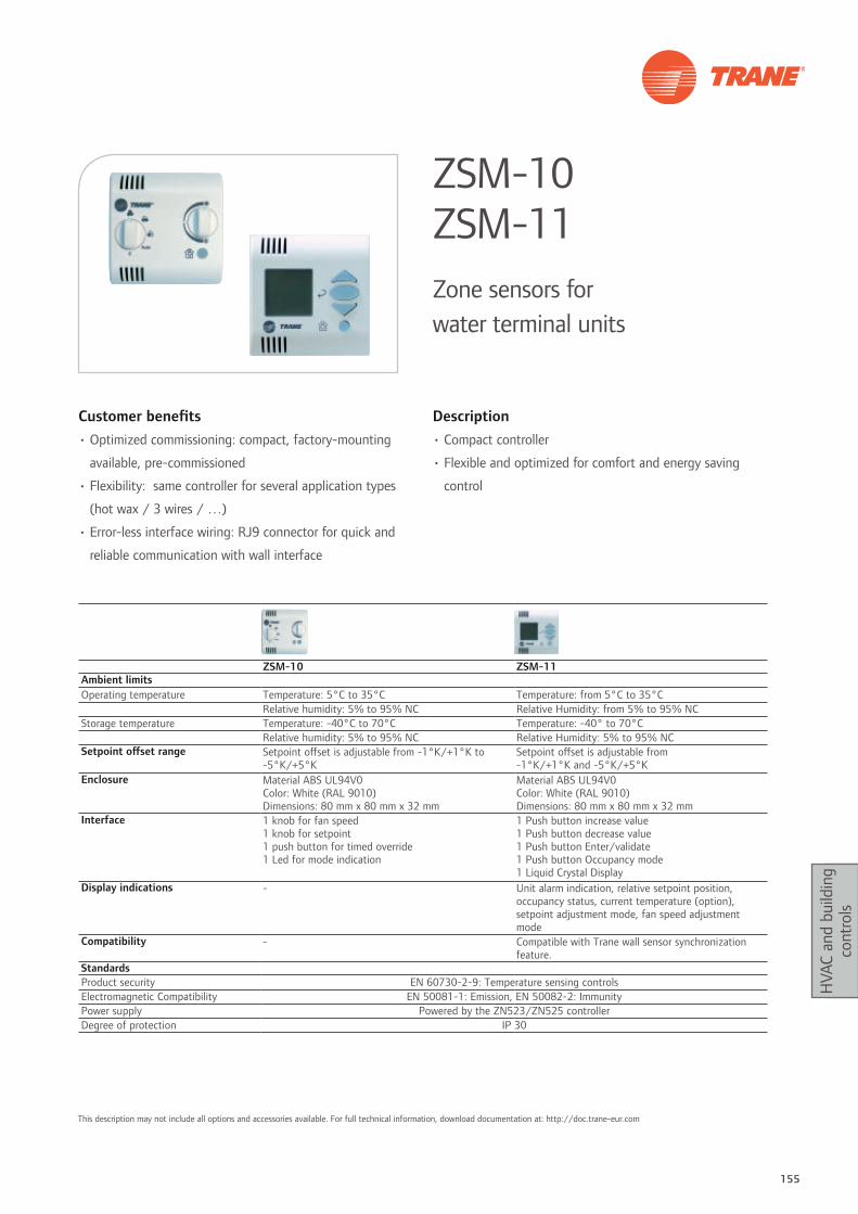
155
HVA
C an
d bu
ildin
g co
ntro
ls
Customer benefits• Optimized commissioning: compact, factory-mounting
available, pre-commissioned
• Flexibility: same controller for several application types
(hot wax / 3 wires / …)
• Error-less interface wiring: RJ9 connector for quick and
reliable communication with wall interface
Description• Compact controller
• Flexible and optimized for comfort and energy saving
control
ZSM-10 ZSM-11Zone sensors for water terminal units
ZSM-10 ZSM-11Ambient limitsOperating temperature Temperature: 5°C to 35°C Temperature: from 5°C to 35°C
Relative humidity: 5% to 95% NC Relative Humidity: from 5% to 95% NCStorage temperature Temperature: -40°C to 70°C Temperature: -40° to 70°C
Relative humidity: 5% to 95% NC Relative Humidity: 5% to 95% NCSetpoint offset range Setpoint offset is adjustable from -1°K/+1°K to
-5°K/+5°KSetpoint offset is adjustable from -1°K/+1°K and -5°K/+5°K
Enclosure Material ABS UL94V0Color: White (RAL 9010)Dimensions: 80 mm x 80 mm x 32 mm
Material ABS UL94V0Color: White (RAL 9010)Dimensions: 80 mm x 80 mm x 32 mm
Interface 1 knob for fan speed1 knob for setpoint1 push button for timed override1 Led for mode indication
1 Push button increase value1 Push button decrease value1 Push button Enter/validate1 Push button Occupancy mode1 Liquid Crystal Display
Display indications - Unit alarm indication, relative setpoint position, occupancy status, current temperature (option), setpoint adjustment mode, fan speed adjustment mode
Compatibility - Compatible with Trane wall sensor synchronization feature.
StandardsProduct security EN 60730-2-9: Temperature sensing controlsElectromagnetic Compatibility EN 50081-1: Emission, EN 50082-2: ImmunityPower supply Powered by the ZN523/ZN525 controllerDegree of protection IP 30
This description may not include all options and accessories available. For full technical information, download documentation at: http://doc.trane-eur.com
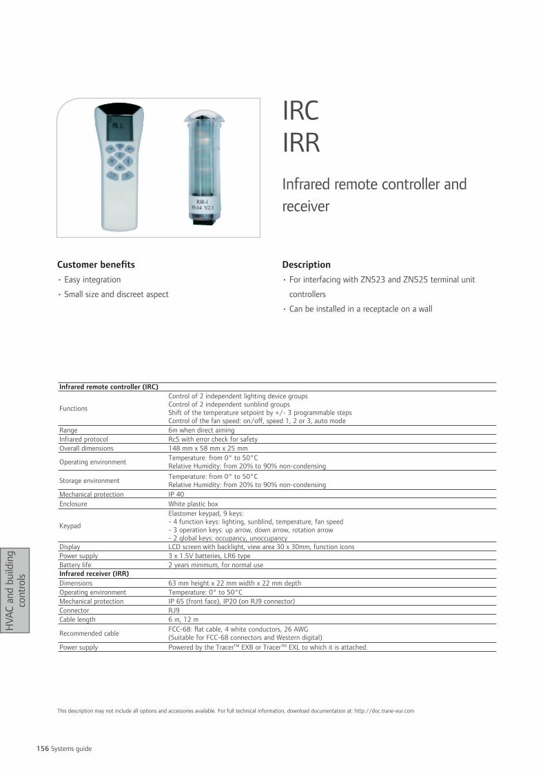
156 Systems guide
HVA
C an
d bu
ildin
g co
ntro
ls
Customer benefits• Easy integration
• Small size and discreet aspect
Description• For interfacing with ZN523 and ZN525 terminal unit
controllers
• Can be installed in a receptacle on a wall
IRC IRRInfrared remote controller and receiver
Infrared remote controller (IRC)
Functions
Control of 2 independent lighting device groupsControl of 2 independent sunblind groupsShift of the temperature setpoint by +/- 3 programmable stepsControl of the fan speed: on/off, speed 1, 2 or 3, auto mode
Range 6m when direct aimingInfrared protocol Rc5 with error check for safetyOverall dimensions 148 mm x 58 mm x 25 mm
Operating environment Temperature: from 0° to 50°CRelative Humidity: from 20% to 90% non-condensing
Storage environment Temperature: from 0° to 50°CRelative Humidity: from 20% to 90% non-condensing
Mechanical protection IP 40Enclosure White plastic box
Keypad
Elastomer keypad, 9 keys:- 4 function keys: lighting, sunblind, temperature, fan speed- 3 operation keys: up arrow, down arrow, rotation arrow- 2 global keys: occupancy, unoccupancy
Display LCD screen with backlight, view area 30 x 30mm, function iconsPower supply 3 x 1.5V batteries, LR6 typeBattery life 2 years minimum, for normal useInfrared receiver (IRR)Dimensions 63 mm height x 22 mm width x 22 mm depthOperating environment Temperature: 0° to 50°CMechanical protection IP 65 (front face), IP20 (on RJ9 connector)Connector RJ9Cable length 6 m, 12 m
Recommended cable FCC-68: flat cable, 4 white conductors, 26 AWG(Suitable for FCC-68 connectors and Western digital)
Power supply Powered by the TracerTM EXB or TracerTM EXL to which it is attached.
This description may not include all options and accessories available. For full technical information, download documentation at: http://doc.trane-eur.com

Building services Trane Building Services provide a wide range of offerings that enable you to benefit
from the highest levels of performance from the systems in your facility. Whether you’re installing new equipment, maintaining an existing system or completely upgrading your
infrastructure, Trane Building Services provide exactly the expertise you need.

158 Systems guide
Build
ing
serv
ices
Customer benefits
Trane’s startup services are key to ensuring your new
product purchases are installed correctly and operating
at maximum performance during the first year. Trane’s
factory authorized technicians have access to the latest
training and service tools to optimize ensure HVAC design
performance and optimal operation.
Main features
• Startup - following prescribed engineering checklists
to ensure all equipment functions meet operational
parameters in a reliable and efficient manner
• Operation - from startup, ensures new Trane products will
operate within designed parameters
• Performance - assures customers that new Trane products
will operate at peak reliability and efficiency during first
year of service. These services are available for all Trane
products.
Elite Start™ servicesSolutions for proper and optimized operation
For full technical information, download documentation at: http://doc.trane-eur.com

159
Build
ing
serv
ices
Customer benefits
Assure first-year system performance
Make sure your HVAC system gets off to the right start with
Trane Extended Start. It’s the best way to validate proper
installation and assure the highest level of performance
during that all-important first year of operation.
Trane Extended Start goes above and beyond the warranty
and includes five essential services and three optional
services which will create a system baseline to build a strong
high performance building foundation.
1. Validate Installation and Startup
Most HVAC failures that occur early in the system’s life are
during the first year of operation.
2. Monitor Critical Parameters and Adjust System Settings
Monitoring first-year operation and critical parameters is
crucial during the initial break-in months. This assures your
investment is properly integrated into your environment,
and is providing peak performance and efficient energy use.
Main features
The baseline for high performance buildings: twelve months
of value-added services
Trane Extended Start - 5 plus 3
5 Essential Services
• Post-installation inspection
• to validate that installation and start-up were done to
factory specifications.
• Benchmark report
• an analysis of the current operating characteristics
of your equipment. It will be an “as-installed”
benchmark to track changes in performance in later
years.
• Health check inspection
• to measure critical parameters, adjust unit control
settings and correct any operational deviations.
• Chiller oil analysis
• to analyze samples, indicate any deviation and
recommend corrective actions.
• Filter changes
• as per Trane recommendations to maximize flow and
system efficiency.
3 Optional Services
• Vibration analysis
• to establish a benchmark reference to later identify
a range of future faults such as shaft misalignment,
bearing defects, or motor electrical problems.
• Get connected
• to remotely monitor critical alarms, provide periodic
communications link verification and produce
automatic critical alarm activity reports.
• Operator training
• your operators receive on-site training on best
operation and maintenance procedures to ensure safe,
reliable and efficient operation of your system.
Trane Extended StartFoundation for high performance buildings
For full technical information, download documentation at: http://doc.trane-eur.com

160 Systems guide
Build
ing
serv
ices
Having the right part for your needs is only part of the story.
From precision Trane original to generic parts, Trane offers
a comprehensive parts inventory to answer customers’
needs. This means finding the right part for you, regardless
of who makes it. Whether you are looking for compressors,
controls, electrical supplies, HVAC accessories, chemicals, or
tools and tests equipment, we can give you a competitive
edge.
State-of-the-art logistics
We have the infrastructure to find, deliver and even install
the required part anywhere in the world with a minimum of
downtime. Trane is committed to giving you the best value
backed with the most advanced logistics infrastructure and
a highly efficient distribution network.
– Main Parts Center in Genk, Belgium with 5,000 references
and a total of 250,000 parts.
– Three additional major Parts Distribution Centers in Turkey,
the United Arab Emirates and India.
– Logistic platforms in Trane factories.
– Local parts centers to ensure all your parts needs are
fulfilled.
Easy to do business with
• Simple to contact a Trane service expert.
• A reliable and loyal partner.
• Consistent level of service throughout Europe, Middle
East, India and Africa.
• A single-source supplier for Trane original and generic
parts, simplifying purchasing processes and invoicing.
Expertise
• With over 90 years of experience, Trane stands out in the
industry as a reference in terms of innovation, high quality
and efficient service.
• Highly qualified Trane professionals provide the right
solution for your specific needs, no matter what your
system, budget, or brand requirements might be.
Fast and efficient
• Easy access to parts information and quick quotations.
• On-line inventory management system offers real-time
visibility of inventory levels to all Trane sales offices.
• Strategically located near international carrier hubs, Genk
Parts Center enables late order processing with guaranteed
next day delivery.
• On-line tracking system provides reliable shipment
status.
Competitive pricing
• On Trane and generic parts.
• On shipping costs thanks to strategically located parts
centers and our extended distribution network.
Customer proximity
With 130 locations in Europe, Middle East, India and Africa,
Trane has one the most extended service networks always
offering expert advice on the right parts, at the right place
and at the right time.
HVAC parts and supplies
For full technical information, download documentation at: http://doc.trane-eur.com
161
Build
ing
serv
ices
Customer benefits
Best cost of ownership
• Planned maintenance ensures your HVAC system runs at
top efficiency, providing up to 12% energy savings.
• Your equipment will receive regular inspection, preventive
maintenance and proper calibration. Any potential problem
will be corrected before anyone in your building becomes
aware of it.
• In choosing your level of coverage, you know exactly what
services and parts are covered.
There are no surprises when it comes to expenses.
Total peace of mind
• Trane looks out for your needs.
Main features
With our extended service plans, Trane is your ideal service
solutions provider to protect your HVAC installation
investment. Trane Select Contracts are tailored to fit your
HVAC system needs and business requirements.
They offer four different levels of coverage - from
preventive maintenance plans to comprehensive
maintenance.
Trane Select™ contractsComprehensive service contracts for HVAC systems
Maintenance
24hrs/day, 7 days/week Parts coverage
Lifecycle management
For full technical information, download documentation at: http://doc.trane-eur.com
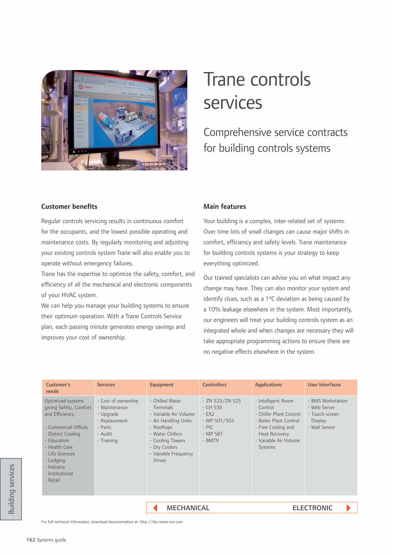
162 Systems guide
Build
ing
serv
ices
Customer benefits
Regular controls servicing results in continuous comfort
for the occupants, and the lowest possible operating and
maintenance costs. By regularly monitoring and adjusting
your existing controls system Trane will also enable you to
operate without emergency failures.
Trane has the expertise to optimize the safety, comfort, and
efficiency of all the mechanical and electronic components
of your HVAC system.
We can help you manage your building systems to ensure
their optimum operation. With a Trane Controls Service
plan, each passing minute generates energy savings and
improves your cost of ownership.
Main features
Your building is a complex, inter-related set of systems.
Over time lots of small changes can cause major shifts in
comfort, efficiency and safety levels. Trane maintenance
for building controls systems is your strategy to keep
everything optimized.
Our trained specialists can advise you on what impact any
change may have. They can also monitor your system and
identify clues, such as a 1ºC deviation as being caused by
a 10% leakage elsewhere in the system. Most importantly,
our engineers will treat your building controls system as an
integrated whole and when changes are necessary they will
take appropriate programming actions to ensure there are
no negative effects elsewhere in the system.
Trane controls servicesComprehensive service contracts for building controls systems
Customer’s needs
Services Equipment Controllers Applications User Interfaces
Optimized systems giving Safety, Comfort and Efficiency:
- Commercial Offices- District Cooling - Education- Health Care- Life Sciences- Lodging- Industry- Institutional- Retail
- Cost of ownership- Maintenance- Upgrade- Replacement- Parts - Audit- Training
- Chilled Water Terminals
- Variable Air Volume- Air Handling Units- Rooftops- Water Chillers- Cooling Towers- Dry Coolers- Variable Frequency
Drives
- ZN 523/ZN 525- CH 530- EX2- MP 501/503- PIC- MP 581- BMTX
- Intelligent Room Control
- Chiller Plant Control- Boiler Plant Control- Free Cooling and
Heat Recovery- Variable Air Volume
Systems
- BMS Workstation- Web Server- Touch screen
Display- Wall Sensor
MEChAnICAl ElECtronIC
For full technical information, download documentation at: http://doc.trane-eur.com

163
Build
ing
serv
ices
Customer benefits • Optimize your system performance
• Protect your investment
Main features
Building owners and companies in all markets face new
challenges and embrace a world full of change:
• Innovation
• Reorganization
• Compliance
• Reprioritization
We’re ready to help restore and modernize your HVAC
installation to meet your building’s current needs.
No matter where your equipment is in its life cycle,
Trane CareTM can restore and modernize your installation to
help your building perform at its best and sustain it day in
and day out:
• Renewal services
• Technology upgrades
• Replace/repair decision consultations
• Reprioritization
Trane will turn your building systems into business
advantages in terms of reliability, energy and environment.
Reliability Solutions
Our service experts will identify where your HVAC
installation is not performing to its full potential and offer
the solutions that will restore like-new reliability
Energy Solutions
Trane CareTM offers cost-effective solutions to optimize the
energy efficiency of your existing system and generate
immediate savings
Environment Solutions
Trane CareTM third focus can provide solutions that reduce
building and system impacts on the environment and
human health
A Trane CareTM upgrade of your HVAC installation will
provide peak performance:
• Right level of indoor air quality
• Reduced operating costs
• Extended equipment life
• Compliance with governmental and environmental
regulations
We have the same goal: your business success.
Trane Care™ servicesComprehensive HVAC service solutions for high-performance buildings
rElIABIlItYVibration Analysis
Exchanger Cleaning
Leak Testing
Tube Testing
Variable Frequency Drives
Refrigerant Monitor
Oil Analysis
Heat Recovery
Noise Reduction
Exchanger Enhancement
Control Retrofit
Indoor Air Quality
Compressor R’newal™
Adiabatic cooling
Refrigerant Retrofit
EnErGY
EnVIronMEnt
For full technical information, download documentation at: http://doc.trane-eur.com

164 Systems guide
Build
ing
serv
ices
Customer benefits
Every piece of HVAC equipment with rotating components
has its own vibration signature.
Any change in this signature can be used as an accurate
means of identifying developing problems such as bearing
wear, shaft imbalacing, and degrading helical-rotary
compressor rotor tolerance.
The monitoring and diagnostics system will reliably detect
not only potential defects at the initial stage of their
development but also identify the exact defect type and its
severity. Vibration analysis can identify problems long before
they become noticeable.
Main features
The vibration measurement and analysis techniques used by
Trane can identify a wide range of developing faults such
as shaft misalignment, bearing defects, imbalance, or motor
electrical problems.
Sensitive sensors are installed in carefully selected places.
The smallest deviation or any abnormal behavior is detected
and recorded. The vibration spectrum of your equipment
illustrates its internal condition. These graphs are simply and
clearly explained to you. To help you further, we will provide
you recommendations in terms of maintenance scheduling.
If the vibration analysis report indicates, for instance, an
imminent compressor fault, then we will advise you how to
plan for a scheduled compressor renewal.
Vibration analysisA Trane Care™ predictive maintenance service
For full technical information, download documentation at: http://doc.trane-eur.com

165
Build
ing
serv
ices
Customer benefits
• Improved equipment operation and reliability
• Extended equipment life
• Reduced operating costs
• Reduced risk of costly breakdowns
• Reduced downtime.
Main features
The condition of the tubes in a shell and tubes heat
exchanger has a direct impact on the efficiency of your
chiller. Depending on its size, a heat exchanger contains
hundreds or thousands tubes, all undergoing mechanical
stress and chemical corrosion. Tubes are therefore critical
to chiller performance, and yet standard maintenance
techniques can check most everything except these tubes.
Equipped with the latest technological tools, Trane can
detect, locate and record internal and external corrosion,
deposits, wear or cracking before their consequences start to
damage your installation.
This analysis results in a detailed report containing all the
recordings, photographs of defective zones, and most
importantly, recommendations as to the technical and
practical actions required to resolve the situation.
Eddy current tube analysisA Trane Care™ predictive maintenance service
For full technical information, download documentation at: http://doc.trane-eur.com

166 Systems guide
Build
ing
serv
ices
The Trane Chemical Laboratory has developed the
specialized expertise to analyze various types of fluids found
in your HVAC installation.
Having regular analyses done by experienced service
engineers helps reduce maintenance costs and guarantee
equipment efficiency and reliability. Problems can be found
and fixed before they become major.
• Fast delivery of results
• Graphs of the current test data with past test data for easy
comparison
• Past and present interpretations and service
recommendations
Compressor oil analysis
• All compressor makes and types (scroll, reciprocating,
helical-rotary and centrifugal)
• Helps extend the life of the existing charge and maintain
compressor efficiency
• Allows compressor repairs to be scheduled to reduce
downtime
• Identify problems without tearing down the compressor
• Reduce problems of used oil disposal
• Lower refrigerant emissions
• Standard testing includes: ferrous index, non-ferrous
index, particle count, spectrometry, wear level evolution
chart, contamination index, total presence of moisture,
contamination level evolution chart, chemical index,
dielectric test, viscosity at 40°C, viscosity index, chemistry
level evolution chart, TAN (total acid number) test.
refrigerant analysis
• Detects contamination levels. When contaminant levels
fall outside acceptable ranges, corrective actions are
recommended.
• All types of refrigerants
• Helps extend the life of the existing charge
lithium bromide analysis
• Detects substance imbalance
• Corrective actions are recommended if necessary.
• Helps extend the life of the existing charge
Chemical analysisA Trane Care™ predictive maintenance service
For full technical information, download documentation at: http://doc.trane-eur.com

167
Build
ing
serv
ices
Customer benefits
Equipment breakdown can have disastrous consequences.
In human terms, it can mean discomfort to building tenants,
leading to dissatisfaction and complaints.
In financial terms, it can mean extensive repair or
replacement costs. But with Trane R’newalTM, all this can be
avoided.
The Trane R’newalTM program is a comprehensive service
solution designed to restore your chiller’s compressor
performance and reliability to like-new levels.
Main features
The R’newalTM service restores your compressor to like-new
specifications and operating condition:
• Thorough cleansing
• Clearance measurements
• Mechanical parts are ground and polished where necessary
to restore optimal operation.
• Motor: thorough electrical tests, revarnishing or new
replacement motor fitted.
• Original quality parts replacement: bearings, gaskets,
non-return valve, capacity control valve, lip seal, motor
terminals, impellers.
• Remounting
• Packing: compressor is painted and packed for shipping to
your site.
Compressor R’Newal™A Trane Care™ service
For full technical information, download documentation at: http://doc.trane-eur.com
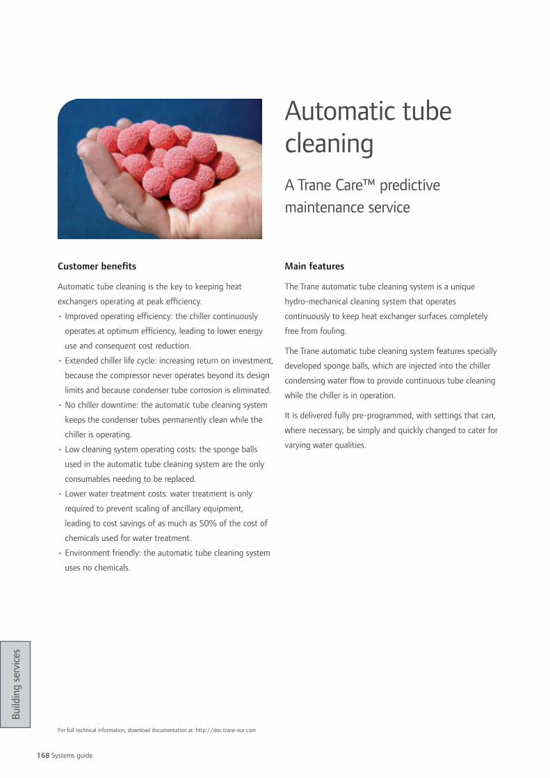
168 Systems guide
Build
ing
serv
ices
Customer benefits
Automatic tube cleaning is the key to keeping heat
exchangers operating at peak efficiency.
• Improved operating efficiency: the chiller continuously
operates at optimum efficiency, leading to lower energy
use and consequent cost reduction.
• Extended chiller life cycle: increasing return on investment,
because the compressor never operates beyond its design
limits and because condenser tube corrosion is eliminated.
• No chiller downtime: the automatic tube cleaning system
keeps the condenser tubes permanently clean while the
chiller is operating.
• Low cleaning system operating costs: the sponge balls
used in the automatic tube cleaning system are the only
consumables needing to be replaced.
• Lower water treatment costs: water treatment is only
required to prevent scaling of ancillary equipment,
leading to cost savings of as much as 50% of the cost of
chemicals used for water treatment.
• Environment friendly: the automatic tube cleaning system
uses no chemicals.
Main features
The Trane automatic tube cleaning system is a unique
hydro-mechanical cleaning system that operates
continuously to keep heat exchanger surfaces completely
free from fouling.
The Trane automatic tube cleaning system features specially
developed sponge balls, which are injected into the chiller
condensing water flow to provide continuous tube cleaning
while the chiller is in operation.
It is delivered fully pre-programmed, with settings that can,
where necessary, be simply and quickly changed to cater for
varying water qualities.
Automatic tube cleaningA Trane Care™ predictive maintenance service
For full technical information, download documentation at: http://doc.trane-eur.com

169
Build
ing
serv
ices
Customer benefits
If you are a building owner who has an older Trane
CenTraVac™ chiller, this is the right solution for you. The
Trane Tracer AdaptiView™ control panel upgrade allows you
to update your chillers to the same controls offered on new
Trane CenTraVacTM chillers.
Tracer AdaptiViewTM helps operators keep the chiller
plant running at its most efficient level. All this is made
possible by a graphical user interface that provides deeper
understanding, along with quicker response times.
• Improves operator productivity
• Guarantees continuous operation utilizing industry best
adaptive control algorithms
• Optimizes chiller operation
• Offers easier integration in Building Automation Systems
thanks to open protocol flexibility
Main features
AdaptiView™ upgradeA Trane Care™ service for centrifugal chillers
1 large, full-color touch screen for fingertip control of chiller subsystems2 Instant access to operational data for faster issue analysis and resolution3 At-a-glance status updates readily display key operating parameters4 Easy-to-read trending charts and diagnostic reports help fine tune chiller control5 Industry-leading algorithms optimize control during rapidly changing conditions
Specifications
• Adjustable arm and tilt screen for better viewing
• Opened protocols: BACnet, MSTP Lontalk, Comm4,
Modbus Slave
• Optional cover UV IP56 available for outdoor usage
For full technical information, download documentation at: http://doc.trane-eur.com
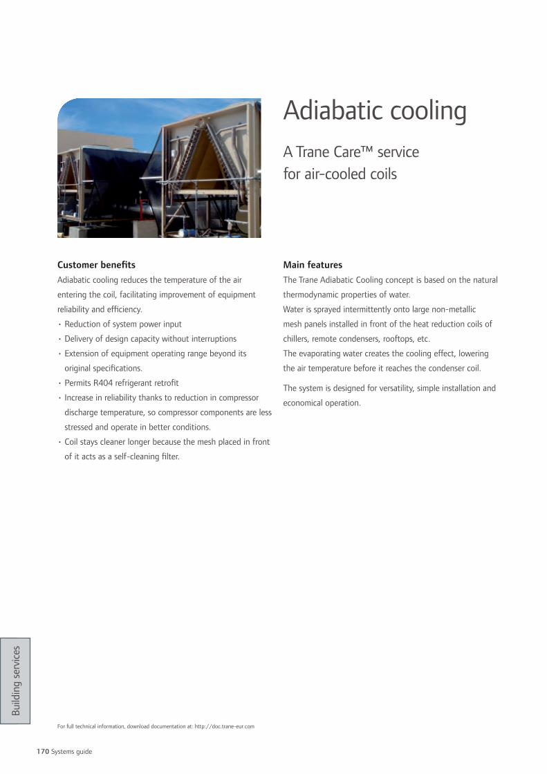
170 Systems guide
Build
ing
serv
ices
Customer benefitsAdiabatic cooling reduces the temperature of the air
entering the coil, facilitating improvement of equipment
reliability and efficiency.
• Reduction of system power input
• Delivery of design capacity without interruptions
• Extension of equipment operating range beyond its
original specifications.
• Permits R404 refrigerant retrofit
• Increase in reliability thanks to reduction in compressor
discharge temperature, so compressor components are less
stressed and operate in better conditions.
• Coil stays cleaner longer because the mesh placed in front
of it acts as a self-cleaning filter.
Main featuresThe Trane Adiabatic Cooling concept is based on the natural
thermodynamic properties of water.
Water is sprayed intermittently onto large non-metallic
mesh panels installed in front of the heat reduction coils of
chillers, remote condensers, rooftops, etc.
The evaporating water creates the cooling effect, lowering
the air temperature before it reaches the condenser coil.
The system is designed for versatility, simple installation and
economical operation.
Adiabatic coolingA Trane Care™ service for air-cooled coils
For full technical information, download documentation at: http://doc.trane-eur.com

171
Build
ing
serv
ices
Customer benefits• Early awareness ensures earlier corrective actions
• Proactive measurement 24 hours a day, 365 days a year
• Reduction of your building and system impact on the
environment and human health
• Improvement of your equipment operation.
Leakages impact reliability and energy efficiency
• Risk reduction of costly breakdowns
• Extension of your equipment lifetime.
Optimal refrigerant charge reduces component stress
• Compliance with (EU) F-Gas regulation and/ or ozone
regulation workplace codes (health and safety), and other
national regulations.
Main featuresStandard monitor
• Technology: Semi-conductor
• Integrated visible and sound alarm
• Multi-refrigerant control
• Sensitivity: 10ppm
• Analog connectivity: Free relays
• Can be connected to a Trane Building Management
System
Premium monitor
• Technology: Photo-acoustic Infrared
• LCD display
• Multi-refrigerant control
• Sensitivity: 1ppm
• Digital connectivity: Free relays, 4-20 mA analog output
or serial communication (RS 232)
• Can be connected to a Trane Building Management
System
Leak testing
Trane CareTM customized service solutions offer a tailored
leak testing procedure to identify where a refrigerant leak
occurs. This procedure is an integral part of any Trane
maintenance contract but can also be ordered as a separate
service solution.
Refrigerant managementA Trane Care™ service Automatic refrigerant monitoring system
For full technical information, download documentation at: http://doc.trane-eur.com

172 Systems guide
Build
ing
serv
ices
Customer benefitsTrane refrigerant retrofit is the key to upgrading HCFC 22
equipment and maintaining optimum performance and
efficiency.
A retrofit ensures that your system complies with
international ozone regulations
Trane can advise on the best way to maintain optimum
performance and efficiency
Main featuresOptions for HCFC 22 replacement include:
• Retrofit to an HFC refrigerant. This can be an attractive
option, depending on equipment type, age and working
conditions. Only Trane has the necessary computer based
selection tools to do the retrofit properly and ensure the
results.
• Keep operating your HCFC equipment after 2015. Trane
can advise you on refrigerant containment strategies.
• Replace your HCFC equipment before 2015 with
equipment using non ozone-depleting HFCs.
Trane Engineered Retrofit
A Trane engineered retrofit, factory tested and qualified,
optimizes your chiller to meet your current operation needs.
Performed on site it will restore your chiller to its original
state, allowing your system to run at peak performance with
ozone friendly refrigerants (R134a, R404A, R407C).
Trane Soft Retrofit
A soft retrofit can act as a bridge to either an engineered
retrofit or equipment replacement if fast action is needed
due to breakdown or refrigerant loss. In such cases, Trane
can provide an economical solution using an alternative
refrigerant. The soft retrofit depends greatly on the type of
chiller and heat exchangers, running conditions, levels of
expected performance and climatic conditions.
Refrigerant retrofitA Trane Care™ service HCFC 22 equipment upgrade
HCFC 22 production stopped at the end of 2009. Recycled or reclaimed refrigerant is available but not sufficient, consequently a shortage of HCFC 22 is inevitable and can lead to both unplanned downtime and aggressive price rises.The limited availability will also increase the risk that certain companies might offer “polluted” or illegally imported virgin HCFC 22. It is, of course, illegal to use such refrigerants and doing so can put your business at risk.
hCF 22 Availability versus Price (EU only)
Price
Demand
Shortage
Recycled or reclaimed R22 only
Virgin R22 and recycled or reclaimed R22
2005 Dec-2009 Dec-2014
For full technical information, download documentation at: http://doc.trane-eur.com

173
Build
ing
serv
ices
Customer benefits
Trane Intelligent Services helps minimize the occurrence
and severity of system failures through early detection of
alarms and performance issues. With automated monitoring
that’s always on, and Technical Specialists watching non-
stop, nothing slips by unnoticed.
If you need to consolidate or centralize your Operations,
Trane Intelligent Services can deliver the standardized
procedures and consistent outcomes you want, at a fraction
of the costs you would incur to set up the capabilities
in-house. Trane invests in leading technologies and top-
notch personnel, so you don’t have to.
Main features
Trane Intelligent Services is available in three options that
provide increasing levels of functionality.
Level 1: Alarm notification
A custom notification procedure assures rapid response to
system faults.
Level 2: Active monitoring
The benefits of level 1, plus alarm management, timely
diagnosis and intelligent mobilization of local resources.
Level 3: Building performance
Provides the benefits of levels 1 and 2, plus open gateway
to Trane expertise and recommendation to keep your
building operating at peak efficiency. Close monitoring and
analysis of the system trends by Trane analytical programs
and technical specialists elevates decisions regarding HVAC
system performance to a strategic business level.
Trane intelligent servicesAdvanced capabilities in remote building system monitoring
For full technical information, download documentation at: http://doc.trane-eur.com

174 Systems guide
Build
ing
serv
ices
realistic means to reach your specific building goals: energy, financials, sustainability or occupant satisfaction
Over the lifecycle of your building, you could substantially
strengthen your bottom line through reduced energy bills
and improved operational efficiencies. High Performance
Buildings will help you, the building owner:
• Maximize the value and ROI of your property,
• Take advantage of Trane knowledge and expertise to
achieve operational advances,
• Utilize smart and sustainable energy resources to lower
variable costs
• Reduce your building’s carbon footprint
• Increase the productivity and satisfaction of the lives in
your building
Trane will work with you through every step of the process,
reaching your goals, helping to eliminate inefficiency and
increasing your ROI for the life of your building. High
Performance Building assessments offer diverse benefits to
building owners, depending on whether you are restoring
and modernizing an older building or taking a proactive
approach to operating and maintaining a newer structure.
The best performing buildings are designed for efficiency
from the ground up. The processes and systems that keep
a building functioning are interrelated, and one process
affects others. That’s why it’s critical to have a higher level
of knowledge, training and experience on every system –
not just one or two – when designing a sustainable building
environment.
We base our recommendations on a deep understanding
of your priorities and other big-picture factors – your
strategic objectives, maintenance philosophy, environmental
consciousness and the level of control you want over your
building’s systems.
Our services professionals and engineers use an assessment-
based approach resulting in customized and outcome-
based solutions in designing and delivering these services.
We share information, knowledge and industry leading
practices to help businesses achieve high performance,
sustainable building systems and practices that generate
energy, financial and operational efficiencies and reduce the
impact to the environment.
High Performance Building
For full technical information, download documentation at: http://doc.trane-eur.com

175
Build
ing
serv
ices
Energy retrofit Services
If you own or operate a small to mid-sized commercial
building built or upgraded more than 10 years ago, we
can show you what can be done to increase your energy
efficiency, how much it will cost and how much you will save
over time.
turnkey Contracting Services
From replacing a chiller to customized system and
infrastructure solutions, our Turnkey Contracting Services are
based on a thorough understanding of your business goals
as well as your infrastructure needs. With our full knowledge
of the interrelated workings of your building or buildings,
we can recommend adjustments in equipment and services
for maximum efficiency and cost-savings. Leverage these
efficiencies to finance your capital investment with future
savings, backed by the added confidence of a performance
contract from Trane.
Comprehensive Solutions
Certain organizations and industries, such as datacenters
and hospitals require a customized approach to their indoor
environment, energy use and operational efficiencies. Based
on a detailed understanding of your organization’s strategy
and goals – and how your facility contributes to reaching
these objectives – Trane provides specialized services to
maximize the unique needs of your operation.
Mission-critical hVAC systems
Datacenter
Food and Beverage
Healthcare
Industrial
Lodging
Life Sciences and Biotechnologies

Notes
176 Systems guide

Notes
177

Index by name
Name PageAdaptiView™ upgrade A Trane Care™ service for centrifugal chillers 169Adiabatic cooling A Trane Care™ service for air-cooled coils 7, 170AH541 Air handling unit controllers 143, 146Automatic tube cleaning A Trane Care™ predictive maintenance service 168BAC Active chilled beam 5, 108BCU Building systems controller 142CCEB Custom air handling unit 5, 90CCTA Air handling unit 86CCTB Air handling unit 86CCUH Condenserless scroll chillers 44CCUN Condenserless scroll chillers 46CDHF CenTraVac™ Water-cooled centrifugal packaged chiller 54CDHG CenTraVac™ Water-cooled centrifugal packaged chiller 54CFAS 1-way cassette water terminal 102CGA Air-cooled scroll chiller 28CGAK Air-cooled scroll chiller 26CGAM AquaStream 3G™ Air-cooled scroll chiller 4, 30, 56CGAR Reversible air-to-water heat pump 62CGCL Air-cooled scroll chiller 42CGWH Water-cooled packaged chiller 44CGWH Water-to-water heat pump 74CGWN Water-cooled packaged chiller 46CGWN Water-to-water heat pump 76Chemical analysis A Trane Care™ predictive maintenance service 166CLCE Air handling unit 82CLCP Air handling unit 88Comprehensive Solutions 175Compressor R’Newal™ A Trane Care™ service 167CVGF CenTraVac™ Water-cooled centrifugal packaged chiller 52CVHE CenTraVac™ Water-cooled centrifugal packaged chiller 54CVHF CenTraVac™ Water-cooled centrifugal packaged chiller 54CVHG CenTraVac™ Water-cooled centrifugal packaged chiller 54CWE 4-way cassette water terminal 5, 100CWS 4-way cassette water terminal 100CXA Reversible air-to-water heat pump 64CXAM AquaStream 3G™ Reversible air-to-water heat pump 4, 59, 66DKD Voyager™ Packaged rooftop 118, 120DKH Voyager™ Packaged rooftop 118, 120DLEA Linear slot diffuser 112DSEA Multidirectional diffuser 113EDAB Mercury Close control unit 128EDAV Mercury Close control unit 128EDCB Mercury Close control unit 128EDCV Mercury Close control unit 128Eddy current tube analysis A Trane Care™ predictive maintenance service 165EDWB Mercury Close control unit 128EDWV Mercury Close control unit 128Elite Start™ services Solutions for proper and optimized operation 158Energy Retrofit Services 175EUAB Mercury Close control unit 128EUAV Mercury Close control unit 128EUCB Mercury Close control unit 128EUCV Mercury Close control unit 128EUWB Mercury Close control unit 128EUWV Mercury Close control unit 128EX2 MP581 I/O expansion module 151FCC UniTrane™ fan coil water terminal 92FCD UniTrane™ ductable fan coil water terminal 94FCK UniTrane™ fan coil water terminal 92FCU UniTrane™ ductable fan coil water terminal 96FED UniTrane™ ductable fan coil water terminal 5, 94FEU UniTrane™ ductable fan coil water terminal 5, 96FVC UniTrane™ fan coil water terminal 92FWD Ductable water terminal 98Heat rejection systems 60HFCE Fan coil water terminal 104HFCF Fan coil water terminal 106HFXE Fan coil water terminal 104High Performance Building 174HRCU Air handling unit - Heat recovery compact unit 5, 84HVAC parts and supplies 160IRC Infrared remote controller 156IRR Infrared remote receiver 156JDAC Jupiter Close control unit 126JDAV Jupiter Close control unit 126JDCC Jupiter Close control unit 126JDCV Jupiter Close control unit 126JDWC Jupiter Close control unit 126JDWV Jupiter Close control unit 126Jenesys Tracer Summit™ communication bridge 148
Name PageJUAC Jupiter Close control unit 126JUAV Jupiter Close control unit 126JUCC Jupiter Close control unit 126JUCV Jupiter Close control unit 126JUWC Jupiter Close control unit 126JUWV Jupiter Close control unit 126LPCF VariTrane™ Variable air volume systems 110LPEF VariTrane™ Variable air volume systems 110LPWF VariTrane™ Variable air volume systems 110LSCF VariTrane™ Variable air volume systems 110LSEF VariTrane™ Variable air volume systems 110LSWF VariTrane™ Variable air volume systems 110MP501 Input/output controller 149MP503 Input/output controller 149MP581 Air handling unit controller 150, 151
Protocol gateway Interface between Trane equipment and third-party BMS 147
PIC Tracer Summit™ communication bridge 148RAUJ Condensing unit 124RAUL Condensing unit 122
Refrigerant management A Trane Care™ service - Automatic refrigerant monitoring system 171
Refrigerant retrofit A Trane Care™ service - HCFC 22 equipment upgrade 172RTAC Air-cooled helical-rotary chiller 4, 38RTAD Air-cooled helical-rotary chiller 36RTHD Water-cooled packaged helical-rotary chiller 50RTUD Condenserless helical-rotary chiller 48RTWD Water-cooled packaged helical-rotary chiller 4, 48RTWD Water-to-water heat pump 4, 78TR200 Variable frequency drive 15, 19
Tracer ES™ control software Enterprise level management - building management solution 7, 136, 139
Tracer ES™ express software Enterprise level management - building management solution 7, 136, 139
Tracer Summit™ BMS workstation software solution 138, 141Tracer™ SC Web-based all-in-one BMS solution 7, 134, 140
Trane Care™ Services Comprehensive HVAC service solutions for high-performance buildings 163
Trane controls services Comprehensive service contracts for building controls systems 162
Trane Extended Start Foundation for high performance buildings 6, 159
Trane Intelligent Services Advanced capabilities in remote building system monitoring 173
Trane Select™ contracts Comprehensive service contracts for HVAC systems 161TSD Voyager™ Packaged rooftop 116TSH Voyager™ Packaged rooftop 116Turnkey Contracting Services 175UC400 VAV terminal unit/Air handling unit controllers 7, 145, 146, 152
UC600 Air handling unit controller 145, 146, 152
UC800 Centrifugal chiller unit controller 7UCM VAV III/IV VAV terminal unit controllers 145VCCF VariTrane™ Variable air volume systems 110VCDF VariTrane™ Variable air volume systems 110VCEF VariTrane™ Variable air volume systems 110VCWF VariTrane™ Variable air volume systems 110VFCE VariTrane™ Variable air volume systems 110VFXE VariTrane™ Variable air volume systems 110VGA Air-cooled scroll chiller 28Vibration analysis A Trane Care™ predictive maintenance service 164VPCF VariTrane™ Variable air volume systems 110VPEF VariTrane™ Variable air volume systems 110VPWF VariTrane™ Variable air volume systems 110VSCF VariTrane™ Variable air volume systems 110VSEF VariTrane™ Variable air volume systems 110VSWF VariTrane™ Variable air volume systems 110VV550 VAV terminal unit controllers 143, 145VXA Reversible air-to-water heat pump 64WSD Voyager™ Packaged rooftop 116WSH Voyager™ Packaged rooftop 116XM UC400 /UC600 I/O expansion module 153YSD Voyager™ Packaged rooftop 116YSH Voyager™ Packaged rooftop 116ZN523 Water terminal unit/chilled beam controllers 154ZN525 Water terminal unit/chilled beam controllers 154ZSM-10/ZSM-11 Zone sensors for water terminal units 155
178 Systems guide

Pictogram key
Cooling-only
Tracer Summit™ compatibility
Heat pump (or reversible cooling/heating)
Conforms to the BACnet® standard
Heat recovery
Free cooling
Conforms to the applicable LonMark® profiles
Cooling-only and electric heater
Cooling-only and gas burner
Plant control applications
Reversible heat pump with gas burner for auxiliary heat
Water terminal and scroll chiller systems applications
R134a refrigerant
Air handling unit and air distribution system applications
R407C refrigerant
Rooftop and VAV applications
R410A refrigerant
Interoperability and integration
Factory-mounted controller
Conforms to the Modbus® profiles
Performance certified by Eurovent

Ingersoll Rand (NYSE:IR) is a world leader in creating and sustaining safe, comfortable and effi cient environments in commercial, residential and industrial markets. Our people and our family of brands—including Club Car®, Hussmann®, Ingersoll Rand®, Schlage®, Thermo King® and Trane®—work together to enhance the quality and comfort of air in homes and buildings, transport and protect food and perishables, secure homes and commercial properties, and increase industrial productivity and effi ciency. We are a $14 billion global business committed to sustainable business practices within our company and for our customers.
Trane has a policy of continuous product and product data improvement and reserves the right to change design and specifi cations without notice. Trane bvba, Lenneke Marelaan 6, 1932 Sint-Stevens-Woluwe, Belgium, ON 0888.048.262 - RPR Brussels
© 2011 Trane All rights reservedPROD-PRC020-E4 May 2, 2011
Produced on recyclable paper, using environmentally friendly print practices that reduce waste.


