Embed Size (px)
Citation preview

Synopsys Confidential Information
Verification Continuum™
SynopsysSynplify Pro for Microsemi Edition User Guide
December 2019
LO
Preface
© 2019 Synopsys, Inc. Synplify Pro for Microsemi Edition User Guide2 Synopsys Confidential Information December 2019
Copyright Notice and Proprietary Information© 2019 Synopsys, Inc. All rights reserved. This software and documentation contain confidential and proprietary information that is the property of Synopsys, Inc. The software and documentation are furnished under a license agreement and may be used or copied only in accordance with the terms of the license agreement. No part of the software and documentation may be reproduced, transmitted, or translated, in any form or by any means, electronic, mechanical, manual, optical, or otherwise, without prior written permission of Synopsys, Inc., or as expressly provided by the license agree-ment.
Free and Open-Source Licensing NoticesIf applicable, Free and Open-Source Software (FOSS) licensing notices are available in the product installation.
Destination Control StatementAll technical data contained in this publication is subject to the export control laws of the United States of America. Disclosure to nationals of other countries contrary to United States law is prohibited. It is the reader’s responsibility to determine the applicable regulations and to comply with them.
DisclaimerSYNOPSYS, INC., AND ITS LICENSORS MAKE NO WARRANTY OF ANY KIND, EXPRESS OR IMPLIED, WITH REGARD TO THIS MATERIAL, INCLUDING, BUT NOT LIMITED TO, THE IMPLIED WARRANTIES OF MERCHANTABILITY AND FITNESS FOR A PARTICULAR PURPOSE.
Preface
Synplify Pro for Microsemi Edition User Guide © 2019 Synopsys, Inc.December 2019 Synopsys Confidential Information 3
TrademarksSynopsys and certain Synopsys product names are trademarks of Synopsys, as set forth athttp://www.synopsys.com/Company/Pages/Trademarks.aspx.All other product or company names may be trademarks of their respective owners.
Third-Party LinksAny links to third-party websites included in this document are for your convenience only. Synopsys does not endorse and is not responsible for such websites and their practices, including privacy practices, availability, and content.
Synopsys, Inc.690 East Middlefield RoadMountain View, CA 94043www.synopsys.com
December 2019

LO
Preface
© 2019 Synopsys, Inc. Synplify Pro for Microsemi Edition User Guide4 Synopsys Confidential Information December 2019
Synplify Pro for Microsemi Edition User Guide © 2019 Synopsys, Inc.December 2019 Synopsys Confidential Information 5
Contents
Chapter 1: IntroductionSynopsys FPGA and Prototyping Products . . . . . . . . . . . . . . . . . . . . . . . . . . . . . . . 16
FPGA Implementation Tools . . . . . . . . . . . . . . . . . . . . . . . . . . . . . . . . . . . . . . . 16Synphony Model Compiler . . . . . . . . . . . . . . . . . . . . . . . . . . . . . . . . . . . . . . . . . 18Rapid Prototyping . . . . . . . . . . . . . . . . . . . . . . . . . . . . . . . . . . . . . . . . . . . . . . . . 19
Starting the Synthesis Tool . . . . . . . . . . . . . . . . . . . . . . . . . . . . . . . . . . . . . . . . . . . . 20
Logic Synthesis Overview . . . . . . . . . . . . . . . . . . . . . . . . . . . . . . . . . . . . . . . . . . . . 22Synthesizing Your Design . . . . . . . . . . . . . . . . . . . . . . . . . . . . . . . . . . . . . . . . . 24
User Interface Overview . . . . . . . . . . . . . . . . . . . . . . . . . . . . . . . . . . . . . . . . . . . . . . 27
Chapter 2: FPGA Synthesis Design FlowsLogic Synthesis Design Flow . . . . . . . . . . . . . . . . . . . . . . . . . . . . . . . . . . . . . . . . . . 30
Chapter 3: Preparing the InputSetting Up HDL Source Files . . . . . . . . . . . . . . . . . . . . . . . . . . . . . . . . . . . . . . . . . . 34
Creating HDL Source Files . . . . . . . . . . . . . . . . . . . . . . . . . . . . . . . . . . . . . . . . 34Using the Context Help Editor . . . . . . . . . . . . . . . . . . . . . . . . . . . . . . . . . . . . . . 36Checking HDL Source Files . . . . . . . . . . . . . . . . . . . . . . . . . . . . . . . . . . . . . . . . 38Editing HDL Source Files with the Built-in Text Editor . . . . . . . . . . . . . . . . . . . . 39Setting Editing Window Preferences . . . . . . . . . . . . . . . . . . . . . . . . . . . . . . . . . 42Using an External Text Editor . . . . . . . . . . . . . . . . . . . . . . . . . . . . . . . . . . . . . . 44Using Library Extensions for Verilog Library Files . . . . . . . . . . . . . . . . . . . . . . . 45
Using Mixed Language Source Files . . . . . . . . . . . . . . . . . . . . . . . . . . . . . . . . . . . . 48
Using the Structural Verilog Flow . . . . . . . . . . . . . . . . . . . . . . . . . . . . . . . . . . . . . . . 53Structural Verilog Limitations . . . . . . . . . . . . . . . . . . . . . . . . . . . . . . . . . . . . . . . 54
Working with Constraint Files . . . . . . . . . . . . . . . . . . . . . . . . . . . . . . . . . . . . . . . . . . 55When to Use Constraint Files over Source Code . . . . . . . . . . . . . . . . . . . . . . . 55Tcl Syntax Guidelines for Constraint Files . . . . . . . . . . . . . . . . . . . . . . . . . . . . . 55Checking Constraint Files . . . . . . . . . . . . . . . . . . . . . . . . . . . . . . . . . . . . . . . . . 57
LO
© 2019 Synopsys, Inc. Synplify Pro for Microsemi Edition User Guide6 Synopsys Confidential Information December 2019
Chapter 4: Setting Up a Logic Synthesis ProjectSetting Up Project Files . . . . . . . . . . . . . . . . . . . . . . . . . . . . . . . . . . . . . . . . . . . . . . 60
Creating a Project File . . . . . . . . . . . . . . . . . . . . . . . . . . . . . . . . . . . . . . . . . . . . 60Opening an Existing Project File . . . . . . . . . . . . . . . . . . . . . . . . . . . . . . . . . . . . 63Making Changes to a Project . . . . . . . . . . . . . . . . . . . . . . . . . . . . . . . . . . . . . . . 64Setting Project View Display Preferences . . . . . . . . . . . . . . . . . . . . . . . . . . . . . 65Updating Verilog Include Paths in Older Project Files . . . . . . . . . . . . . . . . . . . . 68
Managing Project File Hierarchy . . . . . . . . . . . . . . . . . . . . . . . . . . . . . . . . . . . . . . . . 70Creating Custom Folders . . . . . . . . . . . . . . . . . . . . . . . . . . . . . . . . . . . . . . . . . . 70Manipulating Custom Project Folders . . . . . . . . . . . . . . . . . . . . . . . . . . . . . . . . 73Manipulating Custom Files . . . . . . . . . . . . . . . . . . . . . . . . . . . . . . . . . . . . . . . . . 74
Setting Up Implementations . . . . . . . . . . . . . . . . . . . . . . . . . . . . . . . . . . . . . . . . . . . 76
Setting Logic Synthesis Implementation Options . . . . . . . . . . . . . . . . . . . . . . . . . . . 78Setting Device Options . . . . . . . . . . . . . . . . . . . . . . . . . . . . . . . . . . . . . . . . . . . . 78Setting Optimization Options . . . . . . . . . . . . . . . . . . . . . . . . . . . . . . . . . . . . . . . 81Specifying Global Frequency and Constraint Files . . . . . . . . . . . . . . . . . . . . . . 83Specifying Result Options . . . . . . . . . . . . . . . . . . . . . . . . . . . . . . . . . . . . . . . . . 85Specifying Timing Report Output . . . . . . . . . . . . . . . . . . . . . . . . . . . . . . . . . . . . 87Setting Verilog and VHDL Options . . . . . . . . . . . . . . . . . . . . . . . . . . . . . . . . . . . 87
Specifying Attributes and Directives . . . . . . . . . . . . . . . . . . . . . . . . . . . . . . . . . . . . . 93Specifying Attributes and Directives in VHDL . . . . . . . . . . . . . . . . . . . . . . . . . . 93Specifying Attributes and Directives in Verilog . . . . . . . . . . . . . . . . . . . . . . . . . . 95Specifying Attributes Using the SCOPE Editor . . . . . . . . . . . . . . . . . . . . . . . . . 96Specifying Attributes in the Constraints File . . . . . . . . . . . . . . . . . . . . . . . . . . . 100Handling Properties with Attributes or Directives . . . . . . . . . . . . . . . . . . . . . . . 100
Searching Files . . . . . . . . . . . . . . . . . . . . . . . . . . . . . . . . . . . . . . . . . . . . . . . . . . . . 102Identifying the Files to Search . . . . . . . . . . . . . . . . . . . . . . . . . . . . . . . . . . . . . 103Filtering the Files to Search . . . . . . . . . . . . . . . . . . . . . . . . . . . . . . . . . . . . . . . 103Initiating the Search . . . . . . . . . . . . . . . . . . . . . . . . . . . . . . . . . . . . . . . . . . . . . 104Search Results . . . . . . . . . . . . . . . . . . . . . . . . . . . . . . . . . . . . . . . . . . . . . . . . . 104
Archiving Files and Projects . . . . . . . . . . . . . . . . . . . . . . . . . . . . . . . . . . . . . . . . . . 105Archive a Project . . . . . . . . . . . . . . . . . . . . . . . . . . . . . . . . . . . . . . . . . . . . . . . 105Un-Archive a Project . . . . . . . . . . . . . . . . . . . . . . . . . . . . . . . . . . . . . . . . . . . . 110Copy a Project . . . . . . . . . . . . . . . . . . . . . . . . . . . . . . . . . . . . . . . . . . . . . . . . . 114Support for Hierarchical Include Paths . . . . . . . . . . . . . . . . . . . . . . . . . . . . . . . 117
Chapter 5: Specifying ConstraintsUsing the SCOPE Editor . . . . . . . . . . . . . . . . . . . . . . . . . . . . . . . . . . . . . . . . . . . . . 122
Synplify Pro for Microsemi Edition User Guide © 2019 Synopsys, Inc.December 2019 Synopsys Confidential Information 7
Creating Constraints in the SCOPE Editor . . . . . . . . . . . . . . . . . . . . . . . . . . . . 122Creating Constraints With the FDC Template Command . . . . . . . . . . . . . . . . 126
Specifying SCOPE Constraints . . . . . . . . . . . . . . . . . . . . . . . . . . . . . . . . . . . . . . . 128Entering and Editing SCOPE Constraints . . . . . . . . . . . . . . . . . . . . . . . . . . . . 128Setting Clock and Path Constraints . . . . . . . . . . . . . . . . . . . . . . . . . . . . . . . . . 130Defining Input and Output Constraints . . . . . . . . . . . . . . . . . . . . . . . . . . . . . . . 132Specifying Standard I/O Pad Types . . . . . . . . . . . . . . . . . . . . . . . . . . . . . . . . . 133Using the TCL View of SCOPE GUI . . . . . . . . . . . . . . . . . . . . . . . . . . . . . . . . . 134Guidelines for Entering and Editing Constraints . . . . . . . . . . . . . . . . . . . . . . . . 136
Specifying Timing Exceptions . . . . . . . . . . . . . . . . . . . . . . . . . . . . . . . . . . . . . . . . . 139Defining From/To/Through Points for Timing Exceptions . . . . . . . . . . . . . . . . . 139Defining Multicycle Paths . . . . . . . . . . . . . . . . . . . . . . . . . . . . . . . . . . . . . . . . . 143Defining False Paths . . . . . . . . . . . . . . . . . . . . . . . . . . . . . . . . . . . . . . . . . . . . 144
Finding Objects with Tcl find and expand . . . . . . . . . . . . . . . . . . . . . . . . . . . . . . . . 145Specifying Search Patterns for Tcl find . . . . . . . . . . . . . . . . . . . . . . . . . . . . . . 145Refining Tcl Find Results with -filter . . . . . . . . . . . . . . . . . . . . . . . . . . . . . . . . . 147Using the Tcl Find Command to Define Collections . . . . . . . . . . . . . . . . . . . . . 149Using the Tcl expand Command to Define Collections . . . . . . . . . . . . . . . . . . 150Checking Tcl find and expand Results . . . . . . . . . . . . . . . . . . . . . . . . . . . . . . . 151Using Tcl find and expand in Batch Mode . . . . . . . . . . . . . . . . . . . . . . . . . . . . 152
Using Collections . . . . . . . . . . . . . . . . . . . . . . . . . . . . . . . . . . . . . . . . . . . . . . . . . . 154Creating and Using SCOPE Collections . . . . . . . . . . . . . . . . . . . . . . . . . . . . . 155Creating Collections using Tcl Commands . . . . . . . . . . . . . . . . . . . . . . . . . . . 157Viewing and Manipulating Collections with Tcl Commands . . . . . . . . . . . . . . . 160
Converting SDC to FDC . . . . . . . . . . . . . . . . . . . . . . . . . . . . . . . . . . . . . . . . . . . . . 164
Using the SCOPE Editor (Legacy) . . . . . . . . . . . . . . . . . . . . . . . . . . . . . . . . . . . . . 165Entering and Editing SCOPE Constraints (Legacy) . . . . . . . . . . . . . . . . . . . . . 167Specifying SCOPE Timing Constraints (Legacy) . . . . . . . . . . . . . . . . . . . . . . . 168Defining Input and Output Constraints (Legacy) . . . . . . . . . . . . . . . . . . . . . . . 178Defining False Paths (Legacy) . . . . . . . . . . . . . . . . . . . . . . . . . . . . . . . . . . . . . 180Using a Text Editor for Constraint Files (Legacy) . . . . . . . . . . . . . . . . . . . . . . . 181
Chapter 6: Synthesizing and Analyzing the ResultsSynthesizing Your Design . . . . . . . . . . . . . . . . . . . . . . . . . . . . . . . . . . . . . . . . . . . . 184
Running Logic Synthesis . . . . . . . . . . . . . . . . . . . . . . . . . . . . . . . . . . . . . . . . . 184Using Up-to-date Checking for Job Management . . . . . . . . . . . . . . . . . . . . . . 184
Checking Log File Results . . . . . . . . . . . . . . . . . . . . . . . . . . . . . . . . . . . . . . . . . . . 189Viewing and Working with the Log File . . . . . . . . . . . . . . . . . . . . . . . . . . . . . . 189Accessing Specific Reports Quickly . . . . . . . . . . . . . . . . . . . . . . . . . . . . . . . . . 193
LO
© 2019 Synopsys, Inc. Synplify Pro for Microsemi Edition User Guide8 Synopsys Confidential Information December 2019
Accessing Results Remotely . . . . . . . . . . . . . . . . . . . . . . . . . . . . . . . . . . . . . . 195Analyzing Results Using the Log File Reports . . . . . . . . . . . . . . . . . . . . . . . . . 199Using the Watch Window . . . . . . . . . . . . . . . . . . . . . . . . . . . . . . . . . . . . . . . . . 199Checking Resource Usage . . . . . . . . . . . . . . . . . . . . . . . . . . . . . . . . . . . . . . . . 201Querying Metrics for a Design . . . . . . . . . . . . . . . . . . . . . . . . . . . . . . . . . . . . . 203
Handling Messages . . . . . . . . . . . . . . . . . . . . . . . . . . . . . . . . . . . . . . . . . . . . . . . . 205Checking Results in the Message Viewer . . . . . . . . . . . . . . . . . . . . . . . . . . . . 205Filtering Messages in the Message Viewer . . . . . . . . . . . . . . . . . . . . . . . . . . . 207Filtering Messages from the Command Line . . . . . . . . . . . . . . . . . . . . . . . . . . 209Automating Message Filtering with a Tcl Script . . . . . . . . . . . . . . . . . . . . . . . . 210Log File Message Controls . . . . . . . . . . . . . . . . . . . . . . . . . . . . . . . . . . . . . . . . 213Working with Downgradable Errors and Critical Warnings . . . . . . . . . . . . . . . . 216
Using Continue on Error . . . . . . . . . . . . . . . . . . . . . . . . . . . . . . . . . . . . . . . . . . . . . 219Using Continue on Error for Compile Point Synthesis . . . . . . . . . . . . . . . . . . . 219
Chapter 7: Analyzing with HDL AnalystWorking in the Schematic . . . . . . . . . . . . . . . . . . . . . . . . . . . . . . . . . . . . . . . . . . . 224
Opening the Views . . . . . . . . . . . . . . . . . . . . . . . . . . . . . . . . . . . . . . . . . . . . . . 224Cloning Schematics . . . . . . . . . . . . . . . . . . . . . . . . . . . . . . . . . . . . . . . . . . . . . 227Viewing Object Properties . . . . . . . . . . . . . . . . . . . . . . . . . . . . . . . . . . . . . . . . 228Viewing Objects with Constant Values . . . . . . . . . . . . . . . . . . . . . . . . . . . . . . . 231Viewing Objects in a Source File . . . . . . . . . . . . . . . . . . . . . . . . . . . . . . . . . . . 232Selecting Objects in the Schematic . . . . . . . . . . . . . . . . . . . . . . . . . . . . . . . . . 235Grouping Objects in the Schematic . . . . . . . . . . . . . . . . . . . . . . . . . . . . . . . . . 237Moving Between Views in a Schematic Window . . . . . . . . . . . . . . . . . . . . . . . 241Setting Schematic Preferences . . . . . . . . . . . . . . . . . . . . . . . . . . . . . . . . . . . . 242
Exploring Design Hierarchy . . . . . . . . . . . . . . . . . . . . . . . . . . . . . . . . . . . . . . . . . . 245Traversing Design Hierarchy with the Hierarchy Browser . . . . . . . . . . . . . . . . 245Exploring Object Hierarchy with Push/Pop Commands . . . . . . . . . . . . . . . . . . 248
Finding Objects . . . . . . . . . . . . . . . . . . . . . . . . . . . . . . . . . . . . . . . . . . . . . . . . . . . . 253Browsing to Find Objects in HDL Analyst Views . . . . . . . . . . . . . . . . . . . . . . . 253Using Wildcards with the Find Command . . . . . . . . . . . . . . . . . . . . . . . . . . . . 263
Crossprobing . . . . . . . . . . . . . . . . . . . . . . . . . . . . . . . . . . . . . . . . . . . . . . . . . . . . . . 264Crossprobing within a View . . . . . . . . . . . . . . . . . . . . . . . . . . . . . . . . . . . . . . . 264Crossprobing from an HDL Analyst View . . . . . . . . . . . . . . . . . . . . . . . . . . . . . 265Crossprobing to the Source Code . . . . . . . . . . . . . . . . . . . . . . . . . . . . . . . . . . 267Crossprobing from the Text Editor Window . . . . . . . . . . . . . . . . . . . . . . . . . . . 269Crossprobing from the Log File . . . . . . . . . . . . . . . . . . . . . . . . . . . . . . . . . . . . 271
Analyzing With the HDL Analyst Tool . . . . . . . . . . . . . . . . . . . . . . . . . . . . . . . . . . . 272
Synplify Pro for Microsemi Edition User Guide © 2019 Synopsys, Inc.December 2019 Synopsys Confidential Information 9
Viewing Design Hierarchy and Context . . . . . . . . . . . . . . . . . . . . . . . . . . . . . . 272Filtering Schematics . . . . . . . . . . . . . . . . . . . . . . . . . . . . . . . . . . . . . . . . . . . . . 277Expanding Pin and Net Logic . . . . . . . . . . . . . . . . . . . . . . . . . . . . . . . . . . . . . . 279Dissolving and Partial Dissolving of Buses and Pins . . . . . . . . . . . . . . . . . . . . 285Dissolving of Ports . . . . . . . . . . . . . . . . . . . . . . . . . . . . . . . . . . . . . . . . . . . . . . 288Flattening Schematic Hierarchy . . . . . . . . . . . . . . . . . . . . . . . . . . . . . . . . . . . . 289Using the FSM Viewer . . . . . . . . . . . . . . . . . . . . . . . . . . . . . . . . . . . . . . . . . . . 291
Working in the Standard Schematic . . . . . . . . . . . . . . . . . . . . . . . . . . . . . . . . . . . . 295Differentiating Between the HDL Analyst Views . . . . . . . . . . . . . . . . . . . . . . . . 296Opening the Views . . . . . . . . . . . . . . . . . . . . . . . . . . . . . . . . . . . . . . . . . . . . . . 296Viewing Object Properties . . . . . . . . . . . . . . . . . . . . . . . . . . . . . . . . . . . . . . . . 297Selecting Objects in the RTL/Technology Views . . . . . . . . . . . . . . . . . . . . . . . 302Working with Multisheet Schematics . . . . . . . . . . . . . . . . . . . . . . . . . . . . . . . . 303Moving Between Views in a Schematic Window . . . . . . . . . . . . . . . . . . . . . . . 304Setting Schematic Preferences . . . . . . . . . . . . . . . . . . . . . . . . . . . . . . . . . . . . 305Managing Windows . . . . . . . . . . . . . . . . . . . . . . . . . . . . . . . . . . . . . . . . . . . . . 306
Exploring Design Hierarchy (Standard) . . . . . . . . . . . . . . . . . . . . . . . . . . . . . . . . . 308Traversing Design Hierarchy with the Hierarchy Browser . . . . . . . . . . . . . . . . 308Exploring Object Hierarchy by Pushing/Popping . . . . . . . . . . . . . . . . . . . . . . . 309Exploring Object Hierarchy of Transparent Instances . . . . . . . . . . . . . . . . . . . 314
Finding Objects (Standard) . . . . . . . . . . . . . . . . . . . . . . . . . . . . . . . . . . . . . . . . . . . 316Browsing to Find Objects in HDL Analyst Views . . . . . . . . . . . . . . . . . . . . . . . 316Using Find for Hierarchical and Restricted Searches . . . . . . . . . . . . . . . . . . . . 318Using Wildcards with the Find Command . . . . . . . . . . . . . . . . . . . . . . . . . . . . 321Combining Find with Filtering to Refine Searches . . . . . . . . . . . . . . . . . . . . . . 325Using Find to Search the Output Netlist . . . . . . . . . . . . . . . . . . . . . . . . . . . . . . 326
Crossprobing (Standard) . . . . . . . . . . . . . . . . . . . . . . . . . . . . . . . . . . . . . . . . . . . . 329Crossprobing within an RTL/Technology View . . . . . . . . . . . . . . . . . . . . . . . . . 329Crossprobing from the RTL/Technology View . . . . . . . . . . . . . . . . . . . . . . . . . 330Crossprobing from the Text Editor Window . . . . . . . . . . . . . . . . . . . . . . . . . . . 331Crossprobing from the Tcl Script Window . . . . . . . . . . . . . . . . . . . . . . . . . . . . 334Crossprobing from the FSM Viewer . . . . . . . . . . . . . . . . . . . . . . . . . . . . . . . . . 334
Analyzing With the Standard HDL Analyst Tool . . . . . . . . . . . . . . . . . . . . . . . . . . . 336Viewing Design Hierarchy and Context . . . . . . . . . . . . . . . . . . . . . . . . . . . . . . 337Filtering Schematics . . . . . . . . . . . . . . . . . . . . . . . . . . . . . . . . . . . . . . . . . . . . . 340Expanding Pin and Net Logic . . . . . . . . . . . . . . . . . . . . . . . . . . . . . . . . . . . . . . 342Expanding and Viewing Connections . . . . . . . . . . . . . . . . . . . . . . . . . . . . . . . . 346Flattening Schematic Hierarchy . . . . . . . . . . . . . . . . . . . . . . . . . . . . . . . . . . . . 347Minimizing Memory Usage While Analyzing Designs . . . . . . . . . . . . . . . . . . . 351
LO
© 2019 Synopsys, Inc. Synplify Pro for Microsemi Edition User Guide10 Synopsys Confidential Information December 2019
Using the FSM Viewer (Standard) . . . . . . . . . . . . . . . . . . . . . . . . . . . . . . . . . . . . . 353
Chapter 8: Analyzing TimingAnalyzing Timing in Schematic Views . . . . . . . . . . . . . . . . . . . . . . . . . . . . . . . . . . 358
Viewing Timing Information . . . . . . . . . . . . . . . . . . . . . . . . . . . . . . . . . . . . . . . 358Annotating Timing Information in the Schematic Views . . . . . . . . . . . . . . . . . . 359Analyzing Clock Trees in the RTL View . . . . . . . . . . . . . . . . . . . . . . . . . . . . . . 361Viewing Critical Paths . . . . . . . . . . . . . . . . . . . . . . . . . . . . . . . . . . . . . . . . . . . . 361Handling Negative Slack . . . . . . . . . . . . . . . . . . . . . . . . . . . . . . . . . . . . . . . . . 364
Generating Custom Timing Reports with STA . . . . . . . . . . . . . . . . . . . . . . . . . . . . 366
Using Analysis Design Constraints . . . . . . . . . . . . . . . . . . . . . . . . . . . . . . . . . . . . . 369Scenarios for Using Analysis Design Constraints . . . . . . . . . . . . . . . . . . . . . . 370Creating an ADC File . . . . . . . . . . . . . . . . . . . . . . . . . . . . . . . . . . . . . . . . . . . . 371Using Object Names Correctly in the adc File . . . . . . . . . . . . . . . . . . . . . . . . . 375
Using Auto Constraints . . . . . . . . . . . . . . . . . . . . . . . . . . . . . . . . . . . . . . . . . . . . . . 376Results of Auto Constraints . . . . . . . . . . . . . . . . . . . . . . . . . . . . . . . . . . . . . . . 378
Chapter 9: Inferring High-Level ObjectsDefining Black Boxes for Synthesis . . . . . . . . . . . . . . . . . . . . . . . . . . . . . . . . . . . . 382
Instantiating Black Boxes and I/Os in Verilog . . . . . . . . . . . . . . . . . . . . . . . . . . 382Instantiating Black Boxes and I/Os in VHDL . . . . . . . . . . . . . . . . . . . . . . . . . . 384Adding Black Box Timing Constraints . . . . . . . . . . . . . . . . . . . . . . . . . . . . . . . 386Adding Other Black Box Attributes . . . . . . . . . . . . . . . . . . . . . . . . . . . . . . . . . . 390
Defining State Machines for Synthesis . . . . . . . . . . . . . . . . . . . . . . . . . . . . . . . . . . 391Defining State Machines in Verilog . . . . . . . . . . . . . . . . . . . . . . . . . . . . . . . . . 391Defining State Machines in VHDL . . . . . . . . . . . . . . . . . . . . . . . . . . . . . . . . . . 392Specifying FSMs with Attributes and Directives . . . . . . . . . . . . . . . . . . . . . . . . 393
Initializing RAMs . . . . . . . . . . . . . . . . . . . . . . . . . . . . . . . . . . . . . . . . . . . . . . . . . . . 396Initializing RAMs in Verilog . . . . . . . . . . . . . . . . . . . . . . . . . . . . . . . . . . . . . . . . 396Initializing RAMs in VHDL . . . . . . . . . . . . . . . . . . . . . . . . . . . . . . . . . . . . . . . . 397
Chapter 10: Specifying Design-Level OptimizationsTips for Optimization . . . . . . . . . . . . . . . . . . . . . . . . . . . . . . . . . . . . . . . . . . . . . . . . 402
General Optimization Tips . . . . . . . . . . . . . . . . . . . . . . . . . . . . . . . . . . . . . . . . 402Optimizing for Area . . . . . . . . . . . . . . . . . . . . . . . . . . . . . . . . . . . . . . . . . . . . . . 403Optimizing for Timing . . . . . . . . . . . . . . . . . . . . . . . . . . . . . . . . . . . . . . . . . . . . 404
Retiming . . . . . . . . . . . . . . . . . . . . . . . . . . . . . . . . . . . . . . . . . . . . . . . . . . . . . . . . . 406Controlling Retiming . . . . . . . . . . . . . . . . . . . . . . . . . . . . . . . . . . . . . . . . . . . . . 407
Synplify Pro for Microsemi Edition User Guide © 2019 Synopsys, Inc.December 2019 Synopsys Confidential Information 11
Retiming Example . . . . . . . . . . . . . . . . . . . . . . . . . . . . . . . . . . . . . . . . . . . . . . 408Retiming Report . . . . . . . . . . . . . . . . . . . . . . . . . . . . . . . . . . . . . . . . . . . . . . . . 409How Retiming Works . . . . . . . . . . . . . . . . . . . . . . . . . . . . . . . . . . . . . . . . . . . . 410
Preserving Objects from Being Optimized Away . . . . . . . . . . . . . . . . . . . . . . . . . . 413Using syn_keep for Preservation or Replication . . . . . . . . . . . . . . . . . . . . . . . 414Controlling Hierarchy Flattening . . . . . . . . . . . . . . . . . . . . . . . . . . . . . . . . . . . . 416Preserving Hierarchy . . . . . . . . . . . . . . . . . . . . . . . . . . . . . . . . . . . . . . . . . . . . 417
Optimizing Fanout . . . . . . . . . . . . . . . . . . . . . . . . . . . . . . . . . . . . . . . . . . . . . . . . . . 418Setting Fanout Limits . . . . . . . . . . . . . . . . . . . . . . . . . . . . . . . . . . . . . . . . . . . . 418Controlling Buffering and Replication . . . . . . . . . . . . . . . . . . . . . . . . . . . . . . . . 420
Sharing Resources . . . . . . . . . . . . . . . . . . . . . . . . . . . . . . . . . . . . . . . . . . . . . . . . . 422Inserting I/Os . . . . . . . . . . . . . . . . . . . . . . . . . . . . . . . . . . . . . . . . . . . . . . . . . . . . . 423
Optimizing State Machines . . . . . . . . . . . . . . . . . . . . . . . . . . . . . . . . . . . . . . . . . . . 424Deciding when to Optimize State Machines . . . . . . . . . . . . . . . . . . . . . . . . . . . 424Running the FSM Compiler . . . . . . . . . . . . . . . . . . . . . . . . . . . . . . . . . . . . . . . 425Running the FSM Explorer . . . . . . . . . . . . . . . . . . . . . . . . . . . . . . . . . . . . . . . . 429
Inserting Probes . . . . . . . . . . . . . . . . . . . . . . . . . . . . . . . . . . . . . . . . . . . . . . . . . . . 432Specifying Probes in the Source Code . . . . . . . . . . . . . . . . . . . . . . . . . . . . . . 432Adding Probe Attributes Interactively . . . . . . . . . . . . . . . . . . . . . . . . . . . . . . . . 433
Chapter 11: Working with Compile PointsCompile Point Basics . . . . . . . . . . . . . . . . . . . . . . . . . . . . . . . . . . . . . . . . . . . . . . . 436
Advantages of Compile Point Design . . . . . . . . . . . . . . . . . . . . . . . . . . . . . . . . 436Automatic and Manual Compile Points . . . . . . . . . . . . . . . . . . . . . . . . . . . . . . 438Nested Compile Points . . . . . . . . . . . . . . . . . . . . . . . . . . . . . . . . . . . . . . . . . . . 439Compile Point Types . . . . . . . . . . . . . . . . . . . . . . . . . . . . . . . . . . . . . . . . . . . . 440
Compile Point Synthesis Basics . . . . . . . . . . . . . . . . . . . . . . . . . . . . . . . . . . . . . . . 445Compile Point Constraint Files . . . . . . . . . . . . . . . . . . . . . . . . . . . . . . . . . . . . . 445Interface Logic Models . . . . . . . . . . . . . . . . . . . . . . . . . . . . . . . . . . . . . . . . . . . 447Interface Timing for Compile Points . . . . . . . . . . . . . . . . . . . . . . . . . . . . . . . . . 448Compile Point Synthesis . . . . . . . . . . . . . . . . . . . . . . . . . . . . . . . . . . . . . . . . . 451Incremental Compile Point Synthesis . . . . . . . . . . . . . . . . . . . . . . . . . . . . . . . . 454Forward-annotation of Compile Point Timing Constraints . . . . . . . . . . . . . . . . 455
Synthesizing Compile Points . . . . . . . . . . . . . . . . . . . . . . . . . . . . . . . . . . . . . . . . . 455The Automatic Compile Point Flow . . . . . . . . . . . . . . . . . . . . . . . . . . . . . . . . . 456The Manual Compile Point Flow . . . . . . . . . . . . . . . . . . . . . . . . . . . . . . . . . . . 459Creating a Top-Level Constraints File for Compile Points . . . . . . . . . . . . . . . . 461Defining Manual Compile Points . . . . . . . . . . . . . . . . . . . . . . . . . . . . . . . . . . . 462
LO
© 2019 Synopsys, Inc. Synplify Pro for Microsemi Edition User Guide12 Synopsys Confidential Information December 2019
Setting Constraints at the Compile Point Level . . . . . . . . . . . . . . . . . . . . . . . . 465Analyzing Compile Point Results . . . . . . . . . . . . . . . . . . . . . . . . . . . . . . . . . . . 467Using Automatic and Manual Compile Points Together . . . . . . . . . . . . . . . . . . 469
Using Compile Points with Other Features . . . . . . . . . . . . . . . . . . . . . . . . . . . . . . . 470Combining Compile Points with Multiprocessing . . . . . . . . . . . . . . . . . . . . . . . 470
Resynthesizing Incrementally . . . . . . . . . . . . . . . . . . . . . . . . . . . . . . . . . . . . . . . . . 471Resynthesizing Compile Points Incrementally . . . . . . . . . . . . . . . . . . . . . . . . . 471
Chapter 12: Working with IP InputThe Synopsys FPGA IP Encryption Flow . . . . . . . . . . . . . . . . . . . . . . . . . . . . . . . . 476
Overview of the Synopsys FPGA IP Encryption Flow . . . . . . . . . . . . . . . . . . . 476Encryption and Decryption . . . . . . . . . . . . . . . . . . . . . . . . . . . . . . . . . . . . . . . . 477Preparing and Encrypting IP . . . . . . . . . . . . . . . . . . . . . . . . . . . . . . . . . . . . . . 482Preparing the IP Package . . . . . . . . . . . . . . . . . . . . . . . . . . . . . . . . . . . . . . . . 483
Working with IEEE 1735 Encryption . . . . . . . . . . . . . . . . . . . . . . . . . . . . . . . . . . . . 487Encrypting IP Using IEEE 1735-2014 . . . . . . . . . . . . . . . . . . . . . . . . . . . . . . . 488Including IEEE 1735-Encrypted IP in a Synthesis Flow . . . . . . . . . . . . . . . . . . 492
Encrypting IP Using OpenIP (encryptIP) . . . . . . . . . . . . . . . . . . . . . . . . . . . . . . . . . 493Encrypting IP with the OpenIP Scheme . . . . . . . . . . . . . . . . . . . . . . . . . . . . . . 493
Working with Synenc-encrypted IP . . . . . . . . . . . . . . . . . . . . . . . . . . . . . . . . . . . . . 497
Using Hyper Source . . . . . . . . . . . . . . . . . . . . . . . . . . . . . . . . . . . . . . . . . . . . . . . . 499Using Hyper Source for Prototyping . . . . . . . . . . . . . . . . . . . . . . . . . . . . . . . . . 499Using Hyper Source for IP Designs . . . . . . . . . . . . . . . . . . . . . . . . . . . . . . . . . 499Threading Signals Through the Design Hierarchy of an IP . . . . . . . . . . . . . . . 500
Chapter 13: Optimizing Processes for ProductivityUsing Batch Mode . . . . . . . . . . . . . . . . . . . . . . . . . . . . . . . . . . . . . . . . . . . . . . . . . . 506
Running Batch Mode on a Project File . . . . . . . . . . . . . . . . . . . . . . . . . . . . . . . 506Running Batch Mode with a Tcl Script . . . . . . . . . . . . . . . . . . . . . . . . . . . . . . . 507Queuing Licenses . . . . . . . . . . . . . . . . . . . . . . . . . . . . . . . . . . . . . . . . . . . . . . . 508
Working with Tcl Scripts and Commands . . . . . . . . . . . . . . . . . . . . . . . . . . . . . . . . 512Using Tcl Commands and Scripts . . . . . . . . . . . . . . . . . . . . . . . . . . . . . . . . . . 512Generating a Job Script . . . . . . . . . . . . . . . . . . . . . . . . . . . . . . . . . . . . . . . . . . 513Setting Number of Parallel Jobs . . . . . . . . . . . . . . . . . . . . . . . . . . . . . . . . . . . . 513Creating a Tcl Synthesis Script . . . . . . . . . . . . . . . . . . . . . . . . . . . . . . . . . . . . 515Using Tcl Variables to Try Different Clock Frequencies . . . . . . . . . . . . . . . . . . 516Using Tcl Variables to Try Several Target Technologies . . . . . . . . . . . . . . . . . 518Running Bottom-up Synthesis with a Script . . . . . . . . . . . . . . . . . . . . . . . . . . . 519
Synplify Pro for Microsemi Edition User Guide © 2019 Synopsys, Inc.December 2019 Synopsys Confidential Information 13
Tcl Script Examples . . . . . . . . . . . . . . . . . . . . . . . . . . . . . . . . . . . . . . . . . . . . . 519
Automating Flows with synhooks.tcl . . . . . . . . . . . . . . . . . . . . . . . . . . . . . . . . . . . . 525synhooks File Syntax . . . . . . . . . . . . . . . . . . . . . . . . . . . . . . . . . . . . . . . . . . . . 527
Invoking Third-Party Vendor Tools . . . . . . . . . . . . . . . . . . . . . . . . . . . . . . . . . . . . . 530Configuring Tool Tags . . . . . . . . . . . . . . . . . . . . . . . . . . . . . . . . . . . . . . . . . . . 530Invoking a Third-Party Tool . . . . . . . . . . . . . . . . . . . . . . . . . . . . . . . . . . . . . . . 531
Chapter 14: Improving RuntimeMultiprocessing With Compile Points . . . . . . . . . . . . . . . . . . . . . . . . . . . . . . . . . . . 536
Setting Maximum Parallel Jobs . . . . . . . . . . . . . . . . . . . . . . . . . . . . . . . . . . . . 536Specifying Licenses for Multiprocessing . . . . . . . . . . . . . . . . . . . . . . . . . . . . . 538
Chapter 15: Handling High-Reliability DesignsWorking with Microsemi Radhard Designs . . . . . . . . . . . . . . . . . . . . . . . . . . . . . . . 542
Specifying syn_radhardlevel in the Source Code . . . . . . . . . . . . . . . . . . . . . . . 543
Specifying Safe FSMs . . . . . . . . . . . . . . . . . . . . . . . . . . . . . . . . . . . . . . . . . . . . . . 545Implementing Safe Encoding FSMs . . . . . . . . . . . . . . . . . . . . . . . . . . . . . . . . . 546Implementing Safe Case FSMs . . . . . . . . . . . . . . . . . . . . . . . . . . . . . . . . . . . . 547 Specifying ECC for RAMs . . . . . . . . . . . . . . . . . . . . . . . . . . . . . . . . . . . . . . . . 551
Error Monitoring for High Reliability Features . . . . . . . . . . . . . . . . . . . . . . . . . . . . . 553Error Monitoring Procedure . . . . . . . . . . . . . . . . . . . . . . . . . . . . . . . . . . . . . . . 553Error Monitoring Examples . . . . . . . . . . . . . . . . . . . . . . . . . . . . . . . . . . . . . . . . 554
Chapter 16: Running Post-Synthesis OperationsRunning P&R Automatically after Synthesis . . . . . . . . . . . . . . . . . . . . . . . . . . . . . . 558
Integrating Synthesis and Place-and-Route in One Run . . . . . . . . . . . . . . . . . 558Releasing the Synthesis License During Place and Route . . . . . . . . . . . . . . . 558
Working with the Identify Tools . . . . . . . . . . . . . . . . . . . . . . . . . . . . . . . . . . . . . . . . 560Launching from the Tool . . . . . . . . . . . . . . . . . . . . . . . . . . . . . . . . . . . . . . . . . 560Handling Problems with Launching Identify . . . . . . . . . . . . . . . . . . . . . . . . . . . 564Using the Identify Tool . . . . . . . . . . . . . . . . . . . . . . . . . . . . . . . . . . . . . . . . . . . 566Using Compile Points with the Identify Tool . . . . . . . . . . . . . . . . . . . . . . . . . . . 567
Simulating with the VCS Tool . . . . . . . . . . . . . . . . . . . . . . . . . . . . . . . . . . . . . . . . . 569

LO
© 2019 Synopsys, Inc. Synplify Pro for Microsemi Edition User Guide14 Synopsys Confidential Information December 2019
Synplify Pro for Microsemi Edition User Guide © 2019 Synopsys, Inc.December 2019 Synopsys Confidential Information 15
C H A P T E R 1
Introduction
This document provides an overview of the Synopsys® FPGA synthesis tool.
• Synopsys FPGA and Prototyping Products, on page 16
• Starting the Synthesis Tool, on page 20
• Logic Synthesis Overview, on page 22
• User Interface Overview, on page 27
LO
Chapter 1: Introduction Synopsys FPGA and Prototyping Products
© 2019 Synopsys, Inc. Synplify Pro for Microsemi Edition User Guide16 Synopsys Confidential Information December 2019
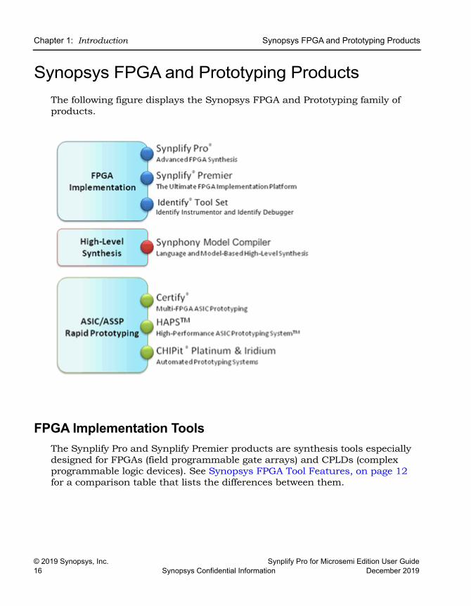
Synopsys FPGA and Prototyping ProductsThe following figure displays the Synopsys FPGA and Prototyping family of products.
FPGA Implementation ToolsThe Synplify Pro and Synplify Premier products are synthesis tools especially designed for FPGAs (field programmable gate arrays) and CPLDs (complex programmable logic devices). See Synopsys FPGA Tool Features, on page 12 for a comparison table that lists the differences between them.
Synopsys FPGA and Prototyping Products Chapter 1: Introduction
Synplify Pro for Microsemi Edition User Guide © 2019 Synopsys, Inc.December 2019 Synopsys Confidential Information 17
Synplify Pro Synthesis SoftwareThe Synplify Pro FPGA synthesis software is the de facto industry standard for producing high-performance, cost-effective FPGA designs. Its unique Behavior Extracting Synthesis Technology® (B.E.S.T.) algorithms, perform high-level optimizations before synthesizing the HDL code into specific FPGA logic. This approach allows for superior optimizations across the FPGA, fast runtimes, and the ability to handle very large designs. The software supports the latest VHDL and Verilog language constructs, including SystemVerilog and VHDL 2008. The tool is technology independent allowing quick and easy retargeting between FPGA devices and vendors from a single design project.
Synplify Premier Synthesis SoftwareThe Synplify Premier functionality is a superset of the Synplify Pro tool, providing the ultimate FPGA implementation and debug environment. It includes a comprehensive suite of tools and technologies for advanced FPGA designers, and also serves as the synthesis engine for ASIC prototypers targeting single FPGA-based prototypes.
The Synplify Premier product offers both FPGA designers and ASIC proto-typers targeting single FPGAs with the most efficient method of design imple-mentation and debug. On the design implementation side, it includes functionality for timing closure, logic verification, IP usage, ASIC compati-bility, and DSP implementation, as well as a tight integration with FPGA vendor back-end tools. On the debug side, it provides for in-system verifi-cation of FPGAs which dramatically accelerates the debug process, and also includes a rapid and incremental method for finding elusive design problems.
The Synplify Premier product offers FPGA designers and ASIC prototypers, targeting single FPGA-based prototypes, with the most efficient method of design implementation and debug. The Synplify Premier software provides in-system verification of FPGAs, dramatically accelerates the debug process, and provides a rapid and incremental method for finding elusive design problems. Features exclusively supported in the Synplify Premier tool are the following:
• Design Planning (Optional)
• DesignWare Support
• Distributed Processing
• Unified Power Format (UPF)
LO
Chapter 1: Introduction Synopsys FPGA and Prototyping Products
© 2019 Synopsys, Inc. Synplify Pro for Microsemi Edition User Guide18 Synopsys Confidential Information December 2019
Identify Tool SetThe Identify® tool set allows you to debug an operating FPGA directly in the HDL source code. The Identify software is used to verify your design in hardware as you would in simulation, however much faster and with in-system stimulus. Designers and verification engineers are able to navigate the design graphically and debug signals directly in HDL with which they are familiar, as probes or sample triggers. After synthesis, results are viewed embedded in the HDL source code or in a waveform. Design iterations are rapidly performed using incremental place and route. Identify software is closely integrated with synthesis and routing tools to create a seamless devel-opment environment.
Synphony Model CompilerSynphony Model Compiler is a language and model-based high-level synthesis technology that provides an efficient path from algorithm concept to silicon. Designers can construct high-level algorithm models from math languages and IP model libraries, then use the Synphony Model Compiler engine to synthesize optimized HDL implementations for FPGA and ASIC architectural exploration and rapid prototyping. In addition, Synphony Model Compiler generates high performance C-models for system validation and early software development in virtual platforms. Key features for this product include:
• MATLAB Language Synthesis
• Automated Fixed-point Conversion Tools
• Synthesizable Fixed-point High Level IP Model Library
• High Level Synthesis Optimizations and Transformations
• Integrated FPGA and ASIC Design Flows
• HDL Testbench Generation
• C-model Generation for Software Development and System Validation
Synopsys FPGA and Prototyping Products Chapter 1: Introduction
Synplify Pro for Microsemi Edition User Guide © 2019 Synopsys, Inc.December 2019 Synopsys Confidential Information 19
Rapid PrototypingThe Certify® and Identify products are tightly integrated with the HAPS and ChipIT® hardware tools.
Certify ProductThe Certify software is the leading implementation and partitioning tool for ASIC designers using FPGA-based prototypes to verify their designs. The tool provides a quick and easy method for partitioning large ASIC designs into multi-FPGA prototyping boards. Powerful features allow the tool to adapt easily to existing device flows, therefore, speeding up the verification process and helping with the time-to-market challenges. Key features include the following:
• Graphical User Interface (GUI) Flow Guide
• Manual Partitioning
• Synopsys Design Constraints Support for Timing Management
• Multi-core Parallel Processing Support for Faster Runtimes
• Support for Most Current FPGA Devices
• Industry Standard Synplify Premier Synthesis Support
• Compatible with HAPS Boards Including HSTDM
LO
Chapter 1: Introduction Starting the Synthesis Tool
© 2019 Synopsys, Inc. Synplify Pro for Microsemi Edition User Guide20 Synopsys Confidential Information December 2019
Starting the Synthesis ToolBefore you can start the synthesis tool, you must install it and set up the software license appropriately. You can then start the tool interactively or in batch mode. How you start the tool depends on your environment. For details, see the installation instructions for the tool.
Starting the Synthesis Tool in Interactive ModeYou can start interactive use of the synthesis tool in any of the following ways:
• To start the synthesis tool from the Microsoft® Windows® operating system, choose
– Start->Synopsys->Synplify Pro version
• To start the tool from a DOS command line, specify the executable:
– installDirectory\bin\synplify_pro.exe
The executable name is the name of the product followed by an exe file extension.
• To start the synthesis tool from a Linux platform, type the appropriate command at the system prompt:
– synplify_proFor information about using the synthesis tool in batch mode, see Starting the Tool in Batch Mode, on page 20.
Starting the Tool in Batch ModeThe command to start the synthesis tool from the command line includes a number of command line options. These options control tool action on startup and, in many cases, can be combined on the same command line. To start the synthesis tool, use the following syntax:
toolName [-option ... ] [projectFile]
In the syntax statement, toolName is the specified synthesis tool:
• synplify_pro

Starting the Synthesis Tool Chapter 1: Introduction
Synplify Pro for Microsemi Edition User Guide © 2019 Synopsys, Inc.December 2019 Synopsys Confidential Information 21
For complete syntax details, refer to synplify_pro, on page 141 in the Command Reference.
LO
Chapter 1: Introduction Logic Synthesis Overview
© 2019 Synopsys, Inc. Synplify Pro for Microsemi Edition User Guide22 Synopsys Confidential Information December 2019
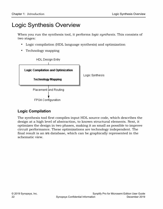
Logic Synthesis OverviewWhen you run the synthesis tool, it performs logic synthesis. This consists of two stages:
• Logic compilation (HDL language synthesis) and optimization
• Technology mapping
Logic Compilation The synthesis tool first compiles input HDL source code, which describes the design at a high level of abstraction, to known structural elements. Next, it optimizes the design in two phases, making it as small as possible to improve circuit performance. These optimizations are technology independent. The final result is an srs database, which can be graphically represented in the schematic view.
Logic Synthesis Overview Chapter 1: Introduction
Synplify Pro for Microsemi Edition User Guide © 2019 Synopsys, Inc.December 2019 Synopsys Confidential Information 23
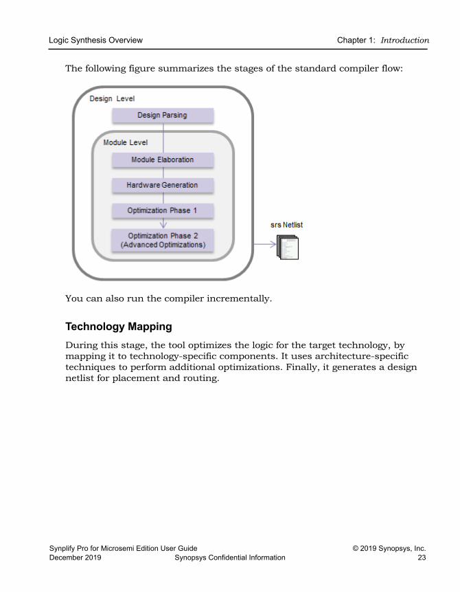
The following figure summarizes the stages of the standard compiler flow:
You can also run the compiler incrementally.
Technology MappingDuring this stage, the tool optimizes the logic for the target technology, by mapping it to technology-specific components. It uses architecture-specific techniques to perform additional optimizations. Finally, it generates a design netlist for placement and routing.
LO
Chapter 1: Introduction Logic Synthesis Overview
© 2019 Synopsys, Inc. Synplify Pro for Microsemi Edition User Guide24 Synopsys Confidential Information December 2019
Synthesizing Your DesignThe synthesis tool accepts high-level designs written in industry-standard hardware description languages (Verilog and VHDL) and uses Behavior Extracting Synthesis Technology® (BEST) algorithms to keep the design at a high level of abstraction for better optimization. See BEST Algorithms, on page 25.
The tool can also write VHDL and Verilog netlists after synthesis, which you can simulate to verify functionality.
You perform the following actions to synthesize your design.
1. Access your design project: open an existing project or create a new one. See Projects and Implementations, on page 26.
2. Specify the input source files to use. Right-click the project name in the Project view, then choose Add Source Files.
– Select the desired Verilog, VHDL, or IP files, then click OK. (See the examples in the directory installation_dir/examples, where installation_dir is the directory where the product is installed.)
– You can also add source files in the Project view by dragging and dropping them there from a Windows® Explorer folder (Microsoft® Windows® operating system only).
– Top-level file: The last file compiled is the top-level file. You can designate a new top-level file by moving the desired file to the bottom of the source files list in the Project view, or by using the Implementation Options dialog box.
3. Add design constraints. Use the SCOPE spreadsheet to assign system-level and circuit-path timing constraints that can be forward-annotated.
See SCOPE Tabs, on page 213, for details on the SCOPE spreadsheet.
4. Choose Project->Implementation Options, then define the following:
– Target architecture and technology specifications
– Optimization options and design constraints
– Outputs
For an initial run, use the default options settings for the technology, and no timing goal (Frequency = 0 MHz).

Logic Synthesis Overview Chapter 1: Introduction
Synplify Pro for Microsemi Edition User Guide © 2019 Synopsys, Inc.December 2019 Synopsys Confidential Information 25
5. Synthesize the design by clicking the Run button.
This step performs logic synthesis. While synthesizing, the synthesis tool displays the status (Compiling... or Mapping...). You can monitor messages by checking the log file (View->View Log File) or in the Tcl window (View->Tcl Window). The log file contains reports with information on timing, usage, and net buffering.
If synthesis is successful, you see the message Done! or Done (warnings). If processing stops because of syntax errors or other design problems, you see the message Errors! displayed, along with the error status in the log file of the Tcl window. If the tool displays Done (warnings), there might be potential design problems to investigate.
6. After synthesis, do one of the following:
– If there were no synthesis warnings or error messages (Done!), analyze your results in the HDL Analyst view. You can then resynthesize with different implementation options, or use the synthesis results to simulate or place-and-route your design.
– If there were synthesis warnings (Done (warnings)) or error messages (Errors!), check them in the log file. From the log file, you can jump to the corresponding source code or display information on the specific error or warning. Correct all errors and any relevant warnings and then rerun synthesis.
BEST AlgorithmsThe Behavior Extracting Synthesis Technology (BEST) feature is the under-lying proprietary technology that the synthesis tool uses to extract and imple-ment your design structures.
During synthesis, the BEST algorithms recognize high-level abstract struc-tures like RAMs, ROMs, finite state machines (FSMs), and arithmetic opera-tors, and maintain them, instead of converting the design entirely to the gate level. The BEST algorithms automatically map these high-level structures to technology-specific resources using module generators. For example, the algorithms map RAMs to target-specific RAMs, and adders to carry chains. The BEST algorithms also optimize hierarchy automatically.
LO
Chapter 1: Introduction Logic Synthesis Overview
© 2019 Synopsys, Inc. Synplify Pro for Microsemi Edition User Guide26 Synopsys Confidential Information December 2019
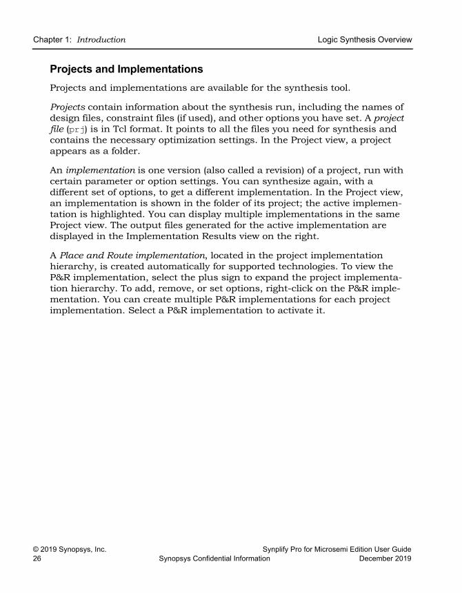
Projects and ImplementationsProjects and implementations are available for the synthesis tool.
Projects contain information about the synthesis run, including the names of design files, constraint files (if used), and other options you have set. A project file (prj) is in Tcl format. It points to all the files you need for synthesis and contains the necessary optimization settings. In the Project view, a project appears as a folder.
An implementation is one version (also called a revision) of a project, run with certain parameter or option settings. You can synthesize again, with a different set of options, to get a different implementation. In the Project view, an implementation is shown in the folder of its project; the active implemen-tation is highlighted. You can display multiple implementations in the same Project view. The output files generated for the active implementation are displayed in the Implementation Results view on the right.
A Place and Route implementation, located in the project implementation hierarchy, is created automatically for supported technologies. To view the P&R implementation, select the plus sign to expand the project implementa-tion hierarchy. To add, remove, or set options, right-click on the P&R imple-mentation. You can create multiple P&R implementations for each project implementation. Select a P&R implementation to activate it.
User Interface Overview Chapter 1: Introduction
Synplify Pro for Microsemi Edition User Guide © 2019 Synopsys, Inc.December 2019 Synopsys Confidential Information 27
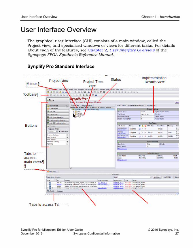
User Interface OverviewThe graphical user interface (GUI) consists of a main window, called the Project view, and specialized windows or views for different tasks. For details about each of the features, see Chapter 2, User Interface Overview of the Synopsys FPGA Synthesis Reference Manual.
Synplify Pro Standard Interface

LO
Chapter 1: Introduction User Interface Overview
© 2019 Synopsys, Inc. Synplify Pro for Microsemi Edition User Guide28 Synopsys Confidential Information December 2019

Synplify Pro for Microsemi Edition User Guide © 2019 Synopsys, Inc.December 2019 Synopsys Confidential Information 29
C H A P T E R 2
FPGA Synthesis Design Flows
This describes the following tool flows:
• Logic Synthesis Design Flow, on page 30
LO
Chapter 2: FPGA Synthesis Design Flows Logic Synthesis Design Flow
© 2019 Synopsys, Inc. Synplify Pro for Microsemi Edition User Guide30 Synopsys Confidential Information December 2019
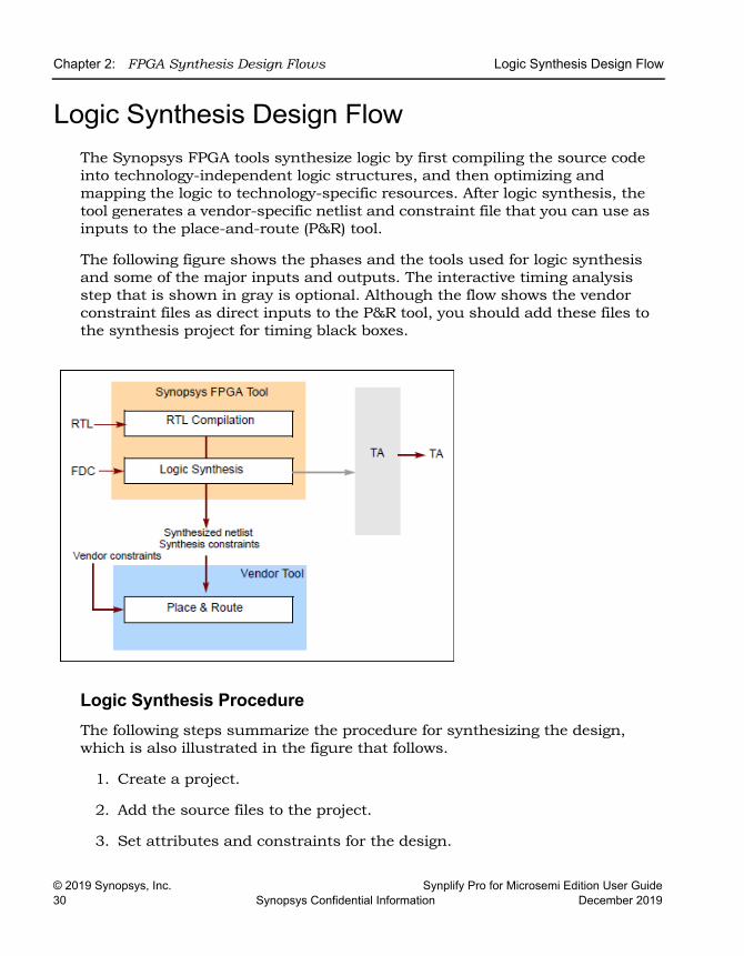
Logic Synthesis Design FlowThe Synopsys FPGA tools synthesize logic by first compiling the source code into technology-independent logic structures, and then optimizing and mapping the logic to technology-specific resources. After logic synthesis, the tool generates a vendor-specific netlist and constraint file that you can use as inputs to the place-and-route (P&R) tool.
The following figure shows the phases and the tools used for logic synthesis and some of the major inputs and outputs. The interactive timing analysis step that is shown in gray is optional. Although the flow shows the vendor constraint files as direct inputs to the P&R tool, you should add these files to the synthesis project for timing black boxes.
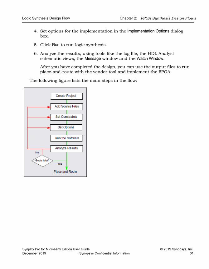
Logic Synthesis ProcedureThe following steps summarize the procedure for synthesizing the design, which is also illustrated in the figure that follows.
1. Create a project.
2. Add the source files to the project.
3. Set attributes and constraints for the design.
Logic Synthesis Design Flow Chapter 2: FPGA Synthesis Design Flows
Synplify Pro for Microsemi Edition User Guide © 2019 Synopsys, Inc.December 2019 Synopsys Confidential Information 31
4. Set options for the implementation in the Implementation Options dialog box.
5. Click Run to run logic synthesis.
6. Analyze the results, using tools like the log file, the HDL Analyst schematic views, the Message window and the Watch Window.
After you have completed the design, you can use the output files to run place-and-route with the vendor tool and implement the FPGA.
The following figure lists the main steps in the flow:

LO
Chapter 2: FPGA Synthesis Design Flows Logic Synthesis Design Flow
© 2019 Synopsys, Inc. Synplify Pro for Microsemi Edition User Guide32 Synopsys Confidential Information December 2019
Synplify Pro for Microsemi Edition User Guide © 2019 Synopsys, Inc.December 2019 Synopsys Confidential Information 33
C H A P T E R 3
Preparing the Input
When you synthesize a design, you need to set up two kinds of files: HDL files that describe your design, and project files to manage the design. This chapter describes the procedures to set up these files and the project. It covers the following:
• Setting Up HDL Source Files, on page 34
• Using Mixed Language Source Files, on page 48
• Using the Structural Verilog Flow, on page 53
• Working with Constraint Files, on page 55
LO
Chapter 3: Preparing the Input Setting Up HDL Source Files
© 2019 Synopsys, Inc. Synplify Pro for Microsemi Edition User Guide34 Synopsys Confidential Information December 2019
Setting Up HDL Source FilesThis section describes how to set up your source files; project file setup is described in Setting Up Project Files, on page 60. Source files can be in Verilog or VHDL. This section discusses the following topics:
• Creating HDL Source Files, on page 34
• Using the Context Help Editor, on page 36
• Checking HDL Source Files, on page 38
• Editing HDL Source Files with the Built-in Text Editor, on page 39
• Setting Editing Window Preferences, on page 42
• Using an External Text Editor, on page 44
• Using Library Extensions for Verilog Library Files, on page 45
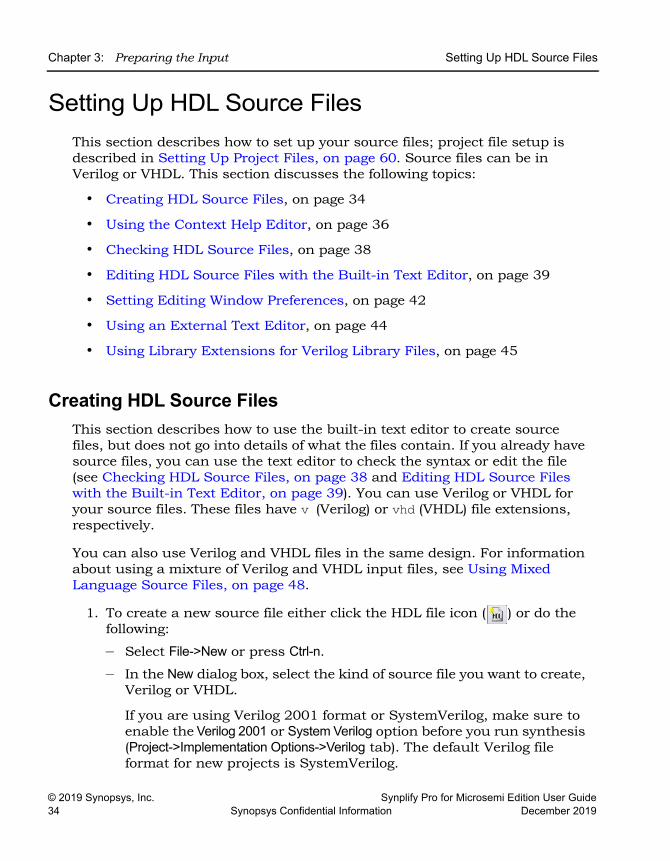
Creating HDL Source FilesThis section describes how to use the built-in text editor to create source files, but does not go into details of what the files contain. If you already have source files, you can use the text editor to check the syntax or edit the file (see Checking HDL Source Files, on page 38 and Editing HDL Source Files with the Built-in Text Editor, on page 39). You can use Verilog or VHDL for your source files. These files have v (Verilog) or vhd (VHDL) file extensions, respectively.
You can also use Verilog and VHDL files in the same design. For information about using a mixture of Verilog and VHDL input files, see Using Mixed Language Source Files, on page 48.
1. To create a new source file either click the HDL file icon ( ) or do the following:
– Select File->New or press Ctrl-n.
– In the New dialog box, select the kind of source file you want to create, Verilog or VHDL.
If you are using Verilog 2001 format or SystemVerilog, make sure to enable the Verilog 2001 or System Verilog option before you run synthesis (Project->Implementation Options->Verilog tab). The default Verilog file format for new projects is SystemVerilog.
Setting Up HDL Source Files Chapter 3: Preparing the Input
Synplify Pro for Microsemi Edition User Guide © 2019 Synopsys, Inc.December 2019 Synopsys Confidential Information 35
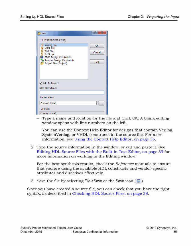
– Type a name and location for the file and Click OK. A blank editing window opens with line numbers on the left.
You can use the Context Help Editor for designs that contain Verilog, SystemVerilog, or VHDL constructs in the source file. For more information, see Using the Context Help Editor, on page 36.
2. Type the source information in the window, or cut and paste it. See Editing HDL Source Files with the Built-in Text Editor, on page 39 for more information on working in the Editing window.
For the best synthesis results, check the Reference manuals to ensure that you are using the available HDL constructs and vendor-specific attributes and directives effectively.
3. Save the file by selecting File->Save or the Save icon ( ).
Once you have created a source file, you can check that you have the right syntax, as described in Checking HDL Source Files, on page 38.
LO
Chapter 3: Preparing the Input Setting Up HDL Source Files
© 2019 Synopsys, Inc. Synplify Pro for Microsemi Edition User Guide36 Synopsys Confidential Information December 2019
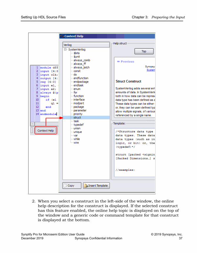
Using the Context Help EditorWhen you create or open a design file, use the Context Help button displayed at the bottom of the window to help you code with Verilog/SystemVerilog/VHDL constructs in the source file or Tcl constraint commands into your Tcl file.
To use the Context Help Editor:
1. Click the Context Help button to display this text editor.
Setting Up HDL Source Files Chapter 3: Preparing the Input
Synplify Pro for Microsemi Edition User Guide © 2019 Synopsys, Inc.December 2019 Synopsys Confidential Information 37
2. When you select a construct in the left-side of the window, the online help description for the construct is displayed. If the selected construct has this feature enabled, the online help topic is displayed on the top of the window and a generic code or command template for that construct is displayed at the bottom.
LO
Chapter 3: Preparing the Input Setting Up HDL Source Files
© 2019 Synopsys, Inc. Synplify Pro for Microsemi Edition User Guide38 Synopsys Confidential Information December 2019
3. The Insert Template button is also enabled. When you click the Insert Template button, the code or command shown in the template window is inserted into your file at the location of the cursor. This allows you to easily insert the code or command and modify it for the design that you are going to synthesize.
4. If you want to copy only parts of the template, select the code or command you want to insert and click Copy. You can then paste it into your file.
Checking HDL Source FilesThe software automatically checks your HDL source files when it compiles them, but if you want to check your source code before synthesis, use the following procedure. There are two kinds of checks you do in the synthesis software: syntax and synthesis.
1. Select the source files you want to check.
– To check all the source files in a project, deselect all files in the project list, and make sure that none of the files are open in an active window. If you have an active source file, the software only checks the active file.
– To check a single file, open the file with File->Open or double-click the file in the Project window. If you have more than one file open and want to check only one of them, put your cursor in the appropriate file window to make sure that it is the active window.
2. To check the syntax, select Run->Syntax Check or press Shift+F7.
The software detects syntax errors such as incorrect keywords and punctuation and reports any errors in a separate log file (syntax.log). If no errors are detected, a successful syntax check is reported at the bottom of this file.
3. To run a synthesis check, select Run->Synthesis Check or press Shift+F8.
The software detects hardware-related errors such as incorrectly coded flip-flops and reports any errors in a separate log file (syntax.log). If there are no errors, a successful syntax check is reported at the bottom of this file.
4. Review the errors by opening the syntax.log file when prompted and use Find to locate the error message (search for @E). Double-click the
Setting Up HDL Source Files Chapter 3: Preparing the Input
Synplify Pro for Microsemi Edition User Guide © 2019 Synopsys, Inc.December 2019 Synopsys Confidential Information 39
5-character error code or click the message text and push F1 to display online error message help.
5. Locate the portion of code responsible for the error by double-clicking on the message text in the syntax.log file. The Text Editor window opens the appropriate source file and highlights the code that caused the error.
6. Repeat steps 4 and 5 until all syntax and synthesis errors are corrected.
Messages can be categorized as errors, warnings, or notes. Review all messages and resolve any errors. Warnings are less serious than errors, but you must read through and understand them even if you do not resolve all of them. Notes are informative and do not need to be resolved.
Editing HDL Source Files with the Built-in Text EditorThe built-in text editor makes it easy to create your HDL source code, view it, or edit it when you need to fix errors. If you want to use an external text editor, see Using an External Text Editor, on page 44.
1. Do one of the following to open a source file for viewing or editing:
– To automatically open the first file in the list with errors, press F5.
– To open a specific file, double-click the file in the Project window or use File->Open (Ctrl-o) and specify the source file.
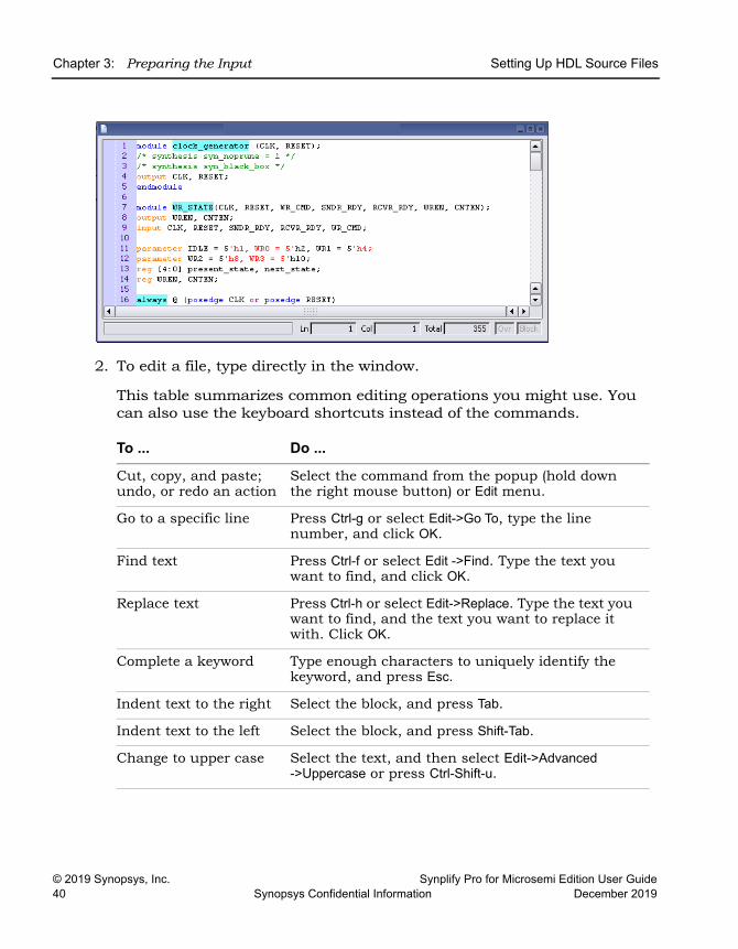
The Text Editor window opens and displays the source file. Lines are numbered. Keywords are in blue, and comments in green. String values are in red. If you want to change these colors, see Setting Editing Window Preferences, on page 42.
LO
Chapter 3: Preparing the Input Setting Up HDL Source Files
© 2019 Synopsys, Inc. Synplify Pro for Microsemi Edition User Guide40 Synopsys Confidential Information December 2019
2. To edit a file, type directly in the window.
This table summarizes common editing operations you might use. You can also use the keyboard shortcuts instead of the commands.
To ... Do ...
Cut, copy, and paste; undo, or redo an action
Select the command from the popup (hold down the right mouse button) or Edit menu.
Go to a specific line Press Ctrl-g or select Edit->Go To, type the line number, and click OK.
Find text Press Ctrl-f or select Edit ->Find. Type the text you want to find, and click OK.
Replace text Press Ctrl-h or select Edit->Replace. Type the text you want to find, and the text you want to replace it with. Click OK.
Complete a keyword Type enough characters to uniquely identify the keyword, and press Esc.
Indent text to the right Select the block, and press Tab.
Indent text to the left Select the block, and press Shift-Tab.
Change to upper case Select the text, and then select Edit->Advanced->Uppercase or press Ctrl-Shift-u.
Setting Up HDL Source Files Chapter 3: Preparing the Input
Synplify Pro for Microsemi Edition User Guide © 2019 Synopsys, Inc.December 2019 Synopsys Confidential Information 41
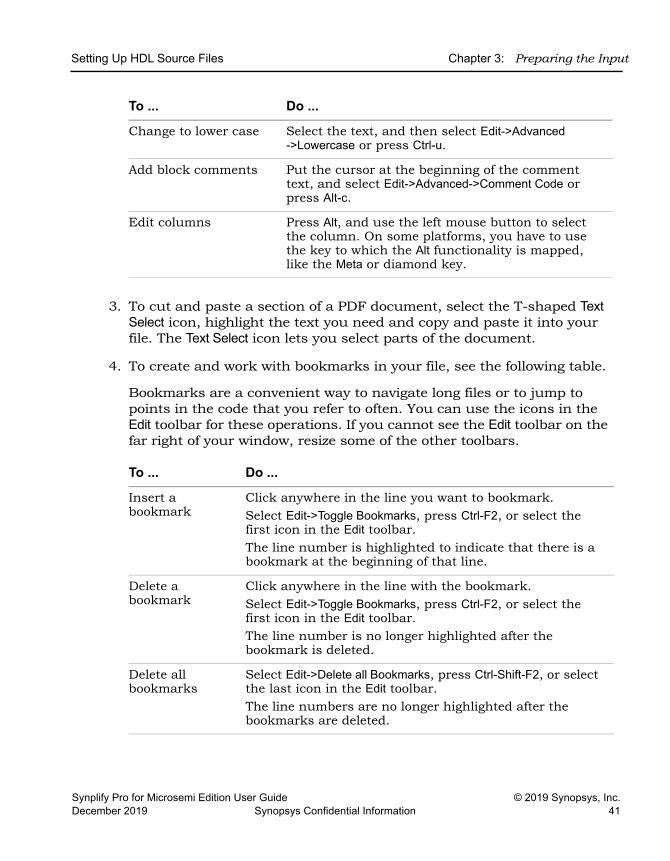
3. To cut and paste a section of a PDF document, select the T-shaped Text Select icon, highlight the text you need and copy and paste it into your file. The Text Select icon lets you select parts of the document.
4. To create and work with bookmarks in your file, see the following table.
Bookmarks are a convenient way to navigate long files or to jump to points in the code that you refer to often. You can use the icons in the Edit toolbar for these operations. If you cannot see the Edit toolbar on the far right of your window, resize some of the other toolbars.
Change to lower case Select the text, and then select Edit->Advanced ->Lowercase or press Ctrl-u.
Add block comments Put the cursor at the beginning of the comment text, and select Edit->Advanced->Comment Code or press Alt-c.
Edit columns Press Alt, and use the left mouse button to select the column. On some platforms, you have to use the key to which the Alt functionality is mapped, like the Meta or diamond key.
To ... Do ...
Insert a bookmark
Click anywhere in the line you want to bookmark. Select Edit->Toggle Bookmarks, press Ctrl-F2, or select the first icon in the Edit toolbar.The line number is highlighted to indicate that there is a bookmark at the beginning of that line.
Delete a bookmark
Click anywhere in the line with the bookmark. Select Edit->Toggle Bookmarks, press Ctrl-F2, or select the first icon in the Edit toolbar.The line number is no longer highlighted after the bookmark is deleted.
Delete all bookmarks
Select Edit->Delete all Bookmarks, press Ctrl-Shift-F2, or select the last icon in the Edit toolbar.The line numbers are no longer highlighted after the bookmarks are deleted.
To ... Do ...
LO
Chapter 3: Preparing the Input Setting Up HDL Source Files
© 2019 Synopsys, Inc. Synplify Pro for Microsemi Edition User Guide42 Synopsys Confidential Information December 2019
5. To fix errors or review warnings in the source code, do the following:
– Open the HDL file with the error or warning by double-clicking the file in the project list.
– Press F5 to go to the first error, warning, or note in the file. At the bottom of the Editing window, you see the message text.
– To go to the next error, warning, or note, select Run->Next Error/Warning or press F5. If there are no more messages in the file, you see the message “No More Errors/Warnings/Notes” at the bottom of the Editing window. Select Run->Next Error/Warning or press F5 to go to the the error, warning, or note in the next file.
– To navigate back to a previous error, warning, or note, select Run->Previous Error/Warning or press Shift-F5.
6. To bring up error message help for a full description of the error, warning, or note:
– Open the text-format log file (click View Log) and either double click the 5-character error code or click the message text and press F1.
– Open the HTML log file and click the 5-character error code.
– In the Tcl window, click the Messages tab and click the 5-character error code in the ID column.
7. To crossprobe from the source code window to other views, open the view and select the piece of code. See Crossprobing from the Text Editor Window, on page 331 for details.
8. When you have fixed all the errors, select File->Save or click the Save icon to save the file.
Setting Editing Window PreferencesYou can customize the fonts and colors used in a Text Editing window.
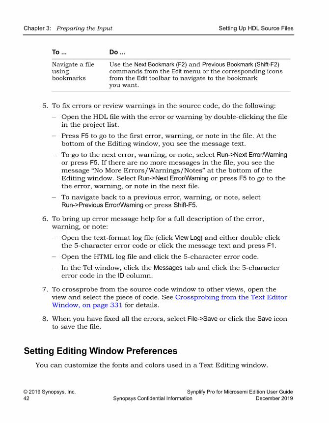
Navigate a file using bookmarks
Use the Next Bookmark (F2) and Previous Bookmark (Shift-F2) commands from the Edit menu or the corresponding icons from the Edit toolbar to navigate to the bookmark you want.
To ... Do ...
Setting Up HDL Source Files Chapter 3: Preparing the Input
Synplify Pro for Microsemi Edition User Guide © 2019 Synopsys, Inc.December 2019 Synopsys Confidential Information 43
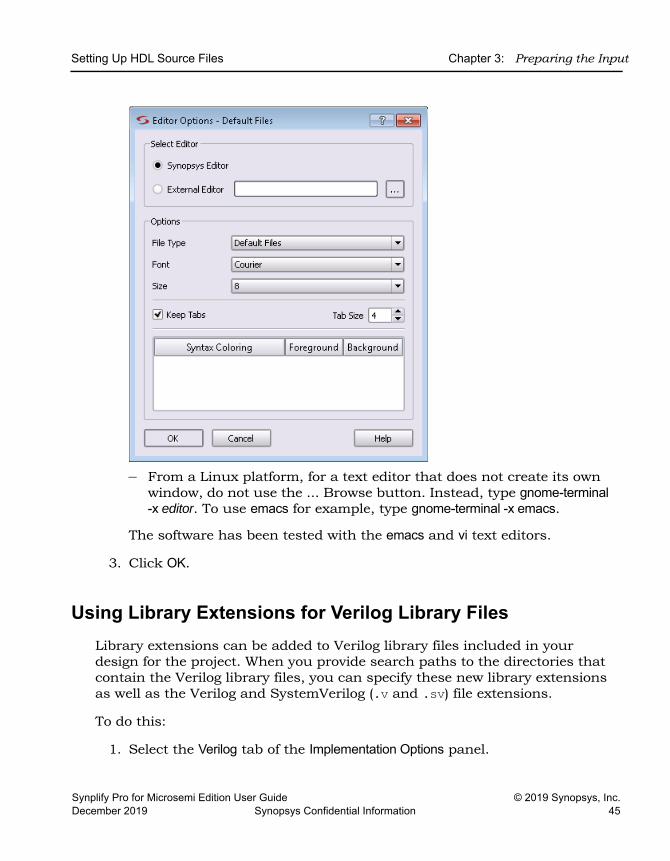
1. Select Options->Editor Options and either Synopsys Editor or External Editor. For more information about the external editor, see Using an External Text Editor, on page 44.
2. Then depending on the type of file you open, you can to set the background, syntax coloring, and font preferences to use with the text editor.
Note: Thereafter, text editing preferences you set for this file will apply to all files of this file type.
The Text Editing window can be used to set preferences for project files, source files (Verilog/VHDL), log files, Tcl files, constraint files, or other default files from the Editor Options dialog box.
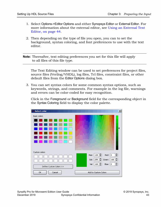
3. You can set syntax colors for some common syntax options, such as keywords, strings, and comments. For example in the log file, warnings and errors can be color-coded for easy recognition.
Click in the Foreground or Background field for the corresponding object in the Syntax Coloring field to display the color palette.
LO
Chapter 3: Preparing the Input Setting Up HDL Source Files
© 2019 Synopsys, Inc. Synplify Pro for Microsemi Edition User Guide44 Synopsys Confidential Information December 2019
You can select basic colors or define custom colors and add them to your custom color palette. To select your desired color click OK.
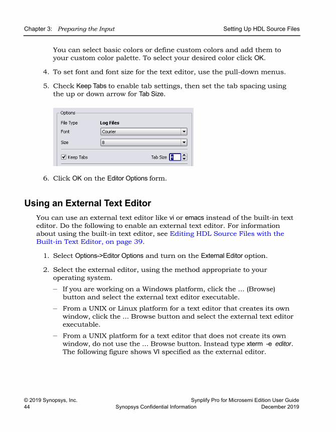
4. To set font and font size for the text editor, use the pull-down menus.
5. Check Keep Tabs to enable tab settings, then set the tab spacing using the up or down arrow for Tab Size.
6. Click OK on the Editor Options form.
Using an External Text EditorYou can use an external text editor like vi or emacs instead of the built-in text editor. Do the following to enable an external text editor. For information about using the built-in text editor, see Editing HDL Source Files with the Built-in Text Editor, on page 39.
1. Select Options->Editor Options and turn on the External Editor option.
2. Select the external editor, using the method appropriate to your operating system.
– If you are working on a Windows platform, click the ... (Browse) button and select the external text editor executable.
– From a UNIX or Linux platform for a text editor that creates its own window, click the ... Browse button and select the external text editor executable.
– From a UNIX platform for a text editor that does not create its own window, do not use the ... Browse button. Instead type xterm -e editor. The following figure shows VI specified as the external editor.
Setting Up HDL Source Files Chapter 3: Preparing the Input
Synplify Pro for Microsemi Edition User Guide © 2019 Synopsys, Inc.December 2019 Synopsys Confidential Information 45
– From a Linux platform, for a text editor that does not create its own window, do not use the ... Browse button. Instead, type gnome-terminal -x editor. To use emacs for example, type gnome-terminal -x emacs.
The software has been tested with the emacs and vi text editors.
3. Click OK.
Using Library Extensions for Verilog Library FilesLibrary extensions can be added to Verilog library files included in your design for the project. When you provide search paths to the directories that contain the Verilog library files, you can specify these new library extensions as well as the Verilog and SystemVerilog (.v and .sv) file extensions.
To do this:
1. Select the Verilog tab of the Implementation Options panel.
LO
Chapter 3: Preparing the Input Setting Up HDL Source Files
© 2019 Synopsys, Inc. Synplify Pro for Microsemi Edition User Guide46 Synopsys Confidential Information December 2019
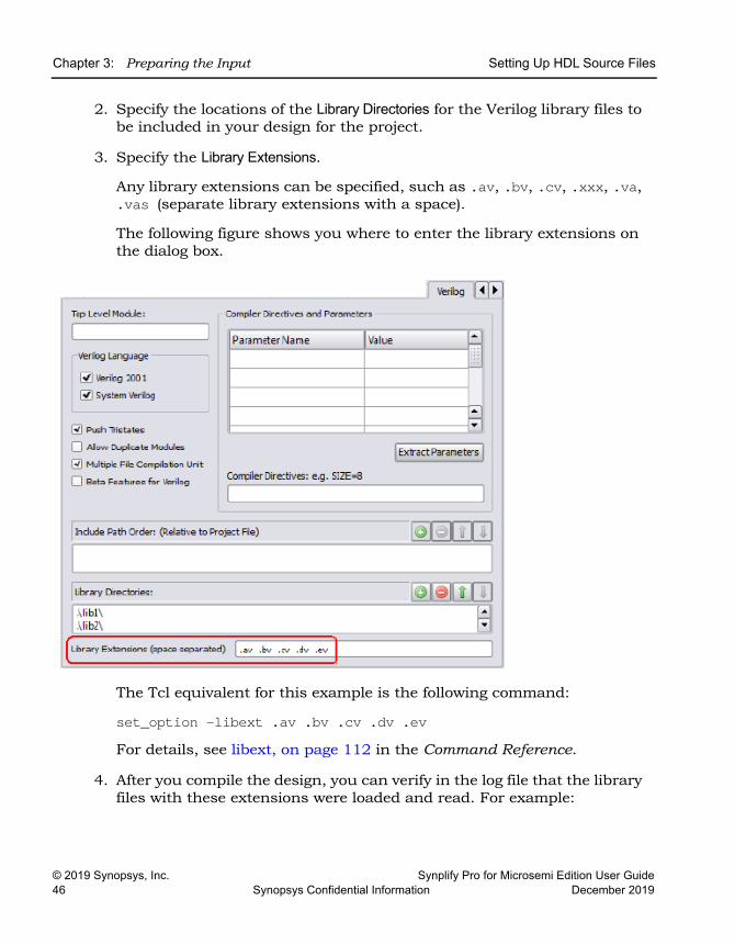
2. Specify the locations of the Library Directories for the Verilog library files to be included in your design for the project.
3. Specify the Library Extensions.
Any library extensions can be specified, such as .av, .bv, .cv, .xxx, .va, .vas (separate library extensions with a space).
The following figure shows you where to enter the library extensions on the dialog box.
The Tcl equivalent for this example is the following command:
set_option -libext .av .bv .cv .dv .ev For details, see libext, on page 112 in the Command Reference.
4. After you compile the design, you can verify in the log file that the library files with these extensions were loaded and read. For example:

Setting Up HDL Source Files Chapter 3: Preparing the Input
Synplify Pro for Microsemi Edition User Guide © 2019 Synopsys, Inc.December 2019 Synopsys Confidential Information 47
@N: Running Verilog Compiler in SystemVerilog mode@I::”C:\dir\top.v"@N: CG1180 :"C:\dir\top.v":8:0:8:3|Loading file C:\dir\lib1\sub1.av from specified library directory C:\dir\lib1@I::"C:\dir\lib1\sub1.av"@N: CG1180 :"C:\dir\top.v":10:0:10:3|Loading file C:\dir\lib2\sub2.bv from specified library directory C:\dir\lib2@I::"C:\dir\lib2\sub2.bv"@N: CG1180 :"C:\dir\top.v":12:0:12:3|Loading file C:\dir\lib3\sub3.cv from specified library directory C:\dir\lib3@I::"C:\dir\lib3\sub3.cv"@N: CG1180 :"C:\dir\top.v":14:0:14:3|Loading file C:\dir\lib4\sub4.dv from specified library directory C:\dir\lib4@I::"C:\dir\lib4\sub4.dv"@N: CG1180 :"C:\dir\top.v":16:0:16:3|Loading file C:\dir\lib5\sub5.ev from specified library directory C:\dir\lib5@I::"C:\dir\lib5\sub5.ev"Verilog syntax check successful!
LO
Chapter 3: Preparing the Input Using Mixed Language Source Files
© 2019 Synopsys, Inc. Synplify Pro for Microsemi Edition User Guide48 Synopsys Confidential Information December 2019
Using Mixed Language Source FilesWith the synthesis software, you can use a mixture of VHDL and Verilog input files in your project. For examples of the VHDL and Verilog files, see the Reference Manual. You cannot use Verilog and VHDL files together in the same design with the Synplify tool.
1. Remember that Verilog does not support unconstrained VHDL ports and set up the mixed language design files accordingly.
2. If you want to organize the Verilog and VHDL files in different folders, select Options->Project View Options and toggle on the View Project Files in Folders option.
When you add the files to the project, the Verilog and VHDL files are in separate folders in the Project view.
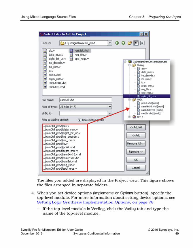
3. When you open a project or create a new one, add the Verilog and VHDL files as follows:
– Select the Project->Add Source File command or click the Add File button.
– On the form, set Files of Type to HDL Files (*.vhd, *.vhdl, *.v).
– Select the Verilog and VHDL files you want and add them to your project. Click OK. For details about adding files to a project, see Making Changes to a Project, on page 64.
Using Mixed Language Source Files Chapter 3: Preparing the Input
Synplify Pro for Microsemi Edition User Guide © 2019 Synopsys, Inc.December 2019 Synopsys Confidential Information 49
The files you added are displayed in the Project view. This figure shows the files arranged in separate folders.
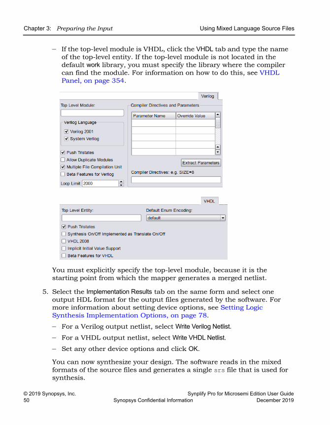
4. When you set device options (Implementation Options button), specify the top-level module. For more information about setting device options, see Setting Logic Synthesis Implementation Options, on page 78.
– If the top-level module is Verilog, click the Verilog tab and type the name of the top-level module.
LO
Chapter 3: Preparing the Input Using Mixed Language Source Files
© 2019 Synopsys, Inc. Synplify Pro for Microsemi Edition User Guide50 Synopsys Confidential Information December 2019
– If the top-level module is VHDL, click the VHDL tab and type the name of the top-level entity. If the top-level module is not located in the default work library, you must specify the library where the compiler can find the module. For information on how to do this, see VHDL Panel, on page 354.
You must explicitly specify the top-level module, because it is the starting point from which the mapper generates a merged netlist.
5. Select the Implementation Results tab on the same form and select one output HDL format for the output files generated by the software. For more information about setting device options, see Setting Logic Synthesis Implementation Options, on page 78.
– For a Verilog output netlist, select Write Verilog Netlist.
– For a VHDL output netlist, select Write VHDL Netlist. – Set any other device options and click OK.
You can now synthesize your design. The software reads in the mixed formats of the source files and generates a single srs file that is used for synthesis.
Using Mixed Language Source Files Chapter 3: Preparing the Input
Synplify Pro for Microsemi Edition User Guide © 2019 Synopsys, Inc.December 2019 Synopsys Confidential Information 51
6. If you run into problems, see Troubleshooting Mixed Language Designs, on page 51 for additional information and tips.
Troubleshooting Mixed Language DesignsThis section provides tips on handling specific situations that might come up with mixed language designs.
VHDL File OrderCorrect file order is important, especially for VHDL files.
• Make sure the files are ordered correctly. To re-order files from the UI, drag files to their correct locations in the order. Alternatively, use the add_file command in the project file to add the input files in the correct sequence. See Ordering Input Files, on page 68 for details about the order sequence for Verilog and VHDL.
• In the Project view, check that the last file in the Project view is the top-level source file. Alternatively, you can specify the top-level file when you set the device options.
An example of correct file order for a design that consists of one top module (top.v) and two sub module files (module1.v and module2.v):
add_file -verilog -lib work module1.vadd_file -verilog -lib work module2.vadd_file -verilog -lib work top.v
For more information about the file order, see Ordering Input Files, on page 68.
VHDL Global SignalsCurrently, you cannot have VHDL global signals in mixed language designs, because the tool only implements these signals in VHDL-only designs.
Passing VHDL Boolean Generics to Verilog ParametersThe tool infers a black box for a VHDL component with Boolean generics, if that component is instantiated in a Verilog design. This is because Verilog does not recognize Boolean data types, so the Boolean value must be repre-sented correctly. If the value of the VHDL Boolean generic is TRUE and the Verilog literal is represented by a 1, the Verilog compiler interprets this as a black box.
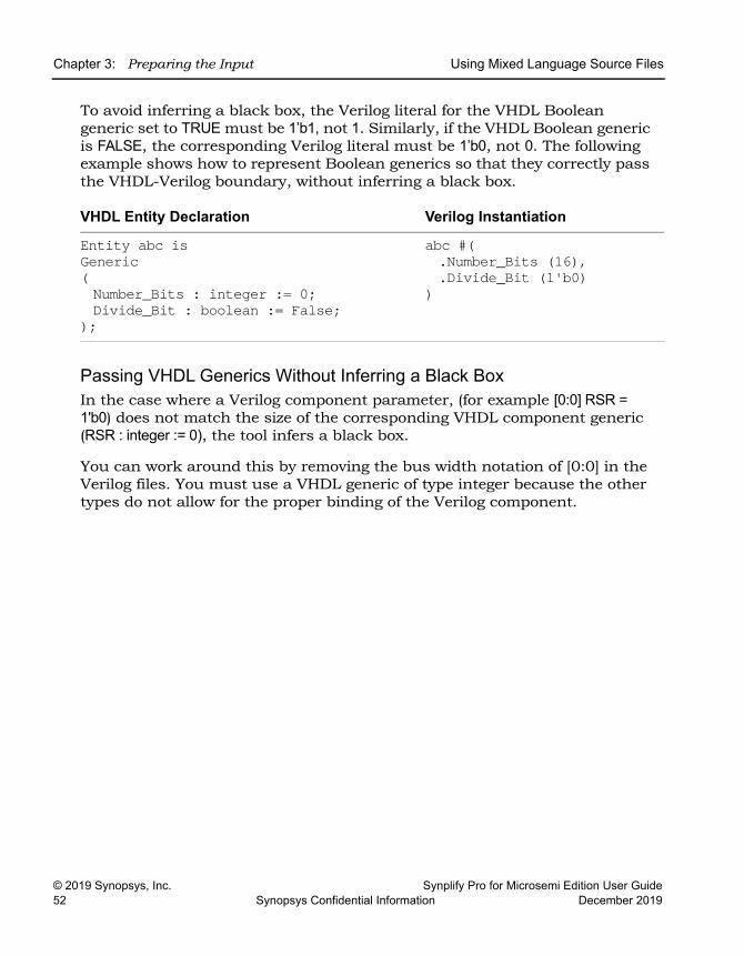
LO
Chapter 3: Preparing the Input Using Mixed Language Source Files
© 2019 Synopsys, Inc. Synplify Pro for Microsemi Edition User Guide52 Synopsys Confidential Information December 2019
To avoid inferring a black box, the Verilog literal for the VHDL Boolean generic set to TRUE must be 1’b1, not 1. Similarly, if the VHDL Boolean generic is FALSE, the corresponding Verilog literal must be 1’b0, not 0. The following example shows how to represent Boolean generics so that they correctly pass the VHDL-Verilog boundary, without inferring a black box.
Passing VHDL Generics Without Inferring a Black BoxIn the case where a Verilog component parameter, (for example [0:0] RSR = 1'b0) does not match the size of the corresponding VHDL component generic (RSR : integer := 0), the tool infers a black box.
You can work around this by removing the bus width notation of [0:0] in the Verilog files. You must use a VHDL generic of type integer because the other types do not allow for the proper binding of the Verilog component.
VHDL Entity Declaration Verilog Instantiation
Entity abc isGeneric(Number_Bits : integer := 0;Divide_Bit : boolean := False;
);
abc #(.Number_Bits (16),.Divide_Bit (1'b0)
)
Using the Structural Verilog Flow Chapter 3: Preparing the Input
Synplify Pro for Microsemi Edition User Guide © 2019 Synopsys, Inc.December 2019 Synopsys Confidential Information 53
Using the Structural Verilog FlowThe synthesis tool accepts structural Verilog files as input for your design project. The structural Verilog compiler performs syntax semantic checks using its light-weight parser to improve runtime. This compiler does not perform complex hardware extractions or RTL optimization operations, so the software runs fast compilation of the structural Verilog files. The software can read these generated structural Verilog files, if they contain:
• Instantiations of technology primitives
• Simple assign statements
• Attributes specified in Verilog 2001 and older formats
• All constructs, except attributes must be specified in Verilog 95 format
To use structural Verilog input files:
1. You must specify the structural Verilog files to include in your design. To do this, add the file to the project using one of the following methods:
– Project->Add Source File or the Add File button in the Project view
– Tcl command: add_file -structver fileNameThis flow can contain only structural Verilog files or mixed HDL files (Verilog/VHDL/EDF/SRS) along with structural Verilog netlist files. However, Verilog/VHDL/EDF/SRS instances are not supported within a structural Verilog module.
2. The structural Verilog files are added to the Structural Verilog folder in the Project view. You can also add files to this directory, when you perform the following:
– Select the structural Verilog file.
– Right-click and select File Options.– Choose Structural Verilog from the File Type drop-down menu.
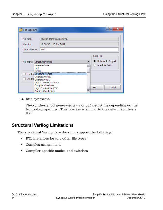
LO
Chapter 3: Preparing the Input Using the Structural Verilog Flow
© 2019 Synopsys, Inc. Synplify Pro for Microsemi Edition User Guide54 Synopsys Confidential Information December 2019
3. Run synthesis.
The synthesis tool generates a vm or edf netlist file depending on the technology specified. This process is similar to the default synthesis flow.
Structural Verilog LimitationsThe structural Verilog flow does not support the following:
• RTL instances for any other file types
• Complex assignments
• Compiler-specific modes and switches
Working with Constraint Files Chapter 3: Preparing the Input
Synplify Pro for Microsemi Edition User Guide © 2019 Synopsys, Inc.December 2019 Synopsys Confidential Information 55
Working with Constraint FilesConstraint files are text files that are automatically generated by the SCOPE interface (see Specifying SCOPE Constraints, on page 128), or which you create manually with a text editor. They contain Tcl commands or attributes that constrain the synthesis run. Alternatively, you can set constraints in the source code, but this is not the preferred method.
This section contains information about
• When to Use Constraint Files over Source Code, on page 55
• Tcl Syntax Guidelines for Constraint Files, on page 55
• Checking Constraint Files, on page 57
When to Use Constraint Files over Source CodeYou can add constraints in constraint files (generated by the SCOPE interface or entered in a text editor) or in the source code. In general, it is better to use constraint files, because you do not have to recompile for the constraints to take effect. It also makes your source code more portable. See Using the SCOPE Editor, on page 122 for more information.
However, if you have black box timing constraints like syn_tco, syn_tpd, and syn_tsu, you must enter them as directives in the source code. Unlike attri-butes, directives can only be added to the source code, not to constraint files. See Specifying Attributes and Directives, on page 93 for more information on adding directives to source code.
Tcl Syntax Guidelines for Constraint FilesThis section covers general guidelines for using Tcl for constraint files:
• Tcl is case-sensitive.
• For naming objects:
– The object name must match the name in the HDL code.
– Enclose instance and port names within curly braces { }.
– Do not use spaces in names.
– Use the dot (.) to separate hierarchical names.
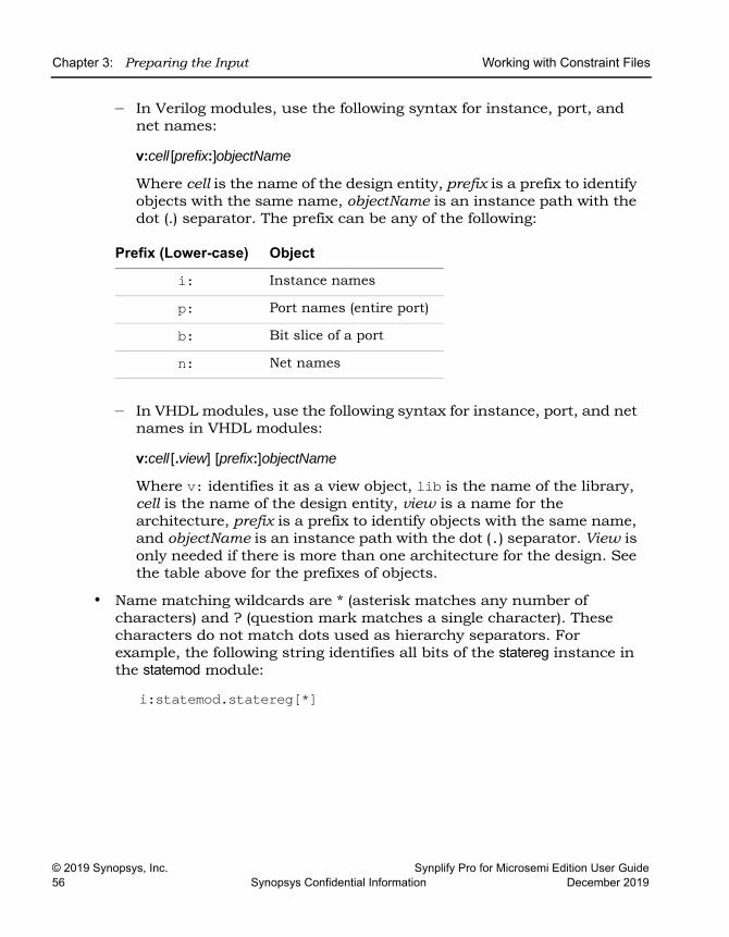
LO
Chapter 3: Preparing the Input Working with Constraint Files
© 2019 Synopsys, Inc. Synplify Pro for Microsemi Edition User Guide56 Synopsys Confidential Information December 2019
– In Verilog modules, use the following syntax for instance, port, and net names:
v:cell [prefix:]objectName
Where cell is the name of the design entity, prefix is a prefix to identify objects with the same name, objectName is an instance path with the dot (.) separator. The prefix can be any of the following:
– In VHDL modules, use the following syntax for instance, port, and net names in VHDL modules:
v:cell [.view] [prefix:]objectName
Where v: identifies it as a view object, lib is the name of the library, cell is the name of the design entity, view is a name for the architecture, prefix is a prefix to identify objects with the same name, and objectName is an instance path with the dot (.) separator. View is only needed if there is more than one architecture for the design. See the table above for the prefixes of objects.
• Name matching wildcards are * (asterisk matches any number of characters) and ? (question mark matches a single character). These characters do not match dots used as hierarchy separators. For example, the following string identifies all bits of the statereg instance in the statemod module:
i:statemod.statereg[*]
Prefix (Lower-case) Object
i: Instance names
p: Port names (entire port)
b: Bit slice of a port
n: Net names
Working with Constraint Files Chapter 3: Preparing the Input
Synplify Pro for Microsemi Edition User Guide © 2019 Synopsys, Inc.December 2019 Synopsys Confidential Information 57
Checking Constraint FilesYou can check syntax and other pertinent information for your constraint files using the Constraint Check command. To generate a constraint report, do the following:
1. Create a constraint file and add it to your project.
2. Select Run->Constraint Check.
This command generates a report that checks the syntax and applica-bility of the timing constraints in the FPGA synthesis constraint files for your project. The report is written to the projectName_cck.rpt file and lists the following information:
– Constraints that are not applied
– Constraints that are valid and applicable to the design
– Wildcard expansion on the constraints
– Constraints on objects that do not exist
For details on this report, see Constraint Checking Report, on page 171 of the Reference Manual.

LO
Chapter 3: Preparing the Input Working with Constraint Files
© 2019 Synopsys, Inc. Synplify Pro for Microsemi Edition User Guide58 Synopsys Confidential Information December 2019

Synplify Pro for Microsemi Edition User Guide © 2019 Synopsys, Inc.December 2019 Synopsys Confidential Information 59
C H A P T E R 4
Setting Up a Logic Synthesis Project
When you synthesize a design with the Synopsys FPGA synthesis tool, you must set up a project for your design. The following describe the procedures for setting up a project for logic synthesis:
• Setting Up Project Files, on page 60
• Managing Project File Hierarchy, on page 70
• Setting Up Implementations, on page 76
• Setting Logic Synthesis Implementation Options, on page 78
• Specifying Attributes and Directives, on page 93
• Searching Files, on page 102
• Archiving Files and Projects, on page 105
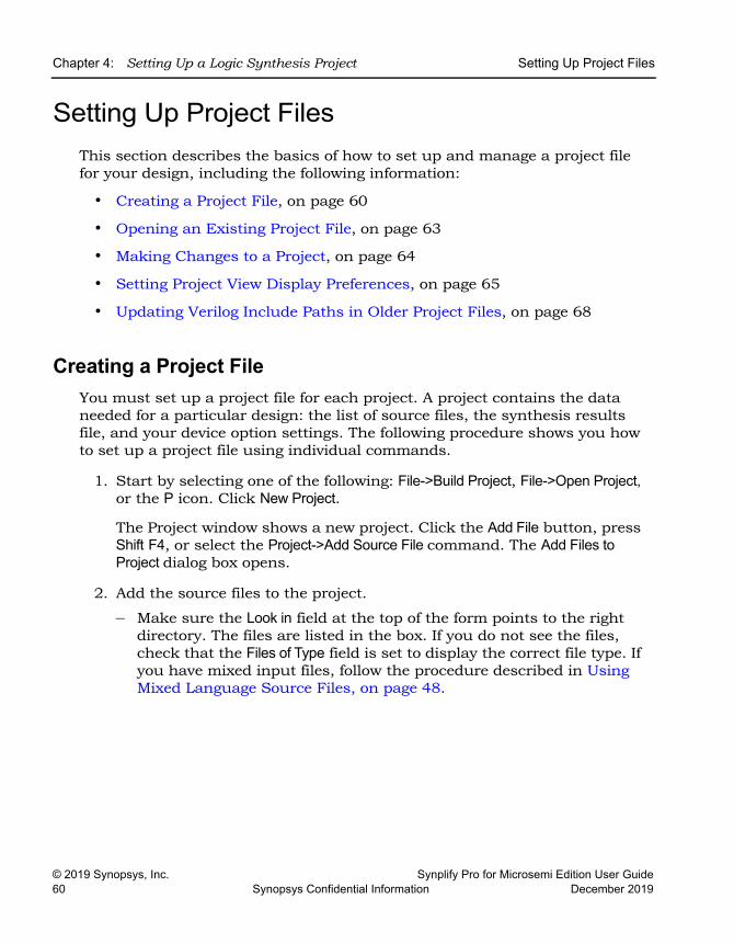
LO
Chapter 4: Setting Up a Logic Synthesis Project Setting Up Project Files
© 2019 Synopsys, Inc. Synplify Pro for Microsemi Edition User Guide60 Synopsys Confidential Information December 2019
Setting Up Project FilesThis section describes the basics of how to set up and manage a project file for your design, including the following information:
• Creating a Project File, on page 60
• Opening an Existing Project File, on page 63
• Making Changes to a Project, on page 64
• Setting Project View Display Preferences, on page 65
• Updating Verilog Include Paths in Older Project Files, on page 68
Creating a Project FileYou must set up a project file for each project. A project contains the data needed for a particular design: the list of source files, the synthesis results file, and your device option settings. The following procedure shows you how to set up a project file using individual commands.
1. Start by selecting one of the following: File->Build Project, File->Open Project, or the P icon. Click New Project.
The Project window shows a new project. Click the Add File button, press Shift F4, or select the Project->Add Source File command. The Add Files to Project dialog box opens.
2. Add the source files to the project.
– Make sure the Look in field at the top of the form points to the right directory. The files are listed in the box. If you do not see the files, check that the Files of Type field is set to display the correct file type. If you have mixed input files, follow the procedure described in Using Mixed Language Source Files, on page 48.
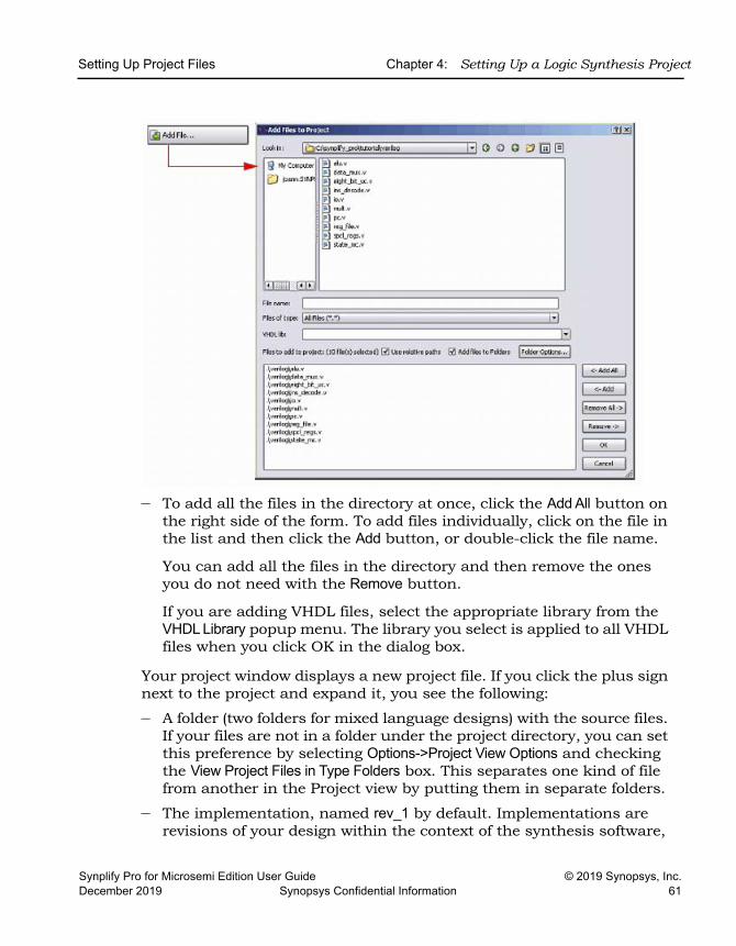
Setting Up Project Files Chapter 4: Setting Up a Logic Synthesis Project
Synplify Pro for Microsemi Edition User Guide © 2019 Synopsys, Inc.December 2019 Synopsys Confidential Information 61
– To add all the files in the directory at once, click the Add All button on the right side of the form. To add files individually, click on the file in the list and then click the Add button, or double-click the file name.
You can add all the files in the directory and then remove the ones you do not need with the Remove button.
If you are adding VHDL files, select the appropriate library from the VHDL Library popup menu. The library you select is applied to all VHDL files when you click OK in the dialog box.
Your project window displays a new project file. If you click the plus sign next to the project and expand it, you see the following:
– A folder (two folders for mixed language designs) with the source files. If your files are not in a folder under the project directory, you can set this preference by selecting Options->Project View Options and checking the View Project Files in Type Folders box. This separates one kind of file from another in the Project view by putting them in separate folders.
– The implementation, named rev_1 by default. Implementations are revisions of your design within the context of the synthesis software,
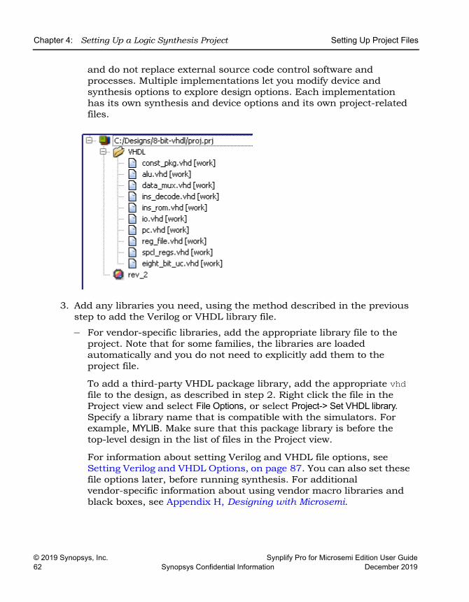
LO
Chapter 4: Setting Up a Logic Synthesis Project Setting Up Project Files
© 2019 Synopsys, Inc. Synplify Pro for Microsemi Edition User Guide62 Synopsys Confidential Information December 2019
and do not replace external source code control software and processes. Multiple implementations let you modify device and synthesis options to explore design options. Each implementation has its own synthesis and device options and its own project-related files.
3. Add any libraries you need, using the method described in the previous step to add the Verilog or VHDL library file.
– For vendor-specific libraries, add the appropriate library file to the project. Note that for some families, the libraries are loaded automatically and you do not need to explicitly add them to the project file.
To add a third-party VHDL package library, add the appropriate vhd file to the design, as described in step 2. Right click the file in the Project view and select File Options, or select Project-> Set VHDL library. Specify a library name that is compatible with the simulators. For example, MYLIB. Make sure that this package library is before the top-level design in the list of files in the Project view.
For information about setting Verilog and VHDL file options, see Setting Verilog and VHDL Options, on page 87. You can also set these file options later, before running synthesis. For additional vendor-specific information about using vendor macro libraries and black boxes, see Appendix H, Designing with Microsemi.
Setting Up Project Files Chapter 4: Setting Up a Logic Synthesis Project
Synplify Pro for Microsemi Edition User Guide © 2019 Synopsys, Inc.December 2019 Synopsys Confidential Information 63
– For generic technology components, you can either add the technology-independent Verilog library supplied with the software (install_dir/lib/generic_ technology/gtech.v) to your design, or add your own generic component library. Do not use both together as there may be conflicts.
4. Check file order in the Project view. File order is important for all HDL files.
– Make sure the files are ordered correctly. To re-order files from the UI, drag files to their correct locations in the order. Alternatively, use the add_file command in the project file to add the input files in the correct sequence. See Ordering Input Files, on page 68 for details about the order sequence for Verilog and VHDL files.
– In the Project view, check that the last file in the Project view is the top-level source file. Alternatively, you can specify the top-level file when you set the device options.
An example of correct file order for a design that consists of one top module (top.v) and two sub module files (module1.v and module2.v):
add_file -verilog -lib work module1.vadd_file -verilog -lib work module2.vadd_file -verilog -lib work top.v
5. Select File->Save, type a name for the project, and click Save. The Project window reflects your changes.
6. To close a project file, select the Close Project button or File->Close Project.
Opening an Existing Project FileThere are two ways to open a project file: the Open Project and the generic File->Open command.
1. If the project you want to open is one you worked on recently, you can select it directly: File->Recent Projects-> projectName.
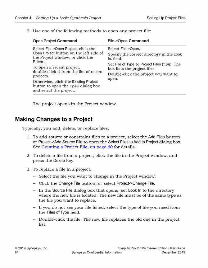
LO
Chapter 4: Setting Up a Logic Synthesis Project Setting Up Project Files
© 2019 Synopsys, Inc. Synplify Pro for Microsemi Edition User Guide64 Synopsys Confidential Information December 2019
2. Use one of the following methods to open any project file:
The project opens in the Project window.
Making Changes to a ProjectTypically, you add, delete, or replace files.
1. To add source or constraint files to a project, select the Add Files button or Project->Add Source File to open the Select Files to Add to Project dialog box. See Creating a Project File, on page 60 for details.
2. To delete a file from a project, click the file in the Project window, and press the Delete key.
3. To replace a file in a project,
– Select the file you want to change in the Project window.
– Click the Change File button, or select Project->Change File.
– In the Source File dialog box that opens, set Look In to the directory where the new file is located. The new file must be of the same type as the file you want to replace.
– If you do not see your file listed, select the type of file you need from the Files of Type field.
– Double-click the file. The new file replaces the old one in the project list.
Open Project Command File->Open Command
Select File->Open Project, click the Open Project button on the left side of the Project window, or click the P icon. To open a recent project, double-click it from the list of recent projects. Otherwise, click the Existing Project button to open the Open dialog box and select the project.
Select File->Open. Specify the correct directory in the Look In: field. Set File of Type to Project Files (*.prj). The box lists the project files. Double-click the project you want to open.
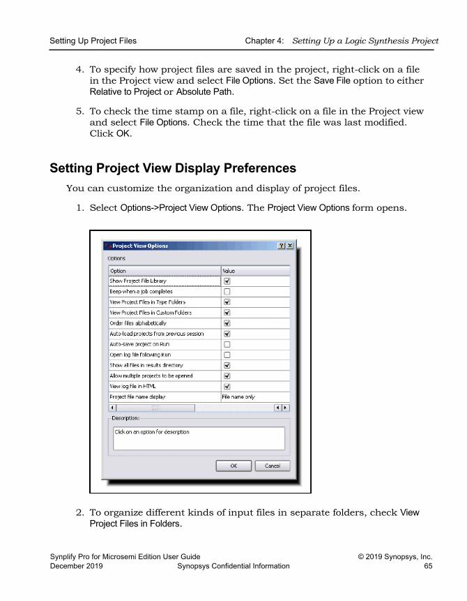
Setting Up Project Files Chapter 4: Setting Up a Logic Synthesis Project
Synplify Pro for Microsemi Edition User Guide © 2019 Synopsys, Inc.December 2019 Synopsys Confidential Information 65
4. To specify how project files are saved in the project, right-click on a file in the Project view and select File Options. Set the Save File option to either Relative to Project or Absolute Path.
5. To check the time stamp on a file, right-click on a file in the Project view and select File Options. Check the time that the file was last modified. Click OK.
Setting Project View Display PreferencesYou can customize the organization and display of project files.
1. Select Options->Project View Options. The Project View Options form opens.
2. To organize different kinds of input files in separate folders, check View Project Files in Folders.
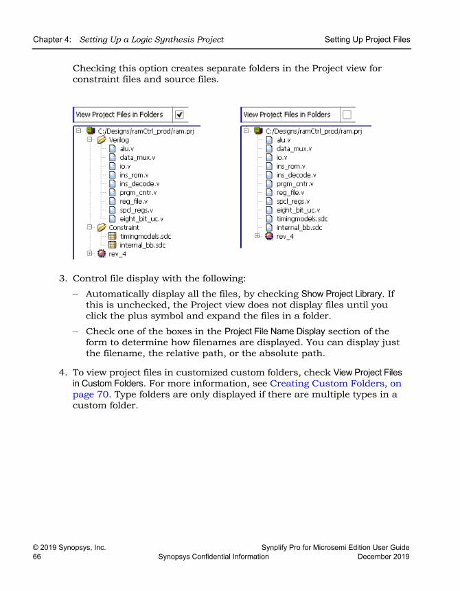
LO
Chapter 4: Setting Up a Logic Synthesis Project Setting Up Project Files
© 2019 Synopsys, Inc. Synplify Pro for Microsemi Edition User Guide66 Synopsys Confidential Information December 2019
Checking this option creates separate folders in the Project view for constraint files and source files.
3. Control file display with the following:
– Automatically display all the files, by checking Show Project Library. If this is unchecked, the Project view does not display files until you click the plus symbol and expand the files in a folder.
– Check one of the boxes in the Project File Name Display section of the form to determine how filenames are displayed. You can display just the filename, the relative path, or the absolute path.
4. To view project files in customized custom folders, check View Project Files in Custom Folders. For more information, see Creating Custom Folders, on page 70. Type folders are only displayed if there are multiple types in a custom folder.
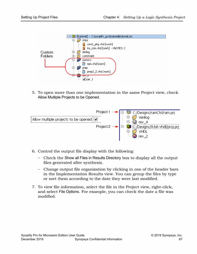
Setting Up Project Files Chapter 4: Setting Up a Logic Synthesis Project
Synplify Pro for Microsemi Edition User Guide © 2019 Synopsys, Inc.December 2019 Synopsys Confidential Information 67
5. To open more than one implementation in the same Project view, check Allow Multiple Projects to be Opened.
6. Control the output file display with the following:
– Check the Show all Files in Results Directory box to display all the output files generated after synthesis.
– Change output file organization by clicking in one of the header bars in the Implementation Results view. You can group the files by type or sort them according to the date they were last modified.
7. To view file information, select the file in the Project view, right-click, and select File Options. For example, you can check the date a file was modified.
LO
Chapter 4: Setting Up a Logic Synthesis Project Setting Up Project Files
© 2019 Synopsys, Inc. Synplify Pro for Microsemi Edition User Guide68 Synopsys Confidential Information December 2019
Ordering Input FilesCorrect file order is important for all HDL designs, to ensure that the packages are compiled quickly. Incorrect file order causes unwanted errors/warnings and longer run times. The general rule is to instantiate macros or packages that are referenced by other files and list them before the files that instantiate them. The top-level file must be last on the list.
Do the following to correctly arrange VHDL files:
• To automatically arrange the VHDL files, select the Run->Arrange VHDL option from the menu. Run this command only once.
• To manually arrange the VHDL files, make sure to list the package files first because they must be compiled. Then follow this file order for big designs spread out over multiple FPGAs: entity file, then the architec-ture file and lastly the configuration file.
Follow this file order when specifying Verilog files for a design:
• For Verilog designs, list package files first because they are compiled before use. After that, list the corresponding HDL files, and list the top-level source file last.
• For SystemVerilog designs, ensure that package, macro, and component files are listed first. Next add the files that instantiate the packages and macros. For example:
– Package1.sv (package file)
– Test.sv (import Package1.sv)
– Top.sv (instantiates Test.sv)
Do the following to arrange files for mixed designs:
• Arrange Verilog/System Verilog files are described above
• Use the Run->Arrange VHDL option from the menu for VHDL files
Updating Verilog Include Paths in Older Project FilesIf you have a project file created with an older version of the software (prior to 8.1), the Verilog include paths in this file are relative to the results directory or the source file with the `include statements. In releases after 8.1, the project file `include paths are relative to the project file only. The GUI in the more
Setting Up Project Files Chapter 4: Setting Up a Logic Synthesis Project
Synplify Pro for Microsemi Edition User Guide © 2019 Synopsys, Inc.December 2019 Synopsys Confidential Information 69
recent releases does not automatically upgrade the older PRJ files to conform to the newer rules. To upgrade and use the old project file, do one of the following:
• Manually edit the PRJ file in a text editor and add the following on the line before each set_option -include_path:
set_option -project_relative_includes 1 • Start a new project with a newer version of the software and delete the
old project. This will make the new PRJ file obey the new rule where includes are relative to the PRJ file.
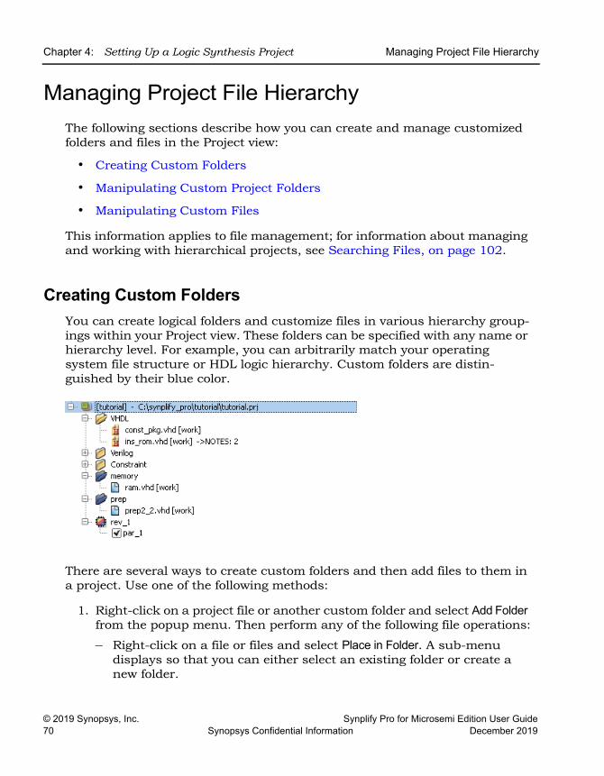
LO
Chapter 4: Setting Up a Logic Synthesis Project Managing Project File Hierarchy
© 2019 Synopsys, Inc. Synplify Pro for Microsemi Edition User Guide70 Synopsys Confidential Information December 2019
Managing Project File HierarchyThe following sections describe how you can create and manage customized folders and files in the Project view:
• Creating Custom Folders
• Manipulating Custom Project Folders
• Manipulating Custom Files
This information applies to file management; for information about managing and working with hierarchical projects, see Searching Files, on page 102.
Creating Custom FoldersYou can create logical folders and customize files in various hierarchy group-ings within your Project view. These folders can be specified with any name or hierarchy level. For example, you can arbitrarily match your operating system file structure or HDL logic hierarchy. Custom folders are distin-guished by their blue color.
There are several ways to create custom folders and then add files to them in a project. Use one of the following methods:
1. Right-click on a project file or another custom folder and select Add Folder from the popup menu. Then perform any of the following file operations:
– Right-click on a file or files and select Place in Folder. A sub-menu displays so that you can either select an existing folder or create a new folder.
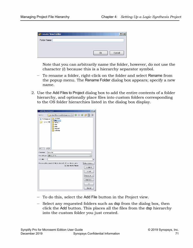
Managing Project File Hierarchy Chapter 4: Setting Up a Logic Synthesis Project
Synplify Pro for Microsemi Edition User Guide © 2019 Synopsys, Inc.December 2019 Synopsys Confidential Information 71
Note that you can arbitrarily name the folder, however, do not use the character (/) because this is a hierarchy separator symbol.
– To rename a folder, right-click on the folder and select Rename from the popup menu. The Rename Folder dialog box appears; specify a new name.
2. Use the Add Files to Project dialog box to add the entire contents of a folder hierarchy, and optionally place files into custom folders corresponding to the OS folder hierarchies listed in the dialog box display.
– To do this, select the Add File button in the Project view.
– Select any requested folders such as dsp from the dialog box, then click the Add button. This places all the files from the dsp hierarchy into the custom folder you just created.
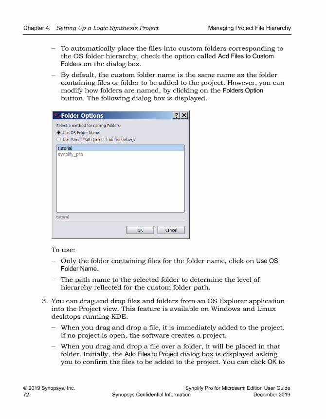
LO
Chapter 4: Setting Up a Logic Synthesis Project Managing Project File Hierarchy
© 2019 Synopsys, Inc. Synplify Pro for Microsemi Edition User Guide72 Synopsys Confidential Information December 2019
– To automatically place the files into custom folders corresponding to the OS folder hierarchy, check the option called Add Files to Custom Folders on the dialog box.
– By default, the custom folder name is the same name as the folder containing files or folder to be added to the project. However, you can modify how folders are named, by clicking on the Folders Option button. The following dialog box is displayed.
To use:
– Only the folder containing files for the folder name, click on Use OS Folder Name.
– The path name to the selected folder to determine the level of hierarchy reflected for the custom folder path.
3. You can drag and drop files and folders from an OS Explorer application into the Project view. This feature is available on Windows and Linux desktops running KDE.
– When you drag and drop a file, it is immediately added to the project. If no project is open, the software creates a project.
– When you drag and drop a file over a folder, it will be placed in that folder. Initially, the Add Files to Project dialog box is displayed asking you to confirm the files to be added to the project. You can click OK to
Managing Project File Hierarchy Chapter 4: Setting Up a Logic Synthesis Project
Synplify Pro for Microsemi Edition User Guide © 2019 Synopsys, Inc.December 2019 Synopsys Confidential Information 73
accept the files. If you want to make changes, you can click the Remove All button and specify a new filter or option.
Note: To display custom folders in the Project view, select the Options->Project View Options menu, then enable/disable the check box for View Project Files in Custom Folders on the dialog box.
Manipulating Custom Project FoldersThe following procedure describes how you can remove files from folders, delete folders, and change the folder hierarchy.
1. To remove a file from a custom folder, either:
– Drag and drop it into another folder or onto the project.
– Highlight the file, right-click and select Remove from Folder from the popup menu.
Do not use the Delete (DEL) key, as this removes the file from the project.
2. To delete a custom folder, highlight it then right-click and select Delete from the popup menu or press the DEL key. When you delete a folder, make one of the following choices:
– Click Yes to delete the folder and the files contained in the folder from the project.
– Click No to just delete the folder.
3. To change the hierarchy of the custom folder:
– Drag and drop the folder within another folder so that it is a sub-folder or over the project to move it to the top-level.
– To remove the top-level hierarchy of a custom folder, drag and drop the desired sub-level of hierarchy over the project. Then delete the empty root directory for the folder.
For example, if the existing custom folder directory is:
/Examples/Verilog/HDL
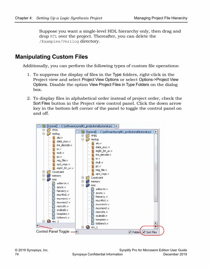
LO
Chapter 4: Setting Up a Logic Synthesis Project Managing Project File Hierarchy
© 2019 Synopsys, Inc. Synplify Pro for Microsemi Edition User Guide74 Synopsys Confidential Information December 2019
Suppose you want a single-level HDL hierarchy only, then drag and drop RTL over the project. Thereafter, you can delete the /Examples/Verilog directory.
Manipulating Custom FilesAdditionally, you can perform the following types of custom file operations:
1. To suppress the display of files in the Type folders, right-click in the Project view and select Project View Options or select Options->Project View Options. Disable the option View Project Files in Type Folders on the dialog box.
2. To display files in alphabetical order instead of project order, check the Sort Files button in the Project view control panel. Click the down arrow key in the bottom-left corner of the panel to toggle the control panel on and off.
Managing Project File Hierarchy Chapter 4: Setting Up a Logic Synthesis Project
Synplify Pro for Microsemi Edition User Guide © 2019 Synopsys, Inc.December 2019 Synopsys Confidential Information 75
3. To change the order of files in the project:
– Make sure to disable custom folders and sorting files.
– Drag and drop a file to the desired position in the list of files.
4. To change the file type, drag and drop it to the new type folder. The software will prompt you for verification.
LO
Chapter 4: Setting Up a Logic Synthesis Project Setting Up Implementations
© 2019 Synopsys, Inc. Synplify Pro for Microsemi Edition User Guide76 Synopsys Confidential Information December 2019
Setting Up ImplementationsAn implementation is a version of a project, implemented with a specific set of constraints and other settings. A project can contain multiple implementa-tions, each one with its own settings.
Working with Multiple ImplementationsThe synthesis tool lets you create multiple implementations of the same design and then compare results. This lets you experiment with different settings for the same design. Implementations are revisions of your design within the context of the synthesis software, and do not replace external source code control software and processes.
1. Click the Add Implementation button or select Project->New Implementation and set new device options (Device tab), new options (Options tab), or a new constraint file (Constraints tab).
The software creates another implementation in the project view. The new implementation has the same name as the previous one, but with a different number suffix. The following figure shows two implementa-tions, rev1 and rev2, with the current (active) implementation highlighted.
The new implementation uses the same source code files, but different device options and constraints. It copies some files from the previous implementation: the tlg log file, the srs RTL netlist file, and the design_fsm.sdc file generated by FSM Explorer. The software keeps a repeatable history of the synthesis runs.
2. Run synthesis again with the new settings.
– To run the current implementation only, click Run.
– To run all the implementations in a project, select Run->Run All Implementations.
You can use multiple implementations to try a different part or experi-ment with a different frequency. See Setting Logic Synthesis Implemen-tation Options, on page 78 for information about setting options.
The Project view shows all implementations with the active implementa-tion highlighted and the corresponding output files generated for the active implementation displayed in the Implementation Results view on the right; changing the active implementation changes the output file display. The Watch window monitors the active implementation. If you
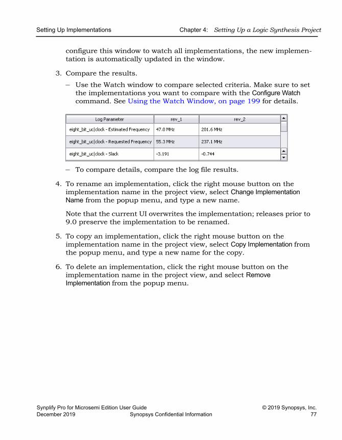
Setting Up Implementations Chapter 4: Setting Up a Logic Synthesis Project
Synplify Pro for Microsemi Edition User Guide © 2019 Synopsys, Inc.December 2019 Synopsys Confidential Information 77
configure this window to watch all implementations, the new implemen-tation is automatically updated in the window.
3. Compare the results.
– Use the Watch window to compare selected criteria. Make sure to set the implementations you want to compare with the Configure Watch command. See Using the Watch Window, on page 199 for details.
– To compare details, compare the log file results.
4. To rename an implementation, click the right mouse button on the implementation name in the project view, select Change Implementation Name from the popup menu, and type a new name.
Note that the current UI overwrites the implementation; releases prior to 9.0 preserve the implementation to be renamed.
5. To copy an implementation, click the right mouse button on the implementation name in the project view, select Copy Implementation from the popup menu, and type a new name for the copy.
6. To delete an implementation, click the right mouse button on the implementation name in the project view, and select Remove Implementation from the popup menu.
LO
Chapter 4: Setting Up a Logic Synthesis Project Setting Logic Synthesis Implementation Options
© 2019 Synopsys, Inc. Synplify Pro for Microsemi Edition User Guide78 Synopsys Confidential Information December 2019
Setting Logic Synthesis Implementation OptionsYou can set global options for your synthesis implementations, some of them technology-specific. This section describes how to set global options like device, optimization, and file options with the Implementation Options command. For information about setting constraints for the implementation, see Speci-fying SCOPE Constraints, on page 128. For information about overriding global settings with individual attributes or directives, see Specifying Attri-butes and Directives, on page 93.
This section discusses the following topics:
• Setting Device Options, on page 78
• Setting Optimization Options, on page 81
• Specifying Global Frequency and Constraint Files, on page 83
• Specifying Result Options, on page 85
• Specifying Timing Report Output, on page 87
• Setting Verilog and VHDL Options, on page 87
Setting Device OptionsDevice options are part of the global options you can set for the synthesis run. They include the part selection (technology, part and speed grade) and implementation options (I/O insertion and fanouts). The options and the implementation of these options can vary from technology to technology, so check the vendor chapters of the Reference Manual for information about your vendor options.
1. Open the Implementation Options form by clicking the Implementation Options button or selecting Project->Implementation Options, and click the Device tab at the top if it is not already selected.
2. Select the technology, part, package, and speed.
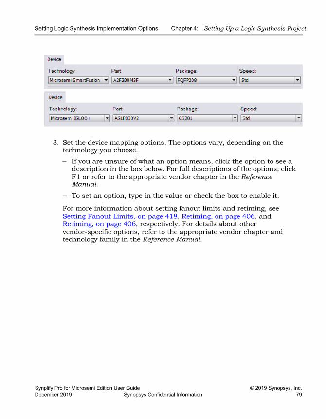
Setting Logic Synthesis Implementation Options Chapter 4: Setting Up a Logic Synthesis Project
Synplify Pro for Microsemi Edition User Guide © 2019 Synopsys, Inc.December 2019 Synopsys Confidential Information 79
3. Set the device mapping options. The options vary, depending on the technology you choose.
– If you are unsure of what an option means, click the option to see a description in the box below. For full descriptions of the options, click F1 or refer to the appropriate vendor chapter in the Reference Manual.
– To set an option, type in the value or check the box to enable it.
For more information about setting fanout limits and retiming, see Setting Fanout Limits, on page 418, Retiming, on page 406, and Retiming, on page 406, respectively. For details about other vendor-specific options, refer to the appropriate vendor chapter and technology family in the Reference Manual.
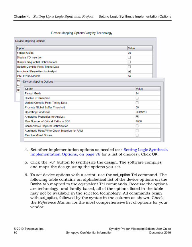
LO
Chapter 4: Setting Up a Logic Synthesis Project Setting Logic Synthesis Implementation Options
© 2019 Synopsys, Inc. Synplify Pro for Microsemi Edition User Guide80 Synopsys Confidential Information December 2019
4. Set other implementation options as needed (see Setting Logic Synthesis Implementation Options, on page 78 for a list of choices). Click OK.
5. Click the Run button to synthesize the design. The software compiles and maps the design using the options you set.
6. To set device options with a script, use the set_option Tcl command. The following table contains an alphabetical list of the device options on the Device tab mapped to the equivalent Tcl commands. Because the options are technology- and family-based, all of the options listed in the table may not be available in the selected technology. All commands begin with set_option, followed by the syntax in the column as shown. Check the Reference Manual for the most comprehensive list of options for your vendor.
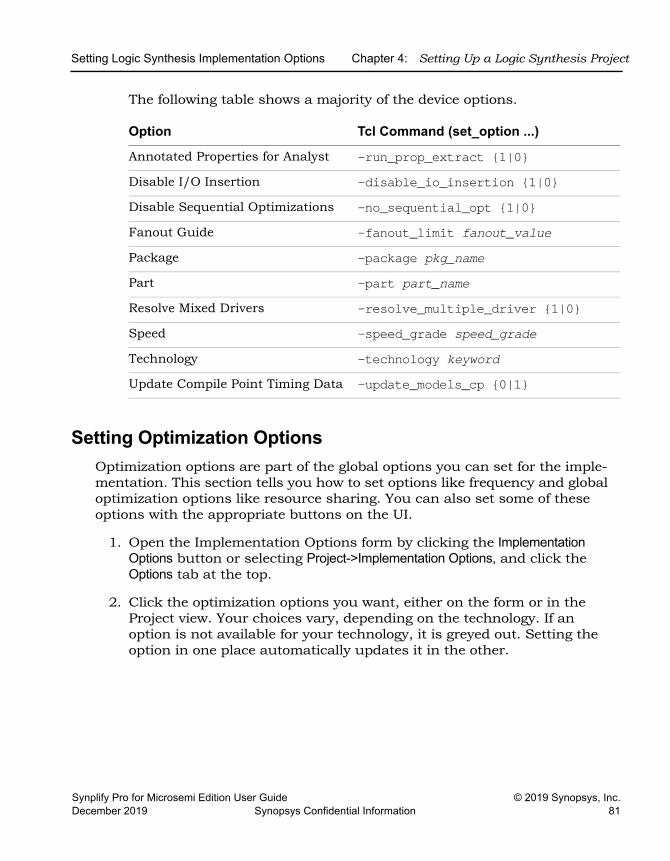
Setting Logic Synthesis Implementation Options Chapter 4: Setting Up a Logic Synthesis Project
Synplify Pro for Microsemi Edition User Guide © 2019 Synopsys, Inc.December 2019 Synopsys Confidential Information 81
The following table shows a majority of the device options.
Setting Optimization OptionsOptimization options are part of the global options you can set for the imple-mentation. This section tells you how to set options like frequency and global optimization options like resource sharing. You can also set some of these options with the appropriate buttons on the UI.
1. Open the Implementation Options form by clicking the Implementation Options button or selecting Project->Implementation Options, and click the Options tab at the top.
2. Click the optimization options you want, either on the form or in the Project view. Your choices vary, depending on the technology. If an option is not available for your technology, it is greyed out. Setting the option in one place automatically updates it in the other.
Option Tcl Command (set_option ...)
Annotated Properties for Analyst -run_prop_extract {1|0}Disable I/O Insertion -disable_io_insertion {1|0}Disable Sequential Optimizations -no_sequential_opt {1|0}Fanout Guide -fanout_limit fanout_valuePackage -package pkg_namePart -part part_nameResolve Mixed Drivers -resolve_multiple_driver {1|0}Speed -speed_grade speed_gradeTechnology -technology keywordUpdate Compile Point Timing Data -update_models_cp {0|1}
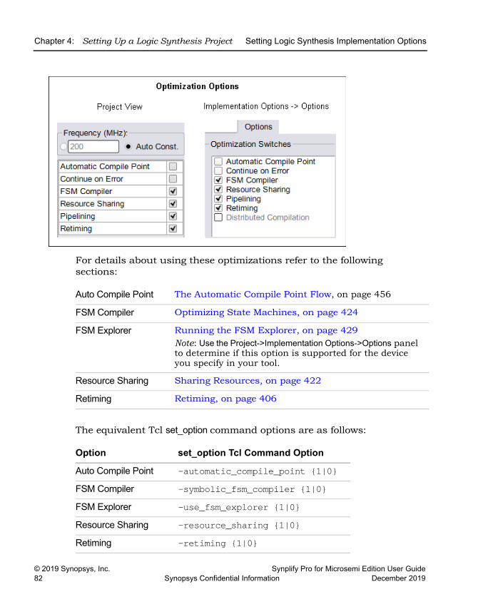
LO
Chapter 4: Setting Up a Logic Synthesis Project Setting Logic Synthesis Implementation Options
© 2019 Synopsys, Inc. Synplify Pro for Microsemi Edition User Guide82 Synopsys Confidential Information December 2019
For details about using these optimizations refer to the following sections:
The equivalent Tcl set_option command options are as follows:
Auto Compile Point The Automatic Compile Point Flow, on page 456
FSM Compiler Optimizing State Machines, on page 424
FSM Explorer Running the FSM Explorer, on page 429Note: Use the Project->Implementation Options->Options panel to determine if this option is supported for the device you specify in your tool.
Resource Sharing Sharing Resources, on page 422
Retiming Retiming, on page 406
Option set_option Tcl Command Option
Auto Compile Point -automatic_compile_point {1|0}FSM Compiler -symbolic_fsm_compiler {1|0}FSM Explorer -use_fsm_explorer {1|0}Resource Sharing -resource_sharing {1|0}Retiming -retiming {1|0}
Setting Logic Synthesis Implementation Options Chapter 4: Setting Up a Logic Synthesis Project
Synplify Pro for Microsemi Edition User Guide © 2019 Synopsys, Inc.December 2019 Synopsys Confidential Information 83
3. Set other implementation options as needed (see Setting Logic Synthesis Implementation Options, on page 78 for a list of choices). Click OK.
4. Click the Run button to run synthesis.
The software compiles and maps the design using the options you set.
Specifying Global Frequency and Constraint FilesThis procedure tells you how to set the global frequency and specify the constraint files for the implementation.
1. To set a global frequency, do one of the following:
– Type a global frequency in the Project view.
– Open the Implementation Options form by clicking the Implementation Options button or selecting Project->Implementation Options, and click the Constraints tab.
The equivalent Tcl set_option command is -frequency frequencyValue.
You can override the global frequency with local constraints, as described in Specifying SCOPE Constraints, on page 128. In the Synplify Pro tool, you can automatically generate clock constraints for your design instead of setting a global frequency. See Using Auto Constraints, on page 376 for details.
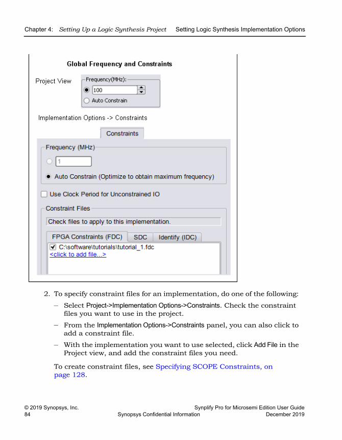
LO
Chapter 4: Setting Up a Logic Synthesis Project Setting Logic Synthesis Implementation Options
© 2019 Synopsys, Inc. Synplify Pro for Microsemi Edition User Guide84 Synopsys Confidential Information December 2019
2. To specify constraint files for an implementation, do one of the following:
– Select Project->Implementation Options->Constraints. Check the constraint files you want to use in the project.
– From the Implementation Options->Constraints panel, you can also click to add a constraint file.
– With the implementation you want to use selected, click Add File in the Project view, and add the constraint files you need.
To create constraint files, see Specifying SCOPE Constraints, on page 128.
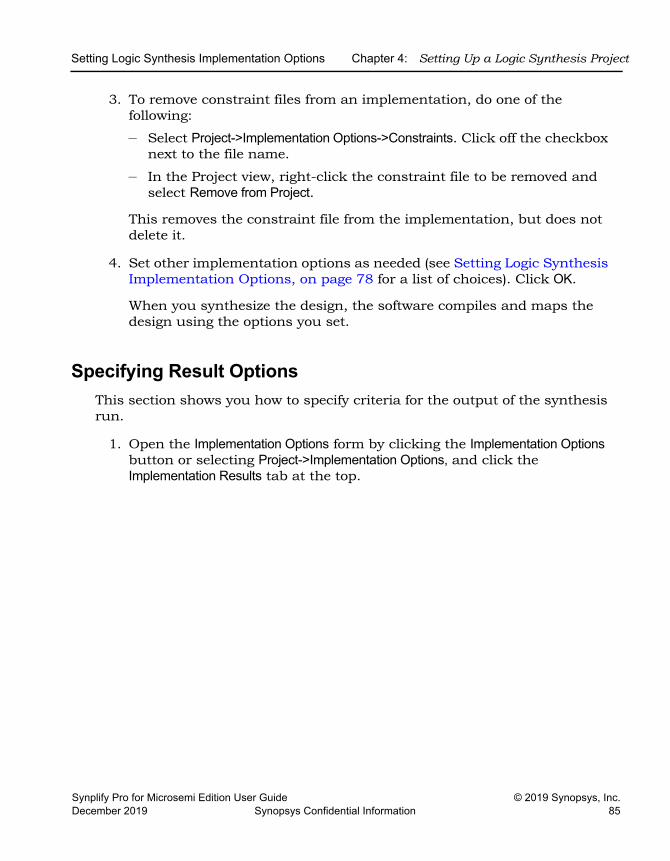
Setting Logic Synthesis Implementation Options Chapter 4: Setting Up a Logic Synthesis Project
Synplify Pro for Microsemi Edition User Guide © 2019 Synopsys, Inc.December 2019 Synopsys Confidential Information 85
3. To remove constraint files from an implementation, do one of the following:
– Select Project->Implementation Options->Constraints. Click off the checkbox next to the file name.
– In the Project view, right-click the constraint file to be removed and select Remove from Project.
This removes the constraint file from the implementation, but does not delete it.
4. Set other implementation options as needed (see Setting Logic Synthesis Implementation Options, on page 78 for a list of choices). Click OK.
When you synthesize the design, the software compiles and maps the design using the options you set.
Specifying Result OptionsThis section shows you how to specify criteria for the output of the synthesis run.
1. Open the Implementation Options form by clicking the Implementation Options button or selecting Project->Implementation Options, and click the Implementation Results tab at the top.
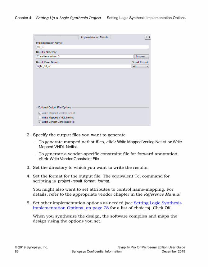
LO
Chapter 4: Setting Up a Logic Synthesis Project Setting Logic Synthesis Implementation Options
© 2019 Synopsys, Inc. Synplify Pro for Microsemi Edition User Guide86 Synopsys Confidential Information December 2019
2. Specify the output files you want to generate.
– To generate mapped netlist files, click Write Mapped Verilog Netlist or Write Mapped VHDL Netlist.
– To generate a vendor-specific constraint file for forward annotation, click Write Vendor Constraint File.
3. Set the directory to which you want to write the results.
4. Set the format for the output file. The equivalent Tcl command for scripting is project -result_format format.
You might also want to set attributes to control name-mapping. For details, refer to the appropriate vendor chapter in the Reference Manual.
5. Set other implementation options as needed (see Setting Logic Synthesis Implementation Options, on page 78 for a list of choices). Click OK.
When you synthesize the design, the software compiles and maps the design using the options you set.
Setting Logic Synthesis Implementation Options Chapter 4: Setting Up a Logic Synthesis Project
Synplify Pro for Microsemi Edition User Guide © 2019 Synopsys, Inc.December 2019 Synopsys Confidential Information 87
Specifying Timing Report OutputYou can determine how much is reported in the timing report by setting the following options.
1. Selecting Project->Implementation Options, and click the Timing Report tab.
2. Set the number of critical paths you want the software to report.
3. Specify the number of start and end points you want to see reported in the critical path sections.
4. Set other implementation options as needed (see Setting Logic Synthesis Implementation Options, on page 78 for a list of choices). Click OK.
When you synthesize the design, the software compiles and maps the design using the options you set.
Setting Verilog and VHDL OptionsWhen you set up the Verilog and VHDL source files in your project, you can also specify certain compiler options.
Setting Verilog File OptionsYou set Verilog file options by selecting either Project->Implementation Options-> Verilog, or Options->Configure Verilog Compiler.
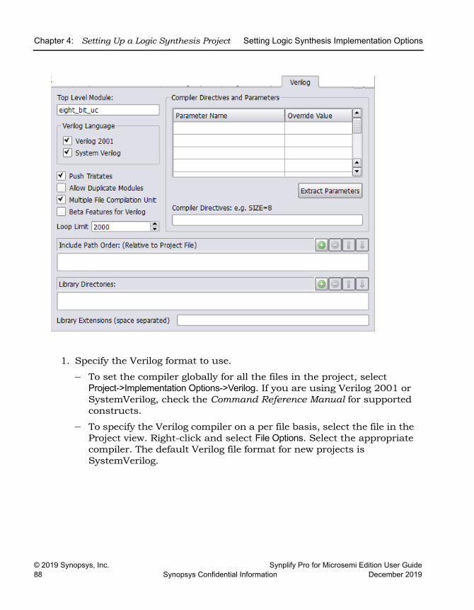
LO
Chapter 4: Setting Up a Logic Synthesis Project Setting Logic Synthesis Implementation Options
© 2019 Synopsys, Inc. Synplify Pro for Microsemi Edition User Guide88 Synopsys Confidential Information December 2019
1. Specify the Verilog format to use.
– To set the compiler globally for all the files in the project, select Project->Implementation Options->Verilog. If you are using Verilog 2001 or SystemVerilog, check the Command Reference Manual for supported constructs.
– To specify the Verilog compiler on a per file basis, select the file in the Project view. Right-click and select File Options. Select the appropriate compiler. The default Verilog file format for new projects is SystemVerilog.
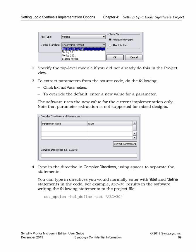
Setting Logic Synthesis Implementation Options Chapter 4: Setting Up a Logic Synthesis Project
Synplify Pro for Microsemi Edition User Guide © 2019 Synopsys, Inc.December 2019 Synopsys Confidential Information 89
2. Specify the top-level module if you did not already do this in the Project view.
3. To extract parameters from the source code, do the following:
– Click Extract Parameters.– To override the default, enter a new value for a parameter.
The software uses the new value for the current implementation only. Note that parameter extraction is not supported for mixed designs.
4. Type in the directive in Compiler Directives, using spaces to separate the statements.
You can type in directives you would normally enter with 'ifdef and ‘define statements in the code. For example, ABC=30 results in the software writing the following statements to the project file:
set_option -hdl_define -set "ABC=30"
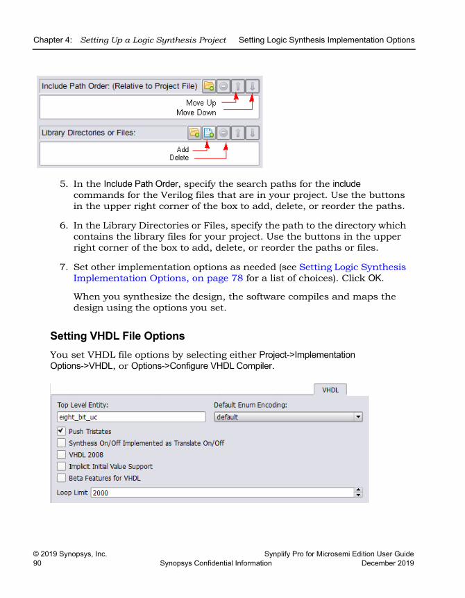
LO
Chapter 4: Setting Up a Logic Synthesis Project Setting Logic Synthesis Implementation Options
© 2019 Synopsys, Inc. Synplify Pro for Microsemi Edition User Guide90 Synopsys Confidential Information December 2019
5. In the Include Path Order, specify the search paths for the include commands for the Verilog files that are in your project. Use the buttons in the upper right corner of the box to add, delete, or reorder the paths.
6. In the Library Directories or Files, specify the path to the directory which contains the library files for your project. Use the buttons in the upper right corner of the box to add, delete, or reorder the paths or files.
7. Set other implementation options as needed (see Setting Logic Synthesis Implementation Options, on page 78 for a list of choices). Click OK.
When you synthesize the design, the software compiles and maps the design using the options you set.
Setting VHDL File OptionsYou set VHDL file options by selecting either Project->Implementation Options->VHDL, or Options->Configure VHDL Compiler.
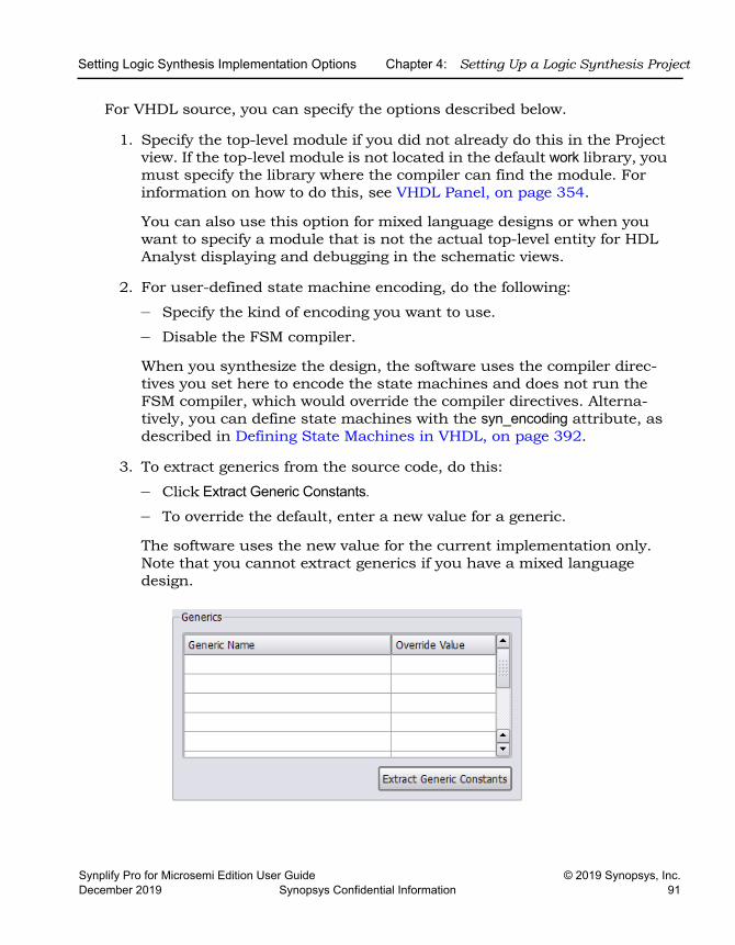
Setting Logic Synthesis Implementation Options Chapter 4: Setting Up a Logic Synthesis Project
Synplify Pro for Microsemi Edition User Guide © 2019 Synopsys, Inc.December 2019 Synopsys Confidential Information 91
For VHDL source, you can specify the options described below.
1. Specify the top-level module if you did not already do this in the Project view. If the top-level module is not located in the default work library, you must specify the library where the compiler can find the module. For information on how to do this, see VHDL Panel, on page 354.
You can also use this option for mixed language designs or when you want to specify a module that is not the actual top-level entity for HDL Analyst displaying and debugging in the schematic views.
2. For user-defined state machine encoding, do the following:
– Specify the kind of encoding you want to use.
– Disable the FSM compiler.
When you synthesize the design, the software uses the compiler direc-tives you set here to encode the state machines and does not run the FSM compiler, which would override the compiler directives. Alterna-tively, you can define state machines with the syn_encoding attribute, as described in Defining State Machines in VHDL, on page 392.
3. To extract generics from the source code, do this:
– Click Extract Generic Constants.
– To override the default, enter a new value for a generic.
The software uses the new value for the current implementation only. Note that you cannot extract generics if you have a mixed language design.
LO
Chapter 4: Setting Up a Logic Synthesis Project Setting Logic Synthesis Implementation Options
© 2019 Synopsys, Inc. Synplify Pro for Microsemi Edition User Guide92 Synopsys Confidential Information December 2019
4. To push tristates across process/block boundaries, check that Push Tristates is enabled. For details, see Push Tristates Option, on page 362 in the Reference Manual.
5. Determine the interpretation of the synthesis_on and synthesis_off directives:
– To make the compiler interpret synthesis_on and synthesis_off directives like translate_on/translate_off, enable the Synthesis On/Off Implemented as Translate On/Off option.
– To ignore the synthesis_on and synthesis_off directives, make sure that this option is not checked. See translate_off/translate_on, on page 281 in the Reference Manual for more information.
6. Set other implementation options as needed (see Setting Logic Synthesis Implementation Options, on page 78 for a list of choices). Click OK.
When you synthesize the design, the software compiles and maps the design using the options you set.
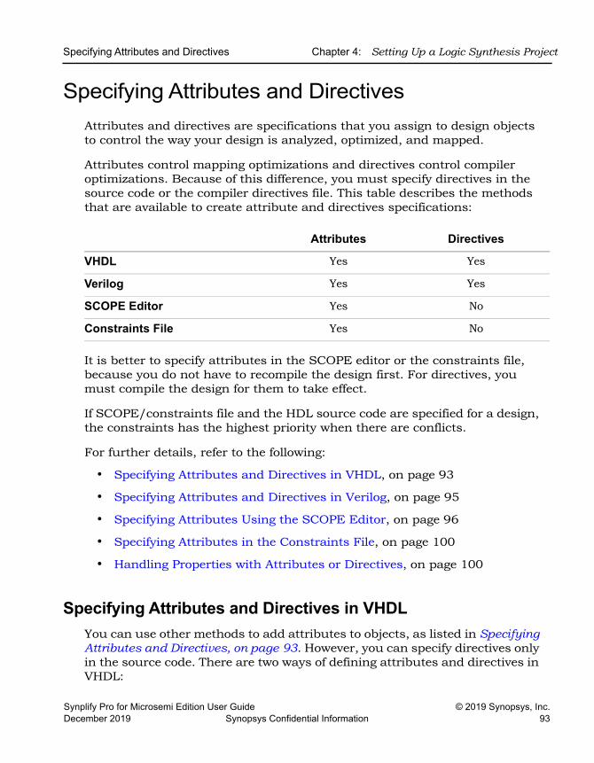
Specifying Attributes and Directives Chapter 4: Setting Up a Logic Synthesis Project
Synplify Pro for Microsemi Edition User Guide © 2019 Synopsys, Inc.December 2019 Synopsys Confidential Information 93
Specifying Attributes and DirectivesAttributes and directives are specifications that you assign to design objects to control the way your design is analyzed, optimized, and mapped.
Attributes control mapping optimizations and directives control compiler optimizations. Because of this difference, you must specify directives in the source code or the compiler directives file. This table describes the methods that are available to create attribute and directives specifications:
It is better to specify attributes in the SCOPE editor or the constraints file, because you do not have to recompile the design first. For directives, you must compile the design for them to take effect.
If SCOPE/constraints file and the HDL source code are specified for a design, the constraints has the highest priority when there are conflicts.
For further details, refer to the following:
• Specifying Attributes and Directives in VHDL, on page 93
• Specifying Attributes and Directives in Verilog, on page 95
• Specifying Attributes Using the SCOPE Editor, on page 96
• Specifying Attributes in the Constraints File, on page 100
• Handling Properties with Attributes or Directives, on page 100
Specifying Attributes and Directives in VHDLYou can use other methods to add attributes to objects, as listed in Specifying Attributes and Directives, on page 93. However, you can specify directives only in the source code. There are two ways of defining attributes and directives in VHDL:
Attributes Directives
VHDL Yes Yes
Verilog Yes Yes
SCOPE Editor Yes No
Constraints File Yes No
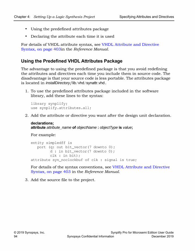
LO
Chapter 4: Setting Up a Logic Synthesis Project Specifying Attributes and Directives
© 2019 Synopsys, Inc. Synplify Pro for Microsemi Edition User Guide94 Synopsys Confidential Information December 2019
• Using the predefined attributes package
• Declaring the attribute each time it is used
For details of VHDL attribute syntax, see VHDL Attribute and Directive Syntax, on page 403in the Reference Manual.
Using the Predefined VHDL Attributes PackageThe advantage to using the predefined package is that you avoid redefining the attributes and directives each time you include them in source code. The disadvantage is that your source code is less portable. The attributes package is located in installDirectory/lib/vhd/synattr.vhd.
1. To use the predefined attributes package included in the software library, add these lines to the syntax:
library synplify;use synplify.attributes.all;
2. Add the attribute or directive you want after the design unit declaration.
declarations;attribute attribute_name of objectName : objectType is value;
For example:
entity simpledff isport (q: out bit_vector(7 downto 0);
d : in bit_vector(7 downto 0);clk : in bit);
attribute syn_noclockbuf of clk : signal is true;For details of the syntax conventions, see VHDL Attribute and Directive Syntax, on page 403 in the Reference Manual.
3. Add the source file to the project.
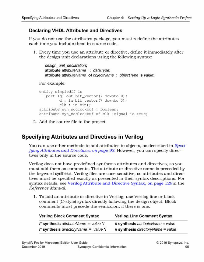
Specifying Attributes and Directives Chapter 4: Setting Up a Logic Synthesis Project
Synplify Pro for Microsemi Edition User Guide © 2019 Synopsys, Inc.December 2019 Synopsys Confidential Information 95
Declaring VHDL Attributes and DirectivesIf you do not use the attributes package, you must redefine the attributes each time you include them in source code.
1. Every time you use an attribute or directive, define it immediately after the design unit declarations using the following syntax:
design_unit_declaration;attribute attributeName : dataType;attribute attributeName of objectName : objectType is value;
For example:
entity simpledff isport (q: out bit_vector(7 downto 0);
d : in bit_vector(7 downto 0);clk : in bit);
attribute syn_noclockbuf : boolean;attribute syn_noclockbuf of clk :signal is true;
2. Add the source file to the project.
Specifying Attributes and Directives in VerilogYou can use other methods to add attributes to objects, as described in Speci-fying Attributes and Directives, on page 93. However, you can specify direc-tives only in the source code.
Verilog does not have predefined synthesis attributes and directives, so you must add them as comments. The attribute or directive name is preceded by the keyword synthesis. Verilog files are case sensitive, so attributes and direc-tives must be specified exactly as presented in their syntax descriptions. For syntax details, see Verilog Attribute and Directive Syntax, on page 129in the Reference Manual.
1. To add an attribute or directive in Verilog, use Verilog line or block comment (C-style) syntax directly following the design object. Block comments must precede the semicolon, if there is one.
Verilog Block Comment Syntax Verilog Line Comment Syntax
/* synthesis attributeName = value *//* synthesis directoryName = value */
// synthesis attributeName = value// synthesis directoryName = value
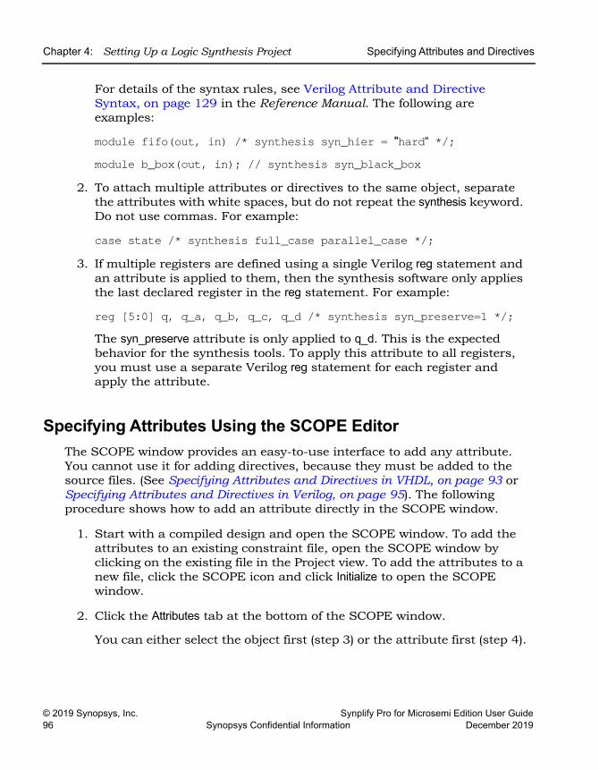
LO
Chapter 4: Setting Up a Logic Synthesis Project Specifying Attributes and Directives
© 2019 Synopsys, Inc. Synplify Pro for Microsemi Edition User Guide96 Synopsys Confidential Information December 2019
For details of the syntax rules, see Verilog Attribute and Directive Syntax, on page 129 in the Reference Manual. The following are examples:
module fifo(out, in) /* synthesis syn_hier = "hard“ */;module b_box(out, in); // synthesis syn_black_box
2. To attach multiple attributes or directives to the same object, separate the attributes with white spaces, but do not repeat the synthesis keyword. Do not use commas. For example:
case state /* synthesis full_case parallel_case */;3. If multiple registers are defined using a single Verilog reg statement and
an attribute is applied to them, then the synthesis software only applies the last declared register in the reg statement. For example:
reg [5:0] q, q_a, q_b, q_c, q_d /* synthesis syn_preserve=1 */;The syn_preserve attribute is only applied to q_d. This is the expected behavior for the synthesis tools. To apply this attribute to all registers, you must use a separate Verilog reg statement for each register and apply the attribute.
Specifying Attributes Using the SCOPE EditorThe SCOPE window provides an easy-to-use interface to add any attribute. You cannot use it for adding directives, because they must be added to the source files. (See Specifying Attributes and Directives in VHDL, on page 93 or Specifying Attributes and Directives in Verilog, on page 95). The following procedure shows how to add an attribute directly in the SCOPE window.
1. Start with a compiled design and open the SCOPE window. To add the attributes to an existing constraint file, open the SCOPE window by clicking on the existing file in the Project view. To add the attributes to a new file, click the SCOPE icon and click Initialize to open the SCOPE window.
2. Click the Attributes tab at the bottom of the SCOPE window.
You can either select the object first (step 3) or the attribute first (step 4).
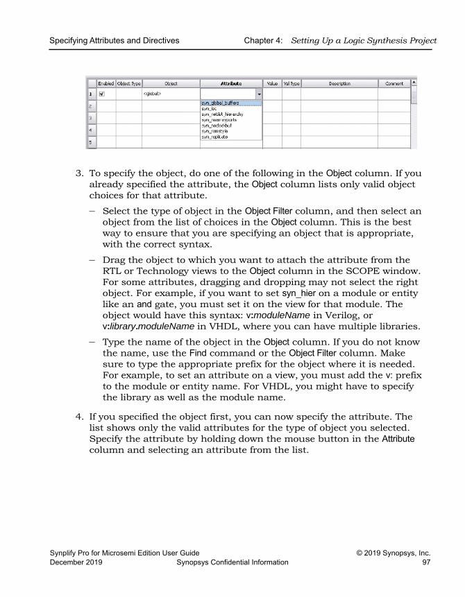
Specifying Attributes and Directives Chapter 4: Setting Up a Logic Synthesis Project
Synplify Pro for Microsemi Edition User Guide © 2019 Synopsys, Inc.December 2019 Synopsys Confidential Information 97
3. To specify the object, do one of the following in the Object column. If you already specified the attribute, the Object column lists only valid object choices for that attribute.
– Select the type of object in the Object Filter column, and then select an object from the list of choices in the Object column. This is the best way to ensure that you are specifying an object that is appropriate, with the correct syntax.
– Drag the object to which you want to attach the attribute from the RTL or Technology views to the Object column in the SCOPE window. For some attributes, dragging and dropping may not select the right object. For example, if you want to set syn_hier on a module or entity like an and gate, you must set it on the view for that module. The object would have this syntax: v:moduleName in Verilog, or v:library.moduleName in VHDL, where you can have multiple libraries.
– Type the name of the object in the Object column. If you do not know the name, use the Find command or the Object Filter column. Make sure to type the appropriate prefix for the object where it is needed. For example, to set an attribute on a view, you must add the v: prefix to the module or entity name. For VHDL, you might have to specify the library as well as the module name.
4. If you specified the object first, you can now specify the attribute. The list shows only the valid attributes for the type of object you selected. Specify the attribute by holding down the mouse button in the Attribute column and selecting an attribute from the list.
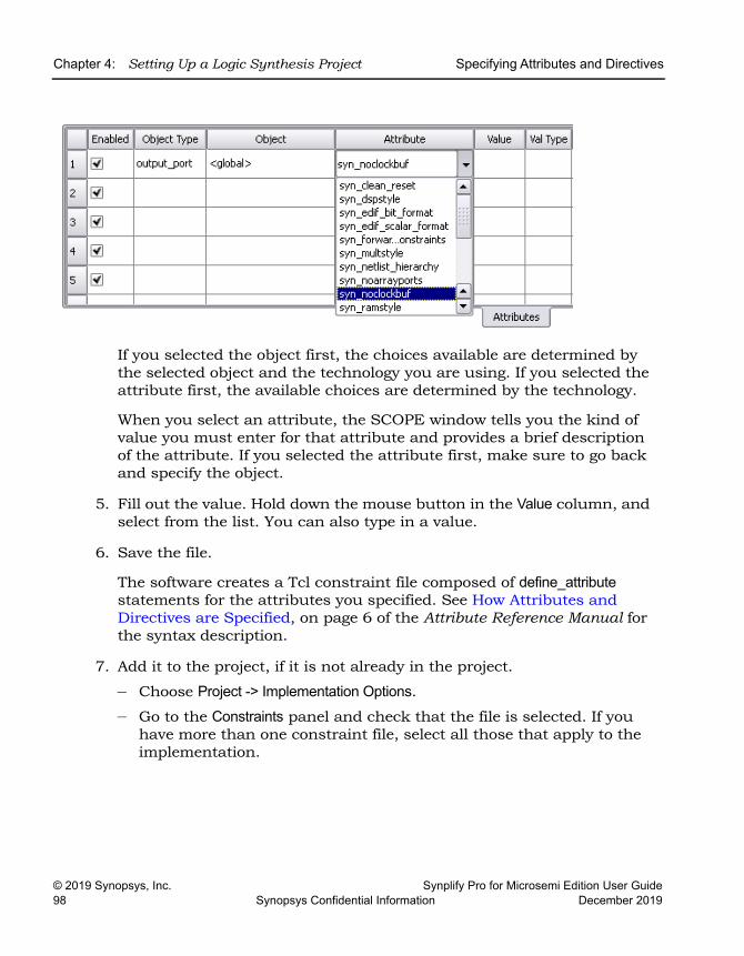
LO
Chapter 4: Setting Up a Logic Synthesis Project Specifying Attributes and Directives
© 2019 Synopsys, Inc. Synplify Pro for Microsemi Edition User Guide98 Synopsys Confidential Information December 2019
If you selected the object first, the choices available are determined by the selected object and the technology you are using. If you selected the attribute first, the available choices are determined by the technology.
When you select an attribute, the SCOPE window tells you the kind of value you must enter for that attribute and provides a brief description of the attribute. If you selected the attribute first, make sure to go back and specify the object.
5. Fill out the value. Hold down the mouse button in the Value column, and select from the list. You can also type in a value.
6. Save the file.
The software creates a Tcl constraint file composed of define_attribute statements for the attributes you specified. See How Attributes and Directives are Specified, on page 6 of the Attribute Reference Manual for the syntax description.
7. Add it to the project, if it is not already in the project.
– Choose Project -> Implementation Options.– Go to the Constraints panel and check that the file is selected. If you
have more than one constraint file, select all those that apply to the implementation.
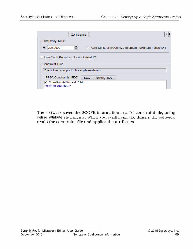
Specifying Attributes and Directives Chapter 4: Setting Up a Logic Synthesis Project
Synplify Pro for Microsemi Edition User Guide © 2019 Synopsys, Inc.December 2019 Synopsys Confidential Information 99
The software saves the SCOPE information in a Tcl constraint file, using define_attribute statements. When you synthesize the design, the software reads the constraint file and applies the attributes.
LO
Chapter 4: Setting Up a Logic Synthesis Project Specifying Attributes and Directives
© 2019 Synopsys, Inc. Synplify Pro for Microsemi Edition User Guide100 Synopsys Confidential Information December 2019
Specifying Attributes in the Constraints File When you use the SCOPE window (Specifying Attributes Using the SCOPE Editor, on page 96), the attributes are automatically written to a constraint file using the Tcl define_attribute syntax. This is the preferred method for defining constraints as the syntax is determined for you.
However, the following procedure explains how you can specify attributes directly in the constraint file.
1. Open a file in a text editor.
2. Enter the desired attributes. For example,
define_attribute {objectName} attributeName value
For commands and syntax, see Summary of Attributes and Directives, on page 14 in the Attribute Reference Manual.
3. Save the constraints in a file using the FDC file extension.
Handling Properties with Attributes or DirectivesAny property added to an object (i.e. net or instance) that is preserved or kept during the flow will be annotated in the netlist. Only properties for the syn_* attributes/directives are processed by the tool; while all other properties are simply annotated in the netlist when the object is available in the flow.
ExamplesSuppose top_property_handling.v contains MyProp=Value, which is associated with out and is annotated in the netlist. If you apply the property on the net intermediate_net, then the property is not annotated in the netlist since this net is not preserved/kept in the flow.
Using the syn_keep AttributeThe syn_keep attribute helps preserve the specified net. If top_syn_keep.v applies syn_keep on the net intermediate_net, then this same net is kept.
Specifying Attributes and Directives Chapter 4: Setting Up a Logic Synthesis Project
Synplify Pro for Microsemi Edition User Guide © 2019 Synopsys, Inc.December 2019 Synopsys Confidential Information 101
Using Properties with the syn_keep AttributeFor this example, top.v applies the syn_keep to the net intermediate_net where the MyProp=Value is associated with intermediate_net. In this case, the property is annotated in the netlist since syn_keep instructs the tool to preserve/keep the net in the flow.
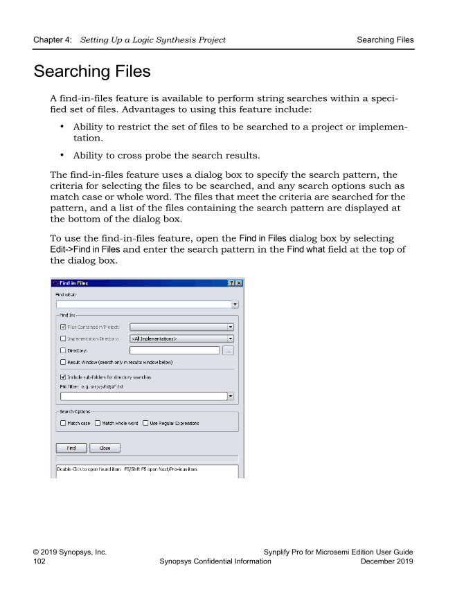
LO
Chapter 4: Setting Up a Logic Synthesis Project Searching Files
© 2019 Synopsys, Inc. Synplify Pro for Microsemi Edition User Guide102 Synopsys Confidential Information December 2019
Searching FilesA find-in-files feature is available to perform string searches within a speci-fied set of files. Advantages to using this feature include:
• Ability to restrict the set of files to be searched to a project or implemen-tation.
• Ability to cross probe the search results.
The find-in-files feature uses a dialog box to specify the search pattern, the criteria for selecting the files to be searched, and any search options such as match case or whole word. The files that meet the criteria are searched for the pattern, and a list of the files containing the search pattern are displayed at the bottom of the dialog box.
To use the find-in-files feature, open the Find in Files dialog box by selecting Edit->Find in Files and enter the search pattern in the Find what field at the top of the dialog box.
Searching Files Chapter 4: Setting Up a Logic Synthesis Project
Synplify Pro for Microsemi Edition User Guide © 2019 Synopsys, Inc.December 2019 Synopsys Confidential Information 103
Identifying the Files to SearchThe Find In section at the top of the dialog box identifies the files to be searched:
• Project Files - Searches the files included in the selected project (use the drop-down menu to select the project). By default, the files in the active project are searched. The files can reside anywhere on the disk; any project ‘include files are also searched.
• Implementation Directory - Searches all files in the specified implemen-tation directory (use the drop-down menu to select the implementation). By default, the files in the active implementation are searched. You can search all implementations by selecting <All Implementations> from the drop-down menu. If Include sub-folders for directory searches is also selected, all files in the implementation directory hierarchy are searched.
• Directory - Searches all files in the specified directory (use the browser button to select the directory). If Include sub-folders for directory searches is also selected, all files in the directory hierarchy are searched.
All of the above selection methods can be applied concurrently when searching for a specified pattern.
The Result Window selection is used after any of the above selection methods to search the resulting list of files for a subsequent sub-pattern.
Filtering the Files to SearchA file filter allows the file set to be searched to be further restricted based on the matching of patterns entered into the File filter field.
• A pattern without a wildcard or a “.” (period) is interpreted as a filename extension. For example, fdc restricts the search to only constraint files.
• Multiple patterns can be specified using a semicolon delimiter. For example, v;vhd restricts the files searched to only Verilog and VHDL files.
• Wildcard characters can be used in the pattern to match file names. For example, a*.vhd restricts the files searched to VHDL files that begin with an “a” character.
LO
Chapter 4: Setting Up a Logic Synthesis Project Searching Files
© 2019 Synopsys, Inc. Synplify Pro for Microsemi Edition User Guide104 Synopsys Confidential Information December 2019
• Leaving the File filter field empty searches all files that meet the Find In criteria.
• The Match Case, Whole Word, and Regular Expressions search options can be used to further restrict searches.
Initiating the SearchAfter entering the search criteria, click the Find button to initiate the search. All matches found are listed in the results area at the bottom of the dialog box; the status line just below the Find button reports the number of matches found in the indicated number of files and the total number of files searched.
While the find operation is running, the status line is continually updated with how many matches are found in how many files and how many files are being searched.
Search ResultsThe search results are displayed in the results window at the bottom of the dialog box. For each match found, the entire line of the file is the displayed in the following format:
fullpath_to_file(lineNumber): matching_line_text
For example, the entry
C:\Designs\leon\dcache.vhd(487): wdata := r.wb.data1; indicates that the search pattern (data1) was found on line 487 of the dcache.vhd file.
To open the target file at the specified line, double-click the line in the results window.
Archiving Files and Projects Chapter 4: Setting Up a Logic Synthesis Project
Synplify Pro for Microsemi Edition User Guide © 2019 Synopsys, Inc.December 2019 Synopsys Confidential Information 105
Archiving Files and ProjectsUse the archive utility to archive, extract (unarchive), or copy design projects. Archived files are in a proprietary format and saved to a file name using the sar extension. The archive utility is available through the Project menu in the GUI or using the project command in the Tcl window.
This document provides a description of how to use the utility.
• Archive a Project
• Un-Archive a Project
• Copy a Project
• Support for Hierarchical Include Paths
Archive a ProjectUse the archive utility to store the files for a design project into a single archive file in a proprietary format (sar). You can archive an entire project or selected files from a project. If you want to create a copy of a project without archiving the files, see Copy a Project, on page 114.
Here are the steps to create an archive:
1. In the Project view, select Project->Archive Project to bring up the wizard.
The Tcl command equivalent is project -archive. For a complete description of the project Tcl command options for archiving, see project, on page 82 of the Reference Manual.
The archive utility automatically runs a syntax check on the active project (Run->Syntax Check command) to ensure that a complete list of project files is generated. If you have Verilog 'include files in your project, the utility includes the complete list of Verilog files. It also checks the syntax automatically for each implementation in the project to ensure that the file list is complete for each implementation as well. The wizard displays the name of the project to archive, the top-level directory where the project file is located (root directory), and other information.
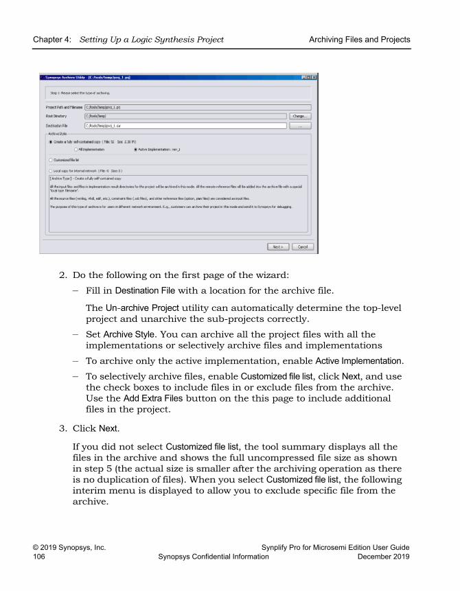
LO
Chapter 4: Setting Up a Logic Synthesis Project Archiving Files and Projects
© 2019 Synopsys, Inc. Synplify Pro for Microsemi Edition User Guide106 Synopsys Confidential Information December 2019
2. Do the following on the first page of the wizard:
– Fill in Destination File with a location for the archive file.
The Un-archive Project utility can automatically determine the top-level project and unarchive the sub-projects correctly.
– Set Archive Style. You can archive all the project files with all the implementations or selectively archive files and implementations
– To archive only the active implementation, enable Active Implementation.
– To selectively archive files, enable Customized file list, click Next, and use the check boxes to include files in or exclude files from the archive. Use the Add Extra Files button on the this page to include additional files in the project.
3. Click Next.
If you did not select Customized file list, the tool summary displays all the files in the archive and shows the full uncompressed file size as shown in step 5 (the actual size is smaller after the archiving operation as there is no duplication of files). When you select Customized file list, the following interim menu is displayed to allow you to exclude specific file from the archive.
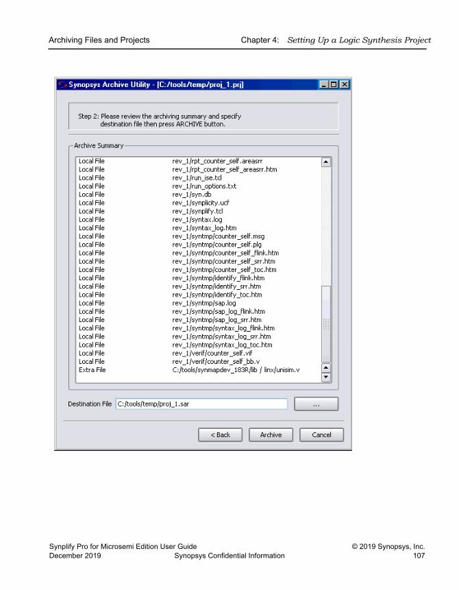
Archiving Files and Projects Chapter 4: Setting Up a Logic Synthesis Project
Synplify Pro for Microsemi Edition User Guide © 2019 Synopsys, Inc.December 2019 Synopsys Confidential Information 107
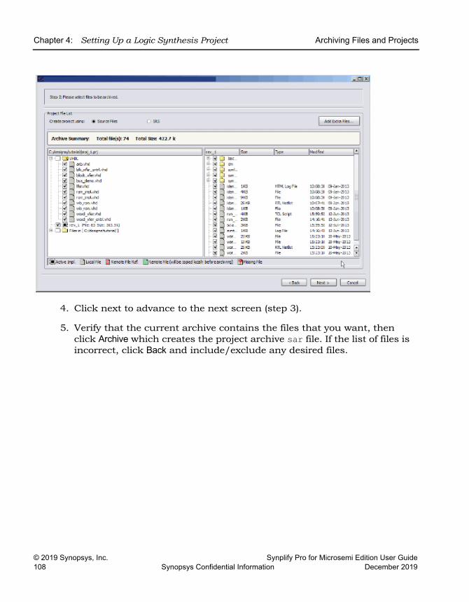
LO
Chapter 4: Setting Up a Logic Synthesis Project Archiving Files and Projects
© 2019 Synopsys, Inc. Synplify Pro for Microsemi Edition User Guide108 Synopsys Confidential Information December 2019
4. Click next to advance to the next screen (step 3).
5. Verify that the current archive contains the files that you want, then click Archive which creates the project archive sar file. If the list of files is incorrect, click Back and include/exclude any desired files.
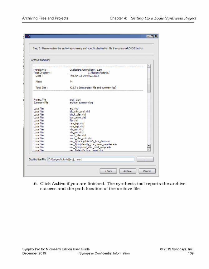
Archiving Files and Projects Chapter 4: Setting Up a Logic Synthesis Project
Synplify Pro for Microsemi Edition User Guide © 2019 Synopsys, Inc.December 2019 Synopsys Confidential Information 109
6. Click Archive if you are finished. The synthesis tool reports the archive success and the path location of the archive file.
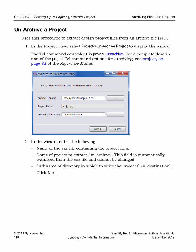
LO
Chapter 4: Setting Up a Logic Synthesis Project Archiving Files and Projects
© 2019 Synopsys, Inc. Synplify Pro for Microsemi Edition User Guide110 Synopsys Confidential Information December 2019
Un-Archive a Project Uses this procedure to extract design project files from an archive file (sar).
1. In the Project view, select Project->Un-Archive Project to display the wizard
The Tcl command equivalent is project -unarchive. For a complete descrip-tion of the project Tcl command options for archiving, see project, on page 82 of the Reference Manual.
2. In the wizard, enter the following:
– Name of the sar file containing the project files.
– Name of project to extract (un-archive). This field is automatically extracted from the sar file and cannot be changed.
– Pathname of directory in which to write the project files (destination).
– Click Next.
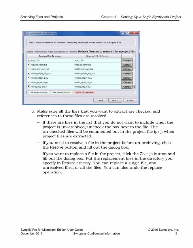
Archiving Files and Projects Chapter 4: Setting Up a Logic Synthesis Project
Synplify Pro for Microsemi Edition User Guide © 2019 Synopsys, Inc.December 2019 Synopsys Confidential Information 111
3. Make sure all the files that you want to extract are checked and references to these files are resolved.
– If there are files in the list that you do not want to include when the project is un-archived, uncheck the box next to the file. The un-checked files will be commented out in the project file (prj) when project files are extracted.
– If you need to resolve a file in the project before un-archiving, click the Resolve button and fill out the dialog box.
– If you want to replace a file in the project, click the Change button and fill out the dialog box. Put the replacement files in the directory you specify in Replace directory. You can replace a single file, any unresolved files, or all the files. You can also undo the replace operation.
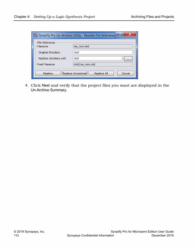
LO
Chapter 4: Setting Up a Logic Synthesis Project Archiving Files and Projects
© 2019 Synopsys, Inc. Synplify Pro for Microsemi Edition User Guide112 Synopsys Confidential Information December 2019
4. Click Next and verify that the project files you want are displayed in the Un-Archive Summary.
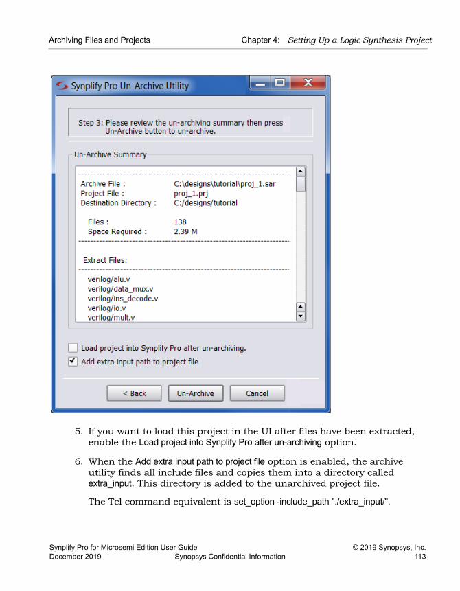
Archiving Files and Projects Chapter 4: Setting Up a Logic Synthesis Project
Synplify Pro for Microsemi Edition User Guide © 2019 Synopsys, Inc.December 2019 Synopsys Confidential Information 113
5. If you want to load this project in the UI after files have been extracted, enable the Load project into Synplify Pro after un-archiving option.
6. When the Add extra input path to project file option is enabled, the archive utility finds all include files and copies them into a directory called extra_input. This directory is added to the unarchived project file.
The Tcl command equivalent is set_option -include_path "./extra_input/".
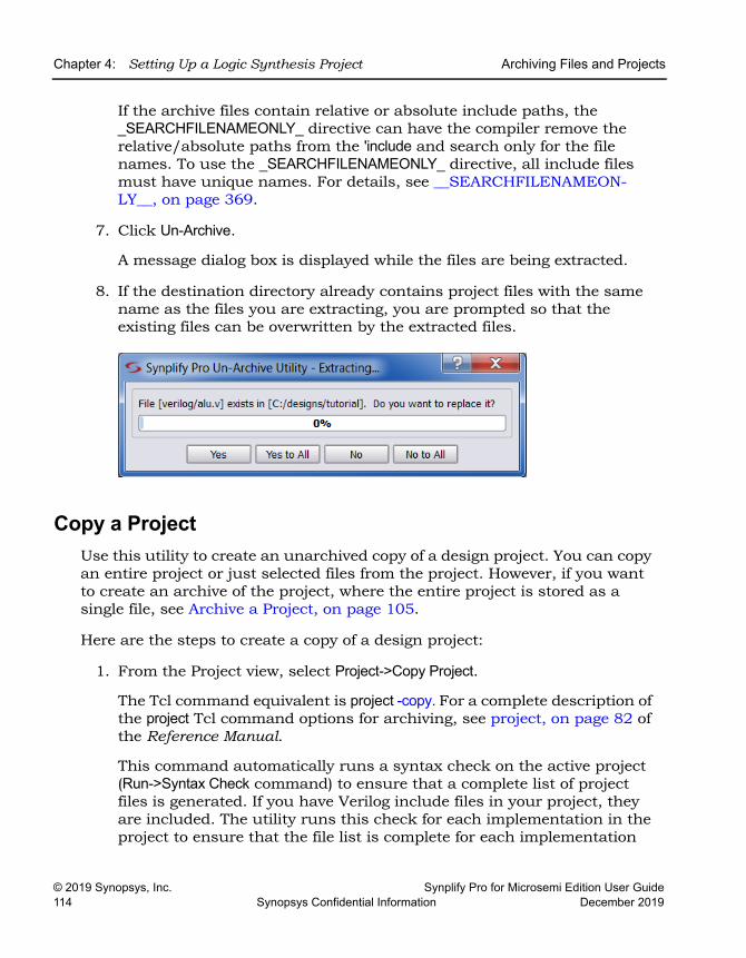
LO
Chapter 4: Setting Up a Logic Synthesis Project Archiving Files and Projects
© 2019 Synopsys, Inc. Synplify Pro for Microsemi Edition User Guide114 Synopsys Confidential Information December 2019
If the archive files contain relative or absolute include paths, the _SEARCHFILENAMEONLY_ directive can have the compiler remove the relative/absolute paths from the 'include and search only for the file names. To use the _SEARCHFILENAMEONLY_ directive, all include files must have unique names. For details, see __SEARCHFILENAMEON-LY__, on page 369.
7. Click Un-Archive.
A message dialog box is displayed while the files are being extracted.
8. If the destination directory already contains project files with the same name as the files you are extracting, you are prompted so that the existing files can be overwritten by the extracted files.
Copy a ProjectUse this utility to create an unarchived copy of a design project. You can copy an entire project or just selected files from the project. However, if you want to create an archive of the project, where the entire project is stored as a single file, see Archive a Project, on page 105.
Here are the steps to create a copy of a design project:
1. From the Project view, select Project->Copy Project.
The Tcl command equivalent is project -copy. For a complete description of the project Tcl command options for archiving, see project, on page 82 of the Reference Manual.
This command automatically runs a syntax check on the active project (Run->Syntax Check command) to ensure that a complete list of project files is generated. If you have Verilog include files in your project, they are included. The utility runs this check for each implementation in the project to ensure that the file list is complete for each implementation
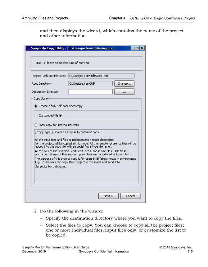
Archiving Files and Projects Chapter 4: Setting Up a Logic Synthesis Project
Synplify Pro for Microsemi Edition User Guide © 2019 Synopsys, Inc.December 2019 Synopsys Confidential Information 115
and then displays the wizard, which contains the name of the project and other information.
2. Do the following in the wizard:
– Specify the destination directory where you want to copy the files.
– Select the files to copy. You can choose to copy all the project files; one or more individual files, input files only, or customize the list to be copied.
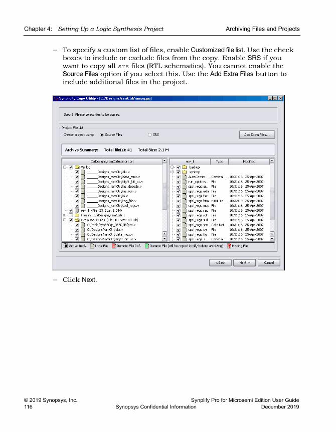
LO
Chapter 4: Setting Up a Logic Synthesis Project Archiving Files and Projects
© 2019 Synopsys, Inc. Synplify Pro for Microsemi Edition User Guide116 Synopsys Confidential Information December 2019
– To specify a custom list of files, enable Customized file list. Use the check boxes to include or exclude files from the copy. Enable SRS if you want to copy all srs files (RTL schematics). You cannot enable the Source Files option if you select this. Use the Add Extra Files button to include additional files in the project.
– Click Next.
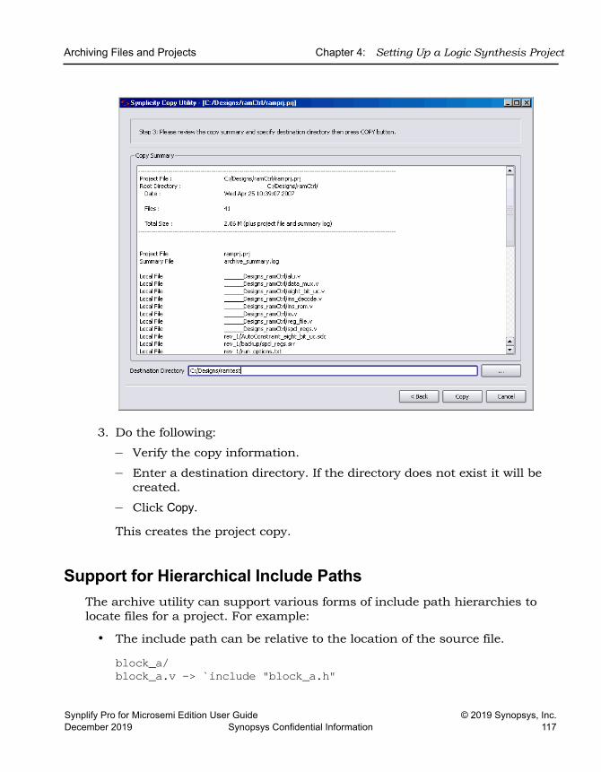
Archiving Files and Projects Chapter 4: Setting Up a Logic Synthesis Project
Synplify Pro for Microsemi Edition User Guide © 2019 Synopsys, Inc.December 2019 Synopsys Confidential Information 117
3. Do the following:
– Verify the copy information.
– Enter a destination directory. If the directory does not exist it will be created.
– Click Copy.
This creates the project copy.
Support for Hierarchical Include PathsThe archive utility can support various forms of include path hierarchies to locate files for a project. For example:
• The include path can be relative to the location of the source file.
block_a/block_a.v -> `include "block_a.h"
LO
Chapter 4: Setting Up a Logic Synthesis Project Archiving Files and Projects
© 2019 Synopsys, Inc. Synplify Pro for Microsemi Edition User Guide118 Synopsys Confidential Information December 2019
• The include path can be a relative path outside of the project.
block_b.v -> `include "../../block_b.h"The archive utility can determine the absolute path for the file from the relative path as shown below:
remote/sbg_pe/tests/feature_flow/include/block_b.hAfter unarchiving the project, you can see the directory structure for the equivalent absolute path relative to the project.
"./remote/sbg_pe/tests/feature_flow/include/block_b.h"• The file location can be specified by include_path in the project file.
block_c/block_c.v -> `include "block_c.h"Where this file is located in the directory /include1/.
• The include path can be an absolute path outside of the project.
block_d/block_d.v -> `include "/slowfs/sbg/tests/include2/block_d.h"When you archive the project, the absolute path becomes a relative path. After unarchiving the project, you can see the directory structure for the relative path to the project.
"./slowfs/sbg/tests/include2/block_d.h"• The file location can be specified by include_path in the project file.
top_block/top_block.v -> `include "top_block.h"Where the top_block.v file is located in the directory /include2/.
• Any additional search paths specified in the project file are copied and included as relative paths to the project.
After you archive and unarchive the project, the relative paths in the original project become absolute paths in the new unarchived project. In the project file, the set_option -include_path preserves the original search order for the files.
Archiving Files and Projects Chapter 4: Setting Up a Logic Synthesis Project
Synplify Pro for Microsemi Edition User Guide © 2019 Synopsys, Inc.December 2019 Synopsys Confidential Information 119
Using the __SEARCHFILENAMEONLY__ Compiler DirectiveWhenever you have a SAR file that contains relative or absolute include paths for the files in the project, you can also use the _SEARCHFILENAMEONLY_ directive to have the compiler remove the relative/absolute paths from the 'include and search only for the file names. Otherwise, you may have problems using the archive utility. For details, see __SEARCHFILENAMEONLY__, on page 369.

LO
Chapter 4: Setting Up a Logic Synthesis Project Archiving Files and Projects
© 2019 Synopsys, Inc. Synplify Pro for Microsemi Edition User Guide120 Synopsys Confidential Information December 2019
Synplify Pro for Microsemi Edition User Guide © 2019 Synopsys, Inc.December 2019 Synopsys Confidential Information 121
C H A P T E R 5
Specifying Constraints
This chapter describes how to specify constraints for your design. It covers the following:
• Using the SCOPE Editor, on page 122
• Specifying SCOPE Constraints, on page 128
• Specifying Timing Exceptions, on page 139
• Finding Objects with Tcl find and expand, on page 145
• Using Collections, on page 154
• Converting SDC to FDC, on page 164
• Using the SCOPE Editor (Legacy), on page 165
The following chapters discuss related information:
• Chapter 4, Constraint Guidelines (Reference Manual) for an overview of constraints
• Chapter 4, Constraint Commands (Reference Manual) for a description of the SCOPE editor
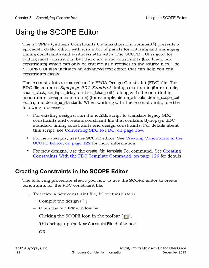
LO
Chapter 5: Specifying Constraints Using the SCOPE Editor
© 2019 Synopsys, Inc. Synplify Pro for Microsemi Edition User Guide122 Synopsys Confidential Information December 2019
Using the SCOPE EditorThe SCOPE (Synthesis Constraints OPtimization Environment®) presents a spreadsheet-like editor with a number of panels for entering and managing timing constraints and synthesis attributes. The SCOPE GUI is good for editing most constraints, but there are some constraints (like black box constraints) which can only be entered as directives in the source files. The SCOPE GUI also includes an advanced text editor that can help you edit constraints easily.
These constraints are saved to the FPGA Design Constraint (FDC) file. The FDC file contains Synopsys SDC Standard timing constraints (for example, create_clock, set_input_delay, and set_false_path), along with the non-timing constraints (design constraints) (for example, define_attribute, define_scope_col-lection, and define_io_standard). When working with these constraints, use the following processes:
• For existing designs, run the sdc2fdc script to translate legacy SDC constraints and create a constraint file that contains Synopsys SDC standard timing constraints and design constraints. For details about this script, see Converting SDC to FDC, on page 164.
• For new designs, use the SCOPE editor. See Creating Constraints in the SCOPE Editor, on page 122 for more information.
• For new designs, use the create_fdc_template Tcl command. See Creating Constraints With the FDC Template Command, on page 126 for details.
Creating Constraints in the SCOPE EditorThe following procedure shows you how to use the SCOPE editor to create constraints for the FDC constraint file.
1. To create a new constraint file, follow these steps:
– Compile the design (F7).
– Open the SCOPE window by:
Clicking the SCOPE icon in the toolbar ( ).
This brings up the New Constraint File dialog box.
OR
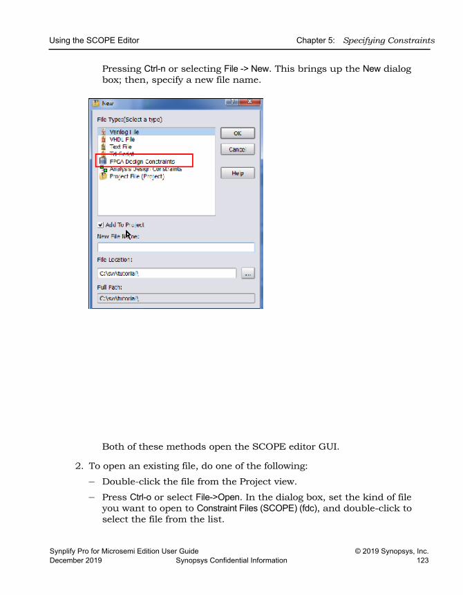
Using the SCOPE Editor Chapter 5: Specifying Constraints
Synplify Pro for Microsemi Edition User Guide © 2019 Synopsys, Inc.December 2019 Synopsys Confidential Information 123
Pressing Ctrl-n or selecting File -> New. This brings up the New dialog box; then, specify a new file name.
Both of these methods open the SCOPE editor GUI.
2. To open an existing file, do one of the following:
– Double-click the file from the Project view.
– Press Ctrl-o or select File->Open. In the dialog box, set the kind of file you want to open to Constraint Files (SCOPE) (fdc), and double-click to select the file from the list.
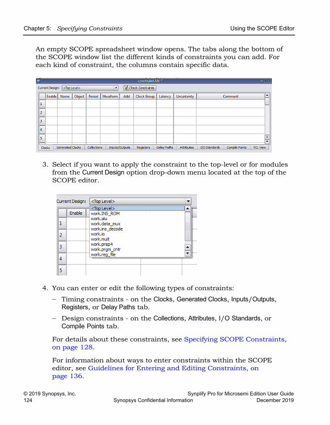
LO
Chapter 5: Specifying Constraints Using the SCOPE Editor
© 2019 Synopsys, Inc. Synplify Pro for Microsemi Edition User Guide124 Synopsys Confidential Information December 2019
An empty SCOPE spreadsheet window opens. The tabs along the bottom of the SCOPE window list the different kinds of constraints you can add. For each kind of constraint, the columns contain specific data.
3. Select if you want to apply the constraint to the top-level or for modules from the Current Design option drop-down menu located at the top of the SCOPE editor.
4. You can enter or edit the following types of constraints:
– Timing constraints - on the Clocks, Generated Clocks, Inputs/Outputs, Registers, or Delay Paths tab.
– Design constraints - on the Collections, Attributes, I/O Standards, or Compile Points tab.
For details about these constraints, see Specifying SCOPE Constraints, on page 128.
For information about ways to enter constraints within the SCOPE editor, see Guidelines for Entering and Editing Constraints, on page 136.
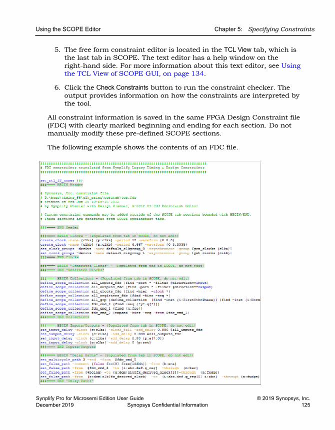
Using the SCOPE Editor Chapter 5: Specifying Constraints
Synplify Pro for Microsemi Edition User Guide © 2019 Synopsys, Inc.December 2019 Synopsys Confidential Information 125
5. The free form constraint editor is located in the TCL View tab, which is the last tab in SCOPE. The text editor has a help window on the right-hand side. For more information about this text editor, see Using the TCL View of SCOPE GUI, on page 134.
6. Click the Check Constraints button to run the constraint checker. The output provides information on how the constraints are interpreted by the tool.
All constraint information is saved in the same FPGA Design Constraint file (FDC) with clearly marked beginning and ending for each section. Do not manually modify these pre-defined SCOPE sections.
The following example shows the contents of an FDC file.
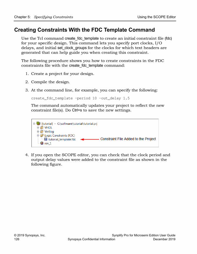
LO
Chapter 5: Specifying Constraints Using the SCOPE Editor
© 2019 Synopsys, Inc. Synplify Pro for Microsemi Edition User Guide126 Synopsys Confidential Information December 2019
Creating Constraints With the FDC Template CommandUse the Tcl command create_fdc_template to create an initial constraint file (fdc) for your specific design. This command lets you specify port clocks, I/O delays, and initial set_clock_groups for the clocks for which text headers are generated that can help guide you when creating this constraint.
The following procedure shows you how to create constraints in the FDC constraints file with the create_fdc_template command:
1. Create a project for your design.
2. Compile the design.
3. At the command line, for example, you can specify the following:
create_fdc_template -period 10 -out_delay 1.5The command automatically updates your project to reflect the new constraint file(s). Do Ctrl+s to save the new settings.
4. If you open the SCOPE editor, you can check that the clock period and output delay values were added to the constraint file as shown in the following figure.
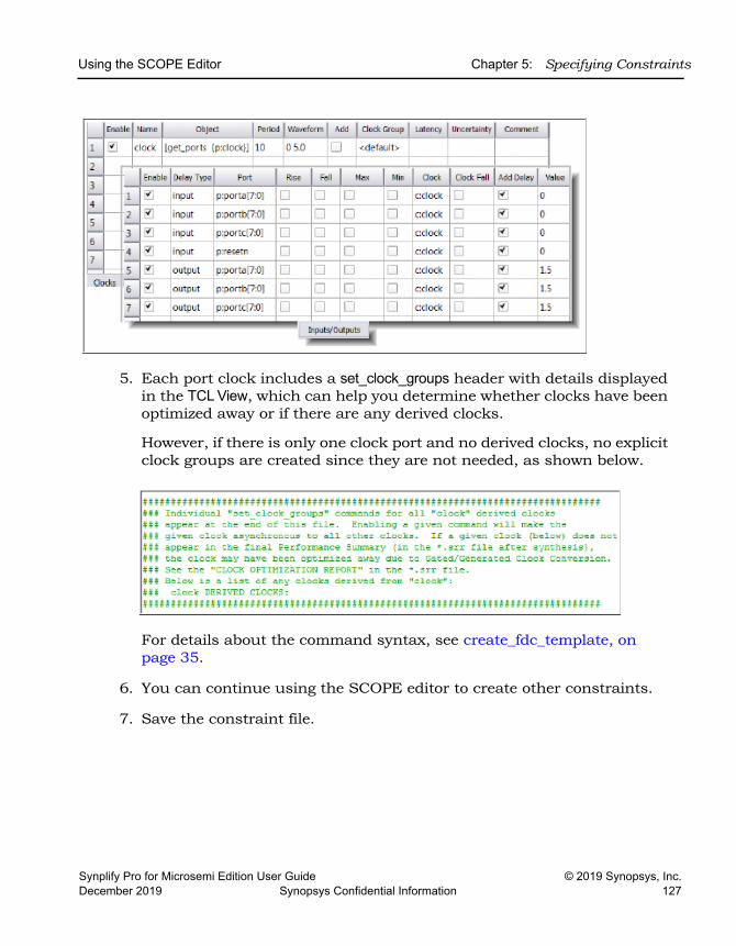
Using the SCOPE Editor Chapter 5: Specifying Constraints
Synplify Pro for Microsemi Edition User Guide © 2019 Synopsys, Inc.December 2019 Synopsys Confidential Information 127
5. Each port clock includes a set_clock_groups header with details displayed in the TCL View, which can help you determine whether clocks have been optimized away or if there are any derived clocks.
However, if there is only one clock port and no derived clocks, no explicit clock groups are created since they are not needed, as shown below.
For details about the command syntax, see create_fdc_template, on page 35.
6. You can continue using the SCOPE editor to create other constraints.
7. Save the constraint file.
LO
Chapter 5: Specifying Constraints Specifying SCOPE Constraints
© 2019 Synopsys, Inc. Synplify Pro for Microsemi Edition User Guide128 Synopsys Confidential Information December 2019
Specifying SCOPE ConstraintsTiming constraints define the performance goals for a design. The FPGA synthesis tool supports a subset of the Synopsys SDC Standard timing constraints (for example, create_clock, set_input_delay, and set_false_path). For additional support, see Synopsys Standard Timing Constraints, on page 129.
Design constraints let you add attributes, define collections and specify constraints for them, and select specific I/O standard pad types for your design.
You can define both timing and design constraints in the SCOPE editor. For the different types of constraints, see the following topics:
• Entering and Editing SCOPE Constraints
• Setting Clock and Path Constraints
• Defining Input and Output Constraints
• Specifying Standard I/O Pad Types
To set constraints for timing exceptions like false paths and multicycle paths, see Specifying Timing Exceptions, on page 139.
For information about collections, see Using Collections, on page 154.
Entering and Editing SCOPE Constraints This section contains a description of the timing and design constraints you can enter in the SCOPE GUI that are saved to an FDC file. The SCOPE timing constraint panels include:
SCOPE Panel See ... Tcl Commands
Clocks Clocks create_clockset_clock_groupsset_clock_latencyset_clock_uncertainty
Generated Clocks Generated Clocks create_generated_clock
Collections Collections define_scope_collection
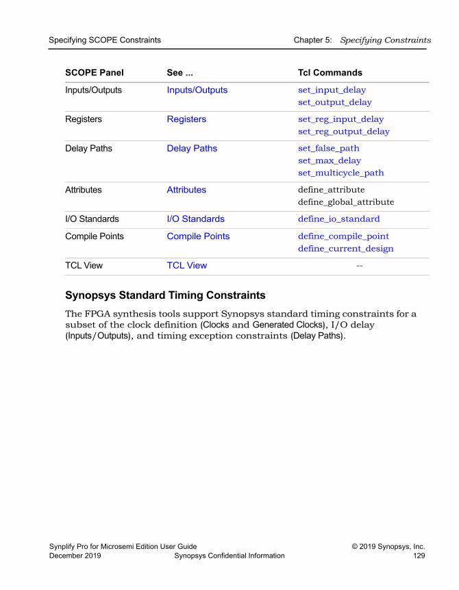
Specifying SCOPE Constraints Chapter 5: Specifying Constraints
Synplify Pro for Microsemi Edition User Guide © 2019 Synopsys, Inc.December 2019 Synopsys Confidential Information 129
Synopsys Standard Timing ConstraintsThe FPGA synthesis tools support Synopsys standard timing constraints for a subset of the clock definition (Clocks and Generated Clocks), I/O delay (Inputs/Outputs), and timing exception constraints (Delay Paths).
Inputs/Outputs Inputs/Outputs set_input_delayset_output_delay
Registers Registers set_reg_input_delayset_reg_output_delay
Delay Paths Delay Paths set_false_pathset_max_delayset_multicycle_path
Attributes Attributes define_attributedefine_global_attribute
I/O Standards I/O Standards define_io_standard
Compile Points Compile Points define_compile_pointdefine_current_design
TCL View TCL View --
SCOPE Panel See ... Tcl Commands
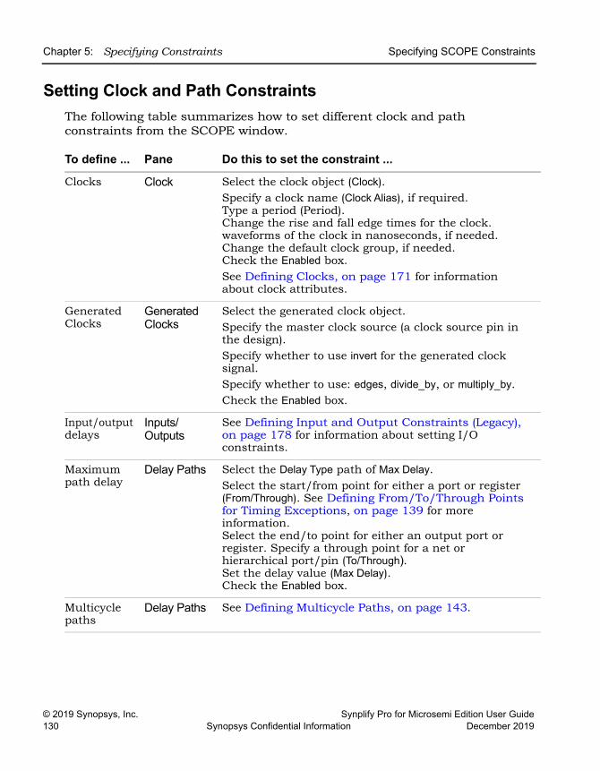
LO
Chapter 5: Specifying Constraints Specifying SCOPE Constraints
© 2019 Synopsys, Inc. Synplify Pro for Microsemi Edition User Guide130 Synopsys Confidential Information December 2019
Setting Clock and Path ConstraintsThe following table summarizes how to set different clock and path constraints from the SCOPE window.
To define ... Pane Do this to set the constraint ...
Clocks Clock Select the clock object (Clock).Specify a clock name (Clock Alias), if required.Type a period (Period). Change the rise and fall edge times for the clock. waveforms of the clock in nanoseconds, if needed. Change the default clock group, if needed.Check the Enabled box. See Defining Clocks, on page 171 for information about clock attributes.
Generated Clocks
Generated Clocks
Select the generated clock object.Specify the master clock source (a clock source pin in the design).Specify whether to use invert for the generated clock signal.Specify whether to use: edges, divide_by, or multiply_by.Check the Enabled box.
Input/output delays
Inputs/Outputs
See Defining Input and Output Constraints (Legacy), on page 178 for information about setting I/O constraints.
Maximum path delay
Delay Paths Select the Delay Type path of Max Delay.Select the start/from point for either a port or register (From/Through). See Defining From/To/Through Points for Timing Exceptions, on page 139 for more information. Select the end/to point for either an output port or register. Specify a through point for a net or hierarchical port/pin (To/Through).Set the delay value (Max Delay).Check the Enabled box.
Multicycle paths
Delay Paths See Defining Multicycle Paths, on page 143.
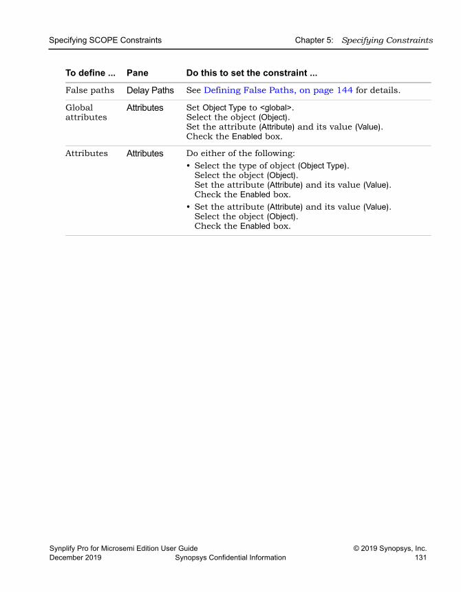
Specifying SCOPE Constraints Chapter 5: Specifying Constraints
Synplify Pro for Microsemi Edition User Guide © 2019 Synopsys, Inc.December 2019 Synopsys Confidential Information 131
False paths Delay Paths See Defining False Paths, on page 144 for details.
Global attributes
Attributes Set Object Type to <global>.Select the object (Object).Set the attribute (Attribute) and its value (Value).Check the Enabled box.
Attributes Attributes Do either of the following:• Select the type of object (Object Type).
Select the object (Object).Set the attribute (Attribute) and its value (Value).Check the Enabled box.
• Set the attribute (Attribute) and its value (Value).Select the object (Object).Check the Enabled box.
To define ... Pane Do this to set the constraint ...
LO
Chapter 5: Specifying Constraints Specifying SCOPE Constraints
© 2019 Synopsys, Inc. Synplify Pro for Microsemi Edition User Guide132 Synopsys Confidential Information December 2019
Defining Input and Output ConstraintsIn addition to setting I/O delays in the SCOPE window as described in Setting Clock and Path Constraints, on page 169, you can also set the Use clock period for unconstrained IO option.
• Open the SCOPE window, click Inputs/Outputs, and select the port (Port). You can set the constraint for
– All inputs and outputs (globally in the top-level netlist)
– For a whole bus
– For single bits
You can specify multiple constraints for the same port. The software applies all the constraints; the tightest constraint determines the worst slack. If there are multiple constraints from different levels, the most specific overrides the more global. For example, if there are two bit constraints and two port constraints, the two bit constraints override the two port constraints for that bit. The other bits get the two port constraints.
• Specify the constraint value in the SCOPE window:
– Select the type of delay: input or output (Type).
– Type a delay value (Value).
– Check the Enabled box, and save the constraint file in the project.
Make sure to specify explicit constraints for each I/O path you want to constrain.
• To determine how the I/O constraints are used during synthesis, do the following:
– Select Project->Implementation Options, and click Constraints. – To use only the explicitly defined constraints disable Use clock period for
unconstrained IO.
– To synthesize with all the constraints, using the clock period for all I/O paths that do not have an explicit constraint enable Use clock period for unconstrained IO.
– Synthesize the design. When you forward-annotate the constraints, the constraints used for synthesis are forward-annotated for place-and-route.
Specifying SCOPE Constraints Chapter 5: Specifying Constraints
Synplify Pro for Microsemi Edition User Guide © 2019 Synopsys, Inc.December 2019 Synopsys Confidential Information 133
• Input or output ports with explicitly defined constraints, but without a reference clock (-ref option) are included in the System clock domain and are considered to belong to every defined or inferred clock group.
• If you do not meet timing goals after place-and-route and you need to adjust the input constraints; do the following:
– Open the SCOPE window with the input constraint.
– Use the set_clock_route_delay command to translate the -route option for the constraint, so that you can specify the actual route delay in nanoseconds, as obtained from the place-and-route results. Adding this constraint is equivalent to putting a register delay on the input register. Use it as a fudge factor to force the synthesis engine to accommodate a routing delay that is larger than expected.
– Resynthesize your design.
Specifying Standard I/O Pad TypesYou can specify a standard I/O pad type to use in the design. The equivalent Tcl command is define_io_standard.
1. Open the SCOPE window and go to the I/O Standard tab.
2. In the Port column, select the port. This determines the port type in the Type column.
3. Enter an appropriate I/O pad type in the I/O Standard column. The Description column shows a description of the I/O standard you selected.
For details of supported I/O standards, see Industry I/O Standards, on page 238.
4. Where applicable, set other parameters like drive strength, slew rate, and termination.
You cannot set these parameter values for industry I/O standards whose parameters are defined by the standard.
The software stores the pad type specification and the parameter values in the syn_pad_type attribute. When you synthesize the design, the I/O specifications are mapped to the appropriate I/O pads within the technology.
LO
Chapter 5: Specifying Constraints Specifying SCOPE Constraints
© 2019 Synopsys, Inc. Synplify Pro for Microsemi Edition User Guide134 Synopsys Confidential Information December 2019
Using the TCL View of SCOPE GUIThe TCL View of the SCOPE GUI is an advanced text file editor used for FPGA timing and design constraints. This text editor provides the following capabil-ities:
• Uses dynamic keyword expansion and tool tips for commands that
– Automatically completes the command from a popup list
– Displays complete command syntax as a tool tip
– Displays parameter options for the command from a popup list
– Includes a keyword command syntax help
• Checks command syntax and uses color indicators that
– Validates commands and command syntax
– Distinguishes between FPGA design constraints and SCOPE legacy constraints
• Allows for standard editor commands, such as copy, paste, comment/un-comment a group of lines, and highlighting of keywords
To use the TCL View of the SCOPE GUI:
1. Click the TCL View of the SCOPE GUI.
2. You can specify FPGA design constraints as follows:
– Type the command; after you type three characters a popup menu displays the design constraint command list. Select a command.
– When you type a dash (-), the options popup menu list is displayed. Select an option.
– When you hover over a command, a tool tip is displayed for the selected commands.
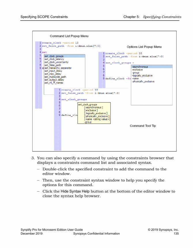
Specifying SCOPE Constraints Chapter 5: Specifying Constraints
Synplify Pro for Microsemi Edition User Guide © 2019 Synopsys, Inc.December 2019 Synopsys Confidential Information 135
3. You can also specify a command by using the constraints browser that displays a constraints command list and associated syntax.
– Double-click the specified constraint to add the command to the editor window.
– Then, use the constraint syntax window to help you specify the options for this command.
– Click the Hide Syntax Help button at the bottom of the editor window to close the syntax help browser.
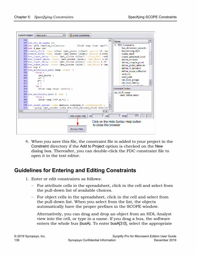
LO
Chapter 5: Specifying Constraints Specifying SCOPE Constraints
© 2019 Synopsys, Inc. Synplify Pro for Microsemi Edition User Guide136 Synopsys Confidential Information December 2019
4. When you save this file, the constraint file is added to your project in the Constraint directory if the Add to Project option is checked on the New dialog box. Thereafter, you can double-click the FDC constraint file to open it in the text editor.
Guidelines for Entering and Editing Constraints 1. Enter or edit constraints as follows:
– For attribute cells in the spreadsheet, click in the cell and select from the pull-down list of available choices.
– For object cells in the spreadsheet, click in the cell and select from the pull-down list. When you select from the list, the objects automatically have the proper prefixes in the SCOPE window.
Alternatively, you can drag and drop an object from an HDL Analyst view into the cell, or type in a name. If you drag a bus, the software enters the whole bus (busA). To enter busA[3:0], select the appropriate
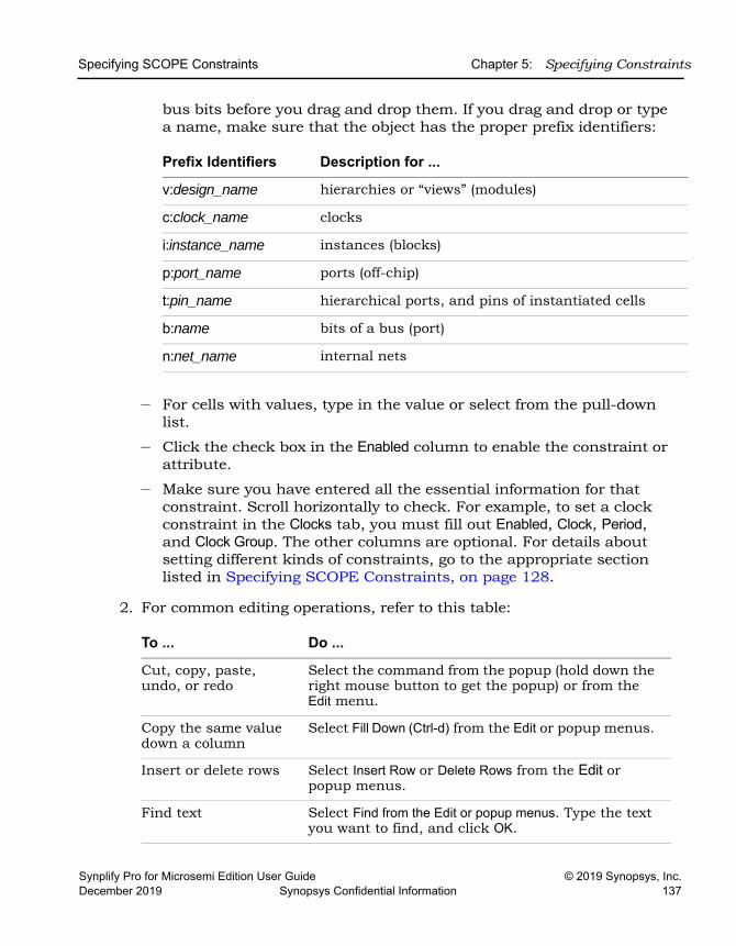
Specifying SCOPE Constraints Chapter 5: Specifying Constraints
Synplify Pro for Microsemi Edition User Guide © 2019 Synopsys, Inc.December 2019 Synopsys Confidential Information 137
bus bits before you drag and drop them. If you drag and drop or type a name, make sure that the object has the proper prefix identifiers:
– For cells with values, type in the value or select from the pull-down list.
– Click the check box in the Enabled column to enable the constraint or attribute.
– Make sure you have entered all the essential information for that constraint. Scroll horizontally to check. For example, to set a clock constraint in the Clocks tab, you must fill out Enabled, Clock, Period, and Clock Group. The other columns are optional. For details about setting different kinds of constraints, go to the appropriate section listed in Specifying SCOPE Constraints, on page 128.
2. For common editing operations, refer to this table:
Prefix Identifiers Description for ...
v:design_name hierarchies or “views” (modules)
c:clock_name clocks
i:instance_name instances (blocks)
p:port_name ports (off-chip)
t:pin_name hierarchical ports, and pins of instantiated cells
b:name bits of a bus (port)
n:net_name internal nets
To ... Do ...
Cut, copy, paste, undo, or redo
Select the command from the popup (hold down the right mouse button to get the popup) or from the Edit menu.
Copy the same value down a column
Select Fill Down (Ctrl-d) from the Edit or popup menus.
Insert or delete rows Select Insert Row or Delete Rows from the Edit or popup menus.
Find text Select Find from the Edit or popup menus. Type the text you want to find, and click OK.
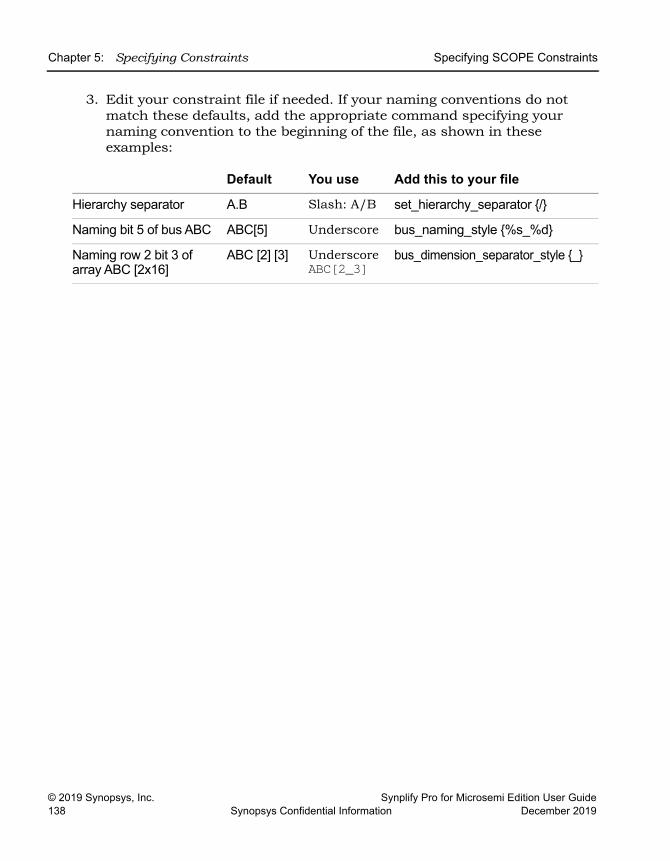
LO
Chapter 5: Specifying Constraints Specifying SCOPE Constraints
© 2019 Synopsys, Inc. Synplify Pro for Microsemi Edition User Guide138 Synopsys Confidential Information December 2019
3. Edit your constraint file if needed. If your naming conventions do not match these defaults, add the appropriate command specifying your naming convention to the beginning of the file, as shown in these examples:
Default You use Add this to your file
Hierarchy separator A.B Slash: A/B set_hierarchy_separator {/}
Naming bit 5 of bus ABC ABC[5] Underscore bus_naming_style {%s_%d}
Naming row 2 bit 3 of array ABC [2x16]
ABC [2] [3] UnderscoreABC[2_3]
bus_dimension_separator_style {_}
Specifying Timing Exceptions Chapter 5: Specifying Constraints
Synplify Pro for Microsemi Edition User Guide © 2019 Synopsys, Inc.December 2019 Synopsys Confidential Information 139
Specifying Timing ExceptionsYou can specify the following timing exception constraints, either from the SCOPE interface or by manually entering the Tcl commands in a file:
• Multicycle Paths - Paths with multiple clock cycles.
• False Paths - Clock paths that you want the synthesis tool to ignore during timing analysis and assign low (or no) priority during optimiza-tion.
• Max Delay Paths - Point-to-point delay constraints for paths.
The following shows you how to specify timing exceptions in the SCOPE GUI. For the equivalent Tcl syntax, see Chapter 2, Tcl Synthesis Commands in the Reference Manual.
• Defining From/To/Through Points for Timing Exceptions, on page 139
• Defining Multicycle Paths, on page 143
• Defining False Paths, on page 144
For information about resolving timing exception conflicts, see Conflict Resolution for Timing Exceptions, on page 254 in the Reference Manual.
Defining From/To/Through Points for Timing ExceptionsFor multi-cycle path, false path, and maximum path delay constraints, you must define paths with a combination of From/To/Through points. Whenever the tool encounters a conflict in the way timing-exception constraints are written, see Conflict Resolution for Timing Exceptions, on page 254 to determine how resolution occurs based on the priorities defined.
The following guidelines provide details for defining these constraints. You must specify at least one From, To, or Through point.
• In the From field, identify the starting point for the path. The starting point can be a clock, input or bidirectional port, or register. Only black box output pins are valid. To specify multiple starting points:
– Such as the bits of a bus, enclose them in square brackets: A[15:0] or A[*].
– Select the first start point from the HDL Analyst view, then drag and drop this instance into the From cell in SCOPE. For each subsequent
LO
Chapter 5: Specifying Constraints Specifying Timing Exceptions
© 2019 Synopsys, Inc. Synplify Pro for Microsemi Edition User Guide140 Synopsys Confidential Information December 2019
instance, press the Shift key as you drag and drop the instance into the From cell in SCOPE. For example, valid Tcl command format include:
set_multicycle_path -from {i:aq i:bq} 2set_multicycle_path -from [i:aq i:bq} -through {n:xor_all} 2
• In the To field, identify the ending point for the path. The ending point can be a clock, output or bidirectional port, or register. Only black box input pins are valid. To specify multiple ending points, such as the bits of a bus, enclose them in square brackets: B[15:0].
• A single through point can be a combinational net, hierarchical port or instantiated cell pin. To specify a net:
– Click in the Through field and click the arrow. This opens the Product of Sums (POS) interface.
– Either type the net name with the n: prefix in the first cell or drag the net from an HDL Analyst view into the cell.
– Click Save.
For example, if you specify n:net1, the constraint applies to any path passing through net1.
• To specify an OR when constraining a list of through points, you can type the net names in the Through field or you can use the POS UI. To do this:
– Click in the Through field and click the arrow. This opens the Product of Sums interface.
– Either type the first net name in a cell in a Prod row or drag the net from an HDL Analyst view into the cell. Repeat this step along the same row, adding other nets in the Sum columns. The nets in each row form an OR list.
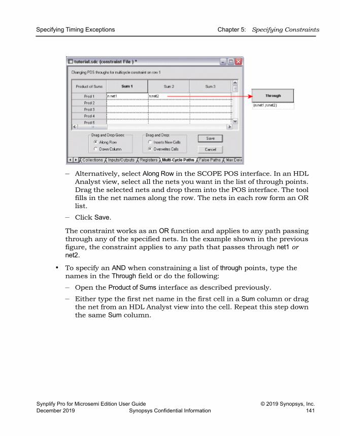
Specifying Timing Exceptions Chapter 5: Specifying Constraints
Synplify Pro for Microsemi Edition User Guide © 2019 Synopsys, Inc.December 2019 Synopsys Confidential Information 141
– Alternatively, select Along Row in the SCOPE POS interface. In an HDL Analyst view, select all the nets you want in the list of through points. Drag the selected nets and drop them into the POS interface. The tool fills in the net names along the row. The nets in each row form an OR list.
– Click Save.
The constraint works as an OR function and applies to any path passing through any of the specified nets. In the example shown in the previous figure, the constraint applies to any path that passes through net1 or net2.
• To specify an AND when constraining a list of through points, type the names in the Through field or do the following:
– Open the Product of Sums interface as described previously.
– Either type the first net name in the first cell in a Sum column or drag the net from an HDL Analyst view into the cell. Repeat this step down the same Sum column.
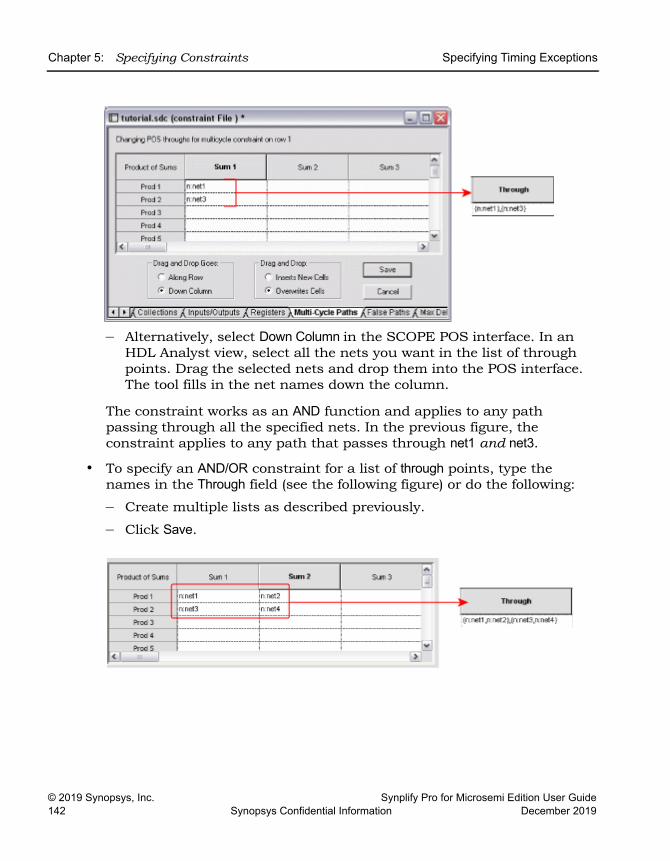
LO
Chapter 5: Specifying Constraints Specifying Timing Exceptions
© 2019 Synopsys, Inc. Synplify Pro for Microsemi Edition User Guide142 Synopsys Confidential Information December 2019
– Alternatively, select Down Column in the SCOPE POS interface. In an HDL Analyst view, select all the nets you want in the list of through points. Drag the selected nets and drop them into the POS interface. The tool fills in the net names down the column.
The constraint works as an AND function and applies to any path passing through all the specified nets. In the previous figure, the constraint applies to any path that passes through net1 and net3.
• To specify an AND/OR constraint for a list of through points, type the names in the Through field (see the following figure) or do the following:
– Create multiple lists as described previously.
– Click Save.
Specifying Timing Exceptions Chapter 5: Specifying Constraints
Synplify Pro for Microsemi Edition User Guide © 2019 Synopsys, Inc.December 2019 Synopsys Confidential Information 143
In this example, the synthesis tool applies the constraint to the paths through all points in the lists as follows:
net1 AND net3 OR net1 AND net4 OR net2 AND net3OR net2 AND net4
Defining Multicycle PathsTo define a multicycle path constraint, use the Tcl set_multicycle_path command, or select the SCOPE Delay Paths tab and do the following;
1. From the Delay Type pull-down menu, select Multicycle.
2. Select a port or register in the From or To columns, or a net in the Through column. You must set at least one From, To, or Through point. You can use a combination of these points. See Defining From/To/Through Points for Timing Exceptions, on page 139 for more information.
3. Select another port or register if needed (From/To/Through).
4. Type the number of clock cycles or nets (Cycles).
5. Specify the clock period to use for the constraint by going to the Start/End column and selecting either Start or End.
If you do not explicitly specify a clock period, the software uses the end clock period. The constraint is now calculated as follows:
multicycle_distance = clock_distance + (cycles -1) * reference_clock_period
In the equation, clock_distance is the shortest distance between the triggering edges of the start and end clocks, cycles is the number of clock cycles specified, and reference_clock_period is either the specified start clock period or the default end clock period.
6. Check the Enabled box.
LO
Chapter 5: Specifying Constraints Specifying Timing Exceptions
© 2019 Synopsys, Inc. Synplify Pro for Microsemi Edition User Guide144 Synopsys Confidential Information December 2019
Defining False PathsYou define false paths by setting constraints explicitly on the Delay Paths tab or implicitly on the Clock tab. See Defining From/To/Through Points for Timing Exceptions, on page 139 for object naming and specifying through points.
• To define a false path between ports or registers, select the SCOPE Delay Paths tab, and do the following:
– From the Delay Type pull-down menu, select False.
– Use the pull-down to select the port or register from the appropriate column (From/To/Through).
– Check the Enabled box.
The software treats this as an explicit false constraint and assigns it the highest priority. Any other constraints on this path are ignored.
• To define a false path between two clocks, select the SCOPE Clocks tab, and assign the clocks to different clock groups:
The software implicitly assumes a false path between clocks in different clock groups. This false path constraint can be overridden by a maximum path delay constraint, or with an explicit constraint.
• To set an implicit false path on a path to/from an I/O port, do the following:
– Select Project->Implementation Options->Constraints.
– Disable Use clock period for unconstrained IO.
Finding Objects with Tcl find and expand Chapter 5: Specifying Constraints
Synplify Pro for Microsemi Edition User Guide © 2019 Synopsys, Inc.December 2019 Synopsys Confidential Information 145
Finding Objects with Tcl find and expandThe Tcl find and expand commands are powerful search tools that you can use to quickly identify the objects you want. The following sections describe how to use these commands effectively:
• Specifying Search Patterns for Tcl find, on page 145
• Refining Tcl Find Results with -filter, on page 147
• Using the Tcl Find Command to Define Collections, on page 149
• Using the Tcl expand Command to Define Collections, on page 150
• Checking Tcl find and expand Results, on page 151
• Using Tcl find and expand in Batch Mode, on page 152
Once you have located objects with the find or expand commands, you can group them into collections, as described in Using Collections, on page 154, and apply constraints to all the objects in the collection at the same time.
Specifying Search Patterns for Tcl findThe usage tips in the following table apply for Tcl find search patterns, regard-less of whether you specify the find command in the SCOPE window or as a Tcl command. For full details of the command syntax, refer to Tcl Find Syntax, on page 150 of the Reference Manual.
LO
Chapter 5: Specifying Constraints Finding Objects with Tcl find and expand
© 2019 Synopsys, Inc. Synplify Pro for Microsemi Edition User Guide146 Synopsys Confidential Information December 2019
Case rules Use the case rules for the language from which the object was generated: • VHDL: case-insensitive• Verilog: case-sensitive. Make sure that the object name
you type in the SCOPE window matches the Verilog name.
For mixed language designs, use the case rules for the parent module. The top level for this example is VHDL, so the following command finds any object in the current view that starts with either a or A:
find {a*} -nocasePattern matching You have two pattern-matching choices:
• Specify the -regexp argument, and then use regular expressions for pattern matching.
• Do not specify -regexp, and use only the * and ? wildcards for pattern matching.
For hierarchical instance names that use dots as separators, the dots must be escaped with a backward slash (\). For example: abc\.d.
Scope of the search The scope of the search varies, depending on where you enter the command. If you enter it in the SCOPE environment, the scope of the search is the entire database, but if it is entered in the Tcl window, the default scope of the search is the current HDL Analyst view. See Comparison of Methods for Defining Collections, on page 154 for a list of the differences. To set the scope to include the hierarchical levels below the current view in HDL Analyst, use the -hier argument. This example finds all objects below the current view that begin with a:
find {a*} -hier
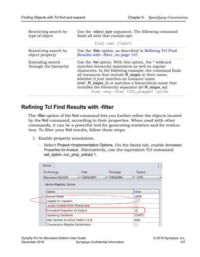
Finding Objects with Tcl find and expand Chapter 5: Specifying Constraints
Synplify Pro for Microsemi Edition User Guide © 2019 Synopsys, Inc.December 2019 Synopsys Confidential Information 147
Refining Tcl Find Results with -filterThe -filter option of the find command lets you further refine the objects located by the find command, according to their properties. When used with other commands, it can be a powerful tool for generating statistics and for evalua-tion. To filter your find results, follow these steps:
1. Enable property annotation.
– Select Project->Implementation Options. On the Device tab, enable Annotated Properties for Analyst. Alternatively, use the equivalent Tcl command: set_option -run_prop_extract 1.
Restricting search by type of object
Use the -object_type argument. The following command finds all nets that contain syn:
find -net {*syn*}Restricting search by object property
Use the -filter option, as described in Refining Tcl Find Results with -filter, on page 147.
Extending search through the hierarchy
Use the -flat option. With this option, the * wildcard matches hierarchy separators as well as regular characters. In the following example, the command finds all instances that include fft_stages in their name, whether it just matches an instance name (inst1_fft_stages_2) or matches a hierarchical name that includes the hierarchy separator (a1.fft_stages_xy):
find -seq -flat *fft_stages* -print
LO
Chapter 5: Specifying Constraints Finding Objects with Tcl find and expand
© 2019 Synopsys, Inc. Synplify Pro for Microsemi Edition User Guide148 Synopsys Confidential Information December 2019
– Compile or synthesize the design. After compilation, the tool annotates the design with properties that you can specify with the -filter option, like clock pins.
2. Specify the command using the find pattern as usual, and then specify the -filter option as the last argument:
find searchPattern -filter expressionfind searchPattern -filter !expression
With this command, the tool first finds objects that match the find search-Pattern, and then further filters the found objects the according to the property criteria specified in -filter expression. Use the ! character before expression if you want to select objects that do not match the properties specified in the filter expression.
expression can be a property name, specified as @propertyName, or a property name and value pair, specified as @propertyName operator value.
The following example finds registers in the current view that are clocked by myclk:
find -seq {*} -filter {@clock==myclk}For further information about the command, see the following:
For ... See
Tips on using find search patterns
Specifying Search Patterns for Tcl find, on page 145
find syntax details find, on page 149 in the Reference Manual
find -filter syntax details find -filter, on page 156in the Reference Manual
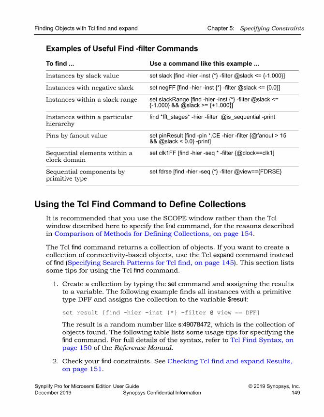
Finding Objects with Tcl find and expand Chapter 5: Specifying Constraints
Synplify Pro for Microsemi Edition User Guide © 2019 Synopsys, Inc.December 2019 Synopsys Confidential Information 149
Examples of Useful Find -filter Commands
Using the Tcl Find Command to Define CollectionsIt is recommended that you use the SCOPE window rather than the Tcl window described here to specify the find command, for the reasons described in Comparison of Methods for Defining Collections, on page 154.
The Tcl find command returns a collection of objects. If you want to create a collection of connectivity-based objects, use the Tcl expand command instead of find (Specifying Search Patterns for Tcl find, on page 145). This section lists some tips for using the Tcl find command.
1. Create a collection by typing the set command and assigning the results to a variable. The following example finds all instances with a primitive type DFF and assigns the collection to the variable $result:
set result [find -hier -inst {*} -filter @ view == DFF]The result is a random number like s:49078472, which is the collection of objects found. The following table lists some usage tips for specifying the find command. For full details of the syntax, refer to Tcl Find Syntax, on page 150 of the Reference Manual.
2. Check your find constraints. See Checking Tcl find and expand Results, on page 151.
To find ... Use a command like this example ...
Instances by slack value set slack [find -hier -inst {*} -filter @slack <= {-1.000}]
Instances with negative slack set negFF [find -hier -inst {*} -filter @slack <= {0.0}]
Instances within a slack range set slackRange [find -hier -inst {*} -filter @slack <={-1.000} && @slack >= {+1.000}]
Instances within a particular hierarchy
find *fft_stages* -hier -filter @is_sequential -print
Pins by fanout value set pinResult [find -pin *.CE -hier -filter {@fanout > 15&& @slack < 0.0} -print]
Sequential elements within a clock domain
set clk1FF [find -hier -seq * -filter {@clock==clk1]
Sequential components by primitive type
set fdrse [find -hier -seq {*} -filter @view=={FDRSE}
LO
Chapter 5: Specifying Constraints Finding Objects with Tcl find and expand
© 2019 Synopsys, Inc. Synplify Pro for Microsemi Edition User Guide150 Synopsys Confidential Information December 2019
3. Once you have defined the collection, you can view the objects in the collection, using one of the following methods, which are described in more detail in Viewing and Manipulating Collections with Tcl Commands, on page 160:
– Print the collection using the -print option to the find command.
– Print the collection without carriage returns or properties, using c_list.– Print the collection in columns, with optional properties, using c_print.
4. To manipulate the objects in the collection, use the commands described in Viewing and Manipulating Collections with Tcl Commands, on page 160.
5. Combine the Tcl find command with other commands:
Using the Tcl expand Command to Define CollectionsThe Tcl expand command returns a list of objects that are logically connected between the specified expansion points. This section contains tips on using the Tcl expand command to generate a collection of objects that are related by their connectivity. For the syntax details, refer to expand, on page 163 in the Command Reference Manual.
1. Specify at least one from, to, or thru point as the starting point for the command. You can use any combination of these points.
The following example expands the cone of logic between reg1 and reg2.
expand -from {i:reg1} -to {i:reg2}If you only specify a thru point, the expansion stops at sequential elements. The following example finds all elements in the transitive fanout and transitive fanin of a clock-enable net:
expand -thru {n:cen}
To ... Combine with ...
Create or copy objects; create collections set define_collection
Generate reports for evaluation c_list c_print
Generate statistics c_info
Finding Objects with Tcl find and expand Chapter 5: Specifying Constraints
Synplify Pro for Microsemi Edition User Guide © 2019 Synopsys, Inc.December 2019 Synopsys Confidential Information 151
2. To specify the hierarchical scope of the expansion, use the -hier argument.
If you do not specify this argument, the command only works on the current view. The following example expands the cone of logic to reg1, including instances below the current level:
expand -hier -to {i:reg1}If you only specify a thru point, you can use the -level argument to specify the number of levels of expansion. The following example finds all elements in the transitive fanout and transitive fanin of a clock-enable net across one level of hierarchy:
expand -thru {n:cen} -level 13. To restrict the search by type of object, use the -object_type argument.
The following command finds all pins driven by the specified pin.
expand -pin -from {t:i_and3.z}4. To print a list of the objects found, either use the -print argument to the
expand command, or use the c_print or c_list commands (see Creating Collections using Tcl Commands, on page 157).
Checking Tcl find and expand ResultsYou must check the validity of the find constraints you set. Use the methods described below.
1. Run the Constraints Checker, either from the UI or at the command line:
– From the UI, select Run->Constraint Check. – At the command line specify the -run constraint_check option to the
synthesis tool command. For example: synplify_pro -batch design.prj -run constraint_check.
– If there are issues, the tool reports them in the design_cck.rpt report file. Check the Summary and Inapplicable Constraints sections in this file.
2. To list objects selected by the find or expand commands, use one of these methods:
– List the results by specifying the -print option to the command.
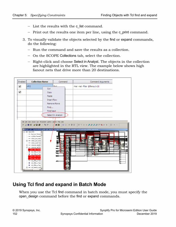
LO
Chapter 5: Specifying Constraints Finding Objects with Tcl find and expand
© 2019 Synopsys, Inc. Synplify Pro for Microsemi Edition User Guide152 Synopsys Confidential Information December 2019
– List the results with the c_list command.
– Print out the results one item per line, using the c_print command.
3. To visually validate the objects selected by the find or expand commands, do the following:
– Run the command and save the results as a collection.
– On the SCOPE Collections tab, select the collection.
– Right-click and choose Select in Analyst. The objects in the collection are highlighted in the RTL view. The example below shows high fanout nets that drive more than 20 destinations.
Using Tcl find and expand in Batch ModeWhen you use the Tcl find command in batch mode, you must specify the open_design command before the find or expand commands.
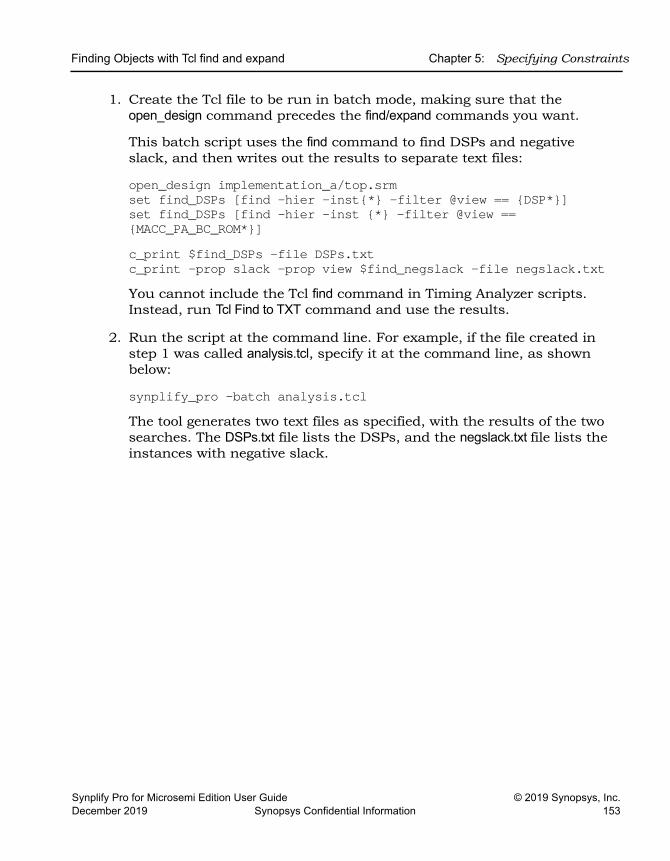
Finding Objects with Tcl find and expand Chapter 5: Specifying Constraints
Synplify Pro for Microsemi Edition User Guide © 2019 Synopsys, Inc.December 2019 Synopsys Confidential Information 153
1. Create the Tcl file to be run in batch mode, making sure that the open_design command precedes the find/expand commands you want.
This batch script uses the find command to find DSPs and negative slack, and then writes out the results to separate text files:
open_design implementation_a/top.srmset find_DSPs [find -hier -inst{*} -filter @view == {DSP*}]set find_DSPs [find -hier -inst {*} -filter @view == {MACC_PA_BC_ROM*}] c_print $find_DSPs -file DSPs.txt c_print -prop slack -prop view $find_negslack -file negslack.txt You cannot include the Tcl find command in Timing Analyzer scripts. Instead, run Tcl Find to TXT command and use the results.
2. Run the script at the command line. For example, if the file created in step 1 was called analysis.tcl, specify it at the command line, as shown below:
synplify_pro -batch analysis.tclThe tool generates two text files as specified, with the results of the two searches. The DSPs.txt file lists the DSPs, and the negslack.txt file lists the instances with negative slack.
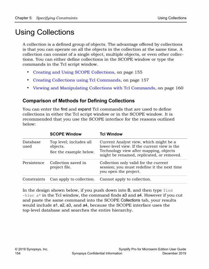
LO
Chapter 5: Specifying Constraints Using Collections
© 2019 Synopsys, Inc. Synplify Pro for Microsemi Edition User Guide154 Synopsys Confidential Information December 2019
Using CollectionsA collection is a defined group of objects. The advantage offered by collections is that you can operate on all the objects in the collection at the same time. A collection can consist of a single object, multiple objects, or even other collec-tions. You can either define collections in the SCOPE window or type the commands in the Tcl script window.
• Creating and Using SCOPE Collections, on page 155
• Creating Collections using Tcl Commands, on page 157
• Viewing and Manipulating Collections with Tcl Commands, on page 160
Comparison of Methods for Defining CollectionsYou can enter the find and expand Tcl commands that are used to define collections in either the Tcl script window or in the SCOPE window. It is recommended that you use the SCOPE interface for the reasons outlined below:
In the design shown below, if you push down into B, and then type find -hier a* in the Tcl window, the command finds a3 and a4. However if you cut and paste the same command into the SCOPE Collections tab, your results would include a1, a2, a3, and a4, because the SCOPE interface uses the top-level database and searches the entire hierarchy.
SCOPE Window Tcl Window
Database used
Top level; includes all objects. See the example below.
Current Analyst view, which might be a lower-level view. If the current view is the Technology view after mapping, objects might be renamed, replicated, or removed.
Persistence Collection saved in project file.
Collection only valid for the current session; you must redefine it the next time you open the project.
Constraints Can apply to collection. Cannot apply to collection.
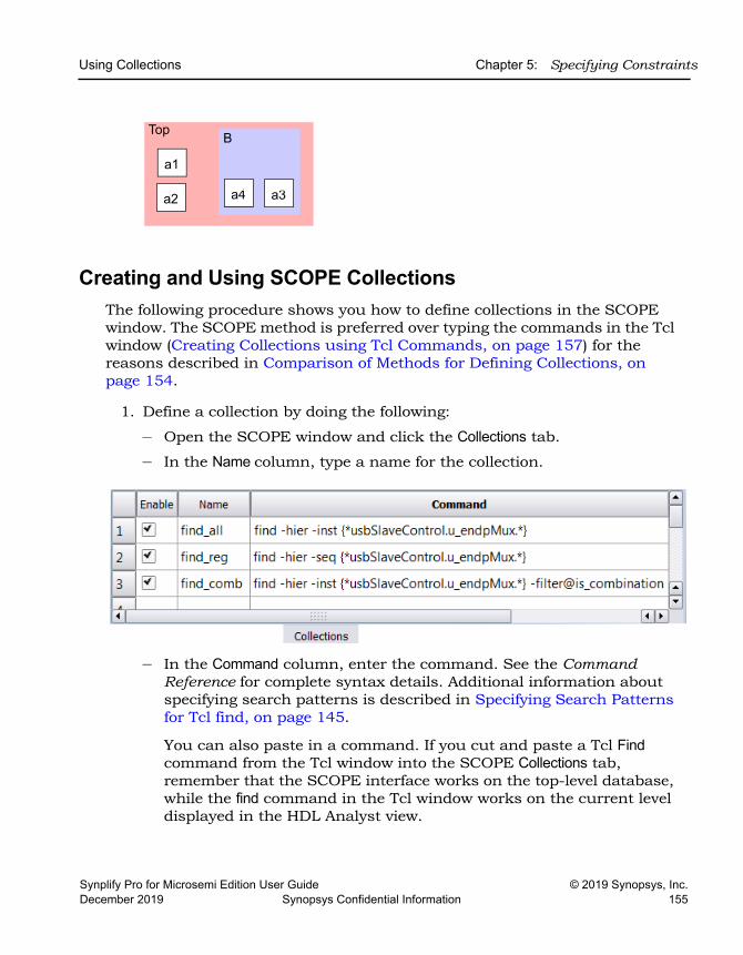
Using Collections Chapter 5: Specifying Constraints
Synplify Pro for Microsemi Edition User Guide © 2019 Synopsys, Inc.December 2019 Synopsys Confidential Information 155
Creating and Using SCOPE Collections The following procedure shows you how to define collections in the SCOPE window. The SCOPE method is preferred over typing the commands in the Tcl window (Creating Collections using Tcl Commands, on page 157) for the reasons described in Comparison of Methods for Defining Collections, on page 154.
1. Define a collection by doing the following:
– Open the SCOPE window and click the Collections tab.
– In the Name column, type a name for the collection.
– In the Command column, enter the command. See the Command Reference for complete syntax details. Additional information about specifying search patterns is described in Specifying Search Patterns for Tcl find, on page 145.
You can also paste in a command. If you cut and paste a Tcl Find command from the Tcl window into the SCOPE Collections tab, remember that the SCOPE interface works on the top-level database, while the find command in the Tcl window works on the current level displayed in the HDL Analyst view.
a2
Top B
a1
a3a4
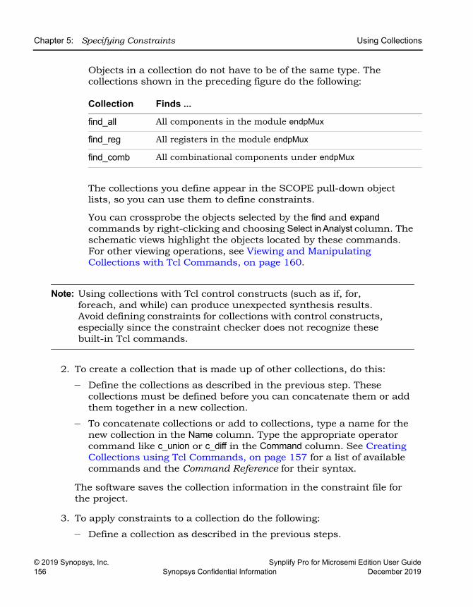
LO
Chapter 5: Specifying Constraints Using Collections
© 2019 Synopsys, Inc. Synplify Pro for Microsemi Edition User Guide156 Synopsys Confidential Information December 2019
Objects in a collection do not have to be of the same type. The collections shown in the preceding figure do the following:
The collections you define appear in the SCOPE pull-down object lists, so you can use them to define constraints.
You can crossprobe the objects selected by the find and expand commands by right-clicking and choosing Select in Analyst column. The schematic views highlight the objects located by these commands. For other viewing operations, see Viewing and Manipulating Collections with Tcl Commands, on page 160.
Note: Using collections with Tcl control constructs (such as if, for, foreach, and while) can produce unexpected synthesis results. Avoid defining constraints for collections with control constructs, especially since the constraint checker does not recognize these built-in Tcl commands.
2. To create a collection that is made up of other collections, do this:
– Define the collections as described in the previous step. These collections must be defined before you can concatenate them or add them together in a new collection.
– To concatenate collections or add to collections, type a name for the new collection in the Name column. Type the appropriate operator command like c_union or c_diff in the Command column. See Creating Collections using Tcl Commands, on page 157 for a list of available commands and the Command Reference for their syntax.
The software saves the collection information in the constraint file for the project.
3. To apply constraints to a collection do the following:
– Define a collection as described in the previous steps.
Collection Finds ...
find_all All components in the module endpMux
find_reg All registers in the module endpMux
find_comb All combinational components under endpMux
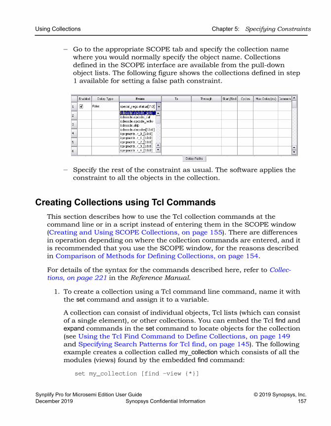
Using Collections Chapter 5: Specifying Constraints
Synplify Pro for Microsemi Edition User Guide © 2019 Synopsys, Inc.December 2019 Synopsys Confidential Information 157
– Go to the appropriate SCOPE tab and specify the collection name where you would normally specify the object name. Collections defined in the SCOPE interface are available from the pull-down object lists. The following figure shows the collections defined in step 1 available for setting a false path constraint.
– Specify the rest of the constraint as usual. The software applies the constraint to all the objects in the collection.
Creating Collections using Tcl CommandsThis section describes how to use the Tcl collection commands at the command line or in a script instead of entering them in the SCOPE window (Creating and Using SCOPE Collections, on page 155). There are differences in operation depending on where the collection commands are entered, and it is recommended that you use the SCOPE window, for the reasons described in Comparison of Methods for Defining Collections, on page 154.
For details of the syntax for the commands described here, refer to Collec-tions, on page 221 in the Reference Manual.
1. To create a collection using a Tcl command line command, name it with the set command and assign it to a variable.
A collection can consist of individual objects, Tcl lists (which can consist of a single element), or other collections. You can embed the Tcl find and expand commands in the set command to locate objects for the collection (see Using the Tcl Find Command to Define Collections, on page 149 and Specifying Search Patterns for Tcl find, on page 145). The following example creates a collection called my_collection which consists of all the modules (views) found by the embedded find command:
set my_collection [find -view {*}]
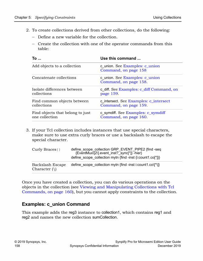
LO
Chapter 5: Specifying Constraints Using Collections
© 2019 Synopsys, Inc. Synplify Pro for Microsemi Edition User Guide158 Synopsys Confidential Information December 2019
2. To create collections derived from other collections, do the following:
– Define a new variable for the collection.
– Create the collection with one of the operator commands from this table:
3. If your Tcl collection includes instances that use special characters, make sure to use extra curly braces or use a backslash to escape the special character.
Once you have created a collection, you can do various operations on the objects in the collection (see Viewing and Manipulating Collections with Tcl Commands, on page 160), but you cannot apply constraints to the collection.
Examples: c_union CommandThis example adds the reg3 instance to collection1, which contains reg1 and reg2 and names the new collection sumCollection.
To ... Use this command ...
Add objects to a collection c_union. See Examples: c_union Command, on page 158
Concatenate collections c_union. See Examples: c_union Command, on page 158.
Isolate differences between collections
c_diff. See Examples: c_diff Command, on page 159.
Find common objects between collections
c_intersect. See Examples: c_intersect Command, on page 159.
Find objects that belong to just one collection
c_symdiff. See Examples: c_symdiff Command, on page 160.
Curly Braces{} define_scope_collection GRP_EVENT_PIPE2 {find -seq{EventMux\[2\].event_inst?_sync[*]} -hier}
define_scope_collection mytn {find -inst {i:count1.co[*]}}
Backslash Escape Character (\)
define_scope_collection mytn {find -inst i:count1.co\[*\]}
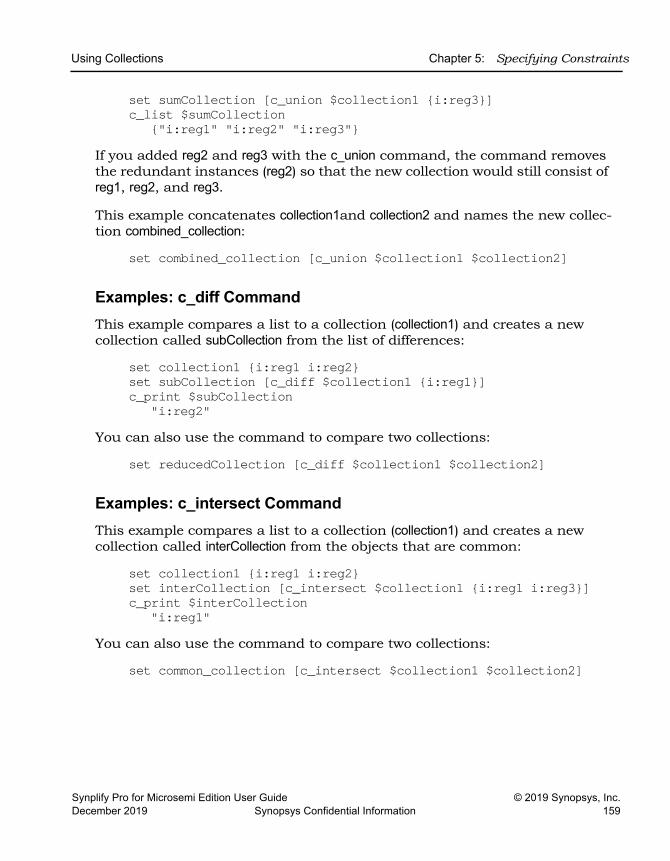
Using Collections Chapter 5: Specifying Constraints
Synplify Pro for Microsemi Edition User Guide © 2019 Synopsys, Inc.December 2019 Synopsys Confidential Information 159
set sumCollection [c_union $collection1 {i:reg3}]c_list $sumCollection
{"i:reg1" "i:reg2" "i:reg3"}If you added reg2 and reg3 with the c_union command, the command removes the redundant instances (reg2) so that the new collection would still consist of reg1, reg2, and reg3.
This example concatenates collection1and collection2 and names the new collec-tion combined_collection:
set combined_collection [c_union $collection1 $collection2]
Examples: c_diff CommandThis example compares a list to a collection (collection1) and creates a new collection called subCollection from the list of differences:
set collection1 {i:reg1 i:reg2}set subCollection [c_diff $collection1 {i:reg1}]c_print $subCollection
"i:reg2"You can also use the command to compare two collections:
set reducedCollection [c_diff $collection1 $collection2]
Examples: c_intersect CommandThis example compares a list to a collection (collection1) and creates a new collection called interCollection from the objects that are common:
set collection1 {i:reg1 i:reg2}set interCollection [c_intersect $collection1 {i:reg1 i:reg3}]c_print $interCollection
"i:reg1"You can also use the command to compare two collections:
set common_collection [c_intersect $collection1 $collection2]
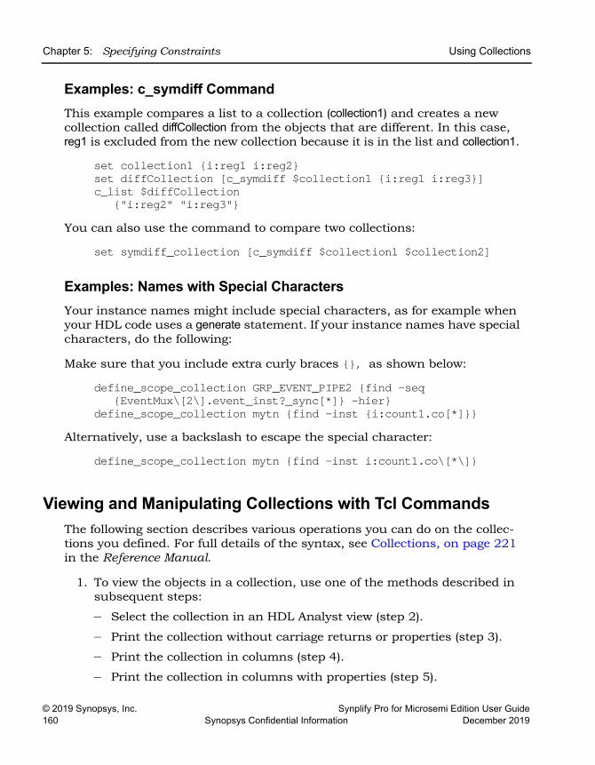
LO
Chapter 5: Specifying Constraints Using Collections
© 2019 Synopsys, Inc. Synplify Pro for Microsemi Edition User Guide160 Synopsys Confidential Information December 2019
Examples: c_symdiff CommandThis example compares a list to a collection (collection1) and creates a new collection called diffCollection from the objects that are different. In this case, reg1 is excluded from the new collection because it is in the list and collection1.
set collection1 {i:reg1 i:reg2}set diffCollection [c_symdiff $collection1 {i:reg1 i:reg3}]c_list $diffCollection
{"i:reg2" "i:reg3"}You can also use the command to compare two collections:
set symdiff_collection [c_symdiff $collection1 $collection2]
Examples: Names with Special CharactersYour instance names might include special characters, as for example when your HDL code uses a generate statement. If your instance names have special characters, do the following:
Make sure that you include extra curly braces {}, as shown below:
define_scope_collection GRP_EVENT_PIPE2 {find -seq {EventMux\[2\].event_inst?_sync[*]} -hier}
define_scope_collection mytn {find -inst {i:count1.co[*]}}Alternatively, use a backslash to escape the special character:
define_scope_collection mytn {find -inst i:count1.co\[*\]}
Viewing and Manipulating Collections with Tcl CommandsThe following section describes various operations you can do on the collec-tions you defined. For full details of the syntax, see Collections, on page 221 in the Reference Manual.
1. To view the objects in a collection, use one of the methods described in subsequent steps:
– Select the collection in an HDL Analyst view (step 2).
– Print the collection without carriage returns or properties (step 3).
– Print the collection in columns (step 4).
– Print the collection in columns with properties (step 5).
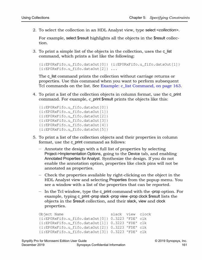
Using Collections Chapter 5: Specifying Constraints
Synplify Pro for Microsemi Edition User Guide © 2019 Synopsys, Inc.December 2019 Synopsys Confidential Information 161
2. To select the collection in an HDL Analyst view, type select <collection>.
For example, select $result highlights all the objects in the $result collec-tion.
3. To print a simple list of the objects in the collection, uses the c_list command, which prints a list like the following:
{i:EP0RxFifo.u_fifo.dataOut[0]} {i:EP0RxFifo.u_fifo.dataOut[1]} {i:EP0RxFifo.u_fifo.dataOut[2]} ...The c_list command prints the collection without carriage returns or properties. Use this command when you want to perform subsequent Tcl commands on the list. See Example: c_list Command, on page 163.
4. To print a list of the collection objects in column format, use the c_print command. For example, c_print $result prints the objects like this:
{i:EP0RxFifo.u_fifo.dataOut[0]}{i:EP0RxFifo.u_fifo.dataOut[1]}{i:EP0RxFifo.u_fifo.dataOut[2]}{i:EP0RxFifo.u_fifo.dataOut[3]}{i:EP0RxFifo.u_fifo.dataOut[4]}{i:EP0RxFifo.u_fifo.dataOut[5]}
5. To print a list of the collection objects and their properties in column format, use the c_print command as follows:
– Annotate the design with a full list of properties by selecting Project->Implementation Options, going to the Device tab, and enabling Annotated Properties for Analyst. Synthesize the design. If you do not enable the annotation option, properties like clock pins will not be annotated as properties.
– Check the properties available by right-clicking on the object in the HDL Analyst view and selecting Properties from the popup menu. You see a window with a list of the properties that can be reported.
– In the Tcl window, type the c_print command with the -prop option. For example, typing c_print -prop slack -prop view -prop clock $result lists the objects in the $result collection, and their slack, view and clock properties.
Object Name slack view clock {i:EP0RxFifo.u_fifo.dataOut[0]} 0.3223 "FDE" clk{i:EP0RxFifo.u_fifo.dataOut[1]} 0.3223 "FDE" clk{i:EP0RxFifo.u_fifo.dataOut[2]} 0.3223 "FDE" clk{i:EP0RxFifo.u_fifo.dataOut[3]} 0.3223 "FDE" clk
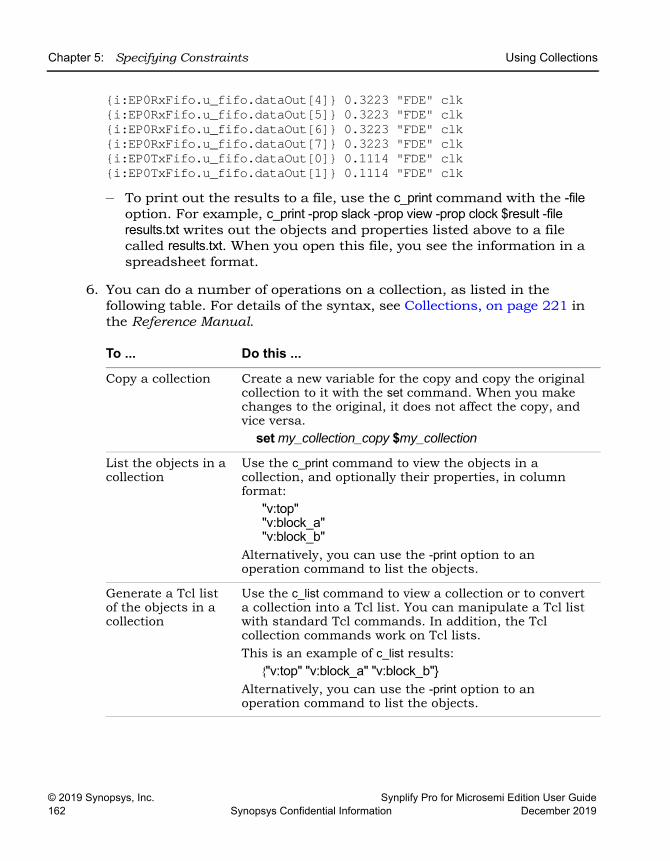
LO
Chapter 5: Specifying Constraints Using Collections
© 2019 Synopsys, Inc. Synplify Pro for Microsemi Edition User Guide162 Synopsys Confidential Information December 2019
{i:EP0RxFifo.u_fifo.dataOut[4]} 0.3223 "FDE" clk{i:EP0RxFifo.u_fifo.dataOut[5]} 0.3223 "FDE" clk{i:EP0RxFifo.u_fifo.dataOut[6]} 0.3223 "FDE" clk{i:EP0RxFifo.u_fifo.dataOut[7]} 0.3223 "FDE" clk{i:EP0TxFifo.u_fifo.dataOut[0]} 0.1114 "FDE" clk{i:EP0TxFifo.u_fifo.dataOut[1]} 0.1114 "FDE" clk– To print out the results to a file, use the c_print command with the -file
option. For example, c_print -prop slack -prop view -prop clock $result -file results.txt writes out the objects and properties listed above to a file called results.txt. When you open this file, you see the information in a spreadsheet format.
6. You can do a number of operations on a collection, as listed in the following table. For details of the syntax, see Collections, on page 221 in the Reference Manual.
To ... Do this ...
Copy a collection Create a new variable for the copy and copy the original collection to it with the set command. When you make changes to the original, it does not affect the copy, and vice versa.
set my_collection_copy $my_collection
List the objects in a collection
Use the c_print command to view the objects in a collection, and optionally their properties, in column format:
"v:top""v:block_a""v:block_b"
Alternatively, you can use the -print option to an operation command to list the objects.
Generate a Tcl list of the objects in a collection
Use the c_list command to view a collection or to convert a collection into a Tcl list. You can manipulate a Tcl list with standard Tcl commands. In addition, the Tcl collection commands work on Tcl lists. This is an example of c_list results:
{"v:top" "v:block_a" "v:block_b"}Alternatively, you can use the -print option to an operation command to list the objects.
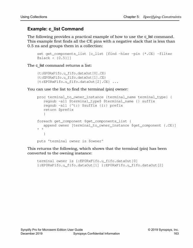
Using Collections Chapter 5: Specifying Constraints
Synplify Pro for Microsemi Edition User Guide © 2019 Synopsys, Inc.December 2019 Synopsys Confidential Information 163
Example: c_list CommandThe following provides a practical example of how to use the c_list command. This example first finds all the CE pins with a negative slack that is less than 0.5 ns and groups them in a collection:
set get_components_list [c_list [find -hier -pin {*.CE} -filter @slack < {0.5}]]
The c_list command returns a list:
{t:EP0RxFifo.u_fifo.dataOut[0].CE} {t:EP0RxFifo.u_fifo.dataOut[1].CE} {t:EP0RxFifo.u_fifo.dataOut[2].CE} ...
You can use the list to find the terminal (pin) owner:
proc terminal_to_owner_instance {terminal_name terminal_type} {regsub -all $terminal_type$ $terminal_name {} suffixregsub -all {^t:} $suffix {i:} prefixreturn $prefix}
foreach get_component $get_components_list {append owner [terminal_to_owner_instance $get_component {.CE}]
" "}
puts "terminal owner is $owner"This returns the following, which shows that the terminal (pin) has been converted to the owning instance:
terminal owner is i:EP0RxFifo.u_fifo.dataOut[0] i:EP0RxFifo.u_fifo.dataOut[1] i:EP0RxFifo.u_fifo.dataOut[2]
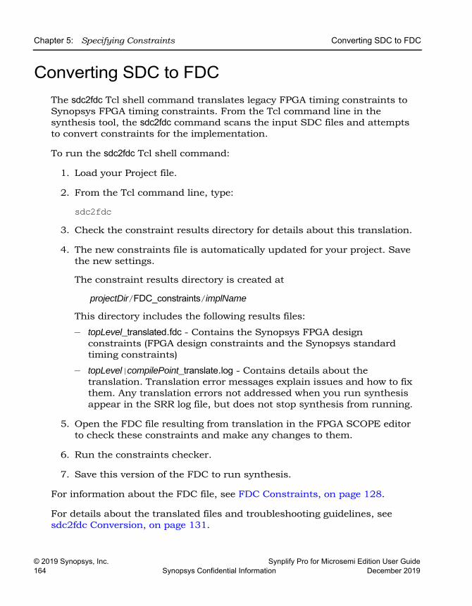
LO
Chapter 5: Specifying Constraints Converting SDC to FDC
© 2019 Synopsys, Inc. Synplify Pro for Microsemi Edition User Guide164 Synopsys Confidential Information December 2019
Converting SDC to FDC The sdc2fdc Tcl shell command translates legacy FPGA timing constraints to Synopsys FPGA timing constraints. From the Tcl command line in the synthesis tool, the sdc2fdc command scans the input SDC files and attempts to convert constraints for the implementation.
To run the sdc2fdc Tcl shell command:
1. Load your Project file.
2. From the Tcl command line, type:
sdc2fdc3. Check the constraint results directory for details about this translation.
4. The new constraints file is automatically updated for your project. Save the new settings.
The constraint results directory is created at
projectDir/FDC_constraints/implName
This directory includes the following results files:
– topLevel_translated.fdc - Contains the Synopsys FPGA design constraints (FPGA design constraints and the Synopsys standard timing constraints)
– topLevel|compilePoint_translate.log - Contains details about the translation. Translation error messages explain issues and how to fix them. Any translation errors not addressed when you run synthesis appear in the SRR log file, but does not stop synthesis from running.
5. Open the FDC file resulting from translation in the FPGA SCOPE editor to check these constraints and make any changes to them.
6. Run the constraints checker.
7. Save this version of the FDC to run synthesis.
For information about the FDC file, see FDC Constraints, on page 128.
For details about the translated files and troubleshooting guidelines, see sdc2fdc Conversion, on page 131.
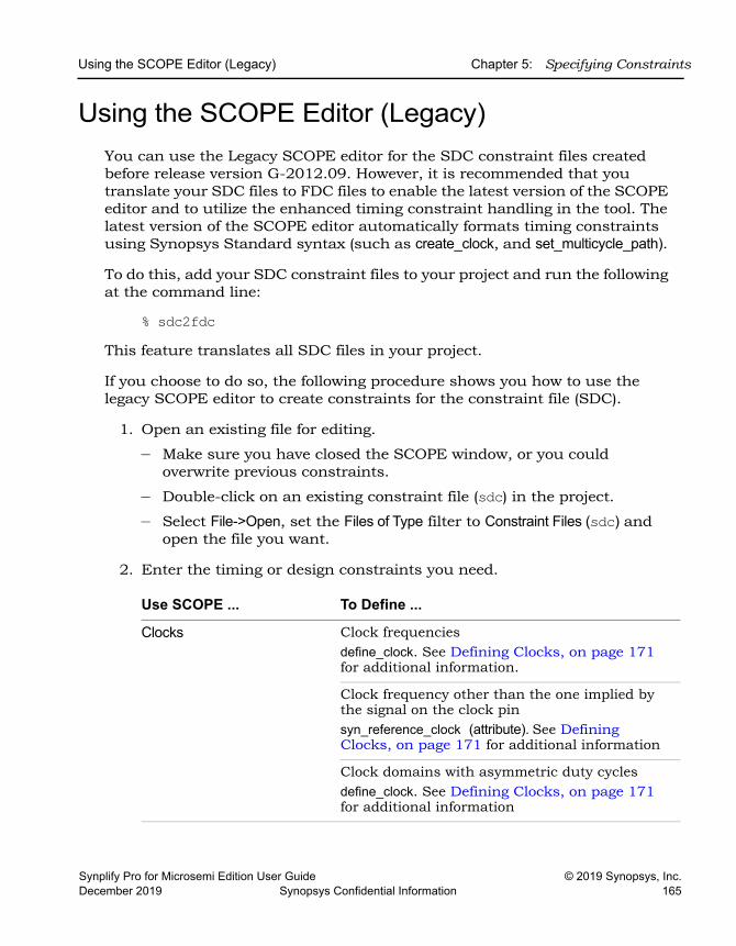
Using the SCOPE Editor (Legacy) Chapter 5: Specifying Constraints
Synplify Pro for Microsemi Edition User Guide © 2019 Synopsys, Inc.December 2019 Synopsys Confidential Information 165
Using the SCOPE Editor (Legacy)You can use the Legacy SCOPE editor for the SDC constraint files created before release version G-2012.09. However, it is recommended that you translate your SDC files to FDC files to enable the latest version of the SCOPE editor and to utilize the enhanced timing constraint handling in the tool. The latest version of the SCOPE editor automatically formats timing constraints using Synopsys Standard syntax (such as create_clock, and set_multicycle_path).
To do this, add your SDC constraint files to your project and run the following at the command line:
% sdc2fdcThis feature translates all SDC files in your project.
If you choose to do so, the following procedure shows you how to use the legacy SCOPE editor to create constraints for the constraint file (SDC).
1. Open an existing file for editing.
– Make sure you have closed the SCOPE window, or you could overwrite previous constraints.
– Double-click on an existing constraint file (sdc) in the project.
– Select File->Open, set the Files of Type filter to Constraint Files (sdc) and open the file you want.
2. Enter the timing or design constraints you need.
Use SCOPE ... To Define ...
Clocks Clock frequenciesdefine_clock. See Defining Clocks, on page 171 for additional information.
Clock frequency other than the one implied by the signal on the clock pinsyn_reference_clock (attribute). See Defining Clocks, on page 171 for additional information
Clock domains with asymmetric duty cyclesdefine_clock. See Defining Clocks, on page 171 for additional information
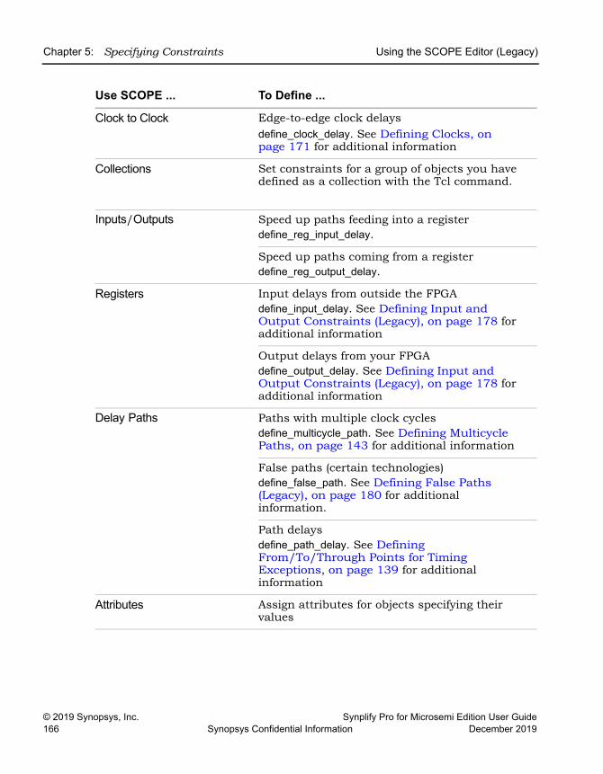
LO
Chapter 5: Specifying Constraints Using the SCOPE Editor (Legacy)
© 2019 Synopsys, Inc. Synplify Pro for Microsemi Edition User Guide166 Synopsys Confidential Information December 2019
Clock to Clock Edge-to-edge clock delaysdefine_clock_delay. See Defining Clocks, on page 171 for additional information
Collections Set constraints for a group of objects you have defined as a collection with the Tcl command.
Inputs/Outputs Speed up paths feeding into a registerdefine_reg_input_delay.
Speed up paths coming from a registerdefine_reg_output_delay.
Registers Input delays from outside the FPGAdefine_input_delay. See Defining Input and Output Constraints (Legacy), on page 178 for additional information
Output delays from your FPGAdefine_output_delay. See Defining Input and Output Constraints (Legacy), on page 178 for additional information
Delay Paths Paths with multiple clock cyclesdefine_multicycle_path. See Defining Multicycle Paths, on page 143 for additional information
False paths (certain technologies)define_false_path. See Defining False Paths (Legacy), on page 180 for additional information.
Path delays define_path_delay. See Defining From/To/Through Points for Timing Exceptions, on page 139 for additional information
Attributes Assign attributes for objects specifying their values
Use SCOPE ... To Define ...
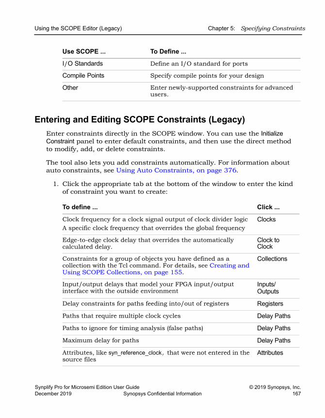
Using the SCOPE Editor (Legacy) Chapter 5: Specifying Constraints
Synplify Pro for Microsemi Edition User Guide © 2019 Synopsys, Inc.December 2019 Synopsys Confidential Information 167
Entering and Editing SCOPE Constraints (Legacy)Enter constraints directly in the SCOPE window. You can use the Initialize Constraint panel to enter default constraints, and then use the direct method to modify, add, or delete constraints.
The tool also lets you add constraints automatically. For information about auto constraints, see Using Auto Constraints, on page 376.
1. Click the appropriate tab at the bottom of the window to enter the kind of constraint you want to create:
I/O Standards Define an I/O standard for ports
Compile Points Specify compile points for your design
Other Enter newly-supported constraints for advanced users.
To define ... Click ...
Clock frequency for a clock signal output of clock divider logicA specific clock frequency that overrides the global frequency
Clocks
Edge-to-edge clock delay that overrides the automatically calculated delay.
Clock to Clock
Constraints for a group of objects you have defined as a collection with the Tcl command. For details, see Creating and Using SCOPE Collections, on page 155.
Collections
Input/output delays that model your FPGA input/output interface with the outside environment
Inputs/Outputs
Delay constraints for paths feeding into/out of registers Registers
Paths that require multiple clock cycles Delay Paths
Paths to ignore for timing analysis (false paths) Delay Paths
Maximum delay for paths Delay Paths
Attributes, like syn_reference_clock, that were not entered in the source files
Attributes
Use SCOPE ... To Define ...
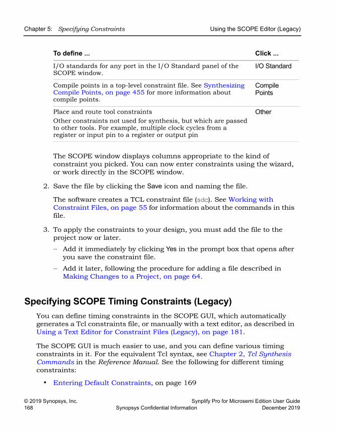
LO
Chapter 5: Specifying Constraints Using the SCOPE Editor (Legacy)
© 2019 Synopsys, Inc. Synplify Pro for Microsemi Edition User Guide168 Synopsys Confidential Information December 2019
The SCOPE window displays columns appropriate to the kind of constraint you picked. You can now enter constraints using the wizard, or work directly in the SCOPE window.
2. Save the file by clicking the Save icon and naming the file.
The software creates a TCL constraint file (sdc). See Working with Constraint Files, on page 55 for information about the commands in this file.
3. To apply the constraints to your design, you must add the file to the project now or later.
– Add it immediately by clicking Yes in the prompt box that opens after you save the constraint file.
– Add it later, following the procedure for adding a file described in Making Changes to a Project, on page 64.
Specifying SCOPE Timing Constraints (Legacy)You can define timing constraints in the SCOPE GUI, which automatically generates a Tcl constraints file, or manually with a text editor, as described in Using a Text Editor for Constraint Files (Legacy), on page 181.
The SCOPE GUI is much easier to use, and you can define various timing constraints in it. For the equivalent Tcl syntax, see Chapter 2, Tcl Synthesis Commands in the Reference Manual. See the following for different timing constraints:
• Entering Default Constraints, on page 169
I/O standards for any port in the I/O Standard panel of the SCOPE window.
I/O Standard
Compile points in a top-level constraint file. See Synthesizing Compile Points, on page 455 for more information about compile points.
Compile Points
Place and route tool constraintsOther constraints not used for synthesis, but which are passed to other tools. For example, multiple clock cycles from a register or input pin to a register or output pin
Other
To define ... Click ...
Using the SCOPE Editor (Legacy) Chapter 5: Specifying Constraints
Synplify Pro for Microsemi Edition User Guide © 2019 Synopsys, Inc.December 2019 Synopsys Confidential Information 169
• Setting Clock and Path Constraints, on page 169
• Defining Clocks, on page 171
• Defining Input and Output Constraints (Legacy), on page 178
• Specifying Standard I/O Pad Types, on page 133
To set constraints for timing exceptions like false paths and multicycle paths, see Specifying Timing Exceptions, on page 139.
Entering Default ConstraintsTo edit or set individual constraints, or to create constraints in the Other tab, work directly in the SCOPE window (Setting Clock and Path Constraints, on page 169). For auto constraints in the Synplify Pro tool, see Using Auto Constraints, on page 376. To apply the constraints, add the file to the project according to the procedure described in Making Changes to a Project, on page 64. The constraints file has an sdc extension. See Working with Constraint Files, on page 55 for more information about constraint files.
Setting Clock and Path ConstraintsThe following table summarizes how to set different clock and path constraints from the SCOPE window. For information about setting compile point constraints or attributes, see Synthesizing Compile Points, on page 455 for more information about compile points and Specifying Attributes Using the SCOPE Editor, on page 96. For information about setting default constraints, see Entering Default Constraints, on page 169.
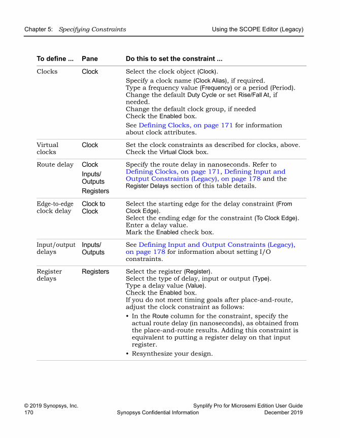
LO
Chapter 5: Specifying Constraints Using the SCOPE Editor (Legacy)
© 2019 Synopsys, Inc. Synplify Pro for Microsemi Edition User Guide170 Synopsys Confidential Information December 2019
To define ... Pane Do this to set the constraint ...
Clocks Clock Select the clock object (Clock).Specify a clock name (Clock Alias), if required.Type a frequency value (Frequency) or a period (Period). Change the default Duty Cycle or set Rise/Fall At, if needed. Change the default clock group, if neededCheck the Enabled box. See Defining Clocks, on page 171 for information about clock attributes.
Virtual clocks
Clock Set the clock constraints as described for clocks, above.Check the Virtual Clock box.
Route delay ClockInputs/OutputsRegisters
Specify the route delay in nanoseconds. Refer to Defining Clocks, on page 171, Defining Input and Output Constraints (Legacy), on page 178 and the Register Delays section of this table details.
Edge-to-edge clock delay
Clock to Clock
Select the starting edge for the delay constraint (From Clock Edge).Select the ending edge for the constraint (To Clock Edge).Enter a delay value.Mark the Enabled check box.
Input/output delays
Inputs/Outputs
See Defining Input and Output Constraints (Legacy), on page 178 for information about setting I/O constraints.
Register delays
Registers Select the register (Register).Select the type of delay, input or output (Type).Type a delay value (Value).Check the Enabled box. If you do not meet timing goals after place-and-route, adjust the clock constraint as follows:• In the Route column for the constraint, specify the
actual route delay (in nanoseconds), as obtained from the place-and-route results. Adding this constraint is equivalent to putting a register delay on that input register.
• Resynthesize your design.
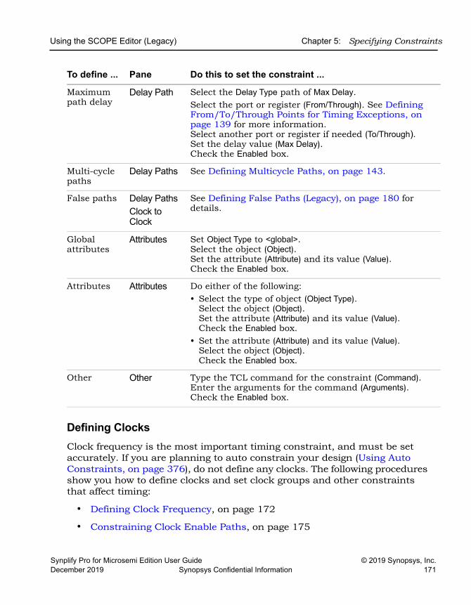
Using the SCOPE Editor (Legacy) Chapter 5: Specifying Constraints
Synplify Pro for Microsemi Edition User Guide © 2019 Synopsys, Inc.December 2019 Synopsys Confidential Information 171
Defining ClocksClock frequency is the most important timing constraint, and must be set accurately. If you are planning to auto constrain your design (Using Auto Constraints, on page 376), do not define any clocks. The following procedures show you how to define clocks and set clock groups and other constraints that affect timing:
• Defining Clock Frequency, on page 172
• Constraining Clock Enable Paths, on page 175
Maximum path delay
Delay Path Select the Delay Type path of Max Delay.Select the port or register (From/Through). See Defining From/To/Through Points for Timing Exceptions, on page 139 for more information. Select another port or register if needed (To/Through).Set the delay value (Max Delay).Check the Enabled box.
Multi-cycle paths
Delay Paths See Defining Multicycle Paths, on page 143.
False paths Delay PathsClock to Clock
See Defining False Paths (Legacy), on page 180 for details.
Global attributes
Attributes Set Object Type to <global>.Select the object (Object).Set the attribute (Attribute) and its value (Value).Check the Enabled box.
Attributes Attributes Do either of the following:• Select the type of object (Object Type).
Select the object (Object).Set the attribute (Attribute) and its value (Value).Check the Enabled box.
• Set the attribute (Attribute) and its value (Value).Select the object (Object).Check the Enabled box.
Other Other Type the TCL command for the constraint (Command).Enter the arguments for the command (Arguments).Check the Enabled box.
To define ... Pane Do this to set the constraint ...
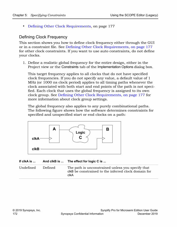
LO
Chapter 5: Specifying Constraints Using the SCOPE Editor (Legacy)
© 2019 Synopsys, Inc. Synplify Pro for Microsemi Edition User Guide172 Synopsys Confidential Information December 2019
• Defining Other Clock Requirements, on page 177
Defining Clock FrequencyThis section shows you how to define clock frequency either through the GUI or in a constraint file. See Defining Other Clock Requirements, on page 177 for other clock constraints. If you want to use auto constraints, do not define your clocks.
1. Define a realistic global frequency for the entire design, either in the Project view or the Constraints tab of the Implementation Options dialog box.
This target frequency applies to all clocks that do not have specified clock frequencies. If you do not specify any value, a default value of 1 MHz (or 1000 ns clock period) applies to all timing paths whenever the clock associated with both start and end points of the path is not speci-fied. Each clock that uses the global frequency is assigned to its own clock group. See Defining Other Clock Requirements, on page 177 for more information about clock group settings.
The global frequency also applies to any purely combinational paths. The following figure shows how the software determines constraints for specified and unspecified start or end clocks on a path:
If clkA is ... And clkB is ... The effect for logic C is ...
Undefined Defined The path is unconstrained unless you specify that clkB be constrained to the inferred clock domain for clkA
clkA
clkB
LogicC
A B
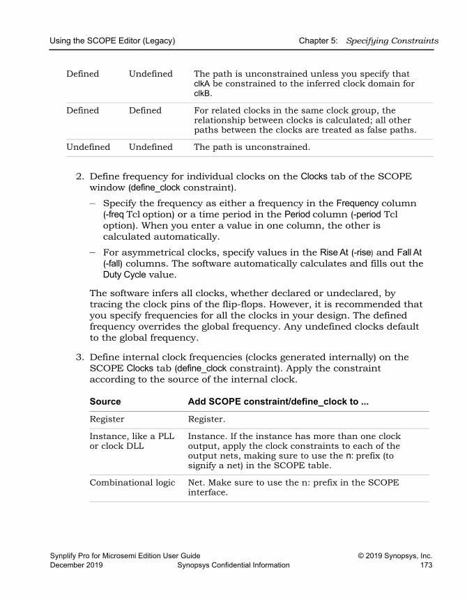
Using the SCOPE Editor (Legacy) Chapter 5: Specifying Constraints
Synplify Pro for Microsemi Edition User Guide © 2019 Synopsys, Inc.December 2019 Synopsys Confidential Information 173
2. Define frequency for individual clocks on the Clocks tab of the SCOPE window (define_clock constraint).
– Specify the frequency as either a frequency in the Frequency column (-freq Tcl option) or a time period in the Period column (-period Tcl option). When you enter a value in one column, the other is calculated automatically.
– For asymmetrical clocks, specify values in the Rise At (-rise) and Fall At (-fall) columns. The software automatically calculates and fills out the Duty Cycle value.
The software infers all clocks, whether declared or undeclared, by tracing the clock pins of the flip-flops. However, it is recommended that you specify frequencies for all the clocks in your design. The defined frequency overrides the global frequency. Any undefined clocks default to the global frequency.
3. Define internal clock frequencies (clocks generated internally) on the SCOPE Clocks tab (define_clock constraint). Apply the constraint according to the source of the internal clock.
Defined Undefined The path is unconstrained unless you specify that clkA be constrained to the inferred clock domain for clkB.
Defined Defined For related clocks in the same clock group, the relationship between clocks is calculated; all other paths between the clocks are treated as false paths.
Undefined Undefined The path is unconstrained.
Source Add SCOPE constraint/define_clock to ...
Register Register.
Instance, like a PLL or clock DLL
Instance. If the instance has more than one clock output, apply the clock constraints to each of the output nets, making sure to use the n: prefix (to signify a net) in the SCOPE table.
Combinational logic Net. Make sure to use the n: prefix in the SCOPE interface.
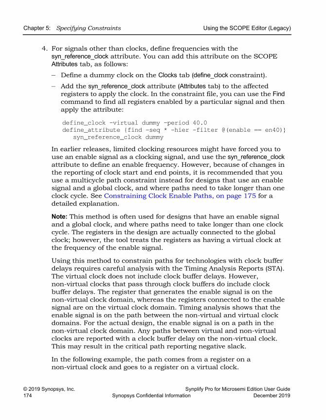
LO
Chapter 5: Specifying Constraints Using the SCOPE Editor (Legacy)
© 2019 Synopsys, Inc. Synplify Pro for Microsemi Edition User Guide174 Synopsys Confidential Information December 2019
4. For signals other than clocks, define frequencies with the syn_reference_clock attribute. You can add this attribute on the SCOPE Attributes tab, as follows:
– Define a dummy clock on the Clocks tab (define_clock constraint).
– Add the syn_reference_clock attribute (Attributes tab) to the affected registers to apply the clock. In the constraint file, you can use the Find command to find all registers enabled by a particular signal and then apply the attribute:
define_clock -virtual dummy -period 40.0 define_attribute {find -seq * -hier -filter @(enable == en40)}
syn_reference_clock dummyIn earlier releases, limited clocking resources might have forced you to use an enable signal as a clocking signal, and use the syn_reference_clock attribute to define an enable frequency. However, because of changes in the reporting of clock start and end points, it is recommended that you use a multicycle path constraint instead for designs that use an enable signal and a global clock, and where paths need to take longer than one clock cycle. See Constraining Clock Enable Paths, on page 175 for a detailed explanation.
Note: This method is often used for designs that have an enable signal and a global clock, and where paths need to take longer than one clock cycle. The registers in the design are actually connected to the global clock; however, the tool treats the registers as having a virtual clock at the frequency of the enable signal.
Using this method to constrain paths for technologies with clock buffer delays requires careful analysis with the Timing Analysis Reports (STA). The virtual clock does not include clock buffer delays. However, non-virtual clocks that pass through clock buffers do include clock buffer delays. The register that generates the enable signal is on the non-virtual clock domain, whereas the registers connected to the enable signal are on the virtual clock domain. Timing analysis shows that the enable signal is on the path between the non-virtual and virtual clock domains. For the actual design, the enable signal is on a path in the non-virtual clock domain. Any paths between virtual and non-virtual clocks are reported with a clock buffer delay on the non-virtual clock. This may result in the critical path reporting negative slack.
In the following example, the path comes from a register on a non-virtual clock and goes to a register on a virtual clock.
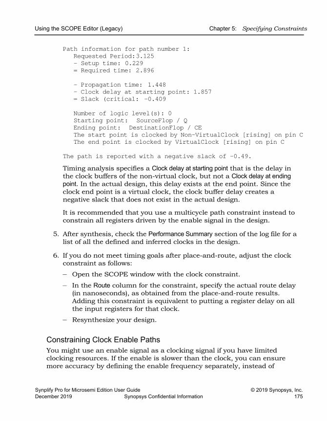
Using the SCOPE Editor (Legacy) Chapter 5: Specifying Constraints
Synplify Pro for Microsemi Edition User Guide © 2019 Synopsys, Inc.December 2019 Synopsys Confidential Information 175
Path information for path number 1:Requested Period:3.125- Setup time: 0.229= Required time: 2.896
- Propagation time: 1.448 - Clock delay at starting point: 1.857 = Slack (critical: -0.409
Number of logic level(s): 0 Starting point: SourceFlop / QEnding point: DestinationFlop / CEThe start point is clocked by Non-VirtualClock [rising] on pin CThe end point is clocked by VirtualClock [rising] on pin C
The path is reported with a negative slack of -0.49.Timing analysis specifies a Clock delay at starting point that is the delay in the clock buffers of the non-virtual clock, but not a Clock delay at ending point. In the actual design, this delay exists at the end point. Since the clock end point is a virtual clock, the clock buffer delay creates a negative slack that does not exist in the actual design.
It is recommended that you use a multicycle path constraint instead to constrain all registers driven by the enable signal in the design.
5. After synthesis, check the Performance Summary section of the log file for a list of all the defined and inferred clocks in the design.
6. If you do not meet timing goals after place-and-route, adjust the clock constraint as follows:
– Open the SCOPE window with the clock constraint.
– In the Route column for the constraint, specify the actual route delay (in nanoseconds), as obtained from the place-and-route results. Adding this constraint is equivalent to putting a register delay on all the input registers for that clock.
– Resynthesize your design.
Constraining Clock Enable PathsYou might use an enable signal as a clocking signal if you have limited clocking resources. If the enable is slower than the clock, you can ensure more accuracy by defining the enable frequency separately, instead of
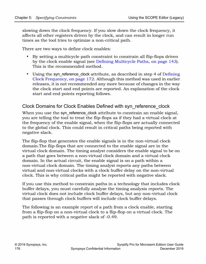
LO
Chapter 5: Specifying Constraints Using the SCOPE Editor (Legacy)
© 2019 Synopsys, Inc. Synplify Pro for Microsemi Edition User Guide176 Synopsys Confidential Information December 2019
slowing down the clock frequency. If you slow down the clock frequency, it affects all other registers driven by the clock, and can result in longer run times as the tool tries to optimize a non-critical path.
There are two ways to define clock enables:
• By setting a multicycle path constraint to constrain all flip-flops driven by the clock enable signal (see Defining Multicycle Paths, on page 143). This is the recommended method.
• Using the syn_reference_clock attribute, as described in step 4 of Defining Clock Frequency, on page 172. Although this method was used in earlier releases, it is not recommended any more because of changes in the way the clock start and end points are reported. An explanation of the clock start and end points reporting follows.
Clock Domains for Clock Enables Defined with syn_reference_clockWhen you use the syn_reference_clock attribute to constrain an enable signal, you are telling the tool to treat the flip-flops as if they had a virtual clock at the frequency of the enable signal, when the flip-flops are actually connected to the global clock. This could result in critical paths being reported with negative slack.
The flip-flop that generates the enable signals is in the non-virtual clock domain.The flip-flops that are connected to the enable signal are in the virtual clock domain. The timing analyst considers the enable signal to be on a path that goes between a non-virtual clock domain and a virtual clock domain. In the actual circuit, the enable signal is on a path within a non-virtual clock domain. The timing analyst reports any paths between virtual and non-virtual clocks with a clock buffer delay on the non-virtual clock. This is why critical paths might be reported with negative slack.
If you use this method to constrain paths in a technology that includes clock buffer delays, you must carefully analyze the timing analysis reports. The virtual clock does not include clock buffer delays, but any non-virtual clock that passes through clock buffers will include clock buffer delays.
The following is an example report of a path from a clock enable, starting from a flip-flop on a non-virtual clock to a flip-flop on a virtual clock. The path is reported with a negative slack of -0.49.
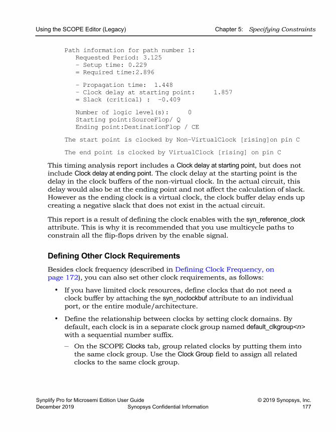
Using the SCOPE Editor (Legacy) Chapter 5: Specifying Constraints
Synplify Pro for Microsemi Edition User Guide © 2019 Synopsys, Inc.December 2019 Synopsys Confidential Information 177
Path information for path number 1:Requested Period: 3.125- Setup time: 0.229= Required time:2.896- Propagation time: 1.448- Clock delay at starting point: 1.857= Slack (critical) : -0.409Number of logic level(s): 0Starting point:SourceFlop/ QEnding point:DestinationFlop / CE
The start point is clocked by Non-VirtualClock [rising]on pin CThe end point is clocked by VirtualClock [rising] on pin C
This timing analysis report includes a Clock delay at starting point, but does not include Clock delay at ending point. The clock delay at the starting point is the delay in the clock buffers of the non-virtual clock. In the actual circuit, this delay would also be at the ending point and not affect the calculation of slack. However as the ending clock is a virtual clock, the clock buffer delay ends up creating a negative slack that does not exist in the actual circuit.
This report is a result of defining the clock enables with the syn_reference_clock attribute. This is why it is recommended that you use multicycle paths to constrain all the flip-flops driven by the enable signal.
Defining Other Clock RequirementsBesides clock frequency (described in Defining Clock Frequency, on page 172), you can also set other clock requirements, as follows:
• If you have limited clock resources, define clocks that do not need a clock buffer by attaching the syn_noclockbuf attribute to an individual port, or the entire module/architecture.
• Define the relationship between clocks by setting clock domains. By default, each clock is in a separate clock group named default_clkgroup<n> with a sequential number suffix.
– On the SCOPE Clocks tab, group related clocks by putting them into the same clock group. Use the Clock Group field to assign all related clocks to the same clock group.
LO
Chapter 5: Specifying Constraints Using the SCOPE Editor (Legacy)
© 2019 Synopsys, Inc. Synplify Pro for Microsemi Edition User Guide178 Synopsys Confidential Information December 2019
– Make sure that unrelated clocks are in different clock groups. If you do not, the software calculates timing paths between unrelated clocks in the same clock group, instead of treating them as false paths.
– Input and output ports that belong to the System clock domain are considered a part of every clock group and will be timed. See Defining Input and Output Constraints (Legacy), on page 178 for more information.
The software does not check design rules, so it is best to define the relationship between clocks as completely as possible.
• Define all gated clocks with the define_clock constraint.
Avoid using gated clocks to eliminate clock skew. If possible, move the logic to the data pin instead of using gated clocks. If you do use gated clocks, you must define them explicitly, because the software does not propagate the frequency of clock ports to gated clocks.
To define a gated clock, attach the define_clock constraint to the clock source, as described above for internal clocks. To attach the constraint to a keepbuf (a keepbuf is a placeholder instance for clocks generated from combinational logic), do the following:
– Attach the syn_keep attribute to the gated clock to ensure that it retains the same name through changes to the RTL code.
– Attach the define_clock constraint to the net or pin connected to the keepbuf instance generated for the gated clock.
• Specify edge-to-edge clock delays on the Clock to Clock tab (define_-clock_delay).
• After synthesis, check the Performance Summary section of the log file for a list of all the defined and inferred clocks in the design.
Defining Input and Output Constraints (Legacy)In addition to setting I/O delays in the SCOPE window as described in Setting Clock and Path Constraints, on page 169, you can also set the Use clock period for unconstrained IO option.
• Open the SCOPE window, click Inputs/Outputs, and select the port (Port). You can set the constraint for
– All inputs and outputs (globally in the top-level netlist)
Using the SCOPE Editor (Legacy) Chapter 5: Specifying Constraints
Synplify Pro for Microsemi Edition User Guide © 2019 Synopsys, Inc.December 2019 Synopsys Confidential Information 179
– For a whole bus
– For single bits
You can specify multiple constraints for the same port. The software applies all the constraints; the tightest constraint determines the worst slack. If there are multiple constraints from different levels, the most specific overrides the more global. For example, if there are two bit constraints and two port constraints, the two bit constraints override the two port constraints for that bit. The other bits get the two port constraints.
• Specify the constraint value in the SCOPE window:
– Select the type of delay: input or output (Type).
– Type a delay value (Value).
– Check the Enabled box, and save the constraint file in the project.
Make sure to specify explicit constraints for each I/O path you want to constrain.
• To determine how the I/O constraints are used during synthesis, do the following:
– Select Project->Implementation Options, and click Constraints. – To use only the explicitly defined constraints disable Use clock period for
unconstrained IO.
– To synthesize with all the constraints, using the clock period for all I/O paths that do not have an explicit constraint enable Use clock period for unconstrained IO.
– Synthesize the design. When you forward-annotate the constraints, the constraints used for synthesis are forward-annotated for place-and-route.
• Input or output ports with explicitly defined constraints, but without a reference clock (-ref option) are included in the System clock domain and are considered to belong to every defined or inferred clock group.
• If you do not meet timing goals after place-and-route and you need to adjust the input constraints; do the following:
– Open the SCOPE window with the input constraint.
– In the Route column for the input constraint, specify the actual route delay in nanoseconds, as obtained from the place-and-route results.
LO
Chapter 5: Specifying Constraints Using the SCOPE Editor (Legacy)
© 2019 Synopsys, Inc. Synplify Pro for Microsemi Edition User Guide180 Synopsys Confidential Information December 2019
Adding this constraint is equivalent to putting a register delay on the input register.
– Resynthesize your design.
Defining False Paths (Legacy)You define false paths by setting constraints explicitly on the Delay Paths tab or implicitly on the Clock and Clock to Clock tabs. See Defining From/To/Through Points for Timing Exceptions, on page 139 for object naming and specifying through points.
• To define a false path between ports or registers, select the SCOPE Delay Paths tab, and do the following:
– From the Delay Type pull-down menu, select False.
– Use the pull-down to select the port or register from the appropriate column (From/To/Through).
– Check the Enabled box.
The software treats this as an explicit false constraint and assigns it the highest priority. Any other constraints on this path are ignored.
• To define a false path between two clocks, select the SCOPE Clocks tab, and assign the clocks to different clock groups:
The software implicitly assumes a false path between clocks in different clock groups. This false path constraint can be overridden by a maximum path delay constraint, or with an explicit constraint.
• To define a false path between two clock edges, select the SCOPE Clock to Clock tab, and do the following:
– Specify one clock as the starting clock edge (From Clock Edge).
– Specify the other clock as the ending clock edge (To Clock Edge).
– Click in the Delay column, and select false.
– Mark the Enabled check box.
Use this technique to specify a false path between any two clocks, regardless of clock groups. This constraint can be overridden by a maximum delay constraint on the same path
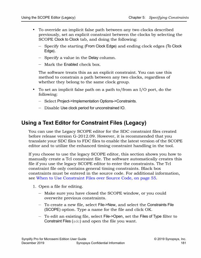
Using the SCOPE Editor (Legacy) Chapter 5: Specifying Constraints
Synplify Pro for Microsemi Edition User Guide © 2019 Synopsys, Inc.December 2019 Synopsys Confidential Information 181
• To override an implicit false path between any two clocks described previously, set an explicit constraint between the clocks by selecting the SCOPE Clock to Clock tab, and doing the following:
– Specify the starting (From Clock Edge) and ending clock edges (To Clock Edge).
– Specify a value in the Delay column.
– Mark the Enabled check box.
The software treats this as an explicit constraint. You can use this method to constrain a path between any two clocks, regardless of whether they belong to the same clock group.
• To set an implicit false path on a path to/from an I/O port, do the following:
– Select Project->Implementation Options->Constraints.
– Disable Use clock period for unconstrained IO.
Using a Text Editor for Constraint Files (Legacy)You can use the Legacy SCOPE editor for the SDC constraint files created before release version G-2012.09. However, it is recommended that you translate your SDC files to FDC files to enable the latest version of the SCOPE editor and to utilize the enhanced timing constraint handling in the tool.
If you choose to use the legacy SCOPE editor, this section shows you how to manually create a Tcl constraint file. The software automatically creates this file if you use the legacy SCOPE editor to enter the constraints. The Tcl constraint file only contains general timing constraints. Black box constraints must be entered in the source code. For additional information, see When to Use Constraint Files over Source Code, on page 55.
1. Open a file for editing.
– Make sure you have closed the SCOPE window, or you could overwrite previous constraints.
– To create a new file, select File->New, and select the Constraints File (SCOPE) option. Type a name for the file and click OK.
– To edit an existing file, select File->Open, set the Files of Type filter to Constraint Files (sdc) and open the file you want.
LO
Chapter 5: Specifying Constraints Using the SCOPE Editor (Legacy)
© 2019 Synopsys, Inc. Synplify Pro for Microsemi Edition User Guide182 Synopsys Confidential Information December 2019
2. Follow the syntax guidelines in Tcl Syntax Guidelines for Constraint Files, on page 55.
3. Enter the timing constraints you need. For the syntax, see the Reference Manual. If you have black box timing constraints, you must enter them in the source code.
4. You can also add vendor-specific attributes in the constraint file using define_attribute. See Specifying Attributes in the Constraints File, on page 100 for more information.
5. Save the file.
6. Add the file to the project as described in Making Changes to a Project, on page 64, and run synthesis.
Synplify Pro for Microsemi Edition User Guide © 2019 Synopsys, Inc.December 2019 Synopsys Confidential Information 183
C H A P T E R 6
Synthesizing and Analyzing the Results
This chapter describes how to run synthesis, and how to analyze the log file generated after synthesis. See the following:
• Synthesizing Your Design, on page 184
• Checking Log File Results, on page 189
• Handling Messages, on page 205
• Using Continue on Error, on page 219
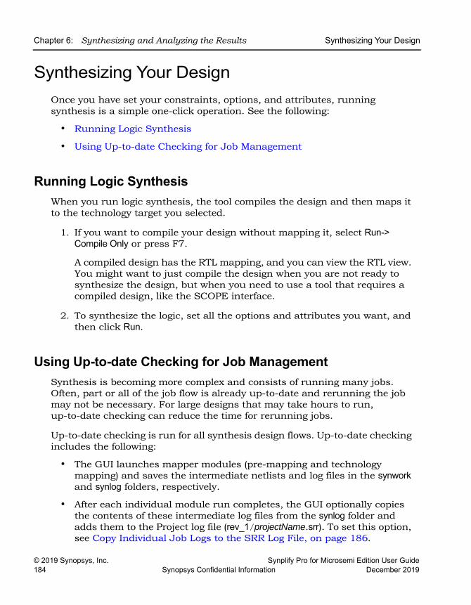
LO
Chapter 6: Synthesizing and Analyzing the Results Synthesizing Your Design
© 2019 Synopsys, Inc. Synplify Pro for Microsemi Edition User Guide184 Synopsys Confidential Information December 2019
Synthesizing Your DesignOnce you have set your constraints, options, and attributes, running synthesis is a simple one-click operation. See the following:
• Running Logic Synthesis
• Using Up-to-date Checking for Job Management
Running Logic SynthesisWhen you run logic synthesis, the tool compiles the design and then maps it to the technology target you selected.
1. If you want to compile your design without mapping it, select Run-> Compile Only or press F7.
A compiled design has the RTL mapping, and you can view the RTL view. You might want to just compile the design when you are not ready to synthesize the design, but when you need to use a tool that requires a compiled design, like the SCOPE interface.
2. To synthesize the logic, set all the options and attributes you want, and then click Run.
Using Up-to-date Checking for Job ManagementSynthesis is becoming more complex and consists of running many jobs. Often, part or all of the job flow is already up-to-date and rerunning the job may not be necessary. For large designs that may take hours to run, up-to-date checking can reduce the time for rerunning jobs.
Up-to-date checking is run for all synthesis design flows. Up-to-date checking includes the following:
• The GUI launches mapper modules (pre-mapping and technology mapping) and saves the intermediate netlists and log files in the synwork and synlog folders, respectively.
• After each individual module run completes, the GUI optionally copies the contents of these intermediate log files from the synlog folder and adds them to the Project log file (rev_1/projectName.srr). To set this option, see Copy Individual Job Logs to the SRR Log File, on page 186.
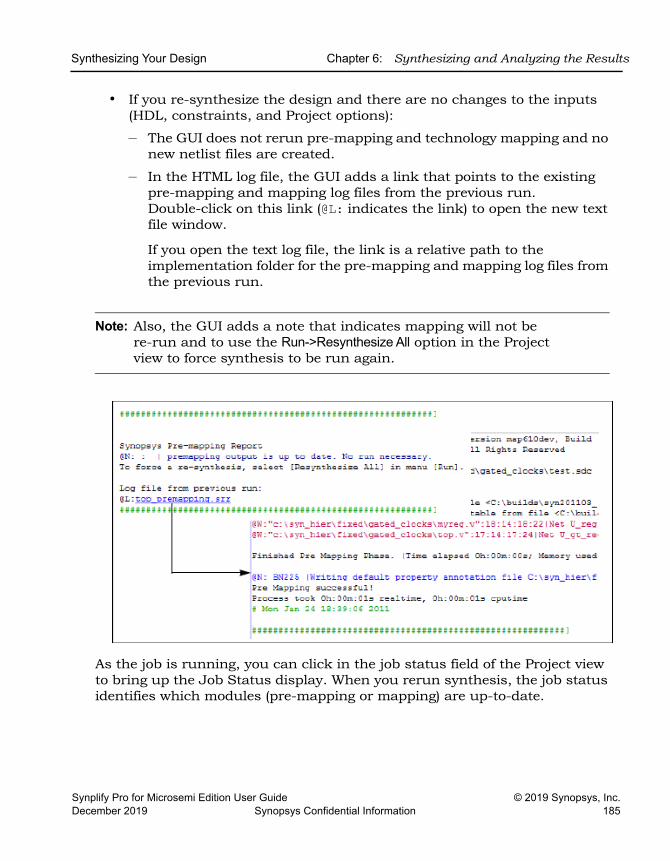
Synthesizing Your Design Chapter 6: Synthesizing and Analyzing the Results
Synplify Pro for Microsemi Edition User Guide © 2019 Synopsys, Inc.December 2019 Synopsys Confidential Information 185
• If you re-synthesize the design and there are no changes to the inputs (HDL, constraints, and Project options):
– The GUI does not rerun pre-mapping and technology mapping and no new netlist files are created.
– In the HTML log file, the GUI adds a link that points to the existing pre-mapping and mapping log files from the previous run. Double-click on this link (@L: indicates the link) to open the new text file window.
If you open the text log file, the link is a relative path to the implementation folder for the pre-mapping and mapping log files from the previous run.
Note: Also, the GUI adds a note that indicates mapping will not be re-run and to use the Run->Resynthesize All option in the Project view to force synthesis to be run again.
As the job is running, you can click in the job status field of the Project view to bring up the Job Status display. When you rerun synthesis, the job status identifies which modules (pre-mapping or mapping) are up-to-date.
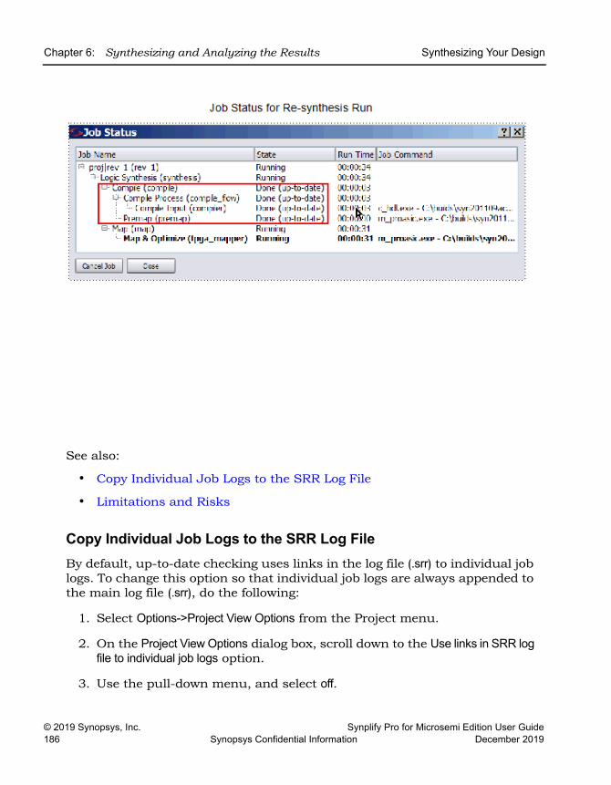
LO
Chapter 6: Synthesizing and Analyzing the Results Synthesizing Your Design
© 2019 Synopsys, Inc. Synplify Pro for Microsemi Edition User Guide186 Synopsys Confidential Information December 2019
See also:
• Copy Individual Job Logs to the SRR Log File
• Limitations and Risks
Copy Individual Job Logs to the SRR Log FileBy default, up-to-date checking uses links in the log file (.srr) to individual job logs. To change this option so that individual job logs are always appended to the main log file (.srr), do the following:
1. Select Options->Project View Options from the Project menu.
2. On the Project View Options dialog box, scroll down to the Use links in SRR log file to individual job logs option.
3. Use the pull-down menu, and select off.
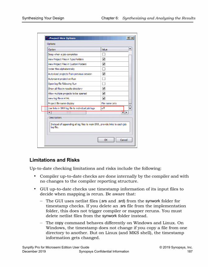
Synthesizing Your Design Chapter 6: Synthesizing and Analyzing the Results
Synplify Pro for Microsemi Edition User Guide © 2019 Synopsys, Inc.December 2019 Synopsys Confidential Information 187
Limitations and RisksUp-to-date checking limitations and risks include the following:
• Compiler up-to-date checks are done internally by the compiler and with no changes to the compiler reporting structure.
• GUI up-to-date checks use timestamp information of its input files to decide when mapping is rerun. Be aware that:
– The GUI uses netlist files (.srs and .srd) from the synwork folder for timestamp checks. If you delete an .srs file from the implementation folder, this does not trigger compiler or mapper reruns. You must delete netlist files from the synwork folder instead.
– The copy command behaves differently on Windows and Linux. On Windows, the timestamp does not change if you copy a file from one directory to another. But on Linux (and MKS shell), the timestamp information gets changed.

LO
Chapter 6: Synthesizing and Analyzing the Results Synthesizing Your Design
© 2019 Synopsys, Inc. Synplify Pro for Microsemi Edition User Guide188 Synopsys Confidential Information December 2019
• When running a design, the up-to-date checking feature automatically determines if the design needs to be re-synthesized. However, when you modify constraints in a Tcl file sourced within the constraints file, the software is not aware of these changes and does not force the design to be re-synthesized.
Checking Log File Results Chapter 6: Synthesizing and Analyzing the Results
Synplify Pro for Microsemi Edition User Guide © 2019 Synopsys, Inc.December 2019 Synopsys Confidential Information 189
Checking Log File ResultsYou can check the log file for information about the synthesis run. In addition, the user interface has a Tcl Script window, that echoes each command as it is run. The following describe different ways to check the results of your run:
• Viewing and Working with the Log File, on page 189
• Accessing Specific Reports Quickly, on page 193
• Accessing Results Remotely, on page 195
• Analyzing Results Using the Log File Reports, on page 199
• Using the Watch Window, on page 199
• Checking Resource Usage, on page 201
• Querying Metrics for a Design, on page 203
Viewing and Working with the Log FileThe log file contains the most comprehensive results and information about a synthesis run. The default log file is in HTML format, but there is a text version available too.
For users who only want to check a few critical performance criteria, it is easier to use the Watch Window (see Using the Watch Window, on page 199) instead of the log file. For details, read through the log file.
1. To open the log file, use one of these listed methods, according to the format you want:
HTML • Select View->Log File. • Click the View Log button in the Project window. • Double-click the designName.htm file in the Implementation Results
view.
Text Double-click the designName.srr file in the Implementation Results view. To set the text file version to open by default instead of the HTML version, select Options->Project View Options, and toggle off the View log file in HTML option.
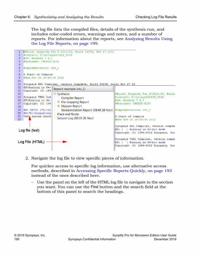
LO
Chapter 6: Synthesizing and Analyzing the Results Checking Log File Results
© 2019 Synopsys, Inc. Synplify Pro for Microsemi Edition User Guide190 Synopsys Confidential Information December 2019
The log file lists the compiled files, details of the synthesis run, and includes color-coded errors, warnings and notes, and a number of reports. For information about the reports, see Analyzing Results Using the Log File Reports, on page 199.
2. Navigate the log file to view specific pieces of information.
For quicker access to specific log information, use alternative access methods, described in Accessing Specific Reports Quickly, on page 193 instead of the ones described here.
– Use the panel on the left of the HTML log file to navigate to the section you want. You can use the Find button and the search field at the bottom of this panel to search the headings.
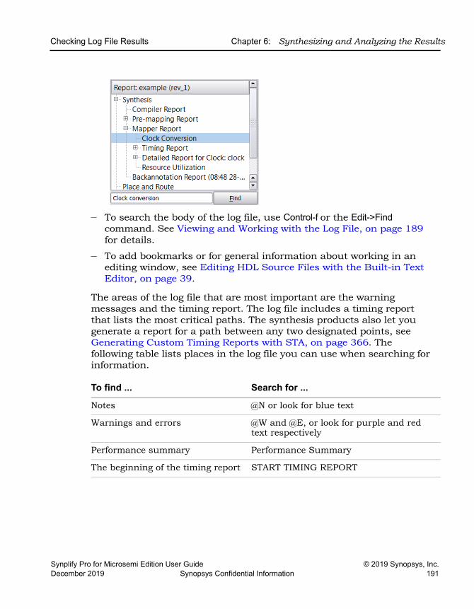
Checking Log File Results Chapter 6: Synthesizing and Analyzing the Results
Synplify Pro for Microsemi Edition User Guide © 2019 Synopsys, Inc.December 2019 Synopsys Confidential Information 191
– To search the body of the log file, use Control-f or the Edit->Find command. See Viewing and Working with the Log File, on page 189 for details.
– To add bookmarks or for general information about working in an editing window, see Editing HDL Source Files with the Built-in Text Editor, on page 39.
The areas of the log file that are most important are the warning messages and the timing report. The log file includes a timing report that lists the most critical paths. The synthesis products also let you generate a report for a path between any two designated points, see Generating Custom Timing Reports with STA, on page 366. The following table lists places in the log file you can use when searching for information.
To find ... Search for ...
Notes @N or look for blue text
Warnings and errors @W and @E, or look for purple and red text respectively
Performance summary Performance Summary
The beginning of the timing report START TIMING REPORT
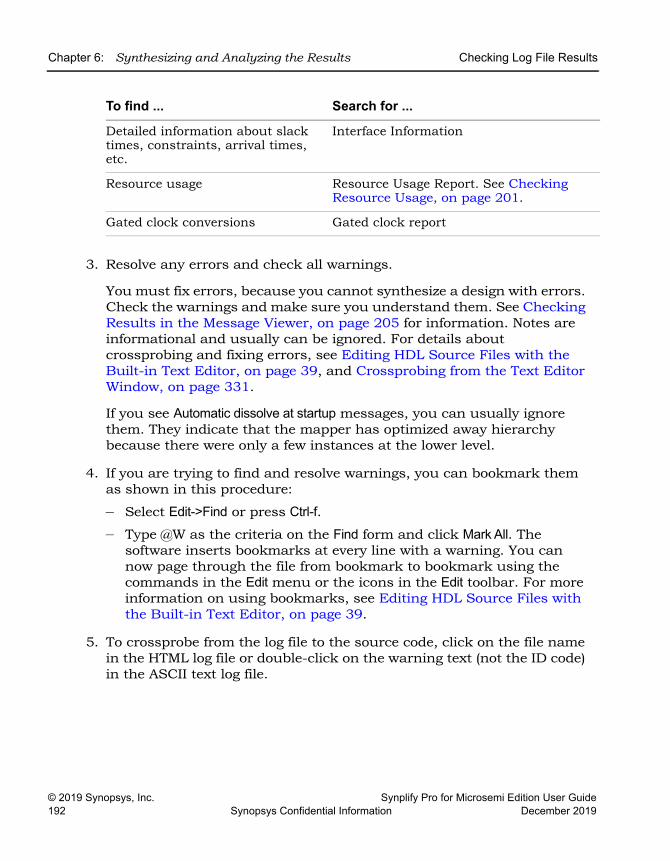
LO
Chapter 6: Synthesizing and Analyzing the Results Checking Log File Results
© 2019 Synopsys, Inc. Synplify Pro for Microsemi Edition User Guide192 Synopsys Confidential Information December 2019
3. Resolve any errors and check all warnings.
You must fix errors, because you cannot synthesize a design with errors. Check the warnings and make sure you understand them. See Checking Results in the Message Viewer, on page 205 for information. Notes are informational and usually can be ignored. For details about crossprobing and fixing errors, see Editing HDL Source Files with the Built-in Text Editor, on page 39, and Crossprobing from the Text Editor Window, on page 331.
If you see Automatic dissolve at startup messages, you can usually ignore them. They indicate that the mapper has optimized away hierarchy because there were only a few instances at the lower level.
4. If you are trying to find and resolve warnings, you can bookmark them as shown in this procedure:
– Select Edit->Find or press Ctrl-f. – Type @W as the criteria on the Find form and click Mark All. The
software inserts bookmarks at every line with a warning. You can now page through the file from bookmark to bookmark using the commands in the Edit menu or the icons in the Edit toolbar. For more information on using bookmarks, see Editing HDL Source Files with the Built-in Text Editor, on page 39.
5. To crossprobe from the log file to the source code, click on the file name in the HTML log file or double-click on the warning text (not the ID code) in the ASCII text log file.
Detailed information about slack times, constraints, arrival times, etc.
Interface Information
Resource usage Resource Usage Report. See Checking Resource Usage, on page 201.
Gated clock conversions Gated clock report
To find ... Search for ...
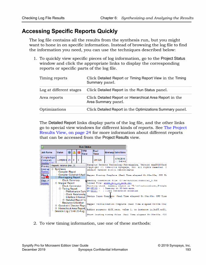
Checking Log File Results Chapter 6: Synthesizing and Analyzing the Results
Synplify Pro for Microsemi Edition User Guide © 2019 Synopsys, Inc.December 2019 Synopsys Confidential Information 193
Accessing Specific Reports QuicklyThe log file contains all the results from the synthesis run, but you might want to hone in on specific information. Instead of browsing the log file to find the information you need, you can use the techniques described below:
1. To quickly view specific pieces of log information, go to the Project Status window and click the appropriate links to display the corresponding reports or specific parts of the log file.
The Detailed Report links display parts of the log file, and the other links go to special view windows for different kinds of reports. See The Project Results View, on page 24 for more information about different reports that can be accessed from the Project Results view.
2. To view timing information, use one of these methods:
Timing reports Click Detailed Report or Timing Report View in the Timing Summary panel.
Log at different stages Click Detailed Report in the Run Status panel.
Area reports Click Detailed Report or Hierarchical Area Report in the Area Summary panel.
Optimizations Click Detailed Report in the Optimizations Summary panel.
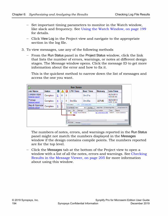
LO
Chapter 6: Synthesizing and Analyzing the Results Checking Log File Results
© 2019 Synopsys, Inc. Synplify Pro for Microsemi Edition User Guide194 Synopsys Confidential Information December 2019
– Set important timing parameters to monitor in the Watch window, like slack and frequency. See Using the Watch Window, on page 199 for details.
– Click View Log in the Project view and navigate to the appropriate section in the log file.
3. To view messages, use any of the following methods
– From the Run Status panel in the Project Status window, click the link that lists the number of errors, warnings, or notes at different design stages. The Message window opens. Click the message ID to get more information about the error and how to fix it.
This is the quickest method to narrow down the list of messages and access the one you want.
The numbers of notes, errors, and warnings reported in the Run Status panel might not match the numbers displayed in the Messages window if the design contains compile points. The numbers reported are for the top level.
– Click the Messages tab at the bottom of the Project view to open a window with a list of all the notes, errors and warnings. See Checking Results in the Message Viewer, on page 205 for more information about using this window.
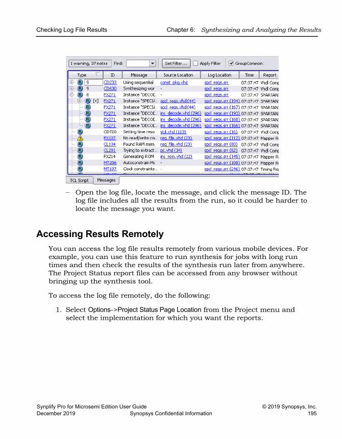
Checking Log File Results Chapter 6: Synthesizing and Analyzing the Results
Synplify Pro for Microsemi Edition User Guide © 2019 Synopsys, Inc.December 2019 Synopsys Confidential Information 195
– Open the log file, locate the message, and click the message ID. The log file includes all the results from the run, so it could be harder to locate the message you want.
Accessing Results RemotelyYou can access the log file results remotely from various mobile devices. For example, you can use this feature to run synthesis for jobs with long run times and then check the results of the synthesis run later from anywhere. The Project Status report files can be accessed from any browser without bringing up the synthesis tool.
To access the log file remotely, do the following:
1. Select Options->Project Status Page Location from the Project menu and select the implementation for which you want the reports.
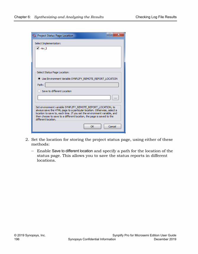
LO
Chapter 6: Synthesizing and Analyzing the Results Checking Log File Results
© 2019 Synopsys, Inc. Synplify Pro for Microsemi Edition User Guide196 Synopsys Confidential Information December 2019
2. Set the location for storing the project status page, using either of these methods:
– Enable Save to different location and specify a path for the location of the status page. This allows you to save the status reports in different locations.
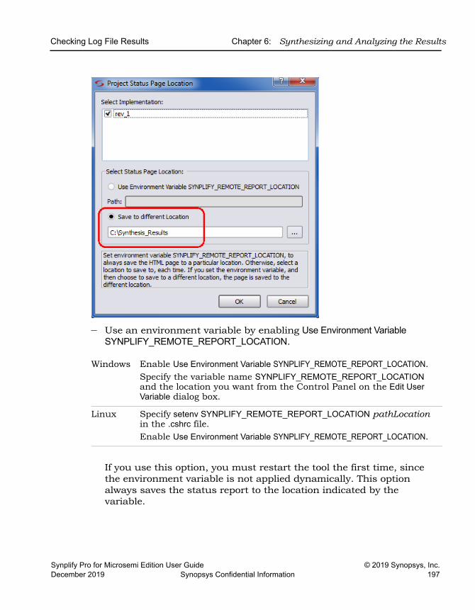
Checking Log File Results Chapter 6: Synthesizing and Analyzing the Results
Synplify Pro for Microsemi Edition User Guide © 2019 Synopsys, Inc.December 2019 Synopsys Confidential Information 197
– Use an environment variable by enabling Use Environment Variable SYNPLIFY_REMOTE_REPORT_LOCATION.
If you use this option, you must restart the tool the first time, since the environment variable is not applied dynamically. This option always saves the status report to the location indicated by the variable.
Windows Enable Use Environment Variable SYNPLIFY_REMOTE_REPORT_LOCATION. Specify the variable name SYNPLIFY_REMOTE_REPORT_LOCATION and the location you want from the Control Panel on the Edit User Variable dialog box.
Linux Specify setenv SYNPLIFY_REMOTE_REPORT_LOCATION pathLocation in the .cshrc file. Enable Use Environment Variable SYNPLIFY_REMOTE_REPORT_LOCATION.
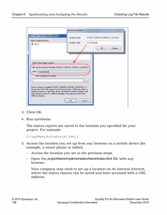
LO
Chapter 6: Synthesizing and Analyzing the Results Checking Log File Results
© 2019 Synopsys, Inc. Synplify Pro for Microsemi Edition User Guide198 Synopsys Confidential Information December 2019
3. Click OK.
4. Run synthesis.
The status reports are saved to the location you specified for your project. For example:
C:\synResults\tutorial\rev_15. Access the location you set up from any browser on a mobile device (for
example, a smart phone or tablet).
– Access the location you set in the previous steps.
– Open the projectName/implementationName/index.html file with any browser.
Your company may need to set up a location on its internal internet, where the status reports can be saved and later accessed with a URL address.
Checking Log File Results Chapter 6: Synthesizing and Analyzing the Results
Synplify Pro for Microsemi Edition User Guide © 2019 Synopsys, Inc.December 2019 Synopsys Confidential Information 199
Analyzing Results Using the Log File ReportsThe log file contains technology-appropriate reports like timing reports, resource usage reports, and net buffering reports, in addition to any notes, errors, and warning messages.
1. To analyze timing results, do the following:
– View the Timing Report (Performance Summary section of the log file) and check the slack times. See Handling Negative Slack, on page 364 for details.
– Check the detailed information for the critical paths, including the setup requirements at the end of the detailed critical path description. You can crossprobe and view the information graphically and determine how to improve the timing.
– In the HTML log file, click the link to open up the HDL Analyst view for the path with the worst slack.
To generate timing information for a path between any two designated points, see Generating Custom Timing Reports with STA, on page 366.
2. To check buffers, do the following:
– Check the report by going to the Net Buffering Report section of the log file.
– Check the number of buffers or registers added or replicated and determine whether this fits into your design optimization strategy.
3. To check logic resources, check the Resource Usage Report section at the end of the log file, as described in Checking Resource Usage, on page 201.
Using the Watch WindowThe Watch window provides a more convenient viewing mechanism than the log file for quickly checking key performance criteria or comparing results from different runs. Its limitation is that it only displays certain criteria. If you need details, use the log file, as described in Viewing and Working with the Log File, on page 189.
1. Open the Watch window, if needed, by checking View->Watch Window.
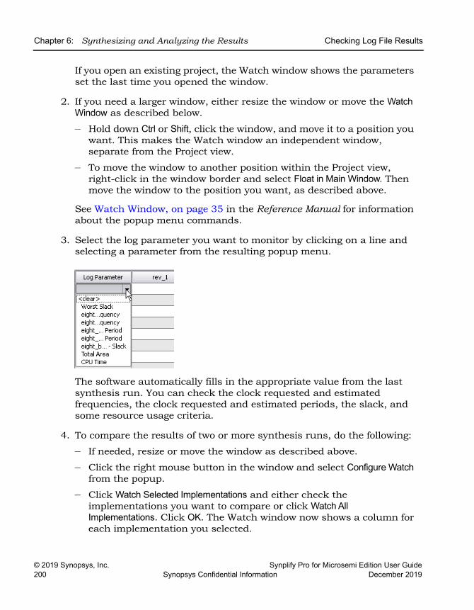
LO
Chapter 6: Synthesizing and Analyzing the Results Checking Log File Results
© 2019 Synopsys, Inc. Synplify Pro for Microsemi Edition User Guide200 Synopsys Confidential Information December 2019
If you open an existing project, the Watch window shows the parameters set the last time you opened the window.
2. If you need a larger window, either resize the window or move the Watch Window as described below.
– Hold down Ctrl or Shift, click the window, and move it to a position you want. This makes the Watch window an independent window, separate from the Project view.
– To move the window to another position within the Project view, right-click in the window border and select Float in Main Window. Then move the window to the position you want, as described above.
See Watch Window, on page 35 in the Reference Manual for information about the popup menu commands.
3. Select the log parameter you want to monitor by clicking on a line and selecting a parameter from the resulting popup menu.
The software automatically fills in the appropriate value from the last synthesis run. You can check the clock requested and estimated frequencies, the clock requested and estimated periods, the slack, and some resource usage criteria.
4. To compare the results of two or more synthesis runs, do the following:
– If needed, resize or move the window as described above.
– Click the right mouse button in the window and select Configure Watch from the popup.
– Click Watch Selected Implementations and either check the implementations you want to compare or click Watch All Implementations. Click OK. The Watch window now shows a column for each implementation you selected.
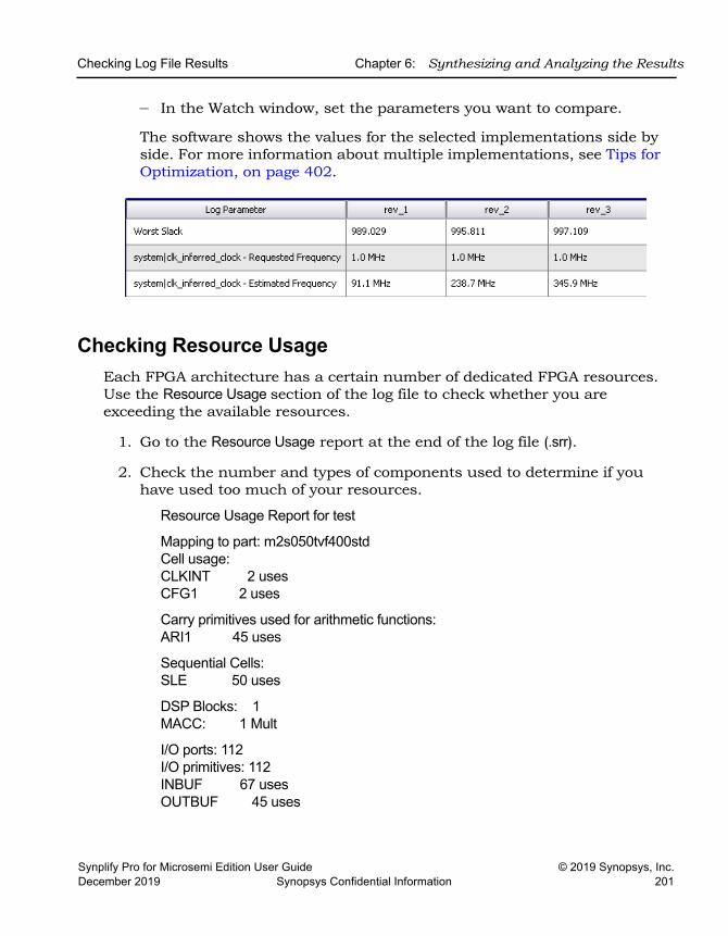
Checking Log File Results Chapter 6: Synthesizing and Analyzing the Results
Synplify Pro for Microsemi Edition User Guide © 2019 Synopsys, Inc.December 2019 Synopsys Confidential Information 201
– In the Watch window, set the parameters you want to compare.
The software shows the values for the selected implementations side by side. For more information about multiple implementations, see Tips for Optimization, on page 402.
Checking Resource UsageEach FPGA architecture has a certain number of dedicated FPGA resources. Use the Resource Usage section of the log file to check whether you are exceeding the available resources.
1. Go to the Resource Usage report at the end of the log file (.srr).
2. Check the number and types of components used to determine if you have used too much of your resources.
Resource Usage Report for test
Mapping to part: m2s050tvf400std Cell usage: CLKINT 2 uses CFG1 2 uses
Carry primitives used for arithmetic functions: ARI1 45 uses
Sequential Cells: SLE 50 uses
DSP Blocks: 1 MACC: 1 Mult
I/O ports: 112 I/O primitives: 112 INBUF 67 uses OUTBUF 45 uses
LO
Chapter 6: Synthesizing and Analyzing the Results Checking Log File Results
© 2019 Synopsys, Inc. Synplify Pro for Microsemi Edition User Guide202 Synopsys Confidential Information December 2019
3. For technology-specific designs, you can also check the hierarchical area report (projectName.areasrr).
This file contains the percentage utilization for various elements in the design. See Hierarchical Area Report, on page 170 in the Reference Manual for more about this file.
If your design is overutilized, you can manage usage with resource-specific attributes like syn_ramstyle, syn_dspstyle, and so on. For hierarchical designs you can set limits with attributes like syn_allowed_resources or the Allocate Timing and Resource Budgets command.
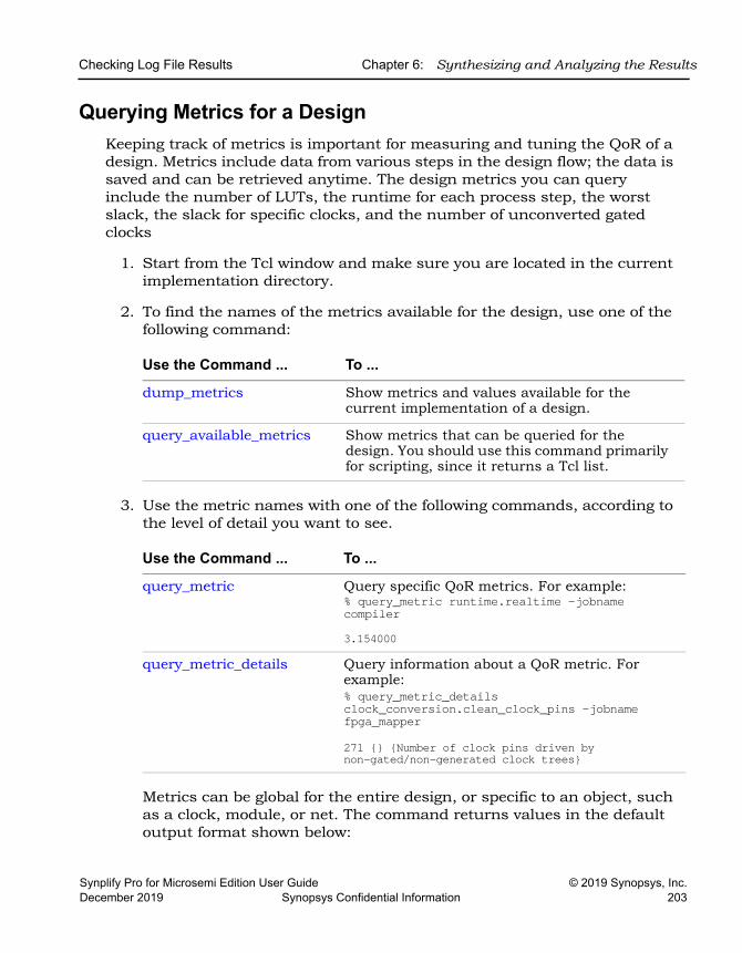
Checking Log File Results Chapter 6: Synthesizing and Analyzing the Results
Synplify Pro for Microsemi Edition User Guide © 2019 Synopsys, Inc.December 2019 Synopsys Confidential Information 203
Querying Metrics for a DesignKeeping track of metrics is important for measuring and tuning the QoR of a design. Metrics include data from various steps in the design flow; the data is saved and can be retrieved anytime. The design metrics you can query include the number of LUTs, the runtime for each process step, the worst slack, the slack for specific clocks, and the number of unconverted gated clocks
1. Start from the Tcl window and make sure you are located in the current implementation directory.
2. To find the names of the metrics available for the design, use one of the following command:
3. Use the metric names with one of the following commands, according to the level of detail you want to see.
Metrics can be global for the entire design, or specific to an object, such as a clock, module, or net. The command returns values in the default output format shown below:
Use the Command ... To ...
dump_metrics Show metrics and values available for the current implementation of a design.
query_available_metrics Show metrics that can be queried for the design. You should use this command primarily for scripting, since it returns a Tcl list.
Use the Command ... To ...
query_metric Query specific QoR metrics. For example:% query_metric runtime.realtime -jobname compiler3.154000
query_metric_details Query information about a QoR metric. For example:% query_metric_details clock_conversion.clean_clock_pins -jobname fpga_mapper271 {} {Number of clock pins driven by non-gated/non-generated clock trees}
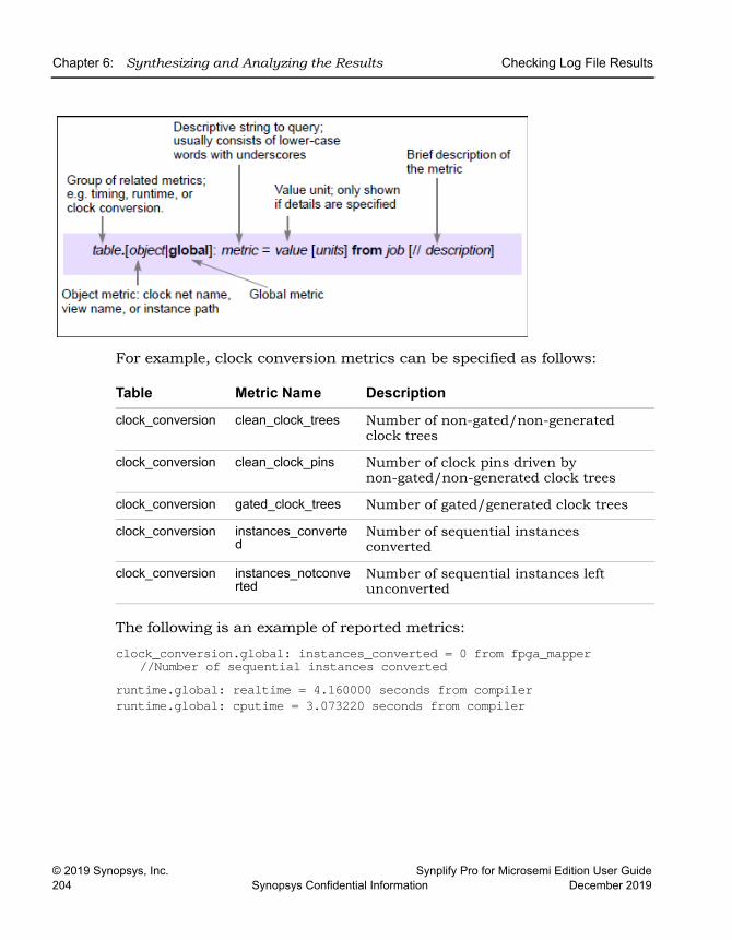
LO
Chapter 6: Synthesizing and Analyzing the Results Checking Log File Results
© 2019 Synopsys, Inc. Synplify Pro for Microsemi Edition User Guide204 Synopsys Confidential Information December 2019
For example, clock conversion metrics can be specified as follows:
The following is an example of reported metrics:
clock_conversion.global: instances_converted = 0 from fpga_mapper//Number of sequential instances converted
runtime.global: realtime = 4.160000 seconds from compilerruntime.global: cputime = 3.073220 seconds from compiler
Table Metric Name Description
clock_conversion clean_clock_trees Number of non-gated/non-generated clock trees
clock_conversion clean_clock_pins Number of clock pins driven by non-gated/non-generated clock trees
clock_conversion gated_clock_trees Number of gated/generated clock trees
clock_conversion instances_converted
Number of sequential instances converted
clock_conversion instances_notconverted
Number of sequential instances left unconverted
Handling Messages Chapter 6: Synthesizing and Analyzing the Results
Synplify Pro for Microsemi Edition User Guide © 2019 Synopsys, Inc.December 2019 Synopsys Confidential Information 205
Handling Messages This section describes how to work with the error messages, notes, and warnings that result after a run. See the following for details:
• Checking Results in the Message Viewer, on page 205
• Filtering Messages in the Message Viewer, on page 207
• Filtering Messages from the Command Line, on page 209
• Automating Message Filtering with a Tcl Script, on page 210
• Log File Message Controls, on page 213
• Working with Downgradable Errors and Critical Warnings, on page 216
Checking Results in the Message ViewerThe Tcl Script window includes a Message Viewer. By default, the Tcl window is in the lower left corner of the main window. This procedure shows you how to check results in the message viewer.
1. If you need a larger window, either resize the window or move the Tcl window. Click in the window border and move it to a position you want. You can float it outside the main window or move it to another position within the main window.
2. Click the Messages tab to open the message viewer.
The window lists the errors, warnings, and notes in a spreadsheet format. See Message Viewer, on page 39 in the Reference Manual for a full description of the window.
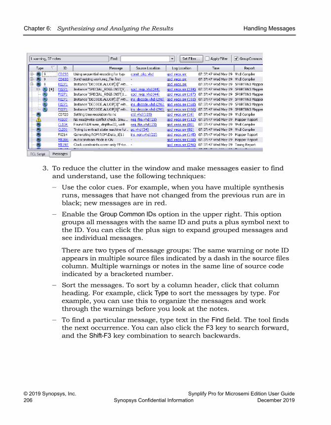
LO
Chapter 6: Synthesizing and Analyzing the Results Handling Messages
© 2019 Synopsys, Inc. Synplify Pro for Microsemi Edition User Guide206 Synopsys Confidential Information December 2019
3. To reduce the clutter in the window and make messages easier to find and understand, use the following techniques:
– Use the color cues. For example, when you have multiple synthesis runs, messages that have not changed from the previous run are in black; new messages are in red.
– Enable the Group Common IDs option in the upper right. This option groups all messages with the same ID and puts a plus symbol next to the ID. You can click the plus sign to expand grouped messages and see individual messages.
There are two types of message groups: The same warning or note ID appears in multiple source files indicated by a dash in the source files column. Multiple warnings or notes in the same line of source code indicated by a bracketed number.
– Sort the messages. To sort by a column header, click that column heading. For example, click Type to sort the messages by type. For example, you can use this to organize the messages and work through the warnings before you look at the notes.
– To find a particular message, type text in the Find field. The tool finds the next occurrence. You can also click the F3 key to search forward, and the Shift-F3 key combination to search backwards.
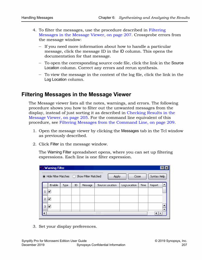
Handling Messages Chapter 6: Synthesizing and Analyzing the Results
Synplify Pro for Microsemi Edition User Guide © 2019 Synopsys, Inc.December 2019 Synopsys Confidential Information 207
4. To filter the messages, use the procedure described in Filtering Messages in the Message Viewer, on page 207. Crossprobe errors from the message window:
– If you need more information about how to handle a particular message, click the message ID in the ID column. This opens the documentation for that message.
– To open the corresponding source code file, click the link in the Source Location column. Correct any errors and rerun synthesis.
– To view the message in the context of the log file, click the link in the Log Location column.
Filtering Messages in the Message ViewerThe Message viewer lists all the notes, warnings, and errors. The following procedure shows you how to filter out the unwanted messages from the display, instead of just sorting it as described in Checking Results in the Message Viewer, on page 205. For the command line equivalent of this procedure, see Filtering Messages from the Command Line, on page 209.
1. Open the message viewer by clicking the Messages tab in the Tcl window as previously described.
2. Click Filter in the message window.
The Warning Filter spreadsheet opens, where you can set up filtering expressions. Each line is one filter expression.
3. Set your display preferences.
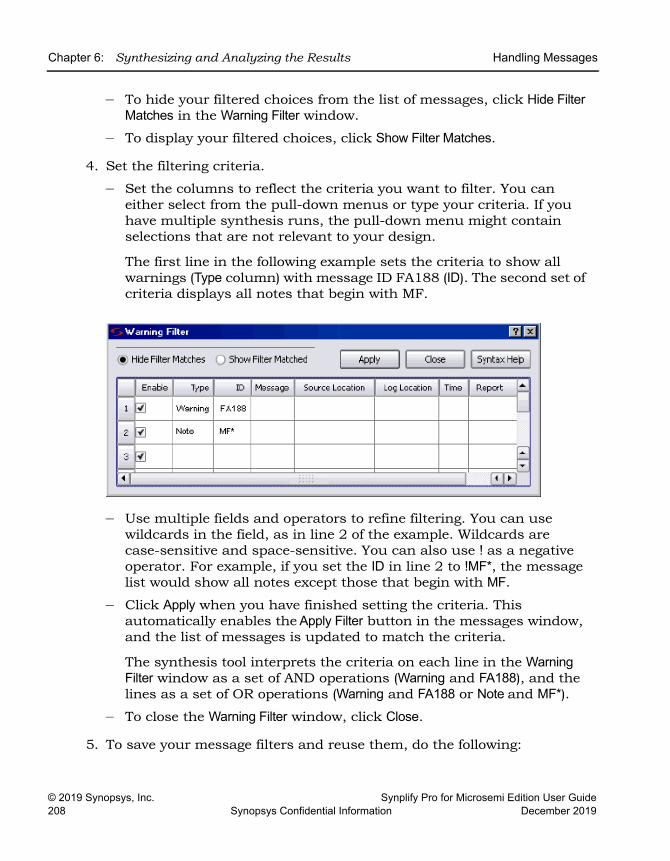
LO
Chapter 6: Synthesizing and Analyzing the Results Handling Messages
© 2019 Synopsys, Inc. Synplify Pro for Microsemi Edition User Guide208 Synopsys Confidential Information December 2019
– To hide your filtered choices from the list of messages, click Hide Filter Matches in the Warning Filter window.
– To display your filtered choices, click Show Filter Matches.
4. Set the filtering criteria.
– Set the columns to reflect the criteria you want to filter. You can either select from the pull-down menus or type your criteria. If you have multiple synthesis runs, the pull-down menu might contain selections that are not relevant to your design.
The first line in the following example sets the criteria to show all warnings (Type column) with message ID FA188 (ID). The second set of criteria displays all notes that begin with MF.
– Use multiple fields and operators to refine filtering. You can use wildcards in the field, as in line 2 of the example. Wildcards are case-sensitive and space-sensitive. You can also use ! as a negative operator. For example, if you set the ID in line 2 to !MF*, the message list would show all notes except those that begin with MF.
– Click Apply when you have finished setting the criteria. This automatically enables the Apply Filter button in the messages window, and the list of messages is updated to match the criteria.
The synthesis tool interprets the criteria on each line in the Warning Filter window as a set of AND operations (Warning and FA188), and the lines as a set of OR operations (Warning and FA188 or Note and MF*).
– To close the Warning Filter window, click Close.
5. To save your message filters and reuse them, do the following:
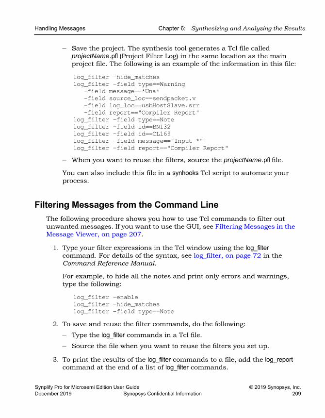
Handling Messages Chapter 6: Synthesizing and Analyzing the Results
Synplify Pro for Microsemi Edition User Guide © 2019 Synopsys, Inc.December 2019 Synopsys Confidential Information 209
– Save the project. The synthesis tool generates a Tcl file called projectName.pfl (Project Filter Log) in the same location as the main project file. The following is an example of the information in this file:
log_filter -hide_matcheslog_filter -field type==Warning
-field message==*Una* -field source_loc==sendpacket.v -field log_loc==usbHostSlave.srr -field report=="Compiler Report"
log_filter -field type==Notelog_filter -field id==BN132log_filter -field id==CL169log_filter -field message=="Input *"log_filter -field report=="Compiler Report"
– When you want to reuse the filters, source the projectName.pfl file.
You can also include this file in a synhooks Tcl script to automate your process.
Filtering Messages from the Command LineThe following procedure shows you how to use Tcl commands to filter out unwanted messages. If you want to use the GUI, see Filtering Messages in the Message Viewer, on page 207.
1. Type your filter expressions in the Tcl window using the log_filter command. For details of the syntax, see log_filter, on page 72 in the Command Reference Manual.
For example, to hide all the notes and print only errors and warnings, type the following:
log_filter -enablelog_filter -hide_matcheslog_filter -field type==Note
2. To save and reuse the filter commands, do the following:
– Type the log_filter commands in a Tcl file.
– Source the file when you want to reuse the filters you set up.
3. To print the results of the log_filter commands to a file, add the log_report command at the end of a list of log_filter commands.
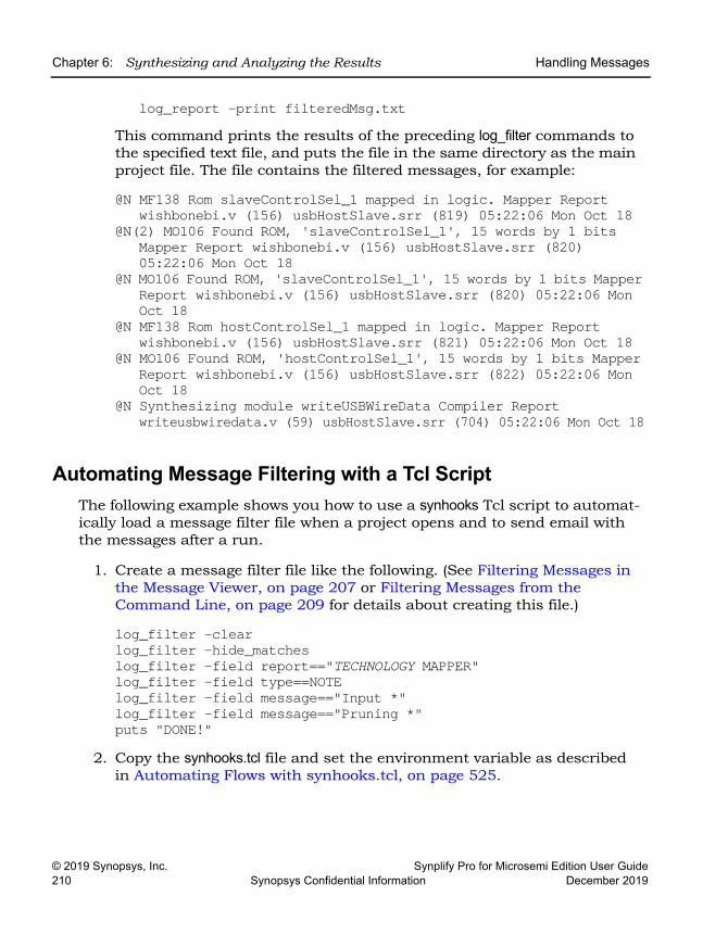
LO
Chapter 6: Synthesizing and Analyzing the Results Handling Messages
© 2019 Synopsys, Inc. Synplify Pro for Microsemi Edition User Guide210 Synopsys Confidential Information December 2019
log_report -print filteredMsg.txtThis command prints the results of the preceding log_filter commands to the specified text file, and puts the file in the same directory as the main project file. The file contains the filtered messages, for example:
@N MF138 Rom slaveControlSel_1 mapped in logic. Mapper Report wishbonebi.v (156) usbHostSlave.srr (819) 05:22:06 Mon Oct 18
@N(2) MO106 Found ROM, 'slaveControlSel_1', 15 words by 1 bits Mapper Report wishbonebi.v (156) usbHostSlave.srr (820)05:22:06 Mon Oct 18
@N MO106 Found ROM, 'slaveControlSel_1', 15 words by 1 bits Mapper Report wishbonebi.v (156) usbHostSlave.srr (820) 05:22:06 Mon Oct 18
@N MF138 Rom hostControlSel_1 mapped in logic. Mapper Report wishbonebi.v (156) usbHostSlave.srr (821) 05:22:06 Mon Oct 18
@N MO106 Found ROM, 'hostControlSel_1', 15 words by 1 bits MapperReport wishbonebi.v (156) usbHostSlave.srr (822) 05:22:06 MonOct 18
@N Synthesizing module writeUSBWireData Compiler Report writeusbwiredata.v (59) usbHostSlave.srr (704) 05:22:06 Mon Oct 18
Automating Message Filtering with a Tcl ScriptThe following example shows you how to use a synhooks Tcl script to automat-ically load a message filter file when a project opens and to send email with the messages after a run.
1. Create a message filter file like the following. (See Filtering Messages in the Message Viewer, on page 207 or Filtering Messages from the Command Line, on page 209 for details about creating this file.)
log_filter -clearlog_filter -hide_matcheslog_filter -field report=="TECHNOLOGY MAPPER"log_filter -field type==NOTElog_filter -field message=="Input *"log_filter -field message=="Pruning *"puts "DONE!"
2. Copy the synhooks.tcl file and set the environment variable as described in Automating Flows with synhooks.tcl, on page 525.
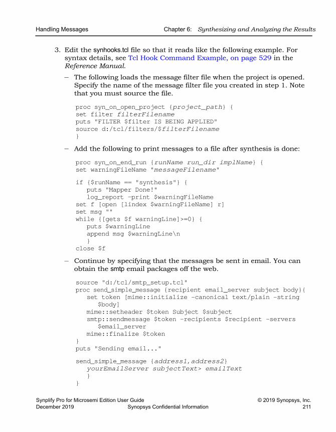
Handling Messages Chapter 6: Synthesizing and Analyzing the Results
Synplify Pro for Microsemi Edition User Guide © 2019 Synopsys, Inc.December 2019 Synopsys Confidential Information 211
3. Edit the synhooks.tcl file so that it reads like the following example. For syntax details, see Tcl Hook Command Example, on page 529 in the Reference Manual.
– The following loads the message filter file when the project is opened. Specify the name of the message filter file you created in step 1. Note that you must source the file.
proc syn_on_open_project {project_path} {set filter filterFilenameputs "FILTER $filter IS BEING APPLIED"source d:/tcl/filters/$filterFilename}
– Add the following to print messages to a file after synthesis is done:
proc syn_on_end_run {runName run_dir implName} {set warningFileName "messageFilename"if {$runName == "synthesis"} {
puts "Mapper Done!"log_report -print $warningFileName
set f [open [lindex $warningFileName] r]set msg "" while {[gets $f warningLine]>=0} {
puts $warningLineappend msg $warningLine\n}
close $f– Continue by specifying that the messages be sent in email. You can
obtain the smtp email packages off the web.
source "d:/tcl/smtp_setup.tcl"proc send_simple_message {recipient email_server subject body}{
set token [mime::initialize -canonical text/plain -string$body]
mime::setheader $token Subject $subjectsmtp::sendmessage $token -recipients $recipient -servers
$email_servermime::finalize $token
}puts "Sending email..."send_simple_message {address1,address2}
yourEmailServer subjectText> emailText}
}

LO
Chapter 6: Synthesizing and Analyzing the Results Handling Messages
© 2019 Synopsys, Inc. Synplify Pro for Microsemi Edition User Guide212 Synopsys Confidential Information December 2019
When the script runs, an email with all the warnings from the synthesis run is automatically sent to the specified email addresses.
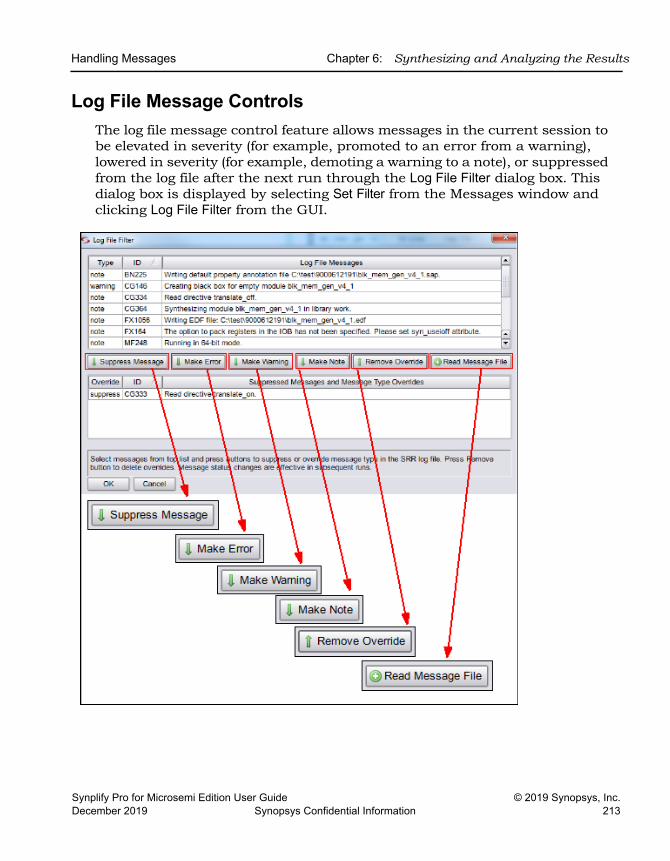
Handling Messages Chapter 6: Synthesizing and Analyzing the Results
Synplify Pro for Microsemi Edition User Guide © 2019 Synopsys, Inc.December 2019 Synopsys Confidential Information 213
Log File Message ControlsThe log file message control feature allows messages in the current session to be elevated in severity (for example, promoted to an error from a warning), lowered in severity (for example, demoting a warning to a note), or suppressed from the log file after the next run through the Log File Filter dialog box. This dialog box is displayed by selecting Set Filter from the Messages window and clicking Log File Filter from the GUI.
LO
Chapter 6: Synthesizing and Analyzing the Results Handling Messages
© 2019 Synopsys, Inc. Synplify Pro for Microsemi Edition User Guide214 Synopsys Confidential Information December 2019
Log File Filter Dialog BoxThe Log File Filter dialog box is the primary control for changing a message priority or suppressing a message. When you initially open the dialog box, all of the messages from the log (.srr) file for the active implementation are displayed in the upper section and the lower section is empty. To use the dialog box:
1. Select (highlight) the message to be promoted, demoted, or suppressed from the messages displayed in the upper section.
2. Select the Suppress Message, Make Error, Make Warning, or Make Note button to move the selected message from the upper section to the lower section. The selected message is repopulated in the lower section with the Override column reflecting the disposition of the message according to the button selected.
Allowed Severity ChangesAllowed severity levels and preference settings for warning, note, and advisory messages are:
• Promote - warning to error, note to warning, note to error
• Demote - warning to note
• Suppress - suppress warning, suppress note, suppress advisory
Note: Normal error messages (messages generated by default) cannot be suppressed or changed to a lesser severity level.
When using the dialog box:
• Use the control and shift keys to select multiple messages.
• If an srr file is not present (for example, if you are starting a new project) the table will be empty. Run the design at least once to generate an srr file.
• Clicking the OK button saves the message status changes to the project-Name.pfl file in the project directory.
Handling Messages Chapter 6: Synthesizing and Analyzing the Results
Synplify Pro for Microsemi Edition User Guide © 2019 Synopsys, Inc.December 2019 Synopsys Confidential Information 215
Message ReportingThe compiler and mapper must be rerun before the impact of the message status changes can be seen in the updated log file.
When a projectName.pfl input file is present at the start of the run, the message-status changes in the file are forwarded to the mapper and compiler which generate an updated log file. Depending on the changes specified:
• If an ID is promoted to an error, the mapper/compiler stops execution at the first occurrence of the message and prints the message in the @E:msgID :messageText format
• If an ID is promoted to a warning, the mapper/compiler prints the message in the @W:msgID :messageText format.
• If an ID is demoted to a note, the mapper/compiler prints the message in the @N:msgID :messageText format.
• If an ID is suppressed, the mapper/compiler excludes the message from the srr file.
Note: The online, error-message help documentation is unchanged by any message modification performed by the filtering mechanism. If a message is initially categorized as a warning in the synthesis tool, it continues to be reported as a warning in error-message help irrespective its promotion/demotion status.
Updating the projectName.pfl fileThe projectName.pfl file in the top-level project directory stores the user message filter settings from the Log File Filter dialog box for that project. This file can be edited with a text editor. The file entry syntax is:
message_override -suppress ID [ID ...] | -error ID [ID ...] | -warning ID [ID ...] | -note ID [ID ...]
For example, to override the default message definition for note FX702 as a warning, enter:
message_override -warning FX702You can also limit the number of occurrences for specified message IDs with the following syntax:
LO
Chapter 6: Synthesizing and Analyzing the Results Handling Messages
© 2019 Synopsys, Inc. Synplify Pro for Microsemi Edition User Guide216 Synopsys Confidential Information December 2019
message_override [-limit value] [-count value]
For example, limit messages with IDs FX214 and FX271 to 100 each in each log file as follows:
message_override -limit {FX214 FX271} -count 100Then, select the message filter file (.pfl) to be read for the project with the Read Message File option.
Note: After editing the .pfl file, close and reopen the project to update the overrides.
messagefilter.txt FileA messagefilter.txt file in the implementation/syntmp directory lists any changes made to message priority or suppression through the Log File Filter dialog box. This file, which is only generated when changes are made to the default status of a message, can be accessed outside of the GUI without consuming a license.
Working with Downgradable Errors and Critical WarningsYou can temporarily change the classification for certain kinds of messages:
You can downgrade or upgrade these messages from the GUI or through a Tcl command.
Downgradable errors(@DE)
Can be downgraded to warnings. This is a small set of non-fatal errors where you can temporarily postpone addressing the error and continue with the design flow and verification of other aspects of the design.
Critical warnings(@CW)
Can be upgraded to errors. This small set of warnings represent critical problems. Elevating them to errors ensures that they are recognized and dealt with, because the error status forces the tool to stop.
Handling Messages Chapter 6: Synthesizing and Analyzing the Results
Synplify Pro for Microsemi Edition User Guide © 2019 Synopsys, Inc.December 2019 Synopsys Confidential Information 217
Downgrading or Upgrading Messages from the GUI1. Open the log file.
2. Right click within the log file and select Log File Message Filter from the pop-up menu to display the Log File Filter dialog box.
3. Highlight the DE or CW message from the list of messages displayed at the top of the dialog box. You can only downgrade messages with a DE prefix, or upgrade messages with a CE prefix.
4. Depending on the message type selected:
– Click the Make Warning button to downgrade the error to a warning. This action moves the message from the top section of the message filter to the bottom section. The Override column in the bottom section displays the updated status for the message (Warning).
– Click the Make Error button to upgrade the critical warning to an error. This action moves the message from the top section of the message filter to the bottom section. The Override column in the bottom section displays the updated status for the message (Error).
5. To see the changes reflected, click the Run button. You can verify that the message is now treated as:
– A warning (the mapping operation continues past the initial point of the error condition)
– An error (the operation stops at the initial point of the error).
6. To revert the DE or CW message:
– Click on one of the downgraded DE warning IDs in the report and select Log File Message Filter from the pop-up menu to display the Log File Filter dialog box. This reverts the warning message to an error.
– Click on one of the upgraded CW warning IDs in the report and select Log File Message Filter from the pop-up menu to display the Log File Filter dialog box. This reverts the error message to a warning.
7. From the dialog box, highlight the DE or CW message from the list of messages displayed at the top of the dialog box. Click either the:
– Make Error button to return the message to its original error status.
– Make Warning button to return the message to its original critical warning status.
LO
Chapter 6: Synthesizing and Analyzing the Results Handling Messages
© 2019 Synopsys, Inc. Synplify Pro for Microsemi Edition User Guide218 Synopsys Confidential Information December 2019
Modifying the status of a message does not affect the message string. A message originally categorized as an error continues to be reported as an error regardless of its user-assigned status.
Downgrading or Upgrading Messages with a Tcl CommandType the message_override command in the Tcl script window to change the classification of DE and CW messages.
1. To downgrade DE errors or upgrade CW warnings, use the appropriate message_override command:
message_override -warning DEmessageIDmessage_override -error CWmessageID
Enter the message ID without the @ prefix, as shown above.
2. To see the changes reflected, rerun the state from the database where you changed the message classification.
After you have fixed the cause of the upgraded warning (critical warning) or completed the rest of the flow (downgradable error), you must change the message classification back to its original status.
3. To revert the messages back to their original status, use the appropriate message_override command:
message_override -error DEmessageIDmessage_override -warning CWmessageID
4. Rerun again to confirm that the message status has reverted to the original.
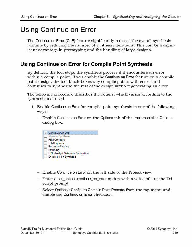
Using Continue on Error Chapter 6: Synthesizing and Analyzing the Results
Synplify Pro for Microsemi Edition User Guide © 2019 Synopsys, Inc.December 2019 Synopsys Confidential Information 219
Using Continue on Error The Continue on Error (CoE) feature significantly reduces the overall synthesis runtime by reducing the number of synthesis iterations. This can be a signif-icant advantage in prototyping and the handling of large designs.
Using Continue on Error for Compile Point SynthesisBy default, the tool stops the synthesis process if it encounters an error within a compile point. If you enable the Continue on Error feature on a compile point design, the tool black-boxes any compile points with errors and continues to synthesize the rest of the design without generating an error.
The following procedure describes the details, which varies according to the synthesis tool used.
1. Enable Continue on Error for compile-point synthesis in one of the following ways:
– Enable Continue on Error on the Options tab of the Implementation Options dialog box.
– Enable Continue on Error on the left side of the Project view.
– Enter a set_option -continue_on_error option with a value of 1 at the Tcl script prompt.
– Select Options->Configure Compile Point Process from the top menu and enable the Continue on Error checkbox.
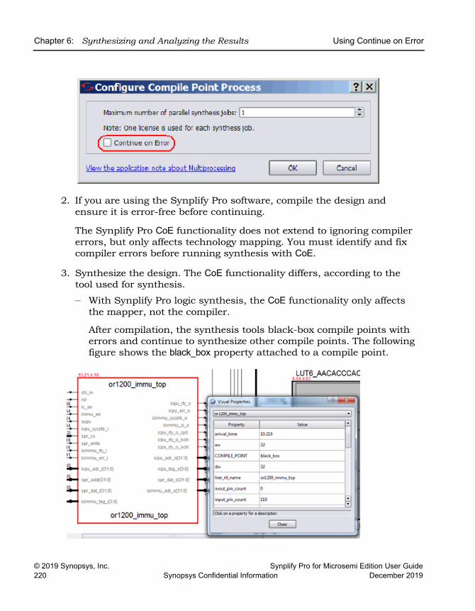
LO
Chapter 6: Synthesizing and Analyzing the Results Using Continue on Error
© 2019 Synopsys, Inc. Synplify Pro for Microsemi Edition User Guide220 Synopsys Confidential Information December 2019
2. If you are using the Synplify Pro software, compile the design and ensure it is error-free before continuing.
The Synplify Pro CoE functionality does not extend to ignoring compiler errors, but only affects technology mapping. You must identify and fix compiler errors before running synthesis with CoE.
3. Synthesize the design. The CoE functionality differs, according to the tool used for synthesis.
– With Synplify Pro logic synthesis, the CoE functionality only affects the mapper, not the compiler.
After compilation, the synthesis tools black-box compile points with errors and continue to synthesize other compile points. The following figure shows the black_box property attached to a compile point.
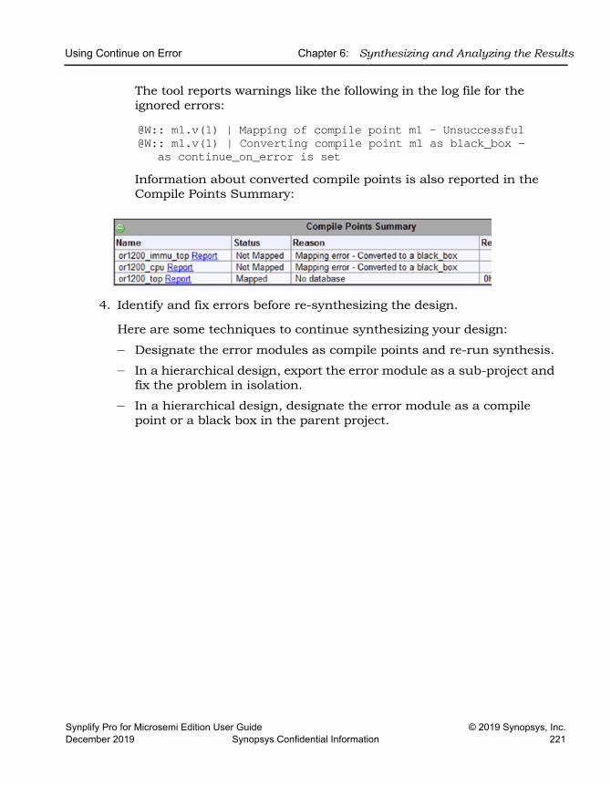
Using Continue on Error Chapter 6: Synthesizing and Analyzing the Results
Synplify Pro for Microsemi Edition User Guide © 2019 Synopsys, Inc.December 2019 Synopsys Confidential Information 221
The tool reports warnings like the following in the log file for the ignored errors:
@W:: m1.v(1) | Mapping of compile point m1 - Unsuccessful @W:: m1.v(1) | Converting compile point m1 as black_box -
as continue_on_error is set Information about converted compile points is also reported in the Compile Points Summary:
4. Identify and fix errors before re-synthesizing the design.
Here are some techniques to continue synthesizing your design:
– Designate the error modules as compile points and re-run synthesis.
– In a hierarchical design, export the error module as a sub-project and fix the problem in isolation.
– In a hierarchical design, designate the error module as a compile point or a black box in the parent project.

LO
Chapter 6: Synthesizing and Analyzing the Results Using Continue on Error
© 2019 Synopsys, Inc. Synplify Pro for Microsemi Edition User Guide222 Synopsys Confidential Information December 2019
Synplify Pro for Microsemi Edition User Guide © 2019 Synopsys, Inc.December 2019 Synopsys Confidential Information 223
C H A P T E R 7
Analyzing with HDL Analyst
This chapter describes how to analyze logic in the HDL Analyst and FSM Viewer.
See the following for detailed procedures:
• Working in the Schematic, on page 224
• Exploring Design Hierarchy, on page 245
• Finding Objects, on page 253
• Crossprobing, on page 264
• Analyzing With the HDL Analyst Tool, on page 272
• Working in the Standard Schematic, on page 295
• Exploring Design Hierarchy (Standard), on page 308
• Finding Objects (Standard), on page 316
• Crossprobing (Standard), on page 329
• Analyzing With the Standard HDL Analyst Tool, on page 336
• Using the FSM Viewer (Standard), on page 353
LO
Chapter 7: Analyzing with HDL Analyst Working in the Schematic
© 2019 Synopsys, Inc. Synplify Pro for Microsemi Edition User Guide224 Synopsys Confidential Information December 2019
Working in the Schematic The HDL Analyst tool includes single-page schematics, which can help you graphically analyze and navigate your entire design easier. This section describes basic procedures you use in the schematics. These procedures include the following topics:
• Clone Schematic – See Cloning Schematics, on page 227
• Instance Groups – See Grouping Objects in the Schematic, on page 237
• Partial Dissolve – See Grouping Objects in the Schematic, on page 237
• Net Based Filtering – See Filtering Schematics, on page 277
• Unfilter – See Filtering Schematics, on page 277
• Multi-threaded Find – See Browsing to Find Objects in HDL Analyst Views, on page 253
• New Mouse Strokes with Cancel Display– See Mouse Stroke Conven-tions, on page 227
• New Push View Tab – See Cloning Schematics, on page 227
• Peek – See Viewing Design Hierarchy and Context, on page 272
• Improved Bus Display and Handling – See Dissolving and Partial Dissolving of Buses and Pins, on page 285
For information on specific tasks like analyzing critical paths, see the following sections:
• Traversing Design Hierarchy with the Hierarchy Browser, on page 245
• Exploring Object Hierarchy with Push/Pop Commands, on page 248
• Crossprobing, on page 264
• Analyzing With the HDL Analyst Tool, on page 272
Opening the ViewsThe procedure for opening a view is the same at different design stages; the main difference is the content that is available at the different design database states.
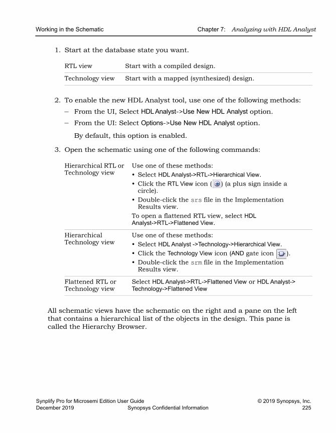
Working in the Schematic Chapter 7: Analyzing with HDL Analyst
Synplify Pro for Microsemi Edition User Guide © 2019 Synopsys, Inc.December 2019 Synopsys Confidential Information 225
1. Start at the database state you want.
2. To enable the new HDL Analyst tool, use one of the following methods:
– From the UI, Select HDL Analyst->Use New HDL Analyst option.
– From the UI: Select Options->Use New HDL Analyst option.
By default, this option is enabled.
3. Open the schematic using one of the following commands:
All schematic views have the schematic on the right and a pane on the left that contains a hierarchical list of the objects in the design. This pane is called the Hierarchy Browser.
RTL view Start with a compiled design.
Technology view Start with a mapped (synthesized) design.
Hierarchical RTL or Technology view
Use one of these methods: • Select HDL Analyst->RTL->Hierarchical View. • Click the RTL View icon ( ) (a plus sign inside a
circle).• Double-click the srs file in the Implementation
Results view.To open a flattened RTL view, select HDL Analyst->RTL->Flattened View.
Hierarchical Technology view
Use one of these methods: • Select HDL Analyst ->Technology->Hierarchical View. • Click the Technology View icon (AND gate icon ). • Double-click the srm file in the Implementation
Results view.
Flattened RTL or Technology view
Select HDL Analyst->RTL->Flattened View or HDL Analyst-> Technology->Flattened View
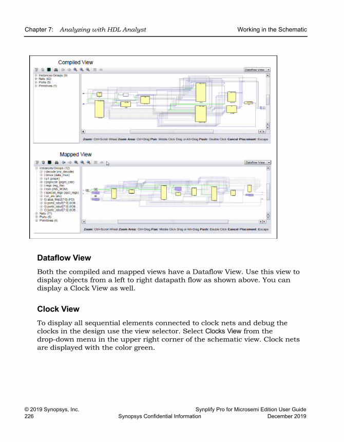
LO
Chapter 7: Analyzing with HDL Analyst Working in the Schematic
© 2019 Synopsys, Inc. Synplify Pro for Microsemi Edition User Guide226 Synopsys Confidential Information December 2019
Dataflow ViewBoth the compiled and mapped views have a Dataflow View. Use this view to display objects from a left to right datapath flow as shown above. You can display a Clock View as well.
Clock ViewTo display all sequential elements connected to clock nets and debug the clocks in the design use the view selector. Select Clocks View from the drop-down menu in the upper right corner of the schematic view. Clock nets are displayed with the color green.
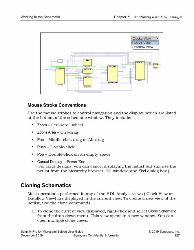
Working in the Schematic Chapter 7: Analyzing with HDL Analyst
Synplify Pro for Microsemi Edition User Guide © 2019 Synopsys, Inc.December 2019 Synopsys Confidential Information 227
Mouse Stroke ConventionsUse the mouse strokes to control navigation and the display, which are listed at the bottom of the schematic window. They include:
• Zoom – Ctrl-scroll wheel
• Zoom Area – Ctrl-drag
• Pan – Middle-click drag or Alt-drag
• Push – Double-click
• Pop – Double-click on an empty space
• Cancel Display – Press Esc(For large designs, you can cancel displaying the netlist but still use the netlist from the hierarchy browser, Tcl window, and Find dialog box.)
Cloning SchematicsMost operations performed in any of the HDL Analyst views ( Clock View or Dataflow View) are displayed in the current view. To create a new view of the netlist, use the clone commands.
1. To clone the current view displayed, right-click and select Clone Schematic from the drop-down menu. This view opens in a new window. You can open multiple clone views.
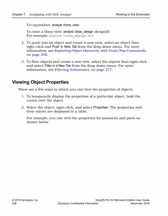
LO
Chapter 7: Analyzing with HDL Analyst Working in the Schematic
© 2019 Synopsys, Inc. Synplify Pro for Microsemi Edition User Guide228 Synopsys Confidential Information December 2019
Tcl equivalent: analyst clone_view
To close a clone view: analyst close_design designID. For example: analyst close_design d:3
2. To push into an object and create a new view, select an object then right-click and Push in New Tab from the drop-down menu. For more information, see Exploring Object Hierarchy with Push/Pop Commands, on page 248.
3. To filter objects and create a new view, select the objects then right-click and select Filter in a New Tab from the drop-down menu. For more information, see Filtering Schematics, on page 277.
Viewing Object PropertiesThere are a few ways in which you can view the properties of objects.
1. To temporarily display the properties of a particular object, hold the cursor over the object.
2. Select the object, right-click, and select Properties. The properties and their values are displayed in a table.
For example, you can view the properties for instances and ports as shown below.
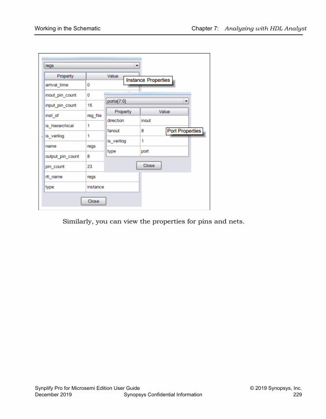
Working in the Schematic Chapter 7: Analyzing with HDL Analyst
Synplify Pro for Microsemi Edition User Guide © 2019 Synopsys, Inc.December 2019 Synopsys Confidential Information 229
Similarly, you can view the properties for pins and nets.
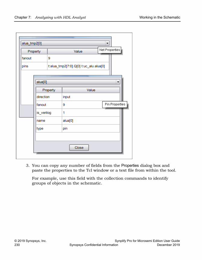
LO
Chapter 7: Analyzing with HDL Analyst Working in the Schematic
© 2019 Synopsys, Inc. Synplify Pro for Microsemi Edition User Guide230 Synopsys Confidential Information December 2019
3. You can copy any number of fields from the Properties dialog box and paste the properties to the Tcl window or a text file from within the tool.
For example, use this field with the collection commands to identify groups of objects in the schematic.
Working in the Schematic Chapter 7: Analyzing with HDL Analyst
Synplify Pro for Microsemi Edition User Guide © 2019 Synopsys, Inc.December 2019 Synopsys Confidential Information 231
Viewing Objects with Constant ValuesYou can display constants and view their constant values. Individual functions of the constant are displayed. Use tool tips to see the full value for the constant.
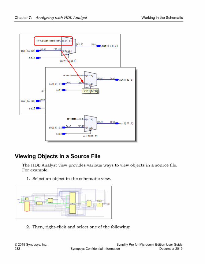
LO
Chapter 7: Analyzing with HDL Analyst Working in the Schematic
© 2019 Synopsys, Inc. Synplify Pro for Microsemi Edition User Guide232 Synopsys Confidential Information December 2019
Viewing Objects in a Source FileThe HDL Analyst view provides various ways to view objects in a source file. For example:
1. Select an object in the schematic view.
2. Then, right-click and select one of the following:
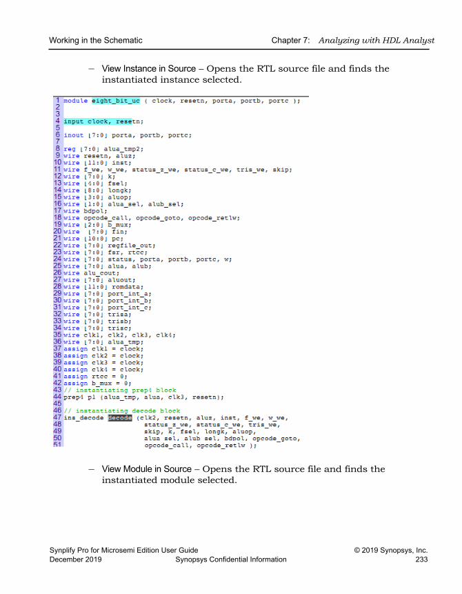
Working in the Schematic Chapter 7: Analyzing with HDL Analyst
Synplify Pro for Microsemi Edition User Guide © 2019 Synopsys, Inc.December 2019 Synopsys Confidential Information 233
– View Instance in Source – Opens the RTL source file and finds the instantiated instance selected.
– View Module in Source – Opens the RTL source file and finds the instantiated module selected.
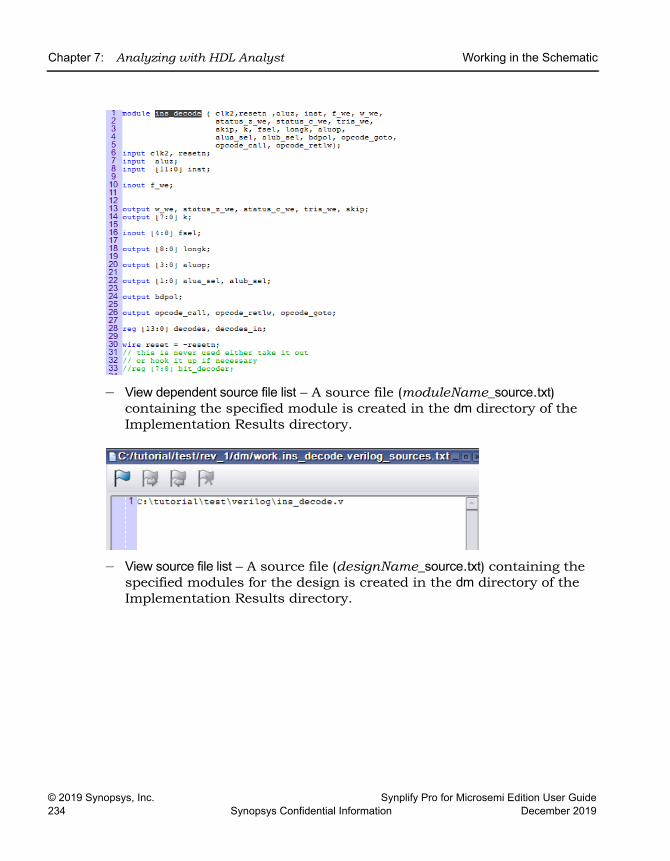
LO
Chapter 7: Analyzing with HDL Analyst Working in the Schematic
© 2019 Synopsys, Inc. Synplify Pro for Microsemi Edition User Guide234 Synopsys Confidential Information December 2019
– View dependent source file list – A source file (moduleName_source.txt) containing the specified module is created in the dm directory of the Implementation Results directory.
– View source file list – A source file (designName_source.txt) containing the specified modules for the design is created in the dm directory of the Implementation Results directory.
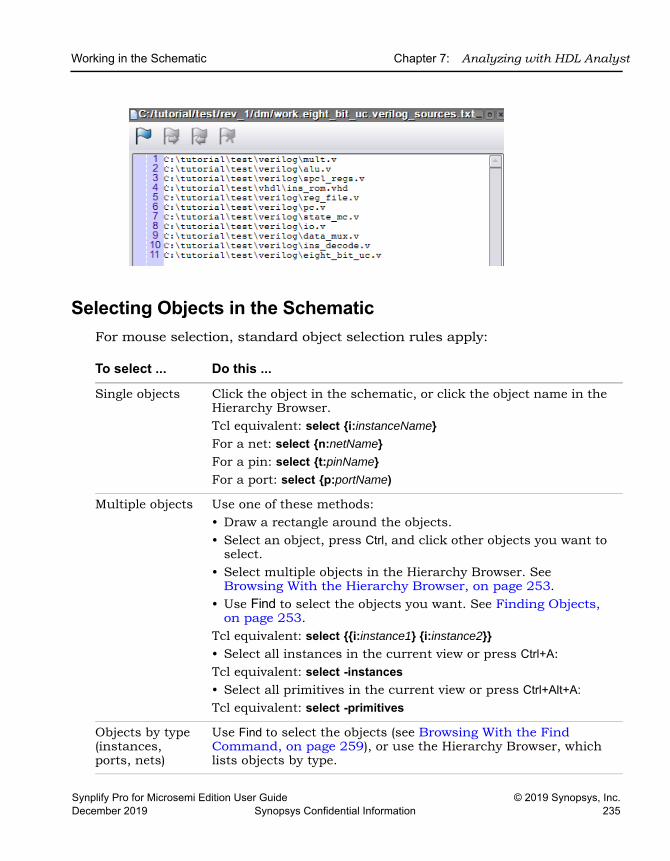
Working in the Schematic Chapter 7: Analyzing with HDL Analyst
Synplify Pro for Microsemi Edition User Guide © 2019 Synopsys, Inc.December 2019 Synopsys Confidential Information 235
Selecting Objects in the SchematicFor mouse selection, standard object selection rules apply:
To select ... Do this ...
Single objects Click the object in the schematic, or click the object name in the Hierarchy Browser. Tcl equivalent: select {i:instanceName}For a net: select {n:netName}For a pin: select {t:pinName}For a port: select {p:portName)
Multiple objects Use one of these methods:• Draw a rectangle around the objects. • Select an object, press Ctrl, and click other objects you want to
select.• Select multiple objects in the Hierarchy Browser. See
Browsing With the Hierarchy Browser, on page 253. • Use Find to select the objects you want. See Finding Objects,
on page 253.Tcl equivalent: select {{i:instance1} {i:instance2}} • Select all instances in the current view or press Ctrl+A:Tcl equivalent: select -instances• Select all primitives in the current view or press Ctrl+Alt+A:Tcl equivalent: select -primitives
Objects by type (instances, ports, nets)
Use Find to select the objects (see Browsing With the Find Command, on page 259), or use the Hierarchy Browser, which lists objects by type.
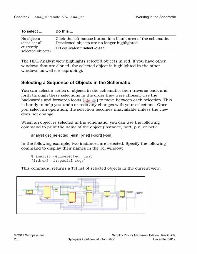
LO
Chapter 7: Analyzing with HDL Analyst Working in the Schematic
© 2019 Synopsys, Inc. Synplify Pro for Microsemi Edition User Guide236 Synopsys Confidential Information December 2019
The HDL Analyst view highlights selected objects in red. If you have other windows that are cloned, the selected object is highlighted in the other windows as well (crossprobing).
Selecting a Sequence of Objects in the SchematicYou can select a series of objects in the schematic, then traverse back and forth through these selections in the order they were chosen. Use the backwards and forwards icons ( ) to move between each selection. This is handy to help you undo or redo any changes with your selections. Once you select an operation, the selection becomes unavailable unless the view does not change.
When an object is selected in the schematic, you can use the following command to print the name of the object (instance, port, pin, or net):
analyst get_selected [-inst] [-net] [-port] [-pin]
In the following example, two instances are selected. Specify the following command to display their names in the Tcl window:
% analyst get_selected -inst{i:dmux} {i:special_regs}
This command returns a Tcl list of selected objects in the current view.
No objects (deselect all currently selected objects)
Click the left mouse button in a blank area of the schematic. Deselected objects are no longer highlighted.Tcl equivalent: select -clear
To select ... Do this ...
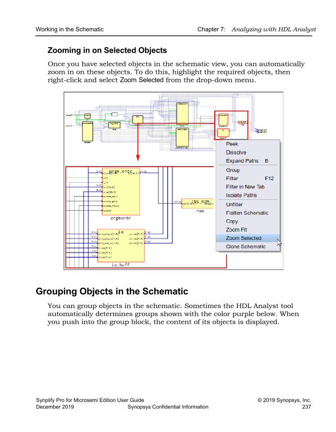
Working in the Schematic Chapter 7: Analyzing with HDL Analyst
Synplify Pro for Microsemi Edition User Guide © 2019 Synopsys, Inc.December 2019 Synopsys Confidential Information 237
Zooming in on Selected ObjectsOnce you have selected objects in the schematic view, you can automatically zoom in on these objects. To do this, highlight the required objects, then right-click and select Zoom Selected from the drop-down menu.
Grouping Objects in the SchematicYou can group objects in the schematic. Sometimes the HDL Analyst tool automatically determines groups shown with the color purple below. When you push into the group block, the content of its objects is displayed.
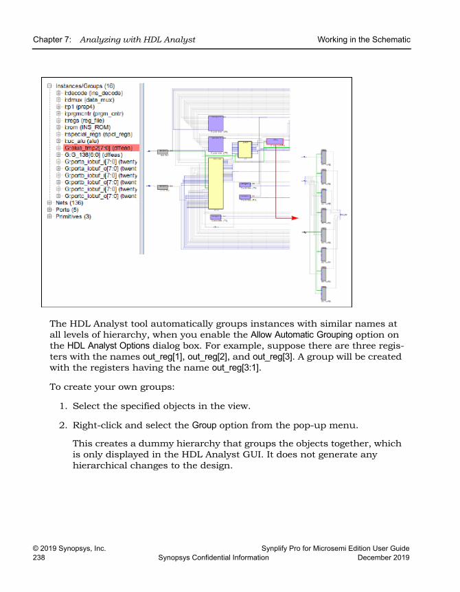
LO
Chapter 7: Analyzing with HDL Analyst Working in the Schematic
© 2019 Synopsys, Inc. Synplify Pro for Microsemi Edition User Guide238 Synopsys Confidential Information December 2019
The HDL Analyst tool automatically groups instances with similar names at all levels of hierarchy, when you enable the Allow Automatic Grouping option on the HDL Analyst Options dialog box. For example, suppose there are three regis-ters with the names out_reg[1], out_reg[2], and out_reg[3]. A group will be created with the registers having the name out_reg[3:1].
To create your own groups:
1. Select the specified objects in the view.
2. Right-click and select the Group option from the pop-up menu.
This creates a dummy hierarchy that groups the objects together, which is only displayed in the HDL Analyst GUI. It does not generate any hierarchical changes to the design.
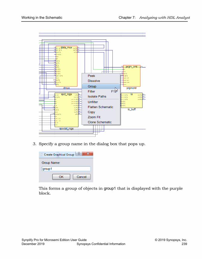
Working in the Schematic Chapter 7: Analyzing with HDL Analyst
Synplify Pro for Microsemi Edition User Guide © 2019 Synopsys, Inc.December 2019 Synopsys Confidential Information 239
3. Specify a group name in the dialog box that pops up.
This forms a group of objects in group1 that is displayed with the purple block.
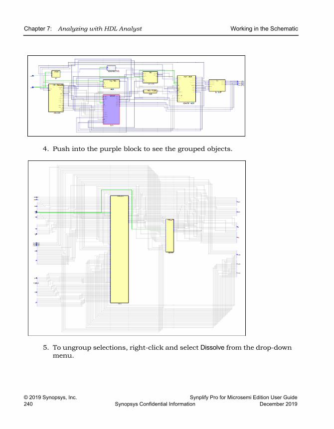
LO
Chapter 7: Analyzing with HDL Analyst Working in the Schematic
© 2019 Synopsys, Inc. Synplify Pro for Microsemi Edition User Guide240 Synopsys Confidential Information December 2019
4. Push into the purple block to see the grouped objects.
5. To ungroup selections, right-click and select Dissolve from the drop-down menu.
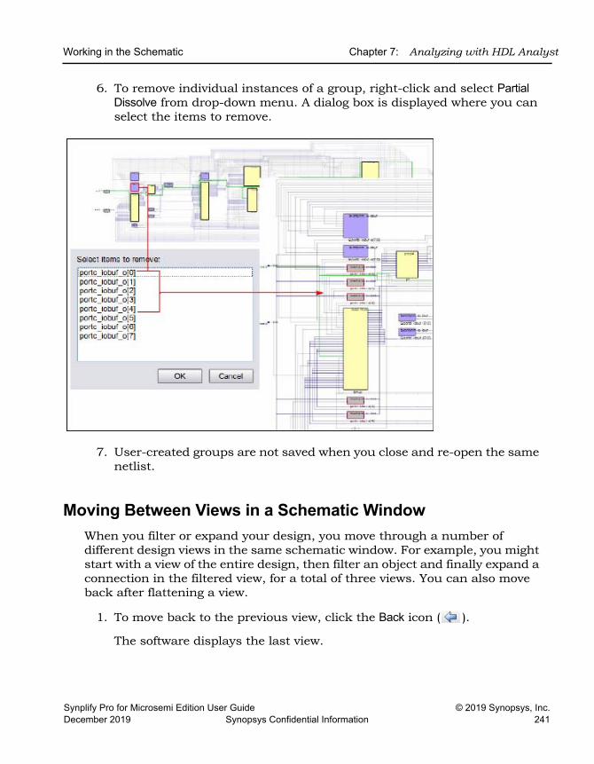
Working in the Schematic Chapter 7: Analyzing with HDL Analyst
Synplify Pro for Microsemi Edition User Guide © 2019 Synopsys, Inc.December 2019 Synopsys Confidential Information 241
6. To remove individual instances of a group, right-click and select Partial Dissolve from drop-down menu. A dialog box is displayed where you can select the items to remove.
7. User-created groups are not saved when you close and re-open the same netlist.
Moving Between Views in a Schematic WindowWhen you filter or expand your design, you move through a number of different design views in the same schematic window. For example, you might start with a view of the entire design, then filter an object and finally expand a connection in the filtered view, for a total of three views. You can also move back after flattening a view.
1. To move back to the previous view, click the Back icon ( ).
The software displays the last view.
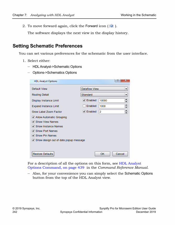
LO
Chapter 7: Analyzing with HDL Analyst Working in the Schematic
© 2019 Synopsys, Inc. Synplify Pro for Microsemi Edition User Guide242 Synopsys Confidential Information December 2019
2. To move forward again, click the Forward icon ( ).
The software displays the next view in the display history.
Setting Schematic PreferencesYou can set various preferences for the schematic from the user interface.
1. Select either:
– HDL Analyst->Schematic Options– Options->Schematics Options
For a description of all the options on this form, see HDL Analyst Options Command, on page 439 in the Command Reference Manual.
– Also, for your convenience you can simply select the Schematic Options button from the top of the HDL Analyst view.
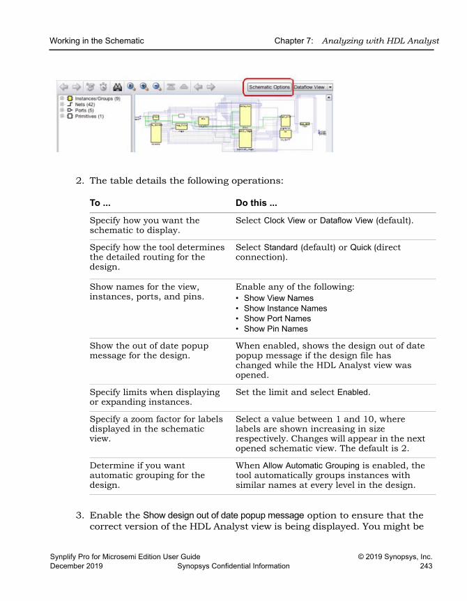
Working in the Schematic Chapter 7: Analyzing with HDL Analyst
Synplify Pro for Microsemi Edition User Guide © 2019 Synopsys, Inc.December 2019 Synopsys Confidential Information 243
2. The table details the following operations:
3. Enable the Show design out of date popup message option to ensure that the correct version of the HDL Analyst view is being displayed. You might be
To ... Do this ...
Specify how you want the schematic to display.
Select Clock View or Dataflow View (default).
Specify how the tool determines the detailed routing for the design.
Select Standard (default) or Quick (direct connection).
Show names for the view, instances, ports, and pins.
Enable any of the following:• Show View Names• Show Instance Names• Show Port Names• Show Pin Names
Show the out of date popup message for the design.
When enabled, shows the design out of date popup message if the design file has changed while the HDL Analyst view was opened.
Specify limits when displaying or expanding instances.
Set the limit and select Enabled.
Specify a zoom factor for labels displayed in the schematic view.
Select a value between 1 and 10, where labels are shown increasing in size respectively. Changes will appear in the next opened schematic view. The default is 2.
Determine if you want automatic grouping for the design.
When Allow Automatic Grouping is enabled, the tool automatically groups instances with similar names at every level in the design.
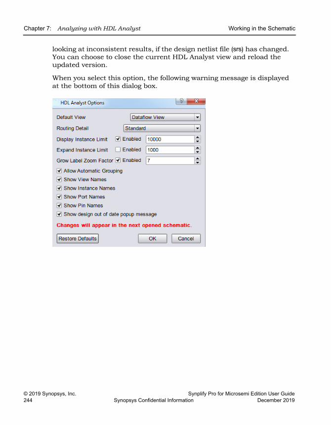
LO
Chapter 7: Analyzing with HDL Analyst Working in the Schematic
© 2019 Synopsys, Inc. Synplify Pro for Microsemi Edition User Guide244 Synopsys Confidential Information December 2019
looking at inconsistent results, if the design netlist file (srs) has changed. You can choose to close the current HDL Analyst view and reload the updated version.
When you select this option, the following warning message is displayed at the bottom of this dialog box.
Exploring Design Hierarchy Chapter 7: Analyzing with HDL Analyst
Synplify Pro for Microsemi Edition User Guide © 2019 Synopsys, Inc.December 2019 Synopsys Confidential Information 245
Exploring Design Hierarchy Schematics generally have a certain amount of design hierarchy. You can move between hierarchical levels using the Hierarchy Browser mode. For additional information, see Analyzing With the HDL Analyst Tool, on page 272. See Traversing Design Hierarchy with the Hierarchy Browser, on page 245.
Traversing Design Hierarchy with the Hierarchy BrowserThe Hierarchy Browser is the list of objects on the left side of the schematic view. It is best used to get an overview, or when you need to browse and find an object. If you want to move between design levels of a particular object, using the Push command is more direct. Refer to Exploring Object Hierarchy with Push/Pop Commands, on page 248 for details.
The hierarchy browser allows you to traverse and select the following:
• Instances or Groups
• Ports
• Internal nets
The browser lists the objects by type. Use the expand ( ) and collapse ( ) signs to ascend or descend the hierarchy.
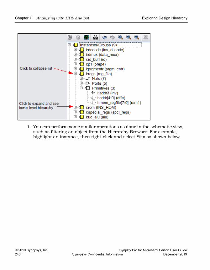
LO
Chapter 7: Analyzing with HDL Analyst Exploring Design Hierarchy
© 2019 Synopsys, Inc. Synplify Pro for Microsemi Edition User Guide246 Synopsys Confidential Information December 2019
1. You can perform some similar operations as done in the schematic view, such as filtering an object from the Hierarchy Browser. For example, highlight an instance, then right-click and select Filter as shown below.
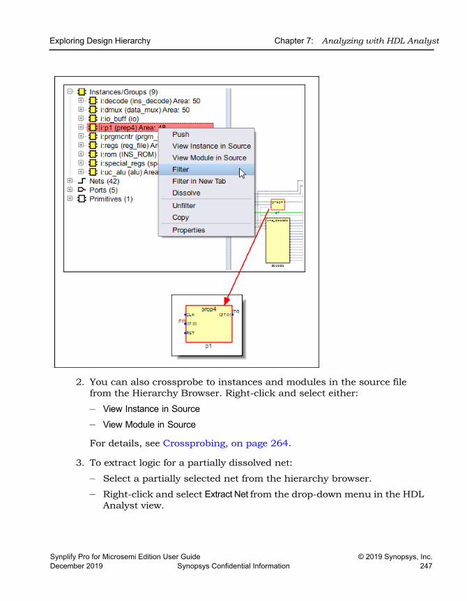
Exploring Design Hierarchy Chapter 7: Analyzing with HDL Analyst
Synplify Pro for Microsemi Edition User Guide © 2019 Synopsys, Inc.December 2019 Synopsys Confidential Information 247
2. You can also crossprobe to instances and modules in the source file from the Hierarchy Browser. Right-click and select either:
– View Instance in Source– View Module in Source
For details, see Crossprobing, on page 264.
3. To extract logic for a partially dissolved net:
– Select a partially selected net from the hierarchy browser.
– Right-click and select Extract Net from the drop-down menu in the HDL Analyst view.
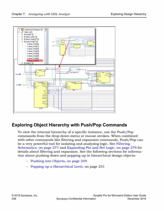
LO
Chapter 7: Analyzing with HDL Analyst Exploring Design Hierarchy
© 2019 Synopsys, Inc. Synplify Pro for Microsemi Edition User Guide248 Synopsys Confidential Information December 2019
Exploring Object Hierarchy with Push/Pop CommandsTo view the internal hierarchy of a specific instance, use the Push/Pop commands from the drop-down menu or mouse strokes. When combined with other commands like filtering and expansion commands, Push/Pop can be a very powerful tool for isolating and analyzing logic. See Filtering Schematics, on page 277 and Expanding Pin and Net Logic, on page 279 for details about filtering and expansion. See the following sections for informa-tion about pushing down and popping up in hierarchical design objects:
– Pushing into Objects, on page 249
– Popping up a Hierarchical Level, on page 251
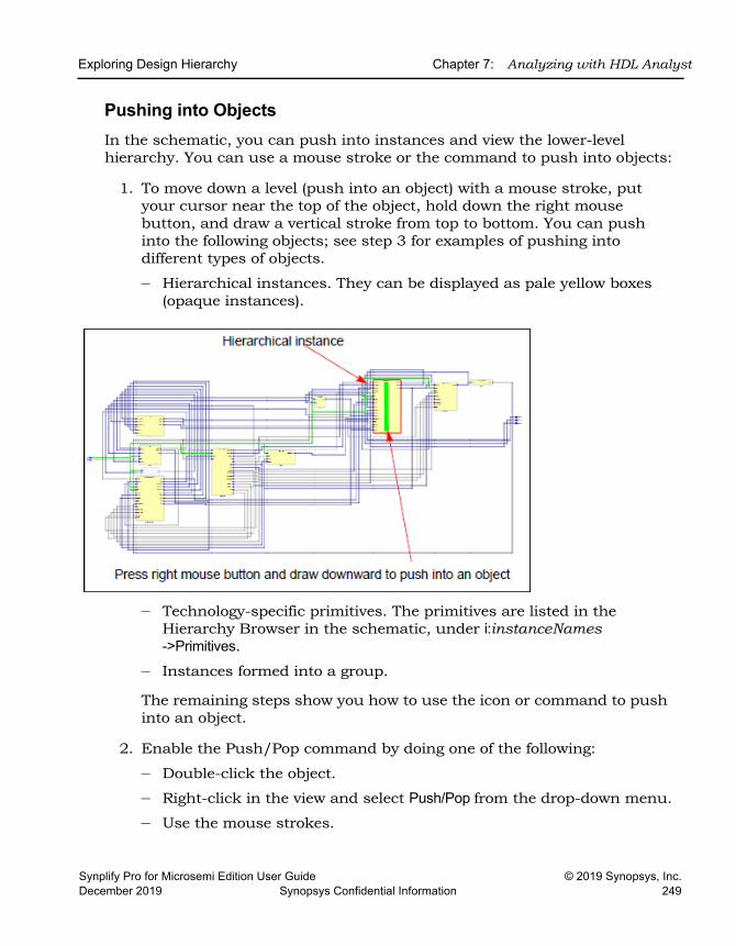
Exploring Design Hierarchy Chapter 7: Analyzing with HDL Analyst
Synplify Pro for Microsemi Edition User Guide © 2019 Synopsys, Inc.December 2019 Synopsys Confidential Information 249
Pushing into ObjectsIn the schematic, you can push into instances and view the lower-level hierarchy. You can use a mouse stroke or the command to push into objects:
1. To move down a level (push into an object) with a mouse stroke, put your cursor near the top of the object, hold down the right mouse button, and draw a vertical stroke from top to bottom. You can push into the following objects; see step 3 for examples of pushing into different types of objects.
– Hierarchical instances. They can be displayed as pale yellow boxes (opaque instances).
– Technology-specific primitives. The primitives are listed in the Hierarchy Browser in the schematic, under i:instanceNames ->Primitives.
– Instances formed into a group.
The remaining steps show you how to use the icon or command to push into an object.
2. Enable the Push/Pop command by doing one of the following:
– Double-click the object.
– Right-click in the view and select Push/Pop from the drop-down menu.
– Use the mouse strokes.
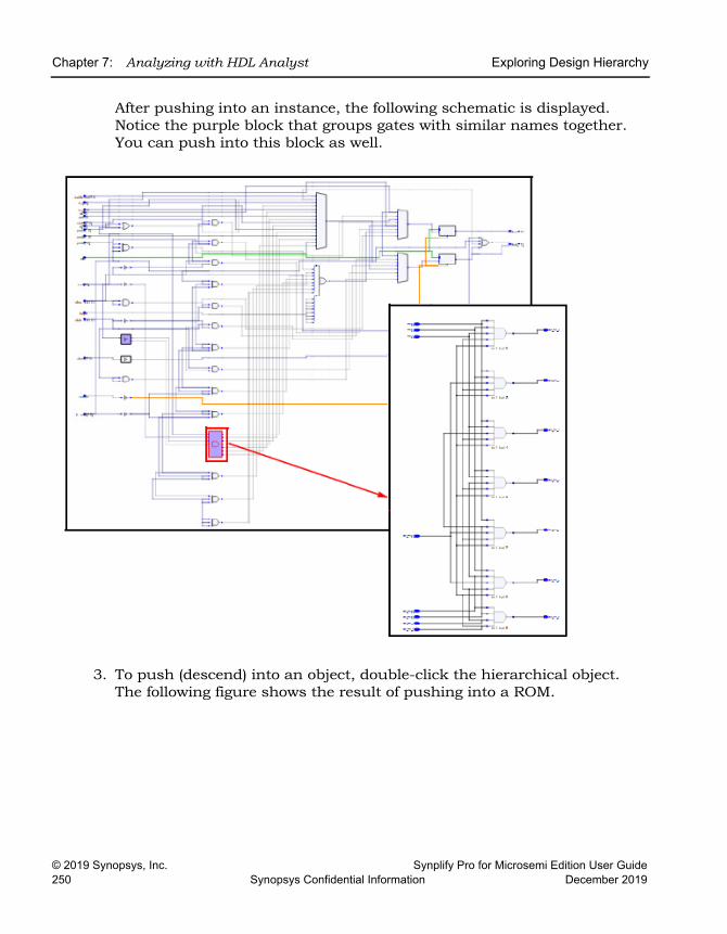
LO
Chapter 7: Analyzing with HDL Analyst Exploring Design Hierarchy
© 2019 Synopsys, Inc. Synplify Pro for Microsemi Edition User Guide250 Synopsys Confidential Information December 2019
After pushing into an instance, the following schematic is displayed. Notice the purple block that groups gates with similar names together. You can push into this block as well.
3. To push (descend) into an object, double-click the hierarchical object. The following figure shows the result of pushing into a ROM.
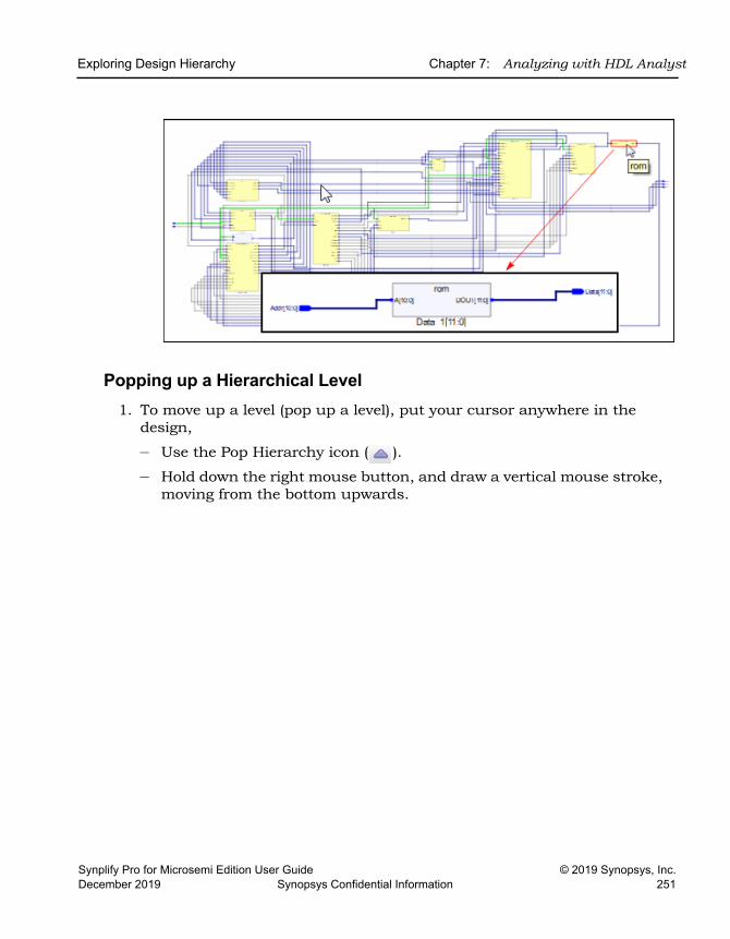
Exploring Design Hierarchy Chapter 7: Analyzing with HDL Analyst
Synplify Pro for Microsemi Edition User Guide © 2019 Synopsys, Inc.December 2019 Synopsys Confidential Information 251
Popping up a Hierarchical Level1. To move up a level (pop up a level), put your cursor anywhere in the
design,
– Use the Pop Hierarchy icon ( ).
– Hold down the right mouse button, and draw a vertical mouse stroke, moving from the bottom upwards.
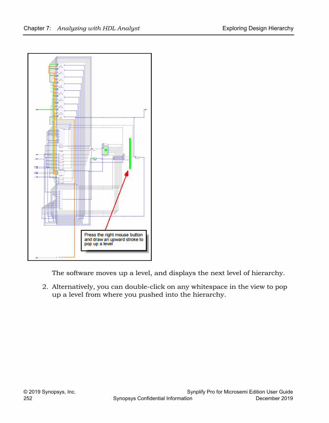
LO
Chapter 7: Analyzing with HDL Analyst Exploring Design Hierarchy
© 2019 Synopsys, Inc. Synplify Pro for Microsemi Edition User Guide252 Synopsys Confidential Information December 2019
The software moves up a level, and displays the next level of hierarchy.
2. Alternatively, you can double-click on any whitespace in the view to pop up a level from where you pushed into the hierarchy.
Finding Objects Chapter 7: Analyzing with HDL Analyst
Synplify Pro for Microsemi Edition User Guide © 2019 Synopsys, Inc.December 2019 Synopsys Confidential Information 253
Finding Objects In the schematics, you can use the Hierarchy Browser or the Find command to find objects, as explained in these sections:
• Browsing to Find Objects in HDL Analyst Views, on page 253
• Using Wildcards with the Find Command, on page 263
Browsing to Find Objects in HDL Analyst ViewsYou can always zoom in to find an object in the schematic. Use Zoom Fit to quickly fit all objects into the schematic. The following procedure shows you how to browse through design objects and find an object at any level of the design hierarchy. You can use the Hierarchy Browser or the Find command to do this. If you are familiar with the design hierarchy, the Hierarchy Browser can be the quickest method to locate an object. The Find command is best used to graphically browse and locate the object you want.
Browsing With the Hierarchy Browser1. In the Hierarchy Browser, click the name of the net, port, or instance
you want to select.
The object is highlighted in the schematic.
2. To select a range of objects, you can press and hold the Shift key while clicking the selected objects in the range.
The software selects and highlights all the objects in the range.
3. If the object is on a lower hierarchical level, do either of the following:
– Expand the appropriate higher-level object by clicking the collapsed symbol next to it, and then select the object you want.
– Push down into the higher-level object, and then select the object from the Hierarchy Browser.
The selected object is highlighted in the schematic. However, you may have to filter the object to view it in the design hierarchy.
4. To select all objects of the same type, select them from the Hierarchy Browser. For example, you can find all the nets in your design.
LO
Chapter 7: Analyzing with HDL Analyst Finding Objects
© 2019 Synopsys, Inc. Synplify Pro for Microsemi Edition User Guide254 Synopsys Confidential Information December 2019
Browsing With the New Hierarchy BrowserBeta
Using the HDL Analyst tool, you can display a hierarchy of design objects in the Hierarchy Browser. Typically, the time taken to display a design hierarchy depends on the size of the design.
To speed up this process, the new Hierarchy Browser traverses the entire (text-based) netlist to quickly extract hierarchical instance data. This helps to display the entire netlist hierarchy quickly and also facilitates the viewing of custom instances on demand, instead of traversing down the design hierarchy. This flow is advantageous in large designs, to display the hierarchy and view any instance, quickly.
To enable the new Hierarchy Browser, follow these steps:
1. To set preference in the schematic from the user interface, select one of the following:
– HDL Analyst->Schematic Options
– Options->Schematics Options
The HDL Analyst Options dialog box is displayed.
2. Enable the [BETA] Use new hierarchy browser option on the HDL Analyst Options dialog box. A warning is displayed, as shown below.
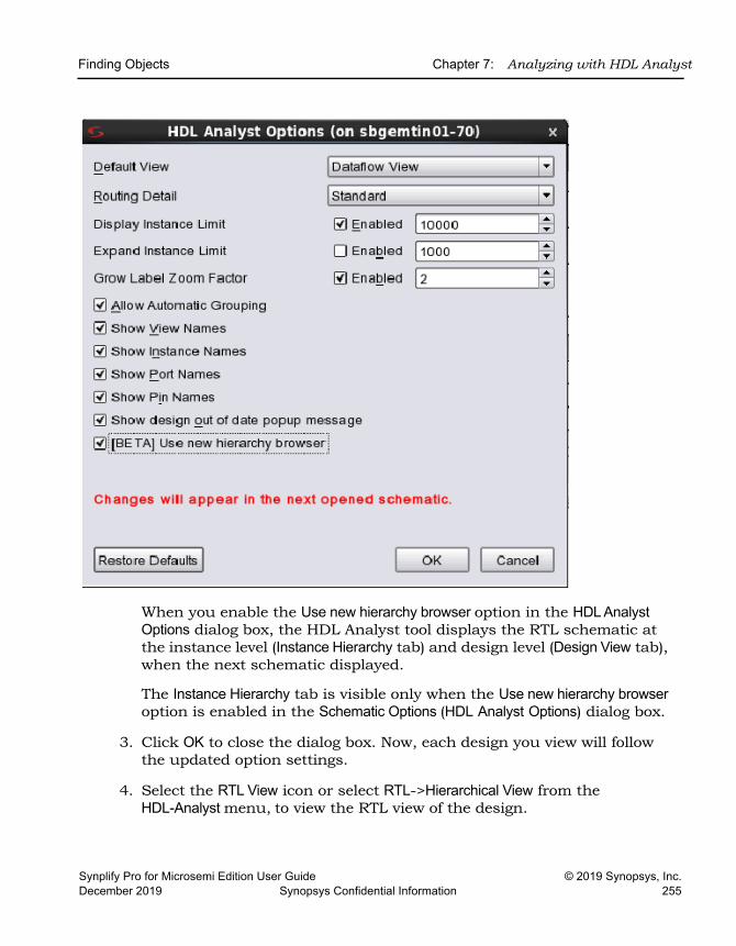
Finding Objects Chapter 7: Analyzing with HDL Analyst
Synplify Pro for Microsemi Edition User Guide © 2019 Synopsys, Inc.December 2019 Synopsys Confidential Information 255
When you enable the Use new hierarchy browser option in the HDL Analyst Options dialog box, the HDL Analyst tool displays the RTL schematic at the instance level (Instance Hierarchy tab) and design level (Design View tab), when the next schematic displayed.
The Instance Hierarchy tab is visible only when the Use new hierarchy browser option is enabled in the Schematic Options (HDL Analyst Options) dialog box.
3. Click OK to close the dialog box. Now, each design you view will follow the updated option settings.
4. Select the RTL View icon or select RTL->Hierarchical View from the HDL-Analyst menu, to view the RTL view of the design.
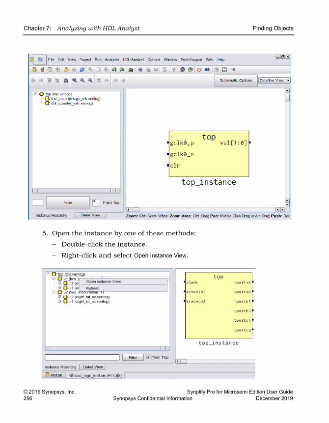
LO
Chapter 7: Analyzing with HDL Analyst Finding Objects
© 2019 Synopsys, Inc. Synplify Pro for Microsemi Edition User Guide256 Synopsys Confidential Information December 2019
5. Open the instance by one of these methods:
– Double-click the instance.
– Right-click and select Open Instance View.
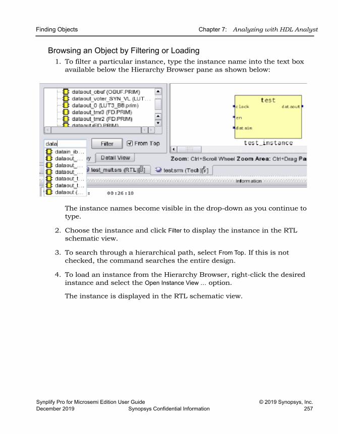
Finding Objects Chapter 7: Analyzing with HDL Analyst
Synplify Pro for Microsemi Edition User Guide © 2019 Synopsys, Inc.December 2019 Synopsys Confidential Information 257
Browsing an Object by Filtering or Loading1. To filter a particular instance, type the instance name into the text box
available below the Hierarchy Browser pane as shown below:
The instance names become visible in the drop-down as you continue to type.
2. Choose the instance and click Filter to display the instance in the RTL schematic view.
3. To search through a hierarchical path, select From Top. If this is not checked, the command searches the entire design.
4. To load an instance from the Hierarchy Browser, right-click the desired instance and select the Open Instance View … option.
The instance is displayed in the RTL schematic view.
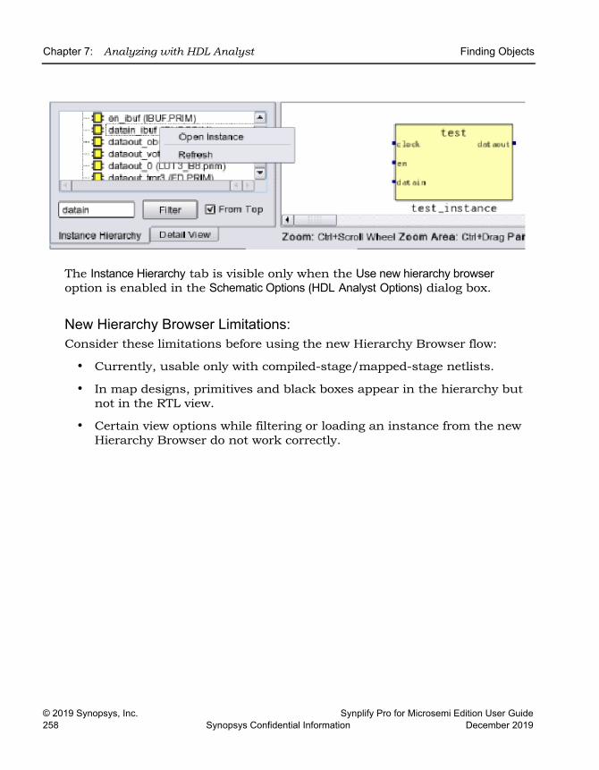
LO
Chapter 7: Analyzing with HDL Analyst Finding Objects
© 2019 Synopsys, Inc. Synplify Pro for Microsemi Edition User Guide258 Synopsys Confidential Information December 2019
The Instance Hierarchy tab is visible only when the Use new hierarchy browser option is enabled in the Schematic Options (HDL Analyst Options) dialog box.
New Hierarchy Browser Limitations:Consider these limitations before using the new Hierarchy Browser flow:
• Currently, usable only with compiled-stage/mapped-stage netlists.
• In map designs, primitives and black boxes appear in the hierarchy but not in the RTL view.
• Certain view options while filtering or loading an instance from the new Hierarchy Browser do not work correctly.
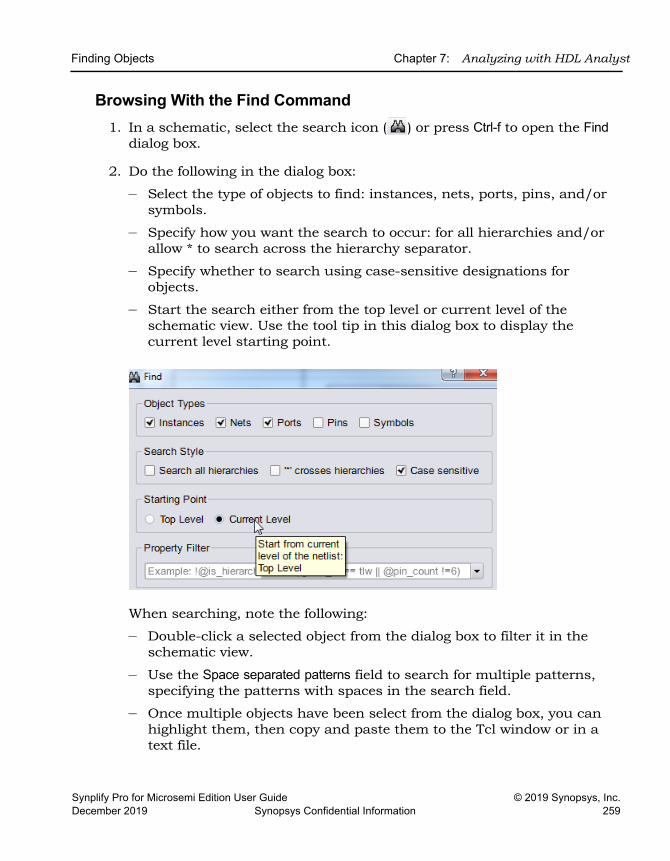
Finding Objects Chapter 7: Analyzing with HDL Analyst
Synplify Pro for Microsemi Edition User Guide © 2019 Synopsys, Inc.December 2019 Synopsys Confidential Information 259
Browsing With the Find Command1. In a schematic, select the search icon ( ) or press Ctrl-f to open the Find
dialog box.
2. Do the following in the dialog box:
– Select the type of objects to find: instances, nets, ports, pins, and/or symbols.
– Specify how you want the search to occur: for all hierarchies and/or allow * to search across the hierarchy separator.
– Specify whether to search using case-sensitive designations for objects.
– Start the search either from the top level or current level of the schematic view. Use the tool tip in this dialog box to display the current level starting point.
When searching, note the following:
– Double-click a selected object from the dialog box to filter it in the schematic view.
– Use the Space separated patterns field to search for multiple patterns, specifying the patterns with spaces in the search field.
– Once multiple objects have been select from the dialog box, you can highlight them, then copy and paste them to the Tcl window or in a text file.
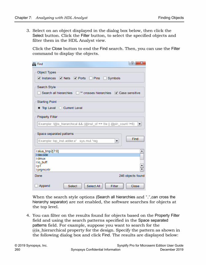
LO
Chapter 7: Analyzing with HDL Analyst Finding Objects
© 2019 Synopsys, Inc. Synplify Pro for Microsemi Edition User Guide260 Synopsys Confidential Information December 2019
3. Select on an object displayed in the dialog box below, then click the Select button. Click the Filter button, to select the specified objects and filter them in the HDL Analyst view.
Click the Close button to end the Find search. Then, you can use the Filter command to display the objects.
When the search style options (Search all hierarchies and ".",can cross the hierarchy separator) are not enabled, the software searches for objects at the top level.
4. You can filter on the results found for objects based on the Property Filter field and using the search patterns specified in the Space separated patterns field. For example, suppose you want to search for the @is_hierarchical property for the design. Specify the pattern as shown in the following dialog box and click Find. The results are displayed below:
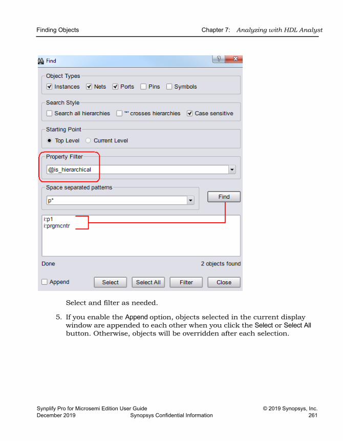
Finding Objects Chapter 7: Analyzing with HDL Analyst
Synplify Pro for Microsemi Edition User Guide © 2019 Synopsys, Inc.December 2019 Synopsys Confidential Information 261
Select and filter as needed.
5. If you enable the Append option, objects selected in the current display window are appended to each other when you click the Select or Select All button. Otherwise, objects will be overridden after each selection.
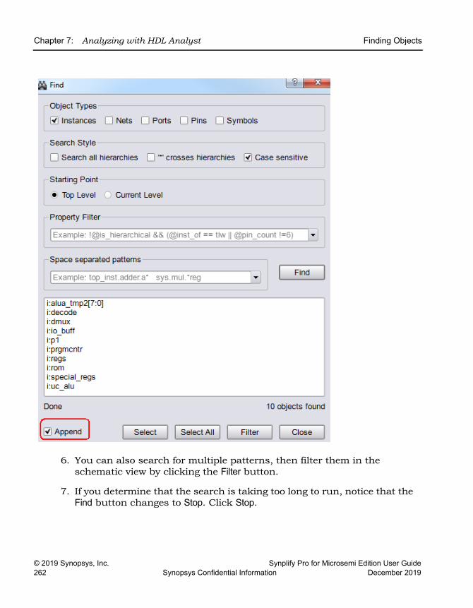
LO
Chapter 7: Analyzing with HDL Analyst Finding Objects
© 2019 Synopsys, Inc. Synplify Pro for Microsemi Edition User Guide262 Synopsys Confidential Information December 2019
6. You can also search for multiple patterns, then filter them in the schematic view by clicking the Filter button.
7. If you determine that the search is taking too long to run, notice that the Find button changes to Stop. Click Stop.
Finding Objects Chapter 7: Analyzing with HDL Analyst
Synplify Pro for Microsemi Edition User Guide © 2019 Synopsys, Inc.December 2019 Synopsys Confidential Information 263
The multi-threaded Find command can be interrupted and canceled once the search term has been identified. If you let the search complete, you will see Finishing and Done appearing under the display window.
Using Wildcards with the Find CommandUse the following wildcards when you search the schematics:
* The asterisk matches any sequence of characters.
? The question mark matches any single character, but not the hierarchy separator by default.
. The dot explicitly matches a hierarchy separator, so type one dot for each level of hierarchy. To use the dot as a pattern and not a hierarchy separator, type a backslash before the dot: \.
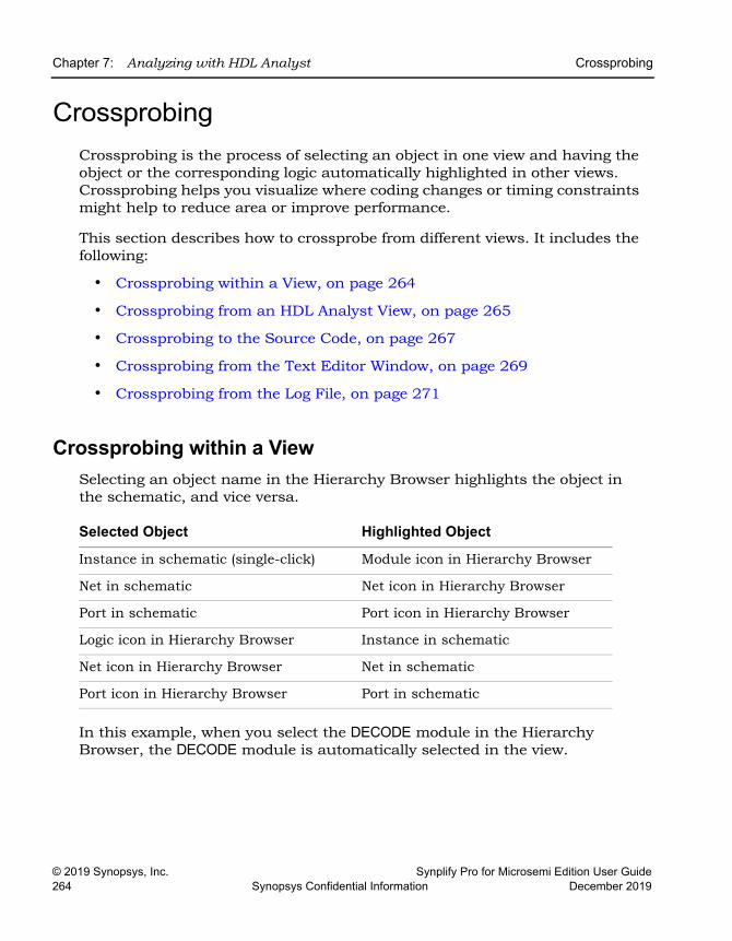
LO
Chapter 7: Analyzing with HDL Analyst Crossprobing
© 2019 Synopsys, Inc. Synplify Pro for Microsemi Edition User Guide264 Synopsys Confidential Information December 2019
Crossprobing Crossprobing is the process of selecting an object in one view and having the object or the corresponding logic automatically highlighted in other views. Crossprobing helps you visualize where coding changes or timing constraints might help to reduce area or improve performance.
This section describes how to crossprobe from different views. It includes the following:
• Crossprobing within a View, on page 264
• Crossprobing from an HDL Analyst View, on page 265
• Crossprobing to the Source Code, on page 267
• Crossprobing from the Text Editor Window, on page 269
• Crossprobing from the Log File, on page 271
Crossprobing within a ViewSelecting an object name in the Hierarchy Browser highlights the object in the schematic, and vice versa.
In this example, when you select the DECODE module in the Hierarchy Browser, the DECODE module is automatically selected in the view.
Selected Object Highlighted Object
Instance in schematic (single-click) Module icon in Hierarchy Browser
Net in schematic Net icon in Hierarchy Browser
Port in schematic Port icon in Hierarchy Browser
Logic icon in Hierarchy Browser Instance in schematic
Net icon in Hierarchy Browser Net in schematic
Port icon in Hierarchy Browser Port in schematic
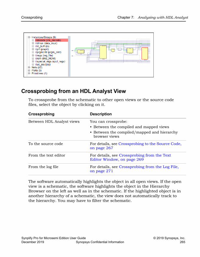
Crossprobing Chapter 7: Analyzing with HDL Analyst
Synplify Pro for Microsemi Edition User Guide © 2019 Synopsys, Inc.December 2019 Synopsys Confidential Information 265
Crossprobing from an HDL Analyst ViewTo crossprobe from the schematic to other open views or the source code files, select the object by clicking on it.
The software automatically highlights the object in all open views. If the open view is a schematic, the software highlights the object in the Hierarchy Browser on the left as well as in the schematic. If the highlighted object is in another hierarchy of a schematic, the view does not automatically track to the hierarchy. You may have to filter the schematic.
Crossprobing Description
Between HDL Analyst views You can crossprobe:• Between the compiled and mapped views• Between the compiled/mapped and hierarchy
browser views
To the source code For details, see Crossprobing to the Source Code, on page 267
From the text editor For details, see Crossprobing from the Text Editor Window, on page 269
From the log file For details, see Crossprobing from the Log File, on page 271
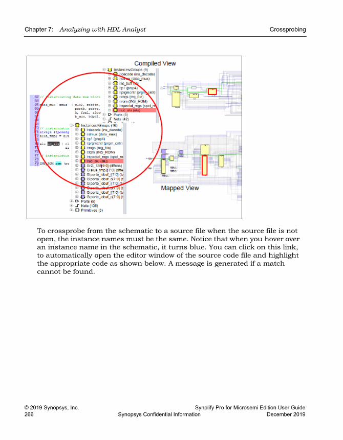
LO
Chapter 7: Analyzing with HDL Analyst Crossprobing
© 2019 Synopsys, Inc. Synplify Pro for Microsemi Edition User Guide266 Synopsys Confidential Information December 2019
To crossprobe from the schematic to a source file when the source file is not open, the instance names must be the same. Notice that when you hover over an instance name in the schematic, it turns blue. You can click on this link, to automatically open the editor window of the source code file and highlight the appropriate code as shown below. A message is generated if a match cannot be found.
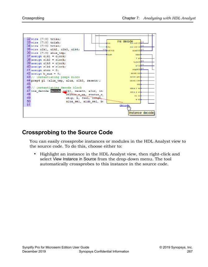
Crossprobing Chapter 7: Analyzing with HDL Analyst
Synplify Pro for Microsemi Edition User Guide © 2019 Synopsys, Inc.December 2019 Synopsys Confidential Information 267
Crossprobing to the Source Code You can easily crossprobe instances or modules in the HDL Analyst view to the source code. To do this, choose either to:
• Highlight an instance in the HDL Analyst view, then right-click and select View Instance in Source from the drop-down menu. The tool automatically crossprobes to this instance in the source code.
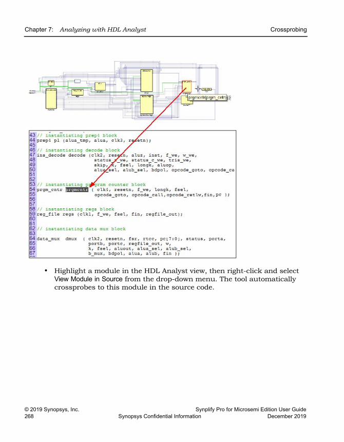
LO
Chapter 7: Analyzing with HDL Analyst Crossprobing
© 2019 Synopsys, Inc. Synplify Pro for Microsemi Edition User Guide268 Synopsys Confidential Information December 2019
• Highlight a module in the HDL Analyst view, then right-click and select View Module in Source from the drop-down menu. The tool automatically crossprobes to this module in the source code.
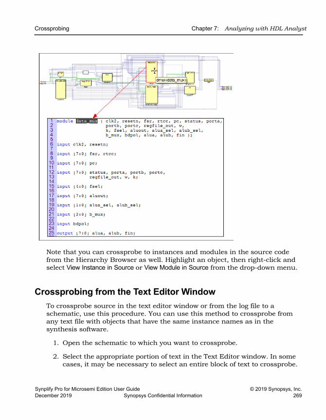
Crossprobing Chapter 7: Analyzing with HDL Analyst
Synplify Pro for Microsemi Edition User Guide © 2019 Synopsys, Inc.December 2019 Synopsys Confidential Information 269
Note that you can crossprobe to instances and modules in the source code from the Hierarchy Browser as well. Highlight an object, then right-click and select View Instance in Source or View Module in Source from the drop-down menu.
Crossprobing from the Text Editor WindowTo crossprobe source in the text editor window or from the log file to a schematic, use this procedure. You can use this method to crossprobe from any text file with objects that have the same instance names as in the synthesis software.
1. Open the schematic to which you want to crossprobe.
2. Select the appropriate portion of text in the Text Editor window. In some cases, it may be necessary to select an entire block of text to crossprobe.
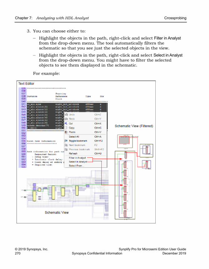
LO
Chapter 7: Analyzing with HDL Analyst Crossprobing
© 2019 Synopsys, Inc. Synplify Pro for Microsemi Edition User Guide270 Synopsys Confidential Information December 2019
3. You can choose either to:
– Highlight the objects in the path, right-click and select Filter in Analyst from the drop-down menu. The tool automatically filters the schematic so that you see just the selected objects in the view.
– Highlight the objects in the path, right-click and select Select in Analyst from the drop-down menu. You might have to filter the selected objects to see them displayed in the schematic.
For example:
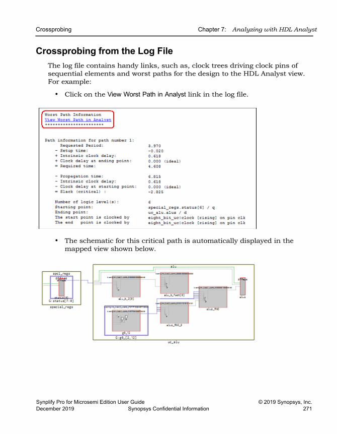
Crossprobing Chapter 7: Analyzing with HDL Analyst
Synplify Pro for Microsemi Edition User Guide © 2019 Synopsys, Inc.December 2019 Synopsys Confidential Information 271
Crossprobing from the Log FileThe log file contains handy links, such as, clock trees driving clock pins of sequential elements and worst paths for the design to the HDL Analyst view. For example:
• Click on the View Worst Path in Analyst link in the log file.
• The schematic for this critical path is automatically displayed in the mapped view shown below.
LO
Chapter 7: Analyzing with HDL Analyst Analyzing With the HDL Analyst Tool
© 2019 Synopsys, Inc. Synplify Pro for Microsemi Edition User Guide272 Synopsys Confidential Information December 2019
Analyzing With the HDL Analyst ToolThe HDL Analyst tool is a graphical productivity tool that helps you visualize your synthesis results. It displays schematics of the design at different stages, allowing you to graphically view and analyze your design. At an early design stage, the schematic displays high-level structures like RAM, ROM, operators, and FSM as abstractions. Later in the cycle, these structures are converted to gates and mapped to technology-specific resources.
To analyze information or compare views with the log file, the FSM view, and the source code, you can use techniques like crossprobing, flattening, and filtering. See the following for more information about analysis techniques.
• Viewing Design Hierarchy and Context, on page 272
• Filtering Schematics, on page 277
• Expanding Pin and Net Logic, on page 279
• Dissolving and Partial Dissolving of Buses and Pins, on page 285
• Flattening Schematic Hierarchy, on page 289
• Using the FSM Viewer, on page 291
For additional information about navigating the HDL Analyst views or using other techniques like crossprobing, see the following:
• Working in the Schematic, on page 224
• Exploring Design Hierarchy, on page 245
• Finding Objects, on page 253
• Crossprobing, on page 264
Viewing Design Hierarchy and ContextMost large designs are hierarchical, so the software provides tools that help you view hierarchy details or put the details in context. Alternatively, you can browse and navigate hierarchy with the Push/Pop command, or flatten the design to view internal hierarchy.
Analyzing With the HDL Analyst Tool Chapter 7: Analyzing with HDL Analyst
Synplify Pro for Microsemi Edition User Guide © 2019 Synopsys, Inc.December 2019 Synopsys Confidential Information 273
This section describes how to use interactive hierarchical viewing operations to better analyze your design. Automatic hierarchy viewing operations that are built into other commands are described in the context in which they appear.
1. To view the internal logic of instances in your design, do either of the following:
– To view the logic of an individual instance, push into it. This generates a new schematic with the internal details. Click the Back icon to return to the previous view.
– To view the logic of all instances in the design, select all the required instances and right-click then select Peek. This command lets you see internal logic in content, by adding the internal details to the current schematic. If the view is too cluttered with this option on, filter the view (see Filtering Schematics, on page 277) or push into the primitive. Click the Back icon to return to the previous view after filtering or pushing into the object.
The following figure compares these two methods:
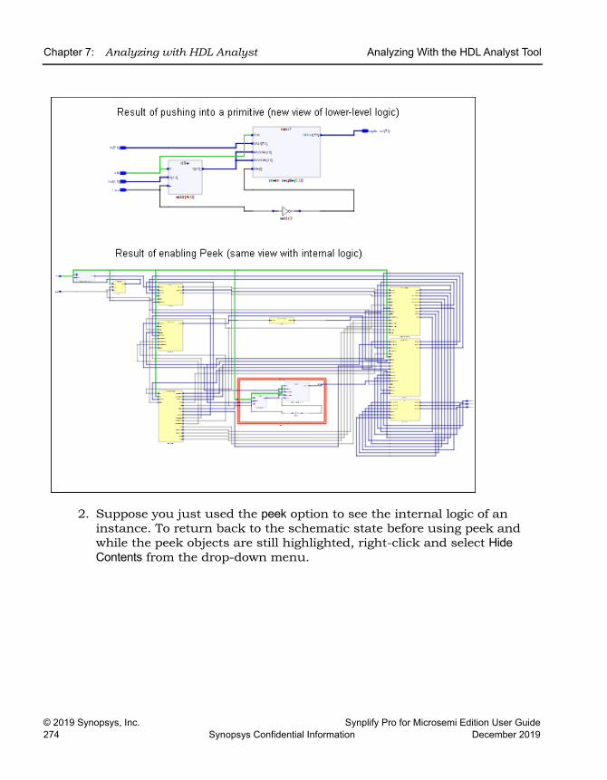
LO
Chapter 7: Analyzing with HDL Analyst Analyzing With the HDL Analyst Tool
© 2019 Synopsys, Inc. Synplify Pro for Microsemi Edition User Guide274 Synopsys Confidential Information December 2019
2. Suppose you just used the peek option to see the internal logic of an instance. To return back to the schematic state before using peek and while the peek objects are still highlighted, right-click and select Hide Contents from the drop-down menu.
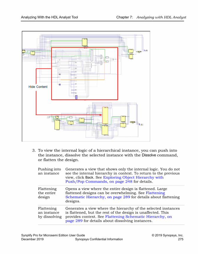
Analyzing With the HDL Analyst Tool Chapter 7: Analyzing with HDL Analyst
Synplify Pro for Microsemi Edition User Guide © 2019 Synopsys, Inc.December 2019 Synopsys Confidential Information 275
3. To view the internal logic of a hierarchical instance, you can push into the instance, dissolve the selected instance with the Dissolve command, or flatten the design.
Pushing into an instance
Generates a view that shows only the internal logic. You do not see the internal hierarchy in context. To return to the previous view, click Back. See Exploring Object Hierarchy with Push/Pop Commands, on page 248 for details.
Flattening the entire design
Opens a view where the entire design is flattened. Large flattened designs can be overwhelming. See Flattening Schematic Hierarchy, on page 289 for details about flattening designs.
Flattening an instance by dissolving
Generates a view where the hierarchy of the selected instances is flattened, but the rest of the design is unaffected. This provides context. See Flattening Schematic Hierarchy, on page 289 for details about dissolving instances.
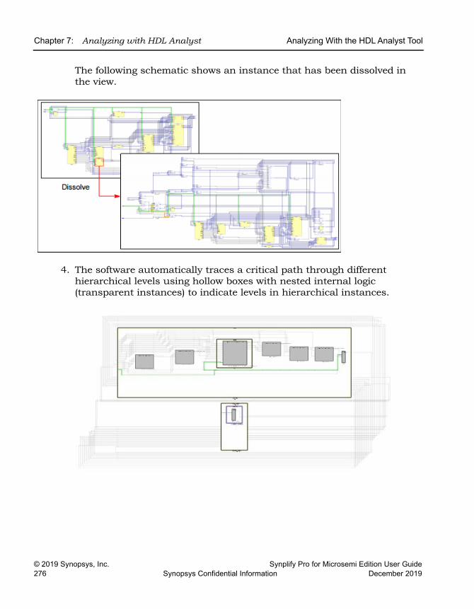
LO
Chapter 7: Analyzing with HDL Analyst Analyzing With the HDL Analyst Tool
© 2019 Synopsys, Inc. Synplify Pro for Microsemi Edition User Guide276 Synopsys Confidential Information December 2019
The following schematic shows an instance that has been dissolved in the view.
4. The software automatically traces a critical path through different hierarchical levels using hollow boxes with nested internal logic (transparent instances) to indicate levels in hierarchical instances.
Analyzing With the HDL Analyst Tool Chapter 7: Analyzing with HDL Analyst
Synplify Pro for Microsemi Edition User Guide © 2019 Synopsys, Inc.December 2019 Synopsys Confidential Information 277
Filtering SchematicsFiltering is a useful first step in analysis, because it focuses analysis on the relevant parts of the design. Some commands, like the Expand commands, automatically generate filtered views; this procedure only discusses manual filtering, where you use the Filter command to isolate selected objects.
This table lists the advantages of using filtering over flattening:
1. Select the objects that you want to isolate. For example, you can select two connected objects.
2. Select the Filter command, using one of these methods:
– Right-click and select Filter from the popup menu.
– Click the Filter icon (buffer gate) ( ).
The software filters the design and displays the selected objects in a filtered view. These objects are isolated in the schematic displayed. Select Unfilter to take you back to the view where objects are at the same level.
Filter Schematic Command Flatten Commands
Loads part of the design; better memory usage
Loads entire design
Combine filtering with the Push/Pop command, and history buttons (Back and Forward) to move freely between hierarchical levels
You can use the Back arrow or Show Top View icon to return to previous view that has been flattened.
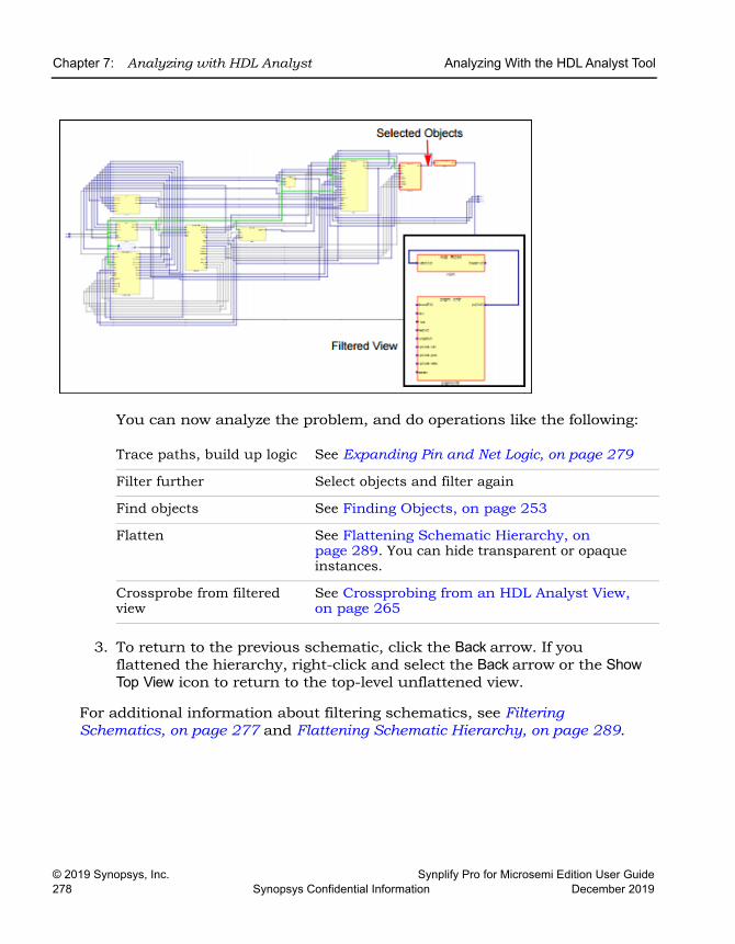
LO
Chapter 7: Analyzing with HDL Analyst Analyzing With the HDL Analyst Tool
© 2019 Synopsys, Inc. Synplify Pro for Microsemi Edition User Guide278 Synopsys Confidential Information December 2019
You can now analyze the problem, and do operations like the following:
3. To return to the previous schematic, click the Back arrow. If you flattened the hierarchy, right-click and select the Back arrow or the Show Top View icon to return to the top-level unflattened view.
For additional information about filtering schematics, see Filtering Schematics, on page 277 and Flattening Schematic Hierarchy, on page 289.
Trace paths, build up logic See Expanding Pin and Net Logic, on page 279
Filter further Select objects and filter again
Find objects See Finding Objects, on page 253
Flatten See Flattening Schematic Hierarchy, on page 289. You can hide transparent or opaque instances.
Crossprobe from filtered view
See Crossprobing from an HDL Analyst View, on page 265
Analyzing With the HDL Analyst Tool Chapter 7: Analyzing with HDL Analyst
Synplify Pro for Microsemi Edition User Guide © 2019 Synopsys, Inc.December 2019 Synopsys Confidential Information 279
Expanding Pin and Net LogicWhen you are working in a filtered view, you might need to include more logic in your selected set to debug your design.
Use the Expand commands with the Filter and Flatten commands to isolate just the logic that you want to examine. Filtering isolates logic, flattening removes hierarchy. See Filtering Schematics, on page 277 and Flattening Schematic Hierarchy, on page 289 for details.
1. To expand logic from a pin hierarchically across boundaries, use the following commands.
To ... Do this ...
See the first-level cells connected to a pin in the same hierarchy
Select a pin and select Expand. See Expanding Filtered Logic Example, on page 280.
See the first-level cells connected to a pin at any level of hierarchy
Select a pin and select Hierarchical Expand.
See all cells until a register or port is connected to the selected pin at the same level of hierarchy
Select a pin and select Expand to Reg/Port.
See internal cells connected to a pin
Select a pin and select Expand Inwards. The software filters the schematic and displays the internal cells closest to the port. See Expanding Inwards Example, on page 280.
Select only one object connected to a port or pin
Select a pin or port and select Expand to One Object.
See all cells until a register or port is connected to the selected pin at any level of hierarchy
Select a pin and select Hierarchical Expand to Reg/Port.
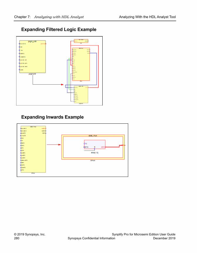
LO
Chapter 7: Analyzing with HDL Analyst Analyzing With the HDL Analyst Tool
© 2019 Synopsys, Inc. Synplify Pro for Microsemi Edition User Guide280 Synopsys Confidential Information December 2019
Expanding Filtered Logic Example
Expanding Inwards Example
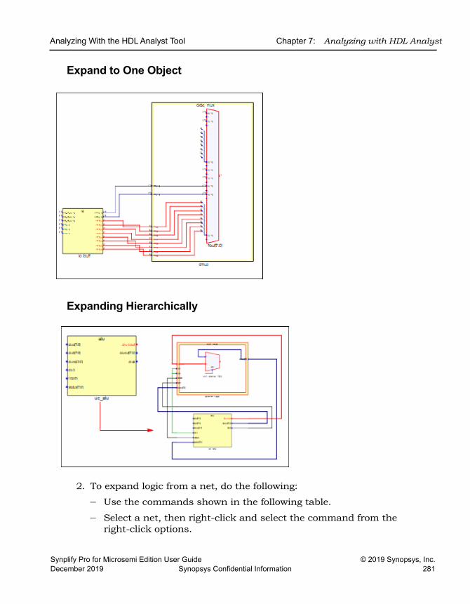
Analyzing With the HDL Analyst Tool Chapter 7: Analyzing with HDL Analyst
Synplify Pro for Microsemi Edition User Guide © 2019 Synopsys, Inc.December 2019 Synopsys Confidential Information 281
Expand to One Object
Expanding Hierarchically
2. To expand logic from a net, do the following:
– Use the commands shown in the following table.
– Select a net, then right-click and select the command from the right-click options.
LO
Chapter 7: Analyzing with HDL Analyst Analyzing With the HDL Analyst Tool
© 2019 Synopsys, Inc. Synplify Pro for Microsemi Edition User Guide282 Synopsys Confidential Information December 2019
The following figures illustrate this.
To ... Do this ...
See all instances connected to the selected net being filtered
Select a net and select Filter by Nets.
Select the instances in the same hierarchy connected to the selected net
Select a net and select Expand Nets.
Select and show instances connected to the selected net at any level of hierarchy. The instance that drives the net and the instance which is driven by the net are shown.
Select a net and select Hierarchical Expand Nets.
Select and show instances connected to the selected net at any level of hierarchy. Instances that are not connected are removed from the view.
Select a net, then Filter by Net, and select Hierarchical Expand Nets.
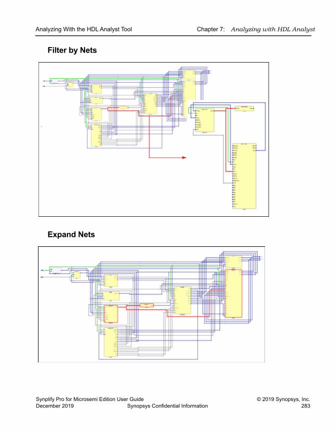
Analyzing With the HDL Analyst Tool Chapter 7: Analyzing with HDL Analyst
Synplify Pro for Microsemi Edition User Guide © 2019 Synopsys, Inc.December 2019 Synopsys Confidential Information 283
Filter by Nets
Expand Nets
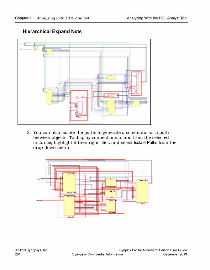
LO
Chapter 7: Analyzing with HDL Analyst Analyzing With the HDL Analyst Tool
© 2019 Synopsys, Inc. Synplify Pro for Microsemi Edition User Guide284 Synopsys Confidential Information December 2019
Hierarchical Expand Nets
3. You can also isolate the paths to generate a schematic for a path between objects. To display connections to and from the selected instance, highlight it then right-click and select Isolate Paths from the drop-down menu.
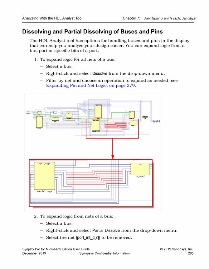
Analyzing With the HDL Analyst Tool Chapter 7: Analyzing with HDL Analyst
Synplify Pro for Microsemi Edition User Guide © 2019 Synopsys, Inc.December 2019 Synopsys Confidential Information 285
Dissolving and Partial Dissolving of Buses and PinsThe HDL Analyst tool has options for handling buses and pins in the display that can help you analyze your design easier. You can expand logic from a bus port or specific bits of a port.
1. To expand logic for all nets of a bus:
– Select a bus.
– Right-click and select Dissolve from the drop-down menu.
– Filter by net and choose an operation to expand as needed; see Expanding Pin and Net Logic, on page 279.
2. To expand logic from nets of a bus:
– Select a bus.
– Right-click and select Partial Dissolve from the drop-down menu.
– Select the net (port_int_c[7]) to be removed.
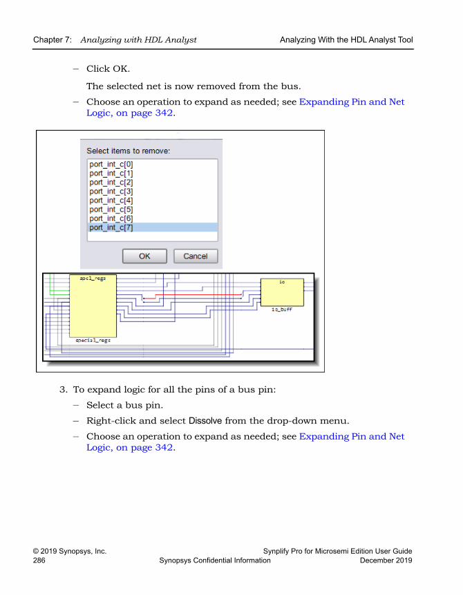
LO
Chapter 7: Analyzing with HDL Analyst Analyzing With the HDL Analyst Tool
© 2019 Synopsys, Inc. Synplify Pro for Microsemi Edition User Guide286 Synopsys Confidential Information December 2019
– Click OK.
The selected net is now removed from the bus.
– Choose an operation to expand as needed; see Expanding Pin and Net Logic, on page 342.
3. To expand logic for all the pins of a bus pin:
– Select a bus pin.
– Right-click and select Dissolve from the drop-down menu.
– Choose an operation to expand as needed; see Expanding Pin and Net Logic, on page 342.
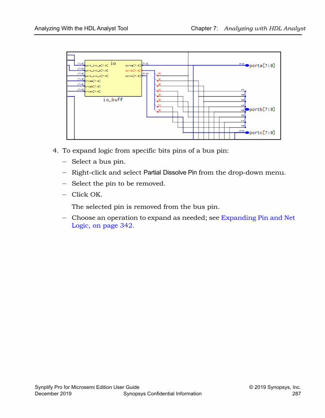
Analyzing With the HDL Analyst Tool Chapter 7: Analyzing with HDL Analyst
Synplify Pro for Microsemi Edition User Guide © 2019 Synopsys, Inc.December 2019 Synopsys Confidential Information 287
4. To expand logic from specific bits pins of a bus pin:
– Select a bus pin.
– Right-click and select Partial Dissolve Pin from the drop-down menu.
– Select the pin to be removed.
– Click OK.
The selected pin is removed from the bus pin.
– Choose an operation to expand as needed; see Expanding Pin and Net Logic, on page 342.
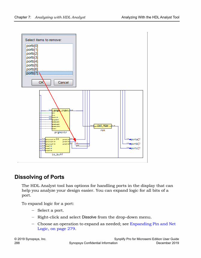
LO
Chapter 7: Analyzing with HDL Analyst Analyzing With the HDL Analyst Tool
© 2019 Synopsys, Inc. Synplify Pro for Microsemi Edition User Guide288 Synopsys Confidential Information December 2019
Dissolving of PortsThe HDL Analyst tool has options for handling ports in the display that can help you analyze your design easier. You can expand logic for all bits of a port.
To expand logic for a port:
– Select a port.
– Right-click and select Dissolve from the drop-down menu.
– Choose an operation to expand as needed; see Expanding Pin and Net Logic, on page 279.
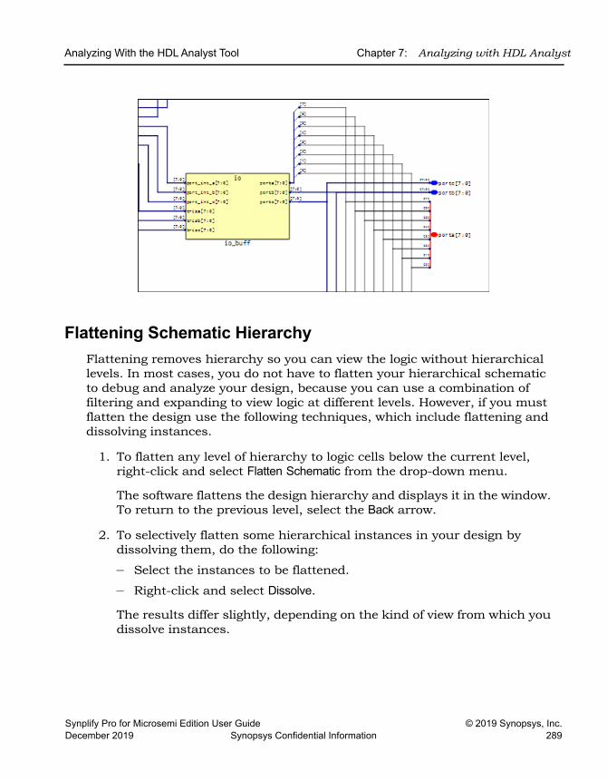
Analyzing With the HDL Analyst Tool Chapter 7: Analyzing with HDL Analyst
Synplify Pro for Microsemi Edition User Guide © 2019 Synopsys, Inc.December 2019 Synopsys Confidential Information 289
Flattening Schematic HierarchyFlattening removes hierarchy so you can view the logic without hierarchical levels. In most cases, you do not have to flatten your hierarchical schematic to debug and analyze your design, because you can use a combination of filtering and expanding to view logic at different levels. However, if you must flatten the design use the following techniques, which include flattening and dissolving instances.
1. To flatten any level of hierarchy to logic cells below the current level, right-click and select Flatten Schematic from the drop-down menu.
The software flattens the design hierarchy and displays it in the window. To return to the previous level, select the Back arrow.
2. To selectively flatten some hierarchical instances in your design by dissolving them, do the following:
– Select the instances to be flattened.
– Right-click and select Dissolve.
The results differ slightly, depending on the kind of view from which you dissolve instances.
LO
Chapter 7: Analyzing with HDL Analyst Analyzing With the HDL Analyst Tool
© 2019 Synopsys, Inc. Synplify Pro for Microsemi Edition User Guide290 Synopsys Confidential Information December 2019
The following figure illustrates this.
Starting View Software Generates a ...
Filtered Filtered view with the internal logic of dissolved instances displayed within hollow bounding boxes (transparent instances), and the hierarchy of the rest of the design unchanged. If the transparent instance does not display internal logic, use one of the alternatives described in step 4 of Viewing Design Hierarchy and Context, on page 272. Use the Back button to return to the undissolved view.
Unfiltered New, flattened view with the dissolved instances flattened in place (no nesting) to Boolean logic, and the hierarchy of the rest of the design unchanged. You can use the Back button to return to previous or the top-level views.
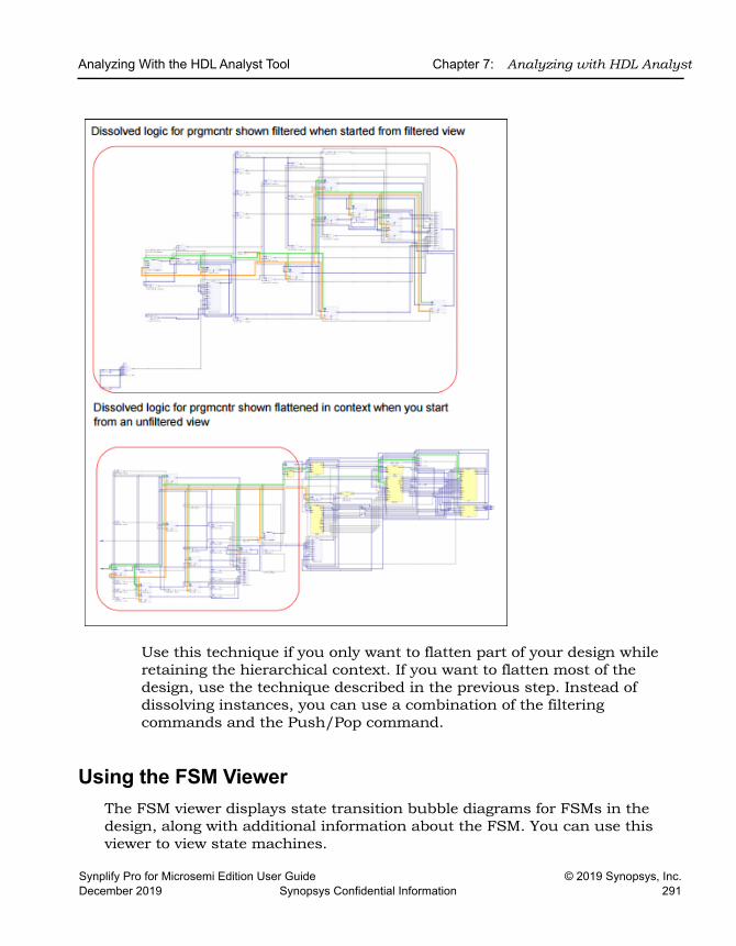
Analyzing With the HDL Analyst Tool Chapter 7: Analyzing with HDL Analyst
Synplify Pro for Microsemi Edition User Guide © 2019 Synopsys, Inc.December 2019 Synopsys Confidential Information 291
Use this technique if you only want to flatten part of your design while retaining the hierarchical context. If you want to flatten most of the design, use the technique described in the previous step. Instead of dissolving instances, you can use a combination of the filtering commands and the Push/Pop command.
Using the FSM ViewerThe FSM viewer displays state transition bubble diagrams for FSMs in the design, along with additional information about the FSM. You can use this viewer to view state machines.
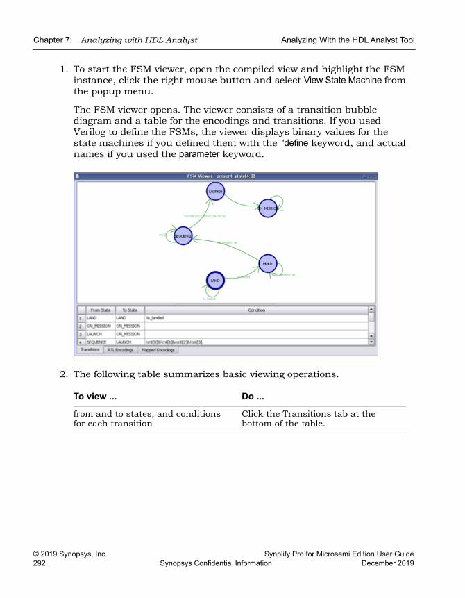
LO
Chapter 7: Analyzing with HDL Analyst Analyzing With the HDL Analyst Tool
© 2019 Synopsys, Inc. Synplify Pro for Microsemi Edition User Guide292 Synopsys Confidential Information December 2019
1. To start the FSM viewer, open the compiled view and highlight the FSM instance, click the right mouse button and select View State Machine from the popup menu.
The FSM viewer opens. The viewer consists of a transition bubble diagram and a table for the encodings and transitions. If you used Verilog to define the FSMs, the viewer displays binary values for the state machines if you defined them with the ‘define keyword, and actual names if you used the parameter keyword.
2. The following table summarizes basic viewing operations.
To view ... Do ...
from and to states, and conditions for each transition
Click the Transitions tab at the bottom of the table.
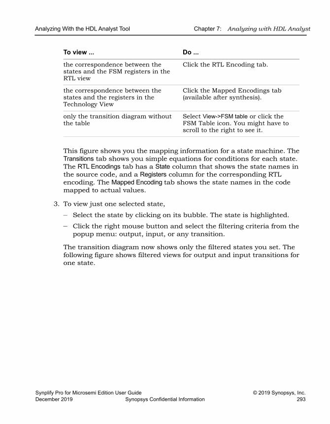
Analyzing With the HDL Analyst Tool Chapter 7: Analyzing with HDL Analyst
Synplify Pro for Microsemi Edition User Guide © 2019 Synopsys, Inc.December 2019 Synopsys Confidential Information 293
This figure shows you the mapping information for a state machine. The Transitions tab shows you simple equations for conditions for each state. The RTL Encodings tab has a State column that shows the state names in the source code, and a Registers column for the corresponding RTL encoding. The Mapped Encoding tab shows the state names in the code mapped to actual values.
3. To view just one selected state,
– Select the state by clicking on its bubble. The state is highlighted.
– Click the right mouse button and select the filtering criteria from the popup menu: output, input, or any transition.
The transition diagram now shows only the filtered states you set. The following figure shows filtered views for output and input transitions for one state.
the correspondence between the states and the FSM registers in the RTL view
Click the RTL Encoding tab.
the correspondence between the states and the registers in the Technology View
Click the Mapped Encodings tab (available after synthesis).
only the transition diagram without the table
Select View->FSM table or click the FSM Table icon. You might have to scroll to the right to see it.
To view ... Do ...
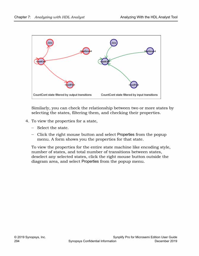
LO
Chapter 7: Analyzing with HDL Analyst Analyzing With the HDL Analyst Tool
© 2019 Synopsys, Inc. Synplify Pro for Microsemi Edition User Guide294 Synopsys Confidential Information December 2019
Similarly, you can check the relationship between two or more states by selecting the states, filtering them, and checking their properties.
4. To view the properties for a state,
– Select the state.
– Click the right mouse button and select Properties from the popup menu. A form shows you the properties for that state.
To view the properties for the entire state machine like encoding style, number of states, and total number of transitions between states, deselect any selected states, click the right mouse button outside the diagram area, and select Properties from the popup menu.
Working in the Standard Schematic Chapter 7: Analyzing with HDL Analyst
Synplify Pro for Microsemi Edition User Guide © 2019 Synopsys, Inc.December 2019 Synopsys Confidential Information 295
Working in the Standard SchematicThe HDL Analyst includes the RTL and Technology views, which are schematics used to graphically analyze your design. The RTL view is available after a design is compiled; the Technology view is available after a designed has been synthesized and contains technology-specific primitives.
For detailed descriptions of these views, see the HDL Analyst Tool section of the Reference Manual. This section describes basic procedures you use in the RTL and Technology views. The information is organized into these topics:
• Differentiating Between the HDL Analyst Views, on page 296
• Opening the Views, on page 296
• Viewing Object Properties, on page 297
• Selecting Objects in the RTL/Technology Views, on page 302
• Working with Multisheet Schematics, on page 303
• Moving Between Views in a Schematic Window, on page 304
• Setting Schematic Preferences, on page 305
• Managing Windows, on page 306
For information on specific tasks like analyzing critical paths, see the following sections:
• Exploring Object Hierarchy by Pushing/Popping, on page 309
• Exploring Object Hierarchy of Transparent Instances, on page 314
• Browsing to Find Objects in HDL Analyst Views, on page 316
• Crossprobing (Standard), on page 329
• Analyzing With the Standard HDL Analyst Tool, on page 336
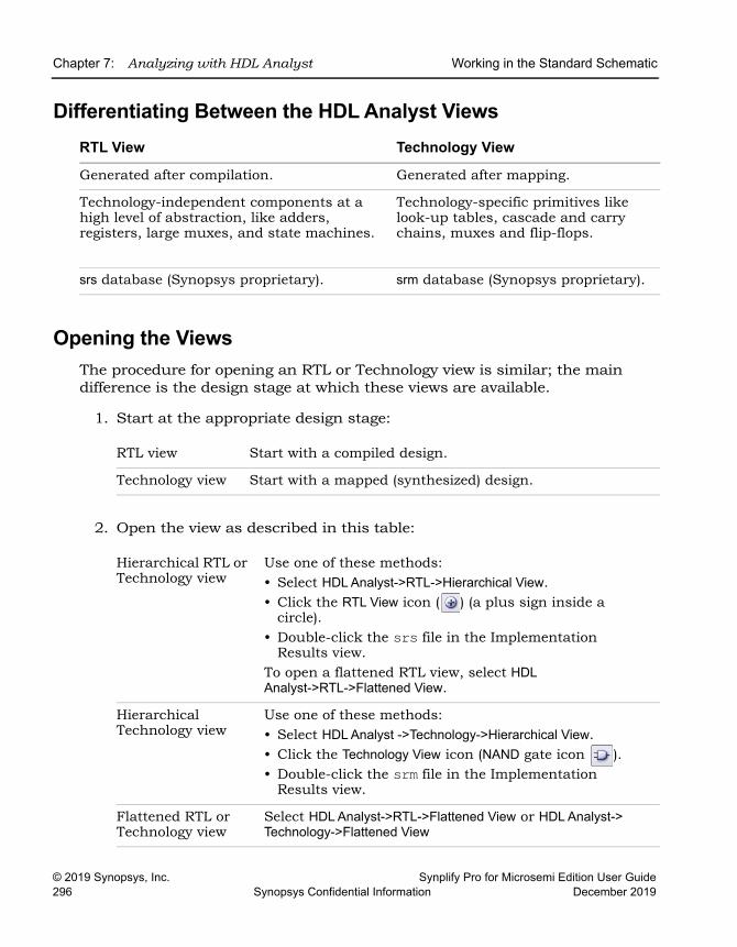
LO
Chapter 7: Analyzing with HDL Analyst Working in the Standard Schematic
© 2019 Synopsys, Inc. Synplify Pro for Microsemi Edition User Guide296 Synopsys Confidential Information December 2019
Differentiating Between the HDL Analyst Views
Opening the ViewsThe procedure for opening an RTL or Technology view is similar; the main difference is the design stage at which these views are available.
1. Start at the appropriate design stage:
2. Open the view as described in this table:
RTL View Technology View
Generated after compilation. Generated after mapping.
Technology-independent components at a high level of abstraction, like adders, registers, large muxes, and state machines.
Technology-specific primitives like look-up tables, cascade and carry chains, muxes and flip-flops.
srs database (Synopsys proprietary). srm database (Synopsys proprietary).
RTL view Start with a compiled design.
Technology view Start with a mapped (synthesized) design.
Hierarchical RTL or Technology view
Use one of these methods: • Select HDL Analyst->RTL->Hierarchical View. • Click the RTL View icon ( ) (a plus sign inside a
circle).• Double-click the srs file in the Implementation
Results view.To open a flattened RTL view, select HDL Analyst->RTL->Flattened View.
Hierarchical Technology view
Use one of these methods: • Select HDL Analyst ->Technology->Hierarchical View. • Click the Technology View icon (NAND gate icon ). • Double-click the srm file in the Implementation
Results view.
Flattened RTL or Technology view
Select HDL Analyst->RTL->Flattened View or HDL Analyst-> Technology->Flattened View
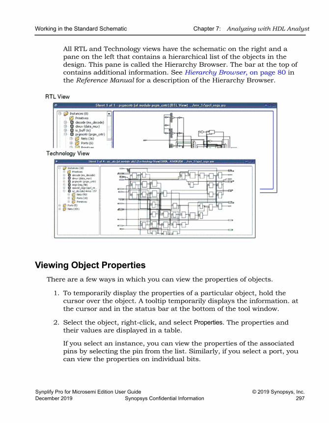
Working in the Standard Schematic Chapter 7: Analyzing with HDL Analyst
Synplify Pro for Microsemi Edition User Guide © 2019 Synopsys, Inc.December 2019 Synopsys Confidential Information 297
All RTL and Technology views have the schematic on the right and a pane on the left that contains a hierarchical list of the objects in the design. This pane is called the Hierarchy Browser. The bar at the top of contains additional information. See Hierarchy Browser, on page 80 in the Reference Manual for a description of the Hierarchy Browser.
Viewing Object PropertiesThere are a few ways in which you can view the properties of objects.
1. To temporarily display the properties of a particular object, hold the cursor over the object. A tooltip temporarily displays the information. at the cursor and in the status bar at the bottom of the tool window.
2. Select the object, right-click, and select Properties. The properties and their values are displayed in a table.
If you select an instance, you can view the properties of the associated pins by selecting the pin from the list. Similarly, if you select a port, you can view the properties on individual bits.
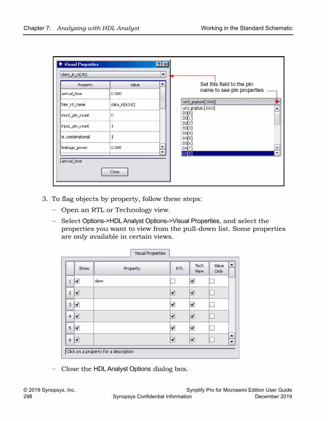
LO
Chapter 7: Analyzing with HDL Analyst Working in the Standard Schematic
© 2019 Synopsys, Inc. Synplify Pro for Microsemi Edition User Guide298 Synopsys Confidential Information December 2019
3. To flag objects by property, follow these steps:
– Open an RTL or Technology view.
– Select Options->HDL Analyst Options->Visual Properties, and select the properties you want to view from the pull-down list. Some properties are only available in certain views.
– Close the HDL Analyst Options dialog box.
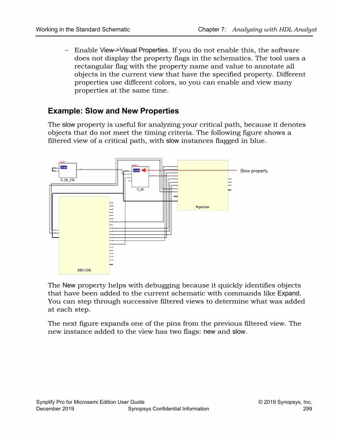
Working in the Standard Schematic Chapter 7: Analyzing with HDL Analyst
Synplify Pro for Microsemi Edition User Guide © 2019 Synopsys, Inc.December 2019 Synopsys Confidential Information 299
– Enable View->Visual Properties. If you do not enable this, the software does not display the property flags in the schematics. The tool uses a rectangular flag with the property name and value to annotate all objects in the current view that have the specified property. Different properties use different colors, so you can enable and view many properties at the same time.
Example: Slow and New PropertiesThe slow property is useful for analyzing your critical path, because it denotes objects that do not meet the timing criteria. The following figure shows a filtered view of a critical path, with slow instances flagged in blue.
The New property helps with debugging because it quickly identifies objects that have been added to the current schematic with commands like Expand. You can step through successive filtered views to determine what was added at each step.
The next figure expands one of the pins from the previous filtered view. The new instance added to the view has two flags: new and slow.
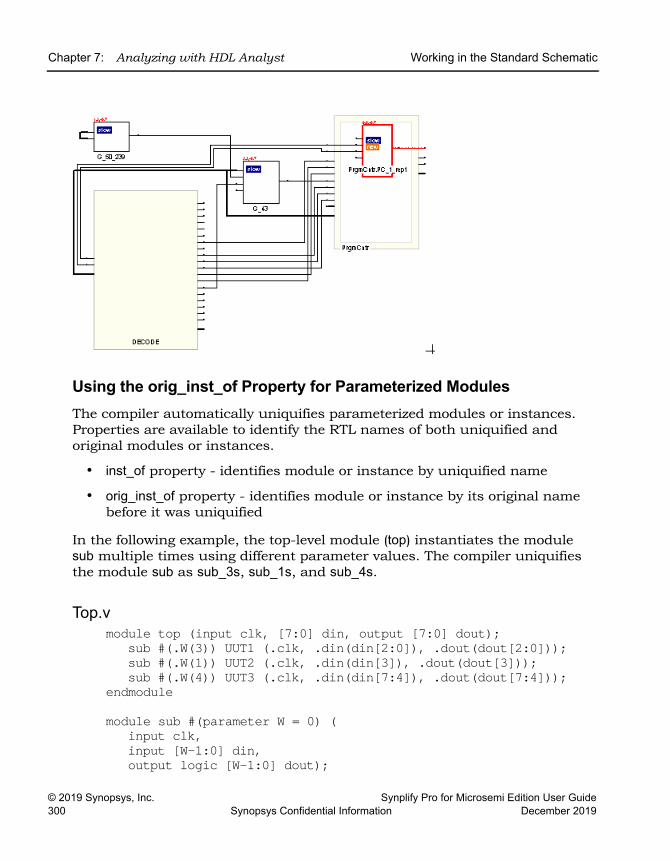
LO
Chapter 7: Analyzing with HDL Analyst Working in the Standard Schematic
© 2019 Synopsys, Inc. Synplify Pro for Microsemi Edition User Guide300 Synopsys Confidential Information December 2019
Using the orig_inst_of Property for Parameterized Modules The compiler automatically uniquifies parameterized modules or instances. Properties are available to identify the RTL names of both uniquified and original modules or instances.
• inst_of property - identifies module or instance by uniquified name
• orig_inst_of property - identifies module or instance by its original name before it was uniquified
In the following example, the top-level module (top) instantiates the module sub multiple times using different parameter values. The compiler uniquifies the module sub as sub_3s, sub_1s, and sub_4s.
Top.vmodule top (input clk, [7:0] din, output [7:0] dout);
sub #(.W(3)) UUT1 (.clk, .din(din[2:0]), .dout(dout[2:0]));sub #(.W(1)) UUT2 (.clk, .din(din[3]), .dout(dout[3]));sub #(.W(4)) UUT3 (.clk, .din(din[7:4]), .dout(dout[7:4]));
endmodule
module sub #(parameter W = 0) (input clk,input [W-1:0] din,output logic [W-1:0] dout);
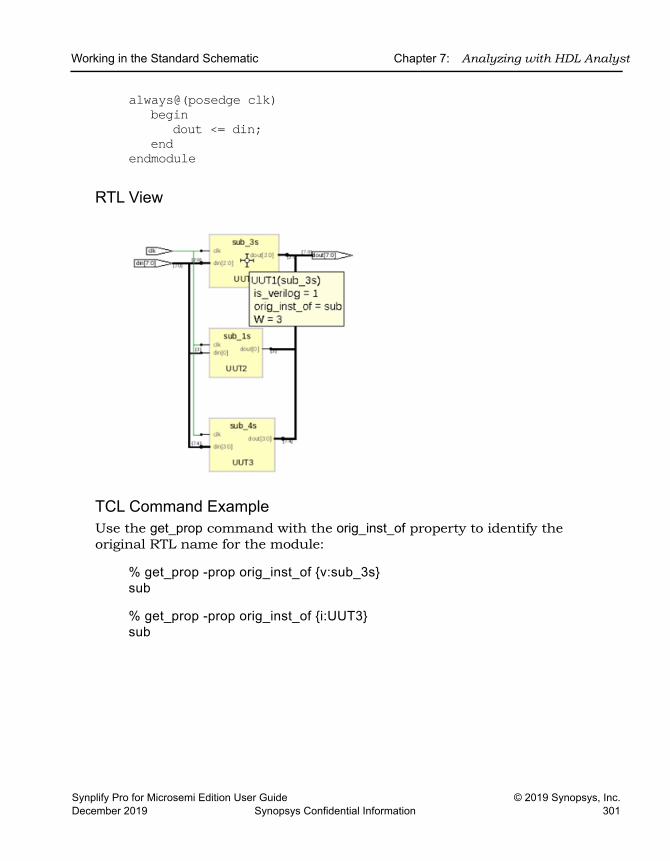
Working in the Standard Schematic Chapter 7: Analyzing with HDL Analyst
Synplify Pro for Microsemi Edition User Guide © 2019 Synopsys, Inc.December 2019 Synopsys Confidential Information 301
always@(posedge clk) begin
dout <= din;end
endmodule
RTL View
TCL Command ExampleUse the get_prop command with the orig_inst_of property to identify the original RTL name for the module:
% get_prop -prop orig_inst_of {v:sub_3s}sub
% get_prop -prop orig_inst_of {i:UUT3}sub
LO
Chapter 7: Analyzing with HDL Analyst Working in the Standard Schematic
© 2019 Synopsys, Inc. Synplify Pro for Microsemi Edition User Guide302 Synopsys Confidential Information December 2019
Selecting Objects in the RTL/Technology ViewsFor mouse selection, standard object selection rules apply: In selection mode, the pointer is shaped like a crosshair.
The HDL Analyst view highlights selected objects in red. If the object you select is on another sheet of the schematic, the schematic tracks to the appropriate sheet. If you have other windows open, the selected object is highlighted in the other windows as well (crossprobing), but the other windows do not track to the correct sheet. Selected nets that span different hierarchical levels are highlighted on all the levels. See Crossprobing (Standard), on page 329 for more information about crossprobing.
Some commands affect selection by adding to the selected set of objects: the Expand commands, the Select All commands, and the Select Net Driver and Select Net Instances commands.
To select ... Do this ...
Single objects Click the object in the RTL or Technology schematic, or click the object name in the Hierarchy Browser.
Multiple objects Use one of these methods:• Draw a rectangle around the objects. • Select an object, press Ctrl, and click other objects you want to
select.• Select multiple objects in the Hierarchy Browser. See
Browsing With the Hierarchy Browser, on page 316. • Use Find to select the objects you want. See Using Find for
Hierarchical and Restricted Searches, on page 318.
Objects by type (instances, ports, nets)
Use Edit->Find to select the objects (see Browsing With the Find Command, on page 317), or use the Hierarchy Browser, which lists objects by type.
All objects of a certain type (instances, ports, nets)
To select all objects of a certain type, do either of the following:• Right-click and choose the appropriate command from the
Select All Schematic/Current Sheet popup menus. • Select the objects in the Hierarchy Browser.
No objects (deselect all currently selected objects)
Click the left mouse button in a blank area of the schematic or click the right mouse button to bring up the pop-up menu and choose Unselect All. Deselected objects are no longer highlighted.
Working in the Standard Schematic Chapter 7: Analyzing with HDL Analyst
Synplify Pro for Microsemi Edition User Guide © 2019 Synopsys, Inc.December 2019 Synopsys Confidential Information 303
Working with Multisheet SchematicsThe title bar of the RTL or Technology view indicates the number of sheets in that schematic. In a multisheet schematic, nets that span multiple sheets are indicated by sheet connector symbols, which you can use for navigation.
1. To reduce the number of sheets in a schematic, select Options->HDL Analyst Options and increase the values set for Sheet Size Options - Instances and Sheet Size Options - Filtered Instances. To display fewer objects per sheet (increase the number of sheets), increase the values.
These options set a limit on the number of objects displayed on an unfil-tered and filtered schematic sheet, respectively. A low Filtered Instances value can cause lower-level logic inside a transparent instance to be displayed on a separate sheet. The sheet numbers are indicated inside the empty transparent instance.
2. To navigate through a multisheet schematic, refer to this table. It summarizes common operations and ways to navigate.
To view ... Use one of these methods ...
Next sheet or previous sheet
Select View->Next/Previous Sheet. Press the right mouse button and draw a horizontal mouse stroke (left to right for next sheet, right to left for previous sheet).Click the icons: Next Sheet ( ) or Previous Sheet ( ) Press Shift-right arrow (Next Sheet) or Shift-left arrow (Previous sheet).Navigate with View->Back and View ->Forward if the next/previous sheets are part of the display history.
A specific sheet number
Select View->View Sheets and select the sheet. Click the right mouse button, select View Sheets from the popup menu, and then select the sheet you want. Press Ctrl-g and select the sheet you want.
Lower-level logic of a transparent instance on separate sheets
Check the sheet numbers indicated inside the empty transparent instance. Use the sheet navigation commands like Next Sheet or View Sheets to move to the sheet you need.
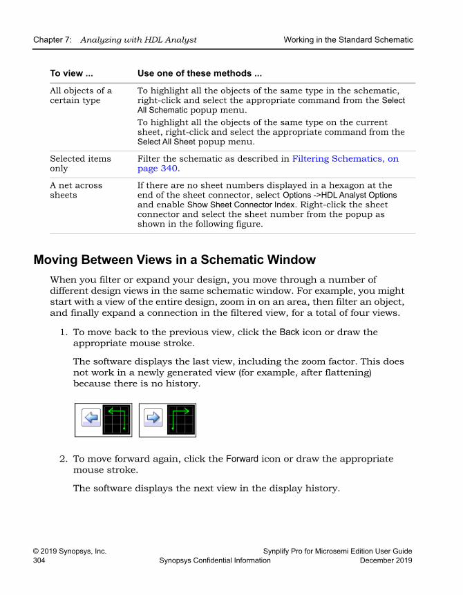
LO
Chapter 7: Analyzing with HDL Analyst Working in the Standard Schematic
© 2019 Synopsys, Inc. Synplify Pro for Microsemi Edition User Guide304 Synopsys Confidential Information December 2019
Moving Between Views in a Schematic WindowWhen you filter or expand your design, you move through a number of different design views in the same schematic window. For example, you might start with a view of the entire design, zoom in on an area, then filter an object, and finally expand a connection in the filtered view, for a total of four views.
1. To move back to the previous view, click the Back icon or draw the appropriate mouse stroke.
The software displays the last view, including the zoom factor. This does not work in a newly generated view (for example, after flattening) because there is no history.
2. To move forward again, click the Forward icon or draw the appropriate mouse stroke.
The software displays the next view in the display history.
All objects of a certain type
To highlight all the objects of the same type in the schematic, right-click and select the appropriate command from the Select All Schematic popup menu. To highlight all the objects of the same type on the current sheet, right-click and select the appropriate command from the Select All Sheet popup menu.
Selected items only
Filter the schematic as described in Filtering Schematics, on page 340.
A net across sheets
If there are no sheet numbers displayed in a hexagon at the end of the sheet connector, select Options ->HDL Analyst Options and enable Show Sheet Connector Index. Right-click the sheet connector and select the sheet number from the popup as shown in the following figure.
To view ... Use one of these methods ...
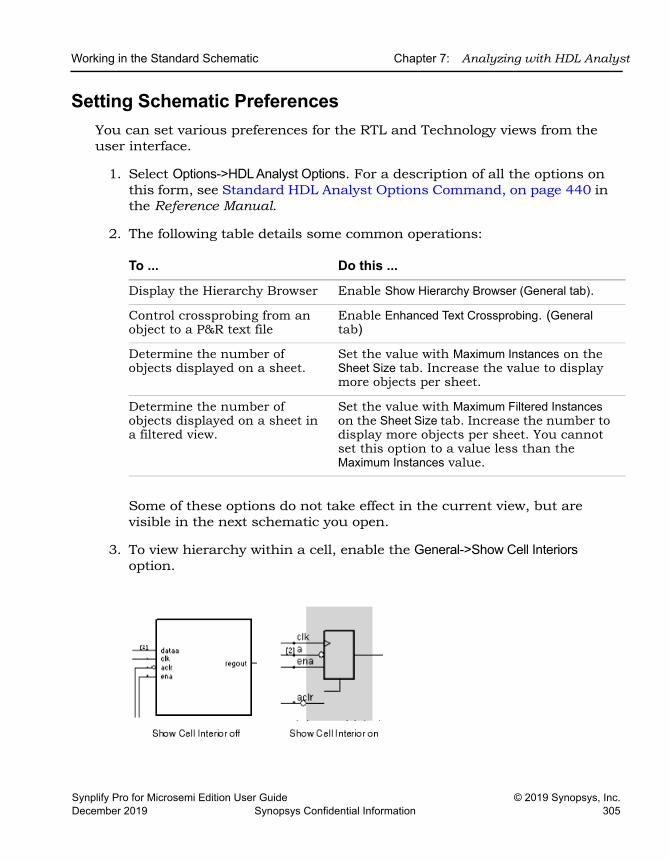
Working in the Standard Schematic Chapter 7: Analyzing with HDL Analyst
Synplify Pro for Microsemi Edition User Guide © 2019 Synopsys, Inc.December 2019 Synopsys Confidential Information 305
Setting Schematic PreferencesYou can set various preferences for the RTL and Technology views from the user interface.
1. Select Options->HDL Analyst Options. For a description of all the options on this form, see Standard HDL Analyst Options Command, on page 440 in the Reference Manual.
2. The following table details some common operations:
Some of these options do not take effect in the current view, but are visible in the next schematic you open.
3. To view hierarchy within a cell, enable the General->Show Cell Interiors option.
To ... Do this ...
Display the Hierarchy Browser Enable Show Hierarchy Browser (General tab).
Control crossprobing from an object to a P&R text file
Enable Enhanced Text Crossprobing. (General tab)
Determine the number of objects displayed on a sheet.
Set the value with Maximum Instances on the Sheet Size tab. Increase the value to display more objects per sheet.
Determine the number of objects displayed on a sheet in a filtered view.
Set the value with Maximum Filtered Instances on the Sheet Size tab. Increase the number to display more objects per sheet. You cannot set this option to a value less than the Maximum Instances value.
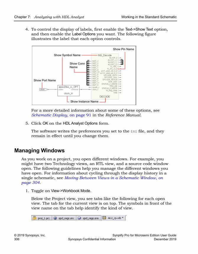
LO
Chapter 7: Analyzing with HDL Analyst Working in the Standard Schematic
© 2019 Synopsys, Inc. Synplify Pro for Microsemi Edition User Guide306 Synopsys Confidential Information December 2019
4. To control the display of labels, first enable the Text->Show Text option, and then enable the Label Options you want. The following figure illustrates the label that each option controls.
For a more detailed information about some of these options, see Schematic Display, on page 91 in the Reference Manual.
5. Click OK on the HDL Analyst Options form.
The software writes the preferences you set to the ini file, and they remain in effect until you change them.
Managing WindowsAs you work on a project, you open different windows. For example, you might have two Technology views, an RTL view, and a source code window open. The following guidelines help you manage the different windows you have open. For information about cycling through the display history in a single schematic, see Moving Between Views in a Schematic Window, on page 304.
1. Toggle on View->Workbook Mode.
Below the Project view, you see tabs like the following for each open view. The tab for the current view is on top. The symbols in front of the view name on the tab help identify the kind of view.
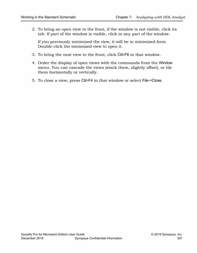
Working in the Standard Schematic Chapter 7: Analyzing with HDL Analyst
Synplify Pro for Microsemi Edition User Guide © 2019 Synopsys, Inc.December 2019 Synopsys Confidential Information 307
2. To bring an open view to the front, if the window is not visible, click its tab. If part of the window is visible, click in any part of the window.
If you previously minimized the view, it will be in minimized form. Double-click the minimized view to open it.
3. To bring the next view to the front, click Ctrl-F6 in that window.
4. Order the display of open views with the commands from the Window menu. You can cascade the views (stack them, slightly offset), or tile them horizontally or vertically.
5. To close a view, press Ctrl-F4 in that window or select File->Close.
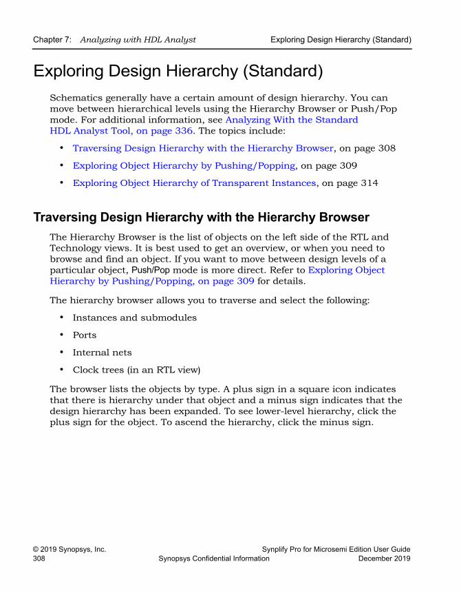
LO
Chapter 7: Analyzing with HDL Analyst Exploring Design Hierarchy (Standard)
© 2019 Synopsys, Inc. Synplify Pro for Microsemi Edition User Guide308 Synopsys Confidential Information December 2019
Exploring Design Hierarchy (Standard)Schematics generally have a certain amount of design hierarchy. You can move between hierarchical levels using the Hierarchy Browser or Push/Pop mode. For additional information, see Analyzing With the Standard HDL Analyst Tool, on page 336. The topics include:
• Traversing Design Hierarchy with the Hierarchy Browser, on page 308
• Exploring Object Hierarchy by Pushing/Popping, on page 309
• Exploring Object Hierarchy of Transparent Instances, on page 314
Traversing Design Hierarchy with the Hierarchy BrowserThe Hierarchy Browser is the list of objects on the left side of the RTL and Technology views. It is best used to get an overview, or when you need to browse and find an object. If you want to move between design levels of a particular object, Push/Pop mode is more direct. Refer to Exploring Object Hierarchy by Pushing/Popping, on page 309 for details.
The hierarchy browser allows you to traverse and select the following:
• Instances and submodules
• Ports
• Internal nets
• Clock trees (in an RTL view)
The browser lists the objects by type. A plus sign in a square icon indicates that there is hierarchy under that object and a minus sign indicates that the design hierarchy has been expanded. To see lower-level hierarchy, click the plus sign for the object. To ascend the hierarchy, click the minus sign.
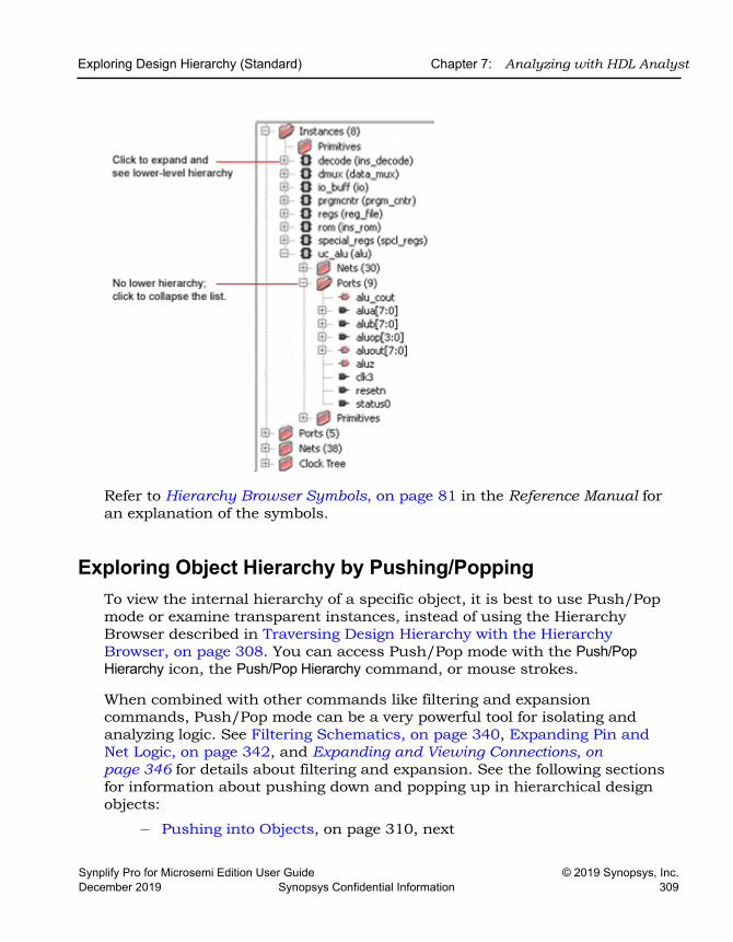
Exploring Design Hierarchy (Standard) Chapter 7: Analyzing with HDL Analyst
Synplify Pro for Microsemi Edition User Guide © 2019 Synopsys, Inc.December 2019 Synopsys Confidential Information 309
Refer to Hierarchy Browser Symbols, on page 81 in the Reference Manual for an explanation of the symbols.
Exploring Object Hierarchy by Pushing/PoppingTo view the internal hierarchy of a specific object, it is best to use Push/Pop mode or examine transparent instances, instead of using the Hierarchy Browser described in Traversing Design Hierarchy with the Hierarchy Browser, on page 308. You can access Push/Pop mode with the Push/Pop Hierarchy icon, the Push/Pop Hierarchy command, or mouse strokes.
When combined with other commands like filtering and expansion commands, Push/Pop mode can be a very powerful tool for isolating and analyzing logic. See Filtering Schematics, on page 340, Expanding Pin and Net Logic, on page 342, and Expanding and Viewing Connections, on page 346 for details about filtering and expansion. See the following sections for information about pushing down and popping up in hierarchical design objects:
– Pushing into Objects, on page 310, next
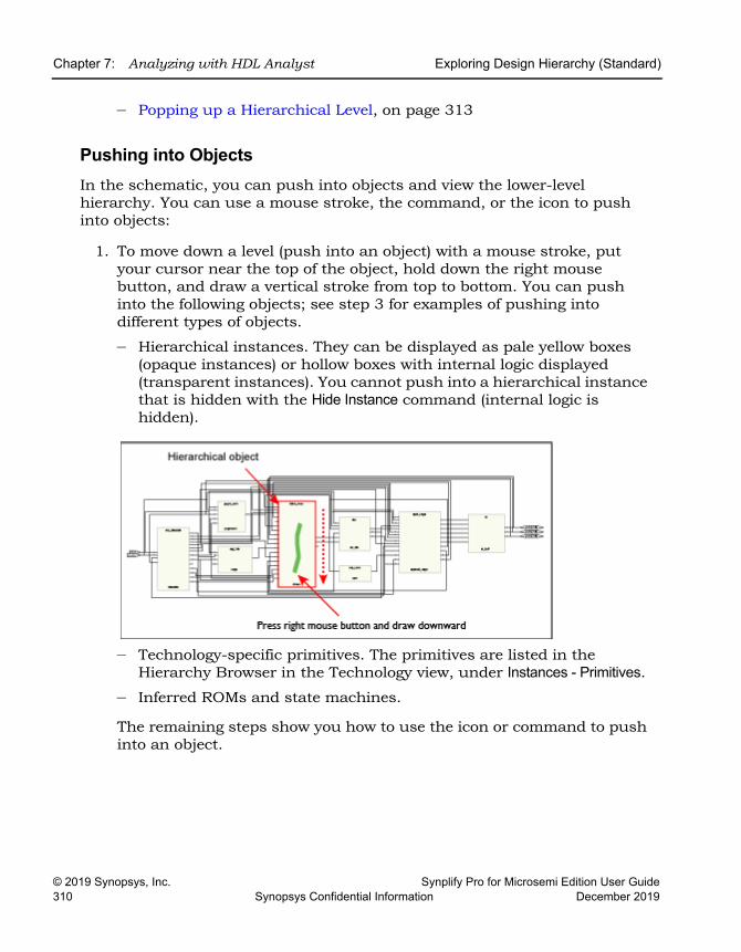
LO
Chapter 7: Analyzing with HDL Analyst Exploring Design Hierarchy (Standard)
© 2019 Synopsys, Inc. Synplify Pro for Microsemi Edition User Guide310 Synopsys Confidential Information December 2019
– Popping up a Hierarchical Level, on page 313
Pushing into ObjectsIn the schematic, you can push into objects and view the lower-level hierarchy. You can use a mouse stroke, the command, or the icon to push into objects:
1. To move down a level (push into an object) with a mouse stroke, put your cursor near the top of the object, hold down the right mouse button, and draw a vertical stroke from top to bottom. You can push into the following objects; see step 3 for examples of pushing into different types of objects.
– Hierarchical instances. They can be displayed as pale yellow boxes (opaque instances) or hollow boxes with internal logic displayed (transparent instances). You cannot push into a hierarchical instance that is hidden with the Hide Instance command (internal logic is hidden).
– Technology-specific primitives. The primitives are listed in the Hierarchy Browser in the Technology view, under Instances - Primitives.
– Inferred ROMs and state machines.
The remaining steps show you how to use the icon or command to push into an object.
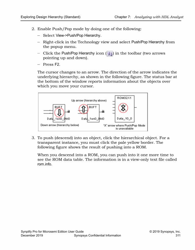
Exploring Design Hierarchy (Standard) Chapter 7: Analyzing with HDL Analyst
Synplify Pro for Microsemi Edition User Guide © 2019 Synopsys, Inc.December 2019 Synopsys Confidential Information 311
2. Enable Push/Pop mode by doing one of the following:
– Select View->Push/Pop Hierarchy.
– Right-click in the Technology view and select Push/Pop Hierarchy from the popup menu.
– Click the Push/Pop Hierarchy icon ( ) in the toolbar (two arrows pointing up and down).
– Press F2.
The cursor changes to an arrow. The direction of the arrow indicates the underlying hierarchy, as shown in the following figure. The status bar at the bottom of the window reports information about the objects over which you move your cursor.
3. To push (descend) into an object, click the hierarchical object. For a transparent instance, you must click the pale yellow border. The following figure shows the result of pushing into a ROM.
When you descend into a ROM, you can push into it one more time to see the ROM data table. The information is in a view-only text file called rom.info.
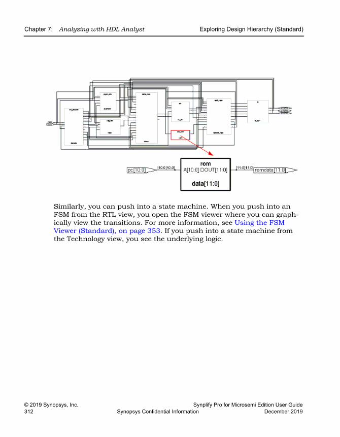
LO
Chapter 7: Analyzing with HDL Analyst Exploring Design Hierarchy (Standard)
© 2019 Synopsys, Inc. Synplify Pro for Microsemi Edition User Guide312 Synopsys Confidential Information December 2019
Similarly, you can push into a state machine. When you push into an FSM from the RTL view, you open the FSM viewer where you can graph-ically view the transitions. For more information, see Using the FSM Viewer (Standard), on page 353. If you push into a state machine from the Technology view, you see the underlying logic.
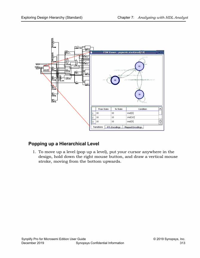
Exploring Design Hierarchy (Standard) Chapter 7: Analyzing with HDL Analyst
Synplify Pro for Microsemi Edition User Guide © 2019 Synopsys, Inc.December 2019 Synopsys Confidential Information 313
Popping up a Hierarchical Level1. To move up a level (pop up a level), put your cursor anywhere in the
design, hold down the right mouse button, and draw a vertical mouse stroke, moving from the bottom upwards.
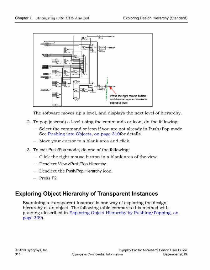
LO
Chapter 7: Analyzing with HDL Analyst Exploring Design Hierarchy (Standard)
© 2019 Synopsys, Inc. Synplify Pro for Microsemi Edition User Guide314 Synopsys Confidential Information December 2019
The software moves up a level, and displays the next level of hierarchy.
2. To pop (ascend) a level using the commands or icon, do the following:
– Select the command or icon if you are not already in Push/Pop mode. See Pushing into Objects, on page 310for details.
– Move your cursor to a blank area and click.
3. To exit Push/Pop mode, do one of the following:
– Click the right mouse button in a blank area of the view.
– Deselect View->Push/Pop Hierarchy.
– Deselect the Push/Pop Hierarchy icon.
– Press F2.
Exploring Object Hierarchy of Transparent InstancesExamining a transparent instance is one way of exploring the design hierarchy of an object. The following table compares this method with pushing (described in Exploring Object Hierarchy by Pushing/Popping, on page 309).
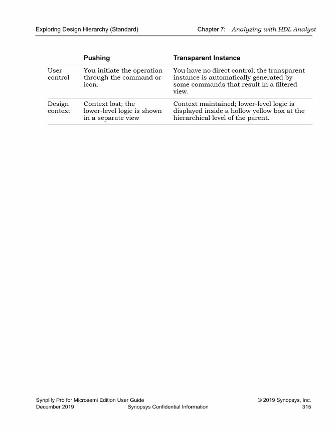
Exploring Design Hierarchy (Standard) Chapter 7: Analyzing with HDL Analyst
Synplify Pro for Microsemi Edition User Guide © 2019 Synopsys, Inc.December 2019 Synopsys Confidential Information 315
Pushing Transparent Instance
User control
You initiate the operation through the command or icon.
You have no direct control; the transparent instance is automatically generated by some commands that result in a filtered view.
Design context
Context lost; the lower-level logic is shown in a separate view
Context maintained; lower-level logic is displayed inside a hollow yellow box at the hierarchical level of the parent.
LO
Chapter 7: Analyzing with HDL Analyst Finding Objects (Standard)
© 2019 Synopsys, Inc. Synplify Pro for Microsemi Edition User Guide316 Synopsys Confidential Information December 2019
Finding Objects (Standard)In the schematic, you can use the Hierarchy Browser or the Find command to find objects, as explained in these sections:
• Browsing to Find Objects in HDL Analyst Views, on page 316
• Using Find for Hierarchical and Restricted Searches, on page 318
• Using Wildcards with the Find Command, on page 321
• Using Find to Search the Output Netlist, on page 326
For information about the Tcl Find command, which you use to locate objects, and create collections, see find, on page 149 in the Reference Manual.
Browsing to Find Objects in HDL Analyst ViewsYou can always zoom in to find an object in the RTL and Technology schematics. The following procedure shows you how to browse through design objects and find an object at any level of the design hierarchy. You can use the Hierarchy Browser or the Find command to do this. If you are familiar with the design hierarchy, the Hierarchy Browser can be the quickest method to locate an object. The Find command is best used to graphically browse and locate the object you want.
Browsing With the Hierarchy Browser1. In the Hierarchy Browser, click the name of the net, port, or instance
you want to select.
The object is highlighted in the schematic.
2. To select a range of objects, select the first object in the range. Then, scroll to display the last object in the range. Press and hold the Shift key while clicking the last object in the range.
The software selects and highlights all the objects in the range.
3. If the object is on a lower hierarchical level, do either of the following:
– Expand the appropriate higher-level object by clicking the plus symbol next to it, and then select the object you want.
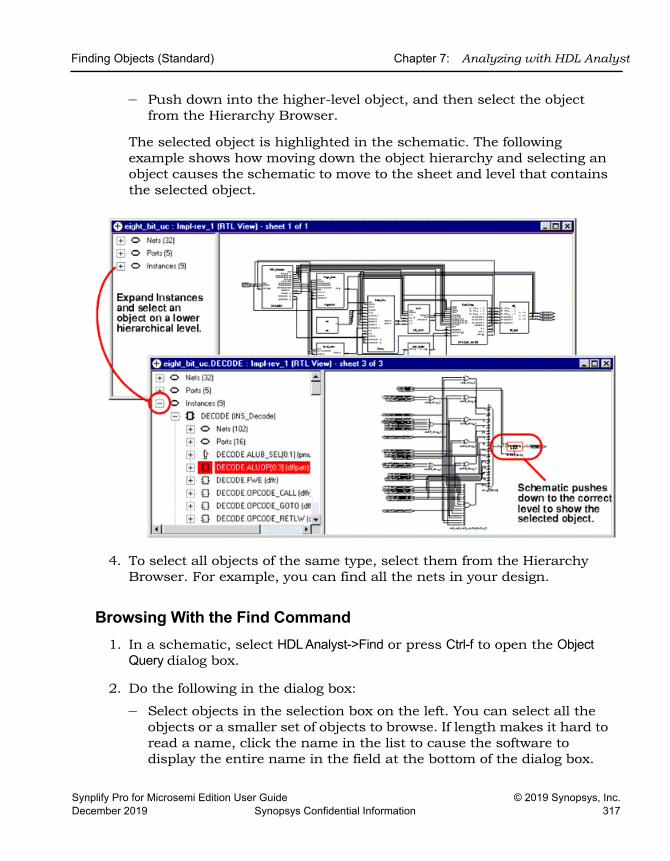
Finding Objects (Standard) Chapter 7: Analyzing with HDL Analyst
Synplify Pro for Microsemi Edition User Guide © 2019 Synopsys, Inc.December 2019 Synopsys Confidential Information 317
– Push down into the higher-level object, and then select the object from the Hierarchy Browser.
The selected object is highlighted in the schematic. The following example shows how moving down the object hierarchy and selecting an object causes the schematic to move to the sheet and level that contains the selected object.
4. To select all objects of the same type, select them from the Hierarchy Browser. For example, you can find all the nets in your design.
Browsing With the Find Command1. In a schematic, select HDL Analyst->Find or press Ctrl-f to open the Object
Query dialog box.
2. Do the following in the dialog box:
– Select objects in the selection box on the left. You can select all the objects or a smaller set of objects to browse. If length makes it hard to read a name, click the name in the list to cause the software to display the entire name in the field at the bottom of the dialog box.
LO
Chapter 7: Analyzing with HDL Analyst Finding Objects (Standard)
© 2019 Synopsys, Inc. Synplify Pro for Microsemi Edition User Guide318 Synopsys Confidential Information December 2019
– Click the arrow to move the selected objects over to the box on the right.
The software highlights the selected objects.
3. In the Object Query dialog box, click on an object in the box on the right.
The software tracks to the schematic page with that object.
Using Find for Hierarchical and Restricted SearchesYou can always zoom in to find an object in the RTL and Technology schematics or use the Hierarchy Browser (see Browsing to Find Objects in HDL Analyst Views, on page 316). This procedure shows you how to use the Find command to do hierarchical object searches or restrict the search to the current level or the current level and its underlying hierarchy.
Note that Find only adds to the current selection; it does not deselect anything that is already selected. you can use successive searches to build up exactly the selection you need, before filtering.
1. If needed, restrict the range of the search by filtering the view.
See Viewing Design Hierarchy and Context, on page 337 and Filtering Schematics, on page 340 for details. With a filtered view, the software only searches the filtered instances, unless you set the scope of the search to Entire Design, as described below, in which case Find searches the entire design.
You can use the filtering technique to restrict your search to just one schematic sheet. Select all the objects on one sheet and filter the view. Continue with the procedure.
2. To further restrict the range of the search, hide instances you do not need.
You can do this in addition to filtering the view, or instead of filtering the view. Hidden instances and their hierarchy are excluded from the search. When you have finished the search, use the Unhide Instances command to make the hierarchy visible again.
3. Open the Object Query dialog box.
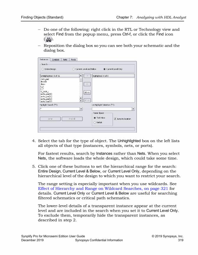
Finding Objects (Standard) Chapter 7: Analyzing with HDL Analyst
Synplify Pro for Microsemi Edition User Guide © 2019 Synopsys, Inc.December 2019 Synopsys Confidential Information 319
– Do one of the following: right click in the RTL or Technology view and select Find from the popup menu, press Ctrl-f, or click the Find icon ( ).
– Reposition the dialog box so you can see both your schematic and the dialog box.
4. Select the tab for the type of object. The Unhighlighted box on the left lists all objects of that type (instances, symbols, nets, or ports).
For fastest results, search by Instances rather than Nets. When you select Nets, the software loads the whole design, which could take some time.
5. Click one of these buttons to set the hierarchical range for the search: Entire Design, Current Level & Below, or Current Level Only, depending on the hierarchical level of the design to which you want to restrict your search.
The range setting is especially important when you use wildcards. See Effect of Hierarchy and Range on Wildcard Searches, on page 321 for details. Current Level Only or Current Level & Below are useful for searching filtered schematics or critical path schematics.
The lower-level details of a transparent instance appear at the current level and are included in the search when you set it to Current Level Only. To exclude them, temporarily hide the transparent instances, as described in step 2.
LO
Chapter 7: Analyzing with HDL Analyst Finding Objects (Standard)
© 2019 Synopsys, Inc. Synplify Pro for Microsemi Edition User Guide320 Synopsys Confidential Information December 2019
Use Entire Design to hierarchically search the whole design. For large hierarchical designs, reduce the scope of the search by using the techniques described in the first step.
The Unhighlighted box shows available objects within the scope you set. Objects are listed in alphabetical order, not hierarchical order.
6. To search for objects in the mapped database or the output netlist, set the Name Space option.
The name of an object might be changed because of synthesis optimiza-tions or to match the place-and-route tool conventions, so that the object name may no longer match the name in the original netlist. Setting the Name Space option ensures that the Find command searches the correct database for the object. For example, if you set this option to Tech View, the tool searches the mapped database (srm) for the object name you specify. For information about using this feature to find objects from an output netlist, see Using Find to Search the Output Netlist, on page 326.
7. Do the following to select objects from the list. To use wildcards in the selection, see the next step.
– Click the objects you want from the list. If length makes it hard to read a name, click the name in the list to cause the software to display the entire name in the field at the bottom of the dialog box.
– Click Find 200 or Find All. The former finds the first 200 matches, and then you can click the button again to find the next 200.
– Click the right arrow to move the objects into the box on the right, or double-click individual names.
The schematic displays highlighted objects in red.
8. Do the following to select objects using patterns or wildcards.
– Type a pattern in the Highlight Wildcard field. See Using Wildcards with the Find Command, on page 321 for a detailed discussion of wildcards.
The Unhighlighted list shows the objects that match the wildcard criteria. If length makes it hard to read a name, click the name in the list to cause the software to display the entire name in the field at the bottom of the form.
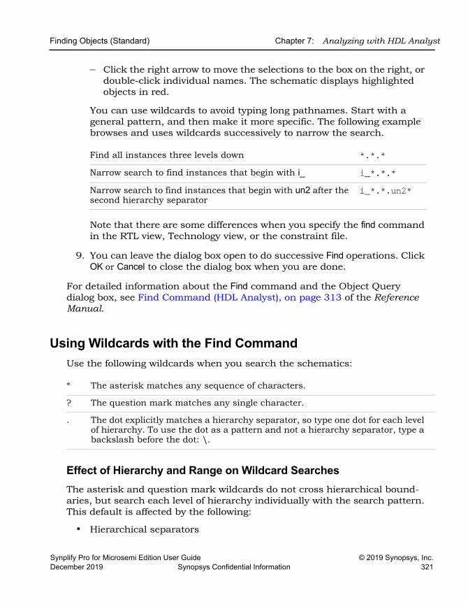
Finding Objects (Standard) Chapter 7: Analyzing with HDL Analyst
Synplify Pro for Microsemi Edition User Guide © 2019 Synopsys, Inc.December 2019 Synopsys Confidential Information 321
– Click the right arrow to move the selections to the box on the right, or double-click individual names. The schematic displays highlighted objects in red.
You can use wildcards to avoid typing long pathnames. Start with a general pattern, and then make it more specific. The following example browses and uses wildcards successively to narrow the search.
Note that there are some differences when you specify the find command in the RTL view, Technology view, or the constraint file.
9. You can leave the dialog box open to do successive Find operations. Click OK or Cancel to close the dialog box when you are done.
For detailed information about the Find command and the Object Query dialog box, see Find Command (HDL Analyst), on page 313 of the Reference Manual.
Using Wildcards with the Find CommandUse the following wildcards when you search the schematics:
Effect of Hierarchy and Range on Wildcard SearchesThe asterisk and question mark wildcards do not cross hierarchical bound-aries, but search each level of hierarchy individually with the search pattern. This default is affected by the following:
• Hierarchical separators
Find all instances three levels down *.*.*Narrow search to find instances that begin with i_ i_*.*.*Narrow search to find instances that begin with un2 after the second hierarchy separator
i_*.*.un2*
* The asterisk matches any sequence of characters.
? The question mark matches any single character.
. The dot explicitly matches a hierarchy separator, so type one dot for each level of hierarchy. To use the dot as a pattern and not a hierarchy separator, type a backslash before the dot: \.
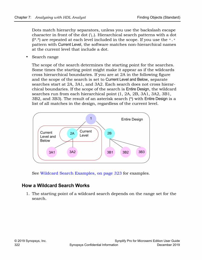
LO
Chapter 7: Analyzing with HDL Analyst Finding Objects (Standard)
© 2019 Synopsys, Inc. Synplify Pro for Microsemi Edition User Guide322 Synopsys Confidential Information December 2019
Dots match hierarchy separators, unless you use the backslash escape character in front of the dot (\.). Hierarchical search patterns with a dot (l*.*) are repeated at each level included in the scope. If you use the *.* pattern with Current Level, the software matches non-hierarchical names at the current level that include a dot.
• Search range
The scope of the search determines the starting point for the searches. Some times the starting point might make it appear as if the wildcards cross hierarchical boundaries. If you are at 2A in the following figure and the scope of the search is set to Current Level and Below, separate searches start at 2A, 3A1, and 3A2. Each search does not cross hierar-chical boundaries. If the scope of the search is Entire Design, the wildcard searches run from each hierarchical point (1, 2A, 2B, 3A1, 3A2, 3B1, 3B2, and 3B3). The result of an asterisk search (*) with Entire Design is a list of all matches in the design, regardless of the current level.
See Wildcard Search Examples, on page 323 for examples.
How a Wildcard Search Works1. The starting point of a wildcard search depends on the range set for the
search.
2A
1
2B
3B33B23B13A23A1
Entire Design
Current Level and Below
Current Level
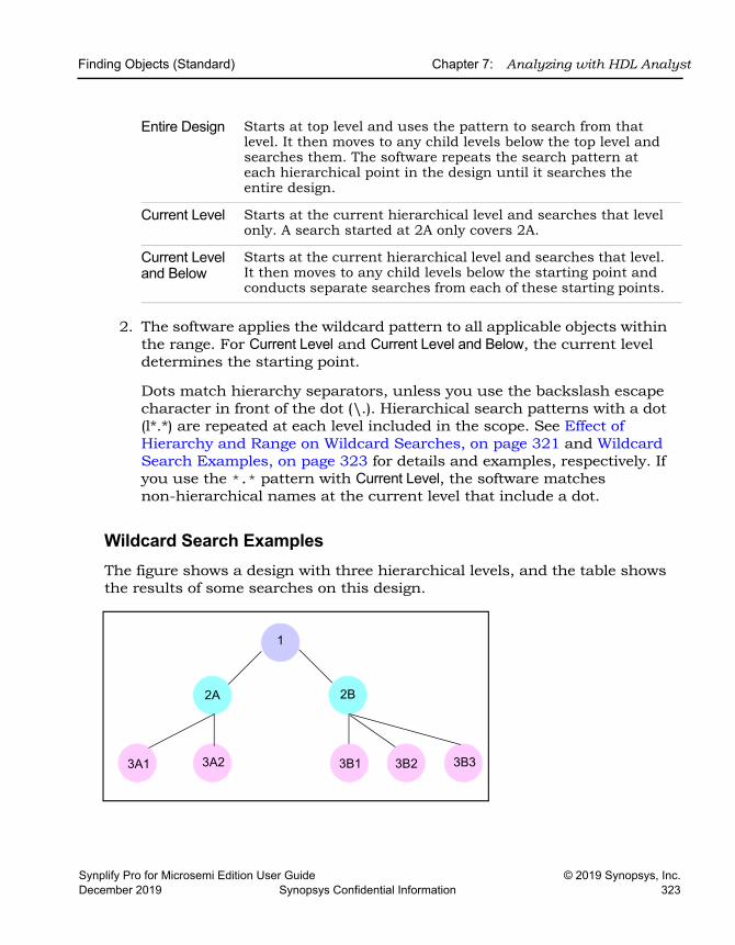
Finding Objects (Standard) Chapter 7: Analyzing with HDL Analyst
Synplify Pro for Microsemi Edition User Guide © 2019 Synopsys, Inc.December 2019 Synopsys Confidential Information 323
2. The software applies the wildcard pattern to all applicable objects within the range. For Current Level and Current Level and Below, the current level determines the starting point.
Dots match hierarchy separators, unless you use the backslash escape character in front of the dot (\.). Hierarchical search patterns with a dot (l*.*) are repeated at each level included in the scope. See Effect of Hierarchy and Range on Wildcard Searches, on page 321 and Wildcard Search Examples, on page 323 for details and examples, respectively. If you use the *.* pattern with Current Level, the software matches non-hierarchical names at the current level that include a dot.
Wildcard Search ExamplesThe figure shows a design with three hierarchical levels, and the table shows the results of some searches on this design.
Entire Design Starts at top level and uses the pattern to search from that level. It then moves to any child levels below the top level and searches them. The software repeats the search pattern at each hierarchical point in the design until it searches the entire design.
Current Level Starts at the current hierarchical level and searches that level only. A search started at 2A only covers 2A.
Current Level and Below
Starts at the current hierarchical level and searches that level. It then moves to any child levels below the starting point and conducts separate searches from each of these starting points.
2A
1
2B
3B33B23B13A23A1
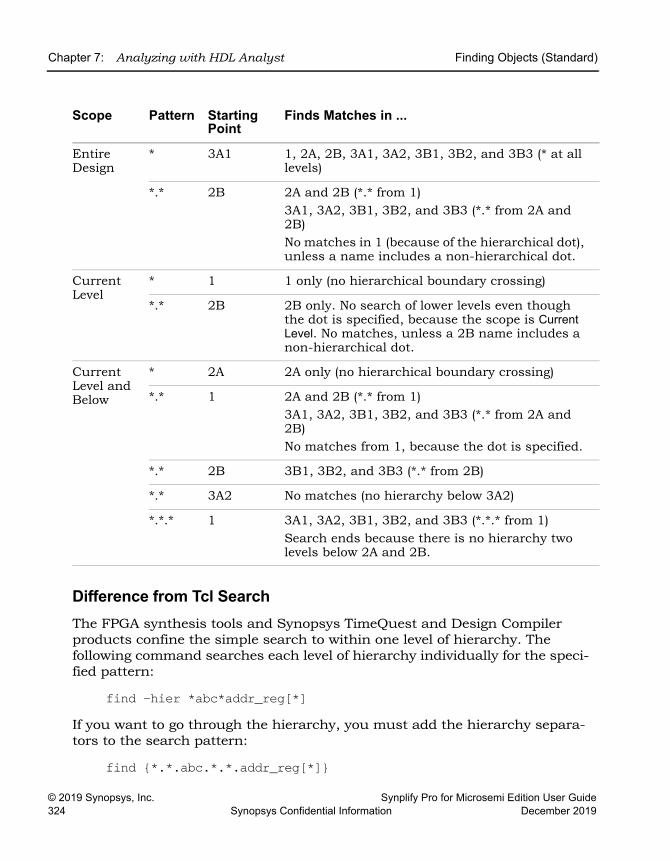
LO
Chapter 7: Analyzing with HDL Analyst Finding Objects (Standard)
© 2019 Synopsys, Inc. Synplify Pro for Microsemi Edition User Guide324 Synopsys Confidential Information December 2019
Difference from Tcl SearchThe FPGA synthesis tools and Synopsys TimeQuest and Design Compiler products confine the simple search to within one level of hierarchy. The following command searches each level of hierarchy individually for the speci-fied pattern:
find -hier *abc*addr_reg[*]If you want to go through the hierarchy, you must add the hierarchy separa-tors to the search pattern:
find {*.*.abc.*.*.addr_reg[*]}
Scope Pattern Starting Point
Finds Matches in ...
Entire Design
* 3A1 1, 2A, 2B, 3A1, 3A2, 3B1, 3B2, and 3B3 (* at all levels)
*.* 2B 2A and 2B (*.* from 1)3A1, 3A2, 3B1, 3B2, and 3B3 (*.* from 2A and 2B)No matches in 1 (because of the hierarchical dot), unless a name includes a non-hierarchical dot.
Current Level
* 1 1 only (no hierarchical boundary crossing)
*.* 2B 2B only. No search of lower levels even though the dot is specified, because the scope is Current Level. No matches, unless a 2B name includes a non-hierarchical dot.
Current Level and Below
* 2A 2A only (no hierarchical boundary crossing)
*.* 1 2A and 2B (*.* from 1)3A1, 3A2, 3B1, 3B2, and 3B3 (*.* from 2A and 2B)No matches from 1, because the dot is specified.
*.* 2B 3B1, 3B2, and 3B3 (*.* from 2B)
*.* 3A2 No matches (no hierarchy below 3A2)
*.*.* 1 3A1, 3A2, 3B1, 3B2, and 3B3 (*.*.* from 1)Search ends because there is no hierarchy two levels below 2A and 2B.
Finding Objects (Standard) Chapter 7: Analyzing with HDL Analyst
Synplify Pro for Microsemi Edition User Guide © 2019 Synopsys, Inc.December 2019 Synopsys Confidential Information 325
Find Command Differences in HDL Analyst Views and Constraint FileThere are some slight differences when you use the Find command in the RTL view, Technology view, and the constraint files:
• You cannot use find to search for bit registers of a bit array in the RTL or Technology views, but you can specify it in a constraint file, where the following command will work:
find -seq {i:modulex_inst.qb[7]}In a HDL Analyst view, you cannot find {i:modulex_inst.qb[7]}, but you can specify and find {i:modulex_inst.qb[7:0]}.
• By default, the following Tcl command does not find objects in the RTL view, although it does find objects in the Technology view:
–hier -seq * -filter @clock == clk75To make this work in an RTL view, you must turn on Annotated Properties for Analyst in the Device tab of the Implementation Options dialog box, recom-pile the design, and then open a new RTL view.
Combining Find with Filtering to Refine SearchesYou can combine the Find command with the filtering commands to better effect. Depending on what you want to do, use the Find command first, or a filtering command.
1. To limit the range of a search, do the following:
– Filter the design.
– Use the Find command on the filtered view, but set the search range to Current Level Only.
2. Select objects for a filtered view.
– Use the Find command to browse and select objects.
– Filter the objects to display them.
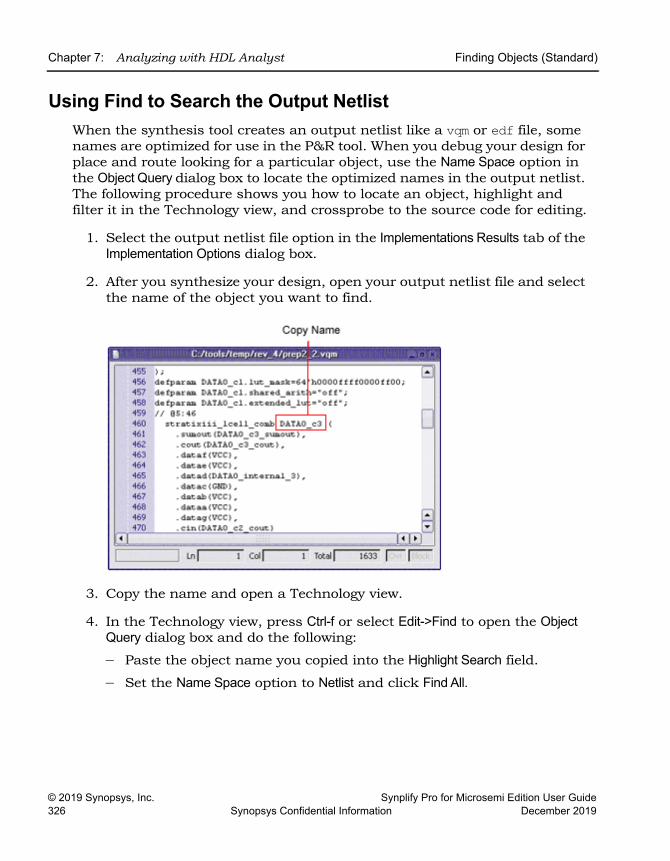
LO
Chapter 7: Analyzing with HDL Analyst Finding Objects (Standard)
© 2019 Synopsys, Inc. Synplify Pro for Microsemi Edition User Guide326 Synopsys Confidential Information December 2019
Using Find to Search the Output NetlistWhen the synthesis tool creates an output netlist like a vqm or edf file, some names are optimized for use in the P&R tool. When you debug your design for place and route looking for a particular object, use the Name Space option in the Object Query dialog box to locate the optimized names in the output netlist. The following procedure shows you how to locate an object, highlight and filter it in the Technology view, and crossprobe to the source code for editing.
1. Select the output netlist file option in the Implementations Results tab of the Implementation Options dialog box.
2. After you synthesize your design, open your output netlist file and select the name of the object you want to find.
3. Copy the name and open a Technology view.
4. In the Technology view, press Ctrl-f or select Edit->Find to open the Object Query dialog box and do the following:
– Paste the object name you copied into the Highlight Search field.
– Set the Name Space option to Netlist and click Find All.
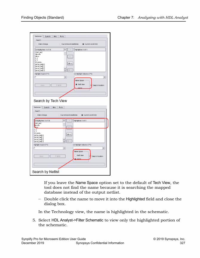
Finding Objects (Standard) Chapter 7: Analyzing with HDL Analyst
Synplify Pro for Microsemi Edition User Guide © 2019 Synopsys, Inc.December 2019 Synopsys Confidential Information 327
If you leave the Name Space option set to the default of Tech View, the tool does not find the name because it is searching the mapped database instead of the output netlist.
– Double click the name to move it into the Highlighted field and close the dialog box.
In the Technology view, the name is highlighted in the schematic.
5. Select HDL Analyst->Filter Schematic to view only the highlighted portion of the schematic.
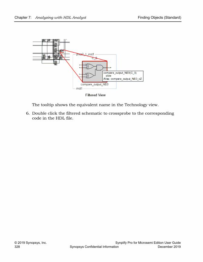
LO
Chapter 7: Analyzing with HDL Analyst Finding Objects (Standard)
© 2019 Synopsys, Inc. Synplify Pro for Microsemi Edition User Guide328 Synopsys Confidential Information December 2019
The tooltip shows the equivalent name in the Technology view.
6. Double click the filtered schematic to crossprobe to the corresponding code in the HDL file.
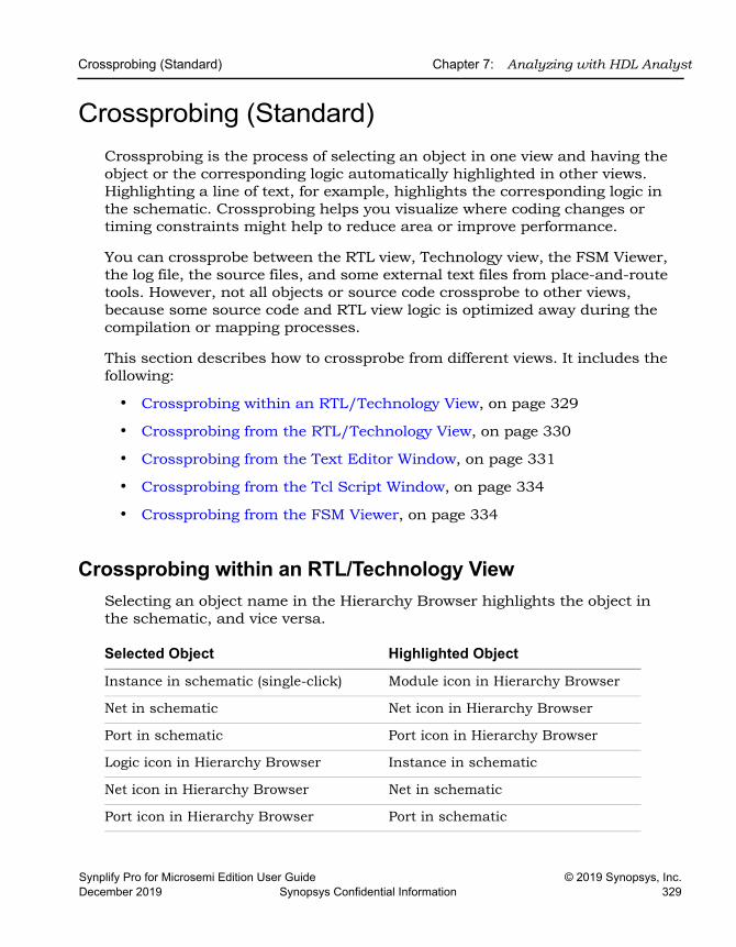
Crossprobing (Standard) Chapter 7: Analyzing with HDL Analyst
Synplify Pro for Microsemi Edition User Guide © 2019 Synopsys, Inc.December 2019 Synopsys Confidential Information 329
Crossprobing (Standard)Crossprobing is the process of selecting an object in one view and having the object or the corresponding logic automatically highlighted in other views. Highlighting a line of text, for example, highlights the corresponding logic in the schematic. Crossprobing helps you visualize where coding changes or timing constraints might help to reduce area or improve performance.
You can crossprobe between the RTL view, Technology view, the FSM Viewer, the log file, the source files, and some external text files from place-and-route tools. However, not all objects or source code crossprobe to other views, because some source code and RTL view logic is optimized away during the compilation or mapping processes.
This section describes how to crossprobe from different views. It includes the following:
• Crossprobing within an RTL/Technology View, on page 329
• Crossprobing from the RTL/Technology View, on page 330
• Crossprobing from the Text Editor Window, on page 331
• Crossprobing from the Tcl Script Window, on page 334
• Crossprobing from the FSM Viewer, on page 334
Crossprobing within an RTL/Technology ViewSelecting an object name in the Hierarchy Browser highlights the object in the schematic, and vice versa.
Selected Object Highlighted Object
Instance in schematic (single-click) Module icon in Hierarchy Browser
Net in schematic Net icon in Hierarchy Browser
Port in schematic Port icon in Hierarchy Browser
Logic icon in Hierarchy Browser Instance in schematic
Net icon in Hierarchy Browser Net in schematic
Port icon in Hierarchy Browser Port in schematic
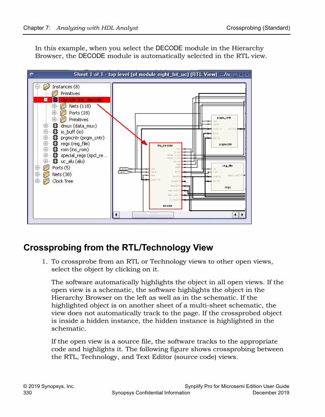
LO
Chapter 7: Analyzing with HDL Analyst Crossprobing (Standard)
© 2019 Synopsys, Inc. Synplify Pro for Microsemi Edition User Guide330 Synopsys Confidential Information December 2019
In this example, when you select the DECODE module in the Hierarchy Browser, the DECODE module is automatically selected in the RTL view.
Crossprobing from the RTL/Technology View1. To crossprobe from an RTL or Technology views to other open views,
select the object by clicking on it.
The software automatically highlights the object in all open views. If the open view is a schematic, the software highlights the object in the Hierarchy Browser on the left as well as in the schematic. If the highlighted object is on another sheet of a multi-sheet schematic, the view does not automatically track to the page. If the crossprobed object is inside a hidden instance, the hidden instance is highlighted in the schematic.
If the open view is a source file, the software tracks to the appropriate code and highlights it. The following figure shows crossprobing between the RTL, Technology, and Text Editor (source code) views.
Crossprobing (Standard) Chapter 7: Analyzing with HDL Analyst
Synplify Pro for Microsemi Edition User Guide © 2019 Synopsys, Inc.December 2019 Synopsys Confidential Information 331
2. To crossprobe from the RTL or Technology view to the source file when the source file is not open, double-click the object in the RTL or Technology view.
Double-clicking automatically opens the appropriate source code file and highlights the appropriate code. For example, if you double-click an object in a Technology view, the HDL Analyst tool automatically opens an editor window with the source code and highlights the code that contains the selected register.
The following table summarizes the crossprobing capability from the RTL or Technology view.
Crossprobing from the Text Editor WindowTo crossprobe from a source code window or from the log file to an RTL, Technology, or FSM view, use this procedure. You can use this method to crossprobe from any text file with objects that have the same instance names as in the synthesis software. For example, you can crossprobe from place-and-route files. See Example of Crossprobing a Path from a Text File, on page 332 for a practical example of how to use crossprobing.
From To Procedure
RTL Source code Double-click an object. If the source code file is not open, the software opens the Text Editor window to the appropriate section of code. If the source file is already open, the software scrolls to the correct section of the code and highlights it.
RTL Technology The Technology view must be open. Click the object to highlight and crossprobe.
RTL FSM Viewer The FSM view must be open. The state machine must be coded with a onehot encoding style. Click the FSM to highlight and crossprobe.
Technology Source code If the source code file is already, open, the software scrolls to the correct section of the code and highlights it. If the source code file is not open, double-click an object in the Technology view to open the source code file.
Technology RTL The RTL view must be open. Click the object to highlight and crossprobe.
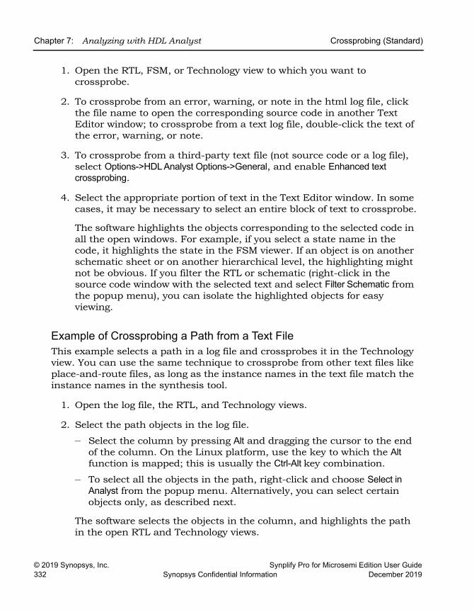
LO
Chapter 7: Analyzing with HDL Analyst Crossprobing (Standard)
© 2019 Synopsys, Inc. Synplify Pro for Microsemi Edition User Guide332 Synopsys Confidential Information December 2019
1. Open the RTL, FSM, or Technology view to which you want to crossprobe.
2. To crossprobe from an error, warning, or note in the html log file, click the file name to open the corresponding source code in another Text Editor window; to crossprobe from a text log file, double-click the text of the error, warning, or note.
3. To crossprobe from a third-party text file (not source code or a log file), select Options->HDL Analyst Options->General, and enable Enhanced text crossprobing.
4. Select the appropriate portion of text in the Text Editor window. In some cases, it may be necessary to select an entire block of text to crossprobe.
The software highlights the objects corresponding to the selected code in all the open windows. For example, if you select a state name in the code, it highlights the state in the FSM viewer. If an object is on another schematic sheet or on another hierarchical level, the highlighting might not be obvious. If you filter the RTL or schematic (right-click in the source code window with the selected text and select Filter Schematic from the popup menu), you can isolate the highlighted objects for easy viewing.
Example of Crossprobing a Path from a Text FileThis example selects a path in a log file and crossprobes it in the Technology view. You can use the same technique to crossprobe from other text files like place-and-route files, as long as the instance names in the text file match the instance names in the synthesis tool.
1. Open the log file, the RTL, and Technology views.
2. Select the path objects in the log file.
– Select the column by pressing Alt and dragging the cursor to the end of the column. On the Linux platform, use the key to which the Alt function is mapped; this is usually the Ctrl-Alt key combination.
– To select all the objects in the path, right-click and choose Select in Analyst from the popup menu. Alternatively, you can select certain objects only, as described next.
The software selects the objects in the column, and highlights the path in the open RTL and Technology views.
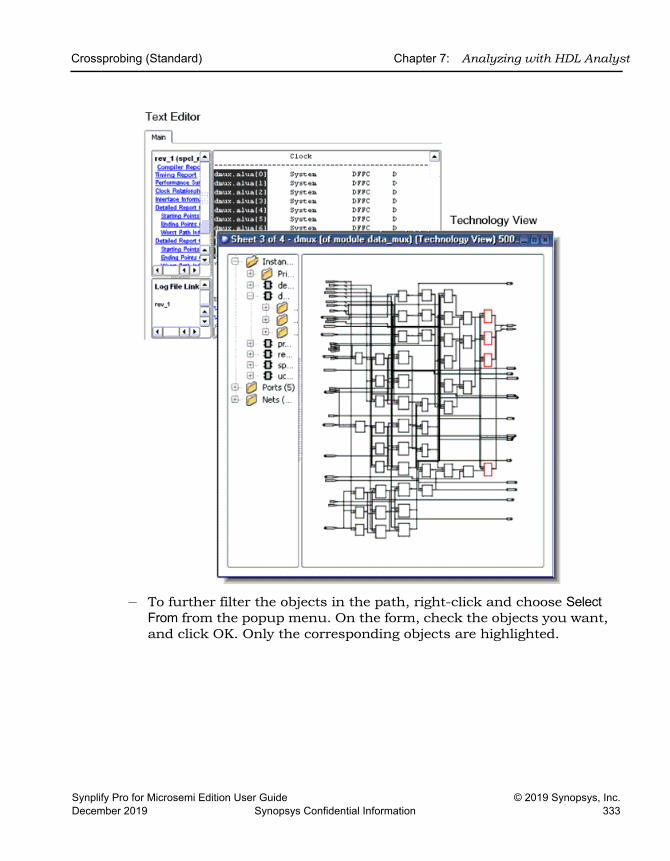
Crossprobing (Standard) Chapter 7: Analyzing with HDL Analyst
Synplify Pro for Microsemi Edition User Guide © 2019 Synopsys, Inc.December 2019 Synopsys Confidential Information 333
– To further filter the objects in the path, right-click and choose Select From from the popup menu. On the form, check the objects you want, and click OK. Only the corresponding objects are highlighted.
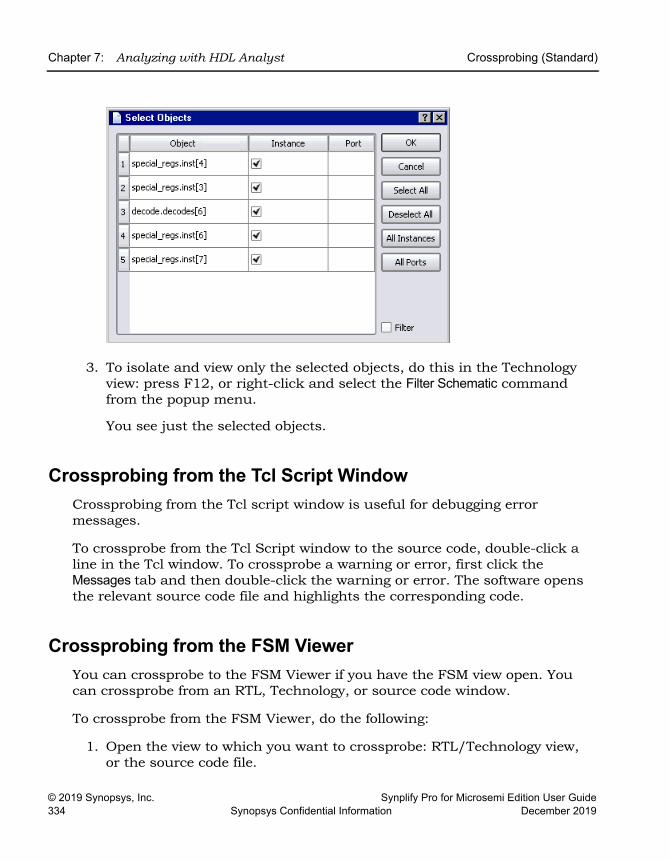
LO
Chapter 7: Analyzing with HDL Analyst Crossprobing (Standard)
© 2019 Synopsys, Inc. Synplify Pro for Microsemi Edition User Guide334 Synopsys Confidential Information December 2019
3. To isolate and view only the selected objects, do this in the Technology view: press F12, or right-click and select the Filter Schematic command from the popup menu.
You see just the selected objects.
Crossprobing from the Tcl Script WindowCrossprobing from the Tcl script window is useful for debugging error messages.
To crossprobe from the Tcl Script window to the source code, double-click a line in the Tcl window. To crossprobe a warning or error, first click the Messages tab and then double-click the warning or error. The software opens the relevant source code file and highlights the corresponding code.
Crossprobing from the FSM ViewerYou can crossprobe to the FSM Viewer if you have the FSM view open. You can crossprobe from an RTL, Technology, or source code window.
To crossprobe from the FSM Viewer, do the following:
1. Open the view to which you want to crossprobe: RTL/Technology view, or the source code file.
Crossprobing (Standard) Chapter 7: Analyzing with HDL Analyst
Synplify Pro for Microsemi Edition User Guide © 2019 Synopsys, Inc.December 2019 Synopsys Confidential Information 335
2. Do the following in the open FSM view:
– For FSMs with a onehot encoding style, click the state bubbles in the bubble diagram or the states in the FSM transition table.
– For all other FSMs, click the states in the bubble diagram. You cannot use the transition table because with these encoding styles, the number of registers in the RTL or Technology views do not match the number of registers in the FSM Viewer.
The software highlights the corresponding code or object in the open views. You can only crossprobe from a state in the FSM table if you used a onehot encoding style.
LO
Chapter 7: Analyzing with HDL Analyst Analyzing With the Standard HDL Analyst Tool
© 2019 Synopsys, Inc. Synplify Pro for Microsemi Edition User Guide336 Synopsys Confidential Information December 2019
Analyzing With the Standard HDL Analyst Tool
The HDL Analyst tool is a graphical productivity tool that helps you visualize your synthesis results. It consists of RTL-level and technology-primitive level schematics that let you graphically view and analyze your design.
• RTL ViewUsing BEST® (Behavior Extracting Synthesis Technology) in the RTL view, the software keeps a high-level of abstraction and makes the RTL view easy to view and debug. High-level structures like RAMs, ROMs, operators, and FSMs are kept as abstractions in this view instead of being converted to gates. You can examine the high-level structure, or push into a component and view the gate-level structure.
• Technology ViewThe software uses module generators to implement the high-level struc-tures from the RTL view, and maps them to technology-specific resources.
To analyze information, compare the current view with the information in the RTL/Technology view, the log file, the FSM view, and the source code, you can use techniques like crossprobing, flattening, and filtering. See the following for more information about analysis techniques.
• Viewing Design Hierarchy and Context, on page 337
• Filtering Schematics, on page 340
• Expanding Pin and Net Logic, on page 342
• Expanding and Viewing Connections, on page 346
• Flattening Schematic Hierarchy, on page 347
• Minimizing Memory Usage While Analyzing Designs, on page 351
For additional information about navigating the HDL Analyst views or using other techniques like crossprobing, see the following:
• Working in the Standard Schematic, on page 295
• Exploring Design Hierarchy (Standard), on page 308
• Finding Objects (Standard), on page 316
• Crossprobing (Standard), on page 329
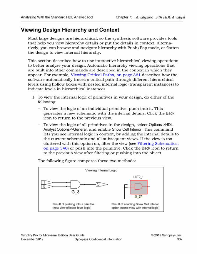
Analyzing With the Standard HDL Analyst Tool Chapter 7: Analyzing with HDL Analyst
Synplify Pro for Microsemi Edition User Guide © 2019 Synopsys, Inc.December 2019 Synopsys Confidential Information 337
Viewing Design Hierarchy and ContextMost large designs are hierarchical, so the synthesis software provides tools that help you view hierarchy details or put the details in context. Alterna-tively, you can browse and navigate hierarchy with Push/Pop mode, or flatten the design to view internal hierarchy.
This section describes how to use interactive hierarchical viewing operations to better analyze your design. Automatic hierarchy viewing operations that are built into other commands are described in the context in which they appear. For example, Viewing Critical Paths, on page 361 describes how the software automatically traces a critical path through different hierarchical levels using hollow boxes with nested internal logic (transparent instances) to indicate levels in hierarchical instances.
1. To view the internal logic of primitives in your design, do either of the following:
– To view the logic of an individual primitive, push into it. This generates a new schematic with the internal details. Click the Back icon to return to the previous view.
– To view the logic of all primitives in the design, select Options->HDL Analyst Options->General, and enable Show Cell Interior. This command lets you see internal logic in context, by adding the internal details to the current schematic and all subsequent views. If the view is too cluttered with this option on, filter the view (see Filtering Schematics, on page 340) or push into the primitive. Click the Back icon to return to the previous view after filtering or pushing into the object.
The following figure compares these two methods:
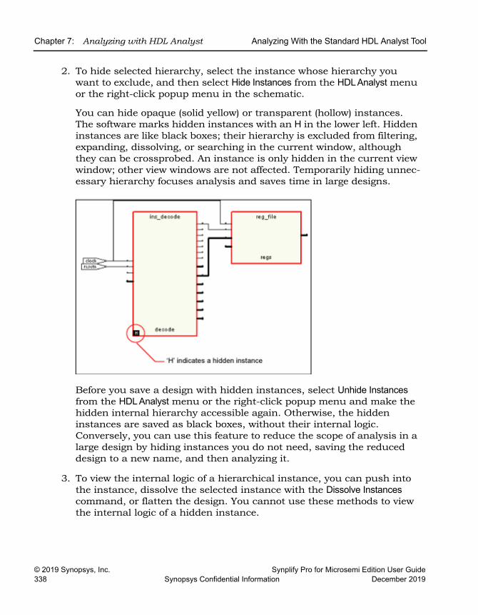
LO
Chapter 7: Analyzing with HDL Analyst Analyzing With the Standard HDL Analyst Tool
© 2019 Synopsys, Inc. Synplify Pro for Microsemi Edition User Guide338 Synopsys Confidential Information December 2019
2. To hide selected hierarchy, select the instance whose hierarchy you want to exclude, and then select Hide Instances from the HDL Analyst menu or the right-click popup menu in the schematic.
You can hide opaque (solid yellow) or transparent (hollow) instances. The software marks hidden instances with an H in the lower left. Hidden instances are like black boxes; their hierarchy is excluded from filtering, expanding, dissolving, or searching in the current window, although they can be crossprobed. An instance is only hidden in the current view window; other view windows are not affected. Temporarily hiding unnec-essary hierarchy focuses analysis and saves time in large designs.
Before you save a design with hidden instances, select Unhide Instances from the HDL Analyst menu or the right-click popup menu and make the hidden internal hierarchy accessible again. Otherwise, the hidden instances are saved as black boxes, without their internal logic. Conversely, you can use this feature to reduce the scope of analysis in a large design by hiding instances you do not need, saving the reduced design to a new name, and then analyzing it.
3. To view the internal logic of a hierarchical instance, you can push into the instance, dissolve the selected instance with the Dissolve Instances command, or flatten the design. You cannot use these methods to view the internal logic of a hidden instance.
Analyzing With the Standard HDL Analyst Tool Chapter 7: Analyzing with HDL Analyst
Synplify Pro for Microsemi Edition User Guide © 2019 Synopsys, Inc.December 2019 Synopsys Confidential Information 339
4. If the result of filtering or dissolving is a hollow box with no internal logic, try either of the following, as appropriate, to view the internal hierarchy:
– Select Options->HDL Analyst Options->Sheet Size and increase the value of Maximum Filtered Instances. Use this option if the view is not too cluttered.
– Use the sheet navigation commands to go to the sheets indicated in the hollow box.
If there is too much internal logic to display in the current view, the software puts the internal hierarchy on separate schematic sheets. It displays a hollow box with no internal logic and indicates the schematic sheets that contain the internal logic.
5. To view the design context of an instance in a filtered view, select the instance, right-click, and select Show Context from the popup menu.
The software displays an unfiltered view of the hierarchical level that contains the selected object, with the instance highlighted. This is useful when you have to go back and forth between different views during analysis. The context differs from the Expand commands, which show connections. To return to the original filtered view, click Back.
Pushing into an instance
Generates a view that shows only the internal logic. You do not see the internal hierarchy in context. To return to the previous view, click Back. See Exploring Object Hierarchy by Pushing/Popping, on page 309 for details.
Flattening the entire design
Opens a new view where the entire design is flattened, except for hidden hierarchy. Large flattened designs can be overwhelming. See Flattening Schematic Hierarchy, on page 347 for details about flattening designs. Because this is a new view, you cannot use Back to return to the previous view. To return to the top-level unflattened schematic, right-click in the view and select Unflatten Schematic.
Flattening an instance by dissolving
Generates a view where the hierarchy of the selected instances is flattened, but the rest of the design is unaffected. This provides context. See Flattening Schematic Hierarchy, on page 347 for details about dissolving instances.
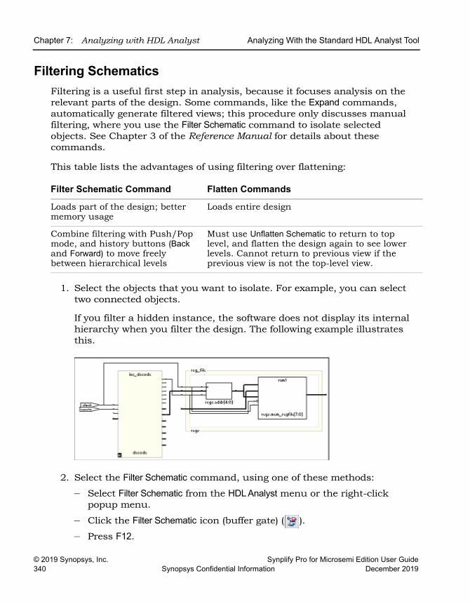
LO
Chapter 7: Analyzing with HDL Analyst Analyzing With the Standard HDL Analyst Tool
© 2019 Synopsys, Inc. Synplify Pro for Microsemi Edition User Guide340 Synopsys Confidential Information December 2019
Filtering SchematicsFiltering is a useful first step in analysis, because it focuses analysis on the relevant parts of the design. Some commands, like the Expand commands, automatically generate filtered views; this procedure only discusses manual filtering, where you use the Filter Schematic command to isolate selected objects. See Chapter 3 of the Reference Manual for details about these commands.
This table lists the advantages of using filtering over flattening:
1. Select the objects that you want to isolate. For example, you can select two connected objects.
If you filter a hidden instance, the software does not display its internal hierarchy when you filter the design. The following example illustrates this.
2. Select the Filter Schematic command, using one of these methods:
– Select Filter Schematic from the HDL Analyst menu or the right-click popup menu.
– Click the Filter Schematic icon (buffer gate) ( ).
– Press F12.
Filter Schematic Command Flatten Commands
Loads part of the design; better memory usage
Loads entire design
Combine filtering with Push/Pop mode, and history buttons (Back and Forward) to move freely between hierarchical levels
Must use Unflatten Schematic to return to top level, and flatten the design again to see lower levels. Cannot return to previous view if the previous view is not the top-level view.
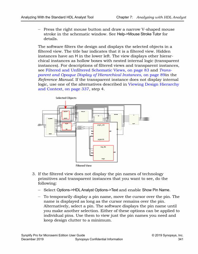
Analyzing With the Standard HDL Analyst Tool Chapter 7: Analyzing with HDL Analyst
Synplify Pro for Microsemi Edition User Guide © 2019 Synopsys, Inc.December 2019 Synopsys Confidential Information 341
– Press the right mouse button and draw a narrow V-shaped mouse stroke in the schematic window. See Help->Mouse Stroke Tutor for details.
The software filters the design and displays the selected objects in a filtered view. The title bar indicates that it is a filtered view. Hidden instances have an H in the lower left. The view displays other hierar-chical instances as hollow boxes with nested internal logic (transparent instances). For descriptions of filtered views and transparent instances, see Filtered and Unfiltered Schematic Views, on page 83 and Trans-parent and Opaque Display of Hierarchical Instances, on page 89in the Reference Manual. If the transparent instance does not display internal logic, use one of the alternatives described in Viewing Design Hierarchy and Context, on page 337, step 4.
3. If the filtered view does not display the pin names of technology primitives and transparent instances that you want to see, do the following:
– Select Options->HDL Analyst Options->Text and enable Show Pin Name.
– To temporarily display a pin name, move the cursor over the pin. The name is displayed as long as the cursor remains over the pin. Alternatively, select a pin. The software displays the pin name until you make another selection. Either of these options can be applied to individual pins. Use them to view just the pin names you need and keep design clutter to a minimum.
LO
Chapter 7: Analyzing with HDL Analyst Analyzing With the Standard HDL Analyst Tool
© 2019 Synopsys, Inc. Synplify Pro for Microsemi Edition User Guide342 Synopsys Confidential Information December 2019
– To see all the hierarchical pins, select the instance, right-click, and select Show All Hier Pins.
You can now analyze the problem, and do operations like the following:
4. To return to the previous schematic, click the Back icon. If you flattened the hierarchy, right-click and select Unflatten Schematic to return to the top-level unflattened view.
For additional information about filtering schematics, see Filtering Schematics, on page 340 and Flattening Schematic Hierarchy, on page 347.
Expanding Pin and Net LogicWhen you are working in a filtered view, you might need to include more logic in your selected set to debug your design. This section describes commands that expand logic fanning out from pins or nets; to expand paths, see Expanding and Viewing Connections, on page 346.
Use the Expand commands with the Filter Schematic, Hide Instances, and Flatten commands to isolate just the logic that you want to examine. Filtering isolates logic, flattening removes hierarchy, and hiding instances prevents their internal hierarchy from being expanded. See Filtering Schematics, on page 340 and Flattening Schematic Hierarchy, on page 347 for details.
1. To expand logic from a pin hierarchically across boundaries, use the following commands.
Trace paths, build up logic See Expanding Pin and Net Logic, on page 342 and Expanding and Viewing Connections, on page 346
Filter further Select objects and filter again
Find objects See Finding Objects (Standard), on page 316
Flatten, or hide and flatten See Flattening Schematic Hierarchy, on page 347. You can hide transparent or opaque instances.
Crossprobe from filtered view
See Crossprobing from the RTL/Technology View, on page 330
Analyzing With the Standard HDL Analyst Tool Chapter 7: Analyzing with HDL Analyst
Synplify Pro for Microsemi Edition User Guide © 2019 Synopsys, Inc.December 2019 Synopsys Confidential Information 343
The software expands the logic as specified, working on the current level and below or working up the hierarchy, crossing hierarchical bound-aries as needed. Hierarchical levels are shown nested in hollow bounding boxes. The internal hierarchy of hidden instances is not displayed.
For descriptions of the Expand commands, see HDL Analyst Menu, on page 408 of the Reference Manual.
2. To expand logic from a pin at the current level only, do the following:
– Select a pin, and go to the HDL Analyst->Current Level menu or the right-click popup menu->Current Level.
– Select Expand or Expand to Register/Ports. The commands work as described in the previous step, but they do not cross hierarchical boundaries.
3. To expand logic from a net, use the commands shown in the following table.
– To expand at the current level and below, select the commands from the HDL Analyst->Hierarchical menu or the right-click popup menu.
– To expand at the current level only, select the commands from the HDL Analyst->Current Level menu or the right-click popup menu->Current Level.
To ... Do this (HDL Analyst->Hierarchical/Popup menu) ...
See all cells connected to a pin
Select a pin and select Expand. See Expanding Filtered Logic Example, on page 344.
See all cells that are connected to a pin, up to the next register
Select a pin and select Expand to Register/Port. See Expanding Filtered Logic to Register/Port Example, on page 345.
See internal cells connected to a pin
Select a pin and select Expand Inwards. The software filters the schematic and displays the internal cells closest to the port. See Expanding Inwards Example, on page 345.
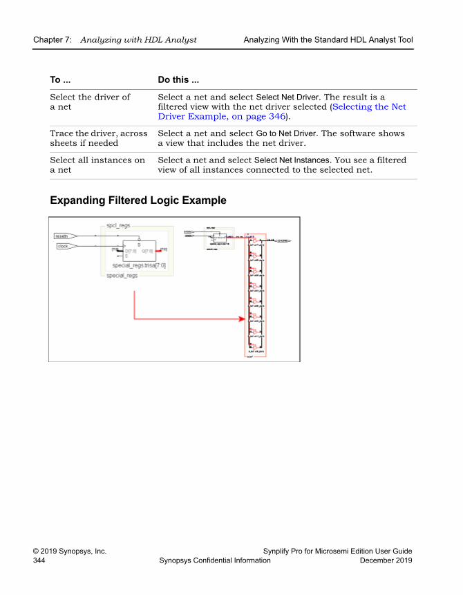
LO
Chapter 7: Analyzing with HDL Analyst Analyzing With the Standard HDL Analyst Tool
© 2019 Synopsys, Inc. Synplify Pro for Microsemi Edition User Guide344 Synopsys Confidential Information December 2019
Expanding Filtered Logic Example
To ... Do this ...
Select the driver of a net
Select a net and select Select Net Driver. The result is a filtered view with the net driver selected (Selecting the Net Driver Example, on page 346).
Trace the driver, across sheets if needed
Select a net and select Go to Net Driver. The software shows a view that includes the net driver.
Select all instances on a net
Select a net and select Select Net Instances. You see a filtered view of all instances connected to the selected net.
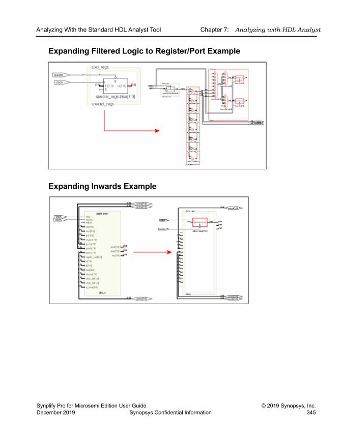
Analyzing With the Standard HDL Analyst Tool Chapter 7: Analyzing with HDL Analyst
Synplify Pro for Microsemi Edition User Guide © 2019 Synopsys, Inc.December 2019 Synopsys Confidential Information 345
Expanding Filtered Logic to Register/Port Example
Expanding Inwards Example
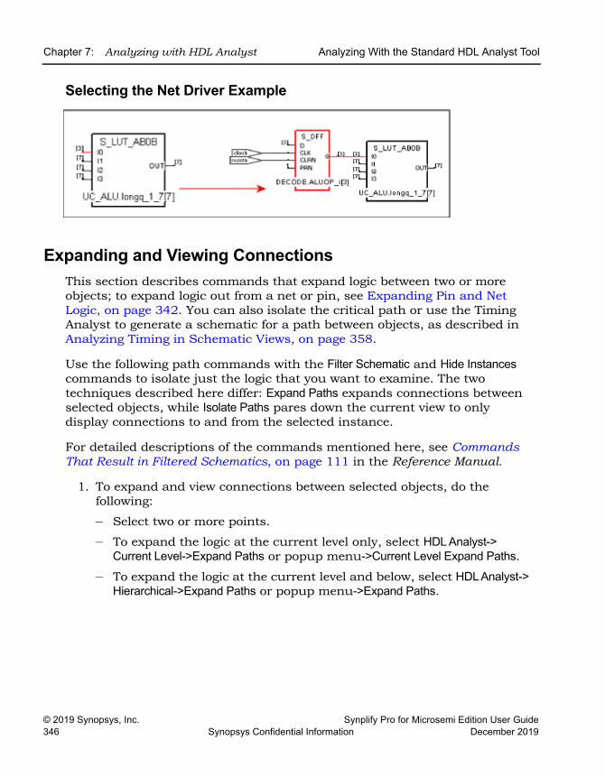
LO
Chapter 7: Analyzing with HDL Analyst Analyzing With the Standard HDL Analyst Tool
© 2019 Synopsys, Inc. Synplify Pro for Microsemi Edition User Guide346 Synopsys Confidential Information December 2019
Selecting the Net Driver Example
Expanding and Viewing ConnectionsThis section describes commands that expand logic between two or more objects; to expand logic out from a net or pin, see Expanding Pin and Net Logic, on page 342. You can also isolate the critical path or use the Timing Analyst to generate a schematic for a path between objects, as described in Analyzing Timing in Schematic Views, on page 358.
Use the following path commands with the Filter Schematic and Hide Instances commands to isolate just the logic that you want to examine. The two techniques described here differ: Expand Paths expands connections between selected objects, while Isolate Paths pares down the current view to only display connections to and from the selected instance.
For detailed descriptions of the commands mentioned here, see Commands That Result in Filtered Schematics, on page 111 in the Reference Manual.
1. To expand and view connections between selected objects, do the following:
– Select two or more points.
– To expand the logic at the current level only, select HDL Analyst-> Current Level->Expand Paths or popup menu->Current Level Expand Paths.
– To expand the logic at the current level and below, select HDL Analyst-> Hierarchical->Expand Paths or popup menu->Expand Paths.
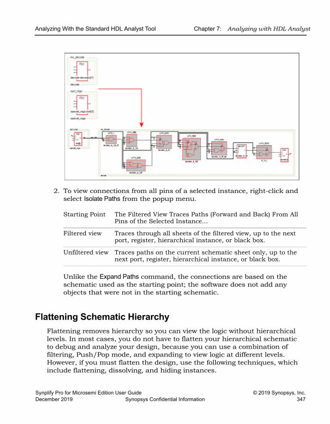
Analyzing With the Standard HDL Analyst Tool Chapter 7: Analyzing with HDL Analyst
Synplify Pro for Microsemi Edition User Guide © 2019 Synopsys, Inc.December 2019 Synopsys Confidential Information 347
2. To view connections from all pins of a selected instance, right-click and select Isolate Paths from the popup menu.
Unlike the Expand Paths command, the connections are based on the schematic used as the starting point; the software does not add any objects that were not in the starting schematic.
Flattening Schematic HierarchyFlattening removes hierarchy so you can view the logic without hierarchical levels. In most cases, you do not have to flatten your hierarchical schematic to debug and analyze your design, because you can use a combination of filtering, Push/Pop mode, and expanding to view logic at different levels. However, if you must flatten the design, use the following techniques, which include flattening, dissolving, and hiding instances.
Starting Point The Filtered View Traces Paths (Forward and Back) From All Pins of the Selected Instance...
Filtered view Traces through all sheets of the filtered view, up to the next port, register, hierarchical instance, or black box.
Unfiltered view Traces paths on the current schematic sheet only, up to the next port, register, hierarchical instance, or black box.
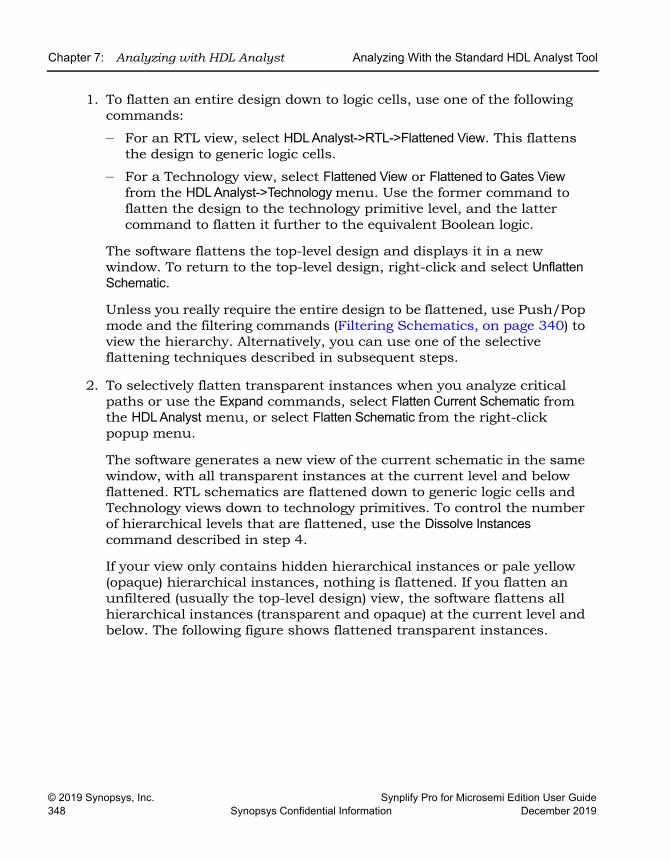
LO
Chapter 7: Analyzing with HDL Analyst Analyzing With the Standard HDL Analyst Tool
© 2019 Synopsys, Inc. Synplify Pro for Microsemi Edition User Guide348 Synopsys Confidential Information December 2019
1. To flatten an entire design down to logic cells, use one of the following commands:
– For an RTL view, select HDL Analyst->RTL->Flattened View. This flattens the design to generic logic cells.
– For a Technology view, select Flattened View or Flattened to Gates View from the HDL Analyst->Technology menu. Use the former command to flatten the design to the technology primitive level, and the latter command to flatten it further to the equivalent Boolean logic.
The software flattens the top-level design and displays it in a new window. To return to the top-level design, right-click and select Unflatten Schematic.
Unless you really require the entire design to be flattened, use Push/Pop mode and the filtering commands (Filtering Schematics, on page 340) to view the hierarchy. Alternatively, you can use one of the selective flattening techniques described in subsequent steps.
2. To selectively flatten transparent instances when you analyze critical paths or use the Expand commands, select Flatten Current Schematic from the HDL Analyst menu, or select Flatten Schematic from the right-click popup menu.
The software generates a new view of the current schematic in the same window, with all transparent instances at the current level and below flattened. RTL schematics are flattened down to generic logic cells and Technology views down to technology primitives. To control the number of hierarchical levels that are flattened, use the Dissolve Instances command described in step 4.
If your view only contains hidden hierarchical instances or pale yellow (opaque) hierarchical instances, nothing is flattened. If you flatten an unfiltered (usually the top-level design) view, the software flattens all hierarchical instances (transparent and opaque) at the current level and below. The following figure shows flattened transparent instances.
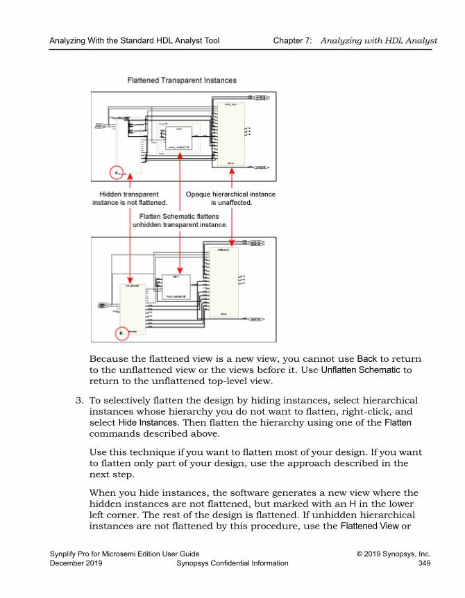
Analyzing With the Standard HDL Analyst Tool Chapter 7: Analyzing with HDL Analyst
Synplify Pro for Microsemi Edition User Guide © 2019 Synopsys, Inc.December 2019 Synopsys Confidential Information 349
Because the flattened view is a new view, you cannot use Back to return to the unflattened view or the views before it. Use Unflatten Schematic to return to the unflattened top-level view.
3. To selectively flatten the design by hiding instances, select hierarchical instances whose hierarchy you do not want to flatten, right-click, and select Hide Instances. Then flatten the hierarchy using one of the Flatten commands described above.
Use this technique if you want to flatten most of your design. If you want to flatten only part of your design, use the approach described in the next step.
When you hide instances, the software generates a new view where the hidden instances are not flattened, but marked with an H in the lower left corner. The rest of the design is flattened. If unhidden hierarchical instances are not flattened by this procedure, use the Flattened View or
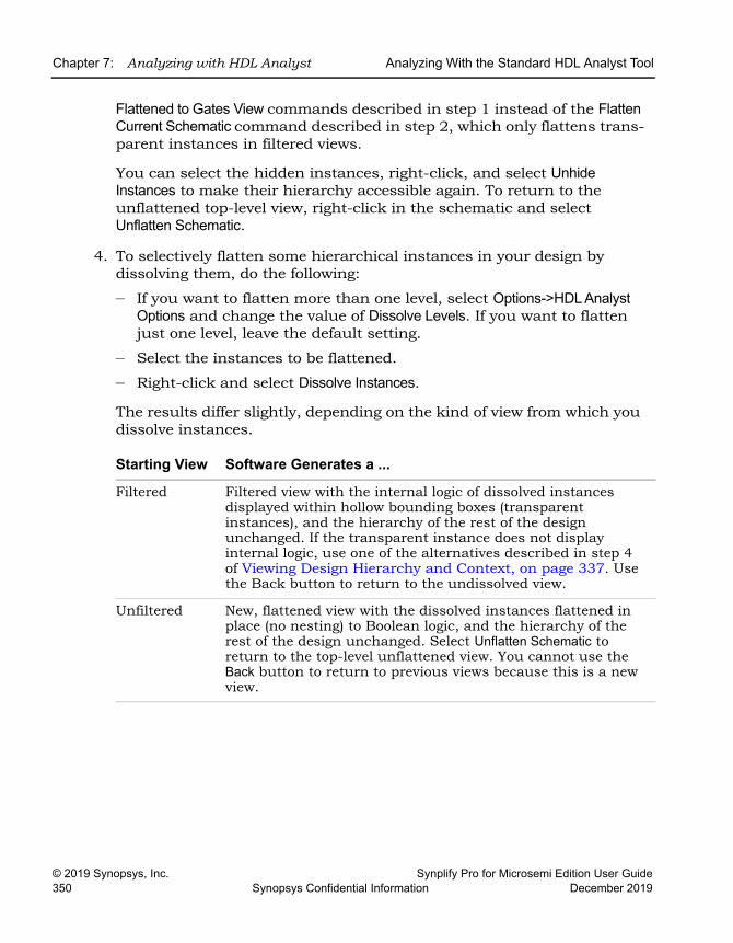
LO
Chapter 7: Analyzing with HDL Analyst Analyzing With the Standard HDL Analyst Tool
© 2019 Synopsys, Inc. Synplify Pro for Microsemi Edition User Guide350 Synopsys Confidential Information December 2019
Flattened to Gates View commands described in step 1 instead of the Flatten Current Schematic command described in step 2, which only flattens trans-parent instances in filtered views.
You can select the hidden instances, right-click, and select Unhide Instances to make their hierarchy accessible again. To return to the unflattened top-level view, right-click in the schematic and select Unflatten Schematic.
4. To selectively flatten some hierarchical instances in your design by dissolving them, do the following:
– If you want to flatten more than one level, select Options->HDL Analyst Options and change the value of Dissolve Levels. If you want to flatten just one level, leave the default setting.
– Select the instances to be flattened.
– Right-click and select Dissolve Instances.
The results differ slightly, depending on the kind of view from which you dissolve instances.
Starting View Software Generates a ...
Filtered Filtered view with the internal logic of dissolved instances displayed within hollow bounding boxes (transparent instances), and the hierarchy of the rest of the design unchanged. If the transparent instance does not display internal logic, use one of the alternatives described in step 4 of Viewing Design Hierarchy and Context, on page 337. Use the Back button to return to the undissolved view.
Unfiltered New, flattened view with the dissolved instances flattened in place (no nesting) to Boolean logic, and the hierarchy of the rest of the design unchanged. Select Unflatten Schematic to return to the top-level unflattened view. You cannot use the Back button to return to previous views because this is a new view.
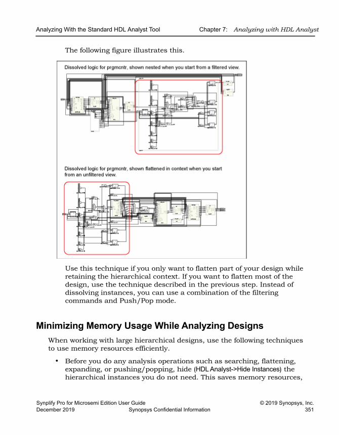
Analyzing With the Standard HDL Analyst Tool Chapter 7: Analyzing with HDL Analyst
Synplify Pro for Microsemi Edition User Guide © 2019 Synopsys, Inc.December 2019 Synopsys Confidential Information 351
The following figure illustrates this.
Use this technique if you only want to flatten part of your design while retaining the hierarchical context. If you want to flatten most of the design, use the technique described in the previous step. Instead of dissolving instances, you can use a combination of the filtering commands and Push/Pop mode.
Minimizing Memory Usage While Analyzing DesignsWhen working with large hierarchical designs, use the following techniques to use memory resources efficiently.
• Before you do any analysis operations such as searching, flattening, expanding, or pushing/popping, hide (HDL Analyst->Hide Instances) the hierarchical instances you do not need. This saves memory resources,
LO
Chapter 7: Analyzing with HDL Analyst Analyzing With the Standard HDL Analyst Tool
© 2019 Synopsys, Inc. Synplify Pro for Microsemi Edition User Guide352 Synopsys Confidential Information December 2019
because the software does not load the hierarchy of the hidden instances.
• Temporarily divide your design into smaller working files. Before you do any analysis, hide the instances you do not need. Save the design. The srs and srm files generated are smaller because the software does not save the hidden hierarchy. Close any open HDL Analyst windows to free all memory from the large design. In the Implementation Results view, double-click one of the smaller files to open the RTL or Technology schematic. Analyze the design using the smaller, working schematics.
• Filter your design instead of flattening it. If you must flatten your design, hide the instances whose hierarchy you do not need before flattening, or use the Dissolve Instances command. See Flattening Schematic Hierarchy, on page 347 for details. For more information on the Expand Paths and Isolate Paths commands, see RTL and Technology Views Popup Menus, on page 479 of the Reference Manual.
• When searching your design, search by instance rather than by net. Searching by net loads the entire design, which uses memory.
• Limit the scope of a search by hiding instances you do not need to analyze. You can limit the scope further by filtering the schematic in addition to hiding the instances you do not want to search.
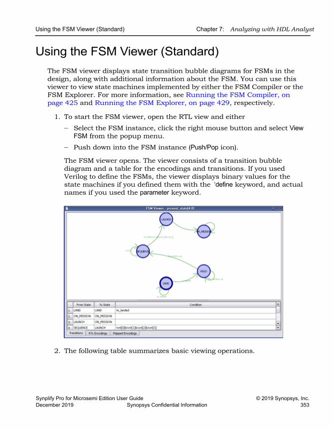
Using the FSM Viewer (Standard) Chapter 7: Analyzing with HDL Analyst
Synplify Pro for Microsemi Edition User Guide © 2019 Synopsys, Inc.December 2019 Synopsys Confidential Information 353
Using the FSM Viewer (Standard)The FSM viewer displays state transition bubble diagrams for FSMs in the design, along with additional information about the FSM. You can use this viewer to view state machines implemented by either the FSM Compiler or the FSM Explorer. For more information, see Running the FSM Compiler, on page 425 and Running the FSM Explorer, on page 429, respectively.
1. To start the FSM viewer, open the RTL view and either
– Select the FSM instance, click the right mouse button and select View FSM from the popup menu.
– Push down into the FSM instance (Push/Pop icon).
The FSM viewer opens. The viewer consists of a transition bubble diagram and a table for the encodings and transitions. If you used Verilog to define the FSMs, the viewer displays binary values for the state machines if you defined them with the ‘define keyword, and actual names if you used the parameter keyword.
2. The following table summarizes basic viewing operations.
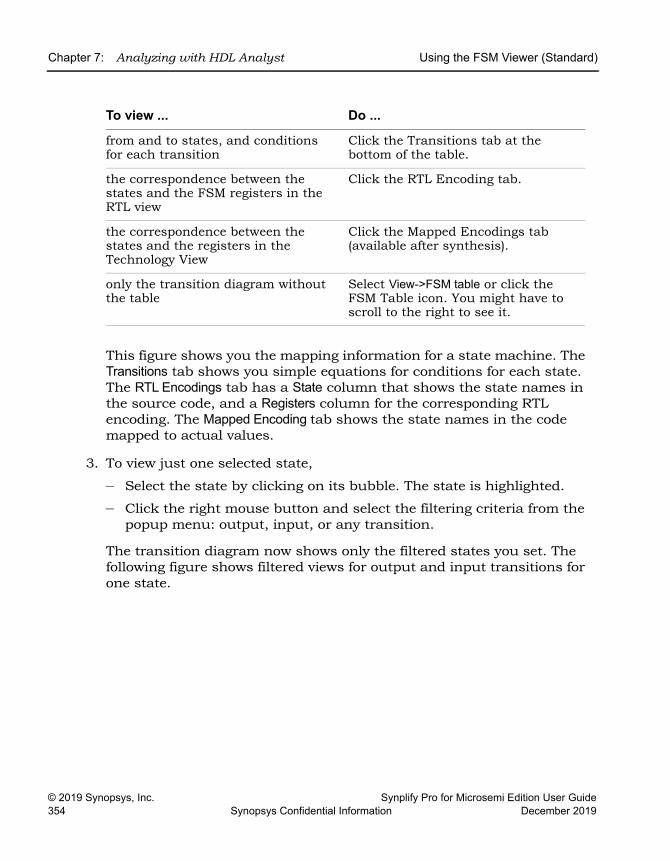
LO
Chapter 7: Analyzing with HDL Analyst Using the FSM Viewer (Standard)
© 2019 Synopsys, Inc. Synplify Pro for Microsemi Edition User Guide354 Synopsys Confidential Information December 2019
This figure shows you the mapping information for a state machine. The Transitions tab shows you simple equations for conditions for each state. The RTL Encodings tab has a State column that shows the state names in the source code, and a Registers column for the corresponding RTL encoding. The Mapped Encoding tab shows the state names in the code mapped to actual values.
3. To view just one selected state,
– Select the state by clicking on its bubble. The state is highlighted.
– Click the right mouse button and select the filtering criteria from the popup menu: output, input, or any transition.
The transition diagram now shows only the filtered states you set. The following figure shows filtered views for output and input transitions for one state.
To view ... Do ...
from and to states, and conditions for each transition
Click the Transitions tab at the bottom of the table.
the correspondence between the states and the FSM registers in the RTL view
Click the RTL Encoding tab.
the correspondence between the states and the registers in the Technology View
Click the Mapped Encodings tab (available after synthesis).
only the transition diagram without the table
Select View->FSM table or click the FSM Table icon. You might have to scroll to the right to see it.
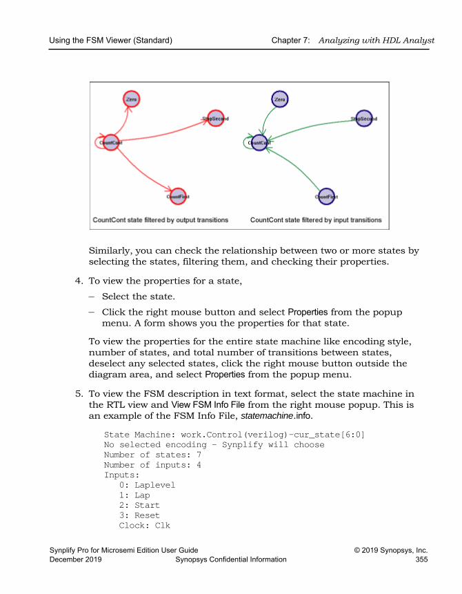
Using the FSM Viewer (Standard) Chapter 7: Analyzing with HDL Analyst
Synplify Pro for Microsemi Edition User Guide © 2019 Synopsys, Inc.December 2019 Synopsys Confidential Information 355
Similarly, you can check the relationship between two or more states by selecting the states, filtering them, and checking their properties.
4. To view the properties for a state,
– Select the state.
– Click the right mouse button and select Properties from the popup menu. A form shows you the properties for that state.
To view the properties for the entire state machine like encoding style, number of states, and total number of transitions between states, deselect any selected states, click the right mouse button outside the diagram area, and select Properties from the popup menu.
5. To view the FSM description in text format, select the state machine in the RTL view and View FSM Info File from the right mouse popup. This is an example of the FSM Info File, statemachine.info.
State Machine: work.Control(verilog)-cur_state[6:0]No selected encoding - Synplify will chooseNumber of states: 7Number of inputs: 4Inputs:
0: Laplevel1: Lap2: Start3: ResetClock: Clk
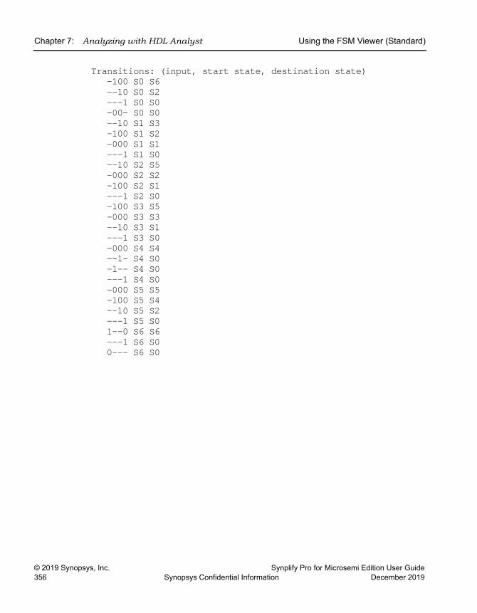
LO
Chapter 7: Analyzing with HDL Analyst Using the FSM Viewer (Standard)
© 2019 Synopsys, Inc. Synplify Pro for Microsemi Edition User Guide356 Synopsys Confidential Information December 2019
Transitions: (input, start state, destination state)-100 S0 S6 --10 S0 S2 ---1 S0 S0 -00- S0 S0 --10 S1 S3 -100 S1 S2 -000 S1 S1 ---1 S1 S0 --10 S2 S5 -000 S2 S2 -100 S2 S1 ---1 S2 S0 -100 S3 S5 -000 S3 S3--10 S3 S1---1 S3 S0 -000 S4 S4 --1- S4 S0-1-- S4 S0 ---1 S4 S0-000 S5 S5 -100 S5 S4 --10 S5 S2 ---1 S5 S01--0 S6 S6 ---1 S6 S00--- S6 S0
Synplify Pro for Microsemi Edition User Guide © 2019 Synopsys, Inc.December 2019 Synopsys Confidential Information 357
C H A P T E R 8
Analyzing Timing
This chapter describes typical analysis tasks. It describes graphical analysis with the HDL Analyst tool as well as interpretation of the text log file. It covers the following:
• Analyzing Timing in Schematic Views, on page 358
• Generating Custom Timing Reports with STA, on page 366
• Using Analysis Design Constraints, on page 369
• Using Auto Constraints, on page 376
LO
Chapter 8: Analyzing Timing Analyzing Timing in Schematic Views
© 2019 Synopsys, Inc. Synplify Pro for Microsemi Edition User Guide358 Synopsys Confidential Information December 2019
Analyzing Timing in Schematic ViewsYou can use the HDL Analyst and Timing Analyst functionality to analyze timing. This section describes the following:
• Viewing Timing Information, on page 358
• Annotating Timing Information in the Schematic Views, on page 359
• Analyzing Clock Trees in the RTL View, on page 361
• Viewing Critical Paths, on page 361
• Handling Negative Slack, on page 364
• Generating Custom Timing Reports with STA, on page 366
Viewing Timing InformationSome commands, like Show Critical Path, Hierarchical Critical Path, Flattened Critical Path, automatically enable Show Timing Information and display the timing infor-mation. The following procedure shows you how to do so manually.
1. To analyze timing, enable HDL Analyst->Show Timing Information.
This displays the timing numbers for all instances in a Technology view. It shows the following:
Delay This is the first number displayed. • Combinational logic
This first number is the cumulative path delay to the output of the instance, which includes the net delay of the output.
• Flip-flopsThis first number is the path delay attributed to the flip-flop. The delay can be associated with either the input or output path, whichever is worse, because the flip-flop is the end of one path and the start of another.
Slack Time
This is the second number, and it is the slack time of the worst path that goes through the instance. A negative value indicates that timing constraints can not be met.
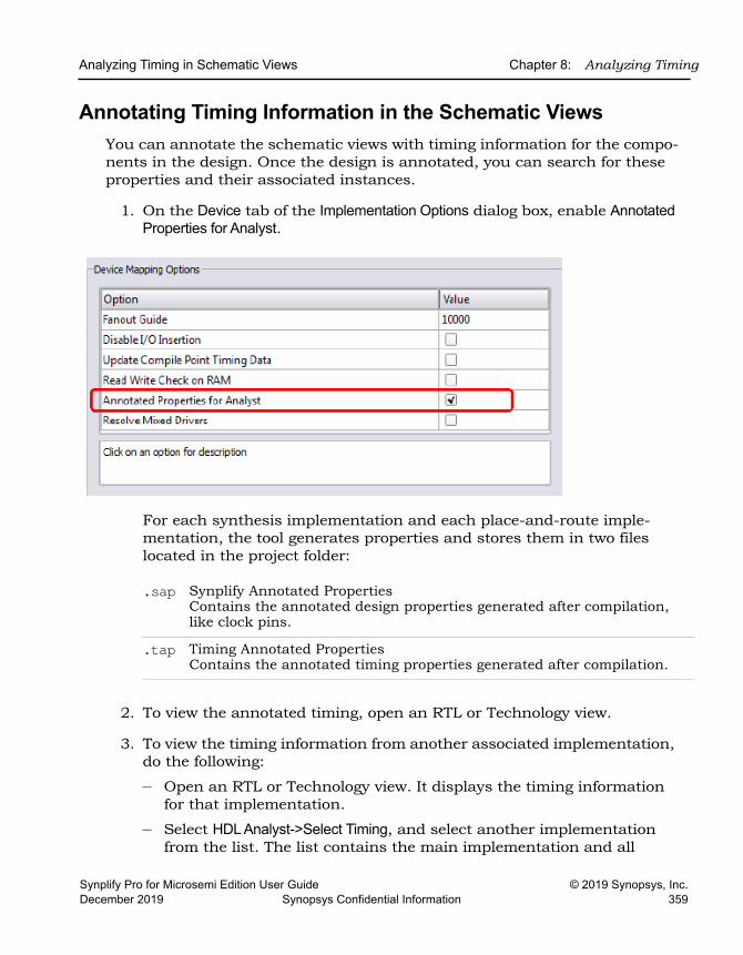
Analyzing Timing in Schematic Views Chapter 8: Analyzing Timing
Synplify Pro for Microsemi Edition User Guide © 2019 Synopsys, Inc.December 2019 Synopsys Confidential Information 359
Annotating Timing Information in the Schematic ViewsYou can annotate the schematic views with timing information for the compo-nents in the design. Once the design is annotated, you can search for these properties and their associated instances.
1. On the Device tab of the Implementation Options dialog box, enable Annotated Properties for Analyst.
For each synthesis implementation and each place-and-route imple-mentation, the tool generates properties and stores them in two files located in the project folder:
2. To view the annotated timing, open an RTL or Technology view.
3. To view the timing information from another associated implementation, do the following:
– Open an RTL or Technology view. It displays the timing information for that implementation.
– Select HDL Analyst->Select Timing, and select another implementation from the list. The list contains the main implementation and all
.sap Synplify Annotated PropertiesContains the annotated design properties generated after compilation, like clock pins.
.tap Timing Annotated PropertiesContains the annotated timing properties generated after compilation.
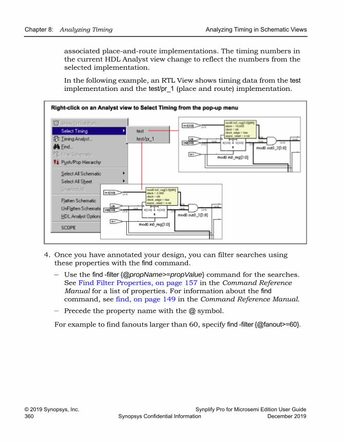
LO
Chapter 8: Analyzing Timing Analyzing Timing in Schematic Views
© 2019 Synopsys, Inc. Synplify Pro for Microsemi Edition User Guide360 Synopsys Confidential Information December 2019
associated place-and-route implementations. The timing numbers in the current HDL Analyst view change to reflect the numbers from the selected implementation.
In the following example, an RTL View shows timing data from the test implementation and the test/pr_1 (place and route) implementation.
4. Once you have annotated your design, you can filter searches using these properties with the find command.
– Use the find -filter {@propName>=propValue} command for the searches. See Find Filter Properties, on page 157 in the Command Reference Manual for a list of properties. For information about the find command, see find, on page 149 in the Command Reference Manual.
– Precede the property name with the @ symbol.
For example to find fanouts larger than 60, specify find -filter {@fanout>=60}.
Analyzing Timing in Schematic Views Chapter 8: Analyzing Timing
Synplify Pro for Microsemi Edition User Guide © 2019 Synopsys, Inc.December 2019 Synopsys Confidential Information 361
Analyzing Clock Trees in the RTL ViewTo analyze clock trees in the RTL view, do the following:
1. In the Hierarchy Browser, expand Clock Tree, select all the clocks, and filter the design.
The Hierarchy Browser lists all clocks and the instances that drive them under Clock Tree. The filtered view shows the selected objects.
2. If necessary, use the filter and expand commands to trace clock connections back to the ports and check them.
For details about the commands for filtering and expanding paths, see Filtering Schematics, on page 340, Expanding Pin and Net Logic, on page 342 and Expanding and Viewing Connections, on page 346.
3. Check that your defined clock constraints cover the objects in the design.
If you do not define your clock constraints accurately, you might not get the best possible synthesis optimizations.
Viewing Critical PathsThe HDL Analyst tool makes it simple to find and examine critical paths and the relevant source code. The following procedure shows you how to filter and analyze a critical path. You can also use the procedure described in Gener-ating Custom Timing Reports with STA, on page 366 to view this and other paths.
1. If needed, set the slack time for your design.
– Select HDL Analyst->Set Slack Margin.
– To view only instances with the worst-case slack time, enter a zero.
– To set a slack margin range, type a value for the slack margin, and click OK. The software gets a range by subtracting this number from the slack time, and the Technology view displays instances within this range. For example, if your slack time is -10 ns, and you set a slack margin of 4 ns, the command displays all instances with slack times between -6 ns and -10 ns. If your slack margin is 6 ns, you see all instances with slack times between -4 ns and -10 ns.
LO
Chapter 8: Analyzing Timing Analyzing Timing in Schematic Views
© 2019 Synopsys, Inc. Synplify Pro for Microsemi Edition User Guide362 Synopsys Confidential Information December 2019
2. Display the critical path using one of the following methods. The Technology view displays a hierarchical view that highlights the instances and nets in the most critical path of your design.
– To generate a hierarchical view of the critical path, click the Show Critical Path icon (stopwatch icon ( ), select HDL Analyst->Technology->Hierarchical Critical Path, or select the command from the popup menu. This is a filtered view in the same window, with hierarchical logic shown in transparent instances. History commands apply, so you can return to the previous view by clicking Back.
– To flatten the hierarchical critical path described above, right-click and select Flatten Schematic. The software generates a new view in the current window, and flattens only the transparent instances needed to show the critical path; the rest of the design remains hierarchical. Click Back to go the top-level design.
– To generate a flattened critical path in a new window, select HDL Analyst->Technology->Flattened Critical Path. This command uses more memory because it flattens the entire design and generates a new view for the flattened critical path in a new window. Click Back in this window to go to the flattened top-level design or to return to the previous window.
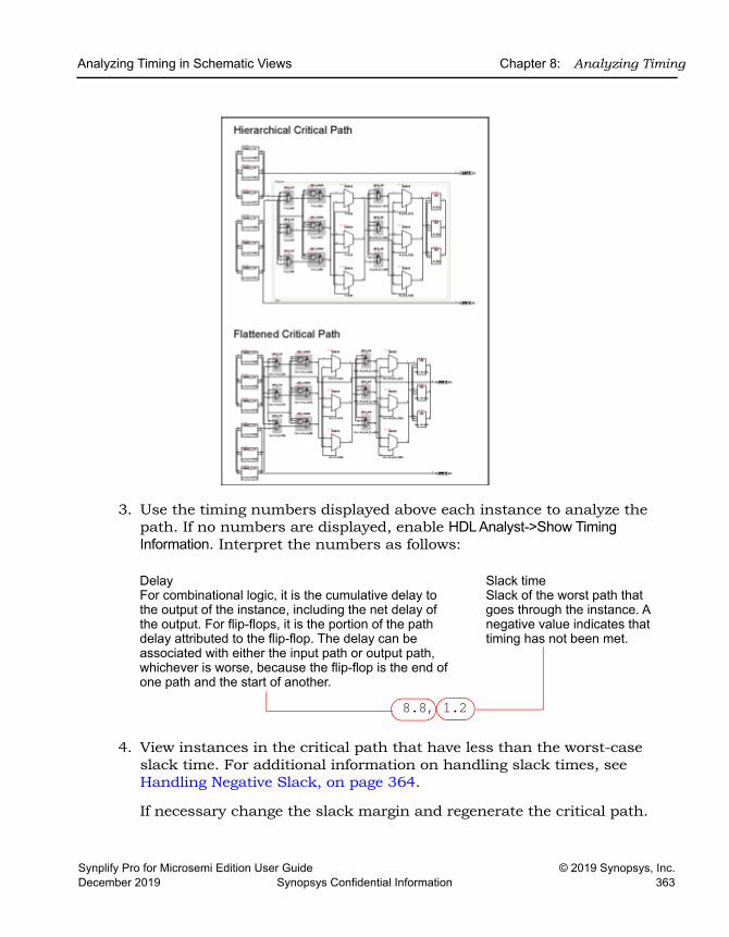
Analyzing Timing in Schematic Views Chapter 8: Analyzing Timing
Synplify Pro for Microsemi Edition User Guide © 2019 Synopsys, Inc.December 2019 Synopsys Confidential Information 363
3. Use the timing numbers displayed above each instance to analyze the path. If no numbers are displayed, enable HDL Analyst->Show Timing Information. Interpret the numbers as follows:
4. View instances in the critical path that have less than the worst-case slack time. For additional information on handling slack times, see Handling Negative Slack, on page 364.
If necessary change the slack margin and regenerate the critical path.
8.8, 1.2
DelayFor combinational logic, it is the cumulative delay to the output of the instance, including the net delay of the output. For flip-flops, it is the portion of the path delay attributed to the flip-flop. The delay can be associated with either the input path or output path, whichever is worse, because the flip-flop is the end of one path and the start of another.
Slack timeSlack of the worst path that goes through the instance. A negative value indicates that timing has not been met.
LO
Chapter 8: Analyzing Timing Analyzing Timing in Schematic Views
© 2019 Synopsys, Inc. Synplify Pro for Microsemi Edition User Guide364 Synopsys Confidential Information December 2019
5. Crossprobe and check the RTL view and source code. Analyze the code and the schematic to determine how to address the problem. You can add more constraints or make code changes.
6. Click the Back icon to return to the previous view. If you flattened your design during analysis, select Unflatten Schematic to return to the top-level design.
There is no need to regenerate the critical path, unless you flattened your design during analysis or changed the slack margin. When you flatten your design, the view is regenerated so the history commands do not apply and you must click the Critical Path icon again to see the critical path view.
7. Rerun synthesis, and check your results.
If you have fixed the path, the window displays the next most critical path when you click the icon.
Repeat this procedure and fix the design for the remaining critical paths. When you are within 5-10 percent of your desired results, place and route your design to see if you meet your goal. If so, you are done. If your vendor provides timing-driven place and route, you might improve your results further by adding timing constraints to place and route.
Handling Negative SlackPositive slack time values (greater than or equal to 0 ns) are good, while negative slack time values (less than 0 ns) indicate the design has not met timing requirements. The negative slack value indicates the amount by which the timing is off because of delays in the critical paths of your design.
The following procedure shows you how to add constraints to correct negative slack values. Timing constraints can improve your design by 10 to 20 percent.
1. Display the critical path in a filtered Technology view.
– For a hierarchical critical path, either click the Critical Path icon, select HDL Analyst->Show Critical Path, or select HDL Analyst->Technology-> Hierarchical Critical Path.
– For a flat path, select HDL Analyst->Technology->Flattened Critical Path.
2. Analyze the critical path.
Analyzing Timing in Schematic Views Chapter 8: Analyzing Timing
Synplify Pro for Microsemi Edition User Guide © 2019 Synopsys, Inc.December 2019 Synopsys Confidential Information 365
– Check the end points of the path. The start point can be a primary input or a flip-flop. The end point can be a primary output or a flip-flop.
– Examine the instances. Use the commands described in Expanding Pin and Net Logic, on page 342 and Expanding and Viewing Connections, on page 346. For more information on filtering schematics, see Filtering Schematics, on page 340.
3. Determine whether there is a timing exception, like a false or multicycle path. If this is the cause of the negative slack, set the appropriate timing constraint.
If there are fewer start points, pick a start point to add the constraint. If there are fewer end points, add the constraint to an end point.
4. If your design does not meet timing by 20 percent or more, you may need to make structural changes. You could do this by doing either of the following:
– Enabling options like retiming (Retiming, on page 406), or resource sharing (Sharing Resources, on page 422).
– Modifying the source code.
5. Rerun synthesis and check your results.
LO
Chapter 8: Analyzing Timing Generating Custom Timing Reports with STA
© 2019 Synopsys, Inc. Synplify Pro for Microsemi Edition User Guide366 Synopsys Confidential Information December 2019
Generating Custom Timing Reports with STAThe log file generated after synthesis includes a timing report and default timing information. Use the stand-alone timing analyst (STA) when you need to generate a customized timing report (ta) for the following situations:
• You need more details about a specific path
• You want results for paths other than the top five timing paths (log file default)
• You want to modify constraints and analyze, without resynthesizing. See Using Analysis Design Constraints, on page 369 for details.
The following procedure shows you how to generate a custom report:
1. Select Analysis->Timing Analyst or click the Timing Analyst icon( ).
2. Fill in the parameters.
– You can type in the from/to or through points, or you can cut and paste or drag and drop valid objects from the Technology view (not the RTL view) into the fields. See Timing Report Generation Parameters, on page 397 in the Command Reference Manual for details on timing analysis parameters and how they can be filtered.
– Set options for clock reports as needed.
– Specify a name for the output timing report (ta).
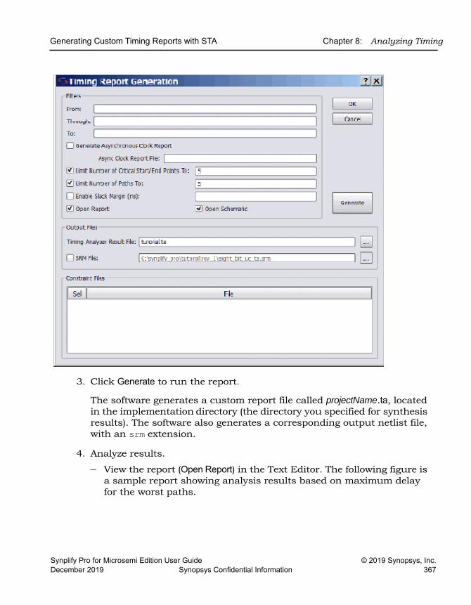
Generating Custom Timing Reports with STA Chapter 8: Analyzing Timing
Synplify Pro for Microsemi Edition User Guide © 2019 Synopsys, Inc.December 2019 Synopsys Confidential Information 367
3. Click Generate to run the report.
The software generates a custom report file called projectName.ta, located in the implementation directory (the directory you specified for synthesis results). The software also generates a corresponding output netlist file, with an srm extension.
4. Analyze results.
– View the report (Open Report) in the Text Editor. The following figure is a sample report showing analysis results based on maximum delay for the worst paths.
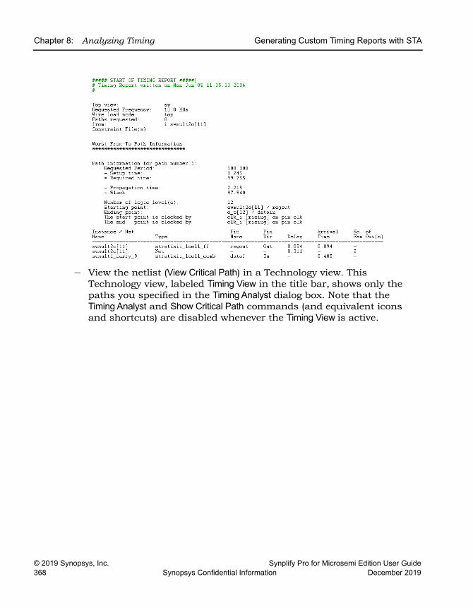
LO
Chapter 8: Analyzing Timing Generating Custom Timing Reports with STA
© 2019 Synopsys, Inc. Synplify Pro for Microsemi Edition User Guide368 Synopsys Confidential Information December 2019
– View the netlist (View Critical Path) in a Technology view. This Technology view, labeled Timing View in the title bar, shows only the paths you specified in the Timing Analyst dialog box. Note that the Timing Analyst and Show Critical Path commands (and equivalent icons and shortcuts) are disabled whenever the Timing View is active.
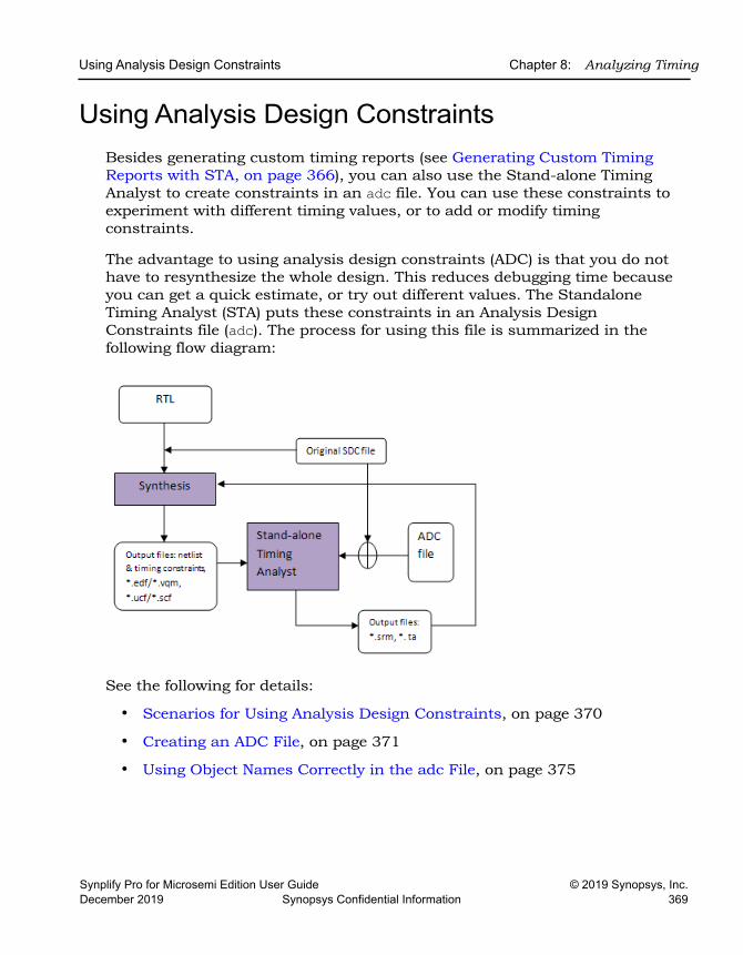
Using Analysis Design Constraints Chapter 8: Analyzing Timing
Synplify Pro for Microsemi Edition User Guide © 2019 Synopsys, Inc.December 2019 Synopsys Confidential Information 369
Using Analysis Design ConstraintsBesides generating custom timing reports (see Generating Custom Timing Reports with STA, on page 366), you can also use the Stand-alone Timing Analyst to create constraints in an adc file. You can use these constraints to experiment with different timing values, or to add or modify timing constraints.
The advantage to using analysis design constraints (ADC) is that you do not have to resynthesize the whole design. This reduces debugging time because you can get a quick estimate, or try out different values. The Standalone Timing Analyst (STA) puts these constraints in an Analysis Design Constraints file (adc). The process for using this file is summarized in the following flow diagram:
See the following for details:
• Scenarios for Using Analysis Design Constraints, on page 370
• Creating an ADC File, on page 371
• Using Object Names Correctly in the adc File, on page 375
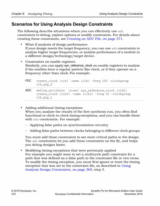
LO
Chapter 8: Analyzing Timing Using Analysis Design Constraints
© 2019 Synopsys, Inc. Synplify Pro for Microsemi Edition User Guide370 Synopsys Confidential Information December 2019
Scenarios for Using Analysis Design ConstraintsThe following describe situations where you can effectively use adc constraints to debug, explore options or modify constraints. For details about creating these constraints, see Creating an ADC File, on page 371.
• What-if analysis of design performanceIf your design meets the target frequency, you can use adc constraints to analyze higher target frequencies, or analyze performance of a module in a different design/technology/target device.
• Constraints on enable registersSimilarly, you can apply syn_reference_clock on enable registers to analyze if the enables have a regular pattern like clock, or if they operate on a frequency other than clock. For example:
• Adding additional timing exceptions When you analyze the results of the first synthesis run, you often find functional or clock-to-clock timing exceptions, and you can handle these with adc constraints. For example:
– Applying false paths on synchronization circuitry
– Adding false paths between clocks belonging to different clock groups
You must add these constraints to see more critical paths in the design. The adc constraints let you add these constraints on the fly, and helps you debug designs faster.
• Modifying timing exceptions that were previously appliedFor example you might want to set a multicycle path constraint for a path that was defined as a false path in the constraint file or vice versa. To modify the timing exception, you must first ignore or reset the timing exception that was set in the constraint file, as described in Using Analysis Design Constraints, on page 369, step 3.
FDC create_clock {clk} -name {clk} -freq 100 -clockgroup clk_grp_0
ADC define_attribute {n:en} syn_reference_clock {clk2} create_clock {clk2} -name {clk2} -freq 50 -clockgroup clk_grp_1
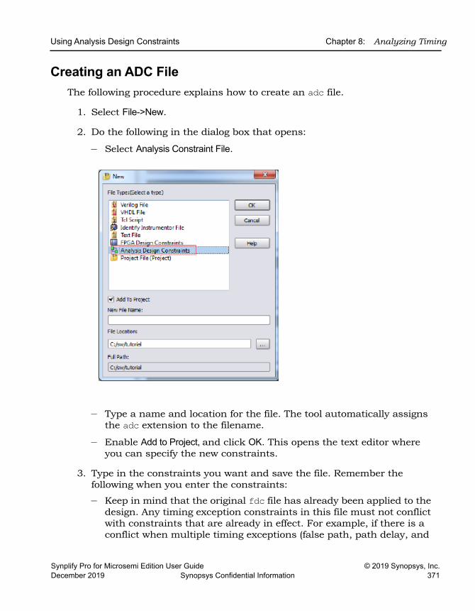
Using Analysis Design Constraints Chapter 8: Analyzing Timing
Synplify Pro for Microsemi Edition User Guide © 2019 Synopsys, Inc.December 2019 Synopsys Confidential Information 371
Creating an ADC File The following procedure explains how to create an adc file.
1. Select File->New.
2. Do the following in the dialog box that opens:
– Select Analysis Constraint File.
– Type a name and location for the file. The tool automatically assigns the adc extension to the filename.
– Enable Add to Project, and click OK. This opens the text editor where you can specify the new constraints.
3. Type in the constraints you want and save the file. Remember the following when you enter the constraints:
– Keep in mind that the original fdc file has already been applied to the design. Any timing exception constraints in this file must not conflict with constraints that are already in effect. For example, if there is a conflict when multiple timing exceptions (false path, path delay, and
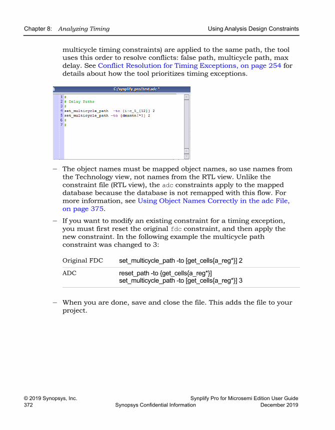
LO
Chapter 8: Analyzing Timing Using Analysis Design Constraints
© 2019 Synopsys, Inc. Synplify Pro for Microsemi Edition User Guide372 Synopsys Confidential Information December 2019
multicycle timing constraints) are applied to the same path, the tool uses this order to resolve conflicts: false path, multicycle path, max delay. See Conflict Resolution for Timing Exceptions, on page 254 for details about how the tool prioritizes timing exceptions.
– The object names must be mapped object names, so use names from the Technology view, not names from the RTL view. Unlike the constraint file (RTL view), the adc constraints apply to the mapped database because the database is not remapped with this flow. For more information, see Using Object Names Correctly in the adc File, on page 375.
– If you want to modify an existing constraint for a timing exception, you must first reset the original fdc constraint, and then apply the new constraint. In the following example the multicycle path constraint was changed to 3:
– When you are done, save and close the file. This adds the file to your project.
Original FDC set_multicycle_path -to [get_cells{a_reg*}] 2
ADC reset_path -to {get_cells{a_reg*}]set_multicycle_path -to [get_cells{a_reg*}] 3
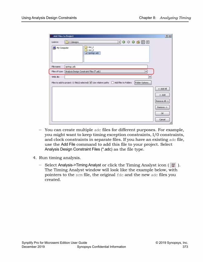
Using Analysis Design Constraints Chapter 8: Analyzing Timing
Synplify Pro for Microsemi Edition User Guide © 2019 Synopsys, Inc.December 2019 Synopsys Confidential Information 373
– You can create multiple adc files for different purposes. For example, you might want to keep timing exception constraints, I/0 constraints, and clock constraints in separate files. If you have an existing adc file, use the Add File command to add this file to your project. Select Analysis Design Constraint Files (*.adc) as the file type.
4. Run timing analysis.
– Select Analysis->Timing Analyst or click the Timing Analyst icon ( ). The Timing Analyst window will look like the example below, with pointers to the srm file, the original fdc and the new adc files you created.
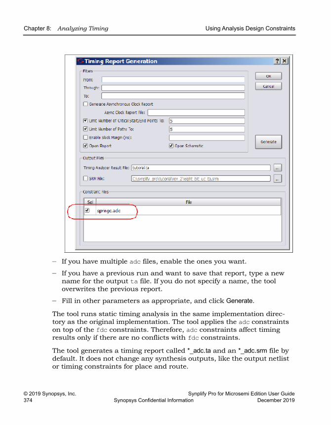
LO
Chapter 8: Analyzing Timing Using Analysis Design Constraints
© 2019 Synopsys, Inc. Synplify Pro for Microsemi Edition User Guide374 Synopsys Confidential Information December 2019
– If you have multiple adc files, enable the ones you want.
– If you have a previous run and want to save that report, type a new name for the output ta file. If you do not specify a name, the tool overwrites the previous report.
– Fill in other parameters as appropriate, and click Generate.
The tool runs static timing analysis in the same implementation direc-tory as the original implementation. The tool applies the adc constraints on top of the fdc constraints. Therefore, adc constraints affect timing results only if there are no conflicts with fdc constraints.
The tool generates a timing report called *_adc.ta and an *_adc.srm file by default. It does not change any synthesis outputs, like the output netlist or timing constraints for place and route.
Using Analysis Design Constraints Chapter 8: Analyzing Timing
Synplify Pro for Microsemi Edition User Guide © 2019 Synopsys, Inc.December 2019 Synopsys Confidential Information 375
5. Analyze the results in the timing report and *_adc.srm file.
6. If you need to resynthesize after analysis, add the adc constraints as an fdc file to the project and rerun synthesis.
Using Object Names Correctly in the adc FileConstraints and collections applied in the constraint file reference the RTL-level database. Synthesis optimizations such as retiming and replication can change object names during mapping because objects may be merged.
The standalone timing analyst does not map objects. It just reads the gate-level object names from the post-mapping database; this is reflected in the Technology view. Therefore, you must define objects either explicitly or with collections from the Technology view when you enter constraints into the adc file. Do not use RTL names when you create these constraints (see Creating an ADC File, on page 371 for details of that process).
ExampleAssume that register en_reg is replicated during mapping to reduce fanout. Further, registers en_reg and en_reg_rep2 connect to register dataout[31:0]. In this case, if you define the following false path constraint in the adc file, then the standalone timing analyzer does not automatically treat paths from the replicated register en_reg_rep2 as false paths.
set_false_path -from {{i:en_reg}} -to {{i:dataout[31:0]}}Unlike constraints in the fdc file, you must specify this replicated register explicitly or as a collection. Only then are all paths properly treated as false paths. So in this example, you must define the following constraints in the adc file:
set_false_path -from {{i:en_reg}} -to {{i:dataout[31:0]}}set_false_path -from {{i:en_reg_rep2}}
-to {{i:dataout[31:0]}}or
define_scope_collection en_regs {find -seq {i:en_reg*} -filter (@name == en_reg || @name == en_reg_rep2)}
set_false_path -from {{$en_regs}} -to {{i:dataout[31:0]}}
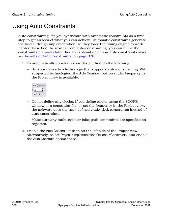
LO
Chapter 8: Analyzing Timing Using Auto Constraints
© 2019 Synopsys, Inc. Synplify Pro for Microsemi Edition User Guide376 Synopsys Confidential Information December 2019
Using Auto ConstraintsAuto constraining lets you synthesize with automatic constraints as a first step to get an idea of what you can achieve. Automatic constraints generate the fastest design implementation, so they force the timing engine to work harder. Based on the results from auto-constraining, you can refine the constraints manually later. For an explanation of how auto constraints work, see Results of Auto Constraints, on page 378
1. To automatically constrain your design, first do the following:
– Set your device to a technology that supports auto-constraining. With supported technologies, the Auto Constrain button under Frequency in the Project view is available.
– Do not define any clocks. If you define clocks using the SCOPE window or a constraint file, or set the frequency in the Project view, the software uses the user-defined create_clock constraints instead of auto constraints.
– Make sure any multi-cycle or false path constraints are specified on registers.
2. Enable the Auto Constrain button on the left side of the Project view. Alternatively, select Project->Implementation Options->Constraints, and enable the Auto Constrain option there.
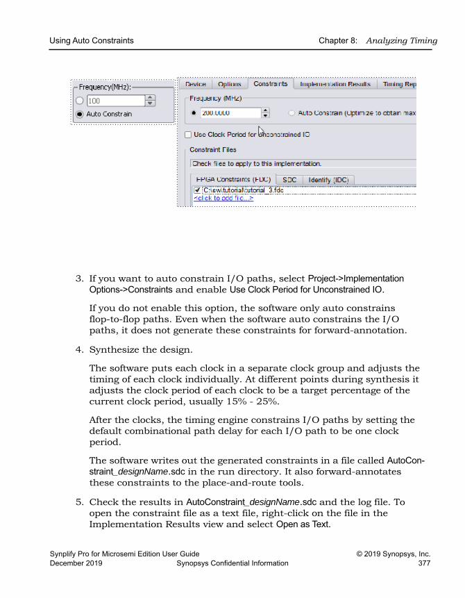
Using Auto Constraints Chapter 8: Analyzing Timing
Synplify Pro for Microsemi Edition User Guide © 2019 Synopsys, Inc.December 2019 Synopsys Confidential Information 377
3. If you want to auto constrain I/O paths, select Project->Implementation Options->Constraints and enable Use Clock Period for Unconstrained IO.
If you do not enable this option, the software only auto constrains flop-to-flop paths. Even when the software auto constrains the I/O paths, it does not generate these constraints for forward-annotation.
4. Synthesize the design.
The software puts each clock in a separate clock group and adjusts the timing of each clock individually. At different points during synthesis it adjusts the clock period of each clock to be a target percentage of the current clock period, usually 15% - 25%.
After the clocks, the timing engine constrains I/O paths by setting the default combinational path delay for each I/O path to be one clock period.
The software writes out the generated constraints in a file called AutoCon-straint_designName.sdc in the run directory. It also forward-annotates these constraints to the place-and-route tools.
5. Check the results in AutoConstraint_designName.sdc and the log file. To open the constraint file as a text file, right-click on the file in the Implementation Results view and select Open as Text.
LO
Chapter 8: Analyzing Timing Using Auto Constraints
© 2019 Synopsys, Inc. Synplify Pro for Microsemi Edition User Guide378 Synopsys Confidential Information December 2019
The flop-to-flop constraints use syntax like the following:
create_clock -name {c:leon|clk} -period 13.327 -clockgroup Autoconstr_clkgroup_0 -rise 0.000 -fall 6.664 -route 0.000
6. You can now add this generated constraint file to the project and rerun synthesis with these constraints.
Results of Auto ConstraintsThis section contains information about the following:
• Stages of the Auto Constrain Algorithm, on page 378
• I/O Constraints, Timing Exceptions, on page 379
• Reports and Forward-annotation, on page 379
• Repeatability of Results, on page 380
Stages of the Auto Constrain AlgorithmTo auto constrain, do not define any clocks. When you enable the Auto Constrain option, the synthesis software goes through these stages:
1. It infers every clock in the design.
2. It puts each clock in its own clock group.
3. It invokes mapper optimizations in stages and generates the best possible synthesis results.
– Clocks derived from DCM/PLLs will be in the clock group of the parent clock (DCM/PLL input clock).
– You should only use Auto Constrain early in the synthesis process to get a general idea of how fast your design runs. This option is not meant to be a substitute for declaring clocks.
4. For each clock, including the system clock, the software maintains a negative slack of between 15 and 25 percent of the requested frequency.
Using Auto Constraints Chapter 8: Analyzing Timing
Synplify Pro for Microsemi Edition User Guide © 2019 Synopsys, Inc.December 2019 Synopsys Confidential Information 379
I/O Constraints, Timing ExceptionsThe auto constrain algorithm infers all the clocks, because none are defined. It handles the following timing situations as described below:
• I/O constraints
You can auto constrain I/O paths as well as flop-to-flop paths by selecting Project->Implementation Options->Constraints and enabling Use Clock Period for Unconstrained IO. The software does not write out these I/O constraints.
• Timing exceptions like multicycle and false paths
The auto constraint algorithm honors SCOPE multicycle and false path constraints that are specified as constraints on registers.
Auto Constrain LimitationsThe Auto Constrain feature has the following limitations:
• Does not respect the vendor-provided maximum frequency constraints for clock generators.
• Over constrains designs with output critical paths.
Reports and Forward-annotationIn the log file, the software reports the Requested and Estimated Frequency or Requested and Estimated Period and the negative slack for each clock it infers. The log file contains all the details.
The software also generates a constraint file in the run directory called AutoConstraint_designName.sdc, which contains the auto constraints generated. The following is an example of an auto constraint file:
#Begin clock constraintcreate_clock -name {c:leon|clk} -period 13.327 -rise 0.000 -fall 6.664 #End clock constraint
The software forward-annotates the create_clock constraints, writing out the appropriate file for the place-and-route tool.
LO
Chapter 8: Analyzing Timing Using Auto Constraints
© 2019 Synopsys, Inc. Synplify Pro for Microsemi Edition User Guide380 Synopsys Confidential Information December 2019
Repeatability of ResultsIf you use the requested frequency resulting from the Auto constrain option as the requested frequency for a regular synthesis run, you might not get the same results as you did with auto constraints. This is because the software invokes the mapper optimizations in stages when it auto constrains. The results from a previous stage are used to drive the next stage. As the interim optimization results vary, there is no guarantee that the final results will stay the same.
5.
Synplify Pro for Microsemi Edition User Guide © 2019 Synopsys, Inc.December 2019 Synopsys Confidential Information 381
C H A P T E R 9
Inferring High-Level Objects
This chapter contains guidelines on how to structure your code or attach attributes so that the synthesis tools can automatically infer high-level objects like RAMs. See the following for more information:
• Defining Black Boxes for Synthesis, on page 382
• Defining State Machines for Synthesis, on page 391
• Initializing RAMs, on page 396
LO
Chapter 9: Inferring High-Level Objects Defining Black Boxes for Synthesis
© 2019 Synopsys, Inc. Synplify Pro for Microsemi Edition User Guide382 Synopsys Confidential Information December 2019
Defining Black Boxes for SynthesisBlack boxes are predefined components for which the interface is specified, but whose internal architectural statements are ignored. They are used as place holders for IP blocks, legacy designs, or a design under development.
This section discusses the following topics:
• Instantiating Black Boxes and I/Os in Verilog, on page 382
• Instantiating Black Boxes and I/Os in VHDL, on page 384
• Adding Black Box Timing Constraints, on page 386
• Adding Other Black Box Attributes, on page 390
Instantiating Black Boxes and I/Os in Verilog Verilog black boxes for macros and I/Os come from two sources: commonly-used or vendor-specific components that are predefined in Verilog macro libraries, or black boxes that are defined in another input source like a schematic. For information about instantiating black boxes in VHDL, see Instantiating Black Boxes and I/Os in VHDL, on page 384.
The following process shows you how to instantiate both types as black boxes. Refer to the installDirectory/examples directory for examples of instantia-tions of low-level resources.
1. To instantiate a predefined Verilog module as a black box:
– Select the library file with the macro you need from the installDirectory/lib/technology directory. Files are named technology.v. Most vendor architectures provide macro libraries that predefine the black boxes for primitives and macros.
– Make sure the library macro file is the first file in the source file list for your project.
2. To instantiate a module that has been defined in another input source as a black box:
– Create an empty macro that only contains ports and port directions.
Defining Black Boxes for Synthesis Chapter 9: Inferring High-Level Objects
Synplify Pro for Microsemi Edition User Guide © 2019 Synopsys, Inc.December 2019 Synopsys Confidential Information 383
– Put the syn_black_box synthesis directive just before the semicolon in the module declaration.
module myram (out, in, addr, we) /* synthesis syn_black_box */;output [15:0] out;input [15:0] in;input [4:0] addr;input we;
endmodule– Make an instance of the stub in your design.
– Compile the stub along with the module containing the instantiation of the stub.
– To simulate with a Verilog simulator, you must have a functional description of the black box. To make sure the synthesis software ignores the functional description and treats it as a black box, use the translate_off and translate_on constructs. For example:
module adder8(cout, sum, a, b, cin);// Code that you want to synthesize/* synthesis translate_off */// Functional description./* synthesis translate_on */// Other code that you want to synthesize.endmodule
3. To instantiate a vendor-specific (black box) I/O that has been defined in another input source:
– Create an empty macro that only contains ports and port directions.
– Put the syn_black_box synthesis directive just before the semicolon in the module declaration.
– Specify the external pad pin with the black_box_pad_pin directive, as in this example:
module BBDLHS(D,E,GIN,GOUT,PAD,Q)/* synthesis syn_black_box black_box_pad_pin="PAD"
– Make an instance of the stub in your design.
– Compile the stub along with the module containing the instantiation of the stub.
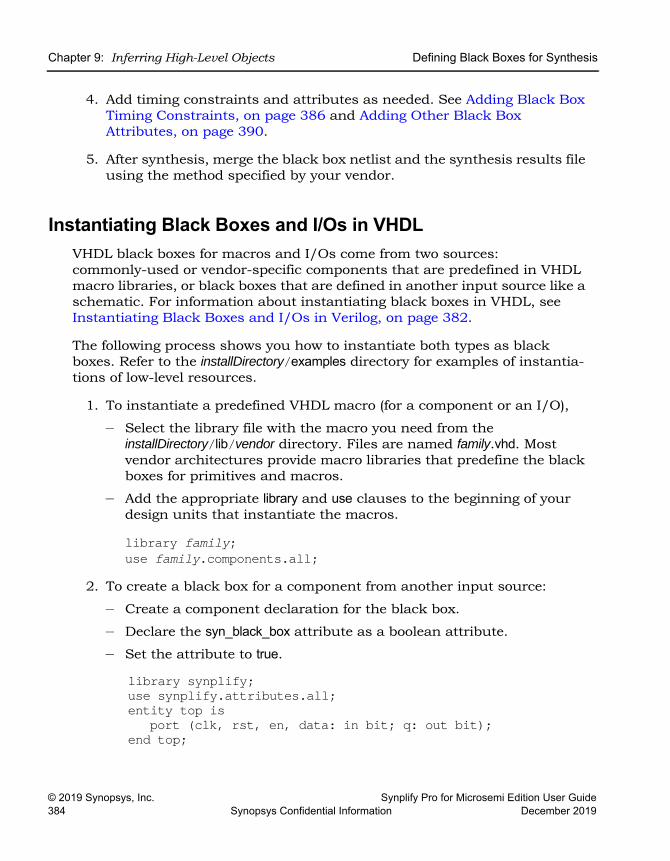
LO
Chapter 9: Inferring High-Level Objects Defining Black Boxes for Synthesis
© 2019 Synopsys, Inc. Synplify Pro for Microsemi Edition User Guide384 Synopsys Confidential Information December 2019
4. Add timing constraints and attributes as needed. See Adding Black Box Timing Constraints, on page 386 and Adding Other Black Box Attributes, on page 390.
5. After synthesis, merge the black box netlist and the synthesis results file using the method specified by your vendor.
Instantiating Black Boxes and I/Os in VHDL VHDL black boxes for macros and I/Os come from two sources: commonly-used or vendor-specific components that are predefined in VHDL macro libraries, or black boxes that are defined in another input source like a schematic. For information about instantiating black boxes in VHDL, see Instantiating Black Boxes and I/Os in Verilog, on page 382.
The following process shows you how to instantiate both types as black boxes. Refer to the installDirectory/examples directory for examples of instantia-tions of low-level resources.
1. To instantiate a predefined VHDL macro (for a component or an I/O),
– Select the library file with the macro you need from the installDirectory/lib/vendor directory. Files are named family.vhd. Most vendor architectures provide macro libraries that predefine the black boxes for primitives and macros.
– Add the appropriate library and use clauses to the beginning of your design units that instantiate the macros.
library family;use family.components.all;
2. To create a black box for a component from another input source:
– Create a component declaration for the black box.
– Declare the syn_black_box attribute as a boolean attribute.
– Set the attribute to true.
library synplify;use synplify.attributes.all;entity top is
port (clk, rst, en, data: in bit; q: out bit);end top;
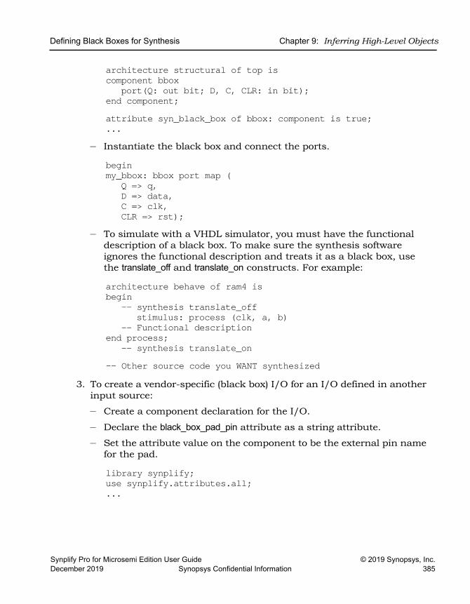
Defining Black Boxes for Synthesis Chapter 9: Inferring High-Level Objects
Synplify Pro for Microsemi Edition User Guide © 2019 Synopsys, Inc.December 2019 Synopsys Confidential Information 385
architecture structural of top iscomponent bbox
port(Q: out bit; D, C, CLR: in bit);end component;attribute syn_black_box of bbox: component is true;...
– Instantiate the black box and connect the ports.
beginmy_bbox: bbox port map (
Q => q,D => data,C => clk,CLR => rst);
– To simulate with a VHDL simulator, you must have the functional description of a black box. To make sure the synthesis software ignores the functional description and treats it as a black box, use the translate_off and translate_on constructs. For example:
architecture behave of ram4 isbegin
-- synthesis translate_offstimulus: process (clk, a, b)
-- Functional descriptionend process;
-- synthesis translate_on-- Other source code you WANT synthesized
3. To create a vendor-specific (black box) I/O for an I/O defined in another input source:
– Create a component declaration for the I/O.
– Declare the black_box_pad_pin attribute as a string attribute.
– Set the attribute value on the component to be the external pin name for the pad.
library synplify;use synplify.attributes.all;...
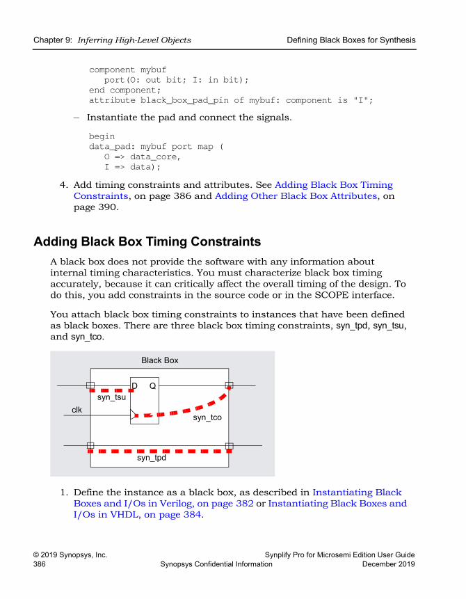
LO
Chapter 9: Inferring High-Level Objects Defining Black Boxes for Synthesis
© 2019 Synopsys, Inc. Synplify Pro for Microsemi Edition User Guide386 Synopsys Confidential Information December 2019
component mybufport(O: out bit; I: in bit);
end component;attribute black_box_pad_pin of mybuf: component is "I";
– Instantiate the pad and connect the signals.
begindata_pad: mybuf port map (
O => data_core,I => data);
4. Add timing constraints and attributes. See Adding Black Box Timing Constraints, on page 386 and Adding Other Black Box Attributes, on page 390.
Adding Black Box Timing ConstraintsA black box does not provide the software with any information about internal timing characteristics. You must characterize black box timing accurately, because it can critically affect the overall timing of the design. To do this, you add constraints in the source code or in the SCOPE interface.
You attach black box timing constraints to instances that have been defined as black boxes. There are three black box timing constraints, syn_tpd, syn_tsu, and syn_tco.
1. Define the instance as a black box, as described in Instantiating Black Boxes and I/Os in Verilog, on page 382 or Instantiating Black Boxes and I/Os in VHDL, on page 384.
Black Box
D
syn_tpd
syn_tsu
syn_tco
Q
clk
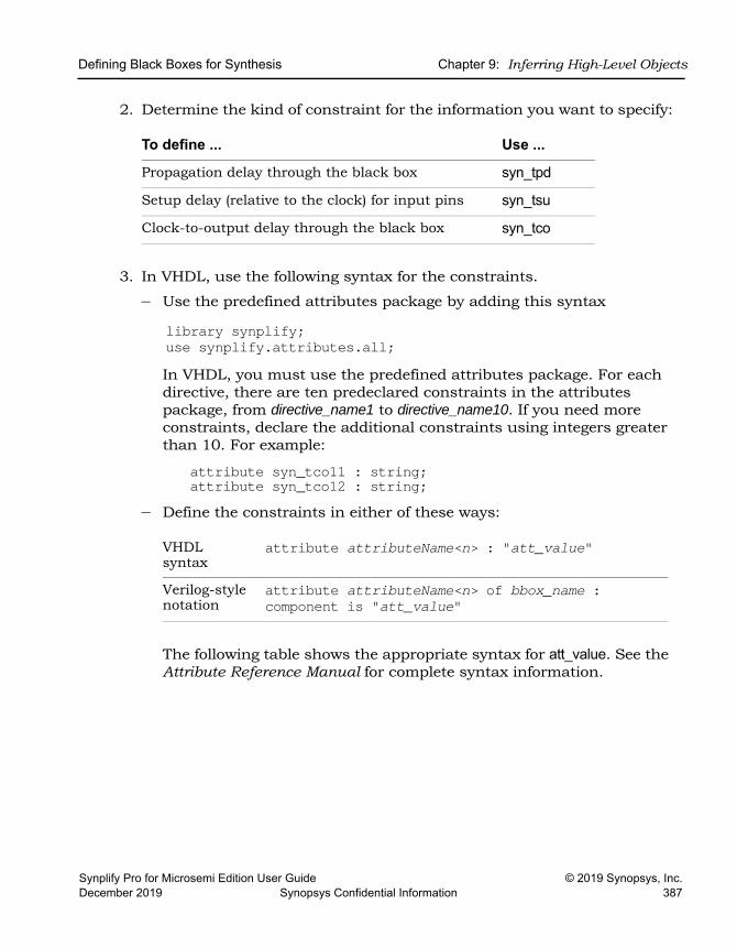
Defining Black Boxes for Synthesis Chapter 9: Inferring High-Level Objects
Synplify Pro for Microsemi Edition User Guide © 2019 Synopsys, Inc.December 2019 Synopsys Confidential Information 387
2. Determine the kind of constraint for the information you want to specify:
3. In VHDL, use the following syntax for the constraints.
– Use the predefined attributes package by adding this syntax
library synplify;use synplify.attributes.all;In VHDL, you must use the predefined attributes package. For each directive, there are ten predeclared constraints in the attributes package, from directive_name1 to directive_name10. If you need more constraints, declare the additional constraints using integers greater than 10. For example:
attribute syn_tco11 : string;attribute syn_tco12 : string;
– Define the constraints in either of these ways:
The following table shows the appropriate syntax for att_value. See the Attribute Reference Manual for complete syntax information.
To define ... Use ...
Propagation delay through the black box syn_tpd
Setup delay (relative to the clock) for input pins syn_tsu
Clock-to-output delay through the black box syn_tco
VHDL syntax
attribute attributeName<n> : "att_value"
Verilog-style notation
attribute attributeName<n> of bbox_name : component is "att_value"
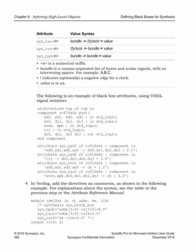
LO
Chapter 9: Inferring High-Level Objects Defining Black Boxes for Synthesis
© 2019 Synopsys, Inc. Synplify Pro for Microsemi Edition User Guide388 Synopsys Confidential Information December 2019
The following is an example of black box attributes, using VHDL signal notation:
architecture top of top is component rcf16x4z port(
ad0, ad1, ad2, ad3 : in std_logic;di0, di1, di2, di3 : in std_logic;wren, wpe : in std_logic;tri : in std_logic;do0, do1, do2 do3 : out std_logic;
end componentattribute syn_tpd1 of rcf16x4z : component is
"ad0,ad1,ad2,ad3 -> do0,do1,do2,do3 = 2.1";attribute syn_tpd2 of rcf16x4z : component is
"tri -> do0,do1,do2,do3 = 2.0";attribute syn_tsu1 of rcf16x4z : component is
"ad0,ad1,ad2,ad3 -> ck = 1.2";attribute syn_tsu2 of rcf16x4z : component is
"wren,wpe,do0,do1,do2,do3 -> ck = 0.0";4. In Verilog, add the directives as comments, as shown in the following
example. For explanations about the syntax, see the table in the previous step or the Attribute Reference Manual.
module ram32x4 (z, d, addr, we, clk)/* synthesis syn_black_boxsyn_tpd1="addr[3:0]->z[3:0]=8.0"syn_tsu1="addr[3:0]->clk=2.0"syn_tsu2="we->clk=3.0" */;
output [3:0] z;
Attribute Value Syntax
syn_tsu<n> bundle -> [!]clock = value
syn_tco<n> [!]clock -> bundle = value
syn_tpd<n> bundle -> bundle = value
• <n> is a numerical suffix. • bundle is a comma-separated list of buses and scalar signals, with no
intervening spaces. For example, A,B,C. • ! indicates (optionally) a negative edge for a clock.• value is in ns.
Defining Black Boxes for Synthesis Chapter 9: Inferring High-Level Objects
Synplify Pro for Microsemi Edition User Guide © 2019 Synopsys, Inc.December 2019 Synopsys Confidential Information 389
input [3:0] d;input [3:0] addr;input we;input clk;endmodule
5. To add black box attributes through the SCOPE interface, do the following:
– Open the SCOPE spreadsheet and select the Attributes panel.
– In the Object column, select the name of the black-box module or component declaration from the pull-down list. Manually prefix the black box name with v: to apply the constraint to the view.
– In the Attribute column, type the name of the timing attribute, followed by the numerical suffix, as shown in the following table. You cannot select timing attributes from the pull-down list.
– In the Value column, type the appropriate value syntax, as shown in the table in step 3.
– Save the constraint file, and add it to the project.
The resulting constraint file contains syntax like this:
define_attribute v:{blackboxModule} attribute<n> {attributeValue}
6. Synthesize the design and check black box timing.
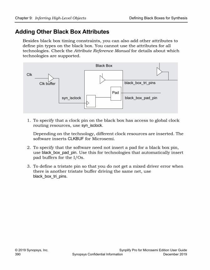
LO
Chapter 9: Inferring High-Level Objects Defining Black Boxes for Synthesis
© 2019 Synopsys, Inc. Synplify Pro for Microsemi Edition User Guide390 Synopsys Confidential Information December 2019
Adding Other Black Box AttributesBesides black box timing constraints, you can also add other attributes to define pin types on the black box. You cannot use the attributes for all technologies. Check the Attribute Reference Manual for details about which technologies are supported.
1. To specify that a clock pin on the black box has access to global clock routing resources, use syn_isclock.
Depending on the technology, different clock resources are inserted. The software inserts CLKBUF for Microsemi.
2. To specify that the software need not insert a pad for a black box pin, use black_box_pad_pin. Use this for technologies that automatically insert pad buffers for the I/Os.
3. To define a tristate pin so that you do not get a mixed driver error when there is another tristate buffer driving the same net, use black_box_tri_pins.
Pad
Clk
Clk buffer
syn_isclock
black_box_tri_pins
Black Box
black_box_pad_pin
Defining State Machines for Synthesis Chapter 9: Inferring High-Level Objects
Synplify Pro for Microsemi Edition User Guide © 2019 Synopsys, Inc.December 2019 Synopsys Confidential Information 391
Defining State Machines for SynthesisA finite state machine (FSM) is a piece of hardware that advances from state to state at a clock edge. The synthesis software recognizes and extracts the state machines from the HDL source code. For guidelines on setting up the source code, see the following:
• Defining State Machines in Verilog, on page 391
• Defining State Machines in VHDL, on page 392
• Specifying FSMs with Attributes and Directives, on page 393
For information about the attributes used to define state machines, see Running the FSM Compiler, on page 425. For information about imple-menting safe FSMs, see Specifying Safe FSMs, on page 545.
Defining State Machines in VerilogThe synthesis software recognizes and automatically extracts state machines from the Verilog source code if you follow the coding guidelines listed below. The software attaches the syn_state_machine attribute to each extracted FSM.
For alternative ways to define state machines, see Defining State Machines for Synthesis, on page 391.
Follow these Verilog coding guidelines:
• In Verilog, model the state machine with case, casex, or casez statements in always blocks. Check the current state to advance to the next state and then set output values. Do not use if statements.
• Always use a default assignment as the last assignment in the case statement, and set the state variable to ‘bx. This is a “don’t care” state-ment and ensures that the software can remove unnecessary decoding and gates.
• Make sure the state machines have a synchronous or asynchronous reset to set the hardware to a valid state after power-up, or to reset the hardware when you are operating.
LO
Chapter 9: Inferring High-Level Objects Defining State Machines for Synthesis
© 2019 Synopsys, Inc. Synplify Pro for Microsemi Edition User Guide392 Synopsys Confidential Information December 2019
• Specify explicit state values for states with parameter or ‘define state-ments. This is an example of a parameter statement that sets the current state to 2’h2:
parameter state1 = 2’h1, state2 = 2’h2;...current_state = state2;
This example shows how to set the current state value with `define state-ments:
‘define state1 2’h1‘define state2 2’h2...current_state = ‘state2;
• Make state assignments using parameter with symbolic state names.Use parameter over `define, because `define is applied globally while parameter definitions are local. Local definitions make it easier to reuse common state names in multiple FSM designs, like RESET, IDLE, READY, READ, WRITE, ERROR, and DONE.
If you use `define to assign the names, you cannot reuse a state name because it has already been used in the global name space. To reuse the same names in this scenario, you have to use `undef and `define state-ments between modules to redefine the names. This method makes it difficult to probe the internal values of FSM state buses from a testbench and compare them to the state names.
Defining State Machines in VHDLThe synthesis software recognizes and automatically extracts state machines from the VHDL source code if you follow the coding guidelines below. For alternative ways to define state machines, see Defining State Machines for Synthesis, on page 391.
The following are VHDL guidelines for coding. The software attaches the syn_state_machine attribute to each extracted FSM.
• Use case statements to check the current state at the clock edge, advance to the next state, and set output values. You can also use if-then-else statements, but case statements are preferable.
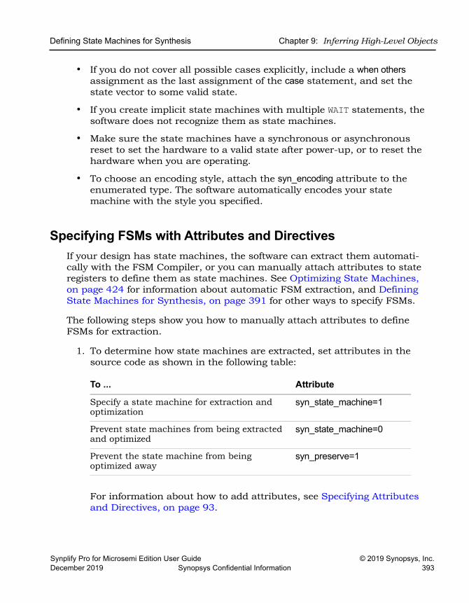
Defining State Machines for Synthesis Chapter 9: Inferring High-Level Objects
Synplify Pro for Microsemi Edition User Guide © 2019 Synopsys, Inc.December 2019 Synopsys Confidential Information 393
• If you do not cover all possible cases explicitly, include a when others assignment as the last assignment of the case statement, and set the state vector to some valid state.
• If you create implicit state machines with multiple WAIT statements, the software does not recognize them as state machines.
• Make sure the state machines have a synchronous or asynchronous reset to set the hardware to a valid state after power-up, or to reset the hardware when you are operating.
• To choose an encoding style, attach the syn_encoding attribute to the enumerated type. The software automatically encodes your state machine with the style you specified.
Specifying FSMs with Attributes and DirectivesIf your design has state machines, the software can extract them automati-cally with the FSM Compiler, or you can manually attach attributes to state registers to define them as state machines. See Optimizing State Machines, on page 424 for information about automatic FSM extraction, and Defining State Machines for Synthesis, on page 391 for other ways to specify FSMs.
The following steps show you how to manually attach attributes to define FSMs for extraction.
1. To determine how state machines are extracted, set attributes in the source code as shown in the following table:
For information about how to add attributes, see Specifying Attributes and Directives, on page 93.
To ... Attribute
Specify a state machine for extraction and optimization
syn_state_machine=1
Prevent state machines from being extracted and optimized
syn_state_machine=0
Prevent the state machine from being optimized away
syn_preserve=1
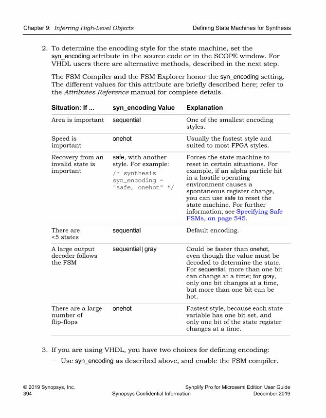
LO
Chapter 9: Inferring High-Level Objects Defining State Machines for Synthesis
© 2019 Synopsys, Inc. Synplify Pro for Microsemi Edition User Guide394 Synopsys Confidential Information December 2019
2. To determine the encoding style for the state machine, set the syn_encoding attribute in the source code or in the SCOPE window. For VHDL users there are alternative methods, described in the next step.
The FSM Compiler and the FSM Explorer honor the syn_encoding setting. The different values for this attribute are briefly described here; refer to the Attributes Reference manual for complete details.
3. If you are using VHDL, you have two choices for defining encoding:
– Use syn_encoding as described above, and enable the FSM compiler.
Situation: If ... syn_encoding Value Explanation
Area is important sequential One of the smallest encoding styles.
Speed is important
onehot Usually the fastest style and suited to most FPGA styles.
Recovery from an invalid state is important
safe, with another style. For example: /* synthesis syn_encoding = "safe, onehot" */
Forces the state machine to reset in certain situations. For example, if an alpha particle hit in a hostile operating environment causes a spontaneous register change, you can use safe to reset the state machine. For further information, see Specifying Safe FSMs, on page 545.
There are <5 states
sequential Default encoding.
A large output decoder follows the FSM
sequential|gray Could be faster than onehot, even though the value must be decoded to determine the state. For sequential, more than one bit can change at a time; for gray, only one bit changes at a time, but more than one bit can be hot.
There are a large number of flip-flops
onehot Fastest style, because each state variable has one bit set, and only one bit of the state register changes at a time.
Defining State Machines for Synthesis Chapter 9: Inferring High-Level Objects
Synplify Pro for Microsemi Edition User Guide © 2019 Synopsys, Inc.December 2019 Synopsys Confidential Information 395
– Use syn_enum_encoding to define the states (sequential, onehot, gray, and safe) and disable the FSM Explorer. If you do not disable the FSM Explorer, the syn_enum_encoding values are not implemented. This is because the FSM Explorer, a mapper operation, overrides syn_enum_encoding, which is a compiler directive. Use the syn_enum_encoding method for user-defined FSM encoding. For example:
attribute syn_enum_encoding of state_type : type is "001 010 101";
LO
Chapter 9: Inferring High-Level Objects Initializing RAMs
© 2019 Synopsys, Inc. Synplify Pro for Microsemi Edition User Guide396 Synopsys Confidential Information December 2019
Initializing RAMsYou can specify startup values for RAMs and pass them on to the place-and-route tools. See the following topics for ways to set the initial values:
• Initializing RAMs in Verilog, on page 396
• Initializing RAMs in VHDL, on page 397
• Initializing RAMs with $readmemb and $readmemh, on page 400
Initializing RAMs in VerilogIn Verilog, you specify startup values using initial statements, which are procedural assign statements guaranteed by the language to be executed by the simulator at the start of simulation. This means that any assignment to a variable within the body of the initial statement is treated as if the variable was initialized with the corresponding LHS value. You can initialize memories using the built-in load memory system tasks $readmemb (binary) and $readmemh (hex).
The following procedure is the recommended method for specifying initial values:
1. Create a data file with an initial value for every address in the memory array. This file can be a binary file or a hex file. See Initialization Data File, on page 230in the Reference Manual for details of the formats for these files.
2. Do the following in the Verilog file to define the module:
– Include the appropriate task enable statement, $readmemb or $readmemh, in the initial statement for the module:
$readmemb ("fileName", memoryName [, startAddress [, stopAddress]]);
$readmemh ("fileName", memoryName [, startAddress [, stopAddress]]);
Use $readmemb for a binary file and use $readmemh for a hex file. For descriptions of the syntax, see Initial Values for RAMs, on page 227in the Reference Manual.
– Make sure the array declaration matches the order in the initial value data file you specified. As the file is read, each number encountered is
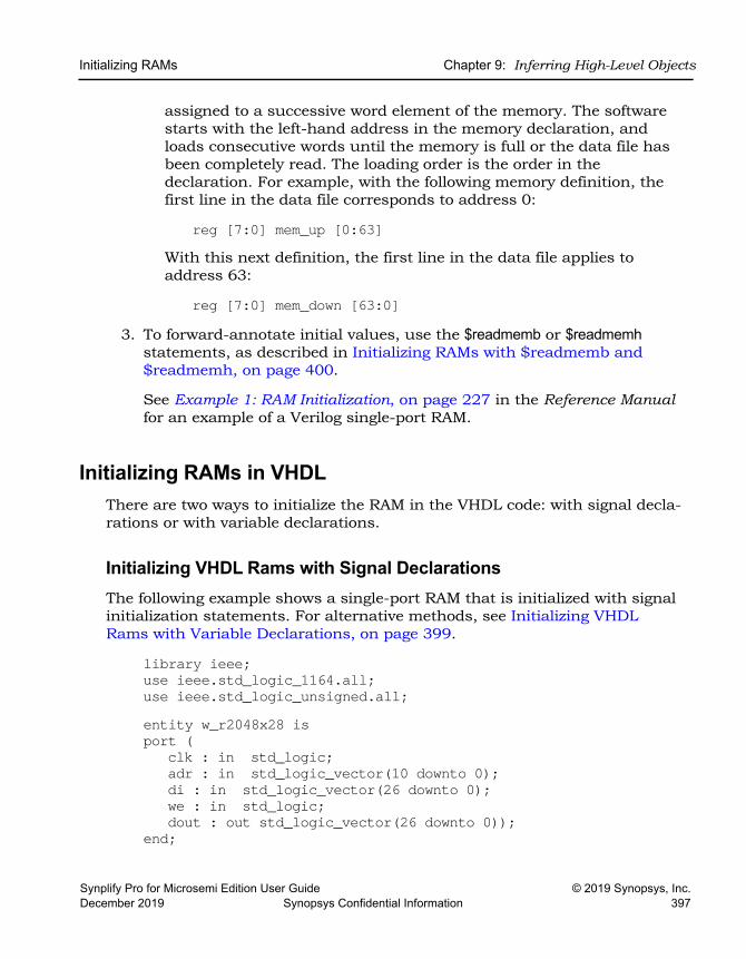
Initializing RAMs Chapter 9: Inferring High-Level Objects
Synplify Pro for Microsemi Edition User Guide © 2019 Synopsys, Inc.December 2019 Synopsys Confidential Information 397
assigned to a successive word element of the memory. The software starts with the left-hand address in the memory declaration, and loads consecutive words until the memory is full or the data file has been completely read. The loading order is the order in the declaration. For example, with the following memory definition, the first line in the data file corresponds to address 0:
reg [7:0] mem_up [0:63]With this next definition, the first line in the data file applies to address 63:
reg [7:0] mem_down [63:0]3. To forward-annotate initial values, use the $readmemb or $readmemh
statements, as described in Initializing RAMs with $readmemb and $readmemh, on page 400.
See Example 1: RAM Initialization, on page 227 in the Reference Manual for an example of a Verilog single-port RAM.
Initializing RAMs in VHDLThere are two ways to initialize the RAM in the VHDL code: with signal decla-rations or with variable declarations.
Initializing VHDL Rams with Signal DeclarationsThe following example shows a single-port RAM that is initialized with signal initialization statements. For alternative methods, see Initializing VHDL Rams with Variable Declarations, on page 399.
library ieee;use ieee.std_logic_1164.all;use ieee.std_logic_unsigned.all;entity w_r2048x28 isport (
clk : in std_logic;adr : in std_logic_vector(10 downto 0);di : in std_logic_vector(26 downto 0);we : in std_logic;dout : out std_logic_vector(26 downto 0));
end;
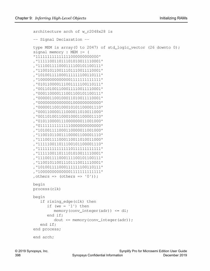
LO
Chapter 9: Inferring High-Level Objects Initializing RAMs
© 2019 Synopsys, Inc. Synplify Pro for Microsemi Edition User Guide398 Synopsys Confidential Information December 2019
architecture arch of w_r2048x28 is-- Signal Declaration --type MEM is array(0 to 2047) of std_logic_vector (26 downto 0);signal memory : MEM := ("111111111111111000000000000","111110011011101010011110001","111001111000111100101100111","110010110011101110011110001","101001111000111111100110111","100000000000001111111111111","010110000111001111100110111","001101001100011110011110001","000110000111001100101100111","000001100100011010011110001","000000000000001000000000000","000001100100010101100001110","000110000111000011010011000","001101001100010001100001110","010110000111000000011001000","011111111111110000000000000","101001111000110000011001000","110010110011100001100001110","111001111000110011010011000","111110011011100101100001110","111111111111110111111111111","111110011011101010011110001","111001111000111100101100111","110010110011101110011110001","101001111000111111100110111","100000000000001111111111111",others => (others => '0'));begin process(clk)begin
if rising_edge(clk) thenif (we = '1') then
memory(conv_integer(adr)) <= di;end if;
dout <= memory(conv_integer(adr));end if;
end process;end arch;
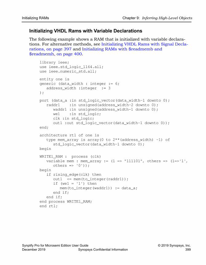
Initializing RAMs Chapter 9: Inferring High-Level Objects
Synplify Pro for Microsemi Edition User Guide © 2019 Synopsys, Inc.December 2019 Synopsys Confidential Information 399
Initializing VHDL Rams with Variable DeclarationsThe following example shows a RAM that is initialized with variable declara-tions. For alternative methods, see Initializing VHDL Rams with Signal Decla-rations, on page 397 and Initializing RAMs with $readmemb and $readmemh, on page 400.
library ieee;use ieee.std_logic_1164.all;use ieee.numeric_std.all;entity one isgeneric (data_width : integer := 6;
address_width :integer := 3);port (data_a :in std_logic_vector(data_width-1 downto 0);
raddr1 :in unsigned(address_width-2 downto 0);waddr1 :in unsigned(address_width-1 downto 0);we1 :in std_logic;clk :in std_logic;out1 :out std_logic_vector(data_width-1 downto 0));
end;architecture rtl of one is
type mem_array is array(0 to 2**(address_width) -1) of std_logic_vector(data_width-1 downto 0);
beginWRITE1_RAM : process (clk)
variable mem : mem_array := (1 => "111101", others => (1=>'1',others => '0'));
beginif rising_edge(clk) then
out1 <= mem(to_integer(raddr1));if (we1 = '1') then
mem(to_integer(waddr1)) := data_a;end if;
end if;end process WRITE1_RAM;end rtl;
LO
Chapter 9: Inferring High-Level Objects Initializing RAMs
© 2019 Synopsys, Inc. Synplify Pro for Microsemi Edition User Guide400 Synopsys Confidential Information December 2019
Initializing RAMs with $readmemb and $readmemh1. Create a data file with an initial value for every address in the memory
array. This file can be a binary file or a hex file. See Initialization Data File, on page 230 in the Reference Manual for details.
2. Include one of the task enable statements, $readmemb or $readmemh, in the initial statement for the module:
$readmemb ("fileName", memoryName [, startAddress [, stopAddress]]);$readmemh ("fileName", memoryName [, startAddress [, stopAddress]]);
Use $readmemb for a binary file and $readmemh for a hex file. For details about the syntax, see Initial Values for RAMs, on page 227 in the Refer-ence Manual.
FPGA FPGA FPGA FPGA FPGA FPGA FPGA FPGAFPGA FPGA
Synplify Pro for Microsemi Edition User Guide © 2019 Synopsys, Inc.December 2019 Synopsys Confidential Information 401
C H A P T E R 1 0
Specifying Design-Level Optimizations
This chapter covers techniques for optimizing your design using built-in tools or attributes. For vendor-specific optimizations, see the Appendices of the Reference manual. It describes the following:
• Tips for Optimization, on page 402
• Retiming, on page 406
• Retiming, on page 406
• Preserving Objects from Being Optimized Away, on page 413
• Optimizing Fanout, on page 418
• Sharing Resources, on page 422
• Inserting I/Os, on page 423
• Optimizing State Machines, on page 424
• Inserting Probes, on page 432
LO
Chapter 10: Specifying Design-Level Optimizations Tips for Optimization
© 2019 Synopsys, Inc. Synplify Pro for Microsemi Edition User Guide402 Synopsys Confidential Information December 2019
Tips for OptimizationThe software automatically makes efficient trade-offs to achieve the best results. However, you can optimize your results by using the appropriate control parameters. This section describes general design guidelines for optimization. The topics have been categorized as follows:
• General Optimization Tips, on page 402
• Optimizing for Area, on page 403
• Optimizing for Timing, on page 404
General Optimization TipsThis section contains general optimization tips that are not directly area or timing-related. For area optimization tips, see Optimizing for Area, on page 403. For timing optimization, see Optimizing for Timing, on page 404.
• In your source code, remove any unnecessary priority structures in timing-critical designs. For example, use CASE statements instead of nested IF-THEN-ELSE statements for priority-independent logic.
• If your design includes safe state machines, use the syn_encoding attri-bute with a value of safe. This ensures that the synthesized state machines never lock in an illegal state.
• For FSMs coded in VHDL using enumerated types, use the same encoding style (syn_enum_encoding attribute value) on both the state machine enumerated type and the state signal. This ensures that there are no discrepancies in the type of encoding to negatively affect the final circuit.
• Make sure that the source code supports inferencing or instantiation by using architecture-specific resources like memory blocks.
• Some designs benefit from hierarchical optimization techniques. To enable hierarchical optimization on your design, set the syn_hier attri-bute to firm.
• For accurate results with timing-driven synthesis, explicitly define clock frequencies with a constraint, instead of using a global clock frequency.
Tips for Optimization Chapter 10: Specifying Design-Level Optimizations
Synplify Pro for Microsemi Edition User Guide © 2019 Synopsys, Inc.December 2019 Synopsys Confidential Information 403
Optimizing for AreaThis section contains information on optimizing to reduce area. Optimizing for area often means larger delays, and you will have to weigh your perfor-mance needs against your area needs to determine what works best for your design. For tips on optimizing for performance, see Optimizing for Timing, on page 404. General optimization tips are in General Optimization Tips, on page 402.
• Increase the fanout limit when you set the implementation options. A higher limit means less replicated logic and fewer buffers inserted during synthesis, and a consequently smaller area. In addition, as P&R tools typically buffer high fanout nets, there is no need for excessive buffering during synthesis. See Setting Fanout Limits, on page 418 for more information.
• Enable the Resource Sharing option when you set implementation options. With this option checked, the software shares hardware resources like adders, multipliers, and counters wherever possible, and minimizes area. This is a global setting, but you can also specify resource sharing on an individual basis for lower-level modules. See Sharing Resources, on page 422 for details.
• For designs with large FSMs, use the gray or sequential encoding styles, because they typically use the least area. For details, see Specifying FSMs with Attributes and Directives, on page 393.
• If you are mapping into a CPLD and do not meet area requirements, set the default encoding style for FSMs to sequential instead of onehot. For details, see Specifying FSMs with Attributes and Directives, on page 393.
• For small CPLD designs (less than 20K gates), you might improve area by using the syn_hier attribute with a value of flatten. When specified, the software optimizes across hierarchical boundaries and creates smaller designs.
LO
Chapter 10: Specifying Design-Level Optimizations Tips for Optimization
© 2019 Synopsys, Inc. Synplify Pro for Microsemi Edition User Guide404 Synopsys Confidential Information December 2019
Optimizing for TimingThis section contains information on optimizing to meet timing requirements. Optimizing for timing is often at the expense of area, and you will have to balance the two to determine what works best for your design. For tips on optimizing for area, see Optimizing for Area, on page 403. General optimiza-tion tips are in General Optimization Tips, on page 402.
• Use realistic design constraints, about 10 to 15 percent of the real goal. Over-constraining your design can be counter-productive because you can get poor implementations. Typically, you set timing constraints like clock frequency, clock-to-clock delay paths, I/O delays, register I/O delays and other miscellaneous path delays. Use clock, false path, and multi-cycle path constraints to make the constraints realistic.
• Enable the Retiming option. This optimization moves registers into I/O buffers if this is permitted by the technology and the design. However, it may add extra registers when clouds of logic are balanced across more than one register-to-register timing path. Extra registers are only added in parallel within the timing path and only if no extra latency is added by the additional registers. For example, if registers are moved across a 2x1 multiplexer, the tool adds two new registers to accommodate the select and data paths.
You can set this option globally or on specific registers. See Retiming, on page 406 for details.
• Select a balanced fanout constraint. A large constraint creates nets with large fanouts, and a low fanout constraint results in replicated logic. See Setting Fanout Limits, on page 418 for information about setting limits and using the syn_maxfan attribute. You can use this in conjunction with the syn_replicate attribute that controls register duplication and buffering.
• Control register duplication and buffering criteria with the syn_replicate attribute. The tool automatically replicates registers during optimization, and you can use this attribute globally or locally on a specific register to turn off register duplication. See Controlling Buffering and Replication, on page 420 for a description. Use syn_replicate in conjunction with the syn_maxfan attribute that controls fanout.
• If the critical path goes through arithmetic components, try disabling Resource Sharing. You can get faster times at the expense of increased area, but use this technique carefully. Adding too many resources can cause longer delays and defeat your purpose.
Tips for Optimization Chapter 10: Specifying Design-Level Optimizations
Synplify Pro for Microsemi Edition User Guide © 2019 Synopsys, Inc.December 2019 Synopsys Confidential Information 405
• If the P&R and synthesis tools report different critical paths, use a timing constraint with the -route option. With this option, the software adds route delay to its calculations when trying to meet the clock frequency goal. Use realistic values for the constraints.
• For FSMs, use the onehot encoding style, because it is often the fastest implementation. If a large output decoder follows an FSM, gray or sequential encoding could be faster.
• For designs with black boxes, characterize the timing models accurately, using the syn_tpd, syn_tco, and syn_tso directives.
• If you see warnings about feedback muxes being created for signals when you compile your source code, make sure to assign set/resets for the signals. This improves performance by eliminating the extra mux delay on the input of the register.
• Make sure that you pass your timing constraints to the place-and-route tools, so that they can use the constraints to optimize timing.
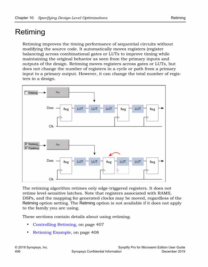
LO
Chapter 10: Specifying Design-Level Optimizations Retiming
© 2019 Synopsys, Inc. Synplify Pro for Microsemi Edition User Guide406 Synopsys Confidential Information December 2019
RetimingRetiming improves the timing performance of sequential circuits without modifying the source code. It automatically moves registers (register balancing) across combinational gates or LUTs to improve timing while maintaining the original behavior as seen from the primary inputs and outputs of the design. Retiming moves registers across gates or LUTs, but does not change the number of registers in a cycle or path from a primary input to a primary output. However, it can change the total number of regis-ters in a design.
The retiming algorithm retimes only edge-triggered registers. It does not retime level-sensitive latches. Note that registers associated with RAMS, DSPs, and the mapping for generated clocks may be moved, regardless of the Retiming option setting. The Retiming option is not available if it does not apply to the family you are using.
These sections contain details about using retiming.
• Controlling Retiming, on page 407
• Retiming Example, on page 408
Retiming Chapter 10: Specifying Design-Level Optimizations
Synplify Pro for Microsemi Edition User Guide © 2019 Synopsys, Inc.December 2019 Synopsys Confidential Information 407
• Retiming Report, on page 409
• How Retiming Works, on page 410
Controlling RetimingThe following procedure shows you how to use retiming.
1. To enable retiming for the whole design, check the Retiming check box.
You can set the Retiming option from the button panel in the Project window, or with the Project->Implementation Options command (Options tab). The option is only available in certain technologies.
See Retiming, on page 406 for more information. For Microsemi designs, retiming does not include pipelining.
Retiming works globally on the design, and moves edge-triggered regis-ters as needed to balance timing.
2. To enable retiming on selected registers, use either of the following techniques:
– Check the Retiming checkbox and attach the syn_allow_retiming attribute with a value of 0 or false to any registers you do not want the software to move. This attribute specifies that the register cannot be moved for retiming. Refer to How Retiming Works, on page 410 for a list of the components the retiming algorithm will move.
– Do not check the Retiming checkbox. Attach the syn_allow_retiming attribute with a value of 1 or true to any registers you want the software to consider for retiming. You can do this in the SCOPE interface or in the source code. This attribute marks the register as one that can be moved during retiming, but does not necessarily force it to be moved during retiming. If you apply the attribute to an FSM, RAM or SRL that is decomposed into flip-flops and logic, the software applies the attribute to all the resulting flip-flops.
3. You can also fine-tune retiming using attributes:
– To preserve the power-on state of flip-flops without sets or resets (FD or FDE) during retiming, set syn_preserve=1 or syn_allow_retiming=0 on these flip-flops.
LO
Chapter 10: Specifying Design-Level Optimizations Retiming
© 2019 Synopsys, Inc. Synplify Pro for Microsemi Edition User Guide408 Synopsys Confidential Information December 2019
– To force flip-flops to be packed in I/O pads, set syn_useioff=1 as a global attribute. This will prevent the flip-flops from being moved during retiming.
4. Set other options for the run. Retiming might affect some constraints and attributes. See How Retiming Works, on page 410 for details.
5. Click Run to start synthesis.
After the LUTs are mapped, the software moves registers to optimize timing. See Retiming Example, on page 408 for an example. The software honors other attributes you set, like syn_preserve, syn_useioff, and syn_ramstyle. See How Retiming Works, on page 410 for details.
Note that the tool might retime registers associated with RAMs, DSPs, and generated clocks, regardless of whether the Retiming option is on or off.
The log file includes a retiming report that you can analyze to under-stand the retiming changes. It contains a list of all the registers added or removed because of retiming. Retimed registers have a _ret suffix added to their names. See Retiming Report, on page 409 for more information about the report.
Retiming ExampleThe following example shows a design with retiming disabled and enabled.
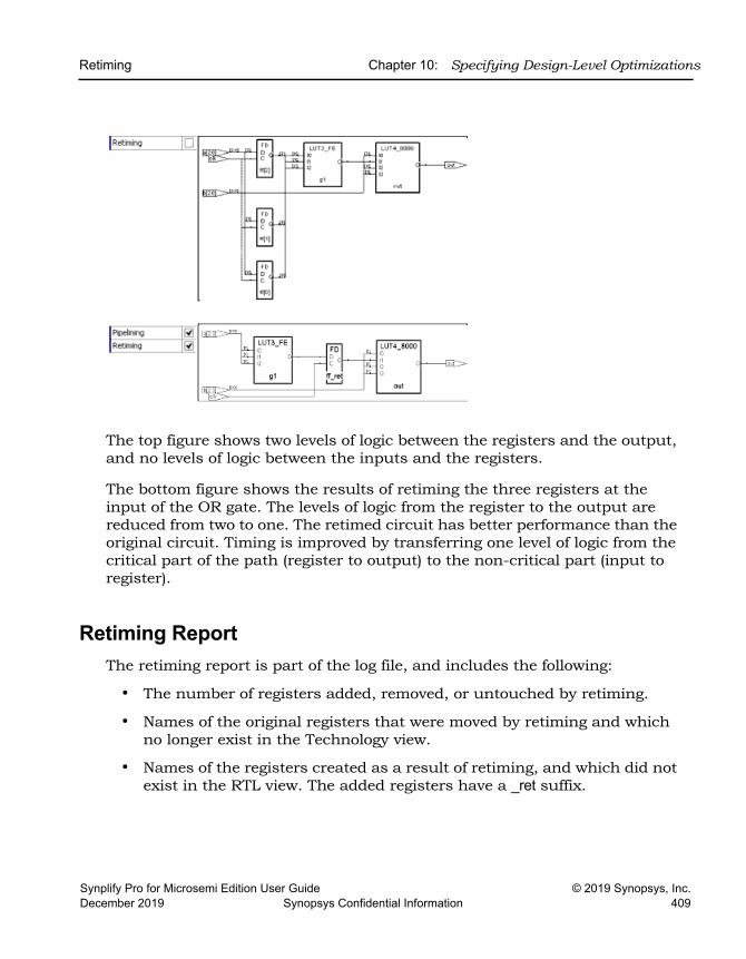
Retiming Chapter 10: Specifying Design-Level Optimizations
Synplify Pro for Microsemi Edition User Guide © 2019 Synopsys, Inc.December 2019 Synopsys Confidential Information 409
The top figure shows two levels of logic between the registers and the output, and no levels of logic between the inputs and the registers.
The bottom figure shows the results of retiming the three registers at the input of the OR gate. The levels of logic from the register to the output are reduced from two to one. The retimed circuit has better performance than the original circuit. Timing is improved by transferring one level of logic from the critical part of the path (register to output) to the non-critical part (input to register).
Retiming ReportThe retiming report is part of the log file, and includes the following:
• The number of registers added, removed, or untouched by retiming.
• Names of the original registers that were moved by retiming and which no longer exist in the Technology view.
• Names of the registers created as a result of retiming, and which did not exist in the RTL view. The added registers have a _ret suffix.
LO
Chapter 10: Specifying Design-Level Optimizations Retiming
© 2019 Synopsys, Inc. Synplify Pro for Microsemi Edition User Guide410 Synopsys Confidential Information December 2019
How Retiming WorksThis section describes how retiming works when it moves sequential compo-nents (flip-flops). Registers associated with RAMs, DSPs, and the mapping for fixing generated clocks might be moved, whether Retiming is enabled or not. Here are some implications and results of retiming:
• Flip-flops with no control signals (resets, presets, and clock enables) are moved. Flip-flops with minimal control logic can also be retimed. Multiple flip-flops with reset, set or enable signals that need to be retimed together are only retimed if they have exactly the same control logic.
• The software does not retime the following combinational sequential elements: flip-flops with both set and reset, flip-flops with attributes like syn_preserve, flip-flops packed in I/O pads, level-sensitive latches, regis-ters that are instantiated in the code, SRLs, and RAMs. If a RAM with combinational logic has syn_ramstyle set to registers, the registers can be retimed into the combinational logic.
• Retimed flip-flops are only moved through combinational logic. The software does not move flip-flops across the following objects: black boxes, sequential components, tristates, I/O pads, instantiated compo-nents, carry and cascade chains, and keepbufs.
• You might not be able to crossprobe retimed registers between the RTL and the Technology view, because there may not be a one-to-one corre-spondence between the registers in these two views after retiming. A single register in the RTL view might now correspond to multiple regis-ters in the Technology view.
• Retiming affects or is affected by, these attributes and constraints:
Attribute/Constraint Effect
False path constraint Does not retime flip-flops with different false path constraints. Retimed registers affect timing constraints.
Multicycle constraint Does not retime flip-flops with different multicycle constraints. Retimed registers affect timing constraints.
Register constraint Does not maintain set_reg_input_delay and set_reg_output_delay constraints. Retimed registers affect timing constraints.
Retiming Chapter 10: Specifying Design-Level Optimizations
Synplify Pro for Microsemi Edition User Guide © 2019 Synopsys, Inc.December 2019 Synopsys Confidential Information 411
• Retiming does not change the simulation behavior (as observed from primary inputs and outputs) of your design, However if you are monitoring (probing) values on individual registers inside the design, you might need to modify your test bench if the probe registers are retimed.
• Beginning with the C-2009.09-SP1 release, the behavior for retiming unconstrained I/O pads has changed. If retiming is enabled, registers connected to unconstrained I/O pins are not retimed by default. If you want to revert back to how retiming I/O paths was previously imple-mented, you can:
from/to timing exceptions
If you set a timing constraint using a from/to specification on a register, it is not retimed. The exception is when using a max_delay constraint. In this case, retiming is performed but the constraint is not forward annotated. (The max_delay value would no longer be valid.)
syn_hier=macro Does not retime registers in a macro with this attribute.
syn_keep Does not retime across keepbufs generated because of this attribute.
syn_pipeline Automatically enabled if retiming is enabled.
syn_preserve Does not retime flip-flops with this attribute set.
syn_probe Does not retime net drivers with this attribute. If the net driver is a LUT or gate, no flip-flops are retimed across it.
syn_reference_clock On a critical path, does not retime registers with different syn_reference_clock values together, because the path effectively has two different clock domains.
syn_useioff Does not override attribute-specified packing of registers in I/O pads. If the attribute value is false, the registers can be retimed. If the attribute is not specified, the timing engine determines whether the register is packed into the I/O block.
syn_allow_retiming Registers are not retimed if the value is 0.
Attribute/Constraint Effect

LO
Chapter 10: Specifying Design-Level Optimizations Retiming
© 2019 Synopsys, Inc. Synplify Pro for Microsemi Edition User Guide412 Synopsys Confidential Information December 2019
– Globally turn on the Use clock period for unconstrained IO switch from the Constraints tab of the Implementation Options panel.
– Add constraints to all input/output ports.
– Separately constrain each I/O pin as required.
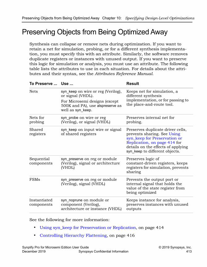
Preserving Objects from Being Optimized Away Chapter 10: Specifying Design-Level Optimizations
Synplify Pro for Microsemi Edition User Guide © 2019 Synopsys, Inc.December 2019 Synopsys Confidential Information 413
Preserving Objects from Being Optimized AwaySynthesis can collapse or remove nets during optimization. If you want to retain a net for simulation, probing, or for a different synthesis implementa-tion, you must specify this with an attribute. Similarly, the software removes duplicate registers or instances with unused output. If you want to preserve this logic for simulation or analysis, you must use an attribute. The following table lists the attributes to use in each situation. For details about the attri-butes and their syntax, see the Attributes Reference Manual.
See the following for more information:
• Using syn_keep for Preservation or Replication, on page 414
• Controlling Hierarchy Flattening, on page 416
To Preserve ... Use ... Result
Nets syn_keep on wire or reg (Verilog), or signal (VHDL). For Microsemi designs (except 500K and PA), use alspreserve as well as syn_keep.
Keeps net for simulation, a different synthesis implementation, or for passing to the place-and-route tool.
Nets for probing
syn_probe on wire or reg (Verilog), or signal (VHDL)
Preserves internal net for probing.
Shared registers
syn_keep on input wire or signal of shared registers
Preserves duplicate driver cells, prevents sharing. See Using syn_keep for Preservation or Replication, on page 414 for details on the effects of applying syn_keep to different objects.
Sequential components
syn_preserve on reg or module (Verilog), signal or architecture (VHDL)
Preserves logic of constant-driven registers, keeps registers for simulation, prevents sharing
FSMs syn_preserve on reg or module (Verilog), signal (VHDL)
Prevents the output port or internal signal that holds the value of the state register from being optimized
Instantiated components
syn_noprune on module or component (Verilog), architecture or instance (VHDL)
Keeps instance for analysis, preserves instances with unused outputs
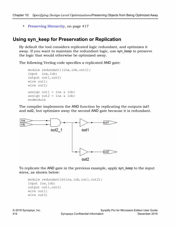
LO
Chapter 10: Specifying Design-Level OptimizationsPreserving Objects from Being Optimized Away
© 2019 Synopsys, Inc. Synplify Pro for Microsemi Edition User Guide414 Synopsys Confidential Information December 2019
• Preserving Hierarchy, on page 417
Using syn_keep for Preservation or ReplicationBy default the tool considers replicated logic redundant, and optimizes it away. If you want to maintain the redundant logic, use syn_keep to preserve the logic that would otherwise be optimized away.
The following Verilog code specifies a replicated AND gate:
module redundant1(ina,inb,out1);input ina,inb;output out1,out2;wire out1;wire out2;assign out1 = ina & inb;assign out2 = ina & inb;endmodule
The compiler implements the AND function by replicating the outputs out1 and out2, but optimizes away the second AND gate because it is redundant.
To replicate the AND gate in the previous example, apply syn_keep to the input wires, as shown below:
module redundant1d(ina,inb,out1,out2);input ina,inb;output out1,out2;wire out1;wire out2;
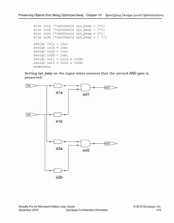
Preserving Objects from Being Optimized Away Chapter 10: Specifying Design-Level Optimizations
Synplify Pro for Microsemi Edition User Guide © 2019 Synopsys, Inc.December 2019 Synopsys Confidential Information 415
wire in1a /*synthesis syn_keep = 1*/;wire in1b /*synthesis syn_keep = 1*/;wire in2a /*synthesis syn_keep = 1*/;wire in2b /*synthesis syn_keep = 1 */;assign in1a = ina;assign in1b = inb;assign in2a = ina;assign in2b = inb;assign out1 = in1a & in1b;assign out2 = in2a & in2b;endmodule
Setting syn_keep on the input wires ensures that the second AND gate is preserved:
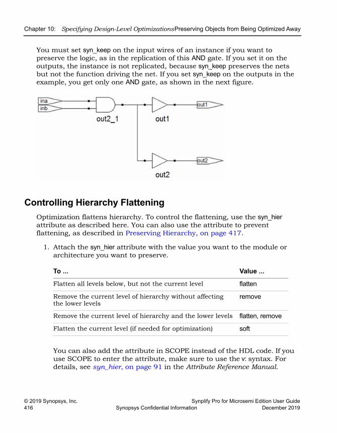
LO
Chapter 10: Specifying Design-Level OptimizationsPreserving Objects from Being Optimized Away
© 2019 Synopsys, Inc. Synplify Pro for Microsemi Edition User Guide416 Synopsys Confidential Information December 2019
You must set syn_keep on the input wires of an instance if you want to preserve the logic, as in the replication of this AND gate. If you set it on the outputs, the instance is not replicated, because syn_keep preserves the nets but not the function driving the net. If you set syn_keep on the outputs in the example, you get only one AND gate, as shown in the next figure.
Controlling Hierarchy FlatteningOptimization flattens hierarchy. To control the flattening, use the syn_hier attribute as described here. You can also use the attribute to prevent flattening, as described in Preserving Hierarchy, on page 417.
1. Attach the syn_hier attribute with the value you want to the module or architecture you want to preserve.
You can also add the attribute in SCOPE instead of the HDL code. If you use SCOPE to enter the attribute, make sure to use the v: syntax. For details, see syn_hier, on page 91 in the Attribute Reference Manual.
To ... Value ...
Flatten all levels below, but not the current level flatten
Remove the current level of hierarchy without affecting the lower levels
remove
Remove the current level of hierarchy and the lower levels flatten, remove
Flatten the current level (if needed for optimization) soft
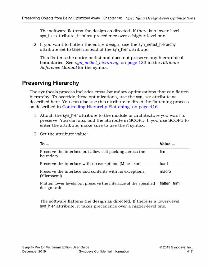
Preserving Objects from Being Optimized Away Chapter 10: Specifying Design-Level Optimizations
Synplify Pro for Microsemi Edition User Guide © 2019 Synopsys, Inc.December 2019 Synopsys Confidential Information 417
The software flattens the design as directed. If there is a lower-level syn_hier attribute, it takes precedence over a higher-level one.
2. If you want to flatten the entire design, use the syn_netlist_hierarchy attribute set to false, instead of the syn_hier attribute.
This flattens the entire netlist and does not preserve any hierarchical boundaries. See syn_netlist_hierarchy, on page 133 in the Attribute Reference Manual for the syntax.
Preserving HierarchyThe synthesis process includes cross-boundary optimizations that can flatten hierarchy. To override these optimizations, use the syn_hier attribute as described here. You can also use this attribute to direct the flattening process as described in Controlling Hierarchy Flattening, on page 416.
1. Attach the syn_hier attribute to the module or architecture you want to preserve. You can also add the attribute in SCOPE. If you use SCOPE to enter the attribute, make sure to use the v: syntax.
2. Set the attribute value:
The software flattens the design as directed. If there is a lower-level syn_hier attribute, it takes precedence over a higher-level one.
To ... Value ...
Preserve the interface but allow cell packing across the boundary
firm
Preserve the interface with no exceptions (Microsemi) hard
Preserve the interface and contents with no exceptions (Microsemi)
macro
Flatten lower levels but preserve the interface of the specified design unit
flatten, firm

LO
Chapter 10: Specifying Design-Level Optimizations Optimizing Fanout
© 2019 Synopsys, Inc. Synplify Pro for Microsemi Edition User Guide418 Synopsys Confidential Information December 2019
Optimizing FanoutYou can optimize your results with attributes and directives, some of which are specific to the technology you are using. Similarly, you can specify objects or hierarchy that you want to preserve during synthesis. For a complete list of all the directives and attributes, see the Attribute Reference Manual. This section describes the following:
• Setting Fanout Limits, on page 418
• Controlling Buffering and Replication, on page 420
Setting Fanout LimitsOptimization affects net fanout. If your design has critical nets with high fanout, you can set fanout limits. You can only do this for certain technolo-gies. For details specific to individual technologies, see the Reference Manual.
1. To set a global fanout limit for the whole design, do either of the following:
– Select Project->Implementation Options->Device and type a value for the Fanout Guide option.
– Apply the syn_maxfan attribute to the top-level view or module.
The value sets the number of fanouts for a given driver, and affects all the nets in the design. The defaults vary, depending on the technology. Select a balanced fanout value. A large constraint creates nets with large fanouts, and a low fanout constraint results in replicated or buffered logic. Both extremes affect routing and design performance. The right value depends on your design. The same value of 32 might result in fanouts of 11 or 12 and large delays on the critical path in one design or in excessive replication in another design.
The software uses the value as a soft limit, or a guide. It traverses the inverters and buffers to identify the fanout, and tries to ensure that all fanouts are under the limit by replicating or buffering where needed (see Controlling Buffering and Replication, on page 420 for details). However, the synthesis tool does not respect the fanout limit absolutely; it ignores the limit if the limit imposes constraints that interfere with optimization.
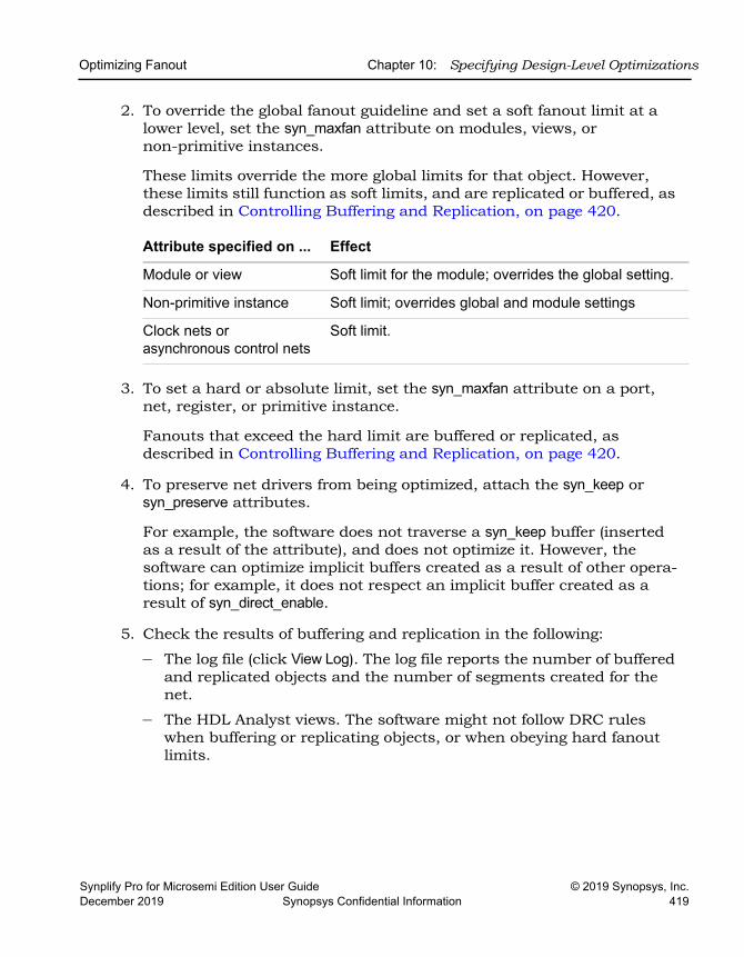
Optimizing Fanout Chapter 10: Specifying Design-Level Optimizations
Synplify Pro for Microsemi Edition User Guide © 2019 Synopsys, Inc.December 2019 Synopsys Confidential Information 419
2. To override the global fanout guideline and set a soft fanout limit at a lower level, set the syn_maxfan attribute on modules, views, or non-primitive instances.
These limits override the more global limits for that object. However, these limits still function as soft limits, and are replicated or buffered, as described in Controlling Buffering and Replication, on page 420.
3. To set a hard or absolute limit, set the syn_maxfan attribute on a port, net, register, or primitive instance.
Fanouts that exceed the hard limit are buffered or replicated, as described in Controlling Buffering and Replication, on page 420.
4. To preserve net drivers from being optimized, attach the syn_keep or syn_preserve attributes.
For example, the software does not traverse a syn_keep buffer (inserted as a result of the attribute), and does not optimize it. However, the software can optimize implicit buffers created as a result of other opera-tions; for example, it does not respect an implicit buffer created as a result of syn_direct_enable.
5. Check the results of buffering and replication in the following:
– The log file (click View Log). The log file reports the number of buffered and replicated objects and the number of segments created for the net.
– The HDL Analyst views. The software might not follow DRC rules when buffering or replicating objects, or when obeying hard fanout limits.
Attribute specified on ... Effect
Module or view Soft limit for the module; overrides the global setting.
Non-primitive instance Soft limit; overrides global and module settings
Clock nets or asynchronous control nets
Soft limit.
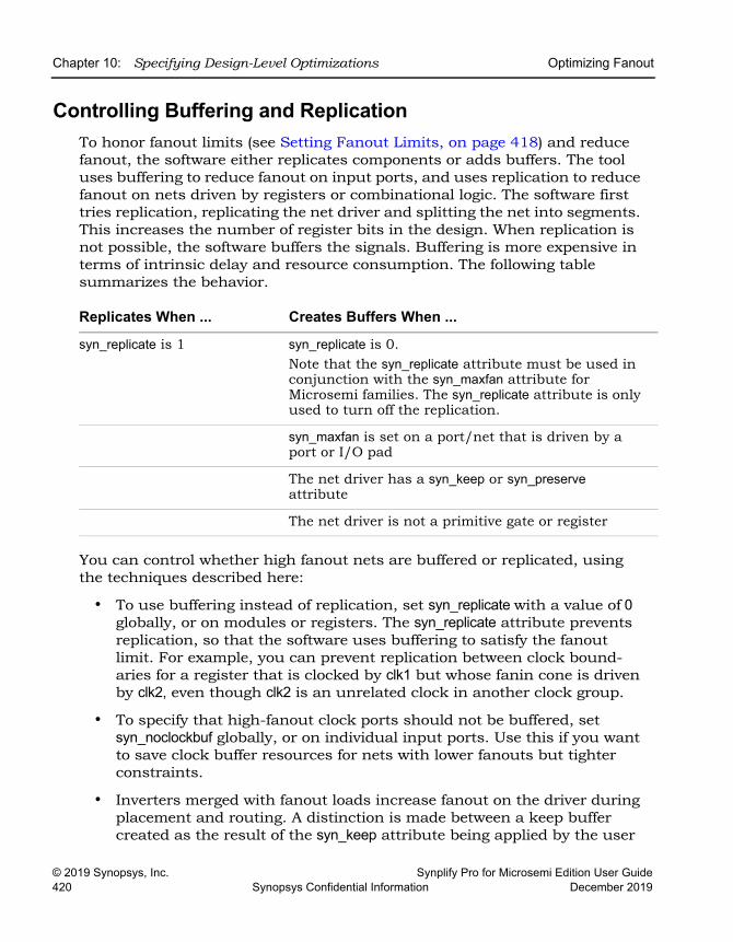
LO
Chapter 10: Specifying Design-Level Optimizations Optimizing Fanout
© 2019 Synopsys, Inc. Synplify Pro for Microsemi Edition User Guide420 Synopsys Confidential Information December 2019
Controlling Buffering and ReplicationTo honor fanout limits (see Setting Fanout Limits, on page 418) and reduce fanout, the software either replicates components or adds buffers. The tool uses buffering to reduce fanout on input ports, and uses replication to reduce fanout on nets driven by registers or combinational logic. The software first tries replication, replicating the net driver and splitting the net into segments. This increases the number of register bits in the design. When replication is not possible, the software buffers the signals. Buffering is more expensive in terms of intrinsic delay and resource consumption. The following table summarizes the behavior.
You can control whether high fanout nets are buffered or replicated, using the techniques described here:
• To use buffering instead of replication, set syn_replicate with a value of 0 globally, or on modules or registers. The syn_replicate attribute prevents replication, so that the software uses buffering to satisfy the fanout limit. For example, you can prevent replication between clock bound-aries for a register that is clocked by clk1 but whose fanin cone is driven by clk2, even though clk2 is an unrelated clock in another clock group.
• To specify that high-fanout clock ports should not be buffered, set syn_noclockbuf globally, or on individual input ports. Use this if you want to save clock buffer resources for nets with lower fanouts but tighter constraints.
• Inverters merged with fanout loads increase fanout on the driver during placement and routing. A distinction is made between a keep buffer created as the result of the syn_keep attribute being applied by the user
Replicates When ... Creates Buffers When ...
syn_replicate is 1 syn_replicate is 0. Note that the syn_replicate attribute must be used in conjunction with the syn_maxfan attribute for Microsemi families. The syn_replicate attribute is only used to turn off the replication.
syn_maxfan is set on a port/net that is driven by a port or I/O pad
The net driver has a syn_keep or syn_preserve attribute
The net driver is not a primitive gate or register
Optimizing Fanout Chapter 10: Specifying Design-Level Optimizations
Synplify Pro for Microsemi Edition User Guide © 2019 Synopsys, Inc.December 2019 Synopsys Confidential Information 421
(explicit keep buffer) and a keep buffer that exists as the result of another attribute (implicit keep buffer). For example, the syn_direct_enable attribute inserts a keep buffer. When a syn_maxfan attribute is applied to the output of an explicit keep buffer, the signal is buffered (the keep buffer is not traversed so that the driver is not replicated). When the syn_maxfan attribute is applied to the output of an implicit keep buffer, the keep buffer is traversed and the driver is replicated.
• Turn off buffering and replication entirely, by setting syn_maxfan to a very high number, like 1000.
LO
Chapter 10: Specifying Design-Level Optimizations Sharing Resources
© 2019 Synopsys, Inc. Synplify Pro for Microsemi Edition User Guide422 Synopsys Confidential Information December 2019
Sharing ResourcesOne of the ways to optimize area is to use resource sharing in the compiler. With resource sharing, the software uses the same arithmetic operators for mutually exclusive statements; for example, with the branches of a case statement. Conversely, you can improve timing by disabling resource sharing, but at the expense of increased area.
Compiler resource sharing is on by default. You can set it globally and then override the global setting on individual modules.
1. To disable resource sharing globally for the whole design, use one of the methods below.
Leave the default setting to improve area; disable the option to improve timing.
– Select Project->Implementation Options->Options, disable Resource Sharing. Alternatively, disable the Resource Sharing button on the left side of the Project view.
– Apply the syn_sharing directive to the top-level module or architecture in the source code. See syn_sharing, on page 227 of the Attribute Reference Manual for syntax and examples.
– Edit your project file and include the following command: set_option -resource_sharing 0
When you save the project file, it includes the Tcl set_option -resource_sharing command.
You cannot specify syn_sharing from the SCOPE interface, because it is a compiler directive, and works during the compilation stage of synthesis. The resource sharing setting does not affect the mapper, so even if resource sharing is disabled, the tool can share resources during the mapping phase to optimize the design and improve results.
Verilog module top(out, in, clk_in) /* synthesis syn_sharing = "off" */;VHDL architecture rtl of top is
attribute syn_sharing : string; attribute syn_sharing of rtl : architecture is "false";
Inserting I/Os Chapter 10: Specifying Design-Level Optimizations
Synplify Pro for Microsemi Edition User Guide © 2019 Synopsys, Inc.December 2019 Synopsys Confidential Information 423
2. To specify resource sharing on an individual basis or override the global setting, specify the syn_sharing attribute for the lower-level module/architecture.
Inserting I/OsYou can control I/O insertion globally, or on a port-by-port basis.
• To control the insertion of I/O pads at the top level of the design, use the Disable I/O Insertion option as follows:
– Select Project->Implementation Options and click the Device panel.
– Enable the option (checkbox on) if you want to do a preliminary run and check the area taken up by logic blocks, before synthesizing the entire design.
Do this if you want to check the area your blocks of logic take up, before you synthesize an entire FPGA. If you disable automatic I/O insertion, you do not get any I/O pads in your design, unless you manually instantiate them.
– Leave the Disable I/O Insertion checkbox empty (disabled) if you want to automatically insert I/O pads for all the inputs, outputs and bidirectionals.
When this option is set, the software inserts I/O pads for inputs, outputs, and bidirectionals in the output netlist. Once inserted, you can override the I/O pad inserted by directly instantiating another I/O pad.
– For the most control, enable the option and then manually instantiate the I/O pads for specific pins, as needed.
Enable this attribute to preserve user-instantiated pads, insert pads on unconnected ports, insert bi-directional pads on bi-directional ports instead of converting them to input ports, or insert output pads on unconnected outputs.
If you do not set the syn_force_pads attribute, the synthesis design optimizes any unconnected I/O buffers away.
LO
Chapter 10: Specifying Design-Level Optimizations Optimizing State Machines
© 2019 Synopsys, Inc. Synplify Pro for Microsemi Edition User Guide424 Synopsys Confidential Information December 2019
Optimizing State MachinesYou can optimize state machines with the symbolic FSM Compiler and the FSM Explorer tools.
• The Symbolic FSM CompilerAn advanced state machine optimizer, it automatically recognizes state machines in your design and optimizes them. Unlike other synthesis tools that treat state machines as regular logic, the FSM Compiler extracts the state machines as symbolic graphs, and then optimizes them by re-encoding the state representations and generating a better logic optimization starting point for the state machines.
• The FSM ExplorerA specialized state machine optimizer that explores different encoding styles before selecting the best style. It uses the FSM Compiler to extract state machines, and runs the FSM Compiler automatically if it has not been run.
For more information, see the following:
• Deciding when to Optimize State Machines, on page 424
• Running the FSM Compiler, on page 425
• Running the FSM Explorer, on page 429
Deciding when to Optimize State MachinesThe FSM Explorer and the FSM Compiler are automatic tools for encoding state machines, but you can also specify FSMs manually with attributes. For more information about using attributes, see Specifying FSMs with Attributes and Directives, on page 393.
Here are the main reasons to use the FSM Compiler:
• To generate better results for your state machines
The software uses optimization techniques that are specifically tuned for FSMs, like reachability analysis for example. The FSM Compiler also lets you convert an encoded state machine to another encoding style (to improve speed and area utilization) without changing the source. For example, you can use a onehot style to improve results.
• To debug the state machines
Optimizing State Machines Chapter 10: Specifying Design-Level Optimizations
Synplify Pro for Microsemi Edition User Guide © 2019 Synopsys, Inc.December 2019 Synopsys Confidential Information 425
State machine description errors result in unreachable states, so if you have errors, you will have fewer states. You can check whether your source code describes your state machines correctly. You can also use the FSM Viewer to see a high-level bubble diagram and crossprobe from there. For information about the FSM Viewer, see Using the FSM Viewer, on page 291.
• To run the FSM Explorer
The FSM Explorer is a tool that examines all the encoding styles before selecting the best option, based on the state machine extraction done by the FSM Compiler. If the FSM Compiler has not been run previously, the Explorer automatically runs it. For more information about using the FSM Explorer, see Running the FSM Explorer, on page 429.
If you are trying to decide whether to use the FSM Compiler or the FSM Explorer to optimize your state machines, remember these points:
• The FSM Explorer runs the FSM Compiler if it has not already been run, because it picks encoding styles based on the state machines that the FSM Compiler extracts.
• Like the FSM Compiler, you use the FSM Explorer to generate better results for your state machines. Unlike the FSM Compiler, which picks an encoding style based on the number of states, the FSM Explorer tries out different encoding styles and picks the best style for the state machine based on overall design constraints.
• The trade-off is that the FSM Explorer takes longer to run than the FSM Compiler.
Running the FSM CompilerThe FSM Compiler performs proprietary, state-machine optimization techniques (other synthesis tools treat state machines as regular logic). You enable the FSM compiler to take advantage of these techniques; you do not need special directives or attributes to locate the state machines in your design. You can also, however, enable the FSM compiler selectively for individual state machines, using synthesis directives in the HDL description.
Use the symbolic FSM compiler to generate better results for state machines or to debug state machines. If you do not want to use the symbolic FSM compiler on the final circuit, you can use it only during initial synthesis to check that the state machines are described correctly. Many common state
LO
Chapter 10: Specifying Design-Level Optimizations Optimizing State Machines
© 2019 Synopsys, Inc. Synplify Pro for Microsemi Edition User Guide426 Synopsys Confidential Information December 2019
machine description errors result in unreachable states, which are optimized away during synthesis, resulting in a smaller number of states than you expect. Reachable states are reported in the log file.
You can run the FSM Compiler tool on the whole design or on individual FSMs. See the following:
• Running the FSM Compiler on the Whole Design, on page 426
• Running the FSM Compiler on Individual FSMs, on page 427
Running the FSM Compiler on the Whole Design1. Enable the compiler by checking the Symbolic FSM Compiler box in one of
these places:
– The main panel on the left side of the project window
– The Options tab of the dialog box that comes up when you click the Add Implementation/New Impl or Implementation Options buttons
2. To set a specific encoding style for a state machine, define the style with the syn_encoding attribute, as described in Specifying FSMs with Attributes and Directives, on page 393.
If you do not specify a style, the FSM Compiler picks an encoding style based on the number of states.
3. Click Run to run synthesis.
The software automatically recognizes and extracts the state machines in your design, and instantiates a state machine primitive in the netlist for each FSM it extracts. It then optimizes all the state machines in the design, using techniques like reachability analysis, next state logic optimization, state machine re-encoding and proprietary optimization algorithms. Unless you specified an encoding style, the tool automati-cally selects the encoding style. If you did specify a style, the tool uses that style.
In the log file, the FSM Compiler writes a report that includes a descrip-tion of each state machine extracted and the set of reachable states for each state machine.
4. Select View->View Log File and check the log file for descriptions of the state machines and the set of reachable states for each one. You see text like the following:
Optimizing State Machines Chapter 10: Specifying Design-Level Optimizations
Synplify Pro for Microsemi Edition User Guide © 2019 Synopsys, Inc.December 2019 Synopsys Confidential Information 427
Extracted state machine for register cur_stateState machine has 7 reachable states with original encodings of:
0000001000001000001000001000001000001000001000000
....original code -> new code
0000001 -> 00000010000010 -> 00000100000100 -> 00001000001000 -> 00010000010000 -> 00100000100000 -> 01000001000000 -> 1000000
5. Check the state machine implementation in the RTL and Technology views and in the FSM viewer.
– In the RTL view you see the FSM primitive with one output for each state.
– In the Technology view, you see a level of hierarchy that contains the FSM, with the registers and logic that implement the final encoding.
– In the FSM viewer you see a bubble diagram and mapping information. For information about the FSM viewer, see Using the FSM Viewer (Standard), on page 353.
– In the statemachine.info text file, you see the state transition information.
Running the FSM Compiler on Individual FSMsIf you have state machines that you do not want automatically optimized by the FSM Compiler, you can use one of these techniques, depending on the number of FSMs to be optimized. You might want to exclude state machines from automatic optimization because you want them implemented with a specific encoding or because you do not want them extracted as state machines. The following procedure shows you how to work with both cases.
LO
Chapter 10: Specifying Design-Level Optimizations Optimizing State Machines
© 2019 Synopsys, Inc. Synplify Pro for Microsemi Edition User Guide428 Synopsys Confidential Information December 2019
1. If you have just a few state machines you do not want to optimize, do the following:
– Enable the FSM Compiler by checking the box in the button panel of the Project window.
– If you do not want to optimize the state machine, add the syn_state_machine directive to the registers in the Verilog or VHDL code. Set the value to 0. When synthesized, these registers are not extracted as state machines.
– If you want to specify a particular encoding style for a state machine, use the syn_encoding attribute, as described in Specifying FSMs with Attributes and Directives, on page 393. When synthesized, these registers have the specified encoding style.
– Run synthesis.
The software automatically recognizes and extracts all the state machines, except the ones you marked. It optimizes the FSMs it extracted from the design, honoring the syn_encoding attribute. It writes out a log file that contains a description of each state machine extracted, and the set of reachable states for each FSM.
2. If you have many state machines you do not want optimized, do this:
– Disable the compiler by disabling the Symbolic FSM Compiler box in one of these places: the main panel on the left side of the project window or the Options tab of the dialog box that comes up when you click the Add Implementation or Implementation Options buttons. This disables the compiler from optimizing any state machine in the design. You can now selectively turn on the FSM compiler for individual FSMs.
– For state machines you want the FSM Compiler to optimize automatically, add the syn_state_machine directive to the individual state registers in the VHDL or Verilog code. Set the value to 1. When synthesized, the FSM Compiler extracts these registers with the default encoding styles according to the number of states.
Verilog reg [3:0] curstate /* synthesis syn_state_machine=0 */;VHDL signal curstate : state_type;
attribute syn_state_machine : boolean;attribute syn_state_machine of curstate : signal is false;v
Optimizing State Machines Chapter 10: Specifying Design-Level Optimizations
Synplify Pro for Microsemi Edition User Guide © 2019 Synopsys, Inc.December 2019 Synopsys Confidential Information 429
– For state machines with specific encoding styles, set the encoding style with the syn_encoding attribute, as described in Specifying FSMs with Attributes and Directives, on page 393. When synthesized, these registers have the specified encoding style.
– Run synthesis.
The software automatically recognizes and extracts only the state machines you marked. It automatically assigns encoding styles to the state machines with the syn_state_machine attribute, and honors the encoding styles set with the syn_encoding attribute. It writes out a log file that contains a description of each state machine extracted, and the set of reachable states for each state machine.
3. Check the state machine in the log file, the RTL and technology views, and the FSM viewer. For information about the FSM viewer, see Using the FSM Viewer (Standard), on page 353.
Running the FSM ExplorerThe FSM Explorer automatically explores different encoding styles for state machines and picks the style best suited to your design. The FSM explorer runs the FSM viewer to identify the finite state machines in a design, then analyzes the FSMs to select the optimum encoding style for each.
1. If you need to customize the extraction process, set attributes.
– Use syn_state_machine=0 to specify state machines you do not want to extract and optimize.
Verilog reg [3:0] curstate /* synthesis syn_state_machine=1 */;VHDL signal curstate : state_type;
attribute syn_state_machine : boolean;attribute syn_state_machine of curstate : signal is true;
Verilog reg [3:0] curstate /* synthesis state_machine */;VHDL signal curstate : state_type;
attribute syn_state_machine : boolean;attribute syn_state_machine of curstate : signal is true;
LO
Chapter 10: Specifying Design-Level Optimizations Optimizing State Machines
© 2019 Synopsys, Inc. Synplify Pro for Microsemi Edition User Guide430 Synopsys Confidential Information December 2019
– Use syn_encoding if you want to set a specific encoding style.
The FSM Compiler honors the syn_state_machine attribute when it extracts state machines, and the FSM Explorer honors the syn_encoding attribute when it sets encoding styles. See Specifying FSMs with Attri-butes and Directives, on page 393 for details.
2. Enable the FSM Explorer by checking the FSM Explorer box in one of these places:
– The main panel on the left side of the project window
– The Options tab of the dialog box that comes up when you click the Add Implementation or Implementation Options buttons.
If you have not checked the FSM Compiler option, checking the FSM Explorer option automatically selects the FSM Compiler option.
3. Click Run to run synthesis.
The FSM Explorer uses the state machines extracted by the FSM Compiler. If you have not run the FSM Compiler, the FSM Explorer invokes the compiler automatically to extract the state machines, instantiate state machine primitives, and optimize them. Then, the FSM Explorer runs through each encoding style for each state machine that does not have a syn_encoding attribute and picks the best style. If you have defined an encoding style with syn_encoding, it uses that style.
The FSM Compiler writes a description of each state machine extracted and the set of reachable states for each state machine in the log file. The FSM Explorer adds the selected encoding styles. The FSM Explorer also generates a <design>_fsm.sdc file that contains the encodings and which is used for mapping.
Verilog reg [3:0] curstate /* synthesis syn_encoding="gray"*/;VHDL signal curstate : state_type;
attribute syn_encoding : string;attribute syn_encoding of curstate : signal is "gray";
Optimizing State Machines Chapter 10: Specifying Design-Level Optimizations
Synplify Pro for Microsemi Edition User Guide © 2019 Synopsys, Inc.December 2019 Synopsys Confidential Information 431
4. Select View->View Log File and check the log file for the descriptions. The following extract shows the state machine and the reachable states as well as the encoding style, gray, set by FSM Explorer.
Extracted state machine for register cur_stateState machine has 7 reachable states with original encodings of:
0000001000001000001000001000001000001000001000000
....Adding property syn_encoding, value "gray", to instance cur_state[6:0]List of partitions to map:
view:work.Control(verilog)Encoding state machine work.Control(verilog)-cur_state_h.cur_state[6:0]original code -> new code
0000001 -> 0000000010 -> 0010000100 -> 0110001000 -> 0100010000 -> 1100100000 -> 1111000000 -> 101
5. Check the state machine implementation in the RTL and Technology views and in the FSM viewer.
For information about the FSM viewer, see Using the FSM Viewer (Standard), on page 353.
LO
Chapter 10: Specifying Design-Level Optimizations Inserting Probes
© 2019 Synopsys, Inc. Synplify Pro for Microsemi Edition User Guide432 Synopsys Confidential Information December 2019
Inserting ProbesProbes are extra wires that you insert into the design for debugging. When you insert a probe, the signal is represented as an output port at the top level. You can specify probes in the source code or by interactively attaching an attribute.
Specifying Probes in the Source CodeTo specify probes in the source code, you must add the syn_probe attribute to the net. You can also add probes interactively, using the procedure described in Adding Probe Attributes Interactively, on page 433.
1. Open the source code file.
2. For Verilog source code, attach the syn_probe attribute as a comment on any internal signal declaration:
module alu(out, opcode, a, b, sel);output [7:0] out;input [2:0] opcode;input [7:0 a, b;input sel;reg [7:0] alu_tmp /* synthesis syn_probe=1 */;reg [7:0] out;
//Other codeThe value 1 indicates that probe insertion is turned on. For detailed information about Verilog attributes and examples of the files, see the Attribute Reference Manual.
To define probes for part of a bus, specify where you want to attach the probes; for example, if you specify reg [1:0] in the previous code, the software only inserts two probes.
3. For VHDL source code, add the syn_probe attribute as follows:
architecture rtl of alu issignal alu_tmp : std_logic_vector(7 downto 0);attribute syn_probe : boolean;attribute syn_probe of alu_tmp : signal is true;--other code;
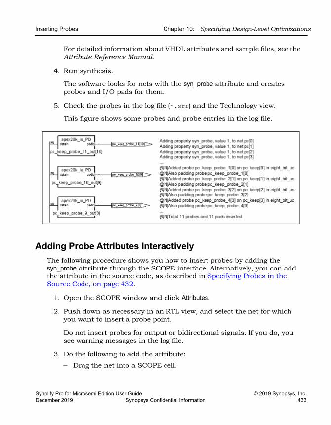
Inserting Probes Chapter 10: Specifying Design-Level Optimizations
Synplify Pro for Microsemi Edition User Guide © 2019 Synopsys, Inc.December 2019 Synopsys Confidential Information 433
For detailed information about VHDL attributes and sample files, see the Attribute Reference Manual.
4. Run synthesis.
The software looks for nets with the syn_probe attribute and creates probes and I/O pads for them.
5. Check the probes in the log file (*.srr) and the Technology view.
This figure shows some probes and probe entries in the log file.
Adding Probe Attributes InteractivelyThe following procedure shows you how to insert probes by adding the syn_probe attribute through the SCOPE interface. Alternatively, you can add the attribute in the source code, as described in Specifying Probes in the Source Code, on page 432.
1. Open the SCOPE window and click Attributes.
2. Push down as necessary in an RTL view, and select the net for which you want to insert a probe point.
Do not insert probes for output or bidirectional signals. If you do, you see warning messages in the log file.
3. Do the following to add the attribute:
– Drag the net into a SCOPE cell.
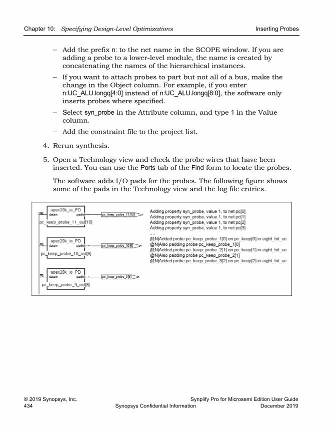
LO
Chapter 10: Specifying Design-Level Optimizations Inserting Probes
© 2019 Synopsys, Inc. Synplify Pro for Microsemi Edition User Guide434 Synopsys Confidential Information December 2019
– Add the prefix n: to the net name in the SCOPE window. If you are adding a probe to a lower-level module, the name is created by concatenating the names of the hierarchical instances.
– If you want to attach probes to part but not all of a bus, make the change in the Object column. For example, if you enter n:UC_ALU.longq[4:0] instead of n:UC_ALU.longq[8:0], the software only inserts probes where specified.
– Select syn_probe in the Attribute column, and type 1 in the Value column.
– Add the constraint file to the project list.
4. Rerun synthesis.
5. Open a Technology view and check the probe wires that have been inserted. You can use the Ports tab of the Find form to locate the probes.
The software adds I/O pads for the probes. The following figure shows some of the pads in the Technology view and the log file entries.
Synplify Pro for Microsemi Edition User Guide © 2019 Synopsys, Inc.December 2019 Synopsys Confidential Information 435
C H A P T E R 11
Working with Compile Points
The following sections describe compile points and how to use them in logic synthesis iterative flows:
• Compile Point Basics, on page 436
• Compile Point Synthesis Basics, on page 445
• Synthesizing Compile Points, on page 455
• Using Compile Points with Other Features, on page 470
• Resynthesizing Incrementally, on page 471
LO
Chapter 11: Working with Compile Points Compile Point Basics
© 2019 Synopsys, Inc. Synplify Pro for Microsemi Edition User Guide436 Synopsys Confidential Information December 2019
Compile Point BasicsCompile points are HDL partitions of the design that you define before synthesizing the design. Compile points can be defined manually, or the tool can generate them automatically. The software treats each compile point as a block and can synthesize, optimize, and place and route the compile points independently. Compile points can be nested.
See the following topics for some details about compile points:
• Advantages of Compile Point Design, on page 436
• Automatic and Manual Compile Points, on page 438
• Nested Compile Points, on page 439
• Compile Point Types, on page 440
Advantages of Compile Point DesignDesigning with compile points makes it more efficient to work with the increasingly larger designs of today and the corresponding team approach to design. They offer several advantages, which are described here:
• Compile Points and Design Flows, next
• Runtime Savings, on page 437
• Design Preservation, on page 437
Compile Points and Design FlowsCompile points improve the efficacy of both top-down and bottom-up design flows:
• In a traditional bottom-up design flow, compile points make it possible to easily divide up the design effort between designers or design teams. The compile points can be worked on separately and individually. The compile point synthesis flow eliminates the need to maintain the complex error-prone scripts for stitching, modeling, and ordering required by the traditional bottom-up design flow.
• From a top-down design flow perspective, compile points make it easier to work on the top-level design. You can mark compile points that are still being developed as black boxes, and synthesize the top level with
Compile Point Basics Chapter 11: Working with Compile Points
Synplify Pro for Microsemi Edition User Guide © 2019 Synopsys, Inc.December 2019 Synopsys Confidential Information 437
what you have. You can also customize the compile point type settings for individual compile points to take advantage of cross-boundary optimizations.
You can also synthesize incrementally, because the tool does not resyn-thesize compile points that are unchanged when you resynthesize the design. This saves runtime and also preserves parts of the design that are done while the rest of the design is completed.
See Compile Point Synthesis, on page 451 for a description of the synthesis process with compile points.
Runtime SavingsCompile points are the required foundation for multiprocessing and incre-mental synthesis, both of which translate directly to runtime savings:
• Multiprocessing runs synthesis as multiple parallel processes, using the compile points as the partitions that are synthesized in parallel on different processors. See Combining Compile Points with Multipro-cessing, on page 470.
• Incremental synthesis uses compile points to determine which portions of the design to resynthesize, only resynthesizing the compile points that have been modified. See Resynthesizing Compile Points Incrementally, on page 471.
Design PreservationUsing compile points addresses the need to maintain the overall stability of a design while portions of the design evolve. When you use compile points to partition the design, you can isolate one part from another. This lets you preserve some compile points, and only resynthesize those that need to be rerun. These scenarios describe some design situations where compile points can be used to isolate parts of the design and run incremental synthesis:
• During the initial design phase, design modules are still being designed. Use compile points to preserve unchanged design modules and evaluate the effects of modifications to parts of the design that are still changing.
• During design integration, use compile points to preserve the main design modules and only allow the glue logic to be remapped.
LO
Chapter 11: Working with Compile Points Compile Point Basics
© 2019 Synopsys, Inc. Synplify Pro for Microsemi Edition User Guide438 Synopsys Confidential Information December 2019
• If your design contains IP, synthesize the IP, and use compile points to preserve them while you run incremental synthesis on the rest of the design.
• In the final stages of the design, use compile points to preserve design modules that do not need to be updated while you work through minor HDL changes in some other part of the design.
Automatic and Manual Compile PointsCompile points can be generated automatically by the tool or you can create them manually. A design can contain a mixture of automatic and manual compile points.
Automatic compile points are simple to use and do not require any setup. Manual compile points require more setup, but provide more control because they let you define the partition boundaries and constraints instead of the tool.
• Automatic compile points (ACP)
Automatic compile points offer the simplest way to set up compile points and are also the most automated way to leverage multiprocessing. The tool makes the decisions and automatically creates compile points based on various parameters, like the size of the design, the sizes of hierar-chical modules, their boundary logic, the number of ports driven by constants, and so on. For details about this process, see Automatic Compile Point Generation, on page 458. You do not need to define boundary constraints for automatic compile points.
The tool automatically sets automatic compile points as hard compile points. See Compile Point Types, on page 440 for a description. The down side to using automatic compile points is that they might increase area if the partition boundaries prevent many cross-boundary optimiza-tions.
• Manual compile points (MCP)
Manual compile points provide more control. You can specify boundary constraints for each compile point individually. You can separate completed parts of the design from parts that are still being designed, or fine-tune the compile points to take advantage of as many cross-boundary optimizations as possible. For example, you can ensure
Compile Point Basics Chapter 11: Working with Compile Points
Synplify Pro for Microsemi Edition User Guide © 2019 Synopsys, Inc.December 2019 Synopsys Confidential Information 439
that a critical path does not cross a compile point boundary, thus ensuring synthesis results with optimal performance.
Guidelines for Using Automatic and Manual Compile PointsDetermine the kind of compile point to use based on what the design requires. The table lists some guidelines:
Nested Compile PointsA design can have any number of compile points, and compile points can be nested inside other compile points. In the following figure, compile point CP6 is nested inside compile point CP5, which is nested inside compile point CP4.
To simplify things, the term child is used to refer to a compile point that is contained inside another compile point; the term parent is used to refer to a container compile point that contains a child. These terms are not used in their strict sense of direct, immediate containment: If a compile point A is nested in B, which is nested in C, then A and B are both considered children of C, and C is a parent of both A and B. The top level is considered the parent
Use Automatic Compile Points ... Use Manual Compile Points ...
When runtime and quick results are more important than the best QoR
When you know the design in detail.Create manual compile points to get better QoR. Good candidates for manual compile points include the following:• Completed modules with registered
interfaces, where you want to preserve the design
• Modules created to include an entire critical path, so as to get the best performance.
• Modules that are less likely to be affected by cross boundary optimizations like constant propagation and register absorption.
When you expect many updates or cross-boundary optimization changes.
When you do not want further optimizations to a completed compile point. When you want more control to determine cross-boundary optimizations on an individual basis.
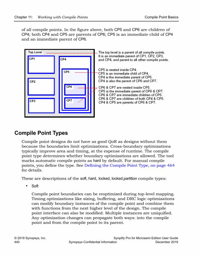
LO
Chapter 11: Working with Compile Points Compile Point Basics
© 2019 Synopsys, Inc. Synplify Pro for Microsemi Edition User Guide440 Synopsys Confidential Information December 2019
of all compile points. In the figure above, both CP5 and CP6 are children of CP4; both CP4 and CP5 are parents of CP6; CP5 is an immediate child of CP4 and an immediate parent of CP6.
Compile Point TypesCompile point designs do not have as good QoR as designs without them because the boundaries limit optimizations. Cross-boundary optimizations typically improve area and timing, at the expense of runtime. The compile point type determines whether boundary optimizations are allowed. The tool marks automatic compile points as hard by default. For manual compile points, you define the type. See Defining the Compile Point Type, on page 464 for details.
These are descriptions of the soft, hard, locked, locked,partition compile types:
• Soft
Compile point boundaries can be reoptimized during top-level mapping. Timing optimizations like sizing, buffering, and DRC logic optimizations can modify boundary instances of the compile point and combine them with functions from the next higher level of the design. The compile point interface can also be modified. Multiple instances are uniquified. Any optimization changes can propagate both ways: into the compile point and from the compile point to its parent.
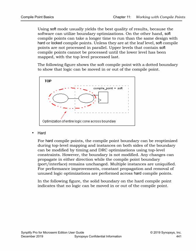
Compile Point Basics Chapter 11: Working with Compile Points
Synplify Pro for Microsemi Edition User Guide © 2019 Synopsys, Inc.December 2019 Synopsys Confidential Information 441
Using soft mode usually yields the best quality of results, because the software can utilize boundary optimizations. On the other hand, soft compile points can take a longer time to run than the same design with hard or locked compile points. Unless they are at the leaf level, soft compile points are not processed in parallel. Upper levels that contain soft compile points cannot be processed until the lower level has been mapped, with the top level processed last.
The following figure shows the soft compile point with a dotted boundary to show that logic can be moved in or out of the compile point.
• Hard
For hard compile points, the compile point boundary can be reoptimized during top-level mapping and instances on both sides of the boundary can be modified by timing and DRC optimizations using top-level constraints. However, the boundary is not modified. Any changes can propagate in either direction while the compile point boundary (port/interface) remains unchanged. Multiple instances are uniquified. For performance improvements, constant propagation and removal of unused logic optimizations are performed across hard compile points.
In the following figure, the solid boundary on the hard compile point indicates that no logic can be moved in or out of the compile point.
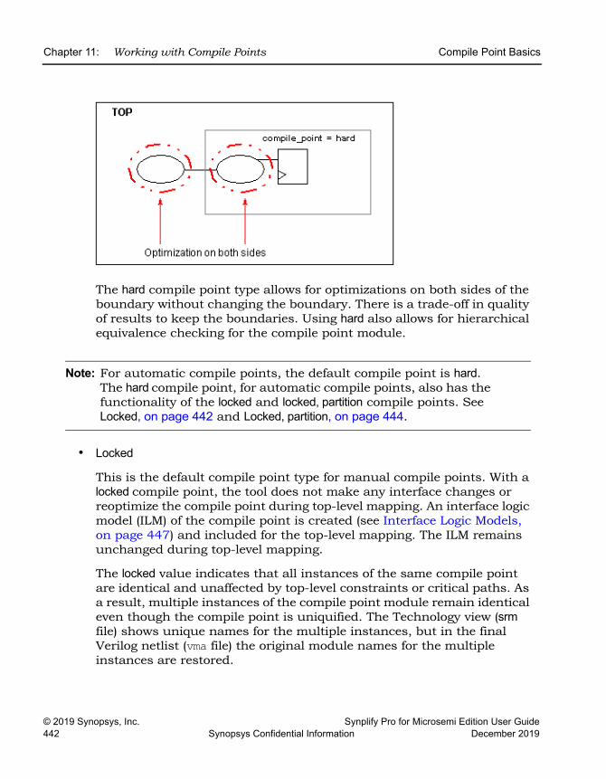
LO
Chapter 11: Working with Compile Points Compile Point Basics
© 2019 Synopsys, Inc. Synplify Pro for Microsemi Edition User Guide442 Synopsys Confidential Information December 2019
The hard compile point type allows for optimizations on both sides of the boundary without changing the boundary. There is a trade-off in quality of results to keep the boundaries. Using hard also allows for hierarchical equivalence checking for the compile point module.
Note: For automatic compile points, the default compile point is hard. The hard compile point, for automatic compile points, also has the functionality of the locked and locked, partition compile points. See Locked, on page 442 and Locked, partition, on page 444.
• Locked
This is the default compile point type for manual compile points. With a locked compile point, the tool does not make any interface changes or reoptimize the compile point during top-level mapping. An interface logic model (ILM) of the compile point is created (see Interface Logic Models, on page 447) and included for the top-level mapping. The ILM remains unchanged during top-level mapping.
The locked value indicates that all instances of the same compile point are identical and unaffected by top-level constraints or critical paths. As a result, multiple instances of the compile point module remain identical even though the compile point is uniquified. The Technology view (srm file) shows unique names for the multiple instances, but in the final Verilog netlist (vma file) the original module names for the multiple instances are restored.
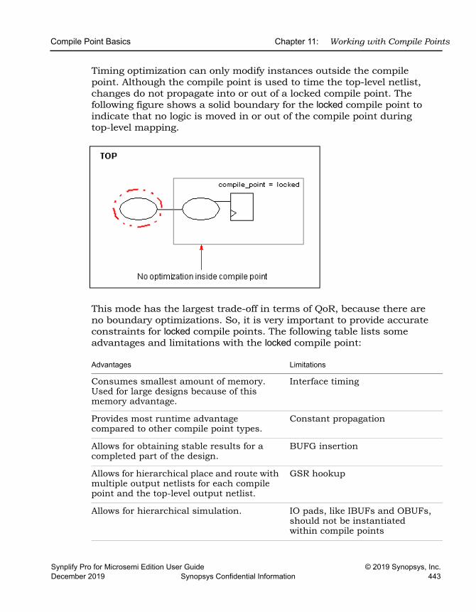
Compile Point Basics Chapter 11: Working with Compile Points
Synplify Pro for Microsemi Edition User Guide © 2019 Synopsys, Inc.December 2019 Synopsys Confidential Information 443
Timing optimization can only modify instances outside the compile point. Although the compile point is used to time the top-level netlist, changes do not propagate into or out of a locked compile point. The following figure shows a solid boundary for the locked compile point to indicate that no logic is moved in or out of the compile point during top-level mapping.
This mode has the largest trade-off in terms of QoR, because there are no boundary optimizations. So, it is very important to provide accurate constraints for locked compile points. The following table lists some advantages and limitations with the locked compile point:
Advantages Limitations
Consumes smallest amount of memory. Used for large designs because of this memory advantage.
Interface timing
Provides most runtime advantage compared to other compile point types.
Constant propagation
Allows for obtaining stable results for a completed part of the design.
BUFG insertion
Allows for hierarchical place and route with multiple output netlists for each compile point and the top-level output netlist.
GSR hookup
Allows for hierarchical simulation. IO pads, like IBUFs and OBUFs, should not be instantiated within compile points
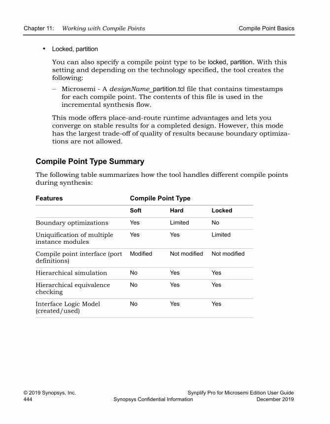
LO
Chapter 11: Working with Compile Points Compile Point Basics
© 2019 Synopsys, Inc. Synplify Pro for Microsemi Edition User Guide444 Synopsys Confidential Information December 2019
• Locked, partition
You can also specify a compile point type to be locked, partition. With this setting and depending on the technology specified, the tool creates the following:
– Microsemi - A designName_partition.tcl file that contains timestamps for each compile point. The contents of this file is used in the incremental synthesis flow.
This mode offers place-and-route runtime advantages and lets you converge on stable results for a completed design. However, this mode has the largest trade-off of quality of results because boundary optimiza-tions are not allowed.
Compile Point Type SummaryThe following table summarizes how the tool handles different compile points during synthesis:
Features Compile Point Type
Soft Hard Locked
Boundary optimizations Yes Limited No
Uniquification of multiple instance modules
Yes Yes Limited
Compile point interface (port definitions)
Modified Not modified Not modified
Hierarchical simulation No Yes Yes
Hierarchical equivalence checking
No Yes Yes
Interface Logic Model (created/used)
No Yes Yes
Compile Point Synthesis Basics Chapter 11: Working with Compile Points
Synplify Pro for Microsemi Edition User Guide © 2019 Synopsys, Inc.December 2019 Synopsys Confidential Information 445
Compile Point Synthesis BasicsThis section describes the compile point constraint files and timing models, and describes the steps the tool goes through to synthesize compile points. See the following for details:
• Compile Point Constraint Files, on page 445
• Interface Logic Models, on page 447
• Interface Timing for Compile Points, on page 448
• Compile Point Synthesis, on page 451
• Incremental Compile Point Synthesis, on page 454
• Forward-annotation of Compile Point Timing Constraints, on page 455
For step-by-step information about how to use compile points, see Synthe-sizing Compile Points, on page 455.
Compile Point Constraint FilesA compile point design can contain two levels of constraint files, as described below:
• The constraint file at the top level
This is a required file, and contains constraints that apply to the entire design. This file also contains the definitions of the compile points in the design. The define_compile_point command is automatically written to the top-level constraint file for each compile point you define.
The following figure shows that this design has one locked compile point, pgrm_cntr. It uses the following syntax to define the compile point:
define_compile_point {v:work.prgm_cntr} -type {locked}
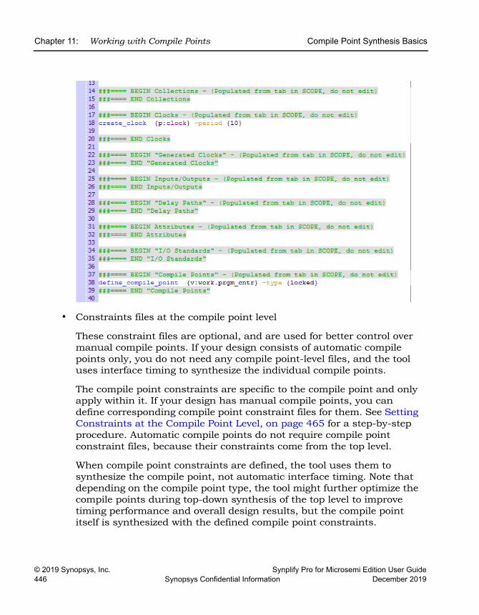
LO
Chapter 11: Working with Compile Points Compile Point Synthesis Basics
© 2019 Synopsys, Inc. Synplify Pro for Microsemi Edition User Guide446 Synopsys Confidential Information December 2019
• Constraints files at the compile point level
These constraint files are optional, and are used for better control over manual compile points. If your design consists of automatic compile points only, you do not need any compile point-level files, and the tool uses interface timing to synthesize the individual compile points.
The compile point constraints are specific to the compile point and only apply within it. If your design has manual compile points, you can define corresponding compile point constraint files for them. See Setting Constraints at the Compile Point Level, on page 465 for a step-by-step procedure. Automatic compile points do not require compile point constraint files, because their constraints come from the top level.
When compile point constraints are defined, the tool uses them to synthesize the compile point, not automatic interface timing. Note that depending on the compile point type, the tool might further optimize the compile points during top-down synthesis of the top level to improve timing performance and overall design results, but the compile point itself is synthesized with the defined compile point constraints.
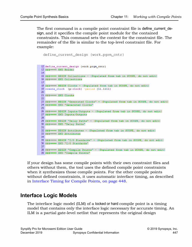
Compile Point Synthesis Basics Chapter 11: Working with Compile Points
Synplify Pro for Microsemi Edition User Guide © 2019 Synopsys, Inc.December 2019 Synopsys Confidential Information 447
The first command in a compile point constraint file is define_current_de-sign, and it specifies the compile point module for the contained constraints. This command sets the context for the constraint file. The remainder of the file is similar to the top-level constraint file. For example:
define_current_design {work.pgrm_cntr}
If your design has some compile points with their own constraint files and others without them, the tool uses the defined compile point constraints when it synthesizes those compile points. For the other compile points without defined constraints, it uses automatic interface timing, as described in Interface Timing for Compile Points, on page 448.
Interface Logic ModelsThe interface logic model (ILM) of a locked or hard compile point is a timing model that contains only the interface logic necessary for accurate timing. An ILM is a partial gate-level netlist that represents the original design
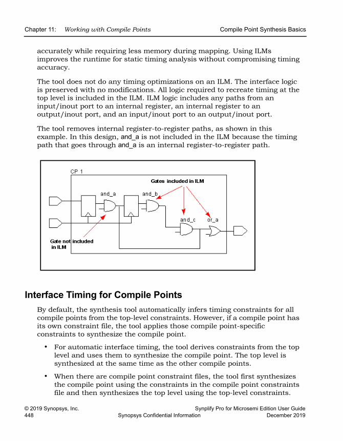
LO
Chapter 11: Working with Compile Points Compile Point Synthesis Basics
© 2019 Synopsys, Inc. Synplify Pro for Microsemi Edition User Guide448 Synopsys Confidential Information December 2019
accurately while requiring less memory during mapping. Using ILMs improves the runtime for static timing analysis without compromising timing accuracy.
The tool does not do any timing optimizations on an ILM. The interface logic is preserved with no modifications. All logic required to recreate timing at the top level is included in the ILM. ILM logic includes any paths from an input/inout port to an internal register, an internal register to an output/inout port, and an input/inout port to an output/inout port.
The tool removes internal register-to-register paths, as shown in this example. In this design, and_a is not included in the ILM because the timing path that goes through and_a is an internal register-to-register path.
Interface Timing for Compile PointsBy default, the synthesis tool automatically infers timing constraints for all compile points from the top-level constraints. However, if a compile point has its own constraint file, the tool applies those compile point-specific constraints to synthesize the compile point.
• For automatic interface timing, the tool derives constraints from the top level and uses them to synthesize the compile point. The top level is synthesized at the same time as the other compile points.
• When there are compile point constraint files, the tool first synthesizes the compile point using the constraints in the compile point constraints file and then synthesizes the top level using the top-level constraints.
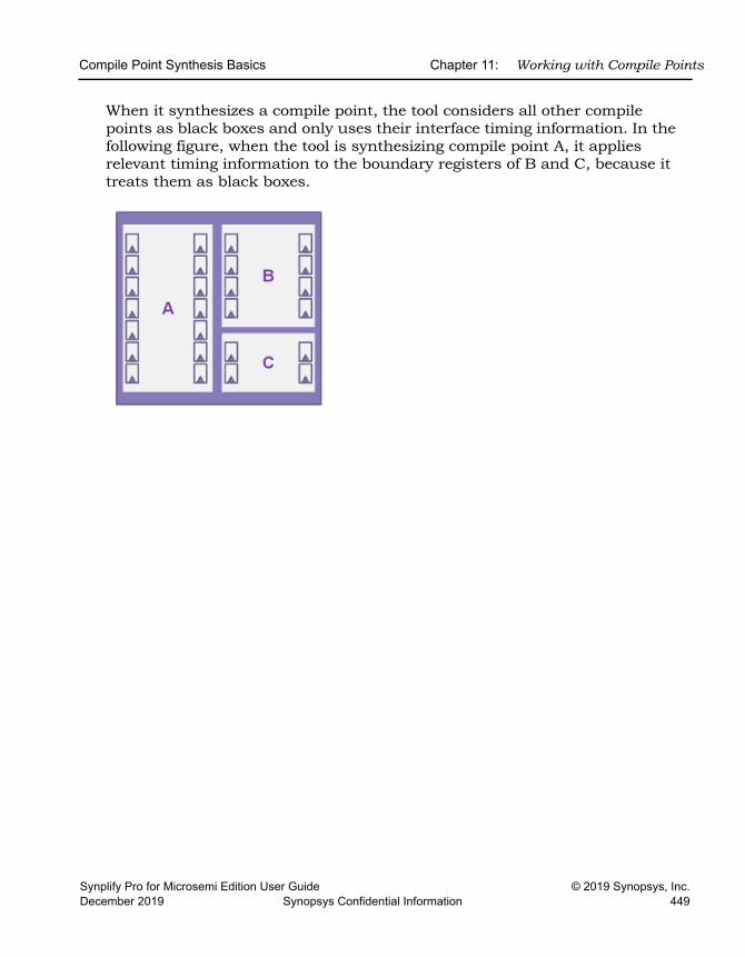
Compile Point Synthesis Basics Chapter 11: Working with Compile Points
Synplify Pro for Microsemi Edition User Guide © 2019 Synopsys, Inc.December 2019 Synopsys Confidential Information 449
When it synthesizes a compile point, the tool considers all other compile points as black boxes and only uses their interface timing information. In the following figure, when the tool is synthesizing compile point A, it applies relevant timing information to the boundary registers of B and C, because it treats them as black boxes.
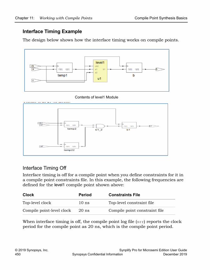
LO
Chapter 11: Working with Compile Points Compile Point Synthesis Basics
© 2019 Synopsys, Inc. Synplify Pro for Microsemi Edition User Guide450 Synopsys Confidential Information December 2019
Interface Timing ExampleThe design below shows how the interface timing works on compile points.
Interface Timing OffInterface timing is off for a compile point when you define constraints for it in a compile point constraints file. In this example, the following frequencies are defined for the level1 compile point shown above:
When interface timing is off, the compile point log file (srr) reports the clock period for the compile point as 20 ns, which is the compile point period.
Clock Period Constraints File
Top-level clock 10 ns Top-level constraint file
Compile point-level clock 20 ns Compile point constraint file
Contents of level1 Module
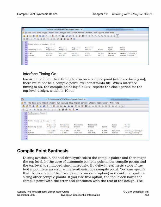
Compile Point Synthesis Basics Chapter 11: Working with Compile Points
Synplify Pro for Microsemi Edition User Guide © 2019 Synopsys, Inc.December 2019 Synopsys Confidential Information 451
Interface Timing OnFor automatic interface timing to run on a compile point (interface timing on), there must not be a compile-point level constraints file. When interface timing is on, the compile point log file (srr) reports the clock period for the top-level design, which is 10 ns:
Compile Point SynthesisDuring synthesis, the tool first synthesizes the compile points and then maps the top level. In the case of automatic compile points, the compile points and the top level are mapped simultaneously. By default, synthesis stops if the tool encounters an error while synthesizing a compile point. You can specify that the tool ignore the error (compile on error option) and continue synthe-sizing other compile points. If you use this option, the tool black boxes the compile point with the error and continues with the rest of the design. The
LO
Chapter 11: Working with Compile Points Compile Point Synthesis Basics
© 2019 Synopsys, Inc. Synplify Pro for Microsemi Edition User Guide452 Synopsys Confidential Information December 2019
rest of this section describes the process that the tool goes through to synthe-size compile points; for step-by-step information about what you need to do to use compile points, see Synthesizing Compile Points, on page 455.
Automatic Compile Point SynthesisThe tool synthesizes all compile points individually. The top level is also treated as a compile point.
A compile point stands on its own, and is optimized separately from its parent environment (the compile point container or the top level). This means that critical paths from a higher level do not propagate downwards, and they are unaffected by them.
Automatic compile points have constraints automatically assigned from the top level, and you do not need to add any constraints at the compile point level.
By default, synthesis stops if the tool encounters an error while synthesizing a compile point. You can specify that the tool ignore the error and continue synthesizing other compile points. See Using Continue on Error for Compile Point Synthesis, on page 219.
After synthesis for all the automatic compile points are done, the software reloads all the automatic compile point results and writes out a single output netlist and one constraint file for the entire design. See Forward-annotation of Compile Point Timing Constraints, on page 455 for a description of the constraints that are forward-annotated.
Manual Compile Point SynthesisThe following headings describe the process of manual compile point synthesis:
Stage 1: Bottom-up Compile Point SynthesisThe tool synthesizes compile points individually from the bottom up. If you have enabled multiprocessing, it synthesizes the compile points in parallel using multiple processing jobs. For nested compile points, it starts with the compile point at the lowest level of hierarchy and works up the hierarchy.
Compile Point Synthesis Basics Chapter 11: Working with Compile Points
Synplify Pro for Microsemi Edition User Guide © 2019 Synopsys, Inc.December 2019 Synopsys Confidential Information 453
A compile point stands on its own, and is optimized separately from its parent environment (the compile point container or the top level). This means that critical paths from a higher level do not propagate downwards, and they are unaffected by them.
If you have specified compile point-level constraints, the tool uses them to synthesize the compile point; if not, it uses automatic interface timing propa-gated from the top level. For compile point synthesis, the tool assumes that all other compile points are black boxes, and only uses the interface informa-tion.
When defined, compile point constraints apply within the compile point. Automatic compile points have constraints automatically assigned from the top level, and you do not need to add any constraints at the compile point level. For manual compile points, it is recommended that you set constraints on locked compile points, but setting constraints is optional for soft and hard compile points.
By default, synthesis stops if the tool encounters an error while synthesizing a compile point. You can specify that the tool ignore the error and continue synthesizing other compile points with the Continue on Error option. See Using Continue on Error for Compile Point Synthesis, on page 219 for details.
Stage 2: Top-Level SynthesisOnce all the compile points have been synthesized, the tool synthesizes the entire design from the top down, using the model information generated for each compile point and constraints defined in the top-level constraints file. You do not need to duplicate compile point constraints at a higher level, because the tool takes the compile point timing models into account when it synthesizes a higher level. Note that if you run standalone timing analysis on a compile point, the timing report reflects the top-level constraints and not the compile point constraints, although the tool used compile point level constraints to synthesize the compile point.
The software writes out a single output netlist and one constraint file for the entire design. See Forward-annotation of Compile Point Timing Constraints, on page 455 for a description of the constraints that are forward-annotated.

LO
Chapter 11: Working with Compile Points Compile Point Synthesis Basics
© 2019 Synopsys, Inc. Synplify Pro for Microsemi Edition User Guide454 Synopsys Confidential Information December 2019
Incremental Compile Point SynthesisThe tool treats compile points as blocks for incremental synthesis. On subse-quent synthesis runs, the tool runs incrementally and only resynthesizes those compile points that have changed, and the top level. The synthesis tool automatically detects design changes and resynthesizes compile points only if necessary. For example, it does not resynthesize a compile point if you only add or change a source code comment, because this change does not really affect the design functionality.
The tool resynthesizes a compile point that has already been synthesized, in any of these cases:
• The HDL source code defining the compile point is changed in such a way that the design logic is changed.
• The constraints applied to the compile point are changed.
• Any of the options on the Device panel of the Implementation Options dialog box, except Update Compile Point Timing Data, are changed. In this case the entire design is resynthesized, including all compile points.
• You intentionally force the resynthesis of your entire design, including all compile points, with the Run -> Resynthesize All command.
• The Update Compile Point Timing Data device mapping option is enabled and at least one child of the compile point (at any level) has been remapped. The option requires that the parent compile point be resynthesized using the updated timing model of the child. This includes the possibility that the child was remapped earlier, while the option was disabled. The newly enabled option requires that the updated timing model of the child be taken into account, by resynthesizing the parent.
For each compile point, the software creates a subdirectory named for the compile point, in which it stores intermediate files that contain hierarchical interface timing and resource information that is used to synthesize the next level. Once generated, the model file is not updated unless there is an inter-face design change or you explicitly specify it. If you happen to delete these files, the associated compile point will be resynthesized and the files regener-ated.
Synthesizing Compile Points Chapter 11: Working with Compile Points
Synplify Pro for Microsemi Edition User Guide © 2019 Synopsys, Inc.December 2019 Synopsys Confidential Information 455
Forward-annotation of Compile Point Timing Constraints In addition to a top-level constraint file, each compile point can have its own constraint file. Constraints are forward-annotated to placement and routing from the top-level as well as the compile point-level files. However, not all compile point constraints are forward-annotated, as explained below. For example, constraints on top-level ports are always forward annotated, but compile point port constraints are not forward annotated.
• Top-level constraints are forward-annotated.
• Constraints applied to the interface (ports and bit ports) of the compile point are not forward-annotated.These include input_delays, output_delays, and clock definitions on the ports. Such constraints are only used to map the compile point itself, not its parents. They are not used in the final timing report, and they are not forward-annotated.
• Constraints applied to instances inside the compile point are forward-annotatedConstraints like timing exceptions and internal clocks are used to map the compile point and its parents. They are used in the final timing report, and they are forward-annotated.
Synthesizing Compile PointsThis section describes the synthesis process with automatic compile points, manual compile points, or a combination of both in your design:
• The Automatic Compile Point Flow, next
• The Manual Compile Point Flow, on page 459
• Creating a Top-Level Constraints File for Compile Points, on page 461
• Defining Manual Compile Points, on page 462
• Setting Constraints at the Compile Point Level, on page 465
• Analyzing Compile Point Results, on page 467
• Using Automatic and Manual Compile Points Together, on page 469
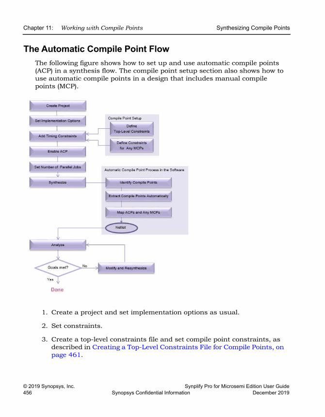
LO
Chapter 11: Working with Compile Points Synthesizing Compile Points
© 2019 Synopsys, Inc. Synplify Pro for Microsemi Edition User Guide456 Synopsys Confidential Information December 2019
The Automatic Compile Point FlowThe following figure shows how to set up and use automatic compile points (ACP) in a synthesis flow. The compile point setup section also shows how to use automatic compile points in a design that includes manual compile points (MCP).
1. Create a project and set implementation options as usual.
2. Set constraints.
3. Create a top-level constraints file and set compile point constraints, as described in Creating a Top-Level Constraints File for Compile Points, on page 461.
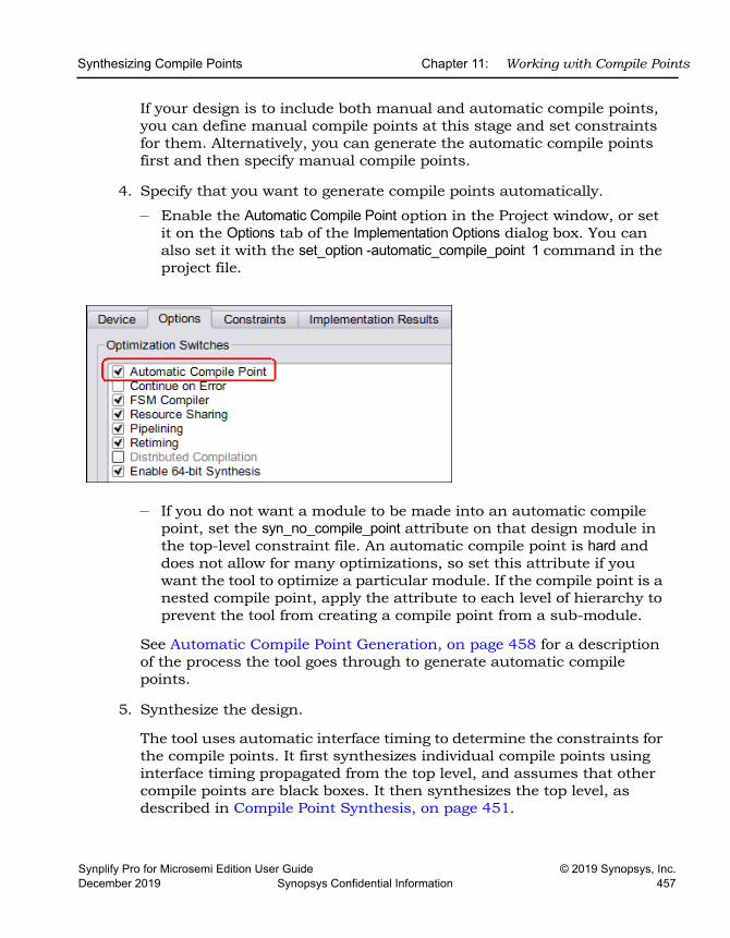
Synthesizing Compile Points Chapter 11: Working with Compile Points
Synplify Pro for Microsemi Edition User Guide © 2019 Synopsys, Inc.December 2019 Synopsys Confidential Information 457
If your design is to include both manual and automatic compile points, you can define manual compile points at this stage and set constraints for them. Alternatively, you can generate the automatic compile points first and then specify manual compile points.
4. Specify that you want to generate compile points automatically.
– Enable the Automatic Compile Point option in the Project window, or set it on the Options tab of the Implementation Options dialog box. You can also set it with the set_option -automatic_compile_point 1 command in the project file.
– If you do not want a module to be made into an automatic compile point, set the syn_no_compile_point attribute on that design module in the top-level constraint file. An automatic compile point is hard and does not allow for many optimizations, so set this attribute if you want the tool to optimize a particular module. If the compile point is a nested compile point, apply the attribute to each level of hierarchy to prevent the tool from creating a compile point from a sub-module.
See Automatic Compile Point Generation, on page 458 for a description of the process the tool goes through to generate automatic compile points.
5. Synthesize the design.
The tool uses automatic interface timing to determine the constraints for the compile points. It first synthesizes individual compile points using interface timing propagated from the top level, and assumes that other compile points are black boxes. It then synthesizes the top level, as described in Compile Point Synthesis, on page 451.

LO
Chapter 11: Working with Compile Points Synthesizing Compile Points
© 2019 Synopsys, Inc. Synplify Pro for Microsemi Edition User Guide458 Synopsys Confidential Information December 2019
For automatic compile points, the top level is treated as another compile point and is synthesized along with them.
6. Analyze the design.
For details, see Analyzing Compile Point Results, on page 467. If you resynthesize the design, the tool uses incremental synthesis. See Resyn-thesizing Compile Points Incrementally, on page 471 for details.
At this point, you can choose to create additional manual compile points as needed, by defining them in the top-level constraints file.
If you want to apply constraints to an automatically identified compile point, first define that compile point as a manual compile point and then apply constraints to it.
Automatic Compile Point GenerationThe automatic compile point process does not generate new hierarchy. It honors existing hierarchy, so if you have RAMs, ROMs or DSPs that cross hierarchies, it does not disturb them..
In a typical design, the tool goes through these stages to generate automatic compile points and their constraints.
• It first identifies compile points based on factors like the size of hierar-chical modules, their boundary logic, and the number of hierarchical ports driven by constants.
• It then extracts compile point constraints from the top-level timing constraints, and propagates this interface timing automatically to the automatic compile points.
• If the design has manual compile points that do not have a constraint file at the top level, the tool derives constraints for them from the top level, just as with automatic compile points. If the design has manual compile points with constraints, the tool honors these defined constraints for the manual compile points.
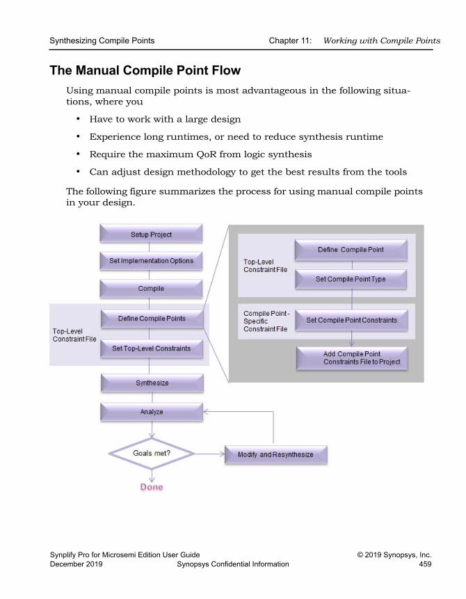
Synthesizing Compile Points Chapter 11: Working with Compile Points
Synplify Pro for Microsemi Edition User Guide © 2019 Synopsys, Inc.December 2019 Synopsys Confidential Information 459
The Manual Compile Point FlowUsing manual compile points is most advantageous in the following situa-tions, where you
• Have to work with a large design
• Experience long runtimes, or need to reduce synthesis runtime
• Require the maximum QoR from logic synthesis
• Can adjust design methodology to get the best results from the tools
The following figure summarizes the process for using manual compile points in your design.
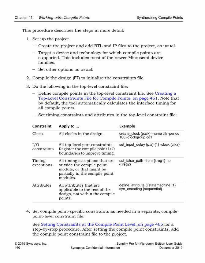
LO
Chapter 11: Working with Compile Points Synthesizing Compile Points
© 2019 Synopsys, Inc. Synplify Pro for Microsemi Edition User Guide460 Synopsys Confidential Information December 2019
This procedure describes the steps in more detail:
1. Set up the project.
– Create the project and add RTL and IP files to the project, as usual.
– Target a device and technology for which compile points are supported. This includes most of the newer Microsemi device families.
– Set other options as usual.
2. Compile the design (F7) to initialize the constraints file.
3. Do the following in the top-level constraint file:
– Define compile points in the top-level constraint file. See Creating a Top-Level Constraints File for Compile Points, on page 461. Note that by default, the tool automatically calculates the interface timing for all compile points.
– Set timing constraints and attributes in the top-level constraint file:
4. Set compile point-specific constraints as needed in a separate, compile point-level constraint file.
See Setting Constraints at the Compile Point Level, on page 465 for a step-by-step procedure. After setting the compile point constraints, add the compile point constraint file to the project.
Constraint Apply to ... ExampleClock All clocks in the design. create_clock {p:clk} -name clk -period
100 -clockgroup cg1
I/O constraints
All top-level port constraints. Register the compile point I/O boundaries to improve timing.
set_input_delay {p:a} {1} -clock {clk:r}
Timing exceptions
All timing exceptions that are outside the compile point module, or that might be partially in the compile point modules.
set_false_path -from {i:reg1} -to {i:reg2}
Attributes All attributes that are applicable to the rest of the design, not within the compile points.
define_attribute {i:statemachine_1} syn_encoding {sequential}
Synthesizing Compile Points Chapter 11: Working with Compile Points
Synplify Pro for Microsemi Edition User Guide © 2019 Synopsys, Inc.December 2019 Synopsys Confidential Information 461
5. If you do not want to interrupt synthesis for compiler errors, select Options->Configure Compile Point Process and enable the Continue on Error option.
With this option enabled, the tool black boxes any compile points that have mapper errors and continues to synthesize the rest of the design. See Combining Compile Points with Multiprocessing, on page 470 for more information about this mode.
6. Synthesize the design.
The tool synthesizes the compile points separately and then synthesizes the top level. See Compile Point Synthesis, on page 451 for details about the process.
– The first time it runs synthesis, the tool maps the entire design.
– For subsequent synthesis runs, the tool only maps compile points that were modified since the last run. It preserves unchanged compile points.
You can also run synthesis on individual compile points, without synthesizing the whole design.
7. Analyze the synthesis results using the top-level srr log file.
See Analyzing Compile Point Results, on page 467 for details.
8. If you do not meet your design goals, make necessary changes to the RTL, constraints, or synthesis controls, and re-synthesize the design.
The tool runs incremental synthesis on the modified parts of the design, as described in Incremental Compile Point Synthesis, on page 454. See Resynthesizing Compile Points Incrementally, on page 471 for a detailed procedure.
Creating a Top-Level Constraints File for Compile PointsAll compile points require a top-level constraints file. If you have manual compile points, define them in this file. The top-level file also contains design-level constraints. The following procedure describes how to create a top-level constraints file for a compile point design.
1. Create the top-level constraints file.
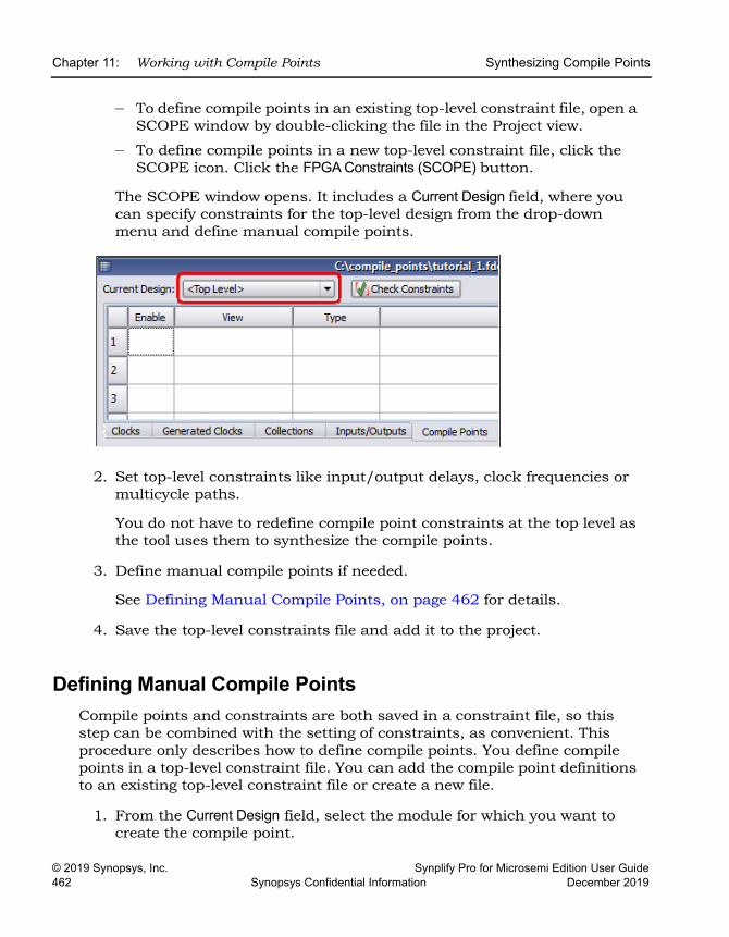
LO
Chapter 11: Working with Compile Points Synthesizing Compile Points
© 2019 Synopsys, Inc. Synplify Pro for Microsemi Edition User Guide462 Synopsys Confidential Information December 2019
– To define compile points in an existing top-level constraint file, open a SCOPE window by double-clicking the file in the Project view.
– To define compile points in a new top-level constraint file, click the SCOPE icon. Click the FPGA Constraints (SCOPE) button.
The SCOPE window opens. It includes a Current Design field, where you can specify constraints for the top-level design from the drop-down menu and define manual compile points.
2. Set top-level constraints like input/output delays, clock frequencies or multicycle paths.
You do not have to redefine compile point constraints at the top level as the tool uses them to synthesize the compile points.
3. Define manual compile points if needed.
See Defining Manual Compile Points, on page 462 for details.
4. Save the top-level constraints file and add it to the project.
Defining Manual Compile PointsCompile points and constraints are both saved in a constraint file, so this step can be combined with the setting of constraints, as convenient. This procedure only describes how to define compile points. You define compile points in a top-level constraint file. You can add the compile point definitions to an existing top-level constraint file or create a new file.
1. From the Current Design field, select the module for which you want to create the compile point.
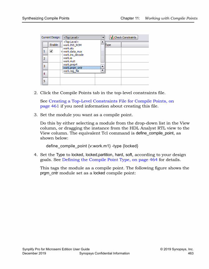
Synthesizing Compile Points Chapter 11: Working with Compile Points
Synplify Pro for Microsemi Edition User Guide © 2019 Synopsys, Inc.December 2019 Synopsys Confidential Information 463
2. Click the Compile Points tab in the top-level constraints file.
See Creating a Top-Level Constraints File for Compile Points, on page 461 if you need information about creating this file.
3. Set the module you want as a compile point.
Do this by either selecting a module from the drop-down list in the View column, or dragging the instance from the HDL Analyst RTL view to the View column. The equivalent Tcl command is define_compile_point, as shown below:
define_compile_point {v:work.m1} -type {locked}
4. Set the Type to locked, locked,partition, hard, soft, according to your design goals. See Defining the Compile Point Type, on page 464 for details.
This tags the module as a compile point. The following figure shows the prgm_cntr module set as a locked compile point:
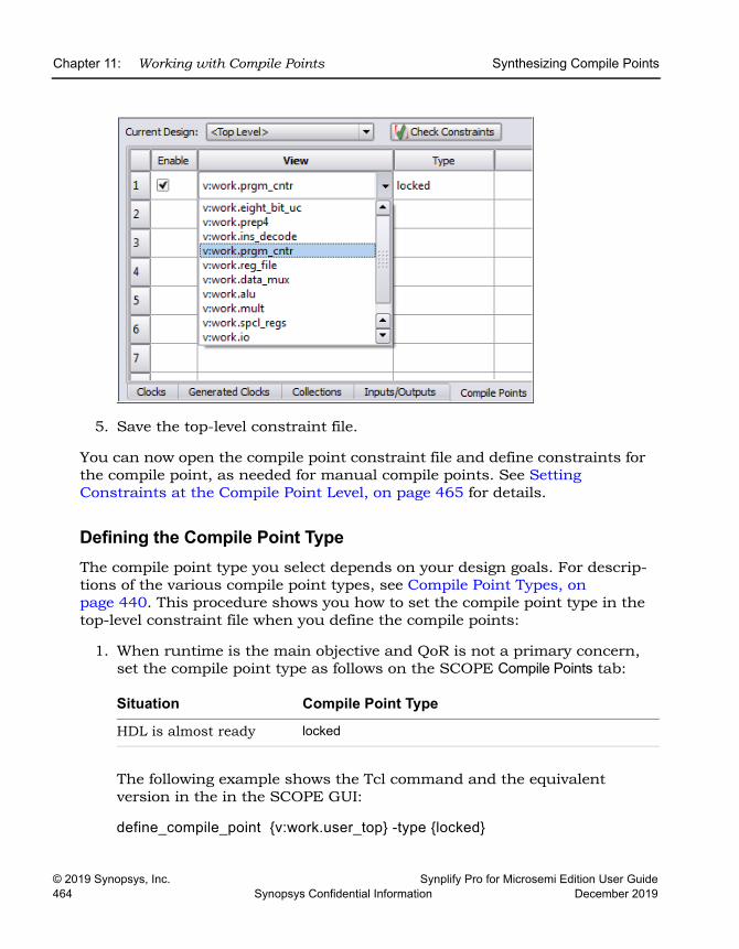
LO
Chapter 11: Working with Compile Points Synthesizing Compile Points
© 2019 Synopsys, Inc. Synplify Pro for Microsemi Edition User Guide464 Synopsys Confidential Information December 2019
5. Save the top-level constraint file.
You can now open the compile point constraint file and define constraints for the compile point, as needed for manual compile points. See Setting Constraints at the Compile Point Level, on page 465 for details.
Defining the Compile Point TypeThe compile point type you select depends on your design goals. For descrip-tions of the various compile point types, see Compile Point Types, on page 440. This procedure shows you how to set the compile point type in the top-level constraint file when you define the compile points:
1. When runtime is the main objective and QoR is not a primary concern, set the compile point type as follows on the SCOPE Compile Points tab:
The following example shows the Tcl command and the equivalent version in the in the SCOPE GUI:
define_compile_point {v:work.user_top} -type {locked}
Situation Compile Point Type
HDL is almost ready locked
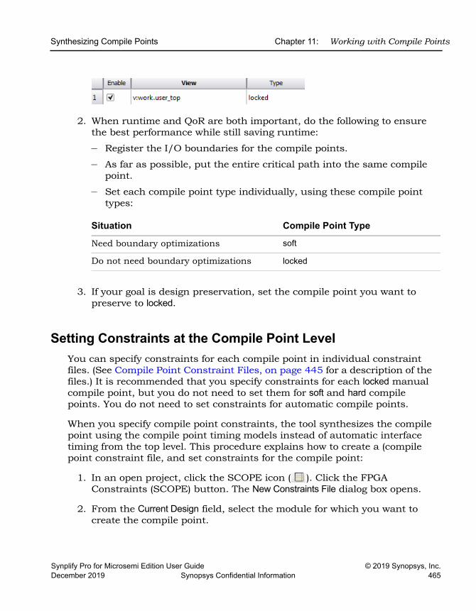
Synthesizing Compile Points Chapter 11: Working with Compile Points
Synplify Pro for Microsemi Edition User Guide © 2019 Synopsys, Inc.December 2019 Synopsys Confidential Information 465
2. When runtime and QoR are both important, do the following to ensure the best performance while still saving runtime:
– Register the I/O boundaries for the compile points.
– As far as possible, put the entire critical path into the same compile point.
– Set each compile point type individually, using these compile point types:
3. If your goal is design preservation, set the compile point you want to preserve to locked.
Setting Constraints at the Compile Point Level You can specify constraints for each compile point in individual constraint files. (See Compile Point Constraint Files, on page 445 for a description of the files.) It is recommended that you specify constraints for each locked manual compile point, but you do not need to set them for soft and hard compile points. You do not need to set constraints for automatic compile points.
When you specify compile point constraints, the tool synthesizes the compile point using the compile point timing models instead of automatic interface timing from the top level. This procedure explains how to create a (compile point constraint file, and set constraints for the compile point:
1. In an open project, click the SCOPE icon ( ). Click the FPGA Constraints (SCOPE) button. The New Constraints File dialog box opens.
2. From the Current Design field, select the module for which you want to create the compile point.
Situation Compile Point Type
Need boundary optimizations soft
Do not need boundary optimizations locked
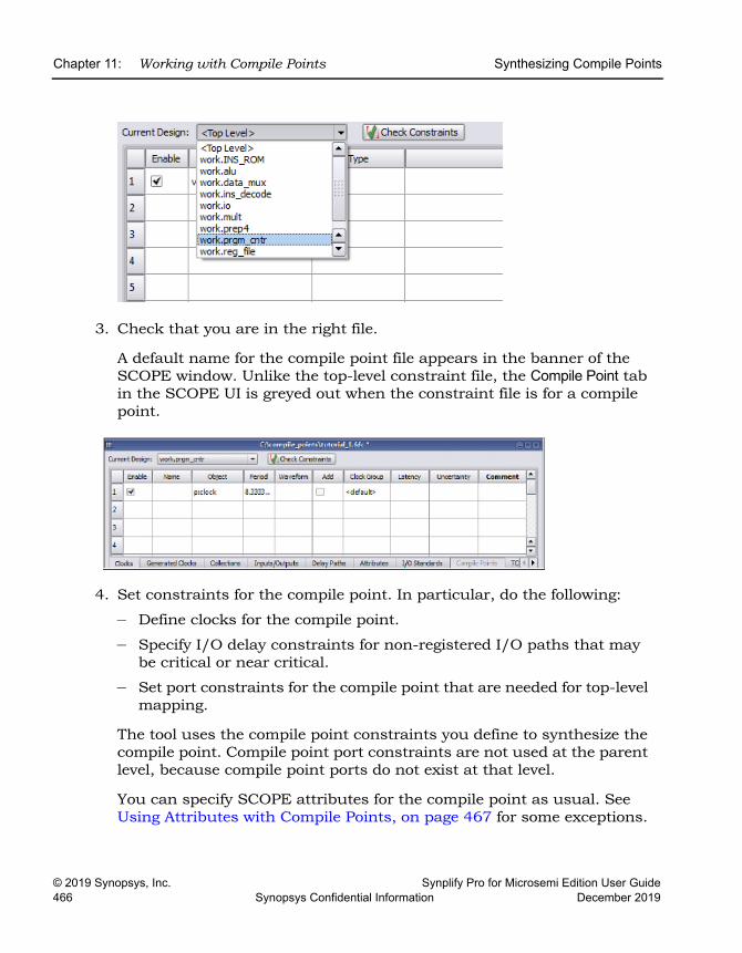
LO
Chapter 11: Working with Compile Points Synthesizing Compile Points
© 2019 Synopsys, Inc. Synplify Pro for Microsemi Edition User Guide466 Synopsys Confidential Information December 2019
3. Check that you are in the right file.
A default name for the compile point file appears in the banner of the SCOPE window. Unlike the top-level constraint file, the Compile Point tab in the SCOPE UI is greyed out when the constraint file is for a compile point.
4. Set constraints for the compile point. In particular, do the following:
– Define clocks for the compile point.
– Specify I/O delay constraints for non-registered I/O paths that may be critical or near critical.
– Set port constraints for the compile point that are needed for top-level mapping.
The tool uses the compile point constraints you define to synthesize the compile point. Compile point port constraints are not used at the parent level, because compile point ports do not exist at that level.
You can specify SCOPE attributes for the compile point as usual. See Using Attributes with Compile Points, on page 467 for some exceptions.
Synthesizing Compile Points Chapter 11: Working with Compile Points
Synplify Pro for Microsemi Edition User Guide © 2019 Synopsys, Inc.December 2019 Synopsys Confidential Information 467
5. Save the file and add it to the project. When prompted, click Yes to add the constraint file to the top-level design project.
Otherwise, use Save As to write a file such as, moduleName.fdc to the current directory. The hierarchical paths for compile point modules in the constraint file are specified at the compile point level; not the top-level design.
Using Attributes with Compile PointsYou can use attributes as usual when you set constraints for compile points. The following sections describe some caveats and exceptions:
• syn_hier
When you use syn_hier on a compile point, the only valid value is flatten. All other values of this attribute are ignored for compile points. The syn_hier attribute behaves normally for all other module boundaries that are not defined as compile points.
• syn_allowed_resources
Apply the syn_allowed_resources attribute globally or to a compile point to specify its allowed resources. When a compile point is synthesized, the resources of its siblings and parents cannot be taken into account because it stands alone as an independent synthesis unit. This attribute limits dedicated resources such as block RAMs or DSPs that the compile point can use, so that there are adequate resources available during the top-down flow.
Analyzing Compile Point ResultsThe software writes all timing and area results to a single log file in the imple-mentation directory. You can check this file and the RTL and Technology views to determine if your design has met the goals for area and performance. You can also view and isolate the critical paths, search for and highlight design objects and crossprobe between the schematics and source files.
1. Check that the design meets the target frequency for the design. Use the Watch window or check the log file.
2. Open the log file and check the following:
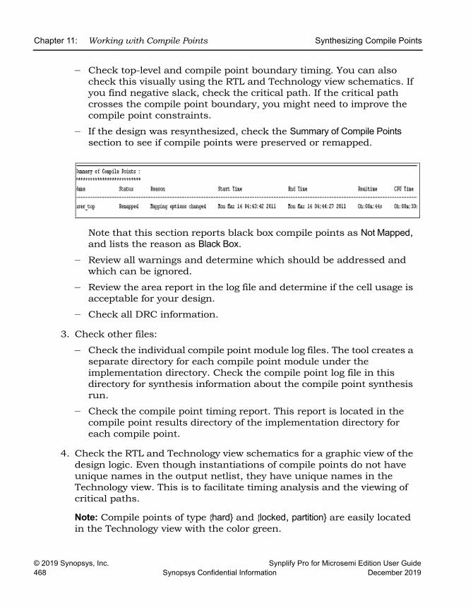
LO
Chapter 11: Working with Compile Points Synthesizing Compile Points
© 2019 Synopsys, Inc. Synplify Pro for Microsemi Edition User Guide468 Synopsys Confidential Information December 2019
– Check top-level and compile point boundary timing. You can also check this visually using the RTL and Technology view schematics. If you find negative slack, check the critical path. If the critical path crosses the compile point boundary, you might need to improve the compile point constraints.
– If the design was resynthesized, check the Summary of Compile Points section to see if compile points were preserved or remapped.
Note that this section reports black box compile points as Not Mapped, and lists the reason as Black Box.
– Review all warnings and determine which should be addressed and which can be ignored.
– Review the area report in the log file and determine if the cell usage is acceptable for your design.
– Check all DRC information.
3. Check other files:
– Check the individual compile point module log files. The tool creates a separate directory for each compile point module under the implementation directory. Check the compile point log file in this directory for synthesis information about the compile point synthesis run.
– Check the compile point timing report. This report is located in the compile point results directory of the implementation directory for each compile point.
4. Check the RTL and Technology view schematics for a graphic view of the design logic. Even though instantiations of compile points do not have unique names in the output netlist, they have unique names in the Technology view. This is to facilitate timing analysis and the viewing of critical paths.
Note: Compile points of type {hard} and {locked, partition} are easily located in the Technology view with the color green.
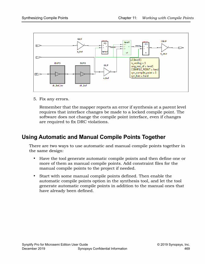
Synthesizing Compile Points Chapter 11: Working with Compile Points
Synplify Pro for Microsemi Edition User Guide © 2019 Synopsys, Inc.December 2019 Synopsys Confidential Information 469
5. Fix any errors.
Remember that the mapper reports an error if synthesis at a parent level requires that interface changes be made to a locked compile point. The software does not change the compile point interface, even if changes are required to fix DRC violations.
Using Automatic and Manual Compile Points TogetherThere are two ways to use automatic and manual compile points together in the same design:
• Have the tool generate automatic compile points and then define one or more of them as manual compile points. Add constraint files for the manual compile points to the project if needed.
• Start with some manual compile points defined. Then enable the automatic compile points option in the synthesis tool, and let the tool generate automatic compile points in addition to the manual ones that have already been defined.
LO
Chapter 11: Working with Compile Points Using Compile Points with Other Features
© 2019 Synopsys, Inc. Synplify Pro for Microsemi Edition User Guide470 Synopsys Confidential Information December 2019
Using Compile Points with Other FeaturesYou can effectively combine compile points with other synthesis features for better runtime. The following sections describe how you can use compile points with multiprocessing:
• Combining Compile Points with Multiprocessing, on page 470
For information about using compile points with Continue on Error, see Using Continue on Error for Compile Point Synthesis, on page 219.
Combining Compile Points with MultiprocessingTo use compile points with multiprocessing, specify the number of parallel jobs to run with the Options->Configure Parallel or Compile Point Process command. For a step-by-step procedure, see Multiprocessing With Compile Points, on page 536.
Resynthesizing Incrementally Chapter 11: Working with Compile Points
Synplify Pro for Microsemi Edition User Guide © 2019 Synopsys, Inc.December 2019 Synopsys Confidential Information 471
Resynthesizing IncrementallyIncremental synthesis can significantly reduce runtime on subsequent runs. It can also help with design stabilization and preservation. The following describe the incremental synthesis process, and how compile points are used in incremental synthesis within the tool and with other tools:
• Incremental Compile Point Synthesis, on page 454
• Resynthesizing Compile Points Incrementally, on page 471
Resynthesizing Compile Points IncrementallyThe following figure illustrates how compile points (CP) are used in incre-mental synthesis.
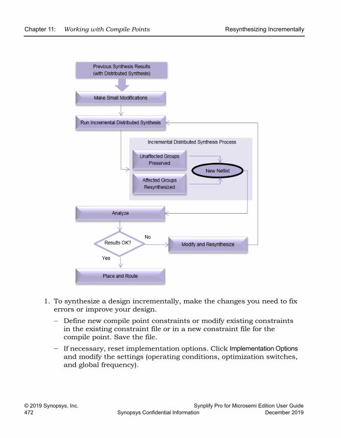
LO
Chapter 11: Working with Compile Points Resynthesizing Incrementally
© 2019 Synopsys, Inc. Synplify Pro for Microsemi Edition User Guide472 Synopsys Confidential Information December 2019
1. To synthesize a design incrementally, make the changes you need to fix errors or improve your design.
– Define new compile point constraints or modify existing constraints in the existing constraint file or in a new constraint file for the compile point. Save the file.
– If necessary, reset implementation options. Click Implementation Options and modify the settings (operating conditions, optimization switches, and global frequency).
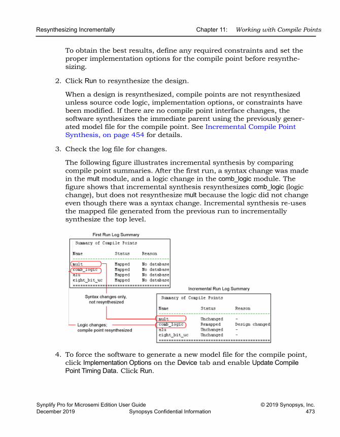
Resynthesizing Incrementally Chapter 11: Working with Compile Points
Synplify Pro for Microsemi Edition User Guide © 2019 Synopsys, Inc.December 2019 Synopsys Confidential Information 473
To obtain the best results, define any required constraints and set the proper implementation options for the compile point before resynthe-sizing.
2. Click Run to resynthesize the design.
When a design is resynthesized, compile points are not resynthesized unless source code logic, implementation options, or constraints have been modified. If there are no compile point interface changes, the software synthesizes the immediate parent using the previously gener-ated model file for the compile point. See Incremental Compile Point Synthesis, on page 454 for details.
3. Check the log file for changes.
The following figure illustrates incremental synthesis by comparing compile point summaries. After the first run, a syntax change was made in the mult module, and a logic change in the comb_logic module. The figure shows that incremental synthesis resynthesizes comb_logic (logic change), but does not resynthesize mult because the logic did not change even though there was a syntax change. Incremental synthesis re-uses the mapped file generated from the previous run to incrementally synthesize the top level.
4. To force the software to generate a new model file for the compile point, click Implementation Options on the Device tab and enable Update Compile Point Timing Data. Click Run.
LO
Chapter 11: Working with Compile Points Resynthesizing Incrementally
© 2019 Synopsys, Inc. Synplify Pro for Microsemi Edition User Guide474 Synopsys Confidential Information December 2019
The software regenerates the model file for each compile point when it synthesizes the compile points. The new model file is used to synthesize the parent. The option remains in effect until you disable it.
5. To override incremental synthesis and force the software to resynthesize all compile points whether or not there have been changes made, use the Run->Resynthesize All command.
You might want to force resynthesis to propagate changes from a locked compile point to its environment, or resynthesize compile points one last time before tape out. When you use this option, incremental synthesis is disabled for the current run only. The Resynthesize All command does not regenerate model files for the compile points unless there are interface changes. If you enable Update Compile Point Timing Data and select Resynthe-size All, you can resynthesize the entire design and regenerate the compile point model files, but synthesis will take longer than an incre-mental synthesis run.
Synplify Pro for Microsemi Edition User Guide © 2019 Synopsys, Inc.December 2019 Synopsys Confidential Information 475
C H A P T E R 1 2
Working with IP Input
This chapter describes how to work with IP from different sources. It describes the following:
• The Synopsys FPGA IP Encryption Flow, on page 476
• Working with IEEE 1735 Encryption, on page 487
• Working with Synenc-encrypted IP, on page 497
• Using Hyper Source, on page 499
LO
Chapter 12: Working with IP Input The Synopsys FPGA IP Encryption Flow
© 2019 Synopsys, Inc. Synplify Pro for Microsemi Edition User Guide476 Synopsys Confidential Information December 2019
The Synopsys FPGA IP Encryption FlowThe Synopsys FPGA IP encryption flow is a design flow that encourages interoperability while protecting IP implementations using encryp-tion/decryption technologies. This flow offers the following advantages: interoperability, protection of IP, reuse of IP, and a standard flow for IP encryption.
See the following for information about the encryption flow:
• Overview of the Synopsys FPGA IP Encryption Flow, on page 476
• Preparing and Encrypting IP, on page 482
The following encryption standards are supported, but the recom-mended scheme is the IEEE 1735 standard.
Regardless of which IP encryption scheme you choose, please be aware that encryption, like any security measure, may become vulnerable to unauthorized access and circumvention. The encryption technology and this documentation are supplied "As Is", and Synopsys makes no warranties or representations (whether express or implied) regarding the efficacy or security of such technology.
• Preparing the IP Package, on page 483
Overview of the Synopsys FPGA IP Encryption FlowThe complete flow for protecting IP requires a partnership between the IP author, Synopsys, and any other downstream tool vendor that consumes the IP. The following figure shows an FPGA synthesis flow, which requires the IP to be handed off from the synthesis tool to the place-and-route tool.
Encryption Standard Details
IEEE 1735-2014 with key-block (Recommended)
Working with IEEE 1735 Encryption, on page 487
OpenIP Encrypting IP Using OpenIP (encryptIP), on page 493
Synenc-encrypted IP Working with Synenc-encrypted IP, on page 497
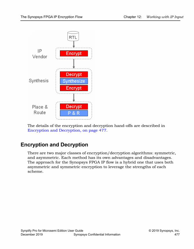
The Synopsys FPGA IP Encryption Flow Chapter 12: Working with IP Input
Synplify Pro for Microsemi Edition User Guide © 2019 Synopsys, Inc.December 2019 Synopsys Confidential Information 477
The details of the encryption and decryption hand-offs are described in Encryption and Decryption, on page 477.
Encryption and DecryptionThere are two major classes of encryption/decryption algorithms: symmetric, and asymmetric. Each method has its own advantages and disadvantages. The approach for the Synopsys FPGA IP flow is a hybrid one that uses both asymmetric and symmetric encryption to leverage the strengths of each scheme.
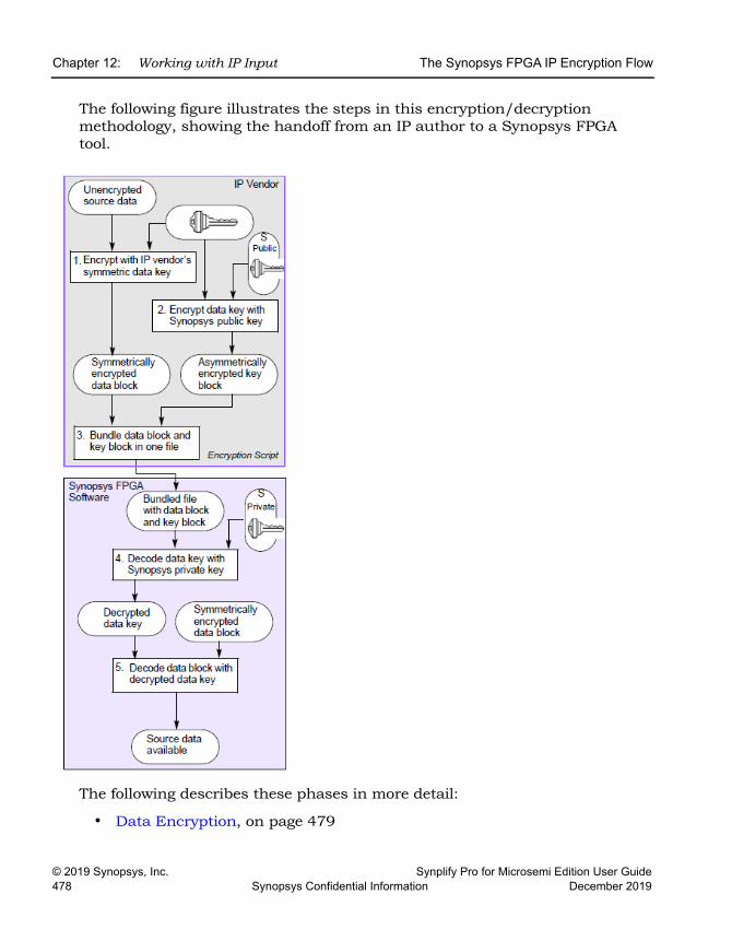
LO
Chapter 12: Working with IP Input The Synopsys FPGA IP Encryption Flow
© 2019 Synopsys, Inc. Synplify Pro for Microsemi Edition User Guide478 Synopsys Confidential Information December 2019
The following figure illustrates the steps in this encryption/decryption methodology, showing the handoff from an IP author to a Synopsys FPGA tool.
The following describes these phases in more detail:
• Data Encryption, on page 479
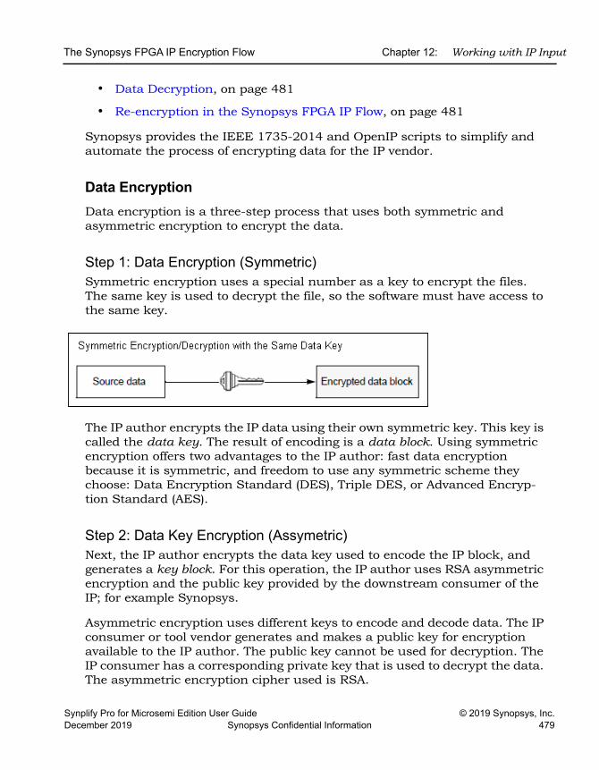
The Synopsys FPGA IP Encryption Flow Chapter 12: Working with IP Input
Synplify Pro for Microsemi Edition User Guide © 2019 Synopsys, Inc.December 2019 Synopsys Confidential Information 479
• Data Decryption, on page 481
• Re-encryption in the Synopsys FPGA IP Flow, on page 481
Synopsys provides the IEEE 1735-2014 and OpenIP scripts to simplify and automate the process of encrypting data for the IP vendor.
Data EncryptionData encryption is a three-step process that uses both symmetric and asymmetric encryption to encrypt the data.
Step 1: Data Encryption (Symmetric)Symmetric encryption uses a special number as a key to encrypt the files. The same key is used to decrypt the file, so the software must have access to the same key.
The IP author encrypts the IP data using their own symmetric key. This key is called the data key. The result of encoding is a data block. Using symmetric encryption offers two advantages to the IP author: fast data encryption because it is symmetric, and freedom to use any symmetric scheme they choose: Data Encryption Standard (DES), Triple DES, or Advanced Encryp-tion Standard (AES).
Step 2: Data Key Encryption (Assymetric)Next, the IP author encrypts the data key used to encode the IP block, and generates a key block. For this operation, the IP author uses RSA asymmetric encryption and the public key provided by the downstream consumer of the IP; for example Synopsys.
Asymmetric encryption uses different keys to encode and decode data. The IP consumer or tool vendor generates and makes a public key for encryption available to the IP author. The public key cannot be used for decryption. The IP consumer has a corresponding private key that is used to decrypt the data. The asymmetric encryption cipher used is RSA.
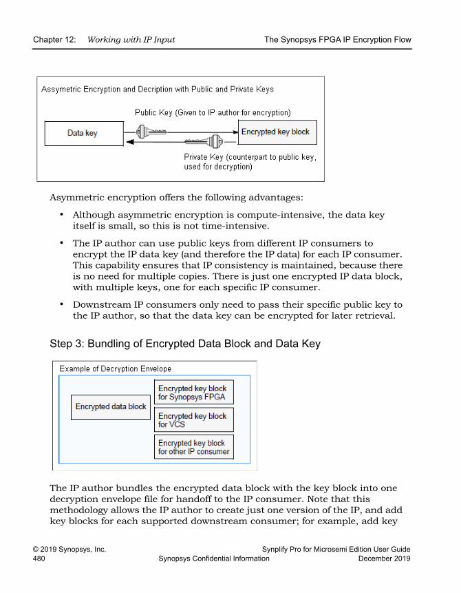
LO
Chapter 12: Working with IP Input The Synopsys FPGA IP Encryption Flow
© 2019 Synopsys, Inc. Synplify Pro for Microsemi Edition User Guide480 Synopsys Confidential Information December 2019
Asymmetric encryption offers the following advantages:
• Although asymmetric encryption is compute-intensive, the data key itself is small, so this is not time-intensive.
• The IP author can use public keys from different IP consumers to encrypt the IP data key (and therefore the IP data) for each IP consumer. This capability ensures that IP consistency is maintained, because there is no need for multiple copies. There is just one encrypted IP data block, with multiple keys, one for each specific IP consumer.
• Downstream IP consumers only need to pass their specific public key to the IP author, so that the data key can be encrypted for later retrieval.
Step 3: Bundling of Encrypted Data Block and Data Key
The IP author bundles the encrypted data block with the key block into one decryption envelope file for handoff to the IP consumer. Note that this methodology allows the IP author to create just one version of the IP, and add key blocks for each supported downstream consumer; for example, add key
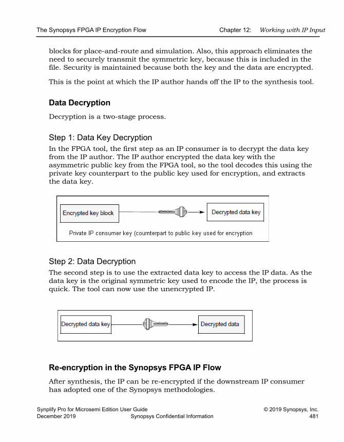
The Synopsys FPGA IP Encryption Flow Chapter 12: Working with IP Input
Synplify Pro for Microsemi Edition User Guide © 2019 Synopsys, Inc.December 2019 Synopsys Confidential Information 481
blocks for place-and-route and simulation. Also, this approach eliminates the need to securely transmit the symmetric key, because this is included in the file. Security is maintained because both the key and the data are encrypted.
This is the point at which the IP author hands off the IP to the synthesis tool.
Data Decryption Decryption is a two-stage process.
Step 1: Data Key DecryptionIn the FPGA tool, the first step as an IP consumer is to decrypt the data key from the IP author. The IP author encrypted the data key with the asymmetric public key from the FPGA tool, so the tool decodes this using the private key counterpart to the public key used for encryption, and extracts the data key.
Step 2: Data DecryptionThe second step is to use the extracted data key to access the IP data. As the data key is the original symmetric key used to encode the IP, the process is quick. The tool can now use the unencrypted IP.
Re-encryption in the Synopsys FPGA IP FlowAfter synthesis, the IP can be re-encrypted if the downstream IP consumer has adopted one of the Synopsys methodologies.
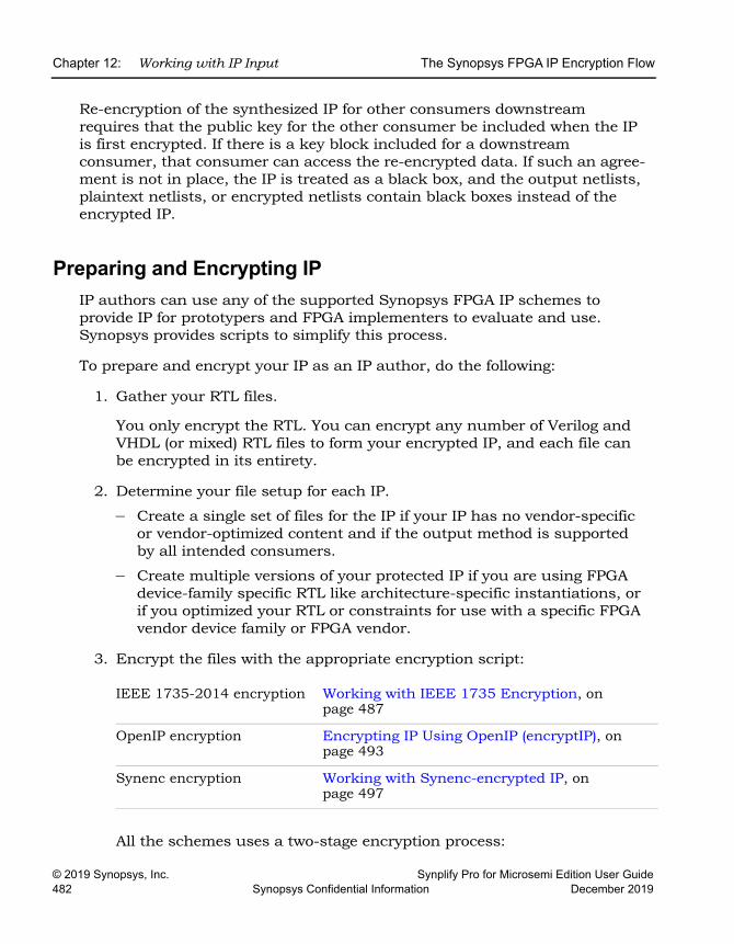
LO
Chapter 12: Working with IP Input The Synopsys FPGA IP Encryption Flow
© 2019 Synopsys, Inc. Synplify Pro for Microsemi Edition User Guide482 Synopsys Confidential Information December 2019
Re-encryption of the synthesized IP for other consumers downstream requires that the public key for the other consumer be included when the IP is first encrypted. If there is a key block included for a downstream consumer, that consumer can access the re-encrypted data. If such an agree-ment is not in place, the IP is treated as a black box, and the output netlists, plaintext netlists, or encrypted netlists contain black boxes instead of the encrypted IP.
Preparing and Encrypting IPIP authors can use any of the supported Synopsys FPGA IP schemes to provide IP for prototypers and FPGA implementers to evaluate and use. Synopsys provides scripts to simplify this process.
To prepare and encrypt your IP as an IP author, do the following:
1. Gather your RTL files.
You only encrypt the RTL. You can encrypt any number of Verilog and VHDL (or mixed) RTL files to form your encrypted IP, and each file can be encrypted in its entirety.
2. Determine your file setup for each IP.
– Create a single set of files for the IP if your IP has no vendor-specific or vendor-optimized content and if the output method is supported by all intended consumers.
– Create multiple versions of your protected IP if you are using FPGA device-family specific RTL like architecture-specific instantiations, or if you optimized your RTL or constraints for use with a specific FPGA vendor device family or FPGA vendor.
3. Encrypt the files with the appropriate encryption script:
All the schemes uses a two-stage encryption process:
IEEE 1735-2014 encryption Working with IEEE 1735 Encryption, on page 487
OpenIP encryption Encrypting IP Using OpenIP (encryptIP), on page 493
Synenc encryption Working with Synenc-encrypted IP, on page 497
The Synopsys FPGA IP Encryption Flow Chapter 12: Working with IP Input
Synplify Pro for Microsemi Edition User Guide © 2019 Synopsys, Inc.December 2019 Synopsys Confidential Information 483
– First, encrypt your IP files using a symmetric encryption algorithm and your own data key to create an encrypted data block. See Step 1: Data Encryption (Symmetric), on page 479 for a general description.
– Next, encrypt the session key for the encrypted data block using an asymmetric algorithm and the Synopsys public key. All the Synopsys encryption methodologies support RSA encryption. See Step 2: Data Key Encryption (Assymetric), on page 479 for a general description.
4. Package your IP, as described in Preparing the IP Package, on page 483.
5. Verify that your IP works with the tool by going through the procedure that the user would use.
– Start the tool and add the IP into a design.
– Run the normal synthesis implementation flow and check that the IP works.
Preparing the IP PackageDo the following to package your IP and make it accessible to an authorized consumer like Synopsys:
1. Collect the files for the package.
– Encrypt the files you need, as described in Preparing and Encrypting IP, on page 482.
– Make sure your package includes the files listed in IP Package File List, on page 484.
– Structure the files as described in Suggested Directory Structure, on page 484.
2. If your IP package is intended for synthesis only, without subsystem assembly, create a compressed package for download, using one of these methods:
– Create a compressed tarball (.tar.gz), which is a tar archive compressed with the gzip utility, using one of these commands:
tar cf -fileList | gzip -c > compressed-tarballgtar -cf compressed-tarball fileList
Preserve the directory structure when you run gzip.
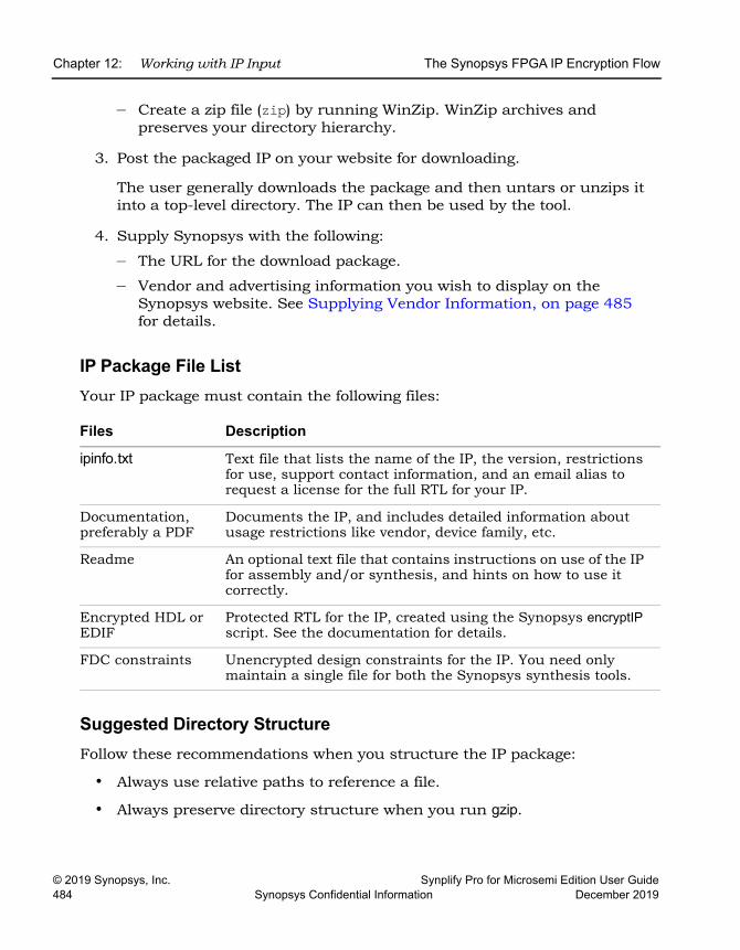
LO
Chapter 12: Working with IP Input The Synopsys FPGA IP Encryption Flow
© 2019 Synopsys, Inc. Synplify Pro for Microsemi Edition User Guide484 Synopsys Confidential Information December 2019
– Create a zip file (zip) by running WinZip. WinZip archives and preserves your directory hierarchy.
3. Post the packaged IP on your website for downloading.
The user generally downloads the package and then untars or unzips it into a top-level directory. The IP can then be used by the tool.
4. Supply Synopsys with the following:
– The URL for the download package.
– Vendor and advertising information you wish to display on the Synopsys website. See Supplying Vendor Information, on page 485 for details.
IP Package File ListYour IP package must contain the following files:
Suggested Directory StructureFollow these recommendations when you structure the IP package:
• Always use relative paths to reference a file.
• Always preserve directory structure when you run gzip.
Files Description
ipinfo.txt Text file that lists the name of the IP, the version, restrictions for use, support contact information, and an email alias to request a license for the full RTL for your IP.
Documentation, preferably a PDF
Documents the IP, and includes detailed information about usage restrictions like vendor, device family, etc.
Readme An optional text file that contains instructions on use of the IP for assembly and/or synthesis, and hints on how to use it correctly.
Encrypted HDL or EDIF
Protected RTL for the IP, created using the Synopsys encryptIP script. See the documentation for details.
FDC constraints Unencrypted design constraints for the IP. You need only maintain a single file for both the Synopsys synthesis tools.
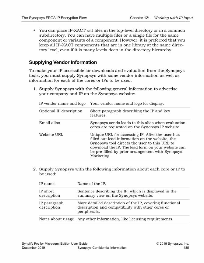
The Synopsys FPGA IP Encryption Flow Chapter 12: Working with IP Input
Synplify Pro for Microsemi Edition User Guide © 2019 Synopsys, Inc.December 2019 Synopsys Confidential Information 485
• You can place IP-XACT xml files in the top-level directory or in a common subdirectory. You can have multiple files or a single file for the same component or variants of a component. However, it is preferred that you keep all IP-XACT components that are in one library at the same direc-tory level, even if it is many levels deep in the directory hierarchy.
Supplying Vendor InformationTo make your IP accessible for downloads and evaluation from the Synopsys tools, you must supply Synopsys with some vendor information as well as information for each of the cores or IPs to be used.
1. Supply Synopsys with the following general information to advertise your company and IP on the Synopsys website:
2. Supply Synopsys with the following information about each core or IP to be used:
IP vendor name and logo Your vendor name and logo for display.
Optional IP description Short paragraph describing the IP and key features.
Email alias Synopsys sends leads to this alias when evaluation cores are requested on the Synopsys IP website.
Website URL Unique URL for accessing IP. After the user has filled out lead information on the website, the Synopsys tool directs the user to this URL to download the IP. The lead form on your website can be pre-filled by prior arrangement with Synopsys Marketing.
IP name Name of the IP.
IP short description
Sentence describing the IP, which is displayed in the summary view on the Synopsys website.
IP paragraph description
More detailed description of the IP, covering functional description and compatibility with other cores or peripherals.
Notes about usage Any other information, like licensing requirements
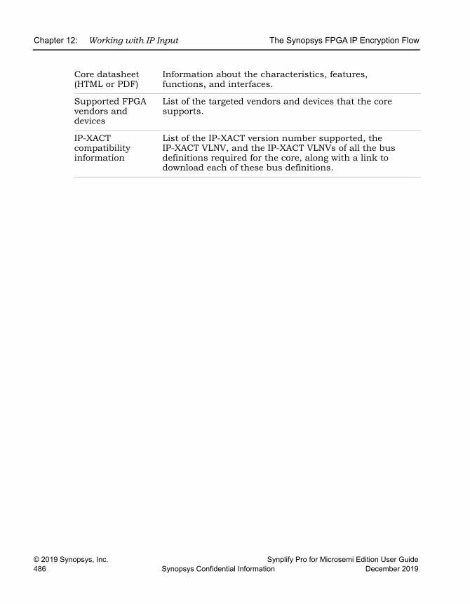
LO
Chapter 12: Working with IP Input The Synopsys FPGA IP Encryption Flow
© 2019 Synopsys, Inc. Synplify Pro for Microsemi Edition User Guide486 Synopsys Confidential Information December 2019
Core datasheet (HTML or PDF)
Information about the characteristics, features, functions, and interfaces.
Supported FPGA vendors and devices
List of the targeted vendors and devices that the core supports.
IP-XACT compatibility information
List of the IP-XACT version number supported, the IP-XACT VLNV, and the IP-XACT VLNVs of all the bus definitions required for the core, along with a link to download each of these bus definitions.
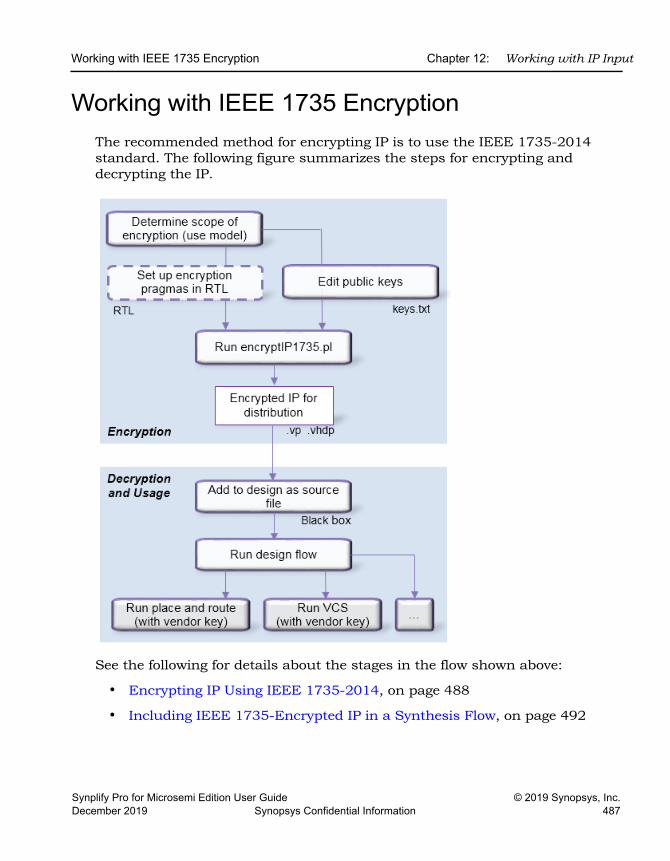
Working with IEEE 1735 Encryption Chapter 12: Working with IP Input
Synplify Pro for Microsemi Edition User Guide © 2019 Synopsys, Inc.December 2019 Synopsys Confidential Information 487
Working with IEEE 1735 EncryptionThe recommended method for encrypting IP is to use the IEEE 1735-2014 standard. The following figure summarizes the steps for encrypting and decrypting the IP.
See the following for details about the stages in the flow shown above:
• Encrypting IP Using IEEE 1735-2014, on page 488
• Including IEEE 1735-Encrypted IP in a Synthesis Flow, on page 492
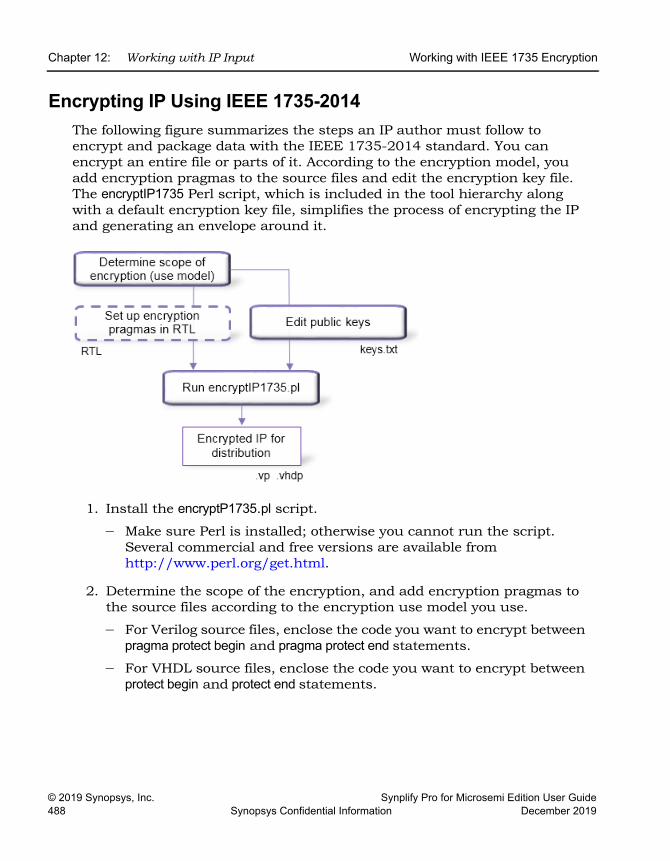
LO
Chapter 12: Working with IP Input Working with IEEE 1735 Encryption
© 2019 Synopsys, Inc. Synplify Pro for Microsemi Edition User Guide488 Synopsys Confidential Information December 2019
Encrypting IP Using IEEE 1735-2014The following figure summarizes the steps an IP author must follow to encrypt and package data with the IEEE 1735-2014 standard. You can encrypt an entire file or parts of it. According to the encryption model, you add encryption pragmas to the source files and edit the encryption key file. The encryptIP1735 Perl script, which is included in the tool hierarchy along with a default encryption key file, simplifies the process of encrypting the IP and generating an envelope around it.
1. Install the encryptP1735.pl script.
– Make sure Perl is installed; otherwise you cannot run the script. Several commercial and free versions are available from http://www.perl.org/get.html.
2. Determine the scope of the encryption, and add encryption pragmas to the source files according to the encryption use model you use.
– For Verilog source files, enclose the code you want to encrypt between pragma protect begin and pragma protect end statements.
– For VHDL source files, enclose the code you want to encrypt between protect begin and protect end statements.
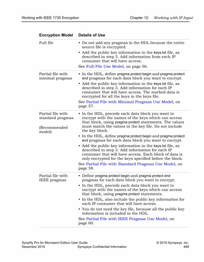
Working with IEEE 1735 Encryption Chapter 12: Working with IP Input
Synplify Pro for Microsemi Edition User Guide © 2019 Synopsys, Inc.December 2019 Synopsys Confidential Information 489
Encryption Model Details of Use
Full file • Do not add any pragmas in the HDL because the entire source file is encrypted.
• Add the public key information in the keys.txt file, as described in step 3. Add information from each IP consumer that will have access.
See Full-File Use Model, on page 56.
Partial file with minimal pragmas
• In the HDL, define pragma protect begin and pragma protect end pragmas for each data block you want to encrypt.
• Add the public key information in the keys.txt file, as described in step 3. Add information for each IP consumer that will have access. The marked data is encrypted for all the keys in the keys file.
See Partial File with Minimal Pragmas Use Model, on page 57.
Partial file with standard pragmas
(Recommended model)
• In the HDL, precede each data block you want to encrypt with the names of the keys which can access that block, using pragma protect statements. The values must match the values in the key file. Do not include the key block.
• In the HDL, define pragma protect begin and pragma protect end pragmas for each data block you want to encrypt.
• Add the public key information in the keys.txt file, as described in step 3. Add information for each IP consumer that will have access. Each block of data is only encrypted for the keys specified before the block.
See Partial File with Standard Pragmas Use Model, on page 58.
Partial file with IEEE pragmas
• Define pragma protect begin and pragma protect end pragmas for each data block you want to encrypt.
• In the HDL, precede each data block you want to encrypt with the names of the keys which can access that block, using pragma protect statements.
• In the HDL, also include the public key information for each IP consumer that will have access.
• You do not need the key file, because all the public key information is included in the HDL.
See Partial File with IEEE Pragmas Use Model, on page 60.
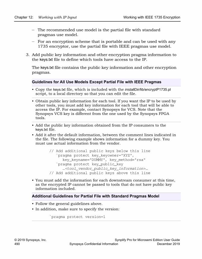
LO
Chapter 12: Working with IP Input Working with IEEE 1735 Encryption
© 2019 Synopsys, Inc. Synplify Pro for Microsemi Edition User Guide490 Synopsys Confidential Information December 2019
– The recommended use model is the partial file with standard pragmas use model.
– For an encryption scheme that is portable and can be used with any 1735 encryptor, use the partial file with IEEE pragmas use model.
3. Add public key information and other encryption pragma information to the keys.txt file to define which tools have access to the IP.
The keys.txt file contains the public key information and other encryption pragmas.
Guidelines for All Use Models Except Partial File with IEEE Pragmas
• Copy the keys.txt file, which is included with the installDir/lib/encryptP1735.pl script, to a local directory so that you can edit the file.
• Obtain public key information for each tool. If you want the IP to be used by other tools, you must add key information for each tool that will be able to access the IP. For example, contact Synopsys for VCS. Note that the Synopsys VCS key is different from the one used by the Synopsys FPGA tools.
• Add the public key information obtained from the IP consumers to the keys.txt file.
• Add it after the default information, between the comment lines indicated in the file. The following example shows information for a dummy key. You must use actual information from the vendor.
// Add additional public keys below this line`pragma protect key_keyowner="XYZ",
key_keyname="DUMMY", key_method="rsa"`pragma protect key_public_key
…<tool_vendor_public_key_information>…// Add additional public keys above this line
• You must add the information for each downstream consumer at this time, as the encrypted IP cannot be passed to tools that do not have public key information included.
Additional Guidelines for Partial File with Standard Pragmas Model
• Follow the general guidelines above. • In addition, make sure to specify the version:
`pragma protect version=1
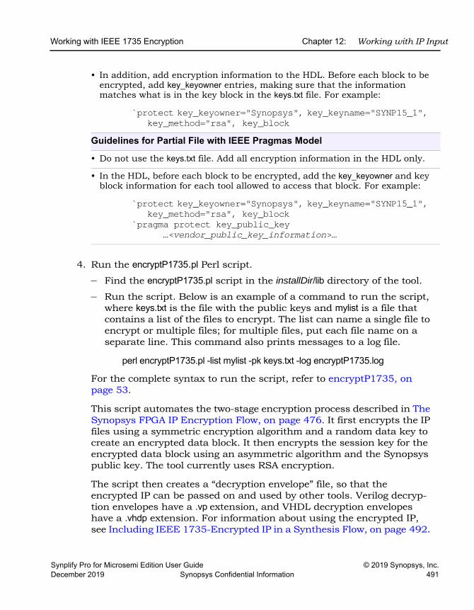
Working with IEEE 1735 Encryption Chapter 12: Working with IP Input
Synplify Pro for Microsemi Edition User Guide © 2019 Synopsys, Inc.December 2019 Synopsys Confidential Information 491
4. Run the encryptP1735.pl Perl script.
– Find the encryptP1735.pl script in the installDir/lib directory of the tool.
– Run the script. Below is an example of a command to run the script, where keys.txt is the file with the public keys and mylist is a file that contains a list of the files to encrypt. The list can name a single file to encrypt or multiple files; for multiple files, put each file name on a separate line. This command also prints messages to a log file.
perl encryptP1735.pl -list mylist -pk keys.txt -log encryptP1735.log
For the complete syntax to run the script, refer to encryptP1735, on page 53.
This script automates the two-stage encryption process described in The Synopsys FPGA IP Encryption Flow, on page 476. It first encrypts the IP files using a symmetric encryption algorithm and a random data key to create an encrypted data block. It then encrypts the session key for the encrypted data block using an asymmetric algorithm and the Synopsys public key. The tool currently uses RSA encryption.
The script then creates a “decryption envelope” file, so that the encrypted IP can be passed on and used by other tools. Verilog decryp-tion envelopes have a .vp extension, and VHDL decryption envelopes have a .vhdp extension. For information about using the encrypted IP, see Including IEEE 1735-Encrypted IP in a Synthesis Flow, on page 492.
• In addition, add encryption information to the HDL. Before each block to be encrypted, add key_keyowner entries, making sure that the information matches what is in the key block in the keys.txt file. For example:
`protect key_keyowner="Synopsys", key_keyname="SYNP15_1", key_method="rsa", key_block
Guidelines for Partial File with IEEE Pragmas Model
• Do not use the keys.txt file. Add all encryption information in the HDL only.
• In the HDL, before each block to be encrypted, add the key_keyowner and key block information for each tool allowed to access that block. For example:
`protect key_keyowner="Synopsys", key_keyname="SYNP15_1", key_method="rsa", key_block
`pragma protect key_public_key…<vendor_public_key_information>…
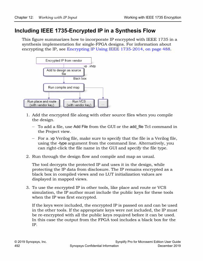
LO
Chapter 12: Working with IP Input Working with IEEE 1735 Encryption
© 2019 Synopsys, Inc. Synplify Pro for Microsemi Edition User Guide492 Synopsys Confidential Information December 2019
Including IEEE 1735-Encrypted IP in a Synthesis FlowThis figure summarizes how to incorporate IP encrypted with IEEE 1735 in a synthesis implementation for single-FPGA designs. For information about encrypting the IP, see Encrypting IP Using IEEE 1735-2014, on page 488.
1. Add the encrypted file along with other source files when you compile the design.
– To add a file, use Add File from the GUI or the add_file Tcl command in the Project view.
– For a .vp Verilog file, make sure to specify that the file is a Verilog file, using the -type argument from the command line. Alternatively, you can right-click the file name in the GUI and specify the file type.
2. Run through the design flow and compile and map as usual.
The tool decrypts the protected IP and uses it in the design, while protecting the IP data from disclosure. The IP remains encrypted as a black box in compiled views and no LUT initialization values are displayed in mapped views.
3. To use the encrypted IP in other tools, like place and route or VCS simulation, the IP author must include the public keys for these tools when the IP was first encrypted.
If the keys were included, the encrypted IP is passed on and can be used in the other tools. If the appropriate keys were not included, the IP must be re-encrypted with all the public keys required before it can be used. In this case the output from the FPGA tool includes a black box for the IP.
Encrypting IP Using OpenIP (encryptIP) Chapter 12: Working with IP Input
Synplify Pro for Microsemi Edition User Guide © 2019 Synopsys, Inc.December 2019 Synopsys Confidential Information 493
Encrypting IP Using OpenIP (encryptIP)OpenIP encryption is a scheme developed by Synopsys and donated to the standards body. You can use it to encrypt modules or components, which can then be downloaded for evaluation or use by the Synopsys FPGA user. Synopsys provides a script (encryptIP) to encrypt your data with this scheme. The script is run with the encryptIP Perl command. For details, see Encrypting IP with the OpenIP Scheme, on page 493.
Encrypting IP with the OpenIP SchemeSynopsys provides a script to encrypt your data with the OpenIP scheme. The encryptIP Perl script is provided to IP vendors who wish to provide IP to synthesis users.The script automates the two-stage encryption process described in the Synopsys FPGA IP methodology (The Synopsys FPGA IP Encryption Flow, on page 476). The following procedure shows you how to encrypt your data with the encryptIP script.
Do the following to use the encryptIP script to encrypt IP:
1. Install the encryptIP Perl script.
– Install Perl on your machine. You cannot run the script if you do not have Perl installed.
2. Make sure that the encryptIP script specifies the decryption key and the matching key length:
– Specify the symmetric data decryption key with the -k option. Optionally, you can also specify a symmetric encryption key in hexadecimal format with the -kx option.
– Make sure you specify the right key length for the encryption algorithm with the -c option. For example, TEST1234 becomes a 64-bit key, so you specify the des-cbc algorithm.
See encryptP1735, on page 53 in the FPGA Synthesis Command Refer-ence for full details of the encryptip syntax.
3. Make sure you specify the appropriate output method (-om) when you run the script.
This is important because the output method (-om) determines what is encrypted to the user. If the output method is plaintext for example, the
LO
Chapter 12: Working with IP Input Encrypting IP Using OpenIP (encryptIP)
© 2019 Synopsys, Inc. Synplify Pro for Microsemi Edition User Guide494 Synopsys Confidential Information December 2019
entire output netlist is unencrypted, and includes the IP netlist in an unencrypted and readable form. See Specifying the Script Output Method for OpenIP Encryption, on page 494 for more information.
The script encrypts the IP with the standard symmetric encryption algorithm you specified, and produces a data_block. The data key used for encrypting the HDL is then encrypted with an asymmetric algorithm and the Synopsys public key, and produces a key_block. The data_block and the key_block are combined with the appropriate pragmas for the flow being used, and the script creates an encrypted HDL file. For a detailed figure, see Encryption and Decryption, on page 477.
All other output files from synthesis, including srm, srd, and srs files, are encrypted using the same encryption method specified for the input to synthesis. Output constraints are not encrypted.
4. Run the encryptIP script on each RTL file you want to encrypt.
The following example encrypts the Verilog plain_ip.v file into an encrypted file called protected_ip.v, using AES128-cbc encryption. The session key is MY_AES_SAMPLEKEY. See encryptIP, on page 50 in the FPGA Synthesis Command Reference for details about the syntax and required parameters.
perl encryptIP -in plain_ip.v -out protected_ip.v -c aes128-cbc -k MY_AES_SAMPLEKEY -bd 16OCT2007 -om plaintext -v
First, it encrypts the IP files using a symmetric encryption algorithm and a random session or data key. This creates an encrypted data block. Next, it encrypts the session key for the encrypted data block using an asymmetric algorithm and the public key for the FPGA software and any other public keys you might have added for other tools.
5. Check the encrypted RTL file to make sure that there is only one key block present.
Specifying the Script Output Method for OpenIP EncryptionYou can control access to the IP encrypted with OpenIP by setting the appro-priate output method. You specify the output method using the -om param-eter, as described in encryptIP, on page 50 in the FPGA Synthesis Command Reference Manual.
Encrypting IP Using OpenIP (encryptIP) Chapter 12: Working with IP Input
Synplify Pro for Microsemi Edition User Guide © 2019 Synopsys, Inc.December 2019 Synopsys Confidential Information 495
The output method mainly affects the output netlist. The following are guide-lines for setting the output method for the encryptIP script, and detail the effects of different settings:
1. When using the encrypyIP script, set -om to persistent_key:– If you have an agreement in place with Synopsys and want the output
netlist to be encrypted
2. Set -om to plaintext in the following cases:
– If you want to allow the IP to be incorporated in a logic synthesis design
Setting the output method to plaintext allows the tool to synthesize, run gate-level simulations, place and route, and implement an FPGA (that includes the IP) on a board.
– If you want the IP to be freely optimized by the synthesis tools
Although IP cores are already optimized, the synthesis tools can effect additional optimizations based on the design context in which it will be used. When the synthesis tool is allowed to optimize the IP, it can prune away IP logic that is unused or unnecessary in the current design context. Or take the case where the output of an instantiated IP core is timing-critical because it drives hundreds of user loads. If the synthesis tool can freely optimize, it can replicate sources within the core and fix the problem.
3. To let the IP be incorporated in a logic synthesis design, set -om to plaintext or blackbox.
Setting the output method to plaintext allows the tool to synthesize, run gate-level simulations, place and route, and implement an FPGA (that includes the IP) on a board. Setting the output method to blackbox does not allow the tool to run gate-level simulations or place and route the IP, because it only uses the port and connectivity information.
4. If you have set -om to plaintext and you want to specify individual cores as white boxes, set the syn_macro directive to 1 on the view for the IP.
Note that you must set this on the view, not the instance. When this is set, the tool treats the IP as a white box and only uses the timing and connection information from the IP. The synthesis tool maintains the IP boundary and only trims unused logic inside the IP.
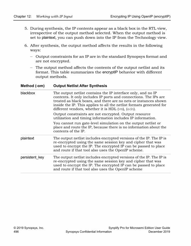
LO
Chapter 12: Working with IP Input Encrypting IP Using OpenIP (encryptIP)
© 2019 Synopsys, Inc. Synplify Pro for Microsemi Edition User Guide496 Synopsys Confidential Information December 2019
5. During synthesis, the IP contents appear as a black box in the RTL view, irrespective of the output method selected. When the output method is set to plaintext, you can push down into the IP from the Technology view.
6. After synthesis, the output method affects the results in the following ways:
– Output constraints for an IP are in the standard Synopsys format and are not encrypted.
– The output method affects the contents of the output netlist and its format. This table summarizes the encryptIP behavior with different output methods.
Method (-om) Output Netlist After Synthesis
blackbox The output netlist contains the IP interface only, and no IP contents. It only includes IP ports and connections. The IPs are treated as black boxes, and there are no nets or instances shown inside the IP. This applies to all the netlist formats generated for different vendors, whether it is HDL (vm), (edn).Output constraints are not encrypted. Output resource utilization and timing information includes IP information.You cannot run gate-level simulation on the output netlist or place and route the IP, because there is no information about the contents of the IP.
plaintext The output netlist includes encrypted versions of the IP. The IP is re-encrypted using the same session key and cipher that was used to encrypt the IP. The encrypted IP can be passed to place and route if that tool also uses the OpenIP scheme.
persistent_key The output netlist includes encrypted versions of the IP. The IP is re-encrypted using the same session key and cipher that was used to encrypt the IP. The encrypted IP can be passed to place and route if that tool also uses the OpenIP scheme
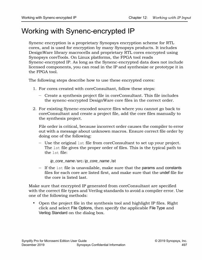
Working with Synenc-encrypted IP Chapter 12: Working with IP Input
Synplify Pro for Microsemi Edition User Guide © 2019 Synopsys, Inc.December 2019 Synopsys Confidential Information 497
Working with Synenc-encrypted IPSynenc encryption is a proprietary Synopsys encryption scheme for RTL cores, and is used for encryption by many Synopsys products. It includes DesignWare library macrocells and proprietary RTL cores encrypted using Synopsys coreTools. On Linux platforms, the FPGA tool reads Synenc-encrypted IP. As long as the Synenc-encrypted data does not include licensed components, you can read in the IP and synthesize or prototype it in the FPGA tool.
The following steps describe how to use these encrypted cores:
1. For cores created with coreConsultant, follow these steps:
– Create a synthesis project file in coreConsultant. This file includes the synenc-encrypted DesignWare core files in the correct order.
2. For existing Synenc-encoded source files where you cannot go back to coreConsultant and create a project file, add the core files manually to the synthesis project.
File order is critical, because incorrect order causes the compiler to error out with a message about unknown macros. Ensure correct file order by doing one of the following:
– Use the original lst file from coreConsultant to set up your project. The lst file gives the proper order of files. This is the typical path to the lst file:
ip_core_name/src/ip_core_name.lst
– If the lst file is unavailable, make sure that the params and constants files for each core are listed first, and make sure that the undef file for the core is listed last.
Make sure that encrypted IP generated from coreConsultant are specified with the correct file types and Verilog standards to avoid a compiler error. Use one of the following methods:
• Open the project file in the synthesis tool and highlight IP files. Right click and select File Options, then specify the applicable File Type and Verilog Standard on the dialog box.
LO
Chapter 12: Working with IP Input Working with Synenc-encrypted IP
© 2019 Synopsys, Inc. Synplify Pro for Microsemi Edition User Guide498 Synopsys Confidential Information December 2019
All files are automatically updated in the project.
• Also, you can manually open the project file and edit the encrypted file with the proper file type and Verilog standard. For example, if the top.v file uses the Verilog 2001 standard specify the following:
add_file -vlog_std v2001 "./top.v"
Similarly, specify the following for an encrypted SystemVerilog top.sv file:
add_file -verilog -vlog_std sysv "./top.sv"
Using Hyper Source Chapter 12: Working with IP Input
Synplify Pro for Microsemi Edition User Guide © 2019 Synopsys, Inc.December 2019 Synopsys Confidential Information 499
Using Hyper SourceHyper source is a useful feature that lets you prototype ASIC designs that use one or more FPGAs. You can also use it to validate and debug the HDL for IP designs. See the following for details:
• Using Hyper Source for Prototyping, on page 499
• Using Hyper Source for IP Designs, on page 499
• Threading Signals Through the Design Hierarchy of an IP, on page 500
Using Hyper Source for PrototypingFor prototyping, use Hyper Source to efficiently thread nets across multiple modules to the top-level design to support Time Domain Multiplexing (TDM).
You can also use it to easily replace an ASIC RAM with an FPGA RAM. Follow these guidelines to replace an ASIC RAM with an FPGA RAM:
1. Change the HDL for the RAM instantiation.
2. Add an extra clock signal to all the module interfaces.
Hyper source reduces the number of modified HDL modules to two, one for the RAM and one for the top level.
Using Hyper Source for IP DesignsFor IP designs, Hyper Source is useful for validating and debugging the HDL without directly modifying it. After the HDL has been fully tested with complete QoR results, use Hyper Source to debug, as described in the following cases:
• Add some instrumentation logic that is not part of the original design, such as a cache profiler that counts cache misses or bus monitor that might count statistics about bus contention. The cache or bus might be buried deep inside the HDL; accessing the cache or the bus means ports might need to be added through several levels of hierarchy in the HDL. The instrumentation logic can be included anywhere in the design, so you can use hyper source and hyper connect to easily thread the neces-sary connections during synthesis.
LO
Chapter 12: Working with IP Input Using Hyper Source
© 2019 Synopsys, Inc. Synplify Pro for Microsemi Edition User Guide500 Synopsys Confidential Information December 2019
• Insert other hyper sourcing inside the IP to probe, monitor, and verify correct operation of known signals within the IP.
Threading Signals Through the Design Hierarchy of an IPUse this mechanism to thread a signal through the design hierarchy of a user IP. This signal can be threaded to a top-level port or signal. This works even if the Verilog or VHDL is compiled separately. The tool automatically adds ports and signals between the source and the connection. Otherwise, these connec-tions must be manually added to the HDL code.
The following procedure describes a method for using hyper source, using the example HDL shown in Hyper Source Example, on page 501.
1. Define how to connect to the signal source. The following apply to this example:
– Signal syn_hyper_source (in1) module defines the source, with a width of 1.
– The tag name "tag_name" is the global name for the hyper source.
2. Define how to access the hyper source which drives the local signal or port. The following apply to this example:
– Signal syn_hyper_connect (out1) module defines the connection. The signal width of 1 matches the source.
– Tag name can be the global name or the instance path to the hyper source.
3. In this hierarchical design, note the following about hyper source:
– Applies to the module lower_module.– Signal syn_hyper_source my_source(din) module is defined for the source
with a width of 8.
– The tag name of "probe_sig" must match the name used in the hyper connect block to thread the signal properly.
4. In this hierarchical design, note the following about the hyper connect:
– Applies to the top-level module top, but can be any level of hierarchy.
– Signal syn_hyper_connect connect_block (probe) module is defined for the connection with a width of 8.
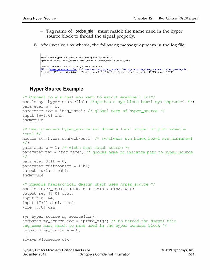
Using Hyper Source Chapter 12: Working with IP Input
Synplify Pro for Microsemi Edition User Guide © 2019 Synopsys, Inc.December 2019 Synopsys Confidential Information 501
– Tag name of "probe_sig" must match the name used in the hyper source block to thread the signal properly.
5. After you run synthesis, the following message appears in the log file:
Hyper Source Example/* Connect to a signal you want to export example : in1*/module syn_hyper_source(in1) /*synthesis syn_black_box=1 syn_noprune=1 */;parameter w = 1;parameter tag = "tag_name"; /* global name of hyper_source */input [w-1:0] in1;endmodule
/* Use to access hyper_source and drive a local signal or port example :out1 */module syn_hyper_connect(out1) /* synthesis syn_black_box=1 syn_noprune=1 */;parameter w = 1; /* width must match source */parameter tag = "tag_name"; /* global name or instance path to hyper_source */parameter dflt = 0;parameter mustconnect = 1'b1;output [w-1:0] out1;endmodule
/* Example hierarchical design which uses hyper_source */module lower_module (clk, dout, din1, din2, we);output reg [7:0] dout;input clk, we;input [7:0] din1, din2;wire [7:0] din;
syn_hyper_source my_source(din);defparam my_source.tag = "probe_sig"; /* to thread the signal thistag_name must match to name used in the hyper connect block */defparam my_source.w = 8;
always @(posedge clk)
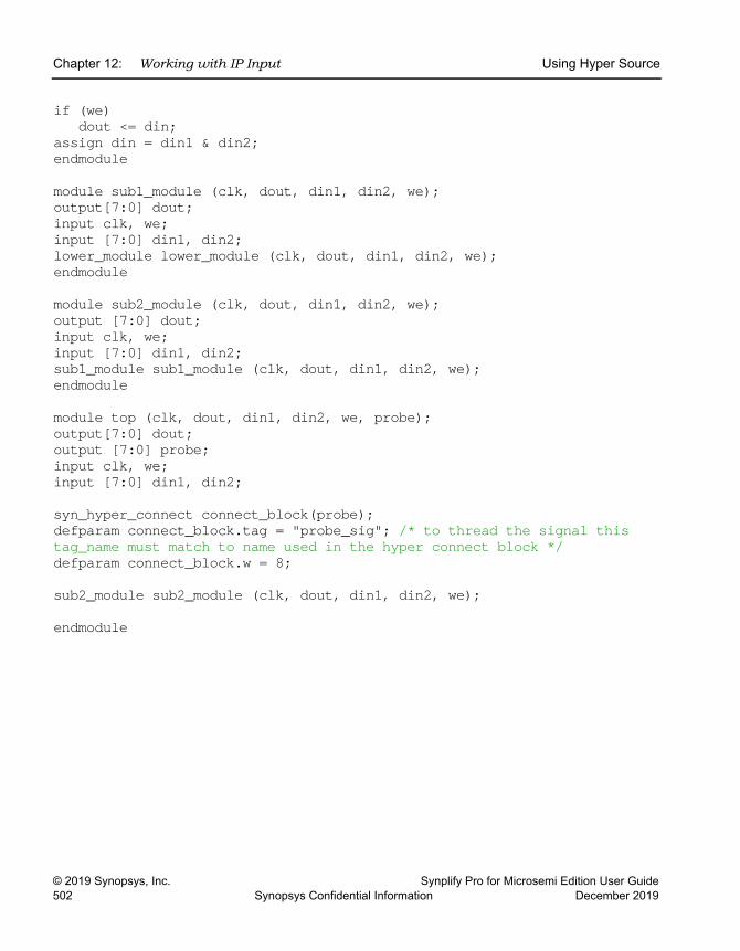
LO
Chapter 12: Working with IP Input Using Hyper Source
© 2019 Synopsys, Inc. Synplify Pro for Microsemi Edition User Guide502 Synopsys Confidential Information December 2019
if (we)dout <= din;
assign din = din1 & din2;endmodule
module sub1_module (clk, dout, din1, din2, we);output[7:0] dout;input clk, we;input [7:0] din1, din2;lower_module lower_module (clk, dout, din1, din2, we);endmodule
module sub2_module (clk, dout, din1, din2, we);output [7:0] dout;input clk, we;input [7:0] din1, din2;sub1_module sub1_module (clk, dout, din1, din2, we);endmodule
module top (clk, dout, din1, din2, we, probe);output[7:0] dout;output [7:0] probe;input clk, we;input [7:0] din1, din2;
syn_hyper_connect connect_block(probe);defparam connect_block.tag = "probe_sig"; /* to thread the signal this tag_name must match to name used in the hyper connect block */defparam connect_block.w = 8;
sub2_module sub2_module (clk, dout, din1, din2, we);
endmodule
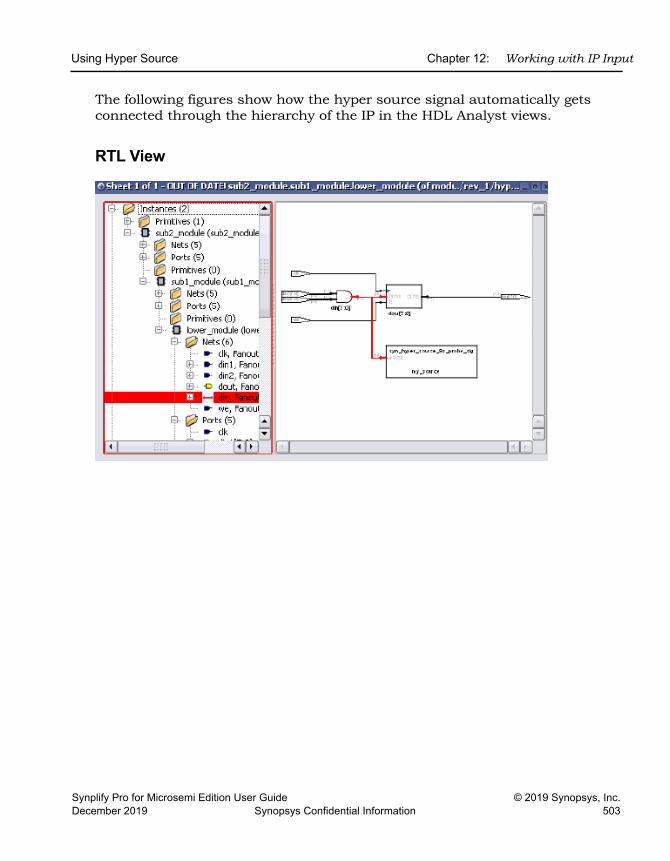
Using Hyper Source Chapter 12: Working with IP Input
Synplify Pro for Microsemi Edition User Guide © 2019 Synopsys, Inc.December 2019 Synopsys Confidential Information 503
The following figures show how the hyper source signal automatically gets connected through the hierarchy of the IP in the HDL Analyst views.
RTL View
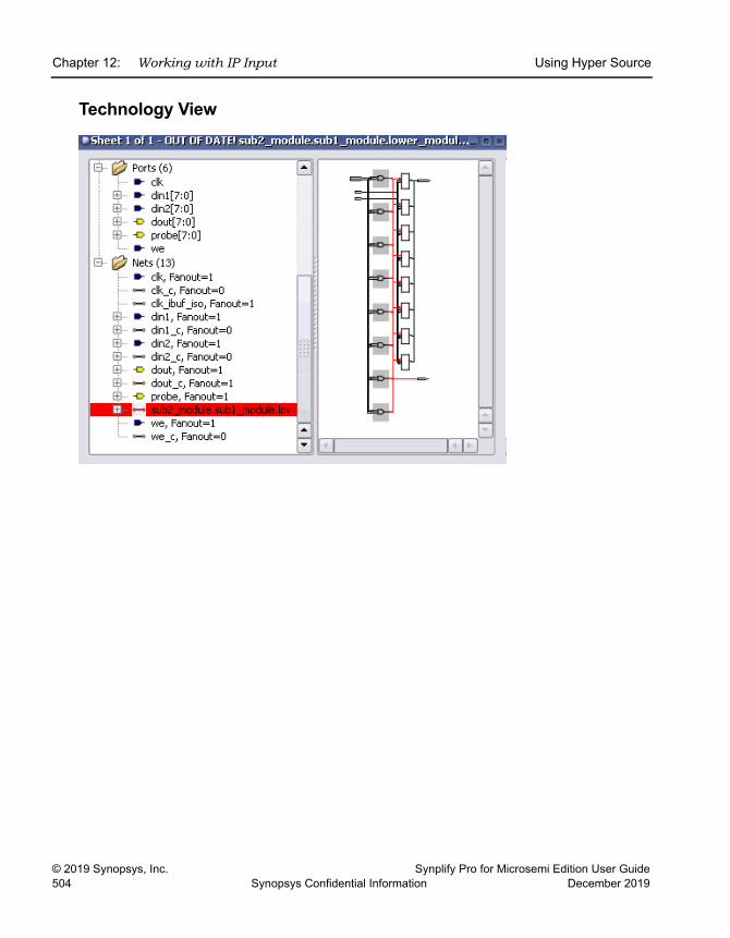
LO
Chapter 12: Working with IP Input Using Hyper Source
© 2019 Synopsys, Inc. Synplify Pro for Microsemi Edition User Guide504 Synopsys Confidential Information December 2019
Technology View
Synplify Pro for Microsemi Edition User Guide © 2019 Synopsys, Inc.December 2019 Synopsys Confidential Information 505
C H A P T E R 1 3
Optimizing Processes for Productivity
This chapter covers topics that can help the advanced user improve produc-tivity and interoperability with other tools. It includes the following:
• Using Batch Mode, on page 506
• Working with Tcl Scripts and Commands, on page 512
• Automating Flows with synhooks.tcl, on page 525
• Invoking Third-Party Vendor Tools, on page 530
LO
Chapter 13: Optimizing Processes for Productivity Using Batch Mode
© 2019 Synopsys, Inc. Synplify Pro for Microsemi Edition User Guide506 Synopsys Confidential Information December 2019
Using Batch ModeBatch mode is a command-line mode in which you run scripts from the command line. You might want to set up multiple synthesis runs with a batch script. You can run in batch mode if you have a floating license, but not with a node-locked license.
Batch scripts are in Tcl format. For more information about Tcl syntax and commands, see Working with Tcl Scripts and Commands, on page 512.
This section describes the following operations:
• Running Batch Mode on a Project File, on page 506
• Running Batch Mode with a Tcl Script, on page 507
• Queuing Licenses, on page 508
Running Batch Mode on a Project FileUse this procedure to run batch mode if you already have a project file set up. You can also run batch mode from a Tcl script, as described in Running Batch Mode with a Tcl Script, on page 507.
1. Make sure you have a project file (prj) set up with the implementation options. For more information about creating this Tcl file, see Creating a Tcl Synthesis Script, on page 515.
2. From a command prompt, go to the directory where the project files are located, and type one of the following, depending on which product you are using:
synplify_pro -batch project_file_name.prjThe software runs synthesis in batch mode. Use absolute path names or a variable instead of a relative path name.
If the -tclcmd switch is used, synthesis will not automatically run. To make synthesis run, project -run must be added:
synplify_pro -tcl myproj.prj -tclcmd "project -run" The -tclcmd switch specifies the tcl commands to be executed before synthesis starts. To run a constraint check before synthesis:
Using Batch Mode Chapter 13: Optimizing Processes for Productivity
Synplify Pro for Microsemi Edition User Guide © 2019 Synopsys, Inc.December 2019 Synopsys Confidential Information 507
synplify_pro -tcl myproj.prj -tclcmd "project -run constraint_-check"The -tclcmd switch also allows the synthesis results path to be changed.
synplify_pro -tcl "D:/tests/myproj.prj" -tclcmd "set_option -result_file \"./impl1/test.edf\"; project -run"The software returns the following codes after the batch run:
0 - OK2 - logical error3 - startup failure4 - licensing failure5 - batch not available6 - duplicate-user error7 - project-load error8 - command-line error9 - Tcl-script error20 - graphic-resource error21 - Tcl-initialization error22 - job-configuration error23 - parts error24 - product-configuration error25 - multiple top levels
3. If there are errors in the source files, check the standard output for messages. On Linux systems, this is generally the monitor; on Windows systems, it is the stdout.log file.
4. After synthesis, check the resultFile.srr log file for error messages about the run.
Running Batch Mode with a Tcl ScriptThe following procedure shows you how to create a Tcl batch script for running synthesis. If you already have a project file set up, use the procedure described in Running Batch Mode on a Project File, on page 506.
1. Create a Tcl batch script. See Creating a Tcl Synthesis Script, on page 515 for details.
2. Save the file with a tcl extension to the directory that contains your source files and other project files.
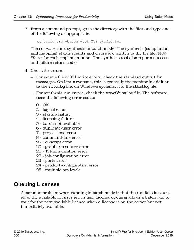
LO
Chapter 13: Optimizing Processes for Productivity Using Batch Mode
© 2019 Synopsys, Inc. Synplify Pro for Microsemi Edition User Guide508 Synopsys Confidential Information December 2019
3. From a command prompt, go to the directory with the files and type one of the following as appropriate:
synplify_pro -batch -tcl Tcl_script.tclThe software runs synthesis in batch mode. The synthesis (compilation and mapping) status results and errors are written to the log file result-File.srr for each implementation. The synthesis tool also reports success and failure return codes.
4. Check for errors.
– For source file or Tcl script errors, check the standard output for messages. On Linux systems, this is generally the monitor in addition to the stdout.log file; on Windows systems, it is the stdout.log file.
– For synthesis run errors, check the resultFile.srr log file. The software uses the following error codes:
0 - OK2 - logical error3 - startup failure4 - licensing failure5 - batch not available6 - duplicate-user error7 - project-load error8 - command-line error9 - Tcl-script error20 - graphic-resource error21 - Tcl-initialization error22 - job-configuration error23 - parts error24 - product-configuration error25 - multiple top levels
Queuing LicensesA common problem when running in batch mode is that the run fails because all of the available licenses are in use. License queuing allows a batch run to wait for the next available license when a license is on the server but not immediately available.
Using Batch Mode Chapter 13: Optimizing Processes for Productivity
Synplify Pro for Microsemi Edition User Guide © 2019 Synopsys, Inc.December 2019 Synopsys Confidential Information 509
You can specify either blocking or non-blocking queuing. With blocking-style queuing, the tool waits until a license becomes available; with non-blocking-style queuing, the tool waits the specified length of time for a license to become available.
For details, see the following:
• Queuing Considerations, on page 509
• Queuing Licenses, on page 510
Queuing ConsiderationsConsider these points when using queuing:
• A blocking-style queuing is used; license checkout does not exit until a license becomes available.
• There is no maximum wait time; once initiated, the tool can wait indefi-nitely for a license.
• If the server shuts down while the tool is waiting, a checkout failure is reported.
• When two licenses are required, queuing waits only until the first license becomes available (and not the second) to avoid holding a license unnec-essarily.
LO
Chapter 13: Optimizing Processes for Productivity Using Batch Mode
© 2019 Synopsys, Inc. Synplify Pro for Microsemi Edition User Guide510 Synopsys Confidential Information December 2019
Queuing LicensesThe following procedure describes how to specify blocking-style or non-blocking style queuing for synthesis licenses. You can specify the licensed features for queuing with an environment variable or directly in batch mode.
1. Specify the list of licensed features you want to queue, using either of the following methods:
– Set the toolName_LICENSE_TYPE environment variable to the features you want. For example:
SYNPLIFYPRO_LICENSE_TYPE=synplifypro:synplifypromicrosemi– Specify a list of features to wait for using the -batch, -licensetype and
-license_wait options. For example:
synplify_pro -batch -license_wait -licensetypesynplifypro:synplifypromicrosemi myProject.prjSee synplify_pro, on page 141 in the Command Reference for syntax details.
2. To enable blocking-style queuing, do one of the following:
– Set environment variable toolName_LICENSE_WAIT=1 (toolName is the name of the FPGA synthesis tool).
– In batch mode, include a -license_wait command-line argument, as shown in the following examples:
synplify_pro -batch -license_wait Tcl_script.tclsynplify_pro -batch -license_wait projectFilename.prj
With blocking-style queuing enabled, the tool waits until the requested license becomes available. It generates the following message in the stdout.log or the Tcl window:
Waiting for license: toolName3. To enable non-blocking-style queuing, do either of the following:
– Set environment variable toolName_LICENSE_WAIT=waitTime (toolName is the name of the FPGA synthesis tool and waitTime is the maximum wait time in seconds). For example:
SYNPLIFYPRO_LICENSE_WAIT=180
Using Batch Mode Chapter 13: Optimizing Processes for Productivity
Synplify Pro for Microsemi Edition User Guide © 2019 Synopsys, Inc.December 2019 Synopsys Confidential Information 511
The waitTime value determines the maximum wait time, in seconds:
– Include a -license_wait waitTime command-line argument when launching batch mode as shown in the following examples:
synplify_pro -batch -license_wait waitTime Tcl_script.tclsynplify_pro -batch -license_wait waitTime projectFilename.prj
When non-blocking-style queuing is enabled, the tool waits up to the maximum time limit specified for the license to become available. The tool generates the following message in stdout.log or the Tcl window:
Waiting up to n seconds for license: toolName
WaitTime Value Queuing Behavior
Undefined or 0 Queuing off
1 Queuing on; wait indefinitely
>1 Queuing on; wait up to the specified number of seconds
LO
Chapter 13: Optimizing Processes for Productivity Working with Tcl Scripts and Commands
© 2019 Synopsys, Inc. Synplify Pro for Microsemi Edition User Guide512 Synopsys Confidential Information December 2019
Working with Tcl Scripts and CommandsThe software uses extensions to the popular Tcl (Tool Command Language) scripting language to control synthesis and for constraint files. See the following for more information:
• Using Tcl Commands and Scripts, next
• Generating a Job Script, on page 513
• Setting Number of Parallel Jobs, on page 513
• Creating a Tcl Synthesis Script, on page 515
• Using Tcl Variables to Try Different Clock Frequencies, on page 516
• Using Tcl Variables to Try Several Target Technologies, on page 518
• Running Bottom-up Synthesis with a Script, on page 519
• Tcl Script Examples, on page 519
You can also use synhooks Tcl scripts, as described in Automating Flows with synhooks.tcl, on page 525.
Using Tcl Commands and ScriptsThe software uses extensions to the popular Tcl (Tool Command Language) scripting language to control synthesis and for constraint files.
1. To get help on Tcl syntax, do any of the following:
– Refer to the online help (Help->Tcl Help) for general information about Tcl syntax.
– Refer to the Command Reference Manual for information about the synthesis commands.
– Enter help * in the Tcl window for a list of all the Tcl synthesis commands.
– Enter help commandName in the Tcl window to see the syntax for an individual command.
Working with Tcl Scripts and Commands Chapter 13: Optimizing Processes for Productivity
Synplify Pro for Microsemi Edition User Guide © 2019 Synopsys, Inc.December 2019 Synopsys Confidential Information 513
2. To run a Tcl script, do the following:
– Create a Tcl script. Refer to Generating a Job Script, on page 513 and Creating a Tcl Synthesis Script, on page 515.
– Run the Tcl script by either entering source Tcl_scriptfile in the Tcl script window, or by selecting File->Run Tcl Script, selecting the Tcl file, and clicking Open.
The software runs the selected script by executing each command in sequence. For more information about Tcl scripts, refer to the following sections.
Generating a Job ScriptYou can record Tcl commands from the interface and use it to generate job scripts.
1. In the Tcl script window, enter recording -file logfile to write out a Tcl log file.
2. Work through a synthesis session.
The software saves the commands from this session into a Tcl file that you can use as a job script or as a starting point for creating other Tcl files.
For the command syntax, see recording, on page 101 in the Command Refer-ence manual.
Setting Number of Parallel JobsYou can set the maximum number of parallel jobs by setting a variable in the .ini file, by defining a Tcl variable or specifying the maximum number in the GUI.
1. To set the maximum number of parallel jobs in the .ini file, do the following:
– Open the .ini file for the synthesis tool. For example, synplify_pro.ini.– Add the MaxParallelJobs variable to the .ini file, as follows:
[JobSetting]MaxParallelJobs=<n>
LO
Chapter 13: Optimizing Processes for Productivity Working with Tcl Scripts and Commands
© 2019 Synopsys, Inc. Synplify Pro for Microsemi Edition User Guide514 Synopsys Confidential Information December 2019
The tool uses the MaxParallelJobs value from the .ini file as the default for both the UI (Project->Options) and batch mode. This value remains in effect until you reset it in the .ini file or from the GUI, as described in the next step. To locate this configuration and initialization file (.ini), see Input Files, on page 142.
2. To set or change the maximum number of parallel jobs from the GUI, do the following:
– Select Options->Configure Parallel or Compile Point Process from the Project view.
– Set the value you want in the Maximum number of parallel synthesis jobs field, and click OK. This field shows the current .ini value, but you can reset it, and it will remain in effect until you change it again. The value you set is saved to the .ini file.
3. To set a Tcl variable for the maximum number of parallel jobs, do the following:
– Determine where you are going to define the variable. You can do this in the project file, or a Tcl file, or you can type it in the Tcl window. If you specify it in a Tcl file, you must source the file. If you specify it in the Tcl window, the tool does not save the value and it will be lost when you end the current session.
– Specify the max_parallel_jobs variable with the set_option Tcl command:
set_option -max_parallel_jobs value
The tool applies the max_parallel_jobs value specified to all project files and their respective implementations. This is a global option. The maximum number of parallel jobs remains in effect until you specify a new value. This new value takes effect immediately, going forward. However, when you set this option from the Tcl command window, the max_parallel_jobs value is not saved and will be lost when you exit the application.
Working with Tcl Scripts and Commands Chapter 13: Optimizing Processes for Productivity
Synplify Pro for Microsemi Edition User Guide © 2019 Synopsys, Inc.December 2019 Synopsys Confidential Information 515
Creating a Tcl Synthesis ScriptTcl scripts are text files with a tcl extension. You can use the graphic user interface to help you create a Tcl script. Interactive commands that you use actually execute Tcl commands, which are displayed in the Tcl window as they are run. You can copy the command text and paste it into a text file that you build to run as a Tcl script. For example:
add_file prep2.vset_option -technology RTG4set_option -part RT4G150set_option -package CG1657
project -runThe following procedure covers general guidelines for creating a synthesis script.
1. Use a text file editor or select File->New, click the Tcl Script option, and type a name for your Tcl script.
2. Start the script by specifying the project with the project -new command. For an existing project, use project -load project.prj.
3. Add files using the add_file command. The files are added to their appropriate directories based on their file name extensions (see add_file, on page 21 in the Command Reference Manual). Make sure the top-level file is last in the file list:
add_file statemach.vhdadd_file rotate.vhdadd_file memory.vhdadd_file top_level.vhdadd_file design.fdc
For information on constraints and vendor-specific attributes, see Guidelines for Entering and Editing Constraints, on page 136 for details about constraint files.
4. Set the design synthesis controls and the output:
– Use the set_option command for setting implementation options and vendor-specific controls as needed. See the appropriate vendor chapter in the Reference Manual for details.
– Set the output file information with project -result_file and project -log_file.
LO
Chapter 13: Optimizing Processes for Productivity Working with Tcl Scripts and Commands
© 2019 Synopsys, Inc. Synplify Pro for Microsemi Edition User Guide516 Synopsys Confidential Information December 2019
5. Set the file and run options:
– Save the project with a project -save command
– Run the project with a project -run command
– Open the RTL and Technology views:
open_file -rtl_viewopen_file -technology_view
6. Check the syntax.
– Check case (Tcl commands are case-sensitive).
– Start all comments with a hash mark (#).
– Always use a forward slash (/) in directory and pathnames, even on the Windows platform.
Using Tcl Variables to Try Different Clock Frequencies To create a single script for multiple synthesis runs with different clock frequencies, you need to create a Tcl variable for the different settings you want to try. For example, you might want to try different target technologies.
1. To create a variable, use this syntax:
set variable_name {first_option_to_trysecond_option_to_try...}
2. Create a foreach loop that runs through each option in the list, using the appropriate Tcl commands. The following example shows a variable set up to synthesize a design with different frequencies. It also creates a separate log file for each run.
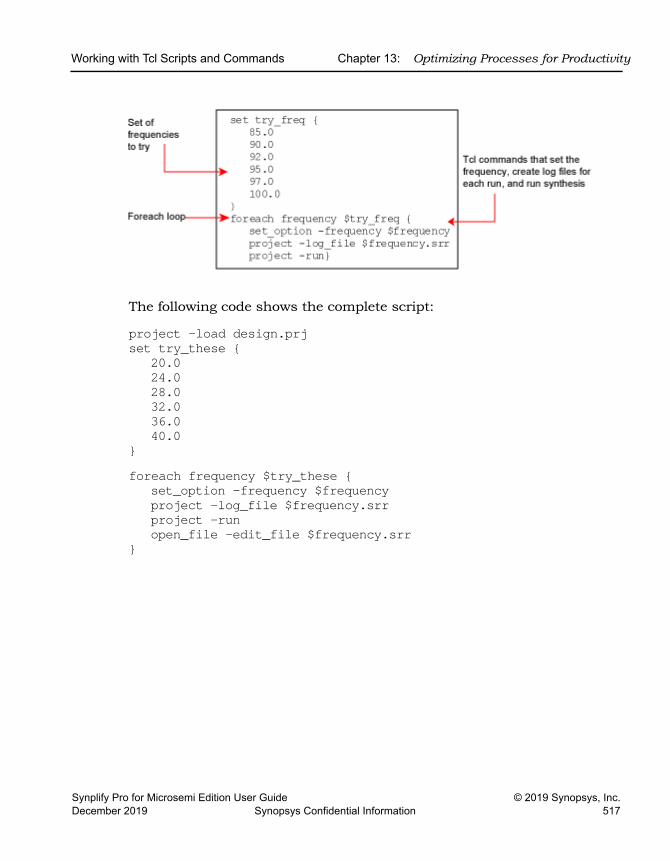
Working with Tcl Scripts and Commands Chapter 13: Optimizing Processes for Productivity
Synplify Pro for Microsemi Edition User Guide © 2019 Synopsys, Inc.December 2019 Synopsys Confidential Information 517
The following code shows the complete script:
project -load design.prjset try_these {
20.024.028.032.036.040.0
}foreach frequency $try_these {
set_option -frequency $frequencyproject -log_file $frequency.srrproject -runopen_file -edit_file $frequency.srr
}
LO
Chapter 13: Optimizing Processes for Productivity Working with Tcl Scripts and Commands
© 2019 Synopsys, Inc. Synplify Pro for Microsemi Edition User Guide518 Synopsys Confidential Information December 2019
Using Tcl Variables to Try Several Target Technologies This technique used here to run multiple synthesis implementations with different target technologies is similar to the one described in Using Tcl Variables to Try Different Clock Frequencies, on page 516. As in that section, you use a variable to define the target technologies you want to try.
1. Create a variable called try_these with a list of the technologies.
set try_these {
RTG4 # list of technologies}
2. Add a foreach loop that creates a new implementation for each technology and opens the RTL view for each implementation.
foreach technology $try_these {impl -addset_option -technology $technologyproject -run -fgopen_file -rtl_view
}The following code example shows the script:
# Open a new project, set frequency, and add files.project -newset_option -frequency 33.3add_file -verilog D:/test/simpletest/prep2_2.v
# Create the Tcl variable to try different target technologies.set try_these
RTG4 # list of technologies}
# Loop through synthesis for each target technology.foreach technology $try_these {
impl -addset_option -technology $technologyproject -run -fgopen_file -rtl_view
}
Working with Tcl Scripts and Commands Chapter 13: Optimizing Processes for Productivity
Synplify Pro for Microsemi Edition User Guide © 2019 Synopsys, Inc.December 2019 Synopsys Confidential Information 519
Running Bottom-up Synthesis with a ScriptTo run bottom-up synthesis, you create Tcl scripts for individual logic blocks, and a script for the top level that reads the other Tcl scripts.
1. Create a Tcl script for each logic block. The Tcl script must synthesize the block. See Creating a Tcl Synthesis Script, on page 515 for details.
2. Create a top-level script that reads the block scripts. Create the script with the with the project -new command.
3. Add the top-level data:
– Add source and constraint files with the add_file command.
– Set the top-level options with the set_option command.
– Set the output file information with project -result_file and project -log_file.
– Save the project with a project -save command.
– Run the project with a project -run command.
4. Save the top-level script, and then run it using this syntax:
source block_script.tcl
When you run this command, the entire design is synthesized, begin-ning with the lower-level logic blocks specified in the sourced files, and then the top level.
Tcl Script ExamplesThis section provides the following examples of Tcl scripts:
• Using Target Technologies, on page 520
• Different Clock Frequency Goals, on page 520
• Setting Options and Timing Constraints, on page 521
• Bottom-up Synthesis, on page 523
LO
Chapter 13: Optimizing Processes for Productivity Working with Tcl Scripts and Commands
© 2019 Synopsys, Inc. Synplify Pro for Microsemi Edition User Guide520 Synopsys Confidential Information December 2019
Using Target Technologies# Run synthesis multiple times without exiting, while trying different# target technologies. View the implementations in the HDL Analyst tool.# Open a new project
project -new# Set the design speed goal to 33.3 MHz.
set_option -frequency 33.3# Add a Verilog file to the source file list.
add_file -verilog "D:/test/simpletest/prep2_2.v"# Create a new Tcl variable, called $try_these, used to synthesize# the design using different target technologies.
set try_these {
RTG4 SMARTFUSION2 IGLOO2 # list of technologies}
# Loop through synthesis for each target technology.foreach technology $try_these {
impl -addset_option -technology $technologyproject -run -fgopen_file -rtl_view
}
Different Clock Frequency Goals # Run synthesis six times on the same design using different clock # frequency goals. Check to see what the speed/area tradeoffs are for # the different timing goals.# Load an existing Project. This Project was created from an # interactive session by saving the Project file, after adding all the# necessary files and setting options in the Project->Options for the# implementation dialog box.
project -load "design.prj"# Create a Tcl variable, called $try_these, that will be used to # synthesize the design with different frequencies.
set try_these {20.0
Working with Tcl Scripts and Commands Chapter 13: Optimizing Processes for Productivity
Synplify Pro for Microsemi Edition User Guide © 2019 Synopsys, Inc.December 2019 Synopsys Confidential Information 521
24.028.032.036.040.0
}# Loop through each frequency, trying each one
foreach frequency $try_these {# Set the frequency from the try_these list
set_option -frequency $frequency# Since I want to keep all Log Files, save each one. Otherwise # the default Log File name "<project_name>.srr" is used, which is# overwritten on each run. Use the name "<$frequency>.srr" obtained from the# $try_these Tcl variable.
project -log_file $frequency.srr# Run synthesis.
project -run# Display the Log File for each synthesis run
open_file -edit_file $frequency.srr}
Setting Options and Timing Constraints# Set a number of options and use timing constraints on the design.# Open a new Project
project -new# Set the target technology, part number, package, and speed grade options.
set_option -technology RTG4set_option -part RT4G150set_option -package CG1657set_option -speed_grade -1
# Load the necessary VHDL files. Add the top-level design last.add_file -vhdl "statemach.vhd"add_file -vhdl "rotate.vhd"add_file -vhdl "memory.vhd"add_file -vhdl "top_level.vhd"
# Add a timing Constraint file and vendor-specific attributes.add_file -constraint "design.fdc"
LO
Chapter 13: Optimizing Processes for Productivity Working with Tcl Scripts and Commands
© 2019 Synopsys, Inc. Synplify Pro for Microsemi Edition User Guide522 Synopsys Confidential Information December 2019
# The top level file ("top_level.vhd") has two different designs, of # which the last is the default entity. Try the first entity (design1)# for this run. In VHDL, you could also specify the top-level architecture# using <entity>.<arch>
set_option -top_module design1# Turn on the Symbolic FSM Compiler to re-encode the state machine # into one-hot.
set_option -symbolic_fsm_compiler true# Set the design frequency.
set_option -frequency 30.0# Save the existing Project to a file. The default synthesis Result File # is named "<project_name>.<ext>".
project -save "design.prj"# Synthesize the existing Project
project -run # Open an RTL View
open_file -rtl_view# Open a Technology View
open_file -technology_view# --------------------------------------------------# This constraint file, "design.fdc," is read by "test3.tcl"# with the add_file -constraint "design.fdc" command. Constraint files # are for timing constraints and synthesis attributes.# --------------------------------------------------# Timing Constraints:# --------------------------------------------------# The default design frequency goal is 30.0 MHz for four clocks. Except# that clk_fast needs to run at 66.0 MHz. Override the 30.0 MHz default# for clk_fast.
create_clock {clk_fast} -freq 66.0# The inputs are delayed by 4 ns
set_input_delay -default 4.0# except for the "sel" signal, which is delayed by 8 ns
set_input_delay {sel} 8.0# The outputs have a delay off-chip of 3.0 ns
set_output_delay -default 3.0# ---------------------------------------------------# Attribute Constraint:
Working with Tcl Scripts and Commands Chapter 13: Optimizing Processes for Productivity
Synplify Pro for Microsemi Edition User Guide © 2019 Synopsys, Inc.December 2019 Synopsys Confidential Information 523
# ---------------------------------------------------# Assign onehot encoding to instance "p1.state{15:0}".
define_attribute {sel} {syn_encoding} {onehot}
Bottom-up Synthesis# Bottom-up synthesis of a large design.# The Source command reads in other Tcl scripts. Each of these scripts does# a compile of one logic block and has its own constraint file.
source "statemach.tcl"source "microproc.tcl"source "handshake.tcl"source "fifo.tcl"source "cherstrp.tcl"
# After synthesizing the individual logic blocks, create a Project for the# top-level design.
project -new # Add the top level VHDL file.
add_file -vhdl top_level.vhd# Add the top level global constraint file.
add_file -constraint top_level.fdc# Set the top level options
set_option -technology RTG4set_option -part RT4G150set_option -speed_grade -1set_option -frequency 50.0set_option -symbolic_fsm_compiler true
# Set the output file informationproject -result_file top_level.edfproject -log_file top_level.srr
# Save the Project to fileproject -save top_level.prj
# Run the Projectproject -run
# Open the top level RTL and Technology Viewsopen_file -rtl_viewopen_file -technology_view
# --------------------------------------------------# This file, "statemach.tcl," is read by "bottom_up.tcl," (the
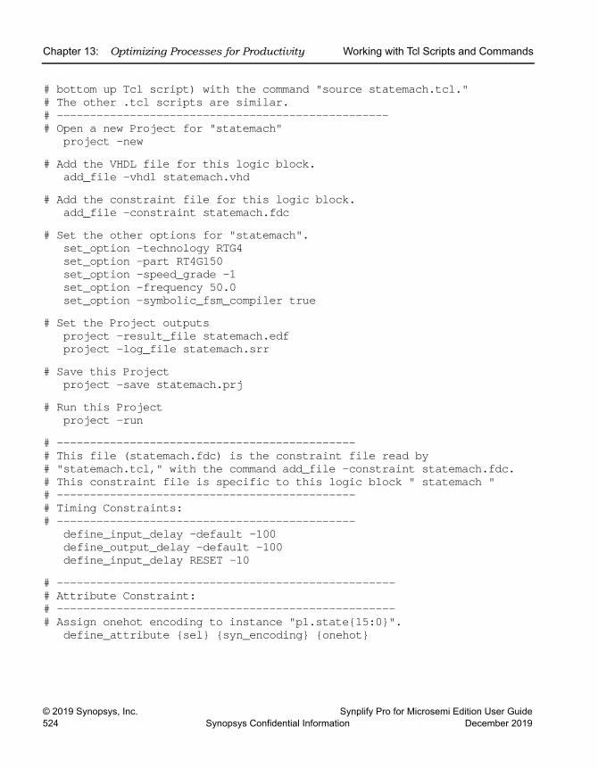
LO
Chapter 13: Optimizing Processes for Productivity Working with Tcl Scripts and Commands
© 2019 Synopsys, Inc. Synplify Pro for Microsemi Edition User Guide524 Synopsys Confidential Information December 2019
# bottom up Tcl script) with the command "source statemach.tcl."# The other .tcl scripts are similar.# --------------------------------------------------# Open a new Project for "statemach"
project -new # Add the VHDL file for this logic block.
add_file -vhdl statemach.vhd# Add the constraint file for this logic block.
add_file -constraint statemach.fdc# Set the other options for "statemach".
set_option -technology RTG4set_option -part RT4G150set_option -speed_grade -1set_option -frequency 50.0set_option -symbolic_fsm_compiler true
# Set the Project outputsproject -result_file statemach.edfproject -log_file statemach.srr
# Save this Projectproject -save statemach.prj
# Run this Projectproject -run
# ---------------------------------------------# This file (statemach.fdc) is the constraint file read by# "statemach.tcl," with the command add_file -constraint statemach.fdc.# This constraint file is specific to this logic block " statemach "# ---------------------------------------------# Timing Constraints:# ---------------------------------------------
define_input_delay -default -100define_output_delay -default -100define_input_delay RESET -10
# ---------------------------------------------------# Attribute Constraint:# ---------------------------------------------------# Assign onehot encoding to instance "p1.state{15:0}".
define_attribute {sel} {syn_encoding} {onehot}
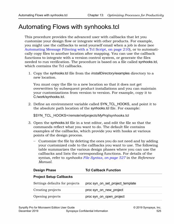
Automating Flows with synhooks.tcl Chapter 13: Optimizing Processes for Productivity
Synplify Pro for Microsemi Edition User Guide © 2019 Synopsys, Inc.December 2019 Synopsys Confidential Information 525
Automating Flows with synhooks.tclThis procedure provides the advanced user with callbacks that let you customize your design flow or integrate with other products. For example, you might use the callbacks to send yourself email when a job is done (see Automating Message Filtering with a Tcl Script, on page 210), or to automati-cally copy files to another location after mapping. You can use the callback functions to integrate with a version control system, or generate the files needed to run verification. The procedure is based on a file called synhooks.tcl, which contains the Tcl callbacks.
1. Copy the synhooks.tcl file from the installDirectory/examples directory to a new location.
You must copy the file to a new location so that it does not get overwritten by subsequent product installations and you can maintain your customizations from version to version. For example, copy it to C:/work/synhooks.tcl.
2. Define an environment variable called SYN_TCL_HOOKS, and point it to the absolute path location of the synhooks.tcl file. For example:
$SYN_TCL_HOOKS=/remote/rel/projects/MyProj/synhooks.tcl
3. Open the synhooks.tcl file in a text editor, and edit the file so that the commands reflect what you want to do. The default file contains examples of the callbacks, which provide you with hooks at various points of the design process.
– Customize the file by deleting the ones you do not need and by adding your customized code to the callbacks you want to use. The following table summarizes the various design phases where you can use the callbacks and lists the corresponding functions. For details of the syntax, refer to synhooks File Syntax, on page 527 in the Reference Manual.
Design Phase Tcl Callback Function
Project Setup Callbacks
Settings defaults for projects proc syn_on_set_project_template
Creating projects proc syn_on_new_project
Opening projects proc syn_on_open_project
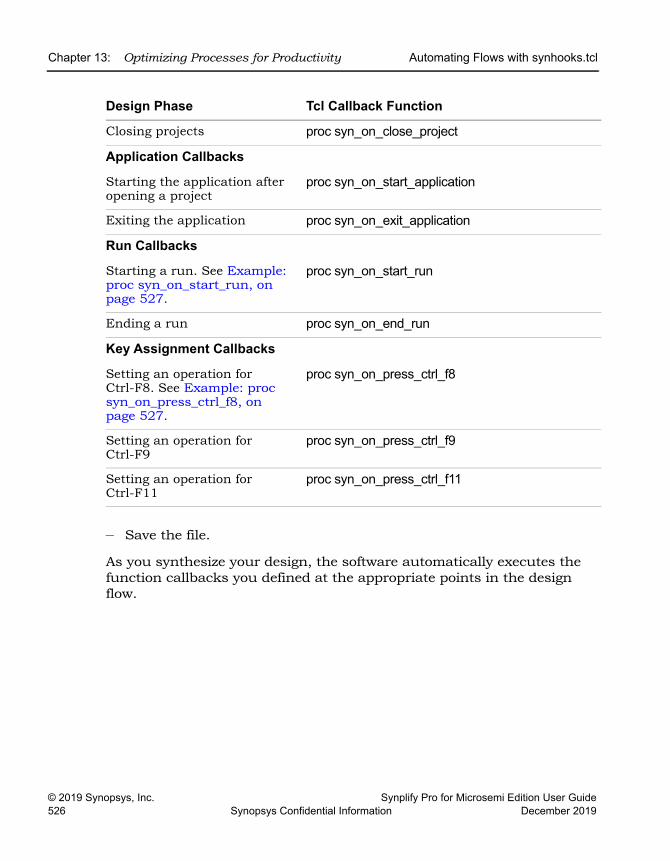
LO
Chapter 13: Optimizing Processes for Productivity Automating Flows with synhooks.tcl
© 2019 Synopsys, Inc. Synplify Pro for Microsemi Edition User Guide526 Synopsys Confidential Information December 2019
– Save the file.
As you synthesize your design, the software automatically executes the function callbacks you defined at the appropriate points in the design flow.
Closing projects proc syn_on_close_project
Application Callbacks
Starting the application after opening a project
proc syn_on_start_application
Exiting the application proc syn_on_exit_application
Run Callbacks
Starting a run. See Example: proc syn_on_start_run, on page 527.
proc syn_on_start_run
Ending a run proc syn_on_end_run
Key Assignment Callbacks
Setting an operation for Ctrl-F8. See Example: proc syn_on_press_ctrl_f8, on page 527.
proc syn_on_press_ctrl_f8
Setting an operation for Ctrl-F9
proc syn_on_press_ctrl_f9
Setting an operation for Ctrl-F11
proc syn_on_press_ctrl_f11
Design Phase Tcl Callback Function
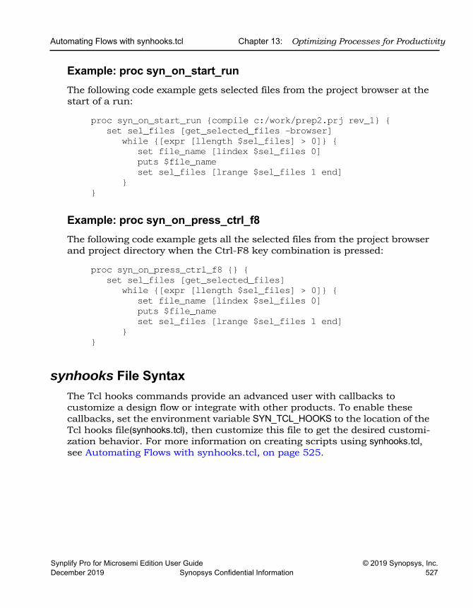
Automating Flows with synhooks.tcl Chapter 13: Optimizing Processes for Productivity
Synplify Pro for Microsemi Edition User Guide © 2019 Synopsys, Inc.December 2019 Synopsys Confidential Information 527
Example: proc syn_on_start_runThe following code example gets selected files from the project browser at the start of a run:
proc syn_on_start_run {compile c:/work/prep2.prj rev_1} {set sel_files [get_selected_files -browser]
while {[expr [llength $sel_files] > 0]} {set file_name [lindex $sel_files 0]puts $file_nameset sel_files [lrange $sel_files 1 end]
}}
Example: proc syn_on_press_ctrl_f8The following code example gets all the selected files from the project browser and project directory when the Ctrl-F8 key combination is pressed:
proc syn_on_press_ctrl_f8 {} {set sel_files [get_selected_files]
while {[expr [llength $sel_files] > 0]} {set file_name [lindex $sel_files 0]puts $file_nameset sel_files [lrange $sel_files 1 end]
}}
synhooks File SyntaxThe Tcl hooks commands provide an advanced user with callbacks to customize a design flow or integrate with other products. To enable these callbacks, set the environment variable SYN_TCL_HOOKS to the location of the Tcl hooks file(synhooks.tcl), then customize this file to get the desired customi-zation behavior. For more information on creating scripts using synhooks.tcl, see Automating Flows with synhooks.tcl, on page 525.
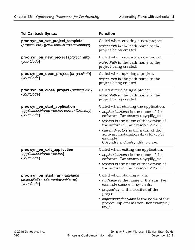
LO
Chapter 13: Optimizing Processes for Productivity Automating Flows with synhooks.tcl
© 2019 Synopsys, Inc. Synplify Pro for Microsemi Edition User Guide528 Synopsys Confidential Information December 2019
Tcl Callback Syntax Function
proc syn_on_set_project_template {projectPath} {yourDefaultProjectSettings}
Called when creating a new project. projectPath is the path name to the project being created.
proc syn_on_new_project {projectPath} {yourCode}
Called when creating a new project.projectPath is the path name to the project being created.
proc syn_on_open_project {projectPath} {yourCode}
Called when opening a project. projectPath is the path name to the project being created.
proc syn_on_close_project {projectPath} {yourCode}
Called after closing a project.projectPath is the path name to the project being created.
proc syn_on_start_application {applicationName version currentDirectory} {yourCode}
Called when starting the application.• applicationName is the name of the
software. For example synplify_pro.• version is the name of the version of
the software. For example 2017.03• currentDirectory is the name of the
software installation directory. For example C:\synplify_pro\bin\synplify_pro.exe.
proc syn_on_exit_application {applicationName version} {yourCode}
Called when exiting the application.• applicationName is the name of the
software. For example synplify_pro.• version is the name of the version of
the software. For example 2017.03.
proc syn_on_start_run {runName projectPath implementationName} {yourCode}
Called when starting a run. • runName is the name of the run. For
example compile or synthesis.• projectPath is the location of the
project.• implementationName is the name of the
project implementation. For example, rev_1.
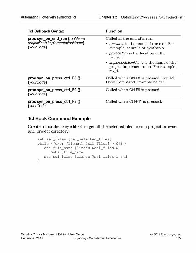
Automating Flows with synhooks.tcl Chapter 13: Optimizing Processes for Productivity
Synplify Pro for Microsemi Edition User Guide © 2019 Synopsys, Inc.December 2019 Synopsys Confidential Information 529
Tcl Hook Command ExampleCreate a modifier key (ctrl-F8) to get all the selected files from a project browser and project directory.
set sel_files [get_selected_files]while {[expr [llength $sel_files] > 0]} {
set file_name [lindex $sel_files 0]puts $file_name
set sel_files [lrange $sel_files 1 end]}
proc syn_on_end_run {runName projectPath implementationName} {yourCode}
Called at the end of a run.• runName is the name of the run. For
example, compile or synthesis.• projectPath is the location of the
project.• implementationName is the name of the
project implementation. For example, rev_1.
proc syn_on_press_ctrl_F8 {} {yourCode}
Called when Ctrl-F8 is pressed. See Tcl Hook Command Example below.
proc syn_on_press_ctrl_F9 {} {yourCode}
Called when Ctrl-F9 is pressed.
proc syn_on_press_ctrl_F8 {} {yourCode
Called when Ctrl-F11 is pressed.
Tcl Callback Syntax Function
LO
Chapter 13: Optimizing Processes for Productivity Invoking Third-Party Vendor Tools
© 2019 Synopsys, Inc. Synplify Pro for Microsemi Edition User Guide530 Synopsys Confidential Information December 2019
Invoking Third-Party Vendor Tools You can invoke third-party tools from within the Synopsys FPGA synthesis products, and configure the locations and common arguments for the tools. This capability lets you modify source files or libraries or debug problems from within the third-party tool, without leaving the synthesis environment.
You can invoke pre-configured tools or add your own. The process consists of two steps:
• Configuring Tool Tags, on page 530
• Invoking a Third-Party Tool, on page 531
Configuring Tool TagsA tool tag is a configuration definition for a tool you want to invoke from the synthesis interface. You define a tool tag to set up the third-party tool you want to use. The following procedure shows you how to define your own tool tags, or add command arguments. Use this to specify other tools, other versions of a tool, or to run a tool with different arguments.
1. Select Options->Configure 3rd Party Tool Options from the Project view.
2. Define the application tag information for the tool you want to invoke.
– Specify the application you want to invoke in Application Tag Name.
– Specify how you want to invoke the application tool. If you want to run the tool directly from the UI, select Direct Execution. If your application is a Tcl procedure, select TCL Mode.
– Specify the location of the application executable or Tcl procedure name in Application Name with Path or Tcl Procedure Name.
– Specify any command arguments you want in the Command Argument if any field. You can use this to define a new tool tag or to add arguments to a tool tag that is already defined.
For a list of predefined command arguments, click the + button and select them from the list. Otherwise, type the command arguments. For the internal Synopsys tools, you must select $SynCode from the Command Argument if any field.
– Click Apply.
Invoking Third-Party Vendor Tools Chapter 13: Optimizing Processes for Productivity
Synplify Pro for Microsemi Edition User Guide © 2019 Synopsys, Inc.December 2019 Synopsys Confidential Information 531
– Click Close.
The tool saves these settings in the FPGA synthesis tool .ini file and retrieves them for subsequent invocations. For information about invoking a third-party tool, see Invoking a Third-Party Tool, on page 531, next.
Invoking a Third-Party ToolYou can define tool tags globally and then use these tool tags to run the third-party tool from the Project view for the specified tool tag only. Some common tool tags are pre-configured and are read when the application starts up. You can add or modify existing tool tags or define your own Tcl procedures to invoke within the FPGA synthesis tools.
1. Define a tool tag for your application, as described in Configuring Tool Tags, on page 530.
2. Right-click in the Project view on a file or folder which is configured to run the vendor tool, and select Launch Tools->Run Vendor Tool from the popup menu.
This dialog box automatically displays tool tag information associated with the file or folder. If no tool tag information is specified, look for the parent hierarchy and edit or change it, if necessary.
3. To associate a file or folder with a particular third-party tool, do the following:
– Select the file or folder in the Project view. If you select a folder, the third-party tool is associated with all the files in the folder. If you associate a tool with a file, this setting overrides the folder setting.
– Right-click a file or folder and select Launch Tools->Run Vendor Tool from the popup menu.
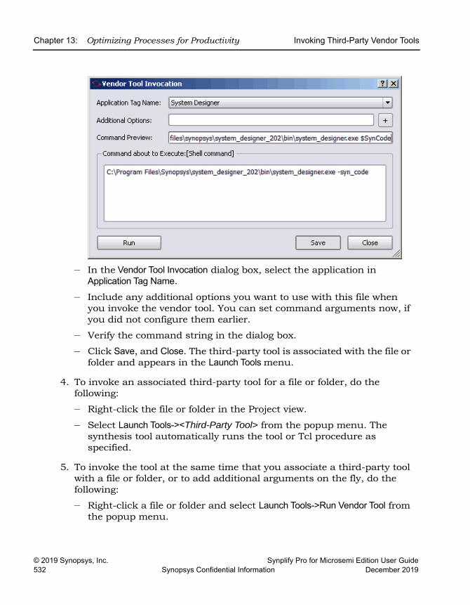
LO
Chapter 13: Optimizing Processes for Productivity Invoking Third-Party Vendor Tools
© 2019 Synopsys, Inc. Synplify Pro for Microsemi Edition User Guide532 Synopsys Confidential Information December 2019
– In the Vendor Tool Invocation dialog box, select the application in Application Tag Name.
– Include any additional options you want to use with this file when you invoke the vendor tool. You can set command arguments now, if you did not configure them earlier.
– Verify the command string in the dialog box.
– Click Save, and Close. The third-party tool is associated with the file or folder and appears in the Launch Tools menu.
4. To invoke an associated third-party tool for a file or folder, do the following:
– Right-click the file or folder in the Project view.
– Select Launch Tools-><Third-Party Tool> from the popup menu. The synthesis tool automatically runs the tool or Tcl procedure as specified.
5. To invoke the tool at the same time that you associate a third-party tool with a file or folder, or to add additional arguments on the fly, do the following:
– Right-click a file or folder and select Launch Tools->Run Vendor Tool from the popup menu.
Invoking Third-Party Vendor Tools Chapter 13: Optimizing Processes for Productivity
Synplify Pro for Microsemi Edition User Guide © 2019 Synopsys, Inc.December 2019 Synopsys Confidential Information 533
– In the Vendor Tool Invocation dialog box, select the application in Application Tag Name.
– Include any additional options you want to use with this file when you invoke the vendor tool. You can set command arguments now, if you did not configure them earlier.
– Verify the command string in the dialog box.
– Click Save. The tool and arguments you specified is associated with the file or folder and appears in the Launch Tools menu.
If you defined a new tool tag, the 3rd Party Tool Configuration dialog box appears. After saving the settings here, go back to the Vendor Tool Invocation dialog box. You are prompted to save this information to the project file before invoking the third-party tool.
– Click the Run button in the Vendor Tool Invocation dialog box. The synthesis tool launches the third-party tool or runs the Tcl procedure with the arguments you specified.
These settings are saved in the FPGA synthesis tool .ini file, from where it can be retrieved for subsequent invocations.

LO
Chapter 13: Optimizing Processes for Productivity Invoking Third-Party Vendor Tools
© 2019 Synopsys, Inc. Synplify Pro for Microsemi Edition User Guide534 Synopsys Confidential Information December 2019
Synplify Pro for Microsemi Edition User Guide © 2019 Synopsys, Inc.December 2019 Synopsys Confidential Information 535
CHAPTER 14
Improving Runtime
The section describes how to use multiprocessing to run parallel synthesis jobs and improve runtime:
• Multiprocessing With Compile Points, on page 536
LO
Chapter 14: Improving Runtime Multiprocessing With Compile Points
© 2019 Synopsys, Inc. Synplify Pro for Microsemi Edition User Guide536 Synopsys Confidential Information December 2019
Multiprocessing With Compile PointsThis procedure describes how to run multiprocessing on a design with compile points. For information about defining compile points, see Chapter 11, Working with Compile Points.
To run compile points with multiprocessing:
1. If required, specify additional license types to use for multiprocessing, as described in Using Different License Types for Multiprocessing, on page 538.
The tool runs four jobs in parallel per license, so additional licenses increase the number of jobs that can be run in parallel. The actual number of licenses used depends on certain factors. See Specifying Licenses for Multiprocessing, on page 538 for an explanation.
2. Select Options->Configure Parallel or Compile Point Process and set the maximum number of jobs to run in parallel.
See Setting Maximum Parallel Jobs, on page 536 for other ways to set this value.
3. Synthesize the design as usual.
The synthesis software runs multiple, independent compile point jobs simultaneously, providing additional runtime improvements for the logical compile point synthesis flows.
Setting Maximum Parallel JobsYou can set maximum number of parallel jobs in the following ways:
• Setting the MaxParallelJobs Variable in the ini File, on page 537
• Setting the max_parallel_jobs Tcl Option
Multiprocessing With Compile Points Chapter 14: Improving Runtime
Synplify Pro for Microsemi Edition User Guide © 2019 Synopsys, Inc.December 2019 Synopsys Confidential Information 537
Setting the MaxParallelJobs Variable in the ini FileThe maximum number of parallel jobs is set in the product ini file. The following commands are set in the product.ini file (for example, synplify_pro.ini):
[JobSetting]MaxParallelJobs=<n>
The MaxParallelJobs value is used by the UI as well as in batch mode. This value is effective until you specify a new value. To change the number of parallel jobs you can run, use the Options->Configure Parallel or Compile Point Process command from the Project view menu. On the Configure Parallel or Compile Point Process dialog box, in the Maximum number of parallel synthesis jobs field you will see the current ini value. You can specify a new MaxParallelJobs value which is effective until you change it again. Once you click OK, the new value is saved in the ini file. For a description of the dialog box, see Configure Parallel or Compile Point Process Command, on page 421.
Setting the max_parallel_jobs Tcl OptionYou can also manually set an override value for the maximum number of parallel jobs. To do this, use the Tcl command:
set_option -max_parallel_jobs numberJobs
You can choose to:
• Source the Tcl file containing this option.
• Add this option to the Project file.
• Set this option from the Tcl command window.
This max_parallel_jobs value is applied to all project files and their respective implementations. This is a global option. The maximum number of parallel jobs remains in effect until you specify a new value. This new value takes affect immediately going forward. However, when you set this option from the Tcl command window, the max_parallel_jobs value is not saved and will be lost when you exit the application.
LO
Chapter 14: Improving Runtime Multiprocessing With Compile Points
© 2019 Synopsys, Inc. Synplify Pro for Microsemi Edition User Guide538 Synopsys Confidential Information December 2019
Specifying Licenses for Multiprocessing When you decide to run parallel synthesis jobs, additional licenses may be required for the compile point jobs. By default, four parallel jobs use one license. For example, if you set the Maximum number of parallel synthesis jobs to 12, the synthesis tool consumes one license to run 4 compile point jobs and can utilize the two additional licenses to run 8 more parallel jobs if they are available for your computing environment. Licenses are released as jobs complete, and then consumed by new jobs which need to run.
The actual number of licenses utilized depends on the following factors:
1. Synthesis software scheme for the compile point requirements used to determine the maximum number of parallel jobs or licenses a particular design tries to use.
2. Value set on the Configure Parallel or Compile Point Process dialog box.
3. Number of licenses actually available. You can use Help->Preferred License Selection to check the number of available license. If you need to increase the number of available licenses, you can specify multiple license types. For more information, see Using Different License Types for Multiprocessing, on page 538.
Factors 1 and 3 can change during a single synthesis run. The number of jobs equals the number of licenses; which then equates to the lowest value of these three factors.
Using Different License Types for MultiprocessingYou can specify multiple license types to increase the total number of licenses available for multiprocessing. Use either of these methods to specify the license types:
• Use the -licensetype command line option when you execute your tool.
For example, suppose you have two synplifypro licenses, two synplifypro_all-vendor licenses, and three synplifypro_microsemi licenses. Type the following at the command line:
synplify_pro.exe -licensetype "synplifypro:synplifypro_allvendor:synplifypro_microsemi"
Multiprocessing With Compile Points Chapter 14: Improving Runtime
Synplify Pro for Microsemi Edition User Guide © 2019 Synopsys, Inc.December 2019 Synopsys Confidential Information 539
• Use the following environment variables specified with the license type:
– SYNPLIFYPRO_LICENSE_TYPE
setenv SYNPLIFYPRO_LICENSE_TYPE="synplifypro:synplifypro_allvendor:synplifypro_microsemi"
Multiprocessing can access any of these license types for additional licenses.

LO
Chapter 14: Improving Runtime Multiprocessing With Compile Points
© 2019 Synopsys, Inc. Synplify Pro for Microsemi Edition User Guide540 Synopsys Confidential Information December 2019
Synplify Pro for Microsemi Edition User Guide © 2019 Synopsys, Inc.December 2019 Synopsys Confidential Information 541
CHAPTER 15
Handling High-Reliability Designs
As geometries shrink, the possibility of soft errors or radiation effects increase. This affects industries like aerospace most immediately, but many other applications increasingly require high reliability and built-in fault toler-ance. The synthesis software provides different ways to implement high reliability, and the following describe methods to implement high reliability in your designs:
• Working with Microsemi Radhard Designs, on page 542
• Specifying Safe FSMs, on page 545
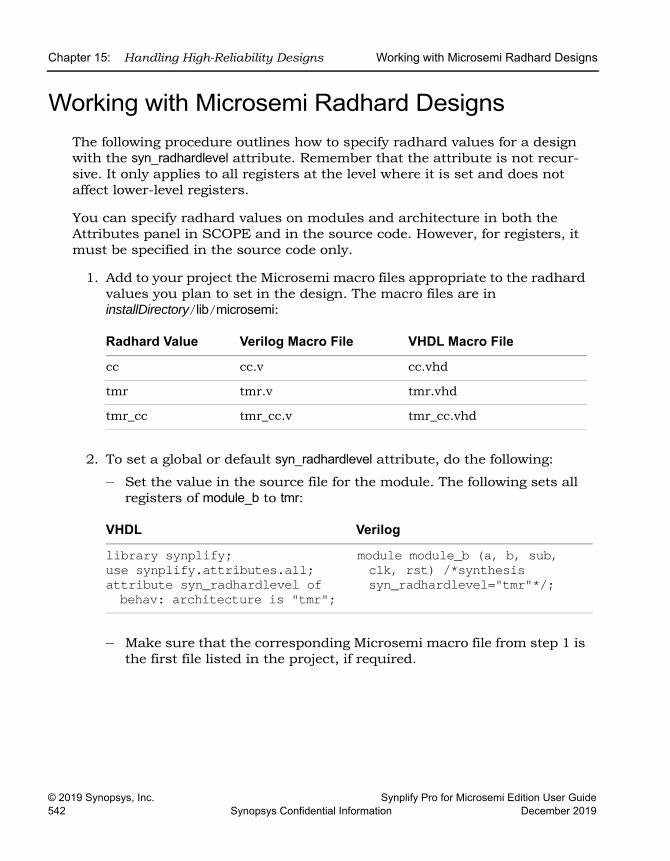
LO
Chapter 15: Handling High-Reliability Designs Working with Microsemi Radhard Designs
© 2019 Synopsys, Inc. Synplify Pro for Microsemi Edition User Guide542 Synopsys Confidential Information December 2019
Working with Microsemi Radhard DesignsThe following procedure outlines how to specify radhard values for a design with the syn_radhardlevel attribute. Remember that the attribute is not recur-sive. It only applies to all registers at the level where it is set and does not affect lower-level registers.
You can specify radhard values on modules and architecture in both the Attributes panel in SCOPE and in the source code. However, for registers, it must be specified in the source code only.
1. Add to your project the Microsemi macro files appropriate to the radhard values you plan to set in the design. The macro files are in installDirectory/lib/microsemi:
2. To set a global or default syn_radhardlevel attribute, do the following:
– Set the value in the source file for the module. The following sets all registers of module_b to tmr:
– Make sure that the corresponding Microsemi macro file from step 1 is the first file listed in the project, if required.
Radhard Value Verilog Macro File VHDL Macro File
cc cc.v cc.vhd
tmr tmr.v tmr.vhd
tmr_cc tmr_cc.v tmr_cc.vhd
VHDL Verilog
library synplify;use synplify.attributes.all;attribute syn_radhardlevel ofbehav: architecture is "tmr";
module module_b (a, b, sub, clk, rst) /*synthesis syn_radhardlevel="tmr"*/;
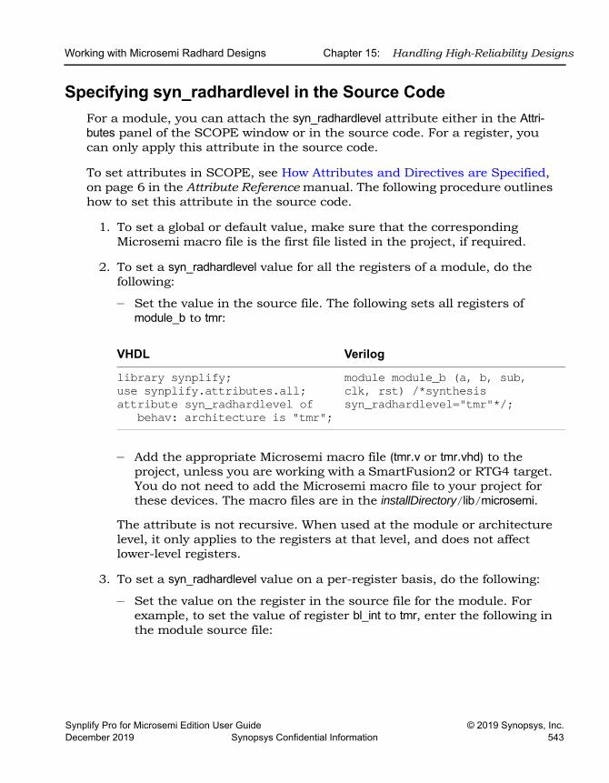
Working with Microsemi Radhard Designs Chapter 15: Handling High-Reliability Designs
Synplify Pro for Microsemi Edition User Guide © 2019 Synopsys, Inc.December 2019 Synopsys Confidential Information 543
Specifying syn_radhardlevel in the Source CodeFor a module, you can attach the syn_radhardlevel attribute either in the Attri-butes panel of the SCOPE window or in the source code. For a register, you can only apply this attribute in the source code.
To set attributes in SCOPE, see How Attributes and Directives are Specified, on page 6 in the Attribute Reference manual. The following procedure outlines how to set this attribute in the source code.
1. To set a global or default value, make sure that the corresponding Microsemi macro file is the first file listed in the project, if required.
2. To set a syn_radhardlevel value for all the registers of a module, do the following:
– Set the value in the source file. The following sets all registers of module_b to tmr:
– Add the appropriate Microsemi macro file (tmr.v or tmr.vhd) to the project, unless you are working with a SmartFusion2 or RTG4 target. You do not need to add the Microsemi macro file to your project for these devices. The macro files are in the installDirectory/lib/microsemi.
The attribute is not recursive. When used at the module or architecture level, it only applies to the registers at that level, and does not affect lower-level registers.
3. To set a syn_radhardlevel value on a per-register basis, do the following:
– Set the value on the register in the source file for the module. For example, to set the value of register bl_int to tmr, enter the following in the module source file:
VHDL Verilog
library synplify;use synplify.attributes.all;attribute syn_radhardlevel of
behav: architecture is "tmr";
module module_b (a, b, sub,clk, rst) /*synthesissyn_radhardlevel="tmr"*/;
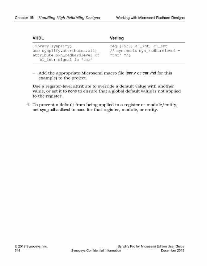
LO
Chapter 15: Handling High-Reliability Designs Working with Microsemi Radhard Designs
© 2019 Synopsys, Inc. Synplify Pro for Microsemi Edition User Guide544 Synopsys Confidential Information December 2019
– Add the appropriate Microsemi macro file (tmr.v or tmr.vhd for this example) to the project.
Use a register-level attribute to override a default value with another value, or set it to none to ensure that a global default value is not applied to the register.
4. To prevent a default from being applied to a register or module/entity, set syn_radhardlevel to none for that register, module, or entity.
VHDL Verilog
library synplify;use synplify.attributes.all;attribute syn_radhardlevel of
bl_int: signal is "tmr"
reg [15:0] a1_int, b1_int /* synthesis syn_radhardlevel = "tmr" */;
Specifying Safe FSMs Chapter 15: Handling High-Reliability Designs
Synplify Pro for Microsemi Edition User Guide © 2019 Synopsys, Inc.December 2019 Synopsys Confidential Information 545
Specifying Safe FSMsTypically, unspecified or unreachable FSM states are optimized away during synthesis, so if an SEU causes a bit to be inverted, the FSM can be put into an undefined, invalid state, and lock up the circuit. An SEU fault is a change of state caused by ions or electro-magnetic radiation that affects sequential elements. The basic principle of a safe FSM is to prevent the state machine from getting stuck in an unknown state because of an SEU.
Safe FSMs are primarily required by commercial or military-aerospace users, especially those who want to ensure that their FSMs are tolerant of single event upset (SEU) faults and continue to function correctly.
The following procedures describe ways to ensure high reliability and fault tolerance for FSMs:
• Implementing Safe Encoding FSMs, on page 546
• Implementing Safe Case FSMs, on page 547
Vendor Support for Safe FSMsThe following technology families support the specification of safe encoding and safe case for FSMs:
Safe Implementation for FSMs on RTG4From L-2016.09M-SP1-5 onwards, Synplify Pro does not support safe implementation for FSMs on the RTG4 technology. RTG4 already has TMR on registers so there is no need to implement safe FSM.
As a result, if you implement safe FSM using any of these options—attribute syn_encoding = safe, attribute syn_safe_case = true, Preserve and Decode Unreachable States under Implementation Options->High Reliability—the following error is displayed:
Safe state machine option is not recommended for Microsemi RTG4 technology. To continue with safe state machine implementation, downgrade this error to warning.
Microsemi(Synplify Pro)
SmartFusion2, IGLOO2, PolarFire
LO
Chapter 15: Handling High-Reliability Designs Specifying Safe FSMs
© 2019 Synopsys, Inc. Synplify Pro for Microsemi Edition User Guide546 Synopsys Confidential Information December 2019
To downgrade the error to a warning, use the message_override -warning DE108 Tcl command. For more information on downgrading errors, see Working with Downgradable Errors and Critical Warnings, on page 216.
Once the error is downgraded, Synplify Pro continues synthesis and implements safe logic for FSMs on RTG4.
Implementing Safe Encoding FSMsFault-tolerant FSMs with safe encoding is an error mitigation technique, which builds error recovery logic that specifies the FSM state use the reset condition when the FSM gets into an invalid or undefined state.
1. Select a supported device in the synthesis tool.
See Vendor Support for Safe FSMs, on page 545 for a list.
2. To apply safe encoding for FSMs, use the syn_encoding attribute with the value safe. When choosing an encoding style, use the syn_encoding attribute with the values safe, encodingStyle. You can apply this attribute on an FSM instance or register in the Verilog/VHDL source code or the FDC constraint file. For example:
module /*synthesis syn_encoding="safe, encodingStyles";*/attribute syn_encoding of architecture : signal is
"safe, encodingStyles";You can also define a SCOPE collection in the constraint file, then apply the attribute to the collection as shown below:
define_scope_collection sm {find -hier -inst * -filter inst_of==statemachine}define_attribute {$sm} {syn_encoding} {safe, encodingStyles}For details about this directive, see syn_encoding, on page 75 in the Attribute Reference Manual.
Note: You must enable the FSM Compiler option to ensure the syn_encoding attribute takes effect. This overrides the default FSM compiler encoding for the state machine.
3. To remove the additional flip-flop inserted on the inactive clock edge of the recovery path, use the syn_shift_resetphase attribute. This attribute can be specified globally or on an FSM instance.
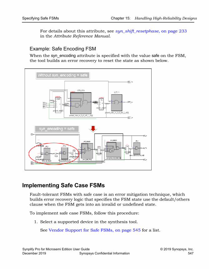
Specifying Safe FSMs Chapter 15: Handling High-Reliability Designs
Synplify Pro for Microsemi Edition User Guide © 2019 Synopsys, Inc.December 2019 Synopsys Confidential Information 547
For details about this attribute, see syn_shift_resetphase, on page 233 in the Attribute Reference Manual.
Example: Safe Encoding FSMWhen the syn_encoding attribute is specified with the value safe on the FSM, the tool builds an error recovery to reset the state as shown below.
Implementing Safe Case FSMsFault-tolerant FSMs with safe case is an error mitigation technique, which builds error recovery logic that specifies the FSM state use the default/others clause when the FSM gets into an invalid or undefined state.
To implement safe case FSMs, follow this procedure:
1. Select a supported device in the synthesis tool.
See Vendor Support for Safe FSMs, on page 545 for a list.
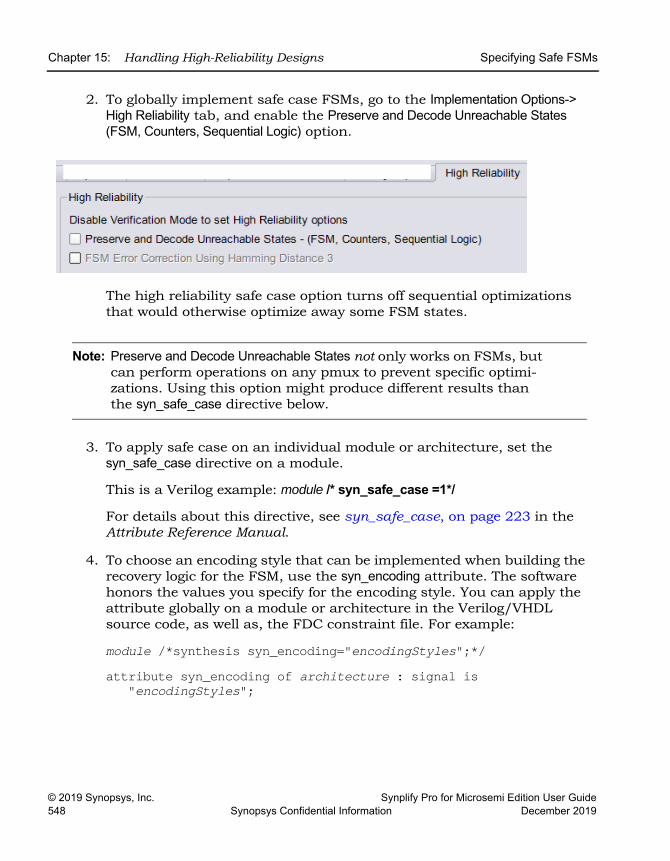
LO
Chapter 15: Handling High-Reliability Designs Specifying Safe FSMs
© 2019 Synopsys, Inc. Synplify Pro for Microsemi Edition User Guide548 Synopsys Confidential Information December 2019
2. To globally implement safe case FSMs, go to the Implementation Options-> High Reliability tab, and enable the Preserve and Decode Unreachable States (FSM, Counters, Sequential Logic) option.
The high reliability safe case option turns off sequential optimizations that would otherwise optimize away some FSM states.
Note: Preserve and Decode Unreachable States not only works on FSMs, but can perform operations on any pmux to prevent specific optimi-zations. Using this option might produce different results than the syn_safe_case directive below.
3. To apply safe case on an individual module or architecture, set the syn_safe_case directive on a module.
This is a Verilog example: module /* syn_safe_case =1*/
For details about this directive, see syn_safe_case, on page 223 in the Attribute Reference Manual.
4. To choose an encoding style that can be implemented when building the recovery logic for the FSM, use the syn_encoding attribute. The software honors the values you specify for the encoding style. You can apply the attribute globally on a module or architecture in the Verilog/VHDL source code, as well as, the FDC constraint file. For example:
module /*synthesis syn_encoding="encodingStyles";*/ attribute syn_encoding of architecture : signal is
"encodingStyles";
Specifying Safe FSMs Chapter 15: Handling High-Reliability Designs
Synplify Pro for Microsemi Edition User Guide © 2019 Synopsys, Inc.December 2019 Synopsys Confidential Information 549
You can also define a SCOPE collection in the constraint file, then apply the attribute to the collection:
define_scope_collection sm {find -hier -inst * -filterinst_of==statemachine}
define_attribute {$sm} {syn_encoding} {encodingStyles}For details about this attribute, see syn_encoding, on page 75.
You must enable the FSM Compiler option to ensure that the syn_encoding attribute takes affect. This overrides the default FSM compiler encoding for the state machine.
5. Provide error monitoring.
See Error Monitoring for High Reliability Features, on page 553 for details.
Note: You can optionally specify the error monitoring Tcl commands for safe FSM.
Example: Safe Case FSMThe syn_safe_case directive is applied on the FSM. When an undefined state occurs, the state machine uses the others clause to synthesize for error recovery as shown below.
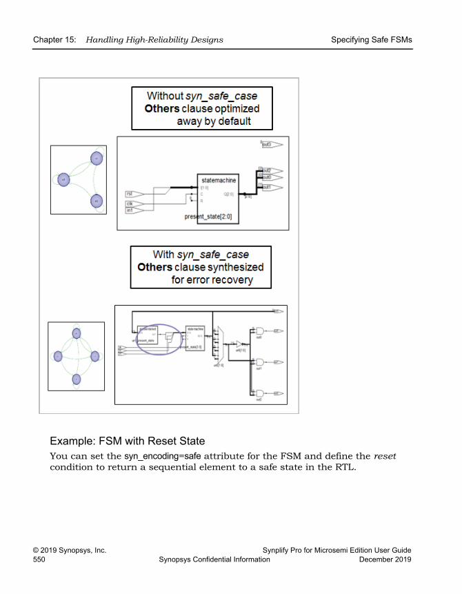
LO
Chapter 15: Handling High-Reliability Designs Specifying Safe FSMs
© 2019 Synopsys, Inc. Synplify Pro for Microsemi Edition User Guide550 Synopsys Confidential Information December 2019
Example: FSM with Reset StateYou can set the syn_encoding=safe attribute for the FSM and define the reset condition to return a sequential element to a safe state in the RTL.
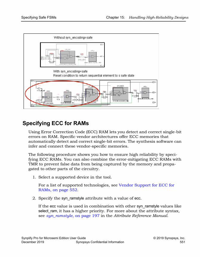
Specifying Safe FSMs Chapter 15: Handling High-Reliability Designs
Synplify Pro for Microsemi Edition User Guide © 2019 Synopsys, Inc.December 2019 Synopsys Confidential Information 551
Specifying ECC for RAMsUsing Error Correction Code (ECC) RAM lets you detect and correct single-bit errors on RAM. Specific vendor architectures offer ECC memories that automatically detect and correct single-bit errors. The synthesis software can infer and connect these vendor-specific memories.
The following procedure shows you how to ensure high reliability by speci-fying ECC RAMs. You can also combine the error-mitigating ECC RAMs with TMR to prevent false data from being captured by the memory and propa-gated to other parts of the circuitry.
1. Select a supported device in the tool.
For a list of supported technologies, see Vendor Support for ECC for RAMs, on page 552.
2. Specify the syn_ramstyle attribute with a value of ecc.
If the ecc value is used in combination with other syn_ramstyle values like select_ram, it has a higher priority. For more about the attribute syntax, see syn_ramstyle, on page 197 in the Attribute Reference Manual.
LO
Chapter 15: Handling High-Reliability Designs Specifying Safe FSMs
© 2019 Synopsys, Inc. Synplify Pro for Microsemi Edition User Guide552 Synopsys Confidential Information December 2019
3. Provide error monitoring.
See Error Monitoring for High Reliability Features, on page 553 for details.
Note: You can optionally specify the error monitoring Tcl commands for ECC RAM.
4. Run synthesis.
The software infers the built-in ECC RAM primitive in the design. The synthesis tool creates the ECC RAM block primitive and its associated glue logic (for example, address decoders/encoders or comparators), while keeping the RAM interface the same.
5. Check the log file for the ECC RAM.
Vendor Support for ECC for RAMsThe following technology families support the specification of TMR for RAMs:
Microsemi RTG4 and PolarFire familyFor examples, see RAM Inference in ECC Mode, on page 400.
Error Monitoring for High Reliability Features Chapter 15: Handling High-Reliability Designs
Synplify Pro for Microsemi Edition User Guide © 2019 Synopsys, Inc.December 2019 Synopsys Confidential Information 553
Error Monitoring for High Reliability Features
The software can inform you when it detects that an error has occurred. Based on the type of error, you may want to take corrective action (such as, reset the design or enable/disable scrubbing). Error monitoring can occur for the following:
• Finite state machines with unreachable states
For details, see the following topics:
• Error Monitoring Procedure, on page 553
• Error Monitoring Examples, on page 554
Error Monitoring ProcedureError monitoring requires that you do the following:
1. As a prerequisite, a top-level port or user instantiated error monitoring IP (EMIP) must be provided in the RTL. You must specify syn_keep on the signal/wire feeding into the top-level port or EMIP port.
2. Specify the connectivity between the module/instance being monitored for the error with the error monitoring IP port or top-level port for the error monitoring module. You must define the control signals of the source and elements for error monitoring with the following Tcl commands:
– syn_create_err_net– syn_connect
Add these commands in the constraint file. For a descriptions of the syntax, see syn_connect, on page 138 and syn_create_err_net, on page 139.
Here are some examples of specifying these commands:
# Unregistered error flag connected to top-level error portsyn_create_err_net {-name {error_flag} -inst {i:inst_A}}
syn_connect {-from {n:error_flag} -to {p:emp}}
LO
Chapter 15: Handling High-Reliability Designs Error Monitoring for High Reliability Features
© 2019 Synopsys, Inc. Synplify Pro for Microsemi Edition User Guide554 Synopsys Confidential Information December 2019
# Error flag with 4 stage pipeline registers with asynchronous reset connected to EMIP port
syn_create_err_net {-name {error_flag} -inst {i:inst_A} -err_pipe_num {4} -err_clk {n:inst_A.clk} -err_reset {n:inst_A.rst} -err_synch {false}}
syn_connect {-from {n:error_flag} -to {t:inst_emip.emp}}The usage model for setting up the error monitoring varies slightly depending on the type of high reliability feature you are implementing, for example ECC.
Error Monitoring ExamplesError monitoring is applied to an instance. You can have a 1-bit error port for each instance. To do this, use the following Tcl commands:
• syn_create_err_net - Creates logic (XOR/OR) that compares the outputs for the selected module and connects it to the source of the new net that you specified. You can also specify pipeline registers along with clock and other control signals to improve timing through the comparator circuitry.
• syn_connect - Connects the new net that you specified to an existing net, top-level port, or input port of the instantiated Error Monitoring IP (EMIP).
See the following example:
• Example 4: Error Monitoring with FSM, on page 554
Example 4: Error Monitoring with FSMTo set up the error monitoring for an FSM and provide access to error bits, specify the following:
1. Enable Preserve and Decode Unreachable States on the High Reliability tab of the Implementation Options panel for the state machine.
2. On the instance:
– syn_create_err_net {–name {error_flag} -inst {i:state[1:3]}}– syn_connect -from {{n:error_flag} -to {t:EMIP.err_port}}
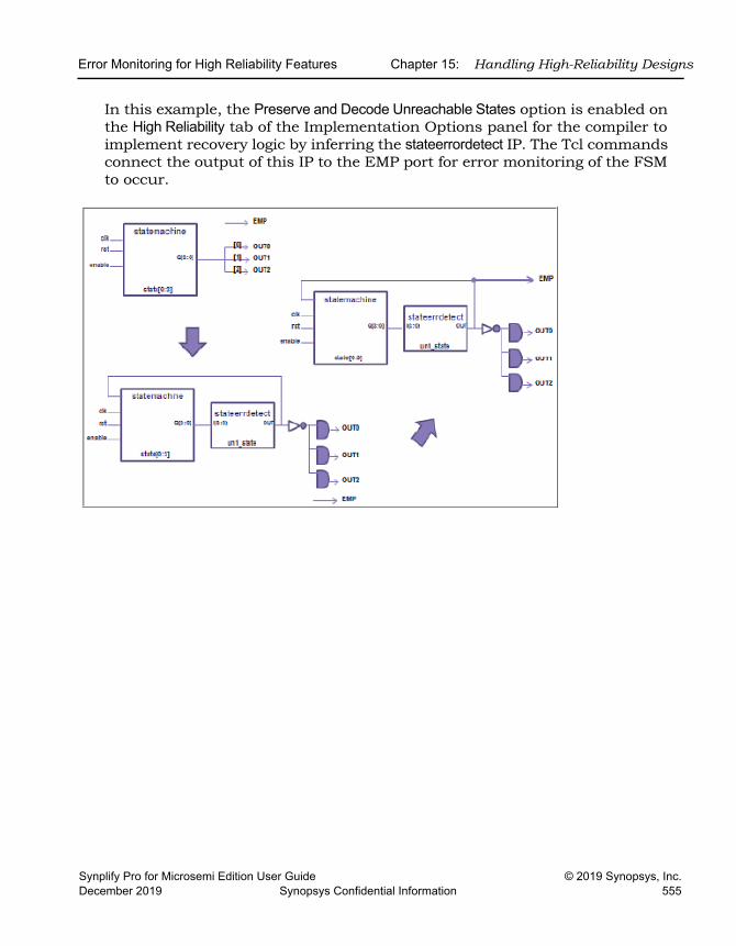
Error Monitoring for High Reliability Features Chapter 15: Handling High-Reliability Designs
Synplify Pro for Microsemi Edition User Guide © 2019 Synopsys, Inc.December 2019 Synopsys Confidential Information 555
In this example, the Preserve and Decode Unreachable States option is enabled on the High Reliability tab of the Implementation Options panel for the compiler to implement recovery logic by inferring the stateerrordetect IP. The Tcl commands connect the output of this IP to the EMP port for error monitoring of the FSM to occur.

LO
Chapter 15: Handling High-Reliability Designs Error Monitoring for High Reliability Features
© 2019 Synopsys, Inc. Synplify Pro for Microsemi Edition User Guide556 Synopsys Confidential Information December 2019
Synplify Pro for Microsemi Edition User Guide © 2019 Synopsys, Inc.December 2019 Synopsys Confidential Information 557
C H A P T E R 1 6
Running Post-Synthesis Operations
The following topics describe how to run post-synthesis operations, like place-and-route and verification, with compatible tools:
• Running P&R Automatically after Synthesis, on page 558
• Working with the Identify Tools, on page 560
• Simulating with the VCS Tool, on page 569
LO
Chapter 16: Running Post-Synthesis Operations Running P&R Automatically after Synthesis
© 2019 Synopsys, Inc. Synplify Pro for Microsemi Edition User Guide558 Synopsys Confidential Information December 2019
Running P&R Automatically after SynthesisYou can run place-and-route automatically from within the tool or in batch mode for certain vendor devices.
For detailed procedures, see the following:
• Integrating Synthesis and Place-and-Route in One Run, on page 558
• Releasing the Synthesis License During Place and Route, on page 558
Integrating Synthesis and Place-and-Route in One RunYou can run the place-and-route tool for your target technology automatically after synthesis.
1. Check the Release Notes and make sure that you are using the correct version of the P&R tool.
2. Set the PATH variable to point to the place-and-route tool.
3. To automatically run the P&R tool after synthesis completes, do the following:
– Click on the Add P&R Implementation button. In the dialog box, select the P&R implementation you want to run and enable Run Place & Route after synthesis.
– Synthesize the design.
The tool automatically runs P&R after synthesis.
Releasing the Synthesis License During Place and RouteWhen invoking a third-party place-and-route tool from the FPGA synthesis tool, you can choose to have place and route continue to run even after exiting the synthesis tool so that it does not consume an FPGA license. The software lets you release the license for the synthesis tool and run the place-and-route tool in batch mode.
To release the FPGA license, specify the following command:
toolName -batch -license_release
Running P&R Automatically after Synthesis Chapter 16: Running Post-Synthesis Operations
Synplify Pro for Microsemi Edition User Guide © 2019 Synopsys, Inc.December 2019 Synopsys Confidential Information 559
Where toolName can be any of the following keywords: synplify_pro. In synthesis batch mode (synbatch), the -license_release option obtains all the synthesis licenses that are checked out for the session and checks them in immediately after the place-and-route job is launched.
When licenses are released, you see the following message is generated:
Exiting session due to -license_release option
LO
Chapter 16: Running Post-Synthesis Operations Working with the Identify Tools
© 2019 Synopsys, Inc. Synplify Pro for Microsemi Edition User Guide560 Synopsys Confidential Information December 2019
Working with the Identify ToolsThe Synopsys Identify tool set is a dual-component system that is a valuable part of the HDL design flow process. The system consists of the Identify instrumentor and Identify debugger.
• The Identify instrumentor allows you to select your design instrumenta-tion at the HDL level and then create an on-chip hardware probe.
• The Identify debugger interacts with the on-chip hardware probe and lets you do live debugging of the design.
The combination of these tools allows you to probe your HDL design in the target environment. The combined system allows you to debug your design faster, easier, and more efficiently. This section describes how to take advan-tage of this integration and use the Identify instrumentor:
• Launching from the Tool, on page 560
• Handling Problems with Launching Identify, on page 564
• Using the Identify Tool, on page 566
• Using Compile Points with the Identify Tool, on page 567
Launching from the ToolThis section describes how to launch the Identify tool from the synthesis software. Define a project that you can pass to and launch in the Identify instrumentor. You must create an Identify implementation in order to run the Identify instrumentor. If you already have an Identify implementation, open it and use the Identify tool as described in Using the Identify Tool, on page 566.
Do the following to add an Identify implementation:
1. In the synthesis interface, open the design you want to debug.
2. Do one of the following tasks to add an Identify implementation:
– With the project implementation selected, right-click and select New Identify Implementation from the pop-up menu.
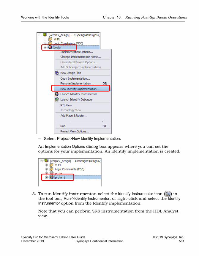
Working with the Identify Tools Chapter 16: Running Post-Synthesis Operations
Synplify Pro for Microsemi Edition User Guide © 2019 Synopsys, Inc.December 2019 Synopsys Confidential Information 561
– Select Project->New Identify Implementation.
An Implementation Options dialog box appears where you can set the options for your implementation. An Identify implementation is created.
3. To run Identify instrumentor, select the Identify Instrumentor icon ( ) in the tool bar, Run->Identify Instrumentor, or right-click and select the Identify Instrumentor option from the Identify implementation.
Note that you can perform SRS instrumentation from the HDL Analyst view.
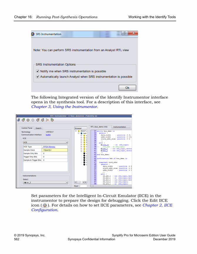
LO
Chapter 16: Running Post-Synthesis Operations Working with the Identify Tools
© 2019 Synopsys, Inc. Synplify Pro for Microsemi Edition User Guide562 Synopsys Confidential Information December 2019
The following Integrated version of the Identify Instrumentor interface opens in the synthesis tool. For a description of this interface, see Chapter 3, Using the Instrumentor.
Set parameters for the Intelligent In-Circuit Emulator (IICE) in the instrumentor to prepare the design for debugging. Click the Edit IICE icon ( ). For details on how to set IICE parameters, see Chapter 2, IICE Configuration.
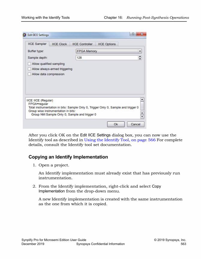
Working with the Identify Tools Chapter 16: Running Post-Synthesis Operations
Synplify Pro for Microsemi Edition User Guide © 2019 Synopsys, Inc.December 2019 Synopsys Confidential Information 563
After you click OK on the Edit IICE Settings dialog box, you can now use the Identify tool as described in Using the Identify Tool, on page 566 For complete details, consult the Identify tool set documentation.
Copying an Identify Implementation1. Open a project.
An Identify implementation must already exist that has previously run instrumentation.
2. From the Identify implementation, right-click and select Copy Implementation from the drop-down menu.
A new Identify implementation is created with the same instrumentation as the one from which it is copied.
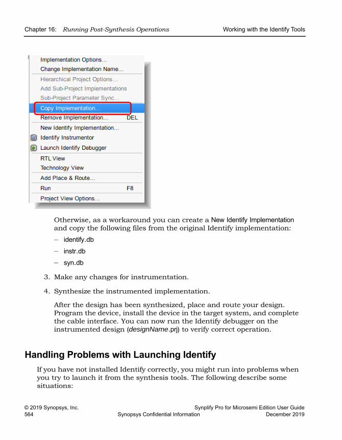
LO
Chapter 16: Running Post-Synthesis Operations Working with the Identify Tools
© 2019 Synopsys, Inc. Synplify Pro for Microsemi Edition User Guide564 Synopsys Confidential Information December 2019
Otherwise, as a workaround you can create a New Identify Implementation and copy the following files from the original Identify implementation:
– identify.db
– instr.db– syn.db
3. Make any changes for instrumentation.
4. Synthesize the instrumented implementation.
After the design has been synthesized, place and route your design. Program the device, install the device in the target system, and complete the cable interface. You can now run the Identify debugger on the instrumented design (designName.prj) to verify correct operation.
Handling Problems with Launching IdentifyIf you have not installed Identify correctly, you might run into problems when you try to launch it from the synthesis tools. The following describe some situations:
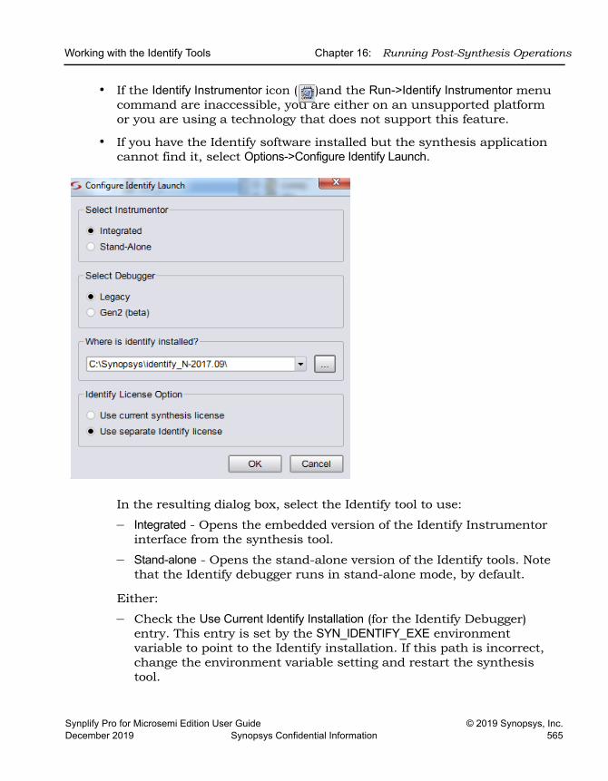
Working with the Identify Tools Chapter 16: Running Post-Synthesis Operations
Synplify Pro for Microsemi Edition User Guide © 2019 Synopsys, Inc.December 2019 Synopsys Confidential Information 565
• If the Identify Instrumentor icon ( )and the Run->Identify Instrumentor menu command are inaccessible, you are either on an unsupported platform or you are using a technology that does not support this feature.
• If you have the Identify software installed but the synthesis application cannot find it, select Options->Configure Identify Launch.
In the resulting dialog box, select the Identify tool to use:
– Integrated - Opens the embedded version of the Identify Instrumentor interface from the synthesis tool.
– Stand-alone - Opens the stand-alone version of the Identify tools. Note that the Identify debugger runs in stand-alone mode, by default.
Either:
– Check the Use Current Identify Installation (for the Identify Debugger) entry. This entry is set by the SYN_IDENTIFY_EXE environment variable to point to the Identify installation. If this path is incorrect, change the environment variable setting and restart the synthesis tool.
LO
Chapter 16: Running Post-Synthesis Operations Working with the Identify Tools
© 2019 Synopsys, Inc. Synplify Pro for Microsemi Edition User Guide566 Synopsys Confidential Information December 2019
– Click the Locate Identify Installation button and specify the correct location in the corresponding field. Use the browse button to open the Select Identify Installation Directory dialog box and navigate to your current Identify installation directory.
Using the Identify ToolThis procedure provides an overview of how to use the Identify instrumentor.
1. The Identify instrumentor software interface opens, with an Identify project automatically set up for the design to be instrumented and debugged (IICE tab).
2. Do the following in the Identify instrumentor interface:
– Instrument the design. For details of using the Identify instrumentor, refer to the Identify Instrumentor documentation.
– Save the instrumented design.
The Identify instrumentor tool exports the instrumented design to the synthesis software. It creates an instrumentation subdirectory under your synthesis working directory called designName_instr, which contains the following:
– A synthesis project file
– An instr_sources subdirectory for the instrumented HDL files
– Tcl scripts for loading the instrumented design
3. Return to the synthesis interface and view the instrumented design that contains the debugging logic.
– In the synthesis interface, open the project file for the instrumented design, which is in the instr_sources subdirectory listed in the Implementations Results view for your original synthesis project.
– Synthesize the design.
– Open the RTL view to see the inserted debugging logic.
4. Place and route the instrumented design after synthesis.
5. Use the Identify debugger tool to debug the instrumented design. For details of using the Identify debugger, refer to the Identify Debugger documentation.
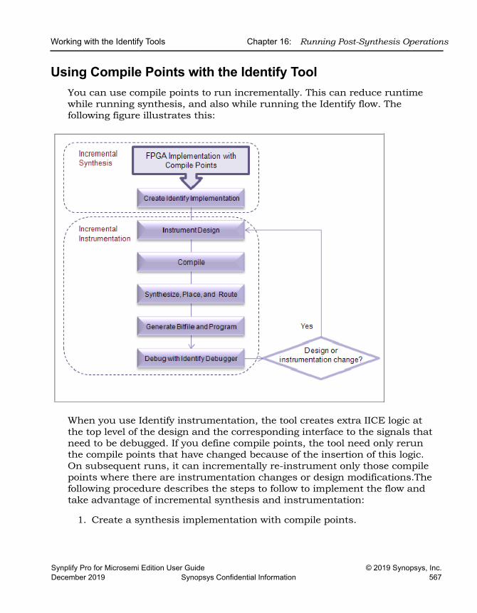
Working with the Identify Tools Chapter 16: Running Post-Synthesis Operations
Synplify Pro for Microsemi Edition User Guide © 2019 Synopsys, Inc.December 2019 Synopsys Confidential Information 567
Using Compile Points with the Identify ToolYou can use compile points to run incrementally. This can reduce runtime while running synthesis, and also while running the Identify flow. The following figure illustrates this:
When you use Identify instrumentation, the tool creates extra IICE logic at the top level of the design and the corresponding interface to the signals that need to be debugged. If you define compile points, the tool need only rerun the compile points that have changed because of the insertion of this logic. On subsequent runs, it can incrementally re-instrument only those compile points where there are instrumentation changes or design modifications.The following procedure describes the steps to follow to implement the flow and take advantage of incremental synthesis and instrumentation:
1. Create a synthesis implementation with compile points.
LO
Chapter 16: Running Post-Synthesis Operations Working with the Identify Tools
© 2019 Synopsys, Inc. Synplify Pro for Microsemi Edition User Guide568 Synopsys Confidential Information December 2019
2. Set up the Identify implementation:
– Generate the Identify implementation by right-clicking the FPGA synthesis implementation and selecting New Identify Implementation from the popup menu.
– Copy the compile point subdirectories manually to the new Identify implementation directory.
3. Run the tools.
– Run synthesis.
– Before running the Identify tool, enable the top-level constraint file and all compile point constraint files in the Identify implementation.
– Instrument the design. The tool inserts additional logic for instrumentation.
4. Resynthesize the design.
The tool runs incrementally, only resynthesizing the compile points affected by the inserted instrumentation logic. If you make any other design changes, the tool incrementally synthesizes the affected compile points.
5. Rerun instrumentation.
The tool runs incrementally, and only re-instruments the affected compile points.
Simulating with the VCS Tool Chapter 16: Running Post-Synthesis Operations
Synplify Pro for Microsemi Edition User Guide © 2019 Synopsys, Inc.December 2019 Synopsys Confidential Information 569
Simulating with the VCS ToolThe Synopsys VCS® tool is a high-performance, high-capacity Verilog simulator that incorporates advanced, high-level abstraction verification technologies into a single, open, native platform. You can launch this simula-tion tool from the synthesis tools on Linux and Unix platforms by following the steps below. The VCS tool does not run under the Windows operating system.
1. Set up the tools.
– Install the VCS software and set up the $VCS_HOME environment variable to define the location of the software.
– Set up the place-and-route tool.
– In the synthesis software, either select Run->Configure and Launch VCS Simulator, or click the icon.
If you did not set up the $VCS_HOME environment variable, you are prompted to define it. The Run VCS Simulator dialog box opens. For descriptions of the options in this dialog box, see Configure and Launch VCS Simulator Command, on page 385 of the Reference Manual.
2. Choose the category Simulation Type in the dialog box to configure the simulation options.
– Specify the kind of simulation you want to run.
RTL simulation Enable Pre-Synthesis
Post-synthesis netlist simulation Enable Post-Synthesis
Post-P&R netlist simulation Enable Post P&R
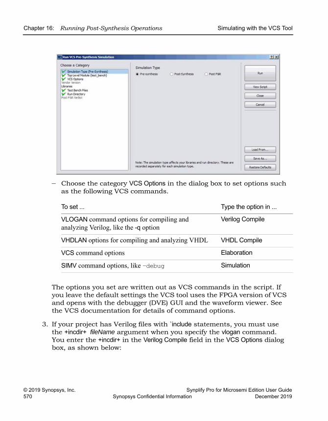
LO
Chapter 16: Running Post-Synthesis Operations Simulating with the VCS Tool
© 2019 Synopsys, Inc. Synplify Pro for Microsemi Edition User Guide570 Synopsys Confidential Information December 2019
– Choose the category VCS Options in the dialog box to set options such as the following VCS commands.
The options you set are written out as VCS commands in the script. If you leave the default settings the VCS tool uses the FPGA version of VCS and opens with the debugger (DVE) GUI and the waveform viewer. See the VCS documentation for details of command options.
3. If your project has Verilog files with `include statements, you must use the +incdir+ fileName argument when you specify the vlogan command. You enter the +incdir+ in the Verilog Compile field in the VCS Options dialog box, as shown below:
To set ... Type the option in ...
VLOGAN command options for compiling and analyzing Verilog, like the -q option
Verilog Compile
VHDLAN options for compiling and analyzing VHDL VHDL Compile
VCS command options Elaboration
SIMV command options, like -debug Simulation
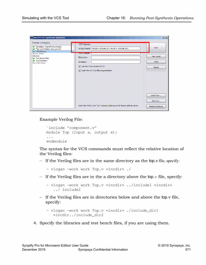
Simulating with the VCS Tool Chapter 16: Running Post-Synthesis Operations
Synplify Pro for Microsemi Edition User Guide © 2019 Synopsys, Inc.December 2019 Synopsys Confidential Information 571
Example Verilog File:
`include "component.v" module Top (input a, output x);...endmodule
The syntax for the VCS commands must reflect the relative location of the Verilog files:
– If the Verilog files are in the same directory as the top.v file, specify:
- vlogan -work work Top.v +incdir+ ./ – If the Verilog files are in the a directory above the top.v file, specify:
- vlogan -work work Top.v +incdir+ ../include1 +incdir+ ../ include2
– If the Verilog files are in directories below and above the top.v file, specify:
- vlogan -work work Top.v +incdir+ ./include_dir1+incdir../include_dir2
4. Specify the libraries and test bench files, if you are using them.
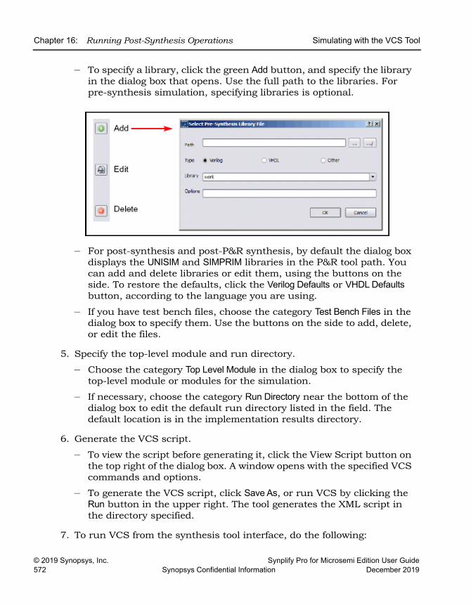
LO
Chapter 16: Running Post-Synthesis Operations Simulating with the VCS Tool
© 2019 Synopsys, Inc. Synplify Pro for Microsemi Edition User Guide572 Synopsys Confidential Information December 2019
– To specify a library, click the green Add button, and specify the library in the dialog box that opens. Use the full path to the libraries. For pre-synthesis simulation, specifying libraries is optional.
– For post-synthesis and post-P&R synthesis, by default the dialog box displays the UNISIM and SIMPRIM libraries in the P&R tool path. You can add and delete libraries or edit them, using the buttons on the side. To restore the defaults, click the Verilog Defaults or VHDL Defaults button, according to the language you are using.
– If you have test bench files, choose the category Test Bench Files in the dialog box to specify them. Use the buttons on the side to add, delete, or edit the files.
5. Specify the top-level module and run directory.
– Choose the category Top Level Module in the dialog box to specify the top-level module or modules for the simulation.
– If necessary, choose the category Run Directory near the bottom of the dialog box to edit the default run directory listed in the field. The default location is in the implementation results directory.
6. Generate the VCS script.
– To view the script before generating it, click the View Script button on the top right of the dialog box. A window opens with the specified VCS commands and options.
– To generate the VCS script, click Save As, or run VCS by clicking the Run button in the upper right. The tool generates the XML script in the directory specified.
7. To run VCS from the synthesis tool interface, do the following:
Simulating with the VCS Tool Chapter 16: Running Post-Synthesis Operations
Synplify Pro for Microsemi Edition User Guide © 2019 Synopsys, Inc.December 2019 Synopsys Confidential Information 573
– If you do not already have it open, open the Run VCS Simulator dialog box by clicking the icon.
– To use an existing script, click the Load From button on the lower right and select the script in the dialog box that opens. Then click Run in the Run VCS Simulator dialog box.
– If you do not have an existing script, specify the VCS options, as described in the previous five steps. Click Run.
The tool invokes VCS from the synthesis interface, using the commands in the script.
LimitationsIf Verilog include paths have been added to your project file, these paths are not automatically added to the VCS script. Add the Verilog include paths manually by using one of the following workarounds:
• From the Run VCS Simulator dialog box, add +incdir+includePath in the Verilog Compile options field.
• Modify the VCS script file, adding the +incdir+includePath to all or any relevant vlogan commands.

LO
Chapter 16: Running Post-Synthesis Operations Simulating with the VCS Tool
© 2019 Synopsys, Inc. Synplify Pro for Microsemi Edition User Guide574 Synopsys Confidential Information December 2019
Synplify Pro for Microsemi Edition User Guide © 2019 Synopsys, Inc.December 2019 Synopsys Confidential Information 575
Index
Symbols.adc file 371.ini file
parallel jobs 513
Numerics3rd party vendor tools
invoking 530
Aadc constraints 371adc file
creating 371object names 375
adc file, using 369Alt key
column editing 41mapping 332
analysis design constraint file (.adc) 371analysis design constraints
design scenarios 370analysis design constraints (adc) 369analysis design constraints (adc), using
with sdc 371Analyst view
traversing hierarchy 245archive utility
using 105archiving projects 105area, optimizing 403asterisk wildcard
Find command 263, 321attributes
adding 93adding in constraint files 182adding in SCOPE 96
adding in Verilog 95adding in VHDL 93effects of retiming 410for FSMs 393, 429handling properties 100syn_hier (on compile points) 467VHDL package 94
Attributes panelusing SCOPE 129
auto constraints, using 376AutoConstraint_design_name.sdc 379automatic compile points
compared to manual 438flow 456using with manual 469
BB.E.S.T 336backslash
escaping dot wildcard in Find command 263, 321
batch mode 20, 506using find and expand 152
Behavior Extracting Synthesis Technology. See B.E.S.T
black boxes 382adding constraints 386adding constraints in SCOPE 389adding constraints in Verilog 388adding constraints in VHDL 387instantiating in Verilog 382instantiating in VHDL 384passing VHDL boolean generics 51passing VHDL integer generics 52pin attributes 390
blocking-style license queuing 510bookmarks
in source files 41using in log files 192
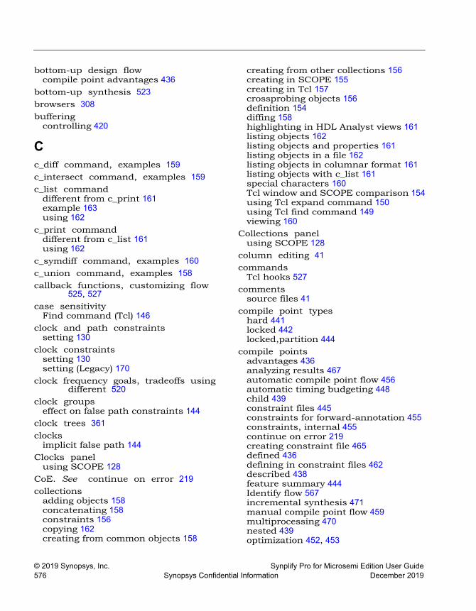
© 2019 Synopsys, Inc. Synplify Pro for Microsemi Edition User Guide576 Synopsys Confidential Information December 2019
bottom-up design flowcompile point advantages 436
bottom-up synthesis 523browsers 308buffering
controlling 420
Cc_diff command, examples 159c_intersect command, examples 159c_list command
different from c_print 161example 163using 162
c_print commanddifferent from c_list 161using 162
c_symdiff command, examples 160c_union command, examples 158callback functions, customizing flow
525, 527case sensitivity
Find command (Tcl) 146clock and path constraints
setting 130clock constraints
setting 130setting (Legacy) 170
clock frequency goals, tradeoffs using different 520
clock groupseffect on false path constraints 144
clock trees 361clocks
implicit false path 144Clocks panel
using SCOPE 128CoE. See continue on error 219collections
adding objects 158concatenating 158constraints 156copying 162creating from common objects 158
creating from other collections 156creating in SCOPE 155creating in Tcl 157crossprobing objects 156definition 154diffing 158highlighting in HDL Analyst views 161listing objects 162listing objects and properties 161listing objects in a file 162listing objects in columnar format 161listing objects with c_list 161special characters 160Tcl window and SCOPE comparison 154using Tcl expand command 150using Tcl find command 149viewing 160
Collections panelusing SCOPE 128
column editing 41commands
Tcl hooks 527comments
source files 41compile point types
hard 441locked 442locked,partition 444
compile pointsadvantages 436analyzing results 467automatic compile point flow 456automatic timing budgeting 448child 439constraint files 445constraints for forward-annotation 455constraints, internal 455continue on error 219creating constraint file 465defined 436defining in constraint files 462described 438feature summary 444Identify flow 567incremental synthesis 471manual compile point flow 459multiprocessing 470nested 439optimization 452, 453
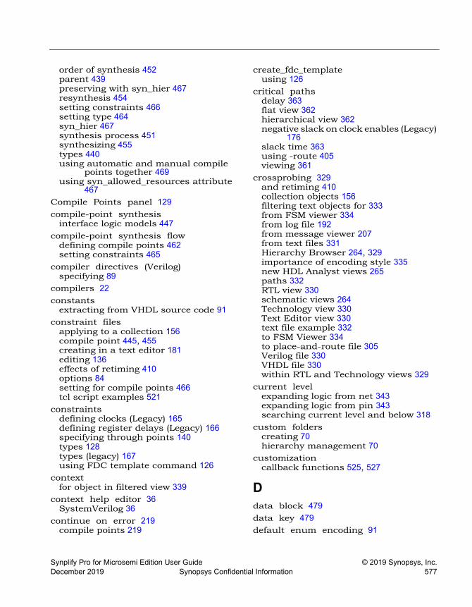
Synplify Pro for Microsemi Edition User Guide © 2019 Synopsys, Inc.December 2019 Synopsys Confidential Information 577
order of synthesis 452parent 439preserving with syn_hier 467resynthesis 454setting constraints 466setting type 464syn_hier 467synthesis process 451synthesizing 455types 440using automatic and manual compile
points together 469using syn_allowed_resources attribute
467Compile Points panel 129compile-point synthesis
interface logic models 447compile-point synthesis flow
defining compile points 462setting constraints 465
compiler directives (Verilog)specifying 89
compilers 22constants
extracting from VHDL source code 91constraint files
applying to a collection 156compile point 445, 455creating in a text editor 181editing 136effects of retiming 410options 84setting for compile points 466tcl script examples 521
constraintsdefining clocks (Legacy) 165defining register delays (Legacy) 166specifying through points 140types 128types (legacy) 167using FDC template command 126
contextfor object in filtered view 339
context help editor 36SystemVerilog 36
continue on error 219compile points 219
create_fdc_templateusing 126
critical pathsdelay 363flat view 362hierarchical view 362negative slack on clock enables (Legacy)
176slack time 363using -route 405viewing 361
crossprobing 329and retiming 410collection objects 156filtering text objects for 333from FSM viewer 334from log file 192from message viewer 207from text files 331Hierarchy Browser 264, 329importance of encoding style 335new HDL Analyst views 265paths 332RTL view 330schematic views 264Technology view 330Text Editor view 330text file example 332to FSM Viewer 334to place-and-route file 305Verilog file 330VHDL file 330within RTL and Technology views 329
current levelexpanding logic from net 343expanding logic from pin 343searching current level and below 318
custom folderscreating 70hierarchy management 70
customizationcallback functions 525, 527
Ddata block 479data key 479default enum encoding 91
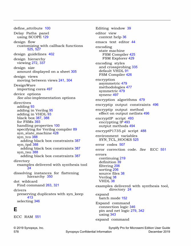
© 2019 Synopsys, Inc. Synplify Pro for Microsemi Edition User Guide578 Synopsys Confidential Information December 2019
define_attribute 100Delay Paths panel
using SCOPE 129design flow
customizing with callback functions 525, 527
design guidelines 402design hierarchy
viewing 272, 337design size
amount displayed on a sheet 305design views
moving between views 241, 304DesignWare
importing cores 497device options
See also implementation optionsdirectives
adding 93adding in Verilog 95adding in VHDL 93black box 387, 388for FSMs 393handling properties 100specifying for Verilog compiler 89syn_state_machine 428syn_tco 388
adding black box constraints 387syn_tpd 388
adding black box constraints 387syn_tsu 388
adding black box constraints 387directory
examples delivered with synthesis tool 24
dissolving instances for flattening hierarchy 350
dot wildcardFind command 263, 321
driverspreserving duplicates with syn_keep
413selecting 346
EECC RAM 551
Editing window 39editor view
context help 36emacs text editor 44encoding
state machineFSM Compiler 425FSM Explorer 429
encoding stylesand crossprobing 335default VHDL 91FSM Compiler 426
encryptionasymmetric 479methodologies 477symmetric 479synenc 497
encryption algorithms 479encryptip output constraints 496encryptip output method
effect on output netlists 496encryptIP script 493
encrypting IP 493output methods 494
encryptP1735.pl script 488environment variables
SYN_TCL_HOOKS 525error codes 507error correction code. See ECC 551errors
continuing 219definition 39filtering 206sorting 206source files 38Verilog 38VHDL 38
examples delivered with synthesis tool, directory 24
expandbatch mode 152
Expand commandconnection logic 346pin and net logic 279, 342using 343
expand command
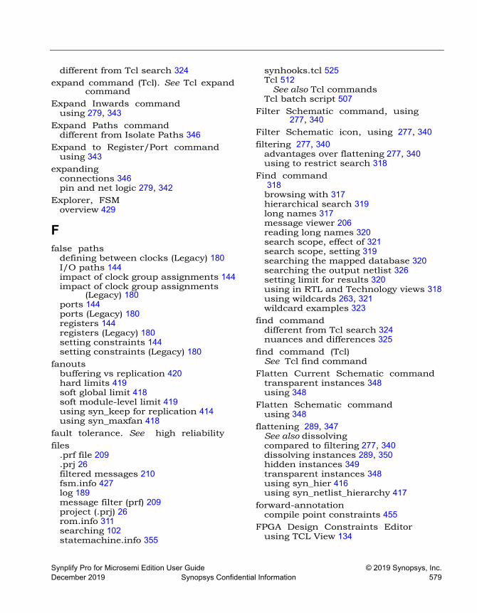
Synplify Pro for Microsemi Edition User Guide © 2019 Synopsys, Inc.December 2019 Synopsys Confidential Information 579
different from Tcl search 324expand command (Tcl). See Tcl expand
commandExpand Inwards command
using 279, 343Expand Paths command
different from Isolate Paths 346Expand to Register/Port command
using 343expanding
connections 346pin and net logic 279, 342
Explorer, FSMoverview 429
Ffalse paths
defining between clocks (Legacy) 180I/O paths 144impact of clock group assignments 144impact of clock group assignments
(Legacy) 180ports 144ports (Legacy) 180registers 144registers (Legacy) 180setting constraints 144setting constraints (Legacy) 180
fanoutsbuffering vs replication 420hard limits 419soft global limit 418soft module-level limit 419using syn_keep for replication 414using syn_maxfan 418
fault tolerance. See high reliabilityfiles
.prf file 209
.prj 26filtered messages 210fsm.info 427log 189message filter (prf) 209project (.prj) 26rom.info 311searching 102statemachine.info 355
synhooks.tcl 525Tcl 512
See also Tcl commandsTcl batch script 507
Filter Schematic command, using 277, 340
Filter Schematic icon, using 277, 340filtering 277, 340
advantages over flattening 277, 340using to restrict search 318
Find command 318browsing with 317hierarchical search 319long names 317message viewer 206reading long names 320search scope, effect of 321search scope, setting 319searching the mapped database 320searching the output netlist 326setting limit for results 320using in RTL and Technology views 318using wildcards 263, 321wildcard examples 323
find commanddifferent from Tcl search 324nuances and differences 325
find command (Tcl)See Tcl find command
Flatten Current Schematic commandtransparent instances 348using 348
Flatten Schematic commandusing 348
flattening 289, 347See also dissolvingcompared to filtering 277, 340dissolving instances 289, 350hidden instances 349transparent instances 348using syn_hier 416using syn_netlist_hierarchy 417
forward-annotationcompile point constraints 455
FPGA Design Constraints Editorusing TCL View 134
© 2019 Synopsys, Inc. Synplify Pro for Microsemi Edition User Guide580 Synopsys Confidential Information December 2019
frequencyclocks (Legacy) 173defining for non-clock signals (Legacy)
174internal clocks (Legacy) 173setting global 83
from constraints 139FSM Compiler
advantages 424enabling 426
FSM encodinguser-defined 395using syn_enum_encoding 395
FSM Explorer 424overview 429running 430when to use 424
FSM viewcrossprobing from source file 331
FSM Viewer 353crossprobing 334
fsm.info file 427FSMs
See also FSM Compiler, FSM Explorerattributes and directives 393defining in Verilog 391defining in VHDL 392definition 391optimizing with FSM Compiler 424properties 355safe. See safe FSMsstate encodings 354transition diagram 353viewing 353
Ggated clocks
defining (Legacy) 178Generated Clocks panel
using SCOPE 128generics
extracting from VHDL source code 91passing boolean 51passing integer 52
global optimization options 81
HHDL Analyst
See also RTL view, Technology viewcritical paths 361crossprobing 264, 329filtering schematics 277, 340Push/Pop mode 311, 314traversing hierarchy with mouse
strokes 309traversing hierarchy with Push/Pop
mode 249, 311using 272, 336
HDL Analyst tooldeselecting objects 236, 302selecting/deselecting objects 235, 302
HDL Analyst viewshighlighting collections 161
HDL views, annotating timing information 359
hidden instancesconsequences of saving 338flattening 349restricting search by hiding 318specifying 338status in other views 338
hierarchical designexpanding logic from nets 343expanding logic from pins 279, 342
hierarchical instancesdissolving 289, 350hiding. See hidden instances, Hide
Instances commandmultiple sheets for internal logic 339pin name display 341viewing internal logic 275, 338
hierarchical objectspushing into with mouse stroke 249, 310traversing with Push/Pop mode 249, 311
hierarchical search 318hierarchy
flattening 289, 347traversing 245, 308
hierarchy browserclock trees 361controlling display 305crossprobing from 264, 329defined 245, 308
Synplify Pro for Microsemi Edition User Guide © 2019 Synopsys, Inc.December 2019 Synopsys Confidential Information 581
finding objects 253, 316traversing hierarchy 308
hierarchy management (custom folders) 70
high reliabilityECC RAM 551safe FSMs 545using safe FSM 545
high reliability design 541hyper source
example 501for IPs 499for prototyping 499IP design hierarchy 499threading signals 500
II/O insertion 423I/O pads
specifying I/O standards 133I/O paths
false path constraint 144I/O standards
specifying 133I/O Standards panel
using SCOPE 129I/Os
auto-constraining 377constraining 132constraining (Legacy) 179preserving 423Verilog black boxes 382VHDL black boxes 384
Identifycompile points 567
IEEE 1735encrypting multiple files 491
implementation options 78device 78global frequency 83global optimization 81part selection 78specifying results 85
implementationscopying 77deleting 77
multiple. See multiple implementations.
overwriting 77renaming 77
incremental synthesiscompile points 471locked,partition compile points 444
initializing 396initializing RAM 396Input and output constraints
defining 132input constraints, setting 132input constraints, setting (Legacy) 178Inputs/Outputs panel
using SCOPE 129Instance Hierarchy tab 255instances
preserving with syn_noprune 413properties 228, 297properties of pins 297
ILM See interface logic modelsinterface logic models 447interface timing 448IP
encryption-decryption flow 477re-encryption 482
IP design hierarchyhyper source 499
IP encryptionIEEE 1735 488
IP encryption flow overview 476IP encryption scheme 482IP vendors
directory structure for package 484encrypting IP 482package file list for encrypted IP flow
484packaging for evaluation 483supplying vendor information 485
IPsencrypting 482encryption flow 476using hyper source for debug 499
Isolate Paths commanddifferent from Expand Paths 346, 347
© 2019 Synopsys, Inc. Synplify Pro for Microsemi Edition User Guide582 Synopsys Confidential Information December 2019
iterationsreducing with compile on error 219
Jjob management
up-to-date checking 184
Kkey assignments
customizing 526key block 479keywords
completing words in Text Editor 40
Llibrary extensions 45license
specifying in batch mode 20license queuing 508
blocking-style 510license release (synthesis)
after P&R 558license_release 558log file
remote access 195log files
checking FSM descriptions 431checking information 189retiming report 409setting default display 189state machine descriptions 426viewing 189
logicexpanding between objects 346expanding from net 281, 343expanding from pin 279, 342
logic preservationsyn_hier 417syn_keep for nets 413syn_keep for registers 413syn_noprune 413syn_preserve 413
logical folderscreating 70
Mmanual compile points
compared to automatic 438flow 459using with automatic 469
max_parallel_jobs variable 514maximum parallel jobs 513, 536MaxParallelJobs variable 513memory usage
maximizing with HDL Analyst 351Message viewer
filtering messages 207keyboard shortcuts 206saving filter expressions 208searching 206using 205using the F3 key to search forward 206using the Shift-F3 key to search
backward 206messagefilter.txt file 216messages
demoting 213filtering 207promoting 213saving filter information from command
line 209saving filter information from GUI 208severity levels 214suppressing 213writing messages to file 210
mitigation technology 541mixed designs
troubleshooting 51mixed language files 48mouse strokes
pushing/popping objects 248, 309multicycle paths
setting constraints 130setting constraints (Legacy) 171
multiple implementations 76running from project 76
multiple target technologies, synthesizing with Tcl script 519
multiprocessingcompile points 470maximum parallel jobs 513, 536
Synplify Pro for Microsemi Edition User Guide © 2019 Synopsys, Inc.December 2019 Synopsys Confidential Information 583
multisheet schematics 303for nested internal logic 339searching just one sheet 318transparent instances 303
Nname spaces
output netlist 326technology view 320
navigating among design views 241, 304nets
expanding logic from 281, 343preserving for probing with syn_probe
413preserving with syn_keep 413properties 228, 297selecting drivers 346
new Hierarchy Browser 254New property 299notes
filtering 206sorting 206
notes, definition 39
Oobjects
finding on current sheet 318flagging by property 298selecting/deselecting 302
open_designwith find and expand 153
optimizationfor area 403for timing 404logic preservation. See logic
preservation.preserving hierarchy 417preserving objects 413state machines 425tips for 402
optionssetting with set_option Tcl command
521orig_inst_of property 300output constraints, setting 132
output constraints, setting (Legacy) 178output files
specifying 85output netlists
finding objects 326overutilization 202
Ppackage library, adding 62pad types
industry standards 133parallel jobs 513parameter passing 52
boolean generics 51parameters
extracting from Verilog source code 89part selection options 78path constraints
false paths 144false paths (Legacy) 180
pathnamesusing wildcards for long names (Find)
321paths
crossprobing 332tracing between objects 346tracing from net 281, 343tracing from pin 279, 342
pattern matchingFind command (Tcl) 146
pattern searching 102PDF
cutting from 41pin names, displaying 341pins
expanding logic from 279, 342properties 228, 297
portsfalse path constraint 144false path constraint (Legacy) 180properties 228, 297
POS interfaceusing 140
post-synthesis constraints with adc 370
© 2019 Synopsys, Inc. Synplify Pro for Microsemi Edition User Guide584 Synopsys Confidential Information December 2019
preferencescrossprobing to place-and-route file 305displaying Hierarchy Browser 305displaying labels 306RTL and Technology views 305sheet size (UI) 305
primitivespin name display 341pushing into with mouse stroke 249, 310viewing internal hierarchy 337
private key 479prj file 26probes
adding in source code 432definition 432retiming 411
Product of Sums interface. See POS interface
project commandarchiving projects 105copying projects 114unarchiving projects 110
project file hierarchy 70project files
adding files 64adding source files 60batch mode 506creating 60definition 60deleting files from 64opening 63replacing files in 64updating include paths 68VHDL library 62
project files (.prj) 26project status report
remote access 195projects
archiving 105copying 114restoring archives 110
propertiesdisplaying with tooltip 228, 297finding objects with Tcl find -filter 147orig_inst_of 300reporting for collections 161viewing for individual objects 228, 297
prototypingusing hyper source threading 499
public key 479Push/Pop mode
HDL Analyst 309keyboard shortcut 311using 248, 249, 309, 311
Qquestion mark wildcard, Find command
263, 321
Rradiation effects. See high reliabilityRAMs 396
ECC 551initializing 396
register balancing. See retimingregister constraints, setting (Legacy) 170registers
false path constraint 144false path constraint (Legacy) 180
Registers panelusing SCOPE 129
remote accessstatus reports 195
replicationcontrolling 420
resource sharingoptimization technique 403overriding option with syn_sharing 423results example 423using 422
resource usage 201resource utilization. See resource usageresynthesis
compile points 454forcing with Resynthesize All 454forcing with Update Compile Point
Timing Data 454retiming
effect on attributes and constraints 410example 408overview 406probes 411
Synplify Pro for Microsemi Edition User Guide © 2019 Synopsys, Inc.December 2019 Synopsys Confidential Information 585
report 409simulation behavior 411
return codes 507rom.info file 311ROMs
viewing data table 311RTL view
See also HDL Analystanalyzing clock trees 361crossprobing collection objects 156crossprobing description 329crossprobing from 330crossprobing from Text Editor 331defined 296description 295filtering 277, 340finding objects with Find 318finding objects with Hierarchy Browser
253, 316flattening hierarchy 289, 347highlighting collections 161opening 225, 297selecting/deselecting objects 302setting preferences 305state machine implementation 427traversing hierarchy 308
running P&Rlicense release (synthesis) 558
runtimecontinue on error 219
Ssafe case 547safe FSM 545
using safe case 547schematics
multisheet. See multisheet schematicspage size 305selecting/deselecting objects 235, 302
SCOPEadding attributes 96adding probe insertion attribute 433Attributes panel 129case sensitivity for Verilog designs 146Clocks panel 128collections compared to Tcl script
window 154
Collections panel 128Compile Points panel 129creating compile-point constraint file
465defining compile points 462Delay Paths panel 129drag and drop 136editing operations 137Generated Clocks panel 128I/O pad type 133I/O Standards panel 129Inputs/Outputs panel 129multicycle paths 143Registers panel 129setting compile point constraints 466setting constraints (FDC) 122specifying constraints 128state machine attributes 393TCL View 129
SCOPE editorusing 122
SCOPE panelsentering and editing constraints 128
SCOPE TCL Viewusing 134
searchbrowsing objects with the Find
command 317browsing with the Hierarchy Browser
253, 316finding objects on current sheet 318setting limit for results 320setting scope 319using the Find command in HDL
Analyst views 318search in Analyst
browsing objects with the Find command 259
See also searchset command
collections 162set_option command 80sheet connectors
navigating with 304sheet size
setting number of objects 305shematic view
setting preferences (New Anallyst) 242
© 2019 Synopsys, Inc. Synplify Pro for Microsemi Edition User Guide586 Synopsys Confidential Information December 2019
Shift-F3 keyMessage Viewer 206
Show Cell Interior option 337Show Context command
different from Expand 339using 339
signalsthreading with hyper source. See hyper
sourcesimulation, effect of retiming 411slack 364
setting margins 361slack time display 358Slow property 299source code
commenting with synthesis on/off 92crossprobing from Tcl window 334defining FSMs 391fixing errors 42opening automatically to crossprobe
331optimizing 402
source filesSee also Verilog, VHDL.adding comments 41adding files 60checking 38column editing 41copying examples from PDF 41creating 34crossprobing 331editing 40editing operations 40mixed language 48specifying default encoding style 91specifying top level file for mixed
language projects 49specifying top-level file 91state machine attributes 393using bookmarks 41
special charactersTcl collections 160
STA 366STA, generating custom timing reports
366STA, using analysis design constraints
(adc) 369
stand-alone timing analyst. See STAstarting Synplify Pro 20state machines
See also FSM Compiler, FSM Explorer, FSM viewer, FSMs.
attributes 393descriptions in log file 426encoding
FSM Compiler 425FSM Explorer 429
implementation 427optimization 425parameter and ’define comparison 392
statemachine.info file 355Structural Verilog flow 53syn_allow_retiming
using for retiming 407syn_allowed_resources
compile points 467syn_encoding attribute 394syn_enum_encoding directive
FSM encoding 395syn_hier attribute
controlling flattening 416preserving hierarchy 417using with compile points 467
syn_isclockblack box clock pins 390
syn_keepreplicating redundant logic 414
syn_keep attributepreserving nets 413preserving shared registers 413
syn_keep directiveeffect on buffering 420
syn_macrospecifying encrypted IP as white box 495
syn_maxfan attributesetting fanout limits 418
syn_noprune directivepreserving instances 413
syn_preserveeffect on buffering 420preserving power-on for retiming 407
syn_preserve directivepreserving FSMs from optimization 393
Synplify Pro for Microsemi Edition User Guide © 2019 Synopsys, Inc.December 2019 Synopsys Confidential Information 587
preserving logic 413syn_probe attribute 432
inserting probes 432preserving nets 413
syn_reference_clock constraint (Legacy) 165
syn_replicate attributeusing buffering 420
syn_sharing directiveoverriding default 423
syn_state_machine directiveusing with value=0 428
SYN_TCL_HOOKS environment variable 525
SYN_TCL_HOOKS variable 527syn_tco attribute
adding in SCOPE 389syn_tco directive 388
adding black box constraints 387syn_tpd attribute
adding in SCOPE 389syn_tpd directive 388
adding black box constraints 387syn_tsu attribute
adding in SCOPE 389syn_tsu directive 388
adding black box constraints 387syn_useioff
preventing flops from moving during retiming 408
synenc encryption 497synhooks
automating message filtering 210synhooks.tcl file 525, 527Synopsys
FPGA product family 16Synplify Pro synthesis tool
overview 16synplify_pro command-line command 20SYNPLIFY_REMOTE_REPORT_LOCATIO
N 197syntax
checking source files 38syntax check 38
synthesis check 38synthesis software
flow 22synthesis_on/off
using 92SystemVerilog keywords
context help 36
Tta file 366Tcl
max_parallel_jobs variable 514tcl callbacks
customizing key assignments 526Tcl commands
batch script 507running 512syntax for Tcl hooks 527
Tcl expandusing 145
Tcl expand commandcrossprobing objects 156usage tips 150using in SCOPE 155
Tcl files 512creating 515for bottom-up synthesis 519guidelines 55naming conventions 56recording from commands 513synhooks.tcl 525using variables 516wildcards 56
Tcl findbatch mode 152filtering results by property 147search patterns 145using 145
Tcl find commandannotating properties 147case sensitivity 146crossprobing objects 156database differences 155pattern matching 146Tcl window vs SCOPE 154usage tips 149
© 2019 Synopsys, Inc. Synplify Pro for Microsemi Edition User Guide588 Synopsys Confidential Information December 2019
useful -filter examples 149using in SCOPE 155
Tcl Script windowcrossprobing 334message viewer 205
Tcl script windowcollections compared to SCOPE 154
Tcl scriptsexamples 519See Tcl files.
TCL View 134using 134using SCOPE 129
-tclcmd 506Technology view
See also HDL Analystcritical paths 361crossprobing 329, 330crossprobing collection objects 156crossprobing from source file 331filtering 277, 340finding objects 320finding objects with Find 318finding objects with Hierarchy Browser
253, 316flattening hierarchy 289, 347general description 295highlighting collections 161opening 297selecting/deselecting objects 302setting preferences 305state machine implementation in 427traversing hierarchy 308
text editorbuilt-in 39external 44using 39
Text Editor viewcrossprobing 330
Text Editor windowcolors 42crossprobing 42fonts 42
text filescrossprobing 331
The Synopsys FPGA Product Family 16third-party vendor tools
invoking 530through constraints 140
AND lists 141OR lists 140
time stamp, checking on files 65timing analysis 358timing analysis using STA 366timing budgeting
compile points 448timing constraints (Legacy) 165timing exceptions, adding constraints
after synthesis 370timing exceptions, modifying with adc
370timing failures 364timing information commands 358timing information in HDL views 359timing information, critical paths 363timing optimization 404timing report, stand-alone 366timing reports
specifying format options 87timing reports, custom 366tips
memory usage 351to constraints
specifying 140tool tags
creating 530definition 530
top levelspecifying 91
top-down design flowcompile point advantages 436
transparent instancesflattening 348lower-level logic on multiple sheets 303
Uup-to-date checking 184
copying job logs to log file 186limitations 187
using 53
Synplify Pro for Microsemi Edition User Guide © 2019 Synopsys, Inc.December 2019 Synopsys Confidential Information 589
Vvendor-specific Tcl commands 527Verilog
‘define statements 89adding attributes and directives 95adding probes 432black boxes 382black boxes, instantiating 382case sensitivity for Tcl Find command
146checking source files 38choosing a compiler 88creating source files 34crossprobing from HDL Analyst view
330defining FSMs 391defining state machines with parameter
and ’define 392editing operations 40extracting parameters 89include paths, updating 68initializing RAMs 396mixed language files 48specifying compiler directives 89specifying top-level module 91using library extensions 45
Verilog 2001setting global option from the Project
view 88setting option per file 88
Verilog library filesusing library extensions 45
Verilog model (.vmd) 447VHDL
adding attributes and directives 93adding probes 432black boxes 384black boxes, instantiating 384case sensitivity for Tcl Find command
146checking source file 38constants 91creating source files 34crossprobing from HDL Analyst view
330defining FSMs 392editing operations 40extracting generics 91global signals in mixed designs 51
initializing RAMs with variable declarations 399
initializing with signal declarations 397mixed language files 48specifying top-level entity 91
VHDL filesadding library 62adding third-party package library 62
vi text editor 44virtual clock, setting (Legacy) 170
Wwarning messages
definition 39warnings
feedback muxes 405filtering 206sorting 206
Watch window 199moving 200, 205multiple implementations 77resizing 200, 205
wildcardseffect of search scope 321Find command (Tcl) 146message filter 208
wildcards (Find)examples 323how they work 263, 321

LO
© 2019 Synopsys, Inc. Synplify Pro for Microsemi Edition User Guide590 Synopsys Confidential Information December 2019


