Embed Size (px)
Citation preview

1
2
3
4
5
Products Available From
Solid State Relays and I/O ModulesCatalog 1
Automation ControlsCatalog 2
Switches and SensorsCatalog 3
Motors and FansCatalog 4
PneumaticsCatalog 5
For your copy of the catalogs, contact
Tel: (800) 677-5311 / Fax: (800) 677-3865www.crouzet-usa.comProducts and specifications subject to change without notice.
Order/Technical Support – Tel: (800) 677-5311 / FAX: (800) 677-3865 / www.crouzet-usa.com
3/i

Products and specifications subject to change without notice.
Order/Technical Support – Tel: (800) 677-5311 / FAX: (800) 677-3865 / www.crouzet-usa.com
3/ii
SWITCHES AND SENSORS SWITCHES AND SENSORS
Snap Action Switches:
83132 / 83133 / 83134 Subminiature Double Break Switches . . . . . . . . . . . . . . . . . . 3/2
83170 Subminiature Switches . . . . . . . . . . . . . . . . . . . . . . . . . . . . . . . . . . . . . . . . . . 3/6
83180 Sealed Subminiature Switches . . . . . . . . . . . . . . . . . . . . . . . . . . . . . . . . . . . . 3/10
83161 Miniature Switches . . . . . . . . . . . . . . . . . . . . . . . . . . . . . . . . . . . . . . . . . . . . . 3/14
83160 Miniature Positive Break Switches . . . . . . . . . . . . . . . . . . . . . . . . . . . . . . . . . 3/18
83137 Miniature Side Rotary Switches . . . . . . . . . . . . . . . . . . . . . . . . . . . . . . . . . . . 3/19
83106 / 83109 / 83112 / 83154 Double Break Switches . . . . . . . . . . . . . . . . . . . . . . 3/20
83139 Sealed Double Break Switches . . . . . . . . . . . . . . . . . . . . . . . . . . . . . . . . . . . 3/24
83169 Sealed Miniature Switches . . . . . . . . . . . . . . . . . . . . . . . . . . . . . . . . . . . . . . . 3/28
83123 Sealed Flat-Pack Switches . . . . . . . . . . . . . . . . . . . . . . . . . . . . . . . . . . . . . . . 3/31
81290 Low Force Position Detectors . . . . . . . . . . . . . . . . . . . . . . . . . . . . . . . . . . . . 3/32
Industrial Limit Switches:
83852 / 83853 Miniature Industrial Limit Switches, Positive Opening . . . . . . . . . . . . . 3/34
83862 Industrial Limit Switches, Positive Opening . . . . . . . . . . . . . . . . . . . . . . . . . . . 3/36
83870 Miniature Pre-Cabled Limit Switches, Positive Opening . . . . . . . . . . . . . . . . . 3/40
83880 Pre-Cabled Limit Switches, Positive Opening . . . . . . . . . . . . . . . . . . . . . . . . . 3/42
83800 Miniature Limit Switches . . . . . . . . . . . . . . . . . . . . . . . . . . . . . . . . . . . . . . . . 3/44
83731 / 83732 / 83733 Automotive Limit Switches . . . . . . . . . . . . . . . . . . . . . . . . . . 3/46
83589 Automotive Limit Switches . . . . . . . . . . . . . . . . . . . . . . . . . . . . . . . . . . . . . . . 3/47
83581 Sealed Limit Switches, Telescopic-Actuator . . . . . . . . . . . . . . . . . . . . . . . . . . 3/48
83523 / 83528 Door Interlock Switches . . . . . . . . . . . . . . . . . . . . . . . . . . . . . . . . . . . 3/50
83856 / 83857 Manual Reset Positive Opening Miniature Limit Switches . . . . . . . . . 3/52
83841 Waterproof Limit Switch . . . . . . . . . . . . . . . . . . . . . . . . . . . . . . . . . . . . . . . . . 3/55
83863 / 83864 Cable Pull Limit Switches . . . . . . . . . . . . . . . . . . . . . . . . . . . . . . . . . 3/56
Safety (Security) Limit Switches:
838930 / 838931 Miniature Plastic Key Lock Limit Switches . . . . . . . . . . . . . . . . . . . 3/58
838932 Solenoid Operated Plastic Key Lock Limit Switches . . . . . . . . . . . . . . . . . . . 3/60
838940 Industrial Metal Key Lock Limit Switches . . . . . . . . . . . . . . . . . . . . . . . . . . . 3/62

Products and specifications subject to change without notice.
Order/Technical Support – Tel: (800) 677-5311 / FAX: (800) 677-3865 / www.crouzet-usa.com
3/iii
3
SWITCHES AND SENSORS SWITCHES AND SENSORS
Safety (Security) Limit Switches:
838941 Solenoid Operated Metal Key Lock Limit Switches . . . . . . . . . . . . . . . . . . . . 3/64
83893 Hinged Limit Switches . . . . . . . . . . . . . . . . . . . . . . . . . . . . . . . . . . . . . . . . . . 3/66
838942 Cable Pull Limit Switches . . . . . . . . . . . . . . . . . . . . . . . . . . . . . . . . . . . . . . . 3/68
838950 / 838951 Foot Switches . . . . . . . . . . . . . . . . . . . . . . . . . . . . . . . . . . . . . . . . 3/70
79697 E-Stop Switches . . . . . . . . . . . . . . . . . . . . . . . . . . . . . . . . . . . . . . . . . . . . . . 3/72
85100 Two-Hand Control Switch . . . . . . . . . . . . . . . . . . . . . . . . . . . . . . . . . . . . . . . . 3/73
Proximity Sensors:
Analog Inductive Proximity Detectors . . . . . . . . . . . . . . . . . . . . . . . . . . . . . . . . . . . . 3/77
Ø4, M5, Ø6, M8 Inductive Proximity Detectors Cable Output-3 Wire DC Series-Stainless Steel . . . . . . . . . . . . . . . . . . . . . . . . . . . . 3/78
Ø4, M5 M8 Inductive Proximity DetectorsConnector Output-3 Wire DC Series-Stainless Steel . . . . . . . . . . . . . . . . . . . . . . . . . 3/78
M12 Inductive Proximity Detectors Cable Output-3 Wire DC Series-Stainless Steel . . . . . . . . . . . . . . . . . . . . . . . . . . . . 3/80
M12 Inductive Proximity Detectors Cable Output-2 Wire AC Series-Stainless Steel . . . . . . . . . . . . . . . . . . . . . . . . . . . . 3/80
M12 Inductive Proximity DetectorsConnector Output-3 Wire DC Series-Stainless Steel . . . . . . . . . . . . . . . . . . . . . . . . . 3/81
M12 Inductive Proximity DetectorsConnectors Output-2 Wire AC Series-Stainless Steel . . . . . . . . . . . . . . . . . . . . . . . . 3/81
M12 Inductive Proximity Detectors Cable Output-3 Wire DC Series-Plastic . . . . . . . . . . . . . . . . . . . . . . . . . . . . . . . . . . . 3/83
M12 Inductive Proximity Detectors Connector Output-3 Wire DC Series-Plastic . . . . . . . . . . . . . . . . . . . . . . . . . . . . . . . 3/83
M18 Inductive Proximity Detectors Cable Output-3 Wire DC Series-Stainless Steel . . . . . . . . . . . . . . . . . . . . . . . . . . . . 3/84
M18 Inductive Proximity DetectorsCable Output-2 Wire AC Series-Stainless Steel . . . . . . . . . . . . . . . . . . . . . . . . . . . . 3/84
M18 Inductive Proximity DetectorsConnector Output-3 Wire DC Series-Stainless Steel . . . . . . . . . . . . . . . . . . . . . . . . . 3/84
M18 Inductive Proximity DetectorsConnector Output-2 Wire AC Series-Stainless Steel . . . . . . . . . . . . . . . . . . . . . . . . . 3/84
M18 Inductive Proximity Detectors Cable Output-3 Wire DC Series-Plastic . . . . . . . . . . . . . . . . . . . . . . . . . . . . . . . . . . . 3/86
M18 Inductive Proximity Detectors Cable Output-2 Wire AC Series-Plastic . . . . . . . . . . . . . . . . . . . . . . . . . . . . . . . . . . . 3/86

Products and specifications subject to change without notice.
Order/Technical Support – Tel: (800) 677-5311 / FAX: (800) 677-3865 / www.crouzet-usa.com
3/iv
SWITCHES AND SENSORS SWITCHES AND SENSORS
Proximity Sensors:
M18 Inductive Proximity Detectors Connector Output-3 Wire DC Series-Plastic . . . . . . . . . . . . . . . . . . . . . . . . . . . . . . . 3/87
M30 Inductive Proximity Detectors Cable Output-3 Wire DC Series-Stainless Steel . . . . . . . . . . . . . . . . . . . . . . . . . . . . 3/88
M30 Inductive Proximity Detectors Cable Output-2 Wire AC Series-Stainless Steel . . . . . . . . . . . . . . . . . . . . . . . . . . . . 3/88
M30 Inductive Proximity DetectorsConnector Output-3 Wire DC Series-Stainless Steel . . . . . . . . . . . . . . . . . . . . . . . . . 3/89
M30 Inductive Proximity Detectors Connector Output-2 Wire AC Series-Stainless Steel . . . . . . . . . . . . . . . . . . . . . . . . . 3/89
M30 Inductive Proximity Detectors Cable Output-3 Wire DC Series-Plastic . . . . . . . . . . . . . . . . . . . . . . . . . . . . . . . . . . . 3/90
M30 Inductive Proximity Detectors Cable Output-2 Wire AC Series-Plastic . . . . . . . . . . . . . . . . . . . . . . . . . . . . . . . . . . . 3/90
M30 Inductive Proximity Detectors Connector Output-3 Wire DC Series-Plastic . . . . . . . . . . . . . . . . . . . . . . . . . . . . . . . 3/91
Inductive Proximity Detector-Flat Pack 55x35 mm . . . . . . . . . . . . . . . . . . . . . . . . . . . 3/92
Inductive Proximity Detector 40x40 mm . . . . . . . . . . . . . . . . . . . . . . . . . . . . . . . . . . 3/93
M8 Inductive Proximity DetectorsCable Output-2 Wire DC NAMUR Series-Stainless Steel . . . . . . . . . . . . . . . . . . . . . 3/94
M18 Inductive Proximity DetectorsCable Output-2 Wire DC NAMUR Series-Stainless Steel . . . . . . . . . . . . . . . . . . . . . 3/94
M18 Inductive Proximity DetectorsConnector Output-2 Wire DC NAMUR Series-Stainless Steel . . . . . . . . . . . . . . . . . . 3/94
M12 Inductive Proximity DetectorsCable Output-2 Wire DC NAMUR Series-Stainless Steel . . . . . . . . . . . . . . . . . . . . . 3/95
M12 Inductive Proximity DetectorsConnector Output-2 Wire DC NAMUR Series-Stainless Steel . . . . . . . . . . . . . . . . . . 3/95
M30 Inductive Proximity DetectorsCable Output-2 Wire DC NAMUR Series-Stainless Steel . . . . . . . . . . . . . . . . . . . . . 3/95
M30 Inductive Proximity Detectors-Connector Output2 Wire DC NAMUR Series-Stainless Steel . . . . . . . . . . . . . . . . . . . . . . . . . . . . . . . . 3/95
Inductive Proximity Detectors for Severe Environments . . . . . . . . . . . . . . . . . . . . . . . 3/96
M18 Capacitive Proximity DetectorsCable Output-3 Wire DC Series-Plastic . . . . . . . . . . . . . . . . . . . . . . . . . . . . . . . . . . . 3/97
M18 Capacitive Proximity DetectorsCable Output-2 Wire AC Series-Plastic . . . . . . . . . . . . . . . . . . . . . . . . . . . . . . . . . . . 3/97
Products and specifications subject to change without notice.
Order/Technical Support – Tel: (800) 677-5311 / FAX: (800) 677-3865 / www.crouzet-usa.com
3/v
3
SWITCHES AND SENSORS SWITCHES AND SENSORS
Proximity Sensors:
M30 Capacitive Proximity DetectorsCable Output-2 Wire AC Series-Plastic . . . . . . . . . . . . . . . . . . . . . . . . . . . . . . . . . . . 3/97
Capacitive Proximity Detector-Flat Pack 55x35 mm . . . . . . . . . . . . . . . . . . . . . . . . . 3/98
M30 Programmable Capacitive Proximity DetectorsCable Output-4 Wire DC Series-Plastic . . . . . . . . . . . . . . . . . . . . . . . . . . . . . . . . . . . 3/99
M30 Programmable Capacitive Proximity DetectorsCable Output-2 Wire AC Series-Plastic . . . . . . . . . . . . . . . . . . . . . . . . . . . . . . . . . . . 3/99
M8 Connectors . . . . . . . . . . . . . . . . . . . . . . . . . . . . . . . . . . . . . . . . . . . . . . . . . . . . . 3/100
M12 Connectors . . . . . . . . . . . . . . . . . . . . . . . . . . . . . . . . . . . . . . . . . . . . . . . . . . . . 3/101
Mounting Flanges . . . . . . . . . . . . . . . . . . . . . . . . . . . . . . . . . . . . . . . . . . . . . . . . . . . 3/102
Switches and Sensors Technical References:
Snap Action Switches-Technical Guide . . . . . . . . . . . . . . . . . . . . . . . . . . . . . . . . . . . 3/104
Limit Switches-Technical Guide . . . . . . . . . . . . . . . . . . . . . . . . . . . . . . . . . . . . . . . . 3/111
Key-Operated Safety Limit Switches-Technical Guide . . . . . . . . . . . . . . . . . . . . . . . . 3/113
Inductive Proximity Detectors-Technical Guide . . . . . . . . . . . . . . . . . . . . . . . . . . . . . 3/115
Capacitive Proximity Detectors-Technical Guide . . . . . . . . . . . . . . . . . . . . . . . . . . . . 3/121
Pivot point
Blade
Mounting hole
Terminal NC nº2
Terminal NO nº4
Contact mobile
Contact fixed
Case
Push button
Return spring
Mounting hole
Common terminal C nº1
10° (x 360°)
24 V
0V
KNA3-XS
13 23 33
14 24 34
A1 Y1 Y22313 33
14 24 3441A2 42
C2
C2
C1
C1
C3
C3

Products and specifications subject to change without notice.
Order/Technical Support – Tel: (800) 677-5311 / FAX: (800) 677-3865 / www.crouzet-usa.com
3/vi
Index
25552953 3/10025552954 3/10025552955 3/10025552956 3/10025552957 3/10025552958 3/10025552959 3/10025552960 3/10025552961 3/10025552962 3/10025552963 3/10025552964 3/10025552965 3/10025552966 3/10025552967 3/10125552968 3/10125552969 3/10125552970 3/10125552971 3/10125552972 3/10125552973 3/10125552974 3/10125552975 3/10125552976 3/10125552977 3/10125552978 3/10125552979 3/10125552980 3/10125552981 3/10125552982 3/10125552983 3/10125552984 3/10125552989 3/10125552990 3/10125552991 3/10125552992 3/10126546820 3/10226546821 3/10226546822 3/10226546823 3/10226546824 3/10226546825 3/10226546826 3/10270500206 3/2170500208 3/2170500218 3/2170500813 3/2170500828 3/2170500840 3/2170500870 3/2170500888 3/2070507524 3/1570507524 3/2970507526 3/1570507528 3/1570507529 3/1570507529 3/2570507529 3/2970514131 3/370514175 3/370514181 3/370514182 3/370514183 3/370514194 3/370514559 3/379210997 3/4579210998 3/4579214571 3/6879214572 3/6879214573 3/6879214574 3/6879214576 3/6879214577 3/6879214578 3/62
79214578 3/6479214579 3/6279214579 3/6479214580 3/6279214580 3/6479214581 3/5879214582 3/5879214583 3/5879214584 3/5879214585 3/5879215332 3/4579215740 3/1479215740 3/2579215740 3/2979215741 3/3279215742 3/1579215742 3/2579215742 3/1979215743 3/3279215835 3/1579218454 3/779218454 3/1179218581 3/2579218581 3/2979218651 3/1479218651 3/2579218651 3/2979250290 3/3679250291 3/3679253326 3/779253326 3/1179253327 3/779253327 3/1179253328 3/779253328 3/1179253329 3/779253329 3/1179507524 3/2579697001 3/7379697003 3/7279697004 3/7279697005 3/7279697006 3/7279697008 3/7279697009 3/7279697010 3/7279697011 3/7279697101 3/7279697101 3/7381290001 3/3281290501 3/32825233 3/51831060 3/20831064 3/21831067 3/21831090 3/21831110 3/21831115 3/21831120 3/21831230 3/31831320 3/3831330 3/3831340 3/3831370 3/19831390 3/25831391 3/25831392 3/25831395 3/25831540 3/21831607 3/2983161.1 3/1583161.2 3/1583161.3 3/1583161.5 3/15
83161.5SP4136 3/1583161.6 3/1583161.8 3/1583161.9 3/1583161.9SP4136 3/15831690 3/29831694 3/29831698 3/29831699 3/2983170.0 3/783170.4 3/783170.4SP4967 3/783170.9 3/783180.0 3/1183181.0 3/1183183.0 3/1183186.0 3/11835230 3/51835280 3/51835283 3/51835810 3/49835811 3/49835890 3/47835898 3/47837313 3/46837323 3/46837333 3/4683770025 3/5483770035 3/5483777021 3/5583778021 3/5583800151 3/4583801051 3/4583802051 3/4583803051 3/4583805051 3/4583806051 3/4583807051 3/4583852001 3/3483852011 3/3483852101 3/3483852111 3/3483852201 3/3483852211 3/3483852301 3/3583852302 3/3583852303 3/3583852304 3/3583852305 3/3583852306 3/3583852307 3/3583852308 3/3583852311 3/3583852312 3/3583852313 3/3583852314 3/3583852315 3/3583852316 3/3583852317 3/3583852318 3/3583852501 3/3483852511 3/3483852601 3/3583852611 3/3583853001 3/3483853011 3/3483853101 3/3483853111 3/3483853201 3/3483853211 3/3483853301 3/3583853302 3/3583853303 3/3583853304 3/35
83853305 3/3583853306 3/3583853307 3/3583853308 3/3583853311 3/3583853312 3/3583853313 3/3583853314 3/3583853315 3/3583853316 3/3583853317 3/3583853318 3/3583853501 3/3483853511 3/3483853601 3/3583853611 3/3583856011 3/5383856111 3/5383856211 3/5383856311 3/5383856312 3/5383856313 3/5383856315 3/5383856316 3/5383856317 3/5383856318 3/5383856511 3/5383857011 3/5383857111 3/5383857211 3/5383857311 3/5383857312 3/5383857313 3/5383857315 3/5383857316 3/5383857317 3/5383857318 3/5383862001 3/3683862011 3/3683862101 3/3683862111 3/3683862201 3/3683862211 3/3683862301 3/3783862302 3/3783862303 3/3783862304 3/3783862305 3/3783862306 3/3783862307 3/3783862308 3/3783862311 3/3783862312 3/3783862313 3/3783862314 3/3783862315 3/3783862316 3/3783862317 3/3783862318 3/3783862501 3/3683862511 3/3683862601 3/3783862611 3/3783863001 3/5683863002 3/5683870102 3/4183870103 3/4183871102 3/4183871103 3/4183872102 3/4183872103 3/4183873102 3/4183873103 3/4183874102 3/41
Part Number Page Part Number Page Part Number Page Part Number Page

Products and specifications subject to change without notice.
Order/Technical Support – Tel: (800) 677-5311 / FAX: (800) 677-3865 / www.crouzet-usa.com
3/vii
3
Index
83874103 3/4183880102 3/4383880103 3/4383881102 3/4383881103 3/4383882102 3/4383882103 3/4383883102 3/4383883103 3/4383884102 3/4383884103 3/4383893001 3/5883893010 3/5883893120 3/5883893130 3/5883893201 3/6083893202 3/6083893203 3/6083893301 3/6783893302 3/6783893303 3/6783893401 3/6783894020 3/6283894120 3/6483894121 3/6483894122 3/6483894130 3/6483894131 3/6483894132 3/6483894201 3/6883895001 3/7083895030 3/7083895101 3/7084717000 3/7884717001 3/7884717002 3/7884717003 3/7884717004 3/7984717005 3/7984717006 3/7984717007 3/7984717008 3/7984717009 3/7984717010 3/7884717011 3/7884717012 3/7884717013 3/7884717014 3/7984717015 3/7984717016 3/7984717017 3/7984717018 3/7984717019 3/7984717020 3/7984717021 3/7984717022 3/7884717023 3/7884717024 3/7884717025 3/7884717026 3/8084717027 3/8084717028 3/8184717029 3/8184717030 3/8184717031 3/8184717032 3/8284717033 3/8284717038 3/8384717039 3/8384717040 3/8384717041 3/8384717042 3/8384717043 3/8384717044 3/83
84717045 3/8384717050 3/8484717051 3/8484717052 3/8584717053 3/8584717054 3/8584717055 3/8584717056 3/8584717057 3/8584717062 3/8684717063 3/8684717064 3/8784717065 3/8784717066 3/8784717067 3/8784717068 3/8784717069 3/8784717074 3/8884717075 3/8884717076 3/8984717077 3/8984717078 3/8984717079 3/8984717080 3/8984717081 3/8984717086 3/9084717087 3/9084717088 3/9184717089 3/9184717090 3/9184717091 3/9184717092 3/9184717093 3/9184717100 3/7884717101 3/7884717102 3/7884717103 3/7884717104 3/7984717105 3/7984717106 3/7984717107 3/7984717108 3/7984717109 3/7984717110 3/7884717111 3/7884717112 3/7884717113 3/7884717114 3/7984717115 3/7984717116 3/7984717117 3/7984717118 3/7984717119 3/7984717120 3/7984717121 3/7984717122 3/7884717123 3/7884717124 3/7884717125 3/7884717126 3/8084717127 3/8084717128 3/8184717129 3/8184717130 3/8184717131 3/8184717132 3/8284717133 3/8284717138 3/8384717139 3/8384717140 3/8384717141 3/8384717142 3/8384717143 3/8384717144 3/83
84717145 3/8384717150 3/8484717151 3/8484717152 3/8584717153 3/8584717154 3/8584717155 3/8584717156 3/8584717157 3/8584717162 3/8684717163 3/8684717164 3/8784717165 3/8784717166 3/8784717167 3/8784717168 3/8784717169 3/8784717174 3/8884717175 3/8884717176 3/8984717177 3/8984717178 3/8984717179 3/8984717180 3/8984717181 3/8984717186 3/9084717187 3/9084717188 3/9184717189 3/9184717190 3/9184717191 3/9184717192 3/9184717193 3/9184717226 3/8084717227 3/8084717228 3/8084717229 3/8084717230 3/8184717231 3/8184717232 3/8184717233 3/8184717238 3/8384717239 3/8384717240 3/8384717241 3/8384717242 3/8384717243 3/8384717244 3/8384717245 3/8384717246 3/8284717247 3/8284717248 3/8284717249 3/8284717250 3/8484717251 3/8484717252 3/8484717253 3/8484717254 3/8584717255 3/8584717256 3/8584717257 3/8584717258 3/8584717259 3/8584717260 3/8584717261 3/8584717262 3/8684717263 3/8684717264 3/8684717265 3/8684717266 3/8784717267 3/8784717268 3/8784717269 3/8784717274 3/88
84717275 3/8884717276 3/8884717277 3/8884717278 3/8984717279 3/8984717280 3/8984717281 3/8984717282 3/8984717283 3/8984717284 3/8984717285 3/8984717286 3/9084717287 3/9084717288 3/9084717289 3/9084717290 3/9184717291 3/9184717292 3/9184717293 3/9184717326 3/8084717327 3/8084717328 3/8084717329 3/8084717330 3/8184717331 3/8184717332 3/8184717333 3/8184717338 3/8384717339 3/8384717340 3/8384717341 3/8384717342 3/8384717343 3/8384717344 3/8384717345 3/8384717346 3/8284717347 3/8284717348 3/8284717349 3/8284717350 3/8484717351 3/8484717352 3/8484717353 3/8484717354 3/8584717355 3/8584717356 3/8584717357 3/8584717358 3/8584717359 3/8584717360 3/8584717361 3/8584717362 3/8684717363 3/8684717364 3/8684717365 3/8684717366 3/8784717367 3/8784717368 3/8784717369 3/8784717374 3/8884717375 3/8884717376 3/8884717377 3/8884717378 3/8984717379 3/8984717380 3/8984717381 3/8984717382 3/8984717383 3/8984717384 3/8984717385 3/8984717386 3/9084717387 3/9084717388 3/90
Part Number Page Part Number Page Part Number Page Part Number Page

Products and specifications subject to change without notice.
Order/Technical Support – Tel: (800) 677-5311 / FAX: (800) 677-3865 / www.crouzet-usa.com
3/viii
Index
84717389 3/9084717390 3/9184717391 3/9184717392 3/9184717393 3/9184717626 3/8084717627 3/8084717628 3/8184717629 3/8184717630 3/8184717631 3/8184717632 3/8284717633 3/8284717646 3/8284717647 3/8284717648 3/8284717649 3/8284717650 3/8484717651 3/8484717652 3/8484717653 3/8484717654 3/8584717655 3/8584717656 3/8584717657 3/8584717662 3/8684717663 3/8684717664 3/8784717665 3/8784717670 3/8484717671 3/8484717672 3/8484717673 3/8484717674 3/8884717675 3/8884717676 3/8884717677 3/8884717678 3/8984717679 3/8984717680 3/8884717681 3/8884717684 3/8984717685 3/8984717686 3/9084717687 3/9084717688 3/9184717689 3/9184717694 3/8984717695 3/8984717707 3/9484717709 3/9484717731 3/9584717733 3/9584717743 3/9584717745 3/9584717755 3/9484717757 3/9484717767 3/9484717769 3/9484717779 3/9584717781 3/9584717791 3/9584717793 3/9584718006 3/9384718008 3/9384718010 3/9384718024 3/9284718026 3/9284718030 3/9284718032 3/9284718036 3/9284718038 3/9284718042 3/9284718044 3/92
84718506 3/9784718508 3/9784718510 3/9784718511 3/9784718524 3/9984718526 3/9984718528 3/9984718530 3/9984718532 3/9984718534 3/9984718572 3/9884718574 3/9884718578 3/9884718580 3/9884718588 3/9784718589 3/9784799801 3/9684799802 3/9684799803 3/9684799804 3/9685100291 3/7385100292 3/7385100293 3/73IMB1805T 3/77
Part Number Page Part Number Page Part Number Page Part Number Page

Snap Action Switches
Products and specifications subject to change without notice.
Order/Technical Support – Tel: (800) 677-5311 / FAX: (800) 677-3865 / www.crouzet-usa.com
3/1
3
Products and specifications subject to change without notice.
Order/Technical Support – Tel: (800) 677-5311 / FAX: (800) 677-3865 / www.crouzet-usa.com
3/2
Also available: 1) Bi-stable operation2) NC or NO contacts3) Custom Actuators
Please consult us for other actuators.
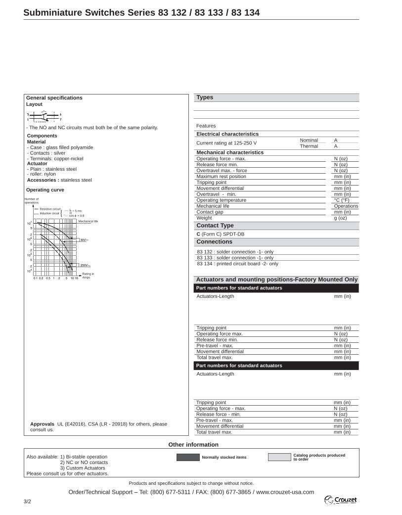
Subminiature Switches Series 83 132 / 83 133 / 83 134
Other information
Normally stocked items Catalog products producedto order
Part numbers for standard actuators
Actuators-Length mm (in)
Part numbers for standard actuators
Actuators-Length mm (in)
83 132 : solder connection -1- only83 133 : solder connection -1- only83 134 : printed circuit board -2- only
Tripping point mm (in)Operating force max. N (oz)Release force min. N (oz)Pre-travel - max. mm (in)Movement differential mm (in)Total travel max. mm (in)
Tripping point mm (in)Operating force - max. N (oz)Release force - min. N (oz)Pre-travel - max. mm (in)Movement differential mm (in)Total travel max. mm (in)
Mechanical characteristicsOperating force - max. N (oz)Release force min. N (oz)Overtravel max. - force N (oz)Maximum rest position mm (in)Tripping point mm (in)Movement differential mm (in)Overtravel - min. mm (in)Operating temperature °C (°F)Mechanical life OperationsContact gap mm (in)Weight g (oz)
C (Form C) SPDT-DB
Electrical characteristicsNominal AThermal A
Types
Actuators and mounting positions-Factory Mounted Only
Contact Type
Current rating at 125-250 V
Connections
General specificationsLayout
- The NO and NC circuits must both be of the same polarity.
Operating curve
Components Material- Case : glass filled polyamide- Contacts : silver- Terminals: copper-nickelActuator- Plain : stainless steel- roller: nylonAccessories : stainless steel
Resistive circuit:
Number ofoperations
= 5 ms
cos ϕ = 0.8
LR
Mechanical life
Rating inAmps
Inductive circuit
Features
Approvals UL (E42016), CSA (LR - 20918) for others, pleaseconsult us.

3
Products and specifications subject to change without notice.
Order/Technical Support – Tel: (800) 677-5311 / FAX: (800) 677-3865 / www.crouzet-usa.com
3/3
70 514 175Flat 54A R14.75 (.58) Flat 54A R35.75 (1.41)
70 514 194Tip-mounted in-line roller 54E R7.5 (.3)
70 514 181Tip-mounted in-line roller 54E R14.1 (.56)
70 514 182
Simulated Roller 54B R13.7 (.54)
1.6 (5.6)0.4 (1.4)10 (35.3)8.45 (.33)7.7±0.2 (.30-.008)0.45 (.018)0.3 (.012)-20 +125 (-4 to +257)107
0.3 x 2 (.012 x 2)1.8 (.06)
C
511
83 132 0
Side terminals
1.6 (5.6)0.4 (1.4)10 (35.3)8.45 (.33)7.7±0.2 (.30-.008)0.45 (.018)0.3 (.012)-20 +125 (-4 to +257)107
0.3 x 2 (.012 x 2)1.8 (.06)
C
511
83 133 0
Base terminals
83 134 0
1.6 (5.6)0.4 (1.4)10 (35.3)8.10 (.32)7.35±0.25 (.29-.010)0.45 (.018)0.3 (.012)-20 +125 (-4 to +257)107
0.3 x 2 (.012 x 2)1.8 (.06)
C
511
Face terminals
9.5 ±0.8 (.374 ±.031) 9.2±0.8 (.362 ±.031)0.18 (.6)0.16 (.5)
2.15 (.085)1±0.3 (.04±.001)
2.8 (.11)
10 ±1.5 (.413 ±.06) 9.7±0.15 (.382 ±.06)0.34 (1.2)0.06 (.2)
5.15 (.203)2.1±0.65 (.083±.026)
6.8 (.268)
83 132 083 133 0 83 134 0
1 solder tags can accept quickconnects .11˝ x .02˝
2 for printedcircuit boards
83 132 083 133 0 83 134 0
14.2 ±0.3 (.56 ±.012) 13.9±0.3 (.547 ±.012)1.6 (5.6)
0.32 (1.1)1.1 (.043)
0.5±0.15 (.02±.006)1.45 (.057)
83 132 083 133 0 83 134 0
12.7 ±0.8 (.5 ±.03) 12.4±0.8 (.49 ±.03)0.85 (3)0.18 (.6)
2.05 (.081)0.95±0.3 (.037±.001)
2.7 (.106)
83 132 083 133 0 83 134 0
70 514 13170 514 559Flat 54A R7.75 (.30)
8.2 ±0.3 (.32 ±.01) 7.9±0.3 (.31 ±.01)1.55 (5.45)0.3 (1.05)1.1 (.04)
.5±0.15 (.02±.006)1.5 (.06)
83 132 083 133 0 83 134 0
Tip-mounted in-line roller 54E R34.4 (1.35)
Ø NoActuator
70 514 183
16.1 ±1.4 (.63 ±.05) 15.8±1.4 (.62 ±.05)0.34 (1.19)0.07 (.25)4.9 (1.9)
2±0.6 (.08±.02)6.6 (.26)
83 132 083 133 0 83 134 0
15.5 ±0.8 (.61 ±.031) 15.2±0.8 (.6 ±.031)0.8 (2.8)0.17 (.6)
2.05 (.081)0.95±0.3 (.037±.001)
2.7 (.106)
83 132 083 133 0 83 134 0
To order please specify :
Contact TypeC
Switch Type831320831330831340
2 Connection12
Example : 831330 C 1 • A L
3 ActuatorsA FB GC ØE L
4 Actuator PositionL - Left (Standard)R - Right
51
L C E F
GAB
Example P/N is 831330, SPDT-DB, solder terminals, A actuator mounted on the left.
Except where otherwise indicated, the actuator is mounted in the position shown in the dimensional drawings (= standard mounting).
4
2
3
1
Products and specifications subject to change without notice.
Order/Technical Support – Tel: (800) 677-5311 / FAX: (800) 677-3865 / www.crouzet-usa.com
3/4
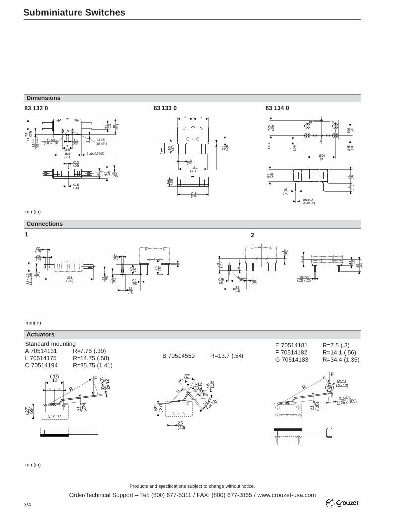
Subminiature Switches
Dimensions
Connections
Actuators
1
2.1
(.08
7.4
(2.9
)+ _0.
15
+ _0.
006OL
fl 1.5 x .7(fl .06 x .03)
1.5(.06)
7(2.8)18.4(.72)
2 tabs 0.7 (.03)
2.1(.08
+_ 0.020.05
+_0.0070.02
3.9
(.15)
10 (3.9
)
01.5(.06)
01.5(.06)
3.2
(.12)
6.4
(.25)
0.6
(.02)
)
)
83 132 0= =
6.4
(.25)
20.4(.80)
3.6(.37)
18.1(.71)
2.1
(.08)
9.3
(.37)
83 133 0
OL
=7.
05(.2
8)
1(.0
4)
15.24(.6)
5.08 (.2)
2.45 (.1)
7.6
(.3)
4 (.16)
0.6 x 0.5(.023 x .02)
6.4
(.25)
03(.12)
83 134 0
2.8(.11)
4
0.5(.02)
R 0.5(.02)
7.9
(.31)
0.75(.3)
2.1
(.08)
==
0.6 x 5.5(.023 x .02)
4.4
(.17)
.82
(.32)
1
Standard mountingA 70514131 R=7.75 (.30)L 70514175 R=14.75 (.58)C 70514194 R=35.75 (1.41)
mm(in)
mm(in)
mm(in)
E 70514181 R=7.5 (.3)F 70514182 R=14.1 (.56)G 70514183 R=34.4 (1.35)
B 70514559 R=13.7 (.54)
6.9
12
= =
2.1
F
(0.5
x3)
R
(.27)
(.47)
.2x.
12
(.08)
6.9 (.27)
70°F
R 3.9 (.15)
R1.2(.05) 4.
6 (.18)
0.5x3
(.2x.1
2)
2.5(.10)
2.1
F
R
(.08)
3.2x4.2(.125 x .165)
Ø5x3(.2x.12)
2
2.2(.09)
2.42(.10)
1.2
(.05)
2.8
x .0
.5(.1
1 x
.02)
32.8(1.29)
2.8(.11)
9.3
(.37)
0.5(.02)
1.2(.05)
9.3
(.37)
2.4
(.09)
2.2
(.08)

Products and specifications subject to change without notice.
Order/Technical Support – Tel: (800) 677-5311 / FAX: (800) 677-3865 / www.crouzet-usa.com
3/5
3
Subminiature Switches
mm(in)
Actuators – For Gang Operation
Actuators and mounting positions – Factory Mounted Only – for Gang Operation
Mounting accessories
0.5 (0.2
)
R
9.2
(.36)
12.8
(.5)
54A2
9.2
(.36)
19.2
.76
19.2
(.76)
54A3
83 132 0 - 83 133 0 83 134 0
6(.24)
6.9
(.26)
5.8
(.23)
6.6
(.26)
1.6(.063)
Delivered separately
2 pole 54A2 R30 (1.18) 3 pole 54A3 R30 (1.18) Side mounting plate (0.4 mm) 54Y
8.8±0,8 (.346±0.03)0.8 (2.8)0.16 (.6)4.3 (.17)
2±0.55 (.08±0.02)5.75 (.23)
Tripping Point mm (in)Operating Force max N (oz)Release Force min N (oz)Pre-travel min mm (in)Movement differential mm (in)Total travel max mm (in)
Part numbers for standard actuators – Consult factory for part numberActuators-Length mm (in)
83 132 083 133 0 *83 134 0
8.8±0,8 (.346±0.03)1.2 (4.2)0.24 (.8)4.3 (.17)
2±0.55 (.08±0.02)5.75 (.23)
83 132 083 133 0 *83 134 0
mm(in)
*For gang operation with83 132 0 or 83 133 0.

Products and specifications subject to change without notice.
Order/Technical Support – Tel: (800) 677-5311 / FAX: (800) 677-3865 / www.crouzet-usa.com
3/6
Subminiature Switches Series 83 170 DIN 41 635 B
For other forces, actuators, connections and temperatures,please consult us.
Other information
General specificationsLayout Components
Approvals: NF - UL - cULOperating curveFor type 83 170 0 For type 83 170 4
Material- Case : polyester UL 94 VO - Button : glass-filled polyamide- Contacts : AgNi,
gold-plated AgNi (dual-current)- Terminals : copper-nickelActuators- flat : stainless steel- roller : stainless steel with polyamide roller
Resistive circuit:
Number ofoperations
= 5 ms
cos ϕ = 0.8
LR
Rating inAmps
Inductive circuit Resistive circuit:
Number ofoperations
= 5 ms
cos ϕ = 0.8
LR
Rating inAmps
Inductive circuit c
a
c
a
Resistive circuit:
Number ofoperations
Mechanicallife
Rating inAmps
For type 83 170 9
Model 83 170 9 is designed to operate equally well on dual-current(1 mA 4 V minimum) or medium-current (5 A maximum) circuits.However, a given product should only be used to switch one type ofcircuit during its working life.
Mechanicallife Mechanical
life
Part numbers for standard actuatorsActuators – Length mm (in.)
Part numbers for standard products (no lever) terminal type
Mounting positionsCoefficientTripping point mm (in.)
Mechanical characteristicsOperating force - max. N (oz.)Release force - min. N (oz.)Total travel force - max. N (oz.)Permitted overtravel force - max. N (oz.)Maximum rest position mm (in.)Tripping point mm (in.)Differential travel mm (in.)Overtravel - min. mm (in.)Ambient operating temperature °CMechanical endurance OperationsContact gap mm (in.)Weight g (oz.)
C (Form C) SPDTB (Form B) SPNC not available in PC terminalsA (Form A) SPNO not available in PC terminals
Electrical characteristicsNominal AThermal A
Types
Actuators and mounting positions
Contact type
Features
Current rating at 250 V
Connections
Mounting positions
Except where otherwise indicated, actuators are supplied unmounted.For factory mounting, specify mounting position L or R.
– To calculate force : take the force quoted for the switch and divide bythe coefficient given in the table.
– To calculate travel : take the travel quoted for the switch and multiplyby the same coefficient.
123
Normally stocked items Catalog products producedto order
Mounting accessories for PCB mounting: 5 / 6 / 7 / 8
See page 3/9.

Products and specifications subject to change without notice.
Order/Technical Support – Tel: (800) 677-5311 / FAX: (800) 677-3865 / www.crouzet-usa.com
3/7
3
79 253 32979 253 327
Flat 170A R18.3 (.72) Dummy roller 170F R19.5 (.77)
FECBA 79 253 326 79 253 328
Flat 170A R24 (.94) Flat 170A R41 (1.61)
79 218 454
Roller 170E R20 (.79)
1.5 (5.3)0.3 (1)1.8 (6.3)10 (35.3)9.2 (.36)8.4±0.3 (.33±.01)0.15 (.006)0.5 (.02)-20 to130 (-4 to 266)107
0.4 (.016)1.7 (.06)
BA
1012.5
Screw 170D R20 (.79)
Characteristics available upon request.
Transverse roller 170L R20 (.79)
831700C1.0831700C2.0
83170.0
831700C3.0
High current
0.6 (2.2)0.1 (.04)1 (3.5)10 (35.3)9.2 (.36)8.4±0.3 (.33±.01)0.15 (.006)0.5 (.02)-20 to130 (-4 to 266)3.107
0.4 (.016)1.7 (.06)
56
831704C1.0831704C2.0831704C3.0
83170.4
Standard
831709C1.0831709C2.0831709C3.0
83170.9
0.6 (2.2)0.1 (.04)1 (3.5)10 (35.3)9.2 (.36)8.4±0.3 (.33±.01)0.15 (.006)0.5 (.02)-20 to130 (-4 to 266)3.107
0.4 (.016)1.7 (.06)
CBA
CCBA
0.1
Low current
L310.4±1.2 (.41±.05)
R1.59.2±0.6 (.36±.24)
L411.1±1.2 (.44±.05)
R29.6±0.6 (.38±.24)
L713.2±2.5 (.52±.1)
R3.510.7±1.2 (.42±.05)
L315.4±1.2 (.61±.05)
R1.514.5±0.6 (.57±.24)
L313±1.2 (.51±.05)
R1.512±0.6 (.47±.24)
79 218 491 LD 79 218 493
21 3 4 5 6 7 8
1.5 (5.3)0.3 (1)1.8 (6.3)10 (35.3)10.8 (.425)9.9±0.3 (.39±.01)0.15 (.006)0.5 (.02)-20 to130 (-4 to 266)106
0.4 (.016)1.7 (.06)
CBA
56
83170.4 SP 4967831704C2.MBSP831704C3.MBSP831704C1.MBSPHigh force
0.6 (2.2)0.1 (.04)1 (3.5)10 (35.3)10.8 (.425)9.9±0.3 (.39±.01)0.15 (.006)0.5 (.02)-20 to130 (-4 to 266)106
0.4 (.016)1.7 (.06)
CBA
56
83170.4831704C1.MB831704C2.MB831704C3.MBStandard
83170.9831709C1.MB831709C2.MB831709C3.MB
0.6 (2.2)0.1 (.04)1 (3.5)10 (35.3)10.8 (.425)9.9±0.3 (.39±.01)0.15 (.006)0.5 (.02)-20 to130 (-4 to 266)106
0.4 (.016)1.7 (.06)
CBA
0.1
Low current
To order please specify :
Contact Type
ABC
Switch Type
831700831704831709
2 Connection
1 52 63 74 8
Example : 831700 C 2 • C L
To order actuators separately, use the 8 digit P/N Example P/N is 831700 SPDT solder terminals “C” actuator mounted on the left.
3 Actuators
A EB FC LD MBØ MB SP4967
4 Actuator Position
L - Left (Standard)R - Right
51
MB
Ø NoActuator
5
4
3
2
1

Products and specifications subject to change without notice.
Order/Technical Support – Tel: (800) 677-5311 / FAX: (800) 677-3865 / www.crouzet-usa.com
3/8
Subminiature Switches DIN 41635 B
Dimensions
Connections
OL
= 7.
6 (.3
0) 2.4–0.1
(.09–.001
R 2.5 (.1)
7.5–0.2
(.3.–008
5–0.1
(.2–.004
2.4
–0.1
(.1–.
009
9.6
–0.2
(.38
–.00
8
fl2.2 +0.1 0
(fl .09 –.004 0
6.4
–0.2
(.25
–.00
8
0.5–0.03 (x3)
(.02–.0019.5–0.1
(.37–.004
6.35–0.2
(.25–.0088.9–0.2
(.35–.008
12.2–0.2
(.48–.008
2.2
–0.1
(.09
–.04
fl 2.5 –0.1
(.1–.004
19.8–0.2
(.78–.008
4–0
.1
(.157
–.00
8
=
=
)
)
)
)
) )
)
)
)
)
)
)
)
)
))
83 170 Asymmetric
7.62±0.2
(.30±.008)7.62±0.2
(.30±.008)
83 170 Symmetric
2.8±0.1
(.11±.004)
Ø1.3 ±0.2 0
(.11±.004)
7.1
±01(.2
8+.
004)
2.2
±02
0 (.0
8+.
008
- 0
)
3.7
±02(.1
5+.
008)
3-4Straight PCB
3 5 7 4 6 8
Printed circuit board mountingAsymmetric Symmetric
1.11x.02 Quick Connects
2Solder
7-8Side Output PCB Front
5-6Side Output PCB Rear
1±0.1(.04±.004)
30°
1.3±0.05 (.05±.002)
3.4
±0.2
(.13
±.00
8)
4.5±
0.15
(.18
±.00
6)
8.9±0.1
(.35±.004)
Ø 1.6±0.1
(.06±.004)
6.35±0.1
(.25±.004)
1.C 4.NO 2.NC
7.62±0.1
(.3±.004)
Ø 1.6±0.1
(.06±.004) 1.C 4.NO 2.NC
(3x2.54)
(3x1)
7.62±0.1
(.3±.004)(3x2.54)
(3x1)
4.1±0.1
(.16±.004)
2.4±0.15
(.1±.006)
1.3
±0.1
(.05
±.00
4 )
4.3
±0.2
(.17
±.00
8 )
6±0
.15
(.236
±.00
6 )
3.5±0.2
(.14±.008)
1.3
±0.0
5 (.0
5±.
002 )
1±0.
1(.0
4±.
004 )
5±0.
2(2
±.00
8 )
3.5±0.2
(.14±.008)
1.3
±0.0
5 (.0
5±.
002 )
1±0.
1(.0
4±.
004 )
5±0.
2(2
±.00
8 )
Mounting by M2 screwsTorque : 2 cm daN
mm (in)
mm (in)
R 3.6(.14)
Ø 5.5
8.9±0.2
(.35±.00812.2±0.2
(.48±.008)
)
Ø 2.5±0.1
(.1±.004)
19.8±0.2
(.73±.008) 7.5±0.2
(.3.±0085±0.1
(.2±.004
)
)
2.4
±0.1
(.1±.
009
±0.2
(.38
±.00
8
)
)9.
6
0.5±0.03 (x3)
(.02±.001)
Ø2.2 +0.1 0
(Ø .09±.004 0 )
9.5±0.1
(.37±.0046.35±0.2
(.25±.008
)
)
6.4
±0.2
(.25
±.00
8 )
2.2
±0.1
(.09
±.04
)
83 170 with MB Button
Products and specifications subject to change without notice.
Order/Technical Support – Tel: (800) 677-5311 / FAX: (800) 677-3865 / www.crouzet-usa.com
3/9
3
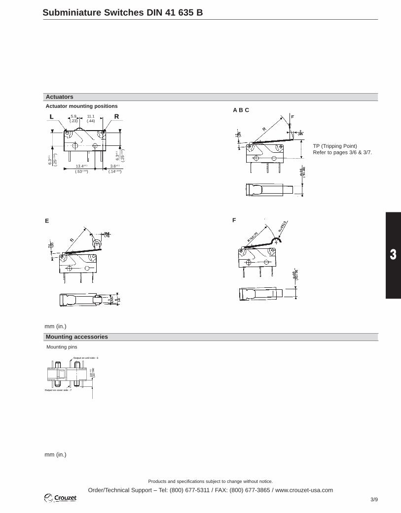
Subminiature Switches DIN 41 635 B
mm (in.)
A B C
Actuators
E F
Mounting accessories
2.9
± 0.
1
(.11±
.004
)
Sortie côte boîtier : X2
Sortie côte couvercle : X3
Mounting pins
Output on cover side : 7
Output on unit side : 5
L RL R5.9(.23)
11.1(.44)
13.4±0.1
(.53±.004)3.6±0.1
(.14±.004)
6.3±0
.1
(.25
±.00
4 )
6.3±0
.1
(.25
±.00
4 )
Actuator mounting positions
mm (in.)
TP (Tripping Point)Refer to pages 3/6 & 3/7.

.
3/10
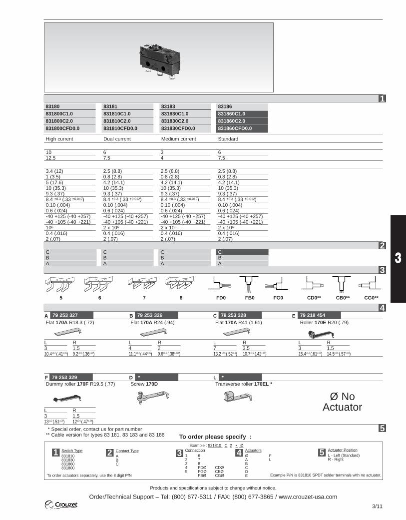
Sealed Subminiature Switches Series 83 180 DIN 41 635 B
For other forces, actuators, connections and temperatures,please consult us.
Other information
Normally stocked items Catalog products producedto order
Layout Components
Material- Case : UL 94VO glass-filled polyester- Button : Polyester- Membrane : silicon- Contacts : AgCdO
AgNi (dual current),- Terminals : tinned brass- Cable : PVC (IP 67)- Leads : PVC
Actuators - flat : stainless steel- roller : stainless steel with polyamide roller
Approvals 83 180/83 186 : NF. UL - cUL on request
Operating curve 250 Va
Switch rating with DC supply
83 180 83 181 83 183 83 186Resistive load 10 A 6 A 3 A 6 A
12 V Inductive 10 A 6 A 3 A 6 AL/R 5 msResistive load 10 A 6 A 3 A 6 A
24 V Inductive 5 A 5 A 3 A 5 AL/R 5 ms
Model 83 181 is designed to operate equally well on dual-current (1 mA 4 V minimum) or medium-current (6 A maximum) circuits.However, a given product should only be used to switch one type ofcircuit during its working life.
Degree of protection- Tag version : casing = IP67
terminals = IP00- Lead / cable version : outlet / casing = IP67
General specifications
Resistive circuitOperations
A
C (Form C) SPDTB (Form B) SPNC not available in PC terminalsA (Form A) SPNO not available in PC terminals
Contact Type
12FD0
Part numbers for standard actuators
Operating force - max. N (oz.)Release force - min. N (oz.)Total travel force - max. N (oz.)Permitted overtravel force - max. N (oz.)Rest position - max. mm (in.)Tripping point mm (in.)Differential travel mm (in.)Overtravel - min. mm (in.)Ambient operating for tag version °C (°F)temperature for lead / cable version °C (°F)Mechanical durability OperationsContact gap mm (in.)Weight (tag version) g (oz.)
Actuators - Length mm (in.)
Mounting positionCoefficientTripping point mm (in.)83 18083 181/183/186
Part numbers for standard products withconnection of type
Types
Connections
Actuators and mounting positionsPart numbers for standard actuatorsPart numbers for standard actuators
Actuators - Length mm (in.)
Mounting positionsCoefficientTripping pointExcept where otherwise indicated, actuators are supplied unmounted.For factory mounting, specify fixing position L or R.- To calculate force : take the force quoted for the switch and divide by
the coefficient given in the table.- To calculate travel : take the travel quoted for the switch and multiply
by the same coefficient.
See page 3/9.
Electrical characteristics
Current rating at 250 V Nominal AHp 1/2
Mechanical characteristics
Features
2 1 3 4
Mounting accessories for PCB mounting : 5 / 6 / 7 / 8
Products and specifications subject to change without notice.
Order/Technical Support – Tel: (800) 677-5311 / FAX: (800) 677-3865 / www.crouzet-usa.com
3/11
3
To order please specify :
Contact TypeABC
Switch Type831810831830831860831800
2 Connection1 62 73 84 FDØ CDØ5 FGØ CBØ
FBØ CGØ
Example : 831810 C 2 • Ø
To order actuators separately, use the 8 digit P/N Example P/N is 831810 SPDT solder terminals with no actuator.
3 ActuatorsØ FA LBCDE
4 Actuator PositionL - Left (Standard)R - Right
51
CBA
CBA
CBA
CBA
79 253 327 79 253 326 79 218 454Flat 170A R18.3 (.72)
L310.4±1.2 (.41±.05)
R1.59.2±0.6 (.36±.24)
Flat 170A R24 (.94) Flat 170A R41 (1.61) Roller 170E R20 (.79)
High current
1012.5
3.4 (12)1 (3.5)5 (17.6)10 (35.3)9.3 (.37)8.4 ±0.3 (.33 ±0.012)0.10 (.004)0.6 (.024)-40 +125 (-40 +257)-40 +105 (-40 +221)106
0.4 (.016)2 (.07)
83181831810C1.0831810C2.0831810CFD0.0
Dual current
67.5
2.5 (8.8)0.8 (2.8)4.2 (14.1)10 (35.3)9.3 (.37)8.4 ±0.3 (.33 ±0.012)0.10 (.004)0.6 (.024)-40 +125 (-40 +257)-40 +105 (-40 +221)2 x 10⁶
0.4 (.016)2 (.07)
83183831830C1.0831830C2.0831830CFD0.0
83186831860C1.0831860C2.0831860CFD0.0
Medium current
34
2.5 (8.8)0.8 (2.8)4.2 (14.1)10 (35.3)9.3 (.37)8.4 ±0.3 (.33 ±0.012)0.10 (.004)0.6 (.024)-40 +125 (-40 +257)-40 +105 (-40 +221)2 x 10⁶
0.4 (.016)2 (.07)
Standard
67.5
2.5 (8.8)0.8 (2.8)4.2 (14.1)10 (35.3)9.3 (.37)8.4 ±0.3 (.33 ±0.012)0.10 (.004)0.6 (.024)-40 +125 (-40 +257)-40 +105 (-40 +221)2 x 10⁶
0.4 (.016)2 (.07)
L411.1±1.2 (.44±.05)
R29.6±0.6 (.38±.024)
L713.2 ±2.5 (.52±.1)
R3.510.7±1.2 (.42±.05)
L315.4±1.2 (.61±.05)
R1.514.5±0.6 (.57±.24)
79 253 329 *Dummy roller 170F R19.5 (.77)
** Special order, contact us for part number** Cable version for types 83 181, 83 183 and 83 186
L313±1.2 (.51±.05)
R1.512±0.6 (.47±.24)
Screw 170D Transverse roller 170EL *
83180831800C1.0831800C2.0831800CFD0.0
5 6 7 8 FD0 FB0 FG0 CD0** CB0** CG0**
A
F D *L
B 79 253 328C E
Ø NoActuator
5
4
3
2
1
Products and specifications subject to change without notice.
Order/Technical Support – Tel: (800) 677-5311 / FAX: (800) 677-3865 / www.crouzet-usa.com
3/12
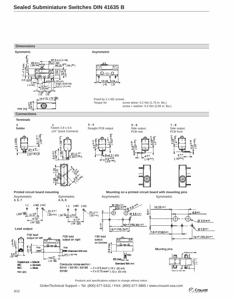
Sealed Subminiature Switches DIN 41635 B
Connections
Dimensions
Symmetric Asymmetric
Fixed by 2 x M2 screwsTorque for screw alone: 0.2 Nm (1.75 in. lbs.)
screw + washer: 0.3 Nm (2.65 in. lbs.)
Terminals
2Solder
1Faston 2.8 x 0.5.110˝ Quick Connects
3 - 4Straight PCB output
5 - 6Side output,PCB rear
7 - 8Side output,PCB front
Mounting on a printed circuit board with mounting pins
Asymmetric SymmetricPrinted circuit board mounting
Asymmetric 3, 5, 7
Symmetric4, 6, 8
OL
Lead output
(.11±.
004 )

Products and specifications subject to change without notice.
Order/Technical Support – Tel: (800) 677-5311 / FAX: (800) 677-3865 / www.crouzet-usa.com
3/13
3
Mounting positions
Actuators
Recommendations for operation from the side
Cable output
CG0 cableoutput on left Conductor cross-section :
83181 / 83183 / 83186 = 3 x 0.5 mm2
(.12 x .02 in2)
CD0 cableoutput on right
CB0 cable output on bottom
Common = blackNC = brownNO = blue
A, B, CFlat
ERoller
FDummy roller
mm (in.)
mm (in.)

Products and specifications subject to change without notice.
Order/Technical Support – Tel: (800) 677-5311 / FAX: (800) 677-3865 / www.crouzet-usa.com
3/14
Miniature Switches Series 83 161 DIN 41635 A
For other forces, actuators, connections and temperatures,please consult us.
Other information
Normally stocked items Catalog products producedto order
General specificationsLayout
Operating curveFor type 83 161 1 3
For type 83 161 9 SP 4136
For type 83 161 5 - 5 SP 4136
For type 83 161 8
ComponentsMaterial- Case : glass-filled polyamide (self-extinguishing version to UL 94 VOand IEC 695-2-1 850° C - available on request)- Button : polyamide - Contacts : nickel silver or gold alloy (dual-current)Actuators- flat : stainless steel- roller : stainless steel, glass-filled polyamide roller - other types of polyamideApprovals: NF - UL/cUL
For types 83 161 8 - 9 SP 4136 dual-currentModels 83 161 8 and 83 161 9 SP 4136 are designed to operate equallywell on dual-current (1 mA 4 V minimum) or medium-current (5 A maximum) circuits.However, a given product should only be used to switch one type ofcircuit during its working life.
Resistive circuit:
Number ofoperations
= 5 ms
cos ϕ = 0.8
LR
Mechanicaldurability
831613831611
Mechanical durability
Rating inAmps
Inductive circuit Resistive circuit:
Number ofoperations
= 5 ms
cos ϕ = 0.8
LR
Mechanicaldurability
Rating inAmps
inductive circuit a
c
a
c
Resistive circuit:
Number ofoperations
Rating inAmps
Mechanicaldurability
Resistive circuit:
Number ofoperations
Rating inAmps
Mechanicaldurability
Electrical characteristicsCurrent AHorsepower HP
Contact type
Part numbers for standard actuators 79 215 740
79 218 651
Actuators-Length mm (in.) Flat 161A R14.2 (.56)
Part numbers for standard products withconnections of type
Mounting positions A BCoefficient 2 1Tripping point (except 83 161 6) 15.2 ±1(.6±.004) 15.2 ±0.45(.6±.018)Tripping point 83 161 6 14.8 ±1(.59±.004) 15 ± 0.45(.59±.018)
Mounting positions A BCoefficient 3 1.8Tripping point (except 83 161 6) 21.7 ±2(.85±.08) 21.7 ±0.7(.85±.03)Tripping point 83 161 6 21.5 ±2(.85±.08) 21.5 ±07(.85±.03)Except where otherwise indicated, flat and roller actuators are supplied unmounted.
Mechanical characteristicsOperating force - max. N (oz.)Release force - min. N (oz.)Total travel force - max. N (oz.)Permitted overtravel force - max. N (oz.)Rest position - max. mm (in.)Tripping point mm (in.)Differential travel mm (in.)Overtravel - min. (OT) mm (in.)Ambient operating temperature °C (°F)Mechanical durability (for 2/3 OT) OperationsContact gap mm (in.)Weight g (oz.)
C (Form C) SPDTB (Form B) SPNCA (Form A) SPNO
Types
Actuators and mounting positions
Part numbers for standard actuators
Actuators-Length mm (in.) Dummy roller 161G R21.8 (.86)
236
Features
2 solder 3 for 1/4˝ Quick Connects
Current rating at 125/250 V
Connections
A
H

3/15
3
CBA
CBA
CBA
CBA
CBA
CBA
CBA
831611C2.0831611C3.0831611C6.0
70 507 524Flat 161A R25.4 (1)
79 215 742Roller 161E R13.6 (.54)
70 507 529Roller 161E R24.1 (.95) Dummy 161F roller R22.2 (.84)
D Factory Mount only121.5 ±1 (.85 ±.04)21.5 ±1 (.85 ±.04)
D Factory Mount only118.35 ±0.45
For factory mounting, specify fixing position A, B or C ** For 83 161 1, 83 161 3, 83 161,6, 83 161 8, mounted in factory (supplied without nut)
3 (10.5)1 (3.5)4.5 (15.8)20 (70.5)16.1 (0.63)14.7±0.4 (.58±0.16)0.35 (0.014)1.1 (0.05)-20 +125 (-4 +257)107
0.4 (0.016)5.6 (.2)
10.11/2
L
** TelescopicplungerManual action161L
V
83161.1(10.1A) 83161.2(15.1A) 83161.3(10.1A) 83161.5(4A)83161.9(0.1A)
83161.5SP413683161.9SP4136
83161.6 83161.8(0.1A)
High Force
0.8 (2.8)0.2 (0.7)2 (7.0)20 (70.5)16.2 (0.64)14.7±0.3 (.58±0.16)0.35 (0.014)1.2 (0.05)-20 +125 (-4 +257)2 x 10⁷
0.4 (0.016)5.6 (.2)
15.11/2
High Current
0.8 (2.8)0.2 (0.7)2 (7.0)20 (70.5)16.2 (0.64)14.7±0.3 (.58±0.16)0.35 (0.014)1.2 (0.05)-20 +125 (-4 +257)2 x 10⁷
0.4 (0.016)5.6 (.2)
10.11/2
Standard
0.25 (0.9)0.05 (0.18)0.35 (1.2)20 (70.5)16.3 (0.64)14.7±0.4 (.58±0.16)0.35 (0.014)1.1 (0.05)-20 +125 (-4 +257)5 x 10⁷
0.4 (0.016)5.6 (.2)
41/10
Low Force
0.15 (0.54)0.04 (0.14)0.2 (0.72)20 (70.5)16.3 (0.64)14.7±0.3 (.58±0.16)0.35 (0.014)1.2 (0.05)-20 +125 (-4 +257)5 x 10⁷
0.4 (0.016)5.6 (.2)
41/10
5 (18)0.5 (1.8)6 (21.6)20 (70.5)16.1 (0.63)14.5±0.4 (.58±0.16)0.8 (0.03)0.9 (0.035)-20 +125 (-4 +257)5 x 10⁴
3.2 (0.126)5.6 (.2)
6.11/3
831616C2.0831616C3.0831616C6.0
Ultra Light Force Wide Gap
0.8 (2.8)0.2 (0.7)0.2 (.07)20 (70.5)16.2 (0.64)14.7±0.4 (.58±0.16)0.35 (0.014)1.2 (0.05)-20 +125 (-4 +257)2 x 10⁷
0.4 (0.016)5.6 (.2)
0.1N/A
831618C2.0831618C3.0831618C6.0
Dual Current
5 screw 6 for 3/16˝ Quick Connects 7 for .11 Quick Connects
A415.2±2.5 (.6±.1)14.4±2.5(.56±.1)
B215.2±1(.6±.04)14.8±1(.58±.04)
C1.515.2 ±0.8(.6±.03)14.9 ±0.8(.59±.03)
A220.5±1.5(.81±.06)20.1±1.5(.79±.06)
B120.5±0.8(.81±.03)20.3±0.8(.80±.03)
A420.5±2.9(.81±.11)19.7±2.9(.76±.11)
B220.5±1.5(.81±.06)20.1±1.5(.79±.06)
C1.520.5±1.2(.81±.05)20.2±1.2(.79±.05)
A320.4±2(.8±.08)20.2±2(.79±.08)
B1.820.5±0.7(.81±.03)20.2±2(.79±.08)
C1.520.5±0.9(.81±.035)
831612C2.0831612C3.0831612C6.0
831613C2.0831613C3.0831613C6.0
831615C2.0831615C3.0831615C6.0
B E G 70 507 528F
70 507 526 79 215 835Flat 161A R60 (2.39)Flat 161A R50 (1.9)161V
A615.2±6.3
B315.2±2
C215.2±1.6
A715.2±6.9
B3.515.2±2.5
C2.215.2±2.3
C D
To order, please specify :Contact Type
ABC
Switch Type
831612 831619831613 831616831615 831611831618
2 Connection
23567
Example : 831612 C 3 • C A
To order actuators seperately, use the 8 digit P/N Example switch is 831612, SPDT, 1/4” Q.C., C actuator mounted in A position
AB
CD(std)
3 Actuators
Ø FA GB HC LD VE
4 Actuator Position1BA C
D
5
Ø = No actuator
5
4
4
2
3
1

Products and specifications subject to change without notice.
Order/Technical Support – Tel: (800) 677-5311 / FAX: (800) 677-3865 / www.crouzet-usa.com
3/16
Miniature Switches DIN 41635 A
Force calculation : divide the switch forces by the coefficient in the table.
Travel calculation : multiply the switch travel by the same coefficient.
Example :83 161 3 with B Flat 161A actuator R 25.4 (1) position A (coef. 4)Operating force : 0.8 4 = 0.2 NPre-travel: 1.4 x 4 = 5.6 mm (.055 x 4 = .22 in)
Actuators
BA CD
F
2mm(.08)
Connections
Dimensions
Ø3 +0.15+0.05
10.3
±0.1
(.41±.
004 )
(.12 +.006+.002
2.8(.11)
22.2±0.2 (.87 ±.008)
20.2±0.2
(.8 ±.008)
3.4(.13)
2.8
(.11)
2.8(.11)
2.8
(.11)
OL
= 13
.35
(.53)
3+0
.15
+0.0
5
)
(.12
+.00
6+.
002
)
15.8
-0.1
5-0
.1(.?
?+.
006
+.00
2)
27.8 ±0.15 (1.09 ±.006)
3.9
3 (.12)10.3
±0.1
5(.4
1±.0
06)
83 161
47°
3.2±0.3
(.13±.012)
3.2
(.13)
6.3
3.2
(.13)
2.8
(.11)
1.7+0.05+0
(.067±.002) 3.9x
0.8
±.02
)
(.15x
.03
±.00
1 )
47°
9.3±0.2
(.366±.008)
6.7
(.264
)
3 (.1
18)
17.4
(.68
5)
9.8(.286)
6.2(.244)
12.1±0.2
(.25 ±.03 )4.3 +0.05
-0.15(.169+.02
-.006)
Ø1.7 +0.05+0
(.067±.002) (6.3
±0.1
(.248
±.00
4 )
3 (6.3x0.8 (1/4x.03)) Quick Connects2 Solder
20 (
.79)
m
ax.
45°
9 x 6(.35x.24)
M3x4(.12x.16)
47°
10.7±0.2 (.42 ±.008)
3.2
(.13)
6.3
(.25)
17.4
(.6
9)4(.16)
Ø1.4±0.06
7.1±0.1
.06±.002
3.1±0.1
.12 ±.004
.28±.004
4.8±0
.1
.19
±.00
4
6 (4.8x0.5 (.3/16x.02)) Quick Connects
2.2 +0.2+0 (.09 +.008
-0 )
2.8
±0.1
(.11
±.00
4)
Ø1.3 +0.2+0 (.05 +.008
-0 )
7.1±0.1
(.28 ±.004)
7 (2.5x0.5 (.11x.02)) Quick Connects5 Screw
mm (in)
mm (in)
Products and specifications subject to change without notice.
Order/Technical Support – Tel: (800) 677-5311 / FAX: (800) 677-3865 / www.crouzet-usa.com
3/17
3
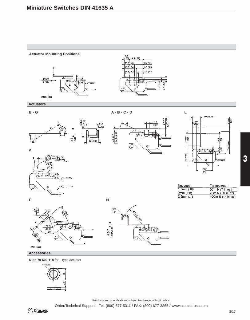
Miniature Switches DIN 41635 A
Actuator Mounting Positions
E - G
V
F
Nuts 70 602 118 for L type actuator
H
A - B - C - D L
Actuators
Accessories

Products and specifications subject to change without notice.
Order/Technical Support – Tel: (800) 677-5311 / FAX: (800) 677-3865 / www.crouzet-usa.com
3/18
To order, specify :
For other accessories, connections : please consult us
*NO – contact is not positive break
** Consult us for actuator length, forces and positions
Miniature Positive Break Switches Series 83 160 DIN 41635 A
Other information
Contact Type
BC
Switch Type
831607
2 Connection
236 X1
3 Actuator Type
A LE
41Example : 831607 B 3 • Ø
Ø = No Actuator
4 (14.1) 4 (14.1)1.5 (3.5) 1.5 (3.5)18 (63.5) 18 (63.5)200 (70.5) 200 (70.5)15.7 (.62) 15.7 (.62)14.8±0.3 (.58±0.012) 14.8±0.3 (.58±0.012)13.5 (.53) 13.5 (.53)1.3 (0.047) 1.3 (0.047)0.5 (1.64) 0.5 (1.64)5 5-40+85 (-40+185) -40+85(-40+185)107 107
1.2 (0.05) 1.2 (0.05)7 (0.25) 7 (0.25)
Electrical characteristicsAssigned working voltage (Ue) VAssigned working current (Ie) AThermal current rating (Ith) AAssigned circuit voltage (Ui) V
Mechanical characteristicsOperating force - max. N (oz.)Release force - min. N (oz.)Min. positive opening force N(oz.)Permitted overtravel force - max. N (oz.)Maximum rest position mm (in.)Tripping point mm (in.)Maximum positive opening position mm (in.)Overtravel - min. mm (in.)Operating speed max. m/s (ft/sec)Operating rate max. (operation/s)Operating temperature °C (°F)Mechanical durability OperationsContact gap mm (in.)Weight g (oz.)
B (NC)C (SPDT)*
Types
Contact Type
Features
Connections
General specificationsLayout
The contact conforms to NFC 63 143 andIEC 947.5.1 *The SPDT version conforms to standardIEC 947.5.1 if only the normally closedcontact is used.
The switch operating principle forces thecontacts open even in the event of welding(positive break operation).
ComponentsMaterial- Case : glass-filled polyamide- Cover : transparent polycarbonate- Contacts : nickel silver- Positive rocker : high temperature thermoplasticActuators : stainless steel- polyamide roller
Electrical characteristicsShort-circuit test(from IEC 947-5-1 § 8.34)- Current peak 1000 A at 250 V a 0.5 <
cos ϕ < 0.7- Short-circuit protection (SCPD) :
fuse 10 A gG- (IEC 60) (1.2/50 µs) : 2500 VElectrical lifeMax. operations : 20 cycles/minResistive load at 250 V~ 16 A : 105 cyclesInductive load (IEC 947.5.1) :AC 15 : 250 V~ 6A : 0.3 x 10⁵ operationsDC 13 : 24 V c 20 W L/R = 40 ms : 3 x 10⁵
operations120 V c 20 W L/R = 40 ms : 5 x 10⁵
operations
DefinitionsP.O.F. Minimum Positive Opening Force.The operating force that has to be applied tothe operating device to produce the positiveopening action.P.O.P. Maximum Positive Opening Position.The position of the operating device at themoment when positive opening of thecontacts occurs.For other definitions, see "Basic concepts".
BC
250 2506 610 10250 250
83 160 7
With positive break operation
2
3
4
1
Actuators and mounting positions
2 solder 3 for 1/4˝ Quick Connects 6 for 3/16˝ Quick Connects X1 for printed circuit board
TP OL
OF POF TTF RF
RLP
PT
DT
OT
NC
NO
Actuators**Dimensions
27.8 (1.09)
10 (.
39)
4 (.1
6)
3.4(.13)
OL=
13.1
(.52
)
10.3
(.41)
3.2
(.125
) 15.8
(.62)
20.2 (.8)
22.2 (.87) 2.8 (.11)
Ø 3.2 (Ø .125)3 (.12)
A (Flat)Ø=noActuator
E (Roller)
L (Pushbutton)
mm (in)
NC SPDT*

Products and specifications subject to change without notice.
Order/Technical Support – Tel: (800) 677-5311 / FAX: (800) 677-3865 / www.crouzet-usa.com
3/19
3
Miniature Side Rotary (High Sensitivity) Switches Series 83 137
To order, please specify :
Contact Type
ABC
Switch Type
8313702 Connection
23
Example : 831370 C 3 • W
Example switch is: 831370, SPDT, 1/4” Q.C.
31
83 137 0
15.5
8°30
'
0
α
11
Mechanical characteristicsMaximum operating force N cm (in. oz)Minimum release torque N cm (in. oz)Overtravel torque N cm (in. oz)Movement differential °Overtravel - min. °Operating temperature °C (F°)Mechanical life OperationsContact gap mm (in)Weight g (oz)
C (Form C) SPDTB (Form B) SPNCA (Form A) SPNO
Electrical characteristicsNominal AThermal A
Types
Contact Type
Dimensions
Features
2 solder 3 for 1/4” Quick Connects
Current rating at 125-250 V
General specificationsLayout
Operating curve
ComponentsMaterial- Case : glass filled polyamide- Contacts : silver Actuators - Stainless steel wire
Actuator setting in α
For other connections, actuators, approvalsaccessories…Please consult factory
Approvals CSA (LR-20418), ASE, Semko,UTE & VDE.
Direction of measurement for α
With special types, α canbe varied from 0 to 360°
Standard setting
Datum point forspecial lever setting
Pre travel angle max. Movement differential angle
Overtravel angle
min.
5.65
(.2
22)
5.5
(.216
)
4.3
(.17)
0.8
(.03
)
A
3.2x0.8 (.125x.03)
1.7 (.07)
5 (.2
)3
(.1
2)
5.2 (.2)
Ø 3.2(Ø.125)
6.35
(.25
)
10(.4)
2 3
Resistive circuit:
Number ofoperations
= 5 ms
cos ϕ = 0.8
LR
Mechanical life
Rating inAmps
Inductive circuit
0.12 (.17)0.03 (.042)0.5 (.71)10±0.4
12-20 to 125 (-4 to 257)107
0.8 (.031)7.2 (.25)
BA
514
Standard
Dimensions connections
C
Connections
±5
15.5 (.61)
15.4 (.61)
8°30
'
5.65
(.222
)
4.3
(.17)
5.5
(.22)
12.4
(.47
)=
18 (.
17)
29.6 (1.17)
24 (.95) ==
8.5(.33)
2.8(.11)
11 (.43)
r 100±.2
(3.94 )
=
15 (.6)
Ø 0
.7(Ø
.03)
16.4
(.65
)
12 (.47)
Ø 4(Ø .16)
mm (in)
mm (in)
3
2
1

Products and specifications subject to change without notice.
Order/Technical Support – Tel: (800) 677-5311 / FAX: (800) 677-3865 / www.crouzet-usa.com
3/20
Standard Switches (Double Break) Series 83 106 / 83 109 / 83 112 / 83 154
For other forces, actuators, connections and temperatures,please consult us.
Other information
Normally stocked items Catalog products producedto order
cos ϕ = 0,8
Resistive circuit:
Number ofoperations
= 5 msLR
Mechanical life
Rating inAmps
Inductive circuit
General specificationsLayout
Operating curve
Components
Material- Case : polyamide (83 106 to 83 112)- Case : Diallyl-Phthalate (83 154)- Contacts : nickel silverActuators- passivated mild steel - roller : nylon- adjustable screws : self-retaining- plates : passivated mild steel (zinc)Note : Fixing holes for these switcheshave metal ferrules.Approvals: UL - cUL
83 154
—1017.5
4 (14.1)1 (3.5)20 (70.5)12.75 (.5)11.45+0.2 -0.25(11.45+0.2 -0.25)0.5 ±0.2 (0.02 ±.008)0.7 (.28)-20 +85 (-4 +185)107
0.4 x 28
Except where otherwise indicated, the flat and roller actuators are mounted asshown in the dimensional drawings (mounted on the left).
Actuators-Length mm (in.) Flat R49 (1.92)
Operating force - max. N (oz.) 1.2 (4.2)Release force - min. N (oz.) 0.25 (.9)Pre-travel - max. mm (in.) 6.2 (.24)Differential travel mm (in.) 2.1 ±0.9 (.083 ±.035)Total travel max. mm (in.) 7.5 (.3)
Mechanical characteristicsOperating force - max. N (oz.)Release force - min. N (oz.)Permitted overtravel force - max. N (oz.)Maximum rest position mm (in.)Tripping point mm (in.)Differential travel mm (in.)Overtravel - min. mm (in.)Ambient operating temperature °C (°C)Mechanical durability OperationsContact gap mm (in.)Weight g (oz.)
Electrical characteristicsNominal c ANominal aThermal A
Types
Actuators and mounting positionsPart numbers for standard actuators
Assemblies
Contact type
Features
Current rating at 250 V
Connections
83 106 0
Standard
CC (Form C) SPDTB (Form B) SPNCA (Form A) SPNO
- The NO and NC circuits must both be ofthe same polarity.
A 70 500 888

Products and specifications subject to change without notice.
Order/Technical Support – Tel: (800) 677-5311 / FAX: (800) 677-3865 / www.crouzet-usa.com
3/21
3
To order, specify :
Contact Type
CBA
Switch Type
831060831090831120831540
2 Connection
123
Example : 831810 C 2 • Ø
To order actuators separately, use the 8 digit P/N
3 Actuators
A TB B9E Ø = No actuatorQ
4 Actuator Position
L - Left (Standard)R - Right
51
—1017.5
4 (14.1)1 (3.5)20 (70.5)12.75 (.5)11.45+0.2 -0.25 (.45+.008)0.5 ±0.2 (.02 ±.008)0.7 (.29)-20 +85 (-4 +185)107
0.4 x 2 (.016 x .08)8 (.3)
Flat R47 (1.85) Operation B9 Plate MountingScrew
R15.5 (.61)R49 (1.92)
Y Side plate H Horizontal single-polemounting plate
O2 2-pole sidemounting plate
K2 2-pole verticalmounting plate
83 109 0 83 112 0 83 106 4 83 106 7 83 111 0 83 111 5 83 154 0
Face terminals Enclosed screws Bistable, 2actuator positions
Bistable, 2 pushbutton positions
Base mountingby screws
Base mountingby clips
Magnetic blow-outswitch
1.2 (4.2)0.25 (.9)6.2 (.24)2.1 ±0.9 (.083 ±.035)7.5 (.31)
4 (14.1)0.8 (2.8)1.45 (.057)0.5 ±0.2 (.02 ±.008)1.9 (.075)
1.2 (4.2)0.25 (.9)6.2 (.24)2.1 ±0.9 (.083 ±.035)8.4 (.33)
2.8 (9.9)0.45 (1.6)3.2 (.125)1.05 ±0.4 (.041 ±.016)4.5 (.18)
Lever R26 (1.02)
2 solder 1 screw3 for 1/4˝ Quick Connects
—1017.5
4 (14.1)1 (3.5)20 (70.5)12.75 (.5)11.45+0.2 -0.25 (.45+.008)0.5 ±0.2 (.02 ±.008)0.7 (.29)-20 +85 (-4 +185)107
0.4 x 2 (.016 x .08)14.5 (.3)
—1017.5
0.45 (1.62)
-20 +85 (-4 +185)106
0.4 x 2 (.016 x .08)9 (.32)
—1017.5
2 (7.19)
-20 +85 (-4 +185)106
0.4 x 2 (.016 x .08)8 (.3)
—1017.5
4 (14.1)1 (3.5)20 (70.5)
11.45+0.2 -0.25 (.45+.008)0.5 ±0.2 (.02 ±.008)0.7 (.29)-20 +85 (-4 +185)107
0.4 x 2 (.016 x .08)8 (.3)
—1017.5
4 (14.1)1 (3.5)20 (70.5)
11.45+0.2 -0.25 (.45+.008)0.5 ±0.2 (.02 ±.008)0.7 (.29)-20 +85 (-4 +185)107
0.4 x 2 (.016 x .08)8 (.3)
5—
17.5
4 (14.1)1 (3.5)20 (70.5)
11.45+0.2 -0.25 (.45+.008)0.65 ±0.25 (.02 ±.008)0.7 (.29)-40 +125 (-4 +257)107
0.5 x 2 (.016 x .08)11 (.3)
C C CBA
Contact typeCBA
CBA
CBA
CBA
4 (14.1)1 (3.5)1.5 (.059)0.5 ±0,2 (.02 ±.008)1.9 (.075)
B 70 500 828
Y 70 500 206 H 70 500 208 O2 70 500 218
E 70 500 813 Q 70 500 840 T 70 500 870 B9 21 416 364
2
3
4
1

Products and specifications subject to change without notice.
Order/Technical Support – Tel: (800) 677-5311 / FAX: (800) 677-3865 / www.crouzet-usa.com
3/22
Standard Switches
mm (in)
Dimensions
Connections
83 106 - 83 109 - 83 154
83 112
1 32 (83 106) 2 (83 109)
+ 0.01+ 0.65Ø 2 Prof. 1.2
Ø 2 (.08 )
2Ø 2.5± 0.1 (.1±.004)
L
6 (.24)
4(.16)
OL=
10.6
5 (.
42)
7.2
(.28
)
16.6
(.6
5)
12.8
(.5)
2.4
(.1)2.
4
(.1)
12.6
(.5
)
13.6
(.5
4)
13± 0.1(.51±.004)
8±0.
1
(.31
±.00
4 )83 106 4 83 106 7
83 111 583 111 0
Products L83 106 / 109 / 111 32 (1.26)83 154 40 (1.57)
0.8
(.032
)8
(.315
)
6(.2
4)
2.8 (.11)
(Ø.06)
23.6 (.93)
(.32)
(.206)
(Ø.125)
(.25)
(.032
)
(.315
)
(.45)(.24)
(.032
)
(.315
)(.1
1)
(Ø.06)
39.2 (1.54) 12.6 (.5)
46.4 (1.83) 13.6 (.54)
39.2 (1.54)
8.15
(.32
)
15.9
(.63
)
16.6
(.65
)
4 (.1
6)
10.5
(.4
1)
6.4
(.25
)
(1.93)
1(.
04)
7.5
(.3)
24 (.94
)
1.9
(.07
)
8 (.
31)
7.8
(.31
)
1.6
(.06
)
23(.91) Ø 8
(.31)4.6
(.18)6
(.24)
8.8
(.35)
7.6
(.30)
23 (.91)
36 (1.42)
7.6
(.30
)
2 (.
08)
6.5
(.26)
Ø 7.5(.3)
+ 0+ .002
– 0– 0.05
8(.
315)
8(.
315)
6.2(.24)
mm (in)

Products and specifications subject to change without notice.
Order/Technical Support – Tel: (800) 677-5311 / FAX: (800) 677-3865 / www.crouzet-usa.com
3/23
3
Standard Switches
mm (in.)
A
Cross-section of actuators 1 x 6.4 mm (.039 x .252 in.)
B E
Actuators
Assemblies
Q
Y
H
Unless indicated, the thickness of platesis 1.5 mm (.059 in).
B9 T
02 K2
6x8.5(.24x.33)
Ø8x
5(.3
15x.
2)
R 15.5(.61)
8.5 (.33)
Ø8 (.315)
7.5
(.3)
x5 (.2)
R 47 (1
.85)
6x (.24)
R 26
(1.02
)
(.315
x.2)
(.24x.33)
11.5(.45)
7.5
(.3)
8
(.32)
12.2
(.48)
3(.12)
3(.12)
M 2.5x12 F
R 49 (1.93)
R 49 (1.93)
19.4
(.7
6)
M 2
52 (2.05)
62 (2.44) Ø 4.2 (.165)
2.1 (.08)
Ø 4.2 (.165)
ép. 1.5 (.059)
20 (.78)
33 (1.30)
33 (1.30)
25 (.98)
4.7 (.185)
7.3
(.29)
22.4
(.88
)
20 (.787)
25 (.98) Ø 4.2 (.165)
13 (.51
)34
.2(1
.35)
17.2
(.68
)5.
9(.2
3)5.
5(.2
2)
4.6
(.18
)
17.2
(.6
8)
29.4
(1.
16)
mm (in.)
Products and specifications subject to change without notice.
Order/Technical Support – Tel: (800) 677-5311 / FAX: (800) 677-3865 / www.crouzet-usa.com
3/24
For other forces, actuators, connections and temperatures,lead lengths, please consult factory.
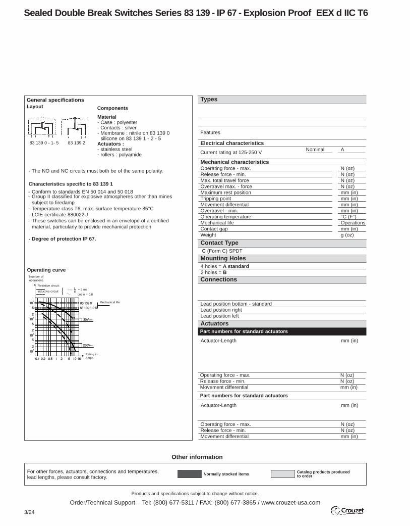
Sealed Double Break Switches Series 83 139 - IP 67 - Explosion Proof EEX d IIC T6
Other information
Normally stocked items Catalog products producedto order
Part numbers for standard actuators
Actuator-Length mm (in)
Actuator-Length mm (in)
Operating force - max. N (oz)Release force - min. N (oz)Movement differential mm (in)
Operating force - max. N (oz)Release force - min. N (oz)Movement differential mm (in)
Mechanical characteristicsOperating force - max. N (oz)Release force - min. N (oz)Max. total travel force N (oz)Overtravel max. - force N (oz)Maximum rest position mm (in)Tripping point mm (in)Movement differential mm (in)Overtravel - min. mm (in)Operating temperature °C (F°)Mechanical life OperationsContact gap mm (in)Weight g (oz)
C (Form C) SPDT
4 holes = A standard2 holes = B
Lead position bottom - standardLead position rightLead position left
Electrical characteristicsNominal A
Types
Actuators
Contact Type
Part numbers for standard actuators
Features
Current rating at 125-250 V
Mounting Holes
General specificationsLayout Components
Operating curve
Material- Case : polyester - Contacts : silver- Membrane : nitrile on 83 139 0 - silicone on 83 139 1 - 2 - 5Actuators : - stainless steel- rollers : polyamide
- The NO and NC circuits must both be of the same polarity.
Characteristics specific to 83 139 1
- Conform to standards EN 50 014 and 50 018- Group II classified for explosive atmospheres other than mines
subject to firedamp- Temperature class T6, max. surface temperature 85°C- LCIE certificate 880022U- These switches can be enclosed in an envelope of a certified
material, particularly to provide mechanical protection
- Degree of protection IP 67.
Resistive circuit:
Inductive circuit
Number ofoperations
= 5 ms
cos ϕ = 0.8
LR
Mechanical life
Rating inAmps
83 139 0 - 1- 5 83 139 2
Connections

Products and specifications subject to change without notice.
Order/Technical Support – Tel: (800) 677-5311 / FAX: (800) 677-3865 / www.crouzet-usa.com
3/25
3
To order, please specify :
Contact Type
C
Switch Type
831390831391831392831395
2 Connection
BRL
Example : 831390 C A B 5 • A
Example switch is: 831390, DBDT, 4 mounting holes, leads exit bottom, .5 meter cable with A actuator. To order actuators seperately, use 8 digit P/N.
4Mounting Holes
AB
3 Lead Length
.5 - 1/2 meter (std)1 - 1 meter2 - 2 meter
5 Actuators
A F PB H RE ØG
61
79 215 740
Roller 139 EX R28.7 (1.13)** R25.4 (1.0)Flat 161A R14.2 (.56) –
79 507 524 79 215 742 70 507 529
R24.1 (.94)Roller 161 E R13.6 (.54) –
Flat 161F R22.3 (1.17)
** Factory mounted only
3 (10.6)0.6 (2.1)4 (14.1)10 (35.3)A = 8.8 (.35) B = 9.8 (.39)A:7.7+0.4 (.30+.016) B:8.7+0.4 (.32+.016)0.35±0.1 (.014±.004)0.3 (.012)0 to 85 (32 to 185)107
0.3 x 2 (.012 x .008)37 (1.3)
C
AB
5
83 139 0
Standard
3 (10.6)0.6 (2.1)4 (14.1)10 (35.3)B = 9.8 (.39)8.7+0.4 (.32+.016)0.35±0.1 (.014±.004)0.3 (.012)-40 to 85 (-40 to 185)5 x 10⁶
0.3 x 2 (.012 x .008)45 (1.6)
C
5
83 139 5
Double insulation to NFC20030 standard classe II
3 (10.6)0.6 (2.1)4 (14.1)10 (35.3)A = 8.8 (.35) B = 9.8 (.39)A:7.7+0.4 (.30+.016) B:8.7+0.4 (.32+.016)0.35±0.1 (.014±.004)0.3 (.012)0 to 85 (32 to 185)5 x 10⁷
0.3 x 2 (.012 x .008)37 (1.3)
3 (10.6)0.6 (2.1)4 (14.1)10 (35.3)B = 9.8 (.39)A:7.7+0.4 (.30+.016) B:8.7+0.4 (.32+.016)0.35±0.1 (.014±.004)0.3 (.012)-40 to 85 (-40 to 185)5 x 10⁶
0.3 x 2 (.012 x .008)37 (1.3)
C C
5 5
83 139 2 83 139 1
Low temperature Explosion proof EEX d11C T6
4 flexible leads ø 2.8 x0.75 mm2 length 0.50 m
4 flexible leads ø 2.8 x0.75 mm2 length 0.50 m
1.5 (5.3)0.2 (.7)1.5 (.06)
1.5 (5.3)0.2 (.7)1.5 (.06)
2.6 (9.2)0.35 (1.2)0.7 (.028)
1.7 (6)0.2 (.7)1.25 (.05)
2.6 (9.2)0.35 (1.2)0.7 (.028)
1.7 (6)0.2 (.7)1.25 (.047)
2 (7.1)0.2 (.7)1.1 (.043)
2 (7.1)0.2 (.7)1.1 (.043)
79 218 65179 218 581
Flat 139 AX R29.7 (1.17)**
BAB B
RL
BBRL
BRL
Dummy roller 161 G R21.8 (.86)
Note : When mounting actuators, a light greasing of the switch push-button is recommended.
For more actuators, see 83161 ØNo Actuator
4 flexible leads ø 2.8 x0.75 mm2 length 0.50 m
3 lead cable 3 x 0.75mm2 length 0.50 m
B
ARP B E G
F H
6
5
4
3
2
1
Products and specifications subject to change without notice.
Order/Technical Support – Tel: (800) 677-5311 / FAX: (800) 677-3865 / www.crouzet-usa.com
3/26
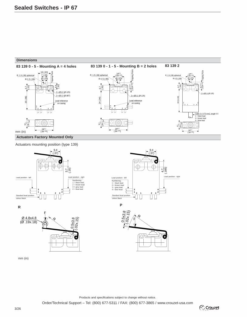
Sealed Switches - IP 67
Dimensions
Actuators Factory Mounted Only
31 3 1
422 4
16 (.63)7 (.28)
Ø2 (.079)R:1.5 (.06)
R: 1.5 (.06) spherical
2 x Ø3.2 (Ø.125)
2 x Ø2.2 (Ø.087)
5.7
(.22
)25
(.9
8)
Lead referenceon casing
8.8
(.35
)
Trip
ping
Poi
nt
24±0.2
(.94±.008)
9 0 -0
.2
(.35
+0 -.008
)
83 139 0 - 5 - Mounting A = 4 holes
R P
31 3 1
422 4
Ø2 (.079)R:1.5 (.06)
R: 1.5 (.06) spherical
2 x Ø3.1 (Ø.125)
6.7
(.26
)24
(.9
4)Lead reference
on casing
Trip
ping
Poi
nt
24±0.2
(.94±.008)
9 0 -0
.2
(.35
+0 -.008
)
14±0.1
(.55±.004)
8.7±0
.4
(.314
±.01
6 )
83 139 0 - 1 - 5 - Mounting B = 2 holes
31 3 1
422 4
Ø2 (.079)R:1.5 (.06)
R: 1.5 (.06) spherical
2 x Ø3.1 (Ø.125)
6.7
(.26
)34
(1.
34)
Cable 3 x 0.75 mm2, length 0.51 = black lead2 = brown lead4 = blue lead
Trip
ping
Poi
nt
24±0.2
(.94±.008)
9 0 -0
.2
(.35
+0 -.008
)
14±0.1
(.55±.004)
8.7±0
.4
(.314
±.01
6 )
83 139 2
9.4(.37)
3.7
(.15
)
31 3 1
422 4
Actuators mounting position (type 139)
Ø 4.8x4.8(Ø .19x.18)
0.5x
3.8
(.02
x.15
)
F
R
9.4(.37)
4.7
(.18
5)
31 3 1
422 4
0.5x
3.8
(.02
x.15
)
FR
Lead position - left Lead position - right Lead position - rightLead position - left
Standard lead position
colour black
Standard lead position
colour black
Numbering :1 = black lead2 = brown lead3 = grey lead4 = blue lead
Numbering :1 = black lead2 = brown lead3 = grey lead4 = blue lead
mm (in)
mm (in)

Products and specifications subject to change without notice.
Order/Technical Support – Tel: (800) 677-5311 / FAX: (800) 677-3865 / www.crouzet-usa.com
3/27
3
Sealed Switches - IP 67
mm (in)
Actuators mounting position (type 161)
A - B
H
E - G F
9(.35)
3.7
(.15
)
31 3 1
422 4
4.3
(.17
)
0.5x
7
(.02
x.28
)FR
4.3
(.17
)
0.5x
7
(.02
x.28
)R 2
1.8
(.86)
Ø5 (.2)
F
Ø 4
.8
(Ø .1
87)
6.3(.25)
8(.315)
R
4.3
(.17)
9(.35)
4.7
(.18
5)31 3 1
422 4
Actuators User or Factory Mounted
R: 2.5 (.1)
5 (.2)
F
R
Lead position - left Lead position - right
Standard lead position
colour black
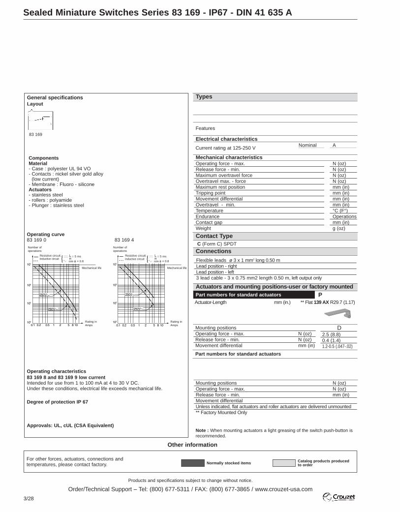
Products and specifications subject to change without notice.
Order/Technical Support – Tel: (800) 677-5311 / FAX: (800) 677-3865 / www.crouzet-usa.com
3/28
For other forces, actuators, connections andtemperatures, please contact factory.
Sealed Miniature Switches Series 83 169 - IP67 - DIN 41 635 A
Other information
Normally stocked items Catalog products producedto order
D2.5 (8.8)0.4 (1.4)1.2-0.5 (.047-.02)
Part numbers for standard actuators
Actuator-Length mm (in.) ** Flat 139 AX R29.7 (1.17)
Mounting positionsOperating force - max. N (oz)Release force - min. N (oz)Movement differential mm (in)
Mounting positions N (oz)Operating force - max. N (oz)Release force - min. mm (in)Movement differential Unless indicated, flat actuators and roller actuators are delivered unmounted** Factory Mounted Only
Mechanical characteristicsOperating force - max. N (oz)Release force - min. N (oz)Maximum overtravel force N (oz)Overtravel max. - force N (oz)Maximum rest position mm (in)Tripping point mm (in)Movement differential mm (in)Overtravel - min. mm (in)Temperature °C (F°)Endurance OperationsContact gap mm (in)Weight g (oz)
C (Form C) SPDT
Electrical characteristicsNominal A
Types
Actuators and mounting positions-user or factory mounted
Contact Type
Part numbers for standard actuators
Note : When mounting actuators a light greasing of the switch push-button isrecommended.
Features
Flexible leads ø 3 x 1 mm2 long 0.50 mLead position - right Lead position - left 3 lead cable - 3 x 0.75 mm2 length 0.50 m, left output only
Current rating at 125-250 V
Connections
General specificationsLayout
Operating curve83 169 0 83 169 4
Operating characteristics83 169 8 and 83 169 9 low currentIntended for use from 1 to 100 mA at 4 to 30 V DC.Under these conditions, electrical life exceeds mechanical life.
Degree of protection IP 67
Approvals: UL, cUL (CSA Equivalent)
ComponentsMaterial- Case : polyester UL 94 VO- Contacts : nickel silver gold alloy
(low current)- Membrane : Fluoro - siliconeActuators - stainless steel- rollers : polyamide- Plunger : stainless steel
Resistive circuit:
Number ofoperations
= 5 ms
cos ϕ = 0.8
LR
Mechanical life
Rating inAmps
Inductive circuit Resistive circuit:
Number ofoperations
= 5 ms
cos ϕ = 0.8
LR
Mechanical life
Rating inAmps
Inductive circuit
83 169
P

Products and specifications subject to change without notice.
Order/Technical Support – Tel: (800) 677-5311 / FAX: (800) 677-3865 / www.crouzet-usa.com
3/29
3L
C(1)
RLC
RLC
RLC
79 215 740 70 507 524 **Roller 139 EX R28.7 (1.13) Flat 161 A R14.2 (.56) - R25.4 (1)
79 215 742 70 507 529Roller 161 E R13.6 (.54) - R24.1 (.95)
For more actuatorssee 83161
ØNo Actuator
Flat 161 F R22.3 (.88)
4 (14.1)1 (3.5)8 (28.2)20 (70.5)15.9 (.63)14.7+0.5 (.58±.02)0.35 (.014)1 (.04)-20 to 85 (-4 to 185)5 x 10⁶
0.4 (.016)30 (1.06)
C
R
10
83 169 0
Standard
4 (14.1)1 (3.5)8 (28.2)20 (70.5)15.9 (.63)14.7+0.5 (.58±.02)0.07 (.003)0.4 (.016)-20 to 85 (-4 to 185)5 x 10⁶
0.4 (.016)30 (1.06)
C
5
83 169 4
Reduced differentialmovement
4 (14.1)1 (3.5)8 (28.2)20 (70.5)15.9 (.63)14.7+0.5 (.58±.02)0.07 (.003)0.4 (.016)-20 to 85 (-4 to 185)5 x 10⁶
0.4 (.016)30 (1.06)
C
0.1
83 169 8
Low current
4 (14.1)1 (3.5)8 (28.2)20 (70.5)15.9 (.63)14.7+0.5 (.58±.02)0.35 (.014)1 (.04)-20 to 85 (-4 to 185)5 x 10⁶
0.4 (.016)30 (1.06)
C
0.1
83 169 9
Low current, reduceddifferential movement
A B2.5 (8.8) 4.2 (14.8)0.5 (1.8) 1 (3.5)
0.8 (.032) 0.4 (.016)
A B C1.4 (4.9) 2.5 (8.8) 3.5 (12.3)0.25 (.88) 0.5 (1.8) 0.6 (2.1)1.6 (.063) 0.8 (.032) 0.6 (.024)
A B2.5 (8.8) 4.2 (14.8)0.5 (1.8) 1 (3.5)
0.8 (.032) 0.4 (.016)
A B1.5 (5.3) 2.6 (9.2)
0.25 (.9) 0.5 (1.8)16 (.63) 0.8 (.032)
A B C1.4 (4.9) 2.5 (8.8) 3.5 (12.3)0.25 (.88) 0.5 (1.8) 0.6 (2.1)1.6 (.063) 0.8 (.032) 0.6 (.024)
A B1.5 (5.3) 2.6 (9.2)
0.25 (.9) 0.5 (1.8)16 (.63) 0.8 (.032)
2.5 (8.8)0.4 (1.4)1.2-0.5 (.047-.02)
79 218 651
Dummy roller 161 G R21.8 (.86)
(1) 83 169 0 Cable limits current to 8 Amps
AR
D
79 218 581F H
B E G
To order, please specify :
Contact Type
C
Switch Type
831690831694831698831699
2 Leangth of Leads
.5 - 1/2 meter (std)1 - 1 meter2 - 2 meter
Example : 831690 C R .5 • Ø
Example switch is: 831690, SPDT, leads exit right, .5 meter leads, with no actuator. To order actuators seperately, use the 8 digit P/N.
4Cinnections
RLC
3 Actuator
Ø EA FB GH P
R
5 Actuator Position61
A B C
D
1
2
3
4
5

Products and specifications subject to change without notice.
Order/Technical Support – Tel: (800) 677-5311 / FAX: (800) 677-3865 / www.crouzet-usa.com
3/30
Sealed Miniature Switches
Dimensions
Actuators
20.2 ±0.2(.8±.008)Ø2 (.079) Ø3+0.15
+0.05
(.12+.006 -.002 )
13 (.
51)
10.5
(.41)2
(.079
)
3x1mm2
Leads1 = black lead (common)2 = brown lead (NC)4 = blue lead (NO)
3+0.1
5+0
.05
(.12+.
006
-.00
2)
8316
9 0
& 8
8316
9 4
& 9
13.1
(.52
)13
.8 (.
54)
2.8(.11) 31 (1.22)
22.2 ±0.1(.87±.004)
Ø3.4 (.134)
6.5(.26)
10.3
±0.1
(.41±.
004)
Output wires
5 (.2
)
3x0.75mm2
cableOutput left
1 = black lead (common)2 = brown lead (NC)4 = blue lead (NO)
Output cable
6.5(.26)
0.5
(.02
)
D
Mounting position for factorymounted actuators
Mounting position for factory orcustomer mounted actuators
P
A - B
R
0.5x
3.8
(.02
x.15
)
R
F
Ø 4
.8(Ø
.187
)
6.3(.25)
8(.315)
R
4.4(.17)
0.6
(.24
)
A B C
14.4(.57)
8.7(.34)
22.2 (.87)
10.3
(.41
)
D
4.3
(.17
)RF 0.
5x7
(.02
x.28
)
OL
=
E - G
FØ 4
.8(Ø
.187
)
6.3(.25)
8(.315)
R
F
5(.2
)
F
R
R: 2.5 (.1)
90°
5(.
2)
H
4.3
(.17
)
0.5x
7(.
02x.
28)
R 22.2 (.87)
Ø5(.2)
mm (in)
mm (in)
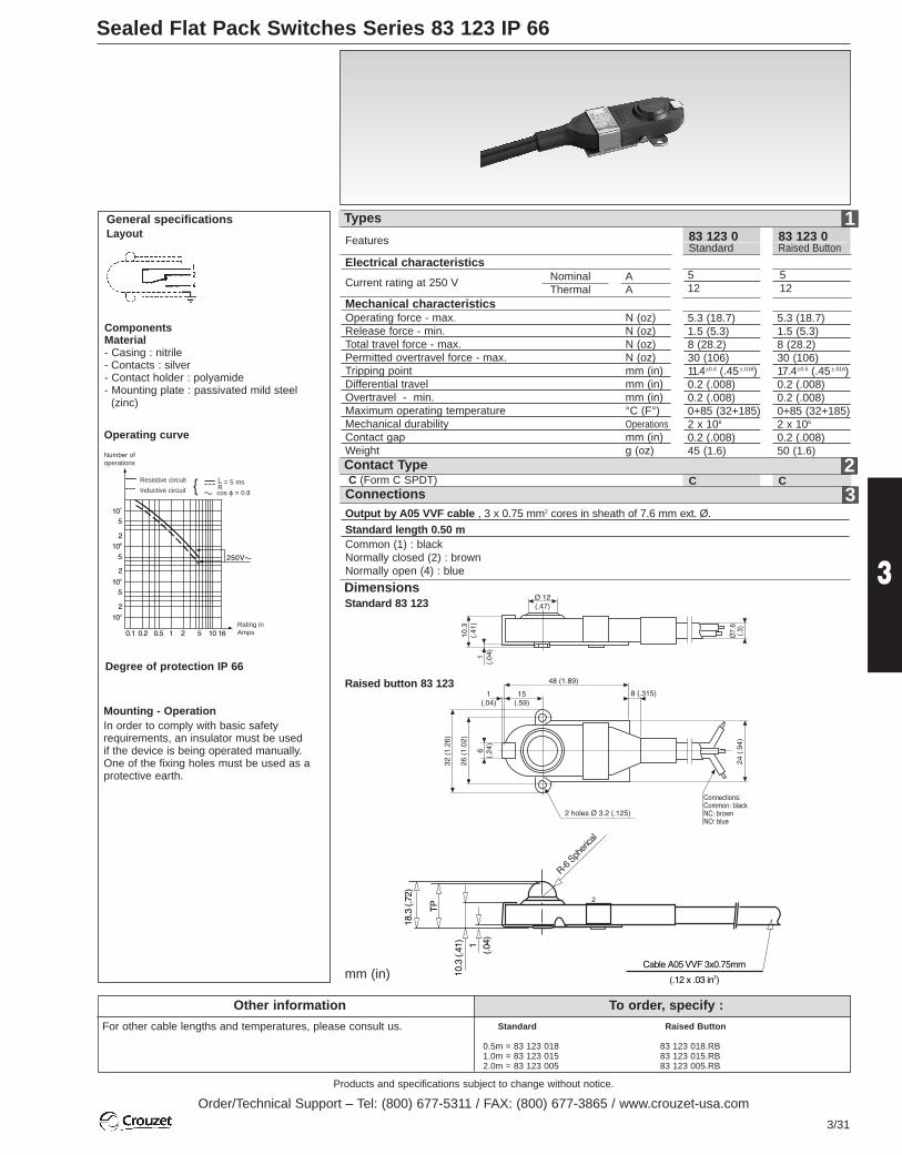
Products and specifications subject to change without notice.
Order/Technical Support – Tel: (800) 677-5311 / FAX: (800) 677-3865 / www.crouzet-usa.com
3/31
3
Sealed Flat Pack Switches Series 83 123 IP 66
To order, specify :
For other cable lengths and temperatures, please consult us.
Other informationStandard
0.5m = 83 123 0181.0m = 83 123 0152.0m = 83 123 005
Raised Button
83 123 018.RB83 123 015.RB83 123 005.RB
5 512 12
Output by A05 VVF cable , 3 x 0.75 mm2 cores in sheath of 7.6 mm ext. Ø.
Standard length 0.50 mCommon (1) : blackNormally closed (2) : brownNormally open (4) : blue
C CContact Type
Mechanical characteristicsOperating force - max. N (oz)Release force - min. N (oz)Total travel force - max. N (oz)Permitted overtravel force - max. N (oz)Tripping point mm (in)Differential travel mm (in)Overtravel - min. mm (in)Maximum operating temperature °C (F°)Mechanical durability OperationsContact gap mm (in)Weight g (oz)
C (Form C SPDT)
Electrical characteristicsNominal AThermal A
Types
Features
Current rating at 250 V
Connections
General specificationsLayout
Operating curve
Degree of protection IP 66
ComponentsMaterial- Casing : nitrile- Contacts : silver- Contact holder : polyamide- Mounting plate : passivated mild steel
(zinc)
Number ofoperations
Rating inAmps
5.3 (18.7) 5.3 (18.7)1.5 (5.3) 1.5 (5.3)8 (28.2) 8 (28.2)30 (106) 30 (106)11.4±0.4 (.45±.016) 17.4±0.5 (.45±.016)0.2 (.008) 0.2 (.008)0.2 (.008) 0.2 (.008)0+85 (32+185) 0+85 (32+185)2 x 10⁶ 2 x 10⁶
0.2 (.008) 0.2 (.008)45 (1.6) 50 (1.6)
83 123 0Standard
83 123 0Raised Button
Resistive circuit
Inductive circuit= 5 ms
cos ϕ = 0.8
LRc
a
Mounting - OperationIn order to comply with basic safetyrequirements, an insulator must be usedif the device is being operated manually.One of the fixing holes must be used as aprotective earth.
DimensionsStandard 83 123
Raised button 83 123
mm (in)
3
2
1

Products and specifications subject to change without notice.
Order/Technical Support – Tel: (800) 677-5311 / FAX: (800) 677-3865 / www.crouzet-usa.com
3/32
Low Force Position Detectors Series 81 290
To order, specify :
On request :
Wide range of actuatorsConnectable exhaust
Standard products
Other information
Part number AccessoryExample : Low force position detector 81 290 501
Flat actuator 79 215 741
21
S (2)
(1)
5/64" (2)30 > 120 (2 > 8)2.5 (>70)<1.7 (< 50)
+20> +120 (-10 > +50)+20> +140 (-10 > +60)+20> +160 (-40 > +70)
10 million≤ 15 ≤ 150.106”I.D.x 5/32”O.D. (2.7x4)8.5
5/64" (2)30 > 120 (2 > 8)4.5 (130)<1.7 (< 50)
+20> +120 (-10 > +50)+20> +140 (-10 > +60)+20> +160 (-40 > +70)
10 million≤ 15 ≤ 150.106”I.D.x 5/32”O.D. (2.7x4)8.5
81 290 501-
-81 290 001
(Form B) SPNCContact type(Form A) SPNO
Orifice diameter inches(mm)Operating pressure psi(bar)Flow at 60 psi(4 bars) cfm(NI/min)Activation force at 90 (6 bars) ounces(g)Permissible fluid: air, inert gasesMax/min. of fluid °F(°C)temperatures operating °F(°C)
storage °F(°C)Mechanical life at 90psi (6 bars) cyclesResponse on activation mstime on release msBarb connection for semi-rigid tubing inches(mm)Weight
Part numbers
Operation accessories
Symbol
Characteristics
Principle of NC operationDeactivated Activated
Dimensions
Unless otherwise requested, flat and roller-endedactuators are supplied loose.
161 Aflat79 215 741
161 Eroller 79 215 743
Conforms to standard DIN 43365 Form A Low activation force < 1.7 oz. (50 g @ at 6
bars) at 90 psi No continuous consumption of compressed
air
grams
2
1
2 x exhaust
(1)
0.09"
(2.4) 1" (25.4)
0.95" (25.4)
0.13
4"(3
.4)
0.125"(6.3)
0.31"(8)
0.19
" di
a
(ø4.
8)
Use (metric) dimensions for critical data
161 A 161 E
(3.8).15
1.18(30)
.126(3.2) (1
1.8)
.466
.788
(20
)
(5)
.197.6
5 (1
6.5)
.51(12.95)
(10.
7).4
3(3
+0.
15)
+0.
05
.118
+.0
06+
.002
(14.
7+0.
5 ).5
9+0.
02O
pera
ting
posi
tion
.63
(16)
Res
et p
ositi
on
2.5
Tot
al tr
avel
.098
(26
)
.874(22.2)
.134(3.4)
.23(5.8)
.608
(10.
3)
(3+0.15)-0.05
.118+0.06-.002
.154(3.9)
in (mm)
0.16
9 +
0.08
(4.3
+0.
2 )
Industrial Limit Switches
Products and specifications subject to change without notice.
Order/Technical Support – Tel: (800) 677-5311 / FAX: (800) 677-3865 / www.crouzet-usa.com
3/33
3

Products and specifications subject to change without notice.
Order/Technical Support – Tel: (800) 677-5311 / FAX: (800) 677-3865 / www.crouzet-usa.com
3/34
Miniature Industrial Limit Switches Series 83 852 / 83 853 EN 50047
For other contact types and accessories or special modes of operation : please consult us.For dimensions see page 3/38.
Other informationReplacement contact blockPart number Configurations Function83157401 SPDT <STD>83157402 SPDT Break before make83157403 SPDT Make before break83157404 2 NO DPST - Normally open83157405 2 NC DPST - Normally closed
Thermoplasticcase with doubleinsulation andmetal actuatorheadMetal bodies and actuator heads
Control mechanisms - adjustableactuator heads 4 positions 90°Steel plungerPlunger with steel rollerLever with plasticroller
With lever and plastic roller
With adjustablelever and plasticroller
With adjustable polyamide rod actuatorFlexible metal lever(1) Action either right or left according to position of head
Independent snap actionSequence
Dependent action
Positive break operation
Mechanical characteristicsMinimum operating forceMinimum total travel forceMinimum positive opening force Minimum operating travelMinimum positive opening travel Differential travelMax. total travel Mechanical life (millions of operations) mini.Temperature Uselimits StoredDegree of protectionWeight Series 83 853
Series 83 852
Conform to the followingstandards : IEC 536-1, IEC 947-5-1, CSA C22.2 No. 14, EN 50047,EN 60947-5-1, EN 60204-1, NFC 20030 class I for 83 852
class II for 83 853UL 508, VDE 0660/200.
Degree of protection : IP 66Version : 1 pole
Function : Four-terminal double breakcontact element (form Zb) with positiveopening NC contacts.The two moving contacts areelectrically isolated from oneanother.
Principle :Independent snap action contact 1 NO + 1NC
Dependent action1 NO + 1NC
Break Before Make
Electrical characteristics Assigned insulation voltage (Ui) :500 VThermal rating (Ith) : 10 AUse category : A300 - Q300AC15 = 6A/250 V - 1.9 A / 380 VDC 13 = 3A/24 V
Short circuit test (under IEC 947.5.1 § 8.3.4)- Current peak 1000 A
at 250 V a 0.5 < cos ϕ < 0.7- Short circuit protection (SCPD) :
fuse 10 A gF- Electrical protection by internal
earth terminal (83 852)
Connections :Saddle washer and M 3.5 screwMax. wire cross-section : 2 x 1.5 mm2
or 1 x 2.5 mm2
Connection :For 1/2˝ NPT
Approvals :UL listed A300 - Q300 - CSA A300 - Q300
83 853 001
83 853 011
83 852 001
83 852 011
10 (35.3)
12 (42.3)
25 (88.2)
5 (.2)
6 (.24)
1.5 (.06)6 (.24)15 -25+80(-13+176)-40+80(-40+176)IP 6690 (3.2)170 (6)
83 853 501
83 853 511
83 852 501
83 852 511
10 (35.3)
12 (42.3)
25 (88.2)
5 (.2)
6 (.24)
1.5 (.06)6 (.24)15 -25+80(-13+176)-40+80(-40+176)IP 66100 (3.5)180 (6.3)
83 853 101
83 853 111
83 852 101
83 852 111
9 (31.7)
10 (35.3)
20 (70.5)
5 (.2)
6.5 (.247)
1.5 (.06)6 (.24)15-25+80(-13+176)-40+80(-40+176)IP 66100 (3.5)180 (6.3)
83 853 201
83 853 211
83 852 201
83 852 211
9 (31.7)
10 (35.3)
20 (70.5)
5 (.2)
6.5 (.247)
1.5 (.06)6 (.24)15-25+80(-13+176)-40+80(-40+176)IP 66105 (3.7)180 (6.3)
Independent snap actionNC + NODependent actionNC + NOIndependent snapaction NC + NODependent actionNC + NO
verticallateral
Ø 22 offset 40Ø 19 offset 53
Ø 50 offset 47offset 53.5
Ø 22 offset 32.5 or 45offset 46
Ø 50 adjustable offset53.5 to 69.5
N (oz.)
N (oz.)
N (oz.)
mm (in.)
mm (in.)
mm (in.)mm (in.)
°C (°F)°C (°F)
g (oz.)g (oz.)
Types
Rotary head, momentary action to right and left (1)
0,9
0 1,8 4,5F 6 mm
0 31,8 3,2F 6 mm21-2213-14
21-2213-14
21-2213-14
1,5
0 3,2 7,8F mm
0 5,63,2 5,8F mm21-2213-14
21-2213-14
21-2213-14
3
0 6,5 15,5Fmm
0 9,56,5 11F mm21-2213-14
21-2213-14
21-2213-14
3
0 6,5 15,5Fmm
0 9,56,5 11F mm21-2213-14
21-2213-14
21-2213-14

Standard products
Standard products,non stocked
To order, specify :
Part number
Example : Limit switch 83 853 001
1
Products and specifications subject to change without notice.
Order/Technical Support – Tel: (800) 677-5311 / FAX: (800) 677-3865 / www.crouzet-usa.com
3/35
3
83 853 305
83 853 315
83 852 305
83 852 315
28cmN (40inoz)
37cmN (52inoz)
75cmN (106inoz)
30°
60º
20º75º15-25+80(-13+176)-40+80(-40+176)IP 66130 (4.6)205 (7.23)
83 853 301
83 853 311
83 852 301
83 852 311
28cmN (40inoz)
37cmN (52inoz)
75cmN (106inoz)
30°
60º
20º75º15-25+80(-13+176)-40+80(-40+176)IP 66130 (4.6)205 (7.23)
83 853 303
83 853 313
83 852 303
83 852 313
28cmN (40inoz)
37cmN (52inoz)
75cmN (106inoz)
30°
60º
20º75º15-25+80(-13+176)-40+80(-40+176)IP 66130 (4.6)205 (7.23)
83 853 304
83 853 314
83 852 304
83 852 314
28cmN (40inoz)
37cmN (52inoz)
75cmN (106inoz)
30°
60º
20º75º15-25+80(-13+176)-40+80(-40+176)IP 66153 (5.4)225 (7.93)
83 853 601
83 853 611
83 852 601
83 852 611
3 (10)
4.5 (16)
30°
60º
20º75º15-25+80(-13+176)-40+80(-40+176)IP 66130 (4.6)200 (7.1)
83 853 307
83 853 317
83 852 307
83 852 317
28cmN (40inoz)
37cmN (52inoz)
75cmN (106inoz)
30°
60º
20º75º15-25+80(-13+176)-40+80(-40+176)IP 66153 (5.4)225 (7.93)
83 853 308
83 853 318
83 852 308
83 852 318
28cmN (40inoz)
37cmN (52inoz)
75cmN (106inoz)
30°
60º
20º75º15-25+80(-13+176)-40+80(-40+176)IP 66153 (5.4)225 (7.93)
83 853 302
83 853 312
83 852 302
83 852 312
28cmN (40inoz)
37cmN (52inoz)
75cmN (106inoz)
30°
60º
20º75º15-25+80(-13+176)-40+80(-40+176)IP 66130 (4.6)205 (7.23)
83 853 306
83 853 316
83 852 306
83 852 316
28cmN (40inoz)
37cmN (52inoz)
75cmN (106inoz)
30°
60º
20º75º15-25+80(-13+176)-40+80(-40+176)IP 66130 (4.6)205 (7.23)
1
12°
0° 25° 60°F 75°
0° 32°25° 46°F 75°21-2213-14
21-2213-14
21-2213-14
12°
0° 25° 60°F 75°
0° 32°25° 46°F 75°21-2213-14
21-2213-14
21-2213-14
12°
0° 25° 60°F 75°
0° 32°25° 46°F 75°21-2213-14
21-2213-14
21-2213-14
12°
0° 25° 60°F 75°
0° 32°25° 46°F 75°21-2213-14
21-2213-14
21-2213-14
12°
0° 25° 75°
0° 32°25° 75°21-2213-14
21-2213-14
21-2213-14
12°
0° 25° 75°
0° 32°25° 75°21-2213-14
21-2213-14
21-2213-14
12°
0° 25° 75°
0° 32°25° 75°21-2213-14
21-2213-14
21-2213-14
12°
0° 25° 75°
0° 32°25° 75°21-2213-14
21-2213-14
21-2213-14
12°
0° 20° 75°
0° 35°25° 75°21-2213-14
21-2213-14
21-2213-14

Products and specifications subject to change without notice.
Order/Technical Support – Tel: (800) 677-5311 / FAX: (800) 677-3865 / www.crouzet-usa.com
3/36
Industrial Limit Switches Series 83 862 EN 50041
For other contact types and accessories or special modes of operation : please consult us.For dimensions see page 3/39.
Other information
Dependent action NC + NOIndependent snap action NC + NOControl mechanisms - adjustableactuator heads 4 positions 90°Steel plungerPlunger with steel rollerLever with plastic roller
With lever andplastic roller
With adjustablelever and plastic roller
With adjustable polyamide rod actuatorFlexible metal lever
Independent snap action
SequenceDependent action
Positive break operation
Mechanical characteristicsMinimum operating forceMinimum total travel forceMinimum positive opening travelMinimum operating travelMinimum positive opening travel Differential travelMax. total travel Mechanical life (millions of operations) mini.Temperature Uselimits StoredDegree of protectionWeight
verticallateral
Ø 22 offset 43.5
Ø 19 offset 56
offset 50.5Ø 50
offset 57
Ø 22 offset 36 or 48
offset 49Ø 50 adjustable offset
57 to 73
N (oz.)
N (oz.)
N (oz.)
mm (in.)
mm (in.)
mm (in.)mm (in.)
°C (ºF)°C (ºF)
g (oz.)
83 862 011 83 862 001
10 (35.5)
12 (42.3)
25 (88.2)
5 (.2)
6 (.24)
1.5 (.06)6 (.24)15-25+80(-13+176)-40+80(-40+176)IP 66305 (10.76)
(1) Action either right or left according to position of head
Cover with status indicator 24.30 V a c 79 250 290(supplied loose) 220 V a 79 250 291
Part number Configuration Function83157401 SPDT <STD>83157402 SPDT Break before make83157403 SPDT Make before break83157404 2 NO DPST - Normally open83157405 2 NC DPST - Normally closed
Rotary head, momentary action to clockwise and/or anti-clockwise (1)
Conform to the following standards : EN 50041, IEC 947-5-1, VDE 0660/200UL 508, CSA C22.2 No.14 IEC 536-1, EN 60204-1, NFC 20030class I
Degree of protection : IP 66
Function : Four-terminal double breakcontact element (form Zb) with positiveopening NC contacts.The two moving contacts are electrically isolated from one another.
Principle :Independent snap action contact 1 NO + 1NC
Dependent action1 NO + 1NC
Break before make
Electrical characteristics :
Assigned insulation voltage (Ui) :500 VThermal rating (Ith) : 10 AUse category : A300 - Q300AC15 = 6A/250 V - 1.9 A / 380 VDC 13 = 3A/24 V
Short circuit test (under IEC 947.5.1 § 8.3.4)- Current peak 1000 A
at 250 V~0.5 < cos ϕ < 0.7- Short circuit protection (SCPD) :
fuse 10 A gF- Electrical protection by internal earth
terminal
Connections :Saddle washer and M 3.5 screwMax. wire cross-section : 2 x 1.5 mm2
or 2.5 mm2
Connection :1/2˝ NPT
Approvals :UL listed A300 - Q300 - CSA A300 - Q300
Types
Accessories
Replacement contact block
83 862 511 83 862 501
10 (35.5)
12 (42.3)
25 (88.2)
5 (.2)
6 (.24)
1.5 (.06)6 (.24)15-25+80(-13+176)-40+80(-40+176)IP 66315 (11.11)
83 862 111 83 862 101
9 (31.7)
10 (35.3)
20 (70.5)
5 (.2)
6.5 (.26)
1.5 (.06)6 (.24)15-25+80(-13+176)-40+80(-40+176)IP 66320 (11.28)
83 862 211 83 862 201
9 (31.7)
10 (35.3)
20 (70.5)
5 (.2)
6.5 (.26)
1.5 (.06)6 (.24)15-25+80(-13+176)-40+80(-40+176)IP 66325 (11.46)
0,9
0 2 4,7F 6 mm
0 3,22 3,4F 6 mm21-2213-14
21-2213-14
21-2213-14
1,5
0 3,4 8F mm
0 5,63,4 5,8F mm21-2213-14
21-2213-14
21-2213-14
3
0 6,5 15,5Fmm
0 9,56,5 11F mm21-2213-14
21-2213-14
21-2213-14
3
0 6,5 15,5Fmm
0 9,56,5 11F mm21-2213-14
21-2213-14
21-2213-14
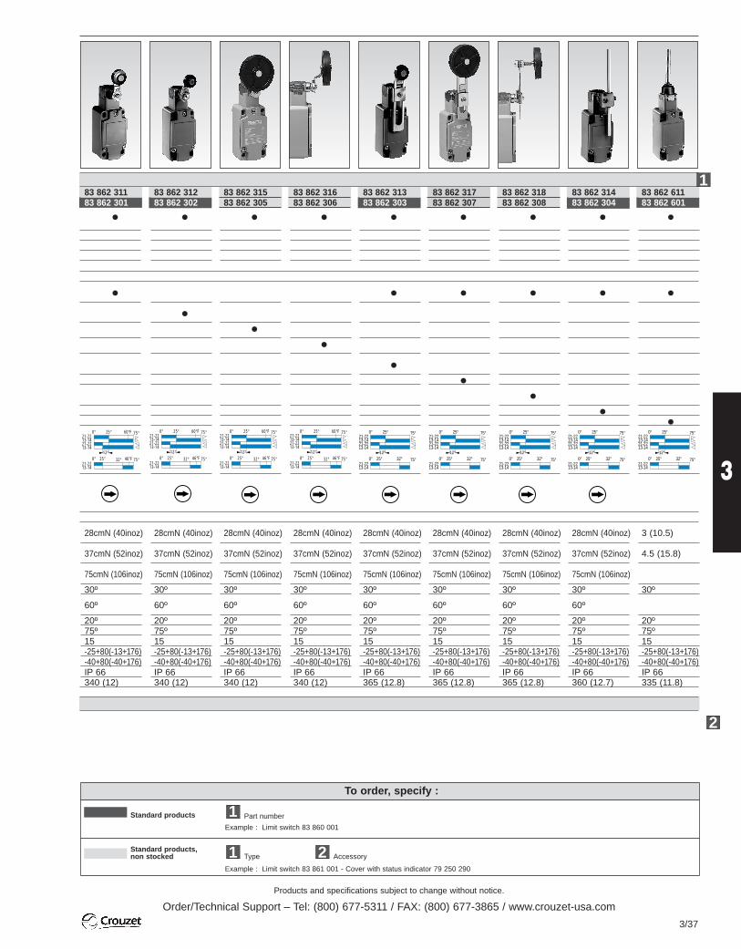
Products and specifications subject to change without notice.
Order/Technical Support – Tel: (800) 677-5311 / FAX: (800) 677-3865 / www.crouzet-usa.com
3/37
3
Standard products
Standard products,non stocked
To order, specify :
Part number
Example : Limit switch 83 860 001
Type Accessory
Example : Limit switch 83 861 001 - Cover with status indicator 79 250 290
21
1
12°
0° 25° 60°F 75°
0° 32°25° 46°F 75°21-2213-14
21-2213-14
21-2213-14
12°
0° 25° 60°F 75°
0° 32°25° 46°F 75°21-2213-14
21-2213-14
21-2213-14
12°
0° 25° 60°F 75°
0° 32°25° 46°F 75°21-2213-14
21-2213-14
21-2213-14
12°
0° 25° 60°F 75°
0° 32°25° 46°F 75°21-2213-14
21-2213-14
21-2213-14
2
83 862 311 83 862 301
28cmN (40inoz)
37cmN (52inoz)
75cmN (106inoz)
30º
60º
20º75º15 -25+80(-13+176)-40+80(-40+176)IP 66340 (12)
83 862 312 83 862 302
28cmN (40inoz)
37cmN (52inoz)
75cmN (106inoz)
30º
60º
20º75º15 -25+80(-13+176)-40+80(-40+176)IP 66340 (12)
83 862 315 83 862 305
28cmN (40inoz)
37cmN (52inoz)
75cmN (106inoz)
30º
60º
20º75º15 -25+80(-13+176)-40+80(-40+176)IP 66340 (12)
83 862 313 83 862 303
28cmN (40inoz)
37cmN (52inoz)
75cmN (106inoz)
30º
60º
20º75º15 -25+80(-13+176)-40+80(-40+176)IP 66365 (12.8)
83 862 611 83 862 601
3 (10.5)
4.5 (15.8)
30º
20º75º15 -25+80(-13+176)-40+80(-40+176)IP 66335 (11.8)
83 862 317 83 862 307
28cmN (40inoz)
37cmN (52inoz)
75cmN (106inoz)
30º
60º
20º75º15 -25+80(-13+176)-40+80(-40+176)IP 66365 (12.8)
83 862 314 83 862 304
28cmN (40inoz)
37cmN (52inoz)
75cmN (106inoz)
30º
60º
20º75º15 -25+80(-13+176)-40+80(-40+176)IP 66360 (12.7)
83 862 318 83 862 308
28cmN (40inoz)
37cmN (52inoz)
75cmN (106inoz)
30º
60º
20º75º15 -25+80(-13+176)-40+80(-40+176)IP 66365 (12.8)
83 862 316 83 862 306
28cmN (40inoz)
37cmN (52inoz)
75cmN (106inoz)
30º
60º
20º75º15 -25+80(-13+176)-40+80(-40+176)IP 66340 (12)
12°
0° 25° 75°
0° 32°25° 75°21-2213-14
21-2213-14
21-2213-14
12°
0° 25° 75°
0° 32°25° 75°21-2213-14
21-2213-14
21-2213-14
12°
0° 25° 75°
0° 32°25° 75°21-2213-14
21-2213-14
21-2213-14
12°
0° 25° 75°
0° 32°25° 75°21-2213-14
21-2213-14
21-2213-14
12°
0° 25° 75°
0° 32°25° 75°21-2213-14
21-2213-14
21-2213-14
1
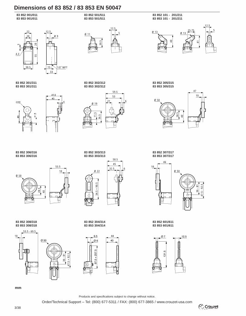
Products and specifications subject to change without notice.
Order/Technical Support – Tel: (800) 677-5311 / FAX: (800) 677-3865 / www.crouzet-usa.com
3/38
Dimensions of 83 852 / 83 853 EN 50047
83 852 306/31683 853 306/316
83 852 303/31383 853 303/313
83 852 307/31783 853 307/317
83 852 301/31183 853 301/311
83 852 302/31283 853 302/312
83 852 305/31583 853 305/315
83 852 001/01183 853 001/011
83 852 501/51183 853 501/511
30.5
203
4.3
1/2˝ NPT
20
22
55
12.5
Ø 9
15
33
30.5
12.5
5Ø 11
40
Ø 13
41
12.5
525.75Ø 13
83 852 101 - 201/21183 853 101 - 201/211
83 852 308/31883 853 308/318
53
636
.511.5
21
59.5
Ø 19
47
10
4028.5
Ø 50
45
6
34.5
+ 9
0.5
50.5
Ø 2232.5
46
10
47.5
- 9
2.5
36 -
81
Ø 50
53.5
10
4028.5
Ø 50
83 852 304/31483 853 304/314
83 852 601/61183 853 601/611
53.5 - 69.5
10
47.5
+ 9
2.5
36 -
81
mm
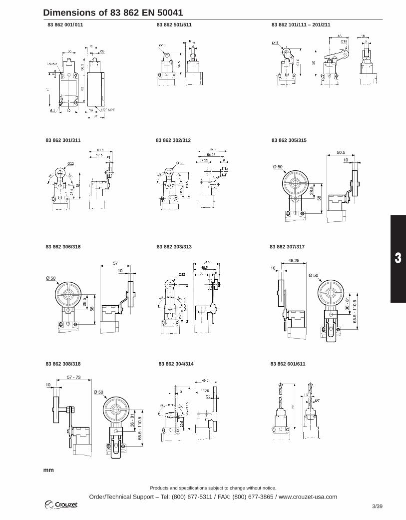
Products and specifications subject to change without notice.
Order/Technical Support – Tel: (800) 677-5311 / FAX: (800) 677-3865 / www.crouzet-usa.com
3/39
3
Dimensions of 83 862 EN 5004183 862 001/011 83 862 501/511 83 862 101/111 – 201/211
83 862 301/311 83 862 302/312 83 862 305/315
83 862 306/316
83 862 308/318
83 862 307/31783 862 303/313
83 862 304/314 83 862 601/611
mm
1/2˝ NPT

Products and specifications subject to change without notice.
Order/Technical Support – Tel: (800) 677-5311 / FAX: (800) 677-3865 / www.crouzet-usa.com
3/40
Positive Opening Enclosed Limit Switches Series 83 870 IP 67
For different actuator arms, low voltage / low current contacts / low temperature, special contacts, custom wiring harness, etc.…, please consult us.
Other information
Conforms to the following standards:IEC / EN 60947.5.1Dimensional conformity: NFC 63145Low voltage directive: 73/23/EEC and 93/68/EECProtection from electric shock: NFC 20030 or IEC 60536 Class 1, degreeof pollution 3.
Temperature specification: –25°/+70°C –13°/+158°F
Degree of protection:IEC 62529: IP 66/67NEMA 250: Type 1, 3, 4, 6, 13
Function:Contact block is SPDT with double break contacts(form Zb). The NC contacts are positive opening. The NO and NCcontacts are electrically isolated.
Contact type:Snap action SPDT-DB
Electrical characteristicsAssigned impulse voltage (Uimp): 2500 VAssigned insulation voltage (Ui): 500 VThermal rating (Ith): 10 AWith standard contacts: Minimum voltage 10V
Minimum current 100mAUse categories:Following IEC 947.5.1 AC15 = 250V / 6A
DC13 = 24V / 8AFollowing UL 508 A300 - Q150
Electrical protection:Under IEC 947.5.1Short-circuit protection (SCPD): 6AgC fuseElectrical protection by internal earth ground
Connections:Non-UL: 5 conductor cable H05VF 0.75mm2 ext. Ø8mm (Black)UL: 5 conductor cable (Grey)
Approvals: UL 508, UL 50
StandardRoller turned 90°
Actuator TypeMetal plungerMetal roller plungerMetal plunger with threaded barrelRoller plunger - metal with threaded barrelMetal roller lever (operates in both directions)Mechanical characteristicsOperating force minimum oz. (N)Total travel force minimum oz. (N)Positive opening force minimum oz. (N)Mechanical life millions of cyclesWeight oz. (grams)
Types
Dimensions mm
Contact Sequences
83 870 0
Standard products 2.0 meter cable* side exit**
Positions given are nominal
(*) For other lengths of cables:
modify the last digit of the part number. For example:
0 = M12 connector output1 = 1.0 meter cable2 = 2.0 meter cable (Standard)3 = 3.0 meter cable
(**) For different cable outputs:
modify the next to the last digit of the part number.:
0 = Cable side exit (Standard)1 = Cable bottom exit2 = Connector side exit3 = Connector bottom exit
940
PR
P
Ø 8
30
Ø 8 x 4.3
r = 0.5
16
5.6
2.6
20
RP
Zb
BU BK GN-YW
BN BK
Brown Black
Blue Black Green-Yellow
UL cables are 4 black wires numbered 1-4with a GRN-YLW ground wire(2) (1)
(3) (4)

Products and specifications subject to change without notice.
Order/Technical Support – Tel: (800) 677-5311 / FAX: (800) 677-3865 / www.crouzet-usa.com
3/41
3
Standard products
Standard products,non stocked
To order, please specify:
Part number
Example : Limit switch 83 871 102; Cable length = 2m
Type
Examples : Limit switch 83 871 103; cable length = 3 m - Limit switch 83 871 006; cable length = 6 m
1
2
83 871 083 870 0
83 870 103•
36 (10)108 (30)100 (28)1010.3 (290)
•
36 (10)108 (30)100 (28)1010.4 (295)
•
36 (10)108 (30)100 (28)1011.1 (315)
•
22 in.oz. (15cmN)52 in.oz. (35cmN)22 in.oz. (15cmN)1010.3 (290)
•
36 (10)108 (30)100 (28)1010.9 (310)
1
283 870 102 83 872 102 83 873 102 83 874 102
83 873 0
83 873 103
83 875 0
83 871 103
83 872 0 83 874 0
83 874 103
83 876 0
83 872 103
RP 19,8
TP 18
POP15,8
OL14,7
BK-BKBN-BU
BK-BKBN-BU
RP 29,9
TP 28
POP25,75
OL24,75
BK-BKBN-BU
BK-BKBN-BU
RP45
TP43,1
POP40,85
OL39,85
BK-BKBN-BU
BK-BKBN-BU
RP0°
TP27°
POP58°
OL69°
BK-BKBN-BU
BK-BKBN-BU
RP34,8
TP33
POP30,8
OL29,7
BK-BKBN-BU
BK-BKBN-BU
Ø 11
3.4
M12 x 0.75
3.4
23.6
2.6
Ø 11
Ø 10
M12 x 0.75
Ø 10
Ø 11
83 871 102
mm
83 871 0 83 872 0 83 873 0 83 874 0
83 875 0 83 876 0

Products and specifications subject to change without notice.
Order/Technical Support – Tel: (800) 677-5311 / FAX: (800) 677-3865 / www.crouzet-usa.com
3/42
Compact Limit Switches Series 83 880 IP 67
For different actuator arms, low voltage / low current contacts / low temperature, special contacts, custom wiring harness, etc.…, please consult us.
Other information
StandardPlunger or roller at 90°
Actuator TypeMetal plungerMetal roller plungerMetal plunger with threaded barrelRoller plunger - metal with threaded barrelMetal roller lever (operates in both directions)Mechanical characteristicsMinimum positive opening force N (cmN)Minimum total travel force N (cmN)Force d’ouverture positive minimumMechanical life millions of operationsWeight g
Types
Dimensions mm
Sequences
83 880
Standard Part Number (Cable length = 2.0 meters, exit: side)
Positions: nominal data
(*) Other cable lengths:
modify the last digit of the part number. For example:
0 = M12 connector output1 = 1.0 meter cable2 = 2.0 meter cable (Standard)3 = 3.0 meter cable6 = 6.0 meter cable
(**) For different cable outputs:
modify the next to the last digit of the part number:
0 = Cable side exit (Standard)1 = Cable bottom exit 2 = Connector side exit3 = Connector bottom exit
Conforms to the following standardsIEC / EN 60947.5.1Dimensional conformity: NFC 63145Low voltage directive: 73/23/EEC and 93/68/EECElectric shock protection: NFC 20030 or IEC 60536 class 1, degree ofpollution 3.
Temperature specification: –25°/+70°C –13°/+158°F
Degree of protectionAccording to IEC 62529: IP 66 / 67According to NEMA : Type 1, 3, 4, 6, 13
FunctionFour-terminal double break contact element (form Zb) with positiveopening NC contacts. The two moving contacts are electrically isolatedfrom one another.
PrincipleSnap-Action SPDT-DB
Electrical characteristicsAssigned impulse voltage (Uimp): 2500 VAssigned insulation voltage (Ui): 500 VThermal rating (Ith): 10 AWith standard contacts: Minimum voltage 10 V
Minimum current 100 mAUse category:according to IEC 947.5.1 AC15 = 250 V / 6 A
DC 13 = 24 V / 8 Aaccording to UL 508 A300 - Q150
Electrical protectionIntegral earth wireShort-circuit protection device: IEC 947.5.1Fuse 6 AgC
Connections5-core cable HO5VF, 75 mm2, ext. Ø 8 mm (non-UL type cable)
Approvals UL 508, UL 50
Zb
BU BK GN-YW
BN BK
Brown Black
Blue Black Green-Yellow
See sequencediagram
RP
UL cables are 4 black wires numbered 1-4with a GRN-YLW ground wire(2) (1)
(3) (4)
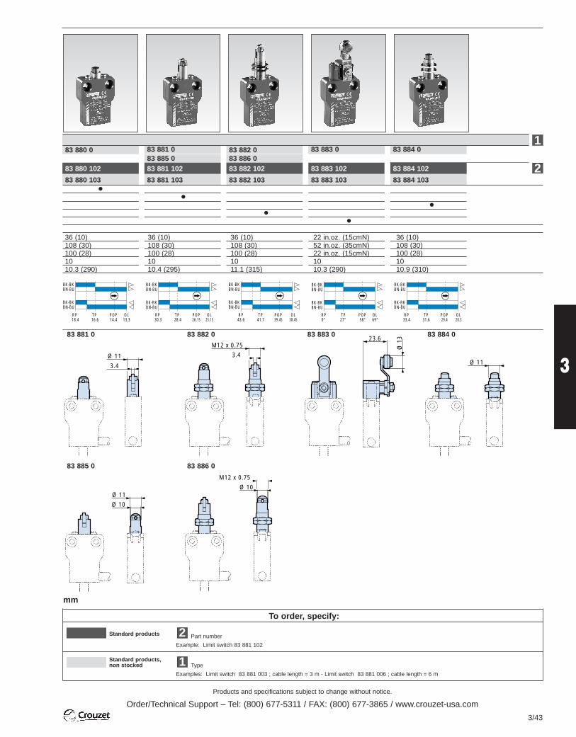
Products and specifications subject to change without notice.
Order/Technical Support – Tel: (800) 677-5311 / FAX: (800) 677-3865 / www.crouzet-usa.com
3/43
3
To order, specify:
Standard products
Standard products,non stocked
Part number
Example: Limit switch 83 881 102
Type
Examples: Limit switch 83 881 003 ; cable length = 3 m - Limit switch 83 881 006 ; cable length = 6 m
1
2
83 881 083 880 0
36 (10)108 (30)100 (28)1010.3 (290)
36 (10)108 (30)100 (28)1010.4 (295)
36 (10)108 (30)100 (28)1011.1 (315)
22 in.oz. (15cmN)52 in.oz. (35cmN)22 in.oz. (15cmN)1010.3 (290)
36 (10)108 (30)100 (28)1010.9 (310)
83 883 083 885 0
83 882 0 83 884 083 886 0
RP 18.4
TP 16.6
POP14.4
OL13.3
BK-BKBN-BU
BK-BKBN-BU
RP 30.3
TP 28.4
POP26.15
OL25.15
BK-BKBN-BU
BK-BKBN-BU
RP43.6
TP41.7
POP39.45
OL38.45
BK-BKBN-BU
BK-BKBN-BU
RP0°
TP27°
POP58°
OL69°
BK-BKBN-BU
BK-BKBN-BU
RP33.4
TP31.6
POP29.4
OL28.3
BK-BKBN-BU
BK-BKBN-BU
83 880 102
83 880 103
83 881 102
83 881 103
83 882 102
83 882 103
83 883 102
83 883 103
83 884 102
83 884 103
Ø 11
3.4
M12 x 0.75
3.4
23.6
Ø 1
3
Ø 11
Ø 10
M12 x 0.75
Ø 10
Ø 11
83 881 0 83 882 0 83 883 0
83 885 0 83 886 0
83 884 0
1
2
mm
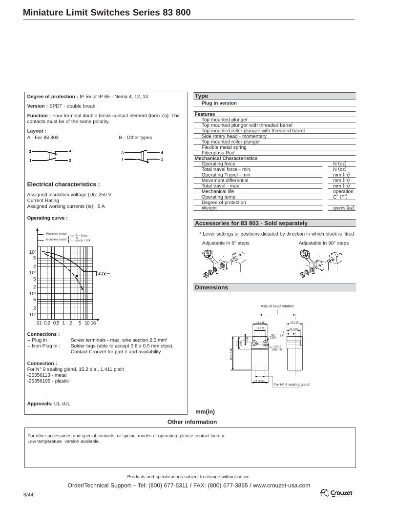
Products and specifications subject to change without notice.
Order/Technical Support – Tel: (800) 677-5311 / FAX: (800) 677-3865 / www.crouzet-usa.com
3/44
Miniature Limit Switches Series 83 800
For other accessories and special contacts, or special modes of operation, please contact factory.Low temperature version available.
Other information
mm(in)
Plug in version
FeaturesTop mounted plungerTop mounted plunger with threaded barrelTop mounted roller plunger with threaded barrelSide rotary head - momentaryTop mounted roller plungerFlexible metal springFiberglass Rod
Mechanical CharacteristicsOperating force N (oz)Total travel force - min. N (oz)Operating Travel - min mm (in)Movement differential mm (in)Total travel - max mm (in)Mechanical life operationOperating temp. C˚ (F˚)Degree of protectionWeight grams (oz)
Degree of protection : IP 55 or IP 65 - Nema 4, 12, 13
Version : SPDT - double break
Function : Four terminal double break contact element (form Za). Thecontacts must be of the same polarity.
Layout :A - For 83 803 B - Other types
Electrical characteristics :
Assigned insulation voltage (Ui): 250 VCurrent RatingAssigned working currents (Ie): 5 A
Operating curve :
Connections :- Plug in : Screw terminals - max. wire section 2.5 mm2
- Non Plug in : Solder tags (able to accept 2.8 x 0.5 mm clips). Contact Crouzet for part # and availability
Connection :For N° 9 sealing gland, 15.2 dia., 1.411 pitch -25356113 - metal -25356109 - plastic
Approvals: UL cUL
Type
Accessories for 83 803 - Sold separately
Dimensions
Resistive circuit= 5 ms
cos ϕ = 0.8
LRInductive circuit
25 (.98)
19 (.75)
Ø8(.315)
25.5 (1)
22 (.87)13
(.51)
2x04.2(.08x.17)
60.5
(2.
38)
21.5
(.85
) 11 (.43
)
27 (1.06)
Axis of head rotation
For N° 9 sealing gland
* Lever settings or positions dictated by direction in which block is fitted
Adjustable in 6° steps Adjustable in 90° steps
107
5
2106
5
2105
5
2104
0.1 0.2 0.5 1 2 5 10 16
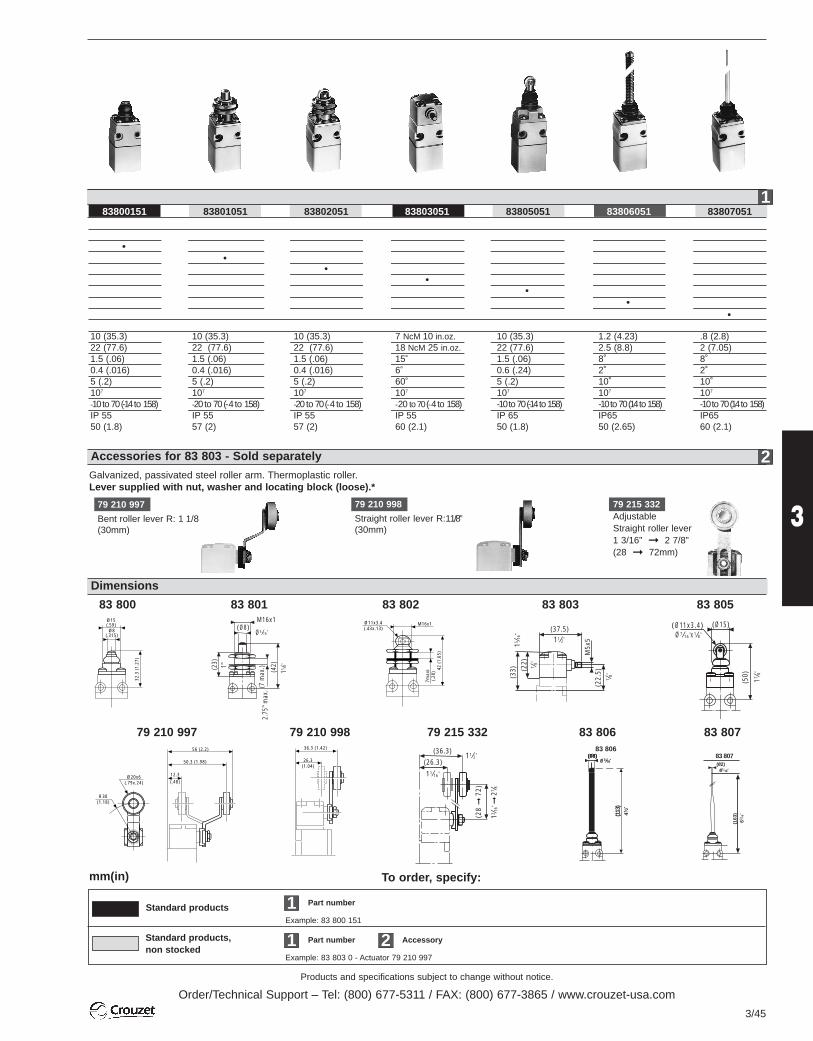
Products and specifications subject to change without notice.
Order/Technical Support – Tel: (800) 677-5311 / FAX: (800) 677-3865 / www.crouzet-usa.com
3/45
3
Standard products, non stocked
Example: 83 803 0 - Actuator 79 210 997
Example: 83 800 151
To order, specify:
1
1
2Part number
Part number
Accessory
mm(in)
Standard products
83800151 83801051 83802051 83803051 83805051 83806051 83807051
10 (35.3)22 (77.6)1.5 (.06)0.4 (.016)5 (.2)107
-10 to 70 (-14 to 158)IP 5550 (1.8)
10 (35.3)22 (77.6)1.5 (.06)0.4 (.016)5 (.2)107
-20 to 70 (- 4 to 158)IP 5557 (2)
10 (35.3)22 (77.6)1.5 (.06)0.4 (.016)5 (.2)107
-20 to 70 (-4 to 158)IP 5557 (2)
7 NcM 10 in.oz.18 NcM 25 in.oz.15˚6˚60˚107
-20 to 70 (-4 to 158)IP 5560 (2.1)
10 (35.3)22 (77.6)1.5 (.06)0.6 (.24)5 (.2)107
-10 to70 (-14 to158)IP 6550 (1.8)
1.2 (4.23)2.5 (8.8)8˚2˚10˚107
-10 to70 (14 to158)IP6550 (2.65)
.8 (2.8)2 (7.05)8˚2˚10˚107
-10 to70 (14 to 158)IP6560 (2.1)
83 803
(37.5)
(33) (2
2)
(22.
5)
7 / 8"
7 / 8"
15 / 16"
11/2"
M5x
5
Accessories for 83 803 - Sold separately
Dimensions
••
••
••
•
Galvanized, passivated steel roller arm. Thermoplastic roller.Lever supplied with nut, washer and locating block (loose).*
79 210 997
79 210 997
Bent roller lever R: 1 1/8(30mm)
79 210 998
Straight roller lever R:11/8”(30mm)
79 215 332AdjustableStraight roller lever1 3/16” 2 7/8”(28 72mm)
79 215 33279 210 998
83 800 83 801
Ø20x6(.79x.24)
R30(1.18)
56 (2.2)
50.3 (1.98)
12.3
(.48)
36.3 (1.42)
26.3(1.04)
(26.3)11/2"
(28
7
2)
13 / 16"
27 / 8
"
(36.3)
11/16"
Ø15(.59)Ø8
(.315)
32.3
(1.
27)
(Ø8)
(23) 1"
(42)
15 /8"
(7 m
ax.)
2.75
" max
.
Ø5/16"
M16x1
83 802 83 805M16x1Ø11x3.4
(.43x.13)
42 (
1.65
)
7max
i(.
28)
(50)
17 / 8"
Ø7/16"x1/8"
(Ø15)(Ø11x3.4)
83 806
(08)83 806
(08)0 "
(113
)4
"
83 807
83 807(02)
0 "
(163
)
1
2
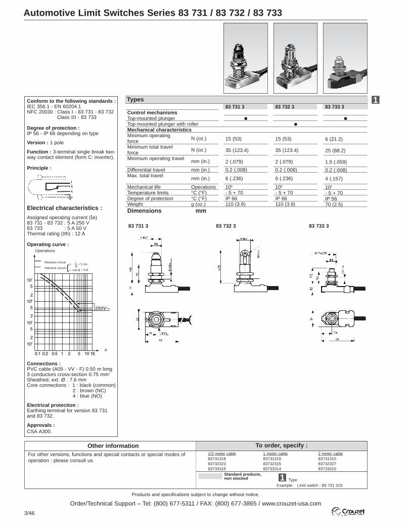
Products and specifications subject to change without notice.
Order/Technical Support – Tel: (800) 677-5311 / FAX: (800) 677-3865 / www.crouzet-usa.com
3/46
To order, specify :Other informationFor other versions, functions and special contacts or special modes ofoperation : please consult us.
Standard products,non stocked
TypeExample : Limit switch - 83 731 319
1
Automotive Limit Switches Series 83 731 / 83 732 / 83 733
1/2 meter cable837313168373232383733315
1 meter cable837313198373231583733314
2 meter cable837313108373232783733310
83 733 3
6 (21.2)
25 (88.2)
1.5 (.059)
0.2 (.008)
4 (.157)
106
- 5 + 70IP 5670 (2.5)
83 731 3
15 (53)
35 (123.4)
2 (.079)
0.2 (.008)
6 (.236)
106
- 5 + 70IP 66110 (3.9)
83 732 3
15 (53)
35 (123.4)
2 (.079)
0.2 (.008)
6 (.236)
106
- 5 + 70IP 66110 (3.9)
1Control mechanismsTop-mounted plunger Top-mounted plunger with rollerMechanical characteristicsMinimum operating forceMinimum total travel forceMinimum operating travel
Differential travelMax. total travel
Mechanical life Temperature limitsDegree of protectionWeightDimensions mm
N (oz.)
N (oz.)
mm (in.)
mm (in.)
mm (in.)
Operations°C (°F)°C (°F)g (oz.)
TypesTypes
83 731 3 83 732 3 83 733 3
Conform to the following standards :IEC 356.1 - EN 60204.1 NFC 20030 : Class I - 83 731 - 83 732
Class III - 83 733
Degree of protection :IP 56 - IP 66 depending on type
Version : 1 pole
Function : 3-terminal single break two-way contact element (form C: inverter).
Principle :
Electrical characteristics :
Assigned operating current (Ie)83 731 - 83 732 : 5 A 250 V83 733 : 5 A 50 VThermal rating (Ith) : 12 A
Operating curve :
Connections :PVC cable (A05 - VV - F) 0.50 m long3 conductors cross-section 0.75 mm2
Sheathed, ext. Ø : 7.6 mmCore connections : 1 : black (common)
2 : brown (NC)4 : blue (NO)
Electrical protection :Earthing terminal for version 83 731 and 83 732.
Approvals :CSA A300.
Resistive circuit = 5 ms
a cos ϕ = 0.8
cLRInductive circuit
Operations
A

Products and specifications subject to change without notice.
Order/Technical Support – Tel: (800) 677-5311 / FAX: (800) 677-3865 / www.crouzet-usa.com
3/47
3
Automotive Limit Switch Series 83 589
Other information To order, specify :
For other versions, functions and special contacts or special modes ofoperation : please consult us.
83589 series
1.) Model 2.) Contact Configuration 3.) Output 4.) Length
835890 A (SPNO) W (Wires) 0.5 (1/2 meter)
835898 B (SPNC) C (Cable) 1.0 (1 meter)
C (SPDT) 2.0 (2 meter)
Conform to the following standards :IEC 356.1 - NFC 20030 class I : plunger actuated via earthed metal partor an insulating device providing additional insulation.
Version : 1 pole
Degree of protection :IP 66/67 Resistant to hydrocarbons and saline mist (400 hours).
Function : Single break two-way contact element (Form C : inverter).
Components : Materials Casing : thermoplastic polyester
Plunger : stainless steelContact : Agcdo - AgNi (gold)Nuts : galvanized steel
Sealing Silicon and teflon sealsPU resin.
Principle :
Electrical characteristics :Standard : 8 A 250 V a : 30 000 operations
200 mA 24 V c relay load L/R = 3 ms 107 operationsTwo-level : 1 mA 4 V : 107 operations
200 mA 24 V c relay load L/R = 3 ms 5 x 10⁶ operations5 A 250 V a : 30,000 operations
The two-level type is designed to operate both on two-level (1 mA 4 V minimum) and medium current (5 A maximum)circuits. However, a given product can only switch a single type of circuit throughout its life.
Connections :3 x 0.75 mm2 PVC cables. 0.50 m longConforms to NFR 13414/13415.
Core connections :1 = black (common)2 = gray (NC)4 = blue (NO)
Mounting :Max. tightening torque : 9 Nm.
Types83 589 0
C
10 (35.5)
15 (53)
2 (0.08)0.1 (.004)4.5 (.177)107
-40+85(-40+185)IP 66 / 6780
StandardTwo-levelControl mechanismTop-mounted plunger Function Form C (SPDT)Mechanical characteristicsMinimum operatingforceMinimum total travel forceMinimum operating travelDifferential travel Max. total travel Mechanical life*Temperature limitsDegree of protectionWeight* For operating travel of 4 mm.Dimensions
N (oz.)
N (oz.)
mm (in.)mm (in.)mm (in.)Operations°C (ºF)
g (oz.)
83 589 8
C
10 (35.5)
15 (53)
2 (0.08)0.1 (.004)4.5 (.177)107
-40+85(-40+185)IP 66 / 6780
3 x 0.75 mm2 cable0.50 m long
21 across flats
Operating travel
Total travel
Direction of operation
1

Products and specifications subject to change without notice.
Order/Technical Support – Tel: (800) 677-5311 / FAX: (800) 677-3865 / www.crouzet-usa.com
3/48
Sealed Limit Switches Telescopic-Actuator Series 83 581
For other accessories and special contacts, or special modes of operation, please consult factory.
Other information
Dimensions mm(in)
Flexible leads Lead position - right (D)Lead position - left (G)
Cable Output on left* Rating restricted to 8A
StandardLow currentOperating devicesTelescopic top-mounted plungerPlunger with axial roller - standard
Form C – SPDT Mechanical characteristicsMinimum operating force N (oz)Minimum total travel force N (oz)Movement differential mm (in)Minimum operating travel mm (in)Total travel max. mm (in)Mechanical life OperationsTemperature limits °C (°F)Degree of protectionWeight g (oz)
Conforms to the following standards : NFC 20030 class II - NFC 20010
Degree of protection : IP 67
Contact type : Three terminal single break contact element (Form C: SPDT)
Layout :
Electrical characteristics :
Assigned working currents (Ie): standard 10 A - 250 V~low current 0.1 A - 250 V~
Electrical endurance : Standard : 10 A - 250 V : 40 000 operations
5 A - 250 V : 100 000 operationsLow current : Designed for use from1 to 100 mA at 4 to 30 volts.
In these conditions, the electrical endurance exceeds the mechanical life.
Connections :Flexible leads 3x1 mm2. Length 0.50 mCable 3x0,75 mm2. Length 0.50 mCore connections: 1 : black
2 : brown4 : blue
Versions
Features
Contact Type
Connections
Plunger roller at 90° (G 90) - Consult Factory
M10x0.75
Ø7(.28)
5.5
max
18.7
(74
)27
.4 (
1.08
)
1.2
(.04
7)
25 (1)6 (.24)
Ø12 (.47)
14 max(.55)
83 581 0
Nuts 14 across flatsDepth 2
R10 spherical

Products and specifications subject to change without notice.
Order/Technical Support – Tel: (800) 677-5311 / FAX: (800) 677-3865 / www.crouzet-usa.com
3/49
3
To order, please specify :
Current Level
S - 10AB - <.1A
Switch Type
835810835811
2 Contacts
C
Example : 835810 S C C •
3Outputs
R - Right (flexible wires)L - Left (flexible wires)C - Cable left output only
4 Lead Length
.5 - 1/2 meter1 - 1 meter2 - 2 meter
51
83 581 1
M10x0.75
5.5
max
1.5
max
(.0
6)
25 (1)6 (.24)
Ø8x3(.315x.12)
14 max(.55)
27.4
(1.
08)
26.5
(1.
04)
6.5
max
(.2
6)
1
2
3
4
S
C
5 (17.6)20 (70.5)1 (.04)2.5 (.1)5.5 (.22)105
-20 to 85 (-4 to 185)IP 6740 (1.4)
RLC*
83 581 0 83 581 1
B
S
B
C
5 (17.6)20 (70.5)1 (.04)2.5 (.1)5.5 (.22)105
-20 to 85 (-4 to 185)IP 6740 (1.4)
C
5 (17.6)20 (70.5)1 (.04)2.5 (.1)5 (.2)105
-20 to 85 (-4 to 185)IP 6745 (1.6)
C
5 (17.6)20 (70.5)1 (.04)2.5 (.1)5 (.2)105
-20 to 85 (-4 to 185)IP 6745 (1.6)
RLC
RLC*
RLC
Roller either in line(standard) or at 90°
Nuts 14 across flatsDepth 2
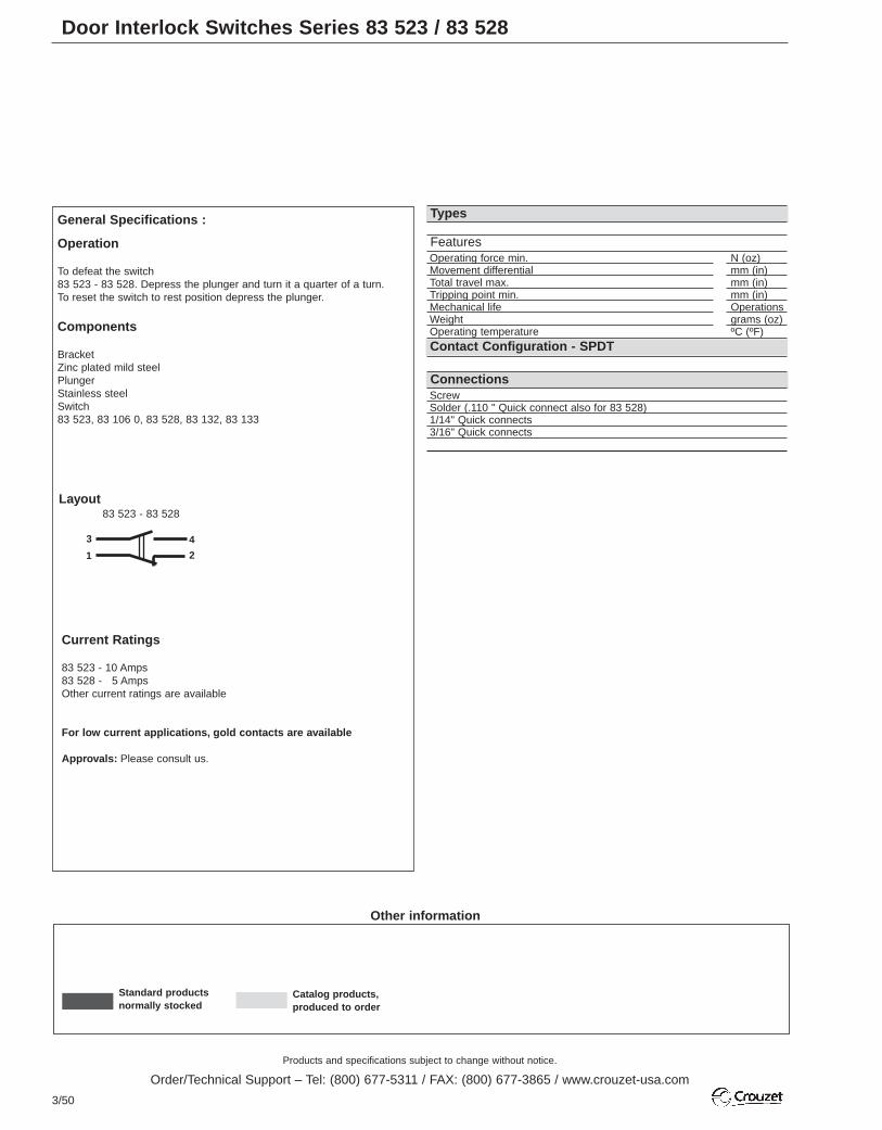
Products and specifications subject to change without notice.
Order/Technical Support – Tel: (800) 677-5311 / FAX: (800) 677-3865 / www.crouzet-usa.com
3/50
Other information
Standard productsnormally stocked
Catalog products, produced to order
Door Interlock Switches Series 83 523 / 83 528
Contact Configuration - SPDT
Types
ScrewSolder (.110 " Quick connect also for 83 528)1/14" Quick connects3/16" Quick connects
Operating force min. N (oz)Movement differential mm (in)Total travel max. mm (in)Tripping point min. mm (in)Mechanical life OperationsWeight grams (oz)Operating temperature ºC (ºF)
General Specifications :
Operation
To defeat the switch83 523 - 83 528. Depress the plunger and turn it a quarter of a turn.To reset the switch to rest position depress the plunger.
Components
Bracket Zinc plated mild steelPlungerStainless steelSwitch83 523, 83 106 0, 83 528, 83 132, 83 133
Features
Connections
3
1
4
2
Layout83 523 - 83 528
Current Ratings
83 523 - 10 Amps83 528 - 5 AmpsOther current ratings are available
For low current applications, gold contacts are available
Approvals: Please consult us.
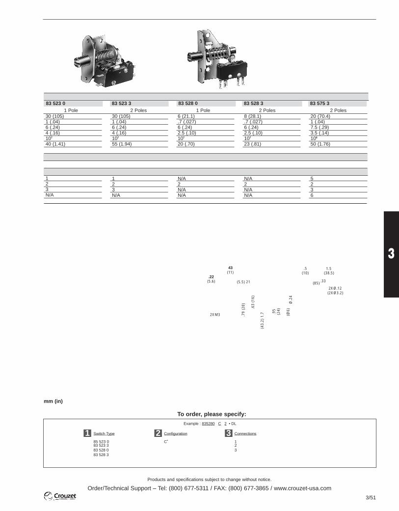
Products and specifications subject to change without notice.
Order/Technical Support – Tel: (800) 677-5311 / FAX: (800) 677-3865 / www.crouzet-usa.com
3/51
3
Example : 835280 C 2 • DL
Switch Type Configuration Connections
85 523 0 C˚ 183 523 3 283 528 0 383 528 3
To order, please specify:
1 2 3
mm (in)
1 Pole 2 Poles 1 Pole 2 Poles 2 Poles
123N/A
123N/A
N/A2N/AN/A
N/A2N/AN/A
5236
30 (105)1 (.04)6 (.24)4 (.16)107
55 (1.94)
6 (21.1).7 (.027)6 (.24)2.5 (.10)107
20 (.70)
8 (28.1).7 (.027)6 (.24)2.5 (.10)107
23 (.81)
20 (70.4)1 (.04)7.5 (.29)3.5 (.14)106
50 (1.76)
30 (105)1 (.04)6 (.24)4 (.16)107
40 (1.41)
83 523 383 523 0 83 528 0 83 528 3 83 575 3
43
.22(11)
(5.6) (5.5) 21
.79
(20)
2XM3
.63
(16)
(43
.2)
1.7 (24
) .9
5
(Ø
6)
(10)
Ø.2
4
(38.5).5 1.5
(85) .33
2XØ.12(2XØ3.2)
83 528
C C C C C
3
1
2
(10)
(16)
.63
.4
Ø.3
1(Ø
.8)
.18 (4.5)
(12.5).49
.63(16)
(55)2.16
2 X Ø.12(2 X Ø3.2)
2XM3
.59(15)
(32)
1.26
1.57
(40)
(4.5).18
A
83 523
Dimensions

Products and specifications subject to change without notice.
Order/Technical Support – Tel: (800) 677-5311 / FAX: (800) 677-3865 / www.crouzet-usa.com
3/52
To order, specify :
Miniature Limit Switches with Manual Reset Series 83 856 / 83 857 EN 50047
Other information
Standard productsStandard products,non stocked
Part numberExample : Limit switch with manual reset - 83 857 011
1
40
33.5
39.5
67
6Ø 22
Ø 11
46.5
30.5
363
4.3
20
22
57.5
(1) Action either right or left according to position of head
Thermoplastic case and metal headMetal bodies and actuator headsSpecial option - configuration EN 50047Control mechanisms - adjustable actuator heads 4 positions 90°Steel plungerPlunger with steel rollerLever with plastic rollerRotary head, momentary action to right and left (1)
With lever andplastic roller
With adjustablelever and plastic roller
Sequence Dependent action
Positive break operation
Mechanical characteristicsMinimum operating forceMinimum total travel forceMinimum positive operating forceMinimum operating travelMinimum positive opening travelDifferential travelMax. total travel Mechanical life Temperature Uselimits StoredDegree of protectionWeight (plastic/metal)
Ø 22Ø 50Ø 22Ø 50
verticallateral
Ø 19 offset 21 or 53Ø 22 offset 33.5 or 40
Ø 50offset 47offset 53.5
Ø 22 offset 32.5 or 45
Ø 50offset 46adjustable offset 53.5 to 69.5
N - (cmN)N - (cmN)N - (cmN)mm - (°)mm - (°)mm - (°)mm - (°)106 operations min.° C° C
g
Conform to the following standards : IEC 536-1, IEC 947-5-1, CSA C22.2 N°14EN 50047, EN 60204-1, EN 60947-5-1NFC 20030 class II for 83 854
class I for 83 855UL 508, VDE 0660/200
Degree of protection : IP 66
Function : Four-terminal double break contact element (form Zb) withpositive opening NC contacts.The two moving contacts are electrically isolated from one another.
Principle :Dependent action contact (1 NC + 1 NO)Break before make
After actuation, the safety contact remains lockedopen in position "NC". It is unlocked by pressing thereset button.
Electrical characteristics :Assigned insulation voltage (Ui) : 500 VThermal rating (I th) : 10 AUse category : A300 - Q300AC15 = 6A/250 V - 1.9 A / 380 VDC 13 = 3A/24 V
Short circuit test (under IEC 947.5.1 § 8.3.4)- Current peak 1000 A at 250 V~0.5 < cos ϕ < 0.7- Short circuit protection (SCPD) : fuse 10 A gF- Electrical protection by internal earth terminal (83 850)
Connections :Saddle washer and M 3.5 screwMax. wire cross-section : 2 x 1.5 mm2 or 1 x 2.5 mm2
Connection :For No. 13 sealing gland
Approvals :Slow break NC + NO version UL / CSA : please consult us.
Part number
Dimensions mm83 856 011 - 83 857 011
83 856 311 - 82 857 311
83 856 511 - 83 857 51112.5
Ø 9
15
33
42
5
12.5
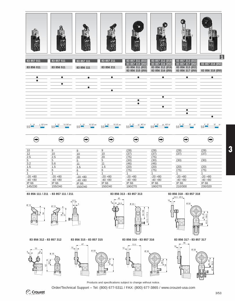
Products and specifications subject to change without notice.
Order/Technical Support – Tel: (800) 677-5311 / FAX: (800) 677-3865 / www.crouzet-usa.com
3/53
3
40
28.5
Ø 50
47
10
58
28.5
Ø 50
53.5
10
46
10
47.5
- 9
2.5
36 -
81
Ø 5053
216
34.5
62
Ø 19
83 857 311 (Ø22)83 857 315 (Ø50)83 856 311 (Ø22)83 856 315 (Ø50)
(28)(37)(75)(30)(46)(20)(75)1-20 +80-40 +80IP 66190/270
83 857 211
83 856 211
910205111.561-20 +80-40 +80IP 66150/240
83 857 111
83 856 111
910205111.561-20 +80-40 +80IP 66150/240
83 857 011
83 856 011
10122.553.21.561-20 +80-40 +80IP 66145/230
83 857 511
83 856 511
9102.555.61.561-20 +80-40 +80IP 66155/240
0 31,8 3,2F 6 mm21-2213-14
0 5,43,2 5,6F mm21-2213-14
0 9,56,5 11F mm21-2213-14
0 9,56,5 11F mm21-2213-14
0° 32°25° 46°F 75°21-2213-14
0° 32°25° 46°F 75°21-2213-14
0° 32°25° 75°21-2213-14
0° 32°25° 75°21-2213-14
83 857 318 (Ø50)
83 856 318 (Ø50)
(28)(37)
(30)
(20)(75)1-20 +80-40 +80IP 66230/320
83 857 313 (Ø22)83 857 317 (Ø50)83 856 313 (Ø22)83 856 317 (Ø50)
(28)(37)
(30)
(20)(75)1-20 +80-40 +80IP 66210/300
83 857 312 (Ø19)83 857 316 (Ø50)83 856 312 (Ø19)83 856 316 (Ø50)
(28)(37)(75)(30)(46)(20)(75)1-20 +80-40 +80IP 66190/270
1
56
18
Ø 13
5719
12.5
5Ø 13
45
32.56
53.5 - 69.5
10
63.5
- 1
08.5
36 -
81
Ø 50
83 856 111 / 211 - 83 857 111 / 211 83 856 313 - 83 857 313
83 856 317 - 83 857 31783 856 316 - 83 857 31683 856 315 - 83 857 31583 856 312 - 83 857 312
61.5
/ 11
7.5
34 /
90
Ø 22 / Ø 50
83 856 318 - 83 857 318

Products and specifications subject to change without notice.
Order/Technical Support – Tel: (800) 677-5311 / FAX: (800) 677-3865 / www.crouzet-usa.com
3/54
Hermetically Sealed Limit Switches
Standard products,non stocked
To order, specify :
Part numberExample : Hermetically sealed limit switch - 83 770 025
1
Epoxy resin coating
Ø 3.2
12.1
Ø 14.2
83 770 02583 770 035
121.5
50
0.30.053100/1150/800 200020100,000
(1) For a service life of 100,000 operations - Permissible current 4A inductive7 A resistive for normally open or normally closed.(2) On soldered connections - For wired connections add 0.1 V per metre.(3) Value for microswitch without control button
CharacteristicsMin. current Nominal current ResistiveLampLampResistiveInductive L/R = 0.005 sResistiveInductive - cos ϕ 0.8Service life at nominal current(3) - operationsDielectric strength betweenconnections and groundRigidity between connectionsInsulation resistance (at 500 Vdc)Voltage drop at 1 A (2)
Operating temperatureResistance to shock (2)
Resistance to vibration (3)
5 V c
48 V c (1)
115 V - 400 Hz30 V c (1)
30 V c (1)
30 V c (1)
220 V a220 V a
mA
AAAAAAA
min
V
VMΩV°Cg/msg/Hz
Hermetically sealed microswitchPart # 83 151 001Without accessories(basic cell -55° +150°C)
Dimensions
Add the dimensions of the various connections for the totaldimensions ( indicates the direction of the wires)
107 - Stop washer - 0.8 thick112 - Locating pin - h.2120 - Nut h 2.5 - 15 across flat
Panel cut-out
Connections (consult factory)
A - Parallel to the axis (//)B - Perpendicular to the axis (⊥ )
1
31231.510.4
200,000
1200
10001000.02-55 +150200/1180/20 2000
Solder
Inert gas filling
Solder
Compressed glass seal
SolderedWired (0.38 mm2 - 0.50 m long)
A B
Part numbersWire 0.38 mm2 with parallel wires0.50 m long perpendicularWith single-pole roller plungerCharacteristicsMax operating forceMin. release forcePermitted overtravel forcePositive overtravel stopMax. pre-travelMax. differential travelMin. overtravelResistance to shocksResistance to vibrationsWeight (without wires)Service life (operations - min)
NN
N
mmmmmmg/msg/Hzg
1

Products and specifications subject to change without notice.
Order/Technical Support – Tel: (800) 677-5311 / FAX: (800) 677-3865 / www.crouzet-usa.com
3/55
3
Waterproof Limit Switches Series 83 141
Standard products,non stocked
To order, specify :
Part numberExample : Waterproof limit switch - 83 777 021
1
83 777 021 83 778 021
60 6010 10150 1501.2 1.20.2 0.23.2 3.230 37
A 0.01A 4A 1A 2A 0.5
50,000
V 1500
V 1000MΩ 100V 0.06°C -55 +125g/ms 50/11g/Hz 10/20 2000
CharacteristicsNominal current
Resistive
Inductive L/R = 0.005 s
Service life at nominal current(1) - operationsOperating temperatureMax. operating forceMin. release forceMax. pre-travelMax. differential travelMin. overtravelWeight
10 V c30 V c220 V a30 V c220 V a
AAAAA
°CNNmmmmmmg
Standard sensitive microswitch83 141 002 - (55 °C +150 °C)Without accessories
0.014120.5100,000-55 +15020.40.50.080.11
9.6
11.5
Ø 16.2
Ø 2.5Ø 3.2
Ø 12.2
ConnectionsSolder tags
(1) Value for microswitch without control button
* For flying leads, add 0.1 V/metre.
107 - Stop washer width 0.8112 - Locating pin117 - Free position118 - Nuts h. 2.5 - 15 across flat120 - Nuts h. 2.5 and 6 - 15 across flat121 - Nuts h. 3 and 6 - 21 across flat122 - Roller Ø 9.6 - width 3 130 - Pin h.2
Part numbers1 pole
With plunger With plunger and rollerOutput with perpendicular wires
CharacteristicsMax. operating forceMin. release forceMax. total travel forceMax. pre-travelMax. differential travelMin. overtravelWeight (with wires)General characteristicsNominal current
Resistive
Inductive L/R = 0.005 s
Service life at nominalcurrent (min. operations)Dielectric strengthbetween connections and groundDielectric strength between connectionsInsulation resistance (at 500 Vdc)Voltage drop at 1 A*Operating temperatureResistance to shockResistance to vibration
NNNmmmmmmg
10 V c30 V c220 V a30 V c220 V a
M12 x 0.75
33
25.4
1214
Ø 17.5
120
112
107
117Ø 6
M12 x 0.75
22.2
25.4
16
Ø 17.5
112
107
117
10
3
118
130
83 777 021 83 778 021
Panel cut-out
1
Dimensions – mm
10
3
122
130
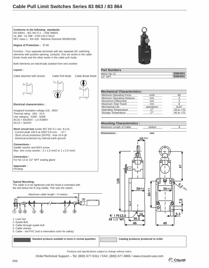
Products and specifications subject to change without notice.
Order/Technical Support – Tel: (800) 677-5311 / FAX: (800) 677-3865 / www.crouzet-usa.com
3/56
Standard products available in-stock in normal quantities Catalog products produced to order
Cable Pull Limit Switches Series 83 863 / 83 864
Metric No 131/2" NPT
8386300183864001
Minimum Operating Force cmN 85Minimum Operating Distance mm 4Movement Differential mm 2Maximum Total Travel mm 8Mechanical Life operations 3x10⁷
Operating Temperature C˚ -25 to +70Storage Temperature C˚ -40 to +70
Part Numbers
Mechanical Characteristics:
Maximum Length of Cable meters 6
Dimensions : mm
Mounting Characteristics :
Conforms to the following standards:EN 50041 - IEC 947.5.1 - VDE 0660/2UL 468 - UL 508 - CSA C22.2 No14NFC class 1 - EN 418 - Machine Directive 89/392/CEE
Degree of Protection : IP 66
Function : Four separate terminals with two separate NC switching elements with positive opening contacts. One set works in the cablebreak mode and the other works in the cable pull mode.
Both elements are electrically isolated from one another.
Layout :
Cable attached with tension Cable Pull Mode Cable Break Mode
Electrical characteristics :
Assigned insulation voltage (Ui) : 500VThermal rating (Ith) : 10 AUse category : A300 - Q300AC15 = 6A/250V - 1.9 A/380VDC13 = 3A/24V
Short circuit test (under IEC 947.5.1 sec. 8.3.4)- Current peak 100 A at 250V`0.5<cos <0.7- Short circuit protection (SCPD) : fuse 10 A gF- Electrical protection by internal earth ground
Connections :Saddle washer and M3.5 screwMax. wire cross section : 2 x 1.5 mm2 or 1 x 2.5 mm2
Connection :For No 13 or 1/2" NPT sealing gland
Approvals :Pending
13 14
21 22
1413
21 22
1413
21 22
1. Lock Nut2. Eyelet Bolt3. Cable through eyelet bolt.4. Cable clamps5. Cable - red PVC (red is internation color for safety)
Typical Mounting:The cable is to be tightened until the head is extended withthe slot below the E-ring visible. This sets the switch.
Maximum cable length = 6 meters
N° 1 PG
675.3
7.5
5.3
40
1636.546
13.5
30
60
30
16
135
±0.4
±0.1±0.1
±0.1±0.4
OR 1/2 "NPT

Safety (Security) Limit Switches
Products and specifications subject to change without notice.
Order/Technical Support – Tel: (800) 677-5311 / FAX: (800) 677-3865 / www.crouzet-usa.com
3/57
3
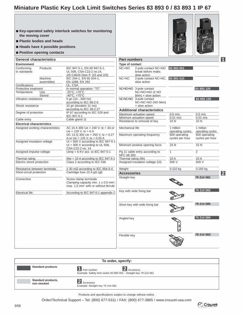
Products and specifications subject to change without notice.
Order/Technical Support – Tel: (800) 677-5311 / FAX: (800) 677-3865 / www.crouzet-usa.com
3/58
To order, specify:
Standard products
Standard products,non stocked
1 Accessory2
Miniature Plastic Key Lock Limit Switches Series 83 893 0 / 83 893 1 IP 67
Part numberExample: Safety limit switch 83 893 001 - Straight key 79 214 581
2 AccessoryExample: Straight key 79 214 581
Straight key
Key with wide fixing bar
Short key with wide fixing bar
Angled key
Flexible key
79 214 581
79 214 582
79 214 585
79 214 584
79 214 583
Type of contactNC+NO 2-pole contact NC+NO
break before make,slow action
NC+NC 2-pole contact NC+NC,slow action
NC+NO+NO 3-pole contactNC+NO+NO (2 NObbm) + slow action
NC+NC+NO 3-pole contactNC+NC+NO (NO bbm)+ slow action
EnvironmentConforming Productsto standards
Machineassemblies
CertificationsProtective treatmentTemperature Use
StoredVibration resistance
Shock resistance
Degree of protection
Cable entry
IEC 947-5-1, EN 60 947-5-1,UL 508, CSA C22-2 no.14,JIS C4520 (See P. 2/2 and 2/3)IEC 204-1, EN 60 204-1,EN 1088, EN 292UL, CSAIn normal operation: "TC"-25°C, +70°C-40°C, +70°C5 gn (10…500 Hz) according to IEC 68-2-610 gn (duration 11 ms) according to IEC 28-2-27IP 67 according to IEC 529 andIEC 947-5-1Cable gland 11
General characteristics
83 893 120
83 893 130
Part numbers
Accessories
Assigned working characteristics
Assigned insulation voltage
Assigned impulse voltage
Thermal ratingElectric shock protection
Resistance between terminalsShort-circuit protection
Connection
Electrical life
AC 15 A 300 Ue = 240 V, Ie = 3A orUe = 120 V, Ie = 6 ADC 13 Q 300 Ue = 250 V, Ie = 0.27A or Ue = 125 V, Ie = 0.55 AUi = 500 V according to IEC 947-5-1Ui = 300 V according to UL 508, CSA C22-2 no. 14Uimp = 6 KV acc. to IEC 947-5-1
Ithe = 10 A according to IEC 947-5-1Class 2 according to IEC 536
≤ 30 mΩ according to IEC 954-5-4Cartridge fuse 10 A gG (gl)
Screw clamp terminalsClamping capacity min. 1 x 0.5 mm2,max. 1.5 mm2 with or without ferrule
According to IEC 947-5-1 appendix C
Electrical characteristics
Additional characteristics
83 893 001
83 893 010
1
2
Maximum actuation speedMinimum actuation speedResistance to removal of key
Mechanical life
Maximum operating frequency
Minimum positive opening force
Pg 11 cable entry according toNFC 68 300Thermal rating (Ith)Assigned insulation voltage (Ui)
Weight
0.5 m/s0.01 m/s10 N
1 millionoperating cycles600 operatingcycles per hour
15 N
1
10 A500 V
0.110 kg
0.5 m/s0.01 m/s10 N
1 millionoperating cycles600 operatingcycles per hour
15 N
2
10 A500 V
0.160 kg
Key-operated safety interlock switches for monitoringthe moving cover
Plastic bodies and heads
Heads have 4 possible positions
Positive opening contacts

Products and specifications subject to change without notice.
Order/Technical Support – Tel: (800) 677-5311 / FAX: (800) 677-3865 / www.crouzet-usa.com
3/59
3
Other information
Dimensions83 893 0 83 839 1
Accessories79 214 581 79 214 582 / 585 79 214 584 79 214 583
Operating radius79 214 581 79 214 582 / 585
34
13.2
30
93.5
39
20/22= =
30 30
30
7
39
20/22
52
40.3
114.
5
12.5
12.5
30
30
34
30
7
1 threadedhole for cable
gland 11
2 slots Ø 4.3 x 8.3 fixingcentres 22 ; 2 holes Ø 4.3fixing centres 20
2 threaded holes forcable gland
2 slots Ø 5.3 x 13.3
2 slots Ø 4.3 x8.3 fixingcentres 22 ;2 holes Ø 4.3fixing centres 20
65 24.
712
22
15
13
55
66
29
45
2
27
1335=
=
10°
10°
32
26
23
5
42
2
26
421213
22
12
4.715
L
2
26
= =
2
1340=
=
5512
2 slots Ø 4.7 x10
2 slotsØ 4.7 x 10
1 slotØ 4.7 x 10
2 slotsØ 4.7 x 10Types Dimension L
(mm)79 214 582 4079 214 585 29
R = 1500
R = 1200
71 71
R = 1500
R = 1200
dd
R = 1500
R = 1200
48
48
R = 300
R = 150
72 72
79 214 584 79 214 583
R = min. radius R = min. radius
R = min. radiusR = min. radius
Types Dimension d (mm)
79 214 582 4679 214 585 35
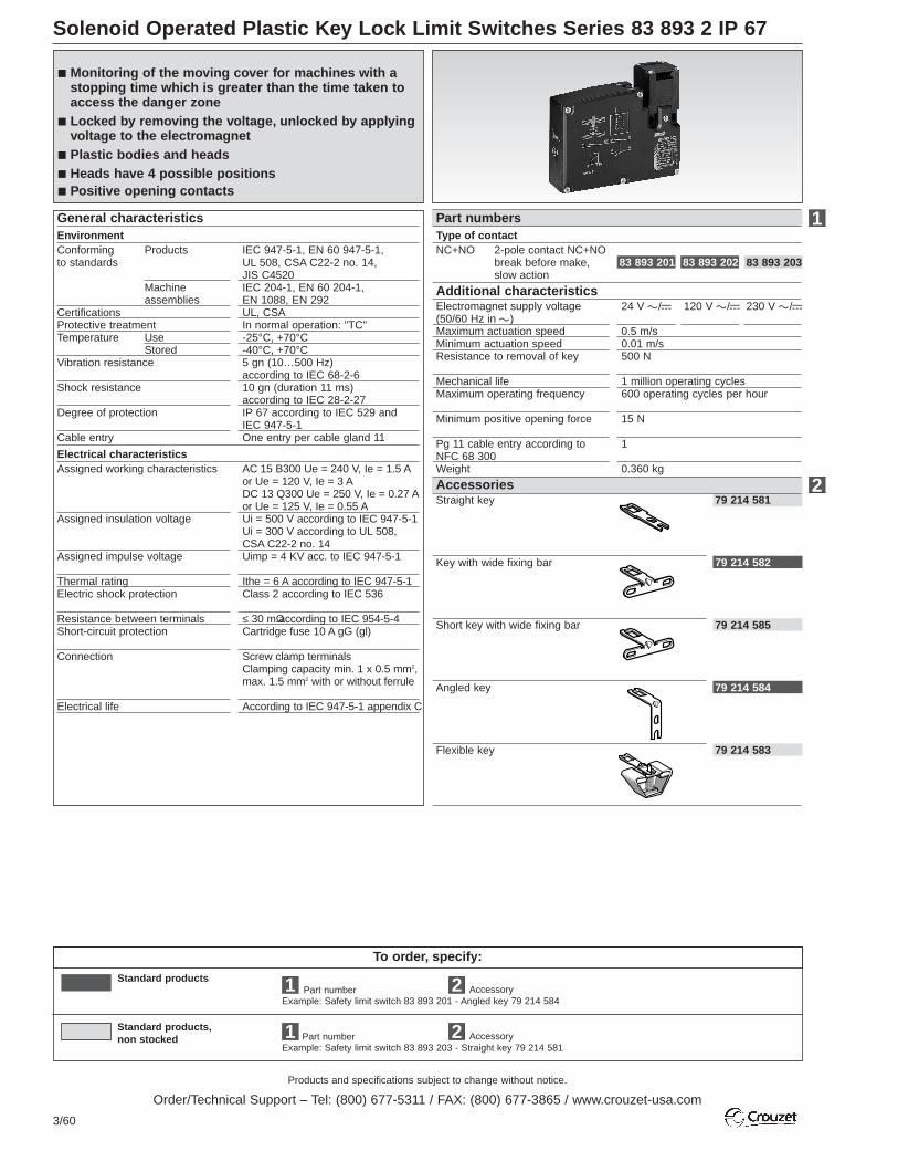
Products and specifications subject to change without notice.
Order/Technical Support – Tel: (800) 677-5311 / FAX: (800) 677-3865 / www.crouzet-usa.com
3/60
Solenoid Operated Plastic Key Lock Limit Switches Series 83 893 2 IP 67
To order, specify:
Example: Safety limit switch 83 893 203 - Straight key 79 214 581
AccessoryExample: Safety limit switch 83 893 201 - Angled key 79 214 584
Standard products,non stocked
1 2
Accessory21
Standard products
Part number
Part number
Straight key
Key with wide fixing bar
Short key with wide fixing bar
Angled key
Flexible key
79 214 581
79 214 582
79 214 585
79 214 584
79 214 583
Type of contactNC+NO 2-pole contact NC+NO
break before make,slow action
Monitoring of the moving cover for machines with astopping time which is greater than the time taken toaccess the danger zone
Locked by removing the voltage, unlocked by applyingvoltage to the electromagnet
Plastic bodies and heads Heads have 4 possible positions Positive opening contacts
EnvironmentConforming Productsto standards
Machineassemblies
CertificationsProtective treatmentTemperature Use
StoredVibration resistance
Shock resistance
Degree of protection
Cable entry
IEC 947-5-1, EN 60 947-5-1,UL 508, CSA C22-2 no. 14,JIS C4520 IEC 204-1, EN 60 204-1,EN 1088, EN 292UL, CSAIn normal operation: "TC"-25°C, +70°C-40°C, +70°C5 gn (10…500 Hz) according to IEC 68-2-610 gn (duration 11 ms) according to IEC 28-2-27IP 67 according to IEC 529 and IEC 947-5-1One entry per cable gland 11
General characteristics Part numbers
AccessoriesAssigned working characteristics
Assigned insulation voltage
Assigned impulse voltage
Thermal ratingElectric shock protection
Resistance between terminalsShort-circuit protection
Connection
Electrical life
AC 15 B300 Ue = 240 V, Ie = 1.5 Aor Ue = 120 V, Ie = 3 ADC 13 Q300 Ue = 250 V, Ie = 0.27 Aor Ue = 125 V, Ie = 0.55 AUi = 500 V according to IEC 947-5-1Ui = 300 V according to UL 508, CSA C22-2 no. 14Uimp = 4 KV acc. to IEC 947-5-1
Ithe = 6 A according to IEC 947-5-1Class 2 according to IEC 536
≤ 30 mΩ according to IEC 954-5-4Cartridge fuse 10 A gG (gl)
Screw clamp terminalsClamping capacity min. 1 x 0.5 mm2,max. 1.5 mm2 with or without ferrule
According to IEC 947-5-1 appendix C
Electrical characteristics
Electromagnet supply voltage(50/60 Hz in a)Maximum actuation speedMinimum actuation speedResistance to removal of key
Mechanical lifeMaximum operating frequency
Minimum positive opening force
Pg 11 cable entry according toNFC 68 300Weight
24 V a/c 120 V a/c 230 V a/c
0.5 m/s0.01 m/s500 N
1 million operating cycles600 operating cycles per hour
15 N
1
0.360 kg
Additional characteristics
83 893 201 83 893 202 83 893 203
1
2

Products and specifications subject to change without notice.
Order/Technical Support – Tel: (800) 677-5311 / FAX: (800) 677-3865 / www.crouzet-usa.com
3/61
3
Other information
For accessory dimensions, see page 2/5.
Locking / unlocking using an electromagnetType 83 893 2 safety switches are fitted with an electromagnet forlocking/unlocking the guard.
With the guard locked, the force required to remove the key is 50 daN.
In addition to the 2-pole contact element actuated by the key, type 83 8932 limit switches also have a positive break type “NC” contact element,actuated by the electromagnet. The “NC” contact is integrated in the machine safety circuit.
Unlocking using a special toolType 83 893 2 safety switches are supplied with a tool (1) which canbe used to unlock the moving guard, bypassing the electromagnet.
Unlocking using a tool is recommended in the following cases:• machine maintenance (if the tool is in the “UNLOCK” position and thenremoved, this will prevent the machine from restarting accidentally,therefore ensuring the safety of maintenance personnel),• mains failure,• problem with unlocking (locking cannot be released: fail-safe condition).Unlocking by applying voltage to the electromagnet always takes priorityover unlocking using a tool. The “NC” contact is integrated in the machinesafety circuit.
Power supply for the electromagnet on 83 893 2The electromagnet for type 83 893 2 safety switches is supplied by anelectronic circuit which increases its service life. As the 24 V version isprotected by a bridge rectifier, an A.C. or D.C. supply can be used.
The 120 V and 230 V versions are A.C. only.It is also protected against voltage surges.
Dimensions
83 893 2
38
3314.5
7
30
20/22 4
110
43
15
93.5
40
E2 31 33E1
F1
(1) (32) 21 22
1413
X
X
M
O
I
2 slots Ø 4.3 x 8.3fixing centres 22 ; 2 holes Ø 4.3 fixingcentres 20
1 threaded hole forcable gland 11
Electromagnet
Category 1 connection according to EN 954-1Examples of wiring diagrams with a fuse to provide protection againstshort-circuits in the cable or tampering.
Locking by removal of voltage 83 893 2
UNLOCK
1
(1) Auxiliary contactE1-E2: Power supply for electromagnet13-14: Safety contact for redundancy or signalling

Products and specifications subject to change without notice.
Order/Technical Support – Tel: (800) 677-5311 / FAX: (800) 677-3865 / www.crouzet-usa.com
3/62
To order, specify:
Standard products
Standard products,non stocked
1 Accessory2Part numberExample: Safety limit switch 83 894 020 - Wide key 79 214 579
2 AccessoryExample: Flexible key 79 214 580
Industrial Metal Key Lock Limit Switches Series 83 894 0 IP 67
Straight key
Key with wide fixing bar
Flexible key
79 214 578
79 214 579
79 214 580
Type of contactNC+NO+NO 3-pole contact
NC+NO+NO (2 NO bbm) slow action
EnvironmentConforming Productsto standards
Machineassemblies
CertificationsProtective treatmentTemperature Use
StoredVibration resistance
Shock resistance
Degree of protection
Cable entry
IEC 947-5-1, EN 60 947-5-1,UL 508, CSA C22-2 no.14,JIS C4520 IEC 204-1, EN 60 204-1,EN 1088, EN 292UL, CSAIn normal operation: "TC"-25°C, +70°C-40°C, +70°C5 gn (10…500 Hz) according to IEC 68-2-610 gn (duration 11 ms) according to IEC 28-2-27IP 67 according to IEC 529 andIEC 947-5-1One threaded entry for cable gland13
General characteristics Part numbers
AccessoriesAssigned working characteristics
Assigned insulation voltage
Assigned impulse voltage
Thermal ratingElectric shock protection
Resistance between terminalsShort-circuit protection
Connection
Electrical life
AC 15 A 300 Ue = 240 V, Ie = 3 A orUe = 120 V, Ie = 6 ADC 13 Q 300 Ue = 250 V, Ie = 0.27A or Ue = 125 V, Ie = 0.55 AUi = 500 V according to IEC 947-5-1Ui = 300 V according to UL 508, CSA C22-2 no.14Uimp = 6 KV according to IEC 947-5-1Ithe = 10 A according to IEC 947-5-1Class 2 according to IEC 536
≤ 30 mΩ according to IEC 954-5-4Cartridge fuse 10 A gG (gl)
Screw clamp terminalsClamping capacity min. 1 x 0.5 mm2,max. 1.5 mm2 with or without ferrule
According to IEC 947-5-1 appendix C
Electrical characteristics
Additional characteristics
83 894 020
1
2
Maximum actuation speedMinimum actuation speedResistance to removal of key
Mechanical life
Maximum operating frequency
Minimum positive opening force
Cable entry (DIN Pg 13.5 cablegland 13) according to NFC 68 300
Weight
0.5 m/s0.01 m/s10 N
> 1 million operating cycles
600 operating cycles per hour
20 N
1
0.360 kg
Spade terminal safety interlock switch for monitoringthe moving cover
Metal bodies and heads
Heads have 4 possible positions
Positive opening contacts

Products and specifications subject to change without notice.
Order/Technical Support – Tel: (800) 677-5311 / FAX: (800) 677-3865 / www.crouzet-usa.com
3/63
3
Other information
Accessories79 214 579 79 214 578 79 214 580
Operating radius79 214 578 79 214 579
1 threaded hole forcable gland 13
2 slots Ø 7.3 x 5.3
2.5
== 1525
81.5
33 20 11
11
55.5
2.5
5135=
==
=
25
332.5
2 slots Ø 5.3 x 10
2 slots Ø 4.7 x 10
R = 2000
83.5
R = 2000
83.5R =15022
55
78
R = 400
16.5
78
79 214 580
R = min. radius R = min. radius
Dimensions mm83 893 0
R = 2000
57.5
R = 2000
57.5
R = min. radius

Products and specifications subject to change without notice.
Order/Technical Support – Tel: (800) 677-5311 / FAX: (800) 677-3865 / www.crouzet-usa.com
3/64
To order, specify:
Standard products
Standard products,non stocked
1 Accessory2
1 Accessory2
Part numberExample: Safety limit switch 83 894 120 - Wide key 79 214 579
Part numberExample: Safety limit switch 83 894 132 - Straight key 79 214 578
Solenoid Operated Metal Key Lock Limit Switches Series 83 894 1
Straight key
Wide key
Flexible key
79 214 578
79 214 579
79 214 580
Type of contactNC+NO+NO 3-pole contact
NC+NO+NO (2 NO bbm) + slow action
NC+NC+NO 3-pole contactNC+NC+NO (NO bbm) slow action
EnvironmentConforming Productsto standards
Machineassemblies
CertificationsProtective treatmentTemperature Use
StoredVibration resistance
Shock resistance
Degree of protection
Cable entry
IEC 947-5-1, EN 60 947-5-1,UL 508, CSA C22-2 no.14,JIS C4520 (See P. 3/14)IEC 204-1, EN 60 204-1,EN 1088, EN 292UL, CSAIn normal operation: "TC"-25°C, +70°C-40°C, +70°C5 gn (10…500 Hz) according to IEC 68-2-610 gn (duration 11 ms) according to IEC 28-2-27IP 67 according to IEC 529 andIEC 947-5-1Threaded entry for cable gland 13
General characteristics Part numbers
Accessories
Assigned working characteristics
Assigned insulation voltage
Assigned impulse voltage
Thermal ratingElectric shock protection
Resistance between terminalsShort-circuit protection
Connection
Electrical life
AC 15 B300 Ue = 240 V, Ie = 1.5 Aor Ue = 120 V, Ie = 3 ADC 13 Q300 Ue = 250 V, Ie = 0.27 Aor Ue = 125 V, Ie = 0.55 AUi = 500 V according to IEC 947-5-1Ui = 300 V according to UL 508, CSA C22-2 no. 14Uimp = 4 KV according to IEC 947-5-1Ithe = 6 A according to IEC 947-5-1Class 2 according to IEC 536
≤ 30 mΩ according to IEC 954-5-4Cartridge fuse 10 A gG (gl)
Screw clamp terminalsClamping capacity min. 1 x 0.5 mm2,max. 1.5 mm2 with or without ferrule
According to IEC 947-5-1 appendix C
Electrical characteristics
Additional characteristics
83 894 120
83 894 130
83 894 121
83 894 131
83 894 122
83 894 132
1
2
Electromagnet supply voltage (50 / 60 Hz in a)Maximum actuation speedMinimum actuation speedResistance to removal of key
Mechanical life
Maximum operating frequency
Minimum positive opening force
Cable entries Pg 13 according toNFC 68 300Weight
24 V a/c 120 V a/c 230 V a/c
0.5 m/s0.01 m/s2000 N
> 1 million operating cycles
600 operating cycles per hour
20 N
2
1.140 kg
Electromagnet characteristicsLoad factorVoltage limitsService lifeConsumption Inrush
Sealed
100%-20% ; +10 %20,000 hours10 VA10 VA
Monitoring of the moving cover for machines with astopping time which is greater than the time taken toaccess the danger zone
Locked by removing the voltage, unlocked by applyingvoltage to the electromagnet
Metal bodies and heads Heads have 4 possible positions Positive opening contacts
Indicator characteristicsAssigned insulation voltageaccording to IEC 947-5-1Current consumptionAssigned working voltagea or cVoltage limits a or c (includingripple)Service lifeProtection against voltage surges
50 V 250 V 250 V
7 mA 7 mA 7 mA24 V 110 / 240 V 110 / 240V
20…52 V 95…264 V 95…264 V
100,000 hrs 100,000 hrs 100,000 hrsyes yes yes
2 slotsØ 7.3 x 5.3
1 threaded hole forcable gland 13
Dimensions mm
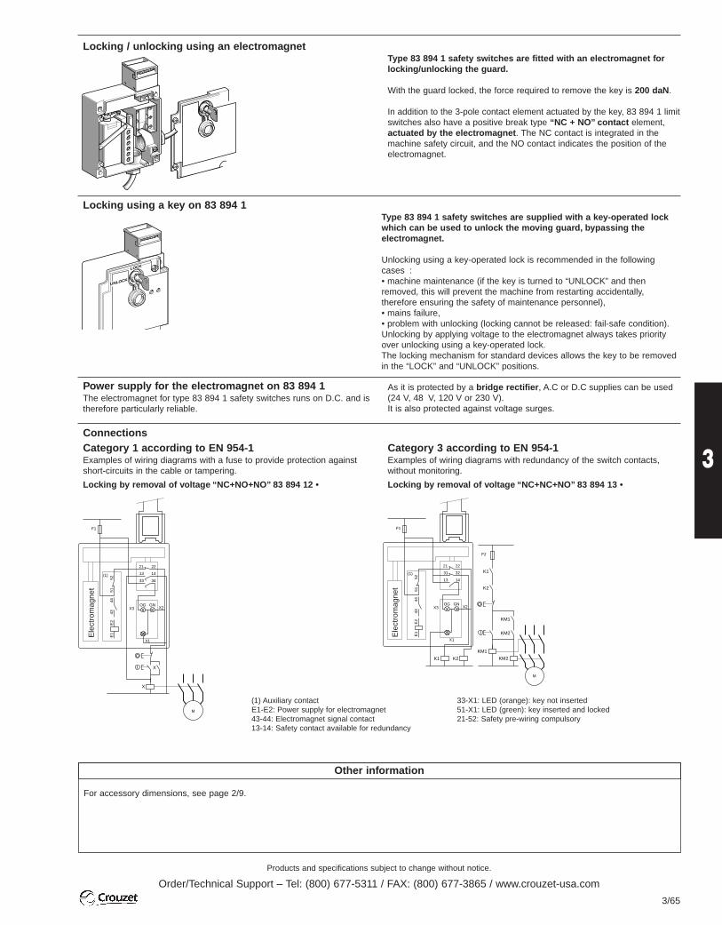
Products and specifications subject to change without notice.
Order/Technical Support – Tel: (800) 677-5311 / FAX: (800) 677-3865 / www.crouzet-usa.com
3/65
3
Other information
For accessory dimensions, see page 2/9.
Locking / unlocking using an electromagnetType 83 894 1 safety switches are fitted with an electromagnet forlocking/unlocking the guard.
With the guard locked, the force required to remove the key is 200 daN.
In addition to the 3-pole contact element actuated by the key, 83 894 1 limitswitches also have a positive break type “NC + NO” contact element,actuated by the electromagnet. The NC contact is integrated in themachine safety circuit, and the NO contact indicates the position of theelectromagnet.
Locking using a key on 83 894 1Type 83 894 1 safety switches are supplied with a key-operated lockwhich can be used to unlock the moving guard, bypassing theelectromagnet.
Unlocking using a key-operated lock is recommended in the followingcases :• machine maintenance (if the key is turned to “UNLOCK” and thenremoved, this will prevent the machine from restarting accidentally,therefore ensuring the safety of maintenance personnel),• mains failure,• problem with unlocking (locking cannot be released: fail-safe condition).Unlocking by applying voltage to the electromagnet always takes priorityover unlocking using a key-operated lock.The locking mechanism for standard devices allows the key to be removedin the “LOCK” and “UNLOCK” positions.
Power supply for the electromagnet on 83 894 1The electromagnet for type 83 894 1 safety switches runs on D.C. and istherefore particularly reliable.
As it is protected by a bridge rectifier, A.C or D.C supplies can be used(24 V, 48 V, 120 V or 230 V).It is also protected against voltage surges.
K1 K2
21
F1
22
5152
3231
1413
X3
X1
X2OG GN
E2
E1
4443
(1)
KM2
O
I
KM1
KM2
K1
K2
F2
M
KM1
X
O
I
X
21
F1
22
5152
1413
3433
X3
X1
X2OG GN
M
E2
E1
4443
(1)
(1) Auxiliary contactE1-E2: Power supply for electromagnet43-44: Electromagnet signal contact13-14: Safety contact available for redundancy
33-X1: LED (orange): key not inserted51-X1: LED (green): key inserted and locked21-52: Safety pre-wiring compulsory
Ele
ctro
mag
net
Ele
ctro
mag
net
ConnectionsCategory 1 according to EN 954-1Examples of wiring diagrams with a fuse to provide protection againstshort-circuits in the cable or tampering.
Locking by removal of voltage “NC+NO+NO” 83 894 12 •
Category 3 according to EN 954-1Examples of wiring diagrams with redundancy of the switch contacts,without monitoring.
Locking by removal of voltage “NC+NC+NO” 83 894 13 •
LOCK
UNLOCK
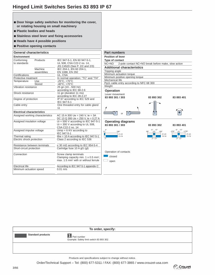
Products and specifications subject to change without notice.
Order/Technical Support – Tel: (800) 677-5311 / FAX: (800) 677-3865 / www.crouzet-usa.com
3/66
To order, specify:
Standard products 1 Part numberExample: Safety limit switch 83 893 302
Hinged Limit Switches Series 83 893 IP 67
Tripping angleMinimum actuation torqueMinimum positive opening torqueMechanical lifePg11 cable entry according to NFC 68 300Weight
Position of leverType of contactNC+NO 2-pole contact NC+NO break before make, slow action
EnvironmentConforming Productsto standards
Machineassemblies
CertificationsProtective treatmentTemperature Use
StoredVibration resistance
Shock resistance
Degree of protection
Cable entry
IEC 947-5-1, EN 60 947-5-1,UL 508, CSA C22-2 no. 14,JIS C4520 (See P. 2/2 and 2/3)IEC 204-1, EN 60 204-1,EN 1088, EN 292UL, CSAIn normal operation: "TC" and "TH"-25°C, +70°C-40°C, +70°C25 gn (10…500 Hz) according to IEC 68-2-611 gn (duration 11 ms) according to IEC 28-2-27IP 67 according to IEC 529 andIEC 947-5-1One threaded entry for cable gland11
General characteristics Part numbers
Assigned working characteristics
Assigned insulation voltage
Assigned impulse voltage
Thermal ratingElectric shock protection
Resistance between terminalsShort-circuit protection
Connection
Electrical lifeMinimum actuation speed
AC 15 A 300 Ue = 240 V, Ie = 3ADC 13 Q 300 Ue = 250 V, Ie = 0.27 AUi = 500 V according to IEC 947-5-1Ui = 300 V according to UL 508, CSA C22-2 no. 14Uimp = 6 KV according to IEC 947-5-1Ithe = 10 A according to IEC 947-5-1Class 2 according to IEC 536
≤ 30 mΩ according to IEC 954-5-4Cartridge fuse 10 A gG (gl)
Screw clamp terminalsClamping capacity min. 1 x 0.5 mm2,max. 1.5 mm2 with or without ferrule
According to IEC 947-5-1 appendix C0.01 m/s
Electrical characteristics
Additional characteristics
Door hinge safety switches for monitoring the cover,or rotating housing on small machinery
Plastic bodies and heads
Stainless steel lever and fixing accessories
Heads have 4 possible positions
Positive opening contacts
7°
0
21-2213-14
180°5°
0-90°
-7° +7°
21-2213-14
+90°-5° +5°
0-270°
-7° +7°
21-2213-14
+270°-5° +5°
OperationLever movement83 893 301 / 303 83 893 302 83 893 401
Operating diagrams83 893 301 / 303 83 893 302 83 893 401
Operation of contacts
closed
open
or

Products and specifications subject to change without notice.
Order/Technical Support – Tel: (800) 677-5311 / FAX: (800) 677-3865 / www.crouzet-usa.com
3/67
3
Other information
Dimensions83 893 3 83 893 401
5°0.1 Nm0.25 Nm1 million operating cycles10.145 kg
Left
83 893 303
5°0.1 Nm0.25 Nm1 million operating cycles10.145 kg
Centre
83 893 302
5°0.1 Nm0.25 Nm1 million operating cycles10.145 kg
Right
83 893 301
5°0.1 Nm0.25 Nm1 million operating cycles10.145 kg
Length 30 mm
83 893 401
1
23.3
5
27.4
2.5
87.5
30
7028
72.543
33
3020/22
16
5.3
1 threadedhole for cable
gland 11
2 slots Ø 4.3 x8.3 fixingcentres 22 ;2 holes Ø 4.3fixing centres 20
1 threadedhole for cable
gland 11
2 slots Ø 4.3 x 8.3fixing centres22; 2 holes Ø 4.3 fixingcentres 20
8.9 mminsidediameter11.95 mmoutsidediameter

Products and specifications subject to change without notice.
Order/Technical Support – Tel: (800) 677-5311 / FAX: (800) 677-3865 / www.crouzet-usa.com
3/68
To order, specify:
Standard products
Standard products,non stocked
1 Accessory2 Mounting kit3
2 Mounting kit3AccessoryExample: Pulley 79 214 576 - Kit 79 214 574
Part numberExample: Safety limit switch 83 894 201 - Pulley 79 214 576 - Kit 79 214 574
Cable Pull Limit Switches Series 83 894 2 IP 67
Mounting kit for cable, length 10 m
Mounting kit for cable, length 15 m
Kit comprising: a galvanised cable, Ø 3.2 mm in accordance with thelength selected, 1 cable lug, 1 end spring
Fixed cable support
Pulley support
Pulley for cable max. Ø 5 mm
End guards
79 214 571
79 214 577
79 214 576
79 214 572
Type of contactNC+NO 2-pole contact
NC+NO, slow action
EnvironmentConforming Productsto standards
Machineassemblies
CertificationsProtective treatmentTemperature Use
StoredVibration resistanceShock resistance
Degree of protection
Mechanical lifeLength of protected zoneCable entry
IEC 947-5-1, EN 60 947-5-1,VDE 0660-200, EN 418, draft EN 616EN 60 204-1, EN 292 machinerydirective: 89/392/EEC and91/368/EEC, social directive:89655/EECUL, CSA"TC"-25°C, +70°C-40°C, +70°C10 gn (10…150 Hz)50 gn (duration 11 ms) according to IEC 28-2-27IP 65 according to IEC 529 andIEC 947-5-1100,000 operating cycles≤ 15 m3 entries for cable gland with amaximum capacity of 12 mm
General characteristics Part numbers
Mounting accessories
Assigned working characteristics
Assigned insulation voltage
Assigned impulse voltage
Thermal ratingElectric shock protection
Resistance between terminalsShort-circuit protection
Terminal labelling
AC 15 A300 Ue = 240 V, Ie = 3 ADC 13 Q300 Ue = 250 V, Ie = 0.27 AUi = 500 V degree of pollution 3according to IEC 947-5-1Ui = 300 V according to UL 508, CSA C22-2 no. 14Uimp = 6 KV according to IEC 947-5-1Ithe = 10 AClass 1 according to IEC 536 andNF C 20-030≤ 35 mΩ according to IEC 954-5-4Cartridge fuse 10 A gG (gl)
According to CENELEC EN 50013
Electrical characteristics
83 894 201
1
2
79 214 573
79 214 574
Mounting kit 3
“Emergency stop” safety switches are essential inareas or on machinery where a danger exists duringoperation
The cable can be used to request an emergency stopat any point in the operating zone
Applications : conveying, materials handling, machinetools
Length of the protected zone: up to 15 metres
Distance between the cablesupportsManual resetCable anchorWeight
5 m
Using booted pushbuttonRight or left0.865 kg
Additional characteristics

Products and specifications subject to change without notice.
Order/Technical Support – Tel: (800) 677-5311 / FAX: (800) 677-3865 / www.crouzet-usa.com
3/69
3
Other information
InstallationDescription of a typical installation
Actuating force and arrows
Standards
5
631 8 7
12 4
1 - Fixing support2 - Emergency stop3 - First cable support4 - Device adjustment5 - Faston connectors & cable clamps6 - Turnbuckle7 - End spring8 - Pulleys and pulley supports
This is the value of the force F1 exerted onthe cable, causing the device to trip.f is the distance covered by the actuator at thebending point of the cable between the pointof equilibrium during operation and the trippingpoint of the device.
Operating values:Average values of the tripping arrows andforces for 5 m fixing centres (standard force): • Arrow f: 160 mm• Arrow F1: 2 daN
83 894 201 devices meet the requirements of the harmonised Europeanstandard EN 418 on “emergency stop devices”. The stronglyrecommended use of an end spring meets the requirements of the draftEuropean standard EN 616 on “continuous materials handling systemsand equipment”.
F1
f
Pulleys must be used if the cable is ever installed with angles (example:perimeter of a machine).
Warning:The sum total of the cable angles must be less than 180°.
Positive operation: The contacts used are positive break type contacts.The device is tripped by positive actuation.Latching: The device is mechanically latched in the tripped position(“NC” safety contacts open). The “NO” contact is only used for signalling.
Reset: The devices have a reset button which closes the safety contact.The machine must only be started by deliberately pressing a start-upbutton, separate from the emergency stop.
Basic principles
Positive operation Latching Reset
Device operating Device stopped Device stopped (waiting)
Cable expansion: d
d 5 m
Fixed cable support
The cable may increase or reduce in length.Variations in length are mainly related totemperature variations on the site of use.83 894 201 devices are fitted with cablevoltage indicators which can be used to check(and correct if necessary) the voltage at anytime.
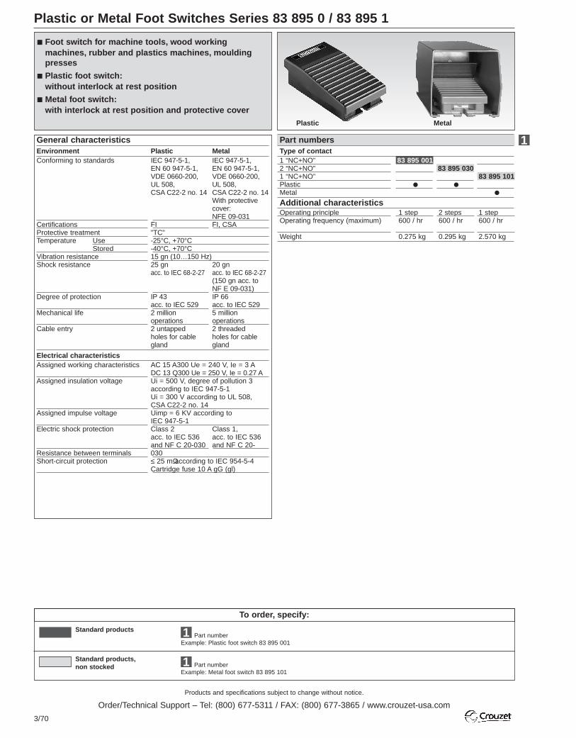
Products and specifications subject to change without notice.
Order/Technical Support – Tel: (800) 677-5311 / FAX: (800) 677-3865 / www.crouzet-usa.com
3/70
To order, specify:
Standard products
Standard products,non stocked
1
Part numberExample: Metal foot switch 83 895 1011
Part numberExample: Plastic foot switch 83 895 001
Plastic or Metal Foot Switches Series 83 895 0 / 83 895 1
Type of contact1 “NC+NO”2 “NC+NO”1 “NC+NO”PlasticMetal
Foot switch for machine tools, wood workingmachines, rubber and plastics machines, mouldingpresses
Plastic foot switch:without interlock at rest position
Metal foot switch:with interlock at rest position and protective cover
EnvironmentConforming to standards
CertificationsProtective treatmentTemperature Use
StoredVibration resistanceShock resistance
Degree of protection
Mechanical life
Cable entry
Plastic MetalIEC 947-5-1, IEC 947-5-1,EN 60 947-5-1, EN 60 947-5-1,VDE 0660-200, VDE 0660-200,UL 508, UL 508,CSA C22-2 no. 14 CSA C22-2 no. 14
With protective cover: NFE 09-031
FI FI, CSA"TC"-25°C, +70°C-40°C, +70°C15 gn (10…150 Hz)25 gn 20 gn acc. to IEC 68-2-27 acc. to IEC 68-2-27
(150 gn acc. to NF E 09-031)
IP 43 IP 66acc. to IEC 529 acc. to IEC 5292 million 5 millionoperations operations2 untapped 2 threaded holes for cable holes for cablegland gland
General characteristics Part numbers
Assigned working characteristics
Assigned insulation voltage
Assigned impulse voltage
Electric shock protection
Resistance between terminalsShort-circuit protection
AC 15 A300 Ue = 240 V, Ie = 3 ADC 13 Q300 Ue = 250 V, Ie = 0.27 AUi = 500 V, degree of pollution 3according to IEC 947-5-1Ui = 300 V according to UL 508, CSA C22-2 no. 14Uimp = 6 KV according to IEC 947-5-1Class 2 Class 1,acc. to IEC 536 acc. to IEC 536and NF C 20-030 and NF C 20-030≤ 25 mΩ according to IEC 954-5-4Cartridge fuse 10 A gG (gl)
Electrical characteristics
83 895 001
83 895 030
83 895 101
1
Operating principleOperating frequency (maximum)
Weight
1 step 2 steps 1 step600 / hr 600 / hr 600 / hr
0.275 kg 0.295 kg 2.570 kg
Additional characteristics
Plastic Metal
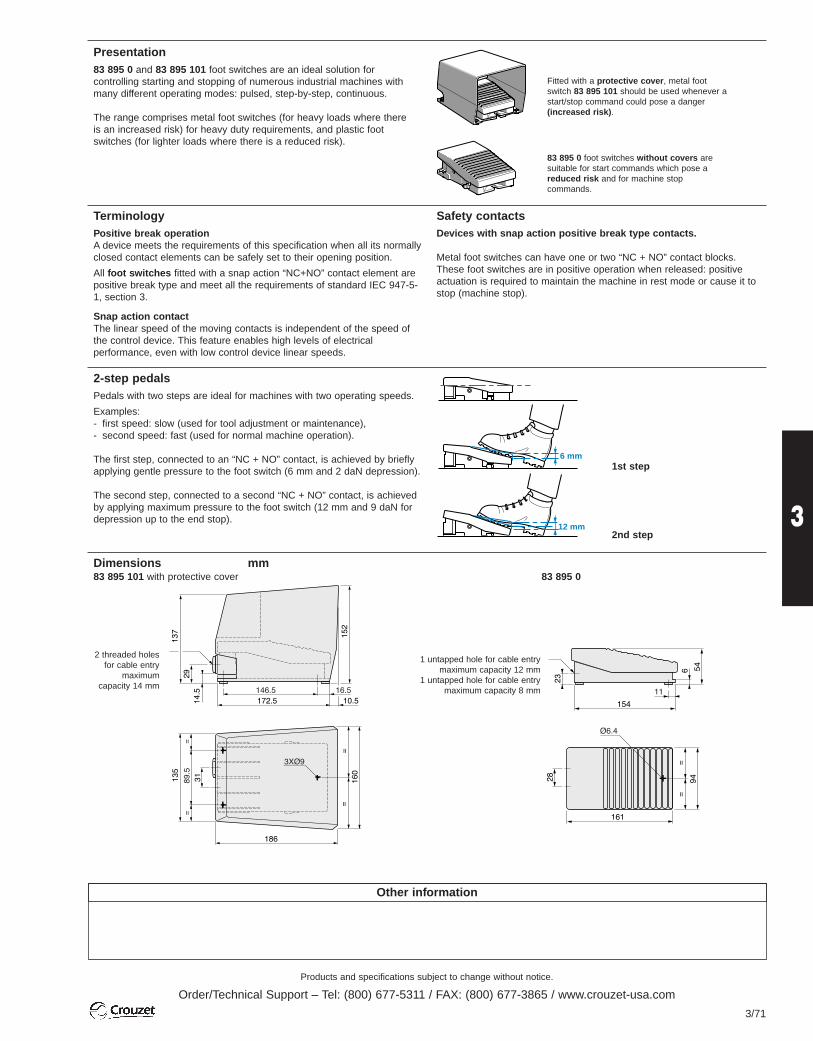
Products and specifications subject to change without notice.
Order/Technical Support – Tel: (800) 677-5311 / FAX: (800) 677-3865 / www.crouzet-usa.com
3/71
3
Other information
Presentation83 895 0 and 83 895 101 foot switches are an ideal solution forcontrolling starting and stopping of numerous industrial machines withmany different operating modes: pulsed, step-by-step, continuous.
The range comprises metal foot switches (for heavy loads where thereis an increased risk) for heavy duty requirements, and plastic footswitches (for lighter loads where there is a reduced risk).
Fitted with a protective cover, metal footswitch 83 895 101 should be used whenever astart/stop command could pose a danger(increased risk).
83 895 0 foot switches without covers aresuitable for start commands which pose areduced risk and for machine stopcommands.
Safety contactsDevices with snap action positive break type contacts.
Metal foot switches can have one or two “NC + NO” contact blocks.These foot switches are in positive operation when released: positiveactuation is required to maintain the machine in rest mode or cause it tostop (machine stop).
TerminologyPositive break operationA device meets the requirements of this specification when all its normallyclosed contact elements can be safely set to their opening position.
All foot switches fitted with a snap action “NC+NO” contact element arepositive break type and meet all the requirements of standard IEC 947-5-1, section 3.
Snap action contactThe linear speed of the moving contacts is independent of the speed ofthe control device. This feature enables high levels of electricalperformance, even with low control device linear speeds.
2-step pedalsPedals with two steps are ideal for machines with two operating speeds.
Examples:- first speed: slow (used for tool adjustment or maintenance),- second speed: fast (used for normal machine operation).
The first step, connected to an “NC + NO” contact, is achieved by brieflyapplying gentle pressure to the foot switch (6 mm and 2 daN depression).
The second step, connected to a second “NC + NO” contact, is achievedby applying maximum pressure to the foot switch (12 mm and 9 daN fordepression up to the end stop).
2 threaded holesfor cable entry
maximumcapacity 14 mm
1 untapped hole for cable entrymaximum capacity 12 mm
1 untapped hole for cable entrymaximum capacity 8 mm
6 mm
12 mm
1st step
2nd step
Dimensions mm83 895 101 with protective cover 83 895 0

Products and specifications subject to change without notice.
Order/Technical Support – Tel: (800) 677-5311 / FAX: (800) 677-3865 / www.crouzet-usa.com
3/72
Emergency Stop Switches Series 79 697
Standard products
Standard products,non stocked
To order, specify:
Part number
Example: Emergency stop pushbuttons for safety applications 79 697 003
1
Safety component
CertificationMechanical lifeElectrical life
Working current
(A) 1410 62
Insulation voltage
Voltage for withstanding shocksElectrical A.C.performance Working voltage
(50 -60 Hz)
Ue (V)230400440500690D.C.Working voltage
Ue (V) 24 V 48 V60 V110 V220 V
Protection against short-circuits
Temperature limits UseStorage
Terminal capacity
Connection
Protection indices PushbuttonBox
Technical characteristics of contacts TypePart numbers1 "N/C" contact1 "N/O" contact Contact mounting bracketMetal label, diameter 80, yellowPush-pull head with 2 stable positionsPush-turn head with 2 stable positionsLocking head with key (supplied)Mushroom head D = 70 black 1 "N/C + 1 "N/O"Mushroom head D = 70 blackSymbol
ConformityEuropean "Machinery" Directive 89/392/EECFrench Decrees 92/765-766-767-768European "Usage" Directive 89/655/EECFrench Decrees 93-40 and 93-41European standard NF EN 60204-1(Machine safety - Electrical equipment)
European standards NF EN 292-1 and 2(Machine safety - Basic concepts
European standard NF EN 418(Machine safety - Emergency stop devices)
Ø 22 control unit with mechanical latch
"CE" conforming product
Positive opening contacts
Pushbutton with positive mechanical action acc. to EN418
Dimensions
Mushroom head
79 697 003 79 697 00479 697 00579 697 00679 697 00879 697 00979 697 01079 697 10179 697 011
Cut-outs for consoles and cabinets
1Positive openingcontactsUL, CSA3 x 106 operationsOperating categoryAC21 230 V/50 - 60Hzconforms to IEC 947-3Number of operations
(x 106)0.20.513
Degree of pollution3-690 V conforms toUTE, VDE, IEC forflush-mountingU impulse: 6 kV
Working current
(IEC 947-3) (IEC 947-5-1)AC21 AC15Ie (A) Ie (A)14 612 4.511 3.510 2.56 1
Working current
(IEC 947-5-1)DC13Ie (A) 1.5 A1 A0.7 A0.3 A0.2 AHPC fuse 10 A gl - gGconforms to IEC 269- 30 to + 60 °C- 50 to + 80 °C2 x 2.5 mm2 withcable endsVia captive screw terminals IP 65IP 657 double insulation
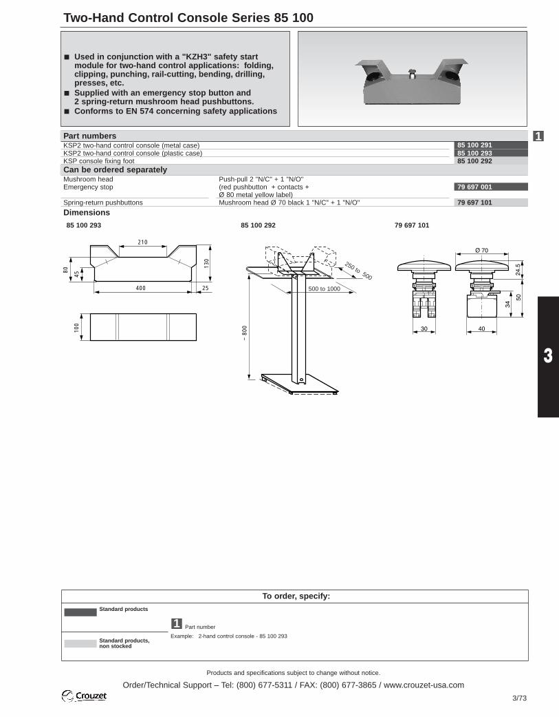
Two-Hand Control Console Series 85 100
Products and specifications subject to change without notice.
Order/Technical Support – Tel: (800) 677-5311 / FAX: (800) 677-3865 / www.crouzet-usa.com
3/73
3
To order, specify:Standard products
Standard products,non stocked
Part number
Example: 2-hand control console - 85 100 293
1
210
400 25
45
80
130
100
85 100 29185 100 293 85 100 292
79 697 001
79 697 101
Part numbersKSP2 two-hand control console (metal case)KSP2 two-hand control console (plastic case)KSP console fixing foot
Mushroom head Emergency stop
Spring-return pushbuttons
Dimensions
Can be ordered separately
Used in conjunction with a "KZH3" safety startmodule for two-hand control applications: folding,clipping, punching, rail-cutting, bending, drilling,presses, etc.
Supplied with an emergency stop button and 2 spring-return mushroom head pushbuttons.
Conforms to EN 574 concerning safety applications
Push-pull 2 "N/C" + 1 "N/O"(red pushbutton + contacts + Ø 80 metal yellow label)Mushroom head Ø 70 black 1 "N/C" + 1 "N/O"
1
85 100 293 85 100 292 79 697 101
~ 8
00
500 to 1000
250 to 500

Products and specifications subject to change without notice.
Order/Technical Support – Tel: (800) 677-5311 / FAX: (800) 677-3865 / www.crouzet-usa.com
3/74

Proximity Sensors
Products and specifications subject to change without notice.
Order/Technical Support – Tel: (800) 677-5311 / FAX: (800) 677-3865 / www.crouzet-usa.com
3/75
3

Products and specifications subject to change without notice.
Order/Technical Support – Tel: (800) 677-5311 / FAX: (800) 677-3865 / www.crouzet-usa.com
3/76
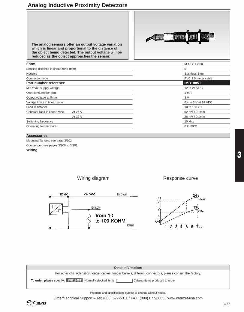
Products and specifications subject to change without notice.
Order/Technical Support – Tel: (800) 677-5311 / FAX: (800) 677-3865 / www.crouzet-usa.com
3/77
3
Analog Inductive Proximity Detectors
To order, please specify: IMB1805T Normally stocked items Catalog items produced to order For assistance call 1-800-677-5311
Other Information:
For other characteristics, longer cables, longer barrels, different connectors, please consult the factory.
The analog sensors offer an output voltage variationwhich is linear and proportional to the distance of the object being detected. The output voltage will bereduced as the object approaches the sensor.
Form M 18 x 1 x 80
Sensing distance in linear zone (mm) 5
Housing Stainless Steel
Connection type PVC 2.0 meter cable
Part number reference IMB1805TMin./max. supply voltage 12 to 24 VDC
Own consumption (Io) 1 mA
Output voltage at 5mm 3 V
Voltage limits in linear zone 0.4 to 3 V at 24 VDC
Load resistance 10 to 100 kΩ
Constant ratio in linear zone At 24 V 52 mV / 0.1mm
Constant ratio in linear zone At 12 V 26 mV / 0.1mm
Switching frequency 10 kHz
Operating temperature 0 to 60°C
AccessoriesMounting flanges, see page 3/102
Connectors, see pages 3/100 to 3/101
Wiring
Wiring diagram Response curve
Brown
Black
Blue

Products and specifications subject to change without notice.
Order/Technical Support – Tel: (800) 677-5311 / FAX: (800) 677-3865 / www.crouzet-usa.com
3/78
Other informationSpecial adaptations are available depending on the type of request and quantity required. Eg. cable length, tube length, connector type, etc.
Inductive Proximity Detectors - Ø 4, M5, Ø 6.5, M8 - Cable
Inductive Proximity Detectors - M8 - Connectors
27
Ø4
11.6
LED
Ø32000
27
Ø32000
11.6
LED
M5x0.5
2.1
SW7
FormNominal sensing distance Sn (mm)HousingTightening torque (Nm)Termination
Ø 4 screened0.8Stainless steel-2 m PVC cable *M8s/steel connector
84 717 000 *84 717 02284 717 001 *84 717 02384 717 100 *84 717 12284 717 101 *84 717 123
10 to 30 V c150 mA0.05 mA / 17.5 mA2.5 V / < 10 %1 kHz / 10 msyesyesyes3 x 0.14 mm2 / 3 mm
Part numbers3-wire DC types
NOPNP NC
NONPN NCMin/max. supply voltageMax. load current (Ia)Residual open-state current (Ir) / Own consumption (Io)Voltage drop in closed state (Ud) / Max. ripple factor (Vr)Switching frequency / Delay on pick-up (td)LED indicatorProtection against permanent short-circuits and overloadsProtection against mis-connections of any typeConductor cross-section / External cable diameter
84 717 002 *84 717 02484 717 003 *84 717 02584 717 102 *84 717 12484 717 103 *84 717 125
10 to 30 V c150 mA0.05 mA / 17.5 mA2.5 V / < 10 %1 kHz / 10 msyesyesyes3 x 0.14 mm2 / 3 mm
M5 screened0.8Stainless steel2.52 m PVC cable *M8s/steel connector
84 717 01284 717 01384 717 11284 717 11310 to 40 V c200 mA0.05 mA / 7 mA3 V / < 10 %1.5 kHz / 50 msyesyesyes
84 717 01084 717 01184 717 11084 717 11110 to 40 V c200 mA0.05 mA / 7 mA3 V / < 10 %2 kHz / 50 msyesyesyes
Part numbers3-wire DC types
NOPNP NC
NONPN NCMin/max. supply voltageMax. load current (Ia)Residual open-state current (Ir) / Own consumption (Io)Voltage drop in closed state (Ud) / Max. ripple factor (Vr)Switching frequency / Delay on pick-up (td)LED indicatorProtection against permanent short-circuits and overloadsProtection against mis-connections of any typeAccessoriesMounting flanges, see page 3/102Connectors, see pages 3/100 to 3/101
M8x1
LED
61.5
35
SW13
4
M8x164
.5
38
SW13
LED
3 4
FormNominal sensing distance Sn (mm)HousingTightening torque (Nm)Termination
M8 screened1Stainless steel10M8 s/steel connector
M8 non-screened2Stainless steel10 M8 s/steel connector

Products and specifications subject to change without notice.
Order/Technical Support – Tel: (800) 677-5311 / FAX: (800) 677-3865 / www.crouzet-usa.com
3/79
3
To order, specify:
Standard products Standard products,non stocked Example : Inductive proximity detector Ø4 84 717 000
1 Part number
84 717 02084 717 02184 717 12084 717 12110 to 40 V c200 mA0.05 mA / 7 mA3 V / < 10 %1.5 kHz / 50 msyesyesyes
84 717 01884 717 01984 717 11884 717 11910 to 40 V c200 mA0.05 mA / 7 mA3 V / < 10 %2 kHz / 50 msyesyesyes
84 717 01684 717 01784 717 11684 717 11710 to 40 V c200 mA0.05 mA / 7 mA3 V / < 10 %1.5 kHz / 50 msyesyesyes
M8 non-screened2Stainless steel102 m PVC cable
M8 screened1Stainless steel102 m PVC cable
84 717 00684 717 00784 717 10684 717 10710 to 40 V c200 mA0.05 mA / 7 mA3 V / < 10 %2 kHz / 50 msyesyesyes3 x 0.14 mm2 / 3 mm
84 717 00884 717 00984 717 10884 717 10910 to 40 V c200 mA0.05 mA / 7 mA3 V / < 10 %1.5 kHz / 50 msyesyesyes3 x 0.14 mm2 / 3 mm
M8 non-screened2Stainless steel10M12 stainless steel connector
M8 screened1Stainless steel10M12 plastic connector
M8 non-screened2Stainless steel10M12 plastic connector
Ø32000
35
51
SW13
M8x1
4
LED
Ø32000
3
M8x1
54
38
SW13
LED
M8x1
LED
62.5
35
SW13
4
M12x1
M8x1
65.5
38
SW13
LED
3 4
M12x1
M8x1
65.5
38
SW13
LED3
4
M12x1
84 717 01484 717 01584 717 11484 717 11510 to 40 V c200 mA0.05 mA / 7 mA3 V / < 10 %2 kHz / 50 msyesyesyes
Ø32000
51
Ø6.5
LED13.5
Ø 6.5 screened1.5Stainless steel-2 m PVC cable
84 717 00484 717 00584 717 10484 717 10510 to 40 V c200 mA0.05 mA / 7 mA3V / < 10 %2 kHz / 50 msyesyesyes3 x 0.14 mm2 / 3 mm
M8x1
LED
62.5
35
SW13
4
M12x1
M8 screened1Stainless steel10M12 s/steel connector
1
1

Products and specifications subject to change without notice.
Order/Technical Support – Tel: (800) 677-5311 / FAX: (800) 677-3865 / www.crouzet-usa.com
3/80
Other information
Special adaptations are available depending on the type of request and quantity required. Eg. cable length, tube length, connector type, etc.
Part numbers2-wire AC types Polarity NOreversible NCMin/max. supply voltageMin/max. load current (Ia)Residual open-state current (Ir) Voltage drop in closed state (Ud)Switching frequency / Delay on pick-up (td)LED indicatorConductor cross-section
Inductive Proximity Detectors - M12 - Stainless Steel
FormNominal sensing distance Sn (mm)HousingTightening torque (Nm)Termination
M12 screened2Stainless steel252 m PVC cable
M12 long, screened2Stainless steel252 m PVC cable
M12 non-screened4 Stainless steel252 m PVC cable
84 717 22684 717 22784 717 32684 717 32710 to 40 V c200 mA0.05 mA / 6.5 mA2 V / < 10 %800 Hz / 10 msyesyesyes3 x 0.3 mm2 / 5.2 mm
Part numbers3-wire DC types
NOPNP NC
NONPN NCMin/max. supply voltageMax. load current (Ia)Residual open-state current (Ir) / Own consumption (Io)Voltage drop in closed state (Ud) / Max. ripple factor (Vr)Switching frequency / Delay on pick-up (td)LED indicatorProtection against permanent short-circuits and overloadsProtection against mis-connections of any typeConductor cross-section / External cable diameter
84 717 02684 717 02784 717 12684 717 12710 to 40 V c200 mA0.05 mA / 6.5 mA2 V / < 10 %800 Hz / 10 msyesyesyes3 x 0.3 mm2 / 5.2 mm
84 717 22884 717 22984 717 32884 717 32910 to 40 V c200 mA0.05 mA / 6.5 mA2 V / < 10 %400 Hz / 10 msyesyesyes3 x 0.3 mm2 / 5.2 mm
2000
LED
SW1746
30
Ø4.5
4
M12x1
2000
LED
SW1750
34
Ø4.5
M12x1
44
LED
M12x1
SW17
4
66
5020
00 Ø4.5
84 717 62684 717 62720 to 250 V a5 to 500 mA< 2 mA< 8 V 5 Hz / 100 msyes2 x 0.5 mm2 / 5.2 mm

Products and specifications subject to change without notice.
Order/Technical Support – Tel: (800) 677-5311 / FAX: (800) 677-3865 / www.crouzet-usa.com
3/81
3
To order, specify:
Standard products Standard products,non stocked Example : Inductive proximity detector M12 84 717 226
1 Part number
Continued onpage 3/82
Continued onpage 3/82
84 717 03084 717 03184 717 13084 717 13110 to 40 V c200 mA0.05 mA / 6.5 mA2 V / < 10 %800 Hz / 10 msyesyesyes
-
1
1
M12 long, non-screened4Stainless steel252 m PVC cable
M12 screened2Stainless steel25M12 plastic connector
M12 long, screened2Stainless steel25M12 plastic connector
M12 non-screened4Stainless steel25M12 plastic connector
84 717 02884 717 02984 717 12884 717 12910 to 40 V c200 mA0.05 mA / 6.5 mA2 V / < 10 %400 Hz / 10 msyesyesyes3 x 0.3 mm2 / 4.5 mm
84 717 62884 717 62920 to 250 V a5 to 500 mA< 2 mA< 8 V 5 Hz / 100 msyes2 x 0.5 mm2 / 5.2 mm
LED
M12x1
SW17
4
70
54
4
2000 Ø4.5
84 717 23084 717 23184 717 33084 717 33110 to 40 V c200 mA0.05 mA / 6.5 mA2 V / < 10 %800 Hz / 10 msyesyesyes
-
54.5
30
M12x1
SW17
11.9
4
LED
84 717 63084 717 63120 to 250 V a5 to 500 mA< 2 mA< 8 V 5 Hz / 100 msyes
-
74.5
50
M12x1
SW17
4
LED
11.9
58.5
34
M12x1
SW17
4
411
.9
LED
84 717 23284 717 23384 717 33284 717 33310 to 40 V c200 mA0.05 mA / 6.5 mA2 V / < 10 %400 Hz / 10 msyesyesyes
-
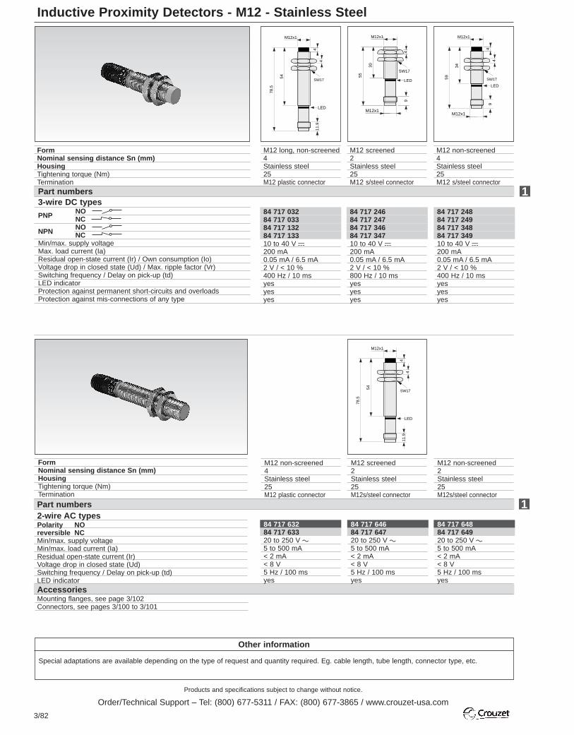
Products and specifications subject to change without notice.
Order/Technical Support – Tel: (800) 677-5311 / FAX: (800) 677-3865 / www.crouzet-usa.com
3/82
Inductive Proximity Detectors - M12 - Stainless Steel
Other information
Special adaptations are available depending on the type of request and quantity required. Eg. cable length, tube length, connector type, etc.
84 717 24884 717 24984 717 34884 717 34910 to 40 V c200 mA0.05 mA / 6.5 mA2 V / < 10 %400 Hz / 10 msyesyesyes
84 717 24684 717 24784 717 34684 717 34710 to 40 V c200 mA0.05 mA / 6.5 mA2 V / < 10 %800 Hz / 10 msyesyesyes
84 717 03284 717 03384 717 13284 717 13310 to 40 V c200 mA0.05 mA / 6.5 mA2 V / < 10 %400 Hz / 10 msyesyesyes
Part numbers3-wire DC types
NOPNP NC
NONPN NCMin/max. supply voltageMax. load current (Ia)Residual open-state current (Ir) / Own consumption (Io)Voltage drop in closed state (Ud) / Max. ripple factor (Vr)Switching frequency / Delay on pick-up (td)LED indicatorProtection against permanent short-circuits and overloadsProtection against mis-connections of any type
M12 non-screened4Stainless steel25M12 s/steel connector
FormNominal sensing distance Sn (mm)HousingTightening torque (Nm)Termination
78.5
54
M12x1
SW17
4
411
.9
LED
M12 long, non-screened4Stainless steel25M12 plastic connector
M12 screened2Stainless steel25M12 s/steel connector
55
30
M12x1
SW17
94
LED
M12x1
59
34
M12x1
SW17
4
49
LED
M12x1
1
84 717 63284 717 63320 to 250 V a5 to 500 mA< 2 mA< 8 V 5 Hz / 100 msyes
AccessoriesMounting flanges, see page 3/102Connectors, see pages 3/100 to 3/101
FormNominal sensing distance Sn (mm)HousingTightening torque (Nm)Termination
Part numbers2-wire AC types Polarity NOreversible NCMin/max. supply voltageMin/max. load current (Ia)Residual open-state current (Ir) Voltage drop in closed state (Ud)Switching frequency / Delay on pick-up (td)LED indicator
1
M12 non-screened4Stainless steel25M12 plastic connector
M12 screened2Stainless steel25M12s/steel connector
M12 non-screened2Stainless steel25M12s/steel connector
78.5
54
M12x1
SW17
4
411
.9
LED
84 717 64684 717 64720 to 250 V a5 to 500 mA< 2 mA< 8 V 5 Hz / 100 msyes
84 717 64884 717 64920 to 250 V a5 to 500 mA< 2 mA< 8 V 5 Hz / 100 msyes

Products and specifications subject to change without notice.
Order/Technical Support – Tel: (800) 677-5311 / FAX: (800) 677-3865 / www.crouzet-usa.com
3/83
3
To order, specify:Standard products Standard products,
non stocked Example : Inductive proximity detector M12 84 717 0281 Part number
Inductive Proximity Detectors - M12 - Plastic
84 717 03884 717 03984 717 13884 717 13910 to 40 V c200 mA
0.05 mA / 6.5 mA
2 V / < 10 %
800 Hz / 10 ms
yesyesyes3 x 0.3 mm2 / 5.2 mm
84 717 24084 717 24184 717 34084 717 34110 to 40 V c200 mA
0.05 mA / 6.5 mA
2 V / < 10 %
400 Hz / 10 ms
yesyesyes3 x 0.3 mm2 / 5.2 mm
84 717 04084 717 04184 717 14084 717 14110 to 40 V c200 mA
0.05 mA / 6.5 mA
2 V / < 10 %
400 Hz / 10 ms
yesyesyes3 x 0.3 mm2 / 5.2 mm
84 717 23884 717 23984 717 33884 717 33910 to 40 V c200 mA
0.05 mA / 6.5 mA
2 V / < 10 %
800 Hz / 10 ms
yesyesyes3 x 0.3 mm2 / 5.2 mm
M12 screened2Plastic1.52 m PVC cable
M12 long, screened2Plastic1.52 m PVC cable
M12 non-screened4Plastic1.52 m PVC cable
M12 long, non-screened4Plastic1.52 m PVC cable
1
2000
LED
SW1746
30
Ø4.5
4
M12x1
LED
M12x1
SW17
4
66
5020
00 Ø4.5
2000
LED
SW1750
34
Ø4.5
M12x1
44
LED
M12x1
SW17
4
70
54
4
2000 Ø4.5
FormNominal sensing distance Sn (mm)HousingTightening torque (Nm)Termination
84 717 24284 717 24384 717 34284 717 34310 to 40 V c200 mA
0.05 mA / 6.5 mA
2 V / < 10 %
800 Hz / 10 ms
yesyesyes
Part numbers3-wire DC types
NOPNP NC
NONPN NCMin/max. supply voltageMax. load current (Ia)Residual open-state current (Ir)Own consumption (Io)Voltage drop in closed state (Ud) Max. ripple factor (Vr)Switching frequency Delay on pick-up (td)LED indicatorProtection against perm. short-circuits and overloadsProtection against mis-connections of any typeAccessoriesMounting flanges, see page 3/102Connectors, see pages 3/100 to 3/101.
78.5
54
M12x1
SW17
4
411
.9
LED
58.5
34
M12x1
SW17
4
411
.9
LED74.5
50
M12x1
SW17
4
LED
11.9
54.5
30
M12x1
SW17
11.9
4
LED
1
FormNominal sensing distance Sn (mm)HousingTightening torque (Nm)Termination
M12 screened2Plastic1.5M12 plastic connector
M12 long, screened2Plastic1.5M12 plastic connector
M12 non-screened4Plastic1.5M12 plastic connector
M12 long, non-screened4Plastic1.5M12 plastic connector
84 717 04284 717 04384 717 14284 717 14310 to 40 V c200 mA
0.05 mA / 6.5 mA
2 V / < 10 %
800 Hz / 10 ms
yesyesyes
84 717 24484 717 24584 717 34484 717 34510 to 40 V c200 mA
0.05 mA / 6.5 mA
2 V / < 10 %
400 Hz / 10 ms
yesyesyes
84 717 04484 717 04584 717 14484 717 14510 to 40 V c200 mA
0.05 mA / 6.5 mA
2 V / < 10 %
400 Hz / 10 ms
yesyesyes
Part numbers3-wire DC types
NOPNP NC
NONPN NCMin/max. supply voltageMax. load current (Ia)Residual open-state current (Ir) / Ownconsumption (Io)Voltage drop in closed state (Ud) /Max. ripple factor (Vr)Switching frequency / Delay on pick-up (td)LED indicatorProtection against perm. short-circuits and overloadsProtection against mis-connections of any typeConductor cross-section / External cable diameter
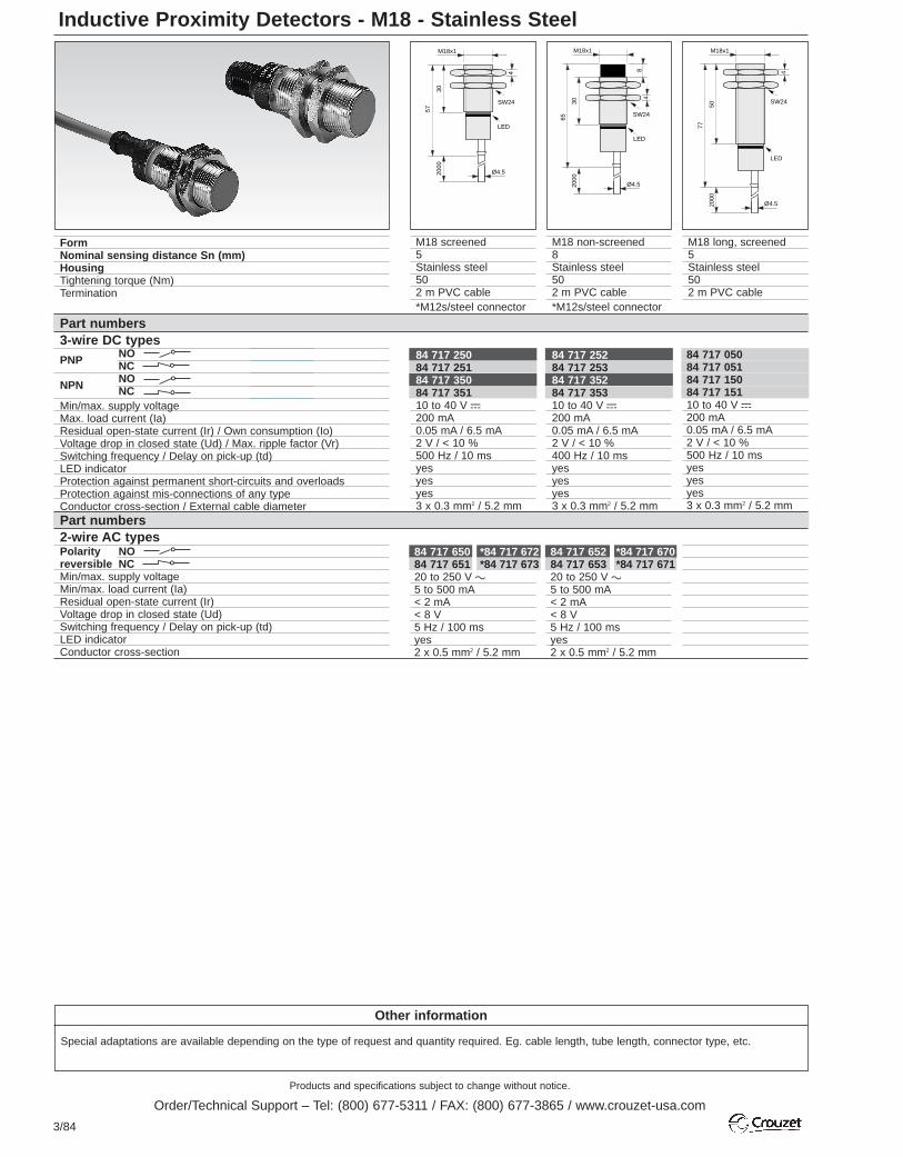
Products and specifications subject to change without notice.
Order/Technical Support – Tel: (800) 677-5311 / FAX: (800) 677-3865 / www.crouzet-usa.com
3/84
Inductive Proximity Detectors - M18 - Stainless Steel
Other information
Special adaptations are available depending on the type of request and quantity required. Eg. cable length, tube length, connector type, etc.
84 717 650 *84 717 67284 717 651 *84 717 67320 to 250 V a5 to 500 mA< 2 mA< 8 V 5 Hz / 100 msyes2 x 0.5 mm2 / 5.2 mm
84 717 652 *84 717 67084 717 653 *84 717 67120 to 250 V a5 to 500 mA< 2 mA< 8 V 5 Hz / 100 msyes2 x 0.5 mm2 / 5.2 mm
84 717 25284 717 25384 717 35284 717 35310 to 40 V c200 mA0.05 mA / 6.5 mA2 V / < 10 %400 Hz / 10 msyesyesyes3 x 0.3 mm2 / 5.2 mm
84 717 25084 717 25184 717 35084 717 35110 to 40 V c200 mA0.05 mA / 6.5 mA2 V / < 10 %500 Hz / 10 msyesyesyes3 x 0.3 mm2 / 5.2 mm
84 717 05084 717 05184 717 15084 717 15110 to 40 V c200 mA0.05 mA / 6.5 mA2 V / < 10 %500 Hz / 10 msyesyesyes3 x 0.3 mm2 / 5.2 mm
FormNominal sensing distance Sn (mm)HousingTightening torque (Nm)Termination
M18 screened5Stainless steel502 m PVC cable*M12s/steel connector
M18 non-screened8Stainless steel502 m PVC cable*M12s/steel connector
M18 long, screened5Stainless steel502 m PVC cable
Part numbers3-wire DC types
NOPNP NC
NONPN NCMin/max. supply voltageMax. load current (Ia)Residual open-state current (Ir) / Own consumption (Io)Voltage drop in closed state (Ud) / Max. ripple factor (Vr)Switching frequency / Delay on pick-up (td)LED indicatorProtection against permanent short-circuits and overloadsProtection against mis-connections of any typeConductor cross-section / External cable diameterPart numbers2-wire AC typesPolarity NOreversible NCMin/max. supply voltageMin/max. load current (Ia)Residual open-state current (Ir) Voltage drop in closed state (Ud)Switching frequency / Delay on pick-up (td)LED indicatorConductor cross-section
M18x1
LED
4
SW24
57
3020
00
Ø4.5
LED
48
SW24
65
3020
00
Ø4.5
M18x1 M18x1
LED
4
SW24
77
5020
00
Ø4.5

Products and specifications subject to change without notice.
Order/Technical Support – Tel: (800) 677-5311 / FAX: (800) 677-3865 / www.crouzet-usa.com
3/85
3
To order, specify:
Standard products Standard products,non stocked Example : Inductive proximity detector M18 84 717 250
1 Part number
4
SW24
55.5
30
M18x1
11.9
M12x1
LED
M18 long, non-screened8Stainless steel502 m PVC cable
M18 screened5Stainless steel50M12 plastic connector *M12s/steel connector
M18 long, screened5Stainless steel50M12 plastic connector
M18 non-screened8Stainless steel50M12 plastic connector *M12s/steel connector
LED
48
SW24
85
5820
00
Ø4.5
M18x1
84 717 65484 717 65520 to 250 V a5 to 500 mA< 2 mA< 8 V 5 Hz / 100 msyes
-
84 717 65684 717 65720 to 250 V a5 to 500 mA< 2 mA< 8 V 5 Hz / 100 msyes
-
84 717 05284 717 05384 717 15284 717 15310 to 40 V c200 mA0.05 mA / 6.5 mA2 V / < 10 %400 Hz / 10 msyesyesyes3 x 0.3 mm2 / 5.2 mm
84 717 254 *84 717 25884 717 255 *84 717 25984 717 354 *84 717 35884 717 355 *84 717 35910 to 40 V c200 mA0.05 mA / 6.5 mA2 V / < 10 %500 Hz / 10 msyesyesyes
-
84 717 05484 717 05584 717 15484 717 15510 to 40 V c200 mA0.05 mA / 6.5 mA2 V / < 10 %500 Hz / 10 msyesyesyes
-
84 717 256 *84 717 26084 717 257 *84 717 26184 717 356 *84 717 36084 717 357 *84 717 36110 to 40 V c200 mA0.05 mA / 6.5 mA2 V / < 10 %400 Hz / 10 msyesyesyes
-
1
14
SW24
75
50
M18x1
11.9
M12x1
LED
48
SW24
63
30
M18x1
11.9
M12x1
LED
84 717 05684 717 05784 717 15684 717 15710 to 40 V c200 mA0.05 mA / 6.5 mA2 V / < 10 %400 Hz / 10 msyesyesyes
-
48
SW24
83
58
M18x1
11.9
M12x1
LED
M18 long, non-screened8Stainless steel50M12 plastic connector
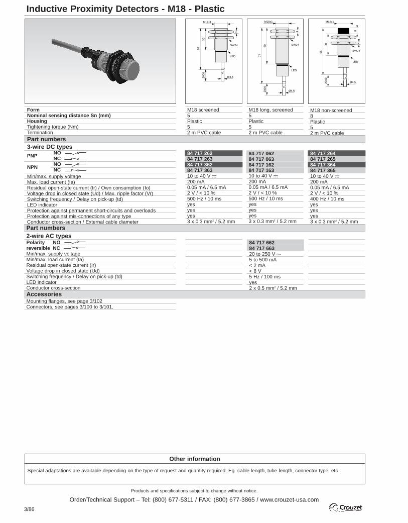
Products and specifications subject to change without notice.
Order/Technical Support – Tel: (800) 677-5311 / FAX: (800) 677-3865 / www.crouzet-usa.com
3/86
Inductive Proximity Detectors - M18 - Plastic
Other information
Special adaptations are available depending on the type of request and quantity required. Eg. cable length, tube length, connector type, etc.
84 717 66284 717 66320 to 250 V a5 to 500 mA< 2 mA< 8 V 5 Hz / 100 msyes2 x 0.5 mm2 / 5.2 mm
84 717 26284 717 26384 717 36284 717 36310 to 40 V c200 mA0.05 mA / 6.5 mA2 V / < 10 %500 Hz / 10 msyesyesyes3 x 0.3 mm2 / 5.2 mm
Part numbers2-wire AC typesPolarity NOreversible NCMin/max. supply voltageMin/max. load current (Ia)Residual open-state current (Ir) Voltage drop in closed state (Ud)Switching frequency / Delay on pick-up (td)LED indicatorConductor cross-section
Part numbers3-wire DC types
NOPNP NC
NONPN NCMin/max. supply voltageMax. load current (Ia)Residual open-state current (Ir) / Own consumption (Io)Voltage drop in closed state (Ud) / Max. ripple factor (Vr)Switching frequency / Delay on pick-up (td)LED indicatorProtection against permanent short-circuits and overloadsProtection against mis-connections of any typeConductor cross-section / External cable diameter
FormNominal sensing distance Sn (mm)HousingTightening torque (Nm)Termination
M18x1
LED
4
SW24
57
3020
00
Ø4.5
M18 screened5Plastic52 m PVC cable
84 717 06284 717 06384 717 16284 717 16310 to 40 V c200 mA0.05 mA / 6.5 mA2 V / < 10 %500 Hz / 10 msyesyesyes3 x 0.3 mm2 / 5.2 mm
M18x1
LED
4
SW24
77
5020
00
Ø4.5
M18 long, screened5Plastic52 m PVC cable
84 717 26484 717 26584 717 36484 717 36510 to 40 V c200 mA0.05 mA / 6.5 mA2 V / < 10 %400 Hz / 10 msyesyesyes3 x 0.3 mm2 / 5.2 mm
LED
48
SW24
65
3020
00
Ø4.5
M18x1
M18 non-screened8Plastic52 m PVC cable
AccessoriesMounting flanges, see page 3/102Connectors, see pages 3/100 to 3/101.

Products and specifications subject to change without notice.
Order/Technical Support – Tel: (800) 677-5311 / FAX: (800) 677-3865 / www.crouzet-usa.com
3/87
3
To order, specify:
Standard products Standard products,non stocked Example : Inductive proximity detector M18 84 717 056
1 Part number
84 717 66484 717 66520 to 250 V a5 to 500 mA< 2 mA< 8 V 5 Hz / 100 msyes2 x 0.5 mm2 / 5.2 mm
84 717 06484 717 06584 717 16484 717 16510 to 40 V c200 mA0.05 mA / 6.5 mA2 V / < 10 %400 Hz / 10 msyesyesyes3 x 0.3 mm2 / 5.2 mm
84 717 06684 717 06784 717 16684 717 16710 to 40 V c200 mA0.05 mA / 6.5 mA2 V / < 10 %500 Hz / 10 msyesyesyes3 x 0.3 mm2 / 5.2 mm
84 717 06884 717 06984 717 16884 717 16910 to 40 V c200 mA0.05 mA / 6.5 mA2 V / < 10 %400 Hz / 10 msyesyesyes
-
84 717 26684 717 26784 717 36684 717 36710 to 40 V c200 mA0.05 mA / 6.5 mA2 V / < 10 %500 Hz / 10 msyesyesyes3 x 0.3 mm2 / 5.2 mm
84 717 26884 717 26984 717 36884 717 36910 to 40 V c200 mA0.05 mA / 6.5 mA2 V / < 10 %400 Hz / 10 msyesyesyes
-
48
SW24
83
58
M18x1
11.9
M12x1
LED
M18 long, non-screened8Plastic52 m PVC cable
M18 non-screened8Plastic5M12 plastic connector
M18 long, non-screened8Plastic5M12 plastic connector
LED
48
SW24
85
5820
00
Ø4.5
M18x1
4
SW24
55
30
M18x1
11.9
M12x1
LED
4
SW24
75
50
M18x1
11.9
M12x1
LED
1
1
48
SW24
63
30
M18x1
11.9
M12x1
LED
M18 long, screened5Plastic5M12 plastic connector
M18 screened5Plastic5M12 plastic connector

Products and specifications subject to change without notice.
Order/Technical Support – Tel: (800) 677-5311 / FAX: (800) 677-3865 / www.crouzet-usa.com
3/88
Other information
Special adaptations are available depending on the type of request and quantity required. Eg. cable length, tube length, connector type, etc.
Inductive Proximity Detectors - M30 - Stainless Steel - 3-Wire DC Types
Inductive Proximity Detectors - M30 - Stainless Steel - 2-Wire AC Types
84 717 27484 717 27584 717 37484 717 37510 to 40 V c200 mA0.05 mA / 6.5 mA2 V / < 10 %300 Hz / 10 msyesyesyes3 x 0.3 mm2 / 5.2 mm
84 717 07484 717 07584 717 17484 717 17510 to 40 V c200 mA0.05 mA / 6.5 mA2 V / < 10 %300 Hz / 10 msyesyesyes3 x 0.3 mm2 / 5.2 mm
84 717 27684 717 27784 717 37684 717 37710 to 40 V c200 mA0.05 mA / 6.5 mA2 V / < 10 %100 Hz / 10 msyesyesyes3 x 0.3 mm2 / 5.2 mm
FormNominal sensing distance Sn (mm)HousingTightening torque (Nm)Termination
1Part numbersNO
PNP NCNONPN NC
Min/max. supply voltageMax. load current (Ia)Residual open-state current (Ir) / Own consumption (Io)Voltage drop in closed state (Ud) / Max. ripple factor (Vr)Switching frequency (F) / Delay on pick-up (td)LED indicatorProtection against permanent short-circuits and overloadsProtection against mis-connections of any typeConductor cross-section / External cable diameter
M30x1.5
SW36
LED
59
30
2000 Ø4.5
M30 screened10Stainless steel1002 m PVC cable
M30 long, screened10Stainless steel1002 m PVC cable
M30 non-screened15Stainless steel1002 m PVC cable
M30x1.5
SW36
LED
79
50
2000 Ø4.5
M30x1.5
SW36
LED
43.6
30
2000 Ø4.5
12
13.4
84 717 67484 717 67520 to 250 V a5 to 500 mA< 2 mA< 8 V 5 Hz / 100 msyes2 x 0.5 mm2 / 5.2 mm
84 717 67684 717 67720 to 250 V a5 to 500 mA< 2 mA< 8 V 5 Hz / 100 msyes2 x 0.5 mm2 / 5.2 mm
84 717 68084 717 68120 to 250 V a5 to 500 mA< 2 mA< 8 V 5 Hz / 100 msyes
-
1Part numbersPolarity NOreversible NCMin/max. supply voltageMin/max. load current (Ia)Residual open-state current (Ir) Voltage drop in closed state (Ud)Switching frequency (F) / Delay on pick-up (td)LED indicatorConductor cross-section
M30x1.5
SW36
LED
59
30
2000 Ø4.5
M30x1.5
SW36
LED
43.6
30
2000 Ø4.5
12
13.4
M30x1.5
SW36
LED55
.5
3011
.912
FormNominal sensing distance Sn (mm)HousingTightening torque (Nm)Termination
M30 screened10Stainless steel1002 m PVC cable
M30 non-screened15Stainless steel1002 m PVC cable
M30 non-screened15Stainless steel100M12 plastic connector

Products and specifications subject to change without notice.
Order/Technical Support – Tel: (800) 677-5311 / FAX: (800) 677-3865 / www.crouzet-usa.com
3/89
3
To order, specify:
Standard products Standard products,non stocked Example : Inductive proximity detector M30 84 717 274
1 Part number
84 717 08084 717 08184 717 18084 717 18110 to 40 V c200 mA0.05 mA / 6.5 mA2 V / < 10 %100 Hz / 10 msyesyesyes
-
84 717 28084 717 28184 717 38084 717 38110 to 40 V c200 mA0.05 mA / 6.5 mA2 V / < 10 %100 Hz / 10 msyesyesyes
-
84 717 07684 717 07784 717 17684 717 17710 to 40 V c200 mA0.05 mA / 6.5 mA2 V / < 10 %100 Hz / 10 msyesyesyes3 x 0.3 mm2 / 5.2 mm
84 717 078 *84 717 28484 717 079 *84 717 28584 717 178 *84 717 38484 717 179 *84 717 38510 to 40 V c200 mA0.05 mA / 6.5 mA2 V / < 10 %300 Hz / 10 msyesyesyes
-
84 717 278 *84 717 28284 717 279 *84 717 28384 717 378 *84 717 38284 717 379 *84 717 38310 to 40 V c200 mA0.05 mA / 6.5 mA2 V / < 10 %300 Hz / 10 msyesyesyes
-
M30 non-screened15Stainless steel100M12 plastic connector
M30 long, non-screened15Stainless steel100M12 plastic connector
M30x1.5
SW36
LED
55.5
3011
.912
M30x1.5
SW36
LED
87.5
6211
.9
12
M12x1
84 717 67884 717 67920 to 250 V a5 to 500 mA< 2 mA< 8 V 5 Hz / 100 msyes
-
M30 long, screened10Stainless steel100M12 plastic connector*M12s/steel connector
M30 screened10Stainless steel100M12 plastic connector*M12s/steel connector
M30 long, non-screened15Stainless steel1002 m PVC cable
M30x1.5
SW36
LED
91
62
2000 Ø4.5
12
M30x1.5
SW36
LED
55.5
3011
.9
M30x1.5
SW36
LED
55.5
3011
.9
M30x1.5
SW36
LED
55.5
3011
.9
M30x1.5
SW36
LED
75.5
5011
.9
M12x1
M30 screened10Stainless steel100M12 plastic connector
84 717 69484 717 69520 to 250 V a5 to 500 mA< 2 mA< 8 V 5 Hz / 100 msyes
-
M30 screened10Stainless steel100M12s/steel connector
84 717 68484 717 68520 to 250 V a5 to 500 mA< 2 mA< 8 V 5 Hz / 100 msyes
-
M30 non-screened15Stainless steel100M12s/steel connector
M30x1.5
SW36
LED
55.5
3011
.912
1
1

Products and specifications subject to change without notice.
Order/Technical Support – Tel: (800) 677-5311 / FAX: (800) 677-3865 / www.crouzet-usa.com
3/90
Inductive Proximity Detectors - M30 - Plastic
Other information
Special adaptations are available depending on the type of request and quantity required. Eg. cable length, tube length, connector type, etc.
84 717 28684 717 28784 717 38684 717 38710 to 40 V c200 mA0.05 mA / 6.5 mA2 V / < 10 %300 Hz / 10 msyesyesyes3 x 0.3 mm2 / 5.2 mm
M30 screened10Plastic152 m PVC cable
AccessoriesMounting flanges, see page 3/102Connectors, see pages 3/100 to 3/101
FormNominal sensing distance Sn (mm)HousingTightening torque (Nm)Termination
M30x1.5
SW36
LED
59
30
2000 Ø4.5
M30 long, screened10Plastic152 m PVC cable
M30 non-screened15Plastic152 m PVC cable
Part numbers3-wire DC types
NOPNP NC
NONPN NCMin/max. supply voltageMax. load current (Ia)Residual open-state current (Ir) / Own consumption (Io)Voltage drop in closed state (Ud) / Max. ripple factor (Vr)Switching frequency (F) / Delay on pick-up (td)LED indicatorProtection against permanent short-circuits and overloadsProtection against mis-connections of any typeConductor cross-section / External cable diameter
84 717 08684 717 08784 717 18684 717 18710 to 40 V c200 mA0.05 mA / 6.5 mA2 V / < 10 %300 Hz / 10 msyesyesyes3 x 0.3 mm2 / 5.2 mm
84 717 28884 717 28984 717 38884 717 38910 to 40 V c200 mA0.05 mA / 6.5 mA2 V / < 10 %100 Hz / 10 msyesyesyes3 x 0.3 mm2 / 5.2 mm
Part numbers2-wire AC types Polarity NOreversible NCMin/max. supply voltageMin/max. load current (Ia)Residual open-state current (Ir) Voltage drop in closed state (Ud)Switching frequency (F) / Delay on pick-up (td)LED indicatorConductor cross-section
M30x1.5
SW36
LED
79
50
2000 Ø4.5
84 717 68684 717 68720 to 250 V a5 to 500 mA< 2 mA< 8 V 5 Hz / 100 msyes2 x 0.5 mm2 / 5.2 mm
M30x1.5
SW36
LED
43.6
30
2000 Ø4.5
12
13.4
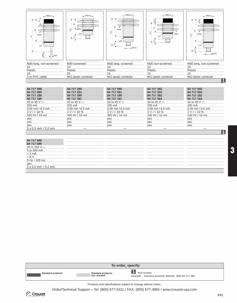
Products and specifications subject to change without notice.
Order/Technical Support – Tel: (800) 677-5311 / FAX: (800) 677-3865 / www.crouzet-usa.com
3/91
3
To order, specify:
Standard products,non stocked Example : Inductive proximity detector M30 84 717 286
1 Part numberStandard products
M30 long, non-screened15Plastic152 m PVC cable
M30 screened10Plastic25M12 plastic connector
M30 long, screened10Plastic15M12 plastic connector
M30 non-screened15Plastic15M12 plastic connector
M30 long, non-screened15Plastic15M12 plastic connector
84 717 08884 717 08984 717 18884 717 18910 to 40 V c200 mA0.05 mA / 6.5 mA2 V / < 10 %100 Hz / 10 msyesyesyes3 x 0.3 mm2 / 5.2 mm
84 717 29084 717 29184 717 39084 717 39110 to 40 V c200 mA0.05 mA / 6.5 mA2 V / < 10 %300 Hz / 10 msyesyesyes
-
84 717 09084 717 09184 717 19084 717 19110 to 40 V c200 mA0.05 mA / 6.5 mA2 V / < 10 %300 Hz / 10 msyesyesyes
-
84 717 29284 717 29384 717 39284 717 39310 to 40 V c200 mA0.05 mA / 6.5 mA2 V / < 10 %100 Hz / 10 msyesyesyes
-
84 717 09284 717 09384 717 19284 717 19310 to 40 V c200 mA0.05 mA / 6.5 mA2 V / < 10 %100 Hz / 10 msyesyesyes
-
84 717 68884 717 68920 to 250 V a5 to 500 mA< 2 mA< 8 V 5 Hz / 100 msyes2 x 0.5 mm2 / 5.2 mm
M30x1.5
SW36
LED
91
62
2000 Ø4.5
12
M30x1.5
SW36
LED
55.5
3011
.9
M30x1.5
SW36
LED
75.5
5011
.9
M12x1
M30x1.5
SW36
LED
55.5
3011
.912
M30x1.5
SW36
LED
87.5
6211
.9
12
M12x1
1
1

Products and specifications subject to change without notice.
Order/Technical Support – Tel: (800) 677-5311 / FAX: (800) 677-3865 / www.crouzet-usa.com
3/92
Standard products
Standard products,non stocked
Inductive Proximity Detectors - Flat Pack
Other information To order, specify:
Special adaptations are available depending on the type of request andquantity required.Eg. cable length, tube length, connector type, etc. Part number
Example : Inductive proximity detector 84 718 024
1
mm
Part numbers4-wire DC types PNP NO / NC /NPN NO / NC /Min/max. supply voltageMax. load current (Ia)Residual open-state current (Ir) / Own consumption (Io)Voltage drop in closed state (Ud) / Max. ripple factor (Vr)Switching frequency (F) / Delay on pick-up (td)LED indicatorProtection against permanent short-circuits and overloadsProtection against mis-connections of any typeConductor cross-section / External cable diameterDimensions
55 x 35 non-screened15Plastic
-2 m PVC cable Connector
1
FormNominal sensing distance Sn (mm)HousingTightening torque (Nm)Termination
18
4
4.5
57.5
55
Ø6.5
Ø 7.5
25
73.5
15 35
LED
55 x 35 screened10Plastic
-2 m PVC cable Connector
84 718 02484 718 02610 to 40 V c200 mA0.05 mA / 7 mA< 2 V / < 10 %300 Hz / 50 msyes yes yes 4 x 0.3 mm2 / 5.2 mm
84 718 03684 718 038
84 718 03084 718 032
84 718 04284 718 044
10 to 40 V c200 mA0.05 mA / 7 mA< 2 V / < 10 %100 Hz / 50 msyes yes yes 4 x 0.3 mm2 / 5.2 mm
4-wire NO and NC operation Easy to mount: only 2 M 3.5 screws required Ideal for conveying and packaging machine
applications Capacitive detection version available in same
housing EMC immunity: 10 V/m
4
4.5
57.5
69.4
55
25
73.5
15 35
LED
M12x1
VERY HIGH
EMC IMMUNITY

Products and specifications subject to change without notice.
Order/Technical Support – Tel: (800) 677-5311 / FAX: (800) 677-3865 / www.crouzet-usa.com
3/93
3
Other information To order, specify:
Special adaptations are available depending on the type of request andquantity required.Eg. cable length, tube length, connector type, etc. Part number
Example : Inductive proximity detector 40 x 40 84 718 006
1
Inductive Proximity Detectors - 40 x 40
Standard products
Standard products,non stocked
84 718 01020 to 250 V a / c5 to 180 mA< 1.7 mA @ 120 V a< 10.5 V 100 Hz / 200 msyes - power supply and outputyes
-
30 40
7.3
6.5
Ø5.3
60
120
46
40
7.3 LED1 LED2
Dimensions (mm)
5-position rotary head
Sensing surface
1
4
2
3
+
-
Part numbers4-wire DC types PNP NO / NC /NPN NO / NC /Min/max. supply voltageMax. load current (Ia)Residual open-state current (Ir) / Own consumption (Io)Voltage drop in closed state (Ud) / Max. ripple factor (Vr)Switching frequency (F) / Delay on pick-up (td)LED indicatorProtection against permanent short-circuits and overloadsProtection against mis-connections of any typeConductor cross-section / External cable diameter
FormNominal sensing distance Sn (mm)HousingTightening torque (Nm)Termination
40 x 40 non-screened25Plastic
-Screw terminal
84 718 00684 718 00810 to 55 V c200 mA< 0.05 mA / 25 mA< 3.5 V / < 10 %100 Hz / < 100 msyes - power supply and outputyesyes
-Part numbers2-wire AC / DC types Polarity reversible NO or NC programmableMin/max. supply voltageMax. load current (Ia)Residual open-state current (Ir) Voltage drop in closed state (Ud)Switching frequency (F) / Delay on pick-up (td)LED indicatorShort-circuit protection Conductor cross-sectionConnections
84 718 006
84 718 006
+
-
1
4
2
3
84 718 008
5-position rotary head Conform to DIN 43 694 Reinforced glass polyamide housing 1 "on" LED 1 detection LED 4-wire NO and NC operation 2-wire a and c version
1
1

Products and specifications subject to change without notice.
Order/Technical Support – Tel: (800) 677-5311 / FAX: (800) 677-3865 / www.crouzet-usa.com
3/94
NAMUR Inductive Proximity Detectors (Acc. DIN 19234) M8 - M12
Other information
Special adaptations are available depending on the type of request and quantity required. Eg. cable length, tube length, connector type, etc.
NAMUR Inductive Proximity Detectors (Acc. DIN 19234) M18 - M30
FormNominal sensing distance Sn (mm)HousingTightening torque (Nm)Termination
AccessoriesMounting flanges, see page 3/102Connectors, see page 3/100 to 3/101
Ø3
Ø6.5
2000
35
51
SW13
M8x1
4
M8 screened1Stainless steel
2 m PVC cable
M8 non-screened2Stainless steel
2 m PVC cable
Ø3
Ø6.5
2000
35
54 SW13
M8x1
43
Part numbers2-wire DC NAMUR types
NCMin/max. supply voltageON state current with V supply=8.2 VOFF state current with V supply=8.2 VCurrent at specified Sn with V supply=8.2 V Max. current (Ia )Switching frequency (F)Conductor cross-section / External cable diameter
84 717 7076 to 35 V c< 1 mA> 2.2 mA1.55 mA9.35 mA2 kHz 2 x 0.14 mm2 / 3 mm
84 717 7096 to 35 V c< 1 mA> 2.2 mA1.55 mA9.35 mA1.5 kHz 2 x 0.14 mm2 / 3 mm
84 717 741
AccessoriesMounting flanges, see page 3/102Connectors, see pages 3/100 to 3/101.
FormNominal sensing distance Sn (mm)HousingTightening torque (Nm)TerminationPart numbers2-wire DC NAMUR types
NCMin/max. supply voltageON state current with V supply=8.2 VOFF state current with V supply=8.2 VCurrent at specified Sn with V supply=8.2 V Max. current (Ia)Switching frequency (F)Conductor cross-section / External cable diameter
84 717 775
4
SW440.1 30
2000
Ø5.2
M18x1
16.9
M18 screened5Stainless steel
2 m PVC cable *M12 plastic connector
84 717 755 *84 717 7676 to 35 V c
< 1 mA> 2.2 mA1.55 mA9.35 mA500 Hz
2 x 0.5 mm2 / 5.2 mm
M18 non-screened5Stainless steel
2 m PVC cable *M12 plastic connector
84 717 757 *84 717 7696 to 35 V c
< 1 mA> 2.2 mA1.55 mA9.35 mA200 Hz
2 x 0.5 mm2 / 5.2 mm
48
48.1
3020
00
Ø5.2
M18x1
SW24
16.9
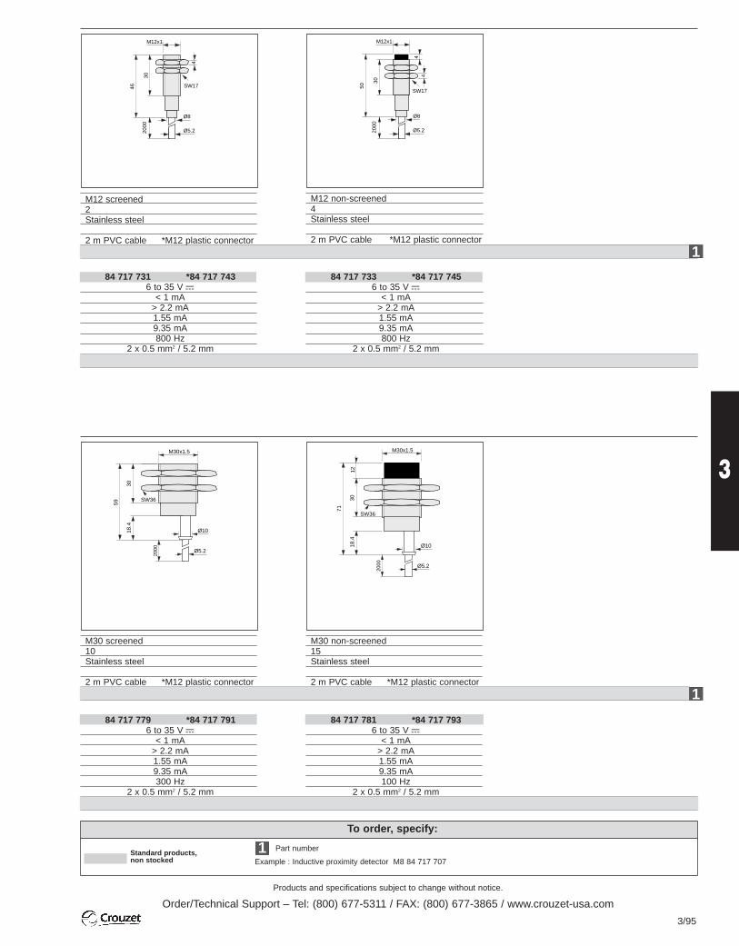
Products and specifications subject to change without notice.
Order/Technical Support – Tel: (800) 677-5311 / FAX: (800) 677-3865 / www.crouzet-usa.com
3/95
3
To order, specify:
Standard products,non stocked Example : Inductive proximity detector M8 84 717 707
1 Part number
M12 screened2Stainless steel
2 m PVC cable *M12 plastic connector
M12 non-screened4Stainless steel
2 m PVC cable *M12 plastic connector
84 717 731 *84 717 7436 to 35 V c
< 1 mA> 2.2 mA1.55 mA9.35 mA800 Hz
2 x 0.5 mm2 / 5.2 mm
84 717 733 *84 717 7456 to 35 V c
< 1 mA> 2.2 mA1.55 mA9.35 mA800 Hz
2 x 0.5 mm2 / 5.2 mm
M30 screened10Stainless steel
2 m PVC cable *M12 plastic connector
84 717 779 *84 717 7916 to 35 V c
< 1 mA> 2.2 mA1.55 mA9.35 mA300 Hz
2 x 0.5 mm2 / 5.2 mm
M30 non-screened15Stainless steel
2 m PVC cable *M12 plastic connector
84 717 781 *84 717 7936 to 35 V c
< 1 mA> 2.2 mA1.55 mA9.35 mA100 Hz
2 x 0.5 mm2 / 5.2 mm
2000
SW1746
30
Ø5.2
Ø8
4
M12x1
M30x1.5
SW36
59
3018
.4
Ø10
Ø5.2
2000
M30x1.5
SW36
71
3018
.412
Ø10
Ø5.2
2000
2000
SW17
50
30
Ø5.2
Ø8
44
M12x1
1
1

Products and specifications subject to change without notice.
Order/Technical Support – Tel: (800) 677-5311 / FAX: (800) 677-3865 / www.crouzet-usa.com
3/96
Inductive Proximity Detectors NAMUR (Acc. DIN 19234)
NAMUR sensors (DIN 19234) are 2-wire DC proximity detectors withno trip or output amplification stage. They are polarised and theirinternal impedance alters in proportion to the distance between thesensor face and the target. NAMUR sensors are designed for usewith an external amplifier which converts the variations in impedanceinto digital signals.
Output characteristics
The nominal sensing range (Sn) specified corresponds to a currentconsumption of 1.55 mA with a supply voltage of 8.2 V to the circuit andRi = 1 Kohm. The table below gives the level of current consumption atnominal sensing range (Sn) for other supply voltage and resistancevalues.
Supply voltageV (Vdc)5121524
Resistance Ri(Kohm)
0.391.82.23.9
Current consumptionI at Sn (mA)0.72.32.93.8
Operating principle
I(mA)
S(mm)
Sn
1.75 mADifference in switchingcurrent
Difference inswitching
1.55 mA
Wiring diagrams
A
Without external amplifier
With external amplifier
NAMURsensor
NAMURsensor
Ri=1K
Ri=1K
+ 8.2 Vdc
+ 8.2 Vdc
-
-
Output
→
→
Inductive Proximity Detectors for Severe Environments
Io (mA)
Io (mA)
Standard products,non stocked
To order, specify :
Part number
Example : Inductive proximity detector 84 799 801
1
Nominal sensing distance Sn (mm)Material Housing
Face Termination
2.5 ±0.25Stainless steelRilsan1m wire
2.5 ±0.25Stainless steelRilsanConnector
Part numbers3-wire DC types NPN NO
NCMin/max. supply voltageSwitching currentMax. off-load current consumptionResidual voltage at 25 °CSwitching frequencyTerminationSealing (MIL - S - 8 805)
against mis-connections of any type
Protection against accidental voltage surges of short durationagainst indirect lightning effects against radio-electrical interference
1
Inductive detector for severe environments Operating range : - 55 °C to + 105 °C Conforms with standards :
- EUROCAE ED 14 C- MIL STD
84 799 80184 799 80212 to 32 V c1 to 250 mA resistive8 mA2V 250 mA250 Hz 3 x 0.6 mm2 wiresDustyesyesyesyes
84 799 80384 799 80412 to 32 V c1 to 250 mA resistive8 mA2V 250 mA250 Hz Type ASN E0053 N8133PNImmersion in wateryesyesyesyes
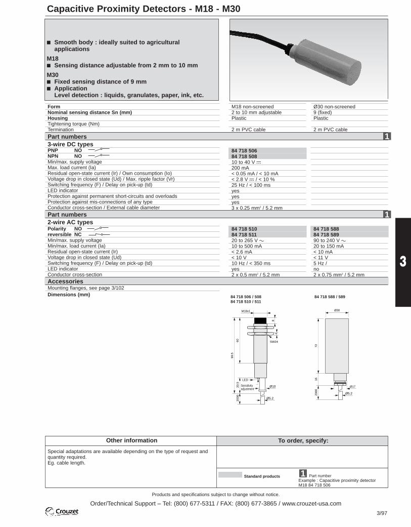
Products and specifications subject to change without notice.
Order/Technical Support – Tel: (800) 677-5311 / FAX: (800) 677-3865 / www.crouzet-usa.com
3/97
3
Capacitive Proximity Detectors - M18 - M30
Other information To order, specify:
Special adaptations are available depending on the type of request andquantity required.Eg. cable length.
Part numberExample : Capacitive proximity detectorM18 84 718 506
1Standard products
FormNominal sensing distance Sn (mm)HousingTightening torque (Nm)Termination
M18 non-screened2 to 10 mm adjustablePlastic
2 m PVC cable
84 718 50684 718 50810 to 40 V c200 mA< 0.05 mA / < 10 mA< 2.8 V c / < 10 %25 Hz / < 100 msyes yes yes 3 x 0.25 mm2 / 5.2 mm
Part numbers3-wire DC types PNP NONPN NOMin/max. supply voltageMax. load current (Ia)Residual open-state current (Ir) / Own consumption (Io)Voltage drop in closed state (Ud) / Max. ripple factor (Vr)Switching frequency (F) / Delay on pick-up (td)LED indicator Protection against permanent short-circuits and overloadsProtection against mis-connections of any typeConductor cross-section / External cable diameter
Ø30 non-screened9 (fixed)Plastic
2 m PVC cable
Part numbers2-wire AC types Polarity NOreversible NCMin/max. supply voltageMin/max. load current (Ia)Residual open-state current (Ir) Voltage drop in closed state (Ud)Switching frequency (F) / Delay on pick-up (td)LED indicator Conductor cross-sectionAccessoriesMounting flanges, see page 3/102Dimensions (mm)
84 718 58884 718 58990 to 240 V a20 to 150 mA< 10 mA< 11 V 5 Hz / no2 x 0.75 mm2 / 5.2 mm
84 718 51084 718 51120 to 265 V a10 to 500 mA< 2.6 mA< 10 V 10 Hz / < 350 msyes 2 x 0.5 mm2 / 5.2 mm
84 718 506 / 50884 718 510 / 511
48
SW24
99.5
60
M18x1
Ø10
Ø5.2
2000
20.5
LED
84 718 588 / 589
72
Ø17
Ø30
Ø5.22000
16
Smooth body : ideally suited to agriculturalapplications
M18 Sensing distance adjustable from 2 mm to 10 mm
M30 Fixed sensing distance of 9 mm Application
Level detection : liquids, granulates, paper, ink, etc.
Sensitivityadjustment
1
1

Products and specifications subject to change without notice.
Order/Technical Support – Tel: (800) 677-5311 / FAX: (800) 677-3865 / www.crouzet-usa.com
3/98
Capacitive Proximity Detectors - Flat Pack
Other information To order, specify:
Special adaptations are available depending on the type of request andquantity required.Eg. cable length. Part number
Example : Capacitive proximity detectorFlat pack 84 718 572
1Standard products
Standard products,non stocked
Part numbers4-wire DC typesPNP NO + NC +NPN NO + NC +Min/max. supply voltageMax. load current (Ia)Residual open-state current (Ir) / Own consumption (Io)Voltage drop in closed state (Ud) / Max. ripple factor (Vr)Switching frequency (F) / Delay on pick-up (td)LED indicator Protection against permanent short-circuits and overloadsProtection against mis-connections of any typeConductor cross-section / External cable diameter
FormNominal sensing distance Sn (mm)
HousingTightening torque (Nm)Termination
55 x 35 non-screened / screened2 - 25 mm adjustable2 - 16 mm adjustablePlastic
2 m PVC cable
non-screened mounting :screened mounting :
84 718 57284 718 57410 to 40 V c200 mA< 0.05 mA / < 15 mA< 3 V c / < 10 %100 Hz / < 300 msyes yes yes 4 x 0.35 mm2 / 6.8 mm
55 x 35 non-screened / screened2 - 25 mm adjustable2 - 16 mm adjustablePlastic
M12 connector
84 718 57884 718 58010 to 40 V c200 mA< 0.05 mA / < 15 mA< 3 V c / < 10 %100 Hz / < 300 msyes yes yes
-
1
Dimensions (mm)
VERY HIGH EMC
IMMUNITY
84 718 572 / 574
18
4
4.5
57.5
55
Ø6.5
Ø 7.5
25
73.5
15 35
LED
84 718 578 / 580
4
4.5
57.5
69.4
55
25
73.5
15 35
LED
M12x1
PotentiometerPotentiometer
4-wire NO and NC operation Easy to mount : only 2 M 3.5 screws required Ideal for packaging machine applications Inductive detection version available in same housing Supplied with adjustment screwdriver
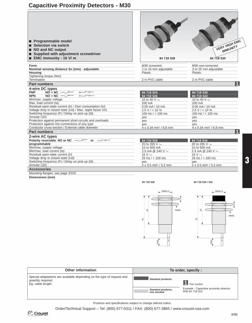
Products and specifications subject to change without notice.
Order/Technical Support – Tel: (800) 677-5311 / FAX: (800) 677-3865 / www.crouzet-usa.com
3/99
3
Capacitive Proximity Detectors - M30
Other information To order, specify :
Special adaptations are available depending on the type of request andquantity required.Eg. cable length. Part number
Example : Capacitive proximity detector M30 84 718 524
1Standard products
Standard products,non stocked
Part numbers2-wire AC types Polarity reversible NO or NC orprogrammableMin/max. supply voltageMin/max. load current (Ia)Residual open-state current (Ir) Voltage drop in closed state (Ud)Switching frequency (F) / Delay on pick-up (td)Annular LEDConductor cross-section
FormNominal sensing distance Sn (mm) - adjustableHousingTightening torque (Nm)Termination
M30 screened2 to 16 mm adjustablePlastic
2 m PVC cable
Part numbers4-wire DC types PNP NO + NC +NPN NO + NC +Min/max. supply voltageMax. load current (Ia)Residual open-state current (Ir) / Own consumption (Io)Voltage drop in closed state (Ud) / Max. ripple factor (Vr)Switching frequency (F) / Delay on pick-up (td)Annular LEDProtection against permanent short-circuits and overloadsProtection against mis-connections of any typeConductor cross-section / External cable diameter
M30 non-screened3 to 25 mm adjustablePlastic
2 m PVC cable
84 718 53084 718 53210 to 40 V c200 mA0.05 mA / 10 mA2.5 V / < 10 %100 Hz / < 100 msyes yes yes 4 x 0.34 mm2 / 6.8 mm
84 718 52484 718 52610 to 40 V c200 mA0.05 mA / 10 mA2.5 V / < 10 %100 Hz / < 100 msyes yes yes 4 x 0.34 mm2 / 6.8 mm
AccessoriesMounting flanges, see page 3/102Dimensions (mm)
84 718 52820 to 265 V a10 to 500 mA2.5 mA @ 240 V a10 V a25 Hz / < 100 msyes 2 x 0.5 mm2 / 5.2 mm
84 718 53420 to 265 V a10 to 500 mA2.5 mA @ 240 V a10 V a25 Hz / < 100 msyes 2 x 0.5 mm2 / 5.2 mm
84 718 528
M30x1.5
SW36
5
91
62
2000
84 718 530 / 532
M30x1.5
SW36
5
91
62
2000
84 718 528 84 718 530
VERY HIGH EMC
IMMUNITY
Programmable model Selection via switch NO and NC output Supplied with adjustment screwdriver EMC immunity : 10 V/ m
1
1

Products and specifications subject to change without notice.
Order/Technical Support – Tel: (800) 677-5311 / FAX: (800) 677-3865 / www.crouzet-usa.com
3/100
To order, specify :
Connectors for V3 and M8 Detectors (with M8 Connector)
Part number
Example : Connector, plug-in version M8 25 552 953
1Standard products
Standard products,non stocked
M8 screw-in versions
Part numbersLength 2 m PVCLength 5 m PVCCompatibility
Display Power supplyvia LED Output activated
Part numbersLength 2 m PVCLength 5 m PVCCompatibility
Display Power supplyvia LED Output activated
General characteristics
SealingConductor cross-sectionLimit temperature Min/max supply for connectors withLED
PresentationNumber of contacts
Straight, no LED3
25 552 95325 552 954
- -- -
--
V3 and M8 detectors with M8 connector andPNP - NO/NC or NPN - NO/NC output
25 552 95525 552 956
25 552 957-
V3 and M8 detectorswith M8 connector andPNP - NO/NC outputGreenYellow
25 552 958-
V3 and M8 detectorswith M8 connector andNPN - NO/NC outputGreenYellow
25 552 95925 552 960
- -- -
--
M8 detectors with M8 connector andPNP - NO/NC or NPN - NO/NC output
25 552 96125 552 962
25 552 96325 552 964M8 detectors with M8connector and PNP -NO/NC outputGreenYellow
25 552 96525 552 966M8 detectors with M8connector and NPN -NO/NC outputGreenYellow
Angled, no LED3
Angled, 2 LEDs (PNP)3
Angled, 2 LEDs (NPN)3
PresentationNumber of contacts
Straight, no LED3
Plug-in versionsIP 653 x 0.25 mm2
-5 °C to + 70 °C
10 to 30 V c
Screw-in versionsIP 683 x 0.25 mm2
-5 °C to + 70 °C
10 to 30 V c
Connector pin-out
Angled, no LED3
Angled, 2 LEDs (PNP)3
Angled, 2 LEDs (NPN)3
M8 plug-in versions
1
1
Connections
3-wire DC
3-wire c PNP 3-wire c NPN
PNP output : load connected to negative supply
load
(4) NO/NCblack cable (NO or NC)
brown
blue
NPN output : load connected to positive supply
load
(4) NO/NCblack cable (NO or NC)
brown
blue
4
3 1
1 - brown (+)3 - blue (-)4 - black (NO/NC output)

Products and specifications subject to change without notice.
Order/Technical Support – Tel: (800) 677-5311 / FAX: (800) 677-3865 / www.crouzet-usa.com
3/101
3
Connectors for Detectors M8 - M12 - M18 - M30 and 35 x 55 mm (with Connector M12)
Part number
Example : Connector for M12 detector - 25 552 967
1Standard products
Standard products,non stocked
- 25 552 97925 552 98025 552 98125 552 982
Connector pin-outVersion with 3 contacts : Version with 4 contacts : M12 double key version :for c detector for c detector for a detector
1
23
.
Part numbersLength 2 m PVCLength 5 m PVCCompatibility
Double key for AC model
Length 2 m PVCLength 5 m PVCCompatibility
Display Power supplyvia LED Output activated
2-wire ACPolarity reversible
load
Earth wire only availablein metal housings
blue
brown
2
3
1
2-wire a
Part numbersScrew terminalLength 2 m PVCLength 5 m PVCLength 2 m PURLength 5 m PURCompatibility
General characteristics SealingConductor cross-section Limit temperature Min/max supply for connectors withLED
PresentationNumber of contacts
Straight, no LED3
25 552 96725 552 968
- -- -
--
25 552 96925 552 970
25 552 98925 552 990
25 552 99125 552 992
25 552 97125 552 9723-wire c detectors with M12 connector andPNP - NO output
GreenYellow
25 552 97325 552 9743-wire c detectors with M12 connector andNPN - NO output
GreenYellow
- 25 552 97525 552 97625 552 97725 552 978
25 552 983----
25 552 984----
Angled, no LED3
Angled, 2 LEDs (PNP)3
for wiringfor wiringM12 M12
Angled, 2 LEDs (NPN)3
PresentationNumber of contacts
Straight, no LED4
Angled, no LED4
Straight, no LED4
Angled, no LED4
Detectors with M12 connector NO, NC or NO andNC output
IP 68 (IP 67 versions for wiring) 3 x 0.34 mm2 or 4 x 0.34 mm2
-5 °C to + 70 °C (PUR -5 °C to +90 °C)
10 to 30 V c
Connections
2-wire DCPolarity reversible
load
blue
brown
(1) NC(3) NO
(2) NC(4) NO
2-wire c
1
3
4
1
3
4 2
1 - brown (+)3 - blue (-)4 - black (NO output)
1 - brown (+)2 - white (NC output)3 - blue (-)4 - black (NO output)
1 - GND2
AC3
3-wire c detectors with M12 connector and NO output2-wire c detectors with M12 connector and NO/NCoutput
2-wire detectors a polarity reversible with M12 connector
To order, specify :
1
1

Products and specifications subject to change without notice.
Order/Technical Support – Tel: (800) 677-5311 / FAX: (800) 677-3865 / www.crouzet-usa.com
3/102
To order, specify :
Mounting Flanges for Inductive Proximity Detectors
Standard products
Example : Mounting flange Ø 4 - 26 546 820
1 Part number
26 546 82026 546 82126 546 822
Mounting flangeØ 4M5Ø 6.5M8M12M18M30
Flange for M18Flange for Ø4 - M5 - Ø 6.5 Flange for M8 Flange for M12 and M30
Part numbers 1
Dimensions
Ø4 Ø6.5
M5
M8M12 M30
M18
26 546 82326 546 824
26 546 82526 546 826
d1 d2 d3 L1 L2 b h tM 8 6.0 3.2 7.5 3.3 20 14 16M12 8 4.5 22 4.5 32 20 12M 18 9.2 5.5 32 - 44 39 20M 30 10 6 44 7.5 60 48.5 17
Technical References
Products and specifications subject to change without notice.
Order/Technical Support – Tel: (800) 677-5311 / FAX: (800) 677-3865 / www.crouzet-usa.com
3/103
3

Products and specifications subject to change without notice.
Order/Technical Support – Tel: (800) 677-5311 / FAX: (800) 677-3865 / www.crouzet-usa.com
3/104
Snap Action Switches – Technical Guide
Switch construction
Single-pole changeover switch (i.e. 83 161)
Double-pole changeover switch (i.e. 83 132 0)
Electrical functionSPDT (C) Normally closed (NC) Normally open (NO)
1 4
2 1 4
Pivot point
Blade
Mounting hole
Terminal NC nº2
Terminal NO nº4
Contact mobile
Contact fixed
Case
Push button
Return spring
Mounting hole
Common terminal C nº1
1 23 4
Blade
Mounting hole
Terminal NO nº4
Contact mobile
Contact fixedCase
Push button
Return spring
Terminal NC nº2
Mounting hole
Terminal NO nº3
Terminal NC nº1
1 2
41 2
Electrical functionSPDT (C) Normally closed (NC) Normally open (NO)
The NO and NC circuits must both be of the same polarity.
These basic principles apply to all our precision switches. The specificcharacteristics of each model are given in more detail in the relevant productionsections.
IntroductionOur switches are high-precision, snap-actionswitches and these are a few of the keyfeatures which distinguish our switches:- High ratings with small dimensions- Very short travels- Low operating forces- Highly dependable force and travel values- Long life- Large range of actuators for easy
adaptation to the most varied applications
3

Products and specifications subject to change without notice.
Order/Technical Support – Tel: (800) 677-5311 / FAX: (800) 677-3865 / www.crouzet-usa.com
3/105
3
Mechanical characteristics
Snap Action Switches – Technical Guide
Terminology - Forces - Positions - Travel
Graphs of forces vs. travel
RP Rest positionPosition of the operating devicewhen no external mechanical force isapplied. Also described as "height atrest".
TP Tripping point Position of the operating device relativeto the fixing point (hole, face) at themoment when the microswitch trips.
PT Pre-travel Distance between the rest position RPand the tripping point TP.
OL Overtravel limitPosition of the operating device when anextreme force has moved it to theeffective end of the available travel.
OT Overtravel Distance between the tripping point TPand the overtravel limit OL.
Ele
ctric
alci
rcui
t P
ositi
ons
Trav
elF
orce
sP
ositi
on o
f pu
shbu
tton
OF Operating Force
Maximum force which must be applied tothe operating device to displace the restposition RP to the tripping point TP.
TTF Total travel forceForce required to displace the operatingdevice from its rest position RP to itsovertravel limit position. (We only specifythis value if it is higher than the operatingforce. When not quoted, it is equal to orless than the operating force).
MOF Maximum overtravel forceThe maximum force which can beapplied to the operating device, withoutdamaging it, in the end of travel positionwhere it is in abutment internally oragainst the face of the case.
RLP Release positionPosition of the operating device at themoment when the snap-action mechanismtrips on its return to its original position.
DT Differential travelDistance between the tripping point TPand the release position RLP.
RF Release forceForce to which the operating force mustbe reduced to allow the snap-actionmechanism to return to its releaseposition RLP.
The reference point for the figures given for travel and forces is a point F situated on the button in the case of a plain microswitch, or, generally, 3 mm in from the end of a plain actuator.The reference point for the positions is one of the fixing holes, unless otherwise indicated.
Force after depression:return outward
Contact force
Operating force (external) appliedto the operating device
Button movement
depressionreturn
Contactforce
OF
RP TP OL RLP
PT O
T
DT
TTF RF

Products and specifications subject to change without notice.
Order/Technical Support – Tel: (800) 677-5311 / FAX: (800) 677-3865 / www.crouzet-usa.com
3/106
• Unless otherwise indicated in the mechanicalcharacteristics table, the torque required for the fixing screws must conform to thefollowing values :
Snap Action Switches – Technical Guide
Mechanical characteristics Environmental conditions
Changeover time
Mechanical durability
This is the time taken by the mobile contactwhen moving from one fixed contact to anotheruntil it becomes fully stable (contact bounceincluded). This time is a function of the contactgap, the mechanical characteristics of the snapaction and the mass of the mobile element. However, thanks to the snap-actionmechanisms employed, the time is largelyindependent of the speed of operation.It is normally less that 20 milliseconds(including bounce times of less than 5 ms).
Resistance to shocks and vibrationsResistance to impact and vibration depends onthe mass of the moving parts and on the forcesholding the contacts together.Generally speaking, for a switch without anactuator :- Vibration >10 G 10 at 500 Hz- Impact > 50 G 11 ms 1/2 sine-waveFurther information on request.
This is an average value indicating the purely mechanical performance of a switchwhen not subject to any electrical load.It may be useful for evaluation purposes incases where the power levels involved are very low and the electrical life is thus close to the mechanical life.
Ambient operating temperatureThe maximum and minimum temperatures atwhich the mechanical and electricalcharacteristics of the switch will remainsubstantially unaltered.
Degree of protectionUnder the IEC 529 or NFC 20010 classificationscheme, standards employ an IP code todefine the degree or class of protection whichelectrical equipment provides against accessto live components, the entry of solid foreignbodies and ingress of water.
Under this classification, our switches comewithin the following categories :- Plain switches = IP 00- Protected switches = IP 40 with isolated
connection- Sealed switches = IP 66 or IP 67
Maximum speed and rate of operation
Our switches will work at speeds of operationvarying over a very wide range : normally from 1 mm/min to 1 ms.The maximum rate of operation with a lowelectrical load may be as high as 10operations/second.
Mounting - Operation
Fixing - Screw torque
• To conform to the leakage paths and air gaps in the standard EEC24 - EN/IEC 61058 -EN/IEC 60947:
- An insulation pad must be inserted betweenthe switch and the fixing surface if the latter ismetal.
- Manual operation of a metal actuator must only be carried out with the help of a secondaryactuator made of insulating materials.
• The installer must ensure adequate protectionagainst direct contact with the output terminals.
Ø of fixing screw 2 2.5 3 3.5 4maximum 25 35 60 100 150minimum 15 25 40 60 100
Screw torquein cm.N
1st numeralProtection equipmentprovides against the entryof solid foreign bodies
0 (not protected)4 diameter ≥ 1 mm5 protected against dust6 sealed against dust
Protection for personsagainst access todangerous parts
(not protected)1 mm Ø wire1 mm Ø wire1 mm Ø wire
2nd numeralProtection equipmentprovides against ingress ofwater
0 (not protected)4 splashed water5 hosed water6 high-pressure
hosed water7 temporary immersion8 prolonged immersion
about
Bounce time
Changeover time

Products and specifications subject to change without notice.
Order/Technical Support – Tel: (800) 677-5311 / FAX: (800) 677-3865 / www.crouzet-usa.com
3/107
3
Snap Action Switches – Technical Guide
0.3 0.5 1 2 5 10 16
12
24
48
110
220
Limit of constant current D.C.Resistive loadInductive load L/R = 5 ms
EC=0.4 mmCG=0.4 mm
EC=3 mmCG=3 mm
Dielectric characteristics Circuit types
Current rating
Thermal rating
This is the current the switch is capable ofmaking and breaking which forms the basis forthe life tests.
Resistive circuitFor a circuit with alternating voltage, this is inphase with the current : Cos ϕ = 1.
This is the current the switch will withstandwhen not being operated, for a temperaturerise of not more than 60 °C.
Inductive circuitA circuit of this type with direct current ischaracterised by a time constant.An inductive circuit, with alternating voltage, forexample, incorporating a motor (cos ϕ < 1) cancause current surges up to 6 times the normalcurrent. For certain switches, we give electricalendurance curves with L = 5 ms in DC
Rand cos ϕ = 0.8 in AC.
Lamp and capacitance circuitThe currents at the time when the circuit isclosed are very high in this case, being up to10 times the nominal figure.
Internal resistanceThis consists of the intrinsic resistance (fixed)of the parts carrying current and the contactresistance (variable).Close to the tripping point and release position,the force holding the contacts together dropsconsiderably and this may cause a rise ininternal resistance.
Switch rating
AC voltages: see the current rating.With DC voltages the switch rating is very muchdependent on the voltage, the contact gap(CG) and the nature of the load being switched.There is a risk of prolonged or indeedpermanent arcing if the following limits areexceeded:
For special applications, please enquire.
Operating curvesThese indicate the electrical life of theswitches, under standard conditions (20 °C, 1 cycle/2 seconds), by showing the number ofswitching operations which can be performedwith given types of load. Insulation resistance
The insulation resistance of the switches isgenerally greater than 50,000 MΩ measured at500 V DC.
Dielectric strengthThe dielectric strength of our switches isgenerally better than:- 1500 volts between live parts and earth- 1000 volts between contacts- 600 volts between contacts for switches
whose contact gap is less than 0.3 mm.
M
τ = LR
Numberof operations
Rating inAmps
Resistive circuit
Inductive circuit

Products and specifications subject to change without notice.
Order/Technical Support – Tel: (800) 677-5311 / FAX: (800) 677-3865 / www.crouzet-usa.com
3/108
Snap Action Switches – Technical Guide
Contact materials Electrical recommendationsChoice of contact material
Contacts for general-purpose use
To choose the best material for the contactsthere are various factors to be considered:- the current and voltages levels- the type of load- the number of operations- the switching frequency- the environmental conditions.
Our switches are normally fitted with silvercontacts. These are suitable for the majority ofapplications and provide the best compromisebetween electrical performance, thermalperformance and life.
Inductive circuits
To increase the life of contacts and their DCrating, arcing on opening can be cut down byusing the following circuits:
- for DC
Contacts for low-power circuits
E < 20 V and/or I < 100 mAThe contacts used in this case are plated withgold (or a gold alloy) for good reliability even incorrosive atmospheres.
Contacts for special applicationsWe can supply special contacts suitable forparticular applications, such as:- Ag CdO contacts for very high drawn
currents,- Cross Bar gold-plated Ag Ni contacts which
allow a very wide range of applications to becovered by a single type of switch.
Fast diode V R > 5 x V nominalI nominal > 10 x I winding
- for DC or AC
A - RC circuit across inductorB - RC circuit across switch
C (nF) ~100 x I nominal (A)V insulation > V peakR(Ω) ~ load resistance (Ω)
C - Varistor circuit across loadD - Varistor circuit across switchV > V peak supply
P (V.A.)E (J) ≥ –––––––
100
Very low power circuitsIn very low power circuits (I > 1 mA, V ≤ 5 V),switching is highly sensitive to environmentalconditions (the atmosphere, pollution).
If the supply is powerful enough, adding apassive resistor to increase the current brokenby the switch to a few milliamps willsubstantially improve reliability of operation.
R - Load resistanceC - Very low current load
A
D
B
C

Products and specifications subject to change without notice.
Order/Technical Support – Tel: (800) 677-5311 / FAX: (800) 677-3865 / www.crouzet-usa.com
3/109
3
Standards - ApprovalsMethods of actuation
Snap Action Switches – Technical Guide
Direct operation
Operation by actuator
Preferably, force should be directly applied to the device – the plunger – along its axis for operation. However, the majority of ourmicroswitches will accept skewed operationprovided the angle of application is not morethan 45°.
The device used to apply the force must neverhamper the travel of the plunger to the trippingpoint (TP). It must under all circumstancesmove the plunger through at least 0.5 times the overtravel (OT) quoted. Steps must also be taken to see that it does not cause theovertravel limit (OL) or maximum overtravelforce (MOF) quoted to be overrun or exceeded.
When operation is by a roller lever, forceshould preferably be applied in the directionshown on the left.
Where the movements involved are fast, theramp should be so designed as to ensure thatthe operating device is not subjected to anyviolent impact or abrupt release.
Quality is built into our switches from the initialdesign stage right through to the point wherethey are put into action at the customer'spremises. All departments of the company areguided by the Quality Manual and thestipulations of the ISO 9000 internationalstandard.The location where the switches aremanufactured (the la Plaine works at Valence)holds ISO 9001 certification, guaranteeing ahigh standard of quality.
Control procedures
Manufacturing quality of our switches iscontrolled systematically during assemblyoperations and on final completion. All ourproducts are subjected to a final inspection,either at 100% on important characteristics, oraccording to the statistical sampling rules ofFrench standards X 06-222 and X 06-023. Thequality levels applied, for normal use such asdefined in previous paragraphs are for thefollowing defects, according to the standards :- critical fault : NQA : 0.40- major fault : NQA : 1- minor fault : NQA : 2.5
At the customer's request, and for certainranges of our products which must meetspecific needs expressed in the specifications,it is always possible to adapt or create aninspection specification of a standard product.
+
Quality
The 83170 switch as an exampleAn 83 170 4 switch marked with the symbolsfor the European (according to CCA/MC12)and American approvals it holds.
EC directivesOur switches are compatible with EuropeanCommunity technical directive (Low Voltage)73/23 and can be used within the framework of Machinery directive 83/392.
Environmental protectionThe modern concept of protection of theenvironment is an integral part of themanufacture of our switches, from productdesign through to packaging.
Rules and regulations
Our switches are designed according tointernational recommendations (IEC), Americanstandards (UL) and/or European standards(EN).
Proof of compliance with these standards andrecommendations is demonstrated by:
- the manufacturer's declaration of conformity(drafted in accordance with the ISO/IEC 22guidelines), or
- approval granted directly by an accreditedbody, or by application of the CCA (CenelecCertification Agreement).
More detailed information on the approval for aparticular type of microswitch can be obtainedon request.

Products and specifications subject to change without notice.
Order/Technical Support – Tel: (800) 677-5311 / FAX: (800) 677-3865 / www.crouzet-usa.com
3/110

Products and specifications subject to change without notice.
Order/Technical Support – Tel: (800) 677-5311 / FAX: (800) 677-3865 / www.crouzet-usa.com
3/111
3
Limit Switches – Technical GuideRules and regulations
Electrical characteristics
Environmental conditions
Construction Our detectors are designed to conform to international IECrecommendations and/or European standards (EN).Proof that a detector conforms to these standards or recommendationstakes the form of a conformity declaration made by the manufacturer(drafted as indicated in guidance document ISO/IEC 22 - EN 450-14).Characteristics in line with the general requirements of standards NFC63140, IEC 947.5.1 and EN 60947.5.1.- Leakage paths and air gaps : IEC 664.1 - NFC 20-040.Our position detectors which comply with IEC 947.5.1 can be fitted tomachine-tools and industrial machines complying with NFC 79130, IEC204.1, EN60204 or VDE 113.
Temperature limitsWhen they are used in the temperature range quoted, the mechanical andelectrical characteristics of our position detectors will remain substantiallyunchanged. If you intend to use them outside this range, please consult us.
Protective treatmentThe treatment given to our position detectors is suitable in the vastmajority of applications.Parts made of steel are zinc-coated or painted according to theirmechanical function. Further information is available on request.This treatment allows our detectors to be used under the followingtemperature and humidity conditions :
T °C 20 40 50Relative humidity % 95 80 50This treatment may thus be suitable for applications in tropical or equatorialclimates where the equipment concerned is in an interior location shelteredfrom direct exposure to atmospheric conditions.Other types of reinforced protection are possible for resistance to very severeenvironments.Please enquire.
Mounting requirementsElectric shock protection.The user should observe the mounting instructions relating to the mode ofprotection against electric shocks defined in the IEC 536.1, EN 60204.1 -NFC 20030 standards :Class I : earth circuit link. Protection via differential circuit-breaker.Class II : double insulation.Class III : very low safety voltage.
Screw tightening torque :1 : Actuator tightening 1.2 to 1.5 Nm
Plastic Metalbody body
2 : Head fixing screw 0.7 to 0.8 Nm 0.8 to 1 Nm3 : Body fixing screw 0.7 to 0.8 Nm 0.8 to 1 Nm4 : Fixing screw 2 to 2.5 Nm
Adjustment of rotary heads with momentary action to right and left :For series 83 850, 83 851, 83 861, 83 854, 83 855, 83 863
Degree of protectionUnder the IEC 529 or NFC 20010 classification scheme, standards employan IP code to define the degree or class of protection which a positiondetector provides against access to live components and against the entryof solid foreign bodies and the entry of water.
Protection equipment providesagainst the entry of solidforeign bodies
0 (not protected)4 diameter ≥ 1 mm5 protected against dust6 sealed against dust
0 (not protected)4 splashed water5 hosed water
6 high-pressure hosed water7 temporary immersion8 prolonged immersion
(not protected)1 mm Ø wire1 mm Ø wire1 mm Ø wire
Protection for persons againstaccess to dangerous parts
Protection equipment provides against the entry of water
1st numeral
2nd numeral
Assigned working current (Ie):- the current level adopted as a basis for the operating conditions quoted
for a detector, and for the life tests on it.
Thermal rating (Ith):- the current the microswitch will withstand when not being operated
electrically, for a temperature rise of not more than 60 °C.
Assigned insulation voltage (Ui):- the voltage adopted as a reference for the dielectric tests and leakage
paths. It must be equal to or greater than the assigned working voltage.
Categories of use (IEC 947.5.1):- AC 15 for operating AC solenoids and electromagnets- DC 13 for operating DC solenoids and electromagnets
Contact element designation(IEC 947.5.1):- a letter and number which define the use category and the assigned
working voltage and currentFor example, A 300 means : in category AC 15, a maximum workingvoltage of 300 V and 6 A at 120 V or 3 A at 240 V.
Contact block electrical wiring diagram Form Za Form Zb
Both contacts have the The 2 contacts aresame polarity electrically isolated
Positive break contact operation (IEC 947-5-1, chapter 3)For contacts used in safety applications, limit switches, emergency stopdevices, assurance that opening has occurred is essential (see IEC 204,EN60204). After each attempt, contact opening is checked by an impulsevoltage test (2500 V).
What is meant by a "position detector" is any device which needs to beoperated by a member which exerts a physical force, in view of :- either the form which its operating device takes- or the considerable force needed to operate it
The distinguishing features of position detectors are :- their high electrical performance capability- their excellent resistance to accidental impact- good protection against splashed or dripping water- a wide range of operating devices to allow the detectors to be
adapted to a vast variety of mechanisms
EC DirectivesOur detectors conform to the EC Low Voltage Technical Directive73/23/EEC and can be used in accordance with the specifications of theMachinery Directive 89/392/EEC.
Introduction
2
1
43
10° (x 360°)
Contact element :
- Snap action contact
This is characterized by tripping points and release points which cannotbe confused. The speed at which the control devices moves isindependent from the speed of the control device. This feature makes itpossible to obtain satisfactory electrical performance even where thecontrol device is moving at low speed.
A : Total travel (TT) of the control deviceB : Pre-travel (PT) until the contact element
opensC : Release travel until the contact element
closesD : B-C = Differential travelF : Travel required to reach the positive opening
point (POT)
B
C D0
A
F
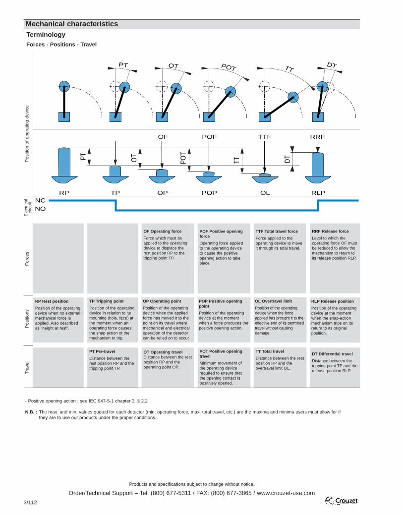
Products and specifications subject to change without notice.
Order/Technical Support – Tel: (800) 677-5311 / FAX: (800) 677-3865 / www.crouzet-usa.com
3/112
Mechanical characteristicsTerminologyForces - Positions - Travel
RP Rest position
Position of the operatingdevice when no externalmechanical force isapplied. Also describedas "height at rest".
TP Tripping point
Position of the operatingdevice in relation to itsmounting (hole, face) atthe moment when anoperating force causesthe snap action of themechanism to trip.
PT Pre-travel
Distance between therest position RP and thetripping point TP.
OP Operating point
Position of the operatingdevice when the appliedforce has moved it to thepoint on its travel wheremechanical and electricaloperation of the detectorcan be relied on to occur.
OT Operating travelDistance between the restposition RP and theoperating point OP.
Ele
ctric
alci
rcui
tP
ositi
ons
Trav
elF
orce
sP
ositi
on o
f op
erat
ing
devi
ce
OF Operating force
Force which must beapplied to the operatingdevice to displace therest position RP to thetripping point TP.
POF Positive openingforce
Operating force applied to the operating device to cause the positiveopening action to takeplace.
POP Positive openingpoint
Position of the operatingdevice at the momentwhen a force produces thepositive opening action.
POT Positive openingtravel
Minimum movement ofthe operating devicerequired to ensure thatthe opening contact ispositively opened.
OL Overtravel limit
Position of the operatingdevice when the forceapplied has brought it to theeffective end of its permittedtravel without causingdamage.
TT Total travel
Distance between the restposition RP and theovertravel limit OL.
RLP Release position
Position of the operatingdevice at the momentwhen the snap-actionmechanism trips on itsreturn to its originalposition.
DT Differential travel
Distance between thetripping point TP and therelease position RLP.
TTF Total travel force
Force applied to theoperating device to moveit through its total travel.
RRF Release force
Level to which theoperating force OF mustbe reduced to allow themechanism to return toits release position RLP.
- Positive opening action : see IEC 947-5-1 chapter 3, § 2.2
N.B. : The max. and min. values quoted for each detector (min. operating force, max. total travel, etc.) are the maxima and minima users must allow for if they are to use our products under the proper conditions.
OTPT POT
TT DT
RRFTTFOF
RLPOLTPRPNCNO
POP
DTTTPOTOTPT
POF
OP

Products and specifications subject to change without notice.
Order/Technical Support – Tel: (800) 677-5311 / FAX: (800) 677-3865 / www.crouzet-usa.com
3/113
3
Key Operated Safety Limit Switches – Technical Guide
Extract from standards EN 292-2 and EN 1088.Moving guards to prevent risks created by moving (and thereforedangerous) parts must be used in conjunction with locking devices orinterlocks with guard locking.Interlocks with guard locking must be used on machines withinertia.An interlock with guard locking must be used if the stopping time isgreater than the time required for a person to reach the danger zone.This mechanism will delay unlocking the moving guard until thedangerous movement has actually stopped.
Standards
Key-operated safety interlock switches have been designed specificallyfor protecting operators working on dangerous machines. They can beused to lock or unlock moving guards on industrial machines, and meetthe requirements of standards EN 292-2, EN 294, EN 1088 and EN60204-1.
Key-operated safety interlock switches are mainly used in applicationswhich form part of the machine operating process. They are used to stopany dangerous movement whenever the moving guard system is open.
Areas of applicationThe start circuit is only closed after the key has been inserted fully and isused to close the NC contacts. Removing the key once the moving coveris open causes the positive action opening of the NC contact(s).
The opening of the moving guard can be:ImmediateMachines without inertia. Machines with a stopping time which is lessthan the time taken to access the danger zone.DelayedMachines with a stopping time which is greater than the time taken toaccess the danger zone.
Operating principle
The use of safety interlock switches in conjunction with XS and RSsafety relays creates control circuits conforming to EN 954-1.
Machine control circuits
Examples of applicationMonitoring of immediate access moving guards
Level 3 for 1 or 2 moving cover(s): KNA3-XS + 83 893 001
Monitoring of immediate access rotary guards
Level 3 for 1 moving cover: KNA3-XS + 83 893 3
Monitoring of delayed access moving guards
Level 3 for 1 moving cover: KZR3-RS + 83 893 201
Level 4 for 1 moving cover: KNA3-RS + KSW2-RS + 83 893 201
1 2
3
NO NC
The KNA3-XSinterrupts the 24 Vsupply to the PLCoutputs (33-34)
Emergency stop and moving cover controlled by two channels onterminals 41-42 (data contact) to a PLC output.
RunEmergencystop
24 V0 V
24 V
0V
KNA3-XS
13 23 33
14 24 34
A1 Y1 Y22313 33
14 24 3441A2 42
C2
C2
C1
C1
C3
C3
Y11A1
24 V C1
C2
0V
c2
c113
KZR3-RS
23 3141
14 24 32K4
K3
K2
K1
42
4123Y12 3113
A2Y1
Y21 Y22Y2
Y12
Y22
14 24 32M42
Y11
Y21
C1 C2
Y11A1
+ 24 V
0V
13
KNA3-RS
23 33 41
14 24 34 42
X1 Y2 S1 S2 4123Y12 3313
A2X2
Y12Y22
Y1 14 24 34Y21Y22 42
Y11
Y21
C1
C2
M
13A1
KSW2-RS
X1 X221
A22214 L2 L3
L1
C1
c1 c2
C2
24 V
0V
KNA3-XS
13 23 33
14 24 34
A1 Y1 Y22313 33
14 24 3441A2 42
C2
C2
C1
C1
C3
C3
PLC
PLC
Run
Cover
Cover(closed)
OP
EN
Run
4
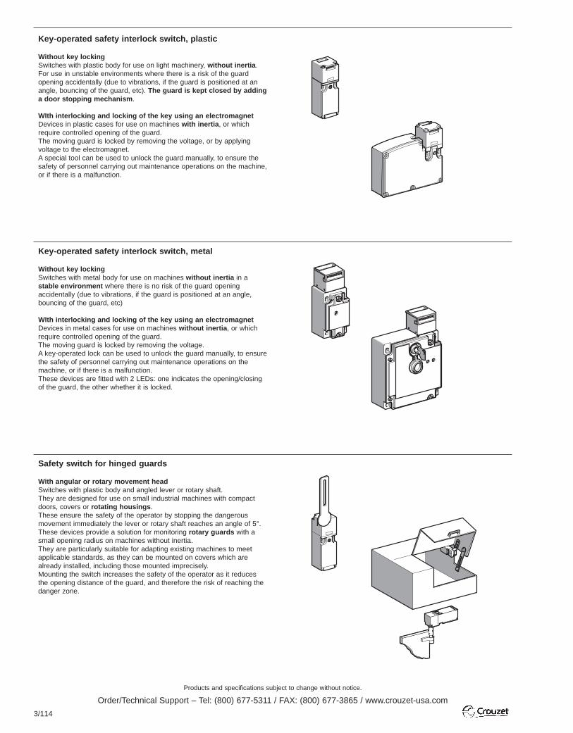
Products and specifications subject to change without notice.
Order/Technical Support – Tel: (800) 677-5311 / FAX: (800) 677-3865 / www.crouzet-usa.com
3/114
Key-operated safety interlock switch, plastic
Without key lockingSwitches with plastic body for use on light machinery, without inertia. For use in unstable environments where there is a risk of the guardopening accidentally (due to vibrations, if the guard is positioned at anangle, bouncing of the guard, etc). The guard is kept closed by addinga door stopping mechanism.
WIth interlocking and locking of the key using an electromagnetDevices in plastic cases for use on machines with inertia, or whichrequire controlled opening of the guard. The moving guard is locked by removing the voltage, or by applyingvoltage to the electromagnet. A special tool can be used to unlock the guard manually, to ensure thesafety of personnel carrying out maintenance operations on the machine,or if there is a malfunction.
Key-operated safety interlock switch, metal
Without key lockingSwitches with metal body for use on machines without inertia in astable environment where there is no risk of the guard openingaccidentally (due to vibrations, if the guard is positioned at an angle,bouncing of the guard, etc)
WIth interlocking and locking of the key using an electromagnetDevices in metal cases for use on machines without inertia, or whichrequire controlled opening of the guard. The moving guard is locked by removing the voltage.A key-operated lock can be used to unlock the guard manually, to ensurethe safety of personnel carrying out maintenance operations on themachine, or if there is a malfunction.These devices are fitted with 2 LEDs: one indicates the opening/closingof the guard, the other whether it is locked.
Safety switch for hinged guards
With angular or rotary movement headSwitches with plastic body and angled lever or rotary shaft.They are designed for use on small industrial machines with compactdoors, covers or rotating housings.These ensure the safety of the operator by stopping the dangerousmovement immediately the lever or rotary shaft reaches an angle of 5°.These devices provide a solution for monitoring rotary guards with asmall opening radius on machines without inertia.They are particularly suitable for adapting existing machines to meetapplicable standards, as they can be mounted on covers which arealready installed, including those mounted imprecisely.Mounting the switch increases the safety of the operator as it reducesthe opening distance of the guard, and therefore the risk of reaching thedanger zone.

Products and specifications subject to change without notice.
Order/Technical Support – Tel: (800) 677-5311 / FAX: (800) 677-3865 / www.crouzet-usa.com
3/115
3
Inductive Proximity Detectors – Technical Guide
Electrical characteristics:
Normally open function (NO): Corresponds to a detector whose outputallows the current to pass through when the target is detected.
Normally closed function (NC): Corresponds to a detector whoseoutput blocks the current when the target is detected.
Voltage drop Ud: Voltage measured across the active output of thedetector in closed state under its nominal operating current (load current Ia).
Load current Ia: Maximum current with which the detector permanentlyoperates correctly.
Leakage current Ir: Current which continues to circulate in the load andin the output circuit when the detector is in the open state.
Minimum operating current Im: Current necessary to maintainconduction of the switching element.
Time delay before availability Tv: Time necessary for the sensoroutput signal to operate when powering up.
Switching frequency F: Number of operating cycles carried out duringa specified time. It is measured according to the method shown below(Standard EN 50010 NFC 63075).
m : width of the target.
Operating voltage Un: Voltage range within which the detectormaintains its specified characteristics.
Ripple voltage: Ratio between the amplitude of an alternating voltage(peak to peak) and the direct voltage on which it is superimposed.
Method of measuring sensing distances: according to standard EN 50010.
Lateral approach and axial approach:
Operating principles
Figure 1 illustrates the principle of an Inductive Proximity Detector (I.P.D.)
The I.P.D. signals the presence of a metal object "M" close to its sensingface.It contains a high-frequency oscillator "O" whose oscillating circuit coil"S", located in a magnetic ferrite open on one side, forms the sensingface. An alternating magnetic field is created in front of this. On enteringthis field, any metal part "M" causes eddy currents, thus reducing theamplitude of oscillation. This reduced amplitude is converted by thepulse shaper "D" into an output signal amplified by "V".
Operating characteristics:
Sensing distance S: Distance at which the target determines a changein the status of the output signal, as it approaches the sensing face.
Nominal sensing distance Sn: Conventional value used to describethe device. Does not take account of dispersion (due to manufacturing,temperature, voltage).
Actual sensing distance Sr: Actual value measured from constantparameters (temperature, voltage, installation conditions etc), whichmust be between 90 and 110 % of the nominal sensing distance Sn.
0.9 Sn < Sr < 1.1 Sn
Usable sensing distance Su: Value measured within the specifiedlimits of the temperature and voltage zones, which must be between81% and 121% of the nominal sensing distance Sn.
0.81 Sn < Su < 1.21 Sn
Operating sensing distance Sa: Distance within which the detector willoperate correctly in specified conditions.
0 < Sa < 0.81 Sn
Repeatability R: Value of variation in the actual sensing distance Sr inspecified conditions (time, temperature, voltage).
Differential travel H: Distance between the pick-up point when thetarget approaches the detector and the drop-out point when the targetmoves away.
Equivalent circuit diagram
NO
NC
Un
Tv
Supply voltage
M
S O D V
Target Oscillator
Target
Su max. + H
Sr max. + H
Sn + H
Sr min. + H
Su min. + H
Su max.
Sr max.
Sn
Sr min.
Su min.
SaGuaranteed
operation
Sensing faceProximitydetector
Pulse shaper Amplifier Load
ON
OF
F
Axial approach : target centred onreference axis
Lateral approach :target perpendicular to reference axis
Detector
Measuring plate
Disc
Rotation
m
m2m
0.5x
Sn
Actual sensing distanceSensing face
Detector
A
B
H
H
Detector status accepted
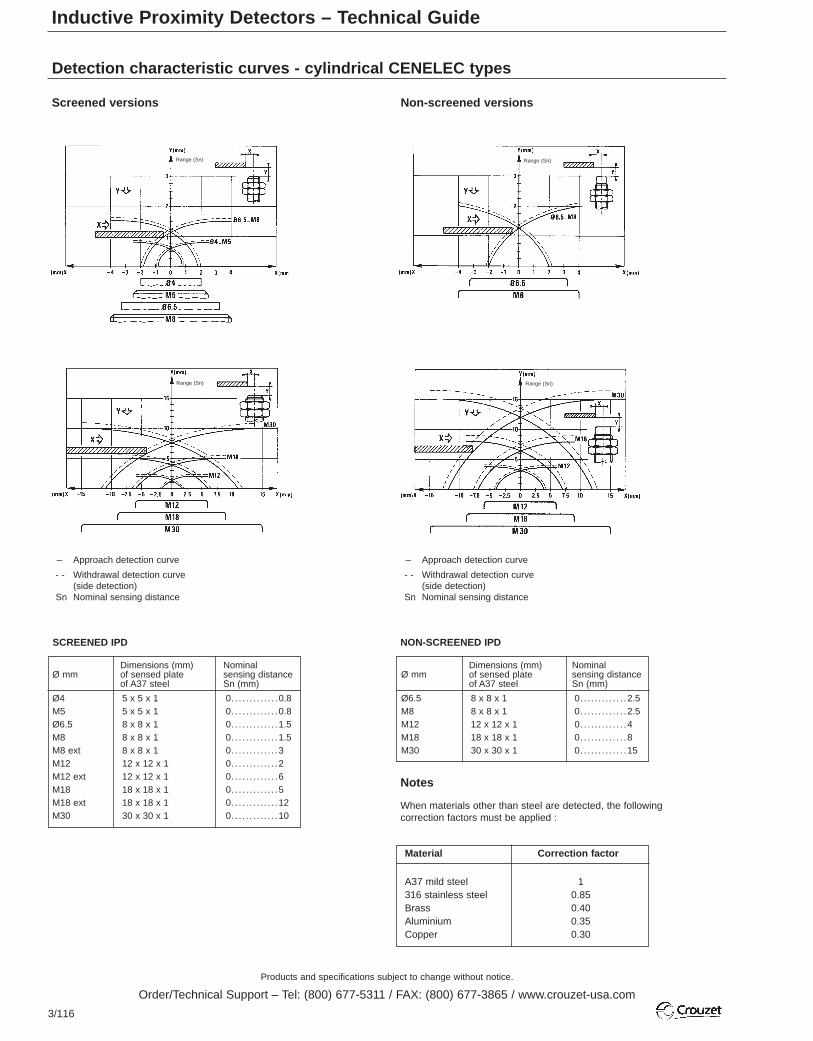
Products and specifications subject to change without notice.
Order/Technical Support – Tel: (800) 677-5311 / FAX: (800) 677-3865 / www.crouzet-usa.com
3/116
Inductive Proximity Detectors – Technical Guide
Detection characteristic curves - cylindrical CENELEC types
Screened versions Non-screened versions
- Approach detection curve
- - Withdrawal detection curve(side detection)
Sn Nominal sensing distance
- Approach detection curve
- - Withdrawal detection curve(side detection)
Sn Nominal sensing distance
Dimensions (mm) Nominal Ø mm of sensed plate sensing distance
of A37 steel Sn (mm)
Ø4 5 x 5 x 1 0. . . . . . . . . . . . .0.8M5 5 x 5 x 1 0. . . . . . . . . . . . .0.8Ø6.5 8 x 8 x 1 0. . . . . . . . . . . . .1.5M8 8 x 8 x 1 0. . . . . . . . . . . . .1.5M8 ext 8 x 8 x 1 0. . . . . . . . . . . . .3M12 12 x 12 x 1 0. . . . . . . . . . . . .2M12 ext 12 x 12 x 1 0. . . . . . . . . . . . .6M18 18 x 18 x 1 0. . . . . . . . . . . . .5M18 ext 18 x 18 x 1 0. . . . . . . . . . . . .12M30 30 x 30 x 1 0. . . . . . . . . . . . .10
SCREENED IPD NON-SCREENED IPD
Notes
When materials other than steel are detected, the followingcorrection factors must be applied :
Material Correction factor
A37 mild steel 1316 stainless steel 0.85Brass 0.40Aluminium 0.35Copper 0.30
Dimensions (mm) Nominal Ø mm of sensed plate sensing distance
of A37 steel Sn (mm)
Ø6.5 8 x 8 x 1 0. . . . . . . . . . . . .2.5M8 8 x 8 x 1 0. . . . . . . . . . . . .2.5M12 12 x 12 x 1 0. . . . . . . . . . . . .4M18 18 x 18 x 1 0. . . . . . . . . . . . .8M30 30 x 30 x 1 0. . . . . . . . . . . . .15
Range (Sn) Range (Sn)
Range (Sn)Range (Sn)
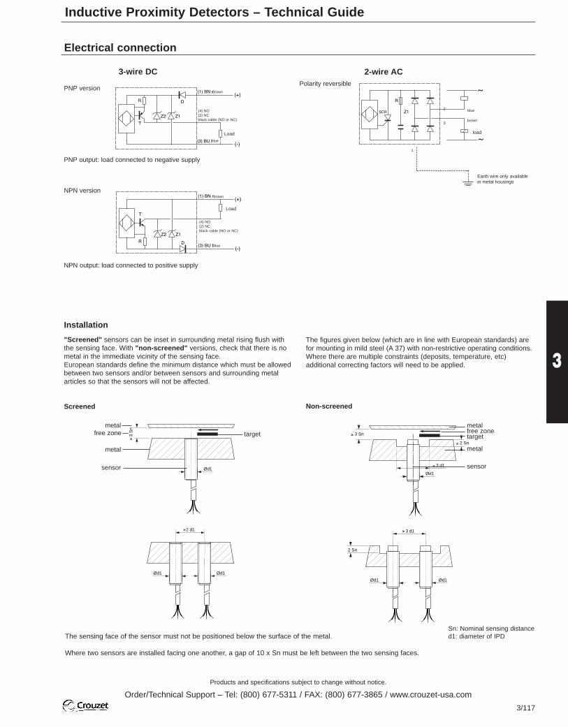
Products and specifications subject to change without notice.
Order/Technical Support – Tel: (800) 677-5311 / FAX: (800) 677-3865 / www.crouzet-usa.com
3/117
3
Electrical connection
3-wire DC 2-wire AC
PNP version
NPN version
Polarity reversible
PNP output: load connected to negative supply
NPN output: load connected to positive supply
Installation
"Screened" sensors can be inset in surrounding metal rising flush withthe sensing face. With "non-screened" versions, check that there is nometal in the immediate vicinity of the sensing face.European standards define the minimum distance which must be allowedbetween two sensors and/or between sensors and surrounding metalarticles so that the sensors will not be affected.
Screened
Ød1
3 S
n≥
Ød1 Ød1
2 d1≥
Ød1
3 Sn
3 d1
≥
≥
2 Sn≥
Ød1
3 d1
Ød1
2 Sn
≥
metal
metal
sensor
free zone target
The figures given below (which are in line with European standards) arefor mounting in mild steel (A 37) with non-restrictive operating conditions.Where there are multiple constraints (deposits, temperature, etc)additional correcting factors will need to be applied.
Non-screened
metalfree zonetarget
metal
sensor
Sn: Nominal sensing distanced1: diameter of IPD
Where two sensors are installed facing one another, a gap of 10 x Sn must be left between the two sensing faces.
The sensing face of the sensor must not be positioned below the surface of the metal.
Load
(4) NO(2) NCblack cable (NO or NC)
Brown
blue
Load
(4) NO(2) NCblack cable (NO or NC)
brown
blue
load
Earth wire only availablein metal housings
blue
brown
2
3
1
Inductive Proximity Detectors – Technical Guide
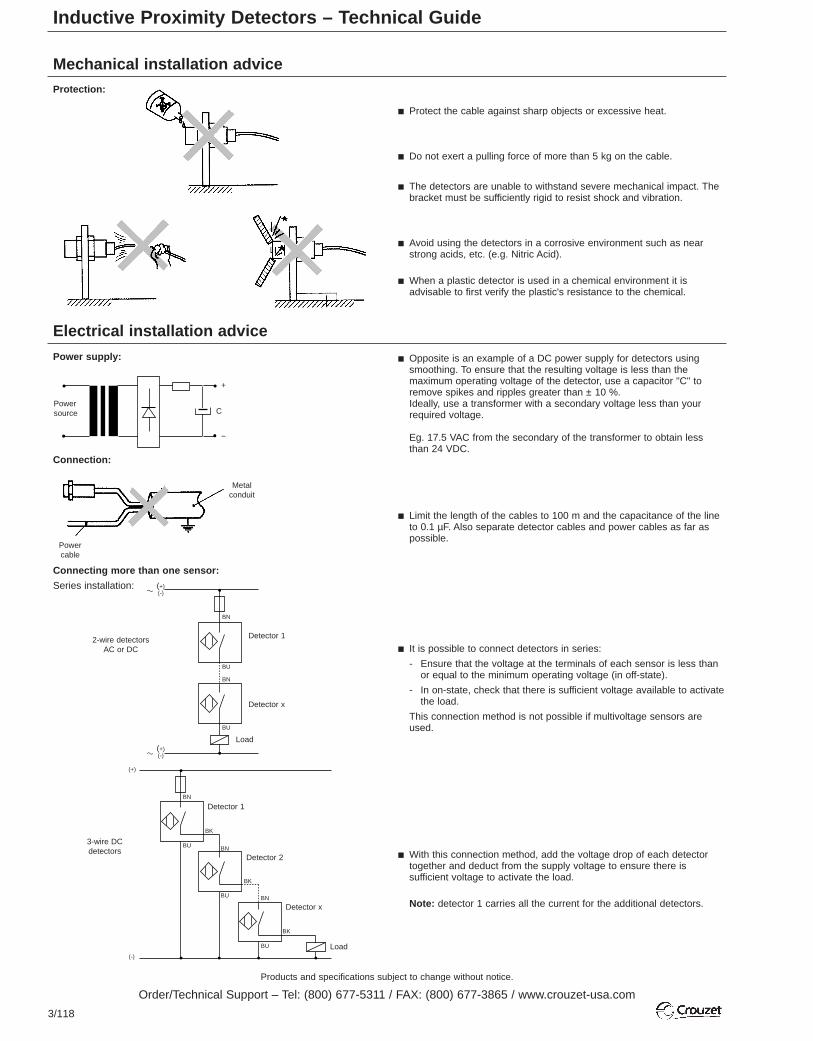
Products and specifications subject to change without notice.
Order/Technical Support – Tel: (800) 677-5311 / FAX: (800) 677-3865 / www.crouzet-usa.com
3/118
Mechanical installation advice
Electrical installation advice
Power supply:
Connection:
Connecting more than one sensor:
Series installation:
Protection:
Protect the cable against sharp objects or excessive heat.
Do not exert a pulling force of more than 5 kg on the cable.
The detectors are unable to withstand severe mechanical impact. Thebracket must be sufficiently rigid to resist shock and vibration.
Avoid using the detectors in a corrosive environment such as nearstrong acids, etc. (e.g. Nitric Acid).
When a plastic detector is used in a chemical environment it isadvisable to first verify the plastic's resistance to the chemical.
Opposite is an example of a DC power supply for detectors usingsmoothing. To ensure that the resulting voltage is less than themaximum operating voltage of the detector, use a capacitor "C" toremove spikes and ripples greater than ± 10 %.Ideally, use a transformer with a secondary voltage less than yourrequired voltage.
Eg. 17.5 VAC from the secondary of the transformer to obtain lessthan 24 VDC.
Limit the length of the cables to 100 m and the capacitance of the lineto 0.1 µF. Also separate detector cables and power cables as far aspossible.
It is possible to connect detectors in series:
- Ensure that the voltage at the terminals of each sensor is less thanor equal to the minimum operating voltage (in off-state).
- In on-state, check that there is sufficient voltage available to activatethe load.
This connection method is not possible if multivoltage sensors areused.
With this connection method, add the voltage drop of each detectortogether and deduct from the supply voltage to ensure there issufficient voltage to activate the load.
Note: detector 1 carries all the current for the additional detectors.
Inductive Proximity Detectors – Technical Guide
Powersource
Metalconduit
Power cable
(+)(-)
Detector 12-wire detectorsAC or DC
3-wire DCdetectors
BN
BU
Detector 1
Detector 2
Detector x
BN
BN
BN
BK
BK
BK
BU
BU
BU
BU
BN
Detector x
Load
Load
a
(+)(-)a
(+)
(-)
C
+
-

Products and specifications subject to change without notice.
Order/Technical Support – Tel: (800) 677-5311 / FAX: (800) 677-3865 / www.crouzet-usa.com
3/119
3
Inductive Proximity Detectors – Technical GuideParallel installation:
With this type of installation the sum of the off-state leakage currentsmust be less than the current needed to drive the load.
Note: this installation should only be used with detectors which areactivated one at a time.
It is possible to connect 3-wire detectors in this configuration withoutany problems.
2-wire ACdetectors
Detector 1 Detector x
BN BN
BN BN
BU BU
Load
3-wire DC detectors
BU BU
BK BK
Load
a
Detector 1 Detector x
a
(+)
(-)
Examples of applications
Parts recognition - Metal detection Part positioning
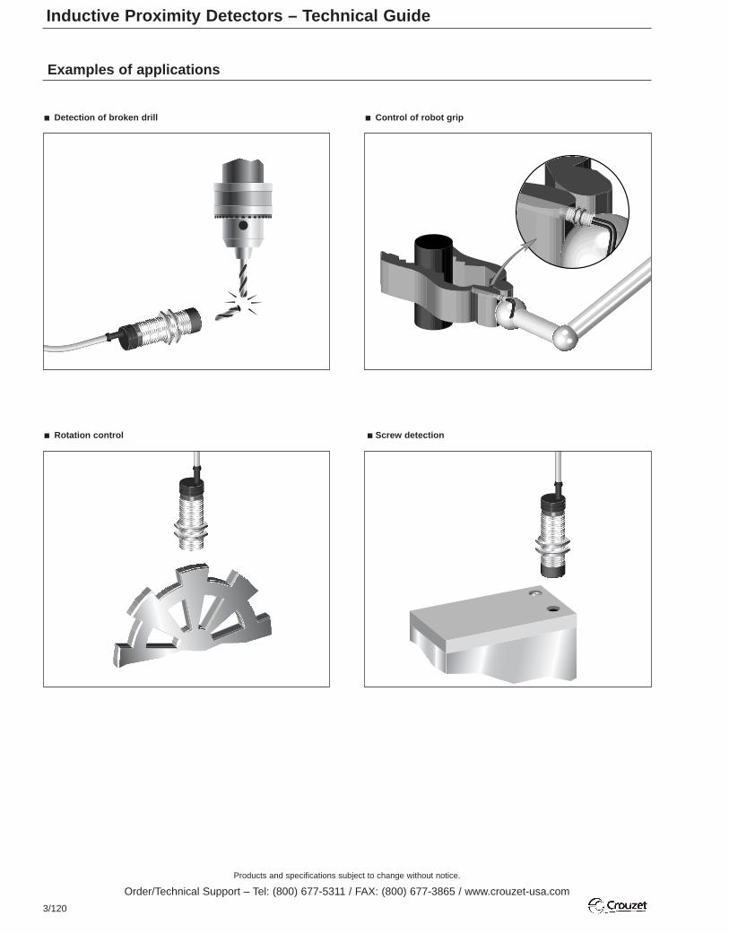
Products and specifications subject to change without notice.
Order/Technical Support – Tel: (800) 677-5311 / FAX: (800) 677-3865 / www.crouzet-usa.com
3/120
Examples of applications
Screw detection
Detection of broken drill
Rotation control
Control of robot grip
Inductive Proximity Detectors – Technical Guide

Products and specifications subject to change without notice.
Order/Technical Support – Tel: (800) 677-5311 / FAX: (800) 677-3865 / www.crouzet-usa.com
3/121
3
Capacitive proximity detectors consist of an RC-oscillator with a specialmulti-part sensing electrode. The electrode and the oscillator circuit havea tube connected with earth potential for lateral screening. This enablesflush-mounting of the sensor in metal, since the electrical field is onlypresent in front of the sensing electrode. This field is the active zone ofthe sensor.
When the conductive material is removed from the active zone, theoscillator is undamped and the oscillation amplitude decreases. Theoscillator voltage amplifier and the sensor sensitivity can be modifiedusing the built-in potentiometer.
The middle electrode and built-in reclosing function provide excellentcompensation in conditions of humidity, dust or freezing. A special circuitautomatically compensates for these influences. The preset sensingrange remains practically constant. The electrode and compensatingcircuitry of the capacitive sensors are unique in design, and provideoperating performances far superior to other capacitive sensors.
A indicates SENSOR ELECTRODEB and C indicates COMPENSATION ELECTRODES
ApplicationsCapacitive sensors can be used to limit the level in tanks and containers.These may contain fluids, pulverised or granulated materials such asPVC, powder, dyes, flour, sugar, powdered milk, etc. These sensors canalso be used as limit switches for checking and regulating machinerysettings, even if the materials are not made of metal (as in conveyor beltpositioning and material stacking), for checking drive belts and paperreels for sag and tear. Additionally, they can be used as detectors forcounting metal and non-metal components.
Areas of application for capacitive sensors.
Screened configuration
Sensors with a straight line electrical field.
These units can sense solids (plates, components, PCBs, hybrids,cartons, bottles, plastic blocks and stacks of paper for example) at adistance or liquids through a separating wall (glass or plastic up to amaximum of 4 mm thick).
Non-screened configuration
Sensors with a spherical electrical field. These units are designed totouch the product, both bulk solids and liquids (granulate, sugar, flour,corn, sand or oil and water) with their active surface.
Sensing rangeThe data was obtained using a 1 mm thick square steel plate (steel 37)as an actuator, with a side length equal to 3 x Sn. The steel plate wasgrounded. The ambient temperature was 25ºC. The maximum sensingrange was defined as the nominal sensing range with a tolerance of± 10%.
The sensing range depends on the shape, size and type of objectconcerned. If the plate is made of different material or has a smallerdiameter, the sensing distance will be reduced.
Size correction factor
For objects which are not flat and which are smaller than the activesensor surface, the following sensing ranges are obtained depending onthe scanned object F/FO surface, where F is the front sensor surface(active surface) and FO the front surface of the object being scanned.The figures in the table below refer to flush-mounting sensors andobjects in the form of long thin rods.
Capacitive Proximity Detectors – Technical Guide
Scanned object F/FO surface1.501.240.800.610.310.200.150.050.03
Nominal sensing range Sn in mm100100100100948582.567.557.5
The diagram below shows the data from the table in graphic form.
CAP
CAP
CA
P
Granulate
Carton
OilWater
CAP
CAP
CAP
CAP
ABC
Sr
H
F/FO
SSn
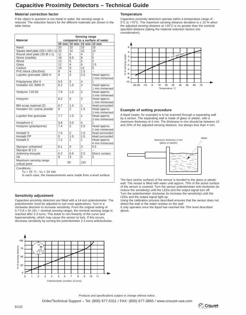
Products and specifications subject to change without notice.
Order/Technical Support – Tel: (800) 677-5311 / FAX: (800) 677-3865 / www.crouzet-usa.com
3/122
Capacitive Proximity Detectors – Technical GuideMaterial correction factorIf the object in question is not metal or water, the sensing range isreduced. The reduction factors for the different materials are shown in thetable below.
TemperatureCapacitive proximity detectors operate within a temperature range of -5°C to +70°C. The maximum sensing distance deviation is ± 10 % whenthe adjusted sensing distance at +20°C is no greater than the nominalspecified distance (taking the material reduction factors intoconsideration).
Example of setting procedureA liquid (water, for example) is to be scanned through a separating wallby a sensor. The separating wall is made of glass or plastic, with amaximum thickness of 4 mm. The thickness in mm should be between 10and 20% of the adjusted sensing distance, but always less than 4 mm.
The face (active surface) of the sensor is bonded to the glass or plasticwall. The vessel is filled with water until approx. 75% of the active surfaceof the sensor is covered. Turn the sensor potentiometer anti-clockwise (toreduce the sensitivity) until the LEDs and the output signal turn off.Turn the potentiometer clockwise (to increase the sensitivity) until theLEDs and the output signal light up.Using the calibration process described ensures that the sensor does notdetect the wall or the water residue on the wall.It only operates once the liquid has reached the 75% level describedabove.
Sensitivity adjustmentCapacitive proximity detectors are fitted with a 14-turn potentiometer. Thepotentiometer must be adjusted to suit most applications. Turn in aclockwise direction to increase sensitivity. From the original setting of 0.7-0.8 x Sn (Sn = nominal sensing range), the nominal sensing range isreached after 2-3 turns. This leads to non-linearity of the curve andhypersensitivity, which may cause the sensor to lock. If this occurs,decrease sensitivity by turning the potentiometer 2-3 turns anticlockwise.
Sensing rangeMaterial compared to a surface of water
20 mm 10 mm 15 mm 10 mmHand 20 10 15 10Square steel plate (100 x 100 x 1) 20 10 15 10Round steel plate (30 Ø x 1) 11 6 4 2Stone (marble) 18 8.5 8 5Wood 13 5 5 3Glass 12 4 6 2.5Carbon 19 9 12 9PVC-block (30x30x5) 8 4 1.5 -Lupolen granulate 1800 H 8 3 2.5 Head approx.
2 mm immersedPolystyrene 454 H 9.5 3 4 1Hostalen GC 8960 H 8.2 1.5 2 Head approx.
1 mm immersedVestyron 719-50 7.9 1.2 2 Head approx.
3 mm immersedHostyren 8.2 3 3 Head approx.
1 mm immersedBM scrap material (Z) 6.7 1.4 1 Head surroundedHostalen GC coarse powder 8 2 1.5 Head approx.
3 mm immersedLupolen fine granulate 7.7 1.5 1 Head approx.
3 mm immersedHostaform C 9.8 3.5 4 1Hostyren (polystyrene) 7.4 2 2.5 Head approx.
2 mm immersedHostalit S 7.5 2 1.5 Head surroundedHostalit PP 5 1.5 1.5 Head surroundedHostalit E 7.2 1 1 Head approx.
4 mm immersedStyropor unfoamed 8.1 3 3 0.5Styropor Ø 1.5 - - - -Antimony-trioxyde 6.2 0.9 2.5 Direct contactOil 9 3 5 3Maximum sensing range
55 110critical point
Conditions :Tu = 25 °C ; VA = 24 VdcIn each case, the measurements were made from a level surface.
Potentiometer (number of turns)
VR
LED
Maximum thickness 4 mm(glass or plastic)
Water
% o
f se
nsin
g di
stan
ce
Temperature °C
% o
f se
nsin
g ra
nge
M30 and Ø34

Products and specifications subject to change without notice.
Order/Technical Support – Tel: (800) 677-5311 / FAX: (800) 677-3865 / www.crouzet-usa.com
3/123
3
Installation conditionsThe presence of surrounding objects may affect capacitive proximitydetectors. These objects may reduce sensing capacity or maythemselves be detected. It is necessary to maintain a standard distancebetween a capacitive proximity detector and the surrounding objectswhen installing this type of detector.
Effects of water droplets on the sensing face The curves below illustrate the modifications to the operating rangewhich may be caused by the presence of water droplets on the sensingface of a capacitive proximity detector. If the quantity of water droplets is0.2 ml (approx. 2-3 drops), the operating range is extended by around 20 %; if the water droplets cover the entire sensing face, the operatingrange is extended by more than 300 %.
WarningThe presence of frost, ice, moisture, oil or dust on the active surface willprevent reliable operation.
The detection of liquids or powders attached to the walls of non-metallicvessels will prevent reliable operation.
Connecting a DC capacitive proximity detector to a high-load current(current higher than 200 mA) (for electric motors and electromagneticcontacts) will cause the output transistor to malfunction. The detectormust be connected via a relay.
>2D
>1.
5D
>2D
>D
>3D
>2D
>D
>3D
D
D
D
DD
Sen
sing
dis
tanc
e (m
m)
Water (ml)
Water
Sen
sing
dis
tanc
e (m
m)
Water (ml)
Water
Capacitive Proximity Detectors – Technical Guide

Products and specifications subject to change without notice.
Order/Technical Support – Tel: (800) 677-5311 / FAX: (800) 677-3865 / www.crouzet-usa.com
3/124

Products and specifications subject to change without notice.
Order/Technical Support – Tel: (800) 677-5311 / FAX: (800) 677-3865 / www.crouzet-usa.com
3/125
3

Products and specifications subject to change without notice.
Order/Technical Support – Tel: (800) 677-5311 / FAX: (800) 677-3865 / www.crouzet-usa.com
3/126

Products and specifications subject to change without notice.
Order/Technical Support – Tel: (800) 677-5311 / FAX: (800) 677-3865 / www.crouzet-usa.com
3/127
3

Products and specifications subject to change without notice.
Order/Technical Support – Tel: (800) 677-5311 / FAX: (800) 677-3865 / www.crouzet-usa.com
3/128

Mouser Electronics
Authorized Distributor
Click to View Pricing, Inventory, Delivery & Lifecycle Information: Crouzet:
70500840


