Embed Size (px)
Citation preview

Delft University of Technology
Surgeon-instrument interactionA hands-off approachArkenbout, Ewout
DOI10.4233/uuid:ed806630-efe2-4484-a5cd-2a8011912841Publication date2018Document VersionFinal published versionCitation (APA)Arkenbout, E. (2018). Surgeon-instrument interaction: A hands-off approach.https://doi.org/10.4233/uuid:ed806630-efe2-4484-a5cd-2a8011912841
Important noteTo cite this publication, please use the final published version (if applicable).Please check the document version above.
CopyrightOther than for strictly personal use, it is not permitted to download, forward or distribute the text or part of it, without the consentof the author(s) and/or copyright holder(s), unless the work is under an open content license such as Creative Commons.
Takedown policyPlease contact us and provide details if you believe this document breaches copyrights.We will remove access to the work immediately and investigate your claim.
This work is downloaded from Delft University of Technology.For technical reasons the number of authors shown on this cover page is limited to a maximum of 10.


SURGEON-INSTRUMENT INTERACTION
A HANDS-OFF APPROACH
Ewout A. Arkenbout

Title: Surgeon-Instrument Interaction, A Hands-Off Approach
Author: E.A. Arkenbout ([email protected])
Cover art : Bare Tree IV – Immortal, by Leonora Knight (DeviantArt ID: leeuona)
Printing: GVO drukkers & vormgevers B.V.
This research was funded by the Netherlands Organisation for Scientific Research
(NWO), project 13425 (Ch. 3) and project 12137 (Part II, Ch. 4-7).
Copyright @ 2018 by E.A. Arkenbout
ISBN: 978-94-6332-319-2
An electronic version of this dissertation is available at
http://repository.tudelft.nl/

SURGEON-INSTRUMENT INTERACTION
A HANDS-OFF APPROACH
Proefschrift
ter verkrijging van de graad van doctor
aan de Technische Universiteit Delft,
op gezag van de Rector Magnificus prof. dr. ir. T.H.J.J. van der Hagen,
voorzitter van het College voor Promoties,
in het openbaar te verdedigen op
maandag 12 februari 2018 om 15:00 uur
door
Ewout Aart ARKENBOUT
werktuigkundig ingenieur, Technische Universiteit Delft, Nederland
geboren te Rotterdam, Nederland

Dit proefschrift is goedgekeurd door de
Promotor: Prof. dr. ir. P. Breedveld
Promotor: Prof. dr. J. Dankelman
Copromotor: Dr. ir. J.C.F. de Winter
Samenstelling promotiecommissie:
Rector Magnificus voorzitter
Prof. dr. ir. P. Breedveld Technische Universiteit Delft, promotor
Prof. dr. J. Dankelman Technische Universiteit Delft, promotor
Dr. ir. J.C.F. de Winter Technische Universiteit Delft, copromotor
Onafhankelijke commissieleden:
Prof. dr. A. Menciassi Scuola Superiore Sant’Anna
Prof. dr. G.W.M. Rauterberg Technische Universiteit Eindhoven
Prof. dr. M.J.A. Malessy Leids Universitair Medisch Centrum
Prof. dr. I. Horvath Technische Universiteit Delft
Prof. dr. Ir. H. Vallery Technische Universiteit Delft, reservelid

v
TABLE OF CONTENTS SUMMARY ................................................................................................................ XI
SAMENVATTING ....................................................................................................... XV
CHAPTER 1: INTRODUCTION ....................................................................................... 1
1.1. CHALLENGES OF MINIMALLY INVASIVE SURGERY ........................................................... 2 1.2. MEDICAL ERRORS AND SURGEON-INSTRUMENT INTERACTION ......................................... 3 1.3. MEDICAL INSTRUMENT DEVELOPMENTS – NOTES AND SILS ............................................ 4 1.4. GOAL OF THIS THESIS ................................................................................................ 5 1.5. APPROACH AND OUTLINE THESIS ................................................................................ 6
1.5.1. Part i - morcellation ............................................................................................... 6 1.5.2. Part ii – multi-branched instrumentation ............................................................ 8 1.5.3. Methods ................................................................................................................. 9
1.6. AUTHOR CONTRIBUTIONS ......................................................................................... 10 1.7. REFERENCES ......................................................................................................... 10
PART I: MORCELLATION ............................................................................................ 15
CHAPTER 2: ASSESSING BASIC ‘PHYSIOLOGY’ OF THE MORCELLATION PROCESS AND TISSUE SPREAD: A TIME ACTION ANALYSIS ............................................................. 17
ABSTRACT ........................................................................................................................... 18 2.1. INTRODUCTION ....................................................................................................... 19 2.2. METHODS AND MATERIALS ...................................................................................... 19 2.3. RESULTS ............................................................................................................... 20 2.4. DISCUSSION & CONCLUSION .................................................................................... 23 2.5. AUTHOR CONTRIBUTIONS ........................................................................................ 26 2.6. REFERENCES ......................................................................................................... 26
CHAPTER 3: A LAPAROSCOPIC MORCELLATOR REDESIGN TO CONSTRAIN TISSUE USING INTEGRATED GRIPPING TEETH ....................................................................... 29
ABSTRACT ........................................................................................................................... 30 3.1. INTRODUCTION ....................................................................................................... 31
3.1.1. Cause of Tissue Spread ...................................................................................... 31 3.1.2. State-of-the-Art .................................................................................................... 33 3.1.3. Proposed solution ............................................................................................... 34
3.2. CONCEPT DESIGN ................................................................................................... 35 3.3. METHOD ............................................................................................................... 36
3.3.1. Teeth optimization for tissue grip – Gelatin tests ............................................ 37 3.3.2. Teeth ring assessment for tissue grip – Bovine tissue tests ........................... 40

vi
3.4. RESULTS ............................................................................................................... 42 3.4.1. Teeth optimization for tissue grip – Gelatin tests ............................................ 42 3.4.2. Teeth ring assessment for tissue grip – Bovine tissue tests ........................... 44 3.4.3. Instrument design ............................................................................................... 45
3.5. DISCUSSION ........................................................................................................... 47 3.5.1. Measurement limitations .................................................................................... 47 3.5.2. Teeth design ........................................................................................................ 47 3.5.3. Instrument design and optimization .................................................................. 49
3.6. CONCLUSIONS ........................................................................................................ 50 3.7. AUTHOR CONTRIBUTIONS ........................................................................................ 50 3.8. ACKNOWLEDGMENTS .............................................................................................. 50 3.9. REFERENCES ......................................................................................................... 50
PART II: MULTI-BRANCHED INSTRUMENTATION ...................................................... 55
CHAPTER 4: A STATE OF THE ART REVIEW AND CATEGORIZATION OF MULTI-BRANCHED INSTRUMENTS FOR NOTES AND SILS .................................................... 57
ABSTRACT ........................................................................................................................... 58 4.1. INTRODUCTION ....................................................................................................... 59 4.2. METHODS.............................................................................................................. 60 4.3. RESULTS ............................................................................................................... 60
4.3.1. Single and double-segmented branches ............................................................ 61 4.3.2. Single and double-segmented branches with passive triangulation ............... 63 4.3.3. Multi-segmented branches and MS instruments .............................................. 65 4.3.4. SILS ports and instruments ................................................................................ 66
4.4. DISCUSSION ........................................................................................................... 68 4.4.1. Mechanical limitations ........................................................................................ 71 4.4.2. Control .................................................................................................................. 72 4.4.3. Future ................................................................................................................... 74
4.5. CONCLUSIONS ........................................................................................................ 75 4.6. AUTHOR CONTRIBUTIONS ........................................................................................ 76
CHAPTER 5: CONTROL ASSESSMENT OF A MULTI-BRANCHED INSTRUMENT: COMPARING BIMANUAL-SEQUENTIAL TO BIMANUAL-SIMULTANEOUS CONTROL ... 85
ABSTRACT ........................................................................................................................... 86 5.1. INTRODUCTION ....................................................................................................... 87
5.1.1. NOTES and EETS ................................................................................................. 87 5.1.2. Human performance and feasibility ................................................................... 88 5.1.3. Aim and approach of the present study ............................................................. 90
5.2. METHODS.............................................................................................................. 90 5.2.1. Multi-branched instrument simulation............................................................... 90 5.2.2. Surgical task simulation ..................................................................................... 91

vii
5.2.3. Physical controllers ............................................................................................ 92 5.2.4. Experiment design .............................................................................................. 94 5.2.5. Data Analysis....................................................................................................... 95
5.3. RESULTS ............................................................................................................... 96 5.3.1. Group comparison and learning curve analysis ................................................ 96 5.3.2. Sequential versus simultaneous controller ....................................................... 97 5.3.3. Intent of movement ........................................................................................... 100
5.4. DISCUSSION ......................................................................................................... 101 5.4.1. Sequential versus simultaneous controllers ................................................... 101 5.4.2. Measurement limitations.................................................................................. 102 5.4.3. Future research ................................................................................................. 102
5.5. AUTHOR CONTRIBUTIONS ...................................................................................... 103 5.6. REFERENCES ....................................................................................................... 104
CHAPTER 6: ROBUST HAND MOTION TRACKING THROUGH DATA FUSION OF 5DT DATA GLOVE AND NIMBLE VR KINECT CAMERA MEASUREMENTS .......................... 107
ABSTRACT ......................................................................................................................... 108 6.1. INTRODUCTION ..................................................................................................... 109
6.1.1. HCI in laparoscopic training ............................................................................. 110 6.1.2. Nimble VR .......................................................................................................... 111
6.2. KALMAN FILTER PROCEDURES AND PARAMETER SETTINGS ......................................... 112 6.2.1. Determining the Kalman filter parameters ...................................................... 114
6.3. METHODS ............................................................................................................ 115 6.3.1. Test setup .......................................................................................................... 115 6.3.2. Wooden hand model measurements to validate the Kalman filter operation 116 6.3.3. Human hand measurements to validate the Kalman filter operation ............ 117 6.3.4. Dependent measures ........................................................................................ 118
6.4. RESULTS ............................................................................................................. 119 6.4.1. Wooden hand model orientation measurements ............................................ 120 6.4.2. Wooden hand model finger joint measurements – index and thumb fingers 120 6.4.3. Wooden hand model finger joint measurements – all fingers ....................... 122 6.4.4. Human hand active finger flexion measurements .......................................... 123
6.5. DISCUSSION ......................................................................................................... 129 6.5.1. Setup limitations ............................................................................................... 129 6.5.2. Active finger flexion measurements ................................................................ 131 6.5.3. Data fusion improvements ............................................................................... 132 6.5.4. Application in medical field .............................................................................. 133
6.6. CONCLUSION........................................................................................................ 134 6.7. APPENDIX A: ORIENTATION DEPENDANT VARIANCE QUANTIFICATION ........................... 134
6.7.1. Methods ............................................................................................................. 134 6.7.2. Results ............................................................................................................... 135

viii
6.8. APPENDIX B: FINGERS MAXIMUM ACCELERATION DETERMINATION .............................. 137 6.8.1. Methods ............................................................................................................. 137 6.8.2. Results ............................................................................................................... 138
6.9. APPENDIX C: DETERMINATION OF DATA GLOVE WEIGHTS .......................................... 140 6.10. AUTHOR CONTRIBUTIONS ...................................................................................... 142 6.11. REFERENCES ....................................................................................................... 142
CHAPTER 7: A GESTURE-BASED DESIGN TOOL: ASSESSING 2DOF VS. 4DOF STEERABLE INSTRUMENT CONTROL ...................................................................... 147
ABSTRACT ......................................................................................................................... 148 7.1. INTRODUCTION ..................................................................................................... 149
7.1.1. Medical instrument design challenges ............................................................ 149 7.1.2. Design tool for steerable instrument human factors evaluation ................... 150
7.2. MATERIALS AND METHODS .................................................................................... 153 7.2.1. Control strategies .............................................................................................. 153 7.2.2. User trials ........................................................................................................... 155 7.2.3. Ethics Statement ............................................................................................... 156 7.2.4. Calibration and error detection ......................................................................... 156 7.2.5. Data Analysis ..................................................................................................... 157
7.3. RESULTS ............................................................................................................. 158 7.3.1. Learning effects................................................................................................. 158 7.3.2. Influence of travel distance to target ............................................................... 159 7.3.3. Influence of target location within workspace ................................................ 159 7.3.4. Simultaneous segments actuation .................................................................. 161 7.3.5. Workload ............................................................................................................ 162
7.4. DISCUSSION ......................................................................................................... 163 7.4.1. Design implications ........................................................................................... 164 7.4.2. Alternative control strategies or instrument designs ..................................... 164 7.4.3. Design tool limitations and considerations ..................................................... 165
7.5. CONCLUSION ....................................................................................................... 166 7.6. AUTHOR CONTRIBUTIONS ...................................................................................... 167 7.7. REFERENCES ....................................................................................................... 167
CHAPTER 8: DISCUSSION ....................................................................................... 171
8.1. RECAP ................................................................................................................ 172 8.2. MORCELLATION .................................................................................................... 173
8.2.1. A recapitulation of the tissue spread issue ..................................................... 173 8.2.2. Practical morcellator related contributions and limitations of this thesis .... 173 8.2.3. Future of morcellation ...................................................................................... 174
8.3. MULTI-BRANCHED INSTRUMENTATION ..................................................................... 175 8.3.1. A recapitulation of the multi-branched instrumentation design issue .......... 175

ix
8.3.2. Designing for multi-branched instrument controls ......................................... 177 8.3.3. Future gesture-based design viability .............................................................. 179
8.4. THE IMPORTANCE OF SURGEON-INSTRUMENT INTERACTION (SII) ................................ 180 8.5. CONCLUSIONS ...................................................................................................... 181
8.5.1. General ............................................................................................................... 181 8.5.2. Morcellation....................................................................................................... 181 8.5.3. Multi-branched instrumentation ...................................................................... 181 8.5.4. Take-home message ......................................................................................... 182
8.6. REFERENCES ....................................................................................................... 183
ACKNOWLEDGMENTS ............................................................................................. 185
CURRICULUM VITAE ................................................................................................ 189
PUBLICATIONS ........................................................................................................ 190

x
xi
SUMMARY The field of minimally invasive surgery (MIS) is constantly evolving towards the minimization of surgical trauma. Surgical instrumentation enabling this advancement must aid the surgeon, rather than hamper or burden. Surgeon-Instrument Interaction (SII) is of particular importance. Bad SII-design choices during instrument development can complicate procedures, introduce errors, and compromise patient safety. The objective of this thesis is to evaluate and improve SII for MIS instrumentation and to investigate new ways to design for SII, such that potential complications of future instrumentation are avoided.
This thesis is divided into two parts, each relating to an instrument for which the investigation of SII is of significant relevance. Part I discusses the gynaecological morcellator, a dedicated instrument that facilitates the laparoscopic removal of bulk uterine tissue. Contrasting the single-purpose morcellation instrument, Part II discusses multi-functional instrumentation. Specifically, Part II investigates multi-branched instrumentation for natural orifice transluminal endoscopic surgery (NOTES) and presents a new design method towards their future development.
PART I - MORCELLATION
CHAPTER 2. Despite having been in use since 1993, the Food and Drug Administration (FDA) issued a press release in 2014, discouraging the use of electromechanical morcellators due to their risk for spreading cancerous tissue in women with unsuspected uterine sarcoma. An assessment was performed of this type of instrument in Chapter 2, to better understand and quantify morcellator induced tissue spread. Through time-action analysis of video footage, it was found that tissue strips cut with the morcellator become smaller as the process continuous and, consequently, the risk of tissue spreading is greatest near the end of the morcellation process.
CHAPTER 3. Addressing the cause of the tissue spread, Chapter 3 proposes and validates a bio-inspired instrument redesign. A flaw in current morcellation instrument designs is the surgeon’s inability to properly constrain and control the bulk tissue mass (i.e., poor SII). This tissue has a tendency to be dragged, uncontrollably, along with the rotating cutting blade, causing tissue spread. The proposed design aims to constrain the tissue whenever this occurs, through the integration of gripping teeth close to the cutting blade. Consequently, control over the tissue mass is improved without needlessly burdening the surgeon.
xii
PART II – MULTI-BRANCHED INSTRUMENTATION
CHAPTER 4. Since the advent of NOTES, a variety of multi-branched instruments have been prototyped. As a first step towards the identification of challenges that hinder developments, a literature survey is presented in Chapter 4. An overview is provided of all multi-branched instruments presented in literature (up until October 2013), categorized on the basis of instrument constructions and degrees of freedom (DOF). It was found that current development efforts focus predominantly on enabling the surgeon to perform bimanual surgical tasks. This led to the integration of too many DOF in the newly designed instruments, introducing significant control complexities that, in most cases, outweigh the potential benefits. Consequently, during the design process, a greater focus must be placed on the optimization of instrument DOF and control strategies.
CHAPTER 5. Accounting for multi-branched instrument controls during development is challenging because human factors can only truly be assessed with a fully functional prototype. Prototyping, however, is a time and resource-intensive process. Chapter 5 presents research into two hypothesised multi-branched instrument control strategies, using physically prototyped handheld controllers, but coupled to virtually simulated instruments. Bimanual-sequential control was compared to bimanual-simultaneous control in a human factors experiment. Both developed controllers allowed for the simultaneous control of multiple steerable instrument branches between hands (i.e., simultaneously steering a branch with each hand), but the latter also allowed for the simultaneous control of two branches with a single hand. Though results showed tasks to be performed slightly faster with the first controller, participants exhibited a sequential task completion strategy at either controller, essentially showing no distinct advantage to be gained by offering full simultaneous control of multiple branches to a single person.
CHAPTER 6. A new measurement setup is presented in Chapter 6 for the tracking of hand and finger motions. The aim of this setup is to enable us to obtain manual control inputs without requiring physical controllers altogether. By using vision and contact based measurement systems and fusing their data through a Kalman filter, hand and finger tracking was achieved. Validation measurements were performed using a wooden hand model placed in various postures and orientations to quantify precision and accuracy of finger joint angles estimates. Additionally, an assessment of time delay and the influence of hand sizes was performed through dynamic real hand motions. Results showed that the sensor redundancy enabled reasonably accurate and precise finger joint angle measurement and robustness of data across a large range of hand orientations and for varying hand sizes.
xiii
CHAPTER 7. In an effort to reduce the need for prototyping as a way to assess SII, Chapter 7 introduces gesture-based instrument design. Implementing the measurement setup from the previous chapter, gestural input was coupled to virtually simulated instrument motions, such that control coupling strategies could be assessed and compared. A human-subject evaluation was performed, comparing 2DOF thumb-control to 4DOF combined thumb-index finger control of a single steerable instrument branch. Learning effects and performance measures as a function of task target locations within the instrument’s workspace were compared between strategies, showing participants to favour the use of the thumb. 4DOF control was associated with a stronger learning curve but appeared a viable control strategy nonetheless. Finally, by using the gesture-based instrument design method, insight was gained without resorting to prototyping of the envisioned instrument.
CHAPTER 8. This thesis ends with a discussion, reflecting back on SII in relation to both morcellation and multi-branched instrumentation. Conclusively, improperly accounting for SII during instrument design can introduce latent errors into systems (as seen in the case of the morcellator) or bar them from seeing implementation into surgical practice (as witnessed with multi-branched instruments). SII must be given due consideration throughout the design and development of medical instrumentation. In particular, with current morcellator developments aimed at using laparoscopic bags to contain tissue spread, it is crucial to assess to which extent these bags further limit the surgeon's ability in controlling the morcellation process. In case of multi-branched instrumentation, more human-factors focused research is required, directed at the potential methods of control of multi-DOF instruments. In this respect, gesture-based instrument design presents a promising method, which, based on current technological advances in hand motion tracking, may mature into a relatively easy implementable design method.

xiv
xv
SAMENVATTING Het minimaal invasieve chirurgie (MIS, EN: minimally invasive surgery) vakgebied ontwikkelt zich geleidelijk richting het steeds verder minimaliseren van chirurgisch trauma. Chirurgische instrumenten die deze vooruitgang mogelijk maken moeten de chirurg helpen in plaats van hinderen of belasten. Chirurg-Instrument Interactie (SII, EN: Surgeon-Instrument Interaction) is om deze reden van bijzonder belang. Slechte SII-ontwerpkeuzes tijdens de ontwikkeling van dergelijke MIS instrumenten kunnen procedures bemoeilijken, fouten introduceren en de veiligheid van patiënten in gevaar brengen. Met die reden is het doel van dit proefschrift om SII van MIS-instrumentatie te evalueren en verbeteren en tevens om nieuwe SII ontwerpmethoden te onderzoeken, zodat potentiele SII-gerelateerde complicaties vermeden worden in de toekomst.
Dit proefschrift is opgedeeld in twee delen, elke met betrekking tot een instrument waarvoor het onderzoek naar SII van groot belang is. Deel I bespreekt de gynaecologische morcellator, een specialistisch type instrument dat de laparoscopische verwijdering van de baarmoeder faciliteert. In tegenstelling tot het morcellatie-instrument dat één specifiek doel dient, bespreekt Deel II multifunctionele instrumentatie. In het specifiek, Deel II betreft het onderzoek naar multi-vertakte instrumentatie voor endoscopische operaties via natuurlijke lichaamsopeningen (NOTES, EN: natural orifice transluminal endoscopic surgery) en presenteert een nieuwe ontwerpmethode ten behoeve van hun toekomstige ontwikkelingen.
DEEL I – MORCELLATIE
HOOFDSTUK 2. Ondanks het feit dat morcellatoren al sinds 1993 in gebruik zijn, heeft de Food and Drug Administration (FDA) in 2014 een persbericht uitgebracht waarin het gebruik van elektromechanische morcellatoren werd ontmoedigd vanwege het risico op verspreiding van kankerweefsel bij vrouwen met onverwacht uterussarcoom. In hoofdstuk 2 is een beoordeling van dit type instrument uitgevoerd om morcellator geïnduceerde weefselspreiding beter te begrijpen en te kwantificeren. Doormiddel van tijd-actie analyses op basis van video-opnamen is aangetoond dat weefsel-strips die gecreëerd worden met de morcellator kleiner worden naarmate het morcellatie proces voortduurt, met als bijgevolg dat het risico op weefsel verspreiding stijgt naarmate het proces vordert.
HOOFDSTUK 3. Met als doel de oorzaak van de weefselverspreiding aan te pakken, wordt in Hoofdstuk 3 een bio-geïnspireerd herontwerp van de morcellator voorgesteld en gevalideerd. Een tekortkoming in de huidige morcellatie-instrumentontwerpen ligt in het onvermogen van de chirurg om de bulk weefsel massa te allen tijde onder controle te houden (d.w.z. ontoereikende SII). De weefselmassa heeft de neiging om samen met
xvi
het roterende snijblad van de morcellator oncontroleerbaar te worden meegesleurd, met weefsel verspreiding tot gevolg. Het voorgestelde ontwerp tracht de weefselmassa te bedwingen wanneer deze situatie zich voordoet, door middel van speciaal ontworpen grijptanden geplaatst dichtbij het roterende snijmes. Zodoende wordt de controle over de weefselmassa verbeterd zonder de chirurg onnodig te belasten.
DEEL II – MULTI-VERTAKTE INSTRUMENTATIE
HOOFDSTUK 4. Sinds de conceptie van NOTES zijn verscheidene multi-vertakte instrumenten prototypes ontwikkeld. Hoofdstuk 4 presenteert daarom eerst een literatuurstudie die de uitdagingen identificeert die de huidige ontwikkelingen belemmeren. Een overzicht is verstrekt van alle multi-vertakte instrumenten die in de literatuur zijn gepubliceerd (tot oktober 2013), gecategoriseerd op basis van hun constructie en geïntegreerde graden van vrijheid (DOF, EN: Degrees Of Freedom). Uit de studie is gebleken dat de huidige ontwikkelingsinspanningen zich voornamelijk richten om het voor de chirurg mogelijk te maken om bimanuele chirurgische handelingen uit te voeren. Deze tendens heeft geleid tot de integratie van té veel DOF in de nieuw ontworpen instrumenten, waardoor aanzienlijke controle complexiteiten werden geïntroduceerd die in de meeste gevallen niet opwegen tegen de potentiële voordelen. Om die reden wordt geconcludeerd dat er tijdens het ontwerpproces meer aandacht besteed moet worden aan de optimalisatie van instrument-DOF en besturingsstrategieën.
HOOFDSTUK 5. Het ontwerpen van besturingsstrategieën voor multi-vertakte instrumenten brengt aanzienlijke uitdagingen met zich mee, hoofdzakelijk met betrekking tot de invloed van menselijke factoren die eigenlijk enkel écht beoordeeld kunnen worden met een volledig functioneel prototype. Het ontwikkelen van een prototype is echter een tijdrovend en kostbaar proces. Hoofdstuk 5 presenteert daarom een onderzoek naar twee gepostuleerde multi-vertakte instrument controlestrategieën, gebruik makend van fysieke prototypes van handbediende controllers, maar gekoppeld aan virtueel gesimuleerde instrumenten (i.p.v. een volledige instrument prototype te ontwikkelen). Bimanuele-sequentiële controle werd vergeleken met bimanuele-simultane controle in een taakprestatie experiment. Beide ontwikkelde controllers maakten het mogelijk om tegelijkertijd stuurbare instrumenttakken te besturen met beide handen (d.w.z. gelijktijdig een instrumenttak besturen met elke hand), maar de bimanuele-simultane controller liet ook de gelijktijdige besturing toe van twee takken met één enkele hand. Hoewel uit de resultaten bleek dat taken iets sneller uitgevoerd konden worden met de eerste controller, vertoonden de deelnemers met beide controllers een sequentiële strategie in het uitvoeren van de taken. In wezen toonde dit dat er geen duidelijk voordeel te behalen valt door één persoon de volledige gelijktijdige besturing van meerdere instrumenttakken aan te bieden.
xvii
HOOFDSTUK 6. Een nieuwe meetopstelling wordt gepresenteerd in Hoofdstuk 6 voor het meten van hand- en vingerbewegingen. Het doel van deze opstelling is om ons in staat te stellen hand- en vingerbewegingen te observeren en vertalen naar besturingssignalen zonder dat daarvoor fysieke controllers nodig zijn (zoals gebruikt in Hoofdstuk 5). Door gebruik te maken van zowel contactloze als op fysiek contact gebaseerde meetsystemen en vervolgens de hiermee verkregen meetdata te fuseren van via een Kalman-filter, werd het live meten van hand- en vingerbeweging mogelijk gemaakt. Validatiemetingen zijn uitgevoerd met behulp van een houten handmodel geplaatst in verschillende houdingen en oriëntaties om de precisie en nauwkeurigheid te kwantificeren van de gemeten buigingen van de gewrichten van de vingers. Bovendien werd een beoordeling van de latentie van het meetsysteem en de invloed van de handgroottes uitgevoerd via dynamische handbewegingen van enkele test deelnemers. De resultaten toonden aan dat de sensorredundantie een redelijk nauwkeurige en precieze meting van de vingerbuigingen mogelijk maakt en robuustheid van data verschaft voor een groot aantal handoriëntaties en variërende handgroottes.
HOOFDSTUK 7. In een poging om de noodzaak van het maken van een prototype ten behoeve van SII evaluaties te verminderen, introduceert Hoofdstuk 7 een op hand gebaren gebaseerde instrumentontwerp methode: gesture-based instrument design. Door de meetopstelling uit het vorige hoofdstuk te implementeren, werden hand- en vingerbewegingen als besturingssignalen gekoppeld aan virtueel gesimuleerde instrumentbewegingen. Zodoende konden controle-koppelingsstrategieën worden beoordeeld en vergeleken. Door middel van deelnemersproeven, werd 2DOF duim besturing vergeleken met 4DOF gecombineerde duim-wijsvinger besturing van één enkele stuurbare instrumenttak. Veelvoudige doelwitproeven in het 3D werkbereik van het instrument maakten het mogelijk om leereffecten en prestatiemetingen, als functie van de locaties van deze doelen binnen het instrument werkbereik, te vergelijken tussen strategieën. Deelnemers gaven de voorkeur aan het gebruik van de duim. 4DOF-controle ging gepaard met een sterke leercurve, maar bleek desondanks een potentieel praktisch toepasbare controlestrategie te zijn. Ten slotte, gaf gesture-based instrument design nieuwe inzichten zonder een prototype te hoeven bouwen van het beoogde instrument.
HOOFDSTUK 8. Dit proefschrift eindigt met een discussie, die terugkijkt op SII met betrekking tot zowel morcelleren als multi-vertakte instrumentatie. Geconcludeerd kan worden dat als er onvoldoende rekening gehouden wordt met SII tijdens het ontwerpen van medische instrumentatie, latente fouten geïntroduceerd kunnen worden in de systemen (zoals is geobserveerd in het geval van de morcellator) en kunnen systemen ook weerhouden worden van implementatie in de praktijk (zoals is gebleken voor alle huidige multi-vertakte instrumenten). SII moet daarom gedurende de ontwikkeling van medische instrumenten de nodige aandacht krijgen. In het bijzonder, gezien de huidige ontwikkelingen op het vlak van de morcellator, gericht op het gebruik van een laparoscopische zak om weefsel verspreiding op te vangen, is het cruciaal om te

xviii
evalueren in welke mate een dergelijke zak het vermogen verder beperkt van de chirurgen om het morcellatieproces te beheersen. In het geval van multi-vertakte instrumentatie is meer onderzoek met betrekking tot menselijke factoren vereist, gericht op potentiele besturingsmethoden van multi-DOF instrumenten. In dit opzicht presenteert gesture-based instrument design een veelbelovende methode die, op basis van de huidige technologische vooruitgang in hand- en vingerbewegingen meetsystemen, kan uitgroeien tot een relatief eenvoudig implementeerbare ontwerpmethode.

1
CHAPTER 1: INTRODUCTION
2
1
1.1. CHALLENGES OF MINIMALLY INVASIVE SURGERY
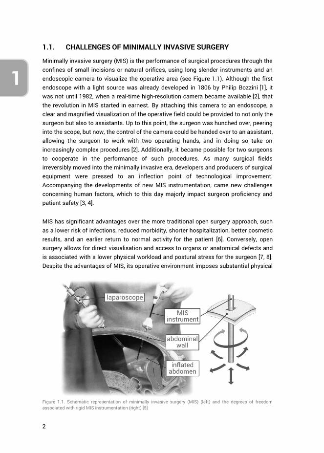
Minimally invasive surgery (MIS) is the performance of surgical procedures through the confines of small incisions or natural orifices, using long slender instruments and an endoscopic camera to visualize the operative area (see Figure 1.1). Although the first endoscope with a light source was already developed in 1806 by Philip Bozzini [1], it was not until 1982, when a real-time high-resolution camera became available [2], that the revolution in MIS started in earnest. By attaching this camera to an endoscope, a clear and magnified visualization of the operative field could be provided to not only the surgeon but also to assistants. Up to this point, the surgeon was hunched over, peering into the scope, but now, the control of the camera could be handed over to an assistant, allowing the surgeon to work with two operating hands, and in doing so take on increasingly complex procedures [2]. Additionally, it became possible for two surgeons to cooperate in the performance of such procedures. As many surgical fields irreversibly moved into the minimally invasive era, developers and producers of surgical equipment were pressed to an inflection point of technological improvement. Accompanying the developments of new MIS instrumentation, came new challenges concerning human factors, which to this day majorly impact surgeon proficiency and patient safety [3, 4].
MIS has significant advantages over the more traditional open surgery approach, such as a lower risk of infections, reduced morbidity, shorter hospitalization, better cosmetic results, and an earlier return to normal activity for the patient [6]. Conversely, open surgery allows for direct visualisation and access to organs or anatomical defects and is associated with a lower physical workload and postural stress for the surgeon [7, 8]. Despite the advantages of MIS, its operative environment imposes substantial physical
Figure 1.1. Schematic representation of minimally invasive surgery (MIS) (left) and the degrees of freedom associated with rigid MIS instrumentation (right) [5]

3
1
3
4
and cognitive strain on the surgeon, increasing the risk of error [9-12]. In particular, performing MIS requires different, and possibly more demanding, psychomotor skills as compared to those needed for open surgical procedures.
Specific psychomotor skills are associated with MIS, for which surgeons require extensive training [13-15]. An example of such a skill is being able to cope with the fulcrum effect, i.e., the spatial relation between motion input and output when an instrument is inserted through a minimal incision (see Figure 1.1). The fulcrum effect essentially mirrors a surgeon’s hand motions outside the patient as compared to the in-vivo instrument motions. Other MIS specific psychomotor skills include: being able to account for the shift from a three-dimensional (3D) operating field to the 2D monitor, judgment of altered depth perception and spatial relations, distorted hand-eye coordination, instrument tip tremor, reduced haptic or tactile feedback, and limited degrees of freedom (DOF) [16]. Many of these aspects are directly impacted by the designs of the MIS instruments, and how instrument controls are afforded to the surgeon.
1.2. MEDICAL ERRORS AND SURGEON-INSTRUMENT INTERACTION
Considering the complexity of the MIS operating room (OR), the challenging nature of MIS tasks and the psychomotor skills involved, it is important to know the sources and types of medical errors that can occur. This is relevant because, in the United States alone, medical errors within hospitals account for more than 2.4 million extra hospital days for patients, $9.3 billion excess charges and 32,000 deaths annually [17], of which surgical errors within the operating theatre account for approximately half of all these adverse events [18, 19]. Errors occurring in the OR can be skill-, rule- or knowledge-based [20] and may be either active or latent [9, 21]. The effects of active errors are apparent immediately, whereas latent errors (or latent conditions) may lie dormant in a system, and not cause adverse effects until combined with other factors [21]. Latent errors are quite literally “accidents waiting to happen,” and often, an error or adverse event which at first appears to be active may in fact have been caused by one or multiple latent conditions [22]. Examples of active errors are pushing the incorrect button, clipping the wrong artery, or accidentally cutting a nerve. Latent errors include unclear protocols, sleep deprivation [23], inadequate training [24], and, arguably most important, poorly designed tools [22, 25]. Even the best-designed equipment can be problematic when its purpose does not fit within the wider context of procurement, training, procedures, and maintenance practices [25].
Minimising errors may only be achieved by assessing the entire surgical system, ranging from hospital policies, regulations, and systems, to interactions between staff, surgeons and technology [9, 24]. However, the inherent complexity of human errors
4
1
makes Surgeon-Instrument Interaction (SII) of particular importance as this encompasses the human performance in the context of complex surgical instrumentation usage [4, 24, 26]. Indeed, no human can maintain a near perfect level of performance due to natural variability in human behavior [27]. This variability depends on many factors such as innate sensorimotor abilities, competing goals, concurrent tasks, environmental conditions, fatigue, mental stress, distractions and circadian variations [28]. Relating to SII, poor surgeon-technology interfaces have been shown to produce a significant level of physical and cognitive stress on the surgeon [4, 29], and in fact, many errors can be ascribed to the mismatch between a system or instrument and the capabilities or limitations of the human operator [30]. Literature provides many examples of errors relating to instruments used in practice, such as those that have been recalled from the market for faulty software or user interfaces [31], malfunctions [32], or inadequacy of safety controls or unintended operations [33].
Considering surgeons operate in sociotechnical environments with many different people, various technologies, and patient-specific variations [34], SII is an essential aspect of every medical device. This relates to MIS instruments in particular, considering the challenging psychomotor skills a surgeon is required to master in order to use them safely. For this reason, accounting for SII is an important part of the design, development, and evaluation process of medical devices such that potential latent errors are avoided.
1.3. MEDICAL INSTRUMENT DEVELOPMENTS – NOTES AND SILS
Based on the intermittent occurrence of latent errors in practice due to poorly designed instrumentation, there is an established need to take a closer at SII during the instrument design process. This is particularly important considering that over the years, MIS has been progressing towards thinner instruments that attempt to provide increasingly complex functionalities and maneuvering capabilities to the surgeon to extend the range of MIS procedures. The most prominent examples in this respect are the directed developments on single incision laparoscopic surgery (SILS) [35] and natural orifice transluminal endoscopic surgery (NOTES) [36, 37], aiming towards the further minimization of surgical trauma [38].
SILS involves performing operations through a single (umbilical) incision, using pre-bent rigid instrumentation. In selected patients, the SILS method may be performed in procedures such as cholecystectomy [39], appendectomy [40], sleeve gastrectomy [41], and splenectomy [42]. NOTES is a technique that takes advantages of natural orifices, avoiding abdominal incisions altogether. Access routes for NOTES include the vagina, stomach, esophagus, colorectum, and the urinary bladder, the first two of which are the (thus far) preferred routes [37]. Cases and patient series using the NOTES concept have
5
1
3
4
been published of transvaginal appendectomy [43], sleeve gastrectomy [44-47], splenectomy [48, 49], and cholecystectomy [50, 51]. However, all these cases were in fact hybrid procedures, adding an extra laparoscopic port for visualization and assistance, thereby safeguarding against potential complications. In essence, NOTES is complicated by the unavailability of dedicated NOTES platforms and the current inability to enable safe and sterile access and closure [37, 47].
Both SILS and NOTES are still far from standardization, regardless of the fact that many device manufacturers quickly embraced SILS and rapidly redesigned and produced new surgical equipment to this end [52]. It is only in recent years that studies have been published relating to human factors and ergonomics evaluations of SILS instrumentation and their potential effects on the surgeon, skills acquisition, surgical performance, and patient safety [53-60]. Looking specifically at SII, research thus far has shown that SILS is accompanied with increased physical and mental workloads [53, 57, 59, 60], more difficult skills acquisition and retention [55], and instrument designs that may yet be improved upon [54]. The same is valid for NOTES, where additionally, the lack of a dedicated NOTES operating platform limits the complexity of operations that can be performed. For example, in bariatric NOTES, key steps such as division of gastric vessels and transection of the stomach are severely hampered by the ergonomic challenges of the used rigid instrumentation and distance to target [47].
1.4. GOAL OF THIS THESIS
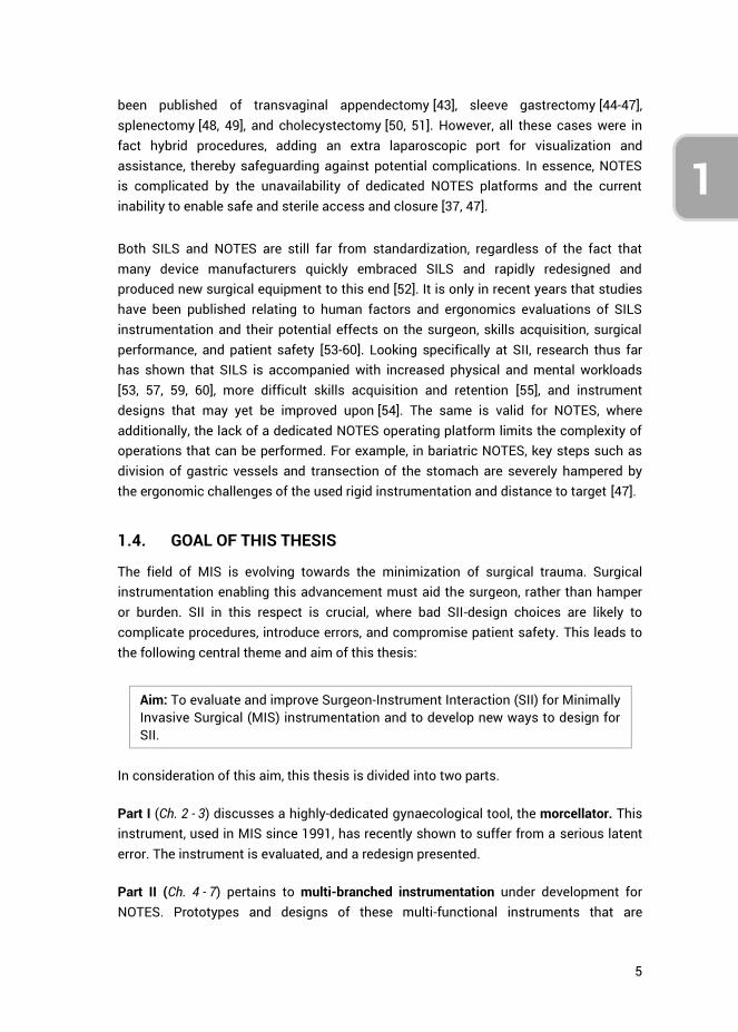
The field of MIS is evolving towards the minimization of surgical trauma. Surgical instrumentation enabling this advancement must aid the surgeon, rather than hamper or burden. SII in this respect is crucial, where bad SII-design choices are likely to complicate procedures, introduce errors, and compromise patient safety. This leads to the following central theme and aim of this thesis:
Aim: To evaluate and improve Surgeon-Instrument Interaction (SII) for Minimally Invasive Surgical (MIS) instrumentation and to develop new ways to design for SII.
In consideration of this aim, this thesis is divided into two parts.
Part I (Ch. 2 - 3) discusses a highly-dedicated gynaecological tool, the morcellator. This instrument, used in MIS since 1991, has recently shown to suffer from a serious latent error. The instrument is evaluated, and a redesign presented.
Part II (Ch. 4 - 7) pertains to multi-branched instrumentation under development for NOTES. Prototypes and designs of these multi-functional instruments that are
6
1
presented in the literature are investigated, their issues concerning SII identified, and based on those findings a new ‘hands-off’ design method is developed. This design method allows for human factors and SII evaluation of instruments without requiring a prototype.
Afterwards, the two parts are jointly addressed in the Discussion (Ch. 8).
1.5. APPROACH AND OUTLINE THESIS
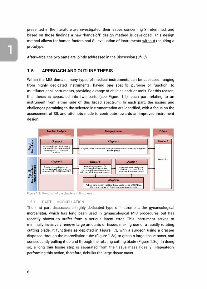
Within the MIS domain, many types of medical instruments can be assessed, ranging from highly dedicated instruments, having one specific purpose or function, to multifunctional instruments, providing a range of abilities and/ or tools. For this reason, this thesis is separated into two parts (see Figure 1.2), each part relating to an instrument from either side of this broad spectrum. In each part, the issues and challenges pertaining to the selected instrumentation are identified, with a focus on the assessment of SII, and attempts made to contribute towards an improved instrument design.
Figure 1.2. Flowchart of the chapters in this thesis.
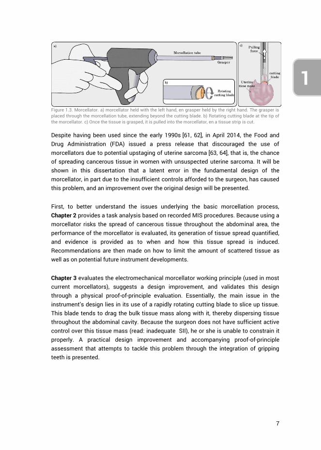
1.5.1. PART I - MORCELLATION The first part discusses a highly dedicated type of instrument, the gynaecological morcellator, which has long been used in gynaecological MIS procedures but has recently shown to suffer from a serious latent error. This instrument serves to minimally invasively remove large amounts of tissue, making use of a rapidly rotating cutting blade. It functions as depicted in Figure 1.3, with a surgeon using a grasper disposed through the morcellation tube (Figure 1.3a) to grasp a large tissue mass, and consequently pulling it up and through the rotating cutting blade (Figure 1.3c). In doing so, a long thin tissue strip is separated from the tissue mass (ideally). Repeatedly performing this action, therefore, debulks the large tissue mass.
7
1
3
4
Despite having been used since the early 1990s [61, 62], in April 2014, the Food and Drug Administration (FDA) issued a press release that discouraged the use of morcellators due to potential upstaging of uterine sarcoma [63, 64], that is, the chance of spreading cancerous tissue in women with unsuspected uterine sarcoma. It will be shown in this dissertation that a latent error in the fundamental design of the morcellator, in part due to the insufficient controls afforded to the surgeon, has caused this problem, and an improvement over the original design will be presented.
First, to better understand the issues underlying the basic morcellation process, Chapter 2 provides a task analysis based on recorded MIS procedures. Because using a morcellator risks the spread of cancerous tissue throughout the abdominal area, the performance of the morcellator is evaluated, its generation of tissue spread quantified, and evidence is provided as to when and how this tissue spread is induced. Recommendations are then made on how to limit the amount of scattered tissue as well as on potential future instrument developments.
Chapter 3 evaluates the electromechanical morcellator working principle (used in most current morcellators), suggests a design improvement, and validates this design through a physical proof-of-principle evaluation. Essentially, the main issue in the instrument’s design lies in its use of a rapidly rotating cutting blade to slice up tissue. This blade tends to drag the bulk tissue mass along with it, thereby dispersing tissue throughout the abdominal cavity. Because the surgeon does not have sufficient active control over this tissue mass (read: inadequate SII), he or she is unable to constrain it properly. A practical design improvement and accompanying proof-of-principle assessment that attempts to tackle this problem through the integration of gripping teeth is presented.
Figure 1.3. Morcellator. a) morcellator held with the left hand, en grasper held by the right hand. The grasper is placed through the morcellation tube, extending beyond the cutting blade. b) Rotating cutting blade at the tip of the morcellator. c) Once the tissue is grasped, it is pulled into the morcellator, en a tissue strip is cut.
8
1
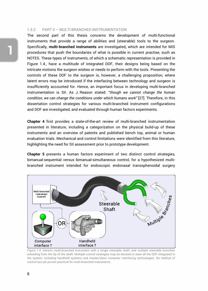
1.5.2. PART II – MULTI-BRANCHED INSTRUMENTATION The second part of this thesis concerns the development of multi-functional instruments that provide a range of abilities and (steerable) tools to the surgeon. Specifically, multi-branched instruments are investigated, which are intended for MIS procedures that push the boundaries of what is possible in current practise, such as NOTES. These types of instruments, of which a schematic representation is provided in Figure 1.4., have a multitude of integrated DOF, their designs being based on the intricate motions the surgeon wishes or needs to perform with the tools. Presenting the controls of these DOF to the surgeon is, however, a challenging proposition, where latent errors may be introduced if the interfacing between technology and surgeon is insufficiently accounted for. Hence, an important focus in developing multi-branched instrumentation is SII. As J. Reason stated: “though we cannot change the human condition, we can change the conditions under which humans work” [27]. Therefore, in this dissertation control strategies for various multi-branched instrument configurations and DOF are investigated, and evaluated through human factors experiments.
Chapter 4 first provides a state-of-the-art review of multi-branched instrumentation presented in literature, including a categorization on the physical build-up of these instruments and an overview of patents and published bench top, animal or human evaluation trials. Mechanical and control limitations were identified from this literature, highlighting the need for SII assessment prior to prototype development.
Chapter 5 presents a human factors experiment of two distinct control strategies, bimanual-sequential versus bimanual-simultaneous control, for a hypothesized multi-branched instrument intended for endoscopic endonasal transsphenoidal surgery
Figure 1.4. Generic multi-branched instrument with a single steerable shaft, and multiple steerable branches extending from the tip of the shaft. Multiple control strategies may be devised to steer all the DOF integrated in the system, including handheld systems and master/slave computer interfacing technologies. No method of control has yet proven practical for multi-branched instruments.
9
1
3
4
(EETS). This instrument has four distinct steerable instrument branches and provides their full control to a single surgeon. Rather than prototyping the envisioned instrument to evaluate the control strategies and related aspects of SII, and in doing so expanding a lot of time and resources, this study implemented an alternate approach. Physical handheld controllers were created and coupled to a virtual instrument simulation of the envisioned multi-branched instrument, allowing for its control evaluation without it actually physically existing.
On the basis of the results obtained in the previous chapter, Chapter 6 introduces and validates a new measurement setup. The purpose of this setup is to allow for the investigation of SII in terms of spatial control coupling between finger motions (input) and simulated instrument motions (output). The setup incorporates the Nimble VR vision-based system [65], using the Kinect camera, and contact based 5DT Data Glove [66], and fuses the measurements using a Kalman filter. A full validation of the system is presented, showing it to provide relatively accurate and precise measurements of hand and finger motions.
Chapter 7 introduces a new design concept, gesture-based instrument design, and presents a human factors evaluation of 2DOF versus 4DOF steerable instrument control. This chapter showcases the potential in using the setup presented in chapter 6 as a design tool that allows for the evaluation and optimization of steerable instrument controls. The design tool couples gestural inputs to virtually simulated instrument motions using hand and finger motion tracking. The human-subject evaluation compared 2DOF thumb control with 4DOF thumb-index finger control. The results exemplify the value of the system for the human factors evaluation of SII related aspects of complex multi-DOF control strategies, without requiring one to construct a prototype first.
Finally, the work presented in this thesis is discussed in Chapter 8. A focus is placed on what can be learned from SII related issues in current instrumentation, taking the morcellator as an example, and how future instrument developments can benefit from this knowledge, in particular for the ongoing developments in SILS and NOTES.
1.5.3. METHODS Part I presents the evaluation and development of a morcellation concept using the research in design context methodology [67]. Firstly morcellator related issues are observed and identified (Ch. 2), following which the design solution space is explored to find a suitable solution and a proof-of-principle evaluation provided towards the design’s potential (Ch. 3).
The methodology implemented in Part II of this thesis may be defined as design inclusive research [67], embedding design as a research means. In particular, in part II a

10
1
dual focus is used by 1) observing the current state of the art (Ch. 4) and adding to the body of literature concerning control strategies for multi-branched instrumentation (Ch. 5 and 7), and 2) concomitantly developing a design tool towards the evaluation of control strategies without requiring the construction of working prototypes (Ch. 6 and 7). The development and implementation of this new design tool aims to serve as a basis from which a multitude of multi-branched instrument control strategies may be studied. This is of particular value for engineers and designers who develop such steerable medical instruments.
The methodologies used in Parts I and II are not similar on account of the fact that they present separate lines of research. Irrespective of this, however, the fundamental issues and design flaws relating to SII and instrument controls as described in the current chapter, and expanded upon in following chapters, are similar. Lastly, it is important to note that throughout this thesis the term ‘control’ is often used within various contexts. In all cases a reference is made to the manual handling of medical instruments, or human factors related aspects thereof. Computer-based ‘control’ systems, algorithms, or ‘control loops’ lie outside the scope of this thesis.
1.6. AUTHOR CONTRIBUTIONS
The work presented in this thesis has predominantly been performed by the main author. Throughout all the research activities that are presented in the articles that make up the body of this thesis, the main author was responsible for conceptualization, methodology, programming, data curation, formal analysis, investigation and article writing. However, two exceptions should be highlighted, related to Chapters 2 and 5 which were jointly authored with Lukas van den Haak and Floris H. van den Berg, respectively. Specifically, in Chapter 2, Lukas contributed substantively to the formal analysis and article writing. Chapter 5 represents a continuation of the graduation work of Floris. Research conceptualization and methodology was performed together, but programming, data curation, investigation (i.e., the performance of experiments), and the initial formal data analysis were performed by Floris. The work was afterwards extended upon by the main author by validating, updating and expanding upon the data analysis, and writing of the article. Supervision was provided on a daily basis by copromotor Joost C.F. de Winter, who also greatly contributed to the presented work through extensive article reviews. Frank Willem Jansen, Jenny Dankelman and Paul Breedveld supervised various research activities. The individual (co)author contributions are further described in greater detail at the end of each chapter.
1.7. REFERENCES
1. Rathert, P., W. Lutzeyer, and W.E. Goddwin, Philipp Bozzini (1773–1809) and the Lichtleiter. Urology, 1974. 3(1): p. 113-118.

11
1
3
4
2. Peter, S.D.S. and G.W. Holcomb III, History of Minimally Invasive Surgery. Atlas of Pediatric Laparoscopy and Thoracoscopy, 2008: p. 1.
3. Ballantyne, G.H., The pitfalls of laparoscopic surgery: challenges for robotics and telerobotic surgery. Surgical Laparoscopy Endoscopy & Percutaneous Techniques, 2002. 12(1): p. 1-5.
4. Choi, S.D., A Review of the Ergonomic Issues in the Laparoscopic Operating Room. Journal of Healthcare Engineering, 2012. 3(4).
5. Breedveld, P., et al., Theoretical background and conceptual solution for depth perception and eye-hand coordination problems in laparoscopic surgery. Minimally Invasive Therapy & Allied Technologies, 1999. 8(4): p. 227-234.
6. Cuschieri, A., Whither minimal access surgery: tribulations and expectations. The American Journal of Surgery, 1995. 169(1): p. 9-19.
7. Berguer, R., et al., A comparison of surgeons' posture during laparoscopic and open surgical procedures. Surgical Endoscopy, 1997. 11(2): p. 139-142.
8. Berguer, R., et al., A comparison of forearm and thumb muscle electromyographic responses to the use of laparoscopic instruments with either a finger grasp or a palm grasp. Ergonomics, 1999. 42(12): p. 1634-1645.
9. McCrory, B., C.A. LaGrange, and M.S. Hallbeck, Quality and Safety of Minimally Invasive Surgery: Past, Present, and Future. Biomedical Engineering and Computational Biology, 2014. 6: p. 1-11.
10. Sari, V., et al., The operation room as a hostile environment for surgeons: Physical complaints during and after laparoscopy. Minimally Invasive Therapy & Allied Technologies, 2010. 19(2): p. 105-109.
11. Park, A., et al., Patients Benefit While Surgeons Suffer: An Impending Epidemic. Journal of the American College of Surgeons, 2010. 210(3): p. 306-313.
12. Szeto, G.P.Y., et al., Work-related Musculoskeletal Symptoms in Surgeons. Journal of Occupational Rehabilitation, 2009. 19(2): p. 175-184.
13. Wolfe, B., et al., Training for minimally invasive surgery. Surgical Endoscopy, 1993. 7(2): p. 93-95.
14. Figert, P.L., et al., Transfer of training in acquiring laparoscopic skills1. Journal of the American College of Surgeons, 2001. 193(5): p. 533-537.
15. Gallagher, P.D.A.G., et al., Objective Psychomotor Skills Assessment of Experienced, Junior, and Novice Laparoscopists with Virtual Reality. World Journal of Surgery, 2001. 25(11): p. 1478-1483.
16. Chmarra, M., et al., The influence of experience and camera holding on laparoscopic instrument movements measured with the TrEndo tracking system. Surgical endoscopy, 2007. 21(11): p. 2069-2075.
17. Zhan, C. and M.R. Miller, Excess length of stay, charges, and mortality attributable to medical injuries during hospitalization. JAMA, 2003. 290(14): p. 1868-1874.
18. D’Addessi, A., et al., Human Factors in Surgery: From Three Mile Island to the Operating Room. Urologia Internationalis, 2009. 83(3): p. 249-257.
19. Cuschieri, A., Nature of Human Error: Implications for Surgical Practice. Annals of Surgery, 2006. 244(5): p. 642-648.
20. Rasmussen, J., Skills, rules, and knowledge; signals, signs, and symbols, and other distinctions in human performance models. Systems, Man and Cybernetics, IEEE Transactions on, 1983. SMC-13(3): p. 257-266.
21. Reason, J., Human error. 1990: Cambridge university press. 22. Thomas, E.J. and L.A. Petersen, Measuring Errors and Adverse Events in Health Care.
Journal of General Internal Medicine, 2003. 18(1): p. 61-67. 23. Krueger, G.P., Fatigue, performance, and medical error. Human Error in Medicine.
Hillsdale, NJ: L. Erlbaum Associates, 1994. 311: p. 326.

12
1
24. Dankelman, J. and C.A. Grimbergen, Systems approach to reduce errors in surgery. Surgical Endoscopy And Other Interventional Techniques, 2005. 19(8): p. 1017-1021.
25. van Beuzekom, M., et al., Patient safety: latent risk factors. BJA: British Journal of Anaesthesia, 2010. 105(1): p. 52-59.
26. Berguer, R., Surgery and ergonomics. Archives of Surgery, 1999. 134(9): p. 1011-1016. 27. Reason, J., Human error: models and management. BMJ : British Medical Journal,
2000. 320(7237): p. 768-770. 28. Green, M. Understanding Human "Error": Fault Tolerance, Practical Drift And Traps.
2013; Available from: http://www.visualexpert.com/Resources/faulttolerance.html. 29. van Det, M.J., et al., Optimal ergonomics for laparoscopic surgery in minimally invasive
surgery suites: a review and guidelines. Surgical Endoscopy, 2009. 23(6): p. 1279-1285. 30. Parker, W.H., Understanding Errors During Laparoscopic Surgery. Obstetrics and
Gynecology Clinics of North America, 2010. 37(3): p. 437-449. 31. WALLACE, D.R. and D.R. KUHN, FAILURE MODES IN MEDICAL DEVICE SOFTWARE: AN
ANALYSIS OF 15 YEARS OF RECALL DATA. International Journal of Reliability, Quality and Safety Engineering, 2001. 08(04): p. 351-371.
32. Brown, S.L. and E.K. Woo, Surgical stapler-associated fatalities and adverse events reported to the Food and Drug Administration1,2 1 2. Journal of the American College of Surgeons, 2004. 199(3): p. 374-381.
33. Alemzadeh, H., et al., Safety Implications of Robotic Surgery: A Study of 13 Years of FDA Data on da Vinci Surgical Systems. University of Illinois Coordinated Science Laboratory Technical Report, UILU-ENG-13-2208, 2013.
34. Carayon, P., et al., Sociotechnical systems analysis in health care: a research agenda. IIE Transactions on Healthcare Systems Engineering, 2011. 1(3): p. 145-160.
35. Cuschieri, A., Single-incision laparoscopic surgery. Journal of Minimal Access Surgery, 2011. 7(1): p. 3-5.
36. Rattner, D. and A. Kalloo, ASGE/SAGES Working Group on Natural Orifice Translumenal Endoscopic Surgery. Surgical Endoscopy And Other Interventional Techniques, 2006. 20(2): p. 329-333.
37. Meining, A., et al., Natural-orifice transluminal endoscopic surgery (NOTES) in Europe: summary of the working group reports of the Euro-NOTES meeting 2010. Endoscopy, 2011. 43(02): p. 140-143.
38. Antoniou, S.A., et al., Past, Present, and Future of Minimally Invasive Abdominal Surgery. JSLS : Journal of the Society of Laparoendoscopic Surgeons, 2015. 19(3): p. e2015.00052.
39. Arezzo, A., et al., Is single-incision laparoscopic cholecystectomy safe? Results of a systematic review and meta-analysis. Surgical Endoscopy, 2013. 27(7): p. 2293-2304.
40. Antoniou, S.A., et al., Meta-analysis of randomized trials on single-incision laparoscopic versus conventional laparoscopic appendectomy. The American Journal of Surgery, 2014. 207(4): p. 613-622.
41. Moreno-Sanz, C., et al., Single-incision laparoscopic bariatric surgery: a systematic review. Surgery for Obesity and Related Diseases, 2015. 11(1): p. 248-257.
42. Fan, Y., et al., Feasibility and safety of single-incision laparoscopic splenectomy: a systematic review. Journal of Surgical Research, 2014. 186(1): p. 354-362.
43. Knuth, J., M.M. Heiss, and D.R. Bulian, Transvaginal hybrid-NOTES appendectomy in routine clinical use: prospective analysis of 13 cases and description of the procedure. Surgical Endoscopy, 2014. 28(9): p. 2661-2665.
44. Ramos, A.C., et al., Human hybrid NOTES transvaginal sleeve gastrectomy: initial experience. Surgery for Obesity and Related Diseases, 2008. 4(5): p. 660-663.

13
1
3
4
45. Fischer, L.J., et al., NOTES laparoscopic-assisted transvaginal sleeve gastrectomy in humans - description of preliminary experience in the United States. Surgery for Obesity and Related Diseases, 2009. 5(5): p. 633-636.
46. Liu, S., S. Horgan, and G.R. Jacobsen, NOTES Transvaginal Sleeve Gastrectomy, in NOTES and Endoluminal Surgery, J.R. Romanelli, D.J. Desilets, and D.B. Earle, Editors. 2017, Springer International Publishing: Cham. p. 221-228.
47. Erridge, S., et al., Natural Orifice Translumenal Endoscopic Surgery: Review of Its Applications in Bariatric Procedures. Obesity surgery, 2016. 26(2): p. 422-428.
48. Targarona, E.M., et al., NOTES-Assisted Transvaginal Splenectomy: The Next Step in the Minimally Invasive Approach to the Spleen. Surgical Innovation, 2009. 16(3): p. 218-222.
49. Almau Trenard, H., J. Mejías González, and J. Arellano Coraggio, Notes híbrido: Esplenectomía transvaginal/umbilical. Acta Gastroenterologica Latinoamericana, 2011. 41(3).
50. Zornig, C., et al., NOTES cholecystectomy: matched-pair analysis comparing the transvaginal hybrid and conventional laparoscopic techniques in a series of 216 patients. Surgical Endoscopy, 2011. 25(6): p. 1822-1826.
51. Chamberlain, R.S. and S.V. Sakpal, A Comprehensive Review of Single-Incision Laparoscopic Surgery (SILS) and Natural Orifice Transluminal Endoscopic Surgery (NOTES) Techniques for Cholecystectomy. Journal of Gastrointestinal Surgery, 2009. 13(9): p. 1733-1740.
52. McCrory, B.J., Improving health care quality and safety: The development and assessment of laparoscopic surgery instrumentation, practices and procedures. 2012: The University of Nebraska-Lincoln.
53. Scerbo, M.W., R.C. Britt, and D. Stefanidis, Differences in mental workload between traditional and single-incision laparoscopic procedures measured with a secondary task. The American Journal of Surgery, 2017. 213(2): p. 244-248.
54. Balaji, S., et al., A Randomized Controlled Study to Evaluate the Impact of Instrument and Laparoscope Length on Performance and Learning Curve in Single-Incision Laparoscopic Surgery. Surgical Innovation, 2015. 22(6): p. 621-628.
55. Ellis, S.M., et al., Acquisition and retention of laparoscopic skills is different comparing conventional laparoscopic and single-incision laparoscopic surgery: a single-centre, prospective randomized study. Surgical Endoscopy, 2016. 30(8): p. 3386-3390.
56. Jennings, A.J., et al., The Feasibility and Safety of Adopting Single-Incision Laparoscopic Surgery into Gynecologic Oncology Practice. Journal of Minimally Invasive Gynecology, 2016. 23(3): p. 358-363.
57. Hallbeck, M.S., et al., Kinematic and ergonomic assessment of laparoendoscopic single-site surgical instruments during simulator training tasks. Applied Ergonomics, 2017. 62: p. 118-130.
58. McCrory, B., et al., Ergonomic evaluation of laparoendoscopic single-site surgery ports in a validated laparoscopic training model. Work, 2012. 41(Supplement 1): p. 1884-1890.
59. Koca, D., et al., Physical and Mental Workload in Single-Incision Laparoscopic Surgery and Conventional Laparoscopy. Surgical Innovation, 2015. 22(3): p. 294-302.
60. Esposito, C., et al., Work-related upper limb musculoskeletal disorders in pediatric minimally invasive surgery: a multicentric survey comparing laparoscopic and sils ergonomy. Pediatric Surgery International, 2014. 30(4): p. 395-399.
61. Semm, K., [Morcellement and suturing using pelviscopy--not a problem any more]. Geburtshilfe und Frauenheilkunde, 1991. 51(10): p. 843-846.
62. Steiner, R.A., et al., Electrical cutting device for laparoscopic removal of tissue from the abdominal cavity. Obstetrics & Gynecology, 1993. 81(3): p. 471-474.

14
1
63. Brölmann, H., et al., Options on fibroid morcellation: a literature review. Gynecological Surgery, 2015. 12(1): p. 3-15.
64. Food and D. Administration, FDA discourages use of laparoscopic power morcellation for removal of uterus or uterine fibroids. 2014.
65. Nimble VR. Nimble VR SDK v0.9.36. 2015 [cited 2015 14-01-2015]; Available from: http://nimblevr.com/ and http://nimblevr.com/latest/doc/CppAPI/.
66. Fifth Dimension Technologies. Data Gloves. 2015 [cited 2015 14-01-2015]; Available from: http://www.5dt.com/?page_id=34.
67. Horvath, I., Differences between 'research in design context' and 'design inclusive
research' in the domain of industrial design engineering. Journal of Design Research,
2008. 7(1), p. 61-83.

15
PART I: MORCELLATION

16
17
CHAPTER 2: ASSESSING BASIC ‘PHYSIOLOGY’ OF THE MORCELLATION PROCESS AND TISSUE SPREAD: A TIME ACTION ANALYSIS
Ewout A. Arkenbout *, Lukas van den Haak *, Sara R. C. Driessen, Andreas L. Thurkow, Frank Willem Jansen.
*Authors contributed equally to the realization of this manuscript
Published in Journal of Minimally Invasive Gynecology, 22(2), 255-260, 2015.

18
2
ABSTRACT
Study Objective: To assess the basic morcellation process in laparoscopic supracervical hysterectomy (LSH). Proper understanding of this process may help enhance future efficacy of morcellation regarding prevention of tissue scatter. Design: Time Action Analysis was performed based on video imaging of the procedures (Canadian Task Force classification II 2). Setting: Procedures were performed at Leiden University Medical Centre and St. Lucas Andreas Hospital, Amsterdam, The Netherlands. Patients: Women undergoing LSH for benign conditions. Interventions: Power morcellation of uterine tissue. Measurements and Main Results: The morcellation process was divided into 4 stages: tissue manipulation, tissue cutting, tissue depositing and cleaning. Stages were timed and perioperative data were gathered. Data were analyzed as a whole, and after subdivision into 3 groups according to uterine weight: <350 g, 350-750 g, >750 g. A cut-off point was found at uterine weight of 350g, after which an increase in uterine weight did not affect the cleaning stage. Tissue strip cutting time was used as a measure for tissue strip length. With progression of the morcellation process, the tissue strip cutting time decreases. The majority of cutting time is of short duration (i.e., 60% of the cutting lasts 5 seconds or less), and these occur later on in the morcellation process. Conclusion: With the current power morcellators, the amount of tissue spread peaks and is independent of uterine weight after a certain cut-off point (in this study 350 g). There is a relative inefficiency in the rotational mechanism, because mostly small tissue strips are created. These small tissue strips occur increasingly later on in the procedure. Because small tissue strips are inherently more prone to scatter by the rotational mechanism of the morcellator, the risk of tissue spread is highest at the end of the morcellation procedure. This means that LSH and laparoscopic hysterectomy procedures may be at higher risk for tissue scatter than total laparoscopic hysterectomy. Finally, engineers should evaluate how to create only large tissue strips or assess alternatives to the rotational mechanism.
This chapter begins with the analysis of the morcellator in relation to its potential for spreading (cancerous) uterine tissue during laparoscopic hysterectomy procedures. Results obtained through this study provide the basis for Chapter 3, where a new morcellator design is presented.
19
2
3
4
2.1. INTRODUCTION
Morcellation has allowed laparoscopic surgeons to remove large uteri and myoma, thereby offering more women the benefits of a minimally invasive approach to their surgery. Yet the United States Food and Drug Administration has recently discouraged the use of uterine power morcellation in laparoscopic hysterectomy and myomectomy because of serious safety concerns after the accidental use of this technique in women with occult uterine sarcoma (e.g., leiomyosarcoma). Patient outcome with respect to morbidity and mortality may be negatively influenced due to morcellation [1, 2]. Unfortunately, the diagnosis of uterine sarcoma is complex because methods to rule out this condition with certainty do not exist. Furthermore, although considered difficult because of a paucity of studies with large series of patients, it was estimated by the Food and Drug Administration that 1 in 350 women undergoing hysterectomy or myomectomy for fibroids will have unsuspected uterine sarcoma [3]. To prevent the unintentional morcellation of a uterine malignancy, it is proposed to stop using a power morcellator and return to traditional methods such as abdominal laparotomy or vaginal incision to remove the uterus or myoma. Methods to avoid tissue spread such as in-bag morcellation are under investigation [4-8]. In theory, contact between tissue and abdominal wall and cavity is avoided; however studies in urology and gastroenterology have, in fact, demonstrated port-site metastases after contained morcellation [9-12]. Although these occurrences have been rare and additional risk factors other than morcellation have been proposed, they stress the importance of larger studies to confirm the efficacy of in-bag morcellation in gynecology. Moreover, before any alternative can be proposed, it is essential to understand the actual problem at hand. Without solid knowledge of the process of morcellation, tissue spread, and tumor seeding, it is unlikely that a sustainable solution will be discovered. The aim of our study was to assess the occurrence and amount of tissue spread in the morcellation procedure, and to identify any factors that influence the tissue spread. This study intends to contribute to the development of a more effective morcellation technique. Understanding the pattern of tissue spread may help us find a solution to a serious problem so that in the future the benefits of minimally invasive surgery will not be lost for women with larger uteri.
2.2. METHODS AND MATERIALS
A prospective observational study was performed from January 2011 till May 2013 at the Leiden University Medical Centre and the St Lucas Andreas Hospital, Amsterdam, The Netherlands. The morcellation procedure in total laparoscopic hysterectomy (TLH) procedures and laparoscopic supracervical hysterectomy (LSH) procedures were timed, and basic procedure and patient characteristics were gathered. Separately, LSH procedures were recorded for time action analysis (TAA). All procedures were performed by 4 experts in minimally invasive gynecologic surgery, except for the
20
2
procedures in the TAA which were performed by 1 expert. The Gynecare Morcellex (Ethicon, Inc., Somerville, NJ) and LiNA Xcise (LiNA medical, Glostrup, Denmark) were used during the procedures1. No distinction was made in the data between the type of morcellator used because the Morcellex and LiNA Xcise rely on the same “motor peeling” working principle; have by approximation a similar instrument diameter, blade rotation speed, weight, and are disposable [13]. Intraoperative data and basic patient characteristics were gathered.
To accurately analyze the morcellation procedure, this procedure was divided into 4 stages: stage 1 or tissue manipulation: grasping and manipulation of the uterine tissue toward the cutting blade of the morcellator; stage 2 or tissue cutting: morcellation instrument actively cutting tissue and tissue being pulled through the morcellation tube; stage 3 or tissue depositing: morcellation instrument inactive, tissue strip being deposited in a retainer outside the patient, and reinsertion of the grasper through the morcellator (stages 1 - 3 were used to calculate the total morcellation time); and stage 4 or cleaning stage: inspection of the abdomen to detect and remove residual uterine tissue pieces and irrigation of the abdominal area. On the basis of this division, the following morcellator related dependent variables were studied: 1) the time pertaining to each phase; 2) tissue spread, determined by counting the number of visually detectable tissue pieces removed during stage 4 through grasping, suction and rinsing; 3) the duration of stage 4 as estimates for the amount of tissue spread; and 4) the morcellation rate calculated in grams per minute as the weight of the excised tissue divided by the morcellation time. The independent variable was the excised uterine tissue weight.
Statistical analysis using the 2-tailed t test under assumption of homogeneity of variance was performed for the LSH and TLH groups separately with respect to the TAA group. For the TAA group, procedures were divided into 3 groups according to uterine weight (A: <350 g, B: 350-750 g, and C: >750 g). A 2-tailed t test was used for identifying significant differences between groups. Standard linear regression analysis was performed to assess the interdependence between recorded variables. A conservative p value of .005 was considered statistically significant to compensate for the number of performed statistical tests. All patients consented to participate in this study.
2.3. RESULTS
A combined total of 52 TLH and LSH procedures were analyzed, of which 23 LSH procedures were analyzed by TAA. Table 2.1 shows the observed patient characteristics and morcellation-related parameters between the procedures that were
1 Note: both these instruments greatly resemble the schematic representation provided in Figure 1.3, Chapter 1: Introduction.

21
2
3
4
timed and the procedures that were analyzed through TAA. No statistical differences were observed between the two groups. A power analysis however reveals that the level of power obtained at these comparisons was below 0.3 in all cases (i.e., posthoc computed achieved power using the observed effect sizes, sample sizes and α = .005 provides 1-β<0.3 in all cases) on account of the large standard deviations and the small observed effect sizes. As such, though the groups do not show any differences, we cannot confirm them to be similar. The average operation time was 152 and 158 minutes, respectively, and the morcellation procedure comprises 13% and 15%, respectively, of total operation time.
The results from the TAA are provided in Table 2.2. Morcellation conditions were similar in all 3 groups because no significant differences were observed in morcellation rate and weight per removed tissue strip. Figure 2.1 is a graphic representation of the time division of the separate morcellation stages. It shows the stage percentages (stages 1 - 3) and total morcellation time compared with the cleaning stage time (stage 4). A large proportion of time is spent on manipulating tissue and depositing tissue and only a limited amount on cutting the tissue. With increasing uterine weight, the total morcellation time also increased. Analysis of the different stages of total morcellation time showed a similar increase for stages 1, 2 and 3 but not for stage 4 (i.e., the cleaning stage). No significant difference was found in the cleaning stage between weight in group B (350–750 g) and C (>750 g). No significant difference was found in the number of scattered tissue pieces between groups B and C either. Due to the small sample sizes of groups B and C however, the statistical Power (1-β) of the observed effect sizes in cleaning stage time and number of scattered tissue pieces was low (0.01 and 0.07 respectively).
To further analyze the cutting process, the tissue cutting time throughout the morcellation procedure was analyzed. The length of every single removed tissue strip was approximated by the time spent cutting that tissue strip in the TAA, thereby allowing an evaluation of the change in length of the removed tissue strips during the morcellation process. This resulted in Figure 2.2, which shows the mean tissue cutting time per tissue strip for all patients combined as a function of morcellation completion (in percentage). The morcellation completion percentage was calculated as 100 times the nth tissue strip cutting action divided by the total number of cutting actions required to remove the full mass. The mean tissue cutting time over all patients was calculated for every 2% of morcellation completion. Linear regression analysis through the mean data shows a negative Pearson’s correlation coefficient of r = -.81 (p < .001). This means that the length of tissue strips appears to decrease with progression of the morcellation process, potentially indicating that the morcellation cutting process becomes less efficient as the morcellation procedure continuous.
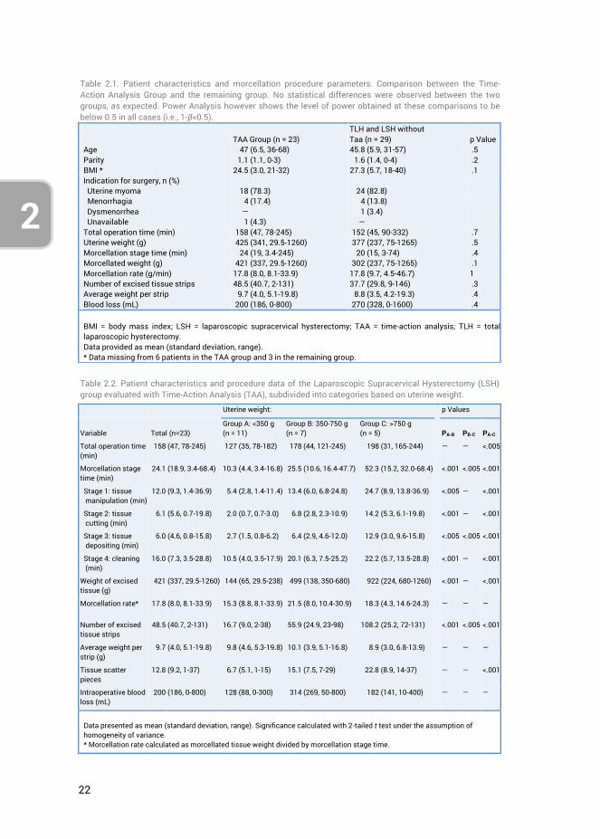
22
2
Table 2.1. Patient characteristics and morcellation procedure parameters. Comparison between the Time-Action Analysis Group and the remaining group. No statistical differences were observed between the two groups, as expected. Power Analysis however shows the level of power obtained at these comparisons to be below 0.5 in all cases (i.e., 1-β<0.5).
TAA Group (n = 23) TLH and LSH without Taa (n = 29)
p Value
Age 47 (6.5, 36-68) 45.8 (5.9, 31-57) .5 Parity 1.1 (1.1, 0-3) 1.6 (1.4, 0-4) .2 BMI * 24.5 (3.0, 21-32) 27.3 (5.7, 18-40) .1 Indication for surgery, n (%) Uterine myoma 18 (78.3) 24 (82.8) Menorrhagia 4 (17.4) 4 (13.8) Dysmenorrhea ― 1 (3.4) Unavailable 1 (4.3) ― Total operation time (min) 158 (47, 78-245) 152 (45, 90-332) .7 Uterine weight (g) 425 (341, 29.5-1260) 377 (237, 75-1265) .5 Morcellation stage time (min) 24 (19, 3.4-245) 20 (15, 3-74) .4 Morcellated weight (g) 421 (337, 29.5-1260) 302 (237, 75-1265) .1 Morcellation rate (g/min) 17.8 (8.0, 8.1-33.9) 17.8 (9.7, 4.5-46.7) 1 Number of excised tissue strips 48.5 (40.7, 2-131) 37.7 (29.8, 9-146) .3 Average weight per strip 9.7 (4.0, 5.1-19.8) 8.8 (3.5, 4.2-19.3) .4 Blood loss (mL) 200 (186, 0-800) 270 (328, 0-1600) .4 BMI = body mass index; LSH = laparoscopic supracervical hysterectomy; TAA = time-action analysis; TLH = total laparoscopic hysterectomy. Data provided as mean (standard deviation, range). * Data missing from 6 patients in the TAA group and 3 in the remaining group.
Table 2.2. Patient characteristics and procedure data of the Laparoscopic Supracervical Hysterectomy (LSH) group evaluated with Time-Action Analysis (TAA), subdivided into categories based on uterine weight.
Uterine weight: p Values
Variable
Total (n=23)
Group A: <350 g (n = 11)
Group B: 350-750 g (n = 7)
Group C: >750 g (n = 5)
PA-B
PB-C
PA-C
Total operation time (min)
158 (47, 78-245) 127 (35, 78-182) 178 (44, 121-245) 198 (31, 165-244) ― ― <.005
Morcellation stage time (min)
24.1 (18.9, 3.4-68.4) 10.3 (4.4, 3.4-16.8) 25.5 (10.6, 16.4-47.7) 52.3 (15.2, 32.0-68.4) <.001 <.005 <.001
Stage 1: tissue manipulation (min)
12.0 (9.3, 1.4-36.9) 5.4 (2.8, 1.4-11.4) 13.4 (6.0, 6.8-24.8) 24.7 (8.9, 13.8-36.9) <.005 ― <.001
Stage 2: tissue cutting (min)
6.1 (5.6, 0.7-19.8) 2.0 (0.7, 0.7-3.0) 6.8 (2.8, 2.3-10.9) 14.2 (5.3, 6.1-19.8) <.001 ― <.001
Stage 3: tissue depositing (min)
6.0 (4.6, 0.8-15.8) 2.7 (1.5, 0.8-6.2) 6.4 (2.9, 4.6-12.0) 12.9 (3.0, 9.6-15.8) <.005 <.005 <.001
Stage 4: cleaning (min)
16.0 (7.3, 3.5-28.8) 10.5 (4.0, 3.5-17.9) 20.1 (6.3, 7.5-25.2) 22.2 (5.7, 13.5-28.8) <.001 ― <.001
Weight of excised tissue (g)
421 (337, 29.5-1260) 144 (65, 29.5-238) 499 (138, 350-680) 922 (224, 680-1260) <.001 ― <.001
Morcellation rate* 17.8 (8.0, 8.1-33.9) 15.3 (8.8, 8.1-33.9) 21.5 (8.0, 10.4-30.9) 18.3 (4.3, 14.6-24.3) ― ― ―
Number of excised tissue strips
48.5 (40.7, 2-131) 16.7 (9.0, 2-38) 55.9 (24.9, 23-98) 108.2 (25.2, 72-131) <.001 <.005 <.001
Average weight per strip (g)
9.7 (4.0, 5.1-19.8) 9.8 (4.6, 5.3-19.8) 10.1 (3.9, 5.1-16.8) 8.9 (3.0, 6.8-13.9) ― ― ―
Tissue scatter pieces
12.8 (9.2, 1-37) 6.7 (5.1, 1-15) 15.1 (7.5, 7-29) 22.8 (8.9, 14-37) ― ― <.001
Intraoperative blood loss (mL)
200 (186, 0-800) 128 (88, 0-300) 314 (269, 50-800) 182 (141, 10-400) ― ― ―
Data presented as mean (standard deviation, range). Significance calculated with 2-tailed t test under the assumption of homogeneity of variance. * Morcellation rate calculated as morcellated tissue weight divided by morcellation stage time.
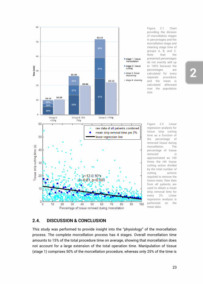
23
2
3
4
2.4. DISCUSSION & CONCLUSION
This study was performed to provide insight into the “physiology” of the morcellation process. The complete morcellation process has 4 stages. Overall morcellation time amounts to 15% of the total procedure time on average, showing that morcellation does not account for a large extension of the total operation time. Manipulation of tissue (stage 1) comprises 50% of the morcellation procedure, whereas only 25% of the time is
Figure 2.1. Chart providing the division of morcellation stages in percentages and the morcellation stage and cleaning stage time of groups A, B, and C. Note that the presented percentages do not exactly add up to 100% because the percentages are calculated for every separate procedure, and the mean is calculated afterward over the population size.
Figure 2.2. Linear regression analysis for tissue strip cutting time as a function of the percentage of removed tissue during morcellation. The percentage of tissue removed is approximated as 100 times the nth tissue cutting action divided by the total number of cutting actions required to remove the tissue mass. Raw data from all patients are used to obtain a mean strip removal time for every 2%. Linear regression analysis is performed on the mean data.
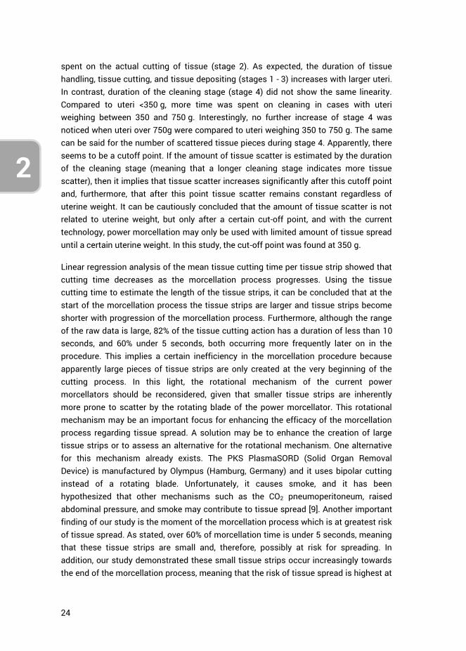
24
2
spent on the actual cutting of tissue (stage 2). As expected, the duration of tissue handling, tissue cutting, and tissue depositing (stages 1 - 3) increases with larger uteri. In contrast, duration of the cleaning stage (stage 4) did not show the same linearity. Compared to uteri <350 g, more time was spent on cleaning in cases with uteri weighing between 350 and 750 g. Interestingly, no further increase of stage 4 was noticed when uteri over 750g were compared to uteri weighing 350 to 750 g. The same can be said for the number of scattered tissue pieces during stage 4. Apparently, there seems to be a cutoff point. If the amount of tissue scatter is estimated by the duration of the cleaning stage (meaning that a longer cleaning stage indicates more tissue scatter), then it implies that tissue scatter increases significantly after this cutoff point and, furthermore, that after this point tissue scatter remains constant regardless of uterine weight. It can be cautiously concluded that the amount of tissue scatter is not related to uterine weight, but only after a certain cut-off point, and with the current technology, power morcellation may only be used with limited amount of tissue spread until a certain uterine weight. In this study, the cut-off point was found at 350 g.
Linear regression analysis of the mean tissue cutting time per tissue strip showed that cutting time decreases as the morcellation process progresses. Using the tissue cutting time to estimate the length of the tissue strips, it can be concluded that at the start of the morcellation process the tissue strips are larger and tissue strips become shorter with progression of the morcellation process. Furthermore, although the range of the raw data is large, 82% of the tissue cutting action has a duration of less than 10 seconds, and 60% under 5 seconds, both occurring more frequently later on in the procedure. This implies a certain inefficiency in the morcellation procedure because apparently large pieces of tissue strips are only created at the very beginning of the cutting process. In this light, the rotational mechanism of the current power morcellators should be reconsidered, given that smaller tissue strips are inherently more prone to scatter by the rotating blade of the power morcellator. This rotational mechanism may be an important focus for enhancing the efficacy of the morcellation process regarding tissue spread. A solution may be to enhance the creation of large tissue strips or to assess an alternative for the rotational mechanism. One alternative for this mechanism already exists. The PKS PlasmaSORD (Solid Organ Removal Device) is manufactured by Olympus (Hamburg, Germany) and it uses bipolar cutting instead of a rotating blade. Unfortunately, it causes smoke, and it has been hypothesized that other mechanisms such as the CO2 pneumoperitoneum, raised abdominal pressure, and smoke may contribute to tissue spread [9]. Another important finding of our study is the moment of the morcellation process which is at greatest risk of tissue spread. As stated, over 60% of morcellation time is under 5 seconds, meaning that these tissue strips are small and, therefore, possibly at risk for spreading. In addition, our study demonstrated these small tissue strips occur increasingly towards the end of the morcellation process, meaning that the risk of tissue spread is highest at
25
2
3
4
the end of the morcellation process. From this it may be concluded that LSH and laparoscopic myomectomy procedures that do not have vaginal access are more prone to tissue scatter because all tissue needs morcellation, compared to TLH procedures in which only part of the uterus is morcellated to the point where the uterine remnant fits through the vagina. A solution to this problem in LSH en laparoscopic myomectomy procedures could be to only use morcellation to the point where the uterine corpus or myoma can be removed vaginally after performing a colpotomy.
Although several studies have been published regarding power morcellators, relatively few comparative or clinical studies exist, and some morcellators have been introduced in clinical practice without any (published) studies altogether [13, 14]. The main focus of these studies appears to have been technical characteristics such as morcellation rate. It is questionable if upon introduction of power morcellators tissue spread was considered to be a severe side effect of the morcellation process. Gradually, reports were published on the iatrogenic spread of benign uterine tissue. It is only afterwards that information regarding the unintentional morcellation of malignant tissue became available. Naturally power morcellators were never intended for use in case of a malignancy, and, moreover, any fragmentation of malignant tissue is usually contraindicated in the principles of oncologic surgery.
The weakness of our study is that tissue spread was not evaluated on a cellular level. Instead, the number of macroscopically detectable scattered tissue pieces and the duration of the cleaning stage were used to determine the amount of tissue spread. Although the complete abdominal cavity and peritoneum were carefully and meticulously searched for tissue spread, it is possible that small tissue fragments were overlooked. Furthermore, the tissue strip cutting time was considered to be representative for the length of the tissue strips. Therefore, any conclusion regarding tissue scatter and tissue strip length should be interpreted with relativism. It was attempted to define the cutoff point of the uterine weight more precisely. A cutoff point calculated on raw data (instead of by comparing the 3 groups according to uterine weight) could not be found because of the relatively limited sample size of 23 patients. For the same reason, a confidence interval in which the cut-off point lies could not be calculated. Lastly, the outcome of our study may not be applicable to power morcellators with other technical specifications such as a difference in diameter.
To solve these shortcomings, a TAA of the morcellation process in a larger population is needed to verify the results of this study. Microscopic evaluation of tissue spread and the pattern of tissue spread may be an interesting addition to future studies. Notwithstanding these limitations, this study offers valuable knowledge regarding the basic “physiology” of the morcellation procedure and tissue spread. Based on the results, the current rotational mechanism of the power morcellators should be reconsidered because of their relative inefficiency with respect to tissue scatter.
26
2
Furthermore, the partial morcellation of uterine tissue seems less at risk to cause tissue spread compared with complete morcellation. For LSH and LH procedures, this means that only part of the uterine tissue should be morcellated after which the remnant tissue can be removed vaginally through colpotomy. In TLH this is already standard procedure.
Finally, solutions that allow morcellation without spread are being investigated and focus mainly on in-bag morcellation. Although in-bag morcellation may be a proper solution for now, it treats a “symptom” rather than the underlying condition. To come to a sustainable solution to the current problem of tissue spread, it is most important that the underlying mechanism is addressed. This study suggests the rotational mechanism as an important factor.
2.5. AUTHOR CONTRIBUTIONS
Ewout A. Arkenbout was responsible for the study conceptualization, data curation, formal analysis, investigation and methodology. Andreas L. Thurkow and Frank Willem Jansen performed the hysterectomy procedures, and thus provided the resources. Writing of the original draft was jointly performed by Ewout A. Arkenbout and Lukas van den Haak. All authors contributed to reviewing and editing the article. Frank Willem Jansen provided supervision.
2.6. REFERENCES
1. Park, J.-Y., et al., The impact of tumor morcellation during surgery on the prognosis of patients with apparently early uterine leiomyosarcoma. Gynecologic Oncology, 2011. 122(2): p. 255-259.
2. George, S., et al., Retrospective cohort study evaluating the impact of intraperitoneal morcellation on outcomes of localized uterine leiomyosarcoma. Cancer, 2014. 120(20): p. 3154-3158.
3. Hodgson, B., AAGL Practice Report: Morcellation During Uterine Tissue Extraction. Journal of Minimally Invasive Gynecology, 2014. 21(4): p. 517-530.
4. Clark, M.A. and J.M. Thomas, Portsite Recurrence After Laparoscopy for Staging of Retroperitoneal Sarcoma. Surgical Laparoscopy Endoscopy & Percutaneous Techniques, 2003. 13(4): p. 290-291.
5. Cohen, S.L., et al., Risk of Leakage and Tissue Dissemination With Various Contained Tissue Extraction (CTE) Techniques: An in Vitro Pilot Study. Journal of Minimally Invasive Gynecology, 2014. 21(5): p. 935-939.
6. Einarsson, J.I., et al., In-Bag Morcellation. Journal of Minimally Invasive Gynecology, 2014. 21(5): p. 951-953.
7. Favero, G., et al., Vaginal morcellation: A new strategy for large gynecological malignant tumor extraction. Gynecologic Oncology, 2012. 126(3): p. 443-447.
8. Montella, F., et al., A safe method of vaginal longitudinal morcellation of bulky uterus with endometrial cancer in a bag at laparoscopy. Surgical Endoscopy, 2014. 28(6): p. 1949-1953.

27
2
3
4
9. Fentie, D.D., P.H. Barrett, and L.A. Taranger, Metastatic renal cell cancer after laparoscopic radical nephrectomy: long-term follow-up. J Endourol, 2000. 14(5): p. 407-11.
10. Paolucci, V., et al., Tumor Seeding following Laparoscopy: International Survey. World Journal of Surgery, 1999. 23(10): p. 989-995.
11. Tsivian, A. and A.A. Sidi, PORT SITE METASTASES IN UROLOGICAL LAPAROSCOPIC SURGERY. The Journal of Urology, 2003. 169(4): p. 1213-1218.
12. Wu, S.D., et al., A multi-institutional study on the safety and efficacy of specimen morcellation after laparoscopic radical nephrectomy for clinical stage T1 or T2 renal cell carcinoma. J Endourol, 2009. 23(9): p. 1513-8.
13. Driessen, S.R.C., et al., Electromechanical Morcellators in Minimally Invasive Gynecologic Surgery: An Update. Journal of Minimally Invasive Gynecology, 2014. 21(3): p. 377-383.
14. Miller, C.E., Methods of tissue extraction in advanced laparoscopy. Current Opinion in Obstetrics and Gynecology, 2001. 13(4): p. 399-405.

28
2

29
3
4
CHAPTER 3: A LAPAROSCOPIC MORCELLATOR REDESIGN TO CONSTRAIN TISSUE USING INTEGRATED GRIPPING TEETH
Ewout. A. Arkenbout, Lukas van den Haak, Maxime Penning, Ellemijn Rog, Amanda Vierwind, Laurien E. van Cappelle, Frank Willem Jansen, Joost C.F. de Winter
Published in Journal of Medical Devices, 11(1), 011005, 2016
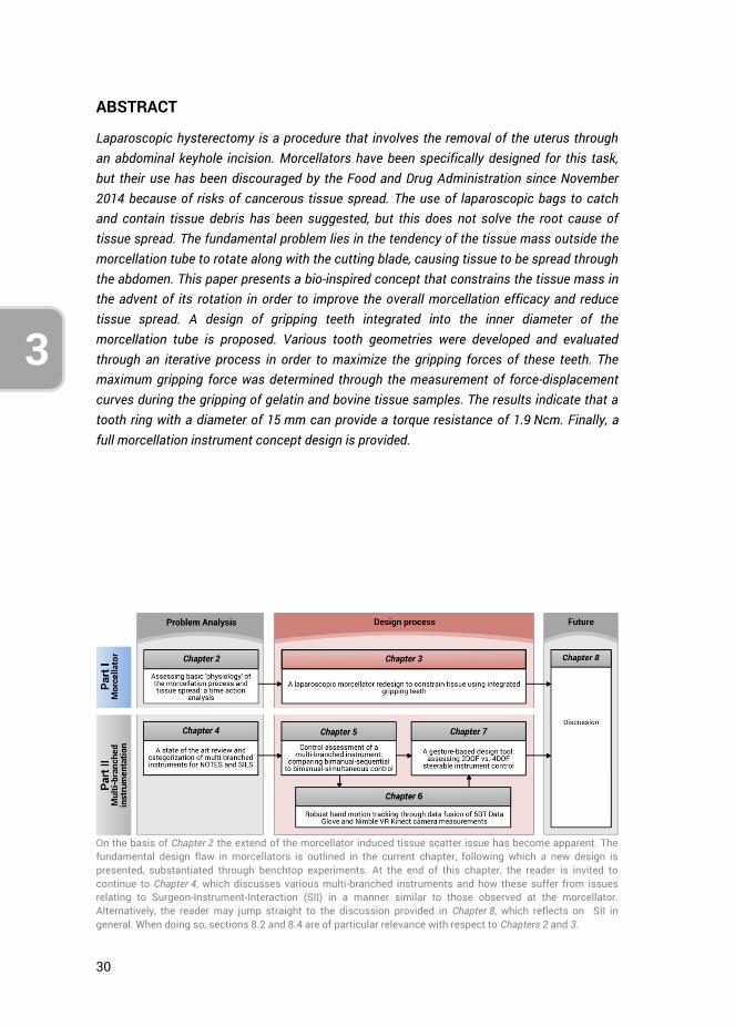
30
3
ABSTRACT
Laparoscopic hysterectomy is a procedure that involves the removal of the uterus through an abdominal keyhole incision. Morcellators have been specifically designed for this task, but their use has been discouraged by the Food and Drug Administration since November 2014 because of risks of cancerous tissue spread. The use of laparoscopic bags to catch and contain tissue debris has been suggested, but this does not solve the root cause of tissue spread. The fundamental problem lies in the tendency of the tissue mass outside the morcellation tube to rotate along with the cutting blade, causing tissue to be spread through the abdomen. This paper presents a bio-inspired concept that constrains the tissue mass in the advent of its rotation in order to improve the overall morcellation efficacy and reduce tissue spread. A design of gripping teeth integrated into the inner diameter of the morcellation tube is proposed. Various tooth geometries were developed and evaluated through an iterative process in order to maximize the gripping forces of these teeth. The maximum gripping force was determined through the measurement of force-displacement curves during the gripping of gelatin and bovine tissue samples. The results indicate that a tooth ring with a diameter of 15 mm can provide a torque resistance of 1.9 Ncm. Finally, a full morcellation instrument concept design is provided.
On the basis of Chapter 2 the extend of the morcellator induced tissue scatter issue has become apparent. The fundamental design flaw in morcellators is outlined in the current chapter, following which a new design is presented, substantiated through benchtop experiments. At the end of this chapter, the reader is invited to continue to Chapter 4, which discusses various multi-branched instruments and how these suffer from issues relating to Surgeon-Instrument-Interaction (SII) in a manner similar to those observed at the morcellator. Alternatively, the reader may jump straight to the discussion provided in Chapter 8, which reflects on SII in general. When doing so, sections 8.2 and 8.4 are of particular relevance with respect to Chapters 2 and 3.
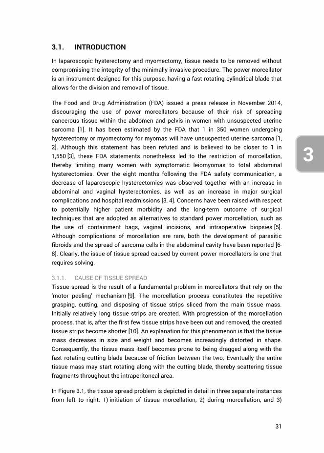
31
3
4
3.1. INTRODUCTION
In laparoscopic hysterectomy and myomectomy, tissue needs to be removed without compromising the integrity of the minimally invasive procedure. The power morcellator is an instrument designed for this purpose, having a fast rotating cylindrical blade that allows for the division and removal of tissue.
The Food and Drug Administration (FDA) issued a press release in November 2014, discouraging the use of power morcellators because of their risk of spreading cancerous tissue within the abdomen and pelvis in women with unsuspected uterine sarcoma [1]. It has been estimated by the FDA that 1 in 350 women undergoing hysterectomy or myomectomy for myomas will have unsuspected uterine sarcoma [1, 2]. Although this statement has been refuted and is believed to be closer to 1 in 1,550 [3], these FDA statements nonetheless led to the restriction of morcellation, thereby limiting many women with symptomatic leiomyomas to total abdominal hysterectomies. Over the eight months following the FDA safety communication, a decrease of laparoscopic hysterectomies was observed together with an increase in abdominal and vaginal hysterectomies, as well as an increase in major surgical complications and hospital readmissions [3, 4]. Concerns have been raised with respect to potentially higher patient morbidity and the long-term outcome of surgical techniques that are adopted as alternatives to standard power morcellation, such as the use of containment bags, vaginal incisions, and intraoperative biopsies [5]. Although complications of morcellation are rare, both the development of parasitic fibroids and the spread of sarcoma cells in the abdominal cavity have been reported [6-8]. Clearly, the issue of tissue spread caused by current power morcellators is one that requires solving.
3.1.1. CAUSE OF TISSUE SPREAD Tissue spread is the result of a fundamental problem in morcellators that rely on the ‘motor peeling’ mechanism [9]. The morcellation process constitutes the repetitive grasping, cutting, and disposing of tissue strips sliced from the main tissue mass. Initially relatively long tissue strips are created. With progression of the morcellation process, that is, after the first few tissue strips have been cut and removed, the created tissue strips become shorter [10]. An explanation for this phenomenon is that the tissue mass decreases in size and weight and becomes increasingly distorted in shape. Consequently, the tissue mass itself becomes prone to being dragged along with the fast rotating cutting blade because of friction between the two. Eventually the entire tissue mass may start rotating along with the cutting blade, thereby scattering tissue fragments throughout the intraperitoneal area.
In Figure 3.1, the tissue spread problem is depicted in detail in three separate instances from left to right: 1) initiation of tissue morcellation, 2) during morcellation, and 3)
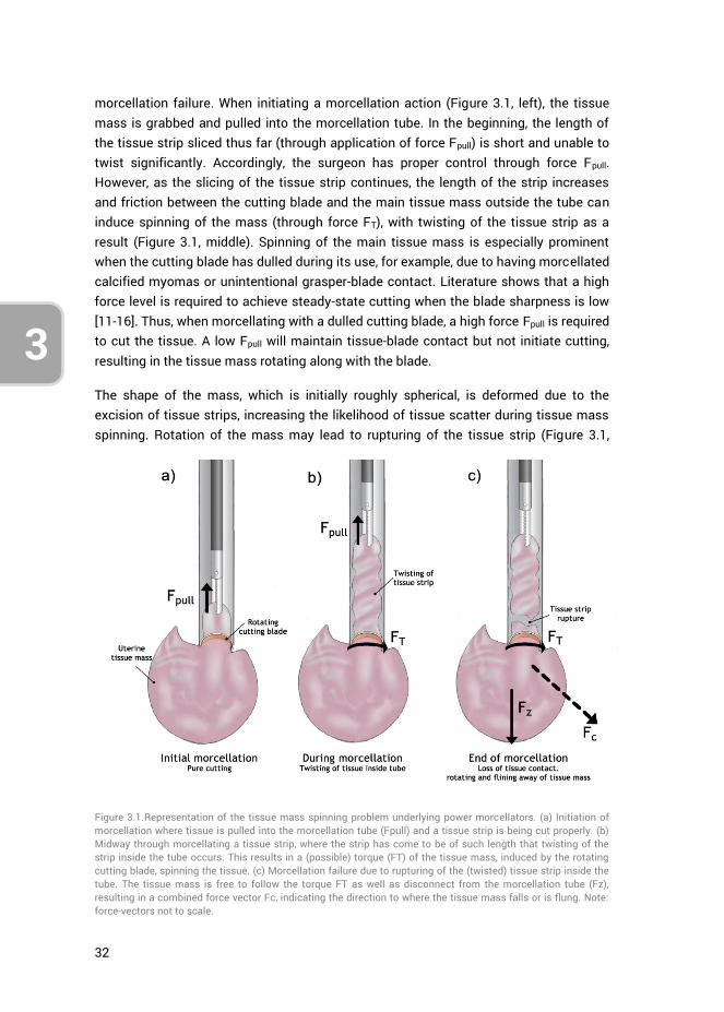
32
3
morcellation failure. When initiating a morcellation action (Figure 3.1, left), the tissue mass is grabbed and pulled into the morcellation tube. In the beginning, the length of the tissue strip sliced thus far (through application of force Fpull) is short and unable to twist significantly. Accordingly, the surgeon has proper control through force Fpull. However, as the slicing of the tissue strip continues, the length of the strip increases and friction between the cutting blade and the main tissue mass outside the tube can induce spinning of the mass (through force FT), with twisting of the tissue strip as a result (Figure 3.1, middle). Spinning of the main tissue mass is especially prominent when the cutting blade has dulled during its use, for example, due to having morcellated calcified myomas or unintentional grasper-blade contact. Literature shows that a high force level is required to achieve steady-state cutting when the blade sharpness is low [11-16]. Thus, when morcellating with a dulled cutting blade, a high force Fpull is required to cut the tissue. A low Fpull will maintain tissue-blade contact but not initiate cutting, resulting in the tissue mass rotating along with the blade.
The shape of the mass, which is initially roughly spherical, is deformed due to the excision of tissue strips, increasing the likelihood of tissue scatter during tissue mass spinning. Rotation of the mass may lead to rupturing of the tissue strip (Figure 3.1,
Figure 3.1.Representation of the tissue mass spinning problem underlying power morcellators. (a) Initiation of morcellation where tissue is pulled into the morcellation tube (Fpull) and a tissue strip is being cut properly. (b) Midway through morcellating a tissue strip, where the strip has come to be of such length that twisting of the strip inside the tube occurs. This results in a (possible) torque (FT) of the tissue mass, induced by the rotating cutting blade, spinning the tissue. (c) Morcellation failure due to rupturing of the (twisted) tissue strip inside the tube. The tissue mass is free to follow the torque FT as well as disconnect from the morcellation tube (Fz), resulting in a combined force vector Fc, indicating the direction to where the tissue mass falls or is flung. Note: force-vectors not to scale.
33
3
4
right), after which the tissue mass is free to rotate with the cutting blade (FT) and disconnect from the distal end of the morcellation tube (e.g., through gravitational force Fz). The combination of forces results in a force vector Fc, in which direction the tissue mass either falls (at low FT) or is flung away (at high FT).
3.1.2. STATE-OF-THE-ART In order to provide a brief overview of the state-of-the-art with respect to morcellators, a patent search was performed in the Espacenet database using the search terms morce* AND (instr* OR tool* OR device*), providing 84 results. Filtering these results on title and abstract on relevance with respect to laparoscopic uterine tissue morcellation (excluding intra-uterine shavers), and removing duplicate patents from the same applicants that describe different or updated facets of the same instrument design, yielded a list of 45 relevant patents. Note that this patent search is not all-inclusive as morcellator patents may exist that do not contain the string morce*.
Standard morcellators that rely on the ‘motor peeling’ working principle are abundant, where the differences between patents mostly relate to aspects such as reusability versus disposability, instrument dimensions, and cutting blade drive mechanisms [17-25]. Patents of existing morcellators include the LiNA Xcise (LiNA Medical, Glostrup, Denmark) [23], Gynecare Morcellex (Ethicon, Inc., Somerville, NJ, USA) [17, 21], and Storz Rotocut G1 (Karl Storz GmbH & Co, Tuttlingen, Germany) [26]. For a full list of current morcellators used in clinical practice, one may refer to Driessen et al. [9]. Alternative cutting mechanisms include oscillating or vibrating cutting blades [27, 28], electrosurgical cutting [29-36], waterjet cutting [37], grinding [38], or the use of a wire mesh to slice tissue [39-41]. Each of these alternative cutting methods have their own strengths and weaknesses. An instrument having an oscillating cutting blade is the MOREsolution Tissue Morcellator (AxtroCare/BlueEndo, Lenexa, KS), which alternately turns four times clockwise and four times counterclockwise. Although this instrument has shown to provide less tissue spread when in oscillation mode as compared to rotation mode [42], the oscillating mode still uses full blade rotations. Electrosurgical cutting speed is dependent on power settings [43], and smoke may obscure the surgeon’s vision [44] and contain carcinogenic agents [45]. Using waterjet cutting as a morcellation method macerates the tissue, potentially creating tissue spill in the process, and making histological evaluation no longer possible [46]. Lastly, wire mesh cutting is a method that encapsulates the tissue mass and subdivides it into multiple smaller pieces by drawing the wire mesh through the tissue [39-41]. This method may be time-consuming, as the time required to manipulate a tissue mass into the encapsulating bag has been reported to range from 1 to 13 minutes [47, 48].
To catch and contain tissue spread, a number of laparoscopic tissue entrapment bags have been proposed, each with their own material properties with respect to robustness against perforations and number of openings [49-58]. Following the FDA safety
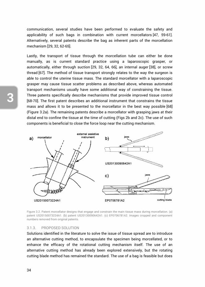
34
3
communication, several studies have been performed to evaluate the safety and applicability of such bags in combination with current morcellators [47, 59-61]. Alternatively, several patents describe the bag as inherent parts of the morcellation mechanism [29, 32, 62-65].
Lastly, the transport of tissue through the morcellation tube can either be done manually, as is current standard practice using a laparoscopic grasper, or automatically, either through suction [29, 32, 64, 66], an internal auger [38], or screw thread [67]. The method of tissue transport strongly relates to the way the surgeon is able to control the uterine tissue mass. The standard morcellator with a laparoscopic grasper may cause tissue scatter problems as described above, whereas automated transport mechanisms usually have some additional way of constraining the tissue. Three patents specifically describe mechanisms that provide improved tissue control [68-70]. The first patent describes an additional instrument that constrains the tissue mass and allows it to be presented to the morcellator in the best way possible [68] (Figure 3.2a). The remaining patents describe a morcellator with grasping jaws at their distal end to confine the tissue at the time of cutting (Figs 2b and 2c). The use of such components is beneficial to close the force loop near the cutting mechanism.
Figure 3.2. Patent morcellator designs that engage and constrain the main tissue mass during morcellation. (a) patent US20150073224A1. (b) patent US20130090642A1. (c) EP0706781A2. Images cropped and component numbers removed from original patents.
3.1.3. PROPOSED SOLUTION Solutions identified in the literature to solve the issue of tissue spread are to introduce an alternative cutting method, to encapsulate the specimen being morcellated, or to enhance the efficacy of the rotational cutting mechanism itself. The use of an alternative cutting method has already been explored extensively, but the rotating cutting blade method has remained the standard. The use of a bag is feasible but does
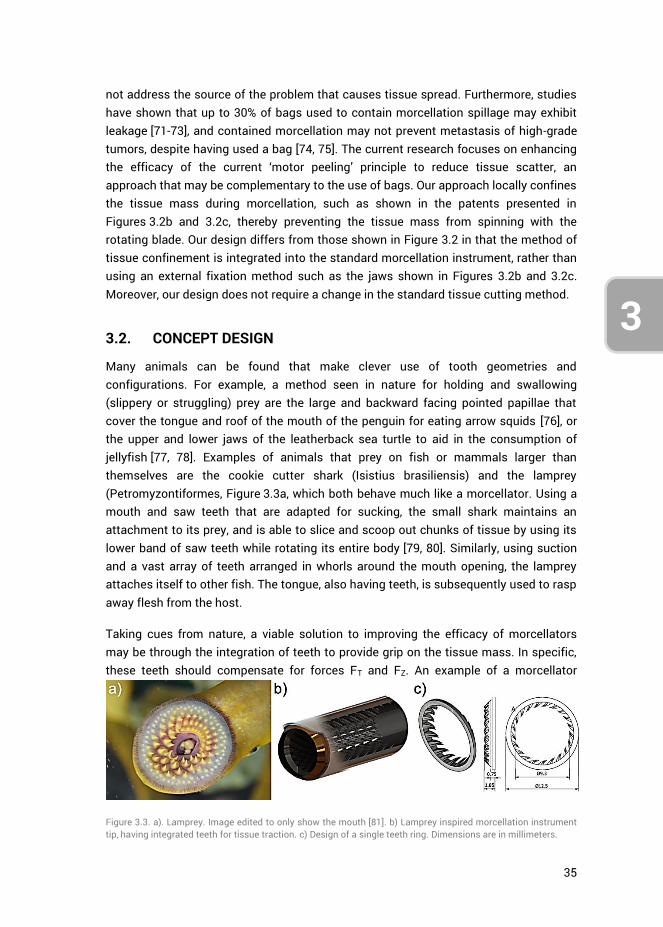
35
3
4
not address the source of the problem that causes tissue spread. Furthermore, studies have shown that up to 30% of bags used to contain morcellation spillage may exhibit leakage [71-73], and contained morcellation may not prevent metastasis of high-grade tumors, despite having used a bag [74, 75]. The current research focuses on enhancing the efficacy of the current ‘motor peeling’ principle to reduce tissue scatter, an approach that may be complementary to the use of bags. Our approach locally confines the tissue mass during morcellation, such as shown in the patents presented in Figures 3.2b and 3.2c, thereby preventing the tissue mass from spinning with the rotating blade. Our design differs from those shown in Figure 3.2 in that the method of tissue confinement is integrated into the standard morcellation instrument, rather than using an external fixation method such as the jaws shown in Figures 3.2b and 3.2c. Moreover, our design does not require a change in the standard tissue cutting method.
3.2. CONCEPT DESIGN
Many animals can be found that make clever use of tooth geometries and configurations. For example, a method seen in nature for holding and swallowing (slippery or struggling) prey are the large and backward facing pointed papillae that cover the tongue and roof of the mouth of the penguin for eating arrow squids [76], or the upper and lower jaws of the leatherback sea turtle to aid in the consumption of jellyfish [77, 78]. Examples of animals that prey on fish or mammals larger than themselves are the cookie cutter shark (Isistius brasiliensis) and the lamprey (Petromyzontiformes, Figure 3.3a, which both behave much like a morcellator. Using a mouth and saw teeth that are adapted for sucking, the small shark maintains an attachment to its prey, and is able to slice and scoop out chunks of tissue by using its lower band of saw teeth while rotating its entire body [79, 80]. Similarly, using suction and a vast array of teeth arranged in whorls around the mouth opening, the lamprey attaches itself to other fish. The tongue, also having teeth, is subsequently used to rasp away flesh from the host.
Taking cues from nature, a viable solution to improving the efficacy of morcellators may be through the integration of teeth to provide grip on the tissue mass. In specific, these teeth should compensate for forces FT and FZ. An example of a morcellator
Figure 3.3. a). Lamprey. Image edited to only show the mouth [81]. b) Lamprey inspired morcellation instrument tip, having integrated teeth for tissue traction. c) Design of a single teeth ring. Dimensions are in millimeters.

36
3
design we have created with this principle in mind is provided in Figure 3.3b, where teeth have been integrated into the instrument tip. In order to investigate the potential of this solution, a proof-of-principle design has been made of a single ring of teeth. These teeth are required to generate a reaction force close to the location where force FT is generated by the blade, thereby locally closing the force-loop in the event of spinning of the tissue mass. The teeth should engage the tissue mass only when it starts to rotate with the blade, and not hinder the normal tissue debulking process of the morcellator.
The design of the ring of teeth (Figure 3.3c) is such that it can be placed coaxially on the inside of the circular rotating blade, at the distal end of a standard morcellation tube. The geometry and orientation of the teeth ensure that they hook into the tissue mass when it starts to rotate with the blade. The teeth are angled inwards, into the morcellation tube, freely allowing the tissue to be pulled up the tube, but blocking it from sliding back into the peritoneal area.
This paper presents research into the dimensions and number of teeth to achieve an optimal gripping force on the tissue mass, whilst still allowing the pulling of the debulked tissue strip through the morcellation tube. Test-bench trials have moreover been performed to assess the grip strength of the teeth on animal muscle tissue.
3.3. METHOD
The measurements and validation of the proposed design was performed in two stages together comprising six measurement sessions where samples were drawn across rows of gripping teeth of varying design in order to assess their gripping strength. The independent variables are the teeth designs, their angle with respect to the horizontal surface, the type of sample used (i.e., gelatin or bovine muscle tissue), and the directions along which these samples are drawn past the designed teeth. The dependent variable is the measured gripping force as function of sample displacement across the teeth. These measured forces relate to the gripping potential of the morcellation instrument tip design presented in the previous section.
In the first stage of measurements, teeth of various dimensions were assessed through porcine gelatin tests (measurement sessions 1–4) in order to motivate the design choices made in prototyping a single teeth ring. The second stage of tests (measurement sessions 5 & 6) provided the quantification of this ring in terms of gripping strength when using bovine muscle tissue. For all measurements, a force-displacement curve was obtained by drawing a sample of gelatin or animal tissue past a row of teeth. The sequence in which the six measurements sessions were performed is shown in Figure 3.4. The selection process of tooth geometries based on measured
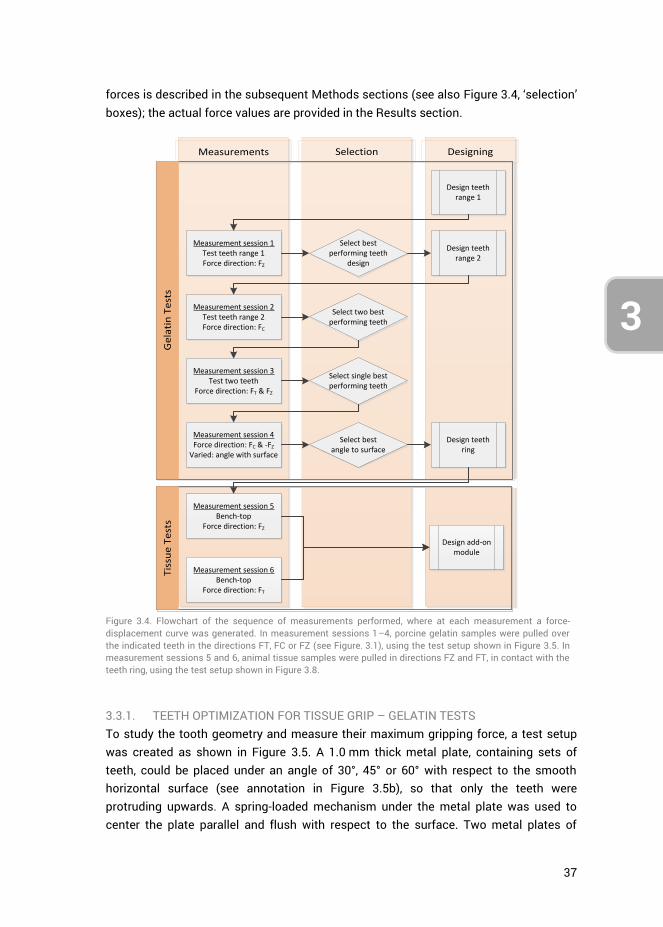
37
3
4
forces is described in the subsequent Methods sections (see also Figure 3.4, ‘selection’ boxes); the actual force values are provided in the Results section.
Measurements Selection Designing
Tis
sue
Te
sts
Ge
lati
n T
est
s
Measurement session 1Test teeth range 1Force direction: FZ
Measurement session 2Test teeth range 2Force direction: FC
Select bestperforming teeth
design
Design teeth range 2
Select two best performing teeth
Measurement session 3Test two teeth
Force direction: FT & FZ
Select single best performing teeth
Measurement session 4Force direction: FC & -FZ
Varied: angle with surface
Select bestangle to surface
Design teeth ring
Measurement session 5Bench-top
Force direction: FZ
Design add-on module
Design teeth range 1
Measurement session 6Bench-top
Force direction: FT
Figure 3.4. Flowchart of the sequence of measurements performed, where at each measurement a force-displacement curve was generated. In measurement sessions 1–4, porcine gelatin samples were pulled over the indicated teeth in the directions FT, FC or FZ (see Figure. 3.1), using the test setup shown in Figure 3.5. In measurement sessions 5 and 6, animal tissue samples were pulled in directions FZ and FT, in contact with the teeth ring, using the test setup shown in Figure 3.8.
3.3.1. TEETH OPTIMIZATION FOR TISSUE GRIP – GELATIN TESTS To study the tooth geometry and measure their maximum gripping force, a test setup was created as shown in Figure 3.5. A 1.0 mm thick metal plate, containing sets of teeth, could be placed under an angle of 30°, 45° or 60° with respect to the smooth horizontal surface (see annotation in Figure 3.5b), so that only the teeth were protruding upwards. A spring-loaded mechanism under the metal plate was used to center the plate parallel and flush with respect to the surface. Two metal plates of
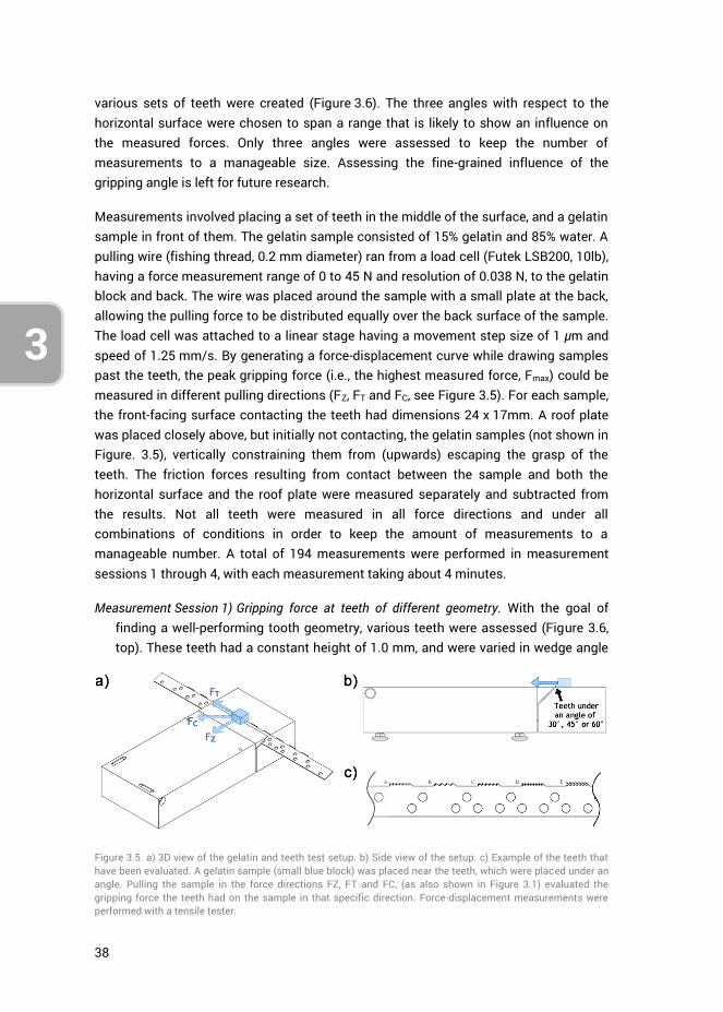
38
3
various sets of teeth were created (Figure 3.6). The three angles with respect to the horizontal surface were chosen to span a range that is likely to show an influence on the measured forces. Only three angles were assessed to keep the number of measurements to a manageable size. Assessing the fine-grained influence of the gripping angle is left for future research.
Measurements involved placing a set of teeth in the middle of the surface, and a gelatin sample in front of them. The gelatin sample consisted of 15% gelatin and 85% water. A pulling wire (fishing thread, 0.2 mm diameter) ran from a load cell (Futek LSB200, 10lb), having a force measurement range of 0 to 45 N and resolution of 0.038 N, to the gelatin block and back. The wire was placed around the sample with a small plate at the back, allowing the pulling force to be distributed equally over the back surface of the sample. The load cell was attached to a linear stage having a movement step size of 1 μm and speed of 1.25 mm/s. By generating a force-displacement curve while drawing samples past the teeth, the peak gripping force (i.e., the highest measured force, Fmax) could be measured in different pulling directions (FZ, FT and FC, see Figure 3.5). For each sample, the front-facing surface contacting the teeth had dimensions 24 x 17mm. A roof plate was placed closely above, but initially not contacting, the gelatin samples (not shown in Figure. 3.5), vertically constraining them from (upwards) escaping the grasp of the teeth. The friction forces resulting from contact between the sample and both the horizontal surface and the roof plate were measured separately and subtracted from the results. Not all teeth were measured in all force directions and under all combinations of conditions in order to keep the amount of measurements to a manageable number. A total of 194 measurements were performed in measurement sessions 1 through 4, with each measurement taking about 4 minutes.
Measurement Session 1) Gripping force at teeth of different geometry. With the goal of finding a well-performing tooth geometry, various teeth were assessed (Figure 3.6, top). These teeth had a constant height of 1.0 mm, and were varied in wedge angle
Figure 3.5. a) 3D view of the gelatin and teeth test setup. b) Side view of the setup. c) Example of the teeth that have been evaluated. A gelatin sample (small blue block) was placed near the teeth, which were placed under an angle. Pulling the sample in the force directions FZ, FT and FC, (as also shown in Figure 3.1) evaluated the gripping force the teeth had on the sample in that specific direction. Force-displacement measurements were performed with a tensile tester.

39
3
4
(range 20° and 60°, see teeth A, B, C, & I), curvature (linear or radius of 1.0 or 2.0 mm, see teeth E, F, & H), combinations of teeth (D & F) and blunt teeth (G). For this measurement session, the teeth were kept under a 45° angle with respect to the horizontal surface (Figure 3.5b). This angle was the mid-range value around which a high gripping force was expected to be measured. Force direction FZ was assessed. The total number of measurements performed was 54 (9 different tooth geometries * 6 measurements per geometry).
Measurement Session 2) Gripping force at teeth of different width and height. The results of measurement session 1 showed that tooth geometry D (Figure 3.6, top), having a combination of two differently sized teeth, generated the highest maximum gripping force (for full results see Section 4.1). These teeth were redesigned to function in force direction FT by curving them in a 45° angle sideways (Figure 3.6, bottom), and were varied in height (1.0, 1.5, & 2.0 mm). The teeth also varied in width by equally distributing their number (range 4 to 8) over a length of 10 mm. Both ‘combined teeth’ (e.g., Figure 3.6, bottom, tooth geometry B) and ‘singular teeth’ (e.g., Figure 3.6, bottom, tooth geometry A) were designed. Measurements were performed in force direction FC, while again keeping the teeth under a 45° angle with respect to the horizontal surface. Total number of measurements performed was 80 (10 types of tooth geometries * 8 measurements per geometry). Figure 3.6 (bottom) provides an overview of the 10 teeth that were tested in measurement session 2.
Measurement Session 3) Gripping force in all force directions. From measurement session
2, teeth F and J (Figure 3.6, bottom) were found to have the highest mean maximum gripping force (Fmax) in force direction FC (for full results see Section 4.1). These teeth were further assessed in force directions FT and FZ, whilst still keeping their angle with respect to the horizontal surface at 45°. Total number of measurement performed was 24 (2 types of tooth geometries * 6 measurements per geometry * 2 force directions).
Measurement Session 4) Gripping force for different teeth angles with respect to the
horizontal surface. Following measurement session 3, tooth geometry J (Figure 3.6, bottom) was found to provide the highest gripping force (Fmax). Having already quantified the teeth in all force directions at a 45° angle with respect to the horizontal surface (Figure 3.5b), this angle was varied to 30°, 45° and 60°. The maximum gripping force was measured in force directions FC and the inverse direction of FZ (i.e., –FZ). –FZ was used to quantify the force required to draw a gelatin sample over the teeth in their non-gripping direction, which is equivalent to drawing tissue into the morcellator tube in a clinical scenario. Total number of measurement performed was 36 (6 measurements * 2 force directions * 3 angles with respect to the horizontal surface).
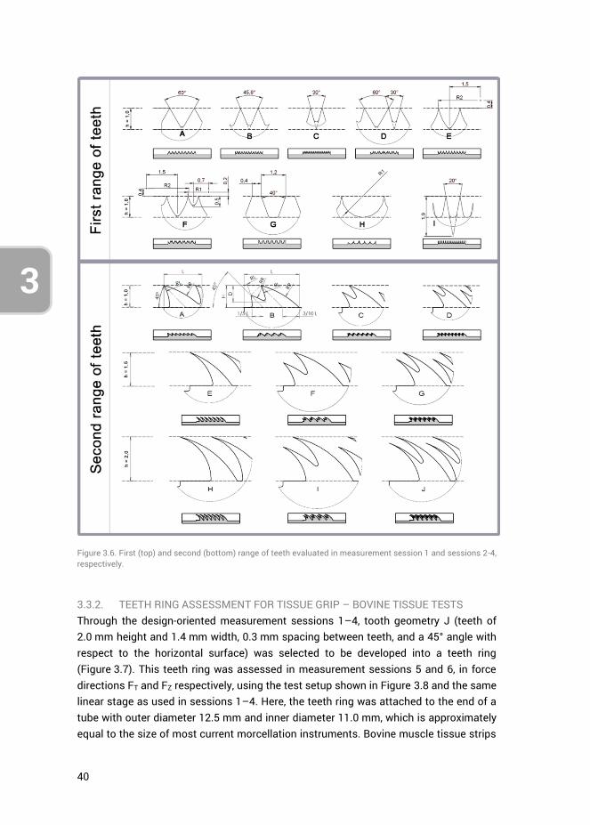
40
3
Figure 3.6. First (top) and second (bottom) range of teeth evaluated in measurement session 1 and sessions 2-4, respectively.
3.3.2. TEETH RING ASSESSMENT FOR TISSUE GRIP – BOVINE TISSUE TESTS Through the design-oriented measurement sessions 1–4, tooth geometry J (teeth of 2.0 mm height and 1.4 mm width, 0.3 mm spacing between teeth, and a 45° angle with respect to the horizontal surface) was selected to be developed into a teeth ring (Figure 3.7). This teeth ring was assessed in measurement sessions 5 and 6, in force directions FT and FZ respectively, using the test setup shown in Figure 3.8 and the same linear stage as used in sessions 1–4. Here, the teeth ring was attached to the end of a tube with outer diameter 12.5 mm and inner diameter 11.0 mm, which is approximately equal to the size of most current morcellation instruments. Bovine muscle tissue strips
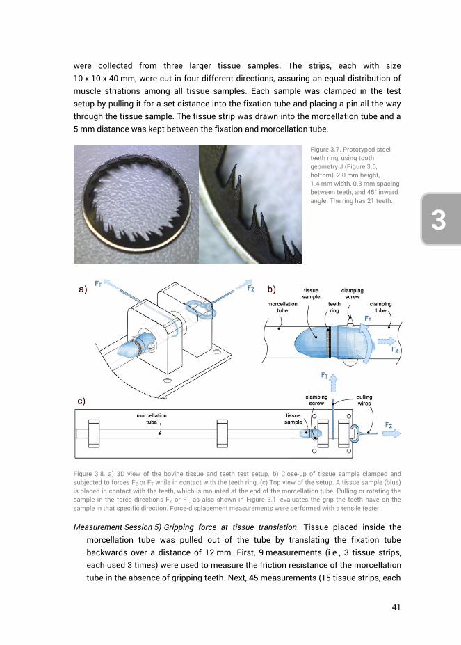
41
3
4
were collected from three larger tissue samples. The strips, each with size 10 x 10 x 40 mm, were cut in four different directions, assuring an equal distribution of muscle striations among all tissue samples. Each sample was clamped in the test setup by pulling it for a set distance into the fixation tube and placing a pin all the way through the tissue sample. The tissue strip was drawn into the morcellation tube and a 5 mm distance was kept between the fixation and morcellation tube.
Figure 3.7. Prototyped steel teeth ring, using tooth geometry J (Figure 3.6, bottom), 2.0 mm height, 1.4 mm width, 0.3 mm spacing between teeth, and 45° inward angle. The ring has 21 teeth.
Figure 3.8. a) 3D view of the bovine tissue and teeth test setup. b) Close-up of tissue sample clamped and subjected to forces FZ or FT while in contact with the teeth ring. (c) Top view of the setup. A tissue sample (blue) is placed in contact with the teeth, which is mounted at the end of the morcellation tube. Pulling or rotating the sample in the force directions FZ or FT, as also shown in Figure 3.1, evaluates the grip the teeth have on the sample in that specific direction. Force-displacement measurements were performed with a tensile tester.
Measurement Session 5) Gripping force at tissue translation. Tissue placed inside the morcellation tube was pulled out of the tube by translating the fixation tube backwards over a distance of 12 mm. First, 9 measurements (i.e., 3 tissue strips, each used 3 times) were used to measure the friction resistance of the morcellation tube in the absence of gripping teeth. Next, 45 measurements (15 tissue strips, each

42
3
used 3 times) were performed, measuring the maximum gripping force (Fmax) of the ring of teeth.
Measurement Session 6) Gripping force at tissue rotation. Lastly, tissue placed inside the
morcellation tube was rotated by rotating the fixation tube by approximately 2.7 turns (by translating the linear stage over a distance of 107 mm). As in measurement session 5, first 9 measurements were performed without involving the gripping teeth to ascertain the friction resistance of the morcellation tube itself. Next, 60 measurements were performed, divided over 15 tissue strips, where each strip was measured 4 times. At each strip, the first three measurements involved rotating the tissue against the pointing direction of the teeth. During the fourth measurement, the tissue was rotated along with the pointing direction of the teeth, to measure the force required to rotate tissue free from the gripping teeth.
Differences between the tooth geometries were assessed using a one-way analysis of variance (ANOVA) with the Tukey-Kramer method and a significance level α of 0.05.
3.4. RESULTS
3.4.1. TEETH OPTIMIZATION FOR TISSUE GRIP – GELATIN TESTS An example of a force-displacement curve of a measurement where a block of gelatin was drawn into teeth D of teeth range 1 is shown in Figure 3.9a. At a displacement of 0 mm, the gelatin sample was right up against the teeth but not yet drawn into them. At continued displacement, the teeth dug into the sample and elastic deformation of the sample occurred while the measured force sharply rose. At the force peak (Fmax), the sample material started to rupture. As a result, the teeth lost grip and the measured force dropped sharply. At continued displacement, the sample was drawn over and through the teeth, where the second rise and drop in grip force can be attributed to the teeth regaining their grip on the gelatin sample.
Measurement Session 1) Gripping force at teeth of different geometry. Means and standard deviations of Fmax at all teeth of the first teeth range (Figure. 3.6, top), measured in force direction FZ, are presented in Figure 3.9b. The ANOVA revealed a significant difference between tooth geometries, (F(8,45) = 3.56, p = .003). Teeth type D provided the highest mean Fmax. This difference is statistically significant compared to teeth types A, B, G, H, and I (pA-D = .043, pB-D = .022, pG-D = .007, pH-
D = .001, pI-D = .015). A possible explanation why teeth type D outperforms the other teeth types may be that it uses a combination of two different teeth types (A and C). The depth of the teeth alternate among each other, which may have an effect on the location from where the gelatin sample starts to rupture.
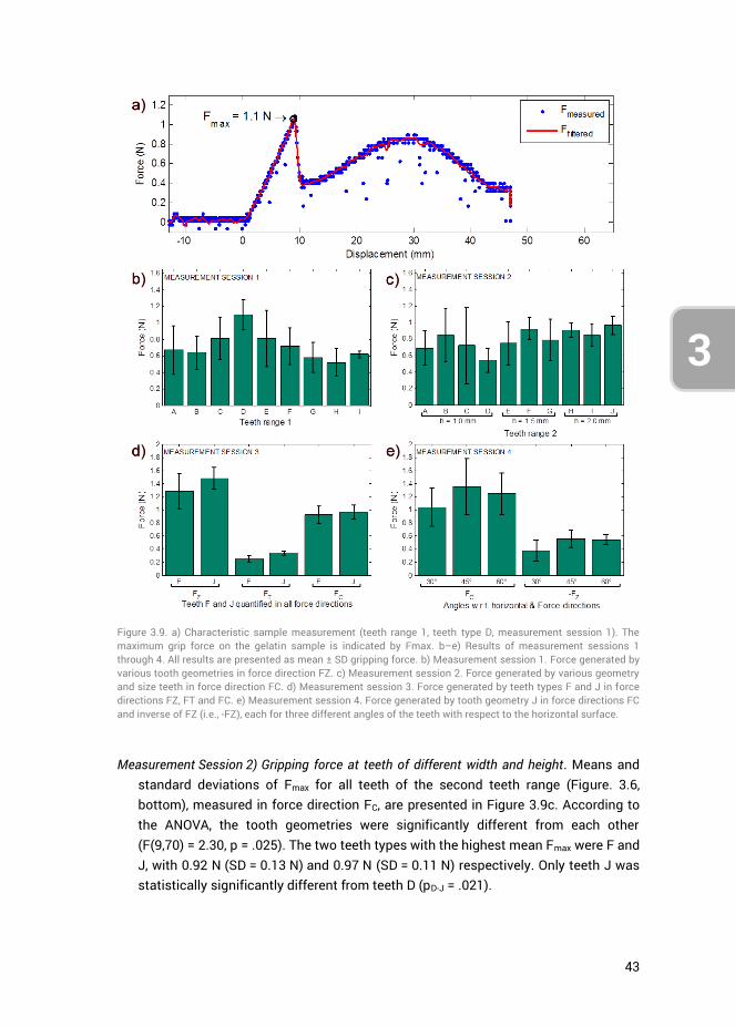
43
3
4
Measurement Session 2) Gripping force at teeth of different width and height. Means and
standard deviations of Fmax for all teeth of the second teeth range (Figure. 3.6, bottom), measured in force direction FC, are presented in Figure 3.9c. According to the ANOVA, the tooth geometries were significantly different from each other (F(9,70) = 2.30, p = .025). The two teeth types with the highest mean Fmax were F and J, with 0.92 N (SD = 0.13 N) and 0.97 N (SD = 0.11 N) respectively. Only teeth J was statistically significantly different from teeth D (pD-J = .021).
Figure 3.9. a) Characteristic sample measurement (teeth range 1, teeth type D, measurement session 1). The maximum grip force on the gelatin sample is indicated by Fmax. b–e) Results of measurement sessions 1 through 4. All results are presented as mean ± SD gripping force. b) Measurement session 1. Force generated by various tooth geometries in force direction FZ. c) Measurement session 2. Force generated by various geometry and size teeth in force direction FC. d) Measurement session 3. Force generated by teeth types F and J in force directions FZ, FT and FC. e) Measurement session 4. Force generated by tooth geometry J in force directions FC and inverse of FZ (i.e., -FZ), each for three different angles of the teeth with respect to the horizontal surface.

44
3
As the teeth height was varied between h = 1.0 mm, 1.5 mm and 2.0 mm, grouping those respective gripping forces together gave 0.70 N (SD = 0.31 N), 0.82 (SD = 0.23 N), and 0.91 N (SD = 0.12 N), respectively. According to the ANOVA, these three means were significantly different from each other, F(2,77) = 5.19, p = .008). The mean force for teeth with a height of 2.0 mm was statistically significantly higher compared to the mean force of teeth 1.0 mm in height (p = .006). No statistically significant difference was found for the teeth having a height of 1.5 mm as compared to the other teeth. The teeth providing the highest mean gripping force of both the 1.5 mm and 2.0 mm teeth height groups, being teeth F and J, were selected to be further investigated.
Measurement Session 3) Gripping force in all force directions. Measuring the gripping
force of teeth types F and J in all force directions yielded the results as shown in Figure 3.9d. Teeth type J outperformed F in all measurements, although this difference is only statistically significant in direction FT (F(1,10) = 13.33, p = .004).
Measurement Session 4) Gripping force for different teeth angles with respect to the horizontal surface. Measuring teeth type J (Figure 3.6, bottom) while varying their angle with respect to the horizontal surface (Figure 3.5b) resulted in Figure 3.9e. Force directions FC and the reverse of FZ (i.e., –FZ) had been assessed. In the direction of –FZ, the force should have been as low as possible, as this represents the resistance of the sample when drawing it along with the facing direction of the teeth, rather than opposing them. No statistically significant differences were observed. For the design of the teeth ring, the aim was to generate a gripping force in the direction of FC as high as possible. Accordingly, the choice for teeth type J under an angle of 45° was made.
3.4.2. TEETH RING ASSESSMENT FOR TISSUE GRIP – BOVINE TISSUE TESTS Measurement Sessions 5&6) Gripping force at tissue translation and rotation.
Measurements were performed using bovine tissue, assessing the gripping force in force directions FZ and FT, by respectively translating and rotating tissue while in contact with the teeth ring. The teeth ring was designed using teeth type J (see Figure 3.6) under an inward angulation of 45° with respect to the morcellation tube. All tissue strips had been measured three times. Separating the measurements into groups based on their trial number yielded the results shown in Figure 3.10a. No significant differences were observed in the FZ force direction. However, the ANOVA showed a significant difference between trials in the FT force direction (F(2,42) = 8.01, p = .001) (see Figure 3.10b). The gripping force for the first trial was significantly higher compared to subsequent trials (ptrial 1 – trial 2 = .019, ptrial 1 –
trial 3 = .001), potentially a result of tissue damage caused by the teeth. In the force direction FZ, all the data was therefore grouped. However, in the direction FT the first
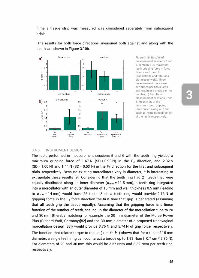
45
3
4
time a tissue strip was measured was considered separately from subsequent trials.
The results for both force directions, measured both against and along with the teeth, are shown in Figure 3.10b.
Figure 3.10. Results of measurement sessions 5 and 6. a) Mean ± SD maximum teeth gripping force in force directions Fz and Fc (translations and rotations plot respectively). Three measurement trials were performed per tissue strip, and results are group per trial number. b) Results of measurement sessions 5 and 6. Mean ± SD of the maximum teeth gripping force pulled along with and against the pointing direction of the teeth, respectively.
3.4.3. INSTRUMENT DESIGN The tests performed in measurement sessions 5 and 6 with the teeth ring yielded a maximum gripping force of 1.67 N (SD = 0.93 N) in the FZ direction, and 2.32 N (SD = 1.00 N) and 1.44 N (SD = 0.53 N) in the FT direction for the first and subsequent trials, respectively. Because existing morcellators vary in diameter, it is interesting to extrapolate these results [9]. Considering that the teeth ring had 21 teeth that were equally distributed along its inner diameter (øinner = 11.5 mm), a teeth ring integrated into a morcellator with an outer diameter of 15 mm and wall thickness 0.5 mm (leading to øinner = 14 mm) would have 25 teeth. Such a teeth ring would provide 2.76 N of gripping force in the FT force direction the first time that grip is generated (assuming that all teeth grip the tissue equally). Assuming that the gripping force is a linear function of the number of teeth, scaling up the diameter of the morcellation tube to 20 and 30 mm (thereby matching for example the 20 mm diameter of the Morce Power Plus (Richard Wolf, Germany)[82] and the 30 mm diameter of a proposed transvaginal morcellation design [83]) would provide 3.76 N and 5.74 N of grip force, respectively.
The function that relates torque to radius ( r F ) shows that for a tube of 15 mm diameter, a single teeth ring can counteract a torque up to 1.93 Ncm (=0.7 cm * 2.76 N). For diameters of 20 and 30 mm this would be 3.57 Ncm and 8.32 Ncm per teeth ring, respectively.
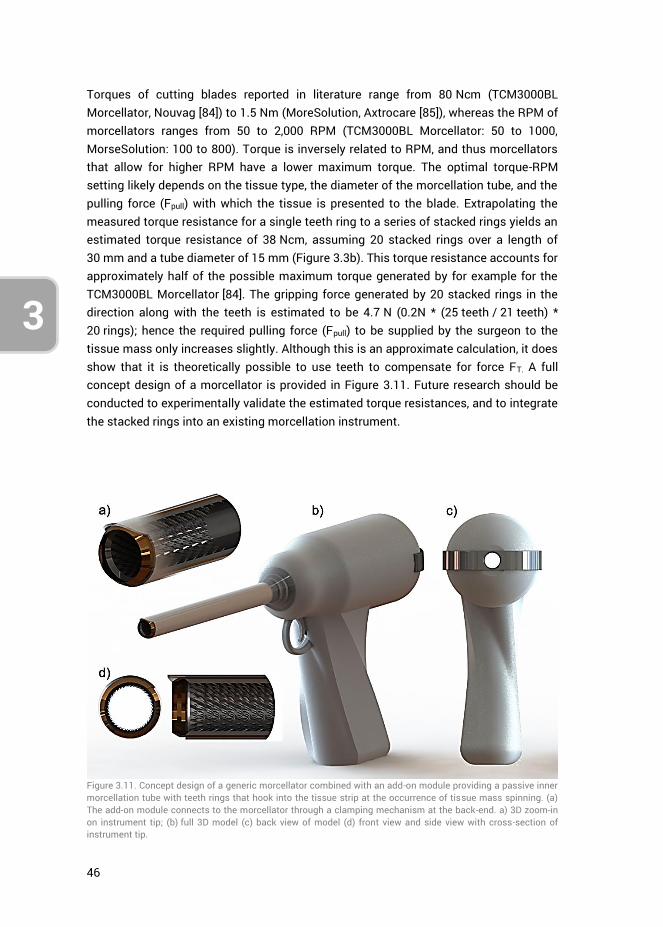
46
3
Torques of cutting blades reported in literature range from 80 Ncm (TCM3000BL Morcellator, Nouvag [84]) to 1.5 Nm (MoreSolution, Axtrocare [85]), whereas the RPM of morcellators ranges from 50 to 2,000 RPM (TCM3000BL Morcellator: 50 to 1000, MorseSolution: 100 to 800). Torque is inversely related to RPM, and thus morcellators that allow for higher RPM have a lower maximum torque. The optimal torque-RPM setting likely depends on the tissue type, the diameter of the morcellation tube, and the pulling force (Fpull) with which the tissue is presented to the blade. Extrapolating the measured torque resistance for a single teeth ring to a series of stacked rings yields an estimated torque resistance of 38 Ncm, assuming 20 stacked rings over a length of 30 mm and a tube diameter of 15 mm (Figure 3.3b). This torque resistance accounts for approximately half of the possible maximum torque generated by for example for the TCM3000BL Morcellator [84]. The gripping force generated by 20 stacked rings in the direction along with the teeth is estimated to be 4.7 N (0.2N * (25 teeth / 21 teeth) * 20 rings); hence the required pulling force (Fpull) to be supplied by the surgeon to the tissue mass only increases slightly. Although this is an approximate calculation, it does show that it is theoretically possible to use teeth to compensate for force FT. A full concept design of a morcellator is provided in Figure 3.11. Future research should be conducted to experimentally validate the estimated torque resistances, and to integrate the stacked rings into an existing morcellation instrument.
Figure 3.11. Concept design of a generic morcellator combined with an add-on module providing a passive inner morcellation tube with teeth rings that hook into the tissue strip at the occurrence of tissue mass spinning. (a) The add-on module connects to the morcellator through a clamping mechanism at the back-end. a) 3D zoom-in on instrument tip; (b) full 3D model (c) back view of model (d) front view and side view with cross-section of instrument tip.
47
3
4
3.5. DISCUSSION
This paper presented the iterative design and evaluation of gripping teeth for the purpose of constraining tissue mass in the advent of its rotation along with the morcellation cutting blade. The measurements suggest that a series of stacked teeth rings can provide an adequate torque resistance for this purpose. Several measurement and design limitation have to be considered, however.
3.5.1. MEASUREMENT LIMITATIONS Measurement sessions 1 through 4 used porcine gelatin samples to evaluate the gripping strength of teeth of varying geometry, and empirically determine which geometry performed the best. The use of gelatin was advantageous as it allowed for a large number of measurements within a short time frame, was readily available, and had an elasticity modulus comparable to that of actual tissue. Gelatin is frequently used for needle-tissue interaction investigations and its force-position curve is linear. In contrast, bovine tissue is nonlinear and has a rupture toughness that differs from gelatin [86]. Therefore, the results from measurement sessions 1 through 4 have to be assessed relative to each other and should not be compared with sessions 5 and 6 in absolute terms.
Bovine muscle tissue is striated by nature, whereas the female uterus consists of smooth muscle tissue. Human uterine tissue or smooth muscle tissue that resembles the human uterus, are not readily available for testing. For this reason, measured gripping force levels may be different from a true clinical scenario. In our research, the tissue strips were cut in various directions to obtain a roughly equal distribution in striation directions, thereby compensating for the influence of striations. An additional limitation of the measurements was that the tissue strips were precut. Therefore, the shape of morcellated tissue strips created during clinical procedures was not a factor that influenced our results. Lastly, the measurement results represent a quasi-static scenario, because the tissue was slowly drawn through the teeth. The speed of tissue translation or rotation was not varied.
Not all observed differences in teeth gripping forces were statistically significant at each individual measurement session. However, through the successive design process (Figure 3.4), this research iterated towards a single teeth design. This process was an efficient alternative to testing all teeth across all possible variations, angles, and force directions. The current design, however, may represent a local optimum in the design solution space, and further refinements may be possible.
3.5.2. TEETH DESIGN The measurement results in this research were used to come to a teeth design that provided the largest gripping force in specific force directions. These teeth were

48
3
subsequently integrated into a proof-of-principle design for future validation and quantification.
The measurements were not intended to provide a deep understanding of the relation between tooth parameters (e.g., geometry and sharpness), tissue properties (e.g., elasticity and viscosity), or crack formation. Although the ability to grasp tissues (e.g., the gall bladder or colon) with laparoscopic graspers without causing tissue damage is important for clinical practice [87], the amount of published research into the design of gripping teeth with respect to pinching force, tissue damage, and tissue slippage is limited [87-92]. One factor of importance is the curvature of individual teeth, where an increase of radius results in reduced tissue damage at the expense of gripping strength [88-91]. During morcellation the degree of tissue damage is not important; hence in this research only aggressive teeth were assessed. In the literature, both 1.0 mm and 2.0 mm sized teeth have been tested, resulting in no clear differences in gripping forces between these two designs [89, 90]. This is in agreement with the present results (Figure 3.9c). However, the results in the literature have been obtained for straight symmetrical teeth, comparable to the teeth tested in measurement session 1 (Figure 3.6, top). To the best of our knowledge, no results are available in the literature with respect to angled teeth such as those used in measurement sessions 2, 3 and 4 (Figure 3.6, bottom).
An interesting finding was that the best-performing tooth geometry consisted of two different sized teeth (teeth D, Figure 3.6, top). Compared to a single teeth design (e.g., teeth A, Figure 3.6, top), there may be a difference in crack formation and propagation, because the depths with which the tissue can sink in between the teeth alternate between 0.85 mm and 0.65 mm. However, teeth F (Figure 3.6, top) also consisted of two differently sized teeth, yet did not exhibit the same performance as teeth D. The underlying mechanism behind the effects of alternating teeth requires further investigation.
The design of the teeth is a trade-off between gripping forces in the FT and FZ force directions and the obstruction force -FZ. These forces are a function of teeth size, tooth geometry, number of teeth, and their angle with respect to the horizontal surface. When stacking multiple teeth rings in a row, the relative spacing between the rings will be another factor that determines the amount of tissue grip generated. One can make a comparison in this regards to fenestrations (i.e., openings) in laparoscopic graspers, where it has been theorized that fenestrations allow the tissue to bulge into them, thereby achieving a form-fit between tissue and grasper. Literature provides contradicting evidence regarding the effects of fenestrations for creating tissue grip [90, 92], thus providing no indication regarding the distance that teeth need be apart.
49
3
4
Lastly, the structural integrity of the tissue strip is of importance for the level of gripping force that can be obtained with the teeth. This is evidenced by the difference that was observed in the FT force direction between the first and subsequent trials. This finding suggests that the initial gripping force generated on tissue mass at the onset of tissue mass rotation should directly be of adequate level to prevent the mass from spinning.
3.5.3. INSTRUMENT DESIGN AND OPTIMIZATION In essence, by using teeth to prevent the tissue mass from spinning, one is removing the surgeon from the ‘force loop’ near the cutting blade. In the standard morcellator design, the influence of the surgeon is limited to applying a pulling force Fpull, whereas in order to prevent the tissue mass from spinning, the surgeon should also be able to rotationally constrain the tissue mass. It is possible, but impractical, to leave this to an assisting surgeon who makes use of a laparoscopic grasper disposed through a different trocar. By integrating gripping teeth designed to compensate for force FT whilst not hindering tissue strip cutting and transport, the tissue mass is controlled without actually having to change the standard morcellation process. Moreover, by preventing the tissue mass from spinning, the amount of tissue spread generated should be reduced. The degree in which tissue spread decreases as well as potential influences of this method on the human-machine interaction (e.g., the influence of increased pull force) are subjects for future research.
Integrating the teeth into an existing morcellator introduces certain design complexities considering that stacked teeth rings need to be integrated into the morcellation tube (Figure 3.3b). A potentially simple fabrication method is to punch press the teeth into a single piece of sheet metal and bend this sheet metal into a tube shape. To be considered is that the addition of a teeth-bearing tube placed into an existing morcellation tube reduces that instrument’s inner diameter. Preferably, the cutting tube should flare open to a larger diameter, allowing for the insertion of a tube with an inner diameter equal to the effective cutting blade diameter. The LiNA Xcise for example has this feature where the cutting tube flares open [93]. However, in the case of the LiNA Xcise this feature is solely intended to reduce the friction between the tissue strip and the inside of the rotating cutting tube.
The presented instrument design (Figure 3.11) may be extended to further improve tissue mass control. Going back to both the cookie cutter shark and the lamprey, their use of a suctorial mouth may inspire continued morcellator development. As suggested in several patents [29, 32, 64], the use of suction to draw tissue into contact with the morcellation instrument, combined with a fluid environment, may be an effective strategy. In light of the recent implementation of laparoscopic containment bags that catch the tissue spread [47, 59-61], adding integrated teeth and suction may be a complementary solution to improve morcellation efficacy and safety.

50
3
3.6. CONCLUSIONS
Through an iterative design and measurement process, a teeth ring was designed, prototyped, and evaluated with respect to its potential gripping strength on tissue. The evaluation showed that the teeth ring generated grip in the advent of tissue translation and rotation. Stacked teeth rings over a length of 30 mm and having an inner tube diameter of 15 mm provide a theoretical 38 Ncm of torque resistance to prevent the tissue mass from rotating along with the morcellation cutting blade. Future research may implement the proposed design into an already existing morcellator and assess it through an in-vitro benchtop evaluation.
3.7. AUTHOR CONTRIBUTIONS
Ewout A. Arkenbout was responsible for the study conceptualization, data curation, formal analysis, investigation and methodology. Maxime Penning, Ellemijn Rog, Amanda Vierwind and Laurien E. van Cappelle aided in methodology (in particular in envisioning the test setup shown in Figure 3.5 and designing the gripping teeth) and jointly performed the experiments of measurement sessions 1-4 under supervision of Ewout A. Arkenbout. Experiments 5 and 6 were performed by Ewout A. Arkenbout as well as writing of the original draft. All authors contributed to reviewing and editing the article. Frank Willem Jansen and Joost C.F. de Winter provided supervision. Lastly, Joost C.F. de Winter provided support in the formal analysis.
3.8. ACKNOWLEDGMENTS
The authors would like to thank Menno Lageweg and Remi van Starkenburg from DEMO (Dienst Elektronische en Mechanische Ontwikkeling) for their help in fabricating the test facilities and the teeth ring.
3.9. REFERENCES
1. Food and Drug Administration (FDA). FDA discourages use of laparoscopic power morcellation for removal of uterus or uterine fibroids. 2014 [cited 2014 17-4-2014]; Available from: http://www.fda.gov/NewsEvents/Newsroom/PressAnnouncements/ucm393689.htm.
2. Hodgson, B., AAGL Practice Report: Morcellation During Uterine Tissue Extraction The Journal of Minimally Invasive Gynecology, 2014. 21(4): p. 517-530.
3. Parker, W.H., et al., U.S. Food and Drug Administration's Guidance Regarding Morcellation of Leiomyomas: Well-Intentioned, But Is It Harmful for Women? Obstetrics & Gynecology, 2016. 127(1): p. 18-22.
4. Harris, J.A., et al., Practice patterns and postoperative complications before and after US Food and Drug Administration safety communication on power morcellation. American Journal of Obstetrics and Gynecology, 2016. 214(1): p. 98.e1-98.e13.

51
3
4
5. Desai, V.B., X.M. Guo, and X. Xu, Alterations in surgical technique after FDA statement on power morcellation. American Journal of Obstetrics and Gynecology, 2015. 212(5): p. 685-687.
6. Brölmann, H., et al., Options on fibroid morcellation: a literature review. Gynecological Surgery, 2015. 12(1): p. 3-15.
7. Cucinella, G., et al., Parasitic myomas after laparoscopic surgery: an emerging complication in the use of morcellator? Description of four cases. Fertility and Sterility, 2011. 96(2): p. e90-e96.
8. Senapati, S., F.F. Tu, and J.F. Magrina, Power morcellators: a review of current practice and assessment of risk. American Journal of Obstetrics and Gynecology, 2015. 212(1): p. 18-23.
9. Driessen, S.R.C., et al., Electromechanical Morcellators in Minimally Invasive Gynecologic Surgery: An Update. Journal of Minimally Invasive Gynecology, 2014. 21(3): p. 377-383.
10. Arkenbout, E.A., et al., Assessing Basic “Physiology” of the Morcellation Process and Tissue Spread: A Time-action Analysis. Journal of Minimally Invasive Gynecology, 2015. 22(2): p. 255-260.
11. McCarthy, C., M. Hussey, and M. Gilchrist, An investigation into the forces generated when cutting biomaterials with surgical scalpel blades. Key Eng. Mater, 2005: p. 293-294.
12. McCarthy, C.T., A.N. Annaidh, and M.D. Gilchrist, On the sharpness of straight edge blades in cutting soft solids: Part II – Analysis of blade geometry. Engineering Fracture Mechanics, 2010. 77(3): p. 437-451.
13. McCarthy, C.T., M. Hussey, and M.D. Gilchrist, On the sharpness of straight edge blades in cutting soft solids: Part I – indentation experiments. Engineering Fracture Mechanics, 2007. 74(14): p. 2205-2224.
14. McGorry, R.W., P.C. Dowd, and P.G. Dempsey, Cutting moments and grip forces in meat cutting operations and the effect of knife sharpness. Applied Ergonomics, 2003. 34(4): p. 375-382.
15. Santhanam, R. and H.L. Valenta, Cutting force measurements platform for quantitative assessment of surgical cutting instruments. Biomedical sciences instrumentation, 1996. 32: p. 237-243.
16. Tholey, G., et al., Measuring grasping and cutting forces for reality-based haptic modeling. International Congress Series, 2003. 1256: p. 794-800.
17. Nohilly, M.J., Anti-coring device for a surgical morcellator. 2008, ETHICON INC, LLP. 18. Nohilly, M.J., A.S. Miksza, and R. Nering, Cutting blade for morcellator. 2010, ETHICON
INC. 19. Savage, G.M., J.J. Christian, and D.C. Dillow, Disposable laparoscopic morcellator. 2000,
FEMRX INC. 20. Tutunaru, D., Electrical Extractor-Morcellator. 2006. 21. Nohilly, M.J. and S. Cohn, Morcellator with detachable handle. 2012, ETHICON INC. 22. Humphrey, L.E., Semi-automatic tissue morcellation device. 1998, LASERSCOPE INC. 23. Poulsen, H.B., Surgical Apparatus. 2010, Kebomed AG, ZUG. 24. Doll, F., C. Walter, and W. Roesch, Surgical instrument system. 2006. 25. DuBois, B.R., J.T. Nielsen, and A. Gordon, Vacuum powered rotary devices and
methods. 2015, LAURIMED LLC. 26. Wolf, T., Morcellator. 2007, STORZ KARL GMBH & CO KG. 27. Sartor, J.D., J.G. Westwood, and A.D. Leyva, Devices, systems, and methods for tissue
morcellation. 2014, COVIDIEN LP. 28. Pravong, B., et al., Method and apparatus for tissue morcellation. 2012, APPLIED MED
RESOURCES.
52
3
29. Hooven, M.D., Apparatus and method for morselating and removing tissue from a patient. 2000, ENABLE MEDICAL CORP.
30. Jenkins, A.E., H.E. Johnston, and A.I. Fleming, Bipolar surgical morcellator. 2014, GYRUS MEDICAL LTD.
31. Ciarrocca, S., Bipolar tissue morcellator. 2005, ETHICON, INC 32. Goble, N.M., Electrosurgical instrument. 2007, GYRUS MEDICAL LTD. 33. Goble, N.M., C.C.O. Goble, and A.N. Syrop, AN ELECTROSURGICAL INSTRUMENT 1999,
GYRUS MEDICAL LTD. 34. Hall, M.R., et al., Surgical instrument. 2011, GYRUS MEDICAL LTD. 35. Jenkins, A.E., SURGICAL INSTRUMENT. 2015, GYRUS MEDICAL LTD. 36. Marshall, M.G., F. Amoah, and F. D'Amelio, Surgical instrument. 2007, GYRUS MEDICAL
LTD. 37. Connor, B.G., et al., Surgical devices incorporating liquid jet assisted tissue
manipulation and methods for their use. 2004, HYDROCISION, INC. 38. Hart, S.R., et al., MINIMALLY INVASIVE LAPAROSCOPIC TISSUE REMOVAL DEVICE. 2015. 39. Pfeffer, H.G. and P.J. Wilk, Method and apparatus for organic specimen retrieval. 1998. 40. Tah, R.C., R. Ciulla, and M.F. Weiser, Retrieval device and related methods of use. 2014,
BOSTON SCIENT SCIMED INC. 41. Isakov, A., et al., SYSTEM AND METHOD FOR A LAPAROSCOPIC MORCELLATOR. 2014,
BRIGHAM & WOMENS HOSPITAL, HARVARD COLLEGE. 42. van den Haak, L., et al., Power Morcellator Features Affecting Tissue Spill in
Gynecologic Laparoscopy: An In-Vitro Study. Journal of Minimally Invasive Gynecology, 2016. 23(1): p. 107-112.
43. Protsenko, D.E. and J.A. Pearce. Electrosurgical tissue resection: a numerical and experimental study. 2003.
44. Milad, M.P. and E.A. Milad, Laparoscopic Morcellator-Related Complications. Journal of Minimally Invasive Gynecology, 2014. 21(3): p. 486-491.
45. de Boorder, T., R. Verdaasdonk, and J. Klaessens. The visualization of surgical smoke produced by energy delivery devices: significance and effectiveness of evacuation systems. 2007.
46. Varkarakis, J.M., et al., Evaluation of water jet morcellation as an alternative to hand morcellation of renal tissue ablation during laparoscopic nephrectomy: an in vitro study. Urology, 2004. 63(4): p. 796-799.
47. Rimbach, S., et al., First clinical experiences using a new in-bag morcellation system during laparoscopic hysterectomy. Archives of Gynecology and Obstetrics, 2015: p. 1-11.
48. RASSWEILER, J., et al., Organ retrieval systems for endoscopic nephrectomy: a comparative study. Journal of endourology, 1998. 12(4): p. 325-333.
49. Lehmann, A.L., et al., ENTRAPMENT AND CONTAINMENT SYSTEM FOR USE WITH A MORCELLATOR AND METHOD OF ENTRAPPING AND CONTAINING MATERIAL PRODUCED DURING MORCELLATION PROCEDURE. 2015, BOEHRINGER LAB INC.
50. Collins, J., Medical device: laparoscopic bag. 2011, ASHFORD & ST PETER S HOSPITALS. 51. Shibley, K.A., et al., Pneumoperitoneum device. 2012, ATROPOS LTD. 52. Hoyte, L. and A. Imudia, Power morcellation in a protected environment. 2015, UNIV
SOUTH FLORIDA. 53. Jospeh, L., SAFETY ISOLATION BAGS FOR INTRA ABDOMINAL, ENDOSCOPIC
PROCEDURES, POWER MORCELLATION AND VAGINAL MORCELLATION 2015. 54. Clayman, R.V. and E.D. Pingleton, Surgical containment apparatus. 1992, VANCE
PRODUCTS INC. 55. Wachli, S., et al., SYSTEMS AND METHODS FOR TISSUE REMOVAL. 2015, APPLIED MED
RESOURCES.

53
3
4
56. Kondrup, J.D., B.A. Sylvester, and M.L. Branning, Tissue Debris and Blood Collection Device and Methods of Use Thereof. 2015, LAPAROSCOPIC INNOVATIONS LLC.
57. Spaeth, E.E., et al., Trocar system for facilitating passage of instruments into a body cavity through a minimal access incision. 1993, ENDOMEDIX CORP.
58. Hart, S.R., et al., Transvaginal specimen extraction device. 2014, UNIV SOUTH FLORIDA. 59. Cohen, S.L., et al., Risk of Leakage and Tissue Dissemination With Various Contained
Tissue Extraction (CTE) Techniques: An in Vitro Pilot Study. Journal of Minimally Invasive Gynecology, 2014. 21(5): p. 935-939.
60. Einarsson, J.I., et al., In-Bag Morcellation. Journal of Minimally Invasive Gynecology, 2014. 21(5): p. 951-953.
61. Paul, P.G., et al., Contained Morcellation for Laparoscopic Myomectomy Within a Specially Designed Bag. Journal of Minimally Invasive Gynecology, 2015.
62. Mohamed, Z. and T.D. McDonald, Medical device and method for human tissue and foreign body extraction. 2012, DAI-Z, LLC.
63. Li, L.K., Morcellator system. 1995, LI MEDICAL TECH INC. 64. Sorensen, J.T., F. Limonta, and L.A. Dial, Tissue morcellator system and method. 1997,
ENDOMEDIX CORP BOX 330. 65. Vaitekunas, J.J., Method of tissue morcellation using an ultrasonic surgical instrument
with a ballistic specimen bag. 2000, ETHICON ENDO SURGERY INC. 66. Fox, W.D. and H.C. Parkhurst, Mechanical morcellator. 1996, ETHICON INC. 67. Saad, A.H., SURGICAL DEVICE HAVING AN INNER THREAD AND A SHARPENING DEVICE
FOR SUCH A DEVICE. 2014, US Patent 20,140,276,912. 68. Sartor, J.D. and D.N. Heard, System for myomectomy and morcellation. 2014,
COVIDIEN LP. 69. Sauer, J.S., et al., Morcellator. 1996, LASERSURGE INC. 70. Shadduck, J.H., et al., Laparscopic tissue morcellator systems and methods. 2012,
ARQOS SURGICAL INC. 71. Cohen, S.L., et al., Contained tissue extraction using power morcellation: prospective
evaluation of leakage parameters. American Journal of Obstetrics and Gynecology, 2016. 214(2): p. 257.e1-257.e6.
72. Solima, E., et al., Vaginal Uterine Morcellation Within a Specimen Containment System: A Study of Bag Integrity. Journal of Minimally Invasive Gynecology, 2015. 22(7): p. 1244-1246.
73. Urban, D.A., et al., Organ entrapment and renal morcellation: permeability studies. The Journal of urology, 1993. 150(6): p. 1792-1794.
74. Ankem, M.K., et al., Examination of laparoscopic retrieval bag washings for malignant cells after hand-assisted laparoscopic radical nephrectomy and intact specimen removal. Urology, 2006. 68(1): p. 50-52.
75. Fentie, D.D., P.H. Barrett, and L.A. Taranger, Metastatic Renal Cell Cancer after Laparoscopic Radical Nephrectomy: Long-Term Follow-Up. Journal of Endourology, 2000. 14(5): p. 407-411.
76. Johnston, N.E., The Avian Tongue. 2014. 77. Spotila, J.R., Sea turtles: A complete guide to their biology, behavior, and conservation.
2004: JHU Press. 78. Lutz, P.L. and J.A. Musick, The biology of sea turtles. 1997: CRC Press LLC. 79. Whitenack, L.B., The biomechanics and evolution of shark teeth. 2008. 80. Bels, V.L., et al., Biomechanics of feeding in vertebrates. Vol. 18. 2012: Springer Science
& Business Media. 81. Gilkeson/USFWS, J., Duluth Boat Show - Sea Lamprey Booth,
16599005556_67146ef10e_o.jpg, Editor. 2015: flickr. p. Copyright information: Creative Commons Attribution - 2.0 Generic (CC BY 2.0)

54
3
82. Richard Wolf. Morce Power Plus, Effective and ergonomic morcellation. [Brochure] 2016 [cited 2016 June 13]; Available from: http://www.richard-wolf.com/broschueren/Gynecology/E_632_MorcePower_plus_VIII14_EN.pdf.
83. Arkenbout, E.A., Design process of a trans-vaginal morcellator for total laparoscopic hysterectomy; from clinical functionality assessment to first prototype. 2012, TU Delft, Delft University of Technology.
84. Nouvag. TCM 3000 BL - Morcellator for Laparoscopic Hysterectomy. 2016 [cited 2016 8 February]; Available from: http://www.nouvag.com/en/medical/laparoscopic-hysterectomy/morcellator-system/559-tcm-3000-bl-morcellator.html.
85. Axtrocare. Morcellator moresolution. 2016; Available from: http://www.axtrocare.com/cms/fileadmin/user_upload/produkte/morcellator/Image-Morcellator_EN.pdf.
86. van Gerwen, D.J., J. Dankelman, and J.J. van den Dobbelsteen, Needle–tissue interaction forces – A survey of experimental data. Medical Engineering & Physics, 2012. 34(6): p. 665-680.
87. Heijnsdijk, E.A.M., J. Dankelman, and D.J. Gouma, Effectiveness of grasping and duration of clamping using laparoscopic graspers. Surgical Endoscopy And Other Interventional Techniques, 2002. 16(9): p. 1329-1331.
88. Cheng, L. and B. Hannaford, Evaluation of liver tissue damage and grasp stability using finite element analysis. Computer Methods in Biomechanics and Biomedical Engineering, 2016. 19(1): p. 31-40.
89. Marucci, D.D., et al., Patterns of Failure at the Instrument–Tissue Interface. Journal of Surgical Research, 2000. 93(1): p. 16-20.
90. Brown, A.W., et al., Impact of fenestrations and surface profiling on the holding of tissue by parallel occlusion laparoscopic graspers. Surgical Endoscopy and Other Interventional Techniques, 2014. 28(4): p. 1277-1283.
91. Heijnsdijk, E.A.M., et al., Slip and damage properties of jaws of laparoscopic graspers. Surgical Endoscopy And Other Interventional Techniques, 2004. 18(6): p. 974-979.
92. Heijnsdijk, E.A.M., et al., Fenestrations in the jaws of laparoscopic graspers. Minimally Invasive Therapy & Allied Technologies, 2005. 14(1): p. 45-48.
93. LiNA Medical, LiNA Xcise Cordless morcellator. 2013.

55
PART II: MULTI-BRANCHED
INSTRUMENTATION

56
57
3
4
CHAPTER 4: A STATE OF THE ART REVIEW AND CATEGORIZATION OF MULTI-BRANCHED INSTRUMENTS FOR NOTES AND SILS
Ewout A. Arkenbout, Paul W. J. Henselmans, Filip Jelínek, Paul Breedveld
Published in Surgical Endoscopy, 29(6), 1281-1296, 2015
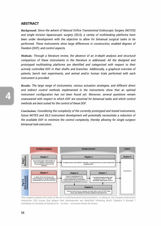
58
4
ABSTRACT
Background: Since the advent of Natural Orifice Transluminal Endoscopic Surgery (NOTES) and single incision laparoscopic surgery (SILS), a variety of multitasking platforms have been under development with the objective to allow for bimanual surgical tasks to be performed. These instruments show large differences in construction, enabled degrees of freedom (DOF), and control aspects.
Methods: Through a literature review, the absence of an in-depth analysis and structural comparison of these instruments in the literature is addressed. All the designed and prototyped multitasking platforms are identified and categorized with respect to their actively controlled DOF in their shafts and branches. Additionally, a graphical overview of patents, bench test experiments, and animal and/or human trials performed with each instrument is provided.
Results: The large range of instruments, various actuation strategies, and different direct and indirect control methods implemented in the instruments show that an optimal instrument configuration has not been found yet. Moreover, several questions remain unanswered with respect to which DOF are essential for bimanual tasks and which control methods are best suited for the control of these DOF.
Conclusions: Considering the complexity of the currently prototyped and tested instruments, future NOTES and SILS instrument development will potentially necessitate a reduction of the available DOF to minimize the control complexity, thereby allowing for single surgeon bimanual task execution.
This chapter analysis the state of the art in multi-branched instrumentation. In doing so, the Surgeon-Instrument Interaction (SII) issues that plague their development are identified, following which Chapters 5 through 7 contribute to the body of literature to – in time – surmount these SII issues.
59
4
3
4.1. INTRODUCTION
Natural Orifice Transluminal Endoscopic Surgery (NOTES) is a hybrid procedure which uses flexible endoscopic technology to perform laparoscopic surgical procedures beyond the confines of the gastrointestinal tract. Single incision laparoscopic surgery (SILS2), which is the execution of surgery through one single incision, is comparable to NOTES as it is associated with equal challenges with respect to bimanual task performance and surgical limitations. These surgical approaches, which can both be categorized as single access surgery, have potential patient advantages which include faster recovery, less adhesions, and reduced risk of infections [1, 2]. Both NOTES and SILS necessitate the development of dexterous endoscopic and laparoscopic instruments for the surgeon. For this reason, in 2006, the Natural Orifice Surgery Consortium for Assessment and Research (NOSCAR) identified the barriers that needed to be surmounted specifically for the development of NOTES [3], and set up a list of steps and guidelines to aid the research of multi-branched instruments, also known as multitasking platforms. According to NOSCAR, several ideal characteristics can be defined for multi-branched instruments, among which adequate maneuverability, independent camera articulation, triangulation, and intuitive control are the most critical for the performance of complex bimanual surgical tasks such as knot-tying and suturing. Other characteristics of importance include adequate stability, sufficiently small instrument dimensions and the incorporation of inflation and irrigation channels.
To provide the surgeon with a stable operating platform, new instruments that attempt to address the aforementioned ideal characteristics have been developed for both NOTES and SILS. While handheld single-branched instruments used for standard minimally invasive surgery (MIS) have been extensively described in the literature [4], very few articles compare surgical task performance, characteristics, and capabilities of prototype multi-branched instruments [5-7]. Moreover, no complete overview of the current state of the art or an in-depth analysis of advantages and disadvantages of the various systems is provided. As such, the goal of this paper is to provide a structured overview of all currently developed multi-branched instruments for NOTES and SILS and to analyse them to help define future obstacles and challenges. As there are inherent differences between instruments intended for NOTES as compared to SILS, this chapter principally compares them based on their construction, manoeuvrability, working space, actuation methods, and control strategies.
2 Synonyms to SILS are Single-Port Access (SPA) surgery, Single-Site Laparoscopy (SSL), Single-Port Laparoscopic Surgery (SPLS), Single-Port Laparoscopy (SPL), and Laparo Endoscopic Single-Site (LESS) surgery.
60
4
4.2. METHODS
A literature study was performed using the Web of Knowledge and PubMed databases to identify literature relating to flexible endoscopic multitasking platforms from January 2004 till October 2013. The following keywords, subdivided into three categories, were used:
(1) Anatomical area: Gastrointestin* OR abdomen* OR *luminal* OR *lumenal*; (2) Surgical access site: ((Insert* OR through) AND (‘‘natural orifice’’ OR oral OR
endonasal* OR anal OR vagina*)) OR SILS OR SPS OR ‘‘single-site’’; (3) Endoscopic instrumentation: Instrument* OR device* OR prototype* OR flexible
OR ‘‘multitasking platform’’ OR robo* OR branch*.
A separate search action was performed for each group, and the results were combined to identify articles containing one or more keywords present in each group. Through this method, the most relevant multi-branched instruments pertaining to NOTES and SILS were identified. Separate search actions for each identified instrument supplemented this survey. All identified instruments were subsequently analyzed with respect to their actively controlled degrees of freedom (DOF; excluding gripper or tool actuation) and their ability to allow for effective bi-manual task performance.
4.3. RESULTS
A total of 31 different multi-branched instrument systems have been identified in the literature (also counting significantly different generations of the same instrument). Because they all display and provide various types of articulating segments, control interfaces, and multitasking capabilities, a categorization is necessary as a basis for comparison. This categorization, based on their mechanical construction, will be developed in the following subsections.
All identified instruments have a common rigid or steerable shaft from which a minimum of two separate branches originate, as schematically depicted in Figure 4.1. These branches have a number of DOF incorporated in them to provide multitasking platform functionality. The sequence or order in which these DOF are placed, and their locations along the branches, are relevant with respect to the working space and the intrinsic control methods provided to the surgeon. In order to categorize the branch DOF sequence, two different kinds of segments are distinguished: a segment providing axial DOF, i.e., axial rotation and/or axial translation, and a segment providing deflection DOF, i.e., sideways bending or deflection in one or two separate (orthogonal) planes. These segments are defined as straight and deflecting segments, respectively, and are also schematically shown in Figure 4.1. On the basis of these segments, one can define and analyse the construction of all existing instrument branches.
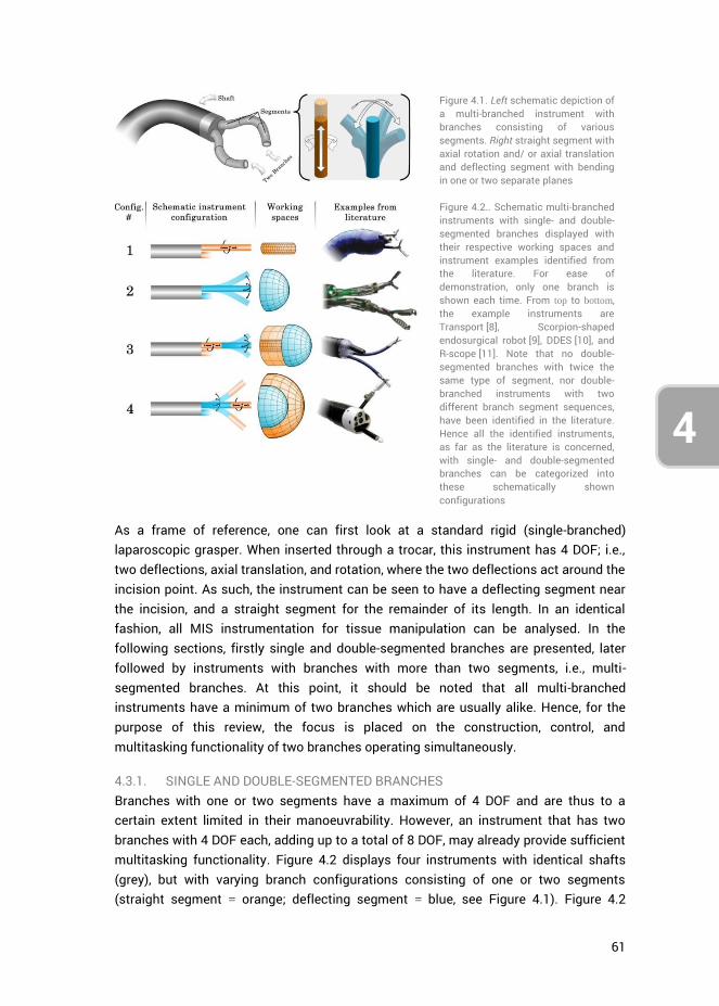
61
4
3
Figure 4.1. Left schematic depiction of a multi-branched instrument with branches consisting of various segments. Right straight segment with axial rotation and/ or axial translation and deflecting segment with bending in one or two separate planes
Figure 4.2.. Schematic multi-branched instruments with single- and double-segmented branches displayed with their respective working spaces and instrument examples identified from the literature. For ease of demonstration, only one branch is shown each time. From top to bottom, the example instruments are Transport [8], Scorpion-shaped endosurgical robot [9], DDES [10], and R-scope [11]. Note that no double-segmented branches with twice the same type of segment, nor double-branched instruments with two different branch segment sequences, have been identified in the literature. Hence all the identified instruments, as far as the literature is concerned, with single- and double-segmented branches can be categorized into these schematically shown configurations
As a frame of reference, one can first look at a standard rigid (single-branched) laparoscopic grasper. When inserted through a trocar, this instrument has 4 DOF; i.e., two deflections, axial translation, and rotation, where the two deflections act around the incision point. As such, the instrument can be seen to have a deflecting segment near the incision, and a straight segment for the remainder of its length. In an identical fashion, all MIS instrumentation for tissue manipulation can be analysed. In the following sections, firstly single and double-segmented branches are presented, later followed by instruments with branches with more than two segments, i.e., multi-segmented branches. At this point, it should be noted that all multi-branched instruments have a minimum of two branches which are usually alike. Hence, for the purpose of this review, the focus is placed on the construction, control, and multitasking functionality of two branches operating simultaneously.
4.3.1. SINGLE AND DOUBLE-SEGMENTED BRANCHES Branches with one or two segments have a maximum of 4 DOF and are thus to a certain extent limited in their manoeuvrability. However, an instrument that has two branches with 4 DOF each, adding up to a total of 8 DOF, may already provide sufficient multitasking functionality. Figure 4.2 displays four instruments with identical shafts (grey), but with varying branch configurations consisting of one or two segments (straight segment = orange; deflecting segment = blue, see Figure 4.1). Figure 4.2
62
4
shows all identified segment combinations for instruments with single- and double- segmented branches. Double-segmented branches with two identical segments in series as well as instruments with dissimilar branch constructions are excluded in Figure 4.2, because no such instruments have been found in the literature. Figure 4.2 additionally shows the working spaces of the various branches, providing an indication of their reachable points in 3D space, as well as instrument examples belonging to the respective branch categories.
Configuration #1 in Figure 4.2 consists of two branches with a single straight segment that can only be translated forward and backward and/or rotated around its axis, restricting the working space to a cylinder as wide as the branch itself. Examples of such instruments are the standard dual channel endoscope (DCE; Olympus) [12] and Transport (USGI Medical, San Capistrano, CA, USA) [8] which is a part of the incisionless operating platform (USGI Medical) [13]. These instruments all consist of a common 2 DOF steerable flexible shaft with passive instrument delivery channels for the insertion of various surgical tools (e.g., graspers). The tools themselves are not steerable and can only be manipulated coaxially with the common steerable shaft. A point in 3D space can still be reached by the instrument as a whole, however, coaxial steering makes bimanual tasks highly challenging.
Configuration #2 consists of two branches with a single deflecting segment, allowing each branch to bend or deflect in one or two perpendicular planes. The accompanying working space of such a branch is a partial sphere, ranging in size from a partial cone to more than a full hemisphere depending on instrument construction and dimensions. With two such branches, bimanual tasks are in principle possible because, depending on the thickness of the shaft defining the distance between the branches, the branches can be deflected slightly inward to reach a common point. An example of an instrument with this construction is Scorpion-shaped endosurgical robot, Suzuki et al. [9], which is an electromechanical master-slave (MS) system.
The branches in Configuration #3 contain a straight segment followed by a deflecting segment, which entails that the branch can translate forward and deflect at the tip. Approaching a surgical target is accomplished by first translating the branch forward, after which small and precise adjustments can be made through tip deflection. The only instrument found with this construction is direct drive endoscopic system (DDES; Boston Scientific, Natick, MA, USA) [10], which has a relatively large bending radius and translation range, making shaft actuation unnecessary for most surgical tasks within a confined space.
Finally, the branches in Configuration #4 contain a deflecting segment followed by a straight segment. When navigating toward a surgical target, first the branch is aligned with the target through branch deflection, followed by branch extension towards it. As
63
4
3
compared to Configuration #3, a drawback of Configuration #4 is that correcting the forward motion by extra bending actions, results in large motions of the tip as the straight segments amplify the deflection of the preceding bending segments. This makes small adjustments in principle less precise and prone to overshooting the surgical target. However, an advantage over Configuration #3 is that Configuration #4 has a larger working space. The only identified example of Configuration #4 is R-scope (XGIF- 2TQ160R; Olympus, Center Valley, PA, USA) [11]. Here it should be noted that this is also the only identified instrument with non-identical branches because the deflecting segments (both having 1 DOF) function in planes perpendicular to each other. R-scope is able to stretch tissue with a grasper in one direction and subsequently slice or cut the tissue in a plane perpendicular to this direction (for example: vertical lift and horizontal cut).
4.3.2. SINGLE AND DOUBLE-SEGMENTED BRANCHES WITH PASSIVE TRIANGULATION The principle of triangulation has often been described in the literature, and is defined as ‘the ability to apply adequate tissue traction and countertraction with independently controlled instrument branches’ [14-16]. For the purpose of this thesis, this definition is refined in that triangulating branches originating from a common shaft, first need to deflect outwards and then back inwards before engaging tissue. This leads to an enhanced working space allowing for bi-manual tasks like suturing and knot tying [5]. In many systems triangulation is accomplished through a mechanism at the base of the branches which predeflects the branches and sometimes allows them to be locked in a parallel position at some distance from each other. According to literature, this triangulating base should be preferably stationary and stable [3]. If the surgeon can only secure the triangulating base in one outward position without being able to control the outward motion over more angles, this will further be referred to as passive triangulation. In the example in Figure 4.3, triangulation is schematically displayed as a fork-shaped extension of the instrument shaft. If the surgeon can control the outward motion over more angles, this will further be referred to as active triangulation. Although active triangulation can be found in instruments with branches having more than two segments, the single- and double-segmented branched triangulating instruments identified from the literature all rely on passive triangulation. These instruments can again be subdivided according to the categorization in Figure 4.2, with the difference that each branch is preceded by a passive triangulating segment.
Configuration #1, i.e., a passively triangulating multi-branched instrument with single-segmented branches composed of one straight segment, has not been found in the literature. This is logical because it is not possible to achieve triangulation with parallel branches that are unable deflect inwards.
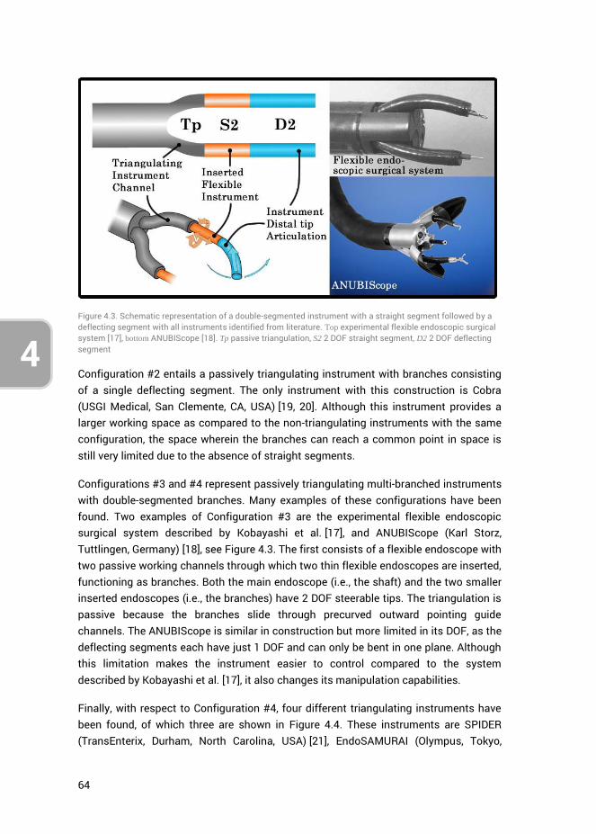
64
4
Figure 4.3. Schematic representation of a double-segmented instrument with a straight segment followed by a deflecting segment with all instruments identified from literature. Top experimental flexible endoscopic surgical system [17], bottom ANUBIScope [18]. Tp passive triangulation, S2 2 DOF straight segment, D2 2 DOF deflecting segment
Configuration #2 entails a passively triangulating instrument with branches consisting of a single deflecting segment. The only instrument with this construction is Cobra (USGI Medical, San Clemente, CA, USA) [19, 20]. Although this instrument provides a larger working space as compared to the non-triangulating instruments with the same configuration, the space wherein the branches can reach a common point in space is still very limited due to the absence of straight segments.
Configurations #3 and #4 represent passively triangulating multi-branched instruments with double-segmented branches. Many examples of these configurations have been found. Two examples of Configuration #3 are the experimental flexible endoscopic surgical system described by Kobayashi et al. [17], and ANUBIScope (Karl Storz, Tuttlingen, Germany) [18], see Figure 4.3. The first consists of a flexible endoscope with two passive working channels through which two thin flexible endoscopes are inserted, functioning as branches. Both the main endoscope (i.e., the shaft) and the two smaller inserted endoscopes (i.e., the branches) have 2 DOF steerable tips. The triangulation is passive because the branches slide through precurved outward pointing guide channels. The ANUBIScope is similar in construction but more limited in its DOF, as the deflecting segments each have just 1 DOF and can only be bent in one plane. Although this limitation makes the instrument easier to control compared to the system described by Kobayashi et al. [17], it also changes its manipulation capabilities.
Finally, with respect to Configuration #4, four different triangulating instruments have been found, of which three are shown in Figure 4.4. These instruments are SPIDER (TransEnterix, Durham, North Carolina, USA) [21], EndoSAMURAI (Olympus, Tokyo,
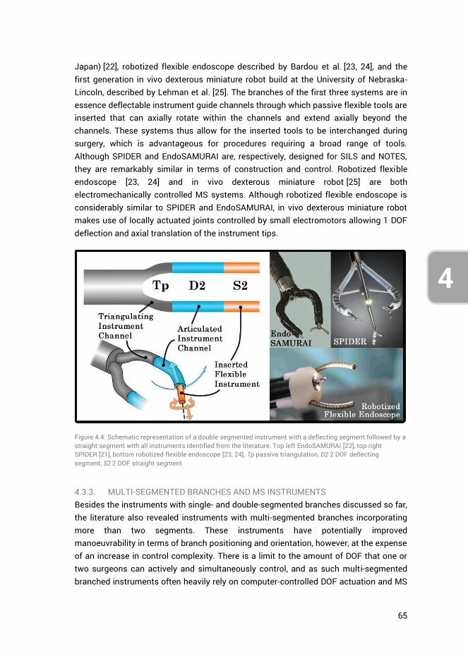
65
4
3
Japan) [22], robotized flexible endoscope described by Bardou et al. [23, 24], and the first generation in vivo dexterous miniature robot build at the University of Nebraska-Lincoln, described by Lehman et al. [25]. The branches of the first three systems are in essence deflectable instrument guide channels through which passive flexible tools are inserted that can axially rotate within the channels and extend axially beyond the channels. These systems thus allow for the inserted tools to be interchanged during surgery, which is advantageous for procedures requiring a broad range of tools. Although SPIDER and EndoSAMURAI are, respectively, designed for SILS and NOTES, they are remarkably similar in terms of construction and control. Robotized flexible endoscope [23, 24] and in vivo dexterous miniature robot [25] are both electromechanically controlled MS systems. Although robotized flexible endoscope is considerably similar to SPIDER and EndoSAMURAI, in vivo dexterous miniature robot makes use of locally actuated joints controlled by small electromotors allowing 1 DOF deflection and axial translation of the instrument tips.
Figure 4.4. Schematic representation of a double segmented instrument with a deflecting segment followed by a straight segment with all instruments identified from the literature. Top left EndoSAMURAI [22], top right SPIDER [21], bottom robotized flexible endoscope [23, 24]. Tp passive triangulation, D2 2 DOF deflecting segment, S2 2 DOF straight segment
4.3.3. MULTI-SEGMENTED BRANCHES AND MS INSTRUMENTS Besides the instruments with single- and double-segmented branches discussed so far, the literature also revealed instruments with multi-segmented branches incorporating more than two segments. These instruments have potentially improved manoeuvrability in terms of branch positioning and orientation, however, at the expense of an increase in control complexity. There is a limit to the amount of DOF that one or two surgeons can actively and simultaneously control, and as such multi-segmented branched instruments often heavily rely on computer-controlled DOF actuation and MS
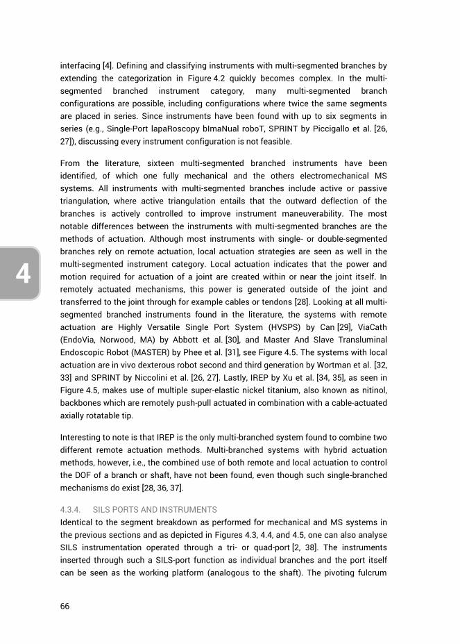
66
4
interfacing [4]. Defining and classifying instruments with multi-segmented branches by extending the categorization in Figure 4.2 quickly becomes complex. In the multi-segmented branched instrument category, many multi-segmented branch configurations are possible, including configurations where twice the same segments are placed in series. Since instruments have been found with up to six segments in series (e.g., Single-Port lapaRoscopy bImaNual roboT, SPRINT by Piccigallo et al. [26, 27]), discussing every instrument configuration is not feasible.
From the literature, sixteen multi-segmented branched instruments have been identified, of which one fully mechanical and the others electromechanical MS systems. All instruments with multi-segmented branches include active or passive triangulation, where active triangulation entails that the outward deflection of the branches is actively controlled to improve instrument maneuverability. The most notable differences between the instruments with multi-segmented branches are the methods of actuation. Although most instruments with single- or double-segmented branches rely on remote actuation, local actuation strategies are seen as well in the multi-segmented instrument category. Local actuation indicates that the power and motion required for actuation of a joint are created within or near the joint itself. In remotely actuated mechanisms, this power is generated outside of the joint and transferred to the joint through for example cables or tendons [28]. Looking at all multi-segmented branched instruments found in the literature, the systems with remote actuation are Highly Versatile Single Port System (HVSPS) by Can [29], ViaCath (EndoVia, Norwood, MA) by Abbott et al. [30], and Master And Slave Transluminal Endoscopic Robot (MASTER) by Phee et al. [31], see Figure 4.5. The systems with local actuation are in vivo dexterous robot second and third generation by Wortman et al. [32, 33] and SPRINT by Niccolini et al. [26, 27]. Lastly, IREP by Xu et al. [34, 35], as seen in Figure 4.5, makes use of multiple super-elastic nickel titanium, also known as nitinol, backbones which are remotely push-pull actuated in combination with a cable-actuated axially rotatable tip.
Interesting to note is that IREP is the only multi-branched system found to combine two different remote actuation methods. Multi-branched systems with hybrid actuation methods, however, i.e., the combined use of both remote and local actuation to control the DOF of a branch or shaft, have not been found, even though such single-branched mechanisms do exist [28, 36, 37].
4.3.4. SILS PORTS AND INSTRUMENTS Identical to the segment breakdown as performed for mechanical and MS systems in the previous sections and as depicted in Figures 4.3, 4.4, and 4.5, one can also analyse SILS instrumentation operated through a tri- or quad-port [2, 38]. The instruments inserted through such a SILS-port function as individual branches and the port itself can be seen as the working platform (analogous to the shaft). The pivoting fulcrum
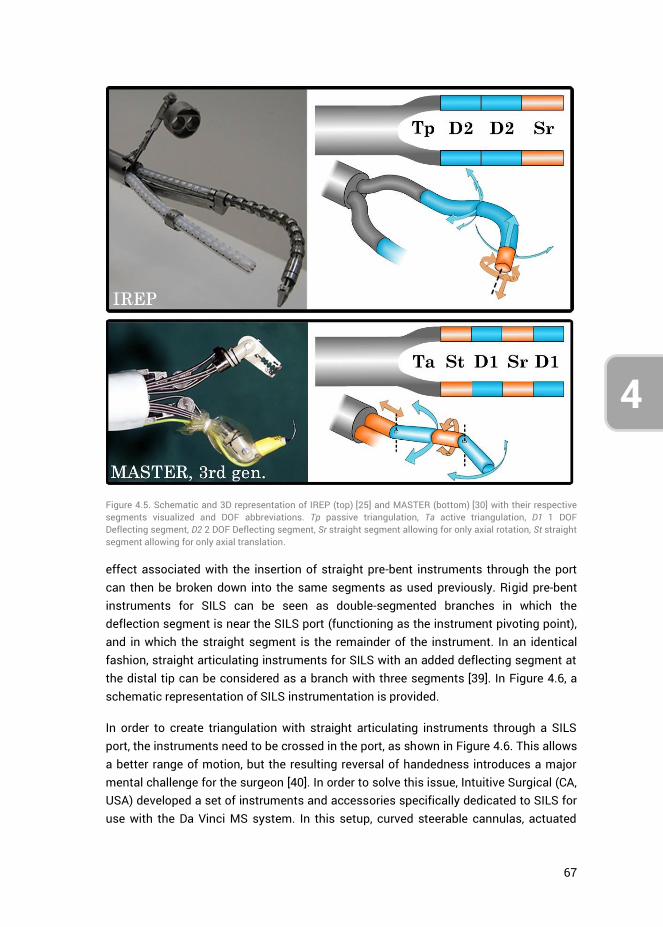
67
4
3
effect associated with the insertion of straight pre-bent instruments through the port can then be broken down into the same segments as used previously. Rigid pre-bent instruments for SILS can be seen as double-segmented branches in which the deflection segment is near the SILS port (functioning as the instrument pivoting point), and in which the straight segment is the remainder of the instrument. In an identical fashion, straight articulating instruments for SILS with an added deflecting segment at the distal tip can be considered as a branch with three segments [39]. In Figure 4.6, a schematic representation of SILS instrumentation is provided.
In order to create triangulation with straight articulating instruments through a SILS port, the instruments need to be crossed in the port, as shown in Figure 4.6. This allows a better range of motion, but the resulting reversal of handedness introduces a major mental challenge for the surgeon [40]. In order to solve this issue, Intuitive Surgical (CA, USA) developed a set of instruments and accessories specifically dedicated to SILS for use with the Da Vinci MS system. In this setup, curved steerable cannulas, actuated
Figure 4.5. Schematic and 3D representation of IREP (top) [25] and MASTER (bottom) [30] with their respective segments visualized and DOF abbreviations. Tp passive triangulation, Ta active triangulation, D1 1 DOF Deflecting segment, D2 2 DOF Deflecting segment, Sr straight segment allowing for only axial rotation, St straight segment allowing for only axial translation.
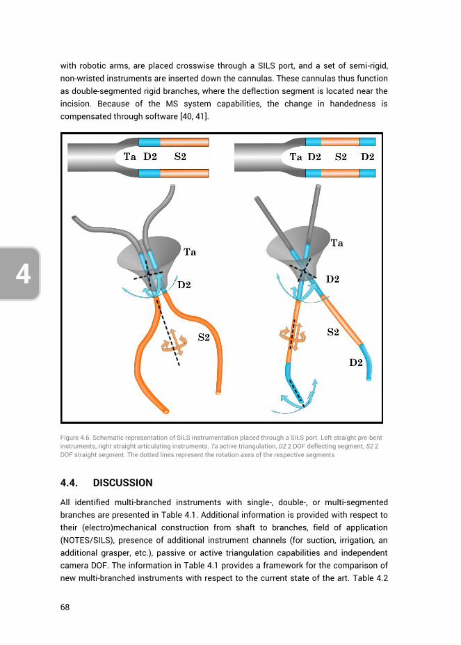
68
4
with robotic arms, are placed crosswise through a SILS port, and a set of semi-rigid, non-wristed instruments are inserted down the cannulas. These cannulas thus function as double-segmented rigid branches, where the deflection segment is located near the incision. Because of the MS system capabilities, the change in handedness is compensated through software [40, 41].
Figure 4.6. Schematic representation of SILS instrumentation placed through a SILS port. Left straight pre-bent instruments, right straight articulating instruments. Ta active triangulation, D2 2 DOF deflecting segment, S2 2 DOF straight segment. The dotted lines represent the rotation axes of the respective segments
4.4. DISCUSSION
All identified multi-branched instruments with single-, double-, or multi-segmented branches are presented in Table 4.1. Additional information is provided with respect to their (electro)mechanical construction from shaft to branches, field of application (NOTES/SILS), presence of additional instrument channels (for suction, irrigation, an additional grasper, etc.), passive or active triangulation capabilities and independent camera DOF. The information in Table 4.1 provides a framework for the comparison of new multi-branched instruments with respect to the current state of the art. Table 4.2
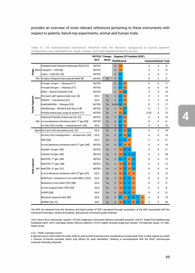
69
4
3
provides an overview of most relevant references pertaining to these instruments with respect to patents, bench-top experiments, animal and human trials.
Table 4.1. All multi-branched instruments identified from the literature categorized to branch segment configuration and subdivided into single-, double-, and multi-segmented branch groups
NOTES/ SILS
Triangu-lation
Degrees Of Freedom (DOF)
Shaft Branch Camera Channel Total
Sing
le
Mech
Standard Dual Channel Endoscope (DCE) [12] NOTES 4 S2 0 0 8
Transport – USGI [8] NOTES 4 S2 2 2 12
Cobra – USGI [19, 20] NOTES 3 D2 4 0 11
MS Scorpion Shaped Endosurgical Robot [9] NOTES Tp 3 D2 0 2 9
Doub
le S
egm
ent
Mech
R-scope 1st gen. – Olympus [11] NOTES 5 D1 S2 0 0 11
R-scope 2nd gen. – Olympus [11] NOTES 4 D1 S2 0 0 10
DDES – Boston Scientific [10] NOTES 3 S2 D2 4 0 15
SILS-port with rigid pre-bent instr. [2] SILS Ta 0 D2 S2 4 2 14
SPIDER – TransEnterix [21] SILS Tp 4 D2 S2 2 2 14
EndoSAMURAI – Olympus [22] NOTES Tp 3+2oa D2 S2 0 2 17
ANUBIScope – IRCAD & Karl Storz [18] NOTES Tp 3 St D1 0 2 11
Flexible endoscopic surgical system [17] NOTES Tp 3 S2 D2 (12)b 2 13
MS
Robotized Flexible Endoscope [23, 42] NOTES Tp 3 D2 S2 0 4 15
In-vivo dexterous miniature robot 1st gen [25] NOTES Tp 4 D1 St 0 0 8
Da Vinci SILS config. – unwristed instr. [43] SILS Ta 0 D2 S2 4 0 12
Mul
ti se
gmen
t
Mech SILS-port with articulating instr. [2] SILS Ta 0 D2 S2 D2 4 2 18
MS
Da Vinci SILS configuration – wristed instr. [43] SILS Ta 0 D2 S2 D2 4 0 16
IREP [34] SILS Tp 4 D2 D2 Sr 3 0 21
In-vivo dexterous miniature robot 2nd gen. [44] NOTES Ta 4 D1 Sr St 0 0 10
ViaCath 1nd gen. [30] NOTES Ta 1c S2 D2 D2 4 4 21
ViaCath 2nd gen. [30] NOTES Ta 4 S2 D2 D2 D2 4 4 28
MASTER, 1st gen. [45] NOTES Ta 3 D2 D1 Sr D1 0 0 13
MASTER, 2nd gen. [46] NOTES Ta 3 Sr D1 Sr D1 0 0 12
MASTER, 3rd gen. [31] NOTES Ta 3 Sr D1 Sr D1 0 0 12
In-vivo dexterous miniature robot 3rd gen. [47] SILS Tp 4 Sr D1 Sr St 0 0 12
Multi-funct. miniature in vivo robot (NB2.1) [32] SILS Tp 4 Sr D1 D1 Sr 0 0 12
Miniature in-vivo robot (TB1) [48] SILS Ta 0 Sr D1 D1 Sr 0 0 8
In-vivo surgical robot (TB2) [33] SILS Ta 0 Sr D1 D1 Sr 0 0 8
HVSPS [29] SILS Ta 4 S2 D1 D2 Sr 5 0 21
Miniature surgical robot [49] SILS Ta 0 D1 Sr D1 D1 D1 Sr 4 0 16
SPRINT [26, 27] SILS Tp 4 Sr D1 D1 Sr D1 Sr 2 2 20
The DOF are obtained from the literature and total number of DOF calculated through summation of the DOF associated with the instrument branches, camera articulation, and passive instrument guide channels
DDES direct drive endoscopic system; SPIDER single-port instrument delivery extended research; SPRINT Single-Port lapaRoscopy bImaNual roboT; IREP insertable robotic effector platform; HVSPS highly versatile single port system; NB Nate-Bot series; TB Tyler-Robot series
a 2o = 2DOF overtube control b Special case in which both the main shaft as well as both branches have visualisation incorporated; thus 3 video signals provided c Passive 3-channel overtube, which only allows for axial translation. Steering is accomplished with the 4DoF colonoscope (camera) internally disposed
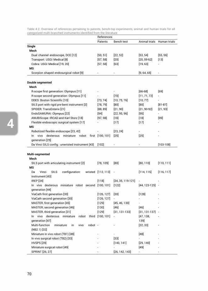
70
4
Table 4.2. Overview of references pertaining to patents, bench-top experiments, animal and human trials for all categorized multi-branched instruments identified from the literature References
Patents Bench test Animal trials Human trials Single Mech Dual channel endoscope, DCE [12] [50, 51] [22, 52] [53, 54] [55, 56] Transport: USGI Medical [8] [57, 58] [20] [20, 59-62] [13] Cobra: USGI Medical [19, 20] [57, 58] [63] [19, 63] - MS Scorpion shaped endosurgical robot [9] - - [9, 64, 65] -
Double segmented Mech R-scope first generation: Olympus [11] - - [66-68] [69] R-scope second generation: Olympus [11] - [70] [11, 71, 72] - DDES: Boston Scientific [10] [73, 74] [10, 75, 76] [10, 77] - SILS port with rigid pre-bent instrument [2] [78, 79] [80] [80] [81-87] SPIDER: TransEnterix [21] [88, 89] [21, 90] [21, 90-92] [21, 93] EndoSAMURAI: Olympus [22] [94] [22, 95, 96] [95] - ANUBIScope: IRCAD and Karl Storz [18] [97, 98] [18] [18] [99] Flexible endoscopic surgical system [17] - [17] [17] - MS Robotized flexible endoscope [23, 42] - [23, 24] - - In vivo dexterous miniature robot first
generation [25] [100, 101] [25] [25] -
Da Vinci SILS config.: unwristed instrument [43] [102] - - [103-108]
Multi-segmented Mech SILS port with articulating instrument [2] [78, 109] [80] [80, 110] [110, 111] MS Da Vinci SILS configuration: wristed
instrument [43] [112, 113] - [114, 115] [116, 117]
IREP [34] [118] [34, 35, 119-121] - - In vivo dexterous miniature robot second
generation [44] [100, 101] [122] [44, 123-125] -
ViaCath first generation [30] [126, 127] [30] [128] - ViaCath second generation [30] [126, 127] - - - MASTER, first generation [45] [129] [45, 46, 130] - - MASTER, second generation [46] [130] [46] [46] - MASTER, third generation [31] [129] [31, 131-133] [31, 131-137] - In vivo dexterous miniature robot third
generation [47] [100, 101] - [47, 138,
139] -
Multi-function miniature in vivo robot (NB2.1) [32]
- - [32, 33] -
Miniature in vivo robot (TB1) [48] - - [48] - In vivo surgical robot (TB2) [33] - [33] - - HVSPS [29] - [140, 141] [29, 140] - Miniature surgical robot [49] - - [49] - SPRINT [26, 27] - [26, 142, 143] - -
71
4
3
As can be deduced from Table 4.1, no two instruments are the same when comparing their sequence of branch segments and the presence of additional features. The explanation behind this wide diversity may be that there is no proven optimal branch construction and a large list of surgical procedure requirements. With respect to branch manoeuvrability, several questions remain unanswered, such as which sequence of segments will provide the surgeon with the most intuitive control, how many DOF can be controlled by one surgeon, what are the effects on the learning curve with respect to basic and complex task performance, which DOF are ‘ideally’ needed to perform bimanual tasks versus which DOF are ‘minimally’ required, and what control interface is best suited for these DOF? Especially with respect to the two last posed questions, it may be that providing the surgeon with the ‘ideal’ set of DOF does not outweigh the increased instrument design and control complexity. Conversely, providing more than the minimum required DOF, but less than what is ‘ideal,’ may prove more cost-effective. Taking as an example the basic tasks of knot tying and suturing; these can already be performed sufficiently well with a standard flexible endoscope (like the DCE) but at the cost of significant learning curves [144, 145]. In comparison, the DDES can be used to perform complex bimanual tasks more easily, however, this instrument needs to be secured to its surroundings and an assistant needs to be present during surgery to control the shaft and additional instruments inserted through passive instrument channels [22]. Which system is the better choice is dependent on many aspects, including the type of surgical procedure to be performed, surgeon experience and preference, hospital facilities, and patient characteristics. Further research is thus required to find answers to the raised questions.
4.4.1. MECHANICAL LIMITATIONS The current designs for multi-branched instruments suffer from considerable complexity, especially when intended for NOTES. The presence of a long flexible shaft, as opposed to SILS where the shaft can be relatively short and straight, influences both the design complexity with respect to the used actuation methods and the maximum allowable dimensions of the instruments. Moreover, as most NOTES instruments are not fixated to the abdominal wall, they are associated with a lower shaft stability as compared to SILS instruments which are often rigidly connected to the outside world. As such, NOSCAR has already stated the need for instrument fixation and stiffening to ensure adequate stability [3]. It is also for this reason that many potential future NOTES instruments are constructed as SILS instruments as an in-between stage to allow for testing under the condition of adequate platform stability.
Currently, all multi-branched instruments with single- or double-segmented branches make use of cable actuation to control the tip deflection of the shaft and the deflecting segments of the branches. Depending on the diameter of the used cables however, cable actuation has inherent limitations, such as a limited stiffness due to elasticity of the cables, minimum bending radii and friction forces between the cables and adjacent
72
4
surfaces [146]. The stiffness issue is even more important when two branches are operated simultaneously. Should the shaft be insufficiently stiff, the force application of one branch can deflect the tip of the shaft, shifting the camera image, influencing task precision, and requiring active correction of the shaft displacement. Research by Swanstrom et al. [20], however, has shown that through the active compression of titanium links incorporated within the shaft, the shaft stiffness can be increased when required.
The exact force levels which are required for NOTES and SILS systems have not been defined in the literature because they are dependent on their respective intended surgical application fields. However, the minimum force requirements can be assumed to be approximately equal to those of standard laparoscopic instruments. Forces reported in the literature for laparoscopic instruments used in a range of surgical tasks vary between 0.4 and 10.5 N [147-151]. The current literature on multi-branched instruments does not reveal whether these force requirements are fulfilled.
Dimensional constraints imposed by the anatomical surroundings of the intended surgical application fields greatly influence the design of NOTES and SILS instruments. Therefore, one key design aspect in the development of these systems is the choice of actuation method. Although most instruments make use of remote cable actuation as it places the power generation outside the patient, a locally placed motorized joint having a rigid transmission allows for a higher joint stiffness and the possibility of exerting higher torques [26]. However, incorporation of miniature motorized joints is often at the expense of larger dimensions, cost-effectiveness, and sterilization demands, and the power output of miniature electromotors is limited. Aside from the number and sequence of segments incorporated in the branches, there is thus a trade-off between actuation methods, force requirements, and anatomical constraints. As evidenced by Table 4.2, the only MS system that has been tested in human trials is Da Vinci which has not been developed specifically for NOTES or SILS. However, using Da Vinci in SILS configuration has been made possible at the expense of several limitations, including a limited range of motion, compared to its usage in standard MIS [117, 152]. The worldwide activities in the design and animal validation of multi-branched instrumentation for NOTES and SILS are a testament to the advancements in this field. However, the absence of human trials at most instruments with multi-segmented branches illustrates the high level of complexity and challenges associated with this field.
4.4.2. CONTROL Bimanual manipulation is essential to the successful performance of complex NOTES and SILS because it permits traction and countertraction, precise and efficient tissue separation, and approximation [8]. During the standard MIS approach, the surgeon uses surgical instruments while assistants provide visualization and apply traction with an
73
4
3
additional tool. This is reversed in the traditional endoscopic setting where the endoscopist, using the control wheels on a gastroscope or colonoscope handle, controls navigation, insufflation, and visualization, as well as specific aspects of tissue manipulation. The assistant is responsible for tissue grasping, exchanging instruments, and helping to clearly visualize the operative field. These duties vary at times, and interactions can become complex and inefficient with more technically demanding procedures [10]. This is for example the case with the DCE, where a single operator has significant difficulties performing these tasks. Multiple operators are required to control the device as a team, through a relatively non-ergonomic user interface [56, 153].
The need for cooperation between multiple surgeons is present in almost all the developed multitasking platforms where in most cases one surgeon controls the branches and another surgeon controls the shaft. A number of systems provide a stable control platform secured to the operating room surroundings (SPIDER [21], EndoSAMURAI [22], ANUBIScope [18], DDES [10]). Since the shaft and branches have separate control interfaces, this stable platform allows for control by a single surgeon who can switch between these interfaces in a modular fashion. However, a single surgeon is not able to simultaneously perform scope stabilization and tissue manipulation, which is often required during interventional endoscopy. Because the tip of the endoscope is rarely stable for a long time [15], a second surgeon is often needed to actively counteract unintended shaft deviations as well as aid with the control of additional instruments passed through passive guide channels. For more insights into the ergonomic properties and control surfaces of the individual systems, the reader is referred to the instrument references provided in Table 4.1, and the comparison articles by Yeung and Gourlay [5], Karimyan et al. [6], and Zhou et al. [7]. MS systems also require the aid of a second surgeon or an assistant in all cases. For example, MASTER [31] requires one surgeon at the patient’s side, manually controlling the instrument shaft, and another surgeon controlling the branches through the master interface. Da Vinci requires a bedside assistant for the introduction and steering of additional instruments which allow for suction and tissue retraction [116].
Important to address at this point is the differing ability in visualization of anatomical structures at the SILS instruments as compared to NOTES. In most of the discussed SILS setups the scope can be moved considerable relative to the branches. This is much less the case in NOTES instruments, where the scope usually has a much smaller range of motion and is more directly influenced by the movements of the shaft. As a result, allowing for scope control similar to standard MIS will likely pose a challenging aspect alongside the branch design and control complexity in the future development of NOTES.
74
4
Focusing on the control methods used for the various DOF incorporated in the multi-branched systems, the coupling between handle and steering motions of the shaft and branches is of importance with respect to both the level of operational difficulty (e.g., level of intuitiveness) as well as the precision in control. Both direct and indirect control methods have been developed for single-branched instruments [4]. Direct control entails that the instrument’s tip motion is in the same plane and same direction as the surgeon’s wrist or finger motion, as opposed to indirect control, where the tip motion occurs in another plane than the surgeon’s wrist or finger motion. In multi-branched instruments the focus appears to be mainly on the incorporation of the more intuitive direct control methods by attempting to simulate the standard two-handed MIS approach. Furthermore, there has also been a shift identified in the literature toward integrated control or shape memory control. This refers to a control concept in which only the first segment of the instrument tip is actively steered, followed passively by the rest of the segments as the instrument is advanced [4]. An example of a system with shape memory control is NeoGuide (NeoGuide Systems, Inc., San Jose, California, USA [6]). The influence of these various control methods in NOTES and SILS systems on the learning curve and task precision has not been investigated thoroughly yet. Moreover, the influence on multitasking efficiency of two surgeons operating one instrument combined with these control methods is unknown.
Spaun et al. [22] stated, after they had analysed and tested the R-scope [11], that a multi-branched instrument design should include independent branch motions, separation of vision and branch end-effectors, and a stable control platform. However, considering the accompanying complexity of such an instrument design, it can be speculated that the advantages of having separately controlled double- or multi-segmented branches, theoretically allowing for a large range of complex bimanual tasks to be performed, do not outweigh the added complexity of these devices [22]. Having two separately controlled branches permitting triangulation at the end of a shaft could even increase procedural instability instead of achieving effective countertraction, enhanced tissue cutting, or the ability to suture [15]. Hence every added feature to a design needs to be weighed for its benefit versus the added complexity in terms of construction and control.
4.4.3. FUTURE As stated by von Renteln et al. [15] ‘‘A single operator with two hands is only able to control a limited number of buttons and wheels. Any functions added to the flexible endoscope that allows for more angles of movement freedom, more capabilities, more control wheels, buttons, and levers will lead to practical limitations due to increased complexity. Consequently, every additional function achieving enhanced triangulation has to be reviewed for its trade-offs in robustness, stability, and practicality.’’
75
4
3
Due to the complexity of the currently existing multi-branched instruments, no instrument has yet proven to be cost-efficient and functional enough for implementation in general medical practice. Moreover, no multi-branched instrument yet exists which can be controlled by a single surgeon. It is the belief of the authors that smart instrument design and a reduction of the amount of DOF incorporated in the multi-branched systems to only those DOF which are the most essential for specific bimanual tasks will provide the solution to this challenge. In this respect, three questions require answers: (1) which DOF or segments are required for which surgical tasks, (2) in which sequence should the various segments be arranged, and (3) what is the most intuitive method to control the selected DOF? Hence proper task identification, accurate definition of task performance requirements and a focus on control methods are key to surmount the challenges in future NOTES and SILS instrument design.
4.5. CONCLUSIONS
A state of the art overview was provided of all the developed multi-branched instruments for SILS and NOTES. The instruments were categorized based on the branch segmentation. It was recognized that so far no systems have found their way into clinical practice yet, or proved superior in bimanual task performance with respect to their conventional counterpart minimally invasive procedures. While non-triangulating instruments do not provide sufficient manoeuvrability for complex tasks such as suturing or knot tying, triangulating instruments quickly become too complex both in terms of design and control. Currently, controlling multi-branched instruments requires a minimum of two surgeons actively working together or the incorporation of a complex MS system. Several fundamental questions remain unanswered: (1) how many and which DOF are minimally needed to perform certain bimanual tasks, (2) which branch segment sequence is optimal for these tasks, and (3) what are the most efficient control methods relating to these DOF and these tasks?
In order to bring NOTES and SILS systems into clinical practice, a reduction of the amount of actively controlled DOF is deemed necessary. Although the design of multi-branched instruments is challenging with respect to anatomical constraints, manoeuvrability requirements, and actuation of the branches, the optimization of the control aspects is of equal importance. Allowing for a single surgeon to perform bimanual tasks without the aid of a second surgeon is of more value than increasing the multi-branched instrument complexity.

76
4
4.6. AUTHOR CONTRIBUTIONS
Ewout A. Arkenbout was responsible for the study conceptualization, data curation, investigation, methodology and writing of the article draft. Paul Breedveld provided supervision, and all authors contributed to reviewing and editing the article.4.7.
4.7. REFERENCES
1. Kalloo, A.N., et al., Flexible transgastric peritoneoscopy: a novel approach to diagnostic and therapeutic interventions in the peritoneal cavity. Gastrointest Endosc, 2004. 60(1): p. 114-7.
2. Dhumane, P.W., et al., Minimally invasive single-site surgery for the digestive system: A technological review. Journal of minimal access surgery, 2011. 7(1): p. 40-51.
3. Rattner, D. and A. Kalloo, ASGE/SAGES Working Group on Natural Orifice Translumenal Endoscopic Surgery. October 2005. Surgical Endoscopy and Other Interventional Techniques, 2006. 20(2): p. 329-33.
4. Fan, C., D. Dodou, and P. Breedveld, Review of manual control methods for handheld maneuverable instruments. Minimally Invasive Therapy \& Allied Technologies, 2012: p. 1-9.
5. Yeung, B.P. and T. Gourlay, A technical review of flexible endoscopic multitasking platforms. Int J Surg, 2012. 10(7): p. 345-54.
6. Karimyan, V., et al., Navigation systems and platforms in natural orifice translumenal endoscopic surgery (NOTES). International Journal of Surgery, 2009. 7(4): p. 297-304.
7. Zhou, Y., et al., Robotics in natural orifice transluminal endoscopic surgery. Journal of Mechanics in Medicine and Biology, 2013. 13(02): p. 1350044.
8. Swanstrom, L.L., M. Whiteford, and Y. Khajanchee, Developing essential tools to enable transgastric surgery. Surgical Endoscopy and Other Interventional Techniques, 2008. 22(3): p. 600-604.
9. Suzuki, N., et al., Scorpion Shaped Endoscopic Surgical Robot for NOTES and SPS With Augmented Reality Functions, in Medical Imaging and Augmented Reality, H. Liao, et al., Editors. 2010, Springer Berlin Heidelberg. p. 541-550.
10. Thompson, C.C., et al., Evaluation of a manually driven, multitasking platform for complex endoluminal and natural orifice transluminal endoscopic surgery applications. Gastrointestinal Endoscopy, 2009. 70(1): p. 121-125.
11. Astudillo, J.A., et al., Transgastric cholecystectomy using a prototype endoscope with 2 deflecting working channels (with video). Gastrointestinal Endoscopy, 2009. 69(2): p. 297-302.
12. Olympus, Olympus GIF type 2T160, Exceptional Dual-Channel Versatility. 2013, http://www.olympusamerica.com/msg_section/download_brochures/694_b_gif2t160.pdf.
13. Horgan, S., et al., Clinical experience with a multifunctional, flexible surgery system for endolumenal, single-port, and NOTES procedures. Surgical Endoscopy and Other Interventional Techniques, 2011. 25(2): p. 586-92.
14. Pearl, J.P. and J.L. Ponsky, Natural orifice translumenal endoscopic surgery: a critical review. J Gastrointest Surg, 2008. 12(7): p. 1293-300.
15. von Renteln, D., et al., Triangulation: the holy grail of endoscopic surgery? Surgical endoscopy, 2011. 25(5): p. 1355-1357.
16. Bardaro, S.J. and L. Swanstrom, Development of advanced endoscopes for Natural Orifice Transluminal Endoscopic Surgery (NOTES). Minim Invasive Ther Allied Technol, 2006. 15(6): p. 378-83.

77
4
3
17. Kobayashi, T., et al., A flexible endoscopic surgical system: First report on a conceptual design of the system validated by experiments. Japanese Journal of Clinical Oncology, 2005. 35(11): p. 667-671.
18. Dallemagne, B. and J. Marescaux, The ANUBIS (TM) project. Minimally Invasive Therapy \& Allied Technologies, 2010. 19(5): p. 257-261.
19. Swanstrom, L.L., et al., Development of a new access device for transgastric surgery. J Gastrointest Surg, 2005. 9(8): p. 1129-36; discussion 1136-7.
20. Swanstrom, L., P. Swain, and P. Denk, Development and validation of a new generation of flexible endoscope for NOTES. Surg Innov, 2009. 16(2): p. 104-110.
21. Haber, G.P., et al., SPIDER surgical system for urologic procedures with laparoendoscopic single-site surgery: from initial laboratory experience to first clinical application. Eur Urol, 2012. 61(2): p. 415-22.
22. Spaun, G.O., B. Zheng, and L.L. Swanstrom, A multitasking platform for natural orifice translumenal endoscopic surgery (NOTES): a benchtop comparison of a new device for flexible endoscopic surgery and a standard dual-channel endoscope. Surgical Endoscopy and Other Interventional Techniques, 2009. 23(12): p. 2720-7.
23. Bardou, B., et al., Design of a telemanipulated system for transluminal surgery. Embc: 2009 Annual International Conference of the Ieee Engineering in Medicine and Biology Society, 2009. 1-20: p. 5577-5582.
24. Bardou, B., et al., Control of a Multiple Sections Flexible Endoscopic System. Ieee/Rsj 2010 International Conference on Intelligent Robots and Systems (Iros 2010), 2010: p. 2345-2350.
25. Lehman, A.C., et al., Robotic Natural Orifice Translumenal Endoscopic Surgery. 2008 Ieee International Conference on Robotics and Automation, Vols 1-9, 2008: p. 2969-2974.
26. Piccigallo, M., et al., Design of a Novel Bimanual Robotic System for Single-Port Laparoscopy. Ieee-Asme Transactions on Mechatronics, 2010. 15(6): p. 871-878.
27. Niccolini, M., et al., Real-Time Control Architecture of a Novel Single-Port lapaRoscopy bimaNual roboT (SPRINT). 2012 Ieee International Conference on Robotics and Automation. 2012, New York: Ieee. 3395-3400.
28. Robinson, G. and J.B.C. Davies, Continuum robots - A state of the art. Icra '99: Ieee International Conference on Robotics and Automation, Vols 1-4, Proceedings, 1999: p. 2849-2854.
29. Can, S., et al. Design, development and evaluation of a highly versatile robot platform for minimally invasive single-port surgery. in 2012 4th IEEE RAS & EMBS International Conference on Biomedical Robotics and Biomechatronics (BioRob). 2012.
30. Abbott, D.J., et al., Design of an endoluminal NOTES robotic system. 2007 Ieee/Rsj International Conference on Intelligent Robots and Systems, Vols 1-9, 2007: p. 416-422.
31. Phee, S.J., et al., Design of a master and slave transluminal endoscopic robot for natural orifice transluminal endoscopic surgery. Proceedings of the Institution of Mechanical Engineers Part C-Journal of Mechanical Engineering Science, 2010. 224(C7): p. 1495-1503.
32. Wortman, T.D., et al., Laparoendoscopic single-site surgery using a multi-functional miniature in vivo robot. International Journal of Medical Robotics and Computer Assisted Surgery, 2011. 7(1): p. 17-21.
33. Wortman, T.D., Design, analysis, and testing of in vivo surgical robots. 2011. 34. Xu, K., et al., System Design of an Insertable Robotic Effector Platform for Single Port
Access (SPA) Surgery. 2009 Ieee-Rsj International Conference on Intelligent Robots and Systems, 2009: p. 5546-5552.
78
4
35. Bajo, A., et al., Integration and Preliminary Evaluation of an Insertable Robotic Effectors Platform for Single Port Access Surgery. 2012 Ieee International Conference on Robotics and Automation. 2012. 3381-3387.
36. McMahan, W., B.A. Jones, and I.D. Walker, Design and implementation of a multi-section continuum robot: Air-octor. 2005 Ieee/Rsj International Conference on Intelligent Robots and Systems, Vols 1-4, 2005: p. 3345-3352.
37. Ning, K.J. and F. Worgotter, A Novel Concept for Building a Hyper-Redundant Chain Robot. Ieee Transactions on Robotics, 2009. 25(6): p. 1237-1248.
38. Kommu, S.S., J.H. Kaouk, and A. Rane, Laparo-endoscopic single-site surgery: preliminary advances in renal surgery. BJU Int, 2009. 103(8): p. 1034-1037.
39. Romanelli, J.R. and D.B. Earle, Single-port laparoscopic surgery: an overview. Surgical Endoscopy and Other Interventional Techniques, 2009. 23(7): p. 1419-1427.
40. Autorino, R., et al., Current Status and Future Directions of Robotic Single-Site Surgery: A Systematic Review. European Urology, 2013. 63(2): p. 266-280.
41. Joseph, R.A., et al., “Chopstick” surgery: a novel technique improves surgeon performance and eliminates arm collision in robotic single-incision laparoscopic surgery. Surgical Endoscopy, 2010. 24(6): p. 1331-1335.
42. Bardou, B., et al., Design of a Robotized Flexible Endoscope for Natural Orifice Transluminal Endoscopic Surgery. Computational Surgery and Dual Training. 2010, New York: Springer. 155-170.
43. Intuitive Surgical. The da Vinci Surgical System. 2013; Available from: http://www.intuitivesurgical.com/products/davinci_surgical_system/.
44. Lehman, A.C., et al., Dexterous miniature in vivo robot for NOTES. 2008 2nd Ieee Ras \& Embs International Conference on Biomedical Robotics and Biomechatronics (Biorob 2008), Vols 1 and 2, 2008: p. 244-249.
45. Low, S.C., et al., Master-slave robotic system for therapeutic gastrointestinal endoscopic procedures. 2006 28th Annual International Conference of the IEEE Engineering in Medicine and Biology Society, Vols 1-15, 2006: p. 738-741.
46. Phee, S.J., et al., Robotic system for no-scar gastrointestinal surgery. International Journal of Medical Robotics and Computer Assisted Surgery, 2008. 4(1): p. 15-22.
47. Tiwari, M.M., et al., In vivo miniature robots for natural orifice surgery: State of the art and future perspectives. World J Gastrointest Surg, 2010. 2(6): p. 217-23.
48. Dolghi, O., et al., Miniature in vivo robot for laparoendoscopic single-site surgery. Surgical Endoscopy and Other Interventional Techniques, 2011. 25(10): p. 3453-3458.
49. Wortman, T.D., et al., Miniature surgical robot for laparoendoscopic single-incision colectomy. Surgical Endoscopy and Other Interventional Techniques, 2012. 26(3): p. 727-731.
50. Aoki, H. and S. Sato, Endoscope Apparatus, Olympus Medical Systems Corp., Editor. 2009.
51. Ito, Y. and M. Miyamoto, Endoscopic system, Olympus Medical Systems Corp., Editor. 2009.
52. Spaun, G.O., et al., Bimanual coordination in natural orifice transluminal endoscopic surgery: comparing the conventional dual-channel endoscope, the R-Scope, and a novel direct-drive system. Gastrointestinal Endoscopy, 2009. 69(6): p. e39-45.
53. Satgunam, S., et al., Transvaginal cholecystectomy without laparoscopic support using prototype flexible endoscopic instruments in a porcine model. Surgical Endoscopy and Other Interventional Techniques, 2012. 26(8): p. 2331-2338.
54. Asakuma, M., et al., Peroral Dual Scope for Natural Orifice Transluminal Endoscopic Surgery (NOTES) Gastrotomy Closure. Surg Innov, 2009. 16(2): p. 97-103.
55. Sodergren, M.H., et al., Natural orifice translumenal endoscopic surgery: critical appraisal of applications in clinical practice. Surg Endosc, 2009. 23(4): p. 680-7.

79
4
3
56. Marescaux, J., et al., Surgery without scars - Report of transluminal cholecystectomy in a human being. Archives of Surgery, 2007. 142(9): p. 823-826.
57. Saadat, V., R.C. Ewers, and E.G. Chen, Shape lockable apparatus and method for advancing an instrument through unsupported anatomy, Usgi Medical Inc., Editor. 2006.
58. Maahs, T.D., et al., Disposable shapelocking system, Usgi Medical Inc., Editor. 2006. 59. Mellinger, J.D., et al., Initial experience with a novel endoscopic device allowing
intragastric manipulation and plication. Surgical Endoscopy and Other Interventional Techniques, 2007. 21(6): p. 1002-5.
60. Swain, P., et al., The development and testing of a new multichannel, shape-locking guide with tip and mid body articulation for intragastric endosurgery. Gastrointestinal Endoscopy, 2005. 61(5): p. AB183.
61. Swain, P., et al., Development and testing of a new platform for retroflexed flexible transgastric surgery: cholecystectomy, fundoplication, gastric restriction and diaphragmatic repair. Gastrointestinal Endoscopy, 2006. 63(5): p. AB102.
62. Clayman, R.V., et al., Transvaginal single-port NOTES nephrectomy: Initial laboratory experience. Journal of Endourology, 2007. 21(6): p. 640-644.
63. Pasricha, P., et al., A next generation therapeutic endoscope: Development of a novel endoluminal surgery system with "birds-eye" visualization and triangulating instruments. Gastrointestinal Endoscopy, 2005. 61(5): p. Ab106-Ab106.
64. Hattori, A., et al., Navigation system for a developed endoscopic surgical robot system. Cars 2004: Computer Assisted Radiology and Surgery, Proceedings, 2004. 1268: p. 539-544.
65. Hattori, A., et al., Surgical Robotics and Instrumentation: General development plan of surgical robotic systems. Int J Cars, 2006. 1: p. 201-228.
66. Neuhaus, H., et al., Testing of a new endoscope (R-Scope) for en-bloc submucosal dissection (EBSD). Gastrointestinal Endoscopy, 2005. 61(5): p. AB234-AB234.
67. Sumiyama, K., et al., Transgastric cholecystectomy: transgastric accessibility to the gallbladder improved with the SEMF method and a novel multibending therapeutic endoscope. Gastrointestinal Endoscopy, 2007. 65(7): p. 1028-1034.
68. Ryou, M., et al., Dual-port distal pancreatectomy using a prototype endoscope and endoscopic stapler: a natural orifice transluminal endoscopic surgery (NOTES) survival study in a porcine model. Endoscopy, 2007. 39(10): p. 881-887.
69. Yonezawa, J., et al., A novel double-channel therapeutic endoscope ("R-scope") facilitates endoscopic submucosal dissection of superficial gastric neoplasms. Endoscopy, 2006. 38(10): p. 1011-1015.
70. Lee, S.H., et al., Efficacy of a prototype endoscope with two deflecting working channels for endoscopic submucosal dissection: a prospective, comparative, ex vivo study. Gastrointestinal Endoscopy, 2010. 72(1): p. 155-160.
71. Moyer, M.T., et al., Transgastric organ resection solely with the prototype R-scope and the self-approximating transluminal access technique. Gastrointestinal Endoscopy, 2010. 72(1): p. 170-176.
72. Trunzo, J.A., et al., The diagnostic efficacy of natural orifice transluminal endoscopic surgery: is there a role in the intensive care unit? Surgical Endoscopy and Other Interventional Techniques, 2010. 24(10): p. 2485-2491.
73. Weitzner, B., et al., Direct drive instruments and methods of use, Boston Scientific Scimed Inc., Editor. 2008.
74. Weitzner, B., et al., Direct drive endoscopy systems and methods, Boston Scientific Scimed Inc., Editor. 2012.
75. Spaun, G.O. and L.L. Swanstrom, Quo vadis NOTES? European Surgery-Acta Chirurgica Austriaca, 2008. 40(5): p. 211-219.
80
4
76. Fernandez-Esparrach, G., et al., A new multi-tasking platform for advanced intralumenal and NOTES procedures: Learning curve assessment, and accuracy in an endoscopic mucosal resection model. Gastrointestinal Endoscopy, 2008. 67(5): p. AB146-AB147.
77. Rothstein, R.I. and L.L. Swanstrom, Use of the direct drive endoscopic system (DDES) for in-vivo mucosal resection in a porcine model. Gastrointestinal Endoscopy, 2008. 67(5): p. Ab146-Ab146.
78. Richard, P.D., Flexible port seal, Covidien LP, Editor. 2010. 79. Azarbarzin, K., D. Mastri, and R. Stearns, Surgical instruments with improved dexterity
for use in minimally invasive surgical procedures, Surgiquest Inc., Editor. 2010. 80. Stolzenburg, J.U., et al., Comparative assessment of laparoscopic single-site surgery
instruments to conventional laparoscopic in laboratory setting. J Endourol, 2010. 24(2): p. 239-45.
81. Desai, M.M., et al., Scarless single port transumbilical nephrectomy and pyeloplasty: first clinical report. BJU Int, 2008. 101(1): p. 83-8.
82. Gill, I.S., et al., Single port transumbilical (E-NOTES) donor nephrectomy. J Urol, 2008. 180(2): p. 637-41; discussion 641.
83. Goel, R.K. and J.H. Kaouk, Single port access renal cryoablation (SPARC): a new approach. Eur Urol, 2008. 53(6): p. 1204-9.
84. Kaouk, J.H., et al., Single-port laparoscopic surgery in urology: initial experience. Urology, 2008. 71(1): p. 3-6.
85. Rane, A., P. Rao, and P. Rao, Single-port-access nephrectomy and other laparoscopic urologic procedures using a novel laparoscopic port (R-port). Urology, 2008. 72(2): p. 260-3; discussion 263-4.
86. Curcillo, P.G., 2nd, et al., Single Port Access (SPA) Minimal Access Surgery Through a Single Incision. Surg Technol Int, 2009. 18: p. 19-25.
87. Mereu, L., et al., Single access laparoscopy for adnexal pathologies using a novel reusable port and curved instruments. International Journal of Gynecology \& Obstetrics, 2010. 109(1): p. 78-80.
88. Williams, M.S., et al., System and method for multi-instrument surgical access, Transenterix Surgical Inc., Editor. 2011.
89. Williams, M.S., et al., Procedural cannula and support system for surgical procedures, TransEnterix Surgical Inc., Editor. 2011.
90. Knight, J., et al., Single-Port Gynecologic Surgery With a Novel Surgical Platform. Surg Innov, 2011.
91. Pryor, A.D., J.R. Tushar, and L.R. DiBernardo, Single-port cholecystectomy with the TransEnterix SPIDER: simple and safe. Surgical Endoscopy and Other Interventional Techniques, 2010. 24(4): p. 917-23.
92. Salas, N., et al., Laparoendoscopic single site nephrectomy with the SPIDER surgical system: engineering advancements tested in a porcine model. Journal of Endourology, 2011. 25(5): p. 739-42.
93. Leveillee, R.J., et al., Initial experience with laparoendoscopic single-site simple nephrectomy using the TransEnterix SPIDER surgical system: assessing feasibility and safety. Journal of Endourology, 2011. 25(6): p. 923-5.
94. Dejima, T., K. Matsuno, and S. Takemoto, Medical treatment endoscope, Olympus Medical Systems Corp., Editor. 2011.
95. Fuchs, K.-H. and W. Breithaupt, Transgastric small bowel resection with the new multitasking platform EndoSAMURAI (TM) for natural orifice transluminal endoscopic surgery. Surgical Endoscopy and Other Interventional Techniques, 2012. 26(8): p. 2281-2287.

81
4
3
96. Ikeda, K., et al., Evaluation of a new multitasking platform for endoscopic full-thickness resection. Gastrointestinal Endoscopy, 2011. 73(1): p. 117-22.
97. Marescaux, J.F.B., et al., Endoscope system with pivotable arms, Karl Storz Endovision Inc., Editor. 2008.
98. Marescaux, J.F.B., et al., Articulating endoscope instrument, Karl Storz Endovision Inc., Editor. 2009.
99. Perretta, S., et al., The ANUBISCOPE(A (R)) flexible platform ready for prime time: description of the first clinical case. Surgical Endoscopy and Other Interventional Techniques, 2013. 27(7): p. 2630-2630.
100. Farritor, S.M., A. Lehman, and M. Rentschler, Multifunctional operational component for robotic devices, Board Of Regents Of The University Of Nebraska, Editor. 2009.
101. Farritor, S.M., et al., Methods, systems, and devices for surgical access and procedures, Board Of Regents Of The University Of Nebraska, Editor. 2012.
102. Prisco, G.M., et al., Curved cannula surgical system, Intuitive Surgical Operations Inc., Editor. 2011.
103. Cestari, A., et al., Feasibility and Preliminary Clinical Outcomes of Robotic Laparoendoscopic Single-Site (R-LESS) Pyeloplasty Using a New Single-Port Platform. European Urology, 2012. 62(1): p. 175-179.
104. Konstantinidis, K.M., et al., Cholecystectomy using a novel Single-Site(A (R)) robotic platform: early experience from 45 consecutive cases. Surgical Endoscopy and Other Interventional Techniques, 2012. 26(9): p. 2687-2694.
105. Kroh, M., et al., First human surgery with a novel single-port robotic system: cholecystectomy using the da Vinci Single-Site platform. Surgical Endoscopy and Other Interventional Techniques, 2011. 25(11): p. 3566-3573.
106. Morel, P., et al., Robotic Single-Port Cholecystectomy Using a New Platform: Initial Clinical Experience. Journal of Gastrointestinal Surgery, 2011. 15(12): p. 2182-2186.
107. Spinoglio, G., et al., Single-site robotic cholecystectomy (SSRC) versus single-incision laparoscopic cholecystectomy (SILC): comparison of learning curves. First European experience. Surgical Endoscopy and Other Interventional Techniques, 2012. 26(6): p. 1648-1655.
108. Wren, S.M. and M.J. Curet, Single-Port Robotic Cholecystectomy Results From a First Human Use Clinical Study of the New da Vinci Single-Site Surgical Platform. Archives of Surgery, 2011. 146(10): p. 1122-1127.
109. Wales, K.S. and C.P. Boudreaux, Surgical instrument with articulating shaft with single pivot closure and double pivot frame ground, Ethicon Endo-Surgery Inc., Editor. 2006.
110. Raman, J.D., et al., Laboratory and clinical development of single keyhole umbilical nephrectomy. Urology, 2007. 70(6): p. 1039-1042.
111. Stolzenburg, J.-U., et al., Technique of Laparoscopic-Endoscopic Single-Site Surgery Radical Nephrectomy. Eur Urol, 2009. 56(4): p. 644-650.
112. Burbank, W.A., Backend mechanism for four-cable wrist, Intuitive Surgical Inc., Editor. 2010.
113. Diolaiti, N., Method and system for moving a plurality of articulated instruments in tandem back towards an entry guide, Intuitive Surgical Operations Inc., Editor. 2012.
114. Box, G.N., et al., Rapid communication - Robot-assisted NOTES nephrectomy: Initial report. Journal of Endourology, 2008. 22(3): p. 503-506.
115. Haber, G.P., et al., Robotic NOTES (Natural Orifice Translumenal Endoscopic Surgery) in reconstructive urology: initial laboratory experience. Urology, 2008. 71(6): p. 996-1000.
116. Kaouk, J.H., et al., Robotic single-port transumbilical surgery in humans: initial report. BJU Int, 2009. 103(3): p. 366-369.
117. White, M.A., G.-P. Haber, and J.H. Kaouk, Robotic single-site surgery. Curr Opin Urol, 2010. 20(1): p. 86-91.
82
4
118. Simaan, N., et al., Systems, devices, and methods for providing insertable robotic sensory and manipulationplatforms for single port surgery, The Trustees Of Columbia University In The City Of New York, Editor. 2011.
119. Ding, J.A., et al., Design, Simulation and Evaluation of Kinematic Alternatives for Insertable Robotic Effectors Platforms in Single Port Access Surgery. 2010 Ieee International Conference on Robotics and Automation (Icra), 2010: p. 1053-1058.
120. Simaan, N., R. Taylor, and P. Flint, High dexterity snake-like robotic slaves for minimally invasive telesurgery of the upper airway. Medical Image Computing and Computer-Assisted Intervention - Miccai 2004, Pt 2, Proceedings, 2004. 3217: p. 17-24.
121. Xu, K. and N. Simaan, An investigation of the intrinsic force sensing capabilities of continuum robots. Ieee Transactions on Robotics, 2008. 24(3): p. 576-587.
122. Dumpert, J., et al., Semi-autonomous Surgical Tasks Using a Miniature In vivo Surgical Robot. Embc: 2009 Annual International Conference of the Ieee Engineering in Medicine and Biology Society, Vols 1-20. 2009. 266-269.
123. Lehman, A.C., et al., Natural Orifice Translumenal Endoscopic Surgery with a miniature in vivo surgical robot. Surgical Endoscopy and Other Interventional Techniques, 2009. 23(7): p. 1649-1649.
124. Lehman, A.C., et al., Natural orifice cholecystectomy using a miniature robot. Surgical Endoscopy and Other Interventional Techniques, 2009. 23(2): p. 260-266.
125. Farritor, S.M., A.C. Lehman, and D. Oleynikov, Miniature in vivo robots for NOTES; surgical robotics, J. Rosen, B. Hannaford, and R.M. Satava, Editors. 2011, Springer US. p. 123-138.
126. Weitzner, B.D., et al., Robotic medical instrument system, Endovia Medical Inc., Editor. 2004.
127. Brock, D.L. and W. Lee, Surgical instrument, Endovia Medical Inc., Editor. 2005. 128. Rothstein, R.I., R.A. Ailinger, and W. Peine, Computer-assisted endoscopic robot system
for advanced therapeutic procedures. Gastrointestinal Endoscopy, 2004. 59(5): p. Ab113-Ab113.
129. Phee, S.J.L., et al., Robotic system for flexible endoscopy, Nanyang Technological University, Editor. 2012.
130. Kencana, A.P., et al., Master and Slave Robotic System For Natural Orifice Transluminal Endoscopic Surgery. 2008 Ieee Conference on Robotics, Automation, and Mechatronics, Vols 1 and 2, 2008: p. 566-570.
131. Phee, S.J., et al., Master And Slave Transluminal Endoscopic Robot (MASTER) for Natural Orifice Transluminal Endoscopic Surgery (NOTES). Embc: 2009 Annual International Conference of the Ieee Engineering in Medicine and Biology Society, Vols 1-20. 2009, New York: Ieee. 1192-1195.
132. Ho, K.Y., et al., Endoscopic submucosal dissection of gastric lesions by using a Master and Slave Transluminal Endoscopic Robot (MASTER). Gastrointestinal Endoscopy, 2010. 72(3): p. 593-599.
133. Sun, Z.L., et al., Enhancement of a Master-Slave Robotic System for Natural Orifice Transluminal Endoscopic Surgery. Annals Academy of Medicine Singapore, 2011. 40(5): p. 223-230.
134. Ho, K.Y., et al., Natural Orifice Trangastric Endoscopic Segmental Hepatectomy Using a Through-the-Scope Intuitively Controlled Robotics-Enhanced Manipulator System. Gastrointestinal Endoscopy, 2009. 69(5): p. Ab162-Ab162.
135. Phee, S.J., et al., Natural orifice transgastric endoscopic wedge hepatic resection in an experimental model using an intuitively controlled master and slave transluminal endoscopic robot (MASTER). Surgical Endoscopy and Other Interventional Techniques, 2010. 24(9): p. 2293-2298.
83
4
3
136. Phee, S.J., et al., Robot-Assisted Endoscopic Submucosal Dissection Is Effective in Treating Patients With Early-Stage Gastric Neoplasia. Clinical Gastroenterology and Hepatology, 2012. 10(10): p. 1117-1121.
137. Wang, Z., et al., Endoscopic submucosal dissection of gastric lesions by using a master and slave transluminal endoscopic robot: an animal survival study. Endoscopy, 2012. 44(7): p. 690-694.
138. Lehman, A.C., et al., Dexterous miniature robot for advanced minimally invasive surgery. Surgical Endoscopy and Other Interventional Techniques, 2011. 25(1): p. 119-123.
139. Lehman, A.C., et al., Recent advances in the CoBRASurge robotic manipulator and dexterous miniature in vivo robotics for minimally invasive surgery. Proceedings of the Institution of Mechanical Engineers Part C-Journal of Mechanical Engineering Science, 2010. 224(C7): p. 1487-1494.
140. Can, S., et al., The mechatronic support system HVSPS and the way to NOTES. Minimally Invasive Therapy \& Allied Technologies, 2008. 17(6): p. 341-345.
141. Can, S., et al., The "Highly Versatile Single Port System" for laparoscopic surgery: Introduction and first clinical application, in 4th European Conference of the International Federation for Medical and Biological Engineering, J. VanderSloten, et al., Editors. 2009, Springer: New York. p. 1650-1654.
142. Sanchez, L.A., et al., Real-time control and evaluation of a teleoperated miniature arm for Single Port Laparoscopy. Conf Proc IEEE Eng Med Biol Soc, 2011. 2011: p. 7049-53.
143. Petroni, G., et al., A novel intracorporeal assembling robotic system for single-port laparoscopic surgery. Surgical Endoscopy, 2013. 27(2): p. 665-670.
144. Swain, P. and P.O. Park, Endoscopic suturing. Best Practice \& Research in Clinical Gastroenterology, 2004. 18(1): p. 37-47.
145. Swain, C.P., et al., Knot Tying at Flexible Endoscopy. Gastrointestinal Endoscopy, 1994. 40(6): p. 722-729.
146. Berkelman, P., et al., Design, control and testing of a novel compact laparoscopic endoscope manipulator. Proceedings of the Institution of Mechanical Engineers, Part I: Journal of Systems and Control Engineering, 2003. 217(4): p. 329-341.
147. Yamashita, H., et al. Multi-slider linkage mechanism for endoscopic forceps manipulator. in Intelligent Robots and Systems, 2003. (IROS 2003). Proceedings. 2003 IEEE/RSJ International Conference on. 2003.
148. Schlaak, H.F., et al., A Novel Laparoscopic Instrument with Multiple Degrees of Freedom and Intuitive Control. 4th European Conference of the International Federation for Medical and Biological Engineering, 2009. 22(1-3): p. 1660-1663.
149. Yamashita, H., et al., Development of endoscopic forceps manipulator using multi-slider linkage mechanisms. Journal of Japan Society of Computer Aided Surgery, 2005. 7(2): p. 201-204.
150. Toledo, L., et al., Study of sustained forces and the working space of endoscopic surgery instruments. Annales de chirurgie, 1999. 53(7): p. 587-597.
151. de Visser, H., et al., Forces and displacements in colon surgery. Surg Endosc, 2002. 16(10): p. 1426-30.
152. Dev, H., et al., LESSons in minimally invasive urology. BJU Int, 2011. 107(10): p. 1555-1559.
153. Mcgee, M.F., et al., A primer on natural orifice transluminal endoscopic surgery: Building a new paradigm. Surgical Innovation, 2006. 13(2): p. 86-93.

84
4

85
3
4
CHAPTER 5: CONTROL ASSESSMENT OF A MULTI-BRANCHED INSTRUMENT: COMPARING BIMANUAL-SEQUENTIAL TO BIMANUAL-SIMULTANEOUS CONTROL
Ewout A. Arkenbout*, Floris H. van den Berg*, Joost C.F. de Winter, Paul W.J. Henselmans, Wouter R. van Furth, Paul Breedveld
* shared first author
Submitted to Ergonomics
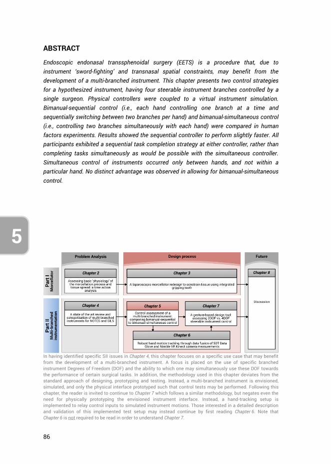
86
5
ABSTRACT
Endoscopic endonasal transsphenoidal surgery (EETS) is a procedure that, due to instrument ‘sword-fighting’ and transnasal spatial constraints, may benefit from the development of a multi-branched instrument. This chapter presents two control strategies for a hypothesized instrument, having four steerable instrument branches controlled by a single surgeon. Physical controllers were coupled to a virtual instrument simulation. Bimanual-sequential control (i.e., each hand controlling one branch at a time and sequentially switching between two branches per hand) and bimanual-simultaneous control (i.e., controlling two branches simultaneously with each hand) were compared in human factors experiments. Results showed the sequential controller to perform slightly faster. All participants exhibited a sequential task completion strategy at either controller, rather than completing tasks simultaneously as would be possible with the simultaneous controller. Simultaneous control of instruments occurred only between hands, and not within a particular hand. No distinct advantage was observed in allowing for bimanual-simultaneous control.
In having identified specific SII issues in Chapter 4, this chapter focuses on a specific use case that may benefit from the development of a multi-branched instrument. A focus is placed on the use of specific branched instrument Degrees of Freedom (DOF) and the ability to which one may simultaneously use these DOF towards the performance of certain surgical tasks. In addition, the methodology used in this chapter deviates from the standard approach of designing, prototyping and testing. Instead, a multi-branched instrument is envisioned, simulated, and only the physical interface prototyped such that control tests may be performed. Following this chapter, the reader is invited to continue to Chapter 7 which follows a similar methodology, but negates even the need for physically prototyping the envisioned instrument interface. Instead, a hand-tracking setup is implemented to relay control inputs to simulated instrument motions. Those interested in a detailed description and validation of this implemented test setup may instead continue by first reading Chapter 6. Note that Chapter 6 is not required to be read in order to understand Chapter 7.
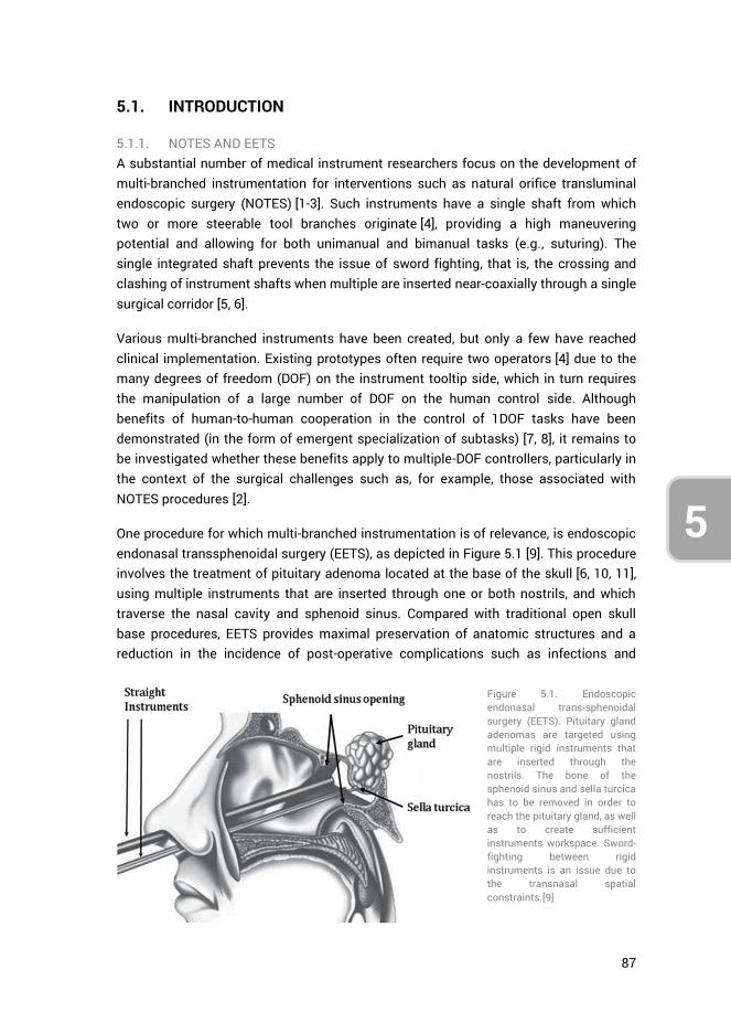
87
5
3
4
5.1. INTRODUCTION
5.1.1. NOTES AND EETS A substantial number of medical instrument researchers focus on the development of multi-branched instrumentation for interventions such as natural orifice transluminal endoscopic surgery (NOTES) [1-3]. Such instruments have a single shaft from which two or more steerable tool branches originate [4], providing a high maneuvering potential and allowing for both unimanual and bimanual tasks (e.g., suturing). The single integrated shaft prevents the issue of sword fighting, that is, the crossing and clashing of instrument shafts when multiple are inserted near-coaxially through a single surgical corridor [5, 6].
Various multi-branched instruments have been created, but only a few have reached clinical implementation. Existing prototypes often require two operators [4] due to the many degrees of freedom (DOF) on the instrument tooltip side, which in turn requires the manipulation of a large number of DOF on the human control side. Although benefits of human-to-human cooperation in the control of 1DOF tasks have been demonstrated (in the form of emergent specialization of subtasks) [7, 8], it remains to be investigated whether these benefits apply to multiple-DOF controllers, particularly in the context of the surgical challenges such as, for example, those associated with NOTES procedures [2].
One procedure for which multi-branched instrumentation is of relevance, is endoscopic endonasal transsphenoidal surgery (EETS), as depicted in Figure 5.1 [9]. This procedure involves the treatment of pituitary adenoma located at the base of the skull [6, 10, 11], using multiple instruments that are inserted through one or both nostrils, and which traverse the nasal cavity and sphenoid sinus. Compared with traditional open skull base procedures, EETS provides maximal preservation of anatomic structures and a reduction in the incidence of post-operative complications such as infections and
Figure 5.1. Endoscopic endonasal trans-sphenoidal surgery (EETS). Pituitary gland adenomas are targeted using multiple rigid instruments that are inserted through the nostrils. The bone of the sphenoid sinus and sella turcica has to be removed in order to reach the pituitary gland, as well as to create sufficient instruments workspace. Sword-fighting between rigid instruments is an issue due to the transnasal spatial constraints.[9]
88
5
internal bleeding [12]. EETS is jointly performed by a neurosurgeon and otolaryngologist, with the otolaryngologist holding the endoscope, while the performance of dissection, curettage, and suction is alternated with the neurosurgeon [13]. For EETS, the concept of multi-branched instruments is relevant, because instrument sword-fighting and transnasal spatial constraints limit the surgeon’s in-vivo workspace. Moreover, due to the multiple required tools, instruments need to be frequently interchanged with one another, as the limited workspace does not allow for all of them to be inserted at the same time.
This chapter presents research into two distinct control strategies for a hypothesized multi-branched instrument intended for EETS, having four distinct instrument branches and providing full control of these four branches to a single surgeon. Each of the four instrument branches corresponds to a specific task that is frequently performed during EETS. Controlling all branches entails that a single surgeon can respond to intra-operative occurrences, without needing to physically interchange surgical instruments or having to communicate one’s intentions to a co-operating surgeon. The advantages of having all tools at one’s disposal, integrated into a multi-branched instrument and controlled by a single surgeon, may outweigh the potential reduction in task performance as a result of multi-tasking.
Through discussions with an experienced neurosurgeon (Furth W.R. van, 2015, oral communication, 28th January), the multi-branched instrument was envisioned to have a single shaft with four individually steerable tool branches that provide the four standard instruments used during EETS: 1) forceps, 2) scissor, 3) suction tube, and 4) curette. Not all four tools are used all the time simultaneously during a standard EETS procedure. Instead, the tools are often used intermittently, and therefore it was deemed plausible that all can be controlled by a single surgeon for the intervention.
5.1.2. HUMAN PERFORMANCE AND FEASIBILITY When providing a surgeon with the option of controlling four branches, the question arises to which extent a human can perform such multi-tasking feats. In particular, during EETS, blood pooling in the surgical workspace as well as obstructing tissues frequently need to be dealt with. Hence, simultaneously being able to use the suction tube and curette while not interrupting the performance of other concurrent tasks may expedite the procedure. Of importance to multi-tasking in this regard is the multiple resources theory proposed by Wickens et al., which states that multitasking is inhibited if the two tasks involve the same processing code (spatial vs. verbal), the same modality (auditory vs. visual), or the same information-processing stage (perception/cognition vs. responding) [14]. Time-shared performance of tasks is better between levels of a dichotomy than within a level. Simultaneously controlling a number of instrument branches will entail multiple visual, spatial, and perceptual/cognitive subtasks, each tapping into the same mental resources. In other words, according to
89
5
3
4
Wickens’ multiple resource theory, multitasking in EETS will likely lead to worse performance as compared to controlling a single instrument branch.
The level of performance-drop as a consequence of the simultaneous control of multiple branches is dependent on the available mental resources of the surgeon. How mental resources are distributed amongst tasks may be defined using performance resource functions (PRF), which describe task performance as a function of mental resource allocation. In particular, if two tasks compete for the same resource, the interference between those two tasks is determined by the shape of their respective PRFs [15, 16]. However, mental resource allocation is in part dependent on the skills of the operator [15]. It is therefore possible that with adequate training, automaticity of performance may ensue [17, 18], so that eventually tasks are performed concurrently almost as well as when they would be performed sequentially [19].
Pashler et al. [20] showed that when presented with two similar stimuli, the first stimulus can be responded to while already perceptually processing the response to the second stimulus. By extension, when a surgeon is presented with two tasks, one of these tasks may get priority in execution while the second task may be mentally preprocessed in the background. In addition, a comparison of the simultaneous performance of two similar tasks with two hands versus both tasks being performed with a single hand, showed that these two scenarios are mentally processed in the same way, although the latter comes with stronger neural activations [21]. In this regard, task demands (i.e., the number of DOF and methods of DOF control) appear to be more important in determining required mental resources, and by extension task performance, than whether the task is performed with one or two hands per se.
In summary, multi-tasking in the control of four instrument branches may be feasible, in restricted conditions (i.e., low or medium demands in terms of both surgical tasks and control complexity), but will likely come at the expense of reduced task performance. However, a single surgeon being able to control multiple instruments at the same time would provide the ability to relatively quickly respond to intra-operative occurrences, contrasting the current situation wherein two cooperating surgeons are required to communicate (which is regarded as a source of error [22] and to anticipate each others’ movements. When comparing bimanual versus intermanual (i.e., interpersonal) task performance in the task of tying a shoelace, Gorman et al. (2015) found that,cooperating participants built upon their pre-existing bimanual skills when learning to perform the same task intermanually, but that extensive practice is required before performance in the intermanual mode equals that in a highly practiced bimanual mode [23]. Thus, a multi-branched instrument that enables single-surgeon bimanual task performance may outperform the current intermanual setting.
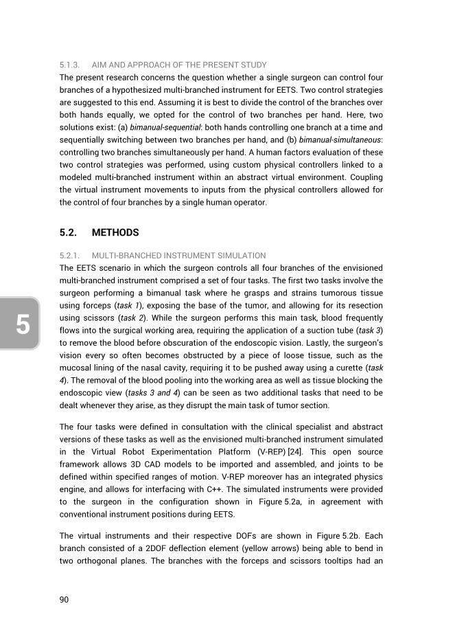
90
5
5.1.3. AIM AND APPROACH OF THE PRESENT STUDY The present research concerns the question whether a single surgeon can control four branches of a hypothesized multi-branched instrument for EETS. Two control strategies are suggested to this end. Assuming it is best to divide the control of the branches over both hands equally, we opted for the control of two branches per hand. Here, two solutions exist: (a) bimanual-sequential: both hands controlling one branch at a time and sequentially switching between two branches per hand, and (b) bimanual-simultaneous: controlling two branches simultaneously per hand. A human factors evaluation of these two control strategies was performed, using custom physical controllers linked to a modeled multi-branched instrument within an abstract virtual environment. Coupling the virtual instrument movements to inputs from the physical controllers allowed for the control of four branches by a single human operator.
5.2. METHODS
5.2.1. MULTI-BRANCHED INSTRUMENT SIMULATION The EETS scenario in which the surgeon controls all four branches of the envisioned multi-branched instrument comprised a set of four tasks. The first two tasks involve the surgeon performing a bimanual task where he grasps and strains tumorous tissue using forceps (task 1), exposing the base of the tumor, and allowing for its resection using scissors (task 2). While the surgeon performs this main task, blood frequently flows into the surgical working area, requiring the application of a suction tube (task 3) to remove the blood before obscuration of the endoscopic vision. Lastly, the surgeon’s vision every so often becomes obstructed by a piece of loose tissue, such as the mucosal lining of the nasal cavity, requiring it to be pushed away using a curette (task 4). The removal of the blood pooling into the working area as well as tissue blocking the endoscopic view (tasks 3 and 4) can be seen as two additional tasks that need to be dealt whenever they arise, as they disrupt the main task of tumor section.
The four tasks were defined in consultation with the clinical specialist and abstract versions of these tasks as well as the envisioned multi-branched instrument simulated in the Virtual Robot Experimentation Platform (V-REP) [24]. This open source framework allows 3D CAD models to be imported and assembled, and joints to be defined within specified ranges of motion. V-REP moreover has an integrated physics engine, and allows for interfacing with C++. The simulated instruments were provided to the surgeon in the configuration shown in Figure 5.2a, in agreement with conventional instrument positions during EETS.
The virtual instruments and their respective DOFs are shown in Figure 5.2b. Each branch consisted of a 2DOF deflection element (yellow arrows) being able to bend in two orthogonal planes. The branches with the forceps and scissors tooltips had an
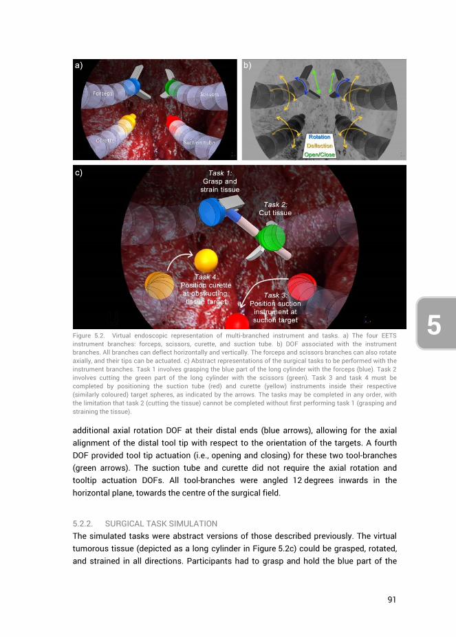
91
5
3
4
additional axial rotation DOF at their distal ends (blue arrows), allowing for the axial alignment of the distal tool tip with respect to the orientation of the targets. A fourth DOF provided tool tip actuation (i.e., opening and closing) for these two tool-branches (green arrows). The suction tube and curette did not require the axial rotation and tooltip actuation DOFs. All tool-branches were angled 12 degrees inwards in the horizontal plane, towards the centre of the surgical field.
5.2.2. SURGICAL TASK SIMULATION The simulated tasks were abstract versions of those described previously. The virtual tumorous tissue (depicted as a long cylinder in Figure 5.2c) could be grasped, rotated, and strained in all directions. Participants had to grasp and hold the blue part of the
Figure 5.2. Virtual endoscopic representation of multi-branched instrument and tasks. a) The four EETS instrument branches: forceps, scissors, curette, and suction tube. b) DOF associated with the instrument branches. All branches can deflect horizontally and vertically. The forceps and scissors branches can also rotate axially, and their tips can be actuated. c) Abstract representations of the surgical tasks to be performed with the instrument branches. Task 1 involves grasping the blue part of the long cylinder with the forceps (blue). Task 2 involves cutting the green part of the long cylinder with the scissors (green). Task 3 and task 4 must be completed by positioning the suction tube (red) and curette (yellow) instruments inside their respective (similarly coloured) target spheres, as indicated by the arrows. The tasks may be completed in any order, with the limitation that task 2 (cutting the tissue) cannot be completed without first performing task 1 (grasping and straining the tissue).

92
5
cylinder with the forceps (task 1), and cut with the scissors at the green part of the cylinder (task 2) while still gripping the virtual tissue in task 1. Tasks 1 and 2 needed to be completed together, that is, the tissue could not be cut (green part), if the tissue was not strained (by grasping the blue part).
The suction and obstructing tissue tasks (task 3 and task 4, respectively) were implemented as positioning tasks with the suction tube and curette respectively. Target spheres indicated the positions where the similarly coloured instruments needed to be placed at. Shortly keeping the instruments inside their corresponding spheres completed the tasks. The spheres changed positions between trials, and all four tasks needed to be completed once per trial. The four tasks could be completed in any order, with the exception that task 2 had to be preceded by task 1. This freedom in task completion allowed the participants to form their own control strategies, including potential simultaneous task performance.
5.2.3. PHYSICAL CONTROLLERS
Physical controller designs
All four simulated instrument branches were required for the simulated tasks. Full control was provided over all four branches to a single surgeon. The two control strategies were:
1. Bimanual-sequential: both hands actively controlling a single branch at a time, and each hand being able to switch between two branches; and
2. Bimanual-simultaneous: controlling two branches simultaneously per hand.
For the remainder of this article, these two control strategies will be referred to as sequential and simultaneous control, respectively. For both control strategies, the deflections of each tool-branch needed to be controlled in the horizontal and vertical direction. The forceps and scissor additionally required axial rotation and instrument tooltip actuation, as depicted in Figure 5.2b.
In literature, control of surgical instruments with a deflectable tip is often accomplished using the thumb [25]. Controlling the deflection of two branches with one hand using the sequential control strategy requires the participant to switch with the thumb between the controls of two branches. Two separate joysticks therefore were presented to the participant side-by-side, both in reach of the thumb, where each joystick controls the deflection of a different branch. Regarding the use of two joysticks in the simultaneous control strategy, one joystick was repositioned to within range of the index finger, and be controlled through index flexion-extension and ab-adduction [26-28]. The two physical controller designs are shown in Figure 5.3. The design of the shape of the controllers was based on the Nintendo Wii Nunchuk, which is an established ergonomic shape [29, 30]. This shape allowed for a decent one-handed grip
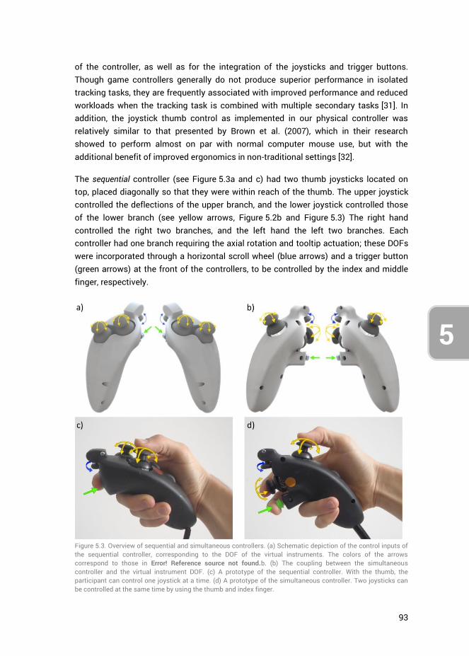
93
5
3
4
of the controller, as well as for the integration of the joysticks and trigger buttons. Though game controllers generally do not produce superior performance in isolated tracking tasks, they are frequently associated with improved performance and reduced workloads when the tracking task is combined with multiple secondary tasks [31]. In addition, the joystick thumb control as implemented in our physical controller was relatively similar to that presented by Brown et al. (2007), which in their research showed to perform almost on par with normal computer mouse use, but with the additional benefit of improved ergonomics in non-traditional settings [32].
The sequential controller (see Figure 5.3a and c) had two thumb joysticks located on top, placed diagonally so that they were within reach of the thumb. The upper joystick controlled the deflections of the upper branch, and the lower joystick controlled those of the lower branch (see yellow arrows, Figure 5.2b and Figure 5.3) The right hand controlled the right two branches, and the left hand the left two branches. Each controller had one branch requiring the axial rotation and tooltip actuation; these DOFs were incorporated through a horizontal scroll wheel (blue arrows) and a trigger button (green arrows) at the front of the controllers, to be controlled by the index and middle finger, respectively.
Figure 5.3. Overview of sequential and simultaneous controllers. (a) Schematic depiction of the control inputs of the sequential controller, corresponding to the DOF of the virtual instruments. The colors of the arrows correspond to those in Error! Reference source not found.b. (b) The coupling between the simultaneous controller and the virtual instrument DOF. (c) A prototype of the sequential controller. With the thumb, the participant can control one joystick at a time. (d) A prototype of the simultaneous controller. Two joysticks can be controlled at the same time by using the thumb and index finger.
94
5
The simultaneous controller (see Figure 5.3b and d) was similar in shape to the sequential controller. The control of the second branch was however shifted to the index finger by placing the second joystick on the front of the controller, allowing both joysticks to be operated at the same time. Though the thumb generally outperforms the index finger in terms of positional task accuracy and precision [33], the difference is small enough to warrant investigation of this simultaneous control strategy. The tooltip rotation scroll wheel and actuation trigger button remained at the same locations.
The control gain between joystick input and virtual instrument output was chosen based on participants’ feedback from a pilot study, and was kept constant between instruments and participants throughout the study.
Hardware
The prototyped controllers displayed in Figure 5.3c and d incorporated Arduino compatible joysticks, measuring the x- and y-positions with potentiometers. The integrated spring in each joystick, meant for centering the joystick upon release, was removed to make the joystick suitable for position control. This way the position of each joystick was directly linked to the position of its respective virtual instrument branch. Non-conductive grease was applied to the mechanical joystick axis, to provide a sense of tactile feedback, because without the springs too little resistance was felt in their control. A tactile push button was integrated into each controller for instrument tooltip actuation, and a potentiometer as a scroll wheel for tooltip orientation. Controller output was streamed through an Arduino MEGA 2560 microcontroller board to V-REP, and data exported to MATLAB.
5.2.4. EXPERIMENT DESIGN Twenty right-handed native Dutch speaking young adults participated in the study. 17 participants were male and 3 female, their ages ranged 19 to 29 years (median = 23), and none of them were avid gamers (i.e., 1 hour/week of gaming). These participants, which were moreover students of the Delft University of Technology at the faculty of Mechanical Engineering, were divided over groups A and B. Group A started the tests using the sequential controller, and group B the simultaneous controller. The participants played console games less than one hour in the week. The experiment design is presented in Figure 5.4.
Both groups started the test with a brief instruction video in their native Dutch language. The participants were placed at a distance of 2.30 m from a 40-inch monitor showing the V-REP simulation. During the four rounds of the first test (“Task test”), the participants performed ten trials per round, where each trial entailed the performance of all four tasks. The purpose of the Task test was to assess the participants’ task performance with both controllers, and to identify whether participants applied a particular task strategy, such as the simultaneous control of any two instrument
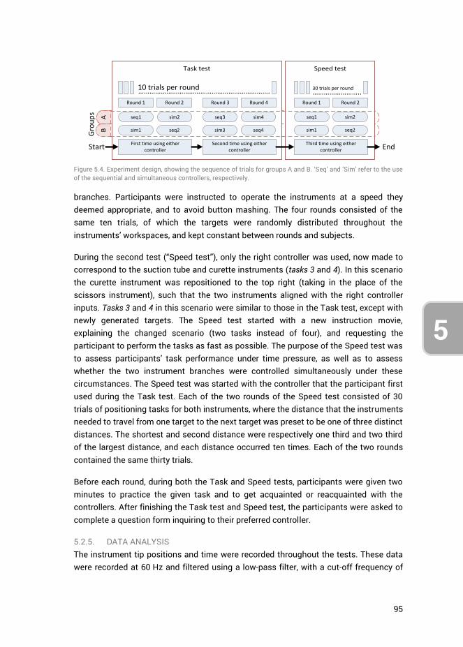
95
5
3
4
branches. Participants were instructed to operate the instruments at a speed they deemed appropriate, and to avoid button mashing. The four rounds consisted of the same ten trials, of which the targets were randomly distributed throughout the instruments’ workspaces, and kept constant between rounds and subjects.
During the second test (“Speed test”), only the right controller was used, now made to correspond to the suction tube and curette instruments (tasks 3 and 4). In this scenario the curette instrument was repositioned to the top right (taking in the place of the scissors instrument), such that the two instruments aligned with the right controller inputs. Tasks 3 and 4 in this scenario were similar to those in the Task test, except with newly generated targets. The Speed test started with a new instruction movie, explaining the changed scenario (two tasks instead of four), and requesting the participant to perform the tasks as fast as possible. The purpose of the Speed test was to assess participants’ task performance under time pressure, as well as to assess whether the two instrument branches were controlled simultaneously under these circumstances. The Speed test was started with the controller that the participant first used during the Task test. Each of the two rounds of the Speed test consisted of 30 trials of positioning tasks for both instruments, where the distance that the instruments needed to travel from one target to the next target was preset to be one of three distinct distances. The shortest and second distance were respectively one third and two third of the largest distance, and each distance occurred ten times. Each of the two rounds contained the same thirty trials.
Before each round, during both the Task and Speed tests, participants were given two minutes to practice the given task and to get acquainted or reacquainted with the controllers. After finishing the Task test and Speed test, the participants were asked to complete a question form inquiring to their preferred controller.
5.2.5. DATA ANALYSIS The instrument tip positions and time were recorded throughout the tests. These data were recorded at 60 Hz and filtered using a low-pass filter, with a cut-off frequency of
Figure 5.4. Experiment design, showing the sequence of trials for groups A and B. ‘Seq’ and ‘Sim’ refer to the use of the sequential and simultaneous controllers, respectively.
BA
Task test Speed test
Round 1 Round 2 Round 3 Round 4
…………………………………………………………….10 trials per round
First time using either controller
Second time using either controller
Round 1 Round 2
……………………..30 trials per round
Third time using either controllerStart End
seq1 sim2 seq3 sim4 seq1 sim2
sim1 seq2 sim3 seq4 sim1 seq2
Gro
up
s
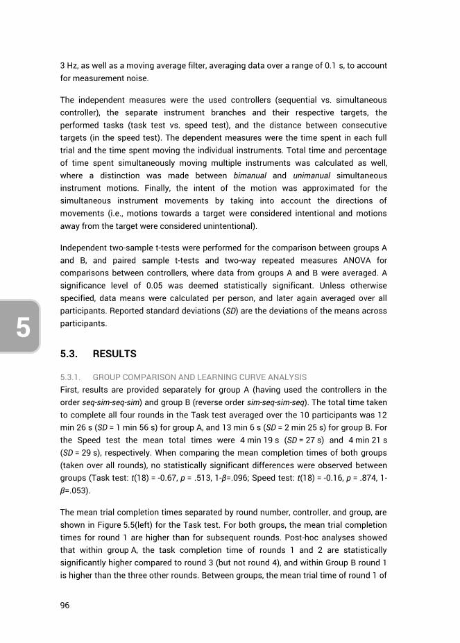
96
5
3 Hz, as well as a moving average filter, averaging data over a range of 0.1 s, to account for measurement noise.
The independent measures were the used controllers (sequential vs. simultaneous controller), the separate instrument branches and their respective targets, the performed tasks (task test vs. speed test), and the distance between consecutive targets (in the speed test). The dependent measures were the time spent in each full trial and the time spent moving the individual instruments. Total time and percentage of time spent simultaneously moving multiple instruments was calculated as well, where a distinction was made between bimanual and unimanual simultaneous instrument motions. Finally, the intent of the motion was approximated for the simultaneous instrument movements by taking into account the directions of movements (i.e., motions towards a target were considered intentional and motions away from the target were considered unintentional).
Independent two-sample t-tests were performed for the comparison between groups A and B, and paired sample t-tests and two-way repeated measures ANOVA for comparisons between controllers, where data from groups A and B were averaged. A significance level of 0.05 was deemed statistically significant. Unless otherwise specified, data means were calculated per person, and later again averaged over all participants. Reported standard deviations (SD) are the deviations of the means across participants.
5.3. RESULTS
5.3.1. GROUP COMPARISON AND LEARNING CURVE ANALYSIS First, results are provided separately for group A (having used the controllers in the order seq-sim-seq-sim) and group B (reverse order sim-seq-sim-seq). The total time taken to complete all four rounds in the Task test averaged over the 10 participants was 12 min 26 s (SD = 1 min 56 s) for group A, and 13 min 6 s (SD = 2 min 25 s) for group B. For the Speed test the mean total times were 4 min 19 s (SD = 27 s) and 4 min 21 s (SD = 29 s), respectively. When comparing the mean completion times of both groups (taken over all rounds), no statistically significant differences were observed between groups (Task test: t(18) = -0.67, p = .513, 1-β=.096; Speed test: t(18) = -0.16, p = .874, 1-β=.053).
The mean trial completion times separated by round number, controller, and group, are shown in Figure 5.5(left) for the Task test. For both groups, the mean trial completion times for round 1 are higher than for subsequent rounds. Post-hoc analyses showed that within group A, the task completion time of rounds 1 and 2 are statistically significantly higher compared to round 3 (but not round 4), and within Group B round 1 is higher than the three other rounds. Between groups, the mean trial time of round 1 of
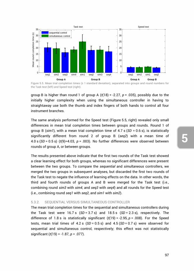
97
5
3
4
group B is higher than round 1 of group A (t(18) = -2.27, p = .035), possibly due to the initially higher complexity when using the simultaneous controller in having to straightaway use both the thumb and index fingers of both hands to control all four instrument branches.
The same analysis performed for the Speed test (Figure 5.5, right) revealed only small differences in mean trial completion times between groups and rounds. Round 1 of group B (sim1), with a mean trial completion time of 4.7 s (SD = 0.6 s), is statistically significantly different from round 2 of group B (seq2) with a mean time of 4.0 s (SD = 0.5 s) (t(9)=4.03, p = .003). No further differences were observed between rounds of group A, or between groups.
The results presented above indicate that the first two rounds of the Task test showed a clear learning effect for both groups, whereas no significant differences were present between the two groups. To compare the sequential and simultaneous controllers, we merged the two groups in subsequent analyses, but discarded the first two rounds of the Task test to negate the influence of learning effects on the data. In other words, the third and fourth rounds of groups A and B were merged for the Task test (i.e., combining round sim3 with sim4, and seq3 with seq4) and all rounds for the Speed test (i.e., combining round seq1 with seq2, and sim1 with sim2).
5.3.2. SEQUENTIAL VERSUS SIMULTANEOUS CONTROLLER The mean trial completion times for the sequential and simultaneous controllers during the Task test were 16.7 s (SD = 3.7 s) and 18.5 s (SD = 2.3 s), respectively. The difference of 1.8 s is statistically significant (t(19) = -2.95, p = .008). For the Speed tests, mean trial times of 4.2 s (SD = 0.5 s) and 4.5 (SD = 0.7 s) were observed for sequential and simultaneous control, respectively; this effect was not statistically significant (t(19) = -1.87, p = .077).
Figure 5.5. Mean trial completion times (± 1 standard deviation), separated into groups and round numbers for the Task test (left) and Speed test (right).
seq1 sim2 seq3 sim4 sim1 seq2 sim3 seq40
5
10
15
20
25
30
35
Mean r
ound c
om
ple
tion t
ime (
s)
Task test
sequential control
simultaneous control
seq1 sim2 sim1 seq20
5
10
15
20
25
30
35Speed test
Group A Group B Group A Group B
98
5
In both the Task test and the Speed test, multiple position tasks needed to be completed. The order in which these were performed was left to the participant, allowing for the formation of strategies of simultaneous instrument use. In order to make a distinction between the four instruments, therefore, we looked at the time spent moving them towards their respective targets, and negated their downtime and time spent rotating the end-effectors. The times that two instruments were used simultaneously was also assessed, where a distinction was made when two instruments were controlled by the right and left hands separately (bimanual simultaneous control) or when two instruments were controlled with one hand (unimanual simultaneous control). The absence of measured bimanual or unimanual simultaneous control indicates sequential instruments control, i.e., the one-by-one steering of the instruments. One should note that both the sequential and simultaneous controllers allow for the implementation of sequential control (steering joysticks one-by-one) as well as bimanual simultaneous control (simultaneously steering a joystick with each hand). Only the simultaneous controller, however, allows for unimanual simultaneous control (steering two-joysticks at the same time with one hand). Unimanual simultaneous control with the sequential controller is by definition not possible.
The total mean movement times (i.e., the sum of time spent moving all individual instruments, excluding instrument end-effector rotations and downtime) for the Task test were 6.3 s (SD = 1.3 s) and 7.0 s (SD = 1.0 s), for the sequential and simultaneous controllers respectively. The individual mean instrument movement times together with their standard deviations are provided in Figure 5.6, where a distinction is made between when instruments were controlled sequentially (one at a time), or simultaneously (making no distinction between bimanual and unimanual simultaneous control). Two-way repeated measures ANOVA showed a significant difference between controllers in instrument movement times (F(1,19) = 8.17, p = .010), as well as between the separate instruments (F(3,57) = 20.82, p < .001). No statistically significant interaction was present, however, between controller and instrument (F(3,57) = .85, p = .470), indicating that the observed difference between controllers is the same, no matter which instrument we are looking at. In all cases the sequential controller yielded slightly faster times.
More simultaneous movements were observed during the Task test at the suction and obstructing tissue tasks (tasks 3 and 4) than at the more complex forceps and scissor tasks (tasks 1 and 2), however, with respect to these simultaneous movements, no statistically significant difference was present between controllers (F(1,19) = .725, p = .405). Bimanual simultaneous control occurred more frequently than unimanual simultaneous control. This difference is statistically significant for both controllers
(pseq < .001, psim = .001, df = 19). Little unimanual simultaneous control was observed for both controllers, where for the sequential controller this was due to the accidental
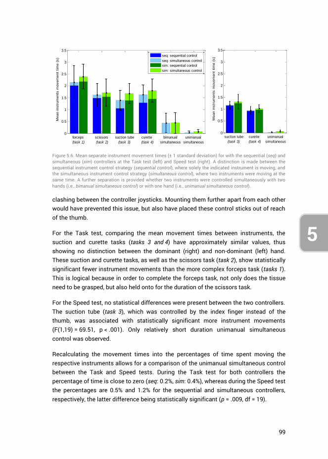
99
5
3
4 clashing between the controller joysticks. Mounting them further apart from each other would have prevented this issue, but also have placed these control sticks out of reach of the thumb.
For the Task test, comparing the mean movement times between instruments, the suction and curette tasks (tasks 3 and 4) have approximately similar values, thus showing no distinction between the dominant (right) and non-dominant (left) hand. These suction and curette tasks, as well as the scissors task (task 2), show statistically significant fewer instrument movements than the more complex forceps task (tasks 1). This is logical because in order to complete the forceps task, not only does the tissue need to be grasped, but also held onto for the duration of the scissors task.
For the Speed test, no statistical differences were present between the two controllers. The suction tube (task 3), which was controlled by the index finger instead of the thumb, was associated with statistically significant more instrument movements (F(1,19) = 69.51, p < .001). Only relatively short duration unimanual simultaneous control was observed.
Recalculating the movement times into the percentages of time spent moving the respective instruments allows for a comparison of the unimanual simultaneous control between the Task and Speed tests. During the Task test for both controllers the percentage of time is close to zero (seq: 0.2%, sim: 0.4%), whereas during the Speed test the percentages are 0.5% and 1.2% for the sequential and simultaneous controllers, respectively, the latter difference being statistically significant (p = .009, df = 19).
Figure 5.6. Mean separate instrument movement times (± 1 standard deviation) for with the sequential (seq) and simultaneous (sim) controllers at the Task test (left) and Speed test (right). A distinction is made between the sequential instrument control strategy (sequential control), where solely the indicated instrument is moving, and the simultaneous instrument control strategy (simultaneous control), where two instruments were moving at the same time. A further separation is provided whether two instruments were controlled simultaneously with two hands (i.e., bimanual simultaneous control) or with one hand (i.e., unimanual simultaneous control).
0
0.5
1
1.5
2
2.5
3
3.5
Mean instr
um
ents
movem
ent
tim
e (
s)
forceps
(task 1)
scissors
(task 2)
suction tube
(task 3)
curette
(task 4)
bimanual
simultaneous
unimanual
simultaneous
seq: sequential control
seq: simultaneous control
sim: sequential control
sim: simultaneous control
0
0.5
1
1.5
2
2.5
3
3.5
Mean instr
um
ents
movem
ent
tim
e (
s)
suction tube
(task 3)
curette
(task 4)
unimanual
simultaneous
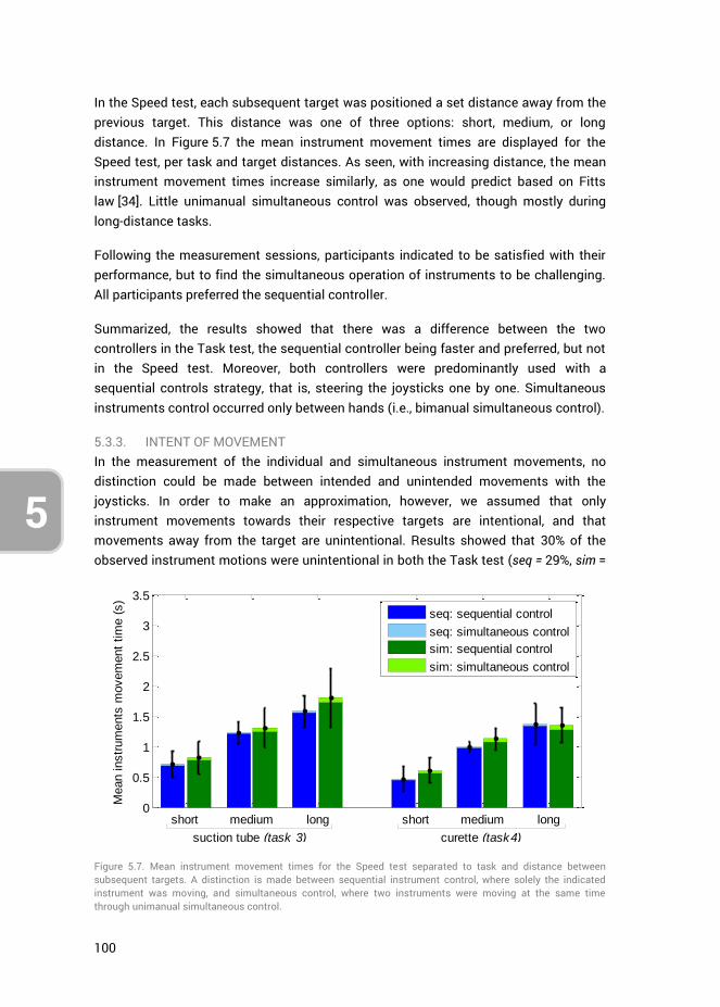
100
5
In the Speed test, each subsequent target was positioned a set distance away from the previous target. This distance was one of three options: short, medium, or long distance. In Figure 5.7 the mean instrument movement times are displayed for the Speed test, per task and target distances. As seen, with increasing distance, the mean instrument movement times increase similarly, as one would predict based on Fitts law [34]. Little unimanual simultaneous control was observed, though mostly during long-distance tasks.
Following the measurement sessions, participants indicated to be satisfied with their performance, but to find the simultaneous operation of instruments to be challenging. All participants preferred the sequential controller.
Summarized, the results showed that there was a difference between the two controllers in the Task test, the sequential controller being faster and preferred, but not in the Speed test. Moreover, both controllers were predominantly used with a sequential controls strategy, that is, steering the joysticks one by one. Simultaneous instruments control occurred only between hands (i.e., bimanual simultaneous control).
5.3.3. INTENT OF MOVEMENT In the measurement of the individual and simultaneous instrument movements, no distinction could be made between intended and unintended movements with the joysticks. In order to make an approximation, however, we assumed that only instrument movements towards their respective targets are intentional, and that movements away from the target are unintentional. Results showed that 30% of the observed instrument motions were unintentional in both the Task test (seq = 29%, sim =
Figure 5.7. Mean instrument movement times for the Speed test separated to task and distance between subsequent targets. A distinction is made between sequential instrument control, where solely the indicated instrument was moving, and simultaneous control, where two instruments were moving at the same time through unimanual simultaneous control.
0
0.5
1
1.5
2
2.5
3
3.5
Mean instr
um
ents
movem
ent
tim
e (
s)
short medium long short medium long
seq: sequential control
seq: simultaneous control
sim: sequential control
sim: simultaneous control
suction tube (task 3) curette (task4)
101
5
3
4
32%), and the Speed test (seq = 28%, sim = 29%).
An analysis of only the bimanual simultaneous instrument motions (Task test) showed that 48% and 57% of those motions were unintentional, for the sequential and simultaneous controllers respectively. In observing the individual trials data, sometimes an instrument was seen approaching its respective target while another instrument moved slightly in a direction opposite to its target, likely indicating unintentional movements. At other times, however, gross movements of the two instruments occurred simultaneously towards their targets. Hence simultaneous instrument control between hands was an observed control strategy aside from sequential control, albeit infrequently. This is in agreement with literature stating that bimanual tasks may start simultaneously, but task completion times will differ between hands [35].
Looking at unimanual simultaneous instrument motions only, results showed that slightly more than half of the simultaneous instrument movements were unintentional for both the Task test (seq = 67%, sim = 57%) and the Speed test (seq = 50%, sim = 67%). For the sequential controller this result followed from the fact that clashing of the joysticks would in approximately half the cases nudge one of the instruments in the wrong direction. The high percentage of unintentional unimanual simultaneous instrument movements observed for the simultaneous controller, combined with the fact that little unimanual simultaneous control was observed in Error! Reference source not found., indicates that participants did not consciously attempt to control two instruments at the same time with a single hand.
5.4. DISCUSSION
5.4.1. SEQUENTIAL VERSUS SIMULTANEOUS CONTROLLERS In this research, two control strategies were developed and tested to steer four virtual instruments by means of sequential versus simultaneous instrument control. No distinct advantage or disadvantage was observed when comparing the two controllers, as the sequential instrument control strategy was predominantly used for both controllers. This finding is in agreement with Srinivasan et al. (2013), who found that if two targets require high-precision, the task completions are sequenced [35]. This was true even when participants were instructed to perform tasks as fast as possible during the Speed test. The sequential controller was on average slightly faster, and the preferred controller by most participants.
The results further showed that bimanual simultaneous control sometimes occurred, but unimanual simultaneous control did not. Although the degree of simultaneous control that was measured during the Speed test was highest at the largest distance
102
5
task (see Figure 5.7), most of those simultaneous motions appeared to be unintentional.
Based on the results it appears that for the EETS scenario as described in the introduction, no advantage is gained through the implementation of the simultaneous controller in regard to the present positioning tasks. Providing all instrument controls to a single surgeon is thus only reasonable if the sequential control strategy is viable in the context of the surgical tasks that need to be performed.
5.4.2. MEASUREMENT LIMITATIONS Several limitations were present in the current research. Due to the randomly generated targets for the separate instruments, the total distance that the separate instruments had to traverse over the course of the tests was unequal. For the Task test, tasks 3 and 4 differed 11.5% in total travel distance from each other. Furthermore, the locations of the tissue to be cut with the scissors (task 2) were dependent on the location of the tissue to be gripped (task 1). Due to this relation between targets, the gripper (task 1) had to cover roughly twice as much distance from target to target as compared to the scissors (task 2), whose target was always in a more restricted workspace. This then explains the difference in the degree of instruments motions between these two tasks. For the Speed tests, the difference between the summed target distances for the two tasks was 5.5%. The observed differences between the two controllers, however, are not affected by these differences between tasks.
The sequential and simultaneous controllers could on account of their size impose a significant stretch on the fingers of some participants. For the simultaneous controller moreover, due to the physical coupling of the thumb and index fingers, crosstalk is likely to have caused some of the observed unintended instrument movements. Crosstalk is a source of interference at which a control movement on one axis spills over onto another control axis [36, 37]. For 2DOF control tasks, research has shown this effect to contribute up to 20% of the human control response [36]. Considering the simultaneous controller has 2x 2DOF, crosstalk likely influences task performance to a certain extent.
Lastly, considering that hand sizes and finger ranges of motions vary between subjects, improved task performance would likely be achieved by having custom sized controllers and fine-tuned control gains better suited to each participant.
5.4.3. FUTURE RESEARCH The literature states that even after extensive single-task training, dual-task training is still required to perform tasks concurrently [19]. In the current research, participants were immediately introduced to the dual-task scenarios, without letting them train to optimize single-task performance first. This was done to limit the duration of the testing sessions. As a consequence, however, the performance drop from single- to the
103
5
3
4
dual task scenario was not assessed, but may be an interesting subject for future research.
In the current scenario, the instruments were fixed in the z-direction, whereas in a real scenario, the targets vary in depth. Controlling two instruments with one hand could entail that a movement of the surgeon’s hand is translated to both instruments, or either one. Various control coupling strategies may be designed to build upon those presented in this research.
The current EETS scenario involved multiple tasks, each to be completed with a 2DOF deflecting instrument, and we observed that participants predominantly employ the sequential control strategy (irrespective of the used controller). This control strategy is in line with Wickens’ multiple resource theory, as the individual tasks compete for the same mental resources. Changing the scenario to a single task, may allow for a different implementation of the controllers presented in this study. For example, several multi-branched instruments have been designed and prototyped that have two 2DOF segments placed in series used for a single task, rather than two or more parallel placed 2DOF segments (as implemented in this study) used for a bimanual task [4]. The control of an instrument with serially placed 2DOF segments with the simultaneous controller may have potential, because this presents a single 4DOF integrated task that necessitates the simultaneous control of all DOF. The level of training required, as well as potential task performance in comparison to that of instruments having different DOF configurations, may therefore be interesting subjects for future study.
Lastly, the instrument evaluation method used in this research, that is, prototyping controllers and connecting these to virtually simulated instruments, provided valuable results without the need to fully prototype the envisioned instrument. The used setup with prototyped controllers may be easily repurposed for the assessment of other multi-DOF instruments.
5.5. AUTHOR CONTRIBUTIONS
Ewout A. Arkenbout, Floris H. van den Berg and Paul W.J. Henselmans were jointly responsible for the study conceptualization and methodology. Wouter R. van Furth aided in conceptualization. Floris H, van den Berg performed the investigation, data curation, investigation and initial formal analysis. Ewout A. Arkenbout performed the final data analysis, validation, and writing of the article draft. Joost C.F. de Winter and Paul Breedveld supervised, and all authors contributed to reviewing and editing the article.

104
5
5.6. REFERENCES
1. Auyang, E.D., et al., Natural orifice translumenal endoscopic surgery (NOTES®): a technical review. Surgical Endoscopy, 2011. 25(10): p. 3135-3148.
2. Rattner, D. and A. Kalloo, ASGE/SAGES Working Group on Natural Orifice Translumenal Endoscopic Surgery. Surgical Endoscopy And Other Interventional Techniques, 2006. 20(2): p. 329-333.
3. Rattner, D.W., et al., The Second SAGES/ASGE White Paper on natural orifice transluminal endoscopic surgery: 5 years of progress. Surgical Endoscopy, 2011. 25(8): p. 2441-2448.
4. Arkenbout, E.A., et al., A state of the art review and categorization of multi-branched instruments for NOTES and SILS. Surgical Endoscopy, 2015. 29(6): p. 1281-1296.
5. Sawyer, M.D. and L.E. Ponsky, Technical and equipment challenges for laparoendoscopic single-site surgery and natural orifice transluminal endoscopic surgery. BJU International, 2010. 106(6b): p. 892-896.
6. Oostra, A., W. van Furth, and C. Georgalas, Extended endoscopic endonasal skull base surgery: from the sella to the anterior and posterior cranial fossa. ANZ journal of surgery, 2012. 82(3): p. 122-130.
7. Reed, K., et al., Initial studies in human-robot-human interaction: Fitts' law for two people, in Robotics and Automation, 2004. Proceedings. ICRA '04. 2004 IEEE International Conference on. 2004. p. 2333-2338.
8. Reed, K.B. and M.A. Peshkin, Physical Collaboration of Human-Human and Human-Robot Teams. IEEE Transactions on Haptics, 2008. 1(2): p. 108-120.
9. Giada, G., et al., HelixFlex : bioinspired maneuverable instrument for skull base surgery. Bioinspiration & Biomimetics, 2015. 10(6): p. 066013.
10. Chirag D. Gandhi, et al., The historical evolution of transsphenoidal surgery: facilitation by technological advances. Neurosurgical Focus, 2009. 27(3): p. E8.
11. Yadav, Y., et al., Endoscopic endonasal trans-sphenoid surgery of pituitary adenoma. Journal of Neurosciences in Rural Practice, 2012. 3(3): p. 328-337.
12. Raper, D.M.S., et al., Endoscopic versus open approaches to the skull base: A comprehensive literature review. Operative Techniques in Otolaryngology-Head and Neck Surgery, 2011. 22(4): p. 302-307.
13. Yang, J.Y.M., et al., Endoscopic endonasal transsphenoidal surgery: a mentoring surgical model. ANZ Journal of Surgery, 2012. 82(6): p. 452-456.
14. Wickens, C.D., Multiple resources and performance prediction. Theoretical Issues in Ergonomics Science, 2002. 3(2): p. 159-177.
15. Wickens, C.D. and J.G. Hollands, Engineering psychology and human performance, Chapter 11. 2000, Upper Saddle River, NJ 07458 USA: Prentice Hall. 573.
16. Norman, D.A. and D.G. Bobrow, On data-limited and resource-limited processes. Cognitive Psychology, 1975. 7(1): p. 44-64.
17. Summers, J.J. and J.G. Anson, Current status of the motor program: Revisited. Human Movement Science, 2009. 28(5): p. 566-577.
18. Stelmach, G.E., Motor control: Issues and trends. 2014: Academic Press. 19. Schneider, W. and M. Detweiler, The Role of Practice in Dual-Task Performance:
Toward Workload Modeling a Connectionist/Control Architecture. Human Factors, 1988. 30(5): p. 539-566.
20. Pashler, H., Attentional Limitations in Doing Two Tasks at the Same Time. Current Directions in Psychological Science, 1992. 1(2): p. 44-48.
21. Koeneke, S., et al., Bimanual versus unimanual coordination: what makes the difference? NeuroImage, 2004. 22(3): p. 1336-1350.

105
5
3
4
22. Hignett, S., et al., State of science: human factors and ergonomics in healthcare. Ergonomics, 2013. 56(10): p. 1491-1503.
23. Gorman, J.C. and M.J. Crites, Learning to tie well with others: bimanual versus intermanual performance of a highly practised skill. Ergonomics, 2015. 58(5): p. 680-697.
24. Freese, M., et al., Virtual robot experimentation platform V-REP: a versatile 3D robot simulator, in Proceedings of the Second international conference on Simulation, modeling, and programming for autonomous robots. 2010, Springer-Verlag: Darmstadt, Germany. p. 51-62.
25. Fan, C., D. Dodou, and P. Breedveld, Review of manual control methods for handheld maneuverable instruments. Minimally Invasive Therapy & Allied Technologies, 2013. 22(3): p. 127-135.
26. Ueda, Y. and T. Maeno, Development of a mouse-shaped haptic device with multiple finger inputs, in 2004 IEEE/RSJ International Conference on Intelligent Robots and Systems (IROS) (IEEE Cat. No.04CH37566). 2004. p. 2886-2891.
27. Gokturk, M. and J.L. Sibert, An analysis of the index finger as a pointing device, in CHI '99 Extended Abstracts on Human Factors in Computing Systems. 1999, ACM: Pittsburgh, Pennsylvania. p. 286-287.
28. Buess, G.F., et al., A new remote-controlled endoscope positioning system for endoscopic solo surgery. The FIPS endoarm. Surg Endosc, 2000. 14(4): p. 395-9.
29. Herman, B., et al., Ergonomic and gesture performance of robotized instruments for laparoscopic surgery, in 2011 IEEE/RSJ International Conference on Intelligent Robots and Systems. 2011. p. 1333-1338.
30. Komlódi, A., et al., Empirical usability evaluation of the Wii controller as an input device for the VirCA immersive virtual space, in 2011 2nd International Conference on Cognitive Infocommunications (CogInfoCom). 2011. p. 1-6.
31. Rupp, M.A., P. Oppold, and D.S. McConnell, Evaluating input device usability as a function of task difficulty in a tracking task. Ergonomics, 2015. 58(5): p. 722-735.
32. Brown, J.N.A., W.J. Albert, and J. Croll, A new input device: comparison to three commercially available mouses. Ergonomics, 2007. 50(2): p. 208-227.
33. Herring, S.R. and M.S. Hallbeck, Evaluation of a two cursor control device for development of a powered laparoscopic surgical tool. Ergonomics, 2009. 52(8): p. 891-906.
34. Fitts, P.M., The information capacity of the human motor system in controlling the amplitude of movement. Journal of Experimental Psychology, 1954. 47(6): p. 381-391.
35. Srinivasan, D., B.J. Martin, and M.P. Reed, Effects of task characteristics on unimanual and bimanual movement times. Ergonomics, 2013. 56(4): p. 612-622.
36. Barendswaard, S., D.M. Pool, and M. Mulder, Human Crossfeed in Dual-Axis Manual Control with Motion Feedback. IFAC-PapersOnLine, 2016. 49(19): p. 189-194.
37. Wickens, C.D. and J.G. Hollands, Engineering psychology and human performance, Chapter 10. 2000, Upper Saddle River, NJ 07458 USA: Prentice Hall. 573.

106
5
107
3
4
CHAPTER 6: ROBUST HAND MOTION TRACKING THROUGH DATA FUSION OF 5DT DATA GLOVE AND NIMBLE VR KINECT CAMERA MEASUREMENTS
Ewout A. Arkenbout*, Joost C.F. de Winter and Paul Breedveld
Published in Sensors, 15(12), 2015
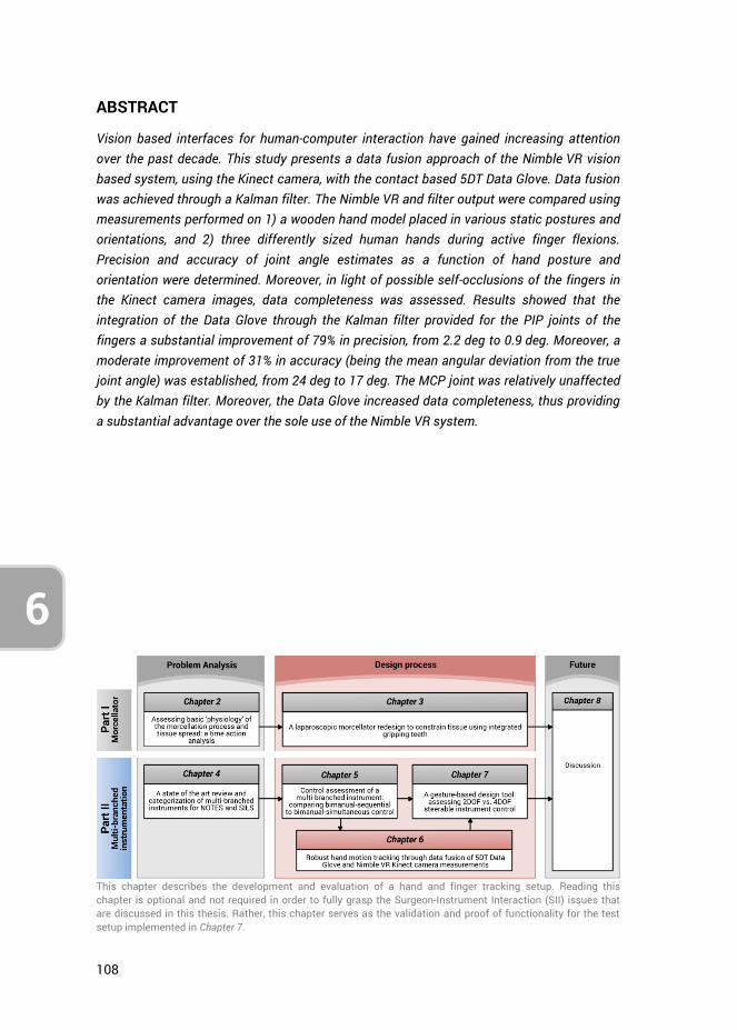
108
6
ABSTRACT
Vision based interfaces for human-computer interaction have gained increasing attention over the past decade. This study presents a data fusion approach of the Nimble VR vision based system, using the Kinect camera, with the contact based 5DT Data Glove. Data fusion was achieved through a Kalman filter. The Nimble VR and filter output were compared using measurements performed on 1) a wooden hand model placed in various static postures and orientations, and 2) three differently sized human hands during active finger flexions. Precision and accuracy of joint angle estimates as a function of hand posture and orientation were determined. Moreover, in light of possible self-occlusions of the fingers in the Kinect camera images, data completeness was assessed. Results showed that the integration of the Data Glove through the Kalman filter provided for the PIP joints of the fingers a substantial improvement of 79% in precision, from 2.2 deg to 0.9 deg. Moreover, a moderate improvement of 31% in accuracy (being the mean angular deviation from the true joint angle) was established, from 24 deg to 17 deg. The MCP joint was relatively unaffected by the Kalman filter. Moreover, the Data Glove increased data completeness, thus providing a substantial advantage over the sole use of the Nimble VR system.
This chapter describes the development and evaluation of a hand and finger tracking setup. Reading this chapter is optional and not required in order to fully grasp the Surgeon-Instrument Interaction (SII) issues that are discussed in this thesis. Rather, this chapter serves as the validation and proof of functionality for the test setup implemented in Chapter 7.
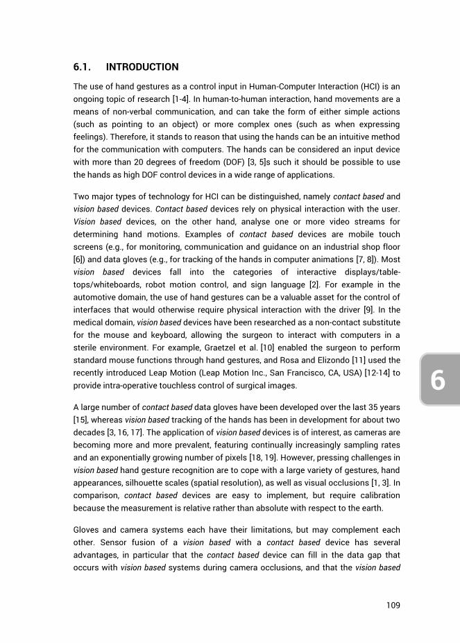
109
3
4
6
6.1. INTRODUCTION
The use of hand gestures as a control input in Human-Computer Interaction (HCI) is an ongoing topic of research [1-4]. In human-to-human interaction, hand movements are a means of non-verbal communication, and can take the form of either simple actions (such as pointing to an object) or more complex ones (such as when expressing feelings). Therefore, it stands to reason that using the hands can be an intuitive method for the communication with computers. The hands can be considered an input device with more than 20 degrees of freedom (DOF) [3, 5]s such it should be possible to use the hands as high DOF control devices in a wide range of applications.
Two major types of technology for HCI can be distinguished, namely contact based and vision based devices. Contact based devices rely on physical interaction with the user. Vision based devices, on the other hand, analyse one or more video streams for determining hand motions. Examples of contact based devices are mobile touch screens (e.g., for monitoring, communication and guidance on an industrial shop floor [6]) and data gloves (e.g., for tracking of the hands in computer animations [7, 8]). Most vision based devices fall into the categories of interactive displays/table-tops/whiteboards, robot motion control, and sign language [2]. For example in the automotive domain, the use of hand gestures can be a valuable asset for the control of interfaces that would otherwise require physical interaction with the driver [9]. In the medical domain, vision based devices have been researched as a non-contact substitute for the mouse and keyboard, allowing the surgeon to interact with computers in a sterile environment. For example, Graetzel et al. [10] enabled the surgeon to perform standard mouse functions through hand gestures, and Rosa and Elizondo [11] used the recently introduced Leap Motion (Leap Motion Inc., San Francisco, CA, USA) [12-14] to provide intra-operative touchless control of surgical images.
A large number of contact based data gloves have been developed over the last 35 years [15], whereas vision based tracking of the hands has been in development for about two decades [3, 16, 17]. The application of vision based devices is of interest, as cameras are becoming more and more prevalent, featuring continually increasingly sampling rates and an exponentially growing number of pixels [18, 19]. However, pressing challenges in vision based hand gesture recognition are to cope with a large variety of gestures, hand appearances, silhouette scales (spatial resolution), as well as visual occlusions [1, 3]. In comparison, contact based devices are easy to implement, but require calibration because the measurement is relative rather than absolute with respect to the earth.
Gloves and camera systems each have their limitations, but may complement each other. Sensor fusion of a vision based with a contact based device has several advantages, in particular that the contact based device can fill in the data gap that occurs with vision based systems during camera occlusions, and that the vision based
110
6
device provides an absolute measurement of hand state. Moreover, the fusion of data can result in a higher precision of pose estimates through redundancy gain.
Previous research has integrated two vision based systems for the purpose of high fidelity hand motion data acquisition [20]. Furthermore, various studies have integrated vision and contact based systems with the aim of aiding in the tracking of the location of a grasped object within a hand [21-24] or for improving the recognition of sign language and hand gestures [25-27]. These multi-sensor techniques supplement each other, where the separate sensors measure different aspects of the motions of the arm and hands, after which their combined data is used for higher-level feature extraction for gesture recognition [28]. However, using sensor redundancy and fusion with the primary purpose of increasing precision and robustness of a vision based hand posture approximation is rarely performed.
Because of the inherent issue of visual occlusions associated with cameras, updating the hand posture approximation with local sensors may often be necessary. A recommendation in this regard is to use as few and as minimally obtrusive sensors as possible, thereby not influencing natural hand and finger motions. Accordingly, this research presents a simple method for fusing contact based with vision based hand tracking systems, where the focus is placed on using a camera tracking system that is readily available, and a data glove that uses a small number of sensors.
6.1.1. HCI IN LAPAROSCOPIC TRAINING A field where hand motions and postures as HCI input may be promising is virtual laparoscopic training. Various medical trainers exist for laparoscopic skills training and assessment, ranging from physical box trainers to high fidelity virtual reality (VR) trainers [29], both of which are effective training devices [30-32]. Contemporary virtual simulators need a physical interface, both for purposes of congruence with the actual operating room scenario as well as for reliable tracking of the hand motions. These VR trainers usually aim to simulate the minimally invasive surgical scenario as realistically as possible. Surgeons in training may benefit from practicing with such realistic systems, but due to the considerable cost gap between VR simulators and physical box trainers, the use of VR simulators is currently limited to a relatively small number of training centres [33]. As such, it may be beneficial to have a cheaper VR alternative.
Comparing the medical field to training methods in aviation, one can see that it is standard practice to train pilots in simulators of increasing complexity, where basic tasks are trained in lower fidelity and part-task simulators. For example, Integrated Procedures Trainers (IPTs) allow for the learning of flow patterns, systems, procedures, and checklists [34]. In the same way, one could train surgeons, starting out with a virtual trainer that simulates basic laparoscopic tasks to train hand-eye coordination skills, for example in a scenario where instrument movements are inverted with respect
111
3
4
6
to the hand movements (i.e., the ‘fulcrum effect’ associated with the entry incision). Training of these basic laparoscopic skills is to a certain extent possible without the need for a physical interface, making visual based tracking devices potentially useful for the early training of surgeons. Depending on the skills that the surgeon aims to learn, a certain level of precision and accuracy of the hand state estimate is required. However, these requirements may be relaxed when learning basic spatial abilities, for example when learning to control an instrument with inverted movement [35, 36] or when learning to use an angled laparoscope [37].
Using a vision based device for virtual laparoscopic training may furthermore be interesting in light of the recent surge in low cost consumer market VR headsets (i.e., Oculus Rift [38], Sony PlayStation VR [39], HTC Vive [40], & Samsung Gear VR [41]), which are devices that could enhance the fidelity of medical VR simulators. Such high fidelity VR simulations may confer effective skills transfer to the in vivo surgical situation, whereas less expensive VR trainers may lead to effective skill generalization [42-45]. Unfortunately, as previously mentioned, the limited accuracy and precision of current vision based devices for tracking of the hand movements, as well as their inherent issue of visual occlusions, makes them not yet suitable for surgical applications. Both issues may be solved through the integration of a contact based device.
6.1.2. NIMBLE VR A relatively new vision based system is the Nimble VR (Nimble VR Inc., San Francisco, CA, USA), previously named 3Gear Systems. It currently relies on the Microsoft KinectTM sensor (Microsoft Corporation, Redmond, WA, USA) and obtains the hand pose estimates through queries of a precomputed database that relates the detected hand silhouettes to their 3D configurations [46]. The Microsoft Kinect has a QVGA (320x240px) depth camera and a VGA (640x480 px.) video camera, both of which can produce image streams up to 30 frames per second [47]. Moreover, the Kinect has a horizontal and vertical field of view of 57 and 43 degrees respectively, with a depth sensor range of 1.2 m to 3.5 m.
Previous research into the Nimble VR system has shown the measurement errors of the position of the hand to depend on the distance from the camera [48] and the variance of the measurement data to depend on the orientation of the hand [49]. Kim et al. [48] evaluated the Nimble VR (v.0.9.21) and concluded that it did not provide results of high enough accuracy and robustness over the working range that is required for a medical robotics master. Continued development, however, as well as the addition of data filtering, smoothing, and downscaling of motions, can improve the performance of this vision based system [48, 50, 51].
112
6
The goal of the present research is to implement a Kalman filter algorithm to fuse measurement data of the vision based Nimble VR system with a contact based measurement system, for research into the use of hand and finger motions in medical VR simulators. As previously mentioned, a requirement for the contact based device is that it should be minimally obtrusive to the surgeon, because physical sensors may impede the naturalness of motion and therefore influence surgical VR skills training. We selected the 5DT Data glove (5th Dimension Technologies, Irvine, CA, USA) [52], providing five basic full finger flexion sensors. Although this data fusion approach negates the contact-free control advantage that characterise vision based systems, it allows for improved pose estimates at visual occlusions and a higher update frequency due to a higher sampling rate of the Data Glove (200 Hz) as compared with the Nimble VR (currently running at 15 Hz). This study presents the implementation of the filter as well as its validation. The validation was performed through measurements of the finger joint angles of a wooden hand model in various poses and orientations. The pose estimates from the 5DT Data Glove, Nimble VR, and the filter were assessed with respect to the actual finger joint angles of the hand model. Additionally, dynamic finger flexion angles, measured on three differently sized hands, were performed, and the data with and without implementation of the filter were compared.
6.2. KALMAN FILTER PROCEDURES AND PARAMETER SETTINGS
The Kalman filter is a computationally efficient recursive solution of the least-squares method, supporting estimates of the past, present, and future states of a modelled system [53].
In this research, we used the Kalman filter to combine Nimble VR measurements with local sensor data obtained from the 5DT Data Glove 5 Ultra [15, 52]. The Data Glove allows for the measurement of overall flexion of each finger by means of fibre-optics-based bending sensors. Although the Data Glove does not distinguish between the individual finger joints, it does have the advantage of being independent of hand orientation and hand position. Moreover, because the Data Glove uses only five simple sensors, it does not significantly impede hand movements. Fusing the local sensor data with the obtained global camera data has the expected advantage of increasing data completeness during hand occlusion and during hand orientations at which the camera-based tracking system is unable to provide an accurate estimation.
The Kalman filter has already been described extensively in the literature [54, 55]. The basic equations are as follows:

113
3
4
6
Measurement update equations Time update equations
1
T T
k k k k k k kK P H H P H R
(1,1) 1k k kk
x A x Bu
(1.2)
k kk kkx x K z H x
(1.3) 1
T
k k k k kP A P A Q
(1.4)
k k k kP I K H P
(1.5)
where k
K is the Kalman gain, k
P the estimate error covariance matrix, k
H the matrix
describing how the measurement equation relates to the actual measurement kz ,
kA
contains the model functions describing the relation between the state at time step k and the state at step k+1, and B the matrix relating control input
ku to the state x . In
our case, the state vector x contains the metacarpophalangeal (MCP) and proximal interphalangeal (PIP) joint angles and angular velocities for each finger. The actual measurements
kz are limited to the MCP and PIP joint angles individually as obtained
through the Nimble VR software and the sum of the two as given by the Data Glove.
Vectors x and kz and matrices
kH ,
kA and B are given as follows:
MCP
MCP
PIP
PIP
MCP
MCP PIPMCP+PIP
PIP
NVR
NVR k
DG DGDG
k
1 0 0 0Nimble VR (NVR)
0 1 0 0
0 0Data Glove (DG)
1 0 d 0
0 1 0 dnull matrix
0 0 1 0
0 0 0 1
kx z H
w w
t
tA B
0
(1.6)
Note that these matrices are valid for all fingers, with the exception that the thumb has an interphalangeal (IP) joint instead of a PIP joint. The carpometacarpal (CMC) joint of the thumb is not measured with the Data Glove, and therefore not present in this model. The Distal interphalangeal (DIP) joint is not measured by either of the two systems, because these joints are linked in motion to the PIP joints and because one cannot easily control one’s own DIP joints. Hence, these joints were left outside the scope of this research. The B matrix is a null matrix because we do not provide a custom input u .

114
6
Matrix k
H contains two weights MCPDG
w and PIPDG
w which represent the degree to which
the respective finger joints contribute to the Data Glove measurement signal. The measurement error covariance matrix
kR , the process noise covariance matrix
kQ and
the Data Glove weights MCPDG
w and PIPDG
w were measured prior to operation of the filter,
and are described next.
6.2.1. DETERMINING THE KALMAN FILTER PARAMETERS Research has shown that the mean finger flexion obtained from Nimble VR (v0.9.34) measurements is dependent on the orientation of the hand [49]. The level of variance for each finger joint as a function of both hand orientation and the degree of finger
flexion serves as input for the measurement error covariance matrix kR :
MCP
PIP
MCP+PIP
2
NVR
2
k k NVR
2
DG
, , , 0 0
, , , 0 , , , 0
0 0
k
k
z
R z z
(1.7)
where MCP
2
NVR k, , , z and
PIP
2
NVR k, , , z are the Nimble VR measured MCP and
PIP joint angle variances as a function of pitch, roll, and yaw angles ( , ,
respectively) and Data Glove measurement kz .
MCP+PIP
2
DG is the data variance
associated with the Data Glove, which is independent of hand orientation. The off-diagonal elements are the correlations between the various joints. Because a person can actuate their MCP and PIP joints independently of each other (to a certain degree), these elements were set to zero. The correlations between the different fingers were set to zero for the same reason. The variance terms used as input for the Kalman filter were measured as a function of hand orientation and finger flexion. The method by which this has been done and the accompanying results are given in Appendix A (section 6.7).
The noise covariance matrix kQ is typically used to represent the uncertainty in the
process model [53]. We set this uncertainty to be equal to the squared angular
deviation from the state estimation k
x , as calculated with the peak rotational
acceleration of the finger flexions. Because changes in finger flexion cannot be greater than the physical maximum during voluntary free finger movement, this approach provides us with a valid uncertainty range for where a finger can be at a point in time based on its previous location. The process noise covariance matrix
kQ then becomes:
115
3
4
6
MCP MCP
PIP PIP
MCP MCP
PIP PIP
2 4 2 3
2 4 2 3
k2 3 2 2
2 3 2 2
1 10 04 2
1 10 04 2
1 0 02
10 02
t t
t t
Q
t t
t t
(1.8)
where MCP
and PIP
are the maximum joint angular accelerations. The values used
as input for this matrix were measured experimentally and are provided in Appendix B (section 6.8).
Lastly, because the Data Glove measures the sum of MCP and PIP flexion, the following
relation holds for the two weights MCPDG
w and PIPDG
w :
MCP+PIP MCP MCP PIP PIPDG DG DGw w (1.9)
Ideally, the weights have a value of 1.0 each, indicating proper measurement of the individual joint rotations. However due to shifting of the Data Glove sensors inside the glove with respect to the fingers, the measurement signals may be biased and vary per finger. Hence, these weights were measured using a medium sized hand prior to the Kalman filter operation. The measurement procedures and resulting weight values are provided in Appendix C (section 6.9).
6.3. METHODS
6.3.1. TEST SETUP A setup was created that implements the Nimble VR camera-based hand tracking software (v0.9.36). This setup made use of a Kinect camera mounted on a rig facing downwards onto a table top (Figure 6.1). Using the infrared depth information obtained from the Kinect camera, the software detected the hands, provided an estimation of the orientation and position of the hands and fingers, and approximated the hand’s skeletal model [56]. Default software settings were used. The 5DT Data Glove was added to this setup, and we wrote a C++ program that exports all measurements to MATLAB. In MATLAB, the Kalman filter function fused the Nimble VR and Data Glove measurements.
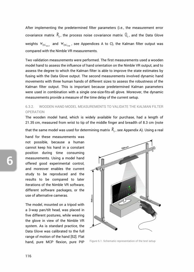
116
6
After implementing the predetermined filter parameters (i.e., the measurement error
covariance matrix kR , the process noise covariance matrix k
Q , and the Data Glove
weights MCPDG
w and PIPDG
w , see Appendices A to C), the Kalman filter output was
compared with the Nimble VR measurements.
Two validation measurements were performed. The first measurements used a wooden model hand to assess the influence of hand orientation on the Nimble VR output, and to assess the degree to which the Kalman filter is able to improve the state estimates by fusing with the Data Glove output. The second measurements involved dynamic hand movements with three human hands of different sizes to assess the robustness of the Kalman filter output. This is important because predetermined Kalman parameters were used in combination with a single one-size-fits-all glove. Moreover, the dynamic measurements provide a measure of the time delay of the current setup.
6.3.2. WOODEN HAND MODEL MEASUREMENTS TO VALIDATE THE KALMAN FILTER OPERATION The wooden model hand, which is widely available for purchase, had a length of 21.35 cm, measured from wrist to tip of the middle finger and breadth of 8.3 cm (note
that the same model was used for determining matrix kR , see Appendix A). Using a real
hand for these measurements was not possible, because a human cannot keep his hand in a constant position during time consuming measurements. Using a model hand offered good experimental control, and moreover enables the current study to be reproduced and the results to be compared to later iterations of the Nimble VR software, different software packages, or the use of alternative cameras.
The model, mounted on a tripod with a 3-way pan/tilt head, was placed in five different postures, while wearing the glove in view of the Nimble VR system. As is standard practice, the Data Glove was calibrated to the full range of motion of the hand [52]. Flat hand, pure MCP flexion, pure PIP
Figure 6.1. Schematic representation of the test setup
117
3
4
6
flexion, combined MCP and PIP flexion, and pinch grip postures were assessed, and the data from the Nimble VR system was compared with the Kalman filtered results. The orientation of the hand model was varied by placing it in varying pitch, roll and yaw angles (ranges: [-60, 30] deg, [-120, 60] deg, and [-60, 60] deg, respectively). These three angles were varied at 5 deg intervals, while keeping the other two angles constant at 0 deg. Five measurements were performed for each of the 5 postures and for each of the 3 ranges, where at each orientation angle 200 samples were collected (representing about 13 seconds of data at a mean frequency of 15 Hz). A measurement thus represents a full sweep through a chosen orientation range, and this entire sequence was repeated five times. The total number of measurements performed per posture for the pitch range for example was therefore 19,000 (= 200 samples * 19 angles * 5 repetitions). In total, 19 pitch angles, 25 yaw angles, and 38 roll angles were assessed. The roll measurements were performed in two separated sessions (ranges [-120, -30] and [-30, 60]), where the model hand was rotated 90 deg in between. As a result, one roll angle was measured twice (angle of -30 deg). The Data Glove was recalibrated at each change of hand posture to account for potential shifting of the sensors inside the glove, caused by the external forces applied to glove during the changing of hand postures. Note that during contactless measurements with human hands this recalibration is not needed as external forces potentially causing sensor shift should be absent. However, in practice the glove can easily be recalibrated in between measurement sessions if sensor drift is observed. The tripod was kept horizontally aligned with the test setup, with the hand rigidly attached to its pan/tilt head.
6.3.3. HUMAN HAND MEASUREMENTS TO VALIDATE THE KALMAN FILTER OPERATION Following the wooden hand model measurements, dynamic finger flexions were conducted on three different sized hands of healthy volunteers, ranging from small to large. Hand scale values, as automatically detected by the Nimble VR software, were 0.81, 0.84 and 0.87 respectively. The hand lengths, measured from wrist to tip of the middle finger, were 16.5 cm, 18.6 cm, and 19.6 cm, and breadth were 8.4, 9.2 cm, and 10.0 cm, respectively. In these tests, an additional Marker Tracking camera was used. This camera, capturing RGB data at 30 Hz with a resolution of 640x480 pixels, was aimed at the side of the hand. The positions of coloured markers, attached to the joint locations of the index, pink, and thumb fingers of the Data Glove, were extracted from the camera footage using RGB threshold and Mean Shift Cluster detection [57]. Calculating the joint angles from the marker locations provided a reference to which the Nimble VR and Kalman Filtered data could be compared. Marker Tracking analysis was not performed online, hence the tracking results are free from any time delay. More information on this Marker Tracking algorithm is provided in Appendix C. The joint angles were measured during active finger flexions with the Marker Tracking, Data Glove, and Nimble VR system. Each of the three participants performed five sets of ten
118
6
repetitive full finger flexions (i.e., from flat hand to closed fist and back) at a relaxed pace with the palm of the hand facing down. In between each set of ten flexions, the participant was asked to move his/ her hand freely before going to the next set. A single glove calibration was performed prior to the measurements, calibrating the measurement range of the glove sensors to the movement range of the fingers of the participant.
6.3.4. DEPENDENT MEASURES The dependent measures are the precision, accuracy, completeness of the data, and time delay. Completeness was defined as the ability to provide (reliable) joint angle estimates of the joints of the fingers as a function of orientation, posture, and degree of visual self-occlusion of the hand. In the analyses, a distinction was made between the MCP and PIP joints of the fingers.
For the wooden hand model test, at each 5 deg step, the mean orientation of the hand was calculated over the 200 samples. The mean hand orientation angle per step was calculated by averaging over the 25 measurement sets performed (i.e., 5 per posture, 5 different postures). The standard deviation (SD) was calculated as the mean of the 25 standard deviations.
Regarding the joint angle, at each 5 deg step of the hand orientation angle, the mean and standard deviation of the joint angle were calculated over the 200 samples. These values were then again averaged over the 5 measurement sessions performed for each of the 5 deg steps. This procedure was performed for each orientation range and each of the five postures.
Comparing the resulting mean joint angles to the actual joint angles provides a measure of the accuracy of the system. The standard deviation (and variance) around these mean joint angles are measures of precision. Additionally, comparing these performance measures of the Nimble VR system with the Kalman filtered data gives insight into the completeness of the data as a function of hand orientation and posture. At hand orientations where visual self-occlusion degrades the joint angle approximations, we expected for the Kalman filtered data lower standard deviations as well as more accurate joint angle approximations compared to the Nimble VR.
Independent two-sample t tests were performed to assess whether the difference in mean calculated joint angles between Nimble VR and the filter output were statistically significantly different from each other. The compared vectors (being of equal lengths) were each composed of the mean joint angles, calculated at each of the five measurements. A t test was performed between these vectors for each posture at every orientation angle, totalling 984 tests (index: 82 orientation angles * 5 postures * 2 joints; thumb: 82 angles * 1 posture * 2 joints). The accompanying degrees of freedom in each of the t tests was 8 (i.e., df = 2n-2, with n = 5). A p value smaller than 0.01 was
119
3
4
6
deemed statistically significant. We selected a conservative significance level in order to reduce the probability of false positives.
In order to assess the overall benefit of the Kalman filter with respect to the Nimble VR system, we calculated for each orientation range the mean of the mean and the mean of the standard deviations taken over the entire range (the pitch, yaw and roll sample sizes were 19, 25 and 38, respectively). This represents the accuracy and precision respectively of the measurements for a specific pose and orientation range.
For the human hand test, the time delay of both the Nimble VR system and the Kalman filter was compared to the Marker Tracking measurements, which were not performed online, but were obtained through video post analysis. Hence, the Marker Tracking results are free from time delay. The root-mean-square error and the Pearson’s correlation coefficient of the Nimble VR and Kalman filter output with respect to the Marker Tracking measurements were calculated. Lastly, the maximum angular under- or overestimation of the measurement systems, occurring at full finger flexion, were extracted.
6.4. RESULTS
The results off the posture measurements are shown in Figure 6.2 as a series of plots. The top three plots indicate the measured orientation of the hand model as a function of the input hand orientations, that is, across the pitch, yaw, and roll ranges. The remainder of the plots in Figure 6.2 show, for each of the hand postures, the index MCP joint angles (in blue) and PIP joint angles (in green) as a function of the actual hand orientation.
A distinction is made between the joint angles determined with the Nimble VR software only (square markers) and joint angles determined with the Kalman filter (asterisk markers). The actual joint angles of the wooden hand model are represented by horizontal lines (MCP: dashed line; PIP: dash-dotted line). Measurements lying closer to these lines are by definition more accurate. In each plot, at the top left corner, two means and two standard deviations are shown per joint. The first mean and standard deviation are that of the Nimble VR joint angle measurements taken over the entire range, and the second mean and standard deviation are that of the Kalman filtered data. A mean that lies closer to the actual joint angle indicates an overall improvement in joint angle approximation accuracy, and a lower standard deviation indicates an improvement in precision. Lastly, a solid triangle marker on the horizontal axes was used to indicate that the difference between the mean joint angle of the PIP joint obtained with Nimble VR and the Kalman filter is not statistically significant. This same display-method was not used for the MCP joint, because for this joint the measured

120
6
angles were the same in approximately 50% of the cases, thereby cluttering the graphs if we were to display this.
6.4.1. WOODEN HAND MODEL ORIENTATION MEASUREMENTS The measured hand orientation angles are shown as a function of actual hand angle in Figure 6.2a–c. There are several orientation ranges of the hand at which the measurements of the hand angles are imprecise. For the pitch orientation (Figure 6.2a), all measured angles below -35 deg show very large standard deviations, that is, when the hand was pitched far downwards. The yaw angles (Figure 6.2b) show high precision for the range [-50, 50] deg. At angles below -50 deg, when the thumb was angled away from the screen, the measurements show large standard deviations, whereas above 50 deg the standard deviation increases slightly. Lastly, for roll angles (Figure 6.2c) in the range [-110, -60] deg, the measured angles have slightly larger standard deviations, which is because of visual occlusion of the fingers. At -90 deg the hand is vertically aligned with the thumb on top. In this condition, the observed surface area of the hand is small, and only the thumb and index fingers can be distinguished by the Nimble VR software. As a result, in this range the orientation measurement becomes somewhat less reliable.
For the yaw measurements, a constant mean difference of about 9 deg is observed between the measured and actual yaw angle. Moreover, for the roll measurements a misalignment is seen at -30 degrees, which is on account of the roll orientation having been measured in two separate sessions. A slight drift from actual the actual roll angle can be seen in the first range, where at -30 deg the measurement was stopped, the hand rotated 90 deg and reoriented, and the measurements (as well as the software) reinitialized. The re-measured roll angle of the hand is then free from drift and closer to the actual angle.
6.4.2. WOODEN HAND MODEL FINGER JOINT MEASUREMENTS – INDEX AND THUMB FINGERS At hand orientations yielding a low precision (SD > 5 deg, see Figure 6.2, graphs a to c), a similar effect on precision can be seen for most of the finger joint angle estimates of the Nimble VR. The consequence of imprecise hand orientation measurements is either a decrease in finger joint angle estimation precision (i.e., SD > 10 deg) or an unrealistically high precision (i.e., SD < 1 deg) combined with a poor accuracy (> 30 deg shift from the true angle). This high precision is the result of visual self-occlusion of the finger, and the Nimble VR software accordingly making an estimation of the joint angles based on the estimated posture. This can for example clearly be seen in graph f2, at angles -60 to -15 deg, where for the PIP joint a 50 deg difference is observed between measured and true angle (thus having a low accuracy), while the observed precision is around 1 deg. Due to the orientation independent standard deviation of the Data Glove, the Kalman filter output has a low standard deviation, even when the
121
3
4
6
standard deviation of the Nimble VR data is high. Furthermore, because the Data Glove output is independent of the hand orientation, the Glove contributes to improved accuracy of the Kalman filter output over all the hand orientation ranges, in particular for the PIP joint. In order to assess both the accuracy and the precision before and after implementation of the filter, Figures2d-f should be referred to, as accuracy and precision are dependent on hand pose and assessed orientation range. The accuracy for a given joint, hand pose, or orientation range is equal to the mean joint angle (provided in the top left of every graph) minus the true joint angle. The precision is given by the standard deviations provided in the top left of every plot.
Looking at the index MCP joint, the two mean joint angles lie close together, and although an improvement in precision can be seen, only 49% of the time a significant difference between the measurement systems was observed, mostly at MCP joint differences larger than about 10 deg. The PIP joint is more affected by the filter, and in a substantial portion of cases (83%) a significant improvement was observed. As indicated by the triangular markers on the horizontal axes in (Figure 6.2, graphs d2 to i4), no significant difference is present when the Nimble VR output overlap with the filter output, which occurs when the Nimble VR measurements already approach the true PIP joint angle. Moreover, at high standard deviations of Nimble VR data, statistically significant differences with the filter data are not always obtained.
Following, the separate hand postures will be discussed.
In the Flat Hand posture (Figure 6.2, graphs d1 to d4), with both MCP and PIP joint angles being 0 deg, the Nimble VR PIP joint estimate shows the poorest accuracy, especially at low hand pitch angles (graph d2). The Kalman filter output adjusts this and keeps both the MCP and PIP joint estimates around 0 deg, even in the ranges where hand orientation measurements are imprecise. This is most clearly shown by the decrease in standard deviation for both joints at graphs d2 to d4.
At Pure PIP Flexion (Figure 6.2, graphs e1 to e4), where the MCP joint angles are kept at 0 deg and the PIP joint at 90 deg, one can see large fluctuations of accuracy in the PIP flexion angle estimate. For the pitch range (graph e2), in the region below -50 deg, the PIP angle is grossly underestimated, but for the remainder of the range, it is close to the actual angle. The Kalman filter output decreases the large variations over this range, keeping the joint estimate relatively accurate with some fluctuations around the actual PIP angle. For both the yaw (graph e3) and roll (graph e4) orientation ranges an improvement in precision and less variation in the accuracy can be seen. The MCP joint estimate deviates from the actual angle at high pitch angles (graph e2), but is relatively accurate for the other orientations (graphs e3 & e4).
At Pure MCP Flexion, (Figure 6.2, graphs f1 to f4), with the PIP joint angles kept at 0 deg, a bias is seen during pitch (graph f2). As with pure PIP flexion, the PIP joint angle is

122
6
wrongly estimated by the Nimble VR up until -10 deg, after which it correctly approaches the actual angle. The Kalman filter output adequately corrects for this bias, and keeps the estimated PIP joint angle around 0 deg at all angles. This comes however at the expense of the accuracy with which the MCP joint angle is estimated, which slightly worsens due to the Kalman filter. This is exemplified by the mean and standard deviations of the MCP joint angles taken over the entire range (see top left of graph f2), showing a slight increase in angle underestimation (i.e., a lower accuracy) and an increase in standard deviation (i.e., a lower precision). However, the reverse is true for the PIP joint. This same effect is seen to a lesser extent for the yaw and roll orientations (graphs f3 and f4).
For Combined MCP & PIP Flexion, (Figure 6.2 graphs g1 to g4), which is a more natural hand closure posture than the pure flexion of either the MCP or PIP joints, the advantage of using the Kalman filter is most pronounced in the PIP joint estimate. Where the Nimble VR measurements for this joint greatly vary for all orientations and are grossly overestimated, the Kalman filter yields a reliable and more accurate PIP joint angle estimate.
Lastly, for the Pinch Grip posture (Figure 6.2, graphs h and i), we show both the index (graphs h1 to h4) and thumb fingers (graphs i1 to i4). Again, the Kalman filter increases the precision of the PIP joint output of the index finger (graphs h2 to h4). However, there is a significant overestimation of the joint angle for all orientations. For the thumb (graphs i2 to i4), the Kalman filter slightly increases precision for both joints estimates and slightly improves the MCP joint accuracy. However, the filter’s effect is less pronounced here as compared to the index finger.
6.4.3. WOODEN HAND MODEL FINGER JOINT MEASUREMENTS – ALL FINGERS In order to assess the improvements gained for all fingers, in Figure 6.3 the difference between the true joint angles and the mean joint angles taken over the range of all assessed hand orientation ranges are given. These differences are equal to the mean joint angle in the top left of every graph in Figure 6.2 minus the true joint angle. The accompanying standard deviation is provided in Figure 6.3 as well. Hence, Figure 3 shows the mean accuracy and precision measures for all fingers, joints and poses, for the respective orientation range. It can be seen that for all fingers, the filter increases precision for the PIP joints and to a lesser extent for the MCP joints, regardless of hand posture. Accuracy improvements are seen for the PIP joints for the flat hand, pure PIP flexion, pure MCP flexion, and combined MCP and PIP flexion postures, but not for the pinch grip posture.
Lastly, we calculated the overall mean accuracy and precision improvements per joint gained by the implementation of the filter. The overall accuracy and overall precision estimates were calculated across 2050 means and 2050 SDs, respectively (82 angles
123
3
4
6
[19 pitch angles + 25 yaw angles + 38 roll angles] * 5 postures * 5 fingers). The results show that accuracy of the MCP slightly worsens by 6% from 12.7 deg (SD = 11.5 deg) to 13.5 deg (SD = 12.9 deg). This is offset by an accuracy improvement for the PIP joint of 31%, from 24.4 deg (SD = 17.4 deg) to 16.8 deg (SD = 15.7 deg). The precision of the MCP joint assessment improves with 5%, from 2.3 deg (SD = 2.5 deg) to 2.2 deg (SD = 2.2 deg), whereas the precision of the PIP joint improves with 79%, from 4.5 deg (SD = 4.1 deg) to 0.9 deg (SD = 1.1 deg). Overall, the filter thus marginally affects the MCP joint estimation, but strongly improves PIP joint estimation.
6.4.4. HUMAN HAND ACTIVE FINGER FLEXION MEASUREMENTS Dynamic flexing of the fingers while performing Marker Tracking of the joint angles and measuring the Nimble VR, Data Glove, and Kalman filter output yields the results shown in Figure 6.4 and Figure 6.5. In Figure 6.4, one of five sessions is shown, for the three differently sized hands. Additionally, all fifty full finger flexions per hand as measured with the Nimble VR system and obtained through the Kalman filter are plotted versus the marker tracked angles. In Figure 6.5 the MCP and PIP joints are shown separately as well in combination for 10 flexions performed by the medium sized hand (Hs = 0.84). Note that the Marker Tracking results are free from any time delay.
In Figure 6.4, at the peaks of the graphs (i.e., the points of maximum finger flexion) a noticeable effect can be seen of the hand size on the degree of under- or overestimation of the joint angles as compared to the Marker Tracking angles. The following presented under- or overestimation values have been calculated over all 50 flexions combined for each hand. At the small hand (top row graphs) one can see that both the Nimble VR and the filter output underestimate the MCP joint angle considerably by 51 deg. However, this is compensated by an overestimation for the PIP joint (Nimble VR: 13 deg, SD = 17 deg; Kalman filter: 14 deg, SD = 11 deg), resulting in an overall underestimation of the full finger flexion by 38 deg (SD = 12 deg) with the Nimble VR system and 36 deg (SD = 8 deg) for the Kalman filter output. This underestimation of the MCP joint angle is less prominent at the medium sized hand (middle row graphs), where the Nimble VR underestimates the MCP joint with 15 deg (SD = 15 deg), overestimates the PIP joint with 28 deg (SD = 8 deg), leading to an overall overestimation of 13 deg (SD = 16 deg). For the medium sized hand, the output from the Kalman filter underestimates the MCP joint with 16 deg (SD = 15 deg) and overestimates the PIP joint with: 26 deg (SD = 10 deg), adding up to a combined overestimation of 9 deg (SD = 9 deg). Lastly, for the large hand (bottom row graphs), an underestimation is again seen for the MCP joint (filter: 23 deg, SD = 11 deg), but the filter output overestimates the PIP joint (filter: 27 deg, SD = 9 deg), leading to an overall small overestimation of 4 deg (SD = 12 deg) (as compared to the Nimble VR output providing an underestimation of 29 deg, SD = 20 deg).
124
6
Summarising, the Kalman filter system underestimates the MCP joint angle (small, medium, large hand underestimation: 61%, 20%, and 50%, respectively) while the PIP joint is overestimated (small, medium, large hand overestimation: 18%, 34% and 28%, respectively). The combined finger flexion approximation is underestimated at the small hand (small hand: 22%), but marginally overestimated at medium and large hands (medium hand: 6%; large hand: 3%). The overall contribution of the Kalman filter compared to the Nimble VR data is relatively limited for the small and medium sized hands, providing a 1% and 3% reduction in under- and overestimation respectively. However, at the large hand Nimble VR data an underestimation of 20% is present, which after implementation of the filter changes to a small overestimation of 3%.
The correlation coefficients provided in the top right of the graphs in Figure 6.4 indicate the degree of linearity in the datasets. At all hands and finger joints, a higher correlation coefficient was found in the Kalman filter output than for the Nimble VR. The correlation for the Kalman filter output is relatively low at the MCP joint of the small hand (r = 0.64), and strongest at the PIP joint of the large hand (r = 0.97).
The root-mean-square errors (rmse) calculated of the Nimble VR and Kalman filter output with respect to the marker tracked angles for the small hand were 43 deg and 33 deg, for the medium hand 38 deg and 20 deg, and the large hand 39 deg and 16 deg, respectively. A substantial improvement is thus visible when using the Kalman filter. Important to note is that these rmse values were calculated over the entire 50 hand flexures, where the maximum absolute error at a particular point in time was 167 deg for the Nimble VR system, and 158 deg for the Kalman filter.
Lastly, in Figure 6.5 the discrepancy in time between the Nimble VR angle measurement and the Marker Tracking output is shown. A delay is present at both joints. Although for the Kalman filter output at the MCP joint the delay of 0.4 s persists (SD = 0.2 s), calculated over the 50 finger flexions of the medium sized hand, this effect is less pronounced at the PIP joint. For the PIP joint, the delay before and after implementation of the filter are 0.17 s (SD = 0.07 s) and 0.07 s (SD = 0.04 s) respectively. The resulting combined finger flexion estimation has a delay of 0.23 s (SD = 0.07 s) before implementation of the filter, and 0.12 s (SD = 0.03 s) after. Lastly, looking at the Nimble VR data at the PIP joint one can see that this joint is at times measured unsteadily, and that some erratic fluctuations occur, which are smoothed in the filter output.
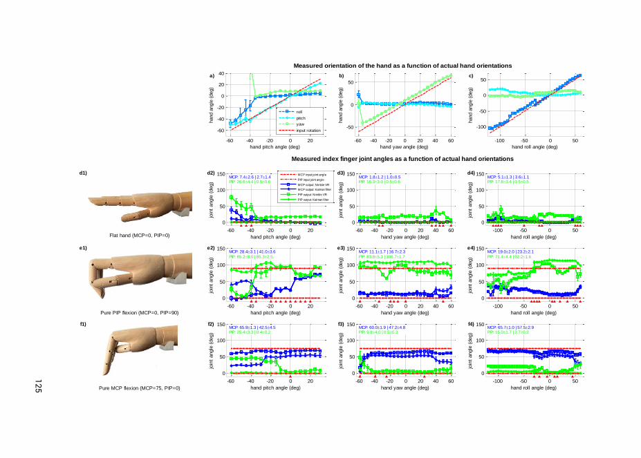
125
3
4
Flat hand (MCP=0, PIP=0)-60 -40 -20 0 20
0
50
100
150
hand pitch angle (deg)
join
t angle
(deg)
MCP: 7.42.6 | 2.71.4PIP: 26.64.4 | 0.50.6
MCP input joint angle
PIP input joint angle
MCP output: Nimble VR
MCP output: Kalman filter
PIP output: Nimble VR
PIP output: Kalman filter
-60 -40 -20 0 20 40 60
0
50
100
150
hand yaw angle (deg)
join
t angle
(deg)
MCP: 1.81.2 | 1.00.5PIP: 18.33.0 | 0.50.6
-100 -50 0 50
0
50
100
150
hand roll angle (deg)
join
t angle
(deg)
MCP: 5.11.3 | 3.61.1PIP: 17.83.4 | 0.50.5
Pure PIP flexion (MCP=0, PIP=90)
-60 -40 -20 0 20
0
50
100
150
hand pitch angle (deg)
join
t angle
(deg)
MCP: 28.43.1 | 41.03.6
PIP: 65.28.0 | 85.32.5
-60 -40 -20 0 20 40 60
0
50
100
150
hand yaw angle (deg)
join
t angle
(deg)
MCP: 11.11.7 | 16.72.3
PIP: 83.85.1 | 106.71.7
-100 -50 0 50
0
50
100
150
hand roll angle (deg)
join
t angle
(deg)
MCP: 19.02.0 | 23.22.1
PIP: 71.44.4 | 92.21.6
Pure MCP flexion (MCP=75, PIP=0)
-60 -40 -20 0 20
0
50
100
150
hand pitch angle (deg)
join
t angle
(deg)
MCP: 65.91.3 | 42.54.5PIP: 25.43.3 | 0.40.2
-60 -40 -20 0 20 40 60
0
50
100
150
hand yaw angle (deg)
join
t angle
(deg)
MCP: 60.01.9 | 47.24.8PIP: 9.84.0 | 0.50.3
-100 -50 0 50
0
50
100
150
hand roll angle (deg)
join
t angle
(deg)
MCP: 65.71.0 | 57.52.9PIP: 15.01.7 | 2.70.3
Measured index finger joint angles as a function of actual hand orientations
d1) d2) d3) d4)
e1) e2) e3) e4)
f1) f2) f3) f4)
-60 -40 -20 0 20
-60
-40
-20
0
20
40
hand pitch angle (deg)
hand a
ngle
(deg)
roll
pitch
yaw
input rotation
-60 -40 -20 0 20 40 60
-50
0
50
hand yaw angle (deg)
hand a
ngle
(deg)
-100 -50 0 50
-100
-50
0
50
hand roll angle (deg)
hand a
ngle
(deg)
Measured orientation of the hand as a function of actual hand orientations
a) b) c)
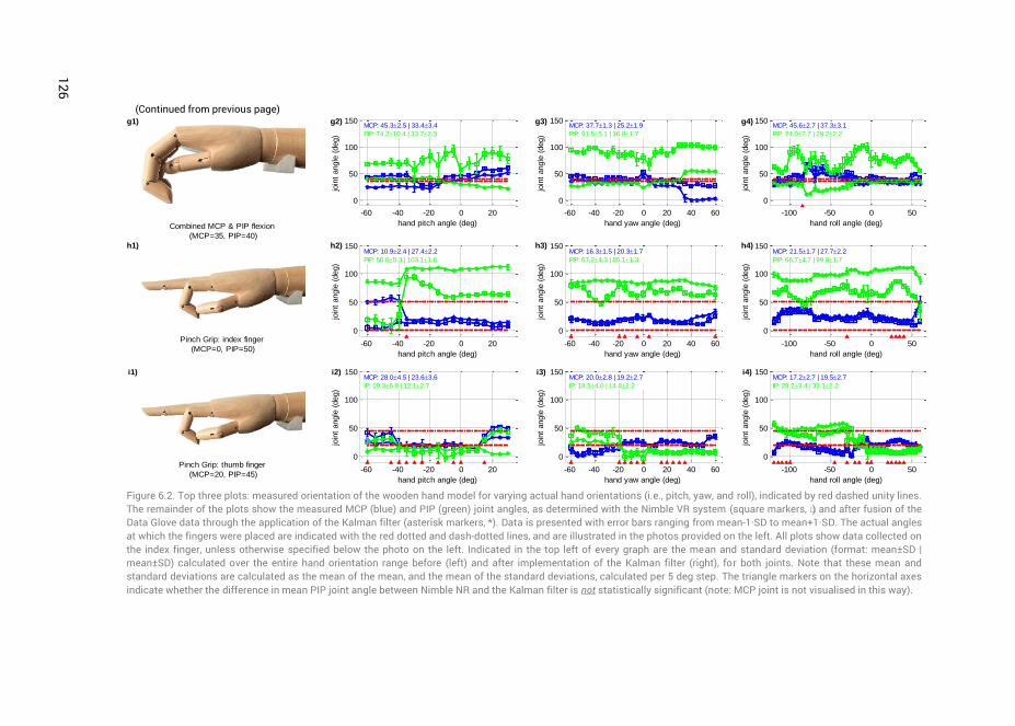
126
(Continued from previous page)
Figure 6.2. Top three plots: measured orientation of the wooden hand model for varying actual hand orientations (i.e., pitch, yaw, and roll), indicated by red dashed unity lines. The remainder of the plots show the measured MCP (blue) and PIP (green) joint angles, as determined with the Nimble VR system (square markers, □) and after fusion of the Data Glove data through the application of the Kalman filter (asterisk markers, *). Data is presented with error bars ranging from mean-1·SD to mean+1·SD. The actual angles at which the fingers were placed are indicated with the red dotted and dash-dotted lines, and are illustrated in the photos provided on the left. All plots show data collected on the index finger, unless otherwise specified below the photo on the left. Indicated in the top left of every graph are the mean and standard deviation (format: mean±SD | mean±SD) calculated over the entire hand orientation range before (left) and after implementation of the Kalman filter (right), for both joints. Note that these mean and standard deviations are calculated as the mean of the mean, and the mean of the standard deviations, calculated per 5 deg step. The triangle markers on the horizontal axes indicate whether the difference in mean PIP joint angle between Nimble NR and the Kalman filter is not statistically significant (note: MCP joint is not visualised in this way).
Combined MCP & PIP flexion
(MCP=35, PIP=40)
-60 -40 -20 0 20
0
50
100
150
hand pitch angle (deg)
join
t angle
(deg)
MCP: 45.32.5 | 33.43.4
PIP: 74.210.4 | 33.72.3
-60 -40 -20 0 20 40 60
0
50
100
150
hand yaw angle (deg)
join
t angle
(deg)
MCP: 37.71.3 | 25.21.9
PIP: 91.55.1 | 36.81.7
-100 -50 0 50
0
50
100
150
hand roll angle (deg)
join
t angle
(deg)
MCP: 45.62.7 | 37.33.1
PIP: 74.07.7 | 29.22.2
Pinch Grip: index finger
(MCP=0, PIP=50)-60 -40 -20 0 20
0
50
100
150
hand pitch angle (deg)
join
t angle
(deg)
MCP: 10.92.4 | 27.42.2
PIP: 56.05.3 | 103.11.8
-60 -40 -20 0 20 40 60
0
50
100
150
hand yaw angle (deg)
join
t angle
(deg)
MCP: 16.31.5 | 20.31.7
PIP: 67.24.3 | 85.11.3
-100 -50 0 50
0
50
100
150
hand roll angle (deg)
join
t angle
(deg)
MCP: 21.51.7 | 27.72.2
PIP: 66.74.7 | 99.81.7
Pinch Grip: thumb finger
(MCP=20, PIP=45)-60 -40 -20 0 20
0
50
100
150
hand pitch angle (deg)
join
t angle
(deg)
MCP: 28.04.5 | 23.63.6
IP: 19.36.8 | 12.12.7
-60 -40 -20 0 20 40 60
0
50
100
150
hand yaw angle (deg)
join
t angle
(deg)
MCP: 20.02.8 | 19.22.7
IP: 18.54.0 | 14.82.2
-100 -50 0 50
0
50
100
150
hand roll angle (deg)
join
t angle
(deg)
MCP: 17.22.7 | 19.52.7
IP: 28.23.4 | 33.12.2
g1) g2) g3) g4)
h1) h2) h3) h4)
i1) i2) i3) i4)
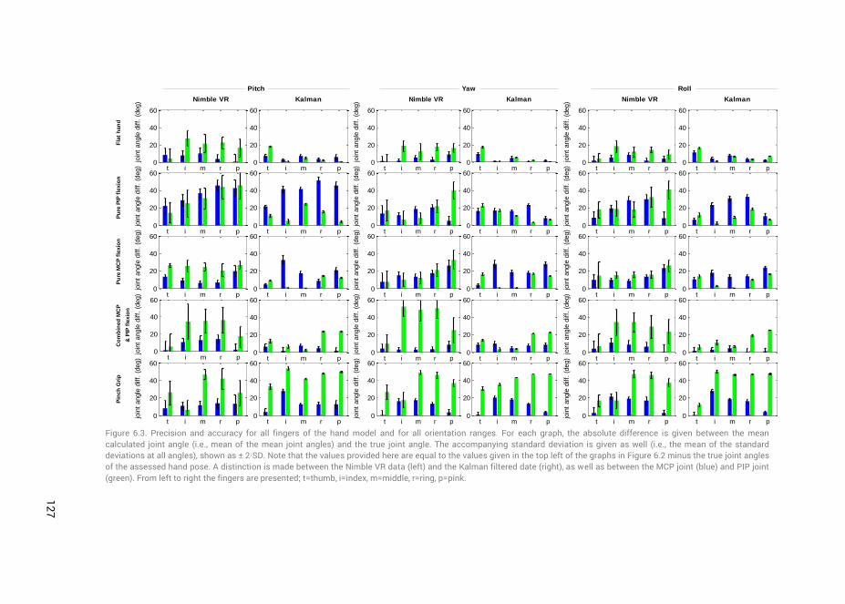
127
3
4
Figure 6.3. Precision and accuracy for all fingers of the hand model and for all orientation ranges. For each graph, the absolute difference is given between the mean calculated joint angle (i.e., mean of the mean joint angles) and the true joint angle. The accompanying standard deviation is given as well (i.e., the mean of the standard deviations at all angles), shown as ± 2·SD. Note that the values provided here are equal to the values given in the top left of the graphs in Figure 6.2 minus the true joint angles of the assessed hand pose. A distinction is made between the Nimble VR data (left) and the Kalman filtered date (right), as well as between the MCP joint (blue) and PIP joint (green). From left to right the fingers are presented; t=thumb, i=index, m=middle, r=ring, p=pink.
t i m r p0
20
40
60
t i m r p0
20
40
60
t i m r p0
20
40
60
t i m r p0
20
40
60
t i m r p0
20
40
60
t i m r p0
20
40
60
t i m r p0
20
40
60
t i m r p0
20
40
60
t i m r p0
20
40
60
t i m r p0
20
40
60
Pitch
Nimble VR Kalman
join
t angle
diff.
(deg)
join
t angle
diff.
(deg)
join
t angle
diff.
(deg)
join
t angle
diff.
(deg)
join
t angle
diff.
(deg)
t i m r p0
20
40
60
t i m r p0
20
40
60
t i m r p0
20
40
60
t i m r p0
20
40
60
t i m r p0
20
40
60
t i m r p0
20
40
60
t i m r p0
20
40
60
t i m r p0
20
40
60
t i m r p0
20
40
60
t i m r p0
20
40
60
Yaw
Nimble VR Kalman
join
t angle
diff.
(deg)
join
t angle
diff.
(deg)
join
t angle
diff.
(deg)
join
t angle
diff.
(deg)
join
t angle
diff.
(deg)
t i m r p0
20
40
60
t i m r p0
20
40
60
t i m r p0
20
40
60
t i m r p0
20
40
60
t i m r p0
20
40
60
t i m r p0
20
40
60
t i m r p0
20
40
60
t i m r p0
20
40
60
t i m r p0
20
40
60
t i m r p0
20
40
60
Roll
Nimble VR Kalman
join
t angle
diff.
(deg)
join
t angle
diff.
(deg)
join
t angle
diff.
(deg)
join
t angle
diff.
(deg)
join
t angle
diff.
(deg)
Fla
t h
an
dP
ure
PIP
fle
xio
nP
ure
MC
P f
lexio
nC
om
bin
ed
MC
P
& P
IP f
lexio
n
Pin
ch
Gri
p
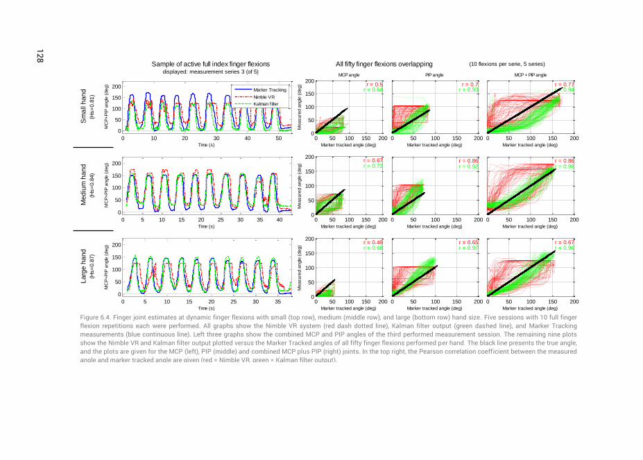
128
Figure 6.4. Finger joint estimates at dynamic finger flexions with small (top row), medium (middle row), and large (bottom row) hand size. Five sessions with 10 full finger flexion repetitions each were performed. All graphs show the Nimble VR system (red dash dotted line), Kalman filter output (green dashed line), and Marker Tracking measurements (blue continuous line). Left three graphs show the combined MCP and PIP angles of the third performed measurement session. The remaining nine plots show the Nimble VR and Kalman filter output plotted versus the Marker Tracked angles of all fifty finger flexions performed per hand. The black line presents the true angle, and the plots are given for the MCP (left), PIP (middle) and combined MCP plus PIP (right) joints. In the top right, the Pearson correlation coefficient between the measured angle and marker tracked angle are given (red = Nimble VR, green = Kalman filter output).
0 10 20 30 40 50
0
50
100
150
200
MC
P+P
IP a
ngle
(deg)
Time (s)
Marker Tracking
Nimble VR
Kalman filter
0 50 100 150 2000
50
100
150
200r = 0.5
r = 0.64
Marker tracked angle (deg)
Measure
d a
ngle
(deg)
MCP angle
0 50 100 150 200
r = 0.7r = 0.93
Marker tracked angle (deg)
PIP angle
0 50 100 150 200
r = 0.77r = 0.94
Marker tracked angle (deg)
MCP + PIP angle
0 5 10 15 20 25 30 35 40
0
50
100
150
200
MC
P+P
IP a
ngle
(deg)
Time (s)
0 50 100 150 2000
50
100
150
200r = 0.67r = 0.72
Marker tracked angle (deg)
Measure
d a
ngle
(deg)
0 50 100 150 200
r = 0.86r = 0.92
Marker tracked angle (deg)
0 50 100 150 200
r = 0.86r = 0.96
Marker tracked angle (deg)
0 5 10 15 20 25 30 35
0
50
100
150
200
MC
P+P
IP a
ngle
(deg)
Time (s)
0 50 100 150 2000
50
100
150
200r = 0.49r = 0.68
Marker tracked angle (deg)
Measure
d a
ngle
(deg)
0 50 100 150 200
r = 0.65r = 0.97
Marker tracked angle (deg)
0 50 100 150 200
r = 0.67r = 0.96
Marker tracked angle (deg)
Sample of active full index finger flexionsdisplayed: measurement series 3 (of 5)
All fifty finger flexions overlapping (10 flexions per serie, 5 series)
Sm
all h
an
d
(Hs=
0.8
1)
Me
diu
m h
an
d
(Hs=
0.8
4)
La
rge
ha
nd
(Hs=
0.8
7)
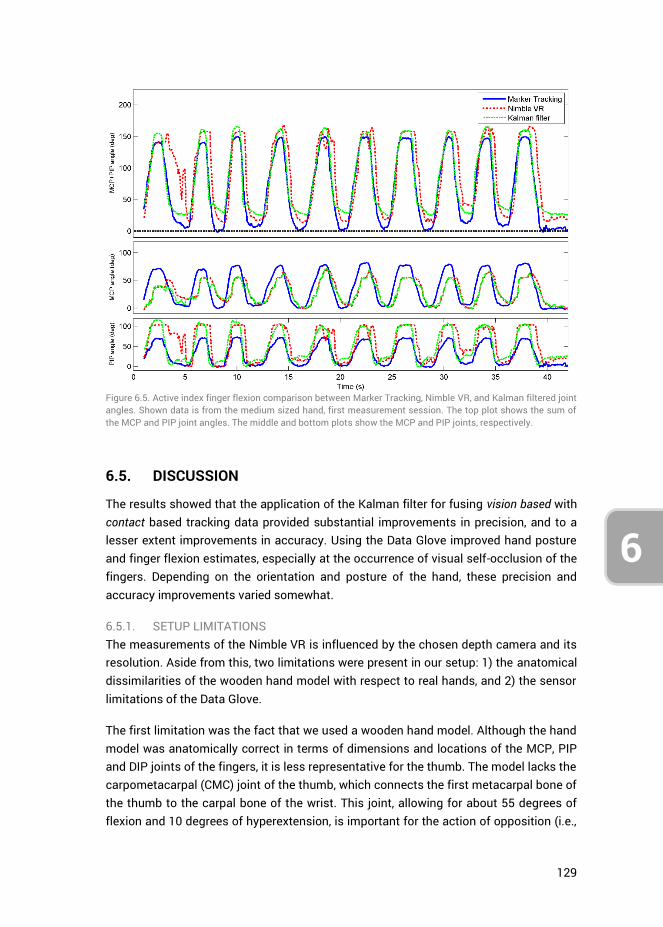
129
6
Figure 6.5. Active index finger flexion comparison between Marker Tracking, Nimble VR, and Kalman filtered joint angles. Shown data is from the medium sized hand, first measurement session. The top plot shows the sum of the MCP and PIP joint angles. The middle and bottom plots show the MCP and PIP joints, respectively.
6.5. DISCUSSION
The results showed that the application of the Kalman filter for fusing vision based with contact based tracking data provided substantial improvements in precision, and to a lesser extent improvements in accuracy. Using the Data Glove improved hand posture and finger flexion estimates, especially at the occurrence of visual self-occlusion of the fingers. Depending on the orientation and posture of the hand, these precision and accuracy improvements varied somewhat.
6.5.1. SETUP LIMITATIONS The measurements of the Nimble VR is influenced by the chosen depth camera and its resolution. Aside from this, two limitations were present in our setup: 1) the anatomical dissimilarities of the wooden hand model with respect to real hands, and 2) the sensor limitations of the Data Glove.
The first limitation was the fact that we used a wooden hand model. Although the hand model was anatomically correct in terms of dimensions and locations of the MCP, PIP and DIP joints of the fingers, it is less representative for the thumb. The model lacks the carpometacarpal (CMC) joint of the thumb, which connects the first metacarpal bone of the thumb to the carpal bone of the wrist. This joint, allowing for about 55 degrees of flexion and 10 degrees of hyperextension, is important for the action of opposition (i.e.,
130
6
touching the tip of the pink finger with the tip of the thumb). Due to the absence of the CMC joint, both palmar and radial abduction are impossible in the hand model, limiting the thumb’s movements to flexion of the MCP and IP joints. As a result, the pinch grip pose that we assessed deviated from an actual pinch grip that relies on the CMC joint. The Nimble VR software (which compares the obtained Kinect camera output to a precomputed database of hand postures) is able to detect this pinch grip posture, and automatically assumes the CMC joint to play a role in it. As a result, the software output better reflects real index and thumb fingers joint angles as compared to the model fingers. If the reader was to place one’s own hand in the pinch grip pose, and compare this to the hand model pinch grip (shown in Figure 6.2 graphs h1 and i1), he/ she can see the degree of flexion of the MCP joint of the index finger to be nonzero and PIP joint to be around 80 degrees, whereas the model had 0 and 50 degrees respectively. When calculating the accuracy of the MCP and PIP joints over all hand poses combined, but excluding the pinch grip pose, the Nimble VR provides 12.8 deg and 22.1 deg, respectively, and after implementation of the filter this is 13.4 deg and 10.5 deg. Compared to previous results, the accuracy for the PIP joint is thus improved by 6 deg when not taking the pinch grip into consideration. The precision stays approximately the same.
An additional restriction of the hand model is that its fingers are not able to perform abduction and adduction at the MCP joints. This did not affect our measurements of the MCP and PIP joints, but limited us in the selection of the postures. For future research, it is interesting to use a hand model that is able to make such joint movements, and to use a Data Glove with additional sensors that measure ab- and adduction of the fingers, such as the 5DT Data Glove 14 Ultra [52]. However, a glove with more sensors is more likely to impede the naturalness of motion of the user, especially considering the fact that ab- and adduction sensors need to be placed in between the fingers.
The second limitation of the used measurement setup was inherent in the Data Glove. Because the glove itself is made of stretch Lycra and made to fit most hand sizes, its measurement accuracy is dependent on the quality with which it is calibrated. Furthermore, its fibre-optics-based bending sensors are positioned inside small hollow sleeves along the glove fingers. Consequently, the sensors are slightly able to shift inside these sleeves, potentially creating drift in the measurements during prolonged usage. As the measurements presented in this research were acquired during passive hand postures, this drift could not be quantified.
Another disadvantage of using the Data Glove is that the predetermined Data Glove weights
MCPDGw and
PIPDGw (see Appendix C) are person-specific to a certain extent. As
the size of peoples’ hands vary, the degree of sensor flexion and their exact positioning with respect to the fingers tend to vary as well. The current weights were determined
131
6
based on a medium sized hand. Where for example the sensor on the pink mainly measures PIP flexion, this may be slightly different for persons with smaller hands, where the sensor will overlay more of the MCP joint. Based on the active finger flexion measurements performed on hands of different sizes, we found that the degree of overall finger flexion is underestimated at small hands, and slightly overestimated at medium and large hands. As such, the glove weights will likely not have to be recalibrated for all test participants. In order to improve the joint angle estimations for small hands, a second set of glove weights may be measured and used in future tests.
6.5.2. ACTIVE FINGER FLEXION MEASUREMENTS When assessing the influence of the Kalman filter on the active finger flexions (Figure 6.4), it can be seen that the time delay inherent in the Nimble VR remains present at the MCP joint estimate, but is reduced at the PIP joint. Similarly, for all the fingers (Figure 6.3), the MCP joint’s increase in precision and accuracy is not as pronounced as for the PIP joint. The explanation for this can be found in the implementation of the variance matrix
kR (see Appendix A). The observed variance of the Nimble VR PIP joint angles is
higher as compared to the MCP joints. The filter therefore assumes the Nimble VR MCP joint estimates to be more reliable than those of the PIP joint. As a result, the Data Glove measurements are predominantly used to smoothen out and correct the PIP joint estimates.
During active finger flexions, both the MCP and PIP joints are flexed simultaneously. It is likely that for the Kinect camera, which has a top-down view of the hand, the flexion of the PIP joints is initially visually more pronounced than the flexion of the MCP joint. The flexion of the MCP joint is not detected directly, providing an explanation for the time delay (which, as shown in Figure 6.5, is larger for the MCP joint compared to the PIP joint). As the Data Glove mostly corrects for the PIP joints, this time delay persists in the filter output for the MCP joints. In order to correct for this, one could adjust the variance terms in matrix
kR accordingly, allowing the Data Glove measurements to
better influence the MCP joint estimates. However, this would come at the cost of the quality of the PIP joint estimates.
The size of the time delays for both joints can be further reduced, as the setup in its current iteration has not yet been optimized in terms of computational efficiency. The time delays have been obtained on a computer with an i7-2640M CPU (2.80GHz), 8GB of RAM and 64-bit Windows 7 Operating System, while using custom written software to capture the data stream from both the camera and data glove system. The time delays will likely decrease with further iterations of the Nimble VR software as well as through the implementation of a dedicated processing unit to perform the relatively heavy Nimble VR calculations.
132
6
6.5.3. DATA FUSION IMPROVEMENTS Sensor redundancy through data fusion of a contact based device with that of a vision based provides data completeness during partial and full visual occlusion of the fingers. Although the Kalman filter method is easy in implementation, it by definition requires the state prediction model to be a linear function of the measurements. It is possible that an extended Kalman filter, using non-linear functions, will provide more accurate state estimates. An interesting way to extend the model could be to use heuristics, and to change the model based on the hand pose detected by the Nimble VR software. For example, if a person is pointing with the index finger, one could assume him or her to have the remaining fingers closed towards the palm of the hand. As such, it is known there is a high likelihood that some of those fingers will be visually occluded, and the model could take this into account.
Another way of improving the current setup may be to use alternative contact based measurement devices that directly measure finger flexion without impeding naturalness of motion of the user. Although the used 5DT data glove is not very intrusive, studies have shown that gloves may have negative effects on manual dexterity, comfort, and possibly the range of finger and wrist movements [58]. One interesting method presented in the literature is the use of adhesives to attach sensor sleeves to the back of the fingers whilst leaving the joints free of adhesives that would restrict movements [59]. These sensors would leave the fingers largely unimpeded, benefiting potential uses for tactile feedback.
An alternative may also be to exchange the contact based device for a locally functioning vision based device such as the Digits wrist-worn gloveless sensor [60]. Digits is a small camera-based sensor attached to the wrist that images a large part of the user’s bare hand. Its infrared camera is placed such that the upper part of the palm and fingers are imaged as they bend inwards towards the device. As the device is not restricted to a fixed space around the user, but moves with the user’s hand, it can image the fingers that may be occluded from vision for the Nimble VR.
A third potential device for integration with the Nimble VR system is the Myo armband from Thalmic Labs [61, 62]. Instead of approximating the flexion of the fingers, this system extracts user gestures from measured EMG signals. Using these observed gestures to update the Nimble VR’s calculated skeletal model may be a different route for obtaining improved finger joint angles estimates.
Regardless of which second measurement system is used to improve data completeness through data fusion, in case of a contact based system its influence on the naturalness of motion needs to be taken into account. Especially in applications such as laparoscopic training, such (minor) physical limitations can easily become a hindrance to the participants (or surgeons), and influence task performance. The
133
6
advantages of more complex measurement systems should thus be considered within the context and duration of the target application(s).
The Nimble VR software and concurrent hardware are still under development, as the company Nimble VR has recently joined Oculus VR, LLC [38]. It is expected that the accuracy and precision will improve prior to consumer market introduction. Additionally, especially with respect to the consumer market, the advantages of fusing simple unobtrusive contact based sensors with ‘low-budget’ vision based systems (e.g., Leap Motion and Nimble VR) may be an easy and computationally efficient way of obtaining data completeness for applications such as 3D computer interaction and gaming [63].
6.5.4. APPLICATION IN MEDICAL FIELD One of the fields where precision and data completeness of measured hand and finger motions is of prime importance is the medical domain. As described in the introduction, hand motions and postures as HCI input have already been applied in several cases [10, 11], but not yet in virtual laparoscopic training. The Nimble VR system used in this research has a working area large enough to allow surgeons to make the same surgical routine motions they would make using the already available Da Vinci master robot (Intuitive Surgical Inc., Sunnyvale, CA, USA) to which some surgeons have already grown accustomed [47, 48]. Before the eventual implementation of vision based devices in applications such as laparoscopic training however, several limitations will need to be overcome. Foremost is the time delay in the detection of the hands by the camera and the (computationally heavy) extraction of the skeletal model of the hand. A time delay of 300 ms is likely to adversely affect skills training [64]. In terms of surgical performance, it has been shown that surgeons are able to compensate for time delays up to 700 ms through a “move and wait” strategy. However, the number of operator errors increases with increasing time delay [65-67]. Hence, ideally the time delay has to be minimized. Secondly, inherent in the use of a vision based device is the lack of haptic feedback, a property which has been shown to improve hand-eye coordination [68]. To certain extents, this limitation can be addressed through the use of visual force feedback [69], implementation of pseudo-haptic feedback in the virtual environment [70], or the integration of a haptic-feedback mechanism in a touch based glove [71].
The precision of the joint angle estimates obtained through implementation of the data glove and the Kalman Filter in this research is generally around 1 to 3 deg, depending on which joint and finger we are looking at. For medical practice, a control precision of 2 mm for standard laparoscopic instruments has been reported [72]. As an example, when controlling a joint incorporated in the shaft of a laparoscopic instrument, depending on the length of the segment attached to the joint controlled through finger flexion, a standard deviation from 1 to 3 deg is acceptable (e.g., with a segment length of 20 mm, which is the approximate length of a functional tooltip of a laparoscopic
134
6
instrument, an angular standard deviation of 3 deg equals a tip positional standard deviation of sin(3) * 20 ≈ 1.0 mm).
The accuracy improvements through implementation of the filter were less pronounced as compared to the precision results. Using the filter, for the MCP joint, the mean deviation from the true joint angle was 13.5 deg, and for the PIP joint around 16.8 deg. Due to the good precision however, touchless control of simulated instruments through flexion of the fingers combined with movements of the hand and concomitant visual feedback should be possible. This is true when considering that humans are able to use visual feedback to correct for unforeseen perturbations during continuous hand movements [73]. Therefore, considering the precision of the joint angle estimates obtained in this research, our aim is to implement and further study the presented measurement setup for VR medical simulator purposes.
6.6. CONCLUSION
In this study, we performed a Kalman filter data fusion of hand and finger motion measurements obtained with the 5DT Data Glove and the Nimble VR using a Kinect camera. Measurements were obtained using a wooden hand model placed in various postures across various orientation ranges, as well as on three different sized hands performing active finger flexions. Through sensor redundancy, more accurate and substantially more precise joint flexion estimates could be obtained compared to the Nimble VR alone. The obtained accuracy for the MCP and PIP joint after implementation of the filter were 13.5 deg (SD = 12.9 deg) and 16.8 deg (SD = 15.7 deg) respectively, and the precision 2.2 deg (SD = 2.2 deg) and 0.9 deg (SD = 1.1 deg). For the PIP joint thus a 31% improvement in accuracy was observed and a 79% improvement in precision. The MCP accuracy worsened by 6% and the precision improved by 5%, showing the filter to only marginally influence this joint. Due to the use of the contact based Data Glove, visual self-occlusion of the fingers for the visual based Nimble VR system could be mitigated, and data completeness obtained.
6.7. APPENDIX A: ORIENTATION DEPENDANT VARIANCE QUANTIFICATION
6.7.1. METHODS
Finger joint variances for matrix kR were measured using an anatomically correct
wooden right-hand model mounted on a tripod with a 3-way pan/tilt head. The wooden hand had a length of 21.35 cm, measured from wrist to tip of the middle finger, and breadth of 8.3 cm.
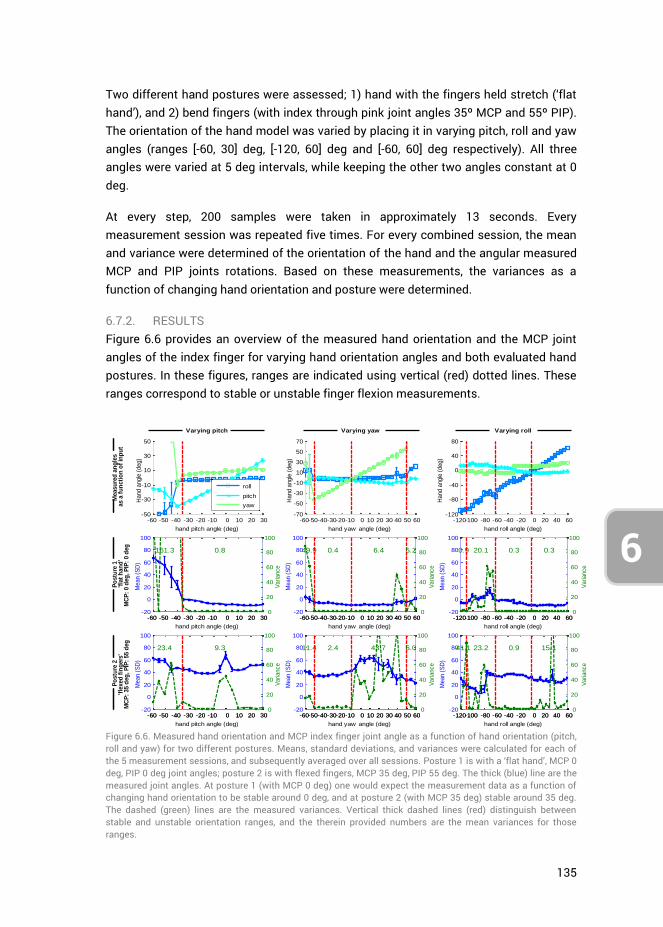
135
6
Two different hand postures were assessed; 1) hand with the fingers held stretch (‘flat hand’), and 2) bend fingers (with index through pink joint angles 35º MCP and 55º PIP). The orientation of the hand model was varied by placing it in varying pitch, roll and yaw angles (ranges [-60, 30] deg, [-120, 60] deg and [-60, 60] deg respectively). All three angles were varied at 5 deg intervals, while keeping the other two angles constant at 0 deg.
At every step, 200 samples were taken in approximately 13 seconds. Every measurement session was repeated five times. For every combined session, the mean and variance were determined of the orientation of the hand and the angular measured MCP and PIP joints rotations. Based on these measurements, the variances as a function of changing hand orientation and posture were determined.
6.7.2. RESULTS Figure 6.6 provides an overview of the measured hand orientation and the MCP joint angles of the index finger for varying hand orientation angles and both evaluated hand postures. In these figures, ranges are indicated using vertical (red) dotted lines. These ranges correspond to stable or unstable finger flexion measurements.
Figure 6.6. Measured hand orientation and MCP index finger joint angle as a function of hand orientation (pitch, roll and yaw) for two different postures. Means, standard deviations, and variances were calculated for each of the 5 measurement sessions, and subsequently averaged over all sessions. Posture 1 is with a ‘flat hand’, MCP 0 deg, PIP 0 deg joint angles; posture 2 is with flexed fingers, MCP 35 deg, PIP 55 deg. The thick (blue) line are the measured joint angles. At posture 1 (with MCP 0 deg) one would expect the measurement data as a function of changing hand orientation to be stable around 0 deg, and at posture 2 (with MCP 35 deg) stable around 35 deg. The dashed (green) lines are the measured variances. Vertical thick dashed lines (red) distinguish between stable and unstable orientation ranges, and the therein provided numbers are the mean variances for those ranges.
-60 -50 -40 -30 -20 -10 0 10 20 30-50
-30
-10
10
30
50
hand pitch angle (deg)
Hand a
ngle
(deg)
roll
pitch
yaw
-120-100 -80 -60 -40 -20 0 20 40 60-120
-80
-40
0
40
80
hand roll angle (deg)
Hand a
ngle
(deg)
-60-50-40-30-20-10 0 10 20 30 40 50 60-70
-50
-30
-10
10
30
50
70
hand yaw angle (deg)
Hand a
ngle
(deg)
-60 -50 -40 -30 -20 -10 0 10 20 30-20
0
20
40
60
80
100
hand pitch angle (deg)
Mean (
SD
)
0.8161.3
-60 -50 -40 -30 -20 -10 0 10 20 30 0
20
40
60
80
100
Variance
-120-100 -80 -60 -40 -20 0 20 40 60-20
0
20
40
60
80
100
hand roll angle (deg)
Mean (
SD
)
0.9 20.1 0.3 0.3
-120-100 -80 -60 -40 -20 0 20 40 60 0
20
40
60
80
100
Variance
-60-50-40-30-20-10 0 10 20 30 40 50 60-20
0
20
40
60
80
100
hand yaw angle (deg)
Mean (
SD
)
49.9 0.4 6.4 5.2
-60-50-40-30-20-10 0 10 20 30 40 50 60 0
20
40
60
80
100
Variance
-60 -50 -40 -30 -20 -10 0 10 20 30-20
0
20
40
60
80
100
hand pitch angle (deg)
Mean (
SD
)
9.323.4
-60 -50 -40 -30 -20 -10 0 10 20 30 0
20
40
60
80
100
Variance
-120-100 -80 -60 -40 -20 0 20 40 60-20
0
20
40
60
80
100
hand roll angle (deg)
Mean (
SD
)
41.1 23.2 0.9 15.1
-120-100 -80 -60 -40 -20 0 20 40 60 0
20
40
60
80
100
Variance
-60-50-40-30-20-10 0 10 20 30 40 50 60-20
0
20
40
60
80
100
hand yaw angle (deg)
Mean (
SD
)
11.4 2.4 43.7 6.0
-60-50-40-30-20-10 0 10 20 30 40 50 60 0
20
40
60
80
100
Variance
Varying pitch Varying yaw Varying roll
Measu
red
an
gle
sas a
fu
ncti
on
of
inp
ut
Po
stu
re 1
'fla
t h
an
d'
MC
P:
0 d
eg
, P
IP:
0 d
eg
Po
stu
re 2
'fle
xed
fin
gers
'M
CP
: 35 d
eg
, P
IP:
55 d
eg

136
6
For varying pitch angles, and independent of posture, the MCP and PIP joints can adequately be estimated in the range [-35, 30] deg, see Figure 6.6. In this stable range, at hand posture 1 (‘flat hand’) no substantial difference is present between the MCP and PIP joints. However, at posture 2 (finger flexion) the PIP joints are subject to higher variances than the MCP joints (75.9 deg2 vs. 9.3 deg2, respectively). No apparent relation is present however between variance and pitch angle. At hand orientation angles below -35 deg, the hand is angling too far downwards for the camera to robustly detect the joint angles. Lastly, for posture 2, the PIP joints appear to be overestimated.
The roll angle measurements are stable over the entire range [-120, 60] deg, except for the range [-110, -60] deg where uncertainty is present in the data. At -90 deg, the hand is angled vertically, with the thumb facing up, and the middle through pink fingers are occluded for the camera by the thumb and index fingers. As a result, finger joint estimates are unstable in this range, and have higher variance as compared to the stable range (for the MCP joint 20.1 deg2 vs. 0.3 deg2 at posture 1 and 23.2 deg2 vs. 8.1 deg2 at posture 2). At range [40, 60] deg, when the thumb is pointing down, the software has significant difficulty detecting the thumb (resulting in either high or zero variance for the thumb). In this range, at high thumb measurement variance, all the other fingers are influenced as well, explaining the variance peak at posture 2 at 40 deg, see Figure 6.6. Again, in the stable range ([-120, -110] deg and [-60, 60] deg), the PIP variance is higher at posture 2 due to camera occlusion as compared to posture 1. This PIP variance is also higher in the range [0, 60] deg, when the thumb is pointing down, as compared to [-60, 0] deg (65.4 deg2 vs. 17.3 deg2 for the PIP joint respectively at posture 2).
Lastly, yaw angles are measured robustly in range [-50, 50] deg. Outside this range, the measurement results are unstable. The yaw stable range can be divided into two separate ranges, depending on whether the thumb is pointing towards or away from the computer screen. These ranges are [-50, -10] deg and [-10, 50] deg respectively, with measured MCP variances 2.4 deg2 and 43.7 deg2 for the index finger at posture 2. We thus measure a higher variance when the thumb is pointing away from the computer screen. Lastly, the PIP flexions are overestimated at posture 2.
Based on these results, the variances of individual fingers and joints can be expressed as a function of hand orientation and degree of finger flexion. Where possible, the measured orientation is used as input in choosing the appropriate corresponding
variance in matrix kR . Moreover, where higher variance is measured at posture 2, the
normalised measurement signal from the Data Glove is used as a weight in scaling up the joint variance at increasing finger flexion. Within the stable orientation ranges (pitch
[-35, 30] deg, roll [-120,60] deg, yaw [-50,50] deg) the parameters for matrix kR
for the MCP joint of the index finger are calculated as follows:

137
6
MCP
MCP MCP
MCP
2
NVR
2 2
NVR DG NVR
2
NVR
, , max , withA B z
MCP
MCP
MCP
2
NVR DG
DG
2
NVR
DG
DG2
NVR
DG
0.8 8.5 if 35 30
0.9 41.1 if 120 110
23.2 if 110 60
0.9 if 60 0
0.3 14.9 if 0 60
0.4 2.0 if 50 10
6.4 37.3 if 10 50
z
z
z
z
z
(A.1)
The A and B values (with unit deg2) for varying orientation angles for all fingers have been determined separately, and have been given below in the format
MCP MCP PIP PIPA B A B
for each finger.
3.7 37.5 11.7 62.4 0.8 8.5 2.3 73.6
0.1 5.9 3.5 7.8 0.9 41.1 2.8 85.3
21.8 0 15.9 0 23.2 0 41.2 0
1.9 0 6.4 0 0.9 0 0.7 16.6
2.4 23.3 5.5 16.2 0.3 14.9
8.1 0 19.6 0 0.4 2.0
19.1 23.3 33.8 45.1 6.4 37.3
thumb index middle ring pink
0.8 11.6 2.0 58.1 0.9 32.4
0.5 19.1 0.7 26.9 0.5 31.7
16.6 0 19.7 0 26.9 0
1.3 0 0.4 41.1 0.7 0
0.7 55.7 0.3 14.8 0.2 95.1 0.4 11.7
0.6 25.0 0.3 2.0 0.2 33.8 0.4 1.0
11.5 214.8 5.8 43.7 29.2 143.9 4
1.5 61.2 1.4 66 2.0 38.4
1.8 103.1 2.4 83.1 4.7 58.7
22.5 72.8 9.3 48.6 47.0 25.7
1.0 14.6 1.1 2.9 2.6 27.9
1.5 44.2 1.1 6.6 1.5 27.8
0.8 28.3 0.9 0.9 2.9 19.6
.0 75.3 36.5 80 7.8 70.4 39.3 88.2
(A.2)
6.8. APPENDIX B: FINGERS MAXIMUM ACCELERATION DETERMINATION
6.8.1. METHODS The process noise covariance matrix
kQ is calculated based on the maximum possible
accelerations of the MCP and PIP joints. Measurements of these accelerations were performed using the 5DT Data Glove. Ten healthy young participants were asked to flex and extend their fingers at a normal pace ten times, and as fast as possible ten times. The measurement frequency of the Data Glove was 200 Hz. Measured flexion data were resampled to 1000 Hz, using a cubic interpolation method, and filtered using a 2nd order Butterworth filter with a cut-off frequency of 10 Hz. At both movement tasks, for each participant the peak accelerations at every flexion and extension for every finger were determined, and the mean (±standard deviation (SD)) calculated. All determined

138
6
mean accelerations and SD were subsequently averaged over all participants, and we use this as input for matrix
kQ .
6.8.2. RESULTS An example of a single measurement session for the index finger is shown in Figure 6.7, with accompanying calculated finger flexion and extension accelerations. The participant was asked to flex his fingers as fast as possible. Accelerations and standard deviations averaged over all 10 participants are shown in Figure 6.8. The accelerations of the index, middle and ring fingers lie in the range 2.5 to 3.2·105 deg/s2, and accelerations of the thumb and pink are generally lower.
In order to make a distinction between MCP
and PIP
, we use the weights calculated in
Appendix C that indicate the individual joint contributions to the overall finger flexion angle as measured with the Data Glove. Recalculating these weights, which are given in equation (C.2), to percentages gives a MCP vs PIP division of 44% vs. 56% for the thumb, around 25% vs. 75% for the index, middle and ring finger, and 6% vs. 94% for the pink. The MCP angle contribution to the Data Glove sensor readings is always lower as compared to the PIP angle due to shifting of the sensors in the glove, and the MCP joint angle being more gradual as compared to the PIP joint angle.
For matrix kQ we take the PIP joint contribution percentages and calculate the
maximum joint accelerations by taking the same percentage of the measured overall flexure acceleration. For the index finger, with a total acceleration of 3.1·104 deg/s2 we thus find a PIP joint acceleration of 0.75*3.1·104 = 2.3·104 deg/s2. The following accelerations were found for the respective fingers:
4
PIP
21.05 2.34 2.10 2.38 2.31 /10
thumb index middle ring pi
g
nk
de s (B.1)
Because of the large spread in maximum accelerations (see Figure 6.8) between participants, these results need to be interpreted with caution. For implementation into the Kalman filter we will assume the MCP joint accelerations to be on par with the PIP accelerations, i.e.,
MCPPIP. Moreover, considering that the accelerations are the
maximum possible, and the normal movement accelerations are generally a lot lower, we can downscale the in (B.1) given values for input into
kQ to increase joint angle
approximation precision under the assumption of normal task operation speeds.
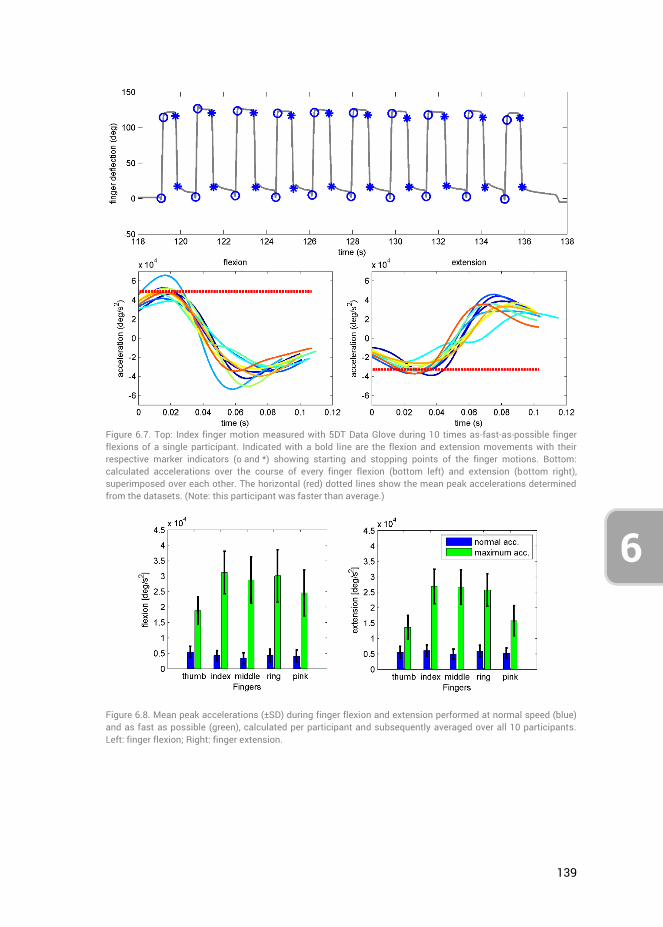
139
6
Figure 6.7. Top: Index finger motion measured with 5DT Data Glove during 10 times as-fast-as-possible finger flexions of a single participant. Indicated with a bold line are the flexion and extension movements with their respective marker indicators (o and *) showing starting and stopping points of the finger motions. Bottom: calculated accelerations over the course of every finger flexion (bottom left) and extension (bottom right), superimposed over each other. The horizontal (red) dotted lines show the mean peak accelerations determined from the datasets. (Note: this participant was faster than average.)
Figure 6.8. Mean peak accelerations (±SD) during finger flexion and extension performed at normal speed (blue) and as fast as possible (green), calculated per participant and subsequently averaged over all 10 participants. Left: finger flexion; Right: finger extension.
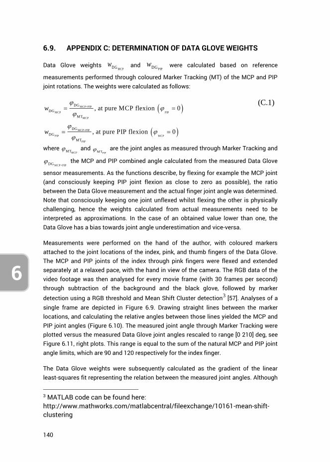
140
6
6.9. APPENDIX C: DETERMINATION OF DATA GLOVE WEIGHTS
Data Glove weights MCPDG
w and PIPDG
w were calculated based on reference
measurements performed through coloured Marker Tracking (MT) of the MCP and PIP joint rotations. The weights were calculated as follows:
MCP+PIP
MCP PIP
MCP
MCP+PIP
PIP MCP
PIP
DG
DG
MT
DG
DG
MT
, at pure MCP flexion 0
, at pure PIP flexion 0
w
w
(C.1)
where MCPMT
and PIPMT
are the joint angles as measured through Marker Tracking and
MCP+PIPDG the MCP and PIP combined angle calculated from the measured Data Glove
sensor measurements. As the functions describe, by flexing for example the MCP joint (and consciously keeping PIP joint flexion as close to zero as possible), the ratio between the Data Glove measurement and the actual finger joint angle was determined. Note that consciously keeping one joint unflexed whilst flexing the other is physically challenging, hence the weights calculated from actual measurements need to be interpreted as approximations. In the case of an obtained value lower than one, the Data Glove has a bias towards joint angle underestimation and vice-versa.
Measurements were performed on the hand of the author, with coloured markers attached to the joint locations of the index, pink, and thumb fingers of the Data Glove. The MCP and PIP joints of the index through pink fingers were flexed and extended separately at a relaxed pace, with the hand in view of the camera. The RGB data of the video footage was then analysed for every movie frame (with 30 frames per second) through subtraction of the background and the black glove, followed by marker
detection using a RGB threshold and Mean Shift Cluster detection3 [57]. Analyses of a single frame are depicted in Figure 6.9. Drawing straight lines between the marker locations, and calculating the relative angles between those lines yielded the MCP and PIP joint angles (Figure 6.10). The measured joint angle through Marker Tracking were plotted versus the measured Data Glove joint angles rescaled to range [0 210] deg, see Figure 6.11, right plots. This range is equal to the sum of the natural MCP and PIP joint angle limits, which are 90 and 120 respectively for the index finger.
The Data Glove weights were subsequently calculated as the gradient of the linear least-squares fit representing the relation between the measured joint angles. Although
3 MATLAB code can be found here: http://www.mathworks.com/matlabcentral/fileexchange/10161-mean-shift-clustering
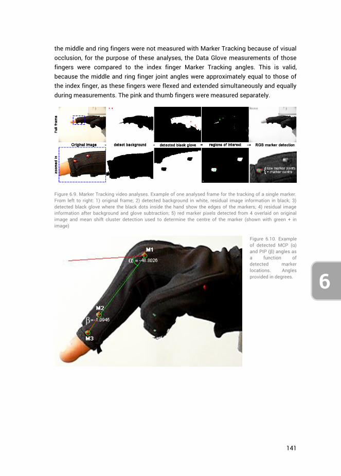
141
6
the middle and ring fingers were not measured with Marker Tracking because of visual occlusion, for the purpose of these analyses, the Data Glove measurements of those fingers were compared to the index finger Marker Tracking angles. This is valid, because the middle and ring finger joint angles were approximately equal to those of the index finger, as these fingers were flexed and extended simultaneously and equally during measurements. The pink and thumb fingers were measured separately.
Figure 6.9. Marker Tracking video analyses. Example of one analysed frame for the tracking of a single marker. From left to right: 1) original frame; 2) detected background in white, residual image information in black; 3) detected black glove where the black dots inside the hand show the edges of the markers; 4) residual image information after background and glove subtraction; 5) red marker pixels detected from 4 overlaid on original image and mean shift cluster detection used to determine the centre of the marker (shown with green + in image)
Figure 6.10. Example of detected MCP (α) and PIP (β) angles as a function of detected marker locations. Angles provided in degrees.
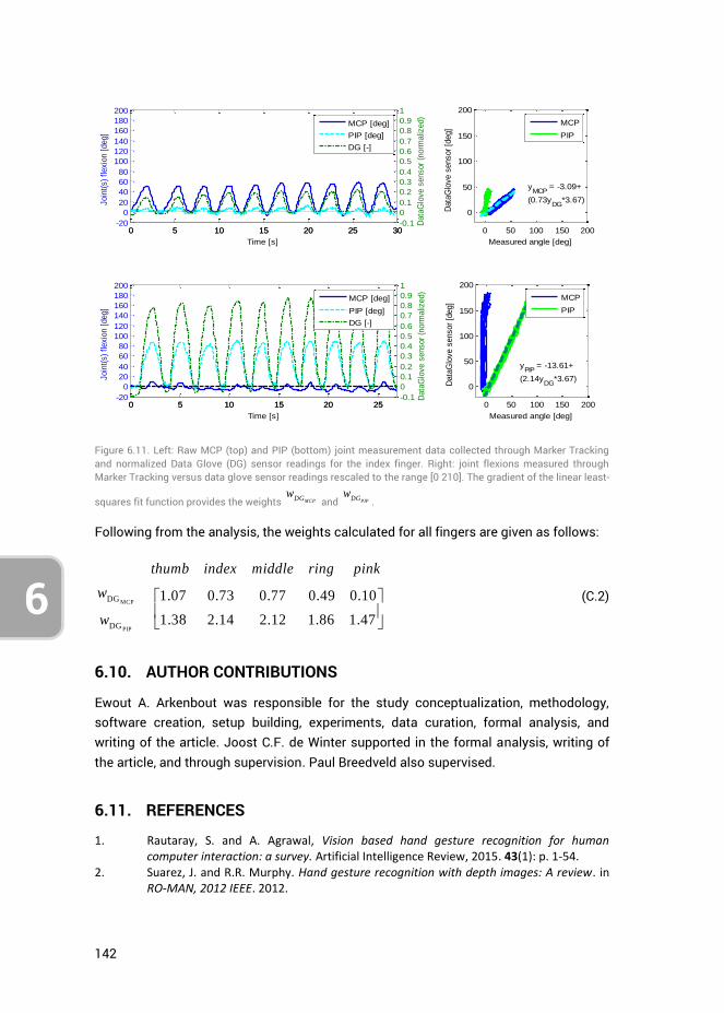
142
6
Figure 6.11. Left: Raw MCP (top) and PIP (bottom) joint measurement data collected through Marker Tracking and normalized Data Glove (DG) sensor readings for the index finger. Right: joint flexions measured through Marker Tracking versus data glove sensor readings rescaled to the range [0 210]. The gradient of the linear least-
squares fit function provides the weights MCPDGw
and PIPDGw
.
Following from the analysis, the weights calculated for all fingers are given as follows:
MCP
PIP
DG
DG
1.07 0.73 0.77 0.49 0.10
1.38 2.14 2.12 1.86 1.47
thumb index middle ring pink
w
w
(C.2)
6.10. AUTHOR CONTRIBUTIONS
Ewout A. Arkenbout was responsible for the study conceptualization, methodology, software creation, setup building, experiments, data curation, formal analysis, and writing of the article. Joost C.F. de Winter supported in the formal analysis, writing of the article, and through supervision. Paul Breedveld also supervised.
6.11. REFERENCES
1. Rautaray, S. and A. Agrawal, Vision based hand gesture recognition for human computer interaction: a survey. Artificial Intelligence Review, 2015. 43(1): p. 1-54.
2. Suarez, J. and R.R. Murphy. Hand gesture recognition with depth images: A review. in RO-MAN, 2012 IEEE. 2012.
0 5 10 15 20 25 30-20
0
20
40
60
80
100
120
140
160
180
200
Time [s]
Join
t(s)
flexio
n [
deg]
0 5 10 15 20 25 30-0.1
0
0.1
0.2
0.3
0.4
0.5
0.6
0.7
0.8
0.9
1
Data
Glo
ve s
ensor
(norm
aliz
ed)
MCP [deg]
PIP [deg]
DG [-]
0 50 100 150 200
0
50
100
150
200
yMCP
= -3.09+
(0.73yDG
*3.67)
Data
Glo
ve s
ensor
[deg]
Measured angle [deg]
MCP
PIP
0 5 10 15 20 25-20
0
20
40
60
80
100
120
140
160
180
200
Time [s]
Join
t(s)
flexio
n [
deg]
0 5 10 15 20 25-0.1
0
0.1
0.2
0.3
0.4
0.5
0.6
0.7
0.8
0.9
1
Data
Glo
ve s
ensor
(norm
aliz
ed)
MCP [deg]
PIP [deg]
DG [-]
0 50 100 150 200
0
50
100
150
200
yPIP
= -13.61+
(2.14yDG
*3.67)
Data
Glo
ve s
ensor
[deg]
Measured angle [deg]
MCP
PIP
143
6
3. Erol, A., et al., Vision-based hand pose estimation: A review. Computer Vision and Image Understanding, 2007. 108(1–2): p. 52-73.
4. Palacios, J., et al., Human-Computer Interaction Based on Hand Gestures Using RGB-D Sensors. Sensors, 2013. 13(9): p. 11842.
5. Sturman, D.J., Whole-hand input. 1991, Massachusetts Institute of Technology. 6. Pintzos, G., et al., A Novel Approach for the Combined Use of AR Goggles and Mobile
Devices as Communication Tools on the Shopfloor. Procedia CIRP, 2014. 25: p. 132-137. 7. Kalra, P., et al., Real-time animation of realistic virtual humans. Computer Graphics
and Applications, IEEE, 1998. 18(5): p. 42-56. 8. Menache, A., Understanding motion capture for computer animation and video games.
2000: Morgan Kaufmann. 9. Ohn-Bar, E. and M.M. Trivedi, Hand Gesture Recognition in Real Time for Automotive
Interfaces: A Multimodal Vision-Based Approach and Evaluations. Intelligent Transportation Systems, IEEE Transactions on, 2014. 15(6): p. 2368-2377.
10. Grätzel, C., et al., A non-contact mouse for surgeon-computer interaction. Technology and Health Care, 2004. 12(3): p. 245-257.
11. Rosa, G.M. and M.L. Elizondo, Use of a gesture user interface as a touchless image navigation system in dental surgery: Case series report. Imaging Sci Dent, 2014. 44(2): p. 155-160.
12. Adhikarla, V., et al., Exploring Direct 3D Interaction for Full Horizontal Parallax Light Field Displays Using Leap Motion Controller. Sensors, 2015. 15(4): p. 8642.
13. Bachmann, D., F. Weichert, and G. Rinkenauer, Evaluation of the Leap Motion Controller as a New Contact-Free Pointing Device. Sensors, 2014. 15(1): p. 214.
14. Guna, J., et al., An Analysis of the Precision and Reliability of the Leap Motion Sensor and Its Suitability for Static and Dynamic Tracking. Sensors, 2014. 14(2): p. 3702.
15. Dipietro, L., A.M. Sabatini, and P. Dario, A Survey of Glove-Based Systems and Their Applications. Systems, Man, and Cybernetics, Part C: Applications and Reviews, IEEE Transactions on, 2008. 38(4): p. 461-482.
16. Pavlovic, V.I., R. Sharma, and T.S. Huang, Visual interpretation of hand gestures for human-computer interaction: a review. Pattern Analysis and Machine Intelligence, IEEE Transactions on, 1997. 19(7): p. 677-695.
17. Wu, Y. and T. Huang, Vision-Based Gesture Recognition: A Review, in Gesture-Based Communication in Human-Computer Interaction, A. Braffort, et al., Editors. 1999, Springer Berlin Heidelberg. p. 103-115.
18. Preil, M., Optimum Dose for EUV: Technical vs. Economic Drivers. Future Fab Intl, 2012(41).
19. Kurzweil, R., The singularity is near: When humans transcend biology. 2005: Penguin. 20. Zhao, W., J. Chai, and Y.-Q. Xu, Combining marker-based mocap and RGB-D camera for
acquiring high-fidelity hand motion data, in Proceedings of the ACM SIGGRAPH/Eurographics Symposium on Computer Animation. 2012, Eurographics Association: Lausanne, Switzerland. p. 33-42.
21. Rogalla, O., M. Ehrenmann, and R. Dillmann. A sensor fusion approach for PbD. in Intelligent Robots and Systems, 1998. Proceedings., 1998 IEEE/RSJ International Conference on. 1998.
22. Ehrenmann, M., et al. Sensor fusion approaches for observation of user actions in programming by demonstration. in Multisensor Fusion and Integration for Intelligent Systems, 2001. MFI 2001. International Conference on. 2001.
23. Hebert, P., et al. Fusion of stereo vision, force-torque, and joint sensors for estimation of in-hand object location. in Robotics and Automation (ICRA), 2011 IEEE International Conference on. 2011.

144
6
24. Zhou, S., et al., Hand-Writing Motion Tracking with Vision-Inertial Sensor Fusion: Calibration and Error Correction. Sensors, 2014. 14(9): p. 15641.
25. Fan, W., et al. A Method of Hand Gesture Recognition Based on Multiple Sensors. in Bioinformatics and Biomedical Engineering (iCBBE), 2010 4th International Conference on. 2010.
26. Zou, W., et al. A method for hand tracking and motion recognizing in Chinese sign language. in Info-tech and Info-net, 2001. Proceedings. ICII 2001 - Beijing. 2001 International Conferences on. 2001.
27. Brashear, H., et al., Using multiple sensors for mobile sign language recognition. 2003. 28. Khaleghi, B., et al., Multisensor data fusion: A review of the state-of-the-art.
Information Fusion, 2013. 14(1): p. 28-44. 29. Kunkler, K., The role of medical simulation: an overview. The International Journal of
Medical Robotics and Computer Assisted Surgery, 2006. 2(3): p. 203-210. 30. Diesen, D.L., et al., Effectiveness of Laparoscopic Computer Simulator Versus Usage of
Box Trainer for Endoscopic Surgery Training of Novices. Journal of Surgical Education, 2011. 68(4): p. 282-289.
31. Newmark, J., et al., Correlating virtual reality and box trainer tasks in the assessment of laparoscopic surgical skills. American Journal of Obstetrics and Gynecology, 2007. 197(5): p. 546.e1-546.e4.
32. Munz, Y., et al., Laparoscopic virtual reality and box trainers: is one superior to the other? Surgical Endoscopy And Other Interventional Techniques, 2004. 18(3): p. 485-494.
33. Hull, L., et al., Increasing the Realism of a Laparoscopic Box Trainer: A Simple, Inexpensive Method. Journal of Laparoendoscopic & Advanced Surgical Techniques, 2010. 20(6): p. 559-562.
34. Bent, J. and K. Chan, Human factors in aviation -H10 Flight Training and Simulation as Safety Generators. 2010: Academic Press.
35. Crothers, I., et al., Experienced laparoscopic surgeons are automated to the" fulcrum effect": an ergonomic demonstration. Endoscopy, 1999. 31(5): p. 365-369.
36. Gallagher, A., et al., An ergonomic analysis of the fulcrum effect in the acquisition of endoscopic skills. Endoscopy, 1998. 30(7): p. 617-620.
37. Eyal, R. and F. Tendick, Spatial Ability and Learning the Use of an Angled Laparoscope in a Virtual. Medicine Meets Virtual Reality 2001: Outer Space, Inner Space, Virtual Space, 2001. 81: p. 146.
38. Oculus VR. LLC. Step into the Rift. 2015; Available from: www.oculus.com. 39. Sony Computer Entertainment America LLC. Project Morpheus. 2015; Available from:
https://www.playstation.com/en-us/explore/project-morpheus/. 40. HTC Corporation, HTC VIVE. 2015. 41. SAMSUNG ELECTRONICS CO. LTD. Samsung GEAR VR. 2015; Available from:
http://www.samsung.com/global/microsite/gearvr/gearvr_features.html. 42. Ahlberg, G., et al., Proficiency-based virtual reality training significantly reduces the
error rate for residents during their first 10 laparoscopic cholecystectomies. The American Journal of Surgery, 2007. 193(6): p. 797-804.
43. Gallagher, A.G., et al., Virtual Reality Simulation for the Operating Room: Proficiency-Based Training as a Paradigm Shift in Surgical Skills Training. Annals of Surgery, 2005. 241(2): p. 364-372.
44. Seymour, N.E., et al., Virtual Reality Training Improves Operating Room Performance: Results of a Randomized, Double-Blinded Study. Annals of Surgery, 2002. 236(4): p. 458-464.
145
6
45. Munz, Y., et al., Curriculum-based solo virtual reality training for laparoscopic intracorporeal knot tying: objective assessment of the transfer of skill from virtual reality to reality. The American Journal of Surgery, 2007. 193(6): p. 774-783.
46. Wang, R., et al., 6D hands: markerless hand-tracking for computer aided design, in Proceedings of the 24th annual ACM symposium on User interface software and technology. 2011, ACM: Santa Barbara, California, USA. p. 549-558.
47. El-laithy, R.A., H. Jidong, and M. Yeh. Study on the use of Microsoft Kinect for robotics applications. in Position Location and Navigation Symposium (PLANS), 2012 IEEE/ION. 2012.
48. Yonjae, K., et al. Experimental evaluation of contact-less hand tracking systems for tele-operation of surgical tasks. in Robotics and Automation (ICRA), 2014 IEEE International Conference on. 2014.
49. Arkenbout, E.A., J.C.F.d. Winter, and P. Breedveld, Using Kinect with 3Gear Systems software to determine hand and finger movement: An assessment for minimally invasive surgery applications in Design of Medical Devices Europe. 2014: Delft, Netherlands.
50. Weichert, F., et al., Analysis of the accuracy and robustness of the leap motion controller. Sensors, 2013. 13(5): p. 6380-6393.
51. Kim, Y., et al., Kinect technology for hand tracking control of surgical robots: technical and surgical skill comparison to current robotic masters. Surgical Endoscopy, 2014. 28(6): p. 1993-2000.
52. Technologies, F.D. Data Gloves. 2015 [cited 2015 14-01-2015]; Available from: http://www.5dt.com/?page_id=34.
53. Bishop, G. and G. Welch, An introduction to the kalman filter. Proc of SIGGRAPH, Course, 2001. 8(27599-23175): p. 41.
54. Harvey, A.C., Forecasting, structural time series models and the Kalman filter. 1990: Cambridge university press.
55. Haykin, S., Kalman filtering and neural networks. Vol. 47. 2004: John Wiley & Sons. 56. Nimble VR. Nimble VR SDK v0.9.36 2015 [cited 2015 14-01-2015]; Available from:
http://nimblevr.com/ and http://nimblevr.com/latest/doc/CppAPI/. 57. Fukunaga, K. and L. Hostetler, The estimation of the gradient of a density function, with
applications in pattern recognition. Information Theory, IEEE Transactions on, 1975. 21(1): p. 32-40.
58. Dianat, I., C.M. Haslegrave, and A.W. Stedmon, Methodology for evaluating gloves in relation to the effects on hand performance capabilities: a literature review. Ergonomics, 2012. 55(11): p. 1429-1451.
59. Simone, L.K., et al. A low cost method to measure finger flexion in individuals with reduced hand and finger range of motion. in Engineering in Medicine and Biology Society, 2004. IEMBS '04. 26th Annual International Conference of the IEEE. 2004.
60. Kim, D., et al., Digits: freehand 3D interactions anywhere using a wrist-worn gloveless sensor, in Proceedings of the 25th annual ACM symposium on User interface software and technology. 2012, ACM: Cambridge, Massachusetts, USA. p. 167-176.
61. Nymoen, K., M.R. Haugen, and A.R. Jensenius, MuMYO–Evaluating and Exploring the MYO Armband for Musical Interaction. 2015.
62. Thalmic Labs Inc. Myo - Touch-Free Control. 2015; Available from: www.thalmic.com. 63. Lynch, J., P. Aughwane, and T.M. Hammond, Video games and surgical ability: a
literature review. Journal of Surgical Education, 2010. 67(3): p. 184-189. 64. Levison, W.H., R. Lancraft, and A. Junker. Effects of simulator delays on performance
and learning in a roll-axis tracking task. in Proceedings of the 15th Annual Conference on Manual Control. 1979. Wright State University Dayton, OH.

146
6
65. Bowersox, J.C., P.R. Cordts, and A.J. LaPorta, Use of an Intuitive Telemanipulator System for Remote Trauma Surgery: An Experimental Study. Journal of the American College of Surgeons, 1998. 186(6): p. 615-621.
66. Fabrlzio, M.D., et al., Effect of Time Delay on Surgical Performance During Telesurgical Manipulation. Journal of Endourology, 2000. 14(2): p. 133-138.
67. Ottensmeyer, M.P., et al., Investigations into Performance of Minimally Invasive Telesurgery with Feedback Time Delays. Presence: Teleoperators and Virtual Environments, 2000. 9(4): p. 369-382.
68. Arsenault, R. and C. Ware, Eye-hand co-ordination with force feedback, in Proceedings of the SIGCHI conference on Human Factors in Computing Systems. 2000, ACM: The Hague, The Netherlands. p. 408-414.
69. Reiley, C.E., et al., Effects of visual force feedback on robot-assisted surgical task performance. The Journal of Thoracic and Cardiovascular Surgery, 2008. 135(1): p. 196-202.
70. Lécuyer, A., Simulating haptic feedback using vision: A survey of research and applications of pseudo-haptic feedback. Presence: Teleoperators and Virtual Environments, 2009. 18(1): p. 39-53.
71. Buchmann, V., et al., FingARtips: gesture based direct manipulation in Augmented Reality, in Proceedings of the 2nd international conference on Computer graphics and interactive techniques in Australasia and South East Asia. 2004, ACM: Singapore. p. 212-221.
72. Judkins, T.N., et al., Effect of Handle Design and Target Location on Wrist Posture during Aiming with a Laparoscopic Tool. Proceedings of the Human Factors and Ergonomics Society Annual Meeting, 2004. 48(12): p. 1464-1468.
73. Saunders, J. and D. Knill, Humans use continuous visual feedback from the hand to control fast reaching movements. Experimental Brain Research, 2003. 152(3): p. 341-352.

147
CHAPTER 7: A GESTURE-BASED DESIGN TOOL: ASSESSING 2DOF VS. 4DOF STEERABLE INSTRUMENT CONTROL
Ewout A. Arkenbout, Joost C.F. de Winter, Awaz Ali, Jenny Dankelman, Paul Breedveld
Submitted to PLOS ONE
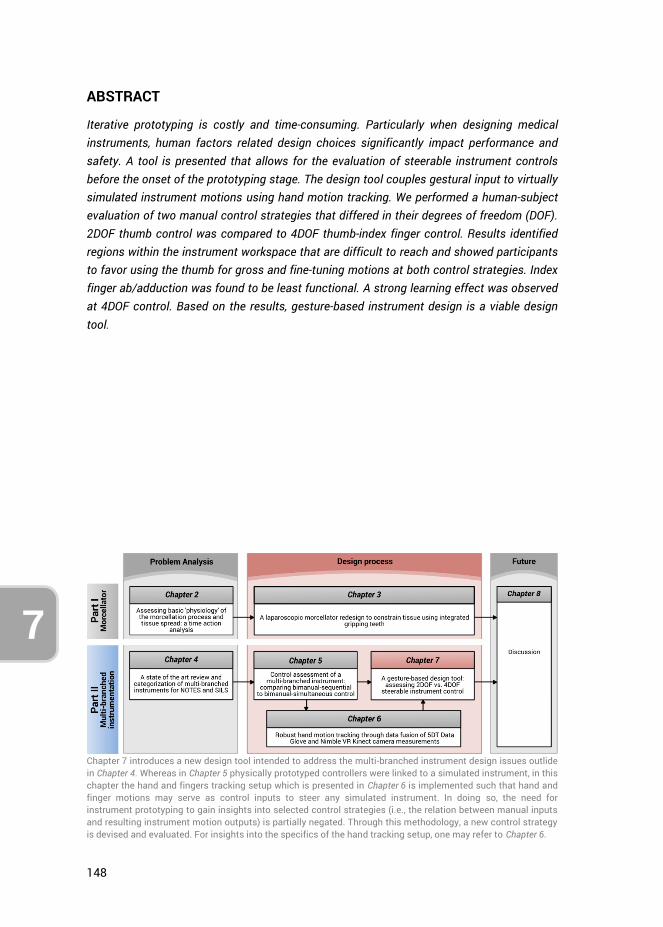
148
7
ABSTRACT
Iterative prototyping is costly and time-consuming. Particularly when designing medical instruments, human factors related design choices significantly impact performance and safety. A tool is presented that allows for the evaluation of steerable instrument controls before the onset of the prototyping stage. The design tool couples gestural input to virtually simulated instrument motions using hand motion tracking. We performed a human-subject evaluation of two manual control strategies that differed in their degrees of freedom (DOF). 2DOF thumb control was compared to 4DOF thumb-index finger control. Results identified regions within the instrument workspace that are difficult to reach and showed participants to favor using the thumb for gross and fine-tuning motions at both control strategies. Index finger ab/adduction was found to be least functional. A strong learning effect was observed at 4DOF control. Based on the results, gesture-based instrument design is a viable design tool.
Chapter 7 introduces a new design tool intended to address the multi-branched instrument design issues outlide in Chapter 4. Whereas in Chapter 5 physically prototyped controllers were linked to a simulated instrument, in this chapter the hand and fingers tracking setup which is presented in Chapter 6 is implemented such that hand and finger motions may serve as control inputs to steer any simulated instrument. In doing so, the need for instrument prototyping to gain insights into selected control strategies (i.e., the relation between manual inputs and resulting instrument motion outputs) is partially negated. Through this methodology, a new control strategy is devised and evaluated. For insights into the specifics of the hand tracking setup, one may refer to Chapter 6.
149
7
7.1. INTRODUCTION
7.1.1. MEDICAL INSTRUMENT DESIGN CHALLENGES “To design, is to consciously aim to create and give form to previously nonexistent artifacts” [1]. Many design methods exist [2-5], including general design theory [6], axiomatic design [7, 8], user-centered design [9-12], scenario based design [13-15], participatory design [16], and combinations or variations thereof [17, 18]. Irrespective of the method one employs, prototypes are a necessity in any design process. Only through prototyping are researchers able to set up experiments for testing and evaluation with appropriate user groups. Unfortunately, prototyping is never a one-time event, as design concepts need to be tested, refined, and retested multiple times throughout a development process [19].
Iterative prototyping, particularly in the medical industry, can be a costly and time-consuming process, with no guarantee of eventual market adoption. In the case of surgical instrumentation, clinical evidence towards effectiveness, gathered through clinical trials, ultimately dictates market uptake [20]. Of particular interest are the challenging developments of multi-branched and multi-steerable instruments, such as those developed for Natural Orifice Transluminal Endoscopic Surgery (NOTES) and Single Incision Laparoscopic Surgery (SILS) since 2006 [21]. These instruments are intended to provide the ability to perform surgical procedures or interventions through a natural orifice or via a keyhole incision. Although literature shows that NOTES and SILS can provide advantages for the patient, such as a reduced risk of infections and faster recovery [22, 23], these techniques present challenges to even experienced surgeons with regard to instrument ‘sword-fighting’, triangulation, tissue handling, and bimanual task performance [24].
Multi-branched instruments for minimally invasive applications (including NOTES and SILS) are now being developed [25-28]. Design efforts are primarily focused on increasing the instruments’ maneuvering potential by expanding the incorporated degrees of freedom (DOF) and by allowing for instrument triangulation [29, 30], thereby providing the ability for bimanual task performance. Other developments include human-in-the-loop computer control schemes [29, 31, 32], varying actuation methods [28, 33-35], alternate fabrication methods [36, 37], integrating various functions (e.g., ultrasound) [33, 38], and improving system properties such as stiffness [39], workspace [34], and force-transmission capabilities [34].
Despite ongoing developments, relatively limited adoption is seen for mechanical and robotic multi-branched systems [20]. In an evaluation of the determinants of medical instrument adoption, O’Toole et al. [20] provided the following six factors: (1) clinical need, (2) clinical effectiveness, (3) safety, (4) compatibility, (5) cost, and (6) usability. For robotic instruments these authors observed that all instruments satisfy the first

150
7
three criteria, but many instruments do not fulfil one or more of the latter three criteria, thus hampering their market uptake. Additionally, issues regarding spatial orientation, ease of use, steep learning curves, operating room limitations, and high costs, are problems that prohibit widespread instrument adoption [20, 40]. We argue that the usability factor, which encompasses aspects of system ergonomics, performance, and intuitiveness of use, is currently a limiting factor concerning multi-branched instrumentation development. Indeed, from the literature, it is apparent that most developed multi-branched instruments have not reached clinical practice, which is in part explained due to their control complexities [26, 40].
Control of multi-branched instruments requires either two surgeons to work in concert or a single surgeon to switch between control modes (usually between shaft and branches control). The complex controls may be an indication that insufficient emphasis has been placed on human factors aspects during instrument development, in particular regarding the relationship between (manual) instrument control and the instrument DOF [26]. Human factors research often concerns the assessment and training of residents’ laparoscopic skills proficiency (e.g., [41] [42]. Although assessment and training are essential, a lack of attention to usability during the design process may lead not only to improperly designed instrument controls, but also to human error, and potentially, life-threatening incidents [43]. By adopting human factors principles, medical equipment and its operations may be made safer and more efficient [43].
Considering the existing multi-branched instrument control complexities, incorporating human-centered design principles may focus and expedite the development process such that prototyped instruments better align with natural human control. In this article, we present a design tool that helps to iteratively evaluate steerable instrument controls before the onset of the prototyping stage. The tool allows for a pre-prototyping iterative design optimization concerning instrument controls. Also, we present a proof-of-principle evaluation of two manual control strategies, differing in their number of integrated DOFs.
7.1.2. DESIGN TOOL FOR STEERABLE INSTRUMENT HUMAN FACTORS EVALUATION In this study, we introduce a new design tool for human factors evaluation of steerable instrument control. This section describes the reasoning behind the design tool, using a hypothetical multi-steerable instrument as an example Figure 7.1a shows an instrument with at the tip two stacked 2DOF deflecting segments, each corresponding to a joystick located at the instrument handle. The joystick controlled by the thumb steers the proximal deflecting segment, and the index finger controlled joystick steers the distal segment. The rationale for this instrument lies in its tip maneuvering ability: It can describe non-linear curves (e.g., S-shapes) as well as approach a point in the
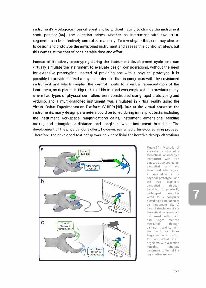
151
7
instrument’s workspace from different angles without having to change the instrument shaft position [44]. The question arises whether an instrument with two 2DOF segments can be effectively controlled manually. To investigate this, one may choose to design and prototype the envisioned instrument and assess this control strategy, but this comes at the cost of considerable time and effort.
Instead of iteratively prototyping during the instrument development cycle, one can virtually simulate the instrument to evaluate design considerations, without the need for extensive prototyping. Instead of providing one with a physical prototype, it is possible to provide instead a physical interface that is congruous with the envisioned instrument and which couples the control inputs to a virtual representation of the instrument, as depicted in Figure 7.1b. This method was employed in a previous study, where two types of physical controllers were constructed using rapid prototyping and Arduino, and a multi-branched instrument was simulated in virtual reality using the Virtual Robot Experimentation Platform (V-REP) [45]. Due to the virtual nature of the instruments, many design parameters could be tuned during initial pilot tests, including the instrument workspace, magnifications gains, instrument dimensions, bending radius, and triangulation-distance and -angle between instrument branches. The development of the physical controllers, however, remained a time-consuming process. Therefore, the developed test setup was only beneficial for iterative design alterations
Figure 7.1. Methods of evaluating control of a theoretical laparoscopic instrument with two stacked 2DOF segments, controlled with the thumb and index fingers. a) evaluation of a physical prototype, with the two segments controlled through joystick; b) physically prototyped controller wired to a computer providing a simulation of an instrument tip; c) control simulation of the theoretical laparoscopic instrument with hand and finger motions measured through camera tracking, with the thumb and index finger motions coupled to two virtual 2DOF segments with a motion mapping strategy congruous to that of the physical instrument.
152
7
of the virtually simulated instrument, and not for the physically constructed controllers themselves.
Taking the virtual prototyping design approach one step further, one may consider the option of not only simulating the instrument tip but also simulating the instrument controls without any physical controllers. Recent developments in sensory techniques [46-48] make it possible to measure hand and fingers motions directly. Assuming such measurements are adequately precise and robust to enable human factors analysis, this negates the need for a physical handheld controller altogether. In Figure 7.1c this method is shown, where the motions the fingers would make when controlling the physical instrument controllers are measured and mapped to the simulated instrument segments. For example, the downward deflection of a (simulated) steerable instrument achieved by pushing down a physical joystick, is instead performed through thumb flexion congruous with the movement the thumb would otherwise make when using the joystick. Although the absence of physical joysticks removes any haptic feedback or tactile cues a person would receive while controlling the physical instrument, the motion mapping strategy is kept as similar as possible. Moreover, any of the input motions may now be changed easily at a moment’s notice. For the purpose of this thesis, we characterize this approach as gesture-based design, and define it as follows:
The live coupling of manual user inputs, in the form of hand and/ or finger motions, to
virtually simulated instrument outputs, in order to investigate their relations within
the context of human factors and the ensuing impacts on the instrument design.
A setup that enables tracking of hand and finger motions, by fusing together Nimble VR software camera-based hand tracking [49] and 5DT Data Glove [50] measurements, was developed in a previous study [51]. This setup is implemented in the current research in tandem with a simulation interface to encompass our proposed design tool as shown in Figure 7.2. The system was determined to have an overall tracking precision of 2.2 deg and 0.9 deg for the metacarpophalangeal (MCP) and proximal interphalangeal (PIP) joints of the fingers, respectively [51]. A 5DT Data Glove, providing five basic full finger flexion sensors (one for each finger), was used to improve data robustness, account for visual (self)occlusions, increase resolution and reduce measurement latency during general finger flexions. A decision was made not to use a 5DT Data Glove 14 Ultra, which has 14 sensors to measure MCP and PIP joints flexions and ab/adduction of the fingers [52], as this large number of sensors were deemed obtrusive. The disadvantage of not using the 14 Ultra glove, however, is that in the current setup the measurement of fingers ab/adduction relies on solely the Nimble VR camera-based tracking, whereas finger flexions are measured using both systems combined. Accordingly, a tracking
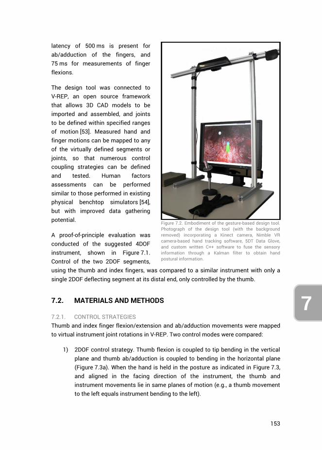
153
7
latency of 500 ms is present for ab/adduction of the fingers, and 75 ms for measurements of finger flexions.
The design tool was connected to V-REP, an open source framework that allows 3D CAD models to be imported and assembled, and joints to be defined within specified ranges of motion [53]. Measured hand and finger motions can be mapped to any of the virtually defined segments or joints, so that numerous control coupling strategies can be defined and tested. Human factors assessments can be performed similar to those performed in existing physical benchtop simulators [54], but with improved data gathering potential.
A proof-of-principle evaluation was conducted of the suggested 4DOF instrument, shown in Figure 7.1. Control of the two 2DOF segments, using the thumb and index fingers, was compared to a similar instrument with only a single 2DOF deflecting segment at its distal end, only controlled by the thumb.
7.2. MATERIALS AND METHODS
7.2.1. CONTROL STRATEGIES Thumb and index finger flexion/extension and ab/adduction movements were mapped to virtual instrument joint rotations in V-REP. Two control modes were compared:
1) 2DOF control strategy. Thumb flexion is coupled to tip bending in the vertical plane and thumb ab/adduction is coupled to bending in the horizontal plane (Figure 7.3a). When the hand is held in the posture as indicated in Figure 7.3, and aligned in the facing direction of the instrument, the thumb and instrument movements lie in same planes of motion (e.g., a thumb movement to the left equals instrument bending to the left).
Figure 7.2. Embodiment of the gesture-based design tool. Photograph of the design tool (with the background removed) incorporating a Kinect camera, Nimble VR camera-based hand tracking software, 5DT Data Glove, and custom written C++ software to fuse the sensory information through a Kalman filter to obtain hand postural information.
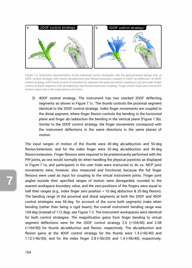
154
7
2) 4DOF control strategy. The instrument has two stacked 2DOF deflecting segments as shown in Figure 7.1c. The thumb controls the proximal segment identical to the 2DOF control strategy. Index finger movements are coupled to the distal segment, where finger flexion controls the bending in the horizontal plane and finger ab-/adduction the bending in the vertical plane (Figure 7.3b). Similar to the 2DOF control strategy, the finger movements correspond with the instrument deflections in the same directions in the same planes of motion.
The input ranges of motion of the thumb were 40 deg ab/adduction and 50 deg flexion/extension, and for the index finger were 20 deg ab/adduction and 40 deg flexion/extension. Finger flexions were required to be predominantly performed with the PIP joints, as one would normally do when handling the physical joysticks as displayed in Figure 7.1a, and participants in the user trials were instructed to do so. MCP joint movements were, however, also measured and functional, because the full finger flexions were used as input for coupling to the virtual instrument joints. Finger joint angles outside their specified ranges of motion were disregarded, rounded to the nearest workspace boundary value, and the zero-positions of the fingers were equal to half their ranges (e.g., index finger zero position = 10 deg abduction & 20 deg flexion). The bending range of the proximal and distal segments at both the 2DOF and 4DOF control strategies was 56 deg. On account of the curve both segments make when bending (rather than being a rigid beam), the overall instrument bending range was 104 deg (instead of 112 deg), see Figure 7.3. The instrument workspaces were identical for both control strategies. The magnification gains from finger bending to virtual segment deflections were for the 2DOF control strategy 2.6 (=104/40) and 2.08 (=104/50) for thumb ab/adduction and flexion, respectively. The ab/adduction and flexion gains at the 4DOF control strategy for the thumb were 1.4 (=56/40) and 1.12 (=56/50), and for the index finger 2.8 (=56/20) and 1.4 (=56/40), respectively.
Figure 7.3. Schematic representation of the evaluated control strategies with the gesture-based design tool. a) 2DOF control strategy, with thumb ab/adduction and flexion/extension coupled to 2DOF tip deflection. b) 4DOF control strategy, with thumb control of proximal tip segment the same as motion coupling in (a), and index finger control of distal segment, with ab/adduction and flexion/extension coupling. Finger motion input and instrument motion output are in the same planes of motion.
155
7
These gains were selected based on pilot trials participants feedback. Note that for both control strategies, the instrument consists of a proximal and distal segment. In the case of the 2DOF strategy, the thumb movements are identically mapped to both segments to make the comparison of segment movements valid between control strategies. The coupling of thumb movements to the proximal segment is thus identical between control strategies.
In the current research, no control conditions were implemented, that is, no physical prototypes resembling the embodied 2DOF and 4DOF control strategies were created and tested to compare with the data obtained through the new design tool. Though this may have been possible for the 2DOF control strategy utilizing an existing product, no instrument resembling the 4DOF strategy exists in practice. In order to preserve resources and time we opted not to create a working prototype utilizing the 4DOF strategy. Rather, in the discussion obtained data is compared to those presented in literature.
7.2.2. USER TRIALS Assessment of the two control strategies was performed through trials in which participants controlled the virtual instrument to perform multiple positioning tasks. Fourteen persons, of which 9 men and 5 women, aged between 22 and 33 years (mean = 27.4, SD = 2.9) participated in the experiment. Half the participants started with the 2DOF controller (4 men, 3 women), the other half with the 4DOF controller (5 men, 2 women). A single positioning task entailed moving the instrument tip and briefly (for 100 ms) touch a target-sphere that was positioned in the instrument’s workspace. After completing a task, the target was relocated to a new position, indicating the start of the next positioning task. Participants were orally instructed to perform each task as fast as possible and provided with a time score after each measurement round to motivate them to beat their own scores. The simulation entailed the use of a 5 mm diameter instrument, approaching target spheres having a diameter of 5 mm. The endpoint of the instrument with which the targets needed to be touched had a diameter of 1 mm, such that a relative minimum targeting accuracy of 3 mm (=(5+1)/2) was required to complete a task. A maximum duration per task was set to 20 s.
User trials started with a short familiarization and calibration phase, followed by ten rounds, alternating between both control strategies. The familiarization phase consisted of 10 target tasks, divided throughout the workspace, but with no time constraint. Each round consisted of 61 target tasks. No rest break was offered between trials unless participants indicated they required such. However, a workload assessment form that was required to be completed after each round provided a minimum of 1 minute downtime. The sequence of the 61 targets was pre-generated, randomly distributed throughout the workspace, and kept identical between rounds and
156
7
control strategies. The travel distances from one target to the next varied between 10, 20, 30 and 40 mm, each distance occurring 15 times (i.e., 4 travel distances * 15 targets per distance). The 1st of the 61 targets of every round was negated because it did not have a prior target, and therefore was not associated with a specific travel distance to get there. For each control strategy, 5 rounds were performed, totaling to 610 target tasks (2 control strategies * 5 rounds * 61 tasks per round).
The positioning tasks were identical between control strategies. For the 4DOF control strategy, the position of the targets within the instrument’s workspace dictated whether all 4DOF were required to reach the target, or that the control of a single 2DOF segment would suffice. Targets closer to the center of the workspace could be reached using a single segment (i.e., either the thumb or index finger), whereas targets along the outer edges of the workspace could only be reached by bending both segments, thus requiring the use of both the thumb and index finger to reach the target successfully.
7.2.3. ETHICS STATEMENT The research adhered to the tenets of the Declaration of Helsinki. This study was approved by the Human Research Ethics Committee of the Delft University of Technology. All individuals gave their written informed consent.
7.2.4. CALIBRATION AND ERROR DETECTION Calibration was performed for both the Data Glove and the Nimble VR system. First, the Data Glove was calibrated using the auto-calibrate function provided in the 5DT Data Glove SDK, automatically scaling sensor readings to the maximum ranges of motion of the participants’ fingers. Auto-calibrate was subsequently turned off for the remainder of the trial.
To calibrate the Nimble VR system, participants were asked to spread both hands in view of the Kinect camera such that the software would calibrate to the proper hand scale (Hs) [55]. Considering that the degree of measured overall finger flexion is underestimated for small hands by approximately 22% in the current setup [51], finger flexion measurements of participants having Hs ≤ 0.82 were scaled up 22%. This was necessary to bring these participants’ sensor readings up to par with those of participants having medium or large sized hands. Note that, as women generally have smaller hands than men, this scaling method was purposely chosen, rather than excluding those women from the trials, thereby skewing results towards a predominantly male participant pool.
Participants were asked to grasp a support handle (Figure 7.2) with the middle-, ring and little finger, to prevent fatigue and keep the hand in place (otherwise participants would be required to keep the hand up in midair throughout the trial). The support handle was made from infrared-translucent Plexiglas, such that it would not influence the Nimble VR hand posture estimates. Erroneous measurements intermittently
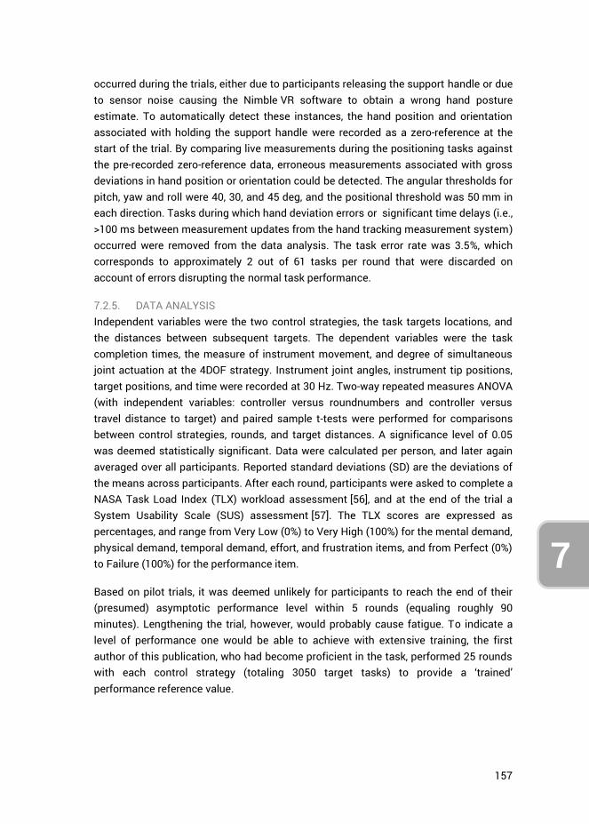
157
7
occurred during the trials, either due to participants releasing the support handle or due to sensor noise causing the Nimble VR software to obtain a wrong hand posture estimate. To automatically detect these instances, the hand position and orientation associated with holding the support handle were recorded as a zero-reference at the start of the trial. By comparing live measurements during the positioning tasks against the pre-recorded zero-reference data, erroneous measurements associated with gross deviations in hand position or orientation could be detected. The angular thresholds for pitch, yaw and roll were 40, 30, and 45 deg, and the positional threshold was 50 mm in each direction. Tasks during which hand deviation errors or significant time delays (i.e., >100 ms between measurement updates from the hand tracking measurement system) occurred were removed from the data analysis. The task error rate was 3.5%, which corresponds to approximately 2 out of 61 tasks per round that were discarded on account of errors disrupting the normal task performance.
7.2.5. DATA ANALYSIS Independent variables were the two control strategies, the task targets locations, and the distances between subsequent targets. The dependent variables were the task completion times, the measure of instrument movement, and degree of simultaneous joint actuation at the 4DOF strategy. Instrument joint angles, instrument tip positions, target positions, and time were recorded at 30 Hz. Two-way repeated measures ANOVA (with independent variables: controller versus roundnumbers and controller versus travel distance to target) and paired sample t-tests were performed for comparisons between control strategies, rounds, and target distances. A significance level of 0.05 was deemed statistically significant. Data were calculated per person, and later again averaged over all participants. Reported standard deviations (SD) are the deviations of the means across participants. After each round, participants were asked to complete a NASA Task Load Index (TLX) workload assessment [56], and at the end of the trial a System Usability Scale (SUS) assessment [57]. The TLX scores are expressed as percentages, and range from Very Low (0%) to Very High (100%) for the mental demand, physical demand, temporal demand, effort, and frustration items, and from Perfect (0%) to Failure (100%) for the performance item.
Based on pilot trials, it was deemed unlikely for participants to reach the end of their (presumed) asymptotic performance level within 5 rounds (equaling roughly 90 minutes). Lengthening the trial, however, would probably cause fatigue. To indicate a level of performance one would be able to achieve with extensive training, the first author of this publication, who had become proficient in the task, performed 25 rounds with each control strategy (totaling 3050 target tasks) to provide a ‘trained’ performance reference value.
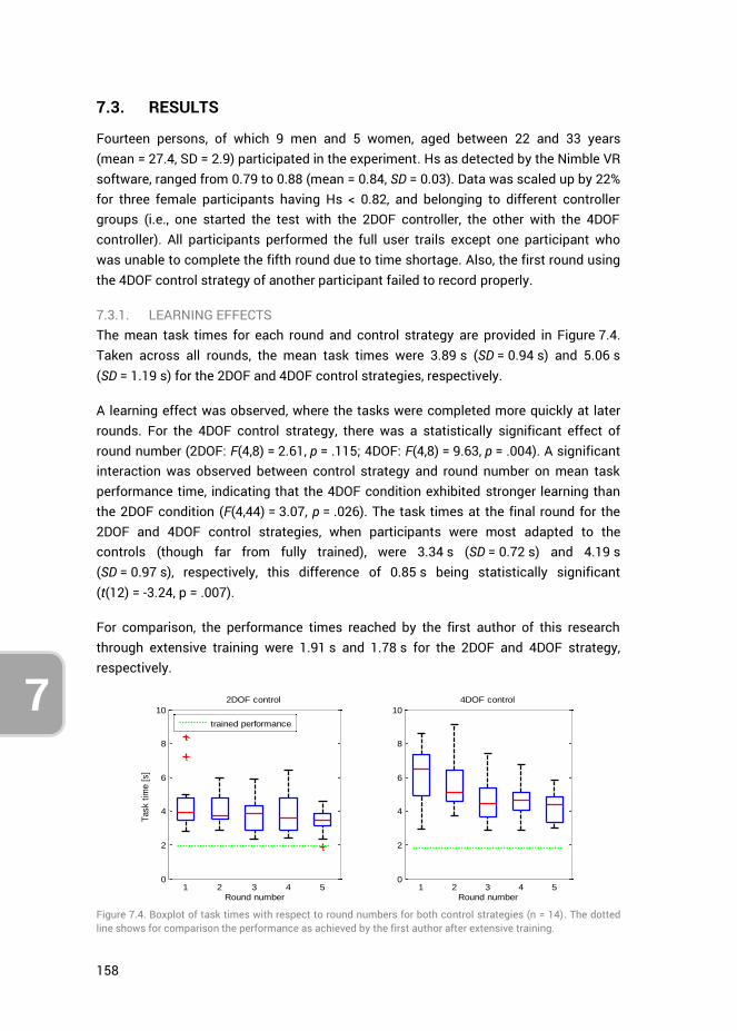
158
7
7.3. RESULTS
Fourteen persons, of which 9 men and 5 women, aged between 22 and 33 years (mean = 27.4, SD = 2.9) participated in the experiment. Hs as detected by the Nimble VR software, ranged from 0.79 to 0.88 (mean = 0.84, SD = 0.03). Data was scaled up by 22% for three female participants having Hs < 0.82, and belonging to different controller groups (i.e., one started the test with the 2DOF controller, the other with the 4DOF controller). All participants performed the full user trails except one participant who was unable to complete the fifth round due to time shortage. Also, the first round using the 4DOF control strategy of another participant failed to record properly.
7.3.1. LEARNING EFFECTS The mean task times for each round and control strategy are provided in Figure 7.4. Taken across all rounds, the mean task times were 3.89 s (SD = 0.94 s) and 5.06 s (SD = 1.19 s) for the 2DOF and 4DOF control strategies, respectively.
A learning effect was observed, where the tasks were completed more quickly at later rounds. For the 4DOF control strategy, there was a statistically significant effect of round number (2DOF: F(4,8) = 2.61, p = .115; 4DOF: F(4,8) = 9.63, p = .004). A significant interaction was observed between control strategy and round number on mean task performance time, indicating that the 4DOF condition exhibited stronger learning than the 2DOF condition (F(4,44) = 3.07, p = .026). The task times at the final round for the 2DOF and 4DOF control strategies, when participants were most adapted to the controls (though far from fully trained), were 3.34 s (SD = 0.72 s) and 4.19 s (SD = 0.97 s), respectively, this difference of 0.85 s being statistically significant (t(12) = -3.24, p = .007).
For comparison, the performance times reached by the first author of this research through extensive training were 1.91 s and 1.78 s for the 2DOF and 4DOF strategy, respectively.
Figure 7.4. Boxplot of task times with respect to round numbers for both control strategies (n = 14). The dotted line shows for comparison the performance as achieved by the first author after extensive training.
0
2
4
6
8
10
1 2 3 4 5
Round number
Task t
ime [
s]
2DOF control
trained performance
0
2
4
6
8
10
1 2 3 4 5
Round number
4DOF control
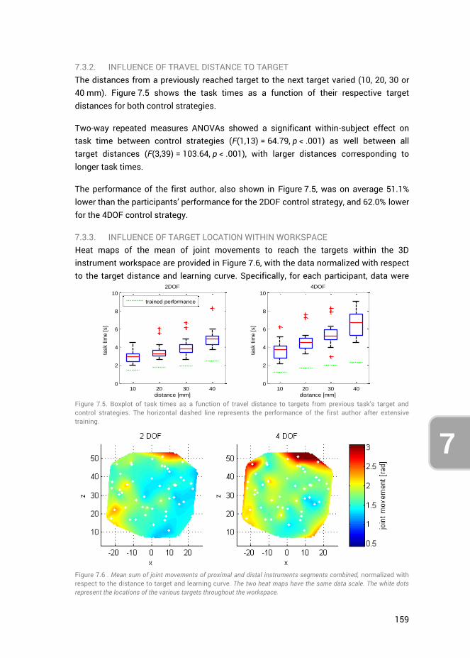
159
7
7.3.2. INFLUENCE OF TRAVEL DISTANCE TO TARGET The distances from a previously reached target to the next target varied (10, 20, 30 or 40 mm). Figure 7.5 shows the task times as a function of their respective target distances for both control strategies.
Two-way repeated measures ANOVAs showed a significant within-subject effect on task time between control strategies (F(1,13) = 64.79, p < .001) as well between all target distances (F(3,39) = 103.64, p < .001), with larger distances corresponding to longer task times.
The performance of the first author, also shown in Figure 7.5, was on average 51.1% lower than the participants’ performance for the 2DOF control strategy, and 62.0% lower for the 4DOF control strategy.
7.3.3. INFLUENCE OF TARGET LOCATION WITHIN WORKSPACE Heat maps of the mean of joint movements to reach the targets within the 3D instrument workspace are provided in Figure 7.6, with the data normalized with respect to the target distance and learning curve. Specifically, for each participant, data were
Figure 7.5. Boxplot of task times as a function of travel distance to targets from previous task’s target and control strategies. The horizontal dashed line represents the performance of the first author after extensive training.
Figure 7.6 . Mean sum of joint movements of proximal and distal instruments segments combined, normalized with respect to the distance to target and learning curve. The two heat maps have the same data scale. The white dots represent the locations of the various targets throughout the workspace.
10 20 30 400
2
4
6
8
10
distance [mm]
task t
ime [
s]
2DOF
trained performance
10 20 30 400
2
4
6
8
10
distance [mm]
task t
ime [
s]
4DOF
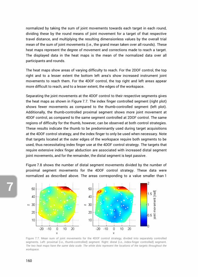
160
7
normalized by taking the sum of joint movements towards each target in each round, dividing these by the round means of joint movement for a target of that respective travel distance, and multiplying the resulting dimensionless values by the overall trial mean of the sum of joint movements (i.e., the grand mean taken over all rounds). These heat maps represent the degree of movement and corrections made to reach a target. The displayed data in the heat maps is the mean of the normalized data over all participants and rounds.
The heat maps show areas of varying difficulty to reach. For the 2DOF control, the top right and to a lesser extent the bottom left area’s show increased instrument joint movements to reach them. For the 4DOF control, the top right and left areas appear more difficult to reach, and to a lesser extent, the edges of the workspace.
Separating the joint movements at the 4DOF control to their respective segments gives the heat maps as shown in Figure 7.7. The index finger controlled segment (right plot) shows fewer movements as compared to the thumb-controlled segment (left plot). Additionally, the thumb-controlled proximal segment shows more joint movement at 4DOF control, as compared to the same segment controlled at 2DOF control. The same regions of difficulty for the thumb, however, can be observed at both control strategies. These results indicate the thumb to be predominantly used during target acquisitions at the 4DOF control strategy, and the index finger to only be used when necessary. Note that targets located at the outer edges of the workspace require both segments to be used, thus necessitating index finger use at the 4DOF control strategy. The targets that require extensive index finger abduction are associated with increased distal segment joint movements, and for the remainder, the distal segment is kept passive.
Figure 7.8 shows the number of distal segment movements divided by the number of proximal segment movements for the 4DOF control strategy. These data were normalized as described above. The areas corresponding to a value smaller than 1
Figure 7.7. Mean sum of joint movements for the 4DOF control strategy, divided into separately controlled segments. Left: proximal (i.e., thumb-controlled) segment. Right: distal (i.e., index-finger controlled) segment. The two heat maps have the same data scale. The white dots represent the locations of the targets throughout the workspace.
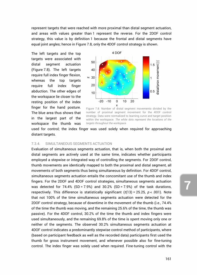
161
7
represent targets that were reached with more proximal than distal segment actuation, and areas with values greater than 1 represent the reverse. For the 2DOF control strategy, this value is by definition 1 because the frontal and distal segments have equal joint angles; hence in Figure 7.8, only the 4DOF control strategy is shown.
The left targets and the top targets were associated with distal segment actuation (Figure 7.8). The left targets require full index finger flexion, whereas the top targets require full index finger abduction. The other edges of the workspace lie closer to the resting position of the index finger for the hand posture. The blue area thus shows that in the largest part of the workspace the thumb was used for control; the index finger was used solely when required for approaching distant targets.
7.3.4. SIMULTANEOUS SEGMENTS ACTUATION Evaluation of simultaneous segments actuation, that is, when both the proximal and distal segments are actively used at the same time, indicates whether participants employed a stepwise or integrated way of controlling the segments. For 2DOF control, thumb movements are identically mapped to both the proximal and distal segment, all movements of both segments thus being simultaneous by definition. For 4DOF control, simultaneous segments actuation entails the concomitant use of the thumb and index fingers. For the 2DOF and 4DOF control strategies, simultaneous segments actuation was detected for 74.4% (SD = 7.9%) and 30.2% (SD = 7.9%) of the task durations, respectively. This difference is statistically significant (t(13) = 25.25, p < .001). Note that not 100% of the time simultaneous segments actuation were detected for the 2DOF control strategy, because of downtime in the movement of the thumb (i.e., 74.4% of the time the thumb was moving, and the remaining 25.6% of the time, the thumb was passive). For the 4DOF control, 30.2% of the time the thumb and index fingers were used simultaneously, and the remaining 69.8% of the time is spent moving only one or neither of the segments. The observed 30.2% simultaneous segments actuation at 4DOF control indicates a predominantly stepwise control method of participants, where (based on participant feedback as well as the recorded data) participants first used the thumb for gross instrument movement, and whenever possible also for fine-tuning control. The index finger was solely used when required. Fine-tuning control with the
Figure 7.8. Number of distal segment movements divided by the number of proximal segment movement for the 4DOF control strategy. Data were normalized to learning curve and target position within the workspace. The white dots represent the locations of the targets throughout the workspace.
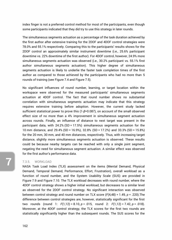
162
7
index finger is not a preferred control method for most of the participants, even though some participants indicated that they did try to use this strategy in later rounds.
The simultaneous segments actuation as a percentage of the task duration achieved by the first author after extensive training for the 2DOF and 4DOF control strategies were 78.0% and 55.1% respectively. Comparing this to the participants’ results shows for the 2DOF control an approximately similar instrument downtime (i.e., 25.6% participant downtime vs. 22% downtime of the first author). For 4DOF control, however, 24.9% more simultaneous segments actuation was observed (i.e., 30.2% participant vs. 55.1% first author simultaneous segments actuation). This higher degree of simultaneous segments actuation is likely to underlie the faster task completion times of the first author as compared to those achieved by the participants who had no more than 5 rounds of training (see Figure 7.4 and Figure 7.5).
No significant influences of round number, learning, or target location within the workspace were observed for the measured participants’ simultaneous segments actuation at 4DOF control. The fact that round number shows no substantial correlation with simultaneous segments actuation may indicate that this strategy requires extensive training before adoption. However, the current study lacked sufficient statistical power to prove this (1-β=0.087), on account of the small observed effect size of no more than a 4% improvement in simultaneous segment actuation across rounds. Finally, an influence of distance to next target was present in the participant data, with 24.2% (SD = 17.5%) simultaneous segments actuation for the 10 mm distance, and 29.4% (SD = 16.9%), 32.8% (SD = 17.2%) and 33.3% (SD = 15.8%) for the 20 mm, 30 mm, and 40 mm distances, respectively. Thus, with increasing target distance, slightly more simultaneous segments actuation is observed. These results could be because nearby targets can be reached with only a single joint segment, negating the need for simultaneous segment actuation. A similar effect was observed for the first author’s performance data.
7.3.5. WORKLOAD NASA Task Load Index (TLX) assessment on the items (Mental Demand, Physical Demand, Temporal Demand, Performance, Effort, Frustration), overall workload as a function of round number, and the System Usability Scale (SUS) are provided in Figure 7.9 and Figure 7.10. The TLX workload decreases with round number, where the 4DOF control strategy shows a higher initial workload, but decreases to a similar level as observed for the 2DOF control strategy. No significant interaction was observed between control strategy and round number on TLX score (F(4,48) = 1.49, p = .220).The difference between control strategies are, however, statistically significant for the first two rounds (round 1: F(1,12) = 8.10, p = .015, round 2: F(1,12) = 7.42, p = .018). Moreover, at the 4DOF control strategy, the TLX scores for the first two rounds are statistically significantly higher than the subsequent rounds. The SUS scores for the
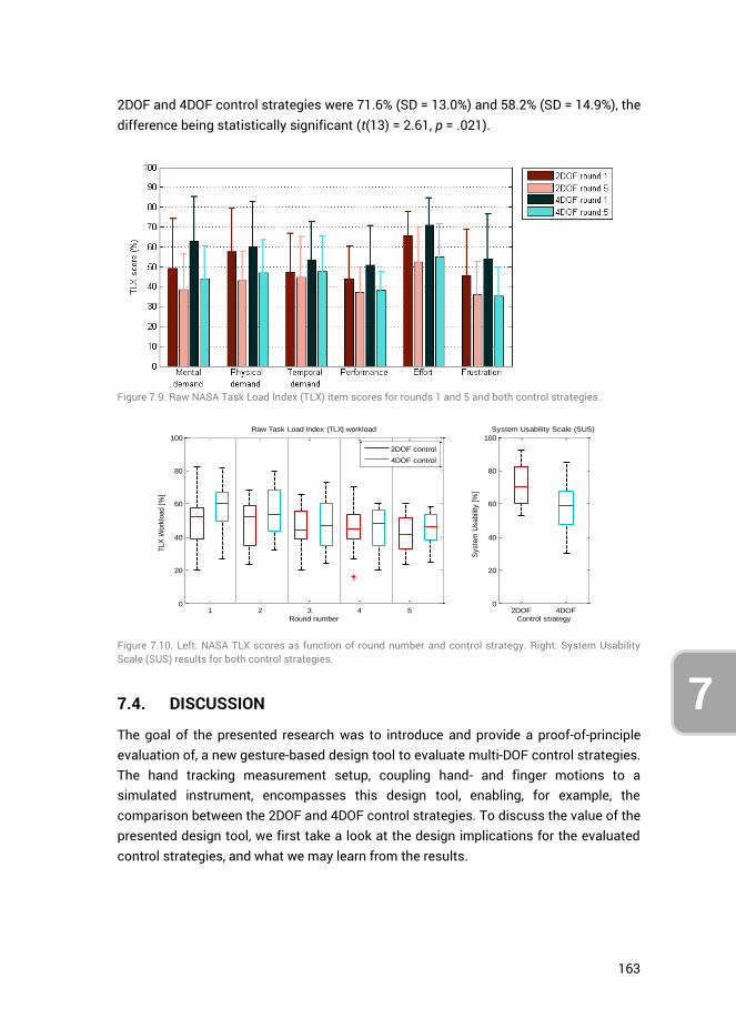
163
7
2DOF and 4DOF control strategies were 71.6% (SD = 13.0%) and 58.2% (SD = 14.9%), the difference being statistically significant (t(13) = 2.61, p = .021).
Figure 7.9. Raw NASA Task Load Index (TLX) item scores for rounds 1 and 5 and both control strategies.
Figure 7.10. Left: NASA TLX scores as function of round number and control strategy. Right: System Usability Scale (SUS) results for both control strategies.
7.4. DISCUSSION
The goal of the presented research was to introduce and provide a proof-of-principle evaluation of, a new gesture-based design tool to evaluate multi-DOF control strategies. The hand tracking measurement setup, coupling hand- and finger motions to a simulated instrument, encompasses this design tool, enabling, for example, the comparison between the 2DOF and 4DOF control strategies. To discuss the value of the presented design tool, we first take a look at the design implications for the evaluated control strategies, and what we may learn from the results.
1 2 3 4 50
20
40
60
80
100
Round number
Raw Task Load Index (TLX) workload
TLX
Work
load [
%]
2DOF control
4DOF control
2DOF 4DOF0
20
40
60
80
100
Control strategy
Syste
m U
sabili
ty [
%]
System Usability Scale (SUS)
164
7
7.4.1. DESIGN IMPLICATIONS Based on the results gathered with the new design tool, the proposed design for 4DOF instrument control can be evaluated. A prominent question is whether humans can control the 4DOF instrument at a performance level similar to that of the 2DOF instrument. Considering that this study is only simulating positioning tasks, the results need to be interpreted with caution. Nevertheless, it can be seen that although the 4DOF control was initially challenging, there was a strong learning effect, and participants eventually reached a task performance that was only slightly slower than for the 2DOF control. The observed performance of the first author after extensive training suggests the two control strategies allow for equal performance on the current positioning tasks.
It is possible to make adjustments to both the input and output measures. To reach top-right targets in the workspace for example (see Figure 7.6), the magnification gain from input to output could be increased. Such an increase would allow for a smaller required thumb flexion and index finger abduction to reach the targets, potentially at the expense of reduced working speed and hit rate [58].
Considering the observed simultaneous segment actuation, it is apparent that participants require extensive training to master using both the thumb and index finger at the same time. The measured performance of the trained first author of this study, however, indicates that the simultaneous segment actuation strategy may be viable. In the current task, only the position of the instrument-tip was of importance in touching the target sphere. The next step in evaluating the 4DOF controlled instrument should be to simulate combined position-orientation tasks, to judge participants’ performance in orienting the instrument tip. Additionally, considering the laparoscopic camera was kept static during the current tasks, a higher fidelity trial in which this camera is actively controlled may provide additional insights (e.g., increased workload) into the 4DOF control strategy. This camera may even be controlled by a second person, as is generally the case in laparoscopic and endoscopic surgery.
7.4.2. ALTERNATIVE CONTROL STRATEGIES OR INSTRUMENT DESIGNS Different levels of performance were observed in different planes. These performance differences may be because the magnification gains from fingers to instrument motions were not equal between the axes and fingers, as the fingers do not have equal ranges of motion. Observing the index finger at the 4DOF control (Figure 7.7, right), it can be seen that the targets in the top positions were the most challenging to reach. This is sensible in light of the rather small abduction range of the index finger that people have in general. The relatively large magnification gain (2.8) from index finger ab-adduction input (20 deg range) to vertical instrument segment deflection (56 deg range), leads to significant strain on the index finger to control it accurately, which raises the question whether this coupling strategy of linking the index finger ab-
165
7
adductions to vertical instrument motions should be used at all. Perhaps it is preferred to use only index finger flexion for horizontal distal instrument segment control, and to couple vertical distal segment control to thumb flexion. In essence, this amounts to 3DOF control, with thumb flexion coupled to overall vertical instrument bending, and thumb ab/adduction and index finger for segmented horizontal bending.
More substantial design alterations may also be investigated in future research. For example, it is possible to switch the control couplings, so that the index finger controls the proximal segment, and the thumb the distal segment. Considering the preference of participants in using the thumb, another control option is to use this finger for both segments but to allow for discrete switching between simultaneous and single-segment actuation. One embodiment may be to use index finger flexion as a discrete control switch (like pressing a button) to alternate between simultaneous segment control (i.e., the 2DOF control strategy used in this study) and distal segment control (while locking the proximal segment in place). This two-step approach is likely to yield relatively slow task performance but may also yield improved positioning accuracy.
7.4.3. DESIGN TOOL LIMITATIONS AND CONSIDERATIONS By implementing the design tool presented in this study, far-reaching design alterations concerning instrument DOF and control strategies may be evaluated without the need for prototyping. The advantages of the measurement tool, however, comes at the cost of several limitations, the largest of which being the lack of tactile cues and haptic feedback otherwise present when handling a physical prototype. Not being able to feel the boundaries of the instrument’s workspace naturally, for example, as would otherwise be the case when handling joysticks, forces one to identify and continually keep track of their finger input motions regarding these boundaries. Haptic feedback, moreover, in laparoscopic instrumentation is an important field of study, considering that minimally invasive instrumentation masks force cues [59]. Haptic feedback is of particular use for feeling differences in tissue consistencies, applied pressures, and limiting strain in surgeon’s hands [60]. Considering the setup currently does not simulate the tactile sensation of holding and using the instrument, nor any of the task-related forces, design considerations to this end cannot be assessed. However, because the Nimble VR measurement system relies on the Kinect’s infrared depth camera, infrared translucent objects (such as the custom Plexiglas support handle used in this study) may be implemented without significantly influencing hand postural estimates. As such, tactile cues and sensations may be approximated using props, though likely at a low level of fidelity.
The 500 ms measurement latency of the system in measuring finger ab/adduction affected participants to mostly adopt an effective “move-and-wait” strategy to cope with the delay. This delay influences the results to an extent, so that measurement results deviate from those that would be obtained with real prototypes. To exemplify,
166
7
one may compare our observed mean task time of 3.34 s (last round of 2DOF control task, see Figure 7.4 left) to the average 0.98 s task time in the study of Fan et al. [61]. Fan et al. used a physical, 2DOF thumb-controlled, instrument (Microflex, DEAM, Amsterdam, NL [62]) for positioning tasks that required shaft and steerable tip control. Although the tasks are not identical, the main task aspect is the control of the 2DOF tip, which shows to be substantially faster in practice than in our measurement tool. Accordingly, on account of the latency issue, the tool is best suited to compare control strategies relative to each other and to assess to which extents participants can cope with complex controls.
The aim of the introduced design tool in this study is to expedite control developments for multi-branched and multi-steerable instrumentation. It is not meant to replace a full prototype control evaluation. The design tool is best suited to aid in the preliminary evaluation of envisioned but untested control methods and settings. However, the quality of the hand tracking used in this setup may still be greatly improved. One way to solve the issue of the measurement latency on the finger ab/adduction measurements is to upgrade the used 5DT Data Glove to a 5DT Data Glove 14 Ultra, which incorporates sensors between the fingers for ab/adduction measurements [52]. However, their placement may be too obtrusive for natural finger motions. Considering the current rapid advances made in consumer electronics for hand motion tracking (e.g. Leap motion sensor [63, 64]), it is likely that technological developments towards Virtual and Augmented Reality [65, 66] will benefit the control evaluation design tool as presented in this study.
7.5. CONCLUSION
A design tool was presented to evaluate multi-DOF control strategies for minimally invasive medical instrumentation. A proof-of-principle evaluation was performed, comparing a 2DOF steerable tip, controlled with the thumb, to a 4DOF steerable tip (two serially stacked 2DOF segments), controlled with the thumb and index finger. Results show that the design tool provides the ability to evaluate instrument control performance regarding task time and learning effects, as well as differentiate performance metrics to travel distances between targets and their respective locations within the instrument workspace.
The proof-of-principle evaluation, based on simulated positioning tasks, showed the 4DOF control strategy to have a stronger learning effect but to eventually perform only slightly slower (0.85 s) as compared to the 2DOF control strategy. Results further indicate that participants favor the use of the thumb in both gross and fine-tuning movements. Additionally, index finger ab/adduction as input motion to control the instrument tip is found least functional and may be negated in future instrument design. Simultaneous segment actuation at the 4DOF control strategy, i.e. using both
167
7
the thumb and index fingers simultaneously, is proven to be challenging for participants, but also a viable control strategy.
Based on the results, and without having to resort to prototyping, the new gesture-based design tool has proven effective in identifying possible improvements for the assessed control strategies as well as identifying potential new control strategies.
7.6. AUTHOR CONTRIBUTIONS
Ewout A. Arkenbout and Awaz Ali conceptualized the control strategies assessed in this study. Ewout A. Arkenbout was responsible for the writing of the software, creation of the virtual simulation, implementation of the test setup, methodology, performance of the experiments, data analysis, and writing of the article. Joost C.F. de Winter provided support for the methodology, data analysis and writing. All authors contributed by reviewing the article. Joost C.F. de Winter, Jenny Dankelman and Paul Breedveld provided supervision.
7.7. REFERENCES
1. Fallman, D., Design-oriented human-computer interaction, in Proceedings of the SIGCHI Conference on Human Factors in Computing Systems. 2003, ACM: Ft. Lauderdale, Florida, USA. p. 225-232.
2. Finger, S. and J.R. Dixon, A review of research in mechanical engineering design. Part I: Descriptive, prescriptive, and computer-based models of design processes. Research in Engineering Design, 1989. 1(1): p. 51-67.
3. Finger, S. and J.R. Dixon, A review of research in mechanical engineering design. Part II: Representations, analysis, and design for the life cycle. Research in Engineering Design, 1989. 1(2): p. 121-137.
4. Tomiyama, T., et al., Design methodologies: Industrial and educational applications. CIRP Annals - Manufacturing Technology, 2009. 58(2): p. 543-565.
5. Birkhofer, H., The future of design methodology. 2011, London: Springer. 6. Reich, Y., A critical review of General Design Theory. Research in Engineering Design,
1995. 7(1): p. 1-18. 7. Suh, N.P., Axiomatic Design of Mechanical Systems. Journal of Mechanical Design,
1995. 117(B): p. 2-10. 8. Nelson, C.A., D.J. Miller, and D. Oleynikov, Design Methodology for a Novel
Multifunction Laparoscopic Tool: Engineering for Surgeons' Needs. Studies in health technology and informatics, 2006. 125: p. 343-348.
9. Money, A.G., et al., The role of the user within the medical device design and development process: medical device manufacturers' perspectives. BMC Medical Informatics and Decision Making, 2011. 11(1): p. 15.
10. Maguire, M., Methods to support human-centred design. International Journal of Human-Computer Studies, 2001. 55(4): p. 587-634.
11. Martin, J.L., et al., A user-centred approach to requirements elicitation in medical device development: A case study from an industry perspective. Applied Ergonomics, 2012. 43(1): p. 184-190.
168
7
12. Gulliksen, J., et al., Key principles for user-centred systems design. Behaviour & Information Technology, 2003. 22(6): p. 397-409.
13. Carroll, J.M., Five reasons for scenario-based design. Interacting with Computers, 2000. 13(1): p. 43-60.
14. Reeder, B. and A.M. Turner, Scenario-based design: A method for connecting information system design with public health operations and emergency management. Journal of Biomedical Informatics, 2011. 44(6): p. 978-988.
15. Rosson, M.B. and J.M. Carroll, Scenario based design. 2009. 16. Kensing, F. and J. Blomberg, Participatory Design: Issues and Concerns. Computer
Supported Cooperative Work (CSCW), 1998. 7(3): p. 167-185. 17. Rasoulifar, R., et al. Proposal of a New Design Methodology in the Surgical Domain. in
ICED'07, International Conference On Engineering Design. 2007. Paris, France. 18. Thomann, G. and J. Caelen. Proposal of a New Design Methodology including PD and
SBD in Minimally Invasive Surgery. in 12th IFToMM World Congress. 2007. Besançon, France.
19. Sawyer, D., et al., An introduction to human factors in medical devices. US Department of Health and Human Services, Public Health Service, Food and Drug Administration, Center for Devices and Radiological Health, 1996.
20. O'Toole, M.D., et al., A methodology for design and appraisal of surgical robotic systems. Robotica, 2009. 28(2): p. 297-310.
21. Rattner, D. and A. Kalloo, ASGE/SAGES Working Group on Natural Orifice Translumenal Endoscopic Surgery. Surgical Endoscopy And Other Interventional Techniques, 2006. 20(2): p. 329-333.
22. Dhumane, P.W., et al., Minimally invasive single-site surgery for the digestive system: A technological review. Journal of Minimal Access Surgery, 2011. 7(1): p. 40-51.
23. Kalloo, A.N., et al., Flexible transgastric peritoneoscopy: a novel approach to diagnostic and therapeutic interventions in the peritoneal cavity. Gastrointestinal endoscopy, 2004. 60(1): p. 114-117.
24. Hallbeck, M.S., et al., Kinematic and ergonomic assessment of laparoendoscopic single-site surgical instruments during simulator training tasks. Applied Ergonomics, 2017. 62: p. 118-130.
25. Kume, K., Flexible robotic endoscopy: current and original devices. Computer Assisted Surgery, 2016. 21(1): p. 150-159.
26. Arkenbout, E.A., et al., A state of the art review and categorization of multi-branched instruments for NOTES and SILS. Surgical Endoscopy, 2015. 29(6): p. 1281-1296.
27. Seah, T.E.T., et al., Future of Flexible Robotic Endoscopy Systems. arXiv preprint arXiv:1703.05569, 2017.
28. Le, H.M., T.N. Do, and S.J. Phee, A survey on actuators-driven surgical robots. Sensors and Actuators A: Physical, 2016. 247: p. 323-354.
29. Koller, S., et al. SISTUM; The single incision system of the Technische Universitat Munchen. in 2015 IEEE International Conference on Robotics and Biomimetics (ROBIO). 2015.
30. Shang, J., et al. Design of a multitasking robotic platform with flexible arms and articulated head for Minimally Invasive Surgery. in 2012 IEEE/RSJ International Conference on Intelligent Robots and Systems. 2012.
31. Evangeliou, N., D. Karageorgos, and A. Tzes. Design and antagonistic control of a tendon-driven Minimally Invasive Surgical robotic tool. in 2016 24th Mediterranean Conference on Control and Automation (MED). 2016.
32. Evangeliou, N. and A. Tzes. Development of an SMA-actuated redundant robotic platform for minimally invasive surgery. in 2016 6th IEEE International Conference on Biomedical Robotics and Biomechatronics (BioRob). 2016.

169
7
33. Shen, T., C. Nelson, and D. Oleynikov, Design and Analysis of a Bimanual Multifunctional Robot for NOTES. Journal of Medical Devices, 2016. 10(3): p. 030903-030903-3.
34. Li, Z., et al., Kinematic comparison of surgical tendon-driven manipulators and concentric tube manipulators. Mechanism and Machine Theory, 2017. 107: p. 148-165.
35. Lu, K., et al., Design of a Novel Cable-Driven Joint for Laparoscopic Instruments. Journal of Medical Devices, 2016. 10(3): p. 030913-030913-2.
36. Krieger, Y., S. Brecht, and D. Roppenecker, First Approach towards a Manipulator System for Single-Incision Laparoscopic Surgery Using Rapid Manufacturing. Universität und Inselspital Bern, 2016: p. 111.
37. Isaac-Lowry, O.J., et al., Compact teleoperated laparoendoscopic single-site robotic surgical system: Kinematics, control, and operation. The International Journal of Medical Robotics and Computer Assisted Surgery, 2017: p. e1811-n/a.
38. Brecht, S.V., et al. A new concept for a Single Incision Laparoscopic Manipulator System integrating intraoperative Laparoscopic Ultrasound. in 2016 IEEE International Conference on Robotics and Biomimetics (ROBIO). 2016.
39. Li, J., et al., Design and evaluation of a variable stiffness manual operating platform for laparoendoscopic single site surgery (LESS). The International Journal of Medical Robotics and Computer Assisted Surgery, 2017.
40. Swanstrom, L. and B. Zheng, Spatial Orientation and Off-Axis Challenges for NOTES. Gastrointestinal Endoscopy Clinics of North America, 2008. 18(2): p. 315-324.
41. Keehner, M.M., et al., Spatial ability, experience, and skill in laparoscopic surgery. The American Journal of Surgery, 2004. 188(1): p. 71-75.
42. Gallagher, A.G., et al., Virtual Reality Simulation for the Operating Room: Proficiency-Based Training as a Paradigm Shift in Surgical Skills Training. Annals of Surgery, 2005. 241(2): p. 364-372.
43. Lin, L., et al., Applying Human Factors to the Design of Medical Equipment: Patient-Controlled Analgesia. Journal of Clinical Monitoring and Computing, 1998. 14(4): p. 253-263.
44. Giada, G., et al., HelixFlex : bioinspired maneuverable instrument for skull base surgery. Bioinspiration & Biomimetics, 2015. 10(6): p. 066013.
45. Arkenbout, E.A., et al., Bimanual control assessment of multi-branched EETS instrument [submitted for publication]. 2017: p. 14.
46. Dipietro, L., A.M. Sabatini, and P. Dario, A Survey of Glove-Based Systems and Their Applications. Systems, Man, and Cybernetics, Part C: Applications and Reviews, IEEE Transactions on, 2008. 38(4): p. 461-482.
47. Erol, A., et al., Vision-based hand pose estimation: A review. Computer Vision and Image Understanding, 2007. 108(1–2): p. 52-73.
48. Khaleghi, B., et al., Multisensor data fusion: A review of the state-of-the-art. Information Fusion, 2013. 14(1): p. 28-44.
49. Nimble VR. Nimble VR SDK v0.9.36. 2015 [cited 2015 14-01-2015]; Available from: http://nimblevr.com/ and http://nimblevr.com/latest/doc/CppAPI/.
50. Fifth Dimension Technologies. Data Gloves. 2015 [cited 2015 14-01-2015]; Available from: http://www.5dt.com/?page_id=34.
51. Arkenbout, E., J. de Winter, and P. Breedveld, Robust Hand Motion Tracking through Data Fusion of 5DT Data Glove and Nimble VR Kinect Camera Measurements. Sensors, 2015. 15(12): p. 29868.
52. Fifth Dimension Technologies. 5DT Data Glove 14 Ultra. 2015 [cited 2017 09-06-2017]; Available from: http://www.5dt.com/products/pdataglove14.html, http://www.5dt.com/?page_id=34.
170
7
53. Freese, M., et al., Virtual robot experimentation platform v-rep: A versatile 3d robot simulator. Simulation, modeling, and programming for autonomous robots, 2010: p. 51-62.
54. Madan, A.K., et al., Assessment of individual hand performance in box trainers compared to virtual reality trainers. The American Surgeon, 2003. 69(12): p. 1112.
55. Arkenbout, E.A., J.C.F. de Winter, and P. Breedveld. Pilot study: validity assessment of camera-based hand motion tracking for MIS instrument control. in Proc. 26th International Conference of Society for Medical innovation and Technology (SMIT). 2014. Shanghai, China.
56. Hart, S.G. and L.E. Staveland, Development of NASA-TLX (Task Load Index): Results of Empirical and Theoretical Research. Advances in Psychology, 1988. 52: p. 139-183.
57. Brooke, J., SUS-A quick and dirty usability scale. Usability evaluation in industry, 1996. 189(194): p. 4-7.
58. Sandfeld, J. and B.R. Jensen, Effect of computer mouse gain and visual demand on mouse clicking performance and muscle activation in a young and elderly group of experienced computer users. Applied Ergonomics, 2005. 36(5): p. 547-555.
59. Okamura, A.M., Haptic Feedback in Robot-Assisted Minimally Invasive Surgery. Current opinion in urology, 2009. 19(1): p. 102-107.
60. Alleblas, C.C.J., M.P.H. Vleugels, and T.E. Nieboer, Ergonomics of laparoscopic graspers and the importance of haptic feedback: the surgeons’ perspective. Gynecological Surgery, 2016. 13(4): p. 379-384.
61. Fan, C., et al., Comparison of Two Control Methods for Minimally Invasive Surgical Instruments. Journal of Medical Devices, 2012. 6(2): p. 021005-021005-6.
62. Fan, C., D. Dodou, and P. Breedveld, Review of manual control methods for handheld maneuverable instruments. Minim Invasive Ther Allied Technol, 2013. 22(3): p. 127-35.
63. Guna, J., et al., An Analysis of the Precision and Reliability of the Leap Motion Sensor and Its Suitability for Static and Dynamic Tracking. Sensors, 2014. 14(2): p. 3702.
64. Vineeth, P.K.R., R. Baskaran, and S. Mukherjee, Intuitive and Adaptive Robotic Control Using Leap Motion. International Journal of Computer Theory and Engineering, 2017. 9(2): p. 97.
65. Pulijala, Y., M. Ma, and A. Ayoub, VR Surgery: Interactive Virtual Reality Application for Training Oral and Maxillofacial Surgeons using Oculus Rift and Leap Motion, in Serious Games and Edutainment Applications : Volume II, M. Ma and A. Oikonomou, Editors. 2017, Springer International Publishing: Cham. p. 187-202.
66. Egger, J., et al. Integration of the HTC Vive into the medical platform MeVisLab. in SPIE Medical Imaging. 2017. International Society for Optics and Photonics.

171
CHAPTER 8: DISCUSSION
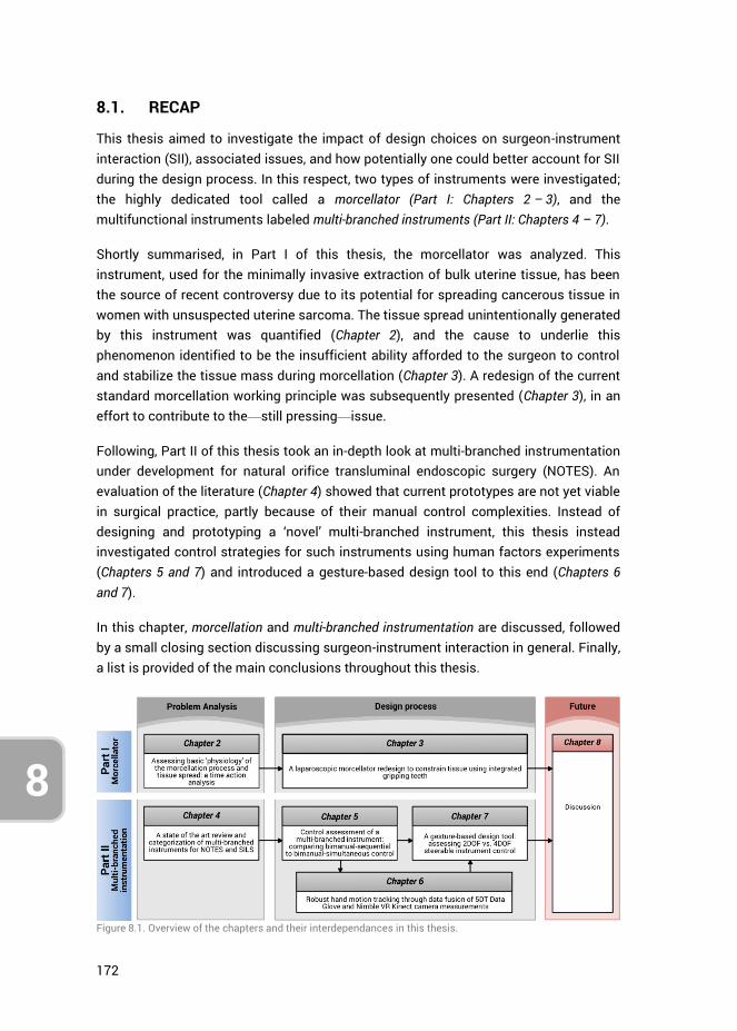
172
8
8.1. RECAP
This thesis aimed to investigate the impact of design choices on surgeon-instrument interaction (SII), associated issues, and how potentially one could better account for SII during the design process. In this respect, two types of instruments were investigated; the highly dedicated tool called a morcellator (Part I: Chapters 2 – 3), and the multifunctional instruments labeled multi-branched instruments (Part II: Chapters 4 – 7).
Shortly summarised, in Part I of this thesis, the morcellator was analyzed. This instrument, used for the minimally invasive extraction of bulk uterine tissue, has been the source of recent controversy due to its potential for spreading cancerous tissue in women with unsuspected uterine sarcoma. The tissue spread unintentionally generated by this instrument was quantified (Chapter 2), and the cause to underlie this phenomenon identified to be the insufficient ability afforded to the surgeon to control and stabilize the tissue mass during morcellation (Chapter 3). A redesign of the current standard morcellation working principle was subsequently presented (Chapter 3), in an effort to contribute to the—still pressing—issue.
Following, Part II of this thesis took an in-depth look at multi-branched instrumentation under development for natural orifice transluminal endoscopic surgery (NOTES). An evaluation of the literature (Chapter 4) showed that current prototypes are not yet viable in surgical practice, partly because of their manual control complexities. Instead of designing and prototyping a ‘novel’ multi-branched instrument, this thesis instead investigated control strategies for such instruments using human factors experiments (Chapters 5 and 7) and introduced a gesture-based design tool to this end (Chapters 6 and 7).
In this chapter, morcellation and multi-branched instrumentation are discussed, followed by a small closing section discussing surgeon-instrument interaction in general. Finally, a list is provided of the main conclusions throughout this thesis.
Figure 8.1. Overview of the chapters and their interdependances in this thesis.
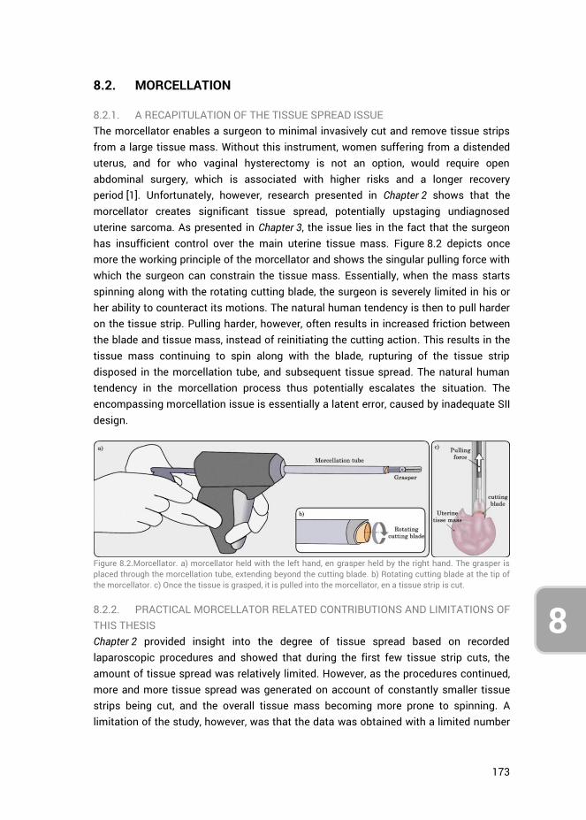
173
8
8.2. MORCELLATION
8.2.1. A RECAPITULATION OF THE TISSUE SPREAD ISSUE The morcellator enables a surgeon to minimal invasively cut and remove tissue strips from a large tissue mass. Without this instrument, women suffering from a distended uterus, and for who vaginal hysterectomy is not an option, would require open abdominal surgery, which is associated with higher risks and a longer recovery period [1]. Unfortunately, however, research presented in Chapter 2 shows that the morcellator creates significant tissue spread, potentially upstaging undiagnosed uterine sarcoma. As presented in Chapter 3, the issue lies in the fact that the surgeon has insufficient control over the main uterine tissue mass. Figure 8.2 depicts once more the working principle of the morcellator and shows the singular pulling force with which the surgeon can constrain the tissue mass. Essentially, when the mass starts spinning along with the rotating cutting blade, the surgeon is severely limited in his or her ability to counteract its motions. The natural human tendency is then to pull harder on the tissue strip. Pulling harder, however, often results in increased friction between the blade and tissue mass, instead of reinitiating the cutting action. This results in the tissue mass continuing to spin along with the blade, rupturing of the tissue strip disposed in the morcellation tube, and subsequent tissue spread. The natural human tendency in the morcellation process thus potentially escalates the situation. The encompassing morcellation issue is essentially a latent error, caused by inadequate SII design.
Figure 8.2.Morcellator. a) morcellator held with the left hand, en grasper held by the right hand. The grasper is placed through the morcellation tube, extending beyond the cutting blade. b) Rotating cutting blade at the tip of the morcellator. c) Once the tissue is grasped, it is pulled into the morcellator, en a tissue strip is cut.
8.2.2. PRACTICAL MORCELLATOR RELATED CONTRIBUTIONS AND LIMITATIONS OF THIS THESIS Chapter 2 provided insight into the degree of tissue spread based on recorded laparoscopic procedures and showed that during the first few tissue strip cuts, the amount of tissue spread was relatively limited. However, as the procedures continued, more and more tissue spread was generated on account of constantly smaller tissue strips being cut, and the overall tissue mass becoming more prone to spinning. A limitation of the study, however, was that the data was obtained with a limited number
174
8
of patients (n = 23), and the tissue spread was assessed by counting the macroscopically detectable scattered tissue pieces. Unfortunately, any degree of cellular material dissemination may be associated with significant clinical consequences, and thus even a few residual cells may lead to unexpected sarcoma after the laparoscopic morcellation procedure [2]. Therefore, future research is warranted towards assessing both micro- and macroscopic morcellator induced tissue spread. Even so, the results of our performed study suggested that partial morcellation would limit the risk of tissue spreading, and enhancement of the morcellation technology that would enable the cleaner cutting of longer tissue strips could further limit tissue spread.
Considering the dependency on the surgeon in establishing and maintaining tissue-blade contact, and the results obtained in Chapter 2, a morcellator design alteration was suggested in Chapter 3 to prevent the generation of tissue spread. The design relies on grasping teeth to constrain the tissue mass from spinning along with the cutting blade, rather than relying on the surgeon for timely intervention. Though benchtop tests were performed to determine the forces generated by the teeth on sample tissue under varying conditions, to ascertain the viability of the concept, more testing is required. Specifically, the design must be tested in a laparoscopic box setup, under simulated surgical conditions, to assess its reliability in constraining the tissue. In this regard, many factors come into play, including tissue properties, the shape of the tissue mass (i.e., nicely spherical vs. cut-up and distorted), the grasping and pulling forces of the grasper, the sharpness, RPM and torque of the cutting blade, and the morcellation tube diameter. Following such assessments, the design of the teeth themselves as presented in Chapter 3 may then also be further optimized for size, shape, and placement. Human factors tests should, therefore, be performed while measuring the cutting, pulling and gripping forces in relation to the morcellation efficacy and the potential for error, followed later by clinical trials.
8.2.3. FUTURE OF MORCELLATION Recent developments in morcellation have been aimed at using (off-label) laparoscopic bags in an attempt to contain morcellation spread [3]. One method describes the use of a large isolation bag, introduced into the laparoscopic cavity [4]. The uterine tissue mass is inserted, the edges of the bag exteriorized through the minimal umbilical incision, and subsequently, the abdominal cavity desufflated while insufflating the isolation bag with the uterine specimen inside. Doing so, effectively makes the large bag function as a thin wall, overlaying the entire abdominal cavity. Unfortunately, however, as the bag closes off all points of entry except the single minimal incision through which the bag is exteriorized, both the morcellator and the laparoscopic camera must be inserted through that same opening (using a SILS port). As operating multiple instruments through a single incision is associated with a higher workload as compared to standard laparoscopy [5], this single-port in-bag morcellation method will
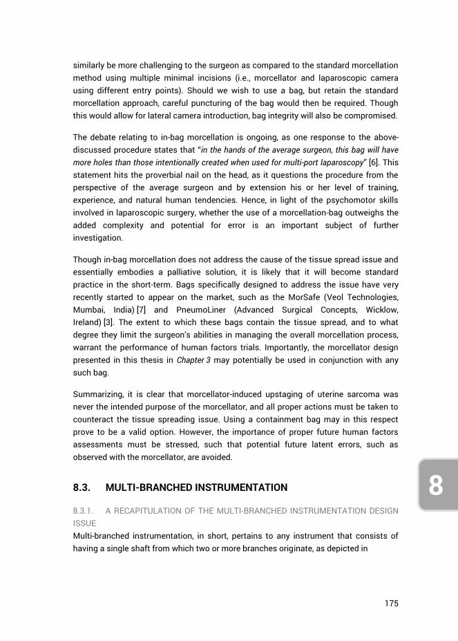
175
8
similarly be more challenging to the surgeon as compared to the standard morcellation method using multiple minimal incisions (i.e., morcellator and laparoscopic camera using different entry points). Should we wish to use a bag, but retain the standard morcellation approach, careful puncturing of the bag would then be required. Though this would allow for lateral camera introduction, bag integrity will also be compromised.
The debate relating to in-bag morcellation is ongoing, as one response to the above-discussed procedure states that “in the hands of the average surgeon, this bag will have more holes than those intentionally created when used for multi-port laparoscopy” [6]. This statement hits the proverbial nail on the head, as it questions the procedure from the perspective of the average surgeon and by extension his or her level of training, experience, and natural human tendencies. Hence, in light of the psychomotor skills involved in laparoscopic surgery, whether the use of a morcellation-bag outweighs the added complexity and potential for error is an important subject of further investigation.
Though in-bag morcellation does not address the cause of the tissue spread issue and essentially embodies a palliative solution, it is likely that it will become standard practice in the short-term. Bags specifically designed to address the issue have very recently started to appear on the market, such as the MorSafe (Veol Technologies, Mumbai, India) [7] and PneumoLiner (Advanced Surgical Concepts, Wicklow, Ireland) [3]. The extent to which these bags contain the tissue spread, and to what degree they limit the surgeon’s abilities in managing the overall morcellation process, warrant the performance of human factors trials. Importantly, the morcellator design presented in this thesis in Chapter 3 may potentially be used in conjunction with any such bag.
Summarizing, it is clear that morcellator-induced upstaging of uterine sarcoma was never the intended purpose of the morcellator, and all proper actions must be taken to counteract the tissue spreading issue. Using a containment bag may in this respect prove to be a valid option. However, the importance of proper future human factors assessments must be stressed, such that potential future latent errors, such as observed with the morcellator, are avoided.
8.3. MULTI-BRANCHED INSTRUMENTATION
8.3.1. A RECAPITULATION OF THE MULTI-BRANCHED INSTRUMENTATION DESIGN ISSUE Multi-branched instrumentation, in short, pertains to any instrument that consists of having a single shaft from which two or more branches originate, as depicted in
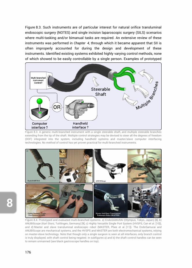
176
8
Figure 8.3. Such instruments are of particular interest for natural orifice transluminal endoscopic surgery (NOTES) and single incision laparoscopic surgery (SILS) scenarios where multi-tasking and/or bimanual tasks are required. An extensive review of these instruments was performed in Chapter 4, through which it became apparent that SII is often improperly accounted for during the design and development of these instruments. Identified existing systems exhibited highly varying control methods, none of which showed to be easily controllable by a single person. Examples of prototyped
Figure 8.3. A generic multi-branched instrument with a single steerable shaft, and multiple steerable branches extending from the tip of the shaft. Multiple control strategies may be devised to steer all the degrees of freedom (DOF) integrated into the system, including handheld systems and master/slave computer interfacing technologies. No method of control has yet proven practical for multi-branched instruments.
Figure 8.4. Prototyped and evaluated multi-branched systems. a) EndoSAMURAI (Olympus, Tokyo, Japan) [8], b) ANUBIScope (Karl Storz, Tuttlingen, Germany) [9], c) Highly Versatile Single Port System (HVSPS, Can et al. [10]), and d) Master and slave transluminal endoscopic robot (MASTER, Phee et al. [11]). The EndoSamurai and ANUBIScope are mechanical systems, and the HVSPS and MASTER are both electromechanical systems, relying on master-slave technology. Note that though only a single surgeon is seen at all interfaces, only branch control is truly displayed, with shaft control being negated. In subfigures a) and b) the shaft control handles can be seen to remain unmanned (see black gastroscope handles on top).
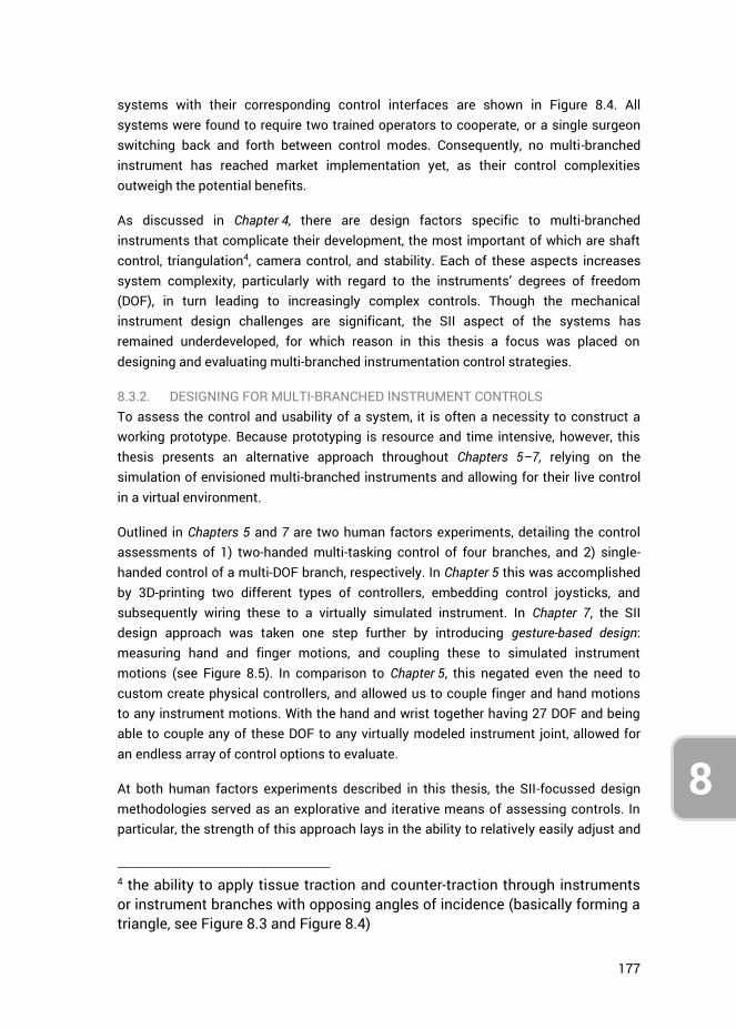
177
8
systems with their corresponding control interfaces are shown in Figure 8.4. All systems were found to require two trained operators to cooperate, or a single surgeon switching back and forth between control modes. Consequently, no multi-branched instrument has reached market implementation yet, as their control complexities outweigh the potential benefits.
As discussed in Chapter 4, there are design factors specific to multi-branched instruments that complicate their development, the most important of which are shaft control, triangulation4, camera control, and stability. Each of these aspects increases system complexity, particularly with regard to the instruments’ degrees of freedom (DOF), in turn leading to increasingly complex controls. Though the mechanical instrument design challenges are significant, the SII aspect of the systems has remained underdeveloped, for which reason in this thesis a focus was placed on designing and evaluating multi-branched instrumentation control strategies.
8.3.2. DESIGNING FOR MULTI-BRANCHED INSTRUMENT CONTROLS To assess the control and usability of a system, it is often a necessity to construct a working prototype. Because prototyping is resource and time intensive, however, this thesis presents an alternative approach throughout Chapters 5–7, relying on the simulation of envisioned multi-branched instruments and allowing for their live control in a virtual environment.
Outlined in Chapters 5 and 7 are two human factors experiments, detailing the control assessments of 1) two-handed multi-tasking control of four branches, and 2) single-handed control of a multi-DOF branch, respectively. In Chapter 5 this was accomplished by 3D-printing two different types of controllers, embedding control joysticks, and subsequently wiring these to a virtually simulated instrument. In Chapter 7, the SII design approach was taken one step further by introducing gesture-based design: measuring hand and finger motions, and coupling these to simulated instrument motions (see Figure 8.5). In comparison to Chapter 5, this negated even the need to custom create physical controllers, and allowed us to couple finger and hand motions to any instrument motions. With the hand and wrist together having 27 DOF and being able to couple any of these DOF to any virtually modeled instrument joint, allowed for an endless array of control options to evaluate.
At both human factors experiments described in this thesis, the SII-focussed design methodologies served as an explorative and iterative means of assessing controls. In particular, the strength of this approach lays in the ability to relatively easily adjust and
4 the ability to apply tissue traction and counter-traction through instruments or instrument branches with opposing angles of incidence (basically forming a triangle, see Figure 8.3 and Figure 8.4)
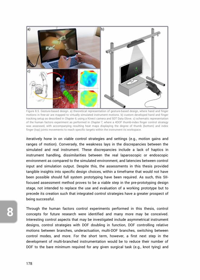
178
8
iteratively hone in on viable control strategies and settings (e.g., motion gains and ranges of motion). Conversely, the weakness lays in the discrepancies between the simulated and real instrument. These discrepancies include a lack of haptics in instrument handling, dissimilarities between the real laparoscopic or endoscopic environment as compared to the simulated environment, and latencies between control input and simulation output. Despite this, the assessments in this thesis provided tangible insights into specific design choices, within a timeframe that would not have been possible should full system prototyping have been required. As such, this SII-focused assessment method proves to be a viable step in the pre-prototyping design stage, not intended to replace the use and evaluation of a working prototype but to precede its creation such that integrated control strategies have a greater prospect of being successful.
Through the human factors control experiments performed in this thesis, control concepts for future research were identified and many more may be conceived. Interesting control aspects that may be investigated include asymmetrical instrument designs, control strategies with DOF doubling in function, DOF controlling relative motions between branches, underactuation, multi-DOF branches, switching between control modes, and more. For the short term, however, a first next step in the development of multi-branched instrumentation would be to reduce their number of DOF to the bare minimum required for any given surgical task (e.g., knot tying) and
Figure 8.5. Gesture-based design. a) theoretical representation of gesture-based design, where hand and finger motions in free-air are mapped to virtually simulated instrument motions. b) custom developed hand and finger tracking setup as described in Chapter 6, using a Kinect camera and 5DT Data Glove. c) schematic representation of the human factors experiment as performed in Chapter 7, where a 4DOF thumb-index finger control strategy was assessed, with accompanying resulting heat maps displaying the degree of thumb (bottom) and index finger (top) joints movements to reach specific targets within the instrument its workspace.
179
8
incrementally add DOF to the (simulated) system that are deemed necessary. Performing human factors assessments with each added DOF will then shed light on the weigh-off between functionality and control complexities in the context of workload, task precision, and the potential for task errors. Though the NOTES and SILS developments have decelerated, many control concepts remain to be tested. Future research is therefore encouraged for multi-branched instrument control strategies in the pre-prototyping stage of development with the use of the gesture-based design tool.
8.3.3. FUTURE GESTURE-BASED DESIGN VIABILITY Though the fundamental approach of gesture-based design was shown to be viable, the implemented measurement setup was limited regarding accuracy and latency. Implemented were a first-generation Kinect camera and Data Glove, each with their limitations. Other measurement modalities, may, therefore, be implemented to enhance the system further (e.g., using the second generation Kinect camera, Intel RealSense [12], or Leap Motion [13]). Additionally, improvements and refactoring of the current custom written program may improve the latency of the system.
In light of recent advances in measurement modalities, in particular, hand tracking systems for consumer virtual reality (VR) systems, gesture-based design may present an effective and cost-efficient way to design and evaluate any “hands-on” system. For example, the Leap Motion system, which provides relative low latency full hand skeletal model tracking and gesture recognition, has been implemented in a variety of studies [14, 15], as well as used in conjunction with VR systems, such as the Samsung Gear VR [16] and Oculus Rift [17]. Considering the increasing consumer uptake of VR systems, as well as ongoing developments in augmented reality headsets such as the Microsoft Hololens [18], the consumer need for immersive interaction with virtual environments will drive hand gesture tracking system developments forward. It is for this reason that gesture-based design is not only promising as a cost-efficient design method for manual control strategies but also as a tool for open innovation [19]. As consumers themselves may have the prerequisite technologies in-house in the near future, large-scale ‘open source’ human factors experiments may complement the design process by allowing one to place an envisioned instrument in any user’s virtual hands (thus including surgeons and surgeons in training), and assess the user-instrument interaction. A practical next step from the gesture-based design tool described in this thesis would be to incorporate current promising hand tracking technologies and further develop, and make openly available, the (currently user-unfriendly) program such that its uptake is made easy.
Lastly, from a human factors standpoint, the gesture-based design tool itself may further be implemented for a range of research activities, in particular, those focused on human factors. For example, the influence of crossfeed on the performance of the human operator in multi-axis tasks may be studied. This is important because it has
180
8
been shown that the geometry of the hand can cause crossfeed during the one-handed performance of a multi-axis task [20]. Depending on which joints of the hands are chosen as control inputs, such crossfeed effects may contribute significantly to the human control responses, potentially undermining an envisioned control strategy and worsening (surgical) task precision. Furthermore, as the design tool does not require a physical prototype, but may still function with an infrared-translucent dummy object or handle (as used in Chapter 7), the influence of shapes, sizes, and weight of handheld controllers on task proficiency and accuracy may be assessed.
8.4. THE IMPORTANCE OF SURGEON-INSTRUMENT INTERACTION
In light of the considerable physical and cognitive strain that MIS places on the surgeon and the complex psychomotor skills one must possess, it is clear that many factors need to be taken into account during instrument design and development. Many of these aspects are mechanical, as instruments are bounded by anatomical constraints, must be sterile, and above all, reliable and safe. Depending on what task(s) an instrument should enable the surgeon to achieve, SII is an equally important aspect. As discussed in this thesis, improperly accounting for user interaction and human factors during design may introduce latent errors into systems, as seen in the case of the morcellator, or bar them from seeing implementation into surgical practice, as witnessed with multi-branched instruments for NOTES or SILS. Accordingly, during the design process, it is at times indicated to give precedence to SII design aspects over mechanical design aspects, rather than the reverse.
Though the research presented in this thesis was limited to the morcellator and multi-branched instrumentation, the role of the user in the design process was shown to be critical in both cases. Therefore, whether taking a 'hands-on’ approach, by placing a physical working prototype into the hands of a prospective user, or a ‘hands-off’ approach, such as gesture-based design, SII should always be assessed in some way with a user during the design of any medical instrument. This does not, however, entail that all SII aspects of an instrument must be comprehensively assessed all at once, as this is a daunting and potentially impractical task. Instead, focussing on specific SII aspects that are deemed of importance, and performing human factors experiments in this regard, is likely to yield valuable information that will contribute to the iterative design process. Moreover, such insights are of great importance to academic knowledge in general, as literature on SII in relation to medical instrument design is sorely lacking, even though human fallibility is a design constraint that impacts all instrumentation.
Finally, as exemplified by the large academic field of Human-Machine Interaction (HMI), which includes the domains of aviation [21], automotive [22], and computer interaction [23], the role of the user is of importance with respect to any system. In this
181
8
regard, gesture-based design may be a design method that is also well suited towards the developments of many other systems that require manual user interactions. Examples can include the designing of physical computer input devices for interacting with virtual and augmented reality (including gaming controllers), self-driving car dashboard interfaces, construction machinery (e.g., crane driver interface), and robot control systems (e.g., robot navigation, robot arm control, etc.). Many aspects of these exemplified systems may already be evaluated through the gesture-based design system presented in this thesis.
8.5. CONCLUSIONS
8.5.1. GENERAL Surgeon-Instrument Interaction (SII) was investigated for morcellators and multi-branched instrumentation. Both types of instruments were found to suffer from inadequate SII. Consequently, for the morcellator a redesign was presented that reduced the need for surgeon intervention, potentially improving on the overall SII of the instrument. For multi-branched instrumentation, gesture-based design was developed as a new way to assess human factors in relation to SII specific design choices. This design method was evaluated and found to provide insights into instrument controls in the pre-prototyping stage of the design process.
8.5.2. MORCELLATION Chapter 2. Morcellators create increasingly small tissue strips as the
morcellation procedure continues, and consequently, the risk of morcellator induced tissue spread increases with procedure duration. Partial morcellation, therefore, limits the risk of tissue spread.
Chapter 3. The cause of tissue spread lies in the tendency of the uterine tissue mass (outside the morcellation tube) to rotate along with the cutting blade. Due to the insufficient control afforded to the surgeon over the tissue mass, intervention is almost impossible.
Chapter 3. Integrating gripping teeth near the rotating cutting blade may, in the event of uterine tissue mass rotation, provide a sufficient counterforce such that it remains constrained, enabling the continuation of the tissue strip cutting action.
8.5.3. MULTI-BRANCHED INSTRUMENTATION Chapter 4. Due to the large number of incorporated DOF, controlling multi-
branched instruments requires a minimum of two surgeons actively working together or the incorporation or master-slave technology. Therefore, a reduction of the amount of actively controlled DOF is deemed necessary,
182
8
concurrently with the development of surgeon-instrument interfaces that enable a single surgeon to control a multi-branched instrument.
Chapter 5. Multi-tasking in the control of four separately steerable instrument branches is always performed sequentially, i.e., one task at a time. Simultaneous control of multiple branches can occur between hands, but not within hands. Accordingly, providing a single surgeon with the full control over four instruments is only viable if a sequential control strategy may be utilized.
Chapter 5. Multi-branched instrument control strategies in the context of multi-tasking capabilities may be evaluated utilizing prototyped controllers linked to a virtual instrument simulation.
Chapter 6. Kalman filter fusion of hand and finger motion measurements obtained with the 5DT Data Glove and the Nimble VR using a Kinect camera can provide acceptably accurate (13.5 to 16.8 deg) and high precision (0.9–2.2 deg) metacarpophalangeal (MCP) and proximal interphalangeal (PIP) joint estimations of the fingers.
Chapter 6. Kalman filter fusion of hand and finger motion measurements obtained with the 5DT Data Glove and the Nimble VR using a Kinect camera provides data completeness superior to the application of only a single vision-based system
Chapter 7. Gesture-based design, measuring hand and finger motions and directly coupling these to simulated instrument motions, provides a viable tool towards the evaluation of control strategies of envisioned multi-branched instruments, without having to resort to prototyping.
Chapter 7. 4DOF thumb-index finger control, as compared to 2DOF thumb control, shows a steep learning curve and performs 0.85 s slower in the performance of position tasks after 5 rounds of training. The end of the learning curve was however not reached. Use of the thumb is preferred at both control modes, for both gross and fine-tuning movements. Use of index finger ab/adduction as input motion is impractical.
8.5.4. TAKE-HOME MESSAGE SII embodies an essential aspect of every minimally invasive instrument. For this reason, human factors evaluations are warranted during and succeeding the design processes of such instruments to ensure reliable and safe SII. Unfortunately, the research presented in this thesis shows that in the cases of the morcellator and multi-branched instrumentation, SII was insufficiently accounted for, leading to latent errors
183
8
and market unviability, respectively. Regardless of the type of manually operated instrument, when human operators are an influential aspect of instrument operations, the SII aspects of relevance with respect to those modes of operation need to be investigated. Important in this regard, is the understanding that this does not necessitate a fully operational prototype. As exemplified in this thesis, manual control strategy evaluations can be accomplished using measurement and simulation modalities, and may even allow one to iteratively hone in on viable manual control strategies before expanding resources to create a prototype. In doing so, the quality of instrument designs with respect to SII may improve and, if reported upon, add to the body of knowledge on human factors and SII, and their relation to clinical practice.
8.6. REFERENCES
1. Siedhoff, M.T., et al., Laparoscopic hysterectomy with morcellation vs abdominal hysterectomy for presumed fibroid tumors in premenopausal women: a decision analysis. Am J Obstet Gynecol, 2015. 212(5): p. 591 e1-8.
2. Seidman, M.A., et al., Peritoneal Dissemination Complicating Morcellation of Uterine Mesenchymal Neoplasms. PLOS ONE, 2012. 7(11): p. e50058.
3. Paul, P.G., et al., Techniques for Laparoscopic Contained Tissue Extraction. Current Obstetrics and Gynecology Reports, 2016. 5(4): p. 325-332.
4. Cohen, S.L., et al., Contained Power Morcellation Within an Insufflated Isolation Bag. Obstetrics & Gynecology, 2014. 124(3): p. 491-497.
5. Montero, P.N., et al., Single Incision Laparoscopic Surgery (SILS) Is Associated with Poorer Performance and Increased Surgeon Workload Compared with Standard Laparoscopy. The American Surgeon, 2011. 77(1): p. 73-77.
6. Harmanli, O., Contained Power Morcellation Within an Insufflated Isolation Bag. Obstetrics & Gynecology, 2015. 125(1): p. 229.
7. Paul, P.G., et al., Contained Morcellation for Laparoscopic Myomectomy Within a Specially Designed Bag. Journal of Minimally Invasive Gynecology, 2016. 23(2): p. 257-260.
8. Ikeda, K., et al., Evaluation of a new multitasking platform for endoscopic full-thickness resection. Gastrointestinal Endoscopy, 2011. 73(1): p. 117-122.
9. Dallemagne, B. and J. Marescaux, The ANUBIS™ project. Minimally Invasive Therapy & Allied Technologies, 2010. 19(5): p. 257-261.
10. Can, S., et al. Design, development and evaluation of a highly versatile robot platform for minimally invasive single-port surgery. in 2012 4th IEEE RAS & EMBS International Conference on Biomedical Robotics and Biomechatronics (BioRob). 2012.
11. Phee, S.J., et al., Natural orifice transgastric endoscopic wedge hepatic resection in an experimental model using an intuitively controlled master and slave transluminal endoscopic robot (MASTER). Surgical Endoscopy, 2010. 24(9): p. 2293-2298.
12. Intel Inc. Intel® RealSense™ Technology. 2017 [cited 2017 September 19]; Available from: https://www.intel.com/content/www/us/en/architecture-and-technology/realsense-overview.html.
13. Leap Motion Inc. Reach into virtual reality with your bare hands. 2017 [cited 2017 September 19]; Available from: www.leapmotion.com.
14. Jin, H., et al., Multi-LeapMotion sensor based demonstration for robotic refine tabletop object manipulation task. CAAI Transactions on Intelligence Technology, 2016. 1(1): p. 104-113.
184
8
15. Lin, W., et al., Design of Hand Gestures for Manipulating Objects in Virtual Reality, in Human-Computer Interaction. User Interface Design, Development and Multimodality: 19th International Conference, HCI International 2017, Vancouver, BC, Canada, July 9-14, 2017, Proceedings, Part I, M. Kurosu, Editor. 2017, Springer International Publishing: Cham. p. 584-592.
16. Sra, M., et al., Resolving Spatial Variation And Allowing Spectator Participation In Multiplayer VR, in Proceedings of the 29th Annual Symposium on User Interface Software and Technology. 2016, ACM: Tokyo, Japan. p. 221-222.
17. Hilfert, T. and M. König, Low-cost virtual reality environment for engineering and construction. Visualization in Engineering, 2016. 4(1): p. 2.
18. Microsoft Inc. Microsoft HoloLens. 2017 [cited 2017 September 19]; Available from: https://www.microsoft.com/en-us/hololens.
19. Huizingh, E.K.R.E., Open innovation: State of the art and future perspectives. Technovation, 2011. 31(1): p. 2-9.
20. Barendswaard, S., et al., Human Crossfeed in Dual-Axis Manual Control with Motion Feedback. IFAC-PapersOnLine, 2016. 49(19): p. 189-194.
21. Taylor, A., Human-Machine Interaction in the Cockpit and Applicable Design Changes Towards Better Collaboration, in Advances in Human Factors and System Interactions: Proceedings of the AHFE 2016 International Conference on Human Factors and System Interactions, July 27-31, 2016, Walt Disney World®, Florida, USA, I.L. Nunes, Editor. 2017, Springer International Publishing: Cham. p. 271-279.
22. Cacciabue, P.C., Modelling driver behaviour in automotive environments: critical issues in driver interactions with intelligent transport systems. 2007: Springer.
23. Norman, D.A., Stages and levels in human-machine interaction. International journal of man-machine studies, 1984. 21(4): p. 365-375.

185
ACKNOWLEDGMENTS

186
Aan het begin van mijn promotietraject zou ik niet hebben kunnen voorspellen hoeveel rijker mijn leven zou worden door het doen van een PhD. Het was niet alleen een grote uitdaging, maar ook een geweldig avontuur, mede dankzij alle fantastische collega’s en memorabele congresreizen. Ik had het voor geen goud willen missen. Het tot stand brengen van deze thesis was niet mogelijk geweest zonder de steun van mijn geweldige familie, schoonfamilie, vrienden en collega’s. Voorop gesteld wil ik daarom iedereen hartelijk danken die mij heeft geholpen en gesteund over de loop van de jaren.
Een aantal mensen wil ik graag met name noemen. Allereerst bedank ik graag mijn copromotor dr. ir. Joost C.F. de Winter. Joost, dank voor de snelle, veelvoudige, en vooral diepgaande feedback die je keer op keer gaf op al mijn werk. Zonder jouw ondersteuning zou ik waarlijk mijn onderzoek niet tot het niveau hebben kunnen tillen dat het nu is. Tevens wil ik graag mijn promotoren prof. dr. ir. Paul Breedveld en prof. dr. Jenny Dankelman bedanken. Paul en Jenny, hartelijk dank dat jullie mij de kans hebben gegeven tot het doen van een promotie onderzoek, het vertrouwen dat jullie in mij hebben gesteld, en de rijke discussies die we hebben mogen voeren over de jaren.
I would like to extend my gratitude to the members of the promotion committee, who found themselves willing to read my thesis, cover to cover, and participate in the defense. Prof. dr. A. Menciassi, Prof. dr. G.W.M. Rauterberg, Prof. dr. M.J.A. Malessy, Prof. dr. I. Horvath, and Prof. dr. Ir. H. Vallery.
Vele mensen hebben direct bijgedragen aan deze thesis. Allereerst bedank ik graag alle co-auteurs: Lukas, Sara, Andreas, Frank Willem, Filip, Giada, Paul, Aimee en Awaz. Ook waren er verscheidene studenten die ik met veel plezier heb mogen begeleiden, en waarvan sommige tevens ook co-auteurs zijn geworden op enkele publicaties: Tim, Paul en Aimee, Maxime, Amanda, Ellemijn, Laurien, Floris en Davey. Niet te vergeten zijn er ook de instrumentmakers van DEMO: Remi, Menno en David. Zonder deze heren zouden de testopstellingen omschreven in deze thesis niet tot stand zijn gekomen (of waarschijnlijk zijn opgemaakt uit ducttape). Als laatste, niet te vergeten, waren er de dames van het secretariaat: Diones, Anouk, Nancy, Sabrina, en Hanneke, zonder wiens goede zorgen deze scriptie er naar alle waarschijnlijkheid ook niet zou zijn geweest. Het was een plezier om met jullie allen te mogen samenwerken.
I am also indebted to the artist who made the artwork, titled Bare Tree IV – Immortal, that now adorns the cover of this thesis. Thank you, Leonora Knight, for permitting me to use your art. I discovered your artwork during the first year of my PhD and never found anything more suited or representative of my work ever since.
Dan was er de geweldige groep collega’s. Allereerst de lieve BITE-collega’s uit het hoofdkantoor: Paul, Awaz, Aimee en Marta. Met jullie op kantoor voelde ik mij altijd thuis. Bram, Steven, Chunman, Annetje en Nick (jullie tweeën in het speciaal bedankt voor het PhD-avontuur dat we samen hebben doorlopen), Frederique, Peter, Eline, Ingrid,
187
Elise, Teun, Nadia, Arjo, Arjan, Tim, Tonke, Roos, John, en alle andere collega’s. Bedankt voor de gezellige koffiepauzes, lunches, uitjes, reizen, congressen, tango-lessen, borrels, feesten, en alle memorabele avonturen die we samen hebben beleeft.
Mijn dank is ook groot voor mijn paranimfen: Bart, mijn langste vriend (in tijd en lengte), mede-nerd, en permanente optimist. Na samen te zijn opgegroeid en over de jaren veel veranderingen samen te hebben meegemaakt, kan ik stellig zeggen dat jouw positivisme altijd voor mij een voorbeeld is geweest hoe het beste te halen uit elke dag. Paul, mede BITE-lid in het hoofdkantoor, één van de eerste studenten die ik heb mogen begeleiden als onderdeel van mijn promotietraject en tevens mijn eerste PhD project collega. Ik heb met veel plezier met jou samengewerkt en gefeest. Gezien het feit dat jij er was vanaf het begin van mijn promotietraject, vind ik het niet meer dan toepasselijk dat jij als paranimf er ook bij bent op het einde.
Mijn promotiejaren waren niet altijd even makkelijk. Alhoewel ik soms de neiging heb mij te verliezen in het werk (en MATLAB), heb ik gelukkig een fantastische groep vrienden die mij regelmatig van de noodzakelijke afleiding voorzien. Bart, Nick, Frank, Frans, Alexander, en alle andere spelletjes-genoten: dank jullie!
Mijn dank is ook ontzettend groot voor mijn familie. Mam, pap, en mijn lieve zus Karin. Zonder jullie steun, aanmoedigingen en onwrikbare vertrouwen in mij, zou ik niet de persoon zijn geweest die ik nu ben. Dank voor alles!
En als laatste: Susanna. Mijn steun en toeverlaat. Mijn rots in de branding. Jij hebt het hele PhD traject met mij meegeleefd, de successen én de tegenslagen, en mij altijd met een overvloed aan liefde ondersteund. Dit boekje is ook een beetje van jou.
Ewout A. Arkenbout Delft, 2018

188
189
CURRICULUM VITAE
Ewout Aart ARKENBOUT
06 – 08 – 1986 Born in Rotterdam, The Netherlands
Relevant work experience 1998 – 2004
VWO (Atheneum), Comenius College, Capelle aan den IJssel, The Netherlands.
2004 – 2008 B.Sc. Mech.,
Delft University of Technology, Delft, The Netherlands.
Internship: Experimental Medical Instrumentation (EMI) department, Erasmus Medical Centre (EMC).
Thesis: Development of a measurement device for acquisition of eyelid-pressure.
2008 – 2012 M.Sc. Biomed. Eng. (cum laude),
Delft University of Technology, Delft, The Netherlands. Internship: Precision Engineering Research Group (PERG),
Massachusetts Institute of Technology (MIT), Massachusetts, USA.
Thesis: Design process of a trans-vaginal morcellator for Total Laparoscopic Hysterectomy. From clinical functionality assessment to first prototype.
2012 – 2017 PhD candidate,
Bio-Inspired Technology group (BITE) Department of Biomechanical Engineering, Delft University of Technology, Delft, The Netherlands. Prog.: Bio-inspired maneuverable dendritic devices for minimally invasive surgery.
2016 – 2017 Mechatronic Engineer,
Heemskerk Innovative Technology, Delft, The Netherlands
190
PUBLICATIONS E. A. Arkenbout, J. C. de Winter, A. Ali, J. Dankelman, and P. Breedveld, "A gesture-based design tool: assessing 2DOF vs. 4DOF steerable instrument control," PLOS ONE, (submitted 2018).
E. A. Arkenbout, F. H. van den Berg, J. C. de Winter, P. W. Henselmans, W. R. van Furth, and P. Breedveld, "Bimanual control assessment of multibranched EETS instrument," Ergonomics, (submitted 2017).
E. A. Arkenbout, L. van den Haak, M. Penning, E. Rog, A. Vierwind, L. van Cappelle, et al., "A Laparoscopic Morcellator Redesign to Constrain Tissue Using Integrated Gripping Teeth," Journal of Medical Devices, vol. 11, p. 011005, 2017.
F. C. Meeuwsen, A. C. Guédon, E. A. Arkenbout, M. van der Elst, J. Dankelman, and J. J. van den Dobbelsteen, "The Art of Electrosurgery: Trainees and Experts," Surgical Innovation, p. 1553350617705207, 2017.
D. Kreeft, E. A. Arkenbout, P. W. J. Henselmans, W. R. van Furth, and P. Breedveld, "Review of Techniques to Achieve Optical Surface Cleanliness and Their Potential Application to Surgical Endoscopes," Surgical Innovation, p. 1553350617708959, 2017.
L. van den Haak, E. A. Arkenbout, E. M. Sandberg, and F. W. Jansen, "Power Morcellator Features Affecting Tissue Spill in Gynecologic Laparoscopy: An In-Vitro Study," Journal of minimally invasive gynecology, vol. 23, pp. 107-112, 2016.
E. A. Arkenbout, J. C. de Winter, and P. Breedveld, "Robust hand motion tracking through data fusion of 5DT data glove and nimble VR Kinect camera measurements," Sensors, vol. 15, pp. 31644-31671, 2015.
E. A. Arkenbout, P. W. Henselmans, F. Jelínek, and P. Breedveld, "A state of the art review and categorization of multi-branched instruments for NOTES and SILS," Surgical endoscopy, vol. 29, pp. 1281-1296, 2015.
L. Van Den Haak, E. A. Arkenbout, and F. Jansen, "In-Bag Morcellation: Is the Patient Left Holding the Bag?," Journal of minimally invasive gynecology, vol. 22, p. S217, 2015.
E. A. Arkenbout, L. van den Haak, S. R. Driessen, A. L. Thurkow, and F.-W. Jansen, "Assessing basic “physiology” of the morcellation process and tissue spread: a time-action analysis," Journal of minimally invasive gynecology, vol. 22, pp. 255-260, 2015.
191
A. Sakes, E. A. Arkenbout, F. Jelínek, J. H. van der Kolk, and P. Breedveld, "Design of an endovascular morcellator for the surgical treatment of equine Cushing's disease," Veterinary quarterly, vol. 35, pp. 165-169, 2015.
G. Gerboni, P. W. Henselmans, E. A. Arkenbout, W. R. van Furth, and P. Breedveld, "HelixFlex: bioinspired maneuverable instrument for skull base surgery," Bioinspiration & biomimetics, vol. 10, p. 066013, 2015.
F. Jelínek, E. A. Arkenbout, P. W. Henselmans, R. Pessers, and P. Breedveld, "Classification of joints used in steerable instruments for minimally invasive surgery—A review of the state of the art," Journal of Medical Devices, vol. 9, p. 010801, 2015.
F. Jelínek, E. A. Arkenbout, A. Sakes, and P. Breedveld, "Minimally invasive surgical instruments with an accessory channel capable of integrating fibre-optic cable for optical biopsy: A review of the state of the art," Proceedings of the Institution of Mechanical Engineers, Part H: Journal of Engineering in Medicine, vol. 228, pp. 843-853, 2014.
S. R. Driessen, E. A. Arkenbout, A. L. Thurkow, and F.-W. Jansen, "Electromechanical morcellators in minimally invasive gynecologic surgery: an update," Journal of minimally invasive gynecology, vol. 21, pp. 377-383, 2014.
Refereed contributions to 10+ international conferences (2010 – 2016)
PATENTS
P. Breedveld, P.W.J. Henselmans, E.A. Arkenbout, W. fan Furth, G. Gerboni (2014). Industrial or medical tool with steering cables. Patentnumber 2012071, Academisch Medisch Centrum (AMC), Stichting voor de Technische Wetenschappen (STW) and Technische Universiteit Delft (TUD), Netherlands.
E.A. Arkenbout, F.W. Jansen (2013). Morcellator. Patentnumber 2010089, Delft University of Technology (TUD), Netherlands.


