Embed Size (px)
Citation preview

SUPERMICRORAID Port Manual
§ Adaptec® ARO-1130CA/SARAIDport II™
§ Adaptec® CI/O Array ManagementSoftware Guide
1.0

_________________________________________________________
The information in this manual has been carefully reviewed and is believed to beaccurate. The vendor assumes no responsibility for any inaccuracies that may becontained in this document, makes no commitment to update or to keep current theinformation in this manual, or to notify any person or organization of the updates.
SUPERMICRO COMPUTER reserves the right to make changes to the productdescribed in this manual at any time and without notice. This product, includingsoftware, if any, and documentation may not, in whole or in part, be copied, photocopied,reproduced, translated or reduced to any medium or machine without prior writtenconsent.
IN NO EVENT WILL SUPERMICRO COMPUTER BE LIABLE FOR DIRECT,INDIRECT, SPECIAL, INCIDENTAL, OR CONSEQUENTIAL DAMAGES ARISINGFROM THE USE OR INABILITY TO USE THIS PRODUCT ORDOCUMENTATION, EVEN IF ADVISED OF THE POSSIBILITY OF SUCHDAMAGES. IN PARTICULAR, THE VENDOR SHALL NOT HAVE LIABILITYFOR ANY HARDWARE, SOFTWARE, OR DATA STORED OR USED WITH THEPRODUCT, INCLUDING THE COSTS OF REPAIRING, REPLACING, ORRECOVERING SUCH HARDWARE, SOFTWARE, OR DATA.
_________________________________________________________
Unless you request and receive written permission fromSUPERMICRO COMPUTER, you may not copy any part of thisdocument.
Information in this document is subject to change without notice.Other products and companies referred to herein are trademarks orregistered trademarks of their respective compaines or mark holders.
Copyright © 1998 by SUPERMICRO COMPUTER INC.
All Rights ReservedPrinted

i
CONTENTS:
PART 1 ADAPTEC® ARO-1130CA/SA RAIDPORT II™
Section 1: Introduction........................................................................ 1System Requirements ........................................................................ 1Installation Overview......................................................................... 2
Section 2: Installing the ARO- 1130xA and Connecting SCSIDevices .................................................................................................. 3
ARO- 1130xA Layout........................................................................ 3Verifying Presence of DIMM Memory ............................................. 4Installing the ARO- 1130xA.............................................................. 5Connecting the LED Activity Indicator to the ARO- 1130xA........... 6Connecting SCSI Devices.................................................................. 8Choosing SCSI Cables....................................................................... 8Connecting Internal SCSI Devices .................................................... 9Connecting External SCSI Devices ................................................. 11Connecting SCSI Array Enclosures (Storage Subsystems) ............. 14Installation Hints for Connecting SCSI Devices.............................. 15Completing the Installation.............................................................. 17
Section 3: Using the Array1000xA BIOS & Driver Selection Utility............................................................................................................. 19
Running the Array1000xA BIOS & Driver Selection Utility .......... 19
Section 4: Configuring the ARO- 1130xA with the _SCSISelectUtility .................................................................................................. 21
Default _SCSISelect Settings .......................................................... 21Starting the _SCSISelect Utility ...................................................... 22Using _SCSISelect Menus............................................................... 22Exiting _SCSISelect ........................................................................ 23Using the SCSI Disk Utilities .......................................................... 23SCSISelect Settings ......................................................................... 24
Section 5: Creating the First Array With the _ArrayConfigxAProgram/Utility .................................................................................. 27
Making the Array Bootable ............................................................. 30
Section 6: Installing Software on a Windows NT System............... 33Installing the Array1000xA Driver for Windows NT...................... 33

ii
Installing the Driver When Installing Windows NT........................ 34Installing the Driver When Windows NT is Already Installed ........ 35Installing Adaptec CI/O Workstation/Server Array ManagementSoftware for Windows NT............................................................... 36
Section 7: Installing Software on a Novell NetWare ServerIMPORTANT: All of the following section (Section 4) applies toARO-1000SA only.............................................................................. 39
Installing the Array1000SA Driver for Novell NetWare ................. 39Installing the Driver When Installing NetWare ............................... 40Installing the Driver When NetWare is Already Installed ............... 42Installing the TIRPC Communications Module............................... 43Installing the Adaptec CI/O Management Software for NovellNetWare........................................................................................... 44Adaptec CI/O Management Software Installation Hints.................. 45
Section 8: Installing Software on a Remote Client IMPORTANT:All of the following section (Section 8) applies to ARO-1000SAonly...................................................................................................... 47
Appendix A: Troubleshooting .......................................................... 51Troubleshooting Checklist ............................................................... 51Problems Running the Software On Your Windows NT................. 51Using the ARO- 1130xA with an AHA-2940 Family Host Adapter53
Appendix B: Advanced Topics ......................................................... 61Installing Multiple Adapters ............................................................ 61
Appendix C: Using a CD-ROM Drive with DOS............................ 63
Appendix D: Using the SNMP Agent (This section refers to ARO-1000SA only) ...................................................................................... 67
NetWare........................................................................................... 67Windows NT.................................................................................... 68Loading MIBs in the MID Database................................................ 68
PART 2 ADAPTEC® CI/O™ MANAGEMENT SOFTWARE
Section 1: Getting Started ................................................................. 73Software Overview .......................................................................... 73Using the Adaptec CI/O Management Software.............................. 73

iii
Section 2: Entering and Viewing Server Information .................... 75Entering and Viewing Server Information....................................... 75Viewing Historical Server Information............................................ 84Interpreting and Responding to Server Event Messages.................. 85Entering and Viewing Preference Information ................................ 86
Section 3: Configuring Arrays and Spares ...................................... 89Starting the Program ........................................................................ 89Creating an Array............................................................................. 91Making an Array the First Virtual Device ....................................... 96Deleting an Array............................................................................. 97Initializing an Array......................................................................... 99Creating Dedicated Spares or a Spare Pool ................................... 100Deleting a Spare............................................................................. 102Arrays from External RAID Controllers........................................ 103
Section 4: Viewing Array and Device Information....................... 105Viewing Array Information ........................................................... 106Viewing Spare Information............................................................ 108Viewing SCSI Device Information from an Array Controller ....... 108Rescanning the Server ................................................................... 109Viewing Array Controller Information .......................................... 110Viewing Array Channel Information ............................................. 111
Section 5: Performing Array, Spare, and Disk Operations.......... 113Performing Array Operations ........................................................ 113Performing Spare Operations......................................................... 122Performing Disk Operations .......................................................... 124
Section 6: Scheduling and Monitoring Array Operations............ 127Setting Scheduling Options............................................................ 127Viewing and Managing Scheduled Activities................................ 128Monitoring Activities That Are Running....................................... 130
Section 7: Setting Security Options ................................................ 133Changing the Password.................................................................. 133Setting Password Time-out Options .............................................. 134Controlling Guest Access .............................................................. 135
Section 8: Managing Arrays and Spares........................................ 137Responding to a Critical Array ...................................................... 137Responding to an Off-Line Array .................................................. 139Optimizing Array Performance...................................................... 140

iv
Selecting a RAID Level for an Array ............................................ 140

Part 1Adaptec® ARO-1130CA/SARAIDport II™


SUPERMICRO RAIDPort Manual
1
Section 1:IntroductionThe Adaptec® ARO™-1130xA RAIDport II™ Card provides powerfuldisk array support in personal workstations/servers with RAIDport IIon-board. ARO-1130CA is for workstations and ARO-1130SA is forservers.
This Installation and Hardware Guide explains how to install theARO- 1130xA, run the Array1000xA BIOS & Driver Selection Utility,create the first array, and then install the supporting software.
System RequirementsThe minimum system requirements for the ARO- 1130xA are
§ A RAIDport II on-board system with an availablePCI/RAIDport II slot
§ A minimum of one SCSI hard disk drive
§ A standard 168-pin, 16-, 32-, or 64-MByte, EDO 3.3v, 60ns orfaster DIMM installed on the card. (See the Adaptec Web Site athttp:// www.adaptec.com/RAID for a list of approved DIMMs andvendors.)
§ Five MBytes of free hard disk space for the ARO- 1130xAsoftware (five MBytes of free hard disk space on the Windowssystem disk are also required for the temporary files created duringinstallation of the software)
§ Windows NT™ Workstation 4.0 or higher for ARO-1130xA orWindows NT™ 4.0 Server, or Novell NetWare 3.12 or 4.11 forARO-1130SA
§ A 3.5-inch 1.44-MByte primary (boot) floppy disk drive§ 64 MBytes or more of system memory recommended for Windows
NT Workstation/Server§ CD-ROM drive recommended for installation of Adaptec CI/O™
Management Software

SUPERMICRO RAIDPort Manual
2
Installation OverviewThe steps involved in installing the ARO- 1130xA hardware andsoftware are:
1. Locate the PCI RAIDport II slot or expansion slot on the
motherboard.
2. Install the ARO- 1130xA in the RAIDport II on-board system.
3. Connect any additional SCSI devices to the RAID ready SCSIconnectors on the motherboard.
4. Run Array 1000xA BIOS & Driver Selection utility.5. Create the first bootable array using the ArrayConfigxATM Utility
(see page 27)6. Install the Array1000xA driver for your operating system.7. Install the Adaptec CI/O Management Software on your
server/workstation8. Install the Adaptec CI/O Management Software on your networked
client (optional/ARO-1000SA only)
Note: Before proceeding with installation, review the readme filefound on Disk 1 of the Adaptec CI/O Management Software forWindows NT diskettes, or the readme file on the \winnt\disk1directory of the Adaptec CI/O Management Software CD-ROM.

SUPERMICRO RAIDPort Manual
3
Section 2:Installing the ARO- 1130xAand Connecting SCSI DevicesThis chapter explains how to install your hardware. To install the ARO-1130xA and devices, you must.
§ Verify presence of DIMM memory
§ Back up any existing data on drives to be used in array
§ Install the ARO-1130xA in your system/server
ARO- 1130xA LayoutFigure 2-1 identifies the major ARO- 1130xA components. You mayfind it helpful to refer to this information while installing the ARO-1130xA.

SUPERMICRO RAIDPort Manual
4
Figure 2-1: ARO-1130xA Major Components.
Verifying Presence of DIMM MemoryBefore you can use the ARO- 1130xA, the DIMM memory socket mustbe populated with a 168-pin, 16-, 32-, or 64-MByte, EDO 3.3v 60ns orfaster DIMM for ARO-1000xA, as shown in Figure 2-2. Install aDIMM if one is not yet installed. (See the Adaptec Web Site athttp://www.adaptec.com/RAID for a list of approved DIMMs andvendors.)
Bus ContactsInserted into thePCI/RAIDport IIexpansion slot
LED ConnectorConnects to the computer’s LED cable todisplay activity on the SCSI bus
BIOS EPROMProvides bootingcapabilities froma SCSI hard diskor array
DIMM Memory SocketMust be populated witha 168-pin EDO, 3.3vDIMM
Expansion SlotBracketSecures theRAIDport II cardinside yourcomputer

SUPERMICRO RAIDPort Manual
5
Figure 2-2: Installing a DIMM in the DIMM Memory Socket.
Installing the ARO- 1130xAFollow these steps to install the ARO- 1130xA:
Note: If you are installing the ARO- 1130xA in an existing systemthat already has data, back up all data before continuing withinstallation. You can restore the data later, once your ARO- 1130xAarrays are created.
1. Turn OFF power to the computer, and disconnect the power cord.
2. Remove the cover from the computer case. (If necessary, refer to the
instructions in your computer documentation.)
3. Locate the PCI/RAIDport II expansion slot; unscrew and remove theexpansion slot bracket that covers the card-slot opening.
4. Insert the ARO- 1130xA in the slot; press down firmly so that thebus contacts are securely seated in the slot. Secure the adapter
bracket with the screw you removed in Step 3, as shown in Figure
2-3.
SUPERMICRO RAIDPort Manual
6
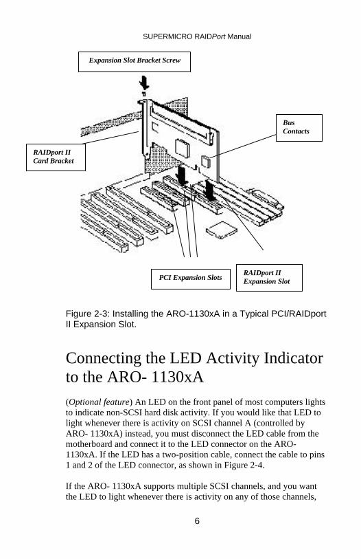
Figure 2-3: Installing the ARO-1130xA in a Typical PCI/RAIDportII Expansion Slot.
Connecting the LED Activity Indicatorto the ARO- 1130xA(Optional feature) An LED on the front panel of most computers lightsto indicate non-SCSI hard disk activity. If you would like that LED tolight whenever there is activity on SCSI channel A (controlled byARO- 1130xA) instead, you must disconnect the LED cable from themotherboard and connect it to the LED connector on the ARO-1130xA. If the LED has a two-position cable, connect the cable to pins1 and 2 of the LED connector, as shown in Figure 2-4.
If the ARO- 1130xA supports multiple SCSI channels, and you wantthe LED to light whenever there is activity on any of those channels,
BusContacts
RAIDport IIExpansion Slot
RAIDport IICard Bracket
Expansion Slot Bracket Screw
PCI Expansion Slots

SUPERMICRO RAIDPort Manual
7
refer to your motherboard documentation for instructions on setting theappropriate motherboard jumpers.
Note: If you are using non-SCSI disk drives (e.g., IDE), the LEDmay no longer indicate activity on these drives when you connectthe LED cable to the ARO- 1130xA.
Figure 2-4: Connecting the LED Activity Indicator.
Completing the InstallationOnce the ARO-1000xA is installed in your server/workstation, refer tothe documentation that came with your computer and SCSI devices forspecific instructions on setting up your SCSI devices and connectingthem to the SCSI connectors on the motherboard.
Note: If you refer to the computer’s documentation for installationinstructions on running the Array1000xA BIOS & Driver SelectionUtility and installing the software included in the package.
In most cases, it is not necessary to run the SCSISelect® utility.Should you need to configure SCSI options (e.g., ID, Parity Checking,and Termination), see Section 4, page 21, Configuring ARO-1130xAwith the SCSISelect Utility.
LED Connector onARO- 1130xA
2-pin LED Cable
LED Cable1
1

SUPERMICRO RAIDPort Manual
8
Connecting SCSI DevicesThe ARO- 1130xA supports both internal and external SCSI devices.Depending on the number of SCSI channels provided on themotherboard. Each channel supports up to 15 SCSI devices—either16-bit devices alone or a combination of 16-bit and up to seven 8-bitdevices.
Note: If you are installing your SCSI devices inside an arrayenclosure, see Connecting SCSI Array Enclosures (StorageSubsystems) on page 14.
Choosing SCSI CablesTo connect your SCSI devices, make sure you have the appropriatecable and connectors as described in the following table (see also CableLengths on page 16 for additional information on cabling SCSIdevices):
To Install… You Will Need…8-bit Internal SCSIDevices
• A 50-pin internal SCSI cable with enoughconnectors to accommodate all of your internalSCSI devices.
16-bit Internal SCSIDevices
• A 68-pin Ultra Wide internal SCSI cable withenough connectors to accommodate all of yourinternal SCSI devices.
8-bit External SCSIDevices1
• A 50-pin internal-to-external SCSI portexpansion kit.• A 50-pin external SCSI cable for each device.
16-bit External SCSIDevices1
• A 68-pin Ultra Wide internal-to-externalSCSI port expansion kit.• A 68-pin Ultra Wide external SCSI cable foreach device.
Array Enclosure • A 68-pin Ultra Wide internal-to-externalSCSI port expansion kit.• A 68-pin Ultra Wide external SCSI cable.
1 Use only high-quality external cables with a single ended impedance range of80-110 ohms.

SUPERMICRO RAIDPort Manual
9
Connecting Internal SCSI DevicesFollow these steps to connect internal devices:
1. Prepare each SCSI device for installation.§ Make sure each device (internal and external) is assigned a unique
SCSI ID number from 0 to 15—no duplicate IDs are permitted ona channel. (See SCSI ID Numbers on page 16 for additionalinformation.)
§ Install (or enable) the terminators on the internal device you areattaching to the end of the cable only. (See SCSI Termination onpage 17 for additional information.)
2. Install and mount each internal SCSI device in an available drive
bay inside your computer. (Refer to your computer and device
documentation for instructions.)
3. If you are connecting 8-bit internal SCSI devices, attach one end of
the 50-pin cable to the 50-pin internal SCSI connector on the
motherboard. If you are connecting 16-bit internal SCSI devices,
attach one end of the 68-pin cable to the 68-pin internal SCSI
connector on the motherboard. Figure 2-5 shows a typical
installation of a 68-pin cable

SUPERMICRO RAIDPort Manual
10
Figure 2-5: Attaching 68-pin Internal Ribbon Cable.
4. Attach the remaining connectors on the cable to the remaining
internal devices.
5. Connect an available DC power cable (from your computer’s power
supply) to the power input connector on each SCSI device.

SUPERMICRO RAIDPort Manual
11
Connecting External SCSI DevicesTo install external SCSI devices, you will first need to install aninternal-to-external SCSI port expansion kit. The kit usually consists ofa special cable that converts the internal SCSI connector on themotherboard to an external SCSI connector on the chassis of yourcomputer. Refer to the expansion kit documentation for installationinstructions. Figure 2-6 shows a typical installation of a 68-pin UltraWide internal-to-external cable.
Figure 2-6: Installing an Internal to External SCSI Port ExpansionCable.
68-Pin UltraWide InternalSCSI Connector
68-Pin UltraWide Internal-to-ExternalSCSI Cable
68-Pin UltraWide ExternalSCSI Connector

SUPERMICRO RAIDPort Manual
12
Once the SCSI port expansion kit is installed, follow these steps toconnect external SCSI devices:
1. Make sure each device (internal and external) is assigned a unique
SCSI ID number from 0 to 15—no duplicate IDs are permitted on
a channel. (See SCSI ID Numbers on page 16 for additional
information.)
2. If you are connecting 8-bit external SCSI devices, attach one end of
the 50-pin cable to the 50-pin external SCSI connector of the
expansion kit. If you are connecting 16-bit external SCSI devices,
attach one end of the 68-pin cable to the 68-pin Ultra Wide
external SCSI connector of the expansion kit (shown in Figure 2-
7.)
Figure 2-7: Attaching an External Cable to External SCSIConnector.

SUPERMICRO RAIDPort Manual
13
3. Attach the connector at the other end of the cable to either one of the
SCSI connectors on the external SCSI device, as shown in Figure
2-8. (If you are installing only one external device, attach a
terminating plug to the device.)
Figure 2-8: Attaching a Single External Device
4. Connect other external SCSI devices by daisy-chaining each device
to the previous device until all external SCSI devices have been
connected, as shown in Figure 2-9. (The device at the end of the
chain must have a terminating plug installed. See SCSITermination on page 17 for additional information.)

SUPERMICRO RAIDPort Manual
14
Figure 2-9: Attaching Multiple External Devices.
Connecting SCSI Array Enclosures(Storage Subsystems)To help you conveniently manage your SCSI storage subsystems, avariety of array enclosures are available from different manufacturers.Figure 2-10 shows a typical setup between the array enclosure and thesystem. To install your SCSI devices in these enclosures, refer to theenclosure’s documentation. The following information is provided tohelp you properly connect your enclosure to the system:
§ All rules for SCSI ID and termination must be followed wheninstalling SCSI devices in an array enclosure.
§ Ideally, the array enclosure itself should provide terminationcapability and you should disable termination on all the drives inthe enclosure. If you terminate the SCSI bus by enablingtermination on a drive, you may run into problems if you have toreplace that drive and you then forget to terminate the replacementdrive.

SUPERMICRO RAIDPort Manual
15
§ If the enclosure you are using for the array drives is notspecifically designed as an array enclosure (such as a standardtower unit), be sure it has adequate cooling and ventilation.
Figure 2-10: A Typical Array Enclosure Setup.
Installation Hints for Connecting SCSIDevices
All SCSI Devices
§ If you are booting your system from a single SCSI hard disk driveor bootable array, the boot order of the disk or array must be set to0. (See Making the Array Bootable on page 30.)
§ Termination power should be enabled on several or all SCSIdevices in the system (or array enclosure) so that if you remove adrive that is supplying termination power other devices will stillprovide it. The devices supplying termination power should belocated near the end of the bus.

SUPERMICRO RAIDPort Manual
16
§ Symptoms of SCSI cabling-related problems are drives that are notrecognized, drives that lock-up, or drives that deactivate.
§ Use good-quality SCSI cabling, and minimize the stub lengths.Good- quality cables should not be limp when you pick them up.The quality of the cable becomes much more critical when you usehigher-speed data transfer (i.e., UltraSCSI data transfer).
Cable Lengths§ The total length of cabling (internal and external) on each SCSI
channel should not exceed the following:
– Three m (9.8 ft) if you are using Fast SCSI data transfer rates (10MBytes/sec) and have 1 to 15 devices (including the Arraycontroller).
– Three m (9.8 ft) if you are using UltraSCSI data transfer rates (20MBytes/sec for 8-bit devices, and 40 MBytes/sec for 16-bitdevices) and have four or less devices (including the Arraycontroller).
– One and one-half m (4.9 ft) if you are using UltraSCSI datatransfer rates and have between four and eight devices (includingthe Array controller).
Note: UltraSCSI data transfer rates do not currently support morethan eight devices per channel.
– Six m (19.7 ft) if you are using 5-MByte/sec asynchronous orsynchronous data transfer rates.
§ When calculating the total length of the bus, be sure to include thecabling inside any array enclosure.
SCSI ID NumbersEach device attached to a SCSI channel supported by the ARO-1130xA must be assigned a unique SCSI ID number—0 to 15 for Wide(16-bit) devices, and 0 to 7 for Narrow (8-bit) devices. No duplicateIDs are permitted on a channel.
§ We recommend that you leave the Array controller set to itsdefault setting of SCSI ID 7. If for some reason you need to changethe Array controller SCSI ID, see Section 4, page 21, Configuringthe ARO-1130xA with the SCSISelect Utility for instructions.
§ SCSI ID 7 has the highest priority on the channel. The priority ofthe remaining IDs, in descending order, is 6 to 0, 15 to 8.

SUPERMICRO RAIDPort Manual
17
§ If you have 8-bit SCSI devices, they must use SCSI IDs 0, 1, 2, 3,4, 5, or 6. (To change the SCSI ID on your hard disk and otherSCSI devices, refer to the device’s documentation.)
§ If you wish to use a single SCSI disk drive (instead of an array) asyour boot device, we recommend that you set the SCSI ID for thedevice to 0.
§ In general, use lower SCSI IDs for single disks and use higherSCSI IDs for drives used as array members or spares.
SCSI TerminationTo ensure reliable communication on the SCSI bus, terminators mustbe installed (or enabled) on the devices at the physical ends of eachSCSI channel. The terminators on all devices between the physical endsmust be removed (or disabled).
To properly terminate the SCSI channel(s) on your system, refer to themotherboard documentation. On most internal SCSI devices, thetermination setting is controlled by setting a jumper or a switch, or byphysically removing or installing a resistor module(s). On mostexternal SCSI devices, termination is controlled by installing orremoving a terminating plug (see Figures 2-8 and 2-9). Refer to thedevice’s documentation to determine how to enable or disabletermination on your particular SCSI device.
Completing the InstallationReinstall your computer cover and connect all power cables. To verifythat the SCSI devices work properly, turn ON the external SCSIdevices first, then turn ON the computer. When the computer boots,the Array1000xA Family BIOS sign-on message should appear on thescreen. If the BIOS message does not appear, see, Troubleshooting onpage 51.
Note: If you need to configure the SCSI options (e.g., ID, ParityChecking, and Termination) of the SCSI channels supported by theARO- 1130xA, see Section 5, Configuring the ARO-1130xA with theSCSISelect Utility.

SUPERMICRO RAIDPort Manual
18

SUPERMICRO RAIDPort Manual
19
Section 3:Using the Array1000xA BIOS& Driver Selection Utility
Whenever you install a new ARO-1130xA in your server/workstationand before you run the Adaptec ArrayConfigxA program to create thefirst array in your system, always run the Array1000xA BIOS & DriverSelection Utility.
Caution: We highly recommend that you back up the data on yourarray(s) before you use the Array1000xA BIOS & Driver SelectionUtility. This ensures that your data is completely protected.
The Array1000xA BIOS & Driver Selection Utility installs the ARO-1130xA BIOS by automatically updating (flashing) the correct ARO-1130xA BIOS. The utility also determines which of the two ManagerSet driver diskettes (Disk A or Disk B) is required when you install theoperating system driver.
Running the Array1000xA BIOS &Driver Selection UtilityThe Array1000xA BIOS & Driver Selection Utility is provided on abootable floppy disk and runs under SOS as a stand-alone utility. Asimple-to-use interface prompts you through the process. Follow thesesteps to run the Array1000xA Bios & Driver Selection Utility:
1. Insert the Array1000xA BIOS & Driver Selection Utility diskettein driver A and reboot your server/workstation. The utility startsautomatically and the initial Array1000xA BIOS & DriverSelection Utility screen appears.
Note: The initial Array1000xA BIOS & Driver Selection Utilityscreen identifies which of the two Manager Set driver diskettes(Disk A or Disk B) are required when you install the operatingsystem driver. Make a note of which diskette to use, and continuewith step 2.

SUPERMICRO RAIDPort Manual
20
2. Select either Express or Advanced setup.
Note: If you receive an “Unsupported Hardware Configuration,”message during setup, contact the system manufacturer. TheARO-1130xA is not supported by the system manufacturer. TheARO-1130xA is not supported by the system.
§ Express setup automatically updates the ARO-1130xA BIOS.Select Express setup and the utility will do the rest. Whenprompted, remove the floppy disk and press any key to reboot theserver/workstation. Continue with Step 6
§ Advanced setup also allows you to update the ARO1130xA BIOS.In addition, Advanced setup allows you to select other optionssuch as:
– Display Current BIOS Checksum. Determines current version ofthe ARO-1130xA BIOS.
– Display New BIOS Checksum. Determines version of the BIOSavailable on the floppy.
– Save current BIOS to a File. Saves the current ARO-1130xABIOS to a file
– Erase Current BIOS. Erases the current ARO-1130xA BIOS
To access these options, select Advanced setup and continue with Step3.
3. From the Main Menu, select the array adapter card you want toupgrade (only available array adapters can be selected). TheUtility Menu appears.
4. Make a selection from the Utility Menu.5. Follow the instructions on the screen.6. When prompted, remove the Array1000xA BIOS & Driver
Selection Utility diskette from drive A and reboot yourserver/workstation.

SUPERMICRO RAIDPort Manual
21
Section 4:Configuring the ARO- 1130xAwith the _SCSISelect UtilityThe Array1000xA _SCSISelect® configuration utility allows you tochange controller settings without opening the computer or handlingthe controller. This section describes the default settings, explains whenyou should change them, and gives instructions for doing so.
Array1000xA _SCSISelect also includes SCSI disk utilities to list theSCSI IDs of devices controlled by the ARO- 1130xA, format SCSI diskdrives, and check them for defects. Instructions for using these utilitiesare included.
Default _SCSISelect SettingsThe default _SCSISelect settings, shown in the table below, areappropriate for most systems. For situations where you might want orneed to change the settings, see the descriptions of each settingbeginning on page 24. To change any setting, or if you would like torun the _SCSISelect utilities, see Starting the SCSISelect Utility onpage 22.
SCSI Bus Interface Definitions DefaultHost Adapter SCSI ID 7SCSI Parity Checking EnabledHost Adapter SCSI Termination EnabledHost Adapter UltraSCSI DisabledSCSI Device Configuration DefaultInitiate Sync Negotiation Yes (Enabled)Maximum Transfer Rate 40.0 MBytes/
sec2
Enable Disconnection Yes (Enabled)Initiate Wide Negotiation3 Yes (Enabled)Send Start Unit Command No (Disabled)
2 If Wide SCSI is not supported on the motherboard, the default setting is 20.0Mbytes/sec.3 The Option is available only if Wide SCSI is supported on the motherboard.

SUPERMICRO RAIDPort Manual
22
Include In BIOS Scan Yes (Enabled)Additional Options DefaultArray 1000 BIOS EnabledBIOS Support for Bootable CD-ROM Disabled
Starting the _SCSISelect UtilityTo start _SCSISelect, press Ctrl-A when the following prompt appearswhen you turn on or reboot your computer:
Press <Ctrl><A> for SCSISelect (TM) Utility!
The menu that appears displays the options Configure/View HostAdapter Settings and SCSI Disk Utilities, as shown in Figure 4-1.
Figure 4-1: _SCSISelect Menu
Using _SCSISelect MenusTo select a _SCSISelect menu option, move the cursor to the optionwith the arrow up and arrow down keys, then press Enter. In somecases, selecting an option displays another menu. You can return to theprevious menu at any time by pressing Esc.
To restore the original _SCSISelect default values, press F6 from themain _SCSISelect screen. To toggle the display between color andmonochrome modes, press F5 from the main _SCSISelect screen (thisfeature does not work on some monitors).

SUPERMICRO RAIDPort Manual
23
Exiting _SCSISelectTo exit _SCSISelect, press Esc until a message prompts you to exit (ifyou changed any host adapter settings, you are prompted to save thechanges before you exit). Select Yes to exit, then press any key toreboot the computer. Any changes you made in _SCSISelect take effectafter the computer/server boots.
Using the SCSI Disk UtilitiesTo access the SCSI disk utilities, select the SCSI Disk Utilities optionfrom the menu that appears after starting _SCSISelect. Once the optionis selected, _SCSISelect immediately scans the SCSI bus (to determinethe devices installed) and displays a list of all SCSI IDs and the devicesassigned to each ID.
When you select a specific ID and device, a small menu appears,displaying the options Format Disk and Verify Disk Media.
§ Format Disk—This utility allows you to perform a low-levelformat on a hard disk drive. Each hard disk drive must be low-level formatted before you can use your operating system’spartitioning and file preparation utilities, such as MS-DOS Fdiskand Format.
Most SCSI disk devices are preformatted at the factory and do not needto be formatted again. The Adaptec Format Disk utility is compatiblewith the vast majority of SCSI disk drives.
Caution: A low-level format destroys all data on the drive. Be sureto back up your data before performing this operation. You cannotabort a low-level format once it is started.
§ Verify Disk Media—This utility allows you to scan the media of ahard disk drive for defects. If the utility finds bad blocks on themedia, it prompts you to reassign them; if you select yes, thoseblocks are longer used. You can press Esc at any time to abort theutility.

SUPERMICRO RAIDPort Manual
24
SCSISelect Settings
SCSI Bus Interface DefinitionsThe following settings are the _SCSISelect settings most likely torequire any modification.
§ Host Adapter SCSI ID— This option sets the ARO- 1130xA’sSCSI ID. The default setting is SCSI ID 7, which gives the ARO-1130xA the highest priority on the SCSI bus. We recommend thatyou leave the ARO- 1130xA set to SCSI ID 7.
§ SCSI Parity Checking—This option determines whether theARO- 1130xA verifies the accuracy of data transfer on the SCSIbus. The default setting is Enabled. You should disable SCSIParity Checking on the ARO- 1130xA and all SCSI devices if anySCSI device supported by the ARO- 1130xA does not supportSCSI parity; otherwise, leave it enabled. Most SCSI devices dosupport SCSI parity. If you are not sure whether a device supportsSCSI parity, consult the documentation for the device.
§ Host Adapter SCSI Termination—This option is used inconjunction with your motherboard termination settings. Refer toyour motherboard documentation for instructions on properlysetting termination.
§ Host Adapter UltraSCSI—This option determines whether theARO- 1130xA supports UltraSCSI data transfer speeds. Thedefault setting is Disabled. If you have any UltraSCSI devicesinstalled, you should enable this setting. When this setting isenabled, the ARO- 1130xA negotiates for data transfer speeds ofup to 20 MBytes/sec (40 MBytes/sec for Wide SCSI devices).
Note: If you use UltraSCSI data transfer speeds, be sure to usehigh-quality cables to connect the disk drives supported by theARO- 1130xA. The quality of the cable is much more critical whenyou use higher-speed data transfer.
SCSI Device Configuration
The SCSI device settings allow you to configure certain parameters foreach device on the SCSI bus. To configure settings for a specificdevice, you must know the SCSI ID assigned to that device. If you arenot sure of the SCSI ID, see Using the SCSI Disk Utilities on page 23.

SUPERMICRO RAIDPort Manual
25
§ Initiate Sync Negotiation—This option determines whethersynchronous data transfer negotiation (Sync Negotiation) betweenthe device and ARO- 1130xA is initiated by the SCSI channelcontrolled by the ARO- 1130xA. Normally, you should leaveInitiate Sync Negotiation set to enabled, because most SCSIdevices support synchronous negotiation and because it allows forfaster data transfer. The default setting is Yes.
§ Maximum Transfer Rate—This option determines the maximumdata transfer rate that the SCSI channel controlled by the ARO-1130xA supports. The default setting is 20.0 MBytes/sec (10MBytes/sec for motherboards that do not support Wide SCSI). (Theeffective data transfer rate is doubled when Initiate WideNegotiation is set to Yes. For example, a transfer rate of20 MBytes/sec becomes 40 MBytes/sec.)
§ Enable Disconnection—This option determines whether the SCSIchannel controlled by the ARO- 1130xA allows the SCSI device todisconnect from the SCSI bus (sometimes calledDisconnect/Reconnect). The default setting is Yes.
You should leave Enable Disconnection set to Yes if two or moreSCSI devices are supported by the ARO- 1130xA. If only oneSCSI device is supported by the ARO- 1130xA, you can set EnableDisconnection to No to achieve slightly better performance.
§ Initiate Wide Negotiation—This option determines whether theSCSI channel controlled by the ARO- 1130xA attempts 16-bit datatransfer instead of 8-bit data transfer. The default setting is Yes.(The effective data transfer rate is doubled when 16-bit datatransfer is used. For example, a transfer rate of 10 MBytes/secbecomes 20 MBytes/sec.)
§ Send Start Unit Command—This option determines whether theStart Unit Command is sent to the SCSI device at bootup (mostdevices do not require this). The default setting is No.
§ Include in BIOS Scan—This option determines whether theARO- 1130xA BIOS supports hard disk drives attached to theSCSI channel controlled by the ARO- 1130xA. When set to Yes,the ARO- 1130xA BIOS controls the hard disk drive. When set toNo, the ARO- 1130xA BIOS does not control the hard disk drive.The default setting is Yes.

SUPERMICRO RAIDPort Manual
26
Additional Options
Array1000xA BIOSThis option determines whether the ARO- 1130xA BIOS is installed atboot time. When set to Enabled, the ARO- 1130xA BIOS is installed,and all Int13 (except bootable CD-ROM) devices are supported. Whenset to Disabled, the ARO- 1130xA BIOS is not installed. The defaultsetting is Enabled.
BIOS Support for Bootable CD-ROMThis option determines whether the ARO- 1130xA BIOS supportsbooting from a CD-ROM drive. When set to Enabled, the ARO-1130xA allows booting from a CD-ROM drive.

SUPERMICRO RAIDPort Manual
27
Section 5:Creating the First Array Withthe _ArrayConfigxAProgram/UtilityThis chapter explains how to use the Adaptec _ArrayConfigxAprogram/utility to create the first bootable or nonbootable array on yourcomputer. ArrayConfigCA is for NT workstations and ArrayConfigSAis for NT Servers and NetWare servers.
Before creating the array, make sure the disks for the array areconnected and installed in your computer (or array enclosure). You canuse _ArrayConfigxA in two ways:
Note: ArrayConfigxA runs from a self-booting diskette. If you arechanging the configuration of a server/workstation that is alreadyin use on a network, log all users off the system and shut it downin an orderly manner before you start ArrayConfigxA. Refer to Part2 of this manual, Adaptec CI/O Array Management Software Guide,for further information.
Creating an Array for ARO-1000xA
Follow these instructions to create the first Array with ArrayConfigxA:
1. Insert the ArrayConfigxA diskette in the server’s drive A andreboot the server. ArrayConfigxA starts automatically.
2. Select Disk Array Operations from the Main Menu.3. Select Create New Array From the Disk Array Operations
menu.4. Type a new array and press Enter. The name can be up to 15
characters long and can include spaces and any other printablecharacters.
5. Select an array type. Your options are:
– RAID 0: Data is striped across the disks in a RAID 0 array,allowing for faster I/O performance than a single disk. RAID 0

SUPERMICRO RAIDPort Manual
28
arrays do not store redundant data; if any disk in the array fails, alldata is lost.
– RAID 1: Data is mirrored on a pair of disks. If one disk fails, datais available. The actual data capacity of the array equals half theavailable disk space.
– RAID 5: (This applies to ARO-1000SA only.) The arraycontains redundant (parity) data distributed across all disks in thearray. If an one disks fails, data can be reconstructed from theparity information. If a second disk fails before the array has beenreconstructed, all data is lost. The actual usable data capacity ofthe array is equal to one less than the total number of disks. ( Onedisk’s worth of capacity is needed to hold the parity information.)
– RAID 0/1: (This applies to ARO-1000SA only.) Data is stripedand mirrored on two or more pairs of disks. If one disk in a pairfails, data is available. The actual data capacity of the array equalshalf the total available disk space.
See Part 2 of this manual for more information on selecting RAIDlevel.
6. Select the number of drives you want in the array and pressEnter. This number should not include spares (drives thatautomatically replace failed array drives). The number ofdrives available for assignment is listed on the screen.
Note: This step does not apply to RAID 1 arrays, which have twodrives by definition.
7. Select array members. When the next screen appears, pressTab to highlight a channel (if more than one SCSI channel isavailable). Select drives for the array by pressing the arrow upand arrow down keys until the drive name is highlighted, andthen press Ins or Enter. The names of selected drives thatappear in the Adaptec Array # box.
To select drives on a different channel press Tab to select anotherchannel and then select the drives from the SCSI Ids on Channel menu.To deselect the drive you most recently added, press Del.
Caution: A warning appears if you select a disk that has partitions.Do not select a partitioned disk if it contains data you want to

SUPERMICRO RAIDPort Manual
29
keep, because any existing data will be erased when the diskbecomes part of the array.
When you have selected the number of drives you specified in step 6the next screen appears automatically. If you are creating a RAID 1,RAID 0/1, or RAID 5 array, and if there are any unassigned drives, thescreen prompts you to define dedicated spare drives for the array. (Werecommend that you use a spare pool instead of dedicated spares.)
Note: A spare must have at least the capacity of the smallest drivein the array.
8. Select spares. If you do not want a spare, type n and continuewith step 10. If you want to select dedicated spares, followthese steps:
a. At the prompt, type y.b. At the next prompt, type 1 or 2.c. Select one or two spares, using the same method you used to
select disks for the array.
9. Initialize array. When the Initialize Mode menu appears,select Initialize Array to Zero. Formatting beginsimmediately. A graph on the screen shows the progress of thisoperation.
Caution: If the drives contain data, all the data is lost when youinitialize the array.
Select Low-Level Format only if the drives were previously formattedon another computer or if you think they may have surface defects.Low-level formatting takes a long time for large disk drives.
10. Select array block size. When the menu of block sizesappears, select a block size. (This menu does not appear if thearray is a mirrored array with only two drives.)
The allowable block sizes are 8, 16, 32, 64 (the default), and 128 KB.The default block size gives the best overall performance in mostnetwork server/workstation environments.
11. Wait for initialization to complete. When you see the messageInitialization of [array name] is complete, press any key toreturn to the Disk Array Operations menu.

SUPERMICRO RAIDPort Manual
30
12. Create additional arrays. To create additional arrays (if disksare available), return to Step 3. When all arrays are created,exit ArrayConfigxA, remove the ArrayConfigxA diskette, andreboot the server. After you reboot you can write data to thearrays.
At this point, you can make your initial array bootable as described inthe next section.
Making the Array BootableYou can make the array bootable so that the computer boots from thearray instead of from a stand-alone (single) disk.
To make the array bootable, the array must be set to #0 in the bootorder. We recommend that you make your initial array bootable.Follow these steps if you want the computer to boot from the newlycreated array:
Note: The computer/server will always attempt to boot from anyinstalled non-SCSI disks (for example, any IDE disk drive at driveC). You must disable or remove all non-SCSI disks if you want thecomputer to boot from a SCSI disk or array.
1. Insert the _ArrayConfigxA diskette in the computer’s floppy disk
drive A.
2. Reboot the computer/server from the diskette. _ArrayConfigxA
starts automatically.
3. Select Display Boot Order from the Main Menu. The Boot Order
for Singles and Arrays window appears.
4. If the newly created array is at the top of the list, preceded by the
words Unit 0, no changes are necessary; if it has some other unit
number, highlight the array name and press Enter.
5. Use the arrow keys to move the selected array to the top of the list.
Then press Enter. If you want to change the boot order of another
array, select it, move it with the arrow keys, and press Enter again.
6. Press Esc to return to the Main Menu.

SUPERMICRO RAIDPort Manual
31
7. Exit _ArrayConfigxA, remove the diskette from drive A, and rebootthe computer.
8. Prepare the array as you normally would prepare a boot disk drivefor your operating system. See page 33, Installing Software on aWindows NT System or page 39, Installing Software on a NovellNetWare Server.
Note: You cannot use this procedure to change the boot order of aSCSI disk drive that is not part of an array. If you want to do this,create a one-disk RAID 0 array from the disk. (Data is not actuallystriped on a one-disk array.)

SUPERMICRO RAIDPort Manual
32

SUPERMICRO RAIDPort Manual
33
Section 6:Installing Software on aWindows NT SystemThis chapter explains how to install the software required to use theARO- 1130xA in a system using Windows NT 4.0 workstation/server.ARO-1000CA is for NT workstations and ARO-1000SA is for NTServers.
Before installing the software, make sure the ARO- 1130xA is alreadyinstalled. If you plan to boot from an array, make sure the array isalready created. To install all of the software, you must complete thefollowing in the order presented:
§ Install the Array1000xA driver for Windows NT
§ Install the Adaptec CI/O Workstation/Server Array ManagementSoftware for Windows NT
Note: If your RAIDport II system has an additional Adapted AHA®-2940, AHA-3940, or any other AIC™-78x0 based host adapterinstalled (which is not associated with the RAIDport), the driver forthese adapters must be from the Adaptec 7800 Family Manager Set1.3 or later
Installing the Array1000xA Driver forWindows NTThis section explains how to install the Array1000xA Miniport Driver(cda1000.sys) for Windows NT. To begin driver installation, see eitherInstalling the Driver When Installing Windows NT below, or Installingthe Driver When Windows NT is Already Installed on pages 34 and 35.
Note: We recommend that you install your Windows NT operatingsystem on an array to take advantage of the performance orredundancy features of the array.

SUPERMICRO RAIDPort Manual
34
Installing the Driver When InstallingWindows NTTo install the cda1000.sys driver when you are installing Windows NT,follow the instructions below.
Note: If you have multiple arrays, we recommend temporarilypowering off all devices except for the boot array before installingWindows NT; otherwise, Windows NT limits the size of thepartitions you can create to 1 GByte. When Windows NTinstallation is complete, power on all devices and reboot thesystem.
To install the cda1000.sys driver when you are installing Windows NT4.0, follow these steps:
1. Start your system with the Windows NT Boot Diskette in the floppydisk drive or the Windows NT Boot CD-ROM in the CD-ROMdrive.
Note: To install Windows NT from a bootable CD-ROM, make sureBIOS Support for Bootable CD-ROM is enabled in SCSISelect.
2. Boot diskette installation: When prompted, insert diskette #2 in yourfloppy drive. After a few moments you will see a blue screen. Tosetup Windows NT now, press Enter and continue with Step 3below.
Boot CD-ROM installation: When the following message appearsonscreen, press the F6 key and skip to Step 4 below.
Setup is inspecting your computer’s hardware…
3. Press S to skip autodetection of your SCSI host adapter.4. Press S again to specify an additional device.
5. Press Enter to select Others; insert the appropriate AdaptecArray1000xA Family Manager Set driver diskette in your floppydisk drive.

SUPERMICRO RAIDPort Manual
35
6. The screen displays the adapter drivers supported on the diskette.Select the Adaptec Array1000xA Family Adapter and press Enter.
7. If you want to add drivers for other host adapters (other than theARO- 1130xA), do so at this time by pressing S and repeating Step5 for each additional adapter and inserting the appropriate diskprovided by the hardware manufacturer.
8. Press Enter to continue with the Windows NT operating systemsetup. Follow the onscreen instructions in the Windows NTdocumentation to complete the installation.
Installing the Driver When WindowsNT is Already InstalledTo update or install the cda1000.sys driver if Windows NT is alreadyinstalled, follow the instructions below.
Updating Windows NT 4.0
To install the cda1000.sys driver when Windows NT 4.0 is alreadyinstalled, follow these steps:
1. Start Windows NT.
2. Click the Start button on the Windows NT task bar, and then pointto Settings.
3. Click the Control Panel.
4. Double-click the SCSI Adapters icon.
5. Click the Drivers tab, and then click the Add button.
6. In the Install Driver window, click the Have Disk button.
7. Insert the Adaptec Array1000xA Family Manager Set driversdiskette into drive A; enter the following path to the installationfiles and then click OK.
a:\winnt
The Adaptec Array1000xA Family Adapter is highlighted by default.
8. In the Install Driver window, Click OK.

SUPERMICRO RAIDPort Manual
36
9. Click the New button when asked if you want to use the currentlyinstalled driver(s) or install new one(s).
10. Type a:\winnt again, and click Continue. The driver is nowinstalled.
11. You must restart your computer for the changes to take effect.Click Yes to restart your computer.
Installing Adaptec CI/OWorkstation/Server Array ManagementSoftware for Windows NTNote: The Adaptec CI/O Management Software installation processautomatically installs both CI/O server and client components onyour Windows NT Server. Before you start the Adaptec CI/OManagement Software, be sure that communication with the servervia the network is already established. (See the documentationprovided with your TCP/IP software for instructions onestablishing communications, and also Hints for EstablishingCommunications With Your Server on page 48)
Follow these steps to install the Adaptec CI/O Workstation/ServerArray Management Software for Windows NT:
1. Start Windows NT.
2. Insert the Adaptec CI/O Workstation/Server Array Management
Software CD-ROM in your CD-ROM drive. If you are installing
the software from diskettes, insert Disk 1 of the Adaptec CI/O
Workstation/Server Array Management Software for Windows NT
in the floppy disk drive.
3. Select Run from the File menu, type the following and press Enter:
[pathname]setup.exe
(The setup.exe file is located at \win_nt\disk1\setup.exe on the CD-ROM, and at \setup.exe on Disk 1 of the Adaptec CI/O Workstation orServer Array Management Software for Windows NT.)
4. Follow the directions that appear on the screen.

SUPERMICRO RAIDPort Manual
37
5. When installation is complete, reboot the system. The following NTServices start automatically in the background:
ARO-1000CA ARO-1000SA§ CIO Array
Management Service§ CIO Array
Management Service§ CIOArrayManager
RPC Command§ CIOArrayManager
RPC EventP§ CIOArrayManager
RPC Event§ NobleNet Portmapper
Note: This NT Service is configured to start automatically at boottime. After installation you can start or stop this service throughthe Services icon in the Windows NT Control Panel.
6. Double-click the CI/O Array Management Software icon to start
the program.
See Part 2: Adaptec CI/O Array Management Guide, for information onusing the Adaptec CI/O Workstation/Server Array ManagementSoftware to add, delete, or manage your arrays. If you are experiencingproblems starting the software, see Problems Running the Software OnYour Windows NT
Note: (This note applies to ARO-1000SA only) You must have theproper level of Adaptec CI/O Management Software passwordauthorization if you want to add and delete arrays and spares froma networked client. The default password is “adaptec.” See Part 2of this manual for information on setting security options.

SUPERMICRO RAIDPort Manual
38

SUPERMICRO RAIDPort Manual
39
Section 7:Installing Software on a NovellNetWare ServerIMPORTANT: All of the following section (Section 4) applies toARO-1000SA only.
This chapter explains how to install the software required to use theARO-1130SA in a novell NetWare (NetWare 3.12 and 4.11) server.Before installing the software, make sure the ARO-1130SA is alreadyinstalled. If you have not already done so, run the Array1000SA BIOS& Driver Selection Utility (see page 19) to determine which of the twoManager Set driver diskettes (Disk A or Disk B) is required to installthe NetWare driver. If you plan to boot from an array, make sure thearray is already created. To install all of the software, you mustcomplete the following in the order presented:
§ Install the cda 1000.dsk driver for Novell NetWare§ Install the TIRPC Communications Module§ Install the Adaptec CI/O Management Software for Novell
Netware
Once all software is installed, refer to the Adaptec CI/O managementSoftware, Part 2 of this Manual, for instructions on adding, deleting andmanaging your arrays from the server console.
Note: If your RAIDport II system has an additional Adaptec AHA-2940, AHA-3940, or any other AIC-78x0 based host adapterinstalled, the NetWare driver form these adapters must be from theAdaptec 7800 Family Manager Set 1.3 or later.
Installing the Array1000SA Driver forNovell NetWareThis section explains how to install the Adaptec Array1000SA driver(cda 1000.dsk) for NetWare. To begin driver installation, see eitherInstalling the Driver When Installing NetWare below, or Installing theDriver When NetWare is Already Installed on pages 40 and 42.

SUPERMICRO RAIDPort Manual
40
Note: We recommend that you install your Novell NetWareoperating system on an array to take advantage of the redundancyand performance features of the array.
Installing the Driver When InstallingNetWareTo Install the cda1000.dsk driver when you are installing NetWare,follow the instructions below for the version of NetWare you areinstalling.
NetWare 4.11Follow these instructions only if you are installing NetWare 4.11 forthe first time:1. Follow the procedures in your NetWare documentations for
installing a new server.2. When a screen appears that asks you to select a disk driver,
press Enter.3. Press Insert to install an unlisted driver.4. Insert the appropriate Adaptec Array1000xA Family Manager
Set Driver Diskette (Disk A or Disk B) into your floppy diskdrive. (See Running the Array1000xA BIOS & DriverSelection Utility on page 19 to determine the appropriatedriver diskette.)
5. Press F3 and specify the path to the cda1000.dsk driver. ForNetWare 4.1, the driver is located in \netware\v4_1x on thediskette.
6. Select cda1000.dsk and press Enter.7. When prompted to save the current version of aspitran.dsk,
select Yes or No.8. When prompted to save the current version of nwpaload.nlm,
select Yes or No.9. When the message File “A:\netware\v4_1x\nwpaloas.nim
was not found…” appears, ignore the message and pressEnter to continue.
10. Select Continue copying the next file.11. Select Yes to install an additional disk driver.12. Select aspicd.dsk and press Enter.13. When prompted to so save current version of aspicd.dsk,
select No.

SUPERMICRO RAIDPort Manual
41
14. When Prompted to save current version of aspicd.ddi, selectNo.
15. Select No when prompted to install an additional disk driver.16. Select Continue Installation.17. Press Enter to Continue.18. Down and exit the server. At the DOS prompt, copy the
nwpa.nlm, nbi.nlm, and nwpaload.nlm files (located on theNovell Installation CD-ROM) to the server’s startup directory(usually c:\nwserver).
Note: To load the driver automatically at Server bootup, make surethe starup.ncf file includes the load command line for the cda1000.dsk driver. (If you also have an Adaptec host adapter thatuses the Adaptec aic78xx.dsk driver, make sure the driver loadsafter the cda1000.dsk driver.)
NetWare 3.12Follow these instructions only if you are installing NetWare 3.12 forthe first time:
1. Follow the procedures in your NetWare documentation forinstalling a new server. (For information on using a CD-ROMdrive on a NetWare server, see Appendix C, Using a CD-ROM Drive.)
2. When you See the NetWare colon prompt (:), use the loadcommand to install the driver from the appropriate AdaptecArray1000xA Family Manager Set driver diskette (Disk A orDisk B). See Running the Array1000xA BIOS & DriverSelection Utility on page 19 to determine the appropriatedriver diskette.)
The correct syntax to load the cda1000.dsk driver is :
:load [pathname]cda1000
(For example, :load a:\netware\v3_1x\cda1000)
Note: To load the drivers automatically at server bootup, copy theaspitran.dsk and cda1000.dsk drivers to the server’s startupdirectory and modify the startup.ncf so that the proper path to thedriver is specified.
The aspitran.dsk, because NetWare attempts to load this fileautomatically. If you also have an Adaptec host adapter that used the

SUPERMICRO RAIDPort Manual
42
Adaptec aic78xx.dsk driver, make sure the driver loads after thecda1000.dsk driver.
3. Load the NetWare install program from the NetWare colonprompt (:load install). Follow the instructions in the NetWaredocumentation to complete the installation (e.g., creating diskpartitions, system volumes, etc.) of your server.
Installing the Driver When NetWare isAlready InstalledTo update or install the cda1000.dsk driver if NetWare is alreadyinstalled, follow the instructions in this section. The procedures aresimilar for all versions of NetWare. Procedures that are specific to aNetWare version are noted when necessary.
1. Copy the cda1000.dsk and aspitran.dsk files from theappropriate Adaptec Array1000SA Family Manager Set driverdiskette (Disk A or Disk B) into the server’s starup directory(e.g., c:\nwserver, c:\server.312) on your hard disk drive. (seerunning the Array1000xA BIOS & Driver Selection Utility onpage 19 to determine the appropriate driver diskette.)
Note: For Netware 3.12, the cda1000.dsk and aspitran.dsk files arelocated in the \netware\v3_1x subdirectory on the diskette; forNetWare 4.11, the files are in \netware\v4_xx.
2. If necessary, modify the load command line in the startup.ncfso that the proper path to the driver is specified. The correctsyntax to load the cda1000.dsk driver is:
Load [pathname]cda1000
Note: If you unload cda1000.dsk driver, you must also unloadcioams.nlm. When you load cda1000.dsk driver again, you mustalso load cioams.nllm. If cioams.nlm is not unloaded when youunload cda1000.dsk, your system may work erratically.

SUPERMICRO RAIDPort Manual
43
Installing the TIRPC CommunicationsModuleThe TIRPC communications module must be installed before youinstall the Adaptec CI/O Management Software. The module allowscommunications between the server and remote clients. Follow theinstructions below for the version of NetWare installed.
NetWare 3.12
1. Insert the Adaptec CI/O Management Software in your CD-ROM drive. If you are installing the software from diskettes,insert Disk 1 of the Adaptec CI/O Management Software forNetWare (TIRPC).
2. From the NetWare colon prompt (:), type the following andpress Enter:
Load install
3. Select Product Options from the Installation Options Menu.4. Press the <Ins> key.5. Enter the path to the CD-ROM or Disk 1 (do not include the
backslash).6. Select Netware 3.x TIRPC Runtime and Configuration
Files. (TIRPC must be installed in the sys:system directoryonly.)
NetWare 4.11
1. Insert the Adaptec CI/O Management Software CD-ROM inyour CD-ROM drive. If you are installing the software fromdiskettes, insert Disk 1 of the Adaptec CI/O ManagementSoftware for NetWare (TIRPC).
2. From the NetWare colon prompt (:), type the following andpress Enter:
Load install
3. Select Product Options from the Installation Options Menu.

SUPERMICRO RAIDPort Manual
44
4. Select Install a Product Not Listed.5. Press <F3> key.6. Enter the path to the CD-ROM or Disk 1 (include the
backslash).7. Select NetWare 4.0 TIRPC Runtime and Configuration
Files. (TIRPC must be installed in the sys:system directoryonly.)
Installing the Adaptec CI/OManagement Software for NovellNetWareNote: Before you start the Adaptec CI/O Management Software, besure that communication with the server via the network is alreadyestablished. (See the documentation provided with your TCP/IPsoftware for instructions on establishing communications, andalso Hints for Establishing Communications with your Server onPage 48.
Follow these steps to install the Adaptec CI/O Management Softwarefor Novell NetWare:
1. Insert the Adaptec CI/O Management Software CD-ROM inyour CD-ROM drive. If you are installing the software fromdiskettes, insert Disk 2 of the Adaptec CI/O ManagementSoftware for NetWare in the floppy disk drive.
2. From the NetWare colon prompt (:), type the following andpress Enter:
Load [pathname]nwsetup
(The nwsetup NLM is located at \netware\disk2\nwserup.nlm on theCD-ROM, and at \nwsetup.nlm on Disk 2 of the Adaptec CI/OManagement Software for NetWare.)
Note: If you are using NetWare 3.12, you may receive a Failed toallocate resources error message at this point. This is because theCD-ROM (or floppy disk drive) is not part of the default searchpath. If this happens, you must add the CD_ROM or floppy disk

SUPERMICRO RAIDPort Manual
45
drive to your search path by entering the following commandbefore loading nwsetup:
Search add [pathname]
3. From the NWSETUP Installation menu, select DefaultInstallation or Custom Installation (press F1 for help).
4. At the end of the installation process, select Yes when you areprompted to update the autoexec.ncf file. (This adds theappropriate NLM command lines to the file so that allsoftware is automatically loaded when the server starts.)
See the Adaptec CI/O Management Software User’s Guide forinformation on using the Adaptec CI/O Management Software to add,delete, or manage your arrays from your server console.
Adaptec CI/O Management SoftwareInstallation Hints§ For Communications supported over TCP/IP, the tcpip.nil must be
loaded and the IP protocol must be bound to a valid IP address.The IP protocol generally needs to be bound to an ethernet frametype, ETHERNET_II, which must be specified when loading theLAN driver. A LAN driver can be loaded multiple times fordifferent ethernet frame types.
§ Command lines similar to the following are automatically added tothe autoexec.ncf file when you run the nwsetup utility:
#
# NWSETUP LAST UPDATE XX-XX-XX#RPCSTARTIOMGR.NCFIOMGRSRV.NCFIOMGRRPC.NCF

SUPERMICRO RAIDPort Manual
46

SUPERMICRO RAIDPort Manual
47
Section 8:Installing Software on a RemoteClientIMPORTANT: All of the following section (Section 8) applies toARO-1000SA only.
This chapter explains how to install the Adaptec CI/O ManagementSoftware on a remote network client running under Windows(Windows 3.1x, Windows® 95, and Windows NT). If you want thecapability to manage your arrays on the server from a remotenetworked client, continue with the remainder of this chapter. Onceinstalled, refer to Part 2 of this manual, Adaptec CI/O ManagementSoftware User’s Guide, for instructions on using the software.
Installing Adaptec CI/O Management Software
Following these steps to install the software:
Note: Before you start the Adaptec CI/O Management Software, besure that communication with the server via the network is alreadyestablished. As long as communication is established, it is not arequirement to log-on to the server to install the software and tomonitor the server via the network (See the documentationprovided with your TCP/IP or SPX/IPX software for instructions onestablishing communications with your Server on page 48.)
1. Start Windows on the client.2. Insert the Adaptec CI/O Management Software CD-ROM
drive. If you are installing the software from diskettes, insertDisk 1 of the Adaptec CI/O Management Software forWindows 95 and Windows NT Clients.
3. Select Run from the File menu (Windows 95 and NT usersselect Start, and then Run), type the following and pressEnter.
[pathname]setup.exe
(The setup.exe file is located in \win_client\disk1\setup.exe on the CD-ROM, and in \setup.exe on Disk 1 of the Adaptec CI/O ManagementSoftware for Windows 95, and Windows NT Clients.)

SUPERMICRO RAIDPort Manual
48
4. Follow the directions that appear on the screen.During the following installation you will be prompted to enter the hostname of the client PC. If you do not know the host name, you can addthe information later by inserting a line in the autoexec.bat file.Instructions for this step appear on the screen during installation.
See the Adaptec CI/O Software User’s Guide, Part 2 of this manual, forinformation on using the Adaptec CI/O Management Software to add,delete, or manage your arrays from the remote client.
Note: You must have the proper level of Adaptec CI/O ManagementSoftware password authorization if you want to add and deletearrays and spares from a networked client. The default passwordis “adaptec.” See Part 2 of this manual, the Adaptec CI/OManagement Software User’s Guide, for information on settingsecurity options.
Hints for Establishing Communications withyour Server
Communication with the server via the network must be establishedprior to installing the Adaptec CI/O Management Software on anetworked client. The following information is provided to help youset up proper communication:
TCP/IP Networks
§ When installing your TCP/IP software (not provided bySUPERMICRO or Adaptec), follow the installation instructionsprovided with your TCP/IP software. You will be asked to enterinformation such as IP address, host name, host file, etc.
§ The TCP/IP stack uses the host name from TCP/IP setup.
SPX/IPX Networks
§ On an SPX/IPX network, make sure to install the NetWare ClientSoftware for Windows (provided by Microsoft). Duringinstallation, certain DLLs required by the Adaptec CI/OManagement Software are installed.

SUPERMICRO RAIDPort Manual
49
§ The host name is identified through the SET RPCHOST=environment variable. You can enter this variable through thesetup process, or you can manually add it to the autoexec.bat file.
Note: Under dual stack situations, we recommend using the same hostname for both TCP/IP and SPX/IPX to minimize any namingconfusion.

SUPERMICRO RAIDPort Manual
50

SUPERMICRO RAIDPort Manual
51
Appendix A:Troubleshooting
Troubleshooting ChecklistCheck the following if you have problems installing or running theARO- 1130xA and SCSI devices:
§ Does the ARO- 1130xA BIOS sign-on message appear duringbootup? If not, check the following items:
– Is the ARO- 1130xA properly seated in a PCI/RAIDport expansionslot? Refer to your computer documentation for the slot location.
– Does your computer CMOS setup require you to enable PCI busparameters (see your computer documentation)? If so, run theCMOS Setup program and assign the parameters—usually IRQ,Enable PCI Slot, and Enable Master.
– Have you run the Array1000xA BIOS & Driver Selection?
§ Is the SCSI bus terminated properly, and are all SCSI devicesturned on?
§ Are all SCSI bus cables and power cables connected?
§ Does each channel and each device on the channel have a uniqueSCSI ID?
§ If you are having trouble booting from a SCSI disk drive or array,make sure your computer’s CMOS setup is set to No DrivesInstalled (the required setting for SCSI drives). Also, verify thatthe drive or array has been selected as the boot-first (boot) deviceand that the boot partition is active.
Problems Running the Software OnYour Windows NTIf the Adaptec CI/O Workstation/Server Array Management Softwaredoes not start when you double-click the program icon and you see awarning box with Unable to Initialize IOMAPI, try the following:

SUPERMICRO RAIDPort Manual
52
§ Verify that the following NT service has a status of Started(double- click the Services icon in Control Panel). If it does not,select the service and press the Start button:
ARO-1000CA ARO-1000SA§ CIO Array
Management Service§ CIO Array
Management Service§ CIOArrayManager
RPC Command§ CIOArrayManager
RPC EventP§ CIOArrayManager
RPC Event§ NobleNet Portmapper
§ Make sure you have the proper security access rights to theWindows NT services. The Windows NT services can be started,stopped, paused, etc., according to the NT service security rulesdefined by Microsoft (refer to the Windows NT documentation formore details).
§ Verify that the Registry was updated correctly during installation.If the values do not match the values listed below, try reinstallingthe Adaptec CI/O Workstation/Server Array ManagementSoftware:
– The correct entries forHKEY_LOCAL_MACHINE\SYSTEM\CurrentControlSet\Services\CIOArrayManagement are:
DisplayName: REG_SZ: CIO Array ManagementService (v x.xx)ErrorControl: REG_DWORD: 0x01ImagePath: REG_SZ: [Pathname specified during
installation]iomgr.exeObjectName: REG_SZ: LocalSystemStart: REG_DWORD: 0x02Type: REG_DWORD: 0x110SharedMemName: REG_SZ: iomgr.shm
– The correct entries forHKEY_LOCAL_MACHINE\SYSTEM\CurrentControlSet\Services\EventLog\System\CIOArrayManagement are:
SUPERMICRO RAIDPort Manual
53
EventMessageFile: REG_SZ: [pathname to system32directory]\system32\iomgrmsg.dllTypesSupported: REG_DWORD: 0x7
§ Verify that the following DLLs are located in your system32directory. If they are not present, try reinstalling the Adaptec CI/OWorkstation/Server Array Management Software:
ctl3dnt.dllxnmhb420.dllxnmhn420.dllxnmte420.dllmsvcrt20.dllmtld.dllxnmba420.dlliomgrmsg.dll
§ Verify that the following files are located in the directory whereyou installed the Adaptec CI/O Workstation/Server ArrayManagement Software. If they are not present try reinstalling thesoftware:
iomgr.emscioams.hlpcioams.exereadme.txtiomgr.exeiomgr.iniiomgr.msg
Using the ARO- 1130xA with anAHA-2940 Family Host AdapterThis section explains how to use an ARO- 1130xA and an AHA-2940Family host adapter in the same computer system. In order to do this,you must load drivers. You also may need to make changes to theWindows NT registry.
Caution: We recommend that you do not attempt theseconfiguration changes unless you are an experienced computeruser.
Two scenarios are presented. Choose the one that matches what youwant to do.

SUPERMICRO RAIDPort Manual
54
Scenario #1: Adding an ARO- 1130xA to aSystem with an AHA-2940 Family Adapter
These instructions assume that Windows NT is already installed on thecomputer system and that the boot drive is currently connected to theAHA-2940 Family adapter. If the ARO- 1130xA is already installed,shut down the computer system, remove the ARO- 1130xA from theexpansion slot, and restart the system.
Installing the ARO- 1130xA Driver
1. Start the Windows NT Control Panel and double click the SCSI
Adapters icon.
2. Click the Drivers tab and click Add.
3. Click Have Disk …, and insert the Array1000xA Family ManagerSet diskette in the floppy disk drive. (This diskette was included
with your ARO- 1130xA adapter.)
4. When the Install from Disk dialog box appears, type A:\winnt on
the command line and click OK.
5. Select Adaptec Array1000xA Family Adapter and click OK.
6. When a message appears asking you if you want to restartWindows NT, click No.
7. Exit from Control Panel.
Changing Registry Settings
1. Back up the NT Registry, using one of the techniques described inBacking up the Windows NT Registry on page 60.
Caution: It is very important to back up the NT Registry before youmake any changes to it. This allows you to restore the original NTRegistry settings if there is a problem with the new configuration.
2. Run the Registry Editor (regedit.exe).
3. When the Registry Editor window appears, expand the tree on theleft until you can see the nodes under
\HKEY_LOCAL_MACHINE\System\CurrentControlSet\Services.

SUPERMICRO RAIDPort Manual
55
4. Select cda1000 on the left part of the screen. Write down thecda1000 Tag value that appears on the right part of the screen.
The Tag value is a hex number followed by an equivalent decimalequivalent in brackets: for example, 0x00000002 [2].
5. Select aic78xx on the left part of the screen. Write down the aic78xx
Tag value that appears on the right part of the screen.
6. Expand the tree on the left until you can see the nodes under
\HKEY_LOCAL_MACHINE\System\CurrentControlSet\Control\
GroupOrderList.
7. Select GroupOrderList.
8. Click the right mouse button on SCSI Miniport on the right side of
the window and select Modify from the popup menu. A table
appears with columns of two- and four-number groups, something
like this:0005 02 00 00 00 03 00 00 000010 01 00 00 00 01 01 00 000015 04 00 00 00 05 00 00 000020 06 00 00 00 07 00 00 00etc.This table of hexidecimal numbers indicates the Tag-valuesequence in which the SCSI Miniport drivers are loaded whenyou start Windows NT.
9. Determine what the Tag value loading sequence is. Here is howyou do this:
a) Ignore the four-digit groups on the left of each row.
b) Going from left to right, and starting on the first row, divide the
two-digit numbers into groups of eight. In this example, the groups
are02 00 00 0003 00 00 0001 00 00 0001 01 00 00etc.
You need to write down all the number groups from all rows in thetable.

SUPERMICRO RAIDPort Manual
56
c) In each group of eight numbers, reverse the sequence of the two-digit pairs, like this:
00 00 00 0200 00 00 0300 00 00 0100 00 01 01etc.
d) Write down the series of resulting numbers, without all the extrazeroes. In this example, it is 2, 3, 1, 101, etc. This is the Tag value
loading sequence for SCSI Miniport drivers. In other words, when
Windows NT loads these miniport drivers, the one with Tag value
2 is loaded first, then the one with Tag value 3, and so on.
10. Compare the Tag value loading sequence to the actual tag values
of cda1000 and aic78xx that you determined in steps 4 and 5. If
cda1000 is loading before aic78xx, skip to step 16. If aic78xx is
loading first, continue with the next step.
11. Expand the tree on the left until you can see the nodes under
\HKEY_LOCAL_MACHINE\System\CurrentControlSet\Services.
12. Select cda1000 on the left part of the screen. Click the right mouse
button on Tag Value on the right part of the screen and select
Modify from the popup menu.
13. Type the tag value of the aic78xx miniport driver in the spaceprovided and click OK.
14. Select aic78xx on the left part of the screen. Click the right mouse
button on Tag Value on the right part of the screen and select
Modify from the popup menu.
15. Type the tag value of the cda1000 miniport driver in the spaceprovided and click OK. You have now reversed the tag values for
the two miniport drivers, and the cda1000 driver will load first.
16. Exit from the Registry Editor and from Windows NT. Then shut
down the computer system.

SUPERMICRO RAIDPort Manual
57
17. Physically install the ARO- 1130xA in the PCI/RAIDportexpansion slot.
18. Attach your boot drive to one of the SCSI channels controlled bythe ARO- 1130xA and boot the computer system.
Scenario #2: Adding an AHA-2940 FamilyAdapter to a RAIDport II System with anARO-1130xAThese instructions assume that Windows NT is already installed on thecomputer system and that the boot drive is connected to the SCSIchannel controlled by the ARO- 1130xA. If the AHA-2940 Familyadapter is already installed, shut down the computer system, removethe adapter from the slot, and restart the system.
Installing the AHA-2940 Family Driver
1. Start the Windows NT Control Panel and double click the SCSI
Adapters icon.
2. Click the Drivers tab and click Add.
3. Click Have Disk …, and insert the AIC-78xx Family Manager Setdiskette in the floppy disk drive. (This diskette was included with
your 2940 Family adapter.)
4. When the Install from Disk dialog box appears, type A:\winnt on the
command line and click OK.
5. Select Adaptec Adaptec AHA-294x/AHA-394x or AIC-78xx PCI
SCSI Controller and click OK.
6. When a message appears asking you if you want to restartWindows NT, click No.
7. Exit from Control Panel.
Changing Registry Settings
1. Back up the NT Registry, using one of the techniques described in
Backing up the Windows NT Registry on page 60.

SUPERMICRO RAIDPort Manual
58
Caution: It is very important to back up the NT Registry before youmake any changes to it. This allows you to restore the original NTRegistry settings if there is a problem with the new configuration.
2. Run the Registry Editor (regedit.exe).
3. When the Registry Editor window appears, expand the tree on theleft until you can see the nodes under
\HKEY_LOCAL_MACHINE\System\CurrentControlSet\Services.
4. Select cda1000 on the left part of the screen. Write down the
cda1000 Tag value that appears on the right part of the screen.
The Tag value is a hex number followed by an equivalent decimalequivalent in brackets: for example, 0x00000002 [2].
5. Select aic78xx on the left part of the screen. Write down the aic78xxTag value that appears on the right part of the screen.
6. Expand the tree on the left until you can see the nodes under\HKEY_LOCAL_MACHINE\System\CurrentControlSet\Control\
GroupOrderList.
7. Select GroupOrderList.
8. Click the right mouse button on SCSI Miniport on the right side ofthe window and select Modify from the popup menu. A table
appears with columns of two- and four-number groups, something
like this:0005 02 00 00 00 03 00 00 000010 01 00 00 00 01 01 00 000015 04 00 00 00 05 00 00 000020 06 00 00 00 07 00 00 00etc.
This table of hexidecimal numbers indicates the Tag-value sequence inwhich the SCSI Miniport drivers are loaded when you startWindows NT.
9. To determine what the Tag value loading sequence is:a) Ignore the four-digit groups on the left of each row.

SUPERMICRO RAIDPort Manual
59
b) Going from left to right, and starting on the first row, divide thetwo-digit numbers into groups of eight. In this example, the groups
are02 00 00 0003 00 00 0001 00 00 0001 01 00 00etc.
You need to write down all the number groups in all rows of the table.
c) In each group of eight numbers, reverse the sequence of the two-
digit pairs, like this:00000002000000030000000100000101etc.
d) Write down the series of resulting numbers, without all the extra
zeroes. In this example, it is 2, 3, 1, 101, etc. This is the Tag value
loading sequence for SCSI Miniport drivers. In other words, when
Windows NT loads these miniport drivers, the one with Tag value
2 is loaded first, then the one with Tag value 3, and so on.
10. Compare the Tag value loading sequence to the actual tag values
of cda1000 and aic78xx that you determined in steps 4 and 5. If
cda1000 is loading before aic78xx, skip to step 16. If aic78xx is
loading first, continue with the next step.
11. Expand the tree on the left until you can see the nodes under
\HKEY_LOCAL_MACHINE\System\CurrentControlSet\Services.
12. Select cda1000 on the left part of the screen. Click the right mousebutton on Tag Value on the right part of the screen and selectModify from the popup menu.
13. Type the tag value of the aic78xx miniport driver in the space
provided and click OK.
14. Select aic78xx on the left part of the screen. Click the right mouse
button on Tag Value on the right part of the screen and select
Modify from the popup menu.

SUPERMICRO RAIDPort Manual
60
15. Type the tag value of the cda1000 miniport driver in the spaceprovided and click OK. You have now reversed the tag values for
the two miniport drivers, and the cda1000 driver will load first.
16. Exit from the Registry Editor and from Windows NT. Then shut
down the computer system.
17. Physically install the AHA-2940 Family adapter in the expansion
slot.
18. Boot the computer system.
Backing up the Windows NT RegistryIt is very important to back up the Windows NT Registry beforemaking any changes to it. This will allow you to recover if the changesmake your system unusable. Here are two ways to back up theWindows NT Registry. The backup utilities described here are includedwith NT Workstation/Server:§ Use the ntbackup utility to create a tape copy of all data files and
Registry information. Be sure to select the Backup Local Registryoption when performing the backup.
§ Run the rdisk utility with the /s option to create a copy of theRegistry on a hard disk. (A typical backup file is 5 MBytes to10 MBytes in size.) Then use xcopy or some other command tocopy the information to removable media. You must have the threeNT boot floppy disks to restore an RDISK-saved registry to yourcomputer system.

SUPERMICRO RAIDPort Manual
61
Appendix B:Advanced Topics
Installing Multiple AdaptersYou cannot install more than one ARO- 1130xA card in the samesystem unless the system is designed with more than onePCI/RAIDport slot; however, you can install an ARO- 1130xA incomputers that have other PCI-, ISA-, or EISA-based host adaptersinstalled. When installing multiple adapters, keep the followingconsiderations in mind:
§ All drives in a single array must be connected to the same hostadapter. A single array cannot be created with drives from two ormore host adapters.
§ If you are booting from a SCSI disk drive or array supported by theARO- 1130xA, then the ARO- 1130xA must be the card that thecomputer scans first. Some computers boot from the device withthe lowest PCI device number; others boot from the device withthe highest number. (See also Making the Array Bootable on page30.) You can disable the BIOS on cards that are scanned before thedesired boot card.
§ In systems with EISA- and ISA-based host adapters, the boot hostadapter must have the lowest BIOS base address. The systemBIOS automatically controls the ARO- 1130xA base address (theuser has no control over the assigned address).

SUPERMICRO RAIDPort Manual
62

SUPERMICRO RAIDPort Manual
63
Appendix C:Using a CD-ROM Drive withDOSTo operate a SCSI CD-ROM drive connected to the ARO- 1130xAunder DOS, you need:
§ The SCSI driver, aspi8dos.sys (version 1.30 or later)
§ The CD-ROM driver, aspicd.sys
§ The Microsoft CD-ROM extensions, mscdex.exe
The aspi8dos.sys and aspicd.sys files must be copied from the AdaptecArray1000xA Family Manager Set drivers diskette to a directory (e.g.,c:\scsi) on your hard disk drive. The mscdex.exe file is included withMS-DOS 6.x and above (see your MS-DOS documentation for details).
Note: If you use MS-DOS 5 and do not have mscdex.exe, werecommend that you upgrade to MS-DOS 6 or above. You can alsoobtain mscdex.exe from Microsoft’s Web site, online bulletinboard, or CompuServe forum.
To complete the driver installation, edit the config.sys file to includecommand lines for aspi8dos.sys and aspicd.sys, and edit theautoexec.bat file to include a command line for mscdex.exe. Thefollowing examples illustrate the command line format and thecommand options appropriate for most systems.§ Sample command lines for config.sys file:
device=c:\scsi\aspi8dos.sys /ddevice=c:\scsi\aspicd.sys /d:aspicd0
§ Sample command line for autoexec.bat file:
\dos\mscdex.exe /d:aspicd0 /M:12
(This assigns the CD-ROM the next available drive letter, typically D ifthere is only one DOS drive.)
The following tables describe the aspi8dos and aspicd command lineoptions. For a description of mscdex command line options, see your

SUPERMICRO RAIDPort Manual
64
Microsoft DOS documentation. You can type command line options inuppercase or lowercase letters. Leave a blank space between options.
Command Line Options for aspi8dos.sys
Option Example Use/ccbs<count> /ccbs8 Specifies the maximum number of concurrent
ASPI commands that can be supported. Thevalid range is 1 through 16. The default is 4. Ifyou increase this value, the size of the ASPImanager also increases. Use this option only ifyou want to run an ASPI program that specifiesa higher number of concurrent commands.
/d /d Displays information about the ARO- 1130xAand attached SCSI devices when the computerboots.
/L /L Enables aspi8dos to recognize all eight possibleLUNs associated with each SCSI ID. If theoption is not used, aspi8dos can recognize onlyLUN 0 for each SCSI ID.
/mn /m1 Causes aspi8dos to scan the PCI bus. Themethod used to scan the bus is determined bythe value of n:/mb = scan PCI bus using PCI BIOS calls/m1 = scan PCI bus using Mechanism #1/m2 = scan PCI bus using Mechanism #2aspi8dos automatically scans the PCI bus forSCSI devices. It tries to determine whichscanning method will work best for the givensystem configuration. Use the /mb, /m1, and/m2 options only if you want to override theaspi8dos internal scanning mechanism. Usuallyaspi8dos can determine which scanning methodis optimal for your system. (PCI BIOS calls aredescribed in the PCI BIOS spec; scanningmechanisms #1 and #2 are described in the PCIspec.
/norst /norst Prevents aspi8dos from resetting the SCSI buswhen you boot your computer. By default,aspi8dos resets the SCSI bus when you boot thecomputer if the host adapter BIOS is notpresent. You can use /norst to prevent this fromhappening.

SUPERMICRO RAIDPort Manual
65
Option Example Use/pause /pause Pauses the system after loading aspi8dos at
bootup, so you can read the message on thescreen. After you read the message, press anykey to resume booting.
/rst /rst Forces aspi8dos to reset the SCSI bus when youboot your computer. By default, aspi8dos doesnot reset the SCSI bus when you boot yourcomputer if the host adapter BIOS is present.
/s<slot num-ber>
/s1/s3 Indicates the slot number(s) where you wantaspi8dos to look for host adapters. Valid slotnumbers = 1 to 15. If you do not use this option,aspi8dos scans all slots for host adapters,beginning at slot 1.
/d:<name> /d:aspicd0 Required in the config.sys command line.Assigns a name to the CD-ROM drive so thatmscdex can assign the CD-ROM a logical driveletter. The name must exactly match the CD-ROM drive name in the mscdex command linein autoexec.bat. Use any eight- character name.
/id={…} /id=2+4/id=3+5+1:4
Specifies CD-ROM drives controlled by aspicd.By default, aspicd controls all drives. In the firstexample, which is for a computer with one hostadapter, aspicd controls the devices with SCSIIDs 2 and 4. In the second example, for acomputer with two host adapters, aspicdcontrols the devices with SCSI IDs 3 and 5 onhost adapter 0 and SCSI ID 4 on host adapter 1(if you do not specify the host adapter number,aspicd assumes it is 0).
/L /L Enables aspicd to recognize all eight possibleLUNs associated with each SCSI ID. If theoption is not used, aspicd can recognize onlyLUN 0 for each SCSI ID. Add the /L option tothe command line if you have a CD-ROM drivethat can access multiple discs.If your computer system includes a PioneerDRM-600 or DRM-604x multiple-disc CD-ROM drive, you do not need to add the /Loption. The aspicd device driver automaticallyscans multiple LUNs if it detects one of thesedevices on the SCSI bus.

SUPERMICRO RAIDPort Manual
66
Option Example Use/norst /norst Prevents aspicd from issuing a SCSI Bus Reset
message at system start-up. The default is toissue it. The SCSI Bus Reset message(supported by Toshiba, Hitachi, and NECdrives) resets drives that are playing audio CDswhen the computer reboots.
/pause /pause Makes your system pause after loading aspicd atbootup, so you can read the message on thescreen. Press any key to resume booting.
/type:<drivevendor>
/type:sony Allows aspicd to support audio play mode forCD-ROM drives that are compatible with asupported drive type but are not included on thelist of supported drives. If you use the /type:<drive vendor> option, aspicd assumesthat all CD-ROM drives on the SCSI bus aremade by this vendor—you cannot combinedifferent brands of CD-ROM drives on the bus.The valid entries for this option are chinon,denon, hitachi, lms, nec, panasonic, sony, texel,and toshiba.

SUPERMICRO RAIDPort Manual
67
Appendix D:Using the SNMP Agent(This section refers to ARO-1000SA only)
This section provides information on using the SNMP agent forNetWare and Windows NT. A section describing how to load MIBs inthe MIB database is also provided.
NetWare1. Modify the traptarg.cfg file which specifies SNMP trap
destinations.a. Open the traptarg.cfg (sys:\etc\traptarg.cfg) file using any
editor.b. Scroll down to the Protocol IPX section of the file.c. For each client PC which is to receive traps using the IPX
network protocol, add a line to the file that includes the IPXnetwork protocol, add a line to the file that includes the IPXnetwork number (8 digits) and the MAC address (12 digits) ofthe client PC. Include a tab character before the IPX NetworkNumber. For Example:
(Tab000000002:008DAD088E24)
When all of the appropriate entries are added, the Protocol IPX sectionshould look something like the following.
Protocol IPX00000002:008DAD088E2400000002:0080AD0761EC
2. Similar to instructions for the Protocol IPX section, edit thetraptarg.cfg file to specify IP addresses mapped to MACaddresses for each client PC which is to receive traps using theTCP/IP network protocol.
3. Start the SNMP agenta. Load the SNMP agent by entering the following command:
Load cio20 [c<string>] [v]

SUPERMICRO RAIDPort Manual
68
b. The optional parameters are:
C<string>
Load the agent using the SNMP community name contained in<string>. The default SNMP community name is “public”.
v
Load the agent in verbose mode, which will cause debugginginformation to be sent to the console.
Note: The I/O Manager must be loaded prior to loading the SNMPagent.
Windows NTThe SNMP agent is automatically installed when you install AdaptecCI/O Management Software.
There are no command line options for the CI/O agent; however, if afile named ciosnmp.vb is placed in the I/O Manager installationdirectory, the CI/O SNMP agent will write a debugging trail to a filenamed ciosnmp.log in the same directory. It does not matter what thecontents of the ciosnmp.vb file are. The log file will be over writteneach time the NT SNMP agent is restarted.
Note: The I/O Manager must be loaded prior to loading the SNMPagent.
Loading MIBs in the MID DatabaseFollow the procedure below to load MIBs in the MIB database whilerunning HP Open View. For more complete information refer to theManaging MIB Data section of the HP Open View Manual.
1. Select the Options:Load/Upload MIBs:SNMP menu item,the MIB Load/Upload MIBs:SNMP dialog box appears,listing the MIBs currently loaded.
2. Click the Load button. The load MIB from File dialog boxappears, listing the files in the default directory.

SUPERMICRO RAIDPort Manual
69
3. Browse the CI/O Setup Diskette and double-click the MIC fileyou want to load. The MIB is automatically loaded and theMIB Load/Unload MIBs dialog box reappears, showing thelist of currently loaded MIBS.
4. The MIB name is now included in the Loaded MIBs scrollablelist.
If a MIB does not load properly, you will receive an error message.The problem could be one of the following:
– A syntax error in the MIB. The MIB loader error messagecontains the MIB where the error is occurring.
– The vendor’s MIB. For example, the vendor’s MIB might notmatch the version for the device that is on the network.
5. Click Close to exit this operation.

SUPERMICRO RAIDPort Manual
70

Part 2Adaptec® CI/O™Management Software


SUPERMICRO RAIDPort Manual
73
Section 1:Getting StartedThis document explains how to view SCSI devices and manage arrayswith the Adaptec® CI/O™ Management Software. It includesinstructions on using all the software features and also information onhow to replace drives, reconstruct arrays, etc.
Software OverviewAdaptec CI/O Management Software— You install the Windows®
client version of Adaptec CI/O Management Software on networkedclients running under _Windows 3.x, Windows® 95, or _Windows NT™
3.51 or 4.0. This program is used to monitor and manage server andarray activities, giving you access to information on multiple servers towhich the client is connected via the network.
Note: This program only supports AIC-78xx devices with theAdaptec 7800 Family Manager Set v. 2.10 or higher orArray1000™xA devices with the Array1000xA Family Manager Set v.3.1 or higher.
Using the Adaptec CI/O ManagementSoftwareHere is some general information on using the Adaptec CI/OManagement Software most effectively. Use the Table of Contents andthe Index to find instructions for specific software commands.Use Adaptec CI/O Management Software to monitor the status of SCSIdevices, arrays, and other devices on the server. This software allowsyou to receive status updates from multiple remote servers. You cansimultaneously monitor servers running under different operatingsystems.
§ Use Adaptec CI/O Management Software to set up regularlyscheduled verification of fault-tolerant arrays and testing of spares.Respond immediately to arrays in Critical status, and replace failedspare disks promptly.

SUPERMICRO RAIDPort Manual
74
§ Use Adaptec CI/O Management Software, running either on theserver console or on a networked client, to add, delete, orreconfigure arrays after the server has already been in use. (Youneed special access rights to change the server configuration.)
§ We recommend that you create a bootable array and boot theserver from the array instead of from a stand-alone disk drive. Youcan create a bootable array with either Adaptec CI/O ManagementSoftware or the _ArrayConfigSA program.
§ Use the password feature of Adaptec CI/O Management Softwareto prevent unauthorized users from changing your arrayconfiguration.
§ Be sure that arrays are adequately protected with spare pools(recommended) or dedicated spares. You can create and deletespares with any of the array management software programs.
Note: Your Adaptec product also includes the diskette-based_ArrayConfigSA Initial Boot Array Installation Utility, which youcan use to create arrays and spares. You can use _ArrayConfigSAto create an initial bootable array for the server.

SUPERMICRO RAIDPort Manual
75
Section 2:Entering and Viewing ServerInformationAdaptec CI/O Management Software allows you to view events takingplace on multiple servers. In addition, you can view the configurationof SCSI devices, arrays, and other hardware on the server(s). Thischapter explains how to view client and server information.
Entering and Viewing ServerInformation
Adding a New Server Address
You must enter information about each server you want to monitor withAdaptec CI/O Management Software. Once this information isrecorded in a configuration file, Adaptec CI/O Management Softwareautomatically finds the server(s) when restarting the application.
Follow these steps to add a new server address to Adaptec CI/OManagement Software :
1. Start the program by double-clicking the icon in the AdaptecCI/O Management Software group.
2. Click the button. The New Server dialog box appears, as
shown in Figure 2-1.

SUPERMICRO RAIDPort Manual
76
Figure 2-1: New Server Dialog Box
3. Select the IP or IPX radio button to indicate which kind of access isthe default.
4. Enter the server’s name or IP/IPX address, which can be up to 32characters. This name will appear beneath the server icon in theServer View window.
– Servers running under NetWare usually use IPX protocol. Selectthe IPX button and type the name of the server. To view the servername, open Windows File Manager and select Connect NetworkDrive from the Disk menu. Then view the scrollable list of servernames. If an error message appears when you click OK in the NewServer dialog box, verify the server name and the use of IPX withthe System Administrator.
If you need to enter an IPX address, the format is xxxxxxxx.xx- xx-xx-xx-xx-xx, where the first eight x’s are hex digits that define the networknumber, and the six pairs of hex digits are the host address or MACaddress.
– Servers running under Windows NT usually use IP protocol. ForWindows NT you can always enter the server address, if you knowit. Otherwise, enter the server name. This could be something likemainserver or mainserver.unisystem.com. Be sure that your

SUPERMICRO RAIDPort Manual
77
networked client is set up with either a host file or with the nameof a domain resolver. Ask the System Administrator if you are notsure.
The format of a TCP/IP address is nnn.nnn.nnn.nnn, where each groupof three decimal digits is a number between 0 and 255 (for example,123.23.45.145).
5. Enter a description of the server—for example, Application Serveror Video Server. This description appears when you double-clickthe server icon in the Server View window.
6. Click OK to add the new server information. You will see one of thefollowing error messages if the server name/address is not correct:
– RPC transport error. This means that you entered a serveraddress with correct IP or IPX syntax, but there is no server withthis address. Check your typing for errors and try again.
– Transport not present. This means that the selected protocoltransport is not present.
– Duplicate server exists. This means that you entered a servername or address that has already been added for this networkedclient monitoring list.
Viewing and Editing Server Information
Follow these steps if you need to enter or change a server’s networkaddress information from the top menu bar of the CI/O ManagementSoftware main screen:
1. Click the button on the toolbar. The Server View windowappears. Each server is represented by an icon in the top part of the
window. The appearance of the icon indicates the server status, as
shown here:
Server is online and available.
Server is unavailable, perhaps due to a network failure. TheAdaptec CI/O will automatically attempt to reattach to the server for a

SUPERMICRO RAIDPort Manual
78
user-selectable time (default is 10 minutes). Double-click the servericon at any time to attempt a reattach.
Server has generated a critical event message.
Guest access to server is disabled. To access server information,double-click the icon and enter the server password when prompted.
Server has generated a warning event message, such as an arrayin Critical status.
Adaptec CI/O has lost communication with the server.
Double-click a server icon in the Server View window. The ServerInformation dialog box appears, similar to Figure 2-2.
Figure 2-2: Server Information Dialog
2. View the server name, IP address, or IPX address.
3. View or edit the server description. The description is for yourinformation only and appears only in this dialog box.

SUPERMICRO RAIDPort Manual
79
4. Click OK to exit the Server Information dialog box and to retrieveany updated server information.
Deleting a Server Address
When you delete a server address, the icon for the server no longerappears in the Server View window and you can no longer viewinformation for that server or manage it with Adaptec CI/OManagement Software.
Follow these steps to delete a server address:
1. Select Server View from the File menu.
2. Click the icon of the server you want to delete.
3. Select Server Delete from the File menu. A prompt appears askingyou to confirm the deletion of the currently selected server address.
4. Click Delete to delete the server address.
Viewing a List of Current Server Events
When you run Adaptec CI/O Management Software, you can use theServer View window to monitor events on all servers to which you areconnected. Event notifications appear at the top of the list as they arereceived, starting from the time when you connect to the network. Acolor- coded circle at the beginning of each message gives you a quickindicator of its severity.
If you minimize Adaptec CI/O Management Software, the icon flasheswhenever a new event notification is received.
Follow these steps to view a list of current server events in the ServerView window:1. Select Server View from the File menu. The Server View window
appears. The Global Current Event Log at the bottom of thiswindow lists server events, as shown in Figure 2-3.

SUPERMICRO RAIDPort Manual
80
Figure 2-3: Listing of Server Events
2. View the event information for one or all servers. New entriesappear on the list as the server events occur, and a date and time islisted for each event. See Interpreting and Responding to ServerEvent Messages on page 85 for more information on how torespond to these messages.
To view detailed information about an event, double-click the list entry.The Log Detail dialog box appears, as shown in Figure 2-4.

SUPERMICRO RAIDPort Manual
81
Figure 2-4: Log Detail Dialog Box
The information displayed in the Log Detail dialog box is similar towhat appears in the one-line log entry, but the format is more readable.
3. Click OK when you are finished viewing the Log Detail dialog box.When you do this, you notify Adaptec CI/O Management Softwarethat you have read the event notification.
– To acknowledge all new event notifications from all serverswithout reading each individually, click OK to All at the bottom ofthe Server View window. This stops the Adaptec CI/OManagement Software icon from flashing when the application isminimized.
– To acknowledge all new event notifications from the currentlyselected server without reading each one individually, click OK toServer at the bottom of the Server View window.
4. Click Filter in the Server View window to filter the eventsnotifications in this window by severity. (See Changing FilterOptions below.)
5. Click Save As to save the event list to a file.

SUPERMICRO RAIDPort Manual
82
6. Close the Server View window when you are finished viewing theserver events or leave it open so you are aware of server events asthey occur.
Changing Filter Options
You can control what kinds of event entries are listed in the GlobalCurrent Event Log (part of the Server View window) and the HistoricEvent Log window. You can set the Filter options globally, or you cancustomize them for individual windows. Follow these steps to changethe filter settings globally:
1. Click the button on the toolbar. The Preferences dialog box
appears.
2. Click Filter. The Default Event Viewing Filter dialog box appears,as shown in Figure 2-5.
Figure 2- 5: Default Event Viewing Filter
3. Select or deselect the Critical, Warning, or Informational entriesto control which kinds of messages appear in the Global CurrentEvent Log and the Historic Event Log. (We recommend that youselect all the boxes.) If you choose not to display some kinds ofmessages, the Items displayed number above the log entries liststhe number of messages that are actually displayed. The Items totalfield always indicates the total number of messages of all types.
4. Click OK to record the Filter option changes.To change the Filter options only for a specific window, open theServer View or Historic Event Log window and click Filter. Change

SUPERMICRO RAIDPort Manual
83
the options as described above and click OK. The changed settingsapply to this window only while it is open; the settings will return tothe defaults if you close and re-open the window or if you restartAdaptec CI/O Management Software .
Choosing Notification Settings
The notification settings determine how you are notified of events thatoccur on servers to which Adaptec CI/O Management Software isconnected. The text describing these events appears in the list ofcurrent server events and the Historic Event Log window.
Follow these steps to choose notification settings:
1. Click the button on the toolbar. The Preferences dialog box
appears.2. Click Notification; the Event Notification Options dialog box
appears, as shown in Figure 2-6.
Figure 2-6: Event Notification Options Dialog Box
3. Select Pop-up Box, Beep, and/or Flash Title Bar to control howyou will be notified of events that occur on servers to whichAdaptec CI/O Management Software is connected.
Note: Regardless of the options you choose, Adaptec CI/OManagement Software will always notify you of Critical events witha pop-up message, a beep, and a flashing title bar.
4. Click OK to save these settings.

SUPERMICRO RAIDPort Manual
84
Viewing Historical Server InformationYou can view a log of historical information for any single server towhich Adaptec CI/O Management Software is connected. Thisinformation is retrieved from the server.
Follow these steps to view historical server information:
1. Click the button on the toolbar. The Historic Event Log
window for the currently selected server appears, as shown in
Figure 2-7.
Figure 2-7: Server Historic Event Log Window
View the historical information for the server. New entries are added tothe top of the list as they occur. A color-coded circle at the beginning ofeach message indicates its severity. (See the next heading, Interpretingand Responding to Server Event Messages, for more information.)
2. To view detailed information about an entry on the list, double-clickthe entry. The Log Detail dialog box appears, as shown in Figure2-4.
3. Click OK when you are finished viewing the Log Detail dialog box.

SUPERMICRO RAIDPort Manual
85
4. Click Filter to change the Message Filter options. Click OK to Allto acknowledge all new event notifications without reading eachone. (This stops the minimized Historic Event Log icon fromflashing.) Click Clear All to delete all log entries. Click Save Asto save the log to a file.
Note: When you open the Historic Event Log window, only themost recent log entries are initially displayed. If you scroll downbeyond these entries, another group of entries are retrieved. Thisavoids the delay that might occur if an entire large log file wereretrieved from the server at one time. To keep the Server Log filefrom getting too large, specify a maximum size for it in theinitialization file.
5. Close the window when you are finished viewing log entries, orminimize it as an icon on the screen.
Interpreting and Responding to ServerEvent MessagesThere are three severity levels for server events:
Critical event messages (red) indicate an array or server problem thatrequires immediate action. An example is an array going off-linebecause two array members have failed. See Responding to an Off-LineArray on page 139 for more information.
Warning event messages (yellow) indicate an array or server problem
that may require attention. An example is a paused channel or a fault-tolerant array with a failed disk. If no spare is available to replace thefailed disk, take action immediately before another disk fails. SeeResponding to a Critical Array on page 137 for more information.
Informational event messages (green) contain information about anormal operation, such as creating a new array, adding a spare, or
verifying an array.

SUPERMICRO RAIDPort Manual
86
Entering and Viewing PreferenceInformationUse the Preferences dialog box to enter or view information about howevent notifications are received from servers and to enable andconfigure password protection for servers and networked clients.
Follow these steps to change or view preferences information:
1. Click the button. The Preferences dialog box appears, as
shown in Figure 2-8.
Figure 2-8: Preferences Dialog Box
You can enter a different name for the configuration file that is storedon the networked client. Click the Browse button if you want to storethis file in a different directory on the client’s hard drive.
2. Click Notification to change the way in which you are alerted ofevent notifications sent from servers. The Event NotificationsOptions dialog box appears, as shown in Figure 2-6. Select one ormore of the available options.
3. Click Filter to view the Log Filter dialog box. Select or deselect thecheck boxes, to filter the types of messages that appear in the

SUPERMICRO RAIDPort Manual
87
window. We recommend that you select all the boxes so you arefully informed of server events.
4. Select a Password Time-out option to set the level of passwordprotection for this workstation or server. See Setting PasswordTime- out Options on page 134 for more information.
5. Click OK to change the option information or to close the dialogbox.
Editing the Permanent List
Each server maintains a permanent list and an active list of networkedclients. Clients that communicate with the server are automaticallyadded to the server’s active list. Adding a client name to the permanentlist allows that client to receive event notifications from the server evenwhen it is not actively monitoring the server. (If a client is on theserver’s permanent list but not the active list, the server icon does notappear in the Server View window.) You can delete the client name ifyou no longer want to be notified of events on a particular server.
When you edit the permanent list, you are required to enter the serverpassword.
Caution: We recommend that you do not use the PermanentNotification feature for normal communications between serversand networked clients. Servers can use the active list to rapidlycommunicate new events to networked clients.
Follow these steps to add clients to or delete clients from the permanentlist:
1. Open the Server View window and select the icon of the serverwhose permanent list you want to edit.
2. Select Server Administration from the View menu.
3. Select Edit Permanent List. Enter the server’s password at theprompt. The Edit Permanent List dialog box appears, as shownin Figure 2-9.

SUPERMICRO RAIDPort Manual
88
Figure 2-9: Edit Permanent List Dialog Box
The list box shows the entries that are currently in the selected server’spermanent notification list.
4. To add a new networked client entry, type the IP or IPX address inthe field at the top of the screen, select IP or IPX, and clickAdd.
5. To delete a networked client entry, highlight the entry in the list boxand click Delete.
6. Click Close when you are finished. The changes are registered in theserver’s permanent list file.

SUPERMICRO RAIDPort Manual
89
Section 3:Configuring Arrays and SparesThis chapter explains how to add and delete arrays and spares with theserver console version or with the networked client version of theAdaptec CI/O Management Software . The menus and commands arethe same for all supported versions of Windows.
You must know the Adaptec CI/O Management Software password toadd and delete arrays and spares. See Section 7, page 133, SettingSecurity Options, for more information.
The following topics are explained in this chapter:
§ Creating an Array on page 91
§ Making an Array the First Virtual Device on page 96
§ Deleting an Array on page 97
§ Initializing an Array on page 99
§ Creating Dedicated Spares or a Spare Pool on page 100
§ Deleting a Spare on page 102
§ Arrays from External RAID Controllers on page 103
These features are available for PCI array controllers and Bridge arraycontrollers only. They are not available for SCSI adapters.
Starting the ProgramFollow these steps to start the Adaptec CI/O Management Software andprepare to configure arrays and spares. This assumes that the softwareis already installed and that communications have been establishedbetween the server and the networked clients or other consoles:
1. Start Windows.
2. Double-click the icon in the Adaptec CI/O ManagementSoftware group to start the program.

SUPERMICRO RAIDPort Manual
90
Note: If you are running Adaptec CI/O Management Software froma networked client and the message Guest Access Disabledappears at this point, the server to which you are trying to connectdoes not allow remote users to view its configuration information.See Controlling Guest Access on page 135 for more information.
3. Open the Server View window by clicking the button on thetoolbar.
Note: If no Server icons appear in the upper part of the window,enter information about the servers you want to monitor beforeyou continue. See Adding a New Server Address on page 75 formore information.
4. Click the icon of the server whose arrays and spares you want toconfigure, as shown in Figure 3-1. You can identify the server bythe name that appears beneath it.
Figure 3-1: Server Icons
If the icon appears dimmed, the server is off-line or otherwiseunavailable. (See Entering and Viewing Server Information on page 75for more information about server icons.)
5. Open the Storage Configuration window by clicking the icon
on the toolbar. All array and spare configuration tasks are done
from within this window.
Note: Depending on your system configuration, the StorageConfiguration window may open automatically when you start theAdaptec CI/O Management Software. See the How-To Topicssection of the Adaptec CI/O Management Software online Help formore information about this window.

SUPERMICRO RAIDPort Manual
91
You can open other Storage Configuration windows for other servers towhich you are connected. To do this, return to the Server View
window, select a different Server icon, and click the buttonagain.
Creating an ArrayFollow these steps to create arrays with Adaptec CI/O ManagementSoftware :
1. Start Adaptec CI/O Management Software and open the StorageConfiguration window, as described in Starting the Program onpage 89. This window looks similar to the one shown in Figure3-2.
Figure 3-2: Storage Configuration Window
The icons on the left side of the Storage Configuration windowrepresent the server’s physical resources—the Adaptec Array1000Family product s, AIC-78xx products, channels, and SCSI devicesinstalled in the server. The icons on the right side represent the server’sarray resources—the arrays and spares you define. Click the buttons inthe middle of the window to perform operations on selected Deviceicons.

SUPERMICRO RAIDPort Manual
92
2. Before you start defining the new array, decide what RAID levelyou want to use, how many disks you want it to have, and whetheryou want to define dedicated spares (spares that can be used onlyby this array). The following table lists your Array options. SeeSelecting a RAID Level for an Array on page 140 for informationon the advantages and disadvantages of each RAID level.
RAID LevelMinimumDisks
Maximum4
DisksDedicatedSpares
PoolSpares
RAID 0 (Striped) 15 16 None NoneRAID 1 (Mirrored) 2 2 1 or 2 up to 8RAID 0/1 (Mirrored& Striped)6
4 16 1 or 2 up to 8
RAID 5 (Striped,with DistributedParity)
3 16 1 or 2 up to 8
3. Select disks for the new array by clicking Disk icons thathave the word Single beneath them, as shown in Figure 3-3.
Figure 3-3: Selecting Array Members
4 This is the maximum number of disks supported by the software driver. Themaximum for your computer system may be less, depending on how many SCSIchannels and devices you have.5 The purpose of one-disk RAID 0 arrays is to give you more control over thevirtual device order of disks controlled by the Adaptec Array 1000 Family product.This is also useful for defining thesystem’s boot device.6 RAID 0/1 arrays must have an even number of disks.

SUPERMICRO RAIDPort Manual
93
Do not include disks that you want to use as dedicated spares. Click asecond time on an icon to deselect it, or click the Clear Selectionbutton to deselect all disk icons. All array disks must be connected tothe same Adaptec Array1000 Family product.
Note: Only devices attached to array controllers can be used forarrays and spares. Devices attached to SCSI adapters can only beviewed.
A warning appears if you select a disk that has a partition. If theoperating system recognizes the partition, you cannot use the disk inthe array. If the operating system does not recognize the partition (forexample, if the disk was previously partitioned under another operatingsystem), you can use the disk in the array.
You cannot use disks with recognized partitions for the array so youwill not accidentally erase the server’s boot disk. To find out if a disk
has a partition, double-click the icon and click Check Partitionsin the SCSI Information dialog box. A small popup box indicateswhether the selected disk has a partition and whether the partition isvisible to the operating system. To use a disk with a recognizedpartition in the array, exit from Adaptec CI/O Management Software ,back up any data you want to keep, and delete the partition from thedisk.
Caution: All data on a disk is deleted when it becomes an arraymember! Back up any data you want to keep before selecting adisk as an array member.
4. Click Create Array.... The Create Array dialog box appears, asshown in Figure 3-4.

SUPERMICRO RAIDPort Manual
94
Figure 3-4: Create Array Dialog Box
The number of disks in the array and the array capacity are listed on theright of the dialog box.
5. Type a name for the new array. The name can be up to 15characters, including spaces and any other printable characters.
6. Select a RAID level for the array by clicking one of the buttons onthe left. The bar graphs on the right show the relative levels of dataprotection, read performance, write performance, and capacityutilization for each RAID level.
RAID levels appear dimmed if they are not consistent with the numberof disks you have selected. (See the table on page 92.) For example,RAID 0/1 appears dimmed if you selected three disks, because a RAID0/1 array must have at least four disks.
7. Select one or two disks from the list as dedicated spares. (Use Ctrl-Click to select multiple disks.) The disks on the list are the singledisks you did not select as array members. The spare(s) you selectshould be at least as large as the smallest array member. Otherwisethe usable capacity of each array member will be reduced to thecapacity of the spare.
We recommend using a spare pool instead of dedicated spares. SeeCreating Dedicated Spares or a Spare Pool on page 100 for more

SUPERMICRO RAIDPort Manual
95
information. Spares in a spare pool can be used by any array on thecontroller.8. Click Advanced... to examine or change the Advanced Array
options. The Advanced Array Options dialog box appears. SeeSetting Advanced Array Options on page 95 for more information.
9. Click OK and then click Yes to confirm that you want to create thearray. If error messages appear, indicating that your arrayselections are inconsistent, change your selections and click OKagain. A warning appears if you selected a dedicated spare that issmaller than the array members.
The array is initialized at this point, unless you deselectedauto-initialize in Advanced Array options. (If you deselected auto-initialize, skip to 11.) To abort the initialization process (notrecommended), open the Array Activity Monitor window, select the
icon for that array, and click Abort.
10. Wait until the new array is initialized. A popup box will appear to
inform you that event notifications are waiting and can be viewed
in the Server View window. Then an icon like this for the
new array appears in the right section of the Storage Configuration
window. Another event notification is generated when the
initialization process finishes.Note: Event notifications may appear as popups or as entries inthe Server Historic Event Log and Event Log, depending on theEvent Notification options you selected in the Client Settingsdialog box.
11. Exit from Adaptec CI/O Management Software. Then reboot theserver. (You cannot use the new array until you reboot.) You mustpartition the new array using the Windows NT Disk Administrator,just as you would partition a new stand-alone disk drive.
Setting Advanced Array Options
The Advanced Array Options dialog box is shown in Figure 3-5. Donot change these options from their default settings unless you have aspecific reason to change them.

SUPERMICRO RAIDPort Manual
96
Figure 3-5: Advanced Array Options Dialog Box
Here is a brief description of the advanced options:
§ Stripe size is the size that will be used to stripe data or parityinformation across the disks in the array. The optimal stripe sizedepends on factors such as the type of data being stored on thearray and the server operating system. The default stripe size of64 KBytes works best in most cases.
§ Deselect auto-initialize to create the array now but initialize it at alater time. You can do this to define several arrays, then initializethem all at the same time.
Caution: All arrays except RAID 0 arrays must be initialized or low-level formatted before you can write data to them. We recommendthat you zero-initialize RAID 0 arrays as well.
§ Click Restore Defaults to restore the default Advanced ArrayOptions settings.
The default settings are the settings that existed when you opened thedialog box. If you change the settings and click OK, these become thenew default settings for this array.
Making an Array the First VirtualDeviceUse this command if you want the server to boot from an array insteadof from a stand-alone disk. (To use a stand-alone SCSI disk as yourboot device, we recommend that you assign SCSI ID 0 to this deviceand that you connect it to Channel A of the Adaptec Array1000 Familyproduct.)

SUPERMICRO RAIDPort Manual
97
You make an array bootable by assigning it virtual device order #0. Thevirtual device order is the sequence in which the server’s operatingsystem detects the arrays, single disks, and other devices connected tothe Adaptec Array1000 Family product when the server boots. Youmay also need to move the Adaptec Array1000 Family product to adifferent PCI slot. See your Adaptec Array1000 Family product’sInstallation and Hardware Guide for more information.
Caution: When you make an array bootable, the drive lettersassigned to other drives and arrays on the server may change,which can cause data access problems on your system.
Follow these steps to create a bootable array:
1. Start Adaptec CI/O Management Software and open the StorageConfiguration window, as described in Starting the Program onpage 89
2. Click the icon in the right part of the window for the array
that you want to make bootable.
3. Click Operations. Click . When the message appears, clickOK to confirm that you want to make this array the boot device.
4. Exit from the Adaptec CI/O Management Software. If the selectedarray does not already have a bootable partition on it, reboot theserver to a floppy disk.
5. Install the operating system on the array. See your AdaptecArray1000 Family product ’s Installation and Hardware Guide formore information.
The next time you boot the server, it will attempt to use this array as theboot device.
Deleting an Array
Caution: Back up the data on an array before you delete it. All dataon the array disks is lost when you delete the array.
If you delete an array, all the disks that were part of the array becomesingle, stand-alone disks. You can then use the disks as spares or asmembers of a new array.

SUPERMICRO RAIDPort Manual
98
Follow these steps to delete an array:
1. Start Adaptec CI/O Management Software and open the StorageConfiguration window, as described in Starting the Program onpage 89.
2. Click the icon in the right area of the window for the array
you want to delete.
3. Click Operations.
4. When the Array Operations dialog box appears, click to
delete the array.
A warning appears if the selected array has a partition. If the partition isrecognized by the operating system, you cannot delete the array. If thepartition is not recognized by the operating system, you can delete thearray.
You are prevented from deleting an array with a recognized partition soyou will not accidentally delete the server’s boot array. To find out if
an array has a partition, double-click the icon and click CheckPartitions in the Array Information dialog box. A small popup boxindicates whether the selected array has a partition and whether thepartition is visible to the operating system. To delete an array with arecognized partition, exit from Adaptec CI/O Management Software,back up any data you want to keep, and delete the partition from thedisk. Then start Adaptec CI/O Management Software again and deletethe array.
5. When the confirmation message appears, click OK to confirm thatyou want to delete the array.
Note: After you delete an array you can immediately use the disksthat formerly belonged to the array to create spares or a new arraywithout rebooting the server. However, you must reboot the serverbefore you can use the disks as single disks that are not membersof an array. Deleting an array may change the boot order and thedrive assignment.

SUPERMICRO RAIDPort Manual
99
Initializing an ArrayWhen you create a new array it is initialized immediately by defaultunless you deselect the auto-initialize option. If you deselect auto-initialize, you can initialize the array later by following the instructionsin this section. You can also reinitialize an array that was previouslyzero-initialized or low-level formatted.
Caution: All arrays except RAID 0 arrays must be initialized orformatted before you can write data to them. We recommend thatyou zero-initialize RAID 0 arrays as well. All data on the disks isoverwritten when you initialize an array.
To low-level format the array instead of initializing it with zeros, usethe _ArrayConfigSA™ program. Low-level formatting checks thesurface of the disks for defects.
Follow these steps to initialize an array to which data has previouslybeen written or a new array that has been defined but not initialized:
1. Start Adaptec CI/O Management Software and open the StorageConfiguration window, as described in Starting the Program onpage 89
2. Click the icon of the array you want to initialize. The
Operations button becomes active.
3. Click Operations.
4. When the Array Operations window appears, click the button.
A warning appears if the selected array has a partition. If the partition isrecognized by the operating system, you cannot initialize the array. Ifthe partition is not recognized by the operating system, you caninitialize the array.
You are prevented from initializing an array with a recognized partitionso you will not accidentally erase the server’s boot array. To find out if
an array has a partition, double-click the icon, and click CheckPartitions in the Array Information dialog box. A small popup box

SUPERMICRO RAIDPort Manual
100
indicates whether the selected array has a partition and whether thepartition is visible to the operating system. To initialize an array with arecognized partition, exit from Adaptec CI/O Management Software,back up any data you want to keep, and delete the partition from thedisk. Then start Adaptec CI/O Management Software again andinitialize the array.
5. When the confirmation message appears, click Initialize to confirmthat you want to initialize the array.
To abort the initialization process (not recommended), open the Array
Activity Monitor window, select the icon, and click Abort.It may take a long time to initialize an array. You can watch theprogress of the initialization process in the Array Activity Monitorwindow.
Creating Dedicated Spares or a SparePoolEach RAID 1, 0/1, or 5 array can have one or two dedicated spares,which automatically replace failed disks only for that array. You cancreate dedicated spares when you create the array, or you can add themto the array at a later time. Each Adaptec Array1000 Family productcan have a spare pool of multiple disks which automatically replacefailed disks on any array on the controller.
We recommend using a spare pool instead of dedicated spares if youhave two or more arrays on a controller. Spare pools give you moreflexibility and provide good data protection with fewer disks than isrequired for dedicated spares.
Note: Adaptec CI/O Management Software is automaticallyconfigured to test all spares on the server once a day to assurethey are always available to replace failed disks in arrays. Werecommend that you leave this default setting.
Follow these steps to add a dedicated spare or a pool spare:1. Start Adaptec CI/O Management Software and open the Storage
Configuration window, as described in Starting the Program onpage 89.

SUPERMICRO RAIDPort Manual
101
2. Select the disk you want to configure as a spare by clicking on itsicon in the left part of the window. (Choose a disk that has theword Single beneath it.)
3. Click Create Spare... The Create Spare dialog box appears, asshown in Figure 3-6. A list of already-defined spares appear on theright. Names of existing arrays appear on the left only if the diskyou selected is large enough to protect that array as a spare.
Figure 3-6: Create Spare Dialog Box
Note: In the Storage Configuration window, pool spares are labeledp-spare and dedicated spares are labeled d-spare in both the leftand right parts of the window.
4. If you want to dedicate the spare to a specific array, selectDedicated To and click the array name in the scrollable list. If youwant to add the spare to the pool of spares available to all arrays onthe controller, do not select the Dedicated To box.
5. Click OK to create the spare. A warning message appears if youselect a disk that has a partition. If the partition is recognized bythe operating system, you cannot use the disk as a spare. If thepartition is not recognized by the operating system (for example, ifthe disk was previously partitioned under another operatingsystem), you can use the disk as a spare.

SUPERMICRO RAIDPort Manual
102
You are prevented from using disks with recognized partitions so youwill not accidentally erase the server’s boot disk. To find out if a disk
has a partition, double-click the icon and click Check Partitionsin the SCSI Information dialog box. A small popup box indicateswhether the selected disk has a partition and whether the partition isvisible to the operating system. To use a disk with a recognizedpartition as a spare, exit from Adaptec CI/O Management Software,back up any data you want to keep, and delete the partition from thedisk.
Newly-created spares are immediately available for use, withoutrebooting the server. If an array is in Critical status, it will bereconstructed as soon as you have created the spare (unless the spare isdedicated to another array).
Note: You can add a disk of any size to the spare pool, even if thedisk is too small to protect the existing arrays. For example, if youhave created two arrays with 1 GByte disks, you can add a500-MByte disk to the spare pool, even though this disk is toosmall to replace any failed array member. This allows you to createa third array later with 500-MByte disks, for example.
To see which arrays are protected by an existing spare, select the sparein the Existing Spares list; the arrays protected by this spare arehighlighted in the Existing Arrays list. You can double-click an array ora spare to view detailed information about it.
Deleting a SpareFollow these steps to delete a spare to use it as a stand-alone disk:
1. Start Adaptec CI/O Management Software and open the StorageConfiguration window, as described in Starting the Program onpage 89.
2. Click the icon in the Array part of the window for the spare youwant to delete.
3. When the confirmation message appears, click OK to confirm thatyou want to delete the spare.

SUPERMICRO RAIDPort Manual
103
After you delete an existing spare, and before you reboot the server,you can use a former spare to create a new array or spare. However,this disk does not become visible to the server operating system as asingle disk until after you reboot the server.
Arrays from External RAID ControllersA bridge controller connects Fibre Channel-to-SCSI or SCSI-to-SCSIexternal intelligent RAID array controllers to bridge the host I/Ointerface to multiple back-end device channels. These devices appearunder a SCSI channel, but are capable of the same functionality asSCSI devices connected to array controllers. Refer to the sections onconfiguring and viewing arrays in this User’s Guide for specificinformation on arrays.

SUPERMICRO RAIDPort Manual
104

SUPERMICRO RAIDPort Manual
105
Section 4:Viewing Array and DeviceInformationThe Adaptec CI/O Management Software allows you to viewinformation about arrays, spares, and SCSI devices on any server towhich you have access.
View this information in the Storage Configuration window. Followthese steps to open the Storage Configuration window:
1. Select Configuration from the View menu, or click the icon
on the toolbar.
2. When the Storage Configuration window appears, double-click theicon that represents the device for which you want to viewinformation.
The Array and Spare icons are virtual devices that appear on the rightside of the Storage Configuration window. Virtual means that arraysand spares do not exist until you configure them on the server. Seefigure 4-1.
Figure 4-1: Storage Configuration IconsPhysical Devices Logical Devices
ControllerArray
ChannelSpare
Disk Device
CD_ROM DriveOther Physical Devices

SUPERMICRO RAIDPort Manual
106
The Product, Channel, and SCSI device icons are physical devices thatappear on the left side of the window. Physical means that the iconscorrespond to actual devices installed in the server, such as a SCSIdrive or a CD-ROM drive.
The following sections explain the information that appears when youclick an icon for a virtual or physical device.
Viewing Array Information
When you double-click an Array icon in the StorageConfiguration window, the Array Information dialog box appears, asshown in Figure 4-2.
Figure 4-2: Array Information Dialog Box
The following information appears in the Array Information dialogbox:§ Status: current status of the array, such as OK, Off-line, Fault-
tolerant, Critical, etc.
§ Model: model name of the Adaptec product to which the arraydisks are connected.
§ Array type: RAID level of the array. The supported levels areRAID 0, RAID 1, RAID 0/1, and RAID 5.
§ Capacity: total usable disk space available in the array, in MBytes.
§ Member size: size of the array members.

SUPERMICRO RAIDPort Manual
107
§ Array members: number of disks in the array.
§ Dedicated spares: number of spare disks dedicated to this array.
§ Available pool spares: number of pool spares available to protectthis array.
Click Check Partitions. A small dialog box indicates whether theselected array has a partition and whether the partition is visible to theoperating system.
When you click Detail, you can view the following additionalinformation about the array:
§ Stripe size: data and parity striping size used on this array.
§ Virtual device order: the sequence in which the server’s operatingsystem detects this array when it boots. If the array’s virtual deviceorder is 0, then this array is the first device the operating systemdetects at boot time.
§ Creation date: date on which the array was created.
§ Date of last verify: date on which the array was last verified. SeeVerifying Array Integrity on page 117 for information on how toverify an array.
§ Date of last reconstruct: date on which the array was lastreconstructed. See Reconstructing an Array on page 114 forinformation on how to reconstruct an array.
Click Close to close the Array Detail and Array Information dialogboxes.

SUPERMICRO RAIDPort Manual
108
Viewing Spare Information
When you double-click a Spare icon in the right side of theStorage Configuration window the Spare Information dialog boxappears, as shown in Figure 4-3.
Figure 4-3: Spare Information Dialog Box
When you double-click a Spare icon in the left side of the window, theSCSI Information dialog box appears, as it does for a single SCSI disk.
The Spare Information dialog box shows which array the spare isdedicated to, whether it is a member of a spare pool, its capacity, andits current status. An Available status means the spare is fullyfunctional and is available to replace a failed array disk.
Note: The Spare icons in the Storage Configuration window arelabeled p-spare for pool spares and d-spare for dedicated spares.
Click Close to close the Spare Information dialog box or SCSIInformation dialog box.
Viewing SCSI Device Informationfrom an Array Controller
SCSI devices can be connected to array controllers as well as to SCSIadapters. The same SCSI device information is provided in both cases.
Note: You cannot use a disk in an array if it has a partition that isvisible to the operating system. (This prevents you from

SUPERMICRO RAIDPort Manual
109
accidentally deleting data or erasing your boot disk.) To use a diskwith a recognized partition in the array, exit from the Adaptec CI/OManagement Software program, back up any data you want tokeep, delete the partition, and then run the program again.
Rescanning the ServerWhenever you boot the server, the operating system software scans theserver for installed devices such as arrays and SCSI devices. AdaptecCI/O Management Software displays icons for these devices in theStorage Configuration window.
You may need to issue a Rescan command while Adaptec CI/OManagement Software is running so it can “see” the new hardwareconfiguration. You need to do a rescan if
§ Connect a new SCSI device to the Adaptec Array1000 Familyproduct without using the Pause I/O command
§ Disconnect a SCSI device from the Adaptec Array1000 Familyproduct without using the Pause I/O command
A rescan is done automatically whenever you pause I/O and resume I/Oto an array or a device. You do not need to issue a Rescan command todetect a failed array member. Adaptec CI/O Management Software willdetect the failed member automatically if I/O is occurring on the array.
Follow these steps to rescan the server:
1. Click the button on the toolbar. The Storage Configuration
window appears.
2. Click Rescan in the area between the Physical Resources and Arrayareas of the window.
3. When the message appears, click Yes to confirm that you want torescan the server. When the rescan is complete, any hardwarechanges are reflected in the icons in the Storage Configurationwindow.

SUPERMICRO RAIDPort Manual
110
4. Click OK when the message appears indicating that the rescan wascompleted successfully.
Note: You cannot use the Rescan command to recognize an entirearray that was transferred from another server. You must rebootthe server before it recognizes the transferred array. However, ifyou remove a disk that is an array member, replace it with anotherdisk, and issue a Rescan command, Adaptec CI/O ManagementSoftware will detect that the new disk is no longer an arraymember.
Viewing Array Controller Information
When you double-click a Controller icon , the ControllerInformation dialog box appears, as shown in Figure 4-4.
Figure 4-4: Controller Information Dialog Box
The information in the Controller Information dialog box is self-explanatory. The PCI bus number field indicates which PCI slot theAdaptec product is installed in. You may need this information toconfigure the server to boot from an array. For more information, readthe server documentation.
Click Capabilities to view a list of the features supported by thisAdaptec Array1000 Family product . The list is informational only; youcannot enable or disable the capabilities on the list. These are controllercapabilities that may appear on the list (not all features appear for everyproduct):
§ Auto Verify: indicates that the product automatically verifies SCSIparity.

SUPERMICRO RAIDPort Manual
111
§ Auto Fix: indicates that the product automatically corrects dataand parity miscompares.
§ Supported RAID Levels: lists the RAID levels the productsupports.
§ Maximum Number of Spares: lists the maximum number ofdedicated spares per array that the product supports.
§ Maximum Number of Physical Arrays: lists the maximumnumber of arrays the product supports.
§ Maximum Number of Drives for a Single Array: lists themaximum number of disks the product supports for a single array.
§ Maximum/Minimum Stripe Size: lists the range of data andparity stripe sizes that the product supports.
§ Spare Pool: indicates that the Adaptec Array1000 Family productsupports using spares from a spare pool.
Click Close to close the Capabilities dialog box and the ControllerInformation dialog box.
Viewing Array Channel InformationWhen you double-click a Channel icon , the Channel Information
dialog box appears, as shown in Figure 4-5.
Figure 4-5: Channel Information Dialog BoxThe following information appears in the Channel Information dialogbox:

SUPERMICRO RAIDPort Manual
112
§ Status: current operational status of the channel (for example,Active, Inactive).
§ Channel Type: type of this channel—for example, SCSI.
§ Maximum Devices: maximum number of SCSI devices that thechannel supports. For example, if this number is 16, you canconnect up to 15 devices, since the channel itself counts as onedevice.
§ Current Devices: number of SCSI devices currently connected tothe channel.
Click Close to close the Channel Information dialog box.

SUPERMICRO RAIDPort Manual
113
Section 5:Performing Array, Spare, andDisk OperationsIn Adaptec CI/O Management Software you can perform a number ofoperations on arrays, spares, and stand-alone disks. These operationsinclude verifying the SCSI parity of arrays, reconstructing an array,testing spares, and blinking the lights on one or more disks. Some ofthe operations are performed immediately; others can be scheduled fora later time, or scheduled to occur periodically at stated intervals.To perform array, spare, and disk operations:
1. Select Configuration from the View menu, or click the
icon on the toolbar.
2. When the Storage Configuration window appears, single-click the
icon that represents the array , spare , or SCSI disk
you want to work on.
3. When you do this, the Operations button becomes active.
4. Click Operations. The Array Operations, Spare Operations, or DiskOperations dialog box appears.
5. Click the button for the operation you want to perform. See theappropriate section of this chapter for a description of theseoperations.
Performing Array OperationsA list of the array operations follows. Note that some of theseoperations are described on page 89, Configuring Arrays and Spares.
§ Reconstructing an Array on page 114
§ Pausing I/O on an Array on page 116

SUPERMICRO RAIDPort Manual
114
§ Verifying Array Integrity on page 117
§ Blinking Array Drive Lights on page 119
§ Reactivating an Off-line Array on page 120
§ Changing an Array Name on page 120
§ Forcing a Spare on page 121
§ Making an Array the First Virtual Device on page 96
§ Creating an Array on page 91
§ Initializing an Array on page 99
Reconstructing an Array
If a spare disk is available when an array disk fails, the array isautomatically reconstructed, and you do not need to use the Reconstructoperation. However, if a disk in an array fails and no spare is availableto replace it, you receive an event notification that the array is Critical.You may need to reconstruct the array with this command after thedrive is replaced. In either case, data on the array is not lost.
You can reconstruct an array immediately after you replace the faileddisk, or you can schedule the reconstruct to occur at a later time. Sincethe reconstruction process may take a long time, you may want toschedule it for a time when there is less activity on the server.
Follow these steps to reconstruct an array when a disk fails:
1. Determine which array is in Critical status and which disk in thearray has failed.
It is possible that a RAID 0/1 array in Critical status may have morethan one failed disk. The array can still be reconstructed without dataloss as long as at least one disk of each mirrored pair is still good.
2. If the array enclosure does not support hot swapping7, pause I/O tothe array. (See Pausing I/O on an Array on page 116.) This is notnecessary if the array enclosure does support hot swapping.
7 Hot Swapping support means that the array enclosure electrically isolates thebad disk’s SCSI connector from the SCSI bus while the disk is being swapped toprevent data corruption. Data can still be transferred to and from the remaininggood disks while the bad drive is replaced.

SUPERMICRO RAIDPort Manual
115
3. Replace the failed disk (or disks) with a good disk of at least thesame storage capacity. Be sure that the SCSI ID of the new disk isdifferent from the SCSI ID of other installed devices. Or, if anarray disk was accidentally disconnected, reconnect it.
4. If you paused I/O in Step 2, wait until it automatically resumes afterthe pause period. If you did not pause I/O, issue a Rescancommand to detect the new disk.
5. If you installed a new disk (or disks), make the disk into a spare byfollowing the directions in Creating Dedicated Spares or a SparePool on page 100. Be sure the new spare disk is at least as large asthe smallest array member.
Note: When the spare is created, Adaptec CI/O ManagementSoftware should automatically start a Reconstruct operation on thearray. If for some reason the reconstruct does not beginautomatically, follow the remaining steps to perform it manually.
6. Select Configuration from the View menu. The StorageConfiguration window appears.
7. Click on the Array icon that looks like this . The Operations
button becomes active.
Click Operations. The Array Operations dialog box appears, as shownin Figure 5-1.
Figure 5-1: Array Options Dialog Box

SUPERMICRO RAIDPort Manual
116
8. Click the button. If the array has one failed drive the
Scheduler dialog box appears.
If you have a RAID 0/1 array with two or more failed disks, and at leastone disk of each mirrored pair is still good, a dialog box appears with alist of the failed drives. You must reconstruct the disks one-at- a-time,starting over each time at the beginning of these steps. Select one of thedrivers on the list and click OK; the Scheduler dialog box appears.(This assumes that you have already physically replaced all of thefailed drives with good drives.)
9. Enter the required information for the Reconstruct operation in theScheduler dialog box. You can select Immediate to reconstruct thedrive immediately or select Once to schedule the operation for alater time. (See Setting Scheduling Options on page 127 for moreinformation.)
10. Select an Execution priority - high, medium, or low.
11. Click OK.
12. When the message appears, confirm that you want to reconstructthe array member.
Read the event notifications that appear in the Server View window(they may also appear as popups on the screen) to determine when thereconstruct is complete.
Open a Watch box if you want to monitor the progress of the arrayreconstruction. (See Monitoring Activities That Are Running onpage 130.)
Pausing I/O on an Array
Use this option to pause data I/O on an array while you replace a disk,reconnect a loose connection, etc. If your array enclosure supports hotswapping8, you probably do not need to pause I/O to replace a disk. Seethe array enclosure documentation for more information.
8 Hot Swapping support means that the array enclosure electrically isolates thebad disk’s SCSI connector from the SCSI bus while the disk is being swapped toprevent data corruption. Data can still be transferred to and from the remaininggood disks while the bad drive is replaced.

SUPERMICRO RAIDPort Manual
117
When you pause an array, all other devices on all channels on theAdaptec Array1000 Family product are also paused. I/O isautomatically resumed after a specified pause interval.
Note: The Pause I/O command is disabled if a Verify, Reconstruct,or Initialize operation is running.
Follow these steps to pause and resume I/O on an array:
1. Open the Storage Configuration window and select the icon of the
array you want to pause.
2. When the Array Operations dialog box appears, click the
button.
3. When the Pause I/O dialog box appears, enter a pause interval thatdoes not exceed the maximum allowable pause period, and clickOK to pause the array. Wait a few seconds until data I/O stops.
The Minimum pause period is 5 seconds; the maximum pause period is120 seconds.
4. Do whatever you need to do with the array disks. Data I/O resumesautomatically at the end of the pause period.
Verifying Array Integrity
Use this option to verify the integrity of redundant data stored on fault-tolerant (RAID 0/1, RAID 1, RAID 5) arrays. When you run thisoperation, Adaptec CI/O Management Software checks the array formiscompares and corrects parity errors automatically. A miscompareoccurs when the parity information on a RAID 5 array does not matchthe user data or when some part of the data on a mirrored disk pair in aRAID 0/1 or RAID 1 array does not match.
In Adaptec CI/O Management Software you can schedule the Verifyoperation to run later or schedule it to run at a regularly occurringinterval. We recommend that you schedule a verification of all arrays at

SUPERMICRO RAIDPort Manual
118
least once a week. See Setting Scheduling Options on page 127 formore information.
Follow these steps to verify the integrity of redundant array data:
1. Select Configuration from the View menu. The StorageConfiguration window appears.
2. Click on the Array icon . The Operations button becomes
active.
3. Click the Operations button.
4. When the Array Operations dialog box appears, click the button to verify the data on the array. The Scheduler dialog boxappears, as shown in Figure 5-2.
Figure 5-2: Scheduler Dialog Box

SUPERMICRO RAIDPort Manual
119
5. Leave the autocorrect box checked so that any data parity ormirroring mismatches will be corrected automatically.
6. Select Immediate if you want to verify parity immediately, or selectScheduled if you want to schedule the operation for a future time.
If you select Scheduled, enter a start time, start day of the week, andother information. (See Setting Scheduling Options on page 127 formore information.)
7. Select an Execution Priority - high, medium, or low. This sets thesystem resources devoted to the operation. A high priority for theVerify operation requires a lot of system resources, which mayslow down other system activity.
8. Click OK to start the operation (if you selected Immediate) or toenter it on the list of scheduled activities.
9. When the message appears, confirm that you want to verify parityinformation.
You can open a Watch window to monitor the progress of the operationas it is running. See Monitoring Activities That Are Running, onpage 130, for more information.
Blinking Array Drive Lights
You can issue a command to blink the drive lights of all the disks in aselected array. This allows you to see which physical drives actuallyform the array.
Follow these steps to blink the drive lights of the disks in an array:
1. Select Configuration from the View menu. The StorageConfiguration window appears.
2. Click on an Array icon in the right side of the dialog box. TheOperations button becomes active.
3. Click the Operations button.
4. When the Array Operations dialog box appears, click the
button.

SUPERMICRO RAIDPort Manual
120
5. Look at the array enclosure to see which disks are members of thearray.
6. Click the Unblink all button in the Storage Configuration dialogbox to stop the drive lights from blinking.
Reactivating an Off-line Array
An array may go off-line because a cable is disconnected or becauseyou mistakenly remove the wrong disk while trying to replace a faileddisk. In these situations, the array shuts down temporarily. Dependingon the reason that the array went off-line, it is possible to reactivate itand resume I/O without data loss. See Responding to an Off-Line Arrayon page 139 for more information.
After you correct any hardware problems, follow these steps toreactivate an off-line array:
1. Select Configuration from the View menu. The StorageConfiguration window appears.
2. Click on the dimmed icon of the off-line array. The Operationsbutton becomes active.
3. Click Operations.
4. When the Array Operations dialog box appears, click the
button.
5. When the message appears, confirm that you want to reactivate thearray. Be sure that any hardware problems are corrected before youdo this.
Changing an Array Name
When you create an array, you assign it a name. This name appearsbeneath the Array icon and in many of the windows and dialog boxes.It is also used to identify the source of event notifications. You canchange this name at a later time.
Follow these steps to change the name of an existing array:
1. Select Configuration from the View menu. The StorageConfiguration window appears.

SUPERMICRO RAIDPort Manual
121
2. Click the icon of the array whose name you want to change.
The Operations button becomes active.
3. Click Operations.
4. When the Array Operations dialog box appears, click the button. The Change Name dialog box appears.
5. Type the new array name and click OK.
6. When the confirmation message appears, confirm that you want tochange the array name. This change appears immediately in theStorage Configuration window.
Forcing a Spare
Forcing a spare means issuing a command for a spare disk to replace aspecific disk in an array. You can do this if the array disk is notperforming well and is giving some indication that an array membermay fail soon. (If an array member actually does fail, a spare replaces itautomatically without requiring you to force a spare.)
Follow these steps to force a spare:
1. Be sure that one or more spares are available for the array. Thesecan either be dedicated spares for the array or spares from a sparepool. See Creating Dedicated Spares or a Spare Pool on page 100for more information on configuring spares.
2. Select Configuration from the View menu. The StorageConfiguration window appears.
3. Click on the icon of the array with the suspect disk. The Operationsbutton becomes active.
4. Click Operations.
5. When the Array Operations dialog box appears, click the
button. This button appears dimmed if no spares are available.
6. Select the disk that you want to replace.

SUPERMICRO RAIDPort Manual
122
7. Click OK to replace this disk with a spare.
8. When the confirmation message appears, confirm that you want toreplace the disk with the spare.
At this point data I/O is paused to the disk, and the spare isautomatically activated to replace it.
If there is a pool of available spares, you cannot control which diskfrom the pool is activated when you force a spare. You can control thisif there is only one dedicated spare or one pool spare. If both dedicatedspares and pool spares are available, the dedicated spares are used first.If an error message indicates that the pool spare is not at least as largeas the smallest disk in the array, add a larger spare.
Performing Spare OperationsThe following are spare operations available in Adaptec CI/OManagement Software.
§ Testing All Spares on page 122
§ Blinking the Spare Drive Light on page 123
§ Deleting a Spare on page 102
All spare operations apply only to the spares on the currently selectedserver.
Testing All Spares
Reliable spares must be available to immediately (and automatically)replace any array disk that fails. Spares should be tested regularly toassure that they are working properly. We recommend that you test allspares daily. You can run this operation immediately by issuing acommand, or you can use the Scheduler function to set up a recurringcheck of all the spares at a time when few, if any, users are logged onto the server.
Note: Adaptec CI/O Management Software automatically sets up adaily Test All Spares operation on the server. We recommend thatyou leave this default setting.

SUPERMICRO RAIDPort Manual
123
Follow these steps to test all spares:
1. Select Configuration from the View menu. The StorageConfiguration window appears.
2. Click the icon of any spare on the right side of the dialog box. TheOperations button becomes active.
3. Click Operations.
4. When the Spare Operations dialog box appears, click the
button. The Scheduler dialog box appears, as shown in Figure 6-2.
5. Select Immediate if you want to test all spares immediately, orselect Scheduled if you want to schedule the operation for a latertime.
6. If you select Scheduled, enter a starting time, starting day, and otherinformation.
7. Select an Execution Priority - high, medium, or low.
8. Click OK to start the operation (if you selected Immediate) or toenter it on the list of scheduled activities.
9. When the confirmation message appears, confirm that you want totest the spares.
10. Read the pop-up message that appears when the test is completed.
(The message is also recorded in the server Historic Event Log and
the Server View window.) If any spares failed the test, look at the
Spare Disk icons in the Storage Configuration window. The icons
of the failed disks will look like this .
11. Replace any failed disks immediately with good disks of at leastthe same capacity.
Blinking the Spare Drive Light
You can issue a command to blink the drive light of a spare. Thisallows you to see which physical drive is the actual spare.
Follow these steps to blink the drive light of a spare:

SUPERMICRO RAIDPort Manual
124
1. Select Configuration from the View menu. The StorageConfiguration window appears.
2. Click a Spare icon in the right side of the dialog box. TheOperations button becomes active.
3. Click Operations.
4. When the Spare Operations dialog box appears, click the
button.
5. Look at the array enclosure to see which disk light is blinking.
6. Click Unblink all in the Storage Configuration window to stop thedrive light from blinking.
Performing Disk OperationsYou can perform the following disk operations with a single disk orwith a selected disk in an existing array:
Blinking the Drive Light on page 124
Downing the Drive on page 125
Pausing I/O to an Array Disk Drive on page 126
Blinking the Drive Light
You can issue a command to blink the light of a disk whose icon youhave selected. This allows you to see which physical disk correspondsto the Disk icon.
Follow these steps to blink a drive light:
1. Select Configuration from the View menu. The StorageConfiguration window appears.
2. Click a Disk icon in the left side of the window. The Operationsbutton becomes active.
3. Click Operations.

SUPERMICRO RAIDPort Manual
125
4. When the Drive Operations window appears, click the
button.
5. Look at the array enclosure to see which disk light is blinking.
6. Click Unblink all in the Storage Configuration dialog box to stopthe drive light from blinking.
Downing the Drive
Use this option to stop all data I/O to a member of an array. You mightneed to use this option if the disk generates a S.M.A.R.T.9 alertindicating that it is about to fail. When you down an array member, aspare is activated immediately (if available) to replace it, and areconstruct is triggered for RAID levels that support it.The Down a Drive command can be used only for array members, notfor spare disks or single disks.Follow these steps to down a disk:Select Configuration from the View menu. The Storage Configurationwindow appears.Select the icon of the disk you want to pause.
Click Operations.
When the Drive Operations dialog box appears, click the
button. If a spare is available, it replaces the downed disk immediatelyand a reconstruct of the array is triggered.
Wait until the Reconstruct operation is complete, then continue withyour work in the program.
9 S.M.A.R.T. stand for Self-Monitoring Analysis and Reporting Technology. Harddrive that support this technology continually analyze their performance andgenerate an alert if they determine that the disk is likely to fail in the next fewhours. Adaptec CI/O Management Software generates an event notification if itreceives this alert, allowingyou to replace the disk before it actually fails.

SUPERMICRO RAIDPort Manual
126
Pausing I/O to an Array Disk Drive
Use this option to pause data I/O on a disk drive that is connected to anarray controller. You can use this option to replace the disk if the arrayenclosure does not support hot swapping10. See the array enclosuredocumentation for more information. When you pause I/O to a diskdrive, all other devices connected to the Adaptec Array1000 Familyproduct are paused as well. I/O resumes automatically at the end of thepause period.The Pause I/O command is disabled if a Verify, Reconstruct, orInitialize operation is running.Follow these steps to pause data I/O to a disk:
1. Select Configuration from the View menu. The StorageConfiguration window appears.
2. Select the icon of the disk you want to pause.
3. Click Operations. When the Array Operations dialog box appears,
click the button.
4. When the Pause I/O dialog box appears, enter a pause interval thatdoes not exceed the maximum allowable pause period, and clickOK to pause the disk. (You may need to enter the server.) Wait afew seconds until data I/O stops.
Note: The minimum pause period is 5 seconds; the maximumpause period is 120 seconds.
Complete your work before the pause period expires. I/O resumesautomatically at the end of this period.
10 Hot swapping support means that the array enclosure electrically isolates thebad disk’s SCSI connector from the SCSI bus while the disk is being swapped toprevent data corruption. Data can still be transferred to and from the remaininggood disks while the bad drive is replaced.

SUPERMICRO RAIDPort Manual
127
Section 6:Scheduling and MonitoringArray OperationsAdaptec CI/O Management Software enables you to schedule certainkinds of operations to run at a later time, or to schedule them to run atregularly recurring intervals. You create these as scheduled jobs at thetime you give the command to run the activity, as described inVerifying Array Integrity on page 117, Reconstructing an Array onpage 114, and Testing All Spares on page 122.
Setting Scheduling OptionsThe Scheduler dialog box allows you to schedule the Reconstruct anArray, Verify Integrity of Array, and Test All Spares operations.Reconstruct an Array is a one-time event for which you can enter a dateand time. Verify Integrity of Array and Test All Spares can bescheduled as hourly, daily, or monthly recurring events.
Follow these steps to set scheduling options for a newly addedoperation:
1. Define a new scheduled operation: Reconstruct an Array, VerifyIntegrity of Array, or Test All Spares. The Scheduler dialog boxappears, as shown in Figure 6-1.

SUPERMICRO RAIDPort Manual
128
Figure 6-1: Scheduler Dialog Box
2. Select Immediate to perform the action immediately or Scheduledto schedule it for later.
3. If you select Scheduled, select Once, Periodically, Daily, orWeekly. Enter other information such as day of the week or starttime/date, as required.
Note: If you are scheduling an array reconstruct, you can onlyselect the Once option.
4. Click OK to record the scheduling options. You may be prompted toconfirm the activity.
Viewing and Managing ScheduledActivitiesYou can view information about scheduled and currently runningactivities in the Array Activity Monitor window. You can abortactivities that are running or delete scheduled activities. The Array

SUPERMICRO RAIDPort Manual
129
Activity Monitor window shows scheduled tasks for the currentlyselected server. To view activities on another server, select the Server’sicon in the Server View window and open a new Array ActivityMonitor window.
Note: Adaptec CI/O Management Software automatically sets up adaily Test All Spares operation on the server.
Follow these steps to view and manage scheduled activities:
1. Select Activities from the View menu. The Array Activity Monitorwindow appears, as shown in Figure 6-2
Figure 6-2: Array Activity Monitor Window
2. Select an Activity icon from the left part of the window. Informationabout the activity is shown in the window. Each kind of activityhas a unique icon. The icon labels indicate which array or spare theactivity applies to.
To view more detailed information about the activity, double-click theActivity icon. The Scheduler dialog box appears, as shown in Figure6-1. Click Cancel to close the dialog box.
3. To change the priority of a Verify or Reconstruct operation that iscurrently running (as indicated by a moving icon), select the

SUPERMICRO RAIDPort Manual
130
activity icon on the left of the window and then click ChangePriority. When the Change Priority dialog box appears, select anoption and click OK.
Note: The priority change applies only while the activity is runningthis time. If it is a regularly scheduled activity, the next time it runsit will have the priority originally assigned to it. You cannot changethe priority of an Initialize or Test all Spares operation that iscurrently running.
4. To delete an activity that is not currently running, select its icon andclick the Delete button. After you confirm the command, theactivity is deleted from the list.
5. To abort a currently-running activity, select its icon and click theAbort button. After you confirm the command, the activity stopsrunning immediately. If this is a regularly recurring activity, suchas a nightly test of all spares, it will run again in the future at thenext scheduled time. Use Abort and then Delete if you want theactivity to never run again.
6. Click the Watch button to open a small window to monitor theselected, currently running activity. See the following section formore information.
Monitoring Activities That AreRunningYou can open one or more Watch windows to monitor currently-running array activities. You can leave these small windows open whileyou continue doing other work on the computer.
When a Verify operation completes, the Watch window shows the totalnumber of miscompares. A miscompare occurs when the parityinformation on a RAID 5 array does not match the user data or whensome part of the data on a mirrored disk pair in a RAID 0/1 or RAID 1array does not match. If you checked the Auto Correct box in theVerify dialog box, the miscompares are automatically fixed.
Follow these steps to monitor activities that are running:Select Activities from the View menu. The Array Activity Monitorwindow appears.

SUPERMICRO RAIDPort Manual
131
Select the icon of a currently-running activity from the scrollable list atthe top of the window.
Click Watch. A small Watch window for this activity appears, asshown in Figure 6-3. Each window has a percent complete graph and aStatus field (OK or Failed). If a Verify operation is running, there isalso a field listing the number of miscompares found. Click Close to
close the Watch window after the activity has completed.Figure 6-3: Watch Window

SUPERMICRO RAIDPort Manual
132

SUPERMICRO RAIDPort Manual
133
Section 7:Setting Security OptionsAdaptec CI/O Management Software provides simple but effectivepassword protection to prevent unauthorized changes to arrayconfiguration. Users who know the password can view serverinformation and can issue commands to add and delete arrays, add anddelete spares, and make other changes to array configuration. Userswho do not know the password can view server information but cannotchange array configuration. The network administrator can disable theGuest Access feature (see page 135) for each server to prevent userswho do not know the password from even viewing server information.
The network administrator sets the initial password for each server andcontrols users’ access to passwords.
Changing the PasswordThe Server Manager allows you to change password from any client onthe network.
Follow these steps to change the Adaptec CI/O Management Softwarepassword:
1. Open the Server View window by clicking the button. Then
select the icon of the server whose password you want to change.2. Select Server Administration from the View menu. Then select
Change Password. The Change Password dialog box appears, asshown in Figure 7-1.

SUPERMICRO RAIDPort Manual
134
Figure 7-1: Change Password Dialog Box
If you are installing a password for the first time, type the defaultpassword, “adaptec” in the Old Password field (password is casesensitive).Note: It is a good idea to change from the default password assoon as possible, to prevent unauthorized users from entering theAdaptec CI/O Management Software program.
3. Type the new password in the New Password field.
Passwords are case sensitive and can be up to 16 characters long,including the characters A-Z, a-z, and 0-9. Spaces are not allowed.Long passwords with a mixture of numerals and letters provide bettersecurity. Do not use obvious passwords like your name, the name of afamily member, your birthday, your social security number, etc.
4. Type the new password again in the Confirm Password field.
5. Click OK to accept the new password.
Setting Password Time-out OptionsThe Password Time-out options allow you to control the way in whichusers are prompted to enter the server’s Adaptec CI/O ManagementSoftware password when they issue commands to change a server’sarray configuration. The Password Time-out options are setindividually for each networked client.
Follow these steps to change the Password Time-out options:

SUPERMICRO RAIDPort Manual
135
1. Click the button on the toolbar. The Preferences dialog box
appears.
2. Select one of the three password time-out options listed on the rightof the dialog box. Here is a description of the options:
– No Password Time-out: Requires you to enter the password onlythe first time (during each session) that you issue a command tochange array configuration. This option provides somewhat lesssecurity than the others: if you leave your workstation unattendedafter entering the password, another person can issue commandsfrom the workstation without being prompted for the password.
– Always Require Password: Requires you to re-enter the passwordevery time you issue a command to change array configuration.
– Enter Password Time-out Interval: Requires you to re-enter thepassword at the stated time-out interval, whenever you issuecommands to change the array configuration. For example,suppose that the time-out interval is 10 minutes. You start theprogram at 9:00 and issue a command to create a new array on aserver. You are prompted to enter the password before thecommand is accepted. After entering the password, you issue acommand at 9:05 to add spares to the spare pool; no password isrequired. At 9:16 you issue a command to delete an array; sinceyou are beyond the 10-minute interval, you are prompted again toenter the password before the command is executed.
3. Click OK to accept the password time-out change. You may berequired to enter the password in order to confirm the change.
Note: You must enter the password at least once after theapplication has started, or when the setting has changed.
Controlling Guest AccessThe Guest Access feature lets the network administrator control who isallowed to view information about the server configuration. GuestAccess is enabled or disabled for each individual server. The GuestAccess setting affects all users who attempt to view server informationfrom networked clients. Here is how Guest Access works:

SUPERMICRO RAIDPort Manual
136
When Guest Access is Enabled (the default), users who do not knowthe Adaptec CI/O Management Software password can view serverinformation from a networked client connected to that server but cannotissue commands to change the server configuration.
When Guest Access is Disabled, users who do not know the Adaptec
CI/O Management Software password cannot view server information
from a networked client or issue commands to change the server
configuration. However, users can still view event notifications
generated by servers that are on that client’s server list. Users who
know the password can view server information by double-clicking the
icon and entering the password.
Note: If you do know the server’s password you can perform arrayoperations such as Creating and Deleting Arrays whether GuestAccess is enabled or disabled.
Follow these steps to enable or disable Guest Access:
1. Open the Server View window by clicking the button.Then select the icon of the server whose Guest Access settingyou want to change.
2. Select Server Administration from the View menu. Then selectGuest Access.
3. When the Enable/Disable Guest Access dialog box appears, select ordeselect the Enable Guest Access check box.
4. Click OK to enter the change. Enter the Adaptec CI/O ManagementSoftware password when you are prompted to do so.
The Guest Access setting is changed on the server.

SUPERMICRO RAIDPort Manual
137
Section 8:Managing Arrays and SparesThis chapter explains what to do when you need to replace a faileddrive, physically reconfigure the disks in your server, and performother tasks.
Note: These steps apply to devices connected to array controllersonly, and do not apply to SCSI adapters.
Responding to a Critical ArrayA fault-tolerant (RAID 1, RAID 0/1 or RAID 5) array enters Criticalstatus if one disk in the array fails. The array continues to operatenormally, but you may lose data if a second disk in the array failsbefore the array is reconstructed. (RAID 0/1 arrays can continueoperating in Critical status even if two or more disks fail, as long as atleast one disk in each mirrored pair remains operational.)
If a spare disk is available, the array management software willreconstruct the Critical array automatically. When the reconstruct iscomplete, the array returns to Fault-tolerant status. If no spare disk isavailable, you should respond immediately to minimize the possibilityof data loss. The most effective strategy is prevention: be sure thatarrays are always protected by a spare pool or by dedicated spares!
In addition, you should monitor the status of arrays at all times withAdaptec CI/O Management Software to detect arrays whose status isCritical. You can monitor arrays effectively by enabling the PopupEvent Notification option so that a message appears on the screenwhenever an array enters Critical status. You can also tell that an arrayis in Critical status if its icon in the Storage Configuration window
looks like this .
Follow these steps to return a Critical array to Fault-tolerant status:

SUPERMICRO RAIDPort Manual
138
1. Click the Array icon and observe the Disk icons of the array
members on the left of the screen. One of the icons should look
like this , indicating that the disk has failed.
2. Click the icon and then click Operations.
3. When the Drive Operations window appears, click the .button
to blink the drive light on the failed disk.
4. Observe which drive light is blinking. This is the disk that you needto replace. If no lights are blinking, this could mean one of thefollowing:
a) The disk is still connected but has failed so badly that it cannotrespond to the Blink command. Try blinking the drive lights of thearray disks that have not failed. You may be able to determine by aprocess of elimination which disk has failed.
b) The disk has been removed or its power cord or SCSI cable hasbeen disconnected.
If an array disk has been disconnected or removed but the server hasnot been rebooted, the icon for this disk will still appear in the StorageConfiguration window. If you know that the disk was disconnectedaccidentally and has not actually failed, reconnect the drive and resumeI/O to the array.
If the server has been rebooted since the disk was disconnected, thedisk will not appear. To determine if a disk is “missing” from an array,double-click the Array icon, and read the Status field at the top of theArray Information dialog box. If this field says Missing member, a diskis missing from the array.
c) The disk does not have an LED that indicates I/O activity.
5. If the array enclosure does not support hot swapping11, pause I/O tothe array before you continue. (Skip this step if the array enclosuresupports hot swapping.)
11 Hot swapping support means that the array enclosure electrically isolates thebad disk’s SCSI connector from the SCSI bus while the disk is being swapped to

SUPERMICRO RAIDPort Manual
139
6. Replace the failed disk with a good disk, or replace the missing disk.Be sure to complete this step before the pause period expires.
7. After I/O resumes automatically, select the icon of the new disk, andissue a Create a Spare command.
8. When the spare has been created, select the Array icon and issue aReconstruct command, if necessary (it is possible that thereconstruct will start automatically at this point).
9. When the reconstruct is completed the array is in Fault-tolerant
status again, and the array icon will look like this
Responding to an Off-Line ArrayYou can tell that an array is in off-line status if OFFLINE appears inthe Array Status field in Adaptec CI/O Management Software for_NetWare or if the Array icon in the Storage Configuration window
looks like this: . There are several reasons for an array goingoff-line, as described below:
§ A second disk in a Critical RAID 5 array has failed, or both disksof a mirrored pair in a RAID 1 or RAID 0/1 array have failed.
If this happens, delete the off-line array, create a new array, and restorethe data from your most recent backup. You cannot recover the arraydata if a second disk fails.
§ You were trying to replace a failed disk in a Critical RAID 1,RAID 0/1, or RAID 5 array, but you mistakenly pulled the wrongdisk out of the array enclosure.
If this happens, reinsert the drive you mistakenly removed and issue theReactivate Array command, which returns the array to Critical status.Then replace the correct disk, down the server, reboot, and reconstructthe array.
§ A cable to a good disk in a RAID 5 array accidentally becamedisconnected, and the array already had one failed drive; or a cableto a good drive in a RAID 1 or RAID 0/1 array accidentally
prevent data corruption. Data can still be transferred to and from the remaininggood disks while the bad drive is replaced.

SUPERMICRO RAIDPort Manual
140
became disconnected, and the other disk of the mirrored pair hadalready failed.
If this happens, reconnect the cable, and use the Reactivate Arraycommand to return the drive to Critical status. Then replace the faileddisk and reconstruct the array.
Optimizing Array PerformanceIf your Adaptec Array1000 Family product has multiple channels, youmay be able to achieve better sequential data access when creatinglarge arrays on powerful, high-end servers if some array members areconnected to each channel.
The array management software and drivers allow you to use disks ofvarious sizes and makes in the same array. To achieve the bestperformance, however, we recommend that you use disks of the samecapacity and same model in an array. (If you use drives of differentsizes, the amount of capacity actually used on each disk will beequivalent to that of the smallest disk in the array: For example, if youuse five 1-GByte drives and one 500-MByte drive, only 500 MBytes oneach disk will be used.)
You can also optimize array performance by selecting a RAID level forthe array that best meets your needs for data reliability, read/writeperformance, and capacity use. See the following for more information.
Selecting a RAID Level for an Array
The term RAID means Redundant Array of Independent Disks. Anarray is a grouping of disks that, by means of array managementsoftware, appears to the computer’s operating system as one large disk.Part of the storage capacity of most kinds of arrays contains redundantinformation about the user data on the array12. If an array disk fails, thecontents of the disk can be regenerated on a new disk from theredundant information on the other array disks.Compared with single disks, arrays can provide one or more of thesedesirable properties:
12 RAID 0 arrays, which do not store redundant data, are an exception to thisdefinition.

SUPERMICRO RAIDPort Manual
141
§ improved Read and Write performance by striping data across thedisks in the array. This allows data to be read from or written totwo or more disks simultaneously.
§ improved data reliability by storing redundant data to regenerate afailed array disk, as described above. This is especially importantfor servers, where arrays are most often used to store largeamounts of mission-critical data.
§ improved capacity utilization by allowing you to manage a largenumber of disks as if they were one large disk. This makes it easierto back up data, create directories, etc.
All disks of an array (including spares) must be connected to the sameAdaptec Array1000 Family product, though they can be connected todifferent channels. You can create dedicated spare disks for eachRAID 1, RAID 0/1, and RAID 5 array. You can also create a pool ofspares that can be used by any RAID 1, RAID 0/1, or RAID 5 array onthe Adaptec Array1000 Family product .13
The array management software and firmware support RAID 0,RAID 1, RAID 0/1, and RAID 5 arrays. The advantages,disadvantages, and requirements of these RAID levels are as follows:
RAID 0 ArraysMaximum Disks Allowed: 1614
Minimum Disks Allowed: 115
In a RAID 0 array, data is distributed, or striped, across the disks in thearray. The capacity of the array is approximately equal to the combinedcapacity of the physical disks. The I/O performance of a RAID 0 arrayis much better than that of a single physical disk because multiple readsand writes can be handled in parallel and because when large files areaccessed the striped data is retrieved simultaneously from several disks.
RAID 0 arrays do not store redundant data and therefore are not trueRAID applications. If one disk fails, the entire array fails and all data islost. This means that the fault tolerance of a RAID 0 array is less thanthat of any single disk in the array. The term RAID 0 is widely used for 13 A disk in a spare pool can only be used to replace a failed disk in an array if itis at least as large as the smallest disk in the array.14 The maximum would be 15 disks if the system has a single SCSI channel.15 One-disk RAID 0 arrays are used only to control the virtual device order ofsingle disks.

SUPERMICRO RAIDPort Manual
142
these arrays, however, because they are conceptually similar to trueRAID applications.
RAID 1 ArraysMaximum Disks Allowed: 2Minimum Disks Allowed: 2
RAID 1 arrays use a single pair of disks. They are called mirroredarrays because both disks in the pair contain the same data. When datais written to a RAID 1 array it is written to each disk in the pair. Theread performance of a RAID 1 array can be much better than that of asingle disk, while the write performance is slightly worse. Mirroredarrays are highly reliable because the data is still safe if one disk in thepair fails. They are more costly, however, because you get only onedisk of actual storage capacity from the pair of disks.
RAID 0/1 ArraysMaximum Disks Allowed: 16 (must be an even number)16
Minimum Disks Allowed: 4
RAID 0/1 disks use from two to eight pairs of disks. They are calledmirrored arrays because both disks in each pair contain the same data.The read and write performance of a RAID 0/1 array is much betterthan that of a single physical disk. RAID 0/1 arrays are highly reliable;the array data remains safe so long as at least one disk of each mirroredpair is good. Thus, in a 12-disk RAID 0/1 array, the array couldcontinue working with up to six failed disks if one disk in each pair isstill good. Because of the mirrored arrangement, RAID 0/1 arraysrequire twice as many disks as the actual amount of storage space.
RAID 5 ArraysMaximum Disks Allowed: 1617
Minimum Disks Allowed: 3
RAID 5 arrays contain redundant information in the form of paritydata, which is calculated block-by-block for all user data. The paritydata is distributed across all the disks in the array and occupies theequivalent capacity of about one disk. User data is interspersed withthis parity data. If one disk in the array fails, its data can bereconstructed from the user data and parity data on the other disks. Two
16 The maximum would be 14 disks if the system has a single SCSI channel.17 The maximum would be 15 disks if the system has a single SCSI channel.

SUPERMICRO RAIDPort Manual
143
disks must fail before the entire array fails. The read performance ofRAID 5 arrays is excellent and is comparable to that of a RAID 0 array.Write performance is slower than that of a RAID 0 array, because newparity data must also be calculated and written when user data iswritten.