Embed Size (px)
Citation preview
1
Study Material

UNIT – 1
SESSION – 1
SERVICE EQUIPMENTS
3
Objectives
After attending this session, you should be able to:
v Explain the construction, working and application of Air Compressor.
v Explain the construction, working and application of Hydraulic Hoist.
v Explain the construction, working and application of Car Washer.
v Explain the construction, working and application of Oil Dispenser.
v Explain the construction, working and application of Grease Dispenser.
v Explaintheconstruction,workingandapplicationofTyreInflator.
v Explain the construction, working and application of Spark Plug Cleaner and Tester.
v Explain the construction, working and application of Wheel Balancer.
v Explaintheconstruction,workingandapplicationofBreakEfficiencyTester.
UNIT – 1Session – 1
Service Equipments
1.1.1: Air compressor
An air compressor is a machine that converts power (using an electric motor, diesel or gasoline engine, etc.) into potential energy stored in pressurized air (i.e., compressed air). By one of several methods, an air compressor forces more and more air into a storage tank, increasing the pressure. When tank pressure reaches its upper limit the air compressor shuts off.
The energy contained in the compressed air can be used for a variety of applications, utilizing the kinetic energy of the air as it is released and the tank depressurizes. When tank pressure reaches its lower limit, the air compressor turns on again and re-pressurizes the tank.
There are many methods of air compression and can be divided into either positive-displacement or negative- displacement type compressors.
v Positive displacement
Positive-displacement compressors work by forcing air into a chamber whose volume is decreased to compress the air. Common types of positive displacement compressors are:
• Piston-type air compressors
• Rotary screw compressors
Service Equipments
4
• Vane compressors
Piston-type air compressors type of air compressors uses the principle in which pumping of air into an air chamber takes place because of the use of constant motion of pistons. They use one-way valves to guide air into a cylinder chamber, where the air is compressed.
Rotary screw compressors use positive-displacement compression by matching two helical screws that, when turned, guide air into a chamber, whose volume is decreased as the screws turn.
Vane compressors use a slotted rotor with varied blade placement to guide air into a chamber and compress the volume.Vane compressors deliver a fixed volume of air at high pressures.
v Negative displacement
Negative-displacement air compressors include centrifugal compressors. These use centrifugal force generated by a spinning impeller to accelerate and then de-accelerate captured air, which pressurises it.
CompressorscanalsobeclassiJfiedaccordingtothetypeofpressure:
• Low-pressure air compressors , which have a discharge pressure of 150 psi or less• Medium-pressure compre0ssors, which have a discharge pressure of 151 psi to 1,000 psi• High-pressure air compressorsz which have a discharge pressure above 1,000 psi
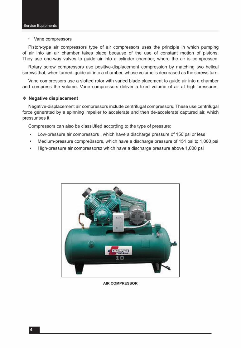
AIR COMPRESSOR
Service Equipments
5
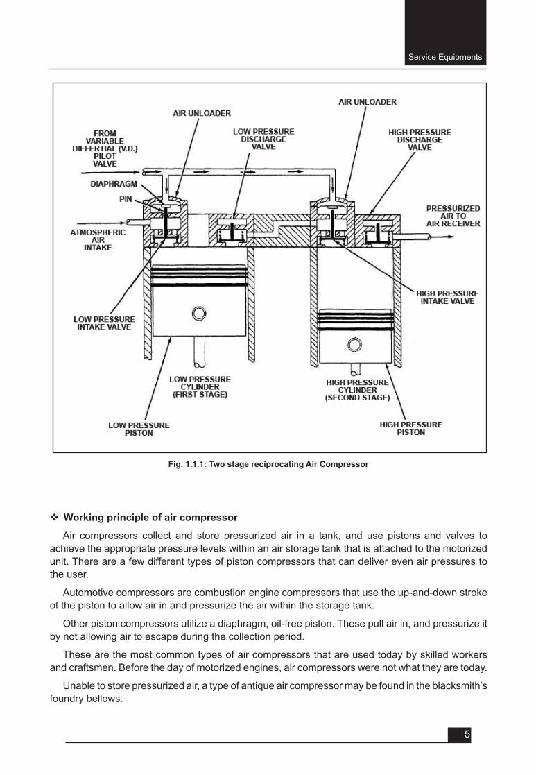
v Working principle of air compressor
Air compressors collect and store pressurized air in a tank, and use pistons and valves to achieve the appropriate pressure levels within an air storage tank that is attached to the motorized unit. There are a few different types of piston compressors that can deliver even air pressures to the user.
Automotive compressors are combustion engine compressors that use the up-and-down stroke of the piston to allow air in and pressurize the air within the storage tank.
Other piston compressors utilize a diaphragm, oil-free piston. These pull air in, and pressurize it by not allowing air to escape during the collection period.
These are the most common types of air compressors that are used today by skilled workers and craftsmen. Before the day of motorized engines, air compressors were not what they are today.
Unable to store pressurized air, a type of antique air compressor may be found in the blacksmith’s foundry bellows.
Fig. 1.1.1: Two stage reciprocating Air Compressor
Service Equipments
6
Now the air compressor is capable of building extreme pressures in storage tanks capable of storing enormous amounts of pressurized gases for industrial use.
v Applications of air compressor
• Portable air compressor for powering tools, such as jack-hammers• Tosupplyhigh-pressurecleanairtofillgascylinders• To supply moderate-pressure clean air to a submerged surface supplied diver• Tosupplymoderate-pressurecleanairfordriving.Someofficeandschool
building pneumatic HVAC control system valves• To supply a large amount of moderate-pressure air to power pneumatic tools ,
such as jack-hammers• Forfillingtyres• To produce large volumes of moderate-pressure air for large-scale industrial
processes (such as oxidation for petroleum coking or cement plant bag house purge systems).
Most air compressors either are reciprocating piston type, rotary vane or rotary screw type. Centrifugal compressors are common in very large applications.
The power of a compressor is measured in HP (Horsepower) and CFM (cubic feet of air per minute).
The gallon size of the tank tells you how much compressed air “in reserve” is available. Gas/diesel powered compressors are widely used in remote areas with problematic access to electricity. They are noisy and require ventilation for exhaust gases.
Common workshop/ garage compressors are 110-120 Volt or 230-240 Volt. Compressor tank shapes are: “pancake”, “twin tank”, “horizontal”, and “vertical”. Depending on a size and purpose compressors can be stationary or portable.
1.1.2: Hoist
A hoist is a device used for lifting or lowering load by means of drum or lift wheel around which rope or chain wraps. It may be manually operated, electrically operated and pneumatically driven andmayusechain,fiberorwireropeasitsliftingmedium.Theloadisattachedtothehoistbymeans of lifting hook.
Hoistscanbeclassifiedaccordingtotheoperatingsystemas:
• Hydraulic hoist,
• Pneumatic hoist,
• Mechanical hoist, and
• Electric hoist
v Hydraulic hoist
It uses high pressurized oil as operating medium to lift the vehicles so that tasks of washing, lubricating, maintenance and repair can be performed on the vehicles. Hydraulic hoist can be furtherclassifiedas:
Service Equipments
7
• Single post hydraulic hoist, and
• Two post hydraulic hoist
Working principle of hydraulic hoistHydraulicsystemsuseanincompressiblefluid,suchasoilorwater,totransmitforcesfromone
locationtoanotherwithinthefluid.Whenthefluidunderpressureisforcedintothecylinder,theramgets a push upwards. The platform carries the load or vehicle moves. v Pneumatic hoist
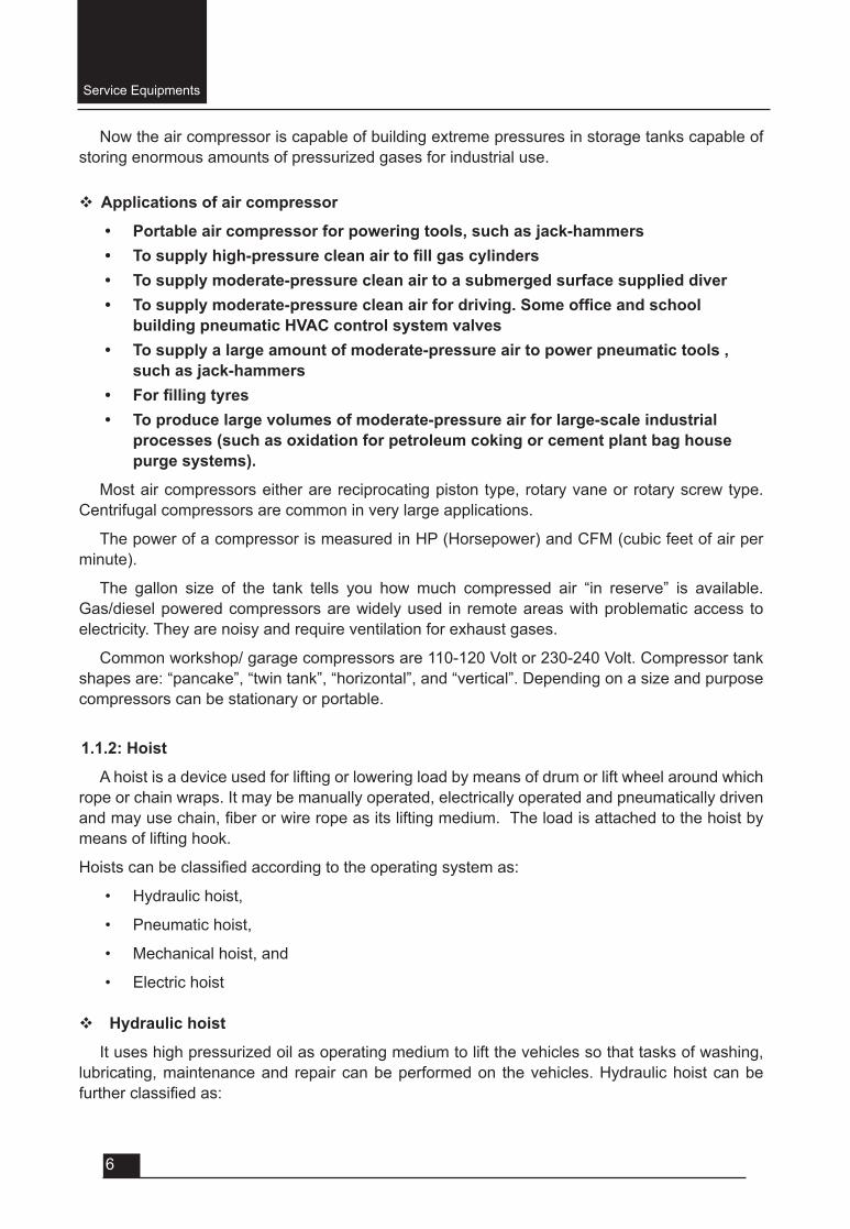
Pneumaticsystemsusecompressiblefluid,suchasair, in theiroperation. Itoperatedbyairpressure. A compressor is used to supply the pressurised air which further operates an air motor to raise or lower the vehicles. A pressure gauge and air control valve are installed for safe operation.
Fig. 1.1.2: Single post hydraulic hoist
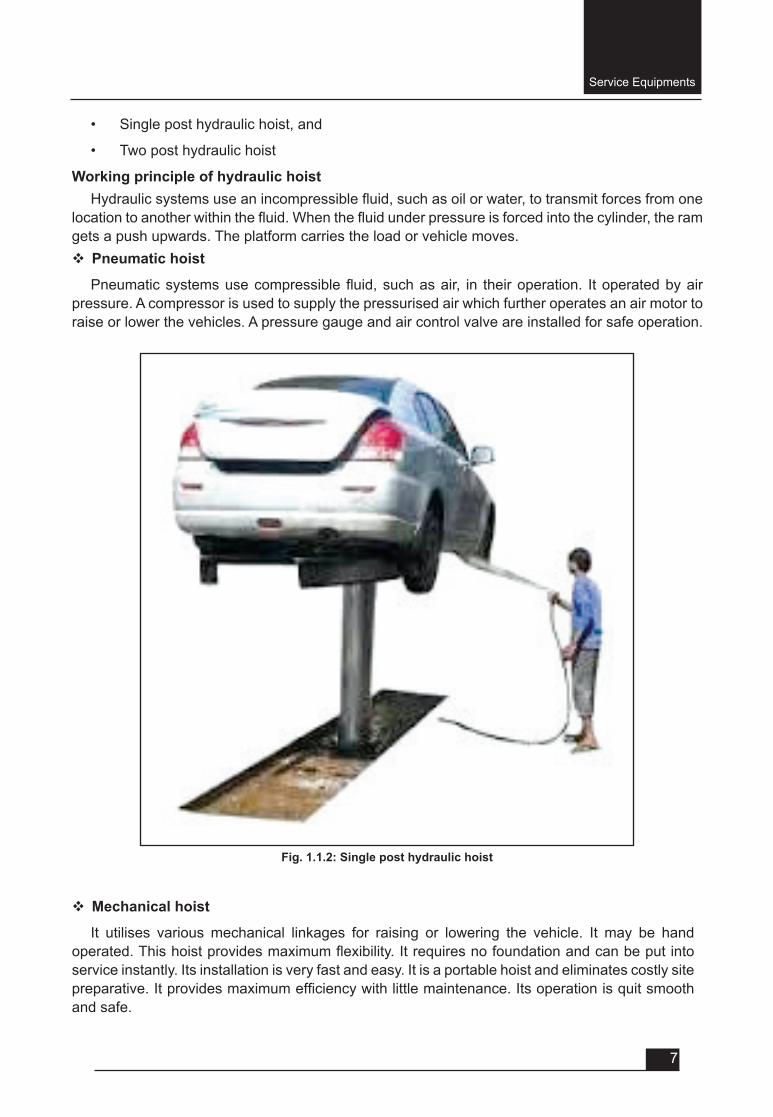
v Mechanical hoist
It utilises various mechanical linkages for raising or lowering the vehicle. It may be hand operated.Thishoistprovidesmaximumflexibility.Itrequiresnofoundationandcanbeputintoservice instantly. Its installation is very fast and easy. It is a portable hoist and eliminates costly site preparative.Itprovidesmaximumefficiencywithlittlemaintenance.Itsoperationisquitsmoothand safe.
Service Equipments
8
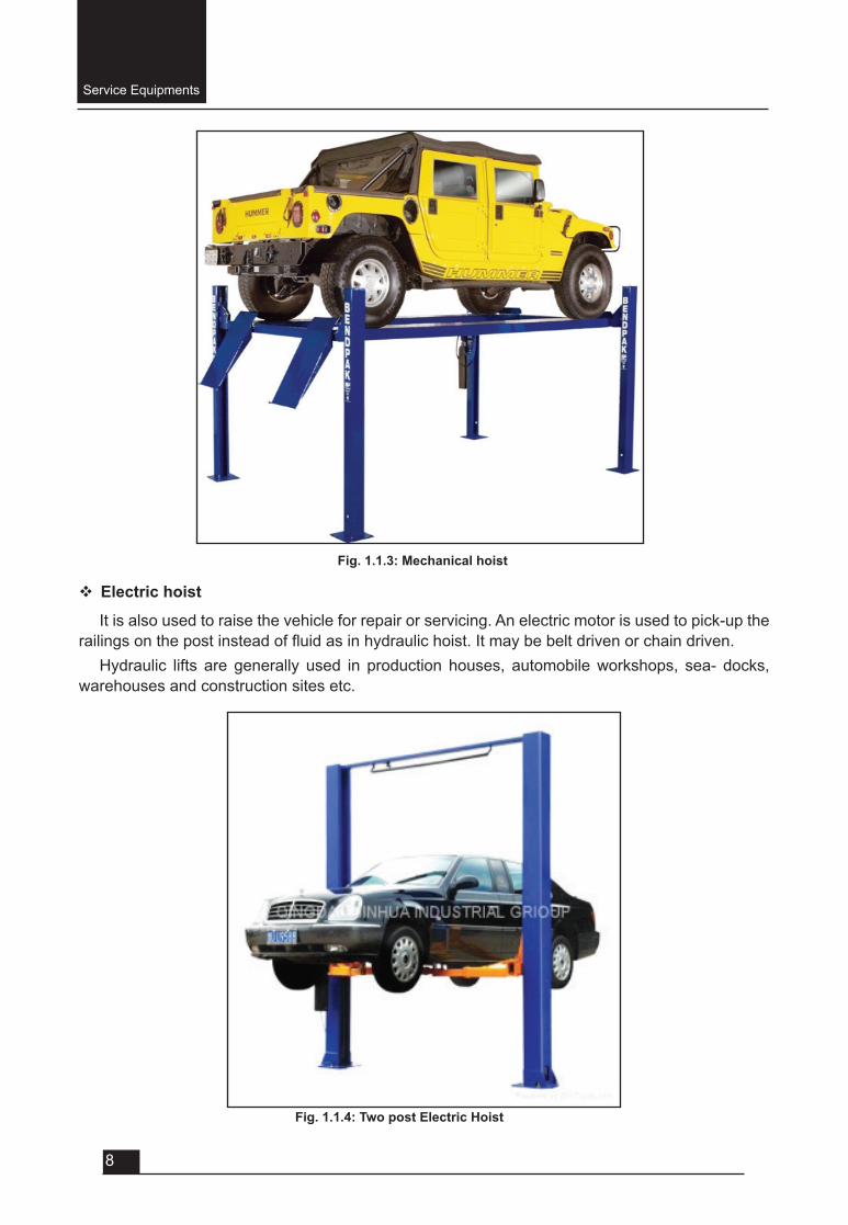
v Electric hoist
It is also used to raise the vehicle for repair or servicing. An electric motor is used to pick-up the railingsonthepostinsteadoffluidasinhydraulichoist.Itmaybebeltdrivenorchaindriven.
Hydraulic lifts are generally used in production houses, automobile workshops, sea- docks, warehouses and construction sites etc.
Fig. 1.1.3: Mechanical hoist
Fig. 1.1.4: Two post Electric Hoist
Service Equipments
9
• At required height, it can be made to stay in level for various services, inspection and repair jobs.
Only trained should be allowed to operate a hydraulic lift, and position vehicles while operating the equipment. The required hydraulic pressure should always be maintained, and should never be allowed to go beyond the recommended levels. The lift area should be kept clean of dirt, oil, tools, grit, etc. Also, the hydraulic lifts should not be overloaded.
1.1.3: Car washer
Car washer is a most commonly used equipment in a garage. It supplies the water under high pressurethroughaflexiblepipeandnozzle.
A commonly used car washer has following main parts:• Electric motor • Reciprocating water pump• Water tank• Spray nozzle• Flexible water pipe• Control valve• Safety valve• V-belt and pulley• Pressure gauge
Carwasherscanbeclassifiedas:
• Manual car washers, and
• Automatic car washers (which are generally computerised and costlier)
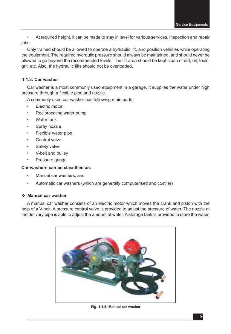
v Manual car washer
A manual car washer consists of an electric motor which moves the crank and piston with the help of a V-belt. A pressure control valve is provided to adjust the pressure of water. The nozzle at the delivery pipe is able to adjust the amount of water. A storage tank is provided to store the water.
Fig. 1.1.5: Manual car washer

Service Equipments
10
v Automatic car washer
Thefirstautomaticcarwashesappearedinthe late1930s.Automaticcarwashesconsistoftunnel-like buildings into which customers (or attendants) drive. In this, car is parked on the platform and is manually pre-washed by jet spraying at high pressure and under chassis wash. Further ph neutral shampoo is spread in form of foam, structure moves on rails along with rotating brush which cleans the car from top as well as from sides. Drying is done manually with cloth. Water used is directly dumped into sewage or water recycling plant.v Applications of car washer
Car washers are used for cleaning the cars and other vehicles. The washing is carried out to remove mud, dust, dirt, grease, wax, oil, fat and other sticky chemicals from the cars.
High pressure pre-wash
Brushing
Foam Wash
Rinsing
Drying
Fig. 1.1.6: Different stages of automatic car washing system
Service Equipments
11
1.1.4: Oil dispenser
It is lubricating equipment used in automotive garages. It contains lubricating oil and spray the oilthroughnozzlestotherequiredspace.Oildispenserscanbeclassifiedas:
• Manual oil dispenser
• Pneumatic oil dispenser
Manual oil dispensers are equipment which requires human effort to operate them and these dispenserscanfurtherbeclassifiedas:
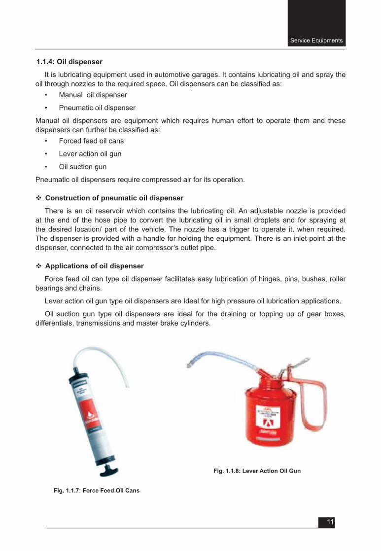
• Forced feed oil cans
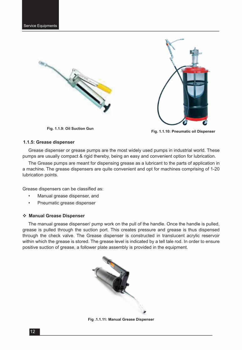
• Lever action oil gun
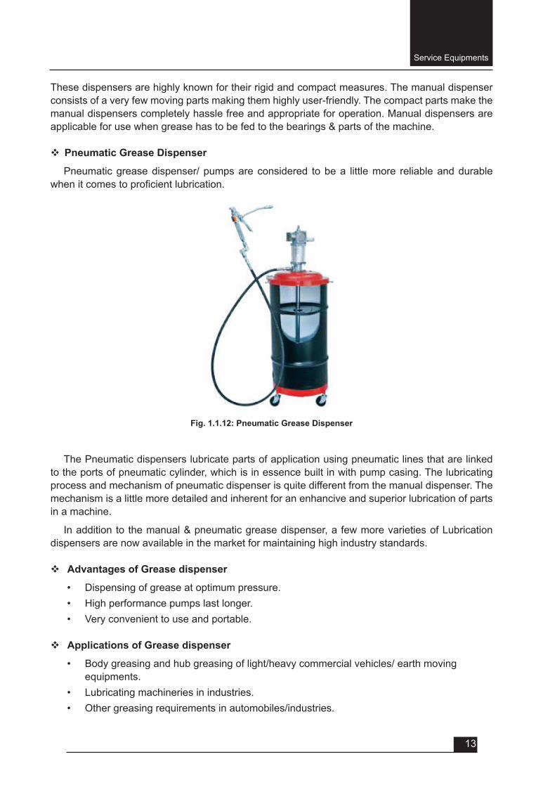
• Oil suction gun
Pneumatic oil dispensers require compressed air for its operation.
v Construction of pneumatic oil dispenser
There is an oil reservoir which contains the lubricating oil. An adjustable nozzle is provided at the end of the hose pipe to convert the lubricating oil in small droplets and for spraying at the desired location/ part of the vehicle. The nozzle has a trigger to operate it, when required. The dispenser is provided with a handle for holding the equipment. There is an inlet point at the dispenser, connected to the air compressor’s outlet pipe.
v Applications of oil dispenser
Force feed oil can type oil dispenser facilitates easy lubrication of hinges, pins, bushes, roller bearings and chains.
Lever action oil gun type oil dispensers are Ideal for high pressure oil lubrication applications.
Oil suction gun type oil dispensers are ideal for the draining or topping up of gear boxes, differentials, transmissions and master brake cylinders.
Fig. 1.1.7: Force Feed Oil Cans
Fig. 1.1.8: Lever Action Oil Gun
Service Equipments
12
1.1.5: Grease dispenser
Grease dispenser or grease pumps are the most widely used pumps in industrial world. These pumps are usually compact & rigid thereby, being an easy and convenient option for lubrication.
The Grease pumps are meant for dispensing grease as a lubricant to the parts of application in a machine. The grease dispensers are quite convenient and opt for machines comprising of 1-20 lubrication points.
Greasedispenserscanbeclassifiedas:• Manual grease dispenser, and• Pneumatic grease dispenser
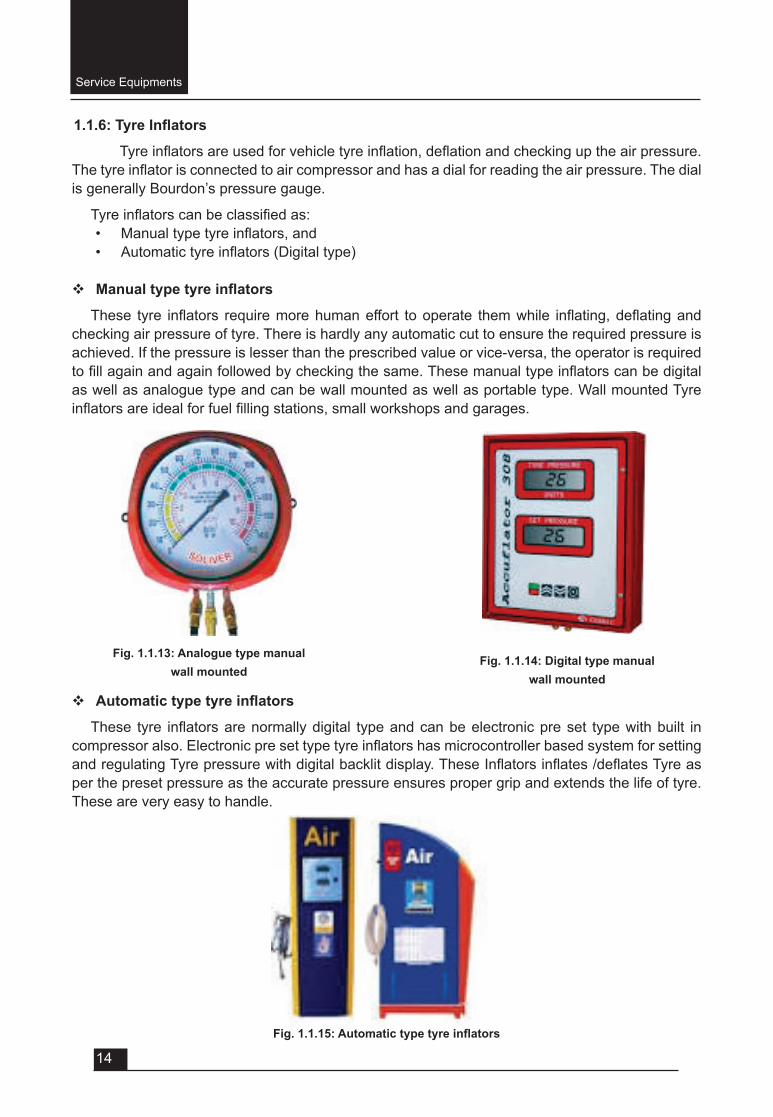
v Manual Grease Dispenser
The manual grease dispenser/ pump work on the pull of the handle. Once the handle is pulled, grease is pulled through the suction port. This creates pressure and grease is thus dispensed through the check valve. The Grease dispenser is constructed in translucent acrylic reservoir within which the grease is stored. The grease level is indicated by a tell tale rod. In order to ensure positive suction of grease, a follower plate assembly is provided in the equipment.
Fig .1.1.11: Manual Grease Dispenser
Fig. 1.1.9: Oil Suction GunFig. 1.1.10: Pneumatic oil Dispenser
Service Equipments
13
These dispensers are highly known for their rigid and compact measures. The manual dispenser consists of a very few moving parts making them highly user-friendly. The compact parts make the manual dispensers completely hassle free and appropriate for operation. Manual dispensers are applicable for use when grease has to be fed to the bearings & parts of the machine.
v Pneumatic Grease Dispenser
Pneumatic grease dispenser/ pumps are considered to be a little more reliable and durable whenitcomestoproficientlubrication.
Fig. 1.1.12: Pneumatic Grease Dispenser
The Pneumatic dispensers lubricate parts of application using pneumatic lines that are linked to the ports of pneumatic cylinder, which is in essence built in with pump casing. The lubricating process and mechanism of pneumatic dispenser is quite different from the manual dispenser. The mechanism is a little more detailed and inherent for an enhancive and superior lubrication of parts in a machine.
In addition to the manual & pneumatic grease dispenser, a few more varieties of Lubrication dispensers are now available in the market for maintaining high industry standards.
v Advantages of Grease dispenser
• Dispensing of grease at optimum pressure.• High performance pumps last longer.• Very convenient to use and portable.
v Applications of Grease dispenser
• Body greasing and hub greasing of light/heavy commercial vehicles/ earth moving equipments.
• Lubricating machineries in industries.• Other greasing requirements in automobiles/industries.
Service Equipments
14
1.1.6:TyreInflators
Tyreinflatorsareusedforvehicletyreinflation,deflationandcheckinguptheairpressure.Thetyreinflatorisconnectedtoaircompressorandhasadialforreadingtheairpressure.Thedialis generally Bourdon’s pressure gauge.
Tyreinflatorscanbeclassifiedas:• Manualtypetyreinflators,and• Automatictyreinflators(Digitaltype)
v Manualtypetyreinflators
These tyre inflators requiremorehumaneffort tooperate themwhile inflating,deflatingandchecking air pressure of tyre. There is hardly any automatic cut to ensure the required pressure is achieved. If the pressure is lesser than the prescribed value or vice-versa, the operator is required tofillagainandagainfollowedbycheckingthesame.Thesemanualtypeinflatorscanbedigitalas well as analogue type and can be wall mounted as well as portable type. Wall mounted Tyre inflatorsareidealforfuelfillingstations,smallworkshopsandgarages.
Fig. 1.1.13: Analogue type manual wall mounted
Fig. 1.1.14: Digital type manual wall mounted
v Automatictypetyreinflators
These tyre inflatorsarenormallydigital typeandcanbeelectronicpreset typewithbuilt incompressoralso.ElectronicpresettypetyreinflatorshasmicrocontrollerbasedsystemforsettingandregulatingTyrepressurewithdigitalbacklitdisplay.TheseInflatorsinflates/deflatesTyreasper the preset pressure as the accurate pressure ensures proper grip and extends the life of tyre. These are very easy to handle.
Fig.1.1.15:Automatictypetyreinflators
Service Equipments
15
v Applicationsoftyreinflators
• Tyreinflatorsareusedforinflate/deflateairpressureintyres.• Tyreinflatorsareusedforcheckingairpressureintyres.• Tyreinflatorsareusedinfuelretailoutlets,servicestations,garagesandtyreshops.
1.1.7: Spark plug cleaner and tester
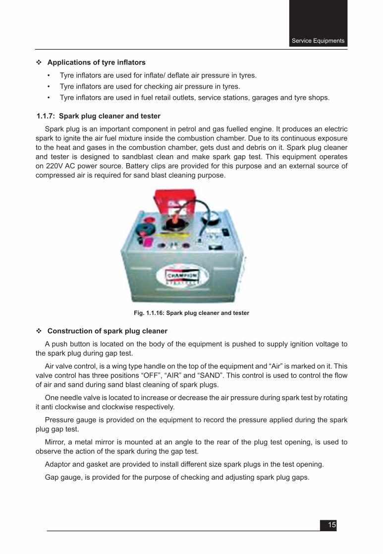
Spark plug is an important component in petrol and gas fuelled engine. It produces an electric spark to ignite the air fuel mixture inside the combustion chamber. Due to its continuous exposure to the heat and gases in the combustion chamber, gets dust and debris on it. Spark plug cleaner and tester is designed to sandblast clean and make spark gap test. This equipment operates on 220V AC power source. Battery clips are provided for this purpose and an external source of compressed air is required for sand blast cleaning purpose.
Fig. 1.1.16: Spark plug cleaner and tester
v Construction of spark plug cleaner
A push button is located on the body of the equipment is pushed to supply ignition voltage to the spark plug during gap test.
Air valve control, is a wing type handle on the top of the equipment and “Air” is marked on it. This valvecontrolhasthreepositions“OFF”,“AIR”and“SAND”.Thiscontrolisusedtocontroltheflowof air and sand during sand blast cleaning of spark plugs.
One needle valve is located to increase or decrease the air pressure during spark test by rotating it anti clockwise and clockwise respectively.
Pressure gauge is provided on the equipment to record the pressure applied during the spark plug gap test.
Mirror, a metal mirror is mounted at an angle to the rear of the plug test opening, is used to observe the action of the spark during the gap test.
Adaptor and gasket are provided to install different size spark plugs in the test opening.
Gap gauge, is provided for the purpose of checking and adjusting spark plug gaps.
Service Equipments
16
v Working of spark plug cleaner
Connect the air line from 125-150 psi air supply to the rear of the air control valve. Ground the equipment properly otherwise the spark gap test won’t be up to the mark.
• Sandblast cleaning: clean the spark plug of any excess oil or water and insert in the opening. With the left hand, turn air control valve to “sand” position. Oscillate outer end of the plug with a circular motion, so that cleaner blast can penetrate all crevices, for about 5 seconds. Without removing plug from the opening, turn valve to “Air” position and again oscillate plug for a few seconds to clean out all particles of loosened carbon. Return the air valve to “off” position and remove the cleaned plug. Shake out any particle of abrasive remaining between plug porcelain and shell.
• Gap testing: Adjust gap of the old plug and screw old plug in the openings. Clip high tension lead to the plug to be observed. Regulate air pressure to correct amount for plug being tested. Press the test button, gradually opening needle valve until the pressure has been around 20psi above normal. While pressure is being increased, observe action of thesparkinthemirrortoseeifthesparkremainsbrightandsteady,withoutflickeringormissing.
1.1.8: Wheel Balancing
Tyre/wheel assembly balancing is a very basic service. Modern automobiles are highly tuned vehicles. Their performance, driver comfort, fuel economy and tyre life all can be negatively affected by even the slightest imbalance. Current wheel balancing machines are much easier to use than earlier machines. Latest wheel balancing machines are equipped with many automatic and computer-generated features designed to give excellent balance. There are three basic times when balancing should be done:
• When a tire is replaced or repaired,• When a balance weight is moved or falls off,• When new tires are purchased.
v Advantages of wheel balancing
• Wheel balancing can eliminate vibration and wobbling.• Wheel balancing will improve tyre wear.• Wheel balancing will increase fuel mileage.• Wheel balancing will remove stress from a vehicle.
v Type of wheel balancing
• Static balancing and • Dynamic balance.
Service Equipments
17
• Static Balancing
Tyre manufacturers’ measure static balance by the use of a sensor mounted to the spindle assembly.
• Dynamic Balancing
Dynamic balance of a tyre/ wheel is checked and measured by mounting a tyre on a test wheel, accelerating the assembly to 300 rpm or higher and then measuring the forces of imbalance as the tyre rotates. Now a day’s computerised wheel balancing machines are commonly used in automobile garages and tyre shops. Dynamic balancers not only determine the location of any imbalance, but also point out the exact amount of counter weight that must be added to correct the imbalance.
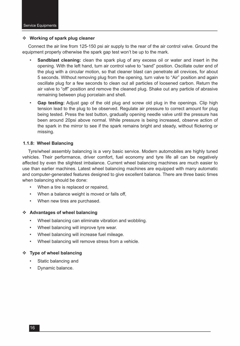
Fig. 1.1.17: Computerised Wheel Balancing Machine
Fig. 1.1.18: Clip-on lead weight (Standard)
Fig. 1.1.19: Stick-on weight (for alloy rims)
Service Equipments
18
v Procedure of wheel balancing/ Working of Wheel Balancing machine
• Turn on the balancer.• Cleanthetyre,rimflangeandwheel.• Mount the tyre/wheel assembly on a balancer.• Enter the wheel dimensions.• Enter width wheel dimensions.• Lower the hood to spin the wheel and check dimensions.• Raise the hood after the tyre stops rotating.• Note when the inboard centre bar blinks.• Attach inboard corrective weight.• Press NEXT, which rotates the wheel.• Note when the outboard centre bar blinks.• Attach outboard corrective weights.• Lower the hood to re-spin and check balance.
1.1.9: BrakeEfficiencyTester
The function of the vehicle brakes is • to control the speed of the vehicle on hills, • to reduce the speed when required and • to stop the vehicle altogether and hold it stationary.
There are some factors which affect the brake functions like
• road surface condition- not under the control of the driver; • tyre condition and • gross vehicle weight, are not directly related to the design and condition of
the brakes although they are the responsibility of the driver.
Theabilityofthebrakestoperformtheirfunctionispopularlyknownasbrakingefficiencyandinmostcountries,isessentialthatallroadvehicleshaveanefficientbrakingsystem.
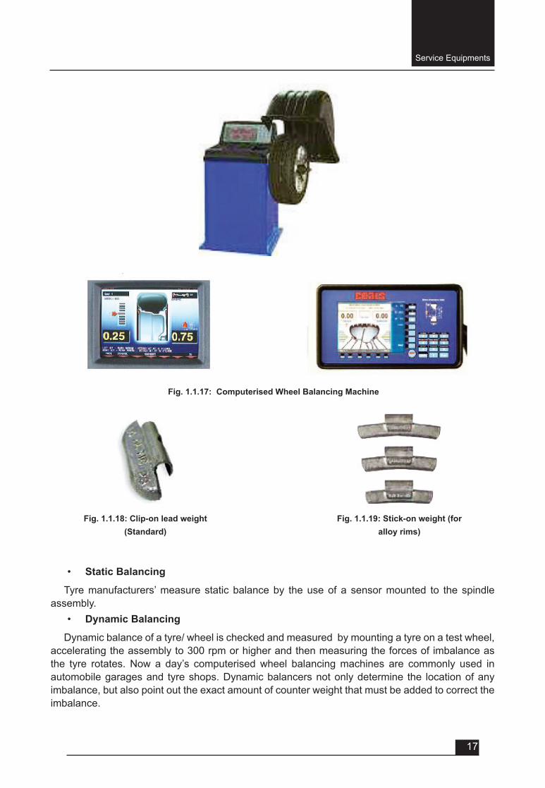
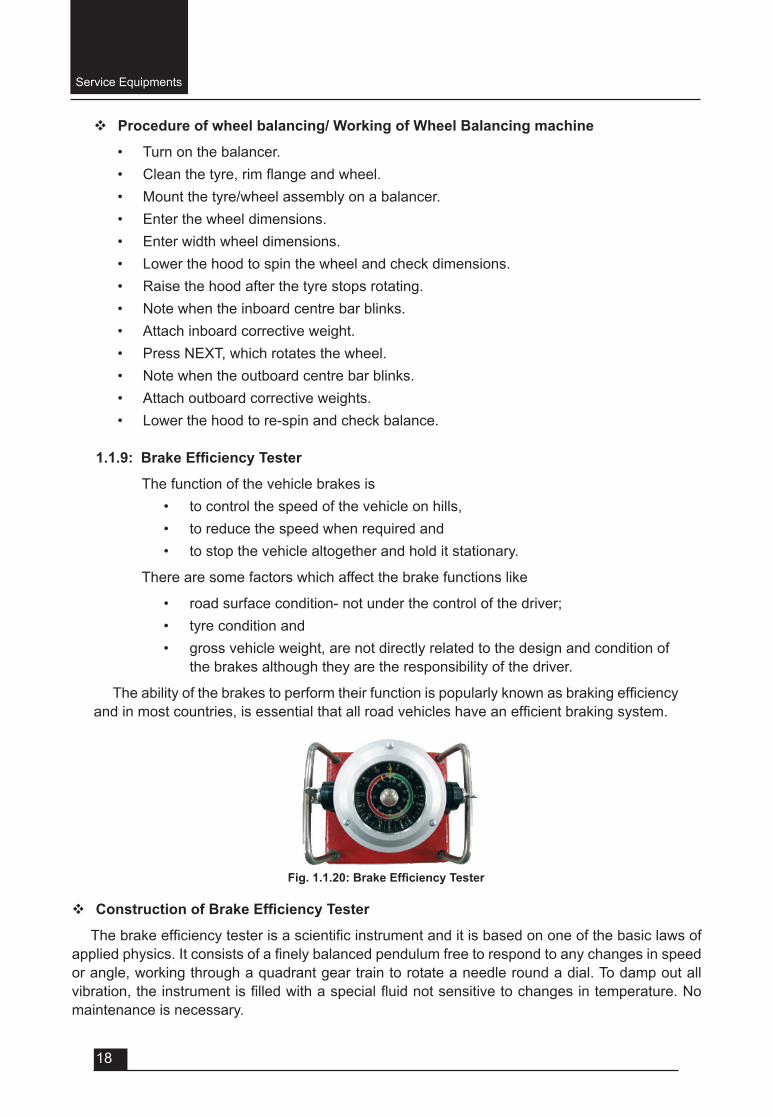
Fig.1.1.20:BrakeEfficiencyTester
v ConstructionofBrakeEfficiencyTester
Thebrakeefficiencytesterisascientificinstrumentanditisbasedononeofthebasiclawsofappliedphysics.Itconsistsofafinelybalancedpendulumfreetorespondtoanychangesinspeedor angle, working through a quadrant gear train to rotate a needle round a dial. To damp out all vibration,theinstrumentisfilledwithaspecialfluidnotsensitivetochangesintemperature.Nomaintenance is necessary.
v WorkingofBrakeEfficiencyTester
Tosettheinstrumentforabraketest,startbylooseningthetwobutterflynutsatthesidesof the swivel-mounting bracket. Tilt the head until the main needle (with arrow) is set at 3.5 if the unit is in meters or 13.4 if in feet with the face of the instrument just back from the vertical. This is important because it can be set with the face nearly horizontal, but it would then be near the end stop and would not move anticlockwise. When set in this manner the butterflynutscanbetightenedagain,andtheinstrumentisreadytostartthetest.
With the main needle set, the recording needle (without arrow) should be turned clockwise by means of the chrome knob in the middle of the dial until it is against the left hand side of the main needle. The vehicle is then driven along a level road at about 30 km/h, and the brakes fully applied by means of the foot brake pedal only. When the vehicle has stopped thebrakeefficiencyreadingcanbetakenfromthedigitshownbytherecordingneedleonthe inner brake scale. Stopping distance readings are taken from the outer scale digits. A similar reading should now be taken from a lower speed using the handbrake only.
Onagoodsurfacerearwheel lockingmight limitthebrakingefficiencytoabout85%,whileonabadsurface,frontwheellockingmightlimittheefficiencyto15%.
v ApplicationsofBrakeEfficiencyTester
The same tester can be used to test all types of vehicles, from heavy trucks and buses to vans and passenger cars. It needs no electrical connections and it is portable.
Disclaimer:
Operating any of the above mentioned garage equipment is a serious business. This information is not meant as a substitute for proper training by respective manufacturers. The recommendations made here are consistent with practises used in the industry. These articles are meant purely for educational purposes. Those who use method recommended are solely responsible for any injuries or losses resulting from their application. Authors and Publisher may not be held responsible.
QUESTIONSVery Short Answer Type (each question carries 1 mark).
1. An air compressor can be driven by______ a. using electric motor.b. using diesel engine. c. using gasoline/ petrol engine.d. all of above.
2. The nozzle at the delivery pipe is able to adjust the ________ of water, in a car washer. 3. A _______is a device used for lifting or lowering load by means of drum or lift wheel around
which rope or chain wraps.4. Hydraulic hoist use an incompressible _____, to transmit forces from one location to another
withinthefluid.5. _________ grease dispenser is considered to be more reliable and durable when it comes
to expert lubrication.6. Tyreinflationgaugescanbeof________
a. analog type.
b. digital type.c. either a or b.d. neither a nor b.
7. Spark plug cleaner and tester is used for ________.a. sandblast cleaning.b. gap testing.c. both a and b.d. none of the above.
8. Proper wheel balancing can ______.a. eliminate vibration and wobbling.b. improve tyre wear.c. increase fuel mileage .d. all of above.
9. Which of the following affect the brake functions_______.a. road surface condition.b. tyre condition.c. gross vehicle weight.d. all of above.
Short Answer Type (each question carries 2 marks).1. Defineaircompressor.Givebroadclassificationofcompressors.2. Definehoist.Howwecanclassifyhoists?3. Whatarethefunctionsofavehiclebrakesystem?4. Name some factors which affect the proper functioning of braking system of a vehicle.
Short Answer Type (each question carries 3 marks).1. Whatarethemainadvantagesofbalancingofwheelsinacar?2. Whyitisessentialtocleanasparkplugafterregularinterval?3. Whatareadvantagesofmaintainingcorrecttyrepressureinavehicle?4. Brieflydescribedifferentstagesofautomaticcarwashingsystem.5. Write different safety precautions to be observed while operating a hoist.
Long Answer Type Questions (each carry 5 marks).1. Definedynamicbalancing.Writeproceduretobalanceawheeloncomputerizedwheelbalancing
machine.2. Whyitisessentialtocleanasparkplugafterregularinterval?Explain.3. Howwecanclassifytyreinflators.Writeadvantages&disadvantagesofautomatictyreinflators
overmanualtyreinflators.4. How we can classify oil dispensers used in an automobile workshop. Name different types of
manual oil dispensers and their uses.5. With a neat sketch explain the construction and working of an air compressor. 6. With a neat sketch explain the construction and working of a hydraulic hoist.7. With a neat sketch explain the construction and working of pneumatic grease dispenser.8. Withaneatsketchexplaintheconstructionandworkingofbrakeefficiencytester.9. With a neat sketch explain the construction and working of spark plug cleaner and tester.

UNIT – 1
SESSION – 2
MAINTENANCE SCHEDULE OF AUTOMOBILE
Maintenance Schedule of Automobile
22
1.2.1: Maintenance
Maintenance is work that is carried out to preserve an asset (which can be an automobile, a house or anything including human), in order to enable its continued use and function, above a minimum acceptable level of performance, over its design service life, without unforeseen renewal or major repair activities.
v Reasons for Maintenance
Maintenance serves to protect the physical integrity to keep owners’ real investment in a number of ways:
• The assets in good working order minimises disruptions and pre mature failure. • To keep the assets in a state of good repair.• Ensure that the assets achieve their full potential service life.
v Preventive maintenance
It is a daily maintenance (cleaning, inspection, oiling and re-tightening), design to retain the healthy condition of any equipment/ automobile and prevent failure through the prevention of wear andtear.Preventivemaintenancecanbefurtherclassifiedas:
• Periodic maintenance, and • Predictive maintenance.
Just like human life is extended by preventive medicine, the equipment service life can be prolonged by doing preventive maintenance.
• Periodic maintenance
Periodic maintenance is also known as time based maintenance. It consists of time bound inspection, servicing and cleaning of equipment/ automobile and replacing parts to prevent sudden failure and process problems.
• Predictive maintenance
This is a method in which the service life of important part is predicted based on inspection or
Objectives
After attending this session, you should be able to:
v Understand reason for maintenance and different types of maintenance.
v Understand different types of maintenance schedules.
UNIT – 1Session – 2
Maintenance Schedule of Automobile
Maintenance Schedule of Automobile
23
diagnosis, in order to use the parts to the limit of their service life.
Compared to periodic maintenance, predictive maintenance is condition based maintenance. It manages trend values, by measuring and analyzing data about wear and tear and employs a surveillance system, designed to monitor conditions through an on-line system.
• Operative maintenance
It improves equipment and its components so that preventive maintenance can be carried out reliably. Equipment with design weakness must be redesigned to improve reliability or improving maintainability
• Breakdown maintenance
It means that people waits until an equipment fails and repair it. Such a thing could be usedwhentheequipmentfailuredoesnotsignificantlyaffecttheoperationorproductionorgenerateanysignificantlossotherthanrepaircost.
v Scheduled maintenance service
Whilst operating your vehicle:• Note any changes in the sound of the exhaust or any smell of exhaust fumes in the
vehicle. • Check for vibrations in the steering wheel. Notice any increased steering effort or
looseness in the steering wheel, or change in its straight-ahead position.• Notice if your vehicle constantly turns slightly or “pulls” to one side when travelling on
smooth, level road.• When stopping, listen and check for unusual sounds, pulling to one side, increased
brake pedal travel or “hard to-push” brake pedal.• If any slipping or changes in the operation of your transaxle occurs, check the transaxle
fluidlevel.• Check automatic transaxle P (Park) function.• Check parking brake.• Checkforfluidleaksunderyourvehicle(waterdrippingfromtheairconditioningsystem
during or after use is normal).
At least monthly:• Check coolant level in the engine coolant reservoir.• Check the operation of all exterior lights, including the stoplights, turn signals and hazard
warningflashers.• Checktheinflationpressuresofalltyresincludingthespare.
At least twice a year (i.e., every spring and fall):• Check radiator, heater and air conditioning hoses for leaks or damage.• Check windscreen washer spray and wiper operation. Clean wiper blades with clean
clothdampenedwithwasherfluid.• Check headlight alignment.• Checkmuffler,exhaustpipes,shieldsandclamps.
Maintenance Schedule of Automobile
24
• Check the lap/shoulder belts for wear and function.• Check for worn tyres and loose wheel lug nuts.
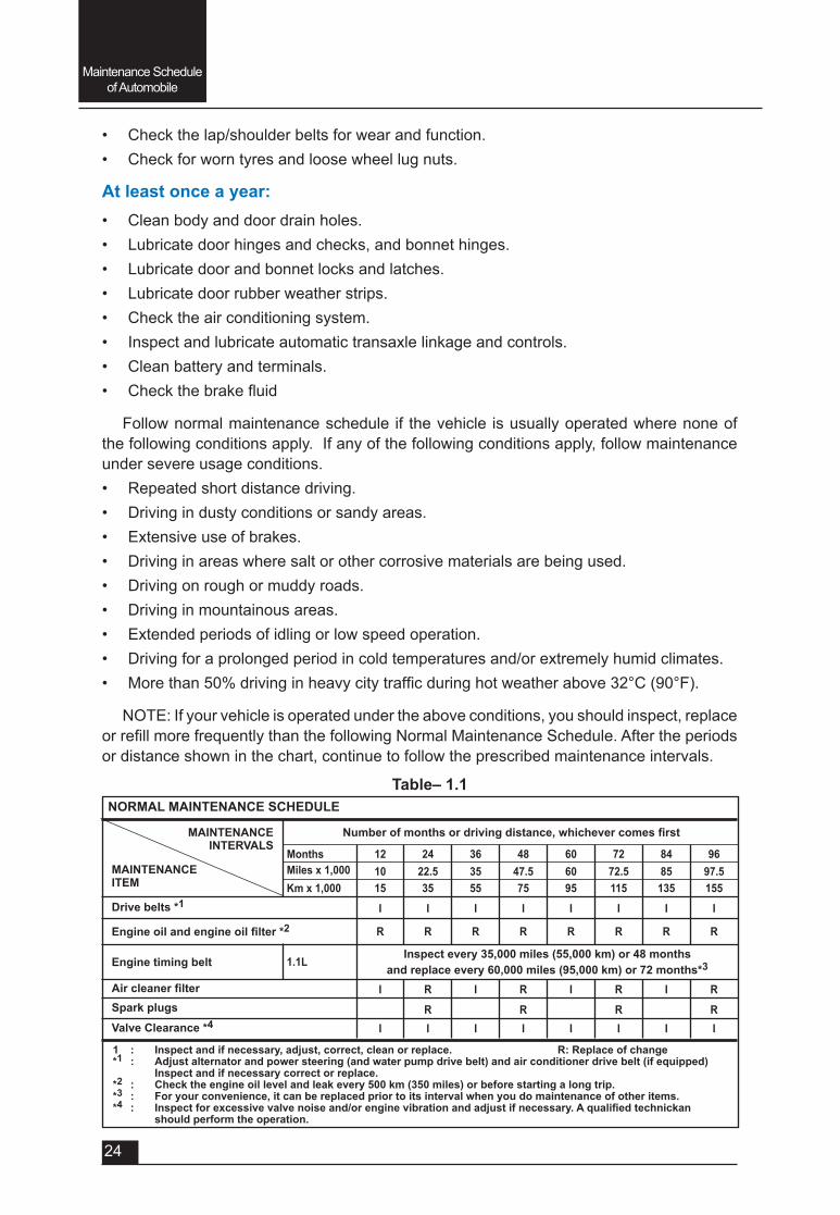
At least once a year:• Clean body and door drain holes.• Lubricate door hinges and checks, and bonnet hinges.• Lubricate door and bonnet locks and latches.• Lubricate door rubber weather strips.• Check the air conditioning system.• Inspect and lubricate automatic transaxle linkage and controls.• Clean battery and terminals.• Checkthebrakefluid
Follow normal maintenance schedule if the vehicle is usually operated where none of the following conditions apply. If any of the following conditions apply, follow maintenance under severe usage conditions.• Repeated short distance driving.• Driving in dusty conditions or sandy areas.• Extensive use of brakes.• Driving in areas where salt or other corrosive materials are being used.• Driving on rough or muddy roads.• Driving in mountainous areas.• Extended periods of idling or low speed operation.• Driving for a prolonged period in cold temperatures and/or extremely humid climates.• Morethan50%drivinginheavycitytrafficduringhotweatherabove32°C(90°F).
NOTE: If your vehicle is operated under the above conditions, you should inspect, replace orrefillmorefrequentlythanthefollowingNormalMaintenanceSchedule.Aftertheperiodsor distance shown in the chart, continue to follow the prescribed maintenance intervals.
Table– 1.1NORMAL MAINTENANCE SCHEDULE
MAINTENANCE INTERVALS
MAINTENANCE ITEM
Drive belts *1
Engineoilandengineoilfilter*2
Engine timing belt
AircleanerfilterSpark plugs
Valve Clearance *4
1 : Inspect and if necessary, adjust, correct, clean or replace. R: Replace of change*1 : Adjust alternator and power steering (and water pump drive belt) and air conditioner drive belt (if equipped)
Inspect and if necessary correct or replace.*2 : Check the engine oil level and leak every 500 km (350 miles) or before starting a long trip.*3 : For your convenience, it can be replaced prior to its interval when you do maintenance of other items.*4 : Inspectforexcessivevalvenoiseand/orenginevibrationandadjustifnecessary.Aqualifiedtechnickan
should perform the operation.
Numberofmonthsordrivingdistance,whichevercomesfirst
Inspect every 35,000 miles (55,000 km) or 48 monthsand replace every 60,000 miles (95,000 km) or 72 months*3
Months 12 24 36 48 60 72 84 9610 22.5 35 47.5 60 72.5 85 97.515
I
I
I
R
35
I
I
R
R
R
55
I
I
I
R
75
I
I
R
R
R
95
I
I
I
R
115
I
I
R
R
R
135
I
I
I
R
155
I
I
R
R
R
Miles x 1,000Km x 1,000
1.1L
Maintenance Schedule of Automobile
25
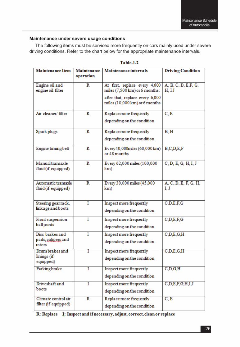
Maintenance under severe usage conditionsThe following items must be serviced more frequently on cars mainly used under severe
driving conditions. Refer to the chart below for the appropriate maintenance intervals.
Maintenance Schedule of Automobile
26
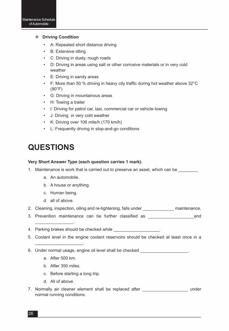
v Driving Condition
• A: Repeated short distance driving• B: Extensive idling• C: Driving in dusty, rough roads• D: Driving in areas using salt or other corrosive materials or in very cold
weather• E: Driving in sandy areas• F:Morethan50%drivinginheavycitytrafficduringhotweatherabove32°C
(90°F)• G: Driving in mountainous areas• H: Towing a trailer• I: Driving for patrol car, taxi, commercial car or vehicle towing• J: Driving in very cold weather• K: Driving over 106 mile/h (170 km/h)• L: Frequently driving in stop-and-go conditions
QUESTIONSVery Short Answer Type (each question carries 1 mark).
1. Maintenance is work that is carried out to preserve an asset, which can be ________
a. An automobile.
b. A house or anything.
c. Human being.
d. all of above.
2. Cleaning, inspection, oiling and re-tightening, falls under _____________ maintenance.
3. Prevention maintenance can be further classified as ___________________and________________.
4. Parking brakes should be checked while ___________________.
5. Coolant level in the engine coolant reservoirs should be checked at least once in a ____________________.
6. Under normal usage, engine oil level shall be checked ____________________.
a. After 500 km.
b. After 350 miles.
c. Before starting a long trip.
d. All of above.
7. Normally air cleaner element shall be replaced after ___________________ under normal running conditions.
Maintenance Schedule of Automobile
27
a. 5000 km.
b. 10000 km.
c. 15000 km.
d. 35000 km.
8. Under normal usage, spark plugs shall be changed ___________________.
a. After 35,000 km.
b. After 24 months.
c. Either a and b whichever is earlier.
d. none of above.
Short Answer Type (each question carries 2 marks).
1. Definemaintenance.
2. Definepreventivemaintenance.
3. Defineperiodicmaintenance.
4. Definebreakdownmaintenance.
5. Definemaintenanceschedule.
Short Answer Type (each question carries 3 marks).
1. Write different reasons for doing any maintenance.
2. Writeanyfivepointstobeobservedbeforeoperatingavehicle.
3. Writeanyfivepointstobeobservedwhileoperatingavehicle.
4. Definesevereusagemaintenanceschedule.
Long Answer Type Questions (each carry 5 marks).
1. Write points to be observed monthly in a vehicle.
2. Write points to be observed at least twice in a year in a vehicle.
3. Write points to be observed at least once in a year in a vehicle.
4. Whyitisessentialtocleanasparkplugafterregularinterval?Explain.
5. Givemaintenanceintervalsforengineoilandfilterunderdifferentusageconditions.
6. Whatareadvantagesofmaintainingpropertyrepressureintyres?Explain.
7. Study maintenance schedule of a vehicle owned by your own family/ relative. Compare with others.
UNIT – 2
SESSION – 1
AUTOMOBILE LUBRICATION
Objectives
After attending this session, you should be able to:
v Understand the necessity of lubrication.
v Explain types of lubricants and their grade (SAE Number).
v Explain the different types of Automobile lubrication system.
v Understand function and working of different components used in lubrication system.
v Understand different trouble shooting and their remedies.
UNIT – 2Session – 1
Automobile Lubrication
2.1.1: Necessity of lubrication system
The main role of the engine oil is to move the any system such as the piston in cylinder and the crankshaft smoothly. In order to achieve the objective:
• Theoilformsanoilfilmatthemetalsurfacetoreducethefrictionbetweenthemetalsurfaces.
• The engine oil doesn’t allow the combusted gas to leak to the crankcase. • It cools the pistons and valves. • It reduces the shock, transmitted from the piston to the crankshaft. • It cleans the engine from inside. • The oil also prevent inside of the engine from being rusted by chemicals from the
combustion.
2.1.2: Engine oil
As we have mentioned, the engine oil works for reducing the wear, cooling the piston and the cylinder head, sealing the gap between the piston and cylinder, releasing the shock, cleaning the engine inside, preventing the knocking and so on.
The required characteristics of the engine oil are as follow:
• Proper viscosity at working condition• Good lubricant performance• High heat and corrosion resistances• Anti-bubble
Mostimportantcharacteristicistheviscosity.Therefore,theengineoilisclassifiedbytwoaspects, the viscosity or the quality.
Automobile Lubrication
30
The commercial oil is sold in packing of 1L, 5L and 20L. At the pack, there are name of manufacturer, brand name and oil name with the viscosity class and the quality class.
Intheviscosityclassification,accordingtothestandardbySAE(SocietyAutomotiveEngineers),the lower viscosity has lower number and higher viscosity has higher number. For cold weather, letter “W”isadded.Forexample,certainclassificationlinethatthenumber30forgeneralpurpose,and the number 20 is for winter, is the single grade using one number system only. Another classification likethatarange isrepresentedsuchas5W-30or10W-30, is themulti grade. in this case, by comparing the 5W-30 with 10w-30, the 5W-30has lower viscosity than 10W-30 at low temperature, but has higher viscosity at the high temperature.
Generally, when the temperature is increased, the viscosity of oil will be decreased. To indicate how the viscosity is changed, the viscosity index is used. If the viscosity is not easily changed, then the viscosity index of the oil is high. The higher viscosity index is easier to use.
In the quality classification, the standard by the API (American Petroleum institute) is used. For gasoline engine, the latter “S” followed from other alphabet letters is assigned. For the diesel engine, the letter “C” followed from other alphabet letters is assigned. For example, letters from SD to SG are assigned for the gasoline engine.
The kind of engine oil and replacing and decided by type of engine, driving condition and ambient temperature, so please refer to the manual carefully to select engine oil. The replacing running time is about 10,000 km for SD, and 15,000 km for SE, and SF 15,000 km for gasoline engine roughly. For turbo engine, the engine oil should be replaced at every 5,000 km running time because the driving condition is very tough. The maintenance intervals for each engines are varies, refer the manuals for the each engine.
2.1.3: SAE Number Engine oil viscosity (thickness) plays an important role in fuel economy of an automobile
andcoldweatheroperatingconditions(enginestartandengineoilflow-ability).Lowerviscosityengine oils can provide better fuel economy and cold weather performance, however higher viscosity engine oils are required for satisfactory lubrication in hot weather. Using oils of any other viscosity than those recommended by the manufacturer may damage the engine. When choosing oil, consider the range of temperature, in which the vehicle will be operated in before the next oil change.
The SAE (Society of Automotive Engineers) classifications are internationally acceptedstandardsfordefiningviscosity.Inthetablegivebelowtwoseriesareemployedforthedesignationwith the letter “W”(winter)beingusedtodefinespecificcoldflowproperties.Theviscositygradesincluding “W”arerelatedtomaximumlowtemperatureviscosityandminimumviscosityat100°C;viscositygradeswithout“W”areratedonlyaccordingtoviscosityat100°C.
Table: 2.1 Temperature range for SAE Viscosity Numbers
Temperature range for SAE Viscosity Numbers
Temperature °C -30 -20 -10 0 10 20 30 40 50
°F -10 0 20 40 60 80 100120
Engine Oil 0W-40, 5W-30, 5W-40
Nowadays multi-grade oils are being used. These oils are characterised by a less pronounced proportional relationship between temperature and viscosity. They reduce friction and wear, can be used all year around, and provide rapid lubrication for all engine components in cold starts.
Automobile Lubrication
31
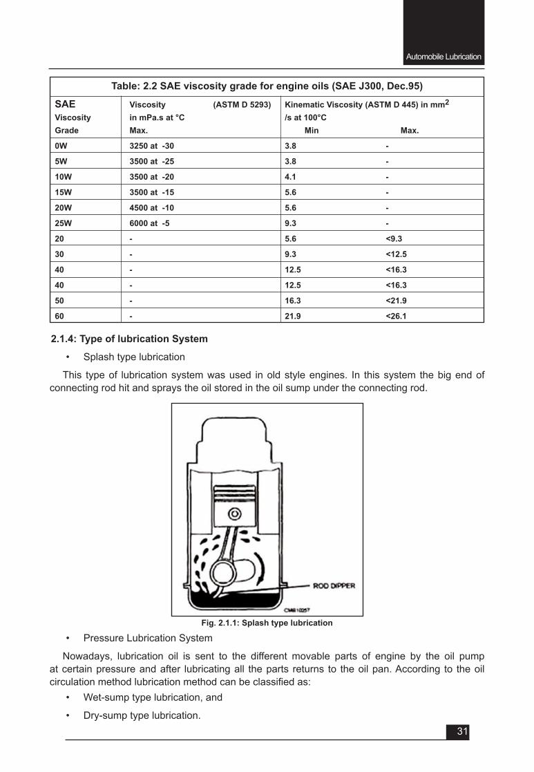
Table: 2.2 SAE viscosity grade for engine oils (SAE J300, Dec.95)
SAE Viscosity (ASTM D 5293) Kinematic Viscosity (ASTM D 445) in mm2
Viscosity in mPa.s at °C /s at 100°CGrade Max. Min Max.
0W 3250 at -30 3.8 -
5W 3500 at -25 3.8 -
10W 3500 at -20 4.1 -
15W 3500 at -15 5.6 -
20W 4500 at -10 5.6 -
25W 6000 at -5 9.3 -
20 - 5.6 <9.3
30 - 9.3 <12.5
40 - 12.5 <16.3
40 - 12.5 <16.3
50 - 16.3 <21.9
60 - 21.9 <26.1
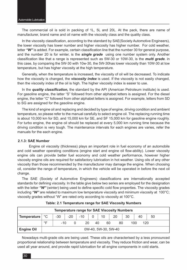
2.1.4: Type of lubrication System
• Splash type lubrication
This type of lubrication system was used in old style engines. In this system the big end of connecting rod hit and sprays the oil stored in the oil sump under the connecting rod.
• Pressure Lubrication System
Nowadays, lubrication oil is sent to the different movable parts of engine by the oil pump at certain pressure and after lubricating all the parts returns to the oil pan. According to the oil circulationmethodlubricationmethodcanbeclassifiedas:
• Wet-sump type lubrication, and
• Dry-sump type lubrication.
Fig. 2.1.1: Splash type lubrication
Automobile Lubrication
32
Fig. 2.1.3: Wet-sump type lubrication
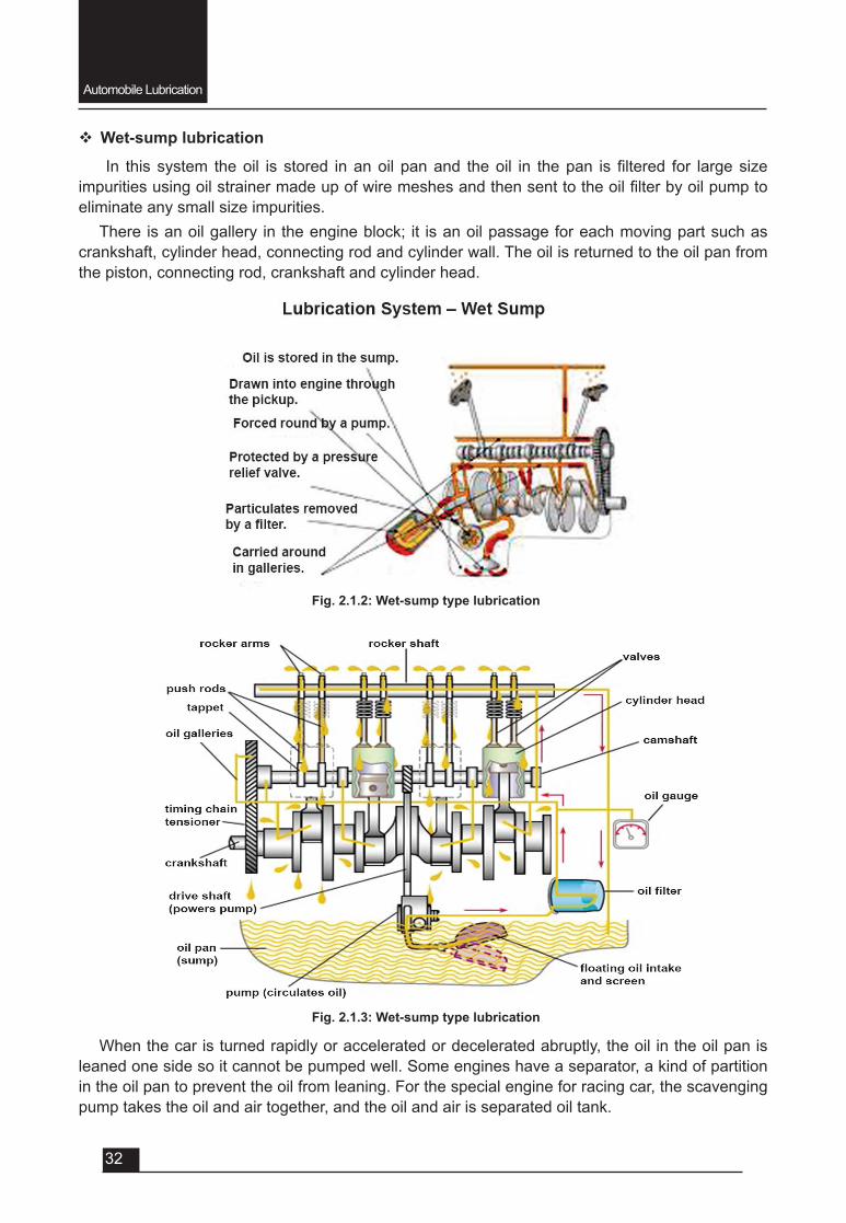
v Wet-sump lubrication
In this system theoil is stored inanoil panand theoil in thepan is filtered for largesizeimpuritiesusingoilstrainermadeupofwiremeshesandthensenttotheoilfilterbyoilpumptoeliminate any small size impurities.
There is an oil gallery in the engine block; it is an oil passage for each moving part such as crankshaft, cylinder head, connecting rod and cylinder wall. The oil is returned to the oil pan from the piston, connecting rod, crankshaft and cylinder head.
Fig. 2.1.2: Wet-sump type lubrication
When the car is turned rapidly or accelerated or decelerated abruptly, the oil in the oil pan is leaned one side so it cannot be pumped well. Some engines have a separator, a kind of partition in the oil pan to prevent the oil from leaning. For the special engine for racing car, the scavenging pump takes the oil and air together, and the oil and air is separated oil tank.
Automobile Lubrication
33
v Dry-Sump Lubrication
As the name indicates, in dry-sump method, the oil is not stored in the pan hence the oil pan can be thinner. So, the lower part of engine is smaller and the engine is designed to have lower weight centre. However, the device should be complexes. It is applied only to the special case for equipping the opposed engine.
2.1.5: Function & working of different components of lubrication system
There are three main components of lubrication system:• Oil pump, • Oilfilterand• Oil cooler for cooling the heated oil.
Oil Pump
There are many types of the oil pump for taking up the oil in the oil pan. But following two types are generally used in automobile.
• Gear type Pump and • Rotor type pump
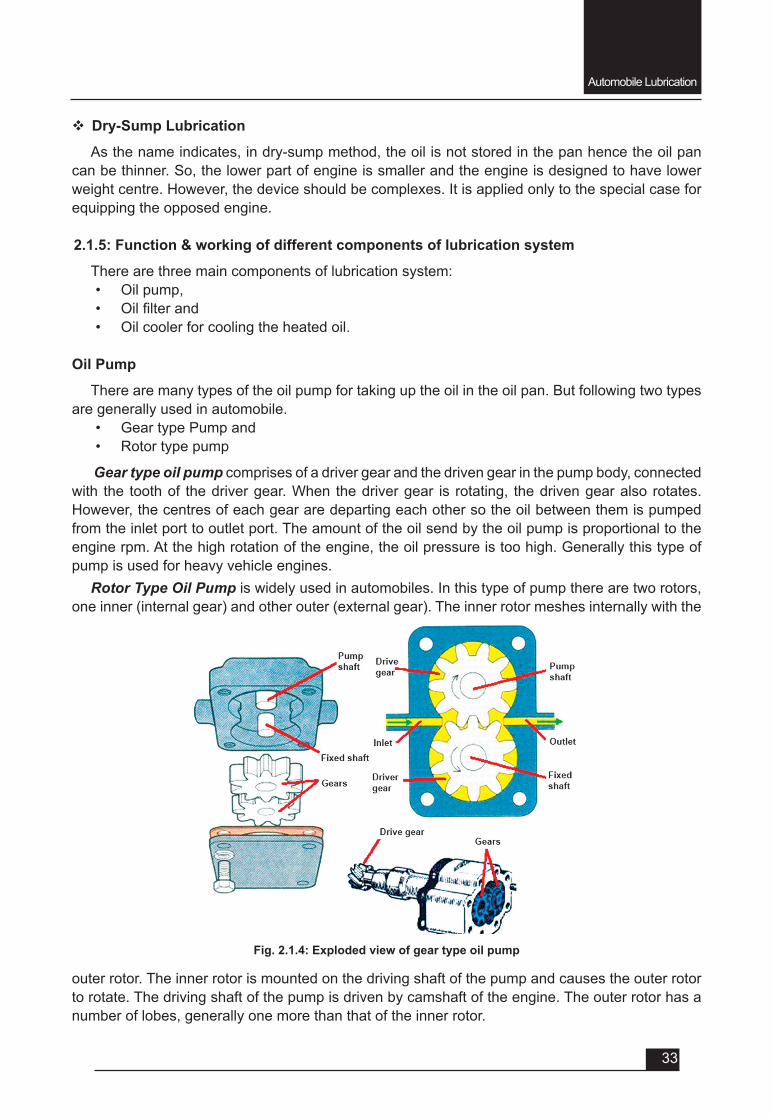
Gear type oil pump comprises of a driver gear and the driven gear in the pump body, connected with the tooth of the driver gear. When the driver gear is rotating, the driven gear also rotates. However, the centres of each gear are departing each other so the oil between them is pumped from the inlet port to outlet port. The amount of the oil send by the oil pump is proportional to the engine rpm. At the high rotation of the engine, the oil pressure is too high. Generally this type of pump is used for heavy vehicle engines.
Rotor Type Oil Pump is widely used in automobiles. In this type of pump there are two rotors, one inner (internal gear) and other outer (external gear). The inner rotor meshes internally with the
Fig. 2.1.4: Exploded view of gear type oil pump
outer rotor. The inner rotor is mounted on the driving shaft of the pump and causes the outer rotor to rotate. The driving shaft of the pump is driven by camshaft of the engine. The outer rotor has a number of lobes, generally one more than that of the inner rotor.
Automobile Lubrication
34
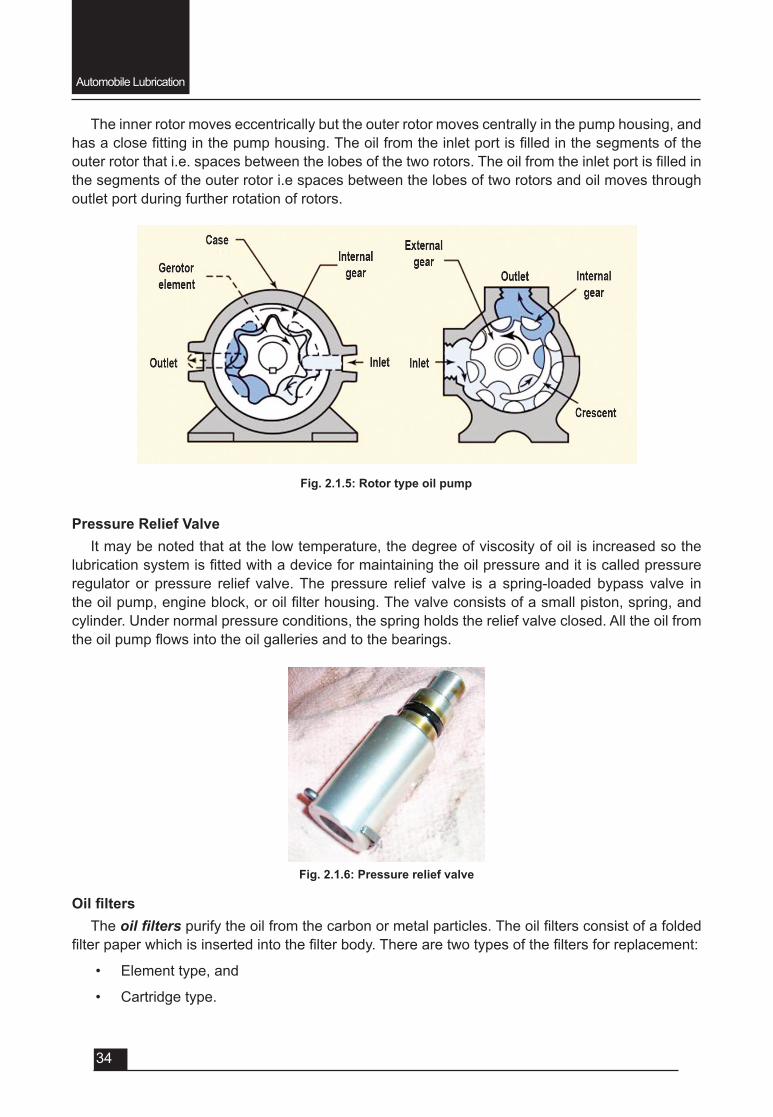
The inner rotor moves eccentrically but the outer rotor moves centrally in the pump housing, and hasaclosefittinginthepumphousing.Theoilfromtheinletportisfilledinthesegmentsoftheouterrotorthati.e.spacesbetweenthelobesofthetworotors.Theoilfromtheinletportisfilledinthe segments of the outer rotor i.e spaces between the lobes of two rotors and oil moves through outlet port during further rotation of rotors.
Fig. 2.1.6: Pressure relief valve
Fig. 2.1.5: Rotor type oil pump
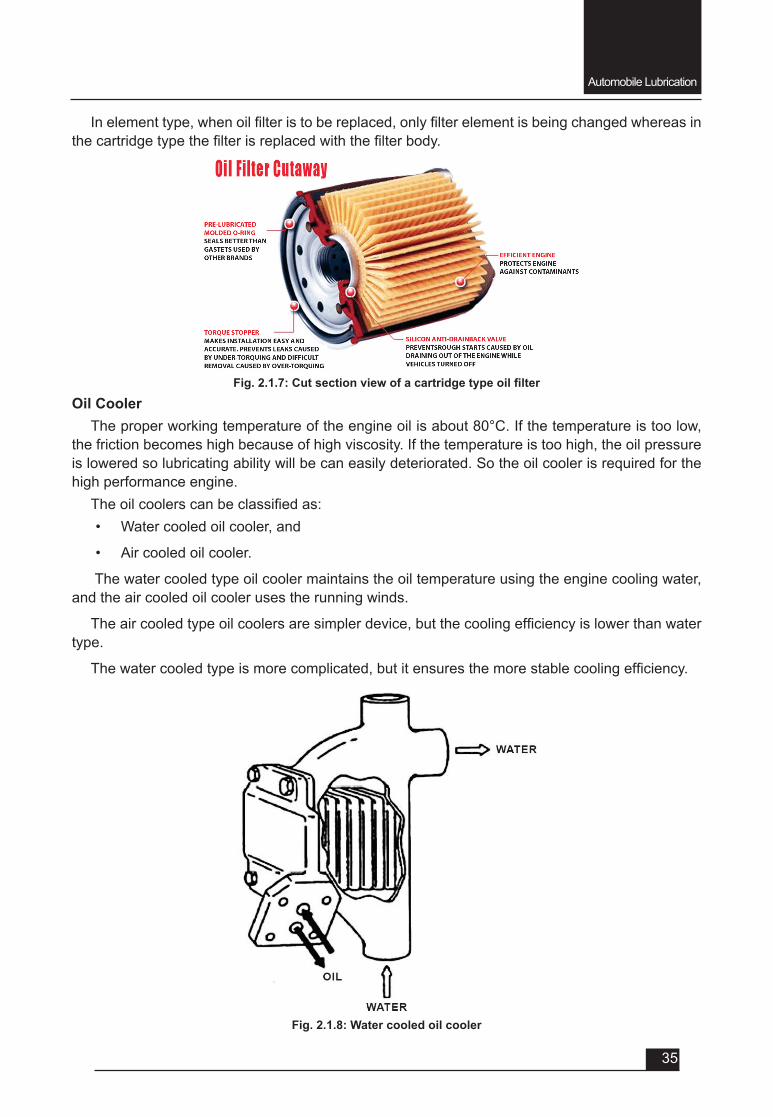
Pressure Relief ValveIt may be noted that at the low temperature, the degree of viscosity of oil is increased so the
lubricationsystemisfittedwithadeviceformaintainingtheoilpressureanditiscalledpressureregulator or pressure relief valve. The pressure relief valve is a spring-loaded bypass valve in theoilpump,engineblock,oroilfilterhousing.Thevalveconsistsofasmallpiston,spring,andcylinder. Under normal pressure conditions, the spring holds the relief valve closed. All the oil from theoilpumpflowsintotheoilgalleriesandtothebearings.
OilfiltersThe oil filterspurifytheoilfromthecarbonormetalparticles.Theoilfiltersconsistofafolded
filterpaperwhichisinsertedintothefilterbody.Therearetwotypesofthefiltersforreplacement:
• Element type, and
• Cartridge type.
Automobile Lubrication
35
Inelementtype,whenoilfilteristobereplaced,onlyfilterelementisbeingchangedwhereasinthecartridgetypethefilterisreplacedwiththefilterbody.
Fig.2.1.7:Cutsectionviewofacartridgetypeoilfilter
Fig. 2.1.8: Water cooled oil cooler
Oil CoolerTheproperworkingtemperatureoftheengineoilisabout80°C.Ifthetemperatureistoolow,
the friction becomes high because of high viscosity. If the temperature is too high, the oil pressure is lowered so lubricating ability will be can easily deteriorated. So the oil cooler is required for the high performance engine.
Theoilcoolerscanbeclassifiedas:• Water cooled oil cooler, and
• Air cooled oil cooler.
The water cooled type oil cooler maintains the oil temperature using the engine cooling water, and the air cooled oil cooler uses the running winds.
Theaircooledtypeoilcoolersaresimplerdevice,butthecoolingefficiencyislowerthanwatertype.
Thewatercooledtypeismorecomplicated,butitensuresthemorestablecoolingefficiency.
Automobile Lubrication
36
2.1.6: Trouble shooting & remedies (Lubrication system)
To troubleshoot an engine lubricating system, begin by gathering information on the problem. The four problems most often occur in the lubrication system are as follows:
• High oil consumption (oil must be added frequently)
• Low oil pressure (gauge reads low, indicator light glows, or abnormal engine noises)
• High oil pressure(gaugereadshigh,oilfilterswelled)
• Defective indicator or gauge circuit (inaccurate operation or readings).
High oil consumption v External oil leakage - detected as darkened oil wet areas on or around the engine. Oil may
also be found in small puddles under the vehicle. Leaking gaskets or seals are usually the source of external engine oil leakage.
v Internal oil leakage - shows up as blue smoke exiting the exhaust system of the vehicle. For example, if the engine piston rings and cylinders are badly worn, oil can enter the combustion chambers and will be burned during combustion.
Low Oil Pressure
Low oil pressure is indicated when the oil indicator light glows, oil gauge reads low, or when the engine lifters or bearings rattle. The most common causes of low oil pressure are as follows:
• Low oil level (oil not high enough in pan to cover oil pickup)
• Worn connecting rod or main bearings (pump cannot provide enough oil volume)
• Thin or diluted oil (low viscosity or fuel in the oil)
• Weak or broken pressure relief valve spring (valve opening too easily)
• Cracked or loose pump pickup tube (air being pulled into the oil pump)
• Worn oil pump (excess clearance between rotor or gears and housing)
• Clogged oil pickup screen (reduce amount of oil entering pump)
• A lowoil level is a commoncauseof lowoil pressure. Always check theoil level firstwhen troubleshooting a low oil pressure problem.
High Oil PressureHigh oil pressure is seldom a problem. When it occurs, the oil pressure gauge will read high.
The most frequent causes of high oil pressure are as follows:
• Pressurereliefvalvestruckopen(notopeningatspecifiedpressure)
• High relief valve spring tension (strong spring or spring has been improperly shimmed)
• High oil viscosity (excessively thick oil or use of oil additive that increases viscosity)
• Restricted oil gallery (defective block casting or debris in oil passage)
Indicator or Gauge Problems• A bad oil pressure indicator or gauge may scare the operator into believing there are major
problems.Theindicatorlightmaystayonorflicker,pointingtoalowoilpressureproblem.The gauge may read low or high, also indicating a lubrication system problem. Inspect the
Automobile Lubrication
37
indicator or gauge circuit for problems. The wire going to the sending unit may have fallen off.
• The sending unit wire may also be shorted to ground (light stays on or gauge always reads high). To check the action of the indicator or gauge, remove the wire from the sending unit. Touch it on a metal part of the engine. This should make the indicator light glow or the oil pressure gauge read maximum. If it does, the sending unit may be defective. If it does not, then the circuit, indicator, or gauge may be faulty.
QUESTIONSVery Short Answer Type (each question carries 1 mark).
1. Theoil formsanoilfilmat themetalsurfacetoreducethe________________betweenthemetal surfaces.
a. speed.
b. friction.
c. Both a and b.
d. None of above.
2. Most important characteristic of engine oil is ________.
3. The lower viscosity has ______ number and higher viscosity has ______number.
4. SAE stands for ____________________.
5. API stands for __________________________.
6. Generally, when the temperature is increased, the viscosities of oil will _______.
a. remains same.
b. increase.
c. decrease.
d. None of above.
7. The oil cooler maintains the oil __________.
a. pressure.
b. temperature.
c. both a and b.
d. neither a nor b.
8. For turbo engine, the engine oil should be replaced at every ______.
a. 5,000km.
b. 10,000 km.
c. 15,000 km.
d. none of above.
Automobile Lubrication
38
Short Answer Type (each question carries 2 marks).
1. Definerequiredcharacteristicsofengineoil.
2. Howwecanclassifylubricatingoil?
3. Howwecanclassifylubricatingsystem?
4. Name main components of a lubricating system.
5. Defineviscosityindex.Short Answer Type (each question carries 3 marks).
1. Whatarethemainobjectivesoflubricationsystem?
2. With a neat sketch describe wet sump lubrication system.
3. With a neat sketch describe splash lubrication system.
4. Whataremainfunctionsofoilcooler?
5. Definesingle/monogradeandmulti-gradelubricatingoil.
6. Definequalityclassificationoflubricatingoils.
7. Write advantages of using multi-grade lubricating oil.
Long Answer Type Questions (each carry 5 marks).
1. With a neat sketch explain the pressure lubrication system.
2. Withaneat sketchexplain the functionsof different components fitted in lubricationsystem.
3. Compare 5w-30 and 10w-30 grade engine oils.
4. Write various causes and remedies for following lubrication system troubles:
i. High oil consumption
ii. High oil pressure
iii. Low oil pressure
iv. Oil pressure gauge problem

UNIT – 2
SESSION – 2
COOLING SYSTEM
Cooling System
40
Objectives
After attending this session, you should be able to:
v Explain the necessity of cooling system.
v Explain the types of cooling system and their merits & demerits.
v Understand the function and working of different components used in cooling system.
v Understand the different trouble shooting of cooling system and their remedies.
UNIT – 2Session – 2
Cooling System
2.2.1: Necessity of cooling system
The energy released from the combustion of fuel in the cylinder is dissipated in roughly three ways:
• 35to45%heatenergydoingusefulworkonthepiston.• 30to40%heatexpelledwiththeexhaustgases,• 22to28%heatcarriedawaybyheattransference.• Thusapproximately25%oftheheatgeneratedmustbetransmittedfromtheenclosed
cylinder through the cylinder walls and head to the surrounding atmosphere and cooling system plays an important role in dissipating this amount of heat.
The cooling system has four primary functions as follows:
• Remove excess heat from the engine,• Maintain a constant engine operating temperature,• Increase the temperature of a cold engine as quickly as possible,• Provide a means for heater operation (warming the passenger compartment).
Air is continually present in large enough quantities to cool a running engine; therefore, vehicle engines are designed to dissipate their heat into the air through which a vehicle passes. This action is accomplished either by direct air-cooling or indirectly by liquid cooling.
2.2.2: Different type of cooling system
Thecoolingsystemforanautomobileenginecanbeclassifiedas:• air-cooling system, and
• liquid/water-cooling system
Cooling System
41
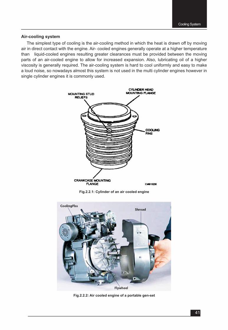
Air-cooling system The simplest type of cooling is the air-cooling method in which the heat is drawn off by moving
air in direct contact with the engine. Air- cooled engines generally operate at a higher temperature than liquid-cooled engines resulting greater clearances must be provided between the moving parts of an air-cooled engine to allow for increased expansion. Also, lubricating oil of a higher viscosity is generally required. The air-cooling system is hard to cool uniformly and easy to make a loud noise, so nowadays almost this system is not used in the multi cylinder engines however in single cylinder engines it is commonly used.
Fig.2.2.1: Cylinder of an air cooled engine
Fig.2.2.2: Air cooled engine of a portable gen-set
Cooling System
42
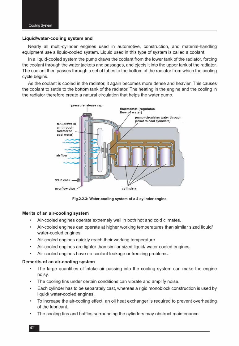
Liquid/water-cooling system and
Nearly all multi-cylinder engines used in automotive, construction, and material-handling equipment use a liquid-cooled system. Liquid used in this type of system is called a coolant.
In a liquid-cooled system the pump draws the coolant from the lower tank of the radiator, forcing the coolant through the water jackets and passages, and ejects it into the upper tank of the radiator. The coolant then passes through a set of tubes to the bottom of the radiator from which the cooling cycle begins.
As the coolant is cooled in the radiator, it again becomes more dense and heavier. This causes the coolant to settle to the bottom tank of the radiator. The heating in the engine and the cooling in the radiator therefore create a natural circulation that helps the water pump.
Fig.2.2.3: Water-cooling system of a 4 cylinder engine
Merits of an air-cooling system• Air-cooled engines operate extremely well in both hot and cold climates.• Air-cooled engines can operate at higher working temperatures than similar sized liquid/
water-cooled engines.• Air-cooled engines quickly reach their working temperature.• Air-cooled engines are lighter than similar sized liquid/ water cooled engines.• Air-cooled engines have no coolant leakage or freezing problems.
Demerits of an air-cooling system• The large quantities of intake air passing into the cooling system can make the engine
noisy.• Thecoolingfinsundercertainconditionscanvibrateandamplifynoise.• Each cylinder has to be separately cast, whereas a rigid monoblock construction is used by
liquid/ water-cooled engines.• To increase the air-cooling effect, an oil heat exchanger is required to prevent overheating
of the lubricant.• Thecoolingfinsandbafflessurroundingthecylindersmayobstructmaintenance.
Cooling System
43
Merits of liquid cooling system• Water cooled engines provide greater temperature uniformity around the cylinders,
so there is less bend compared with air-cooled engines.• The combined power consumption of the coolant pump and the fan in water-coolant
units is far less than that of the air- cooled engine fan.• The liquid cooled engine cylinder has more strength than the air cooled engine.• Mechanical noise from the engine is damped by both the coolant and the jackets.• Liquid cooled units are more reliable for heavy-duty engines than air cooled engines.
Demerits of liquid cooling system • Liquid coolant joints are subject to leakage.• Precautions must be taken to prevent coolant freezing.• Liquid cooled units take longer to warm up than air-cooled engines.• The maximum liquid-coolant temperature is limited to its boiling point, whereas air-
cooled engines can operate at slightly higher temperatures.• The coolant passages tend to scale, and the hoses and radiator tubes deteriorate
with time.
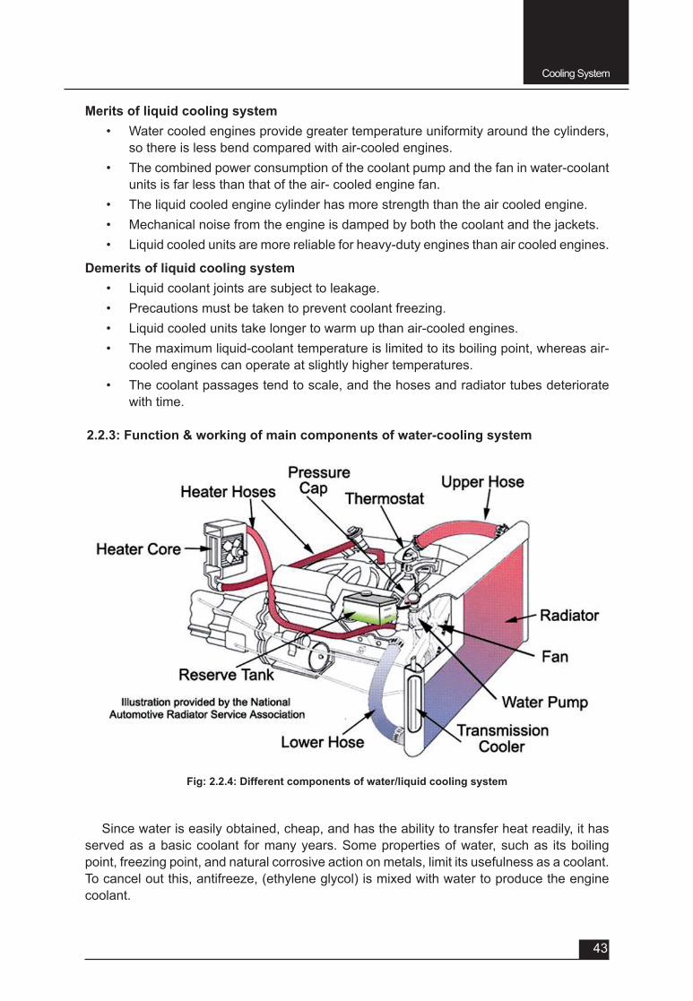
2.2.3: Function & working of main components of water-cooling system
Fig: 2.2.4: Different components of water/liquid cooling system
Since water is easily obtained, cheap, and has the ability to transfer heat readily, it has served as a basic coolant for many years. Some properties of water, such as its boiling point, freezing point, and natural corrosive action on metals, limit its usefulness as a coolant. To cancel out this, antifreeze, (ethylene glycol) is mixed with water to produce the engine coolant.
Cooling System
44
For ideal cooling and winter protection, a 50/50 mixture of antifreeze and water is recommended.
A simple water/liquid-cooled system consists of following components:
• A radiator& pressure cap,• Water/liquid pump,• Piping/ hose pipes,• Radiator fan,• A thermostat, and• A system of water jackets/ passages in the cylinder head and block through which
the coolant circulates.
• Recovery tank
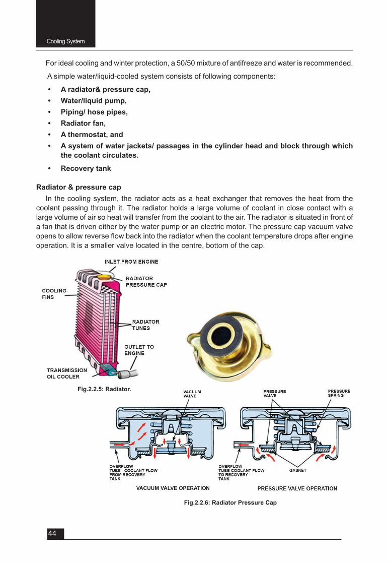
Radiator & pressure capIn the cooling system, the radiator acts as a heat exchanger that removes the heat from the
coolant passing through it. The radiator holds a large volume of coolant in close contact with a large volume of air so heat will transfer from the coolant to the air. The radiator is situated in front of a fan that is driven either by the water pump or an electric motor. The pressure cap vacuum valve openstoallowreverseflowbackintotheradiatorwhenthecoolanttemperaturedropsafterengineoperation. It is a smaller valve located in the centre, bottom of the cap.
Fig.2.2.5: Radiator.
Fig.2.2.6: Radiator Pressure Cap
Cooling System
45
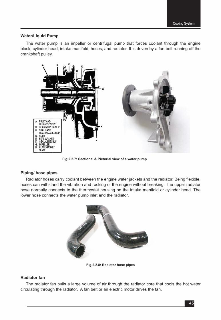
Water/Liquid Pump
The water pump is an impeller or centrifugal pump that forces coolant through the engine block, cylinder head, intake manifold, hoses, and radiator. It is driven by a fan belt running off the crankshaft pulley.
Piping/ hose pipes Radiatorhosescarrycoolantbetweentheenginewaterjacketsandtheradiator.Beingflexible,
hoses can withstand the vibration and rocking of the engine without breaking. The upper radiator hose normally connects to the thermostat housing on the intake manifold or cylinder head. The lower hose connects the water pump inlet and the radiator.
Fig.2.2.7: Sectional & Pictorial view of a water pump
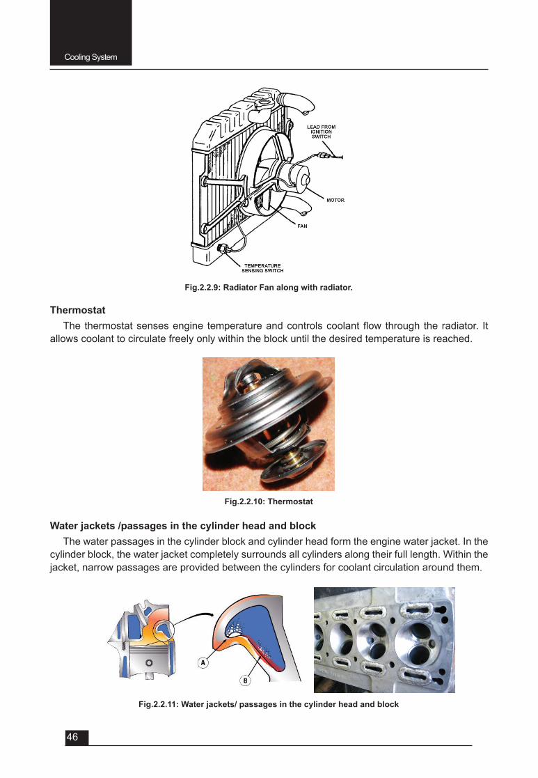
Fig.2.2.8: Radiator hose pipes
Radiator fan The radiator fan pulls a large volume of air through the radiator core that cools the hot water
circulating through the radiator. A fan belt or an electric motor drives the fan.
Cooling System
46
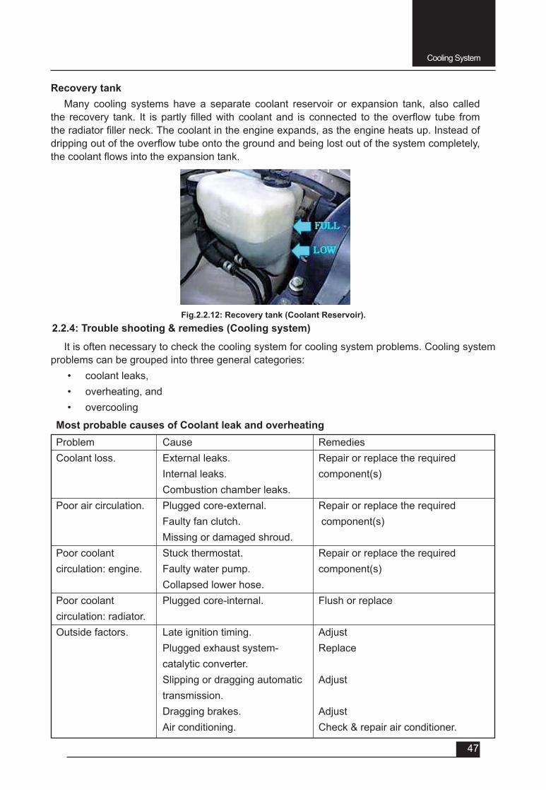
ThermostatThe thermostatsensesengine temperatureandcontrolscoolantflowthrough theradiator. It
allows coolant to circulate freely only within the block until the desired temperature is reached.
Fig.2.2.9: Radiator Fan along with radiator.
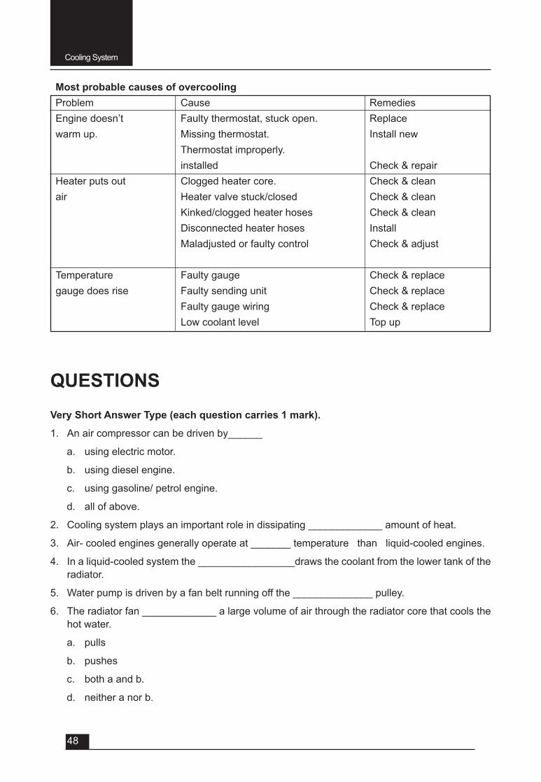
Fig.2.2.10: Thermostat
Fig.2.2.11: Water jackets/ passages in the cylinder head and block
Water jackets /passages in the cylinder head and blockThe water passages in the cylinder block and cylinder head form the engine water jacket. In the
cylinder block, the water jacket completely surrounds all cylinders along their full length. Within the jacket, narrow passages are provided between the cylinders for coolant circulation around them.
Cooling System
47
Recovery tank Many cooling systems have a separate coolant reservoir or expansion tank, also called
the recovery tank. It ispartly filledwithcoolantand isconnected to theoverflow tube fromtheradiatorfillerneck.Thecoolantintheengineexpands,astheengineheatsup.Insteadofdrippingoutoftheoverflowtubeontothegroundandbeinglostoutofthesystemcompletely,thecoolantflowsintotheexpansiontank.
Fig.2.2.12: Recovery tank (Coolant Reservoir).2.2.4: Trouble shooting & remedies (Cooling system)
It is often necessary to check the cooling system for cooling system problems. Cooling system problems can be grouped into three general categories:
• coolant leaks, • overheating, and• overcooling
Most probable causes of Coolant leak and overheatingProblem Cause RemediesCoolant loss. External leaks. Repair or replace the required Internal leaks. component(s) Combustion chamber leaks. Poor air circulation. Plugged core-external. Repair or replace the required Faulty fan clutch. component(s) Missing or damaged shroud. Poor coolant Stuck thermostat. Repair or replace the requiredcirculation: engine. Faulty water pump. component(s) Collapsed lower hose. Poor coolant Plugged core-internal. Flush or replacecirculation: radiator.Outside factors. Late ignition timing. Adjust Plugged exhaust system- Replace catalytic converter. Slipping or dragging automatic Adjust transmission. Dragging brakes. Adjust Air conditioning. Check & repair air conditioner.
Cooling System
48
Most probable causes of overcoolingProblem Cause RemediesEngine doesn’t Faulty thermostat, stuck open. Replacewarm up. Missing thermostat. Install new Thermostat improperly. installed Check & repairHeater puts out Clogged heater core. Check & cleanair Heater valve stuck/closed Check & clean Kinked/clogged heater hoses Check & clean Disconnected heater hoses Install Maladjusted or faulty control Check & adjust Temperature Faulty gauge Check & replacegauge does rise Faulty sending unit Check & replace Faulty gauge wiring Check & replace Low coolant level Top up
QUESTIONSVery Short Answer Type (each question carries 1 mark).
1. An air compressor can be driven by______
a. using electric motor.
b. using diesel engine.
c. using gasoline/ petrol engine.
d. all of above.
2. Cooling system plays an important role in dissipating _____________ amount of heat.
3. Air- cooled engines generally operate at _______ temperature than liquid-cooled engines.
4. In a liquid-cooled system the _________________draws the coolant from the lower tank of the radiator.
5. Water pump is driven by a fan belt running off the ______________ pulley.
6. The radiator fan _____________ a large volume of air through the radiator core that cools the hot water.
a. pulls
b. pushes
c. both a and b.
d. neither a nor b.
Cooling System
49
7. _________________allows coolant to circulate freely only within the block until the operating temperature is reached.
a. Radiator
b. Hose pipe
c. Thermostat
d. none of the above.
8. The______________ofpressurecapopenstoallowreverseflowbackintotheradiatorwhenthe coolant temperature drops after engine operation.
a. pressure valve
b. vacuum valve
c. both a and b
d. none of above.
Short Answer Type (each question carries 2 marks).1. Write primary functions of cooling system used in automobiles.
2. Whyiscoolingnecessaryforinternalcombustionengines?
3. HowwecanclassifycoolingsystemusedinICengines?
Short Answer Type (each question carries 3 marks).
1. Whythermostatisprovidedinwatercoolingsystem?
2. Whyantifreezeisaddedtowaterinwatercoolingsystem?
3. Write the importance of pressure cap in water cooling system.
4. Write the importance of recovery tank in water cooling system.
Long Answer Type Questions (each carry 5 marks).1. Name different components of water cooling system and write their functions too.
2. Differentiate between air and water cooling system.
3. Write merits and demerits of air cooling system.
4. With a neat sketch explain the water cooling system of an automobile.
5. Write merits and demerits of water cooling system.
6. Write various causes and remedies for following cooling system troubles:
i. Overheating
ii. Overcooling
iii. Coolant leakage

UNIT – 3
SESSION – 1
FINAL DRIVE SYSTEM(Propeller Shaft & Universal Joint)
Objectives
After attending this session, you should be able to:
v Explain the function of Propeller Shaft.
v Explain the construction and working of Propeller Shaft.
v Explain the function and type of Universal Joints.
v Explain the construction and operation of Universal Joints.
UNIT – 3Session – 1
Final Drive System(Propeller Shaft & Universal Joint)
3.1.1: Propeller Shaft
In four wheel drive and rear wheel drive vehicles, it is the propeller shaft that serves to transmit the drive force generated by the engine to the axles. The propeller shaft is made of steel tube having a high resistance against torsional or bending forces. It is dynamically balanced, some time a balance weight is welded outside the tube for the purpose of balancing dynamically.
v Function
The functions of propeller shafts are:
• To transmit torque• To allow different drive shaft angles• To allow changes in length• To reduce rotary vibrations
v Construction
The propeller shaft is normally made by seamless steel tubing method with universal joint yokes welded to both ends of the shaft. Some drivelines have two propeller shafts and three universal joints and use a center support bearing. Four wheel-drive wheels use two propeller shafts, one to drive the front wheels and the other to drive the rear wheels.
In practice, propeller shaft should always be short and as stiff as possible, this enable the shaft to resist the bending loads and torque reactions which are imposed during operation. If the shaft cannot be made in a short length, then its stiffness can be improved by making the diameter larger. Propeller shafts are either solid or tubular in construction. A tubular shaft is stronger than a solid shaft of the same weight and therefore offers advantages of reduced weight and low manufacturing costs.
Final Drive System
52
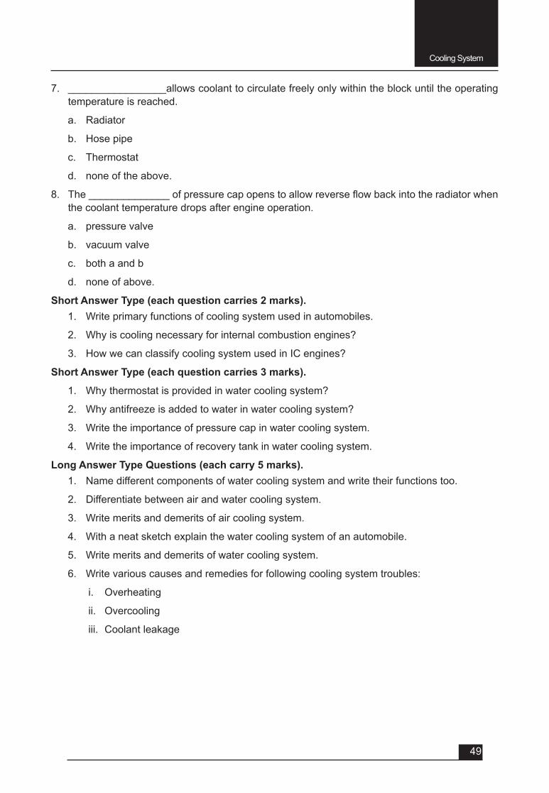
Fig. 3.1.1: Propeller Shaft Assembly
Components of Propeller Shaft Assembly:• Universal Joint: A universal joint forms a mechanical connection between the two shafts
and allows angular movement of one or both shafts. Also it transmits power smoothly from the gearbox to the differential.
Roadshocksduetoroadirregularitieswilldeflectthesprings,whichwillaltertheangleofthepropellershaft,relativetothegearboxandfinaldriveandunlessauniversaljointisfittedtoeachendofthepropellershaft,theshaftwillbendandfracture.
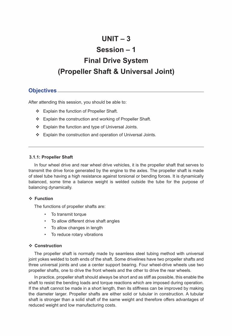
Fig.3.1.2: Exploded view of various components of Propeller shaft and Universal Joint.
Fig.3.1.3: Components and Swing Arc of Propeller shaft and Rear Axle.
Final Drive System
53
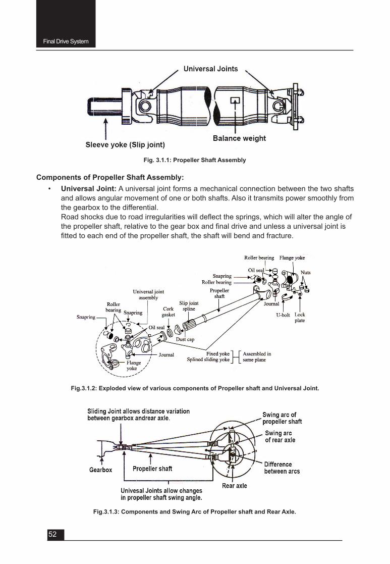
• Slip Joint (or Sliding Joint): Propeller shaft use a slip joint at one end, which allows it to lengthen or shorten. It permits the effective length of the propeller shaft to change due to up and down movement of the wheels.
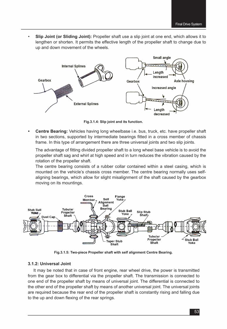
• Centre Bearing: Vehicles having long wheelbase i.e. bus, truck, etc. have propeller shaft in twosections,supportedby intermediatebearingsfitted inacrossmemberofchassisframe. In this type of arrangement there are three universal joints and two slip joints.
Theadvantageoffittingdividedpropellershafttoalongwheelbasevehicleistoavoidthepropeller shaft sag and whirl at high speed and in turn reduces the vibration caused by the rotation of the propeller shaft.
The centre bearing consists of a rubber collar contained within a steel casing, which is mounted on the vehicle’s chassis cross member. The centre bearing normally uses self-aligning bearings, which allow for slight misalignment of the shaft caused by the gearbox moving on its mountings.
Fig.3.1.4: Slip joint and its function.
Fig.3.1.5: Two-piece Propeller shaft with self alignment Centre Bearing.
3.1.2: Universal JointIt may be noted that in case of front engine, rear wheel drive, the power is transmitted
from the gear box to differential via the propeller shaft. The transmission is connected to one end of the propeller shaft by means of universal joint. The differential is connected to the other end of the propeller shaft by means of another universal joint. The universal joints are required because the rear end of the propeller shaft is constantly rising and falling due totheupanddownflexingoftherearsprings.

Final Drive System
54
• Function: The functions of universal joint is to
v transmit power at varied angles v allow rear axle assembly to twist due to the driving and braking torque application.
• Requirements: A modern universal joint is expected to meet the following requirements:
v Strength: High torque must be transmitted with the minimum energy due to friction.v Compactness: Space is limited so the joint must be small and robust.v Large drive angle:Modernroadspringsallowlargewheeldeflectionssothejointmust
be able to accommodate the large drive angle given by this movement.v Shaft balance: Severe vibration occurs if the shaft runs out-of-true, so the joint must
maintain good alignment.v Operating speed:Thejointmustoperateefficientlyathigherspeedundertheconditions
of high torque and variable drive angle. This requirement must be combined with the need for the joint to have a long life and minimum maintenance.
Types of Universal Joint:Theuniversaljointsareclassifiedasfollows:
1. Variable velocity joints and 2 Constant velocity joints.
Thevariablevelocityjointsarefurtherclassifiedas:
(a) Cross or spider type and (b) Flexible Ring type
Theconstantvelocityjointsarefurtherclassifiedas:
(a) Rzeppa joint and (b) Tripod joint.
1. Variable Velocity Joints:In variable velocity joints, the driving and driven members do not turn at the same speed through
each part of a revolution although they turn at the same r.p.m. The driven and driving shaft should therefore, be in a straight line so that they may turn at same speed through each part of a revolution. But in a automobile, it is not feasible as the drive shaft is inclined.
When there is an angle between the driven and driving and driving shafts, the driven shaft turns slower than the driving shaft through half a revolution and faster than the driving shaft through the other half of the revolution. Thus, the average speed of the driven shaft is equal to the driving shaft.Thespeedvariationinthedrivenshaftincreaseswhentheflexangleoftheuniversaljointisincreased.Itisowingtothisfactthatvariablevelocityjointsareusuallyusedwhentheflexangleis small.
It may be noted that when two variable velocity universal joints are used in one drive line, the yoke on the shafts connecting the universal joints should be in the same plane. It helps in balancing the shaft.
Two types of variable velocity joints are explained below:a. Cross or spider type: It is also commonly known as Hooke’s joint. It is most common
type of universal joint widely used in automobiles because of the fact that it is simple in constructionandreasonableefficientatsmallangles(generallyup to 200 angle) of up and down movement of propeller shaft.
It consists of two Y-shaped yokes connected at right angles to each other by means of a cross or spider. The arms of the cross are called as trunnions. The needle type bearings
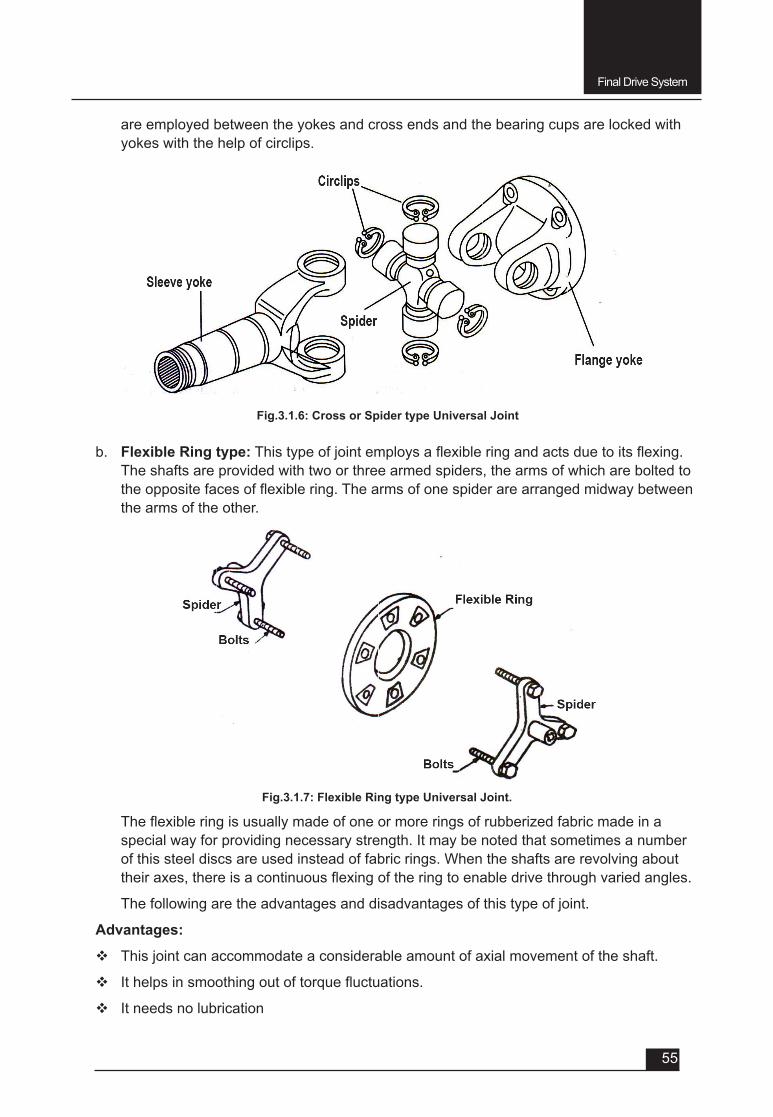
Final Drive System
55
are employed between the yokes and cross ends and the bearing cups are locked with yokes with the help of circlips.
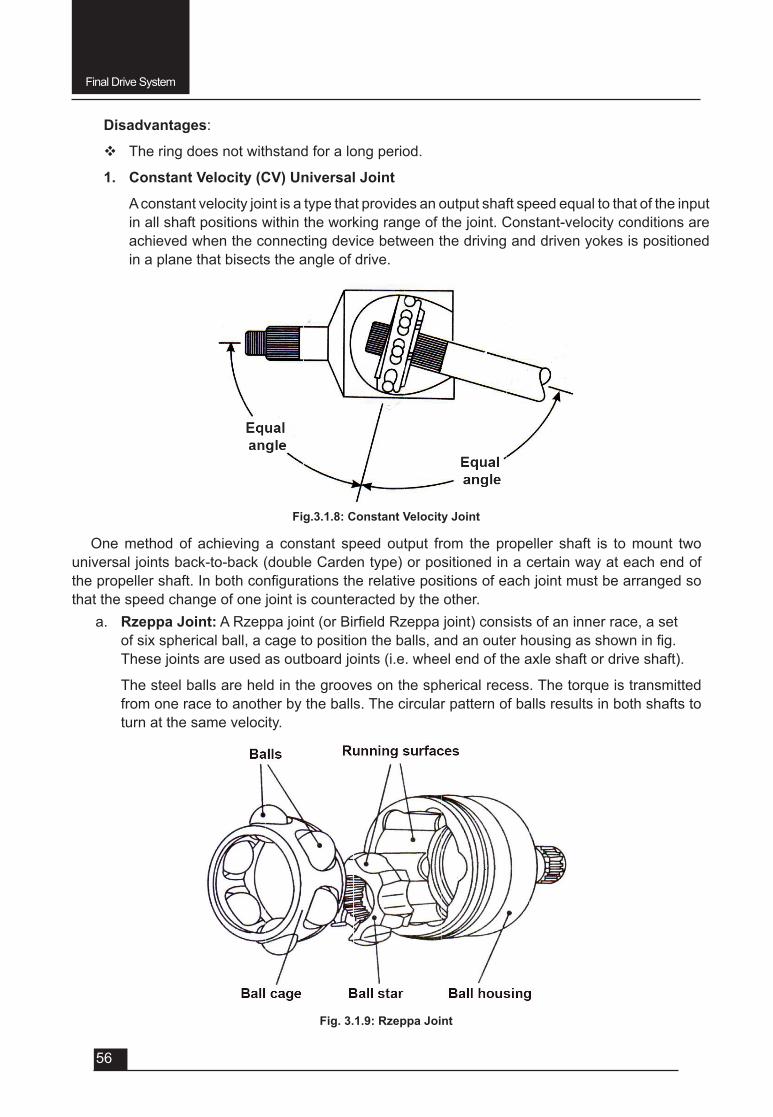
b. Flexible Ring type:Thistypeofjointemploysaflexibleringandactsduetoitsflexing.The shafts are provided with two or three armed spiders, the arms of which are bolted to theoppositefacesofflexiblering.Thearmsofonespiderarearrangedmidwaybetweenthe arms of the other.
Fig.3.1.6: Cross or Spider type Universal Joint
Fig.3.1.7: Flexible Ring type Universal Joint.
Theflexibleringisusuallymadeofoneormoreringsofrubberizedfabricmadeinaspecial way for providing necessary strength. It may be noted that sometimes a number of this steel discs are used instead of fabric rings. When the shafts are revolving about theiraxes,thereisacontinuousflexingoftheringtoenabledrivethroughvariedangles.
The following are the advantages and disadvantages of this type of joint.
Advantages:
v This joint can accommodate a considerable amount of axial movement of the shaft.
v Ithelpsinsmoothingoutoftorquefluctuations.
v It needs no lubrication
Final Drive System
56
Disadvantages:
v The ring does not withstand for a long period.
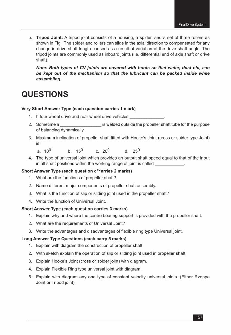
1. Constant Velocity (CV) Universal Joint
A constant velocity joint is a type that provides an output shaft speed equal to that of the input in all shaft positions within the working range of the joint. Constant-velocity conditions are achieved when the connecting device between the driving and driven yokes is positioned in a plane that bisects the angle of drive.
Fig.3.1.8: Constant Velocity Joint
Fig. 3.1.9: Rzeppa Joint
One method of achieving a constant speed output from the propeller shaft is to mount two universal joints back-to-back (double Carden type) or positioned in a certain way at each end of thepropellershaft.Inbothconfigurationstherelativepositionsofeachjointmustbearrangedsothat the speed change of one joint is counteracted by the other.
a. Rzeppa Joint:ARzeppajoint(orBirfieldRzeppajoint)consistsofaninnerrace,asetofsixsphericalball,acagetopositiontheballs,andanouterhousingasshowninfig.These joints are used as outboard joints (i.e. wheel end of the axle shaft or drive shaft).
The steel balls are held in the grooves on the spherical recess. The torque is transmitted from one race to another by the balls. The circular pattern of balls results in both shafts to turn at the same velocity.
Final Drive System
57
b. Tripod Joint: A tripod joint consists of a housing, a spider, and a set of three rollers as shown in Fig. The spider and rollers can slide in the axial direction to compensated for any change in drive shaft length caused as a result of variation of the drive shaft angle. The tripod joints are commonly used as inboard joints (i.e. differential end of axle shaft or drive shaft).
Note: Both types of CV joints are covered with boots so that water, dust etc, can be kept out of the mechanism so that the lubricant can be packed inside while assembling.
QUESTIONSVery Short Answer Type (each question carries 1 mark)
1. If four wheel drive and rear wheel drive vehicles ______________.
2. Sometime a _________________ is welded outside the propeller shaft tube for the purpose of balancing dynamically.
3. MaximuminclinationofpropellershaftfittedwithHooke’sJoint(crossorspidertypeJoint)is
a. 100 b. 150 c. 200 d. 250
4. The type of universal joint which provides an output shaft speed equal to that of the input in all shaft positions within the working range of joint is called ____________.
Short Answer Type (each question c™arries 2 marks)1. Whatarethefunctionsofpropellershaft?
2. Name different major components of propeller shaft assembly.
3. Whatisthefunctionofsliporslidingjointusedinthepropellershaft?
4. Write the function of Universal Joint.
Short Answer Type (each question carries 3 marks)1. Explain why and where the centre bearing support is provided with the propeller shaft.
2. WhataretherequirementsofUniversalJoint?
3. WritetheadvantagesanddisadvantagesofflexibleringtypeUniversaljoint.
Long Answer Type Questions (each carry 5 marks)1. Explain with diagram the construction of propeller shaft
2. With sketch explain the operation of slip or sliding joint used in propeller shaft.
3. Explain Hooke’s Joint (cross or spider joint) with diagram.
4. Explain Flexible Ring type universal joint with diagram.
5. Explain with diagram any one type of constant velocity universal joints. (Either Rzeppa Joint or Tripod joint).
UNIT – 3
SESSION – 2
FINAL DRIVE SYSTEM(Final Drive, Differential and Rear Axle
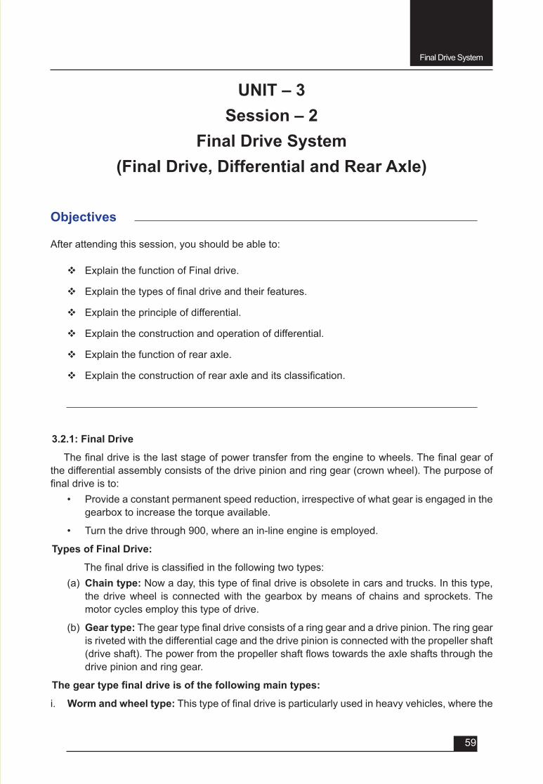
Final Drive System
59
Objectives
After attending this session, you should be able to:
v Explain the function of Final drive.
v Explainthetypesoffinaldriveandtheirfeatures.
v Explain the principle of differential.
v Explain the construction and operation of differential.
v Explain the function of rear axle.
v Explaintheconstructionofrearaxleanditsclassification.
UNIT – 3Session – 2
Final Drive System(Final Drive, Differential and Rear Axle)
3.2.1: Final Drive
Thefinaldriveisthelaststageofpowertransferfromtheenginetowheels.Thefinalgearofthe differential assembly consists of the drive pinion and ring gear (crown wheel). The purpose of finaldriveisto:
• Provide a constant permanent speed reduction, irrespective of what gear is engaged in the gearbox to increase the torque available.
• Turn the drive through 900, where an in-line engine is employed.
Types of Final Drive:
Thefinaldriveisclassifiedinthefollowingtwotypes:(a) Chain type:Nowaday,thistypeoffinaldriveisobsoleteincarsandtrucks.Inthistype,
the drive wheel is connected with the gearbox by means of chains and sprockets. The motor cycles employ this type of drive.
(b) Gear type:Thegeartypefinaldriveconsistsofaringgearandadrivepinion.Theringgearis riveted with the differential cage and the drive pinion is connected with the propeller shaft (driveshaft).Thepowerfromthepropellershaftflowstowardstheaxleshaftsthroughthedrive pinion and ring gear.
Thegeartypefinaldriveisofthefollowingmaintypes:
i. Worm and wheel type:Thistypeoffinaldriveisparticularlyusedinheavyvehicles,wherethe
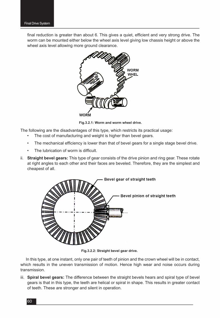
Final Drive System
60
finalreductionisgreaterthanabout6.Thisgivesaquiet,efficientandverystrongdrive.Theworm can be mounted either below the wheel axis level giving low chassis height or above the wheel axis level allowing more ground clearance.
Fig.3.2.1: Worm and worm wheel drive.
Fig.3.2.2: Straight bevel gear drive.
The following are the disadvantages of this type, which restricts its practical usage:• The cost of manufacturing and weight is higher than bevel gears.
• Themechanicalefficiencyislowerthanthatofbevelgearsforasinglestagebeveldrive.
• Thelubricationofwormisdifficult.
ii. Straight bevel gears: This type of gear consists of the drive pinion and ring gear. These rotate at right angles to each other and their faces are beveled. Therefore, they are the simplest and cheapest of all.
In this type, at one instant, only one pair of teeth of pinion and the crown wheel will be in contact, which results in the uneven transmission of motion. Hence high wear and noise occurs during transmission.
iii. Spiral bevel gears: The difference between the straight bevels hears and spiral type of bevel gears is that in this type, the teeth are helical or spiral in shape. This results in greater contact of teeth. These are stronger and silent in operation.
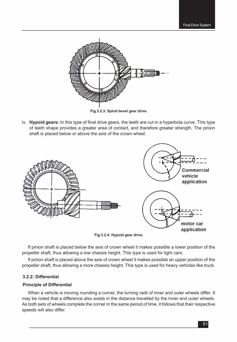
Final Drive System
61
Fig.3.2.3: Spiral bevel gear drive.
iv. Hypoid gears: Inthistypeoffinaldrivegears,theteetharecutinahyperbolacurve.Thistypeof teeth shape provides a greater area of contact, and therefore greater strength. The pinion shaft is placed below or above the axis of the crown wheel.
If pinion shaft is placed below the axis of crown wheel it makes possible a lower position of the propeller shaft, thus allowing a low chassis height. This type is used for light cars.
If pinion shaft is placed above the axis of crown wheel it makes possible an upper position of the propeller shaft, thus allowing a more chassis height. This type is used for heavy vehicles like truck.
3.2.2: Differential
Principle of Differential
When a vehicle is moving rounding a corner, the turning radii of inner and outer wheels differ. It may be noted that a difference also exists in the distance travelled by the inner and outer wheels. As both sets of wheels complete the corner in the same period of time, it follows that their respective speeds will also differ.
Fig.3.2.4: Hypoid gear drive.
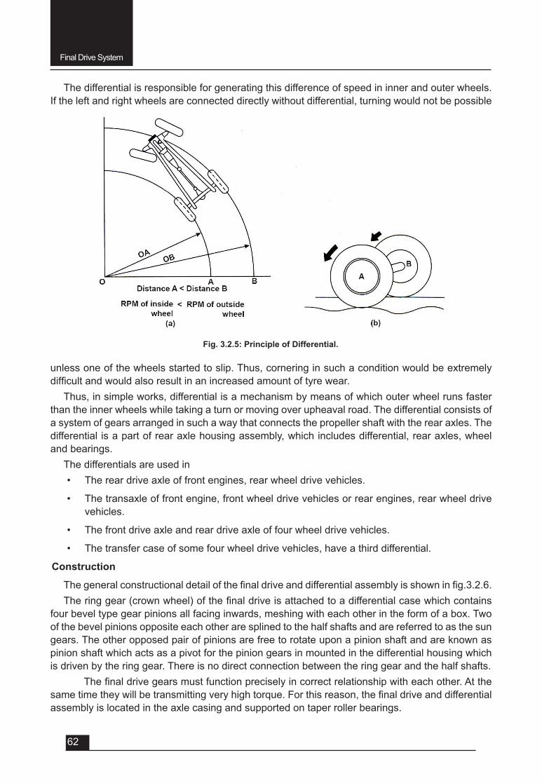
Final Drive System
62
The differential is responsible for generating this difference of speed in inner and outer wheels. If the left and right wheels are connected directly without differential, turning would not be possible
Fig. 3.2.5: Principle of Differential.
unless one of the wheels started to slip. Thus, cornering in such a condition would be extremely difficultandwouldalsoresultinanincreasedamountoftyrewear.
Thus, in simple works, differential is a mechanism by means of which outer wheel runs faster than the inner wheels while taking a turn or moving over upheaval road. The differential consists of a system of gears arranged in such a way that connects the propeller shaft with the rear axles. The differential is a part of rear axle housing assembly, which includes differential, rear axles, wheel and bearings.
The differentials are used in • The rear drive axle of front engines, rear wheel drive vehicles.
• The transaxle of front engine, front wheel drive vehicles or rear engines, rear wheel drive vehicles.
• The front drive axle and rear drive axle of four wheel drive vehicles.
• The transfer case of some four wheel drive vehicles, have a third differential.
Construction
Thegeneralconstructionaldetailofthefinaldriveanddifferentialassemblyisshowninfig.3.2.6.Theringgear(crownwheel)ofthefinaldriveisattachedtoadifferentialcasewhichcontains
four bevel type gear pinions all facing inwards, meshing with each other in the form of a box. Two of the bevel pinions opposite each other are splined to the half shafts and are referred to as the sun gears. The other opposed pair of pinions are free to rotate upon a pinion shaft and are known as pinion shaft which acts as a pivot for the pinion gears in mounted in the differential housing which is driven by the ring gear. There is no direct connection between the ring gear and the half shafts.
Thefinaldrivegearsmustfunctionpreciselyincorrectrelationshipwitheachother.Atthesametimetheywillbetransmittingveryhightorque.Forthisreason,thefinaldriveanddifferentialassembly is located in the axle casing and supported on taper roller bearings.
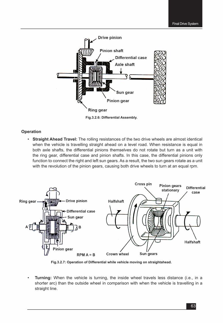
Final Drive System
63
Fig.3.2.6: Differential Assembly.
Operation
• Straight Ahead Travel: The rolling resistances of the two drive wheels are almost identical when the vehicle is travelling straight ahead on a level road. When resistance is equal in both axle shafts, the differential pinions themselves do not rotate but turn as a unit with the ring gear, differential case and pinion shafts. In this case, the differential pinions only function to connect the right and left sun gears. As a result, the two sun gears rotate as a unit with the revolution of the pinion gears, causing both drive wheels to turn at an equal rpm.
Fig.3.2.7: Operation of Differential while vehicle moving on straightahead.
• Turning: When the vehicle is turning, the inside wheel travels less distance (i.e., in a shorter arc) than the outside wheel in comparison with when the vehicle is travelling in a straight line.
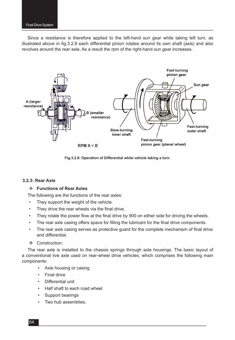
Final Drive System
64
Since a resistance is therefore applied to the left-hand sun gear while taking left turn, as illustratedaboveinfig.3.2.8eachdifferentialpinionrotatesarounditsownshaft(axis)andalsorevolves around the rear axle. As a result the rpm of the right-hand sun gear increases.
Fig.3.2.8: Operation of Differential while vehicle taking a turn.
3.2.3: Rear Axle
v Functions of Rear AxlesThe following are the functions of the rear axles:• They support the weight of the vehicle.• Theydrivetherearwheelsviathefinaldrive.• Theyrotatethepowerflowatthefinaldriveby900oneithersidefordrivingthewheels.• Therearaxlecasingoffersspaceforfillingthelubricantforthefinaldrivecomponents.• Therearaxlecasingservesasprotectiveguardforthecompletemechanismoffinaldrive
and differential.
v Construction:The rear axle is installed to the chassis springs through axle housings. The basic layout of
a conventional live axle used on rear-wheel drive vehicles, which comprises the following main components:
• Axle housing or casing• Final drive• Differential unit • Half shaft to each road wheel• Support bearings• Two hub assemblies.
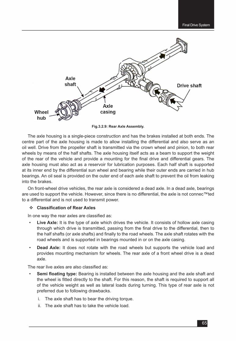
Final Drive System
65
Fig.3.2.9: Rear Axle Assembly.
The axle housing is a single-piece construction and has the brakes installed at both ends. The centre part of the axle housing is made to allow installing the differential and also serve as an oil well. Drive from the propeller shaft is transmitted via the crown wheel and pinion, to both rear wheels by means of the half shafts. The axle housing itself acts as a beam to support the weight of the rearof thevehicleandprovideamounting for thefinaldriveanddifferentialgears.Theaxle housing must also act as a reservoir for lubrication purposes. Each half shaft is supported at its inner end by the differential sun wheel and bearing while their outer ends are carried in hub bearings. An oil seal is provided on the outer end of each axle shaft to prevent the oil from leaking into the brakes.
On front-wheel drive vehicles, the rear axle is considered a dead axle. In a dead axle, bearings are used to support the vehicle. However, since there is no differential, the axle is not connec™ted to a differential and is not used to transmit power.
v ClassificationofRearAxles
Inonewaytherearaxlesareclassifiedas:• Live Axle: It is the type of axle which drives the vehicle. It consists of hollow axle casing
throughwhichdriveistransmitted,passingfromthefinaldrivetothedifferential,thentothehalfshafts(oraxleshafts)andfinallytotheroadwheels.Theaxleshaftrotateswiththeroad wheels and is supported in bearings mounted in or on the axle casing.
• Dead Axle: It does not rotate with the road wheels but supports the vehicle load and provides mounting mechanism for wheels. The rear axle of a front wheel drive is a dead axle.
Therearliveaxlesarealsoclassifiedas:• Semifloatingtype: Bearing is installed between the axle housing and the axle shaft and
thewheelisfitteddirectlytotheshaft.Forthisreason,theshaftisrequiredtosupportallof the vehicle weight as well as lateral loads during turning. This type of rear axle is not preferred due to following drawbacks.
i. The axle shaft has to bear the driving torque.ii. The axle shaft has to take the vehicle load.
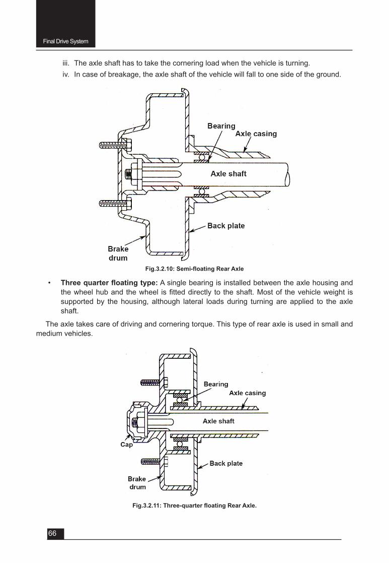
Final Drive System
66
iii. The axle shaft has to take the cornering load when the vehicle is turning.iv. In case of breakage, the axle shaft of the vehicle will fall to one side of the ground.
Fig.3.2.11:Three-quarterfloatingRearAxle.
• Threequarterfloatingtype: A single bearing is installed between the axle housing and thewheelhuband thewheel isfitteddirectly to theshaft.Mostof thevehicleweight issupported by the housing, although lateral loads during turning are applied to the axle shaft.
The axle takes care of driving and cornering torque. This type of rear axle is used in small and medium vehicles.
Fig.3.2.10:Semi-floatingRearAxle
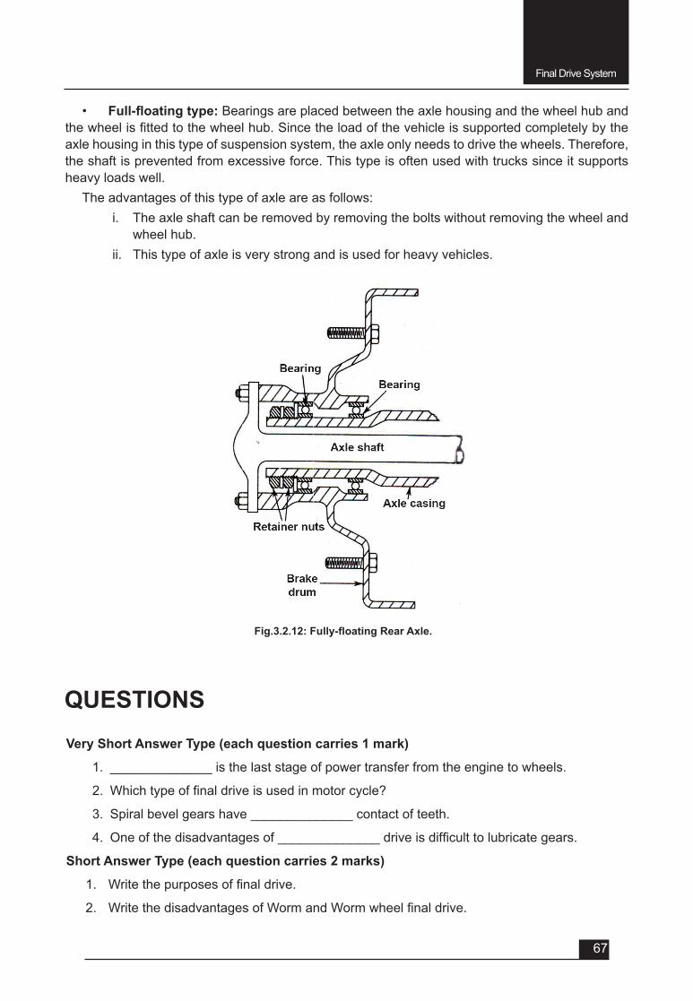
Final Drive System
67
Fig.3.2.12:Fully-floatingRearAxle.
• Full-floatingtype: Bearings are placed between the axle housing and the wheel hub and thewheelisfittedtothewheelhub.Sincetheloadofthevehicleissupportedcompletelybytheaxle housing in this type of suspension system, the axle only needs to drive the wheels. Therefore, the shaft is prevented from excessive force. This type is often used with trucks since it supports heavy loads well.
The advantages of this type of axle are as follows:i. The axle shaft can be removed by removing the bolts without removing the wheel and
wheel hub.ii. This type of axle is very strong and is used for heavy vehicles.
QUESTIONSVery Short Answer Type (each question carries 1 mark)
1. ______________ is the last stage of power transfer from the engine to wheels.
2. Whichtypeoffinaldriveisusedinmotorcycle?
3. Spiral bevel gears have ______________ contact of teeth.
4. Oneofthedisadvantagesof______________driveisdifficulttolubricategears.
Short Answer Type (each question carries 2 marks)
1. Writethepurposesoffinaldrive.
2. WritethedisadvantagesofWormandWormwheelfinaldrive.

Final Drive System
68
3. Write the advantages of spiral bevel gear.
4. Whataretheadvantagesofhypoidgeardrive?
5. Write the advantages of Fully Floating type rear axle.
Short Answer Type (each question carries 3 marks)
1. Namedifferenttypesoffinaldrive.
2. Name different types of rear axle.
3. Write at least three functions of rear axle.
4. What are the drawbacks of Semi-Floating type rear axle.
Long Answer Type Questions (each carry 5 marks)
1. ExplainwithdiagramtheHypoidgearfinadrive,withitsadvantages.
2. Explain with diagram the principle of differential.
3. Write the construction of differential assembly with neat skitch.
4. Explain the operation of differential with diagram when the vehicle moving on straight ahead path.
5. Explain the operation of differential with diagram when the vehicle taking a turn.
6. Write functions of rear axle.
7. Explain the construction of rear axle.
8. With neat sketch explain Semi-Floating type rear axle.
9. With neat sketch explain Three-Quarter type rear axle.
10. With neat sketch explain Fully-Floating type rear axle.
UNIT – 4
SESSION – 1
FRONT AXLE
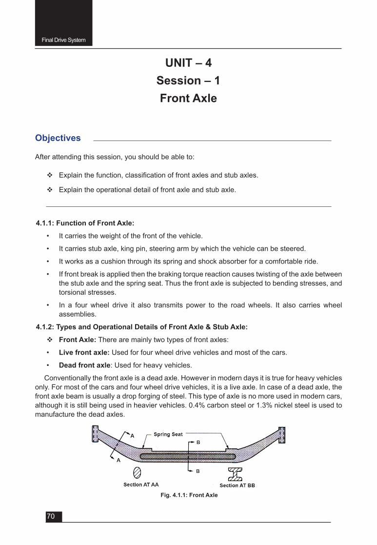
Final Drive System
70
Objectives
After attending this session, you should be able to:
v Explainthefunction,classificationoffrontaxlesandstubaxles.
v Explain the operational detail of front axle and stub axle.
UNIT – 4Session – 1Front Axle
4.1.1: Function of Front Axle:
• It carries the weight of the front of the vehicle.
• It carries stub axle, king pin, steering arm by which the vehicle can be steered.
• It works as a cushion through its spring and shock absorber for a comfortable ride.
• If front break is applied then the braking torque reaction causes twisting of the axle between the stub axle and the spring seat. Thus the front axle is subjected to bending stresses, and torsional stresses.
• In a four wheel drive it also transmits power to the road wheels. It also carries wheel assemblies.
4.1.2: Types and Operational Details of Front Axle & Stub Axle:
v Front Axle: There are mainly two types of front axles:
• Live front axle: Used for four wheel drive vehicles and most of the cars.
• Dead front axle: Used for heavy vehicles.
Conventionally the front axle is a dead axle. However in modern days it is true for heavy vehicles only. For most of the cars and four wheel drive vehicles, it is a live axle. In case of a dead axle, the front axle beam is usually a drop forging of steel. This type of axle is no more used in modern cars, althoughitisstillbeingusedinheaviervehicles.0.4%carbonsteelor1.3%nickelsteelisusedtomanufacture the dead axles.
Fig. 4.1.1: Front Axle
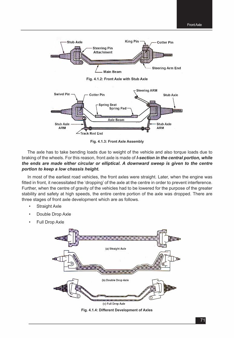
Front Axle
71
The axle has to take bending loads due to weight of the vehicle and also torque loads due to braking of the wheels. For this reason, front axle is made of I-section in the central portion, while the ends are made either circular or elliptical. A downward sweep is given to the centre portion to keep a low chassis height.
In most of the earliest road vehicles, the front axles were straight. Later, when the engine was fittedinfront,itnecessitatedthe‘dropping’oftheaxleatthecentreinordertopreventinterference.Further, when the centre of gravity of the vehicles had to be lowered for the purpose of the greater stability and safety at high speeds, the entire centre portion of the axle was dropped. There are three stages of front axle development which are as follows.
• Straight Axle
• Double Drop Axle
• Full Drop Axle
Fig. 4.1.2: Front Axle with Stub Axle
Fig. 4.1.3: Front Axle Assembly
Fig. 4.1.4: Different Development of Axles
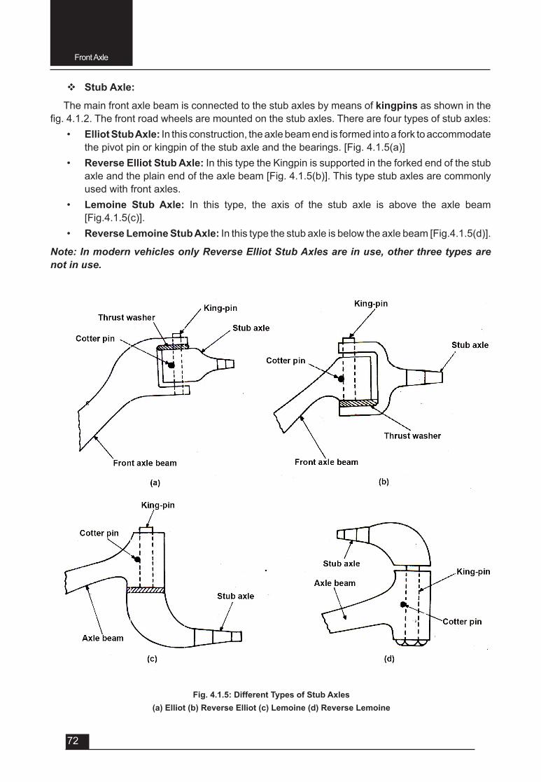
Front Axle
72
v Stub Axle:
The main front axle beam is connected to the stub axles by means of kingpins as shown in the fig.4.1.2.Thefrontroadwheelsaremountedonthestubaxles.Therearefourtypesofstubaxles:
• Elliot Stub Axle: In this construction, the axle beam end is formed into a fork to accommodate the pivot pin or kingpin of the stub axle and the bearings. [Fig. 4.1.5(a)]
• Reverse Elliot Stub Axle: In this type the Kingpin is supported in the forked end of the stub axle and the plain end of the axle beam [Fig. 4.1.5(b)]. This type stub axles are commonly used with front axles.
• Lemoine Stub Axle: In this type, the axis of the stub axle is above the axle beam [Fig.4.1.5(c)].
• Reverse Lemoine Stub Axle: In this type the stub axle is below the axle beam [Fig.4.1.5(d)].
Note: In modern vehicles only Reverse Elliot Stub Axles are in use, other three types are not in use.
Fig. 4.1.5: Different Types of Stub Axles(a) Elliot (b) Reverse Elliot (c) Lemoine (d) Reverse Lemoine
Front Axle
73
QUESTIONSVery Short Answer Type (each question carries 1 mark)
1. Inmodern cars thedeadaxle ismadeof _____%carbonsteel or _________%nickel steel.
2. Whythefrontdeadaxleisgivenadownwardsweepatthecentreportion?
3. Whichtypeofstubaxleiscommonlyusedinmoderncars?
Short Answer Type (each question carries 2 marks)
1. Why the dead front axle is made of I – Section at the centre portion, while the ends aremadeofeithercircularorellipticalcrosssection?
Short Answer Type (each question carries 3 marks)
1. Explain with sketch the Elliot stub axle.
2. Explain with sketch the Reverse Elliot stub axle (commonly used in modern vehicles).
3. Explain with sketch the Lemoine stub axle.
4. Explain with sketch the reverse Lemoine stub axle.
Long Answer Type Questions (each carry 5 marks)
1. Explain the constructional details of dead front axle with diagram.
2. Explain different types of stub-axle with diagram.
UNIT – 4
SESSION – 2
STEERING SYSTEM
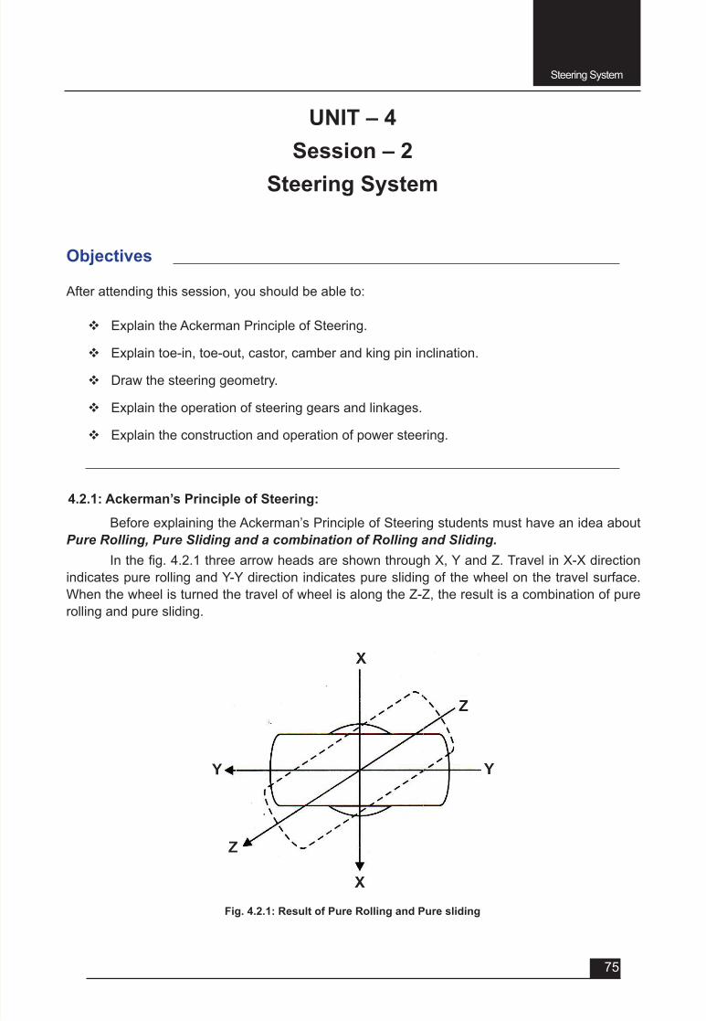
Steering System
75
Objectives
After attending this session, you should be able to:
v Explain the Ackerman Principle of Steering.
v Explain toe-in, toe-out, castor, camber and king pin inclination.
v Draw the steering geometry.
v Explain the operation of steering gears and linkages.
v Explain the construction and operation of power steering.
Fig. 4.2.1: Result of Pure Rolling and Pure sliding
UNIT – 4Session – 2
Steering System
4.2.1: Ackerman’s Principle of Steering:
Before explaining the Ackerman’s Principle of Steering students must have an idea about Pure Rolling, Pure Sliding and a combination of Rolling and Sliding.
Inthefig.4.2.1threearrowheadsareshownthroughX,YandZ.TravelinX-Xdirectionindicates pure rolling and Y-Y direction indicates pure sliding of the wheel on the travel surface. WhenthewheelisturnedthetravelofwheelisalongtheZ-Z,theresultisacombinationofpurerolling and pure sliding.
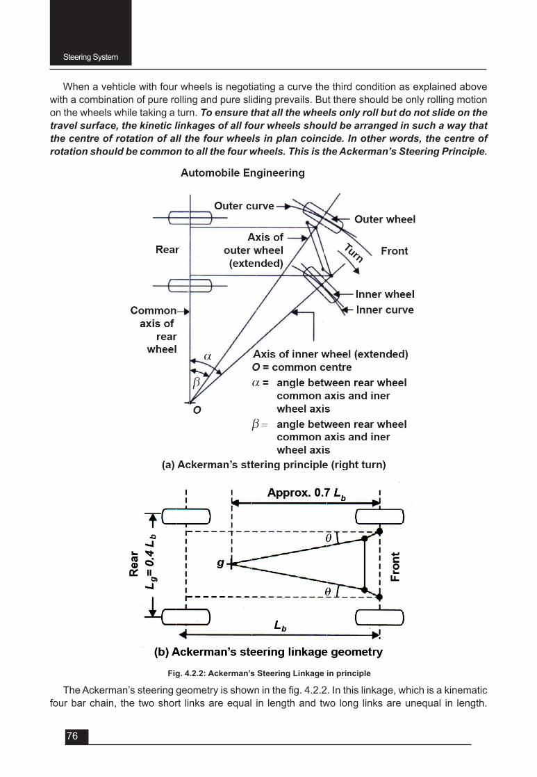
Steering System
76
When a vehticle with four wheels is negotiating a curve the third condition as explained above with a combination of pure rolling and pure sliding prevails. But there should be only rolling motion on the wheels while taking a turn. To ensure that all the wheels only roll but do not slide on the travel surface, the kinetic linkages of all four wheels should be arranged in such a way that the centre of rotation of all the four wheels in plan coincide. In other words, the centre of rotation should be common to all the four wheels. This is the Ackerman’s Steering Principle.
Fig. 4.2.2: Ackerman’s Steering Linkage in principle
TheAckerman’ssteeringgeometryisshowninthefig.4.2.2.Inthislinkage,whichisakinematicfour bar chain, the two short links are equal in length and two long links are unequal in length.
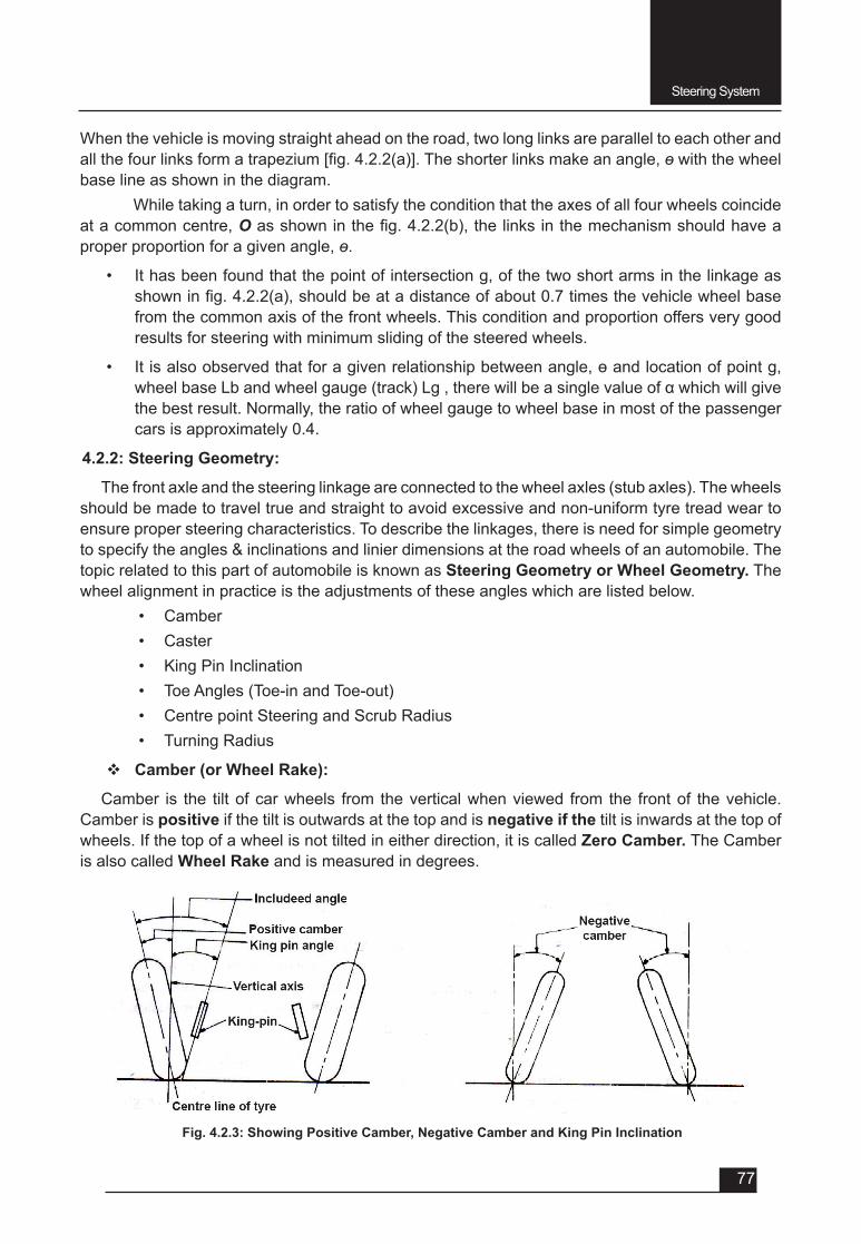
Steering System
77
When the vehicle is moving straight ahead on the road, two long links are parallel to each other and allthefourlinksformatrapezium[fig.4.2.2(a)].Theshorterlinksmakeanangle,ɵ with the wheel base line as shown in the diagram.
While taking a turn, in order to satisfy the condition that the axes of all four wheels coincide at a common centre, Oasshowninthefig.4.2.2(b),thelinksinthemechanismshouldhaveaproper proportion for a given angle, ɵ.
• It has been found that the point of intersection g, of the two short arms in the linkage as showninfig.4.2.2(a),shouldbeatadistanceofabout0.7timesthevehiclewheelbasefrom the common axis of the front wheels. This condition and proportion offers very good results for steering with minimum sliding of the steered wheels.
• Itisalsoobservedthatforagivenrelationshipbetweenangle,ɵandlocationofpointg,wheelbaseLbandwheelgauge(track)Lg,therewillbeasinglevalueofαwhichwillgivethe best result. Normally, the ratio of wheel gauge to wheel base in most of the passenger cars is approximately 0.4.
4.2.2: Steering Geometry:
The front axle and the steering linkage are connected to the wheel axles (stub axles). The wheels should be made to travel true and straight to avoid excessive and non-uniform tyre tread wear to ensure proper steering characteristics. To describe the linkages, there is need for simple geometry to specify the angles & inclinations and linier dimensions at the road wheels of an automobile. The topic related to this part of automobile is known as Steering Geometry or Wheel Geometry. The wheel alignment in practice is the adjustments of these angles which are listed below.
• Camber• Caster• King Pin Inclination• Toe Angles (Toe-in and Toe-out)• Centre point Steering and Scrub Radius• Turning Radius
v Camber (or Wheel Rake):
Camber is the tilt of car wheels from the vertical when viewed from the front of the vehicle. Camber is positive if the tilt is outwards at the top and is negative if the tilt is inwards at the top of wheels. If the top of a wheel is not tilted in either direction, it is called Zero Camber. The Camber is also called Wheel Rake and is measured in degrees.
Fig. 4.2.3: Showing Positive Camber, Negative Camber and King Pin Inclination
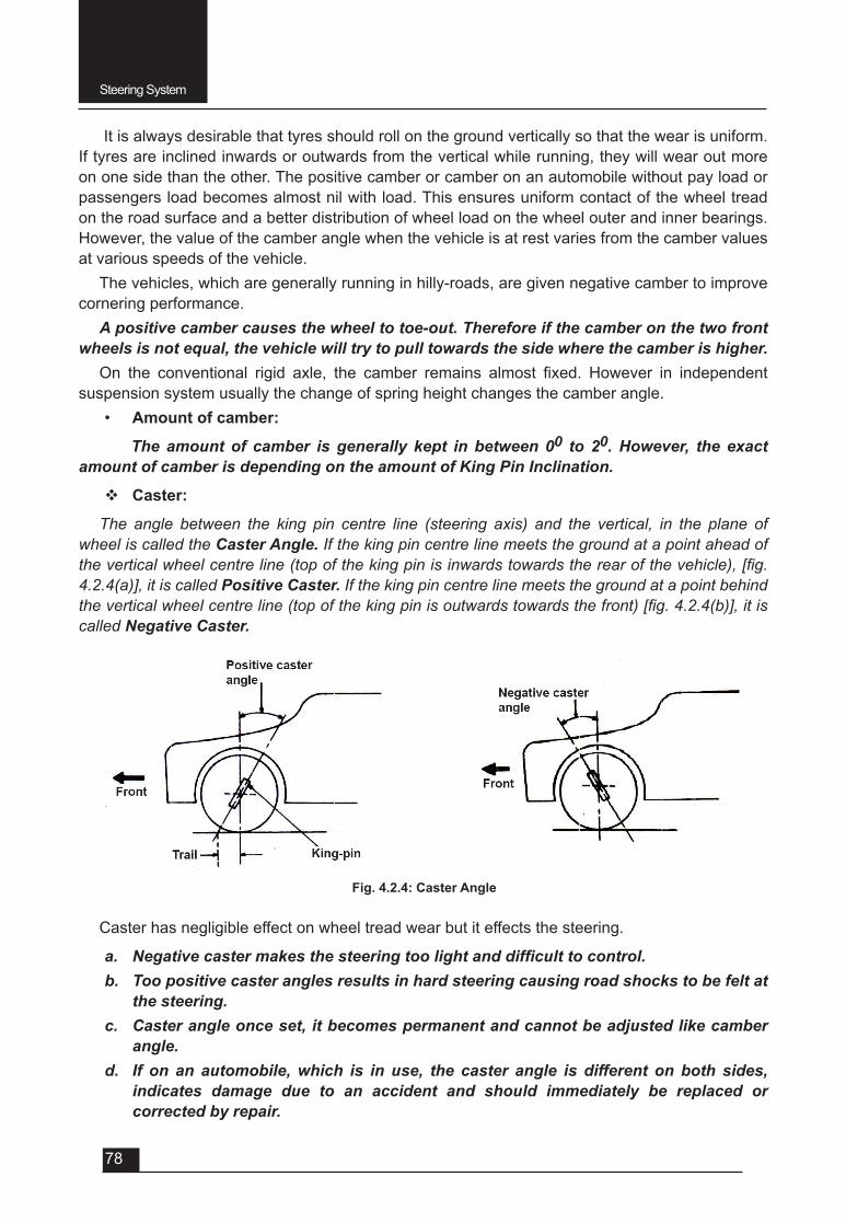
Steering System
78
It is always desirable that tyres should roll on the ground vertically so that the wear is uniform. If tyres are inclined inwards or outwards from the vertical while running, they will wear out more on one side than the other. The positive camber or camber on an automobile without pay load or passengers load becomes almost nil with load. This ensures uniform contact of the wheel tread on the road surface and a better distribution of wheel load on the wheel outer and inner bearings. However, the value of the camber angle when the vehicle is at rest varies from the camber values at various speeds of the vehicle.
The vehicles, which are generally running in hilly-roads, are given negative camber to improve cornering performance.
A positive camber causes the wheel to toe-out. Therefore if the camber on the two front wheels is not equal, the vehicle will try to pull towards the side where the camber is higher.
On the conventional rigid axle, the camber remains almost fixed. However in independentsuspension system usually the change of spring height changes the camber angle.
• Amount of camber:
The amount of camber is generally kept in between 00 to 20. However, the exact amount of camber is depending on the amount of King Pin Inclination.
v Caster:
The angle between the king pin centre line (steering axis) and the vertical, in the plane of wheel is called the Caster Angle. If the king pin centre line meets the ground at a point ahead of the vertical wheel centre line (top of the king pin is inwards towards the rear of the vehicle), [fig. 4.2.4(a)], it is called Positive Caster. If the king pin centre line meets the ground at a point behind the vertical wheel centre line (top of the king pin is outwards towards the front) [fig. 4.2.4(b)], it is called Negative Caster.
Fig. 4.2.4: Caster Angle
Caster has negligible effect on wheel tread wear but it effects the steering.
a. Negative caster makes the steering too light and difficult to control.b. Too positive caster angles results in hard steering causing road shocks to be felt at
the steering.c. Caster angle once set, it becomes permanent and cannot be adjusted like camber
angle.d. If on an automobile, which is in use, the caster angle is different on both sides,
indicates damage due to an accident and should immediately be replaced or corrected by repair.
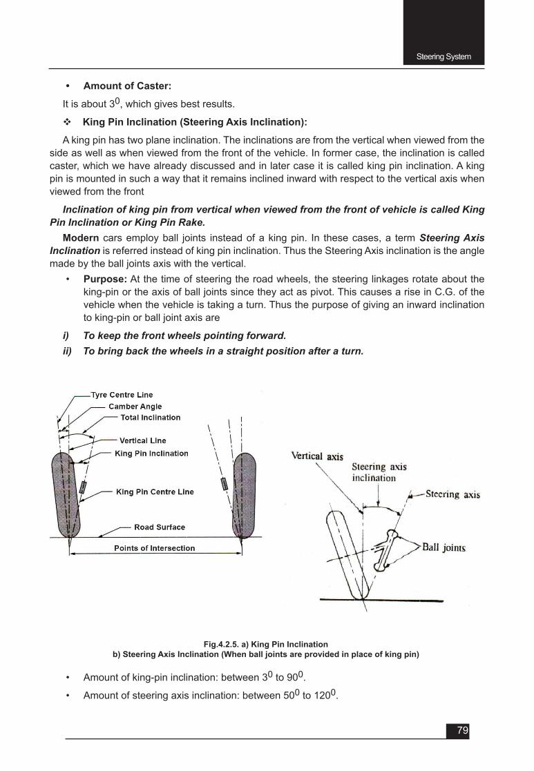
Steering System
79
• Amount of Caster:
It is about 30, which gives best results.
v King Pin Inclination (Steering Axis Inclination):
A king pin has two plane inclination. The inclinations are from the vertical when viewed from the side as well as when viewed from the front of the vehicle. In former case, the inclination is called caster, which we have already discussed and in later case it is called king pin inclination. A king pin is mounted in such a way that it remains inclined inward with respect to the vertical axis when viewed from the front
Inclination of king pin from vertical when viewed from the front of vehicle is called King Pin Inclination or King Pin Rake.
Modern cars employ ball joints instead of a king pin. In these cases, a term Steering Axis Inclination is referred instead of king pin inclination. Thus the Steering Axis inclination is the angle made by the ball joints axis with the vertical.
• Purpose: At the time of steering the road wheels, the steering linkages rotate about the king-pin or the axis of ball joints since they act as pivot. This causes a rise in C.G. of the vehicle when the vehicle is taking a turn. Thus the purpose of giving an inward inclination to king-pin or ball joint axis are
i) To keep the front wheels pointing forward.ii) To bring back the wheels in a straight position after a turn.
Fig.4.2.5. a) King Pin Inclinationb) Steering Axis Inclination (When ball joints are provided in place of king pin)
• Amount of king-pin inclination: between 30 to 900.
• Amount of steering axis inclination: between 500 to 1200.

Steering System
80
F Toe Angles (Toe-in and Toe-out):
Toe-in is the amount by which the front wheels are set closer together at the front than at the rear when the vehicle is stationery. Toe-in is shown in the Fig. 4.2.6(a) i.e.; Toe-in = B – A.
On the other hand, the wheels may be set closer at the rear than at the front, then it is called toe-out. Toe-out is shown in the Fig. 4.2.6(b) i.e.; Toe-out = A – B.
Fig.: 4.2.6: (a) Toe – in (b) Toe – out
• Purpose: The toe-in is provided on all kinds of vehicles except tractors and some front wheel drive cars.
The purpose of providing toe-in is to offset the tendency of wheel rolling
i) On the curves due to the limitation of correct steering
ii) Due to possible play in the steering linkages
iii) Due to camber effect
The toe-out is provided to counter the tendency of inward rolling of the wheels
i) Due to soil condition on agricultural land.
ii) On account of side thrusts and cross wind effect.
• Amount of toe-in and toe-out varies from 0 to 6 mm. depending upon the type of vehicles.
Centre point Steering, Scrub (or roll) radius and combined angle:
• Centre point steering: The point, at which the axis of the road wheel and axis of king-pin (or steering axis) intersects at a point on the ground, is called the centre point of steering.
• Scrub radius: The distance between the steering axis and the axis of the road wheel at the point where they intersect the road surface is called as scrub radius.
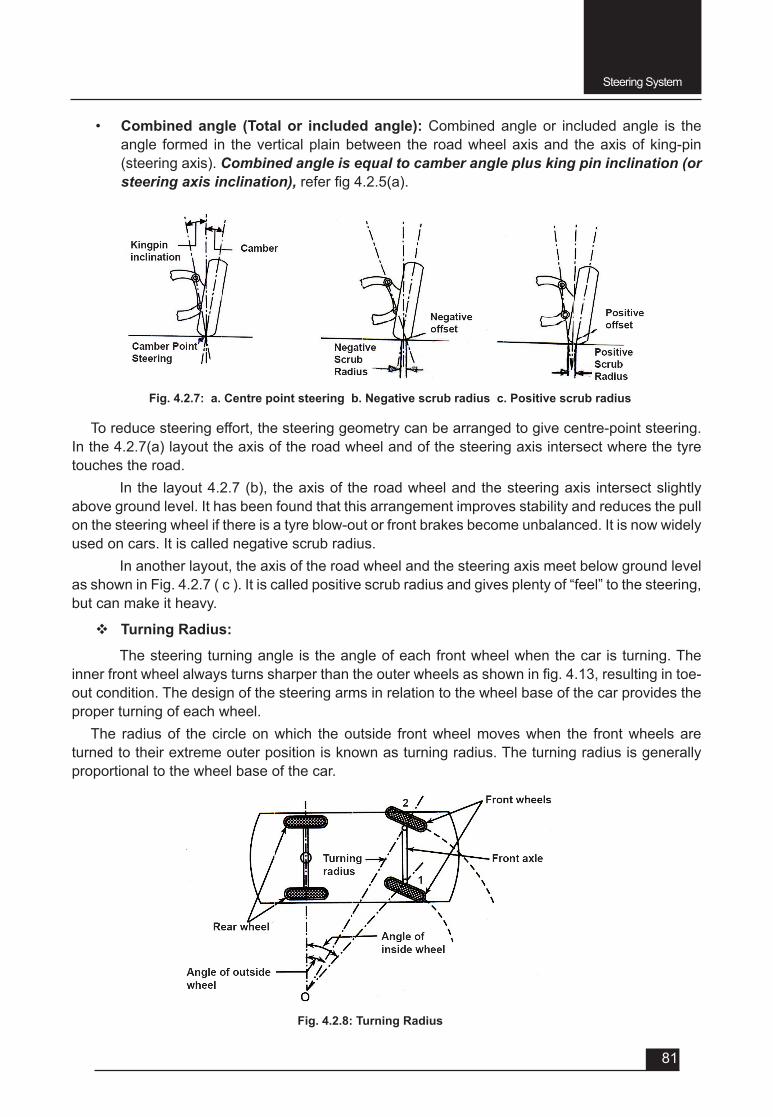
Steering System
81
• Combined angle (Total or included angle): Combined angle or included angle is the angle formed in the vertical plain between the road wheel axis and the axis of king-pin (steering axis). Combined angle is equal to camber angle plus king pin inclination (or steering axis inclination),referfig4.2.5(a).
Fig. 4.2.8: Turning Radius
To reduce steering effort, the steering geometry can be arranged to give centre-point steering. In the 4.2.7(a) layout the axis of the road wheel and of the steering axis intersect where the tyre touches the road.
In the layout 4.2.7 (b), the axis of the road wheel and the steering axis intersect slightly above ground level. It has been found that this arrangement improves stability and reduces the pull on the steering wheel if there is a tyre blow-out or front brakes become unbalanced. It is now widely used on cars. It is called negative scrub radius.
In another layout, the axis of the road wheel and the steering axis meet below ground level as shown in Fig. 4.2.7 ( c ). It is called positive scrub radius and gives plenty of “feel” to the steering, but can make it heavy.
v Turning Radius:
The steering turning angle is the angle of each front wheel when the car is turning. The innerfrontwheelalwaysturnssharperthantheouterwheelsasshowninfig.4.13,resultingintoe-out condition. The design of the steering arms in relation to the wheel base of the car provides the proper turning of each wheel.
The radius of the circle on which the outside front wheel moves when the front wheels are turned to their extreme outer position is known as turning radius. The turning radius is generally proportional to the wheel base of the car.
Fig. 4.2.7: a. Centre point steering b. Negative scrub radius c. Positive scrub radius
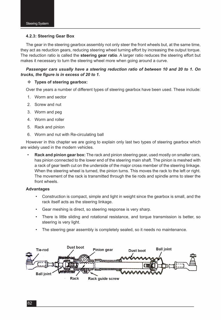
Steering System
82
4.2.3: Steering Gear Box
The gear in the steering gearbox assembly not only steer the front wheels but, at the same time, they act as reduction gears, reducing steering wheel turning effort by increasing the output torque. The reduction ratio is called the steering gear ratio. A larger ratio reduces the steering effort but makes it necessary to turn the steering wheel more when going around a curve.
Passenger cars usually have a steering reduction ratio of between 10 and 20 to 1. On trucks, the figure is in excess of 20 to 1.
v Types of steering gearbox:
Over the years a number of different types of steering gearbox have been used. These include:
1. Worm and sector
2. Screw and nut
3. Worm and peg
4. Worm and roller
5. Rack and pinion
6. Worm and nut with Re-circulating ball
However in this chapter we are going to explain only last two types of steering gearbox which are widely used in the modern vehicles.
• Rack and pinion gear box: The rack and pinion steering gear, used mostly on smaller cars, has pinion connected to the lower end of the steering main shaft. The pinion is meshed with a rack of gear teeth cut on the underside of the major cross member of the steering linkage. When the steering wheel is turned, the pinion turns. This moves the rack to the left or right. The movement of the rack is transmitted through the tie rods and spindle arms to steer the front wheels.
Advantages
• Construction is compact, simple and light in weight since the gearbox is small, and the rack itself acts as the steering linkage.
• Gear meshing is direct, so steering response is very sharp.
• There is little sliding and rotational resistance, and torque transmission is better, so steering is very light.
• The steering gear assembly is completely sealed, so it needs no maintenance.
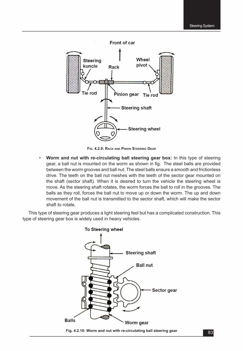
Steering System
83
• Worm and nut with re-circulating ball steering gear box: In this type of steering gear,aballnutismountedonthewormasshowninfig.Thesteelballsareprovidedbetween the worm grooves and ball nut. The steel balls ensure a smooth and frictionless drive. The teeth on the ball nut meshes with the teeth of the sector gear mounted on the shaft (sector shaft). When it is desired to turn the vehicle the steering wheel is move. As the steering shaft rotates, the worm forces the ball to roll in the grooves. The balls as they roll, forces the ball nut to move up or down the worm. The up and down movement of the ball nut is transmitted to the sector shaft, which will make the sector shaft to rotate.
This type of steering gear produces a light steering feel but has a complicated construction. This type of steering gear box is widely used in heavy vehicles.
Fig. 4.2.10: Worm and nut with re-circulating ball steering gear
FIg. 4.2.9: Rack aNd PINIoN STeeRINg geaR
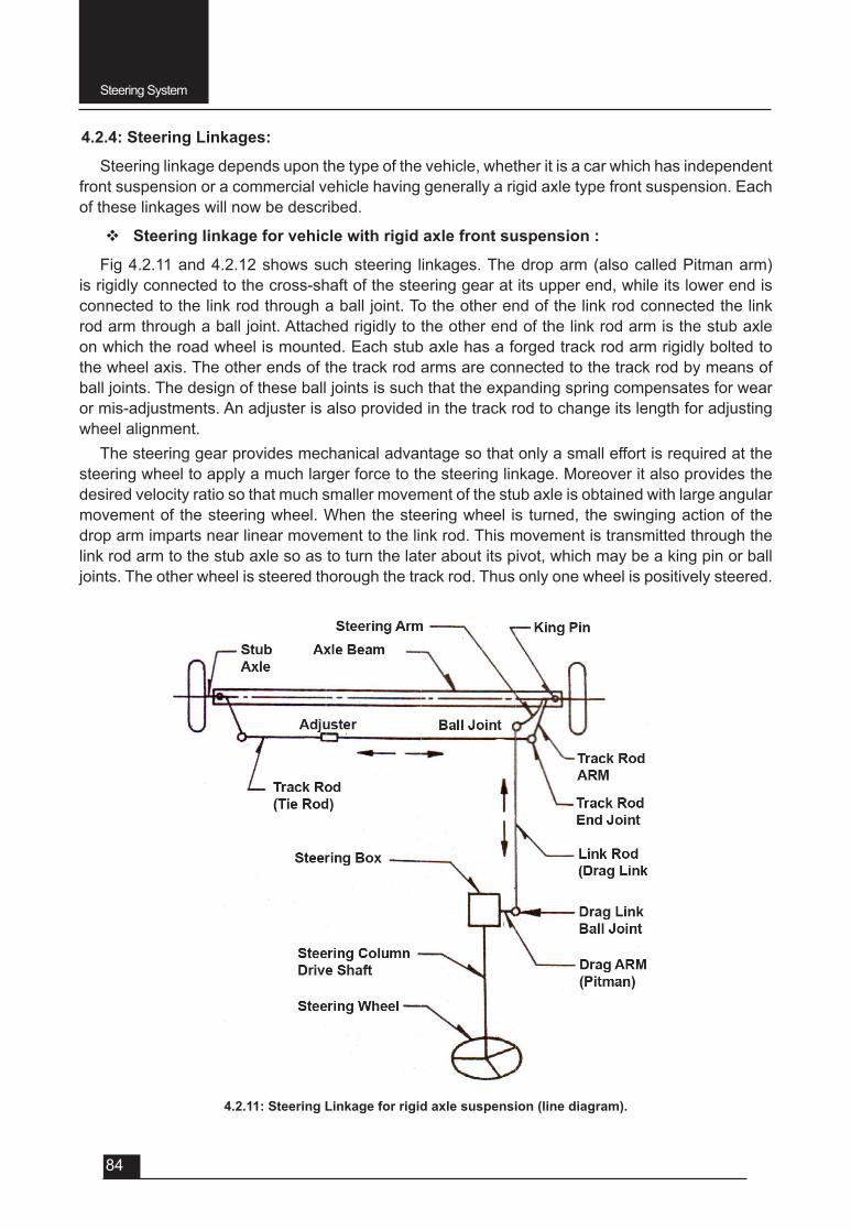
Steering System
84
4.2.4: Steering Linkages:
Steering linkage depends upon the type of the vehicle, whether it is a car which has independent front suspension or a commercial vehicle having generally a rigid axle type front suspension. Each of these linkages will now be described.
v Steering linkage for vehicle with rigid axle front suspension :
Fig 4.2.11 and 4.2.12 shows such steering linkages. The drop arm (also called Pitman arm) is rigidly connected to the cross-shaft of the steering gear at its upper end, while its lower end is connected to the link rod through a ball joint. To the other end of the link rod connected the link rod arm through a ball joint. Attached rigidly to the other end of the link rod arm is the stub axle on which the road wheel is mounted. Each stub axle has a forged track rod arm rigidly bolted to the wheel axis. The other ends of the track rod arms are connected to the track rod by means of ball joints. The design of these ball joints is such that the expanding spring compensates for wear or mis-adjustments. An adjuster is also provided in the track rod to change its length for adjusting wheel alignment.
The steering gear provides mechanical advantage so that only a small effort is required at the steering wheel to apply a much larger force to the steering linkage. Moreover it also provides the desired velocity ratio so that much smaller movement of the stub axle is obtained with large angular movement of the steering wheel. When the steering wheel is turned, the swinging action of the drop arm imparts near linear movement to the link rod. This movement is transmitted through the link rod arm to the stub axle so as to turn the later about its pivot, which may be a king pin or ball joints. The other wheel is steered thorough the track rod. Thus only one wheel is positively steered.
4.2.11: Steering Linkage for rigid axle suspension (line diagram).
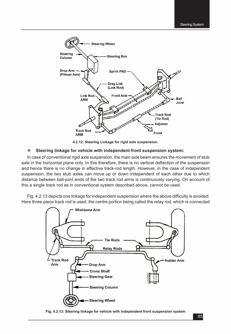
Steering System
85
v Steering linkage for vehicle with independent front suspension system: In case of conventional rigid axle suspension, the main axle beam ensures the movement of stub
axleinthehorizontalplaneonly.Inthistherefore,thereisnoverticaldeflectionofthesuspensionand hence there is no change in effective track-rod length. However, in the case of independent suspension, the two stub axles can move up or down independent of each other due to which distance between ball-joint ends of the two track rod arms is continuously varying. On account of this a single track rod as in conventional system described above, cannot be used.
Fig.4.2.13depictsonelinkageforindependentsuspensionwheretheabovedifficultyisavoided.Here three-piece track rod is used, the centre portion being called the relay rod, which is connected
Fig. 4.2.13: Steering linkage for vehicle with independent front suspension system
4.2.12: Steering Linkage for rigid axle suspension.

Steering System
86
at one end to an idler arm supported on body structure and to the drop arm of the steering gear at the other end through ball joints. The relay rod is restricted to move in horizontal plane only. Movement in vertical plane is provided by the outer portions, viz, the tie rods about the end ball joints.
4.2.5: Power Steering: The power steering system is the system employed in automobiles to reduce the effort
required to operate the steering wheel. This feature adds to the comfort while driving, as less effort is required to turn the steering by the driver.
The following are the advantages and disadvantages of the power steering system.
Advantages
1. The power steering system reduces the number of turns of steering wheel required to move it from lock to lock (i.e. steering ratio on a vehicle having power steering us usually less).
2. Easy steering while parking, at low speeds or tight turns.
Disadvantages
The components used in the power steering assembly are more costly than the ones used in the normal steering.
The most commonly power steering systems employed in automobiles are
1. Hydraulic power steering systems, and
2. Electrically assisted, electronic power steering systems (or simply electronic power steering systems).
Types of Power Steering
There are two types of power steering system
• Hydraulic Power Steering
• Electronic Power Steering
F Hydraulic Power Steering System: The hydraulic power steering, as discussed above, is the system having a hydraulic booster that reduces the force required to operate the steering wheel.
Components
The hydraulic power steering system consists of the following major components, as shown in fig.4.2.14.
1. Pump: It generates hydraulic pressure.
2. Control valve: It switches the oil passage to the power cylinder according to the rotational direction of the steering wheel.
3. Power Cylinder: It moves the piston in the cylinder to the right or left with hydraulic force and thereby assists the steering wheel operation.
4. Fluid reservoir:Thepowersteeringfluidreservoirstoresfluidandcleansitusingabuiltinfilter.
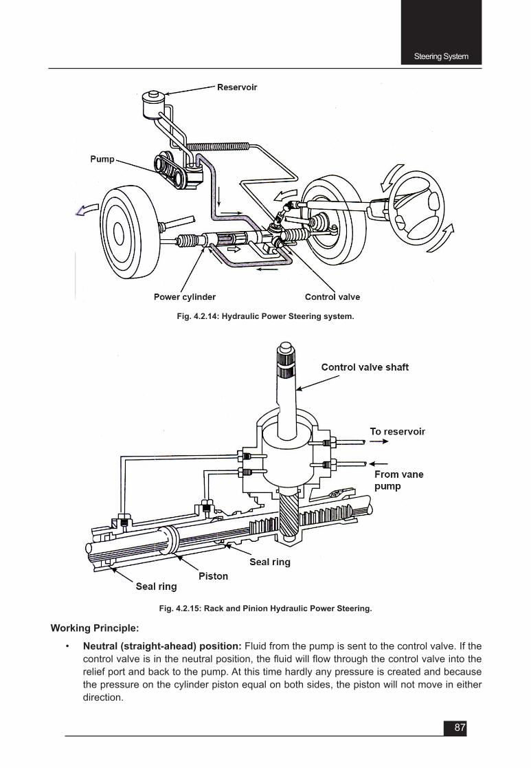
Steering System
87
Working Principle:
• Neutral (straight-ahead) position: Fluid from the pump is sent to the control valve. If the controlvalveisintheneutralposition,thefluidwillflowthroughthecontrolvalveintotherelief port and back to the pump. At this time hardly any pressure is created and because the pressure on the cylinder piston equal on both sides, the piston will not move in either direction.
Fig. 4.2.15: Rack and Pinion Hydraulic Power Steering.
Fig. 4.2.14: Hydraulic Power Steering system.
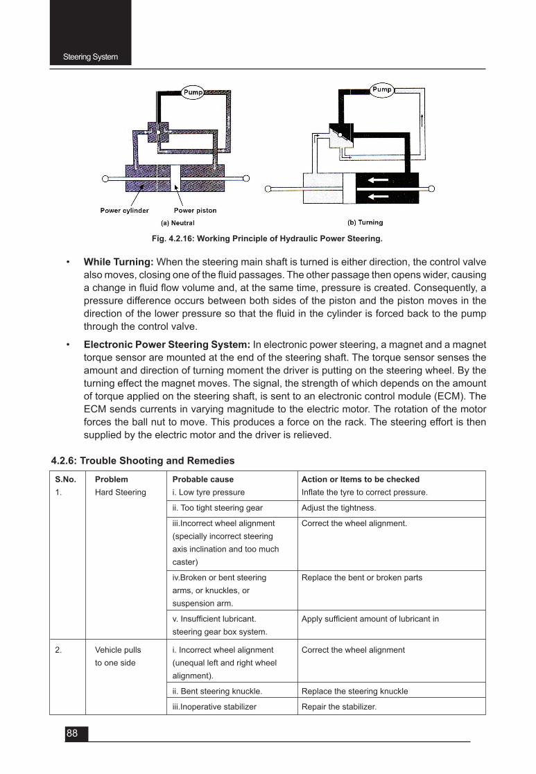
Steering System
88
• While Turning: When the steering main shaft is turned is either direction, the control valve alsomoves,closingoneofthefluidpassages.Theotherpassagethenopenswider,causingachangeinfluidflowvolumeand,atthesametime,pressureiscreated.Consequently,apressure difference occurs between both sides of the piston and the piston moves in the directionofthelowerpressuresothatthefluidinthecylinderisforcedbacktothepumpthrough the control valve.
• Electronic Power Steering System: In electronic power steering, a magnet and a magnet torque sensor are mounted at the end of the steering shaft. The torque sensor senses the amount and direction of turning moment the driver is putting on the steering wheel. By the turning effect the magnet moves. The signal, the strength of which depends on the amount of torque applied on the steering shaft, is sent to an electronic control module (ECM). The ECM sends currents in varying magnitude to the electric motor. The rotation of the motor forces the ball nut to move. This produces a force on the rack. The steering effort is then supplied by the electric motor and the driver is relieved.
4.2.6: Trouble Shooting and Remedies
S.No. Problem Probable cause Action or Items to be checked1. HardSteering i.Lowtyrepressure Inflatethetyretocorrectpressure.
ii. Too tight steering gear Adjust the tightness.
iii.Incorrect wheel alignment Correct the wheel alignment. (specially incorrect steering axis inclination and too much caster)
iv.Broken or bent steering Replace the bent or broken parts arms, or knuckles, or suspension arm.
v.Insufficientlubricant. Applysufficientamountoflubricantin steering gear box system.
2. Vehicle pulls i. Incorrect wheel alignment Correct the wheel alignment to one side (unequal left and right wheel alignment).
ii. Bent steering knuckle. Replace the steering knuckle
iii.Inoperative stabilizer Repair the stabilizer.
Fig. 4.2.16: Working Principle of Hydraulic Power Steering.
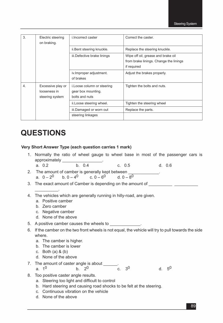
Steering System
89
3. Electric steering i.Incorrect caster Correct the caster. on braking.
ii.Bent steering knuckle. Replace the steering knuckle.
iii.Defective brake linings Wipe off oil, grease and brake oil from brake linings. Change the linings if required
iv.Improper adjustment. Adjust the brakes properly. of brakes
4. Excessive play or i.Loose column or steering Tighten the bolts and nuts. looseness in gear box mounting. steering system bolts and nuts
ii.Loose steering wheel. Tighten the steering wheel
iii.Damaged or worn out Replace the parts. steering linkages
QUESTIONSVery Short Answer Type (each question carries 1 mark)
1. Normally the ratio of wheel gauge to wheel base in most of the passenger cars is approximately _________________.a. 0.2 b. 0.4 c. 0.5 d. 0.6
2. The amount of camber is generally kept between _____________.a. 0 – 20 b. 0 – 40 c. 0 – 60 d. 0 – 80
3. The exact amount of Camber is depending on the amount of __________ __________ __________.
4. The vehicles which are generally running in hilly-road, are given.a. Positive camberb. Zerocamberc. Negative camberd. None of the above
5. A positive camber causes the wheels to _____________.6. If the camber on the two front wheels is not equal, the vehicle will try to pull towards the side
where.a. The camber is higher.b. The camber is lowerc. Both (a) & (b)d. None of the above
7. The amount of caster angle is about ______.a. 10 b. 20 c. 30 d. 50
8. Too positive caster angle results.a. Steeringtoolightanddifficulttocontrolb. Hard steering and causing road shocks to be felt at the steering.c. Continuous vibration on the vehicled. None of the above
Steering System
90
9. Amount of Toe-angle (Toe-in or Toe-out) varies from _________ to __________mm., depending upon the type of vehicle.
10. Steering gear reduction ratio for car is betweena. 10 and 20 to 1b. 20 and 30 to 1c. 30 and 40 to 1d. 40 and 50 to 1
11. Steering gear ratio for trucks is __________.12.Whichtypeofsteeringgearboxiswidelyusedincar?
a. Worm and sectorb. Worm and rollerc. Rack and Piniond. Re-circulating ball type
13.Whichtypeofsteeringgearboxiswidelyusedinheavyvehicles?
a. Worm and sectorb. Worm and rollerc. Rack and Piniond. Re-circulating ball type
Short Answer Type (each question carries 2 marks)1. Write the purpose of providing King Pin inclination or steering axis inclination.2. WhatistheamountofKing-pininclinationandsteeringaxisinclination?3. DefineCentrepointofsteering.4. DefineScrub(orroll)radius5. DefineCombinedangle.6. Name different types of power steering.
Short Answer Type (each question carries 3 marks)1. Explain Pure Rolling, Pure Sliding and combination of both.2. Definethecamberwithsketch.3. Definecasteranglewithsketch.4. Write the effects of caster angle on steering.5. DefineToe-angle(Toe-inandToe-out)withdiagram.6. WhatarethepurposesofToe-inandToe-out?7. Name different types of steering gear boxes.8. Write the advantages and disadvantages of Power Steering.9. Write short note on Electronic Power Steering system.
Long Answer Type Questions (each carry 5 marks)1. Explain the Ackerman’s Principle of Steering.2. Explain with diagram the wheel Rake (camber).3. Explain Caster with diagram.4. Explain with sketch, the king pin inclination and steering axis inclination.5. Explain the following with neat sketches:
a. Centre point of Steeringb. Scrub or roll radiusc. Combined angle.
Steering System
91
6. Explain construction of Rack and Pinion type steering gear box with its advantages.7. Explain construction of Worm and nut with re-circulating ball type steering gear box.8. With neat sketch write the construction of steering linkages for rigid axle suspension
system.9. With neat sketch write the construction of steering linkages for vehicle with independent
front suspension system.10. Explain the function of different components of Hydraulic Power Steering.11. Explain with diagram the working principle of Hydraulic Power Steering.12. Write the causes of following trouble shooting of steering system and their remedial action
a. Hard steeringb. Vehicle pull to one sidec. Excessive play or looseness in steering systemd. Electric steering on braking.

UNIT – 5
SESSION – 1
CHASSIS FRAME
Chassis Frame
93
Objectives
After attending this session, you should be able to:
v Understand the function of frame and difference between frame and chassis.
v Understand the constructional details of different types of frames.
v Gain the knowledge about the different frame sections and different parts of frames.
5.1.1: Chassis Frame
The chassis of an automobile consists of following components suitably mounted:• Engine and the radiator.
• Transmission system.
• Road wheels.
• Steering system.
• Brakes
• Fuel tank.
All the components listed above are mounted in either of the two ways, viz., the conventional construction, in which a separate frame is used and the frameless or unitary construction in which no separate frame is employed. Out of these, the conventional type of construction is being used presently only for heavy vehicles whereas for car the frameless type is being used by all manufactures.
v Function of Frame• To support the chassis components and the body
• Towithstandstaticanddynamicloadswithoutunduedeflectionordistortion.
v Frame Constructional details: The chassis frame is usually constructed from steel pressings which may be welded,
riveted or bolted together and reinforced where necessary. There are two major types, conventional construction and unitized body construction.
• Conventional construction: In this type of chassis construction the frame is the basic unit to which various components are attached and body is bolted on the frame later on. It is also known as framed construction.
UNIT – 5Session – 1
Chassis Frame
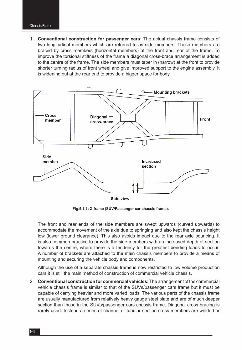
Chassis Frame
94
The front and rear ends of the side members are swept upwards (curved upwards) to accommodate the movement of the axle due to springing and also kept the chassis height low (lower ground clearance). This also avoids impact due to the rear axle bouncing. It is also common practice to provide the side members with an increased depth of section towards the centre, where there is a tendency for the greatest bending loads to occur. A number of brackets are attached to the main chassis members to provide a means of mounting and securing the vehicle body and components.
Although the use of a separate chassis frame is now restricted to low volume production cars it is still the main method of construction of commercial vehicle chassis.
2. Conventional construction for commercial vehicles: The arrangement of the commercial vehicle chassis frame is similar to that of the SUVs/passenger cars frame but it must be capable of carrying heavier and more varied loads. The various parts of the chassis frame are usually manufactured from relatively heavy gauge steel plate and are of much deeper section than those in the SUVs/passenger cars chassis frame. Diagonal cross bracing is rarely used. Instead a series of channel or tubular section cross members are welded or
1. Conventional construction for passenger cars: The actual chassis frame consists of two longitudinal members which are referred to as side members. These members are braced by cross members (horizontal members) at the front and rear of the frame. To improve the torsional stiffness of the frame a diagonal cross-brace arrangement is added to the centre of the frame. The side members must taper in (narrow) at the front to provide shorter turning radius of front wheel and give improved support to the engine assembly. It is widening out at the rear end to provide a bigger space for body.
Fig.5.1.1: X-frame (SUV/Passenger car chassis frame).
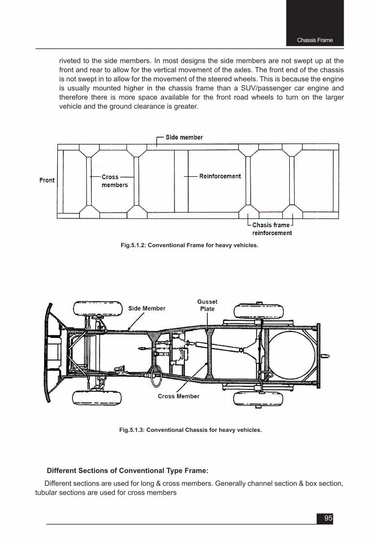
Chassis Frame
95
riveted to the side members. In most designs the side members are not swept up at the front and rear to allow for the vertical movement of the axles. The front end of the chassis is not swept in to allow for the movement of the steered wheels. This is because the engine is usually mounted higher in the chassis frame than a SUV/passenger car engine and therefore there is more space available for the front road wheels to turn on the larger vehicle and the ground clearance is greater.
Fig.5.1.2: Conventional Frame for heavy vehicles.
Fig.5.1.3: Conventional Chassis for heavy vehicles.
Different Sections of Conventional Type Frame:
Different sections are used for long & cross members. Generally channel section & box section, tubular sections are used for cross members
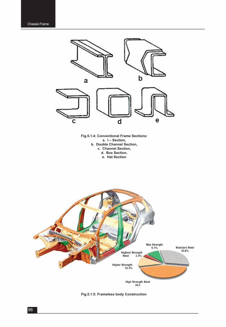
Chassis Frame
96
Fig.5.1.5: Frameless body Construction
Fig.5.1.4: Conventional Frame Sections:a. I – Section,
b. Double Channel Section, c. Channel Section,
d. Box Section, e. Hat Section
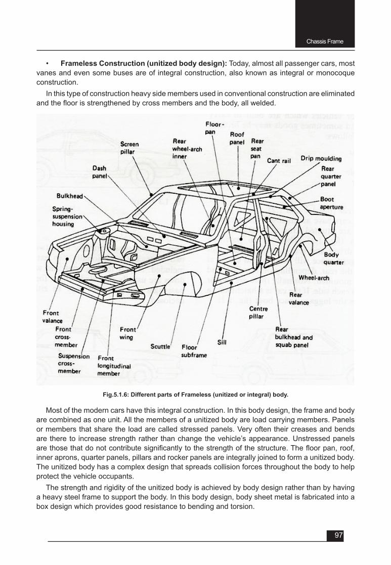
Chassis Frame
97
• Frameless Construction (unitized body design): Today, almost all passenger cars, most vanes and even some buses are of integral construction, also known as integral or monocoque construction.
In this type of construction heavy side members used in conventional construction are eliminated andthefloorisstrengthenedbycrossmembersandthebody,allwelded.
Most of the modern cars have this integral construction. In this body design, the frame and body are combined as one unit. All the members of a unitized body are load carrying members. Panels or members that share the load are called stressed panels. Very often their creases and bends are there to increase strength rather than change the vehicle’s appearance. Unstressed panels arethosethatdonotcontributesignificantlytothestrengthofthestructure.Thefloorpan,roof,inner aprons, quarter panels, pillars and rocker panels are integrally joined to form a unitized body. The unitized body has a complex design that spreads collision forces throughout the body to help protect the vehicle occupants.
The strength and rigidity of the unitized body is achieved by body design rather than by having a heavy steel frame to support the body. In this body design, body sheet metal is fabricated into a box design which provides good resistance to bending and torsion.
Fig.5.1.6: Different parts of Frameless (unitized or integral) body.

Chassis Frame
98
Advantages
F These constructions have low weight. F These designs have the ability to style the outer body panels as desired.
Disadvantages
v Production costs are very high.v Box like shape in design tends to amplify the road and engine noise for occupants. Special
sound deadening materials are used to minimize the transmission noise.
MUST KNOW POINTS:
• The frame is narrowed down at the front (in-swept) to have a better steering lock which provides space for pivoting & swinging of the front wheels.
• Upswept at the rear provided to give room for the vertical movement of the rear axle as it travels over road bumps & other road inequalities.
• Body brackets are provided to support the body of the vehicle.• Spring brackets are provided for mounting the body of the vehiscle.• Extension of chassis frame ahead of the front axle known as front overhung.• Extension of chassis beyond the rear axle known as rear overhung.
QUESTIONS Very Short answer type (each question carries 1 mark)
1. Definechassisframe.
2. Definechassis.
3. Write the purpose of providing the in-swept to the chassis frame.
4. Write the purpose of providing the up-swept to the chassis frame.
5. Write the purpose of providing the body brackets to the chassis frame.
6. Write the purpose of providing the spring brackets to the chassis frame.
7. Whatisfrontover-hungofchassisframe?
8. Whatisrearover-hungofchassisframe?
9. ForwhichtypeofvehicletheX-typechassisframeisused?
Short answer type (each question carries 2 marks)
1. Whatarethefunctionsofchassisframe?
Short answer type (each question carries 3 marks)
1. Draw different sections of conventional chassis frames.
2. Write the advantages and disadvantages of frameless (unitized) body construction.
3. Write the advantages and disadvantages of conventional chassis frame..
Long answer type (each question carries 5 marks)
1. Explain the construction of conventional chassis frame.
2. Explain the construction of frameless (unitized) body construction.

UNIT – 5
SESSION – 2
SUSPENSION SYSTEM
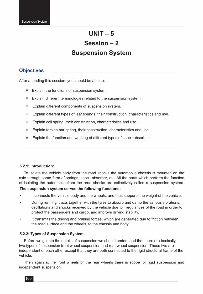
Suspension System
100
Objectives
After attending this session, you should be able to:
v Explain the functions of suspension system.
v Explain different terminologies related to the suspension system.
v Explain different components of suspension system.
v Explain different types of leaf springs, their construction, characteristics and use.
v Explain coil spring, their construction, characteristics and use.
v Explain torsion bar spring, their construction, characteristics and use.
v Explain the function and working of different types of shock absorber.
UNIT – 5Session – 2
Suspension System
5.2.1: Introduction:
To isolate the vehicle body from the road shocks the automobile chassis is mounted on the axle through some form of springs, shock absorber, etc. All the parts which perform the function of isolating the automobile from the road shocks are collectively called a suspension system. The suspension system serves the following functions:
• It connects the vehicle body and the wheels, and thus supports the weight of the vehicle.
• During running it acts together with the tyres to absorb and damp the various vibrations, oscillations and shocks received by the vehicle due to irregularities of the road in order to protect the passengers and cargo, and improve driving stability.
• It transmits the driving and braking forces, which are generated due to friction between the road surface and the wheels, to the chassis and body.
5.2.2: Types of Suspension System
Before we go into the details of suspension we should understand that there are basically two types of suspension front wheel suspension and rear wheel suspension. These two are independent of each other except that they are both connected to the rigid structural frame of the vehicle.
Then again at the front wheels or the rear wheels there is scope for rigid suspension and independent suspension
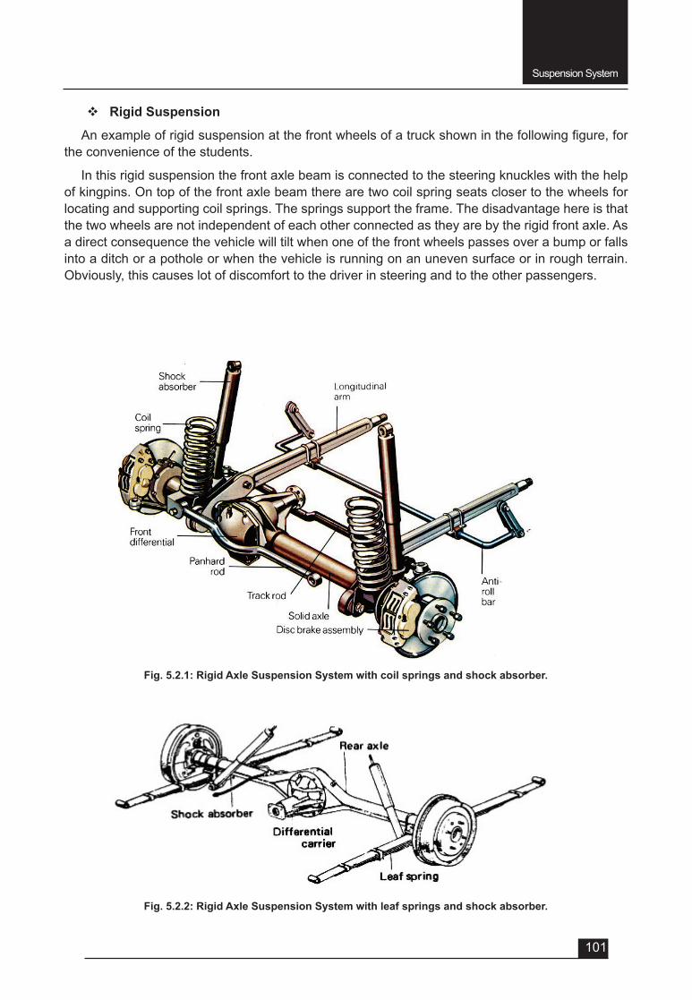
Suspension System
101
v Rigid Suspension
Anexampleofrigidsuspensionatthefrontwheelsofatruckshowninthefollowingfigure,forthe convenience of the students.
In this rigid suspension the front axle beam is connected to the steering knuckles with the help of kingpins. On top of the front axle beam there are two coil spring seats closer to the wheels for locating and supporting coil springs. The springs support the frame. The disadvantage here is that the two wheels are not independent of each other connected as they are by the rigid front axle. As a direct consequence the vehicle will tilt when one of the front wheels passes over a bump or falls into a ditch or a pothole or when the vehicle is running on an uneven surface or in rough terrain. Obviously, this causes lot of discomfort to the driver in steering and to the other passengers.
Fig. 5.2.1: Rigid Axle Suspension System with coil springs and shock absorber.
Fig. 5.2.2: Rigid Axle Suspension System with leaf springs and shock absorber.
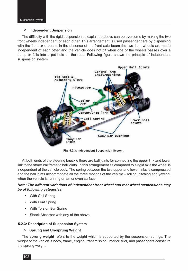
Suspension System
102
v Independent Suspension
Thedifficultywiththerigidsuspensionasexplainedabovecanbeovercomebymakingthetwofront wheels independent of each other. This arrangement is used passenger cars by dispensing with the front axle beam. In the absence of the front axle beam the two front wheels are made independent of each other and the vehicle does not tilt when one of the wheels passes over a bumpor falls intoapot holeon the road.Following figure shows theprincipleof independentsuspension system.
Fig. 5.2.3: Independent Suspension System.
At both ends of the steering knuckle there are ball joints for connecting the upper link and lower link to the structural frame to ball joints. In this arrangement as compared to a rigid axle the wheel is independent of the vehicle body. The spring between the two upper and lower links is compressed and the ball joints accommodate all the three motions of the vehicle – rolling, pitching and yawing, when the vehicle is running on an uneven surface.
Note: The different variations of independent front wheel and rear wheel suspensions may be of following categories;
• With Coil Spring
• With Leaf Spring
• With Torsion Bar Spring
• Shock Absorber with any of the above.
5.2.3: Description of Suspension System
v Sprung and Un-sprung Weight
The sprung weight refers to the weight which is supported by the suspension springs. The weight of the vehicle’s body, frame, engine, transmission, interior, fuel, and passengers constitute the sprung weight.
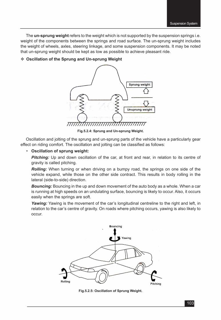
Suspension System
103
Fig.5.2.4: Sprung and Un-sprung Weight.
Oscillation and jolting of the sprung and un-sprung parts of the vehicle have a particularly gear effectonridingcomfort.Theoscillationandjoltingcanbeclassifiedasfollows:
• Oscillation of sprung weight: Pitching: Up and down oscillation of the car, at front and rear, in relation to its centre of
gravity is called pitching. Rolling: When turning or when driving on a bumpy road, the springs on one side of the
vehicle expand, while those on the other side contract. This results in body rolling in the lateral (side-to-side) direction.
Bouncing: Bouncing in the up and down movement of the auto body as a whole. When a car is running at high speeds on an undulating surface, bouncing is likely to occur. Also, it occurs easily when the springs are soft.
Yawing: Yawing is the movement of the car’s longitudinal centreline to the right and left, in relation to the car’s centre of gravity. On roads where pitching occurs, yawing is also likely to occur.
The un-sprung weight refers to the weight which is not supported by the suspension springs i.e. weight of the components between the springs and road surface. The un-sprung weight includes the weight of wheels, axles, steering linkage, and some suspension components. It may be noted that un-sprung weight should be kept as low as possible to achieve pleasant ride.
v Oscillation of the Sprung and Un-sprung Weight
Fig.5.2.5: Oscillation of Sprung Weight.
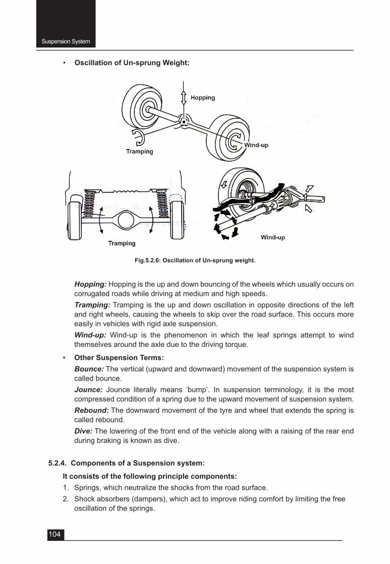
Suspension System
104
Fig.5.2.6: Oscillation of Un-sprung weight.
• Oscillation of Un-sprung Weight:
Hopping: Hopping is the up and down bouncing of the wheels which usually occurs on corrugated roads while driving at medium and high speeds.
Tramping: Tramping is the up and down oscillation in opposite directions of the left and right wheels, causing the wheels to skip over the road surface. This occurs more easily in vehicles with rigid axle suspension.
Wind-up: Wind-up is the phenomenon in which the leaf springs attempt to wind themselves around the axle due to the driving torque.
• Other Suspension Terms: Bounce: The vertical (upward and downward) movement of the suspension system is
called bounce. Jounce: Jounce literally means ‘bump’. In suspension terminology, it is the most
compressed condition of a spring due to the upward movement of suspension system. Rebound: The downward movement of the tyre and wheel that extends the spring is
called rebound. Dive: The lowering of the front end of the vehicle along with a raising of the rear end
during braking is known as dive.
5.2.4. Components of a Suspension system:
It consists of the following principle components:1. Springs, which neutralize the shocks from the road surface.2. Shock absorbers (dampers), which act to improve riding comfort by limiting the free
oscillation of the springs.
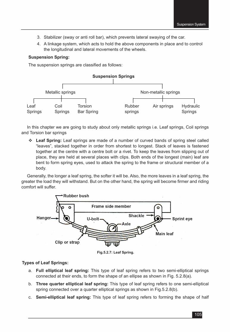
Suspension System
105
3. Stabilizer (sway or anti roll bar), which prevents lateral swaying of the car.4. A linkage system, which acts to hold the above components in place and to control
the longitudinal and lateral movements of the wheels.
Suspension Spring:
Thesuspensionspringsareclassifiedasfollows:
In this chapter we are going to study about only metallic springs i.e. Leaf springs, Coil springs and Torsion bar springs
v Leaf Spring: Leaf springs are made of a number of curved bands of spring steel called “leaves”, stacked together in order from shortest to longest. Stack of leaves is fastened together at the centre with a centre bolt or a rivet. To keep the leaves from slipping out of place, they are held at several places with clips. Both ends of the longest (main) leaf are bent to form spring eyes, used to attack the spring to the frame or structural member of a body.
Generally, the longer a leaf spring, the softer it will be. Also, the more leaves in a leaf spring, the greatertheloadtheywillwithstand.Butontheotherhand,thespringwillbecomefirmerandridingcomfort will suffer.
Fig.5.2.7: Leaf Spring.
Suspension Springs
Metallic springs Non-metallic springs
Leaf Springs
Rubber springs
Coil Springs
Air springsTorsion Bar Spring
Hydraulic Springs
Types of Leaf Springs:
a. Full elliptical leaf spring: This type of leaf spring refers to two semi-elliptical springs connected at their ends, to form the shape of an ellipse as shown in Fig. 5.2.8(a).
b. Three quarter elliptical leaf spring: This type of leaf spring refers to one semi-elliptical spring connected over a quarter elliptical springs as shown in Fig.5.2.8(b).
c. Semi-elliptical leaf spring: This type of leaf spring refers to forming the shape of half
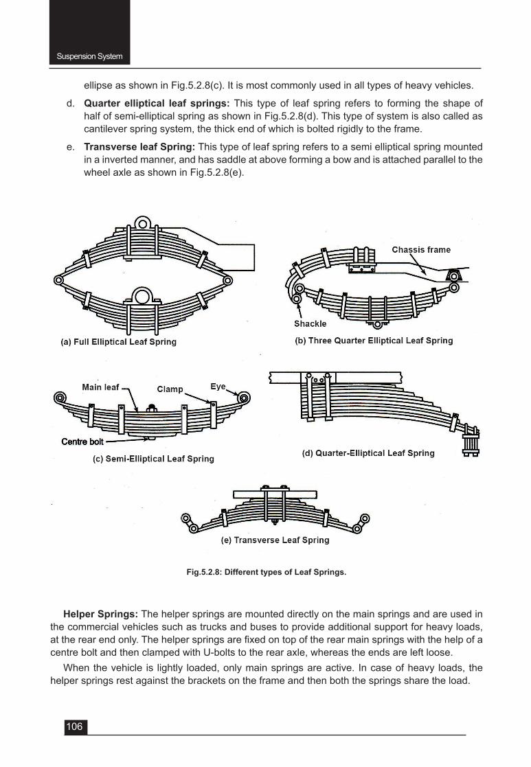
Suspension System
106
ellipse as shown in Fig.5.2.8(c). It is most commonly used in all types of heavy vehicles.
d. Quarter elliptical leaf springs: This type of leaf spring refers to forming the shape of half of semi-elliptical spring as shown in Fig.5.2.8(d). This type of system is also called as cantilever spring system, the thick end of which is bolted rigidly to the frame.
e. Transverse leaf Spring: This type of leaf spring refers to a semi elliptical spring mounted in a inverted manner, and has saddle at above forming a bow and is attached parallel to the wheel axle as shown in Fig.5.2.8(e).
Helper Springs: The helper springs are mounted directly on the main springs and are used in the commercial vehicles such as trucks and buses to provide additional support for heavy loads, attherearendonly.Thehelperspringsarefixedontopoftherearmainspringswiththehelpofacentre bolt and then clamped with U-bolts to the rear axle, whereas the ends are left loose.
When the vehicle is lightly loaded, only main springs are active. In case of heavy loads, the helper springs rest against the brackets on the frame and then both the springs share the load.
Fig.5.2.8: Different types of Leaf Springs.
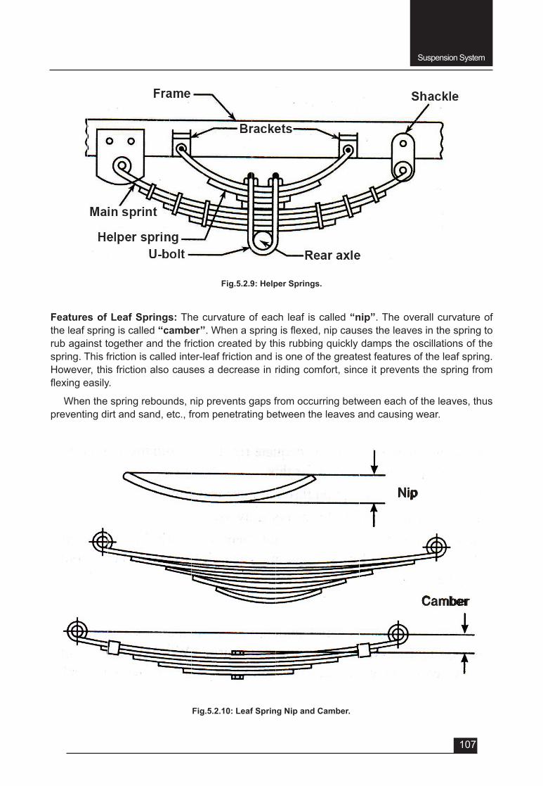
Suspension System
107
Features of Leaf Springs: The curvature of each leaf is called “nip”. The overall curvature of the leaf spring is called ‘‘camber’’.Whenaspringisflexed,nipcausestheleavesinthespringtorub against together and the friction created by this rubbing quickly damps the oscillations of the spring. This friction is called inter-leaf friction and is one of the greatest features of the leaf spring. However, this friction also causes a decrease in riding comfort, since it prevents the spring from flexingeasily.
When the spring rebounds, nip prevents gaps from occurring between each of the leaves, thus preventing dirt and sand, etc., from penetrating between the leaves and causing wear.
Fig.5.2.9: Helper Springs.
Fig.5.2.10: Leaf Spring Nip and Camber.
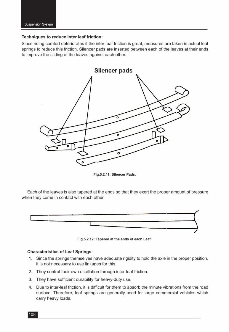
Suspension System
108
Techniques to reduce inter leaf friction: Since riding comfort deteriorates if the inter-leaf friction is great, measures are taken in actual leaf springs to reduce this friction. Silencer pads are inserted between each of the leaves at their ends to improve the sliding of the leaves against each other.
Fig.5.2.11: Silencer Pads.
Each of the leaves is also tapered at the ends so that they exert the proper amount of pressure when they come in contact with each other.
Fig.5.2.12: Tapered at the ends of each Leaf.
Characteristics of Leaf Springs:1. Since the springs themselves have adequate rigidity to hold the axle in the proper position,
it is not necessary to use linkages for this.
2. They control their own oscillation through inter-leaf friction.
3. Theyhavesufficientdurabilityforheavy-dutyuse.
4. Duetointer-leaffriction,itisdifficultforthemtoabsorbtheminutevibrationsfromtheroadsurface. Therefore, leaf springs are generally used for large commercial vehicles which carry heavy loads.
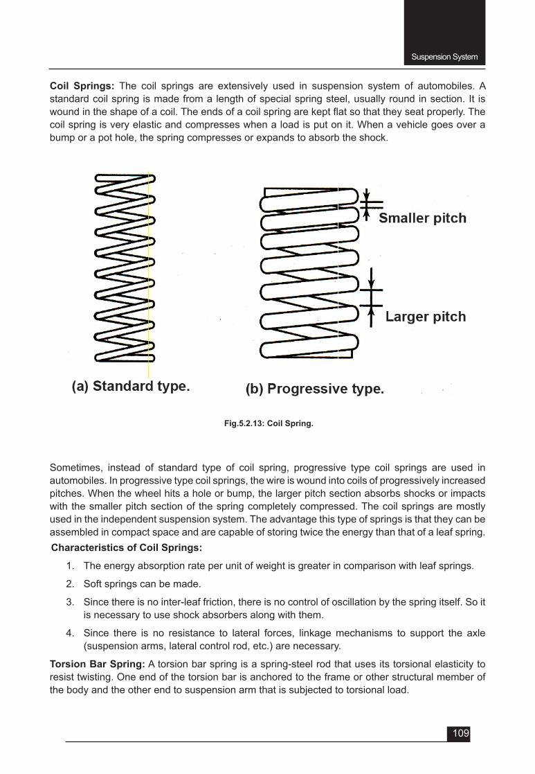
Suspension System
109
Coil Springs: The coil springs are extensively used in suspension system of automobiles. A standard coil spring is made from a length of special spring steel, usually round in section. It is woundintheshapeofacoil.Theendsofacoilspringarekeptflatsothattheyseatproperly.Thecoil spring is very elastic and compresses when a load is put on it. When a vehicle goes over a bump or a pot hole, the spring compresses or expands to absorb the shock.
Fig.5.2.13: Coil Spring.
Sometimes, instead of standard type of coil spring, progressive type coil springs are used in automobiles. In progressive type coil springs, the wire is wound into coils of progressively increased pitches. When the wheel hits a hole or bump, the larger pitch section absorbs shocks or impacts with the smaller pitch section of the spring completely compressed. The coil springs are mostly used in the independent suspension system. The advantage this type of springs is that they can be assembled in compact space and are capable of storing twice the energy than that of a leaf spring.Characteristics of Coil Springs:
1. The energy absorption rate per unit of weight is greater in comparison with leaf springs.
2. Soft springs can be made.
3. Since there is no inter-leaf friction, there is no control of oscillation by the spring itself. So it is necessary to use shock absorbers along with them.
4. Since there is no resistance to lateral forces, linkage mechanisms to support the axle (suspension arms, lateral control rod, etc.) are necessary.
Torsion Bar Spring: A torsion bar spring is a spring-steel rod that uses its torsional elasticity to resist twisting. One end of the torsion bar is anchored to the frame or other structural member of the body and the other end to suspension arm that is subjected to torsional load.
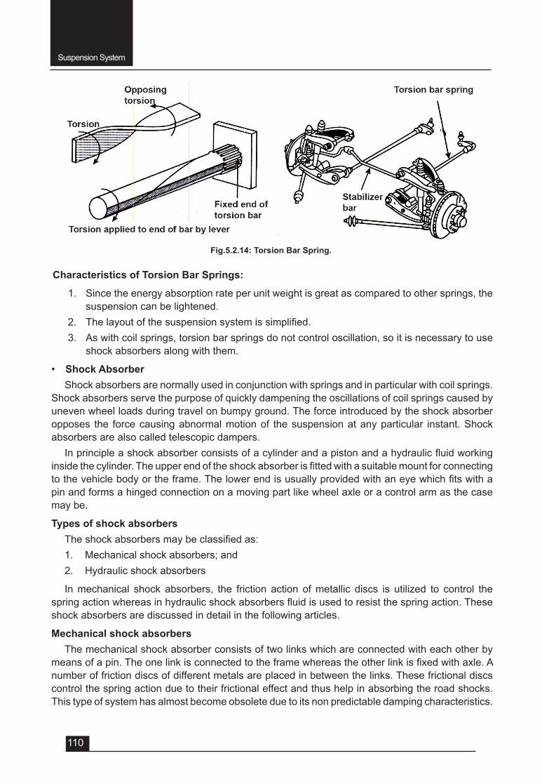
Suspension System
110
Characteristics of Torsion Bar Springs:
1. Since the energy absorption rate per unit weight is great as compared to other springs, the suspension can be lightened.
2. Thelayoutofthesuspensionsystemissimplified.3. As with coil springs, torsion bar springs do not control oscillation, so it is necessary to use
shock absorbers along with them.
• Shock AbsorberShock absorbers are normally used in conjunction with springs and in particular with coil springs.
Shock absorbers serve the purpose of quickly dampening the oscillations of coil springs caused by uneven wheel loads during travel on bumpy ground. The force introduced by the shock absorber opposes the force causing abnormal motion of the suspension at any particular instant. Shock absorbers are also called telescopic dampers.
Inprincipleashockabsorberconsistsofacylinderandapistonandahydraulicfluidworkinginsidethecylinder.Theupperendoftheshockabsorberisfittedwithasuitablemountforconnectingtothevehiclebodyortheframe.Thelowerendisusuallyprovidedwithaneyewhichfitswithapin and forms a hinged connection on a moving part like wheel axle or a control arm as the case may be.
Types of shock absorbersTheshockabsorbersmaybeclassifiedas:1. Mechanical shock absorbers; and2. Hydraulic shock absorbers
In mechanical shock absorbers, the friction action of metallic discs is utilized to control the springactionwhereasinhydraulicshockabsorbersfluidisusedtoresistthespringaction.Theseshock absorbers are discussed in detail in the following articles.
Mechanical shock absorbersThe mechanical shock absorber consists of two links which are connected with each other by
meansofapin.Theonelinkisconnectedtotheframewhereastheotherlinkisfixedwithaxle.Anumber of friction discs of different metals are placed in between the links. These frictional discs control the spring action due to their frictional effect and thus help in absorbing the road shocks. This type of system has almost become obsolete due to its non predictable damping characteristics.
Fig.5.2.14: Torsion Bar Spring.
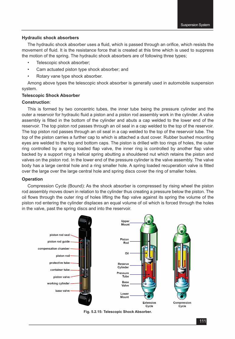
Suspension System
111
Fig. 5.2.15: Telescopic Shock Absorber.
Hydraulic shock absorbersThehydraulicshockabsorberusesafluid,whichispassedthroughanorifice,whichresiststhe
movementoffluid.Itistheresistanceforcethatiscreatedatthistimewhichisusedtosuppressthe motion of the spring. The hydraulic shock absorbers are of following three types;
• Telescopic shock absorber;• Cam actuated piston type shock absorber; and • Rotary vane type shock absorber.Among above types the telescopic shock absorber is generally used in automobile suspension
system. Telescopic Shock AbsorberConstruction:
This is formed by two concentric tubes, the inner tube being the pressure cylinder and the outerareservoirforhydraulicfluidapistonandapistonrodassemblyworkinthecylinder.Avalveassembly isfitted in thebottomof thecylinderandabutsacapweldedto the lowerendof thereservoir. The top piston rod passes through an oil seal in a cap welded to the top of the reservoir. The top piston rod passes through an oil seal in a cap welded to the top of the reservoir tube. The top of the piston carries a further cap to which is attached a dust cover. Rubber bushed mounting eyes are welded to the top and bottom caps. The piston is drilled with too rings of holes, the outer ring controlled by a spring loaded flap valve, the inner ring is controlled by another flap valvebacked by a support ring a helical spring abutting a shouldered nut which retains the piston and valves on the piston rod. In the lower end of the pressure cylinder is the valve assembly. The valve bodyhasalargecentralholeandaringsmallerhole.Aspringloadedrecuperationvalveisfittedover the large over the large central hole and spring discs cover the ring of smaller holes.
OperationCompression Cycle (Bound): As the shock absorber is compressed by rising wheel the piston
rod assembly moves down in relation to the cylinder thus creating a pressure below the piston. The oilflowsthroughtheouterringofholesliftingtheflapvalveagainstitsspringthevolumeofthepiston rod entering the cylinder displaces an equal volume of oil which is forced through the holes in the valve, past the spring discs and into the reservoir.
Suspension System
112
Extension Cycle (Rebound): On the rebound the shock absorber is extended reversing the flowofoil.Thelowerflapvalvemovesagainstthehelicalspringuncoveringtheinnerringofholesandallowingoiltoflowthrough.Asthepistonrodiswithdrawnfromthecylinderanequalvolumeofoilisrecuperatedfromthereservoirthroughthecentralorificeinthevalveassembly.
Servicing of shock absorber
Servicingof this typeof shockabsorber is confined to renewal of the rubberbushes in themounting eyes if the existing bushes are worn or perished
The internal mechanism of the shock absorber is inaccessible because of the welded construction of the tubes; for the same reason theworking fluid cannot normally escapeandnomeansofreplenishment is provided. If examination shows that the shock absorber has leaked, it should be removedfromthevehicleandaserviceableshockabsorberisfitted.
QUESTIONS Very Short answer type (each question carries 1 mark)1. Definepitching,duringoscillationofsprungweightofacar.2. Definerolling, during oscillation of sprung weight of a car.3. Definebouncing, during oscillation of sprung weight of a car.4. Defineyawing, during oscillation of sprung weight of a car.5. Definehopping, during oscillation of un-sprung weight of a car.6. Definetramping, during oscillation of un-sprung weight of a car.7. Definewind-up, during oscillation of un-sprung weight of a car.8. Definethesuspensiontermbounce.9. Definethesuspensiontermjounce.10. Definethesuspensiontermrebound.11. Definethesuspensiontermdive.12. Whatisnipofaleafspring?13. Whatiscamberofaleafspring?14. Springs are made of a. Mild steel b. Carbon steel c. High speed steel d. Spring steel15. The reason why a laminated spring is made up of a series of leaves is to a. Reduce interleaf friction b. Softenthespringactionandincreasethemaximumdeflection c. Allow the leaves to slide during the bump movement d. Overcome the weakness at the centre spring.16. During the rebound stroke, the load is transmitted from the main leaf from the shorter leaves
by a a. U – Bolt b. Spring clip c. Centre bolt d. Shackle pin.17. The provision made to allow a leaf spring to vary its length is a a. Swinging shackle b. Rubber U – bolt mounting
Suspension System
113
c. Sliding centre bolt d. Splines in the spring eye18. The purpose of a suspension damper is to a. Resist the road shocks b. Reducethe‘bump’strokeofthespring c. Absorb the energy stored in the spring d. All above.Short answer type (each question carries 2 marks) 1. Whatarethefunctionsofsuspensionsystem? 2. Definesprungandun-sprungweight.Short answer type (each question carries 3 marks) 1. Explain sprung and un-sprung weight with a sketch. 2. Name different principal components of suspension system. 3. Draw the sketch of a semi-elliptical leaf spring and show its different parts. 4. Howthesuspensionspringsareclassified? 5. With neat sketch explain Nip and Camber of a leaf spring. 6. Explain the technique to reduce the inter leaf friction of leaf spring. 7. Write different characteristics of leaf springs. 8. Write different characteristics of torsion springs.Long answer type (each question carries 5 marks) 1. Explain the oscillations of sprung and un-sprung weight of a vehicle. 2. Draw the sketch of different types of leaf springs and write their uses. 3. Explain the constructional features of suspension coil springs. 4. Explain with diagram the torsion spring suspension. 5. Explain with sketch the construction of telescopic shock absorber. 6. Explain with sketch the operation of telescopic shock absorber.

UNIT – 6
SESSION – 1
AUTOMOBILE ELECTRICAL SYSTEM
Objectives
After attending this session, students should be able to:
v Explain the different purposes of Automobile Electrical System.
v Understand the layout of different components of Automobile Electrical System.
v Explain the purposes of the battery.
v Describe the construction of conventional Lead Acid Battery.
v Identify the main components of the Battery.
v Explain the chemical action and reaction that occurs during charging and discharging of the Lead Acid Battery.
v Carry out the maintenance of Lead Acid Battery.
v Understand the concept of maintenance free batteries.
UNIT – 6Session – 1
Automobile Electrical System (Introduction and Battery)
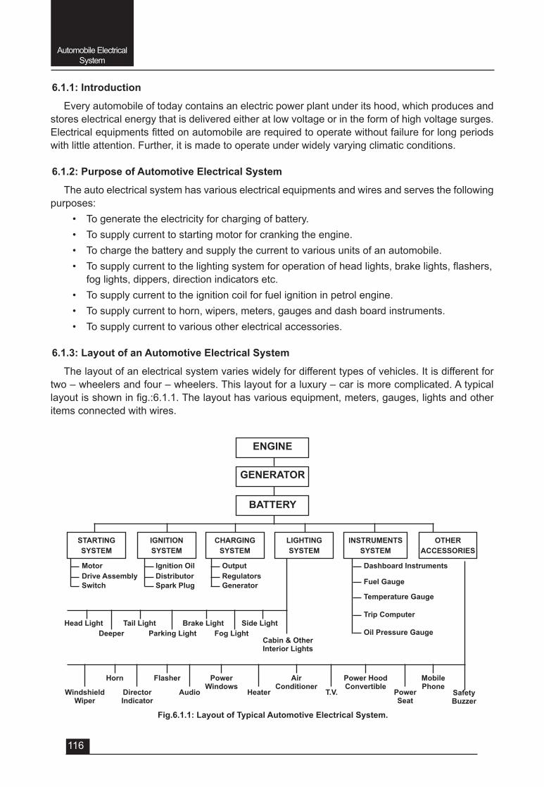
Automobile Electrical System
116
6.1.1: Introduction
Every automobile of today contains an electric power plant under its hood, which produces and stores electrical energy that is delivered either at low voltage or in the form of high voltage surges. Electricalequipmentsfittedonautomobilearerequiredtooperatewithoutfailureforlongperiodswith little attention. Further, it is made to operate under widely varying climatic conditions.
6.1.2: Purpose of Automotive Electrical System
The auto electrical system has various electrical equipments and wires and serves the following purposes:
• To generate the electricity for charging of battery.• To supply current to starting motor for cranking the engine.• To charge the battery and supply the current to various units of an automobile.• Tosupplycurrenttothelightingsystemforoperationofheadlights,brakelights,flashers,
fog lights, dippers, direction indicators etc. • To supply current to the ignition coil for fuel ignition in petrol engine.• To supply current to horn, wipers, meters, gauges and dash board instruments. • To supply current to various other electrical accessories.
6.1.3: Layout of an Automotive Electrical System
The layout of an electrical system varies widely for different types of vehicles. It is different for two – wheelers and four – wheelers. This layout for a luxury – car is more complicated. A typical layoutisshowninfig.:6.1.1.Thelayouthasvariousequipment,meters,gauges,lightsandotheritems connected with wires.
Fig.6.1.1: Layout of Typical Automotive Electrical System.
ENGINE
GENERATOR
BATTERY
STARTINGSYSTEM
Motor Ignition Oil Output Dashboard Instruments
Cabin & OtherInterior Lights
SafetyBuzzer
Side Light
Mobile Phone
PowerSeat
Power HoodConvertible
T.V.
AirConditioner
HeaterAudioDirectorIndicator
WindshieldWiper
PowerWindows
FlasherHorn
Brake LightTail LightHead LightFog LightParking LightDeeper
Switch Spark Plug GeneratorTemperature Gauge
Trip Computer
Oil Pressure Gauge
Drive Assembly Distributor RegulatorsFuel Gauge
IGNITIONSYSTEM
CHARGINGSYSTEM
LIGHTINGSYSTEM
INSTRUMENTSSYSTEM
OTHERACCESSORIES
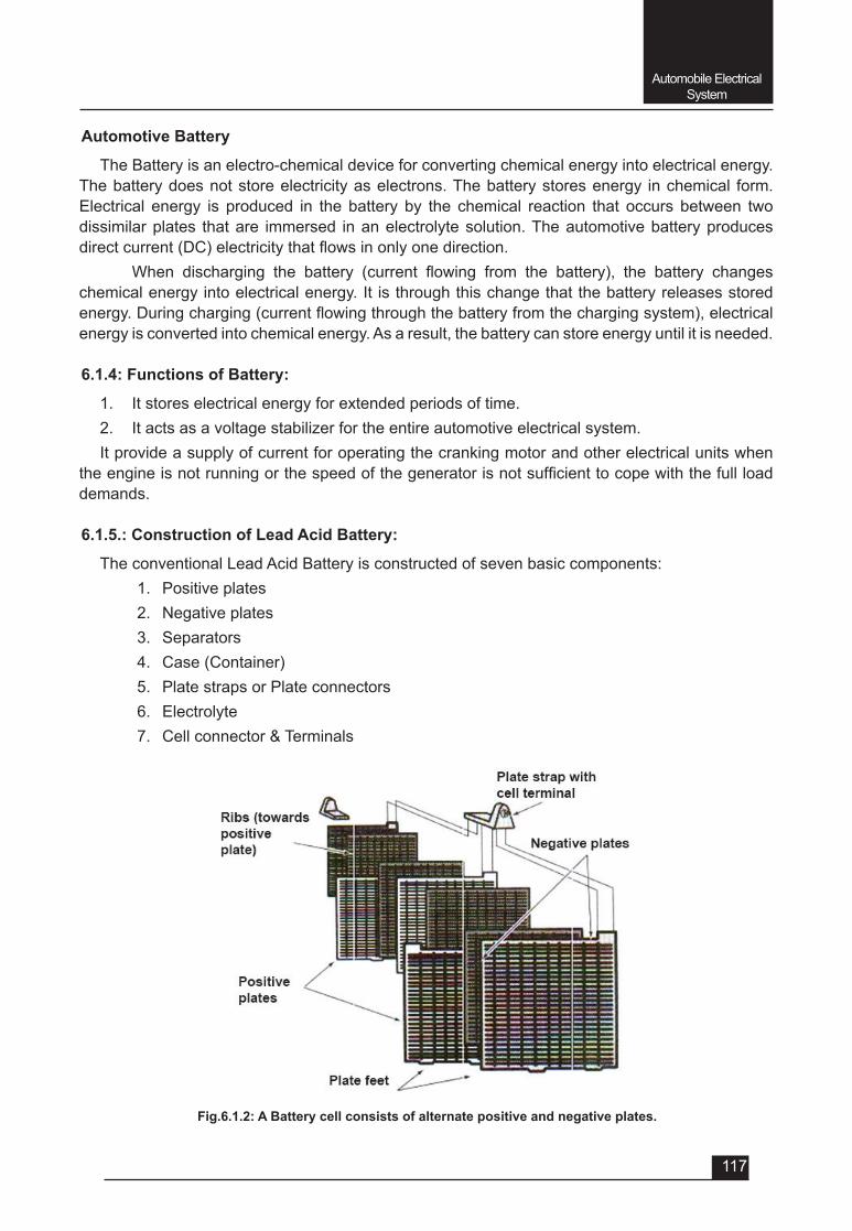
Automobile Electrical System
117
Fig.6.1.2: A Battery cell consists of alternate positive and negative plates.
Automotive Battery
The Battery is an electro-chemical device for converting chemical energy into electrical energy. The battery does not store electricity as electrons. The battery stores energy in chemical form. Electrical energy is produced in the battery by the chemical reaction that occurs between two dissimilar plates that are immersed in an electrolyte solution. The automotive battery produces directcurrent(DC)electricitythatflowsinonlyonedirection.
When discharging the battery (current flowing from the battery), the battery changeschemical energy into electrical energy. It is through this change that the battery releases stored energy.Duringcharging(currentflowingthroughthebatteryfromthechargingsystem),electricalenergy is converted into chemical energy. As a result, the battery can store energy until it is needed.
6.1.4: Functions of Battery:
1. It stores electrical energy for extended periods of time.2. It acts as a voltage stabilizer for the entire automotive electrical system.It provide a supply of current for operating the cranking motor and other electrical units when
theengineisnotrunningorthespeedofthegeneratorisnotsufficienttocopewiththefullloaddemands.
6.1.5.: Construction of Lead Acid Battery:
The conventional Lead Acid Battery is constructed of seven basic components:1. Positive plates2. Negative plates3. Separators 4. Case (Container)5. Plate straps or Plate connectors6. Electrolyte7. Cell connector & Terminals
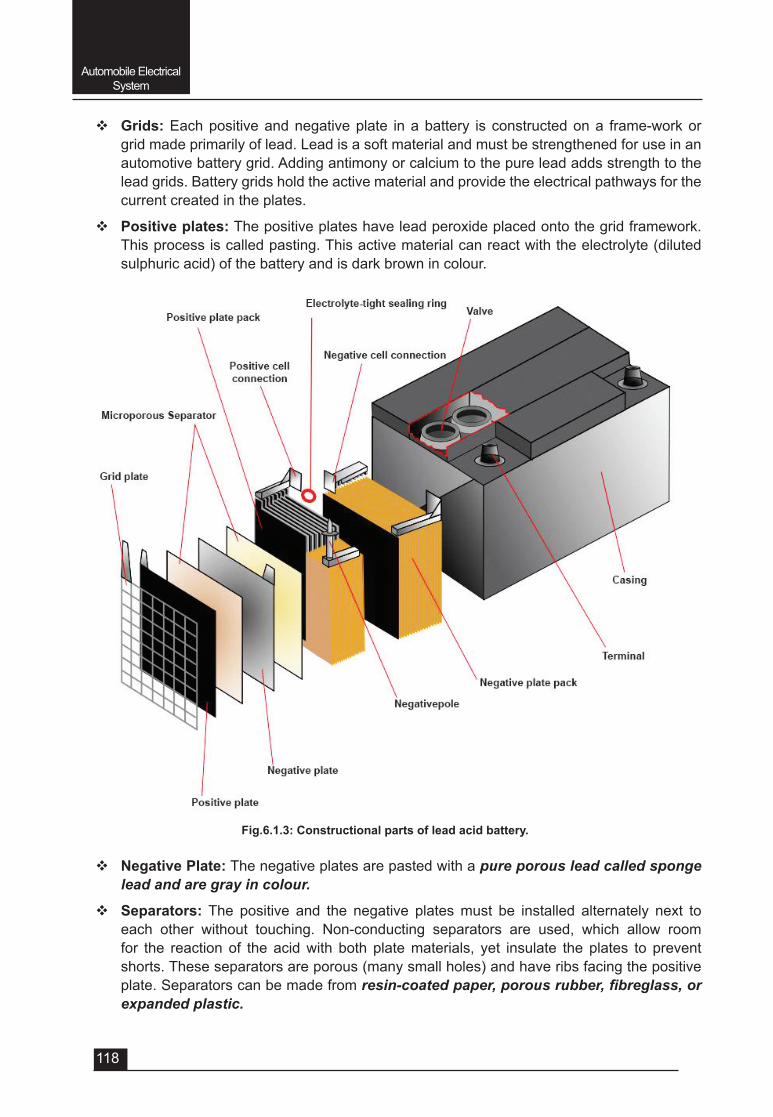
Automobile Electrical System
118
v Grids: Each positive and negative plate in a battery is constructed on a frame-work or grid made primarily of lead. Lead is a soft material and must be strengthened for use in an automotive battery grid. Adding antimony or calcium to the pure lead adds strength to the lead grids. Battery grids hold the active material and provide the electrical pathways for the current created in the plates.
v Positive plates: The positive plates have lead peroxide placed onto the grid framework. This process is called pasting. This active material can react with the electrolyte (diluted sulphuric acid) of the battery and is dark brown in colour.
Fig.6.1.3: Constructional parts of lead acid battery.
v Negative Plate: The negative plates are pasted with a pure porous lead called sponge lead and are gray in colour.
v Separators: The positive and the negative plates must be installed alternately next to each other without touching. Non-conducting separators are used, which allow room for the reaction of the acid with both plate materials, yet insulate the plates to prevent shorts. These separators are porous (many small holes) and have ribs facing the positive plate. Separators can be made from resin-coated paper, porous rubber, fibreglass, or expanded plastic.
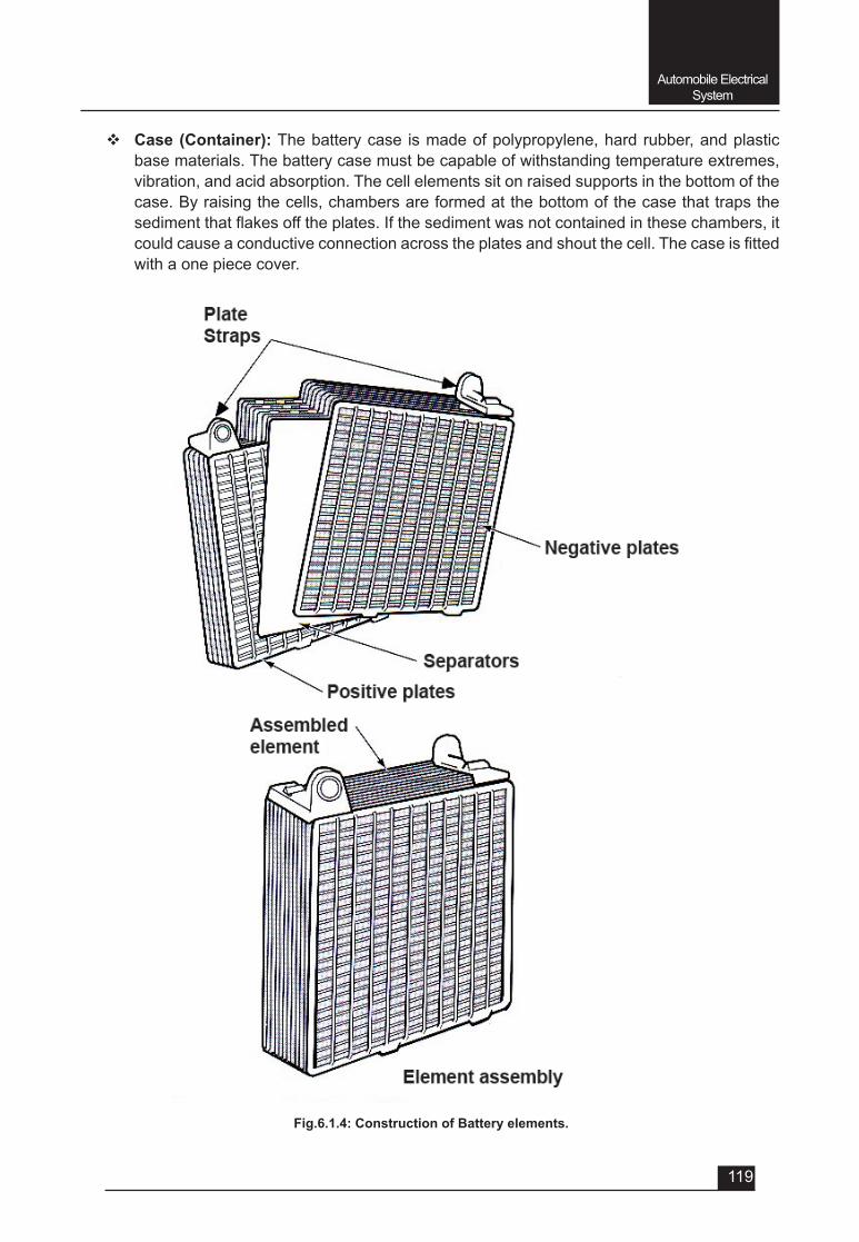
Automobile Electrical System
119
v Case (Container): The battery case is made of polypropylene, hard rubber, and plastic base materials. The battery case must be capable of withstanding temperature extremes, vibration, and acid absorption. The cell elements sit on raised supports in the bottom of the case. By raising the cells, chambers are formed at the bottom of the case that traps the sedimentthatflakesofftheplates.Ifthesedimentwasnotcontainedinthesechambers,itcouldcauseaconductiveconnectionacrosstheplatesandshoutthecell.Thecaseisfittedwith a one piece cover.
Fig.6.1.4: Construction of Battery elements.
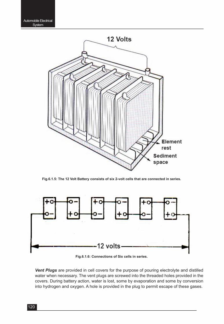
Automobile Electrical System
120
Vent Plugs are provided in cell covers for the purpose of pouring electrolyte and distilled water when necessary. The vent plugs are screwed into the threaded holes provided in the covers. During battery action, water is lost, some by evaporation and some by conversion into hydrogen and oxygen. A hole is provided in the plug to permit escape of these gases.
Fig.6.1.5: The 12 Volt Battery consists of six 2-volt cells that are connected in series.
Fig.6.1.6: Connections of Six cells in series.
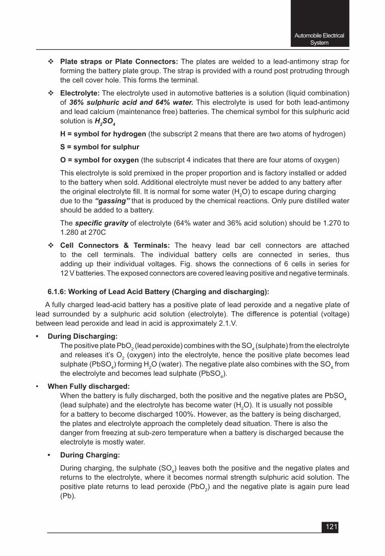
Automobile Electrical System
121
v Plate straps or Plate Connectors: The plates are welded to a lead-antimony strap for forming the battery plate group. The strap is provided with a round post protruding through the cell cover hole. This forms the terminal.
v Electrolyte: The electrolyte used in automotive batteries is a solution (liquid combination) of 36% sulphuric acid and 64% water. This electrolyte is used for both lead-antimony and lead calcium (maintenance free) batteries. The chemical symbol for this sulphuric acid solution is H2SO4
H = symbol for hydrogen (the subscript 2 means that there are two atoms of hydrogen)
S = symbol for sulphur
O = symbol for oxygen (the subscript 4 indicates that there are four atoms of oxygen)
This electrolyte is sold premixed in the proper proportion and is factory installed or added to the battery when sold. Additional electrolyte must never be added to any battery after theoriginalelectrolytefill.Itisnormalforsomewater(H2O) to escape during charging due to the “gassing” that is produced by the chemical reactions. Only pure distilled water should be added to a battery.
The specific gravityofelectrolyte(64%waterand36%acidsolution)shouldbe1.270to1.280 at 270C
v Cell Connectors & Terminals: The heavy lead bar cell connectors are attached to the cell terminals. The individual battery cells are connected in series, thus adding up their individual voltages. Fig. shows the connections of 6 cells in series for 12 V batteries. The exposed connectors are covered leaving positive and negative terminals.
6.1.6: Working of Lead Acid Battery (Charging and discharging):
A fully charged lead-acid battery has a positive plate of lead peroxide and a negative plate of lead surrounded by a sulphuric acid solution (electrolyte). The difference is potential (voltage) between lead peroxide and lead in acid is approximately 2.1.V.
• During Discharging: The positive plate PbO2 (lead peroxide) combines with the SO4 (sulphate) from the electrolyte
and releases it’s O2 (oxygen) into the electrolyte, hence the positive plate becomes lead sulphate (PbSO4) forming H2O (water). The negative plate also combines with the SO4 from the electrolyte and becomes lead sulphate (PbSO4).
• When Fully discharged: When the battery is fully discharged, both the positive and the negative plates are PbSO4
(lead sulphate) and the electrolyte has become water (H2O). It is usually not possible forabatterytobecomedischarged100%.However,asthebatteryisbeingdischarged,the plates and electrolyte approach the completely dead situation. There is also the danger from freezing at sub-zero temperature when a battery is discharged because the electrolyte is mostly water.
• During Charging:
During charging, the sulphate (SO4) leaves both the positive and the negative plates and returns to the electrolyte, where it becomes normal strength sulphuric acid solution. The positive plate returns to lead peroxide (PbO2) and the negative plate is again pure lead (Pb).
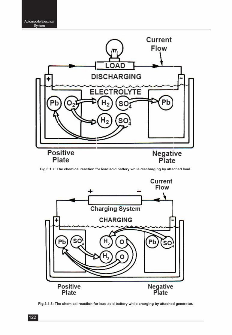
Automobile Electrical System
122
Fig.6.1.7: The chemical reaction for lead acid battery while discharging by attached load.
Fig.6.1.8: The chemical reaction for lead acid battery while charging by attached generator.
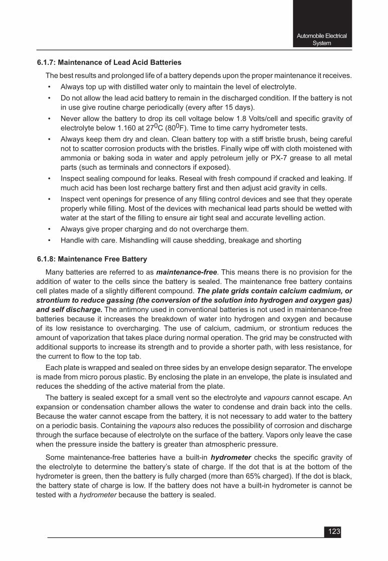
Automobile Electrical System
123
6.1.7: Maintenance of Lead Acid Batteries
The best results and prolonged life of a battery depends upon the proper maintenance it receives.• Always top up with distilled water only to maintain the level of electrolyte.• Do not allow the lead acid battery to remain in the discharged condition. If the battery is not
in use give routine charge periodically (every after 15 days).• Neverallowthebatterytodropitscellvoltagebelow1.8Volts/cellandspecificgravityof
electrolyte below 1.160 at 270C (800F). Time to time carry hydrometer tests. • Always keep them dry and clean. Clean battery top with a stiff bristle brush, being careful
not to scatter corrosion products with the bristles. Finally wipe off with cloth moistened with ammonia or baking soda in water and apply petroleum jelly or PX-7 grease to all metal parts (such as terminals and connectors if exposed).
• Inspect sealing compound for leaks. Reseal with fresh compound if cracked and leaking. If muchacidhasbeenlostrechargebatteryfirstandthenadjustacidgravityincells.
• Inspectventopeningsforpresenceofanyfillingcontroldevicesandseethattheyoperateproperlywhilefilling.Mostofthedeviceswithmechanicalleadpartsshouldbewettedwithwateratthestartofthefillingtoensureairtightsealandaccuratelevellingaction.
• Always give proper charging and do not overcharge them.• Handle with care. Mishandling will cause shedding, breakage and shorting
6.1.8: Maintenance Free Battery
Many batteries are referred to as maintenance-free. This means there is no provision for the addition of water to the cells since the battery is sealed. The maintenance free battery contains cell plates made of a slightly different compound. The plate grids contain calcium cadmium, or strontium to reduce gassing (the conversion of the solution into hydrogen and oxygen gas) and self discharge. The antimony used in conventional batteries is not used in maintenance-free batteries because it increases the breakdown of water into hydrogen and oxygen and because of its low resistance to overcharging. The use of calcium, cadmium, or strontium reduces the amount of vaporization that takes place during normal operation. The grid may be constructed with additional supports to increase its strength and to provide a shorter path, with less resistance, for thecurrenttoflowtothetoptab.
Each plate is wrapped and sealed on three sides by an envelope design separator. The envelope is made from micro porous plastic. By enclosing the plate in an envelope, the plate is insulated and reduces the shedding of the active material from the plate.
The battery is sealed except for a small vent so the electrolyte and vapours cannot escape. An expansion or condensation chamber allows the water to condense and drain back into the cells. Because the water cannot escape from the battery, it is not necessary to add water to the battery on a periodic basis. Containing the vapours also reduces the possibility of corrosion and discharge through the surface because of electrolyte on the surface of the battery. Vapors only leave the case when the pressure inside the battery is greater than atmospheric pressure.
Some maintenance-free batteries have a built-in hydrometer checks the specific gravity ofthe electrolyte to determine the battery’s state of charge. If the dot that is at the bottom of the hydrometerisgreen,thenthebatteryisfullycharged(morethan65%charged).Ifthedotisblack,the battery state of charge is low. If the battery does not have a built-in hydrometer is cannot be tested with a hydrometer because the battery is sealed.
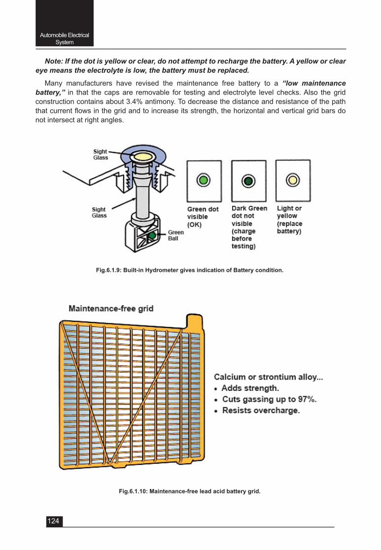
Automobile Electrical System
124
Note: If the dot is yellow or clear, do not attempt to recharge the battery. A yellow or clear eye means the electrolyte is low, the battery must be replaced.
Many manufacturers have revised the maintenance free battery to a “low maintenance battery,” in that the caps are removable for testing and electrolyte level checks. Also the grid constructioncontainsabout3.4%antimony.Todecreasethedistanceandresistanceofthepaththatcurrentflowsinthegridandtoincreaseitsstrength,thehorizontalandverticalgridbarsdonot intersect at right angles.
Fig.6.1.9: Built-in Hydrometer gives indication of Battery condition.
Fig.6.1.10: Maintenance-free lead acid battery grid.
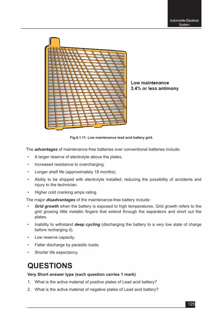
Automobile Electrical System
125
The advantages of maintenance-free batteries over conventional batteries include:
• A larger reserve of electrolyte above the plates.
• Increased resistance to overcharging.
• Longer shelf life (approximately 18 months).
• Ability to be shipped with electrolyte installed, reducing the possibility of accidents and injury to the technician.
• Higher cold cranking amps rating.
The major disadvantages of the maintenance-free battery include:• Grid growth when the battery is exposed to high temperatures. Grid growth refers to the
grid growing littlemetallic fingers that extend through the separators and short out theplates.
• Inability to withstand deep cycling (discharging the battery to a very low state of charge before recharging it).
• Low reserve capacity.
• Falter discharge by parasitic loads.
• Shorter life expectancy.
QUESTIONSVery Short answer type (each question carries 1 mark)
1. WhatistheactivematerialofpositiveplatesofLeadacidbattery?
2. WhatistheactivematerialofnegativeplatesofLeadacidbattery?
Fig.6.1.11: Low maintenance lead acid battery grid.
Automobile Electrical System
126
3. Whatarethematerialsofseparator?
4. Which of the following materials is mixed with lead for strength, to manufacture grids of positiveandnegativeplatesofleadacidbatteries?
a) Antimony
b) Calcium
c) Any one of Antimony or Calcium
d) Carbon
5. The battery case is made of______________________________.
a) Poly-propylene
b) Hard-rubber
c) Plastic base materials
d) Any of the above materials
6. The electrolyte used in automotive lead acid batteries is a solution (liquid combination) of __________%sulphuricacidand_____________%distilledwater.
7. Thespecificgravityofelectrolyte(64%waterand36%acidsolution)shouldbe________to __________ at 270C
Short answer type (each question carries 2 marks)
1. Whatarethefunctionsofbattery?
2. Whatarethemaincomponentsofleadacidbattery?
Short answer type (each question carries 3 marks)
1. Explain built in hydrometer of automobile battery.
2. Write the advantages of maintenance free battery.
3. Write the disadvantages of maintenance free battery.
Long answer type (each question carries 5 marks)
1. Explain the working of lead acid battery during charging and discharging.
2. Explain different maintenance to be carried out on lead acid battery.
3. Explain maintenance free battery.

UNIT – 6
SESSION – 2
AUTOMOBILE ELECTRICAL SYSTEM(Charging & Starging System)
128
Automobile Electrical System
Objectives
After attending this session, you should be able to:
v Understand the charging circuit and its different components.
v Explain the Principle, Construction and Operation of DC Generator or Dynamo.
v Understand the function of regulator unit (Cut-out, Voltage regulator and Current regulator).
v Explain the Principle, Construction and Operation of AC Generator or Alternator.
v Explain the Advantages of Alternators over Dynamo.
v Understand the starting circuit and its different components.
v Explain the Principle, Construction and Operation of Starter Motor.
v Understand the Lighting circuit, Horn circuit, Wind screen wiper circuit and their different components.
UNIT – 6Session – 2
Automobile Electrical System (Charging & Starting System and different Circuits)
6.2.1: Charging System
The charging system consists of 1. Battery
2. Ignition switch
3. A.C Generator (Alternator) or DC Generator (Dynamo)
4. Relay Switch
5. Indicator Lamp
In the previous session we have already discussed about the battery. In this session students are going to learn about the generators (ac and dc) and different important circuits.
During cranking, the battery supplies most of the vehicle’s electrical energy. However, once the engine is running, the charging system is responsible for producing enough energy to meet the demands of all the loads in the electrical system, while also recharging the battery.
For many years the automotive charging system produced direct current using a belt driven DC generator. The DC charging system offered limited voltage output, particularly at low speeds or idle. For this reason, alternating current, or AC charging systems were developed and are now universallyused.Alternators(ACgenerators)arecompactlightweight,andefficientatallenginespeeds.
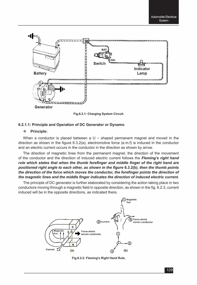
129
Automobile Electrical System
6.2.1.1: Principle and Operation of DC Generator or Dynamo
v Principle:
When a conductor is placed between a U – shaped permanent magnet and moved in the directionasshowninthefigure6.3.2(a),electromotiveforce(e.m.f) is inducedintheconductorand an electric current occurs in the conductor in the direction as shown by arrow.
The direction of magnetic lines from the permanent magnet, the direction of the movement of the conductor and the direction of induced electric current follows the Fleming’s right hand rule which states that when the thumb forefinger and middle finger of the right hand are positioned right angle to each other, as shown in the figure 6.3.2(b), then the thumb points the direction of the force which moves the conductor, the forefinger points the direction of the magnetic lines and the middle finger indicates the direction of induced electric current.
The principle of DC generator is further elaborated by considering the action taking place in two conductorsmovingthroughamagneticfieldinoppositedirection,asshowninthefig.6.2.3,currentinduced will be in the opposite directions, as indicated there.
Fig.6.2.1: Charging System Circuit.
Fig.6.2.2: Fleming’s Right Hand Rule.
(a) (b)
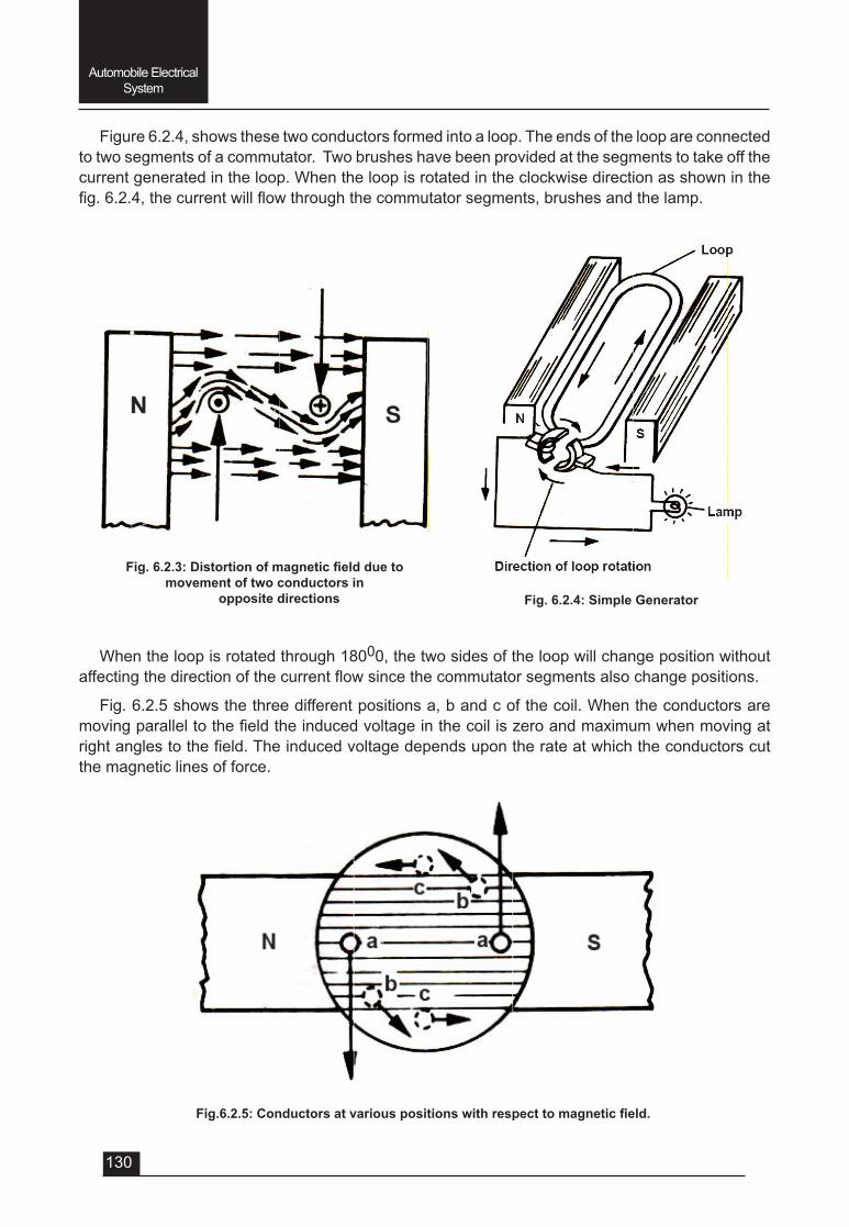
130
Automobile Electrical System
Figure 6.2.4, shows these two conductors formed into a loop. The ends of the loop are connected to two segments of a commutator. Two brushes have been provided at the segments to take off the current generated in the loop. When the loop is rotated in the clockwise direction as shown in the fig.6.2.4,thecurrentwillflowthroughthecommutatorsegments,brushesandthelamp.
When the loop is rotated through 18000, the two sides of the loop will change position without affectingthedirectionofthecurrentflowsincethecommutatorsegmentsalsochangepositions.
Fig. 6.2.5 shows the three different positions a, b and c of the coil. When the conductors are movingparalleltothefieldtheinducedvoltageinthecoiliszeroandmaximumwhenmovingatrightanglestothefield.Theinducedvoltagedependsupontherateatwhichtheconductorscutthe magnetic lines of force.
Fig.6.2.3:Distortionofmagneticfieldduetomovement of two conductors in
opposite directions Fig. 6.2.4: Simple Generator
Fig.6.2.5:Conductorsatvariouspositionswithrespecttomagneticfield.
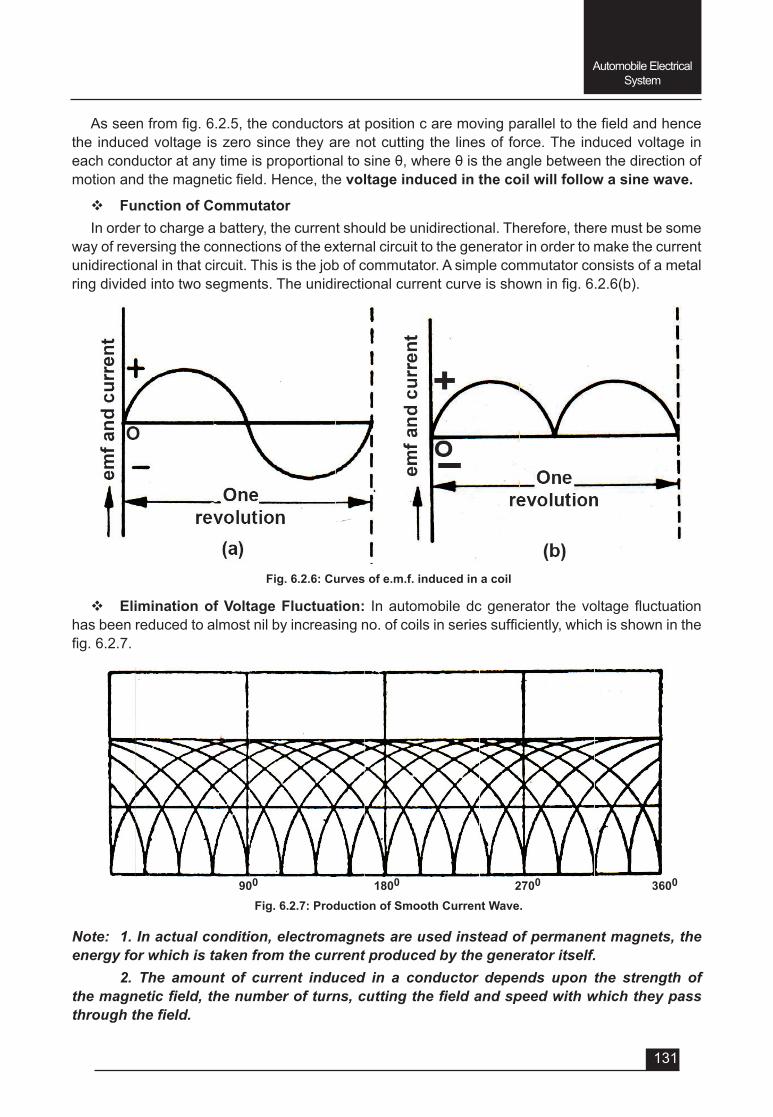
131
Automobile Electrical System
Fig. 6.2.6: Curves of e.m.f. induced in a coil
Fig. 6.2.7: Production of Smooth Current Wave.900 1800 2700 3600
Asseenfromfig.6.2.5,theconductorsatpositioncaremovingparalleltothefieldandhencethe induced voltage is zero since they are not cutting the lines of force. The induced voltage in eachconductoratanytimeisproportionaltosineθ,whereθistheanglebetweenthedirectionofmotionandthemagneticfield.Hence,thevoltage induced in the coil will follow a sine wave.
v Function of CommutatorIn order to charge a battery, the current should be unidirectional. Therefore, there must be some
way of reversing the connections of the external circuit to the generator in order to make the current unidirectional in that circuit. This is the job of commutator. A simple commutator consists of a metal ringdividedintotwosegments.Theunidirectionalcurrentcurveisshowninfig.6.2.6(b).
v Elimination of Voltage Fluctuation: Inautomobiledcgenerator thevoltagefluctuationhasbeenreducedtoalmostnilbyincreasingno.ofcoilsinseriessufficiently,whichisshowninthefig.6.2.7.
Note: 1. In actual condition, electromagnets are used instead of permanent magnets, the energy for which is taken from the current produced by the generator itself.
2. The amount of current induced in a conductor depends upon the strength of the magnetic field, the number of turns, cutting the field and speed with which they pass through the field.
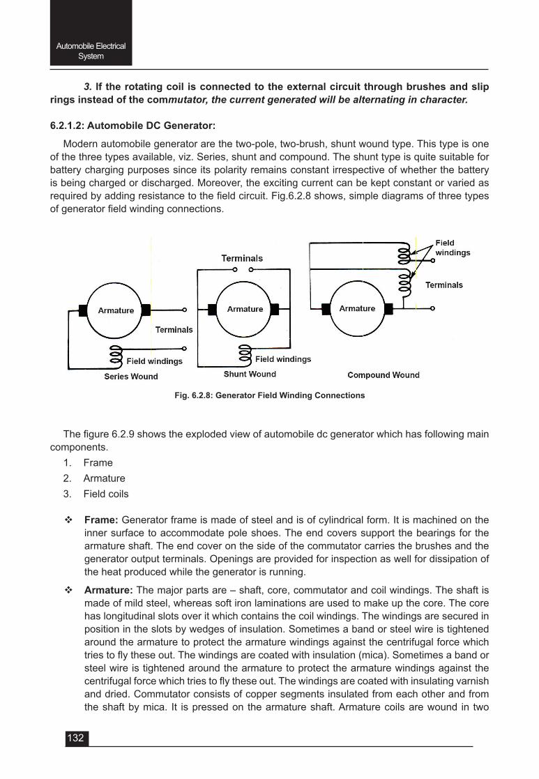
132
Automobile Electrical System
3. If the rotating coil is connected to the external circuit through brushes and slip rings instead of the commutator, the current generated will be alternating in character.
6.2.1.2: Automobile DC Generator:
Modern automobile generator are the two-pole, two-brush, shunt wound type. This type is one of the three types available, viz. Series, shunt and compound. The shunt type is quite suitable for battery charging purposes since its polarity remains constant irrespective of whether the battery is being charged or discharged. Moreover, the exciting current can be kept constant or varied as requiredbyaddingresistancetothefieldcircuit.Fig.6.2.8shows,simplediagramsofthreetypesofgeneratorfieldwindingconnections.
Fig. 6.2.8: Generator Field Winding Connections
Thefigure6.2.9showstheexplodedviewofautomobiledcgeneratorwhichhasfollowingmaincomponents.
1. Frame2. Armature3. Field coils
v Frame: Generator frame is made of steel and is of cylindrical form. It is machined on the inner surface to accommodate pole shoes. The end covers support the bearings for the armature shaft. The end cover on the side of the commutator carries the brushes and the generator output terminals. Openings are provided for inspection as well for dissipation of the heat produced while the generator is running.
v Armature: The major parts are – shaft, core, commutator and coil windings. The shaft is made of mild steel, whereas soft iron laminations are used to make up the core. The core has longitudinal slots over it which contains the coil windings. The windings are secured in position in the slots by wedges of insulation. Sometimes a band or steel wire is tightened around the armature to protect the armature windings against the centrifugal force which triestoflytheseout.Thewindingsarecoatedwithinsulation(mica).Sometimesabandorsteel wire is tightened around the armature to protect the armature windings against the centrifugalforcewhichtriestoflytheseout.Thewindingsarecoatedwithinsulatingvarnishand dried. Commutator consists of copper segments insulated from each other and from the shaft by mica. It is pressed on the armature shaft. Armature coils are wound in two
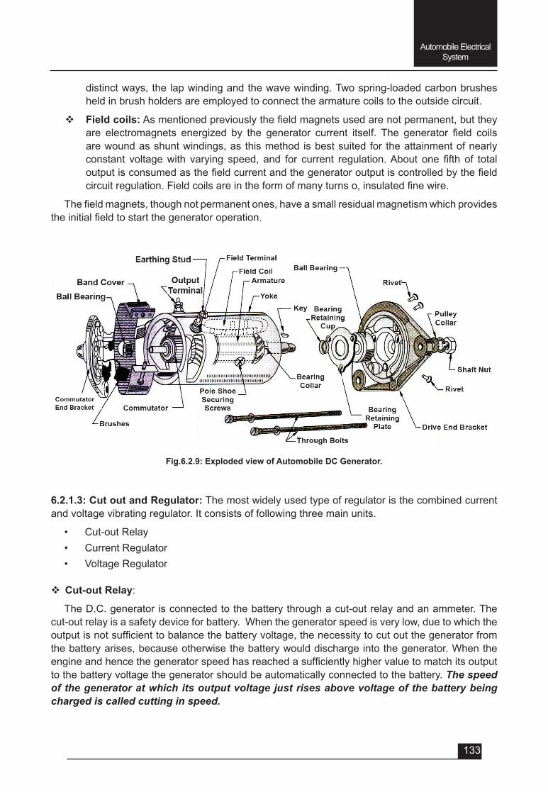
133
Automobile Electrical System
Fig.6.2.9: Exploded view of Automobile DC Generator.
distinct ways, the lap winding and the wave winding. Two spring-loaded carbon brushes held in brush holders are employed to connect the armature coils to the outside circuit.
v Field coils:Asmentionedpreviouslythefieldmagnetsusedarenotpermanent,buttheyare electromagnets energized by the generator current itself. The generator field coilsare wound as shunt windings, as this method is best suited for the attainment of nearly constant voltagewith varying speed, and for current regulation.About one fifth of totaloutputisconsumedasthefieldcurrentandthegeneratoroutputiscontrolledbythefieldcircuitregulation.Fieldcoilsareintheformofmanyturnso,insulatedfinewire.
Thefieldmagnets,thoughnotpermanentones,haveasmallresidualmagnetismwhichprovidestheinitialfieldtostartthegeneratoroperation.
6.2.1.3: Cut out and Regulator: The most widely used type of regulator is the combined current and voltage vibrating regulator. It consists of following three main units.
• Cut-out Relay• Current Regulator • Voltage Regulator
v Cut-out Relay:
The D.C. generator is connected to the battery through a cut-out relay and an ammeter. The cut-out relay is a safety device for battery. When the generator speed is very low, due to which the outputisnotsufficienttobalancethebatteryvoltage,thenecessitytocutoutthegeneratorfromthe battery arises, because otherwise the battery would discharge into the generator. When the engineandhencethegeneratorspeedhasreachedasufficientlyhighervaluetomatchitsoutputto the battery voltage the generator should be automatically connected to the battery. The speed of the generator at which its output voltage just rises above voltage of the battery being charged is called cutting in speed.
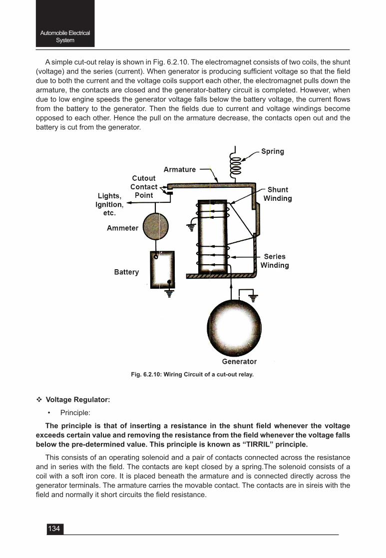
134
Automobile Electrical System
A simple cut-out relay is shown in Fig. 6.2.10. The electromagnet consists of two coils, the shunt (voltage)andtheseries(current).Whengeneratorisproducingsufficientvoltagesothatthefielddue to both the current and the voltage coils support each other, the electromagnet pulls down the armature, the contacts are closed and the generator-battery circuit is completed. However, when duetolowenginespeedsthegeneratorvoltagefallsbelowthebatteryvoltage,thecurrentflowsfrom thebattery to thegenerator.Then thefieldsdue tocurrentandvoltagewindingsbecomeopposed to each other. Hence the pull on the armature decrease, the contacts open out and the battery is cut from the generator.
Fig. 6.2.10: Wiring Circuit of a cut-out relay.
v Voltage Regulator:
• Principle:
Theprinciple is thatof insertinga resistance in theshuntfieldwhenever thevoltageexceedscertainvalueandremovingtheresistancefromthefieldwheneverthevoltagefallsbelow the pre-determined value. This principle is known as “TIRRIL” principle.
This consists of an operating solenoid and a pair of contacts connected across the resistance andinserieswiththefield.Thecontactsarekeptclosedbyaspring.Thesolenoidconsistsofacoil with a soft iron core. It is placed beneath the armature and is connected directly across the generator terminals. The armature carries the movable contact. The contacts are in sireis with the fieldandnormallyitshortcircuitsthefieldresistance.
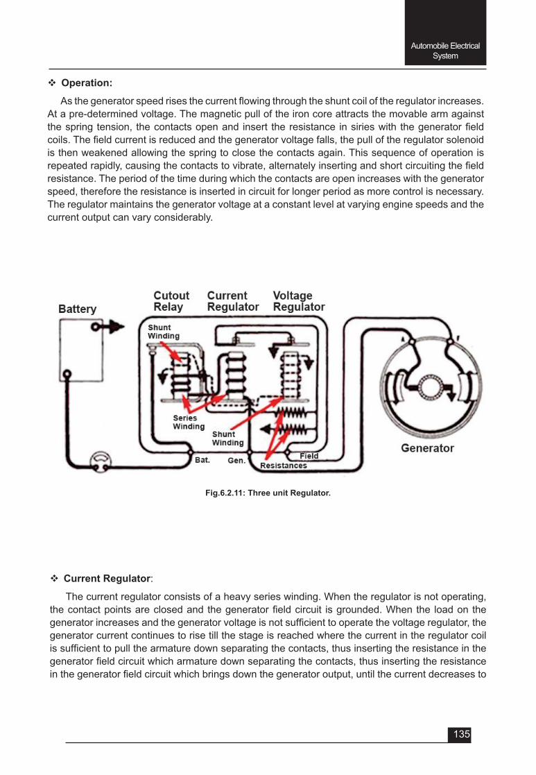
135
Automobile Electrical System
Fig.6.2.11: Three unit Regulator.
v Operation:
Asthegeneratorspeedrisesthecurrentflowingthroughtheshuntcoiloftheregulatorincreases.At a pre-determined voltage. The magnetic pull of the iron core attracts the movable arm against thespringtension, thecontactsopenand insert theresistance insirieswith thegeneratorfieldcoils.Thefieldcurrentisreducedandthegeneratorvoltagefalls,thepulloftheregulatorsolenoidis then weakened allowing the spring to close the contacts again. This sequence of operation is repeatedrapidly,causingthecontactstovibrate,alternatelyinsertingandshortcircuitingthefieldresistance. The period of the time during which the contacts are open increases with the generator speed, therefore the resistance is inserted in circuit for longer period as more control is necessary. The regulator maintains the generator voltage at a constant level at varying engine speeds and the current output can vary considerably.
v Current Regulator:
The current regulator consists of a heavy series winding. When the regulator is not operating, thecontactpointsareclosedandthegeneratorfieldcircuit isgrounded.Whenthe loadonthegeneratorincreasesandthegeneratorvoltageisnotsufficienttooperatethevoltageregulator,thegenerator current continues to rise till the stage is reached where the current in the regulator coil issufficienttopullthearmaturedownseparatingthecontacts,thusinsertingtheresistanceinthegeneratorfieldcircuitwhicharmaturedownseparatingthecontacts,thusinsertingtheresistanceinthegeneratorfieldcircuitwhichbringsdownthegeneratoroutput,untilthecurrentdecreasesto

136
Automobile Electrical System
a value such that the series winding in the current regulator cannot exert enough force to keep the contactsseparated.Thecontactsthencloseandthegeneratorfieldcircuitisgroundedagainthusincreasing its output. In this way the current regulator continues vibrating at a frequency of about 200 times per second, and maintains the current output at a preset constant value.
6.2.1.4: AC Generator or Alternator:
TheDCgeneratorswerenotabletoproducethesufficientamountofcurrentrequiredwhentheengine is running at low speeds, specially in cities where vehicles have to move at very low speeds duetoheavytraffic.Inmodernvehicles,thereisanadditionofmoreelectricalaccessoriesandcomponents like electrically operated power windows, air-conditioners, electrical equipment for automatictransmissions,overdrivesetc.whichrequiressufficientamountofcurrentatslowspeedof vehicle. So, the DC generators is replaced with alternators (or AC generators).
v Principle of Operation:
Inalternatorthemagneticfieldisrotatedandtheconductorsareheldstationary(justoppositetoDCgenerator).Thecurrentfirstflowsinonedirectionandthenintheotherdirectionalternately.
When an electromagnet (or permanent bar magnet) is rotated around a U shaped conductor, the magnetic lines of forces cut the stationary conductor to produce current in it. The conductor is also called as stator as it is stationary and since the magnet in an alternator rotates, therefore it is also called as rotor.
It may be noted that as the magnet is rotating continously and the direction of lines of force is also changing continuously, then the current induced in the conductor is an alternating current. In ordertoconvertthisalternatingcurrentintodirectcurrent,thediodes(orrectifiers)areused,whichallows the current to pass through them in only one direction.
The amount of current produced depends upon the following factors:
• Thestrengthofthemagneticfield,
• Rotatingspeedofmagneticfieldand
• Thenumberofconductorspassingthroughthemagneticfield.
v Construction of Alternator:
• Housing (frame):
The housing of the alternator assembly is made of cast aluminium in two pieces. The aluminium is used because it is non-magnetic, and a light weight material that provides good heat dissipation. The front part of the housing (also called as drive end housing) holds a ball bearing to support the front of the rotor drive shaft. The rotor drive shaft extends through the dirve end housing and holds the drive pulley and colling fan.
The rear part of the housing (also called as slip ring end) holds the rotor drive shaft to support a roller bearing. It also contains the brushes and has all the electrical terninals. If the alternator has an integral regulator, it is also contained in this housing.
The cooling fan draws air into the housing from the openings at the rear part of the housing. The air leaves through the openings behind the cooling fan.
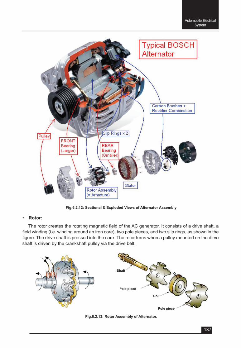
137
Automobile Electrical System
Fig.6.2.12: Sectional & Exploded Views of Alternator Assembly
Fig.6.2.13: Rotor Assembly of Alternator.
• Rotor:
TherotorcreatestherotatingmagneticfieldoftheACgenerator.Itconsistsofadriveshaft,afieldwinding(i.e.windingaroundanironcore),twopolepieces,andtwosliprings,asshowninthefigure.Thedriveshaftispressedintothecore.Therotorturnswhenapulleymountedonthedirveshaft is driven by the crankshaft pulley via the drive belt.
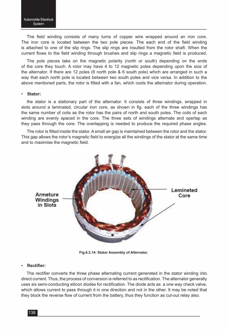
138
Automobile Electrical System
The field winding consists of many turns of copper wire wrapped around an iron core.The iron core is located between the two pole pieces. The each end of the field windingis attached to one of the slip rings. The slip rings are insulted from the rotor shaft. When the current flows to the fieldwinding throughbrushesand slip rings amagnetic field is produced.
The pole pieces take on the magnetic polarity (north or south) depending on the ends of the core they touch. A rotor may have 4 to 12 magnetic poles depending upon the size of the alternator. If there are 12 poles (6 north pole & 6 south pole) which are arranged in such a way that each north pole is located between two south poles and vice versa. In addition to the abovementionedparts,therotorisfittedwithafan,whichcoolsthealternatorduringoperation.
• Stator:
the stator is a stationary part of the alternator. It consists of three windings, wrapped in slots around a laminated, circular iron core, as shown in fig. each of the three windings hasthe same number of coils as the rotor has the pairs of north and south poles. The coils of each winding are evenly spaced in the core. The three sets of windings alternate and operlap as they pass through the core. The overlapping is needed to produce the required phase angles.
Therotorisfittedinsidethestator.Asmallairgapismaintainedbetweentherotorandthestator.Thisgapallowstherotor’smagneticfieldtoenergizeallthewindingsofthestatoratthesametimeandtomaximisethemagneticfield.
Fig.6.2.14: Stator Assembly of Alternator.
• Rectifier:
Therectifierconvertsthethreephasealternatingcurrentgeneratedinthestatorwindingintodirectcurrent.Thus,theprocessofconversionisreferredtoasrectification.Thealternatorgenerallyusessixsemi-conductingsilicondiodesforrectification.Thediodeactsasaonewaycheckvalve,which allows current to pass through it in one direction and not in the other. It may be noted that theyblockthereverseflowofcurrentfromthebattery,thustheyfunctionascut-outrelayalso.
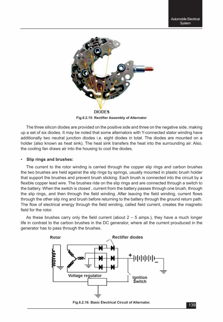
139
Automobile Electrical System
Fig.6.2.15:RectifierAssemblyofAlternator
Fig.6.2.16: Basic Electrical Circuit of Alternator.
The three silicon diodes are provided on the positive side and three on the negative side, making up a set of six diodes. It may be noted that some alternators with Y-connected stator winding have additionally two neutral junction diodes i.e. eight diodes in total. The diodes are mounted on a holder (also known as heat sink). The heat sink transfers the heat into the surrounding air. Also, the cooling fan draws air into the housing to cool the diodes.
• Slip rings and brushes:
The current to the rotor winding is carried through the copper slip rings and carbon brushes the two brushes are held against the slip rings by springs, usually mounted in plastic brush holder that support the brushes and prevent brush sticking. Each brush is connected into the circuit by a flexiblecopperleadwire.Thebrushesrideontheslipringsandareconnectedthroughaswitchtothe battery. When the switch is closed , current from the battery passes through one brush, through the slip rings, and then through the fieldwinding.After leaving the fieldwinding, current flowsthrough the other slip ring and brush before returning to the battery through the ground return path. Theflowofelectricalenergythroughthefieldwinding,calledfieldcurrent,createsthemagneticfieldfortherotor.
As thesebrushescarryonly thefieldcurrent (about2–5amps.), theyhaveamuch longerlife in contrast to the carbon brushes in the DC generator, where all the current prouduced in the generator has to pass through the brushes.
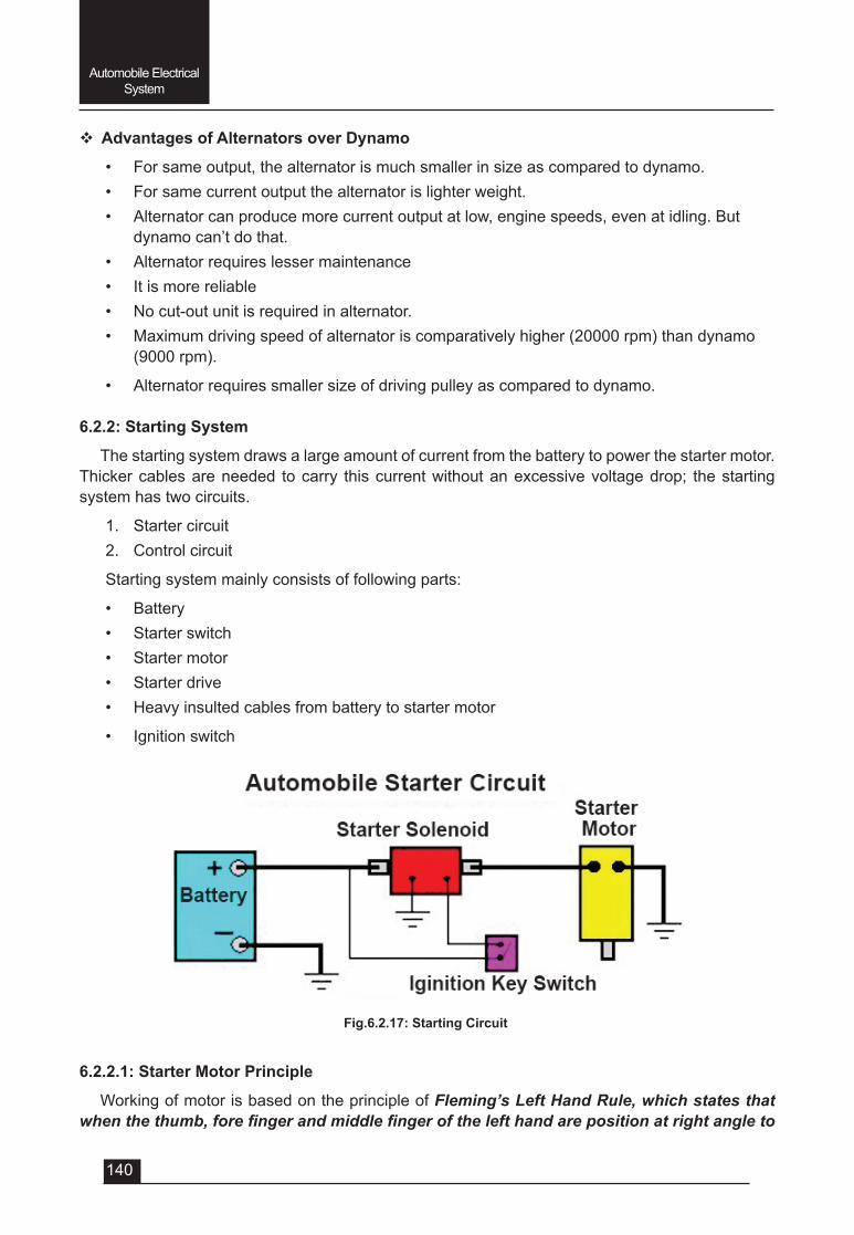
140
Automobile Electrical System
v Advantages of Alternators over Dynamo
• For same output, the alternator is much smaller in size as compared to dynamo.• For same current output the alternator is lighter weight.• Alternator can produce more current output at low, engine speeds, even at idling. But
dynamo can’t do that.• Alternator requires lesser maintenance• It is more reliable• No cut-out unit is required in alternator.• Maximum driving speed of alternator is comparatively higher (20000 rpm) than dynamo
(9000 rpm).
• Alternator requires smaller size of driving pulley as compared to dynamo.
6.2.2: Starting System
The starting system draws a large amount of current from the battery to power the starter motor. Thicker cables are needed to carry this current without an excessive voltage drop; the starting system has two circuits.
1. Starter circuit2. Control circuit
Starting system mainly consists of following parts:
• Battery • Starter switch• Starter motor• Starter drive• Heavy insulted cables from battery to starter motor
• Ignition switch
6.2.2.1: Starter Motor Principle
Working of motor is based on the principle of Fleming’s Left Hand Rule, which states that when the thumb, fore finger and middle finger of the left hand are position at right angle to
Fig.6.2.17: Starting Circuit
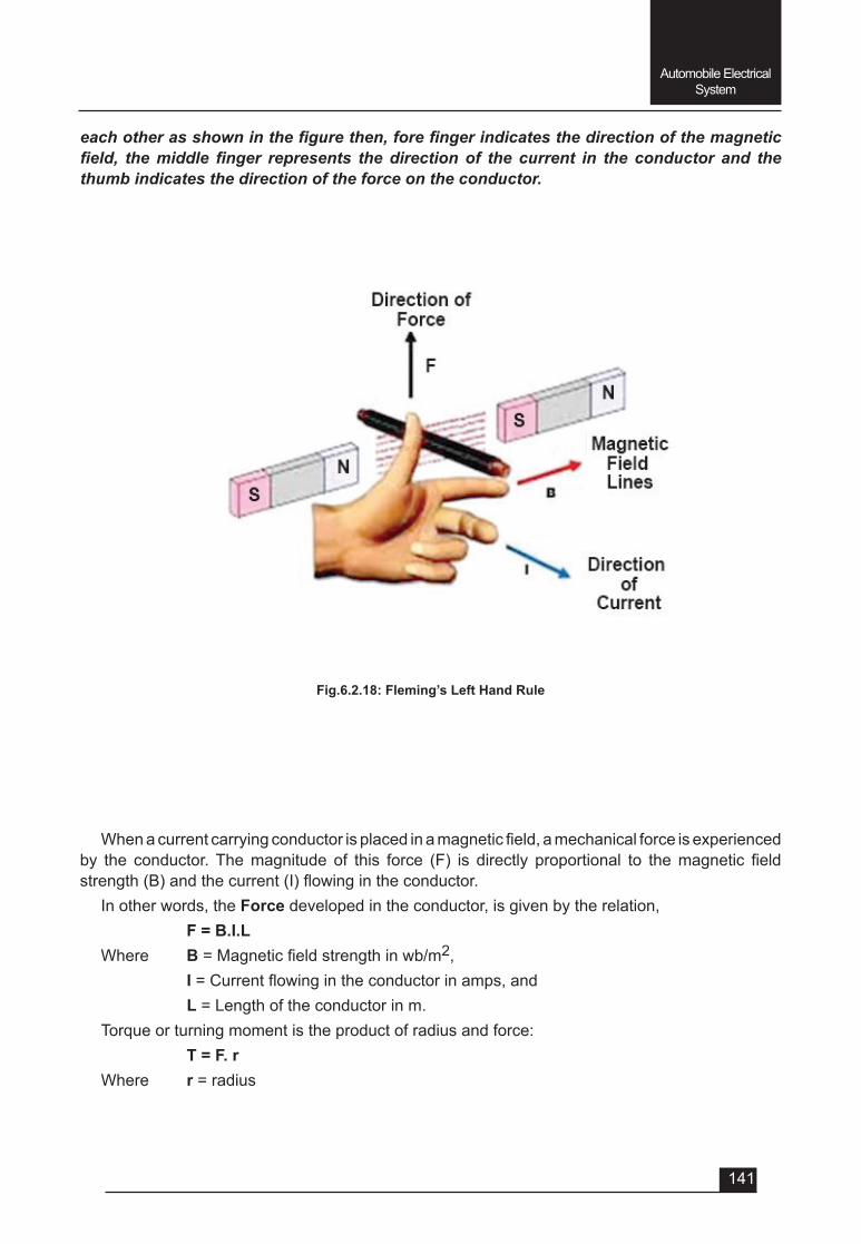
141
Automobile Electrical System
Fig.6.2.18: Fleming’s Left Hand Rule
each other as shown in the figure then, fore finger indicates the direction of the magnetic field, the middle finger represents the direction of the current in the conductor and the thumb indicates the direction of the force on the conductor.
Whenacurrentcarryingconductorisplacedinamagneticfield,amechanicalforceisexperiencedby the conductor.Themagnitude of this force (F) is directly proportional to themagnetic fieldstrength(B)andthecurrent(I)flowingintheconductor.
In other words, the Force developed in the conductor, is given by the relation, F = B.I.LWhere B=Magneticfieldstrengthinwb/m2, I=Currentflowingintheconductorinamps,and L = Length of the conductor in m. Torque or turning moment is the product of radius and force: T = F. rWhere r = radius
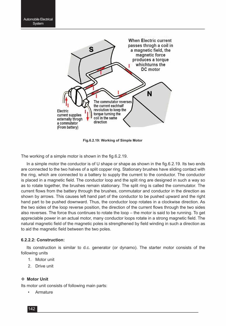
142
Automobile Electrical System
Theworkingofasimplemotorisshowninthefig.6.2.19.
InasimplemotortheconductorisofUshapeorshapeasshowninthefig.6.2.19.Itstwoendsare connected to the two halves of a split copper ring. Stationary brushes have sliding contact with the ring, which are connected to a battery to supply the current to the conductor. The conductor isplacedinamagneticfield.Theconductorloopandthesplitringaredesignedinsuchawaysoas to rotate together, the brushes remain stationary. The split ring is called the commutator. The currentflowsfromthebatterythroughthebrushes,commutatorandconductorinthedirectionasshown by arrows. This causes left hand part of the conductor to be pushed upward and the right hand part to be pushed downward. Thus, the conductor loop rotates in a clockwise direction. As thetwosidesoftheloopreverseposition,thedirectionofthecurrentflowsthroughthetwosidesalso reverses. The force thus continues to rotate the loop – the motor is said to be running. To get appreciablepowerinanactualmotor,manyconductorloopsrotateinastrongmagneticfield.Thenaturalmagneticfieldofthemagneticpolesisstrengthenedbyfieldwindinginsuchadirectionastoaidthemagneticfieldbetweenthetwopoles.
6.2.2.2: Construction:
Its construction is similar to d.c. generator (or dynamo). The starter motor consists of the following units
1. Motor unit2. Drive unit
v Motor UnitIts motor unit consists of following main parts:
• Armature
Fig.6.2.19: Working of Simple Motor
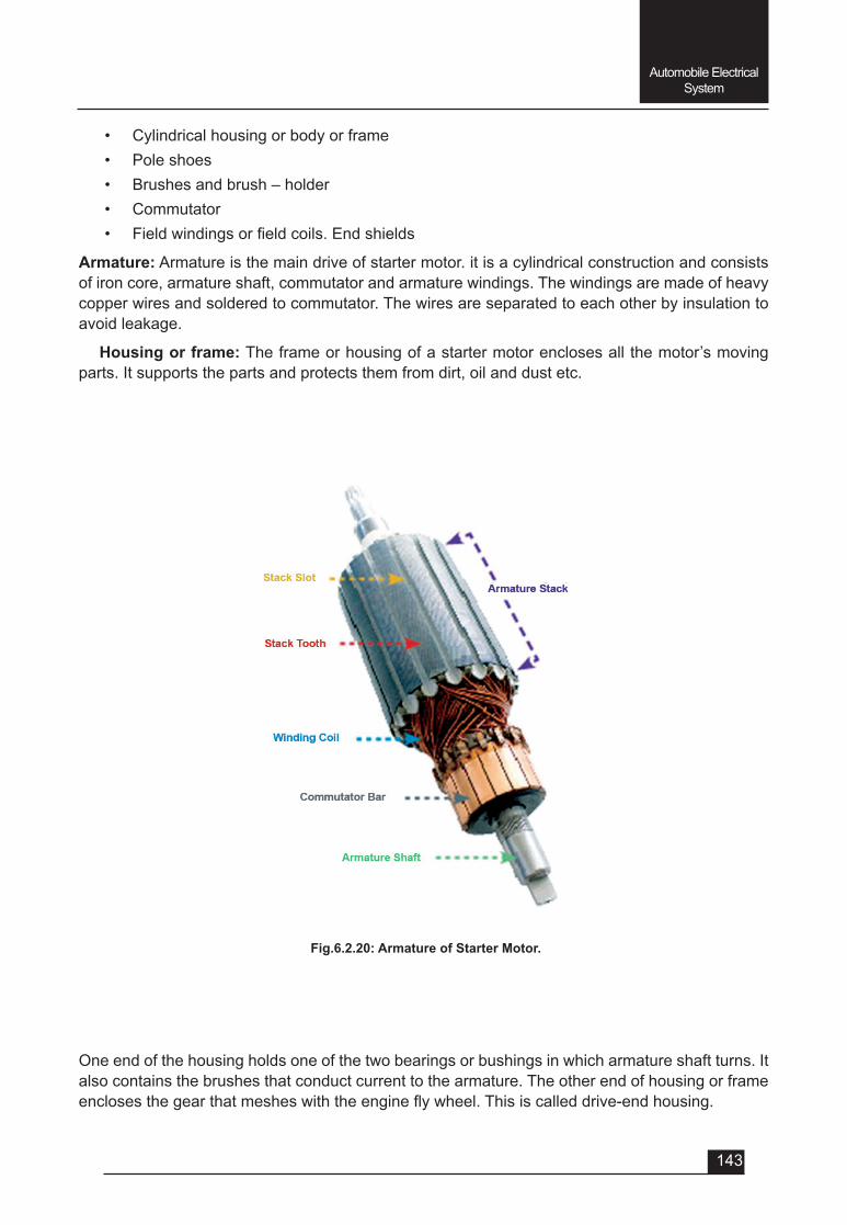
143
Automobile Electrical System
Fig.6.2.20: Armature of Starter Motor.
• Cylindrical housing or body or frame• Pole shoes• Brushes and brush – holder• Commutator• Fieldwindingsorfieldcoils.Endshields
Armature: Armature is the main drive of starter motor. it is a cylindrical construction and consists of iron core, armature shaft, commutator and armature windings. The windings are made of heavy copper wires and soldered to commutator. The wires are separated to each other by insulation to avoid leakage.
Housing or frame: The frame or housing of a starter motor encloses all the motor’s moving parts. It supports the parts and protects them from dirt, oil and dust etc.
One end of the housing holds one of the two bearings or bushings in which armature shaft turns. It also contains the brushes that conduct current to the armature. The other end of housing or frame enclosesthegearthatmesheswiththeengineflywheel.Thisiscalleddrive-endhousing.
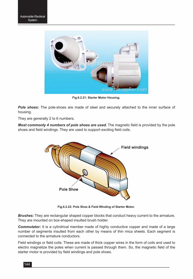
144
Automobile Electrical System
Pole shoes: The pole-shoes are made of steel and securely attached to the inner surface of housing.
They are generally 2 to 6 numbers.
Most commonly 4 numbers of pole shoes are used.Themagneticfieldisprovidedbythepoleshoesandfieldwindings.Theyareusedtosupportexcitingfieldcoils.
Fig.6.2.21: Starter Motor Housing.
Fig.6.2.22: Pole Shoe & Field Winding of Starter Motor.
Brushes: They are rectangular shaped copper blocks that conduct heavy current to the armature. They are mounted on box-shaped insulted brush holder.
Commutator: It is a cylindrical member made of highly conductive copper and made of a large number of segments insulted from each other by means of thin mica sheets. Each segment is connected to the armature conductors.
Fieldwindingsorfieldcoils:Thesearemadeofthickcopperwiresintheformofcoilsandusedtoelectromagnetizethepoleswhencurrentispassedthroughthem.So,themagneticfieldofthestartermotorisprovidedbyfieldwindingsandpoleshoes.
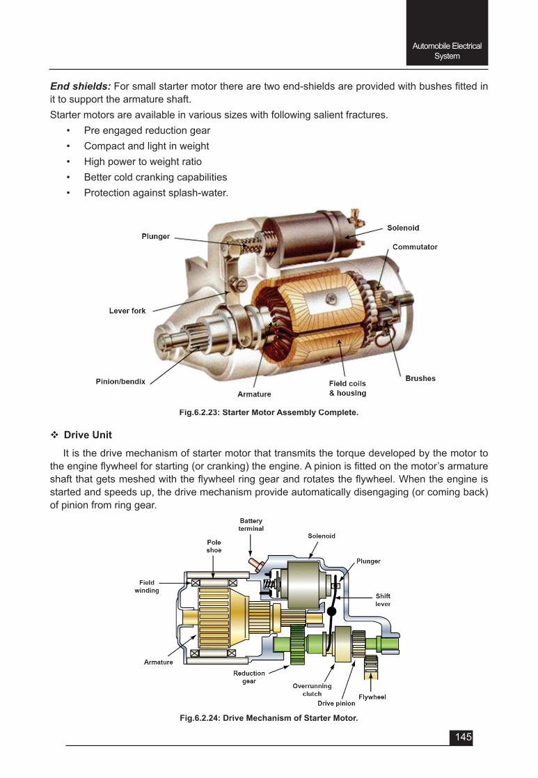
145
Automobile Electrical System
End shields:Forsmallstartermotortherearetwoend-shieldsareprovidedwithbushesfittedinit to support the armature shaft.Starter motors are available in various sizes with following salient fractures.
• Pre engaged reduction gear• Compact and light in weight• High power to weight ratio• Better cold cranking capabilities• Protection against splash-water.
Fig.6.2.23: Starter Motor Assembly Complete.
Fig.6.2.24: Drive Mechanism of Starter Motor.
v Drive Unit
It is the drive mechanism of starter motor that transmits the torque developed by the motor to theengineflywheelforstarting(orcranking)theengine.Apinionisfittedonthemotor’sarmatureshaftthatgetsmeshedwiththeflywheelringgearandrotatestheflywheel.Whentheengineisstarted and speeds up, the drive mechanism provide automatically disengaging (or coming back) of pinion from ring gear.
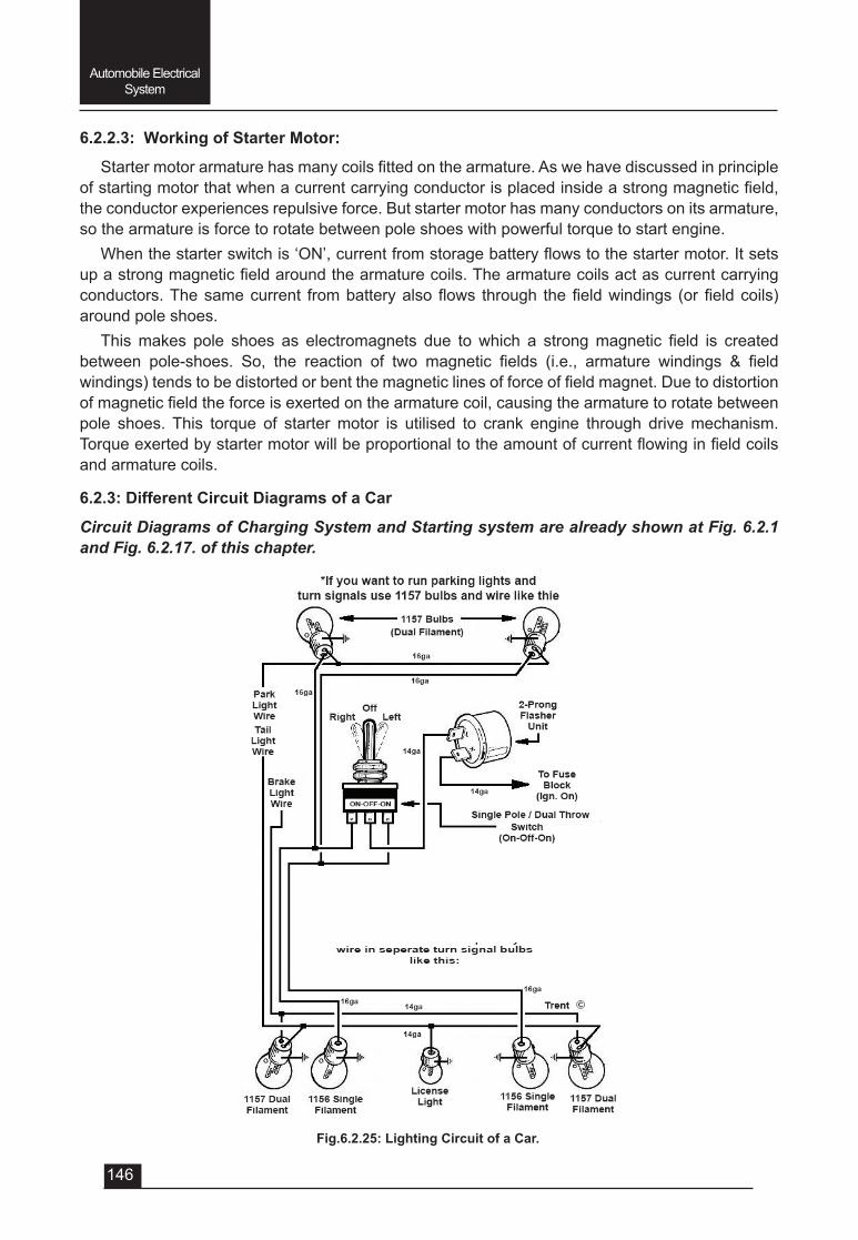
146
Automobile Electrical System
6.2.2.3: Working of Starter Motor:
Startermotorarmaturehasmanycoilsfittedonthearmature.Aswehavediscussedinprincipleofstartingmotorthatwhenacurrentcarryingconductorisplacedinsideastrongmagneticfield,the conductor experiences repulsive force. But starter motor has many conductors on its armature, so the armature is force to rotate between pole shoes with powerful torque to start engine.
Whenthestarterswitchis‘ON’,currentfromstoragebatteryflowstothestartermotor.Itsetsupastrongmagneticfieldaroundthearmaturecoils.Thearmaturecoilsactascurrentcarryingconductors.Thesamecurrent frombatteryalsoflows through thefieldwindings (orfieldcoils)around pole shoes.
Thismakes pole shoes as electromagnets due towhich a strongmagnetic field is createdbetween pole-shoes. So, the reaction of two magnetic fields (i.e., armature windings & fieldwindings)tendstobedistortedorbentthemagneticlinesofforceoffieldmagnet.Duetodistortionofmagneticfieldtheforceisexertedonthearmaturecoil,causingthearmaturetorotatebetweenpole shoes. This torque of starter motor is utilised to crank engine through drive mechanism. Torqueexertedbystartermotorwillbeproportionaltotheamountofcurrentflowinginfieldcoilsand armature coils.
6.2.3: Different Circuit Diagrams of a Car
Circuit Diagrams of Charging System and Starting system are already shown at Fig. 6.2.1 and Fig. 6.2.17. of this chapter.
Fig.6.2.25: Lighting Circuit of a Car.
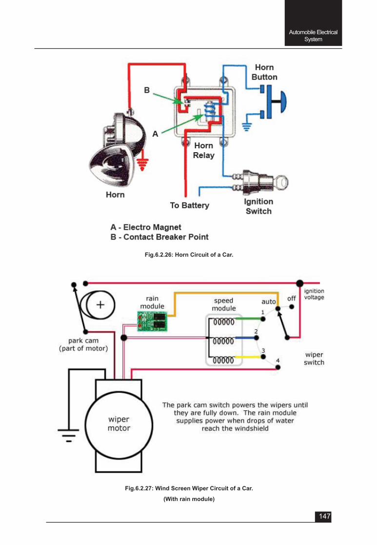
147
Automobile Electrical System
Fig.6.2.26: Horn Circuit of a Car.
Fig.6.2.27: Wind Screen Wiper Circuit of a Car.
(With rain module)
148
Automobile Electrical System
QUESTIONSVery Short answer type (each question carries 1 mark)
1. If the rotating coil is connected to the external circuit through brushes and slip rings instead of the commutator, the current generated will be ________________ in character.
2. The voltage induced in the coil of D.C. generator will follow _________ wave.
3. Modern automobile generators are the two-pole, two-brush, ________ wound type.
4. Inmodernautomobilegeneratorwhichtypeoffollowingwoundisused?
a. Series wound b. Shunt wound c. Compound wound
5. The speed of the generator at which its output voltage just rises above voltage of the battery being charged is called ______________ speed.
6. The principle on which the regulator works is called __________ principle.
7. A rotor may have ____ ____ magnetic poles depending upon the size of the alternator.
8. Inalternatorrectifiersarefittedonaplatecalled________________________.
Short answer type (each question carries 2 marks)
1. Namedifferentcomponentsfittedinthechargingsystem.
2. Onwhatarethefactorstheamountofcurrentinducedinaconductordependsupon?
3. Write the function of cut-out.
4. Write the function of current regulator.
5. Write the function of voltage regulator.
6. Whatistheprincipleonwhichregulatorworks?Andwritetheprinciple.
7. Writethefunctionofrectifierinalternator.
8. Name different components of the starting system.
Short answer type (each question carries 3 marks)
1. Draw the charging circuit of a car and label its different component.
2. Write the principle on which generator works.
3. Explain the function of commutator.
4. WritehowvoltagefluctuationinD.C.generatoriseliminated?
5. With circuit diagram explain the operation of cut-out.
6. Draw the starting circuit of a car and label its different components.
7. Write the principle on which starter motor works.
Long answer type (each question carries 5 marks)
1. Explain the principle of D.C. generator (dynamo) and its working.
2. Explainwithcircuitdiagramdifferenttypeofgeneratorfieldwindings.
149
Automobile Electrical System
3. Brieflyexplaintheconstructionofautomobiledynamo.
4. Whichcircuitdiagramsexplaintheoperationofvoltageandcurrentregulator?
5. Write the working principle of alternator (A.C. generator).
6. Explain the construction of alternator.
7. Write the advantages of alternator over dynamo.
8. Drawtherectifiercircuitandlabelitsdifferentcomponents.
9. Explain with neat sketch the operation of simple motor.
10.Explaintheconstructionofalternatorfittedinautomobile.
11. Explain with neat sketch the drive unit of starter motor.
12. Draw the lighting circuit of any Indian car.
13. Draw the horn circuit of a car.
14. Draw the wind screen wiper circuit of a car.
UNIT – 6
SESSION – 3
AUTOMOBILE ELECTRICAL SYSTEM(Ignition System)
151
Automobile Electrical System
Objectives
After attending this session, students should be able to:
v Explain the function and types of ignition system.
v Explain the Battery Ignition System and to draw its circuit diagram.
v Explain the Magneto Ignition System and to draw its circuit diagram.
v Explaintheclassificationofsparkpluganditsconstructionalfeatures.
v Understand how to carry out the Ignition timing and procedure of checking the Ignition timing with the help of stroboscope.
UNIT – 6Session – 3
Automobile Electrical System (Ignition System)
6.3.1: Introduction:
The spark ignition (S.I.) engines require some device to ignite the compressed air fuel mixture inside the combustion chamber at end of the compression stroke. Ignition system serves this purpose.
Thus Ignition system performs the following main functions:
• To generate an electrical spark with enough heat to ignite the air-fuel mixture in the combustion chamber.
• To maintain the spark long enough to allow for combustion of all the air and fuel in the cylinders.
• Todeliverthesparktoeachcylinderaccordingtothefiringorderofengine,and
• To properly time the spark so that the combustion can be started at right time during the combustion stroke of the each cylinder.
6.3.2: Types of Ignition System
The following types of Ignition system are employed in vehicles.
1. Conventional (or C.B. point type) Ignition system. Thissystemisfurtherclassifiedas
• Battery ignition or coil ignition system
• Magneto ignition system.
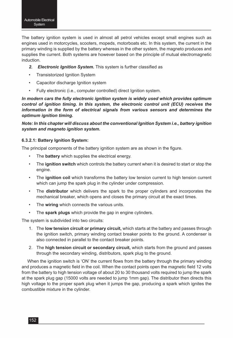
152
Automobile Electrical System
The battery ignition system is used in almost all petrol vehicles except small engines such as engines used in motorcycles, scooters, mopeds, motorboats etc. In this system, the current in the primary winding is supplied by the battery whereas in the other system, the magneto produces and supplies the current. Both systems are however based on the principle of mutual electromagnetic induction.
2. Electronic Ignition System. Thissystemisfurtherclassifiedas
• Transistorized Ignition System
• Capacitor discharge Ignition system
• Fully electronic (i.e., computer controlled) direct Ignition system.
In modern cars the fully electronic ignition system is widely used which provides optimum control of ignition timing. In this system, the electronic control unit (ECU) receives the information in the form of electrical signals from various sensors and determines the optimum ignition timing.
Note: In this chapter will discuss about the conventional Ignition System i.e., battery ignition system and magneto ignition system.
6.3.2.1: Battery Ignition System:
Theprincipalcomponentsofthebatteryignitionsystemareasshowninthefigure.
• The battery which supplies the electrical energy.
• The ignition switch which controls the battery current when it is desired to start or stop the engine.
• The ignition coil which transforms the battery low tension current to high tension current which can jump the spark plug in the cylinder under compression.
• The distributor which delivers the spark to the proper cylinders and incorporates the mechanical breaker, which opens and closes the primary circuit at the exact times.
• The wiring which connects the various units.
• The spark plugs which provide the gap in engine cylinders.
The system is subdivided into two circuits:
1. The low tension circuit or primary circuit, which starts at the battery and passes through the ignition switch, primary winding contact breaker points to the ground. A condenser is also connected in parallel to the contact breaker points.
2. The high tension circuit or secondary circuit, which starts from the ground and passes through the secondary winding, distributors, spark plug to the ground.
Whentheignitionswitchis‘ON’thecurrentflowsfromthebatterythroughtheprimarywindingandproducesamagneticfieldinthecoil.Whenthecontactpointsopenthemagneticfield12voltsfrom the battery to high tension voltage of about 20 to 30 thousand volts required to jump the spark at the spark plug gap (15000 volts are needed to jump 1mm gap). The distributor then directs this high voltage to the proper spark plug when it jumps the gap, producing a spark which ignites the combustible mixture in the cylinder.
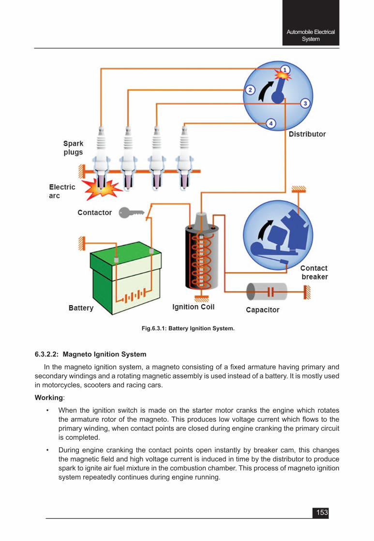
153
Automobile Electrical System
6.3.2.2: Magneto Ignition System
Inthemagnetoignitionsystem,amagnetoconsistingofafixedarmaturehavingprimaryandsecondary windings and a rotating magnetic assembly is used instead of a battery. It is mostly used in motorcycles, scooters and racing cars.
Working:
• When the ignition switch is made on the starter motor cranks the engine which rotates thearmaturerotorofthemagneto.Thisproduceslowvoltagecurrentwhichflowstotheprimary winding, when contact points are closed during engine cranking the primary circuit is completed.
• During engine cranking the contact points open instantly by breaker cam, this changes themagneticfieldandhighvoltagecurrentisinducedintimebythedistributortoproducespark to ignite air fuel mixture in the combustion chamber. This process of magneto ignition system repeatedly continues during engine running.
Fig.6.3.1: Battery Ignition System.
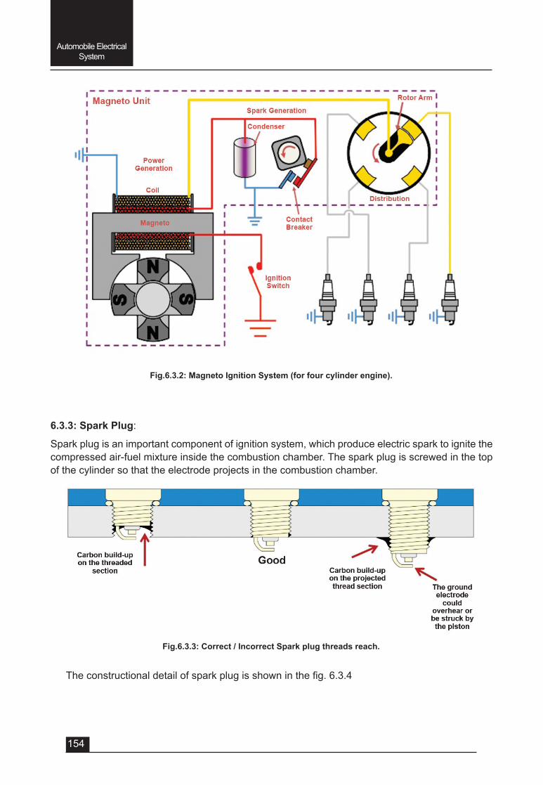
154
Automobile Electrical System
6.3.3: Spark Plug:
Spark plug is an important component of ignition system, which produce electric spark to ignite the compressed air-fuel mixture inside the combustion chamber. The spark plug is screwed in the top of the cylinder so that the electrode projects in the combustion chamber.
Fig.6.3.2: Magneto Ignition System (for four cylinder engine).
Fig.6.3.3: Correct / Incorrect Spark plug threads reach.
Theconstructionaldetailofsparkplugisshowninthefig.6.3.4
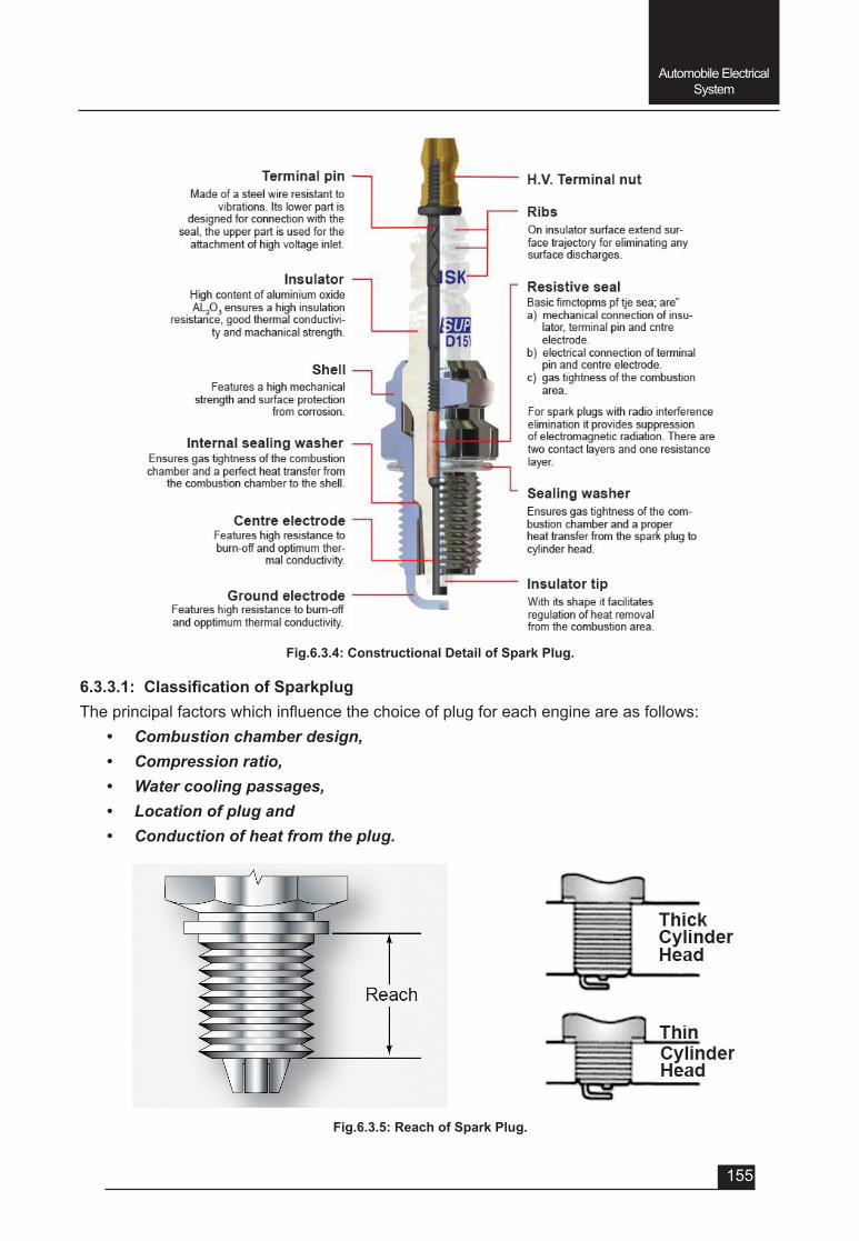
155
Automobile Electrical System
Fig.6.3.4: Constructional Detail of Spark Plug.
6.3.3.1:ClassificationofSparkplugTheprincipalfactorswhichinfluencethechoiceofplugforeachengineareasfollows:
• Combustion chamber design, • Compression ratio, • Water cooling passages, • Location of plug and • Conduction of heat from the plug.
Fig.6.3.5: Reach of Spark Plug.
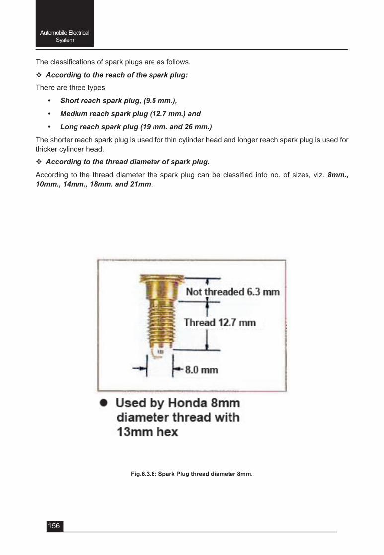
156
Automobile Electrical System
Theclassificationsofsparkplugsareasfollows.
v According to the reach of the spark plug:
There are three types
• Short reach spark plug, (9.5 mm.),
• Medium reach spark plug (12.7 mm.) and
• Long reach spark plug (19 mm. and 26 mm.)
The shorter reach spark plug is used for thin cylinder head and longer reach spark plug is used for thicker cylinder head.
v According to the thread diameter of spark plug.
According to the threaddiameter thesparkplugcanbeclassified intono.ofsizes,viz.8mm., 10mm., 14mm., 18mm. and 21mm.
Fig.6.3.6: Spark Plug thread diameter 8mm.
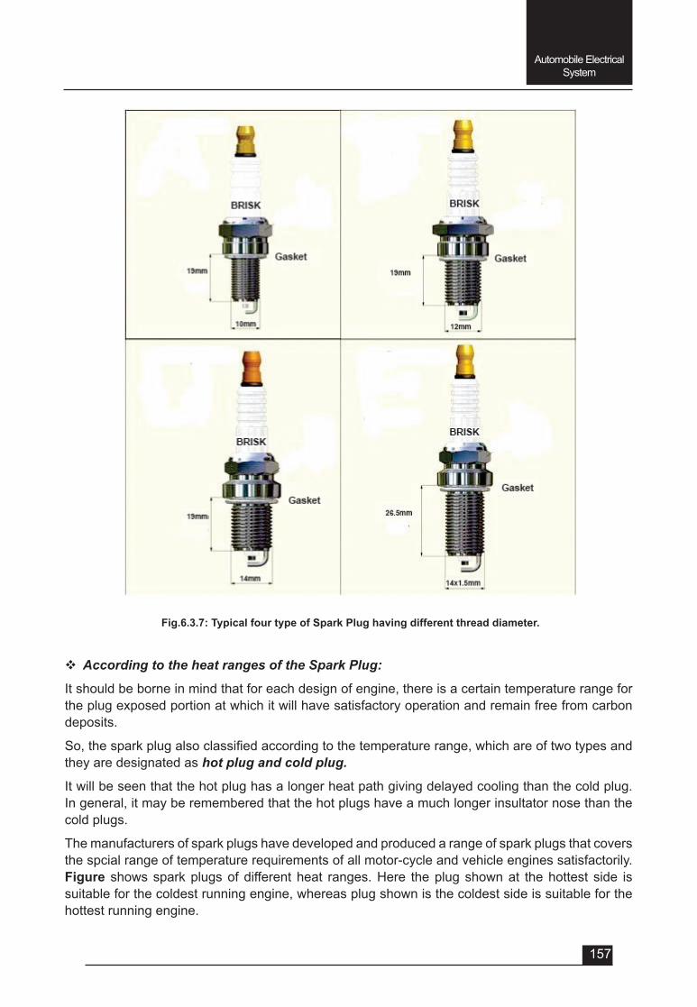
157
Automobile Electrical System
Fig.6.3.7: Typical four type of Spark Plug having different thread diameter.
v According to the heat ranges of the Spark Plug:
It should be borne in mind that for each design of engine, there is a certain temperature range for the plug exposed portion at which it will have satisfactory operation and remain free from carbon deposits.
So,thesparkplugalsoclassifiedaccordingtothetemperaturerange,whichareoftwotypesandthey are designated as hot plug and cold plug.
It will be seen that the hot plug has a longer heat path giving delayed cooling than the cold plug. In general, it may be remembered that the hot plugs have a much longer insultator nose than the cold plugs.
The manufacturers of spark plugs have developed and produced a range of spark plugs that covers the spcial range of temperature requirements of all motor-cycle and vehicle engines satisfactorily. Figure shows spark plugs of different heat ranges. Here the plug shown at the hottest side is suitable for the coldest running engine, whereas plug shown is the coldest side is suitable for the hottest running engine.
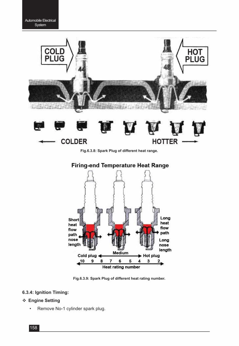
158
Automobile Electrical System
Fig.6.3.8: Spark Plug of different heat range.
Fig.6.3.9: Spark Plug of different heat rating number.
6.3.4: Ignition Timing:
v Engine Setting
• Remove No-1 cylinder spark plug.
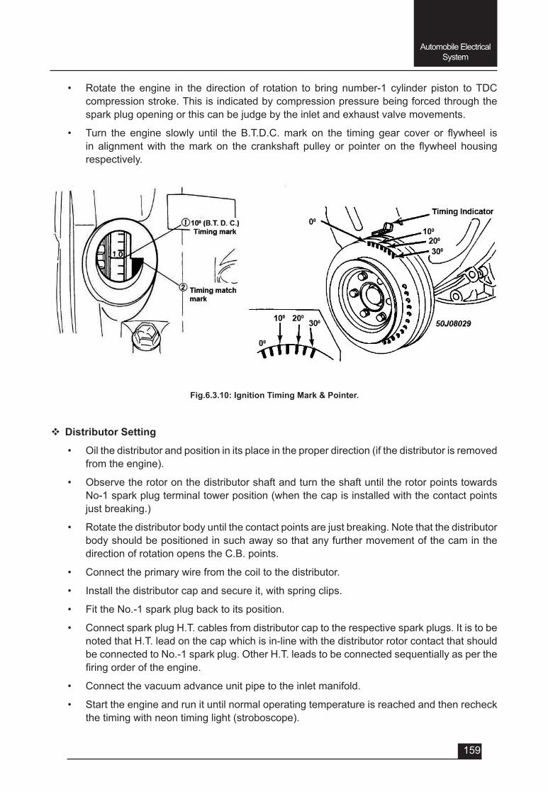
159
Automobile Electrical System
• Rotate the engine in the direction of rotation to bring number-1 cylinder piston to TDC compression stroke. This is indicated by compression pressure being forced through the spark plug opening or this can be judge by the inlet and exhaust valve movements.
• Turn the engine slowly until the B.T.D.C.mark on the timing gear cover or flywheel isin alignmentwith themark on the crankshaft pulley or pointer on the flywheel housingrespectively.
Fig.6.3.10: Ignition Timing Mark & Pointer.
v Distributor Setting
• Oil the distributor and position in its place in the proper direction (if the distributor is removed from the engine).
• Observe the rotor on the distributor shaft and turn the shaft until the rotor points towards No-1 spark plug terminal tower position (when the cap is installed with the contact points just breaking.)
• Rotate the distributor body until the contact points are just breaking. Note that the distributor body should be positioned in such away so that any further movement of the cam in the direction of rotation opens the C.B. points.
• Connect the primary wire from the coil to the distributor.
• Install the distributor cap and secure it, with spring clips.
• Fit the No.-1 spark plug back to its position.
• Connect spark plug H.T. cables from distributor cap to the respective spark plugs. It is to be noted that H.T. lead on the cap which is in-line with the distributor rotor contact that should be connected to No.-1 spark plug. Other H.T. leads to be connected sequentially as per the firingorderoftheengine.
• Connect the vacuum advance unit pipe to the inlet manifold.
• Start the engine and run it until normal operating temperature is reached and then recheck the timing with neon timing light (stroboscope).
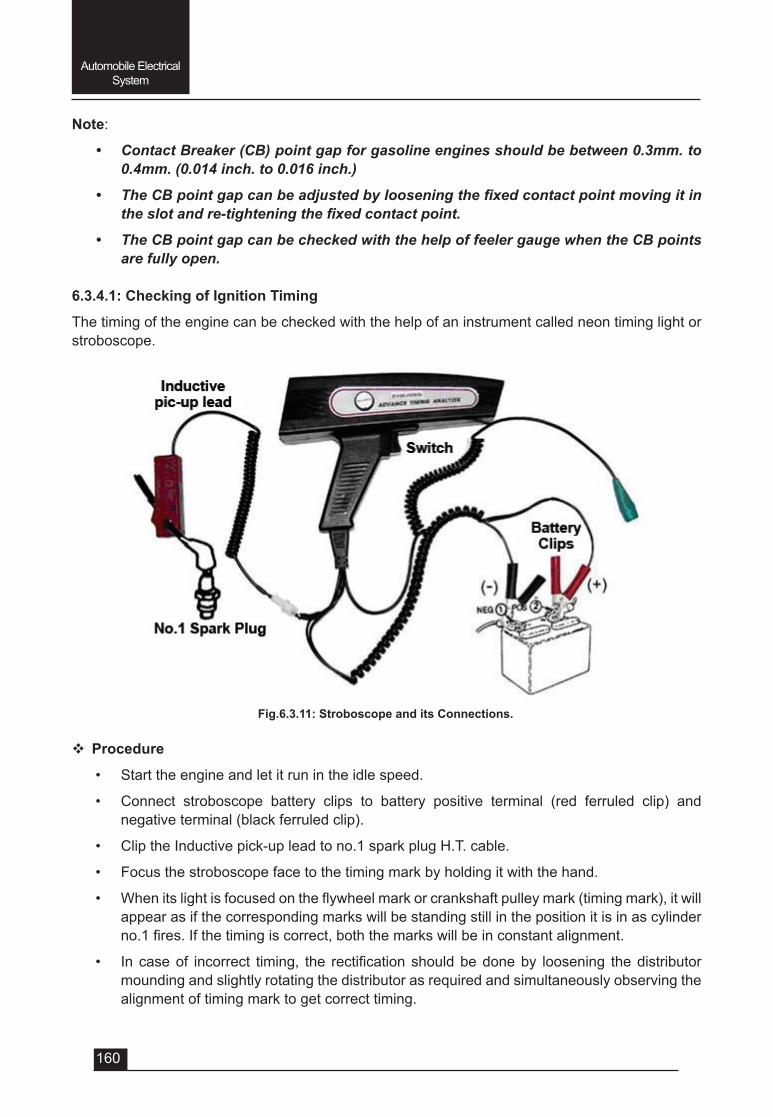
160
Automobile Electrical System
Note:
• Contact Breaker (CB) point gap for gasoline engines should be between 0.3mm. to 0.4mm. (0.014 inch. to 0.016 inch.)
• The CB point gap can be adjusted by loosening the fixed contact point moving it in the slot and re-tightening the fixed contact point.
• The CB point gap can be checked with the help of feeler gauge when the CB points are fully open.
6.3.4.1: Checking of Ignition Timing
The timing of the engine can be checked with the help of an instrument called neon timing light or stroboscope.
Fig.6.3.11: Stroboscope and its Connections.
v Procedure
• Start the engine and let it run in the idle speed.
• Connect stroboscope battery clips to battery positive terminal (red ferruled clip) and negative terminal (black ferruled clip).
• Clip the Inductive pick-up lead to no.1 spark plug H.T. cable.
• Focus the stroboscope face to the timing mark by holding it with the hand.
• Whenitslightisfocusedontheflywheelmarkorcrankshaftpulleymark(timingmark),itwillappear as if the corresponding marks will be standing still in the position it is in as cylinder no.1fires.Ifthetimingiscorrect,boththemarkswillbeinconstantalignment.
• In caseof incorrect timing, the rectificationshouldbedoneby loosening thedistributormounding and slightly rotating the distributor as required and simultaneously observing the alignment of timing mark to get correct timing.

161
Automobile Electrical System
• Finally tighten the distributor mounting.
Note: 1. Timing marks for different engine may be in different location such as on the flywheel
or on the crankshaft pulley.
2. B.T.D.C (Before Top Dead Centre) mark differs according to the design of the engine.
QUESTIONSVery Short answer type (each question carries 1 mark)
1. Whichtheprincipalfactorswhichinfluencethechoiceofplugforeachengine2. The length of reach for a short reach spark plug is _________mm.3. The length of reach for medium reach spark plug is _________mm.4. The length of reach for long reach spark plug is _________mm.5. It may be remembered that the hot plugs have a much longer _________ _______ than the
cold plugs.6. During setting of ignition timing the position of no. 1 cylinder piston should be at a. T.D.C compression strokeb. T.D.C. exhaust strokec. B.D.C. power stroked. B.D.C. suction stroke
Short answer type (each question carries 2 marks)1. Name different type of ignition system.2. Writetheclassificationofsparkplugaccordingtothelengthofreach.3. Draw the neat sketch for the connection of stroboscope while checking the ignition timing.
Short answer type (each question carries 3 marks)1. WhatarethedifferentfunctionsofignitionsystemofS.I.engine?2. Name different principle components of battery ignition system.3. Whataretheprincipalfactors,whichinfluencethechoiceofsparkplugforS.I.engine?4. Writetheclassificationofsparkplugaccordingtothethreaddiameter.5. Writetheclassificationofsparkplugaccordingtotheheatrange.
Long answer type (each question carries 5 marks)1. Draw a circuit diagram of battery ignition system and explain its working.2. Draw a circuit diagram of magneto ignition system and explain its working.3. With a neat sketch explain the constructional detail of a spark plug4. Withsketchesexplaintheclassificationofsparkplugs.5. Write step by step procedure of setting the ignition timing of S.I. engine.6. Write step by step procedure of checking the ignition timing with the help of stroboscope
(timing light).

UNIT – 7
SESSION – 1
MOTOR VEHICLE ACT 1983 AND RULES
163
Motor Vehicle Act
Objectives
After attending this session you should be able to:-v Explain types of licence, Eligibility for obtaining it.
v Documents required for obtaining different types of driving licence and its renewal.
v Understand registration procedure of a vehicle and documents required for registration.
v Explain types of insurance policies and settlement procedure.
v Explaindocumentsrequiredfortransferofownershipandfitnessofvehicle.
UNIT – 7Session -1
Motor Vehicle Act 1983 and Rules
7.1.1: Provision regarding Issue of driving licence
v Driving licence: Driving licence is the permission granted by Govt. Authorities to drive the motor vehicle in public place
v Necessity for driving licence: No person shall drive a motor vehicle in any public place unless he holds an effective driving licence issued to him authorising him to drive the vehicle; and no person shall so drive a transport vehicle unless his driving licence specificallyentitleshimsotodo.
The driving licence are of two types:
v Learner Licence: This is a temporary licence valid up to 6 month only. It is issued to learn driving of Motor Vehicles.
v Permanent Licence: One become eligible for permanent licence after expiry of one month from the date of issuing the learner licence
Eligibility for obtaining a licence:-
• A person should have completed 16 years to obtain license for 2 wheelers without gear.
• A person should have completed 18 years age to obtain license for 2 wheelers with gear, Motor-car, Tractor and other non-transport vehicles.
• For transport vehicles, a person should have completed 20 years of age. In addition he should be passed standard 8th and should have experience of 1 year driving a light motor vehicle.
v Documents required for learner licence
The documents required along with the learner application form are as follows:-
164
Motor Vehicle Act
1) Form No. 1, 2, 3
2) Three 3 copies of applicant recent passport size photograph
3) Proof of residence
4) Proof of Age
5) Proof of citizenship
6) In the case of an application for transport vehicle, the driving license held by the applicant.
7) AppropriateFeehasspecifiedinrule32.
v Documents required for permanent licence: The person having a valid learner licence can apply for permanent licence after 30 days and within 180 days from the date of issuance of learner licence.
An application for a driving license shall be made in form no.4 and shall be accompanied by :-1) An effective learner’s license to drive the vehicle of the type to which application relates
2) Appropriatefeeasspecifiedforthetestofcompetencetodriveandissueoflicense.
3) Nationality Proof.
4) Proof of citizenship. (Attested photocopies)
5) One recent passport size photograph
6) AdrivingcertificateinFormNo.5&14issuedbytheschoolorestablishmentfromwherethe applicant received instruction.
7) The vehicles for test which category you are applying the licence.
Your original licence in case of endorsements of categories.
v Documents required for renewal of driving licence:
• For Private Licence:
1) Application in Form No.9.
2) Fees and Penalties as Applicable.
3) 2 copies of your recent passport size photograph.
4) Original driving licence held.
5) Attested Copy of valid Proof of age and residence.
6) formNo.1selfdeclarationofphysicalfitness
• For Commercial Licence:
1) The above documents as required in Private Licence.
2) MedicalCertificateinformNo.1-A(IncaseofCommercialcategory).
3) DriverrefreshingTrainingcertificateincaseofHMV.
4) IncaseofPrivatelicencetherecordisnotverifiediftheparticularseemstobeclearonthelicence.Howeverforcommercial licencetheparticularsareverifiedfromtheissuing
165
Motor Vehicle Act
authority. The renewal of licence in case of private licence is done on the same day but for commerciallicencetherenewalismadeafterverificationoftheparticulars.
v Documents required to get a duplicate licence:
1) Application in Form LLD.
2) FIR/NCR of the lost licence
3) ChallanclearancereportfromTrafficPolice(incaseofCommerciallicencerenewal).
4) Fee amount, Form No 1.Self Declaration of Physical Fitness.
5) Attested Copy of valid address Proof
Forduplicatelicenceyouhavetoapproachtheissuingauthorityandtheparticularswillbeverifiedfrom their records. The validity of duplicate licence will be the same of your previous licence. The original issuing authority will issue your duplicate licence. If your licence is lost and expired by more than 6 months your case requires permission from Head Quarter of Transport Department.
The following documents can be used as proofs:-1. Residence proof:
1) Voter Identity Card 2) Life Insurance Policy3) Passport4) Payslipissuedanyofficeofthecentralgovernmentorastategovernmentorlocal
body.
Thefollowingdocumentsarealsoacceptedalongwithanaffidavitswornbeforeanotarypublic or any competent magistrate
1) Water Bill 2) Electricity Bill3) Telephone Bill 4) Pay slip accompanied by a PF Receipt (In case of private sector employees)5) Property Ownership like, Registry, Power of Attorney etc.6) PostofficeorbankPassbookindicatingresidentialaddress7) House tax receipt8) CertificatefromemployerincaseofGovernmentServant.9) Ration Card10)MarriagecertificateissuedbyDistrictAdministration11) Income Tax Returns12)ResidenceCertificateissuedbyDistrictAdministration
v Documents valid for proof of age:
1) Schoolcertificate
2) Passport
166
Motor Vehicle Act
3) BirthCertificate
4) CertificateissuedbyaregisteredmedicalpractitionernotbelowtherankofaCivilSurgeon, as to the age of the applicant
5) AffidavitswornbytheapplicantbeforeanExecutiveMagistrateandoraFirstClassMagistrate as a evidence of age.
6) PAN Card
7) CGHS Card
Documents valid for proof of citizenship:-
1) Proof of Birth in India from municipality or registrar of birth & death.
2) SchoolLeavingCertificate/SecondarySchoolCertificateShowingNationality/Placeofbirth
3) Passport Showing place of birth/citizenship/nationality
4) Certificateofcitizenship/nationalityissuedbymagistrateoranyotheradministrativeofficer
5) Residencypermit/domicilecertificateissuedbystategovernment.
6) Grant of patta/lease of property by the central/state government.
7) Refugee Registration card pertaining for the period of 1947-1950
8) CertificateofSC/ST/OBC.
7.1.2: Registration of vehicle:
The vehicle can be driven or allowed to be driven in public place only after registration by registering authority as under the provision of section 39 of motor vehicle Act 1988.
Procedure of registration:
1. Registration by transport department: In this the applicant has to get his vehicle registered by the transport department after getting the vehicle inspected physically by the department and by paying registration charges, road tax etc.
2. Registration by dealers: Transport Department has authorized dealers to register the vehiclesandtodelivertheregistrationcertificateaswell,totheregisteredownerattheirendforthebenefitofpublicandtoavoidthehasslesinregistrationprocedure
The registration procedure includes the vehicle to be inspected physically by Inspecting Authority atzonalofficeforitsparticularsandfollowedbyregistration.Thedocumentsrequiredtoapplytheregistration are as follows :
1) Form20dulyfilledup.
2) Form21(Salecertificate)issuedbythevehicledealer
3) Form22(Roadworthinesscertificate)issuedbythewhichmanufacturer
4) Attested copy of valid vehicle insurance policy/cover note
5) Attested copy of address proof at which vehicle is to be registered.
167
Motor Vehicle Act
6) Form34dulysignedbyownerandthefinancer
7) One time road tax as applicable
8) Prescribed fee for registration
9) PAN Card or Form 60 & 61 (as applicable)
10) Parking fees.
11) Dealer invoice along with manufacturer invoice.
ThefollowingdocumentsarerequiredforchangeofaddressinRegistrationCertificate.
1) Form No. 33
2) OriginalRegistrationCertificate.
3) Attested copy of valid insurance.
4) Attested copy of address proof of the registered owner.
5) Attestedcopyofvalidpollutionundercontrolcertificate.
6) Prescribed fee.
7) Attested copy of PAN Card or Form 60 & 61(as applicable)
8) Regarding the change of address in Registration Certificate, where the hypothecationisendorsed in theRegistrationCertificate,NoObjectionCertificate from thefinancer isneededtogettheaddresschangedintheRegistrationCertificate.
The change of address should be applied within 14 days from the date of effect, after that penalty is applicable.
If a registered owner of a vehicle brings the vehicle to some state, which is already registered in some other state after obtaining a N.O.C from the concerned state can apply for re-registration in that state, the documents required are as under:
1) Otherstateregistrationcertificateinoriginal.
2) Form 20
3) Form 27
4) Form 28(NOC in duplicate)
5) Attested copy of address proof.
6) Attested copy of valid insurance.
7) Attestedcopyofpollutionundercontrolcertificate.
8) Challanclearancefromtrafficpoliceorenforcementwingoftransportdepartment.Oncaseof commercial vehicle only.
9) Fitnesscertificateissuedbytheboardofinspection.
10) Road tax (as applicable)
11) Prescribed fee for registration.
12) PAN Card or Form 60 & 61(as applicable)
13) Parking fees
168
Motor Vehicle Act
14)Certificatemanufacturedregardingemissionnorms
Note: Registration of such vehicle is subject to clearance from National Crime Record Bureau.
7.1.3: Insurance
This is the class of Insurance through which a majority of the people recognize general Insurance and that too because it is compulsory for all motorized vehicles to have an Insurance policy against third party liability before they can come on road. Motor insurance gives protection to the vehicle owner against Damages to his/her vehicle and Pays for any Third Party Liability determined as per law against the owner of the vehicle. Third Party Insurance is a statutory requirement. The owner of the vehicle is legally liable for any injury or damage to third party life or property caused by or arising out of the use of the vehicle in a public place. Driving a motor vehicle without insurance in a public place is a punishable offence in terms of the Motor Vehicles Act, 1988. To a lesser degreevehicleinsurancemayadditionallyofferfinancialprotectionagainsttheftofthevehicleandpossiblydamagetothevehicle,sustainedfromthingsotherthantrafficcollisions.
Types of Motor Insurance policies:
Broadly there are two types of insurances policies that offer motor insurance cover:
a) Liability Only Policy (Statutory requirement) (Form A)
b) Package Policy (Liability Only Policy + Damage to owner’s Vehicle (Form B)
If you take only a Liability Only Policy, damage to your vehicle will not be covered. Hence, it would be prudent to take a Package Policy which would give a wider cover, including cover for your vehicle.
Forpurposeofinsurance,motorvehiclesareclassifiedintothreebroadcategories:
a) Private cars
b) Motor cycles and motor scooters
c) Commercial vehicles
7.1.4: Claims
On receipt of notice of loss, the policy records are checked & the loss is entered in the Claims Register and a claim form is issued to the insured for completion and return. The insured is required to submit a detailed estimate of repairs from any repairer of his choice. Generally, these repairs are acceptable to the insurers but they at times ask the insured to obtain repair estimate from another repairer, if they have reason to believe that the competence, moral hazard or business integrity of therepairerfirstchosenisnotsatisfactory.
AssessmentIndependent automobile surveyors with engineering background are assigned the task of assessing the cause and extent of loss. They are supplied with a copy of the policy, the claim form and the repairer’s estimate. They inspect the damaged vehicle, discuss the cost of repair or replacement with the repairer, negotiate as per the indemnity, and submit their survey report. In respect of minor
169
Motor Vehicle Act
damageclaims, independentsurveyorsarenotalwaysappointed.Theinsurer’sownofficialsortheir own automobile engineers inspect the vehicle and submit a report.
SettlementThe survey report is examined and settlement is effected in accordance with the recommendations contained therein. The usual practice is to authorise the repairs directly with the repairer to whom a letter is issued to that effect. In this letter the repairers are also instructed to collect direct from the insured the amount of the excess, depreciation, salvage, etc.If applicable to the claim, before delivering the repaired vehicle to him. The repairers are also instructed to keep aside the salvage of damaged parts, if there are any, for being collected by the salvage buyer nominated by the Insurers. Or else, if the repairers are willing to retain the salvage, its value, as indicated by the surveyor,isdeductedfromtheclaimbill.Onreceiptoftheirfinalbillofrepairsaftercompletionofrepairs and a satisfaction note or voucher from the insured that the vehicle has been repaired to his satisfaction, the payment to the repairer is effected. Sometimes, the repairer is paid directly by the insured in which case the latter is reimbursed on submission of a receipted bill from the repairers. In either case, discharge voucher or receipt is obtained. The Claims Register and the policy and renewal records are marked that the claim is paid indicating the amount of claim and the amount of salvage, if any.
Claims Documents:
Apart from claim form and Survey report the other documents required for processing the claim are:
1) Driving Licence
2) RegistrationCertificateBook
3) FitnessCertificate(CommercialVehicles)
4) Permit (Commercial Vehicles)
5) Police Report (Taxis, commercial Vehicle need F.I.R./ spot survey if loss is heavy or T.P. loss occurs)
6) Final Bill from repairers
7) Satisfaction Note from the insured
8) Receipted bill from the repairer, if paid by insured.
9) Dischargevoucher(fullandfinalpayment)
Total Loss Claims
Whenever a surveyor finds that a vehicle is either beyond repairs or the repairs are not aneconomic proposition, he negotiates with the insured to assess the loss on a Total Loss basis - for a reasonable sum representing the market value of the vehicle immediately prior to the loss. If the market value is more than the insured value, the settlement will be brought about for the insured value. The Insured will be paid in cash and the Insurers will take over the salvageof the damaged vehiclewhichwill thereafter be disposedoff for their ownbenefitcalling tenders through advertisements in news papers. However, before the actual payment is made to the Insured, the Insurer will collect from him the Registration and Taxation books, ignition keys and blank TO. and T.T.0. forms duly signed by the insured, so that the salvage is usually not encouraged, unless insured desires, so as to avoid the hassle of salvage disposal.
170
Motor Vehicle Act
7.1.5: Transfer of ownership
Thetransferofownershipofavehicleistobeappliedintheconcernedzonalofficewherevehicleis already registered and following are the documents to be submitted:-
1) Registrationcertificateinoriginal
2) Form no 29
3) Form no 30
4) Attestedcopyofvalidinsurancecertificate
5) Attested copy of address proof of purchaser
6) AttestedcopyofvalidPollutionUnderControlCertificate
7) Prescribed fee along with penalty if the transfer of ownership not applied within 14 days from the date of purchase.
8) Attested copy of PAN Card or Form 60 & 61(as applicable)
Application should be submitted within 14 days otherwise penalty will be charged
For commercial vehicles in addition to above
1) Permit surrenders slip for S.T.A.
2) Challanclearance fromTrafficPolice&Enforcementbranchof theTransportDeptt.arerequired.
3) Tax clearance report from Accounts.
4) CopyofValidFitnesscertificate.
Transfer of ownership in case of death of the registered owner:
Insuchcasetheapplication istobemadebythefirst legalheirs/thepersonsucceedingtothepossession of the vehicle with following documents.
1) Registrationcertificateinoriginal
2) FormNo.30&31induplicatewithendorsementofthefinancierifthevehicleisheldonhirepurchaseagreementalongwithNOCfromfinancier.
3) Originalcopyofdeathcertificateoftheregisteredowner.
4) Succession/SurvivalmemberCertificateissuedbySDM.
5) Affidavitbytheapplicanttothiseffectandfromtheotherlegalheirsrelinquishingtheirrightin favour of the applicant.
6) Validinsurancecertificate.
7) Address proof of Applicant.
8) Copy of valid PUC.
9) Copy of PAN Card or Form 60 & 61(as applicable)
10)Verificationofvehicleonformno.20
171
Motor Vehicle Act
Applicationshouldbesubmittedwithin30daysofdeathtothezonalofficeotherwisepenaltywillbe charged.
For Commercial Vehicle in addition to above
1) Permit surrender slip issued by STA branch.
2) ChallanclearancefromTrafficandenforcementbranch.
3) Tax clearance report from Accounts branch.
4) ValidFitnessCertificate
7.1.6:Fitnesscertificate
Under the provision of Motor Vehicle Act, the registrations of vehicle are treated as valid only ifthevehiclehavevalidcertificateoffitness.Theduplicatefitnessisissuedincaseofloss,theftormutilation.Theduplicatefitnessisissuedafterverifyingtherecordsofpreviousfitness.IncaseofPrivateVehiclesthefitnesscertificates isvalid for15yearsandthereafter forevery5years.IncaseofCommercialvehiclesthefitnesscertificatesisissuedfornewvehiclefor2yearsandsubsequently renewed for one year.
Documentsarerequiredforfitnessofnewvehicle:
1) Application From 20
2) SalescertificationForm21
3) ValidinsuranceCertificate
4) LOI from S.T.A. ( for commercial passenger vehicles)
5) Temporary registration if any
6) RoadworthyCertificateinform22fromthemanufacturersforroadworthinessandpollutionunder control
7) Prescribed Fees
DocumentsrequiredforrenewalfitnessofCommercialvehicle:
1) Registrationcertificate
2) Old C.O.F.
3) Road tax clearance from account branch up to date
4) Prescribed Fees
5) Incaseoffitnesscertificateexpirespenaltyischarged.
6) Challan clearance from Transport Deptt.
7) Address proof of the owner
8) Valid Permit
9) For CNG vehicles Third Party Inspection Report for Compliance of CNG Safety Norm
172
Motor Vehicle Act
QUESTIONS Very Short answer type (each question carries 1 mark)
1. Name two type of driving licence.
2. Temporary licence is valid for..............months
3. For transport vehicles licence, a person should have completed ............years of age. In addition he should be passed............. standard.
4. Liability Only Policy requires...........Form
5. Emission includes:-
a) NOx
b) SOx
c) Hydrocarbons
d) All of the above
6. Foraprivatenewvehicletheinitialfitnesscertificateisvalidfor
a) 20 years
b) 15 years
c) 10 years
d) 5 years
7. Foracommercialnewvehicletheinitialfitnesscertificateisvalidfor
a) 15 years
b) 10 years
c) 5 years
d) 2 years
Short answer type (each question carries 2 marks)
1. Whatisthenecessityofadrivinglicence?
2. Write the eligibility for obtaining a driving licence.
3. Whatdoyoumeanbyfitnesscertificateofavehicle?
Short answer type (each question carries 3 marks)
1. Whatarethetypesofdrivinglicence?
2. Explain the two types of registration procedure.
3. Enlist the document required for applying a registration.
4. What are the documents required for the transfer of ownership in case of death of the registeredowner?
5. Explain the types of motor insurance policies
6. Whatisthefitnesscertificate?
173
Motor Vehicle Act
7. Enlistthedocumentsrequiredforvehiclefitnesscertificate.
Long answer type (each question carries 5 marks)
1. WhatistheuseofdrivinglicenceandwhatarethedocumentsrequiredforaLernerlicence?
2. Whatarethedocumentsrequiredfortherenewalandissueofaduplicatedrivinglicence?
3. Howtheinsuranceclaimsarecarriedoutandwhatarethedocumentsrequiredforit?
4. Explaintheprocedureofclaimssettlementandwhatarethedocumentsrequiredforit?

UNIT – 7
SESSION – 2
INDIAN TRAFFIC RULES & SIGNS
175
Indian Traffic Rules & Signs
Objectives
After attending this session you should be able to:-v Understand and explain the different types of road safety signs.
v Understanddifferenthandsignalsusedbythedriversandtrafficpersonnel.
UNIT – 7Session - 2
IndianTrafficRulesandSigns
7.2.1:IndianTrafficrules&signs
At the beginning when the number of vehicle was very low on the roads of our country there were noseriousneedsfortrafficrulesandregulations.ButasandwhenmassproductionofvehiclesbegunandtheroadsfloodedwithdifferentkindandclassofvehiclestheGovernmentfelttheneedforasystemtocontrolthevehiculartraffic.Intheyear1914thefirstlegislationas“IndianMotorVehicle Act 1914” was passed in our country to regulate the motor vehicles and as well as other roadusers.Sincethenthetrafficpressureontheroadsofourcountrymultiplyseveraltimesandatthesametimetocontroltheunprecedentedgrowthinthenumberofmotorvehicles,thefirstMotorVehicle Act 1914 which was in later years known as “The motor Vehicle Act 1988” was amended andrevisedseveraltimesbytheGovernmentofIndia.Trafficrulesandregulationsaredevisedtoassurethesmoothflowingofmotorvehiclesintheroad.Thesehavebeenpreparedforthebenefitof the people and the idea or preparing these rules are not that they should be understood by the drivers but it should also be understood by the other people. It is essential to follow all the rules andregulations.Trafficsignsaresilentspeakersontheroad.Beitthepersonbehindthewheelor a pedestrian having a sound knowledge about road safety is necessary for all before hitting the roads The proper knowledge of these rules can reduce the number of accident and thus can establishahealthyandorganisedtrafficsysteminourcountry
Trafficsignsgiveinformationabouttheroadcondition,instructiontobefollowedatthejunctions,guidedriversandensureproperfunctioningofroadtraffic.Beingunawareofroadsignscanleadto loss of life and property
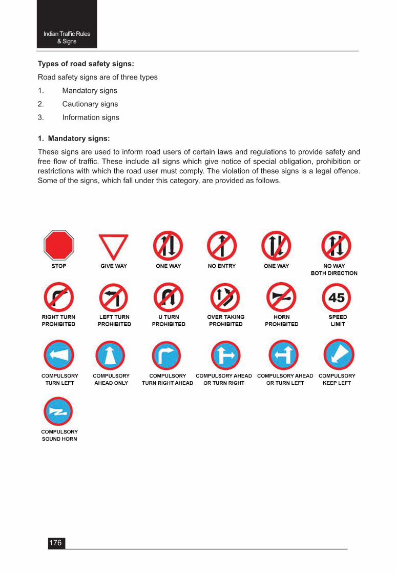
176
Indian Traffic Rules & Signs
Types of road safety signs:
Road safety signs are of three types
1. Mandatory signs
2. Cautionary signs
3. Information signs
1. Mandatory signs:
These signs are used to inform road users of certain laws and regulations to provide safety and freeflowof traffic.These includeallsignswhichgivenoticeofspecialobligation,prohibitionorrestrictions with which the road user must comply. The violation of these signs is a legal offence. Some of the signs, which fall under this category, are provided as follows.
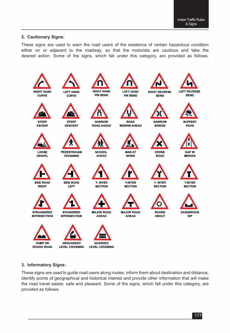
177
Indian Traffic Rules & Signs
2. Cautionary Signs:
These signs are used to warn the road users of the existence of certain hazardous condition either on or adjacent to the roadway, so that the motorists are cautious and take the desired action. Some of the signs, which fall under this category, are provided as follows.
3. Informatory Signs:
These signs are used to guide road users along routes, inform them about destination and distance, identify points of geographical and historical interest and provide other information that will make the road travel easier, safe and pleasant. Some of the signs, which fall under this category, are provided as follows.
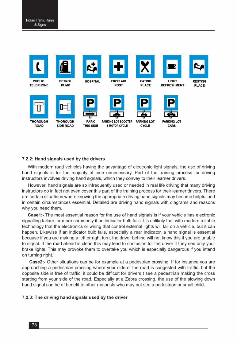
178
Indian Traffic Rules & Signs
7.2.2: Hand signals used by the drivers
With modern road vehicles having the advantage of electronic light signals, the use of driving hand signals is for the majority of time unnecessary. Part of the training process for driving instructors involves driving hand signals, which they convey to their learner drivers.
However, hand signals are so infrequently used or needed in real life driving that many driving instructors do in fact not even cover this part of the training process for their learner drivers. There are certain situations where knowing the appropriate driving hand signals may become helpful and in certain circumstances essential. Detailed are driving hand signals with diagrams and reasons why you need them.
Case1:- The most essential reason for the use of hand signals is if your vehicle has electronic signalling failure, or more commonly if an indicator bulb fails. It’s unlikely that with modern reliable technology that the electronics or wiring that control external lights will fail on a vehicle, but it can happen. Likewise if an indicator bulb fails, especially a rear indicator, a hand signal is essential because if you are making a left or right turn, the driver behind will not know this if you are unable to signal. If the road ahead is clear, this may lead to confusion for the driver if they see only your brake lights. This may provoke them to overtake you which is especially dangerous if you intend on turning right.
Case2:- Other situations can be for example at a pedestrian crossing. If for instance you are approachingapedestriancrossingwhereyoursideoftheroadiscongestedwithtraffic,buttheoppositesideisfreeoftraffic,itcouldbedifficultfordriverstseeapedestrianmakingthecrossstartingfromyoursideoftheroad.EspeciallyataZebracrossing,theuseoftheslowingdownhandsignalcanbeofbenefittoothermotoristswhomaynotseeapedestrianorsmallchild.
7.2.3: The driving hand signals used by the driver
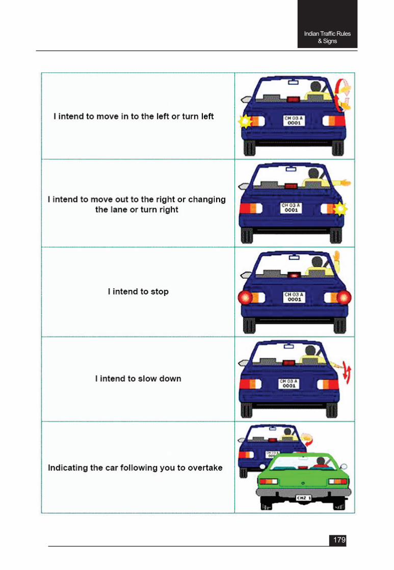
179
Indian Traffic Rules & Signs
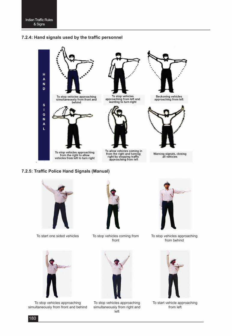
180
Indian Traffic Rules & Signs
7.2.4:Handsignalsusedbythetrafficpersonnel
7.2.5:TrafficPoliceHandSignals(Manual)
To start one sided vehicles
To stop vehicles approaching simultaneously from front and behind
To stop vehicles coming from front
To stop vehicles approaching simultaneously from right and
left
To stop vehicles approaching from behind
To start vehicle approaching from left
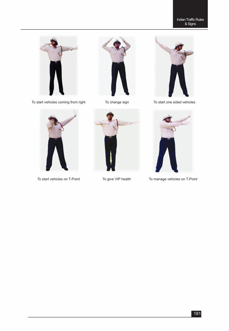
181
Indian Traffic Rules & Signs
To start vehicles coming from right
To start vehicles on T-Point
To change sign
To give VIP health
To start one sided vehicles
To manage vehicles on T-Point
182
Indian Traffic Rules & Signs
QUESTIONSVery Short answer type (each question carries 1 mark)
1. Which one of the following is they type of type safety sign? a) Mandatory signs b) Cautionary signs c) Information signs d) All of the above
2. Theviolationofwhichofthefollowingroadsafetysignsisalegaloffence?
a) Mandatory signs b) Cautionary signs c) Information signs d) All of the above
3. Which of the following road signsare used to guide road users along routes to make the road travel easier,safeandpleasant?
a) Mandatory signs b) Cautionary signs c) Information signs d) All of the above
Short answer type (each question carries 2 marks) 1. Whatistheuseoftrafficsigns? 2. Whatistheuseofhandsignalsusedbythedrivers?Short answer type (eash question carries 3 marks) 1. Explain the hand signals used by the drivers while driving a vehicle.Long answer type (each question carries 5 marks) 1. Explain the type of road safety signs with examples. 2. Explainthehandsignalsusedbythetrafficpolice.

UNIT – 7
SESSION – 3
EMISSION AND ITS CONTROL
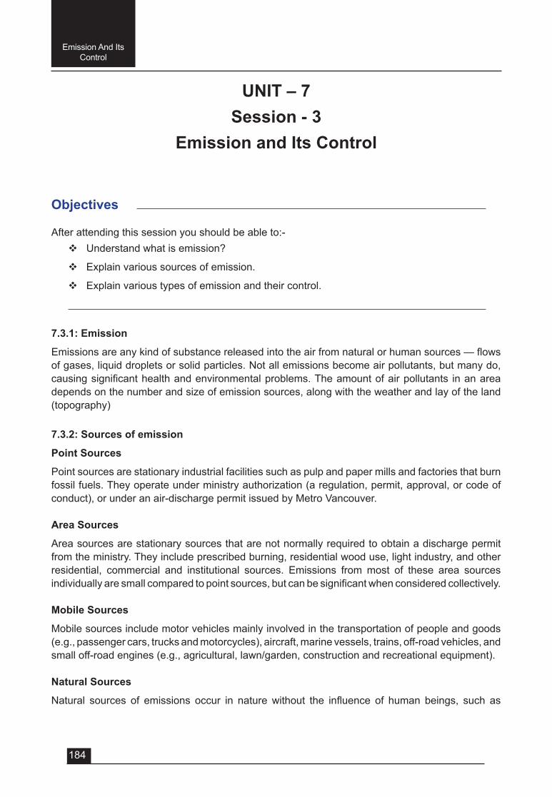
184
Emission And Its Control
Objectives
After attending this session you should be able to:-v Understandwhatisemission?
v Explain various sources of emission.
v Explain various types of emission and their control.
UNIT – 7Session - 3
Emission and Its Control
7.3.1: Emission
Emissionsareanykindofsubstancereleasedintotheairfromnaturalorhumansources—flowsof gases, liquid droplets or solid particles. Not all emissions become air pollutants, but many do, causingsignificanthealthandenvironmentalproblems.Theamountofairpollutants inanareadepends on the number and size of emission sources, along with the weather and lay of the land (topography)
7.3.2: Sources of emission
Point Sources
Point sources are stationary industrial facilities such as pulp and paper mills and factories that burn fossil fuels. They operate under ministry authorization (a regulation, permit, approval, or code of conduct), or under an air-discharge permit issued by Metro Vancouver.
Area Sources
Area sources are stationary sources that are not normally required to obtain a discharge permit from the ministry. They include prescribed burning, residential wood use, light industry, and other residential, commercial and institutional sources. Emissions from most of these area sources individuallyaresmallcomparedtopointsources,butcanbesignificantwhenconsideredcollectively.
Mobile Sources
Mobile sources include motor vehicles mainly involved in the transportation of people and goods (e.g., passenger cars, trucks and motorcycles), aircraft, marine vessels, trains, off-road vehicles, and small off-road engines (e.g., agricultural, lawn/garden, construction and recreational equipment).
Natural Sources
Natural sources of emissions occur in naturewithout the influence of human beings, such as
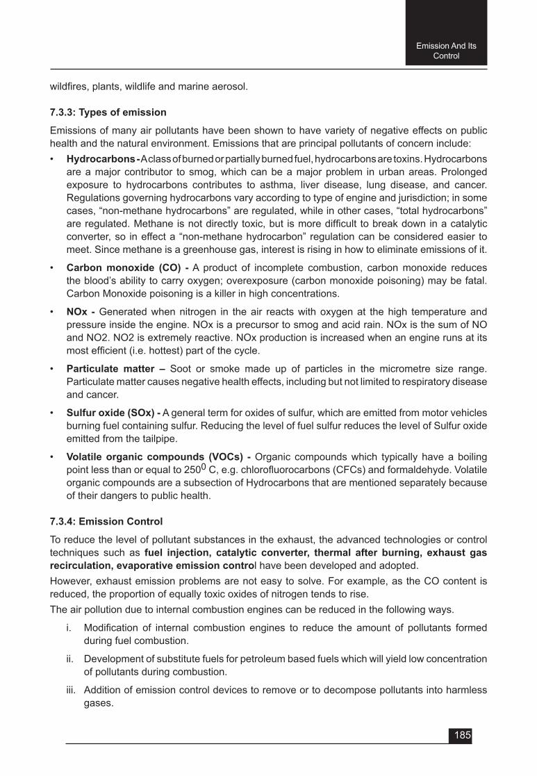
185
Emission And Its Control
wildfires,plants,wildlifeandmarineaerosol.
7.3.3: Types of emission
Emissions of many air pollutants have been shown to have variety of negative effects on public health and the natural environment. Emissions that are principal pollutants of concern include:• Hydrocarbons - A class of burned or partially burned fuel, hydrocarbons are toxins. Hydrocarbons
are a major contributor to smog, which can be a major problem in urban areas. Prolonged exposure to hydrocarbons contributes to asthma, liver disease, lung disease, and cancer. Regulations governing hydrocarbons vary according to type of engine and jurisdiction; in some cases, “non-methane hydrocarbons” are regulated, while in other cases, “total hydrocarbons” areregulated.Methaneisnotdirectlytoxic,but ismoredifficulttobreakdowninacatalyticconverter, so in effect a “non-methane hydrocarbon” regulation can be considered easier to meet. Since methane is a greenhouse gas, interest is rising in how to eliminate emissions of it.
• Carbon monoxide (CO) - A product of incomplete combustion, carbon monoxide reduces the blood’s ability to carry oxygen; overexposure (carbon monoxide poisoning) may be fatal. Carbon Monoxide poisoning is a killer in high concentrations.
• NOx - Generated when nitrogen in the air reacts with oxygen at the high temperature and pressure inside the engine. NOx is a precursor to smog and acid rain. NOx is the sum of NO and NO2. NO2 is extremely reactive. NOx production is increased when an engine runs at its mostefficient(i.e.hottest)partofthecycle.
• Particulate matter – Soot or smoke made up of particles in the micrometre size range. Particulate matter causes negative health effects, including but not limited to respiratory disease and cancer.
• Sulfur oxide (SOx) - A general term for oxides of sulfur, which are emitted from motor vehicles burning fuel containing sulfur. Reducing the level of fuel sulfur reduces the level of Sulfur oxide emitted from the tailpipe.
• Volatile organic compounds (VOCs) - Organic compounds which typically have a boiling point less than or equal to 2500C,e.g.chlorofluorocarbons(CFCs)andformaldehyde.Volatileorganic compounds are a subsection of Hydrocarbons that are mentioned separately because of their dangers to public health.
7.3.4: Emission Control
To reduce the level of pollutant substances in the exhaust, the advanced technologies or control techniques such as fuel injection, catalytic converter, thermal after burning, exhaust gas recirculation, evaporative emission control have been developed and adopted.However, exhaust emission problems are not easy to solve. For example, as the CO content is reduced, the proportion of equally toxic oxides of nitrogen tends to rise.The air pollution due to internal combustion engines can be reduced in the following ways.
i. Modification of internal combustion engines to reduce the amount of pollutants formedduring fuel combustion.
ii. Development of substitute fuels for petroleum based fuels which will yield low concentration of pollutants during combustion.
iii. Addition of emission control devices to remove or to decompose pollutants into harmless gases.
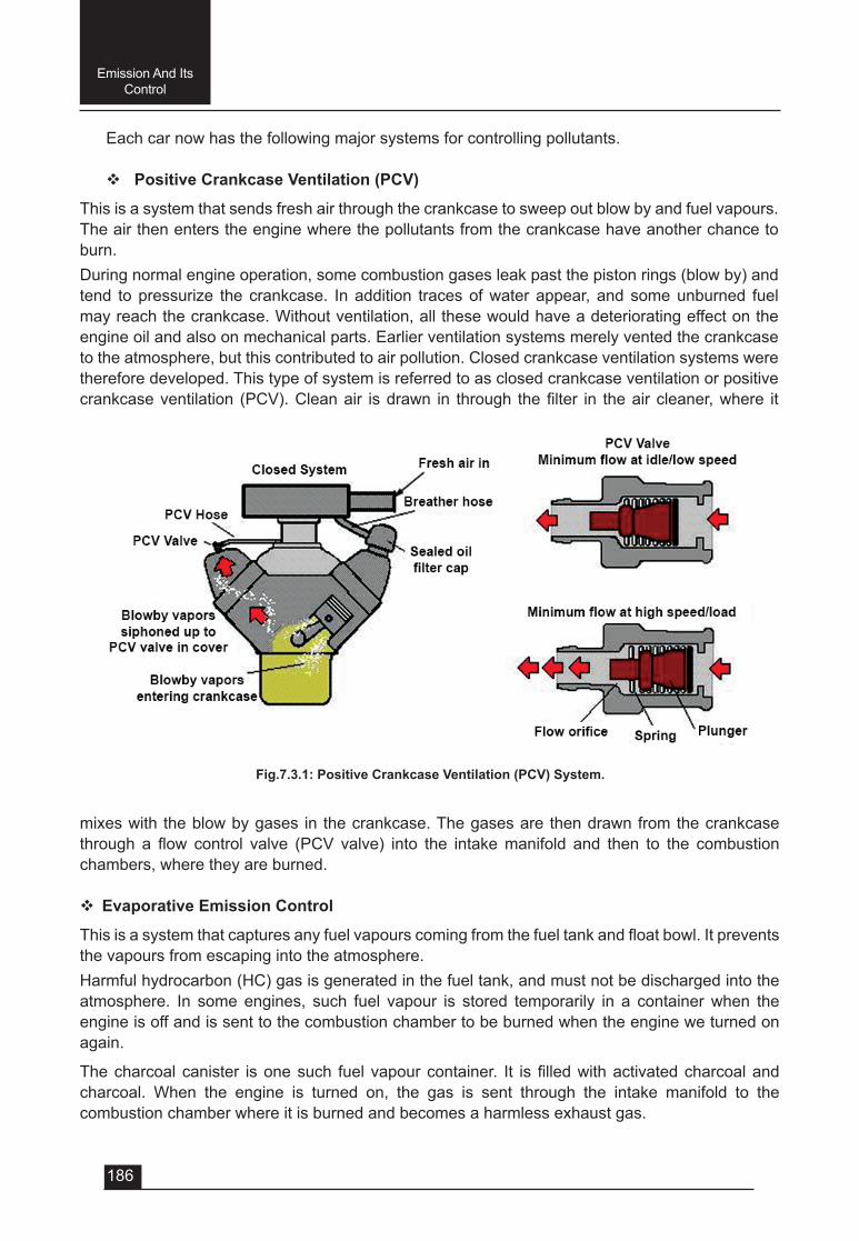
186
Emission And Its Control
Each car now has the following major systems for controlling pollutants.
v Positive Crankcase Ventilation (PCV)
This is a system that sends fresh air through the crankcase to sweep out blow by and fuel vapours. The air then enters the engine where the pollutants from the crankcase have another chance to burn. During normal engine operation, some combustion gases leak past the piston rings (blow by) and tend to pressurize the crankcase. In addition traces of water appear, and some unburned fuel may reach the crankcase. Without ventilation, all these would have a deteriorating effect on the engine oil and also on mechanical parts. Earlier ventilation systems merely vented the crankcase to the atmosphere, but this contributed to air pollution. Closed crankcase ventilation systems were therefore developed. This type of system is referred to as closed crankcase ventilation or positive crankcaseventilation (PCV).Cleanair isdrawn in through thefilter in theaircleaner,where it
Fig.7.3.1: Positive Crankcase Ventilation (PCV) System.
mixes with the blow by gases in the crankcase. The gases are then drawn from the crankcase through a flow control valve (PCV valve) into the intakemanifold and then to the combustionchambers, where they are burned.
v Evaporative Emission Control
Thisisasystemthatcapturesanyfuelvapourscomingfromthefueltankandfloatbowl.Itpreventsthe vapours from escaping into the atmosphere.Harmful hydrocarbon (HC) gas is generated in the fuel tank, and must not be discharged into the atmosphere. In some engines, such fuel vapour is stored temporarily in a container when the engine is off and is sent to the combustion chamber to be burned when the engine we turned on again.
Thecharcoalcanister isonesuch fuelvapourcontainer. It isfilledwithactivatedcharcoalandcharcoal. When the engine is turned on, the gas is sent through the intake manifold to the combustion chamber where it is burned and becomes a harmless exhaust gas.
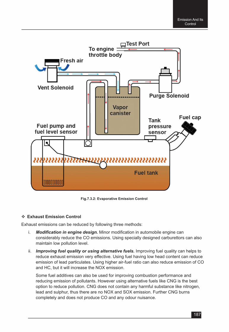
187
Emission And Its Control
Fig.7.3.2: Evaporative Emission Control
v Exhaust Emission Control
Exhaust emissions can be reduced by following three methods:
i. Modification in engine design.Minormodificationinautomobileenginecanconsiderably reduce the CO emissions. Using specially designed carburettors can also maintain low pollution level.
ii. Improving fuel quality or using alternative fuels. Improving fuel quality can helps to reduce exhaust emission very effective. Using fuel having low head content can reduce emission of lead particulates. Using higher air-fuel ratio can also reduce emission of CO and HC, but it will increase the NOX emission.
Some fuel additives can also be used for improving combustion performance and reducing emission of pollutants. However using alternative fuels like CNG is the best option to reduce pollution. CNG does not contain any harmful substance like nitrogen, lead and sulphur, thus there are no NOX and SOX emission. Further CNG burns completely and does not produce CO and any odour nuisance.
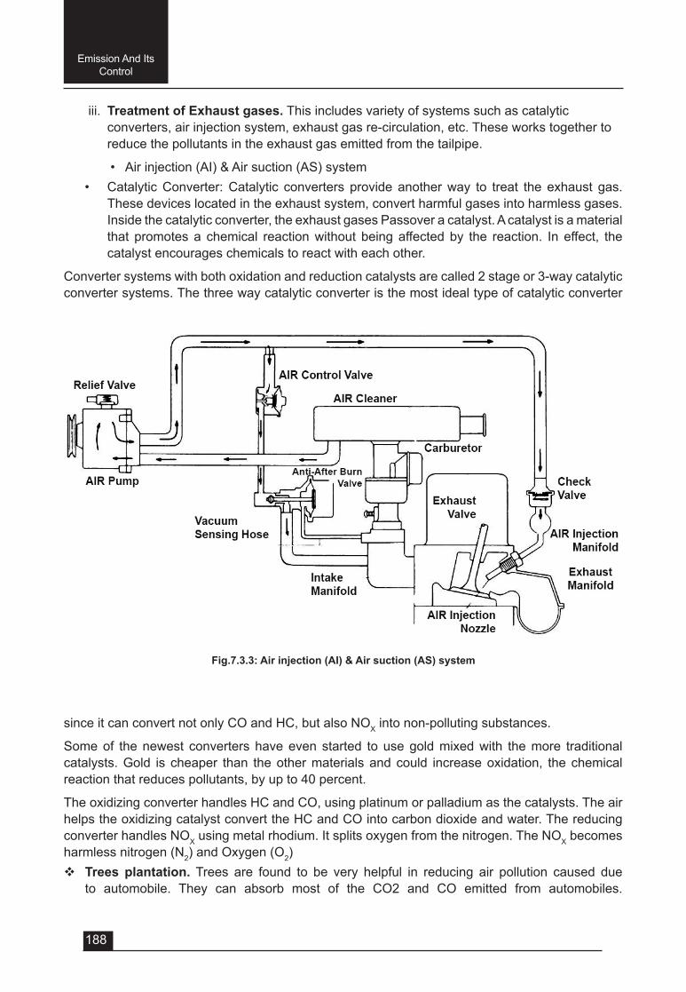
188
Emission And Its Control
Fig.7.3.3: Air injection (AI) & Air suction (AS) system
iii. Treatment of Exhaust gases. This includes variety of systems such as catalytic converters, air injection system, exhaust gas re-circulation, etc. These works together to reduce the pollutants in the exhaust gas emitted from the tailpipe.
• Air injection (AI) & Air suction (AS) system• Catalytic Converter: Catalytic converters provide another way to treat the exhaust gas.
These devices located in the exhaust system, convert harmful gases into harmless gases. Inside the catalytic converter, the exhaust gases Passover a catalyst. A catalyst is a material that promotes a chemical reaction without being affected by the reaction. In effect, the catalyst encourages chemicals to react with each other.
Converter systems with both oxidation and reduction catalysts are called 2 stage or 3-way catalytic converter systems. The three way catalytic converter is the most ideal type of catalytic converter
since it can convert not only CO and HC, but also NOX into non-polluting substances.
Some of the newest converters have even started to use gold mixed with the more traditional catalysts. Gold is cheaper than the other materials and could increase oxidation, the chemical reaction that reduces pollutants, by up to 40 percent.
The oxidizing converter handles HC and CO, using platinum or palladium as the catalysts. The air helps the oxidizing catalyst convert the HC and CO into carbon dioxide and water. The reducing converter handles NOX using metal rhodium. It splits oxygen from the nitrogen. The NOX becomes harmless nitrogen (N2) and Oxygen (O2)v Trees plantation. Trees are found to be very helpful in reducing air pollution caused due
to automobile. They can absorb most of the CO2 and CO emitted from automobiles.
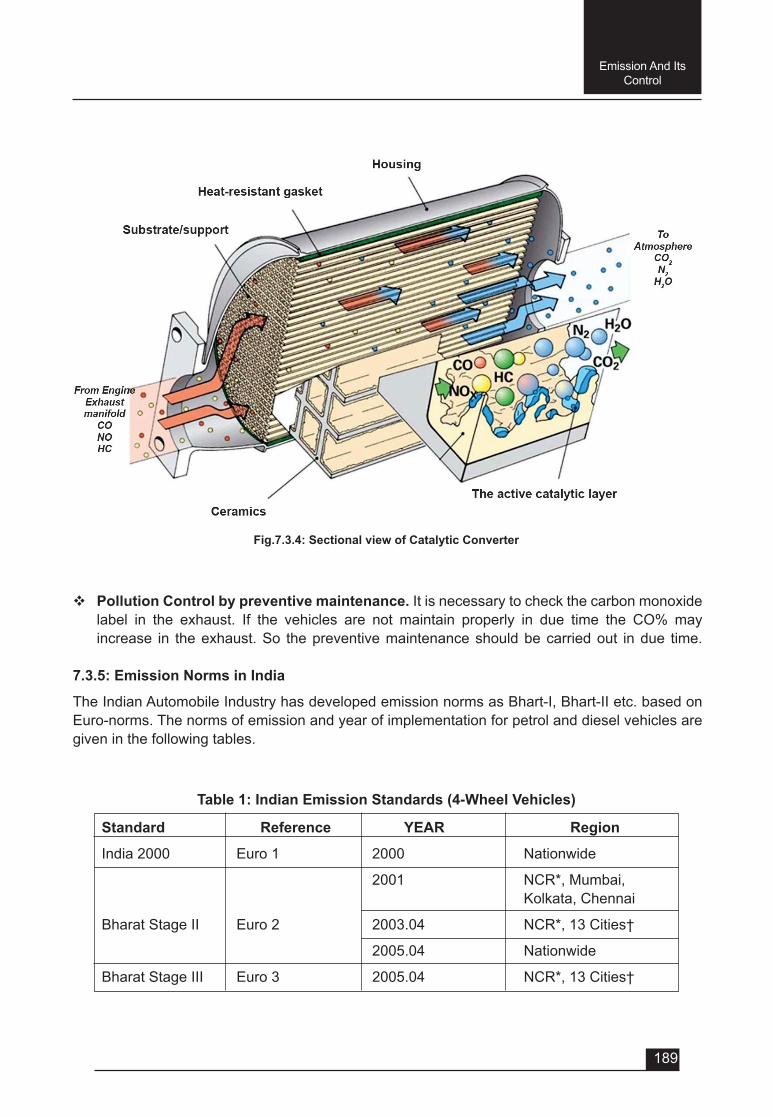
189
Emission And Its Control
Fig.7.3.4: Sectional view of Catalytic Converter
v Pollution Control by preventive maintenance. It is necessary to check the carbon monoxide label in the exhaust. If the vehicles are not maintain properly in due time the CO%mayincrease in the exhaust. So the preventive maintenance should be carried out in due time.
7.3.5: Emission Norms in India
The Indian Automobile Industry has developed emission norms as Bhart-I, Bhart-II etc. based on Euro-norms. The norms of emission and year of implementation for petrol and diesel vehicles are given in the following tables.
Table 1: Indian Emission Standards (4-Wheel Vehicles)
Standard Reference YEAR Region
India 2000 Euro 1 2000 Nationwide
2001 NCR*, Mumbai, Kolkata, Chennai
Bharat Stage II Euro 2 2003.04 NCR*, 13 Cities†
2005.04 Nationwide
Bharat Stage III Euro 3 2005.04 NCR*, 13 Cities†
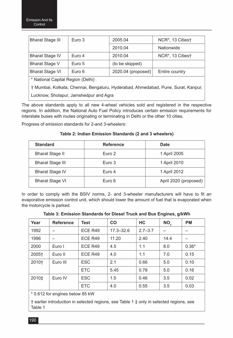
190
Emission And Its Control
Table 2: Indian Emission Standards (2 and 3 wheelers)
Table 3: Emission Standards for Diesel Truck and Bus Engines, g/kWh
Bharat Stage III Euro 3 2005.04 NCR*, 13 Cities†
2010.04 Nationwide
Bharat Stage IV Euro 4 2010.04 NCR*, 13 Cities†
Bharat Stage V Euro 5 (to be skipped)
Bharat Stage VI Euro 6 2020.04 (proposed) Entire country
* National Capital Region (Delhi)
† Mumbai, Kolkata, Chennai, Bengaluru, Hyderabad, Ahmedabad, Pune, Surat, Kanpur,
Lucknow, Sholapur, Jamshedpur and Agra
Year Reference Test CO HC NOx PM
1992 – ECE R49 17.3–32.6 2.7–3.7 – –
1996 – ECE R49 11.20 2.40 14.4 –
2000 Euro I ECE R49 4.5 1.1 8.0 0.36*
2005† Euro II ECE R49 4.0 1.1 7.0 0.15
2010† Euro III ESC 2.1 0.66 5.0 0.10
ETC 5.45 0.78 5.0 0.16
2010‡ Euro IV ESC 1.5 0.46 3.5 0.02
ETC 4.0 0.55 3.5 0.03
* 0.612 for engines below 85 kW
† earlier introduction in selected regions, see Table 1 ‡ only in selected regions, see Table 1
Standard Reference Date
Bharat Stage II Euro 2 1 April 2005
Bharat Stage III Euro 3 1 April 2010
Bharat Stage IV Euro 4 1 April 2012
Bharat Stage VI Euro 6 April 2020 (proposed)
The above standards apply to all new 4-wheel vehicles sold and registered in the respective regions. In addition, the National Auto Fuel Policy introduces certain emission requirements for interstate buses with routes originating or terminating in Delhi or the other 10 cities.
Progress of emission standards for 2-and 3-wheelers:
In order to comply with the BSIV norms, 2- and 3-wheeler manufacturers will have to fit anevaporative emission control unit, which should lower the amount of fuel that is evaporated when the motorcycle is parked.
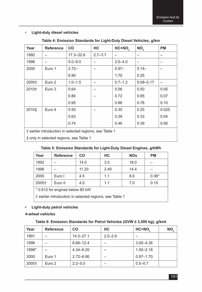
191
Emission And Its Control
Table 4: Emission Standards for Light-Duty Diesel Vehicles, g/km
Table6:EmissionStandardsforPetrolVehicles(GVW≤3,500kg),g/kmt
Table 5: Emission Standards for Light-Duty Diesel Engines, g/kWh
Year Reference CO HC HC+NOx NOx PM
1992 – 17.3–32.6 2.7–3.7 – – –
1996 – 5.0–9.0 – 2.0–4.0 – –
2000 Euro 1 2.72– – 0.97– 0.14– –
6.90 1.70 0.25
2005† Euro 2 1.0–1.5 – 0.7–1.2 0.08–0.17 –
2010† Euro 3 0.64 – 0.56 0.50 0.05
0.80 – 0.72 0.65 0.07
0.95 0.86 0.78 0.10
2010‡ Euro 4 0.50 – 0.30 0.25 0.025
0.63 0.39 0.33 0.04
0.74 0.46 0.39 0.06
† earlier introduction in selected regions, see Table 1
‡ only in selected regions, see Table 1
Year Reference CO HC HC+NOx NOx
1991 – 14.3–27.1 2.0–2.9 –
1996 – 8.68–12.4 – 3.00–4.36
1998* – 4.34–6.20 – 1.50–2.18
2000 Euro 1 2.72–6.90 – 0.97–1.70
2005† Euro 2 2.2–5.0 – 0.5–0.7
Year Reference CO HC NOx PM
1992 – 14.0 3.5 18.0 –
1996 – 11.20 2.40 14.4 –
2000 Euro I 4.5 1.1 8.0 0.36*
2005† Euro II 4.0 1.1 7.0 0.15
* 0.612 for engines below 85 kW
† earlier introduction in selected regions, see Table 1
• Light-duty diesel vehicles
• Light-duty petrol vehicles
4-wheel vehicles
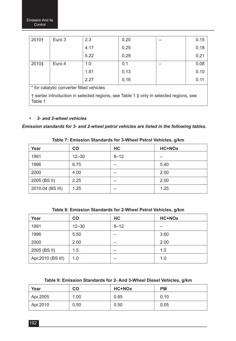
192
Emission And Its Control
2010† Euro 3 2.3 0.20 – 0.15
4.17 0.25 0.18
5.22 0.29 0.21
2010‡ Euro 4 1.0 0.1 – 0.08
1.81 0.13 0.10
2.27 0.16 0.11
*forcatalyticconverterfittedvehicles
† earlier introduction in selected regions, see Table 1 ‡ only in selected regions, see Table 1
• 3- and 2-wheel vehicles
Emission standards for 3- and 2-wheel petrol vehicles are listed in the following tables.
Table 7: Emission Standards for 3-Wheel Petrol Vehicles, g/km
Table 8: Emission Standards for 2-Wheel Petrol Vehicles, g/km
Table 9: Emission Standards for 2- And 3-Wheel Diesel Vehicles, g/km
Year CO HC HC+NOx
1991 12–30 8–12 –
1996 6.75 – 5.40
2000 4.00 – 2.00
2005 (BS II) 2.25 – 2.00
2010.04 (BS III) 1.25 – 1.25
Year CO HC HC+NOx
1991 12–30 8–12 –
1996 5.50 – 3.60
2000 2.00 – 2.00
2005 (BS II) 1.5 – 1.5
Apr.2010 (BS III) 1.0 – 1.0
Year CO HC+NOx PM
Apr.2005 1.00 0.85 0.10
Apr.2010 0.50 0.50 0.05
193
Emission And Its Control
Overview of the emission norms in India
• 1991 – Idle CO Limits for Petrol Vehicles and Free Acceleration Smoke for Diesel Vehicles, Mass Emission Norms for Petrol Vehicles.
• 1992 – Mass Emission Norms for Diesel Vehicles.
• 1996–RevisionofMassEmissionNormsforPetrolandDieselVehicles,mandatoryfitmentof Catalytic Converter for Cars in Metros on Unleaded Petrol.
• 1998 – Cold Start Norms Introduced.
• 2000–India2000(EquivalenttoEuroI)Norms,ModifiedIDC(IndianDrivingCycle),BharatStage II Norms for Delhi.
• 2001 – Bharat Stage II (Equivalent to Euro II) Norms for All Metros, Emission Norms for CNG & LPG Vehicles.
• 2003 – Bharat Stage II (Equivalent to Euro II) Norms for 13 major cities.
• 2005 – From 1 April Bharat Stage III (Equivalent to Euro III) Norms for 13 major cities.
• 2010 – Bharat Stage III Emission Norms for 2-wheelers, 3-wheelers and 4-wheelers for entire country whereas Bharat Stage – IV (Equivalent to Euro IV) for 13 major cities for only 4-wheelers. Bharat Stage IV also has norms on OBD (similar to Euro III but diluted)
• 2020 – Proposed date for country to adopt Bharat Stage VI norms for cars, skipping Bharat Stage V
QUESTIONSVery Short answer type (each question carries 1 mark)
1. Emission includes:-
a) NOx
b) SOx
c) Hydrocarbons
d) All of the above
2. _____________________ reduces the blood’s ability to carry oxygen.
a) Sulphur oxides (SOx) b) Carbon monoxide (CO)
c) Nitrogen oxides (NOx). d) Hydrocarbons
Short answer type (each question carries 2 marks)
1. Whatisemission?
2. Whatdoyoumeanbypointsourcesofemission?
3. Whatdoyoumeanbyareasourcesofemission?
4. Whatdoyoumeanbymobilesourcesofemission?
5. Whatdoyoumeanbynaturalsourcesofemission?
194
Emission And Its Control
6. What are the advanced technologies or control techniques developed and adopted to controlthevehicularpollution?
7. Howthepollutioniscontrolledbyplantationoftrees?
8. Howthepollutioniscontrolledbythepreventivemaintenanceofavehicle?
Short answer type (each question carries 3 marks)
1. Explain any two sources of emission.
2. Explain any two air pollutants.
3. Howairpollutantseffectthehumanhealth?
4. Whatarethewaystoreducetheinternalcombustion(I.C.)enginespollutions?
Long answer type (each question carries 5 marks)
1. Whatisemission?Explainthevarioussourcesofemission.
2. Explain various types of emission.
3. Howtheemissionintheatmosphericaircanbecontrolled?
4. Explain with diagram the positive crankcase ventilation system of I.C. engine.
5. Explain with diagram the evaporative pollution control of automobile engine.
6. With neat sketch explain the working of catalytic converter used in automobile.