Embed Size (px)
Citation preview

Lecture Notesin Business Information Processing 16
Series Editors
Wil van der AalstEindhoven Technical University, The Netherlands
John MylopoulosUniversity of Trento, Italy
Norman M. SadehCarnegie Mellon University, Pittsburgh, PA, USA
Michael J. ShawUniversity of Illinois, Urbana-Champaign, IL, USA
Clemens SzyperskiMicrosoft Research, Redmond, WA, USA

Kay Berkling Mathai JosephBertrand Meyer Martin Nordio (Eds.)
Software EngineeringApproaches forOffshore andOutsourced Development
Second International Conference, SEAFOOD 2008Zurich, Switzerland, July 2-3, 2008Revised Papers
13

Volume Editors
Kay BerklingPolytechnic University of Puerto Rico00919 San Juan, Puerto RicoE-mail: [email protected]
Mathai JosephTata Consultancy ServicesPune 411 001, IndiaE-mail: [email protected]
Bertrand MeyerMartin NordioETH Zurich8092 Zurich, SwitzerlandE-mail: {bertrand.meyer,martin.nordio}@inf.ethz.ch
Library of Congress Control Number: Applied for
ACM Computing Classification (1998): K.6, D.2
ISSN 1865-1348ISBN-10 3-642-01855-6 Springer Berlin Heidelberg New YorkISBN-13 978-3-642-01855-8 Springer Berlin Heidelberg New York
This work is subject to copyright. All rights are reserved, whether the whole or part of the material isconcerned, specifically the rights of translation, reprinting, re-use of illustrations, recitation, broadcasting,reproduction on microfilms or in any other way, and storage in data banks. Duplication of this publicationor parts thereof is permitted only under the provisions of the German Copyright Law of September 9, 1965,in its current version, and permission for use must always be obtained from Springer. Violations are liableto prosecution under the German Copyright Law.
springer.com
© Springer-Verlag Berlin Heidelberg 2009Printed in Germany
Typesetting: Camera-ready by author, data conversion by Scientific Publishing Services, Chennai, IndiaPrinted on acid-free paper SPIN: 12681969 06/3180 5 4 3 2 1 0

Preface
Major economic upheavals can have the sort of effect that Schumpeter foresaw 60years ago as creative destruction. In science and technology, equivalent upheavalsresult from either scientific revolutions (as observed by Kuhn) or the introductionof what Christensen calls disruptive technologies. And in software engineering,there has been no technology more disruptive than outsourcing. That it shouldso quickly reach maturity and an unparalleled scale is truly remarkable; that itshould now be called to demonstrate its sustainability in the current financialturmoil is the challenge that will prove whether and how it will endure. Earlysigns under even the bleak market conditions of the last 12 months are that itwill not only survive, it will firmly establish its role across the world of business.
Outsourcing throws into sharp focus the entire software engineering lifecy-cle. Topics as diverse as requirements analysis, concurrency and model-checkingneed to find a composite working partnership in software engineering practice.This confluence arises from need, not dogma, and the solutions required arethose that will have the right effect on the associated activities in the world ofthe application: e.g., reducing the time for a transaction or making the resultsof a complex analysis available in real-time. While the business of outsourcingcontinues to be studied, the engineering innovations that make it compelling areconstantly changing. It is in this milieu that this series of conferences has placeditself.
SEAFOOD 2008, the Second International Conference on Software Engi-neering Approaches to Outsourcing and Offshore Development, was held inZurich during July 2-3, 2008. There were outstanding invited talks by AshishArora (then at the Heinz School, Carnegie-Mellon University) and Dick Simmons(Texas A&M University), the first on how outsourcing has grown in countries asdifferent as India, Israel and Ireland, and the second on the effects of outsourcingon software engineering in the past, the present and the future.
SEAFOOD 2008 received submissions spanning a wide range of topics, fromprocesses, and risks to education in distributed software development. This vol-ume includes 14 papers from the conference selected after review by the Pro-gram Committee. SEAFOOD 2008 received 50 submissions; the acceptance ratewas 28%. Papers covered areas such as extreme programming and code review,predicting timelines in software development subject to changes and softwareprocess improvement in small companies. There was an outstanding panel dis-cussion (not reported in this volume) organized by Peter Kolb with speakersfrom banking, insurance and engineering industries.
Many people contributed to SEAFOOD 2008. We thank the Program Com-mittee and the external reviewers for their excellent work in reviewing and select-ing papers. SEAFOOD 2008 was co-located with TOOLS 2008; we are gratefulto Manuel Oriol and Marco Piccioni for their support and to Claudia Gunthart

VI Preface
for once again providing with unwavering efficiency the organization that madeSEAFOOD 2008 a success.
March 2009 Mathai JosephBertrand MeyerMartin Nordio

Organization
Program Chairs
Bertrand Meyer ETH Zurich, Switzerland - Co-chairMathai Joseph Tata Consultancy Services, India - Co-chairKay Berkling Polytechnic University of Puerto Rico, Puerto
Rico - Program ChairPeter Kolb Red Expel, Switzerland - Panel Chair
Program Committee
Gabriel Baum La Plata National University, ArgentinaManfred Broy Technische Universitat Munchen, GermanyJean Pierre Corriveau School of Computer Science, Carleton University,
CanadaBarry Dwolatzky South AfricaKokichi Futatsugi Japan Advanced Institute of Science and Technology,
JapanVictor Gergel University of Nizhnyi-Novgorod, RussiaAmar Gupta University of Arizona, USAPankaj Jalote IIT Delhi, IndiaKoichi Kashida SRA Key-Tech Lab, JapanPhilippe Kruchten University of British Columbia, CanadaMingshu Li Chinese Academy of Sciences, ChinaChristine Mingins Monash University, AustraliaJianjun Zhao School of Software, Shanghai Jiao Tong University,
ChinaCleidson de Souza Federal University of Para, Brazil
Local Organization
Martin Nordio ETH Zurich, SwitzerlandClaudia Gunthart ETH Zurich, Switzerland

VIII Organization
External Reviewers
Dong, FeiFritzsche, MartinHe, MeiIslam, ShareefulJuergens, ElmarKeil, PatrickKishida, KoichiKong, WeiqiangKuhrmann, MarcoLi, YinLiu, Dapeng
Mattarelli, ElisaNakamura, MasakiOgata, KazuhiroPister, MarkusSmith, DavidSudaman, FadrianWagner, StefanWu, ShujianXie, LiziYang, DaZundel, Armin

Table of Contents
Outsourcing through Combining Software Departments of SeveralCompanies . . . . . . . . . . . . . . . . . . . . . . . . . . . . . . . . . . . . . . . . . . . . . . . . . . . . . . 1
Jarmo J. Ahonen, Anu Valtanen, Paula Savolainen,Timo Schalkowski, and Mikko Kontio
Timeline Prediction Framework for Iterative Software EngineeringProjects with Changes . . . . . . . . . . . . . . . . . . . . . . . . . . . . . . . . . . . . . . . . . . . . 15
Kay Berkling, Georgios Kiragiannis, Armin Zundel, andSubhajit Datta
Outsourcing-Iterative Improvement Model for Transforming Challengesto Mutual Benefits . . . . . . . . . . . . . . . . . . . . . . . . . . . . . . . . . . . . . . . . . . . . . . . 33
Atanu Bhattacharya
A Structure for Management of Requirements Set for e-LearningApplications . . . . . . . . . . . . . . . . . . . . . . . . . . . . . . . . . . . . . . . . . . . . . . . . . . . . . 46
Dumitru Dan Burdescu, Marian Cristian Mihaescu, andBogdan Logofatu
Evaluation of Software Process Improvement in Small Organizations . . . . 59Pedro E. Colla and Jorge Marcelo Montagna
An Examination of the Effects of Offshore and Outsourced Developmenton the Delegation of Responsibilities to Software Components . . . . . . . . . 73
Subhajit Datta and Robert van Engelen
Students as Partners and Students as Mentors: An Educational Modelfor Quality Assurance in Global Software Development . . . . . . . . . . . . . . . 90
Olly Gotel, Vidya Kulkarni, Christelle Scharff, and Longchrea Neak
Problems and Solutions in Distributed Software Development:A Systematic Review . . . . . . . . . . . . . . . . . . . . . . . . . . . . . . . . . . . . . . . . . . . . . 107
Miguel Jimenez and Mario Piattini
Design and Code Reviews in the Age of the Internet . . . . . . . . . . . . . . . . . . 126Bertrand Meyer
Preliminary Analysis for Risk Finding in Offshore Software Outsourcingfrom Vendor’s Viewpoint . . . . . . . . . . . . . . . . . . . . . . . . . . . . . . . . . . . . . . . . . . 134
Zhongqi Sheng, Hiroshi Tsuji, Akito Sakurai, Ken’ichi Yoshida, andTakako Nakatani
Evidence-Based Management of Outsourced Software Projects . . . . . . . . . 149Fadrian Sudaman and Christine Mingins

X Table of Contents
A Closer Look at Extreme Programming (XP) with an Onsite-OffshoreModel to Develop Software Projects Using XP Methodology . . . . . . . . . . . 166
Ponmurugarajan S. Thiyagarajan and Sachal Verma
Measuring and Monitoring Task Couplings of Developers andDevelopment Sites in Global Software Development . . . . . . . . . . . . . . . . . . 181
Yunwen Ye, Kumiyo Nakakoji, and Yasuhiro Yamamoto
Automated Process Quality Assurance for Distributed SoftwareDevelopment . . . . . . . . . . . . . . . . . . . . . . . . . . . . . . . . . . . . . . . . . . . . . . . . . . . . 196
Jian Zhai, Qiusong Yang, Ye Yang, Junchao Xiao, Qing Wang, andMingshu Li
Author Index . . . . . . . . . . . . . . . . . . . . . . . . . . . . . . . . . . . . . . . . . . . . . . . . . . 211

Outsourcing through Combining Software Departmentsof Several Companies
Jarmo J. Ahonen, Anu Valtanen, Paula Savolainen, Timo Schalkowski,and Mikko Kontio
Department of Computer ScienceUniversity of Kuopio
P.O. Box 1627FI-70211 Kuopio, Finland
[email protected], [email protected],[email protected], [email protected],
Abstract. The different types of outsourcing have emerged during the latest fewyears. The most common types of those cases and their features have been doc-umented and analysed fairly well. In this paper a specific type of outsourcingthrough combining software departments of several companies is documentedand analysed. The analysed case differs from the more commonly analysed casesand therefore adds an interesting point of view to the general knowledge of out-sourcing and the possible pitfalls associated with outsourcing activities.
1 Introduction
Outsourcing has became a notable issue on the information and communication (ICT)industry area and related services [1]. Despite the fact that there has been a lot of de-bate on business benefits versus risks, outsourcing has become a quite common andwidespread practice [2].
Outsourcing is an activity where the outsourcing company decides to handle its ICToperations by purchasing services from some external ICT-suppliers. Such services mayinclude software development, software maintenance and operation. The suppliers willtake care of the activities the outsourcer used to perform itself [3]. Some large scaleenterprises have outsourced all the ICT operations to third party suppliers. In somecases the supplier organisation is from the same country than the outsourcer, but inmany cases the supplier is from another country. One of the most legendary places inwhich those suppliers may be located is India.
There seem to be two main reasons for outsourcing. The first one is to reduce thecosts and the risks related to business and technology [2][4][5]. The second one is toallow the outsourcer to concentrate to its main field of business and let the suppliers tohandle supporting operations like ICT. This attitude seems to be reasonable if the roleof ICT is not dominant in the business domain in question. If the role of ICT is veryimportant, then the situation is not as straightforward.
In those cases in which the role of ICT is not dominant in the business, it seems tobe fairly safe to assume that ICT services are often cheaper in the external marketplace.
K. Berkling et al. (Eds.): SEAFOOD 2008, LNBIP 16, pp. 1–14, 2009.c© Springer-Verlag Berlin Heidelberg 2009

2 J.J. Ahonen et al.
In such cases the ICT costs are seen as an overhead cost instead of being an investment.Therefore it is easy to provide the necessary argumentation for ICT outsourcing.
It is, however, true that outsourcing may not be as easy as expected. Having a foreignsupplier may also be something that is not suitable for the customers that are searchingfor certain types of benefits, e.g. cost efficiency and the faster reaction time enabled bylarger resources. Both of those benefits are not straightforward to be realized.
Considering the cost efficiency of outsourcing it must be noted that the possible prob-lems encountered include hidden costs, contractual differences, service debasement andloss of organization competences [6]. All those problems have a clear negative impacton the general cost efficiency of the outsourcing operation. The most important issuecould be the introduction of possible hidden costs. The hidden costs may be both ad-ditional costs caused by the management of the new business relation and time-relatedissues.
The analysis of the real impact of outsourcing should include all relevant dimensionsof the situation. A certain outsourcing solution may not be suitable one due to somespecific reasons. Those reasons may include the special characteristics of the businessdomain or some of the generally recognised risks like communication barriers, highermanagement attention, different languages and cultures and geopolitical risks [7].
The basic problem of an outsourcer/supplier-relationship is the managementproblem [3]. Factors like ICT-strategy, information management, contracts, contractmanagement and availability of human resources need to be considered and their man-agement planned while outsourcing. Another management related problematic issue totake into account is the possible inability to write formal contracts and service levelagreements [6][8].
In many cases a company that decides to go for an outsourcing solution is going touse several suppliers at the same time. This is a smart move in eliminating and man-aging different risks [5]. Using several suppliers at once may, however, increase thepossibility of undesirable consequences. One of the possible solutions for achieving thebalance between the benefits of outsourcing and the unwanted consequences it that notall ICT-services are outsourced. In such a solution the outsourcer’s ICT-department of-ten remains responsible of some services [3]. This way it is possible to be sure that thecore competence and services stay inside the company.
One interesting approach to the possible benefits of outsourcing is to create the sup-plier company from the scratch. In such a case the company might be created by settingup a completely new company or by combining the software engineering departmentsof different companies into a new company. This article documents a solution in whicha group of companies decided to create a new supplier company by combining theirown software engineering departments into a new company.
In addition to the history of the company the difficulties in setting up the newcompany are analysed and discussed. These issues include problems with the softwareengineering process of the company and some other related problems. Despite thoseproblems the selected outsourcing solution — a brand new company — seems to suitthe business domain and the requirements of the original companies quite well. It evenmay be the case that using a supplier situated far away from the customer companieswould not be a working solution.

Outsourcing through Combining Software Departments of Several Companies 3
The structure of this article is as follows: the next section will outline the researchquestions, the third section will outline the research method used, the fourth section willshed some light to the history of the outsourcing solution, the fifth section presents thefindings regarding the situation, the sixth section consists of an analysis, and the lastsection is a discussion.
2 The Research Problem
In the research described in this article the main goal was to find out whether the per-formed outsourcing operations were functioning as intended. It was almost inevitablethat the closer analysis would reveal serious problems. One part of the research wasto find out the most problematic issues and try to find solutions for those problems. Inaddition to those practically oriented aims the researchers had an additional aim whichwas to find out possible reasons whether the solution to outsource the ICT activitieswas suitable in the case presented here or could there have been better solutions how toarrange the ICT departments of the companies.
In other words, the goals of the research were to
1. find out possible problems;2. provide solutions for possible problems revealed; and3. analyse the suitability of the outsourcing solution in this case.
The success and impacts of outsourcing has normally been studied from the eco-nomical point of view. The economists have evolved a number of outsourcing relatedtheories. These theories include the resource-dependence theory, transaction-cost the-ory and agent cost theory [6]. The theories help to define when some activity shouldbe outsourced and when not [5]. One of the original goals the research presented herewas to consider the general suitability of outsourcing for the customer companies in thelight of those theories. That analysis was not, however, performed in an explicit waydue to the reasons covered in the analysis and discussion sections.
There is one remarkable thing about the case reported here that makes it an interest-ing subject for further outsourcing research despite the previous research in the field.About ten companies on the same line of business decided to outsource their ICT-departments for one ICT supplier they founded together. The outsourcing was donefor synergy and scale reasons of the business domain. Even though there are a lot ofresearch made on outsourcing there is little information on situations like this one, inwhich several outsourcers establishes their own supplier.
3 Research Methods
In this case the research method was a combination of case-specific analysis and actionresearch [9]. When the researcher’s intention is not only to observe, interpret and under-stand a case, but also participate in the efforts of changing the situation, the approachcan be described an action case research.

4 J.J. Ahonen et al.
The first step in a case like the one reported in this article is to get an overviewof the actual situation. In order to get that overview a sufficiently detailed but rela-tively light-weight procedure was performed. The procedure consists of the followingthree steps:
1. The modeling of the actual information flows in the organisation.2. The modeling of the actual software engineering processes of the organisation.3. Interviews of several members of the staff of the organisation.
The actual information flows were modeled by using the technique outlined in [10]with some variations. Those variations included the modeling of information flows be-tween different roles and different geographical locations. The original diagonal matrixtechnique was used.
During the information-flow modeling sessions the number of the software engineersand other relevant staff members who participated the sessions were either five or sixpersons in every geographical location. In Figure 1 a part of a wall-chart producedduring a modeling session is shown. In order to get the permission to use the picturewe had to paint over most of the texts. That is regrettable but understandable from thecompany’s point of view.
Fig. 1. An example of the wall-charts created during the information flow modeling sessions

Outsourcing through Combining Software Departments of Several Companies 5
The software engineering processes were modeled by using the light-weight tech-nique described in [11]. The most important aspects of that approach are its light-weightnature and its informal nature. Due to those features that modeling technique has turnedout to be very effective in revealing the real software engineering processes and theirproblems, see e.g. [12] and [13].
The process-modeling sessions were also based on the use of wall-charts. The rea-son for the use of the technique was its familiarity to both the staff of the companiesand the researchers. The problems with modeling processes with the technique are out-lined in [11].
The modeling sessions were directed by the researches in every case. It is, however,worth to note that only one of the authors participated every case and therefore theremight be some slight variation in the flow of the events. In addition to that it mustbe noted that the author who participated every modeling session did not act as thechairman in all modeling sessions.
There were several modeling sessions hold even for modeling the same informationflows and processes. The reason for multiple modeling sessions regarding the sameprocess was the geographical distribution of the company. Big parts of the companywere in different locations, see the figures 2–4 for reference, although the workings ofthe company should have been identical in every location. That identicality was notexpected by the researchers due to the fact that in other cases remarkable differencesbetween locations have been observed.
After the information flow modeling sessions and the process modeling sessionsthe models were written into electronic forms and sent to the representatives of thecompany. The company representatives added missing knowledge to the models andchanged them in some degree.
After analysing the information flows and the process models it was decided that theinterviews of software engineers should be fairly similar to the interviews used in [14].The most notable difference is that in the reported case the interviews were performedin a very informal manner and in some times in several occasions.
The interviews or informal discussions with the representatives of the company cov-ered the following issues:
1. How many people belong to your team?2. How many products or projects your team manages in a six-month period?3. Please describe your work during a typical month.4. What are the main quality hindrances in you team and the company in general?5. Which are the strengths of software engineering processes, issues or parts in your
team and the company in general?6. What are the tools your team is using? Are they adequate?7. How is your working time divided between different tasks? Please describe the
tasks and the time you use for each task.8. Do you think that the amount of training (tools, methodologies, domain training, or
any other type training) is enough?9. What kind of training would you like to get?
10. How should software quality be improved in your company?11. How would you like to improve your working environment?

6 J.J. Ahonen et al.
After the information flow models and the process models were accepted by therepresentatives of the company in question and the interviews were analysed the resultswere combined into a report in which the situation was analysed and corrective stepsproposed. The report was given to the representatives of the company. The companyfollowed the recommendation into some extent.
In the following section the birth of the analysed company is described and in thesection after that the analysis and the steps are outlined in a level that has been acceptedby the company.
4 How the Company Was Created
The creation of the company has been a slightly uncommon process. In the originalsituation there were over ten companies with their own software engineering depart-ments and some existing supplier/customer relations outside the group of companies.The original situation is shown in Figure 2, in which there are only some of the originalcompanies shown. The same clarity-related simplification is kept for the figures 3 and4 also.
Fig. 2. The original situation
In Figure 2 Company B includes Company A because Company A was owned byCompany B alone. The cooperation between Company A and Company B was naturallyvery close. All of the companies had their own software engineering units and some ofthem had a common customer, which is named Customer X in the figure.
The company with more ambitious software engineering activities was Company Awhich incorporated a fairly sophisticated software development services (SDS) depart-ment. Company A sold its services to several companies outside the cluster of compa-nies that created their own outsourcing solution. The number of software engineeringstaff in Company A was clearly larger than in any other company and the type of busi-ness much more like the business of a normal software engineering services supplier.

Outsourcing through Combining Software Departments of Several Companies 7
In the first round of organisational change the software engineering operations weretransferred to Company A from other companies. The in-house development team ofCustomer X remained unchanged. The result of the change is shown in Figure 3.
Fig. 3. The first round of oursourcing
The resulting company, Company A, was owned by all the companies B, C, D, and E.In the situation after the first round of outsourcing the original companies B, C, D, andE were customers of Company A. The relative role of Company X was quite remarkableas a customer, but it was not an owner of Company A.
It turned out, however, fairly soon that the relative efficiency of the in-house develop-ment team of Customer X was worse than the relative efficiency of Company A. Aftera while the owners of Customer X, some of which were owners of all other companiesalso, decided that the situation was not a good one.
Fig. 4. The final organisation

8 J.J. Ahonen et al.
After some complex negotiations the owners of Company X and the other owners ofthe other companies in question decided to implement another round of organisationalchanges. The result of those changes is shown in Figure 4.
One of the significant features of the analysed case is that the original companieswere located in different geographical regions. The employees of the re-organised Com-pany A continued to work in their previous locations and therefore Company A becamegeographically distributed. Some employees of Company A continued to work evenin the premises of their previous employers. Two reasons for this arrangement werethe need of instant communication and the lessened risk of misuse or loss of criticaldata. The authors of this article assume that the most prominent reason has been thefact that the new company was started very fast and several issues were left for futureconsiderations.
5 Analysis and Recommendations
In this section the results of the modeling sessions are analysed and corrective actionsrecommended. It must be noted that the third research question about the suitability ofthe selected oursourcing solution will not be discussed here. It will be covered in thenext section.
The general problems are outlined in Table 1 with their proposed solutions. Theproblem and the solution are more closely covered in the following subsections.
Table 1. Process problems and recommendations
Problem Description Recommendation
Work management Problems with work controland tracking
Breaking the cycle bymoving developers to newpremises
Project management Customers did not see needfor project managers
Set-up of a process modelthat requires a project man-ager
Communication Inter-company communica-tion difficult
Proper processes and work-ing practices
Timetable issues Rapid changes in timetablesand no proper estimates
Use of a formal estimationapproach
Infrastructure Different infrastructure indifferent locations
General infrastructure for ev-ery location
Documentation Customers not used for ex-plicit documentation
Find the minimum suitablelevel
5.1 Work Management
Work management was a problem in several locations because the company’s employ-ees were located in the office of their previous employer. This might not have been aproblem if there had not been the common history between the employee and his/herprevious employer.

Outsourcing through Combining Software Departments of Several Companies 9
The long history of working together had led to the situation in which some of theemployees worked just like they had been doing before the outsourcing. They carriedout whatever tasks their previous managers wanted them to perform, which caused alarge part of real work to dissappear into the void outside the official projects. Thesupplier company was unable to invoice such work, which lead to somewhat awkwardsituations.
The proposed solution to this problem was to move the developers away from thecustomers office to some premises located reasonably near in order to break the viciouscycle. In addition to that, it was proposed that the communication regarding new oradditional tasks should go through the project manager.
5.2 Project Managers and Projects
Before the outsourcing operation the companies had used the same project managerfor both the business case and the development effort. Therefore customer companieswere not used to have specific project managers for the ICT-parts of the projects. Thisbackground explains why the customer companies were not willing to pay project man-agement expenses — they had managed very well without such expenses before theoutsourcing. The lack of a project manager from the supplier side confused the situa-tion because the employees of the supplier company did not exactly know who was theirboss regarding the project. This problem was connected to the problem that employeeswere doing tasks that the supplier could neither invoice nor follow.
In addition to the lack of formal project managers it was obvious that the customercompanies did not consider smaller software development efforts or updates a project.They considered them to be a part of the normal operation of the organisation, althoughthe software professional were not any more part of the customer company’s organisa-tion. This caused problems because even the updates included implementation of newbusiness logic.
The recommended solution was to nominate a formal project manager for eachproject and make the personnel of the supplier aware that the project manager is theirboss.
5.3 Communication Problems
Most of the outsourcer’s employees were transferred to the supplier but some of theirmanagers continued working for the original customer companies. This inflicted prob-lems on the communications. The outsourcer’s representatives used to contact thesupplier’s employees directly for example regarding changes in the requirements oftimetables. The supplier’s project managers and other management was not able to fol-low the work properly as changes were done without going through the normal modeof operation.
Once again the geographical distribution strengthened this problem. In many casesthe project manager was sitting far away from the outsourcer and the employees some-times worked in the same office than the customer company’s managers. This causedconstant misunderstandings and false assumptions on the real level of resource usage.

10 J.J. Ahonen et al.
5.4 Timetable Problems
Timetable problems were considered one of the most difficult issues. It was not definedhow the outsourcing was affecting timetables but it seems that combining projects fromdifferent customers turned out to be very difficult. The reason for this was that therepresentatives of the customer companies thought that their previous employees stillwere members of their own staff.
The timetables were normally very strict. If there were changes in the requirementsor techniques used, the timetables were not normally reset. Sometimes even largechanges were performed in the middle of a project without sufficient replanning.
The timetables were dictated by the customer companies due to the pressures set bythe business domain. It was noted that in those cases in which the supplier had somewell-argued reasons for proposing a not-that-strict timetable a reasonable compromisewas often found. Without good argumentation such agreement was very difficult to find.
The proposed solution was to take a reasonably light-weight method for effort esti-mation into use. Some variation of the function-point methods was considered as themost promising solution.
5.5 Infrastructure Problems
The supplier was founded by combining several development teams from various geo-graphic locations. The technical infrastructure of the supplier had not been given properconsideration and that had started to hinder the use of company’s resources. In the be-ginning the lack of common infrastructure had not been a problem because the employ-ees continued to use the infrastructure of their previous employer and worked in theprojects of their previous employer.
After some time had passed and the supplier had started to reallocate its personnelto new projects the infrastructure problem started to have its impact. In some cases itturned out very difficult for employees located in one position to work in a project donefor a customer in another location. The common infrastructure started to be a must.
The obvious recommendation was to create a solid enough infrastructure that wouldprovide the required development tools and environments to every location. As a partof that development is was considered natural that the employees of the supplier wouldmove away from the office of their previous employer — especially in the case that theywere working in a project that was not related to their previous employer.
5.6 Documentation Problems
The documentation process of the new supplier/customer-relationship was not in a goodorder. The main reason for the situation seemed to be that when the developers had beenemployees of the customer company the documentation had been created as needed andnot in a systematic way. Because a large part of the created software was at the end ofits life-cycle very fast it had been thought unnecessary to create large documentationfor that software. In those cases in which the life-time of software was longer the doc-umentation had been created after it had been realized that the life-time of the systemcould be longer than originally assumed.

Outsourcing through Combining Software Departments of Several Companies 11
This had caused a situation in which the customers were unwilling to pay for the cre-ation of documentation even in those cases in which the expected life-time of the soft-ware was longer. After the projects were finished and documentation needed it turnedout to be very difficult to create the documentation due to the fact that the developersoften were busy in other projects. That hold even in those cases in which the customerwas willing to pay for the documentation after realising the problems caused by the lackof proper documents.
The proposed solution was to restructure the negotiations with the customers in away that would pay enough attention to the necessary documentation and the resourcesrequired by the creation of that documentation.
6 Effects of Recommendations and the Suitablity of theOutsourcing Solution
Most of the problems were corrected in a six month period observed by the researchers.Some problems were not fixed. Improvements are, however, going on.
The next subsection describes the current situation in the company after the improve-ment process and the second subsection of this section discusses and the suitability ofthe outsourcing solution.
6.1 The Effects of the Recommendations
The transition of the company’s employees away from the customer’s premises didsolve some of the problems related with resource allocation and work management.If people were working at the customer site, then it was very difficult to use them forprojects that were not related to that specific customer. In the office of the supplier suchproblems did not exist any more.
The work management situation was improved after moving the employees to thecompany’s own premises. The direct and uncontrolled communication and work distri-bution between the previous managers of the outsourced employees did not completelystop. It did, however, fizzle to an insignificant level. The new situation has clearly helpedthe company to manage its personnel in a more coherent and systematic way.
The general project management problem was also made less urgent by moving em-ployees away from the customer’s premises. The project management problem wasmainly the lack of project managers in some projects and that was caused by the cus-tomer’s unwillingness to pay for a project manager from the supplier. After the sep-aration of the outsourced employees from their previous managers was performed bymoving the employees to the supplier’s own office it turned out much more easier toset up a process which required a real project manager. In addition to that, the customerorganisations understood the need of project management and project managers muchbetter when the workers were not sitting in the office of the customer.
The inter-company communication problem was, also, a clearly diminished one af-ter the supplier company had obtained its own offices. Just the fact that the suppliercompany’s employees were not in the customer’s premises made the customers more

12 J.J. Ahonen et al.
willing to obey clear rules for communicating with their previous personnel. In addi-tion to that, the communication between the different locations of the company itselfwas easier in the organisational, technological and cultural sense when the employeeswere working in the offices owned by the company itself.
The difficulty of estimating the timetables for projects and keeping those timetableswas at least partly due to the lack of any formal estimation method. The proposed esti-mation technique, FiSMA 1.1 functional size measurement method [15], had been takeninto use. The method turned out to be fairly easy to use and able to provide accurateenough estimates. The use of a formal method proved to be helpful in the negotiationswith the customers by giving both sides a better idea of the size and difficulty of theproject. Without any type of estimation method even the project negotiations would bemuch more difficult than they currently are.
The infrastructure of the supplier was fairly easy to improve. Proper facilities andtools in the own premises of the company were set up and taken into use. After a shortperiod of time the new infrastructure had removed most of the previous hindrancescaused by inadequate and nonuniform tools. The cost of the new infrastructure had avery short pay-back time, only a couple of months.
The documentation related problems were not solved during the followed period. Thecustomer companies made the decision to shorten the project timetables by neglectingdocumentation on purpose. They are willing to pay for the creation of the documen-tation when the need arises but not during the creation of the system. That may makesome sense regarding the need of rapid releases, but it causes constant problems withsystems that live longer.
6.2 The Suitability of the Outsourcing Solution
The success of the outsourcing is difficult to estimate due to the fact that the representa-tives of the companies that outsourced their software engineering were not interviewedin the research. The reason for that lack is that the reported research was commissionedby the company created by the outsourcing activity, and the researches come into thesituation after the the last restructuring, i.e. into the situation shown in Figure 4. Theperformed analysis remains a superficial one due to the fact that the the researchers hadno real data on the situation before the restructuring, i.e. the one shown in Figure 2.
It is, however, assumed that the benefits sought after were:
– the benefits of scale and larger resources,– the ability to react faster to new requirements due to better resources, and– cost benefits.
According to the estimates made by the researchers, the benefits of scale and larger re-sources have been realized in a good way. This is especially remarkable in the businessdomain in which the outsourcer companies operate. In that domain the business is ex-treamly ICT-dependent and requires astonishingly rapid adaptation and development ofinformation systems in order to be fast enough to react to the actions of the competitorsand similarly fast action in order to maintain the proactive attitude.
The faster reaction time had also been achieved. The extreamly fast life-cycle ofproducts and services provided by the outsourcing companies does, however, have its

Outsourcing through Combining Software Departments of Several Companies 13
impact on the general customer/supplier-relationship. The business domain requiresvery fast development times and quite high dependability of the developed systems.Larger resource pool has clearly helped in that respect. It must be noted, however, thatthe additional level of management that the outsourcing-relationship imposes on thepractical operations has its own negative impact on the speed of development.
It seems that some type of combination of agile development and proper processcontrol suits the business domain, the outsourcers, and the supplier company. Fast anduncomplicated communication and rapid reactions are clearly so important that it issomewhat difficult to consider a working solution with a supplier that were locatedfar away. The fast development times and close cooperation would require an exten-sive amount of traveling to the customer site. Such amount of traveling would clearlydiminish any benefits achievable by using a far-away supplier.
Considering the situation in the light of the information available to the researchers itseems to be the case that outsourcing was a good solution for the original companies. Inaddition to that, the current solution in which the supplier is located near the customer isa working one in the light of the demands of the business domain in which the customercompanies operate.
7 Discussion
The separation of the customer companies and the new supplier had not been done ina way that would have fulfilled the benefits of outsourcing. After making the customercompanies and the supplier company less intertwined the benefits were possible to beachieved.
It is, however, very interesting to note that after the outsourcing and separation ofthe customer and the supplier more professional processes were easier to follow thanbefore. The real separation of companies seems to provide some professional back-bone for both the business people needing a new information system and the softwareengineers creating it. Better professional attitude may explain some of the successesof outsourcing, especially in those cases in which the supplier is located in anothercountry.
The better professional attitude and more systematic ways of work do not, however,compensate the possible time delays and cultural differences in every case. In a case likethe reported one, the fastness of communication and and rapid reaction time of the ICTsupplier are essential. Therefore some unprofessionalism or even sloppy work might betolerated as a balancing factor.
It must, however, be noted that the case reported in this article belongs to a specifictype of outsourcing in which several companies create a supplier by outsourcing theirown ICT-departments. Cases belonging to this type have not been often reported, al-though the authors of this article know a few similar cases. Unfortunately the necessarydata on those cases is not available for comparative analysis.
Although the reported case supports the outsourcing tendency it does show that dif-ferent business needs give way for different outsourcing solutions. In some businessdomains and types of operation the use of a supplier that is located far away is not aworking solution. That does, however, hold only in the case that the local suppliers are

14 J.J. Ahonen et al.
not much worse than the ones located in e.g. India. With similar performance the local-ity of the supplier may offer benefits that cannot be compensated by somewhat lowercosts.
References
1. Sarder, M.B., Rogers, K., Prater, E.: Outsourcing swot analysis for some us industry.In: Technology Management for the Global Future, 2006. PICMET 2006, pp. 239–242(2006)
2. Oh, W.: Why Do Some Firms Outsource IT More Aggressively Than Others? The Effectsof Organizational Characteristics on IT Outsourcing Decisions. In: Proceedings of the 38thAnnual Hawaii International Conference on System Sciences, HICSS 2005, p. 259c (2005)
3. Beulen, E., Ribbers, P.: Managing complex it outsourcing - partnerships. In: Proceedings ofthe 35th Annual Hawaii International Conference on System Sciences, HICSS 2002 (2002)
4. Gan, W.: Analysis on the costs of it-outsourcing. Digital Object Identifier10.1109/SOLI.2006.328954, 785–789 (2006)
5. Oh, W.: Analyzing it outsourcing relationships as alliances among multiple clients and ven-dors. In: HICSS 1999: Proceedings of the Thirty-second Annual Hawaii International Con-ference on System Sciences, Washington, DC, USA, vol. 7, p. 7066. IEEE Computer Society,Los Alamitos (1999)
6. Sun, S.Y., Lin, T.C., Sun, P.C.: The factors influencing information systems outsourcing part-nership - a study integrating case study and survey research methods. In: HICSS 2002: Pro-ceedings of the 35th Annual Hawaii International Conference on System Sciences (HICSS2002), Washington, DC, USA, vol. 8, p. 235. IEEE Computer Society, Los Alamitos (2002)
7. Beulen, E., Tija, P.: It-leveranciers in lagelonelanden - hoge kwaliteit tegen lage kosten, mitsje op de kleine lettertjes let (2003)
8. Goo, J., Nam, K.: Contract as a source of trust–commitment in successful it outsourcingrelationship: An empirical study. In: HICSS, p. 239 (2007)
9. Jarvinen, P.: On Research Methods. Opinpajan Kirja, Tampere, Finland (2001)10. Karjalainen, A., PÃd’ivÃd’rinta, T., TyrvÃd’inen, P., Rajala, J.: Genre-based metadata for
enterprise document management. In: HICSS (2000)11. Ahonen, J.J., Forsell, M., Taskinen, S.K.: A modest but practical software process model-
ing technique for software process improvement. Software Process Improvement and Prac-tice 7(1), 33–44 (2002)
12. Ahonen, J.J., Junttila, T., Sakkinen, M.: Impacts of the organizational model on testing: Threeindustrial cases. Empirical Software Engineering 9(4), 275–296 (2004)
13. Ahonen, J.J., Junttila, T.: A case study on quality-affecting problems in software engineeringprojects. In: Proceedings of 2003 IEEE International Conference on Software — Science,Technology & Engineering, SwSTE 2003, November 2003, pp. 145–153 (2003)
14. Ahonen, J.J., Aho, A.M., Sihvonen, H.M.: Three case-studies on common software processproblems in software company acquisitions. In: Richardson, I., Runeson, P., Messnarz, R.(eds.) EuroSPI 2006. LNCS, vol. 4257, pp. 62–73. Springer, Heidelberg (2006)
15. FiSMA: Fisma 1.1 functional size measurement method. Technical report, FiSMA (2008),http://www.fisma.fi/in-english/methods/
K. Berkling et al. (Eds.): SEAFOOD 2008, LNBIP 16, pp. 15–32, 2009. © Springer-Verlag Berlin Heidelberg 2009
Timeline Prediction Framework for Iterative Software Engineering Projects with Changes
Kay Berkling1, Georgios Kiragiannis1, Armin Zundel1, and Subhajit Datta2
1 Polytechnic University of Puerto Rico, Department of Computer Science and Engineering, 377 Ponce de León Ave., San Juan, Puerto Rico 00918
[email protected], [email protected], [email protected] 2 Department of Computer Science and School of Computational
Science, Florida State University, Tallahassee, FL 32306, USA
Abstract. Even today, software projects still suffer from delays and budget overspending. The causes for this problem are compounded when the project team is distributed across different locations and generally attributed to the de-creasing ability to communicate well (due to cultural, linguistic, and physical distance). Many projects, especially those with off-shoring component, consist of small iterations with changes, deletions and additions, yet there is no formal model of the flow of iterations available. A number of commercially available project prediction tools for projects as a whole exist, but the model adaptation process by iteration, if it exists, is unclear. Furthermore, no project data is avail-able publicly to train on and understand the iterative process. In this work, we discuss parameters and formulas that are well founded in the literature and demonstrate their use within a simulation tool. Project timeline prediction capa-bility is demonstrated on various scenarios of change requests. On a real-world example, we show that iteration-based data collection is necessary to train both the parameters and formulas to accurately model the software engineering proc-ess to gain a full understanding of complexities in software engineering process.
1 Introduction and Background
Software projects often suffer from delays and budget overspending. With the addi-tion of off-shoring in the software industry, the complexities of such projects have increased. While it is still very difficult to even understand the mechanics of regular projects, taking the next step in complexity to distributed teams, decreases the ability to trace the effects of change requests on the course of the project. Gaining under-standing of and control over the timeline and consequently the costs of a project is often accomplished through experience of the project manager. However, without that experience, no comprehensive mathematical model of how the timeline is affected throughout iterations is available to replace that experience. Simulators of such a model would provide a deeper understanding of the parameters and how they drive a project.

16 K. Berkling et al.
For the case of total effort estimation, there are a number of function point estima-tion tools on the market such as Charismatek, Softwaremetrics, TotalMetrics [29], EstimatorPal. But as far as the authors can tell, none of these open their parameters to the user or adapt these by iterations to the project itself. This can be problematic as depicted in Table 1. Despite the large number of studies on this subject, it can be seen how models of such projects can vary. While the trends (formula types) are consistent across studies, the parameters vary greatly, without providing enough guidelines in how they apply to a specific project.
In order to deal with this adaptation, one has to look at iterations to learn the pa-rameters from the project. Drappa et al. [9] developed a simulator to train project managers and give them hands on experience. The project manager interacts with the simulator as s/he would with a team of software developers. The project manager is required to have a set of theoretical skills and uses the tool to gain “practical” experi-ence. This simulator works with function points, that the project manager enters into the tool along with the number of workers used and a set of directions. The simulator will then advance a set amount of time and reflect the status of the project. At each step the project manager continues making decisions to navigate through to the end. Thus, this work takes into account iterations within a project and decision making of the project manager at each stage to change the course of the project. However, while Drappa’s work deals with the interaction between project manager decisions and the workers, our work additionally deals with effects of change requests and opens both the parameters and formulas for adaptation. Both systems are based on similar rules of thumb [16]. Jones developed these rules of thumb that are widely quoted and used in the field of software engineering. However, it is still not proven that the same for-mulae hold for iterations within a project. For now, the simulator uses the rules of thumb that define the parameters needed for data collection but with an understanding that the formula may need to be adapted as data is collected.
Table 1. Table taken from Fairley [10] – demonstrating the large variety of models describing the relationship between development time and lines of code and time elapsed vs. man months
Effort Equation Schedule Equation Reference
PM = 5.2 (KDSI)0.91 TDEV = 2.47 (PM) 0.35 Walston [26]
PM = 4.9 (KDSI)0.98 TDEV = 3.04 (PM) 0.36 Nelson [19]
PM = 1.5 (KDSI)1.02 TDEV = 4.38 (PM) 0.25 Freburger et al[12]
PM = 2.4 (KDSI)1.05 TDEV = 2.50 (PM) 0.38 Boehm [6]
PM = 3.0 (KDSI)1.12 TDEV = 2.50 (PM) 0.35 Boehm [6]
PM = 3.6 (KDSI)1.20 TDEV = 2.50 (PM) 0.32 Boehm [6]
PM = 1.0 (KDSI)1.40 Jones [17]
PM = 0.7 (KDSI)1.50 Freburger et al[12]
PM = 28 (KDSI)1.83 Schneider [24]

Timeline Prediction Framework for Iterative Software Engineering Projects 17
In order to look at how change affects project timelines, it is necessary to under-stand the relationships between artifacts. Cleland-Huang et al. [14] worked on a framework to capture traceability in artifacts in order to propagate changes across the project correctly. The framework contains three parts: event server, requirements man-ager and the subscriber manager that combine to partially automate the process and support the workers in maintaining correct traceability. Our work builds on the subscription model for artifacts that she proposes in order to establish links between artifacts and propagate changes correctly. The traceability is important in order to cor-rectly propagate the effects of change requests to all affected artifacts in the project.
Finally, the degree of change in indirectly related artifacts is important. To this end, Datta [7][8] suggests three metrics: Mutation Index, Component Set, and Dependency index. Mutation Index indicates the level of change a requirement has undergone across iterations; Component Set specifies all the components a particular requirement needs for its fulfillment; and Dependency Index reflects on the extent to which a particular requirement's implementation depends on the implementation of other requirements. These three metrics help evaluate the effects of requirement changes for a software system. Although our work groups function points according to use cases and not re-quirements, under reasonable assumptions, the Dependency Index is applicable in our scenario, and is referred to in this paper as . Mechanisms for extracting this metric value automatically from code is under development by Datta.
One of the difficulties in working on simulation of projects is the dearth of rich, publicly available training data. A number of databases are available in the public market. The main repository is available through the International Software Bench-marking Standard Group (ISBSG) [28]. This non-profit organization had put together a standard for benchmarking software development in three categories: software en-hancements, software implementations, and software maintenance. The information enclosed in the repository is divided into a few types of data like: Rating, Sizing, Ef-fort, Productivity, Schedule and others. However, this repository does not provide information on the changes of parameters as a function of time. The data is not given by iteration or phases.
This work argues towards the collection of discussed parameters by iteration and the importance of adapting the simulator to the specific project by allowing the user to adjust the parameters. Currently, available databases are not yet sufficient to train an iteration-based simulator, nor do they collect sufficient data to appropriately ana-lyze the effect of addition, change and deletion on each iteration or the project as a whole. Yet, iterations and adaptations to very project-specific data are absolutely essential when outsourcing is involved in order to reliably estimate timelines. A more accurate timeline prediction for distributed projects will lead to fewer unpre-dictable events and will support management decisions by giving more specific and precise estimates. The rest of this paper will describe our approach to combining a number of formulas and parameters into a simulator that can then be used to simulate project timelines and collect data in order to adapt both functions and parameters built into the simulator. We demonstrate reasonable functionality of the current simulator based on well-known facts about projects and show that adaptation is abso-lutely necessary based on a real-world example, therefore making the call for data collection based on iteration.

18 K. Berkling et al.
Section 2 will discuss the building blocks of the approach used in this paper. Section 3 will discuss trends and parameters within software engineering projects that are used within the simulator. Section 4 will discuss the implementation of the simu-lator and validate the basic simulator functionality by looking at sequence of opera-tions whose properties transcendent project-specific characteristics. Section 5 will conclude by looking at an example project, demonstrating the clear need and feasibil-ity for both parameter and formula adaptation for any simulation tool on an iteration basis. Section 6 concludes by listing a number of enhancements necessary to expand the model under future work and propose the availability of a web-based tool for data collection and simulation and online adaptation.
2 Foundations
The theoretical foundations of this work include the methodology of software project management, Function Point estimation of project size based on Use Cases and Traceability usage in projects. These three topics are described in more detail before Section 3 will clarify their usage in this work.
2.1 Methodology
For the purpose of this work we use the terminology of the Rational Unified Process (RUP) because it presents the collection of best practices from industry and is readily reducible to other methods [15]. RUP defines the artifacts that the simulator produces to emulate a software project timeline. Artifacts are either final or intermediate work products that are produced and used during a project and generally include documen-tation and software. They are used to capture and convey project information and re-sults. The simulator works with the major artifacts listed below:
• Use Case Use cases capture the functional requirements of a project. They are usually based on a number of requirements to come together in order to formulate a goal that an ac-tor/specific user of the system will achieve, such as “withdraw money”. A Use Case contains both functional as well as non-functional requirements. The Use Case further is the primary document used by the implementation team to produce the Class dia-gram, the implementation code and the test case. • Software Requirement Specification The Software Requirement Specification (SRS) is the document that contains all the functional and non-functional requirements of the system as a whole. The document refers to Use Case documentation for the functional details but retains the overall in-formation. While functional requirements are mainly covered through the use cases, non-functional requirements are usually found in the SRS and can be categorized as usability-, reliability, performance, and substitutability-requirements, design con-straints, platform environment and compatibility issues, or applicable standards. In addition, requirements that specify need of compliance with any legal and regulatory requirements may be included. Non-functional requirements that apply to an individ-ual use case are captured within the properties of that use case.

Timeline Prediction Framework for Iterative Software Engineering Projects 19
• Class Diagram The Class Diagram is a document which is based on the entirety of the project and therefore depends on all the Use Cases. A change to any Use Case can affect a change in the class diagram. • Code The Code is designed to implement a Use Case that describes its functionality. For the purpose of this paper the code may belong to several Use Cases as there may be some degree of overlap between Use Cases through common requirements. Therefore, change in one Use Case may affect different code pieces to varying degrees. • Test Case Test Cases are designed to test the code for a particular Use Case. A change in the Use Case may effect both Test Case and Code. • Test Code Test Code implements the test case.
2.2 Function Points
Function Points (FP) is a metric for measuring the functional size of a software sys-tem. The usage of function points is well known and a tested sizing technique in soft-ware engineering [21][18][25][11][13]. FPs have been used since 1979 when Allan Albrecht of IBM [3][4] introduced them. There are other Functional Assessment techniques, mainly Bang, BMA, CASE Size, Entity, IE, Mark II FPA, MGM, and Usability. According to McDonell, Table 2 summarizes that the most tested and gen-erally used functional assessment technique is Function Point Analysis. Mark II FP expects 19 adjustment factors instead of 14 on the original FPA method, making the adjustment factor more difficult to asses in a step in the process where usually the user or PM has little information on the system. Boehm [6] developed and redesigned later an algorithmic cost model called (COCOMO). It provides formulas for the esti-mation of programmer-month and development schedule based on the estimated number of Delivered Source Instructions (DSI). COCOMO model is based on LOC, this metric is harder to obtain in early stages of the product life cycle making FPA the only tested and validated and more reasonable choice.
Table 2. Comparison of functional assessment and estimation methods (taken directly from McDonell [19])
Method Automation Comprehensive Objectivity Specification Testing Validity Bang No Yes No Yes Yes No BMA Yes Yes Yes Yes Yes No CAES Yes Yes Yes Yes Yes No Entity Yes Yes Yes Yes No No FPA No Yes No No Yes Yes IE No Yes No No Yes Yes
Mark II FPA
No Yes No Yes Yes Yes
MGM No Yes No No No No Usability No No No Yes No No
20 K. Berkling et al.
In this work we focus on the existing relationship between Use Cases, Function Points and duration of code implementation that has been studied by a variety of re-searchers in the past. While this is a controversial approach [1] [2], it has been shown to work in real-world industrial applications for certain types of projects [10] [5]. The following is a brief presentation of Function Points and the approach chosen for the simulation model in this work because it is empirically shown to work to a reasonable degree according among others also from the International Software Benchmarking Standards Group.
Function Points can be calculated in two parts. The first part relates to the entire project with a handful of parameters, such as: Data communications, Distributed data/processing, performance objectives, tight configuration, high transaction rate, on-line inquiry data entry, end user efficiency, on-line update, complex processing, code reusability, conversion/installation ease, operational ease, multiple site installation, facilitate change. The second number is calculated at the Use Case level by looking at the number of inputs outputs, files accessed, inquiries, and number of Interfaces. This model is based on Albrecht [4] and is more precise in estimation than the previous model of unadjusted function points.
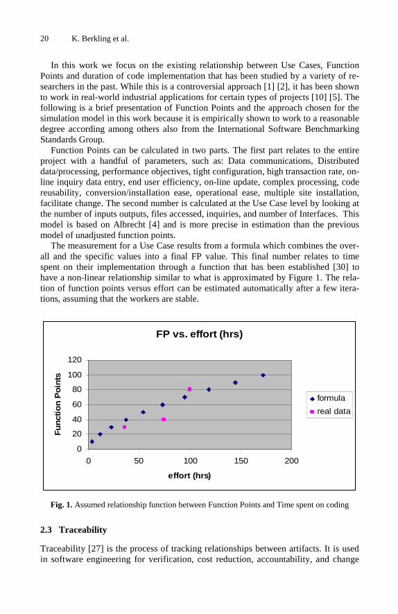
The measurement for a Use Case results from a formula which combines the over-all and the specific values into a final FP value. This final number relates to time spent on their implementation through a function that has been established [30] to have a non-linear relationship similar to what is approximated by Figure 1. The rela-tion of function points versus effort can be estimated automatically after a few itera-tions, assuming that the workers are stable.
FP vs. effort (hrs)
0
20
40
60
80
100
120
0 50 100 150 200
effort (hrs)
Fu
nct
ion
Po
ints
formula
real data
Fig. 1. Assumed relationship function between Function Points and Time spent on coding
2.3 Traceability
Traceability [27] is the process of tracking relationships between artifacts. It is used in software engineering for verification, cost reduction, accountability, and change

Timeline Prediction Framework for Iterative Software Engineering Projects 21
management. Tracking the effect of change requests, such as additions, changes or deletions of use cases on other artifacts are tracked in this manner. Its importance can be appreciated by this statement: “The US Department of Defense spends about 4 percent of its IT costs on traceability.” [23][22]. A model to simulate project data, like artifacts, meeting minutes, meeting agendas, stakeholders, assumes certain re-quired traceability links for artifacts involved in the project in order to propagate the effects of change correctly. Figure 2 below shows how change can be traced through various artifacts in a project.
Fig. 2. Simplistic example of how change affects the software life cycle
This project simulator will process specific input like use cases and change re-quests through traceability models and assumptions into a static project spreadsheet that will capture specific changes in artifacts and all its links. In summary, traceability allows us to see how artifacts are interrelated within a project. This allows us to apply the rules to the project given the collected data.
3 Implementation
Each of the components described above covers aspects of project description that in combination are able to support the simulation model. In order to take the complex interrelationships into account that result in the model of iterations, this section de-scribes a combination of formulas and parameters that make up the simulator.
3.1 Model
The Model presented in the previous section using the RUP terminology is now de-scribed in more detail with further assumptions and parameters and outlining the interrelationships between the artifacts.
• Software Requirement Specification The Software Requirement Specification (SRS) is the document that describes the sys-tem as a whole and refers to the Use Cases for details of the functional specifications in

22 K. Berkling et al.
a modularized fashion. Change requests to Use Cases may affect the SRS. The time to write an SRS is related to the number of Use Cases and non-functional requirements of the system. • Use Cases For the purpose of this work, change requests act on Use Cases directly. More than one change request is required if more than one Use Case documentation is affected by the change. This does not hold true for code and class diagram. There is a degree of interdependence between class diagrams across Use Cases. A change request to a Use Case at the documentation level does affect code of other Use Cases to some degree. We model this interdependence with α as indicated by Figure 3. For the pur-pose of this work, we can assume that there is some degree of overlap between Use Cases regarding the Classes/Objects and the corresponding code sections that are generated. For example, imagine a system with two use cases. The first one describes how books are entered with title only, the second one how to search for them by title. Now, the first use case, for entering new books, receives a change request to add the author field. After those changes are made, the second use case receives the change request to be able to search by author as well. This change is done much faster than the first change since the class diagram has already been updated and the only change that is needed is at the user interface level. This difference in effort required due to the overlap is denoted by α in Figure 3 below. The overlap or interdependency of requirements that make up each of the Use Cases results in various degrees of interdependence between the Use Cases and is one of the parameters of the simulator that can currently be varied. However, it represents a value that can be extracted from the software and is currently studied by one of the authors, S. Datta.
Fig. 3. Simplified view of interrelationships between artifacts
• Class Diagram It is through the use cases that changes in the Class Diagram are effected and propa-gated through to the Code.

Timeline Prediction Framework for Iterative Software Engineering Projects 23
• Code A change in the Use Case is measured in function points and effects a change in the code with the amount of effort related to the FP. Code can be reused between Use Cases whish is related through as described above. Therefore, change in one Use Case may affect different code pieces to varying degrees. Changes directly acting on code, such as refactoring of code, are not currently taken into account in this simulator. • Test Case A change in the Use Case effects a change in the test case directly. • Test Code Test Code implements the test case and is affected directly by a change in the Test Case.
There are other artifacts that belong to the Rational process which should be taken into account in a later version of this simulator. These are, among others the metrics report, the configuration management plan, the project plan, test management plan, the risk management plan, the risk list, the user manual and the installation manual. We currently leave their more detailed implementation for the future work section. Section 3.2 describes how it is possible to lump the entire lines of written documenta-tion into an overall effort size that relates directly to function points as well.
In addition to taking into account the interdependence between artifacts that add to the level of complexity of changes, we model the penalty factor called “Level of change”. It relates to the time difference between modifications of an artifact under the assumption that it becomes increasingly difficult to change older artifacts. For example, if a use case is inserted in iteration 3 and modified in iteration 7 then the level of change is 7-3=4. According to the level of change, x, the penalty is calcu-lated by (1-(1/x^.5)) in the current simulator. This function is based on heuristics of managers, a verification of function and parameter is possibly only through iteration-based data collection.
3.2 Documentation Time
A number of formulas and parameters derived from various sources are combined to formulate the duration of tasks within the project plan. In this section, the formulas are listed, the parameters identified and the default values stated. The equation for the total number of pages produced in a project is related to function points as defined by Caper Jones [16] and given by Equation 1, where AFP stands for the adjusted func-tion points and TNP stands for Total Document Pages in Project. The parameter p is a value defined as 1.15 Jones and is the default value used by the simulator as specified in Table 2.
TNP = pAFP (1)
The following documents are currently part of the simulator: Software Requirements Specifications, Use Case, and Test case documents. All other documents are lumped into a single set, containing metrics report, the configuration management plan, the test management plan, the risk management plan, the risk list, the user manual and the installation manual. Equation 2 shows how these components make up the total num-ber of pages TNP from Equation 1, where uc, srs, tc, and o denote the percentage of

24 K. Berkling et al.
added pages to the total number TNP. This relationship has to be collected from data. The assumptions made by the simulator are stated in Table 2 but can be adapted after several iterations of the project to reflect the specific project more accurately.
TNP = uc·TNP + srs·TNP + tc·TNP + o·TNP (2)
The total number of pages is converted into time by using yet another equation that relates writing time to page numbers [31] as defined by Equation 3, where WPP is words per page and WPM stands for Words per Minute.
Documentation Minutes = TNP * WPP / WPM (3)
Though these formulas are research based, it seems unlikely that pages written for different documents can be written with equal speed. Therefore, this data should also be collected. The true relationship would have to be given through the data. Table 3 depicts the default values that are used in the current system that can be adapted after a few iterations. Similarly, Equation 2 could be rewritten differently not in terms of Function Points but rather in terms of number of Use Cases as well as function points. One can assume that the size of a Use Case is a relatively constant number UC_base since Use Cases have a limited size. The SRS also grows linearly with respect to the number of Use Cases added ( SRS_base + n · SRS_add ). Parts of the Use Case (activity diagram) and the Test Case (test scenarios dependent on activity diagram) depend heavily on the function points in terms of time to write those pages, but not necessarily in terms of number of pages. Therefore, none of these components weigh heavily in the polynomial. Most of the documenting pages therefore must be spent on the other documents that were lumped into “other” (such as project plan, risk man-agement plan, test plan, etc.) or the formula seems wrong. Equation 4 depicts the form the resulting formula would take, which would need to be verified with real data.
Time = n · FPA + qFPA (4)
Table 3. List of variables needed by simulator and their initial values
Documentation Variable Value
Use Case + Test Case + SRS (uc + srs + tc) n = .76
Exponent p 1.15 [16]
Words per page WPP 250 [31]
Words per Minute WPM 19 [32]
3.3 Coding Time
As described in Section 2.1, coding time has a determinable relationship to function points usually depicted as a polynomial curve as defined by Equation 5, where the number of man months increases at a faster rate than the number of function points but is linear for smaller function point levels. It is also well-known that the slope

Timeline Prediction Framework for Iterative Software Engineering Projects 25
depends largely on the team and the type of project. Therefore, the user is asked to supply this variable, q in Equation 5, with each iteration. It is necessary to record this variable for each iteration during data collection in order to see the detailed effects of changes in a particular project. The non-linearity effect is not visible for small Use Cases and change requests.
SLOC = AFP^q; q = 0.6 (5)
Effort is then calculated based on rate of coding (LOCperday) and hours worked per day (hrsperday) as described by Equation 6.
Hours = ( SLOC / LOCperDay ) · hrsperday (6)
These two formulas cover coding, but not really design. Class and database diagram are inherently related to function points as is the user interface. It is not unreasonable to assume a polynomial function relates Function Points to design effort in a similar way as it does to coding effort. This function can be approximated with a linear function for medium sized (3-6 months) projects, perhaps with a different constant that will have to be collected as well from the project. Table 4 summarizes the variables and their origi-nal default values that are consequently adapted after each iteration.
Table 4. List of variables relating design
Artifact Variable Formula
Source Code Hrsperday / LOCper-Day
= 8/100
Source Code Q = Entered by user; default .6
Class/Database Dia-gram
q' = AFP^q' ; q' = q
GUI Interface q'' = AFP^q'' ; q'' = q
Source Code SLOC = AFP^q q = 0.6
Test Code SLOTC = c ·SLOC, c=1
3.4 Assumptions
The model described above specifies key documents of the project management proc-ess. Similar models have to be developed for other documents. In addition, communi-cation and meeting time becomes a major component as a function of both project size and distance between team members, becoming potentially non-linear. These relationships and their changes need to be captured for each iteration. The current simulator assumes one worker, a first step before expanding the model to several workers and distributed environments. The simulator also follows the assumption that the formulas in the literature are correct. However, as data is collected, these formulas as well as their parameters are open for adaptation. Section 5 will demonstrate this necessity on a sample project.

26 K. Berkling et al.
4 Simulation
The simulator proceeds in several steps that serve to collect project-specific data. In this manner the project variables can be set at the beginning and during the project.
(a)
(b)
(c)
(d)
Fig. 4. Sequence of displays to start a project. (a) project specific information, (b,c) variables from Tables 3 and 4, (d) Use Case function points detailed entry form.
Fig. 5. Data entry for Adding, Subtracting and Changing a Use Case in terms of Function Points

Timeline Prediction Framework for Iterative Software Engineering Projects 27
The entry of function points for each use case and change request into the simula-tor is depicted in Figure 6 as described in Section 2. Each component (input, output, inquiries, files, interfaces) is qualified as simple, medium or complex. This categori-zation is clearly defined by Paton and Abran [21].
The resulting screenshot for the first iteration is shown in Figure 6. It shows the ar-tifacts created within the project, using traceability rules: A Use Case as entered in the screen in Figure 5 is linked to several documents that depend on it: SRS, Code, Test Case and Test Code as well as the design documents.
Fig. 6. Screenshot depicting the first iteration of Use Cases
The basic operations in Software Engineering regarding change requests are the adding, deleting and changing of use cases as well as the order and size these opera-tions are presented in. There are well known effects on project timelines that result from particular scenarios. We know that change requests submitted late in the project are more expensive than early change requests, smaller use cases are easier to change than larger ones and less modular code and documentation is difficult to update ac-cording to change requests. With the current set of formulas and parameters the simu-lator is sufficiently complex to demonstrate the effects as expected. These scenarios hold true for a large range of parameters. That is because they transcendent project specific information. Below, are example simulation runs for specific parameters for each of these well-known scenarios.

28 K. Berkling et al.
“Change requests are more economical in the beginning of the project than in the end” In this example four Use Cases with 10 FP each, are added consecutively in sepa-rate iterations. After four iterations the project is completed. The simulator should reflect that a change request to the first Use Case submitted in iteration 2 will affect the entire project less than the same change request submitted late in iteration 4. Below is the depiction of the project details of each scenario. A late change request has a bigger impact on the project duration. This demonstrates both the level of change property as well as the impact provided by changes on more artifacts due to the parameter α.
Scenario A: 4 Iterations with a new USE CASE in each iteration of 10FP with a change on iteration 2 of 8 FP Total Artifacts: 23 Iterations 1: 1.38 days Iterations 2: 3.63 days Iterations 3: 1.63 days Iterations 4: 1.75 days Total: 8.38 days
Scenario B: 4 Iterations with a new USE CASE in each iterations of 10FP with a change on iteration 4 of 8FP Total Artifacts: 27 Iterations 1: 1.38 days Iteration 2: 1.38 days Iteration 3: 1.5 days Iteration 4: 5.5 days Total: 9.75days
“A larger number of small use cases are more efficient than a smaller number of large use cases” In this experiment we want to show that all being equal a Project of 80FP at the first Iteration and a change of 10FP in second iteration will take less time if the project is broken into more functional units. In order to show the effect, two scenarios are created. The first project contains 2 use cases of 40 FP each totaling 80 FP. Then Use Case 1 will be modified by adding 10 more FP. In the second project 4 Use Cases of 20 FP each totaling 80 FP will be followed by a change request to Use Case 1 by 10 FP.
Scenario A: 2UC with 80FP Total CountAmount of Artifacts: 15 Iteration1: 21.88 days Iteration2: 7 days Total: 28.88 days
Scenario B: 4UC with 80FP Total Count Amount of Artifacts: 25 Iteration1: 15.63 days Iteration2: 7 days Total: 22.13
In this example, a delay of approximate 6 days is due because the Use Cases were larger in Scenario 2. The entire project takes less time in the second example because changes to smaller and well modularized code a) have less dependency on other code and b) are less difficult to change due to their size. Point (a) is denoted by α as de-picted in Figure 3 and is set to 5% for this demonstration. Point (b) is implemented with the non-linear function described in Equation 5. As a result, fulfilling a change request of 10 function points is less work when applied to a 20 FP Use Case than a 40 FP Use Case.

Timeline Prediction Framework for Iterative Software Engineering Projects 29
“Show effect of non-modularity of Use Cases” In this example, the simulator compares two scenarios in which two use cases overlap to varying degrees as modeled by α depicted in Figure 3, a parameter that reflects the degree of overlap of components in the database model. In Scenario A, α is set to 5% overlap, modeling a good separation of the use cases; in Scenario B, α is set to 45% overlap, demonstrating a high degree of overlap between use cases. In both projects, a change request is submitted in the second iteration. The simulator can show that a larger degree of dependence between use cases results in a longer duration as pre-dicted by common sense and the model. Both projects have two use cases with 80 FP in total and were affected by the same change request in the second iteration. Scenario A: 5percent overlap within two usecases of 20FP each and a change of 10FP Amount of Artifacts: 15 Iteration 1: 7.38 Iteration 2: 4.63 Total: 12 days
Scenario B: 45percent overlap within two usecases of 20FP each and a change of 10FP Amount of Artifacts: 15 Iteartion 1: 7.38 Iteration 2: 6.63 Total 14 days
Scenario A is 2 days shorter due to the lesser degree of overlap between use cases. With increased overlap between use cases change requests add more effort to the total project because the change request has repercussions throughout a larger area of the project. It is appreciable that if you make a system more independent across use cases then you will diminish the amount of total time to create the changes across the life of the software development cycle. This effect is compounded as the project size in-creases as we know from the previous example.
5 Conclusion
They key to this simulator is not (only) to show the effects of change requests on code, but to specify the rules governing those changes and distill the parameters and func-tions that are essential to both model the data and define the data to be collected for each iteration. We have made the argument that only iteration-based data can support an accurate data-driven model for comparative studies of models based specifically on iterations. In this paper, the authors have suggested a number of parameters and func-tions that need further study for iteration-based projects in order to model a software process accurately. Only through full understanding can we grasp the additional bene-fits and difficulties that are involved in off-shoring parts of software projects.
Looking at a sample real-world project developed with off-shoring, it can be seen that many of the assumed parameters and functions may or may not apply for itera-tions and small- or medium-sized projects as can be seen in Figure 7. In this particu-lar project at hand, provided by the fourth author S. Datta, the actual relationship is quite linear compared to the estimated relationships given by Equations 1 and 5. Figure 7 depicts the best fit linear function compared to the polynomial from the literature. Additionally, Figure 7 shows that coding requires most of the effort, fol-lowed by documentation, test code, code design and User Interface design. Each of
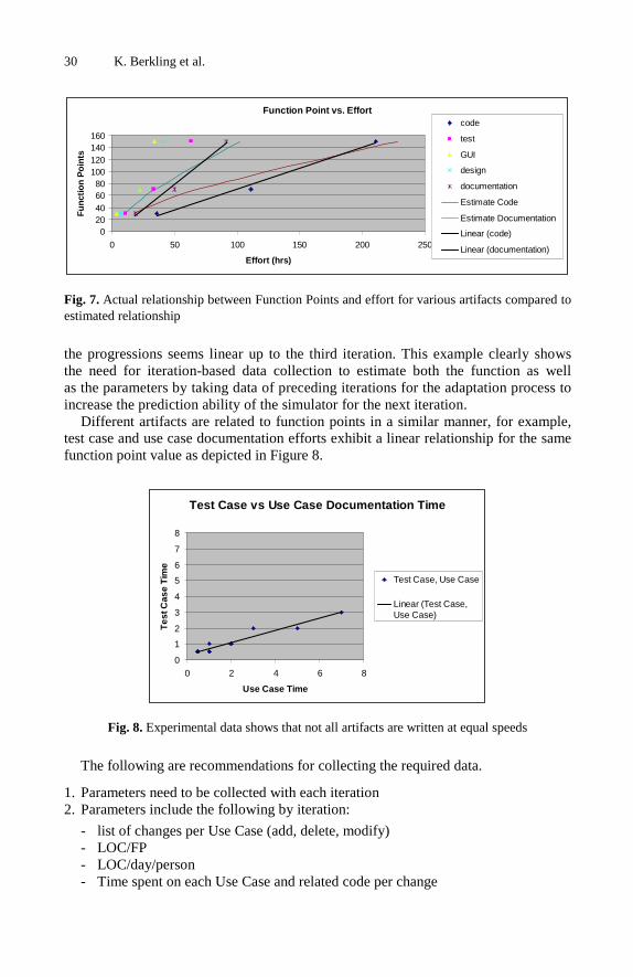
30 K. Berkling et al.
Function Point vs. Effort
020406080
100120140160
0 50 100 150 200 250
Effort (hrs)
Fu
nct
ion
Po
ints
code
test
GUI
design
documentation
Estimate Code
Estimate Documentation
Linear (code)
Linear (documentation)
Fig. 7. Actual relationship between Function Points and effort for various artifacts compared to estimated relationship
the progressions seems linear up to the third iteration. This example clearly shows the need for iteration-based data collection to estimate both the function as well as the parameters by taking data of preceding iterations for the adaptation process to increase the prediction ability of the simulator for the next iteration.
Different artifacts are related to function points in a similar manner, for example, test case and use case documentation efforts exhibit a linear relationship for the same function point value as depicted in Figure 8.
Test Case vs Use Case Documentation Time
0
1
2
3
4
5
6
7
8
0 2 4 6 8
Use Case Time
Tes
t Cas
e T
ime
Test Case, Use Case
Linear (Test Case,Use Case)
Fig. 8. Experimental data shows that not all artifacts are written at equal speeds
The following are recommendations for collecting the required data.
1. Parameters need to be collected with each iteration 2. Parameters include the following by iteration:
- list of changes per Use Case (add, delete, modify) - LOC/FP - LOC/day/person - Time spent on each Use Case and related code per change
Timeline Prediction Framework for Iterative Software Engineering Projects 31
- Time spent on each Test Case and related test code per change - Time spent on each other artifact (SRS, Design, GUI, etc.) - Pages added or changed for each artifact as function Use Case operation (add,
delete, modify)
3. Information that relates the factor [i,j] between artifacts i and j by describing how changes within one Use Case affect other Use Cases and their related code and data-tables.
4. Information about the amount of communication related to each iteration in terms of time spent with emails, meetings and other forms of communication.
6 Future Work
Future work clearly includes analysis of the collected data including the new vari-ables. The addition of division of work effort through additional personnel will be needed along with the communication components. Meeting and communication equations are essential additions to this model that will support understanding of the off-shoring component. Therefore, it is very important to collect off-shoring project data with the iteration-based model. Using the current ISBSG database, it seems pos-sible to show that off-shoring does not add an element of complexity to the project [33]. This however seems to run contrary to industrial experience reports, leading us to the idea that some parameters are still missing. Perhaps, iteration-based data will illuminate this issue further. We also want to introduce mean and variance into the predicted schedule. It can be shown that off-shoring may not change the mean predic-tion time of the project but the variance increases. We would like to show the origin of this increased variability and show how the variability can be controlled.
Finally, current efforts are underway to move the desktop simulator to a web-based application in order to serve as a tool and a data-collection instrument at the same time. It should have the ability to adapt parameters as well as functions automatically with the incoming data.
References
[1] Abran, A., Robillard, P.N.: Function Points: A Study of Their Measurement Processes and Scale Transformations. Journal of Systems and Software 25, 171–184 (1994)
[2] Abran, A., Robillard, P.N.: Identification of the structural weakness of Function Point metrics. In: 3rd Annual Oregon Workshop on Metrics, pp. 1–18 (1991)
[3] Albrecht, A.J.: Measuring application development productivity. In: IBM Corp. (ed.) IBM Application Develop Symp. (1979)
[4] Albrecht, A.J., Gaffney, J.E.: Software Function, Source Lines of Code, and Develop-ment Effort Prediction: A Software Science Validation. IEEE Transactions on Software Engineering SE-9(9), 639 (1983)
[5] Angelis, L., Stamelos, I., Morisio, M.: Building a Software Cost Estimation Model Based on Categorical Data. In: Pro. of the Seventh International Software Metrics Symposium METRICS, pp. 4–15 (2001)
[6] Boehm, B., Englewood Cliffs, N. (eds.): Software Engineering Economics. Prentice-Hall, Englewood Cliffs (1981)

32 K. Berkling et al.
[7] Datta, S.: A Mechanism For Tracking The Effects of Requirement Changes In Enterprise Software Systems, Master’s thesis, Florida State University (2006)
[8] Datta, S., van Engelen, R.: Effects of Changing Requirements: A Tracking Mechanism for the Analysis Workflow, pp. 1739–1744 (2006)
[9] Drappa, A., Ludewig, J.: Quantitative modeling for the interactive simulation of software projects. Journal of Systems and Software 46(2-3), 113–122 (1999)
[10] Fairley, D.: Making Accurate Estimates. IEEE Software, 61–63 (2002) [11] Fetcke, T.: A Generalized Structure for Function Point Analysis. In: International Work-
shop on Software Measurement, pp. 143–153 (1999) [12] Freburger, K., Basili, V.: The Software Engineering Laboratoy: Relationship Equations,
Report TR764, Technical report, University of Maryland (1979) [13] Ho, V.T., Abran, A., Oligny, S.: Using COSMIC -FFP to Quantify Functional Reuse in
Software Development. In: Proc. of the ESCOM-SCOPE, pp. 299–306 (2000) [14] Huang, J.C., Chang, C.K., Christensen, M.: Event-Based Traceability for Managing Evolu-
tionary Change. IEEE Transactions on Software Engineering Journal 29, 796–810 (2003) [15] IBM, Rational Unified Process Best Practices for Software Development Teams, Techni-
cal report, IBM (1998) [16] Jones, C.: Software Estimating Rules of Thumb, 116–119 (2007) [17] Jones, T.: Program Quality and Programmer Productivity, Technical report, IBM, IBM
TR 02.764 (1977) [18] Lawrie, R., Radford, P.: Using Function Points in Early Life Cycle estimation. In: Proc.
of the 4th European Conference on Software Measurement and ICT Control, pp. 197–210 (2001)
[19] MacDonell, S.G.: Comparitive review of functional complexity assessment methods for effort estimation. In: Software Engineering Journal, pp. 107–116 (1994)
[20] Nelson, R.: Software Data Collection and Analysis at RADC, Technical report, Rome Air Development Center (1978)
[21] Paton, K., Abran, A.: A Formal Notation for the Rules of Function Point Analysis. Re-search Report 247, University of Quebec, pp. 1–49 (1995)
[22] Ramesh, B.: Process Knowledge Management with Traceability. IEEE Software, 50–52 (2002)
[23] Ramesh, B., Jarke, M.: Toward Reference Models for Requirements Traceability. IEEE Transanction on Software Engineering Journal 27(1), 58–93 (2001)
[24] Schneider, V.: Prediction of Software Effort and Project Duration: Four New Formulas. In: ACM SIGPLAN Notices (1978)
[25] Symons, C.: Come Back Function Analysis (Modernised) - All Is Forgiven!. In: Proc. of the 4th European Conference on Software Measurement and ICT Control, pp. 413–426 (2001)
[26] Walston, C., Felix, C.: A Method of Programming Measurement and Estimation(1), Technical report, IBM System (1977)
[27] Watkins, R., Neal, M.: Why and How of Requirements Tracing. IEEE Software 11, 104–106 (1994)
[28] http://www.isbsg.org [29] http://www.totalmetrics.com [30] http://www.engin.umd.umich.edu/CIS/course.des/cis525/js/
f00/harvey/FP_Calc.html [31] http://www.writersservices.com/wps/p_word_count.htm [32] http://en.wikipedia.org/wiki/Words_per_minute [33] SMEF 2005 proceedings,
http://realcarbonneau.com/Publications/ Carbonneau2005_SoftDevProd_SMEF.pdf

K. Berkling et al. (Eds.): SEAFOOD 2008, LNBIP 16, pp. 33–45, 2009. © Springer-Verlag Berlin Heidelberg 2009
Outsourcing-Iterative Improvement Model for Transforming Challenges to Mutual Benefits
Atanu Bhattacharya
Tata Consultancy Services Ltd. Tel.: 91 9831517611, 9133 23337500
[email protected], [email protected]
Abstract. The concept of outsourcing though has evolved a lot from an initial one-time cost-rationalization measure, still has a long way to go. It has to trans-form the current challenges to opportunities for growth for the customer as well as the service provider. The success of outsourcing in the coming years will largely depend on optimizing the processes along with evolution of robust pric-ing models capable of providing value benefits every year apart from address-ing the current challenges. This paper proposes the Iterative Improvement Model, which will be capable of transforming the existing challenges of out-sourcing to mutual benefits for growth and excellence in a win-win situation along with a pricing model capable of improving bottom-line every successive year.
Keywords: Outsourcing, Offshore, Cost reduction, Iterative Improvement Model, Evolution of outsourcing.
Abbreviations
IT – Information Technology
KT – Knowledge Transition
OMM – Outsourcing Management Maturity
SLA – Service Level Agreement
SME – Subject Matter Expert
UAT – User Acceptance Testing
1 Introduction
Initially, outsourcing and offshoring started as transferring some non-key business and IT operations by means of person-to-person replacement, often from a developed to a developing country in order to leverage the cost benefit derived out of low wage rates and standard of living in the developing nations. However, the scope of out-sourcing has widened a lot over the last few years. The several challenges inherent with transitioning of the IT operations to remote locations have been addressed ade-quately in the last few years, but they keep on posing new dimensions - not as threats to outsourcing but as opportunities for growth both to the vendor and the customer. In

34 A. Bhattacharya
the next stage of evolution in outsourcing, the IT service providers need to be more responsive to the needs of their customers by adding substantial values to every ser-vice provided, accommodating fluctuating demands and finally moving towards enterprise transformation from process transformation. The existing models of out-sourcing though proposes movement in that direction, but still the maturity of the vendors is yet to be raised to level 5[1] of Outsourcing Management Maturity (OMM) model[2]. The key areas of OMM Level 5 are cost savings, innovation, evolving management formal processes leading to business cost reduction and quantitative performance improvement strategies continuously. This paper analyses the current challenges in software quality and proposes the Iterative Improvement Model capable of providing cost benefit in successive years along with value acceleration to custom-ers in the form of a bouquet of benefits and transforming the current challenges to opportunities.
2 Current Challenges in IT Outsourcing
The challenges in IT outsourcing are evident in all the three levels- strategic, tactical and operational. Based on a study of outsourcing contracts awarded between 2003 and 2005, sourcing specialist, TPI [3] concluded that cost reduction from such contracts is in the tune of 15% on an average, within a range of 10 % to 39% as opposed to the common belief of 60% operational cost reduction. In outsourcing the companies also lose control on outsourced operations and services. But still outsourcing trends are moving upwards all around the globe. Thus outsourcing, as a business model, will not be successful if followed only for cost saving purpose as the cost advantage derived out of salary difference with the developing countries is gradually waning with time. On the contrary, outsourcing model can generate long-term benefits for both the cus-tomer and the vendor, if it is followed with a long-term goal of complementing each other and fostering the idea of partnership between them.
At the strategic level, finalization of the objectives and purposes of outsourcing specific to the business goals along with choosing the right outsourcing partner form the basis of any outsourcing initiative. The outsourcing partner should complement the organization’s weakness; scale up as per the business needs and innovate to drive continuous process improvements along with value additions. The outsourcing partner should also have a proven background in meeting the standard quality and security requirements by means of different certifications such as CMMI, ISO 27001 etc. Switching software vendors frequently inside an organization results in wastage of time on the part of the Subject Matter Experts (SMEs) to transfer and validate the same knowledge time and again. The SMEs on the other hand can contribute more meaningfully to meet the business goals and take it to higher levels.
After choosing the right partner, there are several tactical and operational chal-lenges which need to be addressed in a win-win situation for both the partners. Some of those challenges, which the Iterative Improvement Model attempts to address, are as follows:
Project Management Conflicts It is often seen that the management perspectives of the customer and the vendor don’t match after the initial year. The target of the customer remains at reducing cost year

Outsourcing-Iterative Improvement Model for Transforming Challenges 35
after year, whereas the business goal of the vendor is to increase revenue from the exist-ing customer every year. In the absence of any value-adding partnership model benefit-ing both the customer and vendor mutually, the benefits of outsourcing are not achieved in the long term. It becomes just another short-term cost-rationalization initiative.
Improper Requirements Engineering Requirements management is a great challenge in any outsourced project. It is often seen that the SMEs who provide the business requirements are not in sync with them-selves, and also the persons from the vendor company who capture the requirements, are not qualified enough to understand the business directions of the customer. They are mostly senior developers who rise up the ladder to become analysts or project leads, i.e. the low-cost substitutes of the high-end business analysts. They spend most of their time in understanding how a requirement can be technically implemented or in managing the execution plan for the project without focusing on the ultimate busi-ness goal of the customer. This results in investment of a lot of time in consolidating the requirements from all the business owners on one side, while on the other side due to lack of complete understanding of the business goals of the customer it leads to the development of systems which do not perform as envisaged in the beginning. Thus, it is often found that the business team needs to make compromises and process changes to suit the limitations and shortcomings of the IT systems in contrary to IT leading business to higher levels.
Quality of Software Quality of software remains a concern in all kinds of development and maintenance activities. In case of an outsourcing initiative, it poses a new dimension in the form of requirement gaps as the developers and business users are located in geographically far-off areas and often having different cultural backgrounds. Many defects are caught only at the fag end of the projects on delivery to end-users. These defects being more in offshore developments, quality is always a big concern in any new offshore out-sourcing initiative.
3 Iterative Improvement Model
In an environment of continuous change and adaptability, organizations need to come up with new models for reducing prices and consistently improving the quality of products and services. In order to transform the above challenges to opportunities for mutual growth and provide innovative value additions to customer in an evolving improvement and cost rationalization cycle, the Iterative Improvement Model is being proposed.
A brief overview of different phases in a typical IT outsourcing engagement and the traditional cost models is worth mentioning before describing the new model.
3.1 Phases in IT Outsourcing
Outsourced projects are primarily of two types: Development Project and Mainte-nance Project. In case of development projects, the phases of requirement analysis, High Level Design (HLD), Low Level Design (LLD), coding, system testing and

36 A. Bhattacharya
User Acceptance Testing (UAT) remain the same as any other project, except that some of those phases are executed onsite and some offshore.
In case of a maintenance/enhancement project, the top level phases are as follows:
Knowledge Transfer (KT) Phase This is the first phase after the necessary formalities and Service Level Agreement (SLA) are signed-off mutually by the outsourcer and its partner. In this phase, the employees of the vendor get involved in multiple rounds of discussion with the SMEs of the customer to gain the system and business knowledge.
Secondary Support Phase In this phase, the vendor provides passive support under the guidance of the employ-ees or contractors of the outsourcer organization. The primary responsibility for ad-dressing the defects or tickets and meeting the SLA still remains with the existing service providers.
Primary Support Phase In this phase, the employees of the vendor start providing active support and take necessary help from the existing service providers only when required. The new ven-dor gradually becomes responsible for addressing the defects or tickets along with meeting the necessary SLA.
Steady State Phase In this phase, the employees of the vendor take over the full responsibility of the sys-tems for support and enhancements. The existing support staff of the customer is either moved to other areas or retrenched at this level.
3.2 Traditional Cost Models
The costing model was very simple at the onset, when the concept of outsourcing was evolving. For every resource of the customer, a resource of the outsourcing vendor was proposed at a rate fixed as part of the agreement between the two partners. Based on the initial study of the customer’s business processes, the vendor used to propose an onsite-offshore ratio of resources depending on the business criticality and support requirements. This primitive model of resource augmentation from the outsourcing vendor can be termed as Man-Marking Model due to its close resemblance with the man-to-man marking in a soccer match. However, this model is very defensive in approach and derives the immediate cost benefit out of the wage differences between the two partners only, without much future planning.
With the passage of time, the vendors started coming out of this mode by providing additional cost benefits in successive years by reducing the number of resources at onsite and shifting most of the work to offshore with low billing rates. Several models exploring different levels of offshore leverage factors evolved in the form of “80-20” or “90-10” in the successive years. These models became popular with the gain in confidence in the onsite-offshore methodology, improved network connectivity and secured infrastructure in offshore countries.

Outsourcing-Iterative Improvement Model for Transforming Challenges 37
In order to step into the next phase of outsourcing and offshoring, the proposed It-erative Improvement Model provides a robust pricing mechanism capable of recur-sively reducing operational cost in successive years along with providing several benefits in the form of “bouquet of benefits” and transforming the current challenges to opportunities for growth.
3.3 Key Features of Iterative Improvement Model
1. Reduction in Operational Cost with Iterative Improvement
A key component of this model is a robust pricing mechanism, called the Iterative Value Acceleration Model, which intends to continuously rationalize the operational cost and move up the value chain in quality and scope of services being provided.
Iterative Value Acceleration Model This model considers the long-term strategic partnership between the customer and the outsourcing partner as the basic requirement to be implemented. Though it gives sufficient cost benefit in the initial years, but focuses more on the long-term vision of providing more benefits in successive years through optimization of workforce re-quired to provide the services as per the initial contract and utilization of the remain-ing manpower to provide additional benefits with better quality of services higher in the value chain. This model can be best understood by considering an example of outsourcing three systems (maintenance projects) – Project01, Project02 and Pro-ject03 as depicted in Fig.1.
Fig. 1. Iterative Value Acceleration Model – Evolution of Resources

38 A. Bhattacharya
These systems with similar technological suite under the same business unit of an organization are being outsourced to a strategic outsourcing partner who intends to follow this model in maintaining them, upgrading them and finally driving the busi-ness towards higher goals providing additional benefits at continuously reducing cost. In the first iteration, Project01 and Project02 currently being supported by 10 and 15 employees respectively were taken up for outsourcing. In the KT phase, more or less the same number of resources will be required from the outsourcing partner to under-stand the systems and processes from the customer, thereby requiring 10 and 15 man-markers respectively for man to man replacement of the current workforce. These resources will gain the experience to support and enhance the systems under the guid-ance of the existing employees in Secondary Support Phase. In the Primary Support Phase, these 10 and 15 man-markers will become experts in Project01 and Project02 respectively and will be encouraged to take up additional responsibilities in the form of picking up cross-system knowledge by interfacing with each other in the free time derived out of increased efficiency and improved processes. Considering 2 resources with expertise in Project01 and 3 resources with expertise in Project02 picking up knowledge faster than the others, will be trained in Project02 and Project01 respec-tively in a more aggressive manner compared to others. These 5 resources will thus develop the required knowledge and expertise to support both the systems and will form the pool of mid-fielders as they can move in both the projects as per requirement just the same way as mid-fielders in a soccer match can move forward and backward towards both the goals at ease.
It is assumed that Project03 has a different time line and is being outsourced with a slight time lag compared to Project01 and Project02. In real-life situation, Project03 may also denote a different kind of system with more complexity, thereby requiring more time for the KT and Secondary support phases and hence, requiring a new itera-tion to be optimized. In the next iteration, when Project01 and Project02 are in steady state and Project03 is in Primary Support Phase, 2 more resources from Project02 and 4 resources from Project03 are developed as mid-fielders capable of supporting both Project02 and Project03 just the same way as carried out in the earlier iteration for Project01 and Project02.
Optimization of workforce will continue to be performed in this manner by means of the following process improvements in successive iterations:
• Thorough analysis of defect and change request history will be performed at periodic intervals starting from the KT phase.
• Known Error Defect Database (KEDB) will be maintained along with the solu-tions so that it takes less time to fix the production tickets.
• Based on causal analysis of the defects, “80-20” rule will be applied to proac-tively solve the root cause of the problems occurring most frequently, thereby, gradually freeing the resources to develop cross system expertise.
• Traceability tools will be used for identifying the program units to be changed and the test cases to be run from the defect types found. All such tools available in the market, such as Telelogic DOORS, IBM RequisitePro etc are inadequate for complex systems. As such new tools can also be developed for maintaining the complete traceability matrix to save time and effort in future.

Outsourcing-Iterative Improvement Model for Transforming Challenges 39
• The outsourcing partner will implement various motivational schemes in the form of appreciation and incentives to encourage more resources taking up cross-system responsibility in successive iterations.
This approach of continuous improvement in every iteration will lead to a more op-timized workforce capable of supporting multiple systems at enhanced efficiency. After the size of mid-fielder pool reaches a critical mass, some resources, as depicted with grey color in Fig.1 can be released to take up other assignments and a substantial cost benefit will thus be achieved in successive iterations.
Further optimization of workforce along with processes and methodologies will lead to evolution of another type of resource from the pool of mid-fielders – called Strikers. Some of the efficient mid-fielders will gradually develop the necessary busi-ness and technical skills to take the customer’s business to newer heights in collabora-tion with their counterparts in the customer’s side. These efficient mid-fielders will thus enable the customer to march ahead of its competitors in terms of matured busi-ness models and efficient IT systems aligned with business goals - just the same way as Strikers win matches in soccer. These Strikers will be responsible for recommend-ing and implementing the new solutions to suit the business objectives of the cus-tomer by studying the market trends and the technological advancements along with the SMEs of the respective business units. They will get more involved in developing business and technical prototypes in discussion with the customer to raise its business to higher levels. The accepted prototypes will then be implemented as enhancements or new systems as per new budget approved by the customer later on. The vendor may provide smaller enhancements up to a certain limit as part of the continuous value additions or the bouquet of benefit in successive years also.
This model is thus not only cost optimizing in nature but also focuses more on add-ing values to the customer in every iteration as depicted in Fig. 2. A key requirement from the customer’s side in this model is to gradually evolve its workforce from end users to Subject Matter Experts and finally to Business Champions, who will work closely with the Strikers of the outsourcing partner to enable the movement from process transformation to enterprise transformation and scale the new heights of Business Excellence jointly as two co-operating partners.
Transaction Based Pricing Model The next evolution from Iterative Value Acceleration Model is the Transaction Based Pricing Model, wherein the vendor will operate with such an optimized workforce that most resources will be capable of supporting multiple systems. The vendor will provide cost benefit derived out of increased efficiency in its operation by charging the customer on the basis of number of production tickets serviced or change re-quests/enhancements performed, not on the basis of the number of resources it main-tains. This model thus overcomes the drawback of under-utilization of resources on some occasions in the earlier models. On the other hand, the customer agrees to a minimum contract value based on average ticket volume even if such number of tickets or change requests are not raised on a specific month or year. This helps the vendor in maintaining its optimum work force to meet the SLA. On top of it, the cus-tomer involves the vendor (Strikers and high performing mid-fielders) in evaluating its business and IT needs for the future and thereby providing new opportunities for

40 A. Bhattacharya
Fig. 2. Iterative Value Acceleration Model – Evolution of Pricing Mechanism
growth to the vendor based on its performance. This model can be followed after a year or two in the steady state phase, when the relationship between the two partners attains such a maturity level that each one of them has evolved in its processes and performs at optimum efficiency the areas it is best in. This model thus creates a win-win situation for both the partners.
2. Bouquet of Benefits
The additional benefits or value additions that are automatically passed on to the cus-tomer from a vendor who follows this Iterative Improvement Model are combined together to design this Bouquet of Benefits. This will vary in different outsourcing engagements based on the actual requirements of the customer. A representative Bou-quet of benefits will contain the following add-ons apart from continuous cost benefit derived year after year (excluding inflation adjustments):
• Better quality of services as cross system experts will be able to think through multiple systems while fixing any defect and will be able to understand more clearly the impact of any change in one system on the other.

Outsourcing-Iterative Improvement Model for Transforming Challenges 41
• More participation and contribution from the outsourcing partner in the form of pro-active suggestions, both in business and technological spheres, to push the customer ahead of its competitors.
• Joint product development for different geographies leveraging the multi-market exposure and expertise levels of both the partners.
3. Transforming challenges to Opportunities
The Iterative Improvement Model addresses the existing challenges in outsourcing by transforming them to opportunities for growth and mutual benefit as explained below:
Managing Project Management Conflicts In order to bridge the conflicting management perspectives of the customer and vendor, this model creates a win-win situation for both the partners with equal opportunities of growth. Long-term commitment and vision of growth being the primary objectives of this model, the outsourcing partner gets a multi-year deal with some committed revenue every year in order to provide its basic service. However, in order to increase its revenue it has to improve its operational efficiencies and get involved more and more in provid-ing high-end services in the form of business and technological roadmaps and solutions to keep the customer ahead of its competitors. The customer on the other hand, can focus more on improving its business processes with the help of the latest IT solutions evolved jointly with its outsourcing partner.
Requirements Engineering A major part of the defects found out in outsourced projects are normally caused due to gaps in requirements. This model proposes a pool of business experts from both the sides who will work inter-changeably in different roles in both the organizations from project to project. Thus a business expert, capturing requirements in one project will be providing the requirements in some other project along with the existing SME pool. This will evoke better understanding of the business goals of the customer and both the partners will jointly work towards achieving them by being involved in all the phases of the projects in different roles. The returns in the form of more business, higher in the value chain in the long term, will offset the cost of employing the best business experts from both the sides. Based on root cause analysis [4] of several sce-narios with Requirements Engineering challenges, the strategic success factors in offshore-outsourcing initiatives are shared goal, shared culture, shared process, shared responsibility and trust. The holistic framework containing the best practices in terms of people, process and technology to achieve these success factors in Requirements Engineering, specific to the outsourcer organization, will also be identified and fol-lowed throughout the life-cycle.
3.4 Improvement in Software Quality
In both development and maintenance projects, the total effort is distributed among the different phases of analysis, HLD, LLD, coding, system testing and acceptance testing in various ratios as depicted in Fig.3 based on a study conducted on some outsourced projects. The trend is more or less the same with the peak effort being spent in coding.

42 A. Bhattacharya
Fig. 3. Effort distribution across phases
Fig. 4 depicts the defects found out in different phases for a group of outsourced projects. It is evident that a lot of defects attributed to earlier phases and supposed to be caught in the respective phases lead to considerable rework in the projects.
Fig. 4. Defect distribution across phases
However, it is known that the cost of defect increases exponentially in the later phases of the project. The effort spent and the number of defects found in different phases follow more or less the same pattern [5] as shown in Fig. 5

Outsourcing-Iterative Improvement Model for Transforming Challenges 43
Fig. 5. Effort and Defect distribution across phases
Thus in order to reduce rework and project cost along with enhancing the product quality, the effort curve in Fig.3 needs to be gradually moved leftward as shown in Fig. 6. More “quality” effort, if spent in the earlier phases of the project, will ensure less rework and defects in the later phases. Higher skilled resources engaged in the earlier phases will enhance the quality and reduce overall cost of the project.
Fig. 6. Projected Phase-wise effort distribution
This movement, however, needs to be optimized as per the skill level of the re-sources, expected product quality and project schedule. Increase in development ef-fort reduces number of defects in the system. At the same time increase in validation and verification effort increases the chance of finding more defects before the system goes into production. However, based on the skill level of the resources the amount
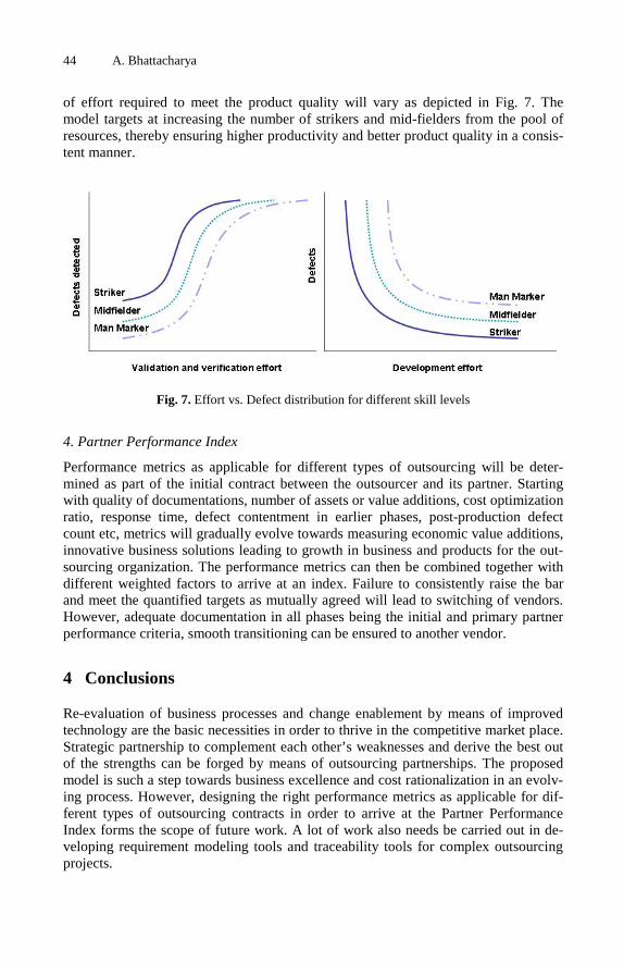
44 A. Bhattacharya
of effort required to meet the product quality will vary as depicted in Fig. 7. The model targets at increasing the number of strikers and mid-fielders from the pool of resources, thereby ensuring higher productivity and better product quality in a consis-tent manner.
Fig. 7. Effort vs. Defect distribution for different skill levels
4. Partner Performance Index
Performance metrics as applicable for different types of outsourcing will be deter-mined as part of the initial contract between the outsourcer and its partner. Starting with quality of documentations, number of assets or value additions, cost optimization ratio, response time, defect contentment in earlier phases, post-production defect count etc, metrics will gradually evolve towards measuring economic value additions, innovative business solutions leading to growth in business and products for the out-sourcing organization. The performance metrics can then be combined together with different weighted factors to arrive at an index. Failure to consistently raise the bar and meet the quantified targets as mutually agreed will lead to switching of vendors. However, adequate documentation in all phases being the initial and primary partner performance criteria, smooth transitioning can be ensured to another vendor.
4 Conclusions
Re-evaluation of business processes and change enablement by means of improved technology are the basic necessities in order to thrive in the competitive market place. Strategic partnership to complement each other’s weaknesses and derive the best out of the strengths can be forged by means of outsourcing partnerships. The proposed model is such a step towards business excellence and cost rationalization in an evolv-ing process. However, designing the right performance metrics as applicable for dif-ferent types of outsourcing contracts in order to arrive at the Partner Performance Index forms the scope of future work. A lot of work also needs be carried out in de-veloping requirement modeling tools and traceability tools for complex outsourcing projects.

Outsourcing-Iterative Improvement Model for Transforming Challenges 45
Acknowledgements
I am grateful to Mr Pradip Pradhan, SEPG Head, Tata Consultancy Services Ltd. for sharing his experience and information from his presentation on “Predicting Process, Product and Performance” which I extrapolated for making the suggested model ro-bust from quality assurance perspective. Special thanks also to my colleagues - Probal Chatterjee, Kaustuv Gupta, Subhasis Sanyal, Sanjay Dutta, Arindom Ghosh, Nilanjan Banerjee, Syamal Basak, Ranjit Sinha, Anand Ujawane, Sougata Banerji and Sarbbot-tam Bandyopadhyay for helping me with valuable suggestions from time to time.
References
1. Fairchild, A.M.: Information Technology Outsourcing (ITO) Governance: An Examination of the Outsourcing Management Maturity Model. In: Proc. 37th Hawaii Intl. Conf. System Sciences (2004),
http://csdl2.computer.org/comp/proceedings/hicss/2004/2056/ 08/205680232c.pdf
2. Raffoul, W.: The road to outsourcing success. The outsourcing management maturity model, ZD Net Tech Update, provided by Meta Group, March 4 (2002),
http://techupdate.zdnet.com/techupdate/stories/main/ 0,14179,2851971-2,00.html
3. Outsourcing: How much is saved? IEEE Spectrum Online (April 2006), http://www.spectrum.ieee.org/apr06/comments/1389
4. Bhat, J.M., Gupta, M., Murthy, S.N.: Overcoming Requirements Engineering Challenges: Lessons from Offshore Outsourcing. IEEE Software,
http://ieeexplore.ieee.org/Xplore/login.jsp?url=/iel5/52/ 35605/01687859.pdf?tp=&arnumber=1687859&isnumber=35605
5. Pradhan, P.: Predicting Process, Product and Performance. In: 20th NASSCOM Quality Fo-rum Kolkata (June 2007),
http://www.nasscom.in/Nasscom/Templates/Events.aspx?id=51629

K. Berkling et al. (Eds.): SEAFOOD 2008, LNBIP 16, pp. 46–58, 2009. © Springer-Verlag Berlin Heidelberg 2009
A Structure for Management of Requirements Set for e-Learning Applications
Dumitru Dan Burdescu1, Marian Cristian Mihăescu2, and Bogdan Logofatu3
1 University of Craiova, Software Engineering Department [email protected]
2 University of Craiova, Software Engineering Department [email protected]
3 University of Bucharest, CREDIS Department [email protected]
Abstract. Extracting and managing requirements is one of the most important tasks in creating a reliable software product. This step of the overall software en-gineering process becomes even more critical when the development process is to become a global one. This paper presents an approach for passing from ad hoc requirements management to systematic requirements management. This step is often needed due to the increasing scale of software system and increasing glob-alization. The study is presented for an e-Learning platform that has been devel-oped and reached a certain maturity level such that these kind of activities are needed. The proposed solution in the paper allows centralization of requests among involved parties (developers and beneficiaries). It is proposed a custom structure for requests that has at its basis the very specificity of developed appli-cation. The structuring of requirements is customized for platform’s functionality such that the process which determines what functionalities may be outsourced is improved.
1 Introduction
The success of a software system depends on how well it fits the needs of its users and its environment [1, 2]. Software requirements comprise these needs, and requirements engineering (RE) is the process by which the requirements are determined. Successful RE involves understanding the needs of users, customers, and other stakeholders; un-derstanding the contexts in which the to-be-developed software will be used; modeling, analyzing, negotiating, and documenting the stakeholders’ requirements; validating that the documented requirements match the negotiated requirements; and managing requirements evolution.
Requirements engineering is not an easy task. There are many reasons that for this situation. Ideas may be ill defined or even conflicting. This situation usually has to shift towards a single, sound, detailed technical specification of the software system. The requirements problem space is usually not that strictly defined. In complex sys-tems there are many too many options to consider. That is why management of large collections of proposed requirements, prioritization, specification of system bounda-ries, negotiating resolutions to conflicts, setting objective acceptance criteria [3] are

A Structure for Management of Requirements Set for e-Learning Applications 47
processes that usually need to be carried out. Reasoning and having conclusions about the software that is to be designed and developed includes identifying not only as-sumptions about the general normal behavior of the environment represented by main scenario use cases, but also about possible threats or hazards that may appear in the system. The obtained top level requirements have to be understood and usable by all involved persons: developers and beneficiaries. Thus, requirements notations and processes must maintain a delicate balance between producing descriptions that are suitable for beneficiaries which may be represented by non-computing audience and producing technical documents that are precise enough for domain experts and down-stream developers.
Due to above presented reasons, requirements engineering activities, in contrast to other software-engineering activities, may involve many more players who have more varied backgrounds and expertise, require more extensive analyses of options, and call for more complicated validations of various components such as software, hard-ware or even human.
Regarding requirements engineering there are several main activities that need to be taken into consideration: elicitation, modeling, analysis, validation/verification and management. Requirements elicitation regards activities that enable the understanding of the goals, objectives, and motives for building a proposed software system. Elicita-tion also involves identifying the requirements that the resulting system must satisfy in order to achieve these goals. This activity rises problems regarding stakeholders identification [4], contextual and personal requirements engineering techniques [5, 6]. In requirements modeling, a project’s requirements is expressed in terms of one or more models. Modeling strategies provide guidelines for structuring models. For example, requirements engineering reference models [7, 8, 9] decompose require-ments-related descriptions into the stakeholders’ requirements, the specification of the proposed system, and assumptions made about the system’s environment. Problems regarding requirements analysis are mainly linked on the techniques employed for evaluating the quality of gathered requirements. Some analyses look for well-formedness errors in requirements, where an “error” can be ambiguity [10, 11], incon-sistency [12, 13], or incompleteness. Other analyses look for anomalies, such as unknown interactions among requirements [14, 15], possible obstacles to require-ments satisfaction [16, 17], or missing assumptions [18]. Requirements validation make sure that obtained models and documentation express as possible as accurate the needs of involved persons, beneficiaries or developers. Validation usually requires that beneficiaries and developers to be directly involved in reviewing the require-ments [19]. Main issues in this area regard improving the information provided to the involved parties including animations [20] or simulations [21]. Requirements man-agement is a general activity that regards tasks related to the management of require-ments, including structuring and evolution over time and across product releases. Currently there are used specific tools that partially automate different tasks (e.g. identification, traceability, version control) [22, 23]. There may be also employed tools that estimate the maturity and stability of elicited requirements, so that the re-quirements most likely to change can be isolated [24]. Organization and structuring of large numbers of requirements [25] that are globally distributed [26], and that are at different phases in development in different product variants [27] are current issues that appear in complex and large systems.

48 D.D. Burdescu, M.C. Mihăescu, and B. Logofatu
This paper presents advances made within an e-Learning platform called Tesys [28] regarding requirements engineering. This platform has initially been designed and implemented only with core functionalities that allowed involved people (learn-ers, course managers, secretaries) to collaborate in good conditions. The requirements engineering followed an ad-hoc process that informally followed the classical life-cycle: elicitation, modeling, analysis, validation, verification and management. The involved parties were represented by three parties: development team, beneficiaries and end-users. Firstly, a prototype that implemented main functionalities has been developed. The requirements were elicited and negotiated between development team and beneficiary. After prototype has been deployed the e-Learning system has been populated with data and users. The beneficiary was the one that kept a close relation with end-users and closely looked the effectiveness of the platform.
The features and functionalities rapidly grow, such that in less than an year the de-velopment team faced a large scale software system. Under these circumstances there had to be found specific solutions to encountered problems regarding requirements engineering. The software system became large in size. The reason for calling it a large-scale system do not necessarily refer to significant size regarding lines of code. Scale factors also include business logic implemented complexity or degree of het-erogeneity among assets. Another important scale factor is variability, as software system needed to accommodate increasingly larger sets of requirements that vary with respect to changes in the software’s environment. Requirements started to come from many different involved persons (secretaries, professors, students), involve multiple aspects (e.g., need for additional functionality, modify existing functionality, imple-ment more complex activities). There was discovered the need for increasing the reliance and self management of the environment. Bringing around new teams of developers and the need to keep them closer with the beneficiary was the decisive step in going towards global software development. Global software development is an emerging paradigm shift towards globally distributed development teams [29]. The shift is motivated by the desire to exploit a 24- hour work day, capitalize on global resource pools, decrease costs, and be geographically closer to the end consumer [26]. The downside is increased risk of communication gaps. For example, elicitation and early modeling are collaborative activities that require the construction of a shared mental model of the problem and requirements. However, there is an explicit discon-nect between this need for collaboration and the distance imposed by global develop-ment. Decisions regarding requirements engineering in this direction are having a huge impact regarding future possibility of outsourcing. In this context, outsourcing may be seen as a particular case of globalization.
Globalization raised two main problems for involved people. First, new or ex-tended requirements engineering techniques are needed to support development tasks, such as design, coding, or testing. Since geographical distance aggravates the gap between teams (e.g. development, beneficiaries, requirements, etc.), particularly if the teams are from different organizations, have different cultures, or have different work environments. In particular, because geographic distance reduces team communica-tion [30], ill-defined requirements are at risk of ultimately being misinterpreted, re-sulting in a system that does not meet the envisioned needs. As a preliminary effort to narrow communication gaps, Bhat et al. [26] have proposed a framework based on a

A Structure for Management of Requirements Set for e-Learning Applications 49
people process- technology paradigm that describes best practices for negotiating goals, culture, processes, and responsibilities across a global organization.
The second problem is to enable effective distributed requirements engineering. Future requirements activities will be globally distributed, since requirements analysts will likely be working with geographically distributed stakeholders and distributed development teams may work with in-house customers. As such, practitioners need techniques to facilitate and manage distributed requirements elicitation, distributed modeling, distributed requirements negotiation, and the management of distributed teams – not just geographically distributed, but distributed in terms of time zone, culture, and language.
2 Tesys Application Platform
An e-Learning platform that represents is a collaborative environment for students, professors, secretaries and administrators has been designed and developed. Secretary users manage sections, professors, disciplines and students. The secretaries have also the task to set up the structure of study years for all sections. The main task of a profes-sor is to manage the assigned disciplines. The professor sets up chapters for each as-signed discipline by specifying the name and the course document, and manages test and exam questions for each chapter. The platform offers students the possibility to download course materials, take tests and exams and communicate with other involved parties like professors and secretaries.
All users must authenticate through username and password. If the username and password are valid the role of the user is determined and the appropriate page is presented.
A message board is implemented for professors, secretaries and students to ensure peer-to-peer communication. This facility is implemented within the platform such that no other service (e.g. email server) is needed.
From software architecture point of view, the platform is a mixture of data access code, business logic code, and presentation code. For development of such an applica-tion we enforced the Model-View-Controller [31] (MVC for short) design pattern for decoupling data access, business logic, and data presentation. This three-tier model makes the software development process a little more complicated but the advantages of having a web application that produces web pages in a dynamic manner is a worthy accomplishment.
From the software development process point of view we enforced the cyclic soft-ware development with project planning, requirements definition, software architecture definition, implementation, test, maintenance and documentation stages. Software development makes intensive use of content management through a versioning system, testing and continuous building infrastructure.
3 Software Architecture of Tesys
The e-learning platform consists of a framework on which a web application may be developed. On server side we choose only open source software that may run on al-most all platforms. To achieve this goal Java related technologies were employed.

50 D.D. Burdescu, M.C. Mihăescu, and B. Logofatu
The model is represented by DBMS (Data Base Management System) that in our case is represented by MySQL [32]. The controller, which represents the business logic of the platform is Java based, being build around Java Servlet Technology [33]. As Servlet container Apache Tomcat 5.0 [34] is used.
This architecture of the platform allows development of the e-learning application using MVC architecture. The view tier is template based, WebMacro [35] technology being used. WebMacro is also a Java based technology the link between view and controller being done at context level. The separation between business logic and view has great advantages against having them together in the same tier. This decoup-ling makes development process more productive and safer. One of the biggest advan-tages of not having business logic and view together is the modularity that avoids problems in application testing and error checking.
In the figure 2 there are presented the main software components from the MVC point of view. MainServlet, Action, Manager, Bean, Helper and all Java classes repre-sent the Controller. The Model is represented by the DBMS itself while the Web-macro templates represent the View. The model is built without any knowledge about views and controllers.
Fig. 1. Software architecture of the platform
The business logic of the application uses Java classes. As it can be seen in figure 2, there are four levels of dependency between classes. The levels are: servlets, actions, managers and beans. Servlets level has so far two of them: MainServlet and DownloadServlet.
The MainServlet first job first job is to initialize application’s parameters. For this purpose the init() method is used. Firstly, there is initialized a pool of database con-nections. Helper classes like ConnectionPool or ExecuteQuery based on the informa-tion from database.properties configuration file conduct this process. In the database configuration file there are set the address of MySQL server and the username and password of MySQL user that is used.

A Structure for Management of Requirements Set for e-Learning Applications 51
Fig. 2. Software components of the application from MVC point of view
Another important part of software architecture regarding software development process is unit testing. For this purpose JUnit [6] is used. Unit tests are created for running the critical code like creating of a test, computing the result, saving the ques-tions from the test, saving the test result, computing time for test. To accomplish this regressive testing is used. For each chain of actions a scenario is defined. If the com-puted result matches the expected result it means the test passed. Otherwise, it means something is wrong with the code because it does not behave like it supposed to. Whenever a method is added, test cases are written trying to have a full coverage of the code. There are created batch files that build the code experimentally and continu-ously and run all the tests. Similarly, a scheduled job runs the nightly build of all the code from the staging area and runs all tests.
The platform is currently in use on Windows 2003 Server machine. This platform has three sections and at each section four disciplines. Twelve professors are defined and more than 650 students. At all disciplines there are edited almost 2500 questions. In the first month of usage almost 500 tests were taken. In the near future, the ex-pected number of students may be close to 1000.
4 Software Development Process
Software development process and practices have as main goal quality software. Re-quirements engineering represents the first and the most general step that needs to be accomplished.
In requirements definition and analysis phase has as final deliverable the functional specifications document for the system and a requirement analysis report. In this phase developers will resolve ambiguities, discrepancies and to-be-determined specifications. From requirements analysis a preliminary design may be derived that defines the soft-ware system architecture and specifies the major subsystems, input/output (I/O) inter-faces, and processing modes.
At this step the system architecture defined during the previous phase is elaborated in detail. The development team fully describes user input, system output, I/O files.
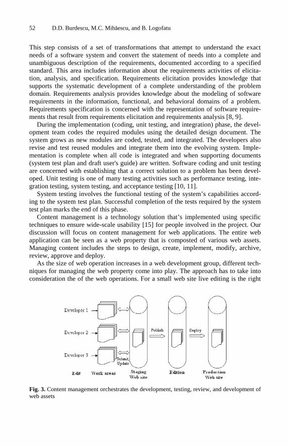
52 D.D. Burdescu, M.C. Mihăescu, and B. Logofatu
This step consists of a set of transformations that attempt to understand the exact needs of a software system and convert the statement of needs into a complete and unambiguous description of the requirements, documented according to a specified standard. This area includes information about the requirements activities of elicita-tion, analysis, and specification. Requirements elicitation provides knowledge that supports the systematic development of a complete understanding of the problem domain. Requirements analysis provides knowledge about the modeling of software requirements in the information, functional, and behavioral domains of a problem. Requirements specification is concerned with the representation of software require-ments that result from requirements elicitation and requirements analysis [8, 9].
During the implementation (coding, unit testing, and integration) phase, the devel-opment team codes the required modules using the detailed design document. The system grows as new modules are coded, tested, and integrated. The developers also revise and test reused modules and integrate them into the evolving system. Imple-mentation is complete when all code is integrated and when supporting documents (system test plan and draft user's guide) are written. Software coding and unit testing are concerned with establishing that a correct solution to a problem has been devel-oped. Unit testing is one of many testing activities such as performance testing, inte-gration testing, system testing, and acceptance testing [10, 11].
System testing involves the functional testing of the system’s capabilities accord-ing to the system test plan. Successful completion of the tests required by the system test plan marks the end of this phase.
Content management is a technology solution that’s implemented using specific techniques to ensure wide-scale usability [15] for people involved in the project. Our discussion will focus on content management for web applications. The entire web application can be seen as a web property that is composted of various web assets. Managing content includes the steps to design, create, implement, modify, archive, review, approve and deploy.
As the size of web operation increases in a web development group, different tech-niques for managing the web property come into play. The approach has to take into consideration the of the web operations. For a small web site live editing is the right
Fig. 3. Content management orchestrates the development, testing, review, and development of web assets

A Structure for Management of Requirements Set for e-Learning Applications 53
way. As the number of assets grows, and the number of developer increases, it is not practical to edit the production server directly. A staging server is used and runs a copy of the production web site. At the next level, development groups retain the staging server but give each developer an independent area in which to make their changes. This has the benefit that each developer is able to test changes independ-ently. When the number of assets or the web team becomes big enough it is necessary to adopt a content management tool. This will manage the asset in a timely, accurate, collaborative, iterative and reproducible manner. A content management infrastruc-ture consists of subsystems that fulfill the following functions: content creation and editing, content repository and versioning, workflow and routing, deployment and operations management. The most important one is the repository and versioning system subsystem since it provides storage, access, retrieval, indexing, versioning and configuration management of content. The measure of effectiveness of the repository subsystem is done by its ability to store assets reliably, with scalability and excellent performance. In figure 3 it is presented how content management orchestrates devel-opment, testing, review and deployment of web assets.
In an environment with multiple developers usage of a versioning system is com-pulsory. In the same time a developer makes an HTML change, a web designer and a graphic designer collaborate on new pages and a developer changes the logic in Java files to fix a bug. Versioning means that there are earlier versions to refer to, and that earlier versions are available to fall back to, as an insurance policy. Although mis-takes always occur, people are more productive, daring and innovative when they know there is a safety net to rescue them.
The basic collaboration operations are: submit (copy assets from work area to stag-ing area), compare (compare assets in work area with corresponding assets in staging area), update (copy assets from staging area to work area), merge (resolve conflict between staging area and work area) and publish (create edition, which is a snapshot of entire staging area).
5 Improvements in Requirements Engineering Process for Globalization
Requirements engineering is the first step in making the development process a global one. Analysis and changes in this direction may have good implications regarding the possibility of future outsourcing of specific activities. Proposed solutions are specific for e-Learning environments in general and to Tesys e-Learning platform in particular.
5.1 Structuring Requirements on User Groups
The first decision is to structure requirements based on user groups. Within Tesys there were defined three main roles: Secretary, Professor and Student. Each user that ac-cesses the platform has to have one of these roles. During prototype development phase the requirements elicitation and negotiations between development team and beneficiary were always carried out for specific role functionality. This was mainly due to disjunctive implemented functionalities for these roles.
54 D.D. Burdescu, M.C. Mihăescu, and B. Logofatu
This decoupling is very natural due to employed software architecture presented in chapter three. The decoupling may be seen at all three MVC levels: view, business logic and model. The functional requirements are very linked with the view tier. That is why the templates that represent this tier are grouped in specific folders according to the user role that will display them.
This decision may have important impact in globalization or even outsourcing since a new group of developers may start working on adding functionality.
Under these circumstances, a requirement started to become an object with his own status and life cycle. The status is determined by the set of values of fields. There has been defined the following set of fields:
Id – uniquely identifies the requirement; Role – defines the role to which the requirement addresses; Activity – defines the activity to which the requirement addresses; Status – there were defined three states: INWORK, SOLVED, VERIFIED; Solver – person responsible for implementing the requirement; Memo – text that represents a short summary about the requirement.
Firstly, the requirement has to be signaled from the beneficiary. The beneficiary may have the requirement either simply as a need for more functionality or as a bug from a user (secretary, professor or student). The requirement is negotiated with de-velopment team and a conclusion is reached. At this phase there are identified all values of fields, which means there is identified the Role and Activity, it is set the Solver and the Memo, and it is assigned an Id and Status is set to INWORK. Basi-cally, from this moment the Solver is announced that he has some work to do. As soon as the Solver accomplishes his job he will signal this by changing the status of the Requirement to SOLVED. This means that the Quality Assurance people may start testing the functionality. At this step they will be aware of the exact functionality it refers from Role, Activity and Memo fields.
At this point there are obvious the advantages of this way of structuring require-ments. If Quality Assurance people do not agree with implemented solution they may change the status back to INWORK such that the Solver will be announced that his solution does not meet the required quality. In this situations there is advisable that additional communication has to take place between management and Solver.
5.2 Determining the Benefit of Requirements Management
When the problem of globalization appears, the next question is: “What?”. In the next table [42] it is presented the percentages of outsourced and in house activities.
From the above highlighted percentages it became obvious that in requirements gathering is not an usual activity that is outsourced. Still, coding is by far the most outsourced activity. Since coding is the most likely activity to be outsourced it means specific measures are to be taken regarding structuring of assets. Code, along tem-plates, data models, data itself, etc. represent the assets of the e-Learning platform. Requirements gathering and management and coding have to be very well coordi-nated such that the productivity is maximized. The structure presented in previous chapter is very well suited for determining groups of activities that belong to a certain role and may be outsourced.

A Structure for Management of Requirements Set for e-Learning Applications 55
Table 1. Percentages of outsourced and in house activities
Activity Outsourced In-house Project Management 30% 90% Requirements Gathering 17% 89% Architecture 19% 88% Research and Development 25% 78% Business Integration 16% 76% Design 51% 77% Systems Integration 35% 76% Deployment 26% 75% Testing 74% 71% Modeling 26% 69% Maintenance 53% 65% Code migration 54% 42% Coding 94% 41% Internationalization 39% 34%
An obvious scenario is when many requirements appear for the same role and same
or related activities. In this situation there may be decided that the corresponding piece of software to be outsourced in the effort of globalization.
5.3 Benefits Regarding Verification and Validation
Requirements engineering relies fundamentally on verification and validation as a way of achieving quality by getting rid of errors, and as a way of identifying requirements.
One benefit from structuring requirements is the use of automation for verification of requirements. The requirements may be inspected such that verification is per-formed by using well established checklists. The checklists are applied to the re-quirements by a well established process.
Modeling requirements in a custom structured form provides the opportunity for analyzing them. Analysis techniques that have been investigated in requirements engineering include requirements animation, automated reasoning, consistency, and a variety of techniques for validation and verification that are further discussed.
Validation is the process of establishing that the requirements and derived struc-tures provide an common and accurate base for involved persons (developers and beneficiaries). Explicitly describing the requirements is a necessary precondition not only for validating requirements, but also for resolving conflicts between developers and beneficiary.
Difficulty of requirements validation comes from many sources. One reason is the problem itself is philosophical in nature. This makes the formalizing process hard to define. On the other hand, there is a big difficulty in reaching agreement among in-volved persons dew to their conflicting goals. The solution to this problem is re-quirements negotiation. These will attempt to resolve conflicts between involved parties without necessarily weakening satisfaction of each person’s goals.

56 D.D. Burdescu, M.C. Mihăescu, and B. Logofatu
Structuring requirements brings a big advantage for validation and verification in case of changing requirements. As all successful systems, our e-Learning platform evolves. This means that when a functionality changes because of beneficiary and developer negotiated such a change, this transition needs to be done with minimum of effort. For this, requirements have to be traceable and this feature is accomplished by proposed structuring.
6 Conclusions
In this paper, there were presented the main challenges in requirements engineering. All of the problems described in introduction (elicitation, modeling, analysis, valida-tion, verification and management) require substantial effort in order to make progress towards effective solutions.
In this general context there was presented Tesys e-Learning platform from func-tional, software architecture and software development point of views. It has been presented the initial requirements engineering process that was used when the proto-type has been developed.
Currently, there is a big effort for globalization of software development process since the application is rapidly growing in size. More than this, the business logic complexity, degree of heterogeneity among assets are increasing.
From requirements point of view there were adopted two solutions. One regards the custom and proper structuring of requirements. This was accomplished according with the nature of the application, in our case represented by an e-Learning platform.
The benefits from this approach are multiple. Centralization and proper structuring of requirements had a big impact in management activity of the project. Although managing the effort of centralization is big at beginning, for future development it is supposed to have a good return of investment.
Other benefit is that there may be created pools of requirements based on function-ality at role level and even with a higher granularity at activity level. This will have a big impact on future decisions regarding what parts of software to be outsourced in the effort of globalization.
Finally, there presented the benefits brought by our structuring to verification and validation processes. The proposed structure ensures traceability of requirements, such that as the system evolves the requirements are still properly managed.
References
1. Nuseibeh, B., Easterbrook, S.: Requirements engineering: a roadmap. In: Proc. of the IEEE Int. Conf. on Soft. Eng. (ICSE), pp. 35–46 (2000)
2. Parnas, D.L.: Software engineering programmes are not computer science programmes. Ann. Soft. Eng. 6(1), 19–37 (1999)
3. van Lamsweerde, A.: Requirements engineering in the year 2000: a research perspective. In: Proc. of the IEEE Int. Conf. on Soft. Eng. (ICSE), pp. 5–19 (2000)
4. Sharp, H., Finkelstein, A., Galal, G.: Stakeholder identification in the requirements engi-neering process. In: Proc. of the 10th Int. Work. on Datab. & Exp. Sys. Appl., pp. 387–391 (1999)

A Structure for Management of Requirements Set for e-Learning Applications 57
5. Cohene, T., Easterbrook, S.: Contextual risk analysis for interview design. In: Proc. of the IEEE Int. Req. Eng. Conf. (RE), pp. 95–104 (2005)
6. Sutcliffe, A., Fickas, S., Sohlberg, M.M.: PC-RE a method for personal and context re-quirements engineering with some experience. Req. Eng. J. 11(3), 1–17 (2006)
7. Gunter, C.A., Gunter, E.L., Jackson, M., Zave, P.: A reference model for requirements and specifications. IEEE Soft. 17(3), 37–43 (2000)
8. Hall, J., Rapanotti, L.: A reference model for requirements engineering. In: Proc. of the IEEE Int. Req. Eng. Conf. (RE), pp. 181–187 (2003)
9. Parnas, D.L., Madey, J.: Functional documents for computer systems. Sci. of Comp. Prog. 25(1), 41–61 (1995)
10. Berry, D., Kamsties, E.: Ambiguity in Requirements Specification. In: Perspectives on Software Requirements, ch. 2. Kluwer Academic Publishers, Dordrecht (2004)
11. Fantechi, A., Gnesi, S., Lami, G., Maccari, A.: Application of linguistic techniques for use case analysis. In: Proc. of the IEEE Int. Req. Eng. Conf. (RE), pp. 157–164 (2002)
12. Campbell, L.A., Cheng, B.H.C., McUmber, W.E., Stirewalt, R.E.K.: Automatically detect-ing and visualizing errors in UML diagrams. Req. Eng. J. 37(10), 74–86 (2002)
13. Engels, G., Küster, J.M., Heckel, R., Groenewegen, L.: A methodology for specifying and analyzing consistency of object-oriented behavioral models. In: Proc. of ACM SIGSOFT Found. on Soft. Eng. (FSE), pp. 186–195 (2001)
14. Chan, W., Anderson, R.J., Beame, P., Burns, S., Modugno, F., Notkin, D., Reese, J.D.: Model checking large software specifications. IEEE Trans. on Soft. Eng. 24(7), 498–520 (1998)
15. Hausmann, J.H., Heckel, R., Taentzer, G.: Detection of conflicting functional requirements in a use case-driven approach. In: Proc. of the IEEE Int. Conf. on Soft. Eng. (ICSE), pp. 105–115 (2002)
16. Lutz, R., Patterson-Hine, A., Nelson, S., Frost, C.R., Tal, D., Harris, R.: Using obstacle analysis to identify contingency requirements on an unpiloted aerial vehicle. Req. Eng. J. 12(1), 41–54 (2006)
17. van Lamsweerde, A., Letier, E.: Handling obstacles in goal-oriented requirements engi-neering. IEEE Trans. on Soft. Eng. 26(10), 978–1005 (2000)
18. Baker, P., Bristow, P., Jervis, C., King, D., Thomson, R., Mitchell, B., Burton, S.: Detect-ing and resolving semantic pathologies in UML sequence diagrams. In: Proc. of ACM SIGSOFT Found. on Soft. Eng. (FSE), pp. 50–59 (2005)
19. Ryan, K.: The role of natural language in requirements engineering. In: Proceedings of the IEEE International Symposium on Requirements Engineering, pp. 240–242. IEEE Com-puter Society Press, Los Alamitos (1993)
20. Heitmeyer, C.L., Jeffords, R.D., Labaw, B.G.: Automated consistency checking of re-quirements specifications. ACM Trans. on Soft. Eng. & Meth. 5(3), 231–261 (1996)
21. Thompson, J.M., Heimdahl, M.P.E., Miller, S.P.: Specification-based prototyping for em-bedded systems. In: Proc. of ACM SIGSOFT Found. on Soft. Eng. (FSE), pp. 163–179 (1999)
22. Cleland-Huang, J., Zemont, G., Lukasik, W.: A heterogeneous solution for improving the return on investment of requirements traceability. In: Proc. of the IEEE Int. Req. Eng. Conf. (RE), pp. 230–239 (2004)
23. Hayes, J.H., Dekhtyar, A., Sundaram, S.K.: Advancing candidate link generation for re-quirements tracing: The study of methods. IEEE Trans. on Soft. Eng. 32(1), 4–19 (2006)
24. Bush, D., Finkelstein, A.: Requirements stability assessment using scenarios. In: Proc. of the IEEE Int. Req. Eng. Conf. (RE), pp. 23–32 (2003)
58 D.D. Burdescu, M.C. Mihăescu, and B. Logofatu
25. Alspaugh, T.A., Antón, A.I.: Scenario networks for software specification and scenario management. Technical Report TR-2001-12, North Carolina State University at Raleigh (2001)
26. Damian, D., Moitra, D. (eds.): Global software development. IEEE Soft. special is-sue 23(5) (2006)
27. Weber, M., Weisbrod, J.: Requirements engineering in automotive development experi-ences and challenges. In: Proc. of the IEEE Int. Req. Eng. Conf. (RE), pp. 331–340 (2002)
28. Burdescu, D.D., Mihăescu, C.M.: Tesys: e-Learning Application Built on a Web Platform. In: Proceedings of International Joint Conference on e-Business and Tele-communications, Setubal, Portugal, pp. 315–318 (2006)
29. Herbsleb, J.D.: Global software engineering: The future of socio-technical coordination. In: Future of Software Engineering. IEEE-CS Press, Los Alamitos (2007)
30. Herbsleb, J., Mockus, A.: An empirical study of speed and communication in globally dis-tributed software development. IEEE Trans. on Soft. Eng. 29(6), 481–494 (2003)
31. Krasner, G.E., Pope, S.T.: A cookbook for using the model-view-controller user interface paradigm in smalltalk-80. In: JOOP (August/September 1988)
32. Yarger, R.J., Reese, G., King, T.: Managing & Using MySQL, 2nd edn. O’Reilly, Sebas-topol (2002)
33. Hunter, J.: Java Servlet Programming, 2nd edn. O’Reilly, Sebastopol (2001) 34. Wiggers, C.: Professional Apache Tomcat. Wiley Publishing, Chichester (2003) 35. Faulk, S.: Software Requirements: A Tutorial, Software Engineering. IEEE Computer So-
ciety Press, Los Alamitos (1996) 36. Link, J.: Unit Testing in Java: How Tests Drive the Code. Morgan Kaufmann, San Fran-
cisco (2002) 37. Davis, A.: Software Requirements: Objects, Functions & States. Prentice-Hall, Englewood
Cliffs (1993) 38. Faulk, S.: Software Requirements: A Tutorial, Software Engineering. IEEE Computer So-
ciety Press, Los Alamitos (1996) 39. Budgen, D.: Software Design. Addison-Wesley, Reading (1994) 40. Pigoski, T.M.: Practical Software Maintenance. John Wiley, New York (1997) 41. Beck, K.: Extreme Programming Explained: Embrace Change. Addison-Wesley, Reading
(2003) 42. Software Development survey of 414 engineers and development managers working on
U.S.-based projects that were partially or completely outsourced offshore (October 2003), http://www.sdmagazine.com/documents/s=9001/sdm0401a/
K. Berkling et al. (Eds.): SEAFOOD 2008, LNBIP 16, pp. 59–72, 2009. © Springer-Verlag Berlin Heidelberg 2009
Evaluation of Software Process Improvement in Small Organizations
Pedro E. Colla1 and Jorge Marcelo Montagna2
1 EDS ASFO – Av. Voz del Interior 7050 -- EDS Argentina [email protected]
Facultad Regional Santa Fé – Universidad Tecnológica Nacional [email protected]
2 INGAR - Avellaneda 3657 -- CIDISI – FRSF – UTN [email protected]
Abstract. At the domestic and regional level most organizations willing to participate in software development projects at international off-shore markets operates at small or medium organizational sizes and therefore isn’t included by the organizational scales referred at the typical SPI bibliography. A sys-temic model is then implemented aiming to get an initial understanding over the behavior of the different variables involved, their contribution to the im-provement effort, outcome sensibility to model parameters, the systemic rela-tions at large and the limits derived from the holistic interaction of all.
Keywords: Software Process Improvement, SPI, CMMI, Simulation, Dynamic Models. Small Organizations, Software Engineering Economics. Net Present Value.
1 Introduction
When software development is performed at Small and Medium Enterprises (SME) organizations the management dilemma is how to justify the investments required to undertake Software Process Improvement (SPI) [1,8] initiatives. This organization size segment operates in a business context where bigger competitors, quite of a global scale, can perform similar actions leveraging much larger structures and therefore being able to better absorb the investment impacts produced by the SPI initiatives.
The consideration of this problem bears relevance after the fact that SME sized or-ganizations seems to be the largest proportion of the companies providing off-shore development services to the demanding technology markets at US and Europe. In these markets the buyers routinely ask provider organizations to present objective proof of their Software Engineering capabilities thru the adherence to some formal quality model, and in many cases specifically to concrete SEI-CMMI maturity levels.
At the same time an SME organization must consider competitors of similar scale which not introducing significant improvements on their core processes enjoy a short term competitive advantage and less margin erosion.
Most scenarios and results captured by the bibliography [2,3,15,16,17,20,23,24,28,38] reflects the experiences of large scale organizations leaving smaller ones wondering

60 P.E. Colla and J.M. Montagna
whether an SPI approach is realistic for them, frequently leading to the a-priori estima-tion that formal SPI initiatives are simply outside their realm of possibilities.
Even though SPI efforts attempted at SME sized companies has been documented previously [4,9,21,25] the focus is often placed at qualitative or methodological fac-tors rather than quantitative ones; it seems the implicit assumption is for SPI efforts to be unconditionally a good initiative no matter what the business context where the company operates really is.
This notion has been challenged by several authors [14,18] where the actual af-fordability and suitability of formal CMMI oriented SPI initiatives for SME is ques-tioned from different perspectives.
Previous work from the authors [11,12,13] outlined a comprehensive framework which helps in the modeling of organizations attempting to implement SPI initiatives and allows understanding the different organizational parameters involved in the business decision, the outcome that might be expected and the level of risk associated with it.
This paper proposes a contribution by focusing on the specific group of small companies (less than 25 persons) trying to understand the dynamic behavior of the different variables associated with the SPI effort outcome in order to evaluate possible strategies to address the initiative and the likelihood of it results.
The model is built by identifying the main factors defined at the organization level, the external context and the intrinsic components of the SPI effort as reflected in the available bibliography, specially some concrete references to small organizations (see Investment Modeling)..
In order to handle the dispersion of the parameters reported by the bibliography a Monte Carlo simulation technique is used where the system variables, the uncertainty of the results, the sensibility to different investment strategies and the limits for a reasonable return can be explored (see Model Execution).
Finally some limits of the approach and conclusions are explored (see Conclusions).
1.1 CMMI as the Reference Model
The SEI CMMI v1.2 reference model seems to be the choice to guide the deployment of SPI efforts through the formulation of a framework to help develop a comprehen-sive process that unveils the organization’s technologic potential at delivering soft-ware products. Positive correlation between the maturity level and better performance is backed up by many industry and academic references [1,2,3,8,15,17,20,23,24,28, 36,38].
The SEI-CMMI model specifies what generic and specific goals must be satisfied at Process Areas through the usage of generic and specific practices [36], actual de-tails of the defined process is left to each organization to decide.
Although other reference models can equally be eligible for this purpose, the SEI-CMMI model receives significant industry acceptance at a global scale, a long standing record of application and some metrics for the results obtained by different organiza-tions [20]. The assumption in this paper is SEI-CMMI v1.2 to be the reference guiding the SPI effort.
Evaluation of Software Process Improvement in Small Organizations 61
1.2 SPI at Small and Medium Enterprises
The importance of the Small and Medium Enterprises (SME) has largely been recog-nized as one of the main drives beneath the global provision of off-shore services.
Laporte [27] identifies that 70% of the organizations providing off-shore services from a number of emerging economies have 25 or less persons with some extreme segments having 60% of the organizations with less than 5 persons.
Staples [37] discussing a cross-section survey on CMMI trends reports 38% of the companies to have less than 20 persons while 23% were in the range 20 to 200 persons.
CESSI [6] in their 2005-06 survey reports for Argentina, a growing player in the offshore market, 75% of the technology companies has a staff of 25 persons or less.
SME needs SPI SME needs to address SPI efforts for a variety of reasons. Conradi [14] elaborates on the reduction of the Procurer Risk as an incentive for smaller companies to provide convincing evidence of their capability to deliver large projects in front of the compa-nies requiring their services.
Garcia [19] identifies as reasons the need to deal with a partner company, to fulfill subcontracting requirements or to follow corporate mandates.
Coleman [10] cites the ability to demonstrate the capability to fulfill deliveries where complex requirements are involved at large and mission critical environments. A number of other sources [2,15,16,17,23,24,28] identify the quest for operational efficiency improvements associated with SPI as the reason to take over such efforts.
McFall [30] justify the importance of CMMI based maturity level evaluations as one of the reasons beneath the strategic direction took by Indian companies towards converging to high maturity levels in order to compete in the global landscape; Indian companies now accounts for more than 55% of the total number of CMMI Level 5 organizations worldwide.
SME are reluctant to adopt SPI Beyond the good reasons and the consistent drive for a SME to initiate and sustain SPI efforts still this segment is reluctant to adopt these initiatives in significant numbers.
Staples [37] cites on a work investigating the reasons why CMMI isn’t adopted that SME considers SPI initiatives as plain infeasible to adopt because of cost, appli-cability and time to implement reasons. Further elaboration on the reasons for this segment of organizations not to embrace SPI initiatives is to have a business context more variable than larger companies. The smaller companies seems to place higher focus on Product Quality than Product Quality Assurance, therefore shifting their focus to engineering practices such as agile methodologies rather than process prac-tices such as CMMI.
Coleman [10] also mentions resistance from top management and key staff as one of the main reasons for SPI efforts not taking place at SME.
Conradi [14] elaborates on the underlying tension between disciplines vs. agility operating at SME organizations as one of the main roadblocks for such efforts to occur. They speculate that ideally SPI initiatives should take 6-12 months for imple-mentation in order to be adopted in this segment.

62 P.E. Colla and J.M. Montagna
SME recognizes the value of SPI Contrary to what the previous sections seems to infer SME organizations under-
stand the value of SPI initiatives and are willing to consider them, especially compa-nies operating at off-shore software development markets because of recognizing the value embedded in these initiatives.
McFall [30] reports that 57% of the companies in the segment of smaller organiza-tional size have some sort of structured development methodology in partial or full usage, up to 90% of the organizations surveyed are willing to engage in a SPI initiative.
Coleman [10] reports 70% of the SME surveyed to have deployed either Agile de-velopment processes such as Extreme Programming (XP) or iterative/incremental methodologies such as Rational Unified Process (RUP) and alike.
CESSI [6] reports in Argentina 22% is considering investment in the quality of services as a top priority.
Finally Staples [37] report that 82% of the organizations surveyed are willing but for a variety of reasons not able to engage in SPI although they are considering as comparable alternatives to address Agile methodologies instead.
2 SPI Business Case
In order to address a SEI-CMMI based SPI initiative the organization will require to undertake a significant effort into defining and deploying policies, plans, processes, instruments and metrics associated with the satisfaction of each one of the Process Areas of each Maturity Level.
A business case needs to be made in order to evaluate the business justification for the SPI investment to be made and also as an instrument to evaluate the best strategy to undergo it.
2.1 Benefits of SPI for Small and Medium Enterprises
Different sources consistently reports the benefits of addressing SPI initiatives at SME as coming from expectations of better Incomes, Operational efficiency im-provements, reduction of the uncertainty of the organizational delivery and a number of intangible benefits regarding customer and staff satisfaction, brand recognition and better fulfillment capabilities in general.
On engaging an SPI initiative a SME seek new business or increased business [41] derived from the fulfillment of bidding requirements, customer vendor selection poli-cies or plain competitiveness; few reports exists on the magnitude of such increase suggesting in most cases would be an strategic reason not easily subject to evaluation, either the company embraces the SPI effort or moves to compete in a market which doesn’t require it.
Even having no choice than to perform the SPI effort the organization still needs to select a deployment strategy that maximize the value of the effort thru the maximiza-tion of the returns or the minimization of the costs or both.
Operational improvements has been widely reported [3,15,17,20,24,28,30] as to come from the drastic reduction of the Cost of Poor Quality (Rework). Tvedt [39] also
Evaluation of Software Process Improvement in Small Organizations 63
captures the cycle time improvement as one of the operational benefits achieved after completing the SPI initiative.
The preferred view for the purposes of this paper is the one set by Clark [7] where all operational improvements are summarized as the 4 to 11% reduction of develop-ment effort to produce similar development sizes as the organization grew each ma-turity level.
Although not necessarily reporting concrete data the bibliography focused on smaller companies [4,9,21,25] suggest that SME companies might expect similar or better operational improvements after SPI efforts than their larger counterparts.
Other critical factors Some authors [2] highlight the other intangible benefits such as the image improve-ment, staff motivation, customer satisfaction and corporate culture as strong reasons to implement SPI.
Small and medium sized organizations in particular will depend critically for their survival on several other factors [16,32,37,40] such as the quality of the human re-sources, the establishment of agile organizational relations, the business model flexi-bility, the legal context, the organizational model adopted and the decision speed as well as interrelation fabric between areas, the debt taking capability, the critical adaptability speed and the very low capacity to survive on a restricted cash flows environment among others.
Although very important the previously enumerated factors are difficult to incorpo-rate in a model like the one presented by this paper; however all of them can concep-tually be considered increasing or decreasing the strengths of the organization and therefore changing the certainty of their results.
As the certainty of the results ultimately drives the risk under which the organization operates these factors should largely be represented by the risk premium component of the opportunity cost the organization uses to evaluate their investment decisions. The model then assumes that incorporating the opportunity cost on the model some of the critical factors, even partially, can be captured.
2.2 Costs of SPI for Small and Medium Enterprises
Garcia [19] identifies SME to face similar groups of cost factors to embrace SPI ini-tiatives, especially by adopting a reference model such as SEI-CMMI, these cost factors would be appraisal definition and deployment costs. While larger companies can leverage their size into cushion the impact of the first two factors SME has a clear advantage on having the chance of lower deployment costs because of their smaller size.
Coleman [10] reports smaller assessment costs on SME per appraisal event with 100 to 200 Staff/Hours of appraisal preparation effort. Reported cycle time for de-ployment seems to be aligned with numbers reported by larger organizations in the order of more than 20 months per level with a total of 3 ½ years to achieve CMMI Level 3.
Garcia [19] reports smaller companies being able under pilot conditions deploy 1 to 2 Process Areas per month getting a deployment cycle time in the order of 10 months per level.

64 P.E. Colla and J.M. Montagna
An SME in Argentina [40] reports 20 Months to achieve CMMI Level 2 which is aligned with the bibliography of larger companies but much smaller 12 months as the cycle time to upgrade to CMMI Level 3 once operating at Level 2. Another in the same market [35] reports 18 months as the total transit to achieve Level 3 and 18 Months additional to achieve Level 5 thereafter. These ranges of values suggest smaller organizations might have an edge on moving faster on SPI initiatives. The same source reports the level to sustain the processes as about 0.8% of the total staff. Available data seems to point to the direction that even cycle time can be reduced the effort measured as the proportion of the organization devoted to the SPI effort is simi-lar to what the bibliography reports at to be required by larger companies [10,19,35].
Garcia [19] highlights the need for smaller organizations to adopt packaged (canned) methodologies with a well defined mapping with CMMI as the way to dras-tically reduce both the deployment effort and cycle time; this is also backed up by learned lessons by Argentina’s organizations [35].
The fact that SME organizations looks at iterative/incremental methodologies such as RUP or Agile development methods in lieu of the satisfaction of their SPI needs are excellent news after several authors such as Paulk [33] already demonstrated a good alignment of XP methodologies with the CMMI requirements. This alignment can be extended even for the highest maturity goals as Maller et al [29] clearly stated. A similar favorable comparison was made by Reitzig [34] and Cintra [5] among oth-ers on the good coverage of the different SEI CMMI maturity level requirements by RUP.
3 Investment Modeling
This paper integrates a previous published effort from the authors [11,12,13] into building a comprehensive model to be used as a framework to evaluate the SPI effort at or-ganizations with emphasis on parameters found in Small companies with a staff of 25 persons or less.
The complete framework won’t be described in detail here because of space re-strictions but a high level overview is provided in the following sections, a summary of the transfer functions can be seen at the Appendix II and the complete model at the referred bibliography.
3.1 Model Parameters
The model captures the relation between a number of organizational parameters, as-sumed to be factors subject to decisions being made by the management such as the target CMMI Level (CMMI), the Total Organization Staff (N), the expectation of the length of the investment horizon (tp), the opportunity cost (r ) used to discount invest-ments and the Cost per Engineer (CPE) among others. The outcome of the model will be the Net Present Value (NPV) of the investment once all cash flows F(t) are consid-ered and discounted using the continuous opportunity cost (δ) [Ec10].
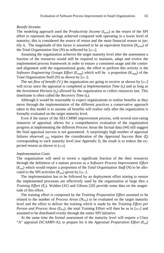
Evaluation of Software Process Improvement in Small Organizations 65
Benefit Streams The modeling approach used the Productivity Income (Iprod) as the return of the SPI effort to represent the savings achieved compared with operating in a lower level of maturity; this is considered the source of return and the main financial reason to jus-tify it. The magnitude of this factor is assumed to be an equivalent fraction (Kprod) of the Total Organization Size (N) as reflected by [[Ec 6].
Assuming the organization achieves the target maturity level after the assessment a fraction of the resources would still be required to maintain, adapt and evolve the implemented process framework in order to ensure a consistent usage and the contin-ued alignment with the organizational goals, the effort to perform this activity is the Software Engineering Groups Effort (Esepg) which will be a proportion (Ksepg) of the Total Organization Staff (N) as shown by [[Ec 5].
The net flow of benefit (Vi) the organization are going to receive as shown by [[Ec7] will occur since the appraisal is completed at Implementation Time (ti) and as long as the Investment Horizon (tp) allowed by the organization to collect resources last. This timeframe is often called the Recovery Time (tr).
Although it would be reasonable to expect organizations to realize benefits as they move through the implementation of the different practices a conservative approach taken in this model is to assume all benefits will realize only after the organization is formally evaluated on the target maturity level.
Even if the nature of the SEI-CMMI improvement process, with several non-rating instances of appraisal, allows for a comprehensive evaluation of the organization progress at implementing the different Process Areas the factual data [44] still suggest the final appraisal success is not guaranteed. A surprisingly high number of appraisal failures observed [36] requires the consideration of the Appraisal Success Rate (ξ) corresponding to each maturity level (see Appendix I), the result is to reduce the ex-pected returns as shown in [[Ec8].
Implementation Costs The organization will need to invest a significant fraction of the their resources through the definition of a mature process as a Software Process Improvement Effort (Espi) which would require a proportion of the Total Organization Staff (N) to be allo-cated to the SPI activities (Kspi) given by [[Ec 1].
The implementation has to be followed by an deployment effort aiming to ensure the implemented processes are effectively used by the organization at large thru a Training Effort (Et). Walden [41] and Gibson [20] provide some data on the magni-tude of this effort.
The training effort is composed by the Training Preparation Effort assumed to be related to the number of Process Areas (NPA) to be evaluated on the target maturity level and the effort to deliver the training which is made by the Training Effort per Person and Process Area (EPA), the total Training Effort will then be as in [[Ec2] and assumed to be distributed evenly through the entire SPI initiative.
At the same time the formal assessment of the maturity level will require a Class “A” appraisal (SCAMPI-A); to prepare for it the Appraisal Preparation Effort (Eap)
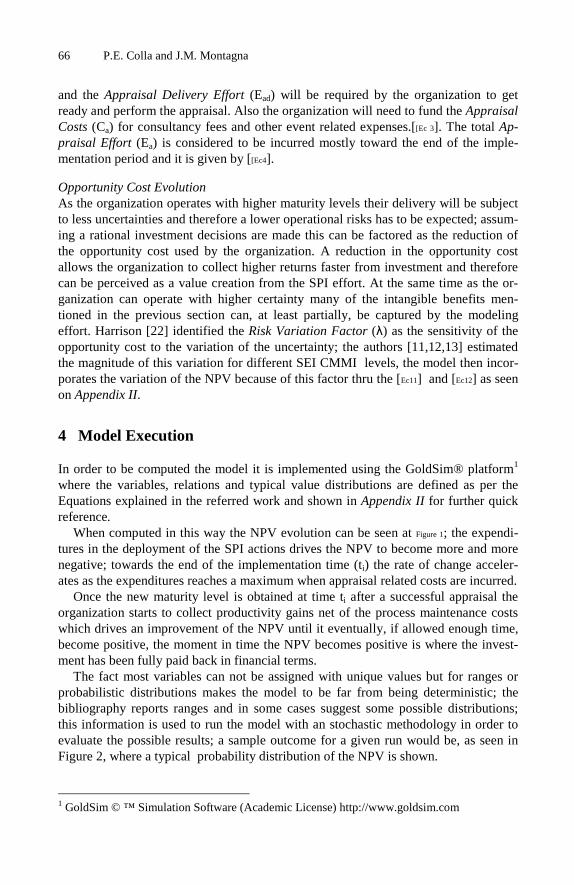
66 P.E. Colla and J.M. Montagna
and the Appraisal Delivery Effort (Ead) will be required by the organization to get ready and perform the appraisal. Also the organization will need to fund the Appraisal Costs (Ca) for consultancy fees and other event related expenses.[[Ec 3]. The total Ap-praisal Effort (Ea) is considered to be incurred mostly toward the end of the imple-mentation period and it is given by [[Ec4].
Opportunity Cost Evolution As the organization operates with higher maturity levels their delivery will be subject to less uncertainties and therefore a lower operational risks has to be expected; assum-ing a rational investment decisions are made this can be factored as the reduction of the opportunity cost used by the organization. A reduction in the opportunity cost allows the organization to collect higher returns faster from investment and therefore can be perceived as a value creation from the SPI effort. At the same time as the or-ganization can operate with higher certainty many of the intangible benefits men-tioned in the previous section can, at least partially, be captured by the modeling effort. Harrison [22] identified the Risk Variation Factor (λ) as the sensitivity of the opportunity cost to the variation of the uncertainty; the authors [11,12,13] estimated the magnitude of this variation for different SEI CMMI levels, the model then incor-porates the variation of the NPV because of this factor thru the [Ec11] and [Ec12] as seen on Appendix II.
4 Model Execution
In order to be computed the model it is implemented using the GoldSim® platform1 where the variables, relations and typical value distributions are defined as per the Equations explained in the referred work and shown in Appendix II for further quick reference.
When computed in this way the NPV evolution can be seen at Figure 1; the expendi-tures in the deployment of the SPI actions drives the NPV to become more and more negative; towards the end of the implementation time (ti) the rate of change acceler-ates as the expenditures reaches a maximum when appraisal related costs are incurred.
Once the new maturity level is obtained at time ti after a successful appraisal the organization starts to collect productivity gains net of the process maintenance costs which drives an improvement of the NPV until it eventually, if allowed enough time, become positive, the moment in time the NPV becomes positive is where the invest-ment has been fully paid back in financial terms.
The fact most variables can not be assigned with unique values but for ranges or probabilistic distributions makes the model to be far from being deterministic; the bibliography reports ranges and in some cases suggest some possible distributions; this information is used to run the model with an stochastic methodology in order to evaluate the possible results; a sample outcome for a given run would be, as seen in Figure 2, where a typical probability distribution of the NPV is shown.
1 GoldSim © ™ Simulation Software (Academic License) http://www.goldsim.com

Evaluation of Software Process Improvement in Small Organizations 67
ti
Fig. 1. NPV evolution with time on a typical SPI simulation run
Fig. 2. NPV Probability distribution for a typical SPI simulation run
By computing the area below the NPV distribution curve for values where a posi-tive result is obtained the probability of a project success can be assessed; each or-ganization could then match their own risk acceptance profile with the investment parameters that yield an acceptable outcome.
Fig. 3. NPV Sensibility to OrganizationalFactors
Fig. 4. Sensitivity of the NPV to variation of Organizational factors
The results of a run with variations in all major parameters for an organization try-ing to acquire CMMI Level 3 is shown in Figure 3; the model highlights increases in NPV as to be sensible mostly to the Organizational Size (N), the Investment Horizon (tp) and to a lesser degree to the Cost per Engineer (CPE), increases in these factors also increases the NPV outcome.
The Appraisal Cost (Ca) and the Opportunity Cost (r ) increases play against the NPV results.
Several scenarios are explored where a typical organization is assumed to have a staff of 25 persons, trying to achieve a CMMI Level 3 maturity in one step, allowing a total investment horizon of 48 months, operating in the offshore environment with a typical cost per engineer of USD 30K per year and expecting an opportunity cost to be effective annual rate of 15%. All scenarios are ran varying one of the parameters through the range of interest while keeping the rest set at the previous values in order to be able to evaluate the variation dynamics.
A summary of the results can be seen at the Figure 4 where the outcome variation is shown as the different model parameters are varied thru the allowed range.
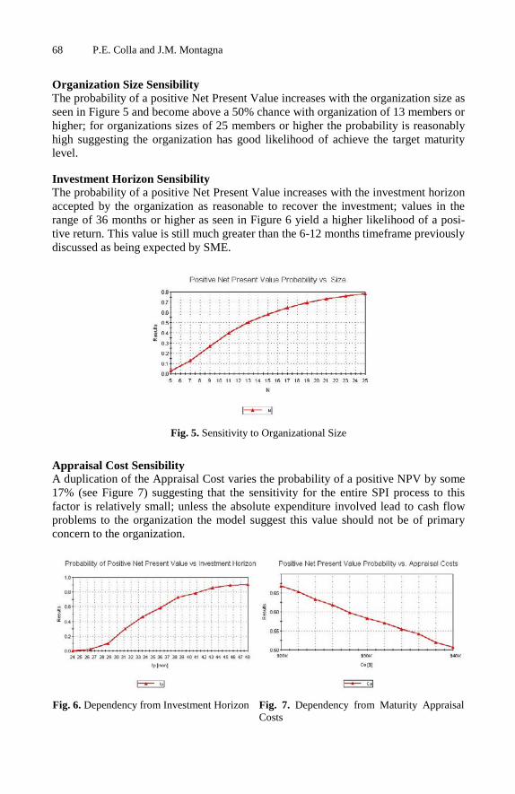
68 P.E. Colla and J.M. Montagna
Organization Size Sensibility The probability of a positive Net Present Value increases with the organization size as seen in Figure 5 and become above a 50% chance with organization of 13 members or higher; for organizations sizes of 25 members or higher the probability is reasonably high suggesting the organization has good likelihood of achieve the target maturity level.
Investment Horizon Sensibility The probability of a positive Net Present Value increases with the investment horizon accepted by the organization as reasonable to recover the investment; values in the range of 36 months or higher as seen in Figure 6 yield a higher likelihood of a posi-tive return. This value is still much greater than the 6-12 months timeframe previously discussed as being expected by SME.
Fig. 5. Sensitivity to Organizational Size
Appraisal Cost Sensibility A duplication of the Appraisal Cost varies the probability of a positive NPV by some 17% (see Figure 7) suggesting that the sensitivity for the entire SPI process to this factor is relatively small; unless the absolute expenditure involved lead to cash flow problems to the organization the model suggest this value should not be of primary concern to the organization.
Fig. 6. Dependency from Investment Horizon Fig. 7. Dependency from Maturity Appraisal Costs

Evaluation of Software Process Improvement in Small Organizations 69
Cost per Engineer Sensibility As the Cost per Engineer increases the probability of a positive NPV increases (see Figure 8); this might be explained by the higher absolute returns obtained after productivity gains to offset faster the fixed costs the SPI process has.
Opportunity Cost Sensibility As the opportunity cost used by the organization increases the likelihood of a positive NPV reduces (see Figure 9); this behavior could be explained after a higher discount rate to require faster or bigger returns to achieve a similar value. This could explain organizations working with higher risk to be less inclined to embrace SPI initiatives.
Fig. 8. Dependency from Cost per Engineer Fig. 9. Dependency from Opportunity Cost
4.1 Limitations and Further Work
Many simplifications has been adopted in the formulation of the model, therefore the results has opportunity for improvement and should be taken as preliminary; the ranges used for the parameters requires further research and confirmation. Additional factors are needed to identify supplemental motivations for organizations with lower Cost per Engineer to embrace SPI efforts often than these with higher costs as the observation seems to infer.
The assumption of similar results using either the Staged or Continuous representation of the SEI CMMI model used in the evaluation framework deserves further validation.
Finally, the model also requires incorporating additional factors such as the intan-gible organization impacts obtained from the SPI effort; a better calibration based on maturity improvement experiences from organizations at the National or Regional level would be an important improvement to perform in order to verify the ranges of results obtained in the bibliography holds.
5 Conclusions
The work suggest the usefulness to enable small organizations facing a SPI invest-ment decision with the ability to use the model as a tool during the decision process; the match between the outcome of the model and results reflected by the bibliography

70 P.E. Colla and J.M. Montagna
are encouraging.. For this organizational target to have the possibility to evaluate the trade-offs between different investment scenarios is one of the benefits of the ap-proach, even considering further work is required to refine the parameters used and the need to capture some additional elements to better explain the empirical evidence.
The usage of the NPV as the main evaluation of the investment seems to add flexi-bility and to better capture the realities of the financial pressure SME have when fac-ing this type of investment.
The preliminary execution of the model suggest that maturity improvements to up to CMMI Level 3, which is typically considered the gate to participate in larger inter-national projects, can be achieved by small organizations with reasonable risk and organizational sacrifice.
A realistic investment horizon seems to be higher than 36 months, the probability of a successful investment with smaller horizons although not zero is considerably smaller. This result strongly suggest the imperative to sponsor smaller companies by providing fiscal, economic and financial support to help hedge the SPI initiatives requiring a larger investment cycle than their business context could allow. The need of placing emphasis in methodologies, best practices and tools to reduce the imple-mentation time as a gate factor for smaller companies to become enabled to operate as high maturity organizations is strongly suggested by the results.
The appraisal cost has a lower impact in the overall investment performance than often assumed by small companies; although in need of being optimized the results suggest this is not necessarily a priority direction to be taken by the industry.
The organizations operating in highly volatile market segments would have objec-tive issues on implementing formal projects unless there are incomes or underlying assets outside the software development projects that gets impacted in their valuation because of the higher certainty. However if these organizations factors the lower un-certainty level they will operate at higher maturity levels that this might create finan-cial incentives to embrace SPI initiatives as well.
References
[1] Bamberger, J.: Essence of the Capability Maturity Model. Computer (June 1997) [2] Brodman, J., Johnson, D.: ROI from Software Process Improvement as Measured in the
US Industry. Software Process Improvement and Practice 1(1), 35–47 [3] Capell, P.: Benefits of Improvement Efforts, Special Report CMU/SEI-2004-SR-010
(September 2004) [4] Cater-Steel, A.P.: Proceedings of Process improvement in four small software companies
Software Engineering Conference. 2001 Australian, August 27-28, pp. 262–272 (2001) [5] Cintra, C.C., Price, R.T.: Experimenting a Requirements Engineering Process based on
RUP reaching CMMI ML3 and considering the use of agile methods practices [6] CESSI Situación actual y desafíos futuros de las PyME de Software y Servicios infor-
máticos (April 2006) ISBN 9872117 [7] Clark, B.K.: Quantifying the effects of process improvement on effort. IEEE Soft-
ware 17(6), 65–70 (2000) [8] Clouse, A., Turner, R.: CMMI Distilled. In: Ahern, D.M. (ed.) Carnegie Mellon – SEI
Series in Software Engineering Conference, COMPSAC (2002) [9] Coleman Dangle, K.C., Larsen, P., Shaw, M., Zelkowitz, M.V.: Software process im-
provement in small organizations: a case study Software. IEEE 22(6), 68–75 (2005)

Evaluation of Software Process Improvement in Small Organizations 71
[10] Coleman, G.: An Empirical Study of Software Processs in Practice. In: Proceedings of the 38th Hawaii ICSS 2005. IEEE, Los Alamitos (2005)
[11] Colla, P.: Marco extendido para la evaluación de iniciativas de mejora en procesos en Ing de SW. In: JIISIC 2006, Puebla, México (2006)
[12] Colla, P., Montagna, M.: Modelado de Mejora de Procesos de Software en Pequeñas Or-ganizaciones. In: JIISIC 2008, Guayaquil, Ecuador (2008)
[13] Colla, P., Montagna, M.: Framework to Evaluate Software Process Improvement in Small Organizations. In: Wang, Q., Pfahl, D., Raffo, D.M. (eds.) ICSP 2008. LNCS, vol. 5007, pp. 36–50. Springer, Heidelberg (2008)
[14] Conradi, H., Fuggetta, A.: Improving Software Process Improvement. IEEE Soft-ware 19(4), 92–99 (2002)
[15] Diaz, M., King, J.: How CMM Impacts Quality, Productivity, Rework, and the Bottom Line. CrossTalk 15(3), 9–14 (2002)
[16] Dyba, T.: An empirical investigation of the key factors for success in software process improvement. IEEE Transactions on Software Engineering 31(5), 410–424 (2005)
[17] El Emam, K., Briand, L.: Cost and Benefits of SPI Int’l SE Research Network. Technical Report ISERN-97-12 (1997)
[18] Galin, D., Avrahami, M.: Are CMM Program Investment Beneficial? In: Analysis of Past Studies – IEEE Software, November/December 2006, pp. 81–87 (2006)
[19] Garcia, S.: Thoughts on applying CMMI on small settings US DoD, Carnegie Mellon (2005) [20] Gibson, D., Goldenson, D., Kost, K.: Performance Results of CMMI based Process Im-
provement, CMU/SEI-2006-TR-004 (2006) [21] Guerrero, F.: Adopting the SW-CMMI in Small IT Organizations – IEEE Software,
pp. 29–35 (January/February 2004) [22] Harrison, W., et al.: Making a business case for software process improvement. Software
Quality Journal 8(2) (November) [23] Hayes, W., Zubrow, D.: Moving On Data and Experience Doing CMM Based Process
Improvement, CMU/SEI-95-TR-008 (1995) [24] Herbsleb, J.D., Goldenson, D.R.: A systematic survey of CMM experience and results.
In: Proceedings of the 18th International Conference on Software Engineering, March 25-30, pp. 323–330 (1996)
[25] Kelly, D.P., Culleton, B.: Process improvement for small organizations. Com-puter 32(10), 41–47 (1999)
[26] Koc, T.: Organizational determinants of innovation capacity in software companies. Computers & Industrial Engineering – Elsevier Science Direct 53, 373–385 (2007)
[27] Laporte, C.Y., April, A.: Applying SWE Standards in Small Settings. IRWPISS, SEI (October 19-20, 2005)
[28] Lawlis, P.K., Flowe, R.M., Thordahl, J.B.: A Correlational Study of the CMM and Soft-ware Development Performance, Crosstalk, pp. 21–25 (September 1995)
[29] Maller, P., et al.: Agilizando el Proceso de Producción de SW en un entorno CMM de Nivel 5 CICYT TIC 01/2705
[30] McFall, D., et al.: Software An evaluation of CMMI process areas for small- to medium-sized software development organizations. Software Process: Improvement and Prac-tice 10 (2), 189–201
[31] McGarry, F., Decker, B.: Attaining Level 5 in CMM process maturity. IEEE Software, 87–96 (November/December 2002)
[32] McLain: Impact of CMM based Software Process Improvement MSIS Thesis, Univ. of Hawaii (2001)
[33] Paulk, M.C.: Extreme Programming from a CMM Perspective. IEEE Software (Novem-ber/December 2001)

72 P.E. Colla and J.M. Montagna
[34] Reitzig, R.W.: Using Rational Software Solutions to Achieve CMMI L2, http://www.therationaledge.com/content
[35] Ruiz de Mendarozqueta, A., et al.: Integración de CMMI, ISO9001 y 6σ en el GSG de Motorota, CESSI-UADE (2007)
[36] SEI-CMU CMMI, http://www.sei.cmu.edu [37] Staples, M., Niazi, M., Jeffery, R., Abrahams, A., Byatt, P., Murphy, R.: An Exploratory
study on why organizations do not adopt CMMI. Journal of Systems and Software 80, 883–895 (2007)
[38] Statz, J., Solon, B.: Benchmarking the ROI for SPI Gartner-Teraquest Report (2002) [39] Tvedt, J.: A modular model for predicting the Impacts of SPI on Development Cycle
Time. Ph.D Thesis dissertation [40] Vates, SPI data supplied thru e-mail by Delgado, J. ([email protected]) [41] Walden, D.: Overview of a Business Case: CMMI Process Improvement. NDIA/SEI
CMMI Presentation, Proceedings 2nd Annual CMMI Technology Conference and User Group (2002)
Appendix. I-Model Parameters
Small Organization Software Process Improvement Modelling
Parameters to achieve an initial formal maturity increase to SEI-CMMI Level 3 thru an SPI process.Parm Name UM Min Med Max Reference
Ksepg % Organization to SEPG %Org 0,8% 0,8% 0,8% [15,20,30,35]Kprod Productivity Gain after SPI %Org 8,0% 22,0% 48,0% [07]Kspi % Organization to SPI %Org 0,8% 0,8% 2,3% [15,20,35]Ca Assessment Costs FTE 8,0 12,0 16,0 Based on $20K-$30K-$40K rangeEae Appraisal Execution Effort FTE 2,7 2,7 6,5 [09,20],10Persx2Wks+3Persx2WksEap Appraisal Preparation Effort FTE 0,6 0,9 1,3 [09,10,20]ti Time to Implement Months 18,0 20,0 32,0 [ 10,15,18,20,35,37]Etp Training Preparation Effort Hrs 12,0 18,0 24,0 [Authors estimation]Epa Training Effort per PA-Person Hrs 4,0 6,0 8,0 [20,41]
λ(∗∗)λ(∗∗)λ(∗∗)λ(∗∗) Npa ξ (*)0,633 21 94%
(*) McGibbon [44] and SEI Assessment Data Base [50] / (**) Colla & Montagna [11,12,13]
CMMI LevelLevel 3
Appendix. II-Modeled Relations and Equations
[Ec 1] NKE spispi ×= [Ec2]
( )[ ] PAtpPAt NENEE ×+×= [Ec 3] ⎟⎠⎞⎜
⎝⎛=
PE
aca C
CE
[Ec4]
caadapa EEEE ++= [Ec 5] NKE sepgsepg ×= [Ec 6] NKI prodprod ×=
[Ec7]
( ) NKKV sepgprodi ×−=
[Ec8]
( ) NKKV sepgprodi ×−×= ξ [Ec 9] ∑= +
=n
tt
t
r
FNPV
0 )1(
[Ec10]
)'1(
)(0
rLn
dtetFNPV t
+=
×= ∫∞
−
δ
δ [Ec 11]
o
o
i
i
μσ
σμλ =
[Ec12]
)(' ff rrrr −×+= λ
An Examination of the Effects of Offshore andOutsourced Development on the Delegation of
Responsibilities to Software Components
Subhajit Datta� and Robert van Engelen
Department of Computer Science and School of Computational Science, Florida StateUniversity, Tallahassee, FL 32306, USA
Abstract. Offshore and outsourced development are the latest facts oflife of professional software building. The easily identifiable advantagesof these trends – such as cost benefits, continuous delivery and sup-port – have already been explored to considerable extent. But how doesoffshore and outsourced development affect the delegation of responsi-bilities to components of a software system? In this paper we investigatethis question by applying the RESP-DIST technique on a set of reallife case studies. Our RESP-DIST technique uses metrics and a linearprogramming based method to recommend the reorganization of com-ponents towards an expedient distribution of responsibilities. The casestudies embody varying degrees of offshore and outsourced development.Results from the case studies lead to some interesting observations onwhether and how offshore and outsourced development influences soft-ware design characteristics.
1 Introduction
The paradigm of offshore and outsourced software development involves distribu-tion of life cycle activities and stakeholder interests across geographical, political,and cultural boundaries. In this paper we will use the phrase dispersed develop-ment to refer to offshore and outsourced software development. We use the term“dispersed” in the sense of distribution of software development resources andconcerns across different directions and wide area.
We seek to examine whether dispersed development has any impact on howresponsibilities are delegated to components in a software system. Towards thisend, we will apply the RESP-DIST technique across a spectrum of softwaredevelopment projects and analyze the results. RESP-DIST is a mechanism toguide RESPonsibility DISTribution in components of a software system suchthat they are best able to collectively deliver the system’s functionality. RESP-DIST uses the metrics Mutation Index [6], Aptitude Index, and ConcordanceIndex [7] and a linear programming (LP) based algorithm [7] to recommend themerging or splitting (as defined in more detail in the next section) of components� Corresponding author.
K. Berkling et al. (Eds.): SEAFOOD 2008, LNBIP 16, pp. 73–89, 2009.c© Springer-Verlag Berlin Heidelberg 2009

74 S. Datta and R. van Engelen
to lead to an even distribution of responsibilities and resilience to requirementchanges. As discussed in a later section, aptitude and concordance are the designcharacteristics which RESP-DIST considers while making its recommendations.By applying RESP-DIST across a set of software projects of varying disper-sion in their development, we expect to discern whether and how offshore andoutsourced development affects the responsibility delegation aspect of softwaredesign.
The remainder of this paper is organized as follows: In the next section wedescribe a model for the software development space which will serve as a foun-dation for applying RESP-DIST. The following section informally reviews somekey concerns of software design, followed by the introduction of the ideas of ap-titude and concordance. We then define the metrics and specify the RESP-DISTtechnique. Subsequently, results from applying RESP-DIST on five real life soft-ware projects are presented. The paper ends with a discussion of related work,open issues and planned future work, and conclusions.
2 A Model for the Software Development Space
The discussion of this paper is based on the following connotations of certaindefinitions:
– A requirement is described as “... a design feature, property, or behaviour ofa system” by Booch, Rumbaugh, and Jacobson [2]. These authors refer tothe statement of a system’s requirements as the assertion of a contract onwhat the system is expected to do; how the system does that is essentiallyfor the designer to decide.
– A component carries out specific responsibilities and interacts with othercomponents through its interfaces to collectively deliver the system’s func-tionality (within acceptable non-functional parameters).
– A collaboration is described in the Unified Modelling Language ReferenceManual, Second Edition as a “... society of cooperating objects assembledto carry out some purpose” [18]. Components collaborate via messages tofulfil their tasks. In this paper “collaboration” and “interaction” will be usedinterchangeably.
– Merging of a particular component will be taken to mean distributing itsresponsibilities to other components in the system and removing the com-ponent from the set of components fulfilling a given set of requirements. Soafter merging, a set of components will be reduced in number, but will befulfilling the same set of requirements as before.
– Splitting of a particular component will be taken to mean distributing someits responsibilities to a new component in the system which will interact onits own with other components to collectively deliver the system’s function-ality. So after splitting, a set of components will be increased in number,but will be fulfilling the same set of requirements as before.
We now present an abstraction of how requirements are fulfilled by components.
An Examination of the Effects of Offshore and Outsourced Development 75
In order to examine the dynamics of software systems through a set of metrics,a model is needed to abstract the essential elements of interest [7].
Let the development space of a software system consist of the set requirementsReq = {R1, ..., Rx} of the system, which are fulfilled by the set of componentsComp = {C1, ..., Cy}.
We take fulfilment to be the satisfaction of any user defined criteria to judgewhether a requirement has been implemented. Fulfilment involves delivering thefunctionality represented by a requirement. A set of mapping exists betweenrequirements and components, we will call these relationships. At one end of arelationship is a requirement, at the other ends are all the components neededto fulfil it. Requirements also mesh with one another – some requirements arelinked to other requirements, as all of them belong to the same system, andcollectively specify the overall scope of the system’s functionality. The linksbetween requirements are referred to as connections. From the designer’s pointof view, of most interest is the interplay of components. To fulfil requirements,components need to collaborate in some useful ways, these are referred to as theinteractions of components.
Based on this model, an important goal of software design can be stated as:Given a set of connected requirements, how to devise a set of interacting compo-nents, such that the requirements and components are able to forge relationshipsthat best deliver the system’s functionality within given constraints?
3 Key Concerns of Software Design
To examine whether and how distributed development affects software design,we discuss the act of design in some detail.
We may say that the conception of a particular system’s design is instantiatedby allocating particular tasks to components and specifying their interaction withother components such that the set of components collectively fulfil the system’srequirements within acceptable non-functional parameters such as performanceetc. In this paper, we focus entirely on the functional aspect of design. How doesone decide on allocating tasks and specifying interactions?
Larman has called the ability to assign responsibilities as a “desert-islandskill” [16], to underline its criticality in the design process. Indeed, decidingwhich component does what remains a key challenge for the software designer.Ideally, each component should perform a specialized task and cooperate withother components to deliver the system’s overall functionality. Whenever a newfunctionality comes to light by analyzing (new or modified) requirements, thedesigner’s instinct is to spawn a new component and assign it the task for de-livering that functionality. This new component acts as something of an initialplaceholder for the new functionality; to be reconsidered later if necessary. Withincreasing accretion of functionality a system usually ends up having a largenumber of fine grained components. Why does the designer instinctively spawna new component for a new functionality, and not just commandeer an existingcomponent to deliver that functionality?

76 S. Datta and R. van Engelen
The instinct perhaps is inspired by one of the lasting credos of effective and el-egant software design: shunning large, bloated units of code (the so called “Swissarmy knife” or “do-it-all” components) in preference to smaller, more coherent,and closely collaborative ones. However, recognizing the inherently iterative na-ture of software design, there is always scope – sometimes a pressing need –for deciding to merge some components while splitting others as developmentproceeds. Merging helps consolidate related responsibilities, thereby decreasingredundant and sometimes costly method calls across components. It is a naturalway to refine components and their interactions after new components had beenspawned (often indiscriminately) earlier to address new functionalities. But of-ten, splitting a component is an useful way to isolate the implementation of apiece of functionality that is undergoing frequent modifications due to changingrequirements. Such isolation helps insulate other components and their interac-tions from the effects of requirements that change often.
Thus the design of a software system in terms of its components – their in-dividual responsibilities and collective interaction – matures iteratively throughmerging and splitting. Over such repeated reorganizations, design objectives ofexpediently fulfilling requirements as well as being resilient to some of theirchanges, are progressively met. But how does one decide on which componentto merge and which to split? This is one the most important concerns of thesoftware designer, usually addressed through experience or intuition or nameless“gut-feelings”. RESP-DIST brings in a degree of discipline and sensitivity intosuch decisions – the technique seeks to complement the best of designers’ judg-ment, and constrict their worst. RESP-DIST leverages certain characteristics ofa software system’s design which we discuss next.
4 Delegation of Responsibilities in Software Design
Design is usually an overloaded word, even in the software development context.There are no universally accepted features of good design, while symptoms ofbad design are easy to discern. In the model for the software development spacepresented in an earlier section, we highlighted one aspect of the design problem.Based on this aspect, we introduce aptitude and concordance [7] as two keycharacteristics of design.
Every software component exists to perform specific tasks, which may becalled its responsibilities. Software design canons recommend that each compo-nent be entrusted with one primary responsibility. In practice, components mayend up being given more than one task, but it is important to try and ensurethey have one primary responsibility. Whether components have one or more re-sponsibilities, they can not perform their tasks entirely by themselves, withoutany interaction with other components. This is specially true for the so-calledbusiness objects – components containing the business logic of an application.The extent to which a component has to interact with other components to fulfilits core functionality is an important consideration. If a component’s responsi-bilities are strongly focused on a particular line of functionality, its interactions

An Examination of the Effects of Offshore and Outsourced Development 77
with other components can be expected to be less disparate. We take aptitude todenote the quality of a component that reflects how coherent its responsibilitiesare. Intuitively, the Aptitude Index measures the extent to which a component(one among a set fulfilling a system’s requirements) is coherent in terms of thevarious tasks it is expected to perform.
The Aptitude Index [7] seeks to measure how coherent a component is in termsof its responsibilities.
To each component Cm of Comp, we attach the following properties [5]. Aproperty is a set of zero, one or more components.
– Core - α(m)– Non-core - β(m)– Adjunct - γ(m)
α(m) represents the set of component(s) required to fulfil the primary respon-sibility of the component Cm. As already noted, sound design principles suggestthe component itself should be in charge of its main function. Thus, most oftenα(m) = {Cm}.
β(m) represents the set of component(s) required to fulfil the secondary re-sponsibilities of the component Cm. Such tasks may include utilities for accessinga database, date or currency calculations, logging, exception handling etc.
γ(m) represents the component(s) that guide any conditional behaviour of thecomponent Cm. For example, for a component which calculates interest rates forbank customers with the proviso that rates may vary according to a customertype (“gold”, “silver” etc.), an Adjunct would be the set of components that helpdetermine a customer’s type.
Definition 1. The Aptitude Index AI(m) for a component Cm is a relativemeasure of how much Cm depends on the interaction with other components fordelivering its core functionality. It is the ratio of the number of components inα(m) to the sum of the number of components in α(m), β(m), and γ(m).
AI(m) =|α(m)|
|α(m)| + |β(m)| + |γ(m)| (1)
As reflected upon earlier, the essence of software design lies in the collabora-tion of components to collectively deliver a system’s functionality within givenconstraints. While it is important to consider the responsibility of individualcomponents, it is also imperative that inter-component interaction be clearlyunderstood. Software components need to work together in a spirit of harmonyif they have to fulfil requirements through the best utilization of resources. Let ustake concordance to denote such cooperation amongst components. How do werecognize such cooperation? It is manifested in the ways components share thedifferent tasks associated with fulfilling a requirement. Some of the symptoms ofless than desirable cooperation are replication of functionality – different compo-nents doing the same task for different contexts, components not honouring theirinterfaces (with other components) in the tasks they perform, one component

78 S. Datta and R. van Engelen
trying to do everything by itself etc. The idea of concordance is an antithesisto all such undesirable characteristics – it is the quality which delegates thefunctionality of a system across its set of components in a way such that it isevenly distributed, and each task goes to the component most well positioned tocarry it out. Intuitively, the metric Concordance Index [7] measures the extentto which a component is concordant in relation to its peer components in thesystem.
Definition 2. The Concordance Index CI(m) for a component Cm is a relativemeasure of the level of concordance between the requirements being fulfilled byCm and those being fulfilled by other components of the same system.
The Requirement Set RS(m) for a component Cm is the set of requirementsthat need Cm for their fulfilment [7].
For a set of components Comp = {C1,C2,...,Cn,...,Cy−1,Cy} let,W = RS(1) ∪ RS(2) ∪ ... ∪ RS(y − 1) ∪ RS(y)
For a component Cm (1 ≤ m ≤ y), let us define,X(m) = (RS(1) ∩ RS(m)) ∪ ... ∪ ((RS(m − 1) ∩ RS(m)) ∪((RS(m) ∩ (RS(m + 1)) ∪ ... ∪ ((RS(m) ∩ (RS(y))
Thus X(m) denotes the set of requirements that are not only being fulfilledby Cm but also by some other component(s).
Expressed as a ratio, the Concordance Index CI(m) for component Cm is:
CI(m) =|X(m)||W | (2)
How do the ideas of aptitude and concordance relate to cohesion and cou-pling? Cohesion is variously defined as “... software property that binds togetherthe various statements and other smaller modules comprising the module” [8]and “... attribute of a software unit or module that refers to the relatedness ofmodule components” [1]. (In the latter quote, “component” has been used inthe sense of part of a whole, rather than a unit of software as is its usual mean-ing in this paper.) Thus cohesion is predominantly an intra-component idea –pointing to some feature of a module that closely relates its constituents to oneanother. But as discussed above, concordance carries the notion of concord orharmony, signifying the spirit of successful collaboration amongst componentstowards collective fulfilment of a system’s requirements. Concordance is an inter-component idea; the concordance of a component can only be seen in the lightof its interaction with other components.
Coupling has been defined as “... a measure of the interdependence betweentwo software modules. It is an intermodule property” [8]. Thus coupling does nottake into account the reasons for the so called “interdependence” – that modules(or components) need to cooperate with one another as they must together fulfila set of connected requirements. Aptitude is an intra-component idea, whichreflects on a component’s need to rely on other components to fulfil its primaryresponsibility/responsibilities.

An Examination of the Effects of Offshore and Outsourced Development 79
Cohesion and coupling are legacy ideas from the time when software systemswere predominantly monolithic. In the age of distributed systems, successful soft-ware is built by carefully regulating the interaction of components, each of whichare entrusted with clearly defined responsibilities. The perspectives of aptitude,and concordance complement cohesion and coupling in helping recognize, isolate,and guide design choices that will lead to the development of usable, reliable, andevolvable software systems.
As mentioned earlier, one of the main drivers of design change is changingrequirements. Let us take the term mutation to mean any change in a particularrequirement that would require a modification in one or more components ful-filling either one or a combination of the display, processing, or storage aspectsof the requirement. In keeping with the principle of separation of concerns, itis usually taken to be good design practice to assign specific components to de-liver each of the display, processing, and storage aspects. Components (or setsof components) delegated to fulfil the display, processing, and storage aspectsof requirement(s) map to the stereotypes of analysis classes: boundary, control,and entity [13]. Intuitively, the metric Mutation Index [6] measures the extentto which a requirement has changed from one iteration to another, in terms ofits display, processing, and storage aspects.
For a system let Req = {R1, R2, ..., Rm..., Rx} denote the set of requirements.Between iterations Iz−1 and Iz each requirement is annotated with its MutationV alue; a combination of the symbols D, P and S. The symbols stand for:
D ≡ Display(1)P ≡ Processing(3)S ≡ Storage(2)
The parenthesized numbers denote the Weights attached to each symbol. Thecombination of more than one symbol signifies the addition of their respectiveWeights, thus:
PD ≡ DP ≡ 1 + 3 = 4SD ≡ DS ≡ 1 + 2 = 3SP ≡ PS ≡ 3 + 2 = 5SPD ≡ ... ≡ DPS ≡ 1 + 3 + 2 = 6
The Weight assigned to each category of components – Display, Processingand Storage – is a relative measure of their complexities. (Complexity here refersto how intense the design, implementation, and maintenance of a componentare in terms of development effort.) Processing components usually embodyapplication logic and are most design and implementation intensive. Storagecomponents encapsulate the access and updating of application data stores; theirlevel of complexity is usually lower than that of the Processing components buthigher than Display ones. Accordingly, Display, Processing and Storage havebeen assigned the Weights 1, 3 and 2 respectively. Exact values of Weightsmay be varied from one project to another; the essential idea is to introduce aquantitative differentiation between the types of components.
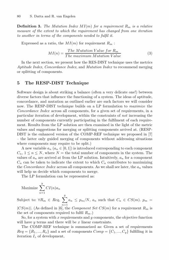
80 S. Datta and R. van Engelen
Definition 3. The Mutation Index MI(m) for a requirement Rm is a relativemeasure of the extent to which the requirement has changed from one iterationto another in terms of the components needed to fulfil it.
Expressed as a ratio, the MI(m) for requirement Rm :
MI(n) =The Mutation V alue for Rm
The maximum Mutation V alue(3)
In the next section, we present how the RES-DIST technique uses the metricsAptitude Index, Concordance Index, and Mutation Index to recommend mergingor splitting of components.
5 The RESP-DIST Technique
Software design is about striking a balance (often a very delicate one!) betweendiverse factors that influence the functioning of a system. The ideas of aptitude,concordance, and mutation as outlined earlier are such factors we will considernow. The RESP-DIST technique builds on a LP formulation to maximize theConcordance Index across all components, for a given set of requirements, in aparticular iteration of development, within the constraints of not increasing thenumber of components currently participating in the fulfilment of each require-ment. Results from the LP solution are then examined in the light of the metricvalues and suggestions for merging or splitting components arrived at. (RESP-DIST is the enhanced version of the COMP-REF technique we proposed in [7]– the latter only guided merging of components without addressing situationswhere components may require to be split.)
A new variable an (an ∈ [0, 1]) is introduced corresponding to each componentCn, 1 ≤ n ≤ N , where N = the total number of components in the system. Thevalues of an are arrived at from the LP solution. Intuitively, an for a componentCn can be taken to indicate the extent to which Cn contributes to maximizingthe Concordance Index across all components. As we shall see later, the an valueswill help us decide which components to merge.
The LP formulation can be represented as:
Maximizey∑
n=1
CI(n)an
Subject to: ∀Rm ∈ Req,y∑
n=1
an ≤ pm/N , an such that Cn ∈ CS(m). pm =
|CS(m)|. (As defined in [6], the Component Set CS(m) for a requirement Rm isthe set of components required to fulfil Rm.)
So, for a system with x requirements and y components, the objective functionwill have y terms and there will be x linear constraints.
The COMP-REF technique is summarized as: Given a set of requirementsReq = {R1, ..., Rx} and a set of components Comp = {C1, ..., Cy} fulfilling it initeration Iz of development,

An Examination of the Effects of Offshore and Outsourced Development 81
– STEP 0: Review Req and Comp for new or modified requirements and/orcomponents compared to previous iteration.
– STEP 1: Calculate the Aptitude Index for each component.– STEP 2: Calculate the Requirement Set for each component.– STEP 3: Calculate the Concordance Index for each component.– STEP 4: Formulate the objective function and the set of linear constraints.– STEP 5: Solve the LP formulation for the values of an.– STEP 6: For each component Cn, check:
• Condition 6.1: an has a low value compared to that of other components?(If yes, implies Cn is not contributing significantly to maximizing theconcordance across the components.)
• Condition 6.2: AI(n) has a low value compared to that of other compo-nents? (If yes, implies Cn has to rely heavily on other components fordelivering its core functionality.)
– STEP 7: If both conditions 6.1 and 6.2 hold TRUE, proceed to next step,else GO TO STEP 10
– STEP 8: For Cn, check:• Condition 8.1: Upon merging Cn with other components, in the resulting
set Comp of q components (say), CI(q) �= 0 for all q? (If yes, impliesresulting set of q components has more than one component).
– STEP 9: If condition 8.1 is TRUE, Cn is a candidate for being merged.– STEP 10: Let Comp′ denote the resulting set of components after above
steps have been performed. For each component Cn′ in Comp′:• 10.1 Calculate the average MI(m) across all requirements in RS(n′).
Let us call this MI(m).• 10.2 Identify the requirement Rm with the highest MI(m) in RS(n′).
Let us call this MI(m)highest.– STEP 11: For each component Cn′ , check:
• Condition 11.1: AI(n′) has a high value compared to that of other com-ponents? (If yes, implies component relies relatively less on other com-ponents for carrying out its primary responsibilities.)
• Condition 11.2: CI(n′) has a low value compared to that of other compo-nents? (If yes, implies component collaborates relatively less with othercomponents for collectively delivering the system’s functionality.)
– STEP 12: If both conditions 11.1 and 11.2 hold TRUE for component Cn′ , itis tending to be monolithic, doing all its activities by itself and collaboratingless with other components. Thus the Cn′ is a candidate for being split;proceed to next step, else GO TO STEP 14.
– STEP 13: Repeat STEPs 10 to 12 for all components of Comp′. For thecomponent for which conditions 11.1 and 11.2 hold TRUE, choose the oneswith the highest MI(m) and split each into two components, one with therequirement corresponding to the respective MI(m)highest and the otherwith remaining requirements (if any) of the respective Requirement Set. If thecomponent was fulfilling only one requirement, the responsibility for fulfillingthe requirement’s functionality may now be delegated to two components.
– STEP 14: Wait for the next iteration of development.
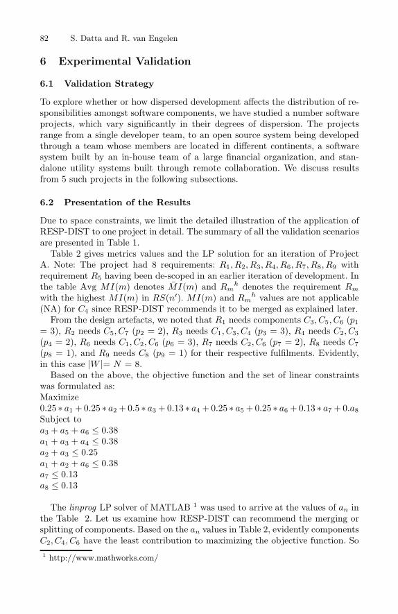
82 S. Datta and R. van Engelen
6 Experimental Validation
6.1 Validation Strategy
To explore whether or how dispersed development affects the distribution of re-sponsibilities amongst software components, we have studied a number softwareprojects, which vary significantly in their degrees of dispersion. The projectsrange from a single developer team, to an open source system being developedthrough a team whose members are located in different continents, a softwaresystem built by an in-house team of a large financial organization, and stan-dalone utility systems built through remote collaboration. We discuss resultsfrom 5 such projects in the following subsections.
6.2 Presentation of the Results
Due to space constraints, we limit the detailed illustration of the application ofRESP-DIST to one project in detail. The summary of all the validation scenariosare presented in Table 1.
Table 2 gives metrics values and the LP solution for an iteration of ProjectA. Note: The project had 8 requirements: R1, R2, R3, R4, R6, R7, R8, R9 withrequirement R5 having been de-scoped in an earlier iteration of development. Inthe table Avg MI(m) denotes MI(m) and Rm
h denotes the requirement Rm
with the highest MI(m) in RS(n′). MI(m) and Rmh values are not applicable
(NA) for C4 since RESP-DIST recommends it to be merged as explained later.From the design artefacts, we noted that R1 needs components C3, C5, C6 (p1
= 3), R2 needs C5, C7 (p2 = 2), R3 needs C1, C3, C4 (p3 = 3), R4 needs C2, C3(p4 = 2), R6 needs C1, C2, C6 (p6 = 3), R7 needs C2, C6 (p7 = 2), R8 needs C7(p8 = 1), and R9 needs C8 (p9 = 1) for their respective fulfilments. Evidently,in this case |W |= N = 8.
Based on the above, the objective function and the set of linear constraintswas formulated as:Maximize0.25 ∗ a1 + 0.25 ∗ a2 + 0.5 ∗ a3 + 0.13 ∗ a4 + 0.25 ∗ a5 + 0.25 ∗ a6 + 0.13 ∗ a7 + 0.a8Subject toa3 + a5 + a6 ≤ 0.38a1 + a3 + a4 ≤ 0.38a2 + a3 ≤ 0.25a1 + a2 + a6 ≤ 0.38a7 ≤ 0.13a8 ≤ 0.13
The linprog LP solver of MATLAB 1 was used to arrive at the values of an inthe Table 2. Let us examine how RESP-DIST can recommend the merging orsplitting of components. Based on the an values in Table 2, evidently componentsC2, C4, C6 have the least contribution to maximizing the objective function. So1 http://www.mathworks.com/

An Examination of the Effects of Offshore and Outsourced Development 83
Table 1. Experimental Validation: A Snapshot
System Scope and Technology Salient Features Findings
Project A A 5 member team dispersed de-velopment project – with 1 mem-ber interfacing with the customerand other members located in an-other continent – to build an auto-mated metrics driven tool to guidethe software development life cycleactivities. The system was releasedas an open source product.
8 requirements, 8 compo-nents; system developedusing Java.
RESP-DIST recommended1 component be merged, 1component be split. Detailedcalculations are given laterin this section.
Project B A 2 member team dispersed de-velopment project – with virtualcollaboration between the teammembers – to build a stan-dalone utility to execute stan-dard text classification algorithmsagainst bodies of text, allowingfor different algorithm implementa-tions to be added, configured andused. Among other uses, a spam de-tection application can use this util-ity to try out different detection al-gorithms.
8 requirements, 7 compo-nents; system developedusing Java. The systemwas selected from a com-petition and integratedin a broader applicationframework. The develop-ers had financial incen-tives.
RESP-DIST did not recom-mended merging of any com-ponents, but 2 componentscould be split.
Project C A 2 member team dispersed de-velopment project – with virtualcollaboration between the teammembers – to define, read, andbuild an object representation of anXML driven business work flow, al-lowing manipulation and executionof the workflow through a rich APIinterface for the easy addition ofworkflow operations.
11 requirements, 13 com-ponents; system devel-oped using the .NETplatform. The systemwas selected from a com-petition and integratedin a broader applicationframework. The develop-ers had financial incen-tives.
RESP-DIST recommendedmerging of 3 components,and splitting of 2 compo-nents.
Project D A 6 member team dispersed devel-opment project – with the devel-opers and customers spread acrosstwo cities of the same country – todevelop an email response manage-ment system for a very large finan-cial company. The system allows foremails from users across six prod-uct segments to be processed andplaced in designated queues for cus-tomer associates to respond, anddeliver the responded back to theusers within prescribed time limits.
5 requirements; 10components; systemdeveloped using Java,Netscape ApplicationServer (NAS), and Lo-tus Notes. Developersworked on the systemas a part of their jobresponsibilities. Thesystem has been runningfor several years, witharound 100,000 users.
RESP-DIST recommendedmerging of 1 component,and splitting of 4 compo-nents.
Project E A 1 member team project to builda Web based banking applicationwhich allowed users to check theirprofile and account information,send messages to the bank; andadministrators to manage user ac-counts, transactions, and messages.
12 requirements, 28components; system de-veloped according to theModel-View-Controller(MVC) architecturalpattern with J2EE anda Cloudscape database.
Result from applying RESP-DIST was inconclusive.

84 S. Datta and R. van Engelen
Table 2. Details for Project A
Cm RS(n) Avg MI(m) Rmh α(n) β(n) γ(n) AI(n) |X(n)| CI(n) an
C1 R3, R6 0 - C1 C3, C5, C7 - 0.25 2 0.25 0.21C2 R4, R7 0 - C2 C3, C7 C6 0.2 2 0.25 0.08C3 R1, R3, R4, R6 0.17 R1 C3 C1, C5, C7 - 0.25 4 0.5 0.17C4 R3 NA NA C4 C3, C5 - 0.33 1 0.13 0C5 R1, R2 0.5 R1 C5 C1 - 0.5 2 0.25 0.12C6 R1, R7 0.34 R1 C6 C2, C7 - 0.33 2 0.25 0.09C7 R2, R8 0.5 R8 C7 - - 1 1 0.13 0.13C8 R9 1 R9 C8 - - 1 0 0 0.105
the tasks performed by these components may be delegated to other compo-nents. However, as mandated by RESP-DIST, another factor needs be takeninto account before merging. How self-sufficient are the components that aresought to be merged? We thus turn to the AI(n) values for the components inTable 2. We notice, AI(2) = 0.2, AI(4) = 0.33, AI(6) = 0.33. Out of these, C4 iscontributing nothing to maximizing concordance (a4 = 0), and its AI(n) valueis not very high either (0.33 on a scale of 1). So a4 can be merged with othercomponents. Now we check for the highest MI(m), which corresponds to C8. C8also has a high AI(8) value of 1 and a low CI(8) value of 0. Thus C8 is tryingto do all its task by itself, without collaborating with other components – thisis indeed a candidate for splitting. The Rm with the highest MI(m) in RS(8)is R9 – in fact R9 is the only requirement in this particular case fulfilled by C8.So RESP-DIST recommends C8 be split into two components, each fulfilling apart of R9. Relating the recommendations to the actual components and require-ments, we find that C4 is an utility component in charge of carrying out somenumerical calculations; whose tasks can very well be re-assigned to componentswhich contain the business logic behind the calculations. On the other hand, R9is a requirement for extracting data from design artefacts. This is certainly arequirement of very large sweep and one likely to change frequently, as the dataneeds of the users change. Thus it is justifiable to have R9 fulfilled by more thanone component, to be able to better localize the effects of potential changes inthis requirement. Figure 1 summarizes these discussions, indicating merging forC4 and splitting for C8.
6.3 Interpretation of the Results
We examined the factors of dispersed development that could potentially affectthe outcome of applying the RESP-DIST technique on these projects.
The Agile Manifesto lists the principles behind agile software development– methodologies being increasingly adopted for delivering quality software inlarge and small projects in the industry, including those utilizing dispersed de-velopment [15]. The Manifesto mentions the following among a set of credos:“The most efficient and effective method of conveying information to and withina development team is face-to-face conversation”, and “Business people and

An Examination of the Effects of Offshore and Outsourced Development 85
Fig. 1. Values of an, AI(n), MI(m) and CI(n) corresponding to the componentsC1,...,C8 for Project A. The RESP-DIST technique suggests merging for C4 and split-ting for C8 – detailed discussion in section 6.3.
developers must work together daily throughout the project” 2. Evidently, thevery nature of dispersed development precludes this kind of interaction betweenthose who commission and use a software system (these two groups may be iden-tical or different, they are often clubbed together as customers) and those whodevelop it, that is, the developers.
We identify the key drivers of the effects of dispersed development on softwaredesign as locational asynchrony (LA), and perceptional asynchrony (PA). LAand PA may exist between customers and developers or within the developmentteam. Locational asynchrony arises from factors like differences in geographyand time zones. An example of LA would be the difficulty in explaining a simplearchitectural block diagram over email or telephone conversation, which can beeasily accomplished with a white board and markers in a room of people (some-thing similar to the consequence of distance highlighted in [10]). Perceptionalasynchrony tends to be more subtle, and is caused by the complex interplay ofstakeholder interests that dispersed development essentially entails. For example,in dispersed development scenarios, developers who have no direct interactionwith the customer often find it hard to visualize the relevance of the modulethey are working on in the overall business context of the application – this isa manifestation of PA. With reference to Table 1, Project A has high LA butmoderate PA; Projects B and C have moderate LA but high PA; Project D hasmoderate LA and low PA, while Project E has low LA and PA.
Apparently, there is no clear trend in the recommendations from RESP-DISTby way of merging or splitting components in Table 1 that suggests locationalasynchrony or perceptional asynchrony have noticeable impact on how responsi-bilities are delegated. However, Projects B and C have a higher requirement tocomponent ratio compared to others. This not only influences the way RESP-DIST runs on these projects but also indicates that moderate to high percep-tional asynchrony may lead to a more defensive analysis of requirements – being
2 http://agilemanifesto.org/principles.html
86 S. Datta and R. van Engelen
relatively unsure of the customers’ intents developers are more comfortable deal-ing with finer grained requirements. The inconclusiveness of RESP-DIST’s rec-ommendation for Project E is also interesting. Project E’s scenario represents byfar the most controlled conditions of development amongst all the projects stud-ied. It was developed by a single developer – a software engineer with more than5+ years of industry experience – who had the mandate to refine the respon-sibility delegations amongst components repeatedly until the system deliveredas expected. So naturally, RESP-DIST did not have much scope for suggestingmerging or splitting of components. Also, compared to other projects Project Ehad a relatively unrelated set of requirements and relatively high number compo-nents with uniformly distributed responsibilities. Thus from the results relatedto Project A to D, RESP-DIST is seen to work best on a small set of closelyrelated requirements and components. For a system with many requirementsand components, it can be applied separately on subsystems that constitute thewhole system.
7 Related Work
Freeman’s paper, Automating Software Design, is one of the earliest expositionsof the ideas and issues relating to design automation [9]. Karimi et al. [14] reporttheir experiences with the implementation of an automated software design as-sistant tool. Ciupke presents a tool based technique for analyzing legacy code todetect design problems [3]. Jackson’s Alloy Analyzer tool employs “automatedreasoning techniques that treat a software design problem as a giant puzzle tobe solved” [12].
Collaboration platforms for offshore software development are evaluated in[17]. Shami et al. simulate dispersed development scenarios [20] and a researchagenda for this new way of software building is presented in [19].
Herbsleb and Grinter in their papers [10], [11] have taken a more social viewof distributed software development. In terms of Conway’s Law – organizationswhich design systems are constrained to produce designs which are copies of thecommunication structures of these organizations [4] – Herbsleb and Grinter seekto establish the importance of the match between how software componentscollaborate and how the members of the teams that develop the software com-ponents collaborate.
8 Open Issues and Future Work
From the interpretation of the case study results, it is apparent the recommen-dations of merging or splitting components from applying the RESP-DIST tech-nique are not significantly influenced by the degree of dispersion in a project’sdevelopment scenario in terms of their location or perceptional asynchronies.However, factors other than locational or perceptional asynchrony may also

An Examination of the Effects of Offshore and Outsourced Development 87
stand to affect the delegation of responsibilities in some dispersed developmentprojects. In future work we plan to develop mechanisms to investigate suchsituations.
The case studies we presented in this paper range from 1 member to 6 memberdevelopment teams, 5 to 12 requirements, and 7 to 28 components. Evidently,these are small to medium projects. We expect the execution of the RESP-DIST technique to scale smoothly to larger systems – more requirements andcomponents will only mean more terms and linear constraints, which can behandled easily by automated LP solvers. However, the ramifications of largersystems on the dynamics of dispersed development is something which can onlybe understood by further case studies, some of which are ongoing.
We also plan to fine-tune the RESP-DIST technique by studying more projectsacross a diverse range of technology and functional area. The applicability oftechniques like RESP-DIST are highly enhanced with tool support. We are work-ing on an automated tool that will take in design artefacts and/or code as input,apply RESP-DIST and suggest the merging or splitting of relevant component.
9 Conclusion
In this paper, we examined whether and how offshore and outsourced develop-ment influences the delegation of responsibilities to software components. Weapplied the RESP-DIST technique – which uses the metrics Aptitude Index,Mutation Index and Dependency Index, and a linear programming based algo-rithm to recommend reorganization of the responsibilities of a software system’scomponents through merging or splitting – on a range of software projects thatembody varying degrees of offshore and outsourced development. It appears thattwo aspects of offshore and outsourced development – what we call as locationalasynchrony and perceptional asynchrony – do not have significant effect on howresponsibilities are distributed in the projects studied. However these factors mayinfluence the way requirements are abstracted by the development team, whichin turn can influences the application of the RESP-DIST technique. We planto extend our work in refining the RESP-DIST technique by conducting furthercase studies. We are also working on developing a software tool to automate theapplication of the RESP-DIST technique.
Acknowledgements
We wish to thank Sean Campion, Project Manager at TopCoder Inc.; Dr Ani-mikh Sen, Executive Director of Strategic Planning and Program Development atBoca Raton Community Hospital; Kshitiz Goel, Pooja Mantri, Prerna Gandhi,and Sidharth Malhotra, graduate students at Symbiosis Center for InformationTechnology for their help with acquiring and analyzing some of the case studyinformation. We would also like to thank the anonymous reviewers for theirhelpful comments and criticism.

88 S. Datta and R. van Engelen
References
1. Bieman, J.M., Ott, L.M.: Measuring functional cohesion. IEEE Trans. Softw.Eng. 20(8), 644–657 (1994)
2. Booch, G., Rumbaugh, J., Jacobson, I.: The Unified Modeling Language UserGuide, 2nd edn. Addison-Wesley, Reading (2005)
3. Ciupke, O.: Automatic detection of design problems in object-oriented reengineer-ing. In: TOOLS 1999: Proceedings of the Technology of Object-Oriented Languagesand Systems, Washington, DC, USA, p. 18. IEEE Computer Society, Los Alamitos(1999)
4. Conway, M.: How do committees invent? Datamation Journal, 28–31 (April 1968)5. Datta, S.: Agility measurement index: a metric for the crossroads of software devel-
opment methodologies. In: ACM-SE 44: Proceedings of the 44th annual southeastregional conference, pp. 271–273. ACM Press, New York (2006)
6. Datta, S., van Engelen, R.: Effects of changing requirements: a tracking mechanismfor the analysis workflow. In: SAC 2006: Proceedings of the 2006 ACM symposiumon Applied computing, pp. 1739–1744. ACM Press, New York (2007)
7. Datta, S., van Engelen, R.: Comp-ref: A technique to guide the delegation of re-sponsibilities to components in software systems. In: Fiadeiro, J.L., Inverardi, P.(eds.) FASE 2008. LNCS, vol. 4961, pp. 332–346. Springer, Heidelberg (2008)
8. Dhama, H.: Quantitative models of cohesion and coupling in software. In: Selectedpapers of the sixth annual Oregon workshop on Software metrics, pp. 65–74. Else-vier Science Inc., Amsterdam (1995)
9. Freeman, P.: Automating software design. In: DAC 1973: Proceedings of the 10thworkshop on Design automation, Piscataway, NJ, USA, pp. 62–67. IEEE Press,Los Alamitos (1973)
10. Herbsleb, J.D., Grinter, R.E.: Architectures, coordination, and distance: Conway’slaw and beyond. IEEE Softw. 16(5), 63–70 (1999)
11. Herbsleb, J.D., Grinter, R.E.: Splitting the organization and integrating the code:Conway’s law revisited. In: ICSE 1999: Proceedings of the 21st international con-ference on Software engineering, pp. 85–95. IEEE Computer Society Press, LosAlamitos (1999)
12. Jackson, D.: Software Abstractions: Logic, Language and Analysis. MIT Press,Cambridge (2006)
13. Jacobson, I., Booch, G., Rumbaugh, J.: The Unified Software Development Process.Addison-Wesley, Reading (1999)
14. Karimi, J., Konsynski, B.R.: An automated software design assistant. IEEE Trans.Softw. Eng. 14(2), 194–210 (1988)
15. Kornstadt, A., Sauer, J.: Mastering dual-shore development - the tools and ma-terials approach adapted to agile offshoring. In: Meyer, B., Joseph, M. (eds.)SEAFOOD 2007. LNCS, vol. 4716, pp. 83–95. Springer, Heidelberg (2007)
16. Larman, C.: Applying UML and Patterns. Prentice Hall, Englewood Cliffs(1997)
17. Rodriguez, F., Geisser, M., Berkling, K., Hildenbrand, T.: Evaluating collabora-tion platforms for offshore software development scenarios. In: Meyer, B., Joseph,M. (eds.) SEAFOOD 2007. LNCS, vol. 4716, pp. 96–108. Springer, Heidelberg(2007)

An Examination of the Effects of Offshore and Outsourced Development 89
18. Rumbaugh, J., Jacobson, I., Booch, G.: The Unified Modeling Language ReferenceManual, 2nd edn. Addison-Wesley, Reading (2005)
19. Sengupta, B., Chandra, S., Sinha, V.: A research agenda for distributed softwaredevelopment. In: ICSE 2006: Proceeding of the 28th international conference onSoftware engineering, pp. 731–740. ACM, New York (2006)
20. Shami, N.S., Bos, N., Wright, Z., Hoch, S., Kuan, K.Y., Olson, J., Olson, G.: Anexperimental simulation of multi-site software development. In: CASCON 2004:Proceedings of the 2004 conference of the Centre for Advanced Studies on Collab-orative research, pp. 255–266. IBM Press (2004)

K. Berkling et al. (Eds.): SEAFOOD 2008, LNBIP 16, pp. 90–106, 2009. © Springer-Verlag Berlin Heidelberg 2009
Students as Partners and Students as Mentors: An Educational Model for Quality Assurance
in Global Software Development
Olly Gotel1, Vidya Kulkarni2, Christelle Scharff1, and Longchrea Neak3
1 Pace University, Seidenberg School of Computer Science and Information Systems, New York, NY, USA
{ogotel,cscharff}@pace.edu 2 University of Delhi, Computer Science Department, Delhi, India
[email protected] 3 Institute of Technology of Cambodia, Computer Science Department,
Phnom Penh, Cambodia [email protected]
Abstract. Since 2005, Pace University in New York City has been collaborat-ing with the Institute of Technology of Cambodia and the University of Delhi in India to bring students together to work on globally distributed software devel-opment projects. Over this period, we have been exploring models through which graduates and undergraduates from the three countries can work together, with pedagogical value to all sides. In 2007, we converged on using Software Quality Assurance as a focal point around which to establish a partnering and mentoring relationship. We included seven graduate students, as internal men-tors and external auditors, to help assure the quality of what was to be a single distributed project involving twenty-seven students from across the three global locations. To focus further on quality, requirements and testing activities were emphasized. The motivation, logistics and experiences from this project are re-ported in this paper, and lessons of wider applicability are provided.
Keywords: Auditing, Global Software Development, Mentoring, Require-ments, Software Engineering Education, Software Quality Assurance, Testing.
1 Introduction
It has become common to set up a Global Software Development (GSD) experience for students as part of their Software Engineering training in an undergraduate Com-puter Science degree [5, 12, 16]. There are many outstanding research challenges with global settings that such educational experiences can contribute towards understand-ing [13]. The initial time a student project of this nature is undertaken, there is a steep learning curve for those involved, and a number of constraints and logistical steps can be overlooked as assumptions are made about locales and educational practices [10]. The first year is about discovering a model for working that fits all parties, spanning time zones, place and cultures. Such experiences can help provide for a smoother
Students as Partners and Students as Mentors 91
second year, in turn allowing for the exploration of particular Software Engineering concerns, practices or working arrangements. For example, outsourcing the develop-ment of a well-defined software component and then integrating it into an evolving software system [8].
Having undertaken GSD projects for two years, we made the observation that it becomes common to focus time and effort on the logistics of the project, meaning that the timely completion of some form of software product by the end of the project be-comes more central than the quality of what is produced. It can be expedient for busy instructors, as well as rewarding for overwhelmed students, to see something demon-strable, whatever the quality. Engineered for a snapshot in time to achieve a grade, little consideration gets given to actual deployment and longevity.
Quality has been defined in numerous ways in the literature. Two of the more pre-vailing definitions are those of Crosby and Juran: “conformance to requirements” [4] and “fitness for use” [15], as reflected in the ISO 9000 family of standards for quality management systems [14]. In the context of software development, quality is generally measured in terms of the specified requirements that are satisfied. According to the pro-ponents of Software Process Improvement, it has long been argued that one of the most effective ways to achieve software quality is to adopt and follow a suitably mature soft-ware process [1]. Software Quality Assurance (SQA) is, at a fundamental level, all those process-related activities that are undertaken in the pursuit of achieving quality. SQA involves requirements, design and code reviews, requirements and defect tracking, test-ing (both validation and verification), and more. Such activities are undertaken to con-trol the process and its products to help ensure problems are addressed early on.
Given that undergraduate Software Engineering is typically a student’s first expo-sure to software development processes, practices and principles, concepts are fre-quently taught in the classroom just as they need to be applied to the project at hand. This affords little opportunity for students to step back and examine their work from the broader perspective that is required for SQA. It also prevents them from having the requisite oversight at the onset to plan for SQA. As a consequence, SQA is an activity that we have found difficult to prepare our undergraduate students for, par-ticularly since it can be perceived to get in the way of the ‘real’ task of developing demonstrable code.
For our third year of collaboration, we deemed it essential to focus on injecting a concern for quality into the GSD project. We decided to engage Software Design and Engineering graduate students in both internal and external SQA capacities. The in-ternal role was to help undergraduates focus on the quality practices related to re-quirements and testing, and the external role was to monitor and provide feedback on the end-to-end process and its deliverables. Moreover, by getting the students to work together on a single project to be deployed, we expected the need for quality to be recognized.
This paper describes the third year project experience. In Section 2, we provide the background and objectives for this work, also summarizing the institutional collabora-tion to date. We give details of the project arrangements in Section 3. In Sections 4 through 6, we describe the emphasis that was placed on requirements and testing, mentoring and auditing. Our findings are presented in Section 7 and wider lessons are drawn with respect to the role of partners and mentors in software development en-deavors in Section 8. We finish the paper with conclusions and a synopsis of our on-going work.

92 O. Gotel et al.
2 Background and Objectives
Undergraduate Computer Science students at Pace University in the US have been collaborating with undergraduate Computer Science students from the Institute of Technology of Cambodia (ITC) for three years. This collaboration takes the form of an annual GSD project. Within these projects, the Cambodian students act as clients and testers, while the US students act as developers. This permits the students to ex-perience a reversal of traditional offshore outsourcing roles. Over the past two years, this arrangement has also involved graduate Computer Science students from the University of Delhi in India playing the role of offshore third-party service providers. Throughout the three years, we have been exploring the processes and communication models that are useful to employ in this context, along with the tools that can support them [8, 9, 10].
This current paper describes the spring 2007 GSD project where students from the three countries worked together on a single project with the intention of developing a software system to be deployed into operation within Cambodia. The focus was on scaling up and so on the true need for both local and global integration, along with an emphasis on requirements and testing for quality. This project incorporated a com-petitive bidding process for an outsourced component of the work to future maximize quality efforts, and made use of US graduate students who were specializing in Soft-ware Engineering to help assure the quality of the distributed global project. The web-site of the project is available at http://atlantis.seidenberg.pace.edu/wiki/gsd2007.
2.1 Research and Teaching Objectives
The two specific objectives for this study were: (1) To provide a ‘real’ project that would require students to take software through to production quality. This was to en-able students to learn about ‘whole-life’ software development and the ‘total cost of ownership’. In addition, we wanted to start to reinforce longevity in our institutional relationships and so provide the potential for future student teams to play a role main-taining a legacy system. (2) To investigate how to incorporate students with specialist skills into the educational model so as to: (a) relieve the instructors of some of the day-to-day work spent on managing the quality of work; and (b) address questions and pro-vide timely advice to the undergraduate students outside of the classroom setting.
3 Project Context
This section provides information about the participating institutions, the students, the project and the team set-up. It also clarifies the logistics and technologies involved.
3.1 Collaborators and Courses
The Institute of Technology of Cambodia (ITC) (http://www.itc.edu.kh): The Soft-ware Engineering course for fourth year Computer Science undergraduate students.
Pace University (http://www.pace.edu): The capstone undergraduate Software Engi-neering course taken by Computer Science students. It also involved students from the

Students as Partners and Students as Mentors 93
Masters Program in Software Design and Engineering who were concurrently taking a Software Reliability and Quality Assurance course. Approximately half of the gradu-ate students had a professional career in the New York City area software industry.
The University of Delhi (http://www.du.ac.in): The second year Master of Computer Applications students studying a Database Applications course.
3.2 Student Roles and Responsibilities
Cambodian Students are Clients and Testers. Their responsibilities were to work with the US undergraduate students to describe the software they wanted to be built and the context in which it was to operate. They had to review and give feedback on the requirements, design and testing documents, test the software system and submit bug reports. At the end of the semester, the Cambodian students had to assess the software system developed by the US students (with Indian sub-contracting) and to compare this with the software system developed solely by the Indian students (see Indian roles later).
US Undergraduate Students are Developers and Lead Contractors. Their responsibili-ties were to elicit the requirements and produce an agreed requirements specification, propose design options that subcontract part of the design and development, prepare a Request For Proposal (RFP), receive and evaluate responses to the RFP, implement the software system and test it, while handling requirements changes, integration of the outsourced component and managing the end-to-end contract. At the end of the semes-ter, they had to deliver the software system to their clients.
US Graduate Students are Internal SQA Mentors and External SQA Auditors. The mentoring role was designed to help ensure that the US undergraduate students were doing what they needed to do to assure a quality result, and so graduate students were charged to help them perfect the techniques and practices introduced in the classroom, especially with respect to writing requirements, tracing them through to design and code, document versioning, change management techniques, integration, and test plan-ning and execution. Mentors were to act as internal eyes for the project and to issue periodic reports to the instructors (as partners). The auditing responsibility was to re-view the artifacts delivered by the undergraduates and the processes used to deliver them. This involved checking for conformance to documented processes, verifying whether the specified requirements were satisfied in design and code, and determining the quality of the testing activities. Auditors were to act as the quality gatekeepers on the project and deliver periodic audit reports to the instructors and to the SQA mentors (as partners).
Indian Students are Third-party Suppliers. Their responsibilities were to submit separate bids for the outsourced component and then to collaborate on the selected bid. In addition, and outside the initial intent of the project, the Indian students de-cided to develop their own variant of the software from the requirements specification in competition with the US undergraduates. This effort was undertaken with visibility of the requirements on a shared wiki, but without direct communication with the clients.

94 O. Gotel et al.
3.3 Project MultiLIB Description
The internal library of the Department of Computer Science at ITC provides many re-sources to its students, such as books in English and French, student internship reports, CD-ROMs, DVDs and e-books. To date, the library management tasks and other related transactions have not been computerized. The departmental secretary, acting as the li-brarian and using an Excel spreadsheet, currently manages the records of all the re-sources. In order to make the students aware of the available resources there is a paper list pasted in front of the office of the department. Not only is this unwieldy as the re-sources increase, it is never clear what is currently available for loan and what is not. The objective of this project, called MultiLIB, was to develop a multi-purpose web-based library management system to be used by students, professors and the librarian.
The development effort was to be partitioned in the following way:
• Librarian / Administrator Side – To focus on that part of MultiLIB that will be used by the librarian and administrator for managing the library policies, all the resources, the accounts in the system and all the issue / return transactions.
• Guest / Student / Professor Side – To focus on that part of MultiLIB that will be used by guests, students and professors to view the information on the available and new resources, to reserve, rate and recommend the resources, and to consult the status of their personal accounts (for students and professors only).
• Innovation Side – To focus on that part of MultiLIB that will be used by students to view the electronic resources, such as e-books, audio and video. Moreover, this side was intended to be forward looking and so to consider future innovative features.
The innovation side of MultiLIB was not intended for the initial release, so the other two sides needed to be engineered to account for future anticipated extensions.
3.4 Teams
Students were to work in global sub-teams on separate components of a larger project that would demand integration. In addition, the project was to incorporate a competi-tive bidding process for a well-defined component of the work in an attempt to en-hance quality through design diversity. Software Engineering and Design graduate students were recruited as ‘specialists’ and given loose guidelines to mentor and audit the US undergraduates. In summary, the global extended teams are detailed in Table 1.
Table 1. Team Set-up on Project MultiLIB
Sub-team Roles Location Additional Members Librarian Side 5 Clients ITC, Cambodia 4 Developers Pace Undergraduates, NYC 1 Mentor Pace Graduate and Industry Professional, NYC 2 Auditors Pace Graduates, NYC Student Side 4 Clients ITC, Cambodia 4 Developers Pace Undergraduates, NYC 1 Mentor Pace Graduate and Industry Professional, NYC 2 Auditors Pace Graduates, New York
1 Integration Mentor - Pace Graduate and Industry Professional, NYC 6 Sub-contractors (Developers) –University of Delhi Graduates, India
Innovation Side 4 Clients ITC, Cambodia

Students as Partners and Students as Mentors 95
3.5 Logistics: Process, Technology and Communication Tools
The project milestones were organized around one week for initialization and team bonding, five weeks for requirements, three weeks for design, three weeks for coding / construction and two weeks for testing. The Software Engineering process model that was used was a loose waterfall model with iteration and feedback, for instructor control and visibility. The technologies that were used are discussed in a companion paper [9].
4 Requirements and Testing for SQA
Central to any definition of ‘quality’ is the term ‘requirements’. Our Software Engi-neering courses therefore pay attention to techniques that can be used for gathering stakeholder requirements, particularly across distances, and for communicating this understanding across languages and cultures. Requirements are also the basis for test-ing, without which assessments as to the attained quality cannot be determined. A sec-ond emphasis in our courses is therefore on bringing testing activities forward and so more consciously to work toward their satisfaction. This section describes the efforts undertaken in these two areas to stress a discipline for SQA in the MultiLIB project.
4.1 Requirements Process
At the beginning of the project, the US undergraduate students received a two-page description of MultiLIB and a PowerPoint presentation describing its context and fea-tures, as prepared by the Cambodian instructor. They also received samples of the current Excel spreadsheets used by the librarian to deal with library loans and the management of available resources. Students used these documents as a starting point to determine the requirements. They then refined and added requirements gathered through questionnaires sent to the Cambodian students, followed-up with chat ses-sions, and gathered during a face-to-face session with the Cambodian instructor when he visited the US. Diversity in the channels for gathering requirements were important due to the difficulties students had to understand each other, mainly due to language and terminology (English is the third language of the Cambodian students, after Khmer and French). The requirements were specified using a simple template for consistency that articulated the users, the source of the requirements, priority and how to test the requirement. Validation took place via chat sessions using a checklist.
4.2 Testing Process
Most of the testing that took place was system-level and user acceptance testing, as these activities were emphasized before delivery. The US developers prepared a test-ing document for the Cambodian testing team. This contained all the data necessary to access the software system, along with details of sample books stored within the data-base, the list of implemented requirements with the name of the developer responsi-ble, and the testing scenarios used for manual testing of each requirement. The Indian students prepared a sixteen-page user manual for their software system. This included descriptions of the functionality included, along with the unique features provided,
96 O. Gotel et al.
and also user-ids and passwords for testing. The same set of Cambodian students per-formed system testing and user acceptance testing on this version.
4.3 Bug Reporting and Issue Tracking
The Cambodian clients and US developers used the Issue Tracker facility of java.net to report, fix and manage bugs throughout the project. During the testing phase, each issue submitted by the Cambodian testing team was assigned to the US team member in charge and broadcast to the whole team. Java.net was used by the client mostly to report bugs in the software rather than by the developers to eliminate them.
The Indian students did not use a specific tool for their testing. Each and every page in their developed web-based system was separately tested with test data during the development and then the complete system was tested with the test data. When the Cambodian students tested the whole system, they sent emails to one of the Indian students who manually undertook issue tracking and resolution.
At the end of the semester, the Cambodian students provided one testing summary of the software developed by the US team and by the Indian team, comprising the number of issues identified in each, along with a description of the main issues dis-covered. The Cambodian students used this as a basis to compare the two delivered software systems.
5 Mentoring for SQA
Mentoring is: “The offering of advice, information, or guidance by a person with use-ful experience, skills, or expertise for another individual’s personal and professional development” [11]. A ‘mentor’ is: “A wise and trusted counselor or teacher” [6]. In this project, US graduate students who were specializing in Software Engineering and working in the software industry were tasked with mentoring local US undergraduates.
The role of internal SQA mentor was established to provide a point of contact and support structure for the two undergraduate sub-teams based in New York. The two components of MultiLIB (the student side and the librarian side) were to be developed independently by the sub-teams, but needed to fit together. Accordingly, one graduate student was assigned to each sub-team, while a third was assigned to an integration role.
The intention of the mentoring role was not for graduates to do the work for the undergraduate students, but to help ensure that the students were doing what they needed to do to assure a quality result. Also, to help the students perfect some of the techniques introduced in class, especially with respect to writing requirements, tracing them through to design and code, document versioning and change management, and test planning. Specifically, they were to work directly with the project leaders of the sub-teams to help them with their management tasks and in resolving some of the typical difficulties faced with team working. The mentors were to act as internal eyes for the project.
The mentors were tasked with preparing an SQA plan describing what they were proposing to do. This included details of the activities, processes, methods, standards, etc. they considered relevant, along with a timeline and communication strategy to

Students as Partners and Students as Mentors 97
engage with the undergraduates. Each mentor was to maintain an individual log of what they did with the students and why, along with the outcome of any advice pro-vided or sessions they ran. The mentoring team produced a final report summarizing their experience, lessons and recommendations for future projects.
6 Auditing for SQA
Auditing is an important and regulatory activity undertaken in many domains (e.g., financial audit). It is an activity undertaken both internally by organizations and externally by independent third parties. It is not solely about compliance, checking that an organization is doing what it is supposed to be doing, and so offering reassurance to customers, but also about alerting to any required intervention before it is too late.
The role of external SQA auditor on this project was to take a more objective look at the quality of the US undergraduate students’ contributions to the global project. Since the undergraduates were to be preparing documents (in draft and final form) at certain key dates, the auditors’ responsibilities were to review everything that the stu-dents were doing (both the products they were delivering and the processes they were using to deliver them) and to provide a periodic audit report. This was to involve checking for conformance to documented processes, verifying whether the specified requirements had been satisfied in design and code, and determining the quality of the testing. They were encouraged to do most of their work face-to-face. The audit report was to be provided to the instructors (as their clients and partners) and to the SQA mentors (as their partners). The latter was to enable their peers to deliver feedback and to determine what activities they may need to focus on going forwards. The audi-tors were to work together as the quality gatekeepers for the project, and they were required to maintain their objectivity.
The auditors were tasked with preparing an SQA audit plan describing what they were proposing to do. This was to include details of all the activities they were to un-dertake, how they proposed to undertake them, along with a timeline and forms / tem-plates they considered useful. Each auditor was to keep an individual log of what they did with the undergraduate students and why. The team was to provide a final report on the quality of the completed work (process and product) and to justify their con-clusions.
7 Findings
In this section, we summarize the key observations with respect to an emphasis on quality-related activities on our project. These relate to the quality that was obtained, the impact of a focus on requirements and testing, and the value of mentoring and auditing.
7.1 Overall Quality Level
The final version of the requirements specification included thirty-four functional requirements and eleven non-functional requirements. The US students implemented eighteen functional and three non-functional requirements in the delivered software
98 O. Gotel et al.
system. In contrast, the Indian students implemented twenty-eight functional require-ments and four non-functional requirements. Based on java.net Issue Tracker, thirty-nine issues were submitted by the Cambodian students for the US software system and forty-seven issues were submitted for the Indian software system, half of these issues being defects and half of them being requests for enhancement. The Cambo-dian students rejected both of the software systems that were developed for them.
While the Indian version of the software implemented more features (i.e., satisfied more of the requirements), it was also delivered with more outstanding issues. How-ever, it was considered to have a “more attractive user interface” and to be more se-cure, which led to perceptions of higher quality, and hence the Cambodian students preferred the Indian version. Note that the Indian students had no contact with the clients and were working directly from the requirements specification that was devel-oped and continuously evolved by the US students. This is an interesting finding as it provides some evidence that a well-written requirements document can communicate across many dimensions of distance. The Indian students reported that the main prob-lem they faced, other than a lack of time to complete the work, was that many times they did not get replies to their queries from the US students. They understood that this was because the US students could not get their queries resolved by the Cambo-dian students in a timely fashion also. Time delays got perpetuated along the commu-nications chain.
The main issues with the US students’ software were due to time constraints, so they only implemented a very simplified version of the software to speed up imple-mentation and deliver something of value. They eased their task by making assump-tions, such as a book can have only one author and cannot contain subtitles. Moreover, features that were specified as high priority by the clients did not gain sufficient atten-tion, which frustrated the clients. The US students spent lots of their time improving the quality of the requirements and design documents, and keeping them up to date on the wiki, diligence and effort that the Indian students benefited from. Focusing on re-quirements meant that development and testing time for their own implementation was squeezed.
It should also be noted that the Indian students regarded the development of this software as a professional challenge -- they were competing with the US students and dedicated all their time to the development and continued to do so for up to two months after their classes had ended, whereas the US students focused more on the practices they were learning and their application, and ceased activities when the se-mester ended.
7.2 Requirements and Testing Focus
All students were new to the type of tool used in this project for bug reporting and is-sue tracking. The Cambodian students found java.net a difficult tool to use, but very powerful in terms of describing issues in detail. The US and Indian students both rec-ognized the importance of the tool, especially for facilitating communication between the development and testing teams, though the Indian students preferred a non-tool-oriented approach. A recurrent problem was that the bugs reported by the clients were not always perceived as bugs by the developers. In some cases, the identified bugs in the Indian software were rectified, but in most cases the Indian students replied that the

Students as Partners and Students as Mentors 99
issue raised was not a part of the requirements document. They often felt that the cli-ents were asking for new features after the testing activity and raising these requests as issues. The perception of the Indian students was that the clients only realized they should have asked for additional features when they started testing the software.
The Cambodian students were not satisfied with the usability of either the US or the Indian software. For instance, they found that the web interface was not easy to navigate and not uniform from one page to the next. Trying to defend the software they developed, both the US and Indian students felt that the Cambodian students gave “too much attention on little things instead of the main functionalities”. By ‘little things’ they meant usability issues, one of the issues known to contribute to software failure [7, 17]. Other common problems, cited in [3], were directly experienced by students and are generally attributed to communication challenges. Working with a client made students eventually realize the need to satisfy non-functional require-ments like usability.
7.3 Mentoring Activities
The mentors ran bi-weekly and then weekly meetings with the US undergraduates. These meetings were mostly conducted face-to-face with the sub-team project leaders, the maximum attendance only ever being nine out of a possible eleven US students. These meetings focused on the following activities:
• Requirements Engineering – Validation of the template used to gather require-ments and suggestions as to additional information to capture to facilitate trace-ability; checking the techniques used for gathering and validating requirements; ensuring that traceability is established; examining the version control method used; and suggesting methods to help ease the identification of changes made to requirements.
• Project Scheduling – Assistance in developing a project plan for the entire pro-ject; ensuring the milestones are aggressive enough to meet deadlines; and inter-nally auditing the execution of the project plan to verify if milestones are achieved.
• Technical Approach – Suggesting design standards and guidelines to follow; ini-tiating brainstorming sessions to develop designs; and preparing for integration.
• Construction – Suggesting test-driven development techniques and tools; verify-ing that the software component version control strategy; and encouraging the team to include a maintenance and deployment strategy for their product early on.
In the words of the mentors: “At one meeting we went over the requirements docu-ments for each team, page by page, and offered suggestions.”
The mentors reported that the technical ability of the undergraduates was always lagging behind where it needed to be to complete the project. By adding more interac-tion into the equation, via mentors and auditors, this had the perception of slowing them down further. As one graduate reported: “By the time we evaluated the problem and made suggestions, too much time had gone by and they had had to figure it out without our help.” This is a direct consequence of the frequent need to teach Software Engineering theory concurrently with its practice for the first time.
100 O. Gotel et al.
While they made themselves available to the undergraduates, the mentors felt that the undergraduates didn’t really always know they needed help or were too busy to seek it. They reported, in retrospect, that the most valuable thing they offered may have been simply: “giving the undergraduates a pat on the back when needed, a gen-tle push towards the goal, and a vision of where to go and what to do to achieve it”. Also, sharing experiences from their various workplaces about what can go wrong if they don’t do some of the things they have been asked to do on the project was con-sidered valuable. From the undergraduate perspective they reported that: “it was nice to have these mentors there just in case everything decided to fall apart.”
7.4 Auditing Activities
The two audit teams created and shared a template to run face-to-face interviews with the undergraduates. The audit template implemented a ‘traffic light’ system where a list of criteria were provided and the result of the audit would be categorized as either red (non-compliant), green (compliant) or amber (issues). Each team reviewed milestone documents and undertook four audits. Typical checklist items in the audits included:
• Team and Communications – Are they organized? Do they communicate well with the Cambodian team? Is there a defined purpose and scope for the project? Does the team know its roles? Any foreseeable problems? Solutions?
• Requirements – Is there a template or standard being used? Is it being properly implemented? Is there a unique identifier for each requirement? Are the require-ments prioritized? Do they list constraints and assumptions? Have they walked through their requirements document? What validation techniques were used? Are the requirements acceptable to the client? Is there any versioning control?
• Design, Code and Test – Does the design correlate with the requirements? Is the code following a standard? Is the code well commented? Is there a bug report / tracking procedure implemented? Do the tests make sense? Do they adequately test the requirements? Are they being carried out?
Given the fact that it took time for the auditors to receive and then review the pro-ject artifacts, schedule interviews with undergraduates and subsequently write their audit reports, it would be a number of weeks before the feedback got back to the in-structors, mentors and students. This was not as effective as it should have been. Au-diting, without the ability to receive and respond to the audit feedback in a timely fashion, is of little constructive value. This is another consequence of the reduced cycle times of student projects. However, some issues were identified, allowing miti-gating actions to be taken, and open issues could be tracked. The auditors provided a valuable set of external eyes.
From a technical perspective, the auditors uncovered unrealistic prioritizations, as-sumptions and missing test cases in the requirements when reviewing the documents. From a social perspective, they noticed when the teams were fragmenting and losing spirit. Sample technical issues from their audit reports include: (i) “NFR5 doesn’t have a test case, we have recommended that they look at it and try to do something with it.” (ii) “The code isn’t really following a template but it seems to be relatively well organized. We did try to emphasize the need for better commenting of the code

Students as Partners and Students as Mentors 101
because there is difficulty in understanding what it does without it.” Sample commu-nication issues include: (i) “There is a problem stemming from an idea that the Student’s software won’t be implemented, either through miscommunication or a mis-understanding this has lead to a huge blow to the motivation/morale of the team as a whole. The project has become a chore to them because its relevance has been de-stroyed.” (ii) “The team seems to have improved, the communication between mem-bers and between international teams has become more consistent, although there is a bit of lag in terms of some paper updates.”
Despite some of the issues with timeliness in the implementation of this model, show-stopping crises were avoided and the other students participating in the project were keen to have their work audited also. Notably, and in the spirit of learning and improvement, the Indian students requested an audit. The auditors themselves gained a valuable learning experience: “The GSD project gave me a chance to approach a process that was rarely shined upon in my undergraduate studies. It gave me a chance to develop a procedure that I believe is very successful in garnering informa-tion from my auditees.”
8 Lessons and Recommendations
The original objectives were to find a way to emphasize the need for quality in a stu-dent GSD project and to seek a way to share responsibilities for accomplishing this. We attempted to achieve the former by instigating a real project to be integrated, de-ployed and maintained and to achieve the latter by setting up a network of mentors and auditors.
We believe we developed an innovative working relationship between instructors, graduates and undergraduates in this project, and satisfied the second objective through a model that we are now refining in our latest GSD work. Although the soft-ware system was not completed and not accepted, we do not believe this negates the benefits that all parties obtained from mentoring and auditing. The lack of client ac-ceptance of MultiLIB was not due to a failure in the concept per se, but more an issue associated with its implementation for the first time. This outcome does mean that we did not fully succeed in realizing the first objective. While quality was improved with respect to requirements and designs, in the opinion of all the instructors when com-paring with previous efforts, this was not the case for the final software system. The project schedule was perhaps too heavily biased towards the upstream software de-velopment activities. Our lessons and recommendations for others are hence provided below.
8.1 Focus on the Partnerships in GSD
A ‘partner’ is defined as: “One that is united or associated with another or others in an activity or a sphere of common interest” [6]. In this study, students from across the globe and across degree levels partnered with each other, and graduate students also partnered with instructors. These are rare partnerships to foster in student-based pro-ject settings, but are models of working that we recommend others to explore.

102 O. Gotel et al.
8.1.1 Establish Student Partnerships Undergraduate and graduate students partnered to work on one project. The advan-tages of this model of education include:
• Reciprocal Learning – Each party in the global project had distinct backgrounds, skills and perspectives, allowing them to learn from each other. For example, the US undergraduates learned about Cambodia and its technology situation. Con-versely, the US students exchanged information on the role and use of wiki tech-nology in American society and in professional business settings, a technology that was new to the Cambodians. In addition, the US undergraduates and gradu-ates got to know each other, the former gaining a support network and benefiting from experience-based explanations that contextualized theory, and the latter be-coming empowered from the ability to practice Software Engineering activities at a different level.
• Accountability – Both the US and Indian students felt accountable to the Cambo-dians for delivering a working software system. This motivated their efforts. Real Projects for Real Clients Courses (RPRCC) is a growing movement in academic settings and we suggest that GSD projects are the ultimate way for students to experience these [2]. When rumors spread that the software would not be used (see Section 7.4), this had devastating effects on morale until remedied. Creating a self-styled competitive situation motivated the Indian students further.
Some outstanding issues were identified and need to be addressed with such models:
• Contribution Disparity – Working in a team setting can present more difficulties than working with new processes and technologies. It can often result in some students carrying the burden of the work, individuals overriding team decisions and in loosing friends. Given the work demanded on a global project, all these is-sues are more prominent and were all experienced. While equally experienced in industrial settings, student project leaders have little option to make firing and hiring decisions. Perhaps a closer simulation of industrial settings needs to be ex-plored as a way to remedy this, else individual assessment structures need more attention.
• Global Team Unity – Due to the project set-up, the Indian students never felt part of the global team; they were service providers. This led to a competitive streak and the request to be audited. Where the requirements custodians are in competi-tion with those developing the requirements this makes for an imbalance in the incentive for cooperation. While no negative repercussions were experienced dur-ing the project, this is an area to pay attention to. Competing student teams need to be on a level-playing field, just as one would expect in industrial competitive arrangements.
• Coordination – Shared awareness and the exchange of project artifacts were fa-cilitated through the use of a wiki. However, when the wiki was not updated in a timely manner, or when students became too focused on development to look at the wiki, coordination problems resulted. For instance, it was not until the Indian students were about to release their software for testing that they realized that the requirements document they were working to was out of date. Expecting belea-guered students to poll for important change information is unrealistic. As in an

Students as Partners and Students as Mentors 103
industrial setting, such information needs to be pushed to relevant parties and change control processes need to be established and institutionalized.
8.1.2 Establish Partnerships between Instructors and Students Pace University graduate students partnered with instructors. This peer relationship is recommended as a model for education for the following reasons:
• Delegation and Oversight – Broader visibility of the project, facilitated by re-ports from mentors and auditors, provided a different perspective on the work. Managing a global project is often the ‘hidden’ cost in GSD arrangements and something that can easily detract instructors from venturing down this educa-tional path. We suggest that a carefully constructed partnership model, engaging students who are ready to put some of their skills into practice, is one way to al-leviate this burden.
• Timely Intervention – The mentors helped to uncover technical training needs and team management skills that were required but not supplied in the curricu-lum, and were able to directly address many such day-to-day issues. The auditors provided wider alerts to systemic project issues, giving the opportunity to inter-vene where necessary, including issues that influence team spirit and jeopardize the project.
• Improved Quality of the Requirements and Design – With the intense focus on the writing and reviewing of the requirements, and of the participation of the mentors in helping the undergraduates to architect the system and the auditors in providing feedback, the quality of both the requirements and design improved. The graduates helped to convey the importance of quality to student outside of the classroom.
Some issues still deserve careful attention when instituting such an arrangement: • Insufficient Audit Planning and Expectations – The audit planning started too
late in the project to allow for adequate review cycles, as time was needed to pre-pare audit checklists. This meant that audits were often undertaken too late. Au-dits need to be planned early, sufficient time needs to be factored in for reporting and responding, and contingency is necessary to accommodate delays. Even though graduate students were undertaking this role, most had never played such a role before and needed more guidance than expected to extrapolate from their own project experiences to create checklists. It would help to share such check-lists with others.
• Inadequate Cycle Time for Feedback – The feedback to instructors, and so to the undergraduate students, was not always timely. Working by day, taking classes by night and meeting in class once a week does not put the project at the top of a graduate’s priority list. Every lost week is critical. Such issues could be addressed by building the students’ contributions more significantly into the grading scheme.
• Sustaining a Quality Focus – The quality of the US software system was not as high as had been expected following on from their requirements and design work. While the Indian students were able to leverage this improvement in quality, the US students ran out of time and energy. A far greater proportion of the time
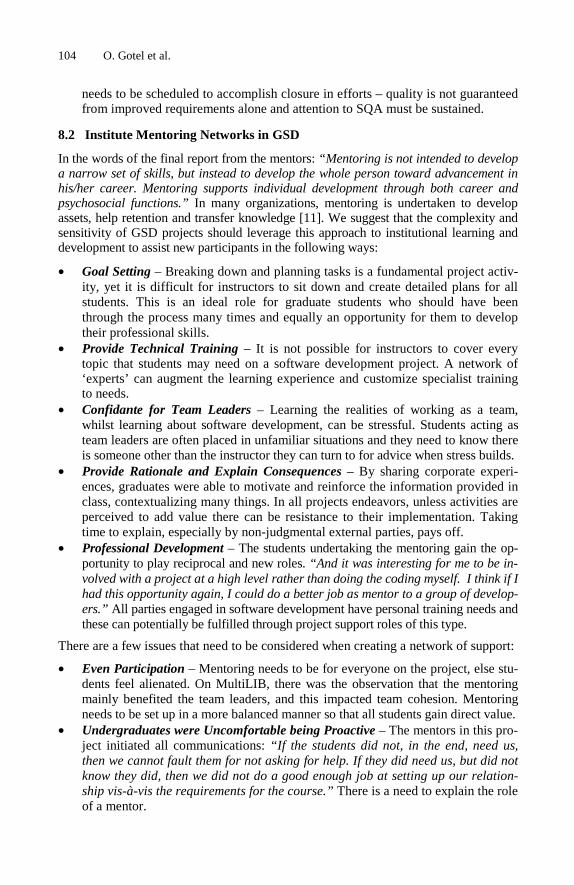
104 O. Gotel et al.
needs to be scheduled to accomplish closure in efforts – quality is not guaranteed from improved requirements alone and attention to SQA must be sustained.
8.2 Institute Mentoring Networks in GSD
In the words of the final report from the mentors: “Mentoring is not intended to develop a narrow set of skills, but instead to develop the whole person toward advancement in his/her career. Mentoring supports individual development through both career and psychosocial functions.” In many organizations, mentoring is undertaken to develop assets, help retention and transfer knowledge [11]. We suggest that the complexity and sensitivity of GSD projects should leverage this approach to institutional learning and development to assist new participants in the following ways:
• Goal Setting – Breaking down and planning tasks is a fundamental project activ-ity, yet it is difficult for instructors to sit down and create detailed plans for all students. This is an ideal role for graduate students who should have been through the process many times and equally an opportunity for them to develop their professional skills.
• Provide Technical Training – It is not possible for instructors to cover every topic that students may need on a software development project. A network of ‘experts’ can augment the learning experience and customize specialist training to needs.
• Confidante for Team Leaders – Learning the realities of working as a team, whilst learning about software development, can be stressful. Students acting as team leaders are often placed in unfamiliar situations and they need to know there is someone other than the instructor they can turn to for advice when stress builds.
• Provide Rationale and Explain Consequences – By sharing corporate experi-ences, graduates were able to motivate and reinforce the information provided in class, contextualizing many things. In all projects endeavors, unless activities are perceived to add value there can be resistance to their implementation. Taking time to explain, especially by non-judgmental external parties, pays off.
• Professional Development – The students undertaking the mentoring gain the op-portunity to play reciprocal and new roles. “And it was interesting for me to be in-volved with a project at a high level rather than doing the coding myself. I think if I had this opportunity again, I could do a better job as mentor to a group of develop-ers.” All parties engaged in software development have personal training needs and these can potentially be fulfilled through project support roles of this type.
There are a few issues that need to be considered when creating a network of support:
• Even Participation – Mentoring needs to be for everyone on the project, else stu-dents feel alienated. On MultiLIB, there was the observation that the mentoring mainly benefited the team leaders, and this impacted team cohesion. Mentoring needs to be set up in a more balanced manner so that all students gain direct value.
• Undergraduates were Uncomfortable being Proactive – The mentors in this pro-ject initiated all communications: “If the students did not, in the end, need us, then we cannot fault them for not asking for help. If they did need us, but did not know they did, then we did not do a good enough job at setting up our relation-ship vis-à-vis the requirements for the course.” There is a need to explain the role of a mentor.

Students as Partners and Students as Mentors 105
8.3 Summary
While the result of having introduced mentoring and auditing was not as profound as anticipated, we certainly saw evidence as to the benefits of orchestrating multiple lev-els of partnership amongst students and instructors. The structure provided via men-tors is a model that extends the reach of the classroom and serves to augment the skills and knowledge base of those directly engaged in the project work. The activities undertaken through auditing can improve quality if executed in a timely fashion and sustained throughout. Mentoring and auditing is one way to actively spotlight the re-quirements and testing activities that are so central to software quality, and are highly recommended to other educators initiating GSD projects, as well as a model for wider industry practice.
9 Conclusions and Ongoing Work
This paper reported on a continuing GSD educational initiative between the US, Cam-bodia and India. In the words of one of the students in the post project survey: “From the interaction with Pace University students, I learnt that the basic thought process of students from anywhere is same. This project was a true example of globalization.” The Indian students, more directly touched by GSD in their daily lives than the Cam-bodian students, asked for certificates of their participation to give to their future em-ployers; they all secured a job one year before graduation. In the post project survey, one of these students qualified the experience as a “golden opportunity” and a US stu-dent stated a “great learning experience that consumed [her] life this semester”.
During this third year of the collaboration, we created a model through which in-ternational undergraduate and graduate students could work together as partners and mentors. We also revealed how this model that promotes internal and external SQA led to improved quality in the written requirements and design, the latter somewhat due to the ability to leverage the variability in three Indian design bids. Our work in 2008 is focusing on some of the outstanding issues with this model, notably ensuring that sufficient time is spent on realizing the requirements in a working system, deliv-ering quality in software and not just in documentation, whilst involving all the stu-dents from across the globe in the mentoring and auditing arrangement. Acknowledgments. This work is kindly supported by an NCIIA grant (#3465-06). We are thankful to all the institutions and students who were involved in this project.
References
1. Ahern, D.M., Clouse, A., Turner, R.: CMMI Distilled: A Practical Introduction to Integrated Process Improvement, 2nd edn. Addison-Wesley, Reading (2003)
2. Almstrum, V., Condly, S., Johnson, A., Klappholz, D., Modesitt, K., Owen, C.: A Framework for Success in Real Projects for Real Clients Courses. In: Ellis, H., Demurjian, S., Naveda, F. (eds.) Software Engineering: Effective Teaching and Learning Approaches and Practices. IGI Global, Hershey (2008)

106 O. Gotel et al.
3. Aloi, M., Fortin, W.: Utilizing IBM Rational Tools to Successfully Outsource in a Globally Distributed Development Environment. In: IBM Rational Software Development Conference, Orlando, Florida, June 10-14 (2007)
4. Crosby, P.B.: Quality is Free. Signet (1980) 5. Damian, D., Hadwin, A., Al-Ani, B.: Instructional Design and Assessment Strategies for
Teaching Global Software Development: A Framework. In: Proceedings of the 28th International Conference on Software Engineering (ICSE 2006), Shanghai, China, May 20-28, pp. 685–690 (2006)
6. Farlex, Inc.: The Free Dictionary (2008), http://www.thefreedictionary.com/ 7. Foraker Design.: Usability First: Your Online Guide to Usability Resources (2002-2006),
http://www.usabilityfirst.com/intro/index.txl 8. Gotel, O., Kulkarni, V., Neak, L., Scharff, C., Seng, S.: Introducing Global Supply Chains
into Software Engineering Education. In: Meyer, B., Joseph, M. (eds.) SEAFOOD 2007. LNCS, vol. 4716, pp. 44–58. Springer, Heidelberg (2007)
9. Gotel, O., Kulkarni, V., Neak, L., Scharff, C.: Working Across Borders: Overcoming Culturally-Based Technology Challenges in Student Global Software Development. In: Proceedings of the 21st Conference on Software Engineering Education and Training (CSEET 2008), Charleston, South Carolina, USA, April 14-17 (2008)
10. Gotel, O., Scharff, C., Seng, S.: Preparing Computer Science Students for Global Software Development. In: Proceedings of the 36th ASEE/IEEE Frontiers in Education Conference (FIE 2006), San Diego, California, USA, October 2006, pp. 9–14 (2006)
11. Harvard Business School Press.: Coaching and Mentoring: How to Develop Top Talent and Achieve Stronger Performance, p. 76 (September 2004)
12. Hawthorne, M.J., Perry, D.E.: Software Engineering Education in the Era of Outsourcing, Distributed Development and Open Source Software: Challenges and Opportunities. In: Inverardi, P., Jazayeri, M. (eds.) ICSE 2005. LNCS, vol. 4309, pp. 166–185. Springer, Heidelberg (2006)
13. Herbsleb, J.D.: Global Software Engineering: The Future of Socio-technical Coordination. In: Proceedings of the 29th International Conference on Software Engineering – The Future of Software Engineering (ICSE-FASE 2007), Minneapolis, Minnesota, USA, May 20-26, pp. 188–198 (2007)
14. The International Organization for Standardization: ISO 9000 - Quality Management. The ISO Standards Collection, ISBN 978-92-67-10455-3 (2007)
15. Juran, J.M.: Juran’s Quality Control Handbook. In: Gryna, F.M. (ed.), 4th edn. McGraw-Hill, New York (1988)
16. Richardson, I., Milewski, E., Keil, P., Mullick, N.: Distributed Development – an Education Perspective on the Global Studio Project. In: Proceedings of the 28th International Conference on Software Engineering (ICSE 2006), Shanghai, China, May 20-28, pp. 679–684 (2006)
17. Rideout, T.B., Uyeda, K.M., Williams, E.L.: Evolving the software usability engineering process at Hewlett-Packard. In: Proceedings of IEEE International Conference on Systems, Man and Cybernetics, Cambridge, MA, USA, November 14-17, vol. 1, pp. 229–234 (1989)

K. Berkling et al. (Eds.): SEAFOOD 2008, LNBIP 16, pp. 107–125, 2009. © Springer-Verlag Berlin Heidelberg 2009
Problems and Solutions in Distributed Software Development: A Systematic Review
Miguel Jiménez1 and Mario Piattini2
1 Alhambra-Eidos Technological Innovation Center
Paseo de la Innovación 1, 02006, Albacete, Spain [email protected]
2 University of Castilla-La Mancha Alarcos Research Group
Institute of Information Technologies & Systems Escuela Superior de Informática
Paseo de la Universidad 4, 13071, Ciudad Real, Spain [email protected]
Abstract. Nowadays software development activity tends to be decentralized, thus expanding greater development efforts towards more attractive zones for organizations. The type of development in which the team members are distrib-uted in remote sites is called Distributed Software Development (DSD). A vari-ant of the DSD is Global Software Development (GSD), where the team is distributed beyond the borders of a nation. The main advantage of this practice is mainly that of having a greater availability of human resources in decentral-ized zones with less cost. On the other hand, some disadvantages appear due to the distance that separates the development teams. This article presents a sys-tematic review of the literature related to the problems and the solutions pro-posed up to the present day in DSD and GSD with the purpose of obtaining a vision of the state-of-the-art which will allow us to identify possible new re-search lines.
Keywords: Distributed Software Development, DSD, Global Software Devel-opment, GSD, Offshore, Outsource, Nearshore, Systematic Review.
1 Introduction
Nowadays, many organizations, especially those dedicated to Information Technol-ogy (IT), and concretely the software industry, are tending to relocate their production units, mainly to take advantage of the greater availability of qualified labor in decen-tralized zones. The objective consists of optimizing resources in order to develop higher quality products at a lower cost. With the same purpose, "software factories" [1] attempt to imitate industrial processes originally linked to more traditional sectors such as those of the automobile and aviation, by decentralizing production units, and promoting the reusability of architectures, knowledge and components.
108 M. Jiménez and M. Piattini
Distributed Software Development (DSD) allows the team members to be located in various remote sites, thus making up a network of distant sub-teams. In this context the traditional face-to-face meetings are no longer common and interaction between members requires the use of technology to facilitate communication and coordination.
The distance between the different teams can vary from a few meters (when the teams work in adjacent buildings) to different continents. The special situation in which the teams are distributed beyond the limits of a nation is called Global Software Development (GSD). This kind of scenario is interesting for several reasons [2], mainly because it enables organizations to abstract themselves from geographical dis-tance, whilst having qualified human resources and minimizing cost [3], increasing their market area by producing software for remote clients and obtaining a longer workday by taking advantage of time differences [4]. On the other hand we must con-front a number of problems [5], caused mainly by distance and time and cultural dif-ferences [6], which depend largely on the specific characteristics of each organization.
In this context, GSD is experiencing a boom thanks to offshoring and nearshoring. Offshoring involves the transfer of an organizational function to another country, usually where human resources are cheaper. We refer to nearshoring when jobs are transferred to geographically closer countries, thus avoiding cultural and time differ-ences between members and saving travel and communication costs.
The aforementioned development practices have as a common factor the problems arising from distance that directly affect the processes of communication as well as coordination and control activities [7]. In these environments, communication is less fluid than in colocalized development groups, as a consequence, problems related to coordination, collaboration or group awareness appear which negatively affect pro-ductivity and, consequently, software quality. All these factors influence the way in which software is defined, built, tested and delivered to customers, thus affecting the corresponding stages of the software life cycle.
In order to mitigate these effects and with the aim of achieving higher levels of productivity, companies need to incorporate new technologies, processes and methods [8], and research into this field is therefore necessary.
This article presents a systematic review of the literature dealing with efforts re-lated to DSD with the purpose of discovering the aspects upon which researchers have focused until this moment. The objective is to identify, evaluate, interpret and synthe-size most of the important studies on the subject, by conducting a rigorous and objec-tive review of literature which will allow us to analyze the issues and the solutions contributed up to the present in the fields of DSD and GSD with the aim of obtaining information with a high scientific and practical value through a rigorous systematic method.
2 The Importance of Systematic Reviews
A systematic review of literature [9] permits the identification, evaluation and inter-pretation of all the available relevant studies related to a particular research question, topic area or phenomenon, providing results with a high scientific value by classifying studies between primary studies and secondary or relevant studies, by means of synthesizing existing work according to a predefined strategy.

Problems and Solutions in Distributed Software Development 109
This systematic review has been carried out within the context of the FABRUM project, whose main objective is the development of a process with which to manage the relationships between a planning and design center and a software production factory, serving this work as a starting point to focus on future research to be done about DSD.
In order to carry out this study we have followed the systematic search procedure proposed by [9], and the selection of primary studies method followed in [10].
2.1 Question Formularization
The research question is: What are the initiatives carried out in relation to the im-provement of DSD processes?
The keywords that guided the search to answer the research question were: distrib-uted, software, development, global, enterprise, organization, company, team, off-shore, offshoring, outsource, outsourcing, nearshore, nearshoring, model, strategy and technique.
During a first iteration, we also included the keywords CMM, CMMI, COBIT and ITIL in an attempt to obtain studies based on these standards, but due to the scarcity of good results these words were misestimated in subsequent iterations.
The ultimate goal of this systematic review consists of identifying the best proce-dures, models and strategies employed, and to determine the most important im-provement factors for the main problems found. The population will be composed of publications found in the selected sources which apply procedures or strategies related to DSD.
2.2 Sources Selection
By combining the keyword list from the previous section through the logical connec-tors "AND" and "OR", we established the search strings shown in Table 1.
The studies were obtained from the search sources: Science@Direct, Wiley Inter-science, IEEE Digital Library, ACM Digital Library and EBSCO Host. The quality of these sources guarantees the quality of the studies. The basic search chains had to be adapted to the search engines of each source.
Table 1. Basic search strings
Basic search strings
1 (“distributed software development” OR “global software development”) AND ((enterprise OR organization OR company OR team) AND (offshore OR offshoring OR outsource OR outsourcing OR nearshore OR nearshoring))
2 (“distributed software development” OR “global software development”) AND (model OR strategy OR technique)
2.3 Studies Selection
The inclusion criteria for determining if a study should be considered relevant (poten-tial candidate to become a primary study) was based on analyzing the title, abstract
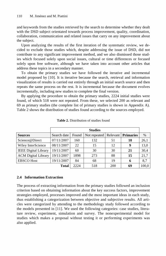
110 M. Jiménez and M. Piattini
and keywords from the studies retrieved by the search to determine whether they dealt with the DSD subject orientated towards process improvement, quality, coordination, collaboration, communication and related issues that carry on any improvement about the subject.
Upon analyzing the results of the first iteration of the systematic review, we de-cided to exclude those studies which, despite addressing the issue of DSD, did not contribute to any significant improvement method, and we also dismissed those stud-ies which focused solely upon social issues, cultural or time differences or focused solely upon free software, although we have taken into account other articles that address these topics in a secondary manner.
To obtain the primary studies we have followed the iterative and incremental model proposed by [10]. It is iterative because the search, retrieval and information visualization of results is carried out entirely through an initial search source and then repeats the same process on the rest. It is incremental because the document evolves incrementally, including new studies to complete the final version.
By applying the procedure to obtain the primary studies, 2224 initial studies were found, of which 518 were not repeated. From these, we selected 200 as relevant and 69 as primary studies (the complete list of primary studies is shown in Appendix A). Table 2 shows the distribution of studies found according to the sources employed.
Table 2. Distribution of studies found
2.4 Information Extraction
The process of extracting information from the primary studies followed an inclusion criterion based on obtaining information about the key success factors, improvement strategies employed, processes improved and the most important ideas in each study, thus establishing a categorization between objective and subjective results. All arti-cles were categorized by attending to the methodology study followed according to the models presented in [11]. We used the following categories: case studies, litera-ture review, experiment, simulation and survey. The nonexperimental model for studies which makes a proposal without testing it or performing experiments was also applied.
Studies Sources Search date Found Not repeated Relevant Primaries %
Science@Direct 07/11/2007 160 132 51 18 26,1 Wiley InterScience 08/11/2007 22 15 12 9 13,0
IEEE Digital Library 19/11/2007 60 30 30 21 30,4 ACM Digital Library 19/11/2007 1898 273 88 15 21,7
EBSCO Host 19/11/2007 84 68 19 6 8,7 Total 2224 518 200 69 100,0

Problems and Solutions in Distributed Software Development 111
3 Trends in Distributed Software Development Research
This section analyzes and discusses proposals and success factors in order to extract relevant information from the information provided by the primary studies.
Figure 1 (left) shows that most of the primary studies analyzed are case studies and nonexperimental articles. Surveys also have a significant representation, in which mem-bers involved in the distributed development take part in outlining their difficulties.
On the other hand, as is shown in Figure 1 (right), the majority of primary studies are focused upon the enterprise field, but studies in the university environment also appear, in which groups of students carried out developments in different locations. Near the half of the studies did not indicate their field of work or their characteriza-tion did not proceed, while 10% were from organizations which did not specify their corporate or university environment.
Enterprise35%
University8%
Not applicable
48%
Environments of study development
Organization (without specifying)9%
Case studies47%
Literature review11%
Experiment13%
Simulation3%
Survey10%
Non-experimental
16%
Type of articles analyzed
Fig. 1. Type of articles analyzed (left) and environments of study development (right)
3.1 Publications Tendency
After attending to the number of relevant studies found through the systematic search carried out, it can be concluded that the subject of DSD is evidently an area which was not widely studied until a few years ago, and it is only recently that a greater number of publications have appeared; thus in Figure 2 we can see that 2006 is by far the year in which most studies were published, bearing in mind that the data shown for 2007 only reflects the studies found before the middle of November.
3.2 Improved or Analyzed Processes
Taking the primary studies analyzed as a reference, we carried out a classification in terms of processes in the software life cycle to which improvements were proposed or success factors or areas to be improved related to DSD were discussed. Primary stud-ies were classified according to the improved or studied processes, in each case based on the ISO/IEC 12207 standard [12], with the aim of obtaining a vision of the proc-esses life cycle that requires special attention when working in a distributed environ-ment and discovering the improvement efforts carried out until that moment.

112 M. Jiménez and M. Piattini
0
10
20
30
40
50
60
2000 2001 2002 2003 2004 2005 2006 2007
Num
ber
of s
tud
ies
Years
Publications by year
Fig. 2. Trends in publications about DSD
0 3 6 9 12 15
Fig. 3. Improved or analyzed processes by the primary studies adjusted to ISO 12207

Problems and Solutions in Distributed Software Development 113
The ISO 12207 standard establishes the activities that may be carried out during the software life cycle, which are grouped into main processes, support processes and general processes. The results are presented graphically in Figure 3 where for every process, its frequency in function of the number of studies that address it is indicated.
The results obtained indicate that greater efforts are focused on human resources, infrastructure, software construction and management and project organization proc-esses. From these data we can infer that communication between team members is a critical factor. On the other hand, other processes, such as software installation or usability are not mentioned in any study. This information will be useful in the focus-ing of future research efforts.
3.3 Employed Standards
Figure 4 presents the standards that the analyzed articles address. Based on the avail-able data, it may be inferred that few studies indicate the use of specific standards. In part, this is attributable to the fact that the great majority of studies deal with issues such as communication difficulties in which the standard used does not matter. The standards supported by most primary studies are CMM and ISO 9001, it being com-mon to jointly apply both. All applications of CMM and CMMI studied employed a maturity level 2 with the exception of one which was certified at CMM level 5. No studies relative to ITIL or COBIT models were obtained.
Standards employed
0 2 4 6 8 10
COPC
ISO 15504
ISO 9001
ISO 12207
Other ISO
CMM
CMMI
Sta
nd
ard
s
Number of articles
Fig. 4. Standards employed in the studies
3.4 Contents of the Studies
Table 3 shows in a schematic way the lines towards which the primary studies have focused. Most of the works study tools or models designed specifically for DSD which attempt to improve certain aspects related to development and coordination. Another large part of the studies are related to communication processes and integra-tion of collaborative tools, combining tools such as e-mail or instant messaging, and studying their application by means of different strategies. Most of the studies address
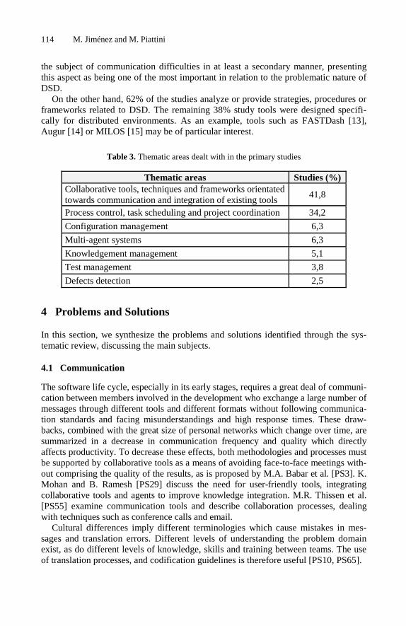
114 M. Jiménez and M. Piattini
the subject of communication difficulties in at least a secondary manner, presenting this aspect as being one of the most important in relation to the problematic nature of DSD.
On the other hand, 62% of the studies analyze or provide strategies, procedures or frameworks related to DSD. The remaining 38% study tools were designed specifi-cally for distributed environments. As an example, tools such as FASTDash [13], Augur [14] or MILOS [15] may be of particular interest.
Table 3. Thematic areas dealt with in the primary studies
Thematic areas Studies (%) Collaborative tools, techniques and frameworks orientated towards communication and integration of existing tools
41,8
Process control, task scheduling and project coordination 34,2
Configuration management 6,3
Multi-agent systems 6,3
Knowledgement management 5,1
Test management 3,8
Defects detection 2,5
4 Problems and Solutions
In this section, we synthesize the problems and solutions identified through the sys-tematic review, discussing the main subjects.
4.1 Communication
The software life cycle, especially in its early stages, requires a great deal of communi-cation between members involved in the development who exchange a large number of messages through different tools and different formats without following communica-tion standards and facing misunderstandings and high response times. These draw-backs, combined with the great size of personal networks which change over time, are summarized in a decrease in communication frequency and quality which directly affects productivity. To decrease these effects, both methodologies and processes must be supported by collaborative tools as a means of avoiding face-to-face meetings with-out comprising the quality of the results, as is proposed by M.A. Babar et al. [PS3]. K. Mohan and B. Ramesh [PS29] discuss the need for user-friendly tools, integrating collaborative tools and agents to improve knowledge integration. M.R. Thissen et al. [PS55] examine communication tools and describe collaboration processes, dealing with techniques such as conference calls and email.
Cultural differences imply different terminologies which cause mistakes in mes-sages and translation errors. Different levels of understanding the problem domain exist, as do different levels of knowledge, skills and training between teams. The use of translation processes, and codification guidelines is therefore useful [PS10, PS65].

Problems and Solutions in Distributed Software Development 115
4.2 Group Awareness
Members who are part of a virtual team tend to be less productive due to feelings of isolation and indifference. They have little informal conversation across sites, and their trust is reduced. Developers need to know the full status of the project and past history which will allow them to create realistic assumptions about how work is done on other sites. Frequent changes in processes, lack of continuity in communications and lack of collaborative tool integration cause the remote groups to be unaware of what is important because they do not know what other people are working on. As a consequence, they cannot find the right person and/or timely information which will enable them to work together efficiently, resulting in misalignment, rework and other coordination problems.
M.A.S. Mangan et al. [PS35] present Odyssey, a middleware for collaborative ap-plications that increases group and workspace awareness information available to developers, helping them to reuse existing applications. On the other hand, J. Froeh-lich and P. Dourish [PS17] describe Augur, a visualization tool that supports DSD processes by creating visual representations of both software artifacts and software development activities, thus allowing developers to explore relationships between them. In the same context, S. Dustdar and H. Gall [PS15] study current technologies such as peer-to-peer, workflow management and groupware systems.
J.D. Herbsleb et al. [PS26] present a tool that provides a visualization of the change management system, making it easy to discover who has experience in work-ing on which parts of the code, and to obtain contact information for that person. In this line C. Gutwin et al. [PS22] propose using social networks to discover the experts in a specific area and project documentation to provide direct information about ac-tivities and areas of work that must be kept up to date.
4.3 Source Control
Distributed environments present problems derived from conflicts caused by editing files simultaneously. Coordination and synchronization become more complex as the degree of distribution of the team grows. Source control systems must support access through internet, confronting its unreliable and insecure nature and the higher re-sponse times.
To reduce these drawbacks, S.E. Dossick and G.E. Kaiser [PS14] propose CHIME, an internet and intranet based application which allows users to be placed in a 3D virtual world representing the software system. Users interact with project artifacts by “walking around” the virtual world, in which they collaborate with other users through a feasible architecture. With the same purpose, J.T. Biehl et al. [PS6] present FASTDash as a user-friendly tool that uses a spatial representation of the shared code base which highlights team members’ current activities, allowing a developer to de-termine rapidly which team members have source files checked out, which files are being viewed, and what methods and classes are currently being changed, providing immediate awareness of potential conflict situations, such as two programmers editing the same source file.

116 M. Jiménez and M. Piattini
4.4 Knowledge Flow Management
The team members’ experiences, methods, decisions, and skills must be accumulated during the development process, so that each team member can use the experience of his/her predecessor and the experience of the team accumulated during development, saving cost and time by avoiding redundant work. For this purpose, documentation must always be updated to prevent assumptions and ambiguity, therefore facilitating the maintainability of the software developed. Distributed environments must facili-tate knowledge sharing by maintaining a product/process repository focused on well understood functionality by linking content from sources such as e-mail and online discussions and sharing metadata information among several tools.
To solve the drawbacks caused by distribution, H. Zhuge [PS60] presents an ap-proach that works with a knowledge repository in which information related to every project is saved, using internet-based communication tools and thus enabling a new team member to become quickly experienced by learning the knowledge stored.
K. Mohan and B. Ramesh [PS29] present an approach based on a traceability framework that identifies the key knowledge elements which are to be integrated, and a prototype system that supports the acquisition, integration, and use of knowledge ele-ments, allowing knowledge fragments stored in diverse environments to be integrated and used by various stakeholders in order to facilitate a common understanding.
4.5 Coordination
Coordination can be interpreted as the management of the right information, the right people and the right time to develop an activity. Coordination in multi-site develop-ments becomes more difficult in terms of articulation work, as problems derived from communication, lack of group awareness and the complexity of the organization ap-pear which influence the way in which the work must be managed. In this sense, more progress reports, project reviews, conference calls and regular meetings to take correc-tive action are needed, thus minimizing task dependencies with other locations. Col-laborative tools must support analysis, design and development, allowing monitoring activities and managing dependencies, notifications and implementation of corrective measures [PS5]. We shall deal with many of these issues in the following sections.
P. Ovaska et al. [PS39] study the coordination of interdependencies between activi-ties including the figure of a chief architect to coordinate the work and maintain the conceptual integrity of the system.
S.S. Vibha et al. [PS66] propose a framework that enables a common understand-ing of the information from different tools and supports loose coupling between them. S. Setamanit et al. [PS50] describe a simulation model to study different ways in which to configure global software development processes. Such models based on empirical data, allow research into and calculation of the impact of coordination efficiency and its effects on productivity.
J.D. Herbsleb et al. [PS26] suggest that multi-site communication and coordination requires more people to participate, which causes a delay. Large changes involve multiple sites and greater implementation times. Changes in multiple distributed sites involve a large number of people.

Problems and Solutions in Distributed Software Development 117
4.6 Collaboration
Concurrent edition of models and processes requires synchronous collaboration between architects and developers who cannot be physically present at a common location. Software modelling requires concurrency control in real time, enabling geo-graphically dispersed developers to edit and discuss the same diagrams, and improv-ing productivity by providing a means through which to easily capture and model difficult concepts through virtual workspaces and the collaborative edition of artifacts by means of tools which permit synchronized interactions.
A. De Lucia [PS62] proposes STEVE, a collaborative tool that supports distributed modelling of software systems which, provides a communication infrastructure to enable concurrent edition of the same diagram at the same time by several distributed developers.
A further approach is presented by J. Suzuki and Y. Yamamoto [PS51] with the SoftDock framework which solves the issues related to software component model-ling and their relationships, describing and sharing component models information, and ensuring the integrity of these models. Developers can therefore work analyzing, designing, and developing software from component models and transfer them using an exchange format, thus enabling communication between team members.
In another direction, X. WenPeng et al. [PS69] study Galaxy Wiki, an on-line col-laborative tool based on the wiki concept which enables a collaborative authoring system for documentation and coordination purposes, allowing developers to compile, execute and debug programs in wiki pages.
4.7 Project and Process Management
Due to high organizational complexity, scheduling and task assignment becomes more problematic in distributed environments because of volatile requirements, changing specifications, and the lack of informal communication and synchronization. Managers must control the overall development process, improving it during the en-actment and minimizing the factors that may decrease productivity, taking into ac-count the possible impacts of diverse cultures and attitudes.
In this context, S. Goldmann et al. [PS19] and S. Bowen and F. Maurer [PS7] ex-plain the main ideas of MILOS, a system orientated towards planning and scheduling which supports process modeling and enactment.
N. Ramasubbu et al. [PS43] propose a process maturity framework with 24 key process areas which are essential for managing distributed software development and capabilities for a continuously improving product management applicable to the CMM framework.
The maturity of the process becomes a key factor for success. In this sense, M. Passivaara and C. Lassenius [PS36] propose incremental integration and frequent deliveries by following informing and monitoring practices. In the same mindset J. Cusick and A. Prasad [PS12] include a set of recommendations based on experience, such as limiting phase durations to maintain control by breaking large projects into medium-size bundles, requiring interim deliverables to ensure quality or enforcing quality through coding standards and verification.

118 M. Jiménez and M. Piattini
4.8 Process Support
Processes should reflect the direct responsibilities and dependencies between tasks, notifying the people involved of the changes that concern them, thus avoiding infor-mation overload of team members. Process modeling and enactment should support inter-site coordination and cooperation of the working teams, offering automated support to distributed project management. Problems derived from process evolution, mobility and tool integration appear within this context. Process engines have to sup-port changes during enactment. Furthermore, distributed environments usually in-volve a large network of heterogeneous, autonomous and distributed models and process engines, which requires the provision of a framework for process system interoperability.
In relation to these problems, A. Fernández et al. [PS2] present the process model-ling environment SPEARMINT, which supports extensive capabilities for multi-view modelling and analysis, and XCHIPS for web-based process support which allows enactment and simulation functionalities. Y. Yang and P. Wojcieszak [PS58] propose a web-based visual environment to support process modelling for software project managers and process enactment for software developers in an asynchronous and/or synchronous manner.
S. Setamanit et al. [PS50] describe a hybrid computer simulation model of software development processes to study alternative ways to configure GSD projects in order to confront communication problems, control and coordination problems, process management and time and cultural differences.
N. Glasser and J-C. Derniane [PS18] analyse CoMoMAS, a multi-agent engineering approach that describes different view points in a software process, permitting the trans-formation of conceptual models into executable programs. In this context, the agents will be able to cover with the high mobility of the members involved in the development process, taking charge of the management of information and permitting artifacts to communicate both with each other and with human users.
4.9 Quality and Measurement
Quality of products is highly influenced by the quality of the processes that support them. Organizations need to introduce new models and metrics to obtain information adapted to the distributed scenarios that could be useful in improving products and processes. With this aim, K.V. Siakas and B. Balstrup [PS30] propose the capability model eSCM-SP, which has many similarities with other capability-assessment mod-els such as CMMI, Bootstrap or SPICE and the SQM-CODE model, which considers the factors that influence software quality management systems from a cultural and organizational perspective.
J.D. Herbsleb et al. [PS25] work with several interesting measures, such as the in-terdependence measure which allows the determination of the degree of dispersion of work among sites by looking up the locations of all the individuals. In this sense, F. Lanubile et al. [PS16] propose metrics associated with products and processes orien-tated towards software defects such as: discovery effort, reported defects, defects density, fixed defects or unfixed defects. D.B. Simmons [PS48] presents PAMPA 2 Knowledge Base to measure the effectiveness of virtual teams by gathering informa-tion from completed projects.

Problems and Solutions in Distributed Software Development 119
Furthermore, software architecture evaluation usually involves a large number of stakeholders, who need face-to-face evaluation meetings, and for this reason adequate collaborative tools are needed, such as propose M.A. Babar et al. [PS3].
4.10 Defects Detection
In distributed environments it is necessary to specify requisites with a higher level of detail. Software defects become more frequent due to the added complexity, and in most cases, this is related to communication problems and lack of group awareness. Defects control must be adapted by making a greater effort in relation to risk man-agement activities.
To minimize these problems, F. Lanubile et al. [PS16] define a process, specifying roles, guidelines, forms and templates, and describe a web-based tool that adopts a reengineered inspection process to minimize synchronous activities and coordination problems to support geographically dispersed teams.
An adequate model cycle must allow the localization and recognition of defect-sensitive areas in complex product development. In this line, Jv. Moll et al. [PS37] indicate that transitions between constituent sub-projects are particularly defect-sensitive. By means of an appropriate modelling of the overall project lifecycle and by applying adequate defect detection measures, the occurrence of defects can be reduced. The goal is to minimize the amount of defects that spread to the subsequent phases early in the software life cycle, and reuse existing components or the applica-tion of third-party components, thus minimizing product quality risks by using tested components.
5 Success Factors
From the experimental studies analyzed, we have extracted the following success factors of DSD, in which the primary studies referenced are listed in the Appendix A:
- Intervention of human resources by participating in surveys [PS3], [PS25]. - Carrying out the improvement based on the needs of the company, taking into
account the technologies and methodologies used [PS1]. The tools employed at the present must be adapted and integrated [PS15].
- Training of human resources in the tools and processes introduced [PS26]. - Registration of activities with information on pending issues, errors and people in
charge [PS6]. - Establishment of an efficient communication mechanism between the members of
the organization, allowing a developer to discover the status and changes made within each project [PS4], [PS6].
- Using a version control tool in order to control conflictive situations [PS40]. - There must be a way to allow the planning and scheduling of distributed tasks,
taking into account dependencies between projects, application of corrective measures and notifications [PS17].
- Application of maturity models [PS43] and agile methodologies [PS33] based on incremental integration and frequent deliveries.
- Systematic use of metrics tailored to the organization [PS26].

120 M. Jiménez and M. Piattini
6 Conclusions and Future Work
In this article we have applied a systematic review method in order to analyze the literature related to the topic of DSD within the FABRUM project context, this work serving as a starting point from which to establish the issues upon which subsequent research will be focused.
Results obtained from this systematic review have allowed us to obtain a global vi-sion of a relatively new topic which should be investigated in detail. However, every organization has concrete needs which basically depend on its distribution character-istics, its activity and the tools it employs. These are the factors that make this such a wide subject, and lead to the necessity of adapting both the technical and organiza-tional procedures, according to each organization’s specific needs.
Generally, the proposals found in the analyzed studies were mainly concerned with improvements related to the use of collaborative tools, integration of existing tools, source code control or use of collaborative agents. Moreover, it should be considered that the evaluation of the results obtained from the proposed improvements are often based on studies in a single organization, and sometimes only takes into account the subjective perception of developers.
On the other hand, it should be noted that maturity models such as CMM, CMMI or ISO, which would be of particular relevance to the present investigation, represent only 27,5% of all analyzed works. The fact that almost all experimental studies that employed CMMI and CMM applied a maturity level 2 suggests that the cost of implementing higher maturity levels under distributed environments might be too high. The application of agile methodologies based on incremental integration and frequent deliveries, and frequent reviews of problems to adjust the process become important success factors.
Finally, we must emphasize that the search excluded studies which addressed the subject of DSD but did not contribute any significant method or improvement in this research context. However, since this is such a wide area, some of these works present interesting parallel subjects for the development of this investigation, which is why their study would be important in a future work. Acknowledgments. We acknowledge the assistance of MELISA project (PAC08-0142-3315), financiered by the “Junta de Comunidades de Castilla-La Mancha” of Spain. This work is part of FABRUM project (PPT-430000-2008-63), financiered by “Ministerio de Ciencia e Innovación” of Spain and by Alhambra-Eidos (http:// www. alhambra-eidos.es/).
References
1. Greenfield, J., Short, K., Cook, S., Kent, S., Crupi, J.: Software Factories: Assembling Ap-plications with Patterns, Models, Frameworks and Tools. John Wiley & Sons, Chichester (2004)
2. Herbsleb, J.D., Moitra, D.: Guest editor’s introduction: Global software development. IEEE Software 18(2), 16–20 (2001)

Problems and Solutions in Distributed Software Development 121
3. Werner, K., Rombach, D., Feldmann, R.: Outsourcing in India. IEEE Software, 78–86 (2001)
4. Christof Ebert, P.D.N.: Surviving Global Software Development. IEEE Software 18(2), 62–69 (2001)
5. Layman, L., Williams, L., Damian, D., Bures, H.: Essential communication practices for Extreme Programming in a global software development team. Information & Software Technology 48(9), 781–794 (2006)
6. Krishna, S., Sundeep, S., Geoff, W.: Managing cross-cultural issues in global software out-sourcing. Commun. ACM 47(4), 62–66 (2004)
7. Damian, D., Lanubile, F., Oppenheimer, H.: Addressing the Challenges of Software Indus-try Globalization: The Workshop on Global Software Development. In: ICSE 2003, pp. 793–794 (2003)
8. Damian, D., Lanubile, F.: The 3rd International Workshop on Global Software Develop-ment. ICSE 2004, pp. 756–757 (2004)
9. Kitchenham, B.: Procedures for performing systematic reviews (Joint Technical Report). Software Engineering Group, Department of Computer Science, Keele University and Empirical Software Engineering National ICT Australia Ltd. (2004)
10. Pino, F.J., García, F., Piattini, M.: Software Process Improvement in Small and Medium Software Enterprises: A Systematic Review. Software Quality Journal (in press, 2007)
11. Marvin, V.Z., Dolores, R.W.: Experimental Models for Validating Technology, pp. 23–31 (1998)
12. ISO/IEC 12207: 2002/FDAM 2. Information technology - Software life cycle processes. Geneva: International Organization for Standardization (2004)
13. Biehl, J.T., Czerwinski, M., Smith, G., Robertson, G.G.: FASTDash: a visual dashboard for fostering awareness in software teams. In: Proceedings of the SIGCHI conference on Human factors in computing systems, San Jose, California, USA, pp. 28–35. ACM Press, New York (2007)
14. Froehlich, J., Dourish, P.: Unifying Artifacts and Activities in a Visual Tool for Distrib-uted Software Development Teams, pp. 387–396 (2004)
15. Goldmann, S., Münch, J., Holz, H.: A Meta-Model for Distributed Software Development, pp. 48–53 (1999)
Appendix A: Primary Studies Selected
In this section the selected primary studies in the systematic review are presented.
Table 4. Primary studies selected in the systematic review
List of primary studies selected in the systematic review
PS1 Strategies for global information systems development. Information & Management 42(1). Published in 2004. Pages: 45-59. Akmanligil M, Palvia PC.
PS2 Guided support for collaborative modeling, enactment and simulation of software development processes. Software Process: Improvement and Practice 9(2). Published in 2004. Pages: 95-106. Fernández A, Garzaldeen B, Grützner I, Münch J.
PS3 An empirical study of groupware support for distributed software architecture evaluation process. Journal of Systems and Software 79(7). Published in 2006. Pages: 912-925. Babar MA, Kitchenham B, Zhu L, Gorton I, Jeffery R.

122 M. Jiménez and M. Piattini
PS4 WebMake: Integrating distributed software development in a structure-enhanced Web. Computer Networks and ISDN Systems 27(6). Published in 1995. Pages: 789-800. Baentsch M, Molter G, Sturm P.
PS5 Coordinating Management Activities in Distributed Software Development Projects. Published in 1998. Pages: 33-38. Bendeck F, Goldmann S, Kötting B.
PS6 FASTDash: a visual dashboard for fostering awareness in software teams. Proceedings of the SIGCHI conference on Human factors in computing systems. Published in 2007. Pages: 28-35. Biehl JT, Czerwinski M, Smith G, Robertson GG.
PS7 Designing a Distributed Software Development Support System Using a Peer-to-Peer Architecture. Published in 2002. Pages: 1087-1092. Bowen S, Maurer F.
PS8 Supporting Agent-Based Distributed Software Development through Modeling and Simulation. Published in 2003. Pages: 56-59. Cai L, Chang CK, Cleland-Huang J.
PS9 How distribution affects the success of pair programming. International Journal of Software Engineering & Knowledge Engineering 16(2). Published in 2006. Pages: 293-313. Canfora G, Cimitile A, Lucca GAD, Visaggio CA.
PS10 Creating global software: A conspectus and review. Interacting with Computers 9(4). Published in 1998. Pages: 449-465. Carey JM.
PS11 Self-organization of teams for free/libre open source software development. Information and Software Technology 49(6). Published in 2007. Pages: 564-575. Crowston K, Li Q, Wei K, Eseryel UY, Howison J.
PS12 A Practical Management and Engineering Approach to Offshore Collaboration. IEEE Software 23(5). Published in 2006. Pages: 20-29. Cusick J, Prasad A.
PS13 Global software development projects in one of the biggest companies in Latvia: is geographical distribution a problem? Software Process: Improvement and Practice 11(1). Published in 2006. Pages: 61-76. Darja m.
PS14
CHIME: a metadata-based distributed software development environment. Proceedings of the 7th European software engineering conference held jointly with the 7th ACM SIGSOFT international symposium on Foundations of software engineering. Published in 1999. Pages: 464-475. Dossick SE, Kaiser GE.
PS15 Process Awareness for Distributed Software Development in Virtual Teams. Published in 2002. Pages: 244-251. Dustdar S, Gall H.
PS16 Tool support for geographically dispersed inspection teams. Software Process: Improvement and Practice 8(4). Published in 2003. Pages: 217-231. Lanubile, F, Mallardo T, Calefato F.
PS17 Unifying Artifacts and Activities in a Visual Tool for Distributed Software Development Teams. Published in 2004. Pages: 387-396. Froehlich J, Dourish P.
PS18 Software Agents: Process Models and User Profiles in Distributed Software Development. Published in 1998. Pages: 45-50. Glaser N, Derniame J-C.
PS19 A Meta-Model for Distributed Software Development. Published in 1999. Pages: 48-53. Goldmann S, Münch J, Holz H.
PS20 Issues in co-operative software engineering using globally distributed teams. Information and Software Technology 38(10). Published in 1996. Pages: 647-655. Gor-ton I, Motwani S.
PS21 Coordinating Distributed Software Development Projects with Integrated Process Modelling and Enactment Environments. Published in 1998. Pages: 39-44. Grundy J, Hosking J, Mugridge R.
PS22 Group awareness in distributed software development. Proceedings of the 2004 ACM conference on Computer supported cooperative work. Published in 2004. Pages: 72-81. Gutwin C, Penner R, Schneider K.

Problems and Solutions in Distributed Software Development 123
PS23
Designing task visualizations to support the coordination of work in software development. Proceedings of the 2006 20th anniversary conference on Computer sup-ported cooperative work. Published in 2006. Pages: 39-48. Halverson CA, Ellis JB, Danis C, Kellogg WA.
PS24 An Empirical Study of Speed and Communication in Globally Distributed Software Development. IEEE Transactions on Software Engineering 29(6). Published in 2003. Pages: 481-492. Herbsleb JD, Mockus A.
PS25 Distance, dependencies, and delay in a global collaboration. Proceedings of the 2000 ACM conference on Computer supported cooperative work. Published in 2000. Pages: 319-328. Herbsleb JD, Mockus A, Finholt TA, Grinter RE.
PS26 An empirical study of global software development: distance and speed. Proceedings of the 23rd International Conference on Software Engineering. Published in 2001. Pages: 81-90. Herbsleb JD, Mockus A, Finholt TA, Grinter RE.
PS27 Global software development at siemens: experience from nine projects. Proceedings of the 27th international conference on Software engineering. Published in 2005. Pages: 524-533. Herbsleb JD, Paulish DJ, Bass M.
PS28 Working Group Report on Coordinating Distributed Software Development Projects. Published in 1998. Pages: 69-72. Holz H, Goldmann S, Maurer F.
PS29 Traceability-based knowledge integration in group decision and negotiation activities. Decision Support Systems 43(3). Published in 2007. Pages: 968-989. Mohan K., Ramesh B.
PS30 Software outsourcing quality achieved by global virtual collaboration. Software Process: Improvement and Practice 11(3). Published in 2006. Pages: 319-328. Siakas K.V., Balstrup B.
PS31 Global software development: technical, organizational, and social challenges. SIGSOFT Softw Eng Notes 28(6). Published in 2003. Pages: 2-2. Lanubile F, Damian D, Oppenheimer HL.
PS32 Essential communication practices for Extreme Programming in a global software development team. Information and Software Technology 48(9). Published in 2006. Pages: 781-794. Layman L, Williams L, Damian D, Bures H.
PS33 Ambidextroux coping strategies in globally distributed software development projects. Communications of the ACM 49(10). Published in 2006. Pages: 35-40. Lee G, Delone W, Espinosa JA.
PS34
Distributed development in an intra-national, intra-organisational context: an experience report. Proceedings of the 2006 international workshop on Global software development for the practitioner. Published in 2006. Pages: 80-86. Lindqvist E, Lundelll B, Lings B.
PS35 A Middleware to Increase Awareness in Distributed Software Development Workspaces. Published in 2004. Pages: 62-64. Mangan MAS, Borges MRS, Werner CML.
PS36 Collaboration practices in global inter-organizational software development projects. Software Process: Improvement and Practice 8(4). Published in 2003. Pages: 183-199. Paasivaara, M, Lassenius C.
PS37 Defect detection oriented lifecycle modeling in complex product development. Information and Software Technology 46(10). Published in 2004. Pages: 665-675. Moll Jv, Jacobs J, Kusters R, Trienekens J.
PS38 Process and technology challenges in swift-starting virtual teams. Information & Management 44(3). Published in 2007. Pages: 287-299. Munkvold BE, Zigurs I.
PS39 Architecture as a coordination tool in multi-site software development. Software Process: Improvement and Practice 8(4). Published in 2003. Pages: 233-247. Ovaska, P, Rossi M, Marttiin P.

124 M. Jiménez and M. Piattini
PS40
Software configuration management over a global software development environment: lessons learned from a case study. Proceedings of the 2006 international workshop on Global software development for the practitioner. Published in 2006. Pages: 45-50. Pilatti L, Audy JLN, Prikladnicki R.
PS41 Virtual teams: a review of current literature and directions for future research. SIGMIS Database 35(1). Published in 2004. Pages: 6-36. Powell A, Piccoli G, Ives B.
PS42 Global software development in practice lessons learned. Software Process: Improvement and Practice 8(4). Published in 2003. Pages: 267-281. Prikladnicki, R, Audy JLN, Evaristo R.
PS43 Leveraging Global Resources: A Process Maturity Framework for Managing Distributed Development. IEEE Software 22(3). Published in 2005. Pages: 80-86. Ramasubbu N, M. S. Krishnan, Kompalli P.
PS44 Can distributed software development be agile? Communications of the ACM 49(10). Published in 2006. Pages: 41-46. Ramesh B, Cao LAN, Mohan K, Peng XU.
PS45 The role of collaborative support to promote participation and commitment in software development teams. Software Process: Improvement and Practice 12(3). Published in 2007. Pages: 229-246. Renata Mendes de Araujo MRSB.
PS46 Virtual workgroups in offshore systems development. Information and Software Technology 47(5). Published in 2005. Pages: 305-318. Sakthivel S.
PS47
An experimental simulation of multi-site software development. Proceedings of the 2004 conference of the Centre for Advanced Studies on Collaborative research. Published in 2004. Pages: 255-266. Shami NS, Bos N, Wright Z, Hoch S, Kuan KY, Olson J, Olson G.
PS48 Measuring and Tracking Distributed Software Development Projects. Published in 2003. Pages: 63-69. Simmons DB.
PS49 A research agenda for distributed software development. Published in 2006. Pages: 731-740. Sinha V, Chandra S, Sengupta B.
PS50 Using simulation to evaluate global software development task allocation strategies. Software Process: Improvement and Practice. Published in 2007. Pages: n/a. Setamanit, S, Wakeland W, Raffo D.
PS51 Leveraging Distributed Software Development. 32(9). Published in 1999. Pages: 59-64. Suzuki J, Yamamoto Y.
PS52 A flexible framework for cooperative distributed software development. Journal of Systems and Software 16(2). Published in 1991. Pages: 97-105. Narayanaswamy. K, Goldman, NM.
PS53 A reliability assessment tool for distributed software development environment based on Java and J/Link. European Journal of Operational Research 175(1). Pub-lished in 2006. Pages: 435-445. Tamura Y, Yamada S, Kimura M.
PS54 An integration centric approach for the coordination of distributed software development projects. Information and Software Technology 48(9). Published in 2006. Pages: 767-780. Taxen L.
PS55
Communication tools for distributed software development teams. Proceedings of the 2007 ACM SIGMIS CPR conference on 2007 computer personnel doctoral consortium and research conference: The global information technology workforce. Published in 2007. Pages: 28-35. Thissen MR, Page JM, Bharathi MC, Austin TL.
PS56 Ontology-based multi-agent system to multi-site software development. Proceedings of the 2004 workshop on Quantitative techniques for software agile process. Published in 2004. Pages: 66-75. Wongthongtham P, Chang E, Dillon TS.
PS57 Ontology-based multi-site software development methodology and tools. Journal of Systems Architecture 52(11). Published in 2006. Pages: 640-653. Wongthongtham P, Chang E, Dillon TS, Sommerville I.

Problems and Solutions in Distributed Software Development 125
PS58 Supporting Distributed Software Development Processes in a Web-Based Environment. Published in 1999. Pages: 292-295. Yang Y, Wojcieszak P.
PS59 Project Management Model: Proposal for Performance in a Physically Distributed Software Development Environment. Engineering Management Journal 16(2). Published in 2004. Pages: 28-34. Zanoni R, Audy JLN.
PS60 Knowledge flow management for distributed team software development. Knowledge-Based Systems 15(8). Published in 2002. Pages: 465-471. Zhuge H.
PS61 Empirical evaluation of distributed pair programming. International Journal of Human-Computer Studies, In Press. Accepted Manuscript 2007. Hanks B.
PS62 Enhancing collaborative synchronous UML modelling with fine-grained versioning of software artefacts. Journal of Visual Languages & Computing 2007 18(5). Published in 2007. Pages: 492-503. De Lucia A., Fasano F., Scanniello G., Tortora G.
PS63
An Evaluation Method for Requirements Engineering Approaches in Distributed Software Development Projects. International Conference on Software Engineering Advances (ICSEA 2007). Published in 2007. Pages: 39-45. Michael G., Tobias H., Franz R., Colin A.
PS64
1st International Workshop on Tools for Managing Globally Distributed Software Development (TOMAG 2007). International Conference on Software Engineering Advances (ICSEA 2007). Published in 2007. Pages: 278-279. Chintan A., Jos van H., Frank H.
PS65 Distributed Software Development: Practices and challenges in different business strategies of offshoring and onshoring. Published in 2007. Pages: 262-274. Rafael P., Jorge Luis N. A., Daniela D., Toacy C. d. O.
PS66 An Adaptive Tool Integration Framework to Enable Coordination in Distributed Software Development. International Conference on Software Engineering Advances (ICSEA 2007). Published in 2007. Pages: 151-155. Vibha S. S., Bikram S., Sugata G.
PS67 Coordination Practices in Distributed Software Development of Small Enterprises. International Conference on Software Engineering Advances (ICSEA 2007). Published in 2007. Pages: 235-246. Alexander B., Bernhard N., Volker W.
PS68
Globally distributed software development project performance: an empirical analysis. Proceedings of the 6th joint meeting of the European software engineering conference and the ACM SIGSOFT symposium on The foundations of software engineering 2007. Published in 2007. Pages: 125-134. Narayan R., Rajesh Krishna B.
PS69 On-line collaborative software development via wiki. Proceedings of the 2007 international symposium on Wikis 2007. Published in 2007. Pages: 177-183. WenPeng X., ChangYan C., Min Y.

K. Berkling et al. (Eds.): SEAFOOD 2008, LNBIP 16, pp. 126–133, 2009. © Springer-Verlag Berlin Heidelberg 2009
Design and Code Reviews in the Age of the Internet
Bertrand Meyer
ETH Zurich and Eiffel Software [email protected]
http://se.ethz.ch, http://eiffel.com
Code reviews are one of the standard practices of software engineering. Or let’s say that they are a standard practice of the software engineering literature. They are widely recommended; how widely practiced, I am not sure.
Eiffel Software has applied code reviews to the recent developments of EiffelStu-dio, a large IDE (interactive development environment) whose developers are spread over three continents. This distributed setup forced us to depart from the standard scheme as described in the literature and led to a fresh look at the concept; some of what appeared initially as constraints (preventing us from ever having all the people involved at the same time in the same room) turned out to be beneficial in the end, encouraging us in particular to emphasize the written medium over verbal discus-sions, to conduct a large part of the process prior to the actual review meeting, and to take advantage of communication tools to allow several threads of discussion to pro-ceed in parallel during the meeting itself. Our reviews are not just about code, but encompass design and specification as well. The process relies on modern, widely available communication and collaboration tools, most of them fairly recent and with considerable room for improvement. This article describes some of the lessons that we have learned, which may also be useful to others.
1 Code Review Concepts
Michael Fagan from IBM introduced “code inspections”, the original name, in a 1976 article1. Inspection or review, the general idea is to examine some element of code in a meeting of (typically) around eight people, with the aim of finding flaws or ele-ments that should be improved. This is the only goal:
• The review is not intended to assess the programmer — although in practice this is not so easy to avoid, especially if the manager is present.
• The review is not intended to correct deficiencies, only to uncover them.
The code and any associated elements are circulated a few days in advance. The meeting typically lasts a few hours; it includes the author, a number of other developer
1 M.E. Fagan, Design and Code inspections to reduce errors in program development, IBM
Systems Journal, Vol. 15, No 3, 1976, pages 182-211; at www.research.ibm.com/ journal/sj/ 153/ibmsj1503C.pdf.

Design and Code Reviews in the Age of the Internet 127
competent to assess the code, a meeting chair who moderates the discussion (and should not be the manager), and a secretary who records it, producing a report with specific recommendations. Some time later, the author should respond to the report by describing whether and how the recommendations have been carried out.
Such is the basic idea of traditional reviews. It is often criticized on various grounds. Advocates of Extreme Programming point out that reviews may be superflu-ous if the project is already practicing pair programming. Others note that when it comes to finding code flaws — a looming buffer overflow, for example — static analysis tools are more effective than human inspection. In any case, the process is highly time-consuming; most teams that apply it perform reviews not on the entire code but on samples. Still, code reviews remain one of the tools in a battery of ac-cepted “best practices” for improving software quality.
We have found that the exercise is indeed useful if adapted to the modern world of software development. The first extension is to include design and specification. Many of the recent references on code reviews focus on detecting low-level code flaws, especially security risks. This is important but increasingly a task for tools rather than humans. We feel that API (abstract program interface) design, architecture choices and other specification and design issues are just as worth the reviewers’ time; in our reviews these aspects have come to play an increasingly important part in the discussions.
Among the traditional review principles that should in our view be retained is the rule that the review should only identify deficiencies, not attempt to correct them. With the advent of better software technology it may be tempting to couple review activities with actual changes to the software repositories; one tool that supports web-based review, Code Collaborator2, allows this through coupling with a configuration management system. We feel that this is risky. Updating software — even for simple code changes, not touching specification and design — is a delicate matter and should be performed carefully, outside of the time pressures inherent in a review.
2 A Distributed Review?
All the descriptions of code reviews I have seen in the literature talk of a review as a physical meeting with people sitting in the same room. This is hardly applicable to the model of software development that is increasingly dominant today: distributed teams, split over many locations and time zones. At Eiffel Software we were curious to see whether we could apply the model in such a setup; our first experience — still fresh and subject to refinement — suggest that thanks to the Internet and modern communication mechanisms this setup is less a hindrance than a benefit, and that to-day’s technology actually provides a strong incentive to revive and expand the idea of the review.
2 http://www.smartbear.com/

128 B. Meyer
The EiffelStudio development team has members in California, Western Europe, Russia and China. In spite of this we manage to have a weekly technical meeting, with some members of the team agreeing to stay up late. (In the winter 8 to 9 AM California means 5 to 6 PM in Western Europe, 7 to 8 PM in Moscow, and midnight to 1 AM in Shanghai.) We are now devoting one out of three such meetings to a code review.
3 Constraints and Technology
Although many of the lessons should be valid for any other team, here are some of the specifics of our reviews, which may influence our practice and conclusions.
Our meetings, whether ordinary ones or for code reviews, last one hour. We are strict on the time limit, obviously because it’s late at night for some of the partici-pants, but also because it makes no sense to waste the time of a whole group of highly competent developers. This schedule constraint is an example of limitation that has turned out to be an advantage, forcing us to organize the reviews and other meetings seriously and professionally.
Almost all of our development is done in Eiffel; one aspect that influences the re-view process is that Eiffel applies the “seamless development” principle which treats specification, design and analysis as a continuum, rather than a sequence of separate steps (using, for example, first UML then a programming language); the Eiffel lan-guage serves as the single notation throughout. This has naturally caused the exten-sion to design reviews, although we think that this extension is desirable for teams using any other development language and a less seamless process. Another aspect that influences our process is that, since IDEs are our business, the tool we produce is also the tool we use (this is known as the “eat your own dog food” principle); but again we feel the results would not fundamentally change for another kind of software development.

Design and Code Reviews in the Age of the Internet 129
Distributed reviews need support from communication and collaboration tools. At the moment we essentially rely on four tools:
• The reviews require voice communication, similar to a conference call. We started with Skype but now use it only as a backup since we found too many problems in intensive use. Another Voice over IP solution (X-Lite) is the current voice tool.
• In parallel, we use written communication. For this we retain Skype’s chat mechanism. A chat window involving all the participants remains active throughout the review.
• For shared documents, we use Google Docs, which provides a primitive Mi-crosoft-Word-like editing framework, but on the Web so that several people can update a given document at the same time. The conflict resolution is fine-grained: most of the time changes are accepted even if someone else is also modifying the document; only if two people are changing exactly the same words does the tool reject the requests. While not perfect, Google Docs provides a remarkable tool for collaborative editing, with the advantage that texts can be pasted to and from Microsoft Word documents with approxi-mate preservation of formats.
• It is also important to be able to share a screen, for example to run a demo of a new proposal for a GUI (graphical user interface) idea or other element that a developer has just put together on his or her workstation. For this we use the WebEx sharing tool.
• Wiki pages, especially the developer site at http://dev.eiffel.com, are also useful, but less convenient than Google Docs to edit during a meeting.
Clearly the choice of tools is the part of this article that is most clearly dependent on the time of writing. The technology is evolving quickly enough that a year or two from now the solutions might be fairly different. What is remarkable in the current setup is that we have not so far found a need for specialized reviewing software but been content enough with general-purpose communication and collaboration tools.
4 Reviews for the 21st Century
Here are some of the lessons we have learned. First, scripta manent: prefer the written word. We have found that a review works
much better if it is organized around a document. For any meeting we produce a shared document (currently Google Docs); the whole meeting revolves around it. The document is prepared ahead of the meeting, and updated in real time during the meet-ing (while, as noted, the software itself is not).
The unit of review is a class, or sometimes a small number of closely related classes. A week in advance of the review the code author prepares the shared docu-ment with links to the actual code. It follows a standard structure described below.
One of the differences with a traditional review is a practice which we hadn’t planned, but which quickly imposed itself through experience: most of the work oc-curs off-line, before the meeting. Our original intuition was to limit the amount of advance work and delay written comments to a couple of days before the meeting, to

130 B. Meyer
avoid reviewers influencing each other too much. This was a mistake; interaction be-tween reviewers, before, during and after the meeting, has turned out to be one of the most effective aspects of the process.
The reviewers provide their comments on the review page (the shared document); the code author can then respond at the same place. The benefit of this approach is that it saves considerable time. Before we systematized it we were spending time, in the actual meeting, on non-controversial issues; in fact, our experience suggests that with a competent group most of the comments and criticisms will be readily accepted by the code’s author. We should instead spend the meeting on the remaining points of disagreement. Otherwise we end up replaying the typical company board meeting as described in the opening chapter of C. Northcote Parkinson’s Parkinson’s Law. (There are two items on the agenda: the color of bicycles for the mail messengers; and whether to build a nuclear plant. Everyone has an opinion on colors, so the first item takes 59 minutes ending with the decision to form a committee; the next decision is taken in one minute, with a resolution to let the CEO handle the matter.) Unlike with this all too common pattern, the verbal exchanges can target the issues that truly war-rant discussion.
For an actual example of a document produced before and during one of our code reviews, see
http://dev.eiffel.com/reviews/2008-02-sample.html
which gives a good idea of the process. For a complete picture you would need to see the full discussion in the chat window and hear a recording of the discussion.
5 Review Scope
The standard review page structure consists of 8 sections, dividing the set of aspects to be examined:
1. Choice of abstractions 2. Other aspects of API design 3. Other aspects of architecture, e.g. choice of client links and inheritance hierarchies 4. Implementation, in particular choice of data structures and algorithms 5. Programming style 6. Comments and documentation (including indexing/note clauses) 7. Global comments 8. Coding practices This goes from more high-level to more implementation-oriented. Note in particu-
lar sections 1 to 3, making it clear that we are talking not just about code but about reviewing architecture and design:
• The choice of abstractions (1) is the key issue of object-oriented design. De-velopers will discuss whether a certain class is really justified or should have its functionalities merged with another's; or, conversely, whether an impor-tant potential class has been missed.

Design and Code Reviews in the Age of the Internet 131
• API design (2) is essential to the usability of software elements by others, and in particular to reuse. We enforce systematic API design conventions, with a strong emphasis on consistency across the entire code base. This as-pect is particularly suitable for review.
• Other architectural issues (3) are also essential to good object-oriented de-velopment; the review process is useful, both during the preparatory phase and during the meeting itself, to discuss such questions as whether a class should really inherit from another or instead be a client.
Algorithm design (4) is also a good item for discussion. In our process the lower-level aspects, 5 to 8, are increasingly handled before the
review meeting, in writing, enabling us to devote the meeting time to the deeper and more delicate issues.
6 Making the Process Effective
We have identified the following benefits of the choices described.
• The group saves time. Precious personal interaction time is reserved for top-ics that require it.
• Discussing issues in writing makes it possible to have more thoughtful com-ments. Participants can take care to express their observations — criticism of design and implementation decisions, and the corresponding responses — properly. This is easier than in a verbal conversation.
• The written support allows editing and revision. • There is a record. Indeed the review no longer needs a secretary or the tedi-
ous process of writing minutes: the review page in its final stage, after joint editing, is the minutes.
• The verbal discussion time is much more interesting since it addresses issues of real substance. The dirty secret of traditional code reviews is that most of the proceedings are boring to most of the participants, each of whom is typi-cally interested in only a subset of the items discussed. With an electronic meeting each group member can take care of issues of specific concern in advance and in writing; the verbal discussion is then devoted to the contro-versial and hence interesting stuff.
• In a group with contentious personalities, one may expect that expressing comments in writing will help defuse tension. (I am writing “may expect” because I don’t know from experience — our group is not contentious.)
Through our electronic meetings — not just code reviews — another example has emerged of how constraints can become benefits. Individually, most of us apart from piano players may be most effective when doing one thing at a time, but collectively a group of humans is pretty good at multiplexing. When was the last time you spent a one-hour meeting willingly focused at every minute on the issue then under discus-sion? Even the most attentive, careful not to let their minds wander off topic, react at different speeds from others: you may be thinking deeper about the previous item even when the agenda has moved on; you may be ahead of the game; or you may have

132 B. Meyer
something to say that complements the comments of the current speaker, whom you don’t want to interrupt. But this requires multithreading and a traditional meeting is sequential. In our code reviews and other meetings we have quickly learned to practice a kind of organic multithreading: someone is talking; someone is writing a comment in the chat window (e.g. a program extract that illustrates a point under discussion, or a qualification of what is being said); a couple of people are updating the common document; someone else is preparing next week’s document, or a Wiki page at http://dev.eiffel.com. It is amazing to see the dynamics of such meetings, with the threads progressing in parallel while everyone remains on target, and not bored.
7 An Academic Endeavor
Team distribution is a fact of life in today’s software development, and as well as a challenge it can be a great opportunity to improve the engineering of software. I am also practicing it in an academic environment. ETH Zurich offers a course specifically devoted to studying, in the controlled environment of an academic environment, the issues and techniques of distributed development: DOSE (Distributed and Outsourced Software Engineering). It involved in 2007, for the first time, a cooperative project performed in common by several universities. This was a trial run, and we are now expanding the experience; for details see
http://se.ethz.ch/dose/
Participation is open to any interested university. The goal is to let students dis-cover and confront the challenges of distributed development in the controlled envi-ronment of a university course.
8 Distributed and Collaborative Development
Not all of our experience, as noted, may be transposable to other contexts. Our group is small, we know each other well and have been working together for quite a while; we developed these techniques together, learning from our mistakes and benefiting from the advances of technology in the past years. But whatever the reservations I believe this is the way of the future. Even more so considering that the supporting technology is still in its infancy. Two years ago most of the communication tools we use did not exist; five years ago none did. (Funny to think of all the talks I heard over the years about “Computer-Supported Cooperative Work”, fascinating but remote from anything we could use. Suddenly come the Web, Voice Over IP solutions for the common folk, shared editing tools and a few other commercial offerings, and the gates open without fanfare.)
The tools are still fragile; we waste too much time on meta-communication (“Can you hear me? Did Peter just disconnect? Bill, remember to mute your microphone!”), calls get cut off, we don’t have a really good equivalent of the shared whiteboard. Other aspects of the process still need improvement; for example we have not yet found a good way to make our review results seamlessly available as part of the open-source development site, which is based on Wiki pages. All this will be corrected in

Design and Code Reviews in the Age of the Internet 133
the next few years. I hope that courses such as DOSE and other academic efforts will enable us to understand better what makes collaborative development succeed or fail.
But this is not just an academic issue. Eiffel Software’s still recent experience of collaborative development — every meeting brings new insights — suggests that something fundamental has changed, mostly for the better, in the software develop-ment process. As regards code reviews I do not, for myself, expect ever again to get stuck for three hours in a windowless room with half a dozen other programmers por-ing over some boring printouts.
Acknowledgment. I am grateful to the EiffelStudio development team for their creativ-ity and team spirit, which enabled the team collectively to uncover and apply the techniques described here. An earlier version of this article appeared as a column in the EiffelWorld newsletter, and a slightly different version in Communications of the ACM, September 2008.
K. Berkling et al. (Eds.): SEAFOOD 2008, LNBIP 16, pp. 134–148, 2009. © Springer-Verlag Berlin Heidelberg 2009
Preliminary Analysis for Risk Finding in Offshore Software Outsourcing from Vendor's Viewpoint
Zhongqi Sheng1,2, Hiroshi Tsuji1 , Akito Sakurai3, Ken'ichi Yoshida4, and Takako Nakatani4
1 Osaka Prefecture University, Graduate School of Engineering, 1-1 Gakuencho, Nakaku, Sakai, Japan, 599-8531
[email protected], [email protected] 2 Northeastern University, School of Mechanical Engineering,
3-11 Wenhua Road, Shenyang, Liaoning, China, 110004 3 Keio University, Graduate School of Science and Engineering,
4-1-1 Hiyoshi, Kohoku-ku, Yokohama, Kanagawa, Japan, 223-8521 [email protected]
4 University of Tsukuba, Graduate School of Business Science, 3-29-1 Otsuka, Bunkyo, Tokyo, Japan, 112-0012
{yoshida,nakatani}@gssm.otsuka.tsukuba.ac.jp
Abstract. It is meaningful to investigate the know-how of experienced project managers on the side of vendors about the risk in offshore software outsourcing. A survey is conducted to find out the main risk factors from the vendor's view-point. The questions asked include background information of vendor and re-spondent, suggestions to the client, and evaluations on experienced offshore projects. In all, 131 respondents from 77 vendors evaluate 241 offshore soft-ware outsourcing projects upon 30 items. The background information about the respondents and the vendors is summarized first. The preliminary analysis on the characters and the achievements of experienced offshore projects is re-ported in this paper. Some conclusions are drawn at last.
1 Introduction
Offshore software outsourcing is defined as a situation where a company (client) con-tracts out all or part of its software development activities to another company (vendor) which locates in foreign country and provides agreed productions or services [1]. In the era of globalization and specialization, companies are continuously forced to reduce production costs so as to keep sustainable competitive strength. Outsourcing non-core activities to the third parties has become a universal tool, which helps companies to concentrate on their profit-generating activities [2-5]. The primary motivation of off-shore software outsourcing is the low cost of software development work in develop-ing countries such as India, China. The benefits of offshore software outsourcing also include compression of project development time, easy access to resource pool of highly experienced IT professionals, and so on [6,7]. The trend towards offshore soft-ware outsourcing has been growing steadily since the 1990s and now offshore software
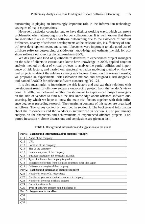
Preliminary Analysis for Risk Finding in Offshore Software Outsourcing 135
outsourcing is playing an increasingly important role in the information technology strategies of major corporations.
However, particular countries tend to have distinct working ways, which can prove problematic when attempting cross border collaboration. It is well known that there are inevitable risks in offshore software outsourcing due to the existence of cultural difference, opacity of software developments at the offshore site, insufficiency of con-trol over development team, and so on. It becomes very important to take good use of offshore software outsourcing practitioners’ knowledge and estimate the risk for off-shore software outsourcing decision-makings [8-9].
We designed one kind of questionnaire delivered to experienced project managers on the side of clients to extract tacit know-how knowledge in 2006, applied conjoint analysis method on data of virtual projects to analyze the partial utilities and impor-tance of risk factors, and carried out structural equation modeling method on data of real projects to detect the relations among risk factors. Based on the research results, we proposed an experimental risk estimation method and designed a risk diagnosis tool named RASOD for offshore software outsourcing [10-12].
It is also meaningful to investigate the risk factors and analyze their relations with development result of offshore software outsourcing project from the vendor’s view-point. In 2007, we delivered another questionnaire to experienced project managers on the side of vendors to find out the risk knowledge about offshore software out-sourcing, by which we hope to know the main risk factors together with their influ-ence degree as preceding research. The remaining contents of this paper are organized as follows. The survey content is described in section 2. The background information about the respondents and the vendors is summarized in section 3. The preliminary analysis on the characters and achievements of experienced offshore projects is re-ported in section 4. Some discussions and conclusions are given at last.
Table 1. Background information and suggestions to the client
Part 1: Background Information about company (vendor)
Q11 Name of the company Q12 URL Q13 Location of the company Q14 Size of the company Q15 Foundation years of the company Q16 Business location of the company in Japan Q17 Type of software the company is good at Q18 Experience of orders from clients in countries other than Japan Q19 Difference strategies of the company Part 2: Background information about respondent Q21 Number of years of IT experience Q22 Number of years of experience in current company Q23 Number of involved offshore projects Q24 Current position/role Q25 Type of software projects being in charge of Part 3: Suggestions to the client
Q31 Q32 Q33

136 Z. Sheng et al.
2 Survey Content
In order to find out tacit knowledge about risks in offshore software outsourcing, we design the questionnaire delivered to experienced project managers of vendors on the base of academy-industry collaboration [10]. The questionnaire consists of five parts.
Table 2. Evaluation items for experienced offshore project
Part X: Evaluation of experienced offshore software outsourcing project (X=4,5)
ID Characters of developed system
QX01 Type of software(Customer application, Middleware, Embedded software)
QX02 Period of development
QX03 Order size
QX04 Times of receiving orders
QX05 Difficulty level of required technology
QX06 Type of development model required and of that desired in your view
QX07 Main appeal of your company to the client
QX08 Share of development between client and vendor
Problems encountered in development
QX09 Was technology level of client higher than necessary, lower, or appropriate ?
QX10 How did you solve them when incomplete specifications or doubtful points existed ?
QX11 What was the biggest problem concerning miscommunication?
QX12 What was the biggest problem encountered during brief meetings?
QX13 Whether did you and the client expect long-term relationship?
QX14 What was the biggest geographic constraint?
QX15 Did you experience problems about development environment?
Quality requirements for development work
QX16 Function requirements
QX17 Performance requirements
QX18 Efficiency requirements
Development achievements and risks
QX19 Company image (including reliability) was improved
QX20 Company technology level (including specialist education) was improved
QX21 New technology was acquired
QX22 Sale was increased
QX23 Profit was improved
QX24 Business knowledge (not technology knowledge) was acquired
QX25 Influenced by the change of exchange rate
QX26 Was the client concerned by brain drain in the vendor
QX27 Did brain drain happen in developing period
QX28 How much was the change of the specification
QX29 How much was the change of schedule/period
Development result of the project
QX30 Please evaluate the development result of the project
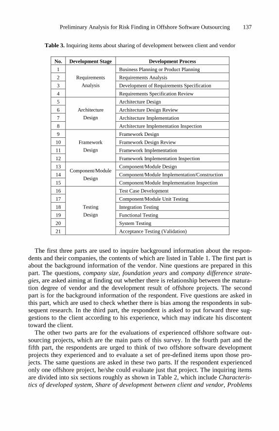
Preliminary Analysis for Risk Finding in Offshore Software Outsourcing 137
Table 3. Inquiring items about sharing of development between client and vendor
No. Development Stage Development Process
1 Business Planning or Product Planning
2 Requirements Analysis
3 Development of Requirements Specification
4
Requirements
Analysis
Requirements Specification Review
5 Architecture Design
6 Architecture Design Review
7 Architecture Implementation
8
Architecture
Design
Architecture Implementation Inspection
9 Framework Design
10 Framework Design Review
11 Framework Implementation
12
Framework
Design
Framework Implementation Inspection
13 Component/Module Design
14 Component/Module Implementation/Construction
15
Component/Module
Design Component/Module Implementation Inspection
16 Test Case Development
17 Component/Module Unit Testing
18 Integration Testing
19 Functional Testing
20 System Testing
21
Testing
Design
Acceptance Testing (Validation)
The first three parts are used to inquire background information about the respon-
dents and their companies, the contents of which are listed in Table 1. The first part is about the background information of the vendor. Nine questions are prepared in this part. The questions, company size, foundation years and company difference strate-gies, are asked aiming at finding out whether there is relationship between the matura-tion degree of vendor and the development result of offshore projects. The second part is for the background information of the respondent. Five questions are asked in this part, which are used to check whether there is bias among the respondents in sub-sequent research. In the third part, the respondent is asked to put forward three sug-gestions to the client according to his experience, which may indicate his discontent toward the client.
The other two parts are for the evaluations of experienced offshore software out-sourcing projects, which are the main parts of this survey. In the fourth part and the fifth part, the respondents are urged to think of two offshore software development projects they experienced and to evaluate a set of pre-defined items upon those pro-jects. The same questions are asked in these two parts. If the respondent experienced only one offshore project, he/she could evaluate just that project. The inquiring items are divided into six sections roughly as shown in Table 2, which include Characteris-tics of developed system, Share of development between client and vendor, Problems

138 Z. Sheng et al.
encountered in development, Quality requirements for development work, Develop-ment achievements and risks, and Development result of the project. In this paper, the inquired items in these two parts are analyzed together, so those items are expressed by the IDs with prefixed QX. To investigate how the client and the vendor share the development processes, twenty-one processes are selected to describe the software development activities as listed in Table 3. These twenty-one processes belong to five development stages including Requirements Analysis, Architecture Design, Frame-work Design, Component/Module Design and Testing Design. The respondent is asked to select the share status from Actively participating, Occasionally participating and Un-participating for the client and the vendor respectively. The maintenance process is not included here because this research concentrates on the development processes but not on the whole software cycles though the maintenance process also requires the joint activities between vendor and client.
3 Basic Survey Results
In April 2007, we carried out this survey with the support of the members of SSR (Joint Forum for Strategic Software Research). We adopt intentional sampling in or-der to assure the return rate though random sampling does not include bias. The ques-tionnaire is written in three languages respectively, which are Japanese, Chinese and English. The answer sheet is designed in the form of EXCEL file and sent to the com-panies on the side of vendors by the members of SSR. The respondent can fill the electrical form directly and send it back by e-mail, or do it on printed sheet and send it back by FAX or mail. In nearly two months, 131 questionnaires sent back by email were received in total, which are from 77 companies on the side of vendors. The off-shore software outsourcing projects in which the development result (QX30) was not evaluated are ignored. In the responses, there are 128 projects in the fourth part and 113 projects in the fifth part evaluated by the respondents. In all, 241 offshore soft-ware outsourcing projects are evaluated completely. The number and percentage of responses divided by country are listed in Table 4. Eighty-five percent of the respon-dents are from China. Only three respondents in India sent back the questionnaires. In the following part of this paper, an evaluated project is called a sample. That is to say, there are 241 samples for the risk analysis in the vendor's viewpoint in this research.
Table 4. Number of respondents, companies, and projects divided by countries
Respondent Company Project Country
Number Percentage Number Percentage Number Percentage India 3 2 3 4 5 2 China 112 85 59 77 208 86
Vietnam 8 6 8 10 15 6 Other 8 6 7 9 13 5 Total 131 100 77 100 241 100

Preliminary Analysis for Risk Finding in Offshore Software Outsourcing 139
Firstly, let us describe the statistics of background information of 77 vendors. 54 vendors have staff in excess of 100. The foundation time of 54 vendors is over five years. 64 vendors have set up business locations in Japan. For 68 vendors, type of software that the vendor is good at is customer application software. 46 vendors have accepted orders from clients of countries other than Japan. For company difference strategies, the respondent is asked to sort four items according to their importance, which are low price, high quality, technology level and communication ability. It is shown that 45 vendors select high quality as the most important item and 44 vendors select low price as the last item. The detailed result is shown in Fig.1. It can be de-duced that most clients use high quality as main standard for selecting the vendors.
Fig. 1. Statistics for company difference strategies
Secondly, let us describe the statistics of background information of 131 respon-dents. 95 respondents have the IT experience of over 5 years. 88 respondents have worked in current company for over 3 years. There are 69 respondents who have taken part in over 10 offshore software outsourcing projects. 51 respondents are pro-ject managers and 30 respondents are project members. 108 respondents are in being charge of the development of customer application software. Among 131 respondents, 112 persons are from the companies of China.
As a response to the third part of questionnaire, 298 suggestions toward the clients are received from 111 respondents. 52 suggestions are about communications, which reflects that communication is both important and difficult. 42 are about the descrip-tion of specification files and 31 suggestions are about requirement analysis.
4 Evaluations on Offshore Projects
4.1 Development Result of the Project
In the question QX30, the respondent is asked to evaluate the development result by selecting one from five choices including Great Success, Success, Ordinary, Failure and Dead Failure. Statistics of evaluations divided by country of vendors is shown in Table 5. The percentage of Success exceeds 70 percent and the percentage of Ordi-nary is 20 percent. Most of the answers are Success and Ordinary as expect that suc-cess rate would be very high. So the development achievements (QX19-QX24) are considered in order to evaluate the development project comprehensively.
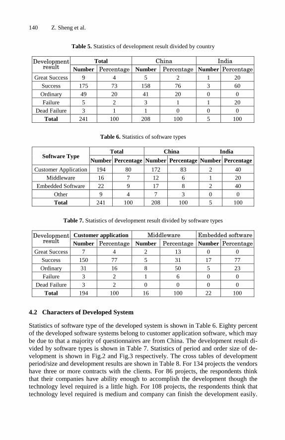
140 Z. Sheng et al.
Table 5. Statistics of development result divided by country
Total China India Developmentresult Number Percentage Number Percentage Number Percentage
Great Success 9 4 5 2 1 20 Success 175 73 158 76 3 60
Ordinary 49 20 41 20 0 0 Failure 5 2 3 1 1 20
Dead Failure 3 1 1 0 0 0 Total 241 100 208 100 5 100
Table 6. Statistics of software types
Total China India Software Type
Number Percentage Number Percentage Number Percentage
Customer Application 194 80 172 83 2 40 Middleware 16 7 12 6 1 20
Embedded Software 22 9 17 8 2 40 Other 9 4 7 3 0 0 Total 241 100 208 100 5 100
Table 7. Statistics of development result divided by software types
Customer application Middleware Embedded software Developmentresult Number Percentage Number Percentage Number Percentage
Great Success 7 4 2 13 0 0 Success 150 77 5 31 17 77 Ordinary 31 16 8 50 5 23 Failure 3 2 1 6 0 0
Dead Failure 3 2 0 0 0 0
Total 194 100 16 100 22 100
4.2 Characters of Developed System
Statistics of software type of the developed system is shown in Table 6. Eighty percent of the developed software systems belong to customer application software, which may be due to that a majority of questionnaires are from China. The development result di-vided by software types is shown in Table 7. Statistics of period and order size of de-velopment is shown in Fig.2 and Fig.3 respectively. The cross tables of development period/size and development results are shown in Table 8. For 134 projects the vendors have three or more contracts with the clients. For 86 projects, the respondents think that their companies have ability enough to accomplish the development though the technology level required is a little high. For 108 projects, the respondents think that technology level required is medium and company can finish the development easily.

Preliminary Analysis for Risk Finding in Offshore Software Outsourcing 141
Statistics of development models required and that adopted is shown in Fig.4. For the characters appealed by the client, the appreciated order of four items is Quality, Tech-nology level, Communication skill and Price, which is the same as the order about the difference strategy of company.
0
10
20
30
40
50
60
70
80
Less than 3
months
Less than 6
months
Less than 1
year
Over 1 year
Number of Projects
Fig. 2. Period of the development
P·Ms: Person-Months
0
10
20
30
40
50
60
70
Less than 10
P·Ms
Less than 20
P·Ms
Less than 50
P·Ms
Less than
100 P·Ms
Over 100
P·Ms
Number of Projects
Fig. 3. Order size of the development
Table 8. Cross tables of period/size of projects and evaluation of the projects
Period of development Great Success Success Ordinary Failure Dead Failure
1 Less than 3 months 3 57 11 2 0
2 Less than 6 months 1 43 23 0 2
3 Less than 1 year 2 31 7 2 1
4 Over 1 year 3 44 8 1 0
Size of order Great Success Success Ordinary Failure Dead Failure
1 Less than 10 person-months 2 19 13 0 1
2 Less than 20 person-months 1 45 6 1 0
3 Less than 50 person-months 1 46 13 2 1
4 Less than 100 person-months 2 27 9 0 0
5 Over 100 person-months 3 38 8 2 1

142 Z. Sheng et al.
Fig. 4. Type of development models adopted and that desired
4.3 Share of Development Processes by Client and Vendor
The software development activities are divided into and described by twenty-one development processes. The respondents are asked how the vendor and the client par-ticipate in these process and to select one status from Actively participating, Occa-sionally participating and Un-participating. By the responses, we hope to know the effect of share of development processes on the development achievements. The number of projects in which the vendors and the clients think they are actively or oc-casionally participating in each of the processes is shown in Fig.5 and Fig.6 respec-tively. It is shown that the vendors actively participate in 7 processes from No.13 (Component/Module design) to No.19 (Functional Testing) and the clients actively participate in the other 14 processes.
Fig. 5. Actively participated processes
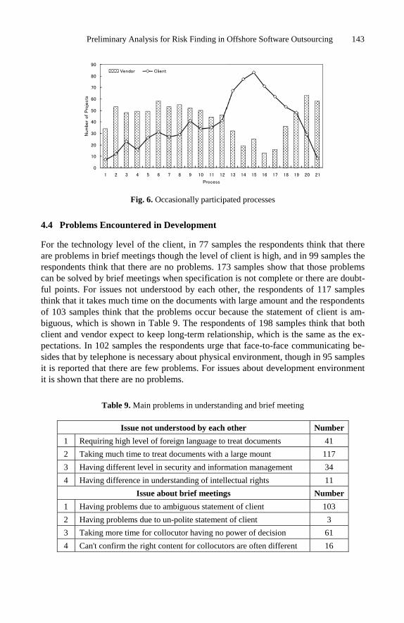
Preliminary Analysis for Risk Finding in Offshore Software Outsourcing 143
Fig. 6. Occasionally participated processes
4.4 Problems Encountered in Development
For the technology level of the client, in 77 samples the respondents think that there are problems in brief meetings though the level of client is high, and in 99 samples the respondents think that there are no problems. 173 samples show that those problems can be solved by brief meetings when specification is not complete or there are doubt-ful points. For issues not understood by each other, the respondents of 117 samples think that it takes much time on the documents with large amount and the respondents of 103 samples think that the problems occur because the statement of client is am-biguous, which is shown in Table 9. The respondents of 198 samples think that both client and vendor expect to keep long-term relationship, which is the same as the ex-pectations. In 102 samples the respondents urge that face-to-face communicating be-sides that by telephone is necessary about physical environment, though in 95 samples it is reported that there are few problems. For issues about development environment it is shown that there are no problems.
Table 9. Main problems in understanding and brief meeting
Issue not understood by each other Number
1 Requiring high level of foreign language to treat documents 41
2 Taking much time to treat documents with a large mount 117
3 Having different level in security and information management 34
4 Having difference in understanding of intellectual rights 11
Issue about brief meetings Number
1 Having problems due to ambiguous statement of client 103
2 Having problems due to un-polite statement of client 3
3 Taking more time for collocutor having no power of decision 61
4 Can't confirm the right content for collocutors are often different 16

144 Z. Sheng et al.
4.5 Requirements for Development Work
Responses to three questions concerning requirements for development work are sum-marized in Table 10. In 148 samples, the respondents report that there are no problems about the function requirements. In 150 samples, the respondents show that the per-formance requirements can be realized. In 182 samples, the respondents report that there are no problems about the efficiency requirements.
Table 10. Requirements for the development work
Item Content Number Having detailed specification 93 Function Re-
quirements Having no special questions 148 Difficult to realize 14 Possible to realize 150 Performance
Requirements Having no special problems 76 Having detailed specification in resource utilizing 58 Efficiency Re-
quirements Having no special problems 183
4.6 Development Achievements and Risks
Six questions are asked about the development achievements. The statistics is listed in Table 11. It is shown that the respondents are very conservative in the evaluation on the technology aspect and sale aspect. On the other hand, most of them agree that off-shore development can improve company image remarkably.
Five questions are inquired about the development risks. In 177 samples, the re-spondents think that the change of exchange rate has some influence on the offshore development projects. By QX26 and QX27, it is checked whether the more the brain drain is, the higher the risk is for many Japanese client companies think that too rapid or too much brain drain will delay the development, which is a risk factor. In 156 samples, the respondents report that the clients concern about the brain drain of ven-dor, and in 151 samples the respondents report that there is some brain drain during developing period. The cross statistics of the change of specification and the change of schedule/period with the development result is shown in Fig.7.
Table 11. Evaluation of development achievements
ID Item Having remarkably General Not having QX19 Improving of company image 160 75 6 QX20 Improving of technology level 125 112 4 QX21 Acquiring of new technology 108 120 13 QX22 Improving of sale 88 138 11 QX23 Improving of profit 64 153 20 QX24 Acquiring of business knowledge 99 126 15

Preliminary Analysis for Risk Finding in Offshore Software Outsourcing 145
0
20
40
60
80
100
120
140
160
180
200
Having beyond
expectation
Having as expectation Not having
Number of Projects
Change of Specification Change of Schedule or Period
Fig. 7. Change of specification and schedule/period
Fig. 8. Cross statistics of consistency of difference strategy of vendor and appeal to client with the development achievements
5 Discussions
5.1 Difference Strategy of Vendor and Appeal to Client
In the first part of questionnaire for background information of vendor, the difference strategy of vendor is asked. The respondent is urged to sort four items including Price, Quality, Communication skill and Technology level according to the difference strategy of his company. In the fourth/fifth part of questionnaire, the appeal of vendor to client is asked and the respondent is urged to select one item from Price, Quality, Communication skill and Technology level. It is investigated whether the consistency of difference strategy of vendor and appeal to client has influence over the develop-ment achievements and development result. Fig.8 and Fig.9 show the cross statistics of the consistency of difference strategy of vendor and appeal to client with the de-velopment achievements and development result respectively. For every development achievement (QX19,QX20,…,QX24), the amounts of samples for three choices (Hav-ing remarkably effect, General effect and Not having effect) are listed from left to right in order in Fig.8. The same analysis is done for the influence of the consistency of software type that the vendor is good at and software type of the offshore project

146 Z. Sheng et al.
over the development result and the cross statistics is shown in Fig.10. According to the statistics, there is no obvious effect on the development achievements and result whether it is consistent.
Fig. 9. Cross statistics of consistency of difference strategy of vendor and appeal to client with the development result
Fig. 10. Cross statistics of consistency of software type with the development achievements
5.2 Factor Analysis of Development Achievement
In order to evaluate offshore development project comprehensively, six items about the development achievements (QX19-QX24) are used besides the development result (QX30). Factor analysis is applied so as to reduce the number of variables for subse-quent analysis. Principal components method is selected to extract component and varimax method is used to rotate the component matrix. Three components are ex-tracted according to the scree plot and the rotated component matrix is shown in Ta-ble 12. All the Initial EigenValues of these three components are bigger than 1. The first component mainly expresses the information of QX20, QX21 and QX24, which are all about technology aspect. The second component mainly stands for the informa-tion of QX22 and QX23, which are about sale aspect. The third component reflects the information of QX19 and QX30.

Preliminary Analysis for Risk Finding in Offshore Software Outsourcing 147
Table 12. Rotated component matrix
Component
1 2 3 QX19 0.330 0.277 0.755
QX20 0.861 0.046 0.244
QX21 0.849 0.173 0.155
QX22 0.120 0.862 0.218
QX23 0.220 0.863 0.125
QX24 0.618 0.410 0.020
QX30 0.072 0.097 0.911
5.3 Future Research Work
As the preceding research, a questionnaire is designed and delivered to experienced project managers on the side of vendors to find out the risk knowledge about offshore software outsourcing. The preliminary analysis on the characters and achievements of experienced offshore projects is reported in this paper. As the future research, whether there is relation between the development share status and the development result will be investigated and the research on the share of development process between the cli-ent and the vendor in the whole cycle will also be expected. Further analysis will be done to find out the difference between the projects evaluated as success and the pro-jects evaluated as failure, and to examine the root causes for the projects evaluated as failure and dead failure.
6 Conclusions
A survey is conducted to find out the main risk items from the vendor's viewpoint in order to support decision-making for offshore software outsourcing projects. The questionnaire includes background information of vendor, background information of respondent, suggestions to the client, and evaluations on experienced offshore pro-jects. 131 respondents from 77 vendors sent back answer sheets and 241 offshore software outsourcing projects are evaluated. This paper reported the primary analysis on the received samples. Some main conclusions are drawn as follows:
1) Japan clients-oriented vendors are mature in both the company scale and the de-velopment experience. The vendors give first rank to High Quality in the differ-ence strategy of company, which reflects the starting point of Japan clients while selecting offshore outsourcing vendors.
2) Requirement analysis and specification design are still main issues in offshore outsourcing development. Because of the existent difference of culture between clients and vendors, farther communication and mutual understanding are neces-sary. The technology level is not the main issue affecting the success of offshore development projects.
3) The evaluation on the achievements of technology and revenue is low though it is thought that company image is improved.

148 Z. Sheng et al.
4) Changes of specification and schedule/period are problems beset the vendors. The brain drain in vendors has little influence on the development work.
Acknowledgments. The authors would like to give sincere thanks to the members of Joint Forum for Strategic Software Research (SSR) who contributed to collect re-sponses of questionnaire and all the respondents who answered the questionnaire carefully. The authors would also like to thank all the reviewers who kindly gave many important recommendations.
References
1. Babar, M.A., Verner, J.M., Nguyen, P.T.: Establishing and Maintaining Trust in Software Outsourcing Relationships: An Empirical Investigation. The Journal of Systems and Soft-ware 80(9), 1438–1449 (2007)
2. Gold, T.: Outsourcing Software Development Offshore: Making It Work. Auerbach Publi-cations (2004)
3. Mayer, B.: The Unspoken Revolution in Software Engineering. Computer 39(1), 121–123, 124 (2005)
4. Aspray, W., Mayadas, F., Vardi, M.Y. (eds.): Globalization and Offshoring of Software: A Report of the ACM Job Migration Task Force. Association for Computing Machinery (2006)
5. Software Business Committee. Report on Software Development Resource. Japan Elec-tronics and Information Technology Industries Association, No. 06-P-9 (2006)
6. Chua, A.L., Pan, S.L.: Knowledge Transfer and Organizational Learning in IS Offshore Sourcing. Omega 36(2), 267–281 (2008)
7. Nicholson, B., Sahay, S.: Embedded Knowledge and Offshore Software Development. In-formation and Organization 14(4), 329–365 (2004)
8. Krishna, S., Sahay, S., Walsham, G.: Managing Cross-cultural Issues in Global Software Outsourcing. Communications of the ACM 47(4), 62–66 (2004)
9. Ellram, L.M., Tate, W.L., Billington, C.: Offshore Outsourcing of Professional Services: A Transaction Cost Economics Perspective. Journal of Operations Management 26(2), 148–163 (2008)
10. Tsuji, H., Sakurai, A., Yoshida, K., Tiwana, A., Bush, A.: Questionnaire-based Risk As-sessment Scheme for Japanese Offshore Software Outsourcing. In: Meyer, B., Joseph, M. (eds.) SEAFOOD 2007. LNCS, vol. 4716, pp. 114–127. Springer, Heidelberg (2007)
11. Wada, Y., Nakahigashi, D., Tsuji, H.: An Evaluation Method for Offshore Software De-velopment by Structural Equation Modeling. In: Meyer, B., Joseph, M. (eds.) SEAFOOD 2007. LNCS, vol. 4716, pp. 128–140. Springer, Heidelberg (2007)
12. Sheng, Z., Nakano, M., Kubo, S., Tsuji, H.: Risk Bias Externalization for Offshore Soft-ware Outsourcing by Conjoint Analysis. In: Satoh, K., Inokuchi, A., Nagao, K., Kawa-mura, T. (eds.) JSAI 2007. LNCS, vol. 4914, pp. 255–268. Springer, Heidelberg (2008)

K. Berkling et al. (Eds.): SEAFOOD 2008, LNBIP 16, pp. 149–165, 2009. © Springer-Verlag Berlin Heidelberg 2009
Evidence-Based Management of Outsourced Software Projects
Fadrian Sudaman and Christine Mingins
Faculty of IT, Monash University, Australia [email protected] [email protected]
Abstract. Outsourcing magnifies many of the risks inherent in large scale soft-ware development. In our view the central problem of outsourcing and other forms of distributed development is that of project management and project control. Distributed development exacerbates the gap between the clients’ needs as expressed in the requirements, and the software product developed to meet those needs. Because of its intangible, dynamic nature, there currently exists no effective automated method of bi-directional mapping from requirements, or even functional specifications to working software, especially as the system evolves and grows over time. Software Engineering standards such as CMMI allow development teams to demonstrate adherence to standards and repeatable processes, but do not necessarily guarantee that an acceptable product will drop off the end of the production line. We believe that the injection of an independ-ent reviewing process, equipped with appropriate tools, into the project will stimulate a culture change at the very least, and perhaps revolutionize out-sourced software development, by placing more timely information in the hands of the outsourcing organization, thus allowing them to better manage their pro-ject risk while at the same time establishing clear accountability policies and reporting guidelines for the service providers. This paper describes an infra-structure that we have developed to support continuous reporting on evolving software, and sketches a case study, demonstrating its application in an out-sourcing context.
1 Introduction
For decades, software practitioners have referenced good engineering approaches used in manufacturing and attempted to apply them to software development with the aim of producing high quality software. We have heard of many success stories of clothing, electronic and automobile manufacturing companies offshoring their manu-facturing to China or outsourcing part of their manufacturing to allow them to focus on their core business and achieve operational and economic efficiency to remain competitive in the global economy [12]. Over the past few years, the software indus-try has followed the same path with statistics showing that a phenomenal one third of US companies IT budgets ($100 billion) were spent in off-shoring and outsourcing in 2005 [2] and big technology companies such as IBM, Microsoft, Hewlett-Packard and Oracle setting up R&D centers in India and recruiting thousands of IT professionals

150 F. Sudaman and C. Mingins
with these numbers are continuing to rise. Conversely, many organizations have felt dissatisfied and also failed to effectively achieve the expected benefits and cost sav-ings, and decided to take their IT outsourcing back internally in the recent few years1.
Fundamentally, software practitioners are fully aware that managing software prod-uct development has some unique issues when compared to manufacturing products due to the fact that software is by nature intangible, dynamic, and often involves com-plex abstractions, thus requiring analysis and design decisions to be made throughout its development life cycle. The annals of software project management show that pro-ject tracking, communication and regular reporting play vital roles in the success of real life software projects [7][13][21]. Distributed development environments exacer-bate project management problems where project teams may be located across the globe in different time zones and possibly with language and cultural differences [20]. Now if we look at outsourcing and offshoring, the challenges are even more immense. Besides crossing geographical boundaries, outsourcing requires teams from different organizations which often have different core businesses, interests and organizational cultures, to work together towards the same project goals. Existing software engineer-ing principles and tools may help in managing the distributed software development such as those offered by software configuration management (SCM) and software metrics modeling [18][17]. However, they do not offer support to establish cross-organizational partnerships due to the lack of a coherent approach for realistic tracking, reporting and quantitatively managing the project evolution within the outsourcing model. Figure 1 below shows a simple IT outsourcing partnership model. The client is responsible for requirements, feedback and financial payment to the service provider who provides staff, reports and software products/services. Both the client and the ser-vice provider are responsible for the mutually agreed contractual agreement and estab-lishing and maintaining an effective working relationship.
Fig. 1. A Simple IT Outsourcing Partnership Model
The evaluation phase of the outsourcing process is unquestionably important to as-sessing the project progress; managing the project economics and even uncovering risks associated with the project development, and it directly impacts on the relation-ship between the outsourcing partners [15]. Conventional reporting whereby the ser-vice provider prepares a quantitative report to the client in an outsource environment faces a major risk of diverging interpretations because of differing viewpoints. The
1 http://www.rttsweb.com/outsourcing/statistics/
Evidence-Based Management of Outsourced Software Projects 151
service provider’s interpretation of project size, number of changes, conformance to design integrity or percentage complete may diverge from the client’s understanding [17]. Typically, clients also have limited access to the actual work done [20] to vali-date the contractor’s reports which further complicates the divergence and may poten-tially lead to damaging trust in the relationship. The authors observe that establishing realistic reporting and reviewing of the outsourced project implementation is very much in line with the objectives of the Software Evolution Management (SEM) field of study [3][16].
This study approaches outsourcing progress reporting and evaluation through the use of a semantically rich SEM infrastructure and aims to establish realistic transpar-ent progress reporting between the client and the service provider. This paper also describes the additional functionality offered by our infrastructure such as the use of custom metadata and extensible policy plug-ins to better manage software evolution in the outsourcing context. The authors believe that applying an effective SEM prac-tice for outsourcing can help to elevate the level of project progress communication, reduce the risks of diverging visions, offer better project control and support im-proved relationships. This in turn elevates the trust relationships in the partnership be-tween the client and the service provider based on a common viewpoint.
Despite the organizational differences between offshoring and outsourcing, their needs for establishing effective partnerships through realistic reporting and evaluation between clients and external service providers are very similar if not identical, thus in the context of this paper we use the term outsourcing and offshoring to refer to the both activities. This paper is structured as follows. Section 2 presents an example to high-light the reporting dilemma in a typical outsourcing environment. Section 3 briefly dis-cusses SEM and how it facilitates outsourcing. Section 4 discusses the technical implementation of our SEM infrastructure. Section 5 discusses how our toolset bridges the communication and trust gap in outsourced software development. Sections 6 and 7 briefly discusses some related work, explores future work and conclusions.
2 The Reporting Dilemma
An example is used here to demonstrate the reporting dilemma in a typical software developing outsourcing environment. GetRich (client) is a medium sized Australian financial company employing about 50 IT staff. GetRich has completed the analysis and design of its new customer profile management software and decided to out-source its development to and Indian company ACE (service provider) six months ago. The project commenced shortly afterwards and will be running for 12 months. The first phase of the system will go into user acceptance testing by GetRich after six months. The reporting and feedback process follows the model listed in Figure 2.
Besides the informal exchange of information, every month the project manager in ACE will be preparing a detailed progress report for GetRich. Amongst other items, the report contains the current project size in term of number of packages (NOP), number of classes (NOC) and number of methods (NOM); growth rate of the system since the last report; development efficiency and unit test progress. Most of these sta-tistics are based on the object-oriented model; software tools need to be used for ex-tracting this information from the source code. A number of automated tools are used,
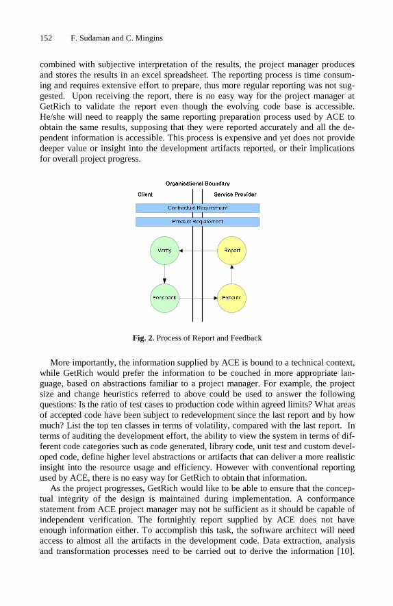
152 F. Sudaman and C. Mingins
combined with subjective interpretation of the results, the project manager produces and stores the results in an excel spreadsheet. The reporting process is time consum-ing and requires extensive effort to prepare, thus more regular reporting was not sug-gested. Upon receiving the report, there is no easy way for the project manager at GetRich to validate the report even though the evolving code base is accessible. He/she will need to reapply the same reporting preparation process used by ACE to obtain the same results, supposing that they were reported accurately and all the de-pendent information is accessible. This process is expensive and yet does not provide deeper value or insight into the development artifacts reported, or their implications for overall project progress.
Fig. 2. Process of Report and Feedback
More importantly, the information supplied by ACE is bound to a technical context, while GetRich would prefer the information to be couched in more appropriate lan-guage, based on abstractions familiar to a project manager. For example, the project size and change heuristics referred to above could be used to answer the following questions: Is the ratio of test cases to production code within agreed limits? What areas of accepted code have been subject to redevelopment since the last report and by how much? List the top ten classes in terms of volatility, compared with the last report. In terms of auditing the development effort, the ability to view the system in terms of dif-ferent code categories such as code generated, library code, unit test and custom devel-oped code, define higher level abstractions or artifacts that can deliver a more realistic insight into the resource usage and efficiency. However with conventional reporting used by ACE, there is no easy way for GetRich to obtain that information.
As the project progresses, GetRich would like to be able to ensure that the concep-tual integrity of the design is maintained during implementation. A conformance statement from ACE project manager may not be sufficient as it should be capable of independent verification. The fortnightly report supplied by ACE does not have enough information either. To accomplish this task, the software architect will need access to almost all the artifacts in the development code. Data extraction, analysis and transformation processes need to be carried out to derive the information [10].

Evidence-Based Management of Outsourced Software Projects 153
These processes are time consuming and not easily repeatable. If a more coherent approach is available for defining, accessing and analyzing such software artifacts without much effort, this process can be performed more regularly, thus any design erosion or deviation in implementation can be detected as early as possible.
Another major challenge faced by GetRich in the outsourced development process is how to ensure that all changes to code-base that have been user acceptance tested are reported accurately by ACE. Any changes will require impact analysis and retest-ing to minimize the risk of breaking changes. Although this is clearly specified in the contractual agreement, there is no way of enforcing it or even revealing it, especially if ACE intends to hide the activity. GetRich is fully aware of this risk and to mitigate it, has allocated extra resources to regression testing and a complete retest of the whole system post-delivery. The same challenges exist in software maintenance out-sourcing where the client may not want the service provider who has very little knowledge about the business domain code base to make any changes in these highly sensitive areas, such as those relating to licensing, security or high risk business trans-actions. This highlights the need for a mechanism to guide and police the software evolution through a set of user defined policies We believe this is crucial for SEM in general but particularly for risk mitigation in outsourced development.
3 SEM and Outsourcing
Outsourced software development by nature involves distributed teams hence the use of Software Configuration Management (SCM) is obvious and necessary for the pro-ject to run effectively [9][23][17]. The field of SCM provides a wealth of evolution-ary history and change reasoning about software systems. It offers a wide range of tools for managing and controlling the development and evolution of software sys-tems. In many respects, SCM can be seen as the underpinning infrastructure for Software Evolution Management (SEM) [9]. SEM is a discipline primarily focused on extracting and analyzing evolutionary information about software systems with the aim of better understanding and tracking the software changes over time. The effec-tive use of SEM enables understanding of the status of the current system and the construction of predictive and retrospective analysis models [16]. Progress reporting in outsourcing projects is by nature reporting about evolution of the system by com-paring the current snapshot of the system against the metrics gathered and reported in the last progress report, or some baseline. Therefore it inherently practices some as-pects of SEM [10]. It is clear that unification of the wealth of information available in SCM and a systematic SEM approach for extracting and analyzing this information is appealing for use in outsourced development to establish realistic reporting that is evidence based, traceable and verifiable. A SEM environment that allows policy to be specified and used to guide the software evolution will facilitate the client’s more ef-fective control of the outsourced development. All these in turn help to elevate project understanding, reduce risks of diverging visions; aid better overall risk management and finally leads to improved relationships built on mutual trust [22].
As it currently stands, SCM is considered to have reached a mature level [14] but more progress is still considered necessary to better support SEM [9][20]. The cur-rent approach to SCM is strongly based on files and source code while evolutionary
154 F. Sudaman and C. Mingins
information, versioning and differentiation are limited to file units. This does not match up with the logical abstractions (such as in the object-oriented context) that software practitioners are familiar with, nor with commonly used software architec-ture or design models such as UML [26][27]. Versioning based only on files and lines of code do not capture the deeper meaning of the evolutionary changes and thus can only provide a very restrictive view, limited control, modeling and reporting of the evolving system [9][25]. Conventional approaches for deriving object oriented metrics for reporting require extensive development effort to extract the information, dealing with language dependent parsing, storing and mining of the extracted infor-mation. This is time consuming, requiring extensive effort and processing resources, therefore it is generally performed only periodically.
To overcome the shortcomings of mainstream SCM, we have introduced a pro-gramming language neutral SEM infrastructure where semantic artifacts (defined in the next section) of an evolving system can be defined, continuously and systemati-cally managed, interpreted, browsed and made accessible at all times for performing software evolution analytics through a well-defined data model and standardized ac-cess mechanism. This enables metric models to be precisely defined and once defined consistently applied to quantitatively manage the project evolution. Another major merit of our infrastructure is that it offers an extensible environment to allow policies to be applied to semantic artifacts. These attributes can be continuously monitored and executed in parallel with the system evolution. The policies can be used to guide the evolution process and also to maintain the conceptual integrity of the system. We present more technical detail about this infrastructure in the next section.
4 Our Solution: OSSEM
OSSEM stands for Object-oriented Software Semantic Evolution Management. We refer to semantic artifacts in this paper as the logical structure of the software in terms of the object-oriented programming model (such as class, method, field and inheri-tance) and any other artifacts of interest to the actor-user that can be modeled and extrapolated from the underlying model. These artifacts can be defined explicitly via declarative metadata on the underlying software, or may relate to implicitly available metadata such as product information.
OSSEM is a system developed to work in partnership with Subversion (SVN) [1] as its SCM tool to offer a systematic approach for managing object-oriented software evolution. It provides automatic monitoring of software systems; defines and extracts information about evolving semantic software artifacts from the file-based source code stored in the SCM into a well-defined data model and stores the information away in a relational database. This information is then accessible at any time for applying soft-ware evolution analysis and reporting. Another OSSEM facility is the policy checking process whereby any changes on semantic artifacts that have preconfigured policies will activate the policy verification process, which will trigger policy violation notifi-cations. Policies are implemented as plug-in modules in OSSEM. On the whole, OSSEM offers an infrastructure that is integral for modeling, guiding and managing

Evidence-Based Management of Outsourced Software Projects 155
software evolution while retaining the entire functionality provided by SVN to con-tinue providing rich and robust functionality for controlling and recording file-based software evolution. Figure 3 shows the high level information flow of OSSEM, where V1, V2, V3 and Vn denote the evolving project versioning in the SCM repository and S1, S2, S3 and Sn denote the evolving project snapshots captured.
It goes without saying that OSSEM needs to be built with performance and storage optimization in mind in order to be practical for use in a real life evolving system. To date we have adopted strategies such as using sandboxes to effectively load and unload data, parallel processing, smart pre-fetching and caching of data and batching of database operations in our implementation.
Fig. 3. OSSEM Overview
Table 1 shows the physical bytecode size, OSSEM database storage size and execu-tion time for the first cycle to collect the semantic artifacts for three different sized pro-jects. Putting the bytecode size into perspective, at the time of the experiment, the compiled bytecode size of the OSSEM SIA module is 541 KB, a result of compiling 127 source code files that contain 181 abstract data types with approximately 47000 lines of code. OSSEM takes approximately 4 to 5 times the storage space over and above the physical bytecode size and is capable of processing approximately 400 KB of bytecode per minute. Subsequent execution of OSSEM system on the project will perform the incremental change analysis and versioning. Our experiments show that subsequent execution of OSSEM on projects with < 10% changes on the artifacts, takes approximately 24% of the base execution time (about 0.21 minutes for OSSEM SIA module to execute with the storage space usage growing consistently to the above statistics to capture the incremental changes. Because OSSEM only stores the changed artifacts, our experiments of applying OSSEM on the rapidly evolving OSSEM project itself repeatedly shows that the storage usage and growth are manageable.

156 F. Sudaman and C. Mingins
Table 1. Projects Storage and Execution Statistics
OSSEM SIA Module
Ms. WCF2 Ms. .NET3
Bytecode Size 0.53 MB 7.46 MB 44.5 MB Storage Size 2.82 MB 38.61 MB 193.56 MB Exec Time 1.12 mins 19.83 mins 126.4 mins ADT Count 181 4963 23676
Currently OSSEM is developed in the C# language targeting the Microsoft .NET plat-form. The architecture of OSSEM consists of three core elements: the Semantic In-strumentation Agent, the Repository Access Library and the OSSEM Studio.
4.1 Semantic Instrumentation Agent (SIA)
The SIA is implemented to deal with software artifacts in the form of bytecode. Its purpose includes extracting, interpreting, collecting and storing semantic evolution in-formation about changes made to the software product controlled by the SCM. Figure 4 provides an overview of the systematic process performed by the SIA. Basi-cally, this agent performs four tasks in sequential order: continuous build, software semantic analysis, policy verification and change semantics persistence of the evolv-ing software products. Current implementation of SIA targets the Microsoft .NET runtime and deals with bytecode in the form of common intermediate code. In devel-oping the module for performing the continuous build, OSSEM drew on proven tools:
Byte Code
Auto Build
Semantic Repository
Repository Access Layer
Change Monitor Establish Baseline
Acquire Source & Configuration
Metadata Extractor and Introspector
Semantic Analyser and Versioning
SCMVersioning Repostory
Policy Verification
Fig. 4. Semantic Instrumentation Agent Process 2 Windows Communication Framework Assemblies (WCF is part of Microsoft .NET 3.0
Framework). 3 Microsoft .NET 2.0 Framework Assemblies.

Evidence-Based Management of Outsourced Software Projects 157
CruiseControl4 and Ant5 as the underlying technologies. The design of the software change semantic analysis and policy checking module is very much inspired by the work of FxCop6 which allows for rich customization and extensibility. We also based some of our work on ReflectionDiff7 for the purpose of performing semantic change detection and persistency.
SIA works just like an integrated build server and is capable of running on a server machine co-located with the SVN server or on a separate machine. The instrumenta-tion process is triggered either explicitly or by an automated process that continuously monitors the SVN repository. Ideally, every time a new change set is committed, the SIA will immediately launch and perform the processes described above. In practice, such an approach may cause a large build queue in an active or large development team environment and put high pressure on system resources. To solve this problem, the implementation of the SIA adopts the periodic monitoring technique employed by CruiseControl4 whereby the SVN repository is continually being monitored for com-mitted changes at defined intervals. Once a change is detected, the agent will then determine if the last committed change set to SVN is longer ago than a user defined period of x minutes. This determines if the committed changes are considered stable and it is appropriate for SIA to launch the auto build process. Each project managed by OSSEM must have an accompanying build configuration setting that is automati-cally used by the build process. The build configuration setting can be supplied through the user interface provided by OSSEM Studio (see 4.3).
Fig. 5. Semantic Artifacts Versioning Metamodel
The integrated build process produces a snapshot of the evolving system in byte-code form that will then be inspected, analyzed and stored away. When analyzing the semantic artifacts, SIA will make default interpretations of known declarative meta-data, applying the policy checking mechanism. If a policy is configured for the current semantic artifact, it will activate the appropriate policy verification. Policy verification modules are implemented as plug-ins to the SIA by conforming to the predefined inter-face contract. The extracted semantic artifacts will be compared and analyzed against
4 http://cruisecontrol.sourceforge.net/ 5 http://ant.apache.org/ 6 http://blogs.msdn.com/fxcop/ 7 Internal project developed by C. Mingins (co-author) in 2004 for identifying changes in .NET
assembly versions.

158 F. Sudaman and C. Mingins
the latest version of the semantic artifacts in the repository using a predefined algo-rithm. Detected differences will trigger new versions of the entities to be created and stored in the repository guided by the OSSEM versioning policy. Figure 5 shows the high level logical model of our semantic artifact versioning data store. Each evolving system in OSSEM has one or more histories (for branching support) that capture one or more project versions. The logical program structure (such as Namespace, Type and Method) is modeled as entities with each entity have a corresponding versioning entity. Each entity may have declarative attributes and their associated fields attached to it. Each version entity points to its previous version for easy navigation and forms the en-tity version history.
4.2 Repository Access Library (RAL)
At the core of the OSSEM implementation is the RAL component. The RAL serves as the entry point for all data access to the OSSEM data store as one virtual repository that is made up of a physical SVN file versioning repository and a change semantics repository (CSR) that contains the associated bytecode and extracted metadata of the evolving systems managed by OSSEM. All semantic evolutionary information gath-ered by OSSEM is stored in the CSR implemented as a MySQL relational database. Data stored in the CSR can be retrieved using RAL programming interfaces provided by a standard query language or other means provided by standard database manage-ment systems. Both the SIA and RAL integrate with the SVN repository through the SVN client library API and the hook extension mechanism provided by SVN. This separation allows a high level modularization of OSSEM and SVN hence allowing OSSEM to evolve independently from SVN and target other SCM tools in the future. RAL contains all the intelligence for managing semantic artifacts about the evolving system and exposes a rich set of interfaces necessary for client applications to access all configuration settings, the evolutionary information captured and all other aggre-gated evolutionary information exposed by OSSEM.
4.3 OSSEM Studio
The OSSEM Studio is a rich client application built on top of RAL to demonstrate the richness, capability and usability of OSSEM in collecting, storing and retrieving se-mantic artifacts of interest about evolving object-oriented systems. Basic functionality includes browsing the evolution tree of the semantic artifacts, performing a diff of two different snapshots of a semantic artifact and drilling down into its children. OSSEM Studio also provides an interface for configuring OSSEM projects, evolution policies on specific semantic artifacts and adding custom metadata for a specific arti-fact such as [OSSEMLabel (“Stage1”)], which in some instances is more suitable than embedding the metadata in the source code.
Because all intelligent logic is centralized in the RAL, it is possible to build differ-ent types of client applications (console application or plug-in components) with simi-lar capabilities to OSSEM Studio with minimal effort. IDE plug-ins to Visual Studio or Eclipse can also be built with ease to integrate OSSEM to development environ-ments in the future by taking advantage of the rich interface offered by the RAL.

Evidence-Based Management of Outsourced Software Projects 159
5 Quantitative Artifacts and Policies
OSSEM is an ideal platform for defining and collecting quantitative information about the evolving product, as all the hard work of collecting, ‘diff’ing and analyzing the changes over time is already done. Standard object-oriented size and coupling metrics [3][21] and design heuristics such as those defined by FxCop can be easily captured and reported on by OSSEM.
Our approach emphasizes the linking of high level concerns of the outsourcing pro-ject manager, through policies, to quantifiable artifacts that are either innate or broader abstractions that can be defined over a set of innate artifacts. We briefly de-scribe below a number of abstractions that represent concerns of the outsourcer and that can be defined as OSSEM artifacts and tracked in an outsourcing environment.
Stability: A stability measure has been agreed between the two parties. It is under-stood that as a system evolves, it may be necessary to revisit and modify completed code. However code that is continuously revisited as the system evolves could denote a design that is inherently unstable, or requirements that are not properly understood. Application of the stability measure will activate reporting over a pre-determined time span of all completed classes whose definition changes by a predefined percentage. ‘Completed code’ is an artifact that can be quite simply defined by tagging classes, namespaces or even entire assemblies via OSSEM Studio.
Not Invented Here: During contract negotiations the contractor stated that all the software would have to be developed from scratch, as there were no libraries or exter-nal components available to fit the specification. The outsourcer agreed to pay for the bespoke development but is wary of being charged for large amounts of pre-existing code that might be introduced unbeknownst to him. Therefore a measure has been es-tablished to monitor the evolving size of the system. The system is partitioned or tagged so that all pre-existing code and libraries are outside the visibility boundary. Artifacts that are designed to auto generate code are identified, and the report is de-signed to quantify classes and methods that were introduced in a certain time span within the visibility boundary only and assess it against agreed size and growth limits.
Change impact: OSSEM can easily collect data that illustrates the impact of imple-menting a requirements change in an otherwise stable system. It can also be used to re-capture and examine a prior change impact for a similar requirement to assist with cost estimation. To take a more interesting example, the outsourcing organization can also establish and enforce policies concerning the relationship between new or sig-nificantly modified functionality and unit tests. For instance the change impact meas-ure could set an acceptable ratio between application code change and unit test change. OSSEM automatically collects custom metadata such as [TestClass] and [TestMethod] annotations on unit test classes and methods (required for the Ms. NET Unit Test Framework). Therefore this ratio can be easily derived.
Artifacts may have policies associated with them. A policy is defined as an agree-ment between the outsourcer and the contractor with respect to some aspect of the evolving system. The policy includes a general description of its intention, identifies the artifacts associated with the policy, the normal state of the artifacts, and abnormal

160 F. Sudaman and C. Mingins
conditions that would trigger policy violation reporting. Below we briefly describe a number of OSSEM policies that would be useful in an outsourcing environment.
Frozen: Certain sets of classes are tagged as Frozen. The Frozen policy dictates that the attached entity is critical or core functionality that must not be modified without prior agreement with the outsourcer. Modifying the entity will trigger an alert or re-port to the outsourcer. The policy could be applied on any entity such as a method, a class, or entire class library or framework.
Loose Coupling: Tools such as FxCop are able to police coupling (e.g. methods should have less than seven parameters) based on absolute heuristics deriving from a single snapshot. OSSEM is able to enforce such coupling trends over time by dictat-ing that changes on any methods within a designated area must, for example, add no more than three parameters and three non system type local variables from the desig-nated baseline. Any method that violates this policy would trigger an alert or report to the outsourcer /auditor with details on the method name, list of parameters, the class and namespace where the method is to be found. This is an example of using policy to preserve the design integrity of the system.
The abstractions above show some effective applications of OSSEM for outsourced software development or maintenance. Reporting dilemmas described in section 2 can be overcome with OSSEM by querying the collected semantic artifacts stored in OSSEM database for project status reporting; constructing reports by aggregating sets of artifacts into higher level abstractions relevant to the project manager; applying policies that facilitate monitoring the accepted code-base and design heuristics of the system during its on-going development. To further emphasize the advantages of ap-plying our infrastructure in an outsourcing context, in the following sections we briefly review some of the other major benefits of OSSEM.
5.1 Systematic Monitoring
Our approach embraces the concept of continuous integration and constant feedback based on the Agile philosophies whereby the semantic instrumentation agent is auto-mated to build and collect the semantic artifacts of the system as often as possible when changes to the system are detected in the source artifacts. To register a project to be monitored by OSSEM, a one-off setup process is required to prepare and set the project build configuration, with minimal effort required. Once this is in place, OSSEM automatically ensures evolutionary information of the evolving system is collected regularly and is available at all times. In an outsourcing context where pro-ject teams are distributed geographically, this is crucial to guarantee that up to date in-formation is always available and accessible without regard for location, time zone or having to rely on the diligence of any particular individual.
5.2 Language Neutrality
Modern virtual machines (VM) offer programming language neutrality by providing a source-language independent instruction set and metadata support beyond primitive ASCII source or binary image files [6]. Today, at least 20-30 programming languages target the .NET platform by producing bytecode consumable by the virtual machine.

Evidence-Based Management of Outsourced Software Projects 161
Compared to using bytecode for static software analysis to elicit program structure, source code analysis would require analysis tools for each programming language with parser capabilities similar to the language compiler. Worse still, language specific parsers will need to be developed for each programming language [6]. By leveraging the use of bytecode analysis and modern virtual machines, OSSEM immediately offers an SEM infrastructure that is language neutral therefore allowing it to have a broader acceptance and not imposing language specific development environment on the out-sourcing and service providers.
5.3 Semantically Rich Artifacts
The availability of semantic rich artifacts besides making quantitative management of outsourced project easier also aligns the implementation with software architecture and design model developed based on object-oriented methodology and UML notations. This narrows the design-implementation gap and enables easier detection of architec-ture drifts and design erosion issues [3][25][26]. The support for custom metadata also essentially enables extensions to the underlying type system and provides an enriched semantic model to seamlessly incorporate user-defined semantic artifacts representing new, project-oriented perspectives into software evolution analysis and modeling. De-spite all the strong arguments for needing to use a logical data models in SCM, OSSEM did not ignore the fact that most mainstream SCM tools (such as CVS and Subversion) use a file-based model [1]. This also applies to mainstream IDEs such as Visual Studio and Eclipse. OSSEM does not replace existing file-based models in SCM; instead it enriches the model with a parallel logical data model to provide richer views to suit users in different roles.
5.4 Data Model and Access
The use of the relational data model and database allows uniform data storage and data access. This enables metric models to be precisely defined and once defined they can be consistently applied to quantitatively manage the project evolution. Today, most if not all data analysis, reporting and programming software packages will have well defined interfaces to access relational databases, hence reporting and data analy-sis are also facilitated. This also clearly opens up opportunities for automated report-ing and auditing toolsets to be developed for more effective outsourced software project management.
5.5 Preserving Conceptual Integrity
The ability to apply policy in OSSEM allows the conceptual integrity of the software product to be preserved throughout its development lifecycle and any violations to be signaled. Relationships between outsourcing partners is strongly driven by the level of trust and trust is closely interrelated with project risk [11][15][22]. The higher the perceived project risk, the more uncertainty there is, hence a higher level of trust is required. The ability for the outsourcing company to gain more direct control through their ability to establish clear policies to guide and monitor the software project changes reduces project risk and uncertainty. We believe it will actually increase the

162 F. Sudaman and C. Mingins
confidence and level of trust between outsourcer and service provider. It will certainly encourage more transparent reporting by the contractor.
6 Related and Future Work
With the distributed nature of outsourced software development the use of SCM, and the need or regular progress reporting, the application of SEM based on SCM seems rather obvious to quantitatively managed outsourced software development. Research work in the area of managing outsourced software development has predominantly focused on partnerships and leans towards project governance, contract management and process modeling [2][11][15][22]. Although reporting framework, collaboration and methodology for outsourcing project have been explored in several research works [18][23][17], we are not aware of any research work that focuses specifically on the use of an SEM infrastructure as the common basis for evidence-based report-ing, validation and applying policies for guiding the software development. In this re-spect, our perspective of applying OSSEM in outsourced software development is novel. This infrastructure can be seen as a technology specific toolset with well de-fined interactions that can facilitate process improvement aligning with the CMMI (Capability Maturity Model Integration) process model [4].
In terms of our SEM infrastructure, there are number of related works that are worth mentioning. OSSEM shares the core idea of Molhado [25] of capturing evolu-tionary information at the logical abstraction level, but OSSEM retains the file-based SCM which is widely used in the industry and offers additional benefits such as pro-gramming language neutrality and the use of declarative metadata. We perceive di-vergence from the widely used file-based model to be high risk at this present time. While the meta-model of OSSEM is analogous to HISMO [24], OSSEM focuses on the entire systematic process of modeling, obtaining and capturing the data rather than just modeling the data as in HISMO. Fact extractor type research projects such as JDevAn [26][27], Bloof [5], CollabDev [23] and Kenyon [8] are closest to the OSSEM approach. Although they share many motivations, design ideas and goals, they differ considerably in their approaches and applications. JDevAn is implemented as plugin to Eclipse, hence the availability of snapshots relies on how regularly the analysis operation is performed by the developer and the data only reflects the local code base. Bloof and CollabDev extracts their historical information based on file and line changes; and other commit metadata (such as date, author and comment) and is therefore clearly lacking in support for object-oriented SEM. Although Kenyon offers more flexibility with custom fact extractors and a well defined data model and data store, it also still focuses on file and code changes, commit and configuration meta-data. There is no evidence to suggest that it supports fact extraction at the logical abstraction level, or modeling and versioning similar to OSSEM. Another desirable feature of OSSEM that sets itself apart from other related work is the policy verifica-tion support, which is in a way similar to the work done by Madhavji and Tasse [19], but OSSEM can operate at a much more fine grained level for targeting specific se-mantic artifacts and our extensibility model based on plugin architecture allows the leveraging of programming language features and flexibility.

Evidence-Based Management of Outsourced Software Projects 163
OSSEM is currently in its implementation phase; a working system has been de-veloped and tested with a limited set of test data. Further development and refinement of the model and policy verification mechanism are still required. The OSSEM Studio currently is still at the prototype stage. More performance tuning is currently under-way to ensure OSSEM performs optimally on medium to large size projects. The ar-chitectural design, components, meta-model and data store are designed or chosen for OSSEM to allow it to work independently of any specific platform and not limited to Ms .NET implementation only. Future work may also extend the semantic instrumen-tation agent to support Java bytecode targeting the JVM.
7 Conclusion
OSSEM facilitates the application of the CMMI process model in organizations to ac-quire capability and maturity 4 Level 2 (Repeatable) where a systematic process is in place for continuously identifying and analyzing semantic artifacts; Level 3 (Defined) where data models and access mechanisms to the semantic artifacts are standardized; Level 4 (Quantitatively Managed) where metric models can be precisely defined based on OSSEM semantic artifacts. The metrics once defined can be consistently ap-plied for reporting, managing software developing effort or developing predictive models for future development tasks.
We believe the introduction of infrastructure such as OSSEM to support evidence-based reporting and qualitative management will stimulate a culture change at the very least, and perhaps revolutionize outsourced software development, by placing more timely information in the hands of the outsourcing organization, thus allowing them to better manage their project risk while at the same time establishing clear ac-countability policies and reporting guidelines for the service providers. We also see an emerging need for a new category of software audit professional, filling much the same role as a financial auditor in the accounting field and also bearing similarities to the role of a quantity surveyor, managing the economics of software development. The software audit professionals would equip with OSSEM-like tools to facilitate ex-ploration, analysis and reporting on the evolving software product. The information extracted would then be interpreted in the context of guidelines and policies that have been agreed upon in the initial project contract. Software audit professionals must be technically skilled in software engineering, just as auditors are qualified accountants. In addition they must be able to interpret and translate the information in a business context to communicate effectively with their clients, the outsourcing organization.
References
1. Sussman, B.C., Fitzpatrick, B.W., Pilato, C.M.: Version Control with Subversion, 1st edn. (June 2004) ISBN 10: 0-596-00448-6
2. Meyer, B.: The Unspoken Revolution in Software Engineering. IEEE Computer 39(1) (January 2006)
164 F. Sudaman and C. Mingins
3. Kemerer, C.F., Slaughter, S.: An Empirical Approach to Studying Software Evolution. IEEE Transactions on Software Engineering 25(4) (July/August 1999)
4. CMMI® for Development Version 1.2, Improving Processes for Better Products. CMU/SEI-2006-TR-008, Carnegie Mellon, Software Engineering Institute (August 2006)
5. Draheim, D., Pekacki, L.: Process-Centric Analytical Processing of Version Control Data. In: Proceedings of the Sixth International Workshop on Principles of Software Evolution, IWPSE 2003 (2002)
6. Lance, D., Unteh, R.H., Wahl, N.J.: Bytecode-based Java Program Analysis. In: Proceed-ings of the 37th annual southeast regional conference (1999)
7. Brooks, F.P.: The Mythical Man-Month: Essay on Software Engineering. Addison-Wesley, Reading (1995)
8. Bevan, J., et al.: Facilitating Software Evolution Research with Kenyon. In: Proceedings of the 10th European Software Engineering Conference, Lisbon, Portugal, September 5-6 (2005)
9. Estublier, J., et al.: Impact of Software Engineering Research on the Practice of Software Configuration Management. In: IEEE TOSEM (2005)
10. Girard, J.F., Verlage, M., Ganesan, D.: Monitoring the Evolution of an OO System with Metrics: an Experience from the Stock Market Software Domain. In: Proceedings of the 20th IEEE International Conference on Software Maintenance, ICSM 2004 (2004)
11. Goo, J., Nam, K.: Contract as a Source of Trust – Commitment in Succesful IT Out-sourcing Relationship: An Emprical Study. In: Proceedings of the 40th Annual Hawaii In-ternational Conferences on System Sciences, HICSS 2007 (2007)
12. Chakraborty, K., Remington, W.: Offshoring of IT Services: The Impact on US Economy. Journal of Computing Sciences in Colleges 20(4) (April 2005)
13. Schwalbe, K.: Information Technology Project Management, Course Technology, 5th edn. (July 2007)
14. Bendix, L.: Widening the Configuration Management Perspective. In: Proceedings of Metainformatics Symposium 2002, Esbjerg, Denmark, August 7-10 (2002)
15. Kinulla, M., et al.: The Formation and Management of a Software Outsourcing Partner-ship. In: Proceedings of the 40th Annual Hawaii International Conferences on System Sci-ences, HICSS 2007 (2007)
16. Lehman, M.M.: Laws of Software Evolution Revisited. In: Proceedings of the 5th Euro-pean Workshop on Software Process Technology, pp. 108–124 (1996)
17. Simons, M.: Distributed Agile Development and the Death of Distance. Sourcing and Vendor Relationships 5(4) Cutter Consortium
18. Chapin, N.: Usefulness of Metrics and Models in Software Maintenance and Evolution. In: WESS 2000 Position Paper (2000)
19. Madhavji, N.H., Tasse, T.: Policy-guided Software Evolution. In: 19th IEEE International Conference on Software Maintenance, ICSM 2003 (2003)
20. Prikladnicki, R., et al.: Distributed Software Development: Practices and Challenges in Different Business Strategies of Offshoring and Onshoring. In: International Conference on Global Software Engineering, ICGSE (2007)
21. Pressman, R.S.: Software Engineering a Practitioner’s Approach, Mc Graw Hill Interna-tional Editions, 5th edn. (2001)
22. Sakthivel, S.: Managing Risk in Offshore Systems Development. Communication of the ACM 50(4) (April 2007)
23. Sarkar, S., Sindhgatta, R., Pooloth, K.: A Collaborative Platform for Application Knowl-edge Management in Software Maintenance Projects. In: Proceedings of the 1st Bangalore Annual Compute Conference (2008)

Evidence-Based Management of Outsourced Software Projects 165
24. Girba, T., Ducasse, S.: Modeling History to Analyze Software Evolution. International Journal on Software Maintenance and Evolution: Research and Practice, JSME (2006)
25. Nguyen, T.N., Munson, E.V., Boyland, J.T.: An Infrastructure for Development of Object Oriented, Multilevel Configuration Management Services. In: Proceedings of the 27th In-ternational Conference on Software Engineering (2005)
26. Xing, Z., Stroulia, E.: Analyzing the Evolutionary History of the Logical Design of Object-Oriented Software. IEEE Transactions on Software Engineering 31(10) (October 2005)
27. Xing, Z., Stroulia, E.: Understanding Class Evolution in Object-Oriented Software. In: Proceeding of the 12th IEEE International Workshop on Program Comprehension, WPC 2004 (2004)

K. Berkling et al. (Eds.): SEAFOOD 2008, LNBIP 16, pp. 166–180, 2009. © Springer-Verlag Berlin Heidelberg 2009
A Closer Look at Extreme Programming (XP) with an Onsite-Offshore Model to Develop Software Projects Using XP Methodology
Ponmurugarajan S. Thiyagarajan and Sachal Verma
Tata Consultancy Services [email protected]
Abstract. The business world of today is highly competitive. Business users demand IT organizations to adapt quickly to changes and provide on-time, cost-effective solutions. This compels companies to look closely at their software development processes, to improve them and remain cost-effective. Offshoring is a well-known cost-effective solution for projects that follow waterfall and other traditional software development life cycles (SDLC). Waterfall SDLC may not be ideal when requirements are changing rapidly. Achieving rapidness in software development along with offshoring will enable companies to pro-vide quick and cost effective IT solutions. To manage rapidly changing re-quirements, a large telecommunications company moved out of traditional waterfall model and adopted Extreme programming (XP) software development methodology. This paper discusses, in detail, a Telecommunication software project case study along with the customized XP onsite-offshore model that was successfully used in developing the project. This paper also share the lessons learnt from this XP onsite-offshore model.
Keywords: Extreme Programming, XP, Offshore, Model, Telecommunication.
1 Introduction
In today’s world, business changes are very rapid due to intense competition and frequent introduction of new products to the market. These changes to business re-quirements trigger changes to traceable IT requirements. Managing rapidly changing business and IT requirements and developing durable and adaptable software may be challenging and costly. Traditional models like waterfall software development meth-odology may not even fit or be efficient in such situations. A move towards agile software development techniques may be necessary. Agile software development techniques, like Extreme Programming or XP (Kent Beck, 2000), can adjust to rapidly changing requirements and help refactor the software accordingly. Extreme Pro-gramming an agile software development methodology, is a predictable way to de-velop high quality software with minimal risk in the short term and the long term, which the customers will like. A reason for this liking is customer presence and close contact with the team through out the tenure of the project.

A Closer Look at Extreme Programming (XP) with an Onsite-Offshore Model 167
Offshoring has now become a common option for many organizations to develop and maintain their cost effective software. Extreme Programming, developed by Kent Beck, is born out of the desire to apply best in class software practices in a disciplined and reproducible way. To perform disciplined software development using XP methodology involving onsite and offshore teams may require suitable customization of XP method-ology. There are efforts by researchers (Samantha Butler et. al., 2003), but not complete study, to investigate the effectiveness of global software development using XP.
This paper is mainly organized as follows: Section 2 provides an overview of XP and compares it with other traditional models. Section 3 details a case study with an onsite-offshore model developed and successfully completed for a large Telecommu-nication company based in the United States. Here, the authors also compare tradi-tional and customized onsite-offshore XP practices. Lessons learnt from this project are also listed. Section 4 describes conclusions.
2 Overview of XP
XP is a deliberate and disciplined approach of software development. It enables users to get reliable, working software quickly and continue development at a rapid, confi-dent, and predictable pace with ever-increasing quality. It is designed to suite environ-ments where requirements are rapidly changing and scope is unclear. It emphasizes on customer satisfaction and teamwork. The following sub-sections discuss some of the important XP concepts.
2.1 XP Values
Key XP values (Chromatic, 2003) are simplicity, communication, testing and courage. XP requires communication to be simple with involvement of onsite business customer during all software development phases. XP encourages good communication so that business people do not promise the unachievable and technical people do not achieve the unwarranted. It involves starting with simple solutions so that more complex func-tionalities shall be added later. Requirements are tweaked into simple and clear user stories for better understanding. Feedback is another key value of XP. Feedback from customers, teams and systems are ensured in all phases of development. Unit tests ensure feedback from systems. Regular presence of customers ensures continuous feedback from them. Daily stand-up calls and pair-programming ensures continuous feedback from teams. Feedback from customers is obtained at all phases to perform necessary refactoring. Courage is another key XP value. XP lets customer drive the project courageously. XP based software development is in small and regular cycles involving frequent evaluations. It practices pair-programming and encourages team to sit together so that everybody could see what each one is capable of doing.
2.2 XP and Traditional Models Compared
Traditional way to software development usually have these:
i. Months of meetings with customers before and during the project startup phase
ii. Generate requirements, specification documents, use cases etc.

168 P.S. Thiyagarajan and S. Verma
iii. Customers negotiate a release date iv. Developers design, code and test v. Customer performs User Acceptance Testing (UAT) vi. Often pieces and requirements are missed vii. Often whole process takes longer than expected
In an XP way,
i. Customer interacts with XP team regularly during development ii. Customer writes requirements which are broken down into clear and crisp
user stories iii. Developer estimate user stories iv. Stories are grouped into releases comprising of various iterations v. Customer provides feedback during development and reviews outputs at
the end of each iteration vi. Customer writes acceptance tests vii. Developers test, code and refactor viii. Customer controls team’s direction
Following diagram (Figure 1) compares traditional methods like Waterfall and Itera-tive development with XP. You can see that XP takes small and simple steps to achieve the target whereas Waterfall and Iterative development progresses in rela-tively large steps and in phases. In a waterfall model, any change or issue discovered at a later point of the project will badly impact project completion and cost.
Fig. 1. XP and Traditional Methods – Compared
The following diagram (Figure 2) compare the development phases in Waterfall mapped to XP. You may note that a release of software in XP methodology consist of several iterations.

A Closer Look at Extreme Programming (XP) with an Onsite-Offshore Model 169
Fig. 2. XP and Waterfall - Compare Releases
2.3 Typical XP Process
The following diagram (Figure 3) illustrates the End-to-End XP Process (Donovan Wells, 1999).
Fig. 3. XP Process

170 P.S. Thiyagarajan and S. Verma
An XP project consists of a series of releases, approximately 1 to 3 months long, each providing some business value. A release consists of number of iterations that are approximately 1 to 3 weeks long. Each iteration consists of stories, which, in turn, are made up of tasks. A task is executed in test and functional code. During release planning, the customer chooses the stories the customer wants in that release. Stories are selected for each iteration based on the customer preference and available user velocity. Stories are spiked or split based on its complexity. Developers estimate effort for each user story. Velocity is a measure of capacity or the effort each team member can put for the iteration. Task assignments are based on available velocity of the team member. Unit tests are written to completely test the user story. Coding and testing take place as pair programming. Once coding and testing is completed, auto-mated integrations tests are run to ensure correctness and completeness of the devel-opment planned for that iteration. At the end of each iteration, customer performs user acceptance tests and once signed-off is implemented in production through a release.
In the next section, the authors explain a case study and discuss a successfully im-plemented onsite-offshore model for an XP based development project for a Tele-communications company.
3 A Case Study
3.1 The Telco Project
A major Telecommunications provider wanted to consolidate its three legacy cus-tomer account management (CAM) applications into a single regional Java based application. Due to mergers and acquisitions, which happened years before, this tele-communication provider had to maintain 3 different legacy applications to perform customer account management functions. These 3 legacy applications ran in main-frame environment. Software enhancement and maintenance of these legacy applica-tions were costly and time consuming, and, demanded consolidation.
The team members of these legacy mainframe applications were located in various locations involving onsite and offshore. Onsite teams were located in Denver, Seattle and Omaha whereas offshore team was in Chennai, India. Onsite teams comprised of business subject matter experts and technical leads which included Telco’s employees and onsite consultants. Onsite consultants, from a contracting company, reporting to the onsite Project Manager, interacted and shared work with their offshore consultants (of the same contracting company). Offshore teams primarily consisted of a Project Manager, programmers and testers.
This was the time, when the Telco made the decision to move out of Waterfall SDLC to XP based software development. With well-known benefits of XP (Gittins et. al., 2001 and 2002), management was committed to propagate and adhere to the new XP methodology and use it for the new CAM project. To avail the best benefits of XP, the team should follow its defined, deliberate and disciplined process.
The proposed consolidated CAM application was designed to be based on J2EE ar-chitecture. The new Java based application was planned to be developed using an open source based integrated development environment (IDE), Eclipse (Eclipse Plat-form Review, 2003). Following is the comparison (Table 1) of the different technolo-gies involved with legacy and new CAM applications.

A Closer Look at Extreme Programming (XP) with an Onsite-Offshore Model 171
Table 1. Technologies Compared
Legacy CAM applications New Consolidated CAM application (XP)
Operating System
z/OS mainframe, MVS Linux
Programming Languages
COBOL, Assembler, JCL Java
Configuration management
Endevor PVCS Dimensions
Database DB2, IMS-DB Oracle Other Software Viasoft, Rexx J2EE Technologies, Hibernate, TIBCO
3.2 Onsite-Offshore Model
3.2.1 Challenges XP is ideal for teams working at a single location that can ensure face to face com-munication. With the current team distribution (3 onsite location and 1 offshore loca-tion), it was impossible to bring the team in one location. These factors triggered customization of the XP methodology and practices for the project and the need to enhance the existing onsite-offshore model. The main challenges were to manage teams located in several geographical locations and working in different time zones. Adding to these challenges, lack of Java skilled programmers was another issue. Telco’s legacy applications SMEs (Subject Matter Experts) were experts in main-frame and did not possess necessary Java/J2EE skills.
3.2.2 Planning and Solutions Offshore consultant team was ready to ramp up trained and skilled Java programmers. Telco’s legacy SMEs were trained in Java technologies for a month’s time period before the project startup. This, to some extent, solved the issue of shortage of Java skilled programmers. Next challenge was to address the team distribution at onsite and offshore. Onsite teams were scattered at various US locations - Denver, Omaha and Seattle. Offshore team was located in Chennai. XP process, ideally, demand teams to sitting face to face at the same location (as shown below in Figure 4). Fol-lowing diagram is an illustration of a typical XP ‘pod’, XP development area.
Pods were created or modified, as necessary, at all 3 onsite locations so that respec-tive teams can ensure face-to-face communication at that location. Team members have to perform XP development work only from their pods. Pods were equipped with telephones, personal computers with web conferencing facilities and whiteboards to ensure effective communication as demanded by XP. Now that infrastructure and other set-up are planned and ready, let us discuss the onsite-offshore XP model to develop the software project.

172 P.S. Thiyagarajan and S. Verma
Fig. 4. XP Pod
3.2.3 The Model The following diagram (Figure 5) represents the onsite-offshore model customized to work in XP methodology.
Fig. 5. Onsite-Offshore XP Model
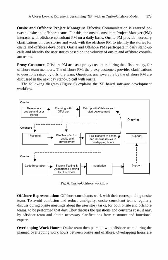
A Closer Look at Extreme Programming (XP) with an Onsite-Offshore Model 173
Onsite and Offshore Project Managers: Effective Communication is ensured be-tween onsite and offshore teams. For this, the onsite consultant Project Manager (PM) interacts with offshore consultant PM on a daily basis. Onsite PM provide necessary clarifications on user stories and work with the offshore PM to identify the stories for onsite and offshore developers. Onsite and Offshore PMs participate in daily stand-up calls and identify the user stories based on the velocity of onsite and offshore consult-ant teams.
Proxy Customer: Offshore PM acts as a proxy customer, during the offshore day, for offshore team members. The offshore PM, the proxy customer, provides clarifications to questions raised by offshore team. Questions unanswerable by the offshore PM are discussed in the next day stand-up call with onsite.
The following diagram (Figure 6) explains the XP based software development workflow.
Fig. 6. Onsite-Offshore workflow
Offshore Representation: Offshore consultants work with their corresponding onsite team. To avoid confusion and reduce ambiguity, onsite consultant teams regularly discuss during onsite meetings about the user story tasks, for both onsite and offshore teams, to be performed that day. They discuss the questions and concerns rose, if any, by offshore team and obtain necessary clarifications from customer and functional experts. Overlapping Work Hours: Onsite team then pairs up with offshore team during the planned overlapping work hours between onsite and offshore. Overlapping hours are
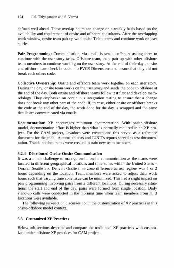
174 P.S. Thiyagarajan and S. Verma
defined well ahead. These overlap hours can change on a weekly basis based on the availability and requirement of onsite and offshore consultants. After the overlapping work window, onsite team pair up with onsite Telco teams and continue work on user stories. Pair-Programming: Communication, via email, is sent to offshore asking them to continue with the user story tasks. Offshore team, then, pair up with other offshore team members to continue working on the user story. At the end of their days, onsite and offshore team check-in code into PVCS Dimensions and ensure that they did not break each others code. Collective Ownership: Onsite and offshore team work together on each user story. During the day, onsite team works on the user story and sends the code to offshore at the end of the day. Both onsite and offshore teams follow test first and develop meth-odology. They emphasize on continuous integration testing to ensure that a change does not break any other part of the code. If, in case, either onsite or offshore breaks the code at the end of the day, the work done for the day is scrapped and the same details are communicated via emails. Documentation: XP encourages minimum documentation. With onsite-offshore model, documentation effort is higher than what is normally required in an XP pro-ject. For the CAM project, Javadocs were created and this served as a reference document for the code. Automated tests and JUNITs reports served as test documen-tation. Transition documents were created to train new team members.
3.2.4 Distributed Onsite-Onsite Communication It was a minor challenge to manage onsite-onsite communication as the teams were located in different geographical locations and time zones within the United States – Omaha, Seattle and Denver. Onsite time zone difference across regions was 1 or 2 hours depending on the location. Team members were asked to adjust their work hours such that varying time zone issue can be minimized. This had a slight impact on pair programming involving pairs from 2 different locations. During necessary situa-tions, the start and end of the day, pairs were formed from single location. Daily stand-up calls were conducted in the morning time when team members from all 3 locations were available.
The following sub-section discusses about the customization of XP practices in this onsite-offshore model context.
3.3 Customized XP Practices
Below sub-sections describe and compare the traditional XP practices with custom-ized onsite-offshore XP practices for CAM project.
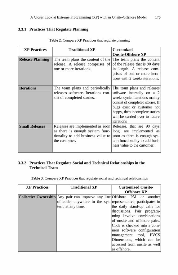
A Closer Look at Extreme Programming (XP) with an Onsite-Offshore Model 175
3.3.1 Practices That Regulate Planning
Table 2. Compare XP Practices that regulate planning
XP Practices Traditional XP Customized Onsite-Offshore XP
Release Planning
The team plans the content of the release. A release comprises of one or more iterations.
The team plans the content of the release that is 90 days in length. A release com-prises of one or more itera-tions with 2 weeks iterations.
Iterations
The team plans and periodically releases software. Iterations con-sist of completed stories.
The team plans and releases software internally on a 2 weeks cycle. Iterations mainly consist of completed stories. If bugs exist or customer not happy, then incomplete stories will be carried over to future iterations
Small Releases Releases are implemented as soon as there is enough system func-tionality to add business value to the customer.
Releases, that are 90 days long, are implemented as soon as there is enough sys-tem functionality to add busi-ness value to the customer.
3.3.2 Practices That Regulate Social and Technical Relationships in the Technical Team
Table 3. Compare XP Practices that regulate social and technical relationships
XP Practices Traditional XP Customized Onsite-Offshore XP
Collective Ownership
Any pair can improve any line of code, anywhere in the sys-tem, at any time.
Offshore PM or another representative, participates in the daily stand-up calls for discussions. Pair program-ming involve combinations of onsite and offshore pairs. Code is checked into a com-mon software configuration management tool, PVCS Dimensions, which can be accessed from onsite as well as offshore.

176 P.S. Thiyagarajan and S. Verma
Table 3. (Continued)
Simple Design
The simplest thing that could possible work to make the unit test pass, in the context of an overall system architecture that supports the requirements. Refactor as necessary.
Design is kept simple with agreement between onsite and offshore teams. Design infor-mation is accessible at a com-mon folder location and can be accessed through a configura-tion management tool.
Coding Standards
Developers and testers write all code in accordance to prede-fined rules that enhance com-munication through the code
Java coding standards are devised and shared with on-site-offshore teams and the same is ensured during pair programming involving onsite and offshore pairs. A Java based IDE; Eclipse is used by both onsite and offshore teams. Software packages, components conventions and standards are followed across the board.
Refactoring
Design changes, no matter how sweeping, take place in small, safe steps
Pair programming involving onsite and offshore ensure necessary refactoring for simplification of code and design.
3.3.3 Practices That Help to Assure Quality Software
Table 4. Compare XP Practices that assure quality
XP Practices Traditional XP Customized Onsite-Offshore XP
Pair Programming
All code is written (includ-ing acceptance tests) with two people at one machine
Pair programming involving onsite and offshore team member combinations is achieved through web con-ferencing (for example, Microsoft Net Meeting) and telephone conferencing. Pair programming also happen at ‘pods’ at respective offshore and onsite locations. In few scenarios, triplets of pro-grammers (combinations of onsite and offshore) were

A Closer Look at Extreme Programming (XP) with an Onsite-Offshore Model 177
Table 4. (Continued)
present during programming for better understanding of business and technology. Triplets, for example, were formed between an onsite Subject Matter Expert, onsite Technical Lead and offshre programmer. A common overlapping work period is devised and fol-lowed for onsite-offshore pair programming.
Test-first Develop-ment
New code is written or existing code is refactored only after a unit test has been created and verified to pass/fail
Unit tests are written and stored in PVCS Dimension which could be accessed via the Eclipse IDE by both onsite and offshore teams. JUNITs are written for per-forming unit tests. Tests are automated to the best possi-ble extent.
Continuous Integration
Code is checked into a central repository and the entire system is checked out and built from scratch AND passes all unit tests 100%. Unit tests automated
A common configuration management tool (PVCS Dimensions) is used for software and document management. This tool is accessible by both onsite an offshore. This helped in version control. Unit tests are also checked into the configuration management tool. Daily builds were en-sured at the end of the re-spective end of the days by the onsite and offshore PMs.
Acceptance Tests
A test is defined by the cus-tomer to accept the story
Acceptance tests are only performed by customer with support from onsite team.
3.4 Lessons Learnt
Listed below are some of the key lessons learnt from this project, which were experi-enced in the customized XP onsite-offshore model based project.

178 P.S. Thiyagarajan and S. Verma
• Offshore suitability should be evaluated. Following types of projects are sug-gested to best suitable: Projects with longer/more iterations. Projects that have longer duration are
ideal. Projects to be developed from scratch. Brand new development projects. Projects previously developed projects from offshore. Repetitive or stream-
line type of projects are best suited to work on the onsite-offshore model. Project with minimal dependencies with other applications. More number of
interfacing applications makes the project complex and possibility of missing functions and requirements related to interfaces.
• Functional Experts must be identified at offshore; who understand business and can provide clarification to offshore developers. Before project startup, offshore functional experts must travel to onsite and obtain a mandatory to provide knowledge transition about the project. Large XP projects often start with a lock-down session. Functional experts should ensure mandatory participation in these lockdown planning sessions.
• Communication must be effective and efficient. Use of Teleconference, WebEx and NetMeeting tools must be encouraged. Must have overlapping hours between Onsite/Offshore teams. Frequent and structured meetings between customers and development teams must be arranged. Onsite coordinators must remain in con-stant touch with customers for any clarifications, validations and suggestions.
• Configuration & Change Management processes must be effective. Should have centralized check-in and checkout along with coordinated code integration between onsite and offshore teams. End of the day checks should be in place to ensure that components which are checked-out are checked back in.
• Coding Standards should be clearly defined and followed. As documentation is relatively less in XP, usage of inline comments should be encouraged.
• Issue Resolution and Escalation must be done at the earliest possible. Identify issues, clarify them, understand them, and resolve them. Ensure everyone under-stands the resolutions and preventive actions, if any.
• Entry & Exit Criteria for each task must be explicitly defined. Offshore should understand these in order to avoid schedule slippage.
• Documentation should be minimal as per project requirements. In an onsite-offshore model, minimum documentation is mandatory. This documentation en-sures knowledge transition and help for training new team members.
• Client Review must be detailed and thorough - not just “sign-offs”. Distance factor (onsite-offshore) should be taken in to account and “sign-offs”, most often, determine the exit criteria for an iteration or release.
• Productivity Increase can be achieved by having triplets of developers with one onsite and two offshore. This is something innovative and when tried in an on-site-offshore model can be effective. Having combination of a technical expert and a subject matter expert, at offshore, added more value to pair programming. Here, the subject matter expert gets an opportunity to improve his technical skills and vice versa.
• Based on the type of project and needs, Work Timings shall be adjusted such that both onsite and offshore teams work during same timings. This can be achieved by making one of the teams work in night shift timings (or equivalent

A Closer Look at Extreme Programming (XP) with an Onsite-Offshore Model 179
matching timings). This type of timing adjustments are needed when either sub-ject matter experts or technical experts are not available at onsite or offshore. In these situations, pairs must be formed with 1 onsite and 1 offshore team member. In cases where there work timings can not be matched, overlapping work hours should be ensured, ideally, at the start or the end of a work day.
• At offshore, Work environment for XP could not be made exactly like a ‘pod’, as demanded by XP, due to floor space and infrastructure issues. So, teams had to assemble in a meeting room for stand-up calls. Work spaces were organized, to the best possible extent, such that project team members were located close to one another.
• Training new team members in XP project was a challenge. With minimum documentation available, team members had to learn from fellow pairs. Due to this, interestingly, the learning curve of new team members was quick and seemed to be very effective.
• Managing maintenance projects in XP mode was another challenge. In reality, many XP practices could not be applied to maintenance projects.
• Usage of agile Test Tools like JUNIT, Eclipse etc., are mandatory for executing any XP project in an onsite-offshore model. These tools will help minimize effort overrun and schedule slippages, as XP methodology require significant amount of testing effort.
4 Conclusions
XP is a proven software development methodology to produce high quality software products. There are challenges to customize XP in an onsite-offshore software devel-opment situation. This paper is an attempt to share the experiences of a Telco’s appli-cation consolidation project developed in XP methodology and successfully completed using an onsite-offshore model. This consolidation project was very complex to con-solidate 3 legacy systems with unclear understanding of the to-be-developed applica-tion. Using traditional models like Waterfall, it could have taken a long duration to complete the project. By adopting XP, there were opportunities for the client to adjust the scope and requirement of the project until a clear understanding of the consolidated application was available. Ability to adjust and proceed further is a good feature of XP and this helped in successful completion of the project within the planned duration of the project.
References
Chromatic: Extreme Programming Pocket Guide. O’Reilly, Sebastopol (2003) Donovan Wells (1999), http://www.extremeprogramming.org/map/project.html Eclipse Platform Technical Overview, Object Technology International, Inc. (2003), http://www.eclipse.org/ Gittins, R.G., Hope, S., Williams, I.: Qualitative Studies of XP in a Medium Sized, Business.
UPGRADE The European Online Magazine for the IT Professional III(2) (2002), http://www.upgrade-cepis.org

180 P.S. Thiyagarajan and S. Verma
Gittins, R.: Qualitative Studies of XP in a Medium Sized Business. In: Proceedings of the 2nd International Conference on Extreme Programming and Flexible Processes in Software Engi-neering, Sardinia, Italy, pp. 20–23 (2001)
Beck, K.: Extreme Programming Explained: Embrace Change. Addison-Wesley Longman Publishing Co., Boston (2000)
Butler, S.J., Hope, S.: Evaluating Effectiveness of Global Software Development Using the eXtreme Programming Development Framework (XPDF). In: ICSE 2003, Global Software Development Workshop. IEEE, Los Alamitos (2003)

K. Berkling et al. (Eds.): SEAFOOD 2008, LNBIP 16, pp. 181–195, 2009. © Springer-Verlag Berlin Heidelberg 2009
Measuring and Monitoring Task Couplings of Developers and Development Sites
in Global Software Development
Yunwen Ye1,3, Kumiyo Nakakoji1,2, and Yasuhiro Yamamoto2
1 SRA Key Technology Laboratory, Inc., 3-12 Yotsuya, Shinjuku, Tokyo 160-0004, Japan 2 RCAST, University of Tokyo, 4-6-1 Komaba, Meguro, Tokyo, 153-8904, Japan
3 L3D Center, University of Colorado, Boulder, CO80309-0430, USA [email protected], [email protected],
Abstract. During the development of a large software system, the dependencies between the tasks of developers beget the needs of communication and coordi-nation among developers. As an analytical instrument to manage and control the cost of communication and coordination in software development, this pa-per introduces the concept of developer coupling to measure the task dependen-cies between developers. In particular, to deal with the greatly increased cost of communication and coordination in offshore and outsourcing development due to barriers of stretched distances and cultural differences, this paper further in-troduces the concept of site coupling to measure the task dependencies between geographically distributed development sites. Methods of computing developer coupling and site coupling are illustrated with examples, and their potential us-ages for controlling and managing communication and coordination in global software development are described.
Keywords: developer coupling, site coupling, software metrics, cost of com-munication and coordination, global software development.
1 Introduction
It has long been recognized that communication and coordination breakdowns are one of the major problems for the development of complex software systems by a large group of software developers [2, 6]. Over the last several decades, software engineer-ing researchers have proposed many design principles and mechanisms such as modu-larization, encapsulation, information hiding, object-orientation, aspect-orientation to divide system into smaller units that are relatively independent of each other. Such small units, or modules, are then assigned as tasks to individual developers in the hope of reducing the needs and cost of communication and coordination among soft-ware developers.
The cost and difficulty of communication and coordination are exacerbated in dis-tributed software development when developers are widely distributed in different geo-graphical sites. Researchers on work cooperation have found that increased distance

182 Y. Ye, K. Nakakoji, and Y. Yamamoto
poses extra challenges for communication and coordination [10, 14]. The situation gets worse in offshore and outsourcing development because in addition to the extended distance, developers have also to deal with differences in culture, language, and time zones. Managing and reducing the needs of communication and coordination, especially those that take place across different development sites, is one of the major challenges faced by offshore and outsourcing software projects.
Coordination between developers is required when their development tasks depend on each other. Many empirical studies have concluded that the needs and cost of communication and coordination are heavily affected by task dependencies and there-fore identifying task dependencies among developers can provide means to predicate the needs of coordination and communication [7, 13, 18], and controlling task de-pendencies leads to the controlling of coordination and communication.
A tendency in software engineering research is to equate task dependency with sys-tem unit dependency. Dependency of system units is reduced through the efforts of system modularization. System modularization, however, does not lead to the elimi-nation of task dependencies among developers. First, the initial design of system architecture that divides system into smaller modules is difficult to be maintained in practice throughout the whole lifecycle of the software system due to the rapid change of requirements and technology. Studies have found that even minor changes in archi-tecture can lead to substantial changes in task dependencies among developers [3, 9]. Second, modules cannot simply be equated to task assignments of developers. A de-veloper often works on multiple modules simultaneously, and a single module is often worked by multiple developers. A study has found that over 90% of the changes made in the Eclipse and Mozilla systems involves more than one file [12].
Dependencies among software developers, therefore, are not fully captured in the structural dependency of system units. Another approach to uncover the dependencies between developers is to examine their real work assignments. When two developers modify the same unit, it creates a potential conflict and dependency between those two developers, and therefore may lead to the needs of coordination [18]. This paper introduces the term developer coupling to refer to task dependency caused by the co-modification of a system unit by multiple developers. Reducing and managing devel-oper coupling is necessary for all large software projects. Global software development such as offshore and outsourcing projects, however, pose an additional challenge. Be-cause development is conducted by teams distributed in different geographical sites, and communication across distant sites is more difficult and costly, the focus for those projects needs to be shift to cross-site communication. We therefore introduce the concept site coupling to describe the task dependency between different development sites and argue that measuring and managing site coupling is necessary to predict and managing the needs and cost of coordination and communication.
The paper is organized as follows. Section 2 discusses related work that inspires, and underlies the foundations of, the research. The concepts of developer coupling and site coupling are defined in Section 3. Section 4 illustrates mechanisms of com-puting metrics derived from the basic concepts, and the practical usages of the metrics and concepts in controlling and managing the cost of communication and coordina-tion for globally distributed software development. Section 5 concludes the paper and discusses future work.

Measuring and Monitoring Task Couplings of Developers 183
2 Related Work
Software dependency analysis has been an important research field in software engi-neering. Most of the traditional research has focused on the structural dependency of system units at different levels of granularities: from statements to functions, classes and architecture [8, 16, 17]. Structure dependency describes the interaction of system units that compose the architecture of the software system, and, as we have pointed out, it does not necessary reflect completely the task dependency among developers.
Software engineering researchers have used the cohesion and coupling metrics to measure the interdependency among system units [4]. A system unit P (e.g. proce-dure, class) is coupled with another system unit Q if P calls or uses Q. Based on this relation, metrics like CBO (Coupling between object classes) that is the count of the number of other classes to which it is coupled are defined and used to measure the complexity of the system to be developed.
The above dependency and metrics are all technical. They are used to describe the attributes and complexity of the system that is produced, but says little about the complexity of the process that produces the system, and the organization of the team that produces the system.
In 1968, Melvin Conway pointed out that the structure of a designed system is generally the same as the structure of the organization that generated the design. This structural homomorphism is necessary because it greatly reduce the needs of commu-nication and coordination [5]. This principle is since known as Conway’s law [11]. Herbsleb and Grinter have set to explore whether geographically distributed software development follows this Conway’s law [11]. They found that architecture-based coordination and communication if not sufficient, and software developers often en-gage in ad hoc communications to coordinate their task dependency not contained by the modularization of the system architecture, and thus engage in cross-team and cross-site communication and coordination activities that are very hard to manage .
Morelli et al [13] compared predicted and actual communication linkages in a product development project at a manufacturer of electrical interconnect technologies. Through interviews, they develop a matrix that represents the task dependency among project members. The task dependency is transformed into a predicated communica-tion matrix. Actual communication is measured through weekly questionnaires, and represented in actual-communication matrix. By comparing the two matrices, they conclude that 81% of all coordination-type communication can be predicted in ad-vance based merely on the task dependency of the team members.
Cataldo et al [3] have studied the relationship between coordination requirements and actual coordination activities in the development of a commercial software sys-tem, and concluded that high congruence between the requirements and activities contributes to the reduction of development time. To compute the coordination re-quirements, they first compute a task assignment (TA) matrix. A cell TA(i,j) repre-sents developer i has made changes to file j over the lifecycle of the history. A second matrix, task dependency (TD) is computed. A cell TD(i, j) represents that file i and file j have been changed simultaneously at some time. The coordination requirements matrix (CR), whose cell CR(i,j) represent the needs of coordination between two developers i and j, is the product of TA, TD and the transpose of TA, meaning that developer i and j needs coordination if some files changed by i and some files
184 Y. Ye, K. Nakakoji, and Y. Yamamoto
changed by j have been changed at the same time by some developers (can be devel-oper i or developer j or any other developer) for the whole life cycle of the system.
The concept of developer coupling is most closely related to the method used by Wagstrom and Herbsleb in producing a networked view of task dependencies among developers for a specified period of time [18].
Another study examines the task dependency among developers based on module dependency [7]. The Ariadne system first computes the module dependency by ana-lyzing the control flow. It then mines development history log to determine those developers who have worked on a particular module. By integrating those two rela-tions, it produces a sociogram that displays the modules that a particular developer is depending on, as well as other developers whose work may have impact on, or may be impacted by, the particular developer. The sociogram is meant to create awareness among developers in terms of their dependency and impacts on other developers. In Ariadne, this kind of dependency is called sociotechnical dependency.
3 Definitions of Concepts
This section describes the concept of developer coupling that reflects the task depend-encies among software developers and the concept of site coupling that reflects the task dependencies among different development sites. Several metrics derived from the two concepts are also defined. The concepts and metrics are based on the actual practices of software development, and therefore they provide retrospective analysis of how things have been. They differ from those dependency measurements based on the designed architecture of the system and the formal assignment of tasks that reflect how things should be and that often does not match actual practices of software de-velopers. The main purpose of the concepts and metrics is to provide a means for project managers and developers to understand what the state of development practice is, to discover the presence of problems, and to devise intervention mechanisms to change practices if the current state is not satisfactory.
3.1 Concepts of Developer and Site Coupling
The concept of developer coupling tries to capture how a developer is dependent on another developer based on their development history in the same project; and it is derived from the modification history of the system, represented by a series of modifi-cation act: modify(d, f, t), which indicates that a developer d modifies a system unit f at time t. The system unit can be of any granularity; it can be a file, a class, or a function.
Definition 1: Developer Coupling. Two developers d1 and d2 are coupled if there exists modify(d1, f, t1) and modify(d2, f, t2), and |t1 – t2| < ts, where ts is a pre-defined time slider.
The variable time slider ts is used to control the precision of analysis, and it should be determined based on the nature of each project, and the purpose of using the concepts and metrics. The longer the time slider ts is, the lower of the intensity of the coupling
Measuring and Monitoring Task Couplings of Developers 185
between the developers. In most projects, the modification history is mined from version control systems and is known only when developers commit their changes. If the project convention is that developers commit their changes only after their own modification has reach a relative stable state, the frequency of commit would be rela-tively low and the time slider ts used for determining developer coupling should be set to a bigger value. If the project convention has frequent commit acts, ts should consequently be set to a smaller number. If some projects employ awareness tools that monitor team members uncommitted modifications to files in their own working space [15], it is also possible to compute developer coupling in real time with a rather small ts to monitor and control developer coupling in real time.
Definition 2: Site Coupling. Two development sites s1 and s2 are coupled if any developer d1 from site s1 has developer coupling with any developer d2 from site s2.
As developer coupling can be used to predicate the needs of coordination between two developers, site coupling is used to predicate the needs of coordination between two sites. For offshore and outsourcing development, due to the much higher cost of coordination across sites, recognizing and reducing site coupling has a higher priority.
Definition 3: Developer-Site Coupling. A developer d is coupled with site s if d has developer coupling with any developer from site s. If d is from site s, d will have in-site coupling; if d is not from s, d has out-site coupling.
The concept of developer site coupling is useful to understand how a particular devel-oper’s task is coupled with developers from other sites. If a developer’s in-site cou-pling is much lower than his or her out-site coupling with another site, then it raises the question whether some task assignments should be adjusted or the developer should be relocated to the other site.
3.2 Metrics of Measuring Couplings among Developers and Sites
Based on the concepts defined above, we now define the following metrics that give quantitative measurements of couplings among developers and sites:
DeveloperCoupling(d1, d2) SiteCoupling(s1, s2) DeveloperSiteCoupling(d, s), InSiteCoupling(d), OutSiteCoupling(d)
The metric DeveloperCoupling(d1, d2) denotes the count of the number of couplings that d1 and d2 has over any unit of the system. For example, Fig. 1 shows the modi-fication history of four developers on two system units. If we set ts to 4, the thin gray line shows that the time window during which modifications by other developers will create one count of developer coupling. The DeveloperCoupling(d1, d2) in Fig. 1 is 3, and the details for computing this value are as follows. For system unit f1,

186 Y. Ye, K. Nakakoji, and Y. Yamamoto
Fig. 1. Computing couplings from modification history. Each cell in the ‘time’ axis represents one time unit, and the time slider is set to 4 units. The gray box indicates the developer made changes to the system unit at the specified time. Thin light grey lines indicate the time slider before and after the modification; modifications made by other developers that fall in the range of the thin grey line indicates a coupling. Thick lines represent cross-site couplings between developers; dotted thick lines represent in-site couplings.
modify(d1, f1, t1) and modify(d2, f1, t4) couple, modify(d2, f1, t7) and modify(d1, f1, t10) couple. For system unit f2, modify(d2, f2, t4) and modify(d1, f2, t5) couple.
Special attention is needed for the coupling between modify(d2, f2, t4) and mod-ify(d1, f2, t7). The two modifications are within the time slider ts=4, but because modify(d1, f2, t5) is also within the same time slider, any conflict that d1 and d2 has probably would have been solved and discussed during the conflict between t4 and t5, and the modification by d1 at time t7 is more related to the one made at time t5 by d1 himself or herself than to what d2 has done at time t4. Therefore, we count only the one caused by modify(d1, f2, t5) in DeveloperCoupling(d1, d2), and ignore the cou-pling between modify(d2, f2, t4) and modify(d1, f2, t7).
A contrasting situation exists between d1 and d4 regarding system unit f2. At time t5, d1 modifies f2; this creates a coupling with the modification made to f2 by d4 at time t6, resulting in one count of DeveloperCoupling(d1, d4). At time t7, d1 modifies f2 again, but in this case, we would count this coupling and set DeveloperCou-pling(d1, d4) to 2. The reason behind it is any conflict between d1 and d4 caused by modification at t5 and t6 would have been settled around t6, and a new modification by t7 indicates d1 is making further changes to what have been done by d4, leading to new probabilities of needs for coordinations.
Table 1 summarizes the values of developer couplings that exist among developers based on the modification history shown in Fig. 1.
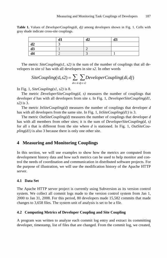
Measuring and Monitoring Task Couplings of Developers 187
Table 1. Values of DeveloperCoupling(di, dj) among developers shown in Fig. 1. Cells with gray shade indicate cross-site couplings.
d1 d2 d3 d2 3 d3 1 2 d4 2 3 1
The metric SiteCoupling(s1, s2) is the sum of the number of couplings that all de-
velopers in site s1 has with all developers in site s2. In other words
SiteCoupling(s1,s2) = DeveloperCoupling(di,dj)dj ∈s2
∑di∈s1
∑
In Fig. 1, SiteCoupling(s1, s2) is 8. The metric DeveloperSiteCoupling(d, s) measures the number of couplings that
developer d has with all developers from site s. In Fig. 1, DeveloperSiteCoupling(d1, s2) is 3.
The metric InSiteCoupling(d) measures the number of couplings that developer d has with all developers from the same site. In Fig. 1, InSiteCoupling(d1) is 3.
The metric OutSiteCoupling(d) measures the number of couplings that developer d has with all members from other sites; it is the sum of DeveloperSiteCoupling(d, s) for all s that is different from the site where d is stationed. In Fig. 1, OutSiteCou-pling(d1) is also 3 because there is only one other site.
4 Measuring and Monitoring Couplings
In this section, we will use examples to show how the metrics are computed from development history data and how such metrics can be used to help monitor and con-trol the needs of coordination and communication in distributed software projects. For the purpose of illustration, we will use the modification history of the Apache HTTP server.
4.1 Data Set
The Apache HTTP server project is currently using Subversion as its version control system. We collect all commit logs made to the version control system from Jan 1, 2000 to Jan 31, 2008. For this period, 80 developers made 15,582 commits that made changes to 3,658 files. The system unit of analysis is set to be a file.
4.2 Computing Metrics of Developer Coupling and Site Coupling
A program was written to analyze each commit log entry and extract its committing developer, timestamp, list of files that are changed. From the commit log, we created,

188 Y. Ye, K. Nakakoji, and Y. Yamamoto
for each file, a list of modification history that consists of a tuple of two elements: the developer and the timestamp of commit. The list of modification history is ordered according to the time. From the list of modification history for each file, we determine all the couplings that developers have about the file within the predetermined time slider. Couplings for each file are then aggregated to produce the final count for each pair of developers.
Fig. 2 shows historical data of developer couplings for the Apache HTTP server. We divide the time into periods of two months and counted developer couplings for each period. The number shown is the sum of developer couplings between each pair of developers. During the analysis, the time slider for determining couplings among modifications was set to 10 days. Namely, if two developers commit changes of the same file within 10 days, the two developers have a count 1 of developer coupling.
Fig. 2. Values of DeveloperCouplings of the Apache HTTP server for each two-month period with time slider set to 10 days
Imposing the information of site location of each developer on the developer cou-pling, we are able to compute the site coupling. We divide the developers who con-tributed code to the Apache HTTP server system based on their physical locations. Because a large number of the developers come from US, we divide US developers based on their states, and non-US developers by their countries. The physical loca-tions of developers are obtained from the Apache Web site. For those developers whose locations cannot be ascertained, we lump them into the “Unknown” site.

Measuring and Monitoring Task Couplings of Developers 189
Fig. 3. Values of DeveloperCoupling and SiteCoupling for the Apache HTTP server
We are fully aware that this division of sites is rather arbitrary because developers from the same state or country are still widely distanced and should not be considered as co-located. In fact, each developer in most Open Source Software systems should be counted as one site. The goal of using this data set is to illustrate how to compute and use site coupling metrics rather than analyzing the cost of cross-site communication and coordination of the Apache HTTP server project. For this project, developer cou-pling is more important. Fig. 3 shows both the values of DeveloperCoupling and Site-Coupling. As the figure shows, the site coupling is almost the same as the developer coupling, reflecting well the nature of Open Source Software systems in which each developer works in relative isolation, relying on computer-supported communication mechanisms rather than face-to-face communications enabled by co-location. For a proprietary software project, a figure like Figure 3 may raise concerns because the lower cost of communications among co-located developers are not well leveraged.
4.2 Scenarios of Usage
Figs 2 and 3 give a historical overview of the couplings among developers and devel-opment sites, and provide a means for project managers and developers to monitor the task dependencies that beget needs of communication and coordination. The figures indicate that there are several peaks of value increase but most of the increased cou-pling reduced immediately, so these peaks may not be a huge concern. The more

190 Y. Ye, K. Nakakoji, and Y. Yamamoto
troublesome spot may be on the right side of the figures where we can see that the project has been currently experiencing increase of couplings since May 2007, and the pace of increase picks up since Nov. 2007. This makes one wonder what has hap-pened since Nov. 2007, and a more detailed exploration of the couplings from Nov 2007 and Jan 2008 is called for. Using this period as an example, this subsection de-scribes scenarios of using the coupling metrics to explore the reasons that cause such couplings so that appropriate adjustments can be applied to deal with unwanted cou-plings to reduce the cost of communication and coordination.
4.3.1 Visualizing the Couplings The first scenario is to examine the details of couplings among developers with visu-alization support. Fig. 4 visualizes the couplings between developers for the interested period: between Nov. 2007 and Jan. 2008, and Fig. 5 visualizes the couplings between development sites for the same period. From the two figures, it is easy to find that two developers contribute most to the couplings: rpluem and minfrin. Comparing the two figures, we can find that most of the couplings are across development sites. These two visualizations give a snapshot of the state of the practice regarding coupling among developers and sites.
Fig. 4. Couplings among developers from 2007-11 to 2008-1. Labels indicate the value of DeveloperCoupling between the two linked developers.
4.3.2 Redesigning to Reduce Couplings If the visualizations reveal that the current state of coupling is not ideal and the pro-ject manager or the developers want to take measures to reduce the coupling. One of the things to look at is which files cause the couplings. This leads to the needs of

Measuring and Monitoring Task Couplings of Developers 191
Fig. 5. Couplings among sites from 2007-11 to 2008-1. Labels indicate the value of Develop-erCoupling between the two linked developers.
computing DeveloperCoupling and SiteCoupling for each file. The table in Fig. 6 lists all files that cause couplings during the period between 2007-11 and 2008-1. From the list, we can see that two files: modules/http/http_filters.c and include/ap_mmn.h need special attention and they may be candidates to be considered for redesign.
4.3.3 Task Reassignment Another possibility of reducing site coupling is to change the task assignments or developer locations.
Examining the details of DeveloperCoupling in Fig. 4, we can see that three devel-opers—rpluem, jim and niq—have relatively complicated coupling relationship, with following values of DeveloperCoupling:
DeveloperCoupling(rpluem, jim) = 4 DeveloperCoupling(rpluem, niq) = 6 DeveloperCoupling(jim, niq) = 2
Some development tasks may need to be reassigned to reduce the couplings among those developers. Managers or developers can examine the details of files that caused the couplings among those developers (Fig. 7). From the output shown in Fig. 7, we can see that the file modules/http/http_filters.c causes multiple couplings. With this information, managers and developers can review task assignments to the three de-velopers in terms of their relationship with those files and make appropriate adjust-ments to reduce coupling.
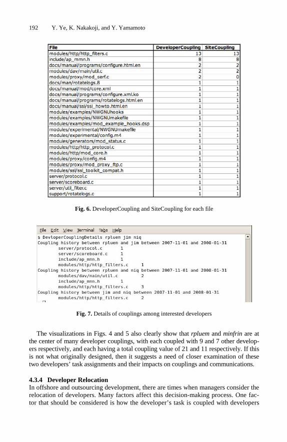
192 Y. Ye, K. Nakakoji, and Y. Yamamoto
Fig. 6. DeveloperCoupling and SiteCoupling for each file
Fig. 7. Details of couplings among interested developers
The visualizations in Figs. 4 and 5 also clearly show that rpluem and minfrin are at the center of many developer couplings, with each coupled with 9 and 7 other develop-ers respectively, and each having a total coupling value of 21 and 11 respectively. If this is not what originally designed, then it suggests a need of closer examination of these two developers’ task assignments and their impacts on couplings and communications.
4.3.4 Developer Relocation In offshore and outsourcing development, there are times when managers consider the relocation of developers. Many factors affect this decision-making process. One fac-tor that should be considered is how the developer’s task is coupled with developers

Measuring and Monitoring Task Couplings of Developers 193
of other sites. This brings the needs of computing InSiteCoupling and OutSiteCou-pling for each developer, and DeveloperSiteCoupling for each pair of developer and site. Fig. 8 shows the values of those couplings for the period between 2007-11 and 2008-1. If a developer whose InSiteCoupling value is high is relocated to another site, the InSiteCoupling would become OutSiteCoupling and may lead to increased cost of communication and difficulty of coordination. On the other hand, if a developer’s DeveloperSiteCoupling value with a particular site is higher than his or her InSite-Coupling, then relocating the developer to that site may help reduce the cost of com-munication and coordination. For example, the data in Fig. 8 suggests that relocating niq from United Kindom to Germany will reduce cross-site couplings between the two sites. If all other conditions are similar, and the project has to move one developer from the site in United Kingdom to the site in Germany, then relocating niq is a better choice than relocating pctony because it would reduce site coupling.
Fig. 8. Couplings between developer and sites
5 Summary and Future Work
The complex inter-dependencies of development tasks are one of the major reasons that make large-scale software development difficult and costly. Task dependencies are the root cause of the well-known Brook’s law: “Adding manpower to a late soft-ware project makes it later” because the increase of communication and coordination cost is often higher than the productive gain by the newly added manpower due to inter-dependencies of work [1]. The concepts of developer coupling and site coupling introduced in this paper attempt to reveal and represent the task dependencies among software developers and development sites that are manifest in actual practices. They differ from existing approaches of task dependency analysis that are mostly based on
194 Y. Ye, K. Nakakoji, and Y. Yamamoto
the structural dependencies of modules, that often generates too many couplings to be useful and miss latent couplings at the same time. Developer coupling and site cou-pling focus on couplings that are actually happening and that matter most in the pro-ject context.
Several metrics were derived from the two concepts. The computation, visualiza-tion and exploration of such metrics afford intuitive as well as quantitative monitoring and reasoning of task dependencies among developers and development sites. Using the metrics, project managers and developers can discover potential coordination problems and address such problems with appropriate measures.
The paper illustrated the metrics with data from an Open Source Software system, and hence the analytical utility of site coupling is not fully demonstrated. Our near future work includes applying those metrics to proprietary offshore or outsourcing development projects and verify further the practical implications of the concepts and metrics. We are also currently developing an integrated tool that dynamically com-putes and visualizes the metrics with flexible controls at granularities, times, and topics.
References
1. Brooks, F.P.J.: No Silver Bullet: Essence and Accidents of Software Engineering. IEEE Computer 20, 10–19 (1987)
2. Brooks, F.P.J.: The Mythical Man-Month: Essays on Software Engineering, 20th Anniver-sary edn. Addison-Wesley, Reading (1995)
3. Cataldo, M., Wagstrom, P.A., Herbsleb, J.D., Carley, K.M.: Identification of Coordination Requirements: Implications for the Design of Collaboration and Awareness Tools. In: Pro-ceedings of CSCW 2006, pp. 353–362. ACM Press, Banff (2006)
4. Chidamber, S.R., Kemerer, C.F.: A Metrics Suite for Object Oriented Design. IEEE Trans. on Software Engineering 20, 476–493 (1994)
5. Conway, M.E.: How Do Committees Invent? Datamation 14, 28–31 (1968) 6. Curtis, B., Krasner, H., Iscoe, N.: A Field Study of the Software Design Process for Large
Systems. Communications of ACM 31, 1268–1287 (1988) 7. de Souza, C.R.B., Quirk, S., Trainer, E., Redmiles, D.: Supporting Collaborative Software
Development through the Visualization of Socio-Technical Dependencies. In: GROUP 2007, Sanibel Island, FL, pp. 147–156 (2007)
8. Ferrante, J., Ottenstein, K.J., Warren, J.D.: The Program Dependence Graph and Its Use in Optimization. ACM Transactions on Programming Languages and Systems 9, 319–349 (1987)
9. Henderson, R.M., Clark, K.B.: Architectural Innovation: The Reconfiguration of Existing Product Technologies and the Failure of Established Firms. Administrative Science Quar-terly 35, 9–30 (1990)
10. Herbsleb, J., Mockus, A., Finholt, T., Grinter, R.E.: Distance, Dependencies, and Delay in a Global Collaboration. In: Proceedings of CSCW 2000, pp. 319–327 (2000)
11. Herbsleb, J.D., Grinter, R.E.: Architectures, Coordination, and Distance: Conway’s Law and Beyond. IEEE Software, 63–70 (1999)
12. Kersten, M., Murphy, G.C.: Using Task Context to Improve Programmer Productivity. In: Proceedings of FSE 2006, pp. 1–11 (2006)

Measuring and Monitoring Task Couplings of Developers 195
13. Morelli, M.D., Eppinger, S.D., Gulati, R.K.: Predicting Technical Communication in Product Development Organizations. IEEE Transactions on Engineering Management 42, 215–222 (1995)
14. Olson, G.M., Malone, T.W., Smith, J.B. (eds.): Coordination Theory and Collaboration Technology. Lawrence Erlbaum Associates, Mahwah (2001)
15. Sarma, A., Noroozi, Z., van der Hoek, A.: Palantir: Raising Awareness among Configura-tion Management Workspace. In: Proceedings of 2003 International Conference on Soft-ware Engineering, pp. 444–454 (2003)
16. Stafford, J.A., Richardson, D.J., Wolf, A.L.: Architecture-Level Dependence Analysis for Software Systems. International Journal of Software Engineering and Knowledge Engi-neering 11, 431–451 (2001)
17. Vieira, M., Dias, M., Richardson, D.J.: Describing Dependencies in Component Access Points. In: Proceedings of 4th ICSE Workshop on Component-Based Software Engineer-ing (2001)
18. Wagstrom, P., Herbsleb, J.: Dependency Forecasting in the Distributed Agile Organiza-tion. Communications of ACM 49, 55–56 (2006)

Automated Process Quality Assurance forDistributed Software Development�
Jian Zhai1,3, Qiusong Yang1,3, Ye Yang1, Junchao Xiao1, Qing Wang1,and Mingshu Li1,2
1 Laboratory for Internet Software Technologies, Institute of SoftwareThe Chinese Academy of Sciences, Beijing, China, 100190
2 The State Key Laboratory of Computer Science, Institute of SoftwareThe Chinese Academy of Sciences, Beijing, China, 100190
3 Graduate University of Chinese Academy of SciencesBeijing, China, 100049
{zhaijian,qiusong yang,ye,xiaojunchao,wq,mingshu}@itechs.iscas.ac.cn
Abstract. As required or implicated in many process improvement orassessment models, Process Quality Assurance (PQA) is introduced toobjectively evaluate actual software processes against applicable pro-cesses descriptions, standards, and procedures and to identify potentialnoncompliance. In a Distributed Software Development (DSD) environ-ment, PQA is also an absolute necessity to ensure that each developmentsite behaves as expected and high quality software is collaboratively de-veloped. However, several problems brought by the distribution nature ofDSD, such as different interpretations of standard processes among de-velopment sites, inconsistent criteria for identifying noncompliance, vis-ibility into development activities of all sites being challenging, hiddenconflicts or noncompliance for political issues within a site, substantialinvestment in setting up PQA teams in each site etc., can underminethe objectivity and effectiveness of PQA activities. To alleviate theseproblems, we introduce an approach in this paper that automates PQAactivities for some routine checking tasks in a DSD environment. In theapproach, a process model describing the actual software process is auto-matically built from each site’s repository and, then, the model is checkedagainst logic formulae derived from a common checklist to detect non-compliance. Experiment results show that the approach is helpful toensure that PQA activities in each site can be conducted according tothe same guideline and the objectivity of PQA results is guaranteed.
Keywords: distributed software development, process quality assur-ance, process modeling, model checking.
� Supported by the National Natural Science Foundation of China under grant Nos.60573082, 60473060, 90718042 and the Hi-Tech Research and Development Program(863 Program) of China under grant No.2006AA01Z185, 2007AA010303, as wellas the National Basic Research Program (973 Program) of China under grant No.2007CB310802.
K. Berkling et al. (Eds.): SEAFOOD 2008, LNBIP 16, pp. 196–210, 2009.c© Springer-Verlag Berlin Heidelberg 2009

Automated Process Quality Assurance for DSD 197
1 Introduction
It is widely accepted that the quality of software is highly related to the pro-duction process that is carried out and can not be ensured simply by inspectingthe products. A software process of good quality leads to good software in mostcases. To make sure of the high quality of software production processes, thereare more and more software enterprises employing the process improvement andassessment models, such as Capability Maturity Model� Integration (CMMI)[1],ISO9000[2] and so on. In such models, those practices and methodologies of PQAhave been widely used. The goal of PQA is to objectively evaluate an actual soft-ware process against applicable process descriptions, standards, and procedures,such that noncompliance issues are identified and feedback is provided to projectstaff and managers. Here the Actual Software Process denotes a sequence thatencompasses the actual activities conducted by human agents and non-humanagents in the course of software development. This process can be stored in andrecovered from the development repository.
In most co-located development environments, to operate PQA activities,PQA staff have to dig into the development repository to recover the actualprocess and decide if each item in a checklist is satisfied in the actual process.A checklist usually consists of a regular set of checking items, and each checkingitem is a binary valued proposition, which actually describes one potential sourceof noncompliance issues between the actual software process and the successfulexperience or standard software process. A proposition of a checking item is sat-isfied means that there is no noncompliance in the actual process for this item,and vice versa. For example, a checking item may focus on the temporal order ofseveral process activities, the existence of certain process activities, propertiesor statements about a process fragment and so on. If all of the checking itemsare satisfied, it implies that there is no noticeable noncompliance in the actualsoftware process, and the process can be recognized as a process of good quality.
Distributed software development has become pervasive in modern enterpriseenvironments. DSD means that the software development is disperse throughoutseveral software development sites that could be located in different locations,i.e. different cities, different countries or even different continents. This wayof software development has been greatly benefiting the software enterprises.With DSD, an enterprise may evidently reduce their whole development costand strengthen their development capability. At the same time, an enterprisecan have direct access to a broader set of skilled workers.
On the other hand, DSD is fraught with a number of issues and pain pointsto distributed PQA. These issues may weaken the benefits that are brought toenterprises brought by DSD. Firstly PQA staff in distributed development sitesmay have a different interpretation or understanding towards standard processesbecause of their differences in training, experience, creativity and ability, whichmay result in inconsistent criteria that the PQA staff follows in identifying non-compliance. Because of the manual manner of PQA, the judgement whether achecking item is satisfied by an actual software process highly depends on thecriteria and the PQA staff’s characteristics. Since the subjective factors of PQA

198 J. Zhai et al.
are hardly to be uniform, the comparison, measurement and evaluation of actualsoftware processes of each distributed site based on such manual PQA resultsare not believable enough. Secondly because an autonomous distributed devel-opment site has its own private interest, which may be not the same as thewhole project’s interest completely. Based on the “Rationalist Assumption” ineconomics, the PQA staff who work for a site tends to conceal the noncompli-ance issues that have been discovered from the manager for the local interest.Since there is lack of visibility into development activities of all sites for a projectmanager in a DSD environment, the manager is hardly to ensure the authen-ticity of a PQA report coming from a distributed development site. It causesthe evaluation of an actual software process out of control. Thirdly DSD causessubstantial investment in setting up PQA teams in each site compared to thatin co-located software development.
To address such problems of PQA in a DSD environment, we introduce an ap-proach in this paper that can help to automatically operate PQA in a distributeddevelopment site objectively, efficiently with a standardized criteria. Because ofthe automated actual software process modeling, checking and PQA results re-porting, the effects of the distributed site’s PQA staff are reduced to a certainextent, and lots of cost on setting up PQA teams for all sites are saved. In ourapproach, a formal process model describing the actual software process of a dis-tributed development site is automatically built from its development repositorywithout the intervention of local staff. On the other hand, with a certain logic,μ-calculus [3] in this paper, the items in checklists used by an organization areexpressed as logic formulae. Since the translation of checking items is an one-offactivity, this step can be ignored in the repeated PQA once the formulae are ac-quired. Being input with the obtained actual process model and logic formulae,model checking tools are then used for automatically deciding if a checking itemis satisfied in an actual process to judge the quality of an actual process, andautomatically report the result to the project manager who is located outside ofthe development site. Experiment results show that the approach is helpful toensure that PQA activities in each site can be conducted according to the sameguideline and the objectivity of PQA results is guaranteed.
The rest of this paper is organized as the following: in Section 2, the relatedwork is presented. In Section 3, TRISO/ML, the process modeling language usedfor describing an actual process, is presented. Section 4 introduces the actualprocess modeling approach, and Section 5 describes how an item in a checklistis formulated in μ-calculus. A case study and the conclusion of this research arepresented in Section 6 and Section 7, respectively.
2 Related Work
There are, two streams of related work that are directly related to this study.One is the studies on quality assurance in co-located and distributed softwaredevelopment, and the other is the studies on the modeling and verification ofactual software processes.

Automated Process Quality Assurance for DSD 199
2.1 Quality Assurance in Software Development
The concept of quality assurance has been widely accepted and implementedin the field of software development. As a result, the quality of software hasbeen improved significantly over the past two decades. Apart from the usage ofnew development techniques, there has been a greater awareness of the impor-tance of software quality management and the adoption of quality managementtechniques from manufacturing in software industry [4]. As for the researcheson software quality assurance, a brief survey is given in [5]. Previous researchsof distributed software quality assurance is mainly focused on the tools andapproaches for distributed testing [6], empirical analysis [7,8], and some globalprojects related technical reports, such as Mozilla [9]. Zhao and Elbaum [10] givea survey on quality related activities in open source software development, whichis a typical distributed software development environment. As for the softwareprocess in distributed software development, S. Becker et al. [11] introduce anapproach in which a client can delegate parts of net-based process models to acontractor, and the client can monitor the progress from the feedback informa-tion provided by the contractor. M. Vanzin et al. [12] present their practices fordefining a global software process in a distributed environment and the factorsthat have a major impact on process definitions. Though the ultimate goal ofthose researches is to improve the quality of software, they do not tell how toensure that those successful experience or well-defined processes are complied inthe actual software process, especially in a DSD environment.
2.2 Modeling and Verification of Actual Software Processes
As for the modeling of actual processes, Cook and Wolf provide an investigationon different approaches in this field [13], and they also introduce their solutionsto model an actual process in [14,15]. Aalst et al. carry out a series of researchesin this field too [16,17]. In the papers, the authors introduce several variants ofthe α-algorithm. They reveal that this type of algorithms can be used in a largeclass of processes. The work mentioned previously mainly focuses on modelingan actual process from the perspective of repeated activity steams, and the tem-poral relationships among activities in a model are discovered through statisticalmethods. The granularity of activities in these approaches is too low to fit forPQA in general. As for process checking, the work of Cook et al. [18] is closelyrelated to this paper. In the paper, the concept of process validation is intro-duced, but the validation mentioned there is based on the comparison betweenthe supposed data stream generated from model and the actual activity streamscollected from actual processes instead of checking the potential noncomplianceissues of the actual processes, which is just the requirement of PQA. Aalst etal. also study process checking in [19,20]. They introduce the fitness and appro-priateness dimensions of process conformance. Though both of the two conceptsare related to PQA, they focus on the classification of the process conformancesinstead of checking actual processes for the potential noncompliance issues.

200 J. Zhai et al.
In addition, there are some papers on verifying abstract model systems, suchas real-time systems, against specific system properties, such as safety properties[21,22]. These works are related to our work, and they fall into different researchdomains.
3 TRISO/ML Process Modeling Language
In our approach, TRISO/ML (TRidimensional Integrated SOftware developmentmodel/Modelling Language) [23] is used to model actual software developmentprocesses. It is a graphical modeling language but with rigorous operational se-mantics in polyadic π-calculus, which is proposed to support the TRISO Modeladvocated in [24] and [25]. The primary element of the language is process activ-ities, which are connected by temporal relation operators to construct a processmodel. The language describes a process as an activity hierarchy and it providespowerful abstractions of control flow, data dependency, and resource usage insoftware processes. Most importantly, this language provides a group of mappingrules to transform a graphical process model into a series of polyadic π-calculusexpressions in a mechanical way. The mapping rules assure that the semanticsof the graphical model and the polyadic π-calculus expressions are fully coin-cident, and each TRISO/ML graphical model can be transformed into a set ofpolyadic π-calculus expressions. Thus, TRISO/ML has a rigorous semantics thatis helpful to precisely describe a process and it can be a good basis for furtheranalysis.
Sequential
||
Parallel
+
Choice Activity
Fig. 1. Structural notations of TRISO/ML graph
The structural notations of TRISO/ML are listed in Fig. 1. The rectanglestands for a process activity and the diamonds stand for the temporal relation-ship operators. The notations “‖”, “→” and “+” inside the diamonds indicatethat the temporal relationship among activities is parallel, sequential or choicerespectively. Furthermore, the choice operator is used to describe the uncertaintyof process models. In TRISO/ML, a software process is defined as a tri-tuple:(V , E , δ), where V is a set of nodes, as the union of C∪A. C represents the set ofnodes controlling the sequencing of activities. Each node in C is in type of eitherparallel, sequential, or choice. A denotes the set of activities that are carried outin a software process. E ⊆ (C ×A ∪A× C) is a set of directed edges connectingthe nodes, and δ : (A∪C ×A) → Attr maps each element in A∪ C ×A to a setof attributes. Further details about mapping a graphical process in TRISO/MLinto a set of π-calculus expressions can be found in [23].

Automated Process Quality Assurance for DSD 201
4 Modeling the Actual Software Processes
In practice, the accumulated information of actual software processes can berecorded and organized in various forms. Gantt chart is a commonly used andconvenient tool to organize and present the information of an actual process,such as the duration, agents, work hours, and involved artifacts of every activity,as well as the planned process. Without loss of generality, we use Gantt chartas the representing form of actual processes and the results in this paper arealso applicable to other forms as long as the information of actual processes isrecorded and it can be obtained.
Fig. 2. The sketch map of the framework
Starting from a Gantt chart of a distributed development site’s actual pro-cesses, we build a TRISO/ML process model with rigorous semantics inπ-calculus that is amenable to further analysis. At the same time, in one-offmanner, the pre-defined and regular checking items in a checklist will be de-scribed by formulae in a certain logic, μ-calculus in this paper. With the inputof generated π-calculus process model and μ-calculus formulae, model checkingtools are used for automatically deciding if a checking item is satisfied in anactual process. And the result can be provided back to the site itself and re-ported to the project manager who is located outside of the site or the othersites that need the information. The sketch map of the framework is shown inFig. 2. In the figure, the dashed line separates the inside and the outside areaof a development site. In most conditions, project manager is located outside of

202 J. Zhai et al.
the site, and the development site can communicate with the project manageras well as the other distributed sites. Inside of the development site, the upperrow of the figure describes how an actual software process in the form of Ganttchart is automatically transformed into an abstract model in π-calculus, whichis described in this section, while the lower one describes the process that achecking item is formulated in μ-calculus, which will be presented in the nextsection. To input the two sets of calculus formulae into model checking tools, theresults that whether checking items are satisfied in the actual software processcan be automatically determined and the results can be automatically outputto the project manager who is located outside of the site.
Though the Gantt chart of an actual process brings various and abundantinformation about the process, the arrangement of process events in a raw chartdoes not ensure that the earlier the starting time of an activity is, the higherthe activity is located in the chart or the one with a later ending time is locatedhigher if their ending times are the same. As a result, some pretreatment isneeded to arrange the activities in a process to be a standard form such that theprocedure of transforming a Gantt chart to TRISO/ML model will be greatlysimplified. A Gantt chart in a standard form is called arranged Gantt chart inthe following part of this paper. For example, Fig. 3(a) is a raw Gantt chartof an actual process, and the attributes of the activities do not matter at thispoint. For the figure, a pretreatment is needed to swap activity A and activityB. That is because the two activities have the same starting time and activityA is ended earlier, so that activity A should be located under activity B. Thearranged Gantt chart is shown in Fig. 3(b).
ssecorP
||
B 1v
A 2v
||
D E
C
A
BC
D
E
A
B
CD
E
A
B
CD
E
ov
ov
ssecorP
||
B 1v
A 2v
||
D E
C
}ov:hcv{
}ov:hcv{
)a( )c(
)e(
)b(
)d(
Fig. 3. An example of modeling an actual process with TRISO/ML graph
Since the chart represents the start and end time of an activity’s execution,the temporal relationship, in terms of parallel or sequential, between any twoactivities can be decided by the concrete starting and ending time of the activ-ities. For two activities with different starting time, if the ending time of theearlier started activity is not later than the starting time of another activity, the

Automated Process Quality Assurance for DSD 203
two activities are sequential ; otherwise, they are parallel. Besides, the activitieswho have the same starting time are parallel as well. Based on the determinedtemporal relationship among activities, the following rules are set to realize thetransformation from an arranged Gantt chart to the TRISO/ML model of anactual process.
1. The root of a TRISO/ML model should be a newly added virtual node, andother activities or virtual nodes are all children nodes of the virtual one.
2. If the temporal relationships between every two adjacent activities in a groupof activities are accordant (sequential or parallel), these activities are ar-ranged as nodes in the same floor in the TRISO/ML model, and the nodesare labeled by the operator and name of the activities. These nodes are allcontrolled by a uniform temporal relationship operator (sequential or paral-lel). Besides, the input and output of the activities should be labeled in theTRISO/ML model.
3. For a group of adjacent activities in Gantt chart, if their temporal relation-ship is accordant, they can be processed according to rule 2. If the temporalrelationship between the last two activities e1 and e2 of a group of activitiesis different from the relationship t among e1 and the activities above e1, thenadd a virtual activity v between e1 and e2, making the temporal relationshipamong v and the activities above e1 to be t. Then, the activities above e1(includes v, and does not include e1) can be processed according to rule 2;the activities under e1 (includes e1) can be processed with rule 3, and theactivities can be treated as children nodes of v.
For example, Fig. 3(b) is an arranged Gantt chart, which can be trans-formed into a TRISO/ML model with the above rules. With the first rule, theTRISO/ML model roots at a virtual node named “Process”. As shown in thechart, activity B and activity A are parallel, and activity A and activity C aresequential. With the third rule, it needs to add a virtual node v1 between activityB and activity A, and make activity B and v1 are parallel just as the temporalrelationship between activity B and activity A. Those events that follow A arechildren nodes of v1. With the second rule, activity B and v1 are the two parallelbranches of the root node “Process”. The following activities A, C and D aresequential, and activity D and activity E are parallel. Similarly, a virtual nodev2 is added above activity D, then activity A, C and v2 are located under v1 withthe controlling of a sequential temporal operator. Event D and activity E areparallel. So that they are located under v2, and controlled by a parallel operator.Then, the Gantt chart is transformed into a TRISO/ML model, which is shownin Fig. 3(d).
From the TRISO/ML model shown in Fig. 3(d), most of the temporal re-lationship among activities can be determined. Activity D and activity E areparallel, and activity A, C and virtual node v1 are sequential. Since v1 is dividedinto activity D and E, activity C and activity D or E are all sequential. ActivityB and activity A, C, D are parallel as well. The temporal relationships amongthose activities in the TRISO/ML model are the same as what they are in the

204 J. Zhai et al.
Gantt chart. But the temporal relationship between activity B and E is con-flicting between the information shown in the Gantt chart and the TRISO/MLmodel. In Gantt chart, it is clear that activity B and activity E are sequential,but in TRISO/ML model, the two activities are parallel. Since there is an in-consistence after the transformation, the TRISO/ML model may cannot reflectthe temporal relationship among the activities in the actual process, which con-strains further analyzes. To avoid such inconsistences, virtual input and outputof activities should be added to a Gantt chart before the transformation. Thesevirtual communication is only used to indicate the temporal relationship of activ-ities, and do not imply any dependent relationship between activities. If activityB has a virtual output when it is finished, and the virtual output performs as avirtual input of activity E when activity E is starting, the sequential relationshipbetween activity B and activity E will not be lost in the transformation. For anactivity, we inspect each activity who locates above it in the order from bottomto the up. Assume that ai is the focused activity, and aj is the activity who islocated above ai. If the following conditions are all satisfied by aj, there is anpotential inconsistence between ai and aj , and a virtual communication shouldbe added between them.
– The activities aj and ai are sequential and nonadjacent.– The outputs of aj are not the input of ai.– No activities between ai and aj are sequential with aj .
With the conditions, it can be determined that there is an potential inconsis-tence between activity B and E, and a virtual output should be added to activityB to perform as the virtual input of activity E. The Gantt chart with virtualcommunication is shown in Fig. 3(c), and the TRISO/ML model with added vir-tual communication is shown in Fig. 3(e) accordingly. In the TRISO/ML modelshown in Fig. 3(e), all of the temporal relationships among activities that canbe determined from the Gantt chart are remained. In the model, vch stands fora virtual output channel, and vo stands for a virtual output artifact. Anotherexample illustrating how to use the above rules to model an actual process, willbe presented in the following case study section.
5 Formulating the Checking Items
To audit an actual software process, a clearly stated criteria should be builtas required in CMMI or other process improvement and assessment models. Inmost organizations, the criteria is often deployed in the form of checklists, whichusually consists of a set of checking items where each item actually describesone potential source of noncompliance issues. In a checklist, majority of itemsfocus on the temporal order of some specific process activities, the existence ofcertain process activity, or properties and statements about a process fragment.Checking items that focus on the first two types of issues can be well describedby temporal logical formulae. Those focus on the third type of issues can bepartially described only. The checking items that cannot be described mainly

Automated Process Quality Assurance for DSD 205
focus on quantity issues, e.g. “The project members’ working time is not toomuch or too little.”, ability issues, e.g. “The project members have the requiredability to operate the assignments.” and so on.
Since the μ-calculus, supported by many powerful verification tools, is one ofthe most popular temporal logics for concurrent systems, it is used in this paperto describe the checking items. The easist and most important statements asdescribed by μ-calculus are that “an action is eventually carried out (TP )” and“an action will never happen in a process (TN )”. The corresponding μ-calculusformulae are listed in the following:
μX.[action]tt ∧ 〈−〉tt ∧ [−action]X
νX.[action]ff ∧ 〈−〉tt ∧ [−action]X
Most of the temporal statements that need to be described can be generatedby the composition of the above two expressions. For example, we focus an state-ment saying “Whenever action a happens, action b eventually happens (T1)”, inwhich, action b should be executed after action a is finished. The μ-calculusformula corresponding to this statement can be described as:
μX.[a](μY.[b]tt ∧ 〈−〉tt ∧ [−b]Y ) ∧ 〈−〉tt ∧ [−a]X
As for a more complex statement, for example, “Action a must be executedbefore action b (T2)”. With the description, action b can be executed after actiona; in addition, if action a is not finished, action b will not happen. The μ-calculusformula corresponding to this statement can be described as:
μX.[a](μY.[b]tt ∧ 〈−〉tt ∧ [−b]Y ) ∧ 〈−〉tt ∧ [b]ff ∧ [−(a, b)]X
As for other statements, the corresponding μ-calculus formulae can be gener-ated similarly. Further details about μ-calculus can be found in [3].
The formulae stated above can be treated as templates for formulating check-ing items. To substitute the uniform notations, such as action, a, b in the aboveformulae, with the name of practical activities that checking items mentioned,the items in checklists are formulated by μ-calculus formulae. For the items fo-cusing on the temporal order of process activities and the existence of certainprocess activities, the uniform notations can be directly substituted to formu-late. As for the properties or statements about a process fragment, they need tobe analyzed and divided into one or more simpler statements to be formulated.
We take the checking item “The process data is measured” for instance. Thisproposition means the activity for measuring process data should happen inthe actual software process, so that the template TP can be used here, and thenotation action should be substituted. If the notation dm stands for this activity,the μ-calculus formula corresponding to this checking item is as following:
μX.[dm]tt ∧ 〈−〉tt ∧ [−dm]X

206 J. Zhai et al.
Furthermore, we take a more complex item for example. For the item “ Thedefects are confirmed before the conclusion is generated”. It is an instance for thetemplate T2, more specifically, the activity of defects confirming is the instancefor a and the activity of conclusion generating is the instance for b in T2. Ifdc stands for defects confirmation and cg stands for conclusion generation, theμ-calculus formula corresponding to this checking item is as following:
μX.[dc](μY.[cg]tt ∧ 〈−〉tt ∧ [−cg]Y ) ∧ 〈−〉tt ∧ [cg]ff ∧ [−(dc, cg)]X
With the model of the actual processes and the checking items formulae, manyexisting model checking tools can be used for further analysis.
6 Case Study
To show the usability and practicability of the approach described previously, wetake an actual distributed software development process fragment in Institute ofSoftware, Chinese Academy of Sciences (ISCAS) for example. ISCAS is a soft-ware development organization that has achieved CMMI ML4, and the checkliststhat ISCAS uses for PQA are generated from CMMI as well. All the distributeddevelopment sites of ISCAS are controlled by the same software process model,which leads to the same checklists.
In the previous distributed projects of ISCAS, the PQA reports from thedistributed development sites are usually found too inaccurate for the managerto complete monitor and control the project. It is partly because of the localemployee of PQA staff, and their turn over. The criteria of PQA and the abilityof PQA staff are hardly to be uniform, though the training is often held and costsmuch. Besides, the project managers are often complaining that they are hardlyto ensure the authenticity of the report, to completely depend on the reportgetting from the distributed PQA staff leads to potential risks, even makes theproject fall in trouble. In addition, the cost to build two PQA teams and to trainthe PQA staff is much higher than that in co-located development environments,which arises to be a cost that cannot be ignored in a project. To address suchproblems, the automated approach presented in this paper is employed in a newproject named SoftPM [26] for experiment.
The SoftPM project is a main part of a multi-year, large-scale, research projectto develop new tools and technologies for supporting the software developmentin high-level maturity software organizations. This project has two distributeddevelopment sites totally, which are located in Beijing Laboratory and WuxiBranch Laboratory of ISCAS separately, and the manager is located in BeijingLaboratory in most time.
The fragment is a review process of SoftPM in Wuxi branch laboratory, andthe quality of the actual software process should be clearly and promptly re-ported to the project manager in Beijing. The process includes 7 project mem-bers and 11 activities. This process lasted from 27th, May, 2007 to 11st, June,2007. We start from the Gantt chart of the actual process fragment recorded inWuxi branch laboratory’s repository.

Automated Process Quality Assurance for DSD 207
1
5
3
4
2
7
6
-50-700282
-60-700270
-60-700260
-60-700250
-60-700240
-60-700230
-60-700220
-60-700210
-50-700213
-50-700203
-50-700292
-60-700280
RP :1pODR 1RRP
RP :2pODR 2RRP
RP :4pODR 4RRP
RP :3pODR 3RRP
MD :1pODR
RP :5pODR 5RRP
CD :5--0pO1RRP2RRP3RRP4RRP
DP
PR:0pODR
RCDGC :0pO
RCDBP :6pO
PMRCDRR :0pO
PM
-50-700272
-60-700290
-60-700201
-60-700211
8
01
9
11
Fig. 4. The arranged Gantt chart with the attributes added
The arranged Gantt chart of the actual process is shown in Fig. 4. In thefigure, the labels locate to the left, in the middle and to the right of activitiesrefer to the input artifacts, the operator and the name, and the output artifactsof activities. Op0 to Op6 stand for 7 different project members, in which Op0 is areview manager, Op6 is a developer, and the rest are reviewers. As for the nameof activities, RP is short for review preparing, PR is short for peer review, DMis short for data measurement, DC is short for defects confirmation, CG is shortfor conclusion generation, PB is short for products betterment, and RR is shortfor re-review ; for the input and output artifacts, PD is short for process data,RD is short for review documents, PRR is short for peer review report, DCR isshort for defects confirmation report, and MP is short for mended products.
Events, such as the 5th, 9th, and 11th activity, do not have output artifacts.Also, it is possible that there are some activities that do not contain inputartifacts. The lack of input and/or output artifacts is legal in a chart, and itdepends on the practical process record.
Then, to maintain the sequential relationship in the obtained process model,virtual communications should be added. With the conditions described in Sec-tion 4, it is easy to determine that the 2nd activity should have a virtual outputto perform as the inputs of the 4th, 5th and 6th activity. The 5th activity shouldhave a virtual output to perform as the input of the 7th activity, whose virtualoutput should be the 11th activity’s input. As for the rest activities, there areno virtual input and/or output needed to be added. To transform the virtualcommunications added Gantt chart, the corresponding TRISO/ML model canbe generated, and it is shown in Fig. 5. In the model, we use ch, vo and vch plusthe activity ID to express the actual output channel, virtual outputs and virtualoutput channel of activities.
On the other hand, the checking items in a checklist would be describedby formulae in μ-calculus. Totally, there are 15 checking items in the ISCAS’schecklist of the review process. Except 4 inapplicable items, 1 ability-related itemand 1 concrete time-related item, the rest 9 items can be described by μ-calculusformulae. The following is the details of the checking items.

208 J. Zhai et al.
Process
||
Op1: PR v2
Op2: PR v3
||
Op3: PR v4
{ch2: PRR1, vch2:vo2} {ch1: RD}
{ch1: RD} {ch3: PRR2}
Op4: PR
{ch1: RD, vch2: vo2} {ch4: PRR4} {ch5: PRR3, vch5:vo5}
Op1: DM v5
||
Op5: PR
{ch1: RD, vch5: vo5} {ch7: PRR5, vch7:vo7}
Op1 5: DC
{ch2: PRR1, ch4: PRR4,ch5: PRR3, ch3: PRR2}
{ch1: RD, vch2: vo2}
{ch0: PD, vch2: vo2}
Op0: RP v1
{ch1: RD} {ch0: PD}
v6
Op0:CG Op6:PB Op0:RR
{ch8: DCR} {ch8: DCR}
{ch8: DCR}
{ch10: MP}
{ch10:MP, vch7:vo7 }
Fig. 5. The TRISO/ML model transforming from the Gantt chart
1. The preparations of review is prepared before the peer review.2. The peer review outputs an peer review report.3. Before generating a conclusion, every reviewer finishes his peer review.4. Each defect is confirmed before the conclusion is generated.5. A document is output after each defect is confirmed.6. The betterment of products starts after each defect is confirmed.7. The review manager re-reviews the mended artifacts after the products
betterment.8. The process data is measured.9. A document is output after the conclusion is generated.
To input the acquired model of actual process in π-calculus expressions andthe checking items described by μ-calculus formulae into CWB-NC and SPINmodel checking tools in their own format of input, the decision that if a checkingitem is satisfied in the actual process can be determined automatically. Thechecking result is that except for the 3rd and the 9th formulae, all of the restformulae are satisfied in the model of actual process. The result means that thereare two noncompliance issues identified, and they are related to the activitiesthat the 3rd and the 9th checking items mentioned, which are the activitiesof peer review and the activity of conclusion document output. And all of theother checking items are satisfied in the process fragment. This result is identicalwith the manually checking result generated by PQA team. This result is thenreported to the project manager in the outside development site of Beijing, andalso the development site of Wuxi as a feedback. This result clearly shows thecorrectness and practicability of the approach.
7 Conclusion
PQA in DSD environment suffers new problems compared to that in co-locateddevelopment environments. The manual decision and report process of tradi-tional PQA tends to be time consuming and error prone, and the results highly

Automated Process Quality Assurance for DSD 209
depend on the PQA staff’s ability, experience, creativity and understanding ofstandard processes, which are hardly to be uniform among distributed devel-opment sites. Furthermore, it is difficult to obtain an objective and accurateevaluation to the quality of software process for the project manager locatedoutside of the development sites, since the authenticity of the PQA report ishardly to be ensured. Besides, the cost of the distributed PQA would be muchhigher than that of co-located development.
In this paper, an automated approach is introduced to objectively operatePQA activities. The first step of the approach is to transform the activitiesrelated development record in the form of Gantt chart into TRISO/ML processmodel. At the same time, in one-off manner, the pre-defined and regular checkingitems in a checklist will be described by formulae in a certain logic, μ-calculus inthis paper. Then, we check the process model against the formulae with variousmodel checking tools to decide if a checking item is satisfied in the actual processof the site and automatically report the result to the project manager who islocated outside of the development site. This approach improves PQA in DSD bysubstituting the pure manual operating way with an automatic manner, avoidsmost of the effect of PQA staff, ensures an uniform criteria, and reduces thecost on labor of a project. As a result, this approach makes the PQA in DSDenvironment much more objective and efficient.
References
1. Chrissis, M.B., Konrad, M., Shrum, S.: CMMI�: Guidelines for Process Integrationand Product Improvement. Addison Wesley Professional, Reading (2003)
2. Schmauch, C.H.: ISO 9000 for Software Developers. ASQC Quality Press (1994)3. Bradfield, J., Stirling, C.: Modal logics and μ-calculi: an introduction. In: Bergstra,
J., Ponse, A., Smolka, S. (eds.) Handbook of Process Algebra, pp. 293–330. Elsevier,Amsterdam (2001)
4. Sommerville, I.: Software Engineering, 7th edn. Addison Wesley, Reading (2004)5. Rai, A., Song, H., Troutt, M.: Software quality assurance: An analytical survey
and research prioritization. Journal of Systems and Software 40, 67–83 (1998)6. Memon, A., Porter, A., Yilmaz, C., Nagarajan, A., Schmidt, D., Natarajan, B.:
Skoll: Distributed continuous quality assurance. In: The 26th IEEE/ACM Interna-tional Conference on Software Engineering, pp. 459–468 (2004)
7. Ramasubbu, N., Balan, R.K.: Globally distributed software development projectperformance: an empirical analysis. In: The 6th joint meeting of the Europeansoftware engineering conference and the ACM SIGSOFT symposium on The foun-dations of software engineering, pp. 125–134. ACM, New York (2007)
8. Gopal, A., Mukhopadhyay, T., Krishnan, M.S.: The role of software processes andcommunication in offshore software development. Communications of the ACM 45,193–200 (2002)
9. Reis, C.R., de Mattos Fortes, R.P.: An overview of the software engineering pro-cess and tools in the mozilla project. In: The Open Source Software DevelopmentWorkshop, pp. 155–175 (2002)
10. Zhao, L., Elbaum, S.: A survey on quality related activities in open source. ACMSIGSOFT Software Engineering Notes 25, 54–57 (2000)

210 J. Zhai et al.
11. Becker, S., Jager, D., Schleicher, A., Westfechtel, B.: A delegation based model fordistributed software process management. In: Ambriola, V. (ed.) EWSPT 2001.LNCS, vol. 2077, pp. 130–144. Springer, Heidelberg (2001)
12. Vanzin, M., Ribeiro, M.B., Prikladnicki, R., Ceccato, I., Antunes, D.: Global soft-ware processes definition in a distributed environment. In: SEW 2005: Proceedingsof the 29th Annual IEEE/NASA on Software Engineering Workshop, Washington,DC, USA, pp. 57–65. IEEE Computer Society, Los Alamitos (2005)
13. Cook, J., Wolf, A.: Discovering models of software processes from event-based data.ACM Transactions on Software Engineering and Methodology 7, 215–249 (1998)
14. Cook, J.E., Du, Z.: Discovering thread interactions in a concurrent system. Journalof Systems and Software 77, 285–297 (2005)
15. Cook, J.E., Du, Z., Liu, C., Wolf, A.L.: Discovering models of behavior for concur-rent workflows. Computers in Industry 53, 297–319 (2004)
16. van der Aalst, W., Weijters, A., Maruster, L.: Workflow mining: Discovering processmodels from event logs. IEEE Transactions on Knowledge and Data Engineering 16,1128–1142 (2004)
17. Weijters, A., van der Aalst, W.: Rediscovering workflow models from event-baseddata using little thumb. Integrated Computer-Aided Engineering 10, 151–162(2003)
18. Cook, J., Wolf, A.: Software process validation: Quantitatively measuring the cor-respondence of a process to a model. ACM Transactions on Software Engineeringand Methodology 8, 147–176 (1999)
19. Rozinat, A., van der Aalst, W.: Conformance testing: Measuring the fit and ap-propriateness of event logs and process models. In: Bussler, C.J., Haller, A. (eds.)BPM 2005. LNCS, vol. 3812, pp. 163–176. Springer, Heidelberg (2006)
20. van der Aalst, W., de Beer, H., van Dongen, B.: Process mining and verification ofproperties: An approach based on temporal logic. In: Meersman, R., Tari, Z. (eds.)OTM 2005. LNCS, vol. 3760, pp. 130–147. Springer, Heidelberg (2005)
21. Cheung, S.C., Kramer, J.: Checking safety properties using compositional reach-ability analysis. ACM Transactions on Software Engineering and Methodology 8,49–78 (1999)
22. Pezze, M., Taylor, R., Young, M.: Graph models for reachability analysis of concur-rent programs. ACM Transactions on Software Engineering and Methodology 4,171–213 (1995)
23. Yang, Q., Li, M., Wang, Q., Yang, G., Zhai, J., Li, J., Hou, L., Yang, Y.: An alge-braic approach for managing inconsistencies in software processes. In: Wang, Q.,Pfahl, D., Raffo, D.M. (eds.) ICSP 2007. LNCS, vol. 4470, pp. 121–133. Springer,Heidelberg (2007)
24. Li, M.: Expanding the horizons of software development processes: A 3-D integratedmethodology. In: Li, M., Boehm, B., Osterweil, L.J. (eds.) SPW 2005. LNCS,vol. 3840, pp. 54–67. Springer, Heidelberg (2006)
25. Li, M.: Assessing 3-D integrated software development processes: A new bench-mark. In: Wang, Q., Pfahl, D., Raffo, D.M., Wernick, P. (eds.) SPW 2006 andProSim 2006. LNCS, vol. 3966, pp. 15–38. Springer, Heidelberg (2006)
26. Wang, Q., Li, M.: Measuring and improving software process in china. In: Pro-ceedings of the 4th International Symposium on Empirical Software Engineering,pp. 183–192 (2005)

Author Index
Ahonen, Jarmo J. 1
Berkling, Kay 15Bhattacharya, Atanu 33Burdescu, Dumitru Dan 46
Colla, Pedro E. 59
Datta, Subhajit 15, 73
Gotel, Olly 90
Jimenez, Miguel 107
Kiragiannis, Georgios 15Kontio, Mikko 1Kulkarni, Vidya 90
Li, Mingshu 196Logofatu, Bogdan 46
Meyer, Bertrand 126Mihaescu, Marian Cristian 46Mingins, Christine 149Montagna, Jorge Marcelo 59
Nakakoji, Kumiyo 181Nakatani, Takako 134Neak, Longchrea 90
Piattini, Mario 107
Sakurai, Akito 134Savolainen, Paula 1Schalkowski, Timo 1Scharff, Christelle 90Sheng, Zhongqi 134Sudaman, Fadrian 149
Thiyagarajan, Ponmurugarajan S. 166Tsuji, Hiroshi 134
Valtanen, Anu 1van Engelen, Robert 73Verma, Sachal 166
Wang, Qing 196
Xiao, Junchao 196
Yamamoto, Yasuhiro 181Yang, Qiusong 196Yang, Ye 196Ye, Yunwen 181Yoshida, Ken’ichi 134
Zhai, Jian 196Zundel, Armin 15


