Embed Size (px)
Citation preview
Published: September 19, 2011
r 2011 American Chemical Society 21481 dx.doi.org/10.1021/jp2042679 | J. Phys. Chem. C 2011, 115, 21481–21486
ARTICLE
pubs.acs.org/JPCC
Strong Efficiency Enhancement of Dye-Sensitized Solar Cells Using aLa-Modified TiCl4 Treatment of Mesoporous TiO2 ElectrodesShay Yahav, Sven R€uhle,* Shlomit Greenwald, Hannah-Noa Barad, Menny Shalom, and Arie Zaban*
Department of Chemistry, Bar Ilan University, Ramat Gan 52900, Israel
bS Supporting Information
’ INTRODUCTION
Dye-sensitized solar cells (DSSCs) are a promising low-costalternative to crystalline p-n junction silicon solar cells.1 Becauseof their simple preparation technique, DSSCs can be producedonto curved surfaces,2 allow optical waveguide integration,3 andbe part of multijunction third-generation solar cells.4 In DSSCs,a thin mesoporous TiO2 film is covered by a dye monolayer thatupon excitation injects electrons from the excited state into theTiO2 conduction band (CB). Subsequently, the oxidized dye isrecharged by a redox electrolyte, which transports the positivecharge to a platinized counter electrode, whereas the electronsdiffuse through the mesoporous network to the transparentconducting front electrode. In the laboratory, DSSCs have shownlight to electric power conversion efficiencies (η) above 11%, butit is still difficult to achieve such results routinely, especially onDSSCs with a cell area of 1 cm2 or larger.5
Suppressing electron recombination from the TiO2 into theredox electrolyte is a major challenge in DSSCs because of thelarge microscopic interface area in mesoporous electrodes.6,7
Electronic states below the CB edge, located at the TiO2 nano-crystal surface, act as recombination centers and traps, whichslow electron transport.8�12 Surface treatments to control theelectronic properties at the TiO2/electrolyte interface have beena subject of great interest.13 In particular, core�shell structureshave been proposed to optimize transport and recombinationkinetics separately, where the mesoporous network is coveredwith a thin layer of a different wide bandgap semiconductor.14�17
The surface treatment can (i) reduce the density of surface trapsthrough which recombination occurs,18 (ii) create an energybarrier to suppress electron transfer to the electrolyte,19 and (iii)generate an interface dipole that shifts the semiconductor energy
levels with respect to the redox potential.20 Furthermore, thesurface treatment can change the surface pH, dye adsorption,and dye surface concentration.21 An improvement of the photo-voltaic performance was observed in DSSCs based on meso-porous TiO2 films coated with Al2O3,
22�24 ZrO2,25 MgTiO3,
26
SrTiO3,27 MgO,28 CaCO3,
29 BaTiO3,30 or nanostructured ZnO
films coated with TiO231 or Al2O3.
32 Electrophoretically depos-ited amorphous TiO2 coatings enabled the development of alow-temperature DSSC fabrication process (<150 �C) suitablefor plastic substrates with a light to electric power conversionefficiency above 6%.33 Furthermore, a TiCl4 surface treatment ofmesoporous TiO2 films is frequently applied to improve theperformance of DSSCs.34,35
Here we show that a lanthanum treatment of mesoporousTiO2 electrodes strongly increases the photocurrent or photo-voltage depending on deposition conditions. This method canbe applied together with the well-known TiCl4 treatment,leading to a much stronger improvement of the solar cell per-formance compared with the La-free process. A huge advan-tage of the La post-treatment is that it does not require amodified nanoparticle synthesis, in contrast with recentlyproposed TiO2 nanoparticle doping.
36�38 La surface modifica-tion can be applied to mesoporous TiO2 films that are preparedby screen printing or the doctor blade method using home-made or commercial pastes or by powders dissolved in solutionusing electrophoretic deposition.39
Received: May 7, 2011Revised: August 21, 2011
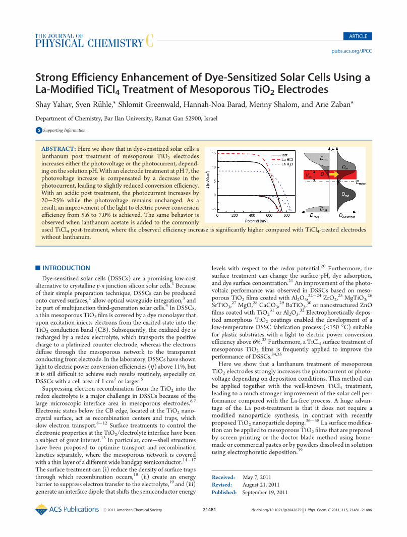
ABSTRACT: Here we show that in dye-sensitized solar cells alanthanum post treatment of mesoporous TiO2 electrodesincreases either the photovoltage or the photocurrent, depend-ing on the solution pH.With an electrode treatment at pH 7, thephotovoltage increase is compensated by a decrease in thephotocurrent, leading to slightly reduced conversion efficiency.With an acidic post treatment, the photocurrent increases by20�25% while the photovoltage remains unchanged. As aresult, an improvement of the light to electric power conversionefficiency from 5.6 to 7.0% is achieved. The same behavior isobserved when lanthanum acetate is added to the commonlyused TiCl4 post-treatment, where the observed efficiency increase is significantly higher compared with TiCl4-treated electrodeswithout lanthanum.
21482 dx.doi.org/10.1021/jp2042679 |J. Phys. Chem. C 2011, 115, 21481–21486
The Journal of Physical Chemistry C ARTICLE
’EXPERIMENTAL SECTION
Mesoporous TiO2 films were deposited by the doctor blademethod onto pretreated fluorine-doped SnO2 (FTO) glass(Pilkington, 8 Ω/square) to improve TiO2 adhesion. For thepretreatment, the FTO substrate was immersed in 40 mM TiCl4solution for 30 min at 90 �C, rinsed, and dried. Subsequently,commercial TiO2 paste with an average particle diameter of20 nm (Dyesol, Australia) was spread by a glass rod over the sub-strate using scotch tape as a spacer. After drying at 120 �C for30min, the thickness wasmeasured using a profilometer (Dektak),and the doctor blade procedure was repeated until a film thick-ness of ∼14 μm was reached. To reach high photocurrents,a light scattering paste was used in the last doctor blade cyclebefore the films were sintered at 500 �C for 30 min in air.La Treatment on TiO2 Electrodes.The TiO2 electrodes were
immersed into freshly prepared solutions of (i) La acetate in 10%HCl, (ii) La acetate with 40 mM TiCl4 in 10% HCl, and (iii) Laacetate dissolved in double-distilled H2O, which were heated in aclosed vile for 30 min at 90 �C. Afterward, the electrodes wererinsed with distilled water and sintered again (500 �C for 30 minin air), cooled to 80 �C, and inserted into a dye solution (0.05 MN719 in ethanol), where they remained overnight.Solar Cell Characterization. DSSCs consisting of the dye-
sensitized La-modified mesoporous TiO2 film, the I�/I3� redox
electrolyte (0.6 M dimethylpropylimidazolium iodide, 0.1 M LiI,0.05 M I2, and 0.5 M tert-butylpyridine in 1:1 acetonitrile�methoxypropionitrile), and a Pt back electrode (100 nm Pt-sputtered onto FTO glass) were sandwiched together usingTeflon tape as spacer. Current�voltage characteristics were re-corded with a potentiostat (Autolab) at a scan rate of 10 mV/s inthe dark and under simulated sunlight (AM 1.5G) using a class Asolar simulator (Newport). The illuminated cell area was1.03 cm2 using a custom-made cell holder.Charge Extraction and Electron Lifetime Measurements.
Open circuit decay and charge extraction measurements wereperformed using a home-built system consisting of an array ofwhite LEDs for bias light and a pulsed red LED for transientmeasurements. For Voc decay measurements, the DSSCwas keptunder open circuit conditions while the potential was adjustedby the light intensity of the white LEDs. A pulse from the redLED was used to generate a small potential perturbation thatwas recorded by an analog to digital card (National Instruments)while a single exponential decay was fitted to the potential signalusing a Labview program. For charge extraction measurements,the bias light was switched off and the DSSC was simultaneouslydischarged via a 10Ω resistor. Charge integration was automati-cally carried out using Labview software. As in the case for solarcell characterization, the illuminated cell area was 1.03 cm2.
’RESULTS
Current�voltage (I�V) characteristics of DSSCs measuredon La-treated mesoporous TiO2 films in the dark and undersimulated sunlight (AM 1.5G, 100 mW/cm2) are shown inFigure 1. We observe a strong increase in the open circuit voltagefrom 695 to 787 mV when the mesoporous TiO2 film is treatedby aqueous La acetate solution under neutral conditions (pH 7)while the photocurrent and the conversion efficiency, η, de-crease. (See the solar cell parameters summarized in Table 1.)Mesoporous TiO2 electrode treated with La under acidic condi-tions in the presence of HCl shows a strong improvement of thephotocurrent from 12.2 to 15.0 mA/cm2 while the photovoltage
remains nearly unchanged. As a result, the conversion efficiencyincreases from 5.6 to 7.0%. The dark I�V curve of the La-treatedelectrode under acidic conditions does not differ significantlyfrom the untreated mesoporous reference system while theLa-treated electrode under neutral conditions shows a stron-ger rectifying behavior with a shift of the current onset towardhigher potentials.
High-resolution transmission electronmicroscopy (HRTEM),X-ray photospectroscopy (XPS), and energy dispersive X-rayspectroscopy (EDS) in conjunction with a focused ion beam(FIB) for cross-section preparation were performed to charac-terize the La modification of the mesoporous TiO2 film. Incontrast with our expectations, we were not able to observe shellformation around the TiO2 nanocrystals using HRTEM. Bymea-suring the cross section of a La-modified sample prepared atneutral pH, it was possible to identify traces of La by EDS whilesimilar results were achieved with XPS measurements performedon the film surface. Therefore either a shell was formed aroundthe TiO2 nanocrystals with a thickness of a few monolayers,which was below the resolution limit of the HRTEM, or La ionsintercalated into the anatase surface, leading to some kind ofsurface doping. In contrast to that, it was not possible to detectLa by XPS, EDS, or Rutherford backscattering in modifiedDSSCs under acidic conditions, indicating that the La treat-ment modified the surface of the TiO2 nanocrystals withoutthe formation of a La compound. Atomic force microscopyimages did not show any differences in surface morphologyand the surface roughness of the treated and untreated films. (Seethe Supporting Information.) We note that also others were not
Table 1. Light to Electric Power Conversion Efficiency (η),Open Circuit Voltage (Voc), Short Circuit Current Density(Jsc), and Fill Factor (FF) for DSSCs Based on a La-TreatedTiO2 Film under Acidic and Neutral Conditions Comparedwith an Untreated Reference Cell
η [%] Voc [mV] Jsc [mA/cm2] FF [%]
ref 5.6 694 12.2 67
La @ pH 1 7.0 689 15.0 68
La @ pH 7 4.7 787 8.8 68
Figure 1. I�V characteristics in the dark and under illumination (1 sun)of DSSCs based on mesoporous TiO2 electrodes including a light-scattering layer. Mesoporous films treated with La under neutral (dottedblue) and acidic conditions (dashed red) are compared with a non-treated reference sample (solid black).
21483 dx.doi.org/10.1021/jp2042679 |J. Phys. Chem. C 2011, 115, 21481–21486
The Journal of Physical Chemistry C ARTICLE
able to observe shell formation as a result of surface treatment;for example, Boschloo et al. observed a strong effect on thephotovoltaic performance with Al3+-treated TiO2 films, althoughit was not possible to identify any known aluminum-containingphase such as Al2O3, aluminum titanate, or ß-Al2TiO5.
40
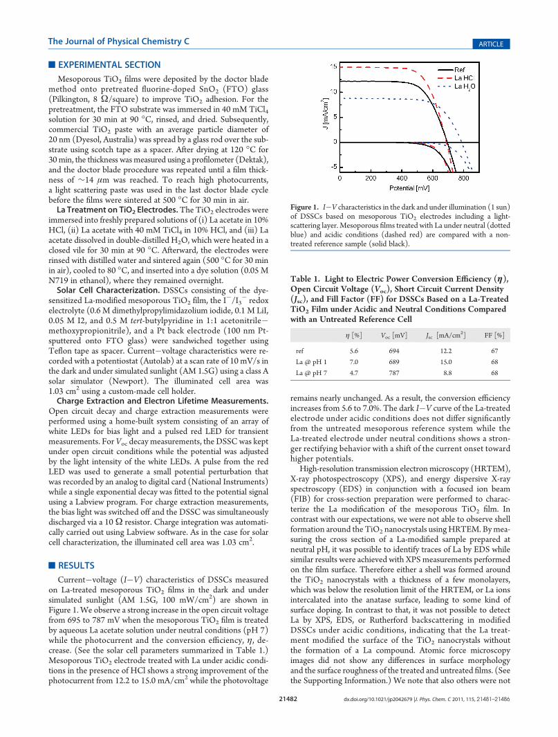
Conversion efficiency measurements as a function of the pHof the La treatment revealed that the highest improvement in ηoccurs at pH 1. (See the Supporting Information.) Consequently,we investigated how far the La treatment can be combined withthe well-known TiCl4 post treatment, which is also carried out atlow pH. Figure 2a shows the I�V characteristics of an untreatedreference cell compared with a TiCl4, a La + HCl, and a La +TiCl4 post-treated electrode. Note that also the La + TiCl4solution contained HCl and has the same pH as the La + HClsolution (pH∼1). To show the La effect on the light-harvestinglayer of the DSSC, the measurements were carried out on deviceswithout light-scattering layer, and the photocurrent was normal-ized with respect to the untreated reference cell. Both Latreatments (La + HCl and La + TiCl4) show a photocurrentimprovement of >40% in contrast with the pure TiCl4 treatment,where the La + TiCl4 treatment even leads to a slightly betterperformance compared with La + HCl. Further investigation ofLa + TiCl4-treated cells shows that the photocurrent improve-ment is nearly independent of the La concentration and occursalready at an addition of 0.01 mol/L lanthanum acetate to theTiCl4 solution (Figure 2b). Note that theDSSCs in Figure 2weremeasured without light scattering layer such that the currentdensities were lower compared with measurements presented in
Figure 1. The Voc, on the other hand, increases slightly afterTiCl4 treatment, whereas a small decrease in the Voc from 715(untreated reference) to 695mV is observed once La is added. Athigher La concentrations (0.4mol/L), theVoc returns to its initialvalue of 715 mV (Figure 2c).
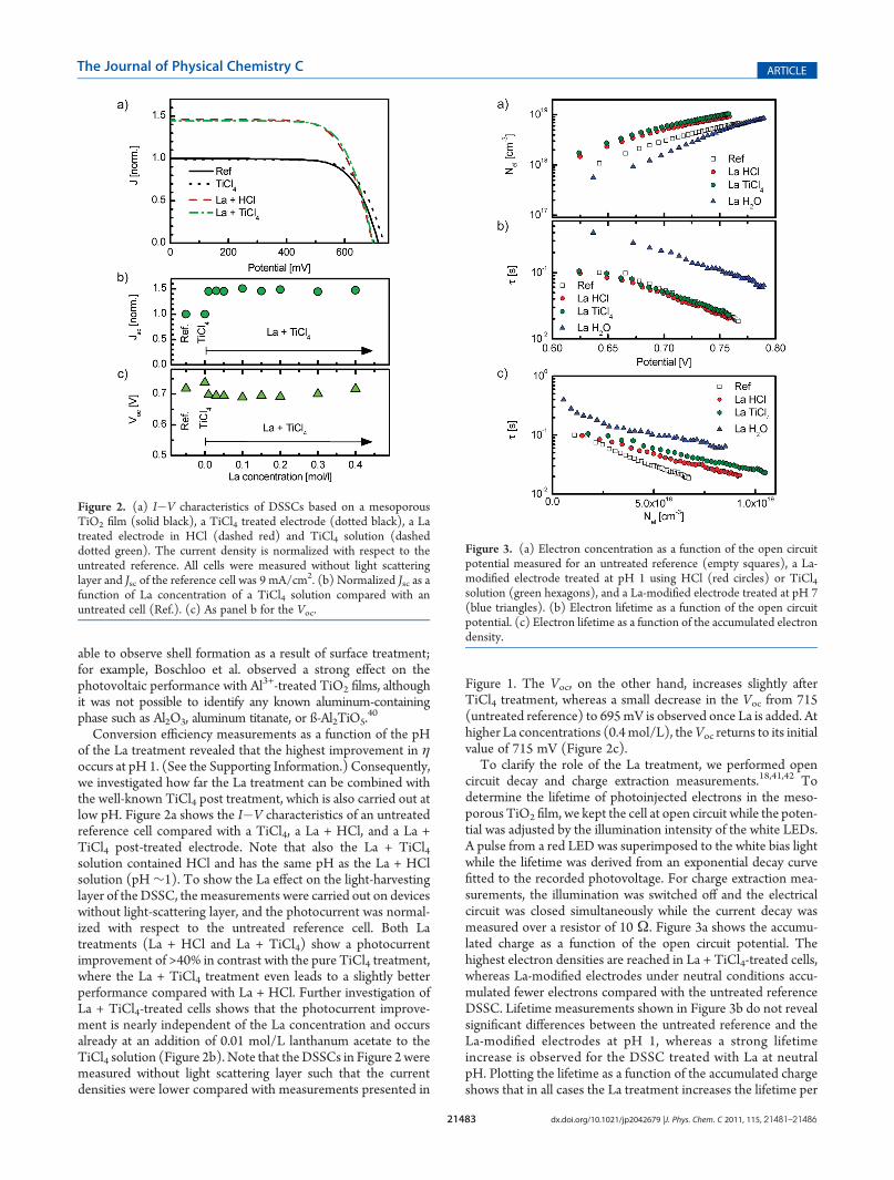
To clarify the role of the La treatment, we performed opencircuit decay and charge extraction measurements.18,41,42 Todetermine the lifetime of photoinjected electrons in the meso-porous TiO2 film, we kept the cell at open circuit while the poten-tial was adjusted by the illumination intensity of the white LEDs.A pulse from a red LED was superimposed to the white bias lightwhile the lifetime was derived from an exponential decay curvefitted to the recorded photovoltage. For charge extraction mea-surements, the illumination was switched off and the electricalcircuit was closed simultaneously while the current decay wasmeasured over a resistor of 10 Ω. Figure 3a shows the accumu-lated charge as a function of the open circuit potential. Thehighest electron densities are reached in La + TiCl4-treated cells,whereas La-modified electrodes under neutral conditions accu-mulated fewer electrons compared with the untreated referenceDSSC. Lifetime measurements shown in Figure 3b do not revealsignificant differences between the untreated reference and theLa-modified electrodes at pH 1, whereas a strong lifetimeincrease is observed for the DSSC treated with La at neutralpH. Plotting the lifetime as a function of the accumulated chargeshows that in all cases the La treatment increases the lifetime per
Figure 2. (a) I�V characteristics of DSSCs based on a mesoporousTiO2 film (solid black), a TiCl4 treated electrode (dotted black), a Latreated electrode in HCl (dashed red) and TiCl4 solution (dasheddotted green). The current density is normalized with respect to theuntreated reference. All cells were measured without light scatteringlayer and Jsc of the reference cell was 9 mA/cm2. (b) Normalized Jsc as afunction of La concentration of a TiCl4 solution compared with anuntreated cell (Ref.). (c) As panel b for the Voc.
Figure 3. (a) Electron concentration as a function of the open circuitpotential measured for an untreated reference (empty squares), a La-modified electrode treated at pH 1 using HCl (red circles) or TiCl4solution (green hexagons), and a La-modified electrode treated at pH 7(blue triangles). (b) Electron lifetime as a function of the open circuitpotential. (c) Electron lifetime as a function of the accumulated electrondensity.
21484 dx.doi.org/10.1021/jp2042679 |J. Phys. Chem. C 2011, 115, 21481–21486
The Journal of Physical Chemistry C ARTICLE
electron (Figure 3c) with the longest life times for neutral Latreated electrodes, followed by La + TiCl4 and La + HCl.
’DISCUSSION
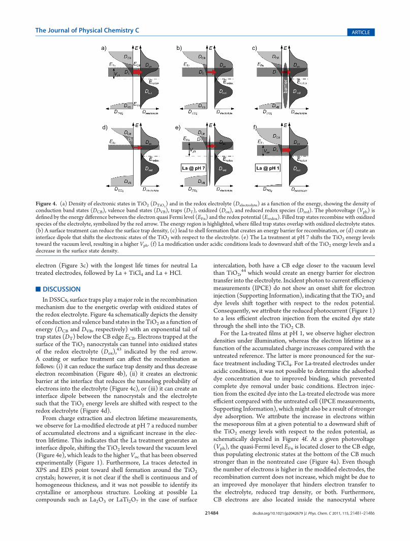
In DSSCs, surface traps play a major role in the recombinationmechanism due to the energetic overlap with oxidized states ofthe redox electrolyte. Figure 4a schematically depicts the densityof conduction and valence band states in the TiO2 as a function ofenergy (DCB and DVB, respectively) with an exponential tail oftrap states (DT) below the CB edge ECB. Electrons trapped at thesurface of the TiO2 nanocrystals can tunnel into oxidized statesof the redox electrolyte (Dox),
43 indicated by the red arrow.A coating or surface treatment can affect the recombination asfollows: (i) it can reduce the surface trap density and thus decreaseelectron recombination (Figure 4b), (ii) it creates an electronicbarrier at the interface that reduces the tunneling probability ofelectrons into the electrolyte (Figure 4c), or (iii) it can create aninterface dipole between the nanocrystals and the electrolytesuch that the TiO2 energy levels are shifted with respect to theredox electrolyte (Figure 4d).
From charge extraction and electron lifetime measurements,we observe for La-modified electrode at pH 7 a reduced numberof accumulated electrons and a significant increase in the elec-tron lifetime. This indicates that the La treatment generates aninterface dipole, shifting the TiO2 levels toward the vacuum level(Figure 4e), which leads to the higher Voc that has been observedexperimentally (Figure 1). Furthermore, La traces detected inXPS and EDS point toward shell formation around the TiO2
crystals; however, it is not clear if the shell is continuous and ofhomogeneous thickness, and it was not possible to identify itscrystalline or amorphous structure. Looking at possible Lacompounds such as La2O3 or LaTi2O7 in the case of surface
intercalation, both have a CB edge closer to the vacuum levelthan TiO2,
44 which would create an energy barrier for electrontransfer into the electrolyte. Incident photon to current efficiencymeasurements (IPCE) do not show an onset shift for electroninjection (Supporting Information), indicating that the TiO2 anddye levels shift together with respect to the redox potential.Consequently, we attribute the reduced photocurrent (Figure 1)to a less efficient electron injection from the excited dye statethrough the shell into the TiO2 CB.
For the La-treated films at pH 1, we observe higher electrondensities under illumination, whereas the electron lifetime as afunction of the accumulated charge increases compared with theuntreated reference. The latter is more pronounced for the sur-face treatment including TiCl4. For La-treated electrodes underacidic conditions, it was not possible to determine the adsorbeddye concentration due to improved binding, which preventedcomplete dye removal under basic conditions. Electron injec-tion from the excited dye into the La-treated electrode was moreefficient compared with the untreated cell (IPCE measurements,Supporting Information), whichmight also be a result of strongerdye adsorption. We attribute the increase in electrons withinthe mesoporous film at a given potential to a downward shift ofthe TiO2 energy levels with respect to the redox potential, asschematically depicted in Figure 4f. At a given photovoltage(Vph), the quasi-Fermi level EFn is located closer to the CB edge,thus populating electronic states at the bottom of the CB muchstronger than in the nontreated case (Figure 4a). Even thoughthe number of electrons is higher in the modified electrodes, therecombination current does not increase, which might be due toan improved dye monolayer that hinders electron transfer tothe electrolyte, reduced trap density, or both. Furthermore,CB electrons are also located inside the nanocrystal where
Figure 4. (a) Density of electronic states in TiO2 (DTiO2) and in the redox electrolyte (Delectrolyte) as a function of the energy, showing the density of
conduction band states (DCB), valence band states (DVB), traps (DT), oxidized (Dox), and reduced redox species (Dred). The photovoltage (Vph) isdefined by the energy difference between the electron quasi Fermi level (EFn) and the redox potential (Eredox). Filled trap states recombine with oxidizedspecies of the electrolyte, symbolized by the red arrow. The energy region is highlighted, where filled trap states overlap with oxidized electrolyte states.(b) A surface treatment can reduce the surface trap density, (c) lead to shell formation that creates an energy barrier for recombination, or (d) create aninterface dipole that shifts the electronic states of the TiO2 with respect to the electrolyte. (e) The La treatment at pH 7 shifts the TiO2 energy levelstoward the vacuum level, resulting in a higher Vph. (f) La modification under acidic conditions leads to downward shift of the TiO2 energy levels and adecrease in the surface state density.
21485 dx.doi.org/10.1021/jp2042679 |J. Phys. Chem. C 2011, 115, 21481–21486
The Journal of Physical Chemistry C ARTICLE
they cannot recombine with the electrolyte species such that thephotovoltage remains nearly unaffected. A similar downwardshift of the TiO2 energy levels together with an increase inelectron lifetime was also observed by O’Regan and coworkersfor TiCl4-treated samples without La.45
Recent work suggests that the performance of DSSCs can beimproved by doping the TiO2 nanocrystals during synthesisusing lanthanum,36,46 neodymium,37 gallium, or yttrium ions.38
For La-doping, it was claimed that an increase in the oxygenvacancy density at the particle surface was responsible for im-proved dye adsorption, resulting in a higher dye load responsiblefor an increased photocurrent, which is analogous to our findings.Nd-doped samples were investigated with a different dye (C101),also showing an increase in the surface concentration of dye as aresult of the doping, although the increase in the photocurrentcame on the expense of the photovoltage. Better results werereported for Ga- and Y-doped TiO2 electrodes, where an improv-ement of all three solar cell parameters, Jsc,Voc, and fill factor, wasachieved. The huge advantage of the La post-treatment reportedin this work is its compatibility with commercially available TiO2
powders and pastes and the fact that it does not require newsynthesis routes. The La modification can easily be carriedtogether with the commonly applied TiCl4 treatment, resultingin a much stronger efficiency increase compared with the La-freeTiCl4 treatment. Even though lanthanum belongs to the group ofrare earths, it is actually a relative abundant material; its occur-rence on the earth’s crust is twice as high compared with lead.47
’CONCLUSIONS
We have demonstrated that a La treatment of mesoporousTiO2 films leads to strong improvements of the photocurrent orphotovoltage, depending on the pH of the deposition conditions.At neutral pH, a strong increase in the photovoltage is observedwhile the photocurrent is reduced. Charge extraction and lifetimemeasurements indicate that the Voc increase is due to a shellformation around the TiO2 nanocrystals, generating an interfacedipole that shifts the TiO2 energy bands toward the vacuum level,whereas the reduced photocurrent is caused by less favorableelectron injection through the shell. With acidic La treatment, weobserve an increase in accumulated electrons in the mesoporouselectrode under illumination leading to a strong photocurrentenhancement. We attribute this to a higher surface density ofadsorbed dye molecules to the TiO2 nanocrystals. Similar toTiCl4-treated samples, our results suggest that the TiO2 energylevels are shifted downward while the electron lifetime as afunction of accumulated charge increases such that the photo-voltage remains nearly unchanged. Finally, we demonstrated thatthe addition of La acetate to the TiCl4 treatment improves thephotovoltaic performance much stronger compared with thewell-known La-free TiCl4 procedure.
’ASSOCIATED CONTENT
bS Supporting Information. I�V measurements of La-treated electrodes at different solution pH, atomic force micro-scopy, and IPCE. This material is available free of charge via theInternet at http://pubs.acs.org.
’AUTHOR INFORMATION
Corresponding Author*E-mail: [email protected] (S.R.), [email protected] (A.Z.).
’ACKNOWLEDGMENT
We acknowledge support from the Israel Ministry of Industryand Trade, Magnet Program, SES. S.R. acknowledges financialsupport from the European Union within the FP7 framework(Marie Curie Intra-European Fellowship for Career Development).
’REFERENCES
(1) O’Regan, B.; Gr€atzel, M. Nature 1991, 353, 737–740.(2) Tachan, Z.; R€uhle, S.; Zaban, A. Sol. EnergyMater. Sol. Cells 2010,
94, 317–322.(3) R€uhle, S.; Greenwald, S.; Koren, E.; Zaban, A.Opt. Express 2008,
16, 21801–21806.(4) R€uhle, S.; Segal, A.; Vilan, A.; Kurtz, S. R.; Grinis, L.; Zaban, A.;
Lubomirsky, I.; Cahen, D. J. Renewable Sustainable Energy 2009, 1,013106.
(5) Green, M. A.; Emery, K.; Hishikawa, Y.; Warta, W. Prog.Photovoltaics 2010, 18, 346–352.
(6) O’Regan, B. C.; Durrant, J. R.Acc. Chem. Res. 2009, 42, 1799–1808.(7) Barnes, P. R. F.; Anderson, A. Y.; Juozapavicius, M.; Liu, L. X.; Li,
X. E.; Palomares, E.; Forneli, A.; O’Regan, B. C. Phys. Chem. Chem. Phys.2011, 13, 3547–3558.
(8) Barnes, P. R. F.; Liu, L. X.; Li, X. E.; Anderson, A. Y.; Kisserwan,H.; Ghaddar, T. H.; Durrant, J. R.; O’Regan, B. C. Nano Lett. 2009,9, 3532–3538.
(9) Salvador, P.; Hidalgo, M. G.; Zaban, A.; Bisquert, J. J. Phys. Chem.B 2005, 109, 15915–15926.
(10) Peter, L. M.; Walker, A. B.; Boschloo, G.; Hagfeldt, A. J. Phys.Chem. B 2006, 110, 13694–13699.
(11) Mohammadpour, R.; Zad, A. I.; Hagfeldt, A.; Boschloo, G.ChemPhysChem 2010, 11, 2140–2145.
(12) Dittrich, T. Phys. Status Solidi A 2000, 182, 447–455.(13) Fabregat-Santiago, F.; Garcia-Canadas, J.; Palomares, E.; Clif-
ford, J. N.; Haque, S. A.; Durrant, J. R.; Garcia-Belmonte, G.; Bisquert, J.J. Appl. Phys. 2004, 96, 6903–6907.
(14) Chappel, S.; Chen, S.-G.; Zaban, A.Langmuir2002, 18, 3336–3342.(15) Jose, R.; Thavasi, V.; Ramakrishna, S. J. Am. Ceram. Soc. 2009,
92, 289–301.(16) Kay, A.; Gr€atzel, M. Chem. Mater. 2002, 14, 2930–2935.(17) Hod, I.; Shalom, M.; Tachan, Z.; R€uhle, S.; Zaban, A. J. Phys.
Chem. C 2010, 114, 10015–10018.(18) Bisquert, J.; Zaban, A.; Greenshtein, M.; Mora-Ser�o, I. J. Am.
Chem. Soc. 2004, 126, 13550–13559.(19) Palomares, E.; Clifford, J. N.; Haque, S. A.; Lutz, T.; Durrant,
J. R. J. Am. Chem. Soc. 2003, 125, 475–482.(20) R€uhle, S.; Greenshtein, M.; Chen, S. G.; Merson, A.; Pizem, H.;
Sukenik, C. S.; Cahen, D.; Zaban, A. J. Phys. Chem. B 2005, 109,18907–18913.
(21) Nazeeruddin, M. K.; Humphry-Baker, R.; Liska, P.; Gr€atzel, M.J. Phys. Chem. B 2003, 107, 8981–8987.
(22) Rhee, S.-W. J. Power Sources 2010, 195, 5138–5143.(23) Lin, C. J. Phys. Chem. C 2010, 114, 10048–10053.(24) Liu, Z.; Pan, K.; Liu, M.; Wang, M.; L€u, Q.; Li, J.; Bai, Y.; Li, T.
Electrochim. Acta 2005, 50, 2583–2589.(25) Menzies, D. B.; Dai, Q.; Cheng, Y.-B.; Simon, G. P.; Spiccia, L.
C. R. Chim. 2006, 9, 713–716.(26) Fu, W. Colloids Surf., A 2009, 340, 182–186.(27) Diamant, Y.; Chen, S. G.; Melamed, O.; Zaban, A. J. Phys. Chem.
B 2003, 107, 1977–1981.(28) Jung, H. S.; Lee, J.-K.; Nastasi, M.; Lee, S.-W.; Kim, J.-Y.; Park,
J.-S.; Hong, K. S.; Shin, H. Langmuir 2005, 21, 10332–10335.(29) Lee, S.; Kim, J. Y.; Youn, S. H.; Park, M.; Hong, K. S.; Jung,
H. S.; Lee, J.-K.; Shin, H. Langmuir 2007, 23, 11907–11910.(30) Zhang, L.; Shi, Y.; Peng, S.; Liang, J.; Tao, Z.; Chen, J.
J. Photochem. Photobiol., A 2008, 197, 260–265.(31) Park, K.; Zhang, Q.; Garcia, B. B.; Zhou, X.; Jeong, Y. H.; Cao,
G. Adv. Mater. 2010, 22, 2329–2332.
21486 dx.doi.org/10.1021/jp2042679 |J. Phys. Chem. C 2011, 115, 21481–21486
The Journal of Physical Chemistry C ARTICLE
(32) Law, M.; Greene, L. E.; Radenovic, A.; Kuykendall, T.;Liphardt, J.; Yang, P. J. Phys. Chem. B 2006, 110, 22652–22663.(33) Grinis, L.; Kotlyar, S.; R€uhle, S.; Grinblat, J.; Zaban, A. Adv.
Funct. Mater. 2010, 20, 282–288.(34) Park, N. G.; Schlichth€orl, G.; van de Lagemaat, J.; Cheong,
H. M.; Mascarenhas, A.; Frank, A. J. J. Phys. Chem. B 1999, 103,3308–3314.(35) Sommeling, P.M.; O’Regan, B. C.; Haswell, R. R.; Smit, H. J. P.;
Bakker, N. J.; Smits, J. J. T.; Kroon, J. M.; van Roosmalen, J. A. M. J. Phys.Chem. B 2006, 110, 19191–19197.(36) Zhang, J.; Zhao, Z.; Wang, X.; Yu, T.; Guan, J.; Yu, Z.; Li, Z.;
Zou, Z. J. Phys. Chem. C 2010, 114, 18396–18400.(37) Chandiran, A. K.; Sauvage, F.; Casas-Cabanas, M.; Comte, P.;
Zakeeruddin, S. M.; Graetzel, M. J. Phys. Chem. C 2010, 114, 15849–15856.(38) Chandiran, A. K.; Sauvage, F.; Etgar, L.; Gr€atzel, M. J. Phys.
Chem. C 2011, 115, 9232.(39) Grinis, L.; Dor, S.; Ofir, A.; Zaban, A. J. Photochem. Photobiol., A
2008, 198, 52–59.(40) Alarcon, H.; Hedlund, M.; Johansson, E. M. J.; Rensmo, H.;
Hagfeldt, A.; Boschloo, G. J. Phys. Chem. C 2007, 111, 13267–13274.(41) Bailes, M.; Cameron, P. J.; Lobato, K.; Peter, L. M. J. Phys.
Chem. B 2005, 109, 15429–15435.(42) S�anchez-Díaz, A.; Izquierdo, M.; Filippone, S.; Martin, N.;
Palomares, E. Adv. Funct. Mater. 2010, 20, 2695–2700.(43) Gerischer, H. Z. Phys. Chem. Neue Fol. 1960, 26, 325–338.(44) Xu, Y.; Schoonen, M. A. A. Am. Mineral. 2000, 85, 543–556.(45) O’Regan, B. C.; Durrant, J. R.; Sommeling, P. M.; Bakker, N. J.
J. Phys. Chem. C 2007, 111, 14001–14010.(46) Wu, X.-H.; Wang, S.; Guo, Y.; Xie, Z.-Y.; Han, L.; Jiang, Z.-H.
Chin. J. Chem. 2008, 26, 1939–1943. Note that the reported efficienciesin this reference are incorrect, i.e., η 6¼ JscVocFF/(100 mW/cm2).(47) Taylor, S. R. Geochim. Cosmochim. Acta 1964, 28, 1273–1285.


