Embed Size (px)
Citation preview
1
Basic information on Fixed edentulous solutions Treatment guide

1
Contents
Your removable and fixed edentulous treatment portfolio 2
More than a fixed rehabilitation. A smart solution with reduced complexity. 6
Clinical case 32
Product overview 35
Appendix A: Straumann® Pro Arch Guide 38
Appendix B: Straumann® Bone Level Bone Profiler 39
2
Removable and fixed options from Straumann
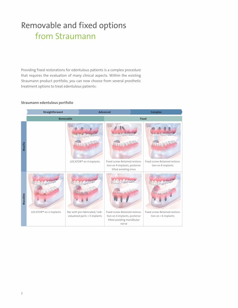
Providing fixed restorations for edentulous patients is a complex procedure that requires the evaluation of many clinical aspects. Within the existing Straumann product portfolio, you can now choose from several prosthetic treatment options to treat edentulous patients:
Straumann edentulous portfolio
Removable Fixed
Max
illa
LOCATOR® on 4 implants Fixed screw-Retained restora-tion on 4 implants, posterior
tilted avoiding sinus
Fixed screw-Retained restora-tion on 8 implants
Man
dibl
e
LOCATOR® on 2 implants Bar with pre-fabricated / indi-vidualized parts > 3 implants
Fixed screw-Retained restora-tion on 4 implants, posterior tilted avoiding mandibular
nerve
Fixed screw-Retained restora-tion on > 6 implants
Straightforward Advanced Complex
3
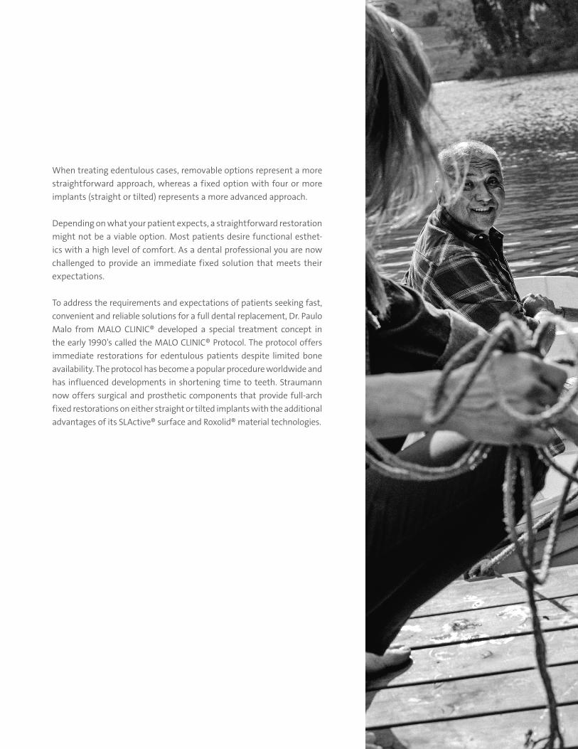
When treating edentulous cases, removable options represent a more straightforward approach, whereas a fixed option with four or more implants (straight or tilted) represents a more advanced approach.
Depending on what your patient expects, a straightforward restoration might not be a viable option. Most patients desire functional esthet-ics with a high level of comfort. As a dental professional you are now challenged to provide an immediate fixed solution that meets their expectations.
To address the requirements and expectations of patients seeking fast, convenient and reliable solutions for a full dental replacement, Dr. Paulo Malo from MALO CLINIC® developed a special treatment concept in the early 1990’s called the MALO CLINIC® Protocol. The protocol offers immediate restorations for edentulous patients despite limited bone availability. The protocol has become a popular procedure worldwide and has influenced developments in shortening time to teeth. Straumann now offers surgical and prosthetic components that provide full-arch fixed restorations on either straight or tilted implants with the additional advantages of its SLActive® surface and Roxolid® material technologies.
4
Prosthetic options for esthetic and efficient restorations.
The Straumann® Bone Level Tapered Implant provides flexibility in challenging clinical and anatomical situations. It represents a combination of the time-tested Straumann Bone Level Roxolid® SLActive® implant with the advantages of a tapered design. The Roxolid material has been specifically designed for dental implantol-ogy and delivers outstanding mechanical properties. Combined with the SLActive surface, Straumann delivers an excellent implant system with outstanding osseo-integration and healing properties.
The Straumann prosthetic portfolio provides flexibility to choose the best solution for the patient.
• The Straumann Screw-Retained Abutment portfolio allows overcoming implant angelations of 17° and 30°
• CARES Restorative Options include a wide range of popular screw-Retained bar and bridge solutions
THE NEW STRAUMANN® BONE LEVEL TAPERED IMPLANT
Roxolid – reducing invasiveness with smaller implants1
ѹ Roxolid material with excellent mechanical properties2
ѹ Roxolid may allow the use of smaller-diameter implants with the same clinical performance as regular-diameter titanium implants3
ѹ Smaller implants have the potential to preserve peri-implant structures and avoid invasive bone grafting procedures
ѹ Create a full denture on two Roxolid 3.3 implants ѹ Increase patient acceptance of implant treatment by providing less invasive solutions1
SLActive – Designed to maximize treatment success and predictability ѹ Faster osseointegration to enhance confidence in all treatments4
ѹ Reduced healing time from 6 to 8 weeks to 3 to 4 weeks4
ѹ Increased predictability in stability critical treatment protocols Apically tapered – matches the natural shape of a tooth root ѹ Helps overcome anatomical restrictions ѹ Full thread at the bottom allows for engagement of threads with the osteotomy ѹ In combination with the hybrid tapered shape, the cutting notches enable placement in
underprepared sites
5
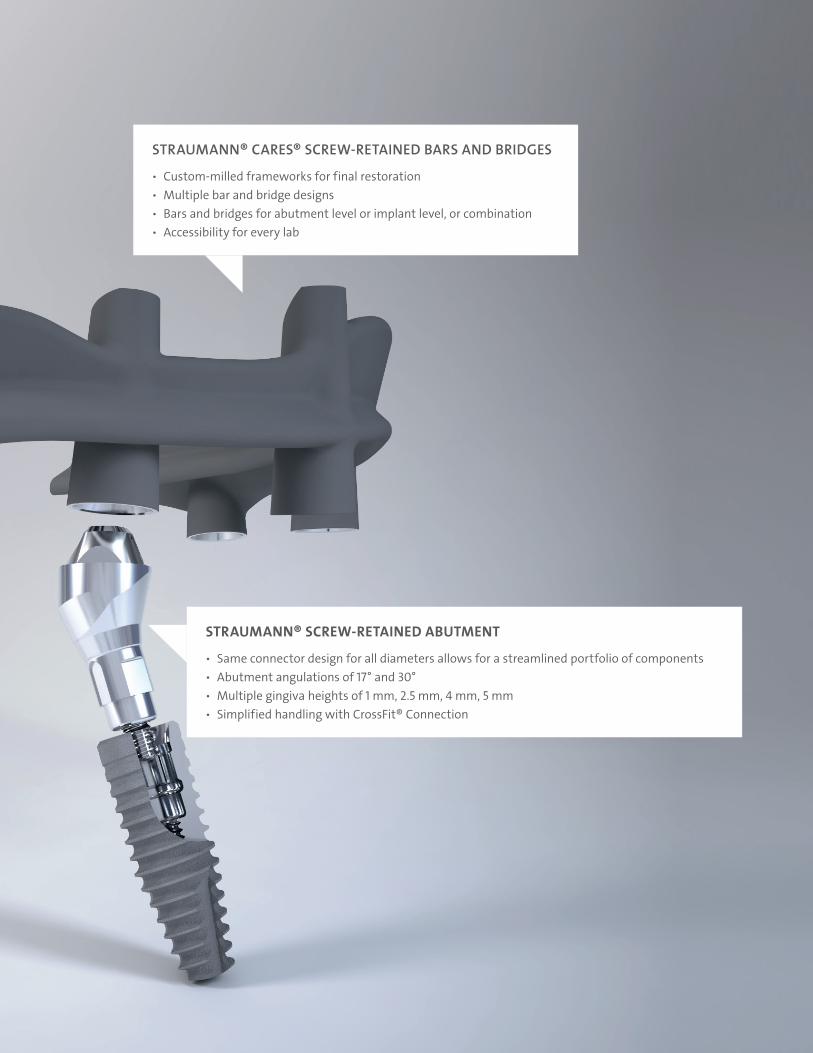
STRAUMANN® SCREW-RETAINED ABUTMENT
ѹ Same connector design for all diameters allows for a streamlined portfolio of components ѹ Abutment angulations of 17° and 30° ѹ Multiple gingiva heights of 1 mm, 2.5 mm, 4 mm, 5 mm ѹ Simplified handling with CrossFit® Connection
STRAUMANN® CARES® SCREW-RETAINED BARS AND BRIDGES
ѹ Custom-milled frameworks for final restoration ѹ Multiple bar and bridge designs ѹ Bars and bridges for abutment level or implant level, or combination ѹ Accessibility for every lab
6
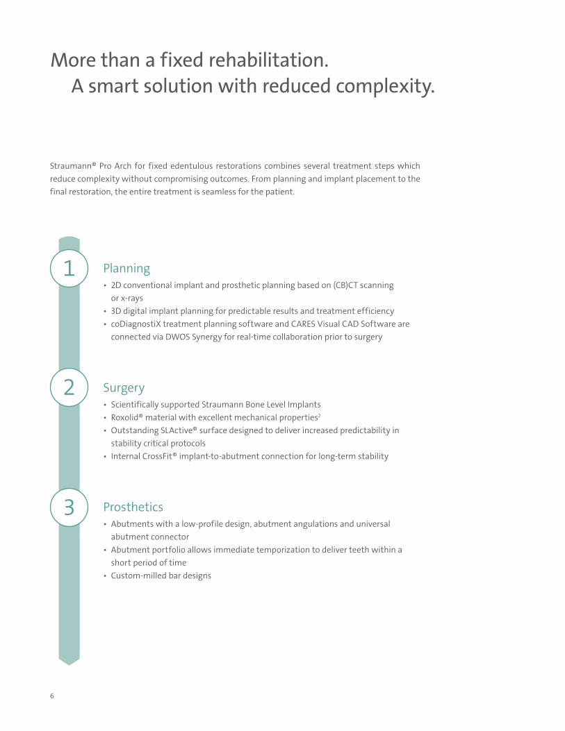
More than a fixed rehabilitation. A smart solution with reduced complexity.
Straumann® Pro Arch for fixed edentulous restorations combines several treatment steps which reduce complexity without compromising outcomes. From planning and implant placement to the final restoration, the entire treatment is seamless for the patient.
Planning• 2D conventional implant and prosthetic planning based on (CB)CT scanning
or x-rays• 3D digital implant planning for predictable results and treatment efficiency• coDiagnostiX treatment planning software and CARES Visual CAD Software are
connected via DWOS Synergy for real-time collaboration prior to surgery
Surgery• Scientifically supported Straumann Bone Level Implants• Roxolid® material with excellent mechanical properties2
• Outstanding SLActive® surface designed to deliver increased predictability in stability critical protocols
• Internal CrossFit® implant-to-abutment connection for long-term stability
Prosthetics• Abutments with a low-profile design, abutment angulations and universal
abutment connector• Abutment portfolio allows immediate temporization to deliver teeth within a
short period of time• Custom-milled bar designs
1
2
3
7
1
PLANNING PHASE
For optimal and long-lasting results, prosthetic-driven planning in collaboration with all treatment partners phase is essential.
During the planning phase the following aspects need to be considered:
• Clarify patient’s expectations• Analyze patient’s oral hygiene compliance• Patient anamnesis (bone density, bone volume, sufficient lip support)• Decide on final prosthetic restoration (fixed/removable)• Decide on surgical procedure and implant placement• Communicate long-term post-operative care and maintenance
Proper diagnosis and treatment planning that includes the needs of patients, – as well as an evidence-based implant/prosthetic design will help to result in a successful treatment outcome. In combination, these factors can significantly improve the patient’s quality of life.5
Enhanced predictability may be achieved by incorporating 3D treatment planning with coDiagnostiX treatment planning software, in combination with a Straumann CARES laboratory.
For additional information on Straumann® Guided Surgery, please consult brochure on Straumann® Guided Surgery, NAMLIT 1103.
Planning
8
2 Surgery
SURGICAL PREPARATION AND GENERAL CONSIDERATIONS
A
P
2
1a
1b
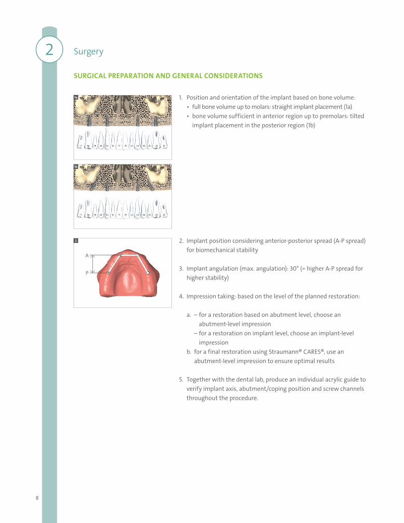
1. Position and orientation of the implant based on bone volume:• full bone volume up to molars: straight implant placement (1a)• bone volume sufficient in anterior region up to premolars: tilted
implant placement in the posterior region (1b)
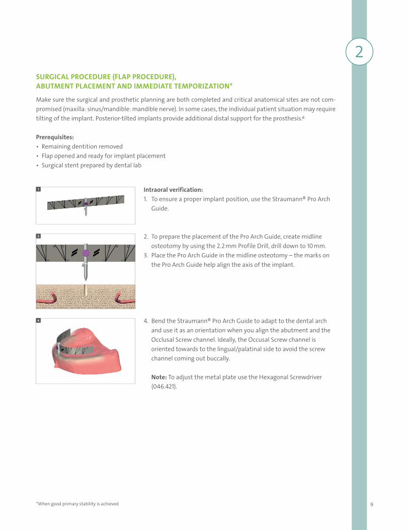
2. Implant position considering anterior-posterior spread (A-P spread) for biomechanical stability
3. Implant angulation (max. angulation): 30° (= higher A-P spread for higher stability)
4. Impression taking: based on the level of the planned restoration:
a. – for a restoration based on abutment level, choose an abutment-level impression
– for a restoration on implant level, choose an implant-level impression
b. for a final restoration using Straumann® CARES®, use an abutment-level impression to ensure optimal results
5. Together with the dental lab, produce an individual acrylic guide to verify implant axis, abutment/coping position and screw channels throughout the procedure.
9
2SURGICAL PROCEDURE (FLAP PROCEDURE), ABUTMENT PLACEMENT AND IMMEDIATE TEMPORIZATION*
Make sure the surgical and prosthetic planning are both completed and critical anatomical sites are not com-promised (maxilla: sinus/mandible: mandible nerve). In some cases, the individual patient situation may require tilting of the implant. Posterior-tilted implants provide additional distal support for the prosthesis.6
Prerequisites: • Remaining dentition removed• Flap opened and ready for implant placement • Surgical stent prepared by dental lab
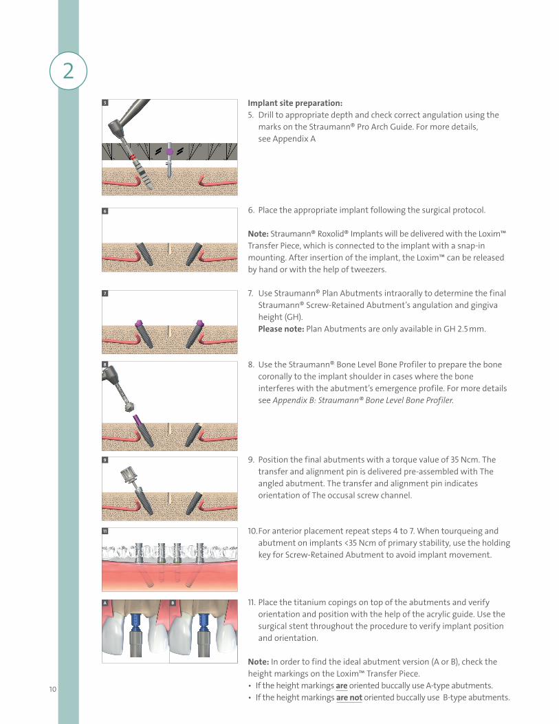
Intraoral verification: 1. To ensure a proper implant position, use the Straumann® Pro Arch
Guide.
2. To prepare the placement of the Pro Arch Guide, create midline osteotomy by using the 2.2 mm Profile Drill, drill down to 10 mm.
3. Place the Pro Arch Guide in the midline osteotomy – the marks on the Pro Arch Guide help align the axis of the implant.
4. Bend the Straumann® Pro Arch Guide to adapt to the dental arch and use it as an orientation when you align the abutment and the Occlusal Screw channel. Ideally, the Occusal Screw channel is oriented towards to the lingual/palatinal side to avoid the screw channel coming out buccally.
Note: To adjust the metal plate use the Hexagonal Screwdriver (046.421).
1
2
4
*When good primary stability is achieved
10
Implant site preparation: 5. Drill to appropriate depth and check correct angulation using the
marks on the Straumann® Pro Arch Guide. For more details, see Appendix A
6. Place the appropriate implant following the surgical protocol. Note: Straumann® Roxolid® Implants will be delivered with the Loxim™ Transfer Piece, which is connected to the implant with a snap-in mounting. After insertion of the implant, the Loxim™ can be released by hand or with the help of tweezers.
7. Use Straumann® Plan Abutments intraorally to determine the final Straumann® Screw-Retained Abutment’s angulation and gingiva height (GH). Please note: Plan Abutments are only available in GH 2.5 mm.
8. Use the Straumann® Bone Level Bone Profiler to prepare the bone coronally to the implant shoulder in cases where the bone interferes with the abutment’s emergence profile. For more details see Appendix B: Straumann® Bone Level Bone Profiler.
9. Position the final abutments with a torque value of 35 Ncm. The transfer and alignment pin is delivered pre-assembled with The angled abutment. The transfer and alignment pin indicates orientation of The occusal screw channel.
10. For anterior placement repeat steps 4 to 7. When tourqueing and abutment on implants <35 Ncm of primary stability, use the holding key for Screw-Retained Abutment to avoid implant movement.
11. Place the titanium copings on top of the abutments and verify orientation and position with the help of the acrylic guide. Use the surgical stent throughout the procedure to verify implant position and orientation.
Note: In order to find the ideal abutment version (A or B), check the height markings on the Loxim™ Transfer Piece. • If the height markings are oriented buccally use A-type abutments.• If the height markings are not oriented buccally use B-type abutments.
5
6
7
8
9
11
A B
2
11
Note: For additional information on the surgical procedure, please consult the Basic information on the surgical procedure for the Straumann® Bone Level Tapered Implant, NAMLIT 1043.
If immediate temporization is not indicated, place Protective Caps for Straumann® Screw-Retained Abutments directly onto the abutments and hand-tighten them.
Note: Do not keep the Protective Caps in the patient’s mouth for more than 30 days. Prepare sufficient space in the patient’s temporary denture until the final prosthesis is placed.
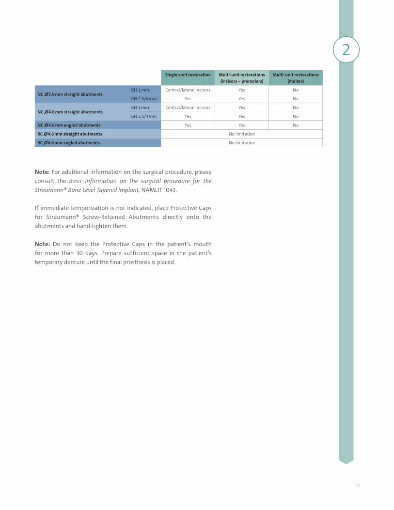
Single-unit restoration Multi-unit restorations (incisors – premolars)
Multi-unit restorations (molars)
NC ∅3.5 mm straight abutmentsGH 1 mm Central/lateral incisors Yes No
GH 2.5/4 mm Yes Yes No
NC ∅4.6 mm straight abutmentsGH 1 mm Central/lateral incisors Yes No
GH 2.5/4 mm Yes Yes No
NC ∅4.6 mm angled abutments Yes Yes No
RC ∅4.6 mm straight abutments No limitation
RC ∅4.6 mm angled abutments No limitation
2
12
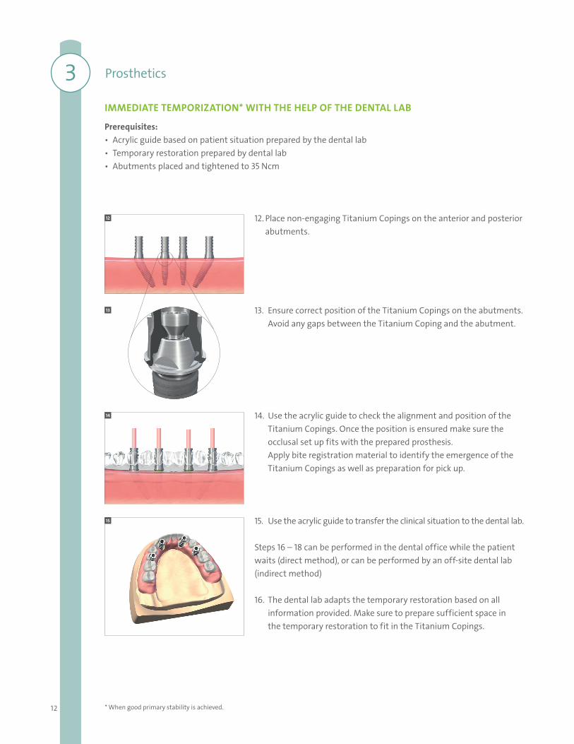
12. Place non-engaging Titanium Copings on the anterior and posterior abutments.
13. Ensure correct position of the Titanium Copings on the abutments. Avoid any gaps between the Titanium Coping and the abutment.
14. Use the acrylic guide to check the alignment and position of the Titanium Copings. Once the position is ensured make sure the occlusal set up fits with the prepared prosthesis.Apply bite registration material to identify the emergence of the Titanium Copings as well as preparation for pick up.
15. Use the acrylic guide to transfer the clinical situation to the dental lab.
Steps 16 – 18 can be performed in the dental office while the patient waits (direct method), or can be performed by an off-site dental lab (indirect method)
16. The dental lab adapts the temporary restoration based on all information provided. Make sure to prepare sufficient space in the temporary restoration to fit in the Titanium Copings.
12
13
14
15
IMMEDIATE TEMPORIZATION* WITH THE HELP OF THE DENTAL LAB
Prerequisites: • Acrylic guide based on patient situation prepared by the dental lab• Temporary restoration prepared by dental lab• Abutments placed and tightened to 35 Ncm
3 Prosthetics
* When good primary stability is achieved.
13
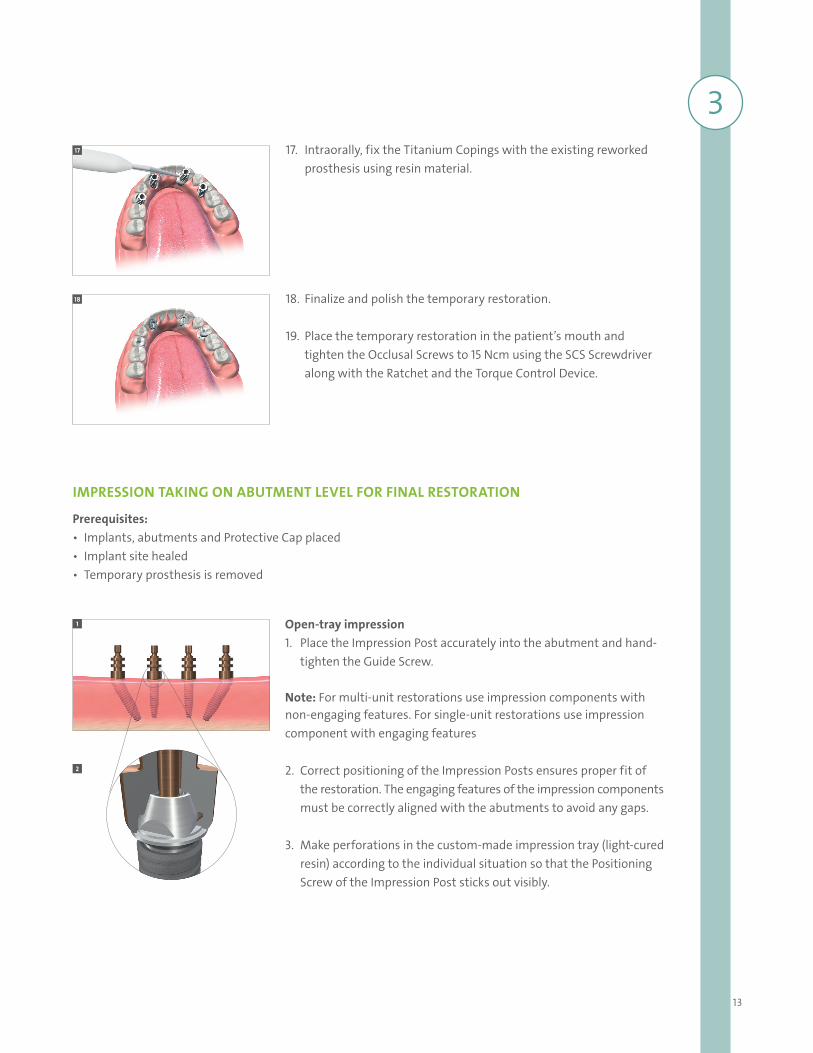
Open-tray impression 1. Place the Impression Post accurately into the abutment and hand-
tighten the Guide Screw.
Note: For multi-unit restorations use impression components with non-engaging features. For single-unit restorations use impression component with engaging features
2. Correct positioning of the Impression Posts ensures proper fit of the restoration. The engaging features of the impression components must be correctly aligned with the abutments to avoid any gaps.
3. Make perforations in the custom-made impression tray (light-cured resin) according to the individual situation so that the Positioning Screw of the Impression Post sticks out visibly.
1
2
IMPRESSION TAKING ON ABUTMENT LEVEL FOR FINAL RESTORATION
Prerequisites: • Implants, abutments and Protective Cap placed• Implant site healed• Temporary prosthesis is removed
17
18
17. Intraorally, fix the Titanium Copings with the existing reworked prosthesis using resin material.
18. Finalize and polish the temporary restoration.
19. Place the temporary restoration in the patient’s mouth and tighten the Occlusal Screws to 15 Ncm using the SCS Screwdriver along with the Ratchet and the Torque Control Device.
3
14
Option for closed-tray impression:Place the Impression Posts onto the Screw-Retained Abutments, ensure correct positioning with the retentive features and click the Positioning Caps onto the Impression Posts allowing a vestibular orientation. After taking the impression, forward all impression components to the dental lab for processing.
In the dental lab, screw the Impression Posts onto the corresponding analogs and click back into the Positioning Caps.
Please note: All Impression Posts are intended for single use only to ensure optimal fit and precise impression taking for each patient.
Note: Hydrocolloid is not suitable for this application due to its low tensile strength.
9
4
8
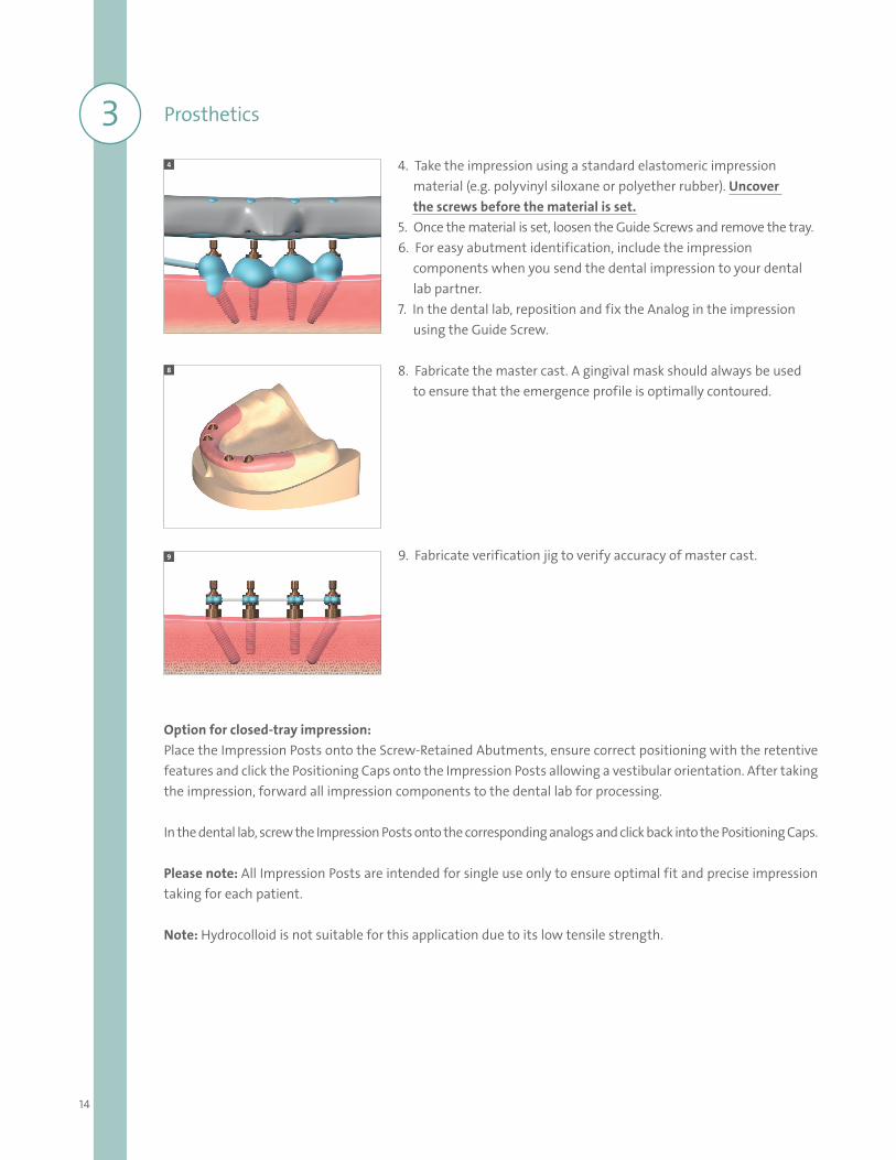
4. Take the impression using a standard elastomeric impression material (e.g. polyvinyl siloxane or polyether rubber). Uncover the screws before the material is set.5. Once the material is set, loosen the Guide Screws and remove the tray.6. For easy abutment identification, include the impression components when you send the dental impression to your dental lab partner.7. In the dental lab, reposition and fix the Analog in the impression using the Guide Screw.
8. Fabricate the master cast. A gingival mask should always be used to ensure that the emergence profile is optimally contoured.
9. Fabricate verification jig to verify accuracy of master cast.
3 Prosthetics
15
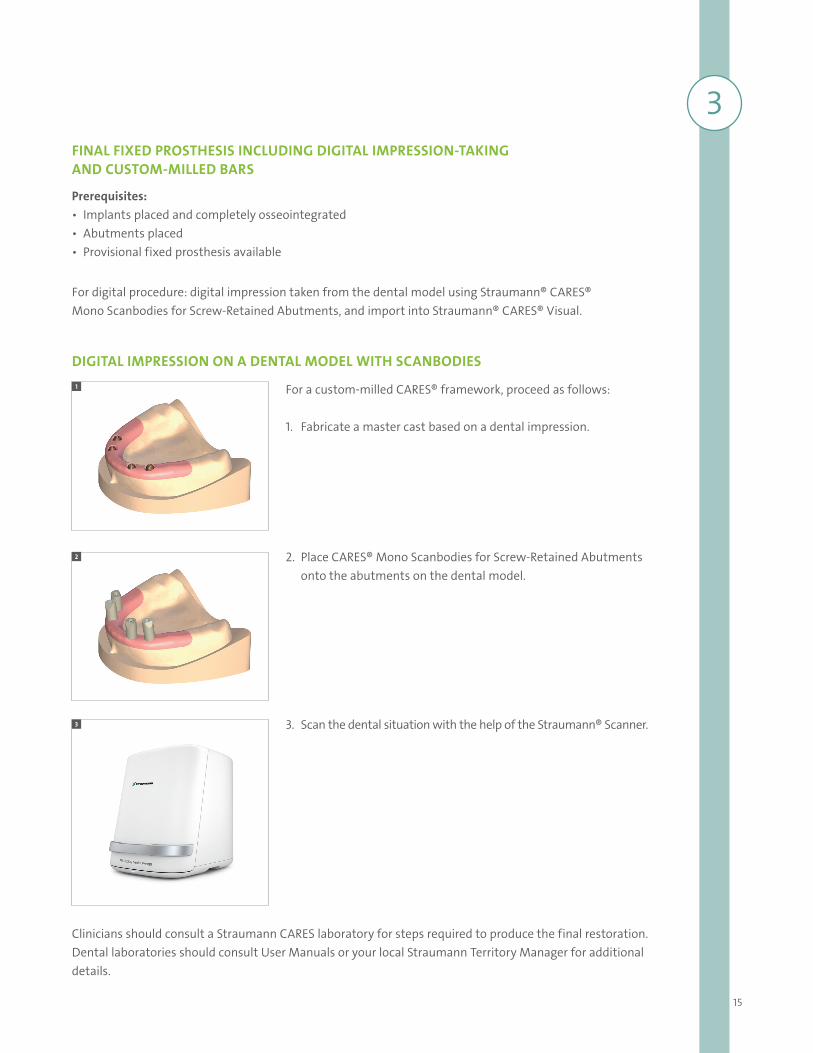
For a custom-milled CARES® framework, proceed as follows:
1. Fabricate a master cast based on a dental impression.
2. Place CARES® Mono Scanbodies for Screw-Retained Abutments onto the abutments on the dental model.
3. Scan the dental situation with the help of the Straumann® Scanner.
1
2
3
FINAL FIXED PROSTHESIS INCLUDING DIGITAL IMPRESSION-TAKING AND CUSTOM-MILLED BARS
Prerequisites: • Implants placed and completely osseointegrated• Abutments placed• Provisional fixed prosthesis available
3
For digital procedure: digital impression taken from the dental model using Straumann® CARES® Mono Scanbodies for Screw-Retained Abutments, and import into Straumann® CARES® Visual.
DIGITAL IMPRESSION ON A DENTAL MODEL WITH SCANBODIES
Clinicians should consult a Straumann CARES laboratory for steps required to produce the final restoration. Dental laboratories should consult User Manuals or your local Straumann Territory Manager for additional details.
16
4
6
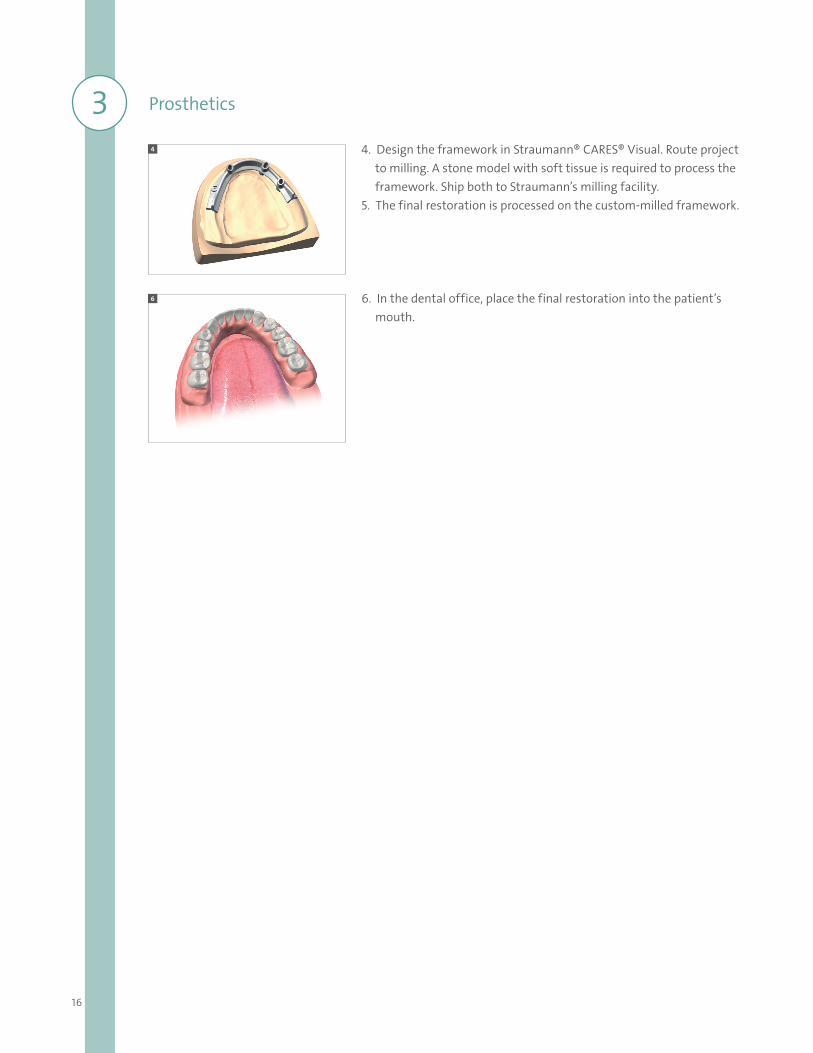
4. Design the framework in Straumann® CARES® Visual. Route project to milling. A stone model with soft tissue is required to process the framework. Ship both to Straumann’s milling facility.5. The final restoration is processed on the custom-milled framework.
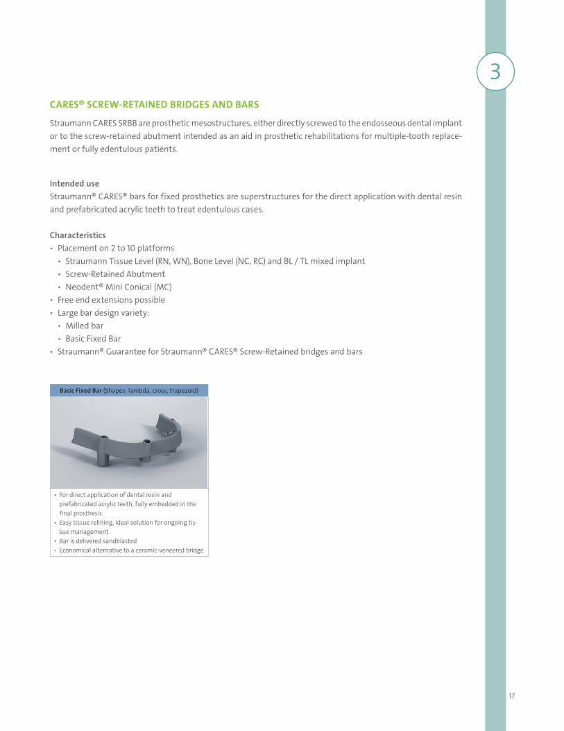
6. In the dental office, place the final restoration into the patient’s mouth.
3 Prosthetics
17
3CARES® SCREW-RETAINED BRIDGES AND BARS
Straumann CARES SRBB are prosthetic mesostructures, either directly screwed to the endosseous dental implant or to the screw-retained abutment intended as an aid in prosthetic rehabilitations for multiple-tooth replace-ment or fully edentulous patients.
Intended useStraumann® CARES® bars for fixed prosthetics are superstructures for the direct application with dental resin and prefabricated acrylic teeth to treat edentulous cases.
Characteristics ѹ Placement on 2 to 10 platforms
ѹ Straumann Tissue Level (RN, WN), Bone Level (NC, RC) and BL / TL mixed implant ѹ Screw-Retained Abutment ѹ Neodent® Mini Conical (MC)
ѹ Free end extensions possible ѹ Large bar design variety:
ѹ Milled bar ѹ Basic Fixed Bar
ѹ Straumann® Guarantee for Straumann® CARES® Screw-Retained bridges and bars
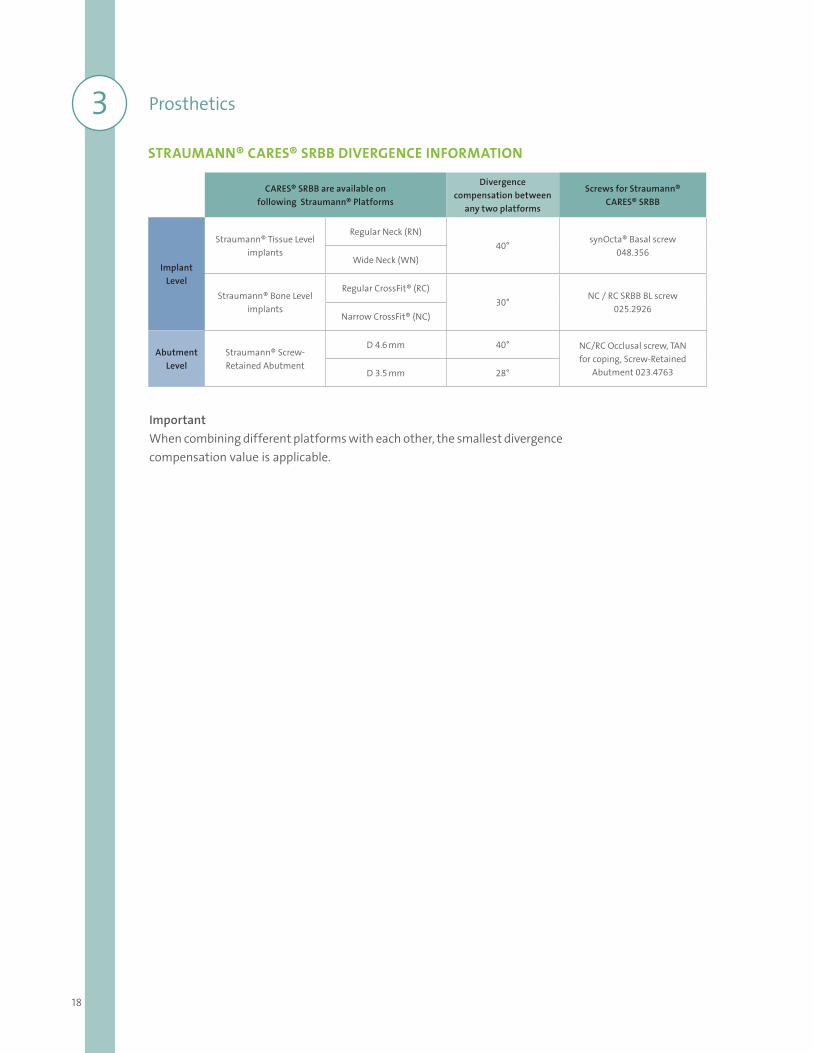
Basic Fixed Bar (Shapes: lambda, cross, trapezoid)
• For direct application of dental resin and prefabricated acrylic teeth, fully embedded in the final prosthesis
• Easy tissue relining, ideal solution for ongoing tis-sue management
• Bar is delivered sandblasted• Economical alternative to a ceramic-veneered bridge
18
3 Prosthetics
CARES® SRBB are available on following Straumann® Platforms
Divergence compensation between
any two platforms
Screws for Straumann®CARES® SRBB
Implant Level
Straumann® Tissue Level implants
Regular Neck (RN)40°
synOcta® Basal screw048.356
Wide Neck (WN)
Straumann® Bone Level implants
Regular CrossFit® (RC)30°
NC / RC SRBB BL screw025.2926
Narrow CrossFit® (NC)
Abutment Level
Straumann® Screw-Retained Abutment
D 4.6 mm 40° NC/RC Occlusal screw, TAN for coping, Screw-Retained
Abutment 023.4763D 3.5 mm 28°
STRAUMANN® CARES® SRBB DIVERGENCE INFORMATION
ImportantWhen combining different platforms with each other, the smallest divergence compensation value is applicable.
19
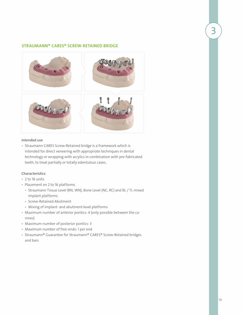
3STRAUMANN® CARES® SCREW-RETAINED BRIDGE
Intended use ѹ Straumann CARES Screw-Retained bridge is a framework which is
intended for direct veneering with appropriate techniques in dental technology or wrapping with acrylics in combination with pre-fabricated teeth, to treat partially or totally edentulous cases.
Characteristics ѹ 2 to 16 units ѹ Placement on 2 to 16 platforms
ѹ Straumann Tissue Level (RN, WN), Bone Level (NC, RC) and BL / TL mixed implant platforms
ѹ Screw-Retained Abutment ѹ Mixing of implant- and abutment-level platforms
ѹ Maximum number of anterior pontics: 4 (only possible between the ca-nines)
ѹ Maximum number of posterior pontics: 3 ѹ Maximum number of free-ends: 1 per end ѹ Straumann® Guarantee for Straumann® CARES® Screw-Retained bridges
and bars
20
3 Prosthetics
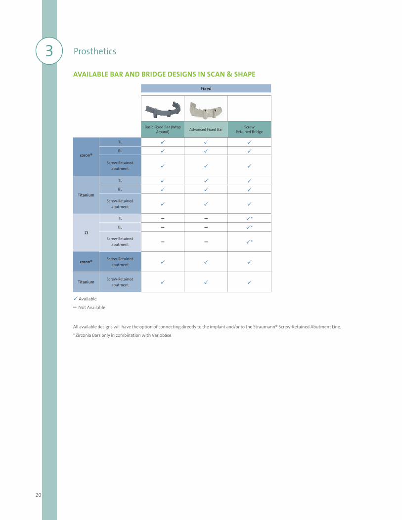
AVAILABLE BAR AND BRIDGE DESIGNS IN SCAN & SHAPE
Available
– Not Available
All available designs will have the option of connecting directly to the implant and/or to the Straumann® Screw-Retained Abutment Line.
* Zirconia Bars only in combination with Variobase
Fixed
Basic Fixed Bar (Wrap Around) Advanced Fixed Bar Screw
Retained Bridge
coron®
TL BL
Screw-Retained abutment
Titanium
TL BL
Screw-Retained abutment
Zi
TL – – *BL – – *
Screw-Retained abutment – – *
coron®Screw-Retained
abutment
TitaniumScrew-Retained
abutment
21
CARES® Scan & Shape lets you benefit from the knowledge and experience of a highly trained team of CADCAM dental experts to provide a tailored design service. The concept is designed to ensure the best possible fit of the final restorations. You can now order CARES® Screw-retained Bars and Bridges (SRBB) via Scan & Shape.
Whether you’re expanding your business or you have an existing staff member out for an extended period of time, we’re open 24/7 so you don’t have to be.
Ordering process ѹ The CARES® Scan & Shape online ordering platform provides a one-stop-shop for all your customized prosthetics. ѹ Send digital files using our open STL-Files upload** service. ѹ Traditional workflow options – send us your master cast and/or wax-up model**.
Premium Straumann® Service ѹ Custom-made SRBB design ѹ Straumann® Original connection ѹ Straumann precision fit between implant and abutment
* Not all products available in all countries.** STL File upload option and model workflow may vary from country to country. Not all products are available through wax up workflow.
Please contact your local sales representative for a detailed overview of the available worklows and products.
STRAUMANN® CARES® SCAN & SHAPE
For labs without a scanner and software, the CARES® Scan & Shape service is available
22
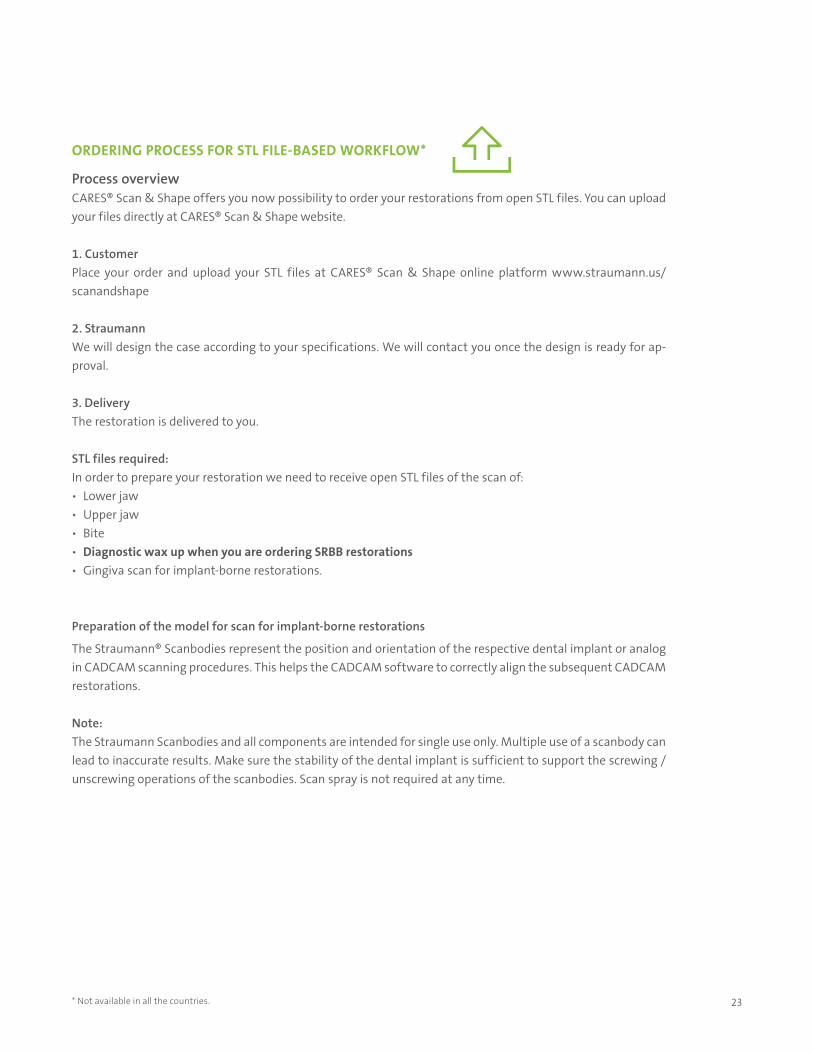
Simple workflow Log onto Straumann® CARES® Scan & Shape Online: www.straumann.us/scanandshape ѹ Send us your STL files, ship us your models or wax-ups** ѹ Manage your orders online anytime around the clock ѹ Receive your CARES® Prosthetics just the way you want it
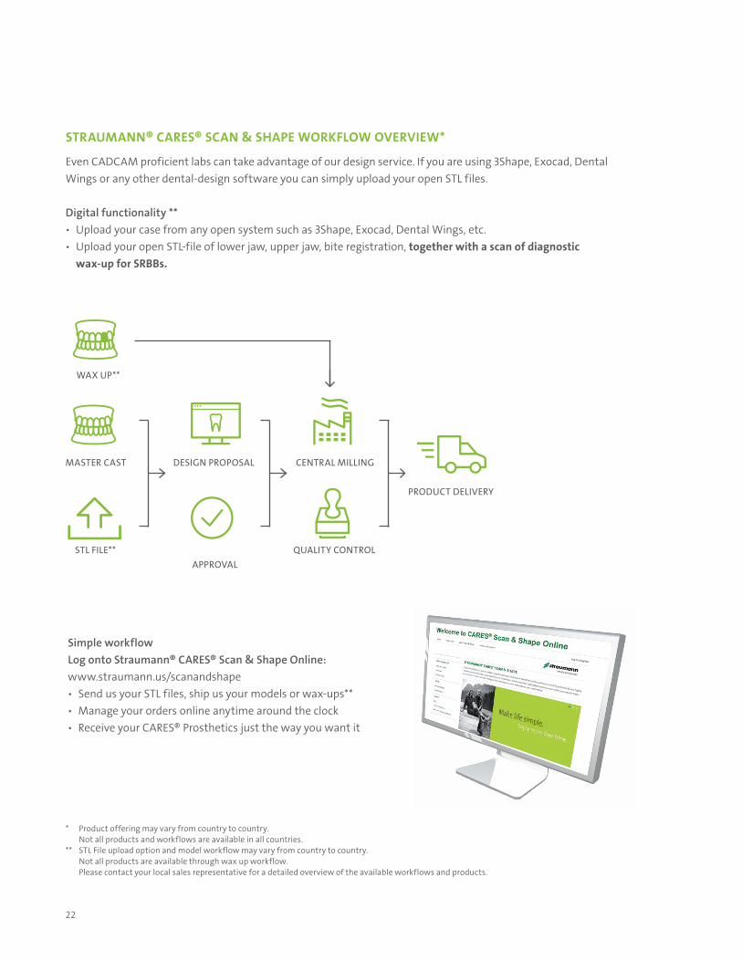
STRAUMANN® CARES® SCAN & SHAPE WORKFLOW OVERVIEW*
Even CADCAM proficient labs can take advantage of our design service. If you are using 3Shape, Exocad, Dental Wings or any other dental-design software you can simply upload your open STL files.
Digital functionality ** ѹ Upload your case from any open system such as 3Shape, Exocad, Dental Wings, etc. ѹ Upload your open STL-file of lower jaw, upper jaw, bite registration, together with a scan of diagnostic
wax-up for SRBBs.
PRODUCT DELIVERY
QUALITY CONTROL
CENTRAL MILLING
APPROVAL
DESIGN PROPOSAL
STL FILE**
MASTER CAST
WAX UP**
* Product offering may vary from country to country. Not all products and workflows are available in all countries.** STL File upload option and model workflow may vary from country to country. Not all products are available through wax up workflow. Please contact your local sales representative for a detailed overview of the available workflows and products.
23
ORDERING PROCESS FOR STL FILE-BASED WORKFLOW*
Process overview CARES® Scan & Shape offers you now possibility to order your restorations from open STL files. You can upload your files directly at CARES® Scan & Shape website.
1. CustomerPlace your order and upload your STL files at CARES® Scan & Shape online platform www.straumann.us/scanandshape
2. StraumannWe will design the case according to your specifications. We will contact you once the design is ready for ap-proval.
3. DeliveryThe restoration is delivered to you.
STL files required:In order to prepare your restoration we need to receive open STL files of the scan of: ѹ Lower jaw ѹ Upper jaw ѹ Bite ѹ Diagnostic wax up when you are ordering SRBB restorations ѹ Gingiva scan for implant-borne restorations.
Preparation of the model for scan for implant-borne restorations
The Straumann® Scanbodies represent the position and orientation of the respective dental implant or analog in CADCAM scanning procedures. This helps the CADCAM software to correctly align the subsequent CADCAM restorations.
Note: The Straumann Scanbodies and all components are intended for single use only. Multiple use of a scanbody can lead to inaccurate results. Make sure the stability of the dental implant is sufficient to support the screwing / unscrewing operations of the scanbodies. Scan spray is not required at any time.
* Not available in all the countries.
24
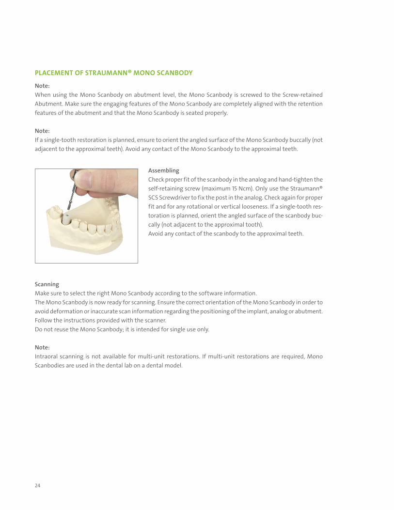
PLACEMENT OF STRAUMANN® MONO SCANBODY
Note: When using the Mono Scanbody on abutment level, the Mono Scanbody is screwed to the Screw-retained Abutment. Make sure the engaging features of the Mono Scanbody are completely aligned with the retention features of the abutment and that the Mono Scanbody is seated properly.
Note: If a single-tooth restoration is planned, ensure to orient the angled surface of the Mono Scanbody buccally (not adjacent to the approximal teeth). Avoid any contact of the Mono Scanbody to the approximal teeth.
ScanningMake sure to select the right Mono Scanbody according to the software information.The Mono Scanbody is now ready for scanning. Ensure the correct orientation of the Mono Scanbody in order to avoid deformation or inaccurate scan information regarding the positioning of the implant, analog or abutment. Follow the instructions provided with the scanner.Do not reuse the Mono Scanbody; it is intended for single use only.
Note: Intraoral scanning is not available for multi-unit restorations. If multi-unit restorations are required, Mono Scanbodies are used in the dental lab on a dental model.
AssemblingCheck proper fit of the scanbody in the analog and hand-tighten the self-retaining screw (maximum 15 Ncm). Only use the Straumann® SCS Screwdriver to fix the post in the analog. Check again for proper fit and for any rotational or vertical looseness. If a sin gle-tooth res-toration is planned, orient the angled surface of the scanbody buc-cally (not adjacent to the approximal tooth). Avoid any contact of the scanbody to the approximal teeth.
25
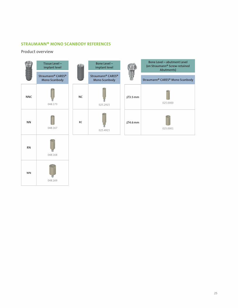
STRAUMANN® MONO SCANBODY REFERENCES
Product overview
Tissue Level – implant level
Straumann® CARES® Mono Scanbody
NNC
048.173
NN
048.167
RN
048.168
WN
048.169
Bone Level – implant level
Straumann® CARES® Mono Scanbody
NC
025.2915
RC
025.4915
Bone Level – abutment Level (on Straumann® Screw-retained
Abutments)
Straumann® CARES® Mono Scanbody
∅3.5 mm
025.0000
∅4.6 mm
025.0001
26
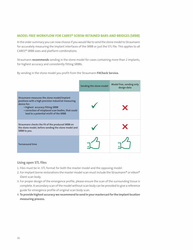
MODEL FREE WORKFLOW FOR CARES® SCREW-RETAINED BARS AND BRIDGES (SRBB)
In the order summary you can now choose if you would like to send the stone model to Straumann for accurately measuring the implant interfaces of the SRBB or just the STL file. This applies to all CARES® SRBB sizes and platform combinations.
Straumann recommends sending in the stone model for cases containing more than 2 implants, for highest accuracy and consistently fitting SRBBs.
By sending in the stone model you profit from the Straumann FitCheck Service.
Using open STL files1. Files must be in .STL format for both the master model and the opposing model.2. For implant borne restorations the master model scan must include the Straumann® or etkon®
iDent scan body.3. For proper design of the emergence profile, please ensure the scan of the surrounding tissue is
complete. A secondary scan of the model without scan body can be provided to give a reference guide for emergence profile of original scan body scan.
4. To provide highest accuracy we recommend to send in your mastercast for the implant location measuring process.
Sending the stone model Model free, sending only design data
Straumann measures the stone model/implant positions with a high precision industrial measuring device for:
• highest accuracy fitting SRBB• correction of misplaced scan bodies, that could
lead to a potential misfit of the SRBB
r
Straumann checks the fit of the produced SRBB on the stone model, before sending the stone model and SRBB to you. r
Turnaround time
27
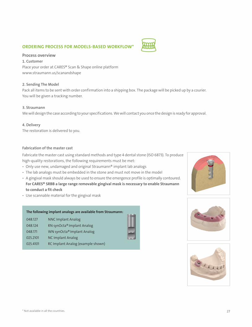
The following implant analogs are available from Straumann:
048.127 NNC Implant Analog
048.124 RN synOcta® Implant Analog
048.171 WN synOcta® Implant Analog
025.2101 NC Implant Analog
025.4101 RC Implant Analog (example shown)
* Not available in all the countries.
ORDERING PROCESS FOR MODELS-BASED WORKFLOW*
Process overview 1. CustomerPlace your order at CARES® Scan & Shape online platform www.straumann.us/scanandshape
2. Sending The Model Pack all items to be sent with order confirmation into a shipping box. The package will be picked up by a courier. You will be given a tracking number.
3. StraumannWe will design the case according to your specifications. We will contact you once the design is ready for approval.
4. DeliveryThe restoration is delivered to you.
Fabrication of the master cast
Fabricate the master cast using standard methods and type 4 dental stone (ISO 6873). To produce high-quality restorations, the following requirements must be met: ѹ Only use new, undamaged and original Straumann® implant lab analogs ѹ The lab analogs must be embedded in the stone and must not move in the model ѹ A gingival mask should always be used to ensure the emergence profile is optimally contoured.
For CARES® SRBB a large range removable gingival mask is necessary to enable Straumann to conduct a fit check
ѹ Use scannable material for the gingival mask
28
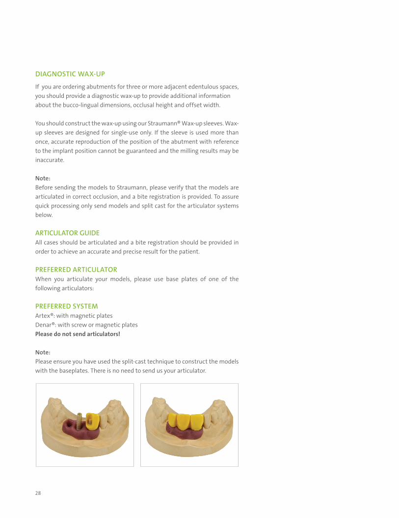
DIAGNOSTIC WAX-UP If you are ordering abutments for three or more adjacent edentulous spaces, you should provide a diagnostic wax-up to provide additional information about the bucco-lingual dimensions, occlusal height and offset width.
You should construct the wax-up using our Straumann® Wax-up sleeves. Wax-up sleeves are designed for single-use only. If the sleeve is used more than once, accurate reproduction of the position of the abutment with reference to the implant position cannot be guaranteed and the milling results may be inaccurate.
Note:Before sending the models to Straumann, please verify that the models are articulated in correct occlusion, and a bite registration is provided. To assure quick processing only send models and split cast for the articulator systems below.
ARTICULATOR GUIDEAll cases should be articulated and a bite registration should be provided in order to achieve an accurate and precise result for the patient.
PREFERRED ARTICULATORWhen you articulate your models, please use base plates of one of the following articulators:
PREFERRED SYSTEMArtex®: with magnetic platesDenar®: with screw or magnetic platesPlease do not send articulators!
Note: Please ensure you have used the split-cast technique to construct the models with the baseplates. There is no need to send us your articulator.
29
IMPORTANT INFORMATION FOR ORDERING CARES® SRBB ON STRAUMANN SCREW-RETAINED ABUTMENT The CARES® SRBB are milled based on their master casts. A precise replication of the oral situation is essential for good-fitting CARES® SRBBs.
*For abutment-level CARES® SRBBs, we recommend that you use a master model with abutment analogs, created from an abutment-level clinical impression of the final abutments which have been torqued intraorally to 35 Ncm into the implants.
*If abutments are placed subsequently on the master cast, they need to be torqued to the implant analog to 35N cm, like the intraoral abutment on the implant. Master models with hand-tightened abutments do not represent the oral situation and may lead to a restoration with height distortion. The restoration may appear to fit on the model, but may not fit well in the patient’s mouth.
Shipment check list for CARES® SRBBs
ѹ Articulated master casts (working and opposing model) with original Straumann or Neodent Lab Analog(s) and soft tissue mask.
ѹ Diagnostic wax-up of the final prosthesis.
It is essential that you send us your diagnostic wax-up in order for us to design a well-fitting prosthesis for you.
Neodent®
*Torque for Neodent Mini Conical according to manufacturer recommendation!
30
TURNAROUND TIMES*** (in-house business days) – Abutment & SRBB Cases• SRBB - 5 days
CASE PROCESSING From STL File and Models*
We will send you the computer-aided design by attaching the screenshot(s) from our software by email within 24 hours of receiving your model. Please confirm your approval by email before we proceed with milling your restoration. Delay in approv-ing the design may affect the turnaround time. For orders placed online you will review your design proposal by logging into the CARES® Scan & Shape platform. Click on Order Management and click on the order with the status Waiting for Approval.
If you have any concerns, please reply by email for further information or specify what changes you require so that an amended proposal can be sent to you. For orders placed online, review your 2D or 3D design proposal images and Approve or Disapprove with comments. The CARES® Scan & Shape Service team will address your comments.
From Wax-Up**
We will proceed immediately to mill the abutment you ordered. This follows the design you have sent us on the wax-up sleeve. We will not send you any further email for approval.
Shipping Checklist
From STL File*1. Files must be in .STL format for both the master model and the opposing model.2. For implant borne restorations the master model scan must include the Straumann®, Neodent® Scanbody.3. For proper design of the emergence profile, please ensure the scan of the surrounding tissue is complete. A secondary scan
of the model without scan body can be provided to give a reference guide for emergence profile of original scan body scan. 4. For SRBBs please provide us also with the scan of diagnostic wax up.
From Models Signed order* form with all required details Articulated master casts with genuine Straumann® Implant
analog(s) (split cast preferred) Do not send articulator!
Model with soft tissue mask Bite registration (recommended) Diagnostic wax-up (if ordering three or more adjacent abutments)
* STL File Upload and model workflow is not available in all countries.
** Please note that not all the materials and restoration types are available with wax up workflow. Not all products avail-able in all countries.
*** Turnaround times reflect the first business day after receipt of all case information and materials, and are based upon de-sign approvals. Does not include shipping. CARES® X-Stream™ cases may vary.
From wax-up Signed order form with all required details Waxed-up abutment, using original
Straumann Wax-up sleeves
For SRBB cases SRBB order form Diagnostix wax up
31
CARE AND MAINTENANCE
For long-term success and proper fit of the fixed prosthesis, thorough patient instruction, and periodic check-ups are recommended.
It may be necessary to exchange the Occlusal Screws at each check-up visit.
During patient visits, you should carefully examine the:• Condition of peri-implant tissues with regard to diseases:
‒ Plaque and calculus, bleeding, recession, bone loss, radiographs• Superstructure:
‒ Occlusal fit and articulation, proper fit of the fixed bridge, wear of occlusal surface, retention, attachment loosening, abutment status
• Function of the prosthesis.
For proper care at home, instruct the patient to clean the space between gingiva and fixed bridges, especially around the implants on a regular basis. Dental floss, super dental floss or interdental brushes are recommended.
32
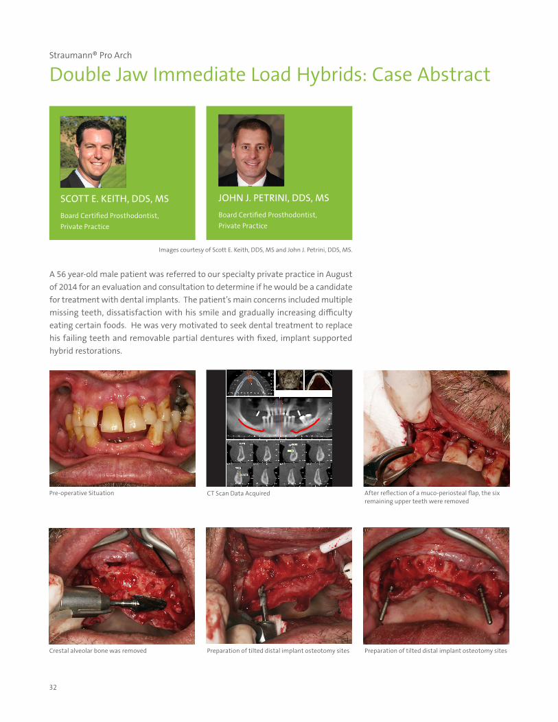
Straumann® Pro Arch
Double Jaw Immediate Load Hybrids: Case Abstract
A 56 year-old male patient was referred to our specialty private practice in August of 2014 for an evaluation and consultation to determine if he would be a candidate for treatment with dental implants. The patient’s main concerns included multiple missing teeth, dissatisfaction with his smile and gradually increasing difficulty eating certain foods. He was very motivated to seek dental treatment to replace his failing teeth and removable partial dentures with fixed, implant supported hybrid restorations.
SCOTT E. KEITH, DDS, MSBoard Certified Prosthodontist, Private Practice
JOHN J. PETRINI, DDS, MSBoard Certified Prosthodontist, Private Practice
Pre-operative Situation CT Scan Data Acquired After reflection of a muco-periosteal flap, the six remaining upper teeth were removed
Preparation of tilted distal implant osteotomy sites Crestal alveolar bone was removed Preparation of tilted distal implant osteotomy sites
Images courtesy of Scott E. Keith, DDS, MS and John J. Petrini, DDS, MS.
33
Straumann® Pro Arch
Double Jaw Immediate Load Hybrids: Case Abstract
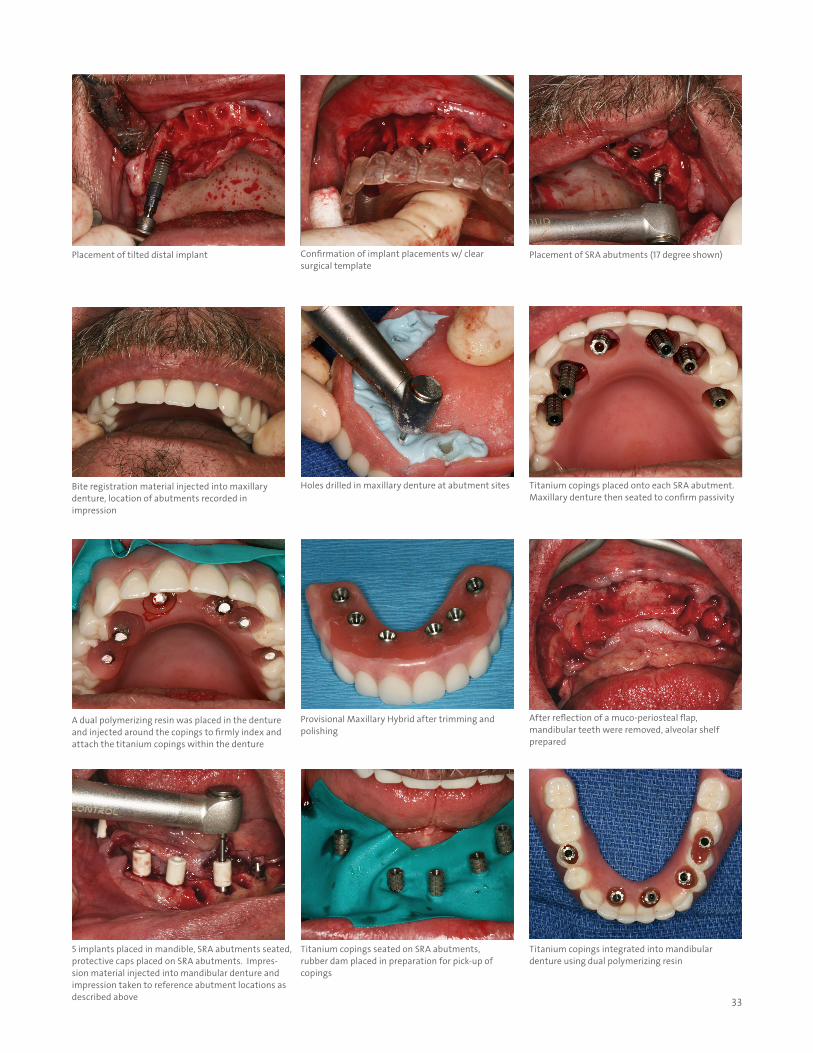
Holes drilled in maxillary denture at abutment sites
Placement of tilted distal implant
A dual polymerizing resin was placed in the denture and injected around the copings to firmly index and attach the titanium copings within the denture
Placement of SRA abutments (17 degree shown)
Titanium copings placed onto each SRA abutment. Maxillary denture then seated to confirm passivity
Confirmation of implant placements w/ clear surgical template
Provisional Maxillary Hybrid after trimming and polishing
Bite registration material injected into maxillary denture, location of abutments recorded in impression
After reflection of a muco-periosteal flap, mandibular teeth were removed, alveolar shelf prepared
5 implants placed in mandible, SRA abutments seated, protective caps placed on SRA abutments. Impres-sion material injected into mandibular denture and impression taken to reference abutment locations as described above
Titanium copings seated on SRA abutments, rubber dam placed in preparation for pick-up of copings
Titanium copings integrated into mandibular denture using dual polymerizing resin
34
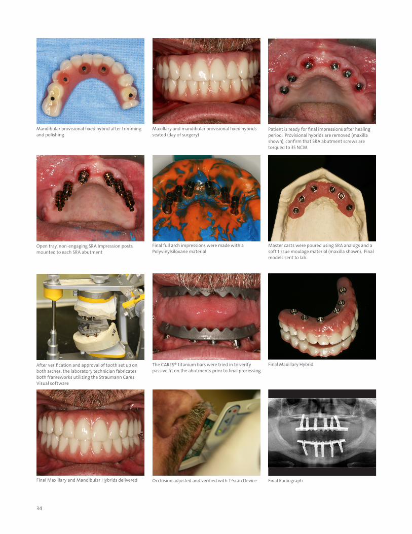
Final Maxillary Hybrid
Mandibular provisional fixed hybrid after trimming and polishing
Final full arch impressions were made with a Polyvinylsiloxane material
Occlusion adjusted and verified with T-Scan Device
Patient is ready for final impressions after healing period. Provisional hybrids are removed (maxilla shown), confirm that SRA abutment screws are torqued to 35 NCM.
After verification and approval of tooth set up on both arches, the laboratory technician fabricates both frameworks utilizing the Straumann Cares Visual software
Final Maxillary and Mandibular Hybrids delivered
Maxillary and mandibular provisional fixed hybrids seated (day of surgery)
Master casts were poured using SRA analogs and a soft tissue moulage material (maxilla shown). Final models sent to lab.
Final Radiograph
Open tray, non-engaging SRA Impression posts mounted to each SRA abutment
The CARES® titanium bars were tried in to verify passive fit on the abutments prior to final processing
35
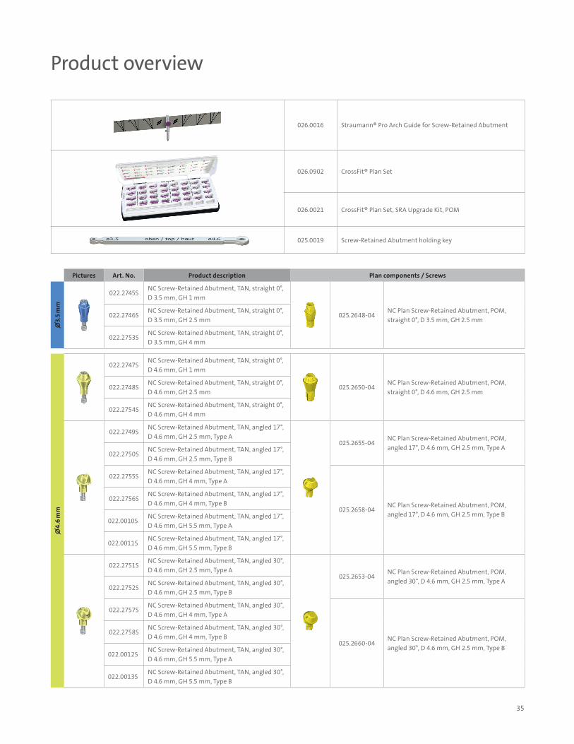
Product overview
Pictures Art. No. Product description Plan components / Screws
∅3.
5 mm
022.2745SNC Screw-Retained Abutment, TAN, straight 0°, D 3.5 mm, GH 1 mm
025.2648-04NC Plan Screw-Retained Abutment, POM, straight 0°, D 3.5 mm, GH 2.5 mm
022.2746SNC Screw-Retained Abutment, TAN, straight 0°, D 3.5 mm, GH 2.5 mm
022.2753SNC Screw-Retained Abutment, TAN, straight 0°, D 3.5 mm, GH 4 mm
∅4.
6 m
m
022.2747SNC Screw-Retained Abutment, TAN, straight 0°, D 4.6 mm, GH 1 mm
025.2650-04NC Plan Screw-Retained Abutment, POM, straight 0°, D 4.6 mm, GH 2.5 mm
022.2748SNC Screw-Retained Abutment, TAN, straight 0°, D 4.6 mm, GH 2.5 mm
022.2754SNC Screw-Retained Abutment, TAN, straight 0°, D 4.6 mm, GH 4 mm
022.2749SNC Screw-Retained Abutment, TAN, angled 17°, D 4.6 mm, GH 2.5 mm, Type A
025.2655-04NC Plan Screw-Retained Abutment, POM, angled 17°, D 4.6 mm, GH 2.5 mm, Type A
022.2750SNC Screw-Retained Abutment, TAN, angled 17°, D 4.6 mm, GH 2.5 mm, Type B
022.2755SNC Screw-Retained Abutment, TAN, angled 17°, D 4.6 mm, GH 4 mm, Type A
025.2658-04NC Plan Screw-Retained Abutment, POM, angled 17°, D 4.6 mm, GH 2.5 mm, Type B
022.2756SNC Screw-Retained Abutment, TAN, angled 17°, D 4.6 mm, GH 4 mm, Type B
022.0010SNC Screw-Retained Abutment, TAN, angled 17°, D 4.6 mm, GH 5.5 mm, Type A
022.0011SNC Screw-Retained Abutment, TAN, angled 17°, D 4.6 mm, GH 5.5 mm, Type B
022.2751SNC Screw-Retained Abutment, TAN, angled 30°, D 4.6 mm, GH 2.5 mm, Type A
025.2653-04NC Plan Screw-Retained Abutment, POM, angled 30°, D 4.6 mm, GH 2.5 mm, Type A
022.2752SNC Screw-Retained Abutment, TAN, angled 30°, D 4.6 mm, GH 2.5 mm, Type B
022.2757SNC Screw-Retained Abutment, TAN, angled 30°, D 4.6 mm, GH 4 mm, Type A
025.2660-04NC Plan Screw-Retained Abutment, POM, angled 30°, D 4.6 mm, GH 2.5 mm, Type B
022.2758SNC Screw-Retained Abutment, TAN, angled 30°, D 4.6 mm, GH 4 mm, Type B
022.0012SNC Screw-Retained Abutment, TAN, angled 30°, D 4.6 mm, GH 5.5 mm, Type A
022.0013SNC Screw-Retained Abutment, TAN, angled 30°, D 4.6 mm, GH 5.5 mm, Type B
026.0016 Straumann® Pro Arch Guide for Screw-Retained Abutment
026.0902 CrossFit® Plan Set
026.0021 CrossFit® Plan Set, SRA Upgrade Kit, POM
025.0019 Screw-Retained Abutment holding key
36
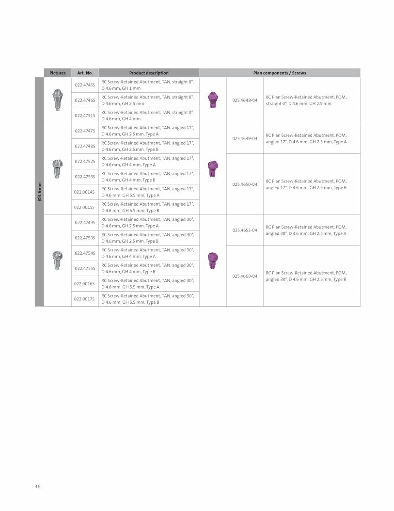
Pictures Art. No. Product description Plan components / Screws
∅4.
6 m
m
022.4745SRC Screw-Retained Abutment, TAN, straight 0°, D 4.6 mm, GH 1 mm
025.4648-04RC Plan Screw-Retained Abutment, POM, straight 0°, D 4.6 mm, GH 2.5 mm
022.4746SRC Screw-Retained Abutment, TAN, straight 0°, D 4.6 mm, GH 2.5 mm
022.4751SRC Screw-Retained Abutment, TAN, straight 0°, D 4.6 mm, GH 4 mm
022.4747SRC Screw-Retained Abutment, TAN, angled 17°, D 4.6 mm, GH 2.5 mm, Type A
025.4649-04RC Plan Screw-Retained Abutment, POM, angled 17°, D 4.6 mm, GH 2.5 mm, Type A
022.4748SRC Screw-Retained Abutment, TAN, angled 17°, D 4.6 mm, GH 2.5 mm, Type B
022.4752SRC Screw-Retained Abutment, TAN, angled 17°, D 4.6 mm, GH 4 mm, Type A
025.4650-04RC Plan Screw-Retained Abutment, POM, angled 17°, D 4.6 mm, GH 2.5 mm, Type B
022.4753SRC Screw-Retained Abutment, TAN, angled 17°, D 4.6 mm, GH 4 mm, Type B
022.0014SRC Screw-Retained Abutment, TAN, angled 17°, D 4.6 mm, GH 5.5 mm, Type A
022.0015SRC Screw-Retained Abutment, TAN, angled 17°, D 4.6 mm, GH 5.5 mm, Type B
022.4749SRC Screw-Retained Abutment, TAN, angled 30°, D 4.6 mm, GH 2.5 mm, Type A
025.4653-04RC Plan Screw-Retained Abutment, POM, angled 30°, D 4.6 mm, GH 2.5 mm, Type A
022.4750SRC Screw-Retained Abutment, TAN, angled 30°, D 4.6 mm, GH 2.5 mm, Type B
022.4754SRC Screw-Retained Abutment, TAN, angled 30°, D 4.6 mm, GH 4 mm, Type A
025.4660-04RC Plan Screw-Retained Abutment, POM, angled 30°, D 4.6 mm, GH 2.5 mm, Type B
022.4755SRC Screw-Retained Abutment, TAN, angled 30°, D 4.6 mm, GH 4 mm, Type B
022.0016SRC Screw-Retained Abutment, TAN, angled 30°, D 4.6 mm, GH 5.5 mm, Type A
022.0017SRC Screw-Retained Abutment, TAN, angled 30°, D 4.6 mm, GH 5.5 mm, Type B
37
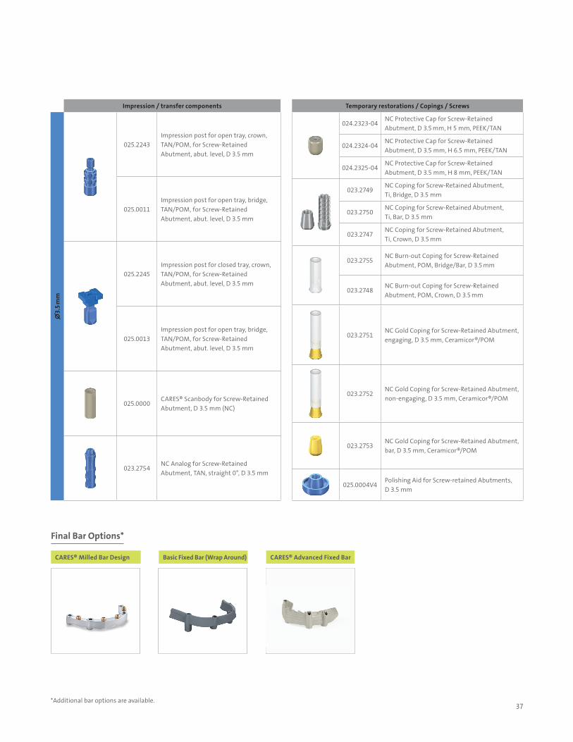
Impression / transfer components
∅3.
5 mm
025.2243Impression post for open tray, crown, TAN/POM, for Screw-Retained Abutment, abut. level, D 3.5 mm
025.0011Impression post for open tray, bridge, TAN/POM, for Screw-Retained Abutment, abut. level, D 3.5 mm
025.2245Impression post for closed tray, crown, TAN/POM, for Screw-Retained Abutment, abut. level, D 3.5 mm
025.0013Impression post for open tray, bridge, TAN/POM, for Screw-Retained Abutment, abut. level, D 3.5 mm
025.0000CARES® Scanbody for Screw-Retained Abutment, D 3.5 mm (NC)
023.2754NC Analog for Screw-Retained Abutment, TAN, straight 0°, D 3.5 mm
Temporary restorations / Copings / Screws
024.2323-04NC Protective Cap for Screw-Retained Abutment, D 3.5 mm, H 5 mm, PEEK/TAN
024.2324-04NC Protective Cap for Screw-Retained Abutment, D 3.5 mm, H 6.5 mm, PEEK/TAN
024.2325-04NC Protective Cap for Screw-Retained Abutment, D 3.5 mm, H 8 mm, PEEK/TAN
023.2749NC Coping for Screw-Retained Abutment, Ti, Bridge, D 3.5 mm
023.2750NC Coping for Screw-Retained Abutment, Ti, Bar, D 3.5 mm
023.2747NC Coping for Screw-Retained Abutment, Ti, Crown, D 3.5 mm
023.2755NC Burn-out Coping for Screw-Retained Abutment, POM, Bridge/Bar, D 3.5 mm
023.2748NC Burn-out Coping for Screw-Retained Abutment, POM, Crown, D 3.5 mm
023.2751NC Gold Coping for Screw-Retained Abutment, engaging, D 3.5 mm, Ceramicor®/POM
023.2752NC Gold Coping for Screw-Retained Abutment, non-engaging, D 3.5 mm, Ceramicor®/POM
023.2753NC Gold Coping for Screw-Retained Abutment, bar, D 3.5 mm, Ceramicor®/POM
025.0004V4 Polishing Aid for Screw-retained Abutments, D 3.5 mm
CARES® Milled Bar Design Basic Fixed Bar (Wrap Around) CARES® Advanced Fixed Bar
Final Bar Options*
*Additional bar options are available.
38
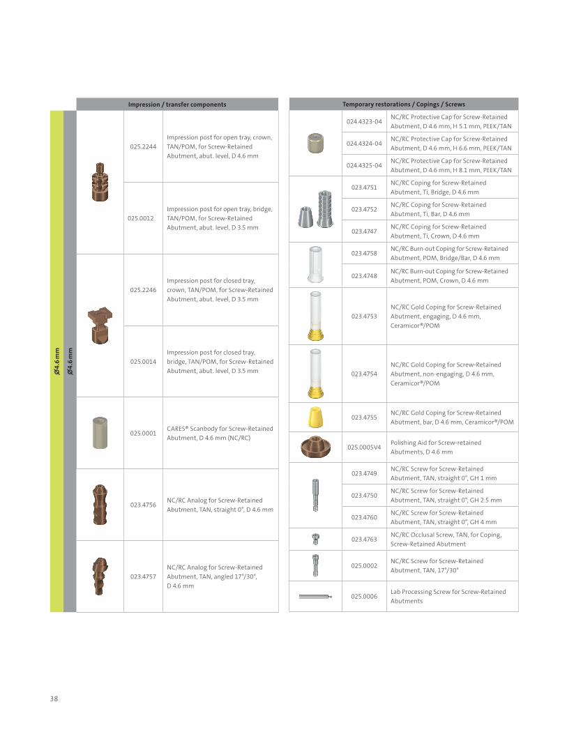
Impression / transfer components
∅4.
6 m
m
∅4.
6 m
m
025.2244Impression post for open tray, crown, TAN/POM, for Screw-Retained Abutment, abut. level, D 4.6 mm
025.0012Impression post for open tray, bridge, TAN/POM, for Screw-Retained Abutment, abut. level, D 3.5 mm
025.2246Impression post for closed tray, crown, TAN/POM, for Screw-Retained Abutment, abut. level, D 3.5 mm
025.0014Impression post for closed tray, bridge, TAN/POM, for Screw-Retained Abutment, abut. level, D 3.5 mm
025.0001CARES® Scanbody for Screw-Retained Abutment, D 4.6 mm (NC/RC)
023.4756NC/RC Analog for Screw-Retained Abutment, TAN, straight 0°, D 4.6 mm
023.4757NC/RC Analog for Screw-Retained Abutment, TAN, angled 17°/30°, D 4.6 mm
Temporary restorations / Copings / Screws
024.4323-04NC/RC Protective Cap for Screw- Retained Abutment, D 4.6 mm, H 5.1 mm, PEEK/TAN
024.4324-04NC/RC Protective Cap for Screw- Retained Abutment, D 4.6 mm, H 6.6 mm, PEEK/TAN
024.4325-04NC/RC Protective Cap for Screw- Retained Abutment, D 4.6 mm, H 8.1 mm, PEEK/TAN
023.4751NC/RC Coping for Screw-Retained Abutment, Ti, Bridge, D 4.6 mm
023.4752NC/RC Coping for Screw-Retained Abutment, Ti, Bar, D 4.6 mm
023.4747NC/RC Coping for Screw-Retained Abutment, Ti, Crown, D 4.6 mm
023.4758NC/RC Burn-out Coping for Screw- Retained Abutment, POM, Bridge/Bar, D 4.6 mm
023.4748NC/RC Burn-out Coping for Screw- Retained Abutment, POM, Crown, D 4.6 mm
023.4753NC/RC Gold Coping for Screw- Retained Abutment, engaging, D 4.6 mm, Ceramicor®/POM
023.4754NC/RC Gold Coping for Screw-Retained Abutment, non-engaging, D 4.6 mm, Ceramicor®/POM
023.4755NC/RC Gold Coping for Screw-Retained Abutment, bar, D 4.6 mm, Ceramicor®/POM
025.0005V4 Polishing Aid for Screw-retained Abutments, D 4.6 mm
023.4749NC/RC Screw for Screw-Retained Abutment, TAN, straight 0°, GH 1 mm
023.4750NC/RC Screw for Screw-Retained Abutment, TAN, straight 0°, GH 2.5 mm
023.4760NC/RC Screw for Screw-Retained Abutment, TAN, straight 0°, GH 4 mm
023.4763NC/RC Occlusal Screw, TAN, for Coping, Screw-Retained Abutment
025.0002NC/RC Screw for Screw-Retained Abutment, TAN, 17°/30°
025.0006Lab Processing Screw for Screw-Retained Abutments
39
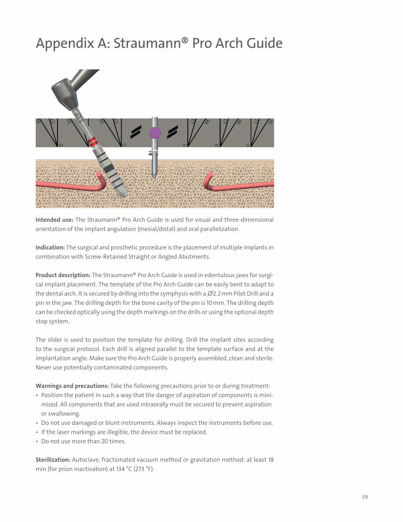
Appendix A: Straumann® Pro Arch Guide
Intended use: The Straumann® Pro Arch Guide is used for visual and three-dimensional orientation of the implant angulation (mesial/distal) and oral parallelization.
Indication: The surgical and prosthetic procedure is the placement of multiple implants in combination with Screw-Retained Straight or Angled Abutments.
Product description: The Straumann® Pro Arch Guide is used in edentulous jaws for surgi-cal implant placement. The template of the Pro Arch Guide can be easily bent to adapt to the dental arch. It is secured by drilling into the symphysis with a ∅2.2 mm Pilot Drill and a pin in the jaw. The drilling depth for the bone cavity of the pin is 10 mm. The drilling depth can be checked optically using the depth markings on the drills or using the optional depth stop system.
The slider is used to position the template for drilling. Drill the implant sites according to the surgical protocol. Each drill is aligned parallel to the template surface and at the implantation angle. Make sure the Pro Arch Guide is properly assembled, clean and sterile. Never use potentially contaminated components.
Warnings and precautions: Take the following precautions prior to or during treatment:• Position the patient in such a way that the danger of aspiration of components is mini-
mized. All components that are used intraorally must be secured to prevent aspiration or swallowing.
• Do not use damaged or blunt instruments. Always inspect the instruments before use.• If the laser markings are illegible, the device must be replaced.• Do not use more than 20 times.
Sterilization: Autoclave, fractionated vacuum method or gravitation method: at least 18 min (for prion inactivation) at 134 °C (273 °F).
40
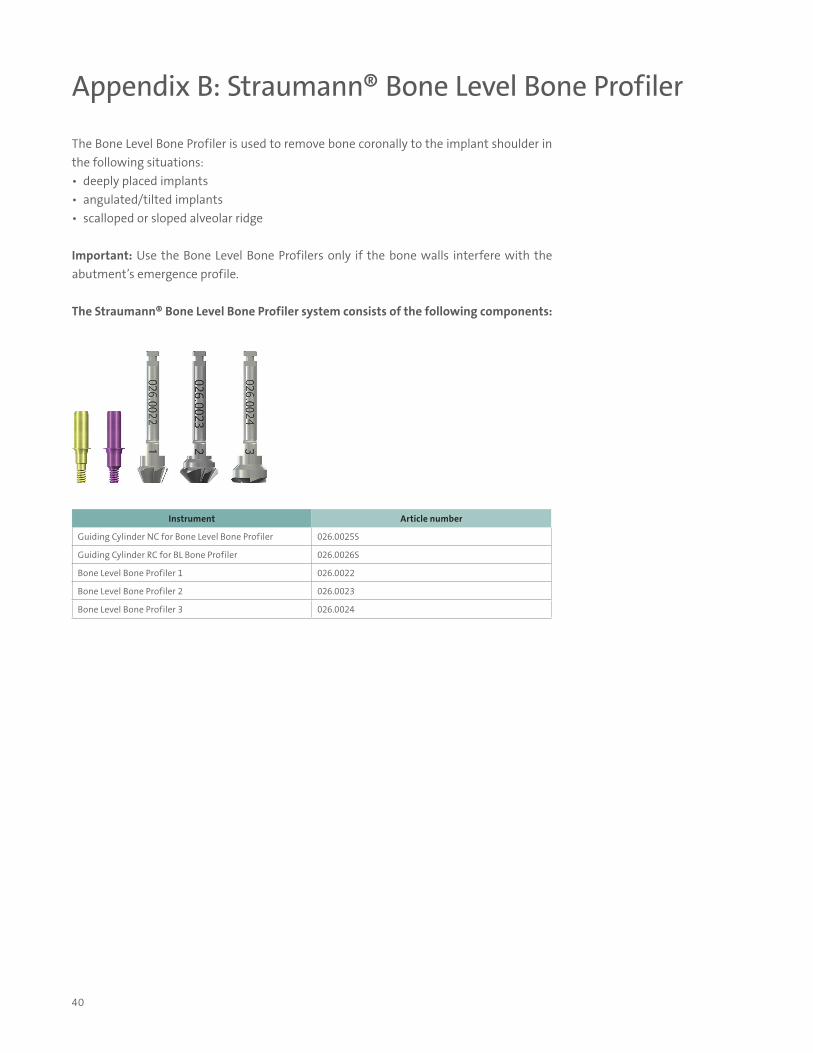
Appendix B: Straumann® Bone Level Bone Profiler
The Bone Level Bone Profiler is used to remove bone coronally to the implant shoulder in the following situations:• deeply placed implants• angulated/tilted implants• scalloped or sloped alveolar ridge
Important: Use the Bone Level Bone Profilers only if the bone walls interfere with the abutment’s emergence profile.
The Straumann® Bone Level Bone Profiler system consists of the following components:
Instrument Article number
Guiding Cylinder NC for Bone Level Bone Profiler 026.0025S
Guiding Cylinder RC for BL Bone Profiler 026.0026S
Bone Level Bone Profiler 1 026.0022
Bone Level Bone Profiler 2 026.0023
Bone Level Bone Profiler 3 026.0024
41
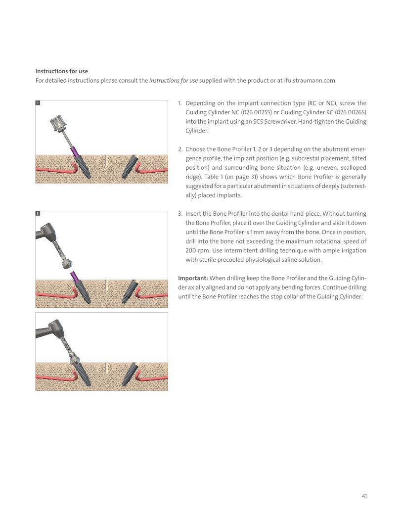
Instructions for use For detailed instructions please consult the Instructions for use supplied with the product or at ifu.straumann.com
1. Depending on the implant connection type (RC or NC), screw the Guiding Cylinder NC (026.0025S) or Guiding Cylinder RC (026.0026S) into the implant using an SCS Screwdriver. Hand-tighten the Guiding Cylinder.
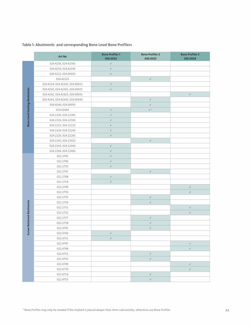
2. Choose the Bone Profiler 1, 2 or 3 depending on the abutment emer-gence profile, the implant position (e.g. subcrestal placement, tilted position) and surrounding bone situation (e.g. uneven, scalloped ridge). Table 1 (on page 31) shows which Bone Profiler is generally suggested for a particular abutment in situations of deeply (subcrest-ally) placed implants.
3. Insert the Bone Profiler into the dental hand-piece. Without turning the Bone Profiler, place it over the Guiding Cylinder and slide it down until the Bone Profiler is 1 mm away from the bone. Once in position, drill into the bone not exceeding the maximum rotational speed of 200 rpm. Use intermittent drilling technique with ample irrigation with sterile precooled physiological saline solution.
Important: When drilling keep the Bone Profiler and the Guiding Cylin-der axially aligned and do not apply any bending forces. Continue drilling until the Bone Profiler reaches the stop collar of the Guiding Cylinder.
1
3
42
4
4a
5
5a
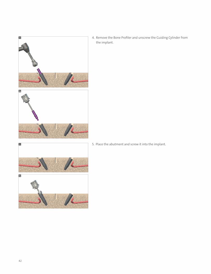
4. Remove the Bone Profiler and unscrew the Guiding Cylinder from the implant.
5. Place the abutment and screw it into the implant.
43
Art NoBone Profiler 1
026.0022Bone Profiler 2
026.0023Bone Profiler 3
026.0024
Bone
Lev
el H
ealin
g Ab
utm
ents
024.4236, 024.4236S
024.4234, 024.4234S
024.4222, 024.0000S
024.4222S
024.4224, 024.4224S, 024.0001S
024.4226, 024.4226S, 024.0002S
024.4242, 024.4242S, 024.0003S
024.4244, 024.4244S, 024.0004S
024.4246, 024.0005S
024.4246S *
024.2236, 024.2236S
024.2234, 024.2234S
024.2222, 024.2222S
024.2224, 024.2224S
024.2226, 024.2226S
024.2242, 024.2242S
024.2244, 024.2244S
024.2246, 024.2246S
Scre
w-R
etai
ned
Abut
men
ts
022.2745
022.2746
022.2753
022.2747
022.2748
022.2754
022.2749
022.2750
022.2755
022.2756
022.2751
022.2752
022.2757
022.2758
022.4745
022.4746
022.4751
022.4747
022.4748
022.4752
022.4753
022.4749
022.4750
022.4754
022.4755
* Bone Profiler may only be needed if the implant is placed deeper than 3mm subcrestally; otherwise use Bone Profiler.
Table 1: Abutments and corresponding Bone Level Bone Profilers
44
Notes

NAM
LIT.
1060
1
/18
V
2 PM
R
© Straumann USA, LLC 2018. All rights reserved. Straumann® and/or other trademarks and logos from Straumann® that are mentioned herein are the trademarks or registered trademarks of Straumann Holding AG and/or its affiliates. All rights reserved.
1 If a guided bone regeneration (GBR) procedure can be avoided. 2 Norm ASTM F67 (states min. tensile strength of annealed titanium). Data on file for Straumann cold-worked titanium and Roxolid® Implants 3 Benic GI et al. : Titanium-zirconium narrow-diameter versus titanium regular-diameter implants for anterior and premolar single crowns: 1-year results of a randomized controlled clinical study. Journal of Clinical Periodontology 2013; [Epub ahead of print]. 4 Compared to SLA. 5 Wismeijer D et al. : ITI Treatment Guide: Loading protocols in Implant Dentistry – Edentulous Patients, Volume 4, 2010, page 223 Patient Consideration. 6 Wismeijer D et al. : ITI Treatment Guide: Loading protocols in Implant Dentistry – Edentulous Patients, Volume 4, 2010, page 54 Treatment Options for the Edentulous Arch.
References
Straumann North American Headquarters Straumann USA, LLC 60 Minuteman Road Andover, MA 01810 Phone 800/448 8168 (US) 800/363 4024 (CA) Fax 978/747 2490 www.straumann.us www.straumann.ca
ifu.straumann.com