Embed Size (px)
Citation preview
energies
Review
Stationary Hybrid Renewable Energy Systems for RailwayElectrification: A Review
Sergey V. Mitrofanov 1,* , Natalya G. Kiryanova 1,2,* and Anna M. Gorlova 2,3,4
�����������������
Citation: Mitrofanov, S.V.;
Kiryanova, N.G.; Gorlova, A.M.
Stationary Hybrid Renewable Energy
Systems for Railway Electrification: A
Review. Energies 2021, 14, 5946.
https://doi.org/10.3390/en14185946
Academic Editors: Laia Ferrer-Martí
and Dimitrios Katsaprakakis
Received: 2 September 2021
Accepted: 15 September 2021
Published: 18 September 2021
Publisher’s Note: MDPI stays neutral
with regard to jurisdictional claims in
published maps and institutional affil-
iations.
Copyright: © 2021 by the authors.
Licensee MDPI, Basel, Switzerland.
This article is an open access article
distributed under the terms and
conditions of the Creative Commons
Attribution (CC BY) license (https://
creativecommons.org/licenses/by/
4.0/).
1 Faculty of Energetics, Novosibirsk State Technical University, 630073 Novosibirsk, Russia2 Scientific Center for Information Technologies and Artificial Intelligence, Sirius University of Science and
Technology, 354340 Sochi, Russia3 Heterogeneous Catalysis Department, Boreskov Institute of Catalysis SB RAS, 630090 Novosibirsk, Russia;
[email protected] Faculty of Natural Sciences, Novosibirsk State University, 630090 Novosibirsk, Russia* Correspondence: [email protected] (S.V.M.); [email protected] (N.G.K.)
Abstract: This article provides an overview of modern technologies and implemented projects inthe field of renewable energy systems for the electrification of railway transport. In the first part,the relevance of the use of renewable energy on the railways is discussed. Various types of power-generating systems in railway stations and platforms along the track, as well as in separate areas, areconsidered. The focus is on wind and solar energy conversion systems. The second part is devotedto the analysis of various types of energy storage devices used in projects for the electrification ofrailway transport since the energy storage system is one of the key elements in a hybrid renewableenergy system. Systems with kinetic storage, electrochemical storage batteries, supercapacitors,hydrogen energy storage are considered. Particular attention is paid to technologies for accumulatingand converting hydrogen into electrical energy, as well as hybrid systems that combine severaltypes of storage devices with different ranges of charge/discharge rates. A comparative analysis ofvarious hybrid electric power plant configurations, depending on the functions they perform in theelectrification systems of railway transport, has been carried out.
Keywords: railway electrification; renewable energy sources; energy storage system;hydrogen energy
1. Introduction
To date, rail transport is one of the largest users of electricity, both in Russia and inother countries with developed and actively developing economies (USA, France, Spain,China, and a number of other countries).
According to the strategy of scientific and technical development of the JSC RussianRailways [1], the goal of the transport sector by 2030 is to reduce greenhouse gas emissionsto 20% below the level of 2008, which corresponds to the Resource Efficient Europe roadmapset out in the Europe 2020 Strategy.
The commitment of the Netherlands Railways to provide all-electric trains with 100%renewable energy (RE) was achieved in 2017 ahead of schedule [2].
It is planned that by 2021, the national rail transport of India will use up to 1 GWof solar energy [3]. Work is underway on projects to create complexes of solar panelsinstalled on roofs, which will have a total capacity of up to 500 MW. Currently, a significantnumber are in operation, including at 900 railway stations. Their total capacity is 100 MW.In the future, Indian Railways can use 51,000 hectares of unused land to build solar powerplants (SPPs) with a total capacity of up to 20 GW. Recently, Indian Railways announcedtheir plans to use up to 200 MW of wind energy on the railways of India by 2021. Thetheoretical potential of solar energy capacity at India’s rail transport facilities is estimatedat 266.034 GW [4].
Energies 2021, 14, 5946. https://doi.org/10.3390/en14185946 https://www.mdpi.com/journal/energies
Energies 2021, 14, 5946 2 of 21
One of the main disadvantages of RE is the instability of its generation, which leadsto the inability of the power system to meet the consumer’s demand at any time. A wayto solve this problem is to use various energy storage devices, for example, batteries,flywheels, electric double-layer capacitors, etc. The excess of energy generated by the REpower system can be stored and then supplied back to the grid when the energy generatedat a certain moment from renewable sources is not enough to meet the demand.
In addition to various physical and electrochemical storage systems, energy can bestored in the form of hydrogen produced by water electrolysis using renewable sources.When the demand for electricity arises, hydrogen is supplied to a fuel cell (FC), whereelectricity is generated because of the electrochemical reaction of oxygen reduction fromthe air with hydrogen [5,6]. According to the Technology Roadmap—Hydrogen and Fuel Cellsby the International Energy Agency [7], by 2025, hydrogen technologies should penetrateall energy sectors, CO2 capture technologies in hydrogen production should be improved,and the number of hydrogen storage systems suitable for integrating into energy systemsbased on RE sources should be increased. Thus, the importance of introducing hydrogenenergy into the transport sector and, specifically, the electrification of railway transport isrecognized by the world community [7].
The paper is organized as follows. In Section 2, different configurations of solar andwind power plants are described, a comparative analysis of such systems is given. InSection 3, energy storage systems (ESS) and their feasibility for railway electrificationsystems are discussed, the best options are chosen based on the analysis. Hydrogentechnologies for hybrid renewable energy systems (HRES) are presented in Section 4.Hydrogen production by water electrolysis using RE is discussed, and a comparativeanalysis of different types of hydrogen FCs is given. Particular attention is paid to the roleof hydrogen technologies in HRES for railway electrification.
2. Renewable Energy Systems for Railway Transport Electrification
The most used renewable energy systems (RES) are SPPs based on photovoltaicconverters and wind farms. Most hybrid systems consider these types due to their greaterversatility compared to other RE sources. Micro-hydro turbine power plants can also beused as an energy source. This type of RES is the most cost-effective, which was clearlydemonstrated in [8,9], but the use of micro-hydro turbine power plants is strongly limitedby the geographical peculiarities of the area.
Among the possible options for introducing RE sources into the electrification systemsof railway transport, the following groups of design solutions can be defined by the type ofRE source:
• Power generation systems based on photovoltaic converters;• Generation systems based on wind power plants;• Hybrid generation systems.
Depending on the region and climatic conditions of the area, it may be economicallyacceptable to use systems based on one energy source or a combination of several sources.According to the report [10], the use of solar energy conversion systems is relevant forcountries such as India, Saudi Arabia, Egypt, and Argentina, but not for the countries ofnorthern Europe, for example, Sweden, Norway, and Finland. At the same time, someregions with low solar radiation can use wind energy quite efficiently. As a rule, these arecountries with coastal territories and highlands or states located near the Arctic Circle.
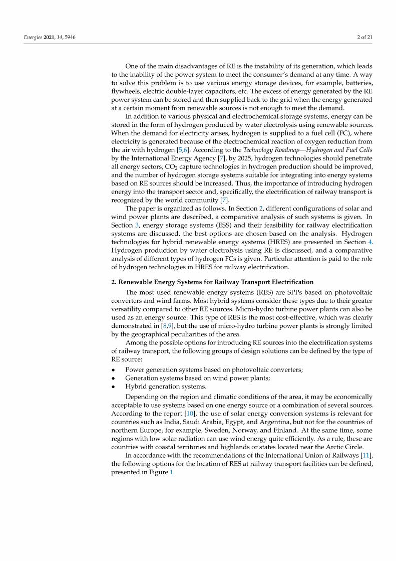
In accordance with the recommendations of the International Union of Railways [11],the following options for the location of RES at railway transport facilities can be defined,presented in Figure 1.
Energies 2021, 14, 5946 3 of 21Energies 2021, 14, x FOR PEER REVIEW 3 of 21
Figure 1. RE sources classification for the railway transport electrification systems.
2.1. Renewable Energy Systems Installed on Rolling Stock Installation of photoelectric converters on the roof of a train is the most convenient
option for generating systems on rolling stock [12]. Researchers and engineers from southern countries, such as India [13–16], Ethiopia [17], Malaysia [18], etc., are showing particular interest in this technology due to the high level of insolation in these regions. PECs are compact, easy to operate, and do not require frequent maintenance due to the absence of moving parts. They can be installed horizontally on the roof, with minimal changes in the aerodynamic properties of the train.
In [19], the design of compact low-power wind turbines (WTs) with a vertical rota-tion axis of the rotor for mounting on the roof of a wagon is considered. The rated power of the WT is 3.6 kW. Generation systems similar in design are given in [20–24]. However, such a solution can cause an increase in the drag coefficient of the train, which will lead to an increase in the power consumption of the main traction motors. In addition, the presence of moving parts in the WT mechanism requires periodic maintenance and re-pair.
2.2. Stationary Renewable Energy Systems The use of stationary systems using RE sources allows generating more “green” en-
ergy. This is due to the absence of restrictions on the scaling of generating plants for large areas and the use of proven designs for generating plants.
2.2.1. Wind Turbines with a Vertical Rotation Axis Installed along Railroad The installation of wind generators with a vertical rotation axis along the railroad
makes it possible to effectively use the airflow transverse to the direction of the train movement, which occurs when the train passes near the turbines. A feature of this type of WT is lower minimum operating speeds. They begin to work at a minimum speed of 1.5–2 m/s, in contrast to WTs with a horizontal rotation axis. They are more efficient at low wind speeds and reach the nominal operating mode at a speed of 10–12 m/s, which is important in low-wind areas and when using the wind flow generated by the move-ment of the train. Examples of such systems are presented in [25–27]. The power of a generator varies, depending on the model and dimensions, in a range from four hun-dred W to several tens of kW; however, the number of installed WTs is limited only by the length of the railway tracks and the terrain. The efficiency of these plants directly depends on the density of train traffic through the considered section of the railway track. As shown by the results of a simulation presented in [26], 10 Kliux Zebra WTs with a nominal capacity of 4 kW are capable of generating 32.3 MW∙h during the year. Similarly, in [27] with 10 WTs with a nominal capacity of 1.8 kW, located in a tunnel
Figure 1. RE sources classification for the railway transport electrification systems.
2.1. Renewable Energy Systems Installed on Rolling Stock
Installation of photoelectric converters on the roof of a train is the most convenientoption for generating systems on rolling stock [12]. Researchers and engineers fromsouthern countries, such as India [13–16], Ethiopia [17], Malaysia [18], etc., are showingparticular interest in this technology due to the high level of insolation in these regions.PECs are compact, easy to operate, and do not require frequent maintenance due to theabsence of moving parts. They can be installed horizontally on the roof, with minimalchanges in the aerodynamic properties of the train.
In [19], the design of compact low-power wind turbines (WTs) with a vertical rotationaxis of the rotor for mounting on the roof of a wagon is considered. The rated power of theWT is 3.6 kW. Generation systems similar in design are given in [20–24]. However, sucha solution can cause an increase in the drag coefficient of the train, which will lead to anincrease in the power consumption of the main traction motors. In addition, the presenceof moving parts in the WT mechanism requires periodic maintenance and repair.
2.2. Stationary Renewable Energy Systems
The use of stationary systems using RE sources allows generating more “green” energy.This is due to the absence of restrictions on the scaling of generating plants for large areasand the use of proven designs for generating plants.
2.2.1. Wind Turbines with a Vertical Rotation Axis Installed along Railroad
The installation of wind generators with a vertical rotation axis along the railroadmakes it possible to effectively use the airflow transverse to the direction of the trainmovement, which occurs when the train passes near the turbines. A feature of this typeof WT is lower minimum operating speeds. They begin to work at a minimum speed of1.5–2 m/s, in contrast to WTs with a horizontal rotation axis. They are more efficient atlow wind speeds and reach the nominal operating mode at a speed of 10–12 m/s, which isimportant in low-wind areas and when using the wind flow generated by the movementof the train. Examples of such systems are presented in [25–27]. The power of a generatorvaries, depending on the model and dimensions, in a range from four hundred W to severaltens of kW; however, the number of installed WTs is limited only by the length of therailway tracks and the terrain. The efficiency of these plants directly depends on the densityof train traffic through the considered section of the railway track. As shown by the resultsof a simulation presented in [26], 10 Kliux Zebra WTs with a nominal capacity of 4 kW arecapable of generating 32.3 MW·h during the year. Similarly, in [27] with 10 WTs with anominal capacity of 1.8 kW, located in a tunnel along the train route, showed the possibilityof generating power of 79.83 MW·h during the year. In [28], the design options for WTswith S-rotor and H-rotor are considered, the pros and cons of both systems are analyzed,
Energies 2021, 14, 5946 4 of 21
and the higher efficiency of WT placement at the exit from the tunnels is substantiated incomparison with the placement of WTs in open areas.
As mentioned above, the unit power of this type of WT does not exceed several kW,which requires the installation of a large number over a long distance along the railway.Local connection of each individual installation to the overhead line through a converteris technically difficult and expensive since the rated voltage of the WT does not exceed1000 V AC, while the rated voltage of the overhead line can reach 12–24 kV DC. Thecentralized connection scheme, at one or several points, will require the laying of a largenumber of cable lines along the tracks, which will have a significant impact on both thevolume of capital costs and the level of losses in power lines on the way from the WT tothe end consumer. This option is convenient for low-power consumers in the immediatevicinity of WTs. For example, for lighting systems or signal lamps on various sections ofthe railway track.
2.2.2. Wind Parks for Railway Electrification
The above-described versions of WT systems with a vertical axis of rotation are usedin small wind power (wind turbines with a capacity of up to 100 kW). However, train andrail auxiliary systems are not the only application for wind energy.
The connection of large wind farms with high-power WTs with a horizontal axisof rotation makes it possible not only to cover the needs of the railway and householdconsumption but also to supply power to such a powerful consumer as an overhead line.This solution will not only reduce the consumption of electricity from the power systemand thus reduce the carbon footprint of the railway company, but also improve the qualityof electricity by compensating for voltage fluctuations in long inter-substation sections ofthe railway. A group of Chinese scientists [29–31] clearly demonstrated the positive effectsof connecting a wind farm, caused by an increase in voltage in the connectivity nodes, anda negative effect on the quality of electricity and the total harmonic distortion in the system.
The power of the connected wind farms can vary from one hundred kW to tens ofMW. For example, in Mongolia, a wind farm with an installed capacity of up to 50 MW isplanned to supply power to railways, as well as SPPs, the first of which has already beenput into operation; its capacity is 10 MW [32].
It should be noted that for the effective operation of large wind farms in the region,there must be sufficiently high average annual wind speeds. The most successful areas forthe installation of WTs are considered to be coastal and high-mountain areas. Engineersfrom China have made significant progress in the projects for the integration of large-capacity wind parks (up to 20 MW) with an overhead railway line, which is described indetail in [29–31,33].
Wind farms can be connected to the railway electrification system through substationsin the area of the railway stations, but the most optimal is the installation of additionalpower plants in the railway inter-substation zones at an equal distance from the substations.This will significantly reduce the power and voltage losses in the overhead line and willprovide a greater freight-carrying capacity of the railway, reducing the likelihood of apower deficit in the rolling stock locomotive.
It should be noted that wind farms with a capacity exceeding 1 MW often operate inparallel with the power system, while lower power systems are used as part of hybrid mi-crogrid systems, together with other types of RE sources and energy storage. Applicationsfor hybrid systems in rail transport will be discussed in more detail in Section 2.2.5.
2.2.3. Photovoltaic Converters on the Roofs of Railway Stations and the Surrounding Area
SPPs based on photovoltaic converters are the most versatile option for RES because,unlike micro-hydroelectric power plants, photovoltaic converters are less tied to the sourceof energy and can be installed in any area and on almost any surface. At the same time,they do not have rotating parts, unlike WT, which greatly simplifies their operation andincreases reliability.
Energies 2021, 14, 5946 5 of 21
Installing photovoltaic panels on railway station roofs, sheds over platforms, openingsbetween railway lines, soundproof and windproof walls, and maintenance depot roofsis a very practical solution. It avoids the alienation of a significant plot of land for theconstruction of a solar station and ensures the location of the energy source in closeproximity to consumers, which may be the station’s household needs.
Many developing (India, Pakistan, Vietnam, Malaysia, Turkey, etc.) and developedcountries (Australia, Germany, Japan, etc.) are designing and implementing photovoltaicsystems at railway stations [18,34–39]. The photogeneration system at the «Beijing Southrailway station» and «Hangzhou East railway station» in China [40] also deserves specialattention, but the experience of Japan is of the greatest interest in the development of thistechnology. The article [41] indicates that the total capacity of photovoltaic stations onthe roofs and adjacent territories of railway stations in the country exceeds 100 MW. Therange of capacities of individual photovoltaic complexes varies, depending on the size ofthe station and the availability of free space on its territory, from 5 kW on the roof of the«Settu-Shi» platform to 453 kW at the «Tokyo station». According to experts of “JR-East”,considerable attention should be paid to the problem of shading from large buildingslocated near railway stations when installing solar panels in large cities. It was observedthat shadowing even one panel in a group leads to the output power reduction of theentire system up to 60%. A detailed analysis of this problem is described in [42]. Sincesolar panels have to be placed on the roof of buildings in a horizontal position, or not atan optimal angle with respect to the sun, the efficiency of such stations can be reduced incomparison with solar stations of similar power but located in an open space at an optimalangle of inclination.
The location of photovoltaic modules above the railway line or along the land adjacentto the rail track between the stations is also considered as one of the options for theeffective use of the territory available to the railway company in the construction of SPPs.In [33,40,43], examples of the installation of photovoltaic modules along railways are given.However, this method of placing the photovoltaic cells creates similar difficulties withconnecting the installations to the overhead line, as for the WTS in Section 2.2.1. Since thephoto panels need cleaning from dirt and dust, it should be noted that the location of thephotovoltaic cells over a long distance complicates their maintenance.
2.2.4. Solar Farms for Railway Electrification
The use of photo panels connected in a specially designated area for a high-powersolar farm (from several hundred kW to tens of MW) leads to the alienation of significantareas, but it has its own advantages, such as:
• Photo panels are at an optimal distance from each other at an optimal angle and can beadditionally equipped with solar trackers to constantly adjust the angle of inclinationof the photo panel;
• Losses for electricity transmission are reduced due to the compact arrangement ofphoto panels;
• Maintenance of photo panels is simplified;• The solar station can simultaneously provide high power to compensate for power
and voltage imbalances in the overhead line.
Today, the use of high-power solar stations to power the overhead train line is acommon practice in many countries with a high level of insolation. Examples of suchsystems are given in [33,40,44]. The most popular option for the production of “green”energy is, of course, in countries with a high level of insolation. For example, in India,Bharat Heavy Electricals Limited (BHEL) has built a 1.7 MW SPP near Bina, MadhyaPradesh. The energy from the solar panels is transferred directly to the overhead catenaryusing an innovative converter that converts DC to single-phase 25 kV AC. Other projectsthat will use solar energy directly for rail transport are a 50 MW SPP on undeveloped landnear Bhilai, Chhattisgarh state, and an SPP with a capacity of 2 MW near the village ofDivana, Haryana state.
Energies 2021, 14, 5946 6 of 21
Large SPPs of the megawatt power can be strong support for energy-deficient junctionsand sections of the railway, where significant voltage drops are observed when heavy trainspass. However, as in the case of WTs, a serious drawback of SPPs is the unevenness ofelectricity production depending on the time of day and cloud cover. To ensure reliablepower supply to consumers in the power system, it is necessary to keep a significantspinning reserve capacity at hydro- and thermoelectric power stations to compensate forthe unplanned decrease in power due to weather conditions, which significantly reducesthe effect of reducing CO2 emissions into the atmosphere. The solution to this problem isthe development of hybrid microgrid systems, including generation systems based on RES,as well as ESSs of various types.
2.2.5. Application of Hybrid Wind-Solar Power Generation Systems Based on the SmartGrid Concept in Railway Transport
Development and implementation of microgrid systems based on Smart Grid tech-nologies in railway electrification systems allow solving a number of urgent problems,such as:
• Increasing the voltage level and transmission capacity in remote sections of the grid;• Reducing the cost of purchasing electricity during periods of peak electricity consumption;• Reducing CO2 emissions due to an increase of the proportion of electricity generation
from RE sources close to direct consumption.
The key trends in the development of such systems are:
1. The selection of the optimal configuration of power generation and storage systemsat the design stage;
2. The development of an algorithm for optimal control of microgrid system modesduring operation.
The solution to the first problem has received considerable attention in the worksof many authors. In [45], the main problems of RE sources in rail transport systems arediscussed. As the main disadvantage of RES installations, the authors highlight the variableoperating mode and significant fluctuations in the output power. At short time intervals(from seconds to minutes), this problem is more typical for WTs, at longer intervals (hours,days)—for SPPs. It is possible to reduce the negative impact of these factors through thejoint use of WTs and photovoltaic converters with an ESS. The authors also note that thepeaks of electricity generation at WTs and photovoltaic converters do not coincide on adaily interval, thus avoiding significant gaps in the power supply from RES to the systemand reducing the capacity of ESS. Articles [9,35,46] contain an analysis of various sourcesof RES and their best combinations with ESSs in a microgrid system. It was shown that,in most cases, combining multiple energy sources allows for greater system efficiency,reduced energy storage costs, and more stable system operation.
The search for the most efficient control algorithms for hybrid microgrid systems hasreceived considerable attention in the publications of various authors [47,48]. In [49], amethod and an algorithm for controlling a hybrid system based on the criterion of powermaximization are proposed. The control is carried out through reversible converters, whichprovide connection of AC and DC systems in a hybrid system.
Particular attention is paid to the stability of the microgrid system during transientscaused by a sharp change in load or output power from RES. Since the power flow betweenthe structural blocks of the system is regulated by changing the opening angle of semicon-ductor converters, the absence of a time delay when changing the mode can lead to sharpvoltage fluctuations. In [50], the control laws for convertors in a hybrid system have beendeveloped. In [36], a solution to the problem of flexible control of modes using algorithmsbased on the fuzzy logic strategy with the use of a genetic algorithm is considered.
Based on the foregoing, we can conclude that the use of microgrid systems based onseveral sources of RES in most cases is a more efficient option for power supply than certaintypes of RES operating in parallel with an external energy system. This solution makes itpossible to compensate for the shortcomings of each individual energy source through the
Energies 2021, 14, 5946 7 of 21
integrated use of technologies for generation, energy storage, regenerative braking, andenergy flow control. The power range of such systems can vary from several hundred kWto tens of MW, which makes it possible to use them both for powering stations and auxiliarysystems of railway substations and for powering the overhead line of electrified rollingstock. However, the construction of these systems requires significant capital investment.It should also be noted that the efficiency of the microgrid system is highly dependent onthe efficiency of the control system. It is the search for optimal methods and algorithmsfor controlling a complex system consisting of a large number of different subsystems andelements that is given the greatest attention in the works of most authors studying hybridmicrogrid systems.
The choice of the configuration of the ESS plays a huge role in the operation of RES.This system can be implemented using ESSs of the same type, or it is a hybrid of severalones using different physical principles.
2.3. Comparative Analysis of the Renewable Energy System Configurations
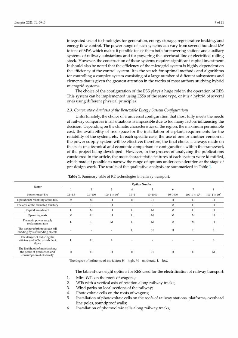
Unfortunately, the choice of a universal configuration that most fully meets the needsof railway companies in all situations is impossible due to too many factors influencing thedecision. Depending on the climatic characteristics of the region, the maximum permissiblecost, the availability of free space for the installation of a plant, requirements for thereliability of the system, etc. In each specific case, the use of one or another version ofthe power supply system will be effective; therefore, the final choice is always made onthe basis of a technical and economic comparison of configurations within the frameworkof the project being developed. However, in the process of analyzing the publicationsconsidered in the article, the most characteristic features of each system were identified,which made it possible to narrow the range of options under consideration at the stage ofpre-design work. The results of the qualitative analysis are summarized in Table 1.
Table 1. Summary table of RE technologies in railway transport.
FactorOption Number
1 2 3 4 5 6 7 8
Power range, kW 0.1–1.5 0.4–100 100–1 × 10⁷ 0.1–1 10–1000 10–1000 100–1 × 10⁶ 100–1 × 10⁷
Operational reliability of the RES M M H H H H H H
The area of the alienated territory - L H - - M H H
Capital investment L M H L M M H H
Operating costs M H H L M M M H
The main power supplyreplacement rate L L M L M M M H
The danger of photovoltaic cellshading by surrounding objects - - - L H H L L
The danger of reducing theefficiency of WTs by turbulent
flowsL H L - - - - L
The likelihood of mismatchingthe peaks of production andconsumption of electricity
H H H H H H H M
The degree of influence of the factor: H—high, M—moderate, L—low.
The table shows eight options for RES used for the electrification of railway transport:
1. Mini WTs on the roofs of wagons;2. WTs with a vertical axis of rotation along railway tracks;3. Wind parks on local sections of the railway;4. Photovoltaic cells on the roofs of wagons;5. Installation of photovoltaic cells on the roofs of railway stations, platforms, overhead
line poles, soundproof walls;6. Installation of photovoltaic cells along railway tracks;

Energies 2021, 14, 5946 8 of 21
7. Solar farms on local sections of the railway;8. Hybrid systems.
Based on the review, the following recommendations can be formulated:
1. RES systems located on the roofs of the wagons are suitable for supplying the train’sown needs. In countries with a high level of insolation, the best option is to placethe photovoltaic cell on the roofs of the wagons. In countries with a low level ofinsolation, it is possible to consider the option of using WTs. The power of one plantusually does not exceed 1 kW; however, their number can vary from a few pieces toseveral dozen pieces, depending on the length of the train.
2. To provide for the needs of electrical receivers on the railway track (lighting, signallamps, etc.), it is possible to use WTs with a vertical axis of rotation. Unit power,depending on the design of the WT, can vary from 1.5 to 5 kW; however, it is possibleto scale the power of the system by installing a different number of WTs along therailway track.
3. Placing solar panels along the railway and on special sheds can also be an effectiveoption for meeting the railway’s own needs. The capacity of such a system is limitedonly by the length of the railway track, as practice shows. At present, the constructionof systems with a nominal capacity of more than several hundred kW is associatedwith high capital costs. A similar situation exists with the placement of photovoltaiccells on the roofs of railway stations and platforms.
4. If the previous options were addressed through the lens of reducing the consumptionof the railway and replacing the share of electricity consumption from the system,then the construction of large wind farms and solar farms with a capacity fromseveral MW to several tens of MW allows ensuring the generation of a sufficientamount of electricity to supply the overhead railway line, as well as voltage regu-lation on the energy-deficient sections of the railway, those most distant from thepower substations.
5. Hybrid microgrid systems, which include various generation systems based on RES,as well as ESSs of various types, are the most effective option in terms of reliabilityand quality of power supply. The presence of an energy storage unit allows avoidinglarge power failures and more efficiently meeting consumption peaks. However, theeffective functioning of these systems is impossible without the development andimplementation of algorithms capable of automatically selecting the optimal controlstrategies for dynamically changing railroad consumption schedules.
3. Stationary Energy Storage Systems for Electrified Railways
ESSs are one of the fastest-growing sectors of the electric power industry activelyimplemented in various areas, including the electrification of railway transport. This isespecially influenced by the recent wide development of RE sources [51]. Due to thestochastic nature of RES generation, an additional means is required to ensure a balancebetween the generated and consumed energy; therefore, ESS is a widely recognized partof the RES integration into any energy system. This problem is especially relevant forrailway transport since the train schedule, and therefore the load on the grid, is strictlyregulated. ESS in the transport sector as on-board (mobile) or stationary (wayside) systemsare becoming more widespread throughout the world.
Flywheels, electric double-layer capacitors (EDLC), and electrochemical batteries areusually used in railway electrification [52].
3.1. Types of Storage Systems3.1.1. Flywheel
Flywheels work by converting electrical energy into kinetic energy from a rotatingmass and vice versa. Inertial energy storage contains a body of rotation with a significantmoment of inertia—a flywheel. The amount of stored kinetic energy depends on the speedof the rotating mass and the inertia: the higher the speed and the mass of the flywheel,
Energies 2021, 14, 5946 9 of 21
the more rotational energy it can store. Conversion of kinetic energy into electrical energyand vice versa is due to the electrical machine: the rotor shaft is connected to the flywheelshaft. When the energy storage unit is charging, the flywheel is spun up to high speed (less10,000 revolutions per minute (rpm) for low speed and from 10,000 to 100,000 rpm for highspeed) [53]. When the energy storage unit is discharging, the flywheel rotates the shaft ofthe electric machine until friction losses and the conversion of kinetic energy into electricalenergy completely extinguish inertia. This provides continuous flywheel rotation withoutadditional power input and with very low losses.
3.1.2. Electric Double-Layer Capacitors
Unlike conventional capacitors, where the charge is concentrated on the surfaces of theelectrodes and the energy of the electric field—in the volume of the interelectrode dielectric,double-layer capacitors are a hybrid of a capacitor and an electrochemical battery. EDLCis an implementation of an idea of the appearance of electrical layers in materials withdifferent types of conductivity (solid and liquid) during their mutual contact proposedin 1879 by Helmholtz. Technical implementation of EDLC comprises a unit cell with twoelectrodes made of nanoporous carbon materials and a liquid electrolyte, separated by aporous polymer or asbestine separator. This structure actually creates two series-connectedsupercapacitors: one of the plates corresponding to the electric layer formed in the liquidis virtual from a technical point of view, and the current is collected from the electricallayers formed in the porous electrode; the boundary of the metal/electrolyte thickness ofa few nanometers or even fractions of a nanometer is a dielectric. The opposite polarityof the plates in the system of two supercapacitors is formed due to the ion-conductingseparator [54].
3.1.3. Electrochemical Energy Storage
The principle of operation of electrochemical energy storage is based on the conversionof electrical energy into chemical energy during charging and vice versa chemical energyinto electrical energy during discharge due to a reversible electrochemical reaction.
Electrochemical energy storage usually classifies into primary batteries, secondarybatteries, and fuel cells (FC) [55]. Primary and secondary batteries use built-in chemicalcomponents, while chemically bound energy of a fuel is provided from the outside for fuelcells. Primary batteries, unlike secondary batteries, cannot be recharged and cannot becalled actual energy storage.
Depending on the chemical material used in the electrodes, there is a wide rangeof secondary electrochemical batteries. Lithium-ion (Li-ion) and nickel-metal hydride(Ni-MH) batteries are the most prevalent types of batteries used in transportation [56].
3.2. Comparison of Energy Storage Types
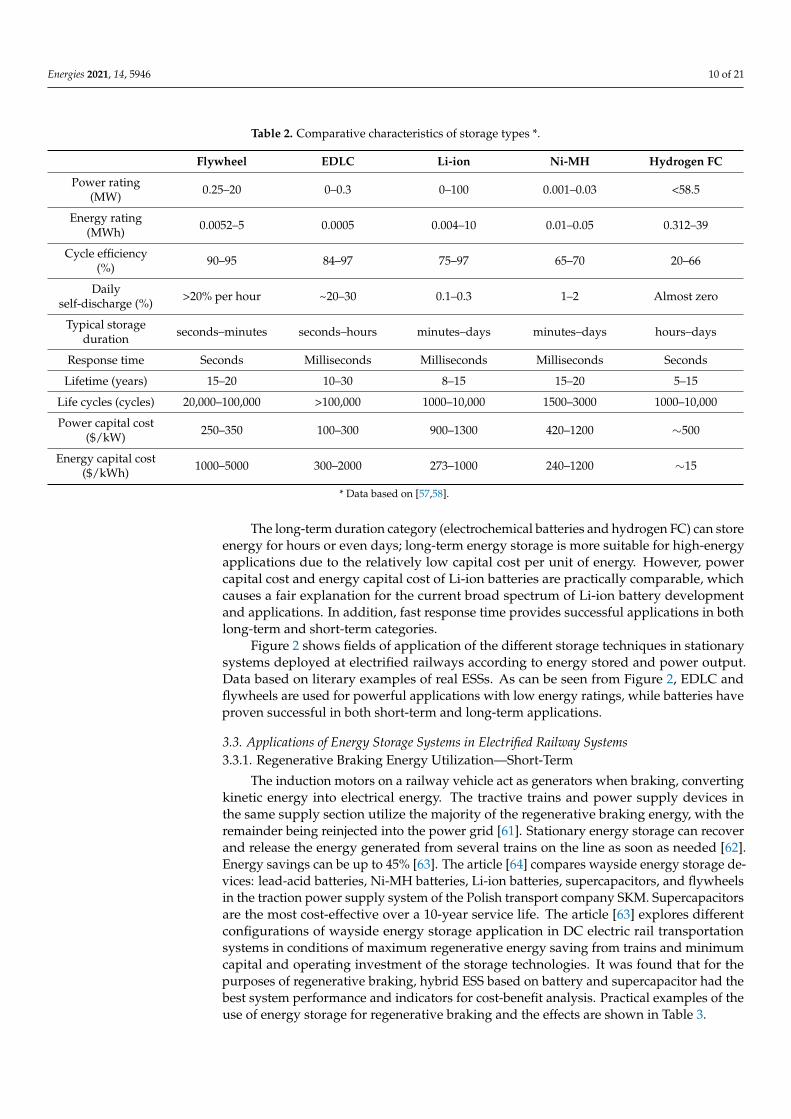
Comparative characteristics of the considered energy storage types are presented inTable 2. Since the article deals with stationary ESSs, when comparing the technologiesunder consideration, such indicators as gravimetric and volumetric energy density andpower density were not taken into account.
Energy storage for stationary railway applications can be classed into two categories:short-term and long-term, based on storage duration.
The short-term duration category (flywheels and electric double-layer capacitors)typically has a small energy rating and is used in powerful applications—work period isregulated by seconds or minutes—high life cycles, and lifetime as well as high round-tripefficiency. Short-term energy storage is more suitable for high-power applications due tolower capital costs per unit of power.
Energies 2021, 14, 5946 10 of 21
Table 2. Comparative characteristics of storage types *.
Flywheel EDLC Li-ion Ni-MH Hydrogen FC
Power rating(MW) 0.25–20 0–0.3 0–100 0.001–0.03 <58.5
Energy rating(MWh) 0.0052–5 0.0005 0.004–10 0.01–0.05 0.312–39
Cycle efficiency(%) 90–95 84–97 75–97 65–70 20–66
Dailyself-discharge (%) >20% per hour ~20–30 0.1–0.3 1–2 Almost zero
Typical storageduration seconds–minutes seconds–hours minutes–days minutes–days hours–days
Response time Seconds Milliseconds Milliseconds Milliseconds Seconds
Lifetime (years) 15–20 10–30 8–15 15–20 5–15
Life cycles (cycles) 20,000–100,000 >100,000 1000–10,000 1500–3000 1000–10,000
Power capital cost($/kW) 250–350 100–300 900–1300 420–1200 ∼500
Energy capital cost($/kWh) 1000–5000 300–2000 273–1000 240–1200 ∼15
* Data based on [57,58].
The long-term duration category (electrochemical batteries and hydrogen FC) can storeenergy for hours or even days; long-term energy storage is more suitable for high-energyapplications due to the relatively low capital cost per unit of energy. However, powercapital cost and energy capital cost of Li-ion batteries are practically comparable, whichcauses a fair explanation for the current broad spectrum of Li-ion battery developmentand applications. In addition, fast response time provides successful applications in bothlong-term and short-term categories.
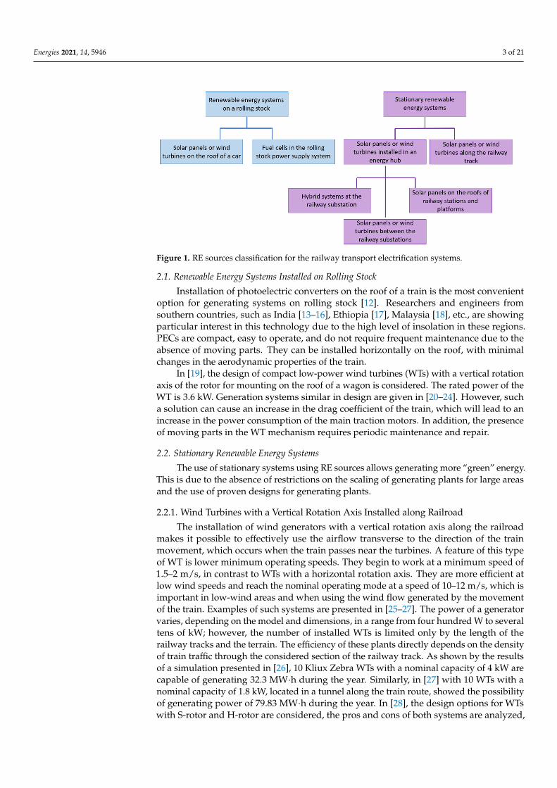
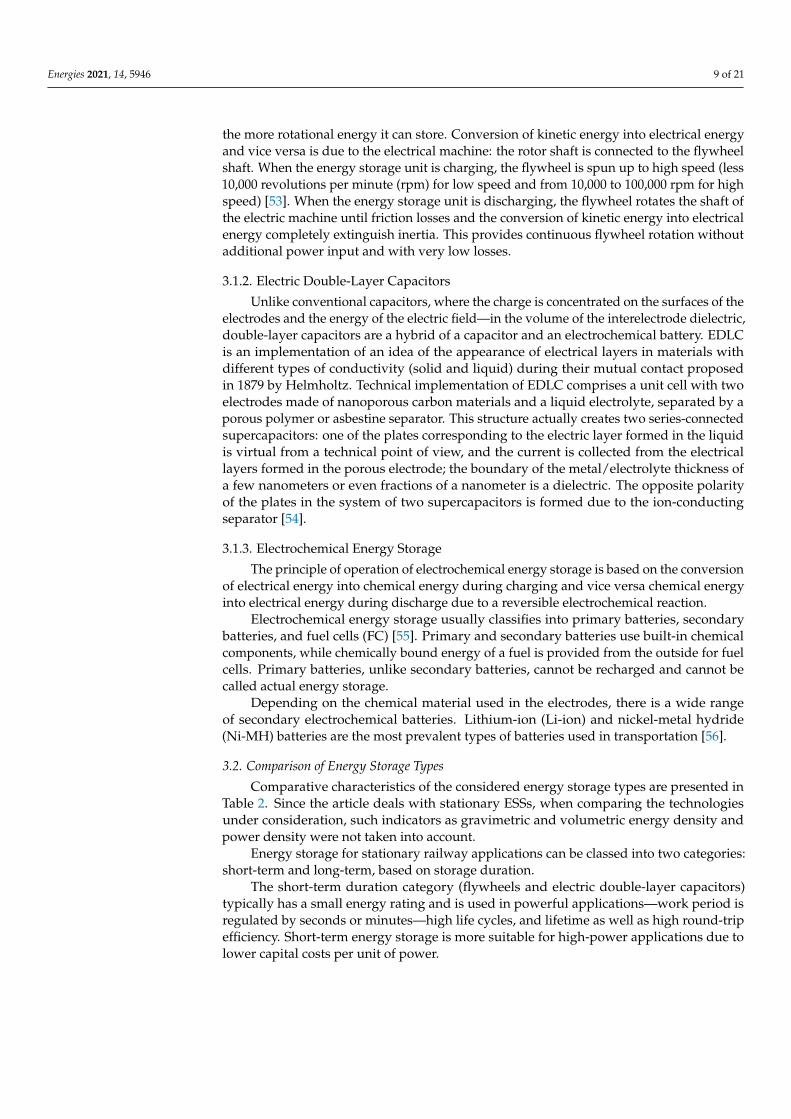
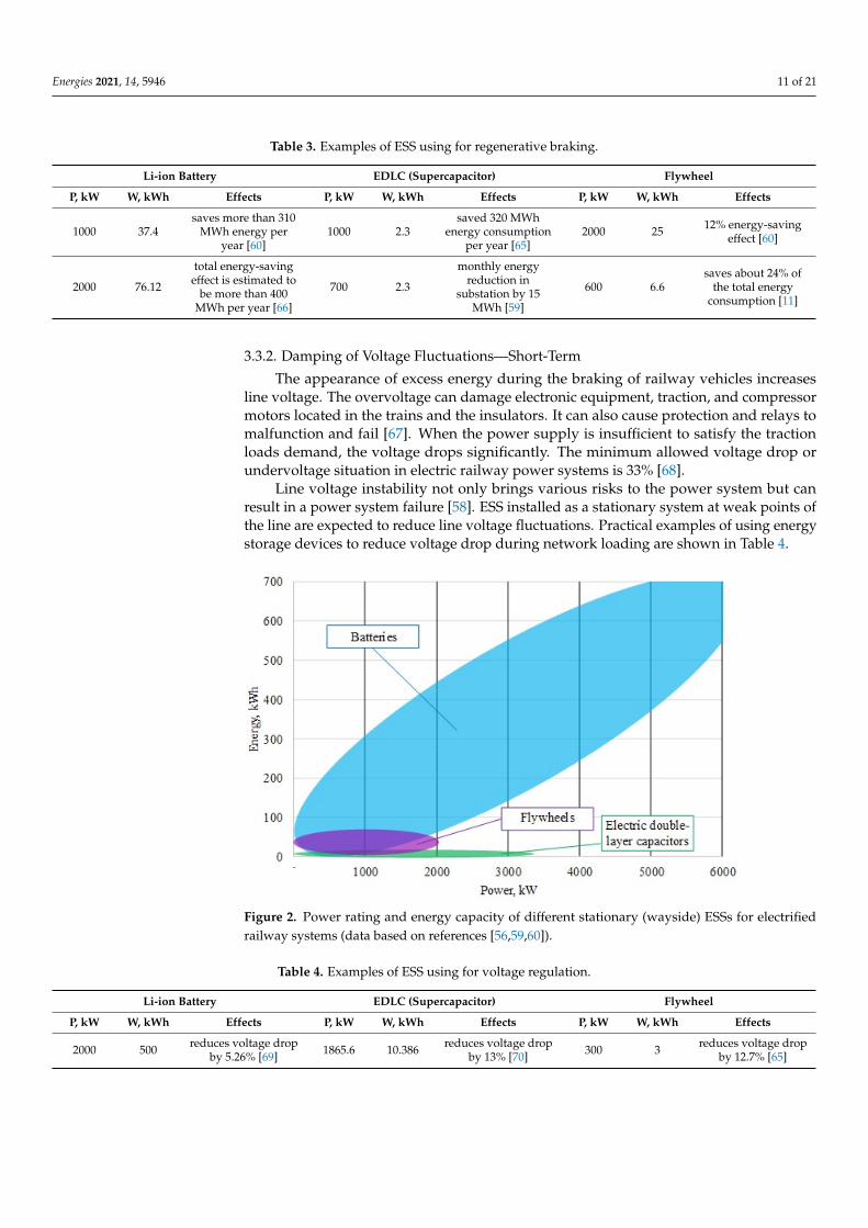
Figure 2 shows fields of application of the different storage techniques in stationarysystems deployed at electrified railways according to energy stored and power output.Data based on literary examples of real ESSs. As can be seen from Figure 2, EDLC andflywheels are used for powerful applications with low energy ratings, while batteries haveproven successful in both short-term and long-term applications.
3.3. Applications of Energy Storage Systems in Electrified Railway Systems3.3.1. Regenerative Braking Energy Utilization—Short-Term
The induction motors on a railway vehicle act as generators when braking, convertingkinetic energy into electrical energy. The tractive trains and power supply devices inthe same supply section utilize the majority of the regenerative braking energy, with theremainder being reinjected into the power grid [61]. Stationary energy storage can recoverand release the energy generated from several trains on the line as soon as needed [62].Energy savings can be up to 45% [63]. The article [64] compares wayside energy storage de-vices: lead-acid batteries, Ni-MH batteries, Li-ion batteries, supercapacitors, and flywheelsin the traction power supply system of the Polish transport company SKM. Supercapacitorsare the most cost-effective over a 10-year service life. The article [63] explores differentconfigurations of wayside energy storage application in DC electric rail transportationsystems in conditions of maximum regenerative energy saving from trains and minimumcapital and operating investment of the storage technologies. It was found that for thepurposes of regenerative braking, hybrid ESS based on battery and supercapacitor had thebest system performance and indicators for cost-benefit analysis. Practical examples of theuse of energy storage for regenerative braking and the effects are shown in Table 3.
Energies 2021, 14, 5946 11 of 21
Table 3. Examples of ESS using for regenerative braking.
Li-ion Battery EDLC (Supercapacitor) Flywheel
P, kW W, kWh Effects P, kW W, kWh Effects P, kW W, kWh Effects
1000 37.4saves more than 310
MWh energy peryear [60]
1000 2.3saved 320 MWh
energy consumptionper year [65]
2000 25 12% energy-savingeffect [60]
2000 76.12
total energy-savingeffect is estimated to
be more than 400MWh per year [66]
700 2.3
monthly energyreduction in
substation by 15MWh [59]
600 6.6saves about 24% of
the total energyconsumption [11]
3.3.2. Damping of Voltage Fluctuations—Short-Term
The appearance of excess energy during the braking of railway vehicles increasesline voltage. The overvoltage can damage electronic equipment, traction, and compressormotors located in the trains and the insulators. It can also cause protection and relays tomalfunction and fail [67]. When the power supply is insufficient to satisfy the tractionloads demand, the voltage drops significantly. The minimum allowed voltage drop orundervoltage situation in electric railway power systems is 33% [68].
Line voltage instability not only brings various risks to the power system but canresult in a power system failure [58]. ESS installed as a stationary system at weak points ofthe line are expected to reduce line voltage fluctuations. Practical examples of using energystorage devices to reduce voltage drop during network loading are shown in Table 4.
Energies 2021, 14, x FOR PEER REVIEW 11 of 21
Figure 2. Power rating and energy capacity of different stationary (wayside) ESSs for electrified railway systems (data based on references [56,59,60]).
3.3. Applications of Energy Storage Systems in Electrified Railway Systems 3.3.1. Regenerative Braking Energy Utilization—Short-Term
The induction motors on a railway vehicle act as generators when braking, convert-ing kinetic energy into electrical energy. The tractive trains and power supply devices in the same supply section utilize the majority of the regenerative braking energy, with the remainder being reinjected into the power grid [61]. Stationary energy storage can re-cover and release the energy generated from several trains on the line as soon as needed [62]. Energy savings can be up to 45% [63]. The article [64] compares wayside energy storage devices: lead-acid batteries, Ni-MH batteries, Li-ion batteries, supercapacitors, and flywheels in the traction power supply system of the Polish transport company SKM. Supercapacitors are the most cost-effective over a 10-year service life. The article [63] explores different configurations of wayside energy storage application in DC elec-tric rail transportation systems in conditions of maximum regenerative energy saving from trains and minimum capital and operating investment of the storage technologies. It was found that for the purposes of regenerative braking, hybrid ESS based on battery and supercapacitor had the best system performance and indicators for cost-benefit analysis. Practical examples of the use of energy storage for regenerative braking and the effects are shown in Table 3.
Table 3. Examples of ESS using for regenerative braking.
Li-ion Battery EDLC (Supercapacitor) Flywheel P, kW W, kWh Effects P, kW W, kWh Effects P, kW W, kWh Effects
1000 37.4 saves more than 310 MWh
energy per year [60] 1000 2.3
saved 320 MWh energy consumption per year
[65] 2000 25
12% energy-saving effect [60]
2000 76.12 total energy-saving effect is estimated to be more than
400 MWh per year [66] 700 2.3
monthly energy reduc-tion in substation by 15
MWh [59] 600 6.6
saves about 24% of the total energy con-
sumption [11]
Figure 2. Power rating and energy capacity of different stationary (wayside) ESSs for electrifiedrailway systems (data based on references [56,59,60]).
Table 4. Examples of ESS using for voltage regulation.
Li-ion Battery EDLC (Supercapacitor) Flywheel
P, kW W, kWh Effects P, kW W, kWh Effects P, kW W, kWh Effects
2000 500 reduces voltage dropby 5.26% [69] 1865.6 10.386 reduces voltage drop
by 13% [70] 300 3 reduces voltage dropby 12.7% [65]
Energies 2021, 14, 5946 12 of 21
3.3.3. Integration of Renewable Energy System Technologies—Long-Term
The available power of generation systems based on RES, primarily SPPs and windfarms, completely depends on weather conditions and are classified as stochastic generation.Ensuring the balance of active power leads to underutilization of the available power ofRES in the case of its surplus or to limitation of the load in case of its deficit. ESS providesthe most optimal process for integrating RES into electrified railway systems, allowing theprocesses of production and consumption of electrical energy to be spaced in time.
Smoothing of the RES output power by ESS is achieved by storing energy duringperiods of high generation and energy output for use when the RES output power decreasesdue to weather conditions. In this case, ESS must respond to changes in accordance withthe speed of oscillations and have a sufficient supply of energy to operate in the range fromseveral minutes to several hours.
Since the integration of RES into the electrified railway systems requires a long-termapplication of ESS, batteries and hydrogen FCs are better suited for it, as shown earlier inthis review.
4. Hydrogen Technologies
In a number of works devoted to ESSs, FCs are presented as such systems. However,it should be noted that these devices themselves are only capable of producing electricity,not storing it. Therefore, FCs are always used in conjunction with a hydrogen storagesystem, which is actually an ESS. FCs are currently the most promising and safest devicesfor generating electricity from hydrogen. Depending on the size and type, they can be usedboth in “on board” and stationary modes. FCs are notable for their noiseless operation,stability of power generation provided that hydrogen is continuously supplied, and theability to use one device to produce heat and electricity at the same time [5]. In the caseof RE power systems, electricity generated from RE is used for water electrolysis, as aresult of which hydrogen is formed. Further, hydrogen is placed in storage, and in caseof demand for electricity, it is supplied to the FC. Thus, for the systems considered in thiswork, hydrogen energy storage consists of three main components: an FC, an electrolyzer,and a hydrogen storage system.
4.1. Hydrogen Energy Storage4.1.1. Fuel Cells
FC serves as a converter in HRES: electricity is produced in FC during hydrogenoxidation with oxygen from the air. Thus, in fact, if a “direct” reaction of water splittingtakes place in an electrolyzer, a “reverse” electrochemical reaction of its formation takesplace in an FC. In principle, an FC consists of pipes for supplying and removing gases andwater, cathode, anode, and electrolyte.
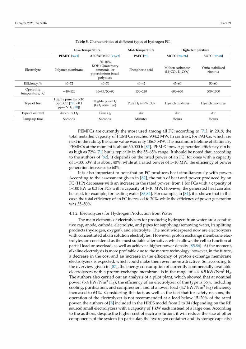
There are 5 types of hydrogen FCs depending on the electrolyte used: proton exchangemembrane (PEMFC), alkali/alkaline anion exchange membrane (AFC/AEMFC), phos-phoric acid (PAFC), molten carbonate (MCFC), and solid oxide (SOFC). Some of the maincharacteristics of these FCs are presented in Table 5.
Since both hydrogen and FCs are not used for continuous power generation, it is low-temperature FCs that are a more suitable option for HRES because they are characterizedby quick response and short ramp-up time. In turn, among low-temperature ones, PEMFCsare of greatest interest since, unlike AFCs, they do not contain corrosive medium and canalso use air as an oxidizing agent (pure oxygen is required for AFC). Indeed, in the majorityof studies on HRES, PEMFCs have been used.
Energies 2021, 14, 5946 13 of 21
Table 5. Characteristics of different types of hydrogen FC.
Low-Temperature Mid-Temperature High-Temperature
PEMFC [5,71] AFC/AEMFC [71,72] PAFC [73] MCFC [74–76] SOFC [77,78]
Electrolyte Polymer membrane
30–40%KOH/Quaternary
ammonia- orpiperidinium based
polymers
Phosphoric acid Molten carbonate(Li2CO3-K2CO3)
Yttria-stabilizedzirconia
Efficiency, % 40–72 40–70 40–42 45–60 50–60
Operatingtemperature, ◦C −40–120 40–75/50–90 150–220 600–650 500–1000
Type of fuelHighly pure H2 (<10
ppm CO [79], <0.1ppm NH3 [80])
Highly pure H2(CO2 sensitive) Pure H2 (<5% CO) H2-rich mixtures H2-rich mixtures
Type of oxidant Air/pure O2 Pure O2 Air Air Air
Ramp-up time Seconds Seconds Minutes Hours Hours
PEMFCs are currently the most used among all FC: according to [71], in 2019, thetotal installed capacity of PEMFCs reached 934.2 MW. In contrast, for PAFCs, which arenext in the rating, the same value was only 106.7 MW. The maximum lifetime of stationaryPEMFCs at the moment is about 30,000 h [81]. PEMFC power generation efficiency can beas high as 72% [71] but is typically in the 55–65% range. It should be noted that, accordingto the authors of [82], it depends on the rated power of an FC: for ones with a capacityof 1–100 kW, it is about 40%, while at a rated power of 1–10 MW, the efficiency of powergeneration increases to 60%.
It is also important to note that an FC produces heat simultaneously with power.According to the assessment given in [82], the ratio of heat and power produced by anFC (H:P) decreases with an increase in the rated power: from 1 for FCs with a capacity of1–100 kW to 0.3 for FCs with a capacity of 1–10 MW. However, the generated heat can alsobe used, for example, for heating water [83,84]. For example, in [84], it is shown that in thiscase, the total efficiency of an FC increased to 70%, while the efficiency of power generationwas 35–50%.
4.1.2. Electrolyzers for Hydrogen Production from Water
The main elements of electrolyzers for producing hydrogen from water are a conduc-tive cap, anode, cathode, electrolyte, and pipes for supplying/removing water, its splittingproducts (hydrogen, oxygen), and electrolyte. The most widespread now are electrolyzerswith concentrated alkali solution electrolytes. However, proton exchange membrane elec-trolytes are considered as the most suitable alternative, which allows the cell to function atpartial load or overload, as well as achieve a higher power density [85,86]. At the moment,alkaline electrolysis is more profitable due to the mature technology; however, in the future,a decrease in the cost and an increase in the efficiency of proton exchange membraneelectrolyzers is expected, which could make them even more attractive. So, according tothe overview given in [87], the energy consumption of currently commercially availableelectrolyzers with a proton-exchange membrane is in the range of 4.4–6.5 kW/Nm3 H2.The authors also carried out an analysis of a pilot plant, which showed that at nominalpower (5.4 kW/Nm3 H2), the efficiency of an electrolyzer of this type is 56%, includingcooling, purification, and compression, and at a lower load (4.7 kW/Nm3 H2) efficiencyincreased to 64%. Considering this fact, as well as the fact that for safety reasons, theoperation of the electrolyzer is not recommended at a load below 15–20% of the ratedpower, the authors of [8] included in the HRES model from 2 to 34 (depending on the REsource) small electrolyzers with a capacity of 1 kW each instead of a large one. Accordingto the authors, despite the higher cost of such a solution, it will reduce the size of othercomponents of the system (in particular, the hydrogen container and its storage capacity)
Energies 2021, 14, 5946 14 of 21
due to the more stable hydrogen generation. A similar approach was applied in work [88],which is devoted to the optimization of the system “solar panels + membrane electrolyzers”in order to ensure the maximum efficient use of solar energy for hydrogen production. Asa result of the study, it was shown that for a system consisting of 4 solar panels with apower of 75 W each and 5 electrolyzers with a power of 50 W each, connected in parallel,the energy transfer was about 95% of the theoretical maximum.
Since both an electrolyzer and an FC are designed in a similar way and can use aproton-exchange membrane as an electrolyte, it is proposed to combine these two devicesin one unitized regenerative (reversible) FC (URFC) in order to reduce the cost of anHRES [89]. It also allows making the HRES more compact, which can also be important forusing it in small areas.
4.1.3. Hydrogen Storage Systems
Hydrogen has the highest gravimetric energy density in comparison with other fuels,but its volumetric energy density is very low. Thus, the development of compact and safehydrogen storage is one of the key problems of the hydrogen economy.
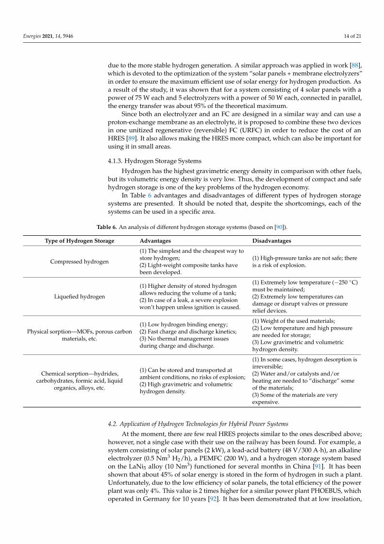
In Table 6 advantages and disadvantages of different types of hydrogen storagesystems are presented. It should be noted that, despite the shortcomings, each of thesystems can be used in a specific area.
Table 6. An analysis of different hydrogen storage systems (based on [90]).
Type of Hydrogen Storage Advantages Disadvantages
Compressed hydrogen
(1) The simplest and the cheapest way tostore hydrogen;(2) Light-weight composite tanks havebeen developed.
(1) High-pressure tanks are not safe; thereis a risk of explosion.
Liquefied hydrogen
(1) Higher density of stored hydrogenallows reducing the volume of a tank;(2) In case of a leak, a severe explosionwon’t happen unless ignition is caused.
(1) Extremely low temperature (−250 ◦C)must be maintained;(2) Extremely low temperatures candamage or disrupt valves or pressurerelief devices.
Physical sorption—MOFs, porous carbonmaterials, etc.
(1) Low hydrogen binding energy;(2) Fast charge and discharge kinetics;(3) No thermal management issuesduring charge and discharge.
(1) Weight of the used materials;(2) Low temperature and high pressureare needed for storage;(3) Low gravimetric and volumetrichydrogen density.
Chemical sorption—hydrides,carbohydrates, formic acid, liquid
organics, alloys, etc.
(1) Can be stored and transported atambient conditions, no risks of explosion;(2) High gravimetric and volumetrichydrogen density.
(1) In some cases, hydrogen desorption isirreversible;(2) Water and/or catalysts and/orheating are needed to “discharge” someof the materials;(3) Some of the materials are veryexpensive.
4.2. Application of Hydrogen Technologies for Hybrid Power Systems
At the moment, there are few real HRES projects similar to the ones described above;however, not a single case with their use on the railway has been found. For example, asystem consisting of solar panels (2 kW), a lead-acid battery (48 V/300 A·h), an alkalineelectrolyzer (0.5 Nm3 H2/h), a PEMFC (200 W), and a hydrogen storage system basedon the LaNi5 alloy (10 Nm3) functioned for several months in China [91]. It has beenshown that about 45% of solar energy is stored in the form of hydrogen in such a plant.Unfortunately, due to the low efficiency of solar panels, the total efficiency of the powerplant was only 4%. This value is 2 times higher for a similar power plant PHOEBUS, whichoperated in Germany for 10 years [92]. It has been demonstrated that at low insolation,
Energies 2021, 14, 5946 15 of 21
50–52% of the total electricity demand was delivered by the battery, while 20–25% wassupplied by the FC. As a result of the project, the authors concluded that the most stableand efficient power supply could be provided by systems with low-capacity batteries incombination with hydrogen.
Also, in the literature, the results of HRES modeling for certain areas are presented. So,for example, in [8], an HRES simulation for various types of RE (solar, wind, hydro-power)is presented. Calculations have shown that for mountainous country in Italy, the HRES witha micro-hydro turbine is the best choice. The efficiency of such a system, which, in additionto a micro-hydro turbine, consists of electrolyzers, a PEMFC, a battery, and a hydrogenstorage system, was 36.5%. While when using solar or wind energy, it dropped to 4.7 or 7.1,respectively. It should be noted that in the case of micro-hydro turbine, the largest amountof energy (30.2% of the power from RES) was sent directly to the consumer; in contrast, inthe case of solar panels and WTs, 20.2% and 9.2% of the generated energy was directly used,respectively. For all RES, the authors have shown that PEMFCs produce 38% of the inputenergy sent to the electrolyzer. It is noted that this value is higher for batteries, but theyare not suitable for long-term seasonal energy storage. For Newfoundland, modeling wasalso made for various HRES using wind energy [93]. It was shown that a system consistingof a wind generator, an FC (3.5 kW), a converter (3.5 kW), an electrolyzer (7.5 kW), and ahydrogen storage system with a capacity of 10 kg could be the best choice for use if it werenot for the high cost of FCs.
Since the power generation from renewable sources often cannot be constant anddepends on both the time of day and the season, several sources can be used simultaneouslyto increase stability. For example, in [94], the HRES used a 10 kW wind turbine and a1 kW solar panel. Combined with PEMFC (5 kW), this system provides high stability inpower generation.
For transport, including railway, it is also a possible scenario when electricity fromrenewable sources is used to produce hydrogen in a stationary installation, while PEMFCand a battery (PEMFC provide a constant average power, while the batteries meet powerpeaks [95]) installed directly on board the vehicle. Thus, a hydrogen refueling infrastructurecan be formed. A similar system using a WT is proposed in [96]—it is shown that it issuitable for use in rail transport in Berlin and Brandenburg.
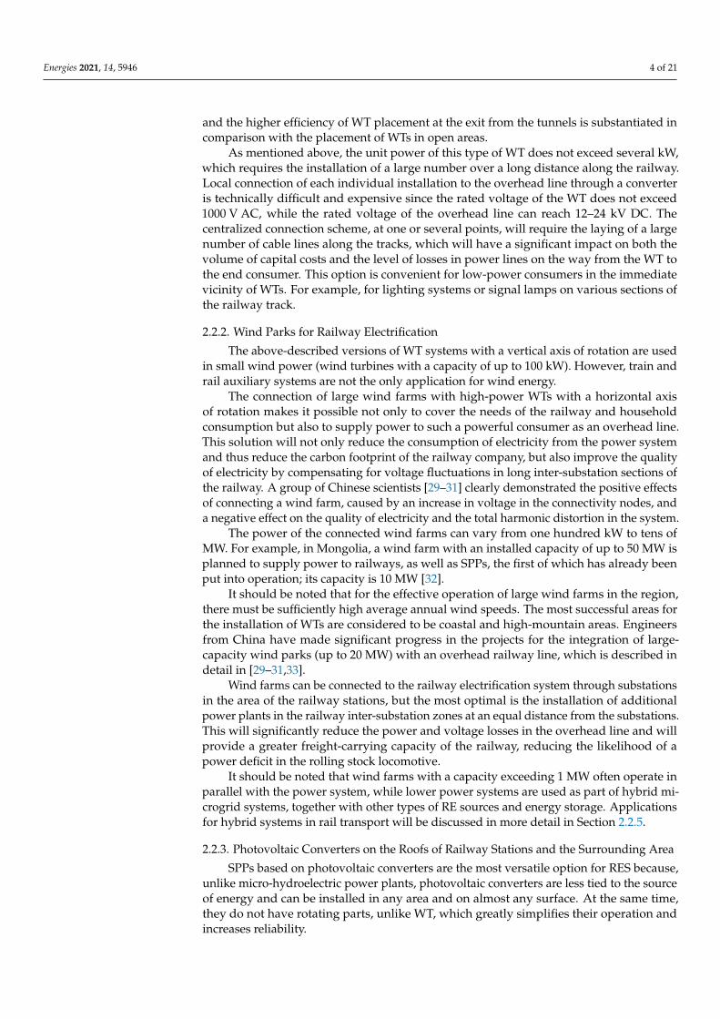
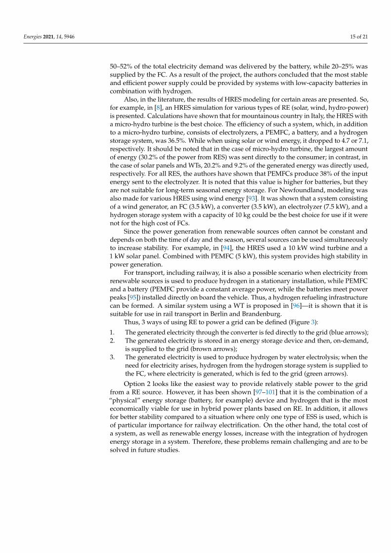
Thus, 3 ways of using RE to power a grid can be defined (Figure 3):
1. The generated electricity through the converter is fed directly to the grid (blue arrows);2. The generated electricity is stored in an energy storage device and then, on-demand,
is supplied to the grid (brown arrows);3. The generated electricity is used to produce hydrogen by water electrolysis; when the
need for electricity arises, hydrogen from the hydrogen storage system is supplied tothe FC, where electricity is generated, which is fed to the grid (green arrows).
Option 2 looks like the easiest way to provide relatively stable power to the gridfrom a RE source. However, it has been shown [97–101] that it is the combination of a“physical” energy storage (battery, for example) device and hydrogen that is the mosteconomically viable for use in hybrid power plants based on RE. In addition, it allowsfor better stability compared to a situation where only one type of ESS is used, which isof particular importance for railway electrification. On the other hand, the total cost ofa system, as well as renewable energy losses, increase with the integration of hydrogenenergy storage in a system. Therefore, these problems remain challenging and are to besolved in future studies.
Energies 2021, 14, 5946 16 of 21Energies 2021, 14, x FOR PEER REVIEW 16 of 21
Figure 3. Scheme of the railway electrification by means of RES.
Option 2 looks like the easiest way to provide relatively stable power to the grid from a RE source. However, it has been shown [97–101] that it is the combination of a “physical” energy storage (battery, for example) device and hydrogen that is the most economically viable for use in hybrid power plants based on RE. In addition, it allows for better stability compared to a situation where only one type of ESS is used, which is of particular importance for railway electrification. On the other hand, the total cost of a system, as well as renewable energy losses, increase with the integration of hydrogen energy storage in a system. Therefore, these problems remain challenging and are to be solved in future studies.
5. Conclusions Renewable energy sources are increasingly being introduced into all sectors of the
economy, and rail transport is no exception. To date, engineers from different countries have already developed and continue to develop many technical solutions based on re-newable energy sources and energy storage systems to improve the efficiency and envi-ronmental friendliness of railway transport. 1. The analysis of the publications allowed defining the main groups of technical solu-
tions for the integration of renewable energy systems into the railway infrastruc-ture. Their advantages and disadvantages were described. Examples of the imple-mentation of these systems in various countries were given. The analysis identified the main criteria for the feasibility of using various options for renewable energy systems at the design stage.
Figure 3. Scheme of the railway electrification by means of RES.
5. Conclusions
Renewable energy sources are increasingly being introduced into all sectors of theeconomy, and rail transport is no exception. To date, engineers from different countries havealready developed and continue to develop many technical solutions based on renewableenergy sources and energy storage systems to improve the efficiency and environmentalfriendliness of railway transport.
1. The analysis of the publications allowed defining the main groups of technical solu-tions for the integration of renewable energy systems into the railway infrastructure.Their advantages and disadvantages were described. Examples of the implementationof these systems in various countries were given. The analysis identified the maincriteria for the feasibility of using various options for renewable energy systems atthe design stage.
2. Various types of energy storage systems that play a key role in integrating renewableenergy with rail electrification systems were also considered. A comparative analysisof the technical and economic characteristics of various types of storage devices hasbeen carried out.
3. In this review, special attention was paid to works describing the configuration ofhybrid energy storage systems based on hydrogen storage, electrochemical storagebatteries, and supercapacitors. Optimally selected characteristics of the storage systemmake it possible to compensate for the shortcomings of each individual element,providing both high-speed performance and high peak power values in the eventof sudden changes in the mode, and a large capacity of stored energy, which allowsusing renewable energy systems with maximum efficiency.
Energies 2021, 14, 5946 17 of 21
4. The analysis of publications showed that at present, the greatest interest from re-searchers is shown to hybrid microgrid systems, which include various generationsystems based on renewable energy sources, as well as energy storage systems ofvarious types. This option is the most effective from the standpoint of reliability andquality of power supply since it reduces the likelihood of imbalances between thegeneration and consumption of electrical energy caused by the variable operatingmode and significant fluctuations in the output power of renewable energy systems.
Summing up, we can say that today modern technologies based on renewable energysources and energy storage systems have found their application in the electrification ofrailway transport and the current trend towards the development of “green” technolo-gies will lead in the future to a significant increase in the share of renewable energy inthis industry.
Funding: The reported study was funded by RFBR, Sirius University of Science and Technology, JSCRussian Railways and Educational Fund “Talent and success”, project number 20-38-51007.
Acknowledgments: The authors thank student Karina Matseruk for the help in the preparation ofthe manuscript and Pavel V. Matrenin for valuable comments.
Conflicts of Interest: The authors declare no conflict of interest. The funders had no role in the designof the study; in the collection, analyses, or interpretation of data; in the writing of the manuscript, orin the decision to publish the results.
References1. Strategiya Nauchno-Tekhnologicheskogo Razvityia Kholdinga “RZhD” na Period do 2020 goda i na Perspectivu do 2025 goda (Belaya Kniga);
JSC Russian Railways: Moscow, Russia, 2018; (In Russian). Available online: http://www.rzd-expo.ru/innovation/BelKniga_2015.pdf (accessed on 14 September 2021).
2. The State of the Global Renewable Energy Transition. Highlights of the REN21 Renewables 2018 Global Status Report inPerspective. Renewable Energy Policy Network for the 21st Century (REN21). 2018. 52p. Available online: https://www.ren21.net/wp-content/uploads/2019/05/GSR2018_Highlights_English.pdf (accessed on 14 September 2021).
3. Al’ternativnaya Energetika na Zheleznodorozhnom Transporte Indii; Center of Scientific-Technical Information and Libraries—JSCRussian Railways Branch: Moscow, Russia, 2021; (In Russian). Available online: https://lib.rgups.ru/site/assets/files/1207/al_ternativnaia_energetika_na_zheleznodorozhnom_transporte_indii.pdf (accessed on 14 September 2021).
4. Singh, A. Indian Railways Power house of India. Zenodo 2019. Available online: https://zenodo.org/record/2598043#.YUPzebgzaUk (accessed on 14 September 2021). [CrossRef]
5. Cigolotti, V.; Genovese, M.; Fragiacomo, P. Comprehensive Review on Fuel Cell Technology for Stationary Applications asSustainable and Efficient Poly-Generation Energy Systems. Energies 2021, 14, 4963. [CrossRef]
6. Jiao, K.; Xuan, J.; Du, Q.; Bao, Z.; Xie, B.; Wang, B.; Zhao, Y.; Fan, L.; Wang, H.; Hou, Z.; et al. Designing the next generation ofproton-exchange membrane fuel cells. Nature 2021, 595, 361–369. [CrossRef]
7. International Energy Agency. Technology Roadmap: Hydrogen and Fuel Cells; International Energy Agency: Paris, France, 2015;Available online: https://www.iea.org/reports/technology-roadmap-hydrogen-and-fuel-cells (accessed on 14 September 2021).
8. Santarelli, M.; Call, M.; Macagno, S. Design and analysis of stand-alone hydrogen energy systems with different renewablesources. Int. J. Hydrogen Energy 2004, 29, 1571–1586. [CrossRef]
9. Kameya, T.; Katsuma, H.; Suzuki, G.; Harada, Y. Proposal of LRT Using Renewable Energy. In Proceedings of the 30th ISESBiennial Solar World Congress, Kassel, Germany, 28 August–2 September 2011; pp. 1–7. [CrossRef]
10. Korfiati, A.; Gkonos, C.; Veronesi, F.; Gaki, A.; Grassi, S.; Schenkel, R.; Volkwein, S.; Raubal, M.; Hurni, L. Estimation of theGlobal Solar Energy Potential and Photovoltaic Cost with the use of Open Data. Int. J. Sustain. Energy Plan. Manag. 2016, 9, 17–30.[CrossRef]
11. International Union of Railways. Technologies and Potential Developments for Energy Efficiency and CO2 Reductions in Rail Systems;International Union of Railways: Paris, France, 2016.
12. Rohollahi, E.; Abdolzadeh, M.; Mehrabian, M.A. Prediction of the power generated by photovoltaic cells fixed on the roof of amoving passenger coach: A case study. Proc. Inst. Mech. Eng. Part F J. Rail Rapid Transit 2014, 229, 830–837. [CrossRef]
13. Darshana, M.K.; Karnataki, K.; Shankar, G.; Sheela, K.R. A practical implementation of energy harvesting, monitoring and analysissystem for solar photo voltaic terrestrial vehicles in Indian scenarios: A case of pilot implementation in the Indian Railways. InProceedings of the 2015 IEEE International WIE Conference on Electrical and Computer Engineering (WIECON-ECE), Dhaka,Bangladesh, 19–20 December 2015; pp. 542–545. [CrossRef]
14. Vasisht, S.M.; Vishal, C.; Srinivasan, J.; Ramasesha, S.K. Solar photovoltaic assistance for LHB rail coaches. Curr. Sci. 2014,107, 255–258. [CrossRef]
Energies 2021, 14, 5946 18 of 21
15. Vasisht, M.S.; Vashista, G.; Srinivasan, J.; Ramasesha, S.K. Rail coaches with rooftop solar photovoltaic systems: A feasibilitystudy. Energy 2017, 118, 684–691. [CrossRef]
16. Gangwar, M.; Sharma, S.M. Evaluating choice of traction option for a sustainable Indian Railways. Transp. Res. Part D Transp.Environ. 2014, 33, 135–145. [CrossRef]
17. Thelkar, A.R.; Veerasamy, B.; Mekonnen, T.; Ahmmed, M.; Alem, A.; Jote, A. Interfacing of regulator and rectifier unit withsolar charge controller for optimal utilization of solar power on railway coaches. In Proceedings of the 2016 IEEE InternationalConference on Renewable Energy Research and Applications (ICRERA), Birmingham, UK, 20–23 November 2016; pp. 730–735.[CrossRef]
18. Omar, W.A.W.; Hayder, G.; Aldrees, A.; Taha, A.T.B. Feasibility study on use of solar energy in Malaysia’s light rail transit. IOPConf. Ser. Earth Environ. Sci. 2021, 708. [CrossRef]
19. Srivastava, A.; Singh, A.; Joshi, G.; Gupta, A. Utilization of wind energy from railways using vertical axis wind turbine.In Proceedings of the 2015 International Conference on Energy Economics and Environment (ICEEE), Greater Noida, India,27–28 March 2015; pp. 1–5.
20. Bharech, S.; Singhal, D. Development of a model to convert wind energy of a speeding locomotive into electrical energy. InProceedings of the 1st National Convention of Electrical Engineers & National Seminar on Renewable Energy and GreenTechnology for Sustainable Development, Bhopal, India, 17–18 October 2015.
21. Mishra, A.; Ashhad, F. A Concept for Wind power Generated in High Speed Luxury Trains. Int. J. Appl. Eng. Res. 2019, 14, 38–42.22. Prasanth, G.; Sudheshnan, T. A renewable energy approach by fast moving vehicles. In Proceedings of the National Seminar &
Exhibition on Non-Destructive Evaluation, Tirupur, India, 8–10 December 2011; pp. 232–236.23. Zulu, J.; Lencwe, M.J.; Chowdhury, S.P.D. Green Energy for railway train mounted Wind Generator. In Proceedings of the 10th
International Renewable Energy Congress (IREC), Sousse, Tunisia, 26–28 March 2019; pp. 1–6.24. Nurmanova, V.; Bagheri, M.; Sultanbek, A.; Hekmati, A.; Bevrani, H. Feasibility study on wind energy harvesting system
implementation in moving trains. In Proceedings of the 2017 International Siberian Conference on Control and Communications(SIBCON), Astana, Kazakhstan, 29–30 June 2017; pp. 1–6.
25. Kumar, A.; Karandikar, P.B.; Chavan, D.S. Generating and saving energy by installing wind turbines along the railway tracks. InProceedings of the 2015 International Conference on Energy Systems and Applications, Pune, India, 30 October–1 November2015; pp. 25–27.
26. Oñederra, O.; Asensio, F.J.; Saldaña, G.; Martín, J.I.S.; Zamora, I. Wind Energy Harnessing in a Railway Infrastructure: ConverterTopology and Control Proposal. Electronics 2020, 9, 1943. [CrossRef]
27. Asensio, F.J.; Martin, J.I.S.; Zamora, I.; Oñederra, O.; Saldaña, G.; Eguia, P. A system approach to harnessing wind energy in arailway infrastructure. In Proceedings of the IECON 2018–44th Annual Conference of the IEEE Industrial Electronics Society,Washington, DC, USA, 21–23 October 2018; pp. 1646–1651. [CrossRef]
28. Pan, H.; Li, H.; Zhang, T.; Laghari, A.A.; Zhang, Z.; Yuan, Y.; Qian, B. A portable renewable wind energy harvesting systemintegrated S-rotor and H-rotor for self-powered applications in high-speed railway tunnels. Energy Convers. Manag. 2019,196, 56–68. [CrossRef]
29. Chen, Y.; Chen, M.; Liu, Y.; Chen, L. Analysing the Voltage Unbalance Impact of Wind Farm on Traction Power Supply System. InProceedings of the 2019 14th IEEE Conference on Industrial Electronics and Applications (ICIEA), Xi’an, China, 19–21 June 2019;pp. 1557–1561. [CrossRef]
30. Ding, F.; Zhang, D.; He, J.; Liu, H.; Li, Y. Evaluation of the influence of electrified railway on wind farm. In Proceedings of the2017 IEEE Transportation Electrification Conference and Expo, Asia-Pacific (ITEC Asia-Pacific), Harbin, China, 7–10 August 2017;pp. 1–6. [CrossRef]
31. Zhang, G.F.; Li, S.H.; Sun, F.; Bai, X.; Cheng, X.K. Power Quality Evaluation of Electrified Railway’s Impact on Wind Farm Electricand Its Engineering Application. J.Phys. Conf. Ser. 2018, 1087, 042066. [CrossRef]
32. Energy Charter Secretariat. In-Depth Review of Energy Efficiency Policies and Programmes; Energy Charter Secretariat: Mongolia,2011; ISBN 9789059480926. Available online: https://www.energycharter.org/what-we-do/energy-efficiency/energy-efficiency-country-reviews/in-depth-review-of-energy-efficiency-policies-and-programmes/ (accessed on 14 September 2021).
33. Ji, L.; Ning, F.; Ma, J.; Jia, L. SWOT analysis for orchestrated development of a solar railway system in China. IET Renew. PowerGener. 2020, 14, 3628–3635. [CrossRef]
34. Shen, X.; Zhang, Y.; Chen, S. Investigation of grid-connected photovoltaic generation system applied for Urban Rail Transit energy-savings. In Proceedings of the 2012 IEEE Industry Applications Society Annual Meeting, Las Vegas, NV, USA, 7–11 October 2012;pp. 1–4. [CrossRef]
35. Sengor, I.; Kilickiran, H.C.; Akdemir, H.; Kekezoglu, B.; Erdinc, O.; Catalao, J.P.S. Energy Management of a Smart RailwayStation Considering Regenerative Braking and Stochastic Behaviour of ESS and PV Generation. IEEE Trans. Sustain. Energy 2017,9, 1041–1050. [CrossRef]
36. Pankovits, P.; Pouget, J.; Robyns, B.; Delhaye, F.; Brisset, S. Towards railway-smartgrid: Energy management optimization forhybrid railway power substations. In Proceedings of the IEEE PES Innovative Smart Grid Technologies, Europe, Istanbul, Turkey,12–15 October 2014; pp. 1–6. [CrossRef]
37. Jaffery, S.H.I.; Khan, H.A.; Khan, M.; Ali, S. A study on the feasibility of solar powered railway system for light weight urbantransport. In Proceedings of the World Renewable Energy Forum, Denver, CO, USA, 13–17 May 2012; pp. 1892–1896.
Energies 2021, 14, 5946 19 of 21
38. Jaffery, S.H.I.; Khan, M.; Ali, L.; Khan, H.; Mufti, R.A.; Khan, A.; Khan, N. The potential of solar powered transportation and thecase for solar powered railway in Pakistan. Renew. Sustain. Energy Rev. 2014, 39, 270–276. [CrossRef]
39. Patil, T.D.; Patil, K.D.; Mahajan, S.M. Efficient Use of Renewable Energy in Train and Railway Station. Int. J. Innov. Technol. Explor.Eng. 2014, 3, 18–22.
40. Jia, L.; Ma, J.; Cheng, P.; Liu, Y. A perspective of solar energy-powered road and rail transportation in China. CSEE J. PowerEnergy Syst. 2020, 6, 760–771. [CrossRef]
41. Hayashiya, H.; Itagaki, H.; Morita, Y.; Mitoma, Y.; Furukawa, T.; Kuraoka, T.; Fukasawa, Y.; Oikawa, T. Potentials, peculiaritiesand prospects of solar power generation on the railway premises. In Proceedings of the 2012 International Conference onRenewable Energy Research and Applications (ICRERA), Nagasaki, Japan, 11–14 November 2012; pp. 1–6.
42. Morita, Y.; Honda, M.; Kuraoka, T.; Fukasawa, Y.; Mitoma, Y.; Yoshizumi, H.; Hayashiya, H. Analysis of local smoothing effect onthe PV on Tokyo station. In Proceedings of the 2012 International Conference on Renewable Energy Research and Applications(ICRERA), Nagasaki, Japan, 11–14 November 2012; pp. 1–6.
43. Nazir, C.P. Solar Energy for Traction of High Speed Rail Transportation: A Techno-economic Analysis. Civ. Eng. J. 2019,5, 1566–1576. [CrossRef]
44. Zhou, X. A Study on Potential for Using New Energy and Renewable Energy Sources in Railways. Int. J. Energy Power Eng. 2019,8, 45. [CrossRef]
45. Ostapchuk, O.; Kuznietsov, M.; Kuznetsov, V.; Kuznetsov, V. Problems of the use of renewable energy sources in the structure ofrailway power supply. IOP Conf. Ser. Mater. Sci. Eng. 2020, 985, 012011. [CrossRef]
46. Pankovits, P.; Ployard, M.; Pouget, J.; Brisset, S.; Abbes, D.; Robyns, B. Design and operation optimization of a hybrid railwaypower substation. In Proceedings of the 2013 15th European Conference on Power Electronics and Applications (EPE), Lille,France, 2–6 September 2013; pp. 1–8.
47. Aguado, J.A.; Racero, A.J.S.; De La Torre, S. Optimal Operation of Electric Railways With Renewable Energy and Electric StorageSystems. IEEE Trans. Smart Grid 2016, 9, 993–1001. [CrossRef]
48. Boudoudouh, S.; Maaroufi, M. Renewable Energy Sources Integration and Control in Railway Microgrid. IEEE Trans. Ind. Appl.2018, 55, 2045–2052. [CrossRef]
49. Nasr, S.; Iordache, M.; Petit, M. Smart micro-grid integration in DC railway systems. In Proceedings of the IEEE PES InnovativeSmart Grid Technologies, Europe, Istanbul, Turkey, 12–15 October 2014; pp. 1–6. [CrossRef]
50. Perez, F.; Iovine, A.; Damm, G.; Galai-Dol, L.; Ribeiro, P.F. Stability Analysis of a DC MicroGrid for a Smart Railway StationIntegrating Renewable Sources. IEEE Trans. Control. Syst. Technol. 2019, 28, 1802–1816. [CrossRef]
51. Jamal, T.; Salehin, S. Hybrid renewable energy sources power systems. Hybrid Renew. Energy Syst. Microgrids 2021, 179–214.Available online: https://www.sciencedirect.com/science/article/pii/B9780128217245000106?via%3Dihub (accessed on 14September 2021). [CrossRef]
52. Ghaviha, N.; Campillo, J.; Bohlin, M.; Dahlquist, E. Review of Application of Energy Storage Devices in Railway Transportation.Energy Procedia 2017, 105, 4561–4568. [CrossRef]
53. Olabi, A.; Wilberforce, T.; Abdelkareem, M.; Ramadan, M. Critical Review of Flywheel Energy Storage System. Energies 2021,14, 2159. [CrossRef]
54. Sharma, P.; Bhatti, T. A review on electrochemical double-layer capacitors. Energy Convers. Manag. 2010, 51, 2901–2912. [CrossRef]55. Buckley, D.N.; O’Dwyer, C.; Quill, N.; Lynch, R.P. Electrochemical Energy Storage. In Energy Storage Options and Their Envi-
ronmental Impact; The Royal Society of Chemistry: Croydon, UK, 2019; pp. 115–149. ISBN 978-1-78801-399-4. Available online:https://pubs.rsc.org/en/content/chapter/bk9781788013994-00115/978-1-78801-399-4 (accessed on 14 September 2021).
56. Ratniyomchai, T.; Hillmansen, S.; Tricoli, P. Recent developments and applications of energy storage devices in electrified railways.IET Electr. Syst. Transp. 2014, 4, 9–20. [CrossRef]
57. Hossain, E.; Faruque, H.; Sunny, S.H.; Mohammad, N.; Nawar, N. A Comprehensive Review on Energy Storage Systems: Types,Comparison, Current Scenario, Applications, Barriers, and Potential Solutions, Policies, and Future Prospects. Energies 2020,13, 3651. [CrossRef]
58. Liu, X.; Li, K. Energy storage devices in electrified railway systems: A review. Transp. Saf. Environ. 2020, 2, 183–201. [CrossRef]59. Meishner, F.; Sauer, D.U. Wayside energy recovery systems in DC urban railway grids. eTransportation 2019, 1, 100001. [CrossRef]60. Okui, A.; Hase, S.; Shigeeda, H.; Konishi, T.; Yoshi, T. Application of energy storage system for railway transportation in
Japan. In Proceedings of the The 2010 International Power Electronics Conference-ECCE ASIA, Sapporo, Japan, 21–24 June 2010;pp. 3117–3123.
61. Chen, J.; Hu, H.; Ge, Y.; Wang, K.; Huang, W.; He, Z. An Energy Storage System for Recycling Regenerative Braking Energy inHigh-Speed Railway. IEEE Trans. Power Deliv. 2020, 36, 320–330. [CrossRef]
62. Cipolletta, G.; Femine, A.D.; Gallo, D.; Luiso, M.; Landi, C. Design of a Stationary Energy Recovery System in Rail Transport.Energies 2021, 14, 2560. [CrossRef]
63. Dutta, O.; Saleh, M.; Khodaparastan, M.; Mohamed, A. A Dual-Stage Modeling and Optimization Framework for Wayside EnergyStorage in Electric Rail Transit Systems. Energies 2020, 13, 1614. [CrossRef]
64. Radu, P.V.; Drazek, Z. Analysis of wayside energy storage devices for DC heavy rail transport. MATEC Web Conf. 2018, 180.[CrossRef]
Energies 2021, 14, 5946 20 of 21
65. Radcliffe, P.; Wallace, J.S.; Shu, L.H. Stationary applications of energy storage technologies for transit systems. In Proceedings ofthe 2010 IEEE Electrical Power & Energy Conference, Halifax, NS, Canada, 25–27 August 2010; pp. 1–7.
66. Hayashiya, H.; Hara, D.; Tojo, M.; Watanabe, K.; Hino, M.; Suzuki, T.; Okamoto, H.; Takahashi, H.; Kato, T.; Teshima, M.Lithium-ion battery installation in traction power supply system for regenerative energy utilization: Initial report of effectevaluation after half a year operation. In Proceedings of the 2014 16th International Power Electronics and Motion ControlConference and Exposition, Antalya, Turkey, 21–24 September 2014; pp. 119–124. [CrossRef]
67. Kaleybar, H.J.; Brenna, M.; Foiadelli, F.; Fazel, S.S.; Zaninelli, D. Power Quality Phenomena in Electric Railway Power SupplySystems: An Exhaustive Framework and Classification. Energies 2020, 13, 6662. [CrossRef]
68. Brenna, M.; Foiadelli, F.; Zaninelli, D. DC Railway Electrification Systems. In Electrical Railway Transportation Systems; Wiley-IEEEPress: Hoboken, NJ, USA, 2018; pp. 99–176. [CrossRef]
69. Lamedica, R.; Ruvio, A.; Galdi, V.; Graber, G.; Sforza, P.; GuidiBuffarini, G.; Spalvieri, C. Application of battery auxiliarysubstations in 3kV railway systems. In Proceedings of the 2015 AEIT International Annual Conference (AEIT), Naples, Italy,14–16 October 2015; pp. 1–6.
70. Lee, H.; Kim, G.; Lee, C.; Joung, E. Field Tests of DC 1500 V Stationary Energy Storage System. Int. J. Railw. 2012, 5, 124–128.[CrossRef]
71. Wang, Y.; Seo, B.; Wang, B.; Zamel, N.; Jiao, K.; Adroher, X.C. Fundamentals, materials, and machine learning of polymerelectrolyte membrane fuel cell technology. Energy AI 2020, 1, 100014. [CrossRef]
72. Ferriday, T.; Middleton, P.H. Alkaline fuel cell technology—A review. Int. J. Hydrogen Energy 2021, 46, 18489–18510. [CrossRef]73. Ramadhani, F.; Hussain, M.A.; Mokhlis, H. A Comprehensive Review and Technical Guideline for Optimal Design and Operations
of Fuel Cell-Based Cogeneration Systems. Processes 2019, 7, 950. [CrossRef]74. Wee, J.-H. Carbon dioxide emission reduction using molten carbonate fuel cell systems. Renew. Sustain. Energy Rev. 2014,
32, 178–191. [CrossRef]75. Leo, T. Molten Carbonate Fuel Cells: Theory and Application. Compr. Renew. Energy 2012, 4, 247–259. [CrossRef]76. Cassir, M.; Ringuedé, A.; Lair, V. Molten Carbonates from Fuel Cells to New Energy Devices. In Molten Salts Chemistry; Elsevier:
Burlington, VT, USA, 2013; pp. 355–371. Available online: https://www.sciencedirect.com/science/article/pii/B9780123985385000172?via%3Dihub (accessed on 14 September 2021). [CrossRef]
77. Kirubakaran, A.; Jain, S.; Nema, R. A review on fuel cell technologies and power electronic interface. Renew. Sustain. Energy Rev.2009, 13, 2430–2440. [CrossRef]
78. Singh, M.; Zappa, D.; Comini, E. Solid oxide fuel cell: Decade of progress, future perspectives and challenges. Int. J. HydrogenEnergy 2021, 46, 27643–27674. [CrossRef]
79. Park, E.D.; Lee, D.; Lee, H.C. Recent progress in selective CO removal in a H2-rich stream. Catal. Today 2009, 139, 280–290.[CrossRef]
80. Miyaoka, H.; Miyaoka, H.; Ichikawa, T.; Ichikawa, T.; Kojima, Y. Highly purified hydrogen production from ammonia for PEMfuel cell. Int. J. Hydrogen Energy 2018, 43, 14486–14492. [CrossRef]
81. Li, B.; Roche, R.; Miraoui, A. Microgrid sizing with combined evolutionary algorithm and MILP unit commitment. Appl. Energy2017, 188, 547–562. [CrossRef]
82. Bauen, A.; Hart, D.; Chase, A. Fuel cells for distributed generation in developing countries—An analysis. Int. J. Hydrogen Energy2003, 28, 695–701. [CrossRef]
83. Facci, A.L.; Ubertini, S. Analysis of a fuel cell combined heat and power plant under realistic smart management scenarios. Appl.Energy 2018, 216, 60–72. [CrossRef]
84. Shabani, B.; Andrews, J. An experimental investigation of a PEM fuel cell to supply both heat and power in a solar-hydrogenRAPS system. Int. J. Hydrogen Energy 2011, 36, 5442–5452. [CrossRef]
85. Götz, M.; Lefebvre, J.; Mörs, F.; Koch, A.M.; Graf, F.; Bajohr, S.; Reimert, R.; Kolb, T. Renewable Power-to-Gas: A technologicaland economic review. Renew. Energy 2016, 85, 1371–1390. [CrossRef]
86. Parra, D.; Patel, M.K. Techno-economic implications of the electrolyser technology and size for power-to-gas systems. Int. J.Hydrogen Energy 2016, 41, 3748–3761. [CrossRef]
87. Buttler, A.; Spliethoff, H. Current status of water electrolysis for energy storage, grid balancing and sector coupling via power-to-gas and power-to-liquids: A review. Renew. Sustain. Energy Rev. 2018, 82, 2440–2454. [CrossRef]
88. Paul, B.; Andrews, J. Optimal coupling of PV arrays to PEM electrolysers in solar–hydrogen systems for remote area powersupply. Int. J. Hydrogen Energy 2008, 33, 490–498. [CrossRef]
89. Pu, Z.; Zhang, G.; Hassanpour, A.; Zheng, D.; Wang, S.; Liao, S.; Chen, Z.; Sun, S. Regenerative fuel cells: Recent progress,challenges, perspectives and their applications for space energy system. Appl. Energy 2020, 283, 116376. [CrossRef]
90. Moradi, R.; Groth, K.M. Hydrogen storage and delivery: Review of the state of the art technologies and risk and reliabilityanalysis. Int. J. Hydrogen Energy 2019, 44, 12254–12269. [CrossRef]
91. Liu, Z.; Qiu, Z.; Luo, Y.; Mao, Z.; Wang, C. Operation of first solar-hydrogen system in China. Int. J. Hydrogen Energy 2010,35, 2762–2766. [CrossRef]
92. Ghosh, P.C.; Emonts, B.; Janßen, H.; Mergel, J.; Stolten, D. Ten years of operational experience with a hydrogen-based renewableenergy supply system. Sol. Energy 2003, 75, 469–478. [CrossRef]

Energies 2021, 14, 5946 21 of 21
93. Khan, M.J.; Iqbal, M.T. Pre-feasibility study of stand-alone hybrid energy systems for applications in Newfoundland. Renew.Energy 2005, 30, 835–854. [CrossRef]
94. Agbossou, K.; Chahine, R.; Hamelin, J.; Laurencelle, F.; Anouar, A.; St-Arnaud, J.-M.; Bose, T.K. Renewable energy systems basedon hydrogen for remote applications. J. Power Sources 2001, 96, 168–172. [CrossRef]
95. Zenith, F.; Isaac, R.; Hoffrichter, A.; Thomassen, M.S.; Møller-Holst, S. Techno-economic analysis of freight railway electrificationby overhead line, hydrogen and batteries: Case studies in Norway and USA. Proc. Inst. Mech. Eng. Part. F J. Rail Rapid Transit2019, 234, 791–802. [CrossRef]
96. Herwartz, S.; Pagenkopf, J.; Streuling, C. Sector coupling potential of wind-based hydrogen production and fuel cell trainoperation in regional rail transport in Berlin and Brandenburg. Int. J. Hydrogen Energy 2021, 46, 29597–29615. [CrossRef]
97. Dong, W.; Li, Y.; Xiang, J. Optimal Sizing of a Stand-Alone Hybrid Power System Based on Battery/Hydrogen with an ImprovedAnt Colony Optimization. Energies 2016, 9, 785. [CrossRef]
98. Dawood, F.; Shafiullah, G.M.; Anda, M. Stand-Alone Microgrid with 100% Renewable Energy: A Case Study with Hybrid SolarPV-Battery-Hydrogen. Sustainability 2020, 12, 2047. [CrossRef]
99. Li, C.-H.; Zhu, X.-J.; Cao, G.-Y.; Sui, S.; Hu, M.-R. Dynamic modeling and sizing optimization of stand-alone photovoltaic powersystems using hybrid energy storage technology. Renew. Energy 2009, 34, 815–826. [CrossRef]
100. Nordin, N.D.; Rahman, H.A. Comparison of optimum design, sizing, and economic analysis of standalone photovoltaic/batterywithout and with hydrogen production systems. Renew. Energy 2019, 141, 107–123. [CrossRef]
101. Marocco, P.; Ferrero, D.; Lanzini, A.; Santarelli, M. Optimal design of stand-alone solutions based on RES + hydrogen storagefeeding off-grid communities. Energy Convers. Manag. 2021, 238, 114147. [CrossRef]


