Embed Size (px)
Citation preview
71:2 (2014) 49–55 | www.jurnalteknologi.utm.my | eISSN 2180–3722 |
Full paper Jurnal
Teknologi
Static and Dynamic Balancing of Helicopter Tail Rotor Blade Using Two-Plane Balancing Method Mohd Shariff bin Ammoo*, Ziad Bin Abdul Awal, Norhidayah binti Mat Sangiti
Dept. of Aeronautics, Automotive and Ocean Engineering, Faculty of Mechanical Engineering, Universiti Teknologi Malaysia, 81310 UTM Johor Bahru, Johor Malaysia
*Corresponding author: [email protected] Article history
Received 12 Sep 2014
Received in revised form 20 Sep 2014
Accepted 1 Oct 2014
Graphical abstract
Abstract
Balancing is a rotating component is critical in any mechanism. Devoid of proper balancing, any
vehicle - be it in air, land or sea, it will affect stability, control and safety. The same goes for rotor
crafts. Imbalance of the helicopter tail rotor system leads to vibrations in the entire vehicle and may cause accident. Typically, for the tail rotor of a helicopter, the blade is a source of vibration on the
tail boom. This not only causes inconvenience to the pilot but also reduces the life span of the
helicopter. There is a certain amount of vibration in the helicopter rotor systems especially the tail rotor. Hence, balancing procedure for rotating mass was conducted to reduce the vibration. This
research focuses on balancing of the tail rotor for UTM Single Seat Helicopter. Experiments have been conducted in order to study the vibration level of the tail rotor. Adding and removing masses
separately on the tail rotor exhibited different vibration levels. The responses were analyzed and
used for balancing the tail of rotor system. The balancing effort was considered successful, although there was still some residual unbalance in the tail rotor.
Keywords: Correction mass; trial mass; vibration; vibratory acceleration; residual unbalance;
© 2014Penerbit UTM Press. All rights reserved.
1.0 INTRODUCTION
Aviation industry has come long way since the days of Wright
brothers. Aerodynamic design, structures and advanced materials
are the principal and the most concerted attributes in aeronautics
[1-4]. However, all the individual parts can only properly function
only if there is proper design. Balancing is a key issue in aircraft
design especially for rotating parts. Apposite and clear-cut
balancing of aircraft parts and components are vital for aircraft
stability and performance. This research focuses on conducting an
extensive study on the static and dynamic balancing of the UTM
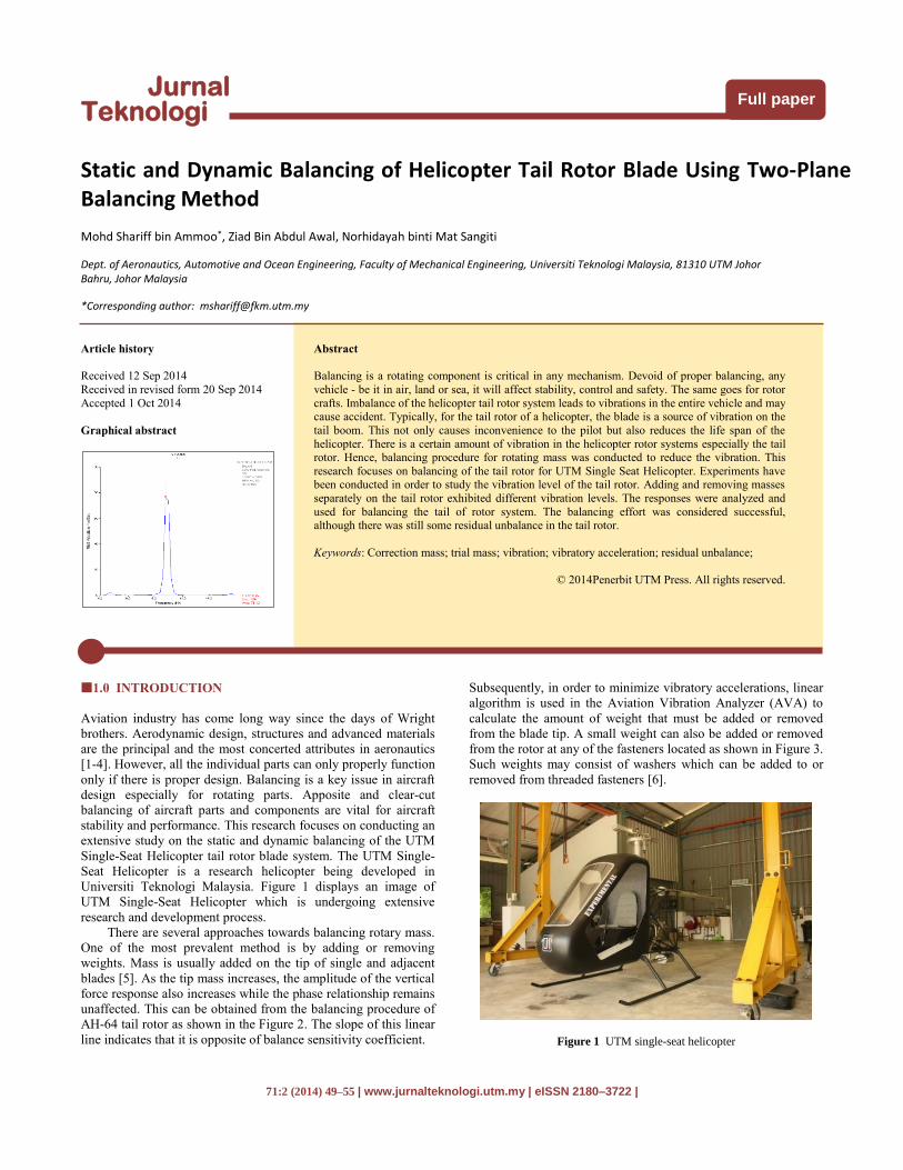
Single-Seat Helicopter tail rotor blade system. The UTM Single-
Seat Helicopter is a research helicopter being developed in
Universiti Teknologi Malaysia. Figure 1 displays an image of
UTM Single-Seat Helicopter which is undergoing extensive
research and development process.
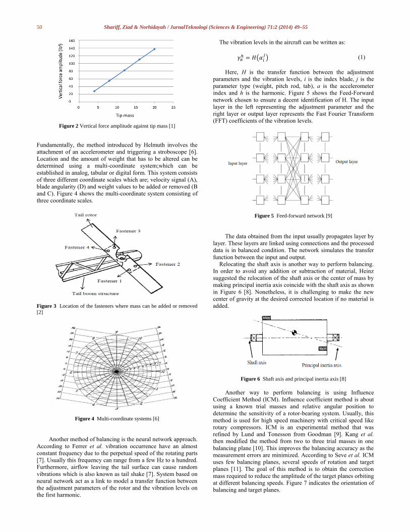
There are several approaches towards balancing rotary mass.
One of the most prevalent method is by adding or removing
weights. Mass is usually added on the tip of single and adjacent
blades [5]. As the tip mass increases, the amplitude of the vertical
force response also increases while the phase relationship remains
unaffected. This can be obtained from the balancing procedure of
AH-64 tail rotor as shown in the Figure 2. The slope of this linear
line indicates that it is opposite of balance sensitivity coefficient.
Subsequently, in order to minimize vibratory accelerations, linear
algorithm is used in the Aviation Vibration Analyzer (AVA) to
calculate the amount of weight that must be added or removed
from the blade tip. A small weight can also be added or removed
from the rotor at any of the fasteners located as shown in Figure 3.
Such weights may consist of washers which can be added to or
removed from threaded fasteners [6].
Figure 1 UTM single-seat helicopter
50 Shariff, Ziad & Norhidayah / JurnalTeknologi (Sciences & Engineering) 71:2 (2014) 49–55
Figure 2 Vertical force amplitude against tip mass [1]
Fundamentally, the method introduced by Helmuth involves the
attachment of an accelerometer and triggering a stroboscope [6].
Location and the amount of weight that has to be altered can be
determined using a multi-coordinate system;which can be
established in analog, tabular or digital form. This system consists
of three different coordinate scales which are; velocity signal (A),
blade angularity (D) and weight values to be added or removed (B
and C). Figure 4 shows the multi-coordinate system consisting of
three coordinate scales.
Figure 3 Location of the fasteners where mass can be added or removed
[2]
Figure 4 Multi-coordinate systems [6]
Another method of balancing is the neural network approach.
According to Ferrer et al. vibration occurrence have an almost
constant frequency due to the perpetual speed of the rotating parts
[7]. Usually this frequency can range from a few Hz to a hundred.
Furthermore, airflow leaving the tail surface can cause random
vibrations which is also known as tail shake [7]. System based on
neural network act as a link to model a transfer function between
the adjustment parameters of the rotor and the vibration levels on
the first harmonic.
The vibration levels in the aircraft can be written as:
𝛾𝑎ℎ = 𝐻(𝛼𝑖
𝑗) (1)
Here, H is the transfer function between the adjustment
parameters and the vibration levels, i is the index blade, j is the
parameter type (weight, pitch rod, tab), a is the accelerometer
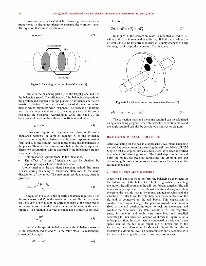
index and h is the harmonic. Figure 5 shows the Feed-Forward
network chosen to ensure a decent identification of H. The input
layer in the left representing the adjustment parameter and the
right layer or output layer represents the Fast Fourier Transform
(FFT) coefficients of the vibration levels.
Figure 5 Feed-forward network [9]
The data obtained from the input usually propagates layer by
layer. These layers are linked using connections and the processed
data is in balanced condition. The network simulates the transfer
function between the input and output.
Relocating the shaft axis is another way to perform balancing.
In order to avoid any addition or subtraction of material, Heinz
suggested the relocation of the shaft axis or the center of mass by
making principal inertia axis coincide with the shaft axis as shown
in Figure 6 [8]. Nonetheless, it is challenging to make the new
center of gravity at the desired corrected location if no material is
added.
Figure 6 Shaft axis and principal inertia axis [8]
Another way to perform balancing is using Influence
Coefficient Method (ICM). Influence coefficient method is about
using a known trial masses and relative angular position to
determine the sensitivity of a rotor-bearing system. Usually, this
method is used for high speed machinery with critical speed like
rotary compressors. ICM is an experimental method that was
refined by Lund and Tonesson from Goodman [9]. Kang et al.
then modified the method from two to three trial masses in one
balancing plane [10]. This improves the balancing accuracy as the
measurement errors are minimized. According to Seve et al. ICM
uses few balancing planes, several speeds of rotation and target
planes [11]. The goal of this method is to obtain the correction
mass required to reduce the amplitude of the target planes orbiting
at different balancing speeds. Figure 7 indicates the orientation of
balancing and target planes.
51 Shariff, Ziad & Norhidayah / JurnalTeknologi (Sciences & Engineering) 71:2 (2014) 49–55
Correction mass is located at the balancing planes which is
proportional to the target planes to measure the vibration level.
The equation that can be used here is:
𝑞 = 𝑝 × 𝑠 (2)
Figure 7 Balancing and target plane definition [11]
Here, q is the balancing plane, p is the target plane and s is
the balancing speed. The efficiency of the balancing depends on
the position and number of target planes. An influence coefficient
matrix is obtained from the data of a set of discrete correction
masses which minimize whirl response. The process of applying
trial masses is repeated for all balancing planes and the rotor
responses are measured. According to Zhou and Shi [12], the
basic principle used in the influence coefficient method is:
𝑣𝑊 = 𝐶𝑤 (3)
In this case, 𝑣𝑊 is the magnitude and phase of the rotor
imbalance response in complex number, C is the influence
coefficient relating the imbalance and the rotor response in matrix
form and w is the column vector representing the imbalances in
the planes. There are two assumptions behind the above equation.
These two assumptions will be accepted if the imbalances are not
very large. They are:
Rotor response is proportional to the imbalance.
The effect of a set of imbalances can be obtained by
superimposing each individual unbalance.
Another method is the two-plane balancing method. Trial mass
is used during balancing as temporary alterations to the mass
distribution of the rotor. The maximum residual mass, MMR is
given by:
𝑀𝑀𝑅 =𝑆. 𝑈 × 𝑀𝑅
𝑅𝐶 (4)
In equation (4), S.U. is the specific unbalance required, MR is
the rotor mass and RC is the correction radius. During balancing
trial, it is difficult to mount the correction mass at the same radius
as the trial mass due to different structure of the rotor as shown in
Figure 8. The relation to correct the imbalance is given as follows:
𝑒 =𝑚𝑟
𝑀 (5)
Here, 𝑒 is the specific imbalance, m is the imbalance mass, 𝑟⃗⃗⃗
is the correction radius and M is the rotor mass. By rearranging
equation (v) we get:
𝑒𝑀 = 𝑚𝑟 (6)
Therefore,
�⃗�𝑀 = 𝑚𝑟 = 𝑚𝑟1⃗⃗ ⃗ = 𝑚𝑟2⃗⃗ ⃗ (7)
In Figure 8, the correction mass is mounted at radius r2,
while trial mass is mounted at radius r1. If both radii values are
different, the value for correction mass m2 simply changes to keep
the integrity of the product constant. That is to say:
Figure 8 Location for correction mass and trail mass [13]
�⃗�𝑀 = 𝑚𝑟 = 𝑚𝑟1⃗⃗ ⃗ = 𝑚𝑟2⃗⃗ ⃗ (8)
The correction mass and the angle required can be calculated
using a balancing program. The values for the correction mass and
the angle required can also be calculated using vector diagram.
2.0 EXPERIMENTAL PROCEDURE
After evaluating all the possible approaches, two-plane balancing
method has been chosen for balancing the tail rotor blade of UTM
Single-Seat Helicopter. Basically four steps have been identified
to conduct this balancing process. The initial step is to design and
build the model, followed by conducting the vibration test and
determining the correction mass necessary as well as checking the
residual unbalance.
2.1 Model Design And Construction
A test rig is constructed to perform the balancing experiment on
the tail section of the helicopter. The test rig aids in connecting
the motor, the tail boom and the tail rotor blades together. The tail
boom usually experiences the utmost vibration during operation
therefore the test rig has to be robust enough to withstand the
vibration. In order to run the rotor blades, a motor is placed on the
rig and is connected to the tail boom. This experiment is
conducted at zero pitch angle. The pitch control of the tail rotor is
fixed at the tail gearbox in order to lock its movement and
conduct the experiment in a stable condition. All the respective
parts, instruments and tools were assembled and installed
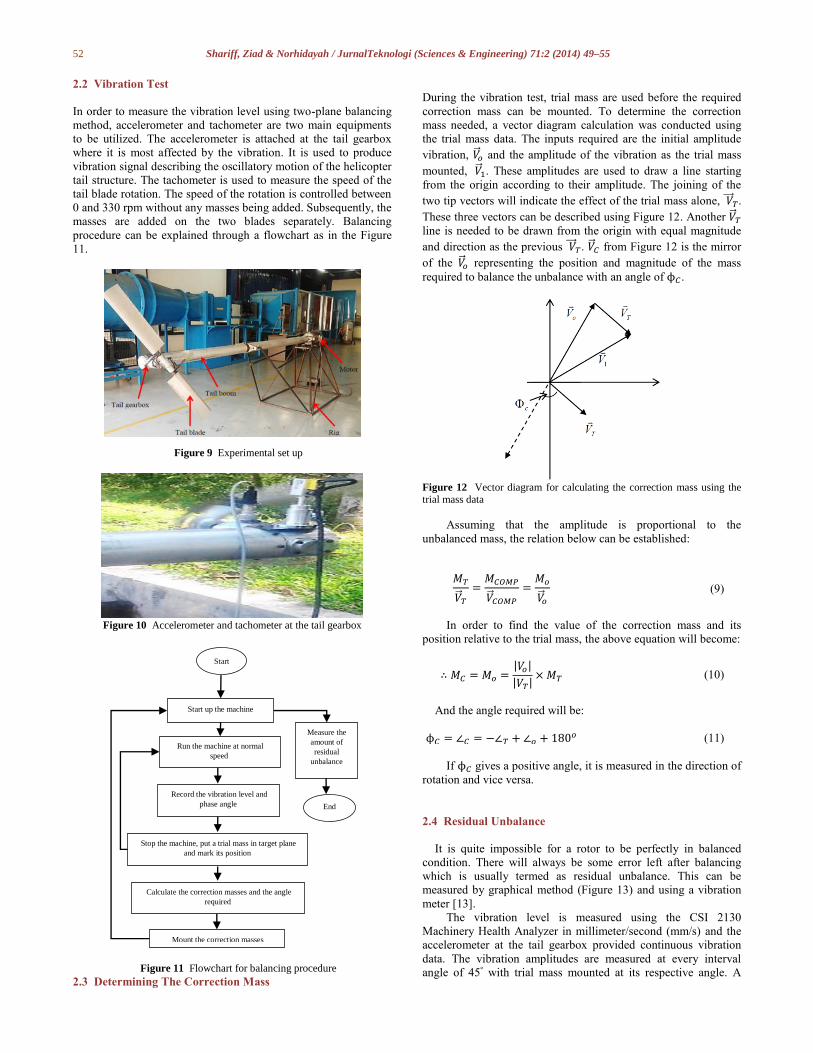
according to their specified location as shown in Figure 9. As a
safety precaution, the experiment is conducted in a wide and open
space area as the tail rotor might slip or break due to the
increasing speed of rotation. As shown in Figure 10, in order to
measure the vibration level, an accelerometer and a tachometer is
installed at the tail gearbox where most vibration occurs.
52 Shariff, Ziad & Norhidayah / JurnalTeknologi (Sciences & Engineering) 71:2 (2014) 49–55
2.2 Vibration Test
In order to measure the vibration level using two-plane balancing
method, accelerometer and tachometer are two main equipments
to be utilized. The accelerometer is attached at the tail gearbox
where it is most affected by the vibration. It is used to produce
vibration signal describing the oscillatory motion of the helicopter
tail structure. The tachometer is used to measure the speed of the
tail blade rotation. The speed of the rotation is controlled between
0 and 330 rpm without any masses being added. Subsequently, the
masses are added on the two blades separately. Balancing
procedure can be explained through a flowchart as in the Figure
11.
Figure 9 Experimental set up
Figure 10 Accelerometer and tachometer at the tail gearbox
Figure 11 Flowchart for balancing procedure
2.3 Determining The Correction Mass
During the vibration test, trial mass are used before the required
correction mass can be mounted. To determine the correction
mass needed, a vector diagram calculation was conducted using
the trial mass data. The inputs required are the initial amplitude
vibration, �⃗⃗�𝑜 and the amplitude of the vibration as the trial mass
mounted, �⃗⃗�1. These amplitudes are used to draw a line starting
from the origin according to their amplitude. The joining of the
two tip vectors will indicate the effect of the trial mass alone, 𝑉⃗⃗⃗⃗ 𝑇.
These three vectors can be described using Figure 12. Another �⃗⃗�𝑇
line is needed to be drawn from the origin with equal magnitude
and direction as the previous 𝑉⃗⃗⃗⃗ 𝑇. �⃗⃗�𝐶 from Figure 12 is the mirror
of the �⃗⃗�𝑜 representing the position and magnitude of the mass
required to balance the unbalance with an angle of ϕ𝐶.
Figure 12 Vector diagram for calculating the correction mass using the trial mass data
Assuming that the amplitude is proportional to the
unbalanced mass, the relation below can be established:
𝑀𝑇
�⃗⃗�𝑇
=𝑀𝐶𝑂𝑀𝑃
�⃗⃗�𝐶𝑂𝑀𝑃
=𝑀𝑜
�⃗⃗�𝑜
(9)
In order to find the value of the correction mass and its
position relative to the trial mass, the above equation will become:
∴ 𝑀𝐶 = 𝑀𝑜 =|𝑉𝑜|
|𝑉𝑇|× 𝑀𝑇 (10)
And the angle required will be:
ϕ𝐶 = ∠𝐶 = −∠𝑇 + ∠𝑜 + 180𝑜 (11)
If ϕ𝐶 gives a positive angle, it is measured in the direction of
rotation and vice versa.
2.4 Residual Unbalance
It is quite impossible for a rotor to be perfectly in balanced
condition. There will always be some error left after balancing
which is usually termed as residual unbalance. This can be
measured by graphical method (Figure 13) and using a vibration
meter [13].
The vibration level is measured using the CSI 2130
Machinery Health Analyzer in millimeter/second (mm/s) and the
accelerometer at the tail gearbox provided continuous vibration
data. The vibration amplitudes are measured at every interval
angle of 45º with trial mass mounted at its respective angle. A
Start
Start up the machine
Run the machine at normal
speed
Record the vibration level and
phase angle
Measure the
amount of
residual
unbalance
Stop the machine, put a trial mass in target plane
and mark its position
Calculate the correction masses and the angle
required
Mount the correction masses
End
53 Shariff, Ziad & Norhidayah / JurnalTeknologi (Sciences & Engineering) 71:2 (2014) 49–55
graph of vibration amplitude against the position can be drawn
from the data as shown in the Figure 14.
The plotted graph should approximately project a sinusoidal
curve. Otherwise, the residual unbalance is under the limit of
reproducibility. This can occur if the trial mass is too small or the
measuring sensitivity is inadequate. From the sinusoidal curve,
the magnitude of the unbalance, Vres and the distance to the zero
line represents the magnitude of the trial mass, VT. So, the
magnitude of the residual unbalance mass, Mres can then be
calculated from the equation below:
𝑀𝑟𝑒𝑠 =|𝑉𝑟𝑒𝑠|
|𝑉𝑇|× 𝑀𝑇 (12)
Figure 13 Checking residual unbalance [8]
Figure 14 A graph of vibration amplitude against the position of trial
mass [8]
3.0 RESULTS AND DISCUSSION
The purpose of this experiment is to get the vibration level and
response data for the UTM Single-Seat Helicopter in order to
balance the tail rotor blades. Vibration levels during zero mass
addition and after addition of the mass at the two blades were
found to be different and intermittent. In this experiment, the tail
rotor speed has been kept steady at 660rpm.The vibration level
without any mass added acts as a reference to compare with the
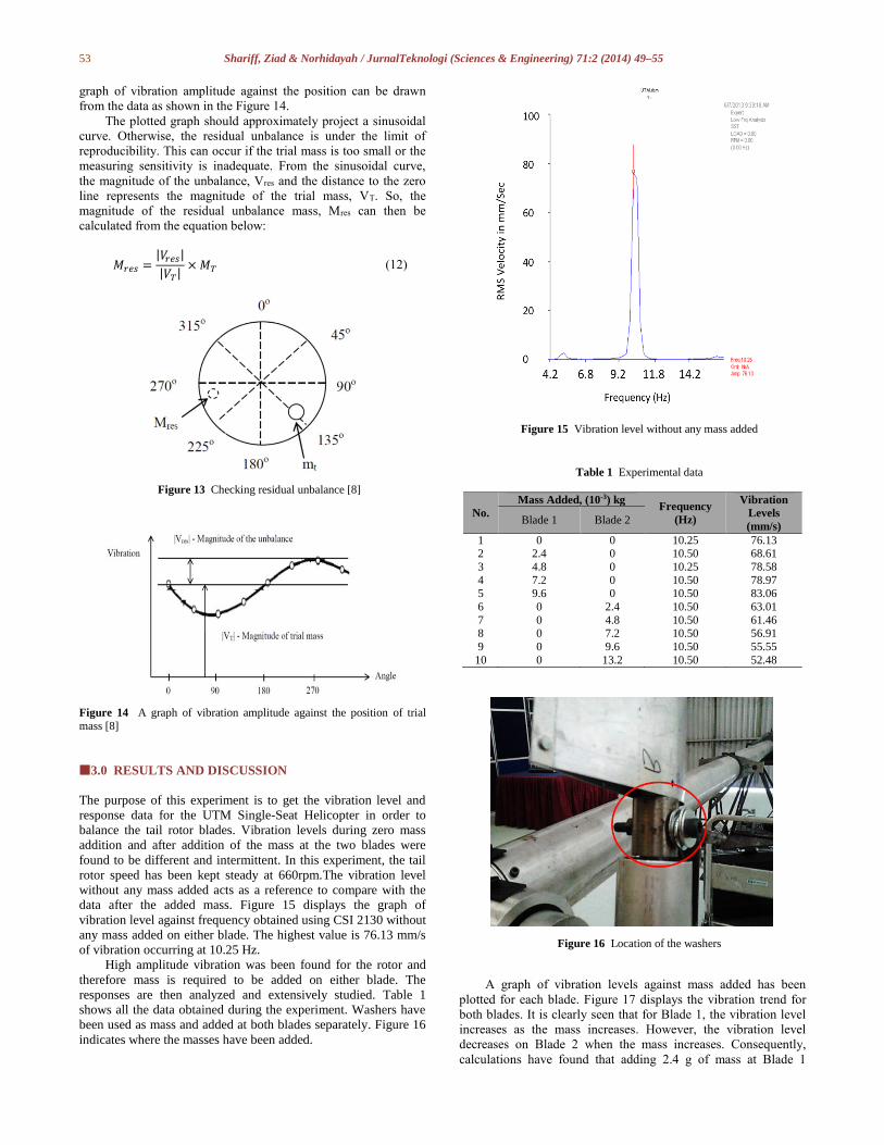
data after the added mass. Figure 15 displays the graph of
vibration level against frequency obtained using CSI 2130 without
any mass added on either blade. The highest value is 76.13 mm/s
of vibration occurring at 10.25 Hz.
High amplitude vibration was been found for the rotor and
therefore mass is required to be added on either blade. The
responses are then analyzed and extensively studied. Table 1
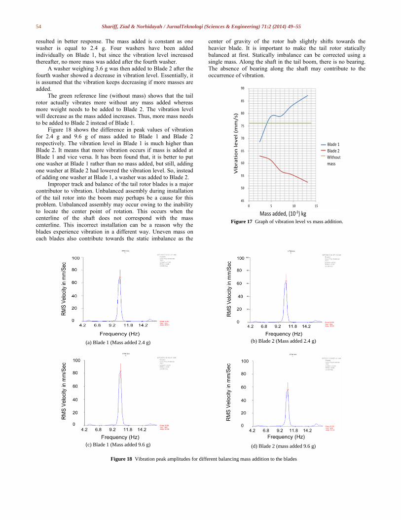
shows all the data obtained during the experiment. Washers have
been used as mass and added at both blades separately. Figure 16
indicates where the masses have been added.
Figure 15 Vibration level without any mass added
Table 1 Experimental data
No.
Mass Added, (10-3) kg Frequency
(Hz)
Vibration
Levels
(mm/s) Blade 1 Blade 2
1 0 0 10.25 76.13 2 2.4 0 10.50 68.61
3 4.8 0 10.25 78.58
4 7.2 0 10.50 78.97 5 9.6 0 10.50 83.06
6 0 2.4 10.50 63.01
7 0 4.8 10.50 61.46
8 0 7.2 10.50 56.91
9 0 9.6 10.50 55.55
10 0 13.2 10.50 52.48
Figure 16 Location of the washers
A graph of vibration levels against mass added has been
plotted for each blade. Figure 17 displays the vibration trend for
both blades. It is clearly seen that for Blade 1, the vibration level
increases as the mass increases. However, the vibration level
decreases on Blade 2 when the mass increases. Consequently,
calculations have found that adding 2.4 g of mass at Blade 1
54 Shariff, Ziad & Norhidayah / JurnalTeknologi (Sciences & Engineering) 71:2 (2014) 49–55
resulted in better response. The mass added is constant as one
washer is equal to 2.4 g. Four washers have been added
individually on Blade 1, but since the vibration level increased
thereafter, no more mass was added after the fourth washer.
A washer weighing 3.6 g was then added to Blade 2 after the
fourth washer showed a decrease in vibration level. Essentially, it
is assumed that the vibration keeps decreasing if more masses are
added.
The green reference line (without mass) shows that the tail
rotor actually vibrates more without any mass added whereas
more weight needs to be added to Blade 2. The vibration level
will decrease as the mass added increases. Thus, more mass needs
to be added to Blade 2 instead of Blade 1.
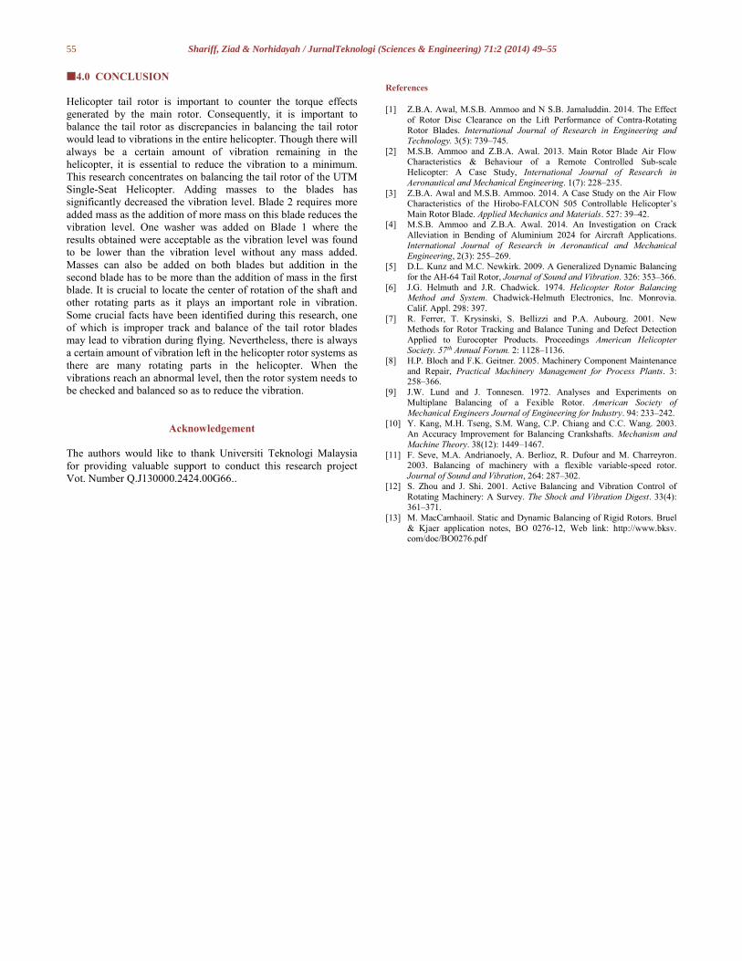
Figure 18 shows the difference in peak values of vibration
for 2.4 g and 9.6 g of mass added to Blade 1 and Blade 2
respectively. The vibration level in Blade 1 is much higher than
Blade 2. It means that more vibration occurs if mass is added at
Blade 1 and vice versa. It has been found that, it is better to put
one washer at Blade 1 rather than no mass added, but still, adding
one washer at Blade 2 had lowered the vibration level. So, instead
of adding one washer at Blade 1, a washer was added to Blade 2.
Improper track and balance of the tail rotor blades is a major
contributor to vibration. Unbalanced assembly during installation
of the tail rotor into the boom may perhaps be a cause for this
problem. Unbalanced assembly may occur owing to the inability
to locate the center point of rotation. This occurs when the
centerline of the shaft does not correspond with the mass
centerline. This incorrect installation can be a reason why the
blades experience vibration in a different way. Uneven mass on
each blades also contribute towards the static imbalance as the
center of gravity of the rotor hub slightly shifts towards the
heavier blade. It is important to make the tail rotor statically
balanced at first. Statically imbalance can be corrected using a
single mass. Along the shaft in the tail boom, there is no bearing.
The absence of bearing along the shaft may contribute to the
occurrence of vibration.
Figure 17 Graph of vibration level vs mass addition.
(a) Blade 1 (Mass added 2.4 g)
(b) Blade 2 (Mass added 2.4 g)
(c) Blade 1 (Mass added 9.6 g)
(d) Blade 2 (mass added 9.6 g)
Figure 18 Vibration peak amplitudes for different balancing mass addition to the blades
55 Shariff, Ziad & Norhidayah / JurnalTeknologi (Sciences & Engineering) 71:2 (2014) 49–55
4.0 CONCLUSION
Helicopter tail rotor is important to counter the torque effects
generated by the main rotor. Consequently, it is important to
balance the tail rotor as discrepancies in balancing the tail rotor
would lead to vibrations in the entire helicopter. Though there will
always be a certain amount of vibration remaining in the
helicopter, it is essential to reduce the vibration to a minimum.
This research concentrates on balancing the tail rotor of the UTM
Single-Seat Helicopter. Adding masses to the blades has
significantly decreased the vibration level. Blade 2 requires more
added mass as the addition of more mass on this blade reduces the
vibration level. One washer was added on Blade 1 where the
results obtained were acceptable as the vibration level was found
to be lower than the vibration level without any mass added.
Masses can also be added on both blades but addition in the
second blade has to be more than the addition of mass in the first
blade. It is crucial to locate the center of rotation of the shaft and
other rotating parts as it plays an important role in vibration.
Some crucial facts have been identified during this research, one
of which is improper track and balance of the tail rotor blades
may lead to vibration during flying. Nevertheless, there is always
a certain amount of vibration left in the helicopter rotor systems as
there are many rotating parts in the helicopter. When the
vibrations reach an abnormal level, then the rotor system needs to
be checked and balanced so as to reduce the vibration.
Acknowledgement
The authors would like to thank Universiti Teknologi Malaysia
for providing valuable support to conduct this research project
Vot. Number Q.J130000.2424.00G66..
References
[1] Z.B.A. Awal, M.S.B. Ammoo and N S.B. Jamaluddin. 2014. The Effect
of Rotor Disc Clearance on the Lift Performance of Contra-Rotating
Rotor Blades. International Journal of Research in Engineering and Technology. 3(5): 739–745.
[2] M.S.B. Ammoo and Z.B.A. Awal. 2013. Main Rotor Blade Air Flow
Characteristics & Behaviour of a Remote Controlled Sub-scale
Helicopter: A Case Study, International Journal of Research in
Aeronautical and Mechanical Engineering. 1(7): 228–235.
[3] Z.B.A. Awal and M.S.B. Ammoo. 2014. A Case Study on the Air Flow
Characteristics of the Hirobo-FALCON 505 Controllable Helicopter’s
Main Rotor Blade. Applied Mechanics and Materials. 527: 39–42. [4] M.S.B. Ammoo and Z.B.A. Awal. 2014. An Investigation on Crack
Alleviation in Bending of Aluminium 2024 for Aircraft Applications.
International Journal of Research in Aeronautical and Mechanical
Engineering, 2(3): 255–269.
[5] D.L. Kunz and M.C. Newkirk. 2009. A Generalized Dynamic Balancing
for the AH-64 Tail Rotor, Journal of Sound and Vibration. 326: 353–366.
[6] J.G. Helmuth and J.R. Chadwick. 1974. Helicopter Rotor Balancing Method and System. Chadwick-Helmuth Electronics, Inc. Monrovia.
Calif. Appl. 298: 397.
[7] R. Ferrer, T. Krysinski, S. Bellizzi and P.A. Aubourg. 2001. New
Methods for Rotor Tracking and Balance Tuning and Defect Detection
Applied to Eurocopter Products. Proceedings American Helicopter
Society. 57th Annual Forum. 2: 1128–1136.
[8] H.P. Bloch and F.K. Geitner. 2005. Machinery Component Maintenance
and Repair, Practical Machinery Management for Process Plants. 3: 258–366.
[9] J.W. Lund and J. Tonnesen. 1972. Analyses and Experiments on
Multiplane Balancing of a Fexible Rotor. American Society of
Mechanical Engineers Journal of Engineering for Industry. 94: 233–242.
[10] Y. Kang, M.H. Tseng, S.M. Wang, C.P. Chiang and C.C. Wang. 2003.
An Accuracy Improvement for Balancing Crankshafts. Mechanism and
Machine Theory. 38(12): 1449–1467.
[11] F. Seve, M.A. Andrianoely, A. Berlioz, R. Dufour and M. Charreyron. 2003. Balancing of machinery with a flexible variable-speed rotor.
Journal of Sound and Vibration, 264: 287–302.
[12] S. Zhou and J. Shi. 2001. Active Balancing and Vibration Control of
Rotating Machinery: A Survey. The Shock and Vibration Digest. 33(4):
361–371.
[13] M. MacCamhaoil. Static and Dynamic Balancing of Rigid Rotors. Bruel
& Kjaer application notes, BO 0276-12, Web link: http://www.bksv. com/doc/BO0276.pdf


