Embed Size (px)
Citation preview

Shutdown SISPrevious ScreenProduct: GENERATOR Model: SR4B GENERATOR 7TN02606 Configuration: SR4B Four-Pole Generators 7TN00001-UP
Systems OperationPL1000T Communication ECMMedia Number -RENR7945-01 Publication Date -01/08/2007 Date Updated -31/08/2007
i02813382
FeaturesSMCS - 7610
J1939 BridgeThe PL1000T, when configured to provide the "J1939 Bridge" functionality, will join two independent J1939 networks into a single J1939 network.
Illustration 1 g01114474Illustration 1 shows a complete "J1939 Bridge" network. The two independent J1939 networks are joined through the PL1000T. When configured to provide the "J1939 Bridge" functionality, the PL1000T ECM functions as a repeater between the two J1939 networks. The PL1000T will forward any incoming J1939 data to the bridged network, regardless of message format or data content.All J1939 messages on Network 1 will be relayed to Network 2, and all J1939 messages on Network 2 will be relayed to Network 1. Each message being relayed will be presented on the destination J1939 Network in its entirety and will appear to have originated on the destination J1939 network.
An example application for implementation of the "J1939 Bridge" feature is on a marine vessel. In some larger marine vessels the engines are typically located a significant distance from the bridge or engine monitoring station. Typical CAN data link physical network specifications require the wiring be limited to a total distance of no greater than 40 meters.The "J1939 Bridge" feature of the PL1000T can provide two physical networks while maintaining a single logical network, which will allow wiring on each CAN network to run a total of 40 m (131 ft) each. With an available 40 m (131 ft) on each physical link, the total logical CAN network is now limited by the total of 80 m (262 ft).In this particular example the PL1000T would be positioned mid distant between the engine room and the bridge or monitoring station.
CAN Extension BridgeThe PL1000T, when configured to provide the CAN Extension Bridge functionality, will join two CAN networks into a single network. While similar in function to the "J1939 Bridge" feature, the CAN Extension Bridge feature provides an ability to span much longer distances and requires two PL1000Ts.
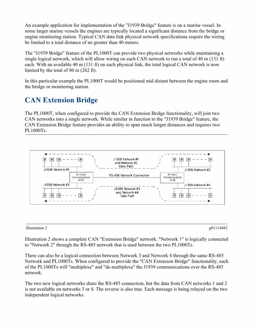
Illustration 2 g01114482Illustration 2 shows a complete CAN "Extension Bridge" network. "Network 1" is logically connected to "Network 2" through the RS-485 network that is used between the two PL1000Ts.There can also be a logical connection between Network 3 and Network 4 through the same RS-485 Network and PL1000Ts. When configured to provide the "CAN Extension Bridge" functionality, each of the PL1000Ts will "multiplexe" and "de-multiplexe" the J1939 communications over the RS-485 network.The two new logical networks share the RS-485 connection, but the data from CAN networks 1 and 2 is not available on networks 3 or 4. The reverse is also true. Each message is being relayed on the two independent logical networks.

An example application for implementation of the "CAN Extension Bridge" feature is on a marine vessel. In some larger marine vessels the engines are typically located a significant distance from the bridge or engine monitoring station. Typical CAN data link physical network specifications require the wiring be limited to a total distance of no greater than 40 m (131 ft).The "CAN Extension Bridge" feature can accomodate four physical networks while maintaining two independent logical networks. The "CAN Extension Bridge" feature will allow wiring on each original CAN network to run a total of 40 m (131 ft) each.The information from each of these networks can then be passed along the RS-485 network between the two PL1000Ts for a distance up to 305 m (1000 ft).One of the PL1000Ts in this example would be positioned within 40 m (131 ft) of up to two CAN networks in the bridge or engine monitoring station, and the other PL1000T would be positioned within 40 m (131 ft) of up to two CAN networks in the engine room.These two PL1000Ts would then be connected by the RS-485 network not to exceed 305 m (1000 ft). Messages would then be relayed across the two logical CAN networks."Multi-plexing" two J1939 networks over the RS-485 communication link between the two PL1000T devices can restrict the normal bandwidth of a J1939 network by as much as 40 percent. If intermittent data loss is experienced, the date link loading should be analyzed.
Embedded Communications Adapter (ECA)The PL1000T provides an embedded communication adapter for standard Caterpillar service tools such as Electronic Technician. The PL1000T has been designed to be a direct embedded communication adapter replacement of all previous communication adapters. In order to utilize the ECA feature, simply connect the serial port 3 of the PL1000T to a laptop computer that is running a standard Caterpillar service tool. Configure the service tool preferences to use the "Embedded Communication Adapter". The ECA feature is always enabled and assigned to serial port 3 within the PL1000T. Once integrated into the system, the PL1000T alleviates the need for the traditional external communication adapters. The PL1000T provides all of the same electronic control servicing as previously provided by the traditional external communication adapters.The ECA usage is compatible with Caterpillar Electronic Technician version 2004B or later and Caterpillar Communication Tool Kit version 2005A or later.Illustration 3 shows alternative use of the ECA or the 171-4400 Comm Adapter II. The two devices should not be actively used by separate service tools at the same time.Note: Illustration 3 depicts only ECA interface to the Cat Datalink. However, the ECA also allows interface to J1939 networks.

Engine Vision Interface Module (EVIM)The Engine Vision Display is a computerized monitoring system that is used in order to display engine information. The engine information includes temperatures, pressures and levels concurrently up to three engines.
Illustration 3 g01114578Illustration 3 shows an example integration of the PL1000T into a system as an "Engine Vision Interface Module".The PL1000T, when configured to provide the EVIM feature, translates the EVIM data requests to the engine control and translates the engine data responses back to the EVIM.The PL1000T is a direct functional replacement for the existing 225-0774 System Communication Module Gp. However, the PL1000T will require some different system wiring and system integration considerations.This manual is intended to address the EVIM communications capability of the PL1000T. For specific information related to installation, operation, and troubleshooting of the "Engine Vision Display", refer to the Service Manual, SENR5002.
Global Positioning System Interface Module (GPSIM)The PL1000T, when configured to provide the GPSIM feature, receives "Global Positioning System" (GPS) information from the "NMEA-183" sensing module. The PL1000T transmits the GPS information on the Cat Datalink and J1939 networks.

Illustration 4 g01114611Illustration 4 shows an example integration of the PL1000T into a system as a "Global Positioning System Interface Module".This PL1000T feature is designed as a direct functional replacement of the existing 130-6191 System Communication Module Gp. However, The PL1000T will require some changes to the system wiring and system integration considerations.This manual is intended to address the GPSIM communications capability of the PL1000T, which is typically used in conjunction with the "Engine Vision Display". For specific information related to installation, operation, and troubleshooting of the "Engine Vision Display" refer to the Service Manual, SENR5002.
Cat Datalink (CDL) TunnelThe PL1000T can be configured to transmit the full content of one protocol inside the envelope of another protocol.All messages on the Cat Datalink are received by the PL1000T. The messages are placed into a special tunneling J1939 message in its entirety. The messages are transmitted over the J1939 network. The "CDL Tunnel" feature is specifically designed for use with the Caterpillar 3500B Series II Engines. The "CDL Tunnel" is a replacement for the previous 171-4454 Interface Module Gp.
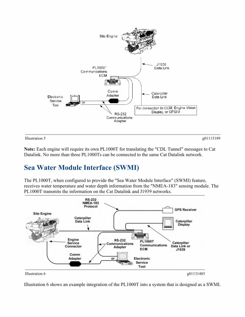
Illustration 5 g01115189Note: Each engine will require its own PL1000T for translating the "CDL Tunnel" messages to Cat Datalink. No more than three PL1000Ts can be connected to the same Cat Datalink network.
Sea Water Module Interface (SWMI)The PL1000T, when configured to provide the "Sea Water Module Interface" (SWMI) feature, receives water temperature and water depth information from the "NMEA-183" sensing module. The PL1000T transmits the information on the Cat Datalink and J1939 networks.
Illustration 6 g01131485Illustration 6 shows an example integration of the PL1000T into a system that is designed as a SWMI.

This manual is intended to address the SWMI interface capability of the PL1000T. Refer to the documentation of the Caterpillar display for specific information for installation, operation, and troubleshooting its ability to display the "Sea Water Module" information.
CDL Boost"CDL Boost" is available with the PL1000T. "CDL Boost" enables a customer to extend the lengths of CDL wire harnesses. The lengths of CDL wire harnesses can extend to a maximum length of 300 m (1000 ft). Data integrity will be maintained.Note: In order to enable CDL boost for the 256-7511 Communication Electronic Control Module v4, pin 7 of the PL1000T must be grounded. Cat ET will show a status parameter that informs the user if CDL boost is enabled or disabled.
Customer Communications Module (CCM)The PL1000T, when configured to provide the Customer Communications Module Interface feature, is designed to communicate with Caterpillar M5X and M50 protocol commands. Communication is accomplished with the use of Cat DataLink and J1939 networks. Either single parameter read/write commands are used or broadcast list commands are used. Refer to the M5X programming section or the M50 programming section of this document for information about the communication protocols.The CCM feature allows the PL1000T to provide a communications link between the ECM and a host device. The host device can be a:
• Programmable Logic Control (PLC)• Personal Computer (PC)• RS-232 Capable Device
The CCM feature requires special instructions in order to interface with the PL1000T that use M5X or M50 protocols. The protocols provide "Instruction Identifiers" (IID). The "Instruction Identifiers" can be used in order to program the PL1000T for monitoring and control of the desired engine parameters.The requested parameters will be gathered by the PL1000T from the engine control. The requested parameters will be presented over the M5X or M50 protocol link based upon the information that is provided with the instruction identifier.Refer to the M5X programming section or the M50 programming section of this manual for information about the communications requirements and the methods of using the instruction identifiers for M5X or M50 protocol. The programming section of this manual does not address the engine specific parameters that are necessary for monitoring engines. The parameters that are specific to the engine and the supported M5X or M50 protocol should be referenced in the "System Operation Test and Adjust" manual for the specific engine.Refer to the "System Operation Test and Adjust" manual that is for a specific engine for information about the parameters that are specific to the engine and the supported M5X or M50 protocol.
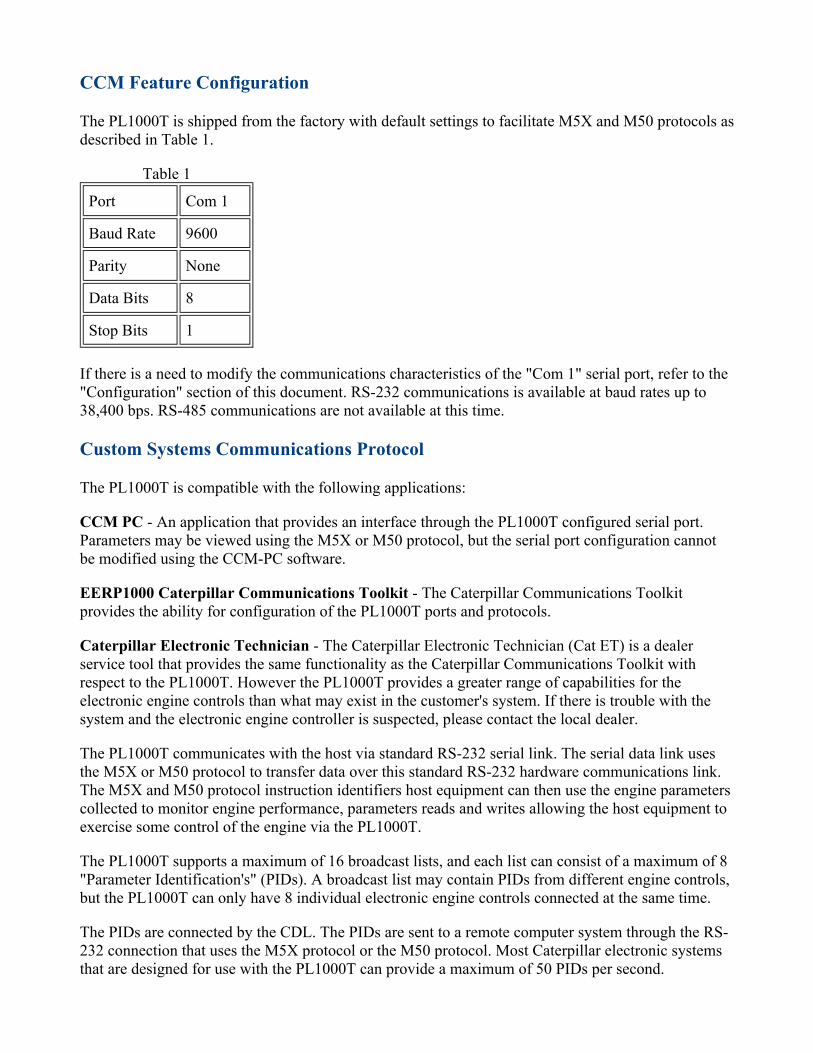
CCM Feature ConfigurationThe PL1000T is shipped from the factory with default settings to facilitate M5X and M50 protocols as described in Table 1.
Table 1Port Com 1 Baud Rate 9600 Parity None Data Bits 8 Stop Bits 1
If there is a need to modify the communications characteristics of the "Com 1" serial port, refer to the "Configuration" section of this document. RS-232 communications is available at baud rates up to 38,400 bps. RS-485 communications are not available at this time. Custom Systems Communications ProtocolThe PL1000T is compatible with the following applications:CCM PC - An application that provides an interface through the PL1000T configured serial port. Parameters may be viewed using the M5X or M50 protocol, but the serial port configuration cannot be modified using the CCM-PC software.EERP1000 Caterpillar Communications Toolkit - The Caterpillar Communications Toolkit provides the ability for configuration of the PL1000T ports and protocols.Caterpillar Electronic Technician - The Caterpillar Electronic Technician (Cat ET) is a dealer service tool that provides the same functionality as the Caterpillar Communications Toolkit with respect to the PL1000T. However the PL1000T provides a greater range of capabilities for the electronic engine controls than what may exist in the customer's system. If there is trouble with the system and the electronic engine controller is suspected, please contact the local dealer.The PL1000T communicates with the host via standard RS-232 serial link. The serial data link uses the M5X or M50 protocol to transfer data over this standard RS-232 hardware communications link. The M5X and M50 protocol instruction identifiers host equipment can then use the engine parameters collected to monitor engine performance, parameters reads and writes allowing the host equipment to exercise some control of the engine via the PL1000T.The PL1000T supports a maximum of 16 broadcast lists, and each list can consist of a maximum of 8 "Parameter Identification's" (PIDs). A broadcast list may contain PIDs from different engine controls, but the PL1000T can only have 8 individual electronic engine controls connected at the same time.The PIDs are connected by the CDL. The PIDs are sent to a remote computer system through the RS-232 connection that uses the M5X protocol or the M50 protocol. Most Caterpillar electronic systems that are designed for use with the PL1000T can provide a maximum of 50 PIDs per second.
However that speed may vary depending upon baud rate and the type electronic module connected. For example, a cellular phone connection at 2400 baud rate would reduce the throughput to only 29 PIDs per second. Other modules on the CDL utilize complex systems that can reduce the number of PIDs managed to less than 40 PIDs per second.The following suggestions will help obtain the maximum throughput possible.
• Request stable PIDs less frequently• Configure broadcast lists that retrieve data such as hour meter, atmospheric pressure, or
diagnostics at less frequent rates that parameters such as engine speed or oil pressure.• Requesting stable PIDs less frequently will optimize the capability of the data transfer and
minimize communications loading.All command messages must be sent to the PL1000T in ASCII format, and the response will also be in ASCII format. See Table 1. The broadcast lists can be programmed in either ASCII or binary format. Communication InitializationThe PL1000T may be connected directly to the host equipment. The PL1000T may also be connected to the equipment by using modems. The initialization procedure depends on the type of connection. The correct initialization procedure is necessary for proper communication between the PL1000T and the equipment.When modems are installed between the PL1000T and the host equipment, the complexity of the communications network is increased. The RS-232 ports must be set to the proper parameters for communication on the following equipment: host equipment, modems, and PL1000T. The phone line ports of the modems must be compatible. To connect the modems, consult the manufacturer's instructions.If the PL1000T is connected to other "Data Terminal Equipment" (DTE) devices, then a "Null Modem" cable or an adapter is required. A personal computer is an example of a DTE device.The "Transmit" line of the PL1000T must be connected to the "Receive" line of the personal computer or other DTE device. Also, the "Transmit" line of the personal computer or other DTE device must be connected to the "Receive" line of the PL1000T. The wiring configuration that is discussed here, is commonly referred to as "Crossover" or "Null Modem" wiring. Direct Connection Wiring

Illustration 7 g01265126
Verifying Direct Serial Port ConnectionDirect connections with the PL1000T can be verified with the use of a serial ASCII terminal program. Many terminal programs are commercially available, such as Procomm Plus. However, for the purpose of this example, a terminal program will be used that is available with Microsoft Windows. The terminal program that is available with Microsoft Windows is called Hyperterminal.Refer to the "Hyperterminal" section of this document for usage information.The PL1000T communicates with the use of the M5X protocol or M50 protocol. The protocols consists of single parameter, composite, and broadcast list commands. If any of the 16 broadcast lists, events, or diagnostic messages are enabled, then the data is continuously placed in the port buffers. The data is continuously placed in the port buffers in order to allow transmission of the data at the established baud rates. The data will appear as a continuous string of numbers that represent hexadecimal values of ASCII characters.
M5X Protocol Programming
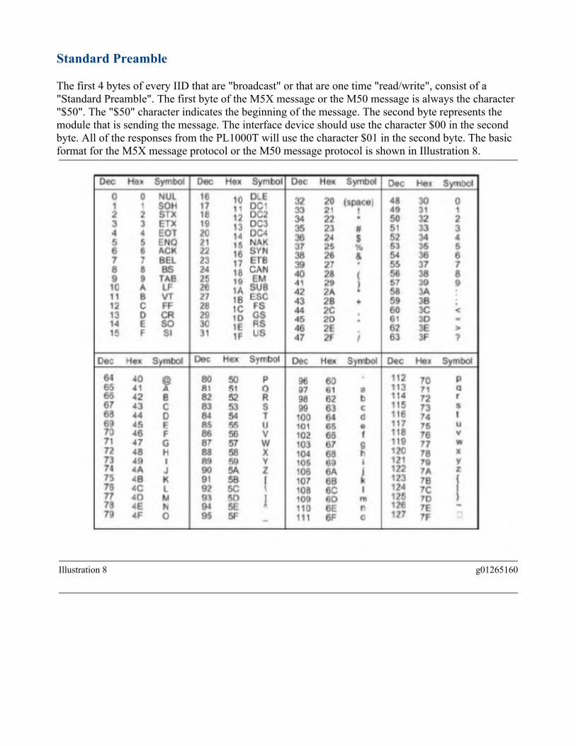
Standard PreambleThe first 4 bytes of every IID that are "broadcast" or that are one time "read/write", consist of a "Standard Preamble". The first byte of the M5X message or the M50 message is always the character "$50". The "$50" character indicates the beginning of the message. The second byte represents the module that is sending the message. The interface device should use the character $00 in the second byte. All of the responses from the PL1000T will use the character $01 in the second byte. The basic format for the M5X message protocol or the M50 message protocol is shown in Illustration 8.
Illustration 8 g01265160

Illustration 9 g01265165Table 2
IID Description M5X M50$10 Broadcast Response X X $11 Activate Broadcast List X X $12 Deactivate Broadcast List X X $13 Program Broadcast List X X $15 Status Response to IID $11, $12, $13 X X $1A Advanced Broadcast Response Data X X $1C Advanced Broadcast Activate X X $1D Advanced Broadcast Deactivate X X $1E Advanced Broadcast Setup X NA $1F Status Response to IID $1C, $1D, or $1E X NA $24 Single Parameter Read Request X X $25 Single Parameter Read Response X X $34 Single Parameter Write Request X X $35 Single Parameter Write Response X X $80 Composite Data Response X NA $81 Program Composite Request X NA $82 Diagnostic Data Request X X $85 Response to Request IID $81 X NA

Engine ECM Module Identifier - MIDThe electronic controller of each engine can be configured to use different "Module Identifiers" (MID). The module identifier has also been referred to in previous documents as a "Unit Number". The M5X protocol or the M50 protocol uses the MID in order to identify each engine controller that is on the network. Most of the engine controllers are configured at the factory with the default address of $24. The $24 character represents the hexadecimal number 24. If there is a need to identify, confirm, or change the MID of an electronic engine controller, refer to the System Operation Test and Adjust manual for the specific engine.If either of the following situations occur in the network, then the MID for the engine controllers may need to be reviewed or modified.
• More than one electronic engine controller is connected to the CDL network in the system to the same serial port onf the PL1000T.
• More than one Caterpillar EMCP or other generator set control panel device is connected to the CDL network in the system to the same serial port of the PL1000T.
Refer to Table 3 for a list of typical MID error codes for engine controllers. For information about the MID for a specific engine application, refer to the appropriate publication that was distributed with the engine model.
Table 3Typical MID
Error Codes for Engine Controllers MID Number Description
33 Engine Control #2 34 Engine Control #3 35 Engine Control #4 36 Engine Control #1 37 Engine Control #5 38 Engine Control #6 40 Engine Control #7 41 Engine Control #8 47 Backup Engine Control
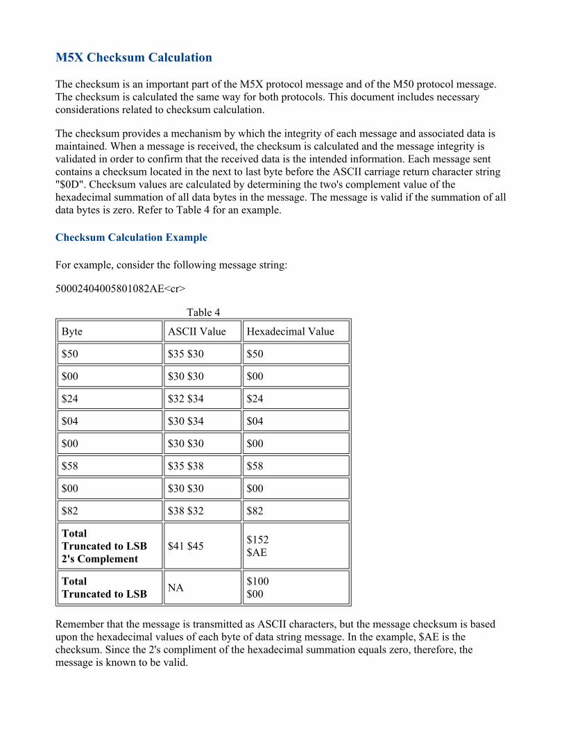
M5X Checksum CalculationThe checksum is an important part of the M5X protocol message and of the M50 protocol message. The checksum is calculated the same way for both protocols. This document includes necessary considerations related to checksum calculation.The checksum provides a mechanism by which the integrity of each message and associated data is maintained. When a message is received, the checksum is calculated and the message integrity is validated in order to confirm that the received data is the intended information. Each message sent contains a checksum located in the next to last byte before the ASCII carriage return character string "$0D". Checksum values are calculated by determining the two's complement value of the hexadecimal summation of all data bytes in the message. The message is valid if the summation of all data bytes is zero. Refer to Table 4 for an example. Checksum Calculation ExampleFor example, consider the following message string:50002404005801082AE<cr>
Table 4Byte ASCII Value Hexadecimal Value $50 $35 $30 $50 $00 $30 $30 $00 $24 $32 $34 $24 $04 $30 $34 $04 $00 $30 $30 $00 $58 $35 $38 $58 $00 $30 $30 $00 $82 $38 $32 $82 TotalTruncated to LSB2's Complement
$41 $45 $152 $AE
Total Truncated to LSB NA $100
$00 Remember that the message is transmitted as ASCII characters, but the message checksum is based upon the hexadecimal values of each byte of data string message. In the example, $AE is the checksum. Since the 2's compliment of the hexadecimal summation equals zero, therefore, the message is known to be valid.

Heartbeat MessageThe heartbeat message is a method used in order to continuously monitor and in order to verify the PL1000T data stream. The heartbeat message should be used in order to verify the PL1000T connection before the login process. The heartbeat message should be used periodically during normal operations. The heartbeat PID is $F0 $12 that uses a "Single Parameter Read IID" $24.Periodic read requests and received responses will serve to validate the RS-232 connection. Periodic read requests and received responses will provide an ability to monitor the security level of the PL1000T for unexpected changes. Unexpected changes in the security level received in the heartbeat response message may prevent some data from being transmitted. Security LevelsEvery individual PID that is supported by the engine electronic controller has an associated security level 0, 1, 2, or 3. Likewise, there is a security level associated with every PID that is supported by the PL1000T. The security levels are numerically related in an "equal or lower" relationship. For instance, when the security level response indicates a security level of 2, any PID with a security level of 3 would not be accessable. For troubleshooting information and procedures related to security level issues, please refer to the Systems Operation Test and Adjust manual.Table 5 lists the PIDs that are supported by the PL1000T and also lists the associated security level requirements.
Table 5Associated Security Levels of PL1000T Supported PIDs
PID Security Level Read/Write $00 $80 0 Read
NA NA NA $AA $8A 0 Write
$F0 $12 0 1 2
3
Read/Write Write Write
Write NA NA NA
$F8 $14 0 3
Read Write
NA NA NA $00 $82 1 Read
NA NA NA

$F6 $01 1 3
Read Write
NA NA NA $AA $12 3 Read/Write
NA NA NA $AA $87 3 Read/Write $AA $88 3 Read/Write
NA NA NA $AA $89 3 Read/Write
PL1000T LoginThe first step toward establishing protocol communications with the PL1000T is to perform the login procedure. Login must be accomplished before any PIDs can be assessed. The login procedure consists of sending the appropriate password to the PL1000T via IID $34 writing to PID $AA $8A. All PL1000T communication modules are shipped from the factory with blank passwords. To login to a PL1000T with a blank password, send the following message. 500034040061AA8AE3Note: This message assumes the PL1000T is configured as module number 1. If the PL1000T is not configured as module number 1 for the specific application, then the appropriate checksum will need to be formated. Also, the appropriate checksum will need to be calculate for the specific application.Additionally, a separate and unique password can be programmed in for each of the security levels 1, 2, and 3. At login the PL1000T security level is transitioned to the level associated with the password used to login. Using the is method security levels can be customized for different users or devices that access the PL1000T. The password example above assumes the factory default of a "blank" password, and the security level is set to its highest level of 3.If the password for security level 1 were set to "11112222" then the login would consist of the items shown in Illustration 10.
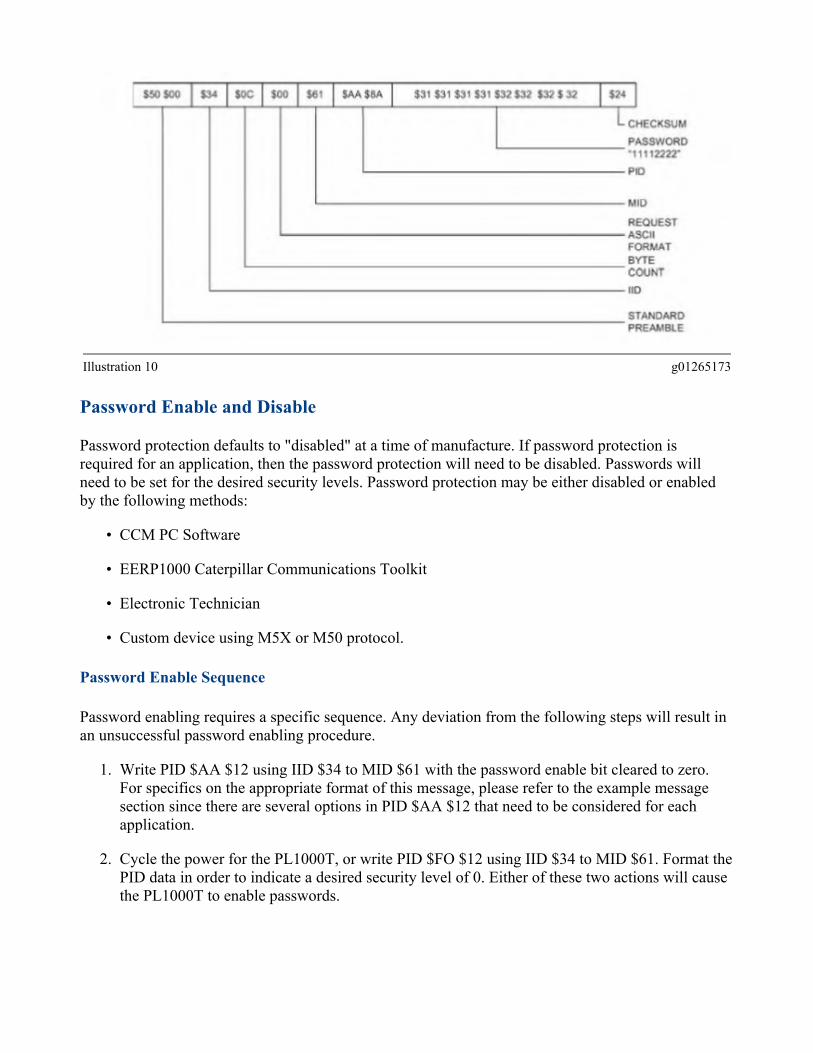
Illustration 10 g01265173
Password Enable and DisablePassword protection defaults to "disabled" at a time of manufacture. If password protection is required for an application, then the password protection will need to be disabled. Passwords will need to be set for the desired security levels. Password protection may be either disabled or enabled by the following methods:
• CCM PC Software• EERP1000 Caterpillar Communications Toolkit• Electronic Technician• Custom device using M5X or M50 protocol.
Password Enable SequencePassword enabling requires a specific sequence. Any deviation from the following steps will result in an unsuccessful password enabling procedure.
1. Write PID $AA $12 using IID $34 to MID $61 with the password enable bit cleared to zero. For specifics on the appropriate format of this message, please refer to the example message section since there are several options in PID $AA $12 that need to be considered for each application.
2. Cycle the power for the PL1000T, or write PID $FO $12 using IID $34 to MID $61. Format the PID data in order to indicate a desired security level of 0. Either of these two actions will cause the PL1000T to enable passwords.
Password Disable SequencePassword disablement is a specific sequence. Any deviation from the following steps will result in unsuccessful password disablement.
1. Write PID $AA $8A using IID $34 to MID $61 with a security level 3 password. For specifics on the appropriate format of the message, please refer to the example message section.
2. Write PID $AA $12 using IID $34 to MID $61 with the "Password Enable Bit" set to 1. For specifics on the appropriate format of the message, please refer to the example message section. Since there are several options in PID $AA $12 that will need to be considered for each application.Note: When a password enable or disable sequence is successfully completed, the default passwords are set to "blank". If password protection is implemented after either of these actions, the passwords for each security level must be programmed.
Instruction Identifiers"Instruction Identifiers" are used to convey a desired action to the PL1000T for a respective PID and MID combination. Depending on the specific IID that is used, the PL1000T will perform different actions. The PL1000T will perform different actions such as single parameter read, single parameter write, broadcast list setup, and broadcast list enable. Standard Broadcast List Management"Standard Broadcast Lists" can be easily programed. "Standard Broadcast Lists" can be maintained by following a specific set of guidelines. The "Standard Broadcast List" should be setup with IID $13. Then the "Standard Broadcast List" should be enabled with IID $11. The "Standard Broadcast List" are retained in the PL1000T memory even when power is removed. There is no need to re-configure the "Standard Broadcast List" each time the system power is cycled. "Standard Broadcast Lists" only support parameters that are 1 or 2 bytes in length. Parameters that require more than 2 bytes in length must use the "Advanced Broadcast List" or "Single Parameter Read Request". Broadcast lists, advanced and standard, are a more efficient use of the RS-232 port than single reads and writes. Advanced or standard broadcast lists should be used whenever possible in order to minimize serial data traffic. Standard Broadcast List ResponseThe "Standard Broadcast List Response" is transmitted to the requesting host device. The "Standard Broadcast List Response" contains the appropriate PID data combinations for each "Standard Broadcast List" that has been configured and that has been enabled within the PL1000T. Each list
has a unique transmission frequency, therefore, the response will be transmitted on a specific requested frequency. The lists, their respective PIDs, and transmission frequencies are:
• configured in the host device with IID $13• enabled by IID $11• disabled by IID $12
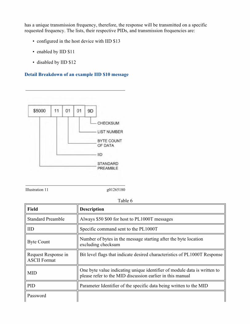
Detail Breakdown of an example IID $10 message
Illustration 11 g01265180Table 6
Field DescriptionStandard Preamble Always $50 $00 for host to PL1000T messages IID Specific command sent to the PL1000T Byte Count Number of bytes in the message starting after the byte location
excluding checksum Request Response in ASCII Format
Bit level flags that indicate desired characteristics of PL1000T Response
MID One byte value indicating unique identifier of module data is written to please refer to the MID discussion earlier in this manual
PID Parameter Identifier of the specific data being written to the MID Password
8 character password. Please refer to the password discussion earlier in this manual
Checksum Refer to the "Checksum Calculation Example" section
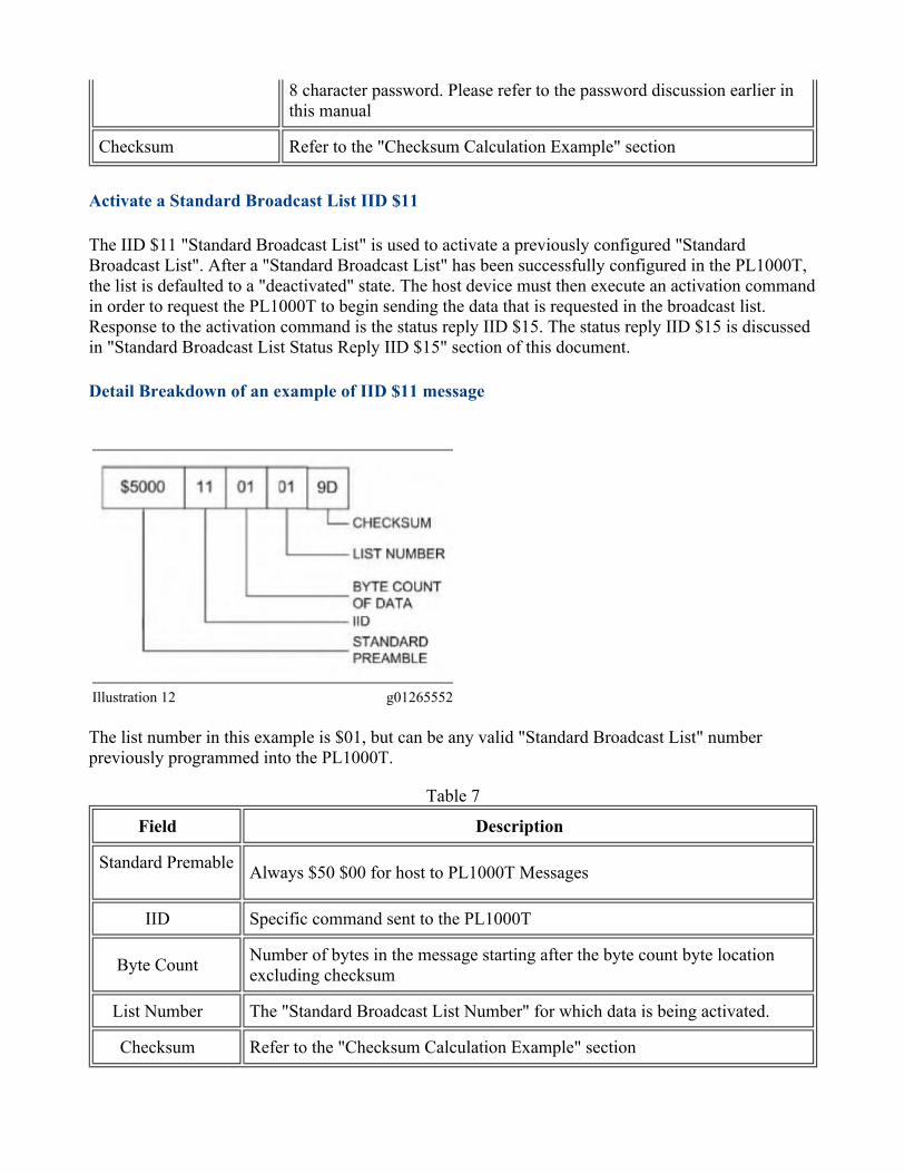
Activate a Standard Broadcast List IID $11The IID $11 "Standard Broadcast List" is used to activate a previously configured "Standard Broadcast List". After a "Standard Broadcast List" has been successfully configured in the PL1000T, the list is defaulted to a "deactivated" state. The host device must then execute an activation command in order to request the PL1000T to begin sending the data that is requested in the broadcast list. Response to the activation command is the status reply IID $15. The status reply IID $15 is discussed in "Standard Broadcast List Status Reply IID $15" section of this document. Detail Breakdown of an example of IID $11 message
Illustration 12 g01265552The list number in this example is $01, but can be any valid "Standard Broadcast List" number previously programmed into the PL1000T.
Table 7Field Description
Standard Premable Always $50 $00 for host to PL1000T Messages IID Specific command sent to the PL1000T
Byte Count Number of bytes in the message starting after the byte count byte location excluding checksum
List Number The "Standard Broadcast List Number" for which data is being activated. Checksum Refer to the "Checksum Calculation Example" section

Deactivate Standard Broadcast List IID $12The IID $12 command is used to deactivate a "Standard Broadcast List" that was previously configured and that was previously activated. Once activated, a "Standard Broadcast List" remains activated until the PL1000T receives the deactivation command. Since the active state of the "Standard Broadcast List" is retained even through the power is cycled for the system, therefore, the list must be deactivated by the IID $12 command before the PL1000T will cease transmissions of the list data.The response to a deactivation command is status reply IID $15. Refer to the "Detail Breakdown of an Example IID $15 Message" section for more IID $15 status reply information. Detail Breakdown of an Example IID $12 Message
Illustration 13 g01265555Table 8
Field DescriptionStandard Preamble Always $50 $00 for host to PL1000T Messages IID Specific command sent to the PL1000T Byte Count Number of bytes in the message starting after the byte count byte location
excluding checksum List Number The Standard Broadcast List Number for which data is being activated. Checksum Refer to the "Checksum Calculation Example" section

Standard Broadcast List Setup IID $13The IID $13 command is used to configure "Standard Broadcast Lists" in the PL1000T. The "Standard Broadcasts Lists" only support parameters that are one or two data bytes in length. The "Standard Broadcast List" setup command must consist of 8 PIDs. If the number of PIDs desired is less than eight, the remaining number of parameters that are not specified, must be set to zero.The corresponding "Standard Broadcast List Response" string, IID $10, will only contain data for the PIDs that are specified as "non-zero" in the "Standard Broadcast List Setup". All of the remaining data bytes in the return string will be zeros. Detail Breakdown of an Example IID $13 Message
Illustration 14 g01265558Table 9
Field DescriptionStandard Preamble Always $50 $00 for host to PL1000T Messages IID Specific command sent to the PL1000T Byte Count Number of bytes in the message starting after the byte count byte location
excluding checksum List Number The "Standard Broadcast List Number" for which data is being returned.
MID One byte value indicating unique identifier of module for which data is being returned. Please refer to the MID discussion earlier in this section.

Update Rate The rate at which the data for this standard broadcast list will be transmitted on the M5X or M50 data link. Resolution is 0.5 seconds per bit. A value of $00 causes a .5 second rate default minimum.
Flags Bit level flags indicate desired characteristics of PL1000T response.
PID 1 2 or 3 bytes depending on range of first byte of PID $00-$D4 as first byte indicates that PID is 3 bytes. All others are 2 bytes. Pad with leading zeros if needed.
PID 2 2 or 3 bytes depending on range of first byte of PID $00-$D4 as first byte indicates that PID is 3 bytes. All others are 2 bytes. Pad with leading zeros is needed.
PID 3-8 All non configured PIDs are set to $00 $00. They are 2 bytes in length since the first byte, $00 is not in the range of $D0-D4
Checksum Refer to the "Checksum Calculation Example" section
Standard Broadcast List Status Reply IID $15The IID $15 status reply is transmitted by the PL1000T in response to the IID $11, the IID $12 or the IID $13 message. The contents of the status message indicates the validity of success of the IID to which the PL1000T is responding. The M5X protocol requires that the number of bytes be given after the IID. The M50 protocol does not require that the number of bytes be given after the IID. Detail Breakdown of an Example IID $15 Message
Illustration 15 g01265562Table 10
Field Description Standard Preamble Always $50 $00 for host to PL1000T messages
IID Spcific command sent to the PL1000T Byte Count Number of bytes in the message starting after the byte cound location
excluding checksum
Status of Requested Action
Status Byte $00 = Data OK $10 = Invalid List Specified $20 = Requested List Number not Programmed $30 = Incorrect Checksum or command format $40 = Inappropriate List $50 = At least one PID requested is not supported by the Target Electronic Engine Control $60 = Target Electronic Engine Control Module specified not found on Cat Data Link $70 = Unavailable space for list storeage
Checksum Refer to the Checksum Calculation Example section
Advanced Broadcast List Management"Advanced Broadcast Lists" can easily be configured by following a specific set of guidelines. The "Advanced Broadcast List" should be setup first by using IID $1E. The "Advanced Broadcast List" should be then enabled using IID $1C. "Advanced Broadcast Lists" are retained by the PL1000T even when power is removed. Therefore there is no need to reconfigure the "Advanced Broadcast List" in the event of a system power loss greater than four bytes in length must be retrieved using "Single Parameter Read Request". "Advanced" or "Standard" broadcast lists make more efficient use of the RS-232 port than do "Single Parameter Requests". "Advanced" or "Standard" broadcast lists should be used whenever possible in order to minimize serial data traffic. Advanced Broadcast List Response Data IID $1AThe "Advanced Broadcast List Response" is transmitted to the requesting host device. The "Standard Broadcast List Response" contains the appropriate PID data combinations for each "Advanced Broadcast List" that has been configured and that has been enabled within the PL1000T. Each list has a unique transmission frequency therefore the response will be transmitted on a specific requested frequency. The lists their respective PIDs and transmission frequencies are:
• configured by the host device with IID $1E• enabled by IID $1C• disabled by IID $1D
The advanced broadcast response can be utilized for parameters of one to four bytes in length. The response will be formatted with 1 2 or 4 data bytes per PID depending on the data length definition for each specific PID. When processing the message string the host device must recall the defined length of each PID for correct byte distribution. For correct PID data length definitions refer to the "Engine Control" System Operation Test and Adjust manual for the specific engine type.

Detail Breakdown of an Example IID $1A Message
Illustration 16 g01265564Table 11
Field DescriptionStandard Preamble Always $50 $00 for host to PL1000T Messages IID Specific command sent to the PL1000T Byte Count Number of bytes in the message starting after the byte count byte location
excluding checksum List Number The "Standard Broadcast List Number" for which data is being returned.
MID One byte value indicating unique identifier of module for which data is being returned. Please refer to the MID discussion earlier in this section.
Update Rate The rate at which the data for this standard broadcast list will be transmitted on the M5X or M50 data link. Resolution is 0.5 seconds per bit. A value of $00 causes a .5 second rate default minimum.
Flags Bit level flags to indicate desired characteristics of PL1000T Response. PID 1 Data for the first PID in the Advanced Broadcast List PID 2 Data for the second PID in the Advanced Broadcast List PID 3 Data for the third PID in the Advanced Broadcast List Checksum Refer to the "Checksum Calculation Example" section
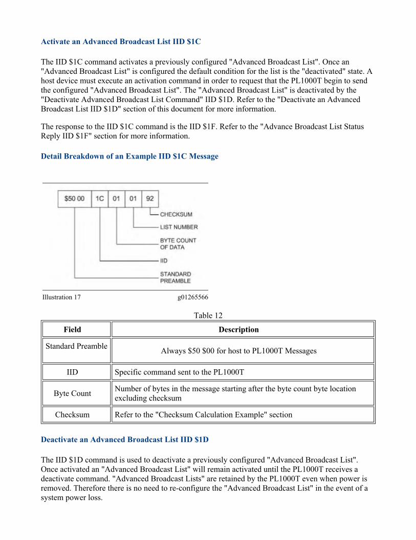
Activate an Advanced Broadcast List IID $1CThe IID $1C command activates a previously configured "Advanced Broadcast List". Once an "Advanced Broadcast List" is configured the default condition for the list is the "deactivated" state. A host device must execute an activation command in order to request that the PL1000T begin to send the configured "Advanced Broadcast List". The "Advanced Broadcast List" is deactivated by the "Deactivate Advanced Broadcast List Command" IID $1D. Refer to the "Deactivate an Advanced Broadcast List IID $1D" section of this document for more information.The response to the IID $1C command is the IID $1F. Refer to the "Advance Broadcast List Status Reply IID $1F" section for more information. Detail Breakdown of an Example IID $1C Message
Illustration 17 g01265566Table 12
Field DescriptionStandard Preamble Always $50 $00 for host to PL1000T Messages
IID Specific command sent to the PL1000T Byte Count Number of bytes in the message starting after the byte count byte location
excluding checksum Checksum Refer to the "Checksum Calculation Example" section
Deactivate an Advanced Broadcast List IID $1DThe IID $1D command is used to deactivate a previously configured "Advanced Broadcast List". Once activated an "Advanced Broadcast List" will remain activated until the PL1000T receives a deactivate command. "Advanced Broadcast Lists" are retained by the PL1000T even when power is removed. Therefore there is no need to re-configure the "Advanced Broadcast List" in the event of a system power loss.

The response to a deactivation command is the status reply IID $1F. Refer to the Advance Broadcast List Status Reply IID $1F section of this document for more information.
Illustration 18 g01265570Table 13
Field DescriptionStandard Preamble Always $50 $00 for host to PL1000T Messages IID Specific command sent to the PL1000T Byte Count Number of bytes in the message starting after the byte count byte location
excluding checksum List Number The "Standard Broadcast List Number" for which data is being activated. Checksum Refer to the "Checksum Calculation Example" section
Advanced Broadcast List Setup IID $1ETable 14
Field DescriptionStandard Preamble Always $50 $00 for host to PL1000T Messages IID Specific command sent to the PL1000T Byte Count Number of bytes in the message starting after the byte count byte location
excluding checksum List Number The "Standard Broadcast List Number" for which data is being returned.
MID One byte value indicating unique identifier of module for which data is being returned. Please refer to the MID discussion earlier in this section.
Update Rate The rate at which the data for this standard broadcast list will be transmitted on the M5X or the M50 data link. Resolution is 0.5 seconds per bit. A value of $00 causes a .5 second rate default minimum.
Flags Bit level flags to indicate desired characteristics of PL1000T response. PID 1 Data for the first PID in the Advanced Broadcast List PID 2 Data for the second PID in the Advanced Broadcast List PID 3 Data for the third PID in the Advanced Broadcast List Checksum Refer to the "Checksum Calculation Example" section
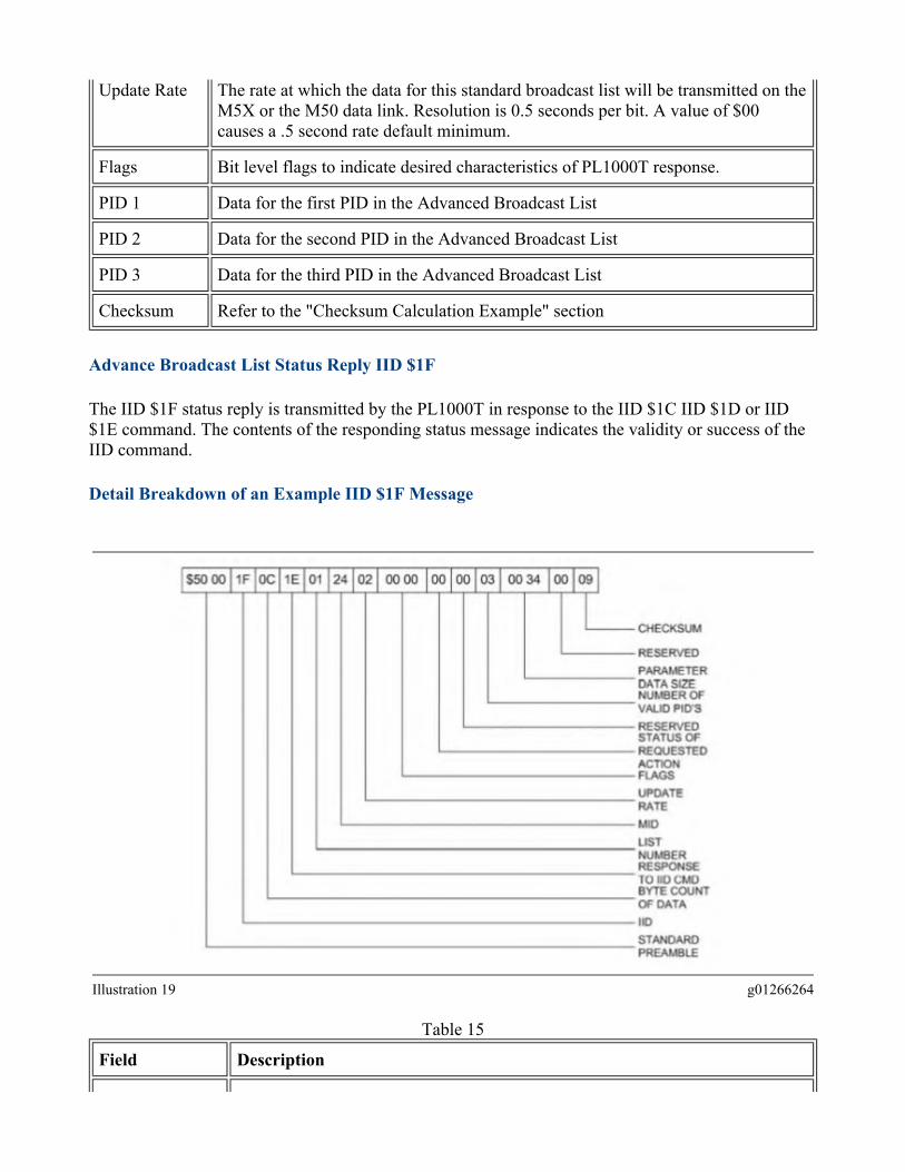
Advance Broadcast List Status Reply IID $1FThe IID $1F status reply is transmitted by the PL1000T in response to the IID $1C IID $1D or IID $1E command. The contents of the responding status message indicates the validity or success of the IID command. Detail Breakdown of an Example IID $1F Message
Illustration 19 g01266264Table 15
Field Description
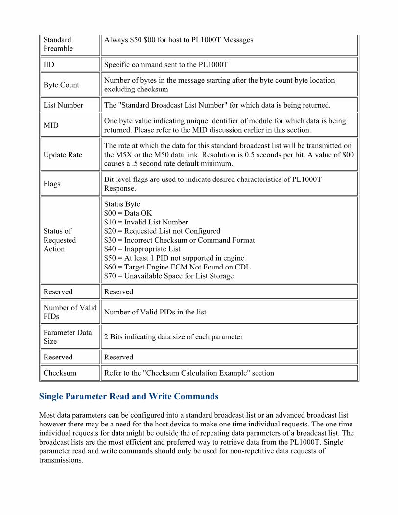
Standard Preamble
Always $50 $00 for host to PL1000T Messages
IID Specific command sent to the PL1000T Byte Count Number of bytes in the message starting after the byte count byte location
excluding checksum List Number The "Standard Broadcast List Number" for which data is being returned. MID One byte value indicating unique identifier of module for which data is being
returned. Please refer to the MID discussion earlier in this section.
Update Rate The rate at which the data for this standard broadcast list will be transmitted on the M5X or the M50 data link. Resolution is 0.5 seconds per bit. A value of $00 causes a .5 second rate default minimum.
Flags Bit level flags are used to indicate desired characteristics of PL1000T Response.
Status of Requested Action
Status Byte $00 = Data OK $10 = Invalid List Number $20 = Requested List not Configured $30 = Incorrect Checksum or Command Format $40 = Inappropriate List $50 = At least 1 PID not supported in engine $60 = Target Engine ECM Not Found on CDL $70 = Unavailable Space for List Storage
Reserved Reserved Number of Valid PIDs Number of Valid PIDs in the list Parameter Data Size 2 Bits indicating data size of each parameter Reserved Reserved Checksum Refer to the "Checksum Calculation Example" section
Single Parameter Read and Write CommandsMost data parameters can be configured into a standard broadcast list or an advanced broadcast list however there may be a need for the host device to make one time individual requests. The one time individual requests for data might be outside the of repeating data parameters of a broadcast list. The broadcast lists are the most efficient and preferred way to retrieve data from the PL1000T. Single parameter read and write commands should only be used for non-repetitive data requests of transmissions.

Single Parameter Read Request IID $24The IID $24 read request command is used to request non-repeating data for an individual PID. A time interval of one second is the suggested update interval when reading or writing parameters with the use of the IID $24 command. For example if reading five parameters send the request command for the first parameter then wait one second to send another request command and until all five parameters are requested. Therefore each request command will be one second apart.In addition to the request interval time limitation no subsequent parameter read request should be sent until a response is received for the first request. If an interval of three seconds has elapsed without response then a retry of the request may be attempted. After the retry period has elapsed the original parameter may be requested or the next in the series may be sent.Occasional "time-outs" of three seconds may be expected when requesting large amounts of parameters however if the "time-outs" become frequent then the frequent "time-outs" could signal that there is a system level problem. In cases with frequent data "time-out" intervals use a signal analyzer in order to determine Cat Datalink M5X M50 and data link loading. Refer to the troubleshooting section of this manual for further information about analyzing the cause of frequent "time-outs".Single parameter reads are useful when determining if conditions are appropriate to start an engine. The specific parameters that are used for this analysis may vary from engine type to engine type. Therefore consult the Systems Operation Test and Adjust manual for specific information about the engine model. The following procedures will be the same regardless of engine type of model.
• The host device will disable all active non-essential broadcast lists. That is the host device will disable any list that is not needed during the engine start-up sequence.
• The host device will execute single parameter read commands in order to collect the desired start-up condition analysis data.
• The host device will perform necessary analysis.• The host device will enable any broadcast lists that are disabled.• The host device will start the engine if analysis reveals that a desirable starting condition exists.
Detail Breakdown of an Example IID $24 Message

Illustration 20 g01266268Table 16
Field DescriptionStandard Preamble Always $50 $00 for host to PL1000T Messages IID Specific command sent to the PL1000T Byte Count Number of bytes in the message starting after the byte count byte location
excluding checksum Flags Bit level flags to indicate desired characteristics of PL1000T response. MID One byte value indicating unique identifier of module returning PID data. Refer
to earlier discussion on MID PID Two or three bytes depending on range of first PID $D0-$D4. First byte is three
bytes all others are 2 bytes. Pad with leading zeros. Checksum Refer to the "Checksum Calculation Example" section
Single Parameter Read Response IID $25The IID $25 read response is transmitted from the PL1000T in response to a single parameter read request. The $25 message response string is variable in length depending upon the defined format of the requested PID. Refer to the System Operation Test and Adjust manual for the specific engine parameter identification and specific engine parameter format.Illustration 21 is the response to the PID in the above parameter read request example. $F53E is the "Engine Oil Temperature". $FE3E is defined as having 2 data bytes and a resolution of 1.0 degree Celsius per bit.

Detail Breakdown of an Example IID $25 Message
Illustration 21 g01266271Table 17
Field DescriptionStandard Preamble Always $50 $00 for host to PL1000T Messages IID Specific command sent to the PL1000T Byte Count Number of bytes in the message starting after the byte count byte location
excluding checksum Flags Bit level flags to indicate desired characteristics of PL1000T response. MID One byte value indicating unique identifier of module returning PID data. Refer
to earlier discussion on MID PID Two or three bytes depending on the range of first PID $D0-$D4. First byte is
three bytes all others are 2 bytes. Pad with leading zeros. PID Data Data retrieved from the MID of the requested PID. The size and the format
depend upon definition of the PID. Checksum Refer to the "Checksum Calculation Example" section
Single Parameter Write Request IID $34The IID $34 write request writes data to an individual parameter. One second is the suggested update interval when writing parameters with the use of the IID $34 command. For example if writing five parameters send the write command for the first parameter then wait one second before sending the next parameter.In addition to the IID $34 write request interval time limitation no subsequent parameter write request should be sent until a response is received for the first write request. If an interval of three seconds has
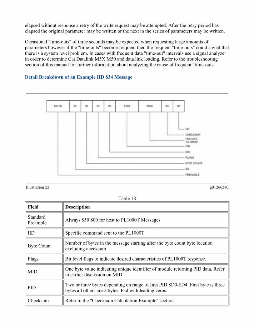
elapsed without response a retry of the write request may be attempted. After the retry period has elapsed the original parameter may be written or the next in the series of parameters may be written.Occasional "time-outs" of three seconds may be expected when requesting large amounts of parameters however if the "time-outs" become frequent then the frequent "time-outs" could signal that there is a system level problem. In cases with frequent data "time-out" intervals use a signal analyzer in order to determine Cat Datalink M5X M50 and data link loading. Refer to the troubleshooting section of this manual for further information about analyzing the cause of frequent "time-outs". Detail Breakdown of an Example IID $34 Message
Illustration 22 g01266280Table 18
Field DescriptionStandard Preamble Always $50 $00 for host to PL1000T Messages IID Specific command sent to the PL1000T Byte Count Number of bytes in the message starting after the byte count byte location
excluding checksum Flags Bit level flags to indicate desired characteristics of PL1000T response. MID One byte value indicating unique identifier of module returning PID data. Refer
to earlier discussion on MID PID Two or three bytes depending on range of first PID $D0-$D4. First byte is three
bytes all others are 2 bytes. Pad with leading zeros. Checksum Refer to the "Checksum Calculation Example" section

Single Parameter Write Response IID $35The IID $35 write response is transmitted from the PL1000T in response to a single parameter write request. The $35 message response string is variable in length depending upon the defined format of the requested PID. Refer to the System Operation Test and Adjust manual for the specific engine parameter identification and parameter format.Illustration 23 shows the response to the PID in the above single parameter write request example $F510. The single parameter write request $F510 is "Low Idle Speed". $FE10 is defined as having 2 data bytes and a resolution of 0.5 rpm per bit. Detail Breakdown of an Example IID $35 Message
Illustration 23 g01266296Table 19
Field DescriptionStandard Preamble Always $50 $00 for host to PL1000T Messages IID Specific command sent to the PL1000T Byte Count Number of bytes in the message starting after the byte count byte location
excluding checksum Flags Bit level flags to indicate desired characteristics of PL1000T response. MID One byte value indicating unique identifier of module returning PID data. Refer
to earlier discussion on MID PID Two or three bytes depending on range of first PID $D0-$D4. First byte is three
bytes all others are 2 bytes. Pad with leading zeros.

PID Data Data retrieved from the MID of the requested PID. The size and the format depend upon definition of the PID.
Checksum Refer to the "Checksum Calculation Example" section
Composite Data ManagementComposite data consists of event and diagnostic codes that are currently active in the system for the identified MID. Composite data is similar to the broadcast lists in that the messages must be first configured before any event or diagnostic data is transmitted from the PL1000T.Only two PIDs are valid for use in order to retrieve composite data. The PID $FA0D is used for diagnostic data and the PID $FA0E is used for event data retrieval. The two PID codes are for use only with the M5X protocol.Note: The M50 protocol does not support composite data formatting.In order to setup a composite data request for either events or diagnostics data using M5X protocol first transmit a "Composite Data Activation/Deactivation Request" IID $81 from a host device. Detail Breakdown of an Example IID $81 MessageThe M50 protocol uses $81 to activate and to deactivate the composite broadcast.
Illustration 24 g01266303Table 20
Field Description
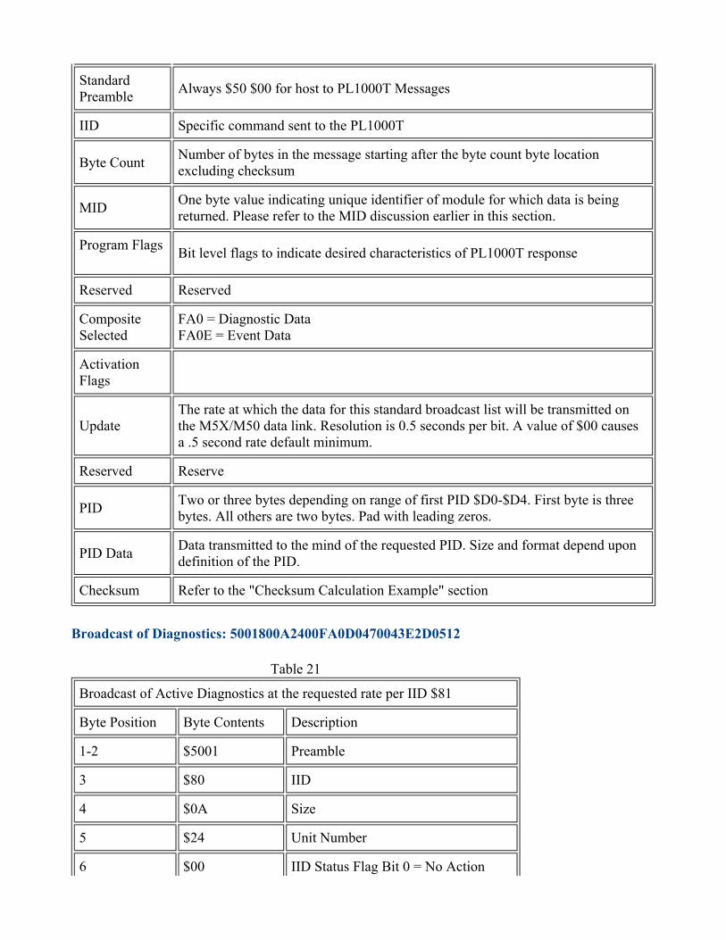
Standard Preamble Always $50 $00 for host to PL1000T Messages IID Specific command sent to the PL1000T Byte Count Number of bytes in the message starting after the byte count byte location
excluding checksum MID One byte value indicating unique identifier of module for which data is being
returned. Please refer to the MID discussion earlier in this section. Program Flags Bit level flags to indicate desired characteristics of PL1000T response Reserved Reserved Composite Selected
FA0 = Diagnostic Data FA0E = Event Data
Activation Flags
Update The rate at which the data for this standard broadcast list will be transmitted on the M5X/M50 data link. Resolution is 0.5 seconds per bit. A value of $00 causes a .5 second rate default minimum.
Reserved Reserve PID Two or three bytes depending on range of first PID $D0-$D4. First byte is three
bytes. All others are two bytes. Pad with leading zeros. PID Data Data transmitted to the mind of the requested PID. Size and format depend upon
definition of the PID. Checksum Refer to the "Checksum Calculation Example" section
Broadcast of Diagnostics: 5001800A2400FA0D0470043E2D0512Table 21
Broadcast of Active Diagnostics at the requested rate per IID $81 Byte Position Byte Contents Description 1-2 $5001 Preamble 3 $80 IID 4 $0A Size 5 $24 Unit Number 6 $00 IID Status Flag Bit 0 = No Action

7-8 $FA0D Diagnostic Broadcast Response 9 $04 Cyclic Message No 4 10 %01110000 Status Flags 11-12 $043E Component Identifier 13 $2D Warning Level FMI PID Diagnostic
14 $05 Only in Diagnostic Bits 3 2 = Diagnostic Type 1 = Maintenance Diagnostic All other bits not used
15 $12 Checksum The PL1000T will transmit the composite data response when new or modified composite data is identified. For example if an event becomes active that was not previously active the composite data response is transmitted containing the newly activated response. "Systems Diagnostics" operates the same way. Message IID $80 conveys both events and diagnostics information so the PID embedded within the message indicates data type. PID $FA0D indicates that diagnostic data is being transmitted. PID $FA0E indicates that events are being transmitted. Composite Data Response IID $80
Illustration 25 g01266310

$FA0D PID Format
Code Example to Start Diagnostic Data: $50008109240000AAFA0D01180038Table 22
Start Diagnostic Messages per IID $81 Byte Position Byte Contents Description 1-2 $5000 Preamble 3 $81 IID 4 $09 Number of Bytes 5 $24 Unit Number 6 %00000000 Programming Flags 7 $00 Reserved 8-10 $AAFA0D PID for Diagnostic Broadcast 11 %00000001 Activation Flags 12 $18 Update Rate 4 Sec/Bit Max 1020 Seconds 13 $00 Reserved 14 $00 Checksum
Code Example to Stop Diagnostic Data: $50008109240100AAFA0D1002003ETable 23
Turn Off All Diagnostic Messages per IID $81 Byte Position Byte Contents Description 1-2 $5000 Preamble 3 $81 IID 4 $09 Number of Bytes 5 $24 Unit Number 6 %00000001 Programming Flags 7 $00 Reserved 8-10 $AAFA0D PID for Diagnostic Broadcast

11 %00000010 Activation Flags 12 $02 Update Rate 4 sec/bit max 1020 seconds 13 $00 Reserved 14 $3E Checksum
Response to IID 81 Message = $5001850B24000000AAFA0D0001180031Table 24
Response to IID $81 Byte Position Byte Contents Description 1-2 $5001 Preamble 3 $85 IID 4 $0B Number of Bytes 5 $00 All Devices (Turn Off Only) 6 %00000001 Programming Flags 7 $00 IID Errors 0 = Data OK 8 $00 Reserved 9-11 %AAFA0D PID For Diagnostic Broadcast 12 %00000000 Programming Flags 13 %00000010 Activation Flags 14 $02 Update Rate 4 sec/bit max 1020 seconds 15 $00 Reserved 16 $5B Checksum
Start Event Broadcast: $50008109240000AFFA0E0102004DTable 25
Start Event Broadcast Byte Position Byte Contents Description 1-2 $5000 Preamble 3 $81 IID
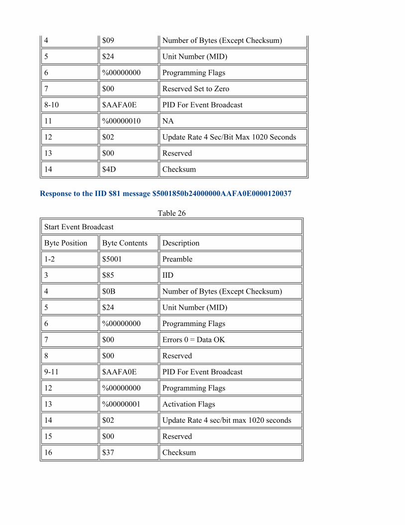
4 $09 Number of Bytes (Except Checksum) 5 $24 Unit Number (MID) 6 %00000000 Programming Flags 7 $00 Reserved Set to Zero 8-10 $AAFA0E PID For Event Broadcast 11 %00000010 NA 12 $02 Update Rate 4 Sec/Bit Max 1020 Seconds 13 $00 Reserved 14 $4D Checksum
Response to the IID $81 message $5001850b24000000AAFA0E0000120037Table 26
Start Event Broadcast Byte Position Byte Contents Description 1-2 $5001 Preamble 3 $85 IID 4 $0B Number of Bytes (Except Checksum) 5 $24 Unit Number (MID) 6 %00000000 Programming Flags 7 $00 Errors 0 = Data OK 8 $00 Reserved 9-11 $AAFA0E PID For Event Broadcast 12 %00000000 Programming Flags 13 %00000001 Activation Flags 14 $02 Update Rate 4 sec/bit max 1020 seconds 15 $00 Reserved 16 $37 Checksum

Broadcast of Diagnostics: $5001800A2400FA0D0470043E2D0512Table 27
Start Event Broadcast Byte Position Byte Contents Description 1-2 $5001 Preamble 3 $80 IID 4 $06 Size 8-22 for events 5 $24 Unit Number 6 $00 IID Status Flag Bit 0 = No Action 7 $FA0E Event Broadcast Response 8 $01 Cyclic Message Number ($00-FF) = 01 9 %01110000 Status Flags 10 $8C Checksum
Code example to stop EVENTS data: 50008109240100AAFA0E1002003DTable 28
Turn OFF All Events Messages per IID $81 Byte Position Byte Contents Description 1-2 $5000 Preamble 3 $81 IID 4 $09 Number of Bytes 5 $24 Unit Number 6 %00000001 Programming Flags 7 $00 Reserved 8-10 $AAFA0E PID For Events Broadcast 11 %00000010 Activation Flags 12 $02 Update Rate 4 sec/bit max 1020 seconds 13 $00 Reserved
14 $3D Checksum
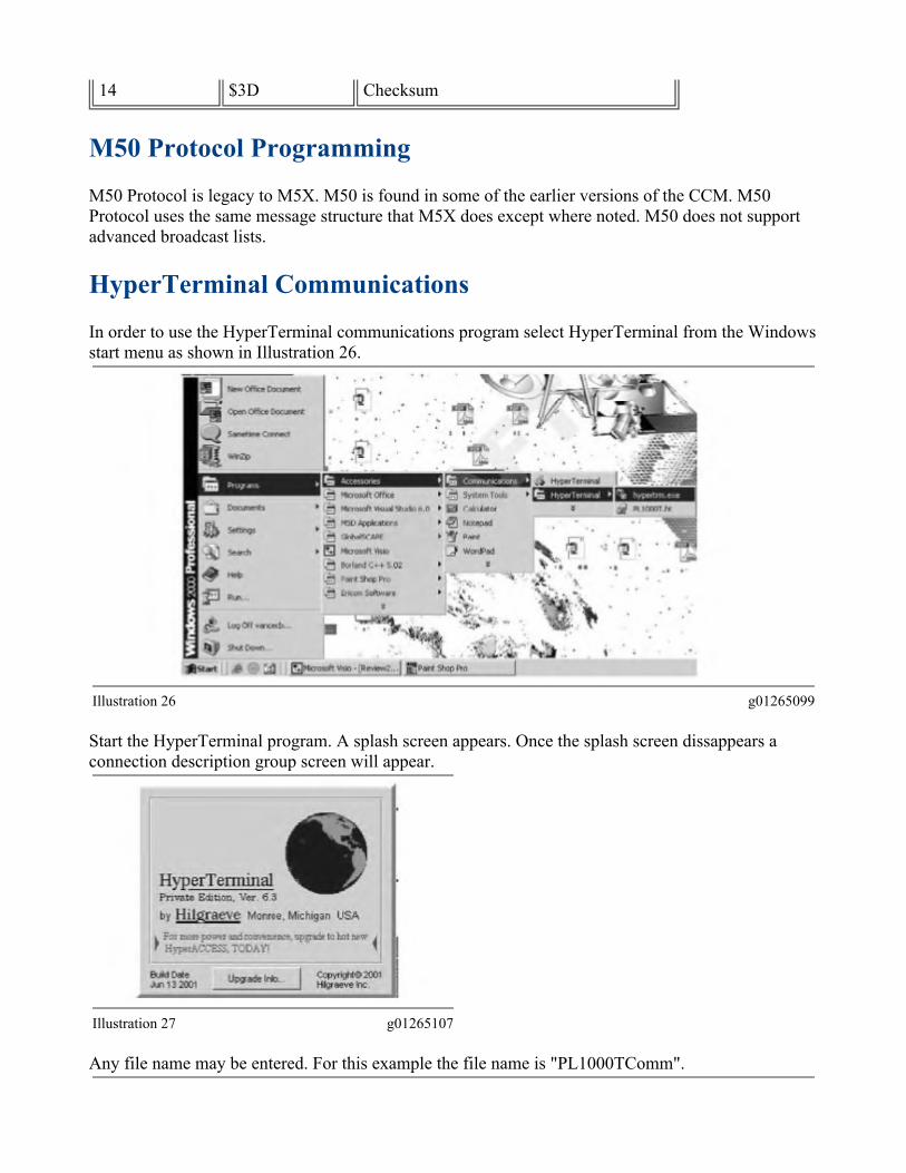
M50 Protocol ProgrammingM50 Protocol is legacy to M5X. M50 is found in some of the earlier versions of the CCM. M50 Protocol uses the same message structure that M5X does except where noted. M50 does not support advanced broadcast lists.
HyperTerminal CommunicationsIn order to use the HyperTerminal communications program select HyperTerminal from the Windows start menu as shown in Illustration 26.
Illustration 26 g01265099Start the HyperTerminal program. A splash screen appears. Once the splash screen dissappears a connection description group screen will appear.
Illustration 27 g01265107Any file name may be entered. For this example the file name is "PL1000TComm".

Illustration 28 g01265111Click the "OK" button. A dialog box will appear.
Illustration 29 g01265117Select the "Connect Using" entry window. Choose an available communication port for the applications. The applications use "COM1". Click "OK" again when ready.After clicking the "OK" button on the communication port selection screen the baud rate selection screen will appear with the valid ranges of baud rates that are available. The baud rates are available when using the PL1000T on either serial port 1 or serial port 2. The available baud rates are 300, 600, 1200, 2400, 4800, 9600, 19200 and 38400 baud. This example uses the fastest data rate available 38400 baud or 38.4k baud.

Illustration 30 g01265137After the selections have been made click "OK" once more. The screen will close to leave only the HyperTerminal window workspace. Next the property setting will need to be changed in order to make sure the data received from the PL1000T will be in the proper format for viewing. From the Hyperterminal menu bar select "File/Properties". Click the ASCII setup button as shown in Illustration 31. When the ASCII setup screen appears click on each section box so that all items have a checkmark next to them. Click "OK".

Illustration 31 g01265140A file named "PL1000TComm.ht " is created that contains all of the settings just were just configured. Next time the file is needed HyperTerminal may be started with the use of a shortcut to this file from the desktop. The file that was created will eliminate the need for future configuration when establishing a connection to a PL1000T that was similarly configured.The communications status of the HyperTerminal can be readily determined from the status bar located at the lower left hand corner of the application window. If HyperTerminal is connected to the PL1000T the status message reads "Connected". Otherwise the status message reads "Disconnected".If the HyperTerminal program is not connected to the PL1000T then click the icon to make a connection verified at the bottom lower left area of the screen in the status message bar. If the connection is valid and data is being transmitted it will begin to appear in the terminal data window shown in Figure 32.

Illustration 32 g01265148In this example the PL1000T is transmitting an advanced broadcast list 1 composite data and an events and diagnostics command.If the data window remains blank and the status message shows "Connected" a command can be sent to the PL1000T. The command will cause the PL1000T to transmit a response which will serve to verify a valid direct communication link.The command string that must be sent is "500124040061AA86F3". The command string will force the PL1000T to respond with its level 3 password. The level 3 password verifies that a valid direct connection exists.Open an instance of "notepad.exe". Enter the command string exactly as shown in Illustration 32. Once the string is entered into notepad highlight the string using a mouse. Copy the string to the clipboard.
Illustration 33 g01265152

Once the selected command string is highlighted and is copied into the clipboard click the "Edit/Paste to Host" function from the menu bar. Press the "Enter" key. If the direct connection to the PL1000T is valid the command string will appear. Also a response will appear that contains the level 3 password for the PL1000T.If sending the security level request command string 500124040061AA89F3 does not illicit a response from the PL1000T then the connection is suspect. After confirming that power is applied to the PL1000T that the PL1000T is operating correctly and the HyperTerminal program indicates a "Connected" status any failure to receive data responses will be isolated to the physical connection. Connection to a ModemWhen the PL1000T is connected to "Data Communications Equipment" (DCE) devices a "Null Modem" cable or an adapter is not required. A printer or a modem are examples of a DCE device.When connecting the PL1000T to a modem handshaking and ring indication is required. The" Data Terminal Ready" (DTR) "Data Carrier Detect" DCD and "Ring Indicator" (RI) lines must be properly connected as shown in Illustration 34.
Illustration 34 g01265126Perform the following procedure in order to initialize communication with the PL1000T and the "Answering Modem". The "Originating Modem" is set up later by the PC software.

Note: In the following steps the PC and the modems should be turned OFF before changing the cables on the serial ports. When power is reapplied the modem must be powered up first.
1. The PL1000T should be installed with all of the wiring. Refer to the "System Schematic" section of the document.
2. Determine the parameters that are needed for communication for the installation. The RS-232 default rate communication (bits per second or bps) is 9600. The remaining default settings from the factory are no parity 8 data bits and 1 stop bit. These parameters will work well in most installations. Use the Operation and Maintenance Manual "Communication Parameters-Identify" to determine the parameters of communication that are stored.Note: The RS-232 serial port communication baud rate is often referred to as the DTE speed. The phone port communication rate is often referred to as the DCE speed.
Table 29Typical Answering Modem Setup CommandsItem Explanation Command
ExampleA Set the modem to the factory defaults. This is important if the setup of the
modem is unknown. AT&F
B Set to communicate in error control and asynchronous mode. If the modem does not support this command enter the AT command for error control. Set to communicate in asynchronous mode with a separate command (Item C).
AT&Q5
C Set to communicate in asynchronous mode. If the &Q5 command is supported the modem will never answer an incoming call. The value of this register can be seen with the ATSQ? command
AT&Q0
D Set "Auto" answer to "ON". This tells the modem to answer the phone line after the first ring. If left at 0 the modem will never answer an incoming call.
ATS0=1
E Set Flow Control to XON/OFF. This turns off RTS/CTS hardware handshaking between the modem and CCM since the CCM does not have RTS or CTS lines. It turns on the XON/OFF software shaking.
AT&K4
F
Set DCD to track status of carrier detect signal. This causes the DCD line from the modem to follow the state of the phone line carrier. When the call to the CCM's modem has been made and the modem to modem handshaking is done the DCD line will change and allow the CCM to receive data. This is very important. If the DCD line is not at the right state the CCM cannot receive data.
AT&C1
G Set DTR to monitor DTR signal and hang up and reset modem on an on-to-off DTR transition. This causes the modem to hang up and reset the CCM drops the DTR line.
AT&D3
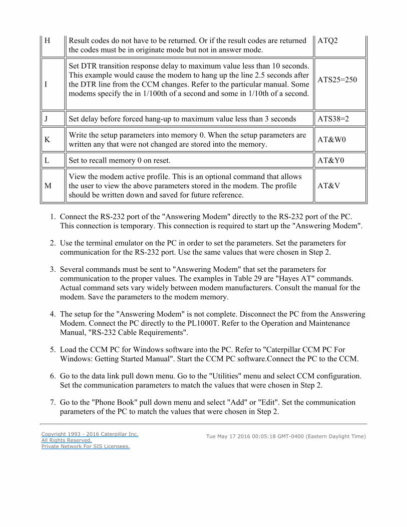
H Result codes do not have to be returned. Or if the result codes are returned the codes must be in originate mode but not in answer mode.
ATQ2
I Set DTR transition response delay to maximum value less than 10 seconds. This example would cause the modem to hang up the line 2.5 seconds after the DTR line from the CCM changes. Refer to the particular manual. Some modems specify the in 1/100th of a second and some in 1/10th of a second.
ATS25=250
J Set delay before forced hang-up to maximum value less than 3 seconds ATS38=2 K Write the setup parameters into memory 0. When the setup parameters are
written any that were not changed are stored into the memory. AT&W0 L Set to recall memory 0 on reset. AT&Y0
M View the modem active profile. This is an optional command that allows the user to view the above parameters stored in the modem. The profile should be written down and saved for future reference.
AT&V
1. Connect the RS-232 port of the "Answering Modem" directly to the RS-232 port of the PC. This connection is temporary. This connection is required to start up the "Answering Modem".
2. Use the terminal emulator on the PC in order to set the parameters. Set the parameters for communication for the RS-232 port. Use the same values that were chosen in Step 2.
3. Several commands must be sent to "Answering Modem" that set the parameters for communication to the proper values. The examples in Table 29 are "Hayes AT" commands. Actual command sets vary widely between modem manufacturers. Consult the manual for the modem. Save the parameters to the modem memory.
4. The setup for the "Answering Modem" is not complete. Disconnect the PC from the Answering Modem. Connect the PC directly to the PL1000T. Refer to the Operation and Maintenance Manual, "RS-232 Cable Requirements".
5. Load the CCM PC for Windows software into the PC. Refer to "Caterpillar CCM PC For Windows: Getting Started Manual". Start the CCM PC software.Connect the PC to the CCM.
6. Go to the data link pull down menu. Go to the "Utilities" menu and select CCM configuration. Set the communication parameters to match the values that were chosen in Step 2.
7. Go to the "Phone Book" pull down menu and select "Add" or "Edit". Set the communication parameters of the PC to match the values that were chosen in Step 2.
Copyright 1993 - 2016 Caterpillar Inc.All Rights Reserved.Private Network For SIS Licensees.Tue May 17 2016 00:05:18 GMT-0400 (Eastern Daylight Time)


