Embed Size (px)
Citation preview

U. S. DEPARTMENT OF COMMERCE NATIONAL BUREAU OF STANDARDS
RESEARCH PAPER RP1688
Part of Journal of Research of the N.ational Bureau of Standards, Volume 36, January 1946
SPECIFICATION OF RAILROAD SIGNAL COLORS AND GLASSES
By Kasson S. Gibson, Geraldine Walker Haupt, and Harry J. Keegan
ABSTRACT
This paper is a continuation of Bureau Research Paper RP1209 and describes the cooperative work done by the Association of American Railroads Signal Section, Corning Glass Works, and the National Bureau of Standards leading to the formulation of the AAR Signal Section specifications for signal colors and glasses.
The previous paper defined the luminous transmission scale used by the signal engineers and glass manufacturers. The p resent paper describes the glasses selected by these engineers to define the limits of acceptable chromaticities afforded by these glasses when combined with kerosine* or electric illuminant. The spectral transmissions of t he glasses are given, together with the luminous transmissions and chromaticities for the specified illuminants.
The photometric and colorimetric parts of the AAR Signal Section three-part specifications are illustrated and the reasons given for the choice of tolerances both on the acceptable signal colors and on the glasses certified by the National Bureau of Standards as duplicates of the standard limit glasses.
Various other data of interest are given, including the expression of the permissible chromaticities of signal colors in a uniform-chromaticity-scale coordinate system.
1. II.
III.
IV. V.
VI.
VII.
CONTENTS Page
Introduction________________________ ___ __ ______________________ 1 Methods used to specify the chromaticities of railroad signal colors and
glasses_____ __________________________________________________ 3 Standard glasses defining limits of acceptable chromaticities for railroad
signal colors_______ _ __ _ _ ___ _____ _ _ _ _ __ _ _ _ _ __ _ __ _____ _ _ _ _ __ _ _ _ _ 5 Chromaticity limits of railroad signal colors_ __ _ _ _ _ _ _ _ _ _ _ _ _ _ _ _ _ _ _ _ _ _ _ 14 Tolerances for certifying duplicates of standard limit glasses_ _ _ _ _ _ _ _ _ _ 20 Expression of railroad signal colors on a uniform-chromaticity-scale
coordinate system_ _ _ _ _ _ _ _ _ _ _ _ _ _ _ _ _ _ _ _ _ _ _ _ _ _ _ _ _ _ _ _ _ _ _ _ _ _ _ _ _ _ _ _ _ 26 Association of American Railroads Signal Section specifications for
signal glasses and hand lantern globes_ _ _ _ _ _ _ _ _ _ _ _ _ _ _ _ _ _ _ _ _ _ _ _ _ _ _ 28
1. INTRODUCTION
This is the second paper describing the work of the National Bureau of Standards on the color standardization of railroad signal glasses. This standardization has resulted from the cooperative efforts of the Signal Section of the Association of American Railroads (formerly the American Railway Association), Corning Glass Works, and the National Bureau of Standards.
The first paper 1 gave a historical resume of signal-color activities "In this paper, except for quoted matter and publication titles, the spellings "kerosine" and "disk" are
used consistent with Bureau practice. I Kasson s. Gibson and Geraldine WaIker Haupt, Standardization of the luminous· transmission scale
used in the speci1lcation of railroad signal glasses, J . Eesearcb NBS 22, 627 (1939) RPl209; J. Opt. Soc. Am. Z', 188 (1939).
1

2 Journal of Researc7~ of the National Bureau of Standards
of the AAR Signal Section with particular reference to the specifications issued by that organization (or its precursors) in 1908, 1918, and 1935. Various acknowledgments and references to previous work were also given, which are not repeated here.
The principal purpose of the previous paper was to describe the methods and data used in the derivation of thEl luminous-transmission scale now used by the signal engineers and to express that scale on a fundamental, absolute basis. The end result of that work is given in table 1, which is a transcription of table 7 of the earlier paper.
T ABLE I.-Relation between values of TAAR and of T2•360, which defines the luminous transmission scale used in the present AAR signal-glass spteifications
Equivalent luminous
Equivalent luminous
AAR transmission, AAR transmission, trans· 1931101 trans· 1931101
Color designation of glass mission, standard Color designation of glass mission, standard TAAR
observer, TAAR
observer, iIIuminant iIIuminant 2,360° K, 2,360° K,
T2,360 T2,360
Red ... .. ..... ...••..... .. 100.0 0.069 Blue 100.0 0.0223 yellow .....•.............. 100. 0 .247 Purple': ::::::::::: ::: ::: 100.0 .0129 Green ....•..... . . . ..... ... 100.0 . 119 Lunar white . . ........ .. . 100.0 . 190
It may be seen that for each of the six. signal colors used by the railroad engineers-designated by them as red, yellow, green, blue, purple, and lunar white-the luminous transmissions of glasses are expressed on an arbitrary scale with the symbol T AAR' The expression of that scale (in reality six scales, a different one for each color) on an absolute basis with illuminant at 2,360 0 K is given in table 1.
The purpose of the present paper is to consider the chromaticities of railroad signal colors and glasses. The parts of the 1908 and 1918 specifi:oations dealing with chromaticity are noted, the glasses newly selected by the signal engineers (beginning in 1931) to define the limits of permissible colors are listed and their spectral and luminous transmissions given, the methods used to express the results in colorimetric terms suitable for specification purposes are described, and pertinent parts of the current railroad signal specifications are quoted and illustrated.
The work covered in these two papers, and many other details of the investigation, may be found in seven formal reports issued to the cooperating agencies during the period 1932 to 1938.2
, Standardization of railway signal glasses-Reports on measurements and investigations undertaken by the Colorimetry Section of the National Bureau of Standards at the request of the Signal Section, American Railway Association.
Reports 1 to 5, Signal Section Proc., Am. Ry. Assn . 30, 384 (1933): Report 1. K. S. Gibson. The transmission (ARA scale) of 36 specimens of signal glass relative to trans·
mission 01 6 ARA standards marked "J. C. Mock 19-3-30," a report on measurements made at Corning Glass Works, December 9-11, 1930 (June I, 1932).
Report 2. K . S. Gibson and Geraldine K . Walker, Measurementsolspectral and luminous transmissions leading to the derivation of new ARA transmissions for the 36 glasses listed in report 1 (October 24, 1932).
Report 3. Geraldine K. Walker and K. S. Gibson, Spectral and luminous transmissions and derivation of new values of ARA transmissipn for the 22 "limit" glasses selected by committee VI, ARA, at Corning, November 5-1\, 1931, and engraved "J. C. M. 11-6-31" (December 2, 1932).
Report 4. K. S. Gibson and Geraldine K. Walker, Chromaticities and luminous transmissions, with illuminants at 1,9000 K and 2,8480 K,lor the 22 "limit" glasses described in rcport 3 (January 30,1933).
Report 5. K. S. Gibson, Tentative specifications for railway signal colors (April 27, 1933). Reports 6 and 7, K . S. Gibson, Geraldine Walker Haupt, and H. J. Keegan, Signal Section Proc., Assn.,
Am. R. R. 36, 136 (1939) : Report 6. Examination of 65 duplicate limit glasses (July 26, 1934). Report 7. Colorimetric data leading to specification 59-38 for kerosene hand lantern globes; comparison
of specifications 59-38, 69-38, and 69-35; certification Of duplicate lantern glasses (September 28, 1938).

Railroad Signal Oolors 3
II. METHODS USED TO SPECIFY THE CHROMATICITIES OF RAILROAD SIGNAL COLORS AND GLASSES
Workers in colorimetry have become so familiar with the methods of computation and specification in terms of the 1931 ICI Standard Observer and Coordinate System for Colorimetry that discussion and explanations are often no longer needed. This has only recently been true, however, and at the times of issue of the 1908 and 1918 railroad signal glass specifications 3 little knowledge and no convenient computational procedures were available for such work. Furthermore, the art of spectrophotometry had not progressed sufficiently, at least in 1908, to warrant the precise colorimetric standardization that has become commonplace in recent years.
It was noted in the previous paper that a chromaticity (mixture) diagram, so essential in specifying the chromatic properties of signal lights, had been illustrated in colors and used by Dr. Churchill in 1905 in his study of the characteristics of signal glassware. 4 No attempt was made, however, in either the 1908 or 1918 specification to use a method of specification based on such a system. Instead, are found the following qualitative restrictions expressed in terms of spectral hues:
Excerpts from 1908 Railway Signal Association Specifications for Signal Roundels and Lenses
Red.-Will be of such quality that all yellow rays of light are absorbed, the spectrum being either red, or red and orange. The photometric value shall be, light 125, standard 100, dark 75.
Green.-Will be of the color known as admiralty green, having a slightly bluish tint. The spectrum shall show very little yellow, being a full green with some blue. The photometric value shall be, light 125, standard 100, dark 75.
Yellow.-Will give a spectrum showing a full yellow band, most of the red and slightly of the green. The photometric value shall be, Jight 120, standard 100, dark 80.
Blue.-Will give a spectrum having a full blue band, with a narrow band of green. The photometric value shall be, light 125, standard 100, dark 75.
Purple.-Will give a spectrum showing a considerable proportion of both red and blue. The photometric value shall be, light 125, standard 100, dark 75.
Lunar White.- Shall show a maximum of absorption for the yellow. The photometric value shall be, light 120, standard 100, dark 80.
The scales on which the photometric values of the 1908 and 1918 specification are based are roughly as defined in table 1. This is discussed in the previous paper.
Excerpts from 1918 Railway Signal Association Specification 6918 for Signal Roundels, Lenses and Glass Slides
Red.-Shall be of such quality that all yellow rays of light emitted by the sodium flame are absorbed, the spectrum being either red, or red and orange.
Green.-Shall be of the color known as admiralty green, having a slightly bluish tint as seen in daylight. The spectrum shall show most of the blue and green, a slight amount of yellow, and not mor~ than a trace of orange and red.
Yellow.-Shall give a spectrum showing most of the red, all of the yellow, and part of the green, but no blue. ,
3 Specifications for signal roundels, lenses, and glass slides, Proc. Ry. Signal Assn. 5 (11108) . Railway Signal Association specification 6918, Signal roundels, lenses, and glass slides (J918).
• Wm. Churchill, The roundel problem. A paper presented at the Ninth Annual M eeting of the Railway Signal Association, Nagrara Falls, N. Y., October 10-12, 1905.

4 J oUll'nal of Research of the National Bureau of Standards
Blue.-Shall give a spectrum showing most of the blue, some green, and almost no red.
Purple.-Shall give a spectrum showing most of the blue, some green, and a narrow band of the extreme red.
Lunar White.-Shall show blue and green, with about ten (10) percent of yellow and orange, and some red. It shall appear a light blue when viewed by daylight, and when placed in front of a yellow kerosene flame, it shall make this flame appear white.
In addition, in the 1918 specification there is given a table showing the light and dark limits for each of the six colors: red 160 to 100, green 175 to 125, yellow 140 to 100, blue 125 to 75, purple 125 to 75, and lunar white 120 to 80.
While it is obvious, therefore, that chromaticity limits were not given as such in either specification, the light and dark limits were apparently tacitly used as chromaticity limits. This, combined with the spectral restrictions noted above, served with considerable effectiveness to protect American railroads against signal glassware outside the chosen chromaticity and transmission ranges. It was noted in the previous paper that the 1908 specification appears to have been the first effort in this country to place the colorimetric part of a purchase specification on a fundamental basis, the specification being based on spectrophotometric data and establishing tolerances within which the manufactured product must come.
During the 1920's great advances were made in colorimetry. In 1922 the Optical Society of America Colorimetry Committee published a report 6 giving data and computational procedures for deriving and specifying the chromaticity of a color based on spectrophotometric data. In 1924, standard luminosity factors 6 were adopted by the International Commission on Illumination, in terms of which the intensities of colored lights and the luminous transmissions of signal glasses may be expressed. In 1931 the International Commission on Illumination adopted data defining a standard observer and coordinate system for colorimetry/ which has become the recognized method for specifying color. It incorporates the standard luminosity factors. The computational procedure, operating on spectrophotometric data, results in coordinates serving to specify the chromaticity of a color. In this coordinate system, x, y, and z represent fractional parts of hypothetical reddish, greenish, and bluish primaries (x+y+z=l), and it is customary to express the chromaticity diagram in terms of x and y. This system is now well known and widely used, and the reader is referred to the other publications listed for further information.
Along with this advance in colorimetry there occurred further progress in the manufacture of signal glassware. The status of this work was summarized by Gage in 1928. 8
In 1930 was initiated the program in which the AAR Signal Section, Corning Glass Works, and the National Bureau of Standards have
6 Optical Society of America Committee on Colorimetry, L. T. Troland, chairman, R eport for 192()-1ll, J . Opt. Soc. Am. & Rev. Sci. Instr. 6, 527 (1922).
• Proceedings Sixth Meeting Int. Comm. IlIum., Geneva, p. 67 (1924). For a rl!sum~ of recent work and the present status of these 10 1 luminosity factors, see K. S. Gibson, Spectral luminosity factors, J. Opt. Soc. Am. 3D, 51 (1940),
7 Proceedings Eighth Meeting, Int. Comm. IlIum., Cambridge, p. 19 (1931). D . B. Judd, The 1931 ICI standard observer and coordinate system for colorimetry, 1. Opt. Soc. Am. 23,
359 (1933). A. O. Hardy, Handbook of colorimetry, Technology Press, Cambridge, Mass. (1936). Optical Society of America, Committee on Colorimetry, Quantitative data and methods for colorimetry,
J . Opt. Soc. Am. 3', 633 (1944); chapter VII of the forthcoming OSA Colorimetry Committee report. , H . P . Gage, Practical considerations in the selection of standards for signal glass in the UOlted States,
Proc., Int. Congo mum., Saranac Inn, N . Y ., p . 834 (1928) .
Railroad Signal Colors 5
cooperated, as described in the previous paper. In 1931 the railroad signal engineers selected a completely new set of standard glasses explicitly defining new limits of chromaticity for the respective colors. As a result of the work thus started, new AAR Signal Section specifications have appeared during the years 1935 to 1940. g The colorimetric parts of these specifications are expressed entirely in the fundamental terms of the 1931 ICI standard observer and coordinate system. Here, as before, the signal engineers have been pioneers in the use of color specifications. It is believed that the suggested "Specification for railway signa'! colors" appearing in the 1933 Signal Section Proceedings and including a chromatiCIty (x, y) diagram (similar to fig. 8), on which are plotted points representing the standard ~lasses and areas representing permissible chromaticities for the six sIgnal colors, is the first published use of the ICI colorimetric system for specification purposes. 10 Methods similar to this have since been followed in specifying the colors and glasses used in traffic, marine, and aviation signaling, both here and abroadY
III. STANDARD GLASSES DEFINING LIMITS OF ACCEPTABLE CHROMATICITIES FOR RAILROAD SIGNAL COLORS.
At a meeting held at Corning Glass Works on November 5 and 6, 1931, numerous glasses were selected to define the new limits of acceptable chromaticities which it was desired to standardize. These glasses were selected by members of Committee VI of the AAR Signal Section, J. C. Mock, chairman. During the course of the work a few of the glasses were superseded by others. As a group they comprise the standards covering the use of roundels, lenses, slides (pressed ware), and disks for railroad signaling, and are designed for use with electric (incandescent) and/or kerosine illuminants. They include the colors designated as red, yellow, green, blue, purple, and lunar white.
At a meeting of Subcommittee C of Committee VI, A. S. Haigh, chairman, held at Corning Glass Works in June 1935, additional glasses were selected, representing the chromaticity limits for red, yellow, green, and blue kerosine hand lantern globes, and in 1939 the limits for highway-crossing red were likewise selected.
It may be noted that all of these standard limit glasses were selected by experienced signal engineers as a result of field tests conducted at Corning Glass Works. Final selection was based both on the desired differentiation of signals of the various colors and on reasonable manufacturing tolerances required for each of the colors. Numerous details may be found in the seven published reports from the National Bureau of Standards (see footnote 2, p. 2) and in the Proceedings of the
I Specification 69 Is entitled "Signal glasses (exclusive of kerosene hand lantern glohes)." It was published in essentially its present form in 1035, and was designated as 69-35. Slightly revised editions were published in 1938, 1939, and 1940, 69-40 being the current specification. Similarly, specification 59, "Kerosene hand lantern globes," was published in essentially its present form in 1938, the current edition being designated 59-39. Copies of these specifications are obtainable from R. H . C. BaIliet, Secretary, AAR Signal Section, 30 Vesey St., New York, N. Y.
10 K. S. Oibson, Report 5, Tentative specifications for railway signal colors, Signal Section Proc., Am. Ry. Assn. 30, 429 (1933).
11 See, for example, (1) Standards of the Institute of Traffic Engineers, Technical Report No. I, Adiustable face traffic control signal head standards, 1940 Proceedings, (2) Bureau of Marine Inspection and Navigation (now part of U. S. Coast Guard), Proposed specification covering navigation lights for vessels, alteration D (1941), (3) Army·Navy Aeronautical Specification: Colors; aeronautical lights and lighting equipment; AN-C-56 (1942); (4) Proceedings Int. Comm. IlIum., Tenth Session, Scheveningen, Holland (1939) , condensed unofficial version edited and published by the United States National Committee, figure 17,

6 Journal of Research of the National Bureau of Standards
AAR Signal Section, to which reference is made in the previous paper. These standard limit glasses have all been deposited with the National Bureau of Standards.
A description of the glasses finally selected as standards (and in current use) is given in table 2.12 Their spectral transmissions are given in table 3.
In table 4 are given (1) the chromaticity coordinates and luminous transmissions of each glass in combination with the illuminants of color temperatures 1,900°, 2,360°, and 2,848° K, (2) the TAAR value for each glass, and (3) the ratio of red to total luminous transmission, Tr/Tw, for the blue and purple glasses for 2,360° K. The values given in table 4 are all uncertain in the last figure given; this uncertainty relates to uncertainties in. the spectral transmissions in table 3 and to rejection errors or other factors in the methods of computation. In some cases this uncertainty may extend slightly into the next to last figure. Values of TAAR are derived from values of T2 •360
by conversion factors carried to one more significant figure than given in table 1.
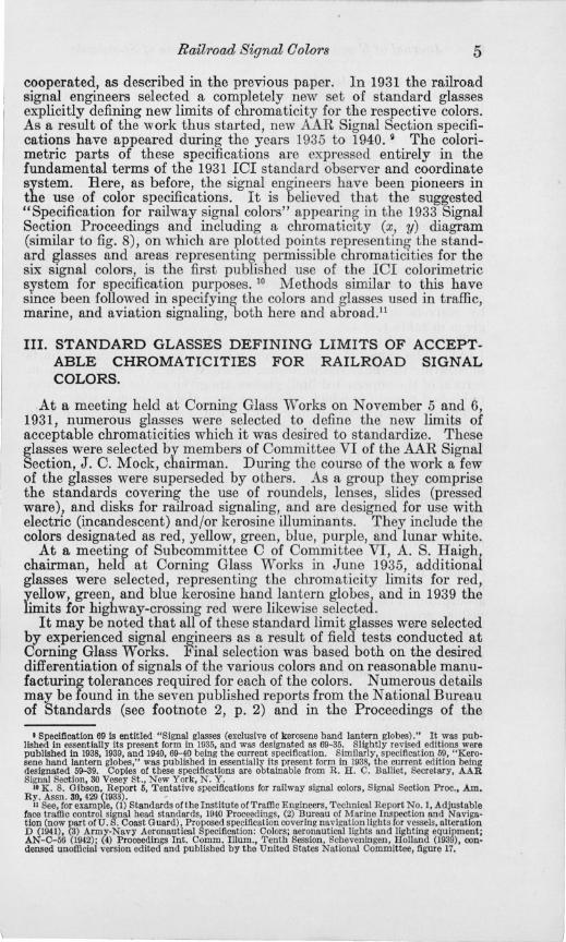
The spectral transmissions given in table 3 are illustrated in figures 1 to 6. The values of x and y given in table 4 are plotted in the charts illustrating the final specifications, figures 8 and 9. Various data on certain of the superseded limit glasses are given in the several Bureau published reports to which references have already been made.
The spectral transmissions given in table 3 were determined mostly on the Konig-Martens visual spectrophtometer 13 and the Gibson photoelectric spectrophotometer. a Measurements were made usually at every 10 mtL from 380 to 770 mtL, the photoelectric measurements extending usually from 380 to 500 mtL and from 660 to 770 mtL, and the visual measurements from somewhere in the range 450 to 500 mtL to somewhere in the range 680 to 720 mtL, in addition to the mercury wavelengths 404.7 and 435.8 mtL. The values adopted and given in table 3 are usually uncertain in the last figure. All the curves in figures 1 to 6 are typical with one exception. This exception is the curve for red-limit disk yellow 200, figure 2. Glasses 199 and 200 are of the type known as selenium yellows, characterized usually by the high transmission in the red, orange, and yellow, essentially complete absorption in the blue and violet, and sharp transition in the green or yellow green. Occasionally, however, a melt is obtained with an "unsharp cut-off," as it is usually called, and glass 200 is a good example. Note the transmission extending in measurable amounts through the blue and violet.
Glass 200 had been selected and marked as standard before it was suspected that it failed to be typical. The fact that the failure was not detected by inspection shows that it is not of much importance. However, the value of the blue coordinate, z, is larger than normal and affected the tolerance established for such glasses, as is illustrated in figure 11.
12 In describing these glasses the expressions "light limit" and "dark limit" have been retained because of their widespread use among sigual engineers and glass manulacturers. The term "dark limit" is more or less appropriate, but the term "light limit" is inappropriate, as there is no upper limit 01 luminous trans· mission placed on any glassware in the specifications. The "light limit" glasses a ll define chromaticitys limits, as indicated in table 2. Likewise, the values 01 T •• n are given in the tahle hecause 01 their wide· spread usage in describing sigual glasses.
13 H. 1. McNicholas, Equipment lor routine spectral transmission and reflection measurements, BB J . Research 1, 793 (1928) RP30.
" K. S. Gibson, Direct·readiug photoelectric measurement of spectral transmission, J. Opt . Soc. Am . & Rev. Sci. lnstr. 7,693 (1923).

TABLE 2.-Description of glasses selected by AAR Signal Section Committee VI as defining the chromaticity limits of railroad signal colors
Color designation Type Photome~ric I ~e~~i I Values of I desIgnatIOn glass TAAR
Chromatioity limit Designed for illuminant Remarks
AAR SIGNAL SECTION SPECIFICATION 69-40
{LighL ____ ___ _
Red _________________ __ ____ _ Except highway crossing ______ Dark _________ _
Do_ ____________ _ _______ Highway crossing ______ --_ -- _ - {tif:r_-_~:::::::
Yellow _____ ___ ____ -______ -- Non-HR _______ ____ - --- -- -- --- {ti£'L~:::::::
Disk_________ ____ __ ___________ (,) I{ Green_ ___ _____ __ ___ _ ___ _ _ __ Non-HR _________ --- -- -- -- -- -- {tif:r_-_-_:::::::
BIU~_~~:: ::::::::::::: ::::: ~~:~~: :::::::::: ::::::: :::: t~:~:~:::~~~~~~~~ Purple ____________ ~ _ _ _ _____ Kerosine _________ _____________ {tii~t.__~:::::::
. {Light ______ _ Do ________ _ ---- ----- -- - Electnc ________ - ----- -- --- -- -- Dark'__~ __ ____ _
Lunar white__ ___ ___ _ ___ ____ Kerosine ____________ ___ ____ ___ {t~~t.__~:::::::
Do_ _____ ________ __ ____ _ Electric _____ ___________ _____ {ti[~.-_~:::::::
154
86 75
400 141 142 199 200 134
87 139 140
47 57 56 47 80
108 45 74
124 73
17i. O
102.9 288.2 217.6 214. 1 160.8 270.5 251. 0 205. 9 150.5 193. 4 138.7 130.2 74.7
131. 2 73.3 40.1 30.3
121. 7 79.6
205.3 146.6
Pale and yellow ___________ Electric, E, and For pressed ware and disks, heat Kerosine, K . resisting, HR. (0) __________ ___________ _____________________________________ __ _________________ _
Pale and yellow _________ __ E _________________ For pressed ware, HR. (0)- __ _ .. _____________ __ __ __ _____________________________________________________ _ Pale and green ____________ E and K ________ __ For pressed ware. Red ____ ____ _____ __ _______ . ________ ________________ ____________________ _________ _ Pale and green ____________ E __ _______________ For disks, HR. Red ________________ ____ _______________________________________________________ _ _ Pale and yellow ___________ E and R __________ For pressed ware. Blue ___ . ________________________________________ ___ ________________ ____ . ___ ___ _ _ Pale and yellow ___________ E _________________ For disks, HR_ (b) _______ _______ ____________ ____ _______________ ________________________________ _ Pale and green ___ _________ E and Te _________ _ For pressed ware. Red __________ __________ _____ __ ______ ___ __ ___ _____ ______________________________ _ Pale and green , ___________ K _________________ For pressed ware, non-HR. Red· ___________ _____________________________ _ _________________________________ _ Pale and green c ___________ E _________________ For disks, HR. Red· __________________ ________ __ .. _______ __ __ ____ _________ __ ________ ______ ___ __ _ Yellow d _____________ _____ K ________________ _ For pressed ware, non-HR. Blue d _______________ ___ ______________ _ _______ __ _______________ ____ _______ _ _____ _
Yellow d __________________ E _________________ For disks, non-HR. Blue d ____________________ _
AAR SIGNAL SECTION SPECIFICATION 59-39
Red ____ _____ _____________ _ _ Kerosine lantern __ -- --- - ----_ -I{ti;:r.-_~:::::::
Yellow ____ ________________ .I _____ do __________________ _____ __ {ti;rhkt_-_:::: ::::
{Light.. ______ _ Dark. __ ______ _
{UghL _ -------Dark _________ _
Green _____ -- _____ -- --- _____ 1_ --- _no_ ----Blue __________________ _____ _
201 211 261 271 137 322 141 131
256.7 145.5 297.4 241.2 184.9 126.6 124.8 56.0
Pale and yellow ___________ K _________________ For hand lantern globes, HR. (0) __________________________________________________________________________ ___ _ Pale and green ____________ K _________________ For hand lantern globes, HR. Red _________________________________________________________________________ ___ _ Pale and yellow ______ ___ __ K ________________ _ For hand lantern globes, HR. Blne _________________________________________ _ _________________________________ _ Pale and green ____________ Ie _____ _____ ______ For hand lantern globes, HR. Red ______________________ _
• ~o chromaticity limit is needed. The dark limit glass is useful , however, in the photometry of red signal glassware. b Non-HR green No. 87 bas been accepted as the blue limit for disk greens . • These chromaticity limits have little significance. The purple glass gives a dichromatic signal, and the ratio of red to blue (or total) light is the important criterion. d Green and purple limit glasses were not selected. , In use, one side of each disk is "depolished"; no other restrictions are placed on the luminous trnmmissiolls.
~ ~
""-~ ~ ~
V:! ~-~ ~ ..... ~ ~
~ ~
...:r

TABLE 3.-Spectral transmissions, Tk of glasses selected by AAR Signal Section Committee VI as defining the chromaticity limits of railroad signal colors
Red Yellow Green
Wavelength in Pressed ware Highway Hand lantern Pressed ware Disk Hand lantern Pressed waro Disk Hand lantern millimicrons and disk crossing globes globes globes
L I D L I D L I D L I D - I - L I D L I D L I D L D 154 86 75 400 201 211 141 142 199 200 261 271 134 87 139 140 137 322 1---1---1---1---1---1---1---1---1---1----1--_, ____ , ___ , ___ • __ 1 ___ ' ___ _ 380 __________ _____ _______________________________________________ -------- 0. 008 0.0002 0.0008 ------- - -- --- --- 0.121 0.073 0.097 0.040 0.230 0.13 90 _________ ________ _____
- ------- ----- -- - - -- ----- - --- ---- ------ - - -------- .008 .0002 . 0009 -------- -------- . 242 .152 .150 .082 .294 . 19 400 _____ __ _______________ -------- -------- -------- -- - ---- - -- ----- - ------ -- .0075 .0002 .0010 -------- -- ------ .335 .237 .207 .126 . 356 .247 10 ____________ _________ _ -------- -------- -------- -------- -- - - ---- --- ----- .0074 .0002 . 0014 ----- --- -------- . 405 .307 .266 . 174 .408 .304 20 ____ ____ ____ ____ ______ - ------- -------- -------- -------- --- - -- - - -------- .0076 . 0003 . 0020 -------- --- --- -- .464 .366 .315 .222 .457 .362 30 __ _________ ___ ________ ------ -- -------- ---- - --- -------- ------ -- -------- . 0087 .0004 . 0028 ------- - ---- - - -- .521 . 425 .371 .273 .505 . 416 40 ______________________ -------- ---.---- - ---- --- ----- -- - -- ------ ------- - .0113 .0007 . 0039 -------- -------- .565 .480 .414 .326 .545 . 465 450 ______________________ ------.- -------- ----. --- --.--._- ---.---- --.---- - .0169 .0014 .0054 .-.----- -------- .617 .541 .459 .373 .582 .512 60 ___ ____ ___ _____ ___ ____ .---._-- ------ -- "--._---- ------ -- -------- - - - --- - - .0271 .0030 .0075 -------- ------.- .659 .588 .503 .423 . 620 .552 70 ______________________ --- - ---- -------- -------- -------- -------- ---- --- - . 0423 .0064 .0101 - ------- -------- .686 . 625 .540 .459 .645 .581 80 ______________________ ----._-- -------- ------- - ------ - - -------- -._----- . 0636 .0126 .0137 -------- -------- .696 .638 .565 .483 .662 .600 90 _________ _____________ "._------ ---- - --- ------- - - ----- - - --- -- --- - -.----- . 0952 .0238 .0190 -------- - ------ - .695 .633 .577 .501 .666 .600 liOO ______________________ -------- --- ----- -------- --._---- - ----- -- - - -- ---- .1324 .0424 0.0000 .0289 0.000 . 680 .618 .578 .501 .658 .580 10 __ _________ ___ ________ -------- -.-----. -- ----- - --- - -- -- -------- -------- .186 .0712 .0001 .0526 .001 .656 .584 .569 .483 . 628 .540 20 ___ _________ __ ____ ____ -- ------ -------- ---- - - -- -- - - ---- - -- ----- -------- .241 .1102 .0003 .0826 .120 0.000 .610 .526 . 536 .450 .578 .481 30 ________ ___ ___ ___ __ ___ ---- ---- -------- --- - --- - -------- -------- -------- .303 .158 .0126 .1125 .518 .001 .540 .450 .493 .396 .509 .404 40 __________ __ __________ ------ - - -------- -------- --- ----- --- ----- -------- .367 .214 .289 . 157 . 705 .048 .462 .366 .430 .333 .434 .319 550 _________________ ____ _ -------- -------- -------- -------- -------- -------- .430 .277 . 654 .277 . 767 .433 .382 .279 . 358 .266 .347 .234 60 ___ ___________________ -------- --- ----- -------- ------ -- -------- -------- .492 .339 .784 .544 . 796 .670 .301 .205 .292 .201 .265 .164 70 _______________ _______ -------- 0. 0000 -------- -------- - --- ---- -- ---- -- .542 .399 . 826 . 770 .818 .738 .230 .1424 .224 .1442 .196 .105 80 ______________________ -------- .0001 0.0000 0.000 .589 .451 .844 .848 .835 .774 .171 . 0952 .172 .0996 .1390 .064 90 ______________________ 0.0000 .0002 .037 0.0000 .001 .625 . 495 .857 .873 .848 .803 .1211 .0609 .1240 .0660 .0968 .0372 600 ______ ___ _________ ____ .0003 .0005 .27 .010 .051 0.000 .654 .532 .864 . 882 .859 .824 . 0856 .0375 .0902 . 0428 .0653 .0217 10 __________ ____________ .037 .0019 .54 .16 .41 . 004 .676 .559 .869 .887 .866 .840 .0588 .0225 .0642 . 0276 .0437 .0124 20 ____ _________ __ ___ ____ . 41 .022 .685 .60 .715 .22 .693 .579 .874 .890 .870 . 854 .0402 .0134 .0460 . 0173 .0289 .0072 30 ____________ __________ .71 .23 .742 .796 .805 .60 .705 .593 .879 .892 .873 .863 .0270 .0084 .0322 . 0109 .0190 .0041 40 ______________ ________ .796 .65 .771 .848 . 835 .734 .713 .599 . 883 .893 .875 .871 .0182 .0051 .0230 .0070 .0127 .0024 650 ______________________ .820 .798 .790 .866 .846 .784 .718 .602 .887 .894 .876 .877 .0124 . 0031 .0167 . 0046 .0088 .0015 60 ______________________ .833 .833 .804 .873 .853 .803 .721 . 603 .889 .894 .877 .880 .0088 .0019 .0122 .0031 .0062 .001 70 ______________________ .842 .844 .817 .879 .858 .813 .723 .601 .890 . 894 .877 .883 .006 .001 .0093 . 0021 .0045 .000 80 ____________________ __ .848 .852 .826 .881 .860 .820 .723 .596 .891 .894 .876 .884 .004 . 000 .0070 .0014 .003 90 __ _______ _____________ .851 .856 .834 .882 .861 .825 .722 .588 .891 .893 .875 .885 .003 . 0054 .001 .0025 700 ____ ____ ___________ ___ .853 .858 .841 .883 .862 .826 . 720 .580 .891 . 892 .873 .884 .002 .0042 .000 .002 10 ______________________ . 852 .859 .846 .884 .860 .826 .717 .570 .891 . 890 .871 .882 .0015 .0033 . 0015 20 ______________________ .850 .858 .851 .883 .857 .824 .712 .560 .890 . 888 .868 .880 .001 .0026 .001 30 ___________________ __ _ .848 .857 .854 .881 .855 .821 .706 .548 .889 .886 .865 .879 .000 _0021 .000 40 ___ ________ _________ __ .846 . 855 .857 .879 .852 .818 .700 .535 .888 .884 .862 .877 ------- - ---- - --- .0017 ------- - --- ----- ---- ----750 ______________________ .843 . 852 . 857 .877 .848 .814 . 692 .522 .886 .883 .859 .875 -------- ------ -- .0014 -------- -------- --------60 ______________________ .840 .849 .857 . 875 .844 .809 .683 .507 .884 .882 .856 .873 -------- -------- .0011 -------- ------ -- --------70 ______________________ .836 .846 .857 .873 .841 .805 .673 .492 .882 . 881 .853 .871 -------- -------- .0008 -------- -------- ----- -- -TAAn=. ________ ___ ____ -m.o102.9 288.22l7.6256:7---w:-52i4.l 160.8 270.5251.() 297.4 ~ 205.9 15o:51l93.4~l84.9 126.6
00
....... ~
~ .,..... ~ ........ ~ (\) Co (\)
~ C':> ~ ~ ........ "'" ;::,.. (\)
~ "'" ~ . ~ .,..... OJ .e . ~ ~ ~ ........ ~
~
~

------
Wavelength in millimicrons Pressed ware
L 47
D 57
Blue
Hand lantern globes
L 141
D 131
Kerosine
L 56
D 47
Purple
L 80
Electric
D 108
Lunar white
Kerosine
L 45
D 74
Electric
L 124
D 73
---------------------\----,----,----,----,----,----,----,----,----,----,----,----
sgg::::::::::::::::::::::::::::::::::::-------------~::::: ::::::: ::::: :------:::: ::::: ::::::: :::::::: -~::::::::::: ::: ::::::::::--- ---- -- - --- -- ---- -----40 _______________________ _
4~~~~~~~~~~~ ~~~~~~~~~~~~~~~~~~~~~~~~~~~~~~::::::::--90___ _ _ _ ____ __ __ _ _ _ _ _ __ _ _ ______ _____________ ___ ___ _
1~~~~~~~~~~~~~~~~~~~~::::::::::::::;;;;;;;::;;;;;;: 6~~~~~~~~~~~~~~~~~~~~~~~~::~~~~~~~~~~~~:::::::::::: : i::~::::::::::·· .illl [ii [i~ ~i·:::::
40 _____________________ _ 65(L _____ _____ _____ ____ • ___ _
~:::::::::::::::::::::::::::::::::::: ::::::::::: ::-
:~t:::t:::~~::::::::::~::::::::;;;;:;:
0.579 .716 .770 .790 .785 .771 .751 .719 .670 .690 .467 . 331 .225 .1362 .0710 .0319 .0191 .0219 .0325 .0254 .0092 .0024 .0020 .0022 .0019 .0015 .0010 . 0010 .0015 .0035 .0109 .0275 .042 .050 .051 .049 .047 .045 .043 .041
TAAR= ____________________________________________ J 130.2
0.442 .596 .675 .718 .731 . 726 .707 .673 .625 .630 .393 .258 .16b .0854 .0376 .0135 .0072 .0084 .0123 .0083 .0022 .0004 .0003 .0003 .0002 .0002 .0001 .0001 .0002 .0003 .0005 .0020 .0030 .0040 .0041 .0037 .0034 .0031 .0026 .0021
74.7
0.50 0.45 0.835 .63 .58 .853 .710 .655 .857 .738 .685 .831 .742 .691 .798 .734 .680 .763 .717 .659 .727 .693 .630 . 676 .652 .576 .615 .564 .470 .504 . 426 .320 .355 .286 .186 .214 .197 .112 . 1305 .117 .0529 .0636 .0601 .0215 .0266 .0270 .0075 .0088 .0188 .0044 .0050 .0244 . 0067 .0073 .0361 . 0109 .0147 .0280 .0071 .0119 .0096 .0016 .0033 .0026 .0003 .0006 . 0021 .0002 .0005 .0021 .0002 .0007 .0023 .0003 .0008 .0021 .0002 .0007 .0016 .0001 .0005 .0015 .0001 .0006 .0020 .0002 .0018 .0054 .0006 . 0075 . 017 . 0032 .043 .042 . 014 .19 .071 . 027 .44 . 090 .037 .68 .096 .041 .80 .096 . 040 .859 .093 . 039 .882 .090 .037 .892 .087 . 035 . 895 .084 .033 .896
124.8 56.0 131. 2
0.783 0.886 0.875 0.828 0. 835 0. 825 0.819 .849 .867 .858 .856 .854 .875 .890 .852 .838 .827 .873 .867 .888 .900 .823 .787 .780 .867 .858 .884 .888 .779 . 727 .714 .847 .830 .876 .869 .733 . 647 .625 .838 .820 .871 . 860 .684 . 558 .527 .830 .807 .866 .851 .625 .448 .422 . 818 .792 .862 .842 . 552 .328 .302 .800 .769 .851 .826 .426 .197 .172 .764 .718 .824 .792 . 269 .098 .077 .698 .637 .783 .733 .1397 . 0408 .0304 .612 .535 .732 . 656 .0713 .0189 . 0130 .542 . 446 .672 .583 .0275 .0076 .0045 . 450 .350 .598 .495 .0087 .0032 .0017 .357 .258 .520 .408 .0022 .0016 .0007 .266 .174 .434 .319 .0010 . 0017 .0008 . 230 .143 .397 .281 . 0017 .0039 .0019 . 255 . 164 .423 .307 .0042 .0056 .0029 .306 .211 .470 .357 .0031 .0023 .0011 .291 .195 .462 .342 .0006 .0004 .0002 .203 .1231 .373 .253 .0001 .0001 . 0000 . 132 .0675 .282 .173 .0001 .0001 . 0000 .128 .0651 .277 . 170 . 0001 .0001 .0001 .141 .0743 .293 .185 .0001 .0001 .0001 .145 .0778 .299 .190 .0001 .0001 .0001 .138 .0740 .292 .183 .0001 .0001 .0000 . 128 .0654 .276 . 168 .0001 .0001 .0000 .131 . 0688 . 283 .174 .0003 .0002 .0001 .165 .0942 .327 .214 .0015 . 0012 .0004 .248 .161 .425 .302 .016 .0080 .0045 .308 .303 .560 .453 .11 .045 .036 .587 .514 .707 .628 .35 .18 .16 . 734 .700 .810 .766 .61 .41 .38 .821 .812 .865 .846 .77 .62 .60 .854 . 862 .888 .880 .84 .76 .75 .872 .884 .900 .892 .874 .84 .83 .877 _893 . 902 .897 .885 . 878 .875 .878 .895 .903 .899 .889 .897 .895 .878 .895 .904 . 900 .890 .902 .902 .878 .895 .904 . 900
73.3 40.1 30.3 121. 7 79.6 205.3 146.6
~ .., . ~ <::> t:I t:I..
~
l --~ 0-"i Co
<:0

TABLE 4.-Luminous transmissions, T .. , ratios of red to total luminous transmission, TrI T .. , and chromaticity coordinates, x, y, z, for glasses selected by AAR Signal Section Committee VI as defining the chromaticity limits of railroad signal color~
Illuminant at 1,900° K llIuminant at 2,360° K IIluminant at 2,848° K
Color designation Number of glass
x 11 z Tv x 1J z Tv TAAR T,/Tw x y z T.
--------------------------------------------
R"'__ _ ! 154 0.7148 0.2852 0.0000 0.1564 0.7138 0.2862 0.0000 0.1222 177.0 ---------- 0.7132 0.2867 0.0000 0.1009 86 .7234 .2766 .0000 .0944 .7228 . 2772 . 0000 .0711 102.9 ---- - ----- . 7224 .2776 .0000 . 0572 75 .6967 .3032 . 0001 .2431 .6944 .3055 .0001 .1989 288.2 .--------- .6927 .3072 .OOO! . 1698
400 .7108 .2891 .0001 . 1898 .7096 .2904 .0001 . 1502 217.6 ---------- . 7088 . 2912 .0001 .1251 201 .7051 .2948 . 0001 .2205 .7036 . 2963 . 0001 . 1771 256.7 ---_.--- -- . 7025 .2974 .0001 .1493 211 .7178 .2822 .0000 .1300 .7171 .2829 .0000 . 1004 145.5 ---------- .7165 . 2835 .0000 .0823
y"""--I 141 • 5963 . 3976 .0062 . 5571 . 5740 . 4157 .0103 . 5296 214.1 ---- ------ . 5560 .4291 . 0149 .5082 142 .6113 .3861 . 0027 .4262 .5934 .4026 .0041 .3978 160.8 ---------- .5794 .4151 .0056 .3762 199 .6036 .3955 . 0009 .7 137 .5878 .4111 .0011 .6692 270.5 ---------- .5762 .4226 . 0012 .6334 200 . 6147 .3836 .0018 .6708 .6000 .3972 .0027 .6210 251. 0 -- -------- .5889 . 4073 . 0038 .5823 261 .5873 .4107 . 0020 . 7669 .5669 .4306 . 0026 . 7358 297.4 ------ - --- .5515 .4454 . 0030 .7095 271 .6151 .3843 . 0007 .6456 .6014 .3979 .0008 .5967 241. 2 ---- - --.- - .5913 . 4078 .0009 .5584
o~"___1 134 .3197 .4944 .1859 .2105 .2749 .4550 .2702 .2442 205.9 ---------- .2448 .4145 .3407 .2698 87 .2584 .4976 .2340 . 1492 .2316 . 4472 .3212 . 1784 150.5 ---------- .2084 .4016 .3899 .2013
139 .3407 .5025 .1558 . 2002 .2951 .4721 .2328 .2294 193.4 - --- - ----- . 2634 .4376 .2990 .2515 140 . 2949 .5138 . 1913 . 1397 .2555 .4742 .2702 .1645 138.7 -- -.------ .2295 .4348 • 3357 . 1835 137 .3025 .4974 .2001 . 1872 .2G02 . 4542 . 2856 .2193 184. 9 -- - - - ---- - . 2324 . 4116 . 3561 .2440 322 . 2415 .4942 . 2643 . 1236 . 2099 . 4376 .3525 . 1502 126.6 ----- - --- - . 1909 .3891 . 4200 . 1712
Blue ________________ { • 47 . 1783 .2049 .6158 .02216 .1595 .1521 .5884 . 02909 130.2 0.0089 . 1530 .1221 . 7249 .03556
57 . 1458 .1387 .7154 . 01164 .1436 .1051 . 7514 .01669 74.7 . 0011 .1440 . 0862 .7698 .02155 141 . 1916 . 2070 .6014 .02173 .1665 .1522 .5812 .02789 124.8 . 0147 .1575 .1212 .7213 .03372 131 . 1543 .1187 .7270 .00876 . 1482 .0889 . 7630 .01252 56.0 .0088 .1474 .0728 . 7798 . 01626
Purple •• ____________ { 56 .2280 . 1475 .6245 . 01386 .1765 .1035 .7200 .01692 131. 2 . 116 .1610 .0818 .7572 .02062 47 . 2158 .1000 .5842 . 00752 .1700 .0690 .7610 .00945 73.3 .158 .1579 .0552 .7869 . 01200 80 .2292 .0904 .5804 .00443 .1799 .0564 .7636 . 00517 40.1 . 188 .1661 .0426 . 7913 .00634
108 .2277 . 0758 .6965 .00336 . 1786 .0463 .7750 . 00390 30.3 . 227 . 1658 . 0352 . 7990 .00485
Lunar white ______ __ { 45 .4395 . 3981 .1624 .2173 .3651 .3664 .2585 .2306 121. 7 -- -------- .3122 .3279 .3599 .2421 74 . 4005 .3766 . 2229 .1394 .3216 .3308 .3476 .1509 79.6 ________ __ .2711 .2852 .4437 .1612
124 .4822 . 4106 _1072 .3755 _4169 .3953 .1878 . 3891 205.3 1------- - - - .3654 .3588 .2658 .4004 73 . 4556 .4032 .1413 .2643 .3840 .3772 .2388 .2779 146.6 ______ ____ . 3308 .3426 .3266 .2895
'---~-
.... o
~ ~ ~ <::> 'ta
~ (\)
~ ~ ~ <::> ........ "'" ;;:... (\)
~ ~ "" . <::>
i b;;
~ ~ <::> ........ V:<
~
~

Railroad Signal OOl01'S
1.00r-.---,----,--,----,--,---,---..----,
5·eo iii ~ ::!! II) z ... :: .60
.40
.20
REDS
?.r .201
'1<>0
211
I.PI
.00L~~~--L---~~~---J---L600~~--L---~700~---L-J
WAVELENGTH, mf'
11
FIGURE l.--Spectml transmissions of standard limit glasses designated as red. Glasses 154 and 86, pressed ware and disk; 75 and 400, highway crossing; 201 and 211, lantern. See tables
2 and 3 for further identification.
5 eo YELLOWS
'" VI
::!!
'" Z ... ::60
40
.20
.00 400 600 700
WAVELENGTH, mf<
FIGURE 2.--Spectral transmissions of standard limit glasses designated as yellow. Glasses 141 and 142, pressed ware (non·HE); 1Q9 and 200, disk; 261 and 271, lantern. See tables 2 and 3
for further identification.

12 Journal of Research of the National Bureau of Standards
,00 400 500 700 WAVELENGTH, mj'
FIGURE 3.-Spectral transmissions of standard limit glasses aesignated as green. Glasses 134 and 87, pressed ware (non-HR), 139 and 140, disk; 137 and 322, lantern. See tables 2 and 3 for
further identification.
_!!I:l. __ _ _
/,' "'" <~,,-}jr - - ---
700 WAVELENGTH, mf<.
FIGUR E 4.-Spectral transmissions of standard limit glasses designated as blue . Glasses 47 and 57, pressed ware; 141 and 131, lantern. See tables 2 and 3 for further identification.

580 iii If)
::; If)
z « ~.60
.40
.20
Railroad Signal Oolor8 13
PURPLES
· 108
80
WAVELENGTH, ml'
FIGURE 5.-Spectral transmissions of standard limit glasses designated as purple. Glasses 56 and 47, kerosine; 80 and 108, electric. See tables 2 and 3 for further identification.
LUNAR WHITES
.40
.20
600 WAVELENGTH, mf.
FIGURE 6.-Spectral transmissions of standard limit glasses designated as lunar white.
Olasses 45 and 74, k~rosiuei 124 and 73, electric. See tables 2 and 3 (Qr furtber identification.,

14 Journal of Researoh of the National Bureau of Standards
Other differences among the curves correlate with the type of glasswhether heat-resistant or nonheat-resistant, whether designed for electric or kerosine illuminant, and so on. Correlation may also be noted between the curves of figures 1 to 6 and the luminous transmissions and chromaticity coordinates given in table 4 and illustrated in figures 8 and 9.
IV. CHROMATICITY LIMITS OF RAILROAD SIGNAL COLORS
The chromaticities of the standard glasses defining the limits of acceptable colors for railroad signaling are given in table 4. Reference to the 1931 ICI standard observer and coordinate system, in terms of which these values of x, y, and z were derived, is given in section II. Reference has also been made to three illuminants used in the railroad signal standardization- kerosine, or 1,900° K; 2,360° K; and electric, or 2,848° K. A word of explanation as to the choice of these illuminants is appropriate.
As noted in the previous paper, the original illuminant used in railroad signaling was the kerosine flame. In time this illuminant was replaced by the electric lamp for many signaling purposes, but in hand lanterns and in certain other installations the kerosine flame is still used. In some cases the same type of glass can be used and will give an acceptable signal with either illuminant; in others, different types have to be used for each illuminant.
The color temperature of the kerosine flame varies with the type of burner. That of the signal burners is close to 1,900° K. It therefore seemed appropriate to adopt 1,900° K as the color temperature of the kerosine illuminant for railroad signaling, and spectral distributions of energy of the "black body", or Planckian radiator, at this temperature have been used in this work in all computations of luminous transmission and chromaticity for the kerosine illuminant.15
The electric illuminant used in railroad signaling, at least one very common type, has a color temperature of approximately 2,680° K. As the rated color temperatures of most gas-filled lamps are higher than this, however, it seemed wise to adopt a higher color temperature for specification purposes. In this way, certain of the limit glasses would not fail to give colors meeting the specification when the color temperature of the illuminant happened to be somewhat higher than 2,680° K. It seemed appropriate, therefore, to select 2,848° K, the color temperature and spectral-energy distribution adopted in 1931 by the International Commission on Illumination and known as ICI illuminant A. (See footnote 7, p. 4).
One other illuminant is of importance in railroad signal standardization, namely, 2,360° K. This is the color temperature at which the TAAR scale of luminous transmissions was established, as explained in the previous paper and illustrated in table 1 of the present paper.
" As is well known, the exact valnes of radiant energy for any specified temperature depend on the value of C, in Planck's equation
E>.= C,h-' • C,
iii_1
For continuity with the published reports and specifications, the value of C,=14,350 micron-degrees is retained. Recent valnes have varied from 14,320 on the International Temperature Scale to 14,360, as recom· mended by Wensel, J. Research NBS %%, 375 (1939) RPllS9. All values of color temperatnre in this paper are based on C.= 14,350.

Railroad Signal OoloTs 15
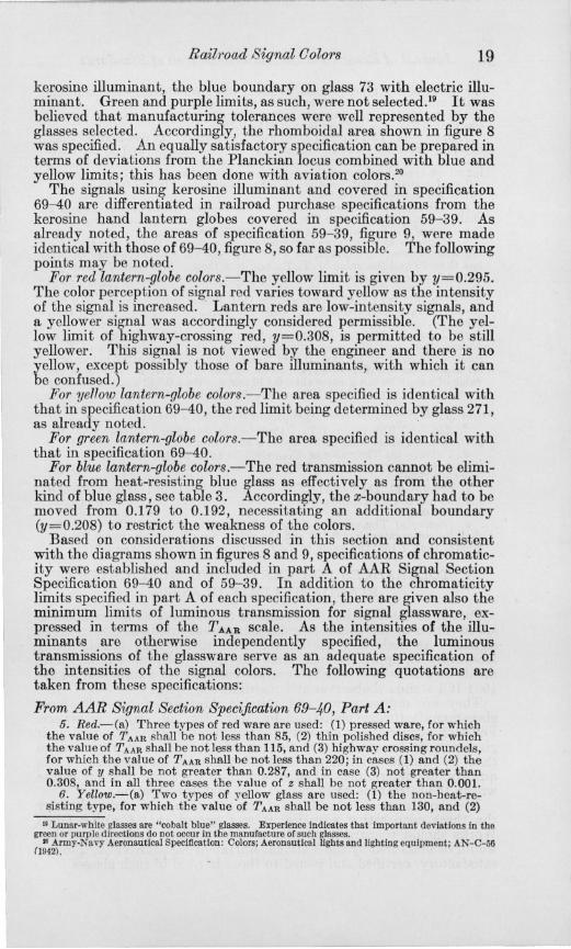
This color temperature is of little importance to the chromaticity specifications, being intermediate to the other two; but values of x, y, and z are given to indicate the course of the chromaticity loci for the respective glasses as the color temperature of the illuminant is varied over the range from 1,900 to 2,848° K. These loci are illustrated in figure 7 .
0 .80
... ~6~.~ .0· .. ·· .o ~.JO
",
5100
,70.
Y Green
.60
5000
.50
.40
./0
' .
MIXTURE DIAGRAM ACCORDING TO THE 1931 I .C.I. STANDARD OBSERVER
AND COORDINATE SYSTEM
'.
Ba sic Stimul us : [qual Energy. Interpolation to eve ry
milli micron by Smith • Guild ITrans. Op t .Soc. vol 31. pp. 98 - 102 ; !l31-3Z~
Pl a nc kian L ocus based on C,' I4,350 micron degrees.
NATIONAL eUR[AU 0" ,TANOAIilOI
COlO"'MtTIIt'f :5[C TIOH
X FIGURE 7.-101 chromatLctty (mixture) diagram showmg variattons in the chroma
ticity (x, y) of signal glasses as the illuminant is changed from 1,9000 through 11,3600 to 2,8480 K.
It is apparent that in defining areas of acceptable chromaticity on the chromaticity diagram, one is interested primarily in the particular illuminant-glass combinations used in actual signaling practice. For example, certain of the glasses are designed for use only with kerosine illuminant and certain others for use only with electric illuminants; see table 2. Others like the nonheat-resisting (non-HR) yellows and certain greens are used with both illuminants. A specification for signal colors (illuminant-glass combinations) must take this into account.
675813-46-- 2

16 Journal of Researoh of the National Bureau of Standards
The areas finally selected and in current status are shown in figure 8, which is a reproduction of the diagram illustrating part A of AAR Signal Section specification 69-40 for signal colors, excluding kerosine hand lantern globes, and in figure 9, which is a reproduction of the corresponding diagram in specification 59-39 for kerosine hand lantern globes. Large-scale sections of parts of figure 8 are shown also in figures 10 to 12.
.60
.000
.50
.40
.10
'0.
-'-~"'! 'I MIXTURE DIAGRAM ACCORDIN G TO THE
1931 I.C.!' STANDARD OBSERVER AND COORDINATE SYSTEM
Basic Stimulus: Equal Energy. InterpofaU o n to ellery
m il limicron by Smith
,-;,..... .0.5•5 0 • Guild (Trans.O p t.Soc. vol 31, pp. 98 -102 19 3 1- 32~ -...
:.., ~_ ·o~60 .... ...,
D·'
(y -1.$4$ (XOO. /JQ»
(x -0._.28'
'. .0.5•70
Yellow
°.0 •560
Planckian Locus based on c,..!4,350 micr on degrees.
COLOR1M[TAY .sECTION
00<) Spectrum locus -- Planckian locus
.B6.!..I...WAY~~ PRES5WARE AND DISC GLASSES
o IJluminant at 1900 0 K 6 lIIumlnant at 2848°K
J:. HIGHWAY CROSSING RED GLASSES
X FIGURE 8.-ICI chromaticity (mixture) diagram showing the permissible areas for
railroad signal colors and the locations of the standard limit glasses Jor the designated illuminants, according to AAR Signal Section specification 69-40.
In figures 8 and 9 16 may be noted (1) the spectrum locus from 380 to 780 mIL, (2) the Planckian locus from <100° K to 00 ° K, (3) the equations defining the straight lines bounding the areas of permissible chromaticities, and (4) the point for each standard glass plotted for illuminant at 1,900° and/or 2,848° K.
A chart similar to figure 8 has appeared in the various AAR Signal Section specifications, beginning in 1935, these being based on reCOill-
" In figures 8, 9, and 13, certain of the numbers designating the blue and purple glasses carry the auxiliary designations B or P, as engraved on the glasses. In the rest of the paper, however, these letters have beell omitted as they seemed unnecessary !\nd somewh~t con(usin~, .

Railroad Signal Oolors 17
mendations made to the signal engineers in 1933, as already noted. The chart shown in figure 9 first appeared in 1938 in specification 59-38. The areas from specification 69-38 were incorporated so far as possible into 59-38, deviations being made only where the standard glasses selected for 59-38 would not fall within the areas already selected for 69-38.
Some discussion should be given regarding the reasons leading to the choice of boundary lines in figure 8. Obviously, simplicity of
.60
5000
.50
.40
. 30
. 20
. 10
/ /
..
MIXTURE DIAGRAM ACCORDING TO THE 1931 I.C l. STANDARD OBSERVER
AND COOR~NATE SYSTEM
Basic Stimulus : Equa l Energy. I nterpo lation to every
m illi m ic ron by Sm i t h & Guil d (Trans. Opt.Soc. vo l 31, pp. 98 -1 02 1931-l2~
Planckian Locus based on C,'14.)50 micron degrees.
N ... TIONAL .VACAU OF STANO",nos
COLo..l lroI[TIIIT stCTIOH
·o.~eo
:? 0." (!I " ~:6='" ()~:;~~Jz ) :;} CfS'I10-;-,. - - - - - - - - -
• 1..£1 <"«c. 2.11 "'z....". (!I . D. J!.,.) 600--------..
o 0 • Specirum locus -- Planckron locus
RAILWAY SIGNAL COLORS LANTERN GLASSE.S o Illuminanl at 19000K
.70
x 0 .80
FIGURE 9.-IeI chromaticity (mixture) diagram showing the permissible areal! for hand lantern colors and the locations of the standard limit glasses for 1,900° K illuminant, according to AAR Signal Section specification 59-39.
specification will be secured by using lines parallel to the x or y axes, at 45° to these axes, or passing through the origin. Where possible, then, such boundaries were used; deviations from such boundaries were made only when it seemed desirable for special reasons. These boundaries of figure 8 and specification 69-40 are considered in detail in the following sections.
For red colors.-The area is defined by the lin es y=0.308 (for highway-crossing red) or 0.287 (for other reds) and z=O.OOl. Reference to table 4 shows that these values of y represent closely the yellow Umits for the respective reds as given by the respective standard

18 Journal 01 Research of the National Bureau of Standards
limit glasses when used with electric illuminant. Kerosine illuminant gives lesser values of y for the same glasses, which is satisfactory. The z limit is a rather liberal tolerance for selenium red glasses, but there is no need to make it more restrictive. Here, as with most of the other colors, the spectrum automatically forms one boundary of the permissible area, but this spectrum line does not need to be specified. It may be noted that the parts of the areas enclosed by the spectrum and the line joining the red and violet ends of the spectrum are indicated by continuous lines. The extensions of these lines beyond the spectrum are indicated by dashed lines.
For yellow coloTs.-The green limit is based upon the value of y for glass 141 with electric illuminant, and the red limit is close to the value of y for glass 142 with kerosine illuminant.17 Values of y for the disk glasses with electric illuminant are between these limits. The third boundary line, y=0.864-0.783x, restricting the weakness of yellow signal colors, was selected to give maximum deviations from the Planckian locus and still make it possible to pass all the glasses. It may be noted from figure 8 that this area falls midway between the red and yellow regions of the diagram rather than within the yellow region. Signals that are truly yellow rather than orange are unsuitable because they are found to be more confusible with bare incandescent lights and lunar-white signals than are the railroad signal yellows.
For green colors.-The yellow limit is based on glass 134 with kerosine illuminant and the blue limit is close to glass 87 with electric illuminant. The somewhat arbitrary boundaries, z=0.186 and y=0.400, would intersect near the illuminant region, and there seemed to be no adequate reason for attempting to secure boundary lines that might theoretically be slightly more appropriate. It might be argued, for example, that the line z=0.186 should be replaced by a line connecting the point for glass 134 (with kerosine illuminant) with the 1,9000 point on the Planckian locus. However, as transmission limitations prevent glasses from being accepted which would plot much closer to the spectrum than do glasses 87 and 140, the exact course of these two boundary lines is of little importance. Simplicity of specification justifies those chosen. The weakness boundary of the acceptable area for green signal colors, y= 1.068x+0.153, was determined by glass 134 for the two illuminants, all the other points fulling within this area.
For blue and purple colors.-These may well be considered together. The most important fact in this connection is, that blue and purple signals are not differentiated by the engineer by their chromaticities in the usual sense. Note in figure 8 that the "purple" signals do not fall in the purple region of the diagram. The blue must not be mistaken for green or lunar white or for the dichromatic purple; the purple must be recognized as a dichromatic (red-blue) signal.I8 It therefore seemed adequate to use the simple triangular areas shown, the overlapping being of no consequence.
For lunar-white colors.-These must be differentiated from yellow, green, and blue. The yellow boundary is based on glass 45 with
17 This boundary was originally at y=O.386, given by glass 142 witb kerosine iIIuminant, but was later lowered to y=O.384 to include the red limit of lantern yellow, No. 271.
Ii Because of cbromatic aberration of the lens system of tbe human eye, the dicbromatic image is normally a red center witb a blue halo or surround, though this will vary witb tbe vision of tbe observer. Neitber blue nor purple are used as long·range bigh·speed signals.
Railroad Signal Oolors 19
kerosine illuminant, the blue boundary on glass 73 with electric illuminant. Green and purple limits, as such, were not selected.19 It was believed that manufacturing tolerances were well represented by the glasses selected. Accordingly, the rhomboidal area shown in figure 8 was specified. An equally satisfactory specification can be prepared in terms of deviations from the Planckian locus combined with blue and yellow limits; this has been done with aviation colors.20
The signals using kerosine illuminant and covered in specification 69--40 are differentiated in railroad purchase specifications from the kerosine hand lantern globes covered in specification 59-39. As already noted, the areas of specification 59-39, figure 9, were made identical with those of 69-40, figure 8, so far as possible. The following points may be noted.
For red lantern-globe colors.- The yellow limit is given by y=0.295. The color perception of signal red varies toward yellow as the intensity of the signal is increased. - Lantern reds are low-intensity signals, and a yellower signal was accordingly considered permissible. (The yellow limit of highway-crossing red, y=0.308, is permitted to be still yellower. This signal is not viewed by the engineer and there is no yellow, except possibly those of bare illuminants, with which it can be confused.)
For ye170w lantern-globe colors .- The area specified is identical with that in specification 69-40, the red limit being determined by glass 271, as already noted.
For green lantern-globe colors.-The area specified is identical with that in specification 69- 40.
For blue lantern-globe colors.-The red transmission cannot be eliminated from heat-resisting blue glass as effectively as from the other kind of blue glass, see table 3. Accordingly, the x-boundary had to be moved from 0.179 to 0.192, necessitating an additional boundary (y=0.208) to restrict the weakness of the colors.
Based on considerations discussed in this section and consistent with the diagrams shown in figures 8 and 9, specifications of chromaticity were established and included in part A of AAR Signal Section Specification 69--40 and of 59-39 . In addition to the chromaticity limits specified in part A of each specification, there are given also the minimum limits of luminous transmission for signal glassware, expressed in terms of the T AAR scale. As the intensities of the illuminants are otherwise independently specified, the luminous transmissions of the glassware serve as an adequate specification of the intensities of the signal colors. The following quotations are taken from these specifications:
From AAR Signal Section Specification 69-40, Part A: 5. Red.-(a) Three types of red ware are used: (1) pressed ware, for which
the value of TAAn shall be not less than 85, (2) thin polished discs, for which the value of T AAR shall be not less than 115, and (3) highway crossing roundels, for which the value of T AAn shall be not less than 220; in cases (1) and (2) the value of y shall be not greater than 0.287, and in case (3) not greater than 0.308, and in all three cases the value of z shall be not greater than 0.001.
6. Yellow.-(a) Two types of yellow glass are used: (1) the non-heat-resisting type, for which the value of TAAR shall be not less than 130, and (2)
" Lunar-white glasses are "cobalt blue" glasses. Experience indicates tbat important deviations in the green or purple directions do not occur in the manufacture of such glasses.
" Army-Nllvy Aeronautical Specification: Colors; Aeronautical lights and lighting equipment; AN-C-56 (I942) .

20 Journal of Research of the National Bureau of Standards
the heat-resisting type, designed for use in thin discs with electric illuminant, which must have one surface depolished and for which the value of TAAR need not be specified; in both cases the value of y shall be not greater than 0.429 nor less than 0.384, also not less than 0.864-0.783x.
7. Green.-(a) Two types of green glass are used: (1) the non-heat-resisting type, for which the value of TAAR shall be not less than 150, and (2) the heatresisting type, designed for use in thin polished discs with electric illuminant, for which type the value of TAAR shall be not less than 138; in both cases the value of y shall be not less than 00400 nor less than 1.068x+ 0.153, and the value of z not less than 0.186.
8. Blue.-(a) The value of TAAR shall be not less than 75; the value of x shall be not greater than 0.179, and the value of y not greater than 1.15x; the value of TrlTw shall be not greater than 0.008.
9. Purple.-(a) Two types of purple glass are used: (1) that designed for use with kerosene illuminant, for which type the value of TAAR shall be not less than 73 and the value of TrlTw not less than 0.116, and (2) that designed for use with electric illuminant, for which type the value of TAAR shall be not less than 30 and the value of TrlT w not less than 0.187; in both cases the value of x shall be not greater than 0.228, and the value of y not greater than 1.505(x-0.130), nor shall the value of TrlTw be greater than 0.240.
10. Lunar White.-(a) Two types of lunar white glass are used: (1) that designed for use with kerosene illuminant, for which type the value of T AAR shall be not less than 80, and (2) that designed for use with electric illuminant, for which type the value of TAAR shall be not less than 147; in both cases the value of x shall be not greater than 00440 nor less than 0.330 and the value of y not greater than 0.5lx+0.183 nor less than 0.5lx+0.172.
From AAR Signal Section Spec1jication 59-39, Part A: 5. Red.-(a) The value of TAAR shall be not less than 140; the value of y
shall be not greater than 0.295; and the value of z not greater than 0.001. 6. Yellow.-(a) The value of TAAR shall be not less than 200; the value of
y shall be not greater than 0.429 nor less than 0.384, also not less than 0.864-0.783x.
7. Green.-(a) The value of TAAR shall be not less than 125; the value of y shall be not less than 00400 nor less than 1.068x+0.153, and the value of z not less than 0.186.
8. Blue.-(a) The value of TAAR shall be not less than 55; the value of x shall be not greater than 0.192 and the value of y not greater than 0.208 nor greater than 1.15x; the value of T,IT", shall be not greater than 0.015.
v. TOLERANCES FOR CERTIFYING DUPLICATES OF STANDARD LIMIT GLASSES
Part A of specification 69-40 and of 59-39 serve as a fundamental specification of the colors (chromaticities and intensities) of railroad signals. As such they are adequate for use by any standardizing laboratory equipped to make accurate spectrophotometric measurements or otherwise to derive accurate colorimetric data based on the 1931 ICI standard observer and coordinate system.
They are not adequate and suitable, however, for use by most glass-manufacturing plants or by inspectors of signal glassware. For such purposes it is apparent that duplicates of the standard limit glasses must be available to the manufacturer or the inspector, so that by simple colorimetric and photometric comparisons it can quickly be determined whether any glassware in question comes within the tolerances given in part A of each specification.
In a continuation, therefore, of the work already undertaken by the three cooperating agencies, it was agreed that Corning Glass Works should prepare duplicates of the standard limit glasses that would be measured by the National Bureau of Standards and, if found satisfactory, certified and issued to those in need of such glasses.

Railroad Signal Colors 21
One of the most important questions to be decided in this connection was the magnitude of the tolerances to be adopted in accepting and certifying duplicates of the standard limit glasses. If too liberal tolerances were adopted, one manufacturer might be at a disadvantage relative to another by having a smaller total range within which he must keep his product. If the tolerances were too small, the difficulties of securing a sufficient number of acceptable duplicates would unduly prolong the work, and the time at which the specifications could be promulgated and the duplicates issued would be seriously delayed
The matter was actually decided largely on the basis that the smallest tolerances would be established and used, which would still permit Corning Glass Works to prepare a suitable number of duplicates within reasonable time and cost. This was effective and practical, even if not ideally scientific.
Space does not permit a detailed description of apparatus and procedures used in examining or measuring the hundreds of duplicate glasses submitted. Many of these details may be found in NBS Reports 6 and 7, to which reference has already been made. The following points may be briefly noted:
1. Colorimetric comparisons were made and relative values of luminous transmission were determined mostly by means of a Schmidt & Haensch Martens photometer with a simple two-part 6° photometric field. Most of the work was done with a color temperature of 2,360 0 K. This was necessary in the determination of TAAR and Tr/T"" and the field brightnesses were such that it was preferable to work at this color temperature for the chromaticity examinations. Care was taken to ascertain that all duplicates accepted would be valid for illuminants at 1,900° or 2,848°K, consistent with the tolerances to be given in the specifications. Duplicates and standards were so nearly identical that important questions of heterochromatic photometry did not arise.
2. Various methods were used to determine acc1.ll'ately the small chromaticity differences involved.
(a) With the selenium red glasses, where melt number has little significance, a large number of duplicates for each standard were examined and a sample found having a chromaticity differing from the standard by about the amount finally adopted in the specification, the magnitude of this tolerance being always sufficient to include the desired number of acceptable duplicates. The differences in x or y of this tolerance-limit sample from the standard were determined spcctrophotometrically.
(b) In certain cases-for example, with some of the blues and purples-duplicates of the standard were prepared from the same melt or piece. In such cases no deviations of chromaticity from thf' standard could be detected, experience indicating that the duplicates were all well within the tolocances finally adopted.
(c) In some cases Lovibond glasses of low number could be inserted in series with the standard until the duplicate was matched in chromaticity. Computation then ga,ve the differences in x or y from the standard. By interpolation, all chromaticities within the tolerance could be measured by means of the Lovibond glasses.
Cd) The chromaticities of the diffusing ("depolished") disk-yellow duplicate glasses were determined relative to the polished nondiffusing

22 Journal of Researoh of the National Bureau of Standards
standards on a color-temperature comparator having a large LummerBrodhun trapezoidal field, with special filters and diffusing plates. Chromaticity matches were made by varying the color temperature of one of the standard lamps.
3. Values of TT/T", for the blue and purple glasses were derived from measurements made on the Martens photometer with illuminant at 2,360oK and with a dark-limit red glass (duplicate of 86) over the ocular. This in effect limits the determinations to the visual range 650 to 770 m}.L, as called for in the specifications. As with measurements of TAAR, values were determined relative to a closely similar standard, whose value of TT/T", had been determined spectrophotometrically.
4. The uniformity of the values of TAAR over the surface of each 2-inch-square duplicate glass was determined by measurements made at four different regions relative to that at the center. Practically all
.285
!I
e---& SP£CTRuM .LOCIJI
.7JO
X.
FIGURE lO.-Large-scale section of figure 8 showing (dark areas) the tolerances in x and y permitted m glasses certified as duplicates of standard limit glasses designated as red, for pressed ware and disks.
glasses but the selenium reds and yellows were found to be uniform in transmission, that is, the values did not differ from those at the center by as much as 1 percent of the value. All the red glasses, and the disk-yellow and lantern-yellow glasses, are "selenium" glasses, whose color varies with heat treatment. On this account they are usually nonuniform in transmission and chromaticity. This was not tested for the 1-inch-diameter disk-yellow duplicate glasses. For the 2-inch squares prepared as duplicates for lantern yellows and for all the reds, however, the uniformity of luminous transmission was measured. Satisfactory chromaticity duplicates were too rare to permit any rejections for, nonuniformity. Instead, the variations of TAAR
are given in the certificate, with a note that such variations are usually accompanied by chromaticity variations- the higher the transmission the yellower (or greener) the glass. These variations of transmission often were several percent of tbe value at the center. Tolerances of ~x and ~y, as finally adopted and given in' part B of AAR Signal Glass Specifications 69-40 and of 59-39, are given in table 5. The tolerances for reds 154 and 86, for yellows 141 and 142

Railroad Signal Oolors 23
and yellows 199 and 200, and for greens 134 and 87 and greens 139 and 140, are illustrated in the large-scale sections of the chromaticity diagram shown in figures 10 to 12. Corresponding diagrams for the other glasses and colors can be plotted from the data of tables 4 and 5 if desired.
T A.BLE 5.- Maximum chromaticity deviations permitted for glasses cerUfied as duplicates of standard limit glasses for railroad signaling, AAR Signal Section Specifications 69- 40 and 59-39
Color Chromaticity, coordinale8, x, V, Z, and maximum rleviA~ Num· temper' tiom, dX, dY, tJ.z, for glasses and illuminants indicated
Color designation ber of ature of glass iIlumi·
nant :r dX Y dy z tJ.z ---------------------- -----------
o K
Rro_ __ _ _ _ _ ---- -- _ ---- _ __ _ I
154 2848 0. 7132 -0.0008 0.2867 +0.0008 0.0000 0. 001 -86 2848 .7224 ±.0008 .2776 ±.0008 .0000 .001-15 2848 .6927 +.0008 .3072 - . 0008 .0001 . 001·
400 2848 .7088 ±.0008 .2912 ±.0008 .0001 . 001· 201 1900 .7051 +.0008 .2948 -.0008 .0001 .001· 211 1900 .7178 ±.0008 .2822 +.0008 .0000 .001·
141 2848 .5560 +.0010 . 4291 - . 0010 .0149 -- ------142 2848 .5794 -.0010 .4151 + . 0010 .0056 ----- ---
yellow .. ........................ 199 2848 .5762 +.0010 .4226 -- ----- --- .0012 ±.0012 200 2848 .5889 -.0010 . 4073 ----- -- --- . 0038 -.0038 261 1900 .5873 +.0010 .4107 -.0010 .0020 ---- --.. -271 1900 . 61 51 -.0010 .3843 + . 0010 . 0006 -- -_. -_ .
0 ___ ------ ---- ----- _ --- -__ -- I
134 2848 .2448 -.0015 .4145 - . 0015 . 3407 --------87 2848 .2084 ±.0015 .4016 ±.0015 .3899 -------.
139 2848 . 2634 -.0015 . 4376 - . 0015 .2990 ----- -.-140 2848 . 2295 ±.0015 .4348 ±.0015 .3357 ___ - _0 __
137 1900 .3025 -.0015 . 4974 -.0015 .2001 --------322 1900 .2415 ±.0015 . 4942 ±.0015 .2643 - --- ----
Blue ...... : ................. .... j 47 1900 .li83 -.0020 . 2049 -.0020 .6168 ------- -57 1900 .1458 + . 0020 . 1387 +.0020 . 7154 ------ --
141 1900 .1916 - . 0030 . 2070 {+.OOIO } .6014 -.0020 ---- -- --131 1900 .1543 ±.0015 .1187 ±.0015 .7270 ----- ---
Purple .......................... { 56 1900 .2280 -.0020 . 147.1 -.0020 .6245 -- ------47 1900 .2158 +.0020 . 1000 +.0020 .6842 ----.---80 2848 .1661 ±.0005 . 0426 -.0010 . 7913 -- -- .-- .
108 2848 . 1658 ±.0005 . 0352 +.0010 .7990 ------ --
Lunar white .................... { 45 1900 .4.395 - . 0015 .3981 ±.0010 .1624 -- _.- ---74 1900 .4005 -.0020 .3766 +.0020 .2229 --------
124 2848 .3654 ±.0010 .3688 ±.0010 .2658 ---- ----73 2848 .3308 ±.0010 .3426 +.0020 .3266 -- _._---
• Tbis tolerance is given in part A of tbe signal glass specifications. In effect it limits the toleranc~s of ±0.0008 in x and V for tbe dark·limit glasses, as shown in fignre 10.
All limit glasses must conform to the restrictions imposed by part A of each specification. This is noted in table 5 for the red glasses by giving the tolerance ~z= 0.001; see also figure 10. Other similar restrictions may be noted for yellow 141, figure 11; green 134, figure 12; and for others.
Probably in most cases the tolerances shown in table 5 are logical in terms of the coordinates used. Where a standard glass is a chro-' maticity limit it is logical that duplicates of this glass be allowed to deviate toward but not away from the optimum chromaticity. For example, with yellow glass 141, which is a pale and green limit, the restrictions of table 5 (combined with part A) insure that duplicates of this glass can deviate only in the red and more saturated directions.
In other cases the logic of the situation is violated. This is t.rue for red 154. The logical tolerances are ~x=+0.0008, ~y=-0.0008, as

24 Journal of Research of the National Bureau of Standard8
are given for reds 75 and 201. With red 154, however, practically all the close duplicate glasses available were in the region x=0.7132 -0.0008 and y=0.2867+0.0008. To expedite the work, therefore, the tolerances shown were adopted, it being considered that a value of y=0.2875 did not exceed the value of y=0.287 given in part A of the sp.ecification.
Corresponding "reasoning," based on expediency rather than idealism, resulted in some of the other tolerances shown. However, the
0.43
.42
AI
.40
.39
!.!I : 0.429 )
d1. ,. f (J.OO/"
dZ .. Z O . CO/Z
L/l. ... _ 0.001 0 59 1 rr'lf1
/ (!I~o.864 ·0·783X)
1700' K
1600 Q K
~ SP'CCTRUM LOCUS 1500' K
~ PLANCKIAN LOCUS
.56 .57 .58
YELLOWS
o ILLUMINANT AT 1900'K
t;. 1 LLUMINANT AT 2848' K
.59 .60 .61
X FIGURE ll.-Large-scale section of figure 8 showing (dark areas) the tolerances in ._ x and y, or x and z, permitted in glasses certified as duplicates of standard limit e.glasses designated as yellow, for pressed ware and disks,
time involved in preparing samples and making measurements was greatly shortened, and the issuance of the specifications expedited, by permitting such deviations from what in many cases might be considered a more ideal set of tolerances.
In addition to restrictions on the chromaticities of the duplicates of the standard limit glasses, as shown in table 5, it was also desirable to set tolerances on the values of T AAR for such glasses, and of TTl TID for the blue and purple glasses. Accordingly, values were adopted as shown in table 6. The magnitudes of the tolerances were determined largely by the same considerations as were effective for the chromaticity tolerances. In these cases, however, itisno disadvantage to any manufacturer if the TAAR value of his glass is more or less than that of another manufacturer. This is because the manufacturer is required to have an "approved photometer," by means of which the value of TAAR for any glassware can be actually measured from the

Railroad Signal Oolors 25
.50 (z = 0 . 186)
.48
.46
.44
.42
GREENS
o II.I.UMINANT AT 19000 K
'" II.I.UMINANT AT 2848 0 K
., 'Y
t4~ • :I O . QOI$
Jly . 3. O . OO IS
.2 2
140
4%" ~ " , O':JI~
4:1: ·0 . /)" ' $
.24
134
o 87
134
A!I ,. • D. DO tS
( y = 1 . 068. + 0.15.3)
.26 .28 .3 0 .32
X
FIGURE 12.-Large-scale section of figure 8 showing (dark areas) the tolerances in x and y permitted in glasses certified as duplicates of standard limit glasses designated as green, for pressed ware and disks.
TABLE 6.-Maximum detiations of luminous transmission on the AAR scale, T AAR, and of red to total luminous transmission, T, / Tv, both for 2,360° K, permitted for glasses certified as duplicates of standard limit glasses for railroad signaling, AAR Signal Section specifications 69- 40 and 59- 39
Color desig· nation Type
{(69-40. Except highway
crossing) . Red ............. Highway crossing_ .. _. _____ _
Lantern_. __ .' ______ . ____ ' _ ..
Yellow .. -- .- .. -- {r!~;;~::::::::::::::::::: INon.HR .. _ . . _ .• -..... --.... Green .•• _ •. _ •• _ _ Disk_ ........ _ ........ __ __ ..
Lantern ___ ... _ .. __ .. _. _ .....
BluL .. -... -. -. L'-nterii~_~: ~ _-.-. ~ :~.-_~:: _-_-_:: Purple_ - -------- ~~le:~~~~::::::: : :::::::::::: Lunar white_. ___ Kerosine _______ ____________ _
Electnc ____________________ _
• For blue and purple glasses only. ~ No values specified_
Values of TAAR Values of T,/Tv '
Light limit Dark limit Light limit Dark limit
170 ±15
310 ±30 250 ±15 215 ±10 (b)
300 ±15 205 ±10 190 ±10 185 ±10 130 ±5 125 ±5 130 ±5 40 ±3
122 ±5 200 ±10
100 ±5
220 ±20 145 ±5 160 ±5 (bl
250 ±15 150±5 138 ±5 127 ±5 75 ±3 56 ±3 73 ±3 30 ± 2 80 ±4
147 ±5
0.008 ±O. 001 .014 ±.002 . 120 ±.01O .190 ±.020
0. 000+0.001 .008 ± . 002 .160 ±.01O .220 ±.02O

26 Journal of R esearch of the National Bureau of Standards
known (certified) values of T AAR engraved on his duplicate limit glasses. In other words, this certified glass is a transmission standard, not a transmission limit, and the minimum values of T AA R given in parts A and C of the specifications are the ones that apply to his glassware. This is taken care of in the specifications by the following note:
It may be noted that in some cases a cert ified dark-limit glass may have, in accordance With this table (table 6) a value of T AAR slightly less than that given in parts A and C of this specification; this does not, however, invalidate parts A and C, which must be met by all glasses to be used in railroad signaling.
VI. EXPRESSION , OF RAILROAD SIGNAL COLORS IN A UNIFORM-CHROMATICITY-SCALE COORDINATE SYSTEM
As already noted, the 1931 ICI coordinate system has become a more or less universal language in which the chromaticities of colors may be expressed in terms understood and used by a great majority of workers in colorimetry, both in this country and abroad. As such, it is useful and adequate to define chromaticities and to express tolerances for specifications in a manner similar to that used in the railroad signal specifications as described in this paper.
This coordinate system suffers from one defect, however, in that equal distances in different parts of the diagram, or equal distances in different directions on the same part of the diagram, do not correspond accurately to equally perceptible differences in chromaticity as judged by the average observer. This matter has been considered by various investigators/1 who have in turn proposed "uniform-chromaticityscale" triangles or coordinate systems, and with a considerable measure of success. However, there are great difficulties in the way of obtaining a satisfactory coordinate system of this kind. Aside from the question whether any plane surface will give such uniform chromaticity scales, it is known that different systems would be necessitated for differing observing conditions. For example, the same coordinate system will not give equal chromaticity scales for both (1) extremely small sources such as are used in most signal installations and (2) large fields, such as are commonly used in color matching of textiles or in comparing samples with Munsell standards.
Although such investigations are of great interest and may eventually lead to revision of the ICI coordinate system, there is no prospect that such revision will be seriously attempted for a long time. In the meantime, however, it is often instructive to express results in one of these systems to obtain a better idea as to the relative perceptibility of the various colors involved.
The first attempt at transformation of the leI coordinate system to a uniform-chromaticity-scale coordinate system was made by Judd.22 As the data on which this transformation was based were obtained with a small (2°) photometric field and with dark surrounds, it is to be expected that this system would be a good approximation to that applicable to signal colors under the usual signaling conditions. In fact, no certain improvement in Judd's system for such a purpose has been made.
21 See references 721- 31 of chapter VII, Quantitative data and methods for colorimetry, of the forthcoming report of the OSA Committee on Colorimetry, J. Opt . Soc. Am. 34, 633 (1944).
22 Deane B . Judd, A Maxwell triangle yielding uniform chromaticity scales, J . R esearch NBS U, 41 (1935) RP756; J . Opt. Soc. Am. 25, 24 (1935).
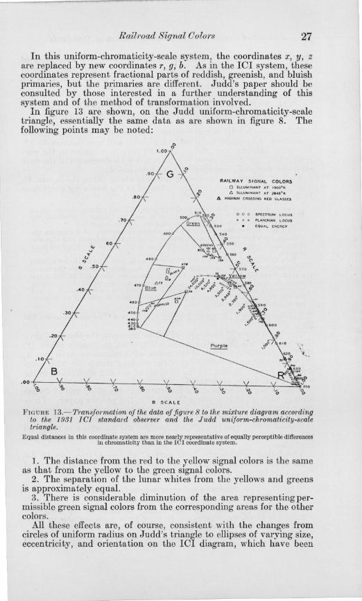
Rail1'oad Signal Colon 27
In this uniform-chromaticity-scale system, the coordinates x, y, z are replaced by new coordinates r, g; b. As in the 101 system, these coordinates represent fractional parts of reddish, greenish, and bluish primaries, but the primaries are different. Judd's paper should be consulted by those interested in a further understanding of this system and of the method of transformation involved.
In figure 13 are shown, on the Judd uniform-chromaticity-scale triangle, essentially the same data as are shown in figure 8. The following points may be noted:
. 80
.30
B SCALE
RAILWAY SIGNAL COLORS o ILLUMINANT AT 1900· ...
6 lLL U M INANT AT ze.-e· ... Il. HIGHWAY CROSSI NG RCO GLASSeS
o 0 0 SPECTRUM LOCUS
P\.ANCKIAN L OCUS
CQUAL (N(RGY
.~
o
FIGURE 13.- l'ransf01·mation of the data of figure 8 to the mixture diagram according to the 1931 leI standard observer and the Judd uniform-chromat1:city-scale triangle.
Equal distances in this coordinate system are more nearly representative of equally perceptible differences in chromaticity than in the IOI coordinate system.
1. The distance from the red to the yellow signal colors is the same as that from the yellow to the green signal colors.
2. The separation of the lunar whites from the yellows and greens is approximately equal.
3. There is considerable diminution of the area representing permissible green signal colors from the corresponding areas for the other colors.
All these effects are, of course, consistent with the changes from circles of uniform radius on Judd's triangle to ellipses of varying size, eccentricity, and orientation on the 101 diagram, which have been

28 Journal of Research of the National Bureau of Standards
illustrated elsewhere.23 They show, furthermore, the excellence of the signal colors selected by the engineers, particularly the choice of the red, yellow, and green signals used for long-range signaling on the main lines, where the trains move at high speed.
VII. AAR SIGNAL SECTION SPECIFICATIONS FOR SIGNAL GLASSES AND HAND LANTERN GLOBES
References to AAR Signal Section specification 69-40, Signal glasses (exclusive of kerosene hand lantern globes), and specification 59-39, Kerosene hand lantern globes, have already been made in the preceding sections of this paper in connection with discussion of the data on which parts of these specifications were based.
Each of these specifications consists of three parts, A, B, and C. The purposes of these parts are indicated in the following quotations from specification 69-40:
Part A of this specification is for the purpose of defining the minimum values of luminous transmission for signal glasses and the limits of chromaticity for signal colors produced by illumiuant-glass combinations.
Part B of this specification is fur the purpose of defining the maximum deviations from the standard limit glasses, both in transmission and chromaticity, to be permitted in glasses certified as duplicates of the standard limit glasses.
Part C of this specification is for the purpose of providing approved colored roundels, lenses, discs, and slides for railroad signaling, to describe the materials and specify the appliances and appurtenances necessary to make the required tests and inspection. It sets forth specific detail requirements representing modern signal practice recommended for new installations and for the replacement of existing material when general renewal or replacement becomes desirable.
Similar purposes are given for parts A, B, and C of specification 59-39.
The three parts of these specifications illustrate the threefold division which a complete color specification often necessarily takes: (1) the fundamental definition of the colors, with tolerances, as in part A, (2) the fundamental definitions of the working standards, with tolerances, as in part B, and (3) the methods of use and application of the working standards, as in part C.
Consideration of parts A and B of specifications 69-40 and 59-39 has already been given in sections IV and V of the present paper. These two parts relate entirely to colorimetric or photometric specifications. Part C gives various information pertinent to a purchase specification, as quoted above, and in addition, specifies the transmission tests and the chromaticity tests that are made possible by the certified duplicate limit glasses.
The following excerpts from part C of specification 69-40 describe these tests, and indicate the part that the National Bureau of Standards takes in the certification of duplicate limit glasses.
3. Apparatus and appurtenances for testing
(a) Certified limit glasse8
1. Certified light and dark limit glasses, calibrated by the N ationaI Bureau of Standards, Washington, D. C., shall be made available by the Seller for use of the Purchaser while conducting tests. These certified glasses
23 Deaue B. Judd, Estimation of chromaticity differences and nearest color temperature on the standard 31 ICI colorimetric coordinate system, J. Research NBS 17, 771 (1936) RP 944; J. Opt. Soc. Am.'ZG,m
6).

Railroad Signal Oolors 29
shall serve to define both the proper luminous transmissions of the glasses to be tested and the proper chromaticities of the resulting signal colors as hereinafter provided.
(b) Photometer
1. An approved photometer shall be made available by the Seller for use of the Purchaser while conducting tests. The illuminant used for measurements shall have a color temperature between 23600 K and 3000o K, and with no samples in the beams the two halves of the photometric field shall have the same chromaticity.
Note.-I. Vacuum tungsten lamps or gas-filled tungsten lamps with white 24
bulbs should give the specified color temperature, if operated at· normal voltage.
2. The 1908 specification established spectrophotometric values for a glass in each of the six colors, having a chromaticity and a transmission value approximately midway between the respective values for the light and dark limits. Each of these glasses was given an arbitrary value of 100 percent for use as a standard in laboratory and routine photomet ry. By means of these standard glasses, the present photometric scale for measuring the transmission of all colored signal glasses was established. This practice is continued, except that the 100 percent pressed standards have been superseded by the standard limit glasses in the form of 2-in. polished squares.
4. Tests and inspection
* * * * (e) Transmission test
1. The Purchaser shall measure the transmission TAAn of each glass, using the above specified photometer and illuminant and respective certified limit glasses whose values of TAAR are engraved thereupon. A glass shall not be acceptable whose value of TAAR is less than the respective minimum value given in the following table:
Table of minimum values of luminous transmission on the AAR scale, TAAR
Color designation
Red __________________________________________________________ _ Red (highway crossing) ___________________ ______ __________ ___ _ Yellow _____ _______ ______ ______________________ __ ___ _____ ____ _ _ Green ________ __________________________ ______________________ _ Blue ____ ___________________________________________________ __ _ _ Purple (kerosene) ____________________________________________ _ Purple (electric) ______________________________________________ _
t~:~ :~[~: ~~IC;;c~~~e!::=: = ====: = === ==::: ::::::: :::::::: ::::::
Pressed lenses and roundels, Polished flat and cut dises
or pressed slides
85 115_ 220 130 { (Depolished on
one side) 150 138. 75 73 30 30. 80
147
Note.-Either of the following additional tests shall be applied to the blue and purple glasses: (1) a red glass (approximately equivalent to the dark limit red glass) shall be placed over the eye-piece of tbe photometer. The transmission of blue glasses for this red light shall be not greater than that of the light limit blue glass, and similarly the transmission of purple glasses for this red light shall be not less than that of the dark limit purple glass; or (2) an incandescent lamp shall be viewed through a red glass (approximately equivalent to the dark limit red glass). The test glass and the limit glass, placed edge to edge, shall be rapidly alternated in position in the beam between the lamp and the eye. The transmission of the blue glasses so examined (for red light) shall appear not greater than that of the light limit blue glass, and similarly the transmission of purple glasses so examined (for red light) shall appear not less than that of the dark limit purple glass:
"That is, inside-frosted incandescent lamps.

30 Journal of Research of the National Bureau of Standards
(f) Chromaticity test 1. The Purchaser shall compare the chromaticity of each glass with that
of the respective certified limit glasse~ using for this purpose the above specified photometer an d illuminant. The comparisons shall be made with brightnesses matched. A glass shall not be acceptable if its chromaticity fails to meet either of the following requirements :
(a) The hue shall be not outside the hue limits given by the respective certified limit glasses; except that (1) for red glasses, only the yellow limit need be tested, and (2) for disc green glasses, the blue limit shall be given by the d,ark limit pressware (non heat-resisting) green glass.
(b) The saturation shall be not less than that given by the respective certified light limit glasses; except that, for lunar white glasses, the saturation shall be not outside the saturation limits given by the respective certified limit glasses.
* * * * 5. Marking
(a) Certified limit glass marking
1. Each certified limit glass (2 in. square or 1 in. diameter disc) shall be permanently engraved with the serial number by the maker and further permanently engraved by the National Bureau of Standards with the serial number, the designation, the value of T AAR, the N. B. S. test number, and thefdate.
Note.-In all cases, the engravings may be verified, and additional information regarding the certified limit glasses obtained, from the N. B. S. Certificates for the glasses which shall be made available to the Purchaser by the Seller.
Since the formulation of these specifications, over 200 duplicate limit glasses, with certificates, have been issued by the National Bureau of Standards to various applicants, some in foreign countries.
Success in carrying through the program of railroad signal glass standardization described in the previous and present papers has resulted in large measure from the generous cooperation of Corning Glass Works. All the field tests conducted by the signal engineers in their selection of colors and glasses have been held at Corning. Special acknowledgment is due in this connection to H. P. Gage, under whose supervision these tests were conducted and who has had charge of the preparation of the hundreds of glasses prepared during this work, either for study or for issuance as certified duplicate glasses.25
The authors have also had the valuable technical advice of Dr. Gage throughout the work.
In conclusion, reference should again be made to the progressive spirit of the railroad signal engineers, which has kept them among the leaders in the use of the best technics in the selection of signal colors and in the formulation of purchase specifications based on colorimetric data. Credit for the present satisfactory status of the railroad signal glass specifications is largely due to (1) the chairman of AAR Signal Section Committee VI, J. C. Mock, under whose supervision the initial program was started, and A. S. Haigh, who carried on after the retirement of Mr. Mock and brought the specifications to their present status, and (2) the secretaries of the Signal Section, H. S. Balliet at the start of the work and his son, R. H. C. Balliet, in whose office the preparation and revision of the specifications have been handled.
WASHINGTON, August 31, 1945. " Many of the glasses certified by tbe National Bureau of Standards bave been prepared by Corning
Glass Works witbout cbarge. Under present arrangements such glasses may be purcbased from Corning Glass Works for a nominal amount and certified by the Nationa! Bureau of Standards at regular test.fee schedules. The Bureau will also accept suitable glasses from other companies for test, witb the regular charge for certification or rejection.