Embed Size (px)
Citation preview

lable at ScienceDirect
International Journal of Pressure Vessels and Piping 86 (2009) 748–756
Contents lists avai
International Journal of Pressure Vessels and Piping
journal homepage: www.elsevier .com/locate/ i jpvp
Spatial variation of residual stresses in a welded pipefor high temperature applications
G. Hilson a, S. Simandjuntak b, P.E.J. Flewitt a,c, K.R. Hallam a, M.J. Pavier b,*, D.J. Smith b
a Interface Analysis Centre, University of Bristol, Bristol BS2 8BS, UKb Department of Mechanical Engineering, University of Bristol, Queen’s Building, University Walk, Bristol BS8 1TR, UKc H.H. Wills Physics Laboratory, Department of Physics, University of Bristol, Bristol BS8 1TL, UK
a r t i c l e i n f o
Article history:Received 28 March 2008Received in revised form8 July 2009Accepted 13 July 2009
Keywords:P91 steel weldmentsResidual stressX-ray diffractionIncremental centre-hole drillingDeep-hole drilling, R6
* Corresponding author. Tel.: þ44 117 928 8211; faE-mail address: [email protected] (M.J.
0308-0161/$ – see front matter � 2009 Elsevier Ltd.doi:10.1016/j.ijpvp.2009.07.003
a b s t r a c t
Measurements of residual macro-stresses have been undertaken in a feature multipass circumferentialsingle V butt-weld made from a P91 ferritic steel pipe over different spatial depths: (i) �10 mm by X-raydiffraction, (ii) �1 mm by incremental centre-hole drilling and (iii) through wall section using deep-holedrilling. The ability to make near-surface X-ray residual stress measurements on as-oxidised surfaces hasbeen demonstrated and the implications for use in the evaluation of overall integrity are discussed. Eachof the three measurement techniques provides complementary and consistent measurement of inducedresidual stresses for weld metal, heat affected zone and parent metal for the as-welded and the post-weld heat-treated conditions over the complete spatial range. The results are discussed with respect tothe importance of the weld capping run in introducing near-surface compressive residual stresses, thethrough-wall profiles of the residual stresses measured at the weld metal position in hoop and axialdirections and the presence of existing surface oxide.
� 2009 Elsevier Ltd. All rights reserved.
1. Introduction
Major construction, process manufacturing, power generationand transport industries seek to underwrite safe, reliable andeconomic use of the structures and components that make up theprofile of their plant. An essential input to achieve this is structuralintegrity assessment. Structural integrity assessment is an activity[1–3] that draws together the individual fields of inspection andmonitoring, mechanical and physical properties of materials, weld-ing technology, structural analysis, general engineering safety andeconomic assessment. The designers of structures and componentsfollow guided, interactive processes directed to achieving a practicalbalance between structural capabilities and service requirements[4]. Because of microstructural complexity and associated stresses,weldments are often key features of structures and components inthe overall integrity assessment [5,6]. In all cases, it is necessary tohave knowledge of both the primary stresses and the secondarystresses, in particular the residual stresses [7].
Residual stresses are particularly important in view of the waythey are incorporated into assessment procedures such as thefailure avoidance procedure, R6 [7]. In general, residual stresses
x: þ44 117 929 4423.Pavier).
All rights reserved.
have been categorised on the basis of the length-scale over whichthey equilibrate [8]. Type I, macro-stresses vary continuously overlarge distances and many grains in a polycrystalline material. TypeII, meso-stresses operate over the dimensions of the size of theindividual grains. Stresses below this length-scale, that is withinindividual grains are classed as Type III, micro-stresses, and typi-cally arise from dislocation stress fields or coherency at interfaceswithin the microstructure. Macro-residual stresses provide theprinciple elastic stored energy in an un-cracked or cracked body togive a driving force for damage creation or evolution, although TypeII and Type III stresses may also provide a contribution.
Calculation of macro-residual stresses induced during weldingis not readily achieved although there have been various summa-ries of the procedures that can be adopted to simulate multipassweldments [9,10]. During multipass welding the material isexposed to different temperature histories and as a consequencecalculation has to take account of the inter-relationship betweenthermal, mechanical and microstructural contributions [11].
There is a range of techniques available for measuring stressesover a range of length-scales as presented in Fig. 1. These tech-niques can be invasive through to non-invasive and measurestresses from macro-scale down to the micro-scale, although ingeneral it is the macro-stresses that are incorporated into failureavoidance assessment procedures such as R6. It is important tounderstand the relationship between measurements made at

Depth (mm)
0.001 0.01 0.1 10 100
Non-invasive
Totallydestructive
Sub-surface
Synchrotron X-ray
Ultrasonic
Magnetic Neutron diffraction
Ring coring
Deep hole drilling
Contour method
PS
BRSL
1
Partiallyinvasive
Centre hole
Raman
Conventional X-ray
Surface
Fig. 1. Comparison of residual stress measurement methods (PS: photoluminescencespectroscopy; BRSL: block removal splitting and layering).
520 mm
300 mm180 mm
60 mm
5 mm
4 mm
2 mm
40 mm
45°
15°
50 mmb
a
Fig. 2. Dimension of pipe: (a) overall dimensions, (b) cross-section through weld.
G. Hilson et al. / International Journal of Pressure Vessels and Piping 86 (2009) 748–756 749
different length-scales and how they may be deployed in integrityassessments. As described by McDonald et al. [12,13], if an under-standing of the distribution of macro-stresses and their magnitudeis achieved from measurement, it is possible to use a combinationof measurement and calculation of these stresses in a strategy forunderwriting the design and operation of the plant.
In this paper we describe the measurement of residual macro-stresses in a feature multipass butt-weld made from a P91 ferriticsteel pipe. The 9–12 wt% chromium martensitic steels, such as P91,are potential candidate materials for the next generation of fossilfuel fired power generation plant. This is because they have goodcreep properties and corrosion resistance up to the higher oper-ating temperatures proposed for these power stations [14–16]. InSection 2, we describe the preparation of the trial welded pipe ofP91 steel together with the residual stress measurement tech-niques used. In Section 3, the results of stress measurements on theas-welded and post-weld heat-treated pipe are presented. Theseresults are discussed in Section 4 with respect to the spatialdistribution of the measured stresses, the ability to make X-raystress measurements on as-oxidised surfaces and the implicationsfor use in the evaluation of overall integrity.
Table 1Typical chemical composition of the P91 steel pipe (wt%).
C Si Mn Cr Mo V Nb Ni P S N Fe
0.104 0.27 0.46 8.17 0.90 0.194 0.064 0.16 0.014 0.003 0.055 Bal.
2. Experiment
2.1. Fabrication of P91 weldment
Fig. 2 shows the dimensions of the P91 pipe used in thesemeasurements and the geometry of the circumferential weld.The chemical composition and the mechanical properties of theP91 steel pipe provided by the manufacturer are shown in Tables 1and 2. The welding process started by pre-heating the pipe toa temperature between 200 �C and 250 �C; a temperature withinthis range was maintained until the weld was completed. Manualmetal arc (MMA) type welding was applied with a weld pass heatinput per unit run length of 1.5 kJ/mm. The weld consumable wasspecified as 4 mm diameter Babcock Type M rod with a typicalcomposition as shown in Table 3. A complete weld of 73 passes,illustrated in Fig. 3, was achieved by welding in one direction fromthe bottom of the weld preparation of the pipe to the outside untilminimum dimensions were achieved. At the outside of the pipe,there are six capping runs. The capping weld beads extend abovethe original pipe surface by approximately 4 mm and beyond theextent of the original butt-weld preparation by w5 mm on eachside. On completion of welding, the pipe was allowed to cool toroom temperature. Various residual stress measurements werecarried out before and after the post-weld heat-treatment (PWHT)
in a vacuum furnace at a temperature of 760 �C for 3 h witha heating rate of 100 �C/h and a cooling rate of 46 �C/h.
The parent P91 steel pipe had a tempered martensitic micro-structure with a prior austenite grain size of w20 mm (mean linearintercept). Within the weld metal the individual weld beads con-tained as-cast columnar grains and grain-refined regions arisingfrom the heat treatment as subsequent beads were laid down.Within each of these regions, the microstructure was temperedmartensite with a small proportion of delta ferrite. The heataffected zone (HAZ) extended over a distance of about 4 mm fromthe weld metal to the parent pipe in the direction normal to thefusion line. Within the HAZ, there were two main microstructuralregions. Immediate to the fusion boundary the microstructure wasessentially coarse grain size tempered martensite, with a prioraustenite grain size of w40 mm, and extending from this wasa region of varying microstructure with a typical prior austenitegrain size of w10 mm.
2.2. Measurement of stresses
Residual stress measurements were carried out using threetechniques: X-ray diffraction (XRD), incremental centre-hole dril-ling (ICHD) and deep-hole drilling (DHD). These techniques aredescribed in the following sub-sections. The locations where themeasurements were made are illustrated in Fig. 4.
2.2.1. X-ray diffractionA computer controlled X-ray diffractometer was used as
described previously [13]. The goniometer was driven overa circular arc to vary the j angle (the angle of the incident X-ray

Table 2Typical mechanical properties at room temperature of 9Cr–1Mo–V (P91) steel.
Yield stress, sY (MPa) Tensile strength, UTS (MPa) Young’s modulus, E (GPa)
450 666 214
12 3
4 56 78 9
10 1112
13 14 15
16 17 18
19 20 21 22
23 24 25 26
27 28 29 30
31 32 33 34 35
36 37 38 39 40
41 42 43 44 45
46 47 48 49 5051 52 53 54 55
56 57 58 59 60 6162 63 64 65 66 67
68 69 70 71 72 73
Fig. 3. Schematic cross-section through weld.
0°
180°240 mm
260 mm280 mm
360 mm
DHD 5
XRD 1
DHD 3DHD 2
DHD 1
ICHD 1 ICHD 2
75°
40°30°
-140°
-115°
0°
90°
-180°180°
-90°
G. Hilson et al. / International Journal of Pressure Vessels and Piping 86 (2009) 748–756750
beam to the specimen surface) between 3� and 50� using a steppermotor with 0.01� intervals. The aperture size used was 1 mmdiameter and the sample distance from the source and detector wascalibrated using cerium oxide powder. Cr Ka X-radiation anda position sensitive detector were used. The Cr Ka X-radiationresults in a {211} diffraction peak at 2q z 156�. The variations of 2q
versus sin2 j plots were recorded and the macro-stress was eval-uated using a linear regression fit to determine the gradient of theplots.
X-ray measurements were made so that the stresses could beprofiled across the weld metal, heat affected zone and parent metalof the pipe. At each position stresses were measured in twodirections along the pipe axis (axial measurements) and perpen-dicular to the pipe axis (hoop measurements). Stresses weremeasured before and after PWHT. First, measurements were takenon the as-oxidised surfaces with no surface preparation. For boththe before and after PWHT conditions the thickness of the surfaceoxide was assessed to be z2 mm. The area across the weld andparent metal (including the HAZ) was then ground to produce flatregions, polished to a 1 mm finish followed by electropolishingusing 5% HCl in water. Between 2 and 2.5 mm of material wasground from the weld metal caps. However less material, onlyabout 0.1 mm was removed from the HAZ and parent metal. X-raymeasurements were then repeated along this prepared surface. Anaccuracy of approximately 10 MPa was achieved using XRD.
2.2.2. Incremental centre-hole drillingIn the ICHD procedure, a special three element strain gauge
rosette with a mean radius of 2.57 mm was fixed to the welded pipesurface with epoxy resin glue. The stresses were relaxed by drillinga small 1.6 mm diameter hole in the centre of the strain gauge arrayin a series of steps. Each element of the gauge was set out to providereadings for the hoop and axial directions as defined in Section2.2.1. Measurements were made before PWHT at the centre of theweld and in the parent metal. It was found difficult to attach therosette gauge at the centre of the weld due to the surface profile ofthe weld beads and therefore approximately 2 mm was removedfrom the top of the weld beads using electro-discharge machining(EDM). For the parent metal, the surface was cleaned and groundwith 800 mm silica carbide paper before the application of a straingauge rosette. An RS 200 precision milling guide was attached tothe pipe and centred over the drilling area. Strain readings weremade at initial step sizes of 16 mm, increasing to 128 mm around1 mm into the pipe wall. Stress profiles were obtained from theICHD using the integral method [20–22]. Typical errors were�20 MPa. ICHD measurements were not made after PWHT.
2.2.3. Deep-hole drillingIn the DHD procedure, a 3.175 mm reference hole was first gun
drilled through the wall of the pipe. The diameter of the hole wasthen measured using an air probe system every 0.2 mm throughthe thickness of the pipe and along the axis of the hole. The
Table 3Chemical composition of the Type M weld metal (wt%).
C Si Mn Cr Mo V Ni P Al Cu Fe
0.098 0.45 1.11 8.61 1.02 0.21 0.22 0.015 <0.01 0.05 Bal.
diameter was measured at nine angular positions around the hole.To relax the stresses, a 10 mm diameter slot was trepanned aroundthe hole using electro-discharge machining (EDM). This leavesa notionally stress-free 10 mm diameter core with the original3.175 mm gun drilled hole at its centre. Finally, the diameter of thereference hole was re-measured using the air probe system. Thechange in the diameter of the hole before and after trepanningdetermines the diametral distortion of the hole edge which maythen be related to residual stresses present in the pipe before themeasurements were made. More details of the method aredescribed by George et al. [17,18]. Typical errors associated with theDHD measurements were �30 MPa.
Residual stress measurements using DHD were carried outbefore and after the PWHT. Before PWHT, stresses were measuredat the centre of the weld, through the heat affected zone at the edgeof the weld and remote from the weld in the parent material. AfterPWHT stresses were only measured at the centre and edge of theweld.
-180°DHD 4
XRD 2
Fig. 4. Position of residual stress measurements: XRD1 as-oxidised, electropolishedand after PWHT, XRD2 as-oxidised. DHD1, DHD2 and DHD3 before PWHT. DHD 4 andDHD5 after PWHT. ICHD1 and ICHD2 before PWHT.
a b
d
f
c
e
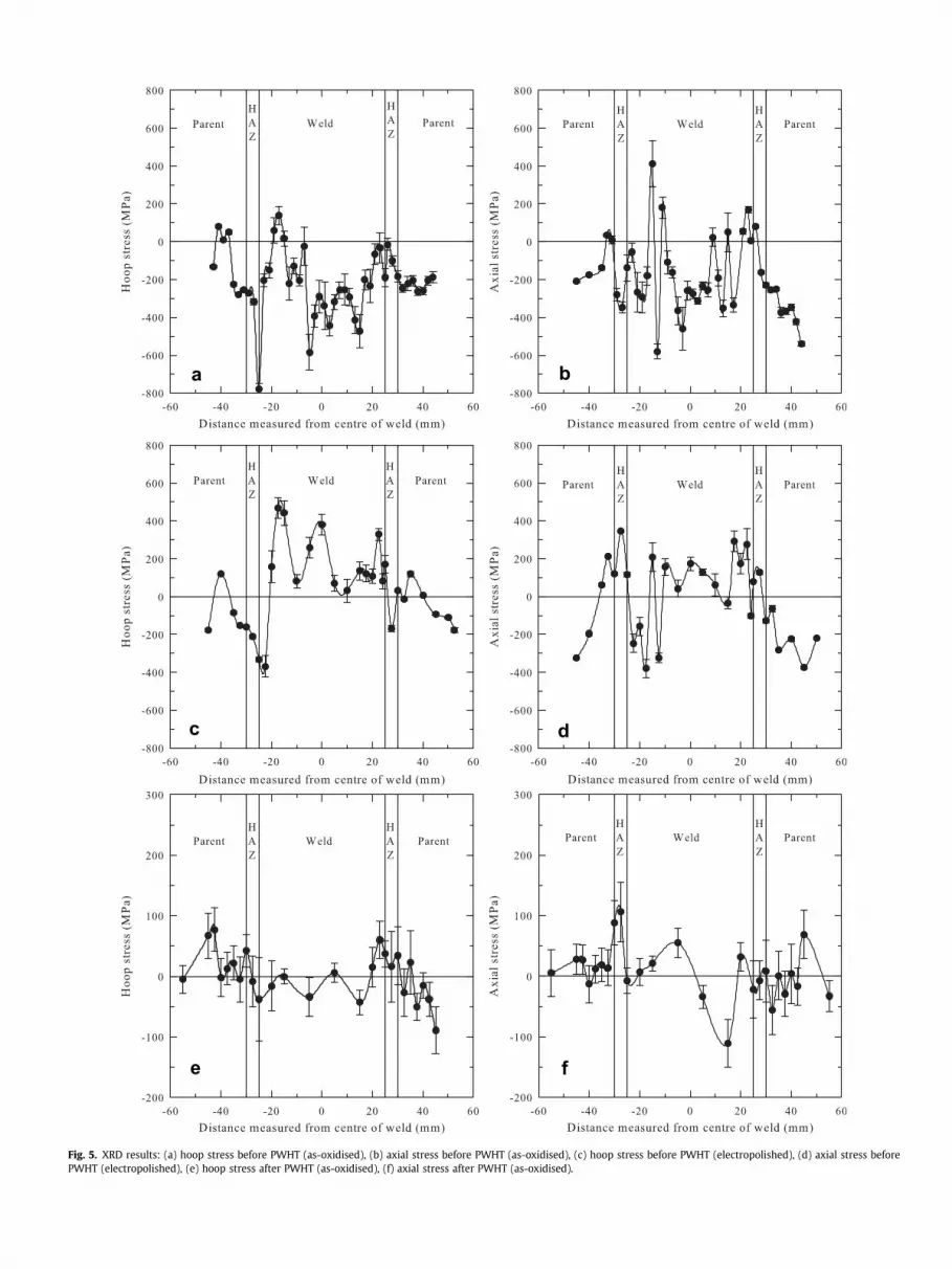
Fig. 5. XRD results: (a) hoop stress before PWHT (as-oxidised), (b) axial stress before PWHT (as-oxidised), (c) hoop stress before PWHT (electropolished), (d) axial stress beforePWHT (electropolished), (e) hoop stress after PWHT (as-oxidised), (f) axial stress after PWHT (as-oxidised).

G. Hilson et al. / International Journal of Pressure Vessels and Piping 86 (2009) 748–756752
3. Results
Profiles of the XRD taken across the weld in the hoop and axialdirections are shown in Fig. 5. Any random or systematic errors onthe measured data were small and the derived stresses were shownto be within the confidence required, indicating that there was nosignificant contribution arising from the various microstructuralregions across the weld. The results in Fig. 5(a) and (b) are beforePWHT with the pipe and weld in the as-oxidised condition. Thosein Fig. 5(c) and (d) are again before PWHT but now after the weldcap and parent pipe were electropolished. Fig. 5(e) and (f) showsthe results after PWHT for the as-oxidised condition. It can be seenthat the PWHT reduces significantly the magnitude of the residualstresses.
Fig. 6(a) and (b) shows the profiles of the residual stressesobtained from ICHD as a function of depth from the surface towardsthe inside of the pipe in hoop and axial directions measured nearthe centre of the weld and the parent metal. Due to the low stressesmeasured from the XRD and DHD techniques after PWHT, stressmeasurements using the ICHD technique were not made after thePWHT.
Fig. 7(a)–(d) shows the hoop and axial residual stressesmeasured using the DHD technique at the three selected locations,measured from the outside of the pipe before and after the PWHT.The results represented in Fig. 7(a) and (b) show that both hoop andaxial components of the residual stresses obtained prior to thePWHT were compressive near to the inside and outside surfacesand tensile near the centre of the of the pipe thickness. Themaximum magnitude of residual stress was in the centre of theweld in the hoop direction and was tensile and close to the yieldstress (see Table 2) of the material. After the PWHT, the stresses inthe hoop and axial directions were close to the magnitude ofresidual stresses measured at locations remote from the weldbefore PWHT, Fig. 7(c) and (d).
4. Discussion
The components of stress in a butt-weld are defined by thelongitudinal and transverse directions which coincide with thehoop and axial pipe directions, respectively [7]. The presence of
a
Fig. 6. ICHD results: (a) hoop stress before
the weld and the processes associated with welding introducethree-dimensional spatial variations in stress. Three techniques,XRD, ICHD, and DHD with different depth and volume samplingcapability have been used to determine the magnitude of thethrough wall section distribution of stresses in the hoop and axialdirections. The following discussion is divided into two sub-sections. The first sub-section is a discussion on the integratedresidual stress measurements that have been carried out using thethree techniques mentioned above. The effect of near-surface oxideon the residual stress measurements using XRD technique is alsoincluded in this part of discussion. The second sub-section containscomparison of residual stress measurements with the R6-level 2structural integrity assessment procedures.
4.1. Integrated residual stress measurements
4.1.1. X-ray diffraction (XRD) and effect of near-surface oxideIn the present case, X-ray diffraction technique was used to
measure and map the near-surface stress distribution across theweld. When undertaking X-ray stress measurements on samplesand indeed service components it is usual to remove any surfaceoxide and prepare the surface mechanically followed by electro-polishing, chemical etching or even electrochemical machining[25]. This latter step is adopted to ensure removal of any mechan-ically-induced damage arising from the preparation method [14]. Inpractice engineering components are usually oxidised followingextended periods in service. Hence if this oxide can be left andrealistic measurements made of the stresses, this increases theflexibility of the X-ray diffraction method. There are several factorsthat are important and have to be taken into account. The first is theattenuation of the X-ray beam as a result of the presence of theoxide. This has the potential to affect the depth of penetration ofthe X-ray beam into the steel substrate and thereby modify thevolume of material sampled when making a stress measurement.The linear absorption coefficients for haematite (Fe2O3) and a-ironwere calculated to be 479 cm�1 and 890 cm�1 respectively. Thepenetration depth of the X-rays into the a-iron substrate varieswith measurement angles j between 0� and 60� for various surfaceoxide thicknesses. In these calculations, it is assumed that the dif-fracted beam intensity is 5%. These results show that although the
b
PWHT, (b) axial stress before PWHT.

G. Hilson et al. / International Journal of Pressure Vessels and Piping 86 (2009) 748–756 753
penetration into the a-iron decreases as the j angle is increased,a realistic depth of substrate is sampled for oxide thicknesses of upto about 10 mm. Hence, the measurements made from the weldedpipe with z2 mm thickness of oxide are consistent with thisprediction. The second factor is that as the oxide grows, a stress isgenerated between the oxide and the substrate as a result of theassociated volume change. However, for oxides of thickness �2 mmthis contribution to the substrate stresses is insignificant.
Comparing Fig. 5(a) with Fig. 5(c) it can be seen that there isa reasonable correspondence of the residual hoop stress measuredby XRD for the as-oxidised and electropolished surfaces in theparent metal, since the electropolishing removes only a smallthickness of material here. However in the HAZ and the weld nosuch correspondence exists. In part this is due to the 2–2.5 mm ofmaterial removed in the electropolished case but also because theresidual stresses fluctuate widely as the point of measurementmoves from weld bead to weld bead. Unless measurements aremade in precisely the same position apparently different resultswill be obtained. The same general pattern can be seen in Fig. 5(b)
a
c
Fig. 7. DHD results: (a) hoop stress before PWHT, (b) axial stress befo
and (d) which shows the residual axial stress for the as-oxidisedand electropolished surfaces.
4.1.2. Incremental centre-hole drilling (ICHD)The incremental centre-hole drilling (ICHD) technique allows
the stress distribution to be measured incrementally to a depth of1 mm. The stress measurements were made near the centre of theweld metal and on the parent metal remote from the weld. To avoiddifficulties associated with attaching the strain gauge to theprofiled surface arising from the weld beads, EDM was employed toobtain a relatively flat surface to get a good attachment. Thisprocedure removed approximately 2 mm of the weld metal.Reports on the effect of EDM on near-surface residual stresses[23,24] mention that high tensile stresses were observed at theimmediate surface of the material and could be of a magnitudeapproaching the ultimate tensile strength of the material. It is alsoreported that the general spatial extent of the resultant residualstresses with depth decreased with the energy discharge level orspark energy although a similar value of maximum stress occurred.
b
d
re PWHT, (c) hoop stress after PWHT, (d) axial stress after PWHT.

G. Hilson et al. / International Journal of Pressure Vessels and Piping 86 (2009) 748–756754
Ekmekci et al. [23] showed for the highest energy level of 1.1 J, thetensile maximum stress was obtained at about 0.04 mm andrapidly changed to compressive stresses at about 0.2 mm depth.They argued that the stresses were deemed to arise mainly asa result of the thermal contraction of the resolidified metal,inducing plastic deformation and biaxial tensile stress. They alsodemonstrated that compressive residual stresses could also berelated to sample thickness, since residual stresses within plasti-cally deformed layers are equilibrated with elastic stresses in thecore of the material. Based on the results of these workers andconsidering the large geometry of this welded pipe, in the presentcase, EDM should only introduce small or negligible residualstresses for depths greater than 0.2 mm.
The stresses measured using the ICHD technique near thesurface down to the first 0.2 mm depth are often associated witherrors due to either the determination of the datum for depthposition or the near-surface geometry of the hole which may notcylindrical. Confidence in the measured stress increases with the
a
c
Fig. 8. Comparison of results before PWHT: (a) hoop stress at weld centreline, (b) axial str
range of depth from 0.2 mm to 1.0 mm as established in ASTM E837code [19] and in the Measurement Group TN-503-5 guidancedocument [20].
4.1.3. Deep-hole drilling (DHD)The deep-hole drilling (DHD) technique measured the stress
distribution through the thickness of the pipe wall. Fig. 7(a) and (b)shows the stresses measured at the centre and at the edge of theweld. Hoop and axial components of the residual stresses arecompressive near the inside and outside surfaces of the pipe andtensile near the mid-thickness. The stresses measured at the outsidesurface of the pipe demonstrate the importance of the weld cappingrun in introducing beneficial compressive residual stresses. Themaximum magnitude of residual stress is in the centre of the weld inthe hoop direction and is close to the yield stress of the material.
The stresses measured at the edge of the weld shown in Fig. 7(a)and (b) is sample of those within three regions: the weld metal, theheat affected zone and the parent metal. Because the stresses are
b
d
ess at weld centreline, (c) hoop stress at edge of weld, (d) axial stress at edge of weld.

G. Hilson et al. / International Journal of Pressure Vessels and Piping 86 (2009) 748–756 755
measured along a radial line, the measurements are taken at theedge of the weld on the outer surface but within the parent metalnear the inner surface. At the outside surface of the pipe, thestresses at the edge of the weld are similar to those at the centre.However, near the inner surface the stresses are quite different tothose in the parent metal. Fig. 7(c) and (d) shows that the stressesafter PWHT at the centre and edge of the weld metal are reduced toapproximately 20 MPa. This is close to the magnitude of thestresses measured in the parent metal before PWHT.
Although the DHD technique is able to measure residual stressesthrough the complete thickness of a component it is unable tomake measurements at precise locations. Because the techniqueworks by measuring changes in diameter of a small hole whena 10 mm diameter slot is cut around the hole, residual stresses areaveraged over a volume related to the diameter of this slot.
4.1.4. Comparison of measurementsNear-surface residual stress measurements using XRD and ICHD
and through-thickness stress measurement using DHD have beencarried out to cover a range of depths. These three techniques allowa full, through section residual stress profile in the butt-welded P91pipe to be determined. The graphs of Fig. 8 show the combined resultsof the measured through-thickness hoop and axial residual stressesin the as-welded pipe. Fig. 8(a) and (b) shows the stress distributionsmeasured at the centre of the weld metal in the hoop and axialdirections. The hoop and axial stress measurements from the threetechniques for the edge of the weld are shown in Fig. 8(c) and (d).
The XRD measurements are shown at two depths: 0.01 mm(10 mm) for the as-oxidised condition and 2 mm for the electro-polished condition. The measurements made in the electropolishedcondition will not correspond precisely to the residual stresses thatexist at a 2 mm depth since the electropolishing procedure willresult in a redistribution of the residual stress. For each conditiona range of values is shown taken from measurements on the surfacewithin a region corresponding to the size of the DHD cylindricalslot. The range of values is a result of the fluctuating stress fromweld bead to weld bead. The ICHD results are shown at depths from2 mm to 3 mm since 2 mm of material was removed before themeasurements could be made. Again, this removal of material willhave resulted in some redistribution of the residual stress. Finally,
a
Fig. 9. Comparison of DHD results before PWHT with R6 [7] and
although the DHD measurements were made without firstremoving material from the surface, the technique does not allowa precise measurement at a set depth as noted previously. Ratherthe measurement represents an average of the residual stressdistribution with depth.
Each of the three measurement techniques introduce uncer-tainties that make direct comparison of the results difficult.Nevertheless, taken together the results provide an understandingof the magnitude of the residual stresses and an indication of thereliability of the measurements.
4.2. Comparison with R6 assessment procedures
As considered in Introduction, it is important to include theresidual stresses in the evaluation of the integrity of weldedstructures and components. One particular assessment procedure,R6, makes recommendations depending upon the level of confi-dence required for the overall assessment. Hence, it is of interest tocompare the stress profiles recommended for level 2 assessmentswith the through section stress distributions obtained from thepresent work. Fig. 9(a) and (b) shows a comparison of the hoop andaxial stress distribution profiles measured from near the centre ofthe weld metal and profiles derived from the defect assessmentprocedure, R6 revision 4, Sections II.7 and IV.4, Characterisationapproach level 2 [7] is followed to define bounding for the through-thickness residual stress profile for the circumferential butt-weld.The R6 procedure presents residual stress distributions normalisedusing the yield stress of the material, therefore to prepare Fig. 9(a)and (b) the value for the yield stress in Table 2 was used. Fig. 9shows that the upper-bound axial and hoop through-thicknessresidual profiles recommended by R6 revision 4 (level 2) provide ingeneral overestimates of the hoop and axial residual stresses,although the measured hoop residual stress is similar in magnitudeto the R6 value at a depth of about 20 mm.
In addition, the residual profiles by Bouchard and Bradford [26]generated from new formulations based on finite element studiesfor axial and hoop residual stress as an extension to level 2approach are also represented in Fig. 9. These new formulationsprovide a generally closer agreement with the measured residualstresses than R6 but do not always provide an overestimate,
b
Bouchard and Bradford [26]: (a) hoop stress, (b) axial stress.

G. Hilson et al. / International Journal of Pressure Vessels and Piping 86 (2009) 748–756756
particularly for the axial component of residual stress near the mid-thickness of the pipe as also noted by Bouchard [27].
5. Conclusions
Measurement of residual stresses have been undertaken ina circumferential butt-welded P91 pipe over different spatialdepths: (i)�10 mm, by X-ray diffraction, (ii)�1 mm, by incrementalcentre-hole drilling and (iii) through wall section by deep-holedrilling. It may be concluded that:
1. The three measurement techniques provide complementaryand generally consistent measurement of welding-inducedresidual stresses for weld metal, heat affected zone and parentpipe over the complete spatial range.
2. The measurements in the as-welded condition point to theimportance of the weld capping run introducing near-surfacecompressive residual stresses for this geometry of butt-weldedpipe.
3. The post-weld heat-treatment of 760 �C for 3 h reduced the as-welded residual stresses to a low value of approximately20 MPa.
4. It is possible to undertake realistic residual stress measurementof near-surface �10 mm depth using X-ray diffraction withoutthe need to remove the surface oxide or any other preparation.This is valid in the present case for the oxide thickness of�2 mm. Simple considerations of X-ray beam attenuationindicate that this should also be applicable for oxide thicknessup to approximately 10 mm.
5. The through-wall profiles of residual stress measured at theweld metal position indicate that the recommended standardprofiles used for structural integrity assessment in proceduressuch as R6 are in general conservative with respect to flaw ordefect evaluation.
Acknowledgement
We would like to acknowledge the support of EPSRC through theSUPERGEN 2 programme (GR/S86334/01) and the followingcompanies: Alstom Power Ltd, Chromalloy UK, E.ON UK, HowmetLtd, Doosan Babcock Energy Ltd, National Physical Laboratory,QinetiQ, Rolls Royce plc, RWEnpower, Sermatech Ltd and SiemensIndustrial Turbomachinery Ltd. for their valuable contributions tothe project.
References
[1] Flewitt PEJ. In: Bakker A, editor. Structural integrity assessment of highintegrity structures and components: user experience, mechanical behaviourof materials. Delft: Delft University Press; 1995.
[2] Knott JF. Two steps from disaster. The science of engineering of structuralintegrity. London: Royal Society and Royal Academy of Engineering; 1999.Joint Lecture.
[3] Flewitt PEJ, Moskovic R. Contribution of multiscale modelling for underwritingnuclear pressure vessel integrity. Material Science and Technology 2004;20:533.
[4] Harris DO, Wells CH, Rau SA, Dedhia DD. Engineering codes for the analysis ofstructural integrity. International Journal of Pressure Vessels and Piping1994;59:175.
[5] Flewitt PEJ, Dowling AR. Proceeding of the TAGSI Seminar 2001. Institute ofMaterials, Maney, London; 2003. p. 1.
[6] Exworthy LF, Little WJ, Flewitt PEJ. Diagnosis of cracking in the boiler shellseam welds at Sizewell A power station. International Journal of PressureVessels and Piping 2002;79(6):413–26.
[7] Assessment of the integrity of structures containing defects. R6 Revision 4.British Energy Ltd.; April 2004.
[8] Withers PJ, Bhadeshia HKDH. Overview: residual stress. Part 2 – nature andorigins. Materials Science and Technology 2001;17:366–75.
[9] Karlson L. Modelling in welding, hot powder forming and casting. ASMInternational, ISBN 0-87170-616-4; 1997.
[10] Borjesson L, Lindgren L-E. Thermal, metallurgical and mechanical models forsimulation of multipass welding. Transactions of the ASME, Journal of Engi-neering Materials and Technology 2001;123:106–11.
[11] Warren AP, Bate SK, Charles R, Watson CT. The effect of phase transformationson predicted values of residual stresses in welded ferritic components.Materials Science Forum 2006;524–525:827–32.
[12] McDonald EJ, Hallam KR, Flewitt PEJ. A strategy for accommodating residualstresses in the assessment of repair weldments based upon measurement ofnear surface stresses. International Journal of Pressure Vessels and Piping2005;82(4):339.
[13] McDonald EJ, Hallam KR, Bell W, Flewitt PEJ. Residual stresses in a multi-passCrMoV low alloy ferritic steel repair weld. Materials Science and Engineering A2002;325:454–64.
[14] Sanderson SJ. Mechanical properties and metallurgy of 9%Cr–1%Mo steel. In:Khare AK, editor. Ferritic steels for high temperature applications, Proceedingsof ASME International Conference on Production, Fabrication, Properties andApplication of Ferritic Steels for High Temperature Applications, Warren, PA,6–8 October 1981, ASME, Metals Park, OH; 1983. p. 85–99.
[15] Bendick W, Ring M. Creep rupture strength of tungsten alloyed 9–12% Cr steelsfor piping in power plants. Steel Research 1996;67:397–405.
[16] Abd El–Azim ME, Nasreldin AM, Zies G, Klenk A. Microstructural instability ofa welded joint in P91 steel during creep at 600 �C. Material Science andTechnology 2005;21:779.
[17] George D, Smith DJ. The application of the deep-hole technique for measuringresidual stresses in autofrettaged tubes. ASME PVP High Pressure Technology2000;406:25–31.
[18] George D, Kingston E, Smith DJ. Measurement of through-thickness stressesusing small holes. Journal of Strain Analysis 2002;37(2):125–39.
[19] ASTM E 837-01. Standard test method for determining residual stresses by thehole drilling strain-gauge method; 2001.
[20] Grant PV, Lord PD, Whitehead PS. The measurement of residual stresses by theincremental hole drilling technique, Issue 2. A national measurement goodpractice guide. Teddington, Middlesex, United Kingdom: National PhysicalLaboratory; 2006. No. 53.
[21] Schajer GS. Measurement of non-uniform residual stresses using the hole-drilling method. Part I: stress calculation procedures. Transactions of theASME, Journal of Engineering Material Technology 1988;110:338–43.
[22] Schajer GS. Measurement of non-uniform residual stresses using the hole-drilling method. Part II: practical application of the Integral method. Trans-actions of the ASME, Journal of Engineering Material Technology1988;110:344–9.
[23] Ekmekci B, Earman Tekkaya A, Erden A. A semi-empirical approach forresidual stresses in electric discharge machining (EDM). International Journalof Machine Tools and Manufacture 2006;46:858–68.
[24] Crookall, JR. and Khor, BC. Residual stresses and surface effects in electrodischarge machining. Proceeding of 13th International Machine Tool Designand Research Conference, Birmingham 1972; p. 331–8.
[25] Chadwick FJ. A portable electromechanical machining surface preparationsystem for use in the field of residual stress measurement. Strain August1981;17(3):107–15.
[26] Bouchard PJ, Bradford RAW. Validated axial residual stress profiles for fractureassessments of austenistic stainless steel pipe girth welds. Fracture andfitness, ASME PVP 2001;423:93–9.
[27] Bouchard PJ. Validated residual stress profiles for fracture assessments ofstainless steel pipe girth welds. International Journal of Pressure Vessels andPiping 2007;84:195–222.


