Embed Size (px)
Citation preview

1
SMOKE AND HEAT VENTS IN HIGH RISE RESIDENTIAL BUILDINGS V3 Fire and Security Consulting Services is frequently asked for advice regarding the presence of unusual windows in high rise residential buildings in Queensland. These buildings were constructed in the period between 1975 and 1989.
Research into the type of window and the applicable Building Regulations applicable at the time of construction; reveals that these windows are in fact “smoke and heat” vents installed to meet the requirements of the “Standard Building By-Laws” in the Building Act 1975 - 1975 for buildings of more that six storeys in height. See note in Section 1, Page 7.
This paper is prepared to assist building owners, building managers, Building Certifiers, Fire Engineers and QFRS Building Approval Officers in understanding the following:-
1. The Regulatory Requirements at the date of construction; and
2. The influence of British Standards on the Building Act 1975; and
3. The intent of section 27.7a of the Building Act 1975 (1984 edition cited) ; and
4. The meaning of the terms “flashover” and “backdraft” NOTE a; and
5. Implications of replacement or decommissioning these windows; and
6. Computer Simulation of vented and non vented compartments; and
7. Maintenance requirements.
Note a – In this paper, backdraft is used instead of the English term backdraught. Appendix A– References
Appendix B – Building Act 1975 – 1984
Appendix C – Computer Simulation Input Data and Results
Appendix D – How do I know if I have these type of windows?
Appendix E – Technical Details, Parts and Suppliers
Appendix F- Maintenance
This version, V3 updates the type of fusible plug available from January 2016 onwards. Note that the 79oC fusible plugs are no longer available and are replaced by a 70oC fusible plug. Computer simulation shows that the 70oC fusible plug activates ~5 seconds faster than the 79oC plug. Accordingly and because of the minor but more favourable response time, the graphical results have not been changed and the change to the revised fusible plug will not be detrimental to the performance of the window release mechanism. Amendments addressing this are noted with revision bars in the margin. Additionally, the supplier of the fusible plugs has been amended; see Appendix E on page 26. The word “link” has been replaced with the word “plug” for consistency.
FIRE AND SECURITY CONSULTING SERVICES
http://fscs-techtalk.com
17 McKenna Court NOOSAVILLE
QUEENSLAND, 4566 AUSTRALIA
Phone: +61 (0)7 5455 5148, Mobile: 0409 399 190, Email: [email protected]

2
1 Regulatory Requirements As discussed in the FSCS paper “A Brief Queensland Regulatory History”, buildings constructed between 1975 and 1990 were required to comply with the Building Act 1975 at the applicable date of reprint. In the Standard By-Laws Schedule, Part 27 of the 1984 reprint entitled “Fire Fighting Services and Appliances”, part 27.7a reproduced in Appendix A to this paper, requires all buildings over 6 storeys in height to have installed the following:-
• Smoke and heat vents - windows or ducts operated automatically by fusible plugs, or manually by apparatus from a fire fighting stair or manually from the entrance to the building or manually by apparatus from the floor below; or
• An automatic fire sprinkler system. Note that in the December 1987 reprint, paragraph 27.7a (2) (ii) and (2) (v) the fusible plug 57oC operating temperature was amended to 79oC. Note also that the original Building Act 1975 – 1975 was amended at various stages during its currency as listed in Appendix B.
It is apparent that because these requirements are required as part of the required Fire Fighting Services and Appliances, that they are provided for the use and safety of attending fire fighters. The implications of this are discussed in Section 7 of this paper. These Smoke and heat vents are often called “fire windows” or “fire flap windows” or, as in the British context (see section 2 below - Automatic Opening Vents – AOV). Their operation needs to be understood in the context of the By-Law and it is strongly emphasised that they are NOT devices to vent smoke from a compartment to provide tenability for occupants! Part 27.7a provides information as to the size and disposition of the vents in relation to the floor areas and compartment perimeters. Section 7 of this paper provides a computer simulation of a fire compartment with the required vent sizes. Note that the Queensland Building Act 1975 (including the relevant parts of NSW Ordinance 70) during this period required buildings over 42m in effective height to be sprinkler protected. The intent of the legislation was that over this height, external ladder access by fire fighters was not feasible. After 1990 when the Building Code of Australia (BCA) was adopted, the requirement for sprinklers was reduced to buildings over 25m effective height. Note that in the absence of the availability of other dates, the 1984 edition of the Building Act is used.
Figure 1 - Fire Fighter Access?
Note re number of storeys and sprinklers:- For buildings more than 42m in effective height, the “Standard Building By-Laws” in the Act required an automatic sprinkler system. Readers should not interpret the “Standard Building By-Laws” to mean that buildings over 42m in height (which obviously have in excess of six storeys) as requiring both smoke and heat vents and sprinklers. In that situation, Section 27.7a provided for an automatic sprinkler system in lieu of the smoke and heat vents which covered any perceived anomaly.

3
2 Influence of British Standards As discussed in the FSCS paper “A Brief Queensland Regulatory History”, Queensland (and NSW) building regulations at the time were significantly influenced by British Standards. Note the UK the suite of BS5588 Standards was in force from circa 1978 through to 2011 when BS 9999 superseded it. The suite of BS5588 Standards between 1978 and 2011included:-
Part 0 General
Part 1 Code of practice for residential buildings
Part 4: Code of practice for smoke control in protected escape routes using pressurisation
Part 5 Code of practice for Access and facilities for fire-fighting
Part 6 Code of practice for places of assembly
Part 7 Code of practice for the incorporation of atria in buildings
Part 8 Code of practice for means of escape for disabled people
Part 9 Code of practice for ventilation and air conditioning ductwork
Part 10 Code of practice for shopping complexes
Part 11 Code of practice for shops, offices, industrial, storage and other similar buildings
Part 12 Code of practice for Managing Fire Safety
Note that these Standards were in force at various times and it is the Part 5 Code that we are interested in.
Also note that during the transition from the prescriptive regime in BS5588 to the Performance regime adopted in BS9999, Approved Documents A and B were published, A being the provisional structural requirements and B being the provisional systems performance requirements.
AMBRC, as discussed in the FSCS paper “A Brief Queensland Regulatory History”, looked to the BS588 Standards and in Queensland the requirements for fire and smoke vents in residential buildings was lifted directly from BD 5588 Part 5 - Code of practice for Access and facilities for fire-fighting and placed in Part 27.7a of the Building Act. Note again the title of the Standard and its use in the Building Act 1975 part 27.7a!
3 The intent of section 27.7a of the Building Act 1975 As discussed in Sections 2 and 3 above, FSCS is of the opinion that the requirement for smoke and heat vents was to provide fire fighters with the required facilities for safe access to and within a building. I have this opinion because in both the Building Act and BS5588, the title infers the requirement!
FSCS is of the opinion that the installation of these vents is not provided as a smoke hazard management system for the safety of occupants. Later in this paper a computer simulation is carried out and demonstrates that fire fighter safety is provided by the smoke and heat vents.

4
4 The meaning of the terms “flashover” and “backdraft” Unlike fire fighters, Fire Engineers and Level 1 Building Certifiers who understand (I hope) these terms, the key to understanding this paper is that these terms are fully understood by building owners, building managers and maintenance contractors.
Fires within enclosed spaces behave differently and with different rates of burning from those in the open. It is important to understand the stages in the development of an enclosed fire as there are implications in the performance between fuel limited and oxygen limited fires.
• Where there is adequate ventilation, the fire will burn freely until all combustible or flammable content has been consumed. Where there is limited fuel, adequate ventilation and no intervention, the fire will eventually burn itself out.
• Where there is inadequate ventilation, a fire will burn freely until such time as all the available oxygen has been consumed after which the fire will abate.
For this paper where the issue of ventilation and safe fire fighter access is discussed, the following is relevant.
The presence of a ‘ceiling’ over a fire has an immediate effect of increasing the radiant heat returned to the surface of the fuel, and the presence of walls will also increase this effect (provided there is sufficient ventilation). With sufficient fuel and ventilation, an enclosed fire will pass through a series of stages after ignition a period of growth, one of stability and then a period of cooling. The plotting of the temperature of a fire against time from ignition will give a fire growth curve, and as these will vary to reflect the conditions of the fire. The growth period lasts from the moment of ignition to the time when all combustible materials within the enclosure are alight as shown in Figure 2 below.
Figure 2 Typical fire growth curve
From “Fire from First Principles” A Design Guide To Building Fire Safety by Paul Stollard and John Abrahams
At first, the vapours given off by the fuel will be burning near the surface from which they are being generated; the ventilation is normally more than enough to supply oxygen for this, and the rate of burning is controlled by the surface area of the fuel. The duration of the growth period depends on many factors, but a critical moment is reached when the flames reach the ceiling. As they spread out under the ceiling, the surface area greatly increases. Consequently, the radiant heat transfer back to the surface of the fuel is dramatically increased. This will probably occur (in a domestic-sized room with typical furnishings) when the temperature at the ceiling has reached approximately 500°C. The remaining combustible materials will now rapidly reach their fire points and ignite within 3– 4 s. This sudden transition is known as flashover and represents the start of the stable phase of the fire.
In most cases, flashover is the desired outcome because any residual flammable vapours will be consumed and the compartment will be relatively safe to enter by fire fighters with appropriate ppe.
If there is inadequate ventilation available to the fire during the growth period, then the fire may fail to flashover due to oxygen starvation. The fire may die out completely, or it may continue to smoulder;
5
and such a smouldering fire can be extremely hazardous as the enclosure fills with flammable vapours. If this is then mixed with a new supply of oxygen (for example, by a door being opened), it may ignite with an eruption of flame, this effect being known as backdraft (see below). This can be highly dangerous for firefighters attempting to enter rooms to search for survivors, and they have to employ techniques to minimise backdraft before entry. These techniques are well known and practiced.
Backdraft is discussed in the UK Fire Service Manual as where limited ventilation can lead to a fire in a compartment producing fire gases containing significant proportions of partial combustion products and unburnt pyrolysis products. If these accumulate, the admission of air when an opening is made, which may occur when or after firefighters enter the fire compartment, leading to a sudden deflagration. This deflagration moving through the compartment and out of the opening is a backdraft.
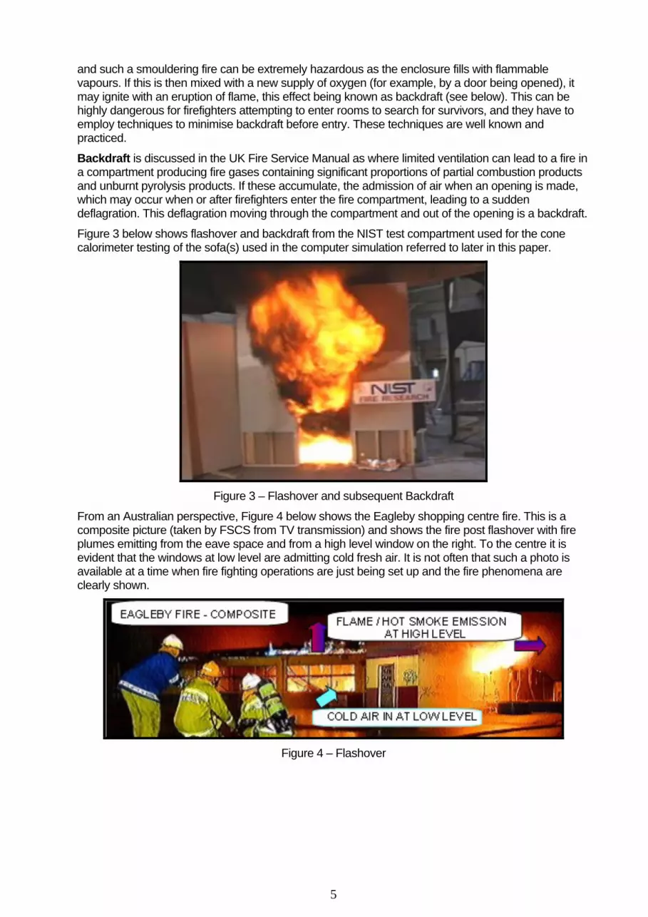
Figure 3 below shows flashover and backdraft from the NIST test compartment used for the cone calorimeter testing of the sofa(s) used in the computer simulation referred to later in this paper.
Figure 3 – Flashover and subsequent Backdraft
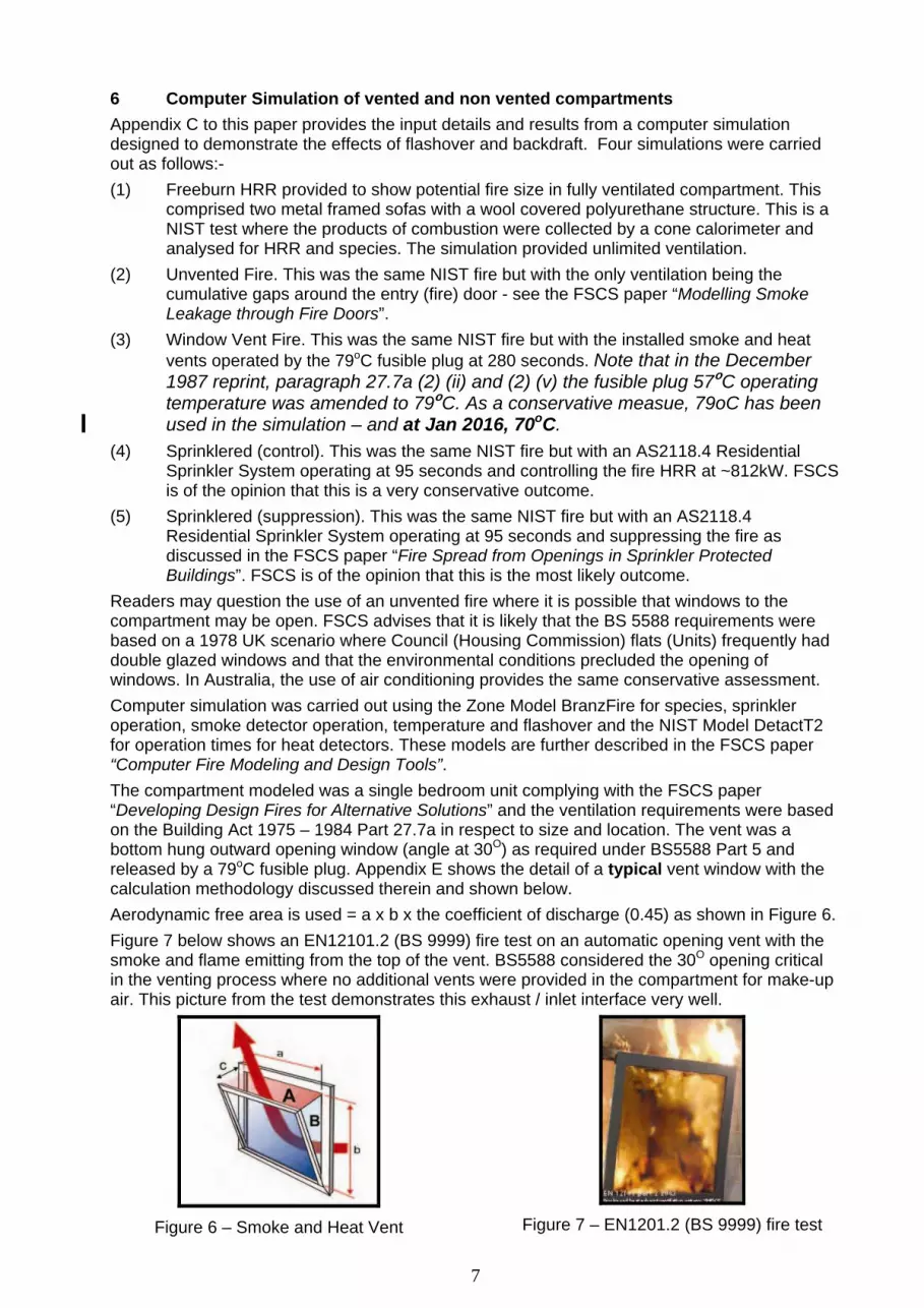
From an Australian perspective, Figure 4 below shows the Eagleby shopping centre fire. This is a composite picture (taken by FSCS from TV transmission) and shows the fire post flashover with fire plumes emitting from the eave space and from a high level window on the right. To the centre it is evident that the windows at low level are admitting cold fresh air. It is not often that such a photo is available at a time when fire fighting operations are just being set up and the fire phenomena are clearly shown.
Figure 4 – Flashover

6
5 Implications of Replacement or Decommissioning These Windows It is critical that Building Owners, Building Certifiers, Fire Engineers and QFRS Building Approval Officers understand that these smoke and heat vents are a required fire safety system under the various pieces of Queensland Legislation and are in fact defined as a “Special Fire Service”.
FSCS is of the opinion that whist Appeal Number: 62 – 11 by QFRS that natural ventilation was not a special fire service, the presence of an automatic or remote control function for the vents puts them squarely in the field and that any repairs, maintenance, replacement or removal should be subject to Building Regulation (2006 shown) schedule 1 part 9 below.
Figure 5 – Building Regulation 2006 Extract
Otherwise, such repairs, maintenance, replacement or removal activities in existing buildings are required to be assessed under Parts 61, 68 and 81 of the Building Act 1975 (at current date) as discussed in the FSCS paper “Alterations to Existing Buildings in Queensland”. Unless the work is minor or maintenance as Building Regulation schedule 1 part 9 as above and the window (vent) is being replaced with an identical unit, a Building Approval is invariably required if more than 20% of such items are being repaired or maintained in the building.
Decommissioning of the windows by screwing them shut or sealing gaps with a silicone sealant such that they cannot operate is unlawful and can lead to prosecution. In the event of fire where the decommissioning of the window renders it non operational, the person or entity doing and / or authorising such activities may be subject to further prosecution under various criminal codes. FSCS has been advised by various insurers that failure to comply with regulatory requirements for the installation and maintenance of fire safety features in a building will automatically void any insurance on the building and contents. This includes decommissioning.
Regardless of any tacit approval or acceptance by the QFRS or Building Certifiers, building owners and / or managers should seek legal both technical and legal advice on this matter. The technical advice should be from an appropriately qualified person who is a Registered Professional Engineer in Queensland and a Building Certifier for building approval (for assessable building work) who is experienced in transitional building approvals and assessments.
7
6 Computer Simulation of vented and non vented compartments Appendix C to this paper provides the input details and results from a computer simulation designed to demonstrate the effects of flashover and backdraft. Four simulations were carried out as follows:- (1) Freeburn HRR provided to show potential fire size in fully ventilated compartment. This
comprised two metal framed sofas with a wool covered polyurethane structure. This is a NIST test where the products of combustion were collected by a cone calorimeter and analysed for HRR and species. The simulation provided unlimited ventilation.
(2) Unvented Fire. This was the same NIST fire but with the only ventilation being the cumulative gaps around the entry (fire) door - see the FSCS paper “Modelling Smoke Leakage through Fire Doors”.
(3) Window Vent Fire. This was the same NIST fire but with the installed smoke and heat vents operated by the 79oC fusible plug at 280 seconds. Note that in the December 1987 reprint, paragraph 27.7a (2) (ii) and (2) (v) the fusible plug 57oC operating temperature was amended to 79oC. As a conservative measue, 79oC has been used in the simulation – and at Jan 2016, 70oC. (4) Sprinklered (control). This was the same NIST fire but with an AS2118.4 Residential
Sprinkler System operating at 95 seconds and controlling the fire HRR at ~812kW. FSCS is of the opinion that this is a very conservative outcome.
(5) Sprinklered (suppression). This was the same NIST fire but with an AS2118.4 Residential Sprinkler System operating at 95 seconds and suppressing the fire as discussed in the FSCS paper “Fire Spread from Openings in Sprinkler Protected Buildings”. FSCS is of the opinion that this is the most likely outcome.
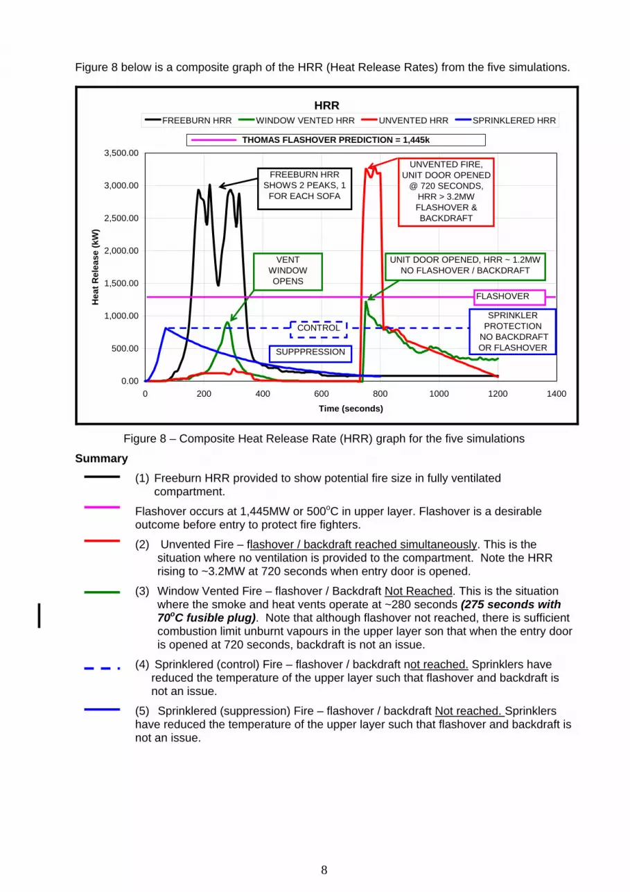
Readers may question the use of an unvented fire where it is possible that windows to the compartment may be open. FSCS advises that it is likely that the BS 5588 requirements were based on a 1978 UK scenario where Council (Housing Commission) flats (Units) frequently had double glazed windows and that the environmental conditions precluded the opening of windows. In Australia, the use of air conditioning provides the same conservative assessment. Computer simulation was carried out using the Zone Model BranzFire for species, sprinkler operation, smoke detector operation, temperature and flashover and the NIST Model DetactT2 for operation times for heat detectors. These models are further described in the FSCS paper “Computer Fire Modeling and Design Tools”. The compartment modeled was a single bedroom unit complying with the FSCS paper “Developing Design Fires for Alternative Solutions” and the ventilation requirements were based on the Building Act 1975 – 1984 Part 27.7a in respect to size and location. The vent was a bottom hung outward opening window (angle at 30O) as required under BS5588 Part 5 and released by a 79oC fusible plug. Appendix E shows the detail of a typical vent window with the calculation methodology discussed therein and shown below. Aerodynamic free area is used = a x b x the coefficient of discharge (0.45) as shown in Figure 6. Figure 7 below shows an EN12101.2 (BS 9999) fire test on an automatic opening vent with the smoke and flame emitting from the top of the vent. BS5588 considered the 30O opening critical in the venting process where no additional vents were provided in the compartment for make-up air. This picture from the test demonstrates this exhaust / inlet interface very well.
Figure 6 – Smoke and Heat Vent
Figure 7 – EN1201.2 (BS 9999) fire test
8
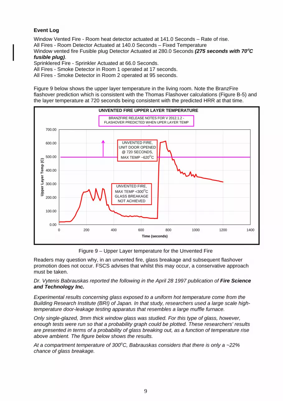
Figure 8 below is a composite graph of the HRR (Heat Release Rates) from the five simulations.
HRR
0.00
500.00
1,000.00
1,500.00
2,000.00
2,500.00
3,000.00
3,500.00
0 200 400 600 800 1000 1200 1400
Time (seconds)
Hea
t Rel
ease
(kW
)
FREEBURN HRR WINDOW VENTED HRR UNVENTED HRR SPRINKLERED HRR
UNVENTED FIRE, UNIT DOOR OPENED
@ 720 SECONDS, HRR > 3.2MWFLASHOVER & BACKDRAFT
UNIT DOOR OPENED, HRR ~ 1.2MWNO FLASHOVER / BACKDRAFT
VENT WINDOW OPENS
FLASHOVER
CONTROL
SUPPPRESSION
SPRINKLER PROTECTION
NO BACKDRAFT OR FLASHOVER
THOMAS FLASHOVER PREDICTION = 1,445k
FREEBURN HRR SHOWS 2 PEAKS, 1
FOR EACH SOFA
Figure 8 – Composite Heat Release Rate (HRR) graph for the five simulations
Summary (1) Freeburn HRR provided to show potential fire size in fully ventilated
compartment.
Flashover occurs at 1,445MW or 500oC in upper layer. Flashover is a desirable outcome before entry to protect fire fighters.
(2) Unvented Fire – flashover / backdraft reached simultaneously. This is the situation where no ventilation is provided to the compartment. Note the HRR rising to ~3.2MW at 720 seconds when entry door is opened.
(3) Window Vented Fire – flashover / Backdraft Not Reached. This is the situation where the smoke and heat vents operate at ~280 seconds (275 seconds with 70oC fusible plug). Note that although flashover not reached, there is sufficient combustion limit unburnt vapours in the upper layer son that when the entry door is opened at 720 seconds, backdraft is not an issue.
(4) Sprinklered (control) Fire – flashover / backdraft not reached. Sprinklers have reduced the temperature of the upper layer such that flashover and backdraft is not an issue.
(5) Sprinklered (suppression) Fire – flashover / backdraft Not reached. Sprinklers have reduced the temperature of the upper layer such that flashover and backdraft is not an issue.
9
Event Log Window Vented Fire - Room heat detector actuated at 141.0 Seconds – Rate of rise. All Fires - Room Detector Actuated at 140.0 Seconds – Fixed Temperature Window vented fire Fusible plug Detector Actuated at 280.0 Seconds (275 seconds with 70oC fusible plug). Sprinklered Fire - Sprinkler Actuated at 66.0 Seconds. All Fires - Smoke Detector in Room 1 operated at 17 seconds. All Fires - Smoke Detector in Room 2 operated at 95 seconds.
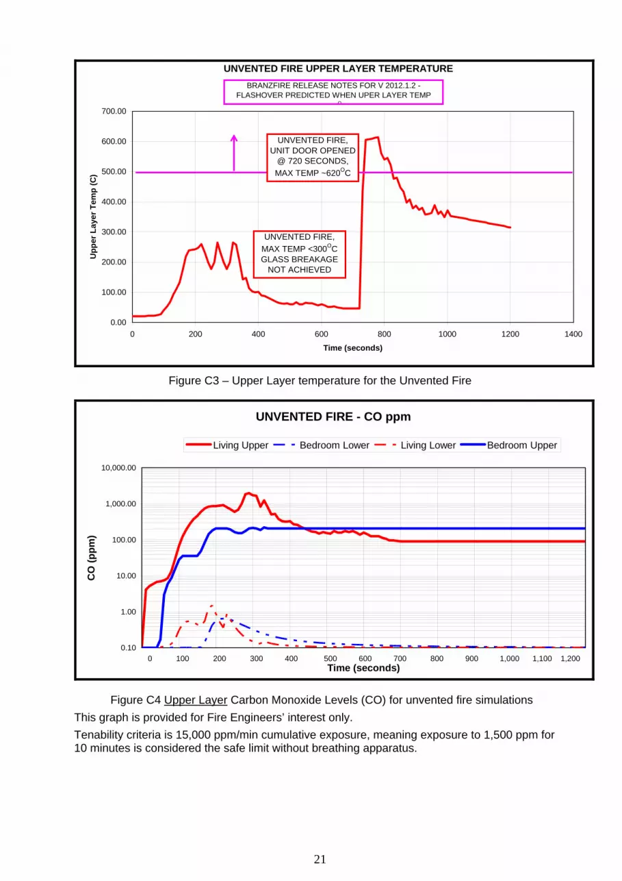
Figure 9 below shows the upper layer temperature in the living room. Note the BranzFire flashover prediction which is consistent with the Thomas Flashover calculations (Figure B-5) and the layer temperature at 720 seconds being consistent with the predicted HRR at that time.
UNVENTED FIRE UPPER LAYER TEMPERATURE
0.00
100.00
200.00
300.00
400.00
500.00
600.00
700.00
0 200 400 600 800 1000 1200 1400
Time (seconds)
Upp
er L
ayer
Tem
p (C
)
UNVENTED FIRE, MAX TEMP <300OCGLASS BREAKAGE
NOT ACHIEVED
UNVENTED FIRE, UNIT DOOR OPENED
@ 720 SECONDS, MAX TEMP ~620OC
BRANZFIRE RELEASE NOTES FOR V 2012.1.2 - FLASHOVER PREDICTED WHEN UPER LAYER TEMP
O
Figure 9 – Upper Layer temperature for the Unvented Fire
Readers may question why, in an unvented fire, glass breakage and subsequent flashover promotion does not occur. FSCS advises that whilst this may occur, a conservative approach must be taken.
Dr. Vytenis Babrauskas reported the following in the April 28 1997 publication of Fire Science and Technology Inc. Experimental results concerning glass exposed to a uniform hot temperature come from the Building Research Institute (BRI) of Japan. In that study, researchers used a large scale high-temperature door-leakage testing apparatus that resembles a large muffle furnace.
Only single-glazed, 3mm thick window glass was studied. For this type of glass, however, enough tests were run so that a probability graph could be plotted. These researchers' results are presented in terms of a probability of glass breaking out, as a function of temperature rise above ambient. The figure below shows the results.
At a compartment temperature of 300oC, Babrauskas considers that there is only a ~22% chance of glass breakage.
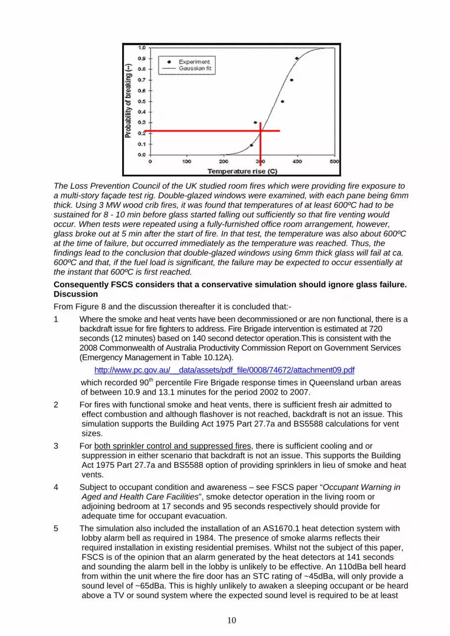
10
The Loss Prevention Council of the UK studied room fires which were providing fire exposure to a multi-story façade test rig. Double-glazed windows were examined, with each pane being 6mm thick. Using 3 MW wood crib fires, it was found that temperatures of at least 600ºC had to be sustained for 8 - 10 min before glass started falling out sufficiently so that fire venting would occur. When tests were repeated using a fully-furnished office room arrangement, however, glass broke out at 5 min after the start of fire. In that test, the temperature was also about 600ºC at the time of failure, but occurred immediately as the temperature was reached. Thus, the findings lead to the conclusion that double-glazed windows using 6mm thick glass will fail at ca. 600ºC and that, if the fuel load is significant, the failure may be expected to occur essentially at the instant that 600ºC is first reached. Consequently FSCS considers that a conservative simulation should ignore glass failure. Discussion From Figure 8 and the discussion thereafter it is concluded that:- 1 Where the smoke and heat vents have been decommissioned or are non functional, there is a
backdraft issue for fire fighters to address. Fire Brigade intervention is estimated at 720 seconds (12 minutes) based on 140 second detector operation.This is consistent with the 2008 Commonwealth of Australia Productivity Commission Report on Government Services (Emergency Management in Table 10.12A).
http://www.pc.gov.au/__data/assets/pdf_file/0008/74672/attachment09.pdf which recorded 90th percentile Fire Brigade response times in Queensland urban areas
of between 10.9 and 13.1 minutes for the period 2002 to 2007. 2 For fires with functional smoke and heat vents, there is sufficient fresh air admitted to
effect combustion and although flashover is not reached, backdraft is not an issue. This simulation supports the Building Act 1975 Part 27.7a and BS5588 calculations for vent sizes.
3 For both sprinkler control and suppressed fires, there is sufficient cooling and or suppression in either scenario that backdraft is not an issue. This supports the Building Act 1975 Part 27.7a and BS5588 option of providing sprinklers in lieu of smoke and heat vents.
4 Subject to occupant condition and awareness – see FSCS paper “Occupant Warning in Aged and Health Care Facilities”, smoke detector operation in the living room or adjoining bedroom at 17 seconds and 95 seconds respectively should provide for adequate time for occupant evacuation.
5 The simulation also included the installation of an AS1670.1 heat detection system with lobby alarm bell as required in 1984. The presence of smoke alarms reflects their required installation in existing residential premises. Whilst not the subject of this paper, FSCS is of the opinion that an alarm generated by the heat detectors at 141 seconds and sounding the alarm bell in the lobby is unlikely to be effective. An 110dBa bell heard from within the unit where the fire door has an STC rating of ~45dBa, will only provide a sound level of ~65dBa. This is highly unlikely to awaken a sleeping occupant or be heard above a TV or sound system where the expected sound level is required to be at least
11
10dBa above ambient sound level, or, in the case of awaking a sleeping occupant, 75dBa at the bedhead. Refer to the FSCS paper “Design Guide for Occupant Warning Sound Levels”.
6 FSCS advises that for a fire at the wall (window) location, flame temperatures impinging on the glazing will be >1,000oC and glass breakage is highly likely to occur. Note that the computer simulation used a “centre of room” fire to provide more conservative results.
Conclusion From the analysis and computer simulation detailed and discussed above, FSCS concludes that:-
1. The installation of the smoke and heat vents prescribed in part 27.7a of the Building Act 1975 – 1984 will provide acceptable backdraft protection for the attending fire fighters.
2. The computer simulation validates the prescribed vent sizes in part 27.7a of the Building Act 1975 – 1984.
3. The computer simulation validates the installation of a sprinkler system as an alternative to the smoke and heat vents either in control or suppression mode.
4. Alternative Solutions must consider the Performance Requirements where the intent of Part 27.7a of the Building Act was to provide fire fighters with the required facilities for safe access to and within a building.
5. It is abundantly clear that part 27.7a of the Building Act 1975 – 1984 considers that as an alternative to the automatic smoke and heat vents discussed and analysed in this paper ( being windows operated automatically by fusible plugs), only the following are acceptable alternatives. As prescribed, they are, in fact, Deemed to Satisfy (DtS) systems:- • Windows operated manually by apparatus from a fire fighting stair or manually from
the entrance to the building or manually by apparatus from the floor below; or • Ducts operated automatically by fusible plug or manually by apparatus from a fire
fighting stair or manually from the entrance to the building or manually by apparatus from the floor below; or
• An automatic fire sprinkler system. 6. Installation of smoke detectors alone will NOT meet the Performance Requirements. 7. Smoke Control Systems P/L supplies a replacement windows (Inova) which meets the
Performance Requirements but is activated by the installed smoke detection system– contact Smoke Control Systems Pty Ltd Craig Lewin on 1300 665 471.
8. Change to a 70oC fusible plug will not make any material difference to the performance. I trust that this paper provides appropriate advice regarding this issue and I suggest that Certifiers and QFRS Building Approval Officers consider the implications of this paper. FSCS thanks John Dunn of John Dunn Building Approvals for his input and review.
Prepared by Richard A Foster Dip Mech Eng; Dip Mar Eng; MSFPE Fire Safety Engineer, Principal – Fire and Security Consulting Services RPEQ Mechanical – 7753: Accredited by Board of Professional Engineers as a Fire Safety Engineer
http://fscs-techtalk.com
Version 3 – March 2016

12
APPENDIX A Report References FSCS Papers See Website – http://fscs-techtalk.com A Brief Queensland Regulatory History Reference - adoption of various parts of BS5588 in Building Act 1975. Alterations to Existing Buildings in Queensland Reference - Building Regulation 2006 part 2 section 1 and Building Act 1975 parts 61, 68 & 81 Modelling Smoke Leakage through Fire Doors Reference – Equivalent openings from maximum specified clearances in AS1905. Fire Spread from Openings in Sprinkler Protected Buildings Reference - sprinkler systems suppression and reliability. Computer Fire Modeling and Design Tools Reference - BranzFire and DetactT2 models Developing Design Fires for Alternative Solutions Reference NIST fire data. Occupant Warning in Aged and Health Care Facilities Reference - audibility and response. Design Guide for Occupant Warning Systems Reference – sound loss through doors & walls
Australian Legislation Current as at January 10th 2014 Building Code of Australia - Class 2 to Class 9 Buildings - Volume 1, Australasian Fire Authorities Council 2004, Fire Brigade Intervention Model – Version 2.2, Australasian Fire Authorities Council, Australia
Queensland Legislation Building Act 1975 – 1984 & 1987 Reprints Building Regulation 2006 Current as at January 10th 2014 Building Fire Safety Regulation (BSFR) 2008 Current as at January 10th 2014
Australian Standards Current as at January 10th 2014 AS 1851 Maintenance of fire protection systems and equipment. 2005 and 2012 editions AS 2118.1 Automatic fire sprinkler systems. Part 1: General requirements AS 2118.4 Automatic fire sprinkler systems. Part 4: Residential AS 1670.1 Fire detection, warning, control and intercom systems – System design, installation and commissioning. Part 1: Fire AS 3786 Smoke alarms
International Paul Stollard and John Abrahams Fire from First Principles A Design Guide To Building Fire Safety. Taylor & Francis e-Library, 2002. Taylor & Francis e-Library, 2002. http://file.zums.ac.ir/ebook/203-Fire%20from%20First%20Principles%20-%20A%20Design%20Guide%20to%20Building%20Fire%20Safety,%203rd%20Edition-John%20Abraham.pdf
UK Fire Service Manual Volume 4 – Guidance and Compliance Framework for compartment fire training Appeal # 62 – 11 by QFRS Queensland Building & Development Resolution Committees Building Codes Queensland BS 5588 – Various Dates Fire precautions in the design, construction and use of buildings BS 9999 – Various Dates Code of practice for fire safety in the design, management and use of buildings BS EN 12101-2:2003 Smoke and heat control systems Part 2: Specification for natural smoke and heat
exhaust ventilators withdrawn on 01-09-2005 and superseded by BS 7346-1:1990.
BS 7346 -1990 Components for smoke and heat control systems H M Government UK The Building Regulations 2010 Approved Document B – Access and Facilities for the Fire Service NBSIR 83-2787 Fire Performance of Furnishings as measured in the NBS Furniture Calorimeter, National Bureau of Standards; National Engineering Laboratory - Center for Fire Research U.SA BRANZ Building Research Association of New Zealand Dr. Vytenis Babrauskas Glass Breakage in Fires . Fire Science and Technology Thomas, Philip H. Testing products and materials for their contribution to flashover in Rooms,” Fire and Materials Fire Engineering Guidelines – Edition 2005

13
APPENDIX B
BUILDING ACT 1975 EXTRACT
http://ozcase.library.qut.edu.au/qhlc/documents/qsr_building_act_1975_to_1984_31Jul84.pdf

14

15
List of amendments to Building Act 1975. BUILDING ACT 1975 Original Act - Building Act 1975 No. 11 [Vol 1975 p 41] date of assent 15 May 1975 pts 5–6 and 8 and sch commenced 1 April 1976 (proc pubd gaz 6 March 1976 p 886) remaining provisions commenced 31 May 1975 (proc pubd gaz 31 May 1975 p 748)
Amending legislation In the Building Act 19775 – 1976, section 27.7a required the smoke and heat vent window to be 5% of the floor area and openable from the floor below. This was amended on March 4th 1976 to the calculation method as described in the 1984 edition.
Building Act Amendment Act 1978 No. 47 [Vol 1978 p 356] date of assent 12 June 1978 commenced 21 September 1978 (proc pubd gaz 23 September 1978 p 245)
Building Act Amendment Act 1981 No. 53 [Vol 1981 p 453] date of assent 12 June 1981 ss 1–2 commenced on date of assent remaining provisions commenced 29 June 1981 (proc pubd gaz 27 June 1981 p 1710)
Building Act Amendment Act 1984 No. 45 [Vol 1984 p 467] date of assent 10 May 1984 ss 1–2 commenced on date of assent ss 3, 5(c), 17, 23, 25 and 26 commenced 7 July 1984 (proc pubd gaz 7 July 1984 p 1608) remaining provisions commenced 2 June 1984 (proc pubd gaz 2 June 1984 p 987)
Building Act Amendment Act 1984 (No. 2) No. 114 [Vol 1984 p 1457] date of assent 18 December 1984 ss 1–2 commenced on date of assent remaining provisions commenced 2 March 1985 (proc pubd gaz 23 February 1985 p 942)
Building Act Amendment Act 1987 No. 69 [Vol 1987 p 954] date of assent 1 December 1987 ss 1–2 commenced on date of assent remaining provisions commenced 28 March 1988 (proc pubd gaz 26 March 1988 p 1735) In the December 1987 reprint, paragraph 27.7a (2) (ii) and (2) (v). the fusible plug 57oC operating temperature was amended to 79oC. Building Act Amendment Act 1991 No. 52 [Vol 1991 p 1286] date of assent 10 September 1991 ss 1.1–1.2 commenced on date of assent. This amendment adopted BCA90 and repealed the Standard Building By-Laws technical provisions in the Act.

16
APPENDIX C – FIRE SIMULATION BRANZFIRE MODEL DATA
Compartment & Vent Arrangement
OPENBEDROOMDOOR
OPEN PLANKITCHEN
CLOSED ENTRY DOOROPEN LOBBY
HEAT DETECTOR FIRE ALARM BELL IN LOBBY FUSIBLE LINK
AS 3786 SMOKE ALARM AS AT JULY 1ST 2007
MAKE SIZE CORRECTION ON WIDTH
EXTERIOR WALL LENGTH OF LIVING ROOM =15M THEREFORE 0.45M2 OF
AERODYNAMIC FREE AREA REQUIRED. 0.48 PROVIDED , 0.54M CORRECTED SIZE FOR MODEL
FIRE VENT WINDOW
MODEL SKETCH
DETECTORS AND ALARMS AS AT BUILDING ACT 1975 UP TO BCA90
REQUIRED FOR SMOKE AND HEAT VENT
FIRE VENT WINDOW CALCULATIONS TO BUILDING ACT 1975 - 1984 ss27.7a (b) & BS 5588 Part 5
- - - - - -EXTERNAL WALL OF UNIT - - - - -
10.5
7.5
0.90
M
1.2 X 0.45 = 0.541.20M ACTUAL SIZE WINDOW
CLOSED WINDOWS
AD
JOIN
ING
UN
IT
Figure C1 – Compartment & Vent Details

17
COMPARTMENT FIRE SIMULATIONS BRANZFIRE Multi-Compartment Fire Model (Version 2012.1) Description of Rooms Room 1 : Living Room Length (m) = 7.50 Room Width (m) = 6.00 Maximum Room Height (m) = 2.70 Wall Surface is concrete Wall Thickness (mm) = 100.0 Ceiling Surface is concrete Ceiling Thickness (mm) = 100.0 Floor Surface is pvc carpet Floor Thickness = (mm) 10.0 Floor Substrate is concrete Floor Substrate Thickness (mm) = 150.0 Room 2 : Bedroom Room Length (m) = 3.50 Room Width (m) = 4.50 Maximum Room Height (m) = 2.70 Wall Surface is concrete Wall Thickness (mm) = 100.0 Ceiling Surface is concrete Ceiling Thickness (mm) = 100.0 Floor Surface is pvc carpet Floor Thickness = (mm) 10.0 Floor Substrate is concrete Floor Substrate Thickness (mm) = 150.0 ==================================================================== Wall Vents
From room 1 to 2 , Vent No 1 NOTE 1 Vent Width (m) = 0.840 Vent Height (m) = 2.100 Vent Sill Height (m) = 0.000 Vent Soffit Height (m) = 2.100 Opening Time (sec) = 0 From room 1 to outside, Vent No 1 NOTE 2 Vent Width (m) = 0.011 Vent Height (m) = 2.100 Vent Sill Height (m) = 0.000 Vent Soffit Height (m) = 2.100 Opening Time (sec) = 0 From room 1 to outside, Vent No 2 NOTE 3 Vent Width (m) = 0.840 Vent Height (m) = 2.100 Vent Sill Height (m) = 0.000 Vent Soffit Height (m) = 2.100 Opening Time (sec) = 720 From room 1 to outside, Vent No 3 NOTE 4 Vent Width (m) = 0.540 Vent Height (m) = 0.900 Vent Sill Height (m) = 1.500 Vent Soffit Height (m) = 2.400 Opening Time (sec) = 280 NOTE 1 OPEN BEDROOM DOOR. Applicable to all simulations. NOTE 2 ENTRY DOOR GAPS – SEE TEXT. Applicable to all simulations. NOTE 3 FIRE FIGHTER OPENS ENTRY DOOR. Applicable to vented simulation. NOTE 4 AUTO WINDO VENT OPENS @ 280s. Applicable to vented simulation.
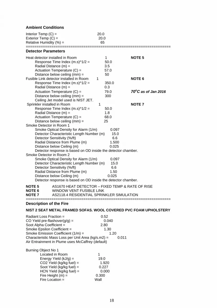
18
Ambient Conditions Interior Temp (C) = 20.0 Exterior Temp (C) = 20.0 Relative Humidity (%) = 65 ==================================================================== Detector Parameters Heat detector installed in Room 1 NOTE 5 Response Time Index (m.s)^1/2 = 50.0 Radial Distance (m) = 3.5 Actuation Temperature (C) = 57.0 Distance below ceiling (mm) = 50 Fusible Link detector installed in Room 1 NOTE 6 Response Time Index (m.s)^1/2 = 350.0 Radial Distance (m) = 0.3 Actuation Temperature (C) = 79.0 70oC as of Jan 2016 Distance below ceiling (mm) = 300 Ceiling Jet model used is NIST JET. Sprinkler installed in Room 1 NOTE 7 Response Time Index (m.s)^1/2 = 50.0 Radial Distance (m) = 1.8 Actuation Temperature (C) = 68.0 Distance below ceiling (mm) = 25 Smoke Detector in Room 1 Smoke Optical Density for Alarm (1/m) 0.097 Detector Characteristic Length Number (m) 15.0 Detector Sensitivity (%/ft) 6.6 Radial Distance from Plume (m) 1.500 Distance below Ceiling (m) 0.025 Detector response is based on OD inside the detector chamber. Smoke Detector in Room 2 Smoke Optical Density for Alarm (1/m) 0.097 Detector Characteristic Length Number (m) 15.0 Detector Sensitivity (%/ft) 6.6 Radial Distance from Plume (m) 1.50 Distance below Ceiling (m) 0.025 Detector response is based on OD inside the detector chamber.
NOTE 5 AS1670 HEAT DETECTOR – FIXED TEMP & RATE OF RISE NOTE 6 WINDOW VENT FUSIBLE LINK NOTE 7 AS2118.4 RESIDENTIAL SPRINKLER SIMULATION ==================================================================== Description of the Fire NIST 2 SEAT METAL FRAMED SOFAS. WOOL COVERED PVC FOAM UPHOLSTERY
Radiant Loss Fraction = 0.52 CO Yield pre-flashover(g/g) = 0.040 Soot Alpha Coefficient = 2.80 Smoke Epsilon Coefficient = 1.30 Smoke Emission Coefficient (1/m) = 1.20 Characteristic Mass Loss per Unit Area (kg/s.m2) = 0.011 Air Entrainment in Plume uses McCaffrey (default) Burning Object No 1 Located in Room 1 Energy Yield (kJ/g) = 19.0 CO2 Yield (kg/kg fuel) = 1.920 Soot Yield (kg/kg fuel) = 0.227 HCN Yield (kg/kg fuel) = 0.000 Fire Height (m) = 0.300 Fire Location = Wall
19
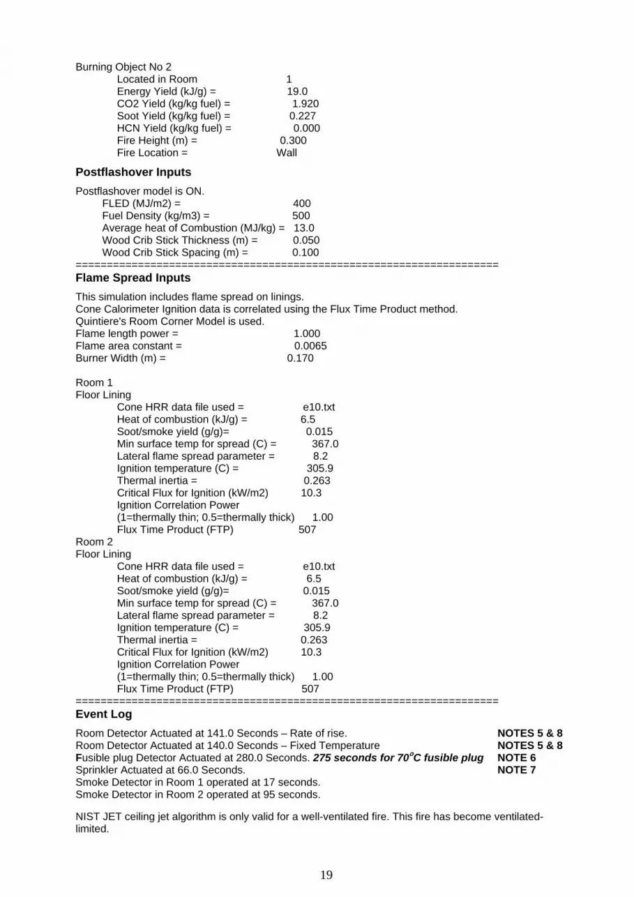
Burning Object No 2 Located in Room 1 Energy Yield (kJ/g) = 19.0 CO2 Yield (kg/kg fuel) = 1.920 Soot Yield (kg/kg fuel) = 0.227 HCN Yield (kg/kg fuel) = 0.000 Fire Height (m) = 0.300 Fire Location = Wall
Postflashover Inputs Postflashover model is ON. FLED (MJ/m2) = 400 Fuel Density (kg/m3) = 500 Average heat of Combustion (MJ/kg) = 13.0 Wood Crib Stick Thickness (m) = 0.050 Wood Crib Stick Spacing (m) = 0.100 ==================================================================== Flame Spread Inputs This simulation includes flame spread on linings. Cone Calorimeter Ignition data is correlated using the Flux Time Product method. Quintiere's Room Corner Model is used. Flame length power = 1.000 Flame area constant = 0.0065 Burner Width (m) = 0.170 Room 1 Floor Lining Cone HRR data file used = e10.txt Heat of combustion (kJ/g) = 6.5 Soot/smoke yield (g/g)= 0.015 Min surface temp for spread (C) = 367.0 Lateral flame spread parameter = 8.2 Ignition temperature (C) = 305.9 Thermal inertia = 0.263 Critical Flux for Ignition (kW/m2) 10.3 Ignition Correlation Power (1=thermally thin; 0.5=thermally thick) 1.00 Flux Time Product (FTP) 507 Room 2 Floor Lining Cone HRR data file used = e10.txt Heat of combustion (kJ/g) = 6.5 Soot/smoke yield (g/g)= 0.015 Min surface temp for spread (C) = 367.0 Lateral flame spread parameter = 8.2 Ignition temperature (C) = 305.9 Thermal inertia = 0.263 Critical Flux for Ignition (kW/m2) 10.3 Ignition Correlation Power (1=thermally thin; 0.5=thermally thick) 1.00 Flux Time Product (FTP) 507 ==================================================================== Event Log Room Detector Actuated at 141.0 Seconds – Rate of rise. NOTES 5 & 8 Room Detector Actuated at 140.0 Seconds – Fixed Temperature NOTES 5 & 8 Fusible plug Detector Actuated at 280.0 Seconds. 275 seconds for 70oC fusible plug NOTE 6 Sprinkler Actuated at 66.0 Seconds. NOTE 7 Smoke Detector in Room 1 operated at 17 seconds. Smoke Detector in Room 2 operated at 95 seconds. NIST JET ceiling jet algorithm is only valid for a well-ventilated fire. This fire has become ventilated-limited.

20
NOTE 5 Room detector only applicable to window vented fire NOTE 6 Fusible plug detector only applicable to window vented fire NOTE 7 Sprinkler only applicable to unvented fire. Residential sprinkler simulation only. NOTE 8 Response calculated by Detact T2 ==================================================================== Summary of End-Point Conditions in Room of Fire Origin NOTE 6 Only applicable to vented fire FED asphyxiant gases (incap) Exceeded 0.3 at 195.0 Seconds. FED thermal (incap) exceeded 0.3 at 170.0 Seconds. An Upper Layer Temperature of 600 deg C Not Reached. Visibility at 2m above floor reduced to 10 m at 60.0 Seconds. Temperature at 2m above floor has reached 80 deg C at 140.0 Seconds. ====================================================================
HRR
0.00
500.00
1,000.00
1,500.00
2,000.00
2,500.00
3,000.00
3,500.00
0 200 400 600 800 1000 1200 1400
Time (seconds)
Hea
t Rel
ease
(kW
)
FREEBURN HRR WINDOW VENTED HRR UNVENTED HRR SPRINKLERED HRR
UNVENTED FIRE, UNIT DOOR OPENED
@ 720 SECONDS, HRR > 3.2MWFLASHOVER & BACKDRAFT
UNIT DOOR OPENED, HRR ~ 1.2MWNO FLASHOVER / BACKDRAFT
VENT WINDOW OPENS
FLASHOVER
CONTROL
SUPPPRESSION
SPRINKLER PROTECTION
NO BACKDRAFT OR FLASHOVER
THOMAS FLASHOVER PREDICTION = 1,445k
FREEBURN HRR SHOWS 2 PEAKS, 1
FOR EACH SOFA
Figure C2 – Composite Heat Release Rate (HRR) graph for the five simulations
(1) Freeburn HRR provided to show potential fire size in fully ventilated compartment
Flashover
(2) Unvented Fire – Flashover / Backdraft Reached
(3) Window Vent Fire – Flashover / Backdraft Not Reached
(4) Sprinklered (control) Fire – Flashover / Backdraft Not Reached
(5) Sprinklered (suppression) Fire – Flashover / Backdraft Not Reached
21
UNVENTED FIRE UPPER LAYER TEMPERATURE
0.00
100.00
200.00
300.00
400.00
500.00
600.00
700.00
0 200 400 600 800 1000 1200 1400
Time (seconds)
Upp
er L
ayer
Tem
p (C
)
UNVENTED FIRE, MAX TEMP <300OCGLASS BREAKAGE
NOT ACHIEVED
UNVENTED FIRE, UNIT DOOR OPENED
@ 720 SECONDS, MAX TEMP ~620OC
BRANZFIRE RELEASE NOTES FOR V 2012.1.2 - FLASHOVER PREDICTED WHEN UPER LAYER TEMP
O
Figure C3 – Upper Layer temperature for the Unvented Fire
UNVENTED FIRE - CO ppm
0.10
1.00
10.00
100.00
1,000.00
10,000.00
Time (seconds)
CO
(ppm
)
Living Upper Bedroom Lower Living Lower Bedroom Upper
0 100 200 300 400 500 600 700 800 900 1,000 1,100 1,200
Figure C4 Upper Layer Carbon Monoxide Levels (CO) for unvented fire simulations This graph is provided for Fire Engineers’ interest only. Tenability criteria is 15,000 ppm/min cumulative exposure, meaning exposure to 1,500 ppm for 10 minutes is considered the safe limit without breathing apparatus.

22
Spreadsheet Templates For Fire Dynamics Calculations
INPUT PARAMETERSROOM LENGTH (L) 7.5 mROOM WIDTH (W) 6 mROOM HEIGHT (H) 2.7 m
OPENING WIDTH (Wo) 0.54 mOPENING HEIGHT (Ho) 0.9 m
BOUNDARY CONDUCTIVITY (k) 0.00012 kW/m.KBOUNDARY THICKNESS (d) 0.1 m
CALCULATED PARAMETERSBOUNDARY SURFACE AREA (At) 162.41 m2
VENTILATION FACTOR 0.46 m^5/2THOMAS FLASHOVER PREDICTION 1445 kW
Fire Risk Forum RiskTOOLS
(c) 2003 Frederick W. Mowrer – all rights reservedFrederick W. Mowrer, Ph.D.
Department of Fire Protection EngineeringUniversity of Maryland at College Park, College Park, MD 20742
Figure C5 – Mowrer / Thomas Flashover Prediction for the window vented fire
23
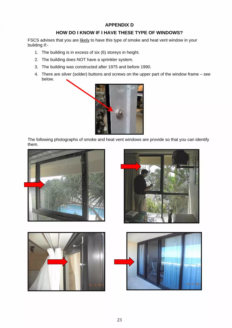
APPENDIX D HOW DO I KNOW IF I HAVE THESE TYPE OF WINDOWS?
FSCS advises that you are likely to have this type of smoke and heat vent window in your building if:-
1. The building is in excess of six (6) storeys in height.
2. The building does NOT have a sprinkler system.
3. The building was constructed after 1975 and before 1990.
4. There are silver (solder) buttons and screws on the upper part of the window frame – see below.
The following photographs of smoke and heat vent windows are provide so that you can identify them.

24
APPENDIX E SMOKE AND HEAT VENT WINDOW TECHNICAL DETAILS

25
NUMBER OF FUSIBLE PLUGS MAY VARY FROM 2 TO 4. 2 AT TOP, OR 2 AT SIDES OR 2 AT BOTH TOP AND SIDESAS SHOWN ABOVE
SOME FUSIBLE PLUGS MAY HAVE RECESSED HEADS TOACCOMMODATE SCREW HEAD
SECTION - WINDOW CLOSEDOPEN POSITION
TORSION SPRING INSTALLED
FUSIBLE PLUGS INSTALLED
ISOMETRIC VIEW
OPENED
SECTION - WINDOW CLOSED
30o
SS STAY WIRE
FUSIBLE PLUG
TORSION SPRING
38 SS SELF TAPPING SCREW
SS STAY WIRE
BOTTOM HINGE MAY BE
EXTERNAL
WINDOW OPEN
FUSIBLE PLUG LOCATIONS
30O
Figure E1 – Window Assembly
Supplier of New / Replacement Windows G James Glass and Aluminium – Gold Coast
Phone: +61 7 5588 5759 | Mob: 0416 193 247 | [email protected] www.gjames.com
Robert de Graaf | Acting Branch Manager

26
Figure E3
Stay Cable
Figure E4 - Swage Tool
Figure E2 – Torsion Spring
Suppliers Torsion Spring G James Glass and Aluminium – Gold Coast
Phone: +61 7 5588 5759 | Mob: 0416 193 247 | [email protected] www.gjames.com
Robert de Graaf - Branch Manager
Fusible Plugs Fusible plugs for either replacement of damaged units or replacement under the required maintenance (see Appendix F) are now available from Northern Smelters in Woodridge, Queensland. Contact details are:- Kathryn Richardson, Phone: 07 32082724, Email: [email protected] Stay Cable 1/16” SS wire rope & swages Any Ship Chandler / Marine Supply store or Tool Specialty Store Swaging Tool Any Ship Chandler / Marine Supply store
27
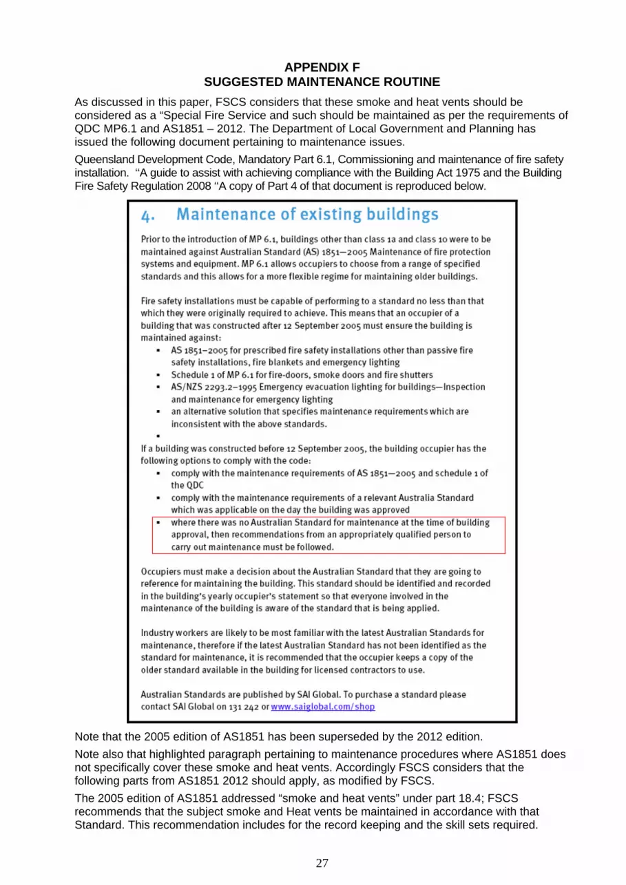
APPENDIX F SUGGESTED MAINTENANCE ROUTINE
As discussed in this paper, FSCS considers that these smoke and heat vents should be considered as a “Special Fire Service and such should be maintained as per the requirements of QDC MP6.1 and AS1851 – 2012. The Department of Local Government and Planning has issued the following document pertaining to maintenance issues. Queensland Development Code, Mandatory Part 6.1, Commissioning and maintenance of fire safety installation. ‘‘A guide to assist with achieving compliance with the Building Act 1975 and the Building Fire Safety Regulation 2008 ‘‘A copy of Part 4 of that document is reproduced below.
Note that the 2005 edition of AS1851 has been superseded by the 2012 edition. Note also that highlighted paragraph pertaining to maintenance procedures where AS1851 does not specifically cover these smoke and heat vents. Accordingly FSCS considers that the following parts from AS1851 2012 should apply, as modified by FSCS. The 2005 edition of AS1851 addressed “smoke and heat vents” under part 18.4; FSCS recommends that the subject smoke and Heat vents be maintained in accordance with that Standard. This recommendation includes for the record keeping and the skill sets required.
28
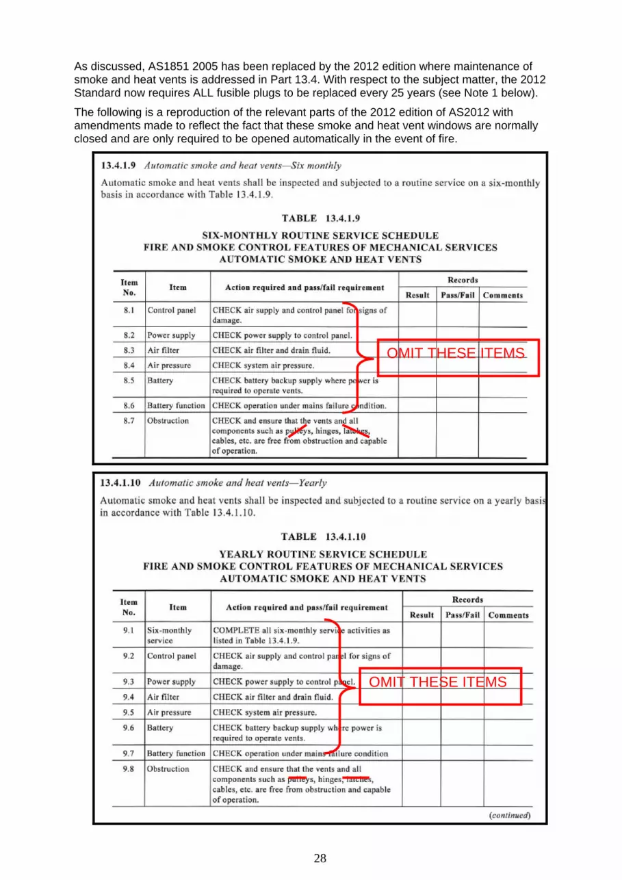
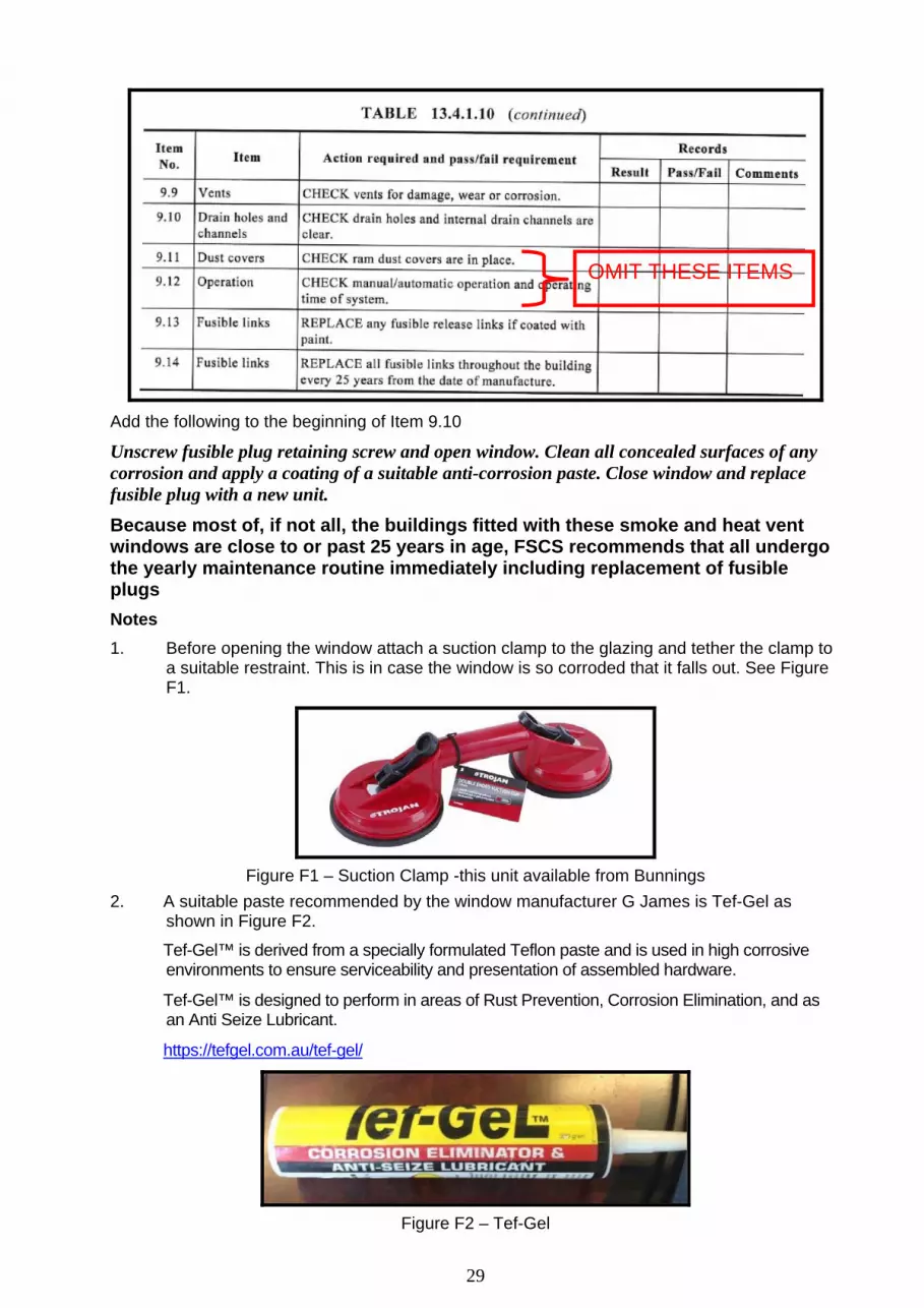
As discussed, AS1851 2005 has been replaced by the 2012 edition where maintenance of smoke and heat vents is addressed in Part 13.4. With respect to the subject matter, the 2012 Standard now requires ALL fusible plugs to be replaced every 25 years (see Note 1 below).
The following is a reproduction of the relevant parts of the 2012 edition of AS2012 with amendments made to reflect the fact that these smoke and heat vent windows are normally closed and are only required to be opened automatically in the event of fire.
OMIT THESE ITEMS
OMIT THESE ITEMS
29
Add the following to the beginning of Item 9.10
Unscrew fusible plug retaining screw and open window. Clean all concealed surfaces of any corrosion and apply a coating of a suitable anti-corrosion paste. Close window and replace fusible plug with a new unit.
Because most of, if not all, the buildings fitted with these smoke and heat vent windows are close to or past 25 years in age, FSCS recommends that all undergo the yearly maintenance routine immediately including replacement of fusible plugs Notes 1. Before opening the window attach a suction clamp to the glazing and tether the clamp to a suitable restraint. This is in case the window is so corroded that it falls out. See Figure F1.
Figure F1 – Suction Clamp -this unit available from Bunnings
2. A suitable paste recommended by the window manufacturer G James is Tef-Gel as shown in Figure F2.
Tef-Gel™ is derived from a specially formulated Teflon paste and is used in high corrosive environments to ensure serviceability and presentation of assembled hardware.
Tef-Gel™ is designed to perform in areas of Rust Prevention, Corrosion Elimination, and as an Anti Seize Lubricant.
https://tefgel.com.au/tef-gel/
Figure F2 – Tef-Gel
OMIT THESE ITEMS


