Embed Size (px)
Citation preview

SPARK MODERN FIRES
™
WARNING: Thisfireplace requires2 feet of verticalventing before
WITH ELECTRONIC IGNITION SYSTEM
SEE THRU / PENINSULA
INSTALLATION AND OPERATING INSTRUCTIONS
DIRECT VENT GAS FIREPLACES
MODELS: 91N-E, 91P-E, 92N-E, 92P-E
Version française de ce manuel est disponible à partir du site WEB : www.sparkfires.com
– Do not store or use gasoline or other flammablevapors and liquids in the vicinity of this or any otherappliance.
– WHAT TO DO IF YOU SMELL GAS
department.– Installation and service must be per formed
by a qualified installer, service agency or thegas supplier.
This appliance is only for use with the type of gas indicated on the rating plate. This appliance is not convertible for use with other gases, unless a certifiedkit is used. INSTALLER: Leave this manual with the appliance.
CONSUMER: Retain this manual for future reference.
This appliance may be installed in an aftermarket, permanently located, manufactured home (USA only) or mobile home where not prohibited by local codes.
WARNING: FIRE OR EXPLOSION HAZARDFailure to follow safety warnings exactly could result in
serious injury, death, or property damage.
•Do not touch any electrical switch; do not use anyphone in your building.
•Do not try to light any appliance.
phone. Follow the gas supplier's instructions.• If you cannot reach your gas supplier, call the fire
WARNING: Improper installation, adjustment, alteration, services or maintenance can cause injury or property damage. Refer to this manual. For assistance or additional information consult a qualified installer, service agency or the gas supplier.
CLOTHING OR OTHER FLAMMABLE MATERIAL SHOULD NOT BE PLACED ON OR NEAR THE APPLIANCE.
YOUNG CHILDREN SHOULD BE SUPERVISED WHEN THEY ARE IN THE SAME ROOM AS THE APPLIANCE.
CHILDREN AND ADULTS SHOULD BE ALERTED TO THE HAZARDS OF HIGH SURFACE TEMPERATURE AND SHOULD STAY AWAY TO AVOID BURNS OR CLOTHING IGNITION.
DUE TO HIGH TEMPERATURES, THE APPLIANCE SHOULD BE LOCATED OUT OF TRAFFIC AND AWAY FROM FURNITUREAND DRAPERIES.
• Leave the building immediately.• Immediately call your gas supplier from a neighbor's
KEEP THE ROOM AREA CLEARAND FREEFROM COMBUSTIBLE MATERIALS, GASO-LINE, AND OTHER FLAMMABLE VAPORS AND LIQUIDS.
French version of this Owner's Manual is available at www.sparkfires.com
any horizontal runsReport # 0321GF004S

2 L100001 3
IMPORTANTThis fireplace is designed for a minimum 2 feet of vertical vent pipe rise before any horizontal vent pipe run.
See pages 13-14 for Vent Installation details.
CONTENTS
Important Safety Information .......................... 3
Product Features............................................ 5
Code Approval ................................................ 5
Pre-Installation Information............................. 6
Installing Above 2000 Feet .......................... 6Orifice Sizes, Pressures and BTUs................ 6Before You Install ........................................ 6Fireplace Framing ........................................ 7Fireplace Dimensions .................................. 8Fireplace Location ....................................... 9
Securing Fireplace to Floor or Framing .......... 10
Clearances................................................... 11
Installation Information................................. 12
Installation Precautions ............................. 13Installation Planning .................................. 14Rear Wall Vent Installation ......................... 17
Horizontal Termination Configuration........... 19Below Grade Installation ............................ 21Vertical Through-the-Roof Installation .......... 22Installation for Vertical Termination..............23Cathedral Ceiling Installation...................... 24
Fireplace Installation .................................... 25
Check Gas Type ........................................ 25Installing Gas Piping to Fireplace/Burner
Checking Gas Pressure................................. 27
Electrical Installation.................................... 28
Electrical Wiring ........................................ 28Wall Switch ............................................... 28
Glass Removal ............................................. 29
Final Installation........................................... 30
Warranty ......................................... Back Cover
Vent Installation ......................................................... 12
Gas Connection .......................................... 26
Media Tray Placement ......................
Operating Instructions .................................. 33
What To Do If You Smell Gas ...........................33Operating Instructions.................................. 33
. ....... 30Safety Screen Installation............................ 31
............................................... 38Stones, Media ........................................... 38Fan Assembly................................................ 38
Replacement Par ts ....................................... 39
Vent Components ...................................... 39Firebox Components .................................. 40SIT Proflame Wiring Diagram........................ 41
Troubleshooting ............................................ 43
Pilot Flame .............................................. 37Burner Flame ........................................... 37Air Shutter Assembly ................................ 37Vent System ............................................. 38Glass Panel
To Turn Of f Gas ......................................... 33
Cleaning and Maintenance............................ 37
Burner, Pilot and Control Compar tment ....... 37

2 L100001 3
4. Never install the fireplace• in a recreational vehicle• where curtains, furniture, clothing, or other flammable
objects are less than 42" from the front, top, or sides ofthe fireplace
• in high traffic areas• in windy or drafty areas
5. This fireplace reaches high temperatures. Keep children andadults away from hot surfaces to avoid burns or clothingignition. Fireplace will remain hot for a time after shutdown.Allow surfaces to cool before touching.
6. Carefully supervise young children when they are in theroom with fireplace.
7. Do not modify fireplace under any circumstances. Any partsremoved for servicing must be replaced prior to operatingfireplace.
8. Turn fireplace off and let cool before servicing, cleaning,or repairing. Only a qualified service person should install,service, or repair the fireplace. Have burner system inspectedannually by a qualified service person.
9. You must keep control compartments, burners, and cir-culating air passages clean. More frequent cleaning maybe needed due to excessive lint and dust from carpeting,bedding material, pet hair, etc. Turn off the gas valve andpilot light before cleaning fireplace.
10. Have venting system inspected annually by a qualifiedservice person. If needed, have venting system cleaned orrepaired. See Cleaning and Maintenance, page 37.
11. Keep the area around your fireplace clear of combustiblematerials, gasoline, and other flammable vapor and liquids.Do not run fireplace where these are used or stored. Do notplace items such as clothing or decorations on or aroundfireplace.
INSTALLERPlease leave these instructions with the owner.
OWNERPlease retain these instructions for future reference.
IMPORTANT SAFETY INFORMATION
This fireplace is a vented product. This fireplace must be properly installed by a qualified service person. The glass panel must be properly seated and sealed. If this unit is not properly installed by a qualified service person with glass panel properly seated and sealed, combustion leakage can occur.
CARBON MONOXIDE POISONING: Early signs of carbon monoxide poisoning are similar to the flu with headaches, diz-ziness and/or nausea. If you have these signs, the fireplace may not have been installed properly. Get fresh air at once! Have the fireplace inspected and serviced by a qualified service person. Some people are more affected by carbon monoxide than others. These include pregnant women, people with heart or lung dis-ease or anemia, those under the influence of alcohol, and those at high altitudes.
Propane/LP gas and natural gas are both odorless. An odor-making agent is added to each of these gases. The odor helps you detect a gas leak. However, the odor added to these gases can fade. Gas may be present even though no odor exists.
Make certain you read and understand all warnings. Keep this manual for reference. It is your guide to safe and proper opera-tion of this fireplace.
1. This appliance is only for use with the type of gas indicatedon the rating plate. This appliance is not convertible for usewith other gases unless a certified kit is used.
2. For propane/LP fireplace, do not place propane/LP supplytank(s) inside any structure. Locate propane/LP supplytank(s) outdoors. To prevent performance problems, do notuse propane/LP fuel tank of less than 100 lbs. capacity.
3. If you smell gas• shut off gas supply• do not try to light any appliance• do not touch any electrical switch; do not use any phone
in your building• immediately call your gas supplier from a neighbor’s
phone. Follow the gas supplier’s instructions.Continued on page 4
• Read this owner’s manual carefully and completely before trying to assemble, operate,or service this fireplace.
• Any change to this fireplace or its controls can be dangerous.
• Improper installation or use of this fireplace can cause serious injury or death from fire,burns, explosions, electrical shock or carbon monoxide poisoning.
WARNING

4 L100001 5
IMPORTANT SAFETY INFORMATION
Continued from page 3
12. Do not use this fireplace to cook food or burn paper orother objects.
13. Never place anything on top of fireplace.
14. Do not use any solid fuels (wood, coal, paper, cardboard,etc.) in this fireplace. Use only the gas type indicated onrating plate.
15. This appliance, when installed, must be electricallygrounded in accordance with local codes or in the absenceof local codes, with the National Electrical Code, ANSI/NFPA 70, or the Canadian Electrical Code, CSA C22.1.
16. Do not obstruct the flow of combustion and ventilation airin any way. Provide adequate clearances around air open-ings into the combustion chamber along with adequateaccessibility clearance for servicing and proper operation.
17. When the appliance is installed directly on carpeting, tileor other combustible material other than wood flooring,you must set appliance on a metal or wood panel or hearthpad extending the full width and depth of the appliance.
18. Do not use fireplace if any part has been exposed to orhas been under water. Immediately call a qualified serviceperson to arrange for replacement of the unit.
IMPORTANT:PLEASE READ THE FOLLOWING CAREFULLY
It is normal for fireplaces fabricated of steel to give off some expansion and/or contraction noises during the start up or cool down cycle. Similar noises are found with your furnace heat exchanger or car engine.
IMPORTANT:PLEASE READ THE FOLLOWING CAREFULLY
It is not unusual for a gas fireplace to give off some odor the first time it is burned. This is due to the manufacturing process.
Please ensure that your room is well ventilated during burn off — open all windows.
It is recommended that you burn your fireplace for at least ten (10) hours the first time you use it. Place the fan switch in the “OFF” position during this time.
19. Do not use a blower insert, heat exchanger insert, or anyother accessory not approved for use with this fireplace.
20. Do not operate the fireplace with glass panel removed,cracked, or broken.
21. Young children should be carefully supervised when they are in the same room as the appliance. Toddlers, young children,and others may be susceptible to accidental contact burns. A physical barrier is recommended if there are at risk individualsin the house. To restrict access to a fireplace or stove, install an adjustable safety gate to keep toddlers, young children, andother at risk individuals out of the room and away from hot surfaces.
22. Any safety screen or guard removed for servicing an appliance must be replaced prior to operatingthe appliance.
Handle glass door with care to avoid striking or scratching it on hard objects. WARNING: Do not operate appliance with the glass front removed, cracked or broken. Replacement of the glass should be done by a licensed or qualified service person.
23.
24. Installation and repair should be done by a qualified service person. The appliance should be inspectedbefore use and at least annually by a profesional service person. More frequent cleaning may be requireddue to excessive lint from carpeting, bedding material, etc. It is imperative that control compartments,burners and circulating air passageway of the appliance be kept clean.
4 L100001 5
PRODUCT FEATURES AND CODE APPROVAL
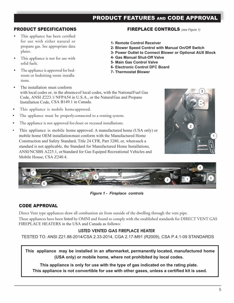
Figure 1 - Fireplace controls
• This appliance has been certifiedfor use with either natural orpropane gas. See appropriate dataplates.
• This appliance is not for use withsolid fuels.
• The appliance is approved for bed-room or bedsitting room installa-tions.
PRODUCT SPECIFICATIONS FIREPLACE CONTROLS (see Figure 1)
1
1
2
2
3
3
4
5
6
7
1- Remote Control Receiver2- Blower Speed Control with Manual On/Off Switch3- Power Outlet to Connect Blower or Optional AUX Block 4- Gas Manual Shut-Off Valve5- Main Gas Control Valve
7- Thermostat Blower6- Electronic Control DFC Board
CSA B149.1 in Canada.
• The installation must conform with local codes or, in the absenceof local codes, with the NationalFuel Gas Code, ANSI Z223.1/NFPA54 in U.S.A., or the NaturalGas and Propane Installation Code,
• This appliance is mobile homeapproved.
• The appliance must be properlyconnected to a venting system.
• The appliance is not approved forcloset or recessed installations.
• This appliance is mobile home approved. A manufactured home (USA only) or mobile home OEM installationmust conform with the Manufactured Home Construction and Safety Standard, Title 24 CFR, Part 3280, or, whensuch a standard is not applicable, the Standard for Manufactured Home Installations, ANSI/NCSBS A225.1, orStandard for Gas Equiped Recreational Vehicles and Mobile House, CSA Z240.4.
TESTED TO: ANSI Z21.88-2014/CSA 2.33-2014, CGA 2.17-M91 (R2009), CSA P.4.1-09 STANDARDS LISTED VENTED GAS FIREPLACE HEATER
Direct Vent type appliances draw all combustion air from outside of the dwelling through the vent pipe.
CODE APPROVAL
These appliances have been listed by OMNI and found to comply with the established standards for DIRECT VENT GAS FIREPLACE HEATERS in the USA and Canada as follows:
This appliance may be installed in an aftermarket, permanently located, manufactured home(USA only) or mobile home, where not prohibited by local codes.
This appliance is only for use with the type of gas indicated on the rating plate. This appliance is not convertible for use with other gases, unless a certified kit is used.

6 L100001 7
PRE-INSTALLATION INFORMATION
INSTALLING ABOVE 2000 FEET• In the USA, the appliance must be derated 4% for every 1,000 ft above 2,000 ft elevations (at the factory).
• In Canada, these appliances are certified for altitudes of 0 – 4,500 ft.
ORIFICE SIZES, PRESSURES AND BTUsNATURAL GAS PROPANE GASManifold Press: (W.C.) 3.5" Manifold Press: (W.C.) 10" Maximum Supply Pressure 10.5" Maximum Supply Pressure 13" Minimum Supply Pressure 4.5" Minimum Supply Pressure 11"
BEFORE YOU STARTRead this homeowner' smanual thoroughly and follow all instructions carefully. Inspect all contents for shipping damage and immediately inform Spark Modern if any damage is found. Do not install any unit with damaged, incomplete, or substitute parts.
ITEMS REQUIRED FOR INSTALLATIONTools: Building Supplies:• Phillips Screwdriver • Framing Materials• Hammer • Wall Finishing Materials• Saw and/or saber saw • Caulking Material (Non-combustible)• Level • Fireplace Surround Material (Non-combustible)• Measuring Tape • Piping Complying with Local Codes• Electric Drill and Bits • Tee Joint• Pliers • Pipe Sealant Approved for use with Propane/LPG• Square (Resistant to Sulfur Compounds)• Pipe Wrench
Model Gas Orifice Size Input Rate, Btu/hr Number Type As Shipped Max Min
91N-E - SeeThru Natural #31 39,000 27,000
91P-E - SeeThru Propane #49 38,000 27,000
92N-E - Peninsula Natural #31 39,000 27,000
92P-E - Peninsula Propane #49 38,000 27,000

L100001 97
PRE-INSTALLATION INFORMATION
Figu
re 2
- Fi
repl
ace
Dim
ensi
ons
MO
DEL
91/
92
FRO
NT
VIE
W
24"
24"
22.5
"
24"
MO
DEL
91
MO
DEL
92
32"
22.5
0"
41.7
5"
52.5
0"
32"
7.5"
17"
7.5"
40"
13"
17"
36.3
3"
SID
E V
IEW
TO
P V
IEW
SID
E V
IEW
DIR
EC
T V
EN
T G
AS
FIR
EP
LAC
E D
IME
NS
ION
S

8 L100001 8
PRE-INSTALLATION INFORMATION
FIREPLACE LOCATIONPlan for the installation of your appliance. This includes determining where the unit is to be installed, the vent configuration to beused, framing and finishing details, and whether any optional accessories (i.e. wall switch, or remote control) are desired. Consult your local building code agency to ensure compliance with local codes, including permits and inspections.
The following factors should be taken into consideration:
• Clearance to side-wall, ceiling, woodwork, and windows. Minimum clearances to combustibles must be maintained.
• Location should be out of high traffic areas and away from furniture and draperies due to heat from appliance.
• Never obstruct the front opening of the fireplace.
• Do not install in the vicinity where gasoline or other flammable liquids may be stored.
• Vent pipe routing. See Venting section in this manual for allowable venting configurations.
• These units can be installed in a bedroom or bathroom. See National Fuel Gas Code ANSI Z233.1/NFPA 54 (current edition),the Uniform Mechanical Code — (current edition), and Local Building Codes for specific installation requirements.
PLANING FIREPLACE FRAMING AND COVERING FACE
Firebox framing can be built before or after the appliance is set in place. Construct firebox framing following Figure 3 and the chart below for your specific installation requirements. See Figure 2 on Page 7 for firebox dimensions. The framing headers may rest on the top of the firebox standoff.
The firebox may be installed directly on a combustible floor or raised on a platform of an appropriate height. When the firebox is installed directly on carpeting, tile, or other combustible material, other than wood flooring, the firebox shall be installed on a metal or wood panel extending the full width and depth of the enclosure.
Do not fill spaces around firebox with insulation or other materials. This could cause a fire.
WARNING IMPORTANT: The following must be taken into consideration ifyou decide to cover over the fireplace face:
1. The covering material must be non combustible, maximum 3/4" thick.2. Minimum outside dimensions of the material over the facing are
41-3/4" x 40" (see Figure 4 on Pge 9).3. The inner opening in covering material must be minimum 36-1/2" wide, 18" tall and centered over the fireplace opening to allow
for glass door removal.4. The cover should maintain an air gap of at least 1/8" between covering material and fireplace to allow for metal fireplace front
to expand and contract during operation.5. PLEASE NOTE: Natural stone products may react to heat by discoloring or cracking. Spark Modern Fires is not resposible for
any damages due to covering materials used. If tiles are to be applied covering the fireplace face, a layer of cement board mustany damages due to covering materials used. If tiles are to be applied covering the fireplace face, a layer of cement board mustbe used as a substrate.

6 L100001 9
PLANING FIREPLACE FRAMING AND COVERING FACE (continued)
-5 - For more information, visit www.desatech.com
Figure 4 - Minimum outside dimensions
of the face covering material

10 L100001 11
The fireplace must be secured to the floor and/or to framing studs as shown in Figure 5. Use two (2) wood screws or masonry/ concrete screws to secure fireplace to the floor. Use four (4) screws to attach fireplace to framing.
SECURING FIREPLACE TO FLOOR OR FRAMING
Figure 5 - Securing Fireplace to Floor and Framing Studs
SCREWS
SCREWS
SIDE TABS
(TWO ON EACH SIDE)
FRAMING
NOTE: If installed in mobile home, fireplace must be bolted securely to floor

10 L100001 11
CLEARANCES
CLEARANCES TO COMBUSTIBLES (both sides)
MANTEL CLEARANCES NOTE: The combustible area above the facing must not protrude more than 3/4" from the facing. If it does, it is considered a mantel and must meet the mantel requirements listed in this manual.
Figure 6 - Clearances
Follow these instructions carefully to ensure safe installation. Failure to follow instructions exactly can create a fire hazard.
The appliance cannot be installed on a carpet, tile or other combustible material other than wood flooring. If installed on carpet or vinyl flooring, the appliance shall be installed on a metal, wood or non-combustible material panel extending full width and depth of the appliance.
WARNING
The fireplace face may becovered with any non-combustible material.Allow clearance for removalof front air panel and glass
66
6
6
6
6
6
614" minimum
90" minimum
Minimum 12"from side wall
12" maximumdepth
COMBUSTIBLE MANTEL
door.
Front 36" (915 mm) Standoff 0" (0 mm)
Back 0.5" (13 mm) Floor 0" (0 mm)
(0 mm) Sides 0"CombustiblesClearance to

12 L100001 13
INSTALLATION PRECAUTIONSConsult local building codes before beginning the installation. The installer must make sure to select the proper vent system for installation. Before installing vent kit, the installer must read this fireplace manual and vent kit instructions.
Only a qualified installer/service person should install venting system. The installer must follow these safety rules:
• Wear gloves and safety glasses for protection.
• Use extreme caution when using ladders or when on rooftops.
• Be aware of electrical wiring locations in walls and ceilings.
The following actions will void the warranty on your fireplace:
• Installation of any damaged venting component.
• Unauthorized modification of the venting system.
• Installation of any component part not manufactured or approved by Spark Modern Fires.
• Installation other than permitted by these instructions.
FINISHING MATERIALNOTE: Any remote wiring (i.e. remote control or wall switch) must be done prior to fina finishin to avoid costly reconstruction.
INSTALLATION INFORMATION
VENT INSTALLATION
Never obstruct or modify the air inlet or outlet. This may create a fire hazard. WARNING
Read all instructions completely and thoroughly before attempting installation. Failure to do so could result in serious injury, property damage or loss of life. Operation of improperly installed and maintained venting system could result in serious injury, property damage or loss of life.
Failure to follow these instructions will void the warranty.
NOTICE
WARNING
State of Massachusetts: The installation must be done by a licensed plumber or gas fitter in the Commonwealth of Massachusetts.
12 L100001 13
VENT INSTALLATION
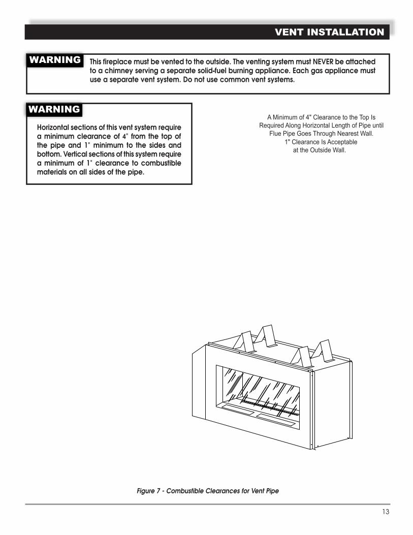
Figure 7 - Combustible Clearances for Vent Pipe
A Minimum of 4" Clearance to the Top Is Required Along Horizontal Length of Pipe until
Flue Pipe Goes Through Nearest Wall.
WA
RN
ING
This fireplace must be vented to the outside. The venting system must NEVER be attached to a chimney serving a separate solid-fuel burning appliance. Each gas appliance must use a separate vent system. Do not use common vent systems.
WARNING
Horizontal sections of this vent system require a minimum clearance of 4" from the top of the pipe and 1" minimum to the sides and bottom. Vertical sections of this system require a minimum of 1" clearance to combustible materials on all sides of the pipe.
WARNING
1" Clearance Is Acceptable at the Outside Wall.
6
6 4" minimum
1" minimum
2' pipe
Basic Horizontal VentInstallation

14 L100001 15
VENT INSTALLATION
INSTALLATION PLANNING There are two basic types of direct-vent installation:
• Horizontal Termination• Vertical Termination
It is important to select the proper length of vent pipe for the type of termination you choose. It is also important to note the wall thickness.
FOR HORIZONTAL TERMINATIONSelect the amount of vertical rise desired. All horizontal run of venting must have 1/4" rise for every 12" of run towards the termination.
You may use up to three 90° elbows in this vent configuration. See Horizontal Termination Configurations on pages 19 and 20.
FOR VERTICAL TERMINATIONMeasure the distance from the fireplace floor to the ceiling. Add the ceiling thickness, the vertical rise in an attic or second story, and allow for sufficient vent height above the roof line.
NOTE: You may use two 45° elbows in place of a 90° elbow. You must follow rise to run ratios when using 45° elbows. The appliance is approved for use with three 90° elbows maximum or a combination of 90° and 45° elbows up to a maximum of 270°.
For two-story applications, firestops are required at each floor level. If an offset is needed in the attic, additional pipe and elbows will be required.
You may use a chase with a vent termination with exposed pipe on the exterior of the house. See Installing Vent System in a Chase below. If pipe is enclosed in chase, it is not exposed.
It is very important that the venting system maintain its balance between the combustion air intake and the flue gas exhaust. Certain limitations apply to vent configurations and must be strictly followed.
INSTALLING A VENT SYSTEM IN AN OUTSIDE CHASEA chase is a vertical boxlike structure built to enclose venting that runs along the outside of a building. A chase is required for such venting.
Never run the vent pipe level or downward. This may cause excessive temperatures which could cause a fire.
WARNING
When installing in a chase, you should insulate the chase as you would the outside walls of your home. This is especially important in cold climates. Insulation should be considered a combustible material. Maintain proper clearances to all combustible materials.
NOTICE
Treatment of firestops and construction of the chase may vary from building type to building type. These instructions are not substitutes for the requirements of local building codes. You must follow all local building codes.
NOTICE

14 L100001 15
�
�
�
�
��
�
�
�
�
�
�
�
�
�
�
� �
��
�
�
�
�
�
�
�
��������
����������� �����
������������
���
�
�
��
�
VENT INSTALLATION
Figure 8 - Horizontal Vent Termination Location
Vent Terminal Air Supply Inlet Area Where Terminals Not Permitted
Inside Corner Detail FOR HORIZONTAL TERMINATION
MINIMUM DISTANCES A = Clearance above the grade, a veranda, porch, deck, or balcony [*12" (305mm) minimum]. B = Clearance to window or door that may be opened [*12" (305mm) minimum]. C = Clearance to permanently closed window [*minimum 12" (305mm) recommended to prevent condensation on window]
D = Vertical clearance to ventilated soffit located above the terminal within a horizontal distance of two (2) feet (610mm) from the centerline of the terminal [18" (457mm) minimum].
E = Clearance to unventilated soffits [12" (305mm) minimum]. Clearance to vinyl soffit [30" (762mm)]. F = Clearance to an outside corner [*6" (152mm) minimum].G = Clearance to an inside corner [*6" (152mm) minimum .]H = *Not to be installed above a gas meter/regulator assembly within three (3) feet (914mm) horizontally from the centerline of
the regulator. I = Clearance to service regulator vent outlet [*3' (914mm) minimum]. J = Clearance to non-mechanical air supply inlet to building or the combustion air inlet to any other appliance [*12"
(305mm) minimum]. K = Clearance to a mechanical air supply inlet [*6' (1829mm) minimum]. L = Clearance above a paved sidewalk or paved driveway located on public property [**7' (2133mm) minimum]. M = Clearance under veranda, porch, deck, or balcony [*12" (305mm) minimum***].N = Clearance above a roof shall extend a minimum of 24" (610mm) above the highest point when it passes through the roof
surface and any other obstruction within a horizontal distance of 18" (457mm).
* As specified in CAN/CGA B149 Installation Codes. Note: Local codes or regulations may require different clearances.** A vent must not terminate directly above a sidewalk or paved driveway, which is located between two single-family dwellings
and serves both dwellings.*** Only permitted if veranda, porch, deck, or balcony is fully open on a minimum of two sides beneath the floor.
Always maintain minimum clearances around vent systems. The minimum clearances to combustibles for horizontal vent pipe are 4" at the top and 1" at the sides and bottom of the vent system until the pipe penetrates the nearest vertical wall. A 1" minimum clearance all around the pipe must be maintained. Do not pack the open air spaces with insulation or other materials. This could cause high temperatures and may present a fire hazard.
WARNING

16 L100001 17
�
� ���� �������
� ���� �������
�
�
�
� � ����������� 12��305����������������� �2��305���
����������� ���������������� � 12� �305���� � ��� �������
�
�
�
� �������� ����� �� ��� ����������� ������ ��������
� �������� ����� ��� ���� ���� �������� ������������������� � ��� ��������������������� � ��� �������
� ���������� ���� ������ �� ������������������������� � �� ��������������������� � �� ������
��
���
������ ������
������ ��������
������� ������
������� ���� �� ���� ���� ������� ���� ����������������� ����
VENT INSTALLATION
TERMINATION CLEARANCES FOR BUILDINGS WITH COMBUSTIBLE AND NONCOMBUSTIBLE EXTERIORS
Figure 9 - Allowable Venting Chart
HOW TO USE THE VENT GRAPHThe Vent Graph should be read in conjunction with the following vent installation instructions to determine the relationship between the vertical and horizontal dimensions of the vent system.
1. Determine the height of the center of the horizontal vent pipe exit-ing through the outer wall. Using this dimension on the SidewallVent Graph below, locate the point intersecting with the slantedgraph line.
2. From the point of this intersection, draw a vertical line to thebottom of the graph.
3. Select the indicated dimension, and position the fireplace inaccordance with same.
Example: If the vertical dimension from the floor of thefireplace is 11' (3.4 m ) the horizontal run to the face of theouter wall must not exceed 17' (5.25 m).
Example: If the vertical dimension from the floor of the unitis 7’ (2.14 m ), the horizontal wall must not exceed 1 2 ' (2.67 m).
run to the face of the outer
Sidewall Vent Graph showing the relationship between vertical and horizontal dimensions for a Direct Vent flue system. Figure 10 - Rear Wall Venting Graph
Horizontal Dimension (Ft) From the Outside of Termination to the Back of the Fireplace
Vertic
al D
imensio
n (Ft) From
the Flo
or o
f Unit to
the C
ente
r of
the H
orizo
nta
l Vent P
ipe
50
48
44
46
40
38
36
42
24
20
22
32
26
30
28
34
6
4
2
14
10
12
8
16
18
00 2 4 6 12108 14 2418 20 2216

16 L100001 17
������������
������������
�����������
������������
Figure 12 - Vent Opening Requirements
Note: Horizontal runs of vent must be supported every three feet (914mm). Use wall straps for this purpose.
Figure 13 - Rigid Vent Pipe Connections
Female Locking Lugs
Male Slots
REAR WALL VENT INSTALLATION When installed as a rear vent unit this appliance may be vented directly to a termination located on the rear wall behind the appliance with 2' of vertical rise minimum.
• The maximum horizontal distance between the rear of the appliance and the outside of termination is 20" (508 mm). SeeFigure 11.
• NOTE: A 30° elbow on 2 foot minimum vertical pipe is required for this configuration.
VENTING INSTALLATION
1. Locate and cut the vent opening in the wall. For com-bustible walls first frame in opening. See Figure 11.
Combustible Walls: Cut a 91⁄2" H x 91⁄2" W(241mm x 241mm) hole through the exterior walland frame as shown. See Figure 12.
Noncombustible Walls: Hole opening should be71⁄2" (190mm) in diameter.
2. Rigid vent pipes and fittings have special twist-lockconnections. Assemble the desired combination ofpipe and elbows to the appliance adaptor with pipeseams oriented towards the wall or floor.
Twist-lock Procedure: The female ends of the pipesand fittings have three locking lugs (indentations).These lugs will slide straight into matching slots onthe male end of adjacent pipes and fittings. Pushthe pipe sections together and twist one sectionclockwise approximately one-quarter turn until thesections are fully locked. See Figure 13.
3. Attach vent pipe assembly to the fireplace. Set fire-place in front of its permanent location to insureminimum clearances. Mark the wall for a 91⁄2"Hx 91⁄2"W (241mm x 241 mm) square hole (fornoncombustible material such as masonry block orconcrete, a 71/2" [190mm] diameter hole is accept-able). See Figure 11. The center of the hole should line up with the center line of the horizontal rigidvent pipe end. Be sure to allow for minimum rise. Cut a 91/2"x91/2" (241mm X 241mm) square hole through combustibleexterior wall (71/2" [190mm] diameter hole if noncombustible). Frame as necessary. Allow 1/4" minimum rise per foot. SeeFigure 12.
Figure 11 - Rear Vent Application,Maximum Horizontal Distance
Maximum 20"

18 L100001 19
HOT
HOT
VENT INSTALLATION
4. Apply a bead of non-hardening mastic around the outsideedge of vent cap. Position the vent cap in the center of holeon the exterior wall with the arrow up on the vent cap.Insure proper clearance of 1" to combustibles is main-tained. Attach the vent cap with four wood screws supplied.See Figure 14.
NOTE: Replace the wood screws with appropriate fasteners for stucco, brick, concrete, or other types of siding.
For vinyl siding, stucco, or wood exterior use vinyl siding stand-offs between vent cap and exterior wall. The vinyl siding standoff prevents excessive heat from melting the vinyl siding material. Bolt the vent cap to the standoff. Apply non-hardening mastic around outside edge of the standoff instead of the vent cap assembly. Use wood screws provided to attach the standoff. See Figure 15.
5. Slide the wall thimble over the vent pipe before connectingthe horizontal run to the vent cap. See Figure 16.
6. Carefully move the fireplace with vent assembly attachedtoward the wall and insert the vent pipe into the horizontaltermination. The pipe overlap should be a minimum of 11/4".Apply silicone to the outer pipe connection. Fasten all ventconnections with screws provided.
7. Slide the wall thimble against the interior wall surface andattach with srews. See Figure 16.
Figure 14 - Installing Horizontal Vent Cap
REAR WALL VENT INSTALLATION (continued)
Figure 15 - Installing Vinyl Siding Standoff
Apply Mastic to All Four
Sides
Vent Cap
Wood Screw
Cut Vinyl Siding Away to Fit Standoff
Wood Screw
Vent Cap
Bolt
Apply Mastic to All Four Sides
Nut
Standoff
Figure 16 - Connecting Vent Cap with Horizontal Vent Pipe
Interior Wall Surface
Decorative Wall Thimble
Horizontal Vent PipeScrew
Vent Cap (Horizontal
Termination)
Deflecting Shield
Do not recess vent termination into any wall. This will cause a fire hazard.
WARNING
S

18 L100001 19
VENT INSTALLATION
HORIZONTAL TERMINATION CONFIGURATIONS — RIGID VENTING Since it is very important that the venting system maintain its balance between the combustion air intake and the flue gas exhaust, certain limitations as to vent configurations apply and must be strictly adhered to.
The Vent Graph, showing the relationship between vertical and horizontal side wall venting, will help to determine the various dimensions allowable. See page 16.
Minimum clearance between vent pipes and combustible materials is 4" on top and 1" from bottom and sides unless otherwise noted.
When vent terminations exit through foundations less than 20" below siding outcrop, the vent pipe must flush up with the sid-ing.
It is best to locate the fireplace in such a way that minimizes the number of offsets and horizontal vent length.
The horizontal vent run refers to the total length of vent pipe from the flue collar of the fireplace (or the top of the Transition Elbow) to the face of the outer wall.
Figure 18 - Maximum Three (3) 90 Elbows Per Installation
• The maximum number of 90° elbows per side wall installation is three (3), the maximum horizontal run is 20" (Figures 18, 19)
Figure 19 - Maximum Horizontal Run with 2 foot rise
20"Max.Rise 2' min
The Commonwealth of Massachusetts requires the installation and USE of Carbon Monoxide detectorsin the rooms of ALL direct vent units which utilize a SIDE WALL VENTING TERMINATION
FOR STATE OF MASSACHUSETTS:
3 x 90o Elbows

20 L100001 21
• If a 90° elbow is used in the horizontal vent run (level heightmaintained) the horizontal vent length is reduced by 36" (914mm) (Fig. 20 A and B) This does not apply if the 90° elbowsare used to increase or redirect a vertical rise. See Figure 19.
Example: According to the vent graph (page 16) the maximum horizontal vent length in a system with a 7.5' vertical rise is 15’ (6m) and if a 90° elbow is required in the horizontal vent it must be reduced to 12'.
In Figure 20, Dimension A plus B must not be greater than 12' (3.66m).
• The maximum number of 45° elbows permitted per side wallinstallation is two (2). These elbows can be installed in eitherthe vertical or horizontal run.
• For each 45° elbow installed in the horizontal run, the lengthof the horizontal run MUST be reduced by 18" (45cm). Thisdoes not apply if the 45° elbows are installed on the verticalpart of the vent system.
• The maximum number of elbow degrees in a system is 270°.See Figure 22.
Figure 21 - Maximum Vent Run with Elbows
Figure 20 - Maximum Vent Run with Elbows
Figure 22 - Maximum Elbow Usage
VENT INSTALLATION
1 + 2 + 3 + 4 = 270°
1
2
31
2
3
4
HORIZONTAL TERMINATION CONFIGURATION — RIGID VENTING (Continued)
Example: Elbow 1 = 90°Elbow 2 = 45°Elbow 3 = 45°Elbow 4 = 90°
Total Angular Variation = 270°
7'6"
8'4'A
B
90° Elbow reduces horizontal run allowed by 3'.
A+B=12' Maximum.

20 L100001 21
VENT INSTALLATION
BELOW GRADE INSTALLATIONS — RIGID VENTING When it is not possible to meet the required vent terminal clearances of 12" above grade level, a snorkel kit is recommended. It
vent pipe as it penetrates through the wall.
Ensure that sidewall venting clearances are observed. If venting system is installed below ground, we recommend a window well with adequate and proper drainage to be installed around the termination area.
If installing a snorkel, a minimum 24" vertical rise is necessary. The maximum horizontal run with the 24” vertical pipe is 36". This measurement is taken from the collar of the fireplace (or transition elbow) to the face of the exterior wall. See the Sidewall Venting Graph for extended horizontal run if the vertical exceeds 24".
1. Establish vent hole through the wall. See Figure 12, page 17.
2. Remove soil to a depth of approximately 16" below base of snorkel. Install drain pipe. Install window well (not supplied).Refill hole with 12" of coarse gravel leaving a clearance of approximately 4" below snorkel. See Figure 23.
3. Install vent system.
4. Ensure a watertight seal is made around the vent pipe coming through the wall.
5. Apply high temperature sealant caulking (supplied) around the 4" and 7" snorkel collars.
6. Slide the snorkel into the vent pipes and secure to the wall.
7. Level the soil so as to maintain a 4" clearance below snorkel. See Figure 23.
Figure 24 - Snorkel Installation, Recessed FoundationFigure 23 - Below Grade Installation
Screws CLEARANCES
4" Minimum 12" MinimumGround
Window Well
Gravel
Drain 12" Minimum
Foundation Wall
Firestop
36"Minimum
FoundationRecess
Watertight Seal Around Pipe
Sheet Metal Screws
Wall Screws
Snorkel
• Do not back fill around snorkel.
• A clearance of at least 4" must be maintainedbetween the snorkel and the soil.
IMPORTANT: For below grade installations IMPORTANT:
If the foundation is recessed, use recess brackets (not supplied) for securing lower portion of the snorkel. Fasten brackets to wall first, then secure to snorkel with self drilling #8x1/2 sheet metal screws. It will be necessary to extend vent pipes out as far as the protruding wall face. See Figure 24.
a 12" minimum clearance above grade for the ter-mination vent must be maintained for all termina- tions including the snorkel vent application forbasements.

22 L100001 23
Restrictor Disk
using a maximum of two 90° elbows. See Figure 25.
Figure 25- Support Straps for Horizontal Runs
VENT INSTALLATION
Figure 26 - Maximum Elbow Usage
• Up to two 45° elbows may be used within thehorizontal run. For each 45° elbow used on thehorizontal plane, the maximum horizontal lengthmust be reduced by 18" (450mm).
Example: Maximum horizontal length
No elbows = 10’ (3m)
1x45° elbows = 8.5’ (2.6m)
2x45° elbows = 7’ (2.1m)
• A minimum of an 8' (2.5m) vertical rise isrequired if venting through the roof.
• Two sets of 45°elbows offsets may be used withinthe vertical sections. From 0 to a maximum of 8'(2.5 m) of vent pipe can be used between elbows.See Figure 26.
• 91, 92 series fireplaces allow for offsets. Thisapplication will require that you first determine theroof pitch and use the appropriate starter kit.
• The maximum angular variation allowed in thesystem is 270°. See Figure 26.
• The minimum height of the vent above the high-est point of penetration through the roof is 2'(610mm).
40' Maximum Height8' Minimum Height 40' Maximum Height
8' Minimum Height
10'Maximum
10'Maximum
1
2
3
4
1
2
3
4
Support StrapsEvery 3'
Support StrapsEvery 3'
Example: Elbow 1 = 45°Elbow 2 = 45°Elbow 3 = 90°Elbow 4 = 90°
Total Angular Variation = 270°
Support StrapsEvery
5'Vertical
Restrictor Disk
Restrictor Disk
Restrictor Disk
RESTRICTOR DISC
NOTE: The restrictor disc included with the installation instructions should be used on vertically terminating installations only.
Install the restrictor disc into the flue collar of the appliance with the bar horizontal.
VERTICAL THROUGH-THE-ROOF APPLICATIONS — RIGID VENTING ONLY This Gas Fireplace has been approved for,
• Vertical installations up to 40' (12m) in height. Up to a 10' (3m) horizontal vent run can be installed within the vent system

22 L100001 23
����������
VENT INSTALLATION
INSTALLATION FOR VERTICAL TERMINATION 1. Determine the route your vertical venting will take. If ceiling joist,
roof rafters or other framing will obstruct the venting system, consideran offset. See Figure 27 to avoid cutting load bearing members.
NOTE: Pay special attention to these installation instructions for required clearances (air space) to combustibles when passing through ceilings, walls, roofs, enclosures, attic rafters, etc. Do not pack air spaces with insulation. Also note maximum vertical rise of the venting system and any maximum horizontal offset limitations. Offsets must fall within the parameters shows in Figure 10, page 16.
2. Set fireplace in desired location. Drop a plumb line down from theceiling to the position of the flue exit. Mark the center point wherethe vent will penetrate the ceiling. Drill a small locating hole a thispoint.
Drop a plumb line from the inside of the roof to the ceiling locat-ing hole in the ceiling. Mark the center point where the vent willpenetrate the roof. Drill a small locating hole at this point.
FLAT CEILING INSTALLATION1. Cut a 91/2" (241mm) square hole in the ceiling using the locating
hole as a center point The opening should be framed to 91/2"x91/2"(241mm x 241mm) inside dimensions as shown in Figure 12, page17 using framing lumber the same size as the ceiling joist. If thearea above the ceiling is an insulated ceiling or a room, nail firestopfrom the top side. This prevents loose insulation from falling intothe required clearance space. See Figure 28. Otherwise, install firestopbelow the framed hole. The firestop should be installed with no lessthan three nails per side. See Figure 29.
2. Assemble the desired lengths of pipe and elbows necessary to reachfrom the burner system flue up through the firestop. Be sure pipe andelbow connections are fully twist-locked. See Figure 13, page 17.
3. Cut a hole in the roof using the locating hole as a center point.(Cover any exposed open vent pipes before cutting hole in roof ).The 91/2"x91/2" (241mm x 241mm) hole must be measured on thehorizontal. Actual length may be larger depending on the pitch ofthe roof. There must be a 1" minimum clearance from the ventpipe to combustible materials. (Insulation should be considered acombustible material). Frame the opening as shown in Figure 12 onpage 17.
Figure 27 - Offset with Wall Strap and 45 Elbows
Roof Flashing
Wall Strap
45° Elbows
Ceiling Firstop
Figure 28- If area above is a room, install firestop above framed hole as shown
Figure 29 - If area above is not a room, install firestop below framed hole as shown
Continued on next page
Firestop
Nails
NailsFirestop

24 L100001 25
VENT INSTALLATION
4. Connect a section of pipe and extend up through the hole.
NOTE: If an offset is needed to avoid obstructions, you must support the vent pipe every three (3) feet. Use wall straps for this purpose. See Figure 25, page 22. Whenever possible, use 45° elbows instead of 90° elbows. The 45° elbow offers less restriction to the flow of the ue gases and intake air.
5. Place the flashing over the pipe section(s) extending through the roof. Secure the base of the flashing to the roof and framingwith roofing nails. Be sure roofing material overlaps the top edge of the flashing. There must be a 1" clearance from the ventpipe to combustible materials.
6. Continue to add pipe sections until the height of the vent cap meets the minimum building code requirements.
NOTE: You must increase vent height for steep roof pitches. Nearby trees, adjoining roof lines, steep pitched roofs, and other similar factors may cause poor draft or down-drafting in high winds. Increasing the vent height may solve this problem.
NOTE: If the vent pipe passes through any occupied areas above the first floor, including storage spaces and closets, you must enclose pipe. You may frame and sheetrock the enclosure with standard construction material. Make sure to meet the minimum allowable clearances to combustibles. Do not fill any of the required clearance spaces with insulation.
Figure 30 - Cathedral Ceiling Support Box Installation
Figure 31 - Installed Cathedral Ceiling Support Box
CATHEDRAL CEILING INSTALLATIONIMPORTANT: Review all information on previous page before planning this installation. Cathedral ceiling installations can be very tricky.
1. Remove shingles or other roof covering as necessary to cutthe rectangular hole for the support box. Mark the outlineof the cathedral ceiling support box on the roof sheathingusing the locating hole as a center point.
2. Cut the hole 1/8" larger than the support box outline. SeeFigure 30.
3. Lower the support box through the hole in the roof untilthe bottom of the box extends at least 2" (51 mm) below theceiling. See Figure 30. Align the support box vertically andhorizontally using a level. Temporarily tack the support boxin place through the inside walls and into the roof sheet-ing.
4. Using tin snips, cut the support box from the top cornersdown to the roofline and fold the resulting flaps over theroof sheeting. See Figure 31. Apply a bead of non-hardeningmastic around the top edges of the support box to make aseal between the box and the roof. Nail in place with roof-ing nails. Remove any combustible material that might beinside the support box.
5. Complete the cathedral ceiling installation by followingthe same procedure outlined in steps 2 through 6 for FlatCeiling Installation, page 23 and above.
Level Cathedral Ceiling Support
Box
2" Minimum Below
Finished Ceiling
Cut Hole 1/8" Larger than Support Box
when Projected onto Roofline
Apply Non-hardening Mastic Under all Edges of
Support Box before Nailing

24 L100001 25
Figure 32 - External Regulator with Vent Pointing Down (Propane/LP Only)
FIREPLACE INSTALLATION
CHECK GAS TYPEUse proper gas type for the fireplace you are installing. If you have conflicting gas type, do not install fireplace. See dealer where you purchased the fireplace for proper fireplace for your gas type or conversion kit.
INSTALLING GAS PIPING TO FIREPLACE / BURNER SYSTEM LOCATION
INSTALLATION ITEMS NEEDEDBefore installing fireplace and burner system, make sure you have the items listed below.
• External regulator (supplied by installer) • Piping (check local codes) • Sealant (resistant to propane/LP gas)• Equipment shutoff valve* • Test gauge connection* • Sediment trap (recommended)• Tee joint • Pipe wrench• Approved flexible gas line with gas connector (if allowed by local codes — not provided)
* A CSA design-certified equipment shutoff valve with 1/8" NPT tap is an acceptable alternative to test gauge connection.Purchase the CSA design-certified equipment shutoff valve from your dealer.
For propane/LP connections only, the installer must supply an external regulator. The external regulator will reduce incoming gas pressure. You must reduce incoming gas pressure to between 11 and 13 inches of WC. If you do not reduce incoming gas pressure, burner system regulator damage could occur. Install external regulator with the vent pointing down as shown in Figure 32. Pointing the vent down protects it from freezing rain or sleet.
External Regulator
100 lb. (min) Propane/LP Supply Tank
Vent Pointing Down When using copper or flex connectors use only fittings approved
for gas connections. The gas control inlet is 3/8" NPT.
A qualified installer or service person must connect appliance to gas supply. Follow all local codes.
WARNING
For propane/LP units, never connect fireplace directly to the propane/LP supply. This burner system requires an external regulator (not supplied). Install the external regulator between the burner system and propane/LP supply.
CAUTION
Use only new black iron or steel pipe. Internally tinned copper or copper tubing can be used per National Fuel Code, section 2.6.3, providing gas meets hydrogen sulfide limits, and where permitted by local codes. Gas piping system must be sized to provide minimum inlet pressure (listed on data plate) at the maximum flow rate (BTU/hr). Undue pressure loss will occur if the pipe is too small.
CAUTION

26 L100001 27
�� �������
FIREPLACE INSTALLATION
A listed manual shutoff valve must be installed upstream of the appliance. Union tee and plugged 1/8" NPT pressure tapping point should be installed upstream of the appliance. See Figure 33.
IMPORTANT: Install main gas valve (equipment shutoff valve) in an accessible location. The main gas valve is for turning on or shutting off the gas to the fireplace.
Check your building codes for any special requirements for locat-ing equipment shutoff valve to fireplaces.
Apply pipe joint sealant lightly to male threads. This will prevent excess sealant from going into pipe. Excess sealant in pipe could result in clogged burner system valves.
We recommend that you install a sediment trap/drip leg in supply line as shown in Figure 33. Locate sediment trap/drip leg where it is within reach for cleaning. Install in piping system between fuel supply and burner system. Locate sediment trap/drip leg where trapped matter is not likely to freeze. A sediment trap traps moisture and contaminants. This keeps them from going into the burner system gas controls. If sediment trap/drip leg is not installed or is installed wrong, burner system may not run properly.
Figure 33 - Gas Connection
Tee JointPipe NippleCap
Approved Flexible Gas Line
CSA Design-Certified Equipment Shutoff Valve with 1/8" NPT Tap
Sediment Trap/Drip Leg
Natural GasFrom Gas Meter
(5" W.C. to 10.5" W.C. Pressure)Propane/LP
From External Regulator (11" W.C. to 13" W.C. Pressure)
NOTE : The gas line connection may be made using 1/2" rigid tubing or an approved flex connector. Since some municipalities have additional local codes it is always best to consult your local authorities and the current edition of the National Fuel Gas Code ANSI.Z223.1, NFPA54. In Canada CAN/CGA-B149 (1 or 2) Installation Code.
Only persons licensed to work with gas piping may make the necessary gas connections to this appliance.
WARNINGA manual shutoff valve must be installed upstream of the appliance. Union tee and plugged 1/8" NPT pressure tapping point should be installed upstream of the appliance. See Figure 33.
CAUTION
Use pipe joint sealant that is resistant to liquid petroleum (LP) gas.
CAUTION

CHECKING GAS PRESSURE
5.
. After completing gas line connection, purge air from
(3.5 kPa).system at test pressures equal to or less than 1/2 psiduring any pressure testing of the gas supply pipingpiping system by closing its equipment shutoff valveThe appliance must be isolated from the gas supplypressures in excess of 1/2 psi (3.5 kPa).during any pressure testing of that system at testbe disconnected from the gas supply piping system
2. The appliance and its appliance main gas valve must
Velcro
lower right outside wall, as shown on page 5)
Inlet Pressure Tap
Pilot Adjustment
Outlet Pressure Tap
BLOWER/FAN LOCATION
(see page 5)
BAC
K
FRO
NT
CavityLower Firebox
TerminalsSpade
WireGround Green
ScrewExhaust Port
Strips
Side View Blower Location
firebox floor agains(Located underneath Duplex Outlet
Plug-InBlower
BracketSwitch
Knob Control
Control Shaft Speed Control
FAN ASSEMBLY DIAGRAMS
WARNINGDo not use open flame to check for gas leaks.
Figure 34 - Gas Pressure Check at Gas Valve
torque. Check test points for gas leaks.captured screw clockwise firmly to reseal. Do not over Figure 34. After taking pressure reading, be sure and turn to pressure gauge over test point. Turn unit to high. See counter clockwise 2 or 3 turns and then place tubing
To check gas pressures at valve, turn captured screw
4.
soap or a gas sniffer. fireplace for leaks. Use a solution of 50/50 water and gas line and test all gas joints from the gas meter to the
appliance. Contact your dealer immediately.is different from the fireplace, STOP! Do not install thestated on the appliance’s rating decal. If the gas supply
1. Check gas type. The gas supply must be the same as
26 L100001 27
3. To ease installation, a 24" flex line with manualshut-off valve has been provided with on this appliance. I nstall and attach 1/2" gas line onto shut-off valve.
28 L100001 29
ELECTRICAL INSTALLATION
ELECTRICAL WIRING
Electrical connections should only be performed by a qualified, licensed electrician. Main power must be off when connecting to main electrical power supply or performing service. All wiring shall be in compliance with all local, city, and state codes. The appliance, when installed, must be electrically grounded in accordance with local codes, or in the absence of local codes, with the National Electrical Code ANSI/ NFPA 70 (latest edition) and Canadian Electrical Code, CSA C22.1.
WARNING
Label all wires before disconnecting when servicing controls. Wiring errors can cause improper and dangerous operation.
CAUTION
This fireplace requires 110V AC electrical supply for normal operation in order to power up blower and 7V DC adapter which is required to operate Remote Control. However, during power outage situation, its electronic system (DFC board) can be temporarily powered with 6V DC battery pack (4 AA batteries).

GLASS REMOVAL
3. Loosen and remove the three nuts at the top of the glass door frame.
4. Carefully lift the glass frame out of the lower channel and remove by angling the frame up to the left
28 L100001 29
GLASS REMOVAL
GLASS FRAME REMOVAL (see Figure 36)1. Remove the front air panel using a screwdriver to lift from center if necessary.
2. Remove the left and right cover plates by lifting up and moving to the center.
Figure 36 - Removing Glass Frame
and tilting out the lower right corner.
NOTE: Avoid contacting the glass to anysurface and be carefull to not damage
Glass frame
Front air panel
Left side panel
Right side panel
any of the controls in the lower cavity.
1
2
23
4

30 L100001 31
FINAL INSTALLATION
MEDIA TRAY PLACEMENT 1. Place media tray (see Figure 37) on the support brackets as shown on Figure 38. 2. Fill the tray with media supplied. Do not place media on burner or block air flow between burner and tray. See Figure 39.
Figure 37 - One piece media tray
Figure 38 - Placing media tray
Figure 39 - Filling the tray with media

SAFETY SCREEN INSTALLATION
WARNING: A barrier (safety screen) designed to reduce the risk of burns from the hot viewing glass is provided with this appliance and shell be installed for the protection of children and other at-risk individuals.
STEP 1: Remove front air panel and both side panels.
STEP 2: Angle the safety screen as shown on the picture and carefully bring into the fireplace opening.
STEP 3: Position the safety screen inside of the fireplace in front of the glass door. Locate the two small vertical studs along the glass door frame bracket.
STEP 4: Center screen door screen door over the small studs and secure the screen in place. Using the nuts provided attach the screen firmly.
31
IMPORTANT: Safety Screen must be in place when the fireplace is in operation. If the barrier becomes damaged, the barrier shall be replaced with the manufacturer's barrier for this appliance. Any safety screen, guard, or barrier removed for servicingthe appliance, must be replaced prior to operating the appliance.
Note: Safety screen on the control side of the unit is removable in order to have access to the inner fireplace. Screens on opposite side and end panel side are permanently attached to the glass frame and should never require removal.
SAFETY SCREEN INSTALLATION (continued)
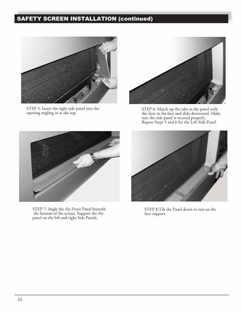
STEP 5: Insert the right side panel into the opening angling in at the top.
STEP 6: Match up the tabs in the panel with the slots in the face and slide downward. Make sure the side panel is secured properly.Repeat Steps 5 and 6 for the Left Side Panel.
STEP 7: Angle the Air Front Panel beneath the bottom of the screen. Support the Air panel on the left and right Side Panels.
STEP 8:Tilt the Panel down to rest on the face support.
32

OPERATING FIREPLACEFOR YOUR SAFETY
READ BEFORELIGHTING
A. This appliance is equipped with an ignition devicewhich automatically lights the pilot. Do Not try tolight the pilot by hand.
use any phone in your building.• Immediately call your gas supplier from a neigh-
bor's phone. Follow the gas supplier's instruc-tions.
• If you cannot reach your gas supplier, call the firedepartment.
C. Main gas valve in this appliance is not serviceableand does not have any control knobs or switches tooperate. Do not remove heat shields covering thevalve and electronic devices; do not try to repair ormodify the valve as it may result in a fire or explo-sion. Call a qualified service technician if you haveany safety concerns.
D. Do not use this appliance if any part has been underwater. Immediately call a qualified service techni-cian to inspect the appliance and to replace any partof the control system and any gas control which hasbeen under water.
OPERATINGINSTRUCTIONS
1. STOP! Read the safety information, starting on page 3.2. Remove media tray from the appliance (see Illustrated
parts list),3. Turn off all electric power to the appliance. Unplug
DC adapter from the power outlet.4. Do not attempt to light the pilot by hand.5. Lift and remove heat shield covering electronic com-
ponents inside of the unit (see illustrated parts list).
If you don't smell gas, go to the next step.
Note: Before applying any power supply to the DFCboard, please verify that the electrical connections
illustrated parts list), or mounted in adjacent wall.Make sure that the remote receiver switch is in"REMOTE" (middle) position.
Initializing the System for the First Time1. Set the remote receiver switch to the OFF position.
WARNING: If you do not follow theseinstructions exactly,a fire or explosion mayresult causing property damage, personalinjury or loss of life.
REMOTE
5. Turn main shutoff valve counterclockwise to ON position.
6. Set remote receiver switch to OFF position.
7. Wait five (5) minutes to clear out any gas. Thensmell for gas, including near the floor. If you smellgas, STOP! Follow "B" in the safety information.
9. Connect the wire to the DC input plug at the unit.
10. Locate remote receiver either inside the unit (see
B. BEFORE LIGHTING: smell all around the appli-ance area for gas. Be sure to smell next to the floorbecause some gas is heavier than air and will settleon the floor.WHAT TO DO IF YOU SMELL GAS:• Do not try to light any appliance.• Do not touch any electric switch; do not
are in accordance to Wiring Diagram.8. Plug supplied DC adapter into 110V power outlet.
11. Replace access panel (i.e inner cover or optional media tray).
2. Make sure that fresh set of AA batteries are installed intothe battery holder and verify the polarity indicated onthe battery holder. If necessary, connect the batteryholder to the DFC's main wir ing harness.
OPERA TING INSTRUCTIONS
Figure 43 - Remote Receiver Switch in OFF Position
Figure 42a w Remote Receiver Switch in OFF Position
Fiqure 42b - Remote Receiver Switch in REMOTEPosition
33

If pilot does not stay lit, contact a qualifiedservice person or gas supplier for repairs.
Figure 9d - Remote Receiver Switch in ON Position
1. Slide the remote receiver switch to the ON position.This will allow the main burner to ignite.
1. Slide the remote receiver switch to the OFF position.This will turn off the main burner.
levels by using the equipment shutoffvalve.
from home for long periods of time. Heater maycome on automatically with remote receiverswitch in the "REMOTE" position.
TO TURN OFF GASTO APPLIANCE
1. Tum off all electric power to the appliance if serviceis to be performed. Unplug DC adapter from thepower outlet.
2. If necessary, remove access panel from the applianceto access manual shutoff valve on gas line.
3. Turn the gas control manual valve clockwiseto the full OFF position.
4. If necessary, replace media tray or access panel
REMOTE CONTROLOPERATION
Proflame G-Fire System OperationInitializing the System for the First Time1. Install the 4 AA batteries into the receiver batter bay.
Note the polarity of the batteries and insert into thebattery bay as indicated on the battery covel' (+/-).
2. Place the 3-posilion slider switch in the REMOTEposition.
3. Insert the end of a paper clip into the hole markedPRG on the receiver front cover. The receiver willbeep three times to indicate that it is ready to syn-chronize with a transmitter.
4. Install the 3 AAA batteries in the transmitter batterybay located on the base of the transmitter.
5. Press the ON button on the transmitter. The receiverwill beep four times to indicate the transmitters
Temperature Indication Display1. With the system in the OFF position, press the
THERMOSTAT key and the MODE key at the sametime.
CAUTION: Do not try to adjust heating
WARNING: Make sure the remote receiverswitch is in the OFF position when you are away
Blue LCD display
ON/OFF KeyTHERMOSTAT Key
UP/DOWN Arrow KeyMODE Key
Manually Turning ON the Appliance
Manually Turning OFF the Appliance
command is accepted. The system is now initial-ized.
2. Look at the LCD screen on the transmitter to verifythat a °C or °F is visible next to the room temperature.
Figure 44 - Remote Receiver Switch in OFF Position
Figure 45 - Remote Receiver
OPERA TING INSTRUCTIONS (continued)
34

T
Turning ON the Appliance1. Press the ON/OFF button on the transmitter. The
transmitter screen will display all active icons. Thereceiver will command the DFC board to start theignition process, Once the pilot flame is lit, the DFC
1. With the system ON and the flame level at maximumheight, press the down-arrow key once to reduce theflame height by one step. Continue pressing down-arrow key until flame is turned OFF.
2. Press the up-arrow key to increase the flamehcight.
Room Thermostat (Transmitter Operation)
The remote control can operate as a room thermostat.The thermostat can be set to a desired temperature tocontrol the comfort level in the room.
1. To activate this function, press the Thermostat key.The LCD display on the transmitter will change toshow that the room thermostat is ON and the set
RoomTemperature
SetTemperature
board will open the main valve outlet and the mainburner will ignite. A single "beep" from the receiverwill confirm the command.
Turning OFF the Appliance1. Press the ON/OFF button 011 the transmitter, The
A single "beep" from the receiver will confirm thecommand.
Proflame GTM
the receiver will confirm the command.
Note: If you press the up-arrow key while the remotesystem is ON but the flame is OFF, the flame willcome on in the high position, A single "beep" from
Flame Height Control
transmitter LCD display will only show the roomtemperature and icon (see Figure 48b). The receiverdisconnects and will command the DFC board toturn off the burner.
Figure 50 - Remote Control Displaying RoomTemperature and Set Temperature
temperature is now displayed (see Figure 50).
2. Adjust the set temperature by pressing the up ordown-arrow keys until the desired set temperature isdisplayed on the LCD screen (see Figure 50).
These units have six flame levels (see Figure 49).
Figure 46 - Remote Control Display in Farenheit andCelsius
Figure 47 - Remote Control Displaying RoomTemperature
Figure 49 - Remote Control Displaying Split Flow Mode
OPERA TING INSTRUCTIONS (continued)
Flame Levell
Flame Level 5 Flame Level Max.
Figure 48 - Remote Control Displaying Flame Levels
35

26 48D0139
Smart Thermostat
The Smart Thermostat function adjusts the flame heightin accordance to the difference between the set pointtemperature and the actual room temperature. As theroom temperature gets closer to the set point, the SmartFunction will modulate the flame down.
2. To adjust the set temperature, press the up ordown-arrow keys until the desired set temperatureis displayed on the LCD screen.
Key LockThis function will lock the keys to avoid unsupervisedoperation.
2. To deactivate this function, press the MODE and UPkeys at the same time. The lock icon will disappearfrom the LCD screen.
Low Battery Power DetectionReceiverThe life span of the receiver batteries depends uponvarious factors: battery quality, Humber of appliance ig-nitions, number of thermostat set point changes, etc.
'Vhen the receiver batteries are low, no "beep" willsound from the receiver when a transmitter commandis sent. Replace batteries when this happens,
TransmitterThe life span of the transmitter batteries depends uponvarious factors: battery quality, number of appliance ig-nitions, number of thermostat set point changes, etc.
Manual Override
If the receiver or transmitter batteries are low or de-pleted, the appliance can still be turned on manually.
1. Move the receivers three-position slider to the ONposition. This will bypass the remote control featureof the system and the appliance main burner willturn on.
Command Definitions
Pilot IPI / CPI
switch
Position of the
receiver slider switch
Command reference
name
Commanded Fireplace
State
Opened, IPI “OFF” “REMOTE”
and “OFF received”
Turn-OFF Flames OFF
Opened, IPI “ON” “REMOTE”
and “ON received”
Turn-ON Pilot + Main burnerflames ON
Closed, CPI “OFF” “REMOTE”
and “OFF received”
Pilot-ON Pilot flame ON
Closed, CPI “ON” “REMOTE”
and “ON received”
Turn-ON Pilot + Main burnerflames ON
(Transmitter Operation" Proflame GTM )
1. To activate this function, press the MODE and UP
Control Displaying SmartFigure 45d- Remote Thermostat Function
Figure 45e - Remote Control Displaying Key Lock Mode
Figure 45f- Remote Control Displaying Low Battery
1. To activate this function, press the Thermostat keyuntil the word "SMART" appears to the right of the temperature bulb on the LCD screen.
keys at the same time. A lock icon will appear on the LCD screen.
When the transmitter batteries arc low, an icon will appeal' on the LCD display, Replace batteries when this icon appears.
OPERA TING INSTRUCTIONS (continued)
36

BURNER FLAMEThe flames from the burner should be visually checked as soon as the heater is installed and periodically during normal operation. In normal operation, at full rate, and after operat-ing for about 15 to 30 minutes, the flame should be yellow and up to 6 inches high. See Figure 46.
If the flame is blue and only in the center, turn off unit and let cool. After unit is cool, remove trays and check to make sure the holes in the burner are not covered with media particles.
configuration, and wind effects may cause the flamepatterns to vary.
AIR SHUTTER ASSEMBLY
If necessary, change this by loosening nut and opening or closing the air shutter more. See Figure 47.
Figure 46 - Burner Flame Appearance
CLEANING AND MAINTENANCE
BURNER, PILOT AND CONTROL COMPARTMENTKeep the control compartment and burner areas clean by vacuuming or brushing at least twice a year. Make sure the burner porting, pilot air opening and burner air opening are free of obstructions at all times.
PILOT FLAMEThe flames from the pilot should be visually checked as soon as the heater is installed and periodically during normal operation. The pilot flame must always be present when the fireplace is in operation. See Figure 45. The pilot flame has two distinct flames, one engulfing the flame sensor, and the other reaching to the main burner.
BURNERInspect area around the injector. Remove any lint or foreign material with a brush or vacuum.
Turn off gas before servicing fireplace. It is recommended that a qualified service technician perform these check-ups at the beginning of each heating season.
WARNING
Figure 47 - Adjusting Air Shutter
Nut
Shutter Opening
Figure 45 - Pilot Flame
NOTE: The type of installation, vent system
37
Air shutter is adjusted at factory: 1/8" for natural gas and 5/16" for propane gas.

CLEANING AND MAINTENANCE
Black21
Off
Black MotorBlower
V.A.C.110/115
On
WhiteGreen
(N.O.)Fan SwitchFan Switch
Variable
Blue
VENT SYSTEMThe fireplace and venting system should be inspected before initial use and at least annually by a qualified field service person. Inspect the external vent cap on a regular basis to make sure that no debris is interfering with the airflow. Inspect entire venting system to ensure proper function.
GLASS PANEL
When cleaning the glass, remember:
• Do not remove the glass when hot. Allow glass to cool before removal.
• NEVER use abrasive materials.
• Keep children and pets a safe distance away.
• Never operate the fireplace without the glass door properly secured.
• Never operate the fireplace if the glass is broken.
• Replace any glass that is chipped, cracked, or broken. Replacement glass door assemblies MUST be supplied by the fireplacemanufacturer – No substitute materials may be used.
• Handle glass door with care to avoid striking or scratching it on hard objects.
To clean glass door, follow “Glass Removal” procedure outlined in the Final Installation section. Film deposit on the inside of the glass should be cleaned off using a nontoxic, non-corrosive, non-abrasive, mild-cleaning solution. Simply apply an adequate amount to the glass and wipe off with a damp cloth. After all maintenance has been completed, re-install glass door.
MEDIAReplace or add media as required following unstallation instructions in the Final Installation section of this manual.
BLOWER/FAN ASSEMBLYThe fan assembly has an automatic temperature control which will turn the fan on as the fireplace heats up. The fan will turn off as the fireplace cools down. The control knob can be used to turn the fan off or control the fan speed. The heat up time and cool downtime is controlled by the temperature disc magnetically mounted under the fireplace bottom. This disc can be moved to adjust the
blower start up and shut off timing.
Fan Wiring Diagram
CAUTION: Label all wires prior to disconnection when servicing controls. Wiring errors can cause improper and dan-gerous operation. Verify proper operation after servicing.
Thoroughly clean the inside of the glass panel after using the fireplace for ten hours. Periodically clean the glass panel as neces-
If the vent system is disassembled for any reason, it must be reassembled and secured before the appliance can be used.
be kept clean.It is imperative that control compartments, burners and circulating air passageway of the applianceMore frequent cleaning may be required due to excessive lint from carpeting, bedding material, etc.
38

RIGID VENT COMPONENTS (not supplied with fireplace)
���
1
3
4
5
6
7 8
9
10
2
ILLUSTRATED PARTS LIST
Direct Vent Pro or Item Qty/Box Description Spark Modern Part #
— 1 30° Starter Elbow for Vertical from Firebox 46DVA-E30 — 1 60° Starter Elbow for Horizontal from Firebox 46DVA-E60 1 1 Simpson Horizontal High Wind Horizontal Termination Cap 46DVA-HC 2 1 High Wind Vertical Termination 46DVA-VCH 3 6 6” Pipe Length 46DVA-06 3 6 9” Pipe Length 46DVA-09 3 6 12” Pipe Length 46DVA-12 3 6 24” Pipe Length 46DVA-24 3 6 36” Pipe Length 46DVA-36 3 6 48” Pipe Length 46DVA-48 4 6 11” To 14 5/8” Pipe, Adjustable 0911 4 6 17” To 24” Pipe, Adjustable 0917 5 6 45° Elbow 46DVA-E45 6 6 90° Elbow 46DVA-E90 7 6 Flashing, 0/12 To 6/12 Roof Pitch 46DVA-F6 8 6 Storm Collar 46DVA-SC 9 6 Firestop 46DVA-FS 10 1 Vinyl Siding Standoff 46DVA-VSS
Simpson Duravent
NOTE: This model is also approved for use with Metal Fab and Selkirk Direct Vent systems. 39

ILLUSTRATED PARTS LISTS
15
17
18 19
20
CONTROL COMPARTMENT
BURNER COMPARTMENT
FIREBOX COMPONENTS
ACCESS AND MEDIA COMPONENTS
12 3
4
5
6
7
8
9
13 14
1011
12
21
16
19A
40

Proflame Wiring Diagram
ILLUSTRATED PARTS LISTS (continued)
REMOTE
REMOTE
Receiver 14 Pin Connector
Pilot
CPI / IPI MODE
120 Vac INPUT
7 Vdc STABILIZED SUPPLY OUTPUT
MO
TO
R
IPI/CPI
RECEIVER
DC SUPPLY
SPLIT FLOW
ON
/ O
FF
TH
TP
TH
DF
C S
UP
PLY
DC
SU
PP
LY
GROUND
885 PROFLAME
OrangeGreen
Chassisconnection
Remote controlGTM
This diagram shows replaceable SIT Proflame parts used in your fireplace.
2511
24
22
23
1
5
6
41

40 L100001 42
ILLUSTRATED PARTS LISTS (continued)
PART NUMBER KEY No.
91,92N-E 91,92P-E
DESCRIPTION QTY
9 D300015 D300016 ORIFICE 1 10 W100071 W100071 BURNER 1 11 C200003 C200004 PILOT ASSEMBLY 1 12 D200059 D200059 PILOT BRACKET 1 13 F200100 F200100 3/8” NPT X 5/16” COMPRESSION CONNECTOR 1
15 D200054 D200054 INNER COVER 1
18 D200088 D200088 LEFT SIDE PANEL 2
D100030/31 GLASS DOOR WITH GASKET 2 20 XXXXXX
XXXXXX VARIOUS TRAY MEDIA (OPTIONAL) SET
22 H200001
H200001 GTM REMOTE CONTROL 1
- D200087
D200087 RIGHT SIDE PANEL (NOT SHOWN) 2
23 H200011 H200011 GTMFS WIRE HARNESS 1
1 H200010....H200010...REMOTE CONTROL RECEIVER 1
5 C200001 C200002 MAIN GAS VALVE 1
7 A100010 A100010 THERMOSTAT , BLOWER WITH SPEED CONTROL 1 6 H100142 H100142 ELECTRONIC CONTROL DFC BOARD 1
8 D200021 D200021 VALVE BRACKET 1
3 C100020 C100020 DUPLEX OUTLET 12 D100027 D100027 FAN CONTROL FACE PLATE 1
19 D100030/31
24 H200012 H200012 DFC TO CPI WIRE HARNESS
This list contains replaceable parts used in your fireplace.All replacement parts should be ordered from your installer or from Spark Modern Fires at 1-866-938-3846 or on-line at www.sparkfires.com
______________________________________________________________________________
1 25 H100140 H100140 7V 10mA DC ADAPTER 1
- D200101,2 D200101,2 SET OF END SIDE PANELS ( DV92 ONLY) 1- D200211 D200211 END AIR PANEL ( DV92 ONLY) 1
____________________________________________________________________________________________________________________________________________________________
- W100075 W100075 SAFETY SCREEN (CONTROL SIDE) 1
- D100032 D100032 END GLASS PANEL WITH GASKET (DV92 ONLY) 1
4 C100009 C100009 FLEX CONNECTOR WITH SHUTOFF VALVE 1
14 C100084 C100084 3/8” NPT X 3/8” FLARE CONNECTION 1
16 W200055 W200055 MEDIA TRAY (OPTIONAL) 1 17 W200086 W200086 FRONT AIR PANEL 2
21 C100032 C100032 BURNER CONNECTOR 1
- W200072A W200072A SAFETY SCREEN (OPOSITE SIDE) 1 - W200073A W200073A END SIDE SAFETY SCREEN (DV92 ONLY) 1

TROUBLESHOOTING
TROUBLESHOOTING
43 43
WARNING: Turn off the unitand let cool before servicing. Onlya qualified service person shouldservice and repair this appliance.
Note: All troubleshooting items are listed inorder of operation.
SYMPTOM POSSIBLE CAUSE ACTION
light pilot after repeated triggering of piezo.
after carefully following lighting instructions.
A. Wire disconnected.
B. Defective ignitor.
C. No gas or low gas pressure.
D. No Propane/LPG in tank
B. Check for spark at electrode and pilot. If no spark and electrode wire is properly connected, replace pilot assembly.
C. Check remote/manual shut off valve from fireplace. Low pressure can be caused by bent lines, restricted lines, low pressure line pres-sure. Consult with plumber or gas supplier.
D. Check Propane/LPG tank. Refill tank.
problem.
burner extinguish while in operation
too low, causing pilot safety to drop out
gases back into system
B. Horizontal vent improperly pitched
on thermocouple.
B. Check horizontal-venting piping is running upward 1/4" per foot. Do not run the pipe level or downward.
lifts off burner (ghost-ing)
the vent system joints are tight and have no leaks. Ensure that no debris has been blocking the inner air intake at the bottom back of the combustion chamber. Ensure that the glass is properly secure and latch.
. Frequent pilot outage A. Pilot flame may be too high or A. Clean and adjust the pilot flame for maximum flame impingement
. The pilot and main A. Inner vent pipe leaking exhaust A. Check for flue product leak. Replace defective pipe section.
. Flame burn blue and A. Insufficient oxygen being supplied A. Ensure that the vent cap is installed properly and free of debris. Ensure that
3
4
5
. Pilot will not stay lit
. Spark ignitor will not
2
1
A. Defective pilot sensor. A. Check that pilot flame impinges on flame sensor. Clean and/oradjust pilot for maximum flame impingement. Ensure sensor is clean.Ensure that the sensor wiring connected to DFC module. If nosuccess, replace pilot assembly.
B. Defective DFC module. B. If ignitor continues to spark after pilot is lit, replace the module.
A. Open door and check to make sure wire is connected to ignitor. Check wiring connections at the DFC module and gas valve.
B. Low gas pressure. B. Check that inlet pressure meets requirements.
C. Improper vent cap installation.D. Weak batteries in remote
C. Check for proper installation and freedom from debris or blockage.
D. Replace AA batteries in remote receiver and AAA batteries in control and receiver. hand held unit. Re-program receiver making sure the battery cover
C. Pilot flame wavering off pilot sensor.
is properly closed.
C. Clean pilot head, make sure sensor is clean.

NOTES

NOTES

NOTES

Date Purchased:
Purchaser/Dealer:
Installer:
Fireplace S/N on product ID tag:
Date Installed:
FUEL: ◯◯ Natural Gas ◯◯ L.P. Propane
Inlet Pressure Measured After Installation: In. W.C.
Manifold Pressure Measured After Installation:
High Fire: In. W.C. Low Fire: In. W.C.
VENTING:
Please Verify The Brand And Model Of Venting Used:
Vent Termination (Cap): ◯◯ Horizontal ◯◯ Vertical ◯◯ Snorkel
Vent Cap Model No:
CONFIGURATION: Vent Configuration Sketch Required Below:
Total Horizontal Run: Feet/Inches
Total Vertical Run: Feet/Inches
Quantity 90° Elbows:
Quantity 45° Elbows:
ALTITUDE: Feet Above Sea Level
Was Stove Derated? ◯◯ Yes ◯ ◯ No
If Yes To What Orifice Size?
Unusual Structure Near Vent?
◯◯ Inside Corner ◯◯ Trees/Shrubs ◯◯ Other
Termination: (Please Describe)
Prevalent Wind Conditions?
Other Installation Notes:
INSTALLATION RECORDINSTALLATION RECORDThe installer should complete the form below that describes the details of the installation. Having this
written record of installation information available will greatly expedite trouble-shooting should any problem
arise with your fireplace. The installer should keep a duplicate of this form for their records. Accurate com-
pletion of this form is required for warranty coverage and for any technical support by Spark Modern Fires.

LIMITED LIFETIME WARRANTYThe following components are warranted for life to the original owner, subject to proof of
purchase: Firebox, Combustion Chamber, and Steel Burner.
BASIC WARRANTYSpark Modern Fires warrants the components and materials in your gas appliance to be free from manufacturing and material defects for a period of two years from date of instal-lation. After installation, if any of the components manufactured by Spark Modern Fires in the appliance are found to be defective in materials or workmanship, Spark Modern Fires will, at its option, replace or repair the defective components at no charge to the original owner. Spark Modern Fires will also pay for reasonable labor cost incurred in replacing or repairing such components for a period of two years from date of installation. Any products
presented for warranty repair must be accompanied by a dated proof of purchase.
This Limited Lifetime Warranty will be void if the appliance is not installed by a qualified installer in accordance with installation instructions. The Limited Lifetime Warranty will also be void if the appliance is not operated and maintained according to the operating in-structions supplied with the appliance, and does not extend to (1) firebox/burner assembly damaged by accident, neglect, misuse, abuse, alterations, negligence of others, including the installation thereof by unqualified installers, (2) the costs of removal, re-installation or transportation of defective parts on the appliance, or (3) identical or consequential damage.
All service work must be performed by an authorized service representative.
This warranty is expressly in lieu of other warranties, express or implied, including the warranty of merchantability of fitness for purpose and of all other obligations or liabilities. Spark Modern Fires does not assume for it any other obligations or liabilities in connection with sale or use of the appliance. In states that do not allow limitations on how long an implied warranty lasts, or do not allow exclusion of indirect damage, those limitations of exclusions may not apply to you. You may also have additional right not covered in the Limited Lifetime Warranty. Spark Modern Fires reserves the right to investigate any and all
the claims against this Warranty and decide upon method of settlement.
For information about this warranty contact:
SPARK MODERN FIRES99B Greenwood Ave Bethel, CT 06801 USA P. 203.791.2725 F. 203.798.8661
WWW.SPARKFIRES.COM
Rev. No: 2/2017
WARRANTY INFORMATIONModel:Serial No.:Date Purchased: Date Installed:
Always specify model and serial numbers when communicating with the factory.


