Embed Size (px)
Citation preview

4G Gateway SMB & WiFi hotspot GW IDG771-0T021 (1*LTE, 2.4GHz WiFi) / IDG771-0T0B1 (1*LTE, 2.4GHz+5GHz WiFi) / IDG771-LT021 (2*LTE, 2.4GHz WiFi)

SMB & WiFi hotspot GW
2
Chapter 1 Introduction ...................................................................................................................................7 1.1 Introduction ..................................................................................................................................... 7
1.2 Contents List ................................................................................................................................... 8
1.2.1 Package Contents ................................................................................................................... 8
1.3 Hardware Configuration .................................................................................................................. 9
1.3.1 IDG771-0T0x1 Variant .......................................................................................................... 9
1.3.2 IDG771-LT021 Variant ........................................................................................................ 10
1.4 LED Indication ...............................................................................................................................11
1.5 Installation & Maintenance Notice ................................................................................................. 12
1.5.1 SYSTEM REQUIREMENTS .............................................................................................. 12
1.5.2 WARNING ......................................................................................................................... 12
1.5.3 HOT SURFACE CAUTION ................................................................................................ 14
1.5.4 Product Information for CE RED Requirements ................................................................... 15
1.6 Hardware Installation ..................................................................................................................... 18
1.6.1 Mount the Unit .................................................................................................................... 18
1.6.2 Insert the SIM Card ............................................................................................................. 18
1.6.3 Connecting to the Network or a Host.................................................................................... 20
1.6.4 Setup by Configuring WEB UI ............................................................................................ 20
Chapter 2 Basic Network ............................................................................................................................. 21 2.1 WAN & Uplink.............................................................................................................................. 21
2.1.1 Physical Interface ................................................................................................................ 22
2.1.2 Internet Setup ...................................................................................................................... 27
2.1.3 Load Balance ....................................................................................................................... 50
2.2 LAN & VLAN .............................................................................................................................. 55
2.2.1 Ethernet LAN....................................................................................................................... 55
2.2.2 VLAN................................................................................................................................. 58
2.2.3 DHCP Server ...................................................................................................................... 71
2.3 WiFi .............................................................................................................................................. 79
2.3.1 WiFi Configuration ............................................................................................................. 80
2.3.2 Wireless Client List ............................................................................................................. 93
2.3.3 Advanced Configuration ...................................................................................................... 95
2.3.4 Uplink Profile ..................................................................................................................... 97

SMB & WiFi hotspot GW
3
2.4 IPv6 .............................................................................................................................................101
2.4.1 IPv6 Configuration .............................................................................................................101
2.5 Port Forwarding ...........................................................................................................................109
2.5.1 Configuration ..................................................................................................................... 110
2.5.2 Virtual Server & Virtual Computer ...................................................................................... 111
2.5.3 DMZ & Pass Through ........................................................................................................ 117
2.5.4 Special AP & ALG (not supported) .....................................................................................120
2.5.5 IP Translation .....................................................................................................................121
2.6 Routing ........................................................................................................................................124
2.6.1 Static Routing ....................................................................................................................125
2.6.2 Dynamic Routing ...............................................................................................................128
2.6.3 Routing Information ...........................................................................................................136
2.7 DNS & DDNS .............................................................................................................................137
2.7.1 DNS & DDNS Configuration .............................................................................................137
2.8 QoS .............................................................................................................................................141
2.8.1 QoS Configuration .............................................................................................................141
2.9 Redundancy..................................................................................................................................150
2.9.1 VRRP ................................................................................................................................150
Chapter 3 Object Definition ....................................................................................................................... 153 3.1 Scheduling ...................................................................................................................................153
3.1.1 Scheduling Configuration ...................................................................................................153
3.2 User .............................................................................................................................................155
3.2.1 User List ............................................................................................................................155
3.2.2 User Profile ........................................................................................................................157
3.2.3 User Group ........................................................................................................................159
3.3 Grouping ......................................................................................................................................161
3.3.1 Host Grouping....................................................................................................................161
3.4 External Server .............................................................................................................................163
3.5 Certificate ....................................................................................................................................166
3.5.1 Configuration .....................................................................................................................166
3.5.2 My Certificate ....................................................................................................................169
3.5.3 Trusted Certificate ..............................................................................................................176

SMB & WiFi hotspot GW
4
3.5.4 Issue Certificate .................................................................................................................183
Chapter 4 Field Communication (not supported) ......................................................................................... 186 Chapter 5 Security ..................................................................................................................................... 187
5.1 VPN .............................................................................................................................................187
5.1.1 IPSec .................................................................................................................................188
5.1.2 OpenVPN ..........................................................................................................................197
5.1.3 L2TP .................................................................................................................................210
5.1.4 PPTP .................................................................................................................................218
5.1.5 GRE ..................................................................................................................................225
5.2 Firewall ........................................................................................................................................229
5.2.1 Packet Filter .......................................................................................................................229
5.2.2 URL Blocking ....................................................................................................................234
5.2.3 MAC Control .....................................................................................................................238
5.2.4 Content Filter (not supported) .............................................................................................241
5.2.5 Application Filter (not supported) .......................................................................................242
5.2.6 IPS.....................................................................................................................................243
5.2.7 Options ..............................................................................................................................247
5.3 Authentication ..............................................................................................................................251
5.3.1 Captive Portal ....................................................................................................................251
5.3.2 MAC Authentication ..........................................................................................................255
Chapter 6 Administration ........................................................................................................................... 257 6.1 Configure & Manage ....................................................................................................................257
6.1.1 Command Script ................................................................................................................258
6.1.2 TR-069 ..............................................................................................................................262
6.1.3 SNMP ................................................................................................................................267
6.1.4 Telnet & SSH .....................................................................................................................278
6.2 System Operation .........................................................................................................................282
6.2.1 Password & MMI ...............................................................................................................282
6.2.2 System Information ............................................................................................................286
6.2.3 System Time ......................................................................................................................287
6.2.4 System Log ........................................................................................................................292
6.2.5 Backup & Restore ..............................................................................................................297
SMB & WiFi hotspot GW
5
6.2.6 Reboot & Reset .................................................................................................................298
6.3 FTP (not supported) ......................................................................................................................299
6.4 Diagnostic ....................................................................................................................................300
6.4.1 Diagnostic Tools.................................................................................................................300
6.4.2 Packet Analyzer .................................................................................................................302
Chapter 7 Service....................................................................................................................................... 305 7.1 Cellular Toolkit.............................................................................................................................305
7.1.1 Data Usage.........................................................................................................................306
7.1.2 SMS ..................................................................................................................................309
7.1.3 SIM PIN ............................................................................................................................313
7.1.4 USSD ................................................................................................................................317
7.1.5 Network Scan.....................................................................................................................320
7.2 SMS & Event ...............................................................................................................................322
7.2.1 Configuration .....................................................................................................................323
7.2.2 Managing Events................................................................................................................328
7.2.3 Notifying Events ................................................................................................................331
Chapter 8 Status......................................................................................................................................... 333 8.1 Dashboard ....................................................................................................................................333
8.1.1 Device Dashboard ..............................................................................................................333
8.2 Basic Network ..............................................................................................................................335
8.2.1 WAN & Uplink Status ........................................................................................................335
8.2.2 LAN & VLAN Status .........................................................................................................339
8.2.3 WiFi Status ........................................................................................................................340
8.2.4 DDNS Status......................................................................................................................343
8.3 Security ........................................................................................................................................344
8.3.1 VPN Status ........................................................................................................................344
8.3.2 Firewall Status ...................................................................................................................349
8.4 Administration ..............................................................................................................................353
8.4.1 Configure & Manage Status ................................................................................................353
8.4.2 Log Storage Status .............................................................................................................355
8.5 Statistics & Report ........................................................................................................................356
8.5.1 Connection Session ............................................................................................................356

SMB & WiFi hotspot GW
6
8.5.2 Network Traffic ..................................................................................................................357
8.5.3 Login Statistics ..................................................................................................................358
8.5.4 Cellular Usage....................................................................................................................359
Appendix A GPL WRITTEN OFFER ......................................................................................................... 360
SMB & WiFi hotspot GW
7
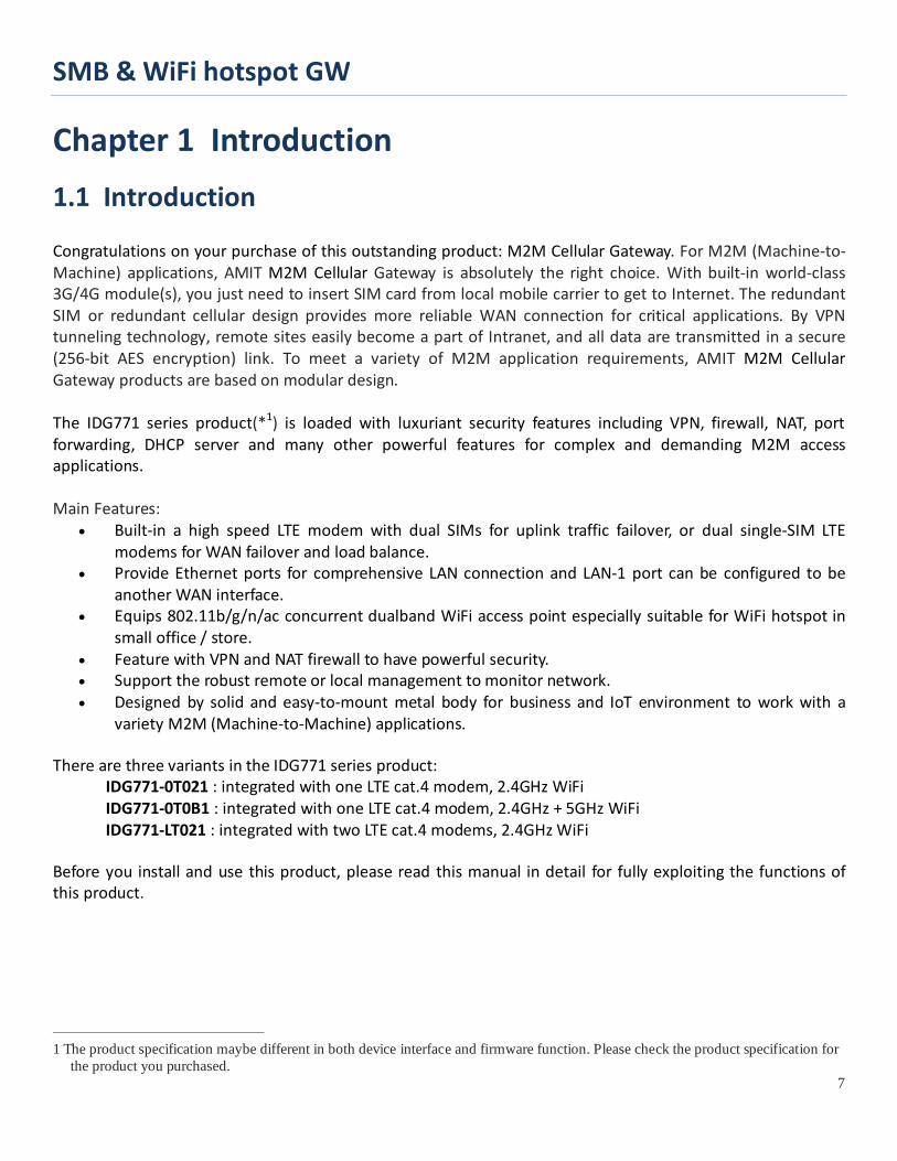
Chapter 1 Introduction 1.1 Introduction Congratulations on your purchase of this outstanding product: M2M Cellular Gateway. For M2M (Machine-to-Machine) applications, AMIT M2M Cellular Gateway is absolutely the right choice. With built-in world-class 3G/4G module(s), you just need to insert SIM card from local mobile carrier to get to Internet. The redundant SIM or redundant cellular design provides more reliable WAN connection for critical applications. By VPN tunneling technology, remote sites easily become a part of Intranet, and all data are transmitted in a secure (256-bit AES encryption) link. To meet a variety of M2M application requirements, AMIT M2M Cellular Gateway products are based on modular design. The IDG771 series product(*1) is loaded with luxuriant security features including VPN, firewall, NAT, port forwarding, DHCP server and many other powerful features for complex and demanding M2M access applications. Main Features:
• Built-in a high speed LTE modem with dual SIMs for uplink traffic failover, or dual single-SIM LTE modems for WAN failover and load balance.
• Provide Ethernet ports for comprehensive LAN connection and LAN-1 port can be configured to be another WAN interface.
• Equips 802.11b/g/n/ac concurrent dualband WiFi access point especially suitable for WiFi hotspot in small office / store.
• Feature with VPN and NAT firewall to have powerful security. • Support the robust remote or local management to monitor network. • Designed by solid and easy-to-mount metal body for business and IoT environment to work with a
variety M2M (Machine-to-Machine) applications. There are three variants in the IDG771 series product: IDG771-0T021 : integrated with one LTE cat.4 modem, 2.4GHz WiFi IDG771-0T0B1 : integrated with one LTE cat.4 modem, 2.4GHz + 5GHz WiFi IDG771-LT021 : integrated with two LTE cat.4 modems, 2.4GHz WiFi Before you install and use this product, please read this manual in detail for fully exploiting the functions of this product.
1 The product specification maybe different in both device interface and firmware function. Please check the product specification for
the product you purchased.

SMB & WiFi hotspot GW
8
1.2 Contents List
1.2.1 Package Contents #Standard Package Items Description Contents Quantity
1 IDG771 SMB & WiFi hotspot GW
1pcs
2 Cellular Antenna 2pcs for 1*LTE model, 4pcs for 2*LTE model;
3 2.4G/5GHz WiFi Antenna 2pcs
4 Power Adapter
(DC 12V/2A) (*2)
1pcs
5 RJ45 Cable
1pcs
2 The maximum power consumption of IDG771 series product is 15.5W.

SMB & WiFi hotspot GW
9
1.3 Hardware Configuration
1.3.1 IDG771-0T0x1 Variant Front View
Rear View
※ Reset Button The RESET button provides user with a quick and easy way to resort the default setting. Press the RESET button continuously for 6 seconds, and then release it. The device will restore to factory default settings.
Auto MDI/MDIX RJ-45 Ports 1x GE WAN to connect Internet 3x GE LAN to connect local devices
SIM Card
WiFi Antenna
Power ON/OFF Switch
WiFi Antenna
Reset Button
DC Power Receptacle
Cellular Antenna
LED Indicators Cellular Antenna
USB PORT

SMB & WiFi hotspot GW
10
1.3.2 IDG771-LT021 Variant Front View
Rear View
※ Reset Button The RESET button provides user with a quick and easy way to resort the default setting. Press the RESET button continuously for 6 seconds, and then release it. The device will restore to factory default settings.
Auto MDI/MDIX RJ-45 Ports 1x GE WAN to connect Internet 3x GE LAN to connect local devices
SIM Card
Cellular-1 Ant. (Aux)
Power ON/OFF Switch
Cellular-1 Ant. (Main)
Reset Button
DC Power Receptacle
Cellular-2 Ant. (Main)
Cellular-2 Ant. (Aux)
WiFi Antenna
LED Indicators WiFi Antenna
USB PORT
SMB & WiFi hotspot GW
11
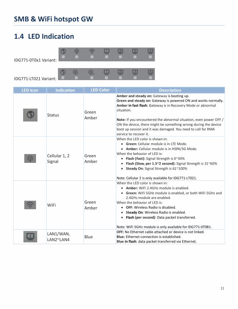
1.4 LED Indication
IDG771-0T0x1 Variant:
IDG771-LT021 Variant:
LED Icon Indication LED Color Description
Status
Green Amber
Amber and steady on: Gateway is booting up. Green and steady on: Gateway is powered ON and works normally. Amber in fast flash: Gateway is in Recovery Mode or abnormal situation. Note: If you encountered the abnormal situation, even power OFF / ON the device, there might be something wrong during the device boot up session and it was damaged. You need to call for RMA service to recover it.
Cellular 1, 2 Signal
Green Amber
When the LED color is shown in: • Green: Cellular module is in LTE Mode. • Amber: Cellular module is in HSPA/3G Mode.
When the behavior of LED is: • Flash (Fast): Signal Strength is 0~30% • Flash (Slow, per 1.5~2 second): Signal Strength is 31~60% • Steady On: Signal Strength is 61~100%
Note: Cellular 2 is only available for IDG771-LT021.
WiFi
Green Amber
When the LED color is shown in: • Amber: WiFi 2.4GHz module is enabled. • Green: WiFi 5GHz module is enabled, or both WiFi 5GHz and
2.4GHz module are enabled. When the behavior of LED is:
• OFF: Wireless Radio is disabled. • Steady On: Wireless Radio is enabled. • Flash (per second): Data packet transferred.
Note: WiFi 5GHz module is only available for IDG771-0T0B1.
LAN1/WAN, LAN2~LAN4
Blue OFF: No Ethernet cable attached or device is not linked. Blue: Ethernet connection is established. Blue in flash: data packet transferred via Ethernet.
SMB & WiFi hotspot GW
12
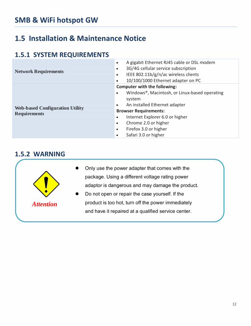
1.5 Installation & Maintenance Notice
1.5.1 SYSTEM REQUIREMENTS
Network Requirements
• A gigabit Ethernet RJ45 cable or DSL modem • 3G/4G cellular service subscription • IEEE 802.11b/g/n/ac wireless clients • 10/100/1000 Ethernet adapter on PC
Web-based Configuration Utility Requirements
Computer with the following: • Windows®, Macintosh, or Linux-based operating
system • An installed Ethernet adapter Browser Requirements: • Internet Explorer 6.0 or higher • Chrome 2.0 or higher • Firefox 3.0 or higher • Safari 3.0 or higher
1.5.2 WARNING
Only use the power adapter that comes with the package. Using a different voltage rating power adaptor is dangerous and may damage the product.
Do not open or repair the case yourself. If the
product is too hot, turn off the power immediately and have it repaired at a qualified service center.
Attention
SMB & WiFi hotspot GW
13
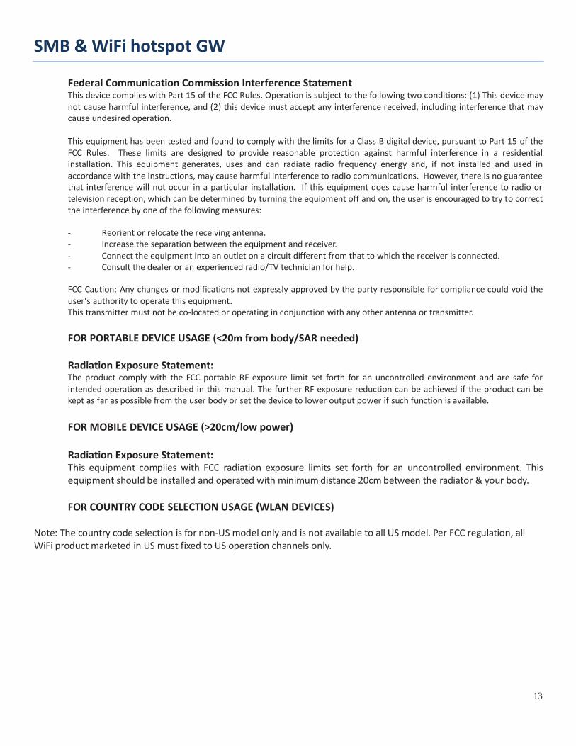
Federal Communication Commission Interference Statement This device complies with Part 15 of the FCC Rules. Operation is subject to the following two conditions: (1) This device may not cause harmful interference, and (2) this device must accept any interference received, including interference that may cause undesired operation. This equipment has been tested and found to comply with the limits for a Class B digital device, pursuant to Part 15 of the FCC Rules. These limits are designed to provide reasonable protection against harmful interference in a residential installation. This equipment generates, uses and can radiate radio frequency energy and, if not installed and used in accordance with the instructions, may cause harmful interference to radio communications. However, there is no guarantee that interference will not occur in a particular installation. If this equipment does cause harmful interference to radio or television reception, which can be determined by turning the equipment off and on, the user is encouraged to try to correct the interference by one of the following measures: - Reorient or relocate the receiving antenna. - Increase the separation between the equipment and receiver. - Connect the equipment into an outlet on a circuit different from that to which the receiver is connected. - Consult the dealer or an experienced radio/TV technician for help. FCC Caution: Any changes or modifications not expressly approved by the party responsible for compliance could void the user's authority to operate this equipment. This transmitter must not be co-located or operating in conjunction with any other antenna or transmitter.
FOR PORTABLE DEVICE USAGE (<20m from body/SAR needed) Radiation Exposure Statement: The product comply with the FCC portable RF exposure limit set forth for an uncontrolled environment and are safe for intended operation as described in this manual. The further RF exposure reduction can be achieved if the product can be kept as far as possible from the user body or set the device to lower output power if such function is available. FOR MOBILE DEVICE USAGE (>20cm/low power) Radiation Exposure Statement: This equipment complies with FCC radiation exposure limits set forth for an uncontrolled environment. This equipment should be installed and operated with minimum distance 20cm between the radiator & your body. FOR COUNTRY CODE SELECTION USAGE (WLAN DEVICES)
Note: The country code selection is for non-US model only and is not available to all US model. Per FCC regulation, all WiFi product marketed in US must fixed to US operation channels only.

SMB & WiFi hotspot GW
14
1.5.3 HOT SURFACE CAUTION
CAUTION: The surface temperature for the metallic enclosure can be very high!
Especially after operating for a long time, installed at a closed cabinet without air conditioning support, or in a high ambient temperature space. DO NOT touch the hot surface with your fingers while servicing!!

SMB & WiFi hotspot GW
15
1.5.4 Product Information for CE RED Requirements The following product information is required to be presented in product User Manual for latest CE RED requirements. 3 (1) Frequency Band & Maximum Power
1.a Frequency Band for Cellular Connection (for ME3630 E1C version) 4 Band number Operating Frequency Max output power LTE FDD BAND 1 Uplink: 1920-1980 MHz
Downlink: 2110-2170 MHz
23 ±2.7 dBm
LTE FDD BAND 3 Uplink: 1710-1785 MHz Downlink: 1805-1880 MHz
LTE FDD BAND 7 Uplink: 2500-2570 MHz Downlink: 2620-2690 MHz
LTE FDD BAND 8 Uplink: 880-915 MHz Downlink: 925-960 MHz
LTE FDD BAND 20 Uplink: 832-862 MHz Downlink: 791-821 MHz
WCDMA BAND 1 Uplink: 1920-1980 MHz Downlink: 2110-2170 MHz
24 +1/-3 dBm WCDMA BAND 8 Uplink: 880-915 MHz
Downlink: 925-960 MHz E-GSM Uplink: 880-915 MHz
Downlink: 925-960 MHz 33 ±2 dBm
DCS Uplink: 1710-1785 MHz Downlink: 1805-1880 MHz 30 ±2 dBm
1.b Frequency Band for Cellular Connection (for EC25-E version)
Band number Operating Frequency Max output power LTE FDD BAND 1 Uplink: 1920-1980 MHz
Downlink: 2110-2170 MHz 23.1 dBm
LTE FDD BAND 3 Uplink: 1710-1785 MHz Downlink: 1805-1880 MHz 23.0 dBm
LTE FDD BAND 7 Uplink: 2500-2570 MHz Downlink: 2620-2690 MHz
22.8 dBm
LTE FDD BAND 8 Uplink: 880-915 MHz Downlink: 925-960 MHz 23.2 dBm
LTE FDD BAND 20 Uplink: 832-862 MHz 23.5 dBm 3 The information presented in this section is ONLY valid for the EU/EFTA regional version. For those non-CE/EFTA versions, please refer to the corresponding product specification.
4 There can be different cellular module intrgrated in the device for EU/EFTA regional version. Refer to the cellular module identifier printed on the device label for the purchased device.
SMB & WiFi hotspot GW
16
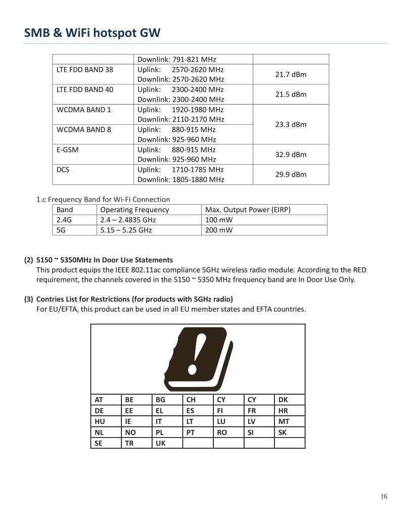
Downlink: 791-821 MHz LTE FDD BAND 38 Uplink: 2570-2620 MHz
Downlink: 2570-2620 MHz 21.7 dBm
LTE FDD BAND 40 Uplink: 2300-2400 MHz Downlink: 2300-2400 MHz
21.5 dBm
WCDMA BAND 1 Uplink: 1920-1980 MHz Downlink: 2110-2170 MHz
23.3 dBm WCDMA BAND 8 Uplink: 880-915 MHz
Downlink: 925-960 MHz E-GSM Uplink: 880-915 MHz
Downlink: 925-960 MHz 32.9 dBm
DCS Uplink: 1710-1785 MHz Downlink: 1805-1880 MHz
29.9 dBm
1.c Frequency Band for Wi-Fi Connection
Band Operating Frequency Max. Output Power (EIRP) 2.4G 2.4 – 2.4835 GHz 100 mW 5G 5.15 – 5.25 GHz 200 mW
(2) 5150 ~ 5350MHz In Door Use Statements
This product equips the IEEE 802.11ac compliance 5GHz wireless radio module. According to the RED requirement, the channels covered in the 5150 ~ 5350 MHz frequency band are In Door Use Only.
(3) Contries List for Restrictions (for products with 5GHz radio)
For EU/EFTA, this product can be used in all EU member states and EFTA countries.
AT BE BG CH CY CY DK DE EE EL ES FI FR HR HU IE IT LT LU LV MT NL NO PL PT RO SI SK SE TR UK

SMB & WiFi hotspot GW
17
(4) DoC Information
You can get the DoC information of this product from the following URL: http://www.amit.com.tw/products-doc/
(5) RF Exposure Statements
The antenna of the product, under normal use condition, is at least 20 cm away from the body of user. (6) Unit Mounting Notice
The product is suitable for mounting at heights <= 2m (approx. 6 ft), or in a cabinet. Ensure the unit is fixed tightly to reduce the likelyhood of injury due to exposure to mechanical hazards if dropped.
(7) Manufacture Information
Manufacture Name: AMIT Wireless Inc. Manufacture Address: No. 28, Lane 31, Sec. 1, Huandong Rd., Xinshi Dist., Tainan 74146, Taiwan (R.O.C.)

SMB & WiFi hotspot GW
18
1.6 Hardware Installation This chapter describes how to install and configure the hardware
1.6.1 Mount the Unit The IDG771 series product can be placed on a desktop, or mounted on the wall. It has designed with mounting brackets (ears) for attaching to the wall.
1.6.2 Insert the SIM Card
WARNING: BEFORE INSERTING OR CHANGING THE SIM CARD, PLEASE MAKE SURE THAT POWER OF THE DEVICE IS SWITCHED OFF.
IDG771-0T0x1 Variant The SIM card slots are located at the rear side of the device housing. You need to unscrew and remove the outer SIM card cover before installing or removing the SIM card. Please follow the instructions to insert or eject a SIM card. After SIM card is well placed, screw back the outer SIM card cover.
Step 1: Loosten the screws as below and remove the SIM cover.
Step 2: Push the SIM card into the SIM A slot (Right) or SIM B slot (Left).
Step 3: Push the inserted SIM card again to eject it from the SIM slot.
B A B A
SMB & WiFi hotspot GW
19
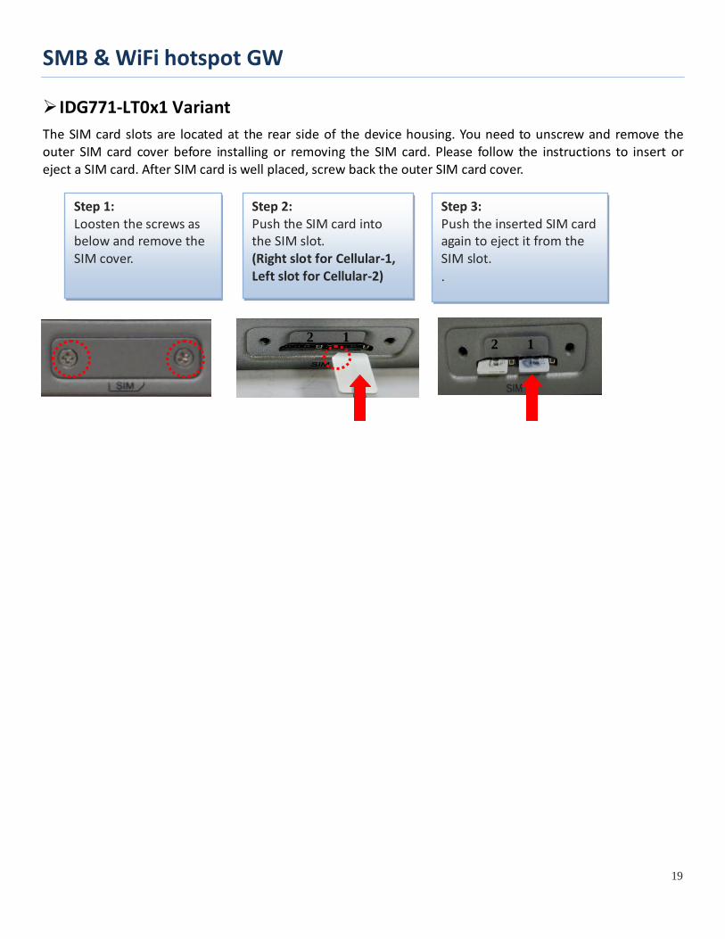
IDG771-LT0x1 Variant The SIM card slots are located at the rear side of the device housing. You need to unscrew and remove the outer SIM card cover before installing or removing the SIM card. Please follow the instructions to insert or eject a SIM card. After SIM card is well placed, screw back the outer SIM card cover.
Step 1: Loosten the screws as below and remove the SIM cover.
Step 2: Push the SIM card into the SIM slot. (Right slot for Cellular-1, Left slot for Cellular-2)
Step 3: Push the inserted SIM card again to eject it from the SIM slot. .
2 1 2 1
SMB & WiFi hotspot GW
20
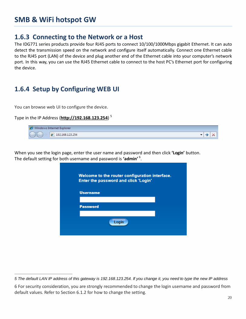
1.6.3 Connecting to the Network or a Host The IDG771 series products provide four RJ45 ports to connect 10/100/1000Mbps gigabit Ethernet. It can auto detect the transmission speed on the network and configure itself automatically. Connect one Ethernet cable to the RJ45 port (LAN) of the device and plug another end of the Ethernet cable into your computer’s network port. In this way, you can use the RJ45 Ethernet cable to connect to the host PC’s Ethernet port for configuring the device.
1.6.4 Setup by Configuring WEB UI
You can browse web UI to configure the device.
Type in the IP Address (http://192.168.123.254) 5
When you see the login page, enter the user name and password and then click ‘Login’ button. The default setting for both username and password is ‘admin’ 6.
5 The default LAN IP address of this gateway is 192.168.123.254. If you change it, you need to type the new IP address
6 For security consideration, you are strongly recommended to change the login username and password from default values. Refer to Section 6.1.2 for how to change the setting.

SMB & WiFi hotspot GW
21
Chapter 2 Basic Network 2.1 WAN & Uplink
The gateway provides multiple WAN interfaces to let all client hosts in Intranet of the gateway access the Internet via ISP. But ISPs in the world apply various connection protocols to let gateways or user's devices dial in ISPs and then link to the Internet via different kinds of transmit media.
So, the WAN Connection lets you specify the WAN Physical Interface, WAN Internet Setup and WAN Load Balance for Intranet to access Internet. For each WAN interface, you must specify its physical interface first and then its Internet setup to connect to ISP. Besides, since the gateway has multiple WAN interfaces, you can assign physical interface to participate in the Load Balance function.
SMB & WiFi hotspot GW
22
2.1.1 Physical Interface
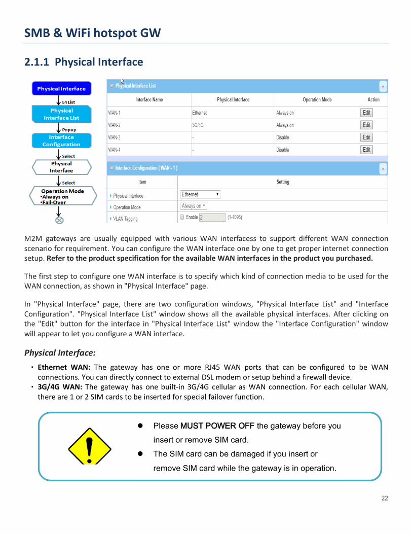
M2M gateways are usually equipped with various WAN interfacess to support different WAN connection scenario for requirement. You can configure the WAN interface one by one to get proper internet connection setup. Refer to the product specification for the available WAN interfaces in the product you purchased.
The first step to configure one WAN interface is to specify which kind of connection media to be used for the WAN connection, as shown in "Physical Interface" page.
In "Physical Interface" page, there are two configuration windows, "Physical Interface List" and "Interface Configuration". "Physical Interface List" window shows all the available physical interfaces. After clicking on the "Edit" button for the interface in "Physical Interface List" window the "Interface Configuration" window will appear to let you configure a WAN interface.
Physical Interface: • Ethernet WAN: The gateway has one or more RJ45 WAN ports that can be configured to be WAN
connections. You can directly connect to external DSL modem or setup behind a firewall device. • 3G/4G WAN: The gateway has one built-in 3G/4G cellular as WAN connection. For each cellular WAN,
there are 1 or 2 SIM cards to be inserted for special failover function.
Please MUST POWER OFF the gateway before you insert or remove SIM card.
The SIM card can be damaged if you insert or
remove SIM card while the gateway is in operation.

SMB & WiFi hotspot GW
23
• WiFi Uplink WAN: For the product with WiFi Uplink function, one WiFi module can be configured to be WAN connections. For the WiFi module with Uplink function activated, you can further create some uplink profiles for ease of connecting to an uplink network.
Operation Mode: There are three option items “Always on”, “Failover”, and “Disable” for the operation mode setting. Always on: Set this WAN interface to be active all the time. When two or more WAN are established at "Always on" mode, outgoing data will through these WAN connections base on load balance policies. Failover:
A failover interface is a backup connection to the primary. That means only when its primary WAN connection is broken, the backup connection will be started up to substitute the primary connection. As shown in the diagram, WAN-2 is backup WAN for WAN-1. WAN-1 serves as the primary connection with operation mode "Always on". WAN-2 won’t be activated until WAN-1 disconnected. When WAN-1 connection is recovered back with a connection, it will take over data traffic again. At that time, WAN-2 connection will be terminated.
Seamless Failover: In addition, there is a "Seamless" option for Failover operation mode. When seamless option is activated by checking on the "Seamless" box in configuration window, both the primary connection and the failover connection are started up after system rebooting. But only the primary connection executes the data transfer, while the failover one just keeps alive of connection line. As soon as the primary connection is broken, the system will switch, meaning failover, the routing path to the failover connection to save the dial up time of failover connection since it has been alive.
When the “Seamless” enable checkbox is activated, it
SMB & WiFi hotspot GW
24
can allow the Failover interface to be connected continuously from system booting up. Failover WAN interface just keeps connecting without data traffic. The purpose is to shorten the switch time during failover process. So, when primary connection is disconnected, failover interface will take over the data transfer mission instantly by only changing routing path to the failover interface. The dialing-up time of failover connection is saved since it has been connected beforehand.
VLAN Tagging Sometimes, your ISP required a VLAN tag to be inserted into the WAN packets from Gateway for specific services. Please enable VLAN tagging and specify tag in the WAN physical interface. Please be noted that only Ethernet and ADSL physical interfaces support the feature. For the device with 3G/4G WAN only, it is disabled.
SMB & WiFi hotspot GW
25
Physical Interface Setting
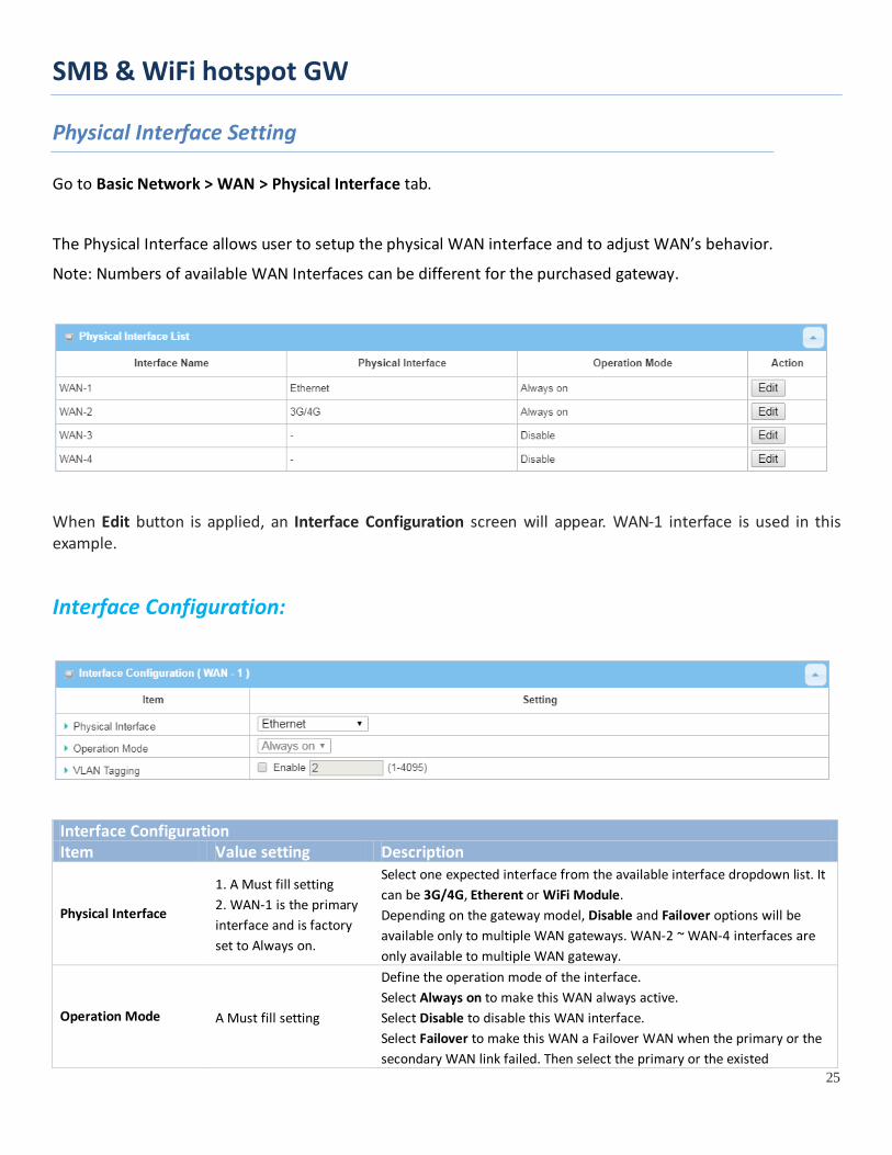
Go to Basic Network > WAN > Physical Interface tab.
The Physical Interface allows user to setup the physical WAN interface and to adjust WAN’s behavior.
Note: Numbers of available WAN Interfaces can be different for the purchased gateway.
When Edit button is applied, an Interface Configuration screen will appear. WAN-1 interface is used in this example.
Interface Configuration:
Interface Configuration Item Value setting Description
Physical Interface
1. A Must fill setting 2. WAN-1 is the primary interface and is factory set to Always on.
Select one expected interface from the available interface dropdown list. It can be 3G/4G, Etherent or WiFi Module. Depending on the gateway model, Disable and Failover options will be available only to multiple WAN gateways. WAN-2 ~ WAN-4 interfaces are only available to multiple WAN gateway.
Operation Mode A Must fill setting
Define the operation mode of the interface. Select Always on to make this WAN always active. Select Disable to disable this WAN interface. Select Failover to make this WAN a Failover WAN when the primary or the secondary WAN link failed. Then select the primary or the existed
SMB & WiFi hotspot GW
26
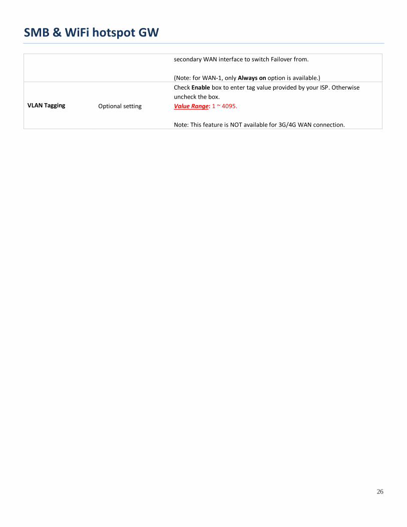
secondary WAN interface to switch Failover from. (Note: for WAN-1, only Always on option is available.)
VLAN Tagging Optional setting
Check Enable box to enter tag value provided by your ISP. Otherwise uncheck the box. Value Range: 1 ~ 4095. Note: This feature is NOT available for 3G/4G WAN connection.

SMB & WiFi hotspot GW
27
2.1.2 Internet Setup
After specifying the physical interface for each WAN connection, administrator must configure their connection profile to meet the dial in process of ISP, so that all client hosts in the Intranet of the gateway can access the Internet.
In "Internet Setup" page, there are some configuration windows: "Internet Connection List", "Internet Connection Configuration", "WAN Type Configuration" and related configuration windows for each WAN type. For the Internet setup of each WAN interface, you must specify its WAN type of physical interface first and then its related parameter configuration for that WAN type.
After clicking on the "Edit" button of a physical interface in "Internet Setup List" window, the "Internet Connection Configuration" window will appear to let you specify which kind of WAN type that you will use for that physical interface to make an Internet connection. Based on your chosen WAN type, you can configure necessary parameters in each corresponding configuration window.
SMB & WiFi hotspot GW
28
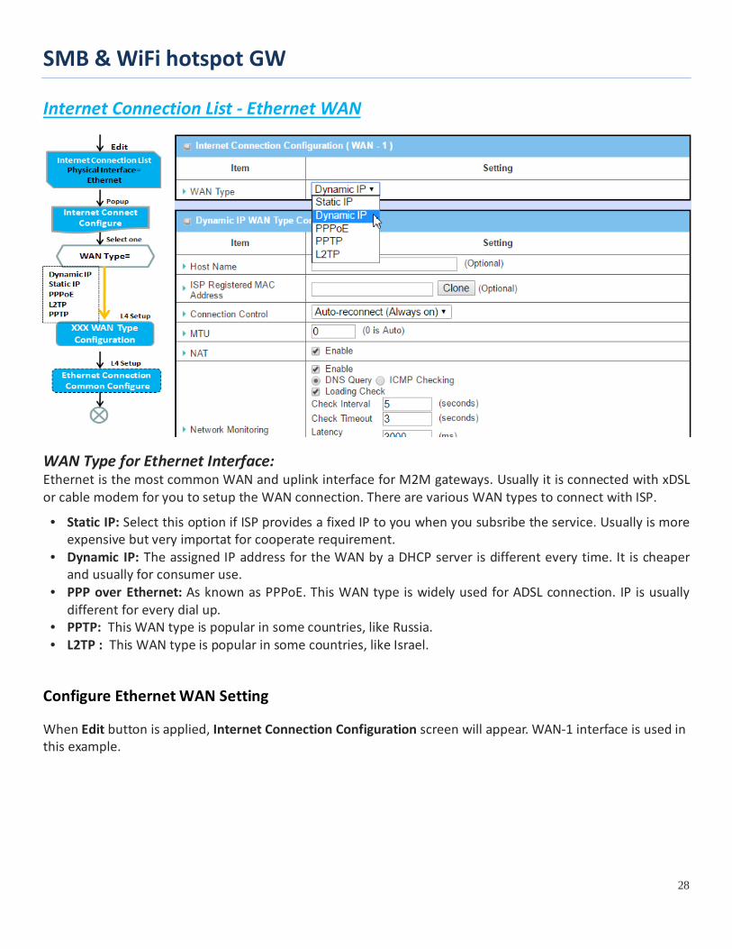
Internet Connection List - Ethernet WAN
WAN Type for Ethernet Interface: Ethernet is the most common WAN and uplink interface for M2M gateways. Usually it is connected with xDSL or cable modem for you to setup the WAN connection. There are various WAN types to connect with ISP. • Static IP: Select this option if ISP provides a fixed IP to you when you subsribe the service. Usually is more
expensive but very importat for cooperate requirement. • Dynamic IP: The assigned IP address for the WAN by a DHCP server is different every time. It is cheaper
and usually for consumer use. • PPP over Ethernet: As known as PPPoE. This WAN type is widely used for ADSL connection. IP is usually
different for every dial up. • PPTP: This WAN type is popular in some countries, like Russia. • L2TP : This WAN type is popular in some countries, like Israel.
Configure Ethernet WAN Setting
When Edit button is applied, Internet Connection Configuration screen will appear. WAN-1 interface is used in this example.
SMB & WiFi hotspot GW
29
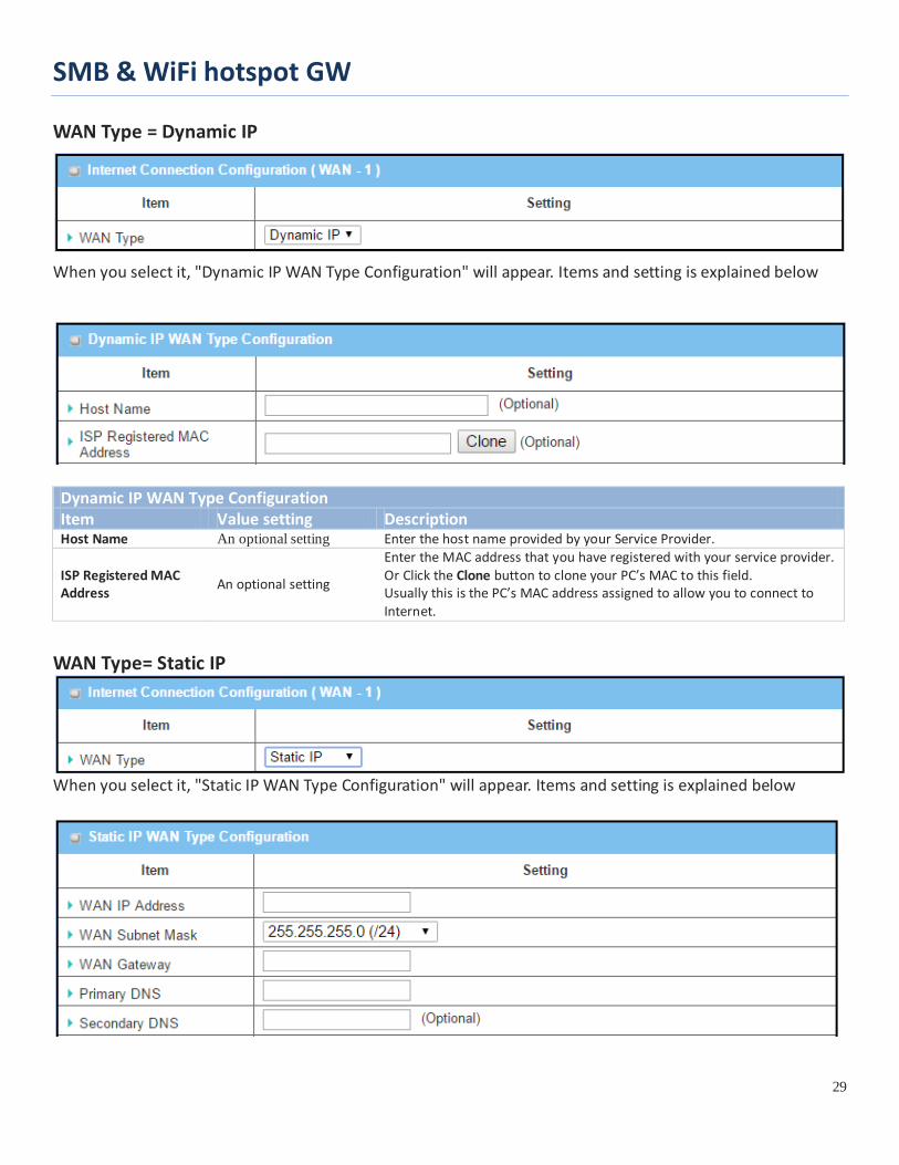
WAN Type = Dynamic IP
When you select it, "Dynamic IP WAN Type Configuration" will appear. Items and setting is explained below
Dynamic IP WAN Type Configuration Item Value setting Description Host Name An optional setting Enter the host name provided by your Service Provider.
ISP Registered MAC Address An optional setting
Enter the MAC address that you have registered with your service provider. Or Click the Clone button to clone your PC’s MAC to this field. Usually this is the PC’s MAC address assigned to allow you to connect to Internet.
WAN Type= Static IP
When you select it, "Static IP WAN Type Configuration" will appear. Items and setting is explained below
SMB & WiFi hotspot GW
30
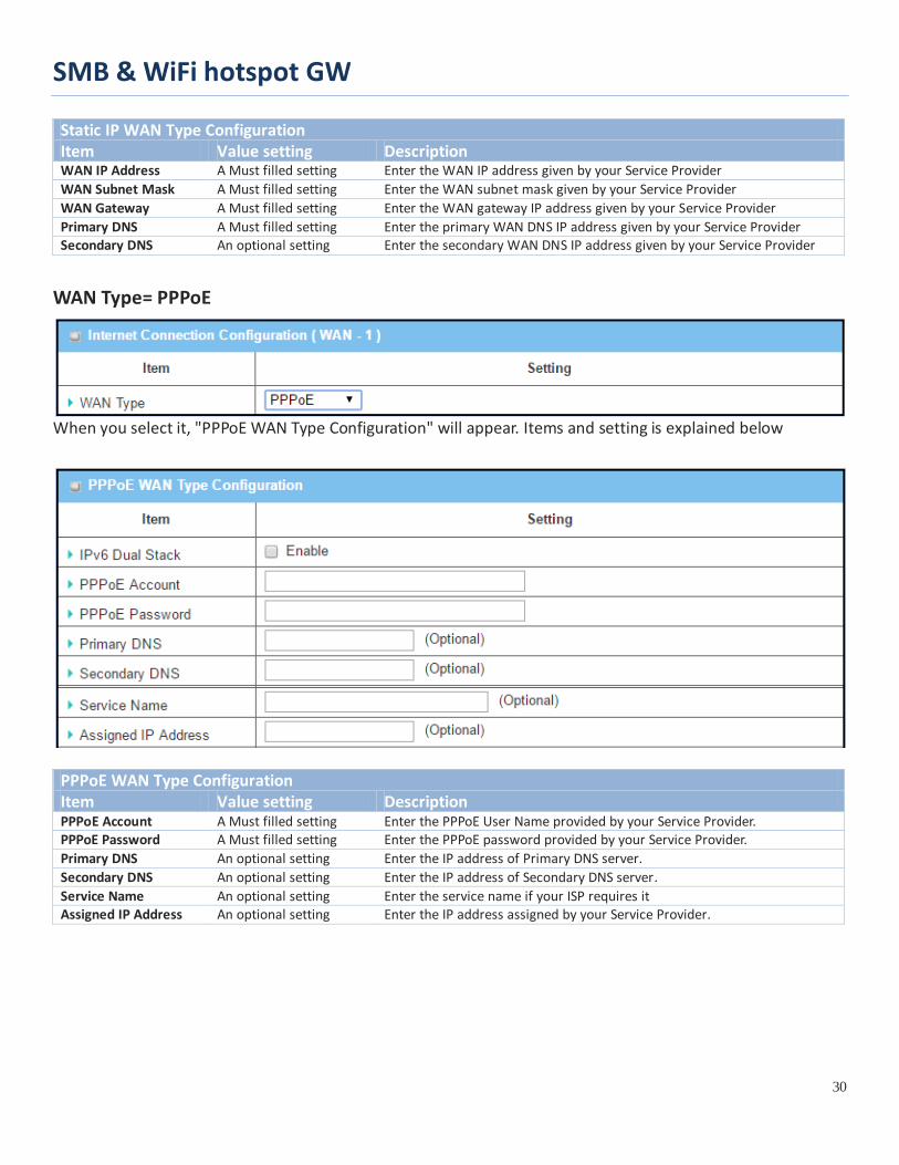
Static IP WAN Type Configuration Item Value setting Description WAN IP Address A Must filled setting Enter the WAN IP address given by your Service Provider WAN Subnet Mask A Must filled setting Enter the WAN subnet mask given by your Service Provider WAN Gateway A Must filled setting Enter the WAN gateway IP address given by your Service Provider Primary DNS A Must filled setting Enter the primary WAN DNS IP address given by your Service Provider Secondary DNS An optional setting Enter the secondary WAN DNS IP address given by your Service Provider
WAN Type= PPPoE
When you select it, "PPPoE WAN Type Configuration" will appear. Items and setting is explained below
PPPoE WAN Type Configuration Item Value setting Description PPPoE Account A Must filled setting Enter the PPPoE User Name provided by your Service Provider. PPPoE Password A Must filled setting Enter the PPPoE password provided by your Service Provider. Primary DNS An optional setting Enter the IP address of Primary DNS server. Secondary DNS An optional setting Enter the IP address of Secondary DNS server. Service Name An optional setting Enter the service name if your ISP requires it Assigned IP Address An optional setting Enter the IP address assigned by your Service Provider.

SMB & WiFi hotspot GW
31
WAN Type= PPTP
When you select it, "PPTP WAN Type Configuration" will appear. Items and setting is explained below
PPTP WAN Type Configuration Item Value setting Description
IP Mode A Must filled setting
Select either Static or Dynamic IP address for PPTP Internet connection. When Static IP Address is selected, you will need to enter the WAN IP
Address, WAN Subnet Mask, and WAN Gateway. WAN IP Address (A Must filled setting): Enter the WAN IP
address given by your Service Provider. WAN Subnet Mask (A Must filled setting): Enter the WAN
subnet mask given by your Service Provider. WAN Gateway (A Must filled setting): Enter the WAN gateway
IP address given by your Service Provider. When Dynamic IP is selected, there are no above settings required.
Server IP Address/Name
A Must filled setting Enter the PPTP server name or IP Address.
PPTP Account A Must filled setting Enter the PPTP username provided by your Service Provider. PPTP Password A Must filled setting Enter the PPTP connection password provided by your Service Provider. Connection ID An optional setting Enter a name to identify the PPTP connection.
MPPE An optional setting Select Enable to enable MPPE (Microsoft Point-to-Point Encryption) security for PPTP connection.
SMB & WiFi hotspot GW
32
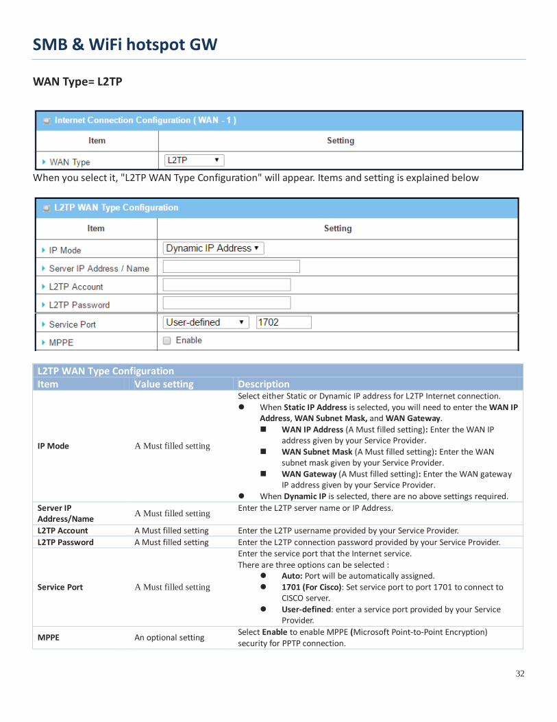
WAN Type= L2TP
When you select it, "L2TP WAN Type Configuration" will appear. Items and setting is explained below
L2TP WAN Type Configuration Item Value setting Description
IP Mode A Must filled setting
Select either Static or Dynamic IP address for L2TP Internet connection. When Static IP Address is selected, you will need to enter the WAN IP
Address, WAN Subnet Mask, and WAN Gateway. WAN IP Address (A Must filled setting): Enter the WAN IP
address given by your Service Provider. WAN Subnet Mask (A Must filled setting): Enter the WAN
subnet mask given by your Service Provider. WAN Gateway (A Must filled setting): Enter the WAN gateway
IP address given by your Service Provider. When Dynamic IP is selected, there are no above settings required.
Server IP Address/Name A Must filled setting Enter the L2TP server name or IP Address.
L2TP Account A Must filled setting Enter the L2TP username provided by your Service Provider. L2TP Password A Must filled setting Enter the L2TP connection password provided by your Service Provider.
Service Port A Must filled setting
Enter the service port that the Internet service. There are three options can be selected :
Auto: Port will be automatically assigned. 1701 (For Cisco): Set service port to port 1701 to connect to
CISCO server. User-defined: enter a service port provided by your Service
Provider.
MPPE An optional setting Select Enable to enable MPPE (Microsoft Point-to-Point Encryption) security for PPTP connection.

SMB & WiFi hotspot GW
33
Ethernet Connection Common Configuration
There are some important parameters to be setup no matter which Ethernet WAN type is selected. You should follow up the rule to configure.
Connection Control.
Auto-reconnect: This gateway will establish Internet connection automatically once it has been booted up, and try to reconnect once the connection is down. It’s recommended to choose this scheme if for mission critical applications to ensure full-time Internet connection.
Connect-on-demand: This gateway won’t start to establish Internet connection until local data is going to be sent to WAN side. After normal data transferring between LAN and WAN sides, this gateway will disconnect WAN connection if idle time reaches value of Maximum Idle Time.

SMB & WiFi hotspot GW
34
Manually: This gateway won’t start to establish WAN connection until you press “Connect” button on web UI. After normal data transferring between LAN and WAN sides, this gateway will disconnect WAN connection if idle time reaches value of Maximum Idle Time.
Please be noted, if the WAN interface serves as the primary one for another WAN interface in Failover role, the Connection Control parameter will not be available to you to configure as the system must set it to “Auto-reconnect (Always on)”.
Network Monitoring It is necessary to monitor connection status continuous. To do it, "ICMP Check" and "FQDN Query" are used to check. When there is trafiic of connection, checking packet will waste bandwidth. Response time of replied packets may also increase. To avoid "Network Monitoring" work abnormally, enabling "Checking Loading" option will stop connection check when there is traffic. It will wait for another "Check Interval" and then check loading again. When you do “Network Monitoring”, if reply time longer than "Latency" or even no response longer than "Checking Timeout", "Fail" count will be increased. If it is continuous and "Fail" count is more than "Fail Threshold", gateway will do exception handing process and re-initial this connection again . Otherwise, network monitoring process will be start again.
SMB & WiFi hotspot GW
35
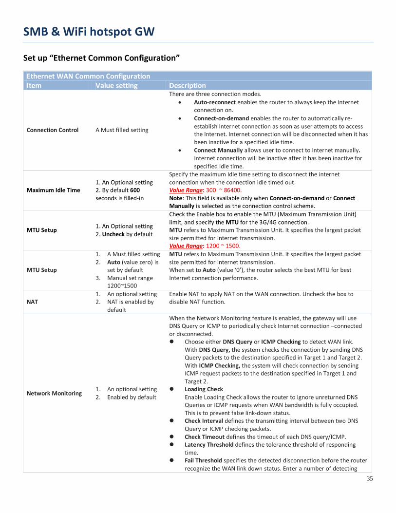
Set up “Ethernet Common Configuration”
Ethernet WAN Common Configuration Item Value setting Description
Connection Control A Must filled setting
There are three connection modes. • Auto-reconnect enables the router to always keep the Internet
connection on. • Connect-on-demand enables the router to automatically re-
establish Internet connection as soon as user attempts to access the Internet. Internet connection will be disconnected when it has been inactive for a specified idle time.
• Connect Manually allows user to connect to Internet manually. Internet connection will be inactive after it has been inactive for specified idle time.
Maximum Idle Time 1. An Optional setting 2. By default 600 seconds is filled-in
Specify the maximum Idle time setting to disconnect the internet connection when the connection idle timed out. Value Range: 300 ~ 86400. Note: This field is available only when Connect-on-demand or Connect Manually is selected as the connection control scheme.
MTU Setup 1. An Optional setting 2. Uncheck by default
Check the Enable box to enable the MTU (Maximum Transmission Unit) limit, and specify the MTU for the 3G/4G connection. MTU refers to Maximum Transmission Unit. It specifies the largest packet size permitted for Internet transmission. Value Range: 1200 ~ 1500.
MTU Setup
1. A Must filled setting 2. Auto (value zero) is
set by default 3. Manual set range
1200~1500
MTU refers to Maximum Transmission Unit. It specifies the largest packet size permitted for Internet transmission. When set to Auto (value ‘0’), the router selects the best MTU for best Internet connection performance.
NAT 1. An optional setting 2. NAT is enabled by
default
Enable NAT to apply NAT on the WAN connection. Uncheck the box to disable NAT function.
Network Monitoring 1. An optional setting 2. Enabled by default
When the Network Monitoring feature is enabled, the gateway will use DNS Query or ICMP to periodically check Internet connection –connected or disconnected. Choose either DNS Query or ICMP Checking to detect WAN link.
With DNS Query, the system checks the connection by sending DNS Query packets to the destination specified in Target 1 and Target 2. With ICMP Checking, the system will check connection by sending ICMP request packets to the destination specified in Target 1 and Target 2.
Loading Check Enable Loading Check allows the router to ignore unreturned DNS Queries or ICMP requests when WAN bandwidth is fully occupied. This is to prevent false link-down status.
Check Interval defines the transmitting interval between two DNS Query or ICMP checking packets.
Check Timeout defines the timeout of each DNS query/ICMP. Latency Threshold defines the tolerance threshold of responding
time. Fail Threshold specifies the detected disconnection before the router
recognize the WAN link down status. Enter a number of detecting

SMB & WiFi hotspot GW
36
disconnection times to be the threshold before disconnection is acknowledged.
Target1 (DNS1 set by default) specifies the first target of sending DNS query/ICMP request. DNS1: set the primary DNS to be the target. DNS2: set the secondary DNS to be the target. Gateway: set the Current gateway to be the target. Other Host: enter an IP address to be the target.
Target2 (None set by default) specifies the second target of sending DNS query/ICMP request. None: to disable Target2. DNS1: set the primary DNS to be the target. DNS2: set the secondary DNS to be the target. Gateway: set the Current gateway to be the target. Other Host: enter an IP address to be the target.
IGMP 1. A Must filled setting 2. Disable is set by default
Enable IGMP (Internet Group Management Protocol) would enable the router to listen to IGMP packets to discover which interfaces are connected to which device. The router uses the interface information generated by IGMP to reduce bandwidth consumption in a multi-access network environment to avoid flooding the entire network.
WAN IP Alias 1. An optional setting 2. Uncheck by default
Enable WAN IP Alias then enter the IP address provided by your service provider. WAN IP Alias is used by the device router and is treated as a second set of WAN IP to provide dual WAN IP address to your LAN network.
Save N/A Click Save to save the settings. Undo N/A Click Undo to cancel the settings.

SMB & WiFi hotspot GW
37
Internet Connection – 3G/4G WAN
Preferred SIM Card – Dual SIM Fail Over For 3G/4G embedded device, one embedded cellular module can create only one WAN interface. This device has featured by using dual SIM cards for one module with special fail-over mechanism. It is called Dual SIM Failover. This feature is useful for ISP switch over when location is changed. Within “Dual SIM Failover”, there are various usage scenarios, including "SIM-A First", "SIM-B First“ with “Failback” enabled or not, and “SIM-A Only and “SIM-B Only”.
SMB & WiFi hotspot GW
38
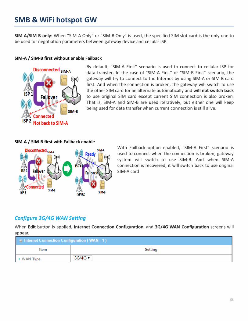
SIM-A/SIM-B only: When “SIM-A Only” or “SIM-B Only” is used, the specified SIM slot card is the only one to be used for negotiation parameters between gateway device and cellular ISP.
SIM-A / SIM-B first without enable Failback
By default, “SIM-A First” scenario is used to connect to cellular ISP for data transfer. In the case of “SIM-A First” or “SIM-B First” scenario, the gateway will try to connect to the Internet by using SIM-A or SIM-B card first. And when the connection is broken, the gateway will switch to use the other SIM card for an alternate automatically and will not switch back to use original SIM card except current SIM connection is also broken. That is, SIM-A and SIM-B are used iteratively, but either one will keep being used for data transfer when current connection is still alive.
SIM-A / SIM-B first with Failback enable With Failback option enabled, “SIM-A First” scenario is used to connect when the connection is broken, gateway system will switch to use SIM-B. And when SIM-A connection is recovered, it will switch back to use original SIM-A card
Configure 3G/4G WAN Setting When Edit button is applied, Internet Connection Configuration, and 3G/4G WAN Configuration screens will appear.
SMB & WiFi hotspot GW
39
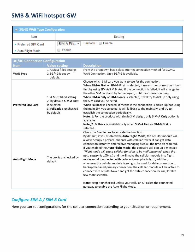
3G/4G Connection Configuration Item Value setting Description
WAN Type 1. A Must filled setting 2. 3G/4G is set by
default.
From the dropdown box, select Internet connection method for 3G/4G WAN Connection. Only 3G/4G is available.
Preferred SIM Card
1. A Must filled setting 2. By default SIM-A First is selected 3. Failback is unchecked by default
Choose which SIM card you want to use for the connection. When SIM-A First or SIM-B First is selected, it means the connection is built first by using SIM A/SIM B. And if the connection is failed, it will change to the other SIM card and try to dial again, until the connection is up. When SIM-A only or SIM-B only is selected, it will try to dial up only using the SIM card you selected. When Failback is checked, it means if the connection is dialed-up not using the main SIM you selected, it will failback to the main SIM and try to establish the connection periodically. Note_1: For the product with single SIM design, only SIM-A Only option is available. Note_2: Failback is available only when SIM-A First or SIM-B First is selected.
Auto Flight Mode The box is unchecked by default
Check the Enable box to activate the function. By default, if you disabled the Auto Flight Mode, the cellular module will always occupy a physical channel with cellular tower. It can get data connection instantly, and receive managing SMS all the time on required. If you enabled the Auto Flight Mode, the gateway will pop up a message “Flight mode will cause cellular function to be malfunctioned when the data session is offline.”, and it will make the cellular module into flight mode and disconnected with cellular tower phycially. In, addition, whenever the cellular module is going to be used for data connection to backup the failed primary connection, the cellular module will be active to connect with cellular tower and get the data connection for use, It takes few more seconds. Note: Keep it unchecked unless your cellular ISP asked the connected gateway to enable the Auto Flight Mode.
Configure SIM-A / SIM-B Card Here you can set configurations for the cellular connection according to your situation or requirement.
SMB & WiFi hotspot GW
40
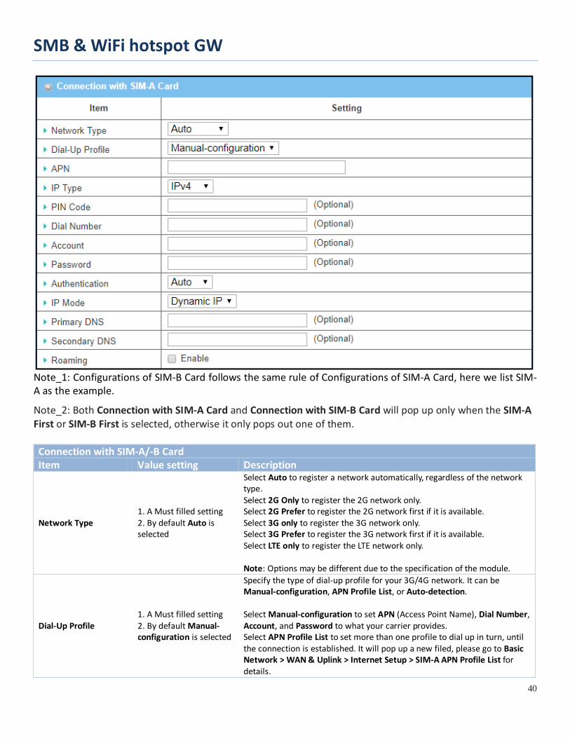
Note_1: Configurations of SIM-B Card follows the same rule of Configurations of SIM-A Card, here we list SIM-A as the example.
Note_2: Both Connection with SIM-A Card and Connection with SIM-B Card will pop up only when the SIM-A First or SIM-B First is selected, otherwise it only pops out one of them. Connection with SIM-A/-B Card Item Value setting Description
Network Type 1. A Must filled setting 2. By default Auto is selected
Select Auto to register a network automatically, regardless of the network type. Select 2G Only to register the 2G network only. Select 2G Prefer to register the 2G network first if it is available. Select 3G only to register the 3G network only. Select 3G Prefer to register the 3G network first if it is available. Select LTE only to register the LTE network only. Note: Options may be different due to the specification of the module.
Dial-Up Profile 1. A Must filled setting 2. By default Manual-configuration is selected
Specify the type of dial-up profile for your 3G/4G network. It can be Manual-configuration, APN Profile List, or Auto-detection. Select Manual-configuration to set APN (Access Point Name), Dial Number, Account, and Password to what your carrier provides. Select APN Profile List to set more than one profile to dial up in turn, until the connection is established. It will pop up a new filed, please go to Basic Network > WAN & Uplink > Internet Setup > SIM-A APN Profile List for details.

SMB & WiFi hotspot GW
41
Select Auto-detection to automatically bring out all configurations needed while dialing-up, by comparing the IMSI of the SIM card to the record listed in the manufacturer’s database. Note_1: You are highly recommended to select the Manual or APN Profile List to specify the network for your subscription. Your ISP always provides such network settings for the subscribers. Note_2: If you select Auto-detection, it is likely to connect to improper network, or failed to find a valid APN for your ISP.
APN 1. A Must filled setting 2. String format : any text
Enter the APN you want to use to establish the connection. This is a must-filled setting if you selected Manual-configuration as dial-up profile scheme.
IP Type 1. A Must filled setting 2. By default IPv4 is selected
Specify the IP type of the network serveice provided by your 3G/4G network. It can be IPv4, IPv6, or IPv4/6.
PIN code 1. An Optional setting 2. String format : interger
Enter the PIN (Personal Identification Number) code if it needs to unlock your SIM card.
Dial Number, Account, Password
1. An Optional setting 2. String format : any text
Enter the optional Dial Number, Account, and Password settings if your ISP provided such settings to you. Note: These settings are only displayed when Manual-configuration is selected.
Authentication 1. A Must filled setting 2. By default Auto is selected
Select PAP (Password Authentication Protocol) and use such protocol to be authenticated with the carrier’s server. Select CHAP (Challenge Handshake Authentication Protocol) and use such protocol to be authenticated with the carrier’s server. When Auto is selected, it means it will authenticate with the server either PAP or CHAP.
IP Mode 1. A Must filled setting 2. By default Dynamic IP is selected
When Dynamic IP is selected, it means it will get all IP configurations from the carrier’s server and set to the device directly. If you have specific application provided by the carrier, and want to set IP configurations on your own, you can switch to Static IP mode and fill in all parameters that required, such as IP address, subnet mask and gateway. Note: IP Subnet Mask is a must filled setting, and make sure you have the right configuration. Otherwise, the connection may get issues.
Primary DNS 1. An Optional setting 2. String format : IP address (IPv4 type)
Enter the IP address to change the primary DNS (Domain Name Server) setting. If it is not filled-in, the server address is given by the carrier while dialing-up.
Secondary DNS 1. An Optional setting 2. String format : IP address (IPv4 type)
Enter the IP address to change the secondary DNS (Domain Name Server) setting. If it is not filled-in, the server address is given by the carrier while dialing-up.
Roaming The box is unchecked by default
Check the box to establish the connection even the registration status is roaming, not in home network. Note: It may cost additional charges if the connection is under roaming.
Create/Edit SIM-A / SIM-B APN Profile List You can add a new APN profile for the connection, or modify the content of the APN profile you added. It is available only when you select Dial-Up Profile as APN Profile List.

SMB & WiFi hotspot GW
42
List all the APN profile you created, easily for you to check and modify. It is available only when you select Dial-Up Profile as APN Profile List.
When Add button is applied, an APN Profile Configuration screen will appear.
SIM-A/-B APN Profile Configuration Item Value setting Description
Profile Name 1. By default Profile-x is listed 2. String format : any text
Enter the profile name you want to describe for this profile.
APN String format : any text Enter the APN you want to use to establish the connection.
IP Type 1. A Must filled setting 2. By default IPv4 is selected
Specify the IP type of the network serveice provided by your 3G/4G network. It can be IPv4, IPv6, or IPv4/6.
Account String format : any text Enter the Account you want to use for the authentication. Value Range: 0 ~ 53 characters.
Password String format : any text Enter the Password you want to use for the authentication.
Authentication 1. A Must filled setting 2. By default Auto is selected
Select the Authentication method for the 3G/4G connection. It can be Auto, PAP, CHAP, or None.
Priority 1. A Must filled setting 2. String format : integer
Enter the value for the dialing-up order. The valid value is from 1 to 16. It will start to dial up with the profile that assigned with the smallest number. Value Range: 1 ~ 16.
Profile The box is checked by default
Check the box to enable this profile. Uncheck the box to disable this profile in dialing-up action.
Save N/A Click the Save button to save the configuration.
Undo N/A Click the Undo button to restore what you just configured back to the previous setting.

SMB & WiFi hotspot GW
43
Back N/A When the Back button is clicked, the screen will return to the previous page.
Setup 3G/4G Connection Common Configuration Here you can change common configurations for 3G/4G WAN.
3G/4G Connection Common Configuration Item Value setting Description
Connection Control By default Auto-reconnect is selected
When Auto-reconnect is selected, it means it will try to keep the Internet connection on all the time whenever the physical link is connected. When Connect-on-demand is selected, it means the Internet connection will be established only when detecting data traffic. When Connect Manually is selected, it means you need to click the Connect button to dial up the connection manually. Please go to Status > Basic Network > WAN & Uplink tab for details. Note: If the WAN interface serves as the primary one for another WAN interface in Failover role( and vice versa), the Connection Control parameter will not be available on both WANs as the system must set it to “Auto-reconnect”
Maximum Idle Time 1. An Optional setting 2. By default 600 seconds is filled-in
Specify the maximum Idle time setting to disconnect the internet connection when the connection idle timed out. Value Range: 300 ~ 86400. Note: This field is available only when Connect-on-demand or Connect Manually is selected as the connection control scheme.
Time Schedule 1. A Must filled setting 2. By default (0) Always is selected
When (0) Always is selected, it means this WAN is under operation all the time. Once you have set other schedule rules, there will be other options to select. Please go to Object Definition > Scheduling for details.
MTU Setup 1. An Optional setting 2. Uncheck by default
Check the Enable box to enable the MTU (Maximum Transmission Unit) limit, and specify the MTU for the 3G/4G connection. MTU refers to Maximum Transmission Unit. It specifies the largest packet size permitted for Internet transmission.

SMB & WiFi hotspot GW
44
Value Range: 1200 ~ 1500.
IP Pass-through (Cellular Bridge)
1. The box is unchecked by default 2. String format for Fixed MAC: MAC address, e.g. 00:50:18:aa:bb:cc
When Enable box is checked, it means the device will directly assign the WAN IP to the first connected local LAN client. However, when an optional Fixed MAC is filled-in a non-zero value, it means only the client with this MAC address can get the WAN IP address. Note: When the IP Pass-through is on, NAT and WAN IP Alias will be unavailable until the function is disabled again.
NAT Check by default Uncheck the box to disable NAT (Network Address Translation) function.
IGMP By default Disable is selected
Select Auto to enable IGMP function. Check the Enable box to enable IGMP Proxy.
WAN IP Alias 1. Unchecked by default 2. String format: IP address (IPv4 type)
Check the box to enable WAN IP Alias, and fill in the IP address you want to assign.
Network Monitoring Configuration Item Value setting Description Network Monitoring Configuration
1. An optional setting 2. Box is checked by default
Check the Enable box to activate the network monitoring function.
Checking Method 1. An Optional setting 2. DNS Query is set by default
Choose either DNS Query or ICMP Checking to detect WAN link. With DNS Query, the system checks the connection by sending DNS Query packets to the destination specified in Target 1 and Target 2. With ICMP Checking, the system will check connection by sending ICMP request packets to the destination specified in Target 1 and Target 2. Query Interval defines the transmitting interval between two DNS Query or ICMP checking packets.
Loading Check 1. An optional setting 2. Box is checked by default
Check the Enable box to activate the loading check function. Enable Loading Check allows the gateway to ignore unreturned DNS queries or ICMP requests when WAN bandwidth is fully occupied. This is to prevent false link-down status. Latency Threshold defines the tolerance threshold of responding time.

SMB & WiFi hotspot GW
45
Fail Threshold specifies the detected disconnection before the router recognize the WAN link down status. Enter a number of detecting disconnection times to be the threshold before disconnection is acknowledged.
Target 1
1. An Optional filled setting 2. DNS1 is selected by default
Target1 specifies the first target of sending DNS query/ICMP request. DNS1: set the primary DNS to be the target. DNS2: set the secondary DNS to be the target. Gateway: set the Current gateway to be the target. Other Host: enter an IP address to be the target.
Target 2
1. An Optional filled setting 2. None is selected by default
Target1 specifies the second target of sending DNS query/ICMP request. None: no second target is required. DNS1: set the primary DNS to be the target. DNS2: set the secondary DNS to be the target. Gateway: set the Current gateway to be the target. Other Host: enter an IP address to be the target.
Save N/A Click Save to save the settings. Undo N/A Click Undo to cancel the settings.
SMB & WiFi hotspot GW
46
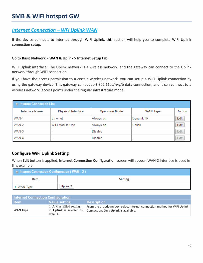
Internet Connection – WFi Uplink WAN
If the device connects to Internet through WiFi Uplink, this section will help you to complete WiFi Uplink connection setup.
Go to Basic Network > WAN & Uplink > Internet Setup tab.
WiFi Uplink interface: The Uplink network is a wireless network, and the gateway can connect to the Uplink network through WiFi connection.
If you have the access permission to a certain wireless network, you can setup a WiFi Uplink connection by using the gateway device. This gateway can support 802.11ac/n/g/b data connection, and it can connect to a wireless network (access point) under the regular infrastrature mode.
Configure WiFi Uplink Setting When Edit button is applied, Internet Connection Configuration screen will appear. WAN-2 interface is used in this example.
Internet Connection Configuration Item Value setting Description
WAN Type 1. A Must filled setting. 2. Uplink is selected by default.
From the dropdown box, select Internet connection method for WiFi Uplink Connection. Only Uplink is available.
SMB & WiFi hotspot GW
47
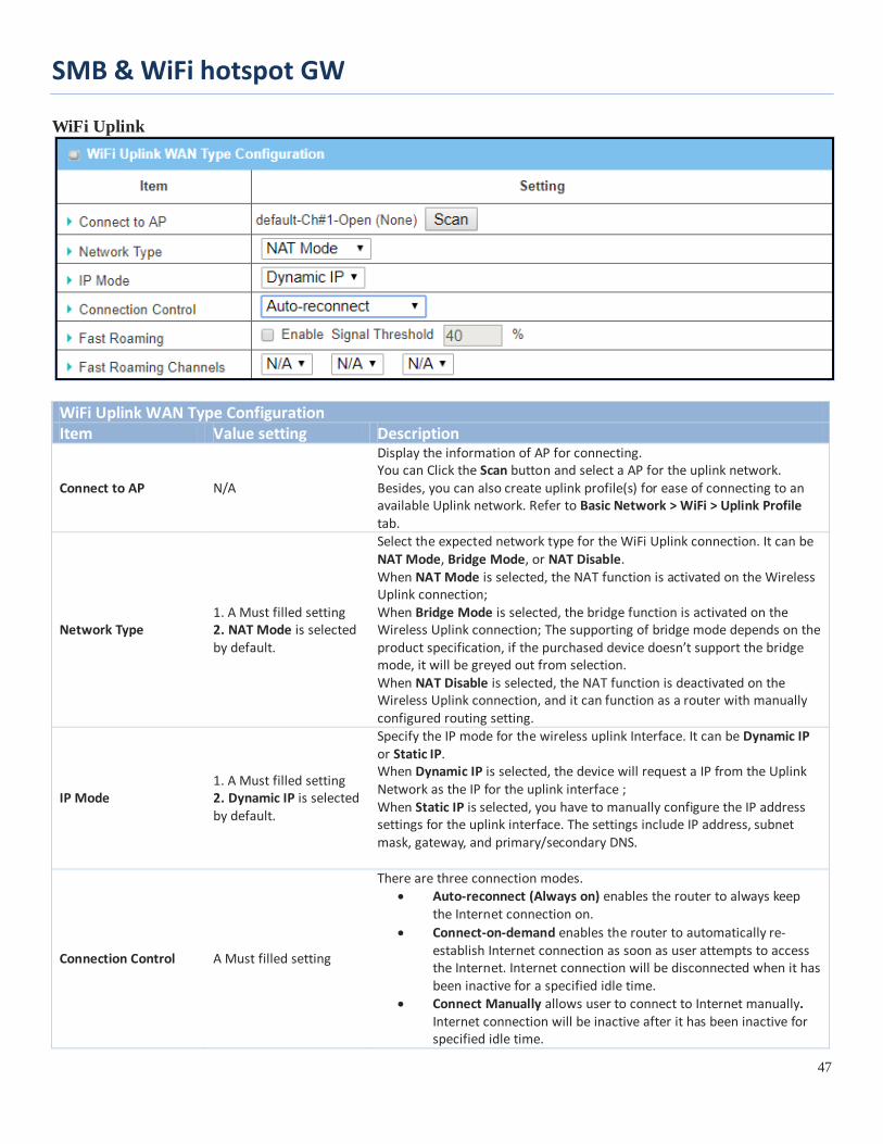
WiFi Uplink
WiFi Uplink WAN Type Configuration Item Value setting Description
Connect to AP N/A
Display the information of AP for connecting. You can Click the Scan button and select a AP for the uplink network. Besides, you can also create uplink profile(s) for ease of connecting to an available Uplink network. Refer to Basic Network > WiFi > Uplink Profile tab.
Network Type 1. A Must filled setting 2. NAT Mode is selected by default.
Select the expected network type for the WiFi Uplink connection. It can be NAT Mode, Bridge Mode, or NAT Disable. When NAT Mode is selected, the NAT function is activated on the Wireless Uplink connection; When Bridge Mode is selected, the bridge function is activated on the Wireless Uplink connection; The supporting of bridge mode depends on the product specification, if the purchased device doesn’t support the bridge mode, it will be greyed out from selection. When NAT Disable is selected, the NAT function is deactivated on the Wireless Uplink connection, and it can function as a router with manually configured routing setting.
IP Mode 1. A Must filled setting 2. Dynamic IP is selected by default.
Specify the IP mode for the wireless uplink Interface. It can be Dynamic IP or Static IP. When Dynamic IP is selected, the device will request a IP from the Uplink Network as the IP for the uplink interface ; When Static IP is selected, you have to manually configure the IP address settings for the uplink interface. The settings include IP address, subnet mask, gateway, and primary/secondary DNS.
Connection Control A Must filled setting
There are three connection modes. • Auto-reconnect (Always on) enables the router to always keep
the Internet connection on. • Connect-on-demand enables the router to automatically re-
establish Internet connection as soon as user attempts to access the Internet. Internet connection will be disconnected when it has been inactive for a specified idle time.
• Connect Manually allows user to connect to Internet manually. Internet connection will be inactive after it has been inactive for specified idle time.
SMB & WiFi hotspot GW
48
Maximum Idle Time 1. An Optional setting 2. By default 600 seconds is filled-in
Specify the maximum Idle time setting to disconnect the internet connection when the connection idle timed out. Value Range: 300 ~ 86400. Note: This field is available only when Connect-on-demand or Connect Manually is selected as the connection control scheme.
Fast Roaming 1. An Optional setting 2. Unchecked is selected by default.
Click the Enable checkbox to activate the fast roaming function. In addition, you can also specify a threshold value for changing from one AP to another near-by AP. The default threshold value is 40%. Value Range: 30 ~ 60%.
Fast Roaming Channels
1. An Optional setting 2. N/A is selected by default.
You can specify up to three channels for WiFi Uplink fast roaming function. If you don’t specify any channel, the WiFi uplink will just operate on original connection channel.
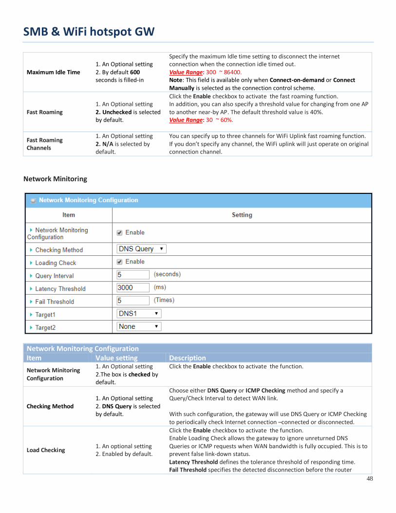
Network Minitoring
Network Monitoring Configuration Item Value setting Description Network Minitoring Configuration
1. An Optional setting 2.The box is checked by default.
Click the Enable checkbox to activate the function.
Checking Method 1. An Optional setting 2. DNS Query is selected by default.
Choose either DNS Query or ICMP Checking method and specify a Query/Check Interval to detect WAN link. With such configuration, the gateway will use DNS Query or ICMP Checking to periodically check Internet connection –connected or disconnected.
Load Checking 1. An optional setting 2. Enabled by default.
Click the Enable checkbox to activate the function. Enable Loading Check allows the gateway to ignore unreturned DNS Queries or ICMP requests when WAN bandwidth is fully occupied. This is to prevent false link-down status. Latency Threshold defines the tolerance threshold of responding time. Fail Threshold specifies the detected disconnection before the router
SMB & WiFi hotspot GW
49
recognize the WAN link down status. Enter a number of detecting disconnection times to be the threshold before disconnection is acknowledged.
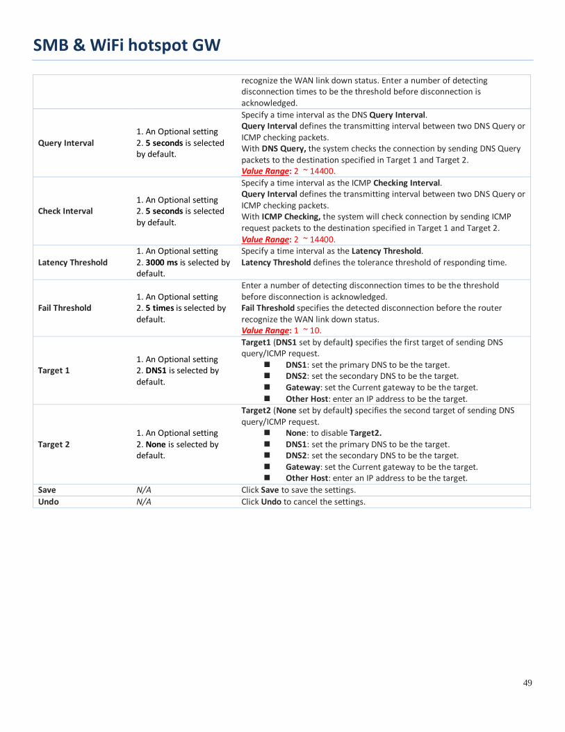
Query Interval 1. An Optional setting 2. 5 seconds is selected by default.
Specify a time interval as the DNS Query Interval. Query Interval defines the transmitting interval between two DNS Query or ICMP checking packets. With DNS Query, the system checks the connection by sending DNS Query packets to the destination specified in Target 1 and Target 2. Value Range: 2 ~ 14400.
Check Interval 1. An Optional setting 2. 5 seconds is selected by default.
Specify a time interval as the ICMP Checking Interval. Query Interval defines the transmitting interval between two DNS Query or ICMP checking packets. With ICMP Checking, the system will check connection by sending ICMP request packets to the destination specified in Target 1 and Target 2. Value Range: 2 ~ 14400.
Latency Threshold 1. An Optional setting 2. 3000 ms is selected by default.
Specify a time interval as the Latency Threshold. Latency Threshold defines the tolerance threshold of responding time.
Fail Threshold 1. An Optional setting 2. 5 times is selected by default.
Enter a number of detecting disconnection times to be the threshold before disconnection is acknowledged. Fail Threshold specifies the detected disconnection before the router recognize the WAN link down status. Value Range: 1 ~ 10.
Target 1 1. An Optional setting 2. DNS1 is selected by default.
Target1 (DNS1 set by default) specifies the first target of sending DNS query/ICMP request.
DNS1: set the primary DNS to be the target. DNS2: set the secondary DNS to be the target. Gateway: set the Current gateway to be the target. Other Host: enter an IP address to be the target.
Target 2 1. An Optional setting 2. None is selected by default.
Target2 (None set by default) specifies the second target of sending DNS query/ICMP request.
None: to disable Target2. DNS1: set the primary DNS to be the target. DNS2: set the secondary DNS to be the target. Gateway: set the Current gateway to be the target. Other Host: enter an IP address to be the target.
Save N/A Click Save to save the settings. Undo N/A Click Undo to cancel the settings.

SMB & WiFi hotspot GW
50
2.1.3 Load Balance
When there are multiple WAN interfaces, and when the bandwidth of one WAN connection is not enough for the traffic loads from the Intranet to the Internet, the WAN load balance function can be considered to enlarge the total WAN bandwidth.
Load Balance Strategy There are three optional strategies for load balance: “By Smart Weight”, “By Specific Weight”, and “By User Policy”. Administrator can select strategy according to application requirement and environment status. The strategies are explained as below.
By Smart Weight If based on "By Smart Weight" strategy, gateway will take the line speed settings of all WAN interfaces specified in "Physical Interface" configuration page as default ratio for data transfer. Based on the ratio of packet bytes via these WAN interfaces in past period (maybe 5 minutes), system decides how many sessions will be transferred via each WAN interface for next period. Administrator may take it as a fast approach to maximize the bandwidth utilization of multiple WAN interfaces in gateway

SMB & WiFi hotspot GW
51
By Specific Weight When you select "By Specific Weight", you need to set up ratio of WAN-1/WAN-2 to decide sessions sent ratio. Total ratio should be 100%. Ratio is usually defined based on practical WAN speed of environment. Gateway's traffic control process will operate routing adequately based on the dedicated weights ratio on all WAN interfaces.
By User Policy If "By User Policy" load balance strategy is selected, it can allow you to mapping Source IP, Destination IP, or Destination Port to assigned WAN interfece. This IP address is not only a single IP but also a subnet or IP range. Destination port can be a single port or port range. You can select one target for one mapping to setup IP address and leave others just left as “any”/ ”All”. Besides this, you can also set protocol as TCP, UDP or both. Diagrams shown on left side are examples user policy. The first diagram illustrates example for mapping various source IP subnets to different WAN interface. All packets from different subnet will be routed to the assigned WAN interfece. Administrator can manage and balance the loading among available WAN interfaces accordingly. The second diagram illustrates another example for routing packets with designated destination IP or domain name to a certain WAN interface. If packets no belong to user policy rule, the gateway just routes those packets based on smart weight algorithm.

SMB & WiFi hotspot GW
52
Load Balance Setting
Go to Basic Network > WAN & Uplink > Load Balance Tab. The Load Balance function is used to manage balance bandwidth usage among multiple WAN connections. When you choose "By Smart Weight" strategy, system will operate load balance function automatically based on the embedded Smart Weight algorithm. However, when you choose "By Specific Weight" strategy, the further "Weight Definition" configuration window will let you define the ratio of transferred sessions between all WAN interfaces for data transfer. At last, when you choose "By User Policy" strategy, the further "User Policy List" shows all defined user policy entries, and the "User Policy Configuration" window will let you create and define one user policy for routing dedicated packet flow via one WAN interface.
Enable/Select Load Balance Strategy
Configuration Item Value setting Description Load Balance Unchecked by default Check the Enable box to activate Load Balance function.
Load Balance Strategy
1. A Must filled setting 2. By Smart Weight is selected by default.
There are up to three load balance strategies. Select the preferred one. By Smart Weight: System will operate load balance function automatically based on the embedded Smart Weight algorithm. By Specific Weight: System will adjust the ratio of transferred sessions among all WANs based on the specified weights for each WAN. By User Policy: System will route traffics through available WAN interface based on user defined rules. Note: The number of available strategies depends on the model you purchased.
Save NA Click the Save button to save the configuration
Undo NA Click the Undo button to restore what you just configured back to the previous setting.
When By Specific Weight is selected, user needs to adjust the percentage of WAN loading. System will give a value according to the bandwidth ratio of each WAN at first time and keep the value after clicking Save button.

SMB & WiFi hotspot GW
53
Weight Definition Item Value setting Description WAN ID NA The Identifier for each available WAN interface..
Weight 1. A Must filled setting 2. Set with bandwidth ratio of each WAN by default.
Enter the weight ratio for each WAN interface. Initially, the bandwidth ratio of each WAN is set by default. Value Range: 1 ~ 99. Note: The sum of all weights can’t be greater than 100%.
Save NA Click the Save button to save the configuration
Undo NA Click the Undo button to restore what you just configured back to the previous setting.
When By User Policy is selected, a User Policy List screen will appear. With properly configured your policy rules, system will route traffics through available WAN interface based on user defined rules Create User Policy
When Add button is applied, User Policy Configuration screen will appear.
User Policy Configuration Item Value setting Description Source IP Address
1. A Must filled setting 2. Any is selected by default.
There are four options can be selected : Any: No specific Source IP is provided. The traffic may come from any source Subnet: Specify the Subnet for the traffics come from the subnet. Input format

SMB & WiFi hotspot GW
54
is : xxx.xxx.xxx.xxx/xx e.g. 192.168.123.0/24. IP Range: Specify the IP Range for the traffics come from the IPs Single IP: Specify a unique IP Address for the traffics come from the IP. Input format is : xxx.xxx.xxx.xxx e.g. 192.168.123.101.
Destination IP Address
1. A Must filled setting 2. Any is selected by default.
There are five options can be selected : Any: No specific destination IP is provided. The traffic may come to any destination. Subnet: Specify the Subnet for the traffics come to the subnet. Input format is : xxx.xxx.xxx.xxx/xx e.g. 192.168.123.0/24. IP Range: Specify the IP Range for the traffics come to the IPs Single IP: Specify a unique IP Address for the traffics come to the IP. Input format is : xxx.xxx.xxx.xxx e.g. 192.168.123.101. Domain Name: Specify the domain name for the traffics come to the domain
Destination Port
1. A Must filled setting 2. All is selected by default.
There are four options can be selected : All: No specific destination port is provided. Port Range: Specify the Destination Port Range for the traffics Single Port: Specify a unique destination Port for the traffics Well-known Applications: Select the service port of well-known application defined in dropdown list.
Protocol 1. A Must filled setting 2. Both is selected by default.
There are three options can be selected. They are Both, TCP, and UDP.
WAN Interface 1. A Must filled setting 2. WAN-1 is selected by default.
User can select the interface that traffic should go. Note that the WAN interface dropdown list will only show the available WAN interfaces.
Policy Unchecked by default Check the Enable checkbox to activate the policy rule. Save NA Click the Save button to save the configuration
Undo NA Click the Undo button to restore what you just configured back to the previous setting.

SMB & WiFi hotspot GW
55
2.2 LAN & VLAN This section provides the configuration of LAN and VLAN. VLAN is an optional feature, and it depends on the product specification of the purchased gateway.
2.2.1 Ethernet LAN
The Local Area Network (LAN) can be used to share data or files among computers attached to a network. Following diagram illustrates the network that wired and interconnects computers.
Please follow the following instructions to do IPv4 Ethernet LAN Setup.
Configuration Item Value setting Description
IP Mode N/A
It shows the LAN IP mode for the gateway according the related configuration. Static IP: If there is at least one WAN interface activated, the LAN IP mode is fixed in Static IP mode. Dynamic IP: If all the available WAN inferfaces are disabled, the LAN IP mode can be Dynamic IP mode.
LAN IP Address
1. A Must filled setting 2. 192.168.123.254 is set by default
Enter the local IP address of this device. The network device(s) on your network must use the LAN IP address of this device as their Default Gateway. You can change it if necessary. Note: It’s also the IP address of web UI. If you change it, you need to type new IP address in the browser to see web UI.
Subnet Mask 1. A Must filled setting 2. 255.255.255.0 (/24) is set
Select the subnet mask for this gateway from the dropdown list. Subnet mask defines how many clients are allowed in one network or subnet.
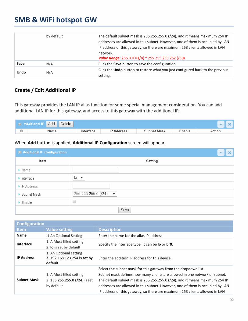
SMB & WiFi hotspot GW
56
by default The default subnet mask is 255.255.255.0 (/24), and it means maximum 254 IP addresses are allowed in this subnet. However, one of them is occupied by LAN IP address of this gateway, so there are maximum 253 clients allowed in LAN network. Value Range: 255.0.0.0 (/8) ~ 255.255.255.252 (/30).
Save N/A Click the Save button to save the configuration
Undo N/A Click the Undo button to restore what you just configured back to the previous setting.
Create / Edit Additional IP
This gateway provides the LAN IP alias function for some special management consideration. You can add additional LAN IP for this gateway, and access to this gateway with the additional IP.
When Add button is applied, Additional IP Configuration screen will appear.
Configuration Item Value setting Description Name .1 An Optional Setting Enter the name for the alias IP address.
Interface 1. A Must filled setting 2. lo is set by default
Specify the Interface type. It can be lo or br0.
IP Address 1. An Optional setting 2. 192.168.123.254 is set by default
Enter the addition IP address for this device.
Subnet Mask 1. A Must filled setting 2. 255.255.255.0 (/24) is set by default
Select the subnet mask for this gateway from the dropdown list. Subnet mask defines how many clients are allowed in one network or subnet. The default subnet mask is 255.255.255.0 (/24), and it means maximum 254 IP addresses are allowed in this subnet. However, one of them is occupied by LAN IP address of this gateway, so there are maximum 253 clients allowed in LAN

SMB & WiFi hotspot GW
57
network. Value Range: 255.0.0.0 (/8) ~ 255.255.255.255 (/32).
Save NA Click the Save button to save the configuration
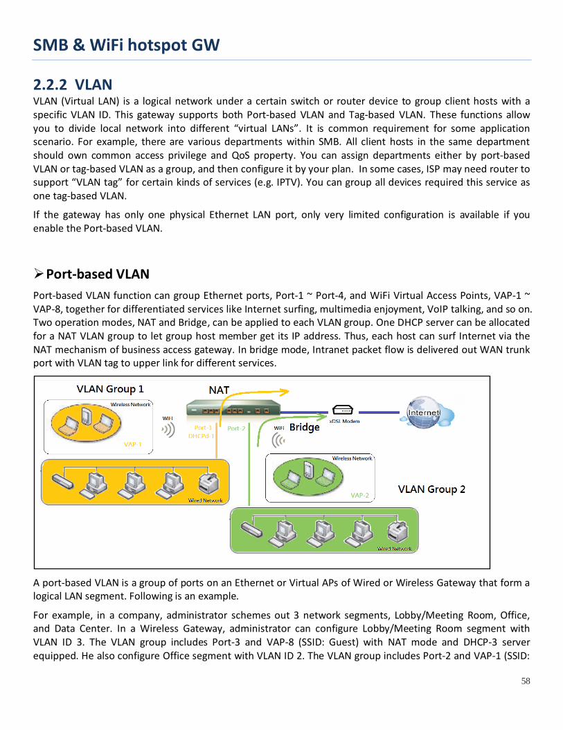
SMB & WiFi hotspot GW
58
2.2.2 VLAN VLAN (Virtual LAN) is a logical network under a certain switch or router device to group client hosts with a specific VLAN ID. This gateway supports both Port-based VLAN and Tag-based VLAN. These functions allow you to divide local network into different “virtual LANs”. It is common requirement for some application scenario. For example, there are various departments within SMB. All client hosts in the same department should own common access privilege and QoS property. You can assign departments either by port-based VLAN or tag-based VLAN as a group, and then configure it by your plan. In some cases, ISP may need router to support “VLAN tag” for certain kinds of services (e.g. IPTV). You can group all devices required this service as one tag-based VLAN.
If the gateway has only one physical Ethernet LAN port, only very limited configuration is available if you enable the Port-based VLAN.
Port-based VLAN Port-based VLAN function can group Ethernet ports, Port-1 ~ Port-4, and WiFi Virtual Access Points, VAP-1 ~ VAP-8, together for differentiated services like Internet surfing, multimedia enjoyment, VoIP talking, and so on. Two operation modes, NAT and Bridge, can be applied to each VLAN group. One DHCP server can be allocated for a NAT VLAN group to let group host member get its IP address. Thus, each host can surf Internet via the NAT mechanism of business access gateway. In bridge mode, Intranet packet flow is delivered out WAN trunk port with VLAN tag to upper link for different services.
A port-based VLAN is a group of ports on an Ethernet or Virtual APs of Wired or Wireless Gateway that form a logical LAN segment. Following is an example.
For example, in a company, administrator schemes out 3 network segments, Lobby/Meeting Room, Office, and Data Center. In a Wireless Gateway, administrator can configure Lobby/Meeting Room segment with VLAN ID 3. The VLAN group includes Port-3 and VAP-8 (SSID: Guest) with NAT mode and DHCP-3 server equipped. He also configure Office segment with VLAN ID 2. The VLAN group includes Port-2 and VAP-1 (SSID:
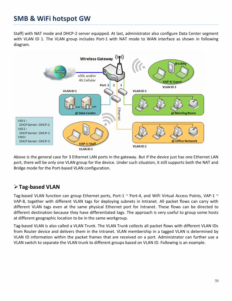
SMB & WiFi hotspot GW
59
Staff) with NAT mode and DHCP-2 server equipped. At last, administrator also configure Data Center segment with VLAN ID 1. The VLAN group includes Port-1 with NAT mode to WAN interface as shown in following diagram.
Above is the general case for 3 Ethernet LAN ports in the gateway. But if the device just has one Ethernet LAN port, there will be only one VLAN group for the device. Under such situation, it still supports both the NAT and Bridge mode for the Port-based VLAN configuration.
Tag-based VLAN Tag-based VLAN function can group Ethernet ports, Port-1 ~ Port-4, and WiFi Virtual Access Points, VAP-1 ~ VAP-8, together with different VLAN tags for deploying subnets in Intranet. All packet flows can carry with different VLAN tags even at the same physical Ethernet port for Intranet. These flows can be directed to different destination because they have differentiated tags. The approach is very useful to group some hosts at different geographic location to be in the same workgroup.
Tag-based VLAN is also called a VLAN Trunk. The VLAN Trunk collects all packet flows with different VLAN IDs from Router device and delivers them in the Intranet. VLAN membership in a tagged VLAN is determined by VLAN ID information within the packet frames that are received on a port. Administrator can further use a VLAN switch to separate the VLAN trunk to different groups based on VLAN ID. Following is an example.
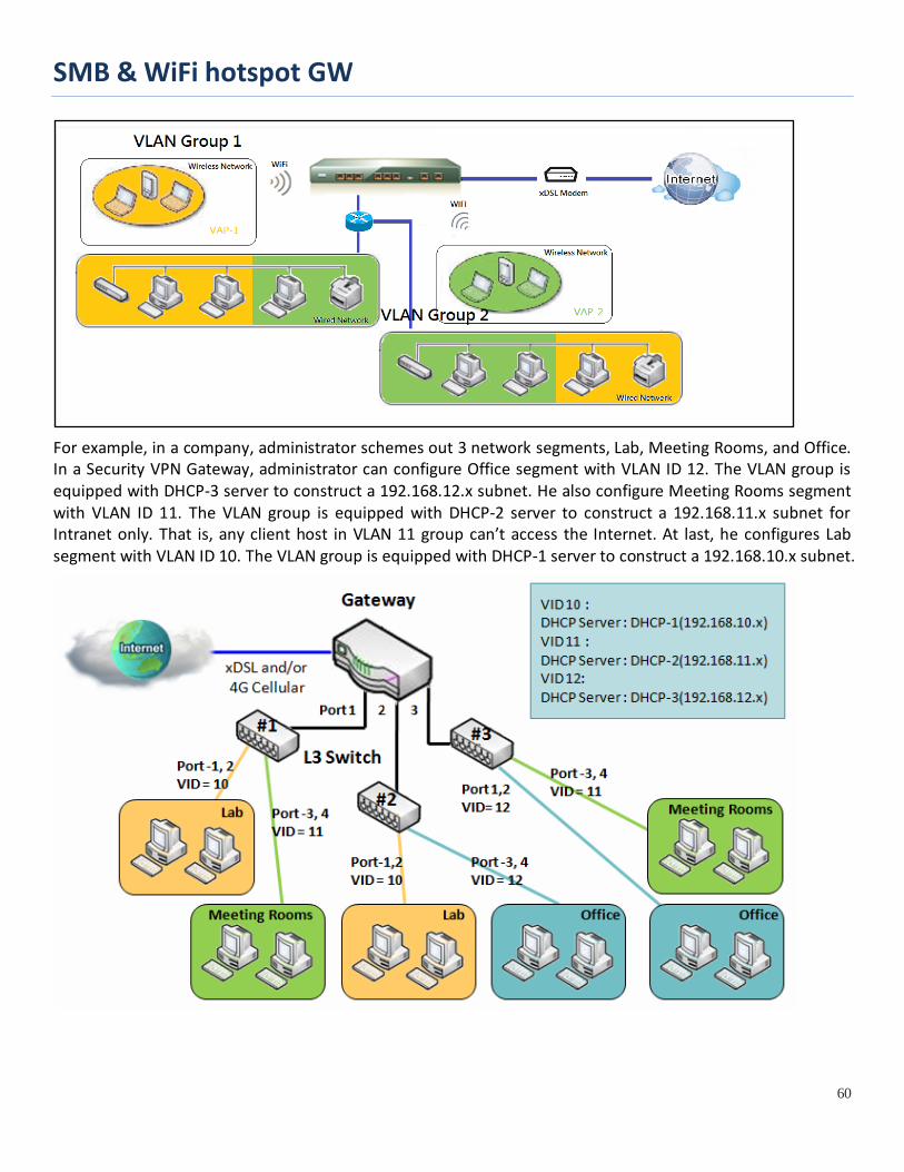
SMB & WiFi hotspot GW
60
For example, in a company, administrator schemes out 3 network segments, Lab, Meeting Rooms, and Office. In a Security VPN Gateway, administrator can configure Office segment with VLAN ID 12. The VLAN group is equipped with DHCP-3 server to construct a 192.168.12.x subnet. He also configure Meeting Rooms segment with VLAN ID 11. The VLAN group is equipped with DHCP-2 server to construct a 192.168.11.x subnet for Intranet only. That is, any client host in VLAN 11 group can’t access the Internet. At last, he configures Lab segment with VLAN ID 10. The VLAN group is equipped with DHCP-1 server to construct a 192.168.10.x subnet.

SMB & WiFi hotspot GW
61
VLAN Groups Access Control Administrator can specify the Internet access permission for all VLAN groups. He can also configure which VLAN groups are allowed to communicate with each other.
VLAN Group Internet Access Administrator can specify members of one VLAN group to be able to access Internet or not. Following is an example that VLAN groups of VID is 2 and 3 can access Internet but the one with VID is 1 cannot access Internet. That is, visitors in meeting room and staffs in office network can access Internet. But the computers/servers in data center cannot access Internet since security consideration. Servers in data center only for trusted staffs or are accessed in secure tunnels.

SMB & WiFi hotspot GW
62
Inter VLAN Group Routing: In Port-based tagging, administrator can specify member hosts of one VLAN group to be able to communicate with the ones of another VLAN group or not. This is a communication pair, and one VLAN group can join many communication pairs. But communication pair doesn’t have the transitive property. That is, A can communicate with B, and B can communicate with C, it doesn’t imply that A can communicate with C. An example is shown at following diagram. VLAN groups of VID is 1 and 2 can access each other but the ones between VID 1 and VID 3 and between VID 2 and VID 3 can’t.

SMB & WiFi hotspot GW
63
VLAN Setting
Go to Basic Network > LAN & VLAN > VLAN Tab.
The VLAN function allows you to divide local network into different virtual LANs. There are Port-based and Tag-based VLAN types. Select one that applies.
Configuration Item Value setting Description
VLAN Type Port-based is selected by default
Select the VLAN type that you want to adopt for organizing you local subnets. Port-based: Port-based VLAN allows you to add rule for each LAN port, and you can do advanced control with its VLAN ID. Tag-based: Tag-based VLAN allows you to add VLAN ID, and select member and DHCP Server for this VLAN ID. Go to Tag-based VLAN List table.
System Reserved VLAN ID
1 ~ 5 is reserved by default
Specify the VLAN ID range that is reserved for the system operation. For the Port-based/Tag-based VLAN grouping, only use the ID outside the reserved range. Value Range: 1 ~ 4091.
Save NA Click the Save button to save the configuration
Port-based VLAN – Create/Edit VLAN Rules The port-based VLAN allows you to custom each LAN port. There is a default rule shows the configuration of all LAN ports. Also, if your device has a DMZ port, you will see DMZ configuration, too. The maxima rule numbers is based on LAN port numbers.
When Add button is applied, Port-based VLAN Configuration screen will appear, which is including 3 sections: Port-based VLAN Configuration, IP Fixed Mapping Rule List, and Inter VLAN Group Routing (enter through a button)

SMB & WiFi hotspot GW
64
Port-based VLAN - Configuration
Port-based VLAN Configuration (part-I) Item Value setting Description
Name 1. A Must filled setting 2. String format: already have default texts
Define the Name of this rule. It has a default text and cannot be modified.
VLAN ID A Must filled setting Define the VLAN ID number, range is 1~4094.
VLAN Tagging Disable is selected by default.
The rule is activated according to VLAN ID and Port Members configuration when Enable is selected. The rule is activated according Port Members configuration when Disable is selected.
NAT / Bridge NAT is selected by default. Select NAT mode or Bridge mode for the rule.
Port Members These boxes are unchecked by default.
Select which LAN port(s) and VAP(s) that you want to add to the rule. Note: The available member list can be different for the purchased product.
LAN to Join The box is unchecked by default.
Check the Enable box and select one of the defined DHCP Server for the List to define the DHCP server for the VLAN group. If you enabled this function, all the rest settings will be greyed out, not required to configured manually.
Save NA Click the Save button to save the configuration
Undo NA Click the Undo button to restore what you just configured back to the previous setting.
If you didn’t decide to bind the VLAN group to a pre-defined DHCP server, you have to further specify the following settings.

SMB & WiFi hotspot GW
65
Port-based VLAN Configuration (part-II) Item Value setting Description WAN & WAN VID to Join
All WANs is selected by default.
Select which WAN or All WANs that allow accessing Internet. Note: If Bridge mode is selected, you need to select a WAN and enter a VID.
LAN IP Address
A Must filled setting Assign an IP Address for the DHCP Server that the rule used, this IP address is a gateway IP.
Subnet Mask 255.255.255.0(/24) is selected by default.
Select a Subnet Mask for the DHCP Server.
DHCP Server /Relay
Server is selected by default.
Define the DHCP Server type. There are three types you can select: Server, Relay, and Disable. Relay: Select Relay to enable DHCP Relay function for the VLAN group, and you only need to fill the DHCP Server IP Address field. Server: Select Server to enable DHCP Server function for the VLAN group, and you need to specify the DHCP Server settings. Disable: Select Disable to disable the DHCP Server function for the VLAN group.
DHCP Server IP Address (for DHCP Relay only)
A Must filled setting
If you select Relay type of DHCP Server, assign a DHCP Server IP Address that the gateway will relay the DHCP requests to the assigned DHCP server.
DHCP Option 82 (for DHCP Relay only)
An Optional filled setting
If you select Relay type of DHCP Server, you can further enable the DHCP Option 82 setting if the DHCP server support it.
DHCP Server Name A Must filled setting
Define name of the DHCP Server for the specified VLAN group.
IP Pool A Must filled setting
Define the IP Pool range. There are Starting Address and Ending Address fields. If a client requests an IP address from this DHCP Server, it will assign an IP address in the range of IP pool.
Lease Time A Must filled setting Define a period of time for an IP Address that the DHCP Server leases to a new

SMB & WiFi hotspot GW
66
device. By default, the lease time is 86400 seconds.
Domain Name String format can be any text
The Domain Name of this DHCP Server. Value Range: 0 ~ 31 characters.
Primary DNS IPv4 format The Primary DNS of this DHCP Server. Secondary DNS IPv4 format The Secondary DNS of this DHCP Server.
Primary WINS IPv4 format The Primary WINS of this DHCP Server. Secondary WINS IPv4 format The Secondary WINS of this DHCP Server.
Gateway IPv4 format The Gateway of this DHCP Server.
Enable The box is unchecked by default.
Click Enable box to activate this rule.
Save NA Click the Save button to save the configuration
Undo NA Click the Undo button to restore what you just configured back to the previous setting.

SMB & WiFi hotspot GW
67
Besides, you can add some IP rules in the IP Fixed Mapping Rule List if DHCP Server for the VLAN groups is required.
When Add button is applied, Mapping Rule Configuration screen will appear. Mapping Rule Configuration Item Value setting Description MAC Address A Must filled setting Define the MAC Address target that the DHCP Server wants to match.
IP Address A Must filled setting
Define the IP Address that the DHCP Server will assign. If there is a request from the MAC Address filled in the above field, the DHCP Server will assign this IP Address to the client whose MAC Address matched the rule.
Enable The box is unchecked by default.
Click Enable box to activate this rule.
Save NA Click the Save button to save the configuration Note: ensure to always click on Apply button to apply the changes after the web browser refreshed taken you back to the VLAN page.

SMB & WiFi hotspot GW
68
Port-based VLAN – Inter VLAN Group Routing Click VLAN Group Routing button, the VLAN Group Internet Access Definition and Inter VLAN Group Routing screen will appear.
When Edit button is applied, a screen similar to this will appear.
Inter VLAN Group Routing Item Value setting Description VALN Group Internet Access Definition
All boxes are checked by default.
By default, all boxes are checked means all VLAN ID members are allow to access WAN interface. If uncheck a certain VLAN ID box, it means the VLAN ID member can’t access Internet anymore.
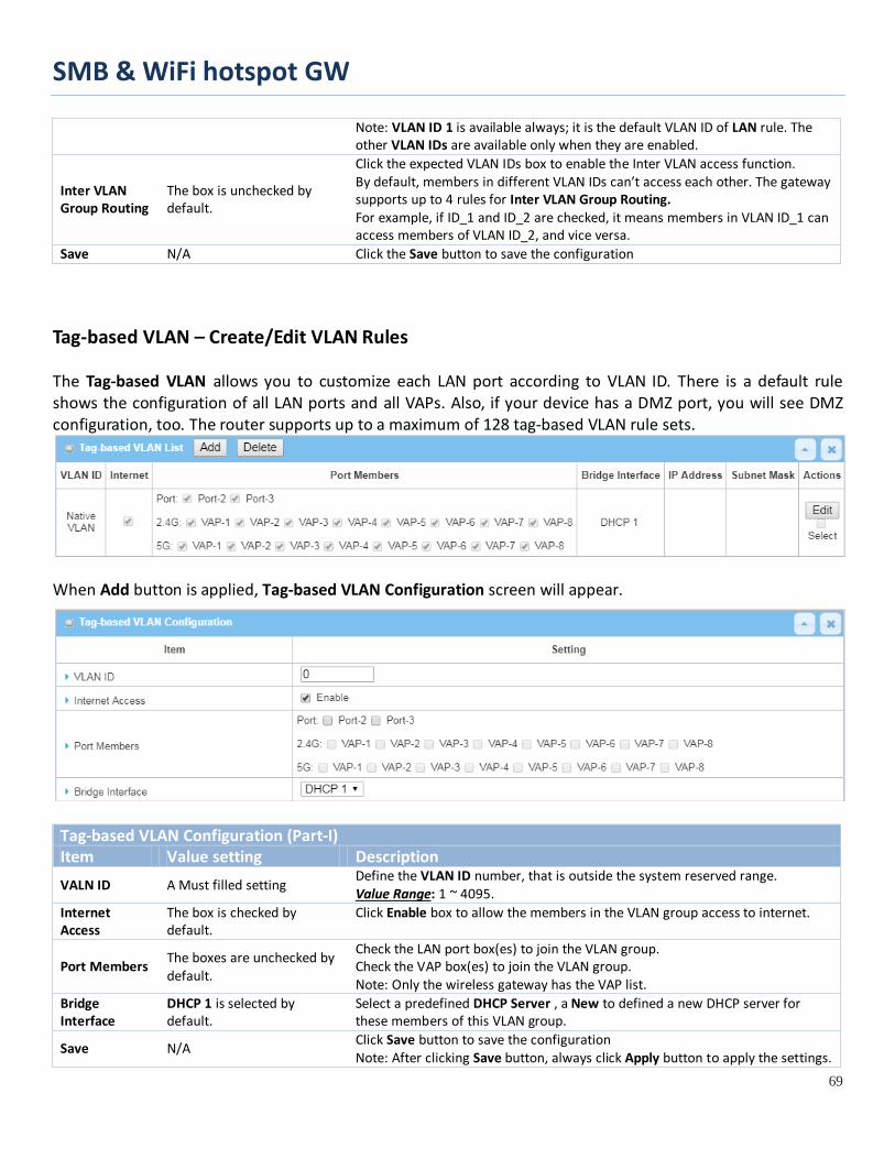
SMB & WiFi hotspot GW
69
Note: VLAN ID 1 is available always; it is the default VLAN ID of LAN rule. The other VLAN IDs are available only when they are enabled.
Inter VLAN Group Routing
The box is unchecked by default.
Click the expected VLAN IDs box to enable the Inter VLAN access function. By default, members in different VLAN IDs can’t access each other. The gateway supports up to 4 rules for Inter VLAN Group Routing. For example, if ID_1 and ID_2 are checked, it means members in VLAN ID_1 can access members of VLAN ID_2, and vice versa.
Save N/A Click the Save button to save the configuration
Tag-based VLAN – Create/Edit VLAN Rules The Tag-based VLAN allows you to customize each LAN port according to VLAN ID. There is a default rule shows the configuration of all LAN ports and all VAPs. Also, if your device has a DMZ port, you will see DMZ configuration, too. The router supports up to a maximum of 128 tag-based VLAN rule sets.
When Add button is applied, Tag-based VLAN Configuration screen will appear.
Tag-based VLAN Configuration (Part-I) Item Value setting Description VALN ID A Must filled setting
Define the VLAN ID number, that is outside the system reserved range. Value Range: 1 ~ 4095.
Internet Access
The box is checked by default.
Click Enable box to allow the members in the VLAN group access to internet.
Port Members The boxes are unchecked by default.
Check the LAN port box(es) to join the VLAN group. Check the VAP box(es) to join the VLAN group. Note: Only the wireless gateway has the VAP list.
Bridge Interface
DHCP 1 is selected by default.
Select a predefined DHCP Server , a New to defined a new DHCP server for these members of this VLAN group.
Save N/A Click Save button to save the configuration Note: After clicking Save button, always click Apply button to apply the settings.

SMB & WiFi hotspot GW
70
If you select New to create a new DHCP server setting for the VLAN group, you have to further specify the following configuration.
Tag-based VLAN Configuration (part-II) Item Value setting Description IP Address A Must filled setting Assign an IP Address for the DHCP Server that the rule used, this IP address is a
gateway IP.
Subnet Mask 255.255.255.0(/24) is selected by default.
Select a Subnet Mask for the DHCP Server.
DHCP Relay The box is unchecked by default.
Check the box to enable the DHCP Relay function for the VLAN group, and you only need to fill the DHCP Server IP Address field.
WAN Interface WAN-1 is selected by default.
Select which WAN interface that allow accessing Internet.
DHCP Option 82 An Optional filled setting If you select Relay type of DHCP Server, you can further enable the DHCP
Option 82 setting if the DHCP server support it. Save NA Click the Save button to save the configuration
Undo NA Click the Undo button to restore what you just configured back to the previous setting.
Tag-based VLAN Summary The configured tag-based VLAN group information will be displayed in the following screen.
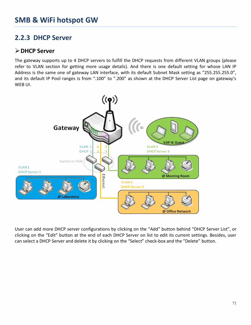
SMB & WiFi hotspot GW
71
2.2.3 DHCP Server
DHCP Server The gateway supports up to 4 DHCP servers to fulfill the DHCP requests from different VLAN groups (please refer to VLAN section for getting more usage details). And there is one default setting for whose LAN IP Address is the same one of gateway LAN interface, with its default Subnet Mask setting as “255.255.255.0”, and its default IP Pool ranges is from “.100” to “.200” as shown at the DHCP Server List page on gateway’s WEB UI.
User can add more DHCP server configurations by clicking on the “Add” button behind “DHCP Server List”, or clicking on the “Edit” button at the end of each DHCP Server on list to edit its current settings. Besides, user can select a DHCP Server and delete it by clicking on the “Select” check-box and the “Delete” button.
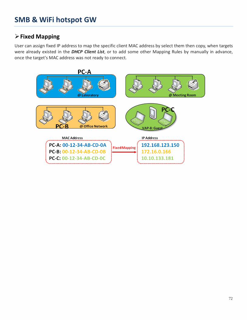
SMB & WiFi hotspot GW
72
Fixed Mapping User can assign fixed IP address to map the specific client MAC address by select them then copy, when targets were already existed in the DHCP Client List, or to add some other Mapping Rules by manually in advance, once the target's MAC address was not ready to connect.

SMB & WiFi hotspot GW
73
DHCP Server Setting
Go to Basic Network > LAN & VLAN > DHCP Server Tab.
The DHCP Server setting allows user to create and customize DHCP Server policies to assign IP Addresses to the devices on the local area network (LAN). Create / Edit DHCP Server Policy
The gateway allows you to custom your DHCP Server Policy. If multiple LAN ports are available, you can define one policy for each LAN (or VLAN group), and it supports up to a maximum of 4 policy sets.
When Add button is applied, DHCP Server Configuration screen will appear.

SMB & WiFi hotspot GW
74
DHCP Server Configuration Item Value setting Description
DHCP Server Name
1. String format can be any text 2. A Must filled setting
Enter a DHCP Server name. Enter a name that is easy for you to understand.
LAN IP Address
1. IPv4 format. 2. A Must filled setting
The LAN IP Address of this DHCP Server.
Subnet Mask 255.0.0.0 (/8) is set by default
The Subnet Mask of this DHCP Server.
IP Pool 1. IPv4 format. 2. A Must filled setting
The IP Pool of this DHCP Server. It composed of Starting Address entered in this field and Ending Address entered in this field.
Lease Time 1. Numberic string format. 2. A Must filled setting
The Lease Time of this DHCP Server. Value Range: 300 ~ 604800 seconds.
Domain Name String format can be any text
The Domain Name of this DHCP Server.
Primary DNS IPv4 format The Primary DNS of this DHCP Server. Secondary DNS IPv4 format The Secondary DNS of this DHCP Server.
Primary WINS IPv4 format The Primary WINS of this DHCP Server. Secondary WINS IPv4 format The Secondary WINS of this DHCP Server.
Gateway IPv4 format The Gateway of this DHCP Server.
Server The box is unchecked by default.
Click Enable box to activate this DHCP Server.
Save N/A Click the Save button to save the configuration
Undo N/A Click the Undo button to restore what you just configured back to the previous setting.
Back N/A When the Back button is clicked the screen will return to the DHCP Server Configuration page.
Create / Edit Mapping Rule List on DHCP Server
The gateway allows you to custom your Mapping Rule List on DHCP Server. It supports up to a maximum of 64 rule sets. When Fix Mapping button is applied, the Mapping Rule List screen will appear.
When Add button is applied, Mapping Rule Configuration screen will appear.

SMB & WiFi hotspot GW
75
Mapping Rule Configuration Item Value setting Description
MAC Address 1. MAC Address string format 2. A Must filled setting
The MAC Address of this mapping rule.
IP Address 1. IPv4 format. 2. A Must filled setting
The IP Address of this mapping rule.
Rule The box is unchecked by default.
Click Enable box to activate this rule.
Save N/A Click the Save button to save the configuration
Undo N/A Click the Undo button to restore what you just configured back to the previous setting.
Back N/A When the Back button is clicked the screen will return to the DHCP Server Configuration page.
View / Copy DHCP Client List
When DHCP Client List button is applied, DHCP Client List screen will appear.
When the DHCP Client is selected and Copy to Fixed Mapping button is applied. The IP and MAC address of DHCP Client will apply to the Mapping Rule List on specific DHCP Server automatically.
Enable / Disable DHCP Server Options The DHCP Server Options setting allows user to set DHCP OPTIONS 66, 72, or 114. Click the Enable button to activate the DHCP option function, and the DHCP Server will add the expected options in its sending out DHCPOFFER DHCPACK packages.

SMB & WiFi hotspot GW
76
Option Meaning RFC 66 TFTP server name [RFC 2132] 72 Default World Wide Web Server [RFC 2132] 114 URL [RFC 3679]
Create / Edit DHCP Server Options The gateway supports up to a maximum of 99 option settings.
When Add/Edit button is applied, DHCP Server Option Configuration screen will appear.
DHCP Server Option Configuration Item Value setting Description
Option Name 1. String format can be any text 2. A Must filled setting.
Enter a DHCP Server Option name. Enter a name that is easy for you to understand.
DHCP Server Select
Dropdown list of all available DHCP servers. Choose the DHCP server this option should apply to.
Option Select 1. A Must filled setting. 2. Option 66 is selected by default.
Choose the specific option from the dropdown list. It can be Option 66, Option 72, Option 144, Option 42, Option 150, or Option 160. Option 42 for ntp server;

SMB & WiFi hotspot GW
77
Option 66 for tftp; Option 72 for www; Option 144 for url;
Type Dropdown list of DHCP server option value’s type
Each different options has different value types.
66 Single IP Address Single FQDN
72 IP Addresses List, separated by “,” 114 Single URL 42 IP Addresses List, separated by “,” 150 IP Addresses List, separated by “,”
160 Single IP Address Single FQDN
Value
1. IPv4 format 2. FQDN format 3. IP list 4. URL format 5. A Must filled setting
Should conform to Type :
Type Value
66 Single IP Address IPv4 format
Single FQDN FQDN format
72 IP Addresses List, separated by “,” IPv4 format, separated by “,”
114 Single URL URL format
Enable The box is unchecked by default. Click Enable box to activate this setting.
Save NA Click the Save button to save the setting.
Undo NA When the Undo button is clicked the screen will return back with nothing changed.
Create / Edit DHCP Relay The gateway supports up to a maximum of 6 DHCP Relay configurations.
When Add/Edit button is applied, DHCP Relay Configuration screen will appear.
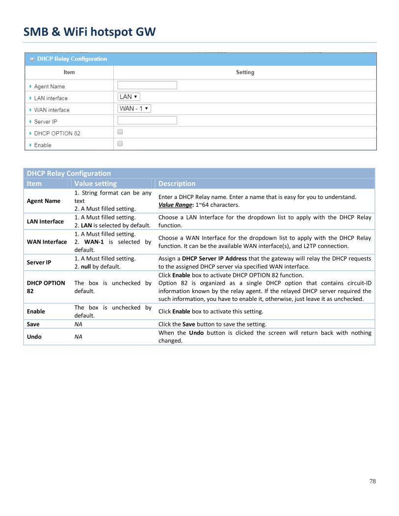
SMB & WiFi hotspot GW
78
DHCP Relay Configuration Item Value setting Description
Agent Name 1. String format can be any text 2. A Must filled setting.
Enter a DHCP Relay name. Enter a name that is easy for you to understand. Value Range: 1~64 characters.
LAN Interface 1. A Must filled setting. 2. LAN is selected by default.
Choose a LAN Interface for the dropdown list to apply with the DHCP Relay function.
WAN Interface 1. A Must filled setting. 2. WAN-1 is selected by default.
Choose a WAN Interface for the dropdown list to apply with the DHCP Relay function. It can be the available WAN interface(s), and L2TP connection.
Server IP 1. A Must filled setting. 2. null by default.
Assign a DHCP Server IP Address that the gateway will relay the DHCP requests to the assigned DHCP server via specified WAN interface.
DHCP OPTION 82
The box is unchecked by default.
Click Enable box to activate DHCP OPTION 82 function. Option 82 is organized as a single DHCP option that contains circuit-ID information known by the relay agent. If the relayed DHCP server required the such information, you have to enable it, otherwise, just leave it as unchecked.
Enable The box is unchecked by default.
Click Enable box to activate this setting.
Save NA Click the Save button to save the setting.
Undo NA When the Undo button is clicked the screen will return back with nothing changed.
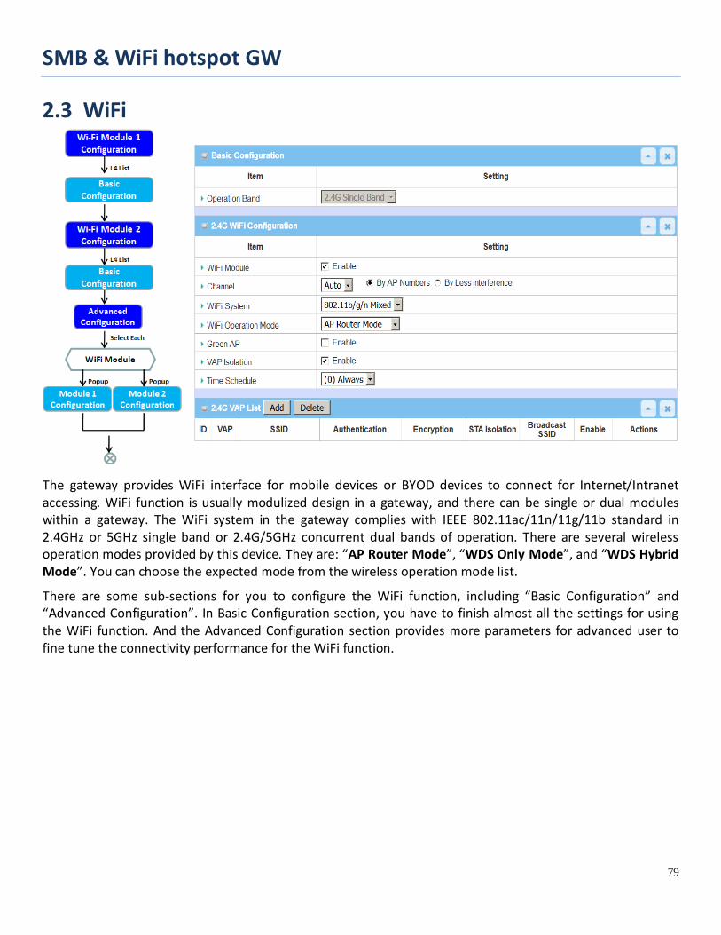
SMB & WiFi hotspot GW
79
2.3 WiFi
The gateway provides WiFi interface for mobile devices or BYOD devices to connect for Internet/Intranet accessing. WiFi function is usually modulized design in a gateway, and there can be single or dual modules within a gateway. The WiFi system in the gateway complies with IEEE 802.11ac/11n/11g/11b standard in 2.4GHz or 5GHz single band or 2.4G/5GHz concurrent dual bands of operation. There are several wireless operation modes provided by this device. They are: “AP Router Mode”, “WDS Only Mode”, and “WDS Hybrid Mode”. You can choose the expected mode from the wireless operation mode list.
There are some sub-sections for you to configure the WiFi function, including “Basic Configuration” and “Advanced Configuration”. In Basic Configuration section, you have to finish almost all the settings for using the WiFi function. And the Advanced Configuration section provides more parameters for advanced user to fine tune the connectivity performance for the WiFi function.

SMB & WiFi hotspot GW
80
2.3.1 WiFi Configuration
Due to optional module(s) and frequency band, you need to setup module one by one. For each module, you need to specify the operation mode, and then setup the virtual APs for wireless access.
Hereunder are the scenarios for each wireless operation mode, you can get how it works, and what is the difference among them. To connect your wireless devices with the wireless gateway, make sure your application scenario for WiFi network and choose the most adequate operation mode.
AP Router Mode This mode allows you to get your wired and wireless devices connected to form the Intranet of the wireless gateway, and the Intranet will link to the Internet with NAT mechanism of the gateway. So, this gateway is working as a WiFi AP, but also a WiFi hotspot for Internet accessing service. It means local WiFi clients can associate to it, and go to Internet. With its NAT mechanism, all of wireless clients don’t need to get public IP addresses from ISP.
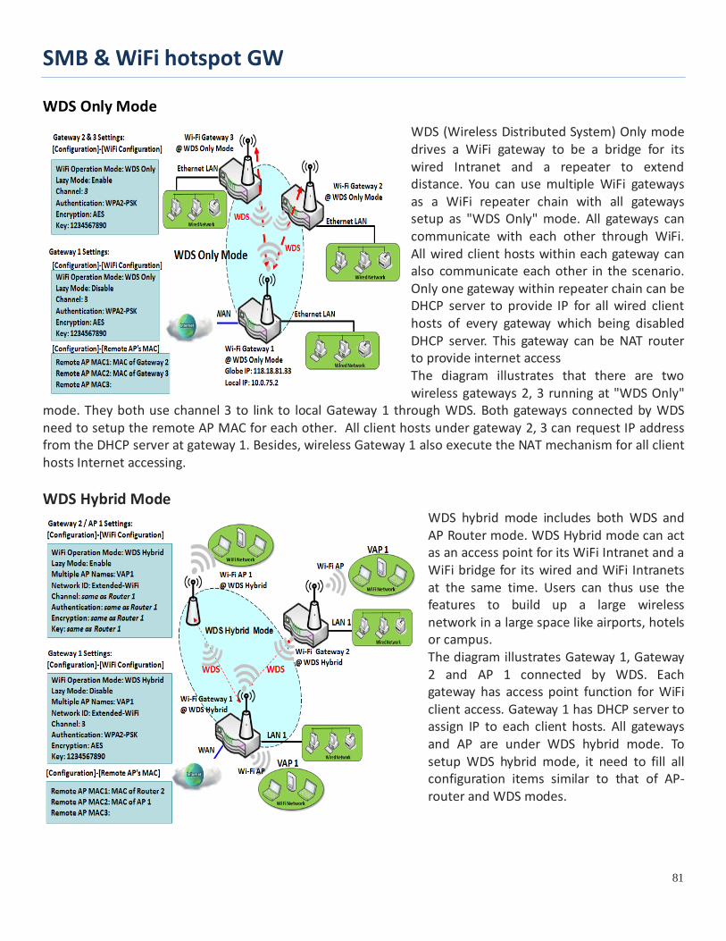
SMB & WiFi hotspot GW
81
WDS Only Mode WDS (Wireless Distributed System) Only mode drives a WiFi gateway to be a bridge for its wired Intranet and a repeater to extend distance. You can use multiple WiFi gateways as a WiFi repeater chain with all gateways setup as "WDS Only" mode. All gateways can communicate with each other through WiFi. All wired client hosts within each gateway can also communicate each other in the scenario. Only one gateway within repeater chain can be DHCP server to provide IP for all wired client hosts of every gateway which being disabled DHCP server. This gateway can be NAT router to provide internet access The diagram illustrates that there are two wireless gateways 2, 3 running at "WDS Only"
mode. They both use channel 3 to link to local Gateway 1 through WDS. Both gateways connected by WDS need to setup the remote AP MAC for each other. All client hosts under gateway 2, 3 can request IP address from the DHCP server at gateway 1. Besides, wireless Gateway 1 also execute the NAT mechanism for all client hosts Internet accessing. WDS Hybrid Mode
WDS hybrid mode includes both WDS and AP Router mode. WDS Hybrid mode can act as an access point for its WiFi Intranet and a WiFi bridge for its wired and WiFi Intranets at the same time. Users can thus use the features to build up a large wireless network in a large space like airports, hotels or campus. The diagram illustrates Gateway 1, Gateway 2 and AP 1 connected by WDS. Each gateway has access point function for WiFi client access. Gateway 1 has DHCP server to assign IP to each client hosts. All gateways and AP are under WDS hybrid mode. To setup WDS hybrid mode, it need to fill all configuration items similar to that of AP-router and WDS modes.
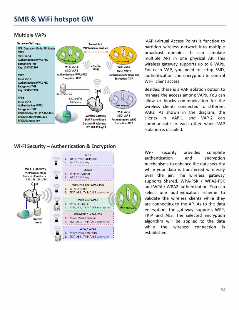
SMB & WiFi hotspot GW
82
Multiple VAPs VAP (Virtual Access Point) is function to partition wireless network into multiple broadcast domains. It can simulate multiple APs in one physical AP. This wireless gateway supports up to 8 VAPs. For each VAP, you need to setup SSID, authentication and encryption to control Wi-Fi client access.
Besides, there is a VAP isolation option to manage the access among VAPs. You can allow or blocks communication for the wireless clients connected to different VAPs. As shown in the diagram, the clients in VAP-1 and VAP-2 can communicate to each other when VAP Isolation is disabled.
Wi-Fi Security – Authentication & Encryption Wi-Fi security provides complete authentication and encryption mechanisms to enhance the data security while your data is transferred wirelessly over the air. The wireless gateway supports Shared, WPA-PSK / WPA2-PSK and WPA / WPA2 authentication. You can select one authentication scheme to validate the wireless clients while they are connecting to the AP. As to the data encryption, the gateway supports WEP, TKIP and AES. The selected encryption algorithm will be applied to the data while the wireless connection is established.

SMB & WiFi hotspot GW
83
WiFi Configuration Setting
The WiFi configuration allows user to configure 2.4GHz or 5GHz WiFi settings.
Go to Basic Network > WiFi > WiFi Module One Tab. If the gateway is equipped with two WiFi modules, there will be another WiFi Module Two. You can do the similar configurations on both WiFi modules.
Basic Configuration
Basic Configuration
Item Value setting Description
Operation Band A Must filled setting
Specify the intended operation band for the WiFi module. Basically, this setting is fixed and cannot be changed once the module is integrated into the product. However, there is some module with selectable band for user to choose according to his network environment. Under such situation, you can specify which operation band is suitable for the application.
Configure WiFi Setting
Configuring Wi-Fi Settings
Item Value setting Description
WiFi Module The box is checked by default
Check the Enable box to activate Wi-Fi function.
Channel 1. A Must filled setting. 2. Auto is selected be default.
Select a radio channel for the VAP. Each channel is corresponding to different radio band. The permissible channels depend on the Regulatory Domain. There are two available options when Auto is selected: By AP Numbers
The channel will be selected according to AP numbers (The less, the better).

SMB & WiFi hotspot GW
84
By Less Interference The channel will be selected according to interference. (The lower, the better).
WiFi System A Must filled setting
Specify the preferred WiFi System. The dropdown list of WiFi system is based on IEEE 802.11 standard. 2.4G WiFi can select b, g and n only or mixed with each other. 5G WiFi can select a, n and ac only or mixed with each other.
WiFi Operation Mode
Specify the WiFi Operation Mode according to your application. Go to the following table for AP Router Mode, WDS Only Mode, and WDS Hybrid Mode settings. Note: The available operation modes depend on the product specification.
In the following, the specific configuration description for each WiFi operation mode is given.
AP Router Mode & VAPs Configuration For the AP Router mode, the device not only supports stations connection but also the router function. The WAN port and the NAT function are enabled.
AP Router Mode
Item Value setting Description
Green AP The box is unchecked by default.
Check the Enable box to activate Green AP function.
VAP Isolation The box is checked by default.
Check the Enable box to activate this function. By default, the box is checked; it means that stations which associated to different VAPs cannot communicate with each other.
Time Schedule A Must filled setting Apply a specific Time Schedule to this rule; otherwise leave it as (0) Always. If the dropdown list is empty ensure Time Schedule is pre-configured. Refer to Object Definition > Scheduling > Configuration tab.
By default, VAP 1 is enabled and security key is required to connect to the gateway wirelessly to enhance the security level and prevent unexpected access of un-authorized devices. The default wifi key is printed on both the device label and the Security Card. It is created randomly and differs from devices. So, you can connected to the VAP1 (SSID: Staff_2.4G) with the provided key. However, it is strongly recommanded that you have to change the security key to a easy-to-remember one

SMB & WiFi hotspot GW
85
by clicking the Edit button. Click Add / Edit button in the VAP List screen to create or edit the settings for a VAP. A VAP Configuration screen will appear. For VAP 1:
For others:
VAP Configuration
Item Value setting Description
SS ID 1. String format : Any text
Enter the SSID for the VAP, and decide whether to broadcast the SSID or not. The SSID is used for identifying from another AP, and client stations will associate with AP according to SSID.
Max. STA The box is unchecked Check this box and enter a limitation to limit the maximum number of client
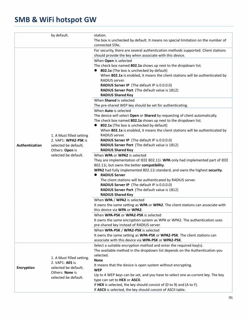
SMB & WiFi hotspot GW
86
by default. station. The box is unchecked by default. It means no special limitation on the number of connected STAs.
Authentication
1. A Must filled setting 2. VAP1: WPA2-PSK is selected be default; Others: Open is selected be default.
For security, there are several authentication methods supported. Client stations should provide the key when associate with this device. When Open is selected The check box named 802.1x shows up next to the dropdown list. 802.1x (The box is unchecked by default)
When 802.1x is enabled, it means the client stations will be authenticated by RADIUS server. RADIUS Server IP (The default IP is 0.0.0.0) RADIUS Server Port (The default value is 1812) RADIUS Shared Key
When Shared is selected The pre-shared WEP key should be set for authenticating. When Auto is selected The device will select Open or Shared by requesting of client automatically. The check box named 802.1x shows up next to the dropdown list. 802.1x (The box is unchecked by default)
When 802.1x is enabled, it means the client stations will be authenticated by RADIUS server. RADIUS Server IP (The default IP is 0.0.0.0) RADIUS Server Port (The default value is 1812) RADIUS Shared Key
When WPA or WPA2 is selected They are implementation of IEEE 802.11i. WPA only had implemented part of IEEE 802.11i, but owns the better compatibility. WPA2 had fully implemented 802.11i standard, and owns the highest security. RADIUS Server
The client stations will be authenticated by RADIUS server. RADIUS Server IP (The default IP is 0.0.0.0) RADIUS Server Port (The default value is 1812) RADIUS Shared Key
When WPA / WPA2 is selected It owns the same setting as WPA or WPA2. The client stations can associate with this device via WPA or WPA2. When WPA-PSK or WPA2-PSK is selected It owns the same encryption system as WPA or WPA2. The authentication uses pre-shared key instead of RADIUS server. When WPA-PSK / WPA2-PSK is selected It owns the same setting as WPA-PSK or WPA2-PSK. The client stations can associate with this device via WPA-PSK or WPA2-PSK.
Encryption
1. A Must filled setting. 2. VAP1: AES is selected be default; Others: None is selected be default.
Select a suitable encryption method and enter the required key(s). The available method in the dropdown list depends on the Authentication you selected. None It means that the device is open system without encrypting. WEP Up to 4 WEP keys can be set, and you have to select one as current key. The key type can set to HEX or ASCII. If HEX is selected, the key should consist of (0 to 9) and (A to F). If ASCII is selected, the key should consist of ASCII table.

SMB & WiFi hotspot GW
87
TKIP TKIP was proposed instead of WEP without upgrading hardware. Enter a Pre-shared Key for it. The length of key is from 8 to 63 characters. AES The newest encryption system in WiFi, it also designed for the fast 802.11n high bitrates schemes. Enter a Pre-shared Key for it. The length of key is from 8 to 63 characters. You are recommended to use AES encryption instead of any others for security. TKIP / AES TKIP / AES mixed mode. It means that the client stations can associate with this device via TKIP or AES. Enter a Pre-shared Key for it. The length of key is from 8 to 63 characters.
STA Isolation
VAP1: The box is checked by default; Others: unchecked by default.
Check the Enable box to activate this function. By default, the box is checked; it means that stations which associated to the same VAP cannot communicate with each other.
Broadcast SSID
VAP1: The box is checked by default; Others: unchecked by default.
Check the Enable box to activate this function. If the broadcast SSID option is enabled, it means the SSID will be broadcasted, and the stations can associate with this device by scanning SSID.
Enable
VAP1: The box is checked by default; Others: unchecked by default.
Check the Enable box to activate this VAP.
Save N/A Click the Save button to save the current configuration. Undo N/A Click the Undo button to restore configuration to previous setting before saving. Apply N/A Click the Apply button to apply the saved configuration.
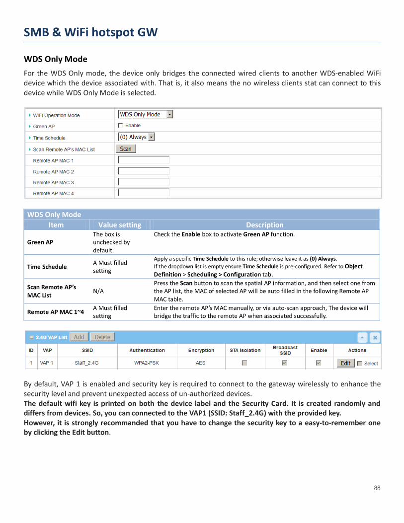
SMB & WiFi hotspot GW
88
WDS Only Mode For the WDS Only mode, the device only bridges the connected wired clients to another WDS-enabled WiFi device which the device associated with. That is, it also means the no wireless clients stat can connect to this device while WDS Only Mode is selected.
WDS Only Mode
Item Value setting Description
Green AP The box is unchecked by default.
Check the Enable box to activate Green AP function.
Time Schedule A Must filled setting
Apply a specific Time Schedule to this rule; otherwise leave it as (0) Always. If the dropdown list is empty ensure Time Schedule is pre-configured. Refer to Object Definition > Scheduling > Configuration tab.
Scan Remote AP’s MAC List
N/A Press the Scan button to scan the spatial AP information, and then select one from the AP list, the MAC of selected AP will be auto filled in the following Remote AP MAC table.
Remote AP MAC 1~4 A Must filled setting
Enter the remote AP’s MAC manually, or via auto-scan approach, The device will bridge the traffic to the remote AP when associated successfully.
By default, VAP 1 is enabled and security key is required to connect to the gateway wirelessly to enhance the security level and prevent unexpected access of un-authorized devices. The default wifi key is printed on both the device label and the Security Card. It is created randomly and differs from devices. So, you can connected to the VAP1 (SSID: Staff_2.4G) with the provided key. However, it is strongly recommanded that you have to change the security key to a easy-to-remember one by clicking the Edit button.
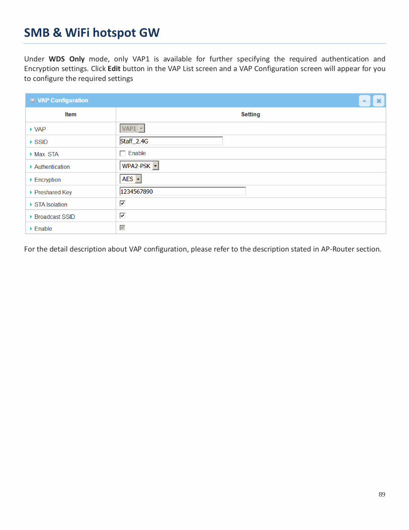
SMB & WiFi hotspot GW
89
Under WDS Only mode, only VAP1 is available for further specifying the required authentication and Encryption settings. Click Edit button in the VAP List screen and a VAP Configuration screen will appear for you to configure the required settings
For the detail description about VAP configuration, please refer to the description stated in AP-Router section.

SMB & WiFi hotspot GW
90
WDS Hybrid Mode For the WDS Hybrid mode, the device bridges all the wired LAN and WLAN clients to another WDS or WDS hybrid enabled WiFi devices which the device associated with.
WDS Hybrid Mode
Item Value setting Description
Lazy Mode The box is checked by default.
Check the Enable box to activate this function. With the function been enabled, the device can auto-learn WDS peers without manually entering other AP’s MAC address. But at least one of the APs has to fill remote AP MAC addresses.
Green AP The box is unchecked by default.
Check the Enable box to activate Green AP function.
VAP Isolation The box is checked by default.
Check the Enable box to activate this function. By default, the box is checked; it means that stations which associated to different VAPs cannot communicate with each other.
Time Schedule A Must filled setting Apply a specific Time Schedule to this rule; otherwise leave it as (0) Always. If the dropdown list is empty ensure Time Schedule is pre-configured. Refer to Object Definition > Scheduling > Configuration tab.
Scan Remote AP’s MAC List
Available when Lazy Mode disabled.
Press the Scan button to scan the spatial AP information, and then select one from the AP list, the MAC of selected AP will be auto filled in the following Remote AP MAC table.
Remote AP MAC 1~4
Available when Lazy Mode disabled.
Enter the remote AP’s MAC manually, or via auto-scan approach, The device will bridge the traffic to the remote AP when associated successfully.
By default, VAP 1 is enabled and security key is required to connect to the gateway wirelessly to enhance the security level and prevent unexpected access of un-authorized devices. The default wifi key is printed on both the device label and the Security Card. It is created randomly and
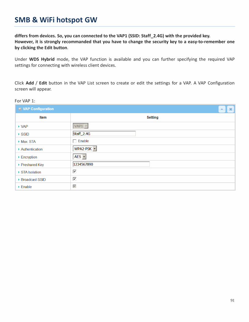
SMB & WiFi hotspot GW
91
differs from devices. So, you can connected to the VAP1 (SSID: Staff_2.4G) with the provided key. However, it is strongly recommanded that you have to change the security key to a easy-to-remember one by clicking the Edit button. Under WDS Hybrid mode, the VAP function is available and you can further specifying the required VAP settings for connecting with wireless client devices. Click Add / Edit button in the VAP List screen to create or edit the settings for a VAP. A VAP Configuration screen will appear. For VAP 1:

SMB & WiFi hotspot GW
92
For others:
For the detail description about VAP configuration, please refer to the description stated in AP-Router section.

SMB & WiFi hotspot GW
93
2.3.2 Wireless Client List The Wireless Client List page shows the information of wireless clients which are associated with this device.
Go to Basic Network > WiFi > Wireless Client List Tab.
Select Target WiFi
Target Configuration Item Value setting Description
Module Select A Must filled setting. Select the WiFi module to check the information of connected clients. For those single WiFi module products, this option is hidden.
Operation Band A Must filled setting.
Specify the intended operation band for the WiFi module. Basically, this setting is fixed and cannot be changed once the module is integrated into the product. However, there is some module with selectable band for user to choose according to his network environment. Under such situation, you can specify which operation band is suitable for the application.
Multiple AP Names
1. A Must filled setting. 2. All is selected by default.
Specify the VAP to show the associated clients information in the following Client List. By default, All VAP is selected.
Show Client List The following Client List shows the information for wireless clients that is associated with the selected VAP(s).
Target Configuration Item Value setting Description IP Address Configuration & Address
N/A It shows the Client’s IP address and the deriving method. Dynamic means the IP address is derived from a DHCP server. Static means the IP address is a fixed one that is self-filled by client.
Host Name N/A It shows the host name of client. MAC Address N/A It shows the MAC address of client. Mode N/A It shows what kind of Wi-Fi system the client used to associate with this device. Rate N/A It shows the data rate between client and this device.
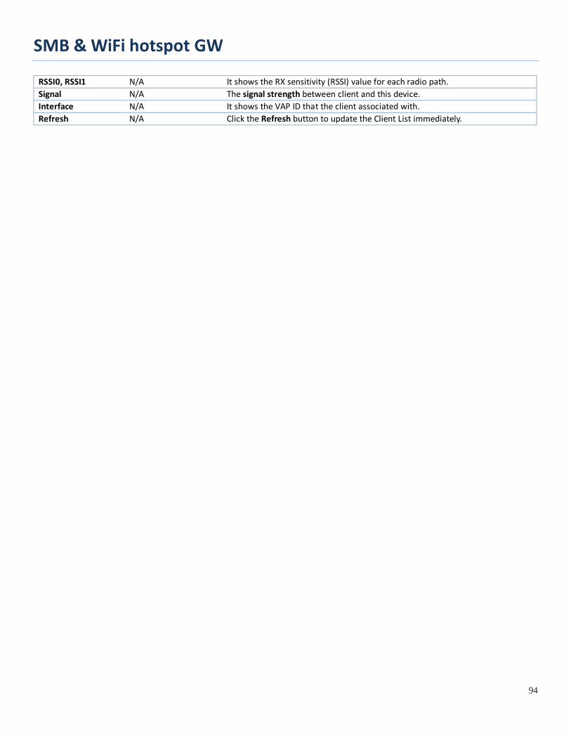
SMB & WiFi hotspot GW
94
RSSI0, RSSI1 N/A It shows the RX sensitivity (RSSI) value for each radio path. Signal N/A The signal strength between client and this device. Interface N/A It shows the VAP ID that the client associated with. Refresh N/A Click the Refresh button to update the Client List immediately.

SMB & WiFi hotspot GW
95
2.3.3 Advanced Configuration This device provides advanced wireless configuration for professional user to optimize the wireless performance under the specific installation environment. Please note that if you are not familiar with the WiFi technology, just leave the advanced configuration with its default values, or the connectivity and performance may get worse with improper settings. Go to Basic Network > WiFi > Advanced Configuration Tab.
Select Target WiFi
Target Configuration Item Value setting Description
Module Select A Must filled setting. Select the WiFi module to check the information of connected clients. For those single WiFi module products, this option is hidden.
Operation Band A Must filled setting.
Specify the intended operation band for the WiFi module. Basically, this setting is fixed and cannot be changed once the module is integrated into the product. However, there is some module with selectable band for user to choose according to his network environment.
Setup Advanced Configuration

SMB & WiFi hotspot GW
96
Advanced Configuration Item Value setting Description
Regulatory Domain The default setting is according to where the product sale to
It limits the available radio channel of this device. The permissible channels depend on the Regulatory Domain.
Beacon Interval 100 It shows the time interval between each beacon packet broadcasted. The beacon packet contains SSID, Channel ID and Security setting.
DTIM Interval 3
A DTIM (Delivery Traffic Indication Message) is a countdown informing clients of the next window for listening to broadcast message. When the device has buffered broadcast message for associated client, it sends the next DTIM with a DTIM value.
RTS Threshold 2347
RTS (Request to send) Threshold means when the packet size is over the setting value, then active RTS technique. RTS/CTS is a collision avoidance technique. It means RTS never activated when the threshold is set to 2347.
Fragmentation 2346 Wireless frames can be divided into smaller units (fragments) to improve performance in the presence of RF interference at the limits of RF coverage.
WMM The box is checked by default
WMM (WiFi Multimedia) can help control latency and jitter when transmitting multimedia content over a wireless connection.
Short GI By default 400ns is selected
Short GI (Guard Interval) is defined to set the sending interval between each packet. Note that lower Short GI could increase not only the transition rate but also error rate.
TX Rate By default Best is selected
It means the data transition rate. When Best is selected, the device will choose a proper data rate according to signal strength.
RF Bandwidth By default Auto is selected The setting of RF bandwidth limits the maximum data rate.
Transmit Power By default 100% is selected
Normally the wireless transmitter operates at 100% power. By setting the transmit power to control the WiFi coverage.
5G Band Steering The box is unchecked by default
When the client station associate with 2.4G WiFi, the device will send the client to 5G WiFi automatically if the client is available on accessing this 5G Wi-Fi band. This option is only available on the module that supports 5GHz band.
WIDS The box is unchecked by default
The WIDS (Wireless Intrusion Detection System) will analyze all packets and make a statistic table in WiFi status. Go to Status > Basic Network > WiFi tab for detailed WIDS status.
Dynamic Frequency Selection
The box is checked by default
Dynamic Frequency Selection (DFS) is a legally required feature for all WiFi devices that share the 5 GHz band with radar. DFS enables a gateway to detect radar signals and switch their operating frequency to prevent interference. This process ensures that radar systems send and receive accurate information. Note: Dynamic Frequency Selection (DFS) option is only available for the WiFi module with 5GHz radio.
Save N/A Click the Save button to save the current configuration.
Undo N/A Click the Undo button to restore configuration to previous setting before saving.
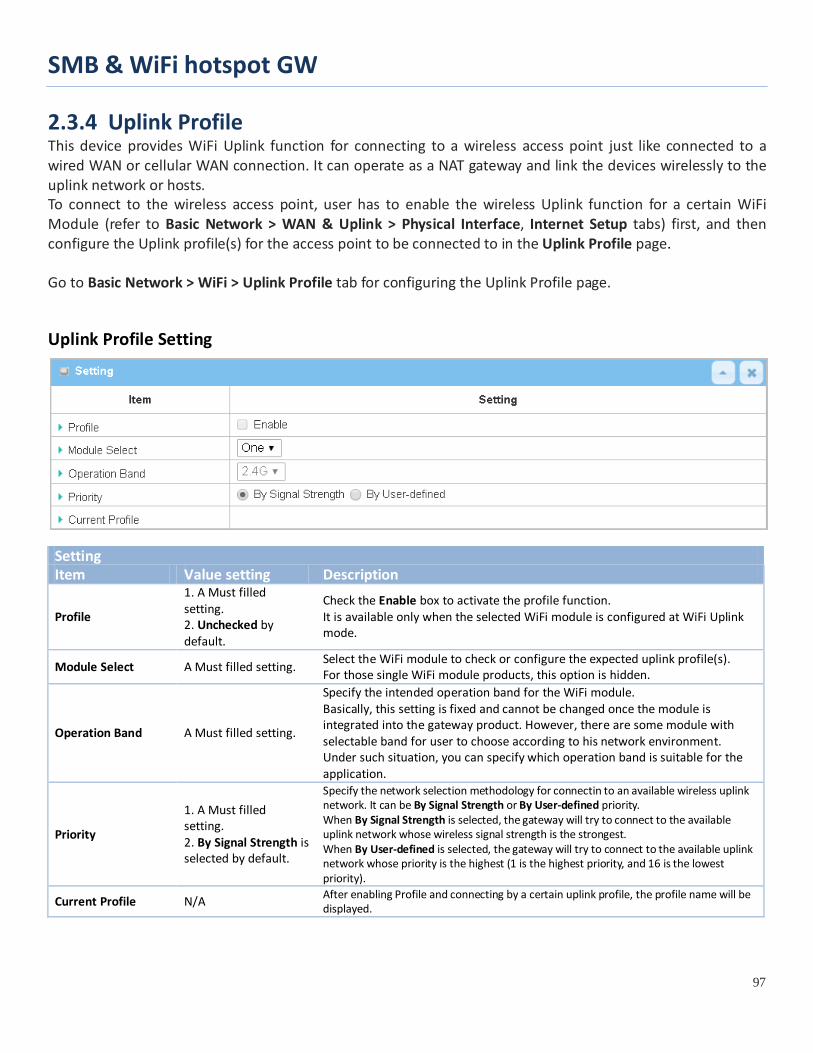
SMB & WiFi hotspot GW
97
2.3.4 Uplink Profile This device provides WiFi Uplink function for connecting to a wireless access point just like connected to a wired WAN or cellular WAN connection. It can operate as a NAT gateway and link the devices wirelessly to the uplink network or hosts. To connect to the wireless access point, user has to enable the wireless Uplink function for a certain WiFi Module (refer to Basic Network > WAN & Uplink > Physical Interface, Internet Setup tabs) first, and then configure the Uplink profile(s) for the access point to be connected to in the Uplink Profile page.
Go to Basic Network > WiFi > Uplink Profile tab for configuring the Uplink Profile page.
Uplink Profile Setting
Setting Item Value setting Description
Profile
1. A Must filled setting. 2. Unchecked by default.
Check the Enable box to activate the profile function. It is available only when the selected WiFi module is configured at WiFi Uplink mode.
Module Select A Must filled setting. Select the WiFi module to check or configure the expected uplink profile(s). For those single WiFi module products, this option is hidden.
Operation Band A Must filled setting.
Specify the intended operation band for the WiFi module. Basically, this setting is fixed and cannot be changed once the module is integrated into the gateway product. However, there are some module with selectable band for user to choose according to his network environment. Under such situation, you can specify which operation band is suitable for the application.
Priority
1. A Must filled setting. 2. By Signal Strength is selected by default.
Specify the network selection methodology for connectin to an available wireless uplink network. It can be By Signal Strength or By User-defined priority. When By Signal Strength is selected, the gateway will try to connect to the available uplink network whose wireless signal strength is the strongest. When By User-defined is selected, the gateway will try to connect to the available uplink network whose priority is the highest (1 is the highest priority, and 16 is the lowest priority).
Current Profile N/A After enabling Profile and connecting by a certain uplink profile, the profile name will be displayed.

SMB & WiFi hotspot GW
98
Note: to apply the defined Uplink profile(s) for the gateway to find a best fit profile for connecting to a certain uplink network, user has to Enable the Profile auto-connect function (Refer to Basic Network > WiFi > (Module 1/ Module 2) WiFi Configuration tab. Create/Edit Uplink Profile
The Profile List shows the settings for the created uplink profiles. The information includes Profile Name, SSID, Channel, Authentication, Encryption, MAC Address, Signal Strength, Priority, and Enable.
When Add button is applied, Profile Configuration screen will appear.
Profile Configuration Item Value setting Description
Profile Name 1. String format can be any text 2. A Must filled setting
Enter a profile name for the uplink network specified below. It is a name that is easy for you to understand. Value Range: 1 ~ 64 characters.
Network ID (SSID)
1. String format : Any text 2. The box is checked by default.
Enter the SSID for the VAP, and decide whether to broadcast the SSID or not. The SSID is used for identifying from another AP, and client stations will associate with AP according to SSID. If the broadcast SSID option is enabled, it means the SSID will be broadcasted, and the stations can associate with this device by scanning SSID.
Channel
1. A Must filled setting. 2. Auto is selected by default.
Select a radio channel for the VAP. Each channel is corresponding to different radio band. The permissible channels depend on the Regulatory Domain. There are two available options when Auto is selected: By AP Numbers
The channel will be selected according to AP numbers (The less, the
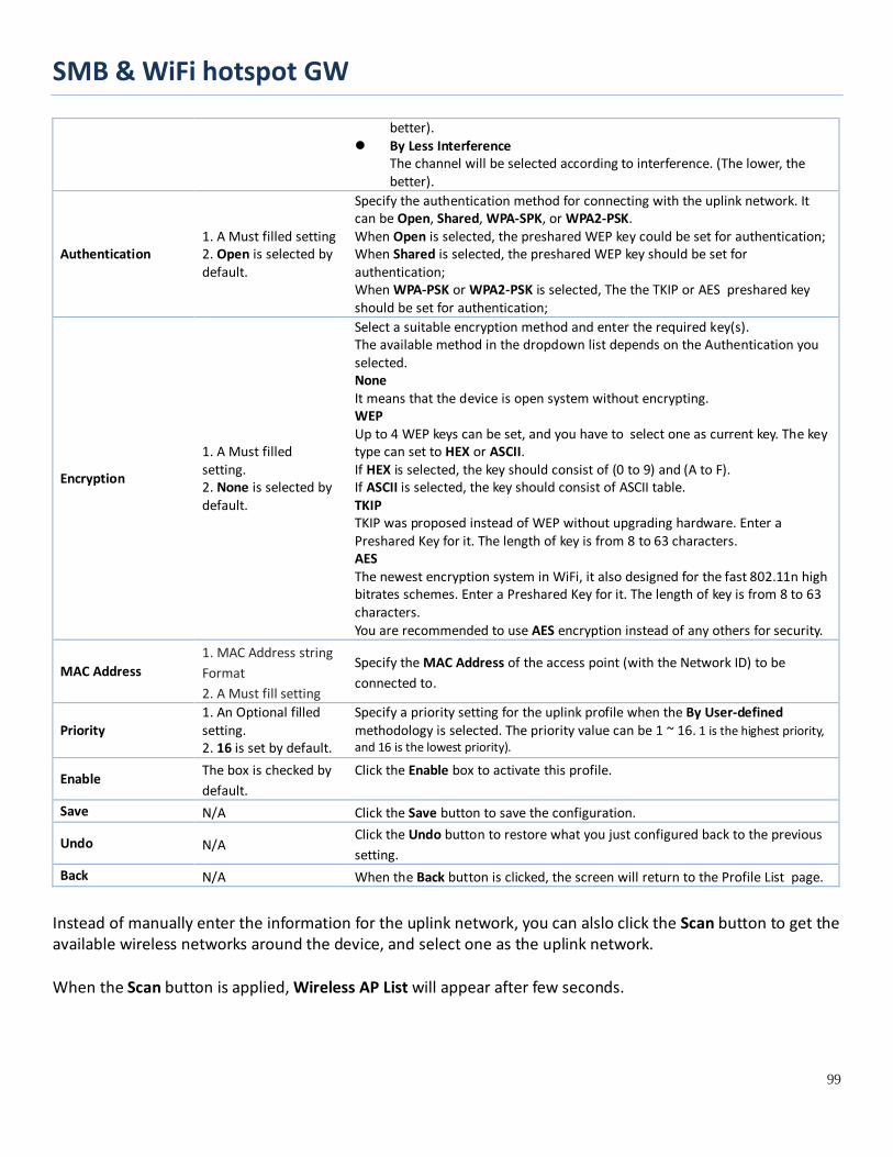
SMB & WiFi hotspot GW
99
better). By Less Interference
The channel will be selected according to interference. (The lower, the better).
Authentication 1. A Must filled setting 2. Open is selected by default.
Specify the authentication method for connecting with the uplink network. It can be Open, Shared, WPA-SPK, or WPA2-PSK. When Open is selected, the preshared WEP key could be set for authentication; When Shared is selected, the preshared WEP key should be set for authentication; When WPA-PSK or WPA2-PSK is selected, The the TKIP or AES preshared key should be set for authentication;
Encryption
1. A Must filled setting. 2. None is selected by default.
Select a suitable encryption method and enter the required key(s). The available method in the dropdown list depends on the Authentication you selected. None It means that the device is open system without encrypting. WEP Up to 4 WEP keys can be set, and you have to select one as current key. The key type can set to HEX or ASCII. If HEX is selected, the key should consist of (0 to 9) and (A to F). If ASCII is selected, the key should consist of ASCII table. TKIP TKIP was proposed instead of WEP without upgrading hardware. Enter a Preshared Key for it. The length of key is from 8 to 63 characters. AES The newest encryption system in WiFi, it also designed for the fast 802.11n high bitrates schemes. Enter a Preshared Key for it. The length of key is from 8 to 63 characters. You are recommended to use AES encryption instead of any others for security.
MAC Address 1. MAC Address string Format 2. A Must fill setting
Specify the MAC Address of the access point (with the Network ID) to be connected to.
Priority 1. An Optional filled setting. 2. 16 is set by default.
Specify a priority setting for the uplink profile when the By User-defined methodology is selected. The priority value can be 1 ~ 16. 1 is the highest priority, and 16 is the lowest priority).
Enable The box is checked by default.
Click the Enable box to activate this profile.
Save N/A Click the Save button to save the configuration.
Undo N/A Click the Undo button to restore what you just configured back to the previous setting.
Back N/A When the Back button is clicked, the screen will return to the Profile List page.
Instead of manually enter the information for the uplink network, you can alslo click the Scan button to get the available wireless networks around the device, and select one as the uplink network. When the Scan button is applied, Wireless AP List will appear after few seconds.

SMB & WiFi hotspot GW
100
Once you selected an AP from the AP list, the channel, SSID, Authentication, Encryption, and MAC address will be automatically filled into the profile, you just have to enter a key for the uplink connection, if required.
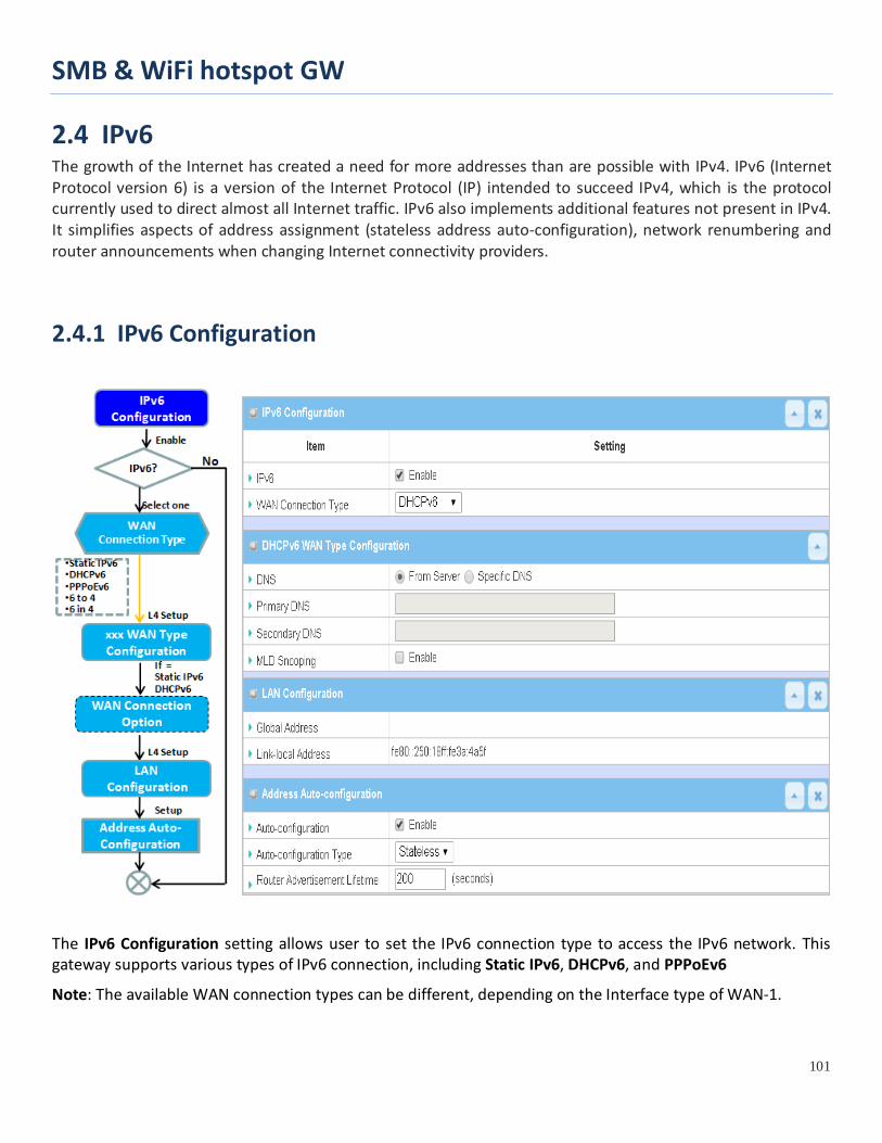
SMB & WiFi hotspot GW
101
2.4 IPv6 The growth of the Internet has created a need for more addresses than are possible with IPv4. IPv6 (Internet Protocol version 6) is a version of the Internet Protocol (IP) intended to succeed IPv4, which is the protocol currently used to direct almost all Internet traffic. IPv6 also implements additional features not present in IPv4. It simplifies aspects of address assignment (stateless address auto-configuration), network renumbering and router announcements when changing Internet connectivity providers.
2.4.1 IPv6 Configuration
The IPv6 Configuration setting allows user to set the IPv6 connection type to access the IPv6 network. This gateway supports various types of IPv6 connection, including Static IPv6, DHCPv6, and PPPoEv6
Note: The available WAN connection types can be different, depending on the Interface type of WAN-1.

SMB & WiFi hotspot GW
102
IPv6 WAN Connection Type
Static IPv6 Static IPv6 does the same function as static IPv4. The static IPv6 provides manual setting of IPv6 address, IPv6 default gateway address, and IPv6 DNS.
Above diagram depicts the IPv6 IP addressing, type in the information provided by your ISP to setup the IPv6 network.
DHCPv6 DHCP in IPv6 does the same function as DHCP in IPv4. The DHCP server sends IP address, DNS server addresses and other possible data to the DHCP client to configure automatically. The server also sends a lease time of the address and time to re-contact the server for IPv6 address renewal. The client has then to resend a request to renew the IPv6 address.
Above diagram depicts DHCP IPv6 IP addressing, the DHCPv6 server on the ISP side assigns IPv6 address, IPv6 default gateway address, and IPv6 DNS to client host’s automatically.

SMB & WiFi hotspot GW
103
PPPoEv6 PPPoEv6 in IPv6 does the same function as PPPoE in IPv4. The PPPoEv6 server provides configuration parameters based on PPPoEv6 client request. When PPPoEv6 server gets client request and successfully authenticates it, the server sends IP address, DNS server addresses and other required parameters to automatically configure the client.
The diagram above depicts the IPv6 addressing through PPPoE, PPPoEv6 server (DSLAM) on the ISP side provides IPv6 configuration upon receiving PPPoEv6 client request. When PPPoEv6 server gets client request and successfully authenticates it, the server sends IP address, DNS server addresses and other required parameters to automatically configure the client.

SMB & WiFi hotspot GW
104
IPv6 Configuration Setting
Go to Basic Network > IPv6 > Configuration Tab.
The IPv6 Configuration setting allows user to set the IPv6 connection type to access the IPv6 network.
IPv6 Configuration Item Value setting Description
IPv6 The box is unchecked by default, Check the Enable box to activate the IPv6 function.
WAN Connection Type
1. A Must filled setting 2. DHCPv6 is selected by default
Define the selected IPv6 WAN Connection Type to establish the IPv6 connectivity via WAN-1 Interface. Select Static IPv6 when your ISP provides you with a set IPv6 addresses. Select DHCPv6 when your ISP provides you with DHCPv6 services. Select PPPoEv6 when your ISP provides you with PPPoEv6 account settings. Note: The available WAN connection types can be different, depending on the Interface type of WAN-1.
Static IPv6 WAN Type Configuration
Static IPv6 WAN Type Configuration Item Value setting Description IPv6 Address A Must filled setting Enter the WAN IPv6 Address for the router. Subnet Prefix A Must filled setting Enter the WAN Subnet Prefix Length for the router.

SMB & WiFi hotspot GW
105
Length Default Gateway A Must filled setting Enter the WAN Default Gateway IPv6 address. Primary DNS An optional setting Enter the WAN primary DNS Server. Secondary DNS An optional setting Enter the WAN secondary DNS Server.
MLD Snooping The box is unchecked by default
Enable/Disable the MLD Snooping function
LAN Configuration
LAN Configuration Item Value setting Description Global Address A Must filled setting Enter the LAN IPv6 Address for the router. Link-local Address Value auto-created Show the link-local address for LAN interface of router.
Then go to Address Auto-configuration (summary) for setting LAN environment. If above setting is configured, click the Save button to save the configuration, and click the Reboot button to reboot the router.

SMB & WiFi hotspot GW
106
DHCPv6 WAN Type Configuration
DHCPv6 WAN Type Configuration Item Value setting Description
DNS The option [From Server] is selected by default
Select the [Specific DNS] option to active Primary DNS and Secondary DNS. Then fill the DNS information.
Primary DNS Can not modified by default Enter the WAN primary DNS Server.
Secondary DNS Can not modified by default Enter the WAN secondary DNS Server.
MLD The box is unchecked by default Enable/Disable the MLD Snooping function
LAN Configuration
LAN Configuration Item Value setting Description Global Address Value auto-created Enter the LAN IPv6 Address for the router. Link-local Address Value auto-created Show the link-local address for LAN interface of router.
Then go to Address Auto-configuration (summary) for setting LAN environment. If above setting is configured, click the Save button to save the configuration, and click Reboot button to reboot the router.

SMB & WiFi hotspot GW
107
PPPoEv6 WAN Type Configuration
PPPoEv6 WAN Type Configuration Item Value setting Description
Account A Must filled setting Enter the Account for setting up PPPoEv6 connection. If you want more information, please contact your ISP. Value Range: 0 ~ 45 characters.
Password A Must filled setting Enter the Password for setting up PPPoEv6 connection. If you want more information, please contact your ISP.
Service Name A Must filled setting/Option
Enter the Service Name for setting up PPPoEv6 connection. If you want more information, please contact your ISP. Value Range: 0 ~ 45 characters.
Connection Control Fixed value The value is Auto-reconnect(Always on).
MTU A Must filled setting Enter the MTU for setting up PPPoEv6 connection. If you want more information, please contact your ISP. Value Range: 1280 ~ 1492.
MLD Snooping The box is unchecked by default
Enable/Disable the MLD Snooping function
LAN Configuration
LAN Configuration Item Value setting Description Global Address Value auto-created The LAN IPv6 Address for the router. Link-local Address Value auto-created Show the link-local address for LAN interface of router.
Then go to Address Auto-configuration (summary) for setting LAN environment. If above setting is configured, click the save button to save the configuration and click reboot button to reboot the router.

SMB & WiFi hotspot GW
108
Then go to Address Auto-configuration (summary) for setting LAN environment. If above setting is configured, click the save button to save the configuration and click reboot button to reboot the router. Address Auto-configuration
Address Auto-configuration Item Value setting Description
Auto-configuration The box is unchecked by default
Check to enable the Auto configuration feature.
Auto-configuration Type
1. Only can be selected when Auto-configuration enabled 2. Stateless is selected by default
Define the selected IPv6 WAN Connection Type to establish the IPv6 connectivity. Select Stateless to manage the Local Area Network to be SLAAC + RDNSS Router Advertisement Lifetime (A Must filled setting): Enter the Router Advertisement Lifetime (in seconds). 200 is set by default. Value Range: 0 ~ 65535. Select Stateful to manage the Local Area Network to be Stateful (DHCPv6). IPv6 Address Range (Start) (A Must filled setting): Enter the start IPv6 Address for the DHCPv6 range for your local computers. 0100 is set by default. Value Range: 0001 ~ FFFF. IPv6 Address Range (End) (A Must filled setting): Enter the end IPv6 Address for the DHCPv6 range for your local computers. 0200 is set by default. Value Range: 0001 ~ FFFF. IPv6 Address Lifetime (A Must filled setting): Enter the DHCPv6 lifetime for your local computers. 36000 is set by default. Value Range: 0 ~ 65535.
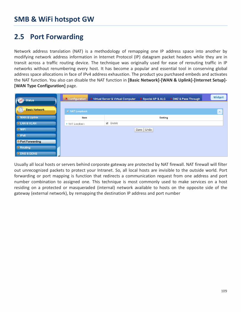
SMB & WiFi hotspot GW
109
2.5 Port Forwarding Network address translation (NAT) is a methodology of remapping one IP address space into another by modifying network address information in Internet Protocol (IP) datagram packet headers while they are in transit across a traffic routing device. The technique was originally used for ease of rerouting traffic in IP networks without renumbering every host. It has become a popular and essential tool in conserving global address space allocations in face of IPv4 address exhaustion. The product you purchased embeds and activates the NAT function. You also can disable the NAT function in [Basic Network]-[WAN & Uplink]-[Internet Setup]-[WAN Type Configuration] page.
Usually all local hosts or servers behind corporate gateway are protected by NAT firewall. NAT firewall will filter out unrecognized packets to protect your Intranet. So, all local hosts are invisible to the outside world. Port forwarding or port mapping is function that redirects a communication request from one address and port number combination to assigned one. This technique is most commonly used to make services on a host residing on a protected or masqueraded (internal) network available to hosts on the opposite side of the gateway (external network), by remapping the destination IP address and port number

SMB & WiFi hotspot GW
110
2.5.1 Configuration
NAT Loopback
This feature allows you to access the WAN global IP address from your inside NAT local network. It is useful when you run a server inside your network. For example, if you set a mail server at LAN side, your local devices can access this mail server through gateway’s global IP address when enable NAT loopback feature. On either side are you in accessing the email server, at the LAN side or at the WAN side, you don’t need to change the IP address of the mail server.
Configuration Setting
Go to Basic Network > Port Forwarding > Configuration tab.
The NAT Loopback allows user to access the WAN IP address from inside your local network.
Enable NAT Loopback
Configuration Item Value setting Description NAT Loopback The box is checked by default Check the Enable box to activate this NAT function Save N/A Click the Save button to save the settings. Undo N/A Click the Undo button to cancel the settings

SMB & WiFi hotspot GW
111
2.5.2 Virtual Server & Virtual Computer
There are some important Pot Forwarding functions implemented within the gateway, including "Virtual Server", "NAT loopback" and "Virtual Computer". It is necessary for cooperate staffs who travel outside and want to access various servers behind office gateway. You can set up those servers by using "Virtual Server" feature. After trip, if want to access those servers from LAN side by global IP, without change original setting, NAT Loopback can achieve it. "Virtual computer" is a host behind NAT gateway whose IP address is a global one and is visible to the outside world. Since it is behind NAT, it is protected by gateway firewall. To configure Virtual Computer, you just have to map the local IP of the virtual computer to a global IP.

SMB & WiFi hotspot GW
112
Virtual Server & NAT Loopback "Virtual Server" allows you to access servers with the global IP address or FQDN of the gateway as if they are servers existed in the Internet. But in fact, these servers are located in the Intranet and are physically behind the gateway. The gateway serves the service requests by port forwarding the requests to the LAN servers and transfers the replies from LAN servers to the requester on the WAN side. As shown in example, an E-mail virtual server is defined to be located at a server with IP address 10.0.75.101 in the Intranet of Network-A, including SMTP service port 25 and POP3 service port 110. So, the remote user can access the E-mail server with the
gateway’s global IP 118.18.81.33 from its WAN side. But the real E-mail server is located at LAN side and the gateway is the port forwarder for E-mail service.
NAT Loopback allows you to access the WAN global IP address from your inside NAT local network. It is useful when you run a server inside your network. For example, if you set a mail server at LAN side, your local devices can access this mail server through gateway’s global IP address when enable NAT loopback feature. On either side are you in accessing the email server, at the LAN side or at the WAN side, you don’t need to change the IP address of the mail server.
Virtual Computer
"Virtual Computer" allows you to assign LAN hosts to global IP addresses, so that they can be visible to outside world. While so, they are also protected by the gateway firewall as being client hosts in the Intranet. For example, if you set a FTP file server at LAN side with local IP address 10.0.75.102 and global IP address 118.18.82.44, a remote user can access the file server while it is hidden behind the NAT gateway. That is because the gateway takes care of all accessing to the IP address 118.18.82.44, including to forward the access requests to the file server and to send the replies from the server to outside world.
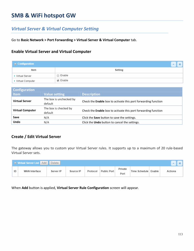
SMB & WiFi hotspot GW
113
Virtual Server & Virtual Computer Setting
Go to Basic Network > Port Forwarding > Virtual Server & Virtual Computer tab.
Enable Virtual Server and Virtual Computer
Configuration Item Value setting Description
Virtual Server The box is unchecked by default
Check the Enable box to activate this port forwarding function
Virtual Computer The box is checked by default
Check the Enable box to activate this port forwarding function
Save N/A Click the Save button to save the settings. Undo N/A Click the Undo button to cancel the settings.
Create / Edit Virtual Server
The gateway allows you to custom your Virtual Server rules. It supports up to a maximum of 20 rule-based Virtual Server sets.
When Add button is applied, Virtual Server Rule Configuration screen will appear.
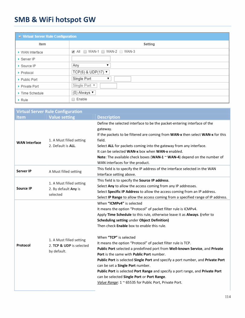
SMB & WiFi hotspot GW
114
Virtual Server Rule Configuration Item Value setting Description
WAN Interface 1. A Must filled setting 2. Default is ALL.
Define the selected interface to be the packet-entering interface of the gateway. If the packets to be filtered are coming from WAN-x then select WAN-x for this field. Select ALL for packets coming into the gateway from any interface. It can be selected WAN-x box when WAN-x enabled. Note: The available check boxes (WAN-1 ~ WAN-4) depend on the number of WAN interfaces for the product.
Server IP A Must filled setting This field is to specify the IP address of the interface selected in the WAN Interface setting above.
Source IP 1. A Must filled setting 2. By default Any is selected
This field is to specify the Source IP address. Select Any to allow the access coming from any IP addresses. Select Specific IP Address to allow the access coming from an IP address. Select IP Range to allow the access coming from a specified range of IP address.
Protocol 1. A Must filled setting 2. TCP & UDP is selected by default.
When “ICMPv4” is selected It means the option “Protocol” of packet filter rule is ICMPv4. Apply Time Schedule to this rule, otherwise leave it as Always. (refer to Scheduling setting under Object Definition) Then check Enable box to enable this rule. When “TCP” is selected It means the option “Protocol” of packet filter rule is TCP. Public Port selected a predefined port from Well-known Service, and Private Port is the same with Public Port number. Public Port is selected Single Port and specify a port number, and Private Port can be set a Single Port number. Public Port is selected Port Range and specify a port range, and Private Port can be selected Single Port or Port Range. Value Range: 1 ~ 65535 for Public Port, Private Port.

SMB & WiFi hotspot GW
115
When “UDP” is selected It means the option “Protocol” of packet filter rule is UDP. Public Port selected a predefined port from Well-known Service, and Private Port is the same with Public Port number. Public Port is selected Single Port and specify a port number, and Private Port can be set a Single Port number. Public Port is selected Port Range and specify a port range, and Private Port can be selected Single Port or Port Range. Value Range: 1 ~ 65535 for Public Port, Private Port. When “TCP & UDP” is selected It means the option “Protocol” of packet filter rule is TCP and UDP. Public Port selected a predefined port from Well-known Service, and Private Port is the same with Public Port number. Public Port is selected Single Port and specify a port number, and Private Port can be set a Single Port number. Public Port is selected Port Range and specify a port range, and Private Port can be selected Single Port or Port Range. Value Range: 1 ~ 65535 for Public Port, Private Port. When “GRE” is selected It means the option “Protocol” of packet filter rule is GRE. When “ESP” is selected It means the option “Protocol” of packet filter rule is ESP. When “SCTP” is selected It means the option “Protocol” of packet filter rule is SCTP. When “User-defined” is selected It means the option “Protocol” of packet filter rule is User-defined. For Protocol Number, enter a port number.
Time Schedule 1. An optional filled setting 2. (0) Always Is selected by default.
Apply Time Schedule to this rule; otherwise leave it as (0) Always. (refer to Scheduling setting under Object Definition)
Rule 1. An optional filled setting 2.The box is unchecked by default.
Check the Enable box to activate the rule.
Save N/A Click the Save button to save the settings. Undo N/A Click the X button to cancel the settings and return to previous page.
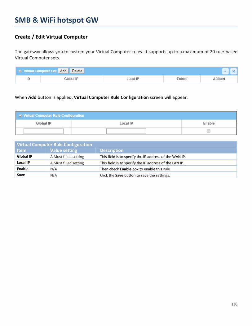
SMB & WiFi hotspot GW
116
Create / Edit Virtual Computer
The gateway allows you to custom your Virtual Computer rules. It supports up to a maximum of 20 rule-based Virtual Computer sets.
When Add button is applied, Virtual Computer Rule Configuration screen will appear.
Virtual Computer Rule Configuration Item Value setting Description Global IP A Must filled setting This field is to specify the IP address of the WAN IP. Local IP A Must filled setting This field is to specify the IP address of the LAN IP. Enable N/A Then check Enable box to enable this rule. Save N/A Click the Save button to save the settings.

SMB & WiFi hotspot GW
117
2.5.3 DMZ & Pass Through DMZ (De Militarized Zone) Host is a host that is exposed to the Internet cyberspace but still within the protection of firewall by gateway device. So, the function allows a computer to execute 2-way communication for Internet games, Video conferencing, Internet telephony and other special applications. In some cases when a specific application is blocked by NAT mechanism, you can indicate that LAN computer as a DMZ host to solve this problem.
The DMZ function allows you to ask the gateway pass through all normal packets to the DMZ host behind the NAT gateway only when these packets are not expected to receive by applications in the gateway or by other client hosts in the Intranet. Certainly, the DMZ host is also protected by the gateway firewall. Activate the feature and specify the DMZ host with a host in the Intranet when needed.
DMZ Scenario When the network administrator wants to set up some service daemons in a host behind NAT gateway to allow remote users request for services from server actively, you just have to configure this host as DMZ Host. As shown in the diagram, there is an X server installed as DMZ host, whose IP address is 10.0.75.100. Then, remote user can request services from X server just as it is provided by the gateway whose global IP address is 118.18.81.33. The gateway will forward those packets, not belonging to any configured virtual server or applications, directly to the DMZ host.

SMB & WiFi hotspot GW
118
VPN Pass through Scenario Since VPN traffic is different from that of TCP or UDP connection, it will be blocked by NAT gateway. To support the pass through function for the VPN connections initiating from VPN clients behind NAT gateway, the gateway must implement some kind of VPN pass through function for such application. The gateway support the pass through function for IPSec, PPTP, and L2TP connections, you just have to check the corresponding checkbox to activate it.
DMZ & Pass Through Setting
Go to Basic Network > Port Forwarding > DMZ & Pass Through tab.
The DMZ host is a host that is exposed to the Internet cyberspace but still within the protection of firewall by gateway device.
Enable DMZ and Pass Through
Configuration Item Value setting Description DMZ 1. A Must filled setting
2. Default is ALL. Check the Enable box to activate the DMZ function Define the selected interface to be the packet-entering interface of the gateway, and fill in the IP address of Host LAN IP in DMZ Host field . If the packets to be filtered are coming from WAN-x then select WAN-x for this field. Select ALL for packets coming into the router from any interfaces. It can be selected WAN-x box when WAN-x enabled.

SMB & WiFi hotspot GW
119
Note: The available check boxes (WAN-1 ~ WAN-4) depend on the number of WAN interfaces for the product.
Pass Through Enable The boxes are checked by default
Check the box to enable the pass through function for the IPSec, PPTP, and L2TP. With the pass through function enabled, the VPN hosts behind the gateway still can connect to remote VPN servers.
Save N/A Click the Save button to save the settings. Undo N/A Click the Undo button to cancel the settings

SMB & WiFi hotspot GW
120
2.5.4 Special AP & ALG (not supported) Not supported feature for the purchased product, leave it as blank.

SMB & WiFi hotspot GW
121
2.5.5 IP Translation IP Translation is slimier to One-to-One NAT. it is a feature where you can configure the gateway with multiple IP addresses issued by your Internet Service Provider (ISP) and map them to individual intranet devices with specific IP addresses. That is, configuring the IP Translation feature creates a one-to-one mapping between a public IP address and a private IP address of a local host. In addition, admin users also map a private IP address range to a public IP address range of equal instances.
This feature offers another way to make systems behind a firewall and configured with private IP addresses appear to have public IP addresses.
As shown in above configuration settings for the VPN gateway at Control Center, the Admin user can access the DNS Server with mapped IP 1.1.1.8, instead of its real IP 8.8.8.8; and he can also access (or manage) the remote IPCams with mapped IP 1.1.1.201 and 1.1.1.202, instead of their real IP 192.168.123.xxx.

SMB & WiFi hotspot GW
122
IP Translation Setting
Go to Basic Network > Port Forwarding > IP Translation tab.
Enable IP Translation
Configuration Item Value setting Description IP Translation The box is unchecked by
default Check the Enable box to activate the IP translation function
Save N/A Click the Save button to save the settings.
Create / Edit IP Translation Rule
When Add button is applied, IP Translation Configuration screen will appear.
IP Translation Configuration Item Value setting Description Mapping Source IP/Domain Name
1. A Must filled setting 2.IP is selected by default.
Specify the mapped IP / Domain Name that will be issued from the hosts behind the NAT gateway. The NAT gateway will translate the specified source IP/Domain Name into other real IP / Domain Name that might be in the Internet or Intranet.
Mask 1. A Must filled setting 2.255.255.255.255(/32) is
Enter the required subnet mask if Source IP is specified above. It can be a single IP with 255.255.255.255 (/32) subnet mask, or an IP group
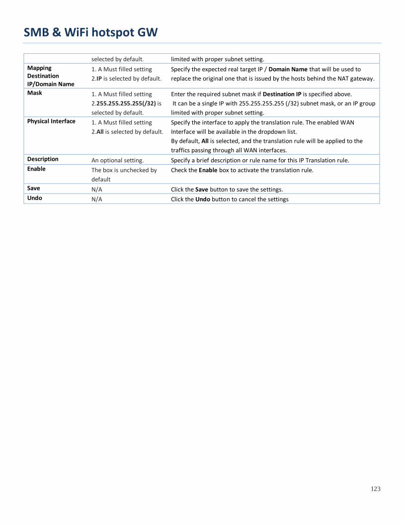
SMB & WiFi hotspot GW
123
selected by default. limited with proper subnet setting. Mapping Destination IP/Domain Name
1. A Must filled setting 2.IP is selected by default.
Specify the expected real target IP / Domain Name that will be used to replace the original one that is issued by the hosts behind the NAT gateway.
Mask 1. A Must filled setting 2.255.255.255.255(/32) is selected by default.
Enter the required subnet mask if Destination IP is specified above. It can be a single IP with 255.255.255.255 (/32) subnet mask, or an IP group limited with proper subnet setting.
Physical Interface 1. A Must filled setting 2.All is selected by default.
Specify the interface to apply the translation rule. The enabled WAN Interface will be available in the dropdown list. By default, All is selected, and the translation rule will be applied to the traffics passing through all WAN interfaces.
Description An optional setting. Specify a brief description or rule name for this IP Translation rule. Enable The box is unchecked by
default Check the Enable box to activate the translation rule.
Save N/A Click the Save button to save the settings. Undo N/A Click the Undo button to cancel the settings
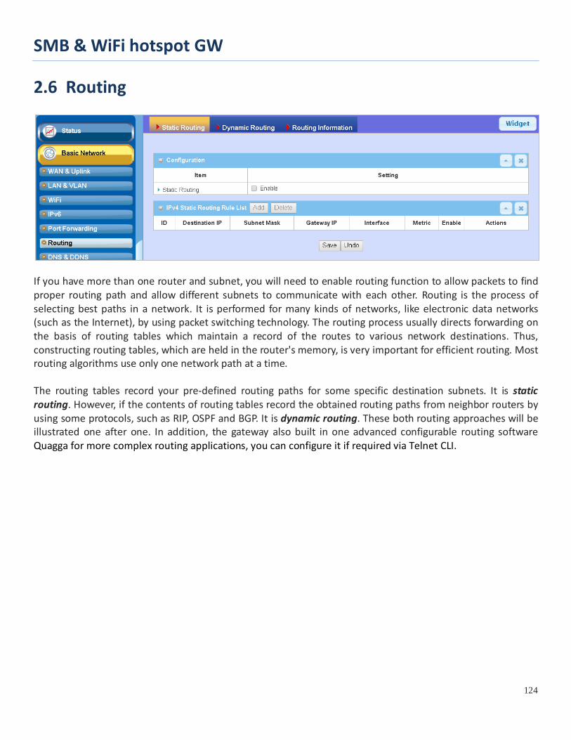
SMB & WiFi hotspot GW
124
2.6 Routing
If you have more than one router and subnet, you will need to enable routing function to allow packets to find proper routing path and allow different subnets to communicate with each other. Routing is the process of selecting best paths in a network. It is performed for many kinds of networks, like electronic data networks (such as the Internet), by using packet switching technology. The routing process usually directs forwarding on the basis of routing tables which maintain a record of the routes to various network destinations. Thus, constructing routing tables, which are held in the router's memory, is very important for efficient routing. Most routing algorithms use only one network path at a time. The routing tables record your pre-defined routing paths for some specific destination subnets. It is static routing. However, if the contents of routing tables record the obtained routing paths from neighbor routers by using some protocols, such as RIP, OSPF and BGP. It is dynamic routing. These both routing approaches will be illustrated one after one. In addition, the gateway also built in one advanced configurable routing software Quagga for more complex routing applications, you can configure it if required via Telnet CLI.

SMB & WiFi hotspot GW
125
2.6.1 Static Routing
"Static Routing" function lets you define the routing paths for some dedicated hosts/servers or subnets to store in the routing table of the gateway. The gateway routes incoming packets to different peer gateways based on the routing table. You need to define the static routing information in gateway routing rule list.
When the administrator of the gateway wants to specify what kinds of packets to be transferred via which gateway interface and which peer gateway to their destination. It can be carried out by the "Static Routing" feature. Dedicated packet flows from the Intranet will be routed to their destination via the pre-defined peer gateway and corresponding gateway interface that are defined in the system routing table by manual.
As shown in the diagram, when the destination is Google access, rule 1 set interface as ADSL, routing gateway as IP-DSLAM gateway 192.168.121.253. All the packets to Google will go through WAN-1. And the same way applied to rule 2 of access Yahoo. Rule 2 sets 3G/4G as interface.

SMB & WiFi hotspot GW
126
Static Routing Setting
Go to Basic Network > Routing > Static Routing Tab.
There are three configuration windows for static routing feature, including "Configuration", "Static Routing Rule List" and "Static Routing Rule Configuration" windows. "Configuration" window lets you activate the global static routing feature. Even there are already routing rules, if you want to disable routing temporarily, just uncheck the Enable box to disable it. "Static Routing Rule List" window lists all your defined static routing rule entries. Using "Add" or "Edit" button to add and create one new static routing rule or to modify an existed one.
When "Add" or "Edit" button is applied, the "Static Routing Rule Configuration" window will appear to let you define a static routing rule.
Enable Static Routing
Just check the Enable box to activate the "Static Routing" feature.
Static Routing Item Value setting Description
Static Routing The box is unchecked by default
Check the Enable box to activate this function
Create / Edit Static Routing Rules The Static Routing Rule List shows the setup parameters of all static routing rule entries. To configure a static routing rule, you must specify related parameters including the destination IP address and subnet mask of dedicated host/server or subnet, the IP address of peer gateway, the metric and the rule activation.
The gateway allows you to custom your static routing rules. It supports up to a maximum of 64 rule sets. When Add button is applied, Static Routing Rule Configuration screen will appear, while the Edit button at the end
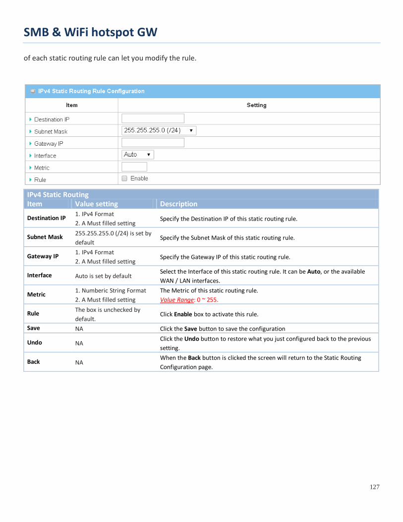
SMB & WiFi hotspot GW
127
of each static routing rule can let you modify the rule.
IPv4 Static Routing Item Value setting Description
Destination IP 1. IPv4 Format 2. A Must filled setting
Specify the Destination IP of this static routing rule.
Subnet Mask 255.255.255.0 (/24) is set by default
Specify the Subnet Mask of this static routing rule.
Gateway IP 1. IPv4 Format 2. A Must filled setting
Specify the Gateway IP of this static routing rule.
Interface Auto is set by default Select the Interface of this static routing rule. It can be Auto, or the available WAN / LAN interfaces.
Metric 1. Numberic String Format 2. A Must filled setting
The Metric of this static routing rule. Value Range: 0 ~ 255.
Rule The box is unchecked by default.
Click Enable box to activate this rule.
Save NA Click the Save button to save the configuration
Undo NA Click the Undo button to restore what you just configured back to the previous setting.
Back NA When the Back button is clicked the screen will return to the Static Routing Configuration page.

SMB & WiFi hotspot GW
128
2.6.2 Dynamic Routing
Dynamic Routing, also called adaptive routing, describes the capability of a system, through which routes are characterized by their destination, to alter the path that the route takes through the system in response to a change in network conditions.
This gateway supports dynamic routing protocols, including RIPv1/RIPv2 (Routing Information Protocol), OSPF (Open Shortest Path First), and BGP (Border Gateway Protocol), for you to establish routing table automatically. The feature of dynamic routing will be very useful when there are lots of subnets in your network. Generally speaking, RIP is suitable for small network. OSPF is more suitable for medium network. BGP is more used for big network infrastructure.
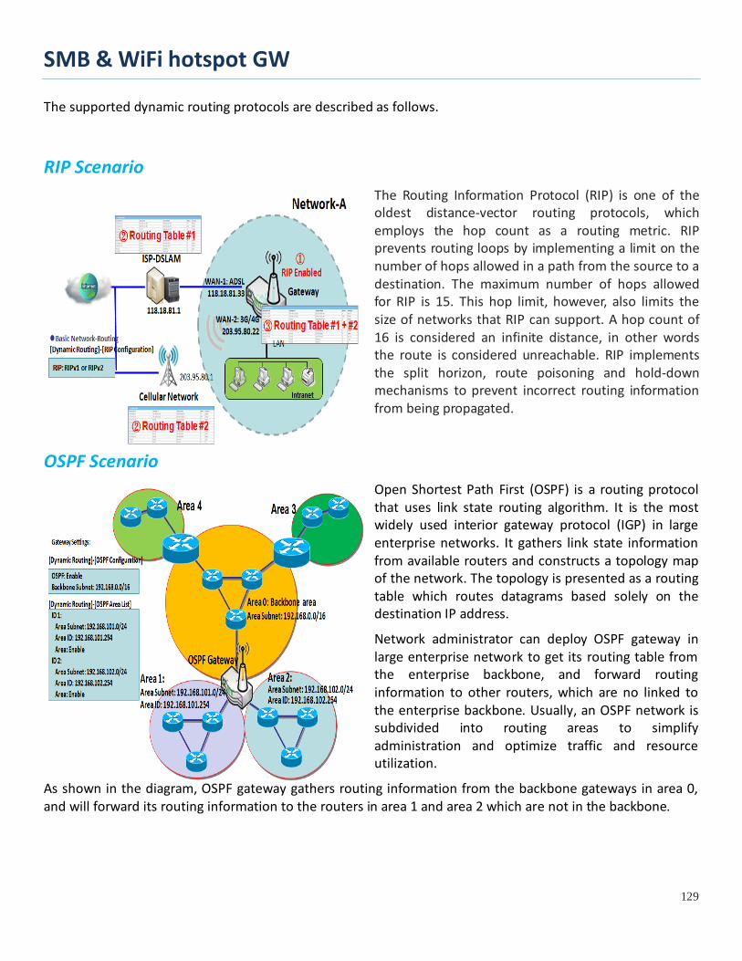
SMB & WiFi hotspot GW
129
The supported dynamic routing protocols are described as follows.
RIP Scenario The Routing Information Protocol (RIP) is one of the oldest distance-vector routing protocols, which employs the hop count as a routing metric. RIP prevents routing loops by implementing a limit on the number of hops allowed in a path from the source to a destination. The maximum number of hops allowed for RIP is 15. This hop limit, however, also limits the size of networks that RIP can support. A hop count of 16 is considered an infinite distance, in other words the route is considered unreachable. RIP implements the split horizon, route poisoning and hold-down mechanisms to prevent incorrect routing information from being propagated.
OSPF Scenario Open Shortest Path First (OSPF) is a routing protocol that uses link state routing algorithm. It is the most widely used interior gateway protocol (IGP) in large enterprise networks. It gathers link state information from available routers and constructs a topology map of the network. The topology is presented as a routing table which routes datagrams based solely on the destination IP address.
Network administrator can deploy OSPF gateway in large enterprise network to get its routing table from the enterprise backbone, and forward routing information to other routers, which are no linked to the enterprise backbone. Usually, an OSPF network is subdivided into routing areas to simplify administration and optimize traffic and resource utilization.
As shown in the diagram, OSPF gateway gathers routing information from the backbone gateways in area 0, and will forward its routing information to the routers in area 1 and area 2 which are not in the backbone.

SMB & WiFi hotspot GW
130
BGP Scenario Border Gateway Protocol (BGP) is a standard exterior gateway protocol designed to exchange routing and reachability information between autonomous systems (AS) on the Internet. It usually makes routing decisions based on paths, network policies, or rule-sets.
Most ISPs use BGP to establish routing between one another (especially for multi-homed). Very large private IP networks also use BGP internally. The major BGP gateway within one AS will links with some other border gateways for exchanging routing information. It will distribute the collected data in AS to all routers in other AS.
As shown in the diagram, BGP 0 is gateway to dominate AS0 (self IP is 10.100.0.1 and self ID is 100). It links with other BGP gateways in the Internet. The scenario is like Subnet in one ISP to be linked with the ones in other ISPs. By operating with BGP protocol, BGP 0 can gather routing information from other BGP gateways in the Internet. And then it forwards the routing data to the routers in its dominated AS. Finally, the routers resided in AS 0 know how to route packets to other AS.

SMB & WiFi hotspot GW
131
Dynamic Routing Setting
Go to Basic Network > Routing > Dynamic Routing Tab.
The dynamic routing setting allows user to customize RIP, OSPF, and BGP protocol through the router based on their office setting.
In the "Dynamic Routing" page, there are several configuration windows for dynamic routing feature. They are the "RIP Configuration" window, "OSPF Configuration" window, "OSPF Area List", "OSPF Area Configuration", "BGP Configuration", "BGP Neighbor List" and "BGP Neighbor Configuration" window. RIP, OSPF and BGP protocols can be configured individually.
The "RIP Configuration" window lets you choose which version of RIP protocol to be activated or disable it. The "OSPF Configuration" window can let you activate the OSPF dynamic routing protocol and specify its backbone subnet. Moreover, the "OSPF Area List" window lists all defined areas in the OSPF network. However, the "BGP Configuration" window can let you activate the BGP dynamic routing protocol and specify its self ID. The "BGP Neighbor List" window lists all defined neighbors in the BGP network.
RIP Configuration The RIP configuration setting allows user to customize RIP protocol through the router based on their office setting.
RIP Configuration Item Value setting Description
RIP Enable Disable is set by default Select Disable will disable RIP protocol. Select RIP v1 will enable RIPv1 protocol. Select RIP v2 will enable RIPv2 protocol.
OSPF Configuration
The OSPF configuration setting allows user to customize OSPF protocol through the router based on their office setting.
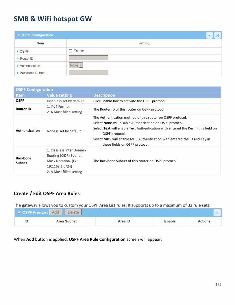
SMB & WiFi hotspot GW
132
OSPF Configuration Item Value setting Description OSPF Disable is set by default Click Enable box to activate the OSPF protocol.
Router ID 1. IPv4 Format 2. A Must filled setting
The Router ID of this router on OSPF protocol
Authentication None is set by default
The Authentication method of this router on OSPF protocol. Select None will disable Authentication on OSPF protocol. Select Text will enable Text Authentication with entered the Key in this field on
OSPF protocol. Select MD5 will enable MD5 Authentication with entered the ID and Key in
these fields on OSPF protocol.
Backbone Subnet
1. Classless Inter Domain Routing (CIDR) Subnet Mask Notation. (Ex: 192.168.1.0/24) 2. A Must filled setting
The Backbone Subnet of this router on OSPF protocol.
Create / Edit OSPF Area Rules The gateway allows you to custom your OSPF Area List rules. It supports up to a maximum of 32 rule sets.
When Add button is applied, OSPF Area Rule Configuration screen will appear.
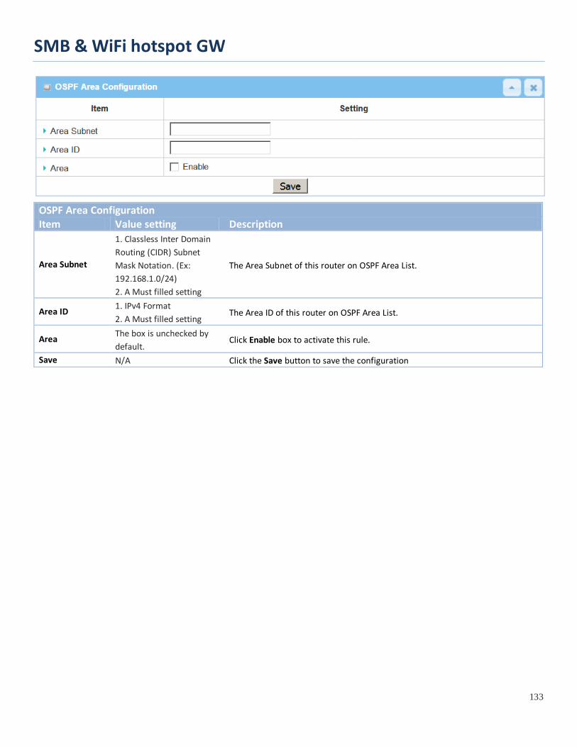
SMB & WiFi hotspot GW
133
OSPF Area Configuration Item Value setting Description
Area Subnet
1. Classless Inter Domain Routing (CIDR) Subnet Mask Notation. (Ex: 192.168.1.0/24) 2. A Must filled setting
The Area Subnet of this router on OSPF Area List.
Area ID 1. IPv4 Format 2. A Must filled setting
The Area ID of this router on OSPF Area List.
Area The box is unchecked by default.
Click Enable box to activate this rule.
Save N/A Click the Save button to save the configuration

SMB & WiFi hotspot GW
134
BGP Configuration
The BGP configuration setting allows user to customize BGP protocol through the router setting.
BGP Network Configuration Item Value setting Description BGP The box is unchecked by
default Check the Enable box to activate the BGP protocol.
ASN 1. Numberic String Format 2. A Must filled setting
The ASN Number of this router on BGP protocol. Value Range: 1 ~ 4294967295.
Router ID 1. IPv4 Format 2. A Must filled setting
The Router ID of this router on BGP protocol.
Create / Edit BGP Network Rules
The gateway allows you to custom your BGP Network rules. It supports up to a maximum of 32 rule sets.
When Add button is applied, BGP Network Configuration screen will appear.
Item Value setting Description
Network Subnet 1. IPv4 Format 2. A Must filled setting
The Network Subnet of this router on BGP Network List. It composes of entered the IP address in this field and the selected subnet mask.

SMB & WiFi hotspot GW
135
Network The box is unchecked by default.
Click Enable box to activate this rule.
Save N/A Click the Save button to save the configuration
Create / Edit BGP Neighbor Rules
The gateway allows you to custom your BGP Neighbor rules. It supports up to a maximum of 32 rule sets.
When Add button is applied, BGP Neighbor Configuration screen will appear.
BGP Neighbor Configuration Item Value setting Description
Neighbor IP 1. IPv4 Format 2. A Must filled setting
The Neighbor IP of this router on BGP Neighbor List.
Remote ASN 1. Numberic String Format 2. A Must filled setting
The Remote ASN of this router on BGP Neighbor List. Value Range: 1 ~ 4294967295.
Neighbor The box is unchecked by default.
Click Enable box to activate this rule.
Save N/A Click the Save button to save the configuration

SMB & WiFi hotspot GW
136
2.6.3 Routing Information The routing information allows user to view the routing table and policy routing information. Policy Routing Information is only available when the Load Balance function is enabled and the Load Balance Strategy is By User Policy.
Go to Basic Network > Routing > Routing Information Tab.
Routing Table Item Value setting Description Destination IP N/A Routing record of Destination IP. IPv4 Format. Subnet Mask N/A Routing record of Subnet Mask. IPv4 Format. Gateway IP N/A Routing record of Gateway IP. IPv4 Format. Metric N/A Routing record of Metric. Numeric String Format. Interface N/A Routing record of Interface Type. String Format.
Policy Routing Information Item Value setting Description Policy Routing Source N/A Policy Routing of Source. String Format. Source IP N/A Policy Routing of Source IP. IPv4 Format. Destination IP N/A Policy Routing of Destination IP. IPv4 Format. Destination Port N/A Policy Routing of Destination Port. String Format. WAN Interface N/A Policy Routing of WAN Interface. String Format.

SMB & WiFi hotspot GW
137
2.7 DNS & DDNS How does user access your server if your WAN IP address changes all the time? One way is to register a new domain name, and maintain your own DNS server. Another simpler way is to apply a domain name to a third-party DDNS service provider. The service can be free or charged. If you want to understand the basic concepts of DNS and Dynamic DNS, you can refer to Wikipedia website7,8.
2.7.1 DNS & DDNS Configuration
Dynamic DNS To host your server on a changing IP address, you have to use dynamic domain name service (DDNS). Therefore, anyone wishing to reach your host only needs to know the domain name. Dynamic DNS will map the name of your host to your current IP address, which changes each time you connect your Internet service provider.
The Dynamic DNS service allows the gateway to alias a public dynamic IP address to a static domain name, allowing the gateway to be more easily accessed from various locations on the Internet. As shown in the diagram, user registered a domain name to a
third-party DDNS service provider (NO-IP) to use DDNS function. Once the IP address of designated WAN interface has changed, the dynamic DNS agent in the gateway will inform the DDNS server with the new IP address. The server automatically re-maps your domain name with the changed IP address. So, other hosts or remote users in the Internet world are able to link to your gateway by using your domain name regardless of the changing global IP address.
7 http://en.wikipedia.org/wiki/Domain_Name_System 8 http://en.wikipedia.org/wiki/Dynamic_DNS

SMB & WiFi hotspot GW
138
DNS & DDNS Setting
Go to Basic Network > DNS & DDNS > Configuration Tab.
The DNS & DDNS setting allows user to setup Dynamic DNS feature and DNS redirect rules.
Setup Dynamic DNS
The gateway allows you to custom your Dynamic DNS settings.
DDNS (Dynamic DNS) Configuration Item Value setting Description
DDNS The box is unchecked by default
Check the Enable box to activate this function.
WAN Interface WAN 1 is set by default Select the WAN Interface IP Address of the gateway.
Provider DynDNS.org (Dynamic) is set by default
Select your DDNS provider of Dynamic DNS. It can be DynDNS.org(Dynamic), DynDNS.org(Custom), NO-IP.com, etc...
Host Name 1. String format can be any text 2. A Must filled setting
Your registered host name of Dynamic DNS. Value Range: 0 ~ 63 characters.
User Name / E-Mail
1. String format can be any text 2. A Must filled setting
Enter your User name or E-mail addresss of Dynamic DNS.
Password / Key 1. String format can be any text 2. A Must filled setting
Enter your Password or Key of Dynamic DNS.
Save N/A Click Save to save the settings Undo N/A Click Undo to cancel the settings

SMB & WiFi hotspot GW
139
Setup DNS Redirect DNS redirect is a special function to redirect certain traffics to a specified host. Administator can manage the internet / intranet traffics that are going to access some restricted DNS and force those traffics to be redirected to a specified host.
DNS Redirect Configuration Item Value setting Description
DNS Redirect The box is unchecked by default
Check the Enable box to activate this function.
Save N/A Click Save to save the settings Undo N/A Click Undo to cancel the settings
If you enabled the DNS Redirect function, you have to further specify the redirect rules. According to the rules, the gateway can redirect the traffic that matched the DNS to corresponding pre-defined IP address.
When Add button is applied, Redirect Rule screen will appear.
Redirect Rule Configuration Item Value setting Description
Domain Name 1. String format can be any text
Enter a domain name to be redirect. The traffic to specified domain name will be redirect to the following IP address.

SMB & WiFi hotspot GW
140
2. A Must filled setting Value Range: at least 1 character is required; ‘*’ for any.
IP 1. IPv4 format 2. A Must filled setting
Enter an IP Address as the target for the DNS redirect.
Condition 1. A Must filled setting 2. Always is selected by default.
Specify when will the DNS redirect action can be applied. It can be Always, or WAN Block. Always: The DNS redirect function can be applied to matched DNS all the time. WAN Block: The DNS redirect function can be applied to matched DNS only when the WAN connection is disconneced, or un-reachable.
Description 1. String format can be any text 2. A Must filled setting
Enter a brief description for this rule. Value Range: 0 ~ 63 characters.
Enable The box is unchecked by default
Click the Enable button to activate this rule.
Save N/A Click Save to save the settings Undo N/A Click Undo to cancel the settings

SMB & WiFi hotspot GW
141
2.8 QoS The total amount of data traffic increases nowadays as the higher demand of mobile applications, like Game / Chat / VoIP / P2P / Video / Web access. In order to pose new requirements for data transport, e.g. low latency, low data loss, the entire network must ensure them via a connection service guarantee.
The main goal of QoS (Quality of Service) is prioritizing incoming data, and preventing data loss due to factors such as jitter, delay and dropping. Another important aspect of QoS is ensuring that prioritizing one data flow doesn’t interfere with other data flows. So, QoS helps to prioritize data as it enters your router. By attaching special identification marks or headers to incoming packets, QoS determines which queue the packets enter, based on priority. This is useful when there are certain types of data you want to give higher priority to, such as voice packets given higher priority than Web data packets.
To utilize your network throughput completely, administrator must define bandwidth control rules carefully to balance the utilization of network bandwidth for all users to access. It is indeed required that an access gateway satisfies the requirements of latency-critical applications, minimum access right guarantee, fair bandwidth usage for same subscribed condition and flexible bandwidth management. AMIT Security Gateway provides a Rule-based QoS to carry out the requirements.
2.8.1 QoS Configuration This gateway provides lots of flexible rules for you to set QoS policies. Basically, you need to know three parts of information before you create your own policies. First, “who” needs to be managed? Second, “what” kind of service needs to be managed? The last part is “how” you prioritize. Once you have this information, you can continue to learn functions in this section in more detail.
QoS Rule Configuration
When you want to add a new QoS rule or edit one already existed, the "QoS Rule Configuration" window shows up for you to configure. The parameters in a rule include the applied WAN interfaces, the dedicated host group based on MAC address or IP address, the dedicated kind of service packets, the system resource to be distributed, the corresponding control function for your specified resource, the packet flow direction, the sharing method for the control function, the integrated time schedule rule and the rule activation. Following diagram illustrates how to organize a QoS rule.
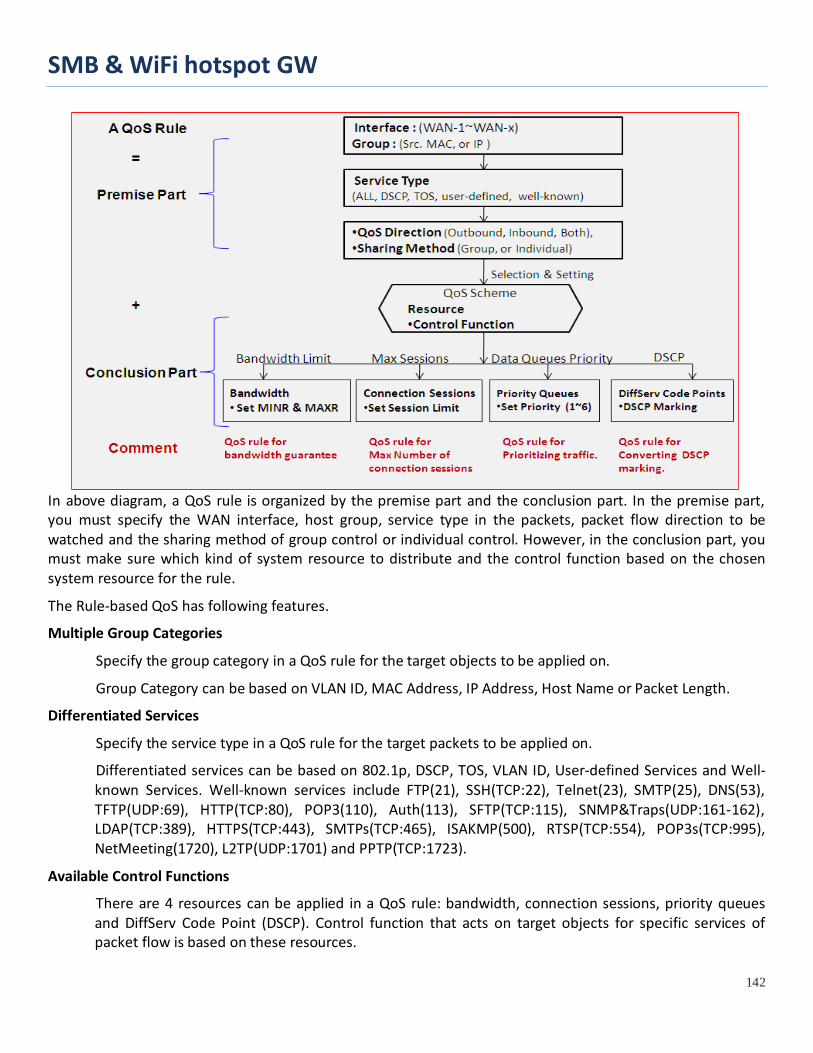
SMB & WiFi hotspot GW
142
In above diagram, a QoS rule is organized by the premise part and the conclusion part. In the premise part, you must specify the WAN interface, host group, service type in the packets, packet flow direction to be watched and the sharing method of group control or individual control. However, in the conclusion part, you must make sure which kind of system resource to distribute and the control function based on the chosen system resource for the rule.
The Rule-based QoS has following features.
Multiple Group Categories
Specify the group category in a QoS rule for the target objects to be applied on.
Group Category can be based on VLAN ID, MAC Address, IP Address, Host Name or Packet Length.
Differentiated Services
Specify the service type in a QoS rule for the target packets to be applied on.
Differentiated services can be based on 802.1p, DSCP, TOS, VLAN ID, User-defined Services and Well-known Services. Well-known services include FTP(21), SSH(TCP:22), Telnet(23), SMTP(25), DNS(53), TFTP(UDP:69), HTTP(TCP:80), POP3(110), Auth(113), SFTP(TCP:115), SNMP&Traps(UDP:161-162), LDAP(TCP:389), HTTPS(TCP:443), SMTPs(TCP:465), ISAKMP(500), RTSP(TCP:554), POP3s(TCP:995), NetMeeting(1720), L2TP(UDP:1701) and PPTP(TCP:1723).
Available Control Functions
There are 4 resources can be applied in a QoS rule: bandwidth, connection sessions, priority queues and DiffServ Code Point (DSCP). Control function that acts on target objects for specific services of packet flow is based on these resources.
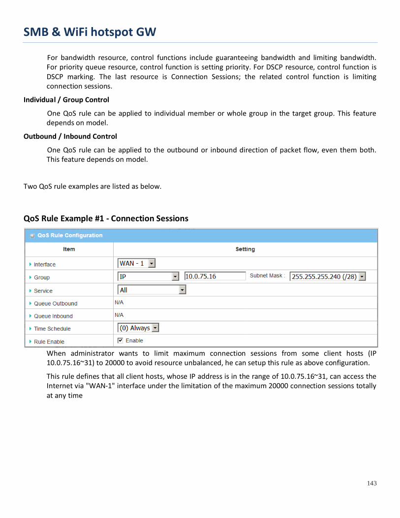
SMB & WiFi hotspot GW
143
For bandwidth resource, control functions include guaranteeing bandwidth and limiting bandwidth. For priority queue resource, control function is setting priority. For DSCP resource, control function is DSCP marking. The last resource is Connection Sessions; the related control function is limiting connection sessions.
Individual / Group Control
One QoS rule can be applied to individual member or whole group in the target group. This feature depends on model.
Outbound / Inbound Control
One QoS rule can be applied to the outbound or inbound direction of packet flow, even them both. This feature depends on model.
Two QoS rule examples are listed as below.
QoS Rule Example #1 - Connection Sessions
When administrator wants to limit maximum connection sessions from some client hosts (IP 10.0.75.16~31) to 20000 to avoid resource unbalanced, he can setup this rule as above configuration.
This rule defines that all client hosts, whose IP address is in the range of 10.0.75.16~31, can access the Internet via "WAN-1" interface under the limitation of the maximum 20000 connection sessions totally at any time
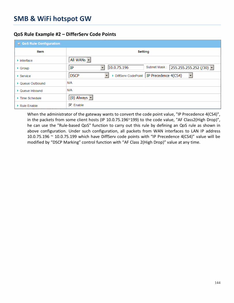
SMB & WiFi hotspot GW
144
QoS Rule Example #2 – DifferServ Code Points
When the administrator of the gateway wants to convert the code point value, "IP Precedence 4(CS4)", in the packets from some client hosts (IP 10.0.75.196~199) to the code value, "AF Class2(High Drop)", he can use the "Rule-based QoS" function to carry out this rule by defining an QoS rule as shown in above configuration. Under such configuration, all packets from WAN interfaces to LAN IP address 10.0.75.196 ~ 10.0.75.199 which have DiffServ code points with “IP Precedence 4(CS4)” value will be modified by “DSCP Marking” control function with “AF Class 2(High Drop)” value at any time.
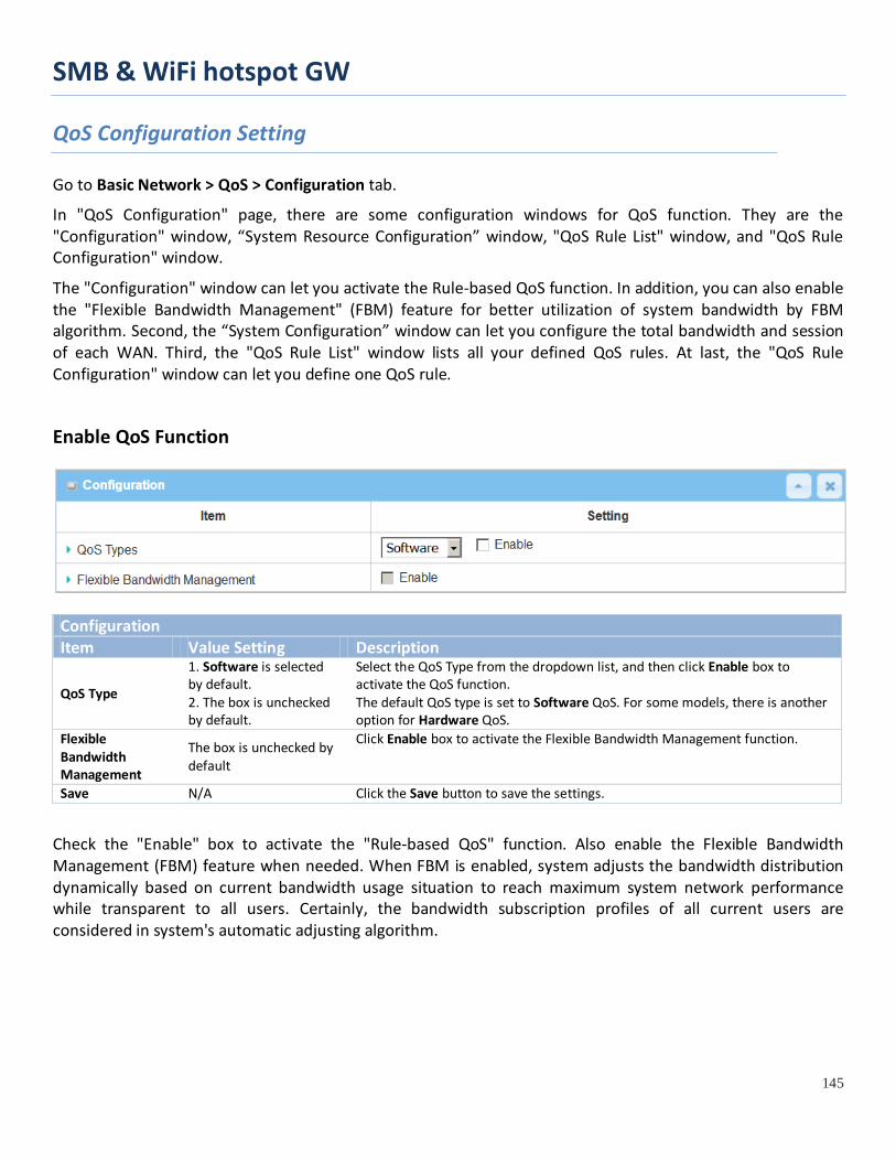
SMB & WiFi hotspot GW
145
QoS Configuration Setting
Go to Basic Network > QoS > Configuration tab.
In "QoS Configuration" page, there are some configuration windows for QoS function. They are the "Configuration" window, “System Resource Configuration” window, "QoS Rule List" window, and "QoS Rule Configuration" window.
The "Configuration" window can let you activate the Rule-based QoS function. In addition, you can also enable the "Flexible Bandwidth Management" (FBM) feature for better utilization of system bandwidth by FBM algorithm. Second, the “System Configuration” window can let you configure the total bandwidth and session of each WAN. Third, the "QoS Rule List" window lists all your defined QoS rules. At last, the "QoS Rule Configuration" window can let you define one QoS rule.
Enable QoS Function
Configuration Item Value Setting Description
QoS Type
1. Software is selected by default. 2. The box is unchecked by default.
Select the QoS Type from the dropdown list, and then click Enable box to activate the QoS function. The default QoS type is set to Software QoS. For some models, there is another option for Hardware QoS.
Flexible Bandwidth Management
The box is unchecked by default
Click Enable box to activate the Flexible Bandwidth Management function.
Save N/A Click the Save button to save the settings.
Check the "Enable" box to activate the "Rule-based QoS" function. Also enable the Flexible Bandwidth Management (FBM) feature when needed. When FBM is enabled, system adjusts the bandwidth distribution dynamically based on current bandwidth usage situation to reach maximum system network performance while transparent to all users. Certainly, the bandwidth subscription profiles of all current users are considered in system's automatic adjusting algorithm.
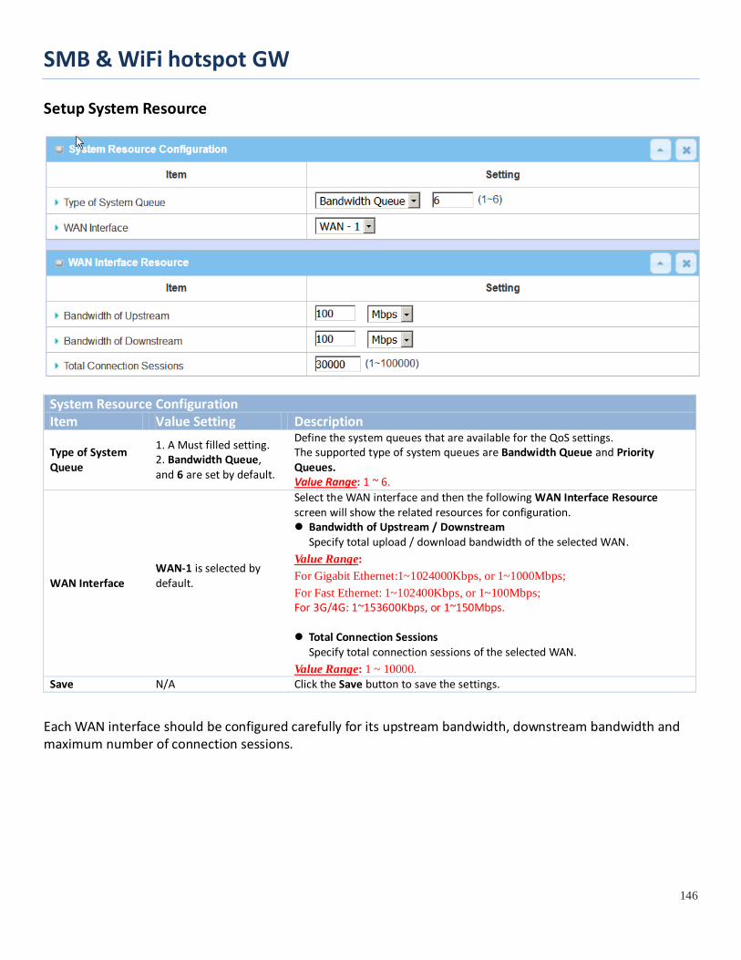
SMB & WiFi hotspot GW
146
Setup System Resource
System Resource Configuration Item Value Setting Description
Type of System Queue
1. A Must filled setting. 2. Bandwidth Queue, and 6 are set by default.
Define the system queues that are available for the QoS settings. The supported type of system queues are Bandwidth Queue and Priority Queues. Value Range: 1 ~ 6.
WAN Interface WAN-1 is selected by default.
Select the WAN interface and then the following WAN Interface Resource screen will show the related resources for configuration. Bandwidth of Upstream / Downstream
Specify total upload / download bandwidth of the selected WAN. Value Range: For Gigabit Ethernet:1~1024000Kbps, or 1~1000Mbps; For Fast Ethernet: 1~102400Kbps, or 1~100Mbps; For 3G/4G: 1~153600Kbps, or 1~150Mbps. Total Connection Sessions
Specify total connection sessions of the selected WAN. Value Range: 1 ~ 10000.
Save N/A Click the Save button to save the settings.
Each WAN interface should be configured carefully for its upstream bandwidth, downstream bandwidth and maximum number of connection sessions.

SMB & WiFi hotspot GW
147
Create / Edit QoS Rules After enabled the QoS function and configured the system resources, you have to further specify some QoS rules for provide better service on the interested traffics. The gateway supports up to a maximum of 128 rule-based QoS rule sets.
When Add button is applied, QoS Rule Configuration screen will appear.
QoS Rule Configuration
Item Value setting Description Interface 1. A Must filled
setting. 2. All WANs is selected by default.
Specify the WAN interface to apply the QoS rule. Select All WANs or a certain WAN-n to filter the packets entering to or leaving from the interface(s).
Group 1. A Must filled setting. 2. Src. MAC Address is selected by default.
Specify the Group category for the QoS rule. It can be Src. MAC Address, IP, or Host Name. Select Src. MAC Address to prioritize packets based on MAC; Select IP to prioritize packets based on IP address and Subnet Mask; Select Host Name to prioritize packets based on a group of a pre-configured group of host from the dropdown list. If the dropdown list is empty, ensure if any group is pre-configured. Note: The required host groups must be created in advance and corresponding QoS checkbox in the Multiple Bound Services field is checked before the Host
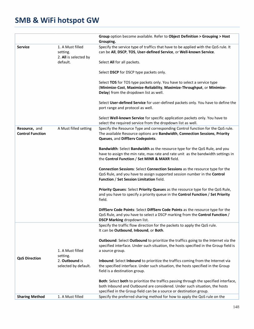
SMB & WiFi hotspot GW
148
Group option become available. Refer to Object Definition > Grouping > Host Grouping.
Service 1. A Must filled setting. 2. All is selected by default.
Specify the service type of traffics that have to be applied with the QoS rule. It can be All, DSCP, TOS, User-defined Service, or Well-known Service. Select All for all packets. Select DSCP for DSCP type packets only. Select TOS for TOS type packets only. You have to select a service type (Minimize-Cost, Maximize-Reliability, Maximize-Throughput, or Minimize-Delay) from the dropdown list as well. Select User-defined Service for user-defined packets only. You have to define the port range and protocol as well. Select Well-known Service for specific application packets only. You have to select the required service from the dropdown list as well.
Resource, and Control Function
A Must filled setting Specify the Resource Type and corresponding Control function for the QoS rule. The available Resource options are Bandwidth, Connection Sessions, Priority Queues, and DiffServ Codepoints. Bandwidth: Select Bandwidth as the resource type for the QoS Rule, and you have to assign the min rate, max rate and rate unit as the bandwidth settings in the Control Function / Set MINR & MAXR field. Connection Sessions: Select Connection Sessions as the resource type for the QoS Rule, and you have to assign supported session number in the Control Function / Set Session Limitation field. Priority Queues: Select Priority Queues as the resource type for the QoS Rule, and you have to specify a priority queue in the Control Function / Set Priority field. DiffServ Code Points: Select DiffServ Code Points as the resource type for the QoS Rule, and you have to select a DSCP marking from the Control Function / DSCP Marking dropdown list.
QoS Direction
1. A Must filled setting. 2. Outbound is selected by default.
Specify the traffic flow direction for the packets to apply the QoS rule. It can be Outbound, Inbound, or Both. Outbound: Select Outbound to prioritize the traffics going to the Internet via the specified interface. Under such situation, the hosts specified in the Group field is a source group. Inbound: Select Inbound to prioritize the traffics coming from the Internet via the specified interface. Under such situation, the hosts specified in the Group field is a destination group. Both: Select both to prioritize the traffics passing through the specified interface, both Inbound and Outbound are considered. Under such situation, the hosts specified in the Group field can be a source or destination group.
Sharing Method 1. A Must filled Specify the preferred sharing method for how to apply the QoS rule on the

SMB & WiFi hotspot GW
149
setting. 2. Group Control is selected by default.
selected group. It can be Individual Control or Group Control. Individual Control: If Individual Control is selected, each host in the group will have his own QoS service resource as specified in the rule. Group Control: If Group Control is selected, all the group hosts share the same QoS service resource.
Time Schedule
1. A Must filled setting. 2. (0) Always is selected by default.
Apply Time Schedule to this rule; otherwise leave it as (0) Always. (refer to Object Definition > Scheduling > Configuration settings)
Rule Enable The box is unchecked by default.
Click Enable box to activate this QoS rule.
Save N/A Click the Save button to save the settings.

SMB & WiFi hotspot GW
150
2.9 Redundancy In engineering, redundancy is the duplication of critical components or functions of a system with the intention of increasing reliability of the system, usually in the form of a backup or fail-safe. In an IP networking, the access gateway is the critical part of the networking system. Redundant gateway plays the backup one of the master gateway and it will take over the data transmitting job once it finds the master gateway failed.
The purchased gateway can serve as the redundant gateway of core router in the enterprise by using the Virtual Router Redundancy Protocol (VRRP).
2.9.1 VRRP
Virtual Router Redundancy Protocol (VRRP) is a computer networking protocol providing device redundancy. It allows a backup router or switch to automatically take over if the primary (master) router or switch fails. This increases the availability and reliability of routing paths via automatic default gateway selections on an IP network.
The protocol achieves this by creation of virtual routers, which are an abstract representation of multiple routers, i.e. master and backup routers, acting as a group. The default gateway of a participating host is assigned to the virtual router instead of a physical router. If the physical router that is routing packets on behalf of the virtual router fails, another physical router is selected to automatically replace it. The physical router that is forwarding packets at any given time is called the master router.
A group of physical VRRP gateways combined together to play a virtual server with one unique virtual server ID and one unique virtual server IP address. But these VRRP gateways have their own priority values to serve as the sequence for backing up the master gateway.
The gateway with VRRP function can join one group of redundant gateways to serve as the backup one for the master gateway. Fill same values of virtual server ID and IP for these gateways, and each gateway owns its own priority as the sequence in the backup list. They construct a VRRP redundant gateway group. Following diagram illustrates the group example with two member gateways.
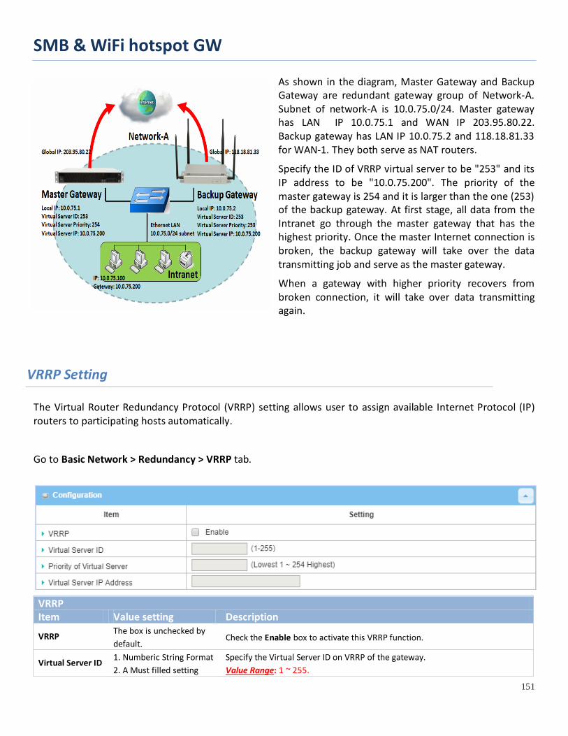
SMB & WiFi hotspot GW
151
As shown in the diagram, Master Gateway and Backup Gateway are redundant gateway group of Network-A. Subnet of network-A is 10.0.75.0/24. Master gateway has LAN IP 10.0.75.1 and WAN IP 203.95.80.22. Backup gateway has LAN IP 10.0.75.2 and 118.18.81.33 for WAN-1. They both serve as NAT routers.
Specify the ID of VRRP virtual server to be "253" and its IP address to be "10.0.75.200". The priority of the master gateway is 254 and it is larger than the one (253) of the backup gateway. At first stage, all data from the Intranet go through the master gateway that has the highest priority. Once the master Internet connection is broken, the backup gateway will take over the data transmitting job and serve as the master gateway.
When a gateway with higher priority recovers from broken connection, it will take over data transmitting again.
VRRP Setting
The Virtual Router Redundancy Protocol (VRRP) setting allows user to assign available Internet Protocol (IP) routers to participating hosts automatically.
Go to Basic Network > Redundancy > VRRP tab.
VRRP Item Value setting Description
VRRP The box is unchecked by default.
Check the Enable box to activate this VRRP function.
Virtual Server ID 1. Numberic String Format 2. A Must filled setting
Specify the Virtual Server ID on VRRP of the gateway. Value Range: 1 ~ 255.
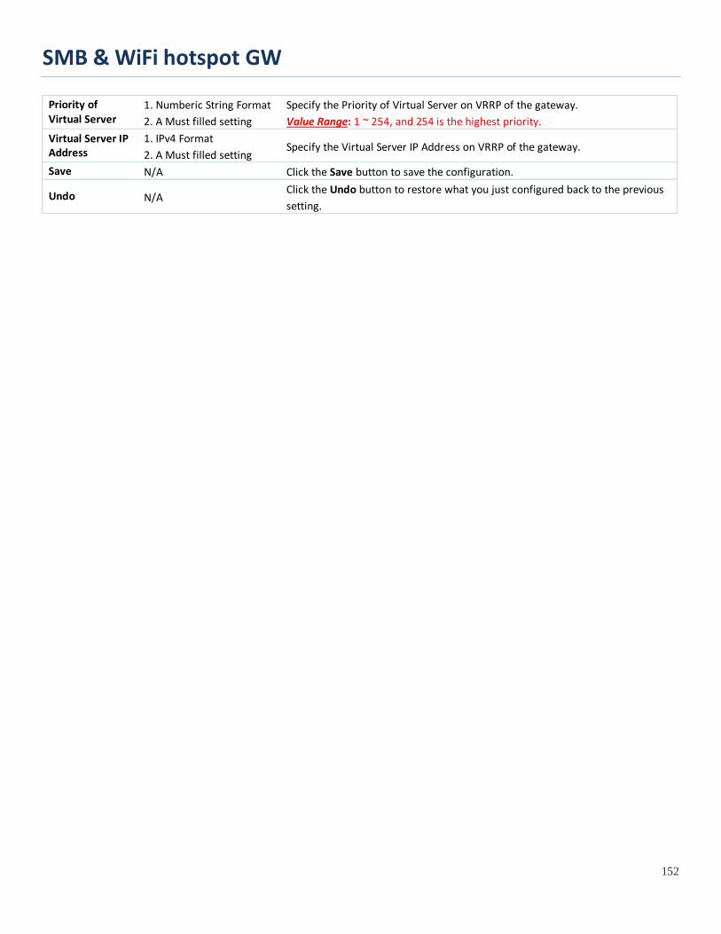
SMB & WiFi hotspot GW
152
Priority of Virtual Server
1. Numberic String Format 2. A Must filled setting
Specify the Priority of Virtual Server on VRRP of the gateway. Value Range: 1 ~ 254, and 254 is the highest priority.
Virtual Server IP Address
1. IPv4 Format 2. A Must filled setting
Specify the Virtual Server IP Address on VRRP of the gateway.
Save N/A Click the Save button to save the configuration.
Undo N/A Click the Undo button to restore what you just configured back to the previous setting.

SMB & WiFi hotspot GW
153
Chapter 3 Object Definition
3.1 Scheduling
Scheduling provides ability of adding/deleting time schedule rules, which can be applied to other functionality.
3.1.1 Scheduling Configuration
Go to Object Definition > Scheduling > Configuration tab.
Button description Item Value setting Description Add N/A Click the Add button to configure time schedule rule Delete N/A Click the Delete button to delete selected rule(s)
When Add button is applied, Time Schedule Configuration and Time Period Definition screens will appear.
Time Schedule Configuration Item Value Setting Description Rule Name String: any text Set rule name Rule Policy Default Inactivate Inactivate/activate the function been applied to in the time period below
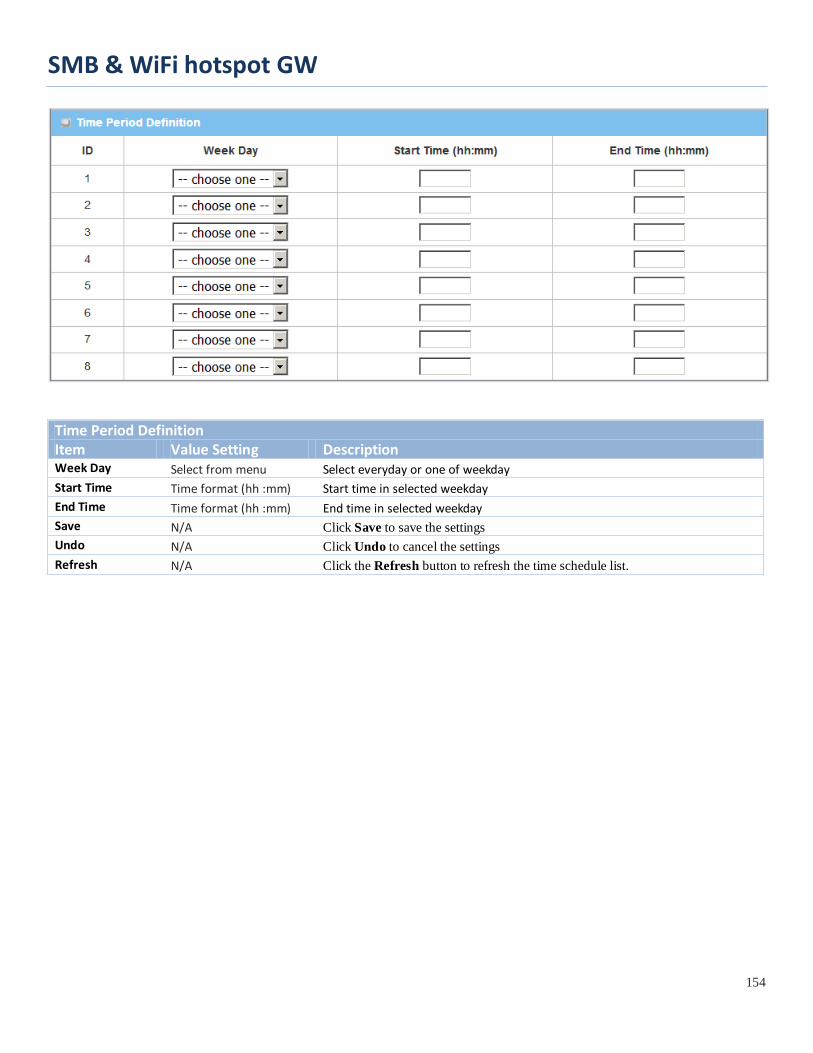
SMB & WiFi hotspot GW
154
Time Period Definition Item Value Setting Description Week Day Select from menu Select everyday or one of weekday Start Time Time format (hh :mm) Start time in selected weekday End Time Time format (hh :mm) End time in selected weekday Save N/A Click Save to save the settings Undo N/A Click Undo to cancel the settings Refresh N/A Click the Refresh button to refresh the time schedule list.
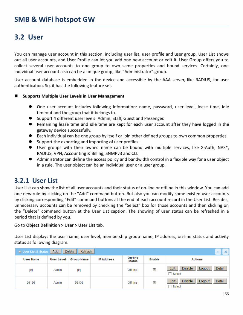
SMB & WiFi hotspot GW
155
3.2 User
You can manage user account in this section, including user list, user profile and user group. User List shows out all user accounts, and User Profile can let you add one new account or edit it. User Group offers you to collect several user accounts to one group to own same properties and bound services. Certainly, one individual user account also can be a unique group, like “Administrator” group.
User account database is embedded in the device and accessible by the AAA server, like RADIUS, for user authentication. So, it has the following feature set.
Supports Multiple User Levels in User Management
One user account includes following information: name, password, user level, lease time, idle timeout and the group that it belongs to.
Support 4 different user levels: Admin, Staff, Guest and Passenger. Remaining lease time and idle time are kept for each user account after they have logged in the
gateway device successfully. Each individual can be one group by itself or join other defined groups to own common properties. Support the exporting and importing of user profiles. User groups with their owned name can be bound with multiple services, like X-Auth, NAS*,
RADIUS, VPN, Accounting & Billing, SNMPv3 and CLI. Administrator can define the access policy and bandwidth control in a flexible way for a user object
in a rule. The user object can be an individual user or a user group.
3.2.1 User List User List can show the list of all user accounts and their status of on-line or offline in this window. You can add one new rule by clicking on the “Add” command button. But also you can modify some existed user accounts by clicking corresponding “Edit” command buttons at the end of each account record in the User List. Besides, unnecessary accounts can be removed by checking the “Select” box for those accounts and then clicking on the “Delete” command button at the User List caption. The showing of user status can be refreshed in a period that is defined by you.
Go to Object Definition > User > User List tab. User List displays the user name, user level, membership group name, IP address, on-line status and activity status as following diagram.

SMB & WiFi hotspot GW
156
There are some additional command buttons in the Actions field of User List table.
Edit: Click on the button to edit the user profile.
Disable: Click the button to disable the user account.
Logout: Click the button to logout the user account.
Detail: Click the button to show additional detail information except the ones in User List about the user account, including Last Login Time, Lease Time, Expired Time, Idle Timeout and current Idle Time.
Select: Select the user account to delete.
When the Add button is applied, User Profile Configuration screen will appear. For the detail about the configuration, please refer to the next section for User Profile.
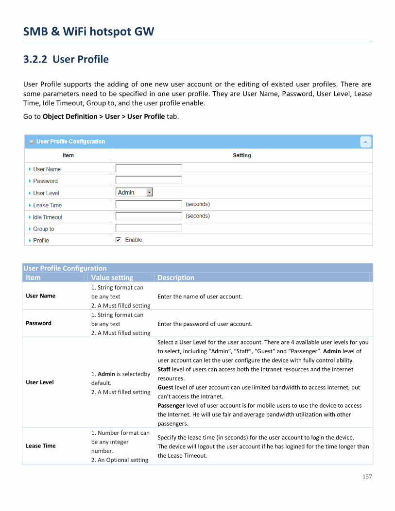
SMB & WiFi hotspot GW
157
3.2.2 User Profile
User Profile supports the adding of one new user account or the editing of existed user profiles. There are some parameters need to be specified in one user profile. They are User Name, Password, User Level, Lease Time, Idle Timeout, Group to, and the user profile enable.
Go to Object Definition > User > User Profile tab.
User Profile Configuration Item Value setting Description
User Name 1. String format can be any text 2. A Must filled setting
Enter the name of user account.
Password 1. String format can be any text 2. A Must filled setting
Enter the password of user account.
User Level 1. Admin is selectedby default. 2. A Must filled setting
Select a User Level for the user account. There are 4 available user levels for you to select, including “Admin”, “Staff”, “Guest” and “Passenger”. Admin level of user account can let the user configure the device with fully control ability. Staff level of users can access both the Intranet resources and the Internet resources. Guest level of user account can use limited bandwidth to access Internet, but can’t access the Intranet. Passenger level of user account is for mobile users to use the device to access the Internet. He will use fair and average bandwidth utilization with other passengers.
Lease Time
1. Number format can be any integer number. 2. An Optional setting
Specify the lease time (in seconds) for the user account to login the device. The device will logout the user account if he has logined for the time longer than the Lease Timeout.

SMB & WiFi hotspot GW
158
Idle Time
1. Number format can be any integer number. 2. An Optional setting
Specify the idle time (in seconds) for the user account. The device will logout the user account if he is idle for the time longer than the Idle Timeout.
Group to 1. String format can be any text 2. An Optional setting
Enter a group name if you would like to collect the user in a certain user group.
Profile 1. The box is checked by default. 2. A Must filled setting
Check the Enable box to activate the user profile.
Save N/A Click the Save button to save the settings Undo N/A Click the Undo button to cancel the settings

SMB & WiFi hotspot GW
159
3.2.3 User Group
User Group supports the grouping of several user accounts to be one user group with common properties. There are some parameters need to be specified in one user group. They are Group Name, Group Members, Bound Services, QoS&BWM Property, Policy Routing Property and finally, the user group enable.
.
Go to Object Definition > User > User Group tab.
When the Add button is applied, User Group Configuration screen will appear.
User Profile Configuration Item Value setting Description
Group Name 1. String format can be any text 2. A Must filled setting
Enter the name of user group. Value Range: at least 1 character, ‘A’ ~ ’Z’, ‘a’ ~ ’z’, and ‘0’ ~ ’9’ are valid;
Multiple User Members N/A Click the Choice button to select multiple user accounts to join the group.
Multiple Bound Services N/A
Check the available service box(es) to bind with the user group. So, the bound service can use the group object or all user account objects in the group.
QoS & BWM Property
1. A Must filled setting. 2. Individual Control is selected by default.
Specify the preferred sharing method for how to apply a QoS rule on the selected group, and define the guaranteed and limited bandwidth usage for the group It can be Individual Control or Group Control. Individual Control: If Individual Control is selected, each user in the group will have his own QoS service resource as specified in the rule. Group Control: If Group Control is selected, the entire user group shares the same QoS service resource.
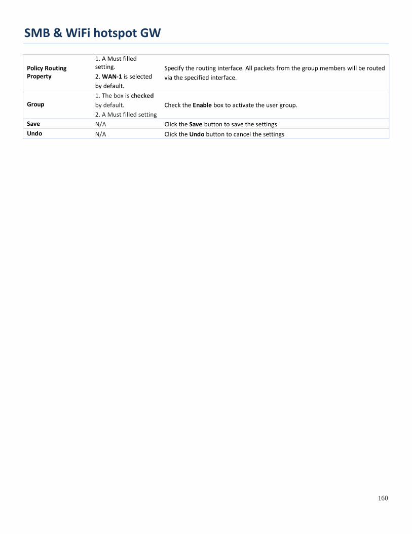
SMB & WiFi hotspot GW
160
Policy Routing Property
1. A Must filled setting. 2. WAN-1 is selected by default.
Specify the routing interface. All packets from the group members will be routed via the specified interface.
Group 1. The box is checked by default. 2. A Must filled setting
Check the Enable box to activate the user group.
Save N/A Click the Save button to save the settings Undo N/A Click the Undo button to cancel the settings

SMB & WiFi hotspot GW
161
3.3 Grouping
The Grouping function allows user to make group for some services.
3.3.1 Host Grouping
Go to Object Definition > Grouping > Host Grouping tab. The Host Grouping function allows user to make host group for some services, such as QoS, Firewall, and Communication Bus. The supported service types could be different for the purchased product.
When Add button is applied, Host Group Configuration screen will appear.
Host Group Configuration Item Value setting Description
Group Name 1. String format can be any text 2. A Must filled setting
Enter a group name for the rule. It is a name that is easy for you to understand.
Group Type 1. IP Address-based is selected by default. 2. A Must filled setting
Select the group type for the host group. It can be IP Address-based, MAC Address-based, or Host Name-based. When IP Address-based is selected, only IP address can be added in Member to Join. When MAC Address-based is selected, only MAC address can be added in Member to Join.
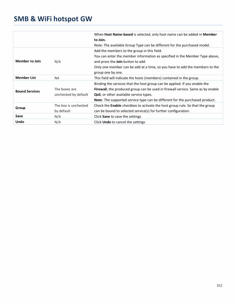
SMB & WiFi hotspot GW
162
When Host Name-based is selected, only host name can be added in Member to Join. Note: The available Group Type can be different for the purchased model.
Member to Join N/A
Add the members to the group in this field. You can enter the member information as specified in the Member Type above, and press the Join button to add. Only one member can be add at a time, so you have to add the members to the group one by one.
Member List NA This field will indicate the hosts (members) contained in the group.
Bound Services The boxes are unchecked by default
Binding the services that the host group can be applied. If you enable the Firewall, the produced group can be used in firewall service. Same as by enable QoS, or other available service types. Note: The supported service type can be different for the purchased product.
Group The box is unchecked by default
Check the Enable checkbox to activate the host group rule. So that the group can be bound to selected service(s) for further configuration.
Save N/A Click Save to save the settings Undo N/A Click Undo to cancel the settings

SMB & WiFi hotspot GW
163
3.4 External Server
Go to Object Definition > External Server > External Server tab.
The External Server setting allows user to add external server.
Create External Server
When Add button is applied, External Server Configuration screen will appear.

SMB & WiFi hotspot GW
164
External Server Configuration
Item Value setting Description
Sever Name 1. String format can be any text 2. A Must filled setting
Enter a server name. Enter a name that is easy for you to understand.
Server Type A Must filled setting
Specify the Server Type of the external server, and enter the required settings for the accessing the server.
Email Server (A Must filled setting) : When Email Server is selected, User Name, and Password are also required. User Name (String format: any text) Password (String format: any text)
RADIUS Server (A Must filled setting) : When RADIUS Server is selected, the following settings are also required. Primary : Shared Key (String format: any text) Authentication Protocol (By default CHAP is selected) Session Timeout (By default 1) The values must be between 1 and 60. Idle Timeout: (By default 1) The values must be between 1 and 15. Secondary : Shared Key (String format: any text) Authentication Protocol (By default CHAP is selected) Session Timeout (By default 1) The values must be between 1 and 60. Idle Timeout: (By default 1) The values must be between 1 and 15.
Active Directory Server (A Must filled setting) : When Active Directory Server is selected, Domain setting is also required. Domain (String format: any text)
LDAP Server (A Must filled setting) : When LDAP Server is selected, the following settings are also required. Base DN (String format: any text) Identity (String format: any text) Password (String format: any text)
UAM Server (A Must filled setting) : When UAM Server is selected, the following settings are also required. Login URL (String format: any text) Shared Secret (String format: any text) NAS/Gateway ID (String format: any text) Location ID (String format: any text) Location Name (String format: any text)
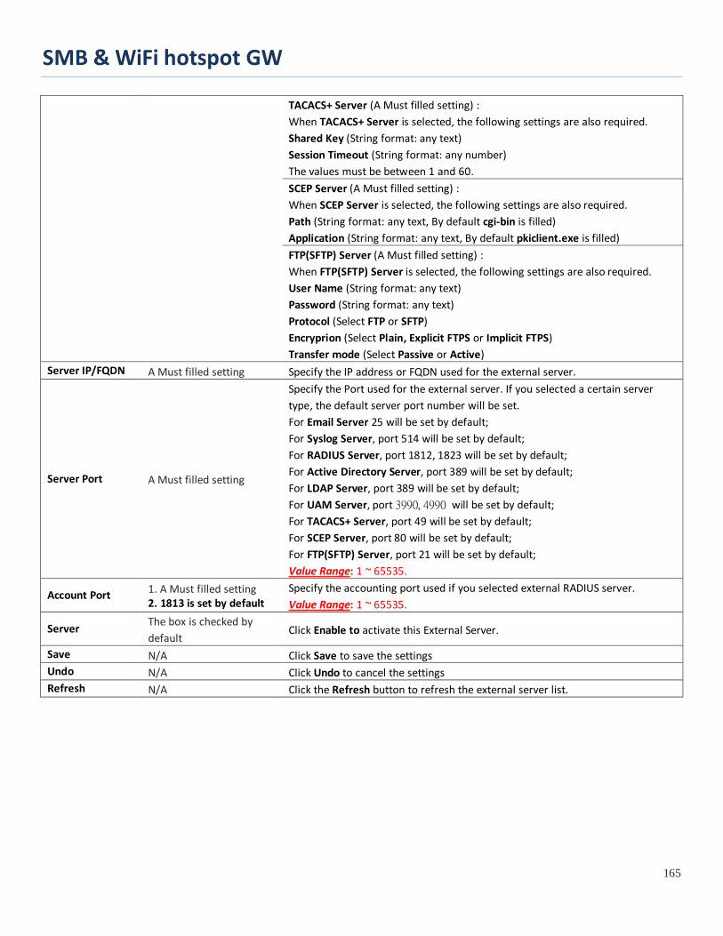
SMB & WiFi hotspot GW
165
TACACS+ Server (A Must filled setting) : When TACACS+ Server is selected, the following settings are also required. Shared Key (String format: any text) Session Timeout (String format: any number) The values must be between 1 and 60. SCEP Server (A Must filled setting) : When SCEP Server is selected, the following settings are also required. Path (String format: any text, By default cgi-bin is filled) Application (String format: any text, By default pkiclient.exe is filled) FTP(SFTP) Server (A Must filled setting) : When FTP(SFTP) Server is selected, the following settings are also required. User Name (String format: any text) Password (String format: any text) Protocol (Select FTP or SFTP) Encryprion (Select Plain, Explicit FTPS or Implicit FTPS) Transfer mode (Select Passive or Active)
Server IP/FQDN A Must filled setting Specify the IP address or FQDN used for the external server.
Server Port A Must filled setting
Specify the Port used for the external server. If you selected a certain server type, the default server port number will be set. For Email Server 25 will be set by default; For Syslog Server, port 514 will be set by default; For RADIUS Server, port 1812, 1823 will be set by default; For Active Directory Server, port 389 will be set by default; For LDAP Server, port 389 will be set by default; For UAM Server, port 3990, 4990 will be set by default; For TACACS+ Server, port 49 will be set by default; For SCEP Server, port 80 will be set by default; For FTP(SFTP) Server, port 21 will be set by default; Value Range: 1 ~ 65535.
Account Port 1. A Must filled setting 2. 1813 is set by default
Specify the accounting port used if you selected external RADIUS server. Value Range: 1 ~ 65535.
Server The box is checked by default
Click Enable to activate this External Server.
Save N/A Click Save to save the settings Undo N/A Click Undo to cancel the settings Refresh N/A Click the Refresh button to refresh the external server list.
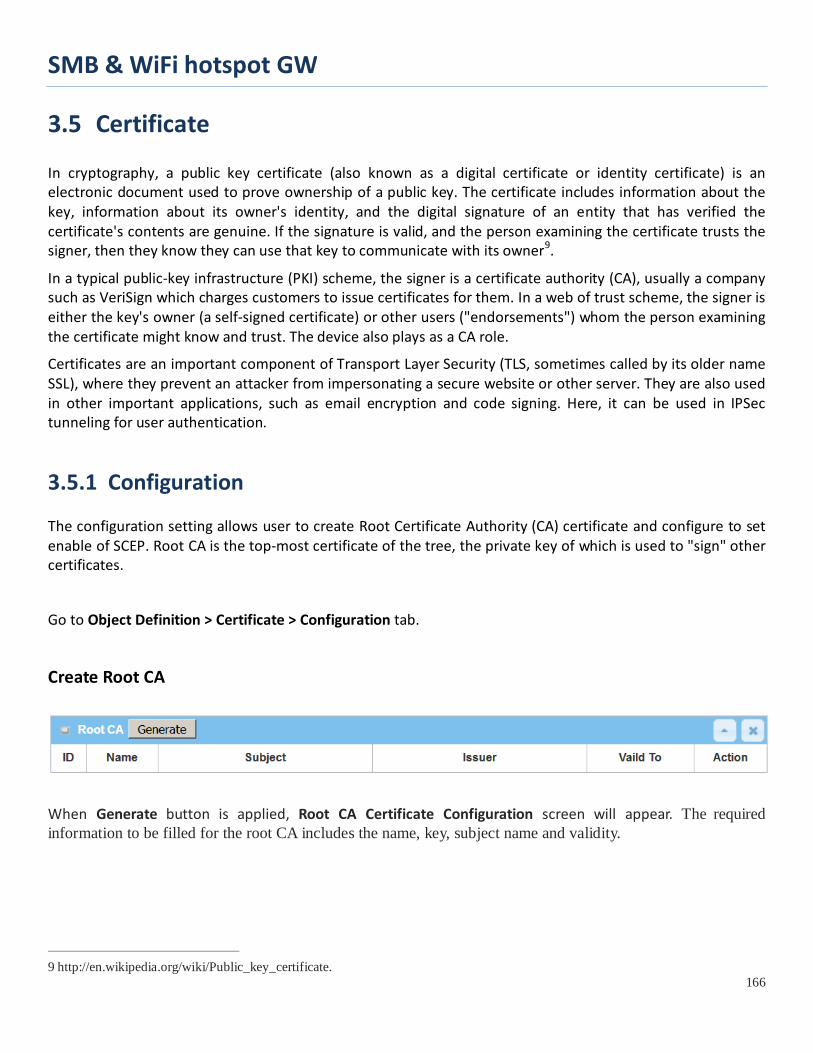
SMB & WiFi hotspot GW
166
3.5 Certificate In cryptography, a public key certificate (also known as a digital certificate or identity certificate) is an electronic document used to prove ownership of a public key. The certificate includes information about the key, information about its owner's identity, and the digital signature of an entity that has verified the certificate's contents are genuine. If the signature is valid, and the person examining the certificate trusts the signer, then they know they can use that key to communicate with its owner9.
In a typical public-key infrastructure (PKI) scheme, the signer is a certificate authority (CA), usually a company such as VeriSign which charges customers to issue certificates for them. In a web of trust scheme, the signer is either the key's owner (a self-signed certificate) or other users ("endorsements") whom the person examining the certificate might know and trust. The device also plays as a CA role.
Certificates are an important component of Transport Layer Security (TLS, sometimes called by its older name SSL), where they prevent an attacker from impersonating a secure website or other server. They are also used in other important applications, such as email encryption and code signing. Here, it can be used in IPSec tunneling for user authentication.
3.5.1 Configuration The configuration setting allows user to create Root Certificate Authority (CA) certificate and configure to set enable of SCEP. Root CA is the top-most certificate of the tree, the private key of which is used to "sign" other certificates.
Go to Object Definition > Certificate > Configuration tab.
Create Root CA
When Generate button is applied, Root CA Certificate Configuration screen will appear. The required information to be filled for the root CA includes the name, key, subject name and validity.
9 http://en.wikipedia.org/wiki/Public_key_certificate.

SMB & WiFi hotspot GW
167
Root CA Certificate Configuration Item Value setting Description
Name 1. String format can be any text 2. A Must filled setting
Enter a Root CA Certificate name. It will be a certificate file name
Key A Must filled setting
This field is to specify the key attribute of certificate. Key Type to set public-key cryptosystems. It only supports RSA now. Key Length to set s the size measured in bits of the key used in a cryptographic algorithm. Digest Algorithm to set identifier in the signature algorithm identifier of certificates
Subject Name A Must filled setting
This field is to specify the information of certificate. Country(C) is the two-letter ISO code for the country where your organization is located. State(ST) is the state where your organization is located. Location(L) is the location where your organization is located. Organization(O) is the name of your organization. Organization Unit(OU) is the name of your organization unit. Common Name(CN) is the name of your organization. Email is the email of your organization. It has to be email address style.
Validity Period A Must filled setting This field is to specify the validity period of certificate.

SMB & WiFi hotspot GW
168
Setup SCEP
SCEP Configuration Item Value setting Description
SCEP The box is unchecked by default
Check the Enable box to activate SCEP function.
Automatically re-enroll aging certificates
The box is unchecked by default
When SCEP is activated, check the Enable box to activate this function. It will be automatically check which certificate is aging. If certificate is aging, it will activate SCEP function to re-enroll automatically.
Save N/A Click Save to save the settings Undo N/A Click Undo to cancel the settings

SMB & WiFi hotspot GW
169
3.5.2 My Certificate My Certificate includes a Local Certificate List. Local Certificate List shows all generated certificates by the root CA for the gateway. And it also stores the generated Certificate Signing Requests (CSR) which will be signed by other external CAs. The signed certificates can be imported as the local ones of the gateway.
Self-signed Certificate Usage Scenario
Scenario Application Timing
When the enterprise gateway owns the root CA and VPN tunneling function, it can generate its own local certificates by being signed by itself or import any local certificates that are signed by other external CAs. Also import the trusted certificates for other CAs and Clients. In addition, since it has the root CA, it also can sign Certificate Signing Requests (CSR) to form corresponding certificates for others. These certificates can be used for two remote peers to make sure their identity during establishing a VPN tunnel.
Scenario Description
Gateway 1 generates the root CA and a local certificate (HQCRT) signed by itself. Import a trusted certificate (BranchCRT) –a BranchCSR certificate of Gateway 2 signed by root CA of Gateway 1.
Gateway 2 creates a CSR (BranchCSR) to let the root CA of the Gateway 1 sign it to be the BranchCRT certificate. Import the certificate into the Gateway 2 as a local certificate. In addition, also import the certificates of the root CA of the Gateway 1 into the Gateway 2 as the trusted ones. (Please also refer to following two sub-sections)
Establish an IPSec VPN tunnel with IKE and X.509 protocols by starting from either peer, so that all
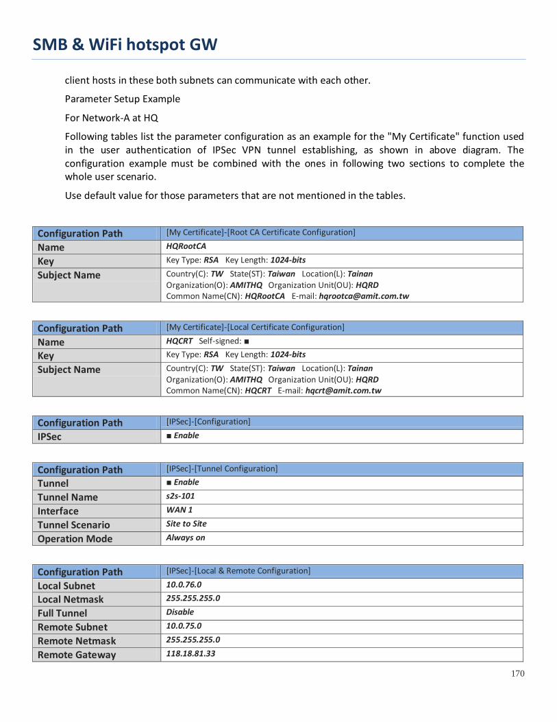
SMB & WiFi hotspot GW
170
client hosts in these both subnets can communicate with each other.
Parameter Setup Example
For Network-A at HQ
Following tables list the parameter configuration as an example for the "My Certificate" function used in the user authentication of IPSec VPN tunnel establishing, as shown in above diagram. The configuration example must be combined with the ones in following two sections to complete the whole user scenario.
Use default value for those parameters that are not mentioned in the tables.
Configuration Path [My Certificate]-[Root CA Certificate Configuration]
Name HQRootCA
Key Key Type: RSA Key Length: 1024-bits
Subject Name Country(C): TW State(ST): Taiwan Location(L): Tainan Organization(O): AMITHQ Organization Unit(OU): HQRD Common Name(CN): HQRootCA E-mail: [email protected]
Configuration Path [My Certificate]-[Local Certificate Configuration]
Name HQCRT Self-signed: ■
Key Key Type: RSA Key Length: 1024-bits
Subject Name Country(C): TW State(ST): Taiwan Location(L): Tainan Organization(O): AMITHQ Organization Unit(OU): HQRD Common Name(CN): HQCRT E-mail: [email protected]
Configuration Path [IPSec]-[Configuration]
IPSec ■ Enable
Configuration Path [IPSec]-[Tunnel Configuration]
Tunnel ■ Enable
Tunnel Name s2s-101
Interface WAN 1
Tunnel Scenario Site to Site
Operation Mode Always on
Configuration Path [IPSec]-[Local & Remote Configuration]
Local Subnet 10.0.76.0
Local Netmask 255.255.255.0
Full Tunnel Disable
Remote Subnet 10.0.75.0
Remote Netmask 255.255.255.0
Remote Gateway 118.18.81.33
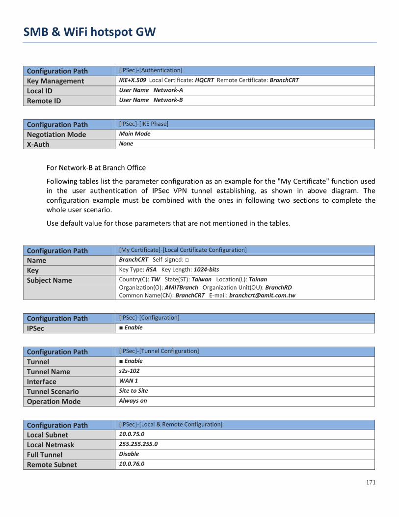
SMB & WiFi hotspot GW
171
Configuration Path [IPSec]-[Authentication]
Key Management IKE+X.509 Local Certificate: HQCRT Remote Certificate: BranchCRT
Local ID User Name Network-A
Remote ID User Name Network-B
Configuration Path [IPSec]-[IKE Phase]
Negotiation Mode Main Mode
X-Auth None
For Network-B at Branch Office
Following tables list the parameter configuration as an example for the "My Certificate" function used in the user authentication of IPSec VPN tunnel establishing, as shown in above diagram. The configuration example must be combined with the ones in following two sections to complete the whole user scenario.
Use default value for those parameters that are not mentioned in the tables.
Configuration Path [My Certificate]-[Local Certificate Configuration]
Name BranchCRT Self-signed: □
Key Key Type: RSA Key Length: 1024-bits
Subject Name Country(C): TW State(ST): Taiwan Location(L): Tainan Organization(O): AMITBranch Organization Unit(OU): BranchRD Common Name(CN): BranchCRT E-mail: [email protected]
Configuration Path [IPSec]-[Configuration]
IPSec ■ Enable
Configuration Path [IPSec]-[Tunnel Configuration]
Tunnel ■ Enable
Tunnel Name s2s-102
Interface WAN 1
Tunnel Scenario Site to Site
Operation Mode Always on
Configuration Path [IPSec]-[Local & Remote Configuration]
Local Subnet 10.0.75.0
Local Netmask 255.255.255.0
Full Tunnel Disable
Remote Subnet 10.0.76.0

SMB & WiFi hotspot GW
172
Remote Netmask 255.255.255.0
Remote Gateway 203.95.80.22
Configuration Path [IPSec]-[Authentication]
Key Management IKE+X.509 Local Certificate: BranchCRT Remote Certificate: HQCRT
Local ID User Name Network-B
Remote ID User Name Network-A
Configuration Path [IPSec]-[IKE Phase]
Negotiation Mode Main Mode
X-Auth None
Scenario Operation Procedure
In above diagram, "Gateway 1" is the gateway of Network-A in headquarters and the subnet of its Intranet is 10.0.76.0/24. It has the IP address of 10.0.76.2 for LAN interface and 203.95.80.22 for WAN-1 interface. "Gateway 2" is the gateway of Network-B in branch office and the subnet of its Intranet is 10.0.75.0/24. It has the IP address of 10.0.75.2 for LAN interface and 118.18.81.33 for WAN-1 interface. They both serve as the NAT security gateways.
Gateway 1 generates the root CA and a local certificate (HQCRT) that is signed by itself. Import the certificates of the root CA and HQCRT into the "Trusted CA Certificate List" and "Trusted Client Certificate List" of Gateway 2.
Gateway 2 generates a Certificate Signing Request (BranchCSR) for its own certificate (BranchCRT) (Please generate one not self-signed certificate in the Gateway 2, and click on the "View" button for that CSR. Just downloads it). Take the CSR to be signed by the root CA of Gateway 1 and obtain the BranchCRT certificate (you need rename it). Import the certificate into the "Trusted Client Certificate List" of the Gateway 1 and the "Local Certificate List" of Gateway 2.
Gateway 2 can establish an IPSec VPN tunnel with "Site to Site" scenario and IKE and X.509 protocols to Gateway 1.
Finally, the client hosts in two subnets of 10.0.75.0/24 and 10.0.76.0/24 can communicate with each other.

SMB & WiFi hotspot GW
173
My Certificate Setting
Go to Object Definition > Certificate > My Certificate tab.
The My Certificate setting allows user to create local certificates. In "My Certificate" page, there are two configuration windows for the "My Certificate" function. The "Local Certificate List" window shows the stored certificates or CSRs for representing the gateway. The "Local Certificate Configuration" window can let you fill required information necessary for corresponding certificate to be generated by itself, or corresponding CSR to be signed by other CAs.
Create Local Certificate
When Add button is applied, Local Certificate Configuration screen will appear. The required information to be filled for the certificate or CSR includes the name, key and subject name. It is a certificate if the "Self-signed" box is checked; otherwise, it is a CSR.
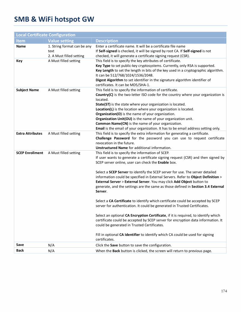
SMB & WiFi hotspot GW
174
Local Certificate Configuration Item Value setting Description Name 1. String format can be any
text 2. A Must filled setting
Enter a certificate name. It will be a certificate file name If Self-signed is checked, it will be signed by root CA. If Self-signed is not checked, it will generate a certificate signing request (CSR).
Key A Must filled setting This field is to specify the key attributes of certificate. Key Type to set public-key cryptosystems. Currently, only RSA is supported. Key Length to set the length in bits of the key used in a cryptographic algorithm. It can be 512/768/1024/1536/2048. Digest Algorithm to set identifier in the signature algorithm identifier of certificates. It can be MD5/SHA-1.
Subject Name A Must filled setting This field is to specify the information of certificate. Country(C) is the two-letter ISO code for the country where your organization is located. State(ST) is the state where your organization is located. Location(L) is the location where your organization is located. Organization(O) is the name of your organization. Organization Unit(OU) is the name of your organization unit. Common Name(CN) is the name of your organization. Email is the email of your organization. It has to be email address setting only.
Extra Attributes A Must filled setting This field is to specify the extra information for generating a certificate. Challenge Password for the password you can use to request certificate revocation in the future. Unstructured Name for additional information.
SCEP Enrollment A Must filled setting This field is to specify the information of SCEP. If user wants to generate a certificate signing request (CSR) and then signed by SCEP server online, user can check the Enable box. Select a SCEP Server to identify the SCEP server for use. The server detailed information could be specified in External Servers. Refer to Object Definition > External Server > External Server. You may click Add Object button to generate, and the settings are the same as those defined in Section 3.4 External Server. Select a CA Certificate to identify which certificate could be accepted by SCEP server for authentication. It could be generated in Trusted Certificates. Select an optional CA Encryption Certificate, if it is required, to identify which certificate could be accepted by SCEP server for encryption data information. It could be generated in Trusted Certificates. Fill in optional CA Identifier to identify which CA could be used for signing certificates.
Save N/A Click the Save button to save the configuration. Back N/A When the Back button is clicked, the screen will return to previous page.

SMB & WiFi hotspot GW
175
When Import button is applied, an Import screen will appear. You can import a certificate from an existed certificate file, or directly paste a PEM encoded string as the certificate.
Import Item Value setting Description Import A Must filled setting Select a certificate file from user’s computer, and click the Apply button to
import the specified certificate file to the gateway. PEM Encoded 1. String format can be any
text 2. A Must filled setting
This is an alternative approach to import a certificate. You can directly fill in (Copy and Paste) the PEM encoded certificate string, and click the Apply button to import the specified certificate to the gateway.
Apply N/A Click the Apply button to import the certificate. Cancel N/A Click the Cancel button to discard the import operation and the screen will
return to the My Certificates page.

SMB & WiFi hotspot GW
176
3.5.3 Trusted Certificate Trusted Certificate includes Trusted CA Certificate List, Trusted Client Certificate List, and Trusted Client Key List. The Trusted CA Certificate List places the certificates of external trusted CAs. The Trusted Client Certificate List places the others' certificates what you trust. And the Trusted Client Key List places the others’ keys what you trusted.
Self-signed Certificate Usage Scenario
Scenario Application Timing (same as the one described in "My Certificate" section)
When the enterprise gateway owns the root CA and VPN tunneling function, it can generate its own local certificates by being signed by itself. Also imports the trusted certificates for other CAs and Clients. These certificates can be used for two remote peers to make sure their identity during establishing a VPN tunnel.
Scenario Description (same as the one described in "My Certificate" section)
Gateway 1 generates the root CA and a local certificate (HQCRT) signed by itself. Import a trusted certificate (BranchCRT) –a BranchCSR certificate of Gateway 2 signed by root CA of Gateway 1.
Gateway 2 creates a CSR (BranchCSR) to let the root CA of the Gateway 1 sign it to be the BranchCRT certificate. Import the certificate into the Gateway 2 as a local certificate. In addition, also imports the certificates of the root CA of Gateway 1 into the Gateway 2 as the trusted ones. (Please also refer to "My Certificate" and "Issue Certificate" sections).
Establish an IPSec VPN tunnel with IKE and X.509 protocols by starting from either peer, so that all client hosts in these both subnets can communicate with each other.
Parameter Setup Example (same as the one described in "My Certificate" section)

SMB & WiFi hotspot GW
177
For Network-A at HQ
Following tables list the parameter configuration as an example for the "Trusted Certificate" function used in the user authentication of IPSec VPN tunnel establishing, as shown in above diagram. The configuration example must be combined with the ones in "My Certificate" and "Issue Certificate" sections to complete the setup for the whole user scenario.
Configuration Path [Trusted Certificate]-[Trusted Client Certificate List]
Command Button Import
Configuration Path [Trusted Certificate]-[Trusted Client Certificate Import from a File]
File BranchCRT.crt
For Network-B at Branch Office
Following tables list the parameter configuration as an example for the "Trusted Certificate" function used in the user authentication of IPSec VPN tunnel establishing, as shown in above diagram. The configuration example must be combined with the ones in "My Certificate" and "Issued Certificate" sections to complete the setup for the whole user scenario.
Configuration Path [Trusted Certificate]-[Trusted CA Certificate List]
Command Button Import
Configuration Path [Trusted Certificate]-[Trusted CA Certificate Import from a File]
File HQRootCA.crt
Configuration Path [Trusted Certificate]-[Trusted Client Certificate List]
Command Button Import
Configuration Path [Trusted Certificate]-[Trusted Client Certificate Import from a File]
File HQCRT.crt
Scenario Operation Procedure (same as the one described in "My Certificate" section)
In above diagram, the "Gateway 1" is the gateway of Network-A in headquarters and the subnet of its Intranet is 10.0.76.0/24. It has the IP address of 10.0.76.2 for LAN interface and 203.95.80.22 for WAN-1 interface. The "Gateway 2" is the gateway of Network-B in branch office and the subnet of its Intranet is 10.0.75.0/24. It has the IP address of 10.0.75.2 for LAN interface and 118.18.81.33 for WAN-1 interface. They both serve as the NAT security gateways.
In Gateway 2 import the certificates of the root CA and HQCRT that were generated and signed by Gateway 1 into the "Trusted CA Certificate List" and "Trusted Client Certificate List" of Gateway 2.

SMB & WiFi hotspot GW
178
Import the obtained BranchCRT certificate (the derived BranchCSR certificate after Gateway 1’s root CA signature) into the "Trusted Client Certificate List" of the Gateway 1 and the "Local Certificate List" of the Gateway 2. For more details, refer to the Network-B operation procedure in "My Certificate" section of this manual.
Gateway 2 can establish an IPSec VPN tunnel with "Site to Site" scenario and IKE and X.509 protocols to Gateway 1.
Finally, the client hosts in two subnets of 10.0.75.0/24 and 10.0.76.0/24 can communicate with each other.

SMB & WiFi hotspot GW
179
Trusted Certificate Setting
Go to Object Definition > Certificate > Trusted Certificate tab.
The Trusted Certificate setting allows user to import trusted certificates and keys.
Import Trusted CA Certificate
When Import button is applied, a Trusted CA import screen will appear. You can import a Trusted CA certificate from an existed certificate file, or directly paste a PEM encoded string as the certificate.
Trusted CA Certificate List Item Value setting Description Import from a File
A Must filled setting Select a CA certificate file from user’s computer, and click the Apply button to import the specified CA certificate file to the gateway.
Import from a PEM
1. String format can be any text 2. A Must filled setting
This is an alternative approach to import a CA certificate. You can directly fill in (Copy and Paste) the PEM encoded CA certificate string, and click the Apply button to import the specified CA certificate to the gateway.
Apply N/A Click the Apply button to import the certificate. Cancel N/A Click the Cancel button to discard the import operation and the screen will
return to the Trusted Certificates page.

SMB & WiFi hotspot GW
180
Instead of importing a Trusted CA certificate with mentioned approaches, you can also get the CA certificate from the SECP server.
If SCEP is enabled (Refer to Object Definition > Certificate > Configuration), you can click Get CA button, a Get CA Configuration screen will appear.
Get CA Configuration Item Value setting Description SCEP Server A Must filled setting Select a SCEP Server to identify the SCEP server for use. The server detailed
information could be specified in External Servers. Refer to Object Definition > External Server > External Server. You may click Add Object button to generate.
CA Identifier 1. String format can be any text
Fill in optional CA Identifier to identify which CA could be used for signing certificates.
Save N/A Click Save to save the settings. Close N/A Click the Close button to return to the Trusted Certificates page.
Import Trusted Client Certificate
When Import button is applied, a Trusted Client Certificate Import screen will appear. You can import a Trusted Client Certificate from an existed certificate file, or directly paste a PEM encoded string as the certificate.
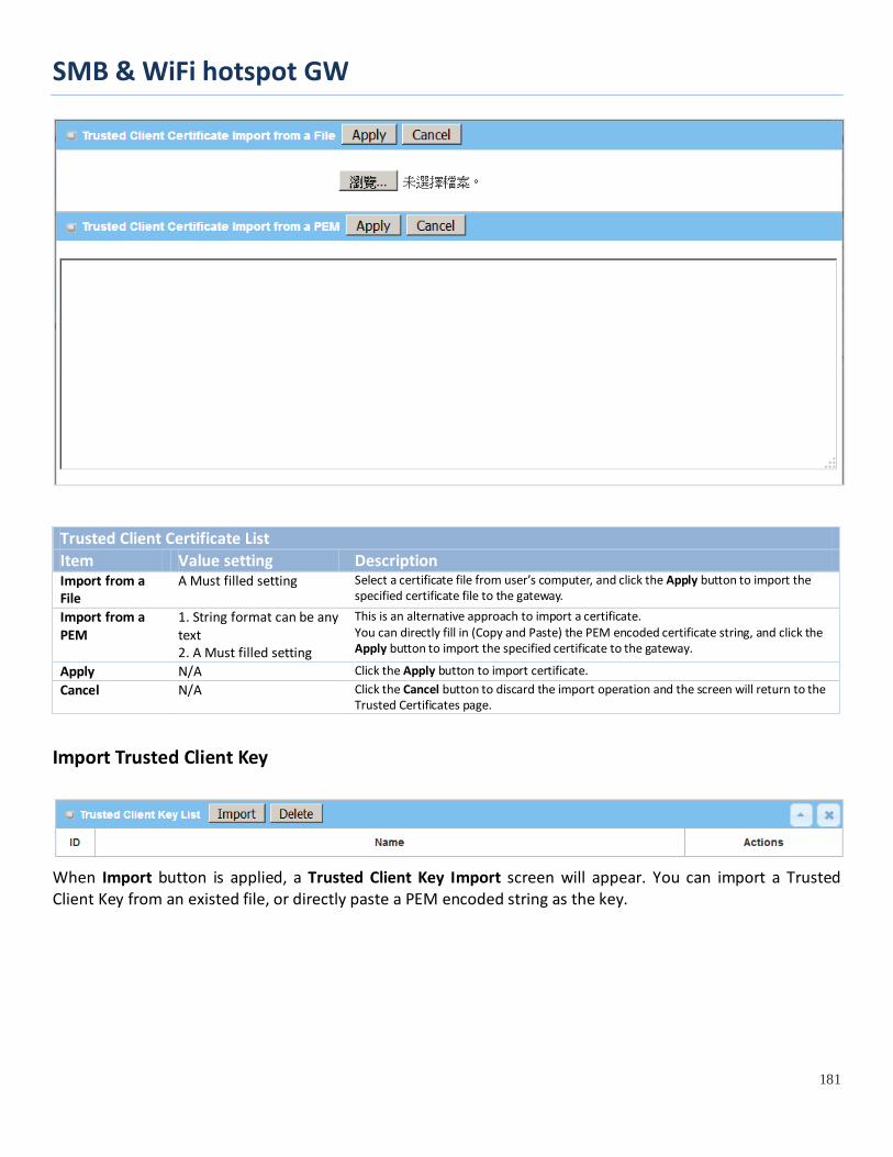
SMB & WiFi hotspot GW
181
Trusted Client Certificate List Item Value setting Description Import from a File
A Must filled setting Select a certificate file from user’s computer, and click the Apply button to import the specified certificate file to the gateway.
Import from a PEM
1. String format can be any text 2. A Must filled setting
This is an alternative approach to import a certificate. You can directly fill in (Copy and Paste) the PEM encoded certificate string, and click the Apply button to import the specified certificate to the gateway.
Apply N/A Click the Apply button to import certificate. Cancel N/A Click the Cancel button to discard the import operation and the screen will return to the
Trusted Certificates page.
Import Trusted Client Key
When Import button is applied, a Trusted Client Key Import screen will appear. You can import a Trusted Client Key from an existed file, or directly paste a PEM encoded string as the key.

SMB & WiFi hotspot GW
182
Trusted Client Key List Item Value setting Description Import from a File
A Must filled setting Select a certificate key file from user’s computer, and click the Apply button to import the specified key file to the gateway.
Import from a PEM
1. String format can be any text 2. A Must filled setting
This is an alternative approach to import a certificate key. You can directly fill in (Copy and Paste) the PEM encoded certificate key string, and click the Apply button to import the specified certificate key to the gateway.
Apply N/A Click the Apply button to import the certificate key. Cancel N/A Click the Cancel button to discard the import operation and the screen will return to the
Trusted Certificates page.
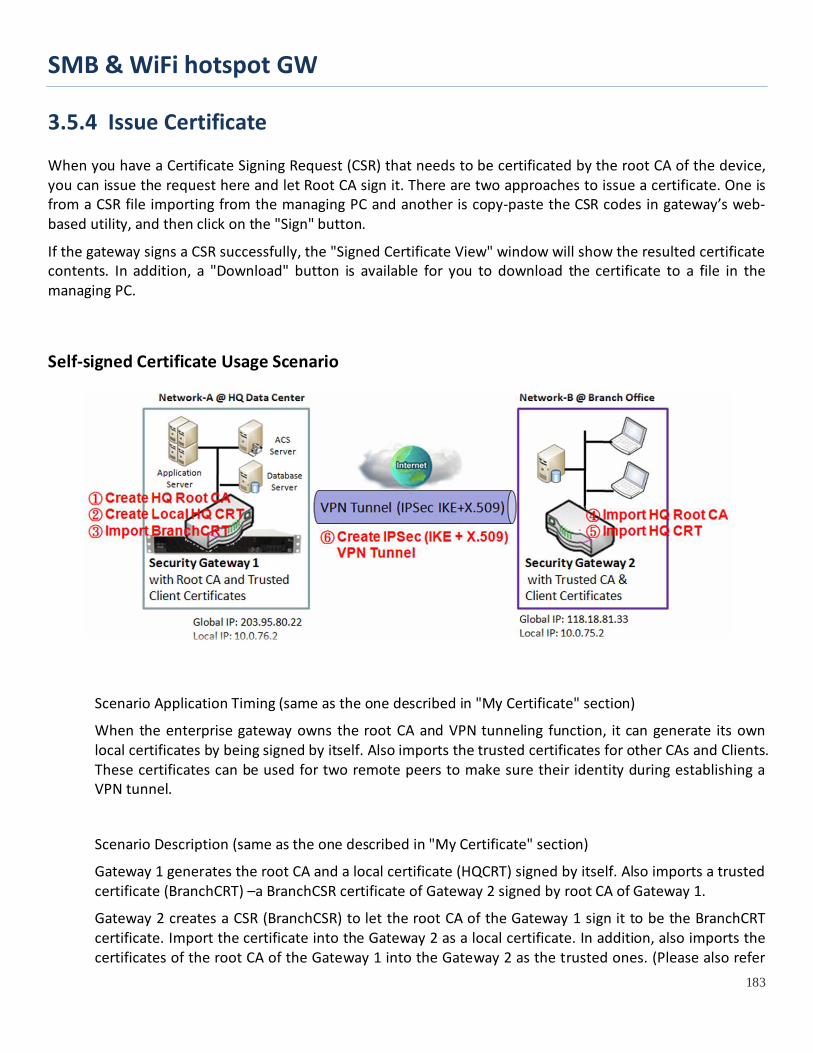
SMB & WiFi hotspot GW
183
3.5.4 Issue Certificate When you have a Certificate Signing Request (CSR) that needs to be certificated by the root CA of the device, you can issue the request here and let Root CA sign it. There are two approaches to issue a certificate. One is from a CSR file importing from the managing PC and another is copy-paste the CSR codes in gateway’s web-based utility, and then click on the "Sign" button.
If the gateway signs a CSR successfully, the "Signed Certificate View" window will show the resulted certificate contents. In addition, a "Download" button is available for you to download the certificate to a file in the managing PC.
Self-signed Certificate Usage Scenario
Scenario Application Timing (same as the one described in "My Certificate" section)
When the enterprise gateway owns the root CA and VPN tunneling function, it can generate its own local certificates by being signed by itself. Also imports the trusted certificates for other CAs and Clients. These certificates can be used for two remote peers to make sure their identity during establishing a VPN tunnel.
Scenario Description (same as the one described in "My Certificate" section)
Gateway 1 generates the root CA and a local certificate (HQCRT) signed by itself. Also imports a trusted certificate (BranchCRT) –a BranchCSR certificate of Gateway 2 signed by root CA of Gateway 1.
Gateway 2 creates a CSR (BranchCSR) to let the root CA of the Gateway 1 sign it to be the BranchCRT certificate. Import the certificate into the Gateway 2 as a local certificate. In addition, also imports the certificates of the root CA of the Gateway 1 into the Gateway 2 as the trusted ones. (Please also refer
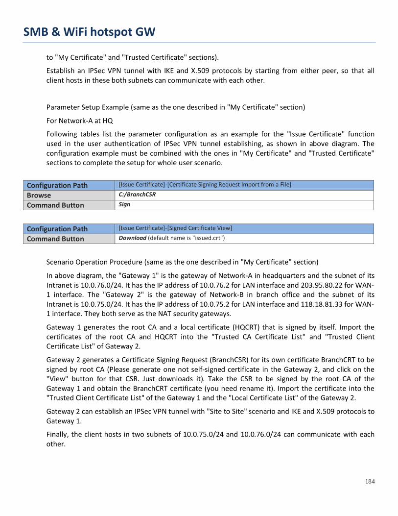
SMB & WiFi hotspot GW
184
to "My Certificate" and "Trusted Certificate" sections).
Establish an IPSec VPN tunnel with IKE and X.509 protocols by starting from either peer, so that all client hosts in these both subnets can communicate with each other.
Parameter Setup Example (same as the one described in "My Certificate" section)
For Network-A at HQ
Following tables list the parameter configuration as an example for the "Issue Certificate" function used in the user authentication of IPSec VPN tunnel establishing, as shown in above diagram. The configuration example must be combined with the ones in "My Certificate" and "Trusted Certificate" sections to complete the setup for whole user scenario.
Configuration Path [Issue Certificate]-[Certificate Signing Request Import from a File]
Browse C:/BranchCSR
Command Button Sign
Configuration Path [Issue Certificate]-[Signed Certificate View]
Command Button Download (default name is "issued.crt")
Scenario Operation Procedure (same as the one described in "My Certificate" section)
In above diagram, the "Gateway 1" is the gateway of Network-A in headquarters and the subnet of its Intranet is 10.0.76.0/24. It has the IP address of 10.0.76.2 for LAN interface and 203.95.80.22 for WAN-1 interface. The "Gateway 2" is the gateway of Network-B in branch office and the subnet of its Intranet is 10.0.75.0/24. It has the IP address of 10.0.75.2 for LAN interface and 118.18.81.33 for WAN-1 interface. They both serve as the NAT security gateways.
Gateway 1 generates the root CA and a local certificate (HQCRT) that is signed by itself. Import the certificates of the root CA and HQCRT into the "Trusted CA Certificate List" and "Trusted Client Certificate List" of Gateway 2.
Gateway 2 generates a Certificate Signing Request (BranchCSR) for its own certificate BranchCRT to be signed by root CA (Please generate one not self-signed certificate in the Gateway 2, and click on the "View" button for that CSR. Just downloads it). Take the CSR to be signed by the root CA of the Gateway 1 and obtain the BranchCRT certificate (you need rename it). Import the certificate into the "Trusted Client Certificate List" of the Gateway 1 and the "Local Certificate List" of the Gateway 2.
Gateway 2 can establish an IPSec VPN tunnel with "Site to Site" scenario and IKE and X.509 protocols to Gateway 1.
Finally, the client hosts in two subnets of 10.0.75.0/24 and 10.0.76.0/24 can communicate with each other.

SMB & WiFi hotspot GW
185
Issue Certificate Setting
Go to Object Definition > Certificate > Issue Certificate tab.
The Issue Certificate setting allows user to import Certificate Signing Request (CSR) to be signed by root CA.
Import and Issue Certificate
Certificate Signing Request (CSR) Import from a File Item Value setting Description Certificate Signing Request (CSR) Import from a File
A Must filled setting Select a certificate signing request file you’re your computer for importing to the gateway.
Certificate Signing Request (CSR) Import from a PEM
1. String format can be any text 2. A Must filled setting
Enter (copy-paste) the certificate signing request PEM encoded certificate to the gateway.
Sign N/A When root CA is exist, click the Sign button sign and issue the imported certificate by root CA.

SMB & WiFi hotspot GW
186
Chapter 4 Field Communication (not supported)
Not supported feature for the purchased product, leave it as blank.

SMB & WiFi hotspot GW
187
Chapter 5 Security
5.1 VPN A virtual private network (VPN) extends a private network across a public network, such as the Internet. It enables a computer to send and receive data across shared or public networks as if it were directly connected to the private network, while benefitting from the functionality, security and management policies of the private network. This is done by establishing a virtual point-to-point connection through the use of dedicated connections, encryption, or a combination of the two. The tunnel technology supports data confidentiality, data origin authentication and data integrity of network information by utilizing encapsulation protocols, encryption algorithms, and hashing algorithms.
The product series supports different tunneling technologies to establish secure tunnels between multiple sites for data transferring, such as IPSec, OpenVPN, L2TP (over IPSec), PPTP and GRE. Besides, some advanced functions, like Full Tunnel, Tunnel Failover, Tunnel Load Balance, NetBIOS over IPSec, NAT Traversal and Dynamic VPN, are also supported.
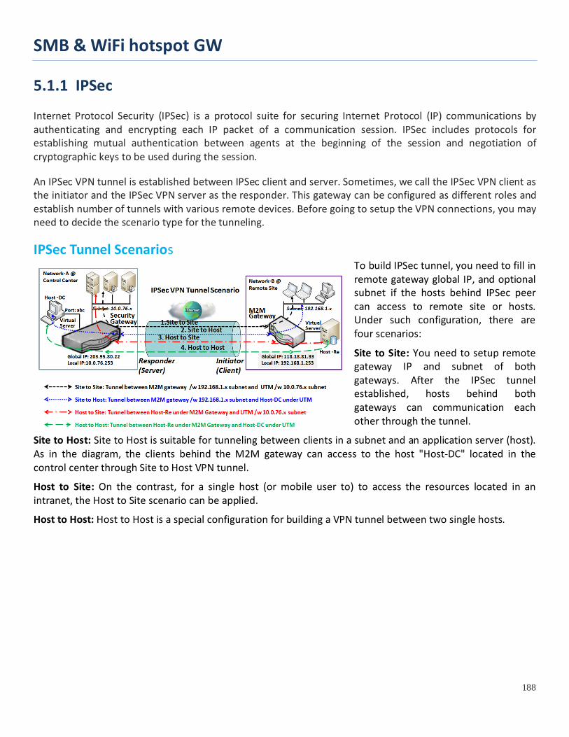
SMB & WiFi hotspot GW
188
5.1.1 IPSec Internet Protocol Security (IPSec) is a protocol suite for securing Internet Protocol (IP) communications by authenticating and encrypting each IP packet of a communication session. IPSec includes protocols for establishing mutual authentication between agents at the beginning of the session and negotiation of cryptographic keys to be used during the session.
An IPSec VPN tunnel is established between IPSec client and server. Sometimes, we call the IPSec VPN client as the initiator and the IPSec VPN server as the responder. This gateway can be configured as different roles and establish number of tunnels with various remote devices. Before going to setup the VPN connections, you may need to decide the scenario type for the tunneling.
IPSec Tunnel Scenarios To build IPSec tunnel, you need to fill in remote gateway global IP, and optional subnet if the hosts behind IPSec peer can access to remote site or hosts. Under such configuration, there are four scenarios:
Site to Site: You need to setup remote gateway IP and subnet of both gateways. After the IPSec tunnel established, hosts behind both gateways can communication each other through the tunnel.
Site to Host: Site to Host is suitable for tunneling between clients in a subnet and an application server (host). As in the diagram, the clients behind the M2M gateway can access to the host "Host-DC" located in the control center through Site to Host VPN tunnel.
Host to Site: On the contrast, for a single host (or mobile user to) to access the resources located in an intranet, the Host to Site scenario can be applied.
Host to Host: Host to Host is a special configuration for building a VPN tunnel between two single hosts.

SMB & WiFi hotspot GW
189
IPSec Setting
Go to Security > VPN > IPSec tab. The IPSec Setting allows user to create and configure IPSec tunnels. Enable IPSec
Configuration Window Item Value setting Description IPsec Unchecked by default Click the Enable box to enable IPSec function. Max. Concurrent IPSec Tunnels
Depends on Product specification.
The specified value will limit the maximum number of simultaneous IPSec tunnel connection. The default value can be different for the purchased model.
Save N/A Click Save to save the settings Undo N/A Click Undo to cancel the settings
Create/Edit IPSec tunnel Ensure that the IPSec enable box is checked to enable before further configuring the IPSec tunnel settings.
When Add/Edit button is applied, a series of configuration screens will appear. They are Tunnel Configuration, Local & Remote Configuration, Authentication, IKE Phase, IKE Proposal Definition, IPSec Phase, and IPSec Proposal Definition. You have to configure the tunnel details for both local and remote VPN devices.

SMB & WiFi hotspot GW
190
Tunnel Configuration Window Item Value setting Description Tunnel Unchecked by default Check the Enable box to activate the IPSec tunnel
Tunnel Name 1. A Must fill setting 2. String format can be any text
Enter a tunnel name. Enter a name that is easy for you to identify. Value Range: 1 ~ 19 characters.
Interface 1. A Must fill setting 2. WAN 1 is selected by default
Select the interface on which IPSec tunnel is to be established. It can be the available WAN and LAN interfaces.
Tunnel Scenario
1. A Must fill setting 2. Site to site is selected by default
Select an IPSec tunneling scenario from the dropdown box for your application. Select Site-to-Site, Site-to-Host, Host-to-Site, or Host-to-Host. If LAN interface is selected, only Host-to-Host scenario is available. With Site-to-Site or Site-to-Host or Host-to-Site, IPSec operates in tunnel mode. The difference among them is the number of subnets. With Host-to-Host, IPSec operates in transport mode.
Tunel TCP MSS 1. An optional setting 2. Auto is set by default
Select from the dropdown box to define the size of Tunel TCP MSS. Select Auto, and all devices will adjust this parameter automatically. Select Manual, and specify an expected vaule for Tunel TCP MSS. Value Range: 64 ~ 1500 bytes.
Encapsulation Protocol
1. A Must fill setting 2. ESP is selected by default
Select the Encapsulation Protocol from the dropdown box for this IPSec tunnel. Available encapsulations are ESP and AH.
IKE Version 1. A Must fill setting 2. v1 is selected by default
Specify the IKE version for this IPSec tunnel. Select v1 or v2.

SMB & WiFi hotspot GW
191
Local & Remote Configuration Window Item Value setting Description
Local Subnet List A Must fill setting
Specify the Local Subnet IP address and Subnet Mask. Click the Add or Delete button to add or delete a Local Subnet. Note_1: When Dynamic VPN option in Tunnel Scenario is selected, there will be only one subnet available. Note_2: When Host-to-Site or Host-to-Host option in Tunnel Scenario is selected, Local Subnet will not be available. Note_3: When Hub and Spoke option in Hub and Spoke is selected, there will be only one subnet available.
Remote Subnet List A Must fill setting Specify the Remote Subnet IP address and Subnet Mask. Click the Add or Delete button to add or delete Remote Subnet setting.
Remote Gateway 1. A Must fill setting. 2. Format can be a ipv4 address or FQDN
Specify the Remote Gateway.
Authentication Configuration Window Item Value setting Description
Key Management 1. A Must fill setting 2. Pre-shared Key 8 to 32 characters.
Select Key Management from the dropdown box for this IPSec tunnel. IKE+Pre-shared Key: user needs to set a key (8 ~ 32 characters). IKE+X.509: user needs Certificate to authenticate. IKE+X.509 will be available only when Certificate has been configured properly. Refer to Certificate section of this manual and also Object Definition > Certificate in web-based utility.
Local ID An optional setting
Specify the Local ID for this IPSec tunnel to authenticate. Select User Name for Local ID and enter the username. The username may include but can’t be all numbers. Select FQDN for Local ID and enter the FQDN. Select User@FQDN for Local ID and enter the User@FQDN.

SMB & WiFi hotspot GW
192
Select Key ID for Local ID and enter the Key ID (English alphabet or number).
Remote ID An optional setting
Specify the Remote ID for this IPSec tunnel to authenticate. Select User Name for Remote ID and enter the username. The username may include but can’t be all numbers. Select FQDN for Local ID and enter the FQDN. Select User@FQDN for Remote ID and enter the User@FQDN. Select Key ID for Remote ID and enter the Key ID (English alphabet or number). Note: Remote ID will be not available when Dynamic VPN option in Tunnel Scenario is selected.

SMB & WiFi hotspot GW
193
IKE Phase Window Item Value setting Description
Negotiation Mode Main Mode is set by default default
Specify the Negotiation Mode for this IPSec tunnel. Select Main Mode or Aggressive Mode.
X-Auth None is selected by default
Specify the X-Auth role for this IPSec tunnel. Select Server, Client, or None. Selected None no X-Auth authentication is required. Selected Server this gateway will be an X-Auth server. Click on the X-Auth Account button to create remote X-Auth client account. Selected Client this gateway will be an X-Auth client. Enter User name and Password to be authenticated by the X-Auth server gateway. Note: X-Auth Client will not be available for Dynamic VPN option selected in Tunnel Scenario.
Dead Peer Detection (DPD)
1. Checked by default 2. Default Timeout 180s and Delay 30s
Click Enable box to enable DPD function. Specify the Timeout and Delay time in seconds. Value Range: 0 ~ 999 seconds for Timeout and Delay.
Phase1 Key Life Time
1. A Must fill setting 2. Default 3600s 3. Max. 86400s
Specify the Phase1 Key Life Time. Value Range: 30 ~ 86400.
IKE Proposal Definition Window Item Value setting Description
IKE Proposal Definition A Must fill setting
Specify the Phase 1 Encryption method. It can be DES / 3DES / AES-128 / AES-192 / AES-256. Specify the Authentication method. It can be None / MD5 / SHA1 / SHA2-256. Specify the DH Group. It can be None / Group1 / Group2 / Group5 / Group14 / Group15 / Group16 / Group17 / Group18. Check Enable box to enable this setting
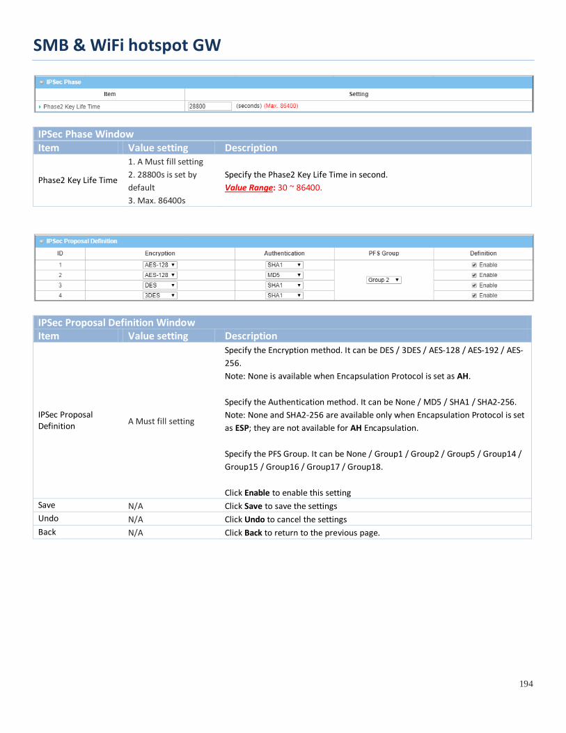
SMB & WiFi hotspot GW
194
IPSec Phase Window Item Value setting Description
Phase2 Key Life Time
1. A Must fill setting 2. 28800s is set by default 3. Max. 86400s
Specify the Phase2 Key Life Time in second. Value Range: 30 ~ 86400.
IPSec Proposal Definition Window Item Value setting Description
IPSec Proposal Definition A Must fill setting
Specify the Encryption method. It can be DES / 3DES / AES-128 / AES-192 / AES-256. Note: None is available when Encapsulation Protocol is set as AH. Specify the Authentication method. It can be None / MD5 / SHA1 / SHA2-256. Note: None and SHA2-256 are available only when Encapsulation Protocol is set as ESP; they are not available for AH Encapsulation. Specify the PFS Group. It can be None / Group1 / Group2 / Group5 / Group14 / Group15 / Group16 / Group17 / Group18. Click Enable to enable this setting
Save N/A Click Save to save the settings Undo N/A Click Undo to cancel the settings Back N/A Click Back to return to the previous page.
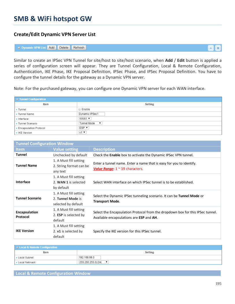
SMB & WiFi hotspot GW
195
Create/Edit Dynamic VPN Server List
Similar to create an IPSec VPN Tunnel for site/host to site/host scenario, when Add / Edit button is applied a series of configuration screen will appear. They are Tunnel Configuration, Local & Remote Configuration, Authentication, IKE Phase, IKE Proposal Definition, IPSec Phase, and IPSec Proposal Definition. You have to configure the tunnel details for the gateway as a Dynamic VPN server. Note: For the purchased gateway, you can configure one Dynamic VPN server for each WAN interface.
Tunnel Configuration Window Item Value setting Description Tunnel Unchecked by default Check the Enable box to activate the Dynamic IPSec VPN tunnel.
Tunnel Name 1. A Must fill setting 2. String format can be any text
Enter a tunnel name. Enter a name that is easy for you to identify. Value Range: 1 ~ 19 characters.
Interface 1. A Must fill setting 2. WAN 1 is selected by default
Select WAN interface on which IPSec tunnel is to be established.
Tunnel Scenario 1. A Must fill setting 2. Tunnel Mode is selected by default
Select the Dynamic IPSec tunneling scenario. It can be Tunnel Mode or Transport Mode.
Encapsulation Protocol
1. A Must fill setting 2. ESP is selected by default
Select the Encapsulation Protocol from the dropdown box for this IPSec tunnel. Available encapsulations are ESP and AH.
IKE Version 1. A Must fill setting 2. v1 is selected by default
Specify the IKE version for this IPSec tunnel.
Local & Remote Configuration Window

SMB & WiFi hotspot GW
196
Item Value setting Description Local Subnet A Must fill setting Specify the Local Subnet IP address. Local Netmask A Must fill setting Specify the Local Subnet Mask.
Authentication Configuration Window Item Value setting Description
Key Management 1. A Must fill setting 2. Pre-shared Key 8 to 32 characters.
Select Key Management from the dropdown box for this IPSec tunnel. IKE+Pre-shared Key: user needs to set a key (8 ~ 32 characters).
Local ID An optional setting
Specify the Local ID for this IPSec tunnel to authenticate. Select User Name for Local ID and enter the username. The username may include but can’t be all numbers. Select FQDN for Local ID and enter the FQDN. Select User@FQDN for Local ID and enter the User@FQDN. Select Key ID for Local ID and enter the Key ID (English alphabet or number).
Remote ID An optional setting
Specify the Remote ID for this IPSec tunnel to authenticate. Select User Name for Remote ID and enter the username. The username may include but can’t be all numbers. Select FQDN for Local ID and enter the FQDN. Select User@FQDN for Remote ID and enter the User@FQDN. Select Key ID for Remote ID and enter the Key ID (English alphabet or number). Note: Remote ID will be not available when Dynamic VPN option in Tunnel Scenario is selected.
For the rest IKE Phase, IKE Proposal Definition, IPSec Phase, and IPSec Proposal Definition settings, they are the same as that of creating an IPSec Tunnel described in previous section. Please refer to the related description.

SMB & WiFi hotspot GW
197
5.1.2 OpenVPN
OpenVPN is an application that implements virtual private network (VPN) techniques for creating secure point-to-point or site-to-site connections in routed or bridged configurations and remote access facilities. It uses a custom security protocol that utilizes SSL/TLS for key exchange. It is capable of traversing network address translators (NATs) and firewalls.
OpenVPN allows peers to authenticate each other using a Static Key (pre-shared key) or certificates. When used in a multi-client-server configuration, it allows the server to release an authentication certificate for every client, using signature and certificate authority. It uses the OpenSSL encryption library extensively, as well as the SSLv3/TLSv1 protocol, and contains many security and control features.
OpenVPN Tunneling is a Client and Server based tunneling technology. The OpenVPN Server must have a Static IP or a FQDN, and maintain a Client list. The OpenVPN Client may be a mobile user or mobile site with public IP or private IP, and requesting the OpenVPN tunnel connection. The product supports both OpenVPN Server and OpenVPN Client features to meet different application requirements.
There are two OpenVPN connection scenarios. They are the TAP and TUN scenarios. The product can create either a layer-3 based IP tunnel (TUN), or a layer-2 based Ethernet TAP that can carry any type of Ethernet traffic. In addition to configuring the device as a Server or Client, you have to specify which type of OpenVPN connection scenario is to be adopted.
OpenVPN TUN Scenario The term "TUN" mode is referred to routing mode and operates with layer 3 packets. In routing mode, the VPN client is given an IP address on a different subnet than the local LAN under the OpenVPN server. This virtual subnet is created for connecting to any remote VPN computers. In routing mode, the OpenVPN server creates a "TUN" interface with its own IP address pool which is different to the local LAN. Remote hosts that dial-in will get an IP address inside the virtual network and will have access only to the server where OpenVPN resides.
If you want to offer remote access to a VPN server from client(s), and inhibit the access to remote LAN resources under VPN server, OpenVPN TUN mode is the simplest
solution.
As shown in the diagram, the M2M-IoT Gateway is configured as an OpenVPN TUN Client, and connects to an OpenVPN UN Server. Once the OpenVPN TUN connection is established, the connected TUN client will be
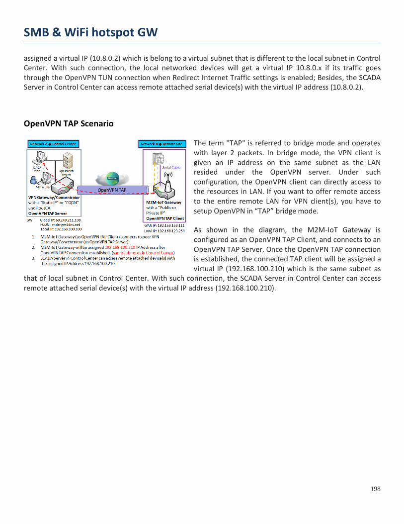
SMB & WiFi hotspot GW
198
assigned a virtual IP (10.8.0.2) which is belong to a virtual subnet that is different to the local subnet in Control Center. With such connection, the local networked devices will get a virtual IP 10.8.0.x if its traffic goes through the OpenVPN TUN connection when Redirect Internet Traffic settings is enabled; Besides, the SCADA Server in Control Center can access remote attached serial device(s) with the virtual IP address (10.8.0.2).
OpenVPN TAP Scenario
The term "TAP" is referred to bridge mode and operates with layer 2 packets. In bridge mode, the VPN client is given an IP address on the same subnet as the LAN resided under the OpenVPN server. Under such configuration, the OpenVPN client can directly access to the resources in LAN. If you want to offer remote access to the entire remote LAN for VPN client(s), you have to setup OpenVPN in “TAP” bridge mode.
As shown in the diagram, the M2M-IoT Gateway is configured as an OpenVPN TAP Client, and connects to an OpenVPN TAP Server. Once the OpenVPN TAP connection is established, the connected TAP client will be assigned a virtual IP (192.168.100.210) which is the same subnet as
that of local subnet in Control Center. With such connection, the SCADA Server in Control Center can access remote attached serial device(s) with the virtual IP address (192.168.100.210).
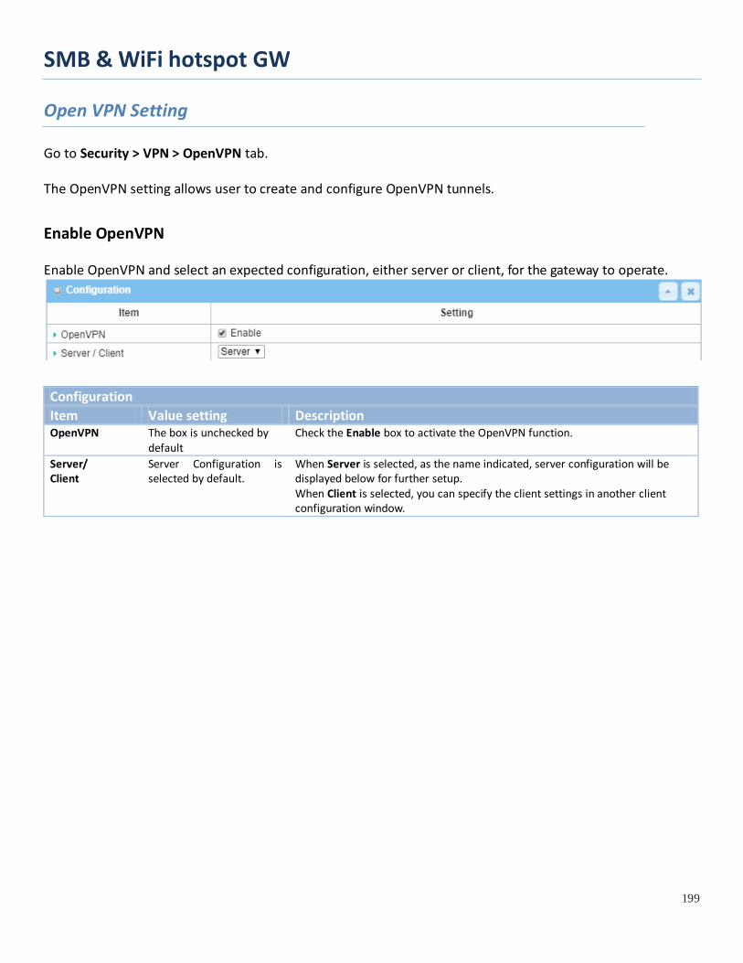
SMB & WiFi hotspot GW
199
Open VPN Setting
Go to Security > VPN > OpenVPN tab. The OpenVPN setting allows user to create and configure OpenVPN tunnels.
Enable OpenVPN Enable OpenVPN and select an expected configuration, either server or client, for the gateway to operate.
Configuration Item Value setting Description OpenVPN The box is unchecked by
default Check the Enable box to activate the OpenVPN function.
Server/ Client
Server Configuration is selected by default.
When Server is selected, as the name indicated, server configuration will be displayed below for further setup. When Client is selected, you can specify the client settings in another client configuration window.
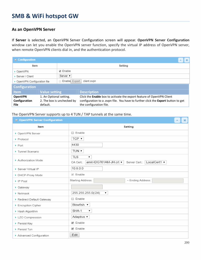
SMB & WiFi hotspot GW
200
As an OpenVPN Server If Server is selected, an OpenVPN Server Configuration screen will appear. OpenVPN Server Configuration window can let you enable the OpenVPN server function, specify the virtual IP address of OpenVPN server, when remote OpenVPN clients dial in, and the authentication protocol.
Configuration Item Value setting Description OpenVPN Configuration File
1. An Optional setting. 2. The box is unchecked by default.
Click the Enable box to activate the export feature of OpenVPN Client configuration to a .ovpn file. You have to further click the Export button to get the configuration file.
The OpenVPN Server supports up to 4 TUN / TAP tunnels at the same time.

SMB & WiFi hotspot GW
201
OpenVPN Server Configuration Item Value setting Description OpenVPN Server The box is unchecked by
default. Click the Enable to activate OpenVPN Server functions.
Protocol 1. A Must filled setting 2. By default TCP is
selected.
Define the selected Protocol for connecting to the OpenVPN Server. • Select TCP , or UDP -> The TCP protocol will be used to access the OpenVPN Server, and Port will be set as 4430 automatically. • Select UDP -> The UDP protocol will be used to access the OpenVPN Server, and Port will be set as 1194 automatically.
Port 1. A Must filled setting 2. By default 4430 is set.
Specify the Port for connecting to the OpenVPN Server. Value Range: 1 ~ 65535.
Tunnel Scenario 1. A Must filled setting 2. By default TUN is
selected.
Specify the type of Tunnel Scenario for connecting to the OpenVPN Server. It can be TUN for TUN tunnel scenario, or TAP for TAP tunnel scenario.
Authorization Mode
1. A Must filled setting 2. By default TLS is
selected.
Specify the authorization mode for the OpenVPN Server. • TLS ->The OpenVPN will use TLS authorization mode, and the following items CA Cert., Server Cert. and DH PEM will be displayed. CA Cert. could be generated in Certificate. Refer to Object Definition > Certificate > Trusted Certificate. Server Cert. could be generated in Certificate. Refer to Object Definition > Certificate > My Certificate. • Static Key ->The OpenVPN will use static key (pre-shared) authorization mode, and the following items Local Endpoint IP Address, Remote Endpoint IP Address and Static Key will be displayed. Note: Static Key will be available only when TUN is chosen in Tunnel Scenario.
Local Endpoint IP Address
A Must filled setting Specify the virtual Local Endpoint IP Address of this OpenVPN gateway. Value Range: The IP format is 10.8.0.x, the range of x is 1~254. Note: Local Endpoint IP Address will be available only when Static Key is chosen in Authorization Mode.
Remote Endpoint IP Address
A Must filled setting Specify the virtual Remote Endpoint IP Address of the peer OpenVPN gateway. Value Range: The IP format is 10.8.0.x, the range of x is 1~254. Note: Remote Endpoint IP Address will be available only when Static Key is chosen in Authorization Mode.
Static Key A Must filled setting Specify the Static Key. Note: Static Key will be available only when Static Key is chosen in Authorization Mode.
Server Virtual IP A Must filled setting Specify the Server Virtual IP. Value Range: The IP format is 10.y.0.0, the range of y is 1~254. Note: Server Virtual IP will be available only when TLS is chosen in Authorization Mode.
DHCP-Proxy Mode
1. A Must filled setting 2. The box is checked by default.
Check the Enable box to activate the DHCP-Proxy Mode. Note: DHCP-Proxy Mode will be available only when TAP is chosen in Tunnel Device.
IP Pool A Must filled setting Specify the virtual IP pool setting for the OpenVPN server. You have to specify the Starting Address and Ending Address as the IP address pool for the OpenVPN clients.

SMB & WiFi hotspot GW
202
Note: IP Pool will be available only when TAP is chosen in Tunnel Device, and DHCP-Proxy Mode is unchecked (disabled).
Gateway A Must filled setting Specify the Gateway setting for the OpenVPN server. It will be assigned to the connected OpenVPN clients. Note: Gateway will be available only when TAP is chosen in Tunnel Device, and DHCP-Proxy Mode is unchecked (disabled).
Netmask By default - select one - is selected.
Specify the Netmask setting for the OpenVPN server. It will be assigned to the connected OpenVPN clients. Value Range: 255.255.255.0/24 (only support class C) Note_1: Netmask will be available when TAP is chosen in Tunnel Device, and DHCP-Proxy Mode is unchecked (disabled). Note_2: Netmask will also be available when TUN is chosen in Tunnel Device.
Redirect Default Gateway
1. An Optional setting. 2. The box is unchecked by default.
Check the Enable box to activate the Redirect Default Gateway function.
Encryption Cipher
1. A Must filled setting. 2. By default Blowfish is selected.
Specify the Encryption Cipher from the dropdown list. It can be Blowfish/AES-256/AES-192/AES-128/None.
Hash Algorithm By default SHA-1 is selected.
Specify the Hash Algorithm from the dropdown list. It can be SHA-1/MD5/MD4/SHA2-256/SHA2-512/None/Disable.
LZO Compression
By default Adaptive is selected.
Specify the LZO Compression scheme. It can be Adaptive/YES/NO/Default.
Persis Key 1. An Optional setting. 2. The box is checked by default.
Check the Enable box to activate the Persis Key function.
Persis Tun 1. An Optional setting. 2. The box is checked by default.
Check the Enable box to activate the Persis Tun function.
Advanced Configuration
N/A Click the Edit button to specify the Advanced Configuration setting for the OpenVPN server. If the button is clicked, Advanced Configuration will be displayed below.
Save N/A Click Save to save the settings. Undo N/A Click X to cancel the changes and return to last page.
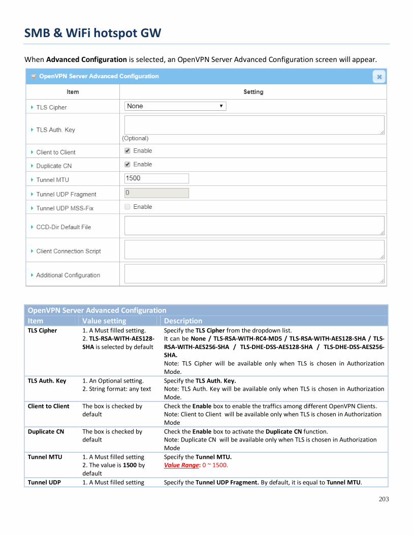
SMB & WiFi hotspot GW
203
When Advanced Configuration is selected, an OpenVPN Server Advanced Configuration screen will appear.
OpenVPN Server Advanced Configuration Item Value setting Description TLS Cipher 1. A Must filled setting.
2. TLS-RSA-WITH-AES128-SHA is selected by default
Specify the TLS Cipher from the dropdown list. It can be None / TLS-RSA-WITH-RC4-MD5 / TLS-RSA-WITH-AES128-SHA / TLS-RSA-WITH-AES256-SHA / TLS-DHE-DSS-AES128-SHA / TLS-DHE-DSS-AES256-SHA. Note: TLS Cipher will be available only when TLS is chosen in Authorization Mode.
TLS Auth. Key 1. An Optional setting. 2. String format: any text
Specify the TLS Auth. Key. Note: TLS Auth. Key will be available only when TLS is chosen in Authorization Mode.
Client to Client The box is checked by default
Check the Enable box to enable the traffics among different OpenVPN Clients. Note: Client to Client will be available only when TLS is chosen in Authorization Mode
Duplicate CN The box is checked by default
Check the Enable box to activate the Duplicate CN function. Note: Duplicate CN will be available only when TLS is chosen in Authorization Mode
Tunnel MTU 1. A Must filled setting 2. The value is 1500 by default
Specify the Tunnel MTU. Value Range: 0 ~ 1500.
Tunnel UDP 1. A Must filled setting Specify the Tunnel UDP Fragment. By default, it is equal to Tunnel MTU.

SMB & WiFi hotspot GW
204
Fragment 2. The value is 1500 by default
Value Range: 0 ~ 1500. Note: Tunnel UDP Fragment will be available only when UDP is chosen in Protocol.
Tunnel UDP MSS-Fix
1. An Optional setting. 2. The box is unchecked by default.
Check the Enable box to activate the Tunnel UDP MSS-Fix Function. Note: Tunnel UDP MSS-Fix will be available only when UDP is chosen in Protocol.
CCD-Dir Default File
1. An Optional setting. 2. String format: any text
Specify the CCD-Dir Default File. Value Range: 0 ~ 256 characters.
Client Connection Script
1. An Optional setting. 2. String format: any text
Specify the Client Connection Script. Value Range: 0 ~ 256 characters.
Additional Configuration
1. An Optional setting. 2. String format: any text
Specify the Additional Configuration. Value Range: 0 ~ 256 characters.

SMB & WiFi hotspot GW
205
As an OpenVPN Client If Client is selected, the configuration screen will be changed as below and an OpenVPN Client List screen appear.
OpenVPN Configuration Item Value setting Description OpenVPN The box is unchecked
by default Check the Enable box to activate the OpenVPN function.
Server/ Client
Server Configuration is selected by default.
When Server is selected, as the name indicated, server configuration will be displayed below for further setup. When Client is selected, you can specify the client settings in another client configuration window.
OpenVPN Configuration file
1. An Optional setting. 2. The box is unchecked by default.
Click the Enable box to activate the OpenVPN Client configuration via a pre-defined configuration file. You have to further click the Upgrade button to upload the configuration from a .ovpn file. If you enabled this function, you can’t add any OpenVPN clients manually.
When Add button is applied, OpenVPN Client Configuration screen will appear. OpenVPN Client Configuration window let you specify the required parameters for an OpenVPN VPN client, such as "OpenVPN Client Name", "Interface", "Protocol", "Tunnel Scenario", "Remote IP/FQDN", "Remote Subnet", "Authorization Mode", "Encryption Cipher", "Hash Algorithm" and tunnel activation.
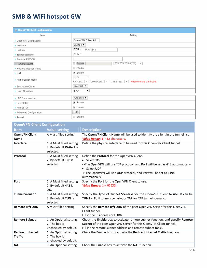
SMB & WiFi hotspot GW
206
OpenVPN Client Configuration Item Value setting Description OpenVPN Client Name
A Must filled setting The OpenVPN Client Name will be used to identify the client in the tunnel list. Value Range: 1 ~ 32 characters.
Interface 1. A Must filled setting 2. By default WAN-1 is selected.
Define the physical interface to be used for this OpenVPN Client tunnel.
Protocol 1. A Must filled setting 2. By default TCP is selected.
Define the Protocol for the OpenVPN Client. • Select TCP ->The OpenVPN will use TCP protocol, and Port will be set as 443 automatically. • Select UDP -> The OpenVPN will use UDP protocol, and Port will be set as 1194 automatically.
Port 1. A Must filled setting 2. By default 443 is set.
Specify the Port for the OpenVPN Client to use. Value Range: 1 ~ 65535.
Tunnel Scenario 1. A Must filled setting 2. By default TUN is selected.
Specify the type of Tunnel Scenario for the OpenVPN Client to use. It can be TUN for TUN tunnel scenario, or TAP for TAP tunnel scenario.
Remote IP/FQDN A Must filled setting Specify the Remote IP/FQDN of the peer OpenVPN Server for this OpenVPN Client tunnel. Fill in the IP address or FQDN.
Remote Subnet 1. An Optional setting. 2. The box is unchecked by default.
Check the Enable box to activate remote subnet function, and specify Remote Subnet of the peer OpenVPN Server for this OpenVPN Client tunnel. Fill in the remote subnet address and remote subnet mask.
Redirect Internet Traffic
1. An Optional setting. 2. The box is unchecked by default.
Check the Enable box to activate the Redirect Internet Traffic function.
NAT 1. An Optional setting. Check the Enable box to activate the NAT function.
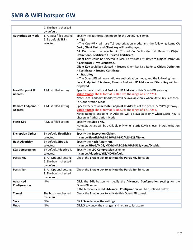
SMB & WiFi hotspot GW
207
2. The box is checked by default.
Authorization Mode 1. A Must filled setting 2. By default TLS is selected.
Specify the authorization mode for the OpenVPN Server. • TLS ->The OpenVPN will use TLS authorization mode, and the following items CA Cert., Client Cert. and Client Key will be displayed. CA Cert. could be selected in Trusted CA Certificate List. Refer to Object Definition > Certificate > Trusted Certificate. Client Cert. could be selected in Local Certificate List. Refer to Object Definition > Certificate > My Certificate. Client Key could be selected in Trusted Client key List. Refer to Object Definition > Certificate > Trusted Certificate. • Static Key ->The OpenVPN will use static key authorization mode, and the following items Local Endpoint IP Address, Remote Endpoint IP Address and Static Key will be displayed.
Local Endpoint IP Address
A Must filled setting Specify the virtual Local Endpoint IP Address of this OpenVPN gateway. Value Range: The IP format is 10.8.0.x, the range of x is 1~254. Note: Local Endpoint IP Address will be available only when Static Key is chosen in Authorization Mode.
Remote Endpoint IP Address
A Must filled setting Specify the virtual Remote Endpoint IP Address of the peer OpenVPN gateway. Value Range: The IP format is 10.8.0.x, the range of x is 1~254. Note: Remote Endpoint IP Address will be available only when Static Key is chosen in Authorization Mode.
Static Key A Must filled setting Specify the Static Key. Note: Static Key will be available only when Static Key is chosen in Authorization Mode.
Encryption Cipher By default Blowfish is selected.
Specify the Encryption Cipher. It can be Blowfish/AES-256/AES-192/AES-128/None.
Hash Algorithm By default SHA-1 is selected.
Specify the Hash Algorithm. It can be SHA-1/MD5/MD4/SHA2-256/SHA2-512/None/Disable.
LZO Compression By default Adaptive is selected.
Specify the LZO Compression scheme. It can be Adaptive/YES/NO/Default.
Persis Key 1. An Optional setting. 2. The box is checked by default.
Check the Enable box to activate the Persis Key function.
Persis Tun 1. An Optional setting. 2. The box is checked by default.
Check the Enable box to activate the Persis Tun function.
Advanced Configuration
N/A Click the Edit button to specify the Advanced Configuration setting for the OpenVPN server. If the button is clicked, Advanced Configuration will be displayed below.
Tunnel The box is unchecked by default
Check the Enable box to activate this OpenVPN tunnel.
Save N/A Click Save to save the settings. Undo N/A Click X to cancel the changes and return to last page.

SMB & WiFi hotspot GW
208
When Advanced Configuration is selected, an OpenVPN Client Advanced Configuration screen will appear.
OpenVPN Advanced Client Configuration Item Value setting Description TLS Cipher 1. A Must filled setting.
2. TLS-RSA-WITH-AES128-SHA is selected by default
Specify the TLS Cipher from the dropdown list. It can be None / TLS-RSA-WITH-RC4-MD5 / TLS-RSA-WITH-AES128-SHA / TLS-RSA-WITH-AES256-SHA / TLS-DHE-DSS-AES128-SHA / TLS-DHE-DSS-AES256-SHA. Note: TLS Cipher will be available only when TLS is chosen in Authorization Mode.
TLS Auth. Key 1. An Optional setting. 2. String format: any text
Specify the TLS Auth. Key for connecting to an OpenVPN server, if the server required it. Note: TLS Auth. Key will be available only when TLS is chosen in Authorization Mode.
User Name An Optional setting. Enter the User account for connecting to an OpenVPN server, if the server required it. Note: User Name will be available only when TLS is chosen in Authorization Mode.
Password An Optional setting. Enter the Password for connecting to an OpenVPN server, if the server required it. Note: User Name will be available only when TLS is chosen in Authorization Mode.
Bridge TAP to By default VLAN 1 is selected
Specify the setting of “Bridge TAP to” to bridge the TAP interface to a certain local network interface or VLAN. Note: Bridge TAP to will be available only when TAP is chosen in Tunnel Scenario and NAT is unchecked.
Firewall Protection The box is unchecked by default.
Check the box to activate the Firewall Protection function. Note: Firewall Protection will be available only when NAT is enabled.
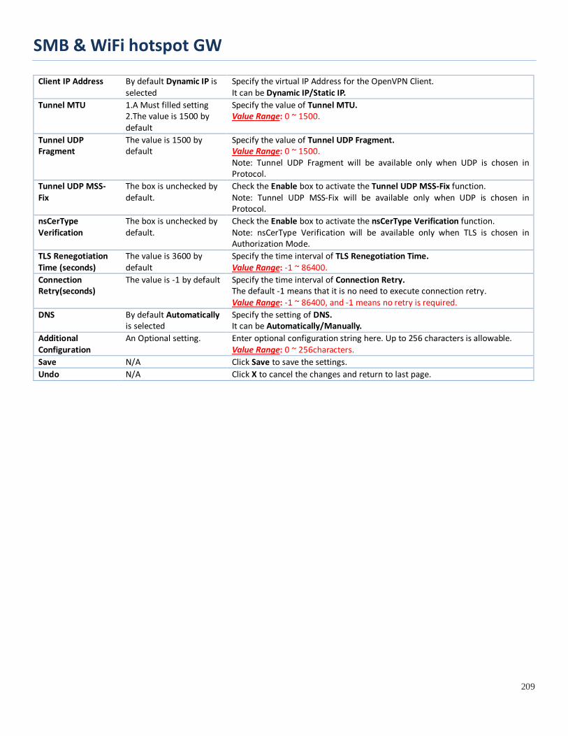
SMB & WiFi hotspot GW
209
Client IP Address By default Dynamic IP is selected
Specify the virtual IP Address for the OpenVPN Client. It can be Dynamic IP/Static IP.
Tunnel MTU 1.A Must filled setting 2.The value is 1500 by default
Specify the value of Tunnel MTU. Value Range: 0 ~ 1500.
Tunnel UDP Fragment
The value is 1500 by default
Specify the value of Tunnel UDP Fragment. Value Range: 0 ~ 1500. Note: Tunnel UDP Fragment will be available only when UDP is chosen in Protocol.
Tunnel UDP MSS-Fix
The box is unchecked by default.
Check the Enable box to activate the Tunnel UDP MSS-Fix function. Note: Tunnel UDP MSS-Fix will be available only when UDP is chosen in Protocol.
nsCerType Verification
The box is unchecked by default.
Check the Enable box to activate the nsCerType Verification function. Note: nsCerType Verification will be available only when TLS is chosen in Authorization Mode.
TLS Renegotiation Time (seconds)
The value is 3600 by default
Specify the time interval of TLS Renegotiation Time. Value Range: -1 ~ 86400.
Connection Retry(seconds)
The value is -1 by default Specify the time interval of Connection Retry. The default -1 means that it is no need to execute connection retry. Value Range: -1 ~ 86400, and -1 means no retry is required.
DNS By default Automatically is selected
Specify the setting of DNS. It can be Automatically/Manually.
Additional Configuration
An Optional setting. Enter optional configuration string here. Up to 256 characters is allowable. Value Range: 0 ~ 256characters.
Save N/A Click Save to save the settings. Undo N/A Click X to cancel the changes and return to last page.

SMB & WiFi hotspot GW
210
5.1.3 L2TP
Layer 2 Tunneling Protocol (L2TP) is a tunneling protocol used to support virtual private networks (VPNs) or as part of the delivery of services by ISPs. It does not provide any encryption or confidentiality by itself. Rather, it relies on an encryption protocol that it passes within the tunnel to provide privacy. This Gateway can behave as a L2TP server and a L2TP client both at the same time.
L2TP Server: It must have a static IP or a FQDN for clients to create L2TP tunnels. It also maintains “User Account list” (user name/ password) for client login authentication; There is a virtual IP pool to assign virtual IP to each connected L2TP client.
L2TP Client: It can be mobile users or gateways in remote offices with dynamic IP. To setup tunnel, it should get “user name”, “password” and server’s global IP. In addition, it is required to identify the operation mode for each tunnel as main connection, failover for another tunnel, or load balance tunnel to increase overall bandwidth. It needs to decide “Default Gateway” or “Remote Subnet” for packet flow. Moreover, you can also define what kind of traffics will pass through the L2TP tunnel in the “Default Gateway / Remote Subnet” parameter.

SMB & WiFi hotspot GW
211
Besides, for the L2TP client peer, a Remote Subnet item is required. It is for the Intranet of L2TP server peer. So, at L2TP client peer, the packets whose destination is in the dedicated subnet will be transferred via the L2TP tunnel. Others will be transferred based on current routing policy of the gateway at L2TP client peer. But, if you entered 0.0.0.0/0 in the Remote Subnet field, it will be treated as a "Default Gateway" setting for the L2TP client peer, all packets, including the Internet accessing of L2TP client peer, will go through the established L2TP tunnel. That means the remote L2TP server peer controls the flow of any packets from the L2TP client peer. Certainly, those packets come through the L2TP tunnel.
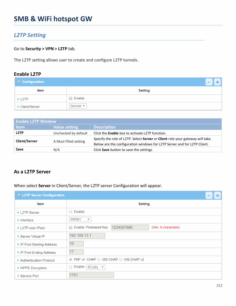
SMB & WiFi hotspot GW
212
L2TP Setting
Go to Security > VPN > L2TP tab. The L2TP setting allows user to create and configure L2TP tunnels.
Enable L2TP
Enable L2TP Window Item Value setting Description L2TP Unchecked by default Click the Enable box to activate L2TP function.
Client/Server A Must filled setting Specify the role of L2TP. Select Server or Client role your gateway will take. Below are the configuration windows for L2TP Server and for L2TP Client.
Save N/A Click Save button to save the settings
As a L2TP Server
When select Server in Client/Server, the L2TP server Configuration will appear.

SMB & WiFi hotspot GW
213
L2TP Server Configuration Item Value setting Description
L2TP Server The box is unchecked by default
When click the Enable box It will active L2TP server
Interface 1. A Must fill setting 2. All WANs is selected by default
Select the interface on which L2TP tunnel is to be established. It can be the available WAN interfaces.
L2TP over IPSec The box is unchecked by default
When click the Enable box. It will enable L2TP over IPSec and need to fill in the Pre-shared Key (8~32 characters).
Server Virtual IP A Must filled setting Specify the L2TP server Virtual IP It will set as this L2TP server local virtual IP
IP Pool Starting Address
1. A Must filled setting 2. 10 is set by default.
Specify the L2TP server starting IP of virtual IP pool It will set as the starting IP which assign to L2TP client Value Range: 1 ~ 254.
IP Pool Ending Address
1. A Must filled setting 2. 17 is set by default.
Specify the L2TP server ending IP of virtual IP pool It will set as the ending IP which assign to L2TP client Value Range: >= Starting Address, and < (Starting Address + 8) or 254.
Authentication Protocol A Must filled setting
Select single or multiple Authentication Protocols for the L2TP server with which to authenticate L2TP clients. Available authentication protocols are PAP / CHAP / MS-CHAP / MS-CHAP v2.
MPPE Encryption A Must filled setting
Specify whether to support MPPE Protocol. Click the Enable box to enable MPPE and from dropdown box to select 40 bits / 56 bits / 128 bits. Note: when MPPE Encryption is enabled, the Authentication Protocol PAP / CHAP options will not be available.
Service Port A Must filled setting Specify the Service Port which L2TP server use. Value Range: 1 ~ 65535.
Save N/A Click the Save button to save the configuration. Undo N/A Click the Undo button to recovery the configuration.
L2TP Server Status Item Value setting Description
L2TP Server Status N/A It displays the User Name, Remote IP, Remote Virtual IP, and Remote Call ID of the connected L2TP clients. Click the Refresh button to renew the L2TP client information.

SMB & WiFi hotspot GW
214
User Account List Window Item Value setting Description
User Account List Max.of 10 user accounts
This is the L2TP authentication user account entry. You can create and add accounts for remote clients to establish L2TP VPN connection to the gateway device. Click Add button to add user account. Enter User name and password. Then check the enable box to enable the user. Click Save button to save new user account. The selected user account can permanently be deleted by clicking the Delete button. Value Range: 1 ~ 32 characters.
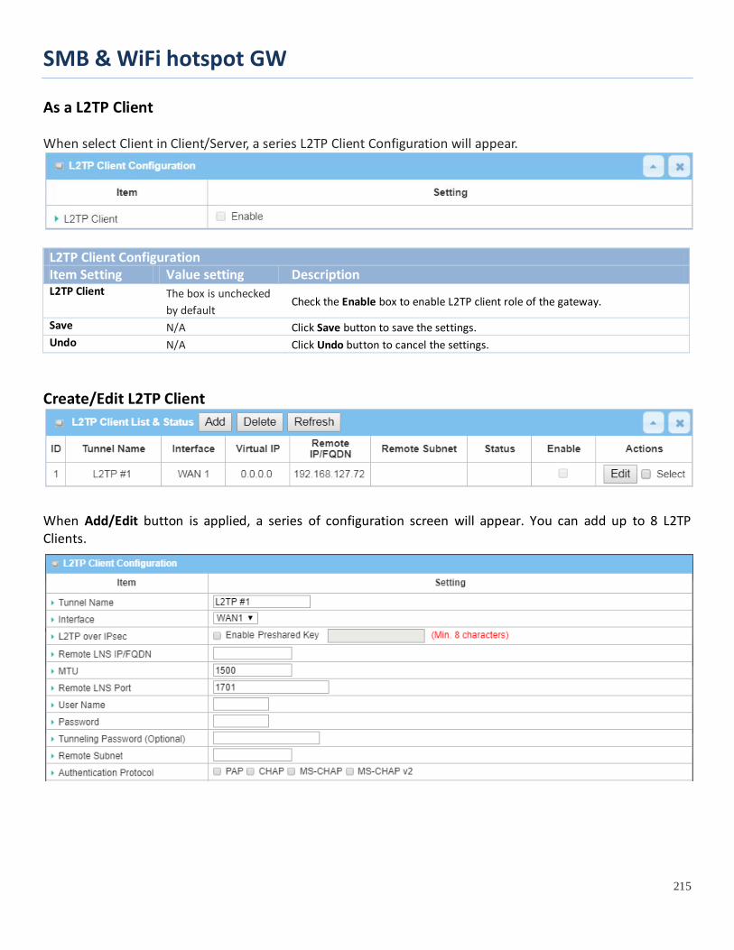
SMB & WiFi hotspot GW
215
As a L2TP Client When select Client in Client/Server, a series L2TP Client Configuration will appear.
L2TP Client Configuration Item Setting Value setting Description L2TP Client The box is unchecked
by default Check the Enable box to enable L2TP client role of the gateway.
Save N/A Click Save button to save the settings. Undo N/A Click Undo button to cancel the settings.
Create/Edit L2TP Client
When Add/Edit button is applied, a series of configuration screen will appear. You can add up to 8 L2TP Clients.
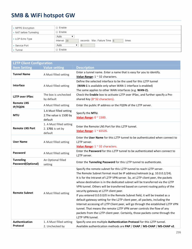
SMB & WiFi hotspot GW
216
L2TP Client Configuration Item Setting Value setting Description
Tunnel Name A Must filled setting Enter a tunnel name. Enter a name that is easy for you to identify. Value Range: 1 ~ 32 characters.
Interface A Must filled setting Define the selected interface to be the used for this L2TP tunnel (WAN-1 is available only when WAN-1 interface is enabled) The same applies to other WAN interfaces (e.g. WAN-2).
L2TP over IPSec The box is unchecked by default
Check the Enable box to activate L2TP over IPSec, and further specify a Pre-shared Key (8~32 characters).
Remote LNS IP/FQDN A Must filled setting Enter the public IP address or the FQDN of the L2TP server.
MTU 1.A Must filled setting 2.The value is 1500 by default
Specify the MTU. Value Range: 0 ~ 1500.
Remote LNS Port 1. A Must filled setting 2. 1701 is set by default
Enter the Remote LNS Port for this L2TP tunnel. Value Range: 1 ~ 65535.
User Name A Must filled setting Enter the User Name for this L2TP tunnel to be authenticated when connect to L2TP server. Value Range: 1 ~ 32 characters.
Password A Must filled setting Enter the Password for this L2TP tunnel to be authenticated when connect to L2TP server.
Tunneling Password(Optional)
An Optional filled setting
Enter the Tunneling Password for this L2TP tunnel to authenticate.
Remote Subnet A Must filled setting
Specify the remote subnet for this L2TP tunnel to reach L2TP server. The Remote Subnet format must be IP address/netmask (e.g. 10.0.0.2/24). It is for the Intranet of L2TP VPN server. So, at L2TP client peer, the packets whose destination is in the dedicated subnet will be transferred via the L2TP VPN tunnel. Others will be transferred based on current routing policy of the security gateway at L2TP client peer. If you entered 0.0.0.0/0 in the Remote Subnet field, it will be treated as a default gateway setting for the L2TP client peer, all packets, including the Internet accessing of L2TP Client peer, will go through the established L2TP VPN tunnel. That means the remote L2TP VPN server controls the flow of any packets from the L2TP client peer. Certainly, those packets come through the L2TP VPN tunnel.
Authentication Protocol
1. A Must filled setting 2. Unchecked by
Specify one ore multiple Authentication Protocol for this L2TP tunnel. Available authentication methods are PAP / CHAP / MS-CHAP / MS-CHAP v2.
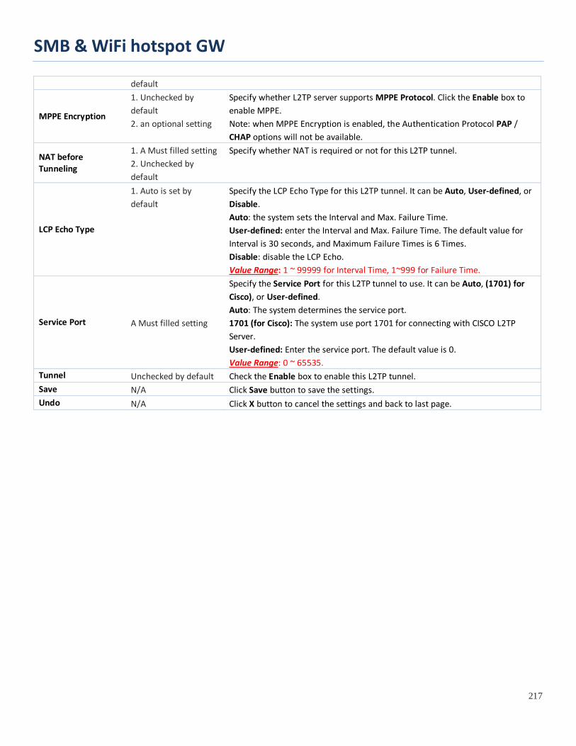
SMB & WiFi hotspot GW
217
default
MPPE Encryption
1. Unchecked by default 2. an optional setting
Specify whether L2TP server supports MPPE Protocol. Click the Enable box to enable MPPE. Note: when MPPE Encryption is enabled, the Authentication Protocol PAP / CHAP options will not be available.
NAT before Tunneling
1. A Must filled setting 2. Unchecked by default
Specify whether NAT is required or not for this L2TP tunnel.
LCP Echo Type
1. Auto is set by default
Specify the LCP Echo Type for this L2TP tunnel. It can be Auto, User-defined, or Disable. Auto: the system sets the Interval and Max. Failure Time. User-defined: enter the Interval and Max. Failure Time. The default value for Interval is 30 seconds, and Maximum Failure Times is 6 Times. Disable: disable the LCP Echo. Value Range: 1 ~ 99999 for Interval Time, 1~999 for Failure Time.
Service Port A Must filled setting
Specify the Service Port for this L2TP tunnel to use. It can be Auto, (1701) for Cisco), or User-defined. Auto: The system determines the service port. 1701 (for Cisco): The system use port 1701 for connecting with CISCO L2TP Server. User-defined: Enter the service port. The default value is 0. Value Range: 0 ~ 65535.
Tunnel Unchecked by default Check the Enable box to enable this L2TP tunnel. Save N/A Click Save button to save the settings. Undo N/A Click X button to cancel the settings and back to last page.
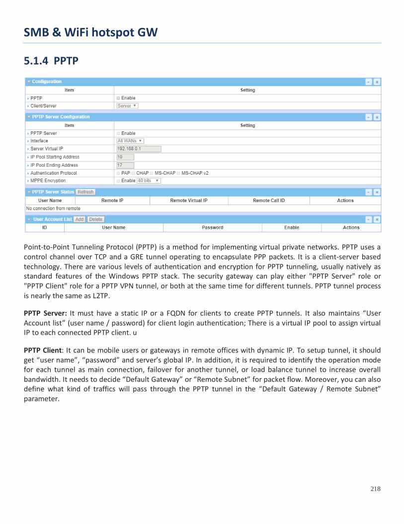
SMB & WiFi hotspot GW
218
5.1.4 PPTP
Point-to-Point Tunneling Protocol (PPTP) is a method for implementing virtual private networks. PPTP uses a control channel over TCP and a GRE tunnel operating to encapsulate PPP packets. It is a client-server based technology. There are various levels of authentication and encryption for PPTP tunneling, usually natively as standard features of the Windows PPTP stack. The security gateway can play either "PPTP Server" role or "PPTP Client" role for a PPTP VPN tunnel, or both at the same time for different tunnels. PPTP tunnel process is nearly the same as L2TP.
PPTP Server: It must have a static IP or a FQDN for clients to create PPTP tunnels. It also maintains “User Account list” (user name / password) for client login authentication; There is a virtual IP pool to assign virtual IP to each connected PPTP client. u
PPTP Client: It can be mobile users or gateways in remote offices with dynamic IP. To setup tunnel, it should get “user name”, “password” and server’s global IP. In addition, it is required to identify the operation mode for each tunnel as main connection, failover for another tunnel, or load balance tunnel to increase overall bandwidth. It needs to decide “Default Gateway” or “Remote Subnet” for packet flow. Moreover, you can also define what kind of traffics will pass through the PPTP tunnel in the “Default Gateway / Remote Subnet” parameter.
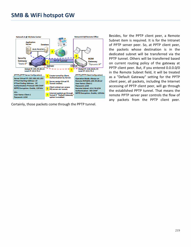
SMB & WiFi hotspot GW
219
Besides, for the PPTP client peer, a Remote Subnet item is required. It is for the Intranet of PPTP server peer. So, at PPTP client peer, the packets whose destination is in the dedicated subnet will be transferred via the PPTP tunnel. Others will be transferred based on current routing policy of the gateway at PPTP client peer. But, if you entered 0.0.0.0/0 in the Remote Subnet field, it will be treated as a "Default Gateway" setting for the PPTP client peer, all packets, including the Internet accessing of PPTP client peer, will go through the established PPTP tunnel. That means the remote PPTP server peer controls the flow of any packets from the PPTP client peer.
Certainly, those packets come through the PPTP tunnel.
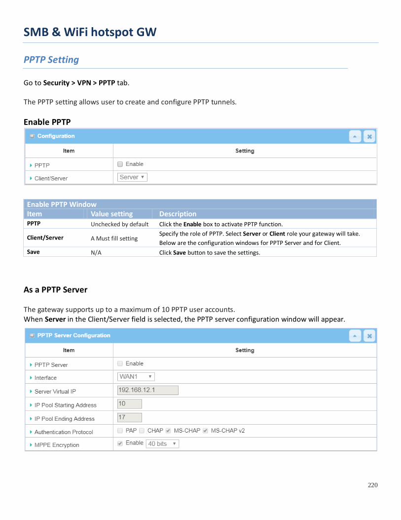
SMB & WiFi hotspot GW
220
PPTP Setting
Go to Security > VPN > PPTP tab. The PPTP setting allows user to create and configure PPTP tunnels. Enable PPTP
Enable PPTP Window Item Value setting Description PPTP Unchecked by default Click the Enable box to activate PPTP function.
Client/Server A Must fill setting Specify the role of PPTP. Select Server or Client role your gateway will take. Below are the configuration windows for PPTP Server and for Client.
Save N/A Click Save button to save the settings.
As a PPTP Server The gateway supports up to a maximum of 10 PPTP user accounts. When Server in the Client/Server field is selected, the PPTP server configuration window will appear.
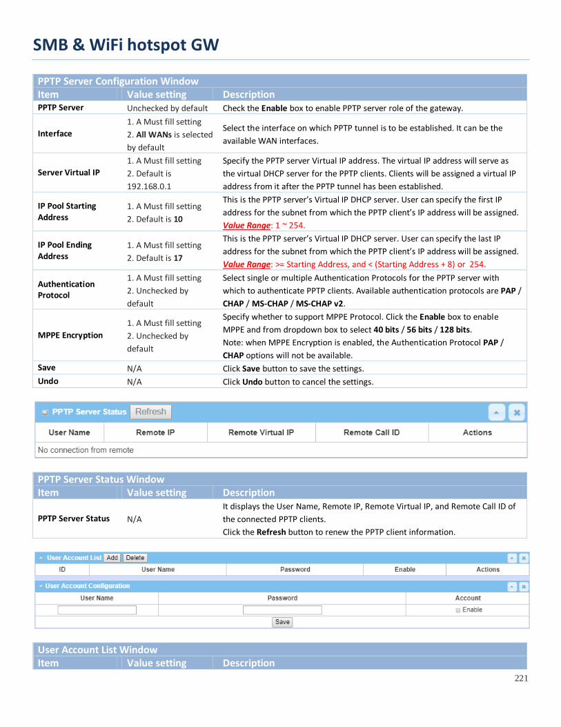
SMB & WiFi hotspot GW
221
PPTP Server Configuration Window Item Value setting Description PPTP Server Unchecked by default Check the Enable box to enable PPTP server role of the gateway.
Interface 1. A Must fill setting 2. All WANs is selected by default
Select the interface on which PPTP tunnel is to be established. It can be the available WAN interfaces.
Server Virtual IP 1. A Must fill setting 2. Default is 192.168.0.1
Specify the PPTP server Virtual IP address. The virtual IP address will serve as the virtual DHCP server for the PPTP clients. Clients will be assigned a virtual IP address from it after the PPTP tunnel has been established.
IP Pool Starting Address
1. A Must fill setting 2. Default is 10
This is the PPTP server’s Virtual IP DHCP server. User can specify the first IP address for the subnet from which the PPTP client’s IP address will be assigned. Value Range: 1 ~ 254.
IP Pool Ending Address
1. A Must fill setting 2. Default is 17
This is the PPTP server’s Virtual IP DHCP server. User can specify the last IP address for the subnet from which the PPTP client’s IP address will be assigned. Value Range: >= Starting Address, and < (Starting Address + 8) or 254.
Authentication Protocol
1. A Must fill setting 2. Unchecked by default
Select single or multiple Authentication Protocols for the PPTP server with which to authenticate PPTP clients. Available authentication protocols are PAP / CHAP / MS-CHAP / MS-CHAP v2.
MPPE Encryption 1. A Must fill setting 2. Unchecked by default
Specify whether to support MPPE Protocol. Click the Enable box to enable MPPE and from dropdown box to select 40 bits / 56 bits / 128 bits. Note: when MPPE Encryption is enabled, the Authentication Protocol PAP / CHAP options will not be available.
Save N/A Click Save button to save the settings. Undo N/A Click Undo button to cancel the settings.
PPTP Server Status Window Item Value setting Description
PPTP Server Status N/A It displays the User Name, Remote IP, Remote Virtual IP, and Remote Call ID of the connected PPTP clients. Click the Refresh button to renew the PPTP client information.
User Account List Window Item Value setting Description
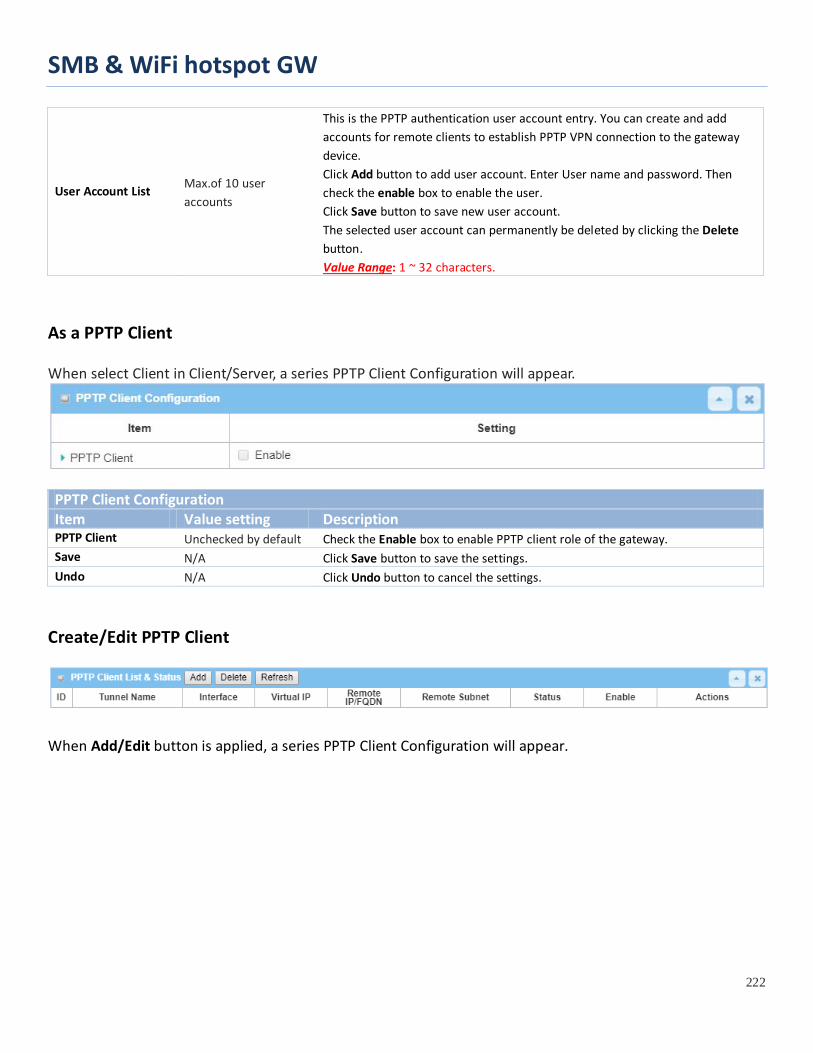
SMB & WiFi hotspot GW
222
User Account List Max.of 10 user accounts
This is the PPTP authentication user account entry. You can create and add accounts for remote clients to establish PPTP VPN connection to the gateway device. Click Add button to add user account. Enter User name and password. Then check the enable box to enable the user. Click Save button to save new user account. The selected user account can permanently be deleted by clicking the Delete button. Value Range: 1 ~ 32 characters.
As a PPTP Client When select Client in Client/Server, a series PPTP Client Configuration will appear.
PPTP Client Configuration Item Value setting Description PPTP Client Unchecked by default Check the Enable box to enable PPTP client role of the gateway. Save N/A Click Save button to save the settings. Undo N/A Click Undo button to cancel the settings.
Create/Edit PPTP Client
When Add/Edit button is applied, a series PPTP Client Configuration will appear.
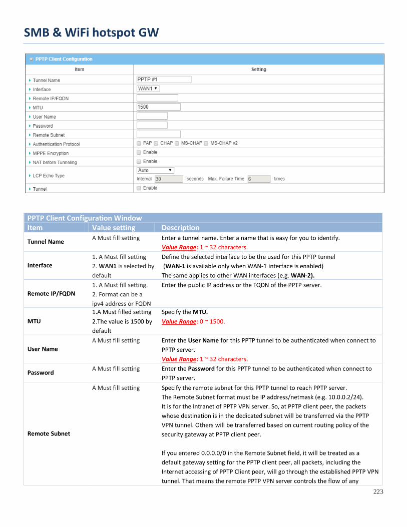
SMB & WiFi hotspot GW
223
PPTP Client Configuration Window Item Value setting Description
Tunnel Name A Must fill setting Enter a tunnel name. Enter a name that is easy for you to identify. Value Range: 1 ~ 32 characters.
Interface 1. A Must fill setting 2. WAN1 is selected by default
Define the selected interface to be the used for this PPTP tunnel (WAN-1 is available only when WAN-1 interface is enabled) The same applies to other WAN interfaces (e.g. WAN-2).
Remote IP/FQDN 1. A Must fill setting. 2. Format can be a ipv4 address or FQDN
Enter the public IP address or the FQDN of the PPTP server.
MTU 1.A Must filled setting 2.The value is 1500 by default
Specify the MTU. Value Range: 0 ~ 1500.
User Name A Must fill setting Enter the User Name for this PPTP tunnel to be authenticated when connect to
PPTP server. Value Range: 1 ~ 32 characters.
Password A Must fill setting Enter the Password for this PPTP tunnel to be authenticated when connect to PPTP server.
Remote Subnet
A Must fill setting Specify the remote subnet for this PPTP tunnel to reach PPTP server. The Remote Subnet format must be IP address/netmask (e.g. 10.0.0.2/24). It is for the Intranet of PPTP VPN server. So, at PPTP client peer, the packets whose destination is in the dedicated subnet will be transferred via the PPTP VPN tunnel. Others will be transferred based on current routing policy of the security gateway at PPTP client peer. If you entered 0.0.0.0/0 in the Remote Subnet field, it will be treated as a default gateway setting for the PPTP client peer, all packets, including the Internet accessing of PPTP Client peer, will go through the established PPTP VPN tunnel. That means the remote PPTP VPN server controls the flow of any
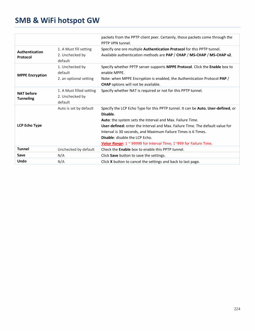
SMB & WiFi hotspot GW
224
packets from the PPTP client peer. Certainly, those packets come through the PPTP VPN tunnel.
Authentication Protocol
1. A Must fill setting 2. Unchecked by default
Specify one ore multiple Authentication Protocol for this PPTP tunnel. Available authentication methods are PAP / CHAP / MS-CHAP / MS-CHAP v2.
MPPE Encryption
1. Unchecked by default 2. an optional setting
Specify whether PPTP server supports MPPE Protocol. Click the Enable box to enable MPPE. Note: when MPPE Encryption is enabled, the Authentication Protocol PAP / CHAP options will not be available.
NAT before Tunneling
1. A Must filled setting 2. Unchecked by default
Specify whether NAT is required or not for this PPTP tunnel.
LCP Echo Type
Auto is set by default
Specify the LCP Echo Type for this PPTP tunnel. It can be Auto, User-defined, or Disable. Auto: the system sets the Interval and Max. Failure Time. User-defined: enter the Interval and Max. Failure Time. The default value for Interval is 30 seconds, and Maximum Failure Times is 6 Times. Disable: disable the LCP Echo. Value Range: 1 ~ 99999 for Interval Time, 1~999 for Failure Time.
Tunnel Unchecked by default Check the Enable box to enable this PPTP tunnel. Save N/A Click Save button to save the settings. Undo N/A Click X button to cancel the settings and back to last page.

SMB & WiFi hotspot GW
225
5.1.5 GRE Generic Routing Encapsulation (GRE) is a tunneling protocol developed by Cisco Systems that encapsulates a wide variety of network layer protocols inside virtual point-to-point links over an Internet Protocol internetwork.
Deploy a M2M gateway for remote site and establish a virtual private network with control center by using GRE tunneling. So, all client hosts behind M2M gateway can make data communication with server hosts behind control center gateway.
GRE Tunneling is similar to IPSec Tunneling, client requesting the tunnel establishment with the server. Both the client and the server must have a Static IP or a FQDN. Any peer gateway can be worked as either a client or a server, even using the same set of configuration rule.
GRE Tunnel Scenario To setup a GRE tunnel, each peer needs to setup its global IP as tunnel IP and fill in the other's global IP as remote IP.
Besides, each peer must further specify the Remote Subnet item. It is for the Intranet of GRE server peer. So, at GRE client peer, the packets whose destination is in the dedicated subnet will be transferred via the GRE tunnel. Others will be transferred based on current routing policy of the gateway at GRE client peer. But, if you entered 0.0.0.0/0 in the Remote Subnet field, it will be treated as a "Default Gateway" setting for the GRE client peer, all packets, including the Internet accessing of GRE client peer, will go through the established GRE
tunnel. That means the remote GRE server peer controls the flow of any packets from the GRE client peer. Certainly, those packets come through the GRE tunnel.
If the GRE server supports DMVPN Hub function, like Cisco router as the VPN concentrator, the GRE client can active the DMVPN spoke function here since it is implemented by GRE over IPSec tunneling.
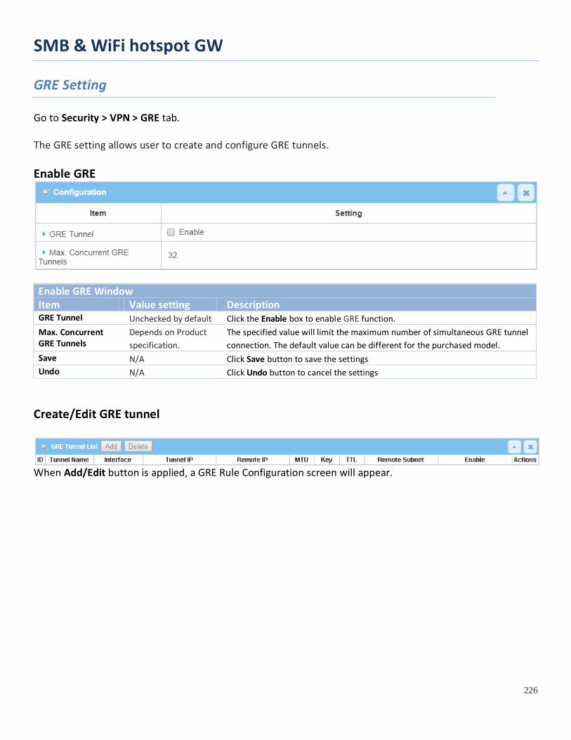
SMB & WiFi hotspot GW
226
GRE Setting
Go to Security > VPN > GRE tab. The GRE setting allows user to create and configure GRE tunnels. Enable GRE
Enable GRE Window Item Value setting Description GRE Tunnel Unchecked by default Click the Enable box to enable GRE function. Max. Concurrent GRE Tunnels
Depends on Product specification.
The specified value will limit the maximum number of simultaneous GRE tunnel connection. The default value can be different for the purchased model.
Save N/A Click Save button to save the settings Undo N/A Click Undo button to cancel the settings
Create/Edit GRE tunnel
When Add/Edit button is applied, a GRE Rule Configuration screen will appear.
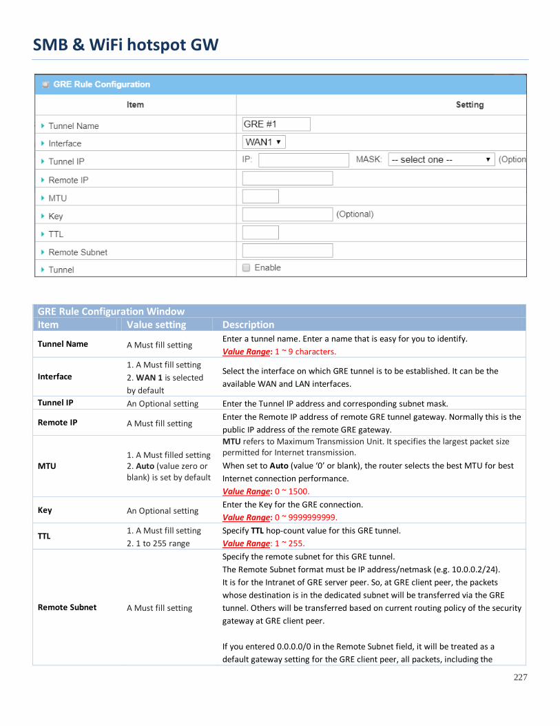
SMB & WiFi hotspot GW
227
GRE Rule Configuration Window Item Value setting Description
Tunnel Name A Must fill setting Enter a tunnel name. Enter a name that is easy for you to identify. Value Range: 1 ~ 9 characters.
Interface 1. A Must fill setting 2. WAN 1 is selected by default
Select the interface on which GRE tunnel is to be established. It can be the available WAN and LAN interfaces.
Tunnel IP An Optional setting Enter the Tunnel IP address and corresponding subnet mask.
Remote IP A Must fill setting Enter the Remote IP address of remote GRE tunnel gateway. Normally this is the public IP address of the remote GRE gateway.
MTU 1. A Must filled setting 2. Auto (value zero or blank) is set by default
MTU refers to Maximum Transmission Unit. It specifies the largest packet size permitted for Internet transmission. When set to Auto (value ‘0’ or blank), the router selects the best MTU for best Internet connection performance. Value Range: 0 ~ 1500.
Key An Optional setting Enter the Key for the GRE connection. Value Range: 0 ~ 9999999999.
TTL 1. A Must fill setting 2. 1 to 255 range
Specify TTL hop-count value for this GRE tunnel. Value Range: 1 ~ 255.
Remote Subnet A Must fill setting
Specify the remote subnet for this GRE tunnel. The Remote Subnet format must be IP address/netmask (e.g. 10.0.0.2/24). It is for the Intranet of GRE server peer. So, at GRE client peer, the packets whose destination is in the dedicated subnet will be transferred via the GRE tunnel. Others will be transferred based on current routing policy of the security gateway at GRE client peer. If you entered 0.0.0.0/0 in the Remote Subnet field, it will be treated as a default gateway setting for the GRE client peer, all packets, including the

SMB & WiFi hotspot GW
228
Internet accessing of GRE client peer, will go through the established GRE tunnel. That means the remote GRE server peer controls the flow of any packets from the GRE client peer. Certainly, those packets come through the GRE tunnel.
Tunnel Unchecked by default Check Enable box to enable this GRE tunnel. Save N/A Click Save button to save the settings. Undo N/A Click X button to cancel the settings and back to last page.

SMB & WiFi hotspot GW
229
5.2 Firewall
The firewall functions include Packet Filter, URL Blocking, Content Filter, MAC Control, Application Filter, IPS and some firewall options. The supported function can be different for the purchased gateway.
5.2.1 Packet Filter

SMB & WiFi hotspot GW
230
"Packet Filter" function can let you define some filtering rules for incoming and outgoing packets. So the gateway can control what packets are allowed or blocked to pass through it. A packet filter rule should indicate from and to which interface the packet enters and leaves the gateway, the source and destination IP addresses, and destination service port type and port number. In addition, the time schedule to which the rule will be active.
Packet Filter with White List Scenario As shown in the diagram, specify "Packet Filter Rule List" as white list (Allow those match the following rules) and define the rules. Rule-1 is to allow HTTP packets to pass, and Rule-2 is to allow HTTPS packets to pass.
Under such configuration, the gateway will allow only HTTP and HTTPS packets, issued from the IP range 192.168.123.200 to 250, which are targeted to TCP port 80 or 443 to pass the WAN interface.
Packet Filter Setting
Go to Security > Firewall > Packet Filter Tab.
The packet filter setting allows user to create and customize packet filter policies to allow or reject specific inbound/outbound packets through the router based on their office setting.
Enable Packet Filter
Configuration Window Item Name Value setting Description
Packet Filter The box is unchecked by default
Check the Enable box to activate Packet Filter function

SMB & WiFi hotspot GW
231
Black List / White List
Deny those match the following rules is set by default
When Deny those match the following rules is selected, as the name suggest, packets specified in the rules will be blocked –black listed. In contrast, with Allow those match the following rules, you can specifically white list the packets to pass and the rest will be blocked.
Log Alert The box is unchecked by default
Check the Enable box to activate Event Log.
Save N/A Click Save to save the settings Undo N/A Click Undo to cancel the settings
Create/Edit Packet Filter Rules The gateway allows you to customize your packet filtering rules. It supports up to a maximum of 20 filter rule sets.
When Add button is applied, Packet Filter Rule Configuration screen will appear.
Packet Filter Rule Configuration Item Name Value setting Description
Rule Name 1. String format can be any text 2. A Must filled setting
Enter a packet filter rule name. Enter a name that is easy for you to remember. Value Range: 1 ~ 30 characters.
From Interface 1. A Must filled setting Define the selected interface to be the packet-entering interface of the router.
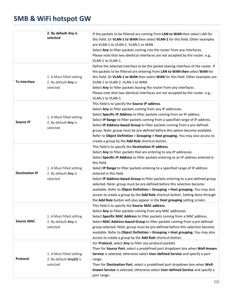
SMB & WiFi hotspot GW
232
2. By default Any is selected
If the packets to be filtered are coming from LAN to WAN then select LAN for this field. Or VLAN-1 to WAN then select VLAN-1 for this field. Other examples are VLAN-1 to VLAN-2. VLAN-1 to WAN. Select Any to filter packets coming into the router from any interfaces. Please note that two identical interfaces are not accepted by the router. e.g., VLAN-1 to VLAN-1.
To Interface 1. A Must filled setting 2. By default Any is selected
Define the selected interface to be the packet-leaving interface of the router. If the packets to be filtered are entering from LAN to WAN then select WAN for this field. Or VLAN-1 to WAN then select WAN for this field. Other examples are VLAN-1 to VLAN-2. VLAN-1 to WAN. Select Any to filter packets leaving the router from any interfaces. Please note that two identical interfaces are not accepted by the router. e.g., VLAN-1 to VLAN-1.
Source IP 1. A Must filled setting 2. By default Any is selected
This field is to specify the Source IP address. Select Any to filter packets coming from any IP addresses. Select Specific IP Address to filter packets coming from an IP address. Select IP Range to filter packets coming from a specified range of IP address. Select IP Address-based Group to filter packets coming from a pre-defined group. Note: group must be pre-defined before this option become available. Refer to Object Definition > Grouping > Host grouping. You may also access to create a group by the Add Rule shortcut button.
Destination IP 1. A Must filled setting 2. By default Any is selected
This field is to specify the Destination IP address. Select Any to filter packets that are entering to any IP addresses. Select Specific IP Address to filter packets entering to an IP address entered in this field. Select IP Range to filter packets entering to a specified range of IP address entered in this field. Select IP Address-based Group to filter packets entering to a pre-defined group selected. Note: group must be pre-defined before this selection become available. Refer to Object Definition > Grouping > Host grouping. You may also access to create a group by the Add Rule shortcut button. Setting done through the Add Rule button will also appear in the Host grouping setting screen.
Source MAC 1. A Must filled setting 2. By default Any is selected
This field is to specify the Source MAC address. Select Any to filter packets coming from any MAC addresses. Select Specific MAC Address to filter packets coming from a MAC address. Select MAC Address-based Group to filter packets coming from a pre-defined group selected. Note: group must be pre-defined before this selection become available. Refer to Object Definition > Grouping > Host grouping. You may also access to create a group by the Add Rule shortcut button.
Protocol 1. A Must filled setting 2. By default Any(0) is selected
For Protocol, select Any to filter any protocol packets Then for Source Port, select a predefined port dropdown box when Well-known Service is selected, otherwise select User-defined Service and specify a port range. Then for Destination Port, select a predefined port dropdown box when Well-known Service is selected, otherwise select User-defined Service and specify a port range.
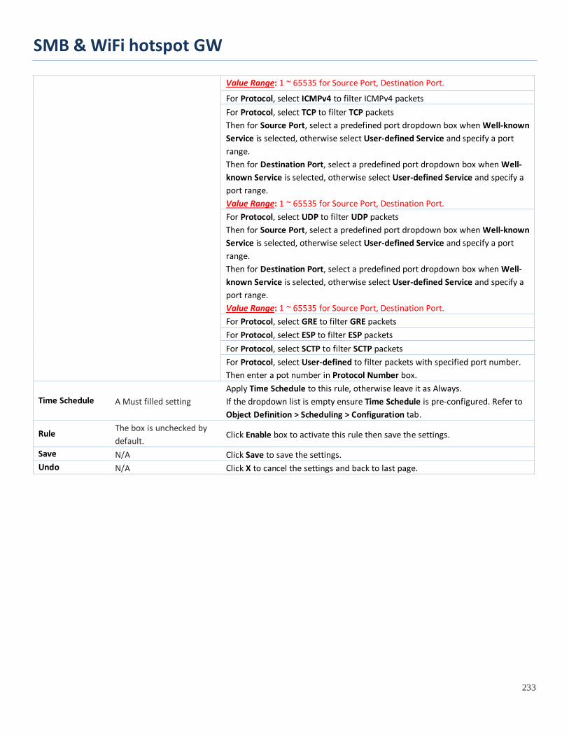
SMB & WiFi hotspot GW
233
Value Range: 1 ~ 65535 for Source Port, Destination Port.
For Protocol, select ICMPv4 to filter ICMPv4 packets For Protocol, select TCP to filter TCP packets Then for Source Port, select a predefined port dropdown box when Well-known Service is selected, otherwise select User-defined Service and specify a port range. Then for Destination Port, select a predefined port dropdown box when Well-known Service is selected, otherwise select User-defined Service and specify a port range. Value Range: 1 ~ 65535 for Source Port, Destination Port. For Protocol, select UDP to filter UDP packets Then for Source Port, select a predefined port dropdown box when Well-known Service is selected, otherwise select User-defined Service and specify a port range. Then for Destination Port, select a predefined port dropdown box when Well-known Service is selected, otherwise select User-defined Service and specify a port range. Value Range: 1 ~ 65535 for Source Port, Destination Port. For Protocol, select GRE to filter GRE packets For Protocol, select ESP to filter ESP packets For Protocol, select SCTP to filter SCTP packets For Protocol, select User-defined to filter packets with specified port number. Then enter a pot number in Protocol Number box.
Time Schedule A Must filled setting Apply Time Schedule to this rule, otherwise leave it as Always. If the dropdown list is empty ensure Time Schedule is pre-configured. Refer to Object Definition > Scheduling > Configuration tab.
Rule The box is unchecked by default.
Click Enable box to activate this rule then save the settings.
Save N/A Click Save to save the settings. Undo N/A Click X to cancel the settings and back to last page.

SMB & WiFi hotspot GW
234
5.2.2 URL Blocking "URL Blocking" function can let you define blocking or allowing rules for incoming and outgoing Web request packets. With defined rules, gateway can control the Web requests containing the complete URL, partial domain name, or pre-defined keywords. For example, one can filter out or allow only the Web requests based on domain input suffixes like .com or .org or keywords like “bct” or “mpe”.
An URL blocking rule should specify the URL, partial domain name, or included keywords in the Web requests from and to the gateway and also the destination service port. Besides, a certain time schedule can be applied to activate the URL Blocking rules during pre-defined time interval(s).
The gateway will logs and displays the disallowed web accessing requests that matched the defined URL blocking rule in the black-list or in the exclusion of the white-list.
When you choose "Allow all to pass except those match the following rules" for the "URL Blocking Rule List", you are setting the defined URL blocking rules to belong to the black list. The packets, listed in the rule list, will be blocked if one pattern in the requests matches to one rule. Other Web requests can pass through the gateway. In contrast, when you choose "Deny all to pass except those match the following rules" for the "URL Blocking Rule List", you are setting the defined packet filtering rules to belong to the white list. The Web requests, listed in the rule, will be allowed if one pattern in the requests matches to one rule. Other Web requests will be blocked.
URL Blocking Rule with Black List When the administrator of the gateway wants to block the Web requests with some dedicated patterns, he can use the "URL Blocking" function to block specific Web requests by defining the black list as shown in above diagram. Certainly, when the administrator wants to allow only the Web requests with some dedicated patterns to go through the gateway, he can also use the "URL Blocking" function by defining the white list to meet the requirement.
As shown in the diagram, enable the URL blocking function and create the first rule to
deny the Web requests with "sex" or "sexygirl" patterns and the other to deny the Web requests with "playboy" pattern to go through the gateway. System will block the Web requests with "sex", "sexygirl" or "playboy" patterns to pass through the gateway.

SMB & WiFi hotspot GW
235
URL Blocking Setting
Go to Security > Firewall > URL Blocking Tab.
In "URL Blocking" page, there are three configuration windows. They are the "Configuration" window, "URL Blocking Rule List" window, and "URL Blocking Rule Configuration" window.
The "Configuration" window can let you activate the URL blocking function and specify to black listing or to white listing the packets defined in the "URL Blocking Rule List" entry. In addition, log alerting can be enabled to record on-going events for any disallowed Web request packets. Refer to "System Status" in "6.1.1 System Related" section in this user manual for how to view recorded log.
The "URL Blocking Rule List" window lists all your defined URL blocking rule entry. And finally, the "URL Blocking Rule Configuration" window can let you define URL blocking rules. The parameters in a rule include the rule name, the Source IP or MAC, the URL/Domain Name/Keyword, the destination service ports, the integrated time schedule rule and the rule activation.
Enable URL Blocking
Configuration
Item Value setting Description
URL Blocking The box is unchecked by default
Check the Enable box to activate URL Blocking function.
Black List / White List
Deny those match the following rules is set by default
Specify the URL Blocking Policy, either Black List or White List. Black List: When Deny those match the following rules is selected, as the name suggest, the matched Web request packets will be blocked. White List: When Allow those match the following rules is selected, the matched Web request packets can pass through the Gateway, and the others that don’t match the rules will be blocked.
Log Alert The box is unchecked by default
Check the Enable box to activate Event Log.
Save NA Click Save button to save the settings Undo NA Click Undo button to cancel the settings
Create/Edit URL Blocking Rules The Gateway supports up to a maximum of 20 URL blocking rule sets. Ensure that the URL Blocking is enabled before we can create blocking rules.

SMB & WiFi hotspot GW
236
When Add button is applied, the URL Blocking Rule Configuration screen will appear.
URL Blocking Rules Configuration Item Value setting Description
Rule Name 1. String format can be any text 2. A Must filled setting
Specify an URL Blocking rule name. Enter a name that is easy for you to understand.
Source IP
1. A Must filled setting 2. Any is set by default
This field is to specify the Source IP address. • Select Any to filter packets coming from any IP addresses. • Select Specific IP Address to filter packets coming from an IP address entered in
this field. • Select IP Range to filter packets coming from a specified range of IP address
entered in this field. • Select IP Address-based Group to filter packets coming from a pre-defined
group selected. Note: group must be pre-defined before this option become available. Refer to Object Definition > Grouping > Host grouping.
Source MAC
1. A Must filled setting 2. Any is set by default
This field is to specify the Source MAC address. • Select Any to filter packets coming from any MAC addresses. • Select Specific MAC Address to filter packets coming from a MAC address
entered in this field. • Select MAC Address-based Group to filter packets coming from a pre-defined
group selected. Note: group must be pre-defined before this selection become available. Refer to Object Definition > Grouping > Host grouping.
URL / Domain Name / Keyword
1. A Must filled setting 2. Supports up to a maximum of 10 Keywords in a rule by using the delimiter “;”.
Specify URL, Domain Name, or Keyword list for URL checking. • In the Black List mode, if a matched rule is found, the packets will be dropped. • In the White List mode, if a matched rule is found, the packets will be accepted
and the others which don’t match any rule will be dropped.
Destination Port
1. A Must filled setting 2. Any is set by default
This field is to specify the Destination Port number. • Select Any to filter packets going to any Port. • Select Specific Service Port to filter packets going to a specific Port entered in this field. • Select Port Range to filter packets going to a specific range of Ports entered in this field.
Time Schedule Rule
A Must filled setting Apply a specific Time Schedule to this rule; otherwise leave it as (0) Always. If the dropdown list is empty ensure Time Schedule is pre-configured. Refer to Object Definition > Scheduling > Configuration tab.
Rule The box is unchecked by Click the Enable box to activate this rule.

SMB & WiFi hotspot GW
237
default. Save NA Click the Save button to save the settings. Undo NA Click the X button to cancel the changes and back to last page.

SMB & WiFi hotspot GW
238
5.2.3 MAC Control
"MAC Control" function allows you to assign the accessibility to the gateway for different users based on device’s MAC address. When the administrator wants to reject the traffics from some client hosts with specific MAC addresses, he can use the "MAC Control" function to reject with the black list configuration.
MAC Control with Black List Scenario As shown in the diagram, enable the MAC control function and specify the "MAC Control Rule List" is a black list, and configure one MAC control rule for the gateway to deny the connection request from the "JP NB" with its own MAC address 20:6A:6A:6A:6A:6B.
System will block the connecting from the "JP NB" to the gateway but allow others.

SMB & WiFi hotspot GW
239
MAC Control Setting
Go to Security > Firewall > MAC Control Tab.
The MAC control setting allows user to create and customize MAC address policies to allow or reject packets with specific source MAC address.
Enable MAC Control
Configuration Window Item Value setting Description
MAC Control The box is unchecked by default
Check the Enable box to activate the MAC filter function
Black List / White List
Deny MAC Address Below is set by default
When Deny MAC Address Below is selected, as the name suggest, packets specified in the rules will be blocked –black listed. In contrast, with Allow MAC Address Below, you can specifically white list the packets to pass and the rest will be blocked.
Log Alert The box is unchecked by default
Check the Enable box to activate to activate Event Log.
Known MAC from LAN PC List N/A
Select a MAC Address from LAN Client List. Click the Copy to to copy the selected MAC Address to the filter rule.
Save N/A Click Save to save the settings Undo N/A Click Undo to cancel the settings
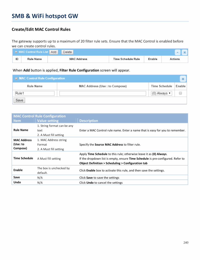
SMB & WiFi hotspot GW
240
Create/Edit MAC Control Rules
The gateway supports up to a maximum of 20 filter rule sets. Ensure that the MAC Control is enabled before we can create control rules.
When Add button is applied, Filter Rule Configuration screen will appear.
MAC Control Rule Configuration Item Value setting Description
Rule Name 1. String format can be any text 2. A Must fill setting
Enter a MAC Control rule name. Enter a name that is easy for you to remember.
MAC Address (Use: to Compose)
1. MAC Address string Format 2. A Must fill setting
Specify the Source MAC Address to filter rule.
Time Schedule A Must fill setting Apply Time Schedule to this rule; otherwise leave it as (0) Always. If the dropdown list is empty, ensure Time Schedule is pre-configured. Refer to Object Definition > Scheduling > Configuration tab
Enable The box is unchecked by default.
Click Enable box to activate this rule, and then save the settings.
Save N/A Click Save to save the settings Undo N/A Click Undo to cancel the settings

SMB & WiFi hotspot GW
241
5.2.4 Content Filter (not supported) Not supported feature for the purchased product, leave it as blank.

SMB & WiFi hotspot GW
242
5.2.5 Application Filter (not supported) Not supported feature for the purchased product, leave it as blank.

SMB & WiFi hotspot GW
243
5.2.6 IPS
To provide application servers in the Internet, administrator may need to open specific ports for the services. However, there are some risks to always open service ports in the Internet. In order to avoid such attack risks, it is important to enable IPS functions.
Intrusion Prevention System (IPS) is network security appliances that monitor network and/or system activities for malicious activity. The main functions of IPS are to identify malicious activity, log information about this activity, attempt to block/stop it and report it. You can enable the IPS function and check the listed intrusion activities when needed. You can also enable the log alerting so that system will record Intrusion events when corresponding intrusions are detected.
IPS Scenario As shown in the diagram, the gateway serves as an E-mail server, Web Server and also provides TCP port 8080 for remote administration. So, remote users or unknown users can request those services from Internet. With IPS enabled, the gateway can detect incoming attack packets, including the TCP ports (25, 80, 110, 443 and 8080) with services. It will block the attack packets and let the normal access to pass through the gateway
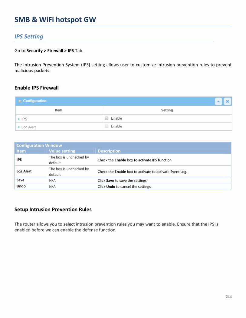
SMB & WiFi hotspot GW
244
IPS Setting
Go to Security > Firewall > IPS Tab.
The Intrusion Prevention System (IPS) setting allows user to customize intrusion prevention rules to prevent malicious packets.
Enable IPS Firewall
Configuration Window Item Value setting Description
IPS The box is unchecked by default
Check the Enable box to activate IPS function
Log Alert The box is unchecked by default
Check the Enable box to activate to activate Event Log.
Save N/A Click Save to save the settings Undo N/A Click Undo to cancel the settings
Setup Intrusion Prevention Rules
The router allows you to select intrusion prevention rules you may want to enable. Ensure that the IPS is enabled before we can enable the defense function.
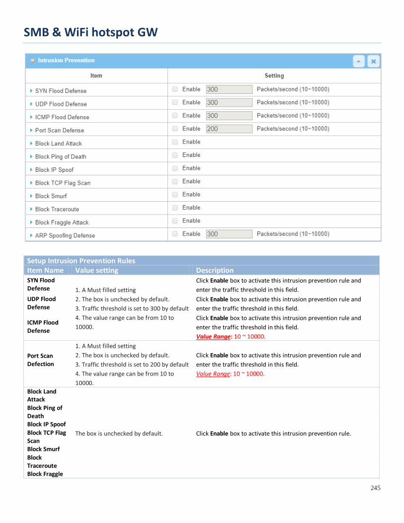
SMB & WiFi hotspot GW
245
Setup Intrusion Prevention Rules Item Name Value setting Description SYN Flood Defense 1. A Must filled setting
2. The box is unchecked by default. 3. Traffic threshold is set to 300 by default 4. The value range can be from 10 to 10000.
Click Enable box to activate this intrusion prevention rule and enter the traffic threshold in this field.
UDP Flood Defense
Click Enable box to activate this intrusion prevention rule and enter the traffic threshold in this field.
ICMP Flood Defense
Click Enable box to activate this intrusion prevention rule and enter the traffic threshold in this field. Value Range: 10 ~ 10000.
Port Scan Defection
1. A Must filled setting 2. The box is unchecked by default. 3. Traffic threshold is set to 200 by default 4. The value range can be from 10 to 10000.
Click Enable box to activate this intrusion prevention rule and enter the traffic threshold in this field. Value Range: 10 ~ 10000.
Block Land Attack
The box is unchecked by default. Click Enable box to activate this intrusion prevention rule.
Block Ping of Death Block IP Spoof Block TCP Flag Scan Block Smurf Block Traceroute Block Fraggle
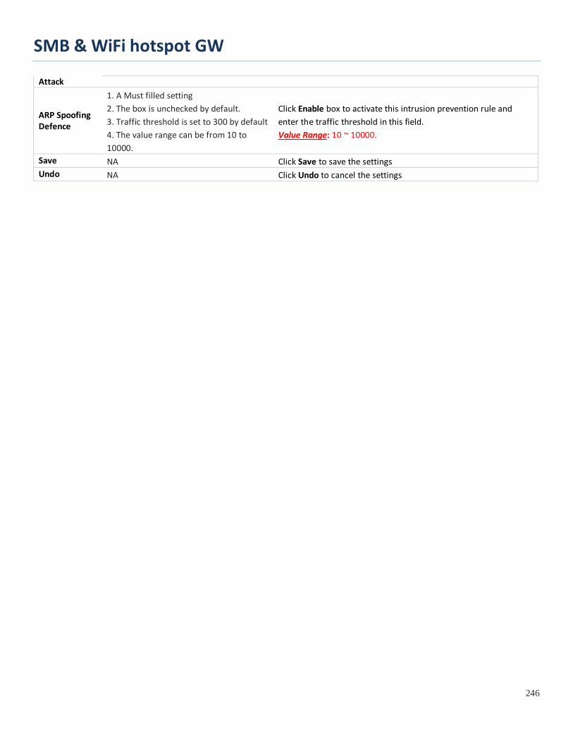
SMB & WiFi hotspot GW
246
Attack
ARP Spoofing Defence
1. A Must filled setting 2. The box is unchecked by default. 3. Traffic threshold is set to 300 by default 4. The value range can be from 10 to 10000.
Click Enable box to activate this intrusion prevention rule and enter the traffic threshold in this field. Value Range: 10 ~ 10000.
Save NA Click Save to save the settings Undo NA Click Undo to cancel the settings
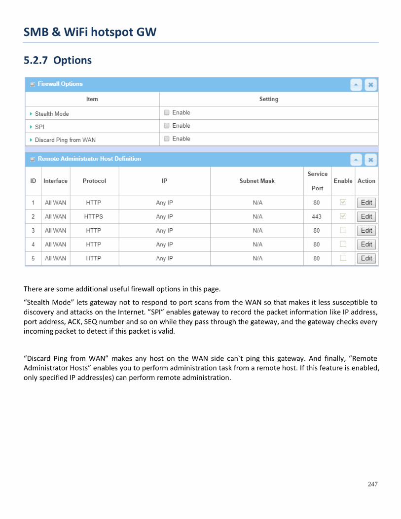
SMB & WiFi hotspot GW
247
5.2.7 Options
There are some additional useful firewall options in this page.
“Stealth Mode” lets gateway not to respond to port scans from the WAN so that makes it less susceptible to discovery and attacks on the Internet. ”SPI” enables gateway to record the packet information like IP address, port address, ACK, SEQ number and so on while they pass through the gateway, and the gateway checks every incoming packet to detect if this packet is valid.
“Discard Ping from WAN” makes any host on the WAN side can`t ping this gateway. And finally, “Remote Administrator Hosts” enables you to perform administration task from a remote host. If this feature is enabled, only specified IP address(es) can perform remote administration.
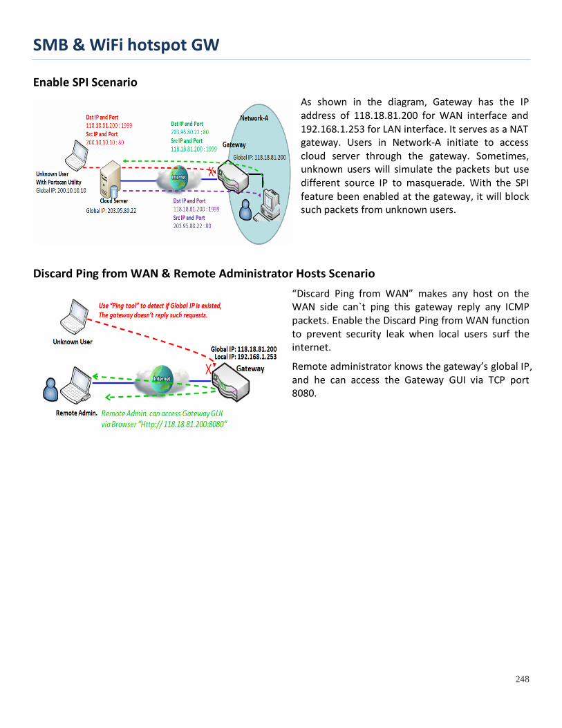
SMB & WiFi hotspot GW
248
Enable SPI Scenario As shown in the diagram, Gateway has the IP address of 118.18.81.200 for WAN interface and 192.168.1.253 for LAN interface. It serves as a NAT gateway. Users in Network-A initiate to access cloud server through the gateway. Sometimes, unknown users will simulate the packets but use different source IP to masquerade. With the SPI feature been enabled at the gateway, it will block such packets from unknown users.
Discard Ping from WAN & Remote Administrator Hosts Scenario “Discard Ping from WAN” makes any host on the WAN side can`t ping this gateway reply any ICMP packets. Enable the Discard Ping from WAN function to prevent security leak when local users surf the internet.
Remote administrator knows the gateway’s global IP, and he can access the Gateway GUI via TCP port 8080.

SMB & WiFi hotspot GW
249
Firewall Options Setting
Go to Security > Firewall > Options Tab.
The firewall options setting allows network administrator to modify the behavior of the firewall and to enable Remote Router Access Control.
Enable Firewall Options
Firewall Options Item Value setting Description
Stealth Mode The box is unchecked by default
Check the Enable box to activate the Stealth Mode function
SPI The box is checked by default
Check the Enable box to activate the SPI function
Discard Ping from WAN
The box is unchecked by default
Check the Enable box to activate the Discard Ping from WAN function
Define Remote Administrator Host
The router allows network administrator to manage router remotely. The network administrator can assign specific IP address and service port to allow accessing the router.

SMB & WiFi hotspot GW
250
Remote Administrator Host Definition
Item Value setting Description Protocol HTTP is set by default Select HTTP or HTTPS method for router access.
IP A Must filled setting
This field is to specify the remote host to assign access right for remote access. Select Any IP to allow any remote hosts Select Specific IP to allow the remote host coming from a specific subnet. An IP address entered in this field and a selected Subnet Mask to compose the subnet.
Service Port 1. 80 for HTTP by default 2. 443 for HTTPS by default
This field is to specify a Service Port to HTTP or HTTPS connection. Value Range: 1 ~ 65535.
Enabling the rule
The box is unchecked by default.
Click Enable box to activate this rule.
Save N/A Click Enable box to activate this rule then save the settings. Undo N/A Click Undo to cancel the settings

SMB & WiFi hotspot GW
251
5.3 Authentication To approve or confirm the truth of a certain object, you have to configure the required settings in the Authentication page. The supported functions could be Captive Portal and MAC Authentication, and the available function might be different for the purchased gateway. With proper configuration, whenever a certain object is accessing the portal or is asked for authentication to get access to internet, the specified authentication server is responsible for the authentication.
5.3.1 Captive Portal
A captive portal is a portal web page that is displayed before a user can browse Internet. The portal is often used to present a login page. This is done by intercepting most packets, regardless of address or port, until the user opens a browser and tries to access the web. At that time the browser is redirected to a web page which may require authentication and/or payment, or simply display an acceptable use policy and require the user to agree. Captive portals are used at many Wi-Fi hotspot services, and can be used to control wired access (e.g. apartment houses, hotel rooms, business centers, "open" Ethernet jacks) as well.10
The gateway supports the Captive Portal function to ask guests or passengers to pass the authentication process before they can surf the Internet via the gateway. There are two approaches, including external captive portal and internal captive portal.
For external captive portal, you must specify external RADIUS (Remote Authentication Dial In User Service) server and external UAM (Universal Access Method) server. In contrast, for internal captive portal, you will only select “Internal RADIUS Server” option for user authentication. The user account database can be an embedded database, an external AD database or an external LDAP database. However, the UAM server is not necessary for this case and that the captive portal Web site is embedded in the device.
Note: Internal captive portal may NOT be supported by the purchased gateway. It depends on the product specification.
External Captive Portal For external captive portal, you must specify external RADIUS (Remote Authentication Dial In User Service) server and external UAM (Universal Access Method) server.
Before enabling the external Captive Portal function, please go to [Object Definition]-[External Server] to setup external server objects, like RADIUS server and UAM server. Then return to configure Captive Portal function back in this page to specific WAN Interface, select external Authentication Server and UAM Server from the pre-defined external server object list.
10 http://en.wikipedia.org/wiki/Captive_portal

SMB & WiFi hotspot GW
252
Internal Captive Portal
In contrast, for internal captive portal, you will only select “Internal RADIUS Server” option for user authentication. The user account database can be an embedded database, an external AD database or an external LDAP database. However, the UAM server is not necessary for this case and that the captive portal Web site is embedded in the device.
Before enabling internal Captive Portal function, please go to [Object Definition]-[External Server] to define some external server objects, like LDAP server or AD server if necessary. Then return to configure Captive Portal function back in this page to specific WAN Interface, select “Internal RADIUS Server” option for user authentication and specify its user database to be the embedded one, an external LDAP server or an external AD server from the pre-defined external server object list.
NOTE: All Internet Packets will be forwarded to Captive Portal Web site of the gateway when Captive portal feature is enabled. Please make sure that at least one user account is created.
Once the user authentication process completes successfully, the gateway redirects the web page to the requested one. Furthermore, the gateway also records the MAC address of guest client host and allows its incoming Internet access requests.
Each account has its own lease time and it will not be reused for authentication once the lease time has run out. The client host with that account will be rejected to surf the Internet.
However, there is a timeout setting for each account. When the client host with that account has been idle at the Internet surfing for a while that reaches the timeout setting, the gateway will re-authenticate the client host for further Internet connection.

SMB & WiFi hotspot GW
253
Captive Portal Setting
Go to Security > Authentication > Captive Portal tab.
The gateway supports the Captive Portal function to ask connecting users to pass the authentication process before they can surf the Internet via the gateway. The Captive Portal will re-direct user to a login page when user try to access the Internet.
Captive Portal Configuration Item Value setting Description Captive Portal The box is unchecked by
default Check the Enable box to activate the Captive Portal function.
WAN Interface 1. A Must filled setting. 2. WAN-1 is selected by default.
Specify a WAN Interface for the authenticated clients or hosts. All the traffics coming from the hosts will be directed to the specified WAN interface.
LAN Subnet 1. A Must filled setting. Specify the LAN subnet which is to be bound with captive portal function.

SMB & WiFi hotspot GW
254
2. DHCP-1 is selected by default.
It can be DHCP-1 ~ DHCP-4, if you configured the corresponding DHCP servers in Basic Network > LAN & VLAN > DHCP Server. If DHCP-1 is selected, users connected to the physical LAN port which bound the DHCP-1 server, will be re-directed to a login page when accessing the Internet.
Web Portal 1. A Must filled setting. 2. The default setting depends on the product specification. It can be Internal or External.
Specify which kind of authentication server is to be used for captive portal function. It can be Internal, External, or Terms and Conditions Only , and depends on the product specification. Not all products with internal option. When External is selected, there is no Customize login page to be configured, but user must specify external UAM Server and Authentication Server for authentication. When Internal is selected, user just needs to specify an Authentication Server and the portal login page can be edited in Customize login page.
Customize login page
N/A Customize login page is available only when Internal, or Terms and Conditions Only Web Portal is selected. Click the Download Default CSS and Logo button to download the default CSS file and Logo of login page for the internal authentication server. Click the Download Current CSS and Logo button to download the current CSS file and Logo of login page for the internal authentication server. User can edit the CSS file or Logo downloaded from above buttons and upload them by Upload CSS and Logo files button.
MAC Whitelist (Separated by ,)
Optional setting Specify a MAC whitelist for the client devices that will not be subjected to the captive portal authentication function. The MAC(s) filled in this field can access Internet directly, instead of been re-direct to the login page.
Walled-Garden Hosts (Separated by ;)
Optional setting Specify the host IP(s) for the devices that will not be subjected to the captive portal authentication function. The IP(s) filled in this field can access Internet directly, instead of been re-direct to the login page.
Walled-Garden domains (Separated by ;)
Optional setting Specify the domain name(s) for the devices that will not be subjected to the captive portal authentication function. The domain names(s) filled in this field can access Internet directly, instead of been re-direct to the login page.
Authentication Server
A Must filled setting Select the type of authentication server and corresponding user database. If Web Portal is Internal, the Internal RADIUS Server is used to authentication by default, and there are three databases you can choose. When Embedded DataBase is selected, the login IDs and Passwords are created in Object Definition > User > User Profile tab. When External LDAP is selected, the login IDs and passwords are from an external LDAP server. Please specify it as well. When External AD is selected, the login IDs and passwords are from an external AD server. Please specify it as well. If Web Portal is External, the External RADIUS Server is used to authentication by default, user need to specify the external RADIUS server. The external radius server can be added by pressing AddObject button directly or added in Object Definition > External Server > External Server tab.
Save N/A Click the Save button to save changes Refresh N/A Click the Refresh button to refresh current page

SMB & WiFi hotspot GW
255
5.3.2 MAC Authentication For some application, a RADIUS server is used to authenticate the Internet accessing permission. For those authorized devices (MACs), they are allowed to access internet, and on the other hand, for those not authorized devices, the internet accessing traffics will be blocked.
This gateway supports such MAC authentication function, the administrator has to configure the settings and create a permissible user account list for those authorized devices. When the MAC Authentication function is enabled, the traffics from the specified interface(s) will be applied with the MAC Authentication process transparently. The gateway will interact with the RADIUS server, and provide the corresponding user information for authentication process.
Go to Security > Authentication > MAC Authentication tab.
Enable MAC Authentication
Configuration Item Value setting Description MAC Authentication
The box is unchecked by default.
Check the Enable box to activate the MAC Authentication function.
Radius Server A Must filled setting. Specify an external RADIUS server for authentication. When the MAC Authentication is enabled, the gateway sends out the connecting client’s information to the RADIUS server for authentication.
LAN Interface A Must filled setting. Select the network interface(s) to apply the MAC Authentication function. It can be LAN or VLAN(s) (port-based). At least, one interface should be selected. Note: DON’T choose the interface which RADIUS server in it.
Client Connection Idle Time
A Must filled setting. Specify the idle time (in seconds) for a client connection. If a client didn’t access network for the specified idle time period, its authentication will be invalided consequently.
Save N/A Click the Save button to save changes Refresh N/A Click the Refresh button to refresh current page
Create/Edit User List There is a User List for listing the information of the available users. Administrator can create, edit, delete, or even search with a certain key and filter function to quick access to the information you are looking for.

SMB & WiFi hotspot GW
256
User List Item Value setting Description Nickname N/A It displays the nickname for a user. User Name N/A It displays the MAC address for a user. Password N/A It displays the password for a user. Add N/A Add information of new device authentication Delete N/A Delete information of exists device authentication Filter N/A Search information of exists device authentication Previous N/A Navigation Button of authentication list Next N/A Navigation Button of authentication list
When Add button is applied, User Configuration screen will appear.
User List Item Value setting Description Nickname 1. A Must filled setting.
2. String format can be any text (max. 64 characters).
Enter a nickname for the user that is easy for you to understand. Value Range: 1 ~ 64 characters.
User Name 1.A Must filled setting. 2. MAC address format.
Enter the MAC address for the user. Value Range: 0 ~ 17 characters, MAC format with ‘:’ or ‘-‘.
Password 1. A Must filled setting. 2. String format can be any text (max. 64 characters).
Enter the password for the user.
Save N/A Click the Save button to save changes. To make sure the MAC authentication function can work properly on those authorized users (MACs), administrator has to create the corresponding user information in the User List. Otherwise, even for those authorized users, the authentication result will be false, and there will be no internet access for the users.
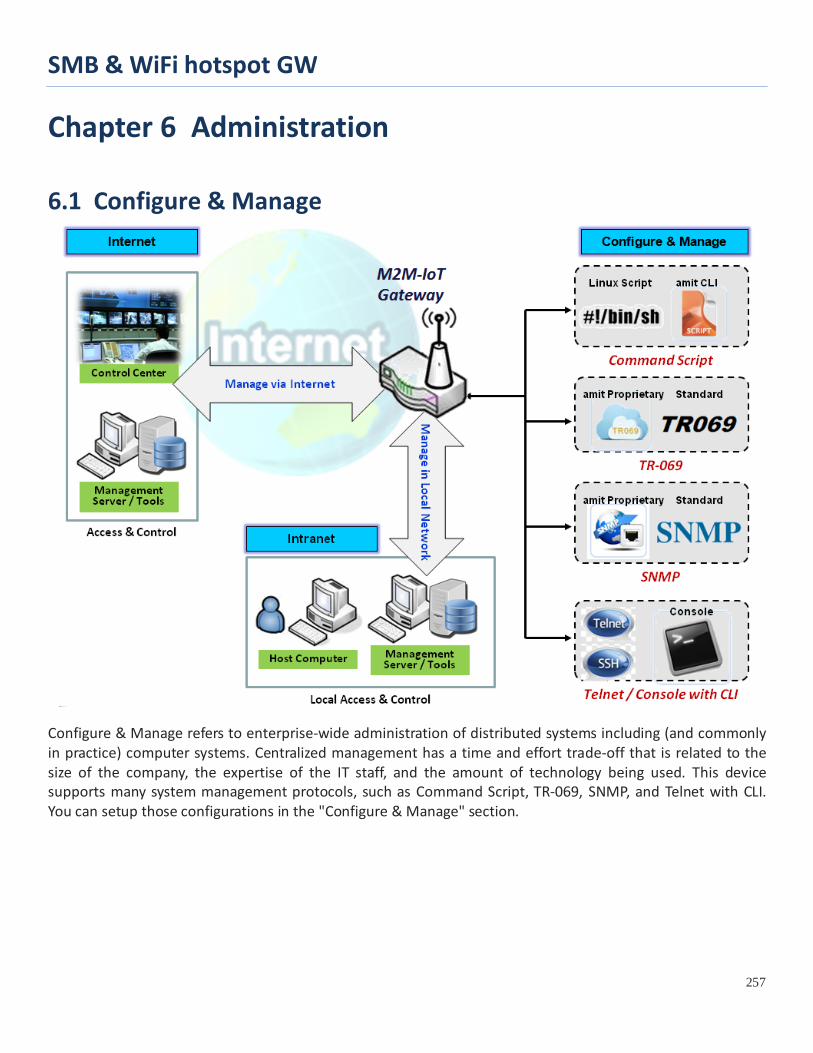
SMB & WiFi hotspot GW
257
Chapter 6 Administration
6.1 Configure & Manage
Configure & Manage refers to enterprise-wide administration of distributed systems including (and commonly in practice) computer systems. Centralized management has a time and effort trade-off that is related to the size of the company, the expertise of the IT staff, and the amount of technology being used. This device supports many system management protocols, such as Command Script, TR-069, SNMP, and Telnet with CLI. You can setup those configurations in the "Configure & Manage" section.

SMB & WiFi hotspot GW
258
6.1.1 Command Script Command script configuration is the application that allows administrator to setup the pre-defined configuration in plain text style and apply configuration on startup.
Go to Administration > Command Script > Configuration Tab.
Enable Command Script Configuration
Configuration Item Value setting Description
Command Script The box is unchecked by default
Check the Enable box to activate the Command Script function.
Backup Script N/A Click the Via Web UI or Via Storage button to backup the existed command script in a .txt file. You can specify the script file name in Script Name below.
Upload Script N/A Click the Via Web UI or Via Storage button to Upload the existed command script from a specified .txt file.
Script Name 1.An Optional setting 2.Any valid file name
Specify a script file name for script backup, or display the selected upload script file name. Value Range: 0 ~ 32 characters.
Version 1.An Optional setting 2.Any string
Specify the version number for the applied Command script. Value Range: 0 ~ 32 characters.
Description 1.An Optional setting 2.Any string
Enter a short description for the applied Command script.
Update time N/A It records the upload time for last commad script upload.

SMB & WiFi hotspot GW
259
Edit/Backup Plain Text Command Script
You can edit the plain text configuration settings in the configuration screen as above. Plain Text Configuration Item Value setting Description Clean NA Clean text area. (You should click Save button to further clean the configuration
already saved in the system.) Backup NA Backup and download configuration. Save NA Save configuration
The supported plain text configuration items are shown in the following list. For the settings that can be executed with standard Linux commands, you can put them in a script file, and apply to the system configure with STARTUP command. For those configurations without corresponding Linux command set to configure, you can configure them with proprietary command set. Configuration Content Key Value setting Description OPENVPN_ENABLED 1 : enable
0 : disable Enable or disable OpenVPN Client function.
OPENVPN_DESCRIPTION A Must filled Setting
Specify the tunnel name for the OpenVPN Client connection.
OPENVPN_PROTO udp tcp
Define the Protocol for the OpenVPN Client. • Select TCP or TCP /UDP ->The OpenVPN will use TCP protocol, and Port will be set as 443 automatically. • Select UDP -> The OpenVPN will use UDP protocol, and Port will be set as 1194 automatically.
OPENVPN_PORT A Must filled Setting
Specify the Port for the OpenVPN Client to use.
OPENVPN_REMOTE_IPADDR IP or FQDN Specify the Remote IP/FQDN of the peer OpenVPN Server for this OpenVPN Client tunnel. Fill in the IP address or FQDN.
OPENVPN_PING_INTVL seconds Specify the time interval for OpenVPN keep-alive checking.

SMB & WiFi hotspot GW
260
OPENVPN_PING_TOUT seconds Specify the timeout value for OpenVPN Client keep-alive checking. OPENVPN_COMP Adaptive Specify the LZO Compression algorithm for OpenVPN client. OPENVPN_AUTH Static Key/TLS Specify the authorization mode for the OpenVPN tunnel.
• TLS ->The OpenVPN will use TLS authorization mode, and the following items CA Cert., Client Cert. and Client Key need to specify as well.
OPENVPN_CA_CERT A Must filled Setting
Specify the Trusted CA certificate for the OpenVPN client. It will go through Base64 Conversion.
OPENVPN_LOCAL_CERT A Must filled Setting
Specify the local certificate for OpenVPN client. It will go through Base64 Conversion.
OPENVPN_LOCAL_KEY A Must filled Setting
Specify the local key for the OpenVPN client. It will go through Base64 Conversion.
OPENVPN_EXTRA_OPTS Options Specify the extra options setting for the OpenVPN client. IP_ADDR1 Ip Ethernet LAN IP IP_NETM1 Net mask Ethernet LAN MASK PPP_MONITORING 1 : enable
0 : disable When the Network Monitoring feature is enabled, the router will use DNS Query or ICMP to periodically check Internet connection –connected or disconnected.
PPP_PING 0 : DNS Query 1 : ICMP Query
With DNS Query, the system checks the connection by sending DNS Query packets to the destination specified in PPP_PING_IPADDR. With ICMP Query, the system will check connection by sending ICMP request packets to the destination specified in PPP_PING_IPADDR.
PPP_PING_IPADDR IP Specify an IP address as the target for sending DNS query/ICMP request.
PPP_PING_INTVL seconds Specify the time interval for between two DNS Query or ICMP checking packets.
STARTUP Script file For the configurations that can be configured with standard Linux commands, you can put them in a script file, and apply the script file with STARTUP command. For example, STARTUP=#!/bin/sh STARTUP=echo “startup done” > /tmp/demo
Plain Text System Configuration with Telnet
In addition to the web-style plain text configuration as mentioned above, the gateway system also allow the configuration via Telnet CLI. Administrator can use the proprietary telnet command “txtConfig” and related action items to perform the plain system configuration.
The command format is: txtConfig (action) [option]
Action Option Description clone Output file Duplicate the configuration content from database and stored as a
configuration file. (ex: txtConfig clone /tmp/config) The contents in the configuration file are the same as the plain text commands mentioned above. This action is exactly the same as performing the “Backup” plain text configuration.

SMB & WiFi hotspot GW
261
commit a existing file Commit the configuration content to database. (ex: txtConfig commit /tmp/config)
enable NA Enable plain text system config. (ex: txtConfig enable)
disable NA Disable plain text system config. (ex: txtConfig disable)
run_immediately NA Apply the configuration content that has been committed in database. (ex: txtConfig run_immediately)
run_immediately a existing file Assign a configuration file to apply. (ex: txtConfig run_immediately /tmp/config)

SMB & WiFi hotspot GW
262
6.1.2 TR-069 TR-069 (Technical Report 069) is a Broadband Forum technical specification entitled CPE WAN Management Protocol (CWMP). It defines an application layer protocol for remote management of end-user devices, like this gateway device. As a bidirectional SOAP/HTTP-based protocol, it provides the communication between customer-premises equipment (CPE) and Auto Configuration Servers (ACS). The Security Gateway is such CPE.
TR-069 is a customized feature for ISP. It is not recommend that you change the configuration for this. If you have any problem in using this feature for device management, please contact with your ISP or the ACS provider for help. At the right upper corner of TR-069 Setting screen, one “[Help]” command let you see the same message about that.
Scenario - Managing deployed gateways through an ACS Server
Scenario Application Timing
When the enterprise data center wants to use an ACS server to manage remote gateways geographically distributed elsewhere in the world, the gateways in all branch offices must have an embedded TR-069 agent to communicate with the ACS server. So that the ACS server can configure, FW upgrade and monitor these gateways and their corresponding Intranets.
Scenario Description
The ACS server can configure, upgrade with latest FW and monitor these gateways.
Remote gateways inquire the ACS server for jobs to do in each time period.
The ACS server can ask the gateways to execute some urgent jobs.
Parameter Setup Example

SMB & WiFi hotspot GW
263
Following tables list the parameter configuration as an example for the Gateway 1 in above diagram with "TR-069" enabling.
Use default value for those parameters that are not mentioned in the tables.
Configuration Path [TR-069]-[Configuration]
TR-069 ■ Enable ACS URL http://qa.acslite.com/cpe.php ACS User Name ACSUserName
ACS Password ACSPassword
ConnectionRequest Port 8099
ConnectionRequest User Name ConnReqUserName
ConnectionRequest Password ConnReqPassword
Inform ■ Enable Interval 900
Scenario Operation Procedure
In above diagram, the ACS server can manage multiple gateways in the Internet. The "Gateway 1" is one of them and has 118.18.81.33 IP address for its WAN-1 interface.
When all remote gateways have booted up, they will try to connect to the ACS server.
Once the connections are established successfully, the ACS server can configure, upgrade with latest FW and monitor these gateways.
Remote gateways inquire the ACS server for jobs to do in each time period.
If the ACS server needs some urgent jobs to be done by the gateways, it will issue the "Connection Request" command to those gateways. And those gateways make immediate connections in response to the ACS server’s immediate connection request for executing the urgent jobs.

SMB & WiFi hotspot GW
264
TR-069 Setting
Go to Administration > Configure & Manage > TR-069 tab.
In "TR-069" page, there is only one configuration window for TR-069 function. In the window, you must specify the related information for your security gateway to connect to the ACS. Drive the function to work by specifying the URL of the ACS server, the account information to login the ACS server, the service port and the account information for connection requesting from the ACS server, and the time interval for job inquiry. Except the inquiry time, there are no activities between the ACS server and the gateways until the next inquiry cycle. But if the ACS server has new jobs that are expected to do by the gateways urgently, it will ask these gateways by using connection request related information for immediate connection for inquiring jobs and executing.
Enable TR-069
TR-069
Item Value setting Description

SMB & WiFi hotspot GW
265
TR-069 The box is unchecked by default
Check the Enable box to activate TR-069 function.
Interface WAN-1 is selected by default.
When you finish set basic network WAN-1 ~ WAN-n, you can choose WAN-1 ~ WAN-n When you finish set Security > VPN > IPSec/OpenVPN/PPTP/L2TP/GRE, you can choose IPSec/OpenVPN/PPTP/L2TP/GRE tunnel, the interface just like “IPSec #1”
Data Model ACS Cloud Data Model is selected by default.
Select the TR-069 dat model for the remote management. Standard : the ACS Server is a standard one, which is fully comply with TR-069. ACS Cloud Data Model : Select this data model if you intend to use Cloud ACS Server to managing the deployed gateways.
ACS URL A Must filled setting You can ask ACS manager provide ACS URL and manually set ACS Username A Must filled setting You can ask ACS manager provide ACS username and manually set ACS Password A Must filled setting You can ask ACS manager provide ACS password and manually set
ConnectionRequest Port
1. A Must filled setting. 2. By default 8099 is set.
You can ask ACS manager provide ACS ConnectionRequest Port and manually set Value Range: 0 ~ 65535.
ConnectionRequest UserName A Must filled setting
You can ask ACS manager provide ACS ConnectionRequest Username and manually set
ConnectionRequest Password A Must filled setting
You can ask ACS manager provide ACS ConnectionRequest Password and manually set
Inform
1. The box is checked by default. 2. The Interval value is 300 by default.
When the Enable box is checked, the gateway (CPE) will periodicly send inform message to ACS Server according to the Interval setting. Value Range: 0 ~ 86400 for Inform Interval.
Certification Setup The default box is selected by default
You can leave it as default or select an expected certificate and key from the drop down list. Refer to Object Definition > Certificate Section for the Certificate configuration.
Save N/A Click Save to save the settings. Undo N/A Click Undo to cancel the modifications.
When you finish set ACS URL ACS Username ACS Password, your gateway (CPE, Client Premium Equipment) can send inform to ACS Server. When you finish set ConnectionRequest Port ConnectionRequest Username ConnectionRequest Password, ACS Server can ask the gateway (CPE) to send inform to ACS Server. Enable STUN Server
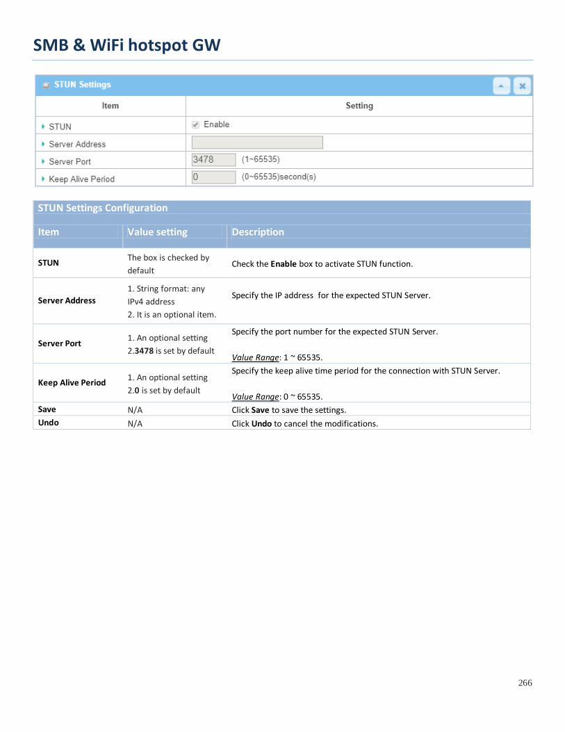
SMB & WiFi hotspot GW
266
STUN Settings Configuration
Item Value setting Description
STUN The box is checked by default
Check the Enable box to activate STUN function.
Server Address 1. String format: any IPv4 address 2. It is an optional item.
Specify the IP address for the expected STUN Server.
Server Port 1. An optional setting 2.3478 is set by default
Specify the port number for the expected STUN Server. Value Range: 1 ~ 65535.
Keep Alive Period 1. An optional setting 2.0 is set by default
Specify the keep alive time period for the connection with STUN Server. Value Range: 0 ~ 65535.
Save N/A Click Save to save the settings. Undo N/A Click Undo to cancel the modifications.

SMB & WiFi hotspot GW
267
6.1.3 SNMP In brief, SNMP, the Simple Network Management Protocol, is a protocol designed to give a user the capability to remotely manage a computer network by polling and setting terminal values and monitoring network events.
In typical SNMP uses, one or more administrative computers, called managers, have the task of monitoring or managing a group of hosts or devices on a computer network. Each managed system executes, at all times, a software component called an agent which reports information via SNMP to the manager.
SNMP agents expose management data on the managed systems as variables. The protocol also permits active management tasks, such as modifying and applying a new configuration through remote modification of these variables. The variables accessible via SNMP are organized in hierarchies. These hierarchies, and other metadata (such as type and description of the variable), are described by Management Information Bases (MIBs).
The device supports several public MIBs and one private MIB for the SNMP agent. The supported MIBs are as follow: MIB-II (RFC 1213, Include IPv6), IF-MIB, IP-MIB, TCP-MIB, UDP-MIB, SMIv1 and SMIv2, SNMPv2-TM and SNMPv2-MIB, and AMIB (a Proprietary MIB)
SNMP Management Scenario
Scenario Application Timing
There are two application scenarios of SNMP Network Management Systems (NMS). Local NMS is in

SMB & WiFi hotspot GW
268
the Intranet and manage all devices that support SNMP protocol in the Intranet. Another one is the Remote NMS to manage some devices whose WAN interfaces are connected together by using a switch or a router with UDP forwarding. If you want to manage some devices and they all have supported SNMP protocol, use either one application scenario, especially the management of devices in the Intranet. In managing devices in the Internet, the TR-069 is the better solution. Please refer to last sub-section.
Scenario Description
The NMS server can monitor and configure the managed devices by using SNMP protocol, and those devices are located at where UDP packets can reach from NMS.
The managed devices report urgent trap events to the NMS servers.
Use SNMPv3 version of protocol can protected the transmitting of SNMP commands and responses.
The remote NMS with privilege IP address can manage the devices, but other remote NMS can't.
Parameter Setup Example
Following tables list the parameter configuration as an example for the Gateway 1 in above diagram with "SNMP" enabling at LAN and WAN interfaces.
Use default value for those parameters that are not mentioned in the tables.
Configuration Path [SNMP]-[Configuration]
SNMP Enable ■ LAN ■ WAN
Supported Versions ■ v1 ■ v2c ■ v3
Get / Set Community ReadCommunity / WriteCommunity
Trap Event Receiver 1 118.18.81.11
WAN Access IP Address 118.18.81.11
Configuration Path [SNMP]-[User Privacy Definition]
ID 1 2 3
User Name UserName1 UserName2 UserName3
Password Password1 Password2 Disable
Authentication MD5 SHA-1 Disable
Encryption DES Disable Disable
Privacy Mode authPriv authNoPriv noAuthNoPriv
Privacy Key 12345678 Disable Disable
Authority Read/Write Read Read
Enable ■ Enable ■ Enable ■ Enable
Scenario Operation Procedure
In above diagram, the NMS server can manage multiple devices in the Intranet or a UDP-reachable network. The "Gateway 1" is one of the managed devices, and it has the IP address of 10.0.75.2 for LAN interface and 118.18.81.33 for WAN-1 interface. It serves as a NAT router.

SMB & WiFi hotspot GW
269
At first stage, the NMS manager prepares related information for all managed devices and records them in the NMS system. Then NMS system gets the status of all managed devices by using SNMP get commands.
When the manager wants to configure the managed devices, the NMS system allows him to do that by using SNMP set commands. The "UserName1" account is used if the manager uses SNMPv3 protocol for configuring the "Gateway 1". Only the "UserName1" account can let the "Gateway 1" accept the configuration from the NMS since the authority of the account is "Read/Write".
Once a managed device has an urgent event to send, the device will issue a trap to the Trap Event Receivers. The NMS itself could be one among them.
If you want to secure the transmitted SNMP commands and responses between the NMS and the managed devices, use SNMPv3 version of protocol.
The remote NMS without privilege IP address can't manage the "Gateway 1", since "Gateway 1" allows only the NMS with privilege IP address can manage it via its WAN interface.

SMB & WiFi hotspot GW
270
SNMP Setting
Go to Administration > Configure & Manage > SNMP tab.
The SNMP allows user to configure SNMP relevant setting which includes interface, version, access control and trap receiver.
Enable SNMP
SNMP Item Value setting Description
SNMP Enable 1.The boxes are unchecked by default
Select the interface for the SNMP and enable SNMP functions. When Check the LAN box, it will activate SNMP functions and you can access SNMP from LAN side; When Check the WAN box, it will activate SNMP functions and you can access SNMP from WAN side.
WAN Interface 1.A Must filled setting 2. ALL WANs is selected by default
Specify the WAN interface that a remote SNMP host can access to the device. By default, All WANs is selected, and there is no limitation for the WAN inferface.
Supported Versions 1.A Must filled setting 2.The boxes are unchecked by default
Select the version for the SNMP When Check the v1 box. It means you can access SNMP by version 1. When Check the v2c box. It means you can access SNMP by version 2c. When Check the v3 box. It means you can access SNMP by version 3.
SNMP Port 1. String format: any Specify the SNMP Port.
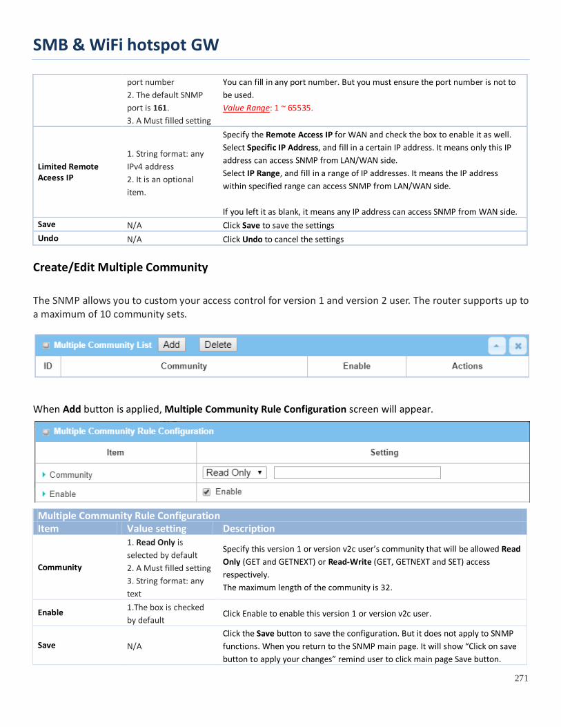
SMB & WiFi hotspot GW
271
port number 2. The default SNMP port is 161. 3. A Must filled setting
You can fill in any port number. But you must ensure the port number is not to be used. Value Range: 1 ~ 65535.
Limited Remote Aceess IP
1. String format: any IPv4 address 2. It is an optional item.
Specify the Remote Access IP for WAN and check the box to enable it as well. Select Specific IP Address, and fill in a certain IP address. It means only this IP address can access SNMP from LAN/WAN side. Select IP Range, and fill in a range of IP addresses. It means the IP address within specified range can access SNMP from LAN/WAN side. If you left it as blank, it means any IP address can access SNMP from WAN side.
Save N/A Click Save to save the settings Undo N/A Click Undo to cancel the settings
Create/Edit Multiple Community
The SNMP allows you to custom your access control for version 1 and version 2 user. The router supports up to a maximum of 10 community sets.
When Add button is applied, Multiple Community Rule Configuration screen will appear.
Multiple Community Rule Configuration Item Value setting Description
Community
1. Read Only is selected by default 2. A Must filled setting 3. String format: any text
Specify this version 1 or version v2c user’s community that will be allowed Read Only (GET and GETNEXT) or Read-Write (GET, GETNEXT and SET) access respectively. The maximum length of the community is 32.
Enable 1.The box is checked by default
Click Enable to enable this version 1 or version v2c user.
Save N/A Click the Save button to save the configuration. But it does not apply to SNMP functions. When you return to the SNMP main page. It will show “Click on save button to apply your changes” remind user to click main page Save button.

SMB & WiFi hotspot GW
272
Undo N/A Click the Undo button to cancel the settings. Back N/A Click the Back button to return to last page.
Create/Edit User Privacy
The SNMP allows you to custom your access control for version 3 user. The router supports up to a maximum of 128 User Privacy sets.
When Add button is applied, User Privacy Rule Configuration screen will appear.
User Privacy Rule Configuration Item Value setting Description User Name 1. A Must filled setting
2. String format: any text
Specify the User Name for this version 3 user. Value Range: 1 ~ 32 characters.
Password 1. String format: any text
When your Privacy Mode is authNoPriv or authPriv, you must specify the Password for this version 3 user. Value Range: 8 ~ 64 characters.
Authentication 1. None is selected by default
When your Privacy Mode is authNoPriv or authPriv, you must specify the Authentication types for this version 3 user. Selected the authentication types MD5/ SHA-1 to use.
Encryption 1. None is selected by default
When your Privacy Mode is authPriv, you must specify the Encryption protocols for this version 3 user. Selected the encryption protocols DES / AES to use.

SMB & WiFi hotspot GW
273
Privacy Mode 1. noAuthNoPriv is selected by default
Specify the Privacy Mode for this version 3 user. Selected the noAuthNoPriv. You do not use any authentication types and encryption protocols. Selected the authNoPriv. You must specify the Authentication and Password. Selected the authPriv. You must specify the Authentication, Password, Encryption and Privacy Key.
Privacy Key 1. String format: any text
When your Privacy Mode is authPriv, you must specify the Privacy Key (8 ~ 64 characters) for this version 3 user.
Authority 1. Read is selected by default
Specify this version 3 user’s Authority that will be allowed Read Only (GET and GETNEXT) or Read-Write (GET, GETNEXT and SET) access respectively.
OID Filter Prefix 1. The default value is 1 2. A Must filled setting 3. String format: any legal OID
The OID Filter Prefix restricts access for this version 3 user to the sub-tree rooted at the given OID. Value Range: 1 ~2080768.
Enable 1.The box is checked by default
Click Enable to enable this version 3 user.
Save N/A Click the Save button to save the configuration. But it does not apply to SNMP functions. When you return to the SNMP main page. It will show “Click on save button to apply your changes” remind user to click main page Save button.
Undo N/A Click the Undo button to cancel the settings Back N/A Click the X button to return the last page.
Create/Edit Trap Event Receiver
The SNMP allows you to custom your trap event receiver. The router supports up to a maximum of 4 Trap Event Receiver sets.
When Add button is applied, Trap Event Receiver Rule Configuration screen will appear. The default SNMP Version is v1. The configuration screen will provide the version 1 must filled items.

SMB & WiFi hotspot GW
274
When you selected v2c, the configuration screen is exactly the same as that of v1, except the version.
When you selected v3, the configuration screen will provide more setting items for the version 3 Trap.
Trap Event Receiver Rule Configuration Item Value setting Description
Server IP 1. A Must filled setting 2. String format: any IPv4 address or FQDN
Specify the trap Server IP or FQDN. The DUT will send trap to the server IP/FQDN.
Server Port
1. String format: any port number 2. The default SNMP trap port is 162 3. A Must filled setting
Specify the trap Server Port. You can fill in any port number. But you must ensure the port number is not to be used. Value Range: 1 ~ 65535.
SNMP Version 1. v1 is selected by default
Select the version for the trap Selected the v1.

SMB & WiFi hotspot GW
275
The configuration screen will provide the version 1 must filled items. Selected the v2c. The configuration screen will provide the version 2c must filled items. Selected the v3. The configuration screen will provide the version 3 must filled items.
Community Name
1. A v1 and v2c Must filled setting 2. String format: any text
Specify the Community Name for this version 1 or version v2c trap. Value Range: 1 ~ 32 characters.
User Name
1. A v3 Must filled setting 2. String format: any text
Specify the User Name for this version 3 trap. Value Range: 1 ~ 32 characters.
Password
1. A v3 Must filled setting 2. String format: any text
When your Privacy Mode is authNoPriv or authPriv, you must specify the Password for this version 3 trap. Value Range: 8 ~ 64 characters.
Privacy Mode
1. A v3 Must filled setting 2. noAuthNoPriv is selected by default
Specify the Privacy Mode for this version 3 trap. Selected the noAuthNoPriv. You do not use any authentication types and encryption protocols. Selected the authNoPriv. You must specify the Authentication and Password. Selected the authPriv. You must specify the Authentication, Password, Encryption and Privacy Key.
Authentication
1. A v3 Must filled setting 2. None is selected by default
When your Privacy Mode is authNoPriv or authPriv, you must specify the Authentication types for this version 3 trap. Selected the authentication types MD5/ SHA-1 to use.
Encryption
1. A v3 Must filled setting 2. None is selected by default
When your Privacy Mode is authPriv, you must specify the Encryption protocols for this version 3 trap. Selected the encryption protocols DES / AES to use.
Privacy Key
1. A v3 Must filled setting 2. String format: any text
When your Privacy Mode is authPriv, you must specify the Privacy Key (8 ~ 64 characters) for this version 3 trap.
Enable 1.The box is checked by default
Click Enable to enable this trap receiver.
Save N/A Click the Save button to save the configuration. But it does not apply to SNMP functions. When you return to the SNMP main page. It will show “Click on save button to apply your changes” remind user to click main page Save button.
Undo N/A Click the Undo button to cancel the settings. Back N/A Click the X button to return to last page.

SMB & WiFi hotspot GW
276
Specify SNMP MIB-2 System If required, you can also specify the required information for the MIB-2 System.
SNMP MIB-2 System Configuration Item Value setting Description sysContact 1. An Optional filled
setting 2. String format: any text
Specify the contact information for MIB-2 system. Value Range: 0 ~ 64 characters.
sysLocation 1. An Optional filled setting 2. String format: any text
Specify the location information for MIB-2 system. Value Range: 0 ~ 64 characters.
Edit SNMP Options
If you use some particular private MIB, you must fill the enterprise name, number and OID.
Options Item Value setting Description
Enterprise Name
1. The default value is Default 2. A Must filled setting 3. String format: any text
Specify the Enterprise Name for the particular private MIB. Value Range: 1 ~ 10 characters, and only string with A~Z, a~z, 0~9, ’–‘, ‘_’.
Enterprise Number
The default value is 12823 (Default Enterprise Number)
Specify the Enterprise Number for the particular private MIB. Value Range: 1 ~2080768.

SMB & WiFi hotspot GW
277
2. A Must filled setting 3. String format: any number
Enterprise OID
1. The default value is 1.3.6.1.4.1.12823.4.4.9 (Default Enterprise OID) 2. A Must filled setting 3. String format: any legal OID
Specify the Enterprise OID for the particular private MIB. The range of the each OID number is 1-2080768. The maximum length of the enterprise OID is 31. The seventh number must be identical with the enterprise number.
Save N/A Click the Save button to save the configuration and apply your changes to SNMP functions.
Undo N/A Click the Undo button to cancel the settings.
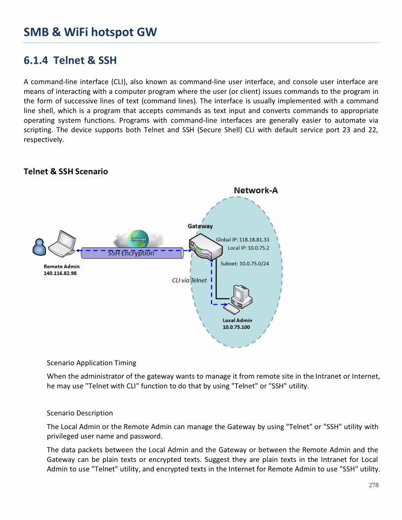
SMB & WiFi hotspot GW
278
6.1.4 Telnet & SSH A command-line interface (CLI), also known as command-line user interface, and console user interface are means of interacting with a computer program where the user (or client) issues commands to the program in the form of successive lines of text (command lines). The interface is usually implemented with a command line shell, which is a program that accepts commands as text input and converts commands to appropriate operating system functions. Programs with command-line interfaces are generally easier to automate via scripting. The device supports both Telnet and SSH (Secure Shell) CLI with default service port 23 and 22, respectively.
Telnet & SSH Scenario
Scenario Application Timing
When the administrator of the gateway wants to manage it from remote site in the Intranet or Internet, he may use "Telnet with CLI" function to do that by using "Telnet" or "SSH" utility.
Scenario Description
The Local Admin or the Remote Admin can manage the Gateway by using "Telnet" or "SSH" utility with privileged user name and password.
The data packets between the Local Admin and the Gateway or between the Remote Admin and the Gateway can be plain texts or encrypted texts. Suggest they are plain texts in the Intranet for Local Admin to use "Telnet" utility, and encrypted texts in the Internet for Remote Admin to use "SSH" utility.
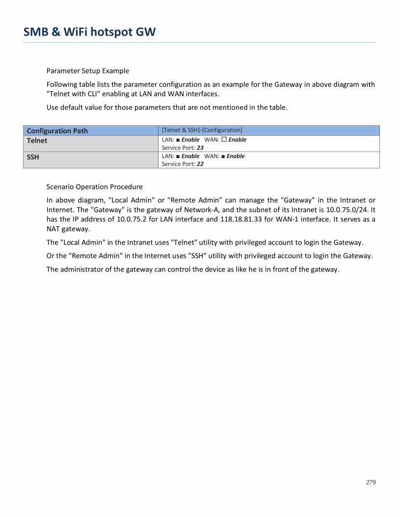
SMB & WiFi hotspot GW
279
Parameter Setup Example
Following table lists the parameter configuration as an example for the Gateway in above diagram with "Telnet with CLI" enabling at LAN and WAN interfaces.
Use default value for those parameters that are not mentioned in the table.
Configuration Path [Telnet & SSH]-[Configuration]
Telnet LAN: ■ Enable WAN: Enable Service Port: 23
SSH LAN: ■ Enable WAN: ■ Enable Service Port: 22
Scenario Operation Procedure
In above diagram, "Local Admin" or "Remote Admin" can manage the "Gateway" in the Intranet or Internet. The "Gateway" is the gateway of Network-A, and the subnet of its Intranet is 10.0.75.0/24. It has the IP address of 10.0.75.2 for LAN interface and 118.18.81.33 for WAN-1 interface. It serves as a NAT gateway.
The "Local Admin" in the Intranet uses "Telnet" utility with privileged account to login the Gateway.
Or the "Remote Admin" in the Internet uses "SSH" utility with privileged account to login the Gateway.
The administrator of the gateway can control the device as like he is in front of the gateway.

SMB & WiFi hotspot GW
280
Telnet & SSH Setting
Go to Administration > Configure & Manage > Telnet & SSH tab.
The Telnet & SSH setting allows administrator to access this device through the traditional Telnet or SSH Telnet program. Before you can telnet (login) to the device, please configure the related settings and password with care. The password management part allows you to set root password for logging telnet and SSH.
Configuration Item Value setting Description Telnet 1. The LAN Enable box is
checked by default. 2. By default Service
Port is 23.
Check the Enable box to activate the Telnet function for connecting from LAN or WAN interfaces. You can set which number of Service Port you want to provide for the corresponding service. Value Range: 1 ~65535.
SSH 3. The LAN Enable box is checked by default.
4. By default Service Port is 22.
Check the Enable box to activate the SSH Telnet function for connecting from LAN or WAN interfaces. You can set which number of Service Port you want to provide for the corresponding service. Value Range: 1 ~65535.
Save N/A Click Save to save the settings Undo N/A Click Undo to cancel the settings

SMB & WiFi hotspot GW
281
Configuration Item Value setting Description root 1. String: any text but no
blank character 2. The default password for telnet is ‘wirelessm2m’.
Type old password and specify new password to change root password. Note_1: You are highly recommended to change the default telnet password with yours before the device is deployed. Note_2: If you have trouble for the default password for previous FW version, please check the corresponding User Manual to get the correct one.
Save N/A Click Save to save the settings Undo N/A Click Undo to cancel the settings

SMB & WiFi hotspot GW
282
6.2 System Operation System Operation allows the network administrator to manage system, settings such as web-based utility access password change, system information, system time, system log, firmware/configuration backup & restore, and reset & reboot.
6.2.1 Password & MMI Go to Administration > System Operation > Password & MMI tab.
Setup Host Name
Host Name screen allows network administrator to setup / change the host name of the gateway. Click the Modify button and provide the new username setting.
Username Configuration Item Value setting Description
Host Name 1. An Optional setting 2. It is blanked by default
Enter the host name of the gateway.
Save N/A Click Save button to save the settings Undo N/A Click Undo button to cancel the settings
Change UserName
Username screen allows network administrator to change the web-based MMI login account to access gateway. Click the Modify button and provide the new username setting.

SMB & WiFi hotspot GW
283
Username Configuration Item Value setting Description
Username 1. The default Username for web-based MMI is ‘admin’.
Display the current MMI login account (Username).
New Username String: any text Enter new Username to replace the current setting.
Password String: any text Enter current password to verify if you have the permission to change the username setting.
Save N/A Click Save button to save the settings Undo N/A Click Undo button to cancel the settings
Change Password
Change password screen allows network administrator to change the web-based MMI login password to access gateway.
Password Configuration Item Value setting Description
Old Password
1. String: any text 2. The default password for web-based MMI is ‘admin’.
Enter the current password to enable you unlock to change password.
New Password String: any text Enter new password New Password Confirmation String: any text Enter new password again to confirm
Save N/A Click Save button to save the settings Undo N/A Click Undo button to cancel the settings
Change MMI Setting for Accessing
This is the gateway’s web-based MMI access which allows administrator to access the gateway for management. The gateway’s web-based MMI will automatically logout when the idle time has elapsed. The setting allows administrator to enable automatic logout and set the logout idle time. When the login timeout
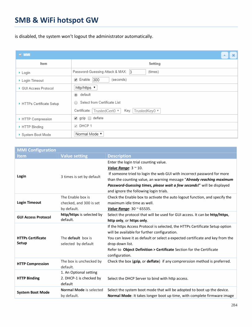
SMB & WiFi hotspot GW
284
is disabled, the system won’t logout the administrator automatically.
MMI Configuration Item Value setting Description
Login 3 times is set by default
Enter the login trial counting value. Value Range: 3 ~ 10. If someone tried to login the web GUI with incorrect password for more than the counting value, an warning message “Already reaching maximum Password-Guessing times, please wait a few seconds!” will be displayed and ignore the following login trials.
Login Timeout The Enable box is checked, and 300 is set by default.
Check the Enable box to activate the auto logout function, and specify the maximum idle time as well. Value Range: 30 ~ 65535.
GUI Access Protocol http/https is selected by default.
Select the protocol that will be used for GUI access. It can be http/https, http only, or https only.
HTTPs Certificate Setup
The default box is selected by default
If the https Access Protocol is selected, the HTTPs Certificate Setup option will be available for further configuration. You can leave it as default or select a expected certificate and key from the drop down list. Refer to Object Definition > Certificate Section for the Certificate configuration.
HTTP Compression The box is unchecked by default.
Check the box (gzip, or deflate) if any comprerssion method is preferred.
HTTP Binding 1. An Optional setting 2. DHCP-1 is checked by default
Select the DHCP Server to bind with http access.
System Boot Mode Normal Mode is selected by default.
Select the system boot mode that will be adopted to boot up the device. Normal Mode: It takes longer boot up time, with complete firmware image
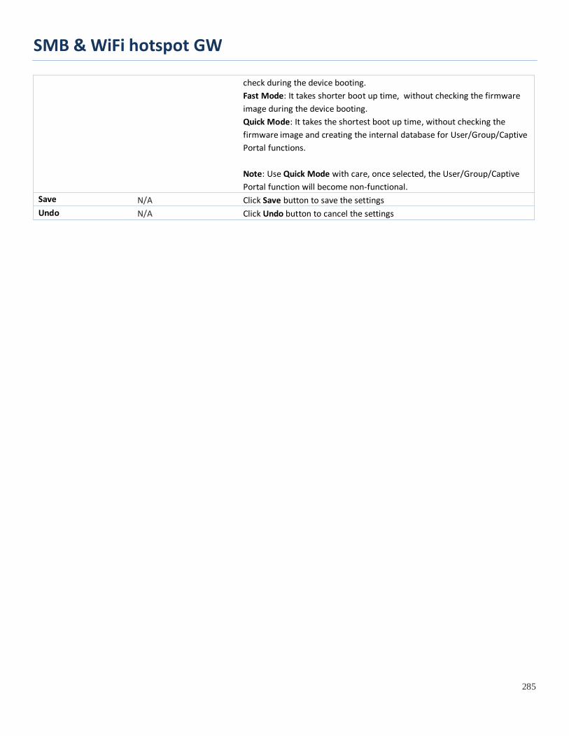
SMB & WiFi hotspot GW
285
check during the device booting. Fast Mode: It takes shorter boot up time, without checking the firmware image during the device booting. Quick Mode: It takes the shortest boot up time, without checking the firmware image and creating the internal database for User/Group/Captive Portal functions. Note: Use Quick Mode with care, once selected, the User/Group/Captive Portal function will become non-functional.
Save N/A Click Save button to save the settings Undo N/A Click Undo button to cancel the settings

SMB & WiFi hotspot GW
286
6.2.2 System Information System Information screen gives network administrator a quick look up on the device information for the purchades gateway.
Go to Administration > System Operation > System Information tab.
System Information Item Value Setting Description Model Name N/A It displays the model name of this product. Device Serial Number N/A It displays the serial number of this product.
Kernel Version N/A It displays the Linux kernel version of the product FW Version N/A It displays the firmware version of the product Memory Usage N/A It displays the percentage of device memory utilization. System Time N/A It displays the current system time that you browsed this web page. Device Up-Time N/A It displays the statistics for the device up-time since last boot up. Refresh N/A Click the Refresh button to update the system Information immediately.

SMB & WiFi hotspot GW
287
6.2.3 System Time The gateway provides manually setup and auto-synchronized approaches for the administrator to setup the system time for the gateway. The time supported synchronization methods can be Time Server, Manual, PC, Cellular Module, or GPS Signal. Select the method first, and then configure rest settings.
Instead of manually configuring the system time for the gateway, there are two simple and quick solutions for you to set the correct time information and set it as the system time for the gateway.
The first one is “Sync with Timer Server”. Based on your selection of time zone and time server in above time information configuration window, system will communicate with time server by NTP Protocol to get system date and time after you click on the Synchronize immediately button.
The second one is “Sync with my PC”. Select the method and the system will synchronize its date and time to the time of the administration PC.
Go to Administration > System Operation > System Time tab.
Synchronize with Time Server
System Time Information Item Value Setting Description
Synchronization method
1. A Must-filled item. 2. Time Server is selected by default.
Select the Time Server as the synchronization method for the system time.
Time Zone 1. A Must-filled item. 2. GMT+00 :00 is selected by default.
Select a time zone where this device locates.
Auto-synchronization
1. A Must-filled item. 2. Auto is selected by default.
Enter the IP or FQDN for the NTP time server you expected, or leave it as auto mode so that the available server will be used for time synchronization one by one.

SMB & WiFi hotspot GW
288
Daylight Saving Time
1. It is an optional item. 2. Un-checked by default
Check the Enable button to activate the daylight saving function. When you enabled this function, you have to specify the start date and end date for the daylight saving time duration.
NTP Service 1. It is an optional item. 2. Un-checked by default
Check the Enable button to activate the NTP Service function. When you enabled this function, the gateway can provide NTP server service for its local connected devices.
Synchronize immediately N/A
Click the Active button to synchronize the system time with specified time server immediately.
Save N/A Click the Save button to save the settings. Refresh N/A Click the Refresh button to update the system time immediately.
Note: Remember to select a correct time zone for the device, otherwise, you will just get the UTC (Coordinated Universal Time) time, not the local time for the device.
Synchronize with Manually Setting
System Time Information Item Value Setting Description
Synchronization method
1. A Must-filled item. 2. Time Server is selected by default.
Select the Manual as the synchronization method for the system time. It means administrator has to set the Date & Time manually.
Time Zone 1. A Must-filled item. 2. GMT+00 :00 is selected by default.
Select a time zone where this device locates.
Daylight Saving Time
1. It is an optional item. 2. Un-checked by default
Check the Enable button to activate the daylight saving function. When you enabled this function, you have to specify the start date and end date for the daylight saving time duration.
Set Date & Time Manually 1. It is an optional item.
Manually set the date (Year/Month/Day) and time (Hour:Minute:Second) as the system time.
NTP Service 1. It is an optional item. 2. Un-checked by default
Check the Enable button to activate the NTP Service function. When you enabled this function, the gateway can provide NTP server service for
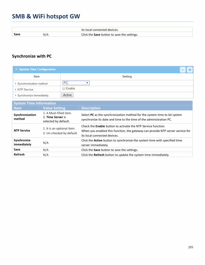
SMB & WiFi hotspot GW
289
its local connected devices. Save N/A Click the Save button to save the settings.
Synchronize with PC
System Time Information Item Value Setting Description
Synchronization method
1. A Must-filled item. 2. Time Server is selected by default.
Select PC as the synchronization method for the system time to let system synchronize its date and time to the time of the administration PC.
NTP Service 1. It is an optional item. 2. Un-checked by default
Check the Enable button to activate the NTP Service function. When you enabled this function, the gateway can provide NTP server service for its local connected devices.
Synchronize immediately N/A
Click the Active button to synchronize the system time with specified time server immediately.
Save N/A Click the Save button to save the settings. Refresh N/A Click the Refresh button to update the system time immediately.
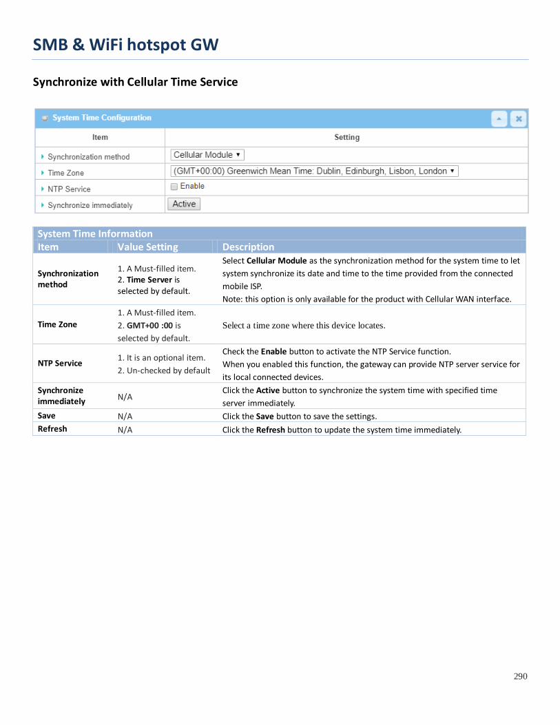
SMB & WiFi hotspot GW
290
Synchronize with Cellular Time Service
System Time Information Item Value Setting Description
Synchronization method
1. A Must-filled item. 2. Time Server is selected by default.
Select Cellular Module as the synchronization method for the system time to let system synchronize its date and time to the time provided from the connected mobile ISP. Note: this option is only available for the product with Cellular WAN interface.
Time Zone 1. A Must-filled item. 2. GMT+00 :00 is selected by default.
Select a time zone where this device locates.
NTP Service 1. It is an optional item. 2. Un-checked by default
Check the Enable button to activate the NTP Service function. When you enabled this function, the gateway can provide NTP server service for its local connected devices.
Synchronize immediately N/A
Click the Active button to synchronize the system time with specified time server immediately.
Save N/A Click the Save button to save the settings. Refresh N/A Click the Refresh button to update the system time immediately.

SMB & WiFi hotspot GW
291
Synchronize with GPS Time Service
System Time Information Item Value Setting Description
Synchronization method
1. A Must-filled item. 2. Time Server is selected by default.
Select GPS Signal as the synchronization method for the system time to let system synchronize its date and time to the time provided from the GNSS service. Note: this option is only available for the product with GNSS interface.
Time Zone 1. A Must-filled item. 2. GMT+00 :00 is selected by default.
Select a time zone where this device locates.
NTP Service 1. It is an optional item. 2. Un-checked by default
Check the Enable button to activate the NTP Service function. When you enabled this function, the gateway can provide NTP server service for its local connected devices.
Synchronize immediately N/A
Click the Active button to synchronize the system time with specified time server immediately.
Save N/A Click the Save button to save the settings. Refresh N/A Click the Refresh button to update the system time immediately.
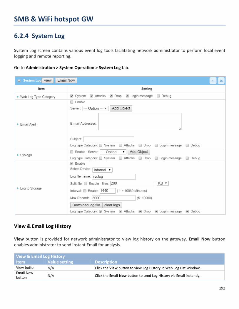
SMB & WiFi hotspot GW
292
6.2.4 System Log System Log screen contains various event log tools facilitating network administrator to perform local event logging and remote reporting. Go to Administration > System Operation > System Log tab.
View & Email Log History View button is provided for network administrator to view log history on the gateway. Email Now button enables administrator to send instant Email for analysis. View & Email Log History Item Value setting Description View button N/A Click the View button to view Log History in Web Log List Window. Email Now button N/A Click the Email Now button to send Log History via Email instantly.
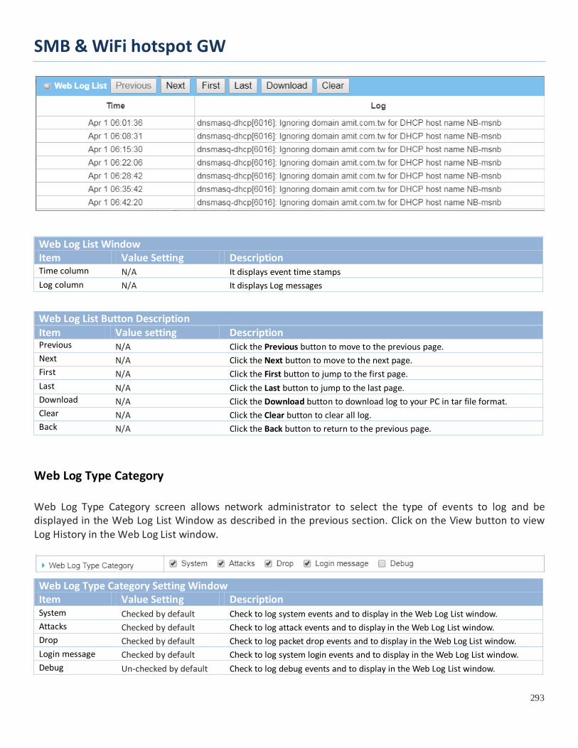
SMB & WiFi hotspot GW
293
Web Log List Window Item Value Setting Description Time column N/A It displays event time stamps Log column N/A It displays Log messages
Web Log List Button Description Item Value setting Description Previous N/A Click the Previous button to move to the previous page. Next N/A Click the Next button to move to the next page. First N/A Click the First button to jump to the first page. Last N/A Click the Last button to jump to the last page. Download N/A Click the Download button to download log to your PC in tar file format. Clear N/A Click the Clear button to clear all log. Back N/A Click the Back button to return to the previous page.
Web Log Type Category Web Log Type Category screen allows network administrator to select the type of events to log and be displayed in the Web Log List Window as described in the previous section. Click on the View button to view Log History in the Web Log List window.
Web Log Type Category Setting Window Item Value Setting Description System Checked by default Check to log system events and to display in the Web Log List window. Attacks Checked by default Check to log attack events and to display in the Web Log List window. Drop Checked by default Check to log packet drop events and to display in the Web Log List window. Login message Checked by default Check to log system login events and to display in the Web Log List window. Debug Un-checked by default Check to log debug events and to display in the Web Log List window.

SMB & WiFi hotspot GW
294
Email Alert
Email Alert screen allows network administrator to select the type of event to log and be sent to the destined Email account.
Email Alert Setting Window Item Value Setting Description
Enable Un-checked by default Check Enable box to enable sending event log messages to destined Email account defined in the E-mail Addresses blank space.
Server N/A
Select one email server from the Server dropdown box to send Email. If none has been available, click the Add Object button to create an outgoing Email server. You may also add an outgoing Email server from Object Definition > External Server > External Server tab.
E-mail address String : email format
Enter the recipient’s Email address. Separate Email addresses with comma ‘,’ or semicolon ‘ ;’ Enter the Email address in the format of ‘[email protected]’
Subject String : any text Enter an Email subject that is easy for you to identify on the Email client.
Log type category Default unchecked Select the type of events to log and be sent to the designated Email account. Available events are System, Attacks, Drop, Login message, and Debug.
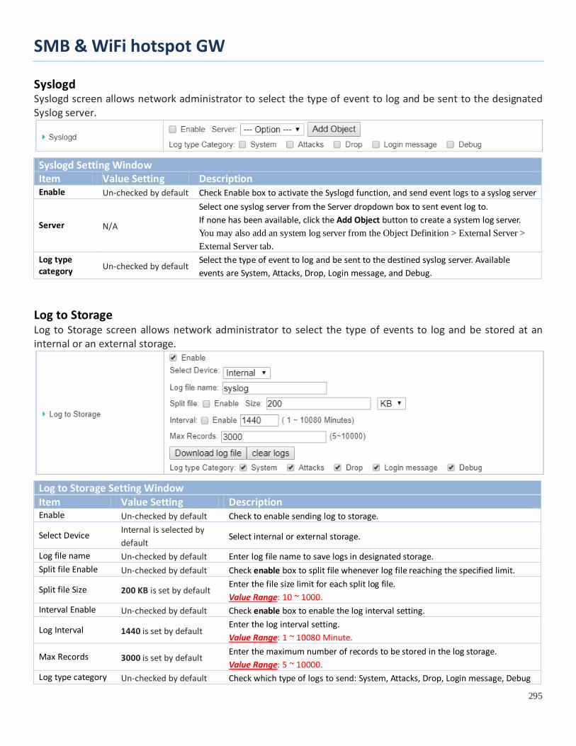
SMB & WiFi hotspot GW
295
Syslogd Syslogd screen allows network administrator to select the type of event to log and be sent to the designated Syslog server.
Syslogd Setting Window Item Value Setting Description Enable Un-checked by default Check Enable box to activate the Syslogd function, and send event logs to a syslog server
Server N/A
Select one syslog server from the Server dropdown box to sent event log to. If none has been available, click the Add Object button to create a system log server. You may also add an system log server from the Object Definition > External Server > External Server tab.
Log type category Un-checked by default
Select the type of event to log and be sent to the destined syslog server. Available events are System, Attacks, Drop, Login message, and Debug.
Log to Storage Log to Storage screen allows network administrator to select the type of events to log and be stored at an internal or an external storage.
Log to Storage Setting Window Item Value Setting Description Enable Un-checked by default Check to enable sending log to storage.
Select Device Internal is selected by default
Select internal or external storage.
Log file name Un-checked by default Enter log file name to save logs in designated storage. Split file Enable Un-checked by default Check enable box to split file whenever log file reaching the specified limit.
Split file Size 200 KB is set by default Enter the file size limit for each split log file. Value Range: 10 ~ 1000.
Interval Enable Un-checked by default Check enable box to enable the log interval setting.
Log Interval 1440 is set by default Enter the log interval setting. Value Range: 1 ~ 10080 Minute.
Max Records 3000 is set by default Enter the maximum number of records to be stored in the log storage. Value Range: 5 ~ 10000.
Log type category Un-checked by default Check which type of logs to send: System, Attacks, Drop, Login message, Debug

SMB & WiFi hotspot GW
296
Log to Storage Button Description Item Value setting Description Download log file
N/A Click the Download log file button to download log files to a log.tar file.
Clear Logs N/A Click the Clear logs button to delete the log files from the storage.

SMB & WiFi hotspot GW
297
6.2.5 Backup & Restore In the Backup & Restore window, you can upgrade the device firmware when new firmware is available and also backup / restore the device configuration.
In addition to the factory default settings, you can also customize a special configuration setting as a customized default value. With this customized default value, you can reset the device to the expected default setting if needed.
Go to Administration > System Operation > Backup & Restore tab.
FW Backup & Restore Item Value Setting Description
FW Upgrade Via Web UI is selected by default
If new firmware is available, click the FW Upgrade button to upgrade the device firmware via Web UI, or Via Storage. After clicking on the “FW Upgrade” command button, you need to specify the file name of new firmware by using “Browse” button, and then click “Upgrade” button to start the FW upgrading process on this device. If you want to upgrade a firmware which is from GPL policy, please check “Accept unofficial firmware”
Backup Configuration Settings
Download is selected by default
You can backup or restore the device configuration settings by clicking the Via Web UI button. Download: for backup the device configuration to a config.bin file. Upload: for restore a designated configuration file to the device. Via Web UI: to retrieve the configuration file via Web GUI.
Auto Restore Configuration
The Enable box is unchecked by default
Chick the Enable button to activate the customized default setting function. Once the function is activated, you can save the expected setting as a customized default setting by clicking the Save Conf. button, or clicking the Clean Conf. button to erase the stored customized configuration.

SMB & WiFi hotspot GW
298
6.2.6 Reboot & Reset For some special reason or situation, you may need to reboot the gateway or reset the device configuration to its default value. In addition to perform these operations through the Power ON/OFF, or pressing the reset button on the device panel, you can do it through the web GUI too.
Go to Administration > System Operation > Reboot & Reset tab.
In the Reboot & Reset window, you can reboot this device by clicking the “Reboot” button, and reset this device to default settings by clicking the “Reset” button.
System Operation Window Item Value Setting Description
Reboot Now is selected by default
Chick the Reboot button to reboot the gateway immediately or on a pre-defined time schedule. Now: Reboot immediately Time Schedule: Select a pre-defined auto-reboot time schedule rule to reboot the auto device on a designated tim. To define a time schedule rule, go to Object Definition > Scheduling > Configuration tab.
Reset to Default N/A Click the Reset button to reset the device configuration to its default value.

SMB & WiFi hotspot GW
299
6.3 FTP (not supported)
Not supported feature for the purchased product, leave it as blank.
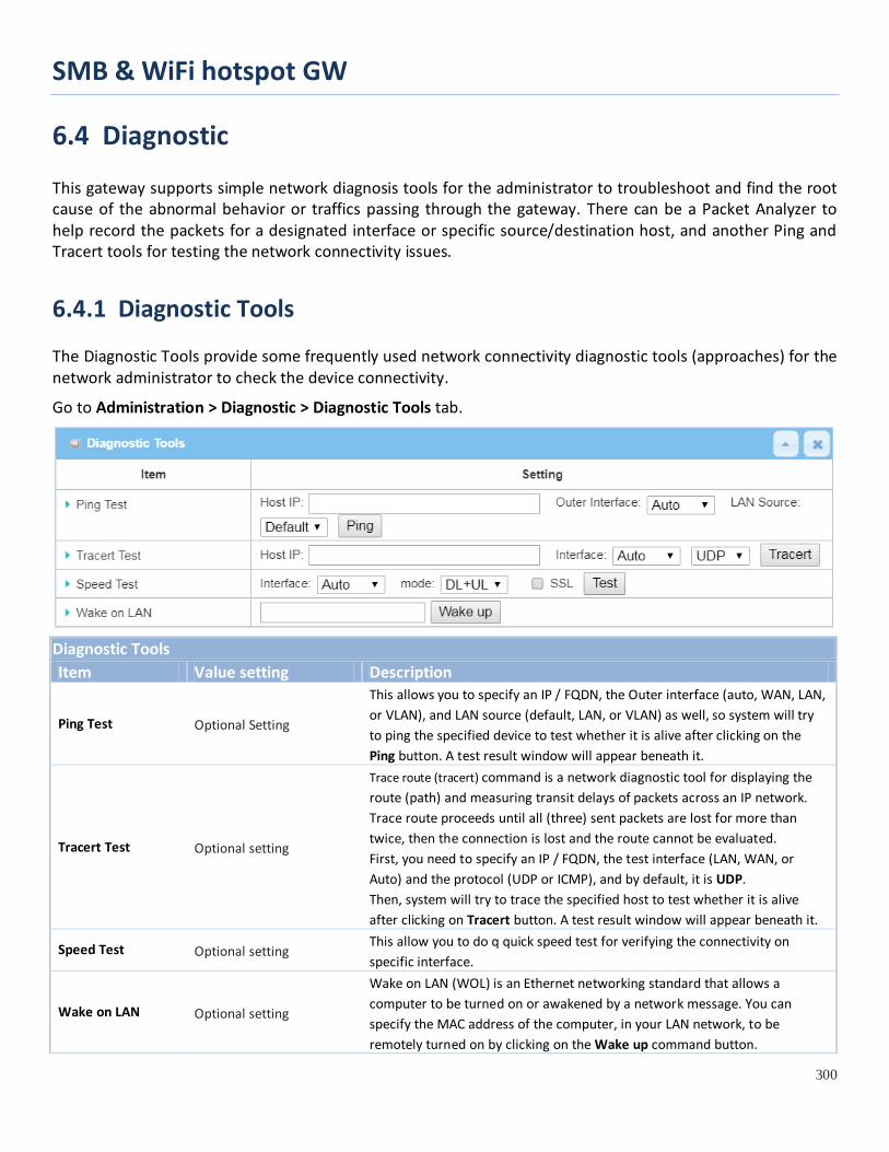
SMB & WiFi hotspot GW
300
6.4 Diagnostic This gateway supports simple network diagnosis tools for the administrator to troubleshoot and find the root cause of the abnormal behavior or traffics passing through the gateway. There can be a Packet Analyzer to help record the packets for a designated interface or specific source/destination host, and another Ping and Tracert tools for testing the network connectivity issues.
6.4.1 Diagnostic Tools The Diagnostic Tools provide some frequently used network connectivity diagnostic tools (approaches) for the network administrator to check the device connectivity.
Go to Administration > Diagnostic > Diagnostic Tools tab.
Diagnostic Tools Item Value setting Description
Ping Test Optional Setting
This allows you to specify an IP / FQDN, the Outer interface (auto, WAN, LAN, or VLAN), and LAN source (default, LAN, or VLAN) as well, so system will try to ping the specified device to test whether it is alive after clicking on the Ping button. A test result window will appear beneath it.
Tracert Test Optional setting
Trace route (tracert) command is a network diagnostic tool for displaying the route (path) and measuring transit delays of packets across an IP network. Trace route proceeds until all (three) sent packets are lost for more than twice, then the connection is lost and the route cannot be evaluated. First, you need to specify an IP / FQDN, the test interface (LAN, WAN, or Auto) and the protocol (UDP or ICMP), and by default, it is UDP. Then, system will try to trace the specified host to test whether it is alive after clicking on Tracert button. A test result window will appear beneath it.
Speed Test Optional setting This allow you to do q quick speed test for verifying the connectivity on specific interface.
Wake on LAN Optional setting
Wake on LAN (WOL) is an Ethernet networking standard that allows a computer to be turned on or awakened by a network message. You can specify the MAC address of the computer, in your LAN network, to be remotely turned on by clicking on the Wake up command button.

SMB & WiFi hotspot GW
301
Save N/A Click the Save button to save the configuration.
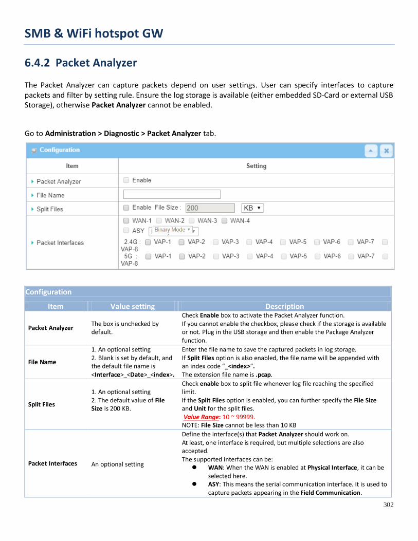
SMB & WiFi hotspot GW
302
6.4.2 Packet Analyzer The Packet Analyzer can capture packets depend on user settings. User can specify interfaces to capture packets and filter by setting rule. Ensure the log storage is available (either embedded SD-Card or external USB Storage), otherwise Packet Analyzer cannot be enabled.
Go to Administration > Diagnostic > Packet Analyzer tab.
Configuration
Item Value setting Description
Packet Analyzer The box is unchecked by default.
Check Enable box to activate the Packet Analyzer function. If you cannot enable the checkbox, please check if the storage is available or not. Plug in the USB storage and then enable the Package Analyzer function.
File Name
1. An optional setting 2. Blank is set by default, and the default file name is <Interface>_<Date>_<index>.
Enter the file name to save the captured packets in log storage. If Split Files option is also enabled, the file name will be appended with an index code “_<index>”. The extension file name is .pcap.
Split Files
1. An optional setting 2. The default value of File Size is 200 KB.
Check enable box to split file whenever log file reaching the specified limit. If the Split Files option is enabled, you can further specify the File Size and Unit for the split files. Value Range: 10 ~ 99999. NOTE: File Size cannot be less than 10 KB
Packet Interfaces An optional setting
Define the interface(s) that Packet Analyzer should work on. At least, one interface is required, but multiple selections are also accepted. The supported interfaces can be: WAN: When the WAN is enabled at Physical Interface, it can be
selected here. ASY: This means the serial communication interface. It is used to
capture packets appearing in the Field Communication.

SMB & WiFi hotspot GW
303
Therefore, it can only be selected when specific field communication protocol, like Modbus, is enabled. Select Binary mode or String mode for the serial interface.
VAP: This means the virtual AP. When WiFi and VAP are enabled, it can be selected here.
Save N/A Click the Save button to save the configuration.
Undo N/A Click the Undo button to restore what you just configured back to the previous setting.
Once you enabled the Packet Analyzer function on specific Interface(s), you can further specify some filter rules to capture the packets which matched the rules.
Capture Fitters
Item Value setting Description Filter Optional setting Check Enable box to activate the Capture Filter function. Source MACs Optional setting Define the filter rule with Source MACs, which means the source MAC address of
packets. Packets which match the rule will be captured. Up to 10 MACs are supported, but they must be separated with “;”, e.g. AA:BB:CC:DD:EE:FF; 11:22:33:44:55:66 The packets will be captured when match any one MAC in the rule.
Source IPs Optional setting Define the filter rule with Source IPs, which means the source IP address of packets.

SMB & WiFi hotspot GW
304
Packets which match the rule will be captured. Up to 10 IPs are supported, but they must be separated with “;”, e.g. 192.168.1.1; 192.168.1.2 The packets will be captured when match any one IP in the rule.
Source Ports Optional setting Define the filter rule with Source Ports, which means the source port of packets. The packets will be captured when match any port in the rule. Up to 10 ports are supported, but they must be separated with “;”, e.g. 80; 53 Value Range: 1 ~ 65535.
Destination MACs Optional setting Define the filter rule with Destination MACs, which means the destination MAC address of packets. Packets which match the rule will be captured. Up to 10 MACs are supported, but they must be separated with “;”, e.g. AA:BB:CC:DD:EE:FF; 11:22:33:44:55:66 The packets will be captured when match any one MAC in the rule.
Destination IPs Optional setting Define the filter rule with Destination IPs, which means the destination IP address of packets. Packets which match the rule will be captured. Up to 10 IPs are supported, but they must be separated with “;”, e.g. 192.168.1.1; 192.168.1.2 The packets will be captured when match any one IP in the rule.
Destination Ports Optional setting Define the filter rule with Destination Ports, which means the destination port of packets. The packets will be captured when match any port in the rule. Up to 10 ports are supported, but they must be separated with “;”, e.g. 80; 53 Value Range: 1 ~ 65535.

SMB & WiFi hotspot GW
305
Chapter 7 Service
7.1 Cellular Toolkit
Besides cellular data connection, you may also like to monitor data usage of cellular WAN, sending text message through SMS, changing PIN code of SIM card, communicating with carrier/ISP by USSD command, or doing a cellular network scan for diagnostic purpose.
In Cellular Toolkit section, it includes several useful features that are related to cellular configuration or application. You can configure settings of Data Usage, SMS, SIM PIN, USSD, and Network Scan here. Please note at least a valid SIM card is required to be
inserted to device before you continue settings in this section.

SMB & WiFi hotspot GW
306
7.1.1 Data Usage Most of data plan for cellular connection is with a limited amount of data usage. If data usage has been over limited quota, either you will get much lower data throughput that may affect your daily operation, or you will get a ‘bill shock’ in the next month because carrier/ISP charges a lot for the over-quota data usage. With help from Data Usage feature, device will monitor cellular data usage continuously and take actions. If data usage reaches limited quota, device can be set to drop the cellular data connection right away. Otherwise, if secondary SIM card is inserted, device will switch to secondary SIM and establish another cellular data connection with secondary SIM automatically. If Data Usage feature is enabled, all history of cellular data usage can be viewed at Status > Statistics & Reports > Cellular Usage tab.
3G/4G Data Usage
Data Usage feature enabling gateway device to continuously monitor cellular data usage and take actions. In the diagram, quota limit of SIM A is 1Gb per month and bill start date is 20th of every month. The device is smart to start a new calculation of data usage on every 20th of month. Enable Connection Restrict will force gateway device to drop cellular connection of SIM A when data usage reaches quota limit (1Gb in this case). If SIM failover feature is configured in Internet Setup, then gateway will switch to SIM B and establish a new cellular data connection automatically.

SMB & WiFi hotspot GW
307
Data Usage Setting
Go to Service > Cellular Toolkit > Data Usage tab. Before finished settings for Data Usage, you need to know bill start date, bill period, and quota limit of data usage according to your data plan. You can ask this information from your carrier or ISP. Create / Edit 3G/4G Data Usage Profile
When Add button is applied, 3G/4G Data Usage Profile Configuration screen will appear. You can create up to four data usage profiles, one profile for each SIM card used in the Gateway.
3G/4G Data Usage Profile Configuration Item Setting Value setting Description SIM Select 3G/4G-1 and SIM A by
default. Choose a cellular interface (3G/4G-1 or 3G/4G-2), and a SIM card bound to the selected cellular interface to configure its data usage profile. Note: 3G/4G-2 is only available for for the product with dual cellular module.
Carrier Name It is an optional item. Fill in the Carrier Name for the selected SIM card for identification. Cycle Period Days by default The first box has three types for cycle period. They are Days, Weekly and Monthly.
Days: For per Days cycle periods, you have to further specify the number of days in the second box. Value Range: 1 ~ 90 days. Weekly, Monthly: The cycle period is one week or one month.
Start Date N/A Specify the date to start measure network traffic. Please don’t select the day before now, otherwise, the traffic statistics will be incorrect.
Data Limitation N/A Specify the allowable data limitation for the defined cycle period.

SMB & WiFi hotspot GW
308
Connection Restrict
Un-Checked by default. Check the Enable box to activate the connection restriction function. During the specified cycle period, if the actual data usage exceeds the allowable data limitation, the cellular connection will be forced to disconnect.
Enable Un-Checked by default. Check the Enable box to activate the data usage profile.

SMB & WiFi hotspot GW
309
7.1.2 SMS Short Message Service (SMS) is a text messaging service, which is used to be widely-used on mobile phones. It uses standardized communications protocols to allow mobile phones or cellular devices to exchange short text messages in an instant and convenient way.
SMS Setting
Go to Service > Cellular Toolkit > SMS tab With this gateway device, you can send SMS text messages or browse received SMS messages as you usually do on a cellular phone.
Setup SMS Configuration
Configuration Item Value setting Description
Physical Interface
The box is 3G/4G-1 by default
Choose a cellular interface (3G/4G-1 or 3G/4G-2) for the following SMS function configuration. Note: 3G/4G-2 is only available for for the product with dual cellular module.
SMS The box is checked by default
This is the SMS switch. If the box checked that the SMS function enable, if the box unchecked that the SMS function disable.
SIM Status N/A Depend on currently SIM status. The possible value will be SIM_A or SIM_B.
SMS Storage The box is SIM Card Only by default
This is the SMS storage location. Currently the option only SIM Card Only.
SMS Space The box is unchecked by default
Check the Enable box and specify a number (1-10) for message count to reserve some available storage space and prevent it from run out of storage. The oldest message(s) will be deleted when the SMS storage is going to full.
Save N/A Click the Save button to save the settings

SMB & WiFi hotspot GW
310
SMS Summary Show Unread SMS, Received SMS, Sent SMS, Remaining SMS, and edit SMS context to send, read SMS from SIM card.
SMS Summary Item Value setting Description
Unread SMS N/A If SIM card insert to router first time, unread SMS value is zero. When received the new SMS but didn’t read, this value plus one.
Received SMS N/A This value record the existing SMS numbers from SIM card, When received the new SMS, this value plus one.
Sent SMS N/A This value record the number of out going SMS, When sent one SMS, this value plus one.
Remaining SMS N/A This value is SMS capacity minus received SMS, When received the new SMS, this value minus one.
New SMS N/A Click New SMS button, a New SMS screen appears. User can set the SMS setting from this screen. Refer to New SMS in the next page.
SMS Inbox N/A Click SMS Inbox button, a SMS Inbox List screen appears. User can read or delete SMS, reply SMS or forward SMS from this screen. Refer to SMS Inbox List in the next page.
Refresh N/A Click the Refresh button to update the SMS summary immediately.

SMB & WiFi hotspot GW
311
New SMS You can set the SMS setting from this screen.
New SMS Item Value setting Description
Receivers N/A Write the receivers to send SMS. User need to add the semicolon and compose multiple receivers that can group send SMS.
Text Message N/A Write the SMS context to send SMS. The router supports up to a maximum of 1023 character for SMS context length.
Send N/A Click the Send button, above text message will be sent as a SMS.
Result N/A If SMS has been sent successfully, it will show Send OK, otherwise Send Failed will be displayed.
SMS Inbox List You can read or delete SMS, reply SMS or forward SMS from this screen.
SMS Inbox List Item Value setting Description ID N/A The number of SMS. From Phone Number N/A Sender List (Phone Number) for the received SMS
Timestamp N/A What time the SMS is received SMS Text Preview N/A Preview the SMS text. Click the Detail button to read a certain message.

SMB & WiFi hotspot GW
312
Action The box is unchecked by default
Click the Detail button to read the SMS detail; Click the Reply / Forward button to reply/forward SMS. Besides, you can check the box(es), and then click the Delete button to delete the checked SMS(s).
Refresh N/A Refresh the SMS Inbox List. Delete N/A Delete the SMS for all checked box from Action. Close N/A Close the Detail SMS Message screen.
SMS Sent Folder You can read or delete SMS from this screen.
SMS Sent Folder Item Value setting Description ID N/A The number of SMS. Receivers N/A Receiver list for the sent SMS. Timestamp N/A What time the SMS is sent SMS Text Preview N/A Preview the SMS text. Click the Detail button to read a certain message.
Action The box is unchecked by default
Click the Detail button to read the SMS detail Besides, you can check the box(es), and then click the Delete button to delete the checked record(s).
Refresh N/A Refresh the SMS Sent Folder. Delete N/A Delete the SMS for all checked box from Action. Close N/A Close the Detail SMS Message screen.
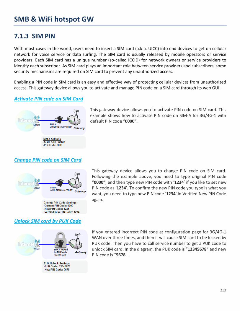
SMB & WiFi hotspot GW
313
7.1.3 SIM PIN With most cases in the world, users need to insert a SIM card (a.k.a. UICC) into end devices to get on cellular network for voice service or data surfing. The SIM card is usually released by mobile operators or service providers. Each SIM card has a unique number (so-called ICCID) for network owners or service providers to identify each subscriber. As SIM card plays an important role between service providers and subscribers, some security mechanisms are required on SIM card to prevent any unauthorized access.
Enabling a PIN code in SIM card is an easy and effective way of protecting cellular devices from unauthorized access. This gateway device allows you to activate and manage PIN code on a SIM card through its web GUI.
Activate PIN code on SIM Card
This gateway device allows you to activate PIN code on SIM card. This example shows how to activate PIN code on SIM-A for 3G/4G-1 with default PIN code “0000”.
Change PIN code on SIM Card
This gateway device allows you to change PIN code on SIM card. Following the example above, you need to type original PIN code “0000”, and then type new PIN code with ‘1234’ if you like to set new PIN code as ‘1234’. To confirm the new PIN code you type is what you want, you need to type new PIN code ‘1234’ in Verified New PIN Code again.
Unlock SIM card by PUK Code
If you entered incorrect PIN code at configuration page for 3G/4G-1 WAN over three times, and then it will cause SIM card to be locked by PUK code. Then you have to call service number to get a PUK code to unlock SIM card. In the diagram, the PUK code is “12345678” and new PIN code is “5678”.

SMB & WiFi hotspot GW
314
SIM PIN Setting
Go to Service > Cellular Toolkit > SIM PIN Tab
With the SIM PIN Function window, it allows you to enable or disable SIM lock (which means protected by PIN code), or change PIN code. You can also see the information of remaining times of failure trials as we mentioned earlier. If you run out of these failure trials, you need to get a PUK code to unlock SIM card.
Select a SIM Card
Configuration Window Item Value setting Description Physical Interface
The box is 3G/4G-1 by default
Choose a cellular interface (3G/4G-1 or 3G/4G-2) to change the SIM PIN setting for the selected SIM Card. Note: 3G/4G-2 is only available for for the product with dual cellular module.
SIM Status N/A Indication for the selected SIM card and the SIM card status. The status could be Ready, Not Insert, or SIM PIN. Ready -- SIM card is inserted and ready to use. It can be a SIM card without PIN protection or that SIM card is already unlocked by correct PIN code. Not Insert -- No SIM card is inserted in that SIM slot. SIM PIN -- SIM card is protected by PIN code, and it’s not unlocked by a correct PIN code yet. That SIM card is still at locked status.
SIM Selection N/A Select the SIM card for further SIM PIN configuration. Press the Switch button, then the Gateway will switch SIM card to another one. After that, you can configure the SIM card.
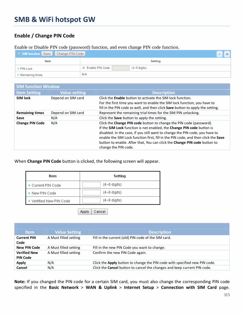
SMB & WiFi hotspot GW
315
Enable / Change PIN Code Enable or Disable PIN code (password) function, and even change PIN code function.
SIM function Window Item Setting Value setting Description SIM lock Depend on SIM card Click the Enable button to activate the SIM lock function.
For the first time you want to enable the SIM lock function, you have to fill in the PIN code as well, and then click Save button to apply the setting.
Remaining times Depend on SIM card Represent the remaining trial times for the SIM PIN unlocking. Save N/A Click the Save button to apply the setting. Change PIN Code N/A Click the Change PIN code button to change the PIN code (password).
If the SIM Lock function is not enabled, the Change PIN code button is disabled. In the case, if you still want to change the PIN code, you have to enable the SIM Lock function first, fill in the PIN code, and then click the Save button to enable. After that, You can click the Change PIN code button to change the PIN code.
When Change PIN Code button is clicked, the following screen will appear.
Item Value Setting Description Current PIN Code
A Must filled setting Fill in the current (old) PIN code of the SIM card.
New PIN Code A Must filled setting Fill in the new PIN Code you want to change. Verified New PIN Code
A Must filled setting Confirm the new PIN Code again.
Apply N/A Click the Apply button to change the PIN code with specified new PIN code. Cancel N/A Click the Cancel button to cancel the changes and keep current PIN code.
Note: If you changed the PIN code for a certain SIM card, you must also change the corresponding PIN code specified in the Basic Network > WAN & Uplink > Internet Setup > Connection with SIM Card page.

SMB & WiFi hotspot GW
316
Otherwise, it may result in wrong SIM PIN trials with invalid (old) PIN code.
Unlock with a PUK Code The PUK Function window is only available for configuration if that SIM card is locked by PUK code. It means that SIM card is locked and needs additional PUK code to unlock. Usually it happens after too many trials of incorrect PIN code, and the remaining times in SIM Function table turns to 0. In this situation, you need to contact your service provider and request a PUK code for your SIM card, and try to unlock the locked SIM card with the provided PUK code. After unlocking a SIM card by PUK code successfully, the SIM lock function will be activated automatically.
PUK Function Window Item Value setting Description PUK status PUK Unlock
/ PUK Lock Indication for the PUK status. The status could be PUK Lock or PUK Unlock. As mentioned earlier, the SIM card will be locked by PUK code after too many trials of failure PIN code. In this case, the PUK Status will turns to PUK Lock. In a normal situation, it will display PUK Unlock.
Remaining times Depend on SIM card Represent the remaining trial times for the PUK unlocking. Note : DO NOT make the remaining times down to zero, it will damage the SIM card FOREVER ! Call for your ISP’s help to get a correct PUK and unlock the SIM if you don’t have the PUK code.
PUK Code A Must filled setting Fill in the PUK code (8 digits) that can unlock the SIM card in PUK unlock status. New PIN Code A Must filled setting Fill in the New PIN Code (4~8 digits) for the SIM card.
You have to determine your new PIN code to replace the old, forgotten one. Keep the PIN code (password) in mind with care.
Save N/A Click the Save button to apply the setting. Note: If you changed the PUK code and PIN code for a certain SIM card, you must also change the corresponding PIN code specified in the Basic Network > WAN & Uplink > Internet Setup > Connection with SIM Card page. Otherwise, it may result in wrong SIM PIN trials with invalid (old) PIN code.
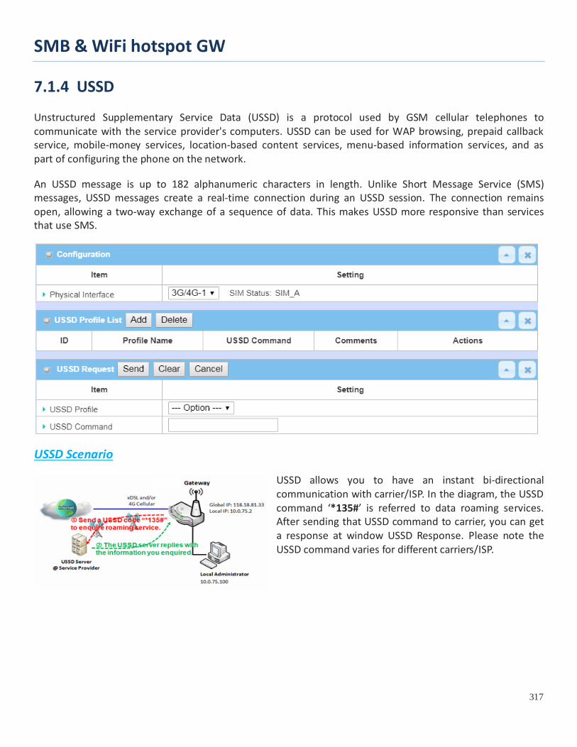
SMB & WiFi hotspot GW
317
7.1.4 USSD Unstructured Supplementary Service Data (USSD) is a protocol used by GSM cellular telephones to communicate with the service provider's computers. USSD can be used for WAP browsing, prepaid callback service, mobile-money services, location-based content services, menu-based information services, and as part of configuring the phone on the network.
An USSD message is up to 182 alphanumeric characters in length. Unlike Short Message Service (SMS) messages, USSD messages create a real-time connection during an USSD session. The connection remains open, allowing a two-way exchange of a sequence of data. This makes USSD more responsive than services that use SMS.
USSD Scenario
USSD allows you to have an instant bi-directional communication with carrier/ISP. In the diagram, the USSD command ‘*135#’ is referred to data roaming services. After sending that USSD command to carrier, you can get a response at window USSD Response. Please note the USSD command varies for different carriers/ISP.

SMB & WiFi hotspot GW
318
USSD Setting
Go to Service > Cellular Toolkit > USSD tab. In "USSD" page, there are four windows for the USSD function. The "Configuration" window can let you specify which 3G/4G module (physical interface) is used for the USSD function, and system will show which SIM card in the module is the current used one. The second window is the "USSD Profile List" and it shows all your defined USSD profiles that store pre-commands for activating an USSD session. An "Add" button in the window can let you add one new USSD profile and define the command for the profile in the third window, the "USSD Profile Configuration". When you want to start the activation of an USSD connection session to the USSD server, select the USSD profile or type in the correct pre-command, and then click on the "Send" button for the session. The responses from the USSD server will be displayed beneath the "USSD Command" line. When commands typed in the "USSD Command" field are sent, received responses will be displayed in the "USSD Response" blank space. User can communicate with the USSD server by sending USSD commands and getting USSD responses via the gateway.
USSD Configuration
Configuration Item Value setting Description
Physical Interface The box is 3G/4G-1 by default.
Choose a cellular interface (3G/4G-1 or 3G/4G-2) to configure the USSD setting for the connected cellular service (identified with SIM_A or SIM_B). Note: 3G/4G-2 is only available for for the product with dual cellular module.
SIM Status N/A Show the connected cellular service (identified with SIM_A or SIM_B).
Create / Edit USSD Profile The cellular gateway allows you to custom your USSD profile. It supports up to a maximum of 35 USSD profiles.
When Add button is applied, USSD Profile Configuration screen will appear.

SMB & WiFi hotspot GW
319
USSD Profile Configuration Item Value setting Description Profile Name N/A Enter a name for the USSD profile.
USSD Command N/A
Enter the USSD command defined for the profile. Normally, it is a command string composed with numeric keypad “0~9”, “*”, and “#”. The USSD commands are highly related to the cellular service, please check with your service provider for the details.
Comments N/A Enter a brief comment for the profile.
Send USSD Request When send the USSD command, the USSD Response screen will appear. When click the Clear button, the USSD Response will disappear.
USSD Request Item Value setting Description USSD Profile N/A Select a USSD profile name from the dropdown list. USSD Command N/A The USSD Command string of the selected profile will be shown here.
USSD Response N/A Click the Send button to send the USSD command, and the USSD Response screen will appear. You will see the response message of the corresponding service, receive the service SMS.

SMB & WiFi hotspot GW
320
7.1.5 Network Scan "Network Scan" function can let administrator specify the device how to connect to the mobile system for data communication in each 3G/4G interface. For example, administrator can specify which generation of mobile system is used for connection, 2G, 3G or LTE. Moreover, he can define their connection sequence for the gateway device to connect to the mobile system automatically. Administrator also can scan the mobile systems in the air manually, select the target operator system and apply it. The manual scanning approach is used for problem diagnosis.
Network Scan Setting
Go to Service > Cellular Toolkit > Network Scan tab. In "Network Scan" page, there are two windows for the Network Scan function. The "Configuration" window can let you select which 3G/4G module (physical interface) is used to perform Network Scan, and system will show the current used SIM card in the module. You can configure each 3G/4G WAN interface by executing the network scanning one after another. You can also specify the connection sequence of the targeted generation of mobile system, 2G/3G/LTE.
Network Scan Configuration
Configuration Item Value setting Description Physical Interface
The box is 3G/4G-1 by default
Choose a cellular interface (3G/4G-1 or 3G/4G-2) for the network scan function. Note: 3G/4G-2 is only available for for the product with dual cellular module.
SIM Status N/A Show the connected cellular service (identified with SIM_A or SIM_B).
Network Type Auto is selected by default.
Specify the network type for the network scan function. It can be Auto, 2G Only, 2G prefer, 3G Only, 3G prefer, or LTE Only. When Auto is selected, the network will be register automatically; If the prefer option is selected, network will be register for your option first; If the only option is selected, network will be register for your option only.
Scan Approach Auto is selected by default.
When Auto selected, cellular module register automatically. If the Manually option is selected, a Network Provider List screen appears. Press Scan button to scan for the nearest base stations. Select (check the box) the preferred base stations then click Apply button to apply settings.

SMB & WiFi hotspot GW
321
Save N/A Click Save to save the settings
The second window is the "Network Provider List" window and it appears when the Manually Scan Approach is selected in the Configuration window. By clicking on the "Scan" button and wait for 1 to 3 minutes, the found mobile operator system will be displayed for you to choose. Click again on the "Apply" button to drive system to connect to that mobile operator system for the dedicated 3G/4G interface.
SMB & WiFi hotspot GW
322
7.2 SMS & Event SMS & Event handling is the application that allows administrator to setup the pre-defined events, handlers, or response behavior with individual profiles. With properly configuring the event handling function, administrator can easily and remotely obtain the status and information via the purchased gateway.
The supported events are categorized into two groups: the managing events and notifying events.
The managing events are the events that are used to manage the gateway or change the setting / status of the specific functionality of the gateway. On receiving the managing event, the gateway will take action to change the functionality, and collect the required status for administration simultaneously.
The notifying events are the events that some related objects have been triggered and take corresponding actions on the occurrence of the events. It could be an event for alerting the administrator something happened with SMS message, Email, and SNMP Trap, etc...
For ease of configuration, administrator can create and edit the common pre-defined managing / notifying event profiles for taking instant reaction on a certain event or managing the devices for some advanced useful purposes. For example, sending/receiving remote managing SMS for the gateway’s routine maintaining, and so on. All of such management and notification function can be realized effectively via the Event Handling feature.
The following is the summary lists for the provided profiles, and events:
Profiles (Rules): • SMS Configuration and Accounts • Email Accounts • Remote Host profiles
Managing Events: • Trigger Type: SMS, SNMP Trap • Actions: Get the Network Status; or Configure the LAN/VLAN behavior, WIFI behavior, NAT
behavior, Firewall behavior, VPN behavior, System Management, Administration, and Remote Host.
Notifying Events: • Trigger Type: Connection Change (WAN, LAN & VLAN, WiFi, DDNS), Administration, Data Usage. • Actions: Notify the administrator with SMS, Syslog, SNMP Trap or Email Alert; Sending collected
information to Remote Host. To use the event handling function, First of all, you have to enable the event management setting and configure the event details with the provided profile settings. You can create or edit pre-defined profiles for individual managing / notifying events. The profile settings are separated into several items; they are the SMS Account Definition, Email Service Definition, and Remote Host Configuration. Then, you have to configure each managing / notifying event with identifying the event’s trigger condition, and the corresponding actions (reaction for the event) for the event. For each event, more than one action can be activated simultaneously.
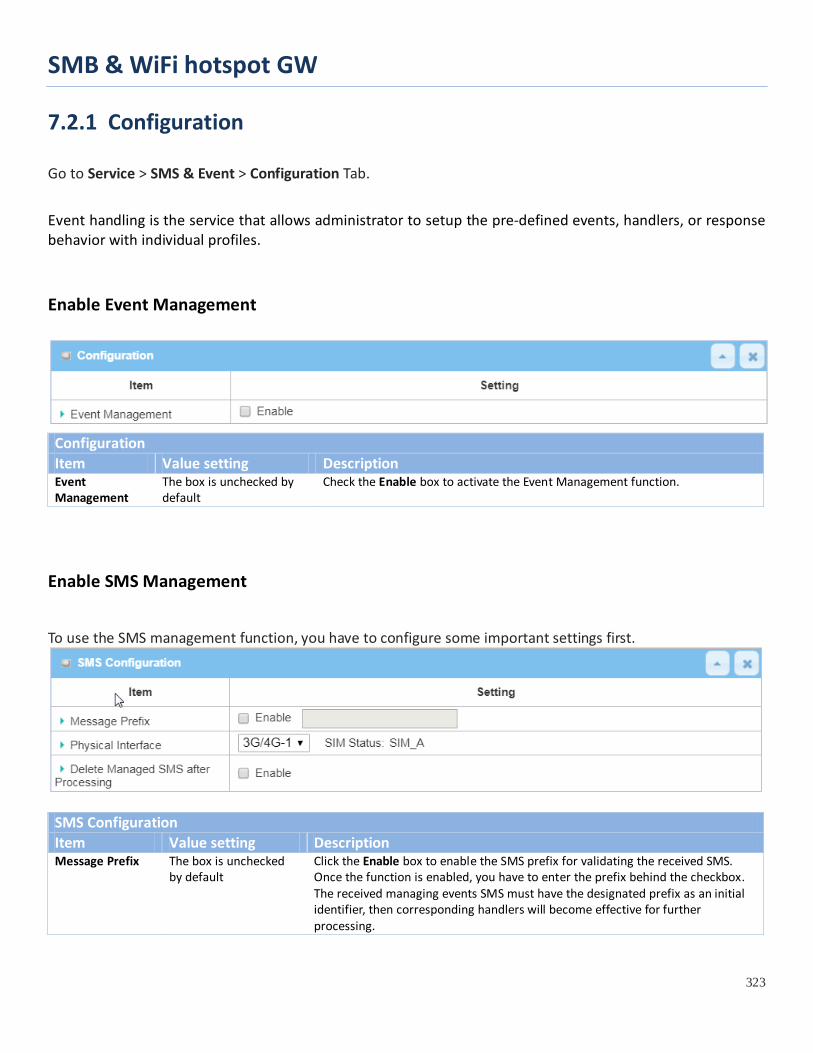
SMB & WiFi hotspot GW
323
7.2.1 Configuration
Go to Service > SMS & Event > Configuration Tab.
Event handling is the service that allows administrator to setup the pre-defined events, handlers, or response behavior with individual profiles.
Enable Event Management
Configuration Item Value setting Description Event Management
The box is unchecked by default
Check the Enable box to activate the Event Management function.
Enable SMS Management
To use the SMS management function, you have to configure some important settings first.
SMS Configuration Item Value setting Description Message Prefix The box is unchecked
by default Click the Enable box to enable the SMS prefix for validating the received SMS. Once the function is enabled, you have to enter the prefix behind the checkbox. The received managing events SMS must have the designated prefix as an initial identifier, then corresponding handlers will become effective for further processing.
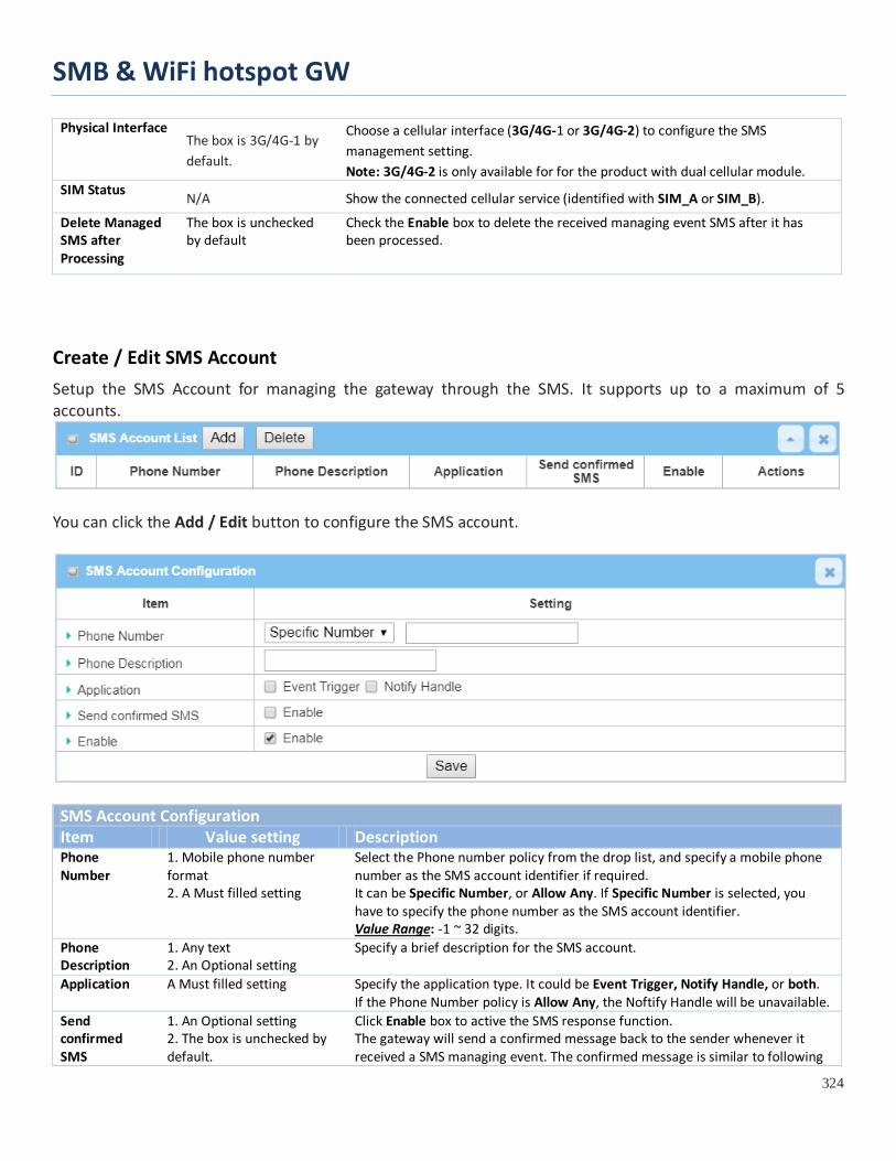
SMB & WiFi hotspot GW
324
Physical Interface The box is 3G/4G-1 by default.
Choose a cellular interface (3G/4G-1 or 3G/4G-2) to configure the SMS management setting. Note: 3G/4G-2 is only available for for the product with dual cellular module.
SIM Status N/A Show the connected cellular service (identified with SIM_A or SIM_B).
Delete Managed SMS after Processing
The box is unchecked by default
Check the Enable box to delete the received managing event SMS after it has been processed.
Create / Edit SMS Account Setup the SMS Account for managing the gateway through the SMS. It supports up to a maximum of 5 accounts.
You can click the Add / Edit button to configure the SMS account.
SMS Account Configuration Item Value setting Description Phone Number
1. Mobile phone number format 2. A Must filled setting
Select the Phone number policy from the drop list, and specify a mobile phone number as the SMS account identifier if required. It can be Specific Number, or Allow Any. If Specific Number is selected, you have to specify the phone number as the SMS account identifier. Value Range: -1 ~ 32 digits.
Phone Description
1. Any text 2. An Optional setting
Specify a brief description for the SMS account.
Application A Must filled setting Specify the application type. It could be Event Trigger, Notify Handle, or both. If the Phone Number policy is Allow Any, the Noftify Handle will be unavailable.
Send confirmed SMS
1. An Optional setting 2. The box is unchecked by default.
Click Enable box to active the SMS response function. The gateway will send a confirmed message back to the sender whenever it received a SMS managing event. The confirmed message is similar to following

SMB & WiFi hotspot GW
325
format: “Device received a SMS with command xxxxx.” Enable The box is unchecked by
default. Click Enable box to activate this account.
Save NA Click the Save button to save the configuration.
Create / Edit Email Service Account Setup the Email Service Account for event notification. It supports up to a maximum of 5 accounts.
You can click the Add / Edit button to configure the Email account.
Email Service Configuration Item Value setting Description Email Server --- Option --- Select an Email Server profile from External Server setting for the email account
setting. Email Addresses
1. Internet E-mail address format 2. A Must filled setting
Specify the Destination Email Addresses.
Enable The box is unchecked by default.
Click Enable box to activate this account.
Save NA Click the Save button to save the configuration
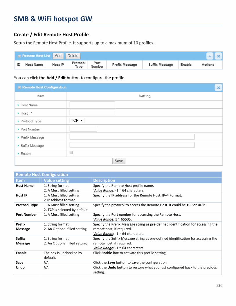
SMB & WiFi hotspot GW
326
Create / Edit Remote Host Profile Setup the Remote Host Profile. It supports up to a maximum of 10 profiles.
You can click the Add / Edit button to configure the profile.
Remote Host Configuration Item Value setting Description Host Name 1. String format
2. A Must filled setting Specify the Remote Host profile name. Value Range: -1 ~ 64 characters.
Host IP 1. A Must filled setting 2.IP Address format.
Specify the IP address for the Remote Host. IPv4 Format.
Protocol Type 1. A Must filled setting 2. TCP is selected by default
Specify the protocol to access the Remote Host. It could be TCP or UDP.
Port Number 1. A Must filled setting Specify the Port number for accessing the Remote Host. Value Range: 1 ~ 65535.
Prefix Message
1. String format 2. An Optional filled setting
Specify the Prefix Message string as pre-defined identification for accessing the remote host, if required. Value Range: -1 ~ 64 characters.
Suffix Message
1. String format 2. An Optional filled setting
Specify the Suffix Message string as pre-defined identification for accessing the remote host, if required. Value Range: -1 ~ 64 characters.
Enable The box is unchecked by default.
Click Enable box to activate this profile setting.
Save NA Click the Save button to save the configuration Undo NA Click the Undo button to restore what you just configured back to the previous
setting.

SMB & WiFi hotspot GW
328
7.2.2 Managing Events Managing Events allow administrator to define the relationship (rule) among event trigger, handlers and response.
Go to Service > SMS & Event > Managing Events Tab.
Enable Managing Events
Configuration Item Value setting Description Managing Events
The box is unchecked by default
Check the Enable box to activate the Managing Events function.
Create / Edit Managing Event Rules Setup the Managing Event rules. It supports up to a maximum of 128 rules.
When Add or Edit button is applied, the Managing Event Configuration screen will appear.

SMB & WiFi hotspot GW
329
Managing Event Configuration Item Value setting Description Event None by default Specify the Event type (SMS, or SNMP Trap) and an event identifier / profile. Up
to 3 event conditions can be specified for defining an event, and the event will be triggered when all the conditions hold simutaneously (AND relation). The supported Event types could be: SMS: Select SMS and fill the message in the textbox to as the trigger condition for the event; SNMP: Select SNMP Trap and fill the message in the textbox to specify SNMP Trap Event; Note: The available Event Type could be different for the purchased product.
Trigger Type Period is selected by default Specify the type of event trigger, either Period or Once. Period: Select Period and specify a time interval, the event will be repeatedly triggered on every time interval when the specified event condition holds. Once: Select Once and the event will be just triggered just one time when the specified event condition holds.
Interval 0 is set by default Specify the repeatedly event trigger time interval. Value Range: 0 ~86400 seconds.
Description String format : any text. Enter a brief description for the Managing Event.

SMB & WiFi hotspot GW
330
Action All box is unchecked by default.
Specify Network Status, or at least one rest action to take when the expected event is triggered. Network Status: Select Network Status Checkbox to get the network status as the action for the event; LAN&VLAN: Select LAN&VLAN Checkbox and the interested sub-items (Port link On/Off), the gateway will change the settings as the action for the event; WiFi: Select WiFi Checkbox and the interested sub-items (WiFi radio On/Off), the gateway will change the settings as the action for the event; NAT: Select NAT Checkbox and the interested sub-items (Virtual Server Rule On/Off, DMZ On/Off), the gateway will change the settings as the action for the event; Firewall: Select Firewall Checkbox and the interested sub-items (Remote Administrator Host ID On/Off), the gateway will change the settings as the action for the event; VPN: Select VPN Checkbox and the interested sub-items (IPSec Tunnel ON/Off, PPTP Client On/Off, L2TP Client On/Off, OpenVPN Client On/Off), the gateway will change the settings as the action for the event; GRE: Select GRE Checkbox and the interested sub-items (GRE Tunnel On/Off), the gateway will change the settings as the action for the event; System Manage: Select System Manage Checkbox and the interested sub-items (WAN SSH Service On/Off, TR-069 On/Off), the gateway will change the settings as the action for the event; Administration: Select Administration Checkbox and the interested sub-items (Backup Config, Restore Config, Reboot, Save Current Setting as Default), the gateway will change the settings as the action for the event; Digital Output: Select Digital Output checkbox and a DO profile you defined as the action for the event; Remote Host: Select Remote Host checkbox and a Remote Host profile you defined as the action for the event; Note: The available Event Type could be different for the purchased product.
Managing Event
The box is unchecked by default.
Click Enable box to activate this Managing Event setting.
Save NA Click the Save button to save the configuration Undo NA Click the Undo button to restore what you just configured back to the previous
setting.

SMB & WiFi hotspot GW
331
7.2.3 Notifying Events
Go to Service > SMS & Event > Notifying Events Tab.
Notifying Events Setting allows administrator to define the relationship (rule) between event trigger and handlers.
Enable Notifying Events
Configuration Item Value setting Description Notifying Events The box is unchecked by
default Check the Enable box to activate the Notifying Events function.
Create / Edit Notifying Event Rules Setup your Notifying Event rules. It supports up to a maximum of 128 rules.
When Add or Edit button is applied, the Notifying Event Configuration screen will appear.

SMB & WiFi hotspot GW
332
Notifying Event Configuration Item Value setting Description Event None by default Specify the Event type and corresponding event configuration. Up to 3 event
conditions can be specified for defining an event, and the event will be triggered when all the conditions hold simutaneously (AND relation). The supported Event Type could be: Power Change: Select Power Change and a trigger condition to specify the event on a certain power source. WAN: Select WAN and a trigger condition to specify a certain WAN Event; LAN&VLAN: Select LAN&VLAN and a trigger condition to specify a certain LAN&VLAN Event; WiFi: Select WiFi and a trigger condition to specify a certain WiFi Event; DDNS: Select DDNS and a trigger condition to specify a certain DDNS Event; Administration: Select Administration and a trigger condition to specify a certain Administration Event; Data Usage: Select Data Usage, the SIM Card (Cellular Service) and a trigger condition to specify a certain Data Usage Event; Note: The available Event Type could be different for the purchased product.
Description String format : any text. Enter a brief description for the Notifying Event. Action All box is unchecked by
default. Specify at least one action to take when the expected event is triggered. SMS: Select SMS, and the gateway will send out a SMS to all the defined SMS accounts as the action for the event; Syslog: Select Syslog and select/unselect the Enable Checkbox to as the action for the event; SNMP Trap: Select SNMP Trap, and the gateway will send out SNMP Trap to the defined SNMP Event Receivers as the action for the event; Email Alert: Select Email Alert, and the gateway will send out an Email to the defined Email accounts as the action for the event; Remote Host: Select Remote Host checkbox and a Remote Host profile you defined as the action for the event; Note: The available Event Type could be different for the purchased product.
Time Schedule (0) Always is selected by default
Select a time scheduling rule for the Notifying Event.
Notifying Events
The box is unchecked by default.
Click Enable box to activate this Notifying Event setting.
Save NA Click the Save button to save the configuration Undo NA Click the Undo button to restore what you just configured back to the previous
setting.

SMB & WiFi hotspot GW
333
Chapter 8 Status
8.1 Dashboard
8.1.1 Device Dashboard The Device Dashboard window shows the current status in graph or tables for quickly understanding the operation status for the gateway. They are the System Information, System Information History, and Network Interface Status. The display will be refreshed once per second. From the menu on the left, select Status > Dashboard > Device Dashboard tab.
System Information Status The System Information screen shows the device Up-time and the resource utilization for the CPU, Memory, and Connection Sessions.
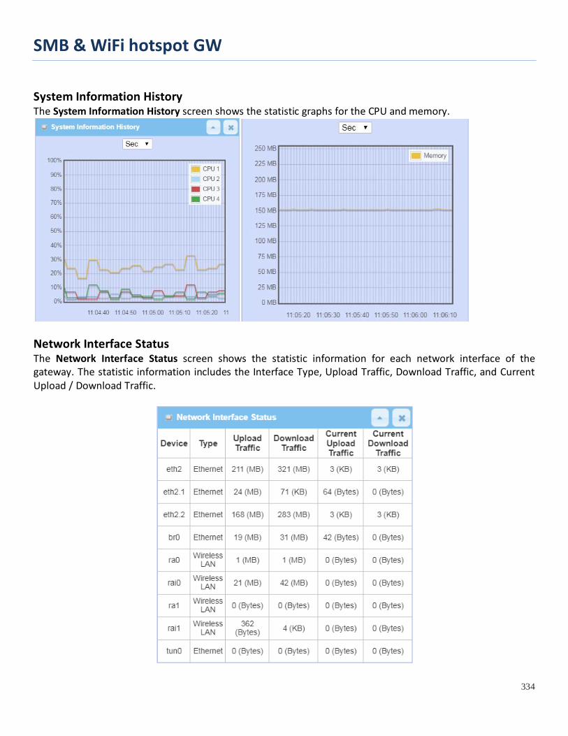
SMB & WiFi hotspot GW
334
System Information History The System Information History screen shows the statistic graphs for the CPU and memory.
Network Interface Status The Network Interface Status screen shows the statistic information for each network interface of the gateway. The statistic information includes the Interface Type, Upload Traffic, Download Traffic, and Current Upload / Download Traffic.

SMB & WiFi hotspot GW
335
8.2 Basic Network
8.2.1 WAN & Uplink Status Go to Status > Basic Network > WAN & Uplink tab.
The WAN & Uplink Status window shows the current status for different network type, including network configuration, connecting information, modem status and traffic statistics. The display will be refreshed on every five seconds. WAN interface IPv4 Network Status
WAN interface IPv4 Network Status screen shows status information for IPv4 network.
WAN interface IPv4 Network Status Item Value setting Description ID N/A It displays corresponding WAN interface WAN IDs.
Interface N/A It displays the type of WAN physical interface. Depending on the model purchased, it can be Ethernet, 3G/4G, or WiFi Uplink.
WAN Type N/A It displays the method which public IP address is obtained from your ISP. Depending on the model purchased, it can be Static IP, Dynamic IP, PPPoE, PPTP, L2TP, 3G/4G.
Network Type N/A It displays the network type for the WAN interface(s). Depending on the model purchased, it can be NAT, Routing, Bridge, or IP Pass-through.
IP Addr. N/A It displays the public IP address obtained from your ISP for Internet connection. Default value is 0.0.0.0 if left unconfigured.
Subnet Mask N/A It displays the Subnet Mask for public IP address obtained from your ISP for Internet connection. Default value is 0.0.0.0 if left unconfigured.
Gateway N/A It displays the Gateway IP address obtained from your ISP for Internet connection. Default value is 0.0.0.0 if left unconfigured.
DNS N/A It displays the IP address of DNS server obtained from your ISP for Internet connection. Default value is 0.0.0.0 if left unconfigured.
MAC Address N/A It displays the MAC Address for your ISP to allow you for Internet access. Note: Not all ISP may require this field.
Conn. Status N/A It displays the connection status of the device to your ISP. Status are Connected or disconnected.

SMB & WiFi hotspot GW
336
Action N/A
This area provides functional buttons. Renew button allows user to force the device to request an IP address from the DHCP server. Note: Renew button is available when DHCP WAN Type is used and WAN connection is disconnected. Release button allows user to force the device to clear its IP address setting to disconnect from DHCP server. Note: Release button is available when DHCP WAN Type is used and WAN connection is connected. Connect button allows user to manually connect the device to the Internet. Note: Connect button is available when Connection Control in WAN Type setting is set to Connect Manually (Refer to Edit button in Basic Network > WAN & Uplink > Internet Setup) and WAN connection status is disconnected. Disconnect button allows user to manually disconnect the device from the Internet. Note: Connect button is available when Connection Control in WAN Type setting is set to Connect Manually (Refer to Edit button in Basic Network > WAN & Uplink > Internet Setup) and WAN connection status is connected.
WAN interface IPv6 Network Status WAN interface IPv6 Network Status screen shows status information for IPv6 network.
WAN interface IPv6 Network Status Item Value setting Description ID N/A It displays corresponding WAN interface WAN IDs.
Interface N/A It displays the type of WAN physical interface. Depending on the model purchased, it can be Ethernet, 3G/4G, etc...
WAN Type N/A It displays the method which public IP address is obtained from your ISP. WAN type setting can be changed from Basic Network > IPv6 > Configuration.
Link-local IP Address N/A It displays the LAN IPv6 Link-Local address.
Global IP Address N/A It displays the IPv6 global IP address assigned by your ISP for your Internet connection.
Conn. Status N/A It displays the connection status. The status can be connected, disconnected and connecting.
Action N/A This area provides functional buttons. Edit Button when pressed, web-based utility will take you to the IPv6 configuration page. (Basic Network > IPv6 > Configuration.)
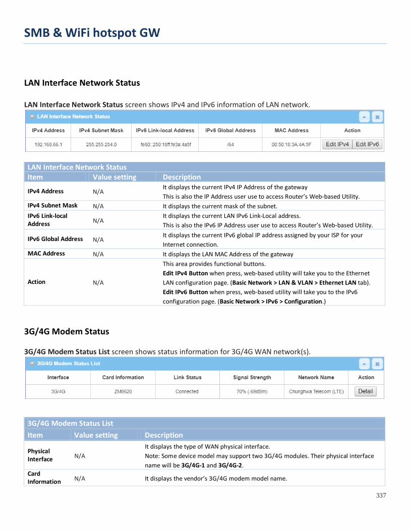
SMB & WiFi hotspot GW
337
LAN Interface Network Status LAN Interface Network Status screen shows IPv4 and IPv6 information of LAN network.
LAN Interface Network Status Item Value setting Description
IPv4 Address N/A It displays the current IPv4 IP Address of the gateway This is also the IP Address user use to access Router’s Web-based Utility.
IPv4 Subnet Mask N/A It displays the current mask of the subnet. IPv6 Link-local Address N/A
It displays the current LAN IPv6 Link-Local address. This is also the IPv6 IP Address user use to access Router’s Web-based Utility.
IPv6 Global Address N/A It displays the current IPv6 global IP address assigned by your ISP for your Internet connection.
MAC Address N/A It displays the LAN MAC Address of the gateway
Action N/A
This area provides functional buttons. Edit IPv4 Button when press, web-based utility will take you to the Ethernet LAN configuration page. (Basic Network > LAN & VLAN > Ethernet LAN tab). Edit IPv6 Button when press, web-based utility will take you to the IPv6 configuration page. (Basic Network > IPv6 > Configuration.)
3G/4G Modem Status 3G/4G Modem Status List screen shows status information for 3G/4G WAN network(s).
3G/4G Modem Status List Item Value setting Description
Physical Interface N/A
It displays the type of WAN physical interface. Note: Some device model may support two 3G/4G modules. Their physical interface name will be 3G/4G-1 and 3G/4G-2.
Card Information N/A It displays the vendor’s 3G/4G modem model name.

SMB & WiFi hotspot GW
338
Link Status N/A It displays the 3G/4G connection status. The status can be Connecting, Connected, Disconnecting, and Disconnected.
Signal Strength N/A It displays the 3G/4G wireless signal level.
Network Name N/A It displays the name of the service network carrier.
Refresh N/A Click the Refresh button to renew the information.
Action N/A
This area provides functional buttons. Detail Button when press, windows of detail information will appear. They are the Modem Information, SIM Status, and Service Information. Refer to next page for more.
When the Detail button is pressed, 3G/4G modem information windows such as Modem Information, SIM Status, Service Information, Signal Strength / Quality, and Error Message will appear. Interface Traffic Statistics Interface Traffic Statistics screen displays the Interface’s total transmitted packets.
Interface Traffic Statistics Item Value setting Description ID N/A It displays corresponding WAN interface WAN IDs.
Interface N/A It displays the type of WAN physical interface. Depending on the model purchased, it can be Ethernet, 3G/4G, etc…
Received Packets (Mb) N/A
It displays the downstream packets (Mb). It is reset when the device is rebooted.
Transmitted Packets (Mb) N/A It displays the upstream packets (Mb). It is reset when the device is rebooted.
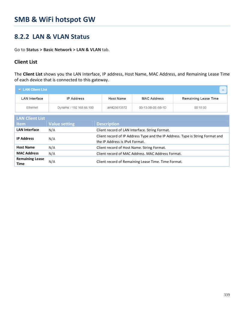
SMB & WiFi hotspot GW
339
8.2.2 LAN & VLAN Status Go to Status > Basic Network > LAN & VLAN tab. Client List The Client List shows you the LAN Interface, IP address, Host Name, MAC Address, and Remaining Lease Time of each device that is connected to this gateway.
LAN Client List Item Value setting Description LAN Interface N/A Client record of LAN Interface. String Format.
IP Address N/A Client record of IP Address Type and the IP Address. Type is String Format and the IP Address is IPv4 Format.
Host Name N/A Client record of Host Name. String Format. MAC Address N/A Client record of MAC Address. MAC Address Format. Remaining Lease Time N/A Client record of Remaining Lease Time. Time Format.
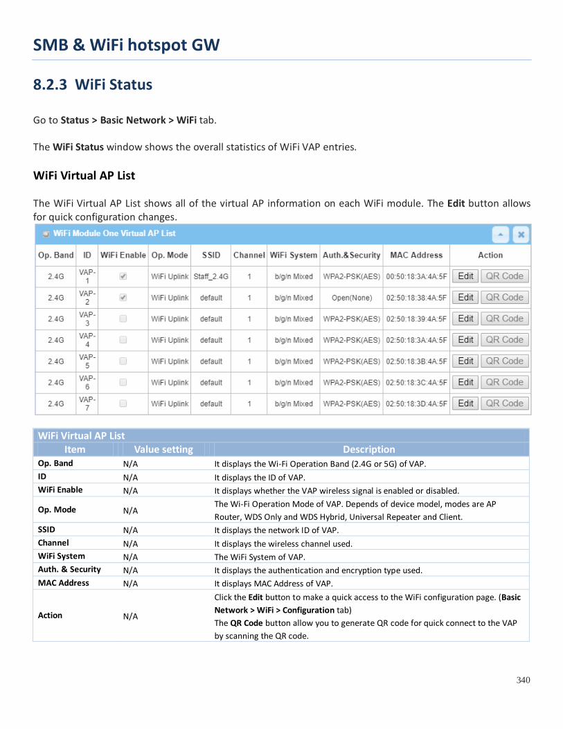
SMB & WiFi hotspot GW
340
8.2.3 WiFi Status
Go to Status > Basic Network > WiFi tab. The WiFi Status window shows the overall statistics of WiFi VAP entries. WiFi Virtual AP List The WiFi Virtual AP List shows all of the virtual AP information on each WiFi module. The Edit button allows for quick configuration changes.
WiFi Virtual AP List
Item Value setting Description Op. Band N/A It displays the Wi-Fi Operation Band (2.4G or 5G) of VAP. ID N/A It displays the ID of VAP. WiFi Enable N/A It displays whether the VAP wireless signal is enabled or disabled.
Op. Mode N/A The Wi-Fi Operation Mode of VAP. Depends of device model, modes are AP Router, WDS Only and WDS Hybrid, Universal Repeater and Client.
SSID N/A It displays the network ID of VAP. Channel N/A It displays the wireless channel used. WiFi System N/A The WiFi System of VAP. Auth. & Security N/A It displays the authentication and encryption type used. MAC Address N/A It displays MAC Address of VAP.
Action N/A
Click the Edit button to make a quick access to the WiFi configuration page. (Basic Network > WiFi > Configuration tab) The QR Code button allow you to generate QR code for quick connect to the VAP by scanning the QR code.
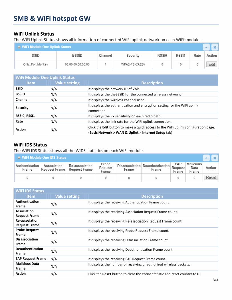
SMB & WiFi hotspot GW
341
WiFi Uplink Status The WiFi Uplink Status shows all information of connected WiFi uplink network on each WiFi module..
WiFi Module One Uplink Status
Item Value setting Description SSID N/A It displays the network ID of VAP. BSSID N/A It displays the theBSSID for the connected wireless network. Channel N/A It displays the wireless channel used.
Security N/A It displays the authentication and encryption setting for the WiFi uplink connection.
RSSI0, RSSI1 N/A It displays the Rx sensitivity on each radio path.. Rate N/A It displays the link rate for the WiFi uplink connection.
Action N/A Click the Edit button to make a quick access to the WiFi uplink configuration page. (Basic Network > WAN & Uplink > Internet Setup tab)
WiFi IDS Status The WiFi IDS Status shows all the WIDS statistics on each WiFi module.
WiFi IDS Status
Item Value setting Description Authentication Frame N/A It displays the receiving Authentication Frame count.
Association Request Frame N/A It displays the receiving Association Request Frame count.
Re-association Request Frame N/A It displays the receiving Re-association Request Frame count.
Probe Request Frame N/A It displays the receiving Probe Request Frame count.
Disassociation Frame N/A It displays the receiving Disassociation Frame count.
Deauthentication Frame N/A It displays the receiving Deauthentication Frame count.
EAP Request Frame N/A It displays the receiving EAP Request Frame count. Malicious Data Frame N/A It displays the number of receiving unauthorized wireless packets.
Action N/A Click the Reset button to clear the entire statistic and reset counter to 0.

SMB & WiFi hotspot GW
342
Ensure WIDS function is enabled
Go to Basic Network > WiFi > Advanced Configuration tab
Note that the WIDS of 2.4GHz or 5GHz WiFi should be configured separately.
WiFi Traffic Statistic The WiFi Traffic Statistic shows all the received and transmitted packets on each WiFi module.
WiFi Traffic Statistic
Item Value setting Description Op. Band N/A It displays the Wi-Fi Operation Band (2.4G or 5G) of VAP. ID N/A It displays the VAP ID. Received Packets N/A It displays the number of reveived packets. Transmitted Packet N/A It displays the number of transmitted packets. Action N/A Click the Reset button to clear individual VAP statistics. Refresh Button N/A Click the Refresh button to update the entire VAP Traffic Statistic instantly.

SMB & WiFi hotspot GW
343
8.2.4 DDNS Status
Go to Status > Basic Network > DDNS tab. The DDNS Status window shows the current DDNS service in use, the last update status, and the last update time to the DDNS service server. DDNS Status
DDNS Status Item Value Setting Description Host Name N/A It displays the name you entered to identify DDNS service provider Provider N/A It displays the DDNS server of DDNS service provider Effective IP N/A It displays the public IP address of the device updated to the DDNS server Last Update Status N/A
It displays whether the last update of the device public IP address to the DDNS server has been successful (Ok) or failed (Fail).
Last Update Time N/A It displays time stamp of the last update of public IP address to the DDNS server. Refresh N/A The refresh button allows user to force the display to refresh information.

SMB & WiFi hotspot GW
344
8.3 Security
8.3.1 VPN Status Go to Status > Security > VPN tab. The VPN Status widow shows the overall VPN tunnel status. The display will be refreshed on every five seconds.
IPSec Tunnel Status IPSec Tunnel Status windows show the configuration for establishing IPSec VPN connection and current connection status.
IPSec Tunnel Status Item Value setting Description Tunnel Name N/A It displays the tunnel name you have entered to identify. Tunnel Scenario N/A It displays the Tunnel Scenario specified. Local Subnets N/A It displays the Local Subnets specified.

SMB & WiFi hotspot GW
345
Remote IP/FQDN N/A It displays the Remote IP/FQDN specified. Remote Subnets N/A It displays the Remote Subnets specified. Conn. Time N/A It displays the connection time for the IPSec tunnel.
Status N/A It displays the Status of the VPN connection. The status displays are Connected, Disconnected, Wait for traffic, and Connecting.
Edit Button N/A Click on Edit Button to change IPSec setting, web-based utility will take you to the IPSec configuration page. (Security > VPN > IPSec tab)
OpenVPN Server Status According to OpenVPN configuration, the OpenVPN Server/Client Status shows the status and statistics for the OpenVPN connection from the server side or client side.
OpenVPN Server Status Item Value setting Description User Name N/A It displays the Client name you have entered for identification. Remote IP/FQDN
N/A It displays the public IP address (the WAN IP address) of the connected OpenVPN Client
Virtual IP/MAC N/A It displays the virtual IP/MAC address assigned to the connected OpenVPN client.
Conn. Time N/A It displays the connection time for the corresponding OpenVPN tunnel. Status N/A It displays the connection status of the corresponding OpenVPN tunnel.
The status can be Connected, or Disconnected. OpenVPN Client Status
OpenVPN Client Status Item Value setting Description OpenVPN Client Name
N/A It displays the Client name you have entered for identification.
Interface N/A It displays the WAN interface specified for the OpenVPN client connection. Remote IP/FQDN
N/A It displays the peer OpenVPN Server’s Public IP address (the WAN IP address) or FQDN.
Remote Subnet N/A It displays the Remote Subnet specified. TUN/TAP Read(bytes)
N/A It displays the TUN/TAP Read Bytes of OpenVPN Client.
TUN/TAP Write(bytes)
N/A It displays the TUN/TAP Write Bytes of OpenVPN Client.
TCP/UDP N/A It displays the TCP/UDP Read Bytes of OpenVPN Client.

SMB & WiFi hotspot GW
346
Read(bytes) TCP/UDP Write(bytes)
N/A It displays the TCP/UDP Write Bytes of OpenVPN Client. Connection
Conn. Time N/A It displays the connection time for the corresponding OpenVPN tunnel. Conn. Status N/A It displays the connection status of the corresponding OpenVPN tunnel.
The status can be Connected, or Disconnected.
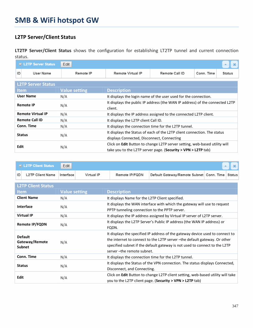
SMB & WiFi hotspot GW
347
L2TP Server/Client Status LT2TP Server/Client Status shows the configuration for establishing LT2TP tunnel and current connection status.
L2TP Server Status Item Value setting Description User Name N/A It displays the login name of the user used for the connection.
Remote IP N/A It displays the public IP address (the WAN IP address) of the connected L2TP client.
Remote Virtual IP N/A It displays the IP address assigned to the connected L2TP client. Remote Call ID N/A It displays the L2TP client Call ID. Conn. Time N/A It displays the connection time for the L2TP tunnel.
Status N/A It displays the Status of each of the L2TP client connection. The status displays Connected, Disconnect, Connecting
Edit N/A Click on Edit Button to change L2TP server setting, web-based utility will take you to the L2TP server page. (Security > VPN > L2TP tab)
L2TP Client Status Item Value setting Description Client Name N/A It displays Name for the L2TP Client specified.
Interface N/A It displays the WAN interface with which the gateway will use to request PPTP tunneling connection to the PPTP server.
Virtual IP N/A It displays the IP address assigned by Virtual IP server of L2TP server.
Remote IP/FQDN N/A It displays the L2TP Server’s Public IP address (the WAN IP address) or FQDN.
Default Gateway/Remote Subnet
N/A
It displays the specified IP address of the gateway device used to connect to the internet to connect to the L2TP server –the default gateway. Or other specified subnet if the default gateway is not used to connect to the L2TP server –the remote subnet.
Conn. Time N/A It displays the connection time for the L2TP tunnel.
Status N/A It displays the Status of the VPN connection. The status displays Connected, Disconnect, and Connecting.
Edit N/A Click on Edit Button to change L2TP client setting, web-based utility will take you to the L2TP client page. (Security > VPN > L2TP tab)
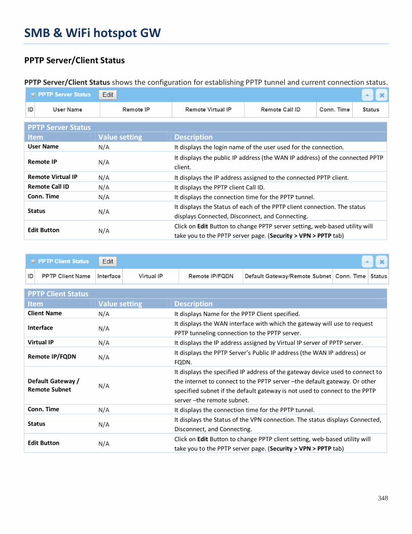
SMB & WiFi hotspot GW
348
PPTP Server/Client Status PPTP Server/Client Status shows the configuration for establishing PPTP tunnel and current connection status.
PPTP Server Status Item Value setting Description User Name N/A It displays the login name of the user used for the connection.
Remote IP N/A It displays the public IP address (the WAN IP address) of the connected PPTP client.
Remote Virtual IP N/A It displays the IP address assigned to the connected PPTP client. Remote Call ID N/A It displays the PPTP client Call ID. Conn. Time N/A It displays the connection time for the PPTP tunnel.
Status N/A It displays the Status of each of the PPTP client connection. The status displays Connected, Disconnect, and Connecting.
Edit Button N/A Click on Edit Button to change PPTP server setting, web-based utility will take you to the PPTP server page. (Security > VPN > PPTP tab)
PPTP Client Status Item Value setting Description Client Name N/A It displays Name for the PPTP Client specified.
Interface N/A It displays the WAN interface with which the gateway will use to request PPTP tunneling connection to the PPTP server.
Virtual IP N/A It displays the IP address assigned by Virtual IP server of PPTP server.
Remote IP/FQDN N/A It displays the PPTP Server’s Public IP address (the WAN IP address) or FQDN.
Default Gateway / Remote Subnet N/A
It displays the specified IP address of the gateway device used to connect to the internet to connect to the PPTP server –the default gateway. Or other specified subnet if the default gateway is not used to connect to the PPTP server –the remote subnet.
Conn. Time N/A It displays the connection time for the PPTP tunnel.
Status N/A It displays the Status of the VPN connection. The status displays Connected, Disconnect, and Connecting.
Edit Button N/A Click on Edit Button to change PPTP client setting, web-based utility will take you to the PPTP server page. (Security > VPN > PPTP tab)
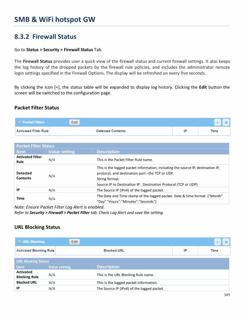
SMB & WiFi hotspot GW
349
8.3.2 Firewall Status Go to Status > Security > Firewall Status Tab. The Firewall Status provides user a quick view of the firewall status and current firewall settings. It also keeps the log history of the dropped packets by the firewall rule policies, and includes the administrator remote login settings specified in the Firewall Options. The display will be refreshed on every five seconds.
By clicking the icon [+], the status table will be expanded to display log history. Clicking the Edit button the screen will be switched to the configuration page.
Packet Filter Status
Packet Filter Status Item Value setting Description Activated Filter Rule N/A This is the Packet Filter Rule name.
Detected Contents N/A
This is the logged packet information, including the source IP, destination IP, protocol, and destination port –the TCP or UDP. String format: Source IP to Destination IP : Destination Protocol (TCP or UDP)
IP N/A The Source IP (IPv4) of the logged packet.
Time N/A The Date and Time stamp of the logged packet. Date & time format. ("Month" "Day" "Hours":"Minutes":"Seconds")
Note: Ensure Packet Filter Log Alert is enabled. Refer to Security > Firewall > Packet Filter tab. Check Log Alert and save the setting.
URL Blocking Status
URL Blocking Status Item Value setting Description Activated Blocking Rule N/A This is the URL Blocking Rule name.
Blocked URL N/A This is the logged packet information. IP N/A The Source IP (IPv4) of the logged packet.
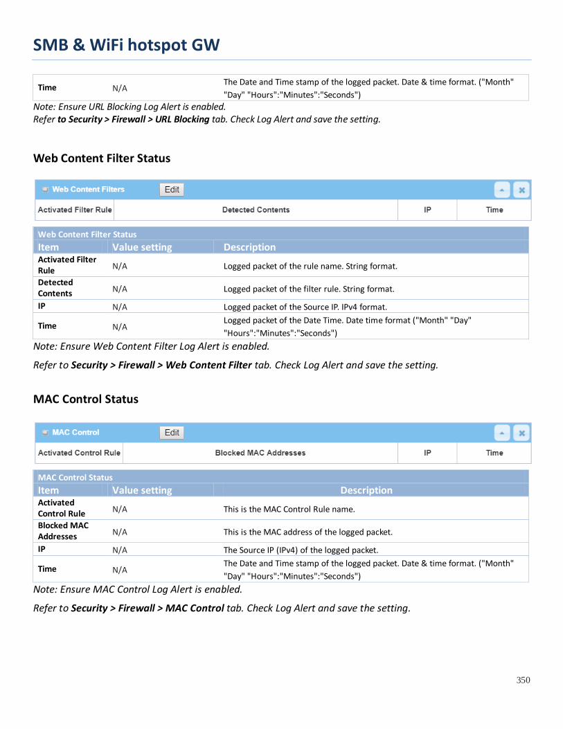
SMB & WiFi hotspot GW
350
Time N/A The Date and Time stamp of the logged packet. Date & time format. ("Month" "Day" "Hours":"Minutes":"Seconds")
Note: Ensure URL Blocking Log Alert is enabled. Refer to Security > Firewall > URL Blocking tab. Check Log Alert and save the setting.
Web Content Filter Status
Web Content Filter Status Item Value setting Description Activated Filter Rule N/A Logged packet of the rule name. String format.
Detected Contents N/A Logged packet of the filter rule. String format.
IP N/A Logged packet of the Source IP. IPv4 format.
Time N/A Logged packet of the Date Time. Date time format ("Month" "Day" "Hours":"Minutes":"Seconds")
Note: Ensure Web Content Filter Log Alert is enabled.
Refer to Security > Firewall > Web Content Filter tab. Check Log Alert and save the setting.
MAC Control Status
MAC Control Status Item Value setting Description Activated Control Rule N/A This is the MAC Control Rule name.
Blocked MAC Addresses N/A This is the MAC address of the logged packet.
IP N/A The Source IP (IPv4) of the logged packet.
Time N/A The Date and Time stamp of the logged packet. Date & time format. ("Month" "Day" "Hours":"Minutes":"Seconds")
Note: Ensure MAC Control Log Alert is enabled.
Refer to Security > Firewall > MAC Control tab. Check Log Alert and save the setting.

SMB & WiFi hotspot GW
351
Application Filters Status
Application Filters Status Item Value setting Description Filtered Application Category N/A The name of the Application Category being blocked.
Filtered Application Name N/A The name of the Application being blocked.
IP N/A The Source IP (IPv4) of the logged packet.
Time N/A The Date and Time stamp of the logged packet. Date & time format. ("Month" "Day" "Hours":"Minutes":"Seconds")
Note: Ensure Application Filter Log Alert is enabled. Refer to Security > Firewall > Application Filter tab. Check Log Alert and save the setting.
IPS Status
IPS Firewall Status Item Value setting Description Detected Intrusion N/A This is the intrusion type of the packets being blocked.
IP N/A The Source IP (IPv4) of the logged packet.
Time N/A The Date and Time stamp of the logged packet. Date & time format. ("Month" "Day" "Hours":"Minutes":"Seconds")
Note: Ensure IPS Log Alert is enabled. Refer to Security > Firewall > IPS tab. Check Log Alert and save the setting.
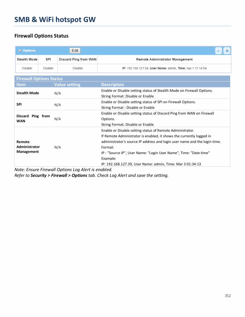
SMB & WiFi hotspot GW
352
Firewall Options Status
Firewall Options Status Item Value setting Description
Stealth Mode N/A Enable or Disable setting status of Stealth Mode on Firewall Options. String Format: Disable or Enable
SPI N/A Enable or Disable setting status of SPI on Firewall Options. String Format : Disable or Enable
Discard Ping from WAN N/A
Enable or Disable setting status of Discard Ping from WAN on Firewall Options. String Format: Disable or Enable
Remote Administrator Management
N/A
Enable or Disable setting status of Remote Administrator. If Remote Administrator is enabled, it shows the currently logged in administrator’s source IP address and login user name and the login time. Format: IP : "Source IP", User Name: "Login User Name", Time: "Date time" Example: IP: 192.168.127.39, User Name: admin, Time: Mar 3 01:34:13
Note: Ensure Firewall Options Log Alert is enabled. Refer to Security > Firewall > Options tab. Check Log Alert and save the setting.
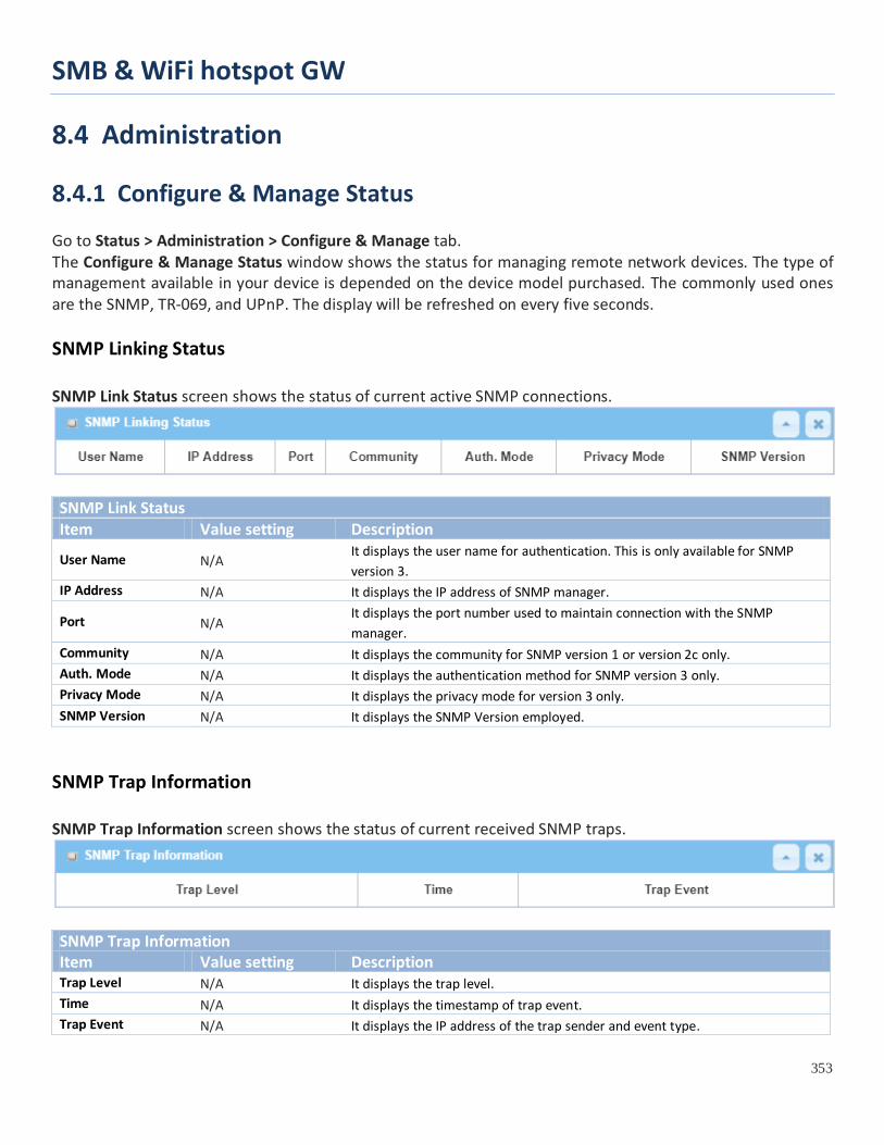
SMB & WiFi hotspot GW
353
8.4 Administration
8.4.1 Configure & Manage Status Go to Status > Administration > Configure & Manage tab. The Configure & Manage Status window shows the status for managing remote network devices. The type of management available in your device is depended on the device model purchased. The commonly used ones are the SNMP, TR-069, and UPnP. The display will be refreshed on every five seconds. SNMP Linking Status SNMP Link Status screen shows the status of current active SNMP connections.
SNMP Link Status Item Value setting Description
User Name N/A It displays the user name for authentication. This is only available for SNMP version 3.
IP Address N/A It displays the IP address of SNMP manager.
Port N/A It displays the port number used to maintain connection with the SNMP manager.
Community N/A It displays the community for SNMP version 1 or version 2c only. Auth. Mode N/A It displays the authentication method for SNMP version 3 only. Privacy Mode N/A It displays the privacy mode for version 3 only. SNMP Version N/A It displays the SNMP Version employed.
SNMP Trap Information SNMP Trap Information screen shows the status of current received SNMP traps.
SNMP Trap Information Item Value setting Description Trap Level N/A It displays the trap level. Time N/A It displays the timestamp of trap event. Trap Event N/A It displays the IP address of the trap sender and event type.

SMB & WiFi hotspot GW
354
TR-069 Status TR-069 Status screen shows the current connection status with the TR-068 server.
TR-069 Status Item Value setting Description
Link Status N/A It displays the current connection status with the TR-068 server. The connection status is either On when the device is connected with the TR-068 server or Off when disconnected.

SMB & WiFi hotspot GW
355
8.4.2 Log Storage Status Go to Status > Administration > Log Storage tab. The Log Storage Status screen shows the status for selected device storage. Log Storage Status Log Storage Status screen shows the status of current the selected device storage. The status includes Device Description, Usage, File System, Speed, and status.
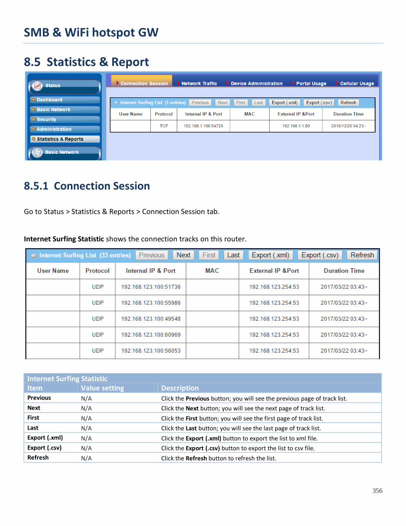
SMB & WiFi hotspot GW
356
8.5 Statistics & Report
8.5.1 Connection Session
Go to Status > Statistics & Reports > Connection Session tab.
Internet Surfing Statistic shows the connection tracks on this router.
Internet Surfing Statistic Item Value setting Description Previous N/A Click the Previous button; you will see the previous page of track list. Next N/A Click the Next button; you will see the next page of track list. First N/A Click the First button; you will see the first page of track list. Last N/A Click the Last button; you will see the last page of track list. Export (.xml) N/A Click the Export (.xml) button to export the list to xml file. Export (.csv) N/A Click the Export (.csv) button to export the list to csv file. Refresh N/A Click the Refresh button to refresh the list.

SMB & WiFi hotspot GW
357
8.5.2 Network Traffic
Go to Status > Statistics & Reports > Network Traffic tab.
Network Traffic Statistics screen shows the historical graph for the selected network interface.
You can change the interface drop list and select the interface you want to monitor.
.
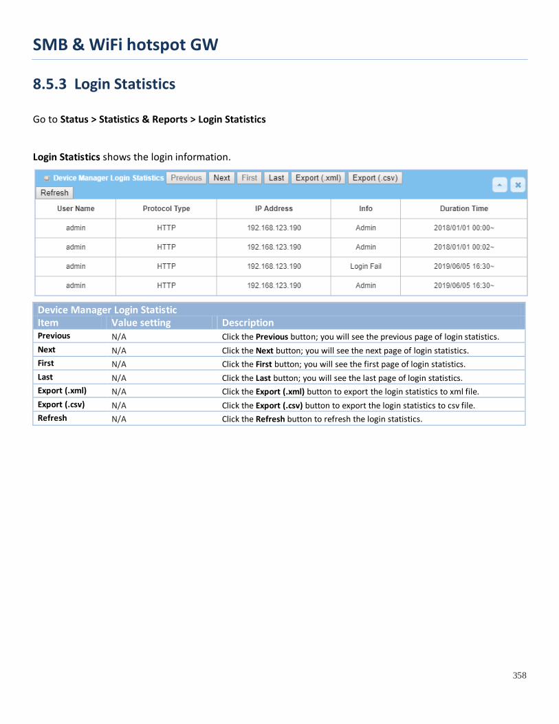
SMB & WiFi hotspot GW
358
8.5.3 Login Statistics
Go to Status > Statistics & Reports > Login Statistics
Login Statistics shows the login information.
Device Manager Login Statistic Item Value setting Description Previous N/A Click the Previous button; you will see the previous page of login statistics. Next N/A Click the Next button; you will see the next page of login statistics. First N/A Click the First button; you will see the first page of login statistics. Last N/A Click the Last button; you will see the last page of login statistics. Export (.xml) N/A Click the Export (.xml) button to export the login statistics to xml file. Export (.csv) N/A Click the Export (.csv) button to export the login statistics to csv file. Refresh N/A Click the Refresh button to refresh the login statistics.
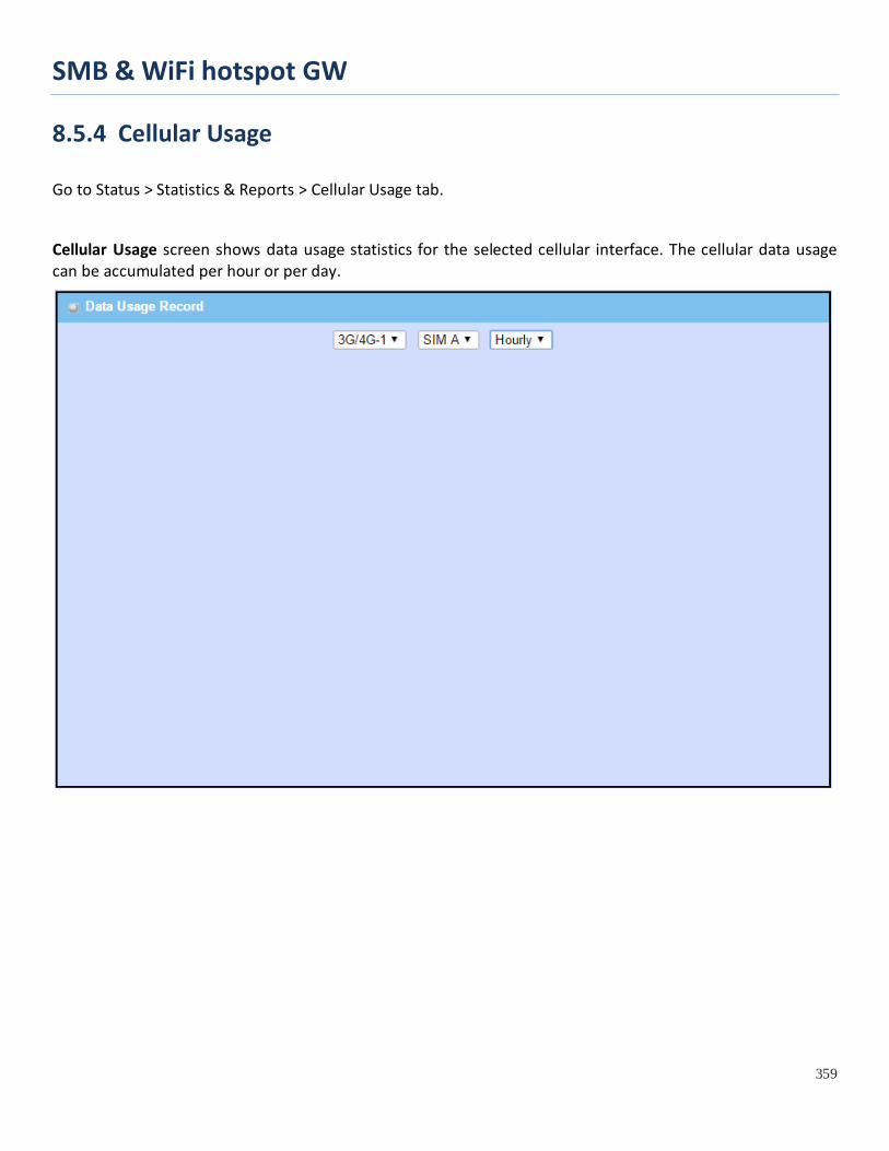
SMB & WiFi hotspot GW
359
8.5.4 Cellular Usage
Go to Status > Statistics & Reports > Cellular Usage tab.
Cellular Usage screen shows data usage statistics for the selected cellular interface. The cellular data usage can be accumulated per hour or per day.

SMB & WiFi hotspot GW
360
Appendix A GPL WRITTEN OFFER This product incorporates open source software components covered by the terms of third party copyright notices and license agreements contained below. GPSBabel Version 1.4.4 Copyright (C) 2002-2005 Robert Lipe<[email protected]> GPL License: https://www.gpsbabel.org/ Curl Version 7.19.6 Copyright (c) 1996-2009, Daniel Stenberg, <[email protected]>. MIT/X derivate License: https://curl.haxx.se/ OpenSSL Version 1.0.2m Copyright (C) 1995-1998 Eric Young ([email protected]) GPL License: https://www.openssl.org/ brctl - ethernet bridge administration Stephen Hemminger <[email protected]> Lennert Buytenhek <[email protected]> version 1.1 GNU GENERAL PUBLIC LICENSE Version 2, June 1991 tc - show / manipulate traffic control settings Stephen Hemminger<[email protected]> Alexey Kuznetsov<[email protected]> version iproute2-ss050330 GNU GENERAL PUBLIC LICENSE Version 2, June 1991 dhcp-fwd — starts the DHCP forwarding agent Enrico Scholz <[email protected]> version 0.7 GNU GENERAL PUBLIC LICENSE Version 2, June 1991 lftp - Sophisticated file transfer program Alexander V. Lukyanov <[email protected]> version:4.5.x Copyright (c) 1996-2014 by Alexander V. Lukyanov ([email protected]) dnsmasq - A lightweight DHCP and caching DNS server. Simon Kelley <[email protected]> version:2.72 dnsmasq is Copyright (c) 2000-2014 Simon Kelley
SMB & WiFi hotspot GW
361
socat - Multipurpose relay Version: 2.0.0-b8 GPLv2 http://www.dest-unreach.org/socat/ LibModbus Version: 3.0.3 LGPL v2 http://libmodbus.org/news/ LibIEC60870 GPLv2 Copyright (C) 1989, 1991 Free Software Foundation, Inc. 59 Temple Place, Suite 330, Boston, MA 02111-1307 USA https://sourceforge.net/projects/mrts/ Openswan Version: v2.6.38 GNU GENERAL PUBLIC LICENSE Version 2, June 1991 Copyright (C) 1989, 1991 Free Software Foundation, Inc. 59 Temple Place, Suite 330, Boston, MA 02111-1307 USA Everyone is permitted to copy and distribute verbatim copies of this license document, but changing it is not allowed. https://www.openswan.org/ Opennhrp Version: v0.14.1 OpenNHRP is an NHRP implementation for Linux. It has most of the RFC2332 and Cisco IOS extensions. Project homepage: http://sourceforge.net/projects/opennhrp Git repository: git://opennhrp.git.sourceforge.net/gitroot/opennhrp LICENSE OpenNHRP is licensed under the MIT License. See MIT-LICENSE.txt for additional details. OpenNHRP embeds libev. libev is dual licensed with 2-clause BSD and GPLv2+ licenses. See libev/LICENSE for additional details. OpenNHRP links to c-ares. c-ares is licensed under the MIT License. https://sourceforge.net/projects/opennhrp/ IPSec-tools Version: v0.8 No GPL be written http://ipsec-tools.sourceforge.net/ PPTP Version: pptp-1.7.1 GNU GENERAL PUBLIC LICENSE Version 2, June 1991

SMB & WiFi hotspot GW
362
Copyright (C) 1989, 1991 Free Software Foundation, Inc. 675 Mass Ave, Cambridge, MA 02139, USA Everyone is permitted to copy and distribute verbatim copies of this license document, but changing it is not allowed. http://pptpclient.sourceforge.net/ PPTPServ Version: 1.3.4 GNU GENERAL PUBLIC LICENSE Version 2, June 1991 Copyright (C) 1989, 1991 Free Software Foundation, Inc. 675 Mass Ave, Cambridge, MA 02139, USA Everyone is permitted to copy and distribute verbatim copies of this license document, but changing it is not allowed. http://poptop.sourceforge.net/ L2TP Version: 0.4 Copying All software included in this package is Copyright 2002 Roaring Penguin Software Inc. You may distribute it under the terms of the GNU General Public License (the "GPL"), Version 2, or (at your option) any later version. http://www.roaringpenguin.com/ L2TPServ Version: v 1.3.1 GNU GENERAL PUBLIC LICENSEVersion 2, June 1991 Copyright (C) 1989, 1991 Free Software Foundation, Inc.59 Temple Place, Suite 330, Boston, MA 02111-1307 USA Everyone is permitted to copy and distribute verbatim copies of this license document, but changing it is not allowed. http://www.xelerance.com/software/xl2tpd/ Mpstat: from sysstat, system performance tools for Linux Version: 10.1.6 Copyright: (C) 1999-2013 by Sebastien Godard (sysstat <at> orange.fr) SSHD: dropbear, a SSH2 server Version: 0.53.1 Copyright: (c) 2002-2008 Matt Johnston Libncurses: The ncurses (new curses) library is a free software emulation of curses in System V Release 4.0 (SVr4), and more. Version: 5.9 Copyright: (c) 1998,2000,2004,2005,2006,2008,2011,2015 Free Software Foundation, Inc., 51 Franklin Street, Boston, MA 02110-1301, USA MiniUPnP: The miniUPnP daemon is an UPnP IGD (internet gateway device) which provide NAT traversal services to any UPnP enabled client on the network. Version: 1.7 Copyright: (c) 2006-2011, Thomas BERNARD

SMB & WiFi hotspot GW
363
CoovaChilli is an open-source software access controller for captive portal (UAM) and 802.1X access provisioning. Version: 1.3.0 Copyright: (C) 2007-2012 David Bird (Coova Technologies) <[email protected]> Krb5: Kerberos is a network authentication protocol. It is designed to provide strong authentication for client/server applications by using secret-key cryptography. Version: 1.11.3 Copyright: (C) 1985-2013 by the Massachusetts Institute of Technology and its contributors OpenLDAP: a suite of the Lightweight Directory Access Protocol (v3) servers, clients, utilities, and development tools. Version: 2.4 Copyright: 1998-2014 The OpenLDAP Foundation Samba3311: the free SMB and CIFS client and server for UNIX and other operating systems Version: 3.3.11 Copyright: (C) 2007 Free Software Foundation, Inc. <http://fsf.org/> NTPClient: an NTP (RFC-1305, RFC-4330) client for unix-alike computers Version: 2007_365 Copyright: 1997, 1999, 2000, 2003, 2006, 2007 Larry Doolittle exFAT: FUSE-based exFAT implementation Version: 0.9.8 Copyright: (C) 2010-2012 Andrew Nayenko ONTFS_3G: The NTFS-3G driver is an open source, freely available read/write NTFS driver for Linux, FreeBSD, Mac OS X, NetBSD, Solaris and Haiku. Version: 2009.4.4 Copyright: (C) 1989, 1991 Free Software Foundation, Inc., 51 Franklin Street, Fifth Floor, Boston, MA 02110-1301 USA mysql-5_1_72: a release of MySQL, a dual-license SQL database server Version: 5.1.72 Copyright: (c) 2000, 2013, Oracle and/or its affiliates FreeRadius: a high performance and highly configurable RADIUS server Version: 2.1.12 Copyright: (C) 1999-2011 The FreeRADIUS server project and contributors
Linux IPv6 Router Advertisement Daemon – radvd Version: V 1.15 Copyright (c) 1996,1997 by Lars Fenneberg<[email protected]> BSD License: http://www.litech.org/radvd/ WIDE-DHCPv6 Dynamic Host Configuration Protocol for IPv6 (DHCPv6) clients, servers, and relay agents.

SMB & WiFi hotspot GW
364
Version: 20080615 Copyright (C) 1998-2004 WIDE Project. BSD License: https://sourceforge.net/projects/wide-dhcpv6/
Python version 2.7.12 This Python distribution contains no GNU General Public Licensed (GPLed) code so it may be used in proprietary projects just like prior Python distributions. There are interfaces to some GNU code but these are entirely optional OpenPAM Radula This software was developed for the FreeBSD Project by ThinkSec AS and Network Associates Laboratories, the Security Research Division of Network Associates, Inc. under DARPA/SPAWAR contract N66001-01-C-8035 ("CBOSS"), as part of the DARPA CHATS research program. ISC DHCP Version 4.3.5 Copyright (c) 2004-2016 by Internet Systems Consortium, Inc. ("ISC")


