Embed Size (px)
Citation preview
SHOPMANUAL model
INDEX
HYDRAULIC EXCAVATOR
SP
EC
IFIC
AT
ION
SM
AIN
TE
NA
NC
ES
YS
TE
MD
ISA
SS
EM
BL
ING
TR
OU
BL
ES
HO
OT
ING
E/G
OP
T.
1
2
3
4
5
6
7
SPECIFICATIONS SECTION
MAINTENANCE SECTION
SYSTEM SECTION
DISASSEMBLY SECTION
TROUBLESHOOTING
ENGINE SECTIONPROCEDURE OF INSTALLINGOPTIONS SECTION
Book Code No.S5YN0046E040-1
SK210LC-9
Copyright©2017 Kobelco Construction Machinery Co.,Ltd. All rights reserved. [S5YN0046E04] [0209CsCshWbYs]
21
21. MECHATRO CONTROLLER
[21. MECHATRO CONTROLLER]
21-1
Book Code No. S5YN2146E01
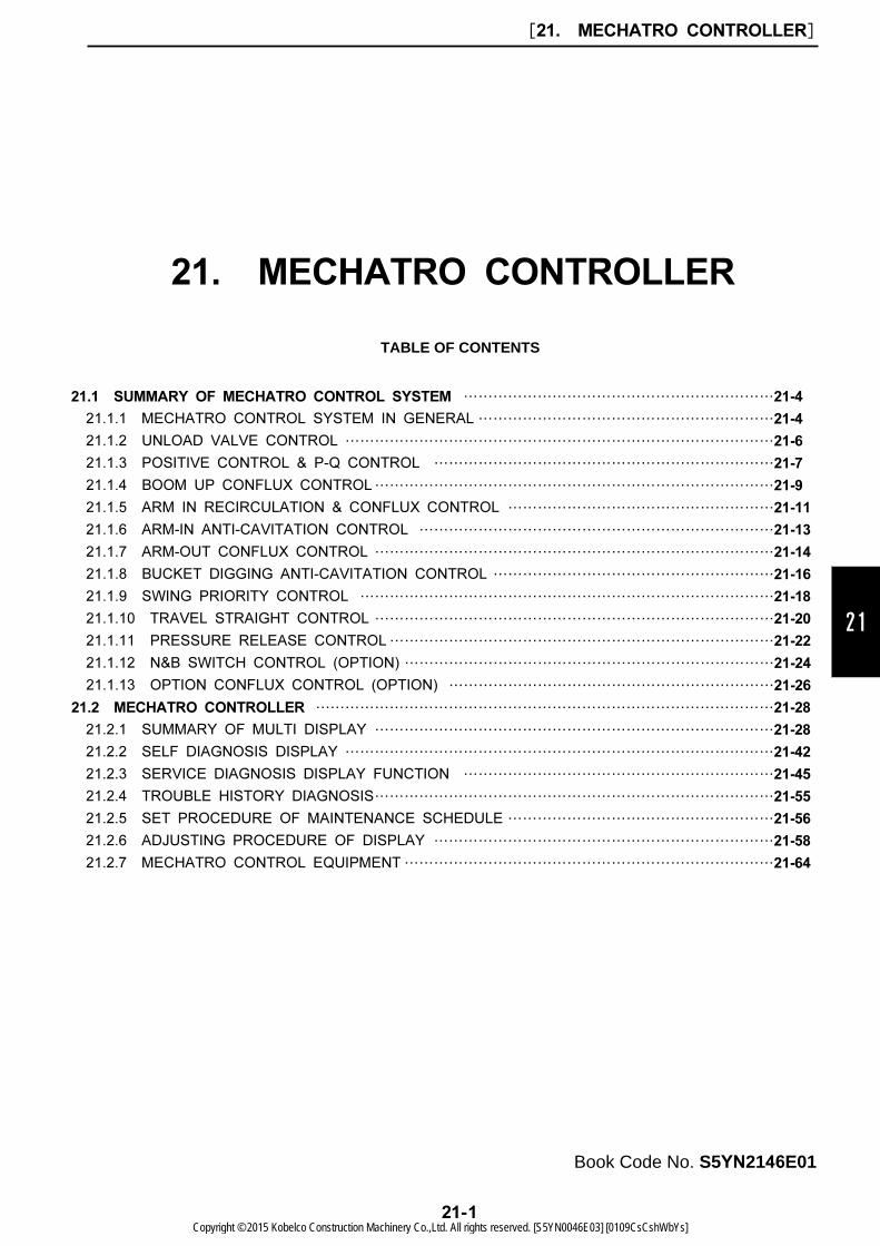
TABLE OF CONTENTS
21.1 SUMMARY OF MECHATRO CONTROL SYSTEM ………………………………………………………21-4
21.1.1 MECHATRO CONTROL SYSTEM IN GENERAL ……………………………………………………21-4
21.1.2 UNLOAD VALVE CONTROL ……………………………………………………………………………21-6
21.1.3 POSITIVE CONTROL & P-Q CONTROL ……………………………………………………………21-7
21.1.4 BOOM UP CONFLUX CONTROL………………………………………………………………………21-9
21.1.5 ARM IN RECIRCULATION & CONFLUX CONTROL ………………………………………………21-11
21.1.6 ARM-IN ANTI-CAVITATION CONTROL ………………………………………………………………21-13
21.1.7 ARM-OUT CONFLUX CONTROL ………………………………………………………………………21-14
21.1.8 BUCKET DIGGING ANTI-CAVITATION CONTROL …………………………………………………21-16
21.1.9 SWING PRIORITY CONTROL …………………………………………………………………………21-18
21.1.10 TRAVEL STRAIGHT CONTROL ………………………………………………………………………21-20
21.1.11 PRESSURE RELEASE CONTROL……………………………………………………………………21-22
21.1.12 N&B SWITCH CONTROL (OPTION) …………………………………………………………………21-24
21.1.13 OPTION CONFLUX CONTROL (OPTION) …………………………………………………………21-26
21.2 MECHATRO CONTROLLER …………………………………………………………………………………21-28
21.2.1 SUMMARY OF MULTI DISPLAY ………………………………………………………………………21-28
21.2.2 SELF DIAGNOSIS DISPLAY ……………………………………………………………………………21-42
21.2.3 SERVICE DIAGNOSIS DISPLAY FUNCTION ………………………………………………………21-45
21.2.4 TROUBLE HISTORY DIAGNOSIS………………………………………………………………………21-55
21.2.5 SET PROCEDURE OF MAINTENANCE SCHEDULE ………………………………………………21-56
21.2.6 ADJUSTING PROCEDURE OF DISPLAY ……………………………………………………………21-58
21.2.7 MECHATRO CONTROL EQUIPMENT…………………………………………………………………21-64
Copyright © 2015 Kobelco Construction Machinery Co.,Ltd. All rights reserved. [S5YN0046E03] [0109CsCshWbYs]

Issue Date of Issue Applicable Machines Remarks
First edition June, 2013 SK210LC-9 : YQ13-10001~S5YN2146E01
(NA)
October, 2013 SK210LC-9 : YQ13-10001~(North America / Europe)
[21. MECHATRO CONTROLLER]
21-2Copyright © 2015 Kobelco Construction Machinery Co.,Ltd. All rights reserved. [S5YN0046E03] [0109CsCshWbYs]
21
PREFACE
This manual explains only those related to the electro hydraulic conversion as mechatro control. This
manual summarizes the mechatro system and the function of the mechatro controller related
apparatuses. Regarding the conditions before and after each conversion, refer to the hydraulic system
and the electric system.
[21. MECHATRO CONTROLLER]
21-3Copyright © 2015 Kobelco Construction Machinery Co.,Ltd. All rights reserved. [S5YN0046E03] [0109CsCshWbYs]

21.1 SUMMARY OF MECHATRO CONTROL SYSTEM
21.1.1 MECHATRO CONTROL SYSTEM IN GENERAL
[21. MECHATRO CONTROLLER]
21-4Copyright © 2015 Kobelco Construction Machinery Co.,Ltd. All rights reserved. [S5YN0046E03] [0109CsCshWbYs]
21
[21. MECHATRO CONTROLLER]
21-5Copyright © 2015 Kobelco Construction Machinery Co.,Ltd. All rights reserved. [S5YN0046E03] [0109CsCshWbYs]
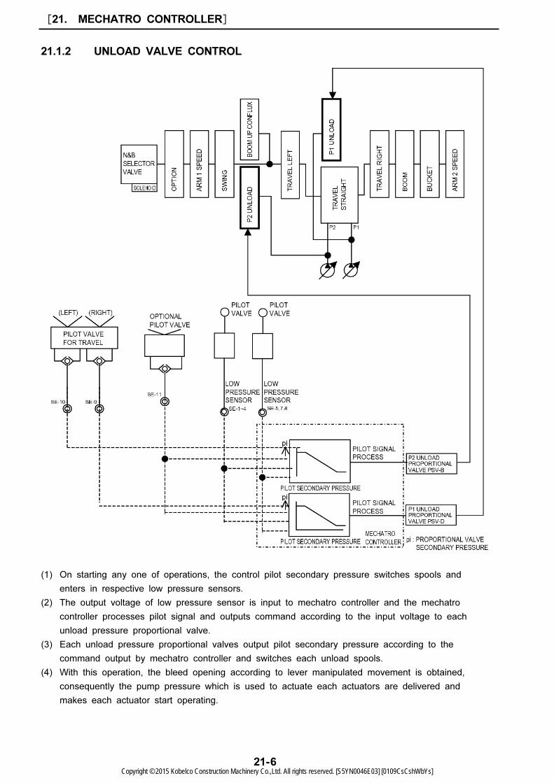
21.1.2 UNLOAD VALVE CONTROL
(1) On starting any one of operations, the control pilot secondary pressure switches spools and
enters in respective low pressure sensors.
(2) The output voltage of low pressure sensor is input to mechatro controller and the mechatro
controller processes pilot signal and outputs command according to the input voltage to each
unload pressure proportional valve.
(3) Each unload pressure proportional valves output pilot secondary pressure according to the
command output by mechatro controller and switches each unload spools.
(4) With this operation, the bleed opening according to lever manipulated movement is obtained,
consequently the pump pressure which is used to actuate each actuators are delivered and
makes each actuator start operating.
[21. MECHATRO CONTROLLER]
21-6Copyright © 2015 Kobelco Construction Machinery Co.,Ltd. All rights reserved. [S5YN0046E03] [0109CsCshWbYs]
21
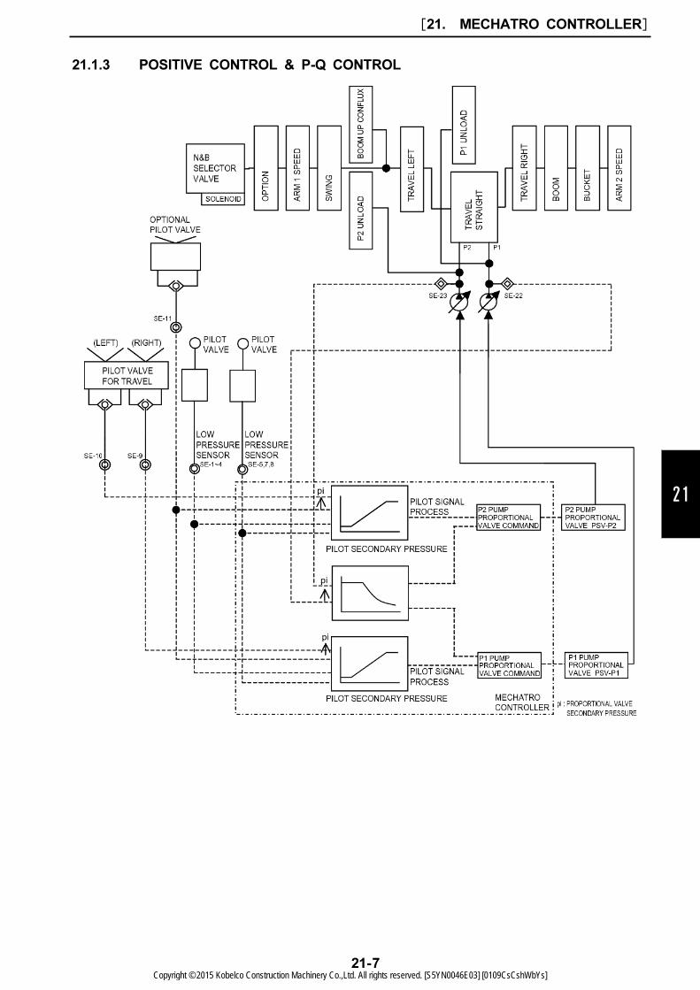
21.1.3 POSITIVE CONTROL & P-Q CONTROL
[21. MECHATRO CONTROLLER]
21-7Copyright © 2015 Kobelco Construction Machinery Co.,Ltd. All rights reserved. [S5YN0046E03] [0109CsCshWbYs]
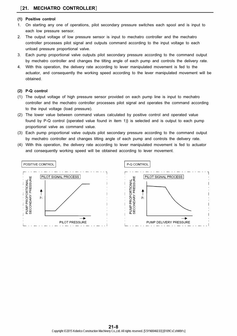
(1) Positive control
1. On starting any one of operations, pilot secondary pressure switches each spool and is input to
each low pressure sensor.
2. The output voltage of low pressure sensor is input to mechatro controller and the mechatro
controller processes pilot signal and outputs command according to the input voltage to each
unload pressure proportional valve.
3. Each pump proportional valve outputs pilot secondary pressure according to the command output
by mechatro controller and changes the tilting angle of each pump and controls the delivery rate.
4. With this operation, the delivery rate according to lever manipulated movement is fed to the
actuator, and consequently the working speed according to the lever manipulated movement will be
obtained.
(2) P-Q control
(1) The output voltage of high pressure sensor provided on each pump line is input to mechatro
controller and the mechatro controller processes pilot signal and operates the command according
to the input voltage (load pressure).
(2) The lower value between command values calculated by positive control and operated value
found by P-Q control {operated value found in item 1)} is selected and is output to each pump
proportional valve as command value.
(3) Each pump proportional valve outputs pilot secondary pressure according to the command output
by mechatro controller and changes tilting angle of each pump and controls the delivery rate.
(4) With this operation, the delivery rate according to lever manipulated movement is fed to actuator
and consequently working speed will be obtained according to lever movement.
[21. MECHATRO CONTROLLER]
21-8Copyright © 2015 Kobelco Construction Machinery Co.,Ltd. All rights reserved. [S5YN0046E03] [0109CsCshWbYs]
21
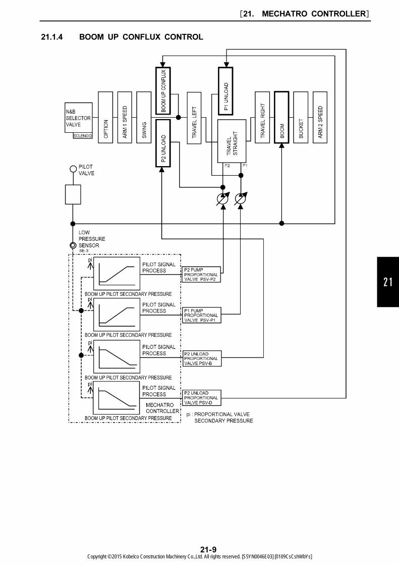
21.1.4 BOOM UP CONFLUX CONTROL
[21. MECHATRO CONTROLLER]
21-9Copyright © 2015 Kobelco Construction Machinery Co.,Ltd. All rights reserved. [S5YN0046E03] [0109CsCshWbYs]
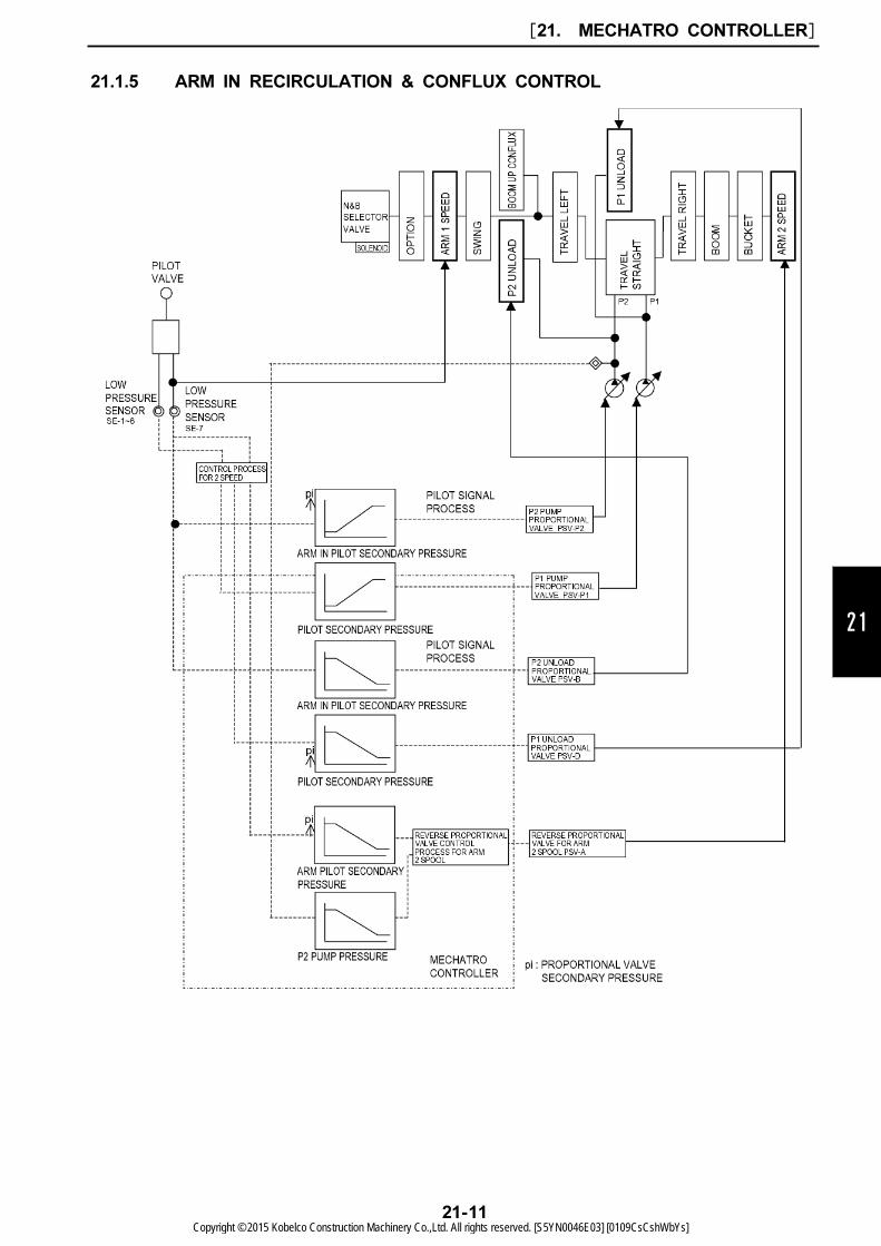
(1) On starting boom up operation, boom up operating pilot pressure switches boom spool and boom
up conflux spool and is input to low pressure sensor.
(2) The output voltage of low pressure sensor is input to mechatro controller and the mechatro
controller processes pilot signal and outputs command according to the input voltage to P1 and P2
proportional valves and P1 and P2 unload proportional valves.
(3) Each proportional valve outputs pilot proportional valve secondary pressure according to the
command output by mechatro controller and changes P1 and P2 pump delivery rate and switches
P1 and P2 unload pressure control valve.
(4) With original hydraulic pressure command, boom main spool and boom up conflux spool are
switched, and also with the command by mechatro controller, P1 and P2 pumps and P1 and P2
unload valves are switched and consequently the delivery oil on P1 pump side confluxes delivery
oil on P2 pump side during boom up operation.
[21. MECHATRO CONTROLLER]
21-10Copyright © 2015 Kobelco Construction Machinery Co.,Ltd. All rights reserved. [S5YN0046E03] [0109CsCshWbYs]
21
21.1.5 ARM IN RECIRCULATION & CONFLUX CONTROL
[21. MECHATRO CONTROLLER]
21-11Copyright © 2015 Kobelco Construction Machinery Co.,Ltd. All rights reserved. [S5YN0046E03] [0109CsCshWbYs]
(1) Recirculation and conflux (Low loading)
1. On starting arm-in operation, arm-in operating pilot secondary pressure is input to arm 1 spool,
arm 2 spool and low pressure sensor.
2. The output voltage of low pressure sensor is input to mechatro controller and the mechatro
controller processes pilot signal and outputs command according to the input voltage to P1 and P2
proportional valves, P1 and P2 unload proportional valves and reverse proportional valve for arm-in
2 spool.
In case of combined operation, the pilot pressure other than arm-in operation is input to low
pressure sensor and the output voltage is input to mechatro controller. And the mechatro
controller processes pilot signal according to the combined operation and outputs command, which
is different from the arm-in independent operation, to P1 pump proportional valve, P1 unload
proportional valve and reverse proportional valve for arm-in 2 spool.
3. Primary pressure of reverse proportional valve for arm-in 2 spool is arm-in pilot secondary pressure
and it switches arm 2 spool by proportional secondary pressure according to command. (Arm 2
spool controls recirculation rate and conflux rate.)
The other proportional valves output proportional secondary pressure according to command from
mechatro controller. These proportional valves change the delivery rate of P1, P2 pump, and
switch P1, P2 unload valve.
4. The arm 1 spool is switched according to original oil pressure command, and P1, P2 pumps, P1,
P2 unload spools and arm 2 spool are switched according to the command output by mechatro
controller, and consequently the return oil from the arm cylinder rod side is recirculated in P1 and
P2 pumps delivery oil during arm operation.
(2) Recirculation cut
The voltage output by high pressure sensor on P2 side is input to mechatro controller, and when the
load is raised during arm operation the mechatro controller processes pilot signal processing according
to the pressure detected by high pressure sensor and outputs command to cut recirculation into
reverse proportional valve for arm-in 2 spool.
The reverse proportional valve for arm-in 2 spool outputs pilot secondary pressure according to the
command output by mechatro controller and switches arm 2 spool to recirculation cut position, and
consequently recirculation passage is blocked.
[21. MECHATRO CONTROLLER]
21-12Copyright © 2015 Kobelco Construction Machinery Co.,Ltd. All rights reserved. [S5YN0046E03] [0109CsCshWbYs]
21
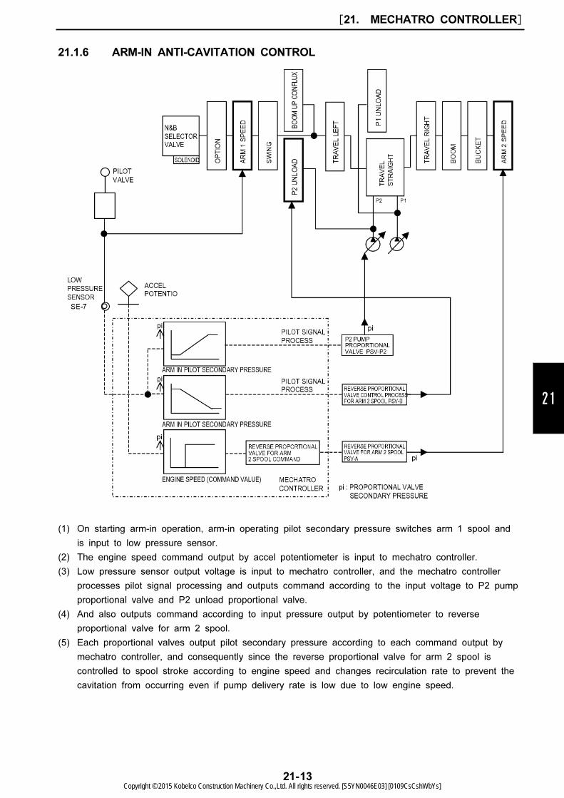
21.1.6 ARM-IN ANTI-CAVITATION CONTROL
(1) On starting arm-in operation, arm-in operating pilot secondary pressure switches arm 1 spool and
is input to low pressure sensor.
(2) The engine speed command output by accel potentiometer is input to mechatro controller.
(3) Low pressure sensor output voltage is input to mechatro controller, and the mechatro controller
processes pilot signal processing and outputs command according to the input voltage to P2 pump
proportional valve and P2 unload proportional valve.
(4) And also outputs command according to input pressure output by potentiometer to reverse
proportional valve for arm 2 spool.
(5) Each proportional valves output pilot secondary pressure according to each command output by
mechatro controller, and consequently since the reverse proportional valve for arm 2 spool is
controlled to spool stroke according to engine speed and changes recirculation rate to prevent the
cavitation from occurring even if pump delivery rate is low due to low engine speed.
[21. MECHATRO CONTROLLER]
21-13Copyright © 2015 Kobelco Construction Machinery Co.,Ltd. All rights reserved. [S5YN0046E03] [0109CsCshWbYs]

21.1.7 ARM-OUT CONFLUX CONTROL
[21. MECHATRO CONTROLLER]
21-14Copyright © 2015 Kobelco Construction Machinery Co.,Ltd. All rights reserved. [S5YN0046E03] [0109CsCshWbYs]
21
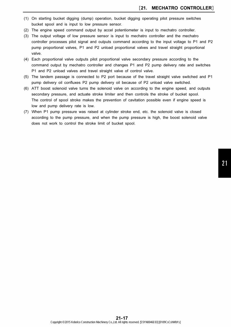
(1) On starting arm-out operation, arm-out operating pilot pressure switches arm 1 spool and arm 2
spool and is input to low pressure sensor.
(2) The output voltage of low pressure sensor is input to mechatro controller and the mechatro
controller processes pilot signal and outputs command according to the input voltage to P1 and P2
proportional valves and P1 and P2 unload proportional valves.
(3) Each proportional valve outputs pilot proportional valve secondary pressure according to the
command output by mechatro controller and changes P1 and P2 pump delivery rate and switches
P1 and P2 unload pressure control valves.
(4) With original hydraulic pressure command, arm 1 spool and arm 2 spool are switched and also
with the command output by mechatro controller, P1 and P2 pumps and P1 and P2 unload valves
are switched, and consequently the delivery oil on P2 pump side confluxes delivery oil on P1
pump side during arm-out operation.
[21. MECHATRO CONTROLLER]
21-15Copyright © 2015 Kobelco Construction Machinery Co.,Ltd. All rights reserved. [S5YN0046E03] [0109CsCshWbYs]
21.1.8 BUCKET DIGGING ANTI-CAVITATION CONTROL
[21. MECHATRO CONTROLLER]
21-16Copyright © 2015 Kobelco Construction Machinery Co.,Ltd. All rights reserved. [S5YN0046E03] [0109CsCshWbYs]
21
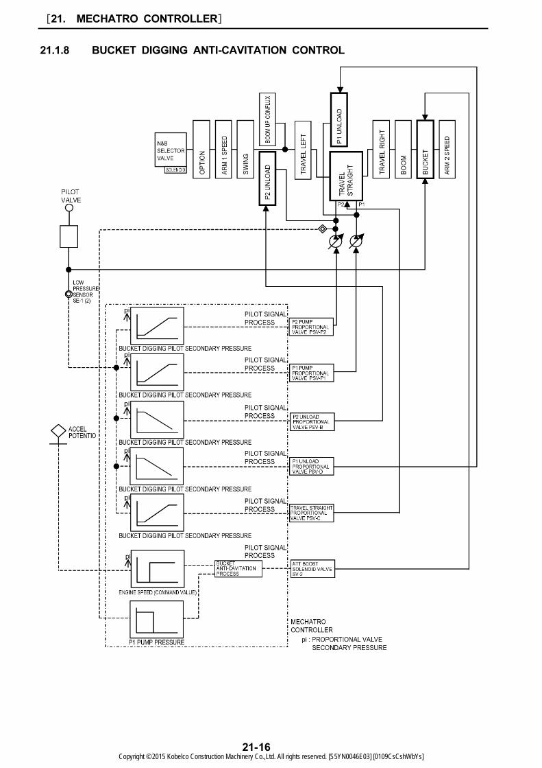
(1) On starting bucket digging (dump) operation, bucket digging operating pilot pressure switches
bucket spool and is input to low pressure sensor.
(2) The engine speed command output by accel potentiometer is input to mechatro controller.
(3) The output voltage of low pressure sensor is input to mechatro controller and the mechatro
controller processes pilot signal and outputs command according to the input voltage to P1 and P2
pump proportional valves, P1 and P2 unload proportional valves and travel straight proportional
valve.
(4) Each proportional valve outputs pilot proportional valve secondary pressure according to the
command output by mechatro controller and changes P1 and P2 pump delivery rate and switches
P1 and P2 unload valves and travel straight valve of control valve.
(5) The tandem passage is connected to P2 port because of the travel straight valve switched and P1
pump delivery oil confluxes P2 pump delivery oil because of P2 unload valve switched.
(6) ATT boost solenoid valve turns the solenoid valve on according to the engine speed, and outputs
secondary pressure, and actuate stroke limiter and then controls the stroke of bucket spool.
The control of spool stroke makes the prevention of cavitation possible even if engine speed is
low and pump delivery rate is low.
(7) When P1 pump pressure was raised at cylinder stroke end, etc. the solenoid valve is closed
according to the pump pressure, and when the pump pressure is high, the boost solenoid valve
does not work to control the stroke limit of bucket spool.
[21. MECHATRO CONTROLLER]
21-17Copyright © 2015 Kobelco Construction Machinery Co.,Ltd. All rights reserved. [S5YN0046E03] [0109CsCshWbYs]
21.1.9 SWING PRIORITY CONTROL
[21. MECHATRO CONTROLLER]
21-18Copyright © 2015 Kobelco Construction Machinery Co.,Ltd. All rights reserved. [S5YN0046E03] [0109CsCshWbYs]
21
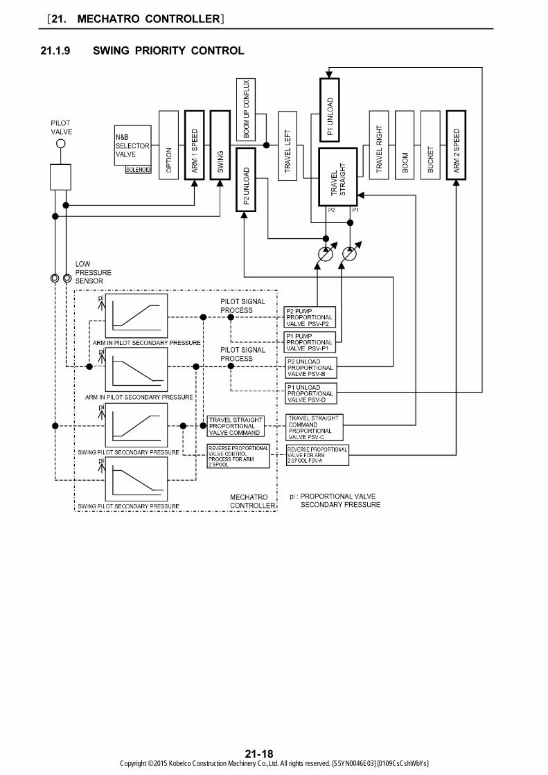
(1) During arm-in operation, arm operating pilot secondary pressure switches arm spool and is input
to low pressure sensor on starting swing operation (or arm-in operation during swing operation),
and swing operation pilot secondary pressure switches swing spool and is input to low pressure
sensor.
(2) The output voltage of low pressure sensor is input to mechatro controller and the mechatro
controller processes pilot signal and outputs command according to the input voltage to P1 and P2
proportional valves, P1 and P2 unload pressure proportional valves, travel straight valve and
reverse proportional valve for arm 2 spool.
(3) Each proportional valve outputs pilot proportional valve secondary pressure according to the
command output by mechatro controller and changes P1 and P2 pump delivery rate and switches
P1 and P2 unload spool, travel straight spool, arm 2 spool.
(4) With original hydraulic pressure command, arm 1 spool and swing spool are switched and also
with the command by mechatro controller, P1 and P2 unload spools, travel straight spool and
arm 2 spool are switched enabling for two pump flow rates to be supplied to the arm cylinder
head side, and consequently the return oil on arm cylinder rod side is recirculated into arm
cylinder head side.
(5) ion by priority, and operated by the recirculated oil, making the operation with minimum speed
drop possible.
[21. MECHATRO CONTROLLER]
21-19Copyright © 2015 Kobelco Construction Machinery Co.,Ltd. All rights reserved. [S5YN0046E03] [0109CsCshWbYs]
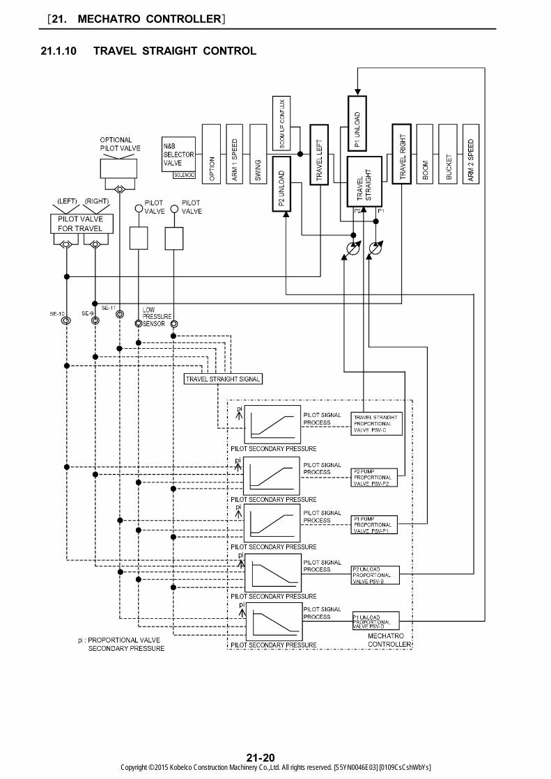
21.1.10 TRAVEL STRAIGHT CONTROL
[21. MECHATRO CONTROLLER]
21-20Copyright © 2015 Kobelco Construction Machinery Co.,Ltd. All rights reserved. [S5YN0046E03] [0109CsCshWbYs]
21
(1) Judgment travel straight
1. During travel operation (right and left), pilot pressure switches each spool and is input to low
pressure sensor on carrying out attachment system operation.
2. Mechatro controller decides as travel straight on receiving the input according to the combination
shown in the table from the low pressure sensor and turns travel straight signal on.
3. On turning travel straight signal on, the following commands are output to each proportional valve.
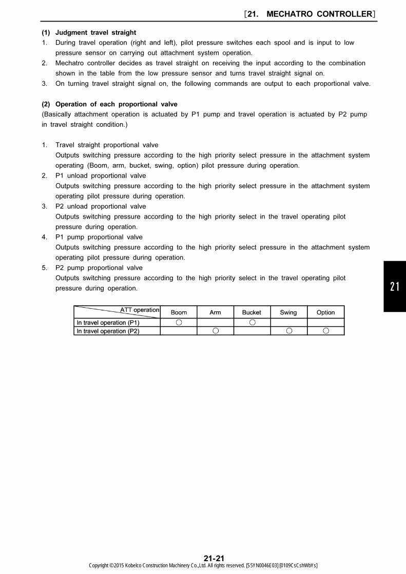
(2) Operation of each proportional valve
(Basically attachment operation is actuated by P1 pump and travel operation is actuated by P2 pump
in travel straight condition.)
1. Travel straight proportional valve
Outputs switching pressure according to the high priority select pressure in the attachment system
operating (Boom, arm, bucket, swing, option) pilot pressure during operation.
2. P1 unload proportional valve
Outputs switching pressure according to the high priority select pressure in the attachment system
operating pilot pressure during operation.
3. P2 unload proportional valve
Outputs switching pressure according to the high priority select in the travel operating pilot
pressure during operation.
4. P1 pump proportional valve
Outputs switching pressure according to the high priority select pressure in the attachment system
operating pilot pressure during operation.
5. P2 pump proportional valve
Outputs switching pressure according to the high priority select in the travel operating pilot
pressure during operation.
[21. MECHATRO CONTROLLER]
21-21Copyright © 2015 Kobelco Construction Machinery Co.,Ltd. All rights reserved. [S5YN0046E03] [0109CsCshWbYs]
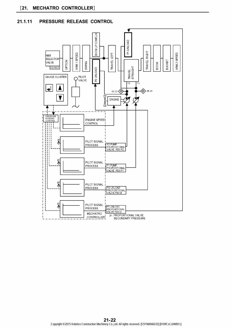
21.1.11 PRESSURE RELEASE CONTROL
[21. MECHATRO CONTROLLER]
21-22Copyright © 2015 Kobelco Construction Machinery Co.,Ltd. All rights reserved. [S5YN0046E03] [0109CsCshWbYs]
21
(1) Change mechatro controller to "PRESSURE DRAINING MODE" by operating switch on gauge
cluster.
For detail of changing mode method, refer to "How to switch to "Pressure release mode"" on item
22.11.1.
(2) Once mechatro controller decides it as pressure release control, regardless of each input signal
(operating pilot, accel potentiometer, etc.) the mechatro controller;
1.
Outputs minimum tilt angle command to P1, P2 pump proportional valves and fixes P1, P2 pump
to minimum tilt angle.
2.
Outputs command of pressure release and outputs command of pressure release control to ECU
and fixes engine speed to pressure release control speed.
3.
Outputs maximum command to P1 and P2 unload valves and each pilot secondary pressure fixes
P1 and P2 unload valves to the maximum opening.
(3) Mechatro controller senses output voltage from the main pump high pressure sensor, decides the
pump pressure and displays "DRAINING HYD. PRESS" or "FAIL DRAIN HYD. PRESS" on gauge
cluster.
(4) Each pump delivery oil is unloaded to tank passage enabling for the remained pressure (trapped
pressure) to be released by operating each control lever and switching spool with the unload valve
opened.
[21. MECHATRO CONTROLLER]
21-23Copyright © 2015 Kobelco Construction Machinery Co.,Ltd. All rights reserved. [S5YN0046E03] [0109CsCshWbYs]
21.1.12 N&B SWITCH CONTROL (OPTION)
[21. MECHATRO CONTROLLER]
21-24Copyright © 2015 Kobelco Construction Machinery Co.,Ltd. All rights reserved. [S5YN0046E03] [0109CsCshWbYs]
21
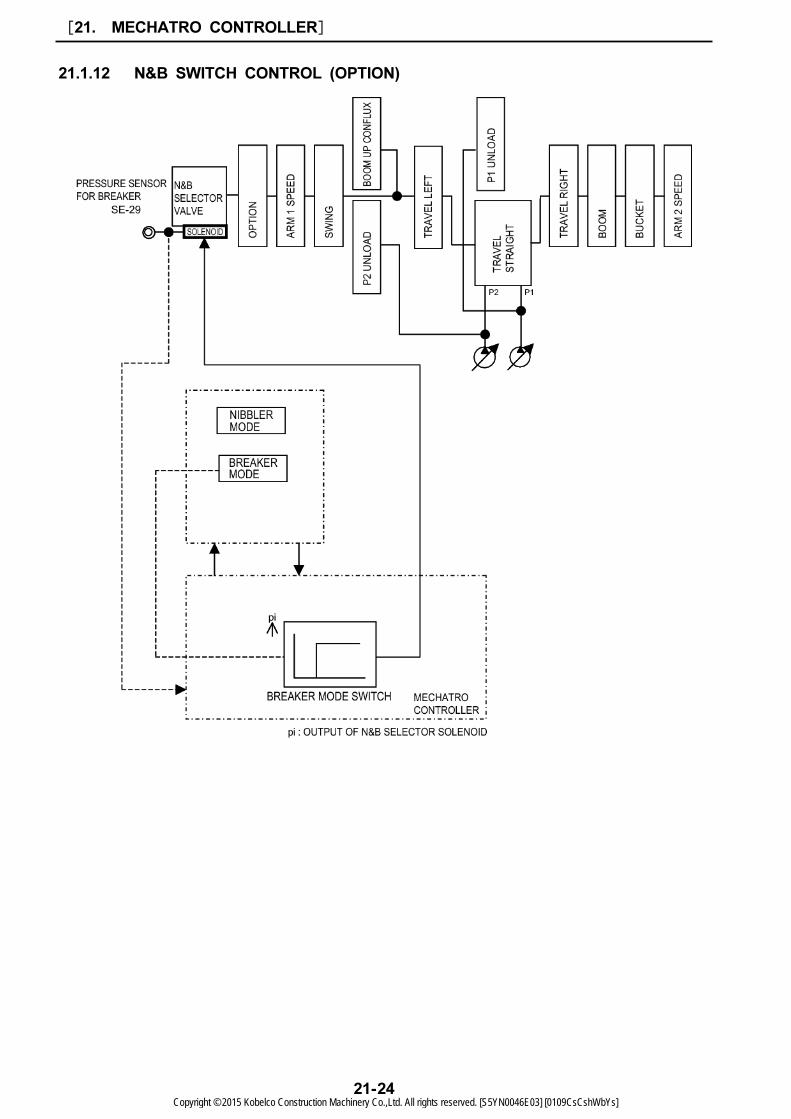
(1) Nibbler circuit
1. Select nibbler mode through select switch.
2. Nibbler display appears on gauge cluster.
3. The return oil from the nibbler passes through selector valve and option spool and led to tank
line of main control valve.
4. When selecting nibbler mode through select switch, the breaker pressure sensor has not function
to output.
It is in normal when there is no output from sensor in nibbler mode, and in cases of other than
above, error display is output to gauge cluster.
(2) Breaker circuit
1. Select breaker mode through select switch.
2. Breaker display appears on gauge cluster.
3. The return oil from the breaker passes through selector valve and directly returns into hydraulic oil
tank.
4. When selecting breaker mode through select switch, the breaker pressure sensor outputs signal.
It is in normal when there is an output from sensor in breaker mode, and in cases of other than
above, error display is output to gauge cluster.
[21. MECHATRO CONTROLLER]
21-25Copyright © 2015 Kobelco Construction Machinery Co.,Ltd. All rights reserved. [S5YN0046E03] [0109CsCshWbYs]
21.1.13 OPTION CONFLUX CONTROL (OPTION)
[21. MECHATRO CONTROLLER]
21-26Copyright © 2015 Kobelco Construction Machinery Co.,Ltd. All rights reserved. [S5YN0046E03] [0109CsCshWbYs]

21
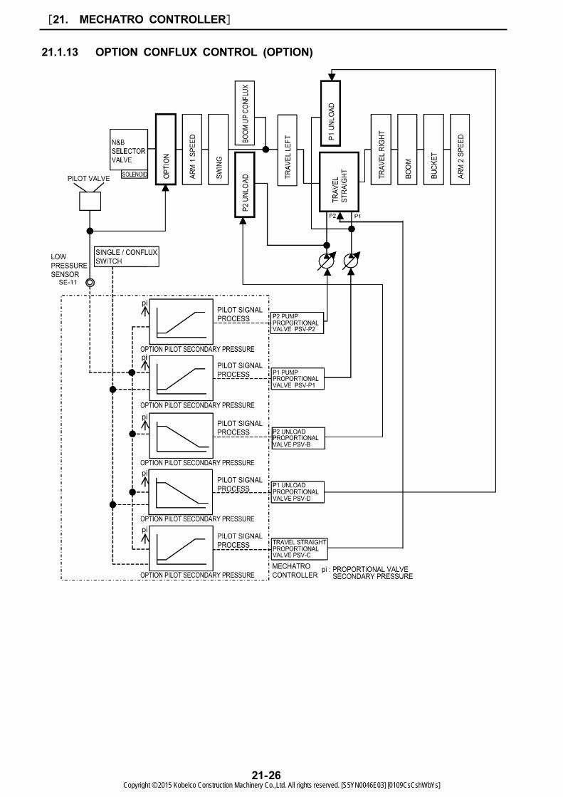
(1) Using "OPTION SETTING" display located on "USER MENU" screen, the flow rate is adjusted. At
this time, if the setting flow rate is larger than one pump flow rate, the flow becomes automatically
confluent flow.
(2) On starting option operation, option operating pilot pressure switches option spool and is input to
low pressure sensor.
(3) The output voltage of low pressure sensor is input to mechatro controller and the mechatro
controller processes pilot signal and outputs command according to the input voltage to P1 and P2
pump proportional valves, P1 and P2 unload pressure proportional valves and travel straight
proportional valve.
(4) Each proportional valves output pilot proportional valve secondary pressure according to the
command output by mechatro controller and changes P1 and P2 pump delivery rate and switches
P1 and P2 unload valves and travel straight valve of the control valve.
(5) The parallel passage on P2 side is connected to P1 port because of the travel straight valve
switched and P1 pump delivery oil confluxes P2 pump delivery oil because of the P2 unload valve
switched.
[21. MECHATRO CONTROLLER]
21-27Copyright © 2015 Kobelco Construction Machinery Co.,Ltd. All rights reserved. [S5YN0046E03] [0109CsCshWbYs]
21.2 MECHATRO CONTROLLER
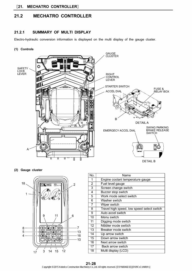
21.2.1 SUMMARY OF MULTI DISPLAY
Electro-hydraulic conversion information is displayed on the multi display of the gauge cluster.
(1) Controls
(2) Gauge cluster
[21. MECHATRO CONTROLLER]
21-28Copyright © 2015 Kobelco Construction Machinery Co.,Ltd. All rights reserved. [S5YN0046E03] [0109CsCshWbYs]
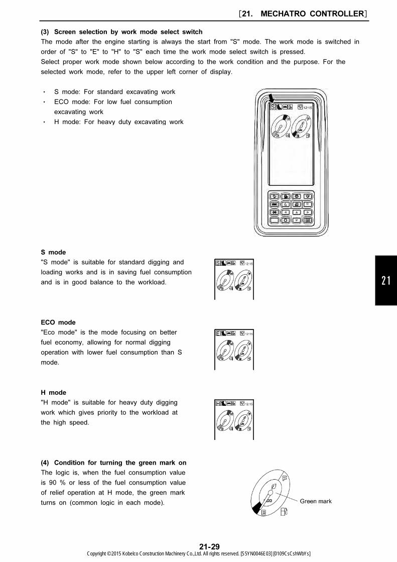
・ S mode: For standard excavating work
・ ECO mode: For low fuel consumption
excavating work
・ H mode: For heavy duty excavating work
"S mode" is suitable for standard digging and
loading works and is in saving fuel consumption
and is in good balance to the workload.
"Eco mode" is the mode focusing on better
fuel economy, allowing for normal digging
operation with lower fuel consumption than S
mode.
"H mode" is suitable for heavy duty digging
work which gives priority to the workload at
the high speed.
The logic is, when the fuel consumption value
is 90 % or less of the fuel consumption value
of relief operation at H mode, the green mark
turns on (common logic in each mode).
21
(3) Screen selection by work mode select switch
The mode after the engine starting is always the start from "S" mode. The work mode is switched in
order of "S" to "E" to "H" to "S" each time the work mode select switch is pressed.
Select proper work mode shown below according to the work condition and the purpose. For the
selected work mode, refer to the upper left corner of display.
S mode
ECO mode
H mode
(4) Condition for turning the green mark on
[21. MECHATRO CONTROLLER]
21-29Copyright © 2015 Kobelco Construction Machinery Co.,Ltd. All rights reserved. [S5YN0046E03] [0109CsCshWbYs]
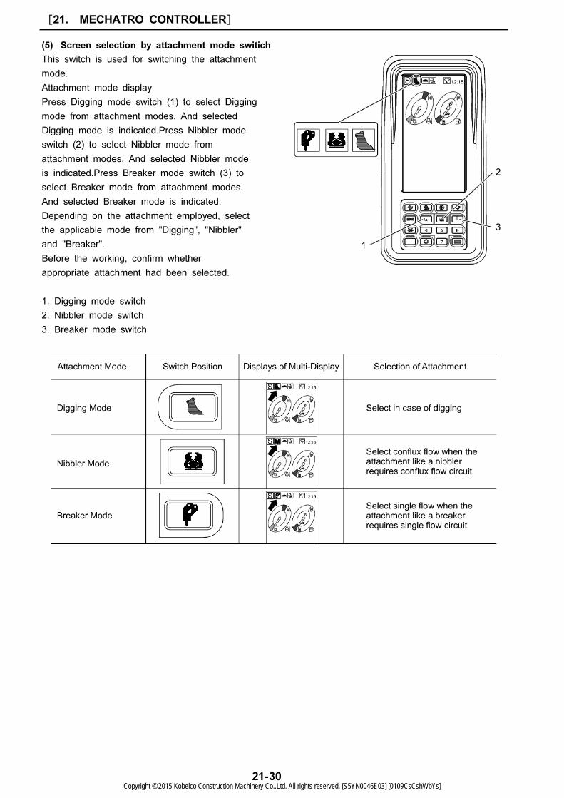
This switch is used for switching the attachment
mode.
Attachment mode display
Press Digging mode switch (1) to select Digging
mode from attachment modes. And selected
Digging mode is indicated.Press Nibbler mode
switch (2) to select Nibbler mode from
attachment modes. And selected Nibbler mode
is indicated.Press Breaker mode switch (3) to
select Breaker mode from attachment modes.
And selected Breaker mode is indicated.
Depending on the attachment employed, select
the applicable mode from "Digging", "Nibbler"
and "Breaker".
Before the working, confirm whether
appropriate attachment had been selected.
1. Digging mode switch
2. Nibbler mode switch
3. Breaker mode switch
(5) Screen selection by attachment mode switich
[21. MECHATRO CONTROLLER]
21-30Copyright © 2015 Kobelco Construction Machinery Co.,Ltd. All rights reserved. [S5YN0046E03] [0109CsCshWbYs]

1: Buzzer Stop Switch
2: Menu Switch
3: Nibbler Mode Switch
4: Breaker Mode Switch
5: Up Arrow Switch
6: Down Arrow Switch
7: Next Arrow Switch
8: Back Arrow Switch
21
(6) Procedure of setting a flow rate and a option relief pressure at Nibbler/Breaker mode
According to some kind of attachment, it is required to change the flow rate and relief pressure for
service circuit.
Regarding the adjustment of flow rate and relief pressure for Nibbler and Breaker, the settings of 10
patterns are available.
Both Nibbler are set in conditions "SET 6" as factory default in the above table at shipping.
Both Breaker are set in conditions "SET 1" as factory default in the above table at shipping.
* The meaning of "Not set yet" shows that 50MPa as pressure is temporary value.
Set the flow rate and relief pressure in accordance with next procedure.
And these setting values in above adjustment are selectable by using after-mentioned "Flow rate and
Relief pressure Selection".
[21. MECHATRO CONTROLLER]
21-31Copyright © 2015 Kobelco Construction Machinery Co.,Ltd. All rights reserved. [S5YN0046E03] [0109CsCshWbYs]
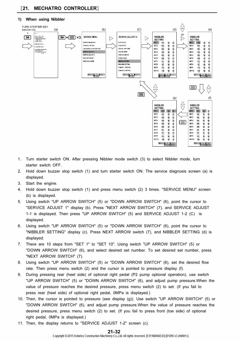
1) When using Nibbler
1. Turn starter switch ON. After pressing Nibbler mode switch (3) to select Nibbler mode, turn
starter switch OFF.
2. Hold down buzzer stop switch (1) and turn starter switch ON. The service diagnosis screen (a) is
displayed.
3. Start the engine.
4. Hold down buzzer stop switch (1) and press menu switch (2) 3 times. "SERVICE MENU" screen
(b) is displayed.
5. Using switch "UP ARROW SWITCH" (5) or "DOWN ARROW SWITCH" (6), point the cursor to
"SERVICE ADJUST 1" display (b). Press "NEXT ARROW SWITCH" (7), and SERVICE ADJUST
1-1 is displayed. Then press "UP ARROW SWITCH" (5) and SERVICE ADJUST 1-2 (C) is
displayed.
6. Using switch "UP ARROW SWITCH" (5) or "DOWN ARROW SWITCH" (6), point the cursor to
"NIBBLER SETTING" display (c). Press NEXT ARROW switch (7), and NIBBLER SETTING (d) is
displayed.
7. There are 10 steps from "SET 1" to "SET 10". Using switch "UP ARROW SWITCH" (5) or
"DOWN ARROW SWITCH" (6), and select desired set number. To set desired set number, press
"NEXT ARROW SWITCH" (7).
8. Using switch "UP ARROW SWITCH" (5) or "DOWN ARROW SWITCH" (6), set the desired flow
rate. Then press menu switch (2) and the cursor is pointed to pressure display (f).
9. During pressing rear (heel side) of optional right pedal (P2 pump optional operation), use switch
"UP ARROW SWITCH" (5) or "DOWN ARROW SWITCH" (6), and adjust pump pressure.When the
value of pressure reaches the desired pressure, press menu switch (2) to set. (If you fail to
press rear (heel side) of optional right pedal, 0MPa is displayed.)
10. Then, the cursor is pointed to pressure (see display (g)). Use switch "UP ARROW SWITCH" (5) or
"DOWN ARROW SWITCH" (6), and adjust pump pressure.When the value of pressure reaches the
desired pressure, press menu switch (2) to set. (If you fail to press front (toe side) of optional
right pedal, 0MPa is displayed.)
11. Then, the display returns to "SERVICE ADJUST 1-2" screen (c).
[21. MECHATRO CONTROLLER]
21-32Copyright © 2015 Kobelco Construction Machinery Co.,Ltd. All rights reserved. [S5YN0046E03] [0109CsCshWbYs]

21
2) When using Breaker
1. Turn starter switch ON. After pressing Breaker mode switch (4) to select Breaker mode, turn
starter switch OFF.
2. Hold down buzzer stop switch (1) and turn starter switch ON. The service diagnosis screen (a) is
displayed.
3. Start the engine.
4. Hold down buzzer stop switch (1) and press menu switch (2) 3 times. "SERVICE MENU" screen
(b) is displayed.
5. Using switch "UP ARROW SWITCH" (5) or "DOWN ARROW SWITCH" (6), point the cursor to
"SERVICE ADJUST 1" display (b). Press "NEXT ARROW SWITCH" (7), and SERVICE ADJUST
1-1 is displayed. Then press "UP ARROW SWITCH" (5) and SERVICE ADJUST 1-2 (C) is
displayed.
6. Using switch "UP ARROW SWITCH" (5) or "DOWN ARROW SWITCH" (6), point the cursor to
"BREAKER SETTING" display (c). Press "NEXT ARROW SWITCH" (7), and BREAKER SETTING
(d) is displayed.
7. There are 10 steps from "SET 1" to "SET 10". Using switch "UP ARROW SWITCH" (5) or
"DOWN ARROW SWITCH" (6), and select desired set number. To set desired set number, press
"NEXT ARROW SWITCH" (7).
8. Using switch "UP ARROW SWITCH" (5) or "DOWN ARROW SWITCH" (6), set the desired flow
rate. Then press menu switch (2) and the cursor is pointed to pressure display (f).
9. During pressing front (toe side) of optional right pedal (P2 pump optional operation), use switch
"UP ARROW SWITCH" (5) or "DOWN ARROW SWITCH" (6), and adjust pump pressure. When
you reach the desired pressure, press menu switch (2) to set. (If you fail to press front (toe side)
of optional right pedal, 0MPa is displayed.)
10. Then, the display returns to "SERVICE ADJUST 1-2" screen (c).
[21. MECHATRO CONTROLLER]
21-33Copyright © 2015 Kobelco Construction Machinery Co.,Ltd. All rights reserved. [S5YN0046E03] [0109CsCshWbYs]
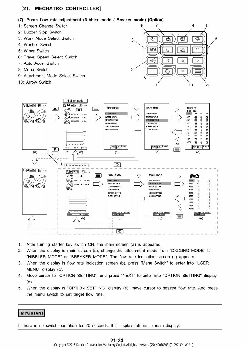
1: Screen Change Switch
2: Buzzer Stop Switch
3: Work Mode Select Switch
4: Washer Switch
5: Wiper Switch
6: Travel Speed Select Switch
7: Auto Accel Switch
8: Menu Switch
9: Attachment Mode Select Switch
10: Arrow Switch
(7) Pump flow rate adjustment (Nibbler mode / Breaker mode) (Option)
1. After turning starter key switch ON, the main screen (a) is appeared.
2. When the display is main screen (a), change the attachment mode from "DIGGING MODE" to
"NIBBLER MODE" or "BREAKER MODE". The flow rate indication screen (b) appears.
3. When the display is flow rate indication screen (b), press "Menu Switch" to enter into "USER
MENU" display (c).
4. Move cursor to "OPTION SETTING", and press "NEXT" to enter into "OPTION SETTING" display
(e).
5. When the display is "OPTION SETTING" display (e), move cursor to desired flow rate. And press
the menu switch to set target flow rate.
If there is no switch operation for 20 seconds, this display returns to main display.
[21. MECHATRO CONTROLLER]
21-34Copyright © 2015 Kobelco Construction Machinery Co.,Ltd. All rights reserved. [S5YN0046E03] [0109CsCshWbYs]

This screen displays the remaining time to the
end of recommended replacement/change
interval specified for filter/oil.
After turning starter key switch ON or starting
engine, Then, the display returns to "SERVICE
ADJUST 1-2" screen (c).
This display shows the recommended
replacement time of engine oil, time for next
engine oil change and date of previous engine
oil change.
Item Default
Engine oil 500 Hr
Fuel filter 500 Hr
Hydraulic oil filter 1,000 Hr
Hydraulic oil 5,000 Hr
1.
Remaining time display to the engine oil change
This display shows the remaining time of
"INTERVAL, REMAINING TIME, EXCHANGE
DAY".
21
(8) Maintenance screen displays
For the initial set value of recommenced replacement/change time, see the following table.
Replacement interval
This menu is available for confirmation of the following items.
The maintenance screen changes each time the screen change switch is pressed.
[21. MECHATRO CONTROLLER]
21-35Copyright © 2015 Kobelco Construction Machinery Co.,Ltd. All rights reserved. [S5YN0046E03] [0109CsCshWbYs]
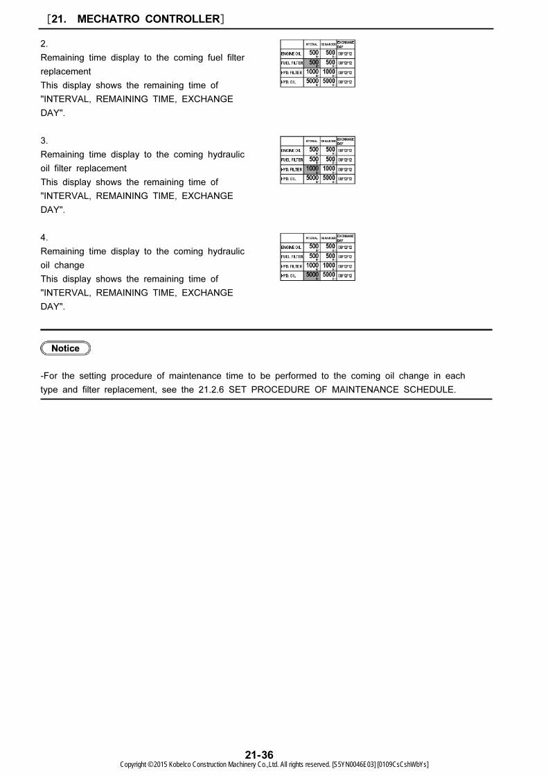
2.
Remaining time display to the coming fuel filter
replacement
This display shows the remaining time of
"INTERVAL, REMAINING TIME, EXCHANGE
DAY".
3.
Remaining time display to the coming hydraulic
oil filter replacement
This display shows the remaining time of
"INTERVAL, REMAINING TIME, EXCHANGE
DAY".
4.
Remaining time display to the coming hydraulic
oil change
This display shows the remaining time of
"INTERVAL, REMAINING TIME, EXCHANGE
DAY".
-For the setting procedure of maintenance time to be performed to the coming oil change in each
type and filter replacement, see the 21.2.6 SET PROCEDURE OF MAINTENANCE SCHEDULE.
[21. MECHATRO CONTROLLER]
21-36Copyright © 2015 Kobelco Construction Machinery Co.,Ltd. All rights reserved. [S5YN0046E03] [0109CsCshWbYs]

1: Screen Change Switch
2: Buzzer Stop Switch
3: Work Mode Select Switch
4: Washer Switch
5: Wiper Switch
6: Travel Speed Select Switch
7: Auto Accel Switch
8: Menu Switch
9: Arrow Switch
21
(9) Consumption
1. Turn on the starter key switch "ON" and the main screen (a) is appeared. And press "Menu
Switch" (8) to enter into "USER MENU" display (b).
2. Using "UP" or "DOWN" arrow switch, move the cursor to "CONSUMPTION" as display (c), and
press "RIGHT" arrow switch. And "Fuel Efficiency Graph" display (d) appears.
3. The graph indicates the fuel consumption from 12 hours ago to now in a 2 hour intervals. And the
values of "Operating Time" "Fuel Consumption" and "Average Fuel Efficiency" are indicated.
4. To reset these values, press "Menu Switch" (8).
5. Press "Screen Change Switch" (1) and the display returns to main screen (a).
Use the indicated "Average Fuel Efficiency" for reference.
[21. MECHATRO CONTROLLER]
21-37Copyright © 2015 Kobelco Construction Machinery Co.,Ltd. All rights reserved. [S5YN0046E03] [0109CsCshWbYs]
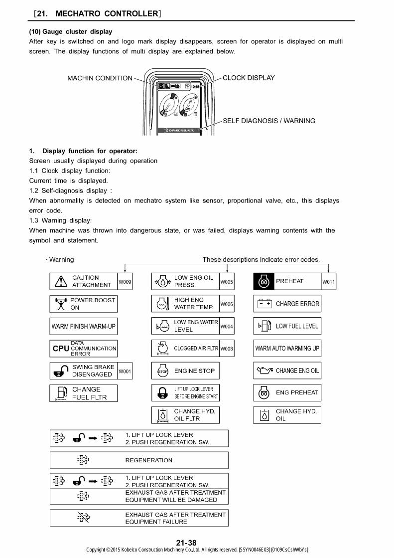
(10) Gauge cluster display
After key is switched on and logo mark display disappears, screen for operator is displayed on multi
screen. The display functions of multi display are explained below.
1. Display function for operator:
Screen usually displayed during operation
1.1 Clock display function:
Current time is displayed.
1.2 Self-diagnosis display :
When abnormality is detected on mechatro system like sensor, proportional valve, etc., this displays
error code.
1.3 Warning display:
When machine was thrown into dangerous state, or was failed, displays warning contents with the
symbol and statement.
[21. MECHATRO CONTROLLER]
21-38Copyright © 2015 Kobelco Construction Machinery Co.,Ltd. All rights reserved. [S5YN0046E03] [0109CsCshWbYs]

21
Error codes were stored as trouble history, and displayed on the monitor by the trouble history display
function.
1.4 Machine condition display :
Displays machine operating condition.
2. Display function for maintenance:
Displays remaining time up to replacement/change of following items.
(1) Engine oil (2) Fuel filter (3) Hydraulic oil filter (4) Hydraulic oil
3. Failure history display function:
Stores abnormality occurred on mechatro system in the past and displays in order of recent occurrence.
4. Mechatro adjustment display:
Displays procedure for adjustment of mechatro system like output adjustment and unload adjustment,
etc.
5. Service diagnosis display :
Displays information like pressure sensor sensed value, proportional valve command, etc. output by
mechatro controller
[21. MECHATRO CONTROLLER]
21-39Copyright © 2015 Kobelco Construction Machinery Co.,Ltd. All rights reserved. [S5YN0046E03] [0109CsCshWbYs]
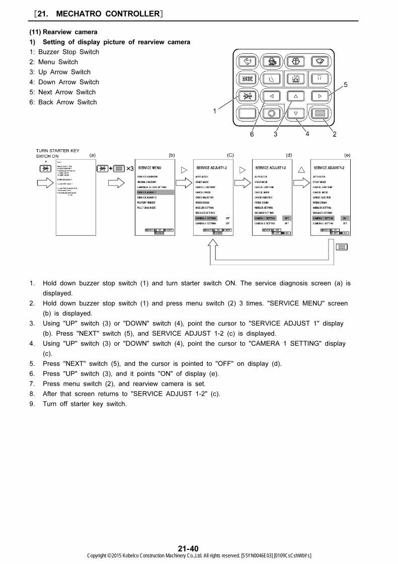
1: Buzzer Stop Switch
2: Menu Switch
3: Up Arrow Switch
4: Down Arrow Switch
5: Next Arrow Switch
6: Back Arrow Switch
(11) Rearview camera
1) Setting of display picture of rearview camera
1. Hold down buzzer stop switch (1) and turn starter switch ON. The service diagnosis screen (a) is
displayed.
2. Hold down buzzer stop switch (1) and press menu switch (2) 3 times. "SERVICE MENU" screen
(b) is displayed.
3. Using "UP" switch (3) or "DOWN" switch (4), point the cursor to "SERVICE ADJUST 1" display
(b). Press "NEXT" switch (5), and SERVICE ADJUST 1-2 (c) is displayed.
4. Using "UP" switch (3) or "DOWN" switch (4), point the cursor to "CAMERA 1 SETTING" display
(c).
5. Press "NEXT" switch (5), and the cursor is pointed to "OFF" on display (d).
6. Press "UP" switch (3), and it points "ON" of display (e).
7. Press menu switch (2), and rearview camera is set.
8. After that screen returns to "SERVICE ADJUST 1-2" (c).
9. Turn off starter key switch.
[21. MECHATRO CONTROLLER]
21-40Copyright © 2015 Kobelco Construction Machinery Co.,Ltd. All rights reserved. [S5YN0046E03] [0109CsCshWbYs]

No. Parts Parts/Normal condition Corrective action
1Power-supply box to Cab
harness
Make sure that connector between
power-supply box and cab harness is
connected.
Check connections.
2 Cable to Cab harnessMake sure that connector between cable
and cab harness is connected.Check connections.
3 Cable to Camera cableMake sure that connector between cable
and camera cable should is connected.Check connections.
4 Fuse & Relay boxMake sure that No. 30 fuse (5A) did not
melt down.Replace fuse.
5 Setting of camera
Make sure that CAMERA 1 SETTING in
SERVICE ADJUSTMENT1-2 screen is ON,
and CAMERA 2 and CAMERA 3
SETTING are OFF.
Check the setting.
No. Parts Parts/Normal condition Corrective action
1 Setting of camera
Make sure that CAMERA 1 SETTING in
SERVICE ADJUSTMENT1-2 screen is ON,
and CAMERA 2 and CAMERA 3
SETTING are OFF.
Check the setting.
21
2) Troubleshooting
1. Gauge cluster is powered on but picture does not appear and it shows blue screen.
2. Gauge cluster is powered on but picture does not appear and it shows fuel consumption graph or
logo.
[21. MECHATRO CONTROLLER]
21-41Copyright © 2015 Kobelco Construction Machinery Co.,Ltd. All rights reserved. [S5YN0046E03] [0109CsCshWbYs]
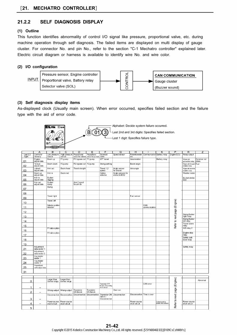
21.2.2 SELF DIAGNOSIS DISPLAY
(1) Outline
This function identifies abnormality of control I/O signal like pressure, proportional valve, etc. during
machine operation through self diagnosis. The failed items are displayed on multi display of gauge
cluster. For connector No. and pin No., refer to the section "C-1 Mechatro controller" explained later.
Electric circuit diagram or harness is available to identify wire No. and wire color.
(2) I/O configuration
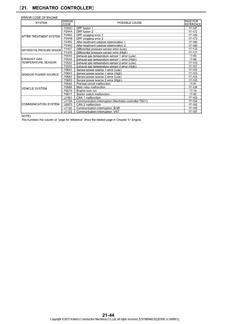
(3) Self diagnosis display items
As-displayed clock (Usually main screen). When error occurred, specifies failed section and the failure
type with the aid of error code.
[21. MECHATRO CONTROLLER]
21-42Copyright © 2015 Kobelco Construction Machinery Co.,Ltd. All rights reserved. [S5YN0046E03] [0109CsCshWbYs]

21
[21. MECHATRO CONTROLLER]
21-43Copyright © 2015 Kobelco Construction Machinery Co.,Ltd. All rights reserved. [S5YN0046E03] [0109CsCshWbYs]
[21. MECHATRO CONTROLLER]
21-44Copyright © 2015 Kobelco Construction Machinery Co.,Ltd. All rights reserved. [S5YN0046E03] [0109CsCshWbYs]
Screen gains by 1 in order.
(No.2-->No.3-->No.4-->...)
Screen loses by 1 in order.
(No.24-->No.23-->No.22-->...)
Service diagnosis number advances from No.1
to No.3, and then returns to No.1.
(No.1 No.2 No.3 No.1 ...)
Service diagnosis number advances from No.3
to No.1, and then returns to No.3.
(No.3-->No.2-->No.1-->No.3-->...)
21
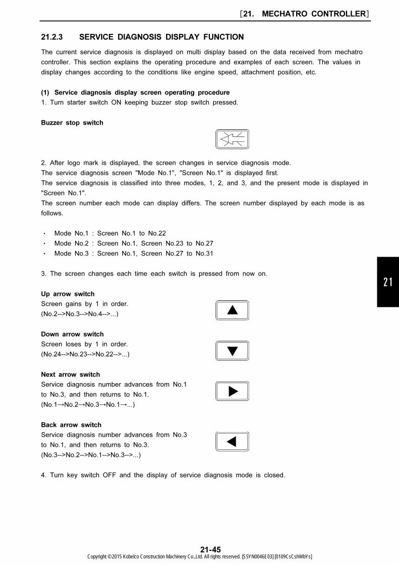
21.2.3 SERVICE DIAGNOSIS DISPLAY FUNCTION
The current service diagnosis is displayed on multi display based on the data received from mechatro
controller. This section explains the operating procedure and examples of each screen. The values in
display changes according to the conditions like engine speed, attachment position, etc.
(1) Service diagnosis display screen operating procedure
1. Turn starter switch ON keeping buzzer stop switch pressed.
Buzzer stop switch
2. After logo mark is displayed, the screen changes in service diagnosis mode.
The service diagnosis screen "Mode No.1", "Screen No.1" is displayed first.
The service diagnosis is classified into three modes, 1, 2, and 3, and the present mode is displayed in
"Screen No.1".
The screen number each mode can display differs. The screen number displayed by each mode is as
follows.
・ Mode No.1 : Screen No.1 to No.22
・ Mode No.2 : Screen No.1, Screen No.23 to No.27
・ Mode No.3 : Screen No.1, Screen No.27 to No.31
3. The screen changes each time each switch is pressed from now on.
Up arrow switch
Down arrow switch
Next arrow switch
Back arrow switch
4. Turn key switch OFF and the display of service diagnosis mode is closed.
[21. MECHATRO CONTROLLER]
21-45Copyright © 2015 Kobelco Construction Machinery Co.,Ltd. All rights reserved. [S5YN0046E03] [0109CsCshWbYs]

(2) Service diagnosis display screen (Example)
The service diagnosis display screen list is shown below. The conditions for display are H mode,
engine low speed and lever to neutral position.)
1) Service diagnosis mode No.1
[21. MECHATRO CONTROLLER]
21-46Copyright © 2015 Kobelco Construction Machinery Co.,Ltd. All rights reserved. [S5YN0046E03] [0109CsCshWbYs]

21
[21. MECHATRO CONTROLLER]
21-47Copyright © 2015 Kobelco Construction Machinery Co.,Ltd. All rights reserved. [S5YN0046E03] [0109CsCshWbYs]

[21. MECHATRO CONTROLLER]
21-48Copyright © 2015 Kobelco Construction Machinery Co.,Ltd. All rights reserved. [S5YN0046E03] [0109CsCshWbYs]
21
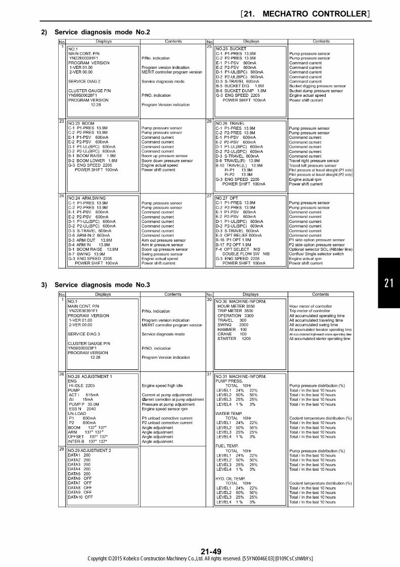
2) Service diagnosis mode No.2
3) Service diagnosis mode No.3
[21. MECHATRO CONTROLLER]
21-49Copyright © 2015 Kobelco Construction Machinery Co.,Ltd. All rights reserved. [S5YN0046E03] [0109CsCshWbYs]
Operation No.1: No operation
H mode Hi idle
Operation No.2: No operation
S mode Hi idle
No.24 ARM, SWING No.24 ARM, SWING
C-1
C-2
E-1
E-2
D-1
D-2
D-3
D-6
B-3
B-4
B-1
B-7
G-3
P1-PRES
P2-PRES
P1-PSV
P2-PSV
P1-UL(BPC)
P2-UL(BPC)
S-TRAVEL
ARM-IN-2
ARM OUT
ARM IN
BOOM RAISE
SWING
ENG SPEED
POWER SHIFT
0.2 to 1.5 M
0.2 to 1.5 M
350 mA
350 mA
750 mA
750 mA
350 mA
750 mA
0.0 M
0.0 M
0.0 M
0.0 M
1970 to 2030
0 mA
C-1
C-2
E-1
E-2
D-1
D-2
D-3
D-6
B-3
B-4
B-1
B-7
G-3
P1-PRES
P2-PRES
P1-PSV
P2-PSV
P1-UL(BPC)
P2-UL(BPC)
S-TRAVEL
ARM-IN-2
ARM OUT
ARM IN
BOOM RAISE
SWING
ENG SPEED
POWER SHIFT
0.2 to 1.5 M
0.2 to 1.5 M
350 mA
350 mA
750 mA
750 mA
350 mA
750 mA
0.0 M
0.0 M
0.0 M
0.0 M
1870 to 1930
0 mA
Operation No.3:
Boom up in full lever operation & relief
H mode Hi idle
Operation No.4:
Boom up in full lever operation & in operation
H mode Hi idle
No.23 BOOM No.23 BOOM
C-1
C-2
E-1
E-2
D-1
D-2
B-1
B-2
G-3
P1-PRES
P2-PRES
P1-PSV
P2-PSV
P1-UL(BPC)
P2-UL(BPC)
BOOM RAISE
BOOM LOWER
ENG SPEED
POWER SHIFT
33.0 to 35.8 M
33.0 to 35.8 M
415 to 525 mA
415 to 525 mA
360 mA
360 mA
3.0 M
0.0 M
1970 to 2030
0 mA
C-1
C-2
E-1
E-2
D-1
D-2
B-1
B-2
G-3
P1-PRES
P2-PRES
P1-PSV
P2-PSV
P1-UL(BPC)
P2-UL(BPC)
BOOM RAISE
BOOM LOWER
ENG SPEED
POWER SHIFT
11.0 to 16.0 M
11.0 to 16.0 M
560 to 750 mA
560 to 750 mA
360 mA
360 mA
3.0 M
0.0 M
1970 to 2030
0 mA
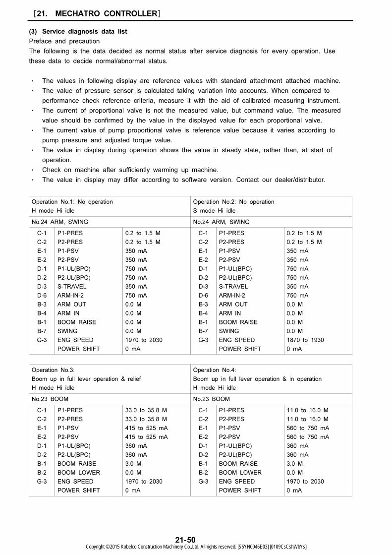
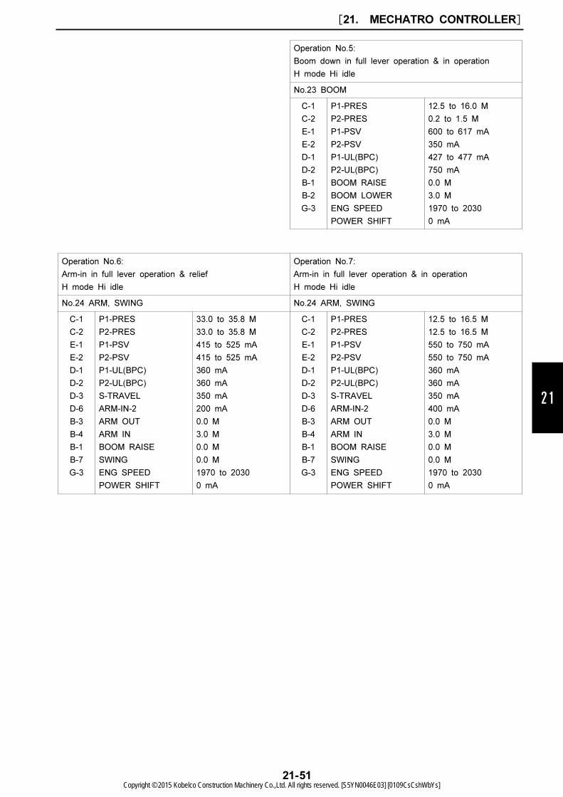
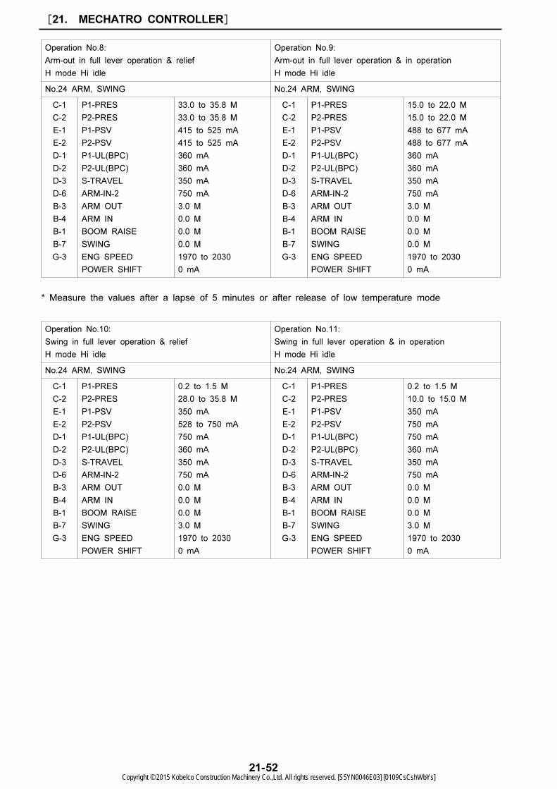
(3) Service diagnosis data list
Preface and precaution
The following is the data decided as normal status after service diagnosis for every operation. Use
these data to decide normal/abnormal status.
・ The values in following display are reference values with standard attachment attached machine.
・ The value of pressure sensor is calculated taking variation into accounts. When compared to
performance check reference criteria, measure it with the aid of calibrated measuring instrument.
・ The current of proportional valve is not the measured value, but command value. The measured
value should be confirmed by the value in the displayed value for each proportional valve.
・ The current value of pump proportional valve is reference value because it varies according to
pump pressure and adjusted torque value.
・ The value in display during operation shows the value in steady state, rather than, at start of
operation.
・ Check on machine after sufficiently warming up machine.
・ The value in display may differ according to software version. Contact our dealer/distributor.
[21. MECHATRO CONTROLLER]
21-50Copyright © 2015 Kobelco Construction Machinery Co.,Ltd. All rights reserved. [S5YN0046E03] [0109CsCshWbYs]
Operation No.5:
Boom down in full lever operation & in operation
H mode Hi idle
No.23 BOOM
C-1
C-2
E-1
E-2
D-1
D-2
B-1
B-2
G-3
P1-PRES
P2-PRES
P1-PSV
P2-PSV
P1-UL(BPC)
P2-UL(BPC)
BOOM RAISE
BOOM LOWER
ENG SPEED
POWER SHIFT
12.5 to 16.0 M
0.2 to 1.5 M
600 to 617 mA
350 mA
427 to 477 mA
750 mA
0.0 M
3.0 M
1970 to 2030
0 mA
Operation No.6:
Arm-in in full lever operation & relief
H mode Hi idle
Operation No.7:
Arm-in in full lever operation & in operation
H mode Hi idle
No.24 ARM, SWING No.24 ARM, SWING
C-1
C-2
E-1
E-2
D-1
D-2
D-3
D-6
B-3
B-4
B-1
B-7
G-3
P1-PRES
P2-PRES
P1-PSV
P2-PSV
P1-UL(BPC)
P2-UL(BPC)
S-TRAVEL
ARM-IN-2
ARM OUT
ARM IN
BOOM RAISE
SWING
ENG SPEED
POWER SHIFT
33.0 to 35.8 M
33.0 to 35.8 M
415 to 525 mA
415 to 525 mA
360 mA
360 mA
350 mA
200 mA
0.0 M
3.0 M
0.0 M
0.0 M
1970 to 2030
0 mA
C-1
C-2
E-1
E-2
D-1
D-2
D-3
D-6
B-3
B-4
B-1
B-7
G-3
P1-PRES
P2-PRES
P1-PSV
P2-PSV
P1-UL(BPC)
P2-UL(BPC)
S-TRAVEL
ARM-IN-2
ARM OUT
ARM IN
BOOM RAISE
SWING
ENG SPEED
POWER SHIFT
12.5 to 16.5 M
12.5 to 16.5 M
550 to 750 mA
550 to 750 mA
360 mA
360 mA
350 mA
400 mA
0.0 M
3.0 M
0.0 M
0.0 M
1970 to 2030
0 mA
21
[21. MECHATRO CONTROLLER]
21-51Copyright © 2015 Kobelco Construction Machinery Co.,Ltd. All rights reserved. [S5YN0046E03] [0109CsCshWbYs]
Operation No.8:
Arm-out in full lever operation & relief
H mode Hi idle
Operation No.9:
Arm-out in full lever operation & in operation
H mode Hi idle
No.24 ARM, SWING No.24 ARM, SWING
C-1
C-2
E-1
E-2
D-1
D-2
D-3
D-6
B-3
B-4
B-1
B-7
G-3
P1-PRES
P2-PRES
P1-PSV
P2-PSV
P1-UL(BPC)
P2-UL(BPC)
S-TRAVEL
ARM-IN-2
ARM OUT
ARM IN
BOOM RAISE
SWING
ENG SPEED
POWER SHIFT
33.0 to 35.8 M
33.0 to 35.8 M
415 to 525 mA
415 to 525 mA
360 mA
360 mA
350 mA
750 mA
3.0 M
0.0 M
0.0 M
0.0 M
1970 to 2030
0 mA
C-1
C-2
E-1
E-2
D-1
D-2
D-3
D-6
B-3
B-4
B-1
B-7
G-3
P1-PRES
P2-PRES
P1-PSV
P2-PSV
P1-UL(BPC)
P2-UL(BPC)
S-TRAVEL
ARM-IN-2
ARM OUT
ARM IN
BOOM RAISE
SWING
ENG SPEED
POWER SHIFT
15.0 to 22.0 M
15.0 to 22.0 M
488 to 677 mA
488 to 677 mA
360 mA
360 mA
350 mA
750 mA
3.0 M
0.0 M
0.0 M
0.0 M
1970 to 2030
0 mA
Operation No.10:
Swing in full lever operation & relief
H mode Hi idle
Operation No.11:
Swing in full lever operation & in operation
H mode Hi idle
No.24 ARM, SWING No.24 ARM, SWING
C-1
C-2
E-1
E-2
D-1
D-2
D-3
D-6
B-3
B-4
B-1
B-7
G-3
P1-PRES
P2-PRES
P1-PSV
P2-PSV
P1-UL(BPC)
P2-UL(BPC)
S-TRAVEL
ARM-IN-2
ARM OUT
ARM IN
BOOM RAISE
SWING
ENG SPEED
POWER SHIFT
0.2 to 1.5 M
28.0 to 35.8 M
350 mA
528 to 750 mA
750 mA
360 mA
350 mA
750 mA
0.0 M
0.0 M
0.0 M
3.0 M
1970 to 2030
0 mA
C-1
C-2
E-1
E-2
D-1
D-2
D-3
D-6
B-3
B-4
B-1
B-7
G-3
P1-PRES
P2-PRES
P1-PSV
P2-PSV
P1-UL(BPC)
P2-UL(BPC)
S-TRAVEL
ARM-IN-2
ARM OUT
ARM IN
BOOM RAISE
SWING
ENG SPEED
POWER SHIFT
0.2 to 1.5 M
10.0 to 15.0 M
350 mA
750 mA
750 mA
360 mA
350 mA
750 mA
0.0 M
0.0 M
0.0 M
3.0 M
1970 to 2030
0 mA
* Measure the values after a lapse of 5 minutes or after release of low temperature mode
[21. MECHATRO CONTROLLER]
21-52Copyright © 2015 Kobelco Construction Machinery Co.,Ltd. All rights reserved. [S5YN0046E03] [0109CsCshWbYs]

Operation No.12:
Bucket digging in full lever operation & relief
H mode Hi idle
Operation No.13:
Bucket digging in full lever operation & in operation
H mode Hi idle
No.25 BUCKET No.25 BUCKET
C-1
C-2
E-1
E-2
D-1
D-2
D-3
B-5
B-6
G-3
P1-PRES
P2-PRES
P1-PSV
P2-PSV
P1-UL(BPC)
P2-UL(BPC)
S-TRAVEL
BUCKET DIG
BUCKET DUMP
ENG SPEED
POWER SHIFT
33.0 to 35.8 M
0.2 to 1.5 M
525 to 650 mA
350 mA
360 mA
750 mA
350 mA
3.0 M
0.0 M
1970 to 2030
0 mA
C-1
C-2
E-1
E-2
D-1
D-2
D-3
B-5
B-6
G-3
P1-PRES
P2-PRES
P1-PSV
P2-PSV
P1-UL(BPC)
P2-UL(BPC)
S-TRAVEL
BUCKET DIG
BUCKET DUMP
ENG SPEED
POWER SHIFT
4.0 to 8.0 M
0.2 to 1.5 M
750 mA
350 mA
360 mA
750 mA
350 mA
3.0 M
0.0 M
1970 to 2030
0 mA
Operation No.14:
Bucket dump in full lever operation & relief
H mode Hi idle
Operation No.15:
Bucket dump in full lever operation & in operation
H mode Hi idle
No.25 BUCKET No.25 BUCKET
C-1
C-2
E-1
E-2
D-1
D-2
D-3
B-5
B-6
G-3
P1-PRES
P2-PRES
P1-PSV
P2-PSV
P1-UL(BPC)
P2-UL(BPC)
S-TRAVEL
BUCKET DIG
BUCKET DUMP
ENG SPEED
POWER SHIFT
33.0 to 35.8 M
0.2 to 1.5 M
435 to 550 mA
350 mA
360 mA
750 mA
350 mA
0.0 M
3.0 M
1970 to 2030
0 mA
C-1
C-2
E-1
E-2
D-1
D-2
D-3
B-5
B-6
G-3
P1-PRES
P2-PRES
P1-PSV
P2-PSV
P1-UL(BPC)
P2-UL(BPC)
S-TRAVEL
BUCKET DIG
BUCKET DUMP
ENG SPEED
POWER SHIFT
6.0 to 15.0 M
0.2 to 1.5 M
625 to 750 mA
350 to 750 mA
360 mA
750 mA
360 mA
0.0 M
3.0 M
1970 to 2030
0 mA
21
[21. MECHATRO CONTROLLER]
21-53Copyright © 2015 Kobelco Construction Machinery Co.,Ltd. All rights reserved. [S5YN0046E03] [0109CsCshWbYs]

Operation No.16:
P2 side option in full lever operation & relief
A mode Hi idle
Operation No.17:
P2 side option in full lever operation & relief
B mode Hi idle
No.27 OPT No.27 OPT
C-1
C-2
E-1
E-2
D-1
D-2
D-3
E-3
B-16
B-17
F-4
G-3
P1-PRES
P2-PRES
P1-PSV
P2-PSV
P1-UL(BPC)
P2-UL(BPC)
S-TRAVEL
OPT RELIEF
P1 OPT
P2 OPT
OPT SELECT
DOUBLE FLOW SW.
ENG SPEED
POWER SHIFT
22.5 to 26.0 M
22.5 to 26.0 M
459 to 584 mA
459 to 584 mA
360 mA
360 mA
720 mA
0 mA
0.0 M
2.0 to 2.6 M
NIB
---
1970 to 2030
0 mA
C-1
C-2
E-1
E-2
D-1
D-2
D-3
E-3
B-16
B-17
F-4
G-3
P1-PRES
P2-PRES
P1-PSV
P2-PSV
P1-UL(BPC)
P2-UL(BPC)
S-TRAVEL
OPT RELIEF
P1 OPT
P2 OPT
OPT SELECT
DOUBLE FLOW SW.
ENG SPEED
POWER SHIFT
0.2 to 1.5 M
22.5 to 26.0 M
500 mA
665 to 750 mA
750 mA
360 mA
350 mA
0 mA
0.0 M
2.0 to 2.6 M
BRK
---
1970 to 2030
0 mA
* Conflux switch is OFF. Relief set pressure is
value of shipping.
Operation No.18:
Travel right in full lever operation & travel idling
H mode Hi idle
Operation No.19 :
Travel left in full lever operation & travel idling
H mode Hi idle
No.26 TRAVEL No.26 TRAVEL
C-1
C-2
E-1
E-2
D-1
D-2
D-3
B-9
B-10
G-3
P1-PRES
P2-PRES
P1-PSV
P2-PSV
P1-UL(BPC)
P2-UL(BPC)
S-TRAVEL
TRAVEL(R)
TRAVEL(L)
Pi-P1
Pi-P2
ENG SPEED
POWER SHIFT
5.0 to 12.0 M
0.2 to 1.5 M
750 mA
350 mA
360 mA
750 mA
350 mA
2.0 to 2.5 M
0.0 M
0.0 M
0.0 M
1970 to 2030
0 mA
C-1
C-2
E-1
E-2
D-1
D-2
D-3
B-9
B-10
G-3
P1-PRES
P2-PRES
P1-PSV
P2-PSV
P1-UL(BPC)
P2-UL(BPC)
S-TRAVEL
TRAVEL(R)
TRAVEL(L)
Pi-P1
Pi-P2
ENG SPEED
POWER SHIFT
0.2 to 1.5 M
5.0 to 12.0 M
350 mA
750 mA
750 mA
360 mA
350 mA
0.0 M
2.0 to 2.5 M
0.0 M
0.0 M
1970 to 2030
0 mA
* Conflux switch is ON. Relief set pressure is
value of shipping.
[21. MECHATRO CONTROLLER]
21-54Copyright © 2015 Kobelco Construction Machinery Co.,Ltd. All rights reserved. [S5YN0046E03] [0109CsCshWbYs]
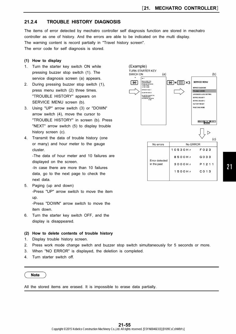
1. Turn the starter key switch ON while
pressing buzzer stop switch (1). The
service diagnosis screen (a) appears.
2. During pressing buzzer stop switch (1),
press menu switch (2) three times.
"TROUBLE HISTORY" appears on
SERVICE MENU screen (b).
3. Using "UP" arrow switch (3) or "DOWN"
arrow switch (4), move the cursor to
"TROUBLE HISTORY" in screen (b). Press
"NEXT" arrow switch (5) to display trouble
history screen (c).
4. Transmit the data of trouble history (one
or many) and hour meter to the gauge
cluster.
-The data of hour meter and 10 failures are
displayed on the screen.
-In case there are more than 10 failures
data, go to the next page to check the
next data.
5. Paging (up and down)
-Press "UP" arrow switch to move the item
up.
-Press "DOWN" arrow switch to move the
item down.
6. Turn the starter key switch OFF, and the
display is disappeared.
21
21.2.4 TROUBLE HISTORY DIAGNOSIS
The items of error detected by mechatro controller self diagnosis function are stored in mechatro
controller as one of history. And the errors are able to be indicated on the multi display.
The warning content is record partially in "Travel history screen".
The error code for self diagnosis is stored.
(1) How to display
(2) How to delete contents of trouble history
1. Display trouble history screen.
2. Press work mode change switch and buzzer stop switch simultaneously for 5 seconds or more.
3. When "NO ERROR" is displayed, the deletion is completed.
4. Turn starter switch off.
All the stored items are erased. It is impossible to erase data partially.
[21. MECHATRO CONTROLLER]
21-55Copyright © 2015 Kobelco Construction Machinery Co.,Ltd. All rights reserved. [S5YN0046E03] [0109CsCshWbYs]
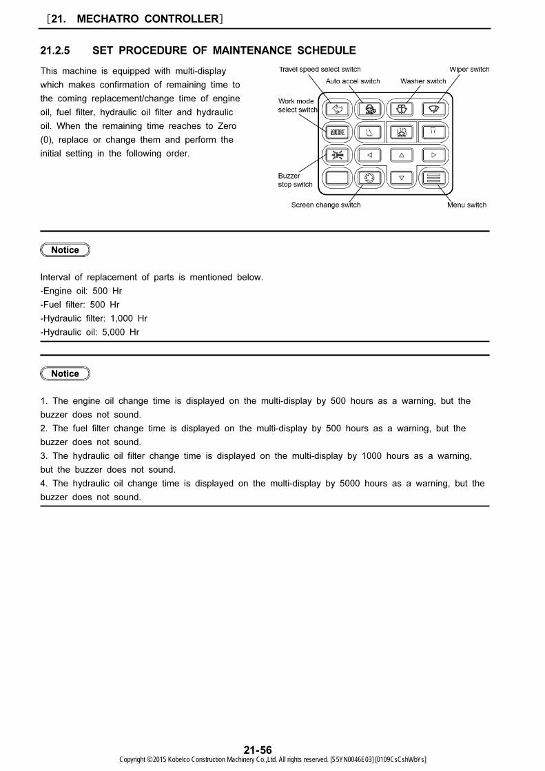
This machine is equipped with multi-display
which makes confirmation of remaining time to
the coming replacement/change time of engine
oil, fuel filter, hydraulic oil filter and hydraulic
oil. When the remaining time reaches to Zero
(0), replace or change them and perform the
initial setting in the following order.
21.2.5 SET PROCEDURE OF MAINTENANCE SCHEDULE
Interval of replacement of parts is mentioned below.
-Engine oil: 500 Hr
-Fuel filter: 500 Hr
-Hydraulic filter: 1,000 Hr
-Hydraulic oil: 5,000 Hr
1. The engine oil change time is displayed on the multi-display by 500 hours as a warning, but the
buzzer does not sound.
2. The fuel filter change time is displayed on the multi-display by 500 hours as a warning, but the
buzzer does not sound.
3. The hydraulic oil filter change time is displayed on the multi-display by 1000 hours as a warning,
but the buzzer does not sound.
4. The hydraulic oil change time is displayed on the multi-display by 5000 hours as a warning, but the
buzzer does not sound.
[21. MECHATRO CONTROLLER]
21-56Copyright © 2015 Kobelco Construction Machinery Co.,Ltd. All rights reserved. [S5YN0046E03] [0109CsCshWbYs]
21
[21. MECHATRO CONTROLLER]
21-57Copyright © 2015 Kobelco Construction Machinery Co.,Ltd. All rights reserved. [S5YN0046E03] [0109CsCshWbYs]
1: Screen Change Switch
2: Buzzer Stop Switch
3: Work Mode Select Switch
4: Washer Switch
5: Wiper Switch
6: Travel Speed Select Switch
7: Auto Acceleration Switch
8: Menu Switch
9: Arrow Switch
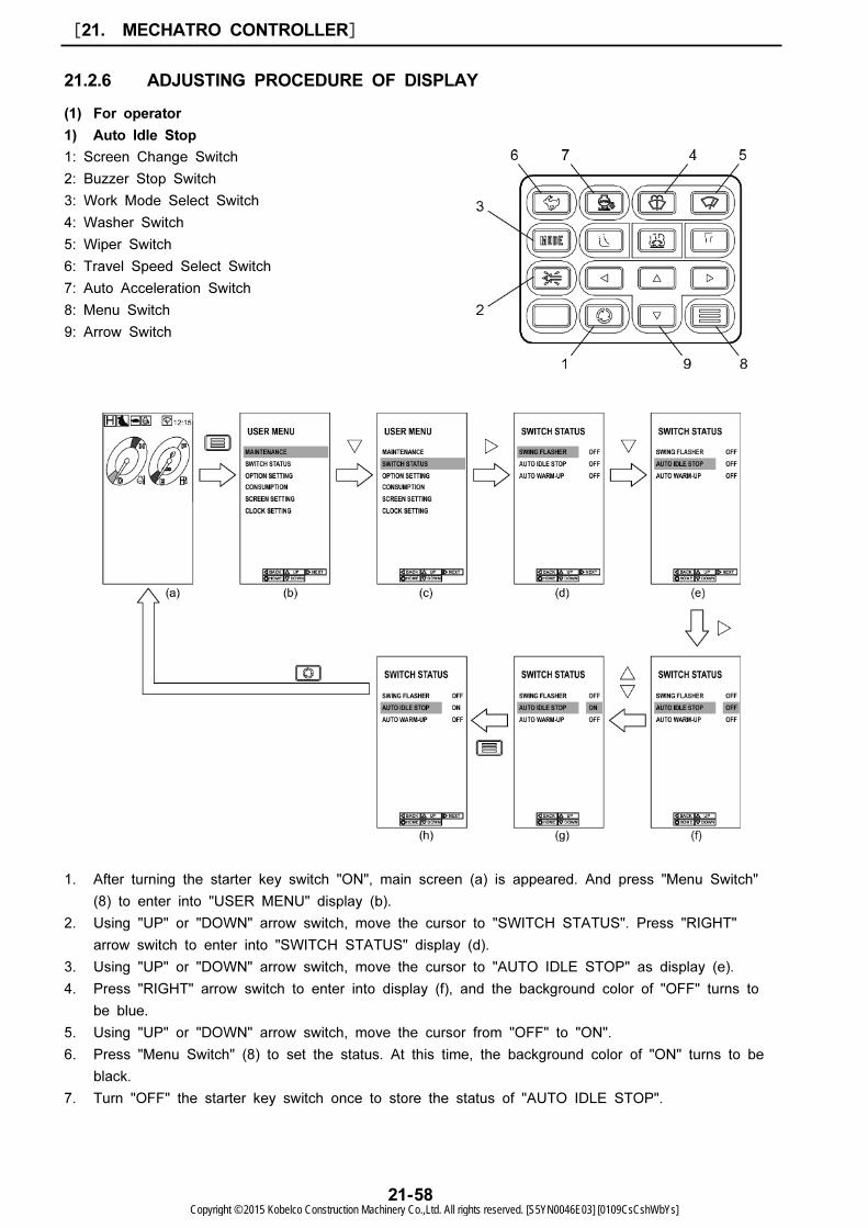
21.2.6 ADJUSTING PROCEDURE OF DISPLAY
(1) For operator
1) Auto Idle Stop
1. After turning the starter key switch "ON", main screen (a) is appeared. And press "Menu Switch"
(8) to enter into "USER MENU" display (b).
2. Using "UP" or "DOWN" arrow switch, move the cursor to "SWITCH STATUS". Press "RIGHT"
arrow switch to enter into "SWITCH STATUS" display (d).
3. Using "UP" or "DOWN" arrow switch, move the cursor to "AUTO IDLE STOP" as display (e).
4. Press "RIGHT" arrow switch to enter into display (f), and the background color of "OFF" turns to
be blue.
5. Using "UP" or "DOWN" arrow switch, move the cursor from "OFF" to "ON".
6. Press "Menu Switch" (8) to set the status. At this time, the background color of "ON" turns to be
black.
7. Turn "OFF" the starter key switch once to store the status of "AUTO IDLE STOP".
[21. MECHATRO CONTROLLER]
21-58Copyright © 2015 Kobelco Construction Machinery Co.,Ltd. All rights reserved. [S5YN0046E03] [0109CsCshWbYs]
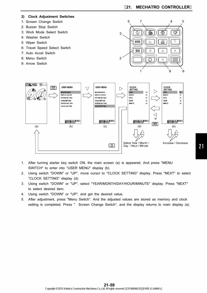
1: Screen Change Switch
2: Buzzer Stop Switch
3: Work Mode Select Switch
4: Washer Switch
5: Wiper Switch
6: Travel Speed Select Switch
7: Auto Accel Switch
8: Menu Switch
9: Arrow Switch
21
2) Clock Adjustment Switches
1. After turning starter key switch ON, the main screen (a) is appeared. And press "MENU
SWITCH" to enter into "USER MENU" display (b).
2. Using switch "DOWN" or "UP", move cursor to "CLOCK SETTING" display. Press "NEXT" to select
"CLOCK SETTING" display (d).
3. Using switch "DOWN" or "UP", select "YEAR/MONTH/DAY/HOUR/MINUTE" display. Press "NEXT"
to select desired item.
4. Using switch "DOWN" or "UP", and get the desired value.
5. After adjustment, press "Menu Switch". And the adjusted values are stored as memory and clock
setting is completed. Press " Screen Change Switch", and the display returns to main display (a).
[21. MECHATRO CONTROLLER]
21-59Copyright © 2015 Kobelco Construction Machinery Co.,Ltd. All rights reserved. [S5YN0046E03] [0109CsCshWbYs]
1: Screen Change Switch
2: Buzzer Stop Switch
3: Work Mode Select Switch
4: Washer Switch
5: Wiper Switch
6: Travel Speed Select Switch
7: Auto Accel Switch
8: Menu Switch
9: Arrow Switch
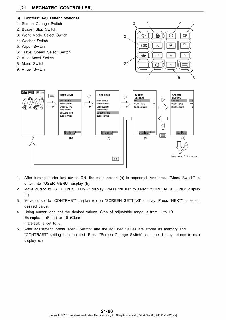
3) Contrast Adjustment Switches
1. After turning starter key switch ON, the main screen (a) is appeared. And press "Menu Switch" to
enter into "USER MENU" display (b).
2. Move cursor to "SCREEN SETTING" display. Press "NEXT" to select "SCREEN SETTING" display
(d).
3. Move cursor to "CONTRAST" display (d) on "SCREEN SETTING" display. Press "NEXT" to select
desired value.
4. Using cursor, and get the desired values. Step of adjustable range is from 1 to 10.
Example: 1 (Faint) to 10 (Clear)
* Default is set to 5.
5. After adjustment, press "Menu Switch" and the adjusted values are stored as memory and
"CONTRAST" setting is completed. Press "Screen Change Switch", and the display returns to main
display (a).
[21. MECHATRO CONTROLLER]
21-60Copyright © 2015 Kobelco Construction Machinery Co.,Ltd. All rights reserved. [S5YN0046E03] [0109CsCshWbYs]
1: Screen Change Switch
2: Buzzer Stop Switch
3: Work Mode Select Switch
4: Washer Switch
5: Wiper Switch
6: Travel Speed Select Switch
7: Auto Acceleration Switch
8: Menu Switch
9: Arrow Switch
21
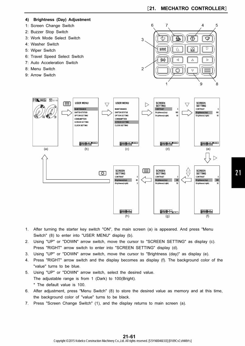
4) Brightness (Day) Adjustment
1. After turning the starter key switch "ON", the main screen (a) is appeared. And press "Menu
Switch" (8) to enter into "USER MENU" display (b).
2. Using "UP" or "DOWN" arrow switch, move the cursor to "SCREEN SETTING" as display (c).
Press "RIGHT" arrow switch to enter into "SCREEN SETTING" display (d).
3. Using "UP" or "DOWN" arrow switch, move the cursor to "Brightness (day)" as display (e).
4. Press "RIGHT" arrow switch and the display becomes as display (f). The background color of the
"value" turns to be blue.
5. Using "UP" or "DOWN" arrow switch, select the desired value.
The adjustable range is from 1 (Dark) to 100(Bright).
* The default value is 100.
6. After adjustment, press "Menu Switch" (8) to store the desired value as memory and at this time,
the background color of "value" turns to be black.
7. Press "Screen Change Switch" (1), and the display returns to main screen (a).
[21. MECHATRO CONTROLLER]
21-61Copyright © 2015 Kobelco Construction Machinery Co.,Ltd. All rights reserved. [S5YN0046E03] [0109CsCshWbYs]
1: Screen Change Switch
2: Buzzer Stop Switch
3: Work Mode Select Switch
4: Washer Switch
5: Wiper Switch
6: Travel Speed Select Switch
7: Auto Acceleration Switch
8: Menu Switch
9: Arrow Switch
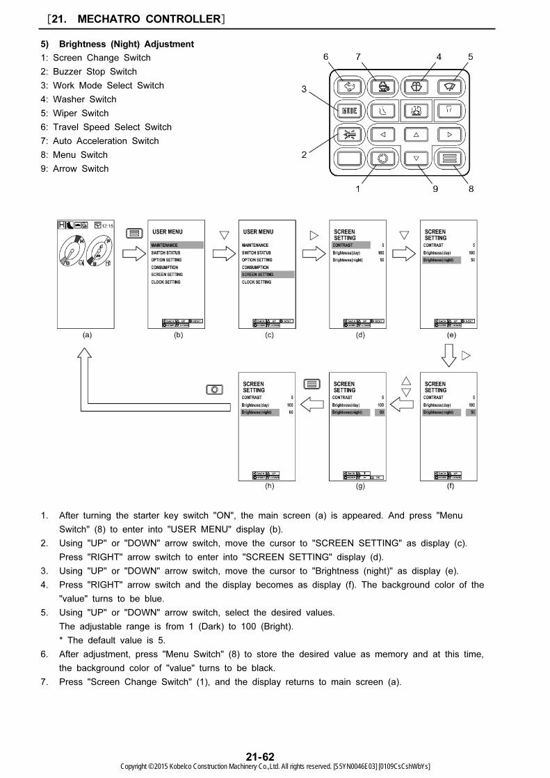
5) Brightness (Night) Adjustment
1. After turning the starter key switch "ON", the main screen (a) is appeared. And press "Menu
Switch" (8) to enter into "USER MENU" display (b).
2. Using "UP" or "DOWN" arrow switch, move the cursor to "SCREEN SETTING" as display (c).
Press "RIGHT" arrow switch to enter into "SCREEN SETTING" display (d).
3. Using "UP" or "DOWN" arrow switch, move the cursor to "Brightness (night)" as display (e).
4. Press "RIGHT" arrow switch and the display becomes as display (f). The background color of the
"value" turns to be blue.
5. Using "UP" or "DOWN" arrow switch, select the desired values.
The adjustable range is from 1 (Dark) to 100 (Bright).
* The default value is 5.
6. After adjustment, press "Menu Switch" (8) to store the desired value as memory and at this time,
the background color of "value" turns to be black.
7. Press "Screen Change Switch" (1), and the display returns to main screen (a).
[21. MECHATRO CONTROLLER]
21-62Copyright © 2015 Kobelco Construction Machinery Co.,Ltd. All rights reserved. [S5YN0046E03] [0109CsCshWbYs]

Item CONTENTS
Language Language selection
Rise-up wiper Wiper control change (When cab is changed)
Idle stop ON/OFF of auto idle stop (ON/OFF of adjustment for user) and time adjust
P1 option pressure sensor ON/OFF of self diagnosis for P1 option pressure sensor
P2 option pressure sensor ON/OFF of self diagnosis for P2 option pressure sensor
Swing alarm ON/OFF of swing alarm (ON/OFF of adjustment for user)
Left pedal for rotation of
option attachment
Does left rotation pedal use?
(Unload valve does not actuate because P4 pump is equipped in EU.)
Setting of optional
equipment
Optional flow rate limitation, relief pressure limitation, combination of return selector
adjustment.
Engine speed ON/OFF of engine rpm display
Auto acceleration Adjustment the type of the engine speed of auto deceleration runs up abruptly.
Change of starter mode Change of start mode
Low temperature mode
forcible release
Low temperature mode release
Pressure release For pressure release
Camera 1 setting ON/OFF of rearview camera 1 display
Camera 2 setting ON/OFF of rearview camera 2 display
Camera 3 setting ON/OFF of rearview camera 3 display
Fuel efficiency graph ON/OFF of fuel efficiency graph display
Logo setting ON/OFF of company logo display
21
(2) Function for service
Following items are provided for adjustment of service function.
[21. MECHATRO CONTROLLER]
21-63Copyright © 2015 Kobelco Construction Machinery Co.,Ltd. All rights reserved. [S5YN0046E03] [0109CsCshWbYs]
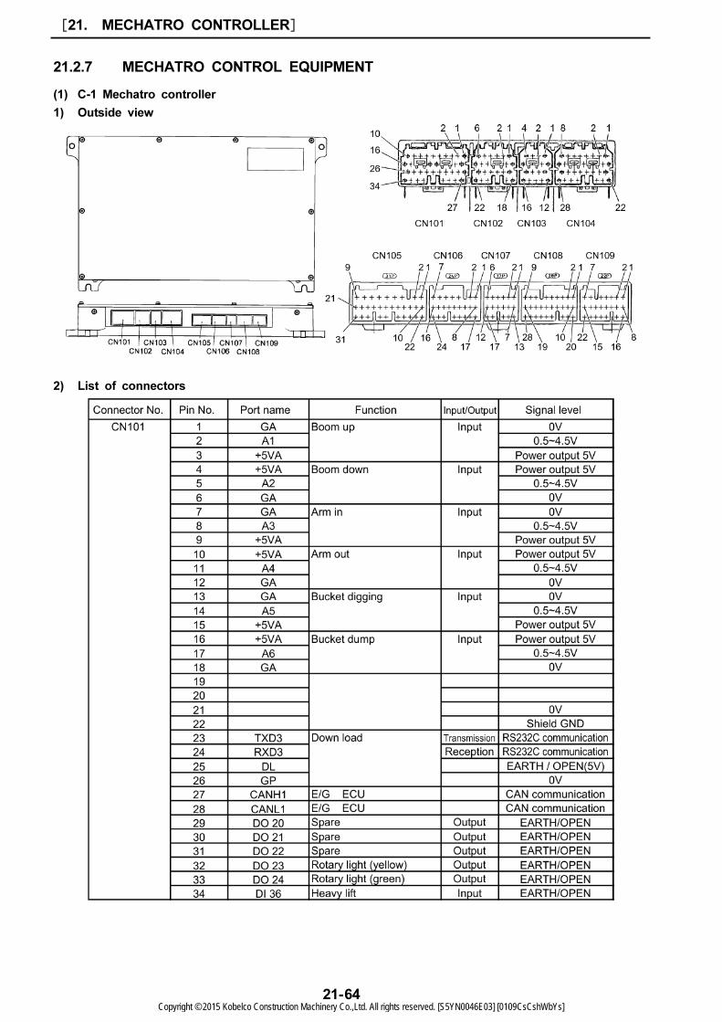
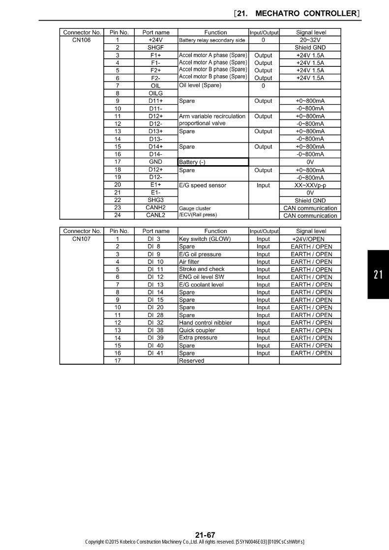
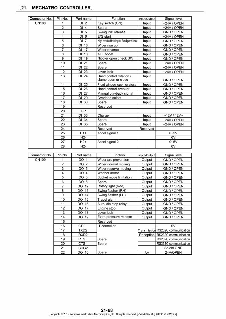
21.2.7 MECHATRO CONTROL EQUIPMENT
(1) C-1 Mechatro controller
1) Outside view
2) List of connectors
[21. MECHATRO CONTROLLER]
21-64Copyright © 2015 Kobelco Construction Machinery Co.,Ltd. All rights reserved. [S5YN0046E03] [0109CsCshWbYs]

21
[21. MECHATRO CONTROLLER]
21-65Copyright © 2015 Kobelco Construction Machinery Co.,Ltd. All rights reserved. [S5YN0046E03] [0109CsCshWbYs]

[21. MECHATRO CONTROLLER]
21-66Copyright © 2015 Kobelco Construction Machinery Co.,Ltd. All rights reserved. [S5YN0046E03] [0109CsCshWbYs]
21
[21. MECHATRO CONTROLLER]
21-67Copyright © 2015 Kobelco Construction Machinery Co.,Ltd. All rights reserved. [S5YN0046E03] [0109CsCshWbYs]
[21. MECHATRO CONTROLLER]
21-68Copyright © 2015 Kobelco Construction Machinery Co.,Ltd. All rights reserved. [S5YN0046E03] [0109CsCshWbYs]
No. Item name Wire color No. Item name Wire color
1 Reserved - 5 Source (+24V) White
2 Reserved - 6 GND Black
3 Reserved - 7 Source (+24V) White
4 Reserved - 8 Reserved -
No. Item name Wire color No. Item name Wire color
1 Reserved - 7 Reserved -
2 Reserved - 8 Reserved -
3 Reserved - 9 Reserved -
4 Rearview camera video signal White 10 GND Black
5 Reserved - 11 Reserved -
6
Mechatro-controller -->
Gauge cluster (CAN
communication)
Red 12
Gauge cluster -->
Mechatro-controller (CAN
communication)
White
21
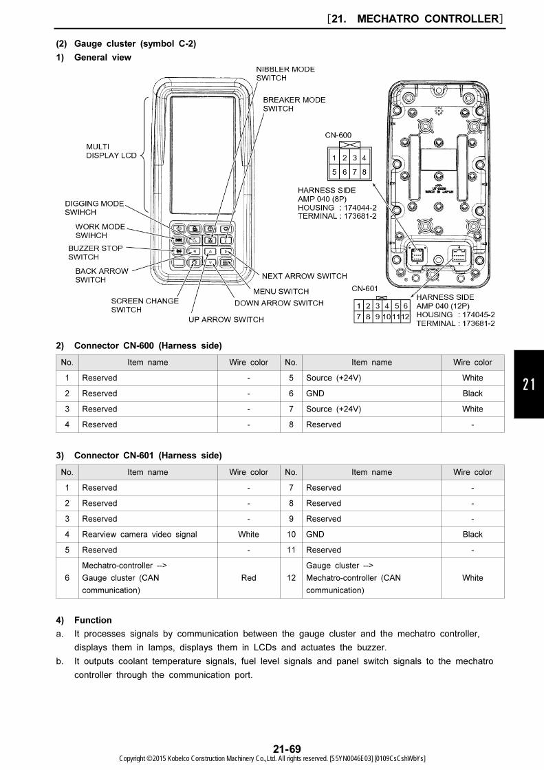
(2) Gauge cluster (symbol C-2)
1) General view
2) Connector CN-600 (Harness side)
3) Connector CN-601 (Harness side)
4) Function
a. It processes signals by communication between the gauge cluster and the mechatro controller,
displays them in lamps, displays them in LCDs and actuates the buzzer.
b. It outputs coolant temperature signals, fuel level signals and panel switch signals to the mechatro
controller through the communication port.
[21. MECHATRO CONTROLLER]
21-69Copyright © 2015 Kobelco Construction Machinery Co.,Ltd. All rights reserved. [S5YN0046E03] [0109CsCshWbYs]
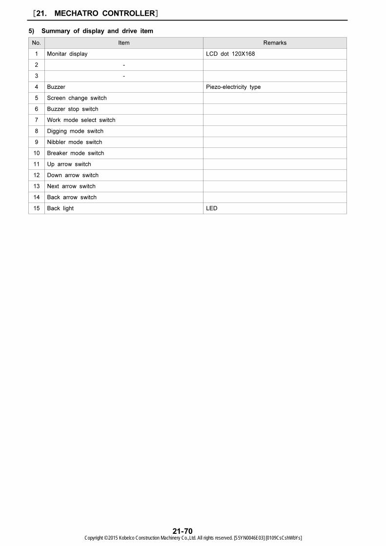
No. Item Remarks
1 Monitar display LCD dot 120X168
2 -
3 -
4 Buzzer Piezo-electricity type
5 Screen change switch
6 Buzzer stop switch
7 Work mode select switch
8 Digging mode switch
9 Nibbler mode switch
10 Breaker mode switch
11 Up arrow switch
12 Down arrow switch
13 Next arrow switch
14 Back arrow switch
15 Back light LED
5) Summary of display and drive item
[21. MECHATRO CONTROLLER]
21-70Copyright © 2015 Kobelco Construction Machinery Co.,Ltd. All rights reserved. [S5YN0046E03] [0109CsCshWbYs]
21
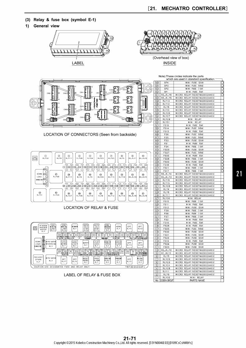
(3) Relay & fuse box (symbol E-1)
1) General view
[21. MECHATRO CONTROLLER]
21-71Copyright © 2015 Kobelco Construction Machinery Co.,Ltd. All rights reserved. [S5YN0046E03] [0109CsCshWbYs]
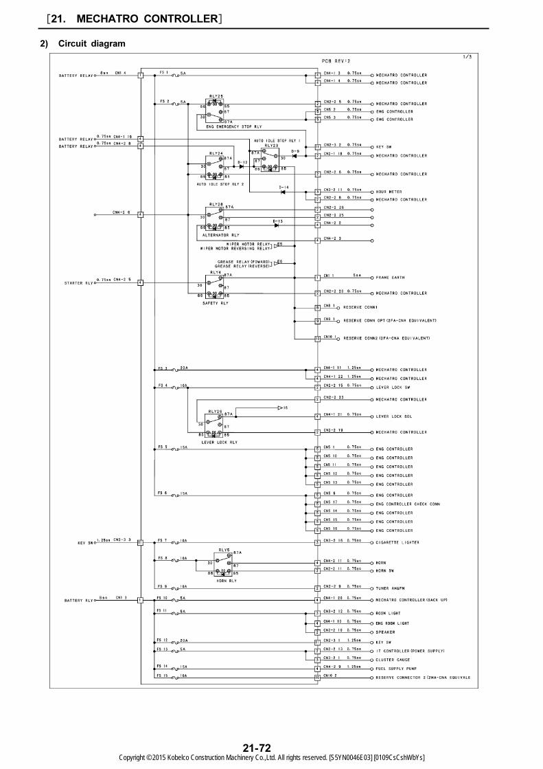
2) Circuit diagram
[21. MECHATRO CONTROLLER]
21-72Copyright © 2015 Kobelco Construction Machinery Co.,Ltd. All rights reserved. [S5YN0046E03] [0109CsCshWbYs]
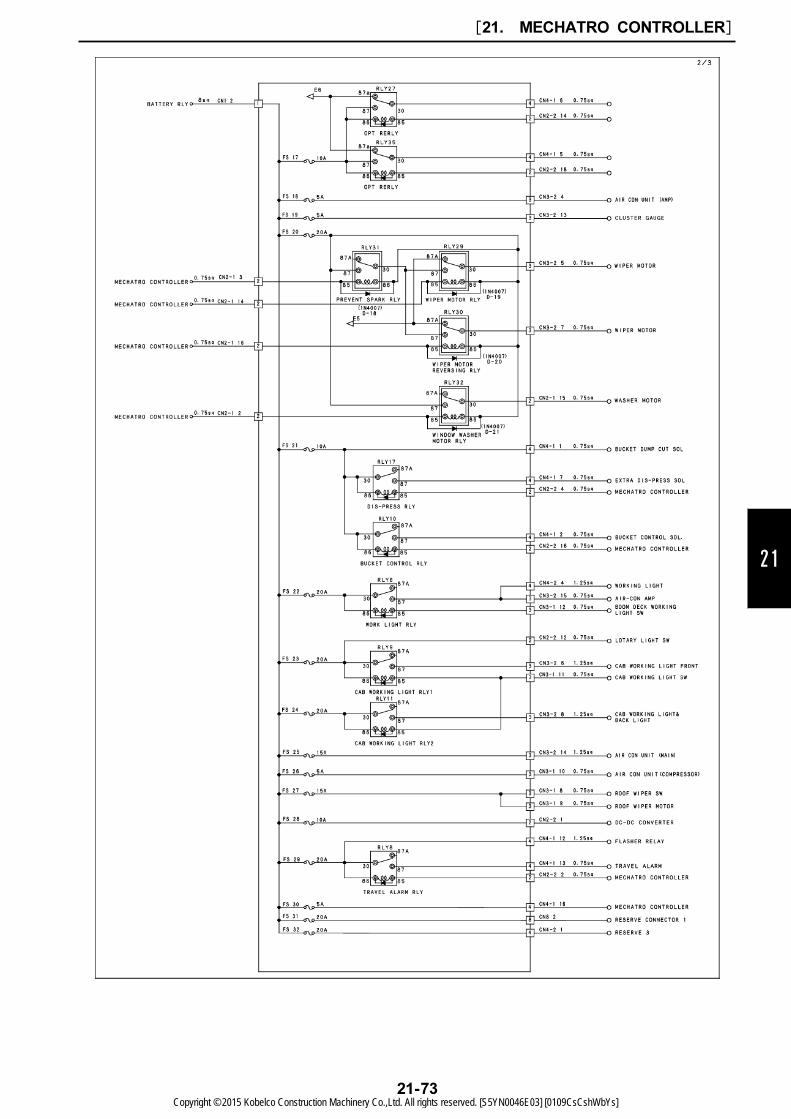
21
[21. MECHATRO CONTROLLER]
21-73Copyright © 2015 Kobelco Construction Machinery Co.,Ltd. All rights reserved. [S5YN0046E03] [0109CsCshWbYs]
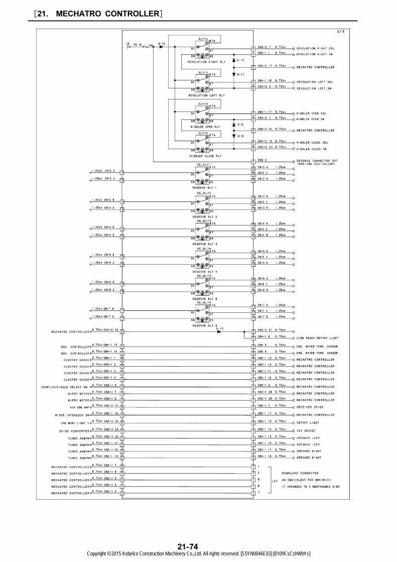
[21. MECHATRO CONTROLLER]
21-74Copyright © 2015 Kobelco Construction Machinery Co.,Ltd. All rights reserved. [S5YN0046E03] [0109CsCshWbYs]

21
(4) High pressure sensor: LS52S00015P1
(5) Low pressure sensor: LC52S00019P1
[21. MECHATRO CONTROLLER]
21-75Copyright © 2015 Kobelco Construction Machinery Co.,Ltd. All rights reserved. [S5YN0046E03] [0109CsCshWbYs]
[21. MECHATRO CONTROLLER]
21-76Copyright © 2015 Kobelco Construction Machinery Co.,Ltd. All rights reserved. [S5YN0046E03] [0109CsCshWbYs]
22
22. HYDRAULIC SYSTEM
[22. HYDRAULIC SYSTEM]
22-1
Book Code No. S5YN2246E02
TABLE OF CONTENTS
22.1 SUMMARY ………………………………………………………………………………………………………22-322.2 HYDRAULIC CIRCUITS AND COMPONENTS ……………………………………………………………22-422.3 COLOR CODING STANDARD FOR HYDRAULIC CIRCUITS …………………………………………22-822.4 NEUTRAL CIRCUIT ……………………………………………………………………………………………22-822.5 TRAVEL CIRCUIT ………………………………………………………………………………………………22-1022.6 BUCKET CIRCUIT………………………………………………………………………………………………22-1222.7 BOOM CIRCUIT…………………………………………………………………………………………………22-1422.8 SWING CIRCUIT ………………………………………………………………………………………………22-1822.9 ARM CIRCUIT …………………………………………………………………………………………………22-2022.10 COMBINED CIRCUIT …………………………………………………………………………………………22-2622.11 PRESSURE DRAINING ………………………………………………………………………………………22-30
Copyright © 2015 Kobelco Construction Machinery Co.,Ltd. All rights reserved. [S5YN0046E03] [0109CsCshWbYs]

Issue Date of Issue Applicable Machines Remarks
First edition June, 2013 SK210LC-9 : YQ13-10001~S5YN2246E01
(NA)
Revision October, 2013 SK210LC-9 : YQ13-10001~S5YN2246E02
(North America / Europe)
[22. HYDRAULIC SYSTEM]
22-2Copyright © 2015 Kobelco Construction Machinery Co.,Ltd. All rights reserved. [S5YN0046E03] [0109CsCshWbYs]

22
22.1 SUMMARY
22.1.1 FUNCTION AND FEATURES OF HYDRAULIC CIRCUIT
The hydraulic circuits are built up with the following functions and features in order to achieve easy
operability, safety, mass volume handling and low fuel consumption.
[22. HYDRAULIC SYSTEM]
22-3Copyright © 2015 Kobelco Construction Machinery Co.,Ltd. All rights reserved. [S5YN0046E03] [0109CsCshWbYs]
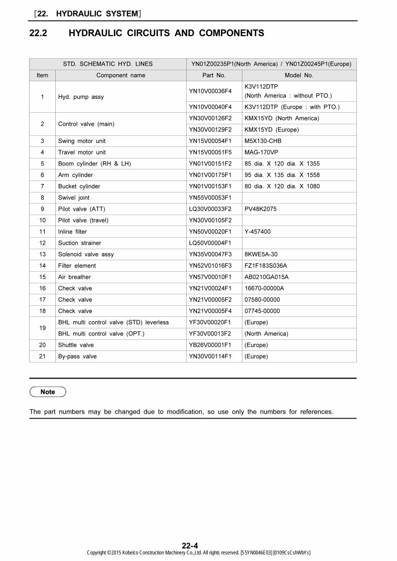
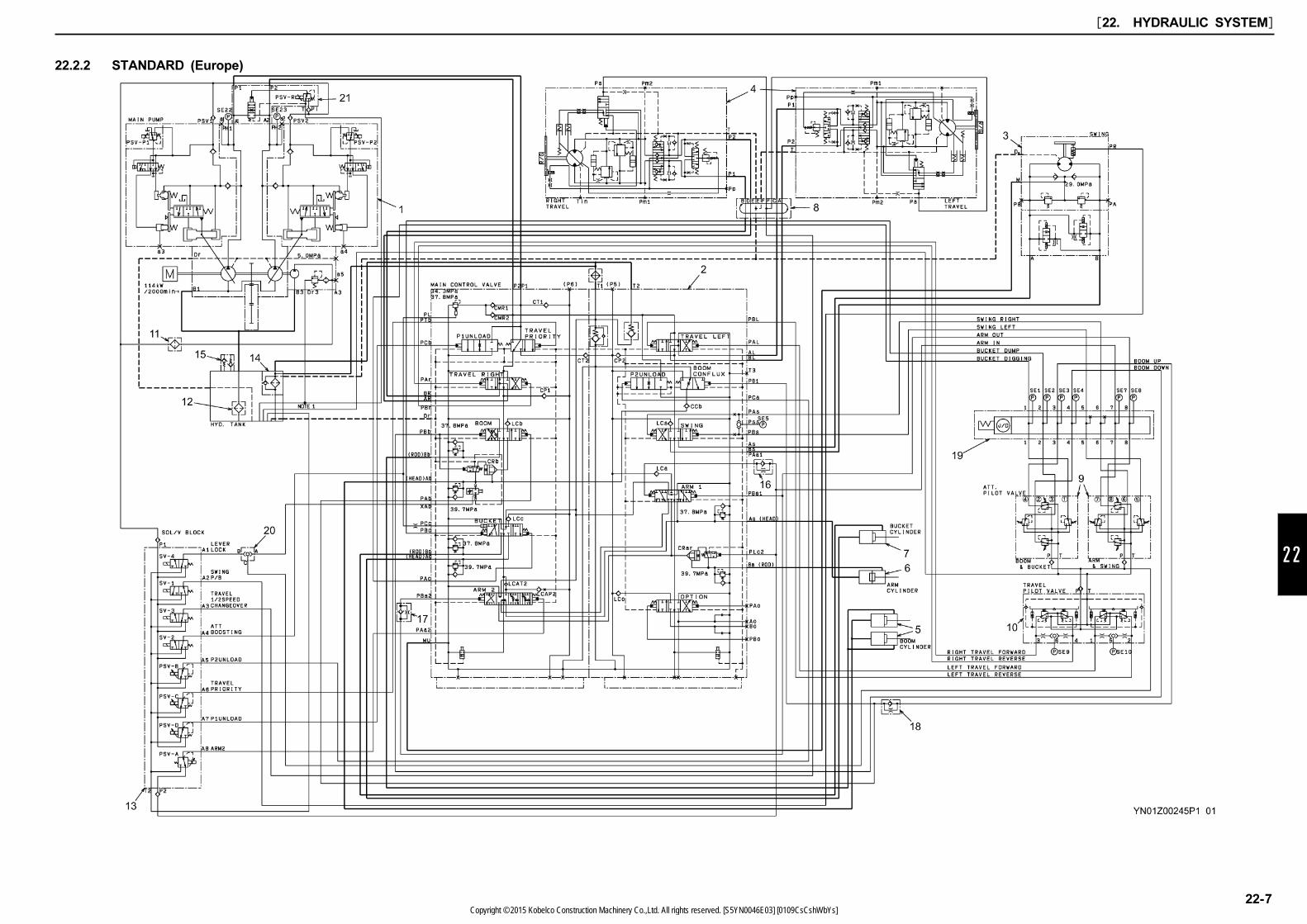
STD. SCHEMATIC HYD. LINES YN01Z00235P1(North America) / YN01Z00245P1(Europe)
Item Component name Part No. Model No.
1 Hyd. pump assyYN10V00036F4
K3V112DTP
(North America : without PTO.)
YN10V00040F4 K3V112DTP (Europe : with PTO.)
2 Control valve (main)YN30V00126F2 KMX15YD (North America)
YN30V00129F2 KMX15YD (Europe)
3 Swing motor unit YN15V00054F1 M5X130-CHB
4 Travel motor unit YN15V00051F5 MAG-170VP
5 Boom cylinder (RH & LH) YN01V00151F2 85 dia. X 120 dia. X 1355
6 Arm cylinder YN01V00175F1 95 dia. X 135 dia. X 1558
7 Bucket cylinder YN01V00153F1 80 dia. X 120 dia. X 1080
8 Swivel joint YN55V00053F1
9 Pilot valve (ATT) LQ30V00033F2 PV48K2075
10 Pilot valve (travel) YN30V00105F2
11 Inline filter YN50V00020F1 Y-457400
12 Suction strainer LQ50V00004F1
13 Solenoid valve assy YN35V00047F3 8KWE5A-30
14 Filter element YN52V01016F3 FZ1F183S036A
15 Air breather YN57V00010F1 AB0210GA015A
16 Check valve YN21V00024F1 16670-00000A
17 Check valve YN21V00005F2 07580-00000
18 Check valve YN21V00005F4 07745-00000
19BHL multi control valve (STD) leverless YF30V00020F1 (Europe)
BHL multi control valve (OPT.) YF30V00013F2 (North America)
20 Shuttle valve YB26V00001F1 (Europe)
21 By-pass valve YN30V00114F1 (Europe)
22.2 HYDRAULIC CIRCUITS AND COMPONENTS
The part numbers may be changed due to modification, so use only the numbers for references.
[22. HYDRAULIC SYSTEM]
22-4Copyright © 2015 Kobelco Construction Machinery Co.,Ltd. All rights reserved. [S5YN0046E03] [0109CsCshWbYs]

22
22.2.1 STANDARD (North America)
[22. HYDRAULIC SYSTEM]
22-5Copyright © 2015 Kobelco Construction Machinery Co.,Ltd. All rights reserved. [S5YN0046E03] [0109CsCshWbYs]

[22. HYDRAULIC SYSTEM]
22-6Copyright © 2015 Kobelco Construction Machinery Co.,Ltd. All rights reserved. [S5YN0046E03] [0109CsCshWbYs]
22
22.2.2 STANDARD (Europe)
[22. HYDRAULIC SYSTEM]
22-7Copyright © 2015 Kobelco Construction Machinery Co.,Ltd. All rights reserved. [S5YN0046E03] [0109CsCshWbYs]
Blue
Feed, drain circuit
less than 0.44 MPa (64 psi)
Green
Return, make up circuit,
0.44~0.59 MPa (64~86 psi)
Purple
Secondary pilot pressure,
(including proportional vlave)
0.59~5 MPa (86~725 psi)
Red
Primary pilot pressure,
(including proportional vlave)
5 MPa (725 psi)
Orange
Main pump drive pressure,
5~34.3 MPa (725~4970 psi)
Blue tone
At valve operation
Red valve
When solenoid proportional valve (reducing) is
operating
Red solenoid
In active and exciting
Displaying the flow circuit and standby circuit when
operating.
Regarding the electrical symbols in this manual, refer to
the electric circuit diagram.
22.3 COLOR CODING STANDARD
FOR HYDRAULIC CIRCUITS
22.4 NEUTRAL CIRCUIT
This section describes the following.
(1) Bypass cut valve and unload valve control
(2) Safety lock lever and pilot circuit
(3) Pump positive flow control
(4) Pump P-Q (Pressure-Quantity) curve control
22.4.1 OPERATION OF UNLOADING
VALVE AND BY-PASS CUT VALVE
HOUSED IN CONTROL VALVE(1) Unloading valve
On starting engine, like by-pass cut valve, the
secondary pressures output by P1 and P2
unloading proportional valves (PSV-D, PSV-B)
exert on PCb and PCa ports, consequently the
P1 and P2 unloading valves are switched to
OPEN side.
(2) By-pass cut valve
When machine is under normal conditions,
by-pass cut valve is closed normally. If pilot
pressure sensor or unloading proportional valve
is disconnected or malfunctioned, the unloading
valve closes completely. Even if control valve is in
neutral position, hydraulic oil is trapped. As a
result, the pump relieves due to pressure increase.
In such the case, before the machine is
repaired, open the by-pass cut valve manually.
And the machine is operable by draining excess
oil to hydraulic tank.
22.4.2 SAFETY LOCK LEVER AND PILOT
CIRCUIT(1) Purpose:
To protect attachment from unexpected
movement for safety.
(2) Principle:
Cut pressure source of pilot valve for operation.
(3) Operation:
If the safety lock lever (red) is pushed forward
after the engine starts, the limit switch (SW-11)
is turned on. The timer relay is actuated one
second later which causes the solenoid (SV-4) of
the solenoid valve block (13) to be energized
and makes the pilot operating circuit to stand by.
22.4.3 PUMP POSITIVE FLOW CONTROL(1) Type:
Electric flow controlled variable displacement pump.
(2) Principle:
The current command I to the pump's solenoid
proportional valve controls the delivery rate of the
pump.
(3) Operation:
1. Flow rate rise operation (Eg. P1 pump)
By operating any of control levers, the operating
secondary pressure of pilot valve rises, and the
rising pressure is transformed to the rise of output
voltage corresponding to the pressure input by the
low pressure sensor. Mechatro controller
signal-processes this change of voltage, resulting
in rise of command current value I to the pump
proportional solenoid valve and consequently the
pump flow rate rises. This is called "Positive
Control System".
As the pump command current value rises, the
secondary pressure of proportional solenoid valve
also rises. On the regulator attached on the
pump, the spool (652) through piston (643) is
pushed leftward, and stops at the position where
being in proportion to the force of pilot spring
(646).
The tank port connected to the large bore of
servo piston (532) opens, and the piston moves
leftward by delivery pressure P1 of the small bore
resulting in the increase of tilt angle (α).
The servo piston and spool (652) are connected
to feedback lever (611). Therefore when servo
piston moves leftward, the spool (652) also moves
rightward by means of feedback lever. With this
movement, the opening of spool sleeve closes
gradually, and the servo piston stops at the
position the opening closed completely.
2. Flow rate reduction operation
As the current value I of mechtro controller
reduces, the secondary pressure of solenoid
proportional valve reduces, and spool (652) is
moved rightward by the force of pilot spring (646).
With the movement of spool, the delivery pressure
P1 usually flows into the large bore of piston
through the spool.
The delivery pressure P1 flows in the small bore
of servo piston, but the servo piston moves
rightward due to the difference of area, resulting
in the reduction of tilt angle. Similarly, when the
servo piston moves rightward, the spool (652) is
moved leftward by the feedback lever.
The operation is maintained until the opening of
spool sleeve is closed.
22.4.4 PUMP P-Q CURVE CONTROL
OPERATION(1) Type:
Electrical flow control type variable pump
(2) Principle:
Perform an operation of the value from pump high
pressure sensor to P-Q curve control value, and
send a command to the pump solenoid
proportional valve.
(3) Operation:
The pump high pressure sensor converts the
pressure to the output voltage corresponding to
the pump delivery pressure.
The mechatro controller converts the voltage
output by the high pressure sensor to the P-Q
curve control value. On the other hand, select the
pump positive control command current value from
the low pressure sensor in lower order, and the
values are output to respective pump proportional
valve as a command current.
With this operation, the pump power is controlled
so as not to be exceed the engine power,
therefore engine dose not stall.
[22. HYDRAULIC SYSTEM]
22-8Copyright © 2015 Kobelco Construction Machinery Co.,Ltd. All rights reserved. [S5YN0046E03] [0109CsCshWbYs]
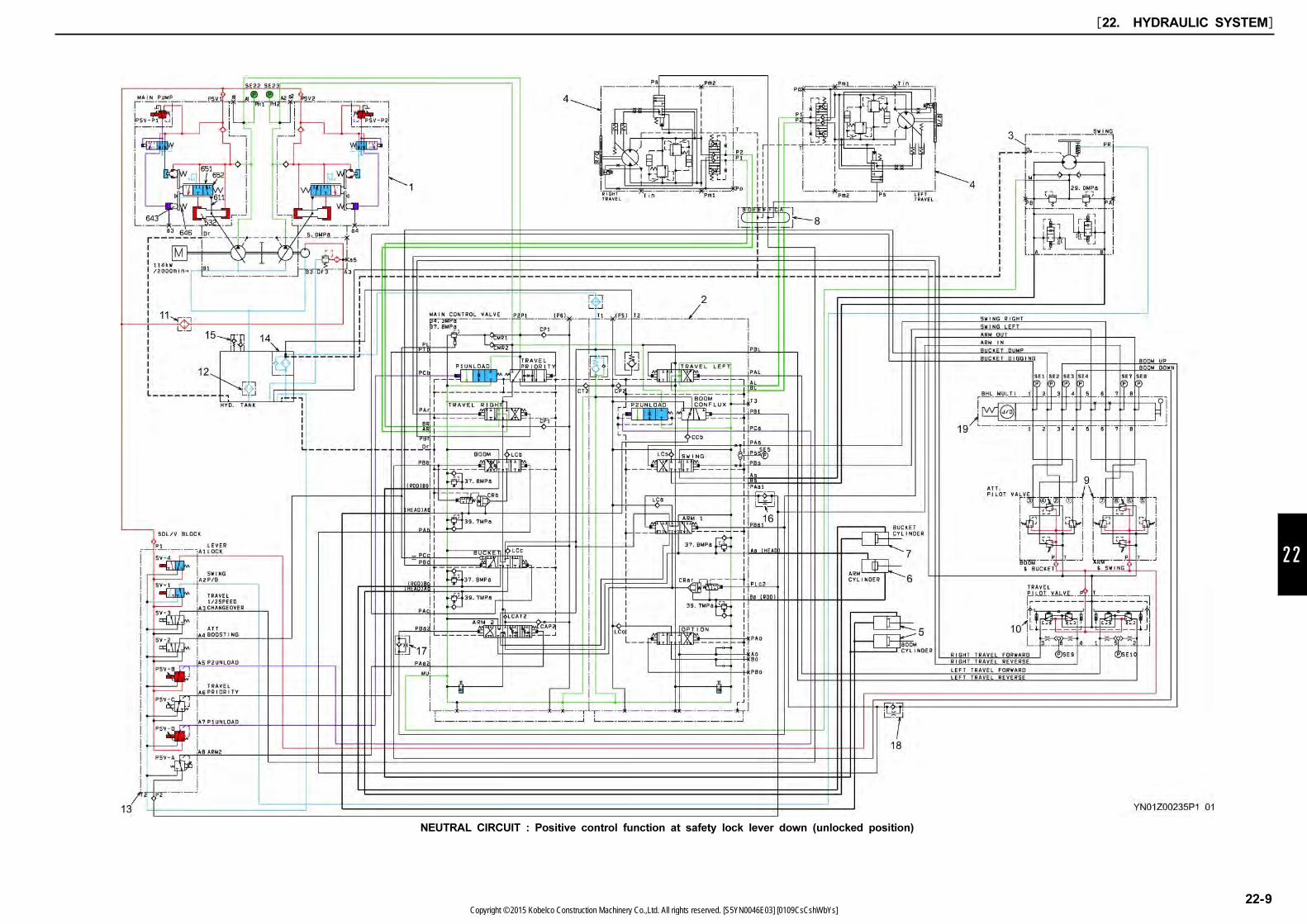
22
NEUTRAL CIRCUIT : Positive control function at safety lock lever down (unlocked position)
[22. HYDRAULIC SYSTEM]
22-9Copyright © 2015 Kobelco Construction Machinery Co.,Ltd. All rights reserved. [S5YN0046E03] [0109CsCshWbYs]
22.5 TRAVEL CIRCUIT
This section describes the following.
(1) Travel forward pilot simultaneous operation circuit
(2) 2 speed travel solenoid command circuit and
auto 1-speed return function
(3) Travel main circuit
(4) Travel motor function
22.5.1 TRAVEL FORWARD PILOT
SIMULTANEOUS OPERATION
CIRCUIT(1) Purpose:
Light operating force and shockless operation
(2) Mechatronics:
1. If the travel lever with damping mechanism is
operated for travel right, left and forward
motions, the secondary pilot proportional pressure
comes out of the 3, 1 ports of P/V (10). The
higher of the pressures is selected, comes out of
the 6, 5 ports and acts upon the low pressure
sensors (SE9) (SE-10).
2. The pilot secondary pressure flows to PAr and
PAL ports of the control valve (2), moves the
travel spool, and switches the main circuit.
3. The low pressure sensor output voltage is input
into mechatro controller. The mechatro controller
performs signal processing and outputs current
corresponding to the increase of flow rate to P1
pump proportional valve (PSV-P1) and P2 pump
proportional valve (PSV-P2), and at the same time
the command current is output to P1 unloading
valve (PSV-D) and P2 unloading valve (PSV-B).
4. The secondary pressures output by P1 pump
proportional valve (PSV-P1) and P2 pump
proportional valve (PSV-P2) exert on pump
regulator, actuating the pump on the delivery
flow rate increase side.
5. The secondary pressure delivered in P1 unloading
valve (PSV-D) and P2 unloading valve (PSV-B)
is fed to Pcb and PCa ports provided in control
valve (2).
The secondary pressure from proportional valve
which has exerted on PCb and PCa ports
switches the unloading spool in CLOSE side.
22.5.2 2-SPEED TRAVEL SOLENOID
COMMAND CIRCUIT AND AUTO 1st
SPEED RETURN FUNCTION(1) Purpose:
Change travel motor speed with switch.
(2) Principle:
If the switch is turned, an electric signal is
issued. It excites the 2-speed travel solenoid
which in turn converts the primary pilot pressure
and the self pressure to a tilting angle of the
variable displacement motor.
(3) Operation:
If the rabbit marked switch on the gauge cluster
is pressed, the solenoid (SV-3) of the
proportional valve block (13) is excited and
changes the proportional valve. Then the
solenoid command pressure is issued from port
A3, enters the Ps port of the travel motor (4),
opens the oil passage to the 2nd speed select
piston, and causes the motor to run in the 2nd
speed tilting mode by its self pressure. However,
when the main circuit pressure rises above 28
MPa (4060 psi), the motor's self pressure pushes
the 2nd speed select piston back to the 1st
speed.
22.5.3 TRAVEL MAIN CIRCUIT(1) Operation:
The delivery oil from Pump A1 and A2 ports by
changing the travel spool with the operation of
travel pilot flows in each P1 port on the left side
of travel motor (4) and P2 port on the right side
of travel motor (4) through C,D ports of swivel
joint (8) from AL, AR ports of C/V, and rotates
the travel motor.
22.5.4 TRAVEL MOTOR FUNCTION(1) Function:
1. Prevents the motor from over running on a slope.
2. Check valve that prevents cavitation of the
hydraulic motor.
3. Shockless relief valve and anti cavitation valve
when inertia force stops.
4. High/Low 2 step speed change mechanism and
auto 1st speed return at high load.
5. Travel parking brake.
[22. HYDRAULIC SYSTEM]
22-10Copyright © 2015 Kobelco Construction Machinery Co.,Ltd. All rights reserved. [S5YN0046E03] [0109CsCshWbYs]
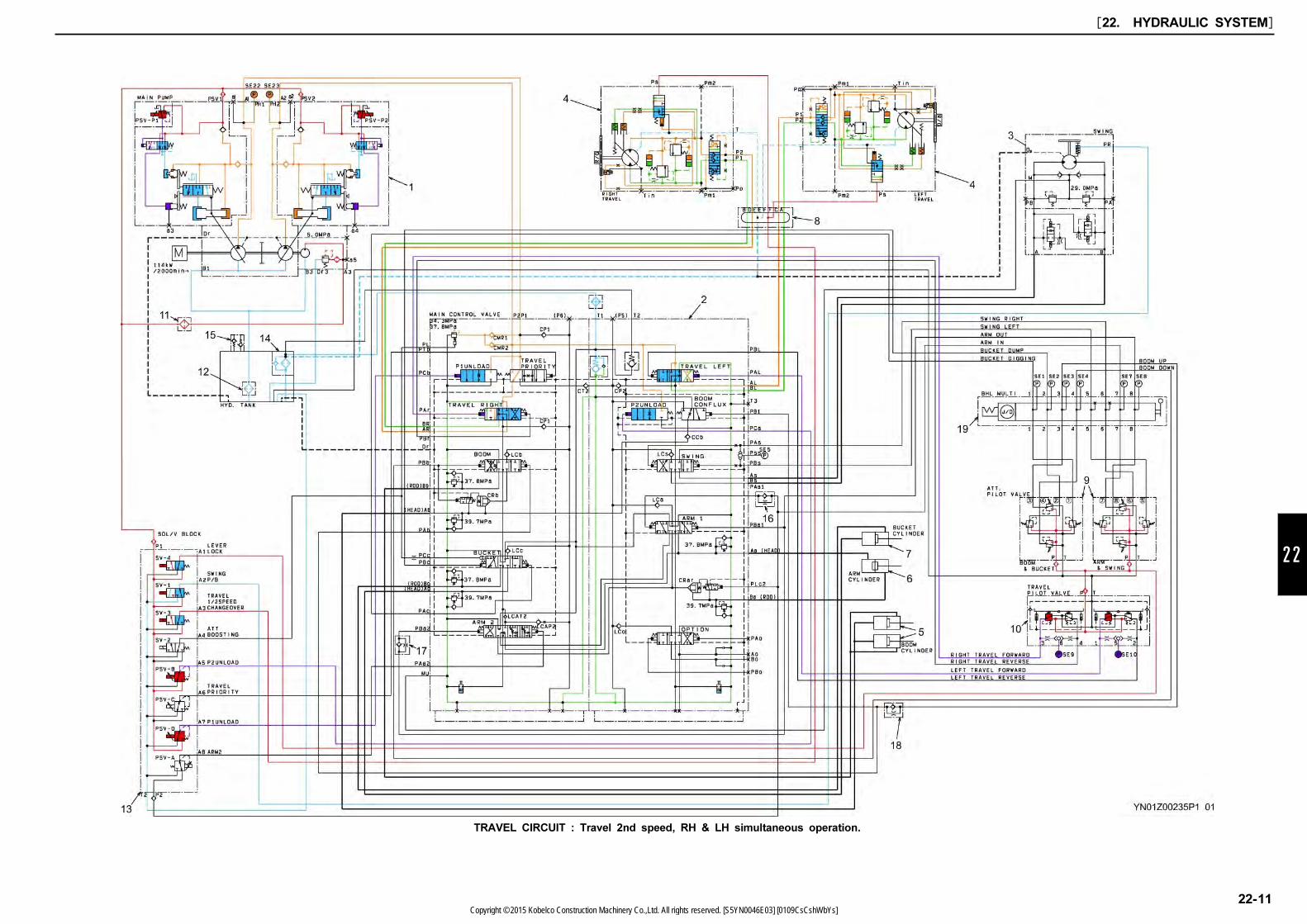
22
TRAVEL CIRCUIT : Travel 2nd speed, RH & LH simultaneous operation.
[22. HYDRAULIC SYSTEM]
22-11Copyright © 2015 Kobelco Construction Machinery Co.,Ltd. All rights reserved. [S5YN0046E03] [0109CsCshWbYs]
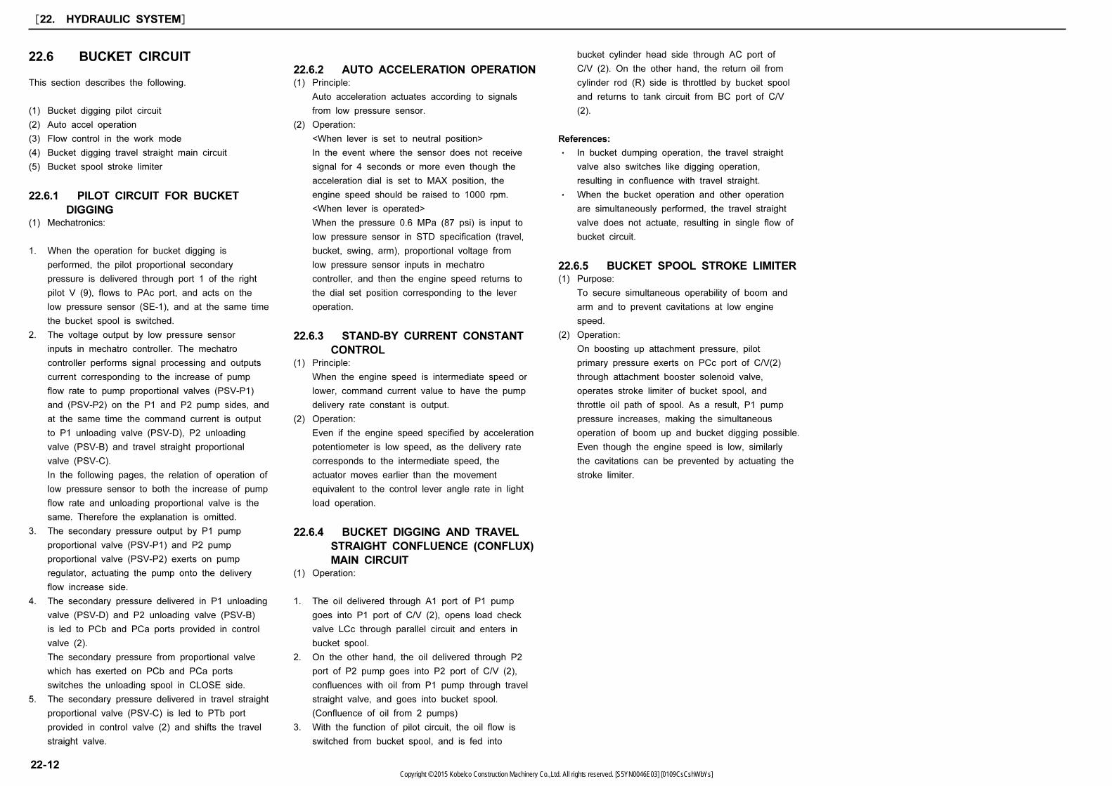
22.6 BUCKET CIRCUIT
This section describes the following.
(1) Bucket digging pilot circuit
(2) Auto accel operation
(3) Flow control in the work mode
(4) Bucket digging travel straight main circuit
(5) Bucket spool stroke limiter
22.6.1 PILOT CIRCUIT FOR BUCKET
DIGGING(1) Mechatronics:
1. When the operation for bucket digging is
performed, the pilot proportional secondary
pressure is delivered through port 1 of the right
pilot V (9), flows to PAc port, and acts on the
low pressure sensor (SE-1), and at the same time
the bucket spool is switched.
2. The voltage output by low pressure sensor
inputs in mechatro controller. The mechatro
controller performs signal processing and outputs
current corresponding to the increase of pump
flow rate to pump proportional valves (PSV-P1)
and (PSV-P2) on the P1 and P2 pump sides, and
at the same time the command current is output
to P1 unloading valve (PSV-D), P2 unloading
valve (PSV-B) and travel straight proportional
valve (PSV-C).
In the following pages, the relation of operation of
low pressure sensor to both the increase of pump
flow rate and unloading proportional valve is the
same. Therefore the explanation is omitted.
3. The secondary pressure output by P1 pump
proportional valve (PSV-P1) and P2 pump
proportional valve (PSV-P2) exerts on pump
regulator, actuating the pump onto the delivery
flow increase side.
4. The secondary pressure delivered in P1 unloading
valve (PSV-D) and P2 unloading valve (PSV-B)
is led to PCb and PCa ports provided in control
valve (2).
The secondary pressure from proportional valve
which has exerted on PCb and PCa ports
switches the unloading spool in CLOSE side.
5. The secondary pressure delivered in travel straight
proportional valve (PSV-C) is led to PTb port
provided in control valve (2) and shifts the travel
straight valve.
22.6.2 AUTO ACCELERATION OPERATION(1) Principle:
Auto acceleration actuates according to signals
from low pressure sensor.
(2) Operation:
<When lever is set to neutral position>
In the event where the sensor does not receive
signal for 4 seconds or more even though the
acceleration dial is set to MAX position, the
engine speed should be raised to 1000 rpm.
<When lever is operated>
When the pressure 0.6 MPa (87 psi) is input to
low pressure sensor in STD specification (travel,
bucket, swing, arm), proportional voltage from
low pressure sensor inputs in mechatro
controller, and then the engine speed returns to
the dial set position corresponding to the lever
operation.
22.6.3 STAND-BY CURRENT CONSTANT
CONTROL(1) Principle:
When the engine speed is intermediate speed or
lower, command current value to have the pump
delivery rate constant is output.
(2) Operation:
Even if the engine speed specified by acceleration
potentiometer is low speed, as the delivery rate
corresponds to the intermediate speed, the
actuator moves earlier than the movement
equivalent to the control lever angle rate in light
load operation.
22.6.4 BUCKET DIGGING AND TRAVEL
STRAIGHT CONFLUENCE (CONFLUX)
MAIN CIRCUIT(1) Operation:
1. The oil delivered through A1 port of P1 pump
goes into P1 port of C/V (2), opens load check
valve LCc through parallel circuit and enters in
bucket spool.
2. On the other hand, the oil delivered through P2
port of P2 pump goes into P2 port of C/V (2),
confluences with oil from P1 pump through travel
straight valve, and goes into bucket spool.
(Confluence of oil from 2 pumps)
3. With the function of pilot circuit, the oil flow is
switched from bucket spool, and is fed into
bucket cylinder head side through AC port of
C/V (2). On the other hand, the return oil from
cylinder rod (R) side is throttled by bucket spool
and returns to tank circuit from BC port of C/V
(2).
References:
・ In bucket dumping operation, the travel straight
valve also switches like digging operation,
resulting in confluence with travel straight.
・ When the bucket operation and other operation
are simultaneously performed, the travel straight
valve does not actuate, resulting in single flow of
bucket circuit.
22.6.5 BUCKET SPOOL STROKE LIMITER(1) Purpose:
To secure simultaneous operability of boom and
arm and to prevent cavitations at low engine
speed.
(2) Operation:
On boosting up attachment pressure, pilot
primary pressure exerts on PCc port of C/V(2)
through attachment booster solenoid valve,
operates stroke limiter of bucket spool, and
throttle oil path of spool. As a result, P1 pump
pressure increases, making the simultaneous
operation of boom up and bucket digging possible.
Even though the engine speed is low, similarly
the cavitations can be prevented by actuating the
stroke limiter.
[22. HYDRAULIC SYSTEM]
22-12Copyright © 2015 Kobelco Construction Machinery Co.,Ltd. All rights reserved. [S5YN0046E03] [0109CsCshWbYs]

22
BUCKET CIRCUIT : Bucket digging (Travel straight conflux), Auto-accelation and Standby flow rate constant control
[22. HYDRAULIC SYSTEM]
22-13Copyright © 2015 Kobelco Construction Machinery Co.,Ltd. All rights reserved. [S5YN0046E03] [0109CsCshWbYs]

22.7 BOOM CIRCUIT
(1) Boom up pilot circuit
(2) Boom up 2 pumps conflux main circuit in C/V
22.7.1 BOOM RAISE PILOT CIRCUIT(1) Operation:
1. If boom up operation is performed, the
secondary pilot proportional pressure from the
right pilot valve (9) gets out of port 3 and acts
upon the low pressure sensor (SE3). At the same
time, the pressure acts upon the PAb and PB1
ports.
2. The secondary pressure which enters the PAb
port of C/V (2) shifts the boom spool. The
secondary pressure which enters the PB1 port
shifts the boom conflux spool.
22.7.2 BOOM UP 2 PUMPS CONFLUX
MAIN CIRCUIT IN C/V(1) Purpose:
Boom up speed up
(2) Principle:
Confluxing oil from 2 pumps
(3) Operation:
1. The oil delivered through A1 port of P1 pump
flows into C/V (2) P1 port, and branches into
bypass circuit and parallel circuit. Since P1
unloading valve is closed, the boom spool is
moved and bypass circuit is closed, the oil
opens load check valve LCb through parallel
circuit and flows into boom spool.
2. Then the oil passes through boom spool, opens
lock valve of boom lock valve CRb, and is led
into H side of boom cylinder through C/V (2) Ab
port.
3. Meanwhile, the oil delivered from the A2 port of
the P2 pump enters the P2 port of C/V (2) and
due to shut off the P2 unloading valve, the oil
then passes through the parallel circuit and via
the restrictor on the circumference of the boom
conflux spool, pushes the load check valve CCb
open from the boom conflux circuit, and combines
the oil delivered by the P1 pump internally.
4. The return oil from boom cylinder R side flows
into tank circuit through boom spool from C/V (2)
Bb port.
[22. HYDRAULIC SYSTEM]
22-14Copyright © 2015 Kobelco Construction Machinery Co.,Ltd. All rights reserved. [S5YN0046E03] [0109CsCshWbYs]
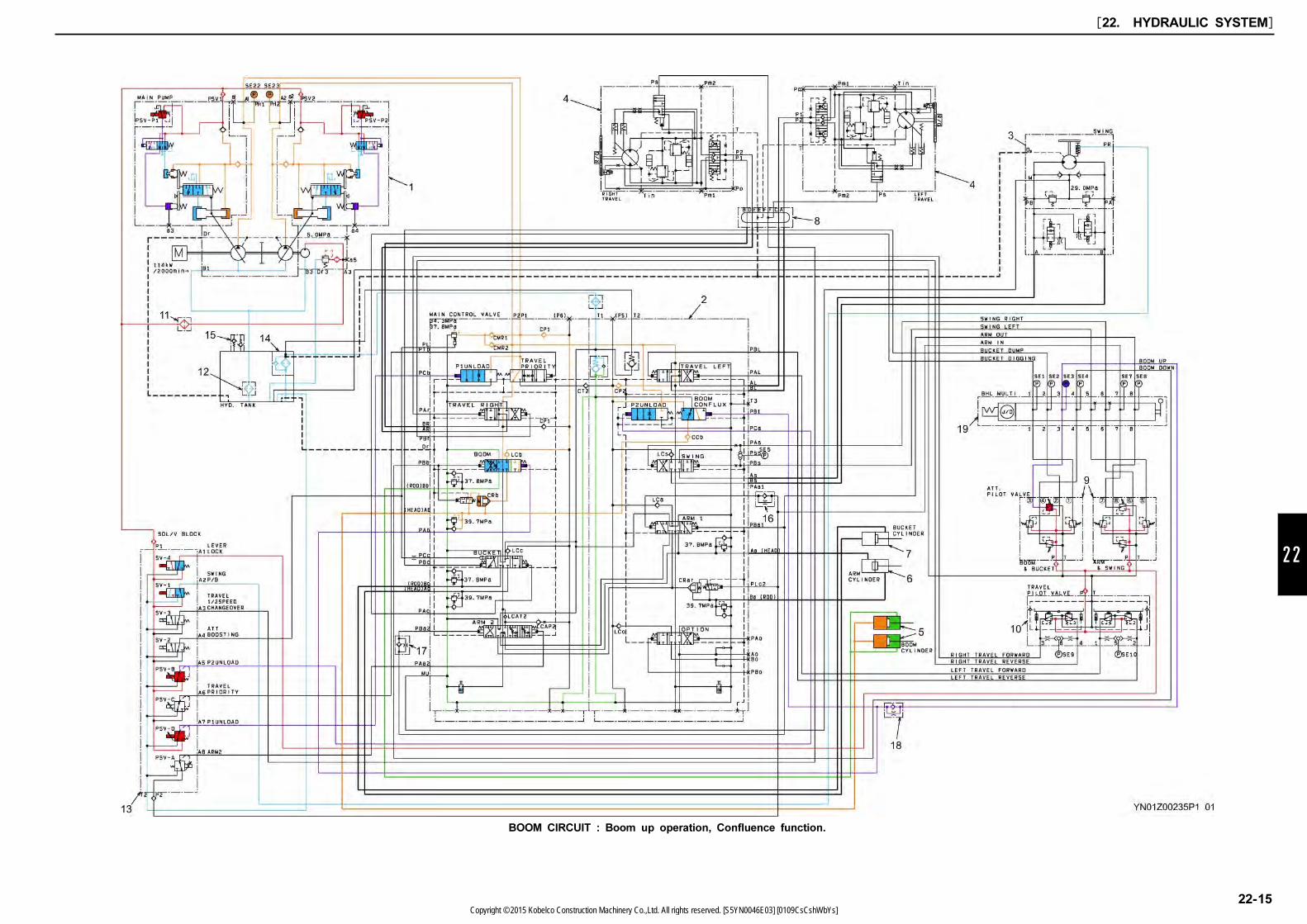
22
BOOM CIRCUIT : Boom up operation, Confluence function.
[22. HYDRAULIC SYSTEM]
22-15Copyright © 2015 Kobelco Construction Machinery Co.,Ltd. All rights reserved. [S5YN0046E03] [0109CsCshWbYs]

This section describes boom lower operation.
(1) Boom down pilot circuit
(2) Prevention of natural fall by lock valve and
actuation at lowering
(3) Constant recirculation function of boom down main
circuit
22.7.3 BOOM DOWN PILOT CIRCUIT(1) Operation:
1. If the boom down operation is performed, the
secondary pilot proportional pressure comes out of
portaC of the right pilot valve (9) and acts upon
the low pressure sensor (SE-4).
At the same time, the pressure acts upon the
PBb port of C/V (2).
2. The voltage output of the low pressure sensor
(SE-4) enters the mechatro controller and
processed in it.
3. Then, the proportionl secondary pressure fed into
C/V (2) PBb port and branches off in two lines
and switches boom spool and releases boom lock
valve.
22.7.4 PREVENTION OF NATURAL FALL
BY LOCK VALVE AND ACTUATION
AT LOWERING(1) Purpose:
Prevention of natural fall when the lever is neutral.
(2) Principle:
The oil is prevented from returning to the boom
spool by the poppet seat of the boom lock valve.
(3) Operation:
In the boom down action, the selector valve is
changed over by the secondary proportional
pressure of PBb port. Then the poppet spring
chamber of the lock valve CRb gets through the
drain line (Dr) and makes the lock valve poppet
open.
When the boom lever is at neutral, the drain line
on the lock valve CRb poppet spring chamber is
closed which causes the poppet closed.
The result is that the oil returning from the boom
cylinder head (H) to the boom spool is held and
makes the leak from the boom spool zero.
Thus the boom cylinder is prevented from
making a natural fall.
22.7.5 CONSTANT RECIRCULATION
FUNCTION OF BOOM DOWN MAIN
CIRCUIT(1) Purpose:
Prevention of cavitation during boom lowering
motion.
(2) Principle:
The oil returning from the boom cylinder head (H)
is recirculated to the rod (R).
(3) Operation:
When the oil is supplied to the boom cylinder
rod (R) side during boom down operation, the
boom moves faster than it should do in some
cases by the self weight of the attachment.
On that occasion, the circuit pressure on the rod
(R) side is on the negative side.
The oil supplied to the boom cylinder rod (R)
flows into the A1 port of the P1 pump and the
P1 port of C/V. The oil then passes through the
boom spool and goes out of the Bb port.
On that occasion, the oil returning from the head
(H) goes through the recirculation path in the
boom spool, pushes the check valve in the spool
open, is recirculated to the Bb port and is
supplied to the rod (R). When the (R) pressure
is larger than the head (H) pressure, the check
valve in spool closes.
Thereupon, the recirculation is stopped.
[22. HYDRAULIC SYSTEM]
22-16Copyright © 2015 Kobelco Construction Machinery Co.,Ltd. All rights reserved. [S5YN0046E03] [0109CsCshWbYs]
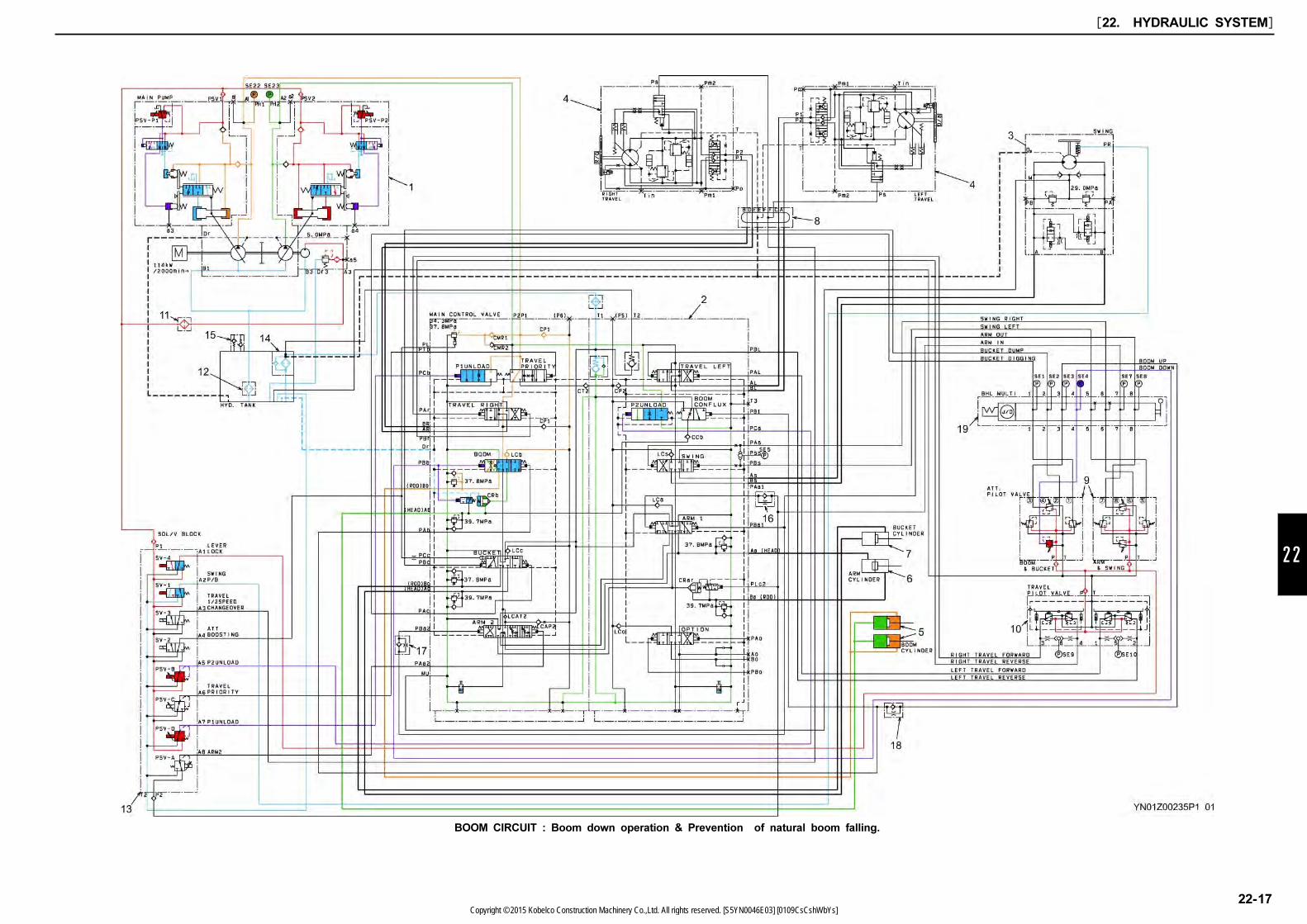
22
BOOM CIRCUIT : Boom down operation & Prevention of natural boom falling.
[22. HYDRAULIC SYSTEM]
22-17Copyright © 2015 Kobelco Construction Machinery Co.,Ltd. All rights reserved. [S5YN0046E03] [0109CsCshWbYs]

22.8 SWING CIRCUIT
This section describes the following operations.
(1) Swing left pilot circuit
(2) Swing auto parking brake
(3) Swing main circuit
(4) Swing motor circuit
22.8.1 PILOT CIRCUIT FOR LEFT SWING(1) Operation:
1. When the left swing operation is performed, the
pilot proportional secondary pressure is delivered
through port (5) of left pilot V (9), and the
secondary pressure acts on PBs port of C/V (2),
and simultaneously flows out from Pss port of
C/V and acts on low pressure sensor (SE-5).
2. The voltage output by the low pressure sensor is
input in the mechatro controller, and is
signal-processed.
3. Then, the secondary pressure led into PBs port of
C/V (2) switches the swing spool.
22.8.2 SWING AUTO PARKING BRAKE(1) Purpose:
Swing lock in neutral position and parking
(2) Principle:
Release mechanical brake only when required to
operate swing and arm in.
(3) Operation:
1. The swing parking system excites the swing
parking SOL (SV-1) usually if the key switch is
turned on and works by the action of the
mechanical brake.
2. The mechanical brake is released if the swing
parking solenoid is de-excited only when the
secondary operating pressure in the swing and
arm in actions acts upon any of the low
pressure sensors (SE-5, 7).
3. The swing parking solenoid (SV-1) is excited five
seconds after the pressure of the swing low
pressure sensors (SE-5) is reduced to zero. In
the case of arm in operation, the swing parking
solenoid (SV-1) is excited the moment the
pressure of the arm in low pressure sensor
(SE-7) is reduced to zero. This causes the
mechanical brake to operate.
22.8.3 SWING MAIN CIRCUIT(1) Operation:
The oil delivered from the A2 port of the P2
pump enters the P2 port of C/V (2) and is
branched off into the bypass line and the parallel
circuit. However, since the bypass line is closed
as the swing spool is shifted, the oil pushes the
load check valve LCs open through the parallel
circuit, enters the B port of the swing motor via
the Bs port of C/V (2), and rotates the swing
motor counterclockwise.
22.8.4 SWING MOTOR CIRCUIT(1) Anti cavitation circuit at swing deceleration
(2) Preventing the swing motor from being reversed
circuit.
(3) Shockless relief valve circuit.
[22. HYDRAULIC SYSTEM]
22-18Copyright © 2015 Kobelco Construction Machinery Co.,Ltd. All rights reserved. [S5YN0046E03] [0109CsCshWbYs]
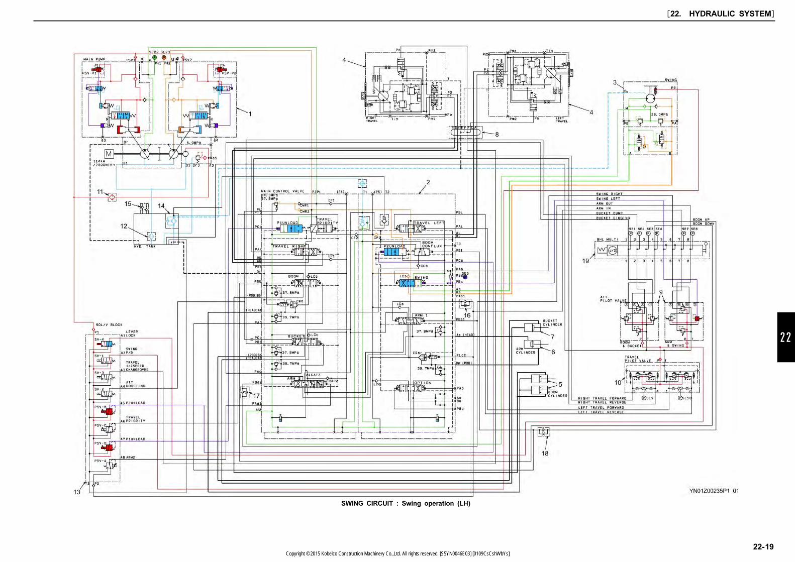
22
SWING CIRCUIT : Swing operation (LH)
[22. HYDRAULIC SYSTEM]
22-19Copyright © 2015 Kobelco Construction Machinery Co.,Ltd. All rights reserved. [S5YN0046E03] [0109CsCshWbYs]

22.9 ARM CIRCUIT
This section describes the following operations.
(1) Arm in, light-load operating pilot circuit
(2) Arm in, light-load variable normal recirculation
main circuit / internal conflux main circuit
22.9.1 ARM IN, LIGHT-LOAD
OPERATING PILOT CIRCUIT(1) Purpose:
Speed-up and Anticavitation when the arm is at
light loaded.
(2) Principle:
The oil returning from the arm cylinder rod (R) is
recirculated variably to the head (H) at arm 2
spool in C/V.
(3) Operation:
1. When the arm in operation is performed, the
secondary pilot proportional pressure gets out of
port 7 of the left pilot valve (9) and acts upon the
low pressure sensor (SE-7).
At the same time, the pressure is branched off
in two flows, acts upon the Paa1 port and the
PLc2 port, changes over the arm spool and the
arm lock valve CRar. releases.
2. The output voltage by the low pressure sensor is
input into mechatro controller, and is pilot
signal-processed, and is output to P1, P2 pump
proportional valve (PSV-P1), (PSV-P2) and arm 2
inverse proportional valve (PSV-A).
3. The secondary pressure from pilot proportional
valve, which is reduced by arm 2 inverse
proportional valve (PSV-A) switches arm 2 spool.
22.9.2 ARM-IN, LIGHT-LOAD VARIABLE
NORMAL RECIRCULATION,
INTERNAL CONFLUX MAIN CIRCUIT(1) Operation:
1. The P2 pump delivery oil flows in travel left
section through P2 port of C/V (2) and is
branched off in by-pass circuit and parallel
circuit, but because arm 1 spool is switched, the
delivery oil which goes through parallel circuit
opens load check valve LCa and is flowed into
arm 1 spool.
2. On the other hand, P1 pump delivery oil flows in
P1 port of C/V (2), and the flows in travel straight
section and travel right tandem path. Then
because arm 2 spool was switched, the delivery
oil opens load check valve LCAT2, goes through
arm 2 spool, and confluences with P2 pump
delivery oil in the valve section, and then is
flowed into arm cylinder head (H) side through Aa
port of C/V (2).
3. The return oil from arm cylinder (R) side flows in
Ba port of C/V (2) and passes through the Ba
port because the arm lock valve CRar is open,
and is flowed into arm 2 spool through arm 1
spool.
4. Because arm 2 spool is switched to normal
recirculation position, causing restriction of
passage to tank, the return oil from arm cylinder
(R) side flows into arm cylinder (H) side.
-Because, at light load, the pressure in cylinder
rod (R) side is higher than that in the head (H)
side, it opens the check valve housed-in arm 2
spool and is recirculated in the head (H) side,
resulting in the speed up of arm-in operation at
light load.
5. Cavitations prevention control in arm-in operation
Command current is output to arm 2 solenoid
proportional valve by signal processing of E/G
speed and arm-in pilot pressure, accordingly the
arm 2 spool is switched to neutral (cavitations
prevention) position, resulting in cavitations
prevention.
Position of arm 2 spool
Reference:
In light-load arm-in operation (normal recirculation,
conflux), when the attachment to which the circuit in
P1 pump side is applied is operated, the meter-in
path of arm 2 spool is closed, resulting in single flow
operation.
[22. HYDRAULIC SYSTEM]
22-20Copyright © 2015 Kobelco Construction Machinery Co.,Ltd. All rights reserved. [S5YN0046E03] [0109CsCshWbYs]

22
ARM CIRCUIT : Arm in (Light load) operation, Arm variable recirculation & Anti cavitation function
[22. HYDRAULIC SYSTEM]
22-21Copyright © 2015 Kobelco Construction Machinery Co.,Ltd. All rights reserved. [S5YN0046E03] [0109CsCshWbYs]

This section describes the following operations.
(3) Arm in, heavy load operating pilot circuit
(recirculation cut)
(4) Arm in, heavy load operating sequence confluxed
main circuit
22.9.3 ARM IN, HEAVY LOAD
OPERATING PILOT CIRCUIT(1) Operation:
1. Left pilot valve actuation due to arm-in operation
is equivalent to that at light load operation.
2. In arm-in operation, when the heavy loading is
applied to arm and the P2 pump pressure
increases to the set pressure, the voltage output
by P2 pump pressure sensor (SE-23) is converted
to signal (signal processing) by mechatro
controller, consequently the current of arm 2
solenoid proportional valve is controlled according
to the load pressure and the arm variable
recirculation is cut.
When the recirculation is cut, internal confluence
is held similarly to that in light load operation.
22.9.4 ARM IN, HEAVY LOAD
OPERATING RECIRCULATION CUT
MAIN CIRCUIT(1) Purpose:
Power up for arm in operation
(2) Principle:
Cut the recirculation and reduce rod pressure.
(3) Operation:
1. P2 pump delivery oil flows in the travel left
section through P2 port of C/V (2) and branched
off in by-pass circuit and parallel circuit.
Consequently the arm spool is switched and
pushes and opens load check valve LCa through
parallel circuit, and flows in the arm spool.
2. On the other hand, P1 pump delivery oil flows in
P1 port of C/V (2), and flow in travel right
tandem passage through travel straight section.
Then because arm 2 spool was switched, the
delivery oil opens load check valve LCAT2, and
confluences with P2 pump delivery oil in the valve
section, and is flowed into arm cylinder head (H)
side through Aa port of C/V(2).
3. The return oil from arm cylinder (R) side flows in
Ba port of C/V(2) and is flowed to arm lock valve
CRar, but because the arm lock valve CRar is
open, the return oil goes through arm lock valve
CRar and flows in arm 2 spool.
4. The return oil returns directly into tank circuit
because arm 2 spool is switched to recirculation
cut position.
Position of arm 2 spool
[22. HYDRAULIC SYSTEM]
22-22Copyright © 2015 Kobelco Construction Machinery Co.,Ltd. All rights reserved. [S5YN0046E03] [0109CsCshWbYs]
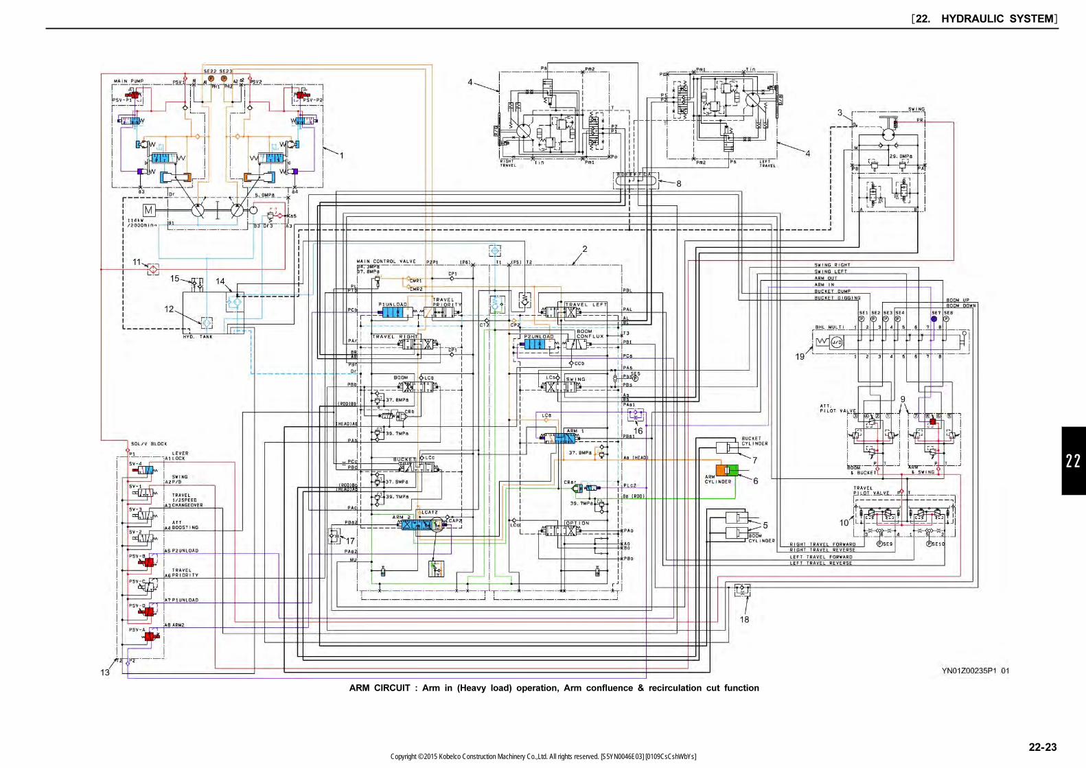
22
ARM CIRCUIT : Arm in (Heavy load) operation, Arm confluence & recirculation cut function
[22. HYDRAULIC SYSTEM]
22-23Copyright © 2015 Kobelco Construction Machinery Co.,Ltd. All rights reserved. [S5YN0046E03] [0109CsCshWbYs]

This section describes the following operations.
(5) Arm out pilot circuit
(6) Arm out 2 pumps conflux main circuit
(7) Natural fall protection with arm lock valve
22.9.5 ARM OUT PILOT CIRCUIT(1) Operation:
1. When the arm out operation is performed, the
secondary pilot proportional pressure gets out of
port 8 of the left pilot valve (9), and acts upon
the low pressure sensor (SE-8). At the same
time, the oil is branched off in two flows and act
upon the PBa1 and Pba2 ports of C/V (2).
2. The operating proportional secondary pressure
flowed in Pba1 port of C/V (2) switches the arm
1 spool.
3. Then, the operating secondary pressure flowed in
PBa2 port of C/V (2) switches the arm 2 spool
valve.
22.9.6 ARM OUT 2 PUMPS CONFLUX
MAIN CIRCUIT(1) Purpose:
Arm out operation speed up.
(2) Principle:
The oil delivered by the P1 pump is confluxed
with that delivered by the P2 pump in C/V (2).
(3) Operation:
1. P1 pump delivery oil opens load check valve
(LCAT2) by switching arm 2 spool and confluxes
with P2 pump delivery oil just short of the arm
lock valve.
2. And, P2 pump delivery oil flows through arm 1
spool and confluences with P1 delivery oil,
opens lock valve of arm lock valve CRar with free
flow and is flowed into arm cylinder rod (R) side
through Ba port of C/V(2).
3. On the other hand, the return oil from arm
cylinder (H) side flows in Aa port, and returns into
tank circuit through arm 1 spool and arm 2 spool.
The return line which does not pass through
boost check valve is used for this return circuit
to reduce the pressure loss.
22.9.7 NATURAL FALL PROTECTION
WITH ARM LOCK VALVE(1) Purpose:
To prevent the arm from falling naturally by the
weight of the arm and bucket.
(2) Principle:
Complete seat of the return circuit against the
arm spool of the arm cylinder (R) side circuit.
(3) Operation:
1. When the secondary pressure for arm operation
disappears and the arm cylinder stops, the
pressure on the rod (R) side passes through the
selector of the lock valve from the Ba port of
C/V, acts the back pressure on the lock valve
CRar and seats the lock valve.
2. Since the oil flow into the arm spool from the
lock valve is shut off completely, natural fall of
the arm due to oil leaks through the arm spool is
prevented.
[22. HYDRAULIC SYSTEM]
22-24Copyright © 2015 Kobelco Construction Machinery Co.,Ltd. All rights reserved. [S5YN0046E03] [0109CsCshWbYs]
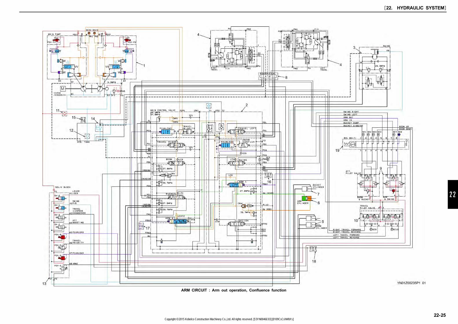
22
ARM CIRCUIT : Arm out operation, Confluence function
[22. HYDRAULIC SYSTEM]
22-25Copyright © 2015 Kobelco Construction Machinery Co.,Ltd. All rights reserved. [S5YN0046E03] [0109CsCshWbYs]
22.10 COMBINED CIRCUIT
This section describes only the difference in combined
operation.
(1) Boom up / travel, pilot circuit
(2) Boom up / travel, main circit
22.10.1 BOOM UP / TRAVEL, PILOT
CIRCUIT(1) Operation:
<Operation: Different point of pilot circuit from
independent operation >
1. The mechatro controller outputs command current
to travel straight solenoid proportional valve after
signal processing, and the solenoid valve outputs
secondary pressure and acts on PTb port of C/V
(2).
2. Then the pressure of PTb port switches the travel
straight valve.
22.10.2 BOOM UP / TRAVEL, MAIN
CIRCUIT(1) Purpose:
To insure straight travel movement during travel
operation even if the attachment is operated.
(2) Principle:
The travel action and the attachment action are
actuated by separate pumps.
(3) Operation:
1. P1 pump delivery oil flows through P1 port of
C/V(2) and branches off in P1 parallel circuit and
travel straight spool.
P2 pump delivery oil flows through P2 port of
C/V(2) and branches off in P2 tandem circuit
and travel straight spool.
2. The delivery oil flowed into P1 parallel circuit of
P1 pump opens check valve CP1 and LCb and
flows in boom spool, which exerts on boom up
operation.
The delivery oil flowed into travel straight spool of
P1 pump opens check valve CT2 because the
travel straight spool is shifted, and flows in boom
conflux spool and exerts on boom up operation
with the internal oil conflux.
(In travel straight operation, P1 pump delivery oil
exerts on swing operation of attachment.)
3. The delivery oil flowed into P2 tandem circuit of
P2 pump flows in left travel spool to travel
leftward.
The delivery oil flowed into travel straight spool of
P2 pump flows in right travel spool because the
travel straight spool is shifted and exerts on the
right travel operation.
(In travel straight operation, P2 pump delivery oil
exerts on travel operation.)
4. However, a portion of the flow is led to the
travel straight spool notch restriction. The speed
of attachments like travel, boom, etc. is adjusted
by the circuit of restriction.
[22. HYDRAULIC SYSTEM]
22-26Copyright © 2015 Kobelco Construction Machinery Co.,Ltd. All rights reserved. [S5YN0046E03] [0109CsCshWbYs]
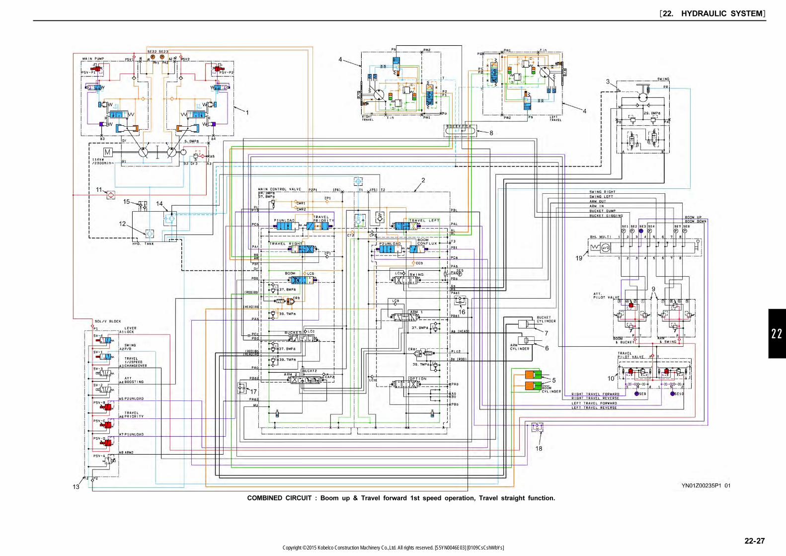
22
COMBINED CIRCUIT : Boom up & Travel forward 1st speed operation, Travel straight function.
[22. HYDRAULIC SYSTEM]
22-27Copyright © 2015 Kobelco Construction Machinery Co.,Ltd. All rights reserved. [S5YN0046E03] [0109CsCshWbYs]

In this section, the independent operation is omitted
and describes difference in combined operation.
(3) Swing / Arm in light load, pilot circuit
(4) Swing / Arm in, swing priority main circuit
22.10.3 SWING / ARM IN LIGHT LOAD,
PILOT CIRCUIT(1) Operation:
1. On operating swing (left) and arm in motions
simultaneously, mechatro controller outputs
command current to travel straight solenoid
proportional valve (PSV-C) and arm 2 solenoid
inverse proportional valve according to signal
processing, and this proportional valve outputs
secondary pressure, which acts on PTb port and
PAa2 port of C/V(2).
2. PTb port pressure switches the travel straight
spool according to the secondary pilot pressure,
and the PAa2 port pressure switches the arm 2
spool to the forced recirculation position.
22.10.4 SWING / ARM IN, SWING
PRIORITY MAIN CIRCUIT(1) Purpose:
Stable swing speed.
(2) Principle:
Raise the oil pressure flowing to arm cylinder,
and give a priority of the delivery of P2 pump to
swing operation.
(3) Operation:
1. The swing main circuit operates with P2 pump
flow. But on P2 pump circuit side, the flow goes
to the swing circuit and arm circuit
simultaneously because the swing circuit and
arm circuit are parallel. The arm 2 spool is
switched to forced recirculation position and the
opening of meter-out is not there, so the pressure
of return oil is raised, causing the rise of circuit
pressure on the arm cylinder head (H) side.
2. At the same time meter-in of arm 2 spool closes
and arm in conflux is therefore cancelled, and
delivery oil from P2 pump and P1 pump are
combined in the parallel circuit on P2 pump side
because the travel straight spool was switched.
The conflux oil of P1 and P2 delivery oil in high
pressure flows in swing side taking priority over
all others.
This operation is called "Swing Priority Circuit".
Position of arm 2 spool
[22. HYDRAULIC SYSTEM]
22-28Copyright © 2015 Kobelco Construction Machinery Co.,Ltd. All rights reserved. [S5YN0046E03] [0109CsCshWbYs]
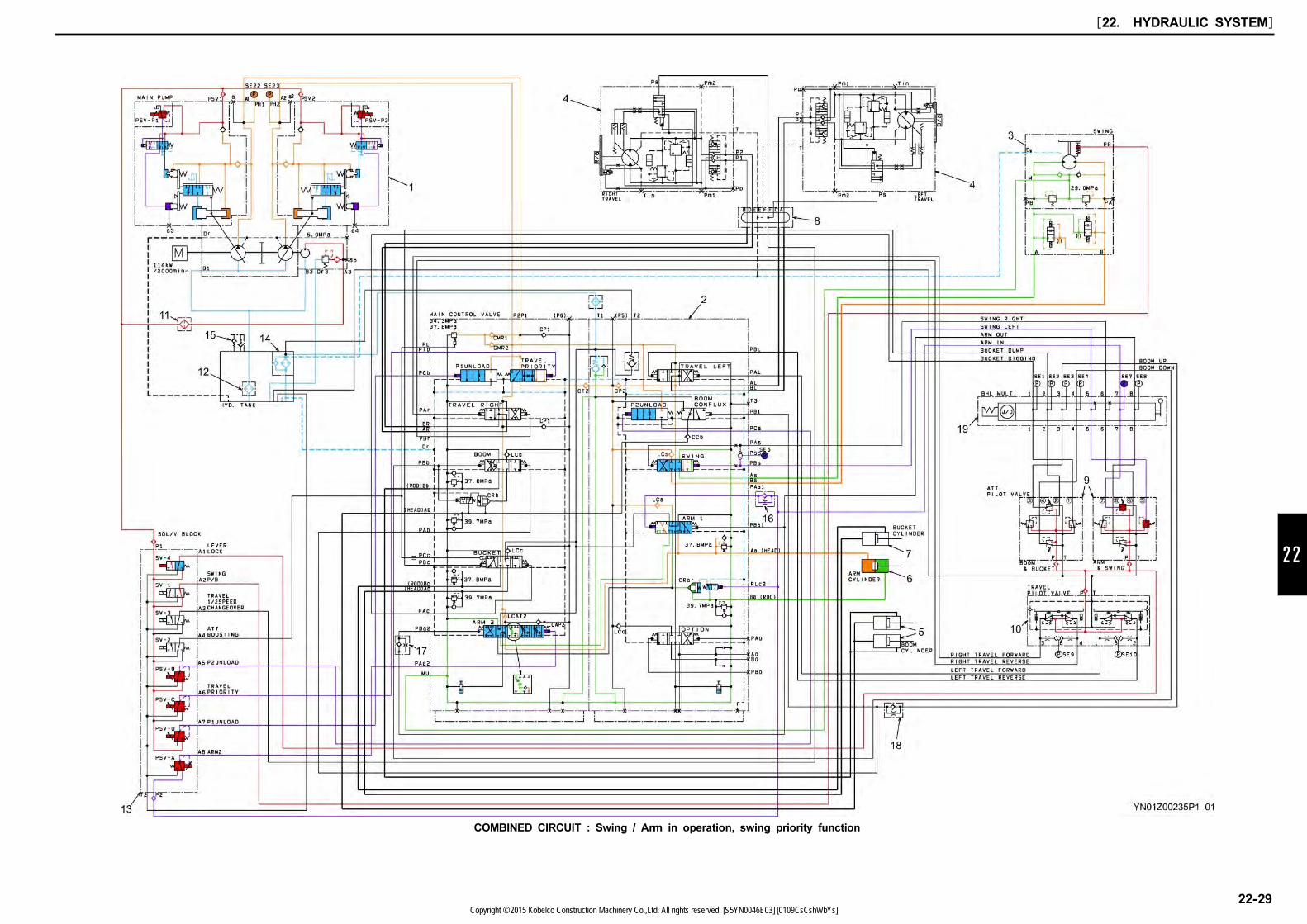
22
COMBINED CIRCUIT : Swing / Arm in operation, swing priority function
[22. HYDRAULIC SYSTEM]
22-29Copyright © 2015 Kobelco Construction Machinery Co.,Ltd. All rights reserved. [S5YN0046E03] [0109CsCshWbYs]
22.11 PRESSURE DRAINING
This section describes the following operations.
(1) Pressure drain (releasing) pilot circuit
(2) Pressure drain (releasing) main circuit
22.11.1 PRESSURE RELIEVING PILOT
CIRCUIT(1) Purpose:
To release the pressure in main circuit for piping
repair works.
(2) Principle:
After the mode is switched to "Pressure Relief
Mode" with switch on gauge cluster, mechatro
controller outputs the following commands.
1. Minimum tilting command value to pump
proportional valve (PSV-P1, PSV-P2).
2. Output "Pressure relief control speed command
value" at ECU. (Electric system)
3. Stand-by command value to P1, P2 unloading
proportional valves
How to switch to "Pressure release mode"
1. Select the service diagnosis mode.
(Hold down the "BUZZER STOP SWITCH" on
gauge cluster, turn the starter key switch on.)
2. Select the service adjustment mode 1.
(Under the condition that "Screen No.1" of
"Service diagnosis mode 1" is indicated, hold
down the "BUZZER STOP SWITCH", press the
"MENU SWITCH" 3 times. When "SERVICE
MENU" is displayed, using "UP" switch or
"DOWN" switch, select "SERVICE ADJUST 1".
Press "NEXT" switch, to select "SERVICE
ADJUST 1-2".)
3. Using "UP" switch or "DOWN" switch, and select
"PRESS DRAIN".
Then press "NEXT" switch, and cursor points to
"OFF".
4. Press "UP" switch to display "ON", and press
"MENU" switch.
5. Screen of gauge cluster changes to ordinary
display, and "DRAINING HYD. PRESS." is
appeared.
(3) Operation:
1. Pump proportional valve reduces the pump flow
rate to the minimum.
2. Unloading proportional valves (PSV-D, PSV-B)
output secondary pressure and the secondary
pressure flows in PCb, PCa ports of C/V(2) and
switches the P1, P2 unloading valves to OPEN
position.
22.11.2 PRESSURE RELEASE MAIN
CIRCUIT
When the hydraulic pressure releasing is performed,
make sure to place bucket on the ground.
(1) Operation:
When the operating lever is shifted to neutral
during engine running, "DRAINING HYD.
PRESS." is displayed on the gauge cluster while
the mode switch is changed to pressure relieving
mode. In this time the intermittent buzzer sounds
continuously. When right and left operating levers
are operated 4 or 5 times to their full stroke,
pressure is relieved.
After draining pressure is completed, turn off the
starter key and buzzer sound stops. If the pump
pressure is determined to be more than 1 MPa
(145 psi) by the output value of the high pressure
sensor or the high pressure sensors (SE-22,23)
are broken, "FAIL DRAIN HYD. PRESS" is
displayed and the buzzer sounds continuously. In
that case, also the buzzer is not stopped unless
the engine key is turned to OFF. Repeat the
pressure releasing procedure once again.
(2) Hydraulics:
If the travel straight valve is turned to the
pressure release position, the oil delivered by
each pump is unloaded to the tank passage. If
the spools are switched by pilot operation, the
remaining pressure from the actuators may be
relieved to the tank circuit, i.e. the main circuit
pressure may be released.
[22. HYDRAULIC SYSTEM]
22-30Copyright © 2015 Kobelco Construction Machinery Co.,Ltd. All rights reserved. [S5YN0046E03] [0109CsCshWbYs]

22
PRESSURE DRAIN (RELEASE) CIRCUIT : At pressure release mode.
[22. HYDRAULIC SYSTEM]
22-31Copyright © 2015 Kobelco Construction Machinery Co.,Ltd. All rights reserved. [S5YN0046E03] [0109CsCshWbYs]

[22. HYDRAULIC SYSTEM]
22-32Copyright © 2015 Kobelco Construction Machinery Co.,Ltd. All rights reserved. [S5YN0046E03] [0109CsCshWbYs]
23
23. ELECTRICAL SYSTEM
[23. ELECTRICAL SYSTEM]
23-1
TABLE OF CONTENTS
Book Code No. S5YN2346E02
23.1 ELECTRIC CIRCUIT DIAGRAM (North America)…………………………………………………………23-3
23.2 ELECTRICAL EQUIPMENT LIST (North America) ………………………………………………………23-13
23.3 ELECTRIC CIRCUIT DIAGRAM (Europe) …………………………………………………………………23-15
23.4 ELECTRICAL EQUIPMENT LIST (Europe)…………………………………………………………………23-25
23.5 HARNESS ………………………………………………………………………………………………………23-27
23.5.1 HARNESS LIST ……………………………………………………………………………………………23-27
23.5.2 INSTRUMENT PANEL ASSY……………………………………………………………………………23-28
23.5.3 CONTROLLER INSTALL …………………………………………………………………………23-29
23.5.4 OPERATORS CONTROLS ………………………………………………………………………23-33
23.5.5 UPPER ELECTRIC ASSY ………………………………………………………………………………23-35
23.5.6 UPPER HARNESS ASSY ………………………………………………………………………23-36
23.5.7 UPPER HARNESS ASSY (FLOOR PLATE) …………………………………………………23-70
23.5.8 HARNESS ASSY (REAR CAMERA) ……………………………………………………………23-88
23.5.9 HARNESS ASSY (OVER LOAD ALARM) ……………………………………………………………23-91
23.5.10 CAB HARNESS ASSY ……………………………………………………………………………23-92
23.5.11 BOOM HARNESS ASSY ………………………………………………………………………………23-105
23.5.12 BOOM LIGHT INSTALL…………………………………………………………………………………23-107
23.5.13 UPPER LIGHT INSTALL ………………………………………………………………………………23-108
23.5.14 FLASHER LAMP INSTALL ……………………………………………………………………………23-109
23.5.15 TRAVEL ALARM ASSY…………………………………………………………………………………23-109
23.5.16 CAMERA INSTAL ………………………………………………………………………………………23-110
23.5.17 FUEL PUMP ASSY………………………………………………………………………………………23-111
23.5.18 SEAT INSTALL……………………………………………………………………………………………23-112
………
………
………
………
………
……
Copyright © 2015 Kobelco Construction Machinery Co.,Ltd. All rights reserved. [S5YN0046E03] [0109CsCshWbYs]
Issue Date of Issue Applicable Machines Remarks
First edition June, 2013 SK210LC-9 : YQ13-10001~S5YN2346E01
(NA)
Revision October, 2013 SK210LC-9 : YQ13-10001~S5YN2346E02
(North America / Europe)
[23. ELECTRICAL SYSTEM]
23-2Copyright © 2015 Kobelco Construction Machinery Co.,Ltd. All rights reserved. [S5YN0046E03] [0109CsCshWbYs]

23
23.1 ELECTRIC CIRCUIT
DIAGRAM (North America)
[23. ELECTRICAL SYSTEM]
23-3Copyright © 2015 Kobelco Construction Machinery Co.,Ltd. All rights reserved. [S5YN0046E03] [0109CsCshWbYs]
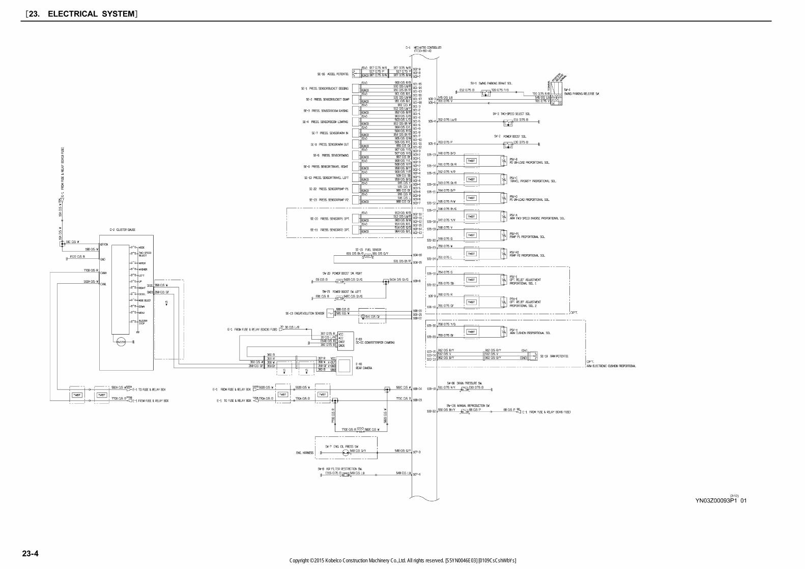
[23. ELECTRICAL SYSTEM]
23-4Copyright © 2015 Kobelco Construction Machinery Co.,Ltd. All rights reserved. [S5YN0046E03] [0109CsCshWbYs]

23
[23. ELECTRICAL SYSTEM]
23-5Copyright © 2015 Kobelco Construction Machinery Co.,Ltd. All rights reserved. [S5YN0046E03] [0109CsCshWbYs]
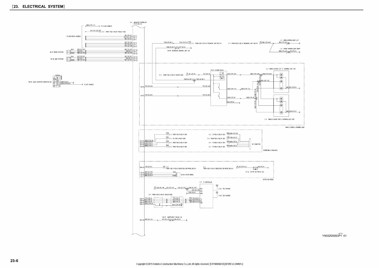
[23. ELECTRICAL SYSTEM]
23-6Copyright © 2015 Kobelco Construction Machinery Co.,Ltd. All rights reserved. [S5YN0046E03] [0109CsCshWbYs]
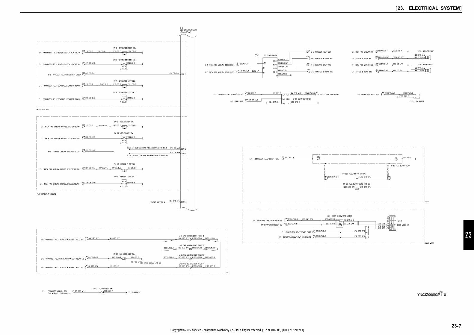
23
[23. ELECTRICAL SYSTEM]
23-7Copyright © 2015 Kobelco Construction Machinery Co.,Ltd. All rights reserved. [S5YN0046E03] [0109CsCshWbYs]
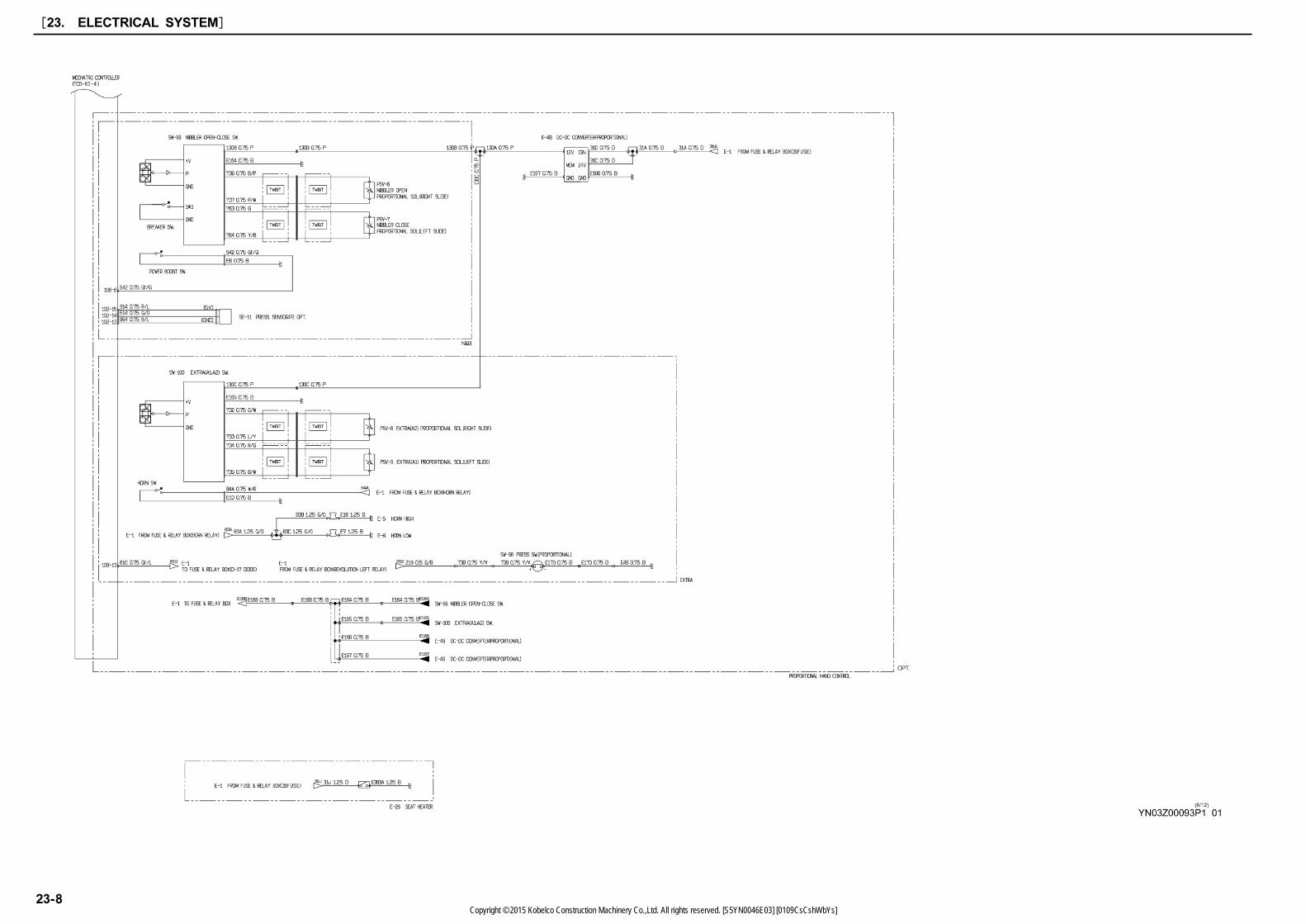
[23. ELECTRICAL SYSTEM]
23-8Copyright © 2015 Kobelco Construction Machinery Co.,Ltd. All rights reserved. [S5YN0046E03] [0109CsCshWbYs]
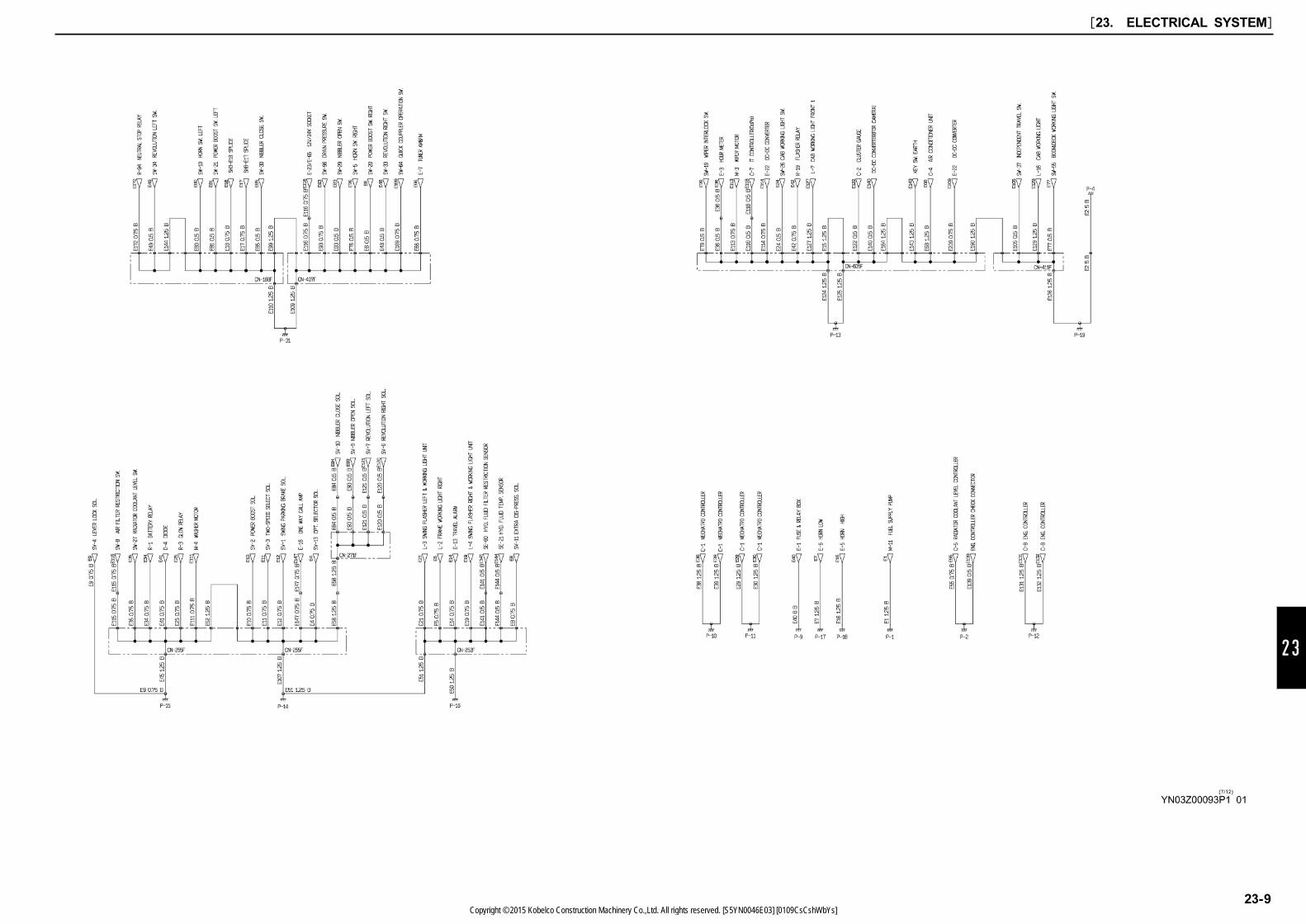
23
[23. ELECTRICAL SYSTEM]
23-9Copyright © 2015 Kobelco Construction Machinery Co.,Ltd. All rights reserved. [S5YN0046E03] [0109CsCshWbYs]
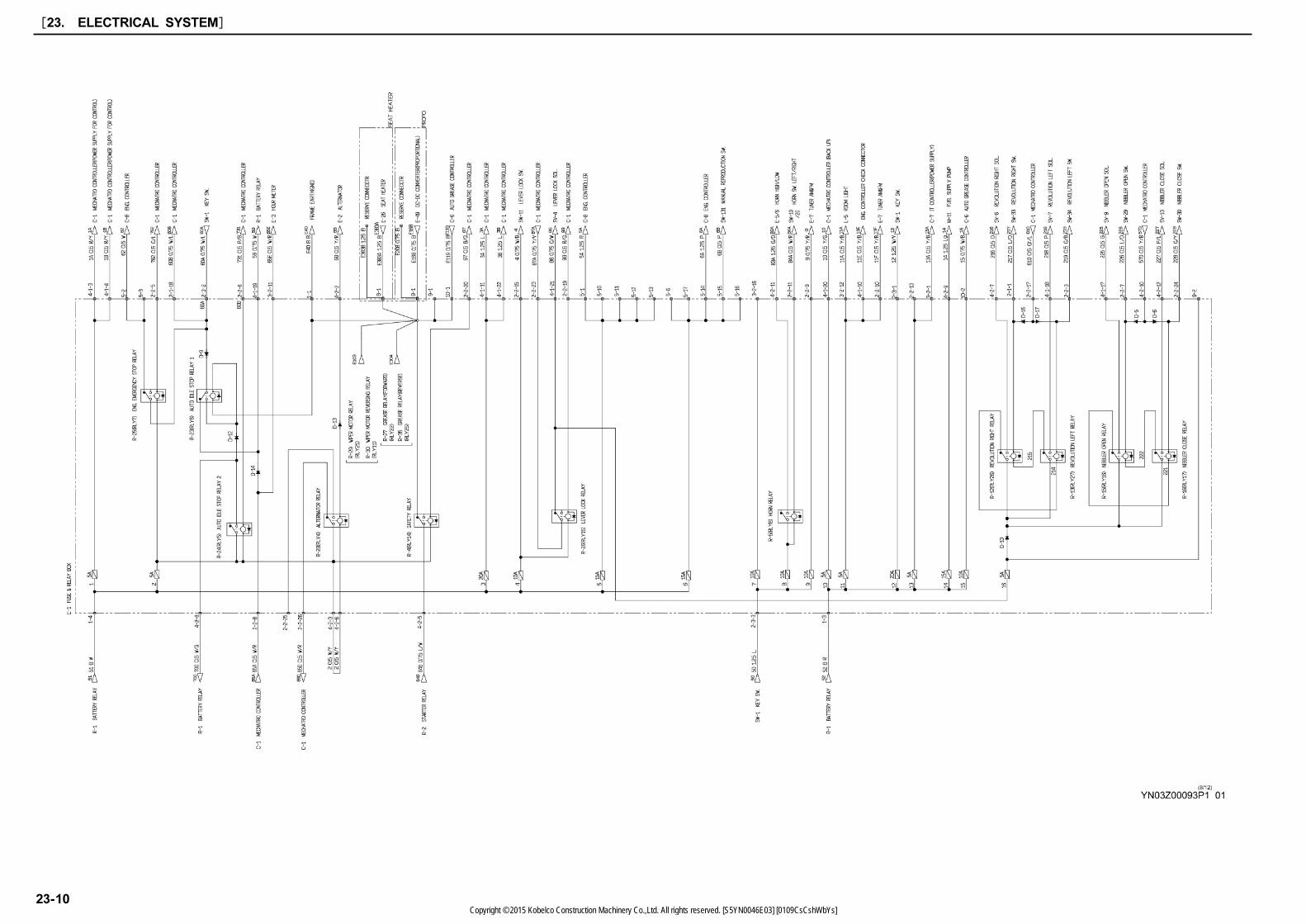
[23. ELECTRICAL SYSTEM]
23-10Copyright © 2015 Kobelco Construction Machinery Co.,Ltd. All rights reserved. [S5YN0046E03] [0109CsCshWbYs]

23
[23. ELECTRICAL SYSTEM]
23-11Copyright © 2015 Kobelco Construction Machinery Co.,Ltd. All rights reserved. [S5YN0046E03] [0109CsCshWbYs]
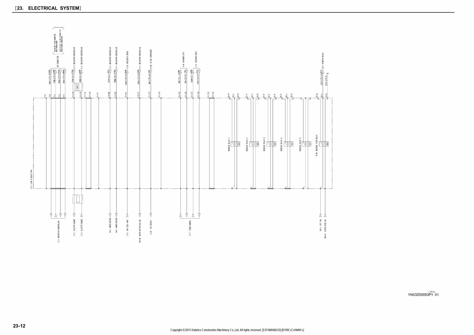
[23. ELECTRICAL SYSTEM]
23-12Copyright © 2015 Kobelco Construction Machinery Co.,Ltd. All rights reserved. [S5YN0046E03] [0109CsCshWbYs]

23
23.2 ELECTRICAL EQUIPMENT
LIST (North America)
[23. ELECTRICAL SYSTEM]
23-13Copyright © 2015 Kobelco Construction Machinery Co.,Ltd. All rights reserved. [S5YN0046E03] [0109CsCshWbYs]
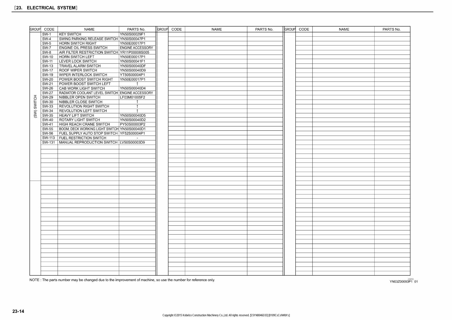
[23. ELECTRICAL SYSTEM]
23-14Copyright © 2015 Kobelco Construction Machinery Co.,Ltd. All rights reserved. [S5YN0046E03] [0109CsCshWbYs]
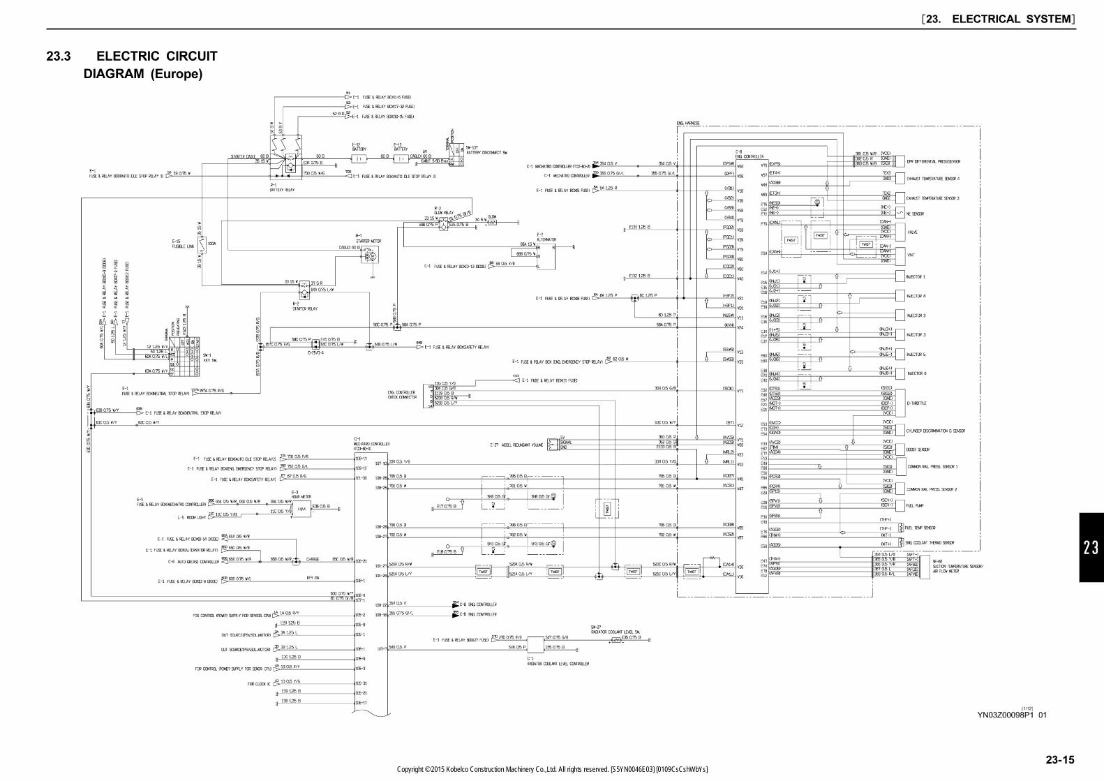
23
23.3 ELECTRIC CIRCUIT
DIAGRAM (Europe)
[23. ELECTRICAL SYSTEM]
23-15Copyright © 2015 Kobelco Construction Machinery Co.,Ltd. All rights reserved. [S5YN0046E03] [0109CsCshWbYs]

[23. ELECTRICAL SYSTEM]
23-16Copyright © 2015 Kobelco Construction Machinery Co.,Ltd. All rights reserved. [S5YN0046E03] [0109CsCshWbYs]
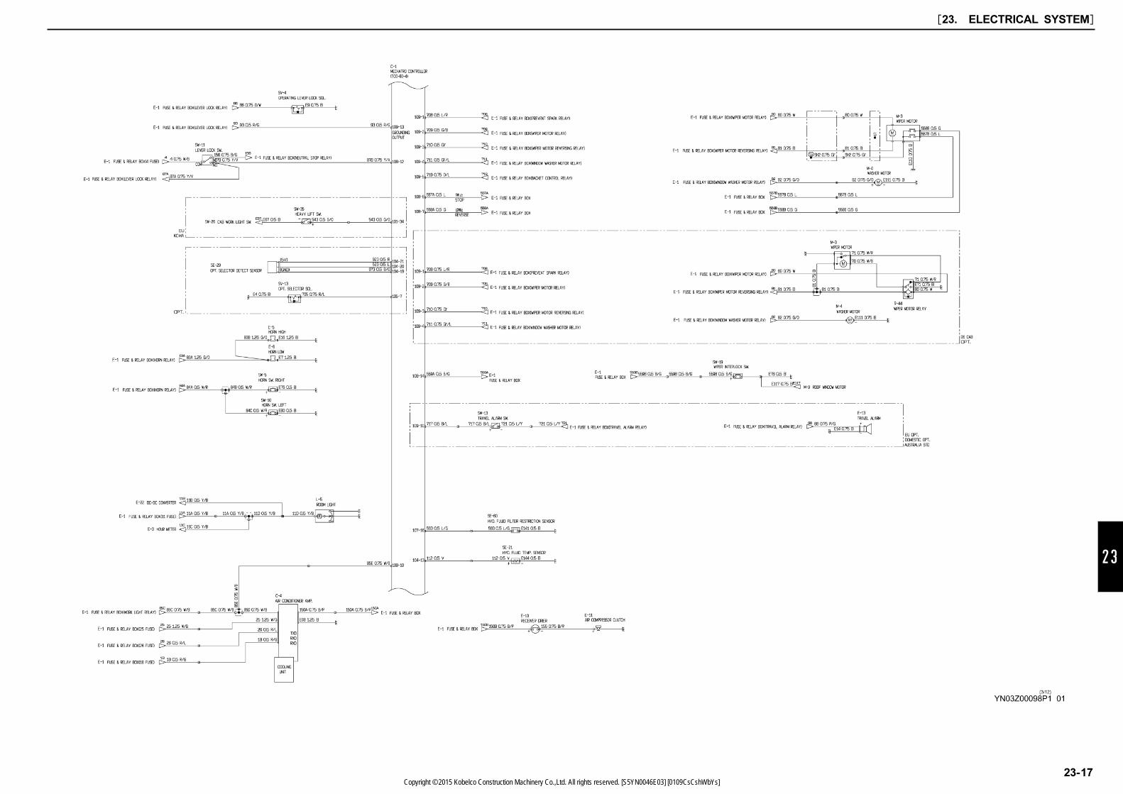
23
[23. ELECTRICAL SYSTEM]
23-17Copyright © 2015 Kobelco Construction Machinery Co.,Ltd. All rights reserved. [S5YN0046E03] [0109CsCshWbYs]
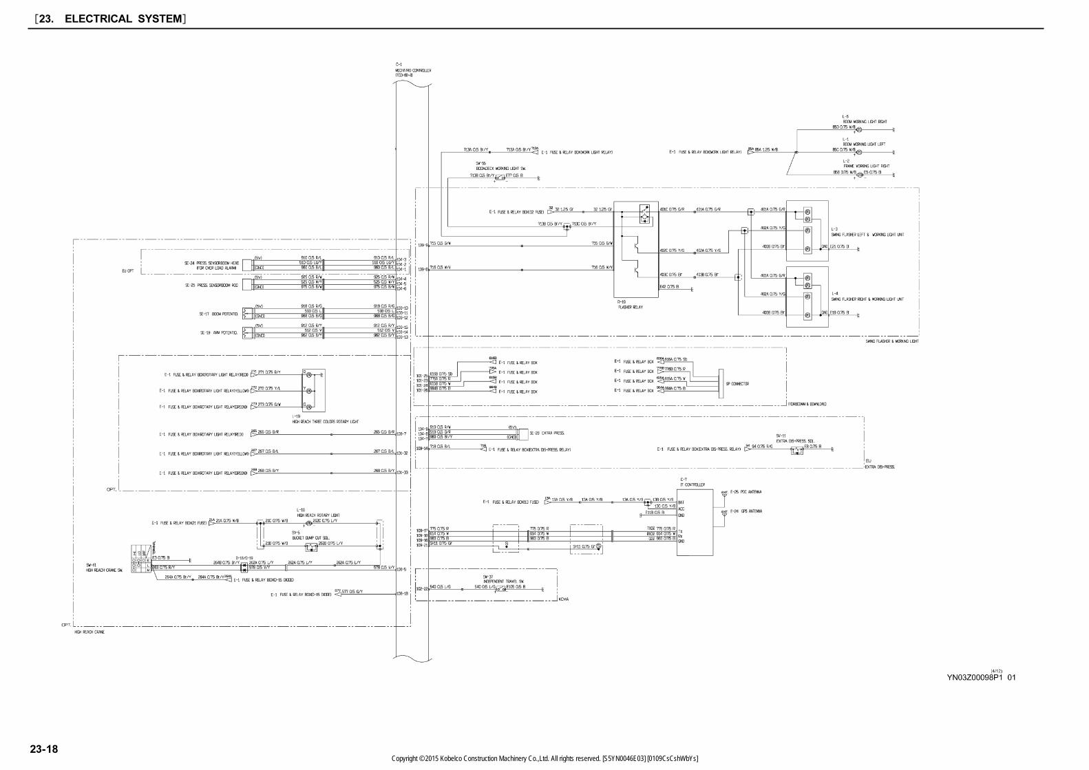
[23. ELECTRICAL SYSTEM]
23-18Copyright © 2015 Kobelco Construction Machinery Co.,Ltd. All rights reserved. [S5YN0046E03] [0109CsCshWbYs]
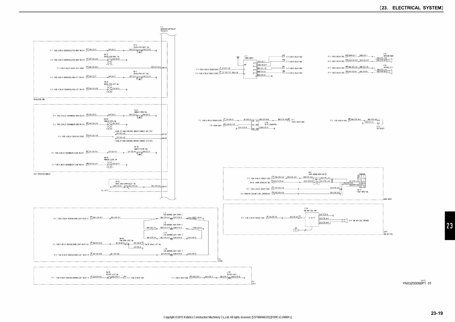
23
[23. ELECTRICAL SYSTEM]
23-19Copyright © 2015 Kobelco Construction Machinery Co.,Ltd. All rights reserved. [S5YN0046E03] [0109CsCshWbYs]

[23. ELECTRICAL SYSTEM]
23-20Copyright © 2015 Kobelco Construction Machinery Co.,Ltd. All rights reserved. [S5YN0046E03] [0109CsCshWbYs]
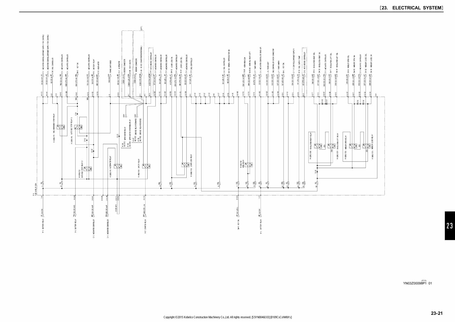
23
[23. ELECTRICAL SYSTEM]
23-21Copyright © 2015 Kobelco Construction Machinery Co.,Ltd. All rights reserved. [S5YN0046E03] [0109CsCshWbYs]

[23. ELECTRICAL SYSTEM]
23-22Copyright © 2015 Kobelco Construction Machinery Co.,Ltd. All rights reserved. [S5YN0046E03] [0109CsCshWbYs]

23
[23. ELECTRICAL SYSTEM]
23-23Copyright © 2015 Kobelco Construction Machinery Co.,Ltd. All rights reserved. [S5YN0046E03] [0109CsCshWbYs]
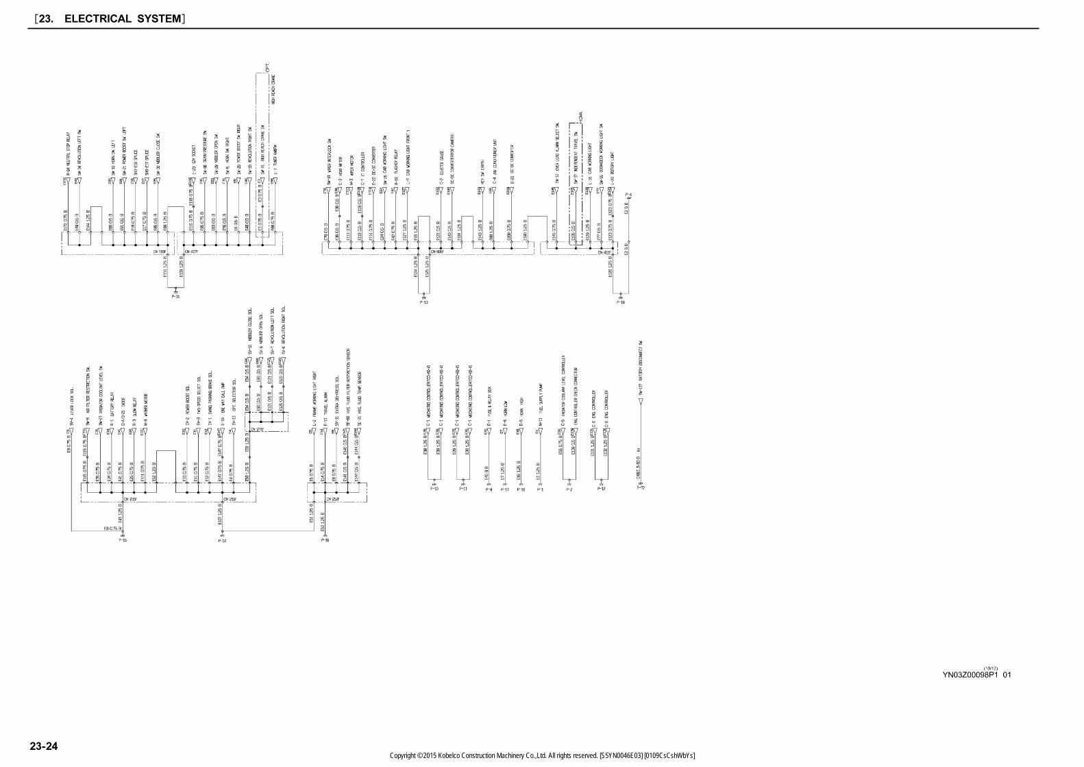
[23. ELECTRICAL SYSTEM]
23-24Copyright © 2015 Kobelco Construction Machinery Co.,Ltd. All rights reserved. [S5YN0046E03] [0109CsCshWbYs]
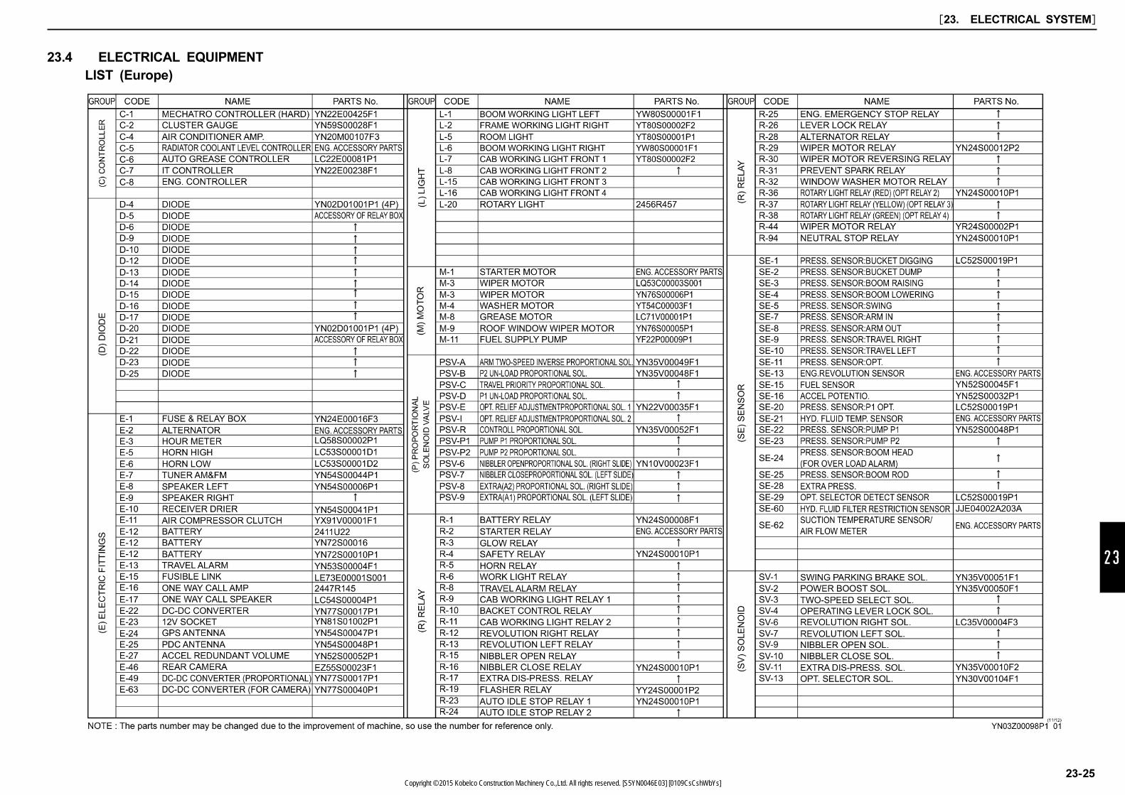
23
23.4 ELECTRICAL EQUIPMENT
LIST (Europe)
[23. ELECTRICAL SYSTEM]
23-25Copyright © 2015 Kobelco Construction Machinery Co.,Ltd. All rights reserved. [S5YN0046E03] [0109CsCshWbYs]
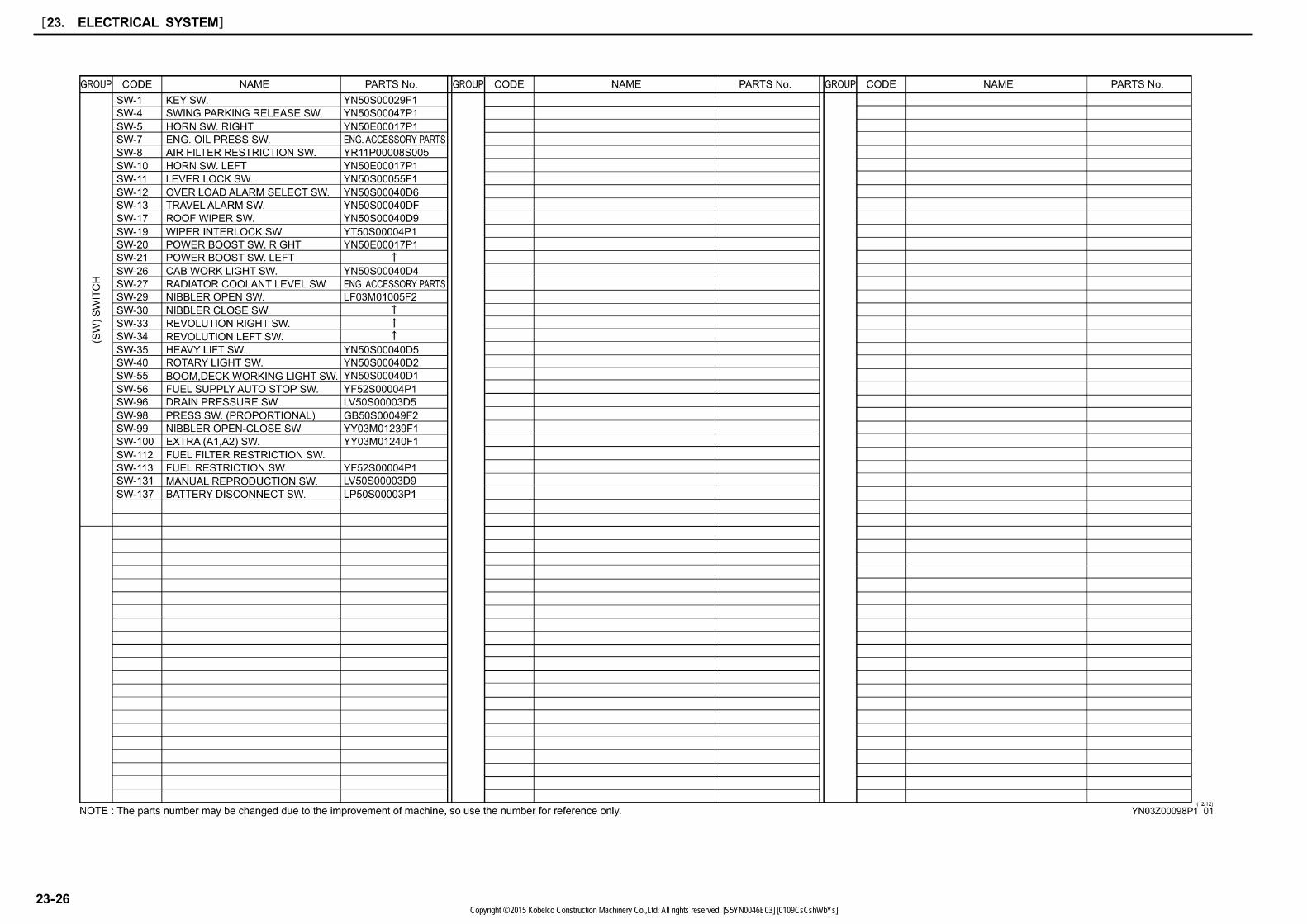
[23. ELECTRICAL SYSTEM]
23-26Copyright © 2015 Kobelco Construction Machinery Co.,Ltd. All rights reserved. [S5YN0046E03] [0109CsCshWbYs]


