Embed Size (px)
Citation preview
[ ]
Operating Manual
Order no.: FDK:521H1134
SFIDK.PS.023.A2.02
SITRANS F M MAGFLO &SITRANS F C MASSFLO
CANopen add-on module forUSM II transmitters
s
CANopen add-on module
SFIDK.PS.023.A2.022
Contents 1. Introduction ................................................................................................................... 3
2. Technical data ............................................................................................................... 4
3. Installation ..................................................................................................................... 53.1 Add-on module ............................................................................................................... 53.2 General electrical information ......................................................................................... 63.3 USM II connections ........................................................................................................ 63.4 Standard CAN connection .............................................................................................. 63.5 CAN bus termination ...................................................................................................... 73.6 CAN topology ................................................................................................................. 73.7 Cable length versus baudrate ........................................................................................ 73.8 Cable specification DC characteristics ........................................................................... 83.9 Cable specification cross-section CAN Bus-line cross-sections ..................................... 8
4. Commissioning ............................................................................................................. 94.1 CANopen display menu .................................................................................................. 94.2 Menu item explanation ................................................................................................. 10
5. Object dictionary overview ........................................................................................ 11
6. PDOs (Process Data Objects) ................................................................................... 126.1 What is a PDO .............................................................................................................. 12
6.1.1 TX PDOs ......................................................................................................... 126.1.2 RX PDOs ......................................................................................................... 12
7. SDOs (Service Data Objects) ..................................................................................... 13
APPENDIX ASI-units used in USM II products .................................................................................. 22
APPENDIX BRaw communication example ....................................................................................... 23

CANopen add-on module
3SFIDK.PS.023.A2.02
This manual is intended to provide instructions for the installation and use of the CANopen add-on module, product code number FDK:085U0228, that can be used in the Siemens FlowInstruments USM II family of transmitters, which presently includes MAG 6000 and MASS 6000.
The CANopen module is effectively a gateway through which a CANopen master device can havecontrolled access to a number of Siemens Flow Instruments USM II signal converter parameters.
This manual is not intended to be a complete tutorial on the CANopen protocol, and it is assumedthe end user already has a general working knowledge of CANopen communications, especiallyin respect of master station configuration and operation. However an overview is included in thefollowing section to explain some of the fundamental aspects of the protocol.
1. Introduction
1. Introduction
CANopen add-on module
SFIDK.PS.023.A2.024
MASS 6000 (2) Value returned is dependent on the BATCH1) Mass flow + Totalizer 1 function.2) Density + Temperature + Pct. Fraction A (1) When ON, batch progress is returned.3) Volume flow + Totalizer 2 (2) When OFF, TOTALIZER 2 is returned.4) Fraction A (1) + Fraction B (1)
2. Technical data
2. Technical data CANopen specificationNMT(Network Management) SlaveBaud rates 10, 20, 50, 100, 125, 250, 500, 1000 Kbits/sNumber of stations Recommended max. 50 per segment (Total max. 127)Error control Node guarding, heartbeatNode id Software, from displayNo. of PDO’s MAG: RX=1 TX=2 MASS: RX=1 TX=4PDO modes Event triggeredPDO linking YesPDO mapping Yes, defaultNo. of SDO’s 1 Server 0 ClientEmergency message NoCANopen version DS-301 V4.01Framework NoCertified NoDevice profile Siemens Flow Instruments specific
Cable specificationCable design Four wire (two pairs) twisted pair with shieldShielding CU shielding braid or shielding braid and shielding foilImpedance 35 up to 165 Ohm at frequencies from 3 to 20 mHzCable capacity < 130 pF per meter at 1000 kbit/s at 40 mCore diameter > 0.34 mm2 at 1000 kbit/s at 40 m (corresponds to
AWG 22)Resistance < 26 Ohm per km at 1000 kbit/s at 40 mSignal attenuation Max. 9 dB over total length of line sectionMax. bus length Up to 1 km at 50 kbit/s. Extendable by repeaters
Default PDO’s:MAG 60001) Volume flow + Totalizer 1 (1) Requires a SENSORPROM flow memory unit2) Totalizer 2 (2) containing valid fraction data.
CANopen add-on module
5SFIDK.PS.023.A2.02
3. Installation
3. Installation
3.1 Add-on module
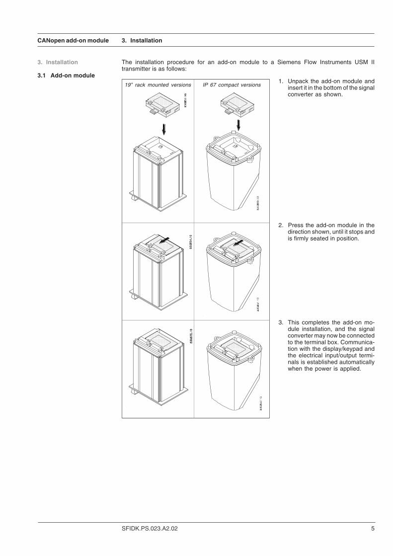
19” rack mounted versions IP 67 compact versions
The installation procedure for an add-on module to a Siemens Flow Instruments USM IItransmitter is as follows:
1. Unpack the add-on module andinsert it in the bottom of the signalconverter as shown.
2. Press the add-on module in thedirection shown, until it stops andis firmly seated in position.
3. This completes the add-on mo-dule installation, and the signalconverter may now be connectedto the terminal box. Communica-tion with the display/keypad andthe electrical input/output termi-nals is established automaticallywhen the power is applied.
CANopen add-on module
SFIDK.PS.023.A2.026
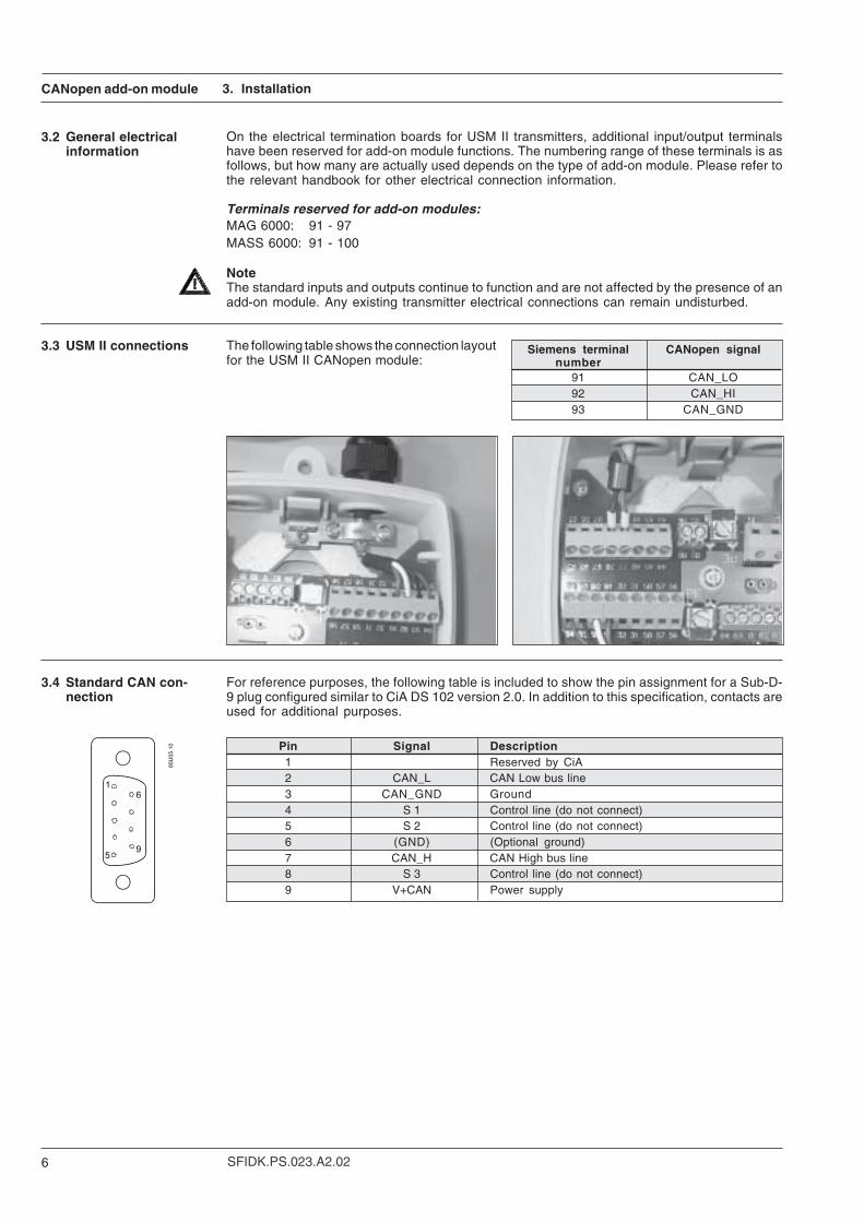
3.2 General electricalinformation
3.3 USM II connections The following table shows the connection layoutfor the USM II CANopen module:
On the electrical termination boards for USM II transmitters, additional input/output terminalshave been reserved for add-on module functions. The numbering range of these terminals is asfollows, but how many are actually used depends on the type of add-on module. Please refer tothe relevant handbook for other electrical connection information.
Terminals reserved for add-on modules:MAG 6000: 91 - 97MASS 6000: 91 - 100
NoteThe standard inputs and outputs continue to function and are not affected by the presence of anadd-on module. Any existing transmitter electrical connections can remain undisturbed.
Siemens terminal CANopen signalnumber
91 CAN_LO92 CAN_HI93 CAN_GND
3.4 Standard CAN con-nection
For reference purposes, the following table is included to show the pin assignment for a Sub-D-9 plug configured similar to CiA DS 102 version 2.0. In addition to this specification, contacts areused for additional purposes.
Pin Signal Description1 Reserved by CiA2 CAN_L CAN Low bus line3 CAN_GND Ground4 S 1 Control line (do not connect)5 S 2 Control line (do not connect)6 (GND) (Optional ground)7 CAN_H CAN High bus line8 S 3 Control line (do not connect)9 V+CAN Power supply
3. Installation
CANopen add-on module
7SFIDK.PS.023.A2.02
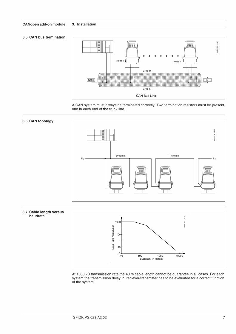
3.6 CAN topology
3.7 Cable length versusbaudrate
3.5 CAN bus termination
At 1000 kB transmission rate the 40 m cable length cannot be guarantee in all cases. For eachsystem the transmission delay in reciever/transmitter has to be evaluated for a correct functionof the system.
3. Installation
A CAN system must always be terminated correctly. Two termination resistors must be present,one in each end of the trunk line.
CANopen add-on module
SFIDK.PS.023.A2.028
3.8 Cable specificationDC characteristics
Bus cable
Bus length Length-related Bus-line cross-section Termination Max.resistance resistance baurade
0 to 40 m 70 mΩ/m 0.25 mm2 to 0.34 mm2 124 Ω (1%) 1 Mbit/sAWG23, AWG22 at 40 m
40 to 300 m <60 mΩ/m 0.34 mm2 to 0.6 mm2 127 Ω (1%) 500 Mbit/s
AWG22, AWG20 at 100 m300 to 600 m <40 mΩ/m 0.5 mm2 to 0.6 mm2 150 Ω to 300 Ω 100 Mbit/s
AWG20 at 100 m
600 to 1 km <26 mΩ/m 0.75 mm2 to 0.8 mm2 150 Ω to 300 Ω 50 Mbit/s
AWG18 at 1k m
3.9 Cable specificationcross-section CANBus-line cross-sections
Length 32 nodes 64 nodes 100 nodes100 m 0.25 mm2 0.25 mm2 0.25 mm2
250 m 0.34 mm2 0.50 mm2 0.50 mm2
500 m 0.75 mm2 0.75 mm2 1.00 mm2
Wire resistance Rw < 21 Ω (32 nodes), < 18.5 Ω (64 nodes), 16 Ω (100 nodes).
At 1000 kB transmission rate the 40 m cable length cannot be guarantee in all cases. For eachsystem the transmission delay in reciever/transmitter has to be evaluated for a correct functionof the system.
3. Installation
CANopen add-on module
9SFIDK.PS.023.A2.02
4. Commissioning
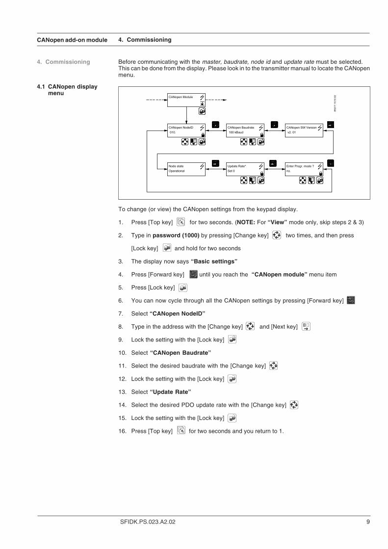
To change (or view) the CANopen settings from the keypad display.
1. Press [Top key] for two seconds. (NOTE: For “View” mode only, skip steps 2 & 3)
2. Type in password (1000) by pressing [Change key] two times, and then press
[Lock key] and hold for two seconds
3. The display now says “Basic settings”
4. Press [Forward key] until you reach the “CANopen module” menu item
5. Press [Lock key]
6. You can now cycle through all the CANopen settings by pressing [Forward key]
7. Select “CANopen NodeID”
8. Type in the address with the [Change key] and [Next key]
9. Lock the setting with the [Lock key]
10. Select “CANopen Baudrate”
11. Select the desired baudrate with the [Change key]
12. Lock the setting with the [Lock key]
13. Select “Update Rate”
14. Select the desired PDO update rate with the [Change key]
15. Lock the setting with the [Lock key]
16. Press [Top key] for two seconds and you return to 1.
4. Commissioning Before communicating with the master, baudrate, node id and update rate must be selected.This can be done from the display. Please look in to the transmitter manual to locate the CANopenmenu.
4.1 CANopen displaymenu
CANopen add-on module
SFIDK.PS.023.A2.0210
4. Commissioning
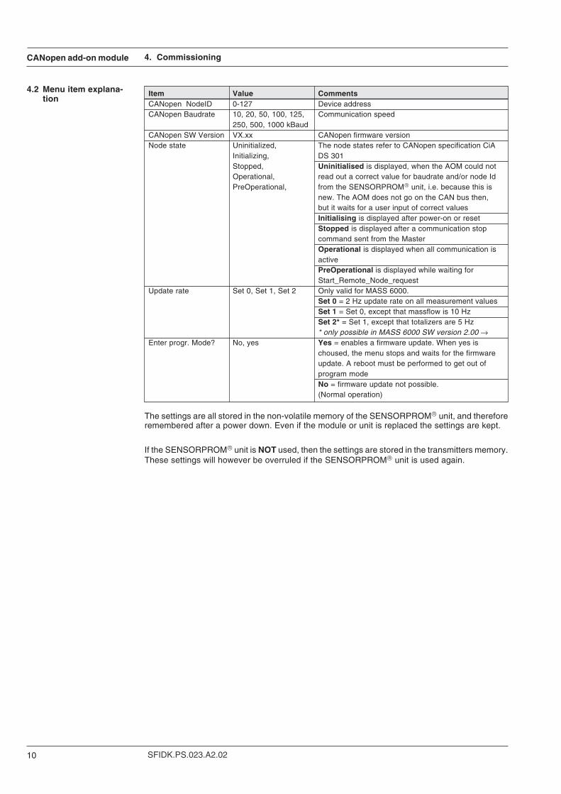
4.2 Menu item explana-tion
Item Value CommentsCANopen NodeID 0-127 Device addressCANopen Baudrate 10, 20, 50, 100, 125, Communication speed
250, 500, 1000 kBaudCANopen SW Version VX.xx CANopen firmware versionNode state Uninitialized, The node states refer to CANopen specification CiA
Initializing, DS 301Stopped, Uninitialised is displayed, when the AOM could notOperational, read out a correct value for baudrate and/or node IdPreOperational, from the SENSORPROM unit, i.e. because this is
new. The AOM does not go on the CAN bus then,but it waits for a user input of correct valuesInitialising is displayed after power-on or resetStopped is displayed after a communication stopcommand sent from the MasterOperational is displayed when all communication isactivePreOperational is displayed while waiting forStart_Remote_Node_request
Update rate Set 0, Set 1, Set 2 Only valid for MASS 6000.Set 0 = 2 Hz update rate on all measurement valuesSet 1 = Set 0, except that massflow is 10 HzSet 2* = Set 1, except that totalizers are 5 Hz* only possible in MASS 6000 SW version 2.00 →
Enter progr. Mode? No, yes Yes = enables a firmware update. When yes ischoused, the menu stops and waits for the firmwareupdate. A reboot must be performed to get out ofprogram modeNo = firmware update not possible.(Normal operation)
The settings are all stored in the non-volatile memory of the SENSORPROM unit, and thereforeremembered after a power down. Even if the module or unit is replaced the settings are kept.
If the SENSORPROM unit is NOT used, then the settings are stored in the transmitters memory.These settings will however be overruled if the SENSORPROM unit is used again.
CANopen add-on module
11SFIDK.PS.023.A2.02
5. Object dictionary overview
5. Object dictionaryoverview
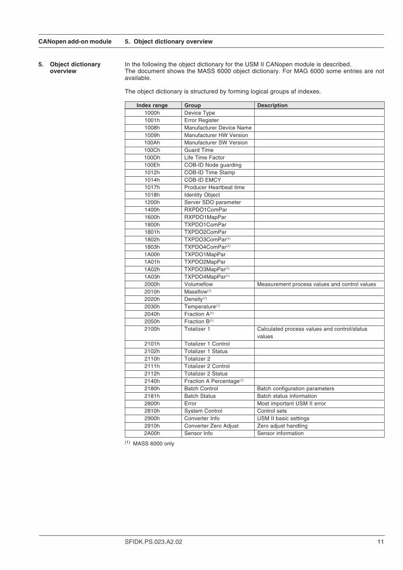
In the following the object dictionary for the USM II CANopen module is described.The document shows the MASS 6000 object dictionary. For MAG 6000 some entries are notavailable.
The object dictionary is structured by forming logical groups af indexes.
Index range Group Description1000h Device Type1001h Error Register1008h Manufacturer Device Name1009h Manufacturer HW Version100Ah Manufacturer SW Version100Ch Guard Time100Dh Life Time Factor100Eh COB-ID Node guarding1012h COB-ID Time Stamp1014h COB-ID EMCY1017h Producer Heartbeat time1018h Identity Object1200h Server SDO parameter1400h RXPDO1ComPar1600h RXPDO1MapPar1800h TXPDO1ComPar1801h TXPDO2ComPar1802h TXPDO3ComPar(1)
1803h TXPDO4ComPar(1)
1A00h TXPDO1MapPar1A01h TXPDO2MapPar1A02h TXPDO3MapPar(1)
1A03h TXPDO4MapPar(1)
2000h Volumeflow Measurement process values and control values2010h Massflow(1)
2020h Density(1)
2030h Temperature(1)
2040h Fraction A(1)
2050h Fraction B(1)
2100h Totalizer 1 Calculated process values and control/statusvalues
2101h Totalizer 1 Control2102h Totalizer 1 Status2110h Totalizer 22111h Totalizer 2 Control2112h Totalizer 2 Status2140h Fraction A Percentage(1)
2180h Batch Control Batch configuration parameters2181h Batch Status Batch status information2800h Error Most important USM II error2810h System Control Control sets2900h Converter Info USM II basic settings2910h Converter Zero Adjust Zero adjust handling2A00h Sensor Info Sensor information
(1) MASS 6000 only
CANopen add-on module
SFIDK.PS.023.A2.0212
6. PDOs (Process Data Objects)
6. PDOs (ProcessData Objects)
6.1 What is a PDO
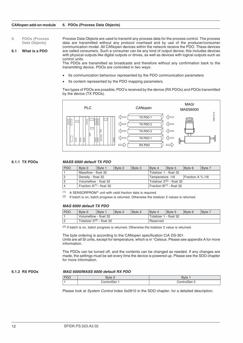
Process Data Objects are used to transmit any process data for the process control. The processdata are transmitted without any protocol overhead and by use of the producer/consumercommunication model. All CANopen devices within the network receive the PDO. These devicesare called consumers. Such a consumer can be any kind of output device; this includes deviceswith physical outputs like digital outputs or drives, as well as devices with logical outputs such ascontrol units.The PDOs are transmitted as broadcasts and therefore without any confirmation back to thetransmitting device. PDOs are controlled in two ways:
• Its communication behaviour represented by the PDO communication parameters
• Its content represented by the PDO mapping parameters.
Two types of PDOs are possible; PDO’s received by the device (RX PDOs) and PDOs transmittedby the device (TX PDOs).
MASS 6000 default TX PDO
PDO Byte 0 Byte 1 Byte 2 Byte 3 Byte 4 Byte 5 Byte 6 Byte 71 Massflow - float 32 Totalizer 1 - float 322 Density - float 32 Temperature i16 Fraction A % i163 Volumeflow - float 32 Totalizer 2(2) - float 324 Fraction A(1) - float 32 Fraction B(1) - float 32
(1) A SENSORPROM unit with valid fraction data is required.(2) If batch is on, batch progress is returned. Otherwise the totalizer 2 values is returned.
MAG 6000 default TX PDO
PDO Byte 0 Byte 1 Byte 2 Byte 3 Byte 4 Byte 5 Byte 6 Byte 71 Volumeflow - float 32 Totalizer 1 - float 322 Totalizer 2(2) - float 32 Reserved
(2) If batch is on, batch progress is returned. Otherwise the totalizer 2 value is returned.
The byte ordering is according to the CANopen specification CiA DS-301.Units are all SI units, except for temperature, which is in °Celsius. Please see appendix A for moreinformation.
The PDOs can be turned off, and the contents can be changed as needed. If any changes aremade, the settings must be set every time the device is powered up. Please see the SDO chapterfor more information.
MAG 6000/MASS 6000 default RX PDO
6.1.1 TX PDOs
6.1.2 RX PDOs
PDO Byte 0 Byte 11 ControlSet 1 ControlSet 2
Please look at System Control index 0x2810 in the SDO chapter, for a detailed description.
CANopen add-on module
13SFIDK.PS.023.A2.02
7. SDOs (Service Data Objects)
7. SDOs (ServiceData Objects)
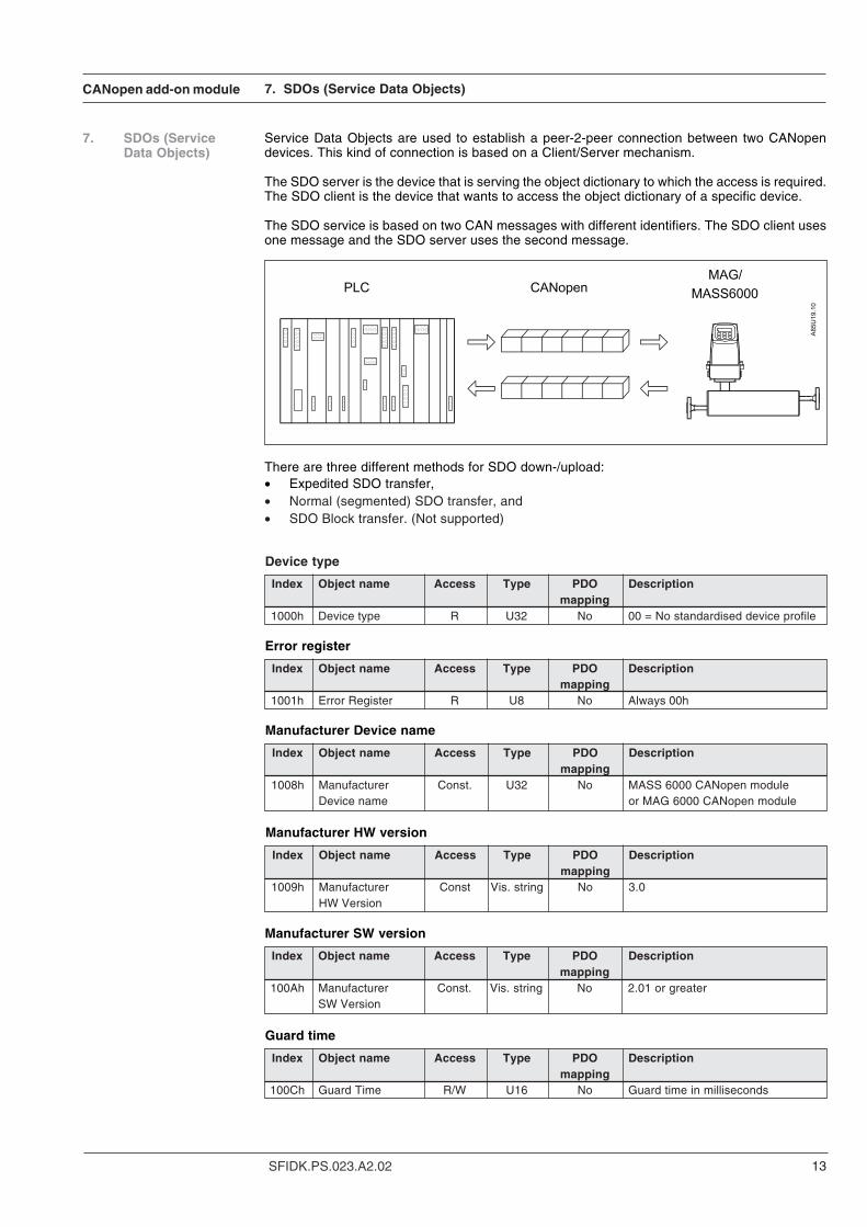
Service Data Objects are used to establish a peer-2-peer connection between two CANopendevices. This kind of connection is based on a Client/Server mechanism.
The SDO server is the device that is serving the object dictionary to which the access is required.The SDO client is the device that wants to access the object dictionary of a specific device.
The SDO service is based on two CAN messages with different identifiers. The SDO client usesone message and the SDO server uses the second message.
There are three different methods for SDO down-/upload:• Expedited SDO transfer,• Normal (segmented) SDO transfer, and• SDO Block transfer. (Not supported)
Device type
Index Object name Access Type PDO Descriptionmapping
1000h Device type R U32 No 00 = No standardised device profile
Error register
Index Object name Access Type PDO Descriptionmapping
1001h Error Register R U8 No Always 00h
Manufacturer Device name
Index Object name Access Type PDO Descriptionmapping
1008h Manufacturer Const. U32 No MASS 6000 CANopen moduleDevice name or MAG 6000 CANopen module
Manufacturer HW version
Index Object name Access Type PDO Descriptionmapping
1009h Manufacturer Const Vis. string No 3.0HW Version
Manufacturer SW version
Index Object name Access Type PDO Descriptionmapping
100Ah Manufacturer Const. Vis. string No 2.01 or greaterSW Version
Guard time
Index Object name Access Type PDO Descriptionmapping
100Ch Guard Time R/W U16 No Guard time in milliseconds
CANopen add-on module
SFIDK.PS.023.A2.0214
7. SDOs (Service Data Objects)
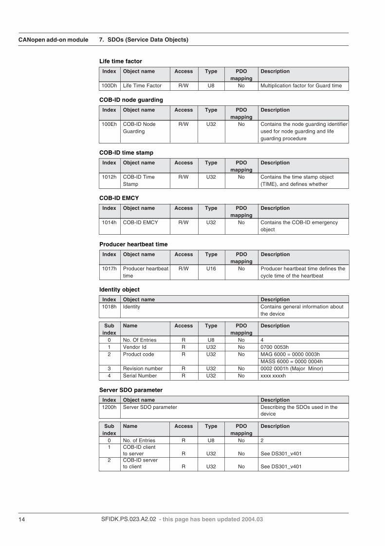
Life time factor
Index Object name Access Type PDO Descriptionmapping
100Dh Life Time Factor R/W U8 No Multiplication factor for Guard time
COB-ID node guarding
Index Object name Access Type PDO Descriptionmapping
100Eh COB-ID Node R/W U32 No Contains the node guarding identifierGuarding used for node guarding and life
guarding procedure
COB-ID time stamp
Index Object name Access Type PDO Descriptionmapping
1012h COB-ID Time R/W U32 No Contains the time stamp objectStamp (TIME), and defines whether
COB-ID EMCY
Index Object name Access Type PDO Descriptionmapping
1014h COB-ID EMCY R/W U32 No Contains the COB-ID emergencyobject
Producer heartbeat time
Index Object name Access Type PDO Descriptionmapping
1017h Producer heartbeat R/W U16 No Producer heartbeat time defines thetime cycle time of the heartbeat
Identity object
Index Object name Description1018h Identity Contains general information about
the device
Sub Name Access Type PDO Descriptionindex mapping
0 No. Of Entries R U8 No 41 Vendor Id R U32 No 0700 0053h2 Product code R U32 No MAG 6000 = 0000 0003h
MASS 6000 = 0000 0004h3 Revision number R U32 No 0002 0001h (Major Minor)4 Serial Number R U32 No xxxx xxxxh
Server SDO parameter
Index Object name Description1200h Server SDO parameter Describing the SDOs used in the
device
Sub Name Access Type PDO Descriptionindex mapping
0 No. of Entries R U8 No 21 COB-ID client
to server R U32 No See DS301_v4012 COB-ID server
to client R U32 No See DS301_v401
- this page has been updated 2004.03
CANopen add-on module
15SFIDK.PS.023.A2.02
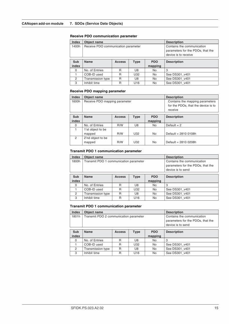
Receive PDO communication parameter
Index Object name Description1400h Receive PDO communication parameter Contains the communication
parameters for the PDOs, that thedevice is to receive
Sub Name Access Type PDO Descriptionindex mapping
0 No. of Entries R U8 No 31 COB-ID used R U32 No See DS301_v4012 Transmission type R U8 No See DS301_v4013 Inhibit time R U16 No See DS301_v401
7. SDOs (Service Data Objects)
Receive PDO mapping parameter
Index Object name Description1600h Receive PDO mapping parameter Contains the mapping parameters
for the PDOs, that the device is toreceive
Sub Name Access Type PDO Descriptionindex mapping
0 No. of Entries R/W U8 No Default = 21 1’st object to be
mapped R/W U32 No Default = 2810 0108h2 2’nd object to be
mapped R/W U32 No Default = 2810 0208h
Transmit PDO 1 communication parameter
Index Object name Description1800h Transmit PDO 1 communication parameter Contains the communication
parameters for the PDOs, that thedevice is to send
Sub Name Access Type PDO Descriptionindex mapping
0 No. of Entries R U8 No 31 COB-ID used R U32 No See DS301_v4012 Transmission type R U8 No See DS301_v4013 Inhibit time R U16 No See DS301_v401
Transmit PDO 1 communication parameter
Index Object name Description1801h Transmit PDO 2 communication parameter Contains the communication
parameters for the PDOs, that thedevice is to send
Sub Name Access Type PDO Descriptionindex mapping
0 No. of Entries R U8 No 31 COB-ID used R U32 No See DS301_v4012 Transmission type R U8 No See DS301_v4013 Inhibit time R U16 No See DS301_v401
CANopen add-on module
SFIDK.PS.023.A2.0216
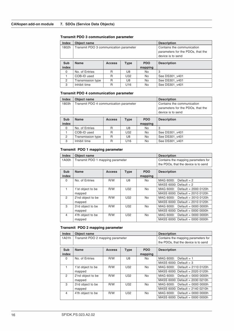
Transmit PDO 3 communication parameter
Index Object name Description1802h Transmit PDO 3 communication parameter Contains the communication
parameters for the PDOs, that thedevice is to send
Sub Name Access Type PDO Descriptionindex mapping
0 No. of Entries R U8 No 31 COB-ID used R U32 No See DS301_v4012 Transmission type R U8 No See DS301_v4013 Inhibit time R U16 No See DS301_v401
7. SDOs (Service Data Objects)
Transmit PDO 4 communication parameter
Index Object name Description1803h Transmit PDO 4 communication parameter Contains the communication
parameters for the PDOs, that thedevice is to send
Sub Name Access Type PDO Descriptionindex mapping
0 No. of Entries R U8 No 31 COB-ID used R U32 No See DS301_v4012 Transmission type R U8 No See DS301_v4013 Inhibit time R U16 No See DS301_v401
Transmit PDO 1 mapping parameter
Index Object name Description1A00h Transmit PDO 1 mapping parameter Contains the mapping parameters for
the PDOs, that the device is to send
Sub Name Access Type PDO Descriptionindex mapping
0 No. of Entries R/W U8 No MAG 6000: Default = 2MASS 6000: Default = 2
1 1’st object to be R/W U32 No MAG 6000: Default = 2000 0120hmapped MASS 6000: Default = 2010 0120h
2 2’nd object to be R/W U32 No MAG 6000: Default = 2010 0120hmapped MASS 6000: Default = 2010 0120h
3 3’rd object to be R/W U32 No MAG 6000: Default = 0000 0000hmapped MASS 6000: Default = 0000 0000h
4 4’th object to be R/W U32 No MAG 6000: Default = 0000 0000hmapped MASS 6000: Default = 0000 0000h
Transmit PDO 2 mapping parameter
Index Object name Description1A01h Transmit PDO 2 mapping parameter Contains the mapping parameters for
the PDOs, that the device is to send
Sub Name Access Type PDO Descriptionindex mapping
0 No. of Entries R/W U8 No MAG 6000: Default = 1MASS 6000: Default = 3
1 1’st object to be R/W U32 No MAG 6000: Default = 2110 0120hmapped MASS 6000: Default = 2020 0120h
2 2’nd object to be R/W U32 No MAG 6000: Default = 0000 0000hmapped MASS 6000: Default = 2030 0210h
3 3’rd object to be R/W U32 No MAG 6000: Default = 0000 0000hmapped MASS 6000: Default = 2140 0210h
4 4’th object to be R/W U32 No MAG 6000: Default = 0000 0000hMASS 6000: Default = 0000 0000h
CANopen add-on module
17SFIDK.PS.023.A2.02
7. SDOs (Service Data Objects)
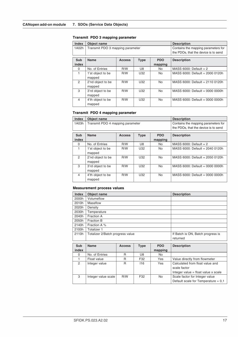
Transmit PDO 3 mapping parameter
Index Object name Description1A02h Transmit PDO 3 mapping parameter Contains the mapping parameters for
the PDOs, that the device is to send
Sub Name Access Type PDO Descriptionindex mapping
0 No. of Entries R/W U8 No MASS 6000: Default = 21 1’st object to be R/W U32 No MASS 6000: Default = 2000 0120h
mapped2 2’nd object to be R/W U32 No MASS 6000: Default = 2110 0120h
mapped3 3’rd object to be R/W U32 No MASS 6000: Default = 0000 0000h
mapped4 4’th object to be R/W U32 No MASS 6000: Default = 0000 0000h
mapped
Transmit PDO 4 mapping parameter
Index Object name Description1A03h Transmit PDO 4 mapping parameter Contains the mapping parameters for
the PDOs, that the device is to send
Sub Name Access Type PDO Descriptionindex mapping
0 No. of Entries R/W U8 No MASS 6000: Default = 21 1’st object to be R/W U32 No MASS 6000: Default = 2040 0120h
mapped2 2’nd object to be R/W U32 No MASS 6000: Default = 2050 0120h
mapped3 3’rd object to be R/W U32 No MASS 6000: Default = 0000 0000h
mapped4 4’th object to be R/W U32 No MASS 6000: Default = 0000 0000h
mapped
Measurement process values
Index Object name Description2000h Volumeflow2010h Massflow2020h Density2030h Temperature2040h Fraction A2050h Fraction B2140h Fraction A %2100h Totalizer 12110h Totalizer 2/Batch progress value If Batch is ON, Batch progress is
returned
Sub Name Access Type PDO Descriptionindex mapping
0 No. of Entries R U8 No1 Float value R F32 Yes Value directly from flowmeter2 Integer value R I16 Yes Calculated from float value and
scale factorInteger value = float value x scale
3 Integer value scale R/W F32 No Scale factor for Integer valueDefault scale for Temperature = 0,1
CANopen add-on module
SFIDK.PS.023.A2.0218
7. SDOs (Service Data Objects)
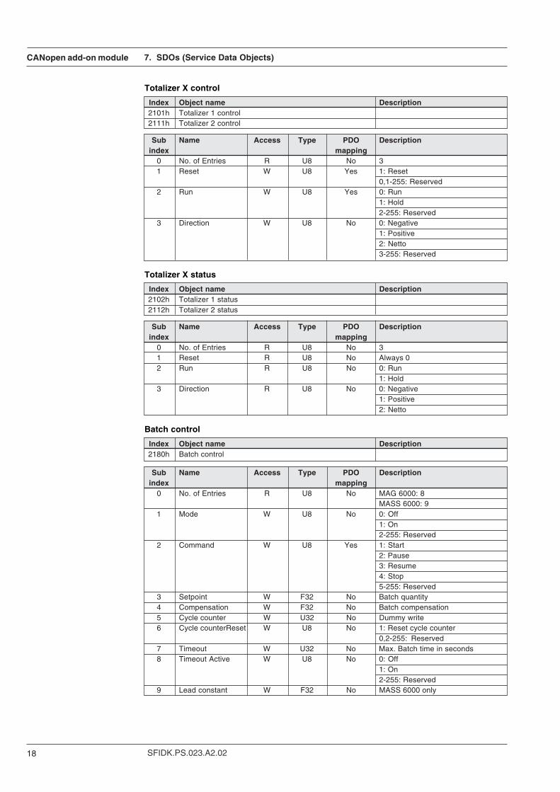
Totalizer X control
Index Object name Description2101h Totalizer 1 control2111h Totalizer 2 control
Sub Name Access Type PDO Descriptionindex mapping
0 No. of Entries R U8 No 31 Reset W U8 Yes 1: Reset
0,1-255: Reserved2 Run W U8 Yes 0: Run
1: Hold2-255: Reserved
3 Direction W U8 No 0: Negative1: Positive2: Netto3-255: Reserved
Totalizer X status
Index Object name Description2102h Totalizer 1 status2112h Totalizer 2 status
Sub Name Access Type PDO Descriptionindex mapping
0 No. of Entries R U8 No 31 Reset R U8 No Always 02 Run R U8 No 0: Run
1: Hold3 Direction R U8 No 0: Negative
1: Positive2: Netto
Batch control
Index Object name Description2180h Batch control
Sub Name Access Type PDO Descriptionindex mapping
0 No. of Entries R U8 No MAG 6000: 8MASS 6000: 9
1 Mode W U8 No 0: Off1: On2-255: Reserved
2 Command W U8 Yes 1: Start2: Pause3: Resume4: Stop5-255: Reserved
3 Setpoint W F32 No Batch quantity4 Compensation W F32 No Batch compensation5 Cycle counter W U32 No Dummy write6 Cycle counterReset W U8 No 1: Reset cycle counter
0,2-255: Reserved7 Timeout W U32 No Max. Batch time in seconds8 Timeout Active W U8 No 0: Off
1: On2-255: Reserved
9 Lead constant W F32 No MASS 6000 only
CANopen add-on module
19SFIDK.PS.023.A2.02
7. SDOs (Service Data Objects)
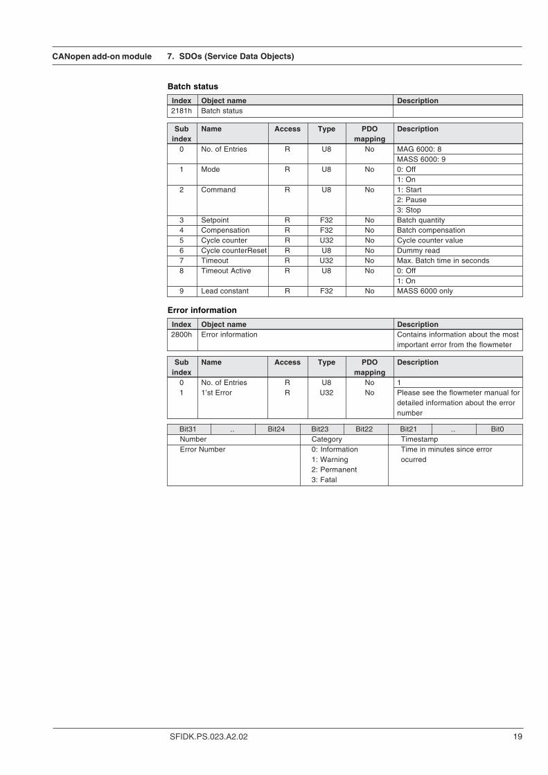
Batch status
Index Object name Description2181h Batch status
Sub Name Access Type PDO Descriptionindex mapping
0 No. of Entries R U8 No MAG 6000: 8MASS 6000: 9
1 Mode R U8 No 0: Off1: On
2 Command R U8 No 1: Start2: Pause3: Stop
3 Setpoint R F32 No Batch quantity4 Compensation R F32 No Batch compensation5 Cycle counter R U32 No Cycle counter value6 Cycle counterReset R U8 No Dummy read7 Timeout R U32 No Max. Batch time in seconds8 Timeout Active R U8 No 0: Off
1: On9 Lead constant R F32 No MASS 6000 only
Error information
Index Object name Description2800h Error information Contains information about the most
important error from the flowmeter
Sub Name Access Type PDO Descriptionindex mapping
0 No. of Entries R U8 No 11 1’st Error R U32 No Please see the flowmeter manual for
detailed information about the errornumber
Bit31 .. Bit24 Bit23 Bit22 Bit21 .. Bit0Number Category TimestampError Number 0: Information Time in minutes since error
1: Warning ocurred2: Permanent3: Fatal
CANopen add-on module
SFIDK.PS.023.A2.0220
7. SDOs (Service Data Objects)
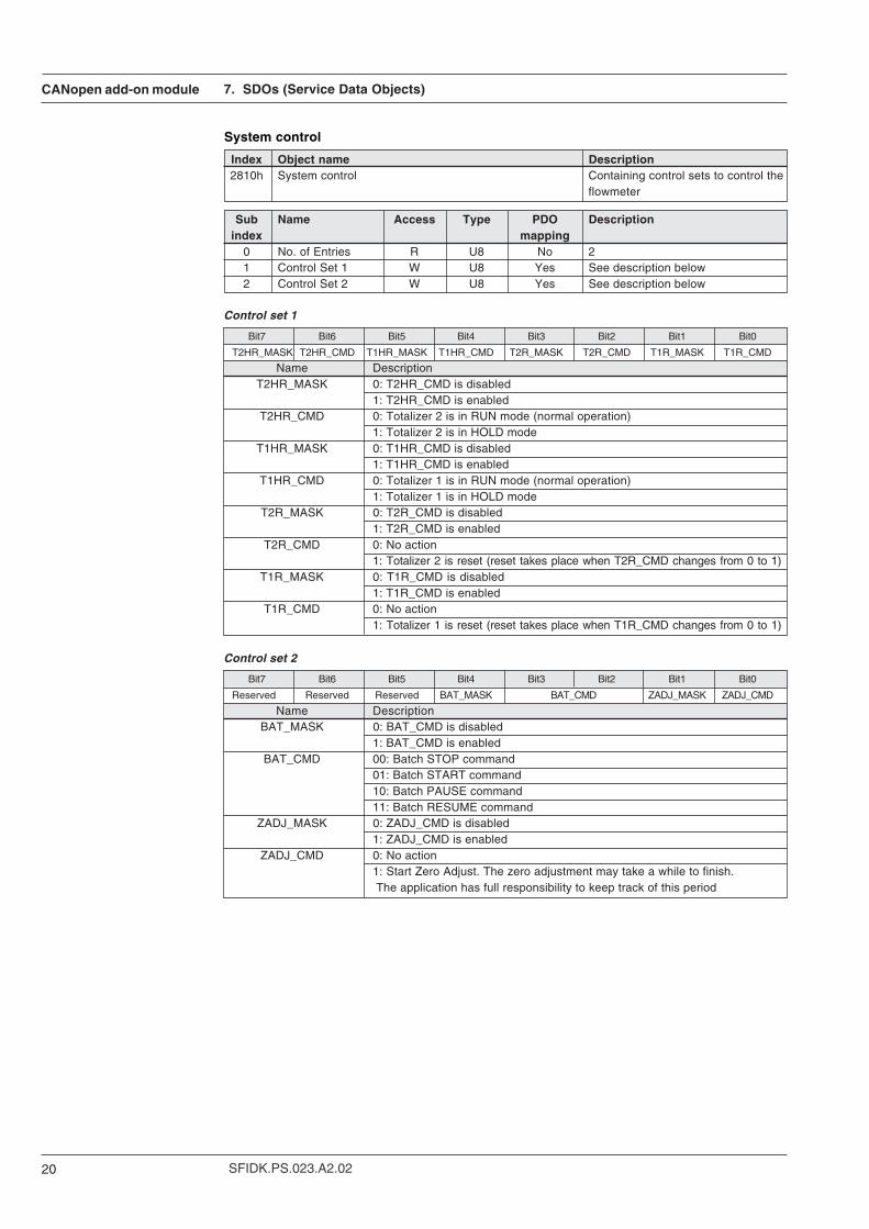
System control
Index Object name Description2810h System control Containing control sets to control the
flowmeter
Sub Name Access Type PDO Descriptionindex mapping
0 No. of Entries R U8 No 21 Control Set 1 W U8 Yes See description below2 Control Set 2 W U8 Yes See description below
Bit7 Bit6 Bit5 Bit4 Bit3 Bit2 Bit1 Bit0
T2HR_MASK T2HR_CMD T1HR_MASK T1HR_CMD T2R_MASK T2R_CMD T1R_MASK T1R_CMD
Name DescriptionT2HR_MASK 0: T2HR_CMD is disabled
1: T2HR_CMD is enabledT2HR_CMD 0: Totalizer 2 is in RUN mode (normal operation)
1: Totalizer 2 is in HOLD modeT1HR_MASK 0: T1HR_CMD is disabled
1: T1HR_CMD is enabledT1HR_CMD 0: Totalizer 1 is in RUN mode (normal operation)
1: Totalizer 1 is in HOLD modeT2R_MASK 0: T2R_CMD is disabled
1: T2R_CMD is enabledT2R_CMD 0: No action
1: Totalizer 2 is reset (reset takes place when T2R_CMD changes from 0 to 1)T1R_MASK 0: T1R_CMD is disabled
1: T1R_CMD is enabledT1R_CMD 0: No action
1: Totalizer 1 is reset (reset takes place when T1R_CMD changes from 0 to 1)
Control set 1
Bit7 Bit6 Bit5 Bit4 Bit3 Bit2 Bit1 Bit0
Reserved Reserved Reserved BAT_MASK BAT_CMD ZADJ_MASK ZADJ_CMD
Name DescriptionBAT_MASK 0: BAT_CMD is disabled
1: BAT_CMD is enabledBAT_CMD 00: Batch STOP command
01: Batch START command10: Batch PAUSE command11: Batch RESUME command
ZADJ_MASK 0: ZADJ_CMD is disabled1: ZADJ_CMD is enabled
ZADJ_CMD 0: No action1: Start Zero Adjust. The zero adjustment may take a while to finish. The application has full responsibility to keep track of this period
Control set 2
CANopen add-on module
21SFIDK.PS.023.A2.02
7. SDOs (Service Data Objects)
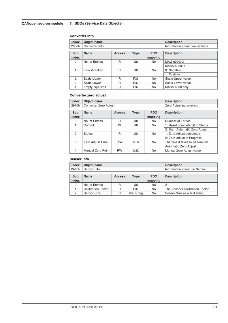
Converter info
Index Object name Description2900h Converter Info Information about flow settings
Sub Name Access Type PDO Descriptionindex mapping
0 No. of Entries R U8 No MAG 6000: 3MASS 6000: 4
1 Flow direction R U8 No 0: Negative1: Positive
2 Scale Upper R F32 No Scale Upper value3 Scale Lower R F32 No Scale Lower value4 Empty pipe limit R F32 No MASS 6000 only
Converter zero adjust
Index Object name Description2910h Converter Zero Adjust Zero Adjust parameters
Sub Name Access Type PDO Descriptionindex mapping
0 No. of Entries R U8 No Number of Entries1 Control W U8 No 1: Reset complete bit in Status
2: Start Automatic Zero Adjust2 Status R U8 No 1: Zero Adjust completed
2: Zero Adjust in Progress3 Zero Adjust Time R/W U16 No The time it takes to perform an
Automatic Zero Adjust4 Manual Zero Point RW U32 No Manual Zero Adjust value
Sensor info
Index Object name Description2A00h Sensor Info Information about the Sensor
Sub Name Access Type PDO Descriptionindex mapping
0 No. of Entries R U8 No 21 Calibration Factor R F32 No The Sensors Calibration Factor2 Sensor Size R Vis. string No Sensor Size as a text string
CANopen add-on module
SFIDK.PS.023.A2.0222
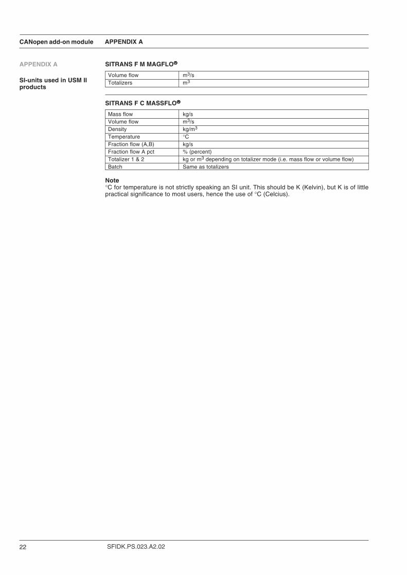
APPENDIX A
SITRANS F M MAGFLO
Volume flow m3/sTotalizers m3
SITRANS F C MASSFLO
Mass flow kg/sVolume flow m3/sDensity kg/m3
Temperature °CFraction flow (A,B) kg/sFraction flow A pct % (percent)Totalizer 1 & 2 kg or m3 depending on totalizer mode (i.e. mass flow or volume flow)Batch Same as totalizers
Note°C for temperature is not strictly speaking an SI unit. This should be K (Kelvin), but K is of littlepractical significance to most users, hence the use of °C (Celcius).
APPENDIX A
SI-units used in USM IIproducts
CANopen add-on module
23SFIDK.PS.023.A2.02
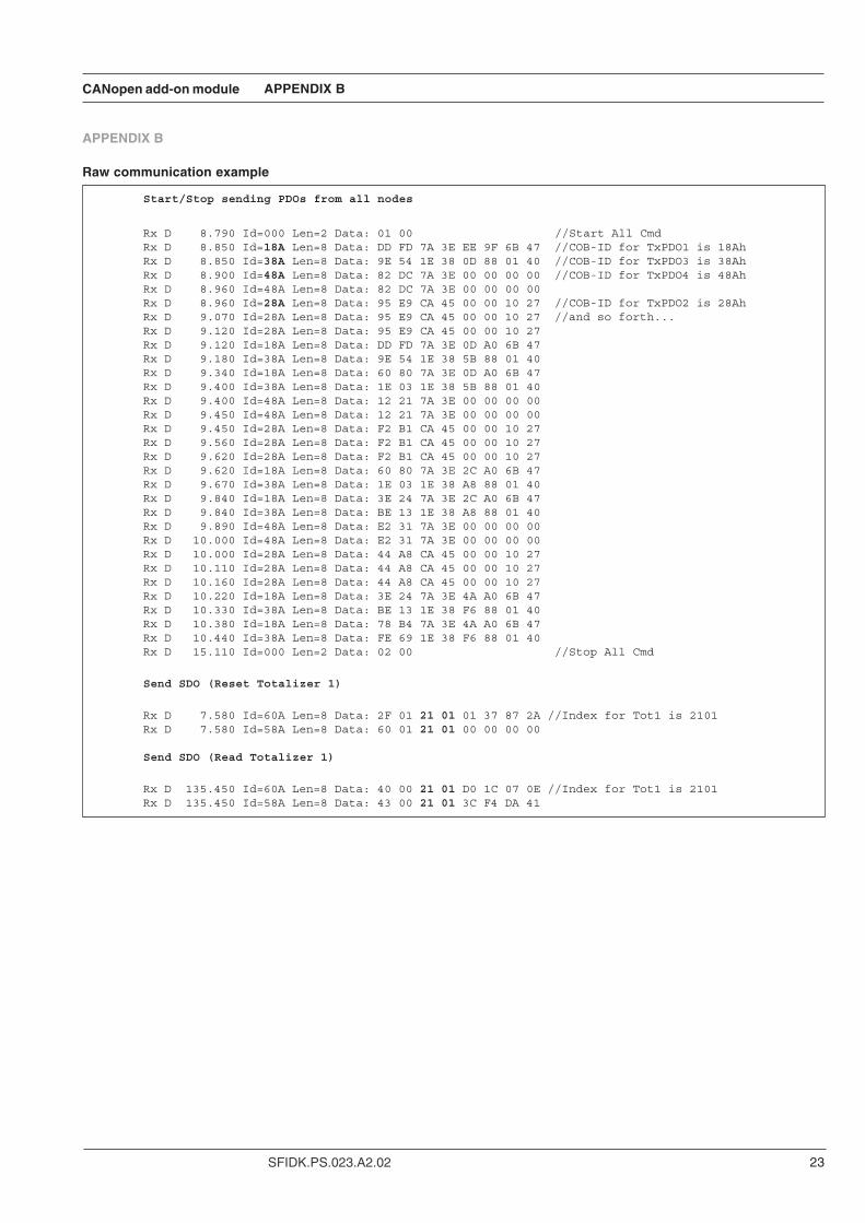
APPENDIX B
Raw communication example
Start/Stop sending PDOs from all nodes
Rx D 8.790 Id=000 Len=2 Data: 01 00 //Start All CmdRx D 8.850 Id=18A Len=8 Data: DD FD 7A 3E EE 9F 6B 47 //COB-ID for TxPDO1 is 18AhRx D 8.850 Id=38A Len=8 Data: 9E 54 1E 38 0D 88 01 40 //COB-ID for TxPDO3 is 38AhRx D 8.900 Id=48A Len=8 Data: 82 DC 7A 3E 00 00 00 00 //COB-ID for TxPDO4 is 48AhRx D 8.960 Id=48A Len=8 Data: 82 DC 7A 3E 00 00 00 00Rx D 8.960 Id=28A Len=8 Data: 95 E9 CA 45 00 00 10 27 //COB-ID for TxPDO2 is 28AhRx D 9.070 Id=28A Len=8 Data: 95 E9 CA 45 00 00 10 27 //and so forth...Rx D 9.120 Id=28A Len=8 Data: 95 E9 CA 45 00 00 10 27Rx D 9.120 Id=18A Len=8 Data: DD FD 7A 3E 0D A0 6B 47Rx D 9.180 Id=38A Len=8 Data: 9E 54 1E 38 5B 88 01 40Rx D 9.340 Id=18A Len=8 Data: 60 80 7A 3E 0D A0 6B 47Rx D 9.400 Id=38A Len=8 Data: 1E 03 1E 38 5B 88 01 40Rx D 9.400 Id=48A Len=8 Data: 12 21 7A 3E 00 00 00 00Rx D 9.450 Id=48A Len=8 Data: 12 21 7A 3E 00 00 00 00Rx D 9.450 Id=28A Len=8 Data: F2 B1 CA 45 00 00 10 27Rx D 9.560 Id=28A Len=8 Data: F2 B1 CA 45 00 00 10 27Rx D 9.620 Id=28A Len=8 Data: F2 B1 CA 45 00 00 10 27Rx D 9.620 Id=18A Len=8 Data: 60 80 7A 3E 2C A0 6B 47Rx D 9.670 Id=38A Len=8 Data: 1E 03 1E 38 A8 88 01 40Rx D 9.840 Id=18A Len=8 Data: 3E 24 7A 3E 2C A0 6B 47Rx D 9.840 Id=38A Len=8 Data: BE 13 1E 38 A8 88 01 40Rx D 9.890 Id=48A Len=8 Data: E2 31 7A 3E 00 00 00 00Rx D 10.000 Id=48A Len=8 Data: E2 31 7A 3E 00 00 00 00Rx D 10.000 Id=28A Len=8 Data: 44 A8 CA 45 00 00 10 27Rx D 10.110 Id=28A Len=8 Data: 44 A8 CA 45 00 00 10 27Rx D 10.160 Id=28A Len=8 Data: 44 A8 CA 45 00 00 10 27Rx D 10.220 Id=18A Len=8 Data: 3E 24 7A 3E 4A A0 6B 47Rx D 10.330 Id=38A Len=8 Data: BE 13 1E 38 F6 88 01 40Rx D 10.380 Id=18A Len=8 Data: 78 B4 7A 3E 4A A0 6B 47Rx D 10.440 Id=38A Len=8 Data: FE 69 1E 38 F6 88 01 40Rx D 15.110 Id=000 Len=2 Data: 02 00 //Stop All Cmd
Send SDO (Reset Totalizer 1)
Rx D 7.580 Id=60A Len=8 Data: 2F 01 21 01 01 37 87 2A //Index for Tot1 is 2101Rx D 7.580 Id=58A Len=8 Data: 60 01 21 01 00 00 00 00
Send SDO (Read Totalizer 1)
Rx D 135.450 Id=60A Len=8 Data: 40 00 21 01 D0 1C 07 0E //Index for Tot1 is 2101Rx D 135.450 Id=58A Len=8 Data: 43 00 21 01 3C F4 DA 41
APPENDIX B

We have checked the contents of this manual for agreement with the hardware andsoftware described. Since deviations cannot be precluded entirely, we cannot guaranteefull agreement. However, the data in this manual are reviewed regularly and anynecessary corrections included in subsequent editions. Suggestions for improvementare always welcomed.
Technical data subject to change without prior notice.
The reproduction, transmission or use of this document or its contents is not permitted withoutexpress written authority.Offenders will be liable for damages. All rights, including rights created by patent grant orregistration of a utility model or design, are reserved.
Copyright © Siemens AG 07-2003 All Rights Reserved
Siemens Flow Instruments A/SNordborgvej 81DK-6430 Nordborg
Order no.: FDK:521H1134-01Printed in: Denmark


