Embed Size (px)
Citation preview
SIPROTEC 5Release V08.30
siemens.com/siprotec5Unrestricted © Siemens 2020

Unrestricted © Siemens 2020
Aug 2020Page 2 Smart Infrastructure | Digital Grid
SIPROTEC 5 –
The benchmark for protection, automation and monitoring
Individually configurable devices –
Save money over the entire life cycle
Trendsetting system architecture –
Flexibility and safety for all kind of grids
Multi-layered integrated safety mechanism –
Highest possible level of safety and availability
Consistent system and device engineering –
Efficient operating concepts, flexible engineering
Powerful intelligent, digital protection relays with a high degree of modularity

Unrestricted © Siemens 2020
Aug 2020Page 3 Smart Infrastructure | Digital Grid
7SJ8 Overcurrent and feeder protection
SIPROTEC 5 relays
Proven solution for all applications
7SS85 Busbar protection
7SK8 Motor protection
6MD8 Bay controller
7KE85 Fault recorder
7VK8 Breaker management
7SA8 Distance protection
7SD8 Line differential protection
7UM85 Generator protection
7VE8 Paralleling device
Easy engineering and evaluation – DIGSI and SIGRA
7UT8 Transformer differential protection
7SL8 Combined line differential & distance protection
6MU85 Merging unit

Unrestricted © Siemens 2020
Aug 2020Page 4 Smart Infrastructure | Digital Grid
Content
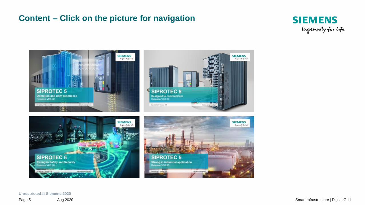
Operation and user experience1
Designed to communicate2
Safety and security inside3
Strong in industrial applications4
Unrestricted © Siemens 2020
Aug 2020Page 5 Smart Infrastructure | Digital Grid
Content – Click on the picture for navigation

SIPROTEC 5Operation and user experienceRelease V08.30
siemens.com/siprotec5Unrestricted © Siemens 2020

Unrestricted © Siemens 2020
Aug 2020Page 8 Smart Infrastructure | Digital Grid
Content
Operation1.2
Retrofit of 3rd party PMUs with SIPROTEC 5 PMUs1.3
Designed to communicate2
Safety and security inside3
Strong in industrial applications4
Operation and user experience1
Handling and engineering1.1

Unrestricted © Siemens 2020
Aug 2020Page 9 Smart Infrastructure | Digital Grid
NEW: Easier filtering of routing information
Simplify complexity• Routing filter to your needs
• Binary inputs, F-Keys and
LEDs

Unrestricted © Siemens 2020
Aug 2020Page 10 Smart Infrastructure | Digital Grid
NEW: Your favorite settings at a glance
Easier setting of parameters with favorites
Simplify complexity• All relevant settings at a
glance
• Settings for one bay on one
screen
• Reduced training
• Reduced risk of changing
wrong parameter

Unrestricted © Siemens 2020
Aug 2020Page 11 Smart Infrastructure | Digital Grid
NEW: Automated IEC 61850 engineering with bay typicals
All instantiated devices
are available in DIGSI 5
project
✓
import and instantiate
typical devices in
SysCon
3
rename and arrange
devices in substation
topology and assign IP
addresses
4
export device ICD’s with
checkmark at “include
DEX5 export”
2create typical
devices in
DIGSI 5
1
Import SCD in
new DIGSI 5
project
5

Unrestricted © Siemens 2020
Aug 2020Page 12 Smart Infrastructure | Digital Grid
Web Browser
Easy, fast and secure access to device
Monitoring:
• Logs and Measurements
• Centralized view on warnings,
alarms and inactive functions
• Device diagnosis data
Download of:
• Logs as CSV or COMFEDE files
• Records as COMTRADE files
Secure:
• https connection
• Access defined per port
• Controlled by RBAC

Unrestricted © Siemens 2020
Aug 2020Page 13 Smart Infrastructure | Digital Grid
Web Browser
Easy, fast and secure access to device
Recording:
• Download, Delete and Trigger of
Fault Records
Parameterization:
• Change of settings within an
active setting-group
Display of:
• Indication of all information
• Vector diagrams of energizing
quantities
• NEW Single line diagrams and
device display pages
• Device diagnosis data

Unrestricted © Siemens 2020
Aug 2020Page 14 Smart Infrastructure | Digital Grid
Diagnosis homepage of ETH-BD-2FO module
Easy and fast access to detailed communication status

Unrestricted © Siemens 2020
Aug 2020Page 15 Smart Infrastructure | Digital Grid
Content
Handling and engineering1.1
Retrofit of 3rd party PMUs with SIPROTEC 5 PMUs1.3
Designed to communicate2
Safety and security inside3
Strong in industrial applications4
Operation and user experience1
Operation1.2
Unrestricted © Siemens 2020
Aug 2020Page 16 Smart Infrastructure | Digital Grid
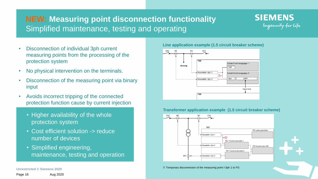
NEW: Measuring point disconnection functionality
Simplified maintenance, testing and operating
Transformer application example (1.5 circuit breaker scheme)
Line application example (1.5 circuit breaker scheme)• Disconnection of individual 3ph current
measuring points from the processing of the
protection system
• No physical intervention on the terminals.
• Disconnection of the measuring point via binary
input
• Avoids incorrect tripping of the connected
protection function cause by current injection
• Higher availability of the whole
protection system
• Cost efficient solution -> reduce
number of devices
• Simplified engineering,
maintenance, testing and operation
Temporary disconnection of the measuring point I-3ph 1 to FG

Unrestricted © Siemens 2020
Aug 2020Page 17 Smart Infrastructure | Digital Grid
NEW: Dynamic voltage regulation (DVR)
For increased infeeds and back-infeeds of
renewable energy sources in the medium voltage,
to keep the voltage in the specified range
• Bidirectional power flow by decentralized feeders
• Overvoltages in the individual nodal points
caused by strong decentralized infeeds
• Voltage limits according to the power quality
standard DIN EN 50160 can be exceeded
• Dynamic voltage regulation (DVR) adapts the
voltage setpoint of the voltage regulator via a
characteristic curve that depends on the direction
of power flow over the transformer
Compliant voltage limits to the power
quality standard DIN EN 50160 in case of
strong renewable infeeds

Unrestricted © Siemens 2020
Aug 2020Page 18 Smart Infrastructure | Digital Grid
Content
Handling and engineering1.1
Operation1.2
Designed to communicate2
Safety and security inside3
Strong in industrial applications4
Operation and user experience1
Retrofit of 3rd party PMUs with SIPROTEC 5 PMUs1.3

Unrestricted © Siemens 2020
Aug 2020Page 19 Smart Infrastructure | Digital Grid
Retrofit of 3rd party PMUs with SIPROTEC 5 PMUs
Easy adaption of SIPROTEC PMUs to existing interface requirements
General PMU functionality
• NEW: Port configuration of PMU communication
• NEW: Transmit P,Q via IEEE C37.118
• NEW: Transmit phasor data and positive sequence together
• PMU multicast communication
• Transmit binary signal names via IEEE C37.11
• New config frame 3 fields
ETH-BD-2FO specific functionality
NEW: IEEE C37.118 PMU together with other communication protocols like IEC
61850-8-1, Profinet IO, IEC 60870-5-104, Process Bus Client, Merging Unit
SIPROTEC 5
SIEMENS SIEMENS
IEEE C37.118
IEC 61850-8-1
IEC 60870-5-104
IEC 61850-9-2

Unrestricted © Siemens 2020
Aug 2020Page 20 Smart Infrastructure | Digital Grid
NEW: Multiple Ethernet protocols on the same module
IEEE C37.118
• PMU protocol in parallel to
station bus protocols
• No additional Ethernet
module for PMU
functionality required
• Saves costs
• Segregation of protocols
via VLAN possible
ETH-BD-2FO

SIPROTEC 5Designed to communicate
Release V08.30
siemens.com/processbusUnrestricted © Siemens 2020

Unrestricted © Siemens 2020
Aug 2020Page 23 Smart Infrastructure | Digital Grid
Content
Operation and user experience1
Easier engineering of IEC 61850 systems through typicals2.2
Powerful and universal Ethernet module ETH-BD-2FO2.3
PMU IEEE C37.1182.4
Pulse per Second synchronization2.5
Safety and security inside3
Strong in industrial applications4
Designed to communicate2
Network Segregation2.1

Unrestricted © Siemens 2020
Aug 2020Page 24 Smart Infrastructure | Digital Grid
Digital Substation
Process Bus Overview
Bay Controller
*for simplification the required IEEE 1588v2/PTP master clock is not shown

Unrestricted © Siemens 2020
Aug 2020Page 25 Smart Infrastructure | Digital Grid
SIPROTEC 6MU85 and SIPROTEC 5 process bus client –
Digitalize your substation – Boost efficiency and reliability
Perfectly tailored fit
Modular functionality
• backup protection functions
• point on wave switching (PoW)
• Autonomous Automation
• Voltage regulation
• Tap changer controller
• synchronized commands
Modular hardware
• multiple CT, VT, LPIT inputs
• scalable BI and BO
• collection of additional data
(temperature, pressure, tap changer
positions, …)
• multiple mounting options
• expandable by a 2nd row
• optical SFP for up to 24 km
Designed to communicate
Process bus
• IEC 61850 Ed 2.1 compliant
• SMV streams IEC 61869-9, IEC 61850-
9-2 and IEC 61850-9-2 LE
Sample and time synchronization
• IEEE 1588v2/PTP with enhanced
stability against GNSS loss
• PPS, IRIG-B
SCADA
• IEC 61850-8-1, IEC 60870-5-104,
Modbus IP, Profinet IO, DNP3, PMU
Network segregation
• physical with multiple interfaces
• virtual with VLAN
Communication redundancy
• PRP and HSR (for SCADA)
Safety and security Inside
Hardware
• Ruggedized design and conformal
coated electronical boards for high
electric strength and installations in
harsh environments - as standard
• high availability - redundant power
supply
Embedded Cyber Security
• Secured communication with TLS/IPSec
and client-server authentication
• firmware integrity checks
• ProductCERT for vulnerability handling
• Centralized account management and
role-based access control
• Centralized security event logging
• Future readiness with PKI support
The SIPROTEC 6MU85 merging unit is the modular, interoperable and powerful solution between primary and secondary technology –
versatile process data acquisition, autonomous automation and secure communication

Unrestricted © Siemens 2020
Aug 2020Page 26 Smart Infrastructure | Digital Grid
Network architectures
Physically network segregation
Network 5:
Feeder CT values
Network 1
CT, VT values
Network 6:
Bus VT values
6MU85 6MU85 6MU85 6MU85 6MU85
Simplify complexityUse of more than one redundant
process bus network reduces the
network engineering
Increase the bandwidth with
additional Ethernet interfaces
Efficient use of network bandwidth
with customization of the analog
values per SMV streams
(not only IEC 61850-9-2LE data
set)
7SJ85
Overcurrent
Protection
7SA86
Distance
Protection
7SD86
Line
Differential
Protection
7UT86
Transformer
Differential
Protection
7SS85
Busbar
Differential
Protection
Feeder 1 Feeder 2 Feeder 3 Feeder 4 Bus VT’s
7KE85
Fault
Recorder
Network 2
CT, VT values
Network 3
CT, VT values
Network 4
CT, VT values
Note: Seamless networks redundancy recommended

Unrestricted © Siemens 2020
Aug 2020Page 27 Smart Infrastructure | Digital Grid
Network architectures
Virtual network segregation (VLAN)
Simplify complexitySegregation of one redundant
process bus network into several
virtual LANs reduces load and
increases cyber security
One physical network reduces
network costs
VLAN 1-4: CT, VT values for feeder protection
VLAN 5: Feeder CT values for busbar protection
and fault recorder
VLAN 6: Bus VT for central fault recorder and
feeder protection
Note: Seamless networks redundancy recommended
7SJ85
Overcurrent
Protection
7SA86
Distance
Protection
7SD86
Line
Differential
Protection
7UT86
Transformer
Differential
Protection
7SS85
Busbar
Differential
Protection
Feeder 1 Feeder 2 Feeder 3 Feeder 4 Bus VT’s
7KE85
Fault
Recorder
VLA
N 1
VLAN 6VLA
N 2
VLA
N 3
VLA
N 4
VLAN 5
6MU85 6MU85 6MU85 6MU85 6MU85

Unrestricted © Siemens 2020
Aug 2020Page 28 Smart Infrastructure | Digital Grid
PRP LAN B
PRP LAN A
3rd
party
MU
IEEE1588v2/PTP
GMC
6MU85 6MU85 6MU85 6MU85
Station Bus
CT 1..14 (VLAN ID 1) CT 15..20 (VLAN ID 2)
CT 1..14 (VLAN ID 1)
CT 15..20 (VLAN ID 2)
SIPROTEC 5SIPROTEC 5
7SS85
Network architectures
Example: VLAN for busbar protection with 20 bays
• For more than 14 bays a
second ETH-BD-2FO is
required
• Segmentation to each ETH-BD-
2FO module via VLAN
SIEMENS SIEMENSSIEMENS SIEMENS

Unrestricted © Siemens 2020
Aug 2020Page 29 Smart Infrastructure | Digital Grid
Network architectures VLAN
Single ETH-BD-2FO module for all your communication
Station bus ( MMS) )
Simplify your network• From 3 networks to 1 network
• Logical (VLAN) segregation of
• Station bus
• PMU network
• Management network
Feeder 1 Feeder 2 Feeder 3 Feeder x
PMU network
Management (DIGSI, SNMP)
Feeder 1 Feeder 2 Feeder 3 Feeder x
Single ETH-BD-2FO Module
One common VLAN network

Unrestricted © Siemens 2020
Aug 2020Page 30 Smart Infrastructure | Digital Grid
Content
Operation and user experience1
Network Segregation2.1
Powerful and universal Ethernet module ETH-BD-2FO2.3
PMU IEEE C37.1182.4
Pulse per Second synchronization2.5
Safety and security inside3
Strong in industrial applications4
Designed to communicate2
Easier engineering of IEC 61850 systems through typicals2.2

Unrestricted © Siemens 2020
Aug 2020Page 31 Smart Infrastructure | Digital Grid
Designed to communicate
NEW: Automated IEC 61850 engineering with bay typicals
All instantiated devices
are available in DIGSI 5
project
✓
import and instantiate
typical devices in
SysCon
3
rename and arrange
devices in substation
topology and assign IP
addresses
4
export device ICD’s with
checkmark at “include
DEX5 export”
2create typical
devices in
DIGSI 5
1
Import SCD in
new DIGSI 5
project
5

Unrestricted © Siemens 2020
Aug 2020Page 32 Smart Infrastructure | Digital Grid
Content
Operation and user experience1
Network Segregation2.1
Easier engineering of IEC 61850 systems through typicals2.2
PMU IEEE C37.1182.4
Pulse per Second synchronization2.5
Safety and security inside3
Strong in industrial applications4
Designed to communicate2
Powerful and universal Ethernet module ETH-BD-2FO2.3

Unrestricted © Siemens 2020
Aug 2020Page 33 Smart Infrastructure | Digital Grid
One Hardware, different functionalities (configurable per software):
• IEEE 1588v2/PTP → Allows the synchronization of the sampled values (1µs).
The same signal can be used as absolute time reference for the device
• Process Bus Server → Merging unit functionality which enables the
SIPROTEC 5 device to publish (send) sampled values. Using the DIGSI 5 is
possible to define the standard/profile to be used (IEC 61850-9-2LE or
IEC 61869-9)
• Process Bus Client→ Enables the SIPROTEC 5 device to
subscribe (receive) sampled values
• Station Bus → IEC 61850-8-1 GOOSE/MMS
• SCADA communication
• PMU
SIPROTEC 5
Plug-in Ethernet Communication Module ETH-BD-2FO
Unrestricted © Siemens 2020
Aug 2020Page 34 Smart Infrastructure | Digital Grid
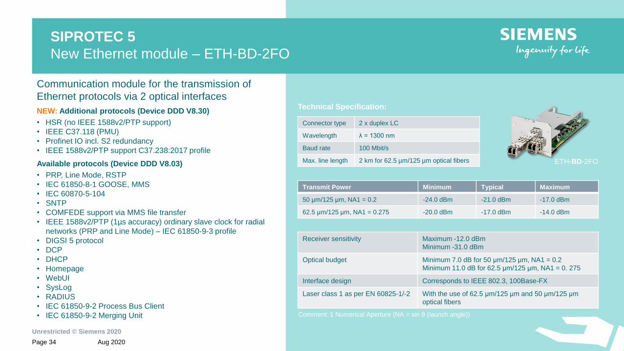
ETH-BD-2FO
Technical Specification:
Communication module for the transmission of
Ethernet protocols via 2 optical interfaces
NEW: Additional protocols (Device DDD V8.30)
• HSR (no IEEE 1588v2/PTP support)
• IEEE C37.118 (PMU)
• Profinet IO incl. S2 redundancy
• IEEE 1588v2/PTP support C37.238:2017 profile
Available protocols (Device DDD V8.03)
• PRP, Line Mode, RSTP
• IEC 61850-8-1 GOOSE, MMS
• IEC 60870-5-104
• SNTP
• COMFEDE support via MMS file transfer
• IEEE 1588v2/PTP (1µs accuracy) ordinary slave clock for radial
networks (PRP and Line Mode) – IEC 61850-9-3 profile
• DIGSI 5 protocol
• DCP
• DHCP
• Homepage
• WebUI
• SysLog
• RADIUS
• IEC 61850-9-2 Process Bus Client
• IEC 61850-9-2 Merging Unit
Transmit Power Minimum Typical Maximum
50 μm/125 μm, NA1 = 0.2 -24.0 dBm -21.0 dBm -17.0 dBm
62.5 μm/125 μm, NA1 = 0.275 -20.0 dBm -17.0 dBm -14.0 dBm
Receiver sensitivity Maximum -12.0 dBm
Minimum -31.0 dBm
Optical budget Minimum 7.0 dB for 50 μm/125 μm, NA1 = 0.2
Minimum 11.0 dB for 62.5 μm/125 μm, NA1 = 0. 275
Interface design Corresponds to IEEE 802.3, 100Base-FX
Laser class 1 as per EN 60825-1/-2 With the use of 62.5 μm/125 μm and 50 μm/125 μm
optical fibers
Connector type 2 x duplex LC
Wavelength λ = 1300 nm
Baud rate 100 Mbit/s
Max. line length 2 km for 62.5 µm/125 µm optical fibers
SIPROTEC 5
New Ethernet module – ETH-BD-2FO
Comment: 1 Numerical Aperture (NA = sin θ (launch angle))

Unrestricted © Siemens 2020
Aug 2020Page 35 Smart Infrastructure | Digital Grid
NEW:* Profinet IO on ETH-BD-2FO
NEW:* High availability connection of
SIPROTEC 5 as an IO device to two
redundant Profinet IO Controllers
NEW:* Sequence of Events log from the
SIPROTEC 5 IO device to enable
monitoring of Process data from your
factory
Effortless integration into existing Profinet IO
networks with optional RJ-45 SFP
*ETH-BD-2FO plug-in module is required
Designed to communicate
Profinet IO with S2 Redundancy
Sequential Event List
(SOE)
IO Controller Main IO Controller Standby

Unrestricted © Siemens 2020
Aug 2020Page 36 Smart Infrastructure | Digital Grid
SIPROTEC 6MU85
Enhancement of streams
NEW Publishing of 2 sampled value streams
With the capability of publishing two sampled value streams
from the same ETH-BD-2FO module
• Reduction of required ETH-BD-2FO for same
amount of sampled value streams
→ reduction of HW cost
• Reduction of required network ports for process bus
network
→ reduction of network cost
• Merging Unit functionality is compensated
via function points per instance activated
at ETH-BD-2FO
→ reduction of FP cost
NEW Start publishing of sampled values without
an available sample synchronization.
The merging unit will start publishing sampled value streams
without a existing or established sample synchronization.
Sampled value streams will be marked as not synchronized.
current implementation
NEW with V8.30
Stream #2 (14,400 Hz / 6 ASDU)
Stream #1 (4,800 Hz / 2 ASDU)
Stream #2 (14,400 Hz / 6 ASDU)
Stream #1 (4,800 Hz / 2 ASDU)

Unrestricted © Siemens 2020
Aug 2020Page 37 Smart Infrastructure | Digital Grid
New sampling rate for Merging Unit and Process Bus Client
IEC 61869-9 , IEC 61850-9-2 and 9-2 LE
Siemens
Implementation
• Support of IEC 61869-9
sampling rates
• Backward compatible
to IEC 61850-9-2 LE
• More fault tolerant:
4,80 kHz and 1 ASDU per frame
can be used for protection
(9-2 LE)
• Missing of one sample
will be interpolated
1 Recommendation by Siemens – more fault tolerant | 2 Recommended by standard | 3 Preferred for distributed BBP
Digital
output
samples
rates kHz
Numbers of
ASDUs per
frame
Remarks Preferred
Applications
4,00 1For use on 50 Hz backward compatible
with 9-2LE guideline
Protection
Fault Recording
4,80 1
For use on 60 Hz systems backward compatible
with 9-2LE guideline, or 50 Hz systems backward
compatible with 96 samples per nominal system
frequency cycle 1
Protection
Fault Recording
4,80 2
Preferred rate for general measuring and
protective applications, regardless of the power
system frequency 2, 3
Protection
Fault Recording
12,80 8Outdated, only for use on 50 Hz systems Power Quality
Fault Recording
NEW 14,40 6Preferred for quality metering applications,
regardless of the power system frequency. 2
Power Quality
Fault Recording
15,36 8Outdated, only for use on 60 Hz systems Power Quality
Fault Recording

Unrestricted © Siemens 2020
Aug 2020Page 38 Smart Infrastructure | Digital Grid
Optional SFP for the ETH-BD-2FO
as replacement of standard multimode SFP for 2 km
Optical SFP for up to 24 km
Order Code P1Z3210 (pack of 10 units)
Connector type 2 x duplex LC
Wavelength λ = 1300 nm
Baud rate 100 Mbit/s
Protocol See ETH-BD-2FO
Max. line length 24 km for 9 µm/125 µm optical fibers
Electrical SFP for up to 20 m (not for sample synchronization)
Order Code P1Z3201 (pack of 10 units)
Connector type RJ45
Baud rate 100 Mbit/s
Protocol See ETH-BD-2FO
Max. line length 20 m with Ethernet patch cable CAT 6 S/FTP,
F/FTP, or SF/FTP
Interface design Corresponds to IEEE 802.3, 100Base-TX

Unrestricted © Siemens 2020
Aug 2020Page 39 Smart Infrastructure | Digital Grid
Sample synchronization vs. time synchronization
▪ Universal time reference signal, provided by a master
clock
▪ Absolute time stamp which contains exact date and
time
▪ Used for data fault analysis (1ms)
▪ Relative reference used to align or synchronize
several signals among each other
▪ It can be provided by a pulse or by a time signal
▪ Used to synchronize the sampled values (1µs)
Sample Synchronization Time Synchronization
Synch. Method Distribution Typical Accuracy Synchronization Application
IRIG-B Separate wiring 10µs – 1ms Time Synchronization
1 PPS Separate wiring <1µs Sample Synchronization
NTP Network 1ms – 10ms Time Synchronization
IEEE 1588 PTP Network <1µs Time and Sample Synchronization
* Some IRIG-B telegrams contain the PPS pulse and can be used for SV synch. as well

Unrestricted © Siemens 2020
Aug 2020Page 40 Smart Infrastructure | Digital Grid
Sample and time synchronization
Precision Time Protocol – IEEE 1588v2/PTP
Sample and time synchronization Time synchronization
Communication
Plug-In ModuleETH-BD-2FO
ETH-BA-2EL
ETH-BB-2FO
Applications
• Date and time synchronization
• Sample synchronization for process bus
• PMU data synchronization
• 87L stabilization for unsymmetrical PI networks
• Date and time synchronization
Type of implementation Hardware / FPGA Software
Accuracy 1 µs 1) 1 ms
Supported devices Modular SIPROTEC 5 devices 7xx85/86/87 (except 7ST85) All SIPROTEC 5 devices
Supported RedundancyPRP
Line Mode
PRP (symmetrical) 2)
Line Mode
Supported ProfilesIEC 61850-9-3 (Power Utility Automation Profile)
NEW: IEEE C37.238:2017 (Power System Application Profile) 2)
Clock Type Ordinary Slave Clock (OSC) Ordinary Slave Clock (OSC)
1) with optional accessory RJ45 SFP module accuracy will be 1ms2) PRP LAN A and PRP LAN B needs to be identical, to ensure the same number of hops to be passed from the PTP telegrams

Unrestricted © Siemens 2020
Aug 2020Page 41 Smart Infrastructure | Digital Grid
Designed to communicate
HSR and PRP redundancy
New on ETH-BD-2FO module:
HSR* ring with clients and server connected to PRP LANs
PR
P L
AN
A
Red
Bo
x
Red
Bo
x
PRP redundancy with clients and server
for station and process bus
PRP LAN A
PRP LAN B
PR
P L
AN
B* Support of IEEE 1588v2/PTP (transparent clock) in preparation

Unrestricted © Siemens 2020
Aug 2020Page 42 Smart Infrastructure | Digital Grid
Content
Operation and user experience1
Network Segregation2.1
Easier engineering of IEC 61850 systems through typicals2.2
Powerful and universal Ethernet module ETH-BD-2FO2.3
Pulse per Second synchronization2.5
Safety and security inside3
Strong in industrial applications4
Designed to communicate2
PMU IEEE C37.1182.4

Unrestricted © Siemens 2020
Aug 2020Page 43 Smart Infrastructure | Digital Grid
Retrofit of 3rd party PMUs with SIPROTEC 5 PMUs
Easy adaption of SIPROTEC PMUs to existing interface requirements
General PMU functionality
• NEW: Port configuration of PMU communication
• NEW: Transmit P,Q via IEEE C37.118
• NEW: Transmit phasor data and positive sequence together
• PMU multicast communication
• Transmit binary signal names via IEEE C37.11
• New config frame 3 fields
ETH-BD-2FO specific functionality
NEW: IEEE C37.118 PMU together with other communication protocols like IEC
61850-8-1, Profinet IO, IEC 60870-5-104, Process Bus Client, Merging Unit
SIPROTEC 5
SIEMENS SIEMENS
IEEE C37.118
IEC 61850-8-1
IEC 60870-5-104
IEC 61850-9-2
Unrestricted © Siemens 2020
Aug 2020Page 44 Smart Infrastructure | Digital Grid
Content
Operation and user experience1
Network Segregation2.1
Easier engineering of IEC 61850 systems through typicals2.2
Powerful and universal Ethernet module ETH-BD-2FO2.3
PMU IEEE C37.1182.4
Safety and security inside3
Strong in industrial applications4
Designed to communicate2
Pulse per Second synchronization2.5

Unrestricted © Siemens 2020
Aug 2020Page 45 Smart Infrastructure | Digital Grid
Designed to communicate
Pulse per Second Input
NEW Optical Pulse per Second input
A optical pulse per second can be connected to the
USART-AD-1FO and USART-AE-2FO serial
communication plug-in module.
• Sample synchronization for IEC 61850-9-2
Small process bus installations benefit from a cost
effective way to synchronize samples
→ reduction of network equipment
• Stabilization of 87L in case of unsymmetrical
communication network
→ simplification of PPS distribution
NEW Electrical Pulse per Second or IRIG-B
for IEC 61850-9-2 sample synchronization
The sample synchronization of a merging unit or
process bus client can be realized with a electrical
pulse per second or IRIG-B signal connected to
Port G of the SIPROTEC 5 device.
6MU85
7XV5450
Mini Star Coupler
GPS
clock
6MU85 6MU85
Protection
Optical PPS for sample synchronization
HSR* for
IEC 61850-9-2
* max. 5 devices in HSR Ring for IEC 61850-9-2

SIPROTEC 5Strong in Safety and SecurityRelease V08.30
siemens.com/gridsecurityUnrestricted © Siemens 2020

Unrestricted © Siemens 2020
Aug 2020Page 48 Smart Infrastructure | Digital Grid
Content
Operation and user experience1
Designed to communicate2
Authenticated network access IEEE 802.1X3.2
Virtual segregation of networks with VLAN IEEE 802.1Q3.3
Conformal coating of electronic boards - harsh environments3.4
Strong in industrial applications4
Safety and security inside3
Comprehensive cyber security features of SIPROTEC 53.1

Unrestricted © Siemens 2020
Aug 2020Page 49 Smart Infrastructure | Digital Grid
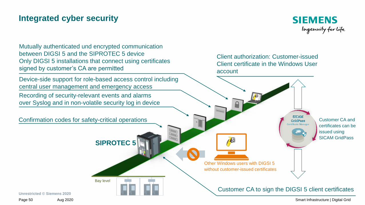
Integrated cyber security
Features
• Customer-authorized
DIGSI 5 Instances
• Role-based Access Control
• Authenticated network
access for COM-Modules
• Use of customer certificates
• Recording of security-
relevant events and alarms
• Confirmation codes for
safety-critical operations
• Crypto-chip for secure
information storage
• Siemens CERT and
Patch management
Unrestricted © Siemens 2020
Aug 2020Page 50 Smart Infrastructure | Digital Grid
Integrated cyber security
Customer CA to sign the DIGSI 5 client certificates
Client authorization: Customer-issued
Client certificate in the Windows User
account
Confirmation codes for safety-critical operations
Recording of security-relevant events and alarms
over Syslog and in non-volatile security log in device
Device-side support for role-based access control including
central user management and emergency access
Mutually authenticated und encrypted communication
between DIGSI 5 and the SIPROTEC 5 device
Only DIGSI 5 installations that connect using certificates
signed by customer’s CA are permitted
SIPROTEC 5
Bay level
Customer CA and
certificates can be
issued using
SICAM GridPass
Other Windows users with DIGSI 5
without customer-issued certificates
Unrestricted © Siemens 2020
Aug 2020Page 51 Smart Infrastructure | Digital Grid
Content
Operation and user experience1
Designed to communicate2
Comprehensive cyber security features of SIPROTEC 53.1
Virtual segregation of networks with VLAN IEEE 802.1Q3.3
Conformal coating of electronic boards - harsh environments3.4
Strong in industrial applications4
Safety and security inside3
Authenticated network access IEEE 802.1X3.2

Unrestricted © Siemens 2020
Aug 2020Page 52 Smart Infrastructure | Digital Grid
NEW: Authenticated Network Access IEEE 802.1X
1. Install customer-issued IEEE 802.1X Client
certificates for COM modules (for network client
authentication)
IEEE 802.1X
capable Switch2. During bootup, the device’s COM module presents
the client certificate for authentication to the switch
using IEEE 802.1X
RADIUS
Server
Line mode, not in Ring mode
1. Install customer-issued IEEE 802.1X CA certificate in
RADIUS Server
3. RADIUS Server authenticates the device using
its certificate and the switch grants or denies
network access to the COM module
Customer CA und certificates
can be created and managed
with SICAM GridPass
Other products without customer-
issued IEEE 802.1x client certificates

Unrestricted © Siemens 2020
Aug 2020Page 53 Smart Infrastructure | Digital Grid
Pro
ble
mS
olu
tio
n
• Any network device can join the management
network without authentication.
• Unauthorized devices in the network exposes risks
of the internal network
Be
ne
fits
• Centrally login each network device through Radius
Authentication Server before the telegrams are
accepted or forwarded to network
• The authentication facility is established through
network switches, where they will act as a guardian
for unauthorized access
Fu
nc
tio
n
• ETH-BA-2EL, ETH-BB-2FO, ETH-BD-2FO modules
provide IEEE 802.1X supplicant support. This
enables Siprotec 5 devices to join IEEE 802.1X
authenticated networks
• Cryptographically prevent undesired access to the
sensitive networks
• Tunneled communication in between network
devices that provides confidentiality
• Centrally manage access credentials using Radius
Server
IEEE 802.1X
Supplicant
IEEE 802.1X
Authenticator
IEEE 802.1X
Radius Authentication Server
NEW: Authenticated Network Access IEEE 802.1X

Unrestricted © Siemens 2020
Aug 2020Page 54 Smart Infrastructure | Digital Grid
Content
Operation and user experience1
Designed to communicate2
Comprehensive cyber security features of SIPROTEC 53.1
Authenticated network access IEEE 802.1X3.2
Conformal coating of electronic boards - harsh environments3.4
Strong in industrial applications4
Safety and security inside3
Virtual segregation of networks with VLAN IEEE 802.1Q3.3
Unrestricted © Siemens 2020
Aug 2020Page 55 Smart Infrastructure | Digital Grid
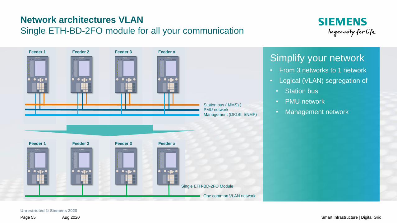
Network architectures VLAN
Single ETH-BD-2FO module for all your communication
Station bus ( MMS) )
Simplify your network• From 3 networks to 1 network
• Logical (VLAN) segregation of
• Station bus
• PMU network
• Management network
Feeder 1 Feeder 2 Feeder 3 Feeder x
PMU network
Management (DIGSI, SNMP)
Feeder 1 Feeder 2 Feeder 3 Feeder x
Single ETH-BD-2FO Module
One common VLAN network
Unrestricted © Siemens 2020
Aug 2020Page 56 Smart Infrastructure | Digital Grid
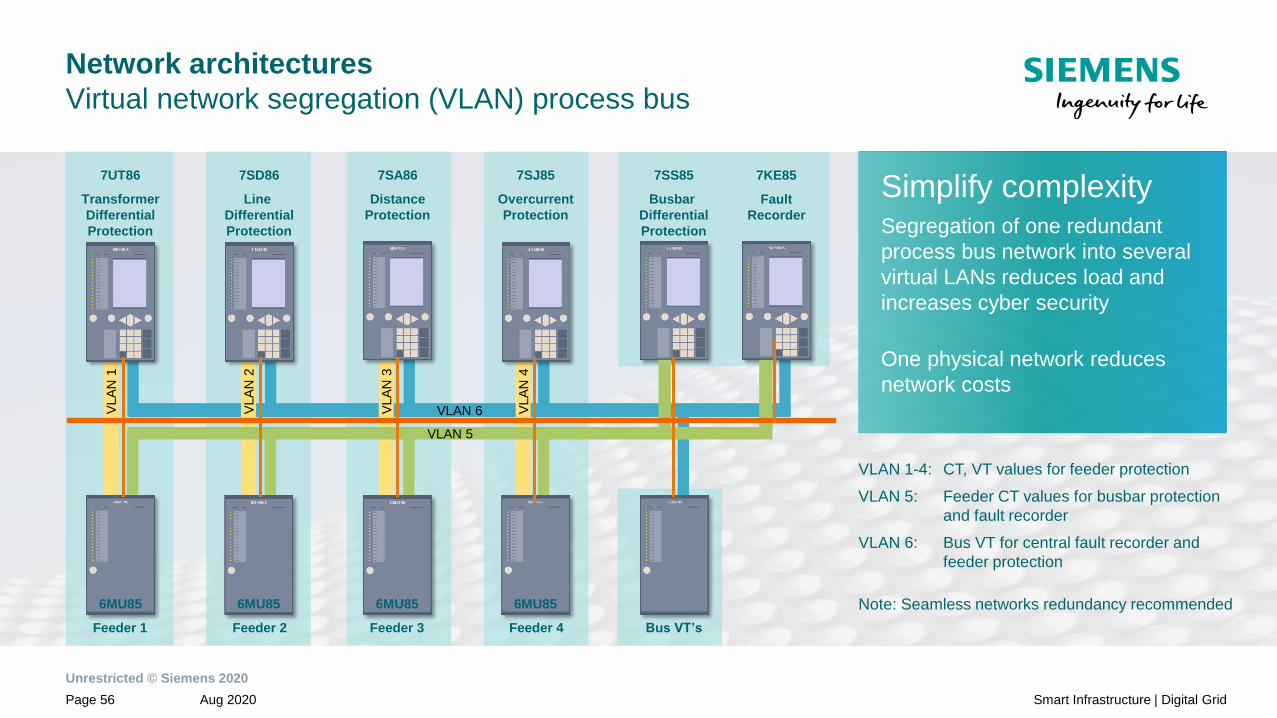
Network architectures
Virtual network segregation (VLAN) process bus
Simplify complexitySegregation of one redundant
process bus network into several
virtual LANs reduces load and
increases cyber security
One physical network reduces
network costs
VLAN 1-4: CT, VT values for feeder protection
VLAN 5: Feeder CT values for busbar protection
and fault recorder
VLAN 6: Bus VT for central fault recorder and
feeder protection
Note: Seamless networks redundancy recommended
7SJ85
Overcurrent
Protection
7SA86
Distance
Protection
7SD86
Line
Differential
Protection
7UT86
Transformer
Differential
Protection
7SS85
Busbar
Differential
Protection
Feeder 1 Feeder 2 Feeder 3 Feeder 4 Bus VT’s
7KE85
Fault
Recorder
VLA
N 1
VLAN 6VLA
N 2
VLA
N 3
VLA
N 4
VLAN 5
6MU85 6MU85 6MU85 6MU85 6MU85

Unrestricted © Siemens 2020
Aug 2020Page 57 Smart Infrastructure | Digital Grid
Content
Operation and user experience1
Designed to communicate2
Comprehensive cyber security features of SIPROTEC 53.1
Authenticated network access IEEE 802.1X3.2
Virtual segregation of networks with VLAN IEEE 802.1Q3.3
Strong in industrial applications4
Safety and security inside3
Conformal coating of electronic boards - harsh environments3.4

Unrestricted © Siemens 2020
Aug 2020Page 58 Smart Infrastructure | Digital Grid
Conformal coating as standard –
Maximum lifetime under extreme industrial conditions
SIPROTEC devices with Conformal Coating
• Double-sided coating standard for all modules
• Optimum quality of coating thanks to certified manufacturing process
• As standard, without additional cost for all new orders of SIPROTEC 5 and
SIPROTEC Compact devices.
Customer benefits
• Increased protection for SIPROTEC devices even under extreme
environmental conditions: Humidity, harmful gases, and aggressive dust,
chemicals, salts and combinations of any of these
• Additional mechanical protection from abrasion, and insects as well as
improper handling

SIPROTEC 5Strong in industrial applicationRelease V08.30
siemens.com/siprotec5Unrestricted © Siemens 2020

Unrestricted © Siemens 2020
Aug 2020Page 61 Smart Infrastructure | Digital Grid
Content
Operation and user experience1
Designed to communicate2
Safety and security inside3
Profinet IO S2 redundancy and communication4.2
Protection of 400 V grids4.3
Conformal coating of electronic boards - harsh environments4.4
Distributed busbar protection as extension of existing feeder protection4.5
Arc protection4.6
Control, protection and monitoring with transformer protection SIPROTEC 7UT84.7
Protection of motors in explosive environment4.8
Strong in industrial applications4
Handling and engineering4.1

Unrestricted © Siemens 2020
Aug 2020Page 62 Smart Infrastructure | Digital Grid
NEW: Easier filtering of routing information
Simplify complexity• Routing filter to your needs
• Binary inputs, F-Keys and
LEDs
Unrestricted © Siemens 2020
Aug 2020Page 63 Smart Infrastructure | Digital Grid
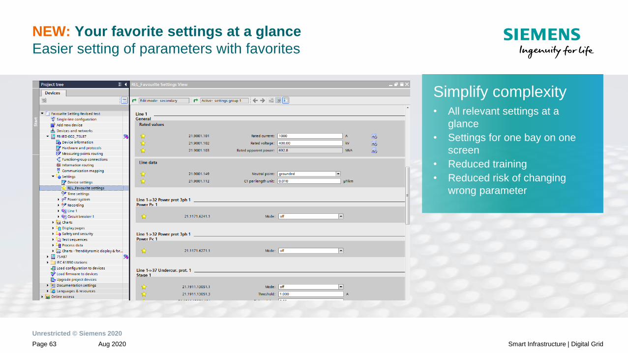
NEW: Your favorite settings at a glance
Easier setting of parameters with favorites
Simplify complexity• All relevant settings at a
glance
• Settings for one bay on one
screen
• Reduced training
• Reduced risk of changing
wrong parameter

Unrestricted © Siemens 2020
Aug 2020Page 64 Smart Infrastructure | Digital Grid
Designed to communicate
NEW: Automated IEC 61850 engineering with bay typicals
All instantiated devices
are available in DIGSI 5
project
✓
import and instantiate
typical devices in
SysCon
3
rename and arrange
devices in substation
topology and assign IP
addresses
4
export device ICD’s with
checkmark at “include
DEX5 export”
2create typical
devices in
DIGSI 5
1
Import SCD in
new DIGSI 5
project
5

Unrestricted © Siemens 2020
Aug 2020Page 65 Smart Infrastructure | Digital Grid
Content
Operation and user experience1
Designed to communicate2
Safety and security inside3
Handling and engineering4.1
Protection of 400 V grids4.3
Conformal coating of electronic boards - harsh environments4.4
Distributed busbar protection as extension of existing feeder protection4.5
Arc protection4.6
Control, protection and monitoring with transformer protection SIPROTEC 7UT84.7
Protection of motors in explosive environment4.8
Strong in industrial applications4
Profinet IO S2 redundancy and communication4.2

Unrestricted © Siemens 2020
Aug 2020Page 66 Smart Infrastructure | Digital Grid
NEW:* Profinet IO on ETH-BD-2FO
NEW:* High availability connection of
SIPROTEC 5 as an IO device to two
redundant Profinet IO Controllers
NEW:* Sequence of Events log from the
SIPROTEC 5 IO device to enable
monitoring of Process data from your
factory
Effortless integration into existing Profinet IO
networks with optional RJ-45 SFP
*ETH-BD-2FO plug-in module is required
Designed to communicate
Profinet IO with S2 Redundancy
Sequential Event List
(SOE)
IO Controller Main IO Controller Standby

Unrestricted © Siemens 2020
Aug 2020Page 67 Smart Infrastructure | Digital Grid
ETH-BD-2FO
Technical Specification:
Communication module for the transmission of
Ethernet protocols via 2 optical interfaces
NEW: Additional protocols (Device DDD V8.30)
• HSR (no IEEE 1588v2/PTP support)
• IEEE C37.118 (PMU)
• Profinet IO incl. S2 redundancy
• IEEE 1588v2/PTP support C37.238:2017 profile
Available protocols (Device DDD V8.03)
• PRP, Line Mode, RSTP
• IEC 61850-8-1 GOOSE, MMS
• IEC 60870-5-104
• SNTP
• COMFEDE support via MMS file transfer
• IEEE 1588v2/PTP (1µs accuracy) ordinary slave clock for radial
networks (PRP and Line Mode) – IEC 61850-9-3 profile
• DIGSI 5 protocol
• DCP
• DHCP
• Homepage
• WebUI
• SysLog
• RADIUS
• IEC 61850-9-2 Process Bus Client
• IEC 61850-9-2 Merging Unit
Transmit Power Minimum Typical Maximum
50 μm/125 μm, NA1 = 0.2 -24.0 dBm -21.0 dBm -17.0 dBm
62.5 μm/125 μm, NA1 = 0.275 -20.0 dBm -17.0 dBm -14.0 dBm
Receiver sensitivity Maximum -12.0 dBm
Minimum -31.0 dBm
Optical budget Minimum 7.0 dB for 50 μm/125 μm, NA1 = 0.2
Minimum 11.0 dB for 62.5 μm/125 μm, NA1 = 0. 275
Interface design Corresponds to IEEE 802.3, 100Base-FX
Laser class 1 as per EN 60825-1/-2 With the use of 62.5 μm/125 μm and 50 μm/125 μm
optical fibers
Connector type 2 x duplex LC
Wavelength λ = 1300 nm
Baud rate 100 Mbit/s
Max. line length 2 km for 62.5 µm/125 µm optical fibers
SIPROTEC 5
Ethernet module – ETH-BD-2FO
Comment: 1 Numerical Aperture (NA = sin θ (launch angle))
Unrestricted © Siemens 2020
Aug 2020Page 68 Smart Infrastructure | Digital Grid
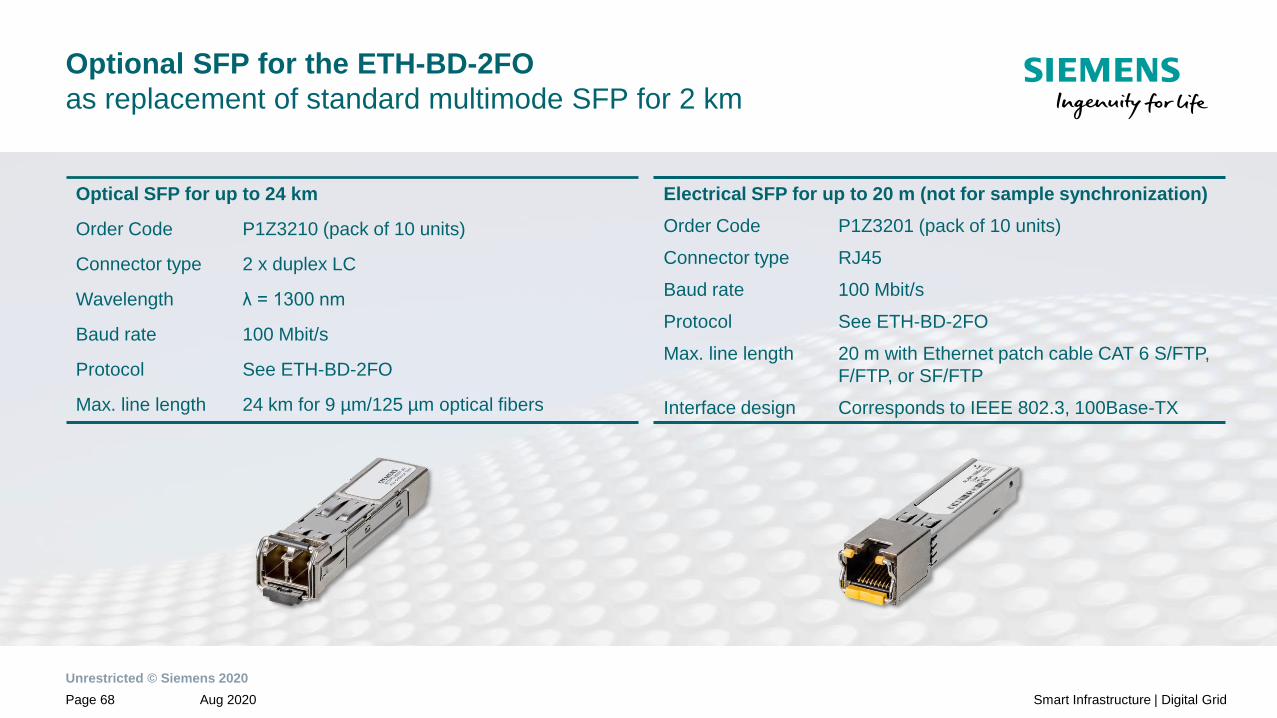
Optional SFP for the ETH-BD-2FO
as replacement of standard multimode SFP for 2 km
Optical SFP for up to 24 km
Order Code P1Z3210 (pack of 10 units)
Connector type 2 x duplex LC
Wavelength λ = 1300 nm
Baud rate 100 Mbit/s
Protocol See ETH-BD-2FO
Max. line length 24 km for 9 µm/125 µm optical fibers
Electrical SFP for up to 20 m (not for sample synchronization)
Order Code P1Z3201 (pack of 10 units)
Connector type RJ45
Baud rate 100 Mbit/s
Protocol See ETH-BD-2FO
Max. line length 20 m with Ethernet patch cable CAT 6 S/FTP,
F/FTP, or SF/FTP
Interface design Corresponds to IEEE 802.3, 100Base-TX

Unrestricted © Siemens 2020
Aug 2020Page 69 Smart Infrastructure | Digital Grid
Network architectures VLAN
Single ETH-BD-2FO module for all your communication
Station bus ( MMS) )
Simplify your network• From 3 networks to 1 network
• Logical (VLAN) segregation of
• Station bus
• PMU network
• Management network
Feeder 1 Feeder 2 Feeder 3 Feeder x
PMU network
Management (DIGSI, SNMP)
Feeder 1 Feeder 2 Feeder 3 Feeder x
Single ETH-BD-2FO Module
One common VLAN network

Unrestricted © Siemens 2020
Aug 2020Page 70 Smart Infrastructure | Digital Grid
Network architectures
Physically network segregation
Network 5:
Feeder CT values
Network 1
CT, VT values
Network 6:
Bus VT values
6MU85 6MU85 6MU85 6MU85 6MU85
Simplify complexityUse of more than one redundant
process bus network reduces the
network engineering
Increase the bandwidth with
additional Ethernet interfaces
Efficient use of network bandwidth
with customization of the analog
values per SMV streams
(not only IEC 61850-9-2LE data
set)
7SJ85
Overcurrent
Protection
7SA86
Distance
Protection
7SD86
Line
Differential
Protection
7UT86
Transformer
Differential
Protection
7SS85
Busbar
Differential
Protection
Feeder 1 Feeder 2 Feeder 3 Feeder 4 Bus VT’s
7KE85
Fault
Recorder
Network 2
CT, VT values
Network 3
CT, VT values
Network 4
CT, VT values
Note: Seamless networks redundancy recommended

Unrestricted © Siemens 2020
Aug 2020Page 71 Smart Infrastructure | Digital Grid
Network architectures
Virtual network segregation (VLAN)
Simplify complexitySegregation of one redundant
process bus network into several
virtual LANs reduces load and
increases cyber security
One physical network reduces
network costs
VLAN 1-4: CT, VT values for feeder protection
VLAN 5: Feeder CT values for busbar protection
and fault recorder
VLAN 6: Bus VT for central fault recorder and
feeder protection
Note: Seamless networks redundancy recommended
7SJ85
Overcurrent
Protection
7SA86
Distance
Protection
7SD86
Line
Differential
Protection
7UT86
Transformer
Differential
Protection
7SS85
Busbar
Differential
Protection
Feeder 1 Feeder 2 Feeder 3 Feeder 4 Bus VT’s
7KE85
Fault
Recorder
VLA
N 1
VLAN 6VLA
N 2
VLA
N 3
VLA
N 4
VLAN 5
6MU85 6MU85 6MU85 6MU85 6MU85

Unrestricted © Siemens 2020
Aug 2020Page 72 Smart Infrastructure | Digital Grid
Designed to communicate
HSR and PRP redundancy
New on ETH-BD-2FO module:
HSR* ring with clients and server connected to PRP LANs
PR
P
LA
N A
Re
dB
ox
Re
dB
ox
PRP redundancy with clients and server
for station and process bus
PRP LAN A
PRP LAN B
PR
P
LA
N B
* Support of IEEE 1588v2/PTP (transparent clock) in preparation

Unrestricted © Siemens 2020
Aug 2020Page 73 Smart Infrastructure | Digital Grid
Content
Operation and user experience1
Designed to communicate2
Safety and security inside3
Handling and engineering4.1
Profinet IO S2 redundancy and communication4.2
Conformal coating of electronic boards - harsh environments4.4
Distributed busbar protection as extension of existing feeder protection4.5
Arc protection4.6
Control, protection and monitoring with transformer protection SIPROTEC 7UT84.7
Protection of motors in explosive environment4.8
Strong in industrial applications4
Protection of 400 V grids4.3

Unrestricted © Siemens 2020
Aug 2020Page 74 Smart Infrastructure | Digital Grid
Protection of 400 V grids
with SIPROTEC 5 multifunctional relays
Advantages of a multi-functional SIPROTEC 5 protection device for low voltage grids
• Cost and space saving due to elimination of the
external voltage transformer
• Local control of the circuit-breaker
• Remote signaling and control via control system
• Fault analysis via fault records (SIGRA)
• Power and energy recording, for internal cost
controlling
• Protection function, also as backup protection for
the medium voltage side of the feeding
transformer
• Compliant with the EMC directive

Unrestricted © Siemens 2020
Aug 2020Page 75 Smart Infrastructure | Digital Grid
Content
Operation and user experience1
Designed to communicate2
Safety and security inside3
Handling and engineering4.1
Profinet IO S2 redundancy and communication4.2
Protection of 400 V grids4.3
Distributed busbar protection as extension of existing feeder protection4.5
Arc protection4.6
Control, protection and monitoring with transformer protection SIPROTEC 7UT84.7
Protection of motors in explosive environment4.8
Strong in industrial applications4
Conformal coating of electronic boards - harsh environments4.4

Unrestricted © Siemens 2020
Aug 2020Page 76 Smart Infrastructure | Digital Grid
Conformal coating as standard –
Maximum lifetime under extreme industrial conditions
SIPROTEC devices with Conformal Coating
• Double-sided coating standard for all modules
• Optimum quality of coating thanks to certified manufacturing process
• As standard, without additional cost for all new orders of SIPROTEC 5 and
SIPROTEC Compact devices.
Customer benefits
• Increased protection for SIPROTEC devices even under extreme
environmental conditions: Humidity, harmful gases, and aggressive dust,
chemicals, salts and combinations of any of these
• Additional mechanical protection from abrasion, and insects as well as
improper handling

Unrestricted © Siemens 2020
Aug 2020Page 77 Smart Infrastructure | Digital Grid
Content
Operation and user experience1
Designed to communicate2
Safety and security inside3
Handling and engineering4.1
Profinet IO S2 redundancy and communication4.2
Protection of 400 V grids4.3
Conformal coating of electronic boards - harsh environments4.4
Arc protection4.6
Control, protection and monitoring with transformer protection SIPROTEC 7UT84.7
Protection of motors in explosive environment4.8
Strong in industrial applications4
Distributed busbar protection as extension of existing feeder protection4.5

Unrestricted © Siemens 2020
Aug 2020Page 78 Smart Infrastructure | Digital Grid
Distributed busbar protection as addition to
existing feeder protection
Brownfield application• Upgrade your protection
system with a small investment
• Get a distributed busbar
protection in your actual
protection system just with one
device and the process bus
module
• Less effort and less investment
• Not additional wiring and
additional CTs for busbar
protection

Unrestricted © Siemens 2020
Aug 2020Page 79 Smart Infrastructure | Digital Grid
Content
Operation and user experience1
Designed to communicate2
Safety and security inside3
Handling and engineering4.1
Profinet IO S2 redundancy and communication4.2
Protection of 400 V grids4.3
Conformal coating of electronic boards - harsh environments4.4
Distributed busbar protection as extension of existing feeder protection4.5
Control, protection and monitoring with transformer protection SIPROTEC 7UT84.7
Protection of motors in explosive environment4.8
Strong in industrial applications4
Arc protection4.6
Unrestricted © Siemens 2020
Aug 2020Page 80 Smart Infrastructure | Digital Grid
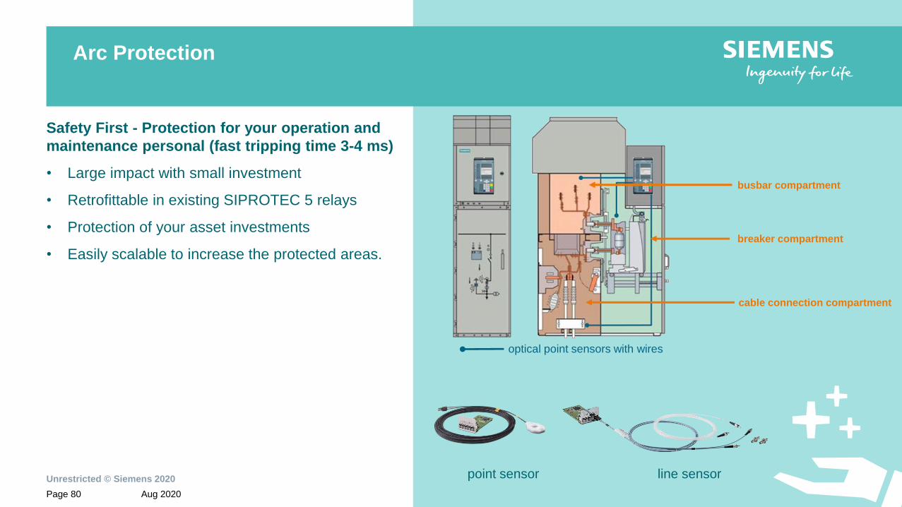
Arc Protection
busbar compartment
point sensor line sensor
breaker compartment
cable connection compartment
optical point sensors with wires
Safety First - Protection for your operation and
maintenance personal (fast tripping time 3-4 ms)
• Large impact with small investment
• Retrofittable in existing SIPROTEC 5 relays
• Protection of your asset investments
• Easily scalable to increase the protected areas.

Unrestricted © Siemens 2020
Aug 2020Page 81 Smart Infrastructure | Digital Grid
Content
Operation and user experience1
Designed to communicate2
Safety and security inside3
Handling and engineering4.1
Profinet IO S2 redundancy and communication4.2
Protection of 400 V grids4.3
Conformal coating of electronic boards - harsh environments4.4
Distributed busbar protection as extension of existing feeder protection4.5
Arc protection4.6
Protection of motors in explosive environment4.8
Strong in industrial applications4
Control, protection and monitoring with transformer protection SIPROTEC 7UT84.7

Unrestricted © Siemens 2020
Aug 2020Page 82 Smart Infrastructure | Digital Grid
Control, protection and monitoring with
SIPROTEC 7UT8 transformer protection
Logic for transformer
cooling group control
Temperature sensors
4..20 mA
TR1200 IP
Buchholz relay
Trip and Alarm
Automatic voltage
regulator
Tap changer
position and control
digital or 4..20mA
Pressure relief devices
Temperature sensor
up to 12x PT100
Highlights• Reduced investment
• One device for monitoring,
control and protection
• Voltage regulation
integrated
• Reduced wiring
• Faster commissioning
Unrestricted © Siemens 2020
Aug 2020Page 83 Smart Infrastructure | Digital Grid
Content
Operation and user experience1
Designed to communicate2
Safety and security inside3
Handling and engineering4.1
Profinet IO S2 redundancy and communication4.2
Protection of 400 V grids4.3
Conformal coating of electronic boards - harsh environments4.4
Distributed busbar protection as extension of existing feeder protection4.5
Arc protection4.6
Control, protection and monitoring with transformer protection SIPROTEC 7UT84.7
Strong in industrial applications4
Protection of motors in explosive environment4.8

Unrestricted © Siemens 2020
Aug 2020Page 84 Smart Infrastructure | Digital Grid
Protection of motors in explosive environment (ATEX)
Certification of motor protection devices
• SIPROTEC 7SK82
• SIPROTEC 7SK85
• SIPROTEC 7UM85
for installing in explosive environment according the
standard EN 60079-14 or the standard VDE 0165,
part 1 (electric equipment for hazardous areas)

Unrestricted © Siemens 2020
Aug 2020Page 85 Smart Infrastructure | Digital Grid
© Siemens 2020
Aug 2020Page 85
Disclaimer:
Subject to changes and errors. The information given in this document only contains general
descriptions and/or performance features which may not always specifically reflect those
described, or which may undergo modification in the course of further development of the products.
The requested performance features are binding only when they are expressly agreed upon in the
concluded contract.
All product designations, product names, etc. may contain trademarks or other rights of Siemens
AG, its affiliated companies or third parties. Their unauthorized use may infringe the rights of the
respective owner.
Gerd Einsiedler
SI DG EA-S
Humboldtstr. 59
90459 Nürnberg
E-mail: [email protected]


