Embed Size (px)
Citation preview
ASME TURBO EXPO 2018: Turbine Technical Conference and Exposition
GT2018
June 15-19, 2018, Oslo, Norway
Shrouded CMC Rotor Blades for High Pressure Turbine Applications
GT2018-76827
Robert J. Boyle Lucas M. Agricola Ankur H. Parikh
N&R Engineering The Ohio State University N&R EngineeringParma Heights, OH Columbus, OH Parma Heights, OH
[email protected] [email protected] [email protected]
Ali A. Ameri Vinod K. Nagpal
The Ohio State University N&R Engineering and Management ServicesColumbus, OH Parma Heights, OH
[email protected] [email protected]
ABSTRACT
The density of Ceramic Matrix Compos-ite(CMC) materials is approximately 1/3 the den-sity of metals currently used for High Pressure Tur-bine(HPT) blades. A lower density, and conse-quently lower centrifugal stresses, increases the fea-sibility of shrouding HPT blades. Shrouding HPTblades improves aerodynamic efficiency, especiallyfor low aspect ratio turbine blades. This paper ex-plores aerodynamic and structural issues associatedwith shrouding HPT rotor blades. Detailed Navier-Stokes analysis of a rotor blade showed that shroud-ing improved blade row aerodynamic efficiency by1.3%, when the clearance was 2% of the blade span.Recessed casings were used. Without a shroud thedepth of the recess equaled the clearance. With ashroud the recess depth increased by the shroud thick-ness, which included a knife seal. There was goodagreement between the predicted stage efficiency forthe unshrouded blades and the experimentally mea-sured efficiency. Structural analysis showed a stronginteraction between stresses in the shroud and peakstresses at the hub of the blade. A thin shroud of uni-form thickness only moderately increased maximumblade stress, but there were very high stresses in theshroud itself. Increasing shroud thickness reducedstresses in the shroud, but increased blade stressesnear the hub. A single knife seal added to the thinshroud noticeably decreased maximum shroud stress,without increasing maximum blade stress. Maximumstresses due to pressure loads and combined pres-sure and centrifugal loads were nearly the same asthe maximum stresses for individual pressure or cen-trifugal loads. Stresses due to a 100K temperature
difference across the blade walls were much lowerthan centrifugal or pressure load stresses.
Nomenclature
S′′′ - Rate of entropy generationper unit volume, W/m3
− KT - Temperature, Kui - Velocity component, m/secxi - Coordinate direction, my+1 - Dimensionless first grid line
- distance from solid surfaceµEFF - Effective viscosity, Pa − sec
INTRODUCTION
This paper addresses the feasibility of shroudingCeramic Matrix Composite(CMC) blades for use inthe High Pressure Turbine(HPT). Shrouding is fea-sible for CMC blades of the HPT, while shrouding isless common for current metallic HPT blades. Cen-trifugal stresses are proportional to material den-sity, and CMCs are only one third as dense as singlecrystal superalloy blade materials. Shrouding re-duces clearance loss, and the stage efficiency ben-efit from shrouding HPT rotor blades increases asthe blade clearance-to-span ratio increases. At con-stant thrust increasing engine Overall Pressure Ra-tio(OPR) yields smaller HPT cores, which is likely
1
to increase clearance-to-span ratios. Clearance lossis a major loss for unshrouded HPT rotor blades, andshrouding the blades is expected to reduce the clear-ance loss by a third to a half(Yoon et al.(1)). Eventhough lower centrifugal stresses are expected whenCMC blades are used, a CMC rotor blade needs suffi-cient strength to accommodate centrifugal, pressure,and thermal load stresses. Some SiC/SiC CMC ma-terials have strengths in the fiber directions close tothe strengths of advanced metal alloys, even whenthe CMC is at a higher temperature.
Detailed steady state Navier-Stokes calculationswere used to compare blade row aerodynamic effi-ciency for shrouded and unshrouded blades. A re-cessed casing was included in the analysis of the un-shrouded and shrouded blades. The shrouded bladehad a knife seal to reduce through flows in the clear-ance region.
Stress analyses were done for shrouded and un-shrouded HPT blades. Different shroud configura-tions were examined. Stresses were calculated forcentrifugal and pressure loads applied separately,and when these loads were applied simultaneously.Thermal stresses were calculated for a uniform tem-perature difference across the blade walls. The un-shrouded HPT blade described by Moffitt et al.(2) isused for both aerodynamic and stress analyses. Thisreference gives blade coordinates, and experimentalaerodynamic performance for an unshrouded blade.
REFERENCE TURBINE BLADE
A turbine, described and tested by Moffitt etal.(2), was analyzed. This turbine was for a HPTapplication, and was unshrouded. The turbine wasdescribed as having relatively thick leading and trail-ing edges, and a high maximum thickness-to-chordratio, along with a low aspect ratio. These char-acteristics make this design a suitable reference casefor investigating the benefits of CMC turbine blades.The rotor blade axial chord was 3.43cm(1.35in.);the span was 3.81cm(1.5in.); and the tip radius was25.4cm(10in.)
The aerodynamic analysis assumed a recessedcasing over the blade. For the unshrouded bladethe recess height and the clearance were both 2%of span. When the shroud was added the casingrecess was significantly greater. The shroud had aknife seal to retard clearance region axial flows. Theclearance above the knife seal remained at 2% ofthe span. A 2% clearance was chosen primarily togive a significant efficiency change due to shroud-ing the rotor. However, the absolute value of thisclearance, 0.076cm(0.030in.), is appropriate for fu-ture HPT turbines, with their lower volumetric flowrates. A notional N+3 single aisle aircraft engine
has a HPT span only half the span of the ana-lyzed turbine.(Jones(3)). A 2% clearance in the no-tional engine corresponds to an absolute clearanceof 0.038cm(0.015in.).
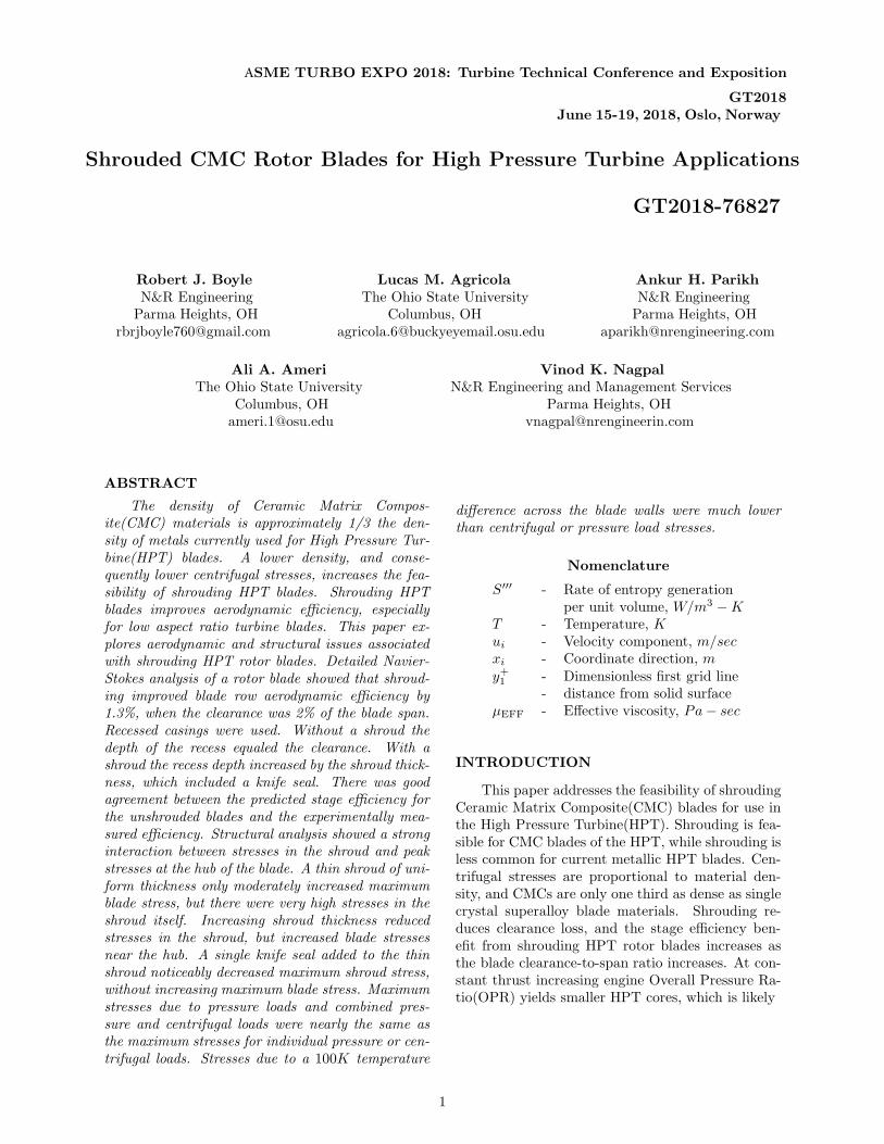
Figure 1 shows three sections of the blade givenby Moffitt et al.(2). The blade shape varies nearlylinearly from hub to tip. The design mean inlet andexit flow angles were 50◦ and 59◦.
Figure 2 shows the tip region of the blade witha shroud. This geometry was used for the aerody-namic analysis. The blade geometry was providedby Moffitt et al.(2), and the shroud geometry issimilar to the shroud discussed by Kanjirakkad etal.(4). For both geometries the casing recess ex-tended 3.8mm, or 11% of the axial chord in frontof and behind the blade. The shroud thickness andthe actual clearance were 2% of the span. The knifeseal was 4.05mm, or 10.6%, of the span. The cas-ing recess was 5.56mm, or 14.6% of the span. Theundersurface of the shroud and the tip of the un-shrouded blade were flush with the upstream statortip location.
RESULTS
Both aerodynamic and stress analysis results arepresented, each in their own section. The aero-dynamic results focus on the efficiency gain fromshrouding the HPT rotor blade. The stress analysisresults focus on the distribution of stresses when ashroud is added. This is done for centrifugal, pres-sure, and thermal loads.
Improved Efficiency for Shrouded Rotors
A 3D steady state analysis was done for theshrouded and unshrouded rotor blade geometries us-ing the Star-CCM+ computer code. The k−ω SSTturbulence model was used. This code is appropri-ate for turbomachinery analysis. For example, Linet al.(5) used the Star-CCM+ analysis for the conju-gate analysis of heat transfer to a gas turbine vane.The k − ω SST turbulence model was used by byAmeri et al.(6) to predict turbine blade tip regionclearance flows and heat transfer. For the resultspresented herein wall functions were not used be-cause the near wall dimensionless wall distance, y+
1 ,was sufficiently low.
Navier-Stokes analyses were done for theshrouded and unshrouded rotor blade. The first ob-jective of the aerodynamic analyses was to determinethe increase in blade row efficiency due to shroudinga HPT blade. The second objective was to show thatthe CFD analysis agreed reasonably well with ex-perimental stage efficiency data for the unshroudedrotor blade.
2
-0.5 0 0.5 1 1.5 2 2.5 3 3.5 4Axial distance, x, cm
-1.5
-1
-0.5
0
0.5
1
1.5
Tan
gent
ial d
ista
nce,
y, c
m
HubMeanTip
Figure 1. THREE SECTIONS of the HPT BLADE(MOFFITT et al.(2)).
Figure 2. BLADE TIP REGION.
Even with only a single knife seal the calculatedefficiency increased by 1.3%, for a 2% clearance. Theanalysis agreed reasonably well with the experimen-tal unshrouded turbine after accounting for differ-ences in clearance and casing geometry. The mea-sured stage efficiency was 88.6% for a design clear-ance of 0.8%. Moffitt et al.(2) estimated the sensitiv-ity of efficiency to clearance, and at 2% clearance thestage efficiency was estimated to be between 86.4%and 87.0%. The calculated efficiency was 87.7% andincluded a 2% absolute total pressure drop acrossthe stator. The calculated efficiency is 0.7% to 1.3%higher than the estimated experimental efficiency at2% clearance. A likely reason for the remaining ef-ficiency over prediction is that the analysis was fora recessed casing, but there was no recess in theexperimental test. The recess provided geometriccommonality with the shrouded rotor configuration.Haas and Kofskey(7) showed that recessing the cas-ing contributes to lower sensitivity of stage efficiencyto clearance. It is expected that for no casing recessthe calculated efficiency would be lower than 87.7%,and closer to the clearance corrected experimentalefficiency of 87% or less.
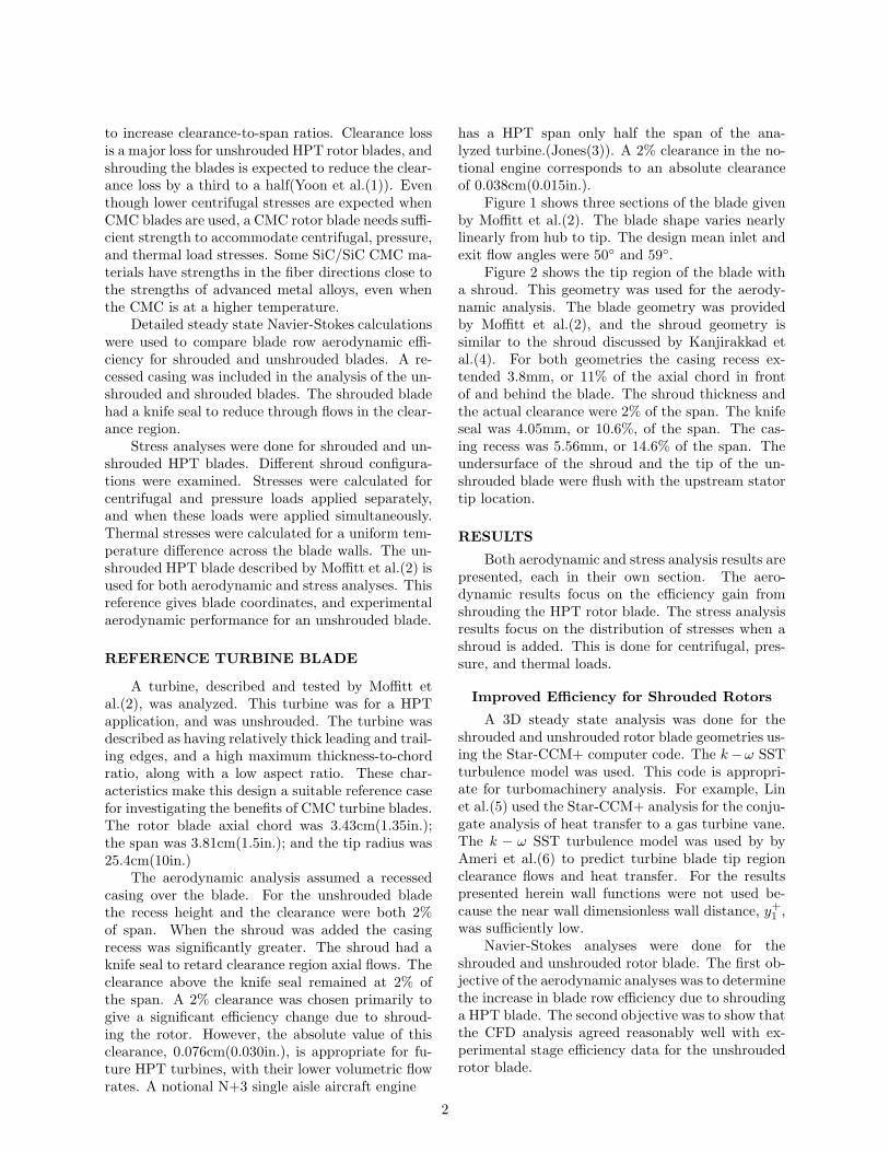
Figure 3 shows views of grids used. Polygongrids were used away from solid surfaces. Body fit-ted grids were used near solid surfaces. This can beseen in the view showing the trailing edge region.The near wall spacing was 1.5 × 10⁻⁷m, which wassufficient to give an average y+ near 0.6 for both
Figure 3. GRIDS USED for AERODYNAMICANALYSIS.
the shrouded and unshrouded cases. The cell countfor the unshrouded case was 3.39 million. For theshrouded case the cell count increased by 25% toaccommodate the increased clearance volume.
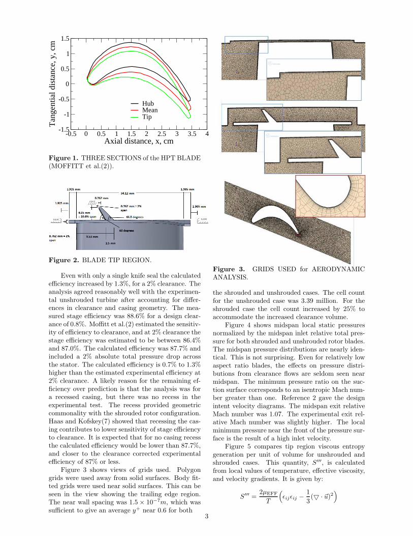
Figure 4 shows midspan local static pressuresnormalized by the midspan inlet relative total pres-sure for both shrouded and unshrouded rotor blades.The midspan pressure distributions are nearly iden-tical. This is not surprising. Even for relatively lowaspect ratio blades, the effects on pressure distri-butions from clearance flows are seldom seen nearmidspan. The minimum pressure ratio on the suc-tion surface corresponds to an isentropic Mach num-ber greater than one. Reference 2 gave the designintent velocity diagrams. The midspan exit relativeMach number was 1.07. The experimental exit rel-ative Mach number was slightly higher. The localminimum pressure near the front of the pressure sur-face is the result of a high inlet velocity.
Figure 5 compares tip region viscous entropygeneration per unit of volume for unshrouded andshrouded cases. This quantity, S′′′, is calculatedfrom local values of temperature, effective viscosity,and velocity gradients. It is given by:
S′′′ =2µEFF
T
(
ǫijǫij −1
3(▽ · ~u)2
)
3
Axial distance, fraction of chord
Figure 4. MIDSPAN SURFACE PRESSURES,UNSHROUDED & SHROUDED BLADES.
PP ′′
IN
a) Unshrouded rotor
b) Shrouded rotor
Figure 5. VISCOUS ENTROPY, W/m3− K.
where:
ǫij =1
2
( ∂ui
∂xj
+∂uj
∂xi
)
Red regions of high viscous entropy correspondto regions of high loss. Tip region results are shownon an axial-radial plane midway through the com-putational domain, and on three tangential-radialplanes. Over the blade the region of high viscous en-tropy for the unshrouded case appears smaller thanfor the shrouded case. But, this is an illusion. Forboth cases the gap is only 2% of the span. The knifeseal increases the distance between the shroud and
a) Unshrouded rotor
b) Shrouded rotor
Figure 6. VISCOUS ENTROPY in MIDSPANPLANE.
casing. There is a high loss region starting near thesame location as the minimum suction surface pres-sure seen in Fig. 4. In the unshrouded case, (Fig.5a), the region of high loss is larger than the lossregion for the shrouded case, (Fig. 5b). At thissuction surface location the high loss region extendsdown the span, and is larger for the unshrouded case.
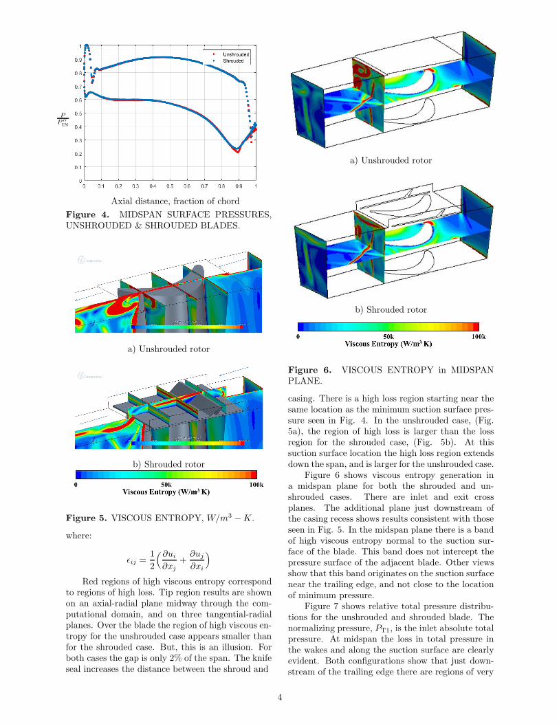
Figure 6 shows viscous entropy generation ina midspan plane for both the shrouded and un-shrouded cases. There are inlet and exit crossplanes. The additional plane just downstream ofthe casing recess shows results consistent with thoseseen in Fig. 5. In the midspan plane there is a bandof high viscous entropy normal to the suction sur-face of the blade. This band does not intercept thepressure surface of the adjacent blade. Other viewsshow that this band originates on the suction surfacenear the trailing edge, and not close to the locationof minimum pressure.
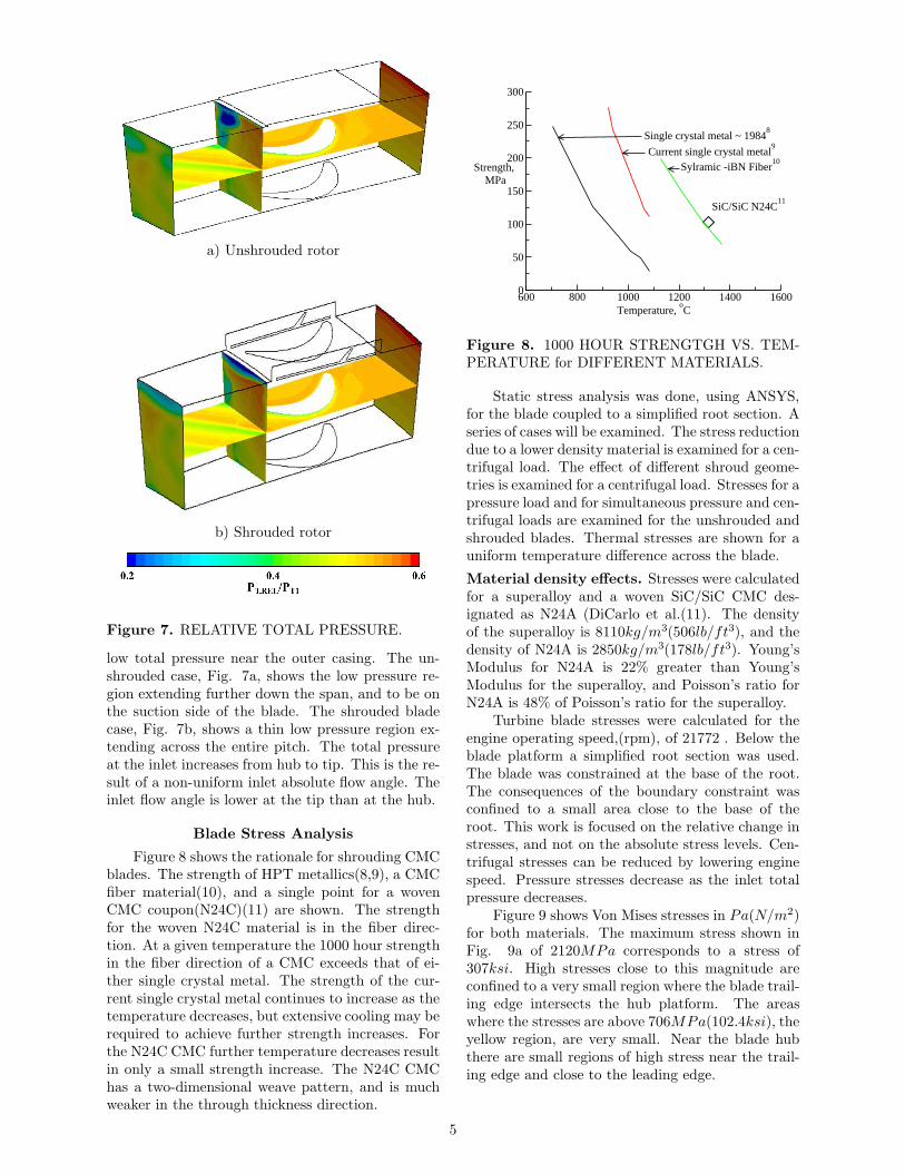
Figure 7 shows relative total pressure distribu-tions for the unshrouded and shrouded blade. Thenormalizing pressure, PT1, is the inlet absolute totalpressure. At midspan the loss in total pressure inthe wakes and along the suction surface are clearlyevident. Both configurations show that just down-stream of the trailing edge there are regions of very
4
a) Unshrouded rotor
b) Shrouded rotor
Figure 7. RELATIVE TOTAL PRESSURE.
low total pressure near the outer casing. The un-shrouded case, Fig. 7a, shows the low pressure re-gion extending further down the span, and to be onthe suction side of the blade. The shrouded bladecase, Fig. 7b, shows a thin low pressure region ex-tending across the entire pitch. The total pressureat the inlet increases from hub to tip. This is the re-sult of a non-uniform inlet absolute flow angle. Theinlet flow angle is lower at the tip than at the hub.
Blade Stress Analysis
Figure 8 shows the rationale for shrouding CMCblades. The strength of HPT metallics(8,9), a CMCfiber material(10), and a single point for a wovenCMC coupon(N24C)(11) are shown. The strengthfor the woven N24C material is in the fiber direc-tion. At a given temperature the 1000 hour strengthin the fiber direction of a CMC exceeds that of ei-ther single crystal metal. The strength of the cur-rent single crystal metal continues to increase as thetemperature decreases, but extensive cooling may berequired to achieve further strength increases. Forthe N24C CMC further temperature decreases resultin only a small strength increase. The N24C CMChas a two-dimensional weave pattern, and is muchweaker in the through thickness direction.
600 800 1000 1200 1400 1600Temperature,
oC
0
50
100
150
200
250
300
Strength,MPa
Single crystal metal ~ 19848
Current single crystal metal9
SiC/SiC N24C11
Sylramic -iBN Fiber10
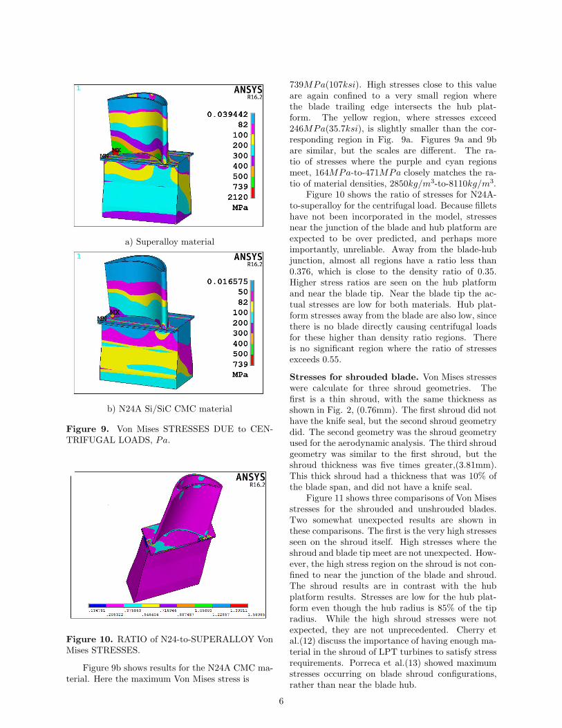
Figure 8. 1000 HOUR STRENGTGH VS. TEM-PERATURE for DIFFERENT MATERIALS.
Static stress analysis was done, using ANSYS,for the blade coupled to a simplified root section. Aseries of cases will be examined. The stress reductiondue to a lower density material is examined for a cen-trifugal load. The effect of different shroud geome-tries is examined for a centrifugal load. Stresses for apressure load and for simultaneous pressure and cen-trifugal loads are examined for the unshrouded andshrouded blades. Thermal stresses are shown for auniform temperature difference across the blade.
Material density effects. Stresses were calculatedfor a superalloy and a woven SiC/SiC CMC des-ignated as N24A (DiCarlo et al.(11). The densityof the superalloy is 8110kg/m3(506lb/ft3), and thedensity of N24A is 2850kg/m3(178lb/ft3). Young’sModulus for N24A is 22% greater than Young’sModulus for the superalloy, and Poisson’s ratio forN24A is 48% of Poisson’s ratio for the superalloy.
Turbine blade stresses were calculated for theengine operating speed,(rpm), of 21772 . Below theblade platform a simplified root section was used.The blade was constrained at the base of the root.The consequences of the boundary constraint wasconfined to a small area close to the base of theroot. This work is focused on the relative change instresses, and not on the absolute stress levels. Cen-trifugal stresses can be reduced by lowering enginespeed. Pressure stresses decrease as the inlet totalpressure decreases.
Figure 9 shows Von Mises stresses in Pa(N/m2)for both materials. The maximum stress shown inFig. 9a of 2120MPa corresponds to a stress of307ksi. High stresses close to this magnitude areconfined to a very small region where the blade trail-ing edge intersects the hub platform. The areaswhere the stresses are above 706MPa(102.4ksi), theyellow region, are very small. Near the blade hubthere are small regions of high stress near the trail-ing edge and close to the leading edge.
5
a) Superalloy material
b) N24A Si/SiC CMC material
Figure 9. Von Mises STRESSES DUE to CEN-TRIFUGAL LOADS, Pa.
Figure 10. RATIO of N24-to-SUPERALLOY VonMises STRESSES.
Figure 9b shows results for the N24A CMC ma-terial. Here the maximum Von Mises stress is
739MPa(107ksi). High stresses close to this valueare again confined to a very small region wherethe blade trailing edge intersects the hub plat-form. The yellow region, where stresses exceed246MPa(35.7ksi), is slightly smaller than the cor-responding region in Fig. 9a. Figures 9a and 9bare similar, but the scales are different. The ra-tio of stresses where the purple and cyan regionsmeet, 164MPa-to-471MPa closely matches the ra-tio of material densities, 2850kg/m3-to-8110kg/m3.
Figure 10 shows the ratio of stresses for N24A-to-superalloy for the centrifugal load. Because filletshave not been incorporated in the model, stressesnear the junction of the blade and hub platform areexpected to be over predicted, and perhaps moreimportantly, unreliable. Away from the blade-hubjunction, almost all regions have a ratio less than0.376, which is close to the density ratio of 0.35.Higher stress ratios are seen on the hub platformand near the blade tip. Near the blade tip the ac-tual stresses are low for both materials. Hub plat-form stresses away from the blade are also low, sincethere is no blade directly causing centrifugal loadsfor these higher than density ratio regions. Thereis no significant region where the ratio of stressesexceeds 0.55.
Stresses for shrouded blade. Von Mises stresseswere calculate for three shroud geometries. Thefirst is a thin shroud, with the same thickness asshown in Fig. 2, (0.76mm). The first shroud did nothave the knife seal, but the second shroud geometrydid. The second geometry was the shroud geometryused for the aerodynamic analysis. The third shroudgeometry was similar to the first shroud, but theshroud thickness was five times greater,(3.81mm).This thick shroud had a thickness that was 10% ofthe blade span, and did not have a knife seal.
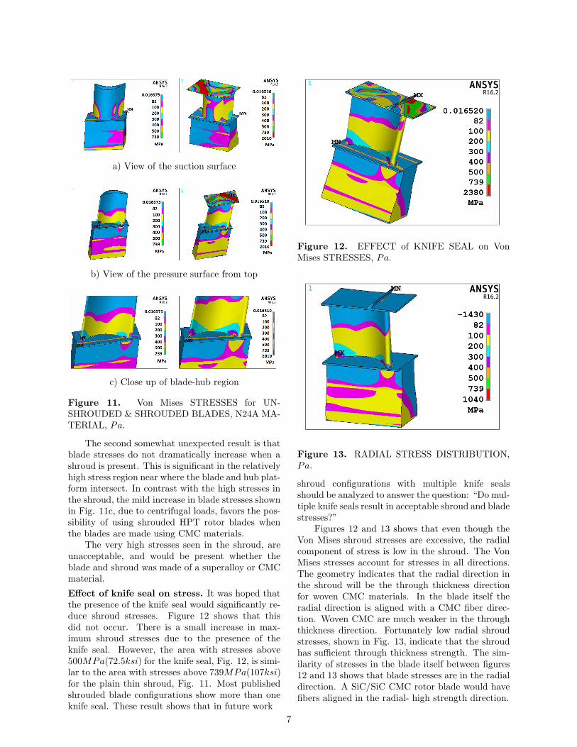
Figure 11 shows three comparisons of Von Misesstresses for the shrouded and unshrouded blades.Two somewhat unexpected results are shown inthese comparisons. The first is the very high stressesseen on the shroud itself. High stresses where theshroud and blade tip meet are not unexpected. How-ever, the high stress region on the shroud is not con-fined to near the junction of the blade and shroud.The shroud results are in contrast with the hubplatform results. Stresses are low for the hub plat-form even though the hub radius is 85% of the tipradius. While the high shroud stresses were notexpected, they are not unprecedented. Cherry etal.(12) discuss the importance of having enough ma-terial in the shroud of LPT turbines to satisfy stressrequirements. Porreca et al.(13) showed maximumstresses occurring on blade shroud configurations,rather than near the blade hub.
6
a) View of the suction surface
b) View of the pressure surface from top
c) Close up of blade-hub region
Figure 11. Von Mises STRESSES for UN-SHROUDED & SHROUDED BLADES, N24A MA-TERIAL, Pa.
The second somewhat unexpected result is thatblade stresses do not dramatically increase when ashroud is present. This is significant in the relativelyhigh stress region near where the blade and hub plat-form intersect. In contrast with the high stresses inthe shroud, the mild increase in blade stresses shownin Fig. 11c, due to centrifugal loads, favors the pos-sibility of using shrouded HPT rotor blades whenthe blades are made using CMC materials.
The very high stresses seen in the shroud, areunacceptable, and would be present whether theblade and shroud was made of a superalloy or CMCmaterial.
Effect of knife seal on stress. It was hoped thatthe presence of the knife seal would significantly re-duce shroud stresses. Figure 12 shows that thisdid not occur. There is a small increase in max-imum shroud stresses due to the presence of theknife seal. However, the area with stresses above500MPa(72.5ksi) for the knife seal, Fig. 12, is simi-lar to the area with stresses above 739MPa(107ksi)for the plain thin shroud, Fig. 11. Most publishedshrouded blade configurations show more than oneknife seal. These result shows that in future work
Figure 12. EFFECT of KNIFE SEAL on VonMises STRESSES, Pa.
Figure 13. RADIAL STRESS DISTRIBUTION,Pa.
shroud configurations with multiple knife sealsshould be analyzed to answer the question: “Do mul-tiple knife seals result in acceptable shroud and bladestresses?”
Figures 12 and 13 shows that even though theVon Mises shroud stresses are excessive, the radialcomponent of stress is low in the shroud. The VonMises stresses account for stresses in all directions.The geometry indicates that the radial direction inthe shroud will be the through thickness directionfor woven CMC materials. In the blade itself theradial direction is aligned with a CMC fiber direc-tion. Woven CMC are much weaker in the throughthickness direction. Fortunately low radial shroudstresses, shown in Fig. 13, indicate that the shroudhas sufficient through thickness strength. The sim-ilarity of stresses in the blade itself between figures12 and 13 shows that blade stresses are in the radialdirection. A SiC/SiC CMC rotor blade would havefibers aligned in the radial- high strength direction.
7
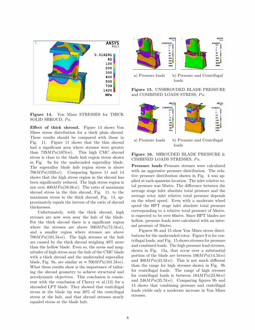
Figure 14. Von Mises STRESSES for THICKSOLID SHROUD, Pa.
Effect of thick shroud. Figure 14 shows VonMises stress distribution for a thick plain shroud.These results should be compared with those inFig. 11. Figure 11 shows that the thin shroudhad a significant area where stresses were greaterthan 739MPa(107ksi). This high CMC shroudstress is close to the blade hub region stress shownin Fig. 9a for the unshrouded superalloy blade.The superalloy blade hub region stress is above706MPa(102ksi). Comparing figures 11 and 14shows that the high stress region in the shroud hasbeen significantly reduced. The high stress region isnot over 400MPa(58.0ksi). The ratio of maximumshroud stress in the thin shroud, Fig. 11, to themaximum stress in the thick shroud, Fig. 14, ap-proximately equals the inverse of the ratio of shroudthicknesses.
Unfortunately, with the thick shroud, highstresses are now seen near the hub of the blade.For the thick shroud there is a significant regionwhere the stresses are above 500MPa(72.5ksi),and a smaller region where stresses are above700MPa(101.5ksi). The high stresses at the hubare caused by the thick shroud weighing 40% morethan the hollow blade. Even so, the areas and mag-nitudes of high stress near the hub of the CMC bladewith a thick shroud and the unshrouded superalloyblade, Fig. 9a, are similar at ≈ 700MPa(101.5ksi).What these results show is the importance of tailor-ing the shroud geometry to achieve structural andaerodynamic objectives. This conclusion is consis-tent with the conclusion of Cherry et al.(12) for ashrouded LPT blade. They showed that centrifugalstress at the blade tip was 20% of the centrifugalstress at the hub, and that shroud stresses nearlyequaled stress at the blade hub.
a) Pressure loads b) Pressure and Centrifugalloads
Figure 15. UNSHROUDED BLADE PRESSUREand COMBINED LOADS STRESS, Pa.
a) Pressure loads b) Pressure and Centrifugalloads
Figure 16. SHROUDED BLADE PRESSURE &CIMBINED LOADS STRESSES, Pa.
Pressure loads Pressure stresses were calculatedwith an aggressive pressure distribution. The rela-tive pressure distribution shown in Fig. 4 was ap-plied at each spanwise location. The inlet relative to-tal pressure was 50atm. The difference between theaverage stage inlet absolute total pressure and theaverage rotor inlet relative total pressure dependson the wheel speed. Even with a moderate wheelspeed the HPT stage inlet absolute total pressurecorresponding to a relative total pressure of 50atm.is expected to be over 60atm. Since HPT blades arehollow, pressure loads were calculated with an inter-nal pressure of 50atm.
Figures 9b and 15 show Von Mises stress distri-butions for the unshrouded rotor. Figure 9 is for cen-trifugal loads, and Fig. 15 shows stresses for pressureand combined loads. The high pressure load stresses,shown in Fig. 15a, that occur over a substantialportion of the blade are between 100MPa(14.5ksi)and 300MPa(43.5ksi). This is not much differentthan the range for high stresses shown in Fig. 9bfor centrifugal loads. The range of high stressesfor centrifugal loads is between 164MPa(23.8ksi)and 246MPa(35.7ksi). Comparing figures 9b and15 shows that combining pressure and centrifugalloads yields only a moderate increase in Von Misesstresses.
8
a) Unshrouded blade b) Shrouded blade
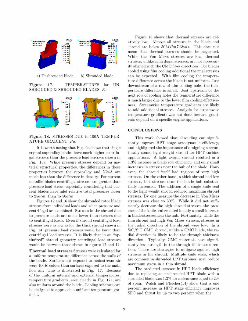
Figure 17. TEMPERATURES for UN-SHROUDED & SHROUDED BLADES, K.
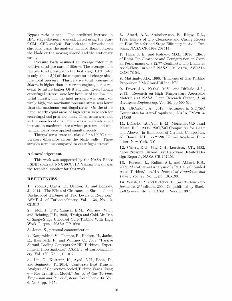
Figure 18. STRESSES DUE to 100K TEMPER-ATURE GRADIENT, Pa.
It is worth noting that Fig. 9a shows that singlecrystal superalloy blades have much higher centrifu-gal stresses than the pressure load stresses shown inFig. 15a. While pressure stresses depend on ma-terial structural properties, the differences in theseproperties between the superalloy and N24A aremuch less than the difference in density. For currentmetallic blades centrifugal stresses are greater thanpressure load stress, especially considering that cur-rent blades have inlet relative total pressures closerto 25atm. than to 50atm.
Figures 12 and 16 show the shrouded rotor bladestresses from individual loads and when pressure andcentrifugal are combined. Stresses in the shroud dueto pressure loads are much lower than stresses dueto centrifugal loads. Even if shroud centrifugal loadstresses were as low as for the thick shroud shown inFig. 14, pressure load stresses would be lower thancentrifugal load stresses. It is likely that in an “op-timized” shroud geometry centrifugal load stresseswould be between those shown in figures 12 and 14.
Thermal load stresses Stresses were calculated fora uniform temperature difference across the walls ofthe blade. Surfaces not exposed to mainstream airwere 100K colder than surfaces exposed to the mainflow air. This is illustrated in Fig. 17. Becauseof the uniform internal and external temperatures,temperature gradients, seen clearly in Fig. 17a, arealso uniform around the blade. Cooling schemes canbe designed to approach a uniform temperature gra-dient.
Figure 18 shows that thermal stresses are rel-atively low. Almost all stresses in the blade andshroud are below 50MPa(7.3ksi). This does notmean that thermal stresses should be neglected.While the Von Mises stresses are low, thermalstresses, unlike centrifugal stresses, are not necessar-ily aligned with the CMC fiber directions. For bladescooled using film cooling additional thermal stressescan be expected. With film cooling the tempera-ture difference across the blade is not uniform. Justdownstream of a row of film cooling holes the tem-perature difference is small. Just upstream of thenext row of cooling holes the temperature differenceis much larger due to the lower film cooling effective-ness. Streamwise temperature gradients are likelyto add additional stresses. Analysis for streamwisetemperature gradients was not done because gradi-ents depend on a specific engine applications.
CONCLUSIONS
This work showed that shrouding can signifi-cantly improve HPT stage aerodynamic efficiency,and highlighted the importance of designing a struc-turally sound light weight shroud for HPT turbineapplications. A light weight shroud resulted in a1.3% increase in blade row efficiency, and only smallincreases in stresses near the hub of the blade. How-ever, the shroud itself had regions of very highstresses. On the other hand, a thick shroud had lowstresses, but stresses near the blade hub substan-tially increased. The addition of a single knife sealto the light weight shroud reduced maximum shroudstresses. By one measure the decrease in Von Misesstresses was close to 30%. While it did not suffi-ciently decrease the high shroud stresses, the pres-ence of the knife seal resulted in only a small increasein blade stresses near the hub. Fortunately, while thethin shroud had high Von Mises stresses, stresses inthe radial direction of the shroud were low. In aSiC/SiC CMC shroud, unlike a CMC blade, the ra-dial direction is likely to be the through thicknessdirection. Typically, CMC materials have signifi-cantly less strength in the through thickness direc-tion. There are strategies to mitigate against highstresses in the shroud. Multiple knife seals, whichare common in shrouded LPT turbines, may reducemaximum stress in a thin shroud.
The predicted increase in HPT blade efficiencydue to replacing an unshrouded HPT blade with ashrouded blade was 1.3% for a clearance equal to 2%of span. Walsh and Fletcher(14) show that a onepercent increase in HPT stage efficiency improvesSFC and thrust by up to two percent when the
9
Bypass ratio is ten. The predicted increase inHPT stage efficiency was calculated using the Star-CCM+ CFD analysis. For both the unshrouded andshrouded cases the analysis included flows betweenthe blade or the moving shroud and the stationarycasing.
Pressure loads assumed an average rotor inletrelative total pressure of 50atm. The average inletrelative total pressure to the first stage HPT rotoris only about 3/4 of the compressor discharge abso-lute total pressure. This relative total pressure of50atm. is higher than in current engines, but is rel-evant to future higher OPR engines. Even thoughcentrifugal stresses were low because of the low ma-terial density, and the inlet pressure was conserva-tively high, the maximum pressure stress was lowerthan the maximum centrifugal stress. On the otherhand, nearly equal areas of high stress were seen forcentrifugal and pressure loads. These areas were notat the same locations. There was a relatively smallincrease in maximum stress when pressure and cen-trifugal loads were applied simultaneously.
Thermal stress were calculated for a 100◦C tem-perature difference across the blade walls. Thesestresses were low compared to centrifugal stresses.
Acknowledgement
This work was supported by the NASA PhaseI SBIR contract NNX16CC31P. Vikram Shyam wasthe technical monitor for this work.
REFERENCES
1. Yoon,S., Curtis, E., Denton, J., and Longley,J., 2014, “The Effect of Clearance on Shrouded andUnshrouded Turbines at Two Levels of Reaction,”ASME J. of Turbomachinery, Vol. 136, No. 2,021013
2. Moffitt, T.P., Szanca, E.M., Whitney, W.J.,and Behning, F.P., 1980, “Design and Cold-Air Testof Single-Stage Uncooled Core Turbine With HighWork Output,” NASA TP 1680.
3. Jones, S., personal communication
4. Kanjirakkad, V., Thomas, R., Hodson, H., Janke,E., Haselbach, F., and Whitney C., 2008, “PassiveShroud Cooling Concepts for HP Turbines: Exper-imental Investigations,” ASME J. of Turbomachin-ery, Vol. 130, No. 1, 011017
5. Lin, G., Kusterer, K., Ayed, A.H., Bohn, D.,and Sugimoto, T., 2014, “Conjugate Heat TransferAnalysis of Convection-cooled Turbine Vanes Usingγ − Reθ Transition Model,” Int. J. of Gas Turbine,Propulsion and Power Systems, December 2014, Vol.6, No 3, pp. 9-15.
6. Ameri, A.A., Steinthorsson, E., Rigby, D.L.,1998, Effects of Tip Clearance and Casing Recesson Heat Transfer and Stage Efficiency in Axial Tur-bines, NASA CR-1998-208514.
7. Haas, J. E., and Kofskey, M.G., 1979, “Effectof Rotor Tip Clearance and Configuration on Over-all Performance of a 12.77-Centimeter Tip DiameterAxial-Flow Turbine,” NASA TM 79025, AVRAD-COM 78-54.
8. Mattingly, J.D,, 1996, “Elements of Gas TurbinePropulsion,” McGraw-Hill Inc. NY.
9. Dever, J.A., Nathal, M.V., and DiCarlo, J.A.,2013, “Research on High Temperature AerospaceMaterials at NASA Glenn Research Center, J. ofAerospace Engineering, Vol. 26, pp 500-514.
10. DiCarlo, J.A., 2013, “Advances in SiC/SiCComposites for Aero-Propulsion,” NASA TM-2013-217889
11. DiCarlo, J.A., Yun, H.-M., Morscher, G,N., andBhatt, R.T., 2005, “SiC/SiC Composites for 1200◦
and Above,” in Handbook of Ceramic Composites,ed. Bansal, N.P., pp 27-98, Kluwer Academic Pub-lisher, New York, NY
12. Cherry, D.G., Gay, C.H., Lenahan, D.T., 1982,“Low Pressure Turbine Test Hardware Detailed De-sign Report”, NASA CR-167956.
13. Porreca, L., Kalfas, A.I., and Abhari, R.S.,2009, “Aerothermal Analysis of a Partially ShroudedAxial Turbine,” AIAA Journal of Propulsion andPower, Vol. 25, No. 1, pp. 181-190.
14. Walsh, P.P., and Fletcher, P., Gas Turbine Per-formance, 2nd edition, 2004, Co-published by Black-well Science Ltd, and ASME Press, p. 337.
10


