Embed Size (px)
Citation preview
CONTENTS3--Rv.ei
1. PARTS OF THE INSTRUMENT. . . . . . . . . . . . . . . . . .. 12. FEATURES................................... 43. SPECiFiCATIONS................... . . . . . . .. . .. 54. STANDARD EQUIPMENT. . . . . . . . . . . . . .. . . . . . . .. 85. POWER SUPPLIES ............................. 96. REFLECTING PRISMS AND ACCESSORIES . . . . . . .. 117. DISPLAY SYMBOLS ........................... 138. kEY FUNCTIONS ............................. 149. INTERNAL SWITCHES ......................... 1710. OPERATION.................................. 18
10.1 PREPARATION FOR ANGLE MEASUREMENT.. 1810.1.1 Battery, BDC18: Mounting and check....... 18
10.1.2 Compensation of zenith angle ............. 19
10.1.3 Centring the SET3 by adjusting tripod leglength ...................,............ 20
10.1.4 Focussing ............................. 2010.2 ANGLE MEASUREMENT............. .'...... 21
10.2.1 Automatically indexing vertical circle ....... 21
10.2.2 Angle measurement ..................... 22
10.2.3 Setting the horizontal circle to a requiredvalue ............. . . . . . . . . . . . . . . . . . . . . 23
10.2.4 Repetition of angles . . . . . . . . . . . . . . . . . . . . . 2410.3 PREPARATION FOR DISTANCE
MEASUREMENT. . .. . . . . . . . . . . . . . . . . . . . . . . . 2610.3.1 Prism constant correction. . . . . . . . . . . " . . . . 2610.3.2 Atmospheric correction .................. 27
10.3.3 Earth-curvature and refraction correction .... 29
10.3.4 Prism sighting ... . . . . . . . . . . . . . . . . . . . . . . . 3010.3.5 Mode selection ......................... 31
10.4 DISTANCE MEASUREMENT. . . . . . . . . . . . . . . . . 3210.4.1 Angle and distance measurement . . . . . . . . . . . 3210.4.2 Measurement of coordinates. . . . . . . . . . . . . . . 3510.4.3 Stake-out measurement .................. 37
10.4.4 Remote elevation measurement ............ 41
10.45 Measurement of horizontal distance betweentwo target points. . . . . . . . . . . . . . . . . . . . . . . . 43
11. SElF DIAGNOSIS ............................. 4412. OPTIONAL ACCESSORIES. . . . . . . .. . . . . . . . . . . . . . 46
12.1 DIAGONAL EYEPIECE DE18.... ....... ......46
12.2 ÈLECTRONIC FIELD BOOK SDR2 ,.........,. 4612.3 INTERFACE IF1A FOR THE HP.41CV .,.......47
13. CHECKS AND ADJUSTMENTS. . . . . . . . . . . . . . . . . . . 4813.1 ANGLE MEASURING FUNCTION. .,. .. .... ...48
13.1.1 Plate level ,............,............... 48
13.1.2 Circular level. . . , . . . . . . . . . , . . , . . . . . . . . . . 5013.1.3 i ndex error of the tilt angle sensor ......... 50
13.1.4 Reticle ..,........,.................,. 52
13.1.5 Perpendicularity of the reticle to thehorizontal axis ......................... 55
13.1.6 Coincidence of the distance measuring axiswith the reticle . . . , . . . ' , . . . . . . , . . . . . . . . . 56
13.1.7 Optical plummet. . . . . . , . . . . . , . , . . . . . . . . . 5713.2 DISTANCE MEASURING FUNCTION. . . . . . . . . , 58
13.2.1 Check flow chart .............,......... 58
13.2.2 Additive distance constant. . . . . . . . . . . . . . . . 5914. FOR ANGLE MEASUREMENT OF THE HIGHEST
ACCURACY ................................,. 6114.1 LEVELLING BY REFERRING TO THE
DISPLAY. . . . . , . . . . . , . . . . . . . . . . . . . . . . . . . . . 6114.2 MANUALLY INDEXING VERTICAL CI RCLE
BY V1, V2', . . . . , . . . . . . . . . . . . . , . . . . . . . . . . . . . 6415. FOR DISTANCE MEASUREMENT OF THE
HIGHEST ACCURACY. . , . . . . . . . . _ . . . , . , . . . . . . . . 6615.1 ACCURACY OF MEASUREMENT OF
ATMOSPHERIC CONDITIONS. , . . . . . . . . . . . . . . 6615.2 TO OBTAIN THE ATMOSPHERIC PRESSURE... 66
16. PRECAUTIONS AND MAINTENANCE. . . . , . . . . . . . . 6816.1 PRECAUTIONS..,.. _ . ' . . . ' . . . . . . . . . . . . . . . . 6816.2 MAINTENANCE.........,.........,........ 69
17. ATMOSPHERIC CORRECTION CHARTS. . . . . . . . . . . 7018. INDEX....................................... 72
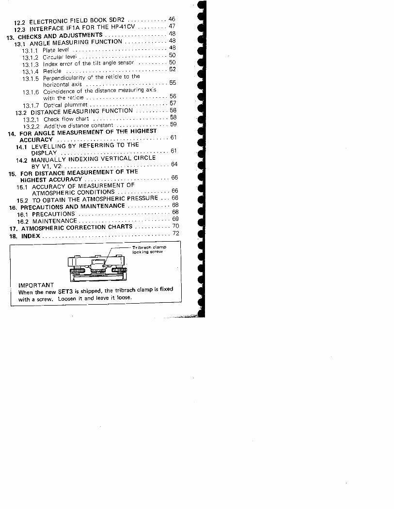
Tribrach clamplock ing screw
IMPORTANTWhen the new SET3 is shipped. the tribrach clamp is fixedwith a screw. Loosen it and leave it loose.
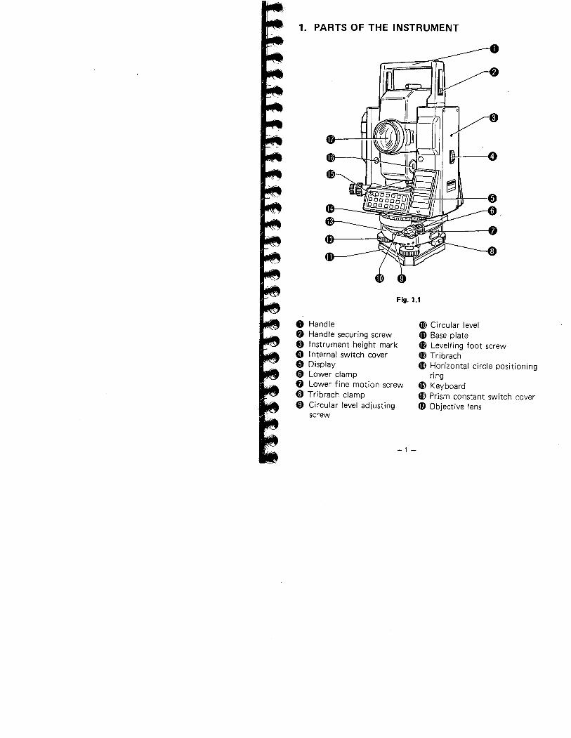
1. PARTS OF THE INSTRUMENT
Fig. 1.1
o Handle8 Handle securing screw
e Instrument height mark
o Internal switch cover
o Display
o Lower clampf) Lower fine motion screw
o Tribrach clamp
o Circular level adjusting
screw
æ Circular levellD Base plate4f Levelling foot screw
4I Tribrach
æ Horizontal circle positioningring
æ Keyboard
æ Prism constant switch cover
fD Objective lens
-1 -
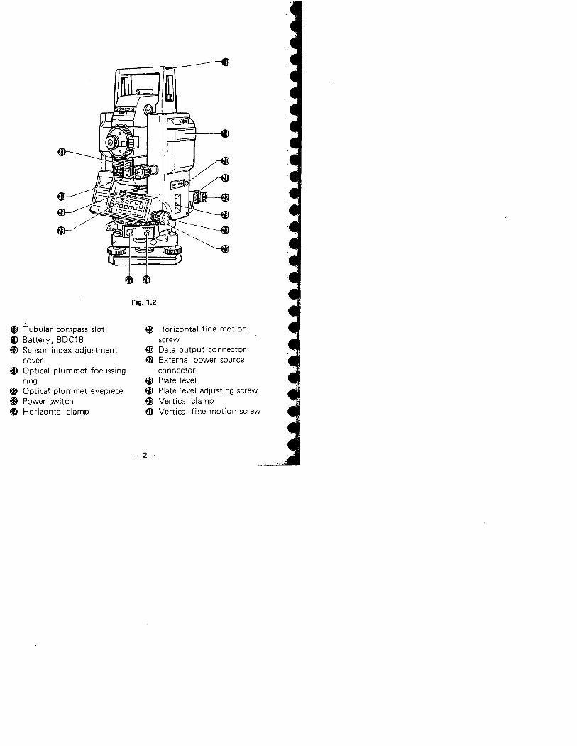
Fig. 1.2
G; Tubular compass slot æ Horizontal fine motionl) Battery, BOC18 screwW Sensor index adjustment ~ Oata output connector
cover q, External power source~ Optical plummet focussing connector
ring W Plate level~ Optical plummet eyepiece W Plate level adjusting screw~ Power switch ~ Vertical clampai Horizontal clamp ~ Vertical fine motion screw
-2-
~
~KD
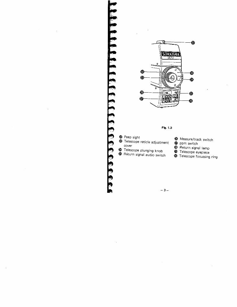
Fig. 1.3
~ Peep sight
i) Telescope reticle adjustment
coverKl Telescope plunging knob~ Return signal audio switch
~ Measure/track switch
~ ppm switch~ Return signal lamp
~ Telescope eyepiece
(D Telescope focussing ring
-3-
2. FEATURES
. Horizontal angle, zenith angle, slope distance, horizontal
distance, height difference, N- and E-coordinates are displayedby key operation.
. Horizontal distance between two prism points and remotemeasurement of objects above and below a prism point areautomatically calculated, A stake-out function by distance and
N- and E-coordinates is standard.. Self-diagnostic function. If, for any reason, the SET3 is not
functioning correctly during use, an error code is displayed.. Angle resolution can be set to 1" (0.2 mgon) or 5" (1 mgon).
. The tilt angle of the vertical axis can be measured by theinternal sensor and displayed. By referring to the display, theSET3 can be levelled. The zenith angle is automatically com-pensated by the tilt sensor and the compensated angle dis-
played.. Horizontal circle can be set to zero in any direction.
. The SET3 automatically switches off 30 minutes after the lastoperation to save battery power.
. An RS-232C data-out connector is standard.
-4-
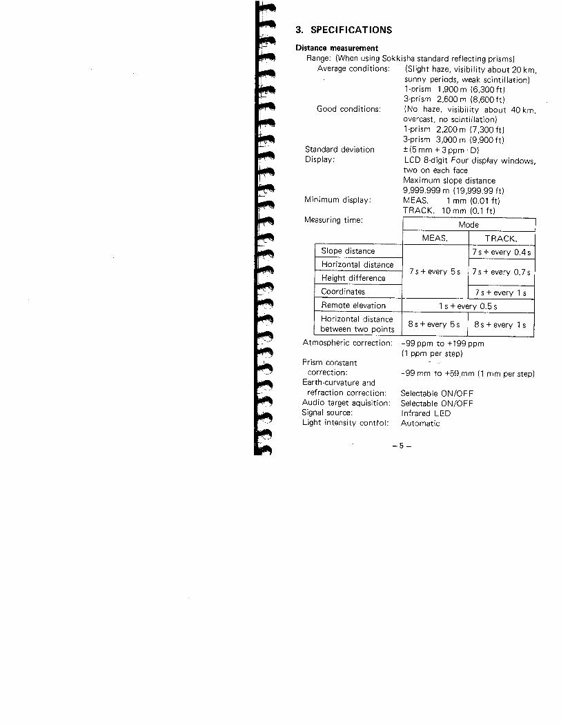
3. SPECIFICATIONS
Average conditions:
Distance measurementRange: (When using Sokkisha standard reflecting prisms)
Good conditions:
Standard deviationDisplay:
Minimum display:
(Slight haze, visibility about 20 km,sunny periods, weak scintillation)1-prism 1,900 m (6,300 ft)3-prism 2,600 m (8,600 ft)(No haze, visibility about 40 km,overcast, no scintillation)1-prism 2,200m (7,300ft)3-prism 3,000 m (9,900 ft):t (5 mm + 3 ppm . D)LCD 8-digit Four display windows,two on each faceMaximum slope distance9,999.999 m (19,999.99 ft)MEAS. 1 mm (0.01 ft)TRACK. 10 mm (0.1 ft)
asuring time:Mode
MEAS. TRACK.
Slope distance 7 s + every 0.4 s
Horizontal distance7 s + every 5 s 7 s + every 0.7 s
Height difference
Coordinates 7 s + every 1 s
Remote elevation 1 s + every 0.5 s
Horizontal distance8 s + every 5 s 8 s + every 1 sbetween two points
Me
Atmospheric correction:
Prism constant
correction:Earth-curvature andrefraction correction:
Audio target aquisition:Signal source:
Light intensity control:
-99 ppm to +199 ppm(1 ppm per step)
-99 mm to +59,mm (1 mm per step)
Selectable ON/OFFSelectable ON/OFFInfrared LEDAutomatic
-5-
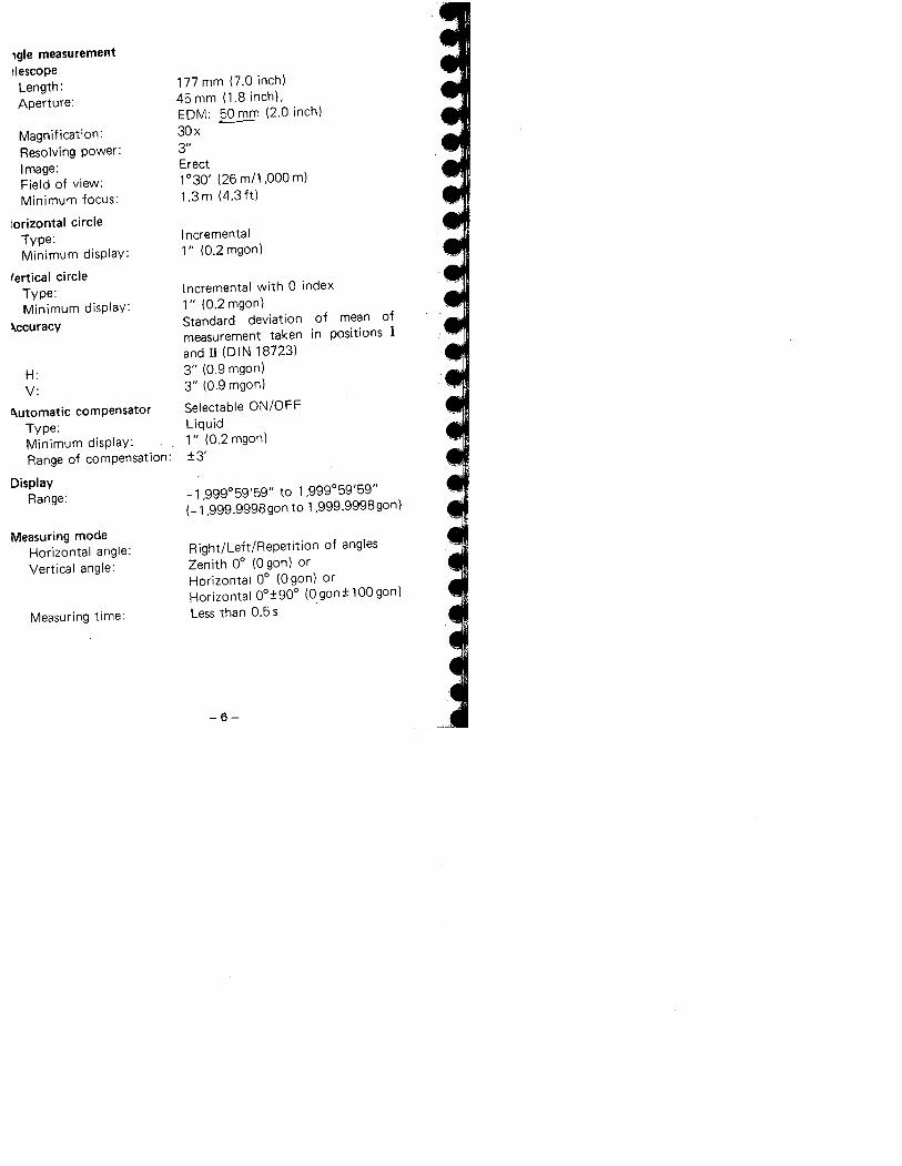
igle measurement!Iescope
Length:Aperture:
Magnification:Resolving power:Image:Field of view:
Minimum focus:
lorizontal circleType:Minimum display:
'ertical circle
Type:Minimum display:
~ccuracy
H:V:
~utomatic compensatorType:Minimum display:Range of compensation:
DisplayRange:
Measuring modeHorizontal angle:Vertical angle:
Measuring time:
177 mm (7.0 inch)45 mm (1.8 inch).EDM: 50 mm (2.0 inch)30x ~3"Erect1 °30' (26 m/l ,000 m)1.3 m (4.3 ft)
I ncrementa i1" (0.2 mgon)
Incremental with 0 index
1" (O.2mgon)
Standard deviation of mean ofmeasurement taken in positions Iand II (DIN 18723)3" (0.9 mgon)3" (0.9 mgon)
Selectable ON/OFFLiquid1" (0.2 mgon):13'
-1,999°59'59" to 1 ,999°59'59"
(-l,999.9998gon to l,999.9998gon)
Right/Left/Repetition of angles
Zenith 0° (0 gon) orHorizontal 0° (Ogon) orHorizontal 0°:190° (Ogon:11009on)Less than 0.5 s
-6-
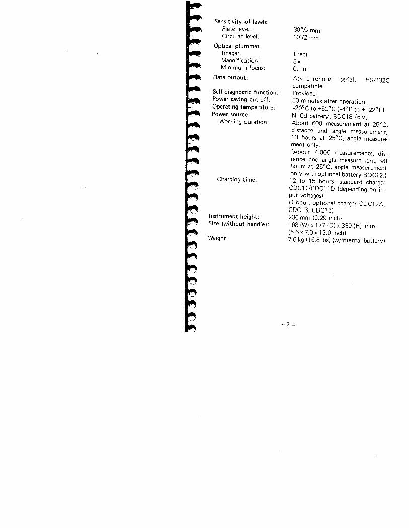
Sensitivity of levels
Plate level:Circular level:
Optical plummetImage:Magnification:Minimum focus:
Data output:
Self-diagnostic function:Power saving cut off:Operating temperature:Power source:
Working duration:
Charging time:
Instrument height:Size (without handle):
Weight:
30"/2 mm10'/2 mm
Erect3x0.1 m
Asynchronous serial, RS-232CcompatibleProvided30 minutes after operation-20°C to +50°C (-4°F to +122°F)Ni-Cd battery, BDC18 (6V)About 600 measurement at 25°C,
distance and angle measurement;
13 hours at 25°C, angle measure-
ment only.(About 4,000 measurel'ents, dis-tance and angle measurement; 90
hours at 25°C. angle measurementonly, with optional battery BDC12.)12 to 15 hours, standard charger
CDC11/CDC11D (depending on in-put voltages)
(1 hour, optional charger CDC12A,CDC13, CDC15)236 mm (9.29 inch)168 (W) x 177 (D) x 330 (H) mm(6,6 x 7.0 x 13.0 inch)7.6 kg (16,8 Ibs) (w/internal battery)
-7 -
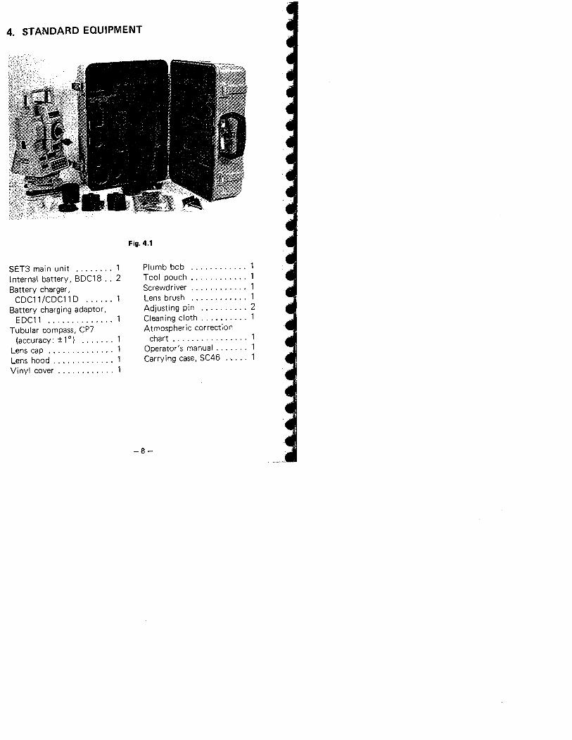
4. STANDARD EQUIPMENT
Fig. 4.1
SET3 main unit ........ 1
Internal battery, BDC18 . . 2Battery charger,
CDC11 /CDCll 0 ......
Battery charging adaptor,
EDC11 .............. 1Tubular compass, CP7
(accuracy: :! 10) .......
Lens cap ..............
Lens hood . . . . . . . . . . . . .Vinyl cover . . . . . . . . . . . .
Plumb bob ............Tool pouch. . . . . . . . . . . .Screwdriver . . . . . . . . . . . .Lens brush ............ 1
Adjusting pin .......... 2
Cleaning cloth. , . . . . . . .. 1Atmospheric correction
chart .,. . . . . ' . . . . . . . .Operator's manual. . . . . . .Carrying case, SC46 .....
-8-
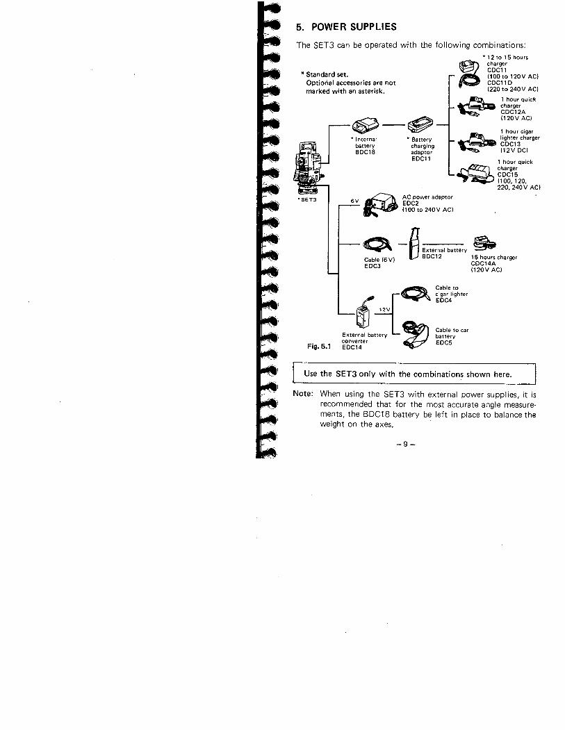
5. POWER SUPPLIES
The SET3 can be operated with the following combinations:
* Standard set.Optional accessories are notmarked with an asterisk.
'SET3
Fig. 5.1
~-~* Internal
batteryBDC18
. Battery
chargingadaptorEDC11
. 12 to 15 hours
~ chargerCDC11(100to 120V AC)CDC11D(220 to 240V ACI
~ 1 hour quickcharger
. CDC12A(120V ACI
1 hour cigar~ lighter charger. CDC13
(12V DC!
1 hour qu ick
~' chargeri CDC15
(100, 120,220, 240V AC)
Q - f1 External battery ~C ble (6 V) lJ BDC12 15 hours chargera CDC14AEDC3 (120V AC)
-9-
Cable tocigar lighterEDC4
Cable to carbatteryEDC5
Use the SET3 only with the combination~ shown here.
ø AC power adaptor6V . EDC2, (100 to 240V AC)
~O\¿( 12V
tJExterna; battery "converterEDC14
Note: When using the SET3 with external power supplies, it isrecommended that for the most accurate angle measure-ments, the BDC18 battery be left in place to balance theweight on the axes.
Battery charging precautions
To charge the battery, use only the recommended charger.
1) Charge the battery at least once a month if it is not used fora long time.
2) Charge the battery at a temperature between iooc and 40°C.
3) Before using EDC2 or CDC15, set the voltage selector to theproper voltage.
4) EDC14 has a breaker switch. Normally the red mark appearson the breaker. If not, set the red mark in place.
5) When using a car battery, make sure that the polarity iscorrect.
6) Make sure that the cigar lighter has 12 V output and that thenegative terminal is grounded.
7) When charging the battery, first connect it to the batterycharger and then connect the charger to the power supply.Check that the battery charger I ight is on. If not switchpower supply off and on again until the light comes on.
8) The battery charger may become warm while charging. Thisis normaL.
9) Do not charge the battery for any longer than specified.
10) Store the battery in a place where the temperature is betweenO°C and 40°C.
11) Battery operating life is shortened at extreme temperatures.
-10 -
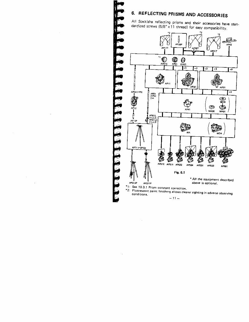
6. REFLECTING PRISMS AND ACCESSORIES
All Sokkísha reflecting prisms and their accessories have stan-dardized screws (5/8" x 11 thread) for easy compatibility.~~~
~P32tl ~ _ ~ AP43AP31T
'2
~
~AP02 (= PSI
r'
I(=P41
(~ ~). 2m ~ ¡AP12AP41
MAOlI
~I AP61L
lf I=LL21AP61 L2AP12P(=LL31 ~ (~)
~AP71 (=SPS31
APS12 APSI I APS2 APS APS31 APS33 APS1
Fig. 6.1
* All the equipment describedabove is oPtionaL.APS12P APSI1 P
*1: See 10.3.1 Prism constant correction.*2: Fluorescent paint finishing allows clearer sighting in adverse observing
conditions.-11-
Precautions
1) Carefully face the reflecting prism towards the instrument;
sight the target centre accurately.
2) To use the triple prism assembly AP31 or AP32 as a singleprism (e.g. for short distances), mount the single prism APOlin the centre hole of the triple prism holder.
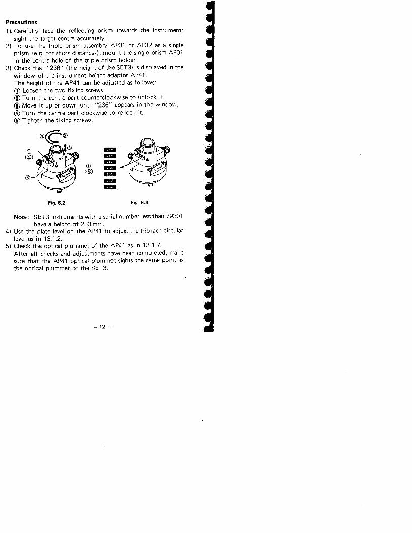
3) Check that "236" (the height of tlie SET3) is displayed in thewindow of the instrument height adaptor AP41.The height of the AP41 can be adjusted as follows:il Loosen the two fixing screws.
(I Turn the centre part counterclockwise to unlock it.(l Move it up or down until "236" appears in the window.
(f Turn the centre part clockwise to re-Iock it.CI Tighten the fixing screws.
CD
((5)~
Fig. 6.2 Fig. 6.3
Note: SET3 instruments with a serial number less than 79301have a height of 233 mm.
4) Use the plate level on the AP41 to adjust the tribrach circularlevel as in 13.1.2.
5) Check the optical plummet of the AP41 as in 13.1.7.After all checks and adjustments have been completed, makesure that the AP41 optical plummet sights the same point asthe optical plummet of the SET3.
-12 -
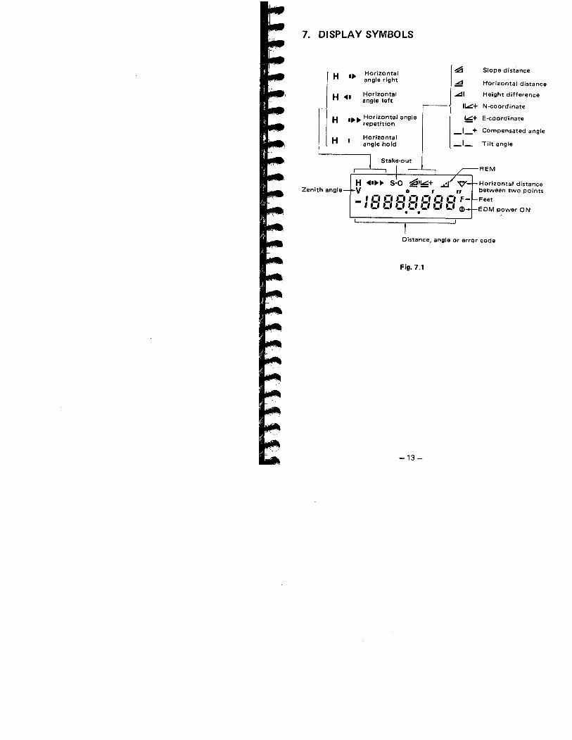
7. DISPLAY SYMBOLS
Horizontal ~ Slope distanceH .~ ' angle right ~ Horizontal distance
H ... Horizontal ..I Height differenceangle left ii.+ N-coordinate
H .~~ Horiz.o,ntal angle !6+ E-coordinaterepetItion
_1_+ Compensated angle
HHorizontal _1-angle hold Tilt angle
Stake-out
Zenith angleH ...~~ 5'0 ~1!6+V 0'"_ 'c,cic,cicicic, F
, ..' ..' ..' ..' ..' ..' ..' CD. .Distance, angle or error code
Fig. 7.1
-13-
REM
Horizontal distancebetween two pointsFeetEDM power ON
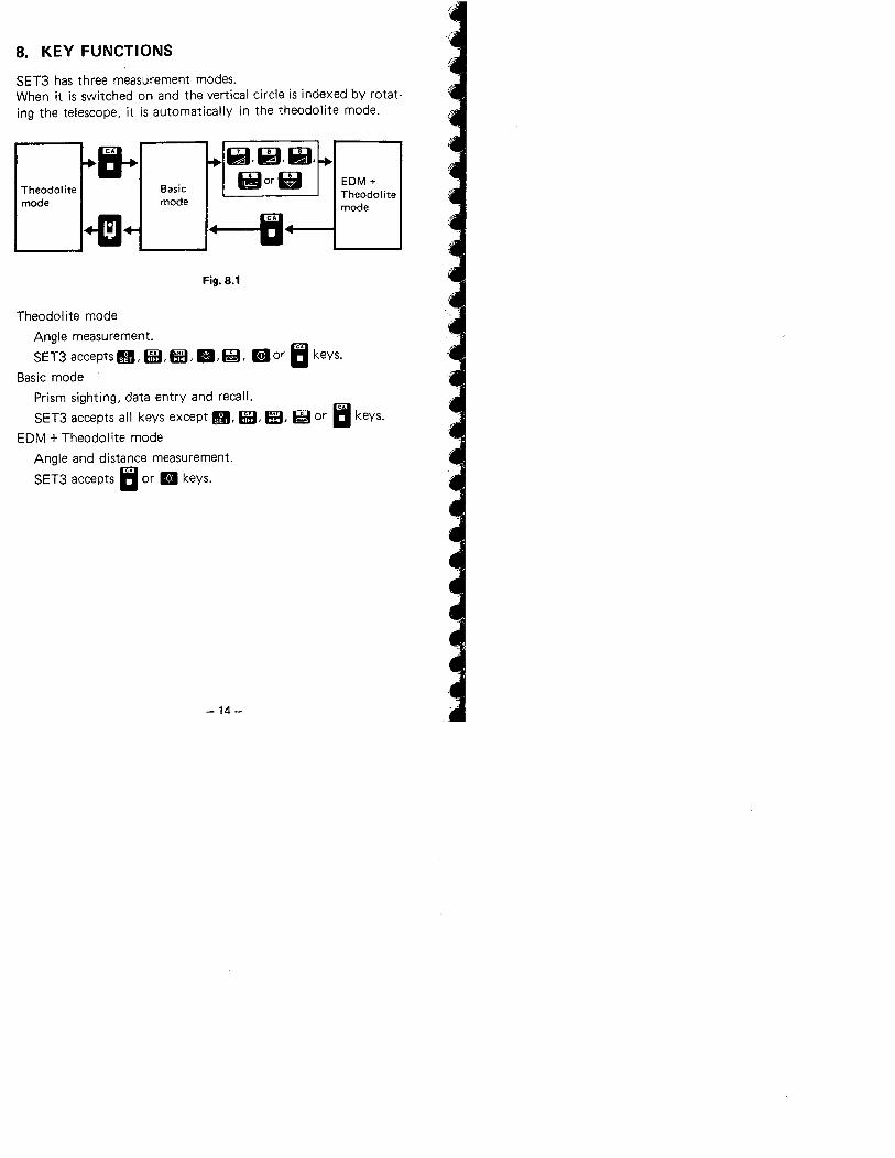
8. KEY FUNCTIONS
SET3 has three measurement modes.When it is switched on and the vertical circle is indexed by rotat-ing the telescope, it is automatically in the theodolite mode.
11 Qi,~,~,Theodolite Basic tior Lt EDM +
mode modeTheodol itemode
+m If IIFig. 8.1
Theodolite modeAngle measurement.
SET3 accepts g, GB, ß:, B, ~, aD or Ii keys.
Basic mode
Prism sighting, data entry and recalL.
SET3 accepts all keys except g, GB, ß:, ~ or Ii keys.
EDM + Theodolite mode
Angle and distance measurement.
SET3 accepts Ii or B keys.
-14 -
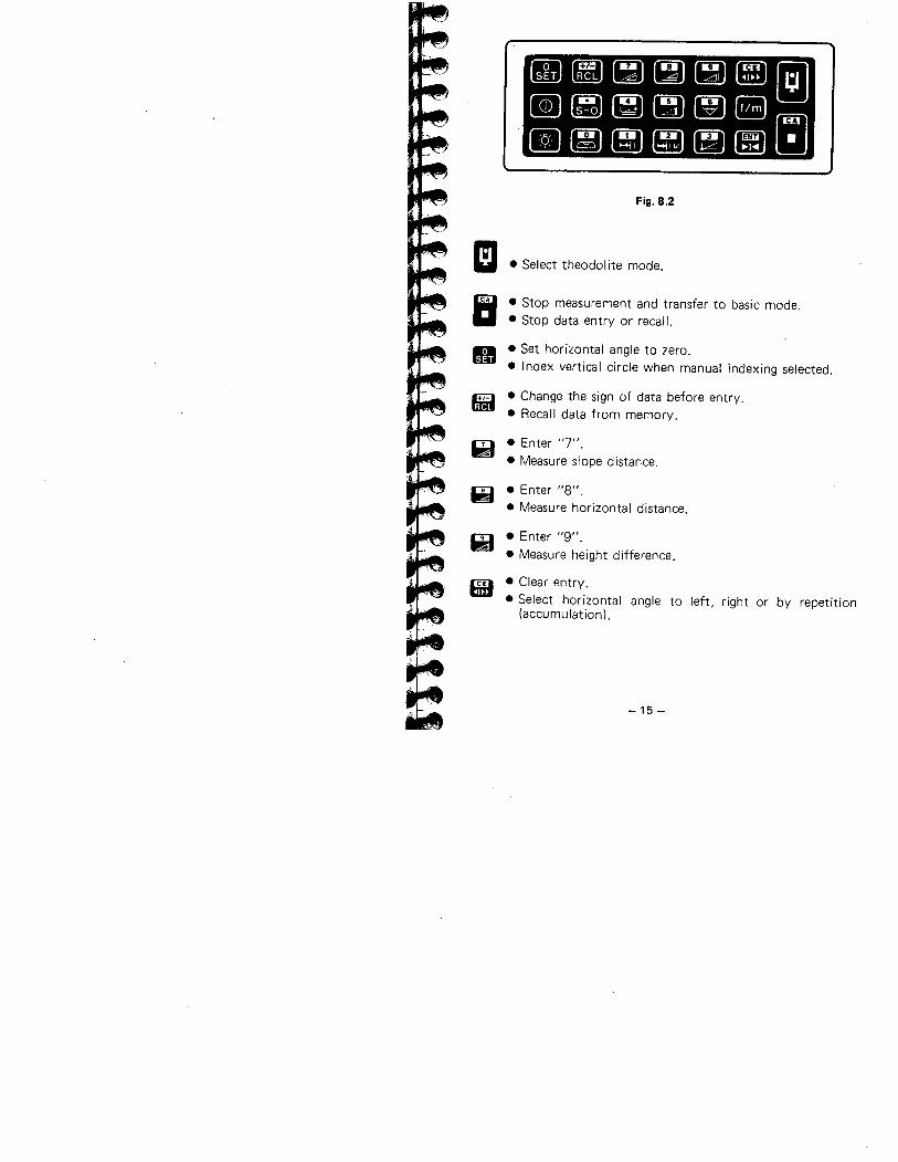
e fi Ii ualll HB mII li I! ~~ IIII..~ 1: Bi ii øa
Fig. 8.2
I!
It
. Select theodol ite mode.
· Stop measurement and transfer to basic mode.· Stop data entry or recall.
II . Set horizontal angle to zero.
· Index vertical circle when manual indexing selected.
fm . Change the sign of data before entry.. Recall data from memory.
~ . Enter "7".
. Measure slope distance.
~ . Enter "8".
. Measure horizontal distance.
Il . Enter "9".
. Measure height difference.
ß9 . Clear entry.
· Select horizontal angle to left, right or by repetition(accumulation).
-15 -
II · EDM power ON/OFF for locating prism.
~ . Enter decimal point.
. Measure stake-out distance.
~ . Enter "4".
. Measure N- and E-coordinates.
~ . Enter "5".
. Measure remote elevation.
w . Enter "6".
. Measure horizontal distance between two prism points.
lI . Convert displayed distance to feet or meters for5 seconds.
II . Illuminate display and reticle of telescope for 30 seconds.
~, . Enter "0".
. Display vertical axis tilt angle ON/OFF.
Ei . Enter "1".
. Enter stake-out distance.
P3. Enter "2".
. Enter stake-out N- and E-coordinates.
Gi. Enter "3".
. Enter coordinates of instrument station.
ßB. Transfer entered data to memory.. Hold/release horizontal angle.
-16-
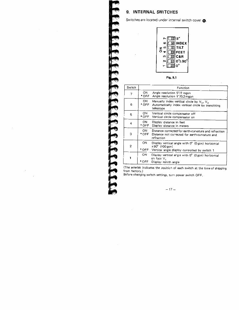
9. INTERNAL SWITCHES
Switches are located under internal switch cover O.
,. 5"(0 Dl INDEX
zit Dl TILTO'l Dl FEET
C' Dl C&R(' 0I 0°::90°
0°
Fig. 9.1
Switch Fu nction
7 ON Angle resolution 5"/1 mgon.OFF Angle resolution 1 "/0.2 mgon
ON Manually index vertical circle by V l' V 26 .OFF Automatically index vertical circle by transitting
telescope
5 ON Vertical circle compensator off.OFF Vertical circle compensator on
4 ON Display distance in feet.OFF Display distance in meters
ON Distance corrected for earth-curvature and refraction3 · OFF Distance not corrected for earth-curvature and
refraction
ON Display vertical angle with 0° (0 gon) horizontal2 :! 90° (100 gonl
· OFF Vertical angle display controlled by switch 1
ON Display vertical angle with 0° (0 gon) horizontal1 on face V i
· OFF Display zenith angle
(The asterisk indicates the position of each switch at the time of shippingfrom factory.)Before changing switch settings. turn power switch OFF.
-17 -
10. OPERATION
10.1 PREPARATION FOR ANGLE MEASUREMENT
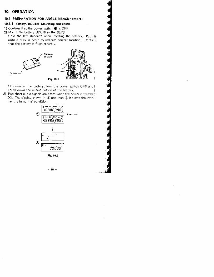
1 0.1.1 Battery. BDC18: Mounting and check1) Confirm that the power switch ~ is OFF.2) Mount the battery BDC18 in the SET3.
Hold the left standard when inserting the battery. Push ituntil a click is heard to indicate correct location. Confirmthat the battery is fixed securely.
Guide
Releasebutton
( To remove the battery, turn the power switch 0 F F and)push down the release button of the battery.3) Two short audio signals are heard when the power is switched
ON. The display shown in CD and then CV indicate the instru-ment is in normal condition,.
H -i.... s-o :ii~+ .. VY .,,,-:888.8.888 ~
CD 1 secondH 4'.. S-O ~l~+ ~ "0V ., rr-:888.8.888~
I v
Cî
_1_+
n,"'
H ..nOn n'n nilt.'f-''-''-''-
Fig. 10.2
-18 -
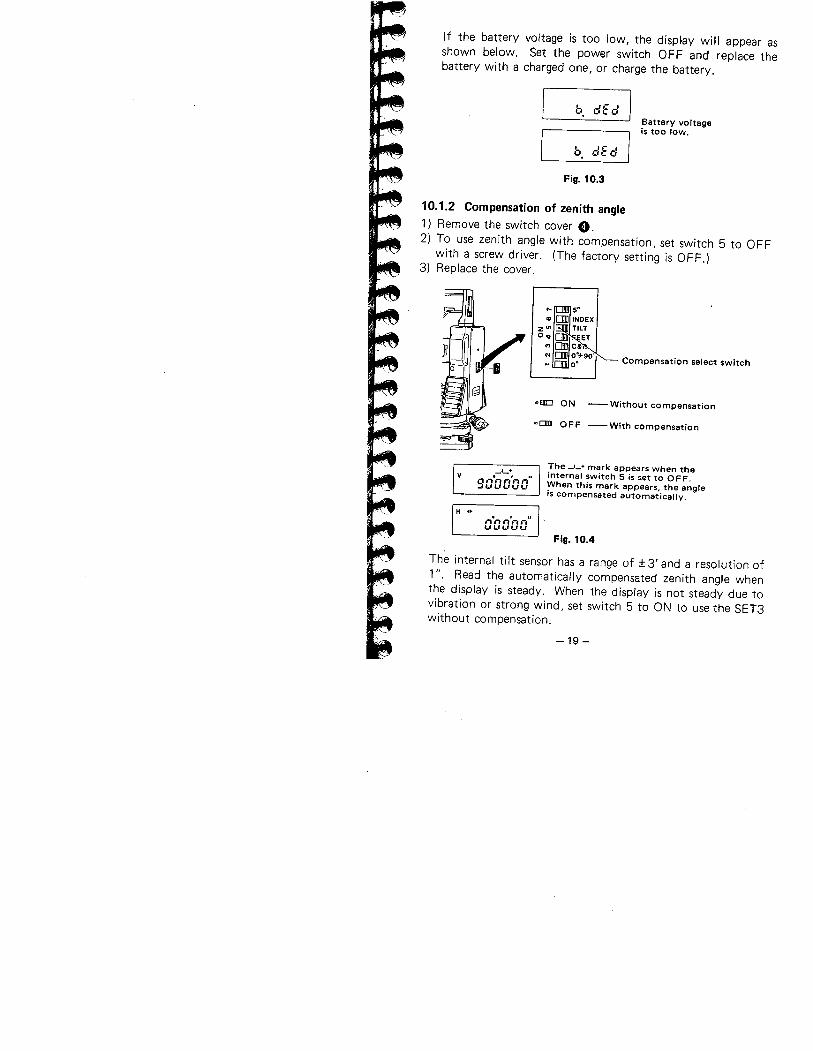
If the battery voltage is too low, the displ'ay will appear as
shown below. Set the power switch OFF and replace thebattery with a charged one, or charge the battery.
b. eifelBattery voltageis too low.
b. eifel
Fig. 10.3
10.1.2 Compensation of zenith angle1) Remove the switch cover O.2) To use zenith angle with compensation, set switch 5 to OFF
with a screw driver. (The factory setting is OFF.)3) Replace the cover.
Compensation select switch
-= ON - Without compensation
OFF -With compensation
v_1_+
9,-l.nn',-ln"u..'uuuThe _1_+ mark appears when theinternal switch 5 is set to OFF,When this mark appears. the angleis compensated automatically.
H .. "On"''-'-l"L'UL'UU
Fig. 10.4
The internal tilt sensor has a range of :! 3' and a resolution of1". Read the automatically compensated zenith angle when
the display is steady. When the display is not steady due tovibration or strong wind, set switch 5 to ON to use the SET3without compensation.
-19-
10.1.3 Centring the SET3 by adjusting tripod leg length1) Make sure that:
a. The tripod head is approximately leveL.
b. The tripod shoes are firmly fixed in the ground.
2) Set the SET3 on the tripod head. Tighten the centring screw.3) Focus on the surveying point:
a. Turn the optical plummet eyepiece ~ to focus on thereticle.
b. Turn the optical plummet focussing ring ~ to focus on thesurveying point.
4) Turn the levelling foot screws 4f to centre the surveying pointin the reticle.
5) Observe the off-centre direction of the bubble in the circularlevel æ. Shorten the leg nearest that direction, or extend theleg farthest from that direction.Generally, two legs must be adjusted to centre the bubble.
6) When centring of the circular level is completed, turn thelevelling screws to centre the plate level W bubble.
7) Look through the optical plummet again. If the surveyingpoint is off-centre, loosen the centring screw to centre the
surveying point on the reticle. Tighten the centring screw.
8) Repeat 6), 7) if the plate level bubble is off-centre.
10.1.4 Focussing
1) Looking through the telescope, turn the eyepiece fully clock-wise, then anticlockwise until just before the reticle image
becomes blurred. In this way. frequent refocussing can bedispensed with, since your eye is focussed at infinity.
2) Loosen the vertical ~ and horizontal clamp fI.Bring the target into the field of view with the peep sight ~.Tighten both clamps.
3) Turn the focussing ring (D and focus on the target.Sight the target with the vertical ~ and horizontal fine
motion screws æ. Focus on the target until there is noparallax between the target and the reticle.
-20-
Parallax:Relative displacement of target image in respect to thereticle when observer's head is moved slightly before theeyepiece.If sighting is carried out before parallax is eliminated,
this will introduce errors in reading and will impair your
observations.
10.2 ANGLE MEASUREMENT
Make sure that:a. The SET3 is set up correctly over the surveying point.b. Battery voltage is adequate.
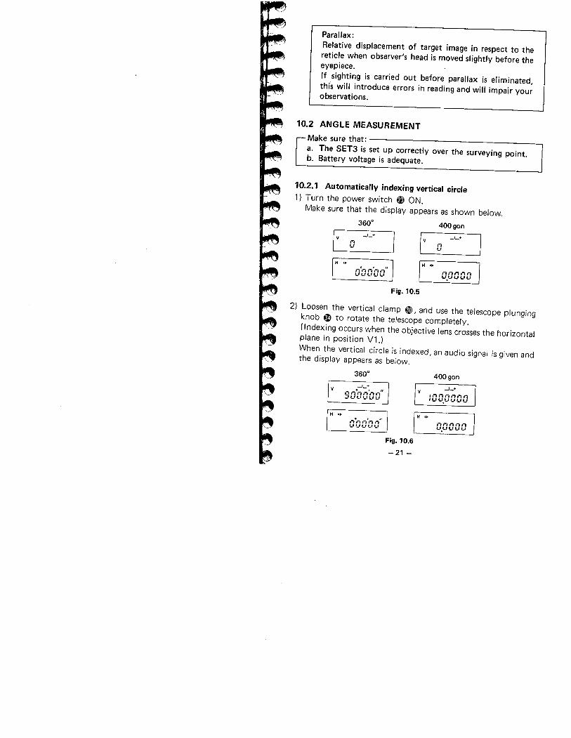
10.2.1 Automatically indexing vertical circle1) Turn the power switch ~ ON.
Make sure that the display appears as shown below,.
3600 400 gon
I V
_,_+
I V
_1_+
I
,"I i"'-''-'
H ..H ,."."-",,, ..
,".,",-..-""'-''-'Ll,-' u.uuuu
Fig. 10.5
2) Loosen the vertical clamp ~, and use the telescope plunging
knob Kl to rotate the telescope completely.
(i ndexing occurs when the objective lens crosses the horizontalplane in position Vl.)When the vertical circle is indexed, an audio signal is given andthe display appears as below.
3600 400 gonv -'-+
0',0;, ,-,'" ,,"_, L' ,_, '_''-' l-,
-'-+'.'1"-.".",IUU.'_"_,uu
H .. H '.o . ",-,,-, '-i l-, """"_"_, l., '-' n,-l,'i-ln
L'.'-LIL''-'
Fig. 10.6
-21 -
Angle measurement can now begin.Note: When the power switch is turned off for any reason,
the vertical index is lost. When the power switch isturned back on, the vertical index must be redeter-mined.
10.2.2 Angle measurement
Before this procedure, index the vertical circle.
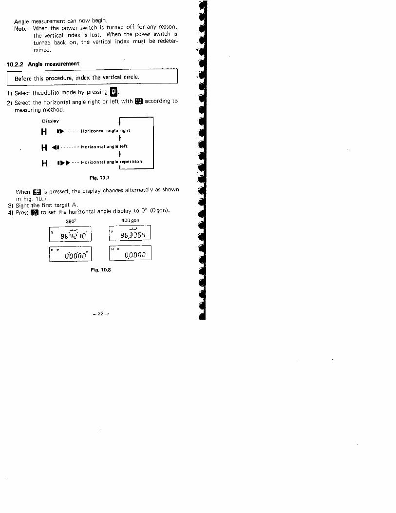
1) Select theodolite mode by pressing m.
2) Select the horizontal angle right or left with HB according tomeasuring method.
Display
H I. ........ Horizontal angle rightl
H ~I ............ Horizontal angle leftl
Hi.. ..... Horizontal angle repetition
Fig. 10.7
When HB is pressed, the display changes alternately as shownin Fig. 10.7,
3) Sight the first target A.4) Press II to set the horizontal angle display to 0° (0 gon).
3600 400 gonv
_1_+
86\-:2' :0"
_1_+
96.3::6'-:
H .. H .."0,, ,,'nn",-'L''-'U'-'
.-l 1-. n.-, IÎ'-'.'_'''' t.' ,_,
Fig. 10.8
-22 -
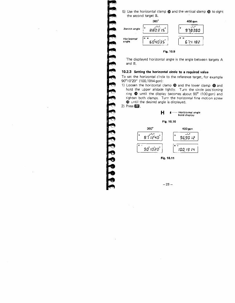
5) Use the horizontal clamp ai and the vertical ~Iamp ~ to sightthe second target B.
3600 400 gonZenith angle
_1_+
8S-0::' :s" 91.8380_1_+
y
Horizontalangle
H .. H ..
60.YO'::S" 61.'-182
Fig. 10.9
The displayed horizontal angle is the angle between targets Aand B.
10.2.3 Setting the horizontal circle to a required valueTo set the horizontal circle to the reference target, for example90°10'20" (100.1914gon):1) Loosen the horizontal clamp ai and the lower clamp 0 and
hold the upper alidade lightly. Turn the circle positioningring æ until the display becomes about 90° (100gon) and
tighten both clamps. Turn the horizontal fine motion screw
æ until the desired angle is displayed.
2) Press ß:.
H I...... Horizontal anglehold display
Fig. 10.10
3600 400 gon
I +
8 ":2''-0''_1_+
y
96.90 12
H . H .. , "::0 :020 .t..... '0 '-L'
IUl,'. I_' I I
Fig. 10.11
-23 -
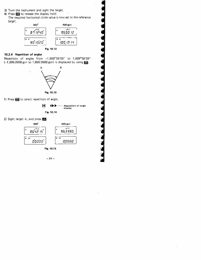
3) Turn the instrument and sight the target.4) Press EI to release the display hold.
The required horizontal circle value is now set to the referencetarget.
3600 400 gon
_I~+
B'. :2'--0"
_1_+v
96.90 :2
H .. H ..
:00.::: :'-. , "
90 :020
Fig. 10.12
10.2.4 Repetition of angles
Repetition of angles from -1,999°59'59" to 1 ,999°59'59"
(-1,999.9998 gon to 1,999.9998 gon) is displayed by using 1f.
A B
W--
---....
Fig. 10.13
1) Press If to select repetition of angle,
H I~~ ...... Repetition of angledisplay
Fig. 10.14
2) Sight target A, and press g.
3600 400 gon
-,_.+
86°""2' :5"
_1_+
96.3380
H..... H .... , ";1 ,-, í, tI '-iL"_'L"_' LI
nnnnnu.uuuu
Fig. 10.15
-24 -
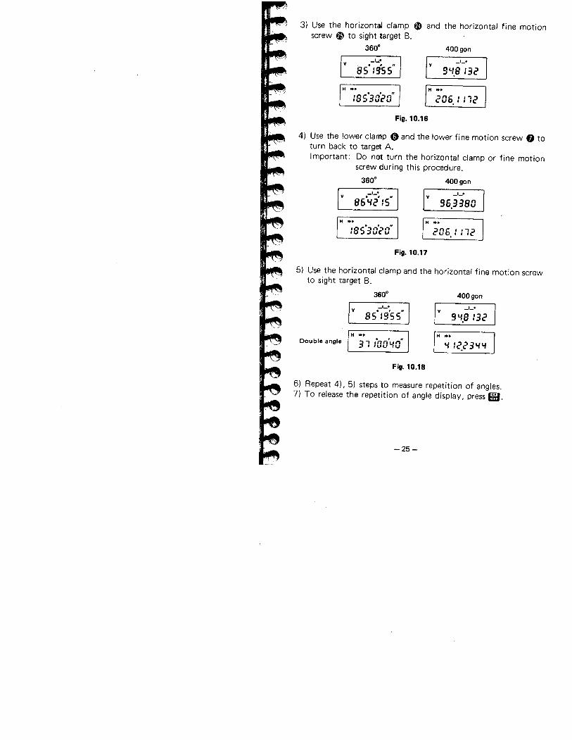
3) Use the horizontal clamp ai and the horizontal fine motionscrew æ to sight target B.
360. 400 gonv
_1_.
85' :9'55"I v
_,_+
94..8 :32
H ...
:8S'3a~0"H ...
206. : : 12
Fig. 10.16
4) Use the lower clamp 0 and the lower fine motion screw f) toturn back to target A.I mportant: Do not turn the horizontal clamp or fine motion
screw during this procedure.
3600 400 gonv
_1_.
86'4.2' :5"I v
_1_+
96.3380
H ,..
:8S'30~0"H...
206. : : 12
Fig. 10.17
5) Use the horizontal clamp and the horizontal fine motion screwto sight target B.
3600 400 gonv
_1_+
85' :9'5 5"I v
_1_+
94..8 :32
Double angleH ...
31 iaa'..a" '" :2.23....H ...
Fig. 10.18
6) Repeat 4), 5) steps to measure repetition of angles.7) To release the repetition of angle display, press if.
-25-
10.3 PREPARATION FOR DISTANCE MEASUREMENT
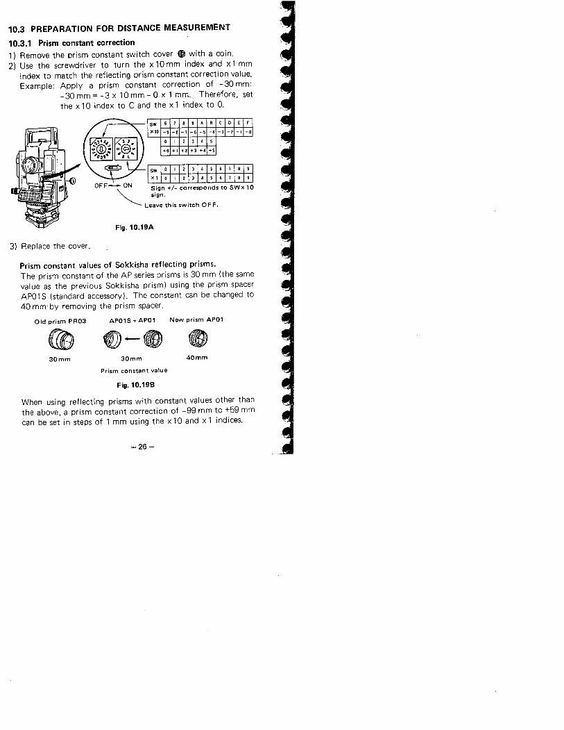
10.3.1 Prism constant correction
1) Remove the prism constant switch cover æ with a coin.2) Use the screwdriver to turn the x 10 mm index and xl mm
index to match the reflecting prism constant correction value.Example: Apply a prism constant correction of -30 mm:
-30 mm = -3 x 10 mm - 0 x 1 mm. Therefore, setthe xl 0 index to C and the x 1 index to 0,
OFF-",ON S.ign +/_ corresponds to SWx 10~ sign.
Leave this switch OFF.
Fig.10.19A
3) Replace the cover.
Prism constant values of Sokkisha reflecting prisms.The prism constant of the AP series prisms is 30 mm (the samevalue as the previous Sokkisha prism) using the prism spacer
APO 1 S (standard accessory). The constant can be changed to
40 mm' by removing the prism spacer.
Old prism PR03 AP01 S + AP01 New prism AP01
~ (l - e30mm 30mm 40mm
Prism constant value
Fig.10.19B
When using reflecting prisms with constant values other thanthe above, a prism constant correction of -99 mm to +59 mmcan be set in steps of 1 mm using the x 10 and x 1 indices.
~26~
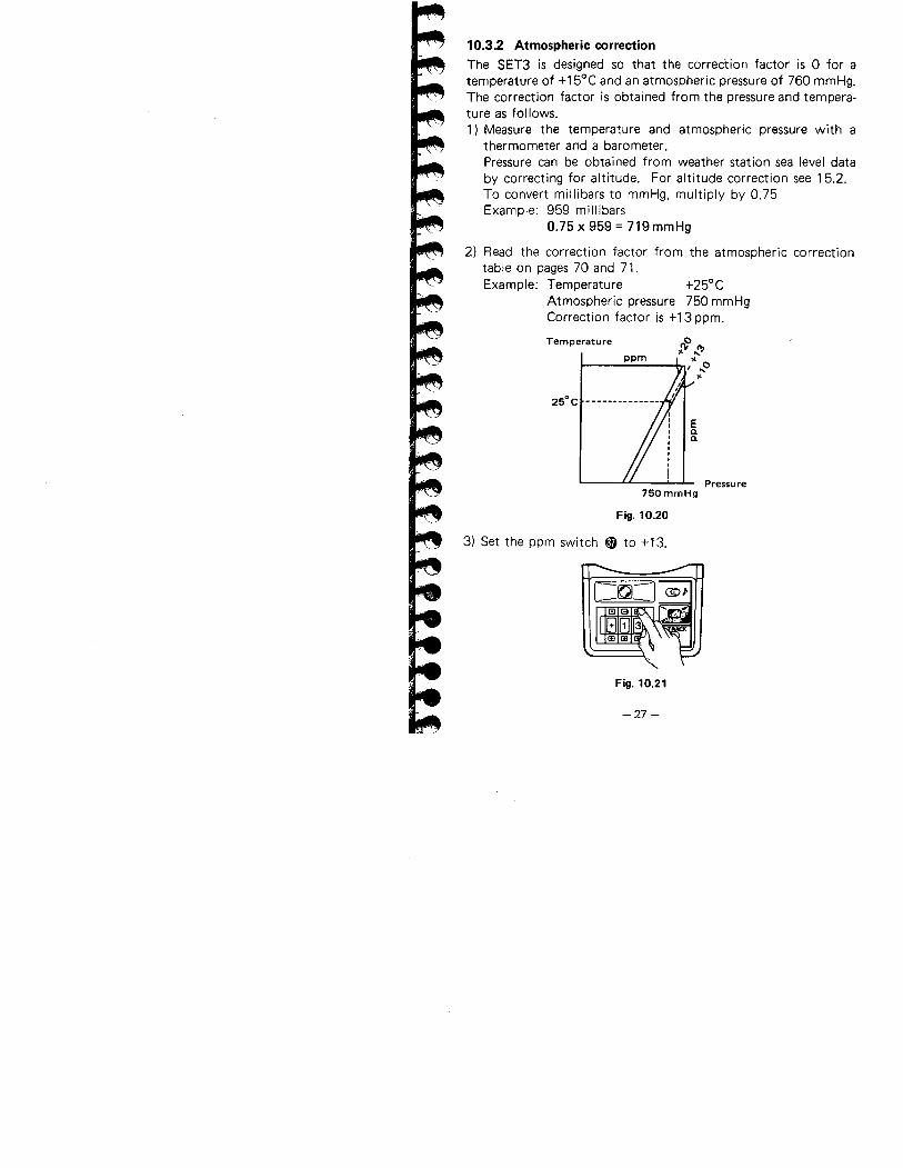
10.3.2 Atmospheric correctionThe SET3 is designed so that the correction factor is 0 for atemperature of +15°C and an atmospheric pressure of 760 mmHg.The correction factor is obtained from the pressure and tempera-
ture as follows.
1) Measure the temperature and atmospheric pressure with athermometer and a barometer.Pressure can be obtained from weather station sea level databy correcting for altitude. For altitude correction see 15.2.
To convert millibars to mmHg, multiply by 0.75Example: 959 millibars
0.75 x 959 = 719 mmHg
2) Read the correction factor from the atmospheric correction
table on pages 70 and 71.Example: Temperature +25°C
Atmospheric pressure 750 mmHgCorrection factor is +13 ppm.
Temperature o:Y ..f'
"i ..0
"
ppm
25° C --------------
Pressu re750 mmHg
Fig. 10.20
3) Set the ppm switch ~ to + 13.
Fig. 10.21
-27 -
4) To obtain the atmospheric correction factor by computation.Example A: Using pressure in mmHg.
0.3872 x PAtmospheric correction factor X = 278.96 - 1 + 0.003661 x t
P: Atmospheric pressure in mmHgt: Temperature in centigradeEx.: P=912mmHg,t=+20°C
0.3872 x 912ppm = 278.96 - 1 + 0.003661 x 20
= -50.07 =: -50
Therefore, set the ppm switch ~ to - 50.
Example B: Using pressure in mbars.0.2904 x P
Atmospheric correction factor X = 278.96 - 1 + 0.003661 x t
P: Atmospheric pressure in mbarst: Temperature in centigrade
Ex.: P = 1020 mbars, t = +50°C
0.2904 x 10²⁰ppm = 278.96 - 1 + 0.003661 x 50
= 28.58 =: 29
Therefore, set the ppm switch ~ to 29.5) The corrected slope distance is calculated by the formula:
XD = d x (1 + 1,000,000)
0: Corrected slope distance
d: The displayed slope di?tance when ppm is set to 0X: Correction factor in ppm
Example: Slope distance 2,010.000 mX = +5 ppm
D = 2,010.000 x (1 + 5 )1,000,000= ~,010.010m
-28-
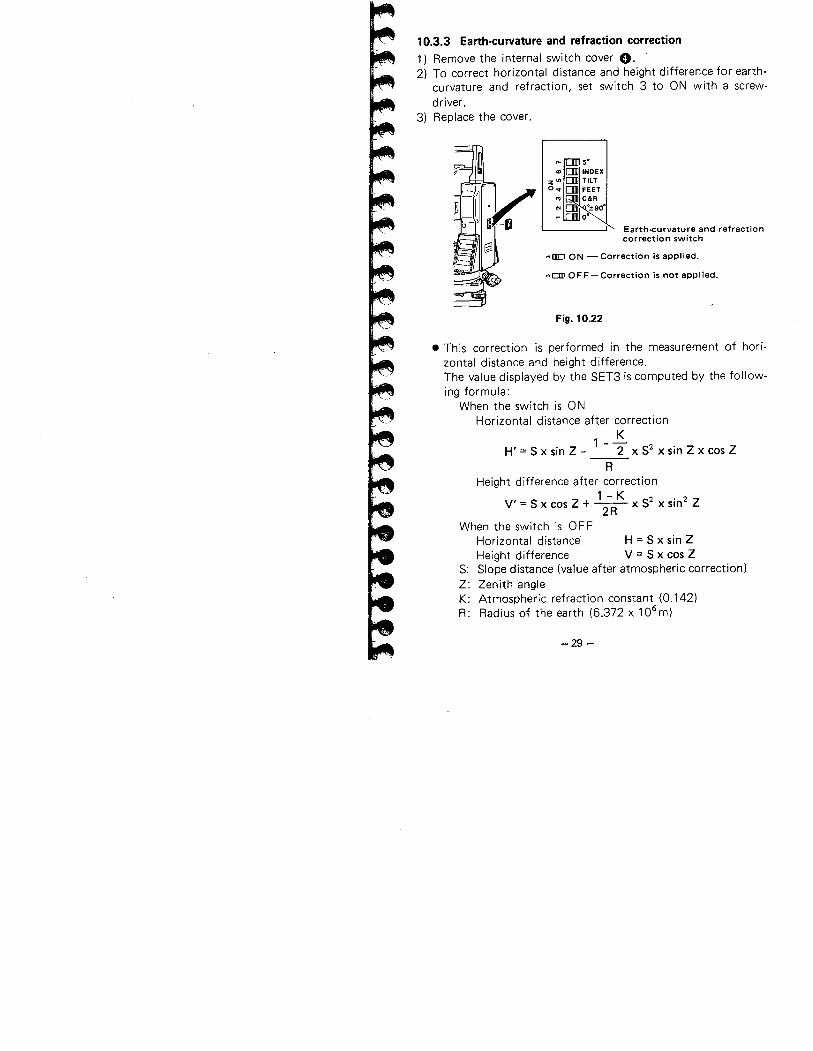
10.3.3 Earth.curvature and refraction correction1) Remove the internal switch cover O. '
2) To correct horizontal distance and height difference for earth-curvature and refraction, set switch 3 to ON with a screw-driver.
3) Replace the cover.
Earth-curvature and refractioncorrection switch
~ni ON - Correction is applied.
~am OFF-Correction is not applied.
Fig. 10.22
. This correction is performed in the measurement of hori-
zontal distance and height difference.The value displayed by the SET3 is computed by the follow-ing formula:
When the switch is ONHorizontal distance after correction
K
H' = S x sin Z - 1 - 2 X S2 x sin Z x cos Z
R
Height difference after correction
V' = S x cos Z + ~ x S2 x sin2 Z2R
When the switch is OFFHorizontal distance H = S x sin ZHeight difference V = S x cos Z
S: Slope distance (value after atmospheric correction)Z: Zenith angle
K: Atmospheric refraction constant (0.142)R: Radius of the earth (6.372 x 10⁶m)
-29 -
Target
s~vH
Average saa leval
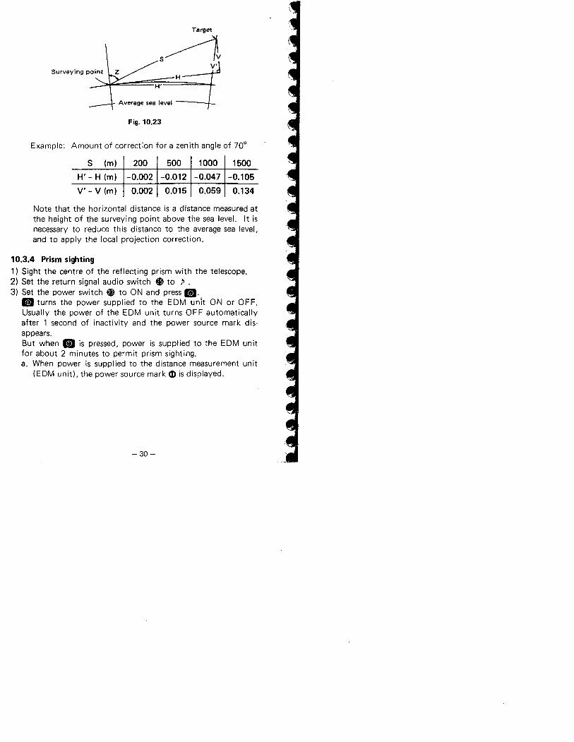
Fig. 10.23
Example: Amount of correction for a zenith angle of 70°
S (m) 200 500 1000 1500
H' - H (m) -0.002 -0.012 -0.047 -0.105
V'- V (m) 0.002 0.015 0.059 0.134
Note that the horizontal distance is a distance measured at
the height of the surveying point above the sea leveL. It isnecessary to reduce this distance to the average sea level,
and to apply the local projection correction.
10.3.4 Prism sighting
1) Sight the centre of the reflecting prism with the telescope.
2) Set the return signal audio switch ~ to P .3) Set the power switch ~ to ON and press II.
II turns the power supplied to the EDM unit ON or OFF.Usually the power of the EDM unit turns OFF automaticallyafter 1 second of inactivity and the power source mark dis-appears.But when II is pressed. power is supplied to the EDM unitfor about 2 minutes to permit prism sighting.a. When power is supplied to the distance measurement unit
(EDM unit), the power source mark CD is displayed.
-30-
b. When the reflected light is received by the telescope, anaudio signal is heard and the return signal lamp ~ lightsup.
When the light intensity coming back from the prism isvery high. the return signal lamp may light up. even fora slight mis.sighting. Make sure that the target centre issighted correctly.
4) Switch off the audio target acquisition.
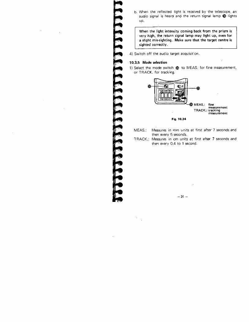
10.3.5 Mode selection1) Select the mode switch ~
or TRACK. for tracking.to MEAS. for fine measurement,
~
~ MEAS.: finemeasurement
TRACK.: trackingmeasurement
4)
Fig. 10.24
MEAS.: Measures in mm units at first after 7 seconds andthen every 5 seconds.
TRACK.: Measures in cm units at first after 7 seconds andthen every 0.4 to 1 second.
-31 -
10.4 DISTANCE MEASUREMENT
Make sure that:a. The SET3 is set up correctly over the surveying point.b. The prism constant switch; the earth-curvature refraction
switch. and ppm switch are set correctly.c. Battery voltage is adequate.
d. Indexing the vertical circle is complete.
10.4.1 Angle and distance measurement
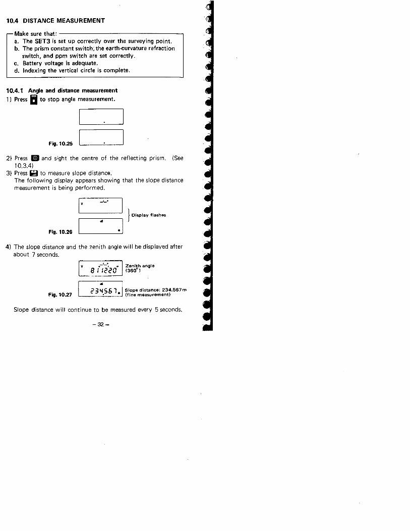
1) Press 1: to stop angle measurement.
Fiii. 10.25
2) Press m and sight the centre of the reflecting prism. (See10.3.4)
3) Press ii to measure slope distance.
The following display appears showing that the slope distancemeasurement is being performed.
I v I
1 Display flashes
.1
_1_+
Fig. 10.26 I
""
4) The slope distance and the zenith angle will be displayed afterabout 7 seconds.
v_1_+
B i :2'20"Zenith angle(360°)
Fig. 10.27 2 3 ~ 5 6 1 ¡siope distance: 234.567 m. · (fine measurement)
Slope distance will continue to be measured every 5 seconds.
-32-
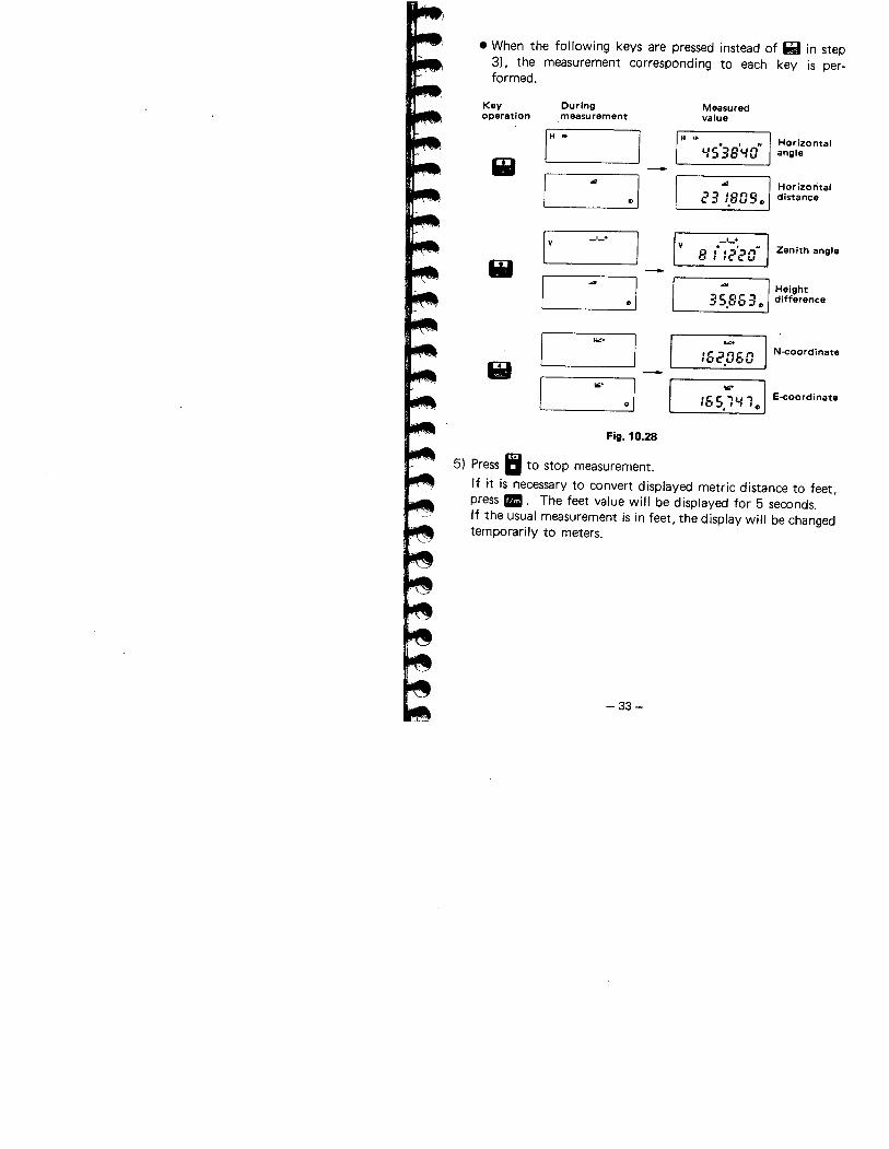
· When the following keys are pressed instead of i! in step3). the measurement corresponding to each key is per-formed.
5) Press II to stop measurement.
If it is necessary to convert displayed metric distance to feet,press II. The feet value will be displayed for 5 seconds.
If the usual measurement is in feet, the display will be changedtemporarily to meters.
-33-
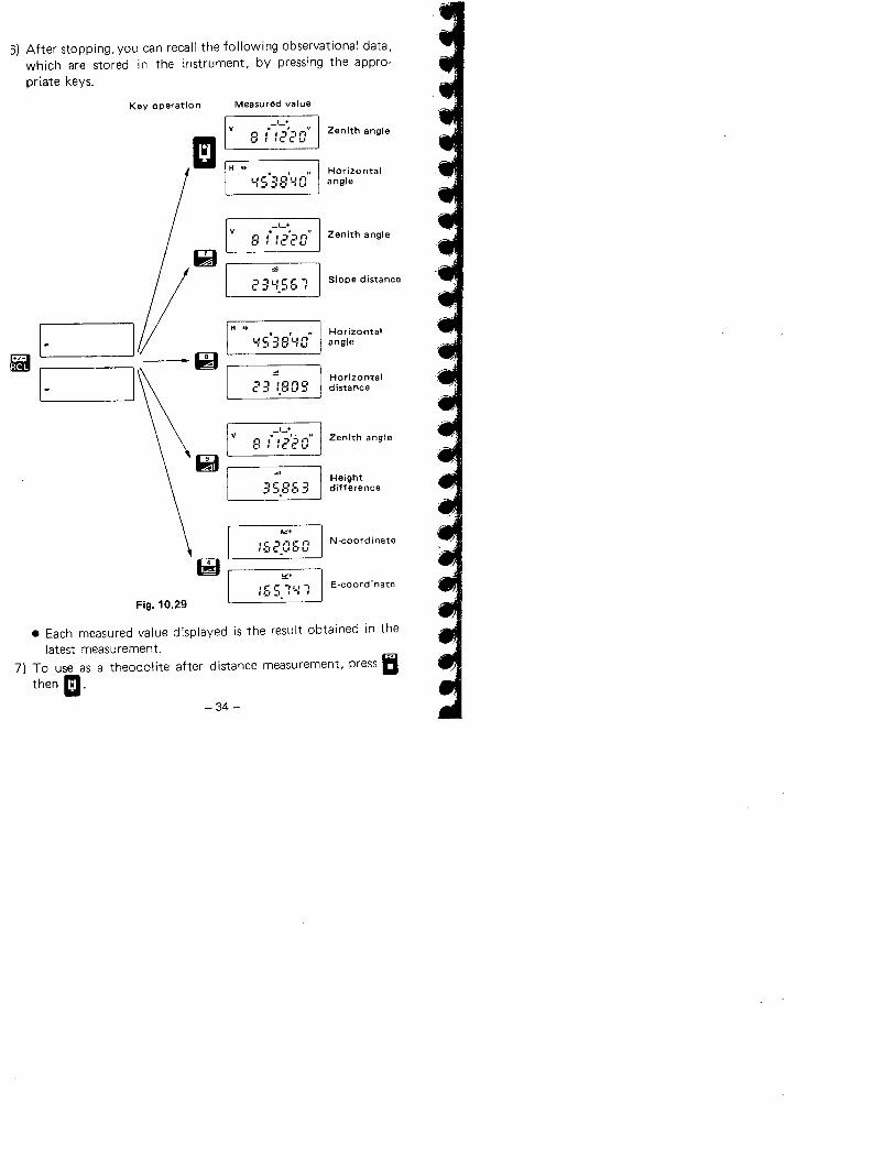
3) After stopping, you can recall the following observational data,which are stored in the instrument, by pressing the appro-
priate keys.
Key operation Measured value
-'-+.:2'20
" Zenith angle
EIF: I-' i
H ..
y S°:: S't.I a
" Horizo ntalangle
v-'-+. , "
Zenith angle8 i 12c'Oi~ .,
il~¿I
3'-1.56 1 Slope distance
1-
H .. Horizontal. , "YS 38'-0 angle
~I- I
Æ Horizontal23 1.809 distance
_1_+.:2'~1C:
" Zenith angle8 i
,
Qi3S.E:El3
Heightdifference
162.060 N -coord i nate
æ ",.ie r ÎII-' E-coordinate
Fig. 10.29f 1_' :'. 1-' ,
. Each measured value displayed is the result obtained in thelatest measurement.
7) To use as a theodolite after distance measurement, press Ii
then II.
-34~
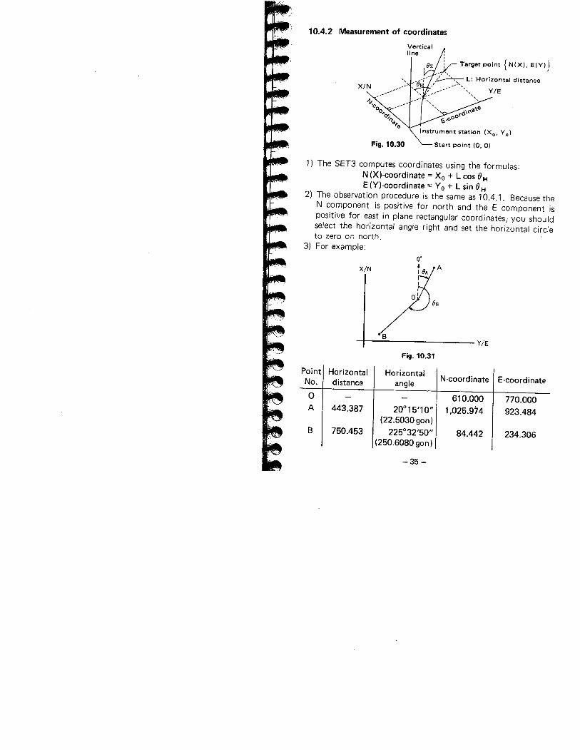
10.4.2 Measurement of coordinates
Verticalline
vie
\:rument station (Xo, Yo)Fig. 10.30 Start point (0, 0)
1) The SET3 computes coordinates using the formulas:N (Xl-coordinate = Xo + Leos 8HE (Yl-coordinate = Yo + L sin 8 H
2) The observation procedure is the same as 10.4.1. Because theN component is positive for north and the E component ispositive for east in plane rectangular coordinates,' you shouldselect the horizontal angle right and set the horizontal circleto zero on north,
3) For example:
X!N
V!E
Fig. 10.31
Point Horizontal HorizontalN-coordinate E-coordinateNo. distance angle
0 610.000 770.000A 443.387 20° 15'1 0" 1.025.974 923.484
(22.5030 gon)
B 750.453 225°32'50" 84.442 234.306(250.6080 gon)
-35 -
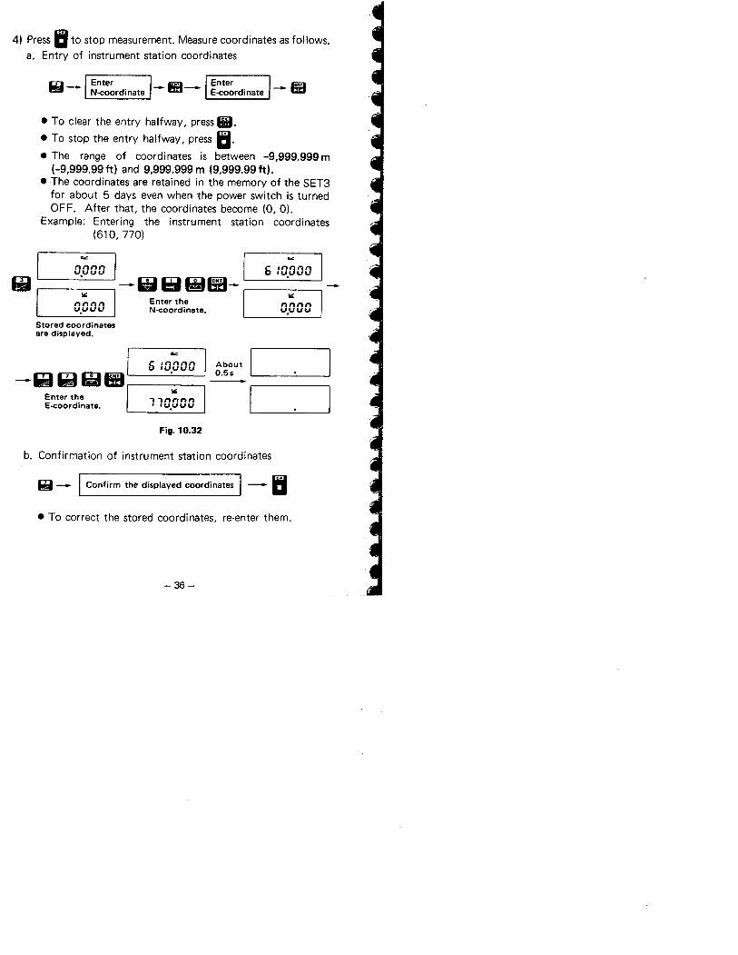
4) Press II to stop measurement. Measure coordinates as follows.
a. Entry of instrument station coordinates
-- II
. To clear the entry halfway, pressHB.
. To stop the entry halfway, press II.
. The range of coordinates is between -9.999.999 m
(-9,999.99 ft) and 9,999.999 m (9.999.99 ft).. The coordinates are retained in the memory of the SET3
for about 5 days even when the power switch is turnedOFF. After that, the coordinates become (0.0).
Example: Entering the instrument station coordinates(610, 770)
'*1
I
nnnn Iu.uuu-1i6J fæ1!-
n~nn I Enter the Iu.u U U N-coordinate.
6 :0.000
'"nnnnU.UUU
Stored coordinatesare displayed.
""
About ID.Ss-WWf§ßa
6 :0.000
Enter theE-eoordinate.
'", ,nnnn.,U.UUU
Fig. 10.32
b. Confirmation of instrument station coordinates
_iiI!- Confirm the displayed coordinates II
. To correct the stored coordinates, re-enter them.
-36-
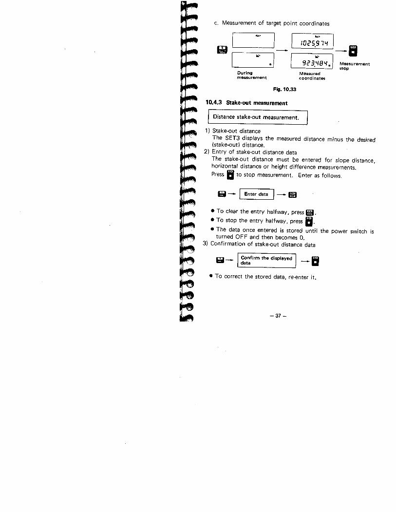
c. Measurement of target point coordinates
&iiI
I
./
... ...:025.91'- -I:
92 3 ~ B '- .1 Measurement. . stop
Measuredcoordinates
10'
Duringmeasurement
Fiii. 10.33
10.4.3 Stake.out measurement
Distance stake-out measurement.
1) Stake-out distanceThe SET3 displays the measured distance minus the desired(stake-out) distance.
2) Entry of stake-out distance data
The stake-out distance must be entered for slope distance,horizontal distance or height difference measurements.Press II to stop measurement. Enter as follows.
61 - I Enter data 1- Ii
· To clear the entry halfway, press HH.
· To stop the entry halfway. press II.
· The data once entered is stored until the power switch isturned OFF and then becomes O.
3) Confirmation of stake-out distance data
61- Confirm the displayeddata -Ii
· To correct the stored data, re-enter it.
-37 -
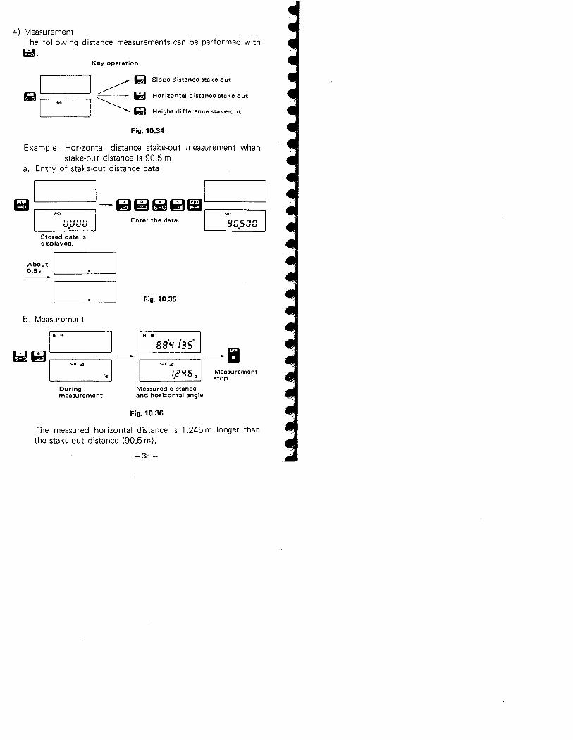
4) Measurement
The following distance measurements can be performed withfi.
Key operation
Ifi i I~~.~I ~ Ii Height difference stake-out
Slope distance stake-out
Horizontal distance stake-out
Fig. 10.34
Example: Horizontal distance stake-out measurement whenstake-out distance is 90.5 m
a. Entry of stake-out distance data
i:l 1- w iæ i;UiÐ ß' IEnter the data. I
s.o s-o
",ïnnv,u v v
Stored data isdisplayed.
About I0.5s
90.500
Fig. 10.35
b. Measurement
I H ..
~~II
'~ I
H ..
BB'1. :'35" -6s-o .. Ii :i i. 6 Measurement'." ~ stop
Measured distanceand horizontal angle
5-0 ..
Duringmeasurement
Fig. 10.36
The measured horizontal distance is 1.246 m longer thanthe stake-out distance (90.5 m).
-38 -
I Coordinates stake-out measurement.
5) Stake-out coordinates
The SET3 displays the measured coordinate values minus thedesired (stake-out) coordinate values.
Dis'played N-coordinate= measured N-coordinate (Xo + L cos 8H)
- stake-out N-coordinateDisplayed E-coordinate
= measured E-coordinate (Yo + L sin 8 H)- stake-out E-coordinate
6) Entry of instrument station coordinates
See 10.4.2.7) Entry of stake-out coordinates data
Press B to stop measurement. Enter as follows.
Si- EnterN-coordinate data -- II --
EnterE-coordinate data -II
. To clear the entry halfway, press 1f.
. To stop the entry halfway, press II.
· Stake-out coordinate values between -9,999.999 m
(-9,999.99 ft) and 9,999.999 m (9,999.99 ft) can be entered.. The data once entered is stored until the power switch is
turned OFF and then becomes (0,0).8) Confirmation of stake-out coordinates data
Si- Confirm the displayeddata -II
. To correct the stored data, re-enter it.
-39 -
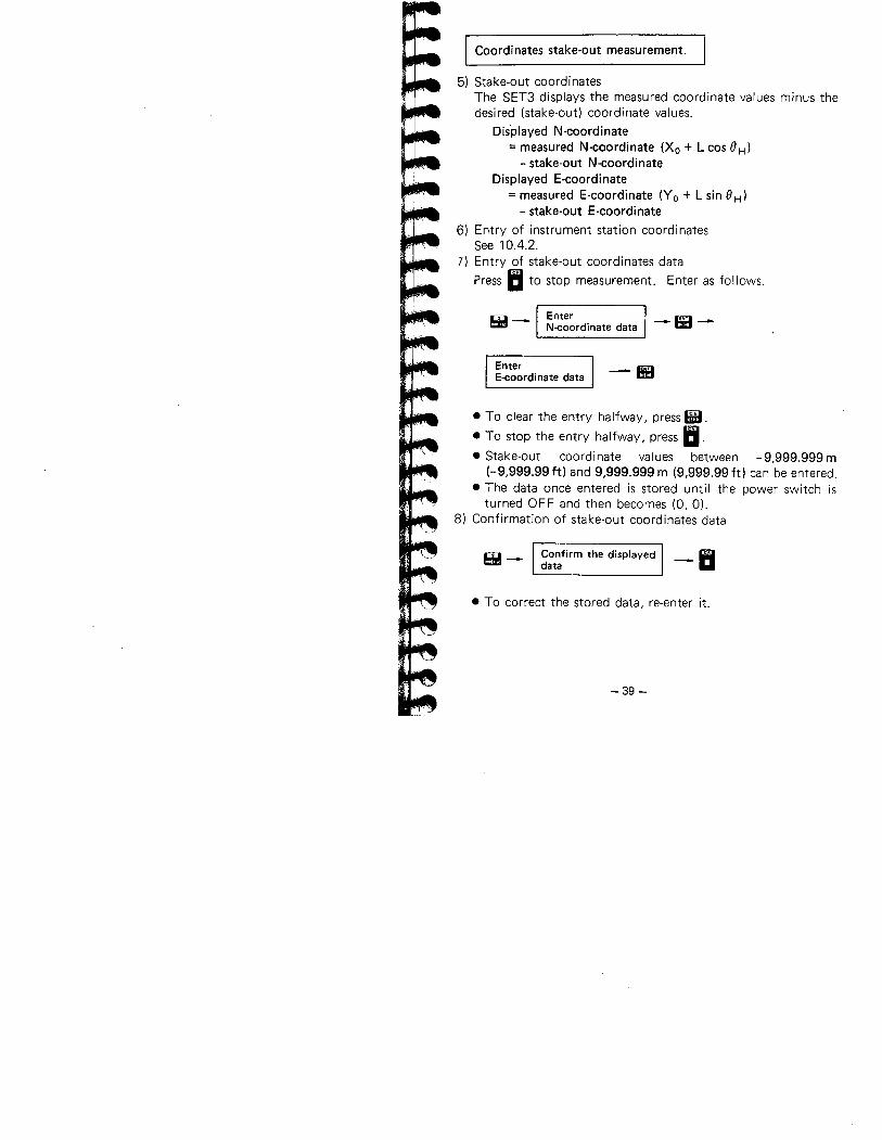
9) Measurement
Example: Coordinates stake-out measuremerit when stake-outN-coordinate value is 1,000 m and stake-out E-coordinate value is 1,000 m.
a. Confirmation of the instrument station coordinates.
6 :0.000 -6SE '",,'"n.,nni 'l.'.'-'UU
b. Entry of stake-out coordinates data
Bi i1- i:l!li l; Ea, I s- nnnn I
v.vvv
I
I
s-innnnnnIUUU.'",uu
s-o
nnnnv.vvv
s-o
nnnnu.,-,t.iu
Stored data isdisplayed. About I
O.5s
s-o
innn.",.,IUl-'U.'-'UU1I1I1I1I in- I: ~ ~ ~ IXs-o
,nnnnnnIUL'L'.'-'t....
Fig. 10.37
c. Measurement
WQlI
s-o iw'
I
s- "".
25.9 l-: -II. I s-o ,..
~ I
s-o ,.,16.5 :6~
Fig. 10.38
The measured N-coordinate value is 25.974 m longer thanthe stake-out value (1,000 m) and the measured E-coordinate value is 76.516 m shorter than the stake-out
value (1,000 m).
-40-
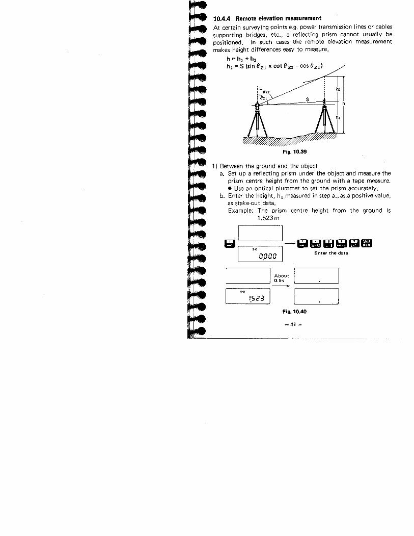
=~10.4.4 Remote elevation measurement
At certain surveying points e.g. power transmission lines or cablessupporting bridges, etc., a reflecting prism cannot usually bepositioned. I n such cases the remote elevation measurement
makes height differences easy to measure.h = hi + h2
h2 = S (sin OZI x cot OZ2 - cos Ozil
s
Fig. 10.39
1) Between the ground and the objecta. Set up a reflecting prism under the object and measure the
prism centre height from the ground with a tape measure.
. Use an optical plummet to set the prism accurately.b. Enter the height, hi measured in step a., asa positive value,
as stake-out data.Example: The prism centre height from the ground is
1.523 m
~II
I
I
1- ~ II '* BiI! ei
I Enter the data
...nnnn'-.'-'-'-
I About0.55
s..
:.523
Fig. 10.40
-41-
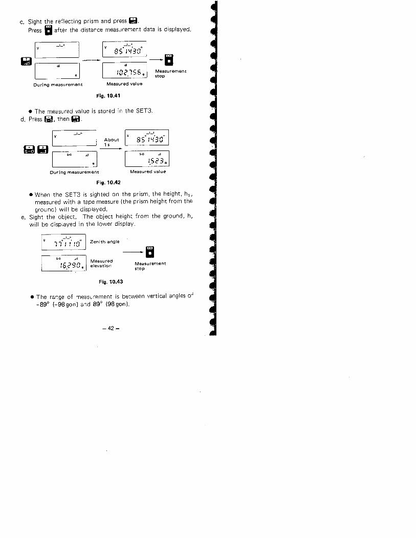
c. Sight the reflecting prism and press ~.Press II after the distance measurement data is displayed.
II Iv
EllI
~ i
Measurementstop
0-1-+' "E:S :l-:::O -II
_1_+
.. ..11-':l-lCC'~I'_. r ..,,_, If
During measurement Measured value
Fig. 10.41
. The measured value is stored in the SET3.d. Press~, then~.
I vl-ll ._1_+
iAbout1 s
s.o
~ ~ I
~
:.S231D
_1_+
(I C,_, ..'
, ..l-: :: c:
s.o
During measurement Measured value
Fig. 10.42
. When the SET3 is sighted on the prism, the height, hi,measured with a tape measure (the prism height from theground) will be displayed.
e. Sight the object. The object height from the ground, h,
will be displayed in the lower display.
_1_+-, _,0 I I , ,-i" Zenith anglei I I , "..' -IIs.o ..
: b.c' S a ~Measuredelevation Measurement
stop
Fig. 10.43
. The range of measurement is between vertical angles of_890 (-98gon) and 890 (98gon).
-42 -
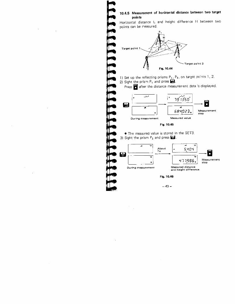
10.4.5 Measurement of horizontal distance between two targetpoints
Horizontal distance L and height difference H between twopoints can be measured.
Target point 1
~ Target point 2
Fig. 10.44
1) Set up the reflecting prisms Pi, P2. on target points 1,2.2) Sight the prism P i and press ~.
Press II after the distance measurement data is displayed.
In Iv1m I
_1_+
I
~ I
Measurementstop
, +
-, 0°-' ;'c ,-,", _I ~-, _, ,_, -Ii.. ,,
6S'-.ae'3~
During measurement Measu red va i u e
Fig. 10.45
. The measured value is stored in the SET3,3) Sight the prism P2 and press W.
wivi v
About 5.'-:GL:7s -II~ I :1
v'-11.9S6~ Measurement
stop
Measured distanceand height difference
During measurement
Fig. 10.46
-43-
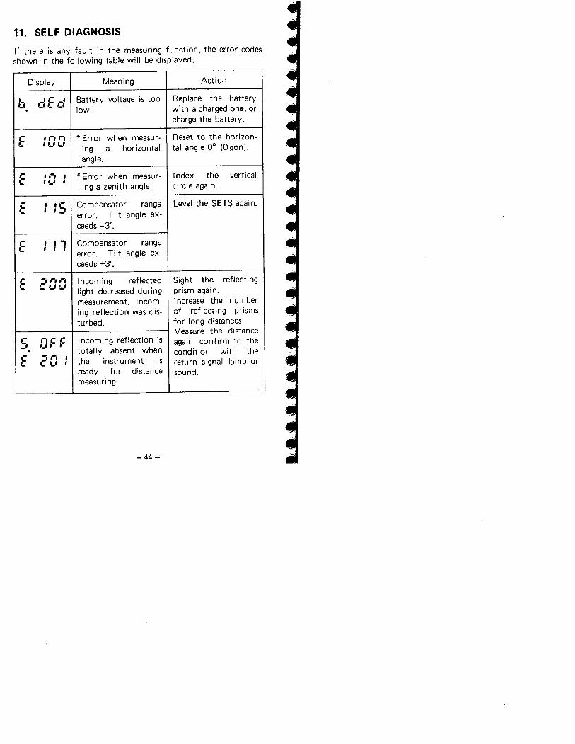
11. SELF DIAGNOSIS
If there is any fault in the measuring function, the error codes
shown in the following table will be displayed.
Display Meaning Action
b .-::: .-:Battery voltage is too Replace the battery
. low. with a charged one, orcharge the battery.
C ,.-,.-, * Error when measur- Reset to the horizon-'- "-"-'
ing horizontal tal angle 0° (Ogon).aangle.
.- ,.-, , * Error when measur- Index the verticalC , '-' ,
ing a zenith angle. circle again.
C , ,.- Compensator range Level the SET3 again.'- , , :'
Tilt angle ex-error.ceeds -3'.
.- , , -, Compensator rangeC , , ,
Tilt angle ex-error.ceeds +3'.
.- -, .-, .-, Incoming reflected Sight the reflectingC C ,_, '-' light decreased during prism again.
measurement. Incom- Increase the numbering reflection was dis- of reflecting prisms
turbed. for long distances.
Measure the distance.- .-,.- .- Incoming reflection is again confirming the:' ._,.- .-. totally absent when condition with the.- -,.-, , the instrument isC C '-' , return signal lamp or
ready for distance sound.measuring.
-44-
iit+
Lir1Mir".'T~ ..
..=,1....
,'.' ....... "........
..-
L.
t:-=..~.'~J.-
r.,.......r...-~".~..
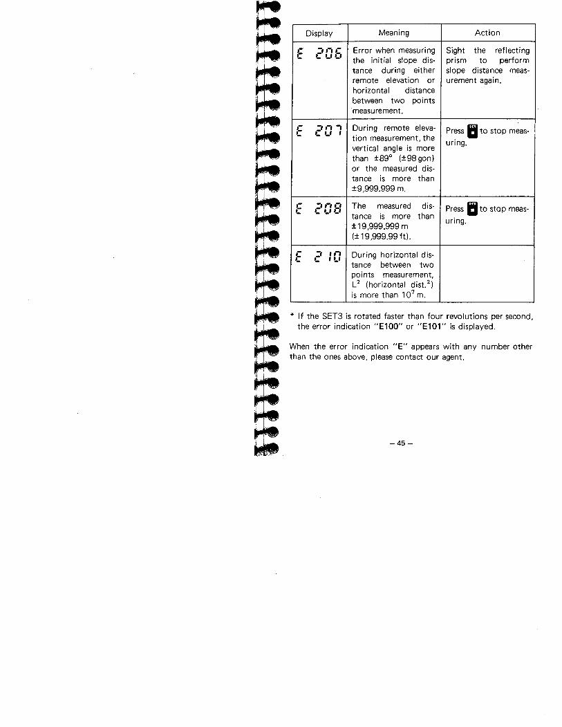
Display Meaning Action
,- -, ,-, ,- Error when measuring Sight the reflectingC C ,_, C' the initial slope dis- prism to perform
tance during either slope distance meas-remote elevation or urement again.horizontal distancebetween two pointsmeasurement.
,- -, ,-, -, During remote eleva- Press II to stop meas-C C ,_, , tion measurement, thevertical angle is more
uring.
than :t89° (:t98 gon)or the measured dis-tance is more than:!9,999.999 m.
,- -, ,-, ,-, The measured dis- Press II to stop meas-C C ,_, i: tance is thanmore uring.:t 19,999.999 m(:t 19,999.99 ft).
,- -, , ,-, During horizontal dis-C C , '-'tance between twopoints measurement,L2 (horizontal dist.2)is more than 107 m.
* If the SET3 is rotated faster than four revolutions per second,
the error indication "E100" or "E101" is displayed.
When the error indication "E" appears with any number otherthan the ones above, please contact our agent.
-45 -
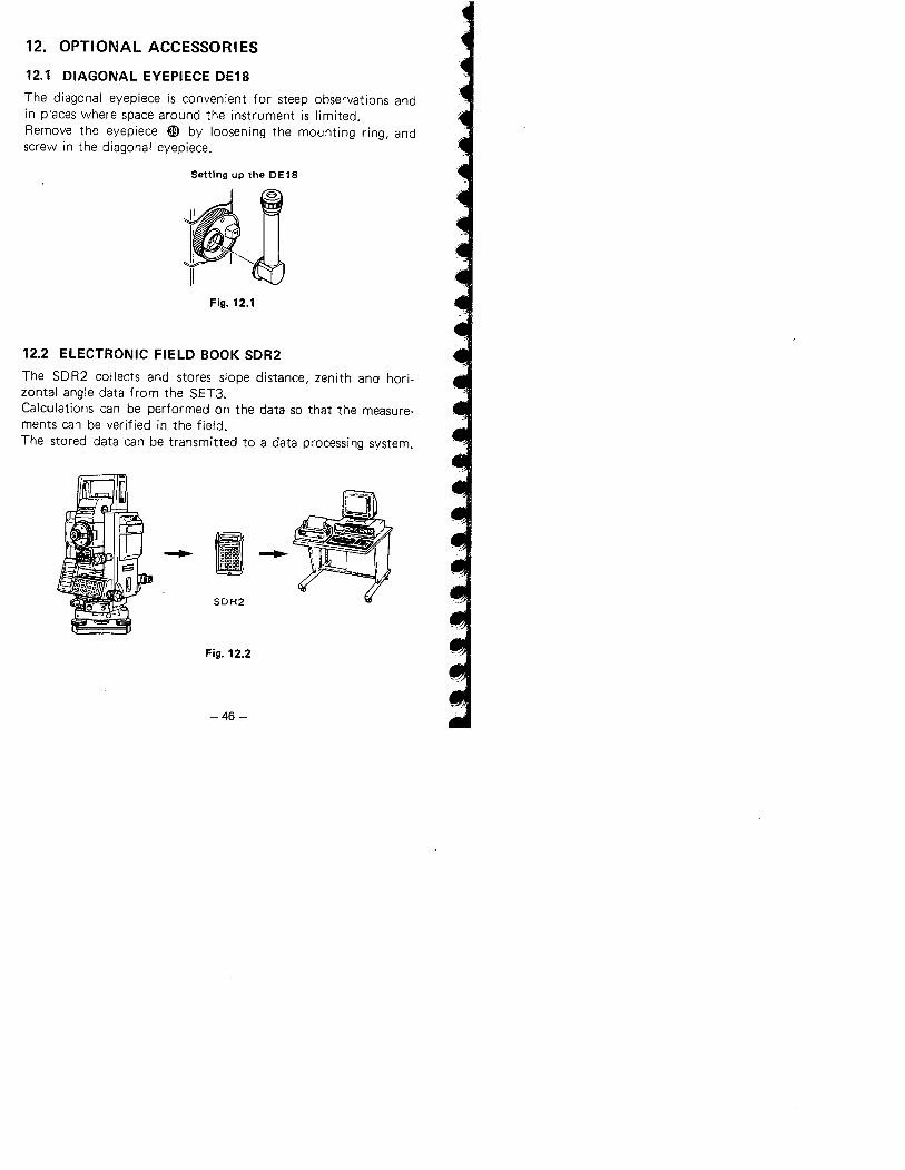
12. OPTIONAL ACCESSORIES
12.1 DIAGONAL EYEPIECE DE18
The diagonal eyepiece is convenient for steep observations andin places where space around the instrument is limited.Remove the eyepiece ~ by loosening the mounting ring, andscrew in the diagonal eyepiece.
Setting up the DE 18
Fig. 12.1
12.2 ElECTRONIC FIELD BOOK SDR2
The SDR2 collects and stores slope distance, zenith and hori-zontal angle data from the SET3.Calculations can be performed on the data so that the measure-
ments can be verified in the field.The stored data can be transmitted to a data processing system.
~SDR2
Fig. 12.2
-46 -
~
SDR2 specificationsPower source: "AA" (UM3) x 4
Memory type: CMOSRAM 16K or 32KROM 16K
Keyboard: 33 keysDisplay: LCD'Baud rate: 300, 600, 1200,
2400, 4800 bps
Operating temperaturerange: 0 to 50°CWeight: 450 g
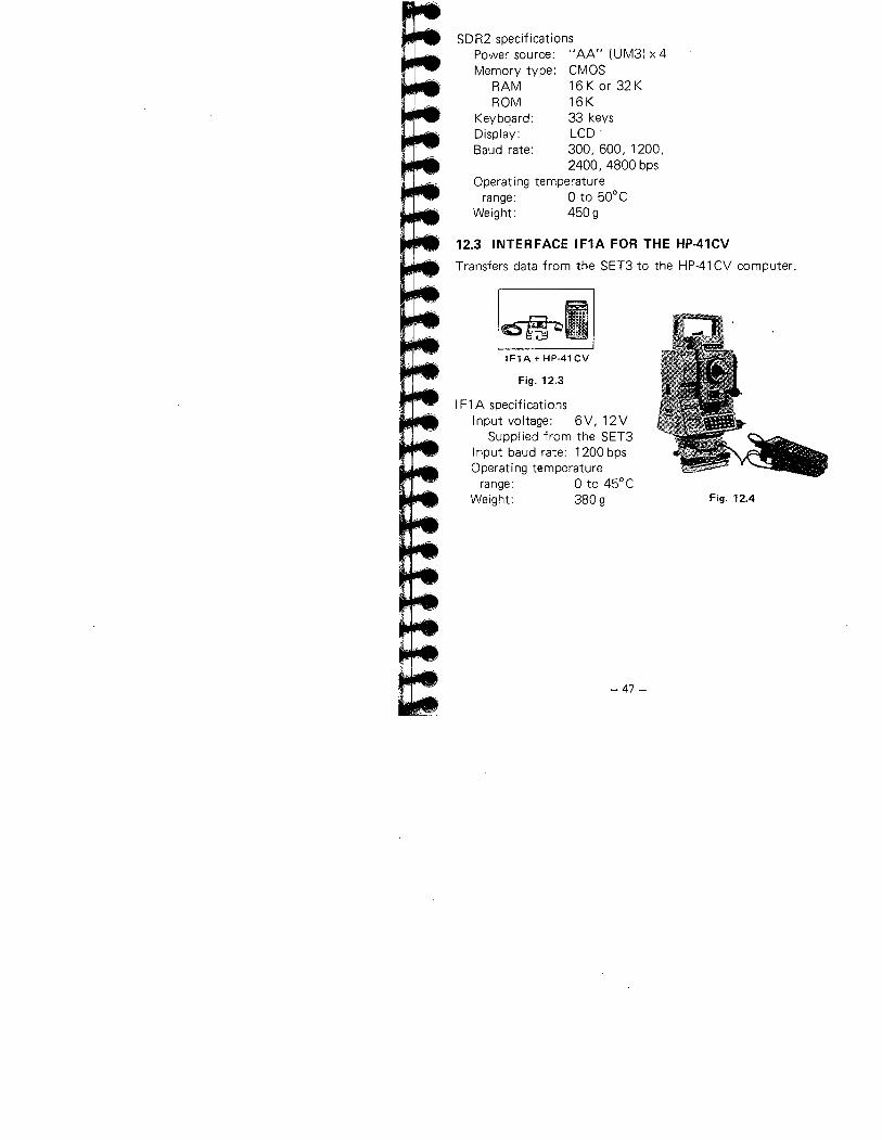
12.3 INTERFACE IF1A FOR THE HP-41CV
Transfers data from the SET3 to the HP-41 CV computer.
~IF1A + HP.41 CV
Fig. 12.3
i Fl A specificationsInput voltage: 6V,12V
Supplied from the SET3i nput baud rate: 1200 bpsOperating temperaturerange: 0 to 45°CWeight: 380 g Fig. 12.4
-47 -
13. CHECKS AND ADJUSTMENTS
The SET3 may be affected by sudden changes in weather condi-tions and excessive vibration. This can result in inaccurate
surveying. Therefore, IT IS IMPORTANT TO CHECK ANDADJUST THE SET3 BEFORE AND DURING USE in the follow-ing order.
13.1 ANGLE MEASURING FUNCTION
13.1.1 Plate level13.1.2 Circular level13.1.3 Index error of the tilt angle sensor13.1.4 Reticle13.1.5 Perpendicularity of the reticle to the horizontal axis13.1.6 Coincidence of the distance measuring axis with the
reticle13.1.7 Optical plummet
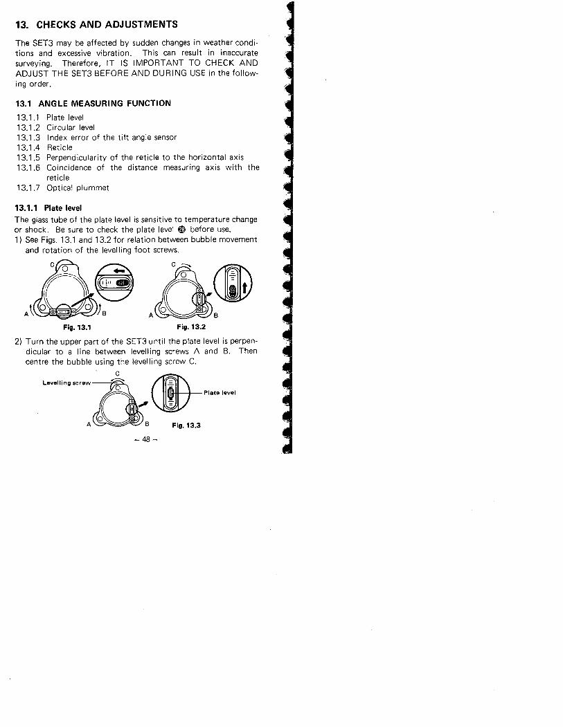
13.1.1 Plate levelThe glass tube of the plate level is sensitive to temperature changeor shock. Be sure to check the plate level W before use.
1) See Figs. 13.1 and 13.2 for relation between bubble movementand rotation of the levelling foot screws.
Fig. 13.1 Fig. 13.2
2) Turn the upper part of the SET3 until the plate level is perpen-dicular to a line between levelling screws A and B. Thencentre the bubble using the levelling screw C.
Levelling screwò' ~ cæ=o ., Plate levelo *" :-
o 0A 8 Fig. 13.3
- 48-
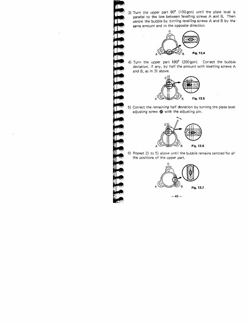
3) Turn the upper part 900 (100gon) until the plate level isparallel to the line between levelling screws A and B. Thencentre the bubble by turning levelling screws A and B by thesame amount and in the opposite direction.
A8A~S Fig. 13.4
4) Turn the upper part 1800 (200 gon). Correct the bubble
deviation, if any, by half the amount with levelling screws A
and B, as in 3) above.
~~A \WIS Fig. 13.5
5) Correct the remaining half deviation by turning the plate leveladjusting screw ~ with the adjusting pin.
..
A Fig. 13.6
~~6) Repeat 2) to 5) above until the bubble remains centred for all
the positions of the upper part.
Ö+ , ..(f') 0A B Fig. 13.7-49 -
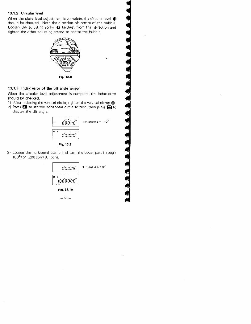
13.1.2 Circular levelWhen the plate level adjustment is complete, the circular level æshould be checked. Note the direction off-centre of the bubble.Loosen the adjusting screw 0 farthest from that direction andtighten the other adjusting screws to centre the bubble.
Fig. 13.8
13.1.3 Index error of the tilt angle sensorWhen the circular level adjustment is complete, the index errorshould be checked.
1) After indexing the vertical circle, tighten the vertical clamp ~.2) Press H to set the horizontal circle to zero, then press ig to
display the tilt angle.
-'-,-0,-, ,-,' i i-a" Tilt angle a = -10",_, l.' ,_, , '-'
H ..,-, 1-, '' ., fIl-I..'ULI'-'
Fig. 13.9
3) Loosen the horizontal clamp and turn the upper part through
180°:15' (200gon:10.1 gon).
-'-o , "GODOS
Tilt angle b = 9"
H '. o , ":BaOOOa
Fig. 13.10
- 50-
~-. '.''-( _.1.-"
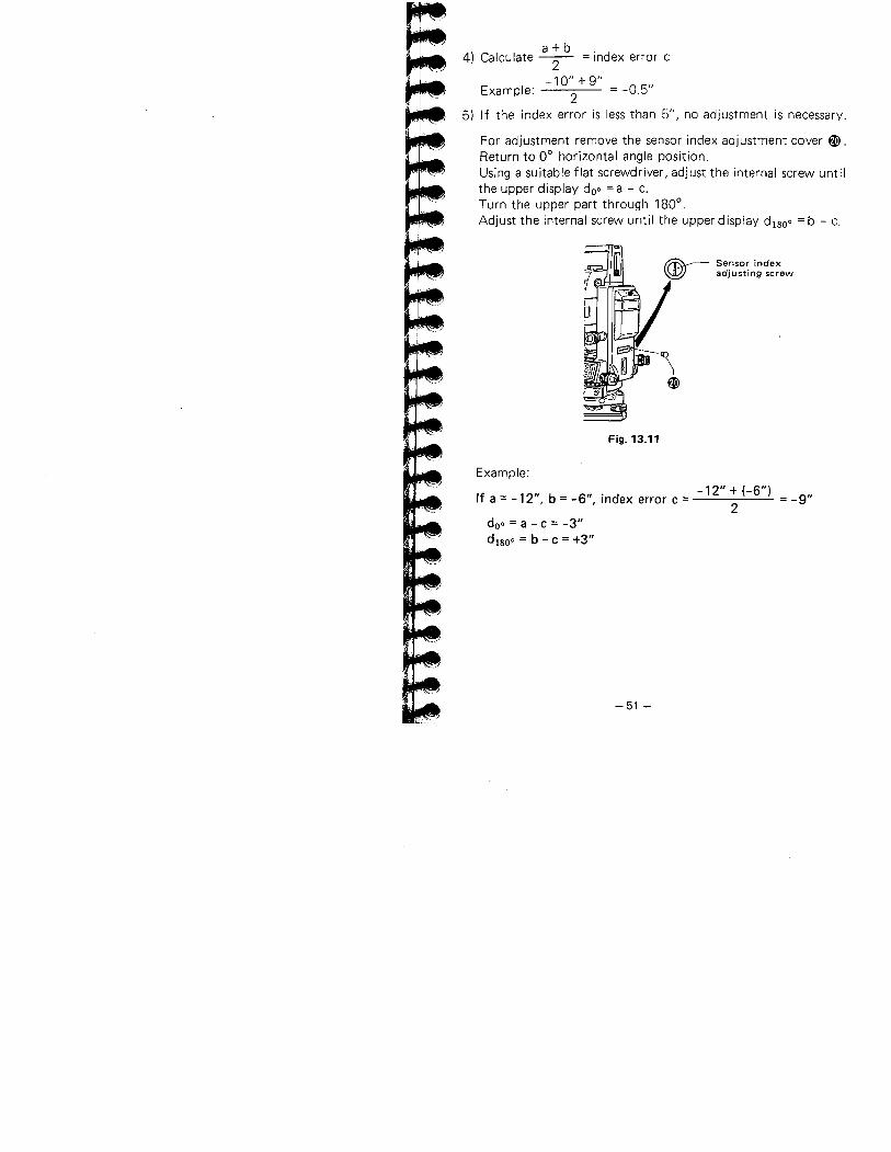
a + b4) Calculate -- = index error c
-10" + 9"Example: 2 = -0.5"5) If the index error is less than 5", no adjustment is necessary.
For adjustment remove the sensor index adjustment cover W.Return to 0° horizontal angle position.Using a suitable flat screwdriver, adjust the internal screw untilthe upper display doo = a-c.
Turn the upper part through 180°,
Adjust the internal screw until the upper display di800 =b - c,
Fig. 13.11
Example:-12"+(-6")If a = -12", b = -6", index error c = = -9"
2doo = a - c = -3"
di800 = b - c = +3"
-51 -
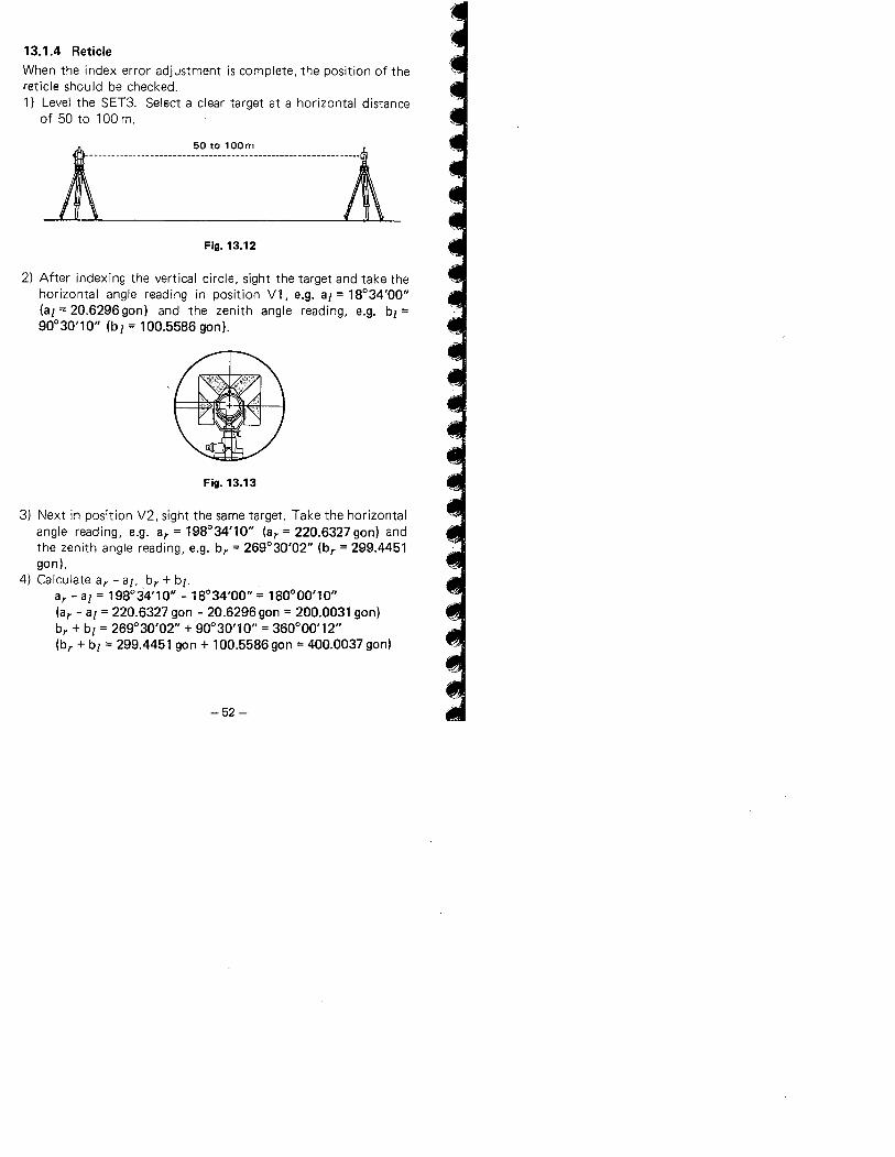
13.1.4 ReticleWhen the index error adjustment is complete, the position of thereticle should be checked.1) Level the SET3. Select a clear target at a horizontal distance
of 50 to 100 m.
l.............m....._".,~."~~............_......~Fig. 13.12
2) After indexing the vertical circle, sight the target and take thehorizontal angle reading in position V1, e.g. a¡ = 18°34'00"
(a¡ = 20.6296gon) and the zenith angle reading, e.g. b¡ =90°30'10" (b¡ = 100.5586 gon).
Fig. 13.13
3) Next in position V2, sight the same target. Take the horizontalangle reading, e.g. ar = 198°34'10" (ar = 220.6327 gon) andthe zenith angle reading, e.g. br = 269°30'02" (br = 299.4451gon ).
4) Calculate ar - a¡, br + b¡.
ar - a¡ = 198°34'10" - 18°34'00" = 180°00'10"(ar - a¡ = 220.6327 gon - 20.6296 gon = 200.0031 gon)br + b¡ = 269°30'02" + 90°30'10" = 360°00'12"(br + b¡ = 299.4451 gon + 100.5586 gon = 400.0037 gon)
-52 -
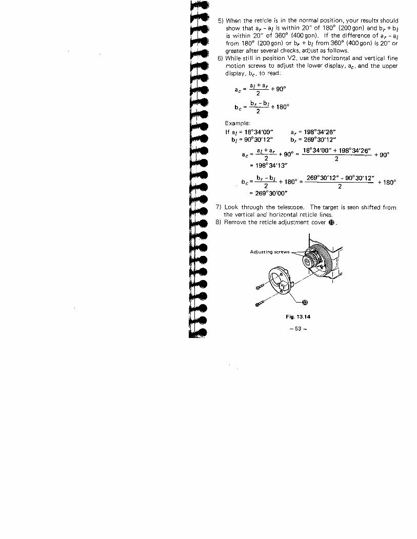
~.....-....,rrj ,5) When the reticle is in the normal position, your results should
show that ar - ai is within 20" of 180° (200 gon) and br + biis within 20" of 360° (400gon). If the difference of ar - aifrom 180° (200 gon) or br + b¡ from 360° (400 gon) is 20" orgreater after several checks, adjust as follows.
6) While still in position V2, use the horizontal and vertical finemotion screws to adjust the lower display, ae, and the upperdisplay, be, to read:
a = ai + ar + 900e 2
b = b r - b ¡ + 1800e 2Example:If ai = 18°34'00" ar = 198°34'26"
b¡ = 90°30'12" br = 269°30'12"
_ a¡ + ar ° 18°34'00" + 198°34'26"a + 90 = + 90°e - 2 2= 198°34'13"
b - b¡ 269°30'12" - 90°30'12"be = r + 180° = + 180°2 2= 269° 30'00"
7) Look through the telescope. The target is seen shifted fromthe vertical and horizontal reticle lines.
8) Remove the reticle adjustment cover i).
Adjusting screws
~~/~/~Øl
Fig. 13.14
-53 -
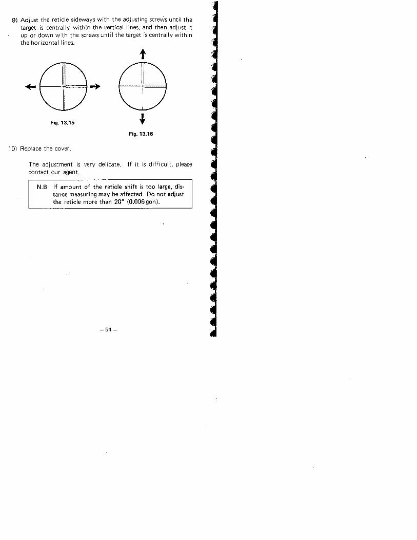
9) Adjust the reticle sideways with the adjusting screws until the
target is centrally within the vertical lines. and then adjust itup or down with the screws until the target is centrally withinthe horizontal lines.
t.. ~
Fig. 13.15 lFig. 13.16
10) Replace the cover.
The adjustment is very delicate. If it is difficult, pleasecontact our agent.
N.B. If amount of the reticle shift is too large, dis-tance measuring may be affected. Do not adjustthe reticle more than 20" (0.006 gon).
-54-
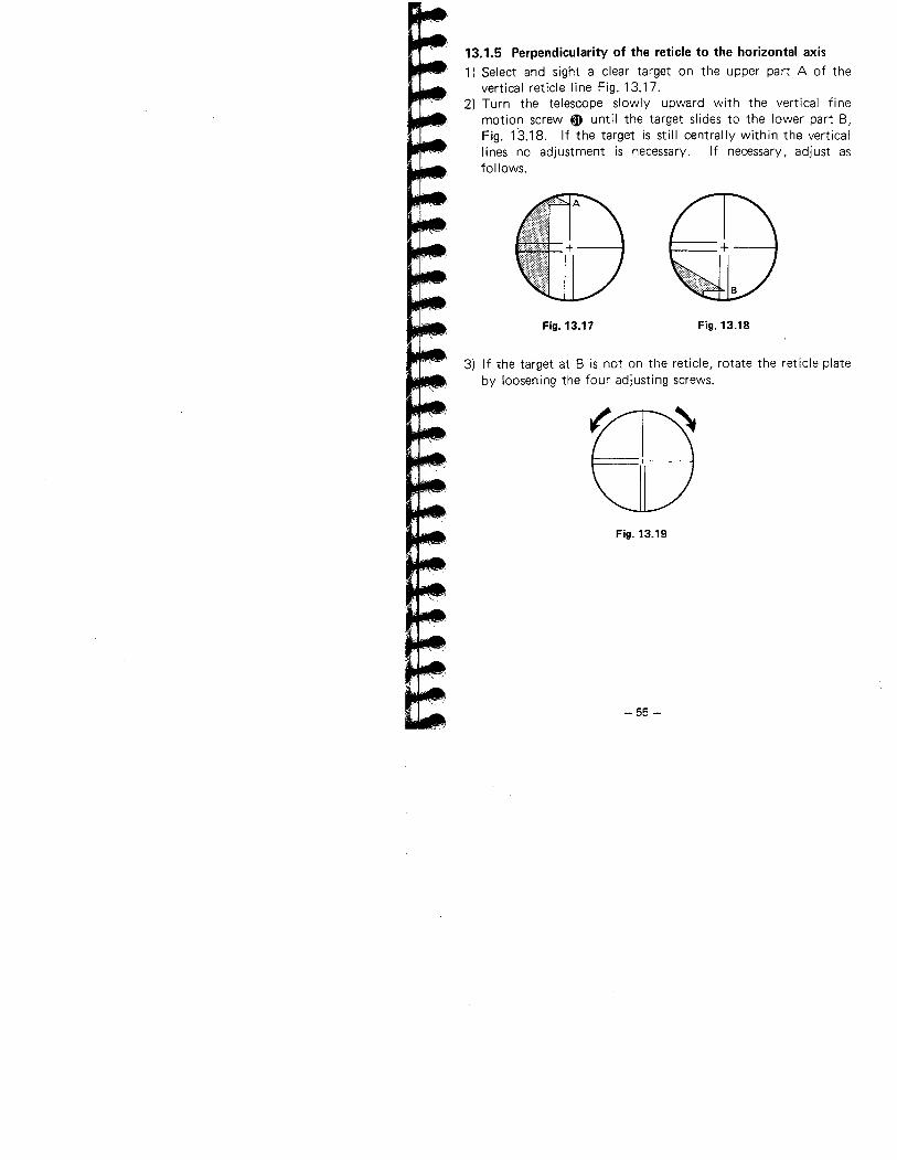
13.1.5 Perpendicularity of the reticle to the horizontal axis1) Select and sight a clear target on the upper part A of the
vertical reticle line Fig. 13.17.2) Turn the telescope slowly upward with the vertical fine
motion screw ~ until the target slides to the lower part B,Fig. 13.18. If the target is still centrally within the verticallines no adjustment is necessary. If necessary, adjust asfollows.
Fig. 13.17 Fig. 13.18
3) If the target at B is not on the reticle, rotate the reticle plateby loosening the four adjusting screws.
Fig. 13.19
-55 -
13.1.6 Coincidence of the distance measuring axis with thereticle
After the reticle has been checked, check the distance measuringaxis relative to the reticle as follows.
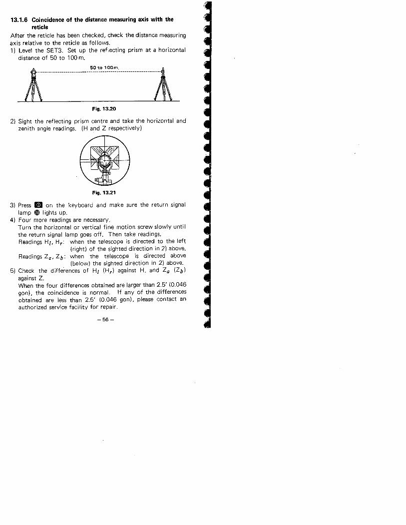
1) Level the SET3. Set up the reflecting prism at a horizontaldistance of 50 to 100 m.
J\ '0" 'OOm. l
- - ----- ----- --------------------------------- ------ -- -
Fig. 13.20
2) Sight the reflecting prism centre and take the horizontal and
zenith angle readings. (H and Z respectively)
Fig. 13.21
3) Press II on the keyboard and make sure the return signallamp ~ lights up.
4) Four more readings are necessary.Turn the horizontal or vertical fine motion screw slowly untilthe return signal lamp goes off. Then take readings.
Readings HZ, Hr: when the telescope is directed to the left(right) of the sighted direction in 2) above.
Readings Za, Zb: when the telescope is directed above
(below) the sighted direction in 2) above.
5) Check the differences of Hz (Hr) against H, and Za (Zb)against Z.
When the four differences obtained are larger than 2.5' (0.046gonl. the coincidence is normaL. If any of the differencesobtained are less than 2.5' (0.046 gon), please contact an
authorized service facility for repair.
-56-
~~ ,i" ..
...
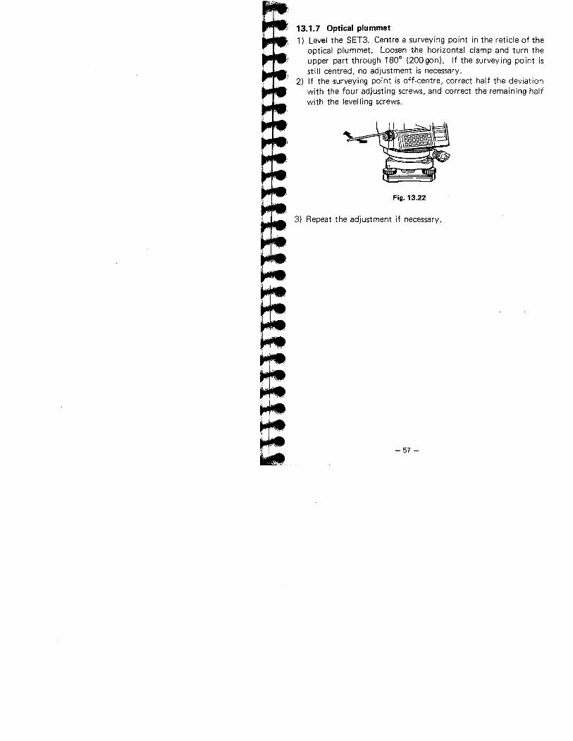
13.1.7 Optical plummet1) Level the SET3. Centre a surveying point in the reticle of the
optical plummet. Loosen the horizontal clamp and turn theupper part through 1800 (200gon). If the surveying point isstill centred, no adjustment is necessary.
2) If the surveying point is off-centre, correct half the deviationwith the four adjusting screws, and correct the remaining half
with the levelling screws.
Fig. 13.22
3) Repeat the adjustment if necessary.
-57 -
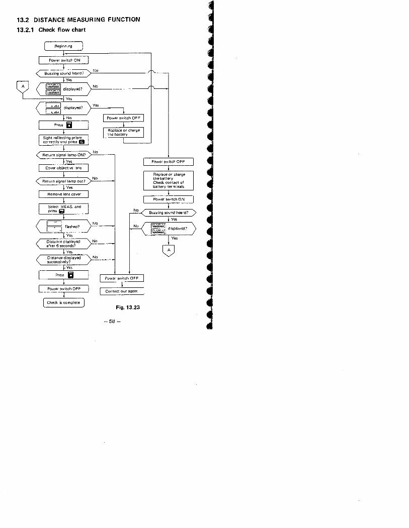
13.2 DISTANCE MEASURING FUNCTION
13.2.1 Check flow chart
Beginning
Power switch ON
No
No
Ye,
Distance displayedsuccessively?
. Yes
Press Ii
I
No
Power SVitch OF F
Power switch OFFContact our agent
Check is completeFig. 13.23
-58 -
Power switch ON
No
No
8
l-..~..LJ.. ...~=~t:..
13.2.2 Additive distance constant
The additive distance constant of the SET3 is adjusted to 0
before delivery. However, the additive constant can change withtime and so should be determined periodically and then used tocorrect distances measured.1) Determining the additive distance constant.
The most reliable method of determining the additive distanceconstant is to test the SET3 on an established base line with
a maximum range of approximately 1,000 m, and with 6 to 8intermediate stations spaced at multiples of the instrumentunit length, which is 10m. Measurements should be taken inall combinations of the 6 to 8 stations.If an additive distance constant of greater than 5 mm is foundplease contact our agent.
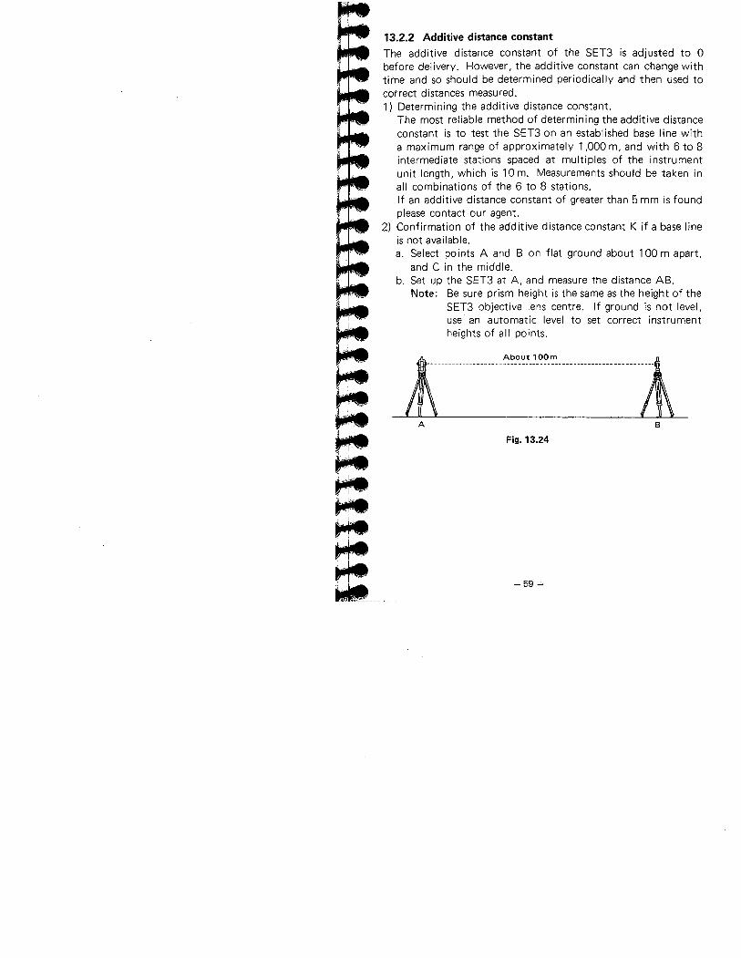
2) Confirmation of the additive distance constant K if a base lineis not available.a. Select points A and B on flat ground about 100 m apart,
and C in the middle.b. Set up the SET3 at A, and measure the distance AB.
Note: Be sure prism height is the same as the height of theSET3 objective lens centre. If ground is not level,use an automatic level to set correct instrumentheights of all points.
l AOo""OOm Â\
..mm.m..............u m....mn.........m
A B
Fig. 13.24
- 59-'
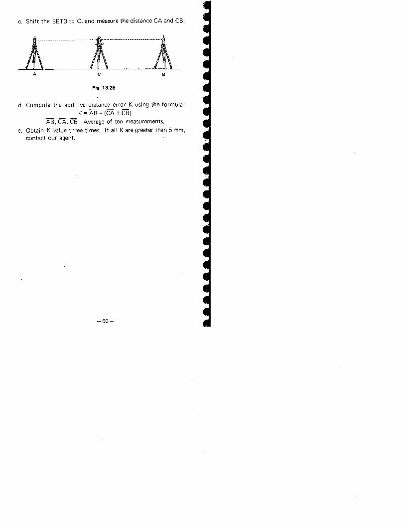
c. Shift the SET3 to C, and measure the distance CA and CB.
lnmnnnninnnnmnnnnlA c B
Fig. 13.25
d. Compute the additive distance error K using the formula:K = AS - (CA + CB)
AB, CA, CB: Average of ten measurements.e. Obtain K value three times. If all K are greater than 5 mm,
contact our agent.
-60-
~.
~~LJ-~
1 ""L.II"-,._~,- ___' .
14. FOR ANGLE MEASUREMENT OF THEHIGHEST ACCURACY
14.1 lEVELLING BY REFERRING TO THE DISPLAY
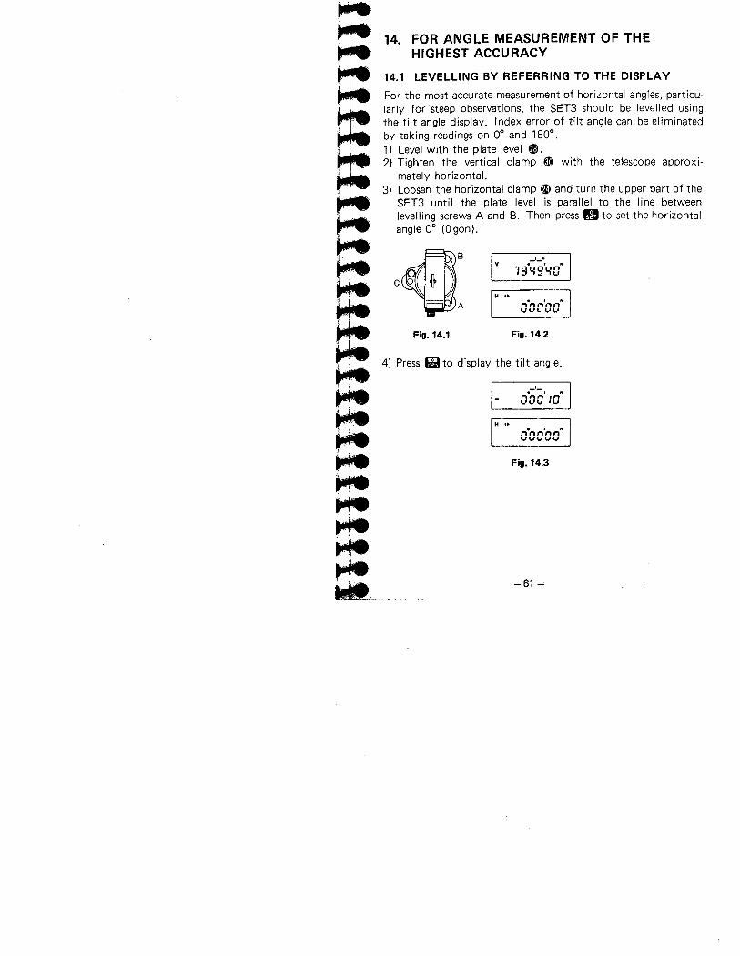
For the most accurate measurement of horizontal angles, particu-larly for 'steep observations, the SET3 should be levelled usingthe tilt angle display. Index error of tilt angle can be eliminatedby taking readings on 0° and 180°.1) Level with the plate level fI.
2) Tighten the vertical clamp ~ with the telescope approxi-
mately horizontaL.3) Loosen the horizontal clamp ai and turn the upper part of the
SET3 until the plate level is parallel to the line betweenlevelling screws A and B. Then press g to set the horizontalangle 0° (Ogon).
c~: vI +
19.~9'L/O"
H ..n-nn'nn"uvt.1t.'..'
Fig. 14.1 Fig. 14.2
4) Press fg to display the tilt angle.
i
n.;:~' in"VVV'V
H ..n-nn'nn"vvvvv
Fig. 14.3
-61 ~
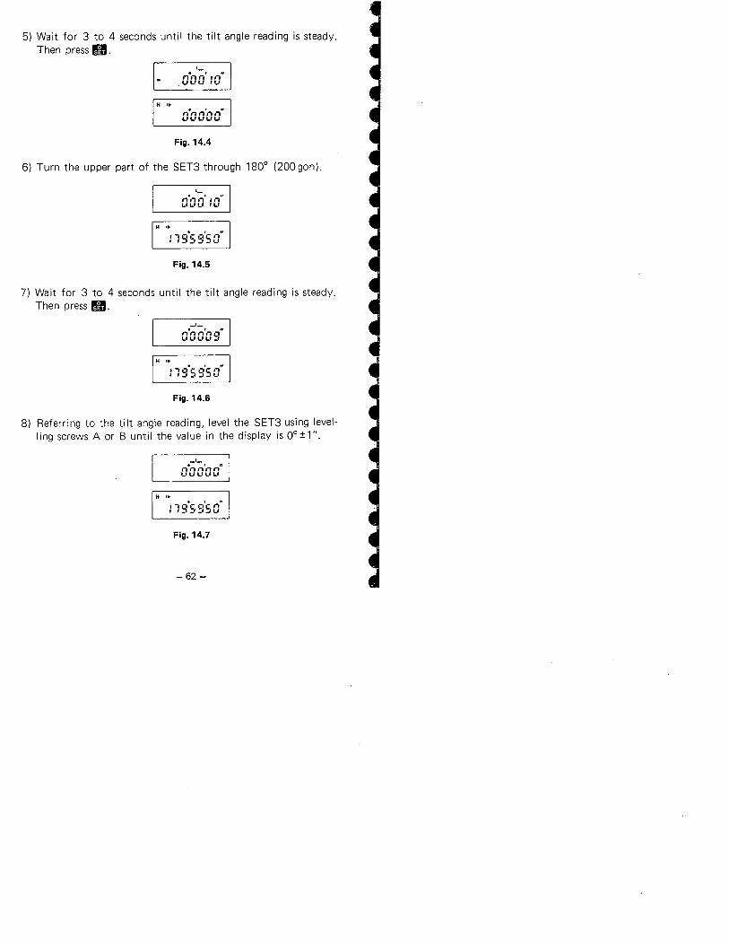
5) Wait for 3 to 4 seconds until the tilt angle reading is steady.Then press g.
'-nert,.' .n".uuu iu
H .,nenn'nn"uuuuu
Fig. 14.4
6) Turn the upper part of the SET3 through 180° (200 gon).
'-. , "iii""'- ii"UUL"LI
H .,
: 19-5 9'50"
Fig. 14.5
7) Wait for 3 to 4 seconds until the tilt angle reading is steady.Then press g.
-'-O-GO'Og"
H .,:19-59'50"
Fig. 14.6
8) Referring to the tilt angle reading, level the SET3 using level-
ling screws A or B until the value in the display is O°:tl".
_1-n-" n'" n"L'UUUU
H ..
: 19'5 9'50"
Fig. 14.7
-62 -
=.
~
=.............~...........
.'
0/
~...........'.-...............'...
"
,.
, _L",
,"l-~.'...... \F-
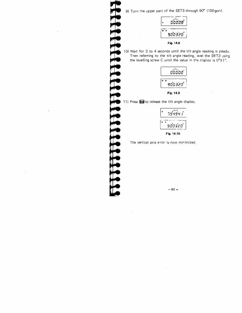
9) Turn the upper part of the SET3 through 90° (100 gon).
-'-o.oa'os"
H ..
90°03'20"
Fig. 14.8
10) Wait for 3 to 4 seconds until the tilt angle reading is steady.Then referring to the tilt angle reading, level the SET3 usingthe levelling screw C until the value in the display is OOf 1 n.
-'-n.nn'nn"'-,'-,'-,'-,'-,
H "
90-03'20"
Fig. 14.9
11) Press ~to release the tilt angle display.
v_1_+
1:t'-/9'Y:"
H .. o , "SOG3c'O
Fig. 14.10
The vertical axis error is now minimized.
-63 -
14.2 MANUALLY INDEXING VERTICAL CIRCLE BYV1, V2
Like every theodolite, the SET3 will have a vertical index error.A vertical index error can be estimated as follows.
1) Turn the power OFF, remove the internal switch cover 0 and
set switch 6 to ON.(When switch 6 is ON, the automatic indexing of the verticalcircle by transitting the telescope is inactive.)
2) After levelling the SET3, turn the power ON and make surethat the display appears as shown below.
3600 400 gon
I V
_1_+
I V
_1_+
H .. 'H ... , " nn,''-";,,-. n iii'i_"_,,..,,-'U ..'.UL....U
Fig. 14.11
3) I n position Vl, accurately sight a clear target at a horizontaldistance of about 30 m. '
Fig. 14.12
4) Press g.
3600 400 gon
I vi v
_1_+ _1_+
èè
H .. H ..o , II2..:0 :30 26.6 9 ..p-:
Fig. 14.13
-64-~
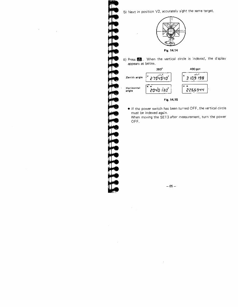
5) Next in position V2, accurately sight the same target.
Fig. 14.14
6) Press g. When the vertical circle is indexed, the displayappears as below.
3600 400 gonZenith angle
_1_+V 219.1.9'1-0"
_1_+v
3 :0.9 :98
Horizontalangle
H ..
20"10 :'30"H ..
226.691.1.
Fig. 14.15
. If the power switch has been turned OFF, the vertical circlemust be indexed again.When moving the SET3 after measurement, turn the powerOFF.
-65 -
15. FOR DISTANCE MEASUREMENT OF THEHIGHEST ACCURACY
15.1 ACCURACY OF MEASUREMENT OF ATMOSPHERICCONDITIONS
The relation between measured distance and the velocity of lightis given by
D =..C = i ~2 2 nT: The period between light emission and reception.C: The velocity of light in the air.
Co: The velocity of light in a vacuum.n: Refractive index of the air.
The measured distance is affected by variation in the refractiveindex dD dn. ( .
D=-~=:dn ordD=:D'dn)Therefore, the accuracy of measurement of the refractive indexmust be the same as that of the measured distance.
To calculate refractive index to an accuracy of 2 ppm, tempera-ture must be measured to within 1°C and pressure to within5 mmHg.
15.2 TO OBTAIN THE ATMOSPHERIC PRESSURE
To obtain the average refractive index of the air throughout themeasured I ight path, you shou Id use the average atmosphericpressure.If flat terrain there is little variation in the atmospheric pressure.In mountains, the following calculation should be used.
-66 - ~
~iw.. ...., ..~:=.~...~~....~
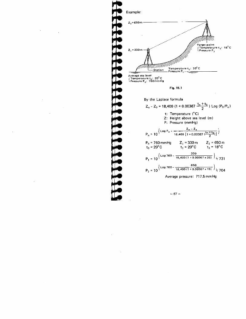
Example:
z,=650m
Z, =330m-
""......../'.."'....
......../......"'..
......../_////'/ 1S0C
/Station Temperature ti: 20° C
Pressure Pi
Average sea level °I Temperature to: 20 C1. Pressure Po: 760mmHg
Fig. 15.1
By the Laplace formula
Zn - Zo = 18,400 (1 +0.00367 tn ;to ) Log (po/Pn)
t: Temperature (0C)
Z: Height above sea level (m)P: Pressure (mmHg)
f zn - Zo Ll Log Po - fPn = 10 18,400 (1 +0.00367 (tn ;to))
Po = 760 mmHgto = 20°C
Z¡=330mti = 20°C
Z2 = 650 mt2 = lSoC
t 330Log 760 -Pi = 10 18,400(1 +0.00367x20)
\ 650Log 760-P2=10 18,400(1
+0.00367 x 19)
J =: 731
J =: 704
Average pressure: 717.5 mmHg
-67 ~
16. PRECAUTIONS AND MAINTENANCE
16.1 PRECAUTIONS
1) When the SET3 is not used for a long time, check it at leastonce every three months.
2) Handle the SET3 with care. Avoid heavy shocks or vibration.
3) If any trouble is found on the rotatable portion, screws or
optical parts (e.g. lens). contact our agent.
4) When removing the SET3 from the carrying case. never pullit out by force. The empty carrying case should then be
closed to exclude dust.
5) Never place the SET3 directly on the ground.
6) Never carry the SET3 on the tripod to another site.
7) Protect the SET3 with an umbrella against direct sunlight,rain and humidity.
8) When the operator leaves the SET3. the vinyl cover shouldbe placed on the instrument.
9) Do not aim the telescope at the sun.
10) Always switch the power off before removing the internalbattery.
11) Always remove the battery from the SET3 when returning itto the case.
12) Do not wipe the display 0, keyboard æ or the carryingcase with an organic solvent.
13) When the SET3 is placed in the carrying case, follow thelayout plan.
14) Make sure that the SET3 and the protective lining of thecarrying case are dry before closing the case.The case is hermetically sealed and if moisture is trappedinside, damage to the instrument could occur.
-68 -
16.2 MAINTENANCE
1) Wipe off moisture completely if the instrument gets wet
during survey work.
2) Always clean the instrument before returning it to the case.
The lens requires special care. Dust it off with the lens
brush first, to remove minute particles. Then, after pro-viding a little condensation by breathing on the lens,wipe it with soft clean cloth or lens tissue.
3) Store the SET3 in a dry room where the temperature remains
fairly constant.
4) If the battery is discharged excessively, its life may be
shortened. Store it in a charged state.
5) Check the tripod for loose fit and loose screws.
-69 -
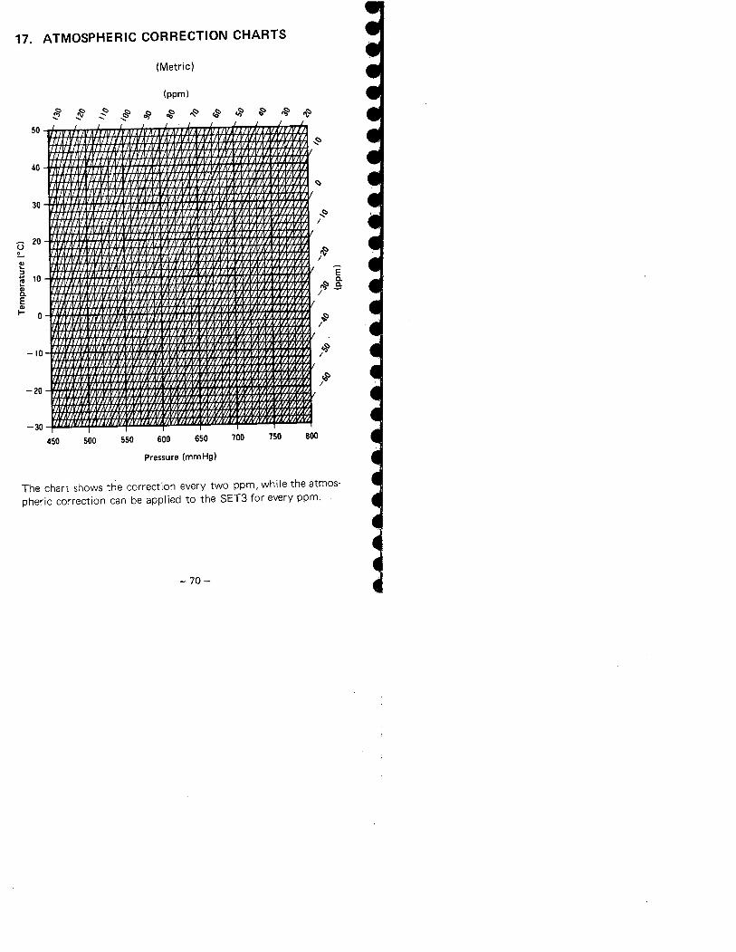
17. ATMOSPHERIC CORRECTION CHARTS
(Metric)
(ppm)R~~~~~~~~~~~50
~/
~
40
c:
30~/
Û 20~ l&/~B~ 10'"c.E'"I- 0
E
~~/
~/
-10 ../
-20
-30450 500 550 600 650 700 750 800
Pressure (mmHg)
The chart shows the correction every two ppm, while the atmos-
pheric correction can be applied to the SET3 for every ppm.
-70-
llI:=:.~....,..~...:.."......,' .,
r~' . ~
,~
..~ .~~5'
.'j, .r .
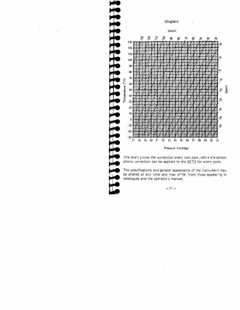
(English)
R§~~~~~&~~~(ppm)
130
120
110
100
90
80
70LL~ 50Ql:; 50..~Ql
40c.EQl
30i-
20
10
0
-10
-20
-3017 18 19 20 21 ~n~3ænæ~30~
Pressure (inchHg)
~
~Êc.'c.
-f
~
l;
~
The chart shows the correction every two ppm, while the atmos-
pheric correction can be appl ied to the SET3 for every ppm.
The specifications and general appearance of the instrument maybe altered at any time and may differ from those appearing incatalogues and the operator's manuaL.
-71 -
18. INDEX
Page
Accessories .................................. 9, 11 , 46
Angle measurement. . . . . . . . . . . . . . . . . . . . . . . . . . . . . . . . . 21Angle measurement modes . . . . . . . . . . . . . . . . . . . . . . . . . . . 22Atmospheric correction ............................. 27
Audio switch ..................................... 30
Batteries ......................................... 9
Circular level adjustment ............................ 50
Coordinate measurement ............................ 35
Curvature and refraction correction .. . . . . , . . . . . . . . . . . . . 29Display limit. . . . . . . . . . . . . . . . . . . . . . . . . . . . . . . . 24,36.39Display symbols ................................... 13
Distance measuring axis checking. . , . . . . . . . . . . . . . . . . . . . 56Distance measurement .............................. 32
Distance measurement checking. . . . . . . . . . . . . . . . . . . . . . . 59Distance measurement flow chart ..................... 58
Error codes . . . . . . . . . . . . . . . . . . . . . . . . . . . . . . . . . . . . . . . 44Features ......................................... 4
Focussing ......................................... 20
Horizontal distance between two points ................ 43
Indexing manually ................................. 64
I nstrument part names ... . . . . . . . . . . . . . . . . . . . . . . . . . .. 1Keyboard functions ........... _ . . . . . . . . . . . . . . . . . . . . 14Levelling with the display. . . . _ _ . . . . . . . . .... . . . . . . . . . . .61Maintenance .......,....,......................... 69
Optical plummet adjustment ......................... 57
Parallax . . . . . . . . . . . . . . . . . . . . . . . . . . . . . . . . . . . . . . . . . . 21Parts per million. . . . . . . . . . . . . . .. . . _ . . . . . . . . . . . . . . . .27Plate level adjustment. . . . . . . . . . . . . . . . . . . . . _ . . . . . . . . . 48Power supplies. .,.................................. 9
Powering up the SET3 ... . . . . _ . . . . . . . . . . . . . . . . . . . . . . 18Precautions . . . . . . . . . . . . . . . . . . . . . . . . . . . . . . . . . . . . . . . 68Prism constant ........................,........... 26
Recalling data. . . . . . . . . . . . . . . . . . . . . . . . . . . . . . . . . . . . . 34Remote elevation measurement ....................... 41
-72-
Page
Repetition of angle. . . . _ . . . . . . . . , . . . . . . . . . . . . . . . . . . . 24Reticle adjustment ............... . . . . . . . . . . . . . . . . . . 52Right and left angles. . . . . . . . . . . . . . . . . . . . . . . . . . . . . . . . 22Setting up over a point. . . . . . . , . . . . . . . . . , . . . . . . . . . . . . 20Specifications ........... - . . . . . . . , .. . . . . . . . . . . . . . .. 5Stake-out measurement. . . . . . . . . . . . . . . . . . . . . . . . . . . . . . 37Standard equipment .. . . . . . . . . . . . . . . . . . . . . . . . . . . . . " 8Switches, internal ........................,......... 17
Tilt angle sensor adjustment. . . . . . . . . . . . . . . . . , . . . . . . . . 50Tracking mode .............,....................,. 31
Zenith angle compensation. . . . . . . . . . . . . . . . . . . . . . . . . .. 19
-73-

MEMO..........................................................................................................................................
..........................................................................................................................................
..........................................................................................................................................
..........................................................................................................................................
..........................................................................................................................................
..........................................................................................................................................
..........................................................................................................................................
..........................................................................................................................................
...........................................................................................................................................
..........................................................................................................................................
..........................................................................................................................................
..........................................................................................................................................
..........................................................................................................................................
..........................................................................................................................................
..........................................................................................................................................
..........................................................................................................................................
..........................................................................................................................................
..........................................................................................................................................
..........................................................................................................................................
..........................................................................................................................................


![Electron cross section set for CHF[sub 3]](https://img.dokumen.tips/doc/110x75/635603b05108319c87031945/electron-cross-section-set-for-chfsub-3.jpg)


