Embed Size (px)
Citation preview
SERVICE MANUALAIR-CONDITIONER (MULTI TYPE)
<SUPER MODULAR MULTI SYSTEM - e>
Outdoor Unit
Model name:
FILE NO. SVM-15067-2
<Heat Pump Model>MMY-MAP0806HT8(J)P-MEMMY-MAP1006HT8(J)P-MEMMY-MAP1206HT8(J)P-MEMMY-MAP1406HT8(J)P-MEMMY-MAP1606HT8(J)P-MEMMY-MAP1806HT8(J)P-MEMMY-MAP2006HT8(J)P-ME
MMY-MAP0806HT8(J)PMMY-MAP1006HT8(J)PMMY-MAP1206HT8(J)PMMY-MAP1406HT8(J)PMMY-MAP1606HT8(J)PMMY-MAP1806HT8(J)PMMY-MAP2006HT8(J)PMMY-MAP2206HT8(J)P
MMY-MAP0806HT7(J)PMMY-MAP1006HT7(J)PMMY-MAP1206HT7(J)PMMY-MAP1406HT7(J)PMMY-MAP1606HT7(J)PMMY-MAP1806HT7(J)PMMY-MAP2006HT7(J)PMMY-MAP2206HT7(J)P
MMY-MAP0806HT7P-MEMMY-MAP1006HT7P-MEMMY-MAP1206HT7P-MEMMY-MAP1406HT7P-MEMMY-MAP1606HT7P-MEMMY-MAP1806HT7P-MEMMY-MAP2006HT7P-ME
MMY-MAP0806HT8(J)P-EMMY-MAP1006HT8(J)P-EMMY-MAP1206HT8(J)P-EMMY-MAP1406HT8(J)P-EMMY-MAP1606HT8(J)P-EMMY-MAP1806HT8(J)P-EMMY-MAP2006HT8(J)P-EMMY-MAP2206HT8(J)P-E
MMY-MAP0806HT8(J)P-TRMMY-MAP1006HT8(J)P-TRMMY-MAP1206HT8(J)P-TRMMY-MAP1406HT8(J)P-TRMMY-MAP1606HT8(J)P-TRMMY-MAP1806HT8(J)P-TRMMY-MAP2006HT8(J)P-TRMMY-MAP2206HT8(J)P-TR
MMY-MAP0806HT8P-AMMY-MAP1006HT8P-AMMY-MAP1206HT8P-AMMY-MAP1406HT8P-AMMY-MAP1606HT8P-AMMY-MAP1806HT8P-AMMY-MAP2006HT8P-A
<Cooling Only Model>MMY-MAP0806T8(J)P-E MMY-MAP1006T8(J)P-E MMY-MAP1206T8(J)P-E MMY-MAP1406T8(J)P-E MMY-MAP1606T8(J)P-E MMY-MAP1806T8(J)P-E MMY-MAP2006T8(J)P-E MMY-MAP2206T8(J)P-E
MMY-MAP0806T8(J)P MMY-MAP1006T8(J)P MMY-MAP1206T8(J)P MMY-MAP14B6T8(J)P MMY-MAP1406T8(J)P MMY-MAP1606T8(J)P MMY-MAP18B6T8(J)P MMY-MAP1806T8(J)P MMY-MAP2006T8(J)P MMY-MAP2206T8(J)P
MMY-MAP0806T7(J)P MMY-MAP1006T7(J)P MMY-MAP1206T7(J)P MMY-MAP14B6T7(J)P MMY-MAP1406T7(J)P MMY-MAP1606T7(J)P MMY-MAP18B6T7(J)P MMY-MAP1806T7(J)P MMY-MAP2006T7(J)P MMY-MAP2206T7(J)P
MMY-MAP0806T8P-SG MMY-MAP1006T8P-SG MMY-MAP1206T8P-SG MMY-MAP14B6T8P-SG MMY-MAP1406T8P-SG MMY-MAP1606T8P-SG MMY-MAP18B6T8P-SG MMY-MAP1806T8P-SG MMY-MAP2006T8P-SG MMY-MAP2206T8P-SG
MMY-MAP0806T8(J)P-ID MMY-MAP1006T8(J)P-ID MMY-MAP1206T8(J)P-ID MMY-MAP14B6T8(J)P-ID MMY-MAP1406T8(J)P-ID MMY-MAP1606T8(J)P-ID MMY-MAP18B6T8(J)P-ID MMY-MAP1806T8(J)P-ID MMY-MAP2006T8(J)P-ID MMY-MAP2206T8(J)P-ID
MMY-MAP0806T8(J)P-T MMY-MAP1006T8(J)P-T MMY-MAP1206T8(J)P-T MMY-MAP14B6T8(J)P-T MMY-MAP1406T8(J)P-T MMY-MAP1606T8(J)P-T MMY-MAP18B6T8(J)P-T MMY-MAP1806T8(J)P-T MMY-MAP2006T8(J)P-T MMY-MAP2206T8(J)P-T
ContentsSAFETY CAUTION . . . . . . . . . . . . . . . . . . . . . . . . . . . . . . . . . . . . . . . . . . . . . . . . . . . . 5
Refrigerant (R410A) . . . . . . . . . . . . . . . . . . . . . . . . . . . . . . . . . . . . . . . . . . . . . . . . . . 241 Wiring Diagrams . . . . . . . . . . . . . . . . . . . . . . . . . . . . . . . . . . . . . . . . . . . . . . . . . . . . . 26
1-1. Outdoor Unit . . . . . . . . . . . . . . . . . . . . . . . . . . . . . . . . . . . . . . . . . . . . . . . . . . . . . . . . . . . . . . . . . 26
2 Parts Rating . . . . . . . . . . . . . . . . . . . . . . . . . . . . . . . . . . . . . . . . . . . . . . . . . . . . . . . . . 352-1. Outdoor Unit (50Hz model: MMY-MAP***6*T8*P*) . . . . . . . . . . . . . . . . . . . . . . . . . . . . . . . . . . 352-2. Outdoor Unit (60Hz model: MMY-MAP***6HT7*P) . . . . . . . . . . . . . . . . . . . . . . . . . . . . . . . . . . 362-3. Outdoor Inverter (50/60Hz model: MMY-MAP***6*T8/7*P*) . . . . . . . . . . . . . . . . . . . . . . . . . . . 372-4. Parts Layout in Outdoor Unit . . . . . . . . . . . . . . . . . . . . . . . . . . . . . . . . . . . . . . . . . . . . . . . . . . . . 382-5. Parts Layout in Inverter Assembly . . . . . . . . . . . . . . . . . . . . . . . . . . . . . . . . . . . . . . . . . . . . . . . . 412-6. Outdoor (Inverter) Print Circuit Board . . . . . . . . . . . . . . . . . . . . . . . . . . . . . . . . . . . . . . . . . . . . . 44
2-6-1. Interface P.C. board (MCC-1673) . . . . . . . . . . . . . . . . . . . . . . . . . . . . . . . . . . . . . . . . . . 442-6-2. Inverter P.C. board for compressor (MCC-1660) A3-IPDU . . . . . . . . . . . . . . . . . . . . . . . 452-6-3. Inverter P.C. board for compressor (MCC-1669) A3-IPDU. . . . . . . . . . . . . . . . . . . . . . . 46
3 Refrigerant Piping Systematic Drawing . . . . . . . . . . . . . . . . . . . . . . . . . . . . . . . . . . 494 Combined Refrigerant Piping System Schematic Diagrams . . . . . . . . . . . . . . . . . 60
4-1. Normal Operation (COOL Mode / DEFROST Mode) -
High Outside Air Temperature (Roughly 20°C or Above) . . . . . . . . . . . . . . . . . . . . . . . . . . . . . . 604-2. Normal Operation (COOL Mode) - Low Outside Air Temperature (Roughly Below 20°C). . . . . . 614-3. Normal Operation (HEAT Mode) . . . . . . . . . . . . . . . . . . . . . . . . . . . . . . . . . . . . . . . . . . . . . . . . . 62
4-5. Emergency Operation (Cooling Operation under Header Outdoor Unit Backup Scenario) . . . . . 644-6. Emergency Operation (Heating Operation under Header Outdoor Unit Backup Scenario) . . . . . 654-7. Refrigerant Recovery from Failed Outdoor Unit (Pump-Down Operation under
Follower Outdoor Unit Backup Scenario) . . . . . . . . . . . . . . . . . . . . . . . . . . . . . . . . . . . . . . . . . . . 66
5 Control Outline . . . . . . . . . . . . . . . . . . . . . . . . . . . . . . . . . . . . . . . . . . . . . . . . . . . . . . 67
6 Applied Control and Functions . . . . . . . . . . . . . . . . . . . . . . . . . . . . .. . . . . . .. . . . . . . . 766-1. Applied Control for Indoor Unit . . . . . . . . . . . . . . . . . . . . . . . . . . . . . . . . . . . . . . . . . . . . .. . . . . 76
2-6-4. Inverter P.C. board for fan motor (MCC-1659) FAN-IPDU . . . . . . . . . . . . . . . . . . . . . . . 472-6-5. Noise Filer PC board (MCC-1608 -A, -B) . . . . . . . . . . . . . . . . . . . . . . . . . . . . . . . . . . . . 48
4-4. Normal Operation (HOT GAS DEFROST Mode) . . . . . . . . . . . . . . . . . . . . . . . . . . . . . . . . . . . . 63
− 1 −
6-2. Applied control for Outdoor Unit . . . . . . . . . . . . . . . . . . . . . . . . . . . . . . . . . . . . . . . . . . . . . . . . . 916-2-1. Outdoor Fan High Static Pressure Shift . . . . . . . . . . . . . . . . . . . . . . . . . . . . . . . . . . . . . 916-2-2. Priority Operation Mode Setting . . . . . . . . . . . . . . . . . . . . . . . . . . . . . . . . .. . . . . . . . . . . 94
6-1-1. Control Specifications . . . . . . . . . . . . . . . . . . . . . . . . . . . . . . . . . . . . . . . . . . . . . . . . . . . . 766-1-2. Optional Connector Specifications of Indoor P.C. Board . . . . . . . . . . . . . . . . . . .. . . . . . . 826-1-3. Test Operation of Indoor Unit . . . . . . . . . . . . . . . . . . . . . . . . . . . . . . . . . . . . . . . . . . . . . . 836-1-4. Method to Set Indoor Unit Function DN Code . . . . . . . . . . . . . . . . . . . . . . . . . . . . . . . . . 846-1-5. Applied Control of Indoor Unit . . . . . . . . . . . . . . . . . . . . . . . . . . . . . . . . . . . . . . . . . . . . . . 88
6-2-3. Applied Control of Outdoor Unit . . . . . . . . . . . . . . . . . . . . . . . . . . . . . . . . . . . . . . . . . . . 966-2-4. Power peak-cut Control (Standard) . . . . . . . . . . . . . . . . . . . . . . . . . . . . . . . . . . . . . . . . . 976-2-5. Power peak-cut Control (Extended) . . . . . . . . . . . . . . . . . . . . . . . . . . . . . . . . . . . . . . . . . 986-2-6. Snowfall Fan Control . . . . . . . . . . . . . . . . . . . . . . . . . . . . . . . . . . . . . . . . . . . . . . . . . . . . 99
7 TEST OPERATION . . . . . . . . . . . . . . . . . . . . . . . . . . . . . . . . . . . . . . . . . . . . . . . . . .1057-1. Procedure and Summary of Test Operation . . . . . . . . . . . . . . . . . . . . . . . . . . . . . . . . . . . . . . 1057-2. Check Items before Test Operation (before powering-on) . . . . . . . . . . . . . . . . . . . . . . . . . . . . 1067-3. Check at Main Power-on . . . . . . . . . . . . . . . . . . . . . . . . . . . . . . . . . . . . . . . . . . . . . . . . . . . . . 1107-4. Address Setup . . . . . . . . . . . . . . . . . . . . . . . . . . . . . . . . . . . . . . . . . . . . . . . . . . . . . . . . . . . . . 111
7-4-1. Precautions . . . . . . . . . . . . . . . . . . . . . . . . . . . . . . . . . . . . . . . . . . . . . . . . . . . . . . . . . 1117-4-2. Address Setup and Check Procedure . . . . . . . . . . . . . . . . . . . . . . . . . . . . . . . . . . . . . 1117-4-3. Address Setup Procedure . . . . . . . . . . . . . . . . . . . . . . . . . . . . . . . . . . . . . . . . . . . . . . 1127-4-4. Check after Address Setup when Central Control System Is Connected . . . . . . . . . . 125
7-5. Troubleshooting in Test Operation . . . . . . . . . . . . . . . . . . . . . . . . . . . . . . . . . . . . . . . . . . . . . . 1267-5-1. A Check Code is Displayed on the Remote Controller . . . . . . . . . . . . . . . . . . . . . . . . 1267-5-2. Operation from the indoor remote controller is not accepted, and a check code is
displayed on the 7-segment display of the interface PC board of the header unit. . . . 127 7-5-3. There is no display of a check code on the 7-segment display on the interface
PC board of the header unit, although there is indoor unit that is not accepting
operation from the indoor remote controller. . . . . . . . . . . . . . . . . . . . . . . . . . . . . . . . . 1277-5-4. In checking the number of connected outdoor units and connected indoor units
after address setup, a lower number of connected units is displayed. (There are
outdoor/indoor units that do not operate in a test operation.) . . . . . . . . . . . . . . . . . . . 1287-6. Test Operation Check . . . . . . . . . . . . . . . . . . . . . . . . . . . . . . . . . . . . . . . . . . . . . . . . . . . . .. . . 130
7-6-1. Fan Check . . . . . . . . . . . . . . . . . . . . . . . . . . . . . . . . . . . . . . . . . . . . . . . . . . . . . . . . . . 1307-6-2. Single cooling/Single heating Test Operation Check . . . . . . . . . . . . . . . . . . . . . . . . . . 131
7-7. Service Support Function . . . . . . . . . . . . . . . . . . . . . . . . . . . . . . . . . . . . . . . . . . . . . . . . . . . . . 1347-7-1. Check Function for Connecting of Refrigerant and Control Lines . . . . . . . . . . . . . . . . 1347-7-2. Function to Start/Stop (ON/OFF) Indoor Unit from Outdoor Unit . . . . . . . . . . . . . . . . . 1377-7-3. Check Code Clearing Function . . . . . . . . . . . . . . . . . . . . . . . . . . . . . . . . . . . . . . . . . . 1437-7-4. Remote Controller Distinction Function . . . . . . . . . . . . . . . . . . . . . . . . . . . . . . . . . . . . 1457-7-5. Pulse Motor Valve (PMV) Forced Open/Close Function in Indoor Unit . . . . . . . . . .. . 1467-7-6. Pulse Motor Valve (PMV) Forced Open Fully/Close fully Function in Outdoor Unit . . 1467-7-7. Solenoid Valve Forced Open/Close Function in Outdoor Unit . . . . . . . . . . . . . . . . . . . 1477-7-8. Fan Operation Check in Outdoor Unit . . . . . . . . . . . . . . . . . . . . . . . . . . . . . . . . . . . . . 1487-7-9. Abnormal Outdoor Unit Discrimination Method By Fan Operating Function . . . . . . . . 1497-7-10. Manual Adjustment Function of Outside Temperature (TO) Sensor . . . . . . . . . . . . . . 1507-7-11. Monitor Function of Remote Controller Switch . . . . . . . . . . . . . . . . . . . . . . . . . . . . . . 152
7-8. SMMS WAVE TOOL FOR SMARTPHONE. . . . . . . . . . . . . . . . . . . . . . . . . . . . . . . . . . . . . . . 1547-8-1. Prohibition/Permission of the NFC Setting . . . . . . . . . . . . . . . . . . . . . . . . . . . . . . . .. . 1547-8-2. Confirmation for the generation of the error of the NFC. . . . . . . . . . . . . . . . . . . . . . . . . . 155
7-9. DRED (Demand response enabling device) . . . . . . . . . . . . . . . . . . . . . . . . . . . . . . . . . . . . . . 156
− 2 −
6-2-7. External master ON/OFF Control . . . . . . . . . . . . . . . . . . . . . . . . . . . . . . . . . . . . . . . . . . . . .996-2-8. Night operation (sound reduction) Control . . . . . . . . . . . . . . . . . . . . . . . . . . . . . . . . . . . . .. .1006-2-9. Operation Mode Selection Control . . . . . . . . . . . . . . . . . . . . . . . . . . . . . . . . . . . . . . . . . . . . 1016-2-10. Error/Operation Output . . . . . . . . . . . . . . . . . . . . . . . . . . . . . . . . . . . . . . . . . . . . . . . . . . ..1026-2-11. Compressor Operation Output . . . . . . . . . . . . . . . . . . . . . . . . . . . . . . . . . . . . . . . . . . . . . . . 1036-2-12. Operating Rate Output . . . . . . . . . . . . . . . . . . . . . . . . . . . . . . . . . . . . . . . . . . . . . . . . . . . . .104
8 TROUBLESHOOTING . . . . . . . . . . . . . . . . . . . . . . . . . . . . . . . . . . . . . . . . . . . . . . . . 1588-1. Overview . . . . . . . . . . . . . . . . . . . . . . . . . . . . . . . . . . . . . . . . . . . . . . . . . . . . . . . . . . . . . . . . . . 1588-2. Troubleshooting Method . . . . . . . . . . . . . . . . . . . . . . . . . . . . . . . . . . . . . . . . . . . . . . . . . . . . . . 1598-3. Troubleshooting Based on Information Displayed on Remote Controller . . . . . . . . . . . . . . . . . 1658-4. Check Codes Displayed on Remote Controller and SMMS-e Outdoor Unit
(7-Segment Display on I/F Board) and Locations to Be Checked . . . . . . . . . . . . . . . . . . . . . . . 1708-5. Diagnosis procedure for each check code . . . . . . . . . . . . . . . . . . . . . . . . . . . . . . . . . . . . . . . . . 1868-6. 7-Segment Display Function . . . . . . . . . . . . . . . . . . . . . . . . . . . . . . . . . . . . . . . . . . . . . . . . . . . 2168-7. Oil Level Judgment Display . . . . . . . . . . . . . . . . . . . . . . . . . . . . . . . . . . . . . . . . . . . . . . . . . . . . 222
8-9. Leakage/Clogging of Refrigerating Cycle Circuit . . . . . . . . . . . . . . . . . . . . . . . . . . . . . . . . . . . . 2268-10. Sensor Characteristics . . . . . . . . . . . . . . . . . . . . . . . . . . . . . . . . . . . . . . . . . . . . . . . . . . . . . . . 2328-11. Pressure Sensor Output Check . . . . . . . . . . . . . . . . . . . . . . . . . . . . . . . . . . . . . . . . . . . . . . . . . 235
9 BACKUP OPERATION(EMERGENCY OPERATION) . . . . . . . . . . . . . . . . . . . . . . . . . . . . . . . . . . . . . . . . . . 237
9-1. Note for Backup Operation . . . . . . . . . . . . . . . . . . . . . . . . . . . . . . . . . . . . . . . . . . . . . . . . . . . . 2379-2. Compressor Backup Operation Setting . . . . . . . . . . . . . . . . . . . . . . . . . . . . . . . . . . . . . . . . . . . 2389-3. Outdoor Unit Backup Operation Setting . . . . . . . . . . . . . . . . . . . . . . . . . . . . . . . . . . . . . . . . . . . 241
9-3-1. Follower outdoor unit backup operation setting (failure of follower outdoor unit) . . . . . 2419-3-2. Header outdoor unit backup operation setting (failure of header outdoor unit) . . . . . . . 243
9-4. Cooling-Season Outdoor Unit Backup Operation Setting . . . . . . . . . . . . . . . . . . . . . . . . . . . . . 245
10 OUTDOOR UNIT REFRIGERANT RECOVERY METHOD . . . . . . . . . . . . . . . . . . . . 24610-1. Refrigerant Recovery from Failed Outdoor Unit (Pump-Down) . . . . . . . . . . . . . . . . . . . . . . . . . 246
10-1-1. Note for refrigerant recovery operation . . . . . . . . . . . . . . . . . . . . . . . . . . . . . . . . . . . . . 24610-1-2. Refrigerant recovery procedure A (Case of no outdoor unit backup operation setting) ..246 10-1-3. Refrigerant recovery procedure B (Case of outdoor unit backup operation setting) . .. . 249
10-2. How to Operate System While Failed Outdoor Unit Being Repaired . . . . . . . . . . . . . . . . . . . . . 25110-3. Work procedure after Repair . . . . . . . . . . . . . . . . . . . . . . . . . . . . . . . . . . . . . . . . . . . . . . . . . . . 252
11 REPLACING COMPRESSORS . . . . . . . . . . . . . . . . . . . . . . . . . . . . . . . . . . . . . . . . . 25311-1. Compressor Replacement Procedure (Outline) . . . . . . . . . . . . . . . . . . . . . . . . . . . . . . . . . . . . . 25311-2. Replacement of Compressors . . . . . . . . . . . . . . . . . . . . . . . . . . . . . . . . . . . . . . . . . . . . . . . . . . 25411-3. Check Procedure to Search Cause of Compressor Oil Shortage . . . . . . . . . . . . . . . . . . . . . . . 260
12 OUTDOOR UNIT PARTS REPLACEMENT METHODS . . . . . . . . . . . . . . . . . . . . . . 26413 P.C. BOARD EXCHANGE PROCEDURES . . . . . . . . . . . . . . . . . . . . . . . . . . . . . . . . 283
13-1. Replacement of Outdoor P.C. Boards . . . . . . . . . . . . . . . . . . . . . . . . . . . . . . . . . . . . . .. . . . . . 28313-1-1. List of service P.C. boards . . . . . . . . . . . . . . . . . . . . . . . . . . . . . . . . . . . . . . . . . . . . . . . 28313-1-2. Configuration of inverter assembly . . . . . . . . . . . . . . . . . . . . . . . . . . . . . . . . . . . . .. . . . 28313-1-3. Interface P.C. Board (MCC-1673) Replacement Procedure . . . . . . . . . . . . . . . . . . . . . 28513-1-4. Comp-IPDU P.C. Board (MCC-1669) Replacement Procedure . . . . . . . . . . . . . . . . . . 28713-1-5. Comp-IPDU P.C. Board (MCC-1669) Replacement Procedure . . . . . . . . . . . . . . . . . . 28913-1-6. Comp-IPDU P.C. Board (MCC-1660) Replacement Procedure . . . . . . . . . . . . . . . . . . 291
14 EXPLODED DIAGRAM/PARTS LIST . . . . . . . . . . . . . . . . . . . . . . . . . . . . . . . . . . . 301
13-1-7. Fan-IPDU P.C. Board (MCC-1659) Replacement Procedure . . . . . . . . . . . . . . . . . . . 29313-1-8. Noise Filter P.C. Board (MCC-1608A, B) Replacement Procedure . . . . . . . . . . . . . . 29513-1-9. Noise Filter P.C. Board (MCC-1608A, B) Replacement Procedure . . . . . . . . . . . . . . . 29713-1-10. Noise Filter P.C. Board (MCC-1608A, B) Replacement Procedure . . . . . . . . . . . . . 299
8-8. SMMS-e Outdoor Interface P.C. Board Function Setting Exchange Table. . . . . . . . . . . . . . . . 223
− 3 −
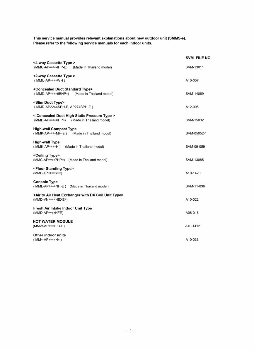
This service manual provides relevant explanations about new outdoor unit (SMMS-e).Please refer to the following service manuals for each indoor units.
SVM FILE NO.<4-way Cassette Type > (MMU-AP∗∗∗∗4HP-E) (Made in Thailand model) SVM-13011
<2-way Cassette Type > ( MMU-AP∗∗∗∗WH ) A10-007
<Concealed Duct Standard Type> ( MMD-AP∗∗∗∗6BHP∗) (Made in Thailand model) SVM-14069
<Slim Duct Type> ( MMD-AP2244SPH-E, AP274SPH-E ) A12-005
< Concealed Duct High Static Pressure Type > (MMD-AP∗∗∗∗6HP∗) (Made in Thailand model) SVM-15032
High-wall Compact Type ( MMK-AP∗∗∗∗MH-E ) (Made in Thailand model) SVM-05052-1
High-wall Type ( MMK-AP∗∗∗∗H ) (Made in Thailand model) SVM-09-059
<Ceiling Type>(MMC-AP∗∗∗∗7HP∗) (Made in Thailand model) SVM-13085
<Floor Standing Type>(MMF-AP∗∗∗∗6H∗) A10-1420
Console Type ( MML-AP∗∗∗∗NH-E ) (Made in Thailand model) SVM-11-036
<Air to Air Heat Exchanger with DX Coil Unit Type>(MMD-VN∗∗∗∗HEXE∗) A10-022
Fresh Air Intake Indoor Unit Type(MMD-AP∗∗∗∗HFE) A06-016
Other indoor units ( MM∗-AP∗∗∗∗H∗ ) A10-033
HOT WATER MODULE(MMW-AP∗∗∗∗LQ-E) A10-1412
− 4 −
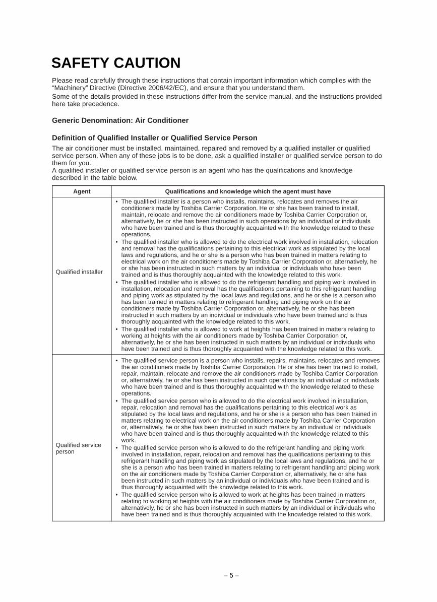
SAFETY CAUTIONPlease read carefully through these instructions that contain important information which complies with the“Machinery” Directive (Directive 2006/42/EC), and ensure that you understand them.Some of the details provided in these instructions differ from the service manual, and the instructions providedhere take precedence.
Generic Denomination: Air Conditioner
Definition of Qualified Installer or Qualified Service PersonThe air conditioner must be installed, maintained, repaired and removed by a qualified installer or qualifiedservice person. When any of these jobs is to be done, ask a qualified installer or qualified service person to dothem for you.A qualified installer or qualified service person is an agent who has the qualifications and knowledgedescribed in the table below.
• The qualified service person is a person who installs, repairs, maintains, relocates and removesthe air conditioners made by Toshiba Carrier Corporation. He or she has been trained to install,repair, maintain, relocate and remove the air conditioners made by Toshiba Carrier Corporationor, alternatively, he or she has been instructed in such operations by an individual or individualswho have been trained and is thus thoroughly acquainted with the knowledge related to theseoperations.
• The qualified service person who is allowed to do the electrical work involved in installation,repair, relocation and removal has the qualifications pertaining to this electrical work asstipulated by the local laws and regulations, and he or she is a person who has been trained inmatters relating to electrical work on the air conditioners made by Toshiba Carrier Corporationor, alternatively, he or she has been instructed in such matters by an individual or individualswho have been trained and is thus thoroughly acquainted with the knowledge related to thiswork.
• The qualified service person who is allowed to do the refrigerant handling and piping workinvolved in installation, repair, relocation and removal has the qualifications pertaining to thisrefrigerant handling and piping work as stipulated by the local laws and regulations, and he orshe is a person who has been trained in matters relating to refrigerant handling and piping workon the air conditioners made by Toshiba Carrier Corporation or, alternatively, he or she hasbeen instructed in such matters by an individual or individuals who have been trained and isthus thoroughly acquainted with the knowledge related to this work.
• The qualified service person who is allowed to work at heights has been trained in mattersrelating to working at heights with the air conditioners made by Toshiba Carrier Corporation or,alternatively, he or she has been instructed in such matters by an individual or individuals whohave been trained and is thus thoroughly acquainted with the knowledge related to this work.
• The qualified installer is a person who installs, maintains, relocates and removes the airconditioners made by Toshiba Carrier Corporation. He or she has been trained to install,maintain, relocate and remove the air conditioners made by Toshiba Carrier Corporation or,alternatively, he or she has been instructed in such operations by an individual or individualswho have been trained and is thus thoroughly acquainted with the knowledge related to theseoperations.
• The qualified installer who is allowed to do the electrical work involved in installation, relocationand removal has the qualifications pertaining to this electrical work as stipulated by the locallaws and regulations, and he or she is a person who has been trained in matters relating toelectrical work on the air conditioners made by Toshiba Carrier Corporation or, alternatively, heor she has been instructed in such matters by an individual or individuals who have beentrained and is thus thoroughly acquainted with the knowledge related to this work.
• The qualified installer who is allowed to do the refrigerant handling and piping work involved ininstallation, relocation and removal has the qualifications pertaining to this refrigerant handlingand piping work as stipulated by the local laws and regulations, and he or she is a person whohas been trained in matters relating to refrigerant handling and piping work on the airconditioners made by Toshiba Carrier Corporation or, alternatively, he or she has beeninstructed in such matters by an individual or individuals who have been trained and is thusthoroughly acquainted with the knowledge related to this work.
• The qualified installer who is allowed to work at heights has been trained in matters relating toworking at heights with the air conditioners made by Toshiba Carrier Corporation or,alternatively, he or she has been instructed in such matters by an individual or individuals whohave been trained and is thus thoroughly acquainted with the knowledge related to this work.
Qualified installer
Qualified serviceperson
Agent Qualifications and knowledge which the agent must have
− 5 −
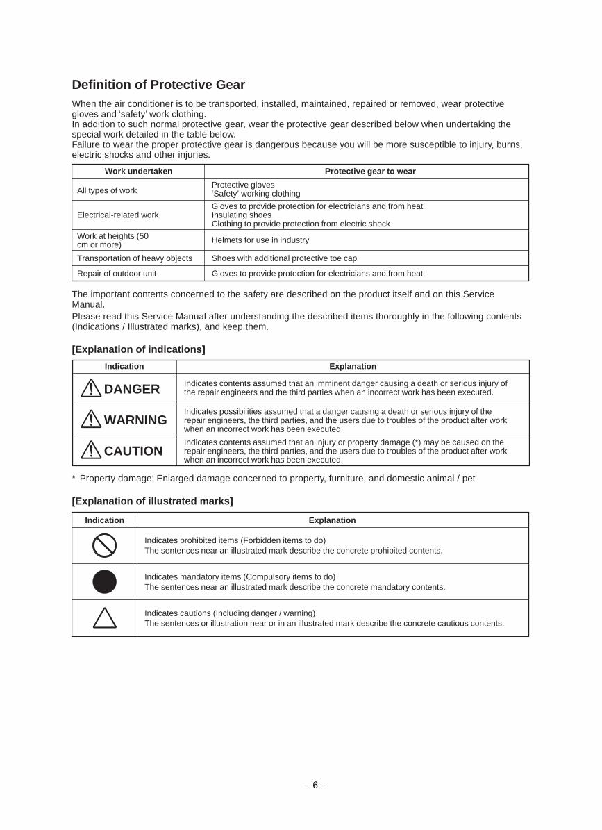
Definition of Protective GearWhen the air conditioner is to be transported, installed, maintained, repaired or removed, wear protectivegloves and ‘safety’ work clothing.In addition to such normal protective gear, wear the protective gear described below when undertaking thespecial work detailed in the table below.Failure to wear the proper protective gear is dangerous because you will be more susceptible to injury, burns,electric shocks and other injuries.
Work undertaken
All types of workProtective gloves‘Safety’ working clothing
Gloves to provide protection for electricians and from heatInsulating shoesClothing to provide protection from electric shock
Helmets for use in industry
Shoes with additional protective toe cap
Gloves to provide protection for electricians and from heat
Electrical-related work
Work at heights (50 cm or more)
Transportation of heavy objects
Repair of outdoor unit
Protective gear to wear
noitanalpxEnoitacidnI
DANGER Indicates contents assumed that an imminent danger causing a death or serious injury ofthe repair engineers and the third parties when an incorrect work has been executed.
Indicates possibilities assumed that a danger causing a death or serious injury of therepair engineers, the third parties, and the users due to troubles of the product after workwhen an incorrect work has been executed.
Indicates contents assumed that an injury or property damage (*) may be caused on therepair engineers, the third parties, and the users due to troubles of the product after workwhen an incorrect work has been executed.
WARNING
CAUTION
noitanalpxEnoitacidnI
Indicates prohibited items (Forbidden items to do)The sentences near an illustrated mark describe the concrete prohibited contents.
Indicates mandatory items (Compulsory items to do)The sentences near an illustrated mark describe the concrete mandatory contents.
Indicates cautions (Including danger / warning)The sentences or illustration near or in an illustrated mark describe the concrete cautious contents.
The important contents concerned to the safety are described on the product itself and on this ServiceManual.Please read this Service Manual after understanding the described items thoroughly in the following contents(Indications / Illustrated marks), and keep them.
[Explanation of indications]
* Property damage: Enlarged damage concerned to property, furniture, and domestic animal / pet
[Explanation of illustrated marks]
− 6 −
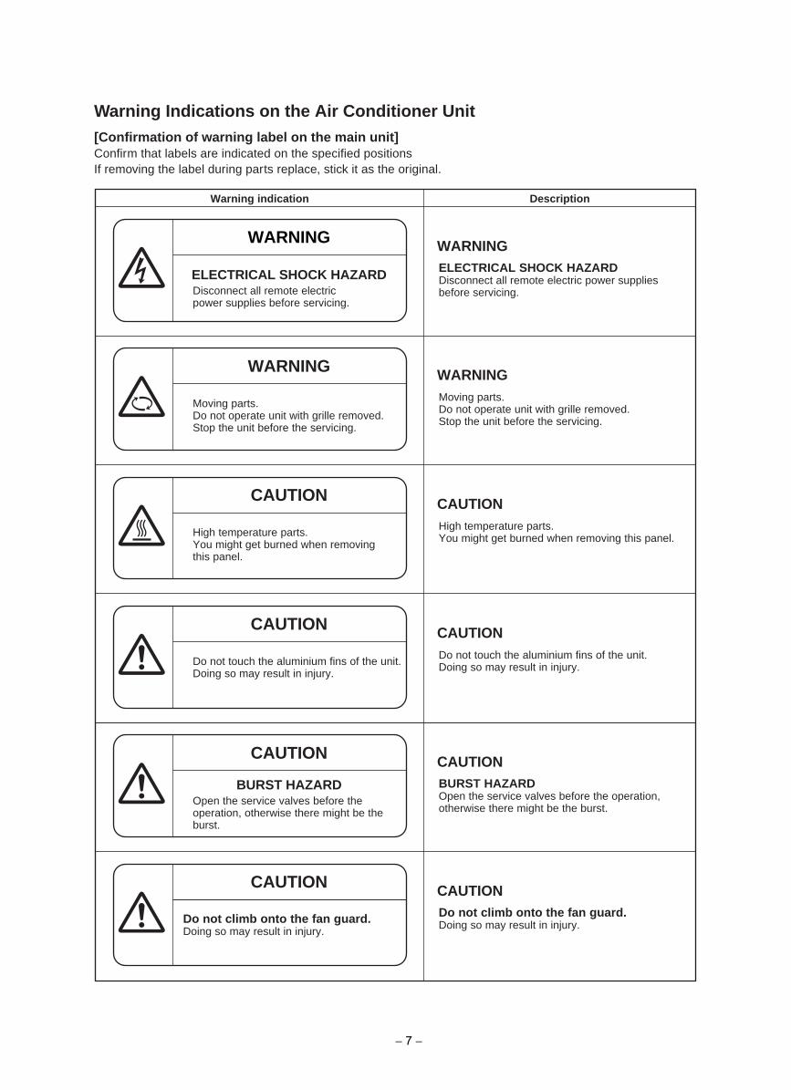
Warning Indications on the Air Conditioner Unit[Confirmation of warning label on the main unit]Confirm that labels are indicated on the specified positionsIf removing the label during parts replace, stick it as the original.
noitpircseDnoitacidni gninraW
WARNING WARNING
ELECTRICAL SHOCK HAZARDDisconnect all remote electricpower supplies before servicing.
BURST HAZARDOpen the service valves before theoperation, otherwise there might be theburst.
ELECTRICAL SHOCK HAZARDDisconnect all remote electric power suppliesbefore servicing.
WARNING WARNING
Moving parts.Do not operate unit with grille removed.Stop the unit before the servicing.
Moving parts.Do not operate unit with grille removed.Stop the unit before the servicing.
CAUTION CAUTION
High temperature parts.You might get burned when removingthis panel.
High temperature parts.You might get burned when removing this panel.
CAUTION CAUTION
Do not touch the aluminium fins of the unit.Doing so may result in injury.
Do not climb onto the fan guard.Doing so may result in injury.
Do not touch the aluminium fins of the unit.Doing so may result in injury.
CAUTION CAUTIONBURST HAZARDOpen the service valves before the operation,otherwise there might be the burst.
CAUTION CAUTIONDo not climb onto the fan guard.Doing so may result in injury.
− 7 −
PRECAUTIONS FOR SAFETYThe manufacturer shall not assume any liability for the damage caused by not observing the description of thismanual.
DANGER
Turn offbreaker
Electricshock hazard
Prohibition
If, in the course of carrying out repairs, it becomes absolutely necessary to check out the electricalparts with the electrical parts box cover of one or more of the indoor units and the service panel of theoutdoor unit removed in order to find out exactly where the trouble lies, wear insulated heat-resistantgloves, insulated boots and insulated work overalls, and take care to avoid touching any live parts.You may receive an electric shock if you fail to heed this warning. Only qualified service person (*1) isallowed to do this kind of work.
Stay onprotection
Before carrying out the installation, maintenance, repair or removal work, be sure to set the circuitbreaker for both the indoor and outdoor units to the OFF position. Otherwise, electric shocks mayresult.
Before opening the intake grille of the indoor unit or service panel of the outdoor unit, set the circuitbreaker to the OFF position.Failure to set the circuit breaker to the OFF position may result in electric shocks through contact withthe interior parts.Only a qualified installer (*1) or qualified service person (*1) is allowed to remove the intake grille of theindoor unit or service panel of the outdoor unit and do the work required.
Before starting to repair the outdoor unit fan or fan guard, be absolutely sure to set the circuit breakerto the OFF position, and place a “Work in progress” sign on the circuit breaker.
When cleaning the filter or other parts of the indoor unit, set the circuit breaker to OFF without fail, andplace a “Work in progress” sign near the circuit breaker before proceeding with the work.
When you have noticed that some kind of trouble (such as when an error display has appeared, thereis a smell of burning, abnormal sounds are heard, the air conditioner fails to cool or heat or water isleaking) has occurred in the air conditioner, do not touch the air conditioner yourself but set the circuitbreaker to the OFF position, and contact a qualified service person. Take steps to ensure that thepower will not be turned on (by marking “out of service” near the circuit breaker, for instance) untilqualified service person arrives. Continuing to use the air conditioner in the trouble status may causemechanical problems to escalate or result in electric shocks or other failure.
When you access inside of the service panel to repair electric parts, wait for about five minutes after turningoff the breaker. Do not start repairing immediately.Otherwise you may get electric shock by touchingterminals of high-voltage capacitors. Natural discharge of the capacitor takes about five minutes.
Place a “Work in progress” sign near the circuit breaker while the installation, maintenance, repair orremoval work is being carried out.There is a danger of electric shocks if the circuit breaker is set to ON by mistake.
Before operating the air conditioner after having completed the work, check that the electrical parts boxcover of the indoor unit and service panel of the outdoor unit are closed, and set the circuit breaker tothe ON position.You may receive an electric shock if the power is turned on without first conducting these checks.
− 8 −
WARNING
General
Before starting to repair the air conditioner, read carefully through the Service Manual, and repair theair conditioner by following its instructions.
Only qualified service person (*1) is allowed to repair the air conditioner.Repair of the air conditioner by unqualified person may give rise to a fire, electric shocks, injury, waterleaks and / or other problems.
Do not use any refrigerant different from the one specified for complement or replacement.Otherwise, abnormally high pressure may be generated in the refrigeration cycle, which may result in afailure or explosion of the product or an injury to your body.
Wear protective gloves and safety work clothing during installation, servicing and removal.
Only a qualified installer (*1) or qualified service person (*1) is allowed to carry out the electrical workof the air conditioner.Under no circumstances must this work be done by an unqualified individual since failure to carry outthe work properly may result in electric shocks and / or electrical leaks.
When transporting the air conditioner, wear shoes with protective toe caps, protective gloves and otherprotective clothing.
When connecting the electrical wires, repairing the electrical parts or undertaking other electrical jobs,wear gloves to provide protection for electricians and from heat, insulating shoes and clothing toprovide protection from electric shocks.Failure to wear this protective gear may result in electric shocks.
Electrical wiring work shall be conducted according to law and regulation in the community andinstallation manual. Failure to do so may result in electrocution or short circuit.
Only a qualified installer (*1) or qualified service person (*1) is allowed to undertake work at heightsusing a stand of 50 cm or more or to remove the intake grille of the indoor unit to undertake work.
When working at heights, use a ladder which complies with the ISO 14122 standard, and follow theprocedure in the ladder’s instructions.Also wear a helmet for use in industry as protective gear to undertake the work.
When working at heights, put a sign in place so that no-one will approach the work location, beforeproceeding with the work.Parts and other objects may fall from above, possibly injuring a person below.
When executing address setting, test run, or troubleshooting through the checking window on theelectric parts box, put on insulated gloves to provide protection from electric shock. Otherwise you mayreceive an electric shock.
Do not touch the aluminum fin of the outdoor unit.You may injure yourself if you do so. If the fin must be touched for some reason, first put on protectivegloves and safety work clothing, and then proceed.
Do not climb onto or place objects on top of the outdoor unit.You may fall or the objects may fall off of the outdoor unit and result in injury.
When transporting the air conditioner, wear shoes with additional protective toe caps.
When transporting the air conditioner, do not take hold of the bands around the packing carton.You may injure yourself if the bands should break.
Be sure that a heavy unit (10 kg or heavier) such as a compressor is carried by two persons.
This air conditioner has passed the pressure test as specified in IEC 60335-2-40 Annex EE.
Before troubleshooting or repair work, check the earth wire is connected to the earth terminals of the main unit,otherwise an electric shock is caused when a leak occurs. If the earth wire is not correctly connected,contact an electric engineer for rework.
After completing the repair or relocation work, check that the ground wires are connected properly.
Be sure to connect earth wire. (Grounding work) Incomplete grounding causes an electric shock.Do not connect ground wires to gas pipes, water pipes, and lightning rods or ground wires fortelephone wires.
Check earthwires.
Prohibition ofmodification.
Do not modify the products. Do not also disassemble or modify the parts.It may cause a fire, electric shock or injury.
Use specifiedparts.
When any of the electrical parts are to be replaced, ensure that the replacement parts satisfy thespecifications given in the Service Manual (or use the parts contained on the parts list in theService Manual).Use of any parts which do not satisfy the required specifications may give rise to electric shocks,smoking and / or a fire.
− 9 −
Do not bringa child close
to theequipment.
Insulatingmeasures
No fire
Refrigerant
If, in the course of carrying out repairs, it becomes absolutely necessary to check out the electricalparts with the electrical parts box cover of one or more of the indoor units and the service panel of theoutdoor unit removed in order to find out exactly where the trouble lies, put a sign in place so that no-one will approach the work location before proceeding with the work. Third-party individuals may enterthe work site and receive electric shocks if this warning is not heeded.
Connect the cut-off lead wires with crimp contact, etc., put the closed end side upward and then applya watercut method, otherwise a leak or production of fire is caused at the users’ side.
When performing repairs using a gas burner, replace the refrigerant with nitrogen gas because the oilthat coats the pipes may otherwise burn.When repairing the refrigerating cycle, take the following measures.1) Be attentive to fire around the cycle. When using a gas stove, etc., be sure to put out fire before work;
otherwise the oil mixed with refrigerant gas may catch fire.2) Do not use a welder in the closed room. When using it without ventilation, carbon monoxide
poisoning may be caused.3) Do not bring inflammables close to the refrigerant cycle, otherwise fire of the welder may catch the
inflammables.
The refrigerant used by this air conditioner is the R410A.
Check the used refrigerant name and use tools and materials of the parts which match with it.For the products which use R410A refrigerant, the refrigerant name is indicated at a position on theoutdoor unit where is easy to see. To prevent miss-charging, the route of the service port is changedfrom one of the former R22.
For an air conditioner which uses R410A, never use other refrigerant than R410A. For an airconditioner which uses other refrigerant (R22, etc.), never use R410A.If different types of refrigerant are mixed, abnormal high pressure generates in the refrigerating cycleand an injury due to breakage may be caused.
When the air conditioner has been installed or relocated, follow the instructions in the InstallationManual and purge the air completely so that no gases other than the refrigerant will be mixed in therefrigerating cycle.Failure to purge the air completely may cause the air conditioner to malfunction.
Do not charge refrigerant additionally. If charging refrigerant additionally when refrigerant gas leaks, therefrigerant composition in the refrigerating cycle changes resulted in change of air conditionercharacteristics or refrigerant over the specified standard amount is charged and an abnormal highpressure is applied to the inside of the refrigerating cycle resulted in cause of breakage or injury.Therefore if the refrigerant gas leaks, recover the refrigerant in the air conditioner, execute vacuuming,and then newly recharge the specified amount of liquid refrigerant.In this time, never charge the refrigerant over the specified amount.
When recharging the refrigerant in the refrigerating cycle, do not mix the refrigerant or air other thanR410A into the specified refrigerant. If air or others is mixed with the refrigerant, abnormal highpressure generates in the refrigerating cycle resulted in cause of injury due to breakage.
Install the refrigerant pipe securely during the installation work before operating the air conditioner. If the compressor is operated with the valve open and without refrigerant pipe, the compressor sucks air and the refrigeration cycles is over pressurized, which may cause injury.
After the installation work, confirm that refrigerant gas does not leak. If refrigerant gas leaks into the room and flows near a fire source, such as a cooking range, noxious gas may be generated.
Never recover the refrigerant into the outdoor unit. When the equipment is moved or repaired, be sureto recover the refrigerant with recovering device.The refrigerant cannot be recovered in the outdoor unit; otherwise a serious accident such as breakageor injury is caused.
Assembly /Wiring
After repair work, surely assemble the disassembled parts, and connect and lead the removed wires as before.Perform the work so that the cabinet or panel does not catch the inner wires.If incorrect assembly or incorrect wire connection was done, a disaster such as a leak or fire is causedat user’s side.
Insulatorcheck
After the work has finished, be sure to use an insulation tester set (500 V Megger) to check the resistance is1 MΩ or more between the charge section and the non-charge metal section (Earth position).If the resistance value is low, a disaster such as a leak or electric shock is caused at user’s side.
− 10 −
Ventilation
When the refrigerant gas leaks during work, execute ventilation.If the refrigerant gas touches to a fire, poisonous gas generates. A case of leakage of the refrigerantand the closed room full with gas is dangerous because a shortage of oxygen occurs. Be sure toexecute ventilation.
Compulsion
When the refrigerant gas leaks, find up the leaked position and repair it surely.If the leaked position cannot be found up and the repair work is interrupted, pump-down and tighten theservice valve, otherwise the refrigerant gas may leak into the room.The poisonous gas generates when gas touches to fire such as fan heater, stove or cocking stove thoughthe refrigerant gas itself is innocuous.When installing equipment which includes a large amount of charged refrigerant such as a multi airconditioner in a sub-room, it is necessary that the density does not the limit even if the refrigerant leaks.If the refrigerant leaks and exceeds the limit density, an accident of shortage of oxygen is caused.
Tighten the flare nut with a torque wrench in the specified manner.Excessive tighten of the flare nut may cause a crack in the flare nut after a long period, which mayresult in refrigerant leakage.
Nitrogen gas must be used for the airtight test.
The charge hose must be connected in such a way that it is not slack.
For the installation / moving / reinstallation work, follow to the Installation Manual.If an incorrect installation is done, a trouble of the refrigerating cycle, water leak, electric shock or fire is caused.
Check afterrepair
Once the repair work has been completed, check for refrigerant leaks, and check the insulationresistance and water drainage.Then perform a trial run to check that the air conditioner is running properly.
After repair work has finished, check there is no trouble. If check is not executed, a fire, electric shockor injury may be caused. For a check, turn off the power breaker.
After repair work (installation of front panel and cabinet) has finished, execute a test run to check thereis no generation of smoke or abnormal sound.If check is not executed, a fire or an electric shock is caused. Before test run, install the front panel and cabinet.
Be sure to fix the screws back which have been removed for installation or other purposes.
Do notoperate theunit with thevalve closed.
Check the following matters before a test run after repairing piping.• Connect the pipes surely and there is no leak of refrigerant.• The valve is opened.Running the compressor under condition that the valve closes causes an abnormal high pressureresulted in damage of the parts of the compressor and etc. and moreover if there is leak of refrigerantat connecting section of pipes, the air is sucked and causes further abnormal high pressure resulted inburst or injury.
Only a qualified installer (*1) or qualified service person (*1) is allowed to relocate the air conditioner. Itis dangerous for the air conditioner to be relocated by an unqualified individual since a fire, electricshocks, injury, water leakage, noise and / or vibration may result.
Check the following items after reinstallation.1) The earth wire is correctly connected.2) The power cord is not caught in the product.3) There is no inclination or unsteadiness and the installation is stable.If check is not executed, a fire, an electric shock or an injury is caused.
When carrying out the pump-down work shut down the compressor before disconnecting the refrigerant pipe. Disconnecting the refrigerant pipe with the service valve left open and the compressor still operating will cause air or other gas to be sucked in, raising the pressure inside the refrigeration cycle to an abnormally high level, and possibly resulting in rupture, injury or other trouble.
Check afterreinstallation
When the service panel of the outdoor unit is to be opened in order for the compressor or the areaaround this part to be repaired immediately after the air conditioner has been shut down, set the circuitbreaker to the OFF position, and then wait at least 10 minutes before opening the service panel.If you fail to heed this warning, you will run the risk of burning yourself because the compressor pipesand other parts will be very hot to the touch. In addition, before proceeding with the repair work, wearthe kind of insulated heat-resistant gloves designed to protect electricians.
Take care not to get burned by compressor pipes or other parts when checking the cooling cycle whilerunning the unit as they get heated while running. Be sure to put on gloves providing protection forelectric shock and heat.
When the service panel of the outdoor unit is to be opened in order for the fan motor, reactor, inverter or theareas around these parts to be repaired immediately after the air conditioner has been shut down, set thecircuit breaker to the OFF position, and then wait at least 10 minutes before opening the service panel.If you fail to heed this warning, you will run the risk of burning yourself because the fan motor, reactor,inverter heat sink and other parts will be very hot to the touch.In addition, before proceeding with the repair work, wear the kind of insulated heat-resistant glovesdesigned to protect electricians.
Cooling check
− 11 −
Installation
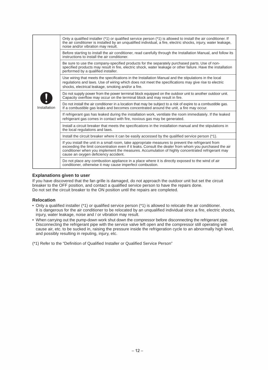
Only a qualified installer (*1) or qualified service person (*1) is allowed to install the air conditioner. Ifthe air conditioner is installed by an unqualified individual, a fire, electric shocks, injury, water leakage,noise and/or vibration may result.
Before starting to install the air conditioner, read carefully through the Installation Manual, and follow itsinstructions to install the air conditioner.
Be sure to use the company-specified products for the separately purchased parts. Use of non-specified products may result in fire, electric shock, water leakage or other failure. Have the installationperformed by a qualified installer.
Do not supply power from the power terminal block equipped on the outdoor unit to another outdoor unit.Capacity overflow may occur on the terminal block and may result in fire.
Use wiring that meets the specifications in the Installation Manual and the stipulations in the local regulations and laws. Use of wiring which does not meet the specifications may give rise to electric shocks, electrical leakage, smoking and/or a fire.
Do not install the air conditioner in a location that may be subject to a risk of expire to a combustible gas.If a combustible gas leaks and becomes concentrated around the unit, a fire may occur.
If refrigerant gas has leaked during the installation work, ventilate the room immediately. If the leaked refrigerant gas comes in contact with fire, noxious gas may be generated.
Install a circuit breaker that meets the specifications in the installation manual and the stipulations inthe local regulations and laws.
Install the circuit breaker where it can be easily accessed by the qualified service person (*1).
If you install the unit in a small room, take appropriate measures to prevent the refrigerant fromexceeding the limit concentration even if it leaks. Consult the dealer from whom you purchased the airconditioner when you implement the measures. Accumulation of highly concentrated refrigerant maycause an oxygen deficiency accident.
Do not place any combustion appliance in a place where it is directly exposed to the wind of airconditioner, otherwise it may cause imperfect combustion.
Explanations given to userIf you have discovered that the fan grille is damaged, do not approach the outdoor unit but set the circuitbreaker to the OFF position, and contact a qualified service person to have the repairs done.Do not set the circuit breaker to the ON position until the repairs are completed.
Relocation• Only a qualified installer (*1) or qualified service person (*1) is allowed to relocate the air conditioner.
It is dangerous for the air conditioner to be relocated by an unqualified individual since a fire, electric shocks,injury, water leakage, noise and / or vibration may result.
• When carrying out the pump-down work shut down the compressor before disconnecting the refrigerant pipe.Disconnecting the refrigerant pipe with the service valve left open and the compressor still operating willcause air, etc. to be sucked in, raising the pressure inside the refrigeration cycle to an abnormally high level,and possibly resulting in reputing, injury, etc.
(*1) Refer to the “Definition of Qualified Installer or Qualified Service Person”
− 12 −
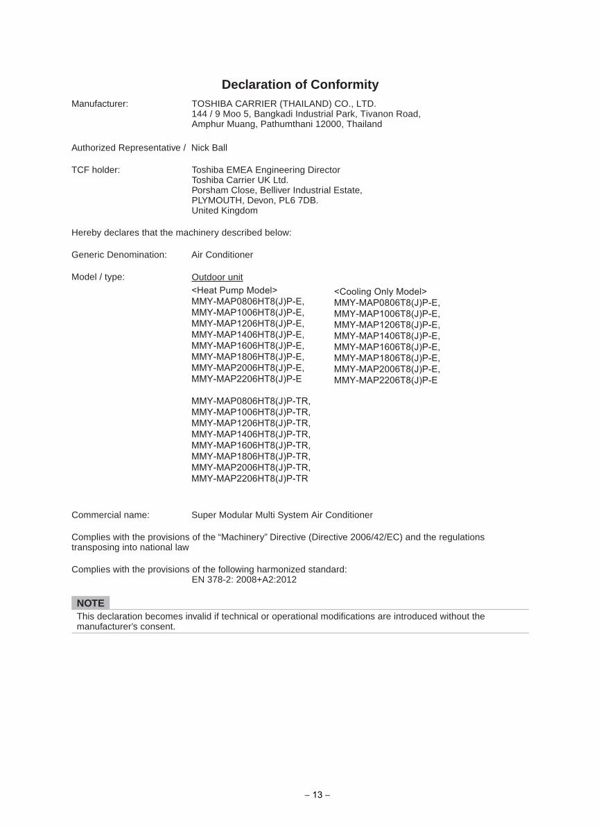
Declaration of ConformityManufacturer: TOSHIBA CARRIER (THAILAND) CO., LTD.
144 / 9 Moo 5, Bangkadi Industrial Park, Tivanon Road,Amphur Muang, Pathumthani 12000, Thailand
Outdoor unit<Heat Pump Model> MMY-MAP0806HT8(J)P-E, MMY-MAP1006HT8(J)P-E, MMY-MAP1206HT8(J)P-E, MMY-MAP1406HT8(J)P-E, MMY-MAP1606HT8(J)P-E, MMY-MAP1806HT8(J)P-E, MMY-MAP2006HT8(J)P-E, MMY-MAP2206HT8(J)P-E
MMY-MAP0806HT8(J)P-TR,MMY-MAP1006HT8(J)P-TR,MMY-MAP1206HT8(J)P-TR,MMY-MAP1406HT8(J)P-TR,MMY-MAP1606HT8(J)P-TR,MMY-MAP1806HT8(J)P-TR,MMY-MAP2006HT8(J)P-TR,MMY-MAP2206HT8(J)P-TR
Toshiba EMEA Engineering DirectorToshiba Carrier UK Ltd.Porsham Close, Belliver Industrial Estate,PLYMOUTH, Devon, PL6 7DB.United Kingdom
Authorized Representative / Nick Ball
TCF holder:
Hereby declares that the machinery described below:
Generic Denomination: Air Conditioner
Model / type:
Commercial name: Super Modular Multi System Air Conditioner
Complies with the provisions of the “Machinery” Directive (Directive 2006/42/EC) and the regulationstransposing into national law
Complies with the provisions of the following harmonized standard:EN 378-2: 2008+A2:2012
NOTEThis declaration becomes invalid if technical or operational modifications are introduced without themanufacturer’s consent.
<Cooling Only Model> MMY-MAP0806T8(J)P-E, MMY-MAP1006T8(J)P-E, MMY-MAP1206T8(J)P-E, MMY-MAP1406T8(J)P-E, MMY-MAP1606T8(J)P-E, MMY-MAP1806T8(J)P-E, MMY-MAP2006T8(J)P-E, MMY-MAP2206T8(J)P-E
− 13 −
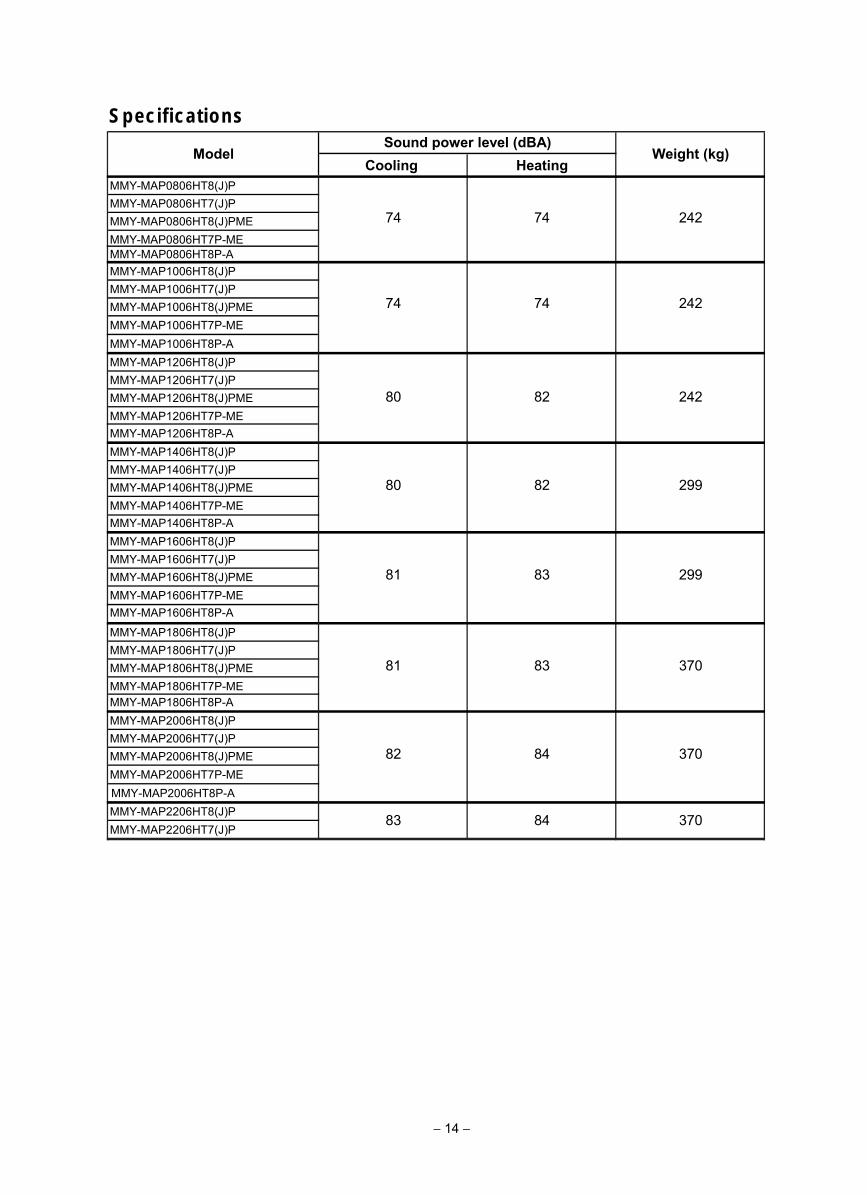
Specifications
Cooling HeatingMMY-MAP0806HT8(J)PMMY-MAP0806HT7(J)PMMY-MAP0806HT8(J)PMEMMY-MAP0806HT7P-ME
MMY-MAP1006HT8(J)PMMY-MAP1006HT7(J)PMMY-MAP1006HT8(J)PMEMMY-MAP1006HT7P-ME
MMY-MAP1206HT8(J)PMMY-MAP1206HT7(J)PMMY-MAP1206HT8(J)PMEMMY-MAP1206HT7P-ME
MMY-MAP1406HT8(J)PMMY-MAP1406HT7(J)PMMY-MAP1406HT8(J)PMEMMY-MAP1406HT7P-ME
MMY-MAP1606HT8(J)PMMY-MAP1606HT7(J)PMMY-MAP1606HT8(J)PMEMMY-MAP1606HT7P-ME
MMY-MAP1806HT8(J)PMMY-MAP1806HT7(J)PMMY-MAP1806HT8(J)PMEMMY-MAP1806HT7P-ME
MMY-MAP2006HT8(J)PMMY-MAP2006HT7(J)PMMY-MAP2006HT8(J)PMEMMY-MAP2006HT7P-ME
MMY-MAP2206HT8(J)PMMY-MAP2206HT7(J)P
370
370
370
299
299
242
8381
82 84
83 84
80 82
80 82
81 83
242
242
Sound power level (dBA)Weight (kg)Model
74 74
74 74
MMY-MAP0806HT8P-A
MMY-MAP1006HT8P-A
MMY-MAP1206HT8P-A
MMY-MAP1406HT8P-A
MMY-MAP1606HT8P-A
MMY-MAP1806HT8P-A
MMY-MAP2006HT8P-A
− 14 −
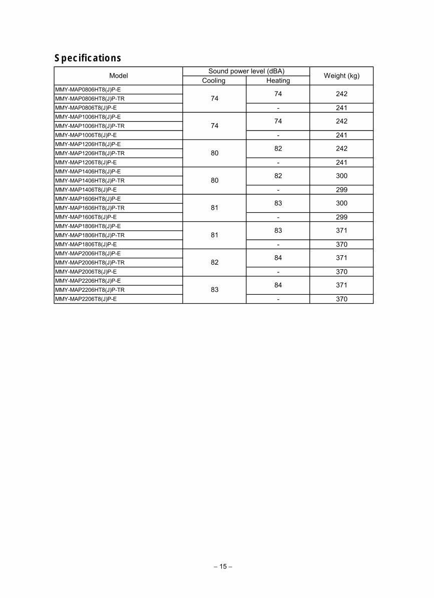
Specifications
Cooling HeatingMMY-MAP0806HT8(J)P-EMMY-MAP0806HT8(J)P-TRMMY-MAP0806T8(J)P-E - 241MMY-MAP1006HT8(J)P-EMMY-MAP1006HT8(J)P-TRMMY-MAP1006T8(J)P-E - 241MMY-MAP1206HT8(J)P-EMMY-MAP1206HT8(J)P-TRMMY-MAP1206T8(J)P-E - 241MMY-MAP1406HT8(J)P-EMMY-MAP1406HT8(J)P-TRMMY-MAP1406T8(J)P-E - 299MMY-MAP1606HT8(J)P-EMMY-MAP1606HT8(J)P-TRMMY-MAP1606T8(J)P-E - 299MMY-MAP1806HT8(J)P-EMMY-MAP1806HT8(J)P-TRMMY-MAP1806T8(J)P-E - 370MMY-MAP2006HT8(J)P-EMMY-MAP2006HT8(J)P-TRMMY-MAP2006T8(J)P-E - 370MMY-MAP2206HT8(J)P-EMMY-MAP2206HT8(J)P-TRMMY-MAP2206T8(J)P-E - 370
80
Model Sound power level (dBA) Weight (kg)
24274
300
24280
74 242
74
74
82
82
83
83
84
81
37183 84
371
37181
82
300
− 15 −
− 16 −
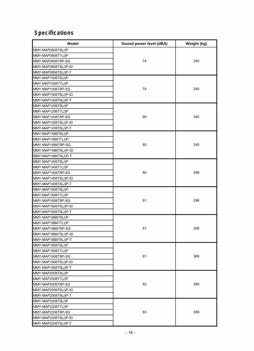
Specifications
Model Sound power level (dBA) Weight (kg)
MMY-MAP0806T8(J)PMMY-MAP0806T7(J)PMMY-MAP0806T8P-SGMMY-MAP0806T8(J)P-IDMMY-MAP0806T8(J)P-TMMY-MAP1006T8(J)PMMY-MAP1006T7(J)PMMY-MAP1006T8P-SGMMY-MAP1006T8(J)P-IDMMY-MAP1006T8(J)P-TMMY-MAP1206T8(J)PMMY-MAP1206T7(J)PMMY-MAP1206T8P-SGMMY-MAP1206T8(J)P-IDMMY-MAP1206T8(J)P-TMMY-MAP14B6T8(J)PMMY-MAP14B6T7(J)PMMY-MAP14B6T8P-SGMMY-MAP14B6T8(J)P-IDMMY-MAP14B6T8(J)P-TMMY-MAP1406T8(J)PMMY-MAP1406T7(J)PMMY-MAP1406T8P-SGMMY-MAP1406T8(J)P-IDMMY-MAP1406T8(J)P-TMMY-MAP1606T8(J)PMMY-MAP1606T7(J)PMMY-MAP1606T8P-SGMMY-MAP1606T8(J)P-IDMMY-MAP1606T8(J)P-TMMY-MAP18B6T8(J)PMMY-MAP18B6T7(J)PMMY-MAP18B6T8P-SGMMY-MAP18B6T8(J)P-IDMMY-MAP18B6T8(J)P-TMMY-MAP1806T8(J)PMMY-MAP1806T7(J)PMMY-MAP1806T8P-SGMMY-MAP1806T8(J)P-IDMMY-MAP1806T8(J)P-TMMY-MAP2006T8(J)PMMY-MAP2006T7(J)PMMY-MAP2006T8P-SGMMY-MAP2006T8(J)P-IDMMY-MAP2006T8(J)P-TMMY-MAP2206T8(J)PMMY-MAP2206T7(J)PMMY-MAP2206T8P-SGMMY-MAP2206T8(J)P-IDMMY-MAP2206T8(J)P-T
82
83 369
240
240
298
369
369
298
240
240
298
74
74
80
81
81
80
80
81
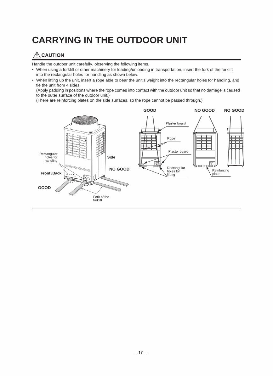
CARRYING IN THE OUTDOOR UNIT
CAUTION
Handle the outdoor unit carefully, observing the following items.• When using a forklift or other machinery for loading/unloading in transportation, insert the fork of the forklift
into the rectangular holes for handling as shown below.• When lifting up the unit, insert a rope able to bear the unit’s weight into the rectangular holes for handling, and
tie the unit from 4 sides.(Apply padding in positions where the rope comes into contact with the outdoor unit so that no damage is causedto the outer surface of the outdoor unit.)(There are reinforcing plates on the side surfaces, so the rope cannot be passed through.)
Front /Back
GOOD NO GOOD NO GOOD
Plaster board
Rope
Plaster board
Rectangular Reinforcing plate
Fork of the forklift
Rectangularholes forhandling
GOOD
NO GOOD
Side
holes for lifting
− 17 −
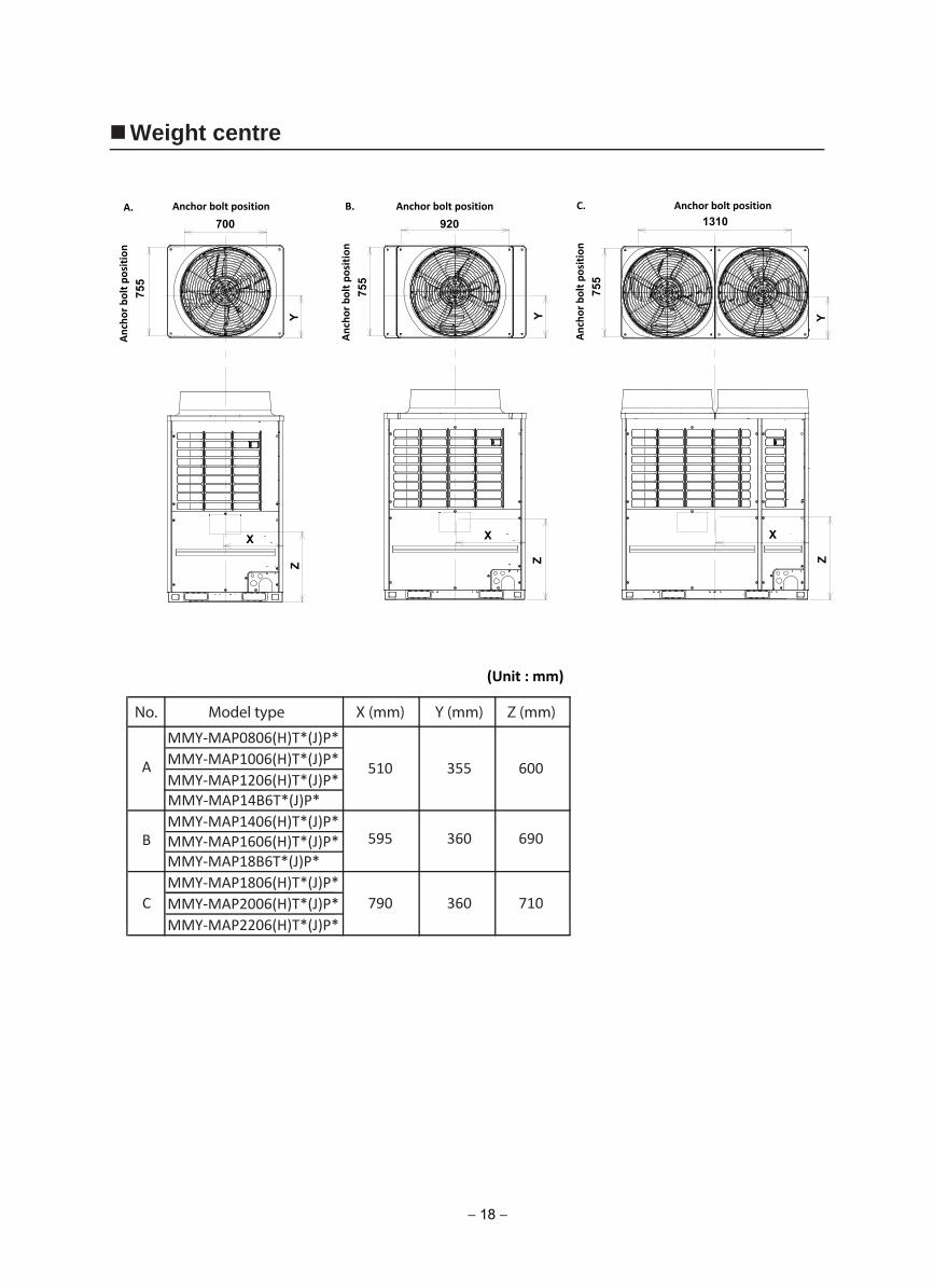
Weight centre
No. Model type X (mm) Y (mm) Z (mm)
MMY-MAP0806(H)T*(J)P*
A MMY-MAP1006(H)T*(J)P* 510 355 600MMY-MAP1206(H)T*(J)P*MMY-MAP14B6T*(J)P*MMY-MAP1406(H)T*(J)P*
B MMY-MAP1606(H)T*(J)P* 595 360 690MMY-MAP18B6T*(J)P*MMY-MAP1806(H)T*(J)P*
C MMY-MAP2006(H)T*(J)P* 790 360 710MMY-MAP2206(H)T*(J)P*
(Unit : mm)
A. Anchor bolt position700
Anch
or b
olt p
ositi
on75
5
Y
B. Anchor bolt position920
Anch
or b
olt p
ositi
on75
5
Y
C. Anchor bolt position1310
Anch
or b
olt p
ositi
on75
5
YZ
XZ
X
Z
X
− 18 −
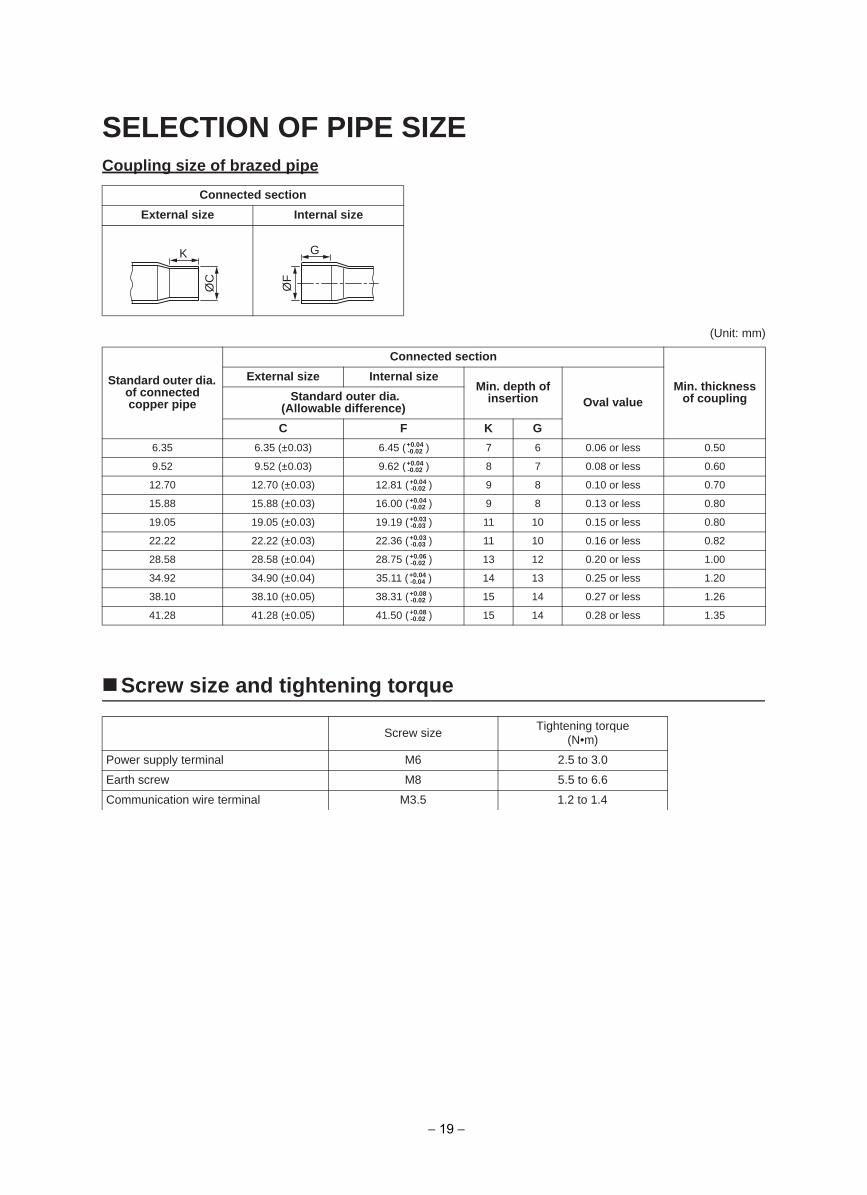
SELECTION OF PIPE SIZECoupling size of brazed pipe
(Unit: mm)
Screw size and tightening torque
Connected section
External size Internal size
Standard outer dia. of connected copper pipe
Connected section
Min. thickness of coupling
External size Internal sizeMin. depth of
insertion Oval value Standard outer dia. (Allowable difference)
C F K G
6.35 6.35 (±0.03) 6.45 ( ) 7 6 0.06 or less 0.50
9.52 9.52 (±0.03) 9.62 ( ) 8 7 0.08 or less 0.60
12.70 12.70 (±0.03) 12.81 ( ) 9 8 0.10 or less 0.70
15.88 15.88 (±0.03) 16.00 ( ) 9 8 0.13 or less 0.80
19.05 19.05 (±0.03) 19.19 ( ) 11 10 0.15 or less 0.80
22.22 22.22 (±0.03) 22.36 ( ) 11 10 0.16 or less 0.82
28.58 28.58 (±0.04) 28.75 ( ) 13 12 0.20 or less 1.00
34.92 34.90 (±0.04) 35.11 ( ) 14 13 0.25 or less 1.20
38.10 38.10 (±0.05) 38.31 ( ) 15 14 0.27 or less 1.26
41.28 41.28 (±0.05) 41.50 ( ) 15 14 0.28 or less 1.35
Screw sizeTightening torque
(N•m)
0.3 ot 5.26Mlanimret ylppus rewoP
6.6 ot 5.58Mwercs htraE
1.2 to 1.45.3Mlanimret eriw noitacinummoC
K
ØC
G
ØF
+0.04-0.02
+0.04-0.02
+0.04-0.02
+0.04-0.02
+0.03-0.03
+0.03-0.03
+0.06-0.02
+0.04-0.04
+0.08-0.02
+0.08-0.02
− 19 −
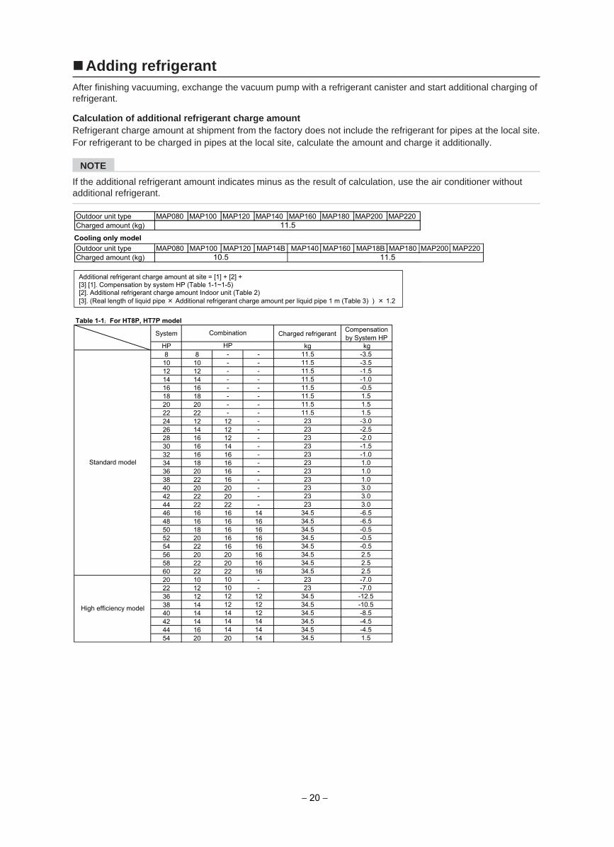
Adding refrigerant After finishing vacuuming, exchange the vacuum pump with a refrigerant canister and start additional charging of refrigerant.
Calculation of additional refrigerant charge amount Refrigerant charge amount at shipment from the factory does not include the refrigerant for pipes at the local site.For refrigerant to be charged in pipes at the local site, calculate the amount and charge it additionally.
NOTE
If the additional refrigerant amount indicates minus as the result of calculation, use the air conditioner without additional refrigerant.
Table 1-1;; For HT8P, HT7P model
System Charged refrigerant Compensationby System HP
HP kg kg8 8 - - 11.5 -3.510 10 - - 11.5 -3.512 12 - - 11.5 -1.514 14 - - 11.5 -1.016 16 - - 11.5 -0.518 18 - - 11.5 1.520 20 - - 11.5 1.522 22 - - 11.5 1.524 12 12 - 23 -3.026 14 12 - 23 -2.528 16 12 - 23 -2.030 16 14 - 23 -1.532 16 16 - 23 -1.034 18 16 - 23 1.036 20 16 - 23 1.038 22 16 - 23 1.040 20 20 - 23 3.042 22 20 - 23 3.044 22 22 - 23 3.046 16 16 14 34.5 -6.548 16 16 16 34.5 -6.550 18 16 16 34.5 -0.552 20 16 16 34.5 -0.554 22 16 16 34.5 -0.556 20 20 16 34.5 2.558 22 20 16 34.5 2.560 22 22 16 34.5 2.520 10 10 - 23 -7.022 12 10 - 23 -7.036 12 12 12 34.5 -12.538 14 12 12 34.5 -10.540 14 14 12 34.5 -8.542 14 14 14 34.5 -4.544 16 14 14 34.5 -4.554 20 20 14 34.5 1.5
High efficiency model
Combination
HP
Standard model
Additional refrigerant charge amount at site = [1] + [2] + [3] [1]. Compensation by system HP (Table 1-1~1-5) [2]. Additional refrigerant charge amount Indoor unit (Table 2) [3]. (Real length of liquid pipe × Additional refrigerant charge amount per liquid pipe 1 m (Table 3) ) × 1.2
Outdoor unit type MAP080 MAP100 MAP120 MAP140 MAP160 MAP180 MAP200 MAP220Charged amount (kg) 11.5
− 20 −
Outdoor unit type MAP080 MAP100 MAP120 MAP14B MAP140 MAP160 MAP18B MAP180 MAP200 MAP220 Charged amount (kg) 11.5
Cooling only model
10.5
HP kg kg
8 8 11.5 -3.5
10 10 11.5 -3.5
12 12 11.5 -1.5
14 14 11.5 -1.016 16 11.5 -0.5
18 18 11.5 1.5
20 20 11.5 1.5
22 12 10 23 -7.024 12 12 23 -3.026 14 12 23 -2.528 14 14 23 -3.030 16 14 23 -1.532 16 16 23 -1.034 18 16 23 1.036 18 18 23 3.038 20 18 23 3.040 20 20 23 3.042 14 14 14 34.5 -4.5
44 16 14 14 34.5 -4.5
46 16 16 14 34.5 -6.5
48 16 16 16 34.5 -6.5
50 18 16 16 34.5 -0.5
52 18 18 16 34.5 1.5
54 20 20 14 34.5 1.5
56 20 20 16 34.5 2.5
Standard model
HP
Compesation by
System HPSystem Combination Charged refrigerant
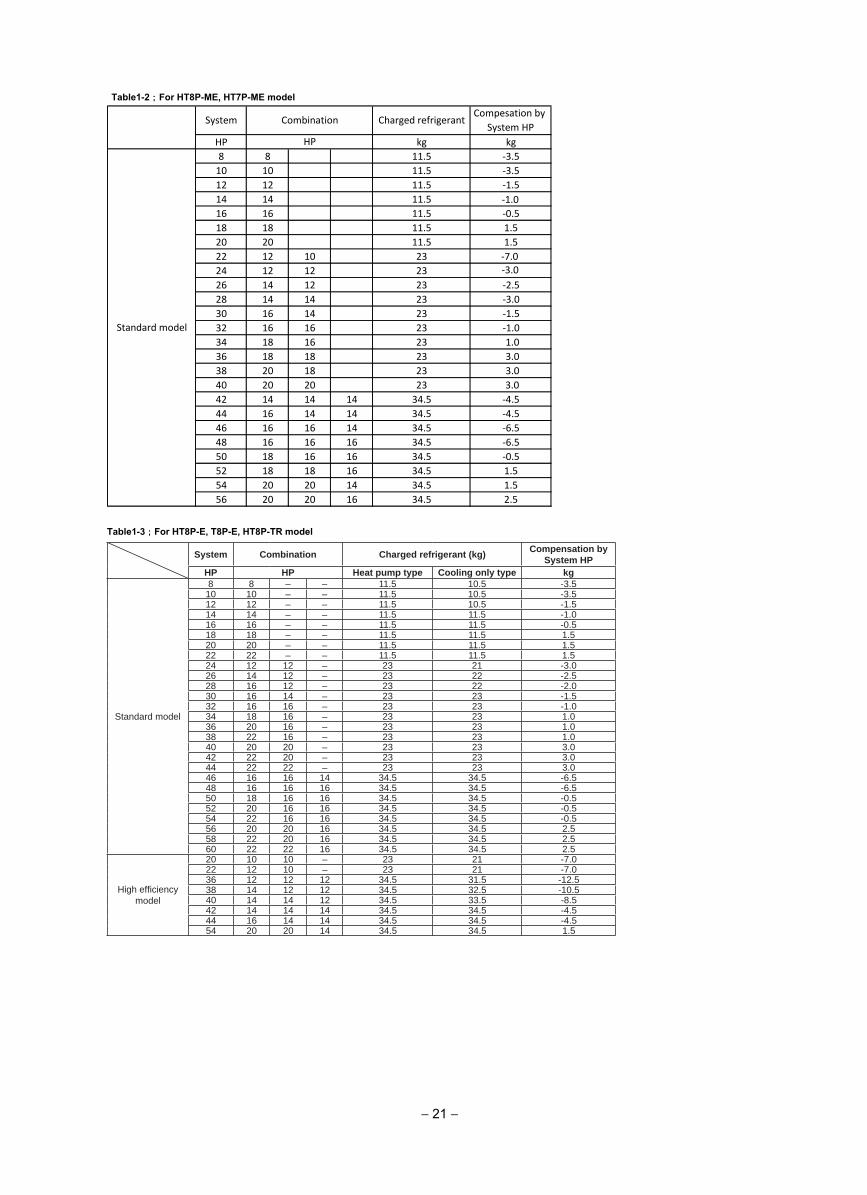
Table1-2 ; For HT8P-ME, HT7P-ME model
− 21 −
System Combination Charged refrigerant (kg) Compensation bySystem HP
HP HP Heat pump type Cooling only type kg
Standard model
8 8 – – 11.5 10.5 -3.510 10 – – 11.5 10.5 -3.512 12 – – 11.5 10.5 -1.514 14 – – 11.5 11.5 -1.016 16 – – 11.5 11.5 -0.518 18 – – 11.5 11.5 1.520 20 – – 11.5 11.5 1.522 22 – – 11.5 11.5 1.524 12 12 – 23 21 -3.026 14 12 – 23 22 -2.528 16 12 – 23 22 -2.030 16 14 – 23 23 -1.532 16 16 – 23 23 -1.034 18 16 – 23 23 1.036 20 16 – 23 23 1.038 22 16 – 23 23 1.040 20 20 – 23 23 3.042 22 20 – 23 23 3.044 22 22 – 23 23 3.046 16 16 14 34.5 34.5 -6.548 16 16 16 34.5 34.5 -6.550 18 16 16 34.5 34.5 -0.552 20 16 16 34.5 34.5 -0.554 22 16 16 34.5 34.5 -0.556 20 20 16 34.5 34.5 2.558 22 20 16 34.5 34.5 2.560 22 22 16 34.5 34.5 2.5
High efficiency model
20 10 10 – 23 21 -7.022 12 10 – 23 21 -7.036 12 12 12 34.5 31.5 -12.538 14 12 12 34.5 32.5 -10.540 14 14 12 34.5 33.5 -8.542 14 14 14 34.5 34.5 -4.544 16 14 14 34.5 34.5 -4.554 20 20 14 34.5 34.5 1.5
Table1-3 ; For HT8P-E, T8P-E, HT8P-TR model
System Combination Charged refrigerant Compensation by System HP
HP HP kg kg
Standard model
8 8 – – 11.5 -3.510 10 – – 11.5 -3.512 12 – – 11.5 -1.514 14 – – 11.5 -1.016 16 – – 11.5 -0.518 18 – – 11.5 1.520 20 – – 11.5 1.522 12 10 – 23 -7.024 12 12 – 23 -3.026 14 12 – 23 -2.528 16 12 – 23 -2.030 16 14 – 23 -1.532 16 16 – 23 -1.034 18 16 – 23 1.036 20 16 – 23 1.038 20 18 – 23 3.040 20 20 – 23 3.042 16 14 12 34.5 -6.544 16 16 12 34.5 -6.546 16 16 14 34.5 -6.548 16 16 16 34.5 -6.550 18 16 16 34.5 -0.552 20 16 16 34.5 -0.554 20 20 14 34.5 1.556 20 20 16 34.5 2.5
High efficiency model
20 10 10 – 23 -7.036 12 12 12 34.5 -12.538 14 12 12 34.5 -10.540 14 14 12 34.5 -8.5
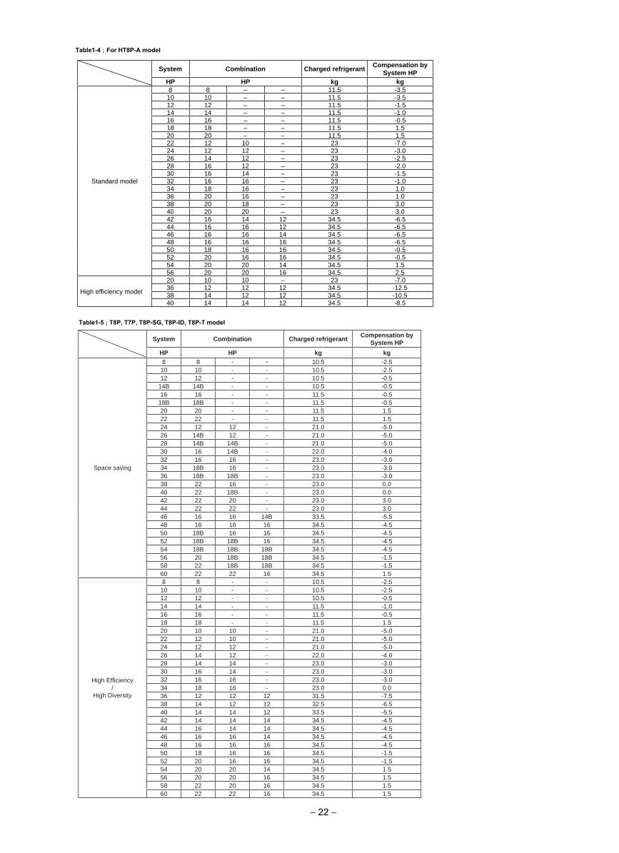
Table1-4 ; For HT8P-A model
System Combination Charged refrigerant Compensation bySystem HP
HP HP kg kg
Space saving
8 8 - - 10.5 -2.510 10 - - 10.5 -2.512 12 - - 10.5 -0.5
14B 14B - - 10.5 -0.516 16 - - 11.5 -0.5
18B 18B - - 11.5 -0.520 20 - - 11.5 1.522 22 - - 11.5 1.524 12 12 - 21.0 -5.026 14B 12 - 21.0 -5.028 14B 14B - 21.0 -5.030 16 14B - 22.0 -4.032 16 16 - 23.0 -3.034 18B 16 - 23.0 -3.036 18B 18B - 23.0 -3.038 22 16 - 23.0 0.040 22 18B - 23.0 0.042 22 20 - 23.0 3.044 22 22 - 23.0 3.046 16 16 14B 33.5 -5.548 16 16 16 34.5 -4.550 18B 16 16 34.5 -4.552 18B 18B 16 34.5 -4.554 18B 18B 18B 34.5 -4.556 20 18B 18B 34.5 -1.558 22 18B 18B 34.5 -1.560 22 22 16 34.5 1.5
High Efficiency /
High Diversity
8 8 - - 10.5 -2.510 10 - - 10.5 -2.512 12 - - 10.5 -0.514 14 - - 11.5 -1.016 16 - - 11.5 -0.518 18 - - 11.5 1.520 10 10 - 21.0 -5.022 12 10 - 21.0 -5.024 12 12 - 21.0 -5.026 14 12 - 22.0 -4.028 14 14 - 23.0 -3.030 16 14 - 23.0 -3.032 16 16 - 23.0 -3.034 18 16 - 23.0 0.036 12 12 12 31.5 -7.538 14 12 12 32.5 -6.540 14 14 12 33.5 -5.542 14 14 14 34.5 -4.544 16 14 14 34.5 -4.546 16 16 14 34.5 -4.548 16 16 16 34.5 -4.550 18 16 16 34.5 -1.552 20 16 16 34.5 -1.554 20 20 14 34.5 1.556 20 20 16 34.5 1.558 22 20 16 34.5 1.560 22 22 16 34.5 1.5
Table1-5 ; T8P, T7P, T8P-SG, T8P-ID, T8P-T model
− 22 −
− 23 −
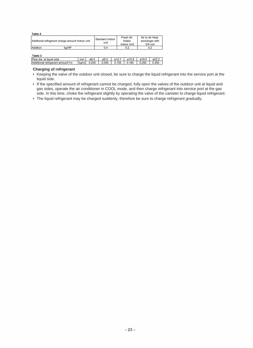
Table 3Pipe dia. at liquid side mm ø6.4 ø9.5 ø12.7 ø15.9 ø19.0 ø22.2Additional refrigerant amount/1m kg/m 0.025 0.055 0.105 0.160 0.250 0.350
Charging of refrigerant• Keeping the valve of the outdoor unit closed, be sure to charge the liquid refrigerant into the service port at the
liquid side.• If the specified amount of refrigerant cannot be charged, fully open the valves of the outdoor unit at liquid and
gas sides, operate the air conditioner in COOL mode, and then charge refrigerant into service port at the gasside. In this time, choke the refrigerant slightly by operating the valve of the canister to charge liquid refrigerant.
• The liquid refrigerant may be charged suddenly, therefore be sure to charge refrigerant gradually.
Table 2
Additional refrigerant charge amount Indoor unit Standard Indoor unit
Fresh Air Intake
Indoor Unit
Air to Air Heat exchanger with
DX-coilAddition kg/HP 0.4 0.2 0.2
This air conditioner adopts a HFC type refrigerant (R410A) which does not deplete the ozone layer.
1. Safety Caution Concerned to refrigerant (R410A)The pressure of R410A is high 1.6 times of that of the former refrigerant (R22). Accompanied with change of refrigerant, the refrigerating oil has been also changed. Therefore, be sure that water, dust, the former refrigerant or the former refrigerating oil is not mixed into the refrigerating cycle of the air conditioner with new refrigerant during installation work or service work. If an incorrect work or incorrect service is performed, there is a possibility to cause a serious accident. Use the tools and materials exclusive to R410A to purpose a safe work.
2. Cautions on Installation/Service(1) Do not mix the other refrigerant or refrigerating oil.
For the tools exclusive to R410A, shapes of all the joints including the service port differ from those of the former refrigerant in order to prevent mixture of them.
(2) As the use pressure of the refrigerant (R410A) is high, use material thickness of the pipe and tools which are specified for R410A.
(3) In the installation time, use clean pipe materials and work with great attention so that water and others do not mix in because pipes are affected by impurities such as water, oxide scales, oil, etc. Use the clean pipes.Be sure to brazing with flowing nitrogen gas. (Never use gas other than nitrogen gas.)
(4) For the earth protection, use a vacuum pump for air purge.(5) R410A refrigerant is azeotropic mixture type refrigerant. Therefore use liquid type to charge the refrigerant.
(If using gas for charging, composition of the refrigerant changes and then characteristics of the air conditioner change.)
3. Pipe MaterialsFor the refrigerant pipes, copper pipe and joints are mainly used. It is necessary to select the most appropriate pipes to conform to the standard. Use clean material in which impurities adhere inside of pipe or joint to a minimum.
(1) Copper pipe
(2) JointThe flare joint and socket joint are used for joints of the copper pipe. The joints are rarely used for installation of the air conditioner. However clear impurities when using them.
<Piping>The pipe thickness, flare finishing size, flare nut and others differ according to a refrigerant type.When using a long copper pipe for R410A, it is recommended to select “Copper or copper-base pipe without seam” and one with bonded oil amount 40mg/10m or less. Also do not use crushed, deformed, discolored (especially inside) pipes. (Impurities cause clogging of expansion valves and capillary tubes.)
<Flare nut>Use the flare nuts which are attached to the air conditioner unit.
Refrigerant (R410A)
− 24 −
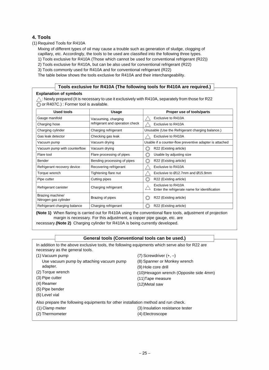
4. Tools(1) Required Tools for R410A
Mixing of different types of oil may cause a trouble such as generation of sludge, clogging of capillary, etc. Accordingly, the tools to be used are classified into the following three types.1) Tools exclusive for R410A (Those which cannot be used for conventional refrigerant (R22))2) Tools exclusive for R410A, but can be also used for conventional refrigerant (R22)3) Tools commonly used for R410A and for conventional refrigerant (R22)The table below shows the tools exclusive for R410A and their interchangeability.
Tools exclusive for R410A (The following tools for R410A are required.)Explanation of symbols
: Newly prepared (It is necessary to use it exclusively with R410A, separately from those for R22 or R407C.) : Former tool is available.
(Note 1) When flaring is carried out for R410A using the conventional flare tools, adjustment of projection margin is necessary. For this adjustment, a copper pipe gauge, etc. are
necessary.(Note 2) Charging cylinder for R410A is being currently developed.
UsageUsed tools Proper use of tools/parts
Gauge manifold Vacuuming, charging refrigerant and operation check
Exclusive to R410A
Exclusive to R410ACharging hose
Charging cylinder Charging refrigerant Unusable (Use the Refrigerant charging balance.)
Gas leak detector Checking gas leak Exclusive to R410A
Vacuum pump Vacuum drying Usable if a counter-flow preventive adapter is attached
R22 (Existing article)Vacuum dryingVacuum pump with counterflow
Usable by adjusting sizeFlare processing of pipesFlare tool
R22 (Existing article)Bending processing of pipesBender
Refrigerant recovery device Recovering refrigerant Exclusive to R410A
Torque wrench Tightening flare nut Exclusive to Ø12.7mm and Ø15.9mm
R22 (Existing article)Cutting pipesPipe cutter
Refrigerant canister Charging refrigerantExclusive to R410AEnter the refrigerate name for identification
Brazing machine/Nitrogen gas cylinder
R22 (Existing article)Brazing of pipes
Refrigerant charging balance Charging refrigerant R22 (Existing article)
General tools (Conventional tools can be used.)In addition to the above exclusive tools, the following equipments which serve also for R22 are necessary as the general tools.(1) Vacuum pump
Use vacuum pump by attaching vacuum pump adapter.
(2) Torque wrench (3) Pipe cutter(4) Reamer(5) Pipe bender (6) Level vial
(7) Screwdriver (+, –)(8) Spanner or Monkey wrench(9) Hole core drill(10)Hexagon wrench (Opposite side 4mm)(11)Tape measure(12)Metal saw
Also prepare the following equipments for other installation method and run check.(1) Clamp meter (2) Thermometer
(3) Insulation resistance tester(4) Electroscope
− 25 −
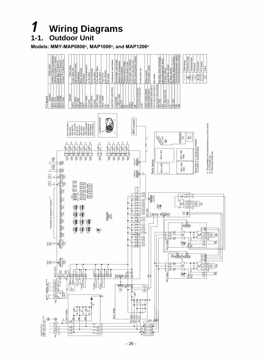
1 Wiring Diagrams1-1. Outdoor UnitModels: MMY-MAP0806*, MAP1006*, and MAP1206*
− 26 −
415V
3NP
OW
ER
SU
PP
LY50
Hz
380
up to
four
pie
ces.
*1MC
C-1
659
MC
C-1
673
TB
1
TB
2
Mg-
CTT
*Noi
se fi
lter P
.C. b
oard
s ar
e in
stal
led
on a
bac
kof
term
inal
blo
ck.
Par
ts lay
out
MC
C-1
669
(CM
1)
MC
C-1
669
(CM
2)
L2L3
N
L1
Rot
ary
switc
hP
ush
butto
n sw
itch
2-w
ay v
alve
coi
l
Acc
umul
ator
cas
e he
ater
Rea
ctor
for c
ompr
esso
rM
agne
t con
tact
orP
ress
ure
sens
or (H
igh)
Pre
ssur
e se
nsor
(Low
)P
ulse
mot
or v
alve
(Mai
n)
Dip
sw
itch
63H
1,63
H2
CN
***
F01,
F02
CM
1,C
M2
4WV
1
CN
-R
SW
01,S
W02
,SW
03S
W04
,SW
05,S
W15
SW
06,S
W07
,SW
09,S
W10
SW
11,S
W12
,SW
13,S
W14
FM
Par
ts n
ame
4-w
ay v
alve
coi
lH
igh
pres
sure
sw
itch
Com
pres
sor
Rel
ay c
onne
ctor
Con
nect
orFu
se (C
ompr
esso
r)31
.5A
500
VFu
se (I
nter
face
) T6
.3A
250
VFu
se (N
oise
filte
r)T6
.3A
250
VFu
se (F
an)
6.3A
750
VD
CFa
n m
otor
HE
ATE
R1,
HE
ATE
R2
Com
pres
sor c
ase
heat
er
(MC
C-1
669)
(MC
C-1
673)
F01,
F02
(MC
C-1
608A
)F0
1,F0
2,F0
3(M
CC
-165
9)
Sym
bol
MC
C-1
608B
MC
C-1
669
MC
C-1
608A
MC
C-1
659
MC
C-1
673
Par
ts n
ame
Inve
rter P
.C.B
oard
(Com
pres
sor)
Inte
rface
Con
trol P
.C.B
oard
Noi
se fi
lter P
.C.B
oard
AN
oise
filte
r P.C
.Boa
rd B
Inve
rter P
.C.B
oard
(Fan
)
P.C
.Boa
rd
Sym
bol
Pul
se m
otor
val
ve (S
ub c
ool)
Rus
h cu
rren
t pro
tect
resi
stor
F01
U1U2
SU3
U4U5
U6S
SW
16,S
W17
,SW
30,S
W80
0TD
1,TD
2TE
1TK
1,TK
2,TK
4,TK
5TL
1,TL
3TO TS
1,TS
3TB
1TB
2
Pipe
tem
p. s
enso
r (Di
scha
rge)
Heat
exc
hang
e te
mp.
sen
sor
Oil
tem
p. s
enso
rLi
quid
tem
p. s
enso
rA
ir te
mp.
sen
sor
Pip
e te
mp.
sen
sor (
Suc
tion)
Term
inal
blo
ck(p
ower
sup
ply)
Term
inal
blo
ck(c
ontro
l wiri
ng)
Term
inal
Con
nect
orP
.C.b
oard
Term
inal
blo
ck
Pro
tect
ive
earth
Fiel
d w
iring
CN
-R
CM
2
MS
3+
+
--
RED
WH
I BLK
MCC
-166
9(2)
SV
2
CN321 SV
3CS
V3B
CN
800
(Ser
vice
)S
WR
T
ON
1OF
F2
3 4
1SW
12ON OF
F
SW
17
23 4
SW
07
1
ON OFF
23 4
ON ONS
W13
OFF
ON
12
3 4
SW
09ON OF
F 12
3 4
2SW
14
OFF 1
3 42SW
10
OFF 1
3 4
CN
511
CN
510
CN
512 FMM
S3
P>
63H
1
4
UV
W
CN301
+
CN
852
MCC
-165
9
CN322
SV
3AS
V3D
CN
101
CN
535
CN
851
CN
600
SW
04
SW
02D
600
D60
1D
602
SW01
CN
30CN
31 CN
32
SW
03D
603
D60
4
SW05
SW
15
CN
523
CN
534
CN
505
CN
503
CN
507
CN
520
TK5
TK4
TL1
TE1
TOTS1
TD2
CN
501
CN
514
CN
513
PD
3
CN
502
CN
500
PS
3
31t°
TD1
UV
W
(WH
I)
(PN
K)
(WH
I)
(YEL
)
(GR
N)
(WH
I)
(YEL
)
(RE
D)
5
31 21 1 21 221 1 3 21
CN311(WHI)
(WHI)
(WHI)
(BLU
)
(WH
I)(B
LU)
(GR
N)
(BLU
)(G
RN
)(R
ED)
(WH
I)
31
63
24
15
21
CN302
CN303
CN211
CN212
CN213
CN
305
RE
DW
HI
BLK
CN19
CN20
23
41
34
RE
DW
HI
BLK
t° t° t° t°t° t°t°
(BLU
)
(BLU
)(R
ED)
CN
852(
WH
I)
(RE
D)
63H
2P>
(RED
)C
N30
6
L-CM
2
*1
F01
F02CN13
CN12
CN11
CN10
2(B
LU)
CN10
2(W
HI)
-
CN
14
MC
C-1
608A
MC
C-1
608B
CM
1
CN23
CN24
CN
22
CN
317
CN
334
CN
50
CN
13
HEA
TER
1
A.H
EAT
ER
HE
ATE
R24W
V1
CN312 SV
41S
V42
ON OFF
ON
12
OFF 1
23
1
ON OFF
23
1OF
FON
23
MC
C-1
673
L2L3
N
CN
-R
TB2
CN
01
CN
03
CN
300
M
5
PM
V1
CN
508
F01
F02
CN
530
4
(BLU)
CCNN331144((WWHHII))
(BLU
)
(RE
D)
CN
331(
WH
I)
CN
335(
GR
Y)
(RED
)(W
HI)
(WH
I)
(BLU
)
BLK
WH
IBL
K
CN
400
(WH
I)
(BLK
)31 31 31 31 31
75
31
+-
CN19
CN20
CN213
CN212
CN211
4
+-
CN11
CN12
CN13
F01
F02
RED
WH
IB
LKM
CC-1
669(
1)
4
RED
WHI
BLK
(BLK) (R
ED)
1 21 26
24
31
(RE
D)
1 3
CN
304
CN
11
CN
12
WHIBLK
BLK BLK
WHI
RED
RB
6T3
4T23L2
5L3Mg-CTT
F03
F02
F01
CN32
CN33
CN34
CN42
CN43
WH
IBL
KB
LK
U
UUU
TO CENTRAL
CONTROLLER
TO INDOOR
UNIT
TO OUTDOOR
UNIT
GR
Y
A1
RED
A2Co
ilM
g-CT
T
GR
Y
CN10
1(W
HI)
CN10
2(B
LU)
RED
GRY
TB1 RE
D
RED
2T11L1CN31 CN41
RED
L1
4
SW
30
4 4SW
16
SW11
SW06
CN
509
Con
nect
or fo
r opt
iona
l P.C
.Boa
rd
(BLK
)
CN
23
CN
21
CN
903
TS3
(PU
R)
21t°
CN
531
CN
532
TK2
TK1
(BLK
)
(GR
N)
1 331
t°t°
SV
52
34
PMV
4 5
CN
303
M (RED
)
62
43
1
A1 A2
MS
3
UV
WR
EDW
HI
BLK
L-CM
1
CN12
CN01
CN
902
TL3
(PN
K)
1 2t°
CN
851(
WH
I)1
23
4
U1U2
SU3
U4U5
U6S
CN
851
(RE
D)
CN
852(
WH
I)
2 3 4 5 2 3 4 5
2 3 4 5
F01
44
2 3 4 5
CN
332(
BLU
)
YEL
BLU
CN
23
CN
21
12
34
5
12
34
5
13
13
13
13
31
21
1 32 4
1 32 4
OFF
ONS
W80
0
OFF
ONS
W80
0
OFF
ON
12
SW
800
12
12
VU
Com
pres
sor t
erm
inal
W
RE
D:R
ED
WH
I:WH
ITE
YE
L:Y
ELL
OW
BLU
:BLU
EB
LK:B
LAC
KG
RY
:GR
AY
PN
K:P
INK
OR
N:O
RA
NG
EB
RN
:BR
OW
NG
RN
:GR
EE
NP
UR
:PU
RP
LE
Col
or in
dica
tion
SV
51
12
A.H
EA
TER
L-C
M1,
L-C
M2
Mg-
CTT
PD
PS
PM
V1
PM
V4
RB
SV
2,S
V3A
,SV
3B,S
V3C
SV
3D,S
V41
,SV
42,S
V51
SV
52
NFC
modu
le
60H
z 38
03N
*2
*2
The
inst
alla
tion
of th
e op
tiona
l boa
rd is
-E
,-TR
mod
el o
nly.
*3He
at p
ump
mod
el o
nly.
*3
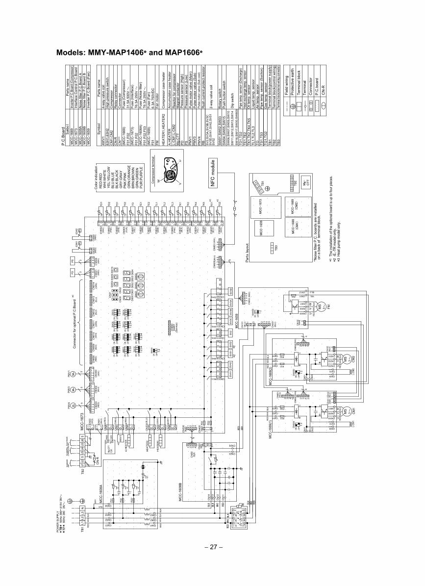
Models: MMY-MAP1406* and MAP1606*
− 27 −
PO
WE
R S
UP
PLY
MC
C-1
659
MC
C-1
673
TB
1
TB
2
Mg-
CTT
*Noi
se fi
lter P
.C. b
oard
s ar
e in
stal
led
ona
back
of
term
inal
bloc
k.
Par
ts lay
out
MC
C-1
669
(C
M1)
MC
C-1
669
(C
M2)
L2L3
N
L1
The
inst
alla
tion
of th
e op
tiona
l boa
rd is
up
to fo
ur p
iece
s.*1
U1U2
SU3
U4U5
U6S
TB
3
CM
2
MS
3+
+
--
RE
DW
HI B
LKM
CC-1
669(
2)
SV
2
CN321 SV
3CS
V3B
CN
800
(Ser
vice
)S
WR
T
ON
1OF
F2
3 4
1SW12
ON OFF
SW17
23 4
SW
07
1
ON OFF
23 4
ON ONS
W13
OFF
ON
12
3 4
SW09
ON OFF 1
23 4
2SW
14
OFF 1
3 42SW
10
OFF 1
3 4
CN
511
CN
510
CN
512 FMM
S3
P>
63H
1
4
UV
W
CN301
CN
852
MCC
-165
9
CN322
SV
3AS
V3D
CN
101
CN
535
CN
851
CN
600
SW
04
SW
02D
600
D60
1D
602
SW
01
CN
30CN
31 CN
32
SW
03D
603
D60
4
SW
05S
W15
CN
523
CN
524
CN
902
CN
534
CN
505
CN
503
CN
507
CN
520
TK5
TK4
TL3
TL2
TL1
TE1
TOTS1
TD2
CN
501
CN
514
CN
513
PD 3
CN
502
CN
500
PS 3
31t°
TD1
UV
W
(WH
I)
(PN
K)
(WH
I)
(YE
L)
(GR
N)
(WH
I)
(GR
Y)
(PN
K)
(YE
L)
(RE
D)
5
31 21 1 21 221 1 31 331 21
CN311(WHI)
(WHI)
(WHI)
(BLU
)
(WH
I)(B
LU)
(GR
N)
(BLU
)(G
RN
)(R
ED
)(W
HI)
31
63
24
15
21
CN302
CN303
CN201
CN202
CN203
CN
305
RE
DW
HI
BLK
CN09
CN10
23
41
34
RE
DW
HI
BLK
t° t° t° t°t° t°t° t°t°
(BLU
)
(BLU
)
(RE
D)
CN
852(
WH
I)
(RE
D)
63H
2P
>
(RE
D)
CN
306
L-CM
2
*1
F01
F02CN03
CN02
CN01
CN10
2(B
LU)
CN10
2(W
HI)
CN
14
MC
C-1
608A
MC
C-1
608B
CM
1
CN23
CN24
CN
22
CN
317
CN
334
CN
50
CN
13
HE
ATE
R1
A.H
EA
TER
HE
ATE
R24W
V1
SV
41S
V42
ON OFF
ON
12
OFF 1
23
1
ON OFF
23
1OF
FON
23
MC
C-1
673
L2
PMV
3 5
CN
302
L3N
CN
01
CN
03
M
CN
300
M
5
PM
V1
CN
508
F01
F02
CN
530
4
CN312(BLU)
(BLU
)
(RE
D)
CN
331(
WH
I)
CN
335(
GR
Y)
(RE
D)
(WH
I)(B
LU)
(WH
I)
(BLU
)
BLK
WH
IB
LK
CN
400
(WH
I)
(BLK
)31 31 31 31 31
75
31
+-
CN09
CN10
CN203
CN202
CN201
4
+-
CN01
CN02
CN03
F01
F02
CN
852CN
851
RE
DW
HI
BLK
MCC
-166
9(1)
4
RED
WHI
BLK
(BLK)
(RED)
(RE
D)
(WH
I)
1 21 26
24
31
62
43
1
(RE
D)
1 3
CN
304
CN
11
CN
12
WHIBLK
BLK BLK
WHI
RED
RB
6T3
4T23L2
5L3
Mg-CTT
F03
F02
F01
CN32
CN33
CN34
CN42
CN43
WH
IB
LKB
LK
U
UUU
GR
Y
A1
RE
D
A2
Coil
Mg-
CTT
GR
Y
CN10
1(W
HI)
CN10
2(B
LU)
RED
GRY
TB1 RE
D
RE
D 2T11L1CN31 CN41
RE
DL1
4
SW30
4 4S
W16
SW
11
SW
06
CN
509
Con
nect
or fo
r opt
iona
l P.C
.Boa
rd
(BLK
)
CN
903
TS3
(PU
R)
21t°
CN
521
TE2
(RE
D)
1 2t°
CN
531
CN
532
TK2
TK1
(BLK
)
(GR
N)
1 331
t°t°
CN
525
TG1
(BLU
)21
t°
CN
526
TG2
(WH
I)21
t°
PM
V4 5
CN
303
M (RE
D)
62
43
1
A1 A2
MS
3
UV
WR
ED
WH
IB
LK
L-CM
1
CN12
CN01
CN
851(
WH
I)
12
34
CN
-R
TB2
TO CENTRAL
CONTROLLER
TO INDOOR
UNIT
TO OUTDOOR
UNIT
2 23 34 45 5
2 3 4 51 3
F01
44
2 3 4 5
U1U2
SU3
U4U5
U6S
CN
332(
BLU
)
YEL
BLU
CN
23
CN
21
CN
23
CN
21
+-
13
13
13
13
12
34
5
12
34
5
1 3
1 2
1 32 4
1 2 3 4
OFF
ON
12
SW80
0
OFF
ONS
W80
0
12
OFF
ONS
W80
0
12
VU
Com
pres
sor t
erm
inal
W
RE
D:R
EDW
HI:W
HIT
EY
EL:
YE
LLO
WB
LU:B
LUE
BLK
:BLA
CK
GR
Y:G
RA
YP
NK
:PIN
KO
RN
:OR
AN
GE
BR
N:B
RO
WN
GR
N:G
RE
EN
PU
R:P
UR
PLE
Col
or in
dica
tion
Rot
ary
switc
hP
ush
butto
n sw
itch
2-w
ay v
alve
coi
l
Dip
sw
itch
63H
1,63
H2
CN
***
F01,
F02
PM
V4
CM
1,C
M2
4WV
1
CN
-R
SW
01,S
W02
,SW
03S
W04
,SW
05,S
W15
SW
06,S
W07
,SW
09,S
W10
SW
11,S
W12
,SW
13,S
W14
FM
Par
ts n
ame
4-w
ay v
alve
coi
lH
igh
pres
sure
sw
itch
Com
pres
sor
Rel
ay c
onne
ctor
Con
nect
orFu
se (C
ompr
esso
r)31
.5A
500
VFu
se (I
nter
face
) T6
.3A
250
VFu
se (N
oise
filte
r)T6
.3A
250
VFu
se (F
an)
6.3A
750
VD
CFa
n m
otor
PD
PS
HE
ATE
R1,
HE
ATE
R2
Com
pres
sor c
ase
heat
er
L-C
M1,
L-C
M2
A.H
EA
TER
(MC
C-1
669)
(MC
C-1
673)
F01,
F02
(MC
C-1
608A
)F0
1,F0
2,F0
3(M
CC
-165
9)
Symbol
MC
C-1
608B
MC
C-1
669
MC
C-1
608A
MC
C-1
659
MC
C-1
673
Par
ts n
ame
Inve
rter P
.C.B
oard
(Com
pres
sor)
Inte
rface
Con
trol P
.C.B
oard
Noi
se fi
lter P
.C.B
oard
AN
oise
filte
r P.C
.Boa
rd B
Inve
rter P
.C.B
oard
(Fan
)
P.C
.Boa
rd
Sym
bol
Mg-
CTT
RB
Rus
h cu
rren
t pro
tect
resi
stor
F01
PM
V3
PM
V1
Acc
umul
ator
cas
e he
ater
Rea
ctor
for c
ompr
esso
rM
agne
t con
tact
orP
ress
ure
sens
or (H
igh)
Pre
ssur
e se
nsor
(Low
)P
ulse
mot
or v
alve
(Mai
n)P
ulse
mot
or v
alve
(Sub
)P
ulse
mot
or v
alve
(Sub
coo
l)
SW
16,S
W17
,SW
30,S
W80
0TD
1,TD
2TE
1,TE
2TK
1,TK
2,TK
4,TK
5TL
1,TL
2,TL
3TO TS
1,TS
3TG
1,TG
2TB
1TB
2TB
3
Pipe
tem
p. s
enso
r (Di
scha
rge)
Heat
exc
hang
e te
mp.
sen
sor
Oil
tem
p. s
enso
rLi
quid
tem
p. s
enso
rA
ir te
mp.
sen
sor
Pip
e te
mp.
sen
sor (
Suc
tion)
Gas
tem
p. s
enso
r Te
rmin
al b
lock
(pow
er s
uppl
y)Te
rmin
al b
lock
(con
trol w
iring
)Te
rmina
l bloc
k(inte
rnal w
iring c
onne
ctor)
Term
inal
Con
nect
orP
.C.b
oard
Term
inal
blo
ck
Pro
tect
ive
earth
Fiel
d w
iring
CN
-R
SV
51S
V52
CN314(WHI)
43
21
SV2
,SV
3A,S
V3B
,SV
3CS
V3D
,SV
41,S
V42
,SV
51S
V52
NFC
modu
le
*2-E
,-TR
mod
el o
nly.
*2
50H
z 38
041
5V3N
60H
z 38
03N
*2
3He
at p
ump
mod
el o
nly.
*
*3 *3
*3
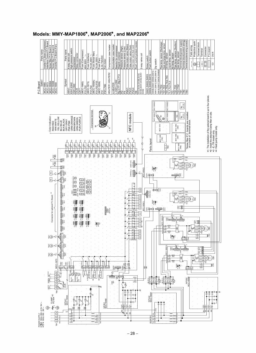
Models: MMY-MAP1806∗, MAP2006∗, and MAP2206∗
− 28 −
*Noi
se fi
lter P
.C. b
oard
s ar
e in
stal
led
ona
back
of
term
inal
blo
ck.
MC
C-1
659
(F
M1)
MC
C-1
673
TB
1
TB
2
Mg-
CTT(1
)
Par
ts lay
out MC
C-1
660
(C
M1)
MC
C-1
660
(C
M2)
L2L3
N
L1
MC
C-1
659
(F
M2)
MC
C-1
608A
(1)
MC
C-1
608B
(1)
U1U2
SU3
U4U5
U6S
Mg-
CTT(2
)
MC
C-1
608A
(2)
MC
C-1
608B
(2)
POW
ER
SU
PPL
Y
TB
3
RE
D:R
ED
WH
I:WH
ITE
YE
L:Y
ELL
OW
BLU
:BLU
EB
LK:B
LAC
KG
RY
:GR
AY
PN
K:P
INK
OR
N:O
RA
NG
EB
RN
:BR
OW
NG
RN
:GR
EE
NP
UR
:PU
RP
LE
Col
or in
dica
tion
CM
2
MS
3+
+
--MCC
-166
0(2)CN311
SV
2
CN321 SV
3CS
V3B
CN
800
(Ser
vice
)S
WR
T
ON
1OF
F2
3 4
1SW
12ON OF
F
SW17
23 4
SW
07
1
ON OFF
23 4
ON ONS
W13
OFF
ON
12
3 4
SW
09ON OF
F 12
3 4
2SW
14
OFF 1
3 42SW
10
OFF 1
3 4
CN
511
CN
510
CN
512 FM
1
MS
3
P>
63H
1
4
UV
W
CN301
+
CN
852
MCC
-165
9(1)
CN322
SV3A
SV3
D
CN
101
CN
535
CN
851
CN
600
SW
04
SW
02D
600
D60
1D
602
SW
01
CN
30CN
31 CN
32
SW
03D
603
D60
4
SW
05S
W15
CN
523
CN
524
CN
902
CN
534
CN
505
CN
503
CN
507
CN
520
TK5
TK4
TL3
TL2
TL1
TE1
TOTS1
TD2
CN
501
CN
514
CN
513
PD
3
CN
502
CN
500
PS 3
31t°
TD1
UV
W
(WH
I)
(PN
K)
(WH
I)
(YE
L)
(GR
N)
(WH
I)
(GR
Y)
(PN
K)
(YE
L)
(RE
D)
5
31 21 1 21 221 1 31 331 21
(WHI)
(WHI)
(WHI)
(BLU
)
(WH
I)(B
LU)
(GR
N)
(BLU
)(G
RN
)(R
ED
)(W
HI)
31
63
24
15
21
CN302
CN303
CN201
CN202
CN203
CN
305
RE
DW
HI
BLK
CN
852
CN09
CN10
RE
DW
HIB
LK
23
41
34
RE
DW
HI
BLK
t° t° t° t°t° t°t° t°t°
(BLU
)
(BLU
)
(RE
D)
(WH
I)
(RE
D)
63H
2P
>
(RE
D)
CN
306
L-CM
2
*1
F01
F02CN03
CN02
CN01
CN10
2(B
LU)
CN10
2(W
HI)
-
CN
15
MC
C-1
608A
MC
C-1
608B
CM
1
CN23
CN24
CN
22
CN
317
CN
334
CN
331
CN
335
CN
50
CN
13
HE
ATE
R1
A.H
EA
TER
HE
ATE
R24W
V1
SV41
SV
42
ON OFF
ON
12
OFF 1
23
1
ON OFF
23
1OF
FON
23
MC
C-1
673
L2
PM
V3 5
CN
302
L3N
CN
01
CN
03
M
CN
300
M
5
PM
V1
CN
508
F01
F02
CN
530
4CN312(BLU)
(BLU
)
(RE
D)
(WH
I)
(GR
Y)
(RE
D)
(WH
I)(B
LU)
(WH
I)
(BLU
)
GRY
WH
IB
LK
CN
400
(WH
I)
(BLK
)31 31 31 31 31
75
31
+-
CN09
CN10
CN203
CN202
CN201
4
+-
CN01
CN02
CN03
F01
F02
CN
852CN
851
MCC
-166
0(1) 4
RE
DW
HI
BLK
REDWHI
BLK
(BLK)
(RED)
(RE
D)
(WH
I)
1 21 26
24
31
62
43
1
(RE
D)
1 3
CN
304
CN
11
CN
12
WHIBLK
BLK
F03
F02
F01
CN32
CN33
CN34
CN42
CN43
WH
IB
LKB
LK
U
UUU
GR
Y
RE
DA
1 A2
Coil
Mg-C
TT1
CN10
1(W
HI)
CN10
2(B
LU)
RED
GRY
TB1 RE
D
RE
D CN31 CN41
RE
DL1
4
SW
30
4 4SW
16
SW
11
SW
06
CN
509
Con
nect
or fo
r opt
iona
l P.C
.Boa
rd
(BLK
)
CN
903
TS3
(PU
R)
21t°
CN
521
TE2
(RE
D)
1 2t°
CN
531
CN
532
TK2
TK1
(BLK
)
(GR
N)
1 331
t°t°
CN
525
TG1
(BLU
)21
t°
CN
526
TG2
(WH
I)21
t°
PMV
4 5
CN
303
M (RE
D)
62
43
1 MS
3
UV
WR
ED
WH
IB
LK
L-CM
1
A1 A2
Coil
Mg-C
TT2
RB
6T3
4T2
3L2
5L3
Mg-CTT
2T1
1L1
CN
15
MC
C-1
608B
CN
13
RED
WHI
BLK
CN
11
CN
12
BLK
CN32
CN33
CN
34
CN42
CN43
WH
IB
LKBL
K
CN31 CN41
RED
FM2
MS
3
UV
W
CN301
+
CN
852
MCC
-165
9(2)
CN
100
CN302
CN303
RE
DW
HI
BLK
(YE
L)
(RE
D)
-
CN
851
(RE
D)
CN
100
(YE
L)
CN01
CN12
CN04
MC
C-1
608A
Mg-CTT(2)
N/F
(A)2
N/F
(B)2
N/F
(A)1
N/F
(B)1
CN04
RB
6T3
4T2
3L2
5L3
Mg-CTT
2T1
1L1
Mg-CTT(1)
CN01
CN12
2 3 4 5
5 54 433 2
2 23 34 45 5
CN
851(
WH
I)
12
34
CN
-R
TB2
TO CENTRAL
CONTROLLER
TO INDOOR
UNIT
TO OUTDOOR
UNIT
3 4 51 3
31
F01
F01
3
44
1 3
U1U2
SU3
U4U5
U6S
CN
332(
BLU
)
CLA
MP
FILT
ER
*21
YEL
BLU
YEL
BLU
CN
22
CN
21
CN
22
CN
21
CN
23
CN
23
12
34
5
12
45
1 2 3 4 1 3
1 2 3 4
1 2
13
13
13
13
3
OFF
ON
12
SW
800
OFF
ON
12
SW
800
OFF
ON
12
SW
800
OFF
ON
12
SW
800
VU
Com
pres
sor t
erm
inal
W
Rot
ary
switc
hPu
sh b
utto
n sw
itch
2-w
ay v
alve
coi
l
Dip
sw
itch
63H
1,63
H2
CN
***
F01,
F02
CM
1,C
M2
SW
16,S
W17
,SW
30,S
W80
0TD
1,TD
2TE
1,TE
2TK
1,TK
2,TK
4,TK
5TL
1,TL
2,TL
3TO TS
1,TS
3TG
1,TG
2
4WV
1
CN
-R
SW
01,S
W02
,SW
03S
W04
,SW
05,S
W15
SW
06,S
W07
,SW
09,S
W10
SW
11,S
W12
,SW
13,S
W14
FM1,
Parts
nam
e4-
way
val
ve c
oil
Hig
h pr
essu
re s
witc
hC
ompr
esso
rR
elay
con
nect
orC
onne
ctor
Fuse
(Com
pres
sor)
40A
500
VFu
se (I
nter
face
) T6
.3A
250
VFu
se (N
oise
filte
r)T6
.3A
250
VFu
se (F
an)
6.3A
750
VD
CFa
n m
otor
HE
ATE
R1,
HE
ATE
R2
Com
pres
sor c
ase
heat
er
(MC
C-1
660)
(MC
C-1
673)
F01,
F02
(MC
C-1
608A
)F0
1,F0
2,F0
3(M
CC
-165
9)
Symbol
MC
C-1
608B
MC
C-1
660
MC
C-1
608A
MC
C-1
659
MC
C-1
673
Par
ts n
ame
Inve
rter P
.C.B
oard
(Com
pres
sor)
Inte
rface
Con
trol P
.C.B
oard
Noi
se fi
lter P
.C.B
oard
AN
oise
filte
r P.C
.Boa
rd B
Inve
rter P
.C.B
oard
(Fan
)
P.C
.Boa
rd
Sym
bol
Rus
h cu
rrent
pro
tect
resi
stor
Term
inal
Con
nect
orP
.C.b
oard
Term
inal
blo
ck
Pro
tect
ive
earth
Fiel
d w
iring
F01
FM2
CN
-R
Accu
mul
ator
cas
e he
ater
Rea
ctor
for c
ompr
esso
rM
agne
t con
tact
orPr
essu
re s
enso
r (H
igh)
Pres
sure
sen
sor (
Low
)Pu
lse
mot
or v
alve
(Mai
n)Pu
lse
mot
or v
alve
(Sub
)P
ulse
mot
or v
alve
(Sub
coo
l)
TB1
TB2
TB3
Pipe
tem
p. s
enso
r (Di
scha
rge)
Heat
exc
hang
e te
mp.
sen
sor
Oil
tem
p. s
enso
rLi
quid
tem
p. s
enso
rAi
r tem
p. s
enso
rPi
pe te
mp.
sen
sor (
Suc
tion)
Gas
tem
p. s
enso
rTe
rmin
al b
lock
(pow
er s
uppl
y)Te
rmin
al b
lock
(con
trol w
iring
)Te
rmina
l bloc
k(inte
rnal w
iring c
onne
ctor)
1 T
he in
stal
latio
n of
the
optio
nal b
oard
is u
p to
four
pie
ces.
* *2In
stal
l the
atta
ched
Cla
mp
filter
on-
site.
SV51
SV
52
CN314(WHI)
43
21
A.H
EATE
RL-
CM
1,L-
CM
2M
g-C
TT1,
Mg-
CTT
2P
DP
SP
MV
1P
MV3
PM
V4R
BS
V2,
SV
3A,S
V3B
,SV
3CS
V3D
,SV
41,S
V42
,SV
51S
V52
NFC
modu
le
*3-E
,-TR
mod
el o
nly.
*4He
at p
ump
mod
el o
nly.
*3*3
*4*4
*4
50H
z 38
041
5V3N
60H
z 38
03N
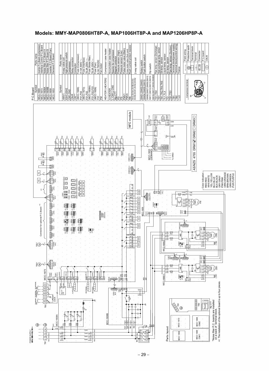
Models: MMY-MAP0806HT8P-A, MAP1006HT8P-A and MAP1206HP8P-AP
OW
ER
SU
PP
LY
Rot
ary
switc
hP
ush
butto
n sw
itch
2-w
ay v
alve
coi
l
Acc
umul
ator
cas
e he
ater
Rea
ctor
for c
ompr
esso
rM
agne
t con
tact
orP
ress
ure
sens
or (H
igh)
Pre
ssur
e se
nsor
(Low
)P
ulse
mot
or v
alve
(Mai
n)
Dip
sw
itch
63H
1,63
H2
CN
***
F01,
F02
A.H
EA
TER
L-C
M1,
L-C
M2
Mg-
CTT
PD
PS
PM
V1
PM
V4
RB
SV
2,S
V3A
,SV
3B,S
V3C
SV
3D,S
V41
,SV
42,S
V52
CM
1,C
M2
4WV
1
CN
-R
SW
01,S
W02
,SW
03S
W04
,SW
05,S
W15
SW
06,S
W07
,SW
09,S
W10
SW
11,S
W12
,SW
13,S
W14
FM
Par
ts n
ame
4-w
ay v
alve
coi
lH
igh
pres
sure
sw
itch
Com
pres
sor
Rel
ay c
onne
ctor
Con
nect
orFu
se (C
ompr
esso
r)31
.5A
500
VFu
se (I
nter
face
) T6
.3A
250
VFu
se (N
oise
filte
r)T6
.3A
250
VFu
se (F
an)
6.3A
750
VD
CFa
n m
otor
HE
ATE
R1,
HE
ATE
R2
Com
pres
sor c
ase
heat
er
(MC
C-1
669)
(MC
C-1
673)
F01,
F02
(MC
C-1
608A
)F0
1,F0
2,F0
3(M
CC
-165
9)
SW
16,S
W17
,SW
30,S
W80
0TD
1,TD
2TE
1TK
1,TK
2,TK
4,TK
5TL
1,TL
3TO TS
1,TS
3Sym
bol
MC
C-1
608B
MC
C-1
669
MC
C-1
608A
MC
C-1
659
MC
C-1
673
P.C
.Boa
rd
Sym
bol
Pul
se m
otor
val
ve (S
ub c
ool)
Rus
h cu
rren
t pro
tect
resi
stor
F01
CM
2
MS
3+
+
--
RED
WH
I BLK
MCC
-166
9(2)
SV
2
CN321 SV
3CS
V3B
CN
800
(Ser
vice
)S
WR
T
ON
1OF
F2
3 4
1SW
12ON OF
F
SW
17
23 4
SW
07
1
ON OFF
23 4
ON ONSW
13
OFF
ON
12
3 4
SW
09ON OF
F 12
3 4
2SW14
OFF 1
3 42SW
10
OFF 1
3 4
CN
511
CN
510
CN
512 FMM
S3
P>
63H
1
4
UV
W
CN301
+
CN
852
MCC
-165
9
CN322
SV
3ASV
3D
CN
101
CN
535
CN
851
CN
600
SW
04
SW
02D
600
D60
1D
602
SW
01
CN
30CN
31 CN
32
SW
03D
603
D60
4
SW05
SW
15
CN
523
CN
534
CN
505
CN
503
CN
507
CN
520
TK5
TK4
TL1
TE1
TOTS1
TD2
CN
501
CN
514
CN
513
PD 3
CN
502
CN
500
PS 3
31t°
TD1
UV
W
(WH
I)
(PN
K)
(WH
I)
(YE
L)
(GR
N)
(WH
I)
(YE
L)
(RE
D)
5
31 21 1 21 221 1 3 21
CN311(WHI)
(WHI)
(WHI)
(BLU
)
(WH
I)(B
LU)
(GR
N)
(BLU
)(G
RN
)(R
ED
)(W
HI)
31
63
24
15
21
CN302
CN303
CN211
CN212
CN213
CN
305
RE
DW
HI
BLK
CN19
CN20
23
41
34
RE
DW
HI
BLK
t° t° t° t°t° t°t°
(BLU
)
(BLU
)(R
ED
)
CN
852(
WH
I)
(RE
D)
63H
2P
>
(RE
D)
CN
306
L-CM
2
F01
F02CN13
CN12
CN11
CN10
2(B
LU)
CN10
2(W
HI)
-
CN
14
MC
C-1
608A
MC
C-1
608B
CM
1
CN23
CN24
CN
22
CN
317
CN
334
CN
50
CN
13
HE
ATER
1
A.H
EAT
ER
HE
ATE
R24W
V1
CN312 SV41
SV
42
ON OFF
ON
12
OFF 1
23
1
ON OFF
23
1OF
FON
23
MC
C-1
673
L2L3
N
CN
-R
TB2
CN
01
CN
03
CN
300
M
5
PMV
1
CN
508
F01
F02
CN
530
4
(BLU)
CCNN331144((WWHHII))
(BLU
)
(RED
)
CN
331(
WH
I)
CN
335(
GR
Y)
(RE
D)
(WH
I)
(WH
I)
(BLU
)
BLK
WH
IB
LK
CN
400
(WH
I)
(BLK
)31 31 31 31 31
75
31
+-
CN19
CN20
CN213
CN212
CN211
4
+-
CN11
CN12
CN13
F01
F02
RED
WH
IBL
KM
CC-1
669(
1)
4
RED
WHI
BLK
(BLK) (R
ED)
1 21 26
24
31
(RE
D)
1 3
CN
304
CN
11
CN
12
WHIBLK
BLK BLK
WHI
RED
RB
6T3
4T23L2
5L3Mg-CTT
F03
F02
F01
CN32
CN33
CN34
CN42
CN43
WH
IBL
KB
LK
U
UUU
TO CENTRAL
CONTROLLER
TO INDOOR
UNIT
TO OUTDOOR
UNIT
GR
Y
A1
RE
D
A2
Coil
Mg-
CTT
GR
Y
CN10
1(W
HI)
CN10
2(B
LU)
RED
GRY
TB1 RE
D
RE
D 2T11L1CN31 CN41
RE
DL1
4
SW
30
4 4S
W16
SW
11
SW
06
CN
509
(BLK
)
CN
23
CN
21
CN
903
TS3
(PU
R)
21t°
CN
531
CN
532
TK2
TK1
(BLK
)
(GR
N)
1 331
t°t°
SV5
2
34
PM
V4 5
CN
303
M (RED
)
62
43
1
A1 A2
MS
3
UV
WR
ED
WH
IB
LK
L-CM
1
CN12
CN01
CN
902
TL3
(PN
K)
1 2t°
CN
851(
WH
I)1
23
4
U1U2
SU3
U4U5
U6S
CN
851
(RE
D)
CN
852(
WH
I)
2 3 4 5 2 3 4 5
2 3 4 5
F01
44
2 3 4 5
CN
332(
BLU
)
YEL
BLU
CN
23
CN
21
12
34
5
12
34
5
13
13
13
13
31
21
1 32 4
1 32 4
OFF
ONS
W80
0
OFF
ONSW
800
OFF
ON
12
SW
800
12
12
*1C
onne
ctor
for o
ptio
nal P
.C.B
oard
MC
C-1
653
Par
ts n
ame
Inve
rter P
.C.B
oard
(Com
pres
sor)
Inte
rface
Con
trol P
.C.B
oard
Noi
se fi
lter P
.C.B
oard
AN
oise
filte
r P.C
.Boa
rd B
Inve
rter P
.C.B
oard
(Fan
)D
eman
d P
.C.B
oard
Term
inal
Con
nect
orP
.C.b
oard
Term
inal
blo
ck
Pro
tect
ive
earth
Fiel
d w
iring
CN
-R
TB1
TB2
T-01
Pipe
tem
p. s
enso
r (Di
scha
rge)
Heat
exc
hang
e te
mp.
sen
sor
Oil
tem
p. s
enso
rLi
quid
tem
p. s
enso
rA
ir te
mp.
sen
sor
Pip
e te
mp.
sen
sor (
Suc
tion)
Term
inal
blo
ck(p
ower
sup
ply)
Term
inal
blo
ck(c
ontro
l wiri
ng)
Tran
ce
1 3
CN
100
13
45
NFC
modu
le
MC
C-1
673
MC
C-1
659
1Th
e in
stal
latio
n of
the
optio
nal b
oard
is u
p to
four
pie
ces.
*
TB
1
TB
2
Mg-
CTT
*Noi
se fi
lter P
.C. b
oard
s ar
e in
stal
led
ona
back
of
term
inal
blo
ck.
Par
ts lay
out
MC
C-1
669
(CM
1)M
CC
-166
9 (C
M2)
L2L3
N
L1 U1U2
SU3
U4U5
U6S
T-0
1
MC
C-1
653
(DEM
AN
D)
RE
D:R
ED
WH
I:WH
ITE
YE
L:Y
ELL
OW
BLU
:BLU
EB
LK:B
LAC
KG
RY
:GR
AYP
NK
:PIN
KO
RN
:OR
ANG
EB
RN
:BR
OW
NG
RN
:GR
EE
NP
UR
:PU
RPL
E
Col
or in
dica
tion
1 3 (YE
L)
GRY
RED
(DE
MA
ND
)M
CC
-165
3
CN
102
(WH
I)
250V
~T3
.15A
Fuse
CN
100
(WH
I)
CN
101
(YE
L)
T-01
13
P02 BLK
DR
M3
DR
M2
DR
M1
CO
M
CN
01(B
LK)
To D
RE
D
CN
106
34
5(W
HI)
31
12
1
4
*1
AS
/NZS
475
5 D
RM
1
DR
M2
D
RM
3W
VU
Com
pres
sor t
erm
inal
− 29 −
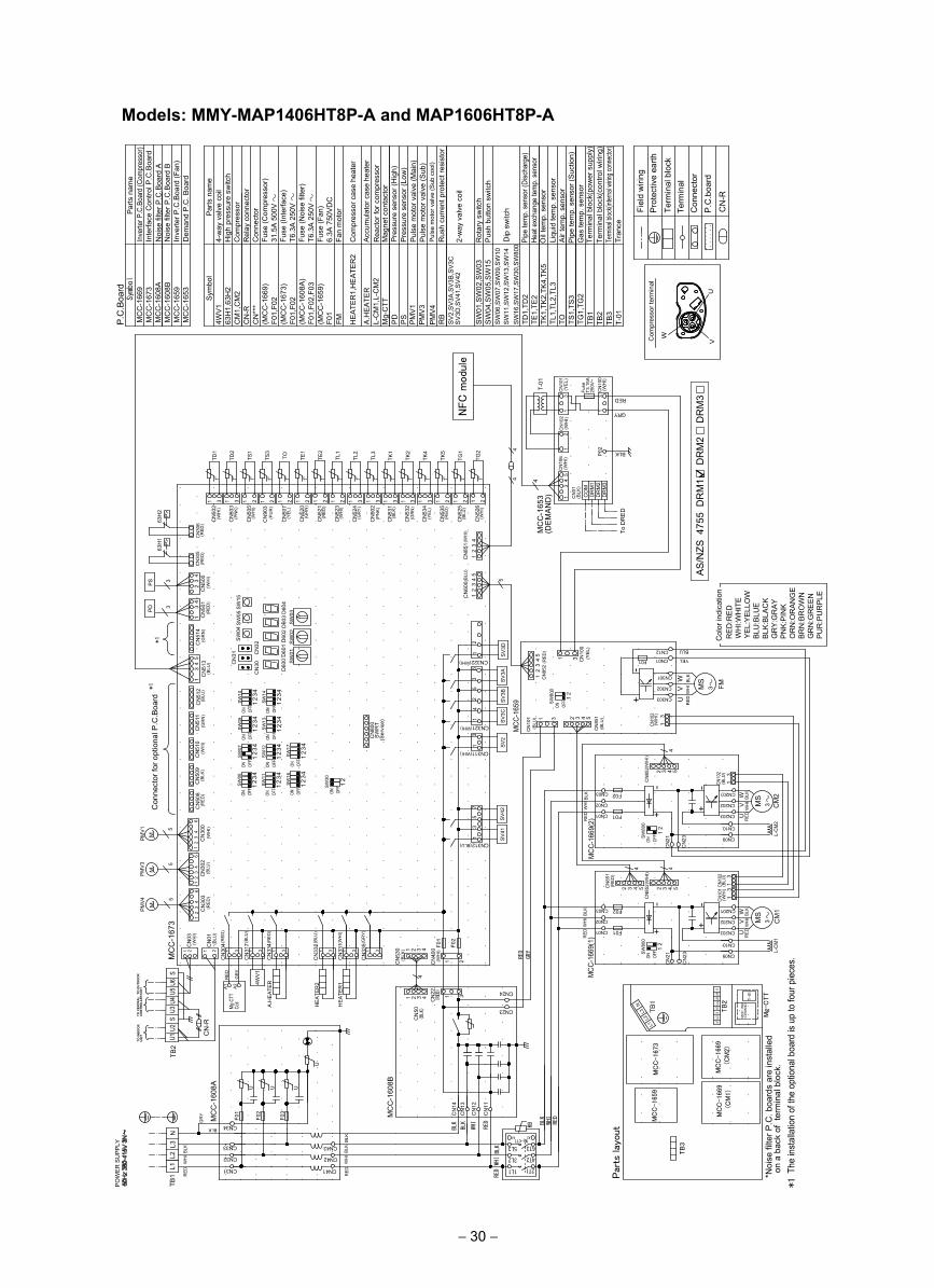
Models: MMY-MAP1406HT8P-A and MAP1606HT8P-AP
OW
ER
SU
PPLY
CM
2
MS
3+
+
--
RE
DW
HI B
LKM
CC-1
669(
2)
SV2
CN321 SV
3CSV
3B
CN
800
(Ser
vice
)S
WR
T
ON
1OF
F2
3 4
1SW12
ON OFF
SW
17
23 4
SW07
1
ON OFF
23 4
ON ONS
W13
OFF
ON
12
3 4
SW
09ON OF
F 12
3 4
2SW14
OFF 1
3 42SW10
OFF 1
3 4
CN
511
CN
510
CN
512 FMM
S3
P>
63H
1
4
UV
W
CN301
CN
852
MCC
-165
9
CN322
SV3A
SV3
D
CN
101
CN
535
CN
851
CN
600
SW
04
SW
02D
600
D60
1D
602
SW01
CN
30CN
31 CN
32
SW03
D60
3D
604
SW
05SW
15
CN
523
CN
524
CN
902
CN
534
CN
505
CN
503
CN
507
CN
520
TK5
TK4
TL3
TL2
TL1
TE1
TOTS1
TD2
CN
501
CN
514
CN
513
PD 3
CN
502
CN
500
PS 3
31t°
TD1
UV
W
(WH
I)
(PN
K)
(WH
I)
(YE
L)
(GR
N)
(WH
I)
(GR
Y)
(PN
K)
(YE
L)
(RE
D)
5
31 21 1 21 221 1 31 331 21
CN311(WHI)
(WHI)
(WHI)
(BLU
)
(WH
I)(B
LU)
(GR
N)
(BLU
)(G
RN
)(R
ED
)(W
HI)
31
63
24
15
21
CN302
CN303
CN201
CN202
CN203
CN
305
RE
DW
HI
BLK
CN
852
CN09
CN10
23
41
34
RE
DW
HI
BLK
t° t° t° t°t° t°t° t°t°
(BLU
)
(BLU
)
(RE
D)
(WH
I)
(RE
D)
63H
2P>
(RE
D)
CN
306
L-CM
2
F01
F02CN03
CN02
CN01
CN10
2(B
LU)
CN10
2(W
HI)
CN
14
MC
C-1
608A
MC
C-1
608B
CM
1
CN23
CN24
CN
22
CN
317
CN
334
CN
331
CN
335
CN
50
CN
13
HEA
TER
1
A.H
EAT
ER
HEA
TER
24WV
1
SV41
SV4
2
ON OFF
ON
12
OFF 1
23
1
ON OFF
23
1OF
FON
23
MC
C-1
673
L2
PMV
3 5
CN
302
L3N
CN
01
CN
03
M
CN
300
M
5
PMV
1
CN
508
F01
F02
CN
530
4
CN312(BLU)
(BLU
)
(RE
D)
(WH
I)
(GR
Y)
(RE
D)
(WH
I)(B
LU)
(WH
I)
(BLU
)
BLK
WH
IB
LK
CN
400
(WH
I)
(BLK
)31 31 31 31 31
75
31
+-
CN09
CN10
CN203
CN202
CN201
4
+-
CN01
CN02
CN03
F01
F02
CN
852CN
851
RE
DW
HI
BLK
MCC
-166
9(1)
4
RED
WHI
BLK
(BLK)
(RED)
(RE
D)
(WH
I)
1 21 26
24
31
62
43
1
(RE
D)
1 3
CN
304
CN
11
CN
12
WHIBLK
BLK BLK
WHI
RED
RB
6T3
4T23L2
5L3Mg-CTT
F03
F02
F01
CN32
CN33
CN34
CN42
CN43
WH
IB
LKB
LK
U
UUU
GR
Y
A1
RE
D
A2
Coil
Mg-C
TT
GR
Y
CN10
1(W
HI)
CN10
2(B
LU)
RED
GRY
TB1 RE
D
RE
D 2T11L1CN31 CN41
RE
DL1
4
SW
30
4 4S
W16
SW11
SW06
CN
509
(BLK
)
CN
903
TS3
(PU
R)
21t°
CN
521
TE2
(RE
D)
1 2t°
CN
531
CN
532
TK2
TK1
(BLK
)
(GR
N)
1 331
t°t°
CN
525
TG1
(BLU
)21
t°
CN
526
TG2
(WH
I)21
t°
PM
V4 5
CN
303
M (RE
D)
62
43
1
A1 A2
MS
3
UV
WR
ED
WH
IB
LK
L-CM
1
CN12
CN01
CN
851(
WH
I)
12
34
CN
-R
TB2
TO CENTRAL
CONTROLLER
TO INDOOR
UNIT
TO OUTDOOR
UNIT
2 23 34 45 5
2 3 4 51 3
F01
44
2 3 4 5
U1U2
SU3
U4U5
U6S
CN
332(
BLU
)
YEL
BLU
CN
23
CN
21
CN
23
CN
21
+-
13
13
13
13
12
34
5
12
34
5
1 3
1 2
1 32 4
1 2 3 4
OFF
ON
12
SW
800
OFF
ONSW
800
12
OFF
ONS
W80
0
12
Rot
ary
switc
hP
ush
butto
n sw
itch
2-w
ay v
alve
coi
l
Dip
sw
itch
63H
1,63
H2
CN
***
F01,
F02
RB
SV
2,S
V3A
,SV3
B,S
V3C
SV
3D,S
V41
,SV
42
PM
V4
CM
1,C
M2
4WV
1
CN
-R
SW
01,S
W02
,SW
03S
W04
,SW
05,S
W15
SW
06,S
W07
,SW
09,S
W10
SW
11,S
W12
,SW
13,S
W14
FM
Par
ts n
ame
4-w
ay v
alve
coi
lH
igh
pres
sure
sw
itch
Com
pres
sor
Rel
ay c
onne
ctor
Con
nect
orFu
se (C
ompr
esso
r)31
.5A
500
VFu
se (I
nter
face
) T6
.3A
250
VFu
se (N
oise
filte
r)T6
.3A
250
VFu
se (F
an)
6.3A
750
VD
CFa
n m
otor
PD
PS
HE
ATE
R1,
HE
ATE
R2
Com
pres
sor c
ase
heat
er
L-C
M1,
L-C
M2
A.H
EA
TER
(MC
C-1
669)
(MC
C-1
673)
F01,
F02
(MC
C-1
608A
)F0
1,F0
2,F0
3(M
CC
-165
9)
Symbol
MC
C-1
608B
MC
C-1
669
MC
C-1
608A
MC
C-1
659
MC
C-1
673
P.C
.Boa
rd
Sym
bol
Mg-
CTT
Rus
h cu
rren
t pro
tect
resi
stor
F01
PM
V3
PM
V1
Acc
umul
ator
cas
e he
ater
Rea
ctor
for c
ompr
esso
rM
agne
t con
tact
orP
ress
ure
sens
or (H
igh)
Pre
ssur
e se
nsor
(Low
)P
ulse
mot
or v
alve
(Mai
n)P
ulse
mot
or v
alve
(Sub
)P
ulse
mot
or v
alve
(Sub
coo
l)
SW
16,S
W17
,SW
30,S
W80
0TD
1,TD
2TE
1,TE
2TK
1,TK
2,TK
4,TK
5TL
1,TL
2,TL
3TO TS
1,TS
3TG
1,TG
2TB
1
VU
Com
pres
sor t
erm
inal
W
Term
inal
Con
nect
orP
.C.b
oard
Term
inal
blo
ck
Pro
tect
ive
earth
Fiel
d w
iring
CN
-RR
ED
:RE
DW
HI:W
HIT
EY
EL:
YE
LLO
WBL
U:B
LUE
BLK
:BLA
CK
GR
Y:G
RAY
PN
K:P
INK
OR
N:O
RAN
GE
BRN
:BR
OW
NG
RN
:GR
EE
NP
UR
:PU
RPL
E
Col
or in
dica
tion
MC
C-1
653
Par
ts n
ame
Inve
rter P
.C.B
oard
(Com
pres
sor)
Inte
rface
Con
trol P
.C.B
oard
Noi
se fi
lter P
.C.B
oard
AN
oise
filte
r P.C
.Boa
rd B
Inve
rter P
.C.B
oard
(Fan
)D
eman
d P
.C. B
oard
TB2
TB3
T-01
Pipe
tem
p. s
enso
r (Di
scha
rge)
Heat
exc
hang
e te
mp.
sen
sor
Oil
tem
p. s
enso
rLi
quid
tem
p. s
enso
rA
ir te
mp.
sen
sor
Pip
e te
mp.
sen
sor (
Suc
tion)
Gas
tem
p. s
enso
r Te
rmin
al b
lock
(pow
er s
uppl
y)Te
rmin
al b
lock
(con
trol w
iring
)Te
rmina
l bloc
k(inte
rnal w
iring c
onne
ctor)
Tran
ce
13
45
NFC
modu
le
Par
ts lay
out
MC
C-1
659
MC
C-1
673
TB
1
TB
2
Mg-
CTT
*Noi
se fi
lter P
.C. b
oard
s ar
e in
stal
led
ona
back
of
term
inal
blo
ck.
MC
C-1
669
(C
M1)
MC
C-1
669
(C
M2)
L2L3
N
L1 U1U2
SU3
U4U5
U6S
TB
3
1 T
he in
stal
latio
n of
the
optio
nal b
oard
is u
p to
four
pie
ces.
*
MC
C-1
653
(DEM
AN
D)
T-0
1
GRY
RED
(DE
MA
ND
)M
CC
-165
3
CN
102
(WH
I)
250V
~T3
.15A
Fuse
CN
100
(WH
I)
CN
101
(YE
L)
T-01
13
P02 BLK
DR
M3
DR
M2
DR
M1
CO
M
CN
01(B
LK)
To D
RE
D
CN
106
34
5(W
HI)
31
12
1
4
31 (YEL
)C
N10
0
Con
nect
or fo
r opt
iona
l P.C
.Boa
rd*1
*1
AS
/NZS
475
5 D
RM
1
DR
M2
D
RM
3
− 30 −
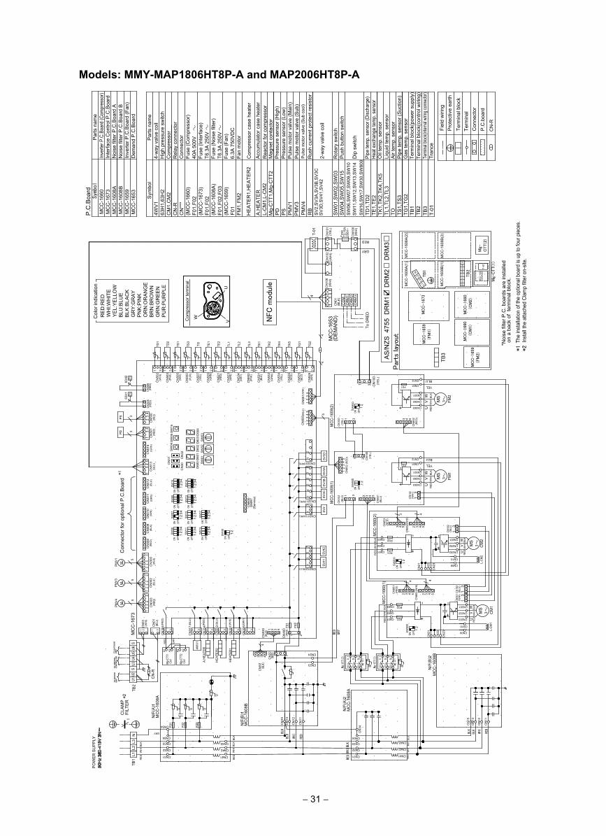
Models: MMY-MAP1806HT8P-A and MAP2006HT8P-AP
OW
ER
SU
PP
LY
CM
2
MS
3+
+
--MCC
-166
0(2)
SV
2
CN321 SV3C
SV
3B
CN
800
(Ser
vice
)S
WR
T
ON
1OF
F2
3 4
1SW
12ON OF
F
SW
17
23 4
SW
07
1
ON OFF
23 4
ON ONS
W13
OFF
ON
12
3 4
SW
09ON OF
F 12
3 4
2SW
14
OFF 1
3 42SW
10
OFF 1
3 4
CN
511
CN
510
CN
512 FM
1
MS
3
P>
63H
1
4
UV
W
CN301
+
CN
852
MCC
-165
9(1)
CN322
SV3
AS
V3D
CN
101
CN
535
CN
851
CN
600
SW04
SW
02D
600
D60
1D
602
SW
01
CN
30CN
31 CN
32
SW03
D60
3D
604
SW05
SW
15
CN
523
CN
524
CN
902
CN
534
CN
505
CN
503
CN
507
CN
520
TK5
TK4
TL3
TL2
TL1
TE1
TOTS1
TD2
CN
501
CN
514
CN
513
PD 3
CN
502
CN
500
PS 3
31t°
TD1
UV
W
(WH
I)
(PN
K)
(WH
I)
(YE
L)
(GR
N)
(WH
I)
(GR
Y)
(PN
K)
(YEL
)
(RE
D)
5
31 21 1 21 221 1 31 331 21
CN311(WHI)
(WHI)
(WHI)
(BLU
)
(WH
I)(B
LU)
(GR
N)
(BLU
)(G
RN
)(R
ED)
(WH
I)
31
63
24
15
21
CN302
CN303
CN201
CN202
CN203
CN
305
RE
DW
HI
BLK
CN
852
CN09
CN10
RED
WH
IBLK
23
41
34
RE
DW
HI
BLK
t° t° t° t°t° t°t° t°t°
(BLU
)
(BLU
)
(RED
)
(WH
I)
(RE
D)
63H
2P
>
(RED
)C
N30
6
L-CM
2
F01
F02CN03
CN02
CN01
CN10
2(B
LU)
CN10
2(W
HI)
-
CN
15
MC
C-1
608A
MC
C-1
608B
CM
1
CN23
CN24
CN
22
CN
317
CN
334
CN
50
CN
13
HEA
TER
1
A.H
EAT
ER
HE
ATER
24WV1
SV
41SV
42
ON OFF
ON
12
OFF 1
23
1
ON OFF
23
1OF
FON
23
MC
C-1
673
L2
PM
V3 5
CN
302
L3N
CN
01
CN
03
M
CN
300
M
5
PMV
1
CN
508
F01
F02
CN
530
4CN312(BLU)
(BLU
)
(RE
D)
CN
331(
WH
I)
CN
335(
GR
Y)
(RE
D)
(WH
I)(B
LU)
(WH
I)
(BLU
)
GRY
WH
IB
LK
CN
400
(WH
I)
(BLK
)31 31 31 31 31
75
31
+-
CN09
CN10
CN203
CN202
CN201
4
+-
CN01
CN02
CN03
F01
F02
CN
852CN
851
MCC
-166
0(1) 4
RED
WH
IBL
K
RED
WHI
BLK
(BLK)
(RED)
(RE
D)
(WH
I)
1 21 26
24
31
62
43
1
(RED
)1 3
CN
304
CN
11
CN
12
WHIBLK
BLK
F03
F02
F01
CN32
CN33
CN34
CN42
CN43
WH
IBL
KBL
K
U
UUU
GR
Y
RE
DA
1 A2Co
ilMg
-CTT
1
CN10
1(W
HI)
CN10
2(B
LU)
RED
GRY
TB1 RE
D
RE
D CN31 CN41
RE
DL1
4
SW
30
4 4S
W16
SW
11
SW
06
CN
509
(BLK
)
CN
903
TS3
(PU
R)
21t°
CN
521
TE2
(RED
)
1 2t°
CN
531
CN
532
TK2
TK1
(BLK
)
(GR
N)
1 331
t°t°
CN
525
TG1
(BLU
)21
t°
CN
526
TG2
(WH
I)21
t°
PM
V4 5
CN
303
M (RED
)
62
43
1 MS
3
UV
WR
EDW
HI
BLK
L-CM
1
A1 A2
Coil
Mg-C
TT2
RB
6T34T2
3L2 5L3
Mg-CTT
2T1
1L1
CN
15
MC
C-1
608B
CN
13
RED
WHI
BLK
CN
11
CN
12
BLK
CN32
CN33
CN
34
CN42
CN43
WH
IB
LKB
LK
CN31 CN41
RE
D
FM2
MS
3
UV
W
CN301
+
CN
852
MCC
-165
9(2)
CN
100
CN302
CN303R
ED
WH
IB
LK
(YEL
)
(RE
D)
-
CN
851
(RE
D)
CN
100
(YEL
)
CN01
CN12
CN04
MC
C-1
608A
Mg-CTT(2)
N/F
(A)2
N/F
(B)2
N/F
(A)1
N/F
(B)1
CN04
RB
6T34T2
3L2 5L3
Mg-CTT
2T1
1L1
Mg-CTT(1)
CN01
CN12
2 3 4 5
5 54 433 2
2 23 34 45 5
CN
851(
WH
I)
12
34
CN
-R
TB2
TO CENTRAL
CONTROLLER
TO INDOOR
UNIT
TO OUTDOOR
UNIT
3 4 51 3
31
F01
F01
3
1 3
U1U2
SU3
U4U5
U6S
CN
332(
BLU
)
CLA
MP
FILT
ER
*21
YEL
BLU
YEL
BLU
CN
22
CN
21
CN
22
CN
21
CN
23
CN
23
12
34
5
12
45
1 2 3 4 1 3
1 2 3 4
1 2
13
13
13
13
3
OFF
ON
12
SW
800
OFF
ON
12
SW
800
OFF
ON
12
SW
800
OFF
ON
12
SW
800
P.C
.Boa
rd
Rot
ary
switc
hP
ush
butto
n sw
itch
2-w
ay v
alve
coi
l
Dip
sw
itch
63H
1,63
H2
CN
***
F01,
F02
A.H
EA
TER
L-C
M1,
L-C
M2
Mg-
CTT
1,M
g-C
TT2
PD
PS
PM
V1
PM
V3
PM
V4
RB
SV2
,SV
3A,S
V3B
,SV3
CS
V3D
,SV
41,S
V42
CM
1,C
M2
4WV
1
CN
-R
SW
01,S
W02
,SW
03S
W04
,SW
05,S
W15
SW
06,S
W07
,SW
09,S
W10
SW
11,S
W12
,SW
13,S
W14
FM1,
Par
ts n
ame
4-w
ay v
alve
coi
lH
igh
pres
sure
sw
itch
Com
pres
sor
Rel
ay c
onne
ctor
Con
nect
orFu
se (C
ompr
esso
r)40
A 5
00V
Fuse
(Int
erfa
ce)
T6.3
A 2
50V
Fuse
(Noi
se fi
lter)
T6.3
A 2
50V
Fuse
(Fan
)6.
3A 7
50V
DC
Fan
mot
or
HE
ATE
R1,
HE
ATE
R2
Com
pres
sor c
ase
heat
er
(MC
C-1
660)
(MC
C-1
673)
F01,
F02
(MC
C-1
608A
)F0
1,F0
2,F0
3(M
CC
-165
9)
Symbol
MC
C-1
608B
MC
C-1
660
MC
C-1
608A
MC
C-1
659
MC
C-1
673
Sym
bol
Rus
h cu
rren
t pro
tect
resi
stor
Term
inal
Con
nect
orP
.C.b
oard
Term
inal
blo
ck
Pro
tect
ive
earth
Fiel
d w
iring
F01
FM2
CN
-R
Acc
umul
ator
cas
e he
ater
Rea
ctor
for c
ompr
esso
rM
agne
t con
tact
orP
ress
ure
sens
or (H
igh)
Pre
ssur
e se
nsor
(Low
)P
ulse
mot
or v
alve
(Mai
n)P
ulse
mot
or v
alve
(Sub
)Pu
lse
mot
or v
alve
(Sub
coo
l)
SW
16,S
W17
,SW
30,S
W80
0TD
1,TD
2TE
1,TE
2TK
1,TK
2,TK
4,TK
5TL
1,TL
2,TL
3TO TS
1,TS
3TG
1,TG
2TB
1
MC
C-1
653
Par
ts n
ame
Inve
rter P
.C.B
oard
(Com
pres
sor)
Inte
rface
Con
trol P
.C.B
oard
Noi
se fi
lter P
.C.B
oard
AN
oise
filte
r P.C
.Boa
rd B
Inve
rter P
.C.B
oard
(Fan
)D
eman
d P
.C.B
oard
TB2
TB3
T-01
Pipe
tem
p. s
enso
r (Di
scha
rge)
Heat
exc
hang
e te
mp.
sen
sor
Oil
tem
p. s
enso
rLi
quid
tem
p. s
enso
rA
ir te
mp.
sen
sor
Pip
e te
mp.
sen
sor (
Suc
tion)
Gas
tem
p. s
enso
rTe
rmin
al b
lock
(pow
er s
uppl
y)Te
rmin
al b
lock
(con
trol w
iring
)Te
rmina
l bloc
k(inte
rnal w
iring c
onne
ctor)
Tran
ceM
CC
-165
9 (FM
1)
MC
C-1
673
TB
1
TB
2
Mg-
CTT(1
)
AS
/NZS
475
5 D
RM
1
DR
M2
D
RM
3Par
ts lay
out MC
C-1
660
(C
M1)
MC
C-1
660
(C
M2)
L2L3
N
L1
MC
C-1
659
(FM
2)
MC
C-1
608A
(1)
MC
C-1
608B
(1)
U1U2
SU3
U4U5
U6S
Mg-
CTT(2
)
MC
C-1
608A
(2)
MC
C-1
608B
(2)
TB
3
MC
C-1
653
(DEM
AN
D)
T-0
1
44
VU
Com
pres
sor t
erm
inal
WRED
:RE
DW
HI:W
HIT
EY
EL:Y
ELLO
WB
LU:B
LUE
BLK
:BLA
CK
GR
Y:G
RA
YP
NK
:PIN
KO
RN
:OR
AN
GE
BR
N:B
RO
WN
GR
N:G
RE
EN
PU
R:P
UR
PLE
Col
or in
dica
tion
GRY
RED
(DE
MA
ND
)M
CC
-165
3C
N10
2(W
HI)
250V
~T3
.15A
Fuse
CN
100
(WH
I)
CN
101
(YE
L)
T-01
13
DR
M3
DR
M2
DR
M1
CO
M
CN
01(B
LK)
To D
RE
D
CN
106
34
5(W
HI)
31
12
1
4
1 3 CN
100
(YE
L)
*1C
onne
ctor
for o
ptio
nal P
.C.B
oard
13
45
The
inst
alla
tion
of th
e op
tiona
l boa
rd is
up
to fo
ur p
iece
s.In
stal
l the
atta
ched
Cla
mp
filter
on-
site.
*1 *2
*Noi
se fi
lter P
.C. b
oard
s ar
e in
stal
led
ona
back
ofte
rmin
al b
lock
.
NFC
modu
le
− 31 −
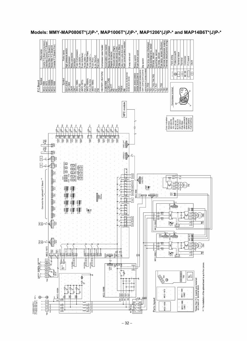
− 32 −
Models: MMY-MAP0806T*(J)P-*, MAP1006T*(J)P-*, MAP1206*(J)P-* and MAP14B6T*(J)P-*
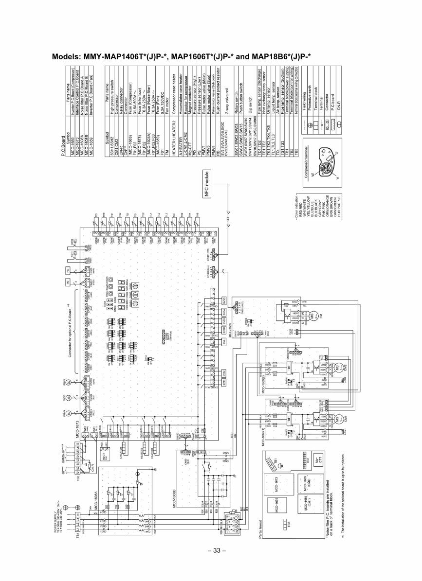
− 33 −
Models: MMY-MAP1406T*(J)P-*, MAP1606T*(J)P-* and MAP18B6*(J)P-*
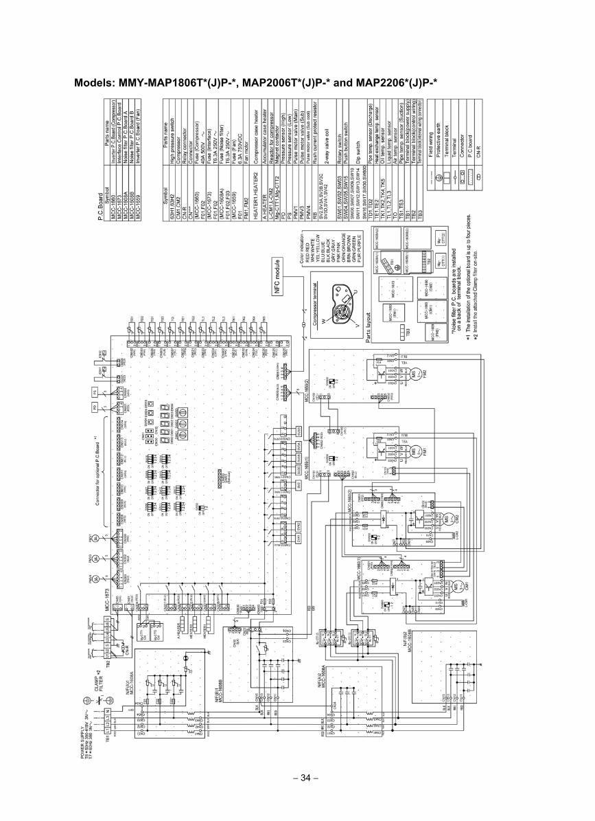
− 34 −
Models: MMY-MAP1806T*(J)P-*, MAP2006T*(J)P-* and MAP2206*(J)P-*
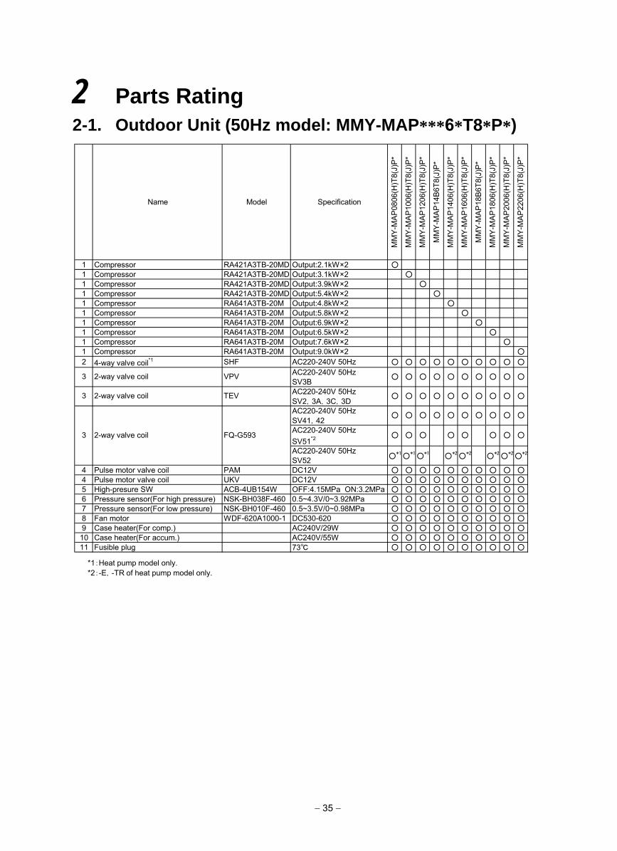
2 Parts Rating2-1. Outdoor Unit (50Hz model: MMY-MAP***6*T8*P*)
− 35 −
Name Model Specification
MM
Y-M
AP
0806
(H)T
8(J)
P*
MM
Y-M
AP
1006
(H)T
8(J)
P*
MM
Y-M
AP
1206
(H)T
8(J)
P*
MM
Y-M
AP
14B
6T8(
J)P
*
MM
Y-M
AP
1406
(H)T
8(J)
P*
MM
Y-M
AP
1606
(H)T
8(J)
P*
MM
Y-M
AP
18B
6T8(
J)P
*
MM
Y-M
AP
1806
(H)T
8(J)
P*
MM
Y-M
AP
2006
(H)T
8(J)
P*
MM
Y-M
AP
2206
(H)T
8(J)
P*
1 Compressor RA421A3TB-20MD Output:2.1kW×2 1 Compressor RA421A3TB-20MD Output:3.1kW×2 1 Compressor RA421A3TB-20MD Output:3.9kW×2 1 Compressor RA421A3TB-20MD Output:5.4kW×2 1 Compressor RA641A3TB-20M Output:4.8kW×2 1 Compressor RA641A3TB-20M Output:5.8kW×2 1 Compressor RA641A3TB-20M Output:6.9kW×2 1 Compressor RA641A3TB-20M Output:6.5kW×2 1 Compressor RA641A3TB-20M Output:7.6kW×2 1 Compressor RA641A3TB-20M Output:9.0kW×2
2 4-way valve coil*1 SHF AC220-240V 50Hz
AC220-240V 50HzSV3BAC220-240V 50HzSV2,3A,3C,3DAC220-240V 50HzSV41,42AC220-240V 50HzSV51*2
AC220-240V 50HzSV52
4 Pulse motor valve coil PAM DC12V 4 Pulse motor valve coil UKV DC12V 5 High-presure SW ACB-4UB154W OFF:4.15MPa ON:3.2MPa 6 Pressure sensor(For high pressure) NSK-BH038F-460 0.5~4.3V/0~3.92MPa 7 Pressure sensor(For low pressure) NSK-BH010F-460 0.5~3.5V/0~0.98MPa 8 Fan motor WDF-620A1000-1 DC530-620 9 Case heater(For comp.) AC240V/29W 10 Case heater(For accum.) AC240V/55W 11 Fusible plug 73
*2 2* *2
3 2-way valve coil FQ-G593
1* *1 1* *2 2*
3 2-way valve coil TEV
3 2-way valve coil VPV
*1:Heat pump model only.*2:-E,-TR of heat pump model only.
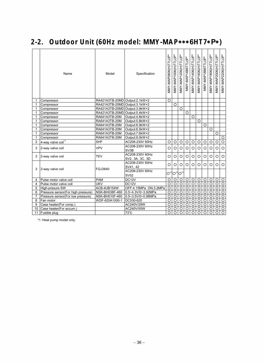
2-2. Outdoor Unit (60Hz model: MMY-MAP∗∗∗6HT7∗P∗)
− 36 −
Name Model Specification
MM
Y-M
AP
0806
(H)T
7(J)
P*
MM
Y-M
AP
1006
(H)T
7(J)
P*
MM
Y-M
AP
1206
(H)T
7(J)
P*
MM
Y-M
AP
14B
6T7(
J)P
*
MM
Y-M
AP
1406
(H)T
7(J)
P*
MM
Y-M
AP
1606
(H)T
7(J)
P*
MM
Y-M
AP
18B
6T7(
J)P
*
MM
Y-M
AP
1806
(H)T
7(J)
P*
MM
Y-M
AP
2006
(H)T
7(J)
P*
MM
Y-M
AP
2206
(H)T
7(J)
P*
1 Compressor RA421A3TB-20MD Output:2.1kW×2 1 Compressor RA421A3TB-20MD Output:3.1kW×2 1 Compressor RA421A3TB-20MD Output:3.9kW×2 1 Compressor RA421A3TB-20MD Output:5.4kW×2 1 Compressor RA641A3TB-20M Output:4.8kW×2 1 Compressor RA641A3TB-20M Output:5.8kW×2 1 Compressor RA641A3TB-20M Output:6.9kW×2 1 Compressor RA641A3TB-20M Output:6.5kW×2 1 Compressor RA641A3TB-20M Output:7.6kW×2 1 Compressor RA641A3TB-20M Output:9.0kW×2
2 4-way valve coil*1 SHF AC208-230V 60Hz
AC208-230V 60HzSV3BAC208-230V 60HzSV2,3A,3C,3DAC208-230V 60HzSV41,42AC208-230V 60HzSV52
4 Pulse motor valve coil PAM DC12V 4 Pulse motor valve coil UKV DC12V 5 High-presure SW ACB-4UB154W OFF:4.15MPa ON:3.2MPa 6 Pressure sensor(For high pressure) NSK-BH038F-460 0.5~4.3V/0~3.92MPa 7 Pressure sensor(For low pressure) NSK-BH010F-460 0.5~3.5V/0~0.98MPa 8 Fan motor WDF-620A1000-1 DC530-620 9 Case heater(For comp.) AC240V/29W 10 Case heater(For accum.) AC240V/55W 11 Fusible plug 73
3
2-way valve coil FQ-D640
3 2-way valve coil TEV
*1*1*1
3 2-way valve coil VPV
*1:Heat pump model only.
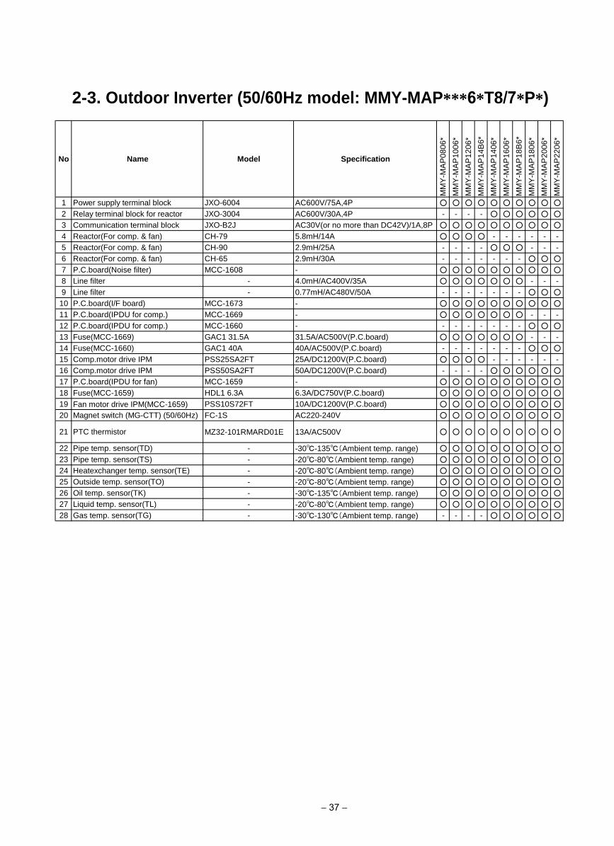
2-3. Outdoor Inverter (50/60Hz model: MMY-MAP***6*T8/7*P*)
− 37 −
No Name Model Specification
MM
Y-M
AP
08
06
*
MM
Y-M
AP
10
06
*
MM
Y-M
AP
12
06
*
MM
Y-M
AP
14
B6
*
MM
Y-M
AP
14
06
*
MM
Y-M
AP
16
06
*
MM
Y-M
AP
18
B6
*
MM
Y-M
AP
18
06
*
MM
Y-M
AP
20
06
*
MM
Y-M
AP
22
06
*
1 Power supply terminal block JXO-6004 AC600V/75A,4P
2 Relay terminal block for reactor JXO-3004 AC600V/30A,4P - - - -
3 Communication terminal block JXO-B2J AC30V(or no more than DC42V)/1A,8P
4 Reactor(For comp. & fan) CH-79 5.8mH/14A - - - - - -
5 Reactor(For comp. & fan) CH-90 2.9mH/25A - - - - - - -
6 Reactor(For comp. & fan) CH-65 2.9mH/30A - - - - - - -
7 P.C.board(Noise filter) MCC-1608 -
8 Line filter - 4.0mH/AC400V/35A - - -
9 Line filter - 0.77mH/AC480V/50A - - - - - - -
10 P.C.board(I/F board) MCC-1673 -
11 P.C.board(IPDU for comp.) MCC-1669 - - - -
12 P.C.board(IPDU for comp.) MCC-1660 - - - - - - - -
13 Fuse(MCC-1669) GAC1 31.5A 31.5A/AC500V(P.C.board) - - -
14 Fuse(MCC-1660) GAC1 40A 40A/AC500V(P.C.board) - - - - - - -
15 Comp.motor drive IPM PSS25SA2FT 25A/DC1200V(P.C.board) - - - - - -
16 Comp.motor drive IPM PSS50SA2FT 50A/DC1200V(P.C.board) - - - -
17 P.C.board(IPDU for fan) MCC-1659 -
18 Fuse(MCC-1659) HDL1 6.3A 6.3A/DC750V(P.C.board)
19 Fan motor drive IPM(MCC-1659) PSS10S72FT 10A/DC1200V(P.C.board)
20 Magnet switch (MG-CTT) (50/60Hz) FC-1S AC220-240V
21 PTC thermistor MZ32-101RMARD01E 13A/AC500V
22 Pipe temp. sensor(TD) - -30-135(Ambient temp. range)
23 Pipe temp. sensor(TS) - -20-80(Ambient temp. range)
24 Heatexchanger temp. sensor(TE) - -20-80(Ambient temp. range)
25 Outside temp. sensor(TO) - -20-80(Ambient temp. range)
26 Oil temp. sensor(TK) - -30-135(Ambient temp. range)
27 Liquid temp. sensor(TL) - -20-80(Ambient temp. range)
28 Gas temp. sensor(TG) - -30-130(Ambient temp. range) - - - -
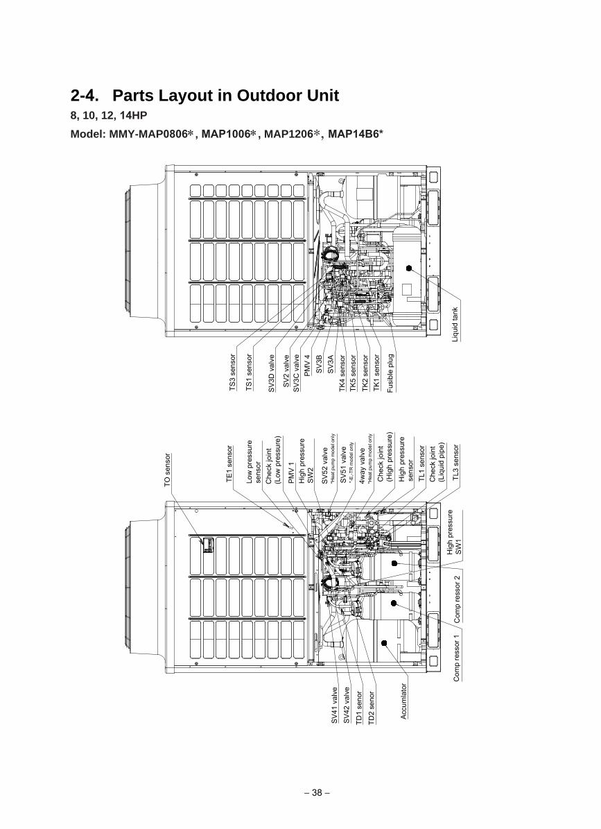
2-4. Parts Layout in Outdoor Unit 8, 10, 12, 14HP
Model: MMY-MAP0806∗, MAP1006∗, MAP1206∗, MAP14B6*
TO s
enso
r
Low
pre
ssur
e se
nsor
TE1
sens
or
Che
ck jo
int
(Low
pre
ssur
e)
PM
V 1
Hig
h pr
essu
reS
W2
SV
52 v
alve
*Hea
t pum
p m
odel
onl
y
4way
val
ve*H
eat p
ump
mod
el o
nly
Che
ck jo
int
(Hig
h pr
essu
re)
TL1
sens
or
TL3
sens
or
Che
ck jo
int
(Liq
uid
pipe
)H
igh
pres
sure
SW
1C
omp
ress
or 1
Com
p re
ssor
2
Acc
umla
tor
TD2
seno
r
TD1
seno
r
SV
42 v
alve
SV
41 v
alve
TS3
sens
or
TS1
sens
or
SV
3D v
alve
SV
2 va
lve
SV
3C v
alve
PM
V 4
SV
3BS
V3A
TK4
sens
orTK
5 se
nsor
TK2
sens
orTK
1 se
nsor
Fusi
ble
plug
Liqu
id ta
nk
SV
51 v
alve
*-E
,-TR
mod
el o
nly
Hig
h pr
essu
rese
nsor
− 38 −
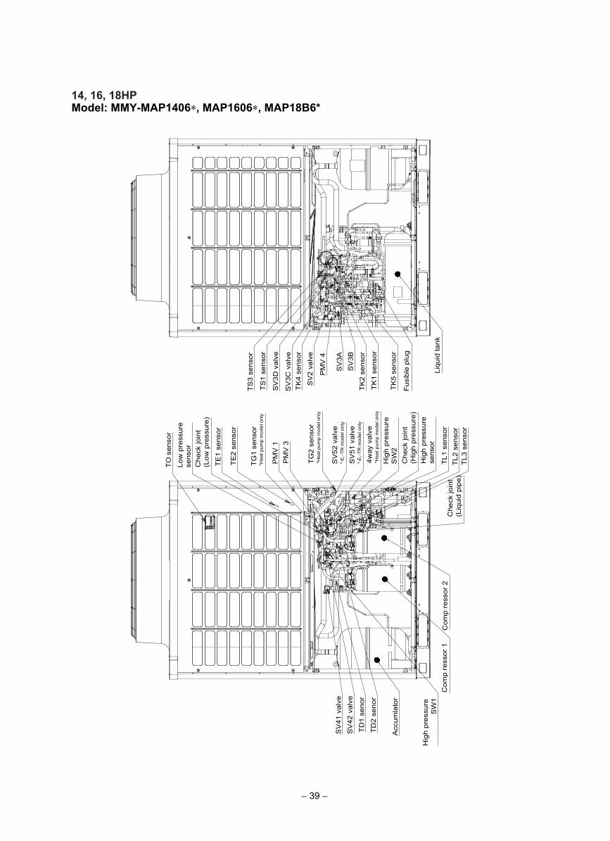
14, 16, 18HPModel: MMY-MAP1406∗, MAP1606∗, MAP18B6*
TO
sen
sor
Com
p re
ssor
1
Low
pre
ssur
e se
nsor
TE
1 se
nsor
Che
ck jo
int
(Low
pre
ssur
e)
PM
V 1
Hig
h pr
essu
reS
W2
SV
52 v
alve
*-E
,-TR
mod
el o
nly
4way
val
ve*H
eat p
ump
mod
el o
nly
Che
ck jo
int
(Hig
h pr
essu
re)
TL1
sen
sor
TL2
sen
sor
Che
ck jo
int
(Liq
uid
pipe
)
TS
3 se
nsor
TS
1 se
nsor
SV
3D v
alve
SV
2 va
lve
SV
3C v
alve
PM
V 4
SV
3BS
V3A
TK
4 se
nsor
TK
5 se
nsor
TK
2 se
nsor
TK
1 se
nsor
Fus
ible
plu
g
Liqu
id ta
nk
SV
51 v
alve
*-E
,-TR
mod
el o
nly
Acc
umla
tor
TD
2 se
nor
TD
1 se
nor
SV
42 v
alve
SV
41 v
alve
TE
2 se
nsor
TG
1 se
nsor
*Hea
t pum
p m
odel
onl
y
TG
2 se
nsor
*Hea
t pum
p m
odel
onl
y
PM
V 3
TL3
sen
sor
Hig
h pr
essu
rese
nsor
Com
p re
ssor
2
Hig
h pr
essu
reS
W1
− 39 −
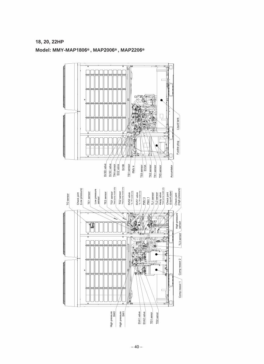
18, 20, 22HP
Model: MMY-MAP1806∗, MAP2006∗, MAP2206∗
TO s
enso
r
TE1
sens
or
Che
ck jo
int
(Low
pre
ssur
e)
PM
V 1
Hig
h pr
essu
reS
W2
SV
52 v
alve
*-E
,-TR
mod
el o
nly
4way
val
ve*H
eat p
ump
mod
el o
nly
Che
ck jo
int
(Hig
h pr
essu
re)
TL1
sens
orTL
2 se
nsor
TS3
sens
or
TS1
sens
or
SV
3D v
alve
SV
2 va
lve
SV
3C v
alve
PM
V 4
SV
3B
SV
3A
TK4
sens
or
TK5
sens
or
TK2
sens
or
TK1
sens
or
Fusi
ble
plug
SV
51 v
alve
*-E
,-TR
mod
el o
nly
TE2
sens
or
TG1
sens
or*H
eat p
ump
mod
el o
nly
TG2
sens
or*H
eat p
ump
mod
el o
nly
PM
V 3
TL3
sens
orH
igh
pres
sure
se
nsor
Com
p re
ssor
1
Che
ck jo
int
(Liq
uid
pipe
)
Com
p re
ssor
2
Acc
umla
tor
TD2
seno
r
TD1
seno
r
SV
42 v
alve
SV4
1 va
lve
Hig
h pr
essu
reS
W1
Liqu
id ta
nk
Low
pre
ssur
e se
nsor
− 40 −
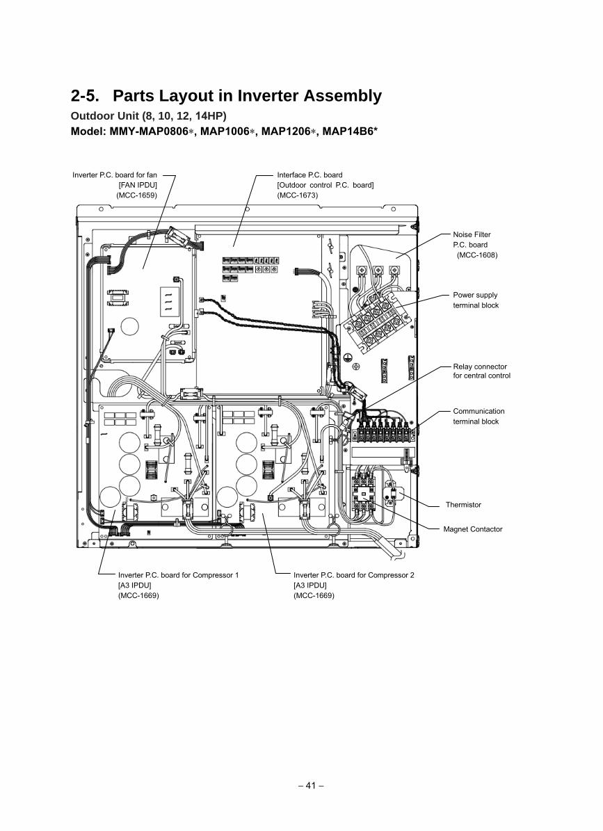
2-5. Parts Layout in Inverter Assembly Outdoor Unit (8, 10, 12, 14HP)Model: MMY-MAP0806∗, MAP1006∗, MAP1206∗, MAP14B6*
Inverter P.C. board for fan [FAN IPDU]
(MCC-1659)
Interface P.C. board [Outdoor control P.C. board] (MCC-1673)
Noise Filter P.C. board (MCC-1608)
Power supply terminal block
Communication terminal block
Relay connectorfor central control
Inverter P.C. board for Compressor 2 [A3 IPDU] (MCC-1669)
Inverter P.C. board for Compressor 1 [A3 IPDU] (MCC-1669)
Magnet Contactor
Thermistor
− 41 −
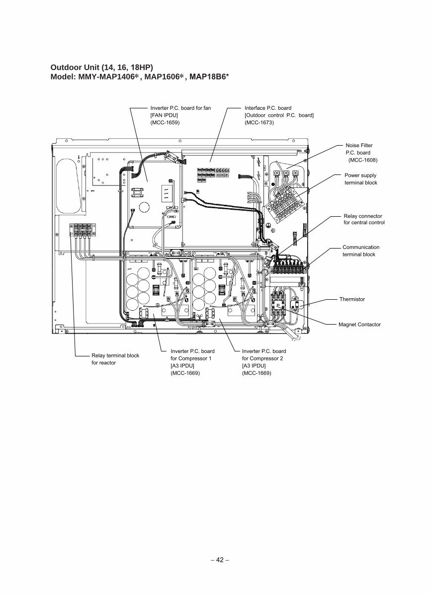
Outdoor Unit (14, 16, 18HP)Model: MMY-MAP1406∗, MAP1606∗, MAP18B6*
Inverter P.C. board for fan [FAN IPDU] (MCC-1659)
Interface P.C. board [Outdoor control P.C. board] (MCC-1673)
Noise Filter P.C. board (MCC-1608)
Power supply terminal block
Relay connectorfor central control
Communication terminal block
Inverter P.C. board for Compressor 1 [A3 IPDU] (MCC-1669)
Inverter P.C. board for Compressor 2 [A3 IPDU] (MCC-1669)
Relay terminal block for reactor
Magnet Contactor
Thermistor
− 42 −
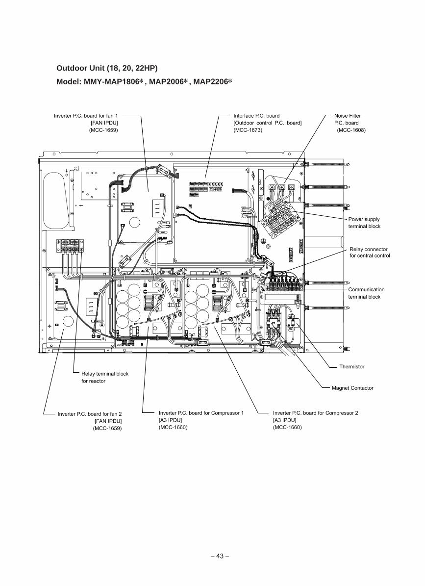
Outdoor Unit (18, 20, 22HP)
Model: MMY-MAP1806∗, MAP2006∗, MAP2206∗
Inverter P.C. board for fan 1 [FAN IPDU]
(MCC-1659)
Interface P.C. board [Outdoor control P.C. board] (MCC-1673)
Noise Filter P.C. board (MCC-1608)
Power supply terminal block
Communication terminal block
Relay connector for central control
Magnet Contactor
Inverter P.C. board for Compressor 2 [A3 IPDU] (MCC-1660)
Inverter P.C. board for Compressor 1 [A3 IPDU] (MCC-1660)
Thermistor
Inverter P.C. board for fan 2 [FAN IPDU]
(MCC-1659)
Relay terminal block for reactor
− 43 −
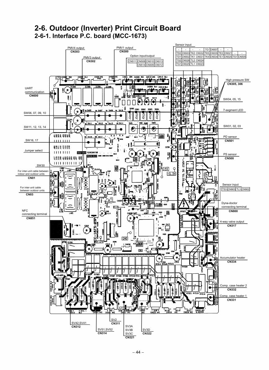
2-6. Outdoor (Inverter) Print Circuit Board 2-6-1. Interface P.C. board (MCC-1673)
- - - - TO CN507 - - TD2 CN503 TK2 CN532 TK5 CN535 TE2 CN521 - - TD1 CN502 TK1 CN531 TK4 CN534 TE1 CN520 TS1 CN505 TG2 CN526 TL2 CN524 TG1 CN525 TL1 CN523
Sensor input
CN511 CN508 CN510 CN513 CN514 CN509 CN512
Option input/output
PMV1 output CN300
PMV3 output CN302
PMV4 output CN303
UART communication
CN600
SW06, 07, 09, 10
SW11, 12, 13, 14
SW16, 17
Jumper select
SW30
For inter-unit cable between indoor and outdoor units
CN01
For inter-unit cable between outdoor units
CN03
SV42,SV41 CN312
SV51,SV52 CN314
SV2 CN311
SV3A SV3B SV3C CN321
SV3D CN322
Comp. case heater 1 CN331
Comp. case heater 2 CN332
Accumulator heater CN334
4-way valve output CN317
Dyna-doctor connecting terminal
CN800
PS sensor CN500
PD sensor CN501
SW01, 02, 03
7-segment LED
SW04, 05, 15
High pressure SW CN305, 306
TS3 CN903 TL3 CN902
Sensor input
NFC connecting terminal
CN851
− 44 −
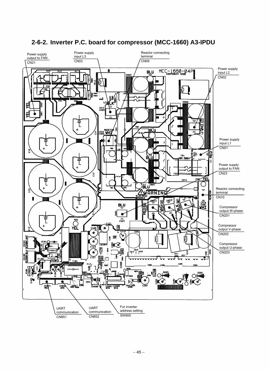
2-6-2. Inverter P.C. board for compressor (MCC-1660) A3-IPDU
Power supply input L1 CN01
Power supply input L2 CN02
Reactor connectingterminal CN09
Reactor connecting terminal CN10
Compressor output W-phase CN201
Compressor output V-phase CN202
Compressor output U-phase CN203
For inverter address setting SW800
UART communication CN852
UART communication CN851
Power supply input L3 CN03
Power supply output to FAN CN21
Power supply output to FAN CN23
− 45 −
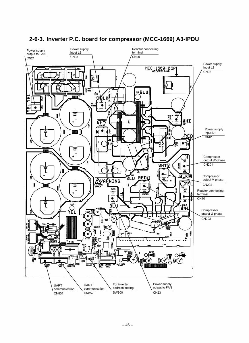
2-6-3. Inverter P.C. board for compressor (MCC-1669) A3-IPDU
Power supply input L1 CN01
Power supply input L2 CN02
Reactor connectingterminal CN09
Reactor connecting terminal CN10
Compressor output W-phase CN201
Compressor output V-phase
CN202
Compressor output U-phase CN203
For inverter address setting SW800
UART communication CN852
UART communication CN851
Power supply input L3 CN03
Power supply output to FAN CN21
Power supply output to FAN CN23
− 46 −
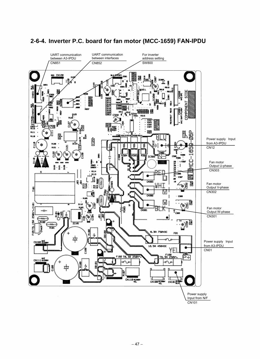
2-6-4. Inverter P.C. board for fan motor (MCC-1659) FAN-IPDU
Fan motor Output U-phase CN303
UART communication between A3-IPDU CN851
Fan motor Output V-phase CN302
Fan motor Output W-phase CN301
Power supply Input from A3-IPDU CN01
UART communication between interfaces CN852
Power supply Input from A3-IPDU CN12
Power supply Input from N/F CN101
For inverter address setting SW800
− 47 −
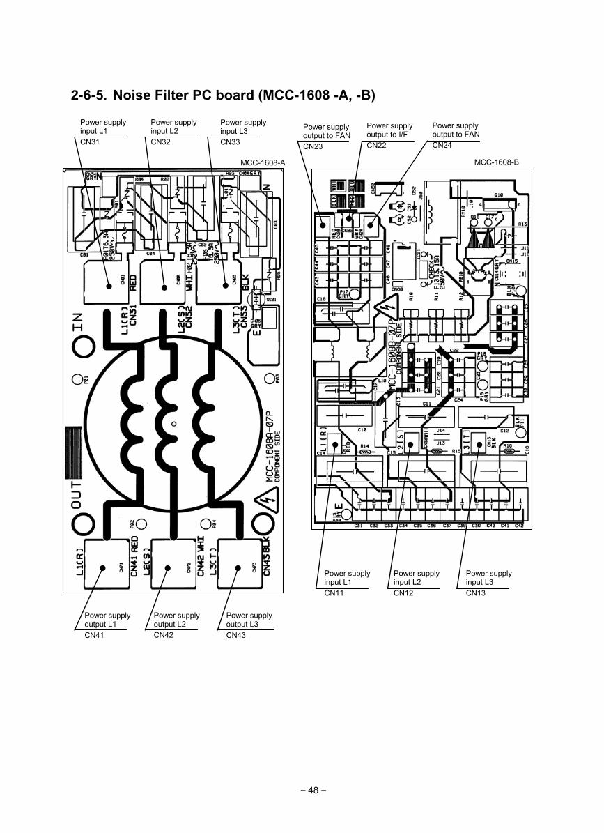
2-6-5. Noise Filter PC board (MCC-1608 -A, -B)
Power supply input L1 CN31
Power supply input L2 CN32
Power supply input L3 CN33
Power supply output L1 CN41
Power supply output L2 CN42
Power supply output L3 CN43
Power supply output to FAN CN23
Power supply output to I/F CN22
Power supply output to FAN CN24
Power supply input L1 CN11
Power supply input L2 CN12
Power supply input L3 CN13
MCC-1608-A MCC-1608-B
− 48 −
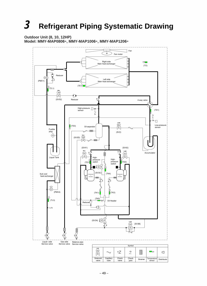
Outdoor Unit (8, 10, 12HP)Model: MMY-MAP0806 , MMY-MAP1006 , MMY-MAP1206
3 Refrigerant Piping Systematic Drawing
(TD2)
(TE1)
(TK2) (TK1)
(TD1)
(TK4)
(TO)
SV
SV
SV SV
M
(TL1)
SV
SV
SV
(TK5)
(TS3)
(TL3)
Reducer
(SV3A)
(SV2)
(SV3D)
(SV42) (SV41)
(SV3C)
(PMV4)
(TS1)
(SV3B)
Fan
Fan motor
Right side Main heat exchanger
Left side Main heat exchanger (PMV1)
4-way valve
High-pressure sensor
Low-pressure sensor Oil separator
Fusible plug
Liquid Tank
Accumulator
High- pressure switch
High- pressure switch
Compressor 1
(Inverter)
Oil Header
Liquid side Service valve
Gas side Service valve
Balance pipe Service valve
Sub cool heat exchanger
SV
(SV52) Reducer
FP
Compressor 2
(Inverter)
SV
Solenoid valve
Capillary tube
Check valve
Check joint Strainer Temperature
sensor
Symbol
Distributor
Reducer
− 49 −
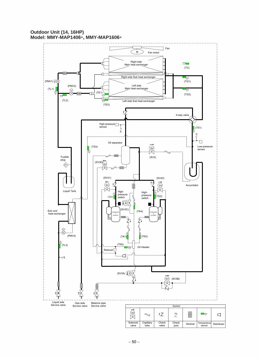
Outdoor Unit (14, 16HP)Model: MMY-MAP1406 , MMY-MAP1606
仮
(TD2)
(TS1)
(TE1)
(TK2) (TK1)
(TD1)
(TK4)
(TE2)
(TO)
SV
SV
SV SV
M
(TG2)
(TG1)
(TL3)
SV
SV
SV
(TK5)
(TS3)
(TL1)
(TL2)
(SV3B)
(SV3A)
(SV2)
(SV3D)
(SV42) (SV41)
(SV3C)
(PMV4)
Fan
Fan motor
Right side Main heat exchanger
Left side Main heat exchanger
Right side Sub heat exchanger
Left side Sub heat exchanger
(PMV1)
(PMV3)
4-way valve
High-pressure sensor
Low-pressure sensor
Oil separator
Accumlator
Liquid Tank
Liquid side Service valve
Gas side Service valve
Balance pipe Service valve
Oil Header
High- pressure switch
High- pressure switch
Reducer
Fusible plug
FP
Sub cool heat exchanger
Compressor 1
(Inverter)
Compressor 2
(Inverter)
SV
Solenoid valve
Capillary tube
Check valve
Check joint Strainer Temperature
sensor
Symbol
Distributor
− 50 −
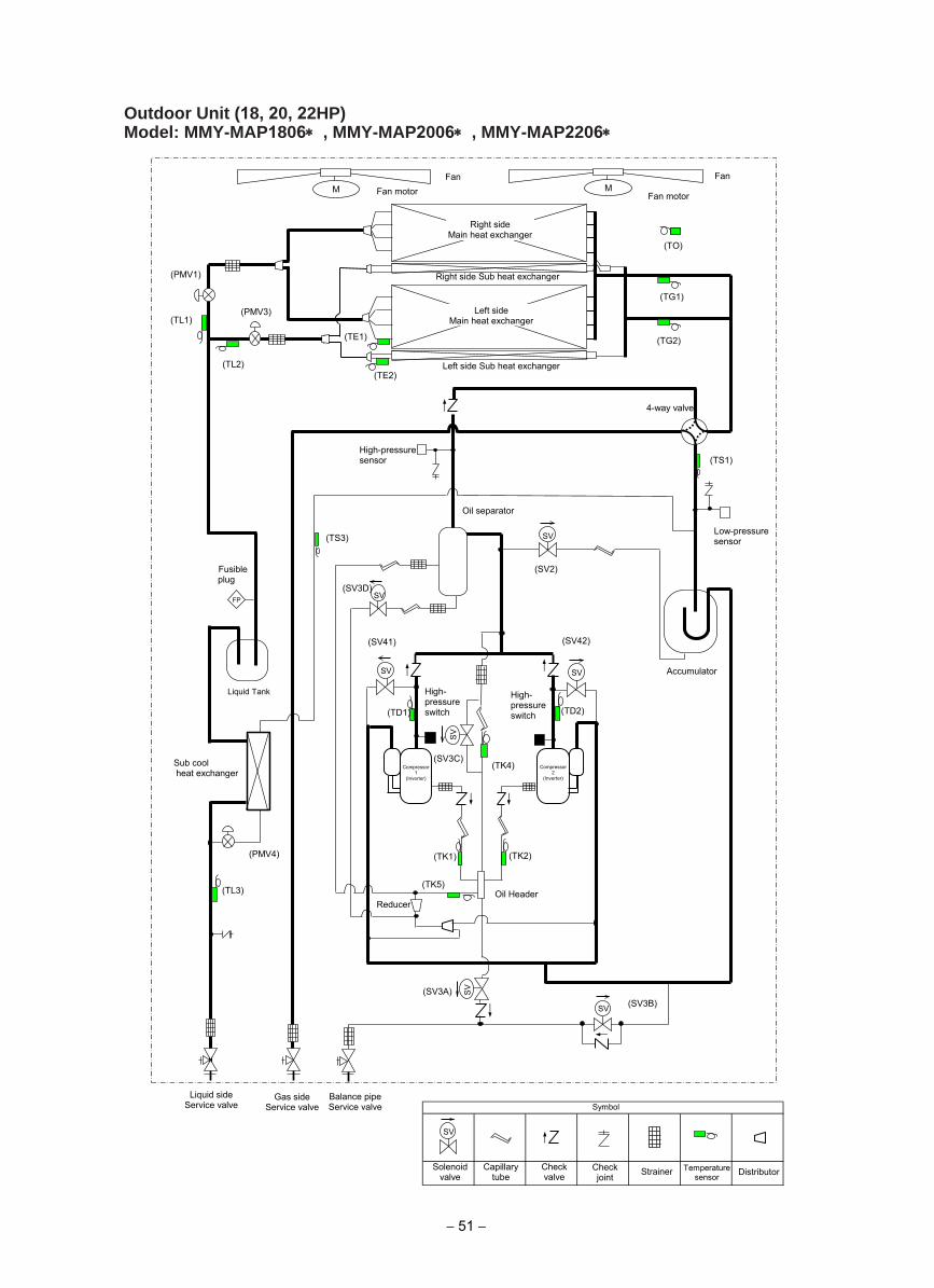
Outdoor Unit (18, 20, 22HP)Model: MMY-MAP1806∗ , MMY-MAP2006∗ , MMY-MAP2206∗
仮
(TD2)
(TS1)
(TE1)
(TK2) (TK1)
(TD1)
(TK4)
(TE2)
(TO)
SV
SV
SV SV
M M
(TG2)
(TG1)
(TL3)
SV
SV
SV
(TK5)
(TS3)
(TL1)
(TL2)
(SV3B) (SV3A)
(SV2)
(SV3D)
(SV42) (SV41)
(SV3C)
(PMV4)
Fan Fan
Fan motor Fan motor
Right side Main heat exchanger
Left side Main heat exchanger
Right side Sub heat exchanger
Left side Sub heat exchanger
(PMV1)
(PMV3)
4-way valve
High-pressure sensor
Low-pressure sensor
Oil separator
Accumulator
Liquid Tank
Oil Header
High- pressure switch
High- pressure switch
Sub cool heat exchanger
Fusible plug
FP
Liquid side Service valve
Gas side Service valve
Balance pipe Service valve
SV
Solenoid valve
Capillary tube
Check valve
Check joint Strainer Temperature
sensor
Symbol
Distributor
Reducer
Compressor 1
(Inverter)
Compressor 2
(Inverter)
− 51 −
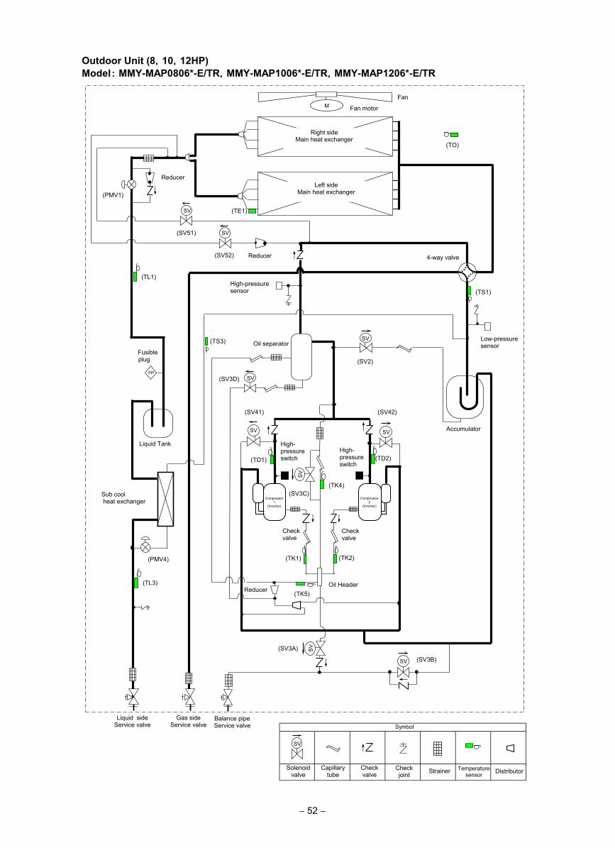
Outdoor Unit (8,10,12HP)Model: MMY-MAP0806*-E/TR,MMY-MAP1006*-E/TR,MMY-MAP1206*-E/TR
(TD2)
(TE1)
(TK2) (TK1)
(TD1)
(TK4)
(TO)
SV
SV
SV SV
M
(TL1)
SV
SV
SV
(TK5)
(TS3)
(TL3)
Reducer
(SV3A)
(SV2)
(SV3D)
(SV42) (SV41)
(SV3C)
(PMV4)
(TS1)
(SV3B)
Fan
Fan motor
Right side Main heat exchanger
Left side Main heat exchanger (PMV1)
4-way valve
High-pressure sensor
Low-pressure sensor Oil separator
Fusible plug
Liquid Tank
Accumulator
High- pressure switch
High- pressure switch
Check valve
Check valve
Compressor 1
(Inverter)
Oil Header
Liquid side Service valve
Gas side Service valve
Balance pipe Service valve
Sub cool heat exchanger
SV
(SV52) Reducer
FP
Compressor 2
(Inverter)
SV
Solenoid valve
Capillary tube
Check valve
Check joint Strainer Temperature
sensor
Symbol
Distributor
Reducer
SV
(SV51)
− 52 −
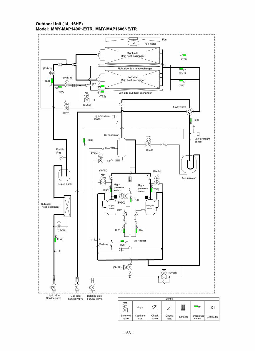
Outdoor Unit (14,16HP)Model: MMY-MAP1406*-E/TR,MMY-MAP1606*-E/TR
仮
(TD2)
(TS1)
(TE1)
(TK2) (TK1)
(TD1)
(TK4)
(TE2)
(TO)
SV
SV
SV SV
M
(TG2)
(TG1)
(TL3)
SV
SV
SV
(TK5)
(TS3)
(TL1)
(TL2)
(SV3B)
(SV3A)
(SV2) (SV3D)
(SV42) (SV41)
(SV3C)
(PMV4)
Fan
Fan motor
Right side Main heat exchanger
Left side Main heat exchanger
Right side Sub heat exchanger
Left side Sub heat exchanger
(PMV1)
(PMV3)
4-way valve
High-pressure sensor
Low-pressure sensor
Oil separator
Accumulator
Liquid Tank
Liquid side Service valve
Gas side Service valve
Balance pipe Service valve
Oil Header
High- pressure switch
High- pressure switch
Reducer
Fusible plug
FP
Sub cool heat exchanger
Compressor 1
(Inverter)
Compressor 2
(Inverter)
SV
Solenoid valve
Capillary tube
Check valve
Check joint Strainer Temperature
sensor
Symbol
Distributor
SV
(SV52) SV
(SV51)
− 53 −
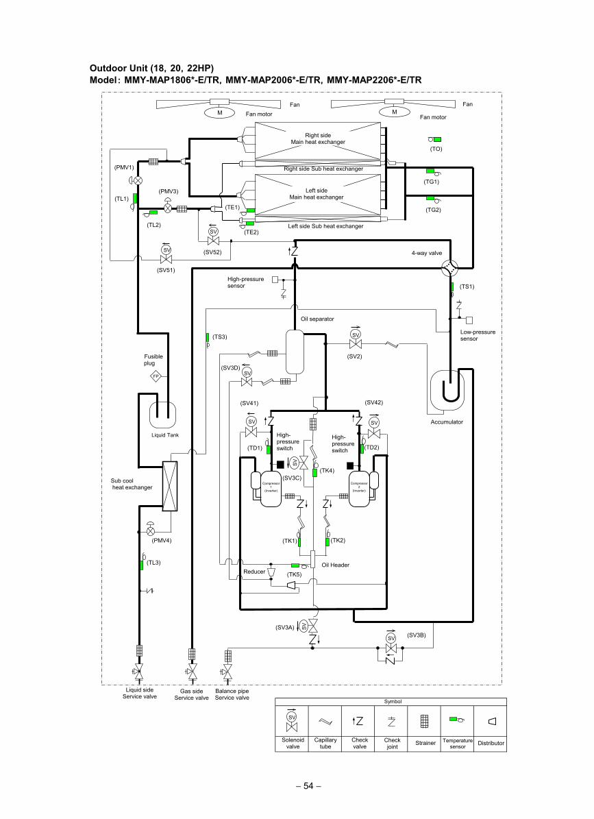
Outdoor Unit (18,20,22HP)Model: MMY-MAP1806*-E/TR,MMY-MAP2006*-E/TR,MMY-MAP2206*-E/TR
仮
(TD2)
(TS1)
(TE1)
(TK2) (TK1)
(TD1)
(TK4)
(TE2)
(TO)
SV
SV
SV SV
M M
(TG2)
(TG1)
(TL3)
SV
SV
SV
(TK5)
(TS3)
(TL1)
(TL2)
(SV3B) (SV3A)
(SV2)
(SV3D)
(SV42) (SV41)
(SV3C)
(PMV4)
Fan Fan
Fan motor Fan motor
Right side Main heat exchanger
Left side Main heat exchanger
Right side Sub heat exchanger
Left side Sub heat exchanger
(PMV1)
(PMV3)
4-way valve
High-pressure sensor
Low-pressure sensor
Oil separator
Accumulator
Liquid Tank
Oil Header
High- pressure switch
High- pressure switch
Sub cool heat exchanger
Fusible plug
FP
Liquid side Service valve
Gas side Service valve
Balance pipe Service valve
SV
Solenoid valve
Capillary tube
Check valve
Check joint Strainer Temperature
sensor
Symbol
Distributor
Reducer
Compressor 1
(Inverter)
Compressor 2
(Inverter)
SV
(SV52) SV
(SV51)
− 54 −
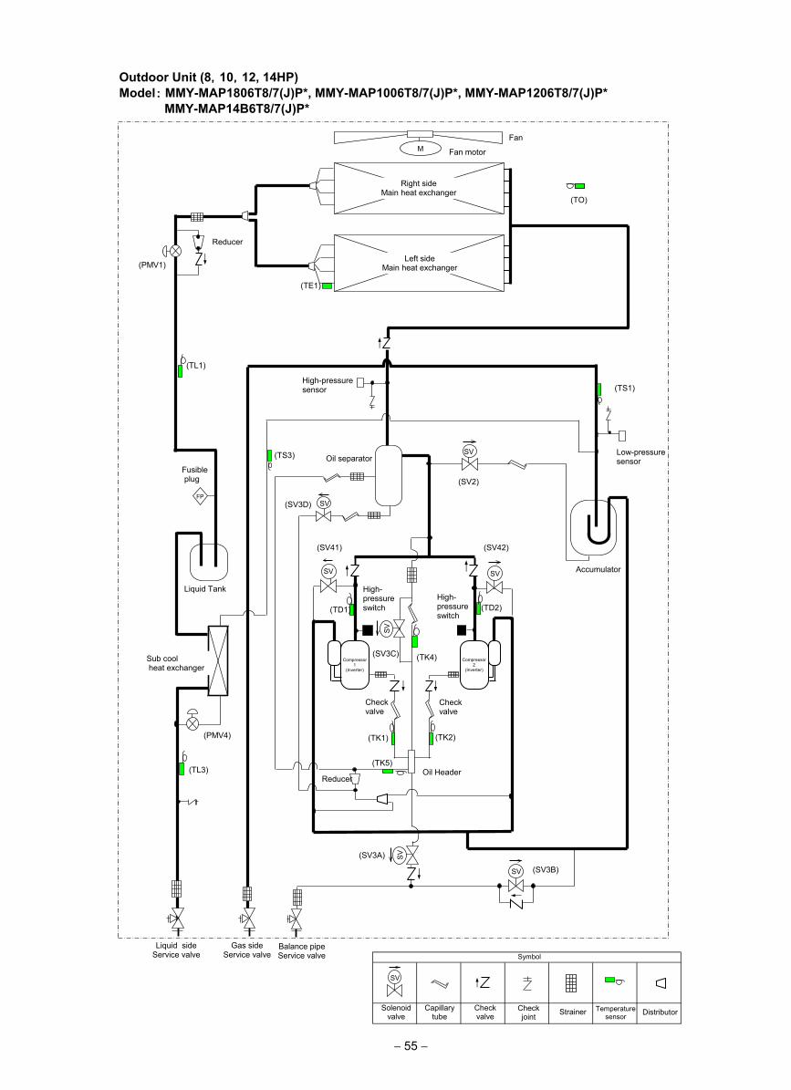
Outdoor Unit (8,10,12, 14HP)Model: MMY-MAP1806T8/7(J)P*, MMY-MAP1006T8/7(J)P*, MMY-MAP1206T8/7(J)P* MMY-MAP14B6T8/7(J)P*
− 55 −
(TD2)
(TE1)
(TK2) (TK1)
(TD1)
(TK4)
(TO)
SV
SV
SV SV
M
(TL1)
SV
SV
SV
(TK5)
(TS3)
(TL3)
Reducer
(SV3A)
(SV2)
(SV3D)
(SV42) (SV41)
(SV3C)
(PMV4)
(TS1)
(SV3B)
Fan
Fan motor
Right side Main heat exchanger
Left side Main heat exchanger (PMV1)
High-pressure sensor
Low-pressure sensor Oil separator
Fusible plug
Liquid Tank
Accumulator
High- pressure switch
High- pressure switch
Check valve
Check valve
Compressor 1
(Inverter)
Oil Header
Liquid side Service valve
Gas side Service valve
Balance pipe Service valve
Sub cool heat exchanger
FP
Compressor 2
(Inverter)
Reducer
SV
Solenoid valve
Capillary tube
Check valve
Check joint Strainer Temperature
sensor
Symbol
Distributor
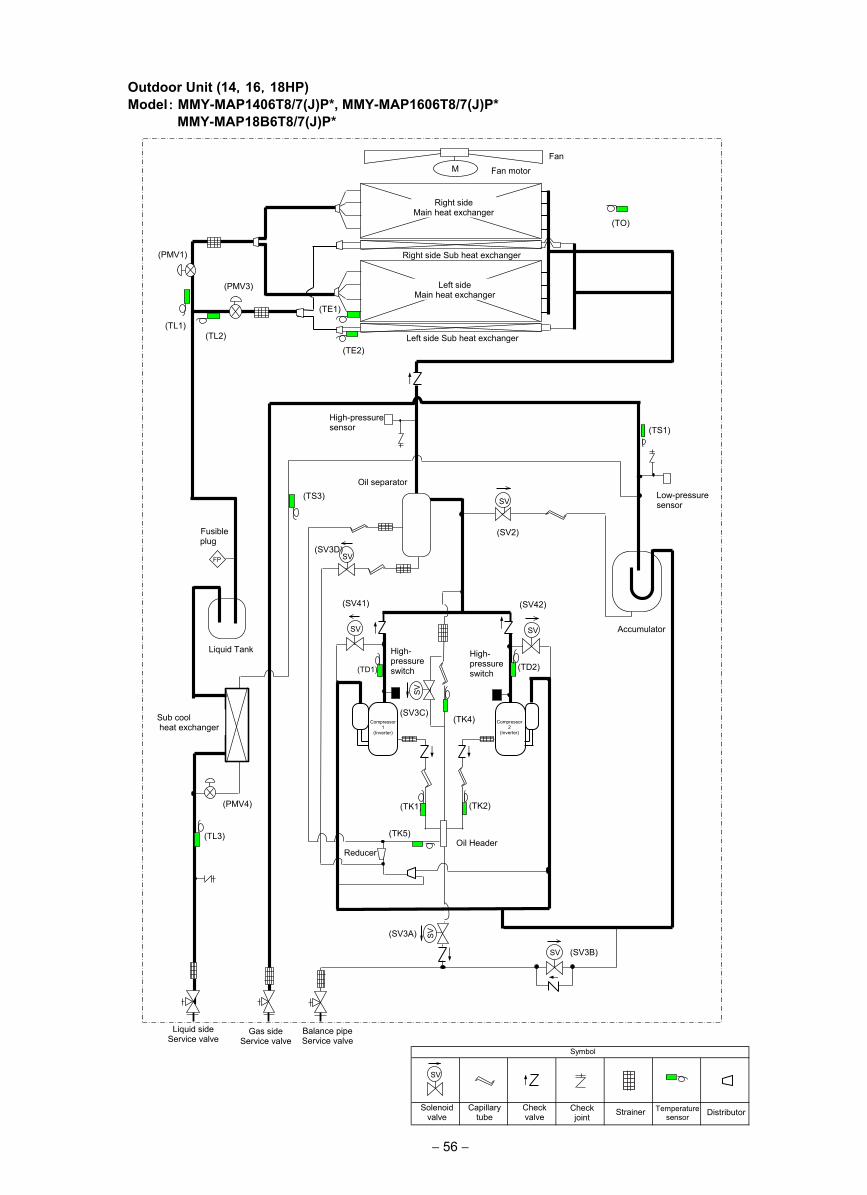
− 56 −
Outdoor Unit (14,16,18HP)Model: MMY-MAP1406T8/7(J)P*, MMY-MAP1606T8/7(J)P* MMY-MAP18B6T8/7(J)P*
仮
(TD2)
(TS1)
(TE1)
(TK2) (TK1)
(TD1)
(TK4)
(TE2)
(TO)
SV
SV
SV SV
M
(TL3)
SV
SV
SV
(TK5)
(TS3)
(TL1) (TL2)
(SV3B)
(SV3A)
(SV2)
(SV3D)
(SV42) (SV41)
(SV3C)
(PMV4)
Fan
Fan motor
Right side Main heat exchanger
Left side Main heat exchanger
Right side Sub heat exchanger
Left side Sub heat exchanger
(PMV1)
(PMV3)
High-pressure sensor
Low-pressure sensor
Oil separator
Accumulator
Liquid Tank
Liquid side Service valve
Gas side Service valve
Balance pipe Service valve
Oil Header
High- pressure switch
High- pressure switch
Reducer
Fusible plug
FP
Sub cool heat exchanger
Compressor 1
(Inverter)
Compressor 2
(Inverter)
SV
Solenoid valve
Capillary tube
Check valve
Check joint Strainer Temperature
sensor
Symbol
Distributor
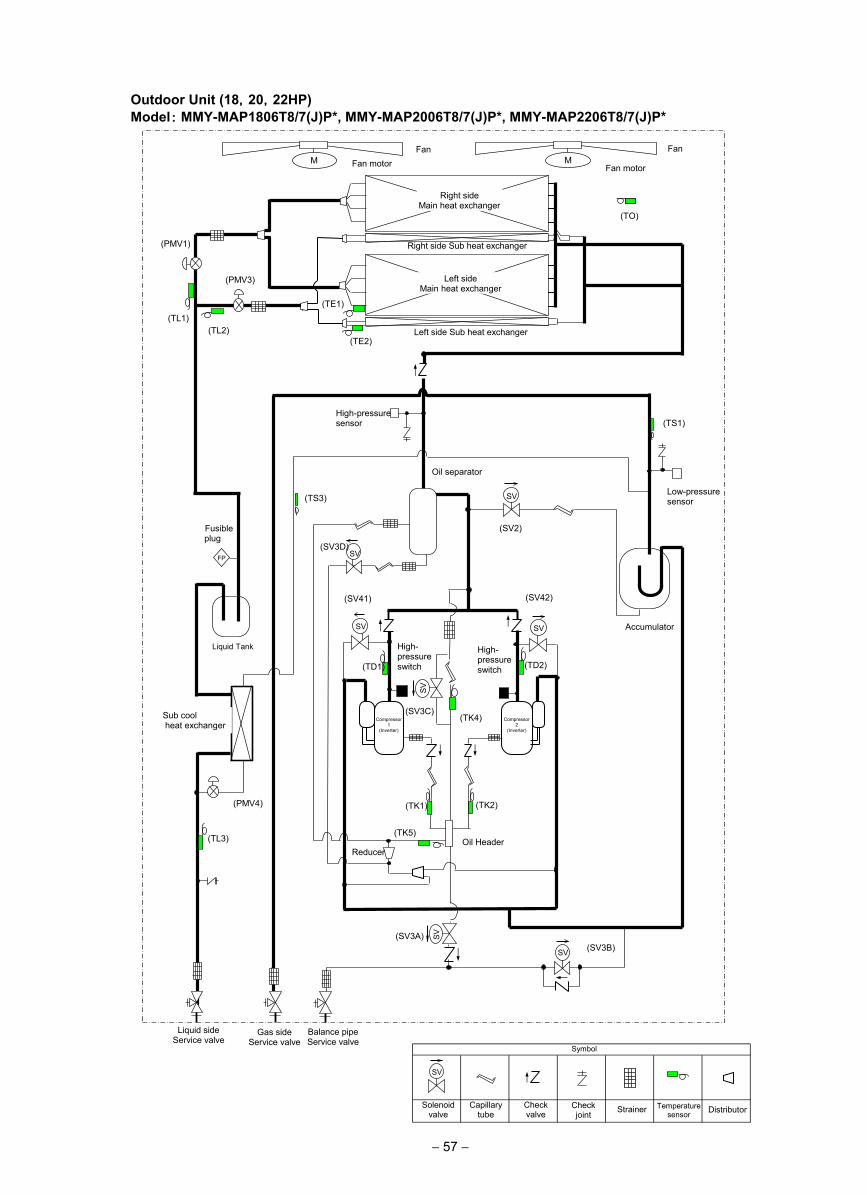
Outdoor Unit (18,20,22HP)Model: MMY-MAP1806T8/7(J)P*, MMY-MAP2006T8/7(J)P*, MMY-MAP2206T8/7(J)P*
− 57 −
SV
Solenoid valve
Capillary tube
Check valve
Check joint Strainer Temperature
sensor
Symbol
Distributor
仮
(TD2)
(TS1)
(TE1)
(TK2) (TK1)
(TD1)
(TK4)
(TE2)
(TO)
SV
SV
SV SV
M M
(TL3)
SV
SV
SV
(TK5)
(TS3)
(TL1) (TL2)
(SV3B) (SV3A)
(SV2)
(SV3D)
(SV42) (SV41)
(SV3C)
(PMV4)
Fan Fan
Fan motor Fan motor
Right side Main heat exchanger
Left side Main heat exchanger
Right side Sub heat exchanger
Left side Sub heat exchanger
(PMV1)
(PMV3)
High-pressure sensor
Low-pressure sensor
Oil separator
Accumulator
Liquid Tank
Oil Header
High- pressure switch
High- pressure switch
Sub cool heat exchanger
Fusible plug
FP
Liquid side Service valve
Gas side Service valve
Balance pipe Service valve
Reducer
Compressor 1
(Inverter)
Compressor 2
(Inverter)
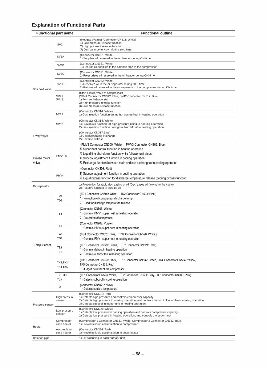
Explanation of Functional Parts
eniltuo lanoitcnuFeman trap lanoitcnuF
Solenoid valve
SV3A (Connector CN321: White)1) Supplies oil reserved in the oil header during ON time.
SV3B (Connector CN321: White)1) Returns oil supplied in the balance pipe to the compressor.
SV3C (Connector CN321: White)1) Pressurizes oil reserved in the oil header during ON time.
SV3D(Connector CN322: White)1) Reserves oil in the oil separator during OFF time.2) Returns oil reserved in the oil separator to the compressor during ON time.
SV2
(Hot gas bypass) (Connector CN311: White)1) Low pressure release function2) High pressure release function3) Gas balance function during stop time
SV41SV42
(Start assure valve of compressor)(SV41 Connector CN312: Blue, SV42 Connector CN312: Blue.1) For gas balance start2) High pressure release function3) Low pressure release function
SV52
(Connector CN314: White)1) Gas injection function during hot gas defrost in heating operation
4-way valve(Connector CN317:Blue)1) Cooling/heating exchange2) Reverse defrost
Oil separator 1) Prevention for rapid decreasing of oil (Decreases oil flowing to the cycle) 2) Reserve function of surplus oil
Pressure sensor
High pressure sensor
(Connector CN501: Red)1) Detects high pressure and controls compressor capacity2) Detects high pressure in cooling operation, and controls the fan in low ambient cooling operation 3) Detects subcool in indoor unit in heating operation
Low pressure sensor
(Connector CN500: White)1) Detects low pressure in cooling operation and controls compressor capacity2) Detects low pressure in heating operation, and controls the super heat
Heater
Compressor case heater
(Compressor 1 Connector CN331: White, Compressor 2 Connector CN332: Blue.1) Prevents liquid accumulation to compressor
Accumulator case heater
(Connector CN334: Red)1) Prevents liquid accumulation to accumulator
tinu roodtuo hcae ni gnicnalab liO )1epip ecnalaB
(PMV1 Connector CN300: White, PMV3 Connector CN302: Blue)1) Super heat control function in heating operation
PMV1, 32) Liquid line shut-down function while follower unit stops
Pulese motor 3) Subcool adjustment function in cooling operationvalve 4) Exchange function between main and sub exchangers in cooling operation
(Connector CN303: Red)
PMV41) Subcool adjustment function in cooling operation2) Liquid bypass function for discharge temperature release (cooling bypass function)
TD1 (TD1 Connector CN502: White, TD2 Connector CN503: Pink )
TD21) Protection of compressor discharge temp.2) Used for dischage temperature release
TS1
(Connector CN505: White)1) Controls PMV1 super heat in heating operation2) Protection of compressor
TS3(Connector CN902: Purple)1) Controls PMV4 super heat in heating operation
TG1 (TG1 Connector CN520: Blue, TG2 Connector CN526: White )TG2 1) Controls PMV1 super heat in heating operation
Temp. SensorTE1
(TE1 Connector CN520: Green, TE2 Connector CN521: Red )
TE21) Controls defrost in heating operation2) Controls outdoor fan in heating operation
TK1,TK2 (TK1 Connector CN531: Black, TK2 Connector CN532: Green, TK4 Connector CN534: Yellow,
TK4,TK5 TK5 Connector CN535: Red)
1) Judges oil level of the compressor
TL1,TL2 (TL1 Connector CN523: White, TL2 Connector CN521: Gray, TL3 Connector CN903: Pink)TL3 1) Detects subcool in cooling operation
TO (Connector CN507: Yellow)1) Detects outside temperature
(Connector CN314: White)1) Preventive function for high-pressure rising in heating operation2) Gas injection function during hot fas defrost in heating operation
SV51
− 58 −
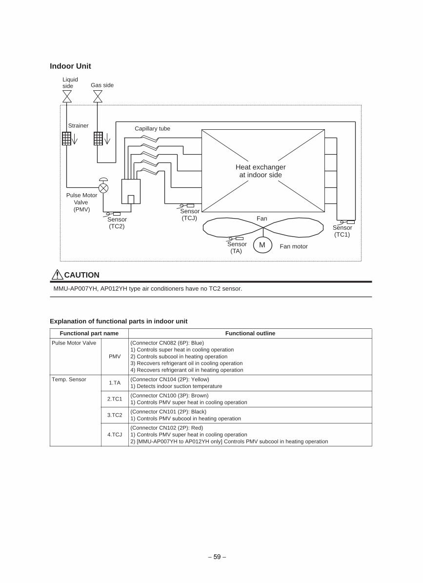
Indoor Unit
CAUTION
MMU-AP007YH, AP012YH type air conditioners have no TC2 sensor.
Explanation of functional parts in indoor unit
eniltuo lanoitcnuFeman trap lanoitcnuF
Pulse Motor Valve
PMV
(Connector CN082 (6P): Blue)1) Controls super heat in cooling operation2) Controls subcool in heating operation3) Recovers refrigerant oil in cooling operation4) Recovers refrigerant oil in heating operation
Temp. Sensor1.TA
(Connector CN104 (2P): Yellow)1) Detects indoor suction temperature
2.TC1(Connector CN100 (3P): Brown)1) Controls PMV super heat in cooling operation
3.TC2(Connector CN101 (2P): Black)1) Controls PMV subcool in heating operation
4.TCJ(Connector CN102 (2P): Red)1) Controls PMV super heat in cooling operation2) [MMU-AP007YH to AP012YH only] Controls PMV subcool in heating operation
Sensor(TC2)
M
Fan
Fan motor
Sensor(TCJ)
Sensor(TC1)
Strainer
Liquidside Gas side
Capillary tube
Sensor(TA)
Pulse Motor Valve (PMV)
Heat exchanger at indoor side
− 59 −
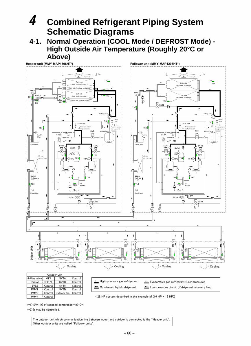
4 Combined Refrigerant Piping SystemSchematic Diagrams
4-1. Normal Operation (COOL Mode / DEFROST Mode) - High Outside Air Temperature (Roughly 20°C or Above)
Header unit (MMY-MAP1606HT*) Follower unit (MMY-MAP1206HT*)
Outdoor Unit
4-Way valve OFF SV3A Control
SV4(n) OFF(*1) SV3B Control
SV52 Control SV3C Control
PMV1 Control SV3D Control
PMV3 Control Outdoor fan Control
PMV4 Control ( 28 HP system described in the example of (16 HP + 12 HP))
(*1) SV4 (n) of stopped compressor (n)=ON
(*2) It may be controlled.
SV41 SV3C
SV42
Fan
圧縮機
1 (インバータ)
SV
SV
SV
SV
SV
SV
SV
FP
Indo
or
Uni
t
Evaporative gas refrigerant (Low pressure)
Low-pressure circuit (Refrigerant recovery line)
High-pressure gas refrigerant
Condensed liquid refrigerant
M
TC2 TCJ TC1
Cooling
PM
V
TC2 TCJ TC1
Cooling
PM
V
TC2 TCJ TC1
Cooling
PM
V
TC2 TCJ TC1
Cooling
PM
V
TS1
Fan motor
PMV1
TE1
TO
SV52
TS3
SV2
SV3D
TD1
TK4
TK5
TD2
TK2 TK1
SV3A
SV3B
SV
PMV4
TL3
SV41 SV3C
HPS
SV42
Accumulator
Pressure sensor
(low pressure)
Check
Joint
Oil
Header
Fan
圧縮機
1 (インバータ)
SV
SV
SV
SV
SV
SV
SV
M
TS1
Fan motor
PMV1
4-Way valve
TE1 PMV3
TL2
TO
Left side Sub heat exchanger
TS3 Pressure sensor
(high pressure)
SV2
SV3D
Liquid tank
Oil
Separator
Check Joint
TD1
TK4
TK5
Compressor
1
TD2
TK2 TK1
SV3A
SV3B
TE2
TL1
TG1
TG2
PMV4
Sub cool
heat exchanger
TL3
Fusible
Plug
FP
HPS
Conpressor
2
Check joint
Left side
Main heat exchanger
Right side Sub heat exchanger
Right side
Main heat exchanger
HPS
Accumulator
Pressure sensor
(low pressure)
Check
Joint
Oil
Header
4-Way valve
Pressure sensor
(high pressure)
Liquid tank
Oil
Separator
Check Joint
Compressor
1
Sub cool
heat exchanger
Fusible
Plug
HPS
Compressor
2
Check joint
Left side
Main heat exchanger
Right side
Main heat exchanger
The outdoor unit which communication line between indoor and outdoor is connected is the "Header unit".
Other outdoor units are called "Follower units".
TL1
− 60 −
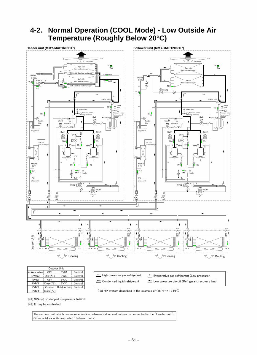
4-2. Normal Operation (COOL Mode) - Low Outside Air Temperature (Roughly Below 20°C)
Header unit (MMY-MAP1606HT*) Follower unit (MMY-MAP1206HT*)
Outdoor Unit
4-Way valve OFF SV3A Control
SV4(n) OFF(*1) SV3B Control
SV52 OFF SV3C Control
PMV1 Close(*2) SV3D Control
PMV3 Control Outdoor fan Control
PMV4 Close(*2) ( 28 HP system described in the example of (16 HP + 12 HP))
(*1) SV4 (n) of stopped compressor (n)=ON
(*2) It may be controlled.
SV41 SV3C
SV42
Fan
圧縮機
1 (インバータ)
SV
SV
SV
SV
SV
SV
SV
FP
Indo
or
Uni
t
M
TC2 TCJ TC1
Cooling
PM
V
TC2 TCJ TC1
Cooling
PM
V
TC2 TCJ TC1
Cooling
PM
V
TC2 TCJ TC1
Cooling
PM
V
TS1
Fan motor
PMV1
TE1
TO
SV52
TS3
SV2
SV3D
TD1
TK4
TK5
TD2
TK2 TK1
SV3A
SV3B
SV
PMV4
TL3
SV41 SV3C
HPS
SV42
Accumulator
Pressure sensor
(low pressure)
Check
Joint
Oil
Header
Fan
圧縮機
1 (インバータ)
SV
SV
SV
SV
SV
SV
SV
M
TS1
Fan motor
PMV1
4-Way valve
TE1 PMV3
TL2
TO
Left side Sub heat exchanger
TS3 Pressure sensor
(high pressure)
SV2
SV3D
Liquid tank
Oil
Separator
Check Joint
TD1
TK4
TK5
Compressor
1
TD2
TK2 TK1
SV3A
SV3B
TE2
TL1
TG1
TG2
PMV4
Sub cool
heat exchanger
TL3
Fusible
Plug
FP
HPS
Compressor
2
Check joint
Left side
Main heat exchanger
Right side Sub heat exchanger
Right side
Main heat exchanger
HPS
Accumulator
Pressure sensor
(low pressure)
Check
Joint
Oil
Header
4-Way valve
Pressure sensor
(high pressure)
Liquid tank
Oil
Separator
Check Joint
Compressor
1
Sub cool
heat exchanger
Fusible
Plug
HPS
Compressor
2
Check joint
Left side
Main heat exchanger
Right side
Main heat exchanger
Evaporative gas refrigerant (Low pressure)
Low-pressure circuit (Refrigerant recovery line)
High-pressure gas refrigerant
Condensed liquid refrigerant
The outdoor unit which communication line between indoor and outdoor is connected is the "Header unit".
Other outdoor units are called "Follower units".
TL1
− 61 −
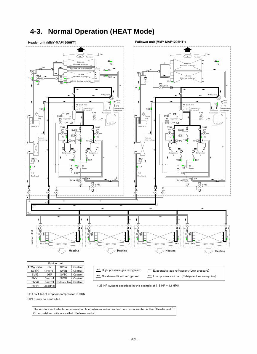
4-3. Normal Operation (HEAT Mode)Header unit (MMY-MAP1606HT*) Follower unit (MMY-MAP1206HT*)
Outdoor Unit
4-Way valve ON SV3A Control
SV4(n) OFF(*1) SV3B Control
SV52 OFF SV3C Control
PMV1 Control SV3D Control
PMV3 Control Outdoor fan Control
PMV4 Close(*2) ( 28 HP system described in the example of (16 HP + 12 HP))
(*1) SV4 (n) of stopped compressor (n)=ON
(*2) It may be controlled.
SV41 SV3C
SV42
Fan
圧縮機
1 (インバータ)
SV
SV
SV
SV
SV SV
SV
FP
Indo
or
Uni
t
M
TC2 TCJ TC1
Heating
PM
V
TC2 TCJ TC1
Heating
PM
V
TC2 TCJ TC1
Heating
PM
V
TC2 TCJ TC1
Heating
PM
V
TS1
Fan motor
PMV1
TE1
TO
SV52
TS3
SV2
SV3D
TD1
TK4
TK5
TD2
TK2 TK1
SV3A
SV3B
SV
PMV4
TL3
SV41 SV3C
HPS
SV42
Accumulator
Pressure sensor
(low pressure)
Check
Joint
Oil
Header
Fan
圧縮機
1 (インバータ)
SV
SV
SV
SV
SV
SV
SV
M
TS1
Fan motor
PMV1
4-Way valve
TE1 PMV3
TL2
TO
Left side Sub heat exchanger
TS3 Pressure sensor
(high pressure)
SV2
SV3D
Liquid tank
Oil
Separator
Check Joint
TD1
TK4
TK5
Compressor
1
TD2
TK2 TK1
SV3A
SV3B
TE2
TL1
TG1
TG2
PMV4
Sub cool
heat exchanger
TL3
Fusible
Plug
FP
HPS
Compressor
2
Check joint
Left side
Main heat exchanger
Right side Sub heat exchanger
Right side
Main heat exchanger
HPS
Accumulator
Pressure sensor
(low pressure)
Check
Joint
Oil
Header
4-Way valve
Pressure sensor
(high pressure)
Liquid tank
Oil
Separator
Check Joint
Compressor
1
Sub cool
heat exchanger
Fusible
Plug
HPS
Compressor
2
Check joint
Left side
Main heat exchanger
Right side
Main heat exchanger
Evaporative gas refrigerant (Low pressure)
Low-pressure circuit (Refrigerant recovery line)
High-pressure gas refrigerant
Condensed liquid refrigerant
The outdoor unit which communication line between indoor and outdoor is connected is the "Header unit".
Other outdoor units are called "Follower units".
TL1
− 62 −
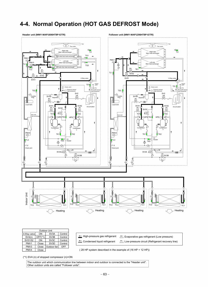
4-4. Normal Operation (HOT GAS DEFROST Mode)
− 63 −
Outdoor UnitON SV3A Control
SV4(n) OFF(*1) SV3B ControlSV51/52 ON SV3C ControlPMV1 Close SV3D ControlPMV3 Close OFFPMV4 Close ( 28 HP system described in the example of (16 HP + 12 HP))
(*1) SV4 (n) of stopped compressor (n)=ON
4-Way valve
Outdoor fan
Evaporative gas refrigerant (Low pressure)
Low-pressure circuit (Refrigerant recovery line)
High-pressure gas refrigerant
Condensed liquid refrigerant
The outdoor unit which communication line between indoor and outdoor is connected is the "Header unit". Other outdoor units are called "Follower units".
SV41
SV3C
SV42
Fan
圧縮機 1
(インバータ)
SV
SV
SV
SV
SV
SV
SV
FP
Indo
or U
nit
Header unit (MMY-MAP1606HT8P-E/TR) Follower unit (MMY-MAP1206HT8P-E/TR)
M
TC2 TCJ TC1
Heating
PM
V
TC2 TCJ TC1
Heating
PM
V
TC2 TCJ TC1
Heating
PM
V
TC2 TCJ TC1
Heating
PM
V
TS1
Fan motor
PMV1
TE1
TO
SV52
TS3 SV2
SV3D
TD1
TK4
TK5
TD2
TK2 TK1
SV3A
SV3B
SV
PMV4
TL3
SV41 SV3C
HPS
SV42 Accumulator
Pressure sensor (low pressure)
Check Joint
Oil Header
Fan
圧縮機 1
(インバータ)
SV
SV
SV
SV
SV
SV
SV
M
TS1
Fan motor
PMV1
4-Way valve
TE1 PMV3
TL2
TO
Left side Sub heat exchanger
TS3 Pressure sensor (high pressure)
SV2 SV3D
Liquid tank
Oil Separator
Check Joint
TD1
TK4
TK5
Compressor 1
TD2
TK2 TK1
SV3A
SV3B
TE2
TL1
TG1
TG2
PMV4
Sub cool heat exchanger
TL3
Fusible Plug
FP
HPS
Compressor 2
Check joint
Left side Main heat exchanger
Right side Sub heat exchanger
Right side Main heat exchanger
HPS
Accumulator
Pressure sensor (low pressure)
Check Joint
Oil Header
4-Way valve
Pressure sensor (high pressure)
Liquid tank
Oil Separator
Check Joint
Compressor 1
Sub cool heat exchanger
Fusible Plug
HPS
Compressor 2
Check joint
Left side Main heat exchanger
Right side Main heat exchanger
TL1 SV
SV51
SV
SV52 SV51
SV
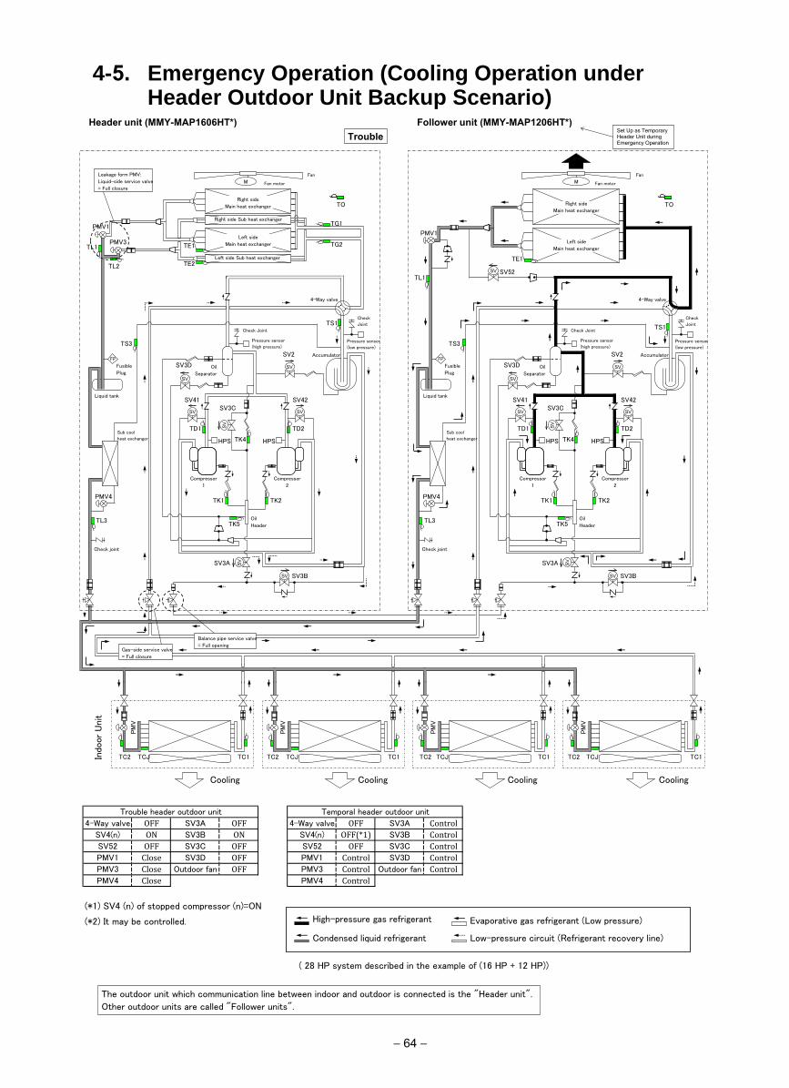
4-5. Emergency Operation (Cooling Operation under Header Outdoor Unit Backup Scenario)
Header unit (MMY-MAP1606HT*) Follower unit (MMY-MAP1206HT*) Trouble
Set Up as Temporary Header Unit during Emergency Operation
Trouble header outdoor unit Temporal header outdoor unit
4-Way valve OFF SV3A OFF 4-Way valve OFF SV3A Control
SV4(n) ON SV3B ON SV4(n) OFF(*1) SV3B Control
SV52 OFF SV3C OFF SV52 OFF SV3C Control
PMV1 Close SV3D OFF PMV1 Control SV3D Control
PMV3 Close Outdoor fan OFF PMV3 Control Outdoor fan Control
PMV4 Close PMV4 Control
(*1) SV4 (n) of stopped compressor (n)=ON
(*2) It may be controlled.
( 28 HP system described in the example of (16 HP + 12 HP))
SV41 SV3C
SV42
Fan
圧縮機
1 (インバータ)
SV
SV
SV
SV
SV
SV
SV
FP
Indo
or
Uni
t
M
TC2 TCJ TC1
Cooling
PM
V
TC2 TCJ TC1
Cooling
PM
V
TC2 TCJ TC1
Cooling
PM
V
TC2 TCJ TC1
Cooling
PM
V
TS1
Fan motor
PMV1
TE1
TO
SV52
TS3
SV2
SV3D
TD1
TK4
TK5
TD2
TK2 TK1
SV3A
SV3B
SV
PMV4
TL3
SV41 SV3C
HPS
SV42
Accumulator
Pressure sensor
(low pressure)
Check
Joint
Oil
Header
Fan
圧縮機
1 (インバータ)
SV
SV
SV
SV
SV
SV
SV
M
TS1
Fan motor
PMV1
4-Way valve
TE1 PMV3
TL2
TO
Left side Sub heat exchanger
TS3 Pressure sensor
(high pressure)
SV2
SV3D
Liquid tank
Oil
Separator
Check Joint
TD1
TK4
TK5
Compressor
1
TD2
TK2 TK1
SV3A
SV3B
TE2
TL1
TG1
TG2
PMV4
Sub cool
heat exchanger
TL3
Fusible
Plug
FP
HPS
Compressor
2
Check joint
Left side
Main heat exchanger
Right side Sub heat exchanger
Right side
Main heat exchanger
HPS
Accumulator
Pressure sensor
(low pressure)
Check
Joint
Oil
Header
4-Way valve
Pressure sensor
(high pressure)
Liquid tank
Oil
Separator
Check Joint
Compressor
1
Sub cool
heat exchanger
Fusible
Plug
HPS
Compressor
2
Check joint
Left side
Main heat exchanger
Right side
Main heat exchanger
Leakage form PMV:
Liquid-side service valve
= Full closure
Balance pipe service valve
= Full opening Gas-side service valve
= Full closure
Evaporative gas refrigerant (Low pressure)
Low-pressure circuit (Refrigerant recovery line)
High-pressure gas refrigerant
Condensed liquid refrigerant
The outdoor unit which communication line between indoor and outdoor is connected is the "Header unit".
Other outdoor units are called "Follower units".
TL1
− 64 −
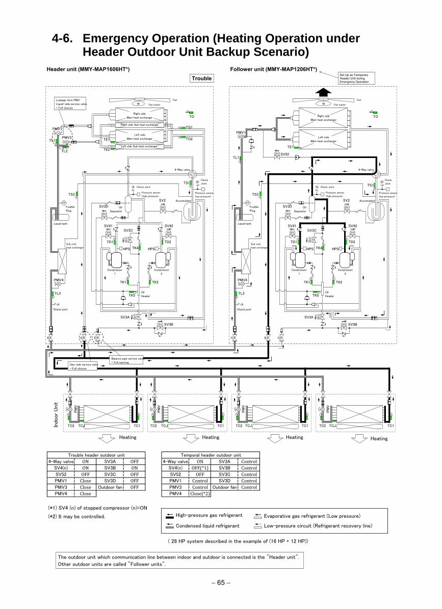
4-6. Emergency Operation (Heating Operation under Header Outdoor Unit Backup Scenario)
Header unit (MMY-MAP1606HT*) Follower unit (MMY-MAP1206HT*) Trouble
Set Up as Temporary Header Unit during Emergency Operation
Trouble header outdoor unit Temporal header outdoor unit
4-Way valve ON SV3A OFF 4-Way valve ON SV3A Control
SV4(n) ON SV3B ON SV4(n) OFF(*1) SV3B Control
SV52 OFF SV3C OFF SV52 OFF SV3C Control
PMV1 Close SV3D OFF PMV1 Control SV3D Control
PMV3 Close Outdoor fan OFF PMV3 Control Outdoor fan Control
PMV4 Close PMV4 Close(*2)
(*1) SV4 (n) of stopped compressor (n)=ON
(*2) It may be controlled.
( 28 HP system described in the example of (16 HP + 12 HP))
SV41 SV3C
SV42
Fan
圧縮機
1 (インバータ)
SV
SV
SV
SV
SV
SV
SV
FP
Indo
or
Uni
t
M
TC2 TCJ TC1
Heating
PM
V
TC2 TCJ TC1
Heating
PM
V
TC2 TCJ TC1
Heating
PM
V
TC2 TCJ TC1
Heating
PM
V
TS1
Fan motor
PMV1
TE1
TO
SV52
TS3
SV2
SV3D
TD1
TK4
TK5
TD2
TK2 TK1
SV3A
SV3B
SV
PMV4
TL3
SV41 SV3C
HPS
SV42
Accumulator
Pressure sensor
(low pressure)
Check
Joint
Oil
Header
Fan
圧縮機
1 (インバータ)
SV
SV
SV
SV
SV
SV
SV
M
TS1
Fan motor
PMV1
4-Way valve
TE1 PMV3
TL2
TO
Left side Sub heat exchanger
TS3 Pressure sensor
(high pressure)
SV2
SV3D
Liquid tank
Oil
Separator
Check Joint
TD1
TK4
TK5
Compressor
1
TD2
TK2 TK1
SV3A
SV3B
TE2
TL1
TG1
TG2
PMV4
Sub cool
heat exchanger
TL3
Fusible
Plug
FP
HPS
Compressor
2
Check joint
Left side
Main heat exchanger
Right side Sub heat exchanger
Right side
Main heat exchanger
HPS
Accumulator
Pressure sensor
(low pressure)
Check
Joint
Oil
Header
4-Way valve
Pressure sensor
(high pressure)
Liquid tank
Oil
Separator
Check Joint
Compressor
1
Sub cool
heat exchanger
Fusible
Plug
HPS
Compressor
2
Check joint
Left side
Main heat exchanger
Right side
Main heat exchanger
Balance pipe service valve
= Full opening Gas-side service valve
= Full closure
Leakage form PMV:
Liquid-side service valve
= Full closure
Evaporative gas refrigerant (Low pressure)
Low-pressure circuit (Refrigerant recovery line)
High-pressure gas refrigerant
Condensed liquid refrigerant
The outdoor unit which communication line between indoor and outdoor is connected is the "Header unit".
Other outdoor units are called "Follower units".
TL1
− 65 −
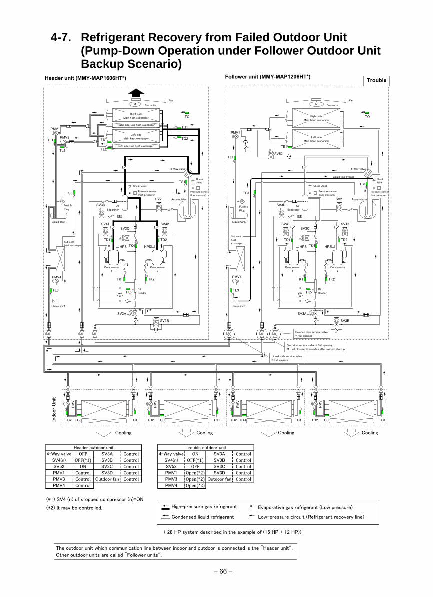
4-7. Refrigerant Recovery from Failed Outdoor Unit (Pump-Down Operation under Follower Outdoor Unit Backup Scenario)
Header unit (MMY-MAP1606HT*) Follower unit (MMY-MAP1206HT*) Trouble
Header outdoor unit Trouble outdoor unit
4-Way valve OFF SV3A Control 4-Way valve ON SV3A Control
SV4(n) OFF(*1) SV3B Control SV4(n) OFF(*1) SV3B Control
SV52 ON SV3C Control SV52 OFF SV3C Control
PMV1 Control SV3D Control PMV1 Open(*2) SV3D Control
PMV3 Control Outdoor fan Control PMV3 Open(*2) Outdoor fan Control
PMV4 Control PMV4 Open(*2)
(*1) SV4 (n) of stopped compressor (n)=ON
(*2) It may be controlled.
( 28 HP system described in the example of (16 HP + 12 HP))
SV41 SV3C
SV42
Fan
圧縮機
1 (インバータ)
SV
SV
SV
SV
SV
SV
SV
FP
Indo
or
Uni
t
M
TC2 TCJ TC1
Cooling
PM
V
TC2 TCJ TC1
Cooling
PM
V
TC2 TCJ TC1
Cooling
PM
V
TC2 TCJ TC1
Cooling
PM
V
TS1
Fan motor
PMV1
TE1
TO
SV52
TS3
SV2
SV3D
TD1
TK4
TK5
TD2
TK2 TK1
SV3A
SV3B
TL1 SV
PMV4
TL3
SV41 SV3C
HPS
SV42
Accumulator
Pressure sensor
(low pressure)
Check
Joint
Oil
Header
Fan
圧縮機
1 (インバータ)
SV
SV
SV
SV
SV
SV
SV
M
TS1
Fan motor
PMV1
4-Way valve
TE1 PMV3
TL2
TO
Left side Sub heat exchanger
TS3 Pressure sensor
(high pressure)
SV2
SV3D
Liquid tank
Oil
Separator
Check Joint
TD1
TK4
TK5
Compressor
1
TD2
TK2 TK1
SV3A
SV3B
TE2
TL1
TG1
TG2
PMV4
Sub cool
heat exchanger
TL3
Fusible
Plug
FP
HPS
Compressor
2
Check joint
Left side
Main heat exchanger
Right side Sub heat exchanger
Right side
Main heat exchanger
HPS
Accumulator
Pressure sensor
(low pressure)
Check
Joint
Oil
Header
4-Way valve
Pressure sensor
(high pressure)
Liquid tank
Oil
Separator
Check Joint
Compressor
1
Sub cool
heat
exchanger
Fusible
Plug
HPS
Compressor
2
Check joint
Left side
Main heat exchanger
Right side
Main heat exchanger
Balance pipe service valve
= Full opening
Gas-side service valve = Full opening
⇒ Full closure 10 minutes after system startup
Liquid-side service valve
= Full closure
Liquid line bypass
Evaporative gas refrigerant (Low pressure)
Low-pressure circuit (Refrigerant recovery line)
High-pressure gas refrigerant
Condensed liquid refrigerant
The outdoor unit which communication line between indoor and outdoor is connected is the "Header unit".
Other outdoor units are called "Follower units".
− 66 −
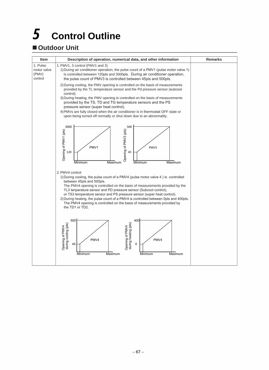
Outdoor Unit
Item Description of operation, numerical data, and other information Remarks
1. Pulsemotor valve (PMV) control
1. PMV1, 3 control (PMV1 and 3)1)During air conditioner operation, the pulse count of a PMV1 (pulse motor valve 1)
is controlled between 120pls and 3000pls. During air conditioner operation,the pulse count of PMV3 is controlled between 45pls and 500pls.
2)During cooling, the PMV opening is controlled on the basis of measurementsprovided by the TL temperature sensor and the Pd pressure sensor (subcoolcontrol).
3)During heating, the PMV opening is controlled on the basis of measurementsprovided by the TS, TD and TG temperature sensors and the PSpressure sensor (super heat control).
4)PMVs are fully closed when the air conditioner is in thermostat OFF state orupon being turned off normally or shut down due to an abnormality.
2. PMV4 control1)During cooling, the pulse count of a PMV4 (pulse motor valve 4 ) is controlled
between 45pls and 500pls.The PMV4 opening is controlled on the basis of measurements provided by theTL3 tenperature sensor and PD pressure sensor (Subcool control),or TS3 temperature sensor and PS pressure sensor (super heat control).
2)During heating, the pulse count of a PMV4 is controlled between 0pls and 400pls.The PMV4 opening is controlled on the basis of measurements provided bythe TD1 or TD2.
5 Control Outline
45
500 O
peni
ng o
f PM
V3
(pls
)
Minimum Maximum
PMV3
120
3000
Ope
ning
of P
MV
1 (p
ls)
Minimum Maximum
PMV1
45
500
Ope
ning
of P
MV
4 d
urin
g co
olin
g (p
ls)
Minimum Maximum
PMV4 0
400
Ope
ning
of P
MV
4 d
urin
g he
atin
g (p
ls)
Minimum Maximum
PMV4
− 67 −
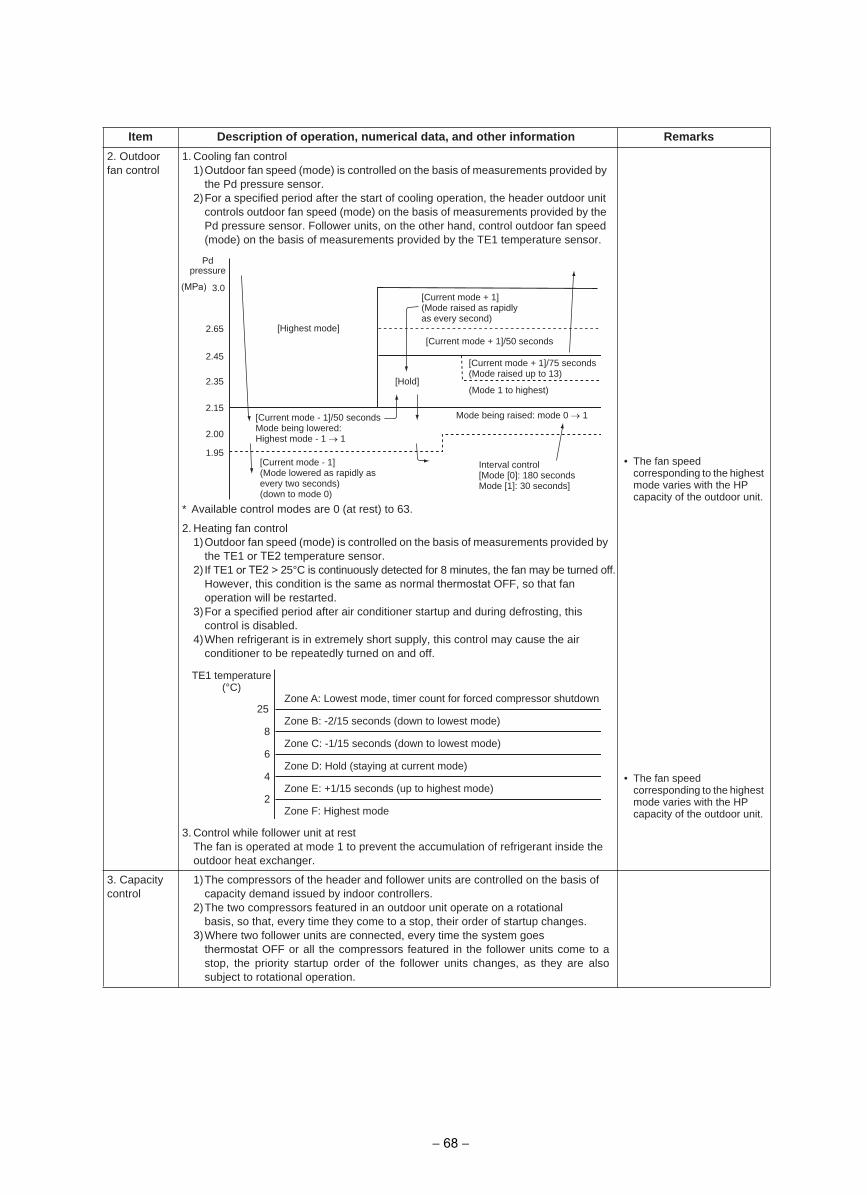
2. Outdoorfan control
1. Cooling fan control1)Outdoor fan speed (mode) is controlled on the basis of measurements provided by
the Pd pressure sensor.2)For a specified period after the start of cooling operation, the header outdoor unit
controls outdoor fan speed (mode) on the basis of measurements provided by thePd pressure sensor. Follower units, on the other hand, control outdoor fan speed(mode) on the basis of measurements provided by the TE1 temperature sensor.
* Available control modes are 0 (at rest) to 63.
• The fan speedcorresponding to the highest mode varies with the HPcapacity of the outdoor unit.
2. Heating fan control1)Outdoor fan speed (mode) is controlled on the basis of measurements provided by
the TE1 or TE2 temperature sensor.2) If TE1 or TE2 > 25°C is continuously detected for 8 minutes, the fan may be turned off.
However, this condition is the same as normal thermostat OFF, so that fanoperation will be restarted.
3)For a specified period after air conditioner startup and during defrosting, thiscontrol is disabled.
4)When refrigerant is in extremely short supply, this control may cause the airconditioner to be repeatedly turned on and off.
• The fan speedcorresponding to the highest mode varies with the HPcapacity of the outdoor unit.
3. Control while follower unit at restThe fan is operated at mode 1 to prevent the accumulation of refrigerant inside theoutdoor heat exchanger.
3. Capacitycontrol
1)The compressors of the header and follower units are controlled on the basis ofcapacity demand issued by indoor controllers.
2)The two compressors featured in an outdoor unit operate on a rotationalbasis, so that, every time they come to a stop, their order of startup changes.
3)Where two follower units are connected, every time the system goesthermostat OFF or all the compressors featured in the follower units come to astop, the priority startup order of the follower units changes, as they are alsosubject to rotational operation.
Item Description of operation, numerical data, and other information Remarks
1.95
2.00
2.15
2.35
2.45
2.65
3.0
[Highest mode]
[Current mode + 1](Mode raised as rapidly as every second)
[Current mode + 1]/50 seconds
[Hold]
[Current mode + 1]/75 seconds(Mode raised up to 13)
(Mode 1 to highest)
[Current mode - 1]/50 secondsMode being lowered:Highest mode - 1 → 1
Mode being raised: mode 0 → 1
[Current mode - 1](Mode lowered as rapidly as every two seconds)(down to mode 0)
Interval control[Mode [0]: 180 secondsMode [1]: 30 seconds]
Pdpressure
25
8
6
4
2
Zone A: Lowest mode, timer count for forced compressor shutdown
Zone B: -2/15 seconds (down to lowest mode)
Zone C: -1/15 seconds (down to lowest mode)
Zone D: Hold (staying at current mode)
Zone E: +1/15 seconds (up to highest mode)
Zone F: Highest mode
TE1 temperature(°C)
(MPa)
− 68 −
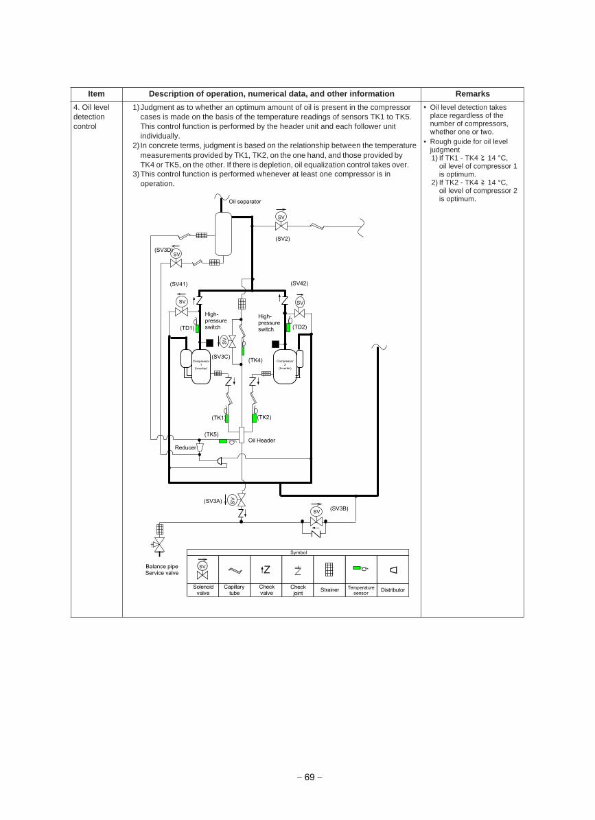
4. Oil leveldetection control
1)Judgment as to whether an optimum amount of oil is present in the compressorcases is made on the basis of the temperature readings of sensors TK1 to TK5.This control function is performed by the header unit and each follower unitindividually.
2) In concrete terms, judgment is based on the relationship between the temperature measurements provided by TK1, TK2, on the one hand, and those provided by TK4 or TK5, on the other. If there is depletion, oil equalization control takes over.
3)This control function is performed whenever at least one compressor is inoperation.
• Oil level detection takesplace regardless of thenumber of compressors,whether one or two.
• Rough guide for oil leveljudgment1) If TK1 - TK4 14 °C,
oil level of compressor 1is optimum.
2) If TK2 - TK4 14 °C,oil level of compressor 2is optimum.
Item Description of operation, numerical data, and other information Remarks
(TD2)
(TK2) (TK1)
(TD1)
(TK4)
SV
SV
SV SV
SV
SV
(TK5)
(SV3B) (SV3A)
(SV2)
(SV3D)
(SV42) (SV41)
(SV3C)
Oil separator
Oil Header
High- pressure switch
High- pressure switch
Balance pipe Service valve
Reducer
Compressor 1
(Inverter)
Compressor 2
(Inverter)
SV
SV
Solenoidvalve
Capillarytube
Checkvalve
Checkjoint Strainer Temperature
sensor
Symbol
Distributor
− 69 −
5. Oilequation control
This control function is aimed at preventing compressors from running out of oil by evening out the oil supply to outdoor units, and is basically performed by opening/closing solenoid valves SV3A, SV3B, SV3C, SV3D. There are three control patterns as described below. (For a schematic diagram of oil equalization control, see page 57.)
1. Preparatory controlIf the oil level judgment result in the memory continues to be “low” for 30 seconds,SV3B is turned on, with SV3D turned on and off intermittently.
• Oil accumulated in the oilseparator is returned to thecompressor.
2. Oil equation controlThis control function is performed to transfer oil to the outdoor unit whose oil level islow from other outdoor units. It takes place whenever the header unit registers a lowoil level result while at least one of its compressors is turned on or at least one of thefollower units issues an oil level equation request.This control function does not apply to a header unit-only system (no follower unitsconnected).
• This is normal oilequalization control.
3. Oil depletion protection controlThis control function is performed if oil equation control fails to achieve an optimumoil level. In concrete terms, if a low oil level situation continues for 30 minutes, the unit is brought to a protective shutdown, followed by a restart 2 minutes and 30 secondslater. If protective shutdown is repeated three times, the error is confirmed as final.(There will be no more restarts.) The check code is “H07”.
• This protective control isperformed when aprolonged low oil level isdetected.
6. Refrigerant/oil recovery control
1. Cooling oil (refrigerant) recovery controlPerformed during cooling, this control function aims to: periodically collect anyrefrigerating oil condensate that has built up in inter-unit gas pipes and indoor unitsand return it to outdoor units when the compressor operation command isinadequate; and prevent the accumulation of refrigerant in outdoor heat exchangerswhile cooling operation is in progress under low outside air temperature conditions.It is managed by the header outdoor unit.1)Control commencement conditions
• When cooling operation has continued for at least 2 hours• When cooling operation has started (compressors have just been turned on, though
this does not always happen depending on outside air temperature conditions).2)Control details
• All compressors currently in operation are operated at the minimum speed, with those currently not in operation turned on.
• Indoor units are set to the cooling oil (refrigerant) recovery control mode, with theirindoor PMVs opened to a certain degree.
• Compressors are operated at the target speed.• After recovery control is performed for a specified period of time, it is terminated, and
normal cooling operation resumes.
• Cooling oil recovery controltakes place approximatelyevery 2 hours.
• Control duration is about 2 to 5 minutes, though it variesaccording to the operatingconditions of the system.
2. Heating refrigerant (oil) recovery controlPerformed during heating, this control function aims to recover any liquid refrigeranttrapped inside indoor units that have been turned off. It also serves the additionalpurposes of recovering indoor/outdoor refrigerant after defrosting and recovering oilpresent in outdoor heat exchangers during heating overload operation.This control function is managed by the header outdoor unit.1)Control commencement conditions
• When heating operation has started (compressors have just been turned on)• When heating takes over upon completion of defrosting• When heating operation has continued for 60 minutes
2)Control details• All compressors currently in operation are operated at the minimum speed, with those
currently not in operation turned on.• Indoor units are set to the heating refrigerant (oil) recovery control mode, with their
indoor PMVs opened to a certain degree.• Compressors are operated at the target speed.• Upon completion of refrigerant recovery for all the indoor units, normal cooling
operation resumes.
• Heating oil recovery controltakes place approximatelyevery hour.
• Control duration is about 2 to 10 minutes, though it variesaccording to loadingconditions.
• Compressor rotationalspeed varies with controlconditions, indoor unitcapacity, and outdoor unitspecification.
Item Description of operation, numerical data, and other information Remarks
− 70 −
7. Defrostingcontrol (reversedefrosting method)
1. Defrosting commencement conditions• During heating operation, the cumulative duration of operation in which TE1 and
TE2 sensor temperature falls below frost formation temperature is measured, andwhen this reaches 55 minutes, defrosting control is introduced. (Just after startupor upon changeover from cooling to heating, the target cumulative duration is 25minutes.)
* If the outdoor units are a combination of different models, all the units begin engaging in defrosting control as soon as one of them satisfies defrosting commencementconditions.
• Frost formation temperature is -1.5 °C.
• If the outdoor units are acombination of differentmodels, defrostingoperation, once started,cannot be manuallyterminated for about 2minutes.
2. Details of defrosting control1)All compressors currently in operation are operated at the minimum speed.2)When a specified amount of time passes from the time the compressors reached
the minimum speed, the outdoor fans are turned off by closing the 4-way valves.And the PMV4 opening operated at the target opening for defrosting control.
3)All compressors currently not in operation are turned on and operated at the target rotational speed for defrosting control.
• To protect the refrigeratingcycle circuit, the fan modemay be controlled duringdefrosting.
3. Defrosting termination conditions• Defrosting termination conditions are met when the TE1 and TE2 temperature
sensor measurement reaches a specified value (roughly 12 °C) a certain periodof time after the commencement of defrosting control. In that event, defrostingtermination control takes over.* If the outdoor units are a combination of different models, defrosting termination
control commences when all the units satisfy the defrosting termination conditions.As long as one or more outdoor units are yet to satisfy the defrosting terminationconditions, those that have engage in standby operation.
• During defrosting control,compressors are controlledso that their speeds do notexceed 76.6 rps.
4. Details of defrosting termination control1)Compressors are operated at the standby operation speed.2)When a specified amount of time passes, the 4-way valves are opened.3) Indoor heating refrigerant recovery control is performed.For control details, see “ 6. Refrigerant/oil recovery control”.
• During standby operation,compressor speed is in the24-33.5 rps range.(It varies from outdoor unit to outdoor unit.)
Item Description of operation, numerical data, and other information Remarks
− 71 −
8.Hot gas defrostingcontrol
1. Hot gas defrosting commencement conditions• During heating operation, the cumulative duration of operation in which
the TE1 (or TE2) temperature sensor falls below the frost formation temperature is recorded. Once the time duration exceeds 30 minutes, the hot gas defrosting control begins.
*If the outdoor units are in a combination (module), only the outdoor unitsthat are operating their compressors, will perform the hot gas defrosting control.
・ Frost formation temperature is -1.5°C.
2. Details of hot gas defrosting control1) SV51 and SV52 are opened.2) PMV1 (and PMV3) are closed. 3)The outdoor fans are turned off.4) Compressors are operated at the target rotational speed for hot gas
defrosting control.
・ When outside temperature is –10°C or lower, hot gas defrosting control is disabled. (Only Reverse defrosting). This is due to insufficient capacity output, from the outdoor unit, resulting in potentially unacceptable performance
3. Hot gas defrosting termination conditions• Hot gas defrosting termination conditions are met when the TS1 (or TG1
and TG2) temperature sensor measurement reaches a value of 12°C for a specified value of time (within 4.5 minutes) after the commencement of hot gas defrosting control. In the event that these values are achieved the hot gas defrosting termination control will take over.
*For module installations (multiple outdoor units). During Hot gasoperation, ALL outdoor units must meet the termination conditionings for the hot gas control. If not the following defrost operation (25 minutes later if TE1 (or TE2) temperatures measurements continues below the frost formation temperature) will results in a standard reverse defrosting operation.
・ During hot gas defrosting control,compressors are controlled so thattheir speeds do not exceed 76.6 rps.
4. Details of hot gas defrosting termination control1) Open the PMV1 (and PMV3) to a certain degree.2) SV51 and SV52 are closed.3) Normal heating operation resumes.
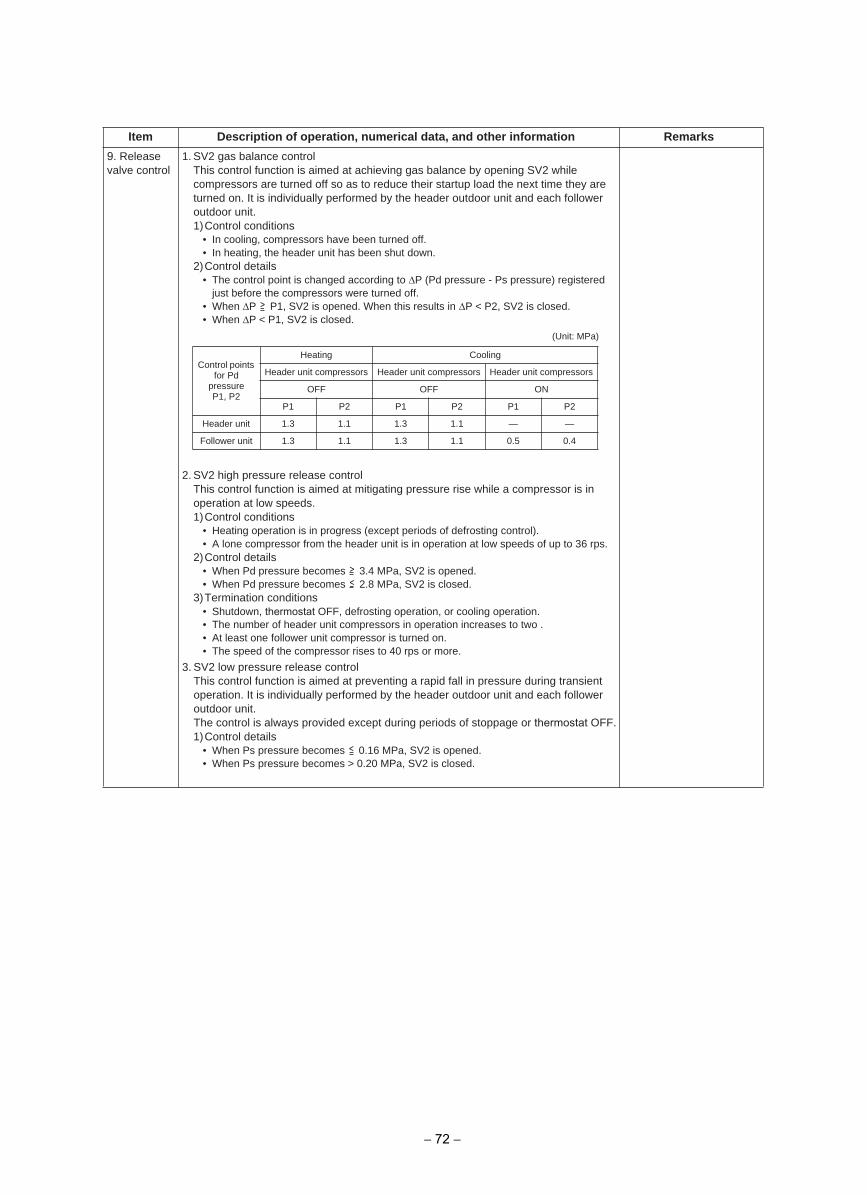
9. Releasevalve control
1. SV2 gas balance controlThis control function is aimed at achieving gas balance by opening SV2 whilecompressors are turned off so as to reduce their startup load the next time they areturned on. It is individually performed by the header outdoor unit and each followeroutdoor unit.1)Control conditions
• In cooling, compressors have been turned off.• In heating, the header unit has been shut down.
2)Control details• The control point is changed according to P (Pd pressure - Ps pressure) registered
just before the compressors were turned off.• When P P1, SV2 is opened. When this results in P < P2, SV2 is closed.• When P < P1, SV2 is closed.
2. SV2 high pressure release controlThis control function is aimed at mitigating pressure rise while a compressor is inoperation at low speeds.1)Control conditions
• Heating operation is in progress (except periods of defrosting control).• A lone compressor from the header unit is in operation at low speeds of up to 36 rps.
2)Control details• When Pd pressure becomes 3.4 MPa, SV2 is opened.• When Pd pressure becomes 2.8 MPa, SV2 is closed.
3)Termination conditions• Shutdown, thermostat OFF, defrosting operation, or cooling operation.• The number of header unit compressors in operation increases to two .• At least one follower unit compressor is turned on.• The speed of the compressor rises to 40 rps or more.
3. SV2 low pressure release controlThis control function is aimed at preventing a rapid fall in pressure during transientoperation. It is individually performed by the header outdoor unit and each followeroutdoor unit.The control is always provided except during periods of stoppage or thermostat OFF.1)Control details
• When Ps pressure becomes 0.16 MPa, SV2 is opened.• When Ps pressure becomes > 0.20 MPa, SV2 is closed.
Item Description of operation, numerical data, and other information Remarks
(Unit: MPa)
Control points for Pd
pressureP1, P2
gnilooCgnitaeH
Header unit compressors Header unit compressors Header unit compressors
NOFFOFFO
P1 P2 P1 P2 P1 P2
Header unit 1.3 1.1 1.3 1.1 — —
Follower unit 1.3 1.1 1.3 1.1 0.5 0.4
− 72 −
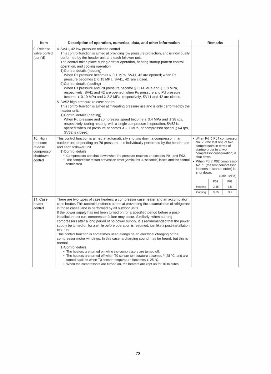
9. Releasevalve control (cont’d)
4. SV41, 42 low pressure release controlThis control function is aimed at providing low pressure protection, and is individually performed by the header unit and each follower unit.The control takes place during defrost operation, heating startup pattern controloperation, and cooling operation.1)Control details (heating)
When Ps pressure becomes 0.1 MPa, SV41, 42 are opened; when Pspressure becomes 0.15 MPa, SV41, 42 are closed.
2)Control details (cooling)When Ps pressure and Pd pressure become 0.14 MPa and 1.8 MPa,respectively, SV41 and 42 are opened; when Ps pressure and Pd pressurebecome 0.19 MPa and 2.2 MPa, respectively, SV41 and 42 are closed.
5. SV52 high pressure release controlThis control function is aimed at mitigating pressure rise and is only performed by the header unit.1)Control details (heating)
When Pd pressure and compressor speed become 3.4 MPa and 38 rps,respectively, during heating, with a single compressor in operation, SV52 is opened; when Pd pressure becomes 2.7 MPa, or compressor speed 64 rps,SV52 is closed.
10. Highpressure release compressor shutdown control
This control function is aimed at automatically shutting down a compressor in an outdoor unit depending on Pd pressure. It is individually performed by the header unit and each follower unit.
1)Control details• Compressors are shut down when Pd pressure reaches or exceeds P01 and P02.• The compressor restart prevention timer (2 minutes 30 seconds) is set, and the control
terminated.
• When Pd P01 compressorNo. 2 (the last one of twocompressors in terms ofstartup order in a twocompressor configuration) is shut down.
•
11. Caseheater control
There are two types of case heaters: a compressor case heater and an accumulator case heater. This control function is aimed at preventing the accumulation of refrigerant in those cases, and is performed by all outdoor units.If the power supply has not been turned on for a specified period before a post-installation test run, compressor failure may occur. Similarly, when starting compressors after a long period of no power supply, it is recommended that the power supply be turned on for a while before operation is resumed, just like a post-installation test run.This control function is sometimes used alongside an electrical charging of the compressor motor windings. In this case, a charging sound may be heard, but this is normal.
1)Control details• The heaters are turned on while the compressors are turned off.• The heaters are turned off when T0 sensor temperature becomes 28 °C, and are
turned back on when T0 sensor temperature becomes 25 °C.• When the compressors are turned on, the heaters are kept on for 10 minutes.
Item Description of operation, numerical data, and other information Remarks
When Pd P02 compressorNo. 1 (the first compressorin terms of startup order) isshut down.
P01 P02
Heating 3.45 3.5
Cooling 3.85 3.9
(unit : MPa)
− 73 −
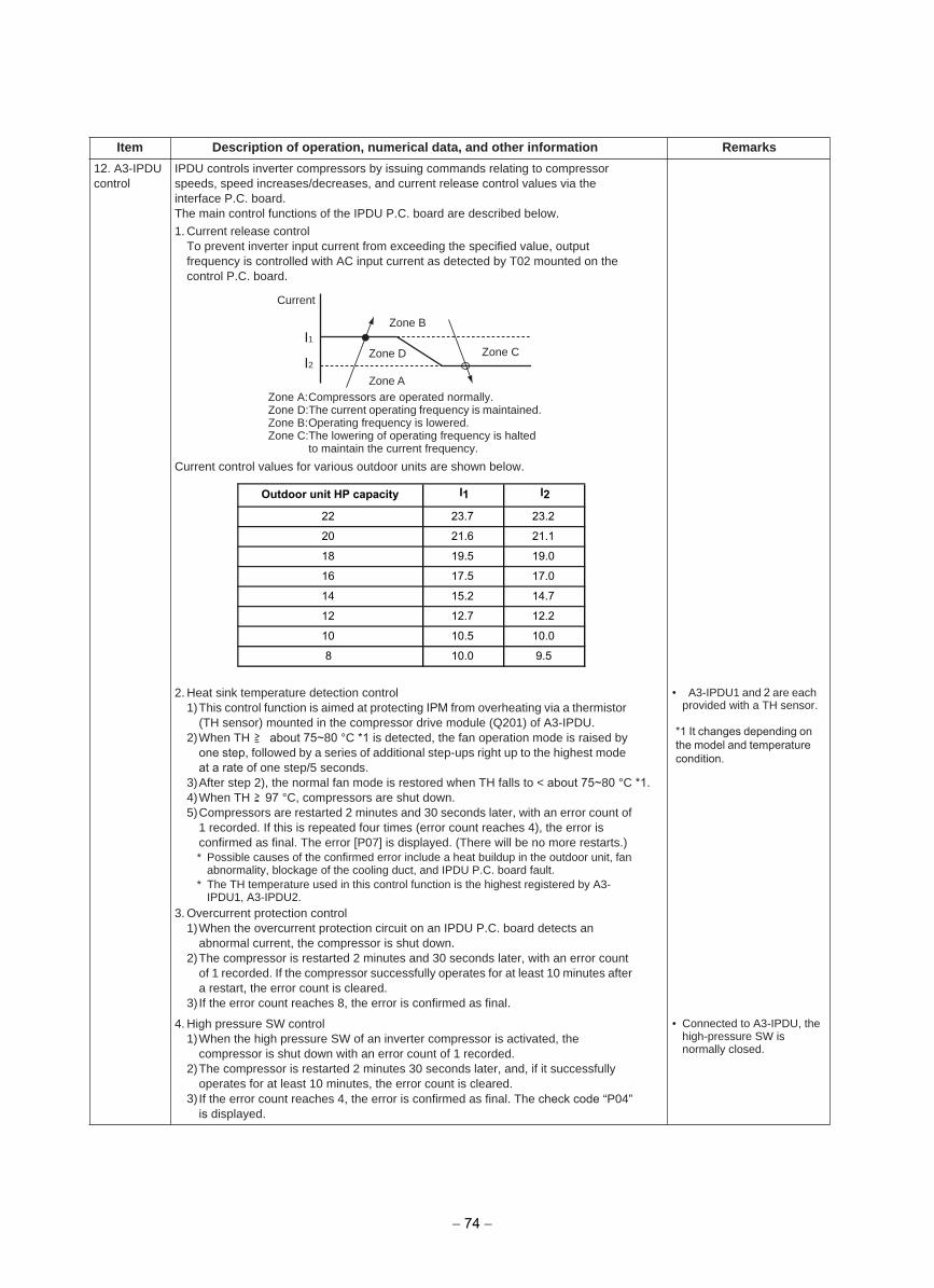
12. A3-IPDUcontrol
IPDU controls inverter compressors by issuing commands relating to compressor speeds, speed increases/decreases, and current release control values via the interface P.C. board.The main control functions of the IPDU P.C. board are described below.
1. Current release controlTo prevent inverter input current from exceeding the specified value, outputfrequency is controlled with AC input current as detected by T02 mounted on thecontrol P.C. board.
Current control values for various outdoor units are shown below.
2. Heat sink temperature detection control1)This control function is aimed at protecting IPM from overheating via a thermistor
(TH sensor) mounted in the compressor drive module (Q201) of A3-IPDU.2)When TH about 75~80 °C *1 is detected, the fan operation mode is raised by
one step, followed by a series of additional step-ups right up to the highest modeat a rate of one step/5 seconds.
3)After step 2), the normal fan mode is restored when TH falls to < about 75~80 °C *1.4)When TH 97 °C, compressors are shut down.5)Compressors are restarted 2 minutes and 30 seconds later, with an error count of
1 recorded. If this is repeated four times (error count reaches 4), the error isconfirmed as final. The error [P07] is displayed. (There will be no more restarts.)* Possible causes of the confirmed error include a heat buildup in the outdoor unit, fan
abnormality, blockage of the cooling duct, and IPDU P.C. board fault.* The TH temperature used in this control function is the highest registered by A3-
IPDU1, A3-IPDU2.3. Overcurrent protection control
1)When the overcurrent protection circuit on an IPDU P.C. board detects anabnormal current, the compressor is shut down.
2)The compressor is restarted 2 minutes and 30 seconds later, with an error countof 1 recorded. If the compressor successfully operates for at least 10 minutes after a restart, the error count is cleared.
3) If the error count reaches 8, the error is confirmed as final.
• A3-IPDU1 and 2 are each provided with a TH sensor.
4. High pressure SW control1)When the high pressure SW of an inverter compressor is activated, the
compressor is shut down with an error count of 1 recorded.2)The compressor is restarted 2 minutes 30 seconds later, and, if it successfully
operates for at least 10 minutes, the error count is cleared.3) If the error count reaches 4, the error is confirmed as final. The check code “P04”
is displayed.
• Connected to A3-IPDU, thehigh-pressure SW isnormally closed.
Item Description of operation, numerical data, and other information Remarks
Zone C
Zone B
Zone A
Zone DI1
I2
Current
Zone A:Compressors are operated normally.Zone D:The current operating frequency is maintained.Zone B:Operating frequency is lowered.Zone C:The lowering of operating frequency is halted
to maintain the current frequency.
Outdoor unit HP capacity I1 I2
22 23.7 23.2
20 21.6 21.1
18 19.5 19.0
16 17.5 17.0
14 15.2 14.7
12 12.7 12.2
10 10.5 10.0
8 10.0 9.5
− 74 −
*1 It changes depending onthe model and temperaturecondition.
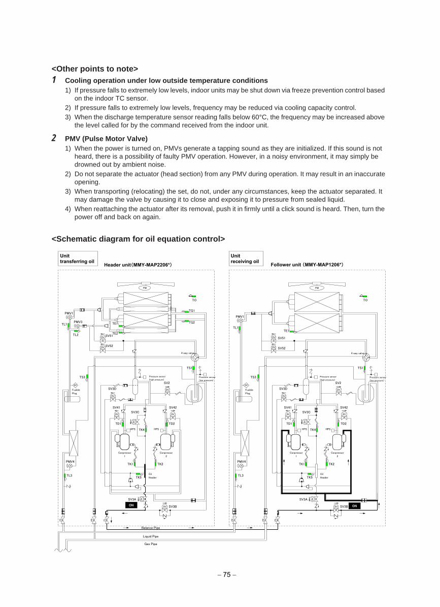
<Other points to note>1 Cooling operation under low outside temperature conditions
1) If pressure falls to extremely low levels, indoor units may be shut down via freeze prevention control basedon the indoor TC sensor.
2) If pressure falls to extremely low levels, frequency may be reduced via cooling capacity control.3) When the discharge temperature sensor reading falls below 60°C, the frequency may be increased above
the level called for by the command received from the indoor unit.
2 PMV (Pulse Motor Valve)1) When the power is turned on, PMVs generate a tapping sound as they are initialized. If this sound is not
heard, there is a possibility of faulty PMV operation. However, in a noisy environment, it may simply bedrowned out by ambient noise.
2) Do not separate the actuator (head section) from any PMV during operation. It may result in an inaccurateopening.
3) When transporting (relocating) the set, do not, under any circumstances, keep the actuator separated. Itmay damage the valve by causing it to close and exposing it to pressure from sealed liquid.
4) When reattaching the actuator after its removal, push it in firmly until a click sound is heard. Then, turn thepower off and back on again.
<Schematic diagram for oil equation control>
SV41
SV3C
SV42
圧縮機
1 (インバータ)
SV
SV
SV
SV
SV
SV
SV
FP
Header unit(MMY-MAP2206*) Follower unit (MMY-MAP1206*)
FM
TS1
PMV1
TE1
TO
SV51
TS3
SV2
SV3D
TD1
TK4
TK5
TD2
TK2 TK1
SV3A
SV3B
TL1
SV SV52
SV
PMV4
TL3
SV41
SV3C
HPS
SV42
圧縮機
1 (インバータ)
SV
SV
SV
SV
SV
SV
SV
FM
TS1
PMV1
4 way valve
TE1 PMV3
TL2
TO
SV51
TS3
SV2
SV3D
TD1
TK4
TK5
TD2
TK2 TK1
HPS
SV3A
SV3B
TE2
TL1
SV SV52
SV
TG1
TG2
PMV4
TL3
FP
Balance Pipe
ON
Liquid Pipe
ON
Gas Pipe
Pressure sensor
(low pressure)
Oil
Header
Conpressor
2
Pressure sensor
(high pressure)
Conpressor
1
Fusible
Plug
4 way valve
Pressure sensor
(low pressure)
Pressure sensor
(high pressure)
HPS HPS
Oil
Header
Conpressor
2
Conpressor
1
Fusible
Plug
Unit transferring oil
Unit receiving oil
− 75 −
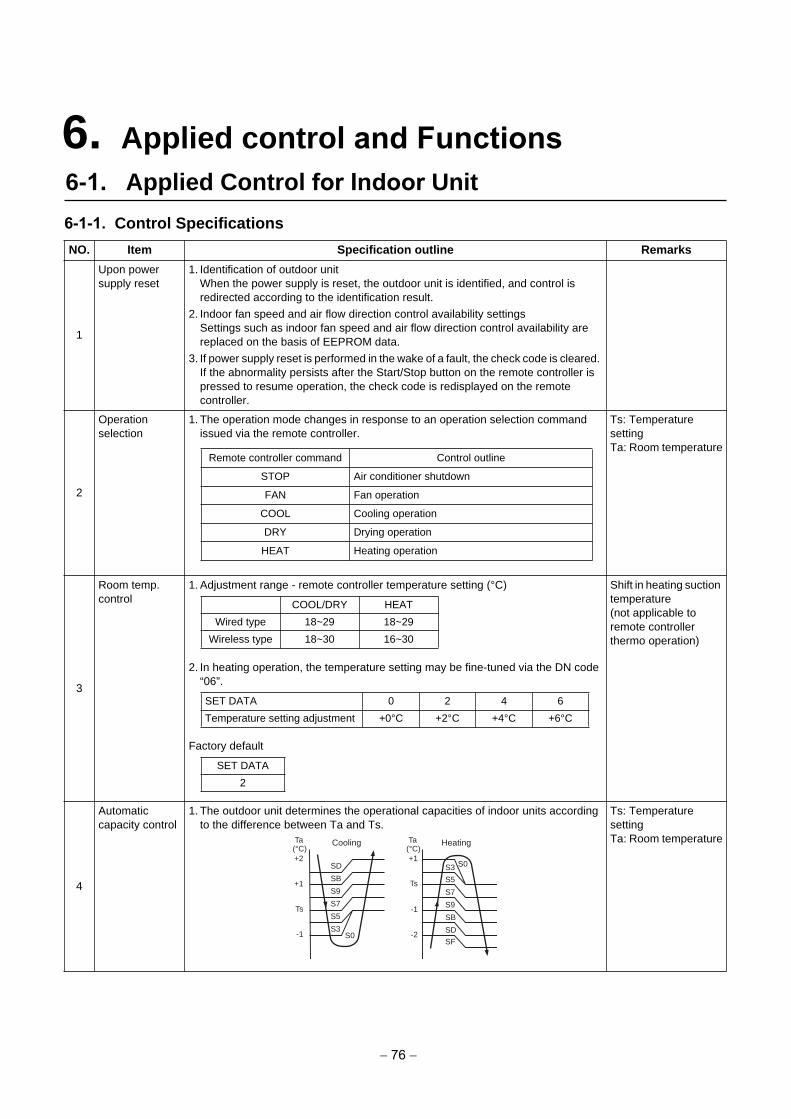
6-1-1. Control Specifications
NO. Item Specification outline Remarks
1
Upon power supply reset
1. Identification of outdoor unitWhen the power supply is reset, the outdoor unit is identified, and control isredirected according to the identification result.
2. Indoor fan speed and air flow direction control availability settingsSettings such as indoor fan speed and air flow direction control availability arereplaced on the basis of EEPROM data.
3. If power supply reset is performed in the wake of a fault, the check code is cleared. If the abnormality persists after the Start/Stop button on the remote controller ispressed to resume operation, the check code is redisplayed on the remotecontroller.
2
Operation selection
1. The operation mode changes in response to an operation selection commandissued via the remote controller.
Ts: Temperature settingTa: Room temperature
3
Room temp. control
1. Adjustment range - remote controller temperature setting (°C)
2. In heating operation, the temperature setting may be fine-tuned via the DN code“06”.
Factory default
Shift in heating suction temperature(not applicable to remote controller thermo operation)
4
Automatic capacity control
1. The outdoor unit determines the operational capacities of indoor units accordingto the difference between Ta and Ts.
Ts: Temperature settingTa: Room temperature
Remote controller command Control outline
STOP Air conditioner shutdown
FAN Fan operation
COOL Cooling operation
DRY Drying operation
HEAT Heating operation
COOL/DRY HEAT
Wired type 18~29 18~29
Wireless type 18~30 16~30
SET DATA 0 2 4 6
Temperature setting adjustment +0°C +2°C +4°C +6°C
SET DATA
2
SD
SB
S9
S7
S5
S3S0
Cooling
+2
+1
Ts
-1
S3
S5
S7
S9
SB
SD
SF
S0
Heating
+1
Ts
-2
-1
Ta(°C)
Ta(°C)
6. Applied control and Functions6-1. Applied Control for Indoor Unit
− 76 −
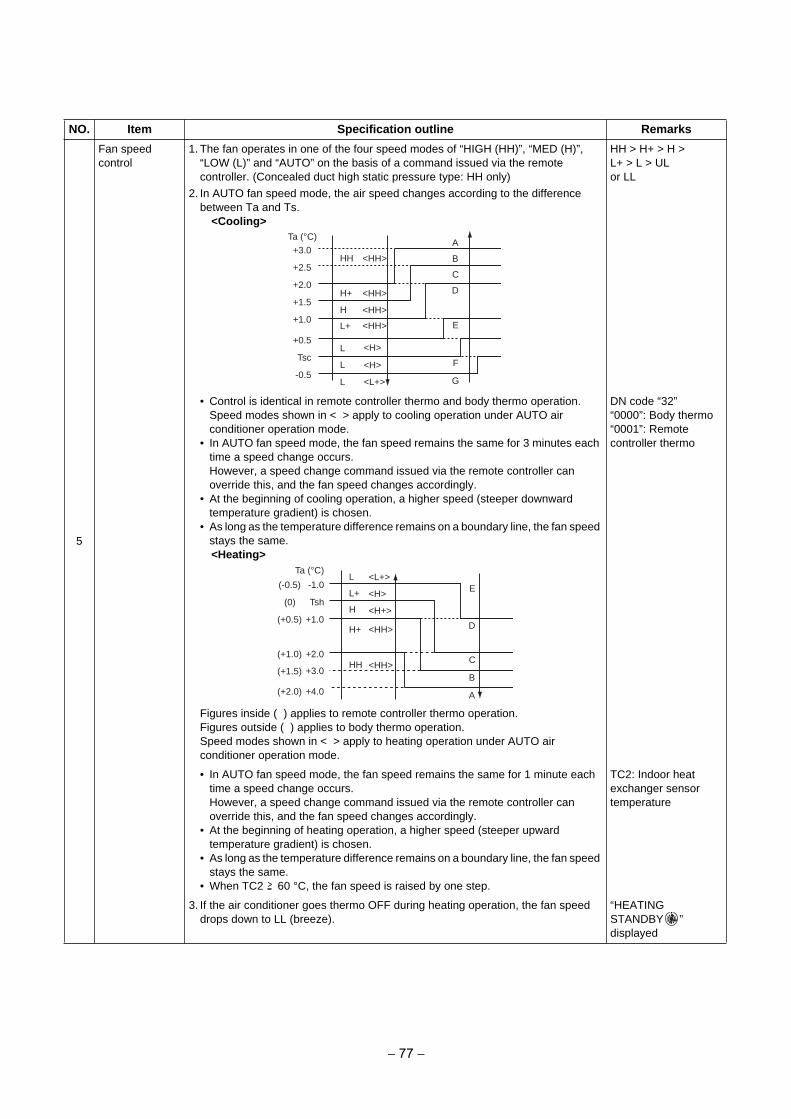
5
Fan speed control
1. The fan operates in one of the four speed modes of “HIGH (HH)”, “MED (H)”,“LOW (L)” and “AUTO” on the basis of a command issued via the remotecontroller. (Concealed duct high static pressure type: HH only)
2. In AUTO fan speed mode, the air speed changes according to the differencebetween Ta and Ts.
<Cooling>
HH > H+ > H >L+ > L > ULor LL
• Control is identical in remote controller thermo and body thermo operation.Speed modes shown in < > apply to cooling operation under AUTO airconditioner operation mode.
• In AUTO fan speed mode, the fan speed remains the same for 3 minutes eachtime a speed change occurs.However, a speed change command issued via the remote controller canoverride this, and the fan speed changes accordingly.
• At the beginning of cooling operation, a higher speed (steeper downwardtemperature gradient) is chosen.
• As long as the temperature difference remains on a boundary line, the fan speed stays the same.<Heating>
Figures inside ( ) applies to remote controller thermo operation.Figures outside ( ) applies to body thermo operation.Speed modes shown in < > apply to heating operation under AUTO air conditioner operation mode.
DN code “32”“0000”: Body thermo“0001”: Remote controller thermo
• In AUTO fan speed mode, the fan speed remains the same for 1 minute eachtime a speed change occurs.However, a speed change command issued via the remote controller canoverride this, and the fan speed changes accordingly.
• At the beginning of heating operation, a higher speed (steeper upwardtemperature gradient) is chosen.
• As long as the temperature difference remains on a boundary line, the fan speed stays the same.
• When TC2 60 °C, the fan speed is raised by one step.
TC2: Indoor heat exchanger sensor temperature
3. If the air conditioner goes thermo OFF during heating operation, the fan speeddrops down to LL (breeze).
“HEATING STANDBY ” displayed
NO. Item Specification outline Remarks
-0.5
Tsc
+0.5
+1.0
+1.5
+2.0
+2.5
+3.0Ta (°C)
HH
H
L
L
L
H+
L+
A
B
C
D
E
F
G
<HH>
<HH>
<HH>
<HH>
<H>
<H>
<L+>
+4.0
+3.0
+2.0
+1.0
Tsh
-1.0
Ta (°C)
(+2.0)
(+1.5)
(+1.0)
(+0.5)
(0)
(-0.5)L
L+
H
H+
HH
E
D
C
B
A
<L+>
<H>
<H+>
<HH>
<HH>
− 77 −
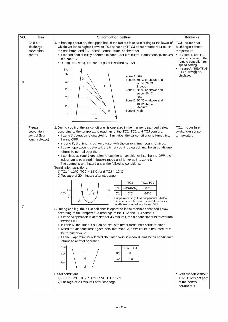
6
Cold air discharge prevention control
1. In heating operation, the upper limit of the fan tap is set according to the lower ofwhichever is the higher between TC2 sensor and TCJ sensor temperatures, onthe one hand, and TC1 sensor temperature, on the other.• If the fan continuously operates in zone B for 6 minutes, it automatically moves
into zone C.• During defrosting, the control point is shifted by +6°C.
TCJ: Indoor heat exchanger sensor temperature• In zones D and E,
priority is given to the remote controller fan speed setting.
• In zone A, “HEATING STANDBY ” is displayed.
7
Freeze prevention control (low temp. release)
1. During cooling, the air conditioner is operated in the manner described belowaccording to the temperature readings of the TC1, TC2 and TCJ sensors.• If zone J operation is detected for 5 minutes, the air conditioner is forced into
thermo OFF.• In zone K, the timer is put on pause, with the current timer count retained.• If zone I operation is detected, the timer count is cleared, and the air conditioner
returns to normal operation.• If continuous zone J operation forces the air conditioner into thermo OFF, the
indoor fan is operated in breeze mode until it moves into zone I.The control is terminated under the following conditions:
Termination conditions1)TC1 12°C, TC2 12°C, and TCJ 12°C2)Passage of 20 minutes after stoppage
2. During cooling, the air conditioner is operated in the manner described belowaccording to the temperature readings of the TC2 and TCJ sensors.• If zone M operation is detected for 45 minutes, the air conditioner is forced into
thermo OFF.• In zone N, the timer is put on pause, with the current timer count retained.• When the air conditioner goes back into zone M, timer count is resumed from
the retained value.• If zone L operation is detected, the timer count is cleared, and the air conditioner
returns to normal operation.
TC1: Indoor heat exchanger sensor temperature
Reset conditions1)TC1 12°C, TC2 12°C and TCJ 12°C2)Passage of 20 minutes after stoppage
* With models withoutTC2, TC2 is not partof the controlparameters.
NO. Item Specification outline Remarks
E
B
28
30
32
26
20
16
A
D
C
(°C)
Zone A:OFFZone B:26 °C or above and
below 28 °CBreeze
Zone C:28 °C or above and below 30 °CLow
Zone D:30 °C or above and below 32 °CMedium
Zone E:High
P1
Q1
J
KaI
(°C)
Temperature in ( ): If the temperature is below this value when the power is turned on, the air conditioner is forced into thermo OFF.
TC1 TC2, TCJ
P1 10°C(5°C) -10°C
Q1 0°C -14°C
P2
Q2
M
N
L(°C) TC2, TCJ
P2 5
Q2 -2.0
− 78 −
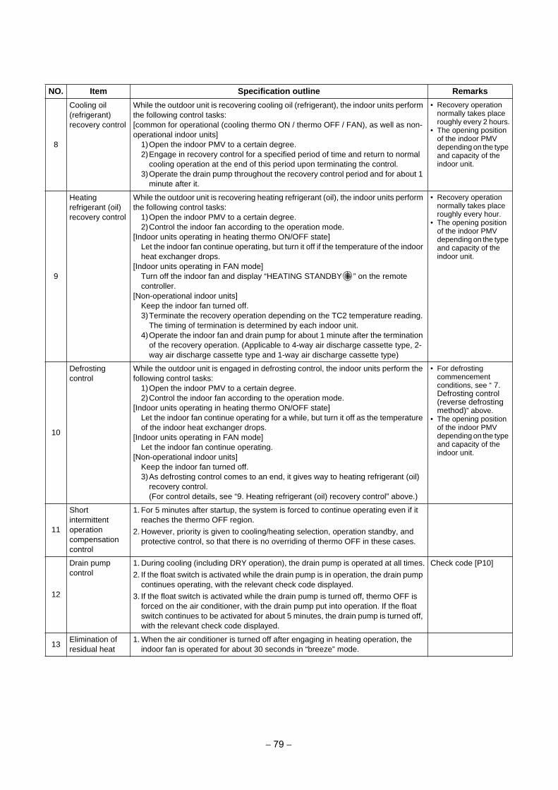
8
Cooling oil (refrigerant) recovery control
While the outdoor unit is recovering cooling oil (refrigerant), the indoor units perform the following control tasks: [common for operational (cooling thermo ON / thermo OFF / FAN), as well as non-operational indoor units]
1)Open the indoor PMV to a certain degree.2)Engage in recovery control for a specified period of time and return to normal
cooling operation at the end of this period upon terminating the control.3)Operate the drain pump throughout the recovery control period and for about 1
minute after it.
• Recovery operationnormally takes placeroughly every 2 hours.
• The opening positionof the indoor PMVdepending on the type and capacity of theindoor unit.
9
Heating refrigerant (oil) recovery control
While the outdoor unit is recovering heating refrigerant (oil), the indoor units perform the following control tasks:
1)Open the indoor PMV to a certain degree.2)Control the indoor fan according to the operation mode.
[Indoor units operating in heating thermo ON/OFF state]Let the indoor fan continue operating, but turn it off if the temperature of the indoor heat exchanger drops.
[Indoor units operating in FAN mode]Turn off the indoor fan and display “HEATING STANDBY ” on the remote controller.
[Non-operational indoor units]Keep the indoor fan turned off.3)Terminate the recovery operation depending on the TC2 temperature reading.
The timing of termination is determined by each indoor unit.4)Operate the indoor fan and drain pump for about 1 minute after the termination
of the recovery operation. (Applicable to 4-way air discharge cassette type, 2-way air discharge cassette type and 1-way air discharge cassette type)
• Recovery operationnormally takes placeroughly every hour.
• The opening positionof the indoor PMVdepending on the type and capacity of theindoor unit.
10
Defrosting control
While the outdoor unit is engaged in defrosting control, the indoor units perform the following control tasks:
1)Open the indoor PMV to a certain degree.2)Control the indoor fan according to the operation mode.
[Indoor units operating in heating thermo ON/OFF state]Let the indoor fan continue operating for a while, but turn it off as the temperature of the indoor heat exchanger drops.
[Indoor units operating in FAN mode]Let the indoor fan continue operating.
[Non-operational indoor units]Keep the indoor fan turned off.3)As defrosting control comes to an end, it gives way to heating refrigerant (oil)
recovery control.(For control details, see “9. Heating refrigerant (oil) recovery control” above.)
• For defrostingcommencementconditions, see “ 7.Defrosting control(reverse defrostingmethod)” above.
• The opening positionof the indoor PMVdepending on the type and capacity of theindoor unit.
11
Short intermittent operation compensation control
1. For 5 minutes after startup, the system is forced to continue operating even if itreaches the thermo OFF region.
2. However, priority is given to cooling/heating selection, operation standby, andprotective control, so that there is no overriding of thermo OFF in these cases.
12
Drain pump control
1. During cooling (including DRY operation), the drain pump is operated at all times.
2. If the float switch is activated while the drain pump is in operation, the drain pumpcontinues operating, with the relevant check code displayed.
3. If the float switch is activated while the drain pump is turned off, thermo OFF isforced on the air conditioner, with the drain pump put into operation. If the floatswitch continues to be activated for about 5 minutes, the drain pump is turned off,with the relevant check code displayed.
Check code [P10]
13Elimination of residual heat
1. When the air conditioner is turned off after engaging in heating operation, theindoor fan is operated for about 30 seconds in “breeze” mode.
NO. Item Specification outline Remarks
− 79 −
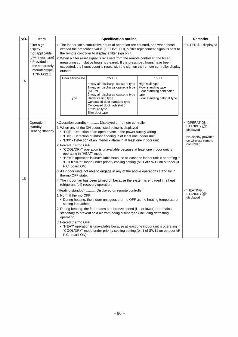
14
Filter sign display(not applicable to wireless type)* Provided in
the separately mounted type, TCB-AX21E.
1. The indoor fan’s cumulative hours of operation are counted, and when theseexceed the prescribed value (150H/2500H), a filter replacement signal is sent tothe remote controller to display a filter sign on it.
2. When a filter reset signal is received from the remote controller, the timermeasuring cumulative hours is cleared. If the prescribed hours have beenexceeded, the hours count is reset, with the sign on the remote controller displayerased.
“FILTER ” displayed
15
Operation standbyHeating standby
<Operation standby> .......... Displayed on remote controller
1. When any of the DN codes listed below is displayed• “P05” - Detection of an open phase in the power supply wiring• “P10” - Detection of indoor flooding in at least one indoor unit• “L30” - Detection of an interlock alarm in at least one indoor unit
2. Forced thermo OFF• “COOL/DRY” operation is unavailable because at least one indoor unit is
operating in “HEAT” mode.• “HEAT” operation is unavailable because at least one indoor unit is operating in
“COOL/DRY” mode under priority cooling setting (bit 1 of SW11 on outdoor I/FP.C. board ON).
3. All indoor units not able to engage in any of the above operations stand by inthermo OFF state.
4. The indoor fan has been turned off because the system is engaged in a heatrefrigerant (oil) recovery operation.
• “OPERATIONSTANDBY ”displayed
No display providedon wireless remotecontroller
<Heating standby> .......... Displayed on remote controller
1. Normal thermo OFF• During heating, the indoor unit goes thermo OFF as the heating temperature
setting is reached.
2. During heating, the fan rotates at a breeze speed (UL or lower) or remainsstationary to prevent cold air from being discharged (including defrostingoperation).
3. Forced thermo OFF• “HEAT” operation is unavailable because at least one indoor unit is operating in
“COOL/DRY” mode under priority cooling setting (bit 1 of SW11 on outdoor I/FP.C. board ON).
• “HEATINGSTANDBY ”displayed
NO. Item Specification outline Remarks
Filter service life 2500H 150H
Type
4-way air discharge cassette type1-way air discharge cassette type(SH, YH)2-way air discharge cassette typeUnder ceiling typeConcealed duct standard typeConcealed duct high static pressure typeSlim duct type
High wall typeFloor standing typeFloor standing concealed typeFloor standing cabinet type
− 80 −
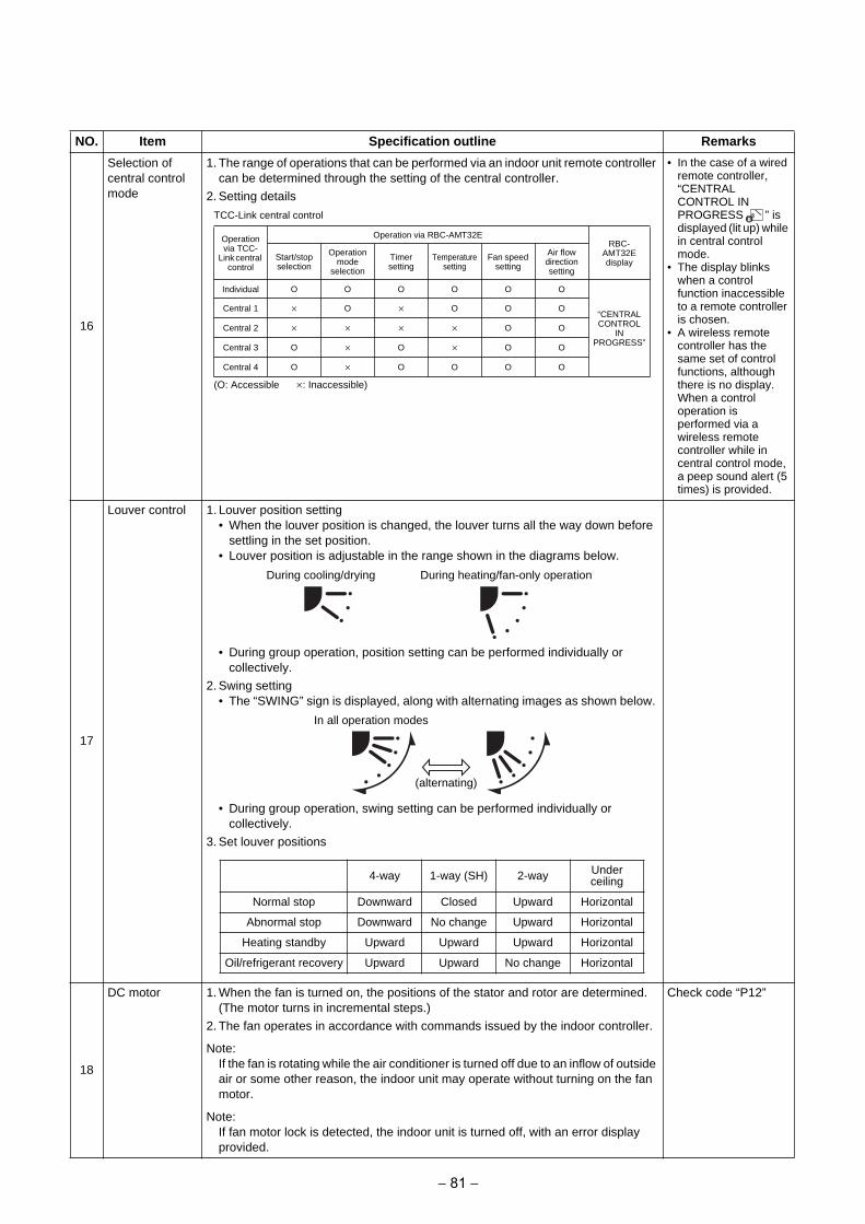
16
Selection of central control mode
1. The range of operations that can be performed via an indoor unit remote controller can be determined through the setting of the central controller.
2. Setting details
• In the case of a wiredremote controller,“CENTRALCONTROL INPROGRESS ” isdisplayed (lit up) while in central controlmode.
• The display blinkswhen a controlfunction inaccessibleto a remote controlleris chosen.
• A wireless remotecontroller has thesame set of controlfunctions, althoughthere is no display.When a controloperation isperformed via awireless remotecontroller while incentral control mode,a peep sound alert (5times) is provided.
17
Louver control 1. Louver position setting• When the louver position is changed, the louver turns all the way down before
settling in the set position.• Louver position is adjustable in the range shown in the diagrams below.
• During group operation, position setting can be performed individually orcollectively.
2. Swing setting• The “SWING” sign is displayed, along with alternating images as shown below.
• During group operation, swing setting can be performed individually orcollectively.
3. Set louver positions
18
DC motor 1. When the fan is turned on, the positions of the stator and rotor are determined.(The motor turns in incremental steps.)
2. The fan operates in accordance with commands issued by the indoor controller.
Note: If the fan is rotating while the air conditioner is turned off due to an inflow of outside air or some other reason, the indoor unit may operate without turning on the fan motor.
Note: If fan motor lock is detected, the indoor unit is turned off, with an error display provided.
Check code “P12”
NO. Item Specification outline Remarks
TCC-Link central control
(O: Accessible : Inaccessible)
Operation via TCC-
Link central control
Operation via RBC-AMT32ERBC-
AMT32E display
Start/stop selection
Operation mode
selection
Timer setting
Temperature setting
Fan speed setting
Air flow direction setting
Individual O O O O O O
“CENTRAL CONTROL
INPROGRESS”
Central 1 O O O O
Central 2 O O
Central 3 O O O O
Central 4 O O O O O
During cooling/drying During heating/fan-only operation
In all operation modes
(alternating)
4-way 1-way (SH) 2-way Under ceiling
Normal stop Downward Closed Upward Horizontal
Abnormal stop Downward No change Upward Horizontal
Heating standby Upward Upward Upward Horizontal
Oil/refrigerant recovery Upward Upward No change Horizontal
− 81 −
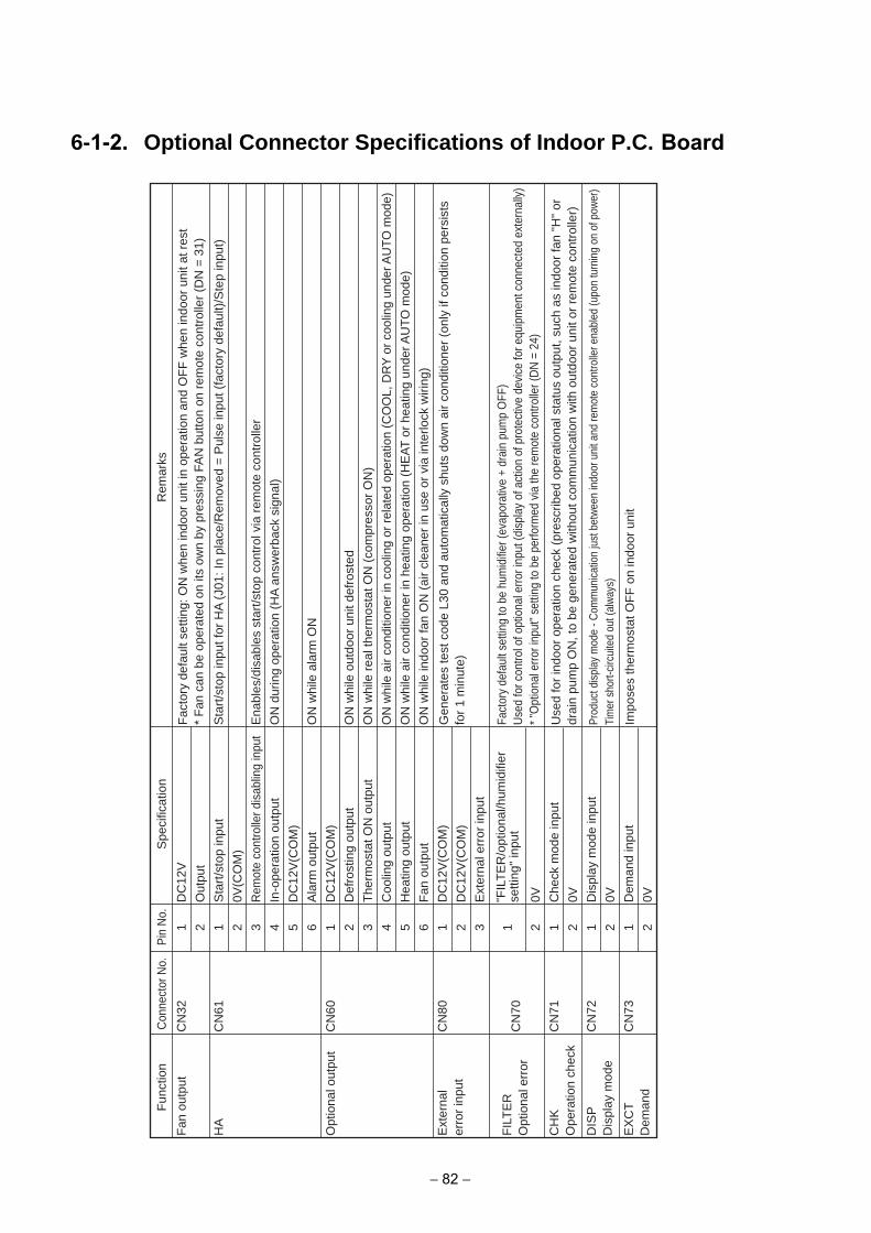
6-1-2. Optional Connector Specifications of Indoor P.C. BoardF
an o
utpu
t
HA
Opt
iona
l out
put
FIL
TE
RO
ptio
nal e
rror
CH
KO
pera
tion
chec
k
DIS
PD
ispl
ay m
ode
EX
CT
Dem
and
CN
32
CN
61
CN
60
CN
80
CN
70
CN
71
CN
72
CN
73
1 2 1 2 3 4 5 6 1 2 3 4 5 6 1 2 3 1 2 1 2 1 2 1 2
Fun
ctio
nC
onne
ctor
No.
Pin
No.
DC
12V
Out
put
Sta
rt/s
top
inpu
t
0V(C
OM
)
Rem
ote
cont
rolle
r dis
ablin
g in
put
In-o
pera
tion
outp
ut
DC
12V
(CO
M)
Ala
rm o
utpu
t
DC
12V
(CO
M)
Def
rost
ing
outp
ut
The
rmos
tat O
N o
utpu
t
Coo
ling
outp
ut
Hea
ting
outp
ut
Fan
out
put
DC
12V
(CO
M)
DC
12V
(CO
M)
Ext
erna
l err
or in
put
0V Che
ck m
ode
inpu
t
0V Dis
play
mod
e in
put
0V Dem
and
inpu
t
0V
Sta
rt/s
top
inpu
t for
HA
(J0
1: In
pla
ce/R
emov
ed =
Pul
se in
put (
fact
ory
defa
ult)
/Ste
p in
put)
Ena
bles
/dis
able
s st
art/s
top
cont
rol v
ia r
emot
e co
ntro
ller
ON
dur
ing
oper
atio
n (H
A a
nsw
erba
ck s
igna
l)
ON
whi
le a
larm
ON
ON
whi
le o
utdo
or u
nit d
efro
sted
ON
whi
le r
eal t
herm
osta
t ON
(co
mpr
esso
r O
N)
ON
whi
le a
ir co
nditi
oner
in c
oolin
g or
rel
ated
ope
ratio
n (C
OO
L, D
RY
or
cool
ing
unde
r AU
TO m
ode)
ON
whi
le a
ir co
nditi
oner
in h
eatin
g op
erat
ion
(HE
AT
or
heat
ing
unde
r AU
TO
mod
e)
ON
whi
le in
door
fan
ON
(ai
r cl
eane
r in
use
or
via
inte
rlock
wiri
ng)
Spe
cific
atio
nR
emar
ks
Gen
erat
es te
st c
ode
L30
and
auto
mat
ical
ly s
huts
dow
n ai
r co
nditi
oner
(on
ly if
con
ditio
n pe
rsis
ts
for
1 m
inut
e)
Fact
ory
defa
ult s
ettin
g to
be
hum
idifi
er (e
vapo
rativ
e +
drai
n pu
mp
OFF
)U
sed
for c
ontro
l of o
ptio
nal e
rror i
nput
(dis
play
of a
ctio
n of
pro
tect
ive
devi
ce fo
r equ
ipm
ent c
onne
cted
ext
erna
lly)
*"O
ptio
nal e
rror i
nput
" set
ting
to b
e pe
rform
ed v
ia th
e re
mot
e co
ntro
ller (
DN
= 2
4)
Use
d fo
r in
door
ope
ratio
n ch
eck
(pre
scrib
ed o
pera
tiona
l sta
tus
outp
ut, s
uch
as in
door
fan
"H"
or
drai
n pu
mp
ON
, to
be g
ener
ated
with
out c
omm
unic
atio
n w
ith o
utdo
or u
nit o
r re
mot
e co
ntro
ller)
Prod
uct d
ispl
ay m
ode
- Com
mun
icat
ion
just
bet
wee
n in
door
uni
t and
rem
ote
cont
rolle
r ena
bled
(upo
n tu
rnin
g on
of p
ower
)Ti
mer
sho
rt-ci
rcui
ted
out (
alw
ays)
Impo
ses
ther
mos
tat O
FF
on
indo
or u
nit
Fac
tory
def
ault
setti
ng: O
N w
hen
indo
or u
nit i
n op
erat
ion
and
OF
F w
hen
indo
or u
nit a
t res
t*
Fan
can
be
oper
ated
on
its o
wn
by p
ress
ing
FAN
but
ton
on r
emot
e co
ntro
ller
(DN
= 3
1)
Ext
erna
ler
ror
inpu
t
"FIL
TE
R/o
ptio
nal/h
umid
ifier
se
tting
" in
put
− 82 −
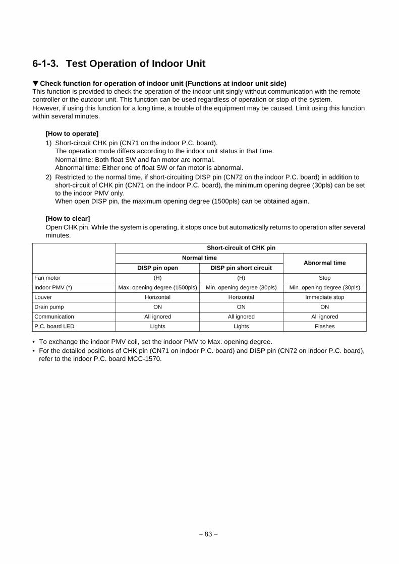
6-1-3. Test Operation of Indoor Unit
Check function for operation of indoor unit (Functions at indoor unit side)This function is provided to check the operation of the indoor unit singly without communication with the remote controller or the outdoor unit. This function can be used regardless of operation or stop of the system.However, if using this function for a long time, a trouble of the equipment may be caused. Limit using this function within several minutes.
[How to operate]
1) Short-circuit CHK pin (CN71 on the indoor P.C. board).The operation mode differs according to the indoor unit status in that time.Normal time: Both float SW and fan motor are normal.Abnormal time: Either one of float SW or fan motor is abnormal.
2) Restricted to the normal time, if short-circuiting DISP pin (CN72 on the indoor P.C. board) in addition toshort-circuit of CHK pin (CN71 on the indoor P.C. board), the minimum opening degree (30pls) can be setto the indoor PMV only.When open DISP pin, the maximum opening degree (1500pls) can be obtained again.
[How to clear]
Open CHK pin. While the system is operating, it stops once but automatically returns to operation after several minutes.
• To exchange the indoor PMV coil, set the indoor PMV to Max. opening degree.• For the detailed positions of CHK pin (CN71 on indoor P.C. board) and DISP pin (CN72 on indoor P.C. board),
refer to the indoor P.C. board MCC-1570.
Short-circuit of CHK pin
Normal timeAbnormal time
DISP pin open DISP pin short circuit
Fan motor (H) (H) Stop
Indoor PMV (*) Max. opening degree (1500pls) Min. opening degree (30pls) Min. opening degree (30pls)
Louver Horizontal Horizontal Immediate stop
Drain pump ON ON ON
Communication All ignored All ignored All ignored
P.C. board LED Lights Lights Flashes
− 83 −
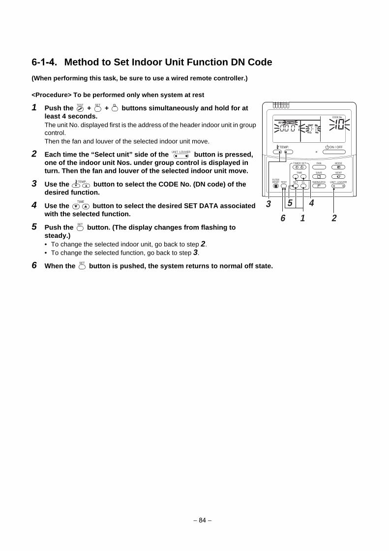
6-1-4. Method to Set Indoor Unit Function DN Code
(When performing this task, be sure to use a wired remote controller.)
<Procedure> To be performed only when system at rest
1 Push the + + buttons simultaneously and hold for at
least 4 seconds.
The unit No. displayed first is the address of the header indoor unit in group control.Then the fan and louver of the selected indoor unit move.
2 Each time the “Select unit” side of the button is pressed,
one of the indoor unit Nos. under group control is displayed in
turn. Then the fan and louver of the selected indoor unit move.
3 Use the button to select the CODE No. (DN code) of the
desired function.
4 Use the button to select the desired SET DATA associated
with the selected function.
5 Push the button. (The display changes from flashing to
steady.)
• To change the selected indoor unit, go back to step 2.• To change the selected function, go back to step 3.
6 When the button is pushed, the system returns to normal off state.
SET
TIME
TIMER SET
TESTFILTERRESET
TEMP.
CL
FAN
SAVE
SWING/FIX
VENT
MODE
ON / OFF
UNIT LOUVER
5 4
1 26
3
UNIT LOUVER
− 84 −
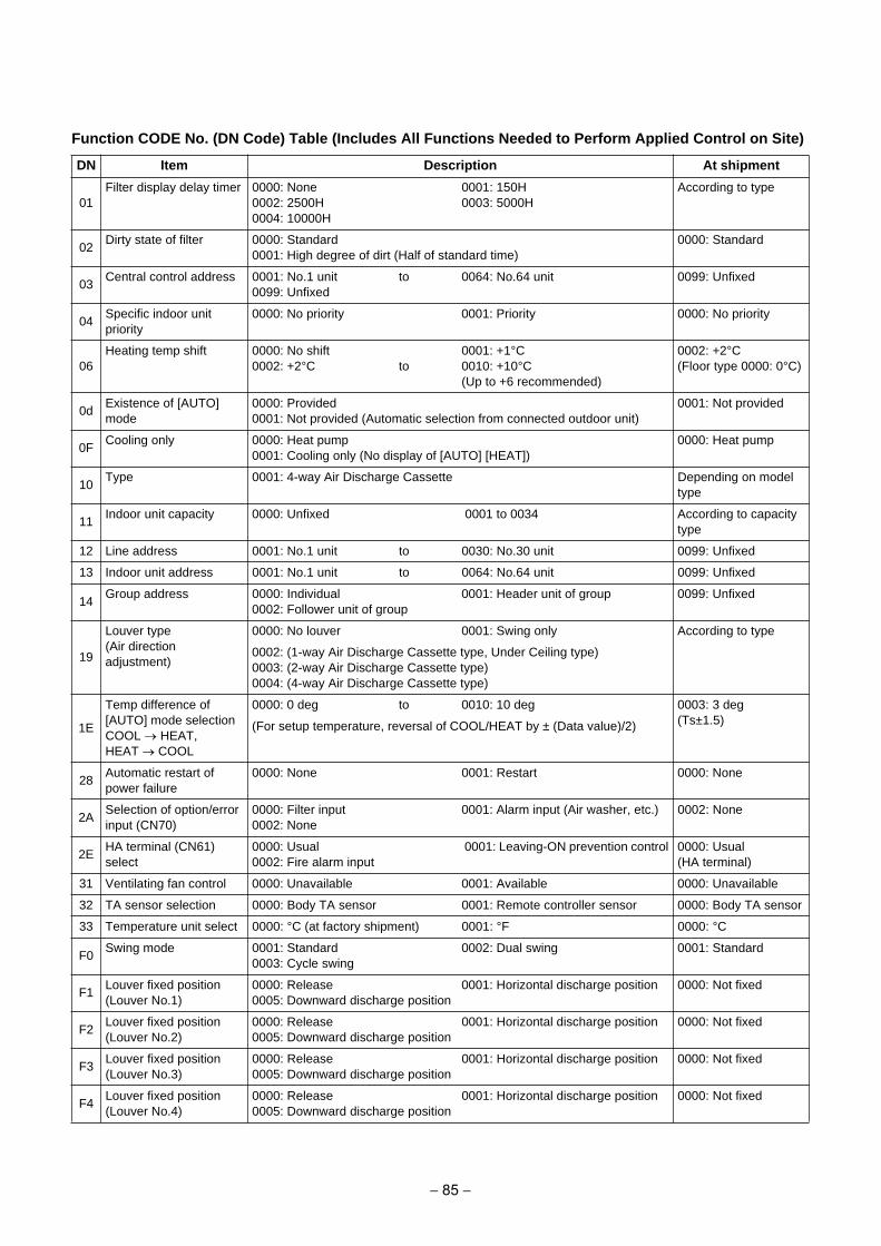
Function CODE No. (DN Code) Table (Includes All Functions Needed to Perform Applied Control on Site)
DN Item Description At shipment
01Filter display delay timer 0000: None
0002: 2500H0004: 10000H
0001: 150H0003: 5000H
According to type
02Dirty state of filter 0000: Standard
0001: High degree of dirt (Half of standard time)0000: Standard
03Central control address 0001: No.1 unit
0099: Unfixedto 0064: No.64 unit 0099: Unfixed
04Specific indoor unit priority
0000: No priority 0001: Priority 0000: No priority
06Heating temp shift 0000: No shift
0002: +2°C to0001: +1°C0010: +10°C(Up to +6 recommended)
0002: +2°C(Floor type 0000: 0°C)
0dExistence of [AUTO] mode
0000: Provided0001: Not provided (Automatic selection from connected outdoor unit)
0001: Not provided
0FCooling only 0000: Heat pump
0001: Cooling only (No display of [AUTO] [HEAT])0000: Heat pump
10Type 0001: 4-way Air Discharge Cassette Depending on model
type
11Indoor unit capacity 0000: Unfixed 0001 to 0034 According to capacity
type
12 Line address 0001: No.1 unit to 0030: No.30 unit 0099: Unfixed
13 Indoor unit address 0001: No.1 unit to 0064: No.64 unit 0099: Unfixed
14Group address 0000: Individual
0002: Follower unit of group0001: Header unit of group 0099: Unfixed
19
Louver type(Air direction adjustment)
0000: No louver 0001: Swing only According to type
0002: (1-way Air Discharge Cassette type, Under Ceiling type)0003: (2-way Air Discharge Cassette type)0004: (4-way Air Discharge Cassette type)
1E
Temp difference of [AUTO] mode selection COOL HEAT, HEAT COOL
0000: 0 deg to 0010: 10 deg 0003: 3 deg(Ts±1.5)(For setup temperature, reversal of COOL/HEAT by ± (Data value)/2)
28Automatic restart of power failure
0000: None 0001: Restart 0000: None
2ASelection of option/error input (CN70)
0000: Filter input0002: None
0001: Alarm input (Air washer, etc.) 0002: None
2EHA terminal (CN61) select
0000: Usual0002: Fire alarm input
0001: Leaving-ON prevention control 0000: Usual(HA terminal)
31 Ventilating fan control 0000: Unavailable 0001: Available 0000: Unavailable
32 TA sensor selection 0000: Body TA sensor 0001: Remote controller sensor 0000: Body TA sensor
33 Temperature unit select 0000: °C (at factory shipment) 0001: °F 0000: °C
F0Swing mode 0001: Standard
0003: Cycle swing0002: Dual swing 0001: Standard
F1Louver fixed position(Louver No.1)
0000: Release0005: Downward discharge position
0001: Horizontal discharge position 0000: Not fixed
F2Louver fixed position(Louver No.2)
0000: Release0005: Downward discharge position
0001: Horizontal discharge position 0000: Not fixed
F3Louver fixed position(Louver No.3)
0000: Release0005: Downward discharge position
0001: Horizontal discharge position 0000: Not fixed
F4Louver fixed position(Louver No.4)
0000: Release0005: Downward discharge position
0001: Horizontal discharge position 0000: Not fixed
− 85 −
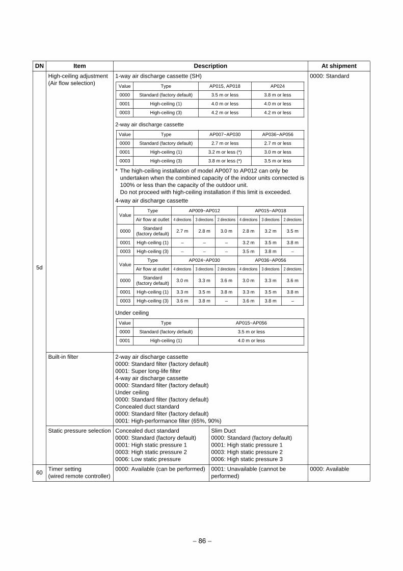
5d
High-ceiling adjustment(Air flow selection)
1-way air discharge cassette (SH)
2-way air discharge cassette
* The high-ceiling installation of model AP007 to AP012 can only beundertaken when the combined capacity of the indoor units connected is100% or less than the capacity of the outdoor unit.Do not proceed with high-ceiling installation if this limit is exceeded.
4-way air discharge cassette
Under ceiling
0000: Standard
Built-in filter 2-way air discharge cassette0000: Standard filter (factory default)0001: Super long-life filter4-way air discharge cassette0000: Standard filter (factory default)Under ceiling0000: Standard filter (factory default)Concealed duct standard0000: Standard filter (factory default)0001: High-performance filter (65%, 90%)
Static pressure selection Concealed duct standard0000: Standard (factory default)0001: High static pressure 10003: High static pressure 20006: Low static pressure
Slim Duct0000: Standard (factory default)0001: High static pressure 10003: High static pressure 20006: High static pressure 3
60Timer setting(wired remote controller)
0000: Available (can be performed) 0001: Unavailable (cannot be performed)
0000: Available
DN Item Description At shipment
Value Type AP015, AP018 AP024
0000 Standard (factory default) 3.5 m or less 3.8 m or less
0001 High-ceiling (1) 4.0 m or less 4.0 m or less
0003 High-ceiling (3) 4.2 m or less 4.2 m or less
Value Type AP007~AP030 AP036~AP056
0000 Standard (factory default) 2.7 m or less 2.7 m or less
0001 High-ceiling (1) 3.2 m or less (*) 3.0 m or less
0003 High-ceiling (3) 3.8 m or less (*) 3.5 m or less
ValueType AP009~AP012 AP015~AP018
Air flow at outlet 4 directions 3 directions 2 directions 4 directions 3 directions 2 directions
0000 Standard (factory default) 2.7 m 2.8 m 3.0 m 2.8 m 3.2 m 3.5 m
0001 High-ceiling (1) – – – 3.2 m 3.5 m 3.8 m
0003 High-ceiling (3) – – – 3.5 m 3.8 m –
ValueType AP024~AP030 AP036~AP056
Air flow at outlet 4 directions 3 directions 2 directions 4 directions 3 directions 2 directions
0000 Standard (factory default) 3.0 m 3.3 m 3.6 m 3.0 m 3.3 m 3.6 m
0001 High-ceiling (1) 3.3 m 3.5 m 3.8 m 3.3 m 3.5 m 3.8 m
0003 High-ceiling (3) 3.6 m 3.8 m – 3.6 m 3.8 m –
Value Type AP015~AP056
0000 Standard (factory default) 3.5 m or less
0001 High-ceiling (1) 4.0 m or less
− 86 −
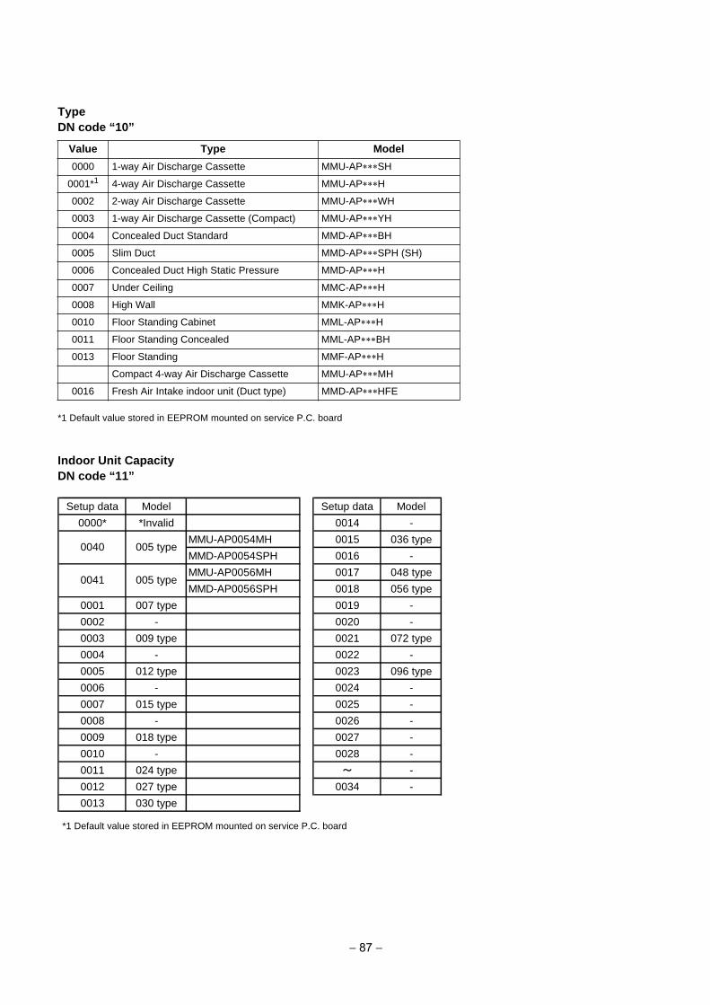
Type
DN code “10”
*1 Default value stored in EEPROM mounted on service P.C. board
Indoor Unit Capacity
DN code “11”
*1 Default value stored in EEPROM mounted on service P.C. board
Value Type Model
0000 1-way Air Discharge Cassette MMU-AP SH
0001*1 4-way Air Discharge Cassette MMU-AP H
0002 2-way Air Discharge Cassette MMU-AP WH
0003 1-way Air Discharge Cassette (Compact) MMU-AP YH
0004 Concealed Duct Standard MMD-AP BH
0005 Slim Duct MMD-AP SPH (SH)
0006 Concealed Duct High Static Pressure MMD-AP H
0007 Under Ceiling MMC-AP H
0008 High Wall MMK-AP H
0010 Floor Standing Cabinet MML-AP H
0011 Floor Standing Concealed MML-AP BH
0013 Floor Standing MMF-AP H
Compact 4-way Air Discharge Cassette MMU-AP MH
0016 Fresh Air Intake indoor unit (Duct type) MMD-AP HFE
Setup data Model Setup data Model
0000* *Invalid 0014 -
MMU-AP0054MH 0015 036 type
MMD-AP0054SPH 0016 -
MMU-AP0056MH 0017 048 type
MMD-AP0056SPH 0018 056 type
0001 007 type 0019 -
0002 - 0020 -
0003 009 type 0021 072 type
0004 - 0022 -
0005 012 type 0023 096 type
0006 - 0024 -
0007 015 type 0025 -
0008 - 0026 -
0009 018 type 0027 -
0010 - 0028 -
0011 024 type ~ -
0012 027 type 0034 -
0013 030 type
0040
0041
005 type
005 type
− 87 −
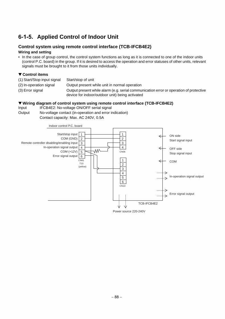
6-1-5. Applied Control of Indoor Unit
Control system using remote control interface (TCB-IFCB4E2)
Wiring and setting
• In the case of group control, the control system functions as long as it is connected to one of the indoor units(control P.C. board) in the group. If it is desired to access the operation and error statuses of other units, relevant signals must be brought to it from those units individually.
Control items
(1) Start/Stop input signal Start/stop of unit(2) In-operation signal Output present while unit in normal operation(3) Error signal Output present while alarm (e.g. serial communication error or operation of protective
device for indoor/outdoor unit) being activated
Wiring diagram of control system using remote control interface (TCB-IFCB4E2)Input IFCB4E2: No-voltage ON/OFF serial signalOutput No-voltage contact (in-operation and error indication)
Contact capacity: Max. AC 240V, 0.5A
123456
1234
CN61T10
(yellow)
123456
CN13
CN06
Indoor control P.C. board
Start/stop inputCOM (GND)
Remote controller disabling/enabling inputIn-operation signal output
COM (+12V)Error signal output
Power source 220-240V
ON side
COM
Start signal input
In-operation signal output
Error signal output
OFF side
Stop signal input
TCB-IFCB4E2
− 88 −

Ventilating fan control from remote controller
[Function]
• The start/stop operation can be operated from the wired remote controller when air to air heat exchanger orventilating fan is installed in the system.
• The fan can be operated even if the indoor unit is not operating.• Use a fan which can receive the no-voltage A contact as an outside input signal.• In a group control, the units are collectively operated and they can not be individually operated.
1. Operation
Handle a wired remote controller in the following procedure.* Use the wired remote controller during stop of the system.* Be sure to set up the wired remote controller to the header unit. (Same in group control)* In a group control, if the wired remote controller is set up to the header unit, both header and follower units
are simultaneously operable.
1 Push concurrently + + buttons for 4 seconds or more.
The unit No. displayed firstly indicates the header indoor unit address in the group control.In this time, the fan of the selected indoor unit turns on.
2 Every pushing button, the indoor unit numbers in group control are displayed
successively.
In this time, the fan of the selected indoor unit only turns on.
3 Using the setup temp or button, specify the CODE No. 31.
4 Using the timer time or button, select the SET DATA. (At shipment: )
The setup data are as follows:
5 Push button. (OK if display goes on.)
• To change the selected indoor unit, go to the procedure 2 ).• To change the item to be set up, go to the procedure 3 ).
6 Pushing returns the status to the usual stop status.
2. Wiring
SET DATA Handling of operation of air to air heat exchanger or ventilating fan
Unavailable (At shipment)
Available
UNIT LOUVER
12
12
CN32FAN DRIVE
(2P WHI)
Compact 4-way Air Discharge Cassette type4-way Air Discharge Cassette type1-way Air Discharge Cassette type (2 series) Concealed Duct Standard typeSlim Duct typeUnder Ceiling typeHigh Wall type
model :
Relay (DC12V, procured locally) Corresponds to the relay upto one that the rated currentof the operation coil is approx. 75mA
Outside control input of fan
To terminal
Indoor control P.C. board
Note) Determine the cable length between the indoor control P.C. board and the relay within 2m.
Corresponds up to a relay in which rated current of the operation coil is approx. 75mA
Other type models: Correspond up to a relay in which rated current of the operation coil is approx. 16mA (Does not correspond to a terminal block type relay on the market.)
− 89 −
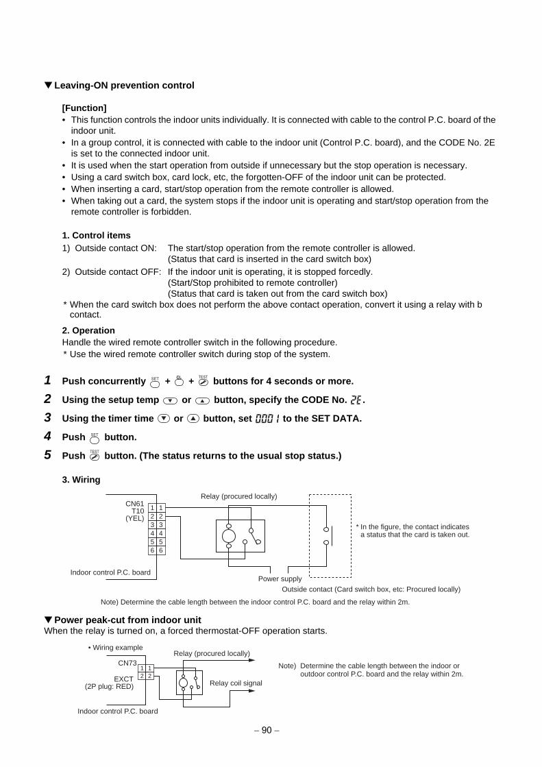
Leaving-ON prevention control
[Function]
• This function controls the indoor units individually. It is connected with cable to the control P.C. board of theindoor unit.
• In a group control, it is connected with cable to the indoor unit (Control P.C. board), and the CODE No. 2Eis set to the connected indoor unit.
• It is used when the start operation from outside if unnecessary but the stop operation is necessary.• Using a card switch box, card lock, etc, the forgotten-OFF of the indoor unit can be protected.• When inserting a card, start/stop operation from the remote controller is allowed.• When taking out a card, the system stops if the indoor unit is operating and start/stop operation from the
remote controller is forbidden.
1. Control items
1) Outside contact ON: The start/stop operation from the remote controller is allowed.(Status that card is inserted in the card switch box)
2) Outside contact OFF: If the indoor unit is operating, it is stopped forcedly.(Start/Stop prohibited to remote controller)(Status that card is taken out from the card switch box)
* When the card switch box does not perform the above contact operation, convert it using a relay with bcontact.
2. Operation
Handle the wired remote controller switch in the following procedure.* Use the wired remote controller switch during stop of the system.
1 Push concurrently + + buttons for 4 seconds or more.
2 Using the setup temp or button, specify the CODE No. .
3 Using the timer time or button, set to the SET DATA.
4 Push button.
5 Push button. (The status returns to the usual stop status.)
3. Wiring
Power peak-cut from indoor unitWhen the relay is turned on, a forced thermostat-OFF operation starts.
12
12
34
34
56
56
CN61T10
(YEL)
Relay (procured locally)
Indoor control P.C. board
Note) Determine the cable length between the indoor control P.C. board and the relay within 2m.
Power supplyOutside contact (Card switch box, etc: Procured locally)
* In the figure, the contact indicatesa status that the card is taken out.
12
12EXCT
(2P plug: RED)
CN73Relay (procured locally)
Relay coil signal
Indoor control P.C. board
• Wiring example
Note) Determine the cable length between the indoor or outdoor control P.C. board and the relay within 2m.
− 90 −
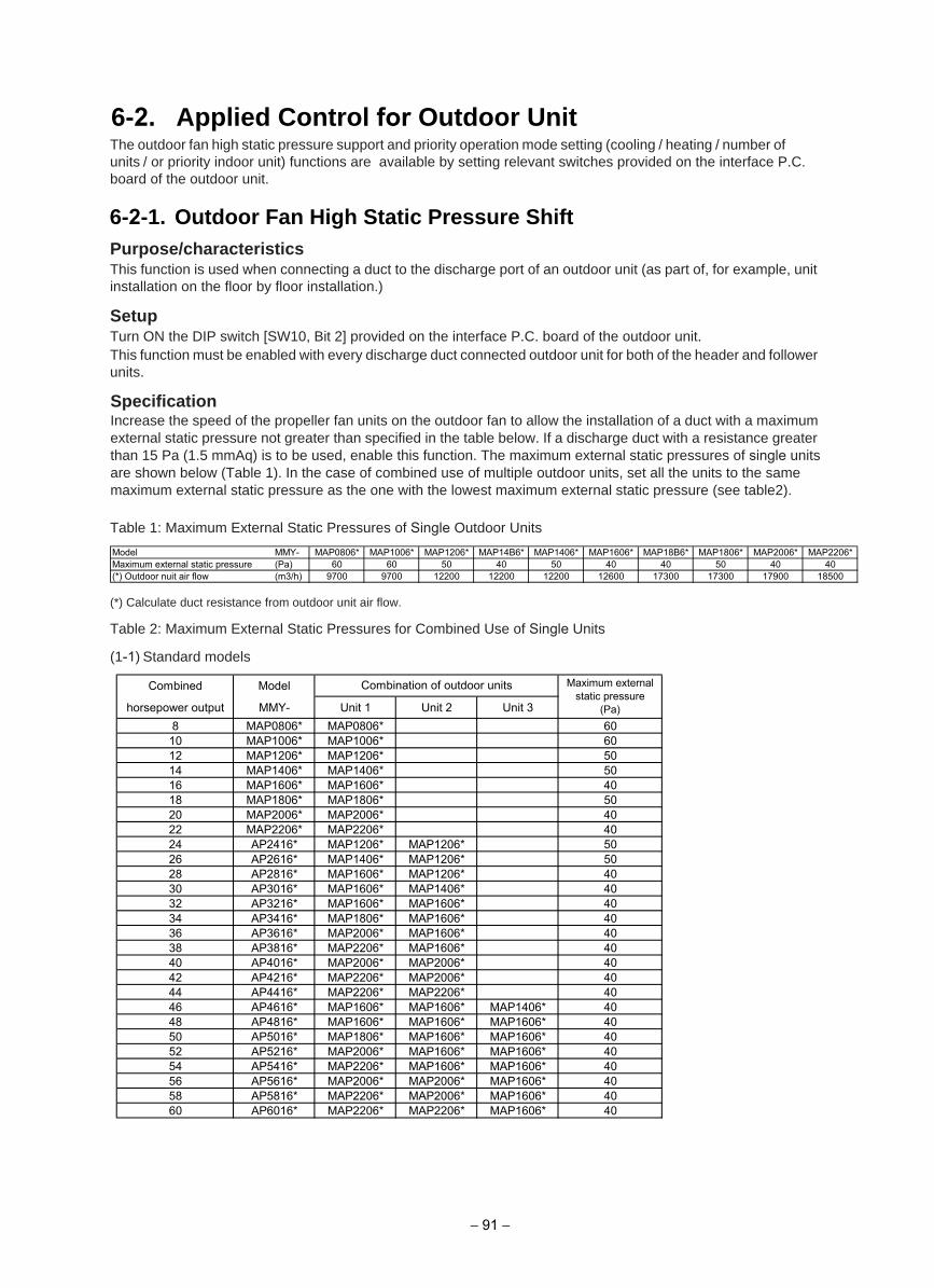
The outdoor fan high static pressure support and priority operation mode setting (cooling / heating / number of units / or priority indoor unit) functions are available by setting relevant switches provided on the interface P.C. board of the outdoor unit.
Purpose/characteristicsThis function is used when connecting a duct to the discharge port of an outdoor unit (as part of, for example, unit installation on the floor by floor installation.)
SetupTurn ON the DIP switch [SW10, Bit 2] provided on the interface P.C. board of the outdoor unit. This function must be enabled with every discharge duct connected outdoor unit for both of the header and follower units.
SpecificationIncrease the speed of the propeller fan units on the outdoor fan to allow the installation of a duct with a maximum external static pressure not greater than specified in the table below. If a discharge duct with a resistance greater than 15 Pa (1.5 mmAq) is to be used, enable this function. The maximum external static pressures of single units are shown below (Table 1). In the case of combined use of multiple outdoor units, set all the units to the same maximum external static pressure as the one with the lowest maximum external static pressure (see table2).
Table 1: Maximum External Static Pressures of Single Outdoor Units
(*) Calculate duct resistance from outdoor unit air flow.
Table 2: Maximum External Static Pressures for Combined Use of Single Units
(1-1) Standard models
6-2-1. Outdoor Fan High Static Pressure Shift
ModelCombined
horsepower output MMY- Unit 1 Unit 2 Unit 38 MAP0806* MAP0806* 60
10 MAP1006* MAP1006* 6012 MAP1206* MAP1206* 5014 MAP1406* MAP1406* 5016 MAP1606* MAP1606* 4018 MAP1806* MAP1806* 5020 MAP2006* MAP2006* 4022 MAP2206* MAP2206* 4024 AP2416* MAP1206* MAP1206* 5026 AP2616* MAP1406* MAP1206* 5028 AP2816* MAP1606* MAP1206* 4030 AP3016* MAP1606* MAP1406* 4032 AP3216* MAP1606* MAP1606* 4034 AP3416* MAP1806* MAP1606* 4036 AP3616* MAP2006* MAP1606* 4038 AP3816* MAP2206* MAP1606* 4040 AP4016* MAP2006* MAP2006* 4042 AP4216* MAP2206* MAP2006* 4044 AP4416* MAP2206* MAP2206* 4046 AP4616* MAP1606* MAP1606* MAP1406* 4048 AP4816* MAP1606* MAP1606* MAP1606* 4050 AP5016* MAP1806* MAP1606* MAP1606* 4052 AP5216* MAP2006* MAP1606* MAP1606* 4054 AP5416* MAP2206* MAP1606* MAP1606* 4056 AP5616* MAP2006* MAP2006* MAP1606* 4058 AP5816* MAP2206* MAP2006* MAP1606* 4060 AP6016* MAP2206* MAP2206* MAP1606* 40
Combination of outdoor units Maximum externalstatic pressure
(Pa)
6-2. Applied Control for Outdoor Unit
− 91 −
Model MMY- MAP0806* MAP1006* MAP1206* MAP14B6* MAP1406* MAP1606* MAP18B6* MAP1806* MAP2006* MAP2206*Maximum external static pressure (Pa) 60 60 50 40 50 40 40 50 40 40(*) Outdoor nuit air flow (m3/h) 9700 9700 12200 12200 12200 12600 17300 17300 17900 18500
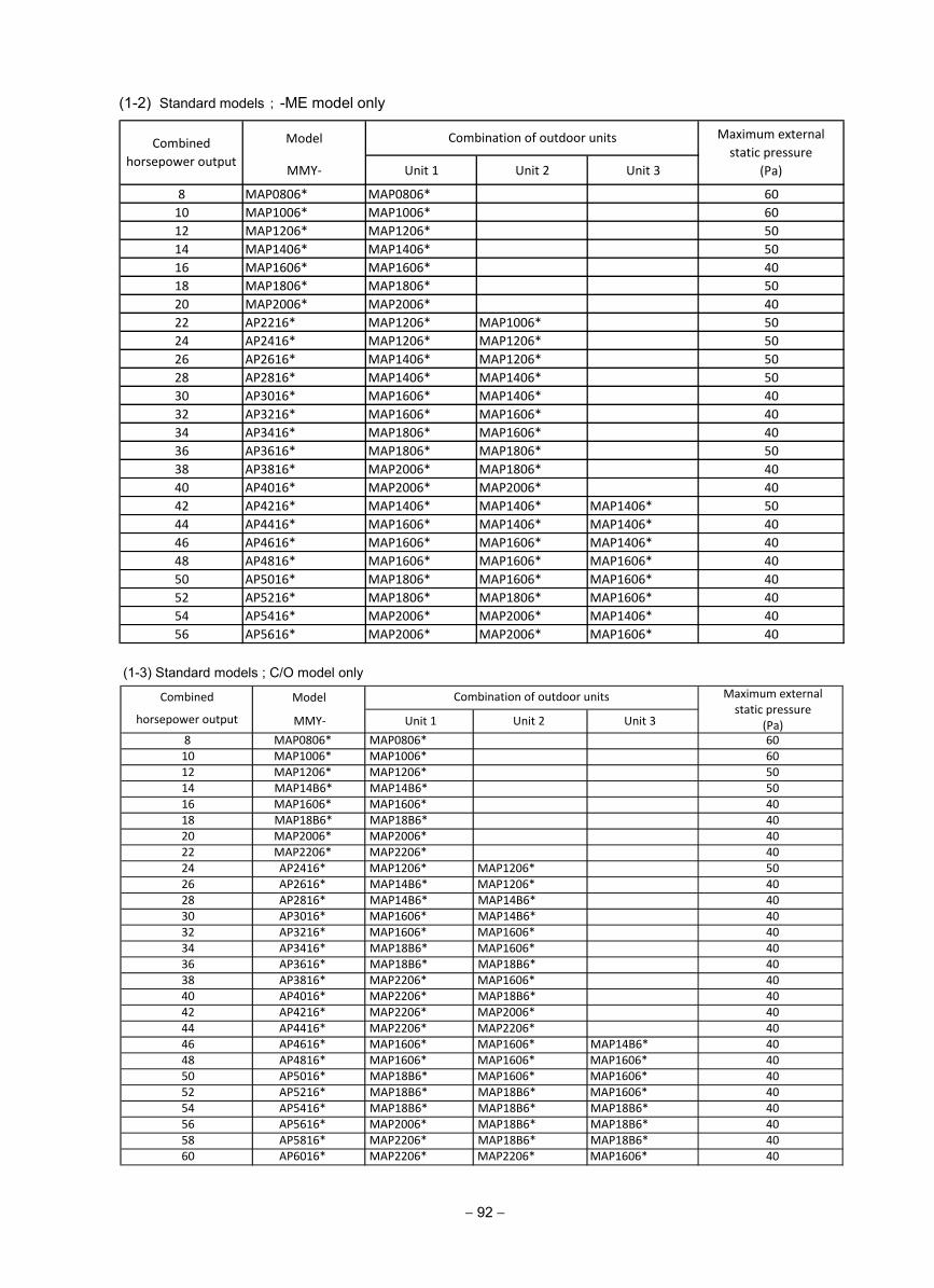
Model
MMY- Unit 1 Unit 2 Unit 3
8 MAP0806* MAP0806* 60
10 MAP1006* MAP1006* 60
12 MAP1206* MAP1206* 50
14 MAP1406* MAP1406* 50
16 MAP1606* MAP1606* 40
18 MAP1806* MAP1806* 50
20 MAP2006* MAP2006* 40
22 AP2216* MAP1206* MAP1006* 50
24 AP2416* MAP1206* MAP1206* 50
26 AP2616* MAP1406* MAP1206* 50
28 AP2816* MAP1406* MAP1406* 50
30 AP3016* MAP1606* MAP1406* 40
32 AP3216* MAP1606* MAP1606* 40
34 AP3416* MAP1806* MAP1606* 40
36 AP3616* MAP1806* MAP1806* 50
38 AP3816* MAP2006* MAP1806* 40
40 AP4016* MAP2006* MAP2006* 40
42 AP4216* MAP1406* MAP1406* MAP1406* 50
44 AP4416* MAP1606* MAP1406* MAP1406* 40
46 AP4616* MAP1606* MAP1606* MAP1406* 40
48 AP4816* MAP1606* MAP1606* MAP1606* 40
50 AP5016* MAP1806* MAP1606* MAP1606* 40
52 AP5216* MAP1806* MAP1806* MAP1606* 40
54 AP5416* MAP2006* MAP2006* MAP1406* 40
56 AP5616* MAP2006* MAP2006* MAP1606* 40
Combined
horsepower output
Combination of outdoor units Maximum external
static pressure
(Pa)
(1-2) Standard models ; -ME model only
− 92 −
(1-3) Standard models ; C/O model only
ModelCombined
horsepower output MMY- Unit 1 Unit 2 Unit 38 MAP0806* MAP0806* 6010 MAP1006* MAP1006* 6012 MAP1206* MAP1206* 5014 MAP14B6* MAP14B6* 5016 MAP1606* MAP1606* 4018 MAP18B6* MAP18B6* 4020 MAP2006* MAP2006* 4022 MAP2206* MAP2206* 4024 AP2416* MAP1206* MAP1206* 5026 AP2616* MAP14B6* MAP1206* 4028 AP2816* MAP14B6* MAP14B6* 4030 AP3016* MAP1606* MAP14B6* 4032 AP3216* MAP1606* MAP1606* 4034 AP3416* MAP18B6* MAP1606* 4036 AP3616* MAP18B6* MAP18B6* 4038 AP3816* MAP2206* MAP1606* 4040 AP4016* MAP2206* MAP18B6* 4042 AP4216* MAP2206* MAP2006* 4044 AP4416* MAP2206* MAP2206* 4046 AP4616* MAP1606* MAP1606* MAP14B6* 4048 AP4816* MAP1606* MAP1606* MAP1606* 4050 AP5016* MAP18B6* MAP1606* MAP1606* 4052 AP5216* MAP18B6* MAP18B6* MAP1606* 4054 AP5416* MAP18B6* MAP18B6* MAP18B6* 4056 AP5616* MAP2006* MAP18B6* MAP18B6* 4058 AP5816* MAP2206* MAP18B6* MAP18B6* 4060 AP6016* MAP2206* MAP2206* MAP1606* 40
Combination of outdoor units Maximum external static pressure
(Pa)
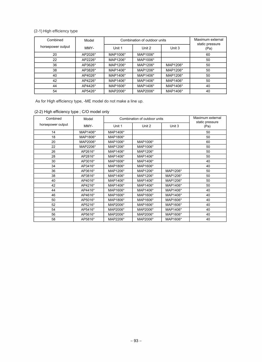
− 93 −
(2-1) High efficiency type
ModelCombined
horsepower output MMY- Unit 1 Unit 2 Unit 3
20 AP2026* MAP1006* MAP1006* 6022 AP2226* MAP1206* MAP1006* 5036 AP3626* MAP1206* MAP1206* MAP1206* 5038 AP3826* MAP1406* MAP1206* MAP1206* 5040 AP4026* MAP1406* MAP1406* MAP1206* 5042 AP4226* MAP1406* MAP1406* MAP1406* 5044 AP4426* MAP1606* MAP1406* MAP1406* 4054 AP5426* MAP2006* MAP2006* MAP1406* 40
Combination of outdoor units Maximum externalstatic pressure
(Pa)
As for High efficiency type, -ME model do not make a line up.
(2-2) High efficiency type ; C/O model only
ModelCombined
horsepower output MMY- Unit 1 Unit 2 Unit 3
14 MAP1406* MAP1406* 5018 MAP1806* MAP1806* 5020 MAP2006* MAP1006* MAP1006* 6022 MAP2206* MAP1206* MAP1006* 5026 AP2616* MAP1406* MAP1206* 5028 AP2816* MAP1406* MAP1406* 5030 AP3016* MAP1606* MAP1406* 4034 AP3416* MAP1806* MAP1606* 4036 AP3616* MAP1206* MAP1206* MAP1206* 5038 AP3816* MAP1406* MAP1206* MAP1206* 5040 AP4016* MAP1406* MAP1406* MAP1206* 5042 AP4216* MAP1406* MAP1406* MAP1406* 5044 AP4416* MAP1606* MAP1406* MAP1406* 4046 AP4616* MAP1606* MAP1606* MAP1406* 4050 AP5016* MAP1806* MAP1606* MAP1606* 4052 AP5216* MAP2006* MAP1606* MAP1606* 4054 AP5416* MAP2006* MAP2006* MAP1406* 4056 AP5616* MAP2006* MAP2006* MAP1606* 4058 AP5816* MAP2206* MAP2006* MAP1606* 40
Combination of outdoor units Maximum external static pressure
(Pa)
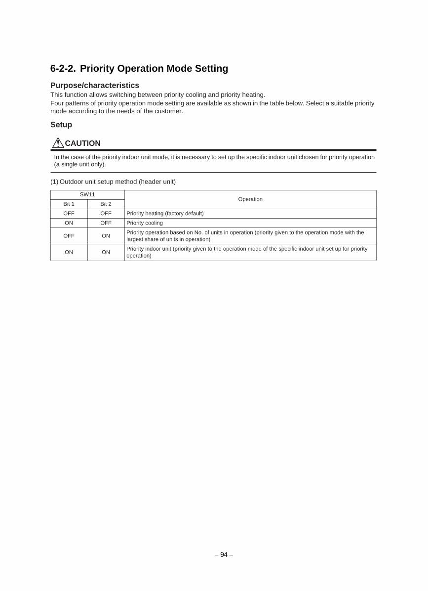
Purpose/characteristicsThis function allows switching between priority cooling and priority heating.Four patterns of priority operation mode setting are available as shown in the table below. Select a suitable priority mode according to the needs of the customer.
Setup
CAUTION
In the case of the priority indoor unit mode, it is necessary to set up the specific indoor unit chosen for priority operation (a single unit only).
(1) Outdoor unit setup method (header unit)
SW11Operation
Bit 1 Bit 2
OFF OFF Priority heating (factory default)
ON OFF Priority cooling
OFF ONPriority operation based on No. of units in operation (priority given to the operation mode with the largest share of units in operation)
ON ONPriority indoor unit (priority given to the operation mode of the specific indoor unit set up for priority operation)
6-2-2. Priority Operation Mode Setting
− 94 −
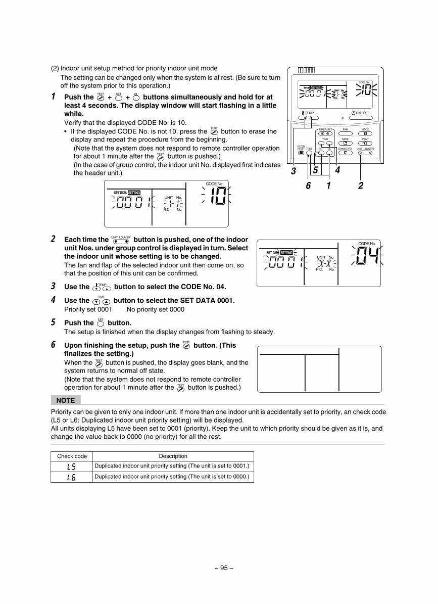
(2) Indoor unit setup method for priority indoor unit modeThe setting can be changed only when the system is at rest. (Be sure to turn off the system prior to this operation.)
1 Push the + + buttons simultaneously and hold for atleast 4 seconds. The display window will start flashing in a little while.Verify that the displayed CODE No. is 10.
If the displayed CODE No. is not 10, press the button to erase the display and repeat the procedure from the beginning.(Note that the system does not respond to remote controller operation for about 1 minute after the button is pushed.)(In the case of group control, the indoor unit No. displayed first indicates the header unit.)
2 Each time the button is pushed, one of the indoorunit Nos. under group control is displayed in turn. Select the indoor unit whose setting is to be changed.The fan and flap of the selected indoor unit then come on, so that the position of this unit can be confirmed.
3 Use the button to select the CODE No. 04.
4 Use the button to select the SET DATA 0001.Priority set 0001 No priority set 0000
5 Push the button.The setup is finished when the display changes from flashing to steady.
6 Upon finishing the setup, push the button. (This finalizes the setting.)When the button is pushed, the display goes blank, and the system returns to normal off state.(Note that the system does not respond to remote controller operation for about 1 minute after the button is pushed.)
NOTE
Priority can be given to only one indoor unit. If more than one indoor unit is accidentally set to priority, an check code (L5 or L6: Duplicated indoor unit priority setting) will be displayed.All units displaying L5 have been set to 0001 (priority). Keep the unit to which priority should be given as it is, and change the value back to 0000 (no priority) for all the rest.
noitpircseDCheck code
Duplicated indoor unit priority setting (The unit is set to 0001.)
Duplicated indoor unit priority setting (The unit is set to 0000.)
SET
TIME
TIMER SET
TESTFILTERRESET
TEMP.
CL
FAN
SAVE
SWING/FIX
VENT
MODE
ON / OFF
UNIT LOUVER
5 4
1 263
UNIT LOUVER
− 95 −
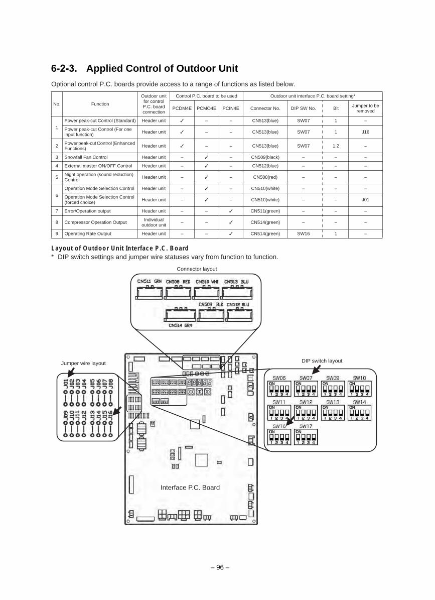
6-2-3. Applied Control of Outdoor UnitOptional control P.C. boards provide access to a range of functions as listed below.
Layout of Outdoor Unit Interface P.C. Board* DIP switch settings and jumper wire statuses vary from function to function.
No. Function
Outdoor unit for control P.C. board connection
Control P.C. board to be used Outdoor unit interface P.C. board setting*
PCDM4E PCMO4E PCIN4E Connector No. DIP SW No. Bit Jumper to be removed
1
Power peak-cut Control (Standard) Header unit – – CN513(blue) SW07 1 –
Power peak-cut Control (For one input function) Header unit – – CN513(blue) SW07 1 J16
2 Power peak-cut Control (Enhanced Functions) Header unit – – CN513(blue) SW07 1.2 –
3 Snowfall Fan Control Header unit – – CN509(black) – – –
4 External master ON/OFF Control Header unit – – CN512(blue) – – –
5 Night operation (sound reduction) Control Header unit – – CN508(red) – – –
6
Operation Mode Selection Control Header unit – – CN510(white) – – –
Operation Mode Selection Control (forced choice) Header unit – – CN510(white) – – J01
7 Error/Operation output Header unit – – CN511(green) – – –
8 Compressor Operation Output Individual outdoor unit – – CN514(green) – – –
9 Operating Rate Output Header unit – – CN514(green) SW16 1 –
Connector layout
DIP switch layout
Interface P.C. Board
Jumper wire layout
− 96 −
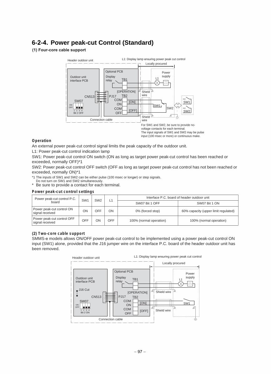
6-2-4. Power peak-cut Control (Standard)
OperationAn external power peak-cut control signal limits the peak capacity of the outdoor unit.L1: Power peak-cut control indication lampSW1: Power peak-cut control ON switch (ON as long as target power peak-cut control has been reached or exceeded, normally OFF)*1SW2: Power peak-cut control OFF switch (OFF as long as target power peak-cut control has not been reached or exceeded, normally ON)*1*1 The inputs of SW1 and SW2 can be either pulse (100 msec or longer) or step signals.
Do not turn on SW1 and SW2 simultaneously.* Be sure to provide a contact for each terminal.
Power peak-cut control settings
(2) Two-core cable support SMMS-e models allows ON/OFF power peak-cut control to be implemented using a power peak-cut control ON input (SW1) alone, provided that the J16 jumper wire on the interface P.C. board of the header outdoor unit has been removed.
Power peak-cut control P.C. board SW1 SW2 L1
Interface P.C. board of header outdoor unit
NO 1 tiB 70WSFFO 1 tiB 70WS
Power peak-cut control ON signal received ON OFF ON 0% (forced stop) 60% capacity (upper limit regulated)
Power peak-cut control OFF signal received OFF ON OFF 100% (normal operation) 100% (normal operation)
PJ17CN513SW07
TB1
[ON]
[OFF]
TB2COM
ONCOMOFFBit 2 OFF
L1
SW1
SW2SW2
SW1ONOFF
1 2 3 4
Connection cable
Locally procured
[OPERATION]
L1: Display lamp ensuring power peak cut control
Optional PCB
Header outdoor unit
Outdoor unit interface PCB
Displayrelay
Powersupply
Shieldwire
Shieldwire
For SW1 and SW2, be sure to provide no-voltage contacts for each terminal. The input signals of SW1 and SW2 may be pulse input (100 msec or more) or continuous make.
PJ17
TB1
TB2COM
ONCOMOFF
CN513SW07
Bit 2 ON
L1
SW1ONOFF
1 2 3 4
[ON]
[OFF]
Connection cable
Locally procured
[OPERATION]
L1: Display lamp ensuring power peak cut control
Optional PCB
Header outdoor unit
J16 CutShield wire
Shield wire
Outdoor unit interface PCB
Displayrelay
Powersupply
− 97 −
(1) Four-core cable support
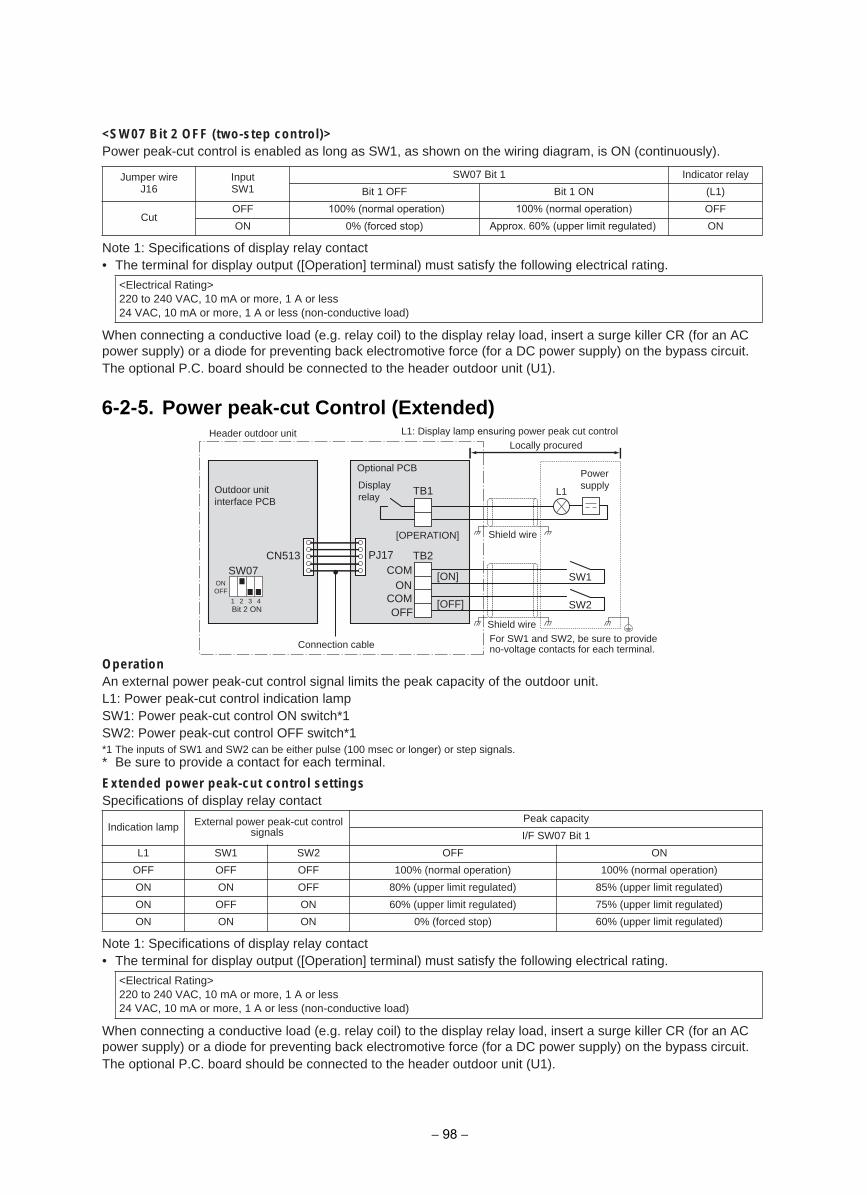
<SW07 Bit 2 OFF (two-step control)>Power peak-cut control is enabled as long as SW1, as shown on the wiring diagram, is ON (continuously).
Note 1: Specifications of display relay contact• The terminal for display output ([Operation] terminal) must satisfy the following electrical rating.
When connecting a conductive load (e.g. relay coil) to the display relay load, insert a surge killer CR (for an AC power supply) or a diode for preventing back electromotive force (for a DC power supply) on the bypass circuit.The optional P.C. board should be connected to the header outdoor unit (U1).
OperationAn external power peak-cut control signal limits the peak capacity of the outdoor unit.L1: Power peak-cut control indication lampSW1: Power peak-cut control ON switch*1SW2: Power peak-cut control OFF switch*1*1 The inputs of SW1 and SW2 can be either pulse (100 msec or longer) or step signals.* Be sure to provide a contact for each terminal.
Extended power peak-cut control settingsSpecifications of display relay contact
Note 1: Specifications of display relay contact• The terminal for display output ([Operation] terminal) must satisfy the following electrical rating.
When connecting a conductive load (e.g. relay coil) to the display relay load, insert a surge killer CR (for an AC power supply) or a diode for preventing back electromotive force (for a DC power supply) on the bypass circuit.The optional P.C. board should be connected to the header outdoor unit (U1).
Jumper wireJ16
InputSW1
yaler rotacidnI1 tiB 70WS
)1L(NO 1 tiBFFO 1 tiB
CutOFF 100% (normal operation) 100% (normal operation) OFF
ON 0% (forced stop) Approx. 60% (upper limit regulated) ON
<Electrical Rating>220 to 240 VAC, 10 mA or more, 1 A or less24 VAC, 10 mA or more, 1 A or less (non-conductive load)
Indication lamp External power peak-cut control signals
Peak capacity
I/F SW07 Bit 1
NOFFO2WS1WS1L
OFF OFF OFF 100% (normal operation) 100% (normal operation)
ON ON OFF 80% (upper limit regulated) 85% (upper limit regulated)
ON OFF ON 60% (upper limit regulated) 75% (upper limit regulated)
ON ON ON 0% (forced stop) 60% (upper limit regulated)
<Electrical Rating>220 to 240 VAC, 10 mA or more, 1 A or less24 VAC, 10 mA or more, 1 A or less (non-conductive load)
PJ17
TB1
[ON]
[OFF]
TB2COM
ONCOMOFF
CN513SW07
Bit 2 ON
L1
SW1ONOFF
1 2 3 4 SW2
Connection cable
Locally procured
[OPERATION]
L1: Display lamp ensuring power peak cut control
Optional PCB
Header outdoor unit
Shield wire
Shield wire
Outdoor unit interface PCB
Displayrelay
Powersupply
For SW1 and SW2, be sure to provide no-voltage contacts for each terminal.
6-2-5. Power peak-cut Control (Extended)
− 98 −
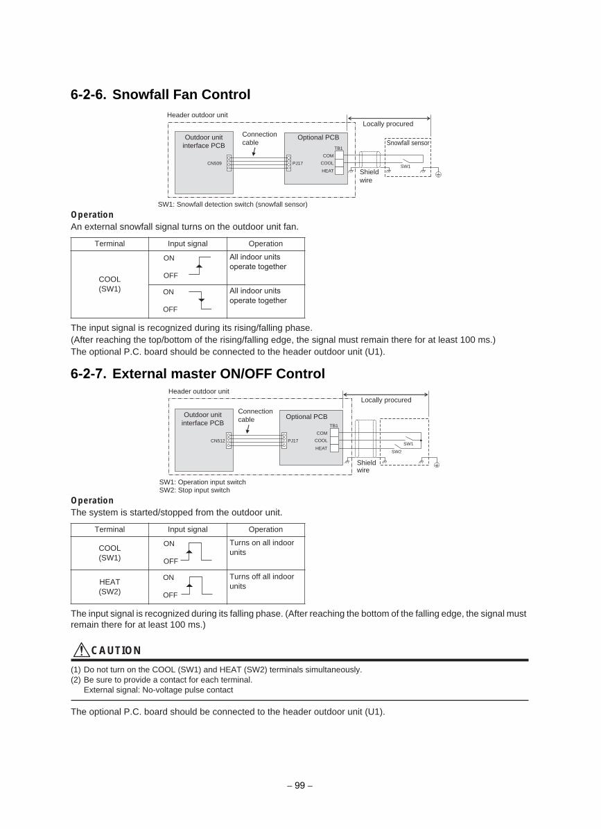
OperationAn external snowfall signal turns on the outdoor unit fan.
The input signal is recognized during its rising/falling phase.(After reaching the top/bottom of the rising/falling edge, the signal must remain there for at least 100 ms.)The optional P.C. board should be connected to the header outdoor unit (U1).
OperationThe system is started/stopped from the outdoor unit.
The input signal is recognized during its falling phase. (After reaching the bottom of the falling edge, the signal must remain there for at least 100 ms.)
CAUTION
(1) Do not turn on the COOL (SW1) and HEAT (SW2) terminals simultaneously.(2) Be sure to provide a contact for each terminal.
External signal: No-voltage pulse contact
The optional P.C. board should be connected to the header outdoor unit (U1).
Terminal Input signal Operation
COOL(SW1)
All indoor units operate together
All indoor units operate together
Terminal Input signal Operation
COOL(SW1)
Turns on all indoor units
HEAT(SW2)
Turns off all indoor units
SW1: Snowfall detection switch (snowfall sensor)
71JP905NC
TB1
SW1
COM
HEAT
COOL
Locally procured
Optional PCBSnowfall sensor
Header outdoor unit
Connectioncable
Outdoor unit interface PCB
Shieldwire
ON
OFF
ON
OFF
SW1: Operation input switchSW2: Stop input switch
71JP215NC
TB1
SW1
SW2
COM
HEAT
COOL
Locally procured
Optional PCB
Header outdoor unit
Outdoor unit interface PCB
Connectioncable
Shieldwire
ON
OFF
ON
OFF
6-2-6. Snowfall Fan Control
6-2-7. External master ON/OFF Control
− 99 −
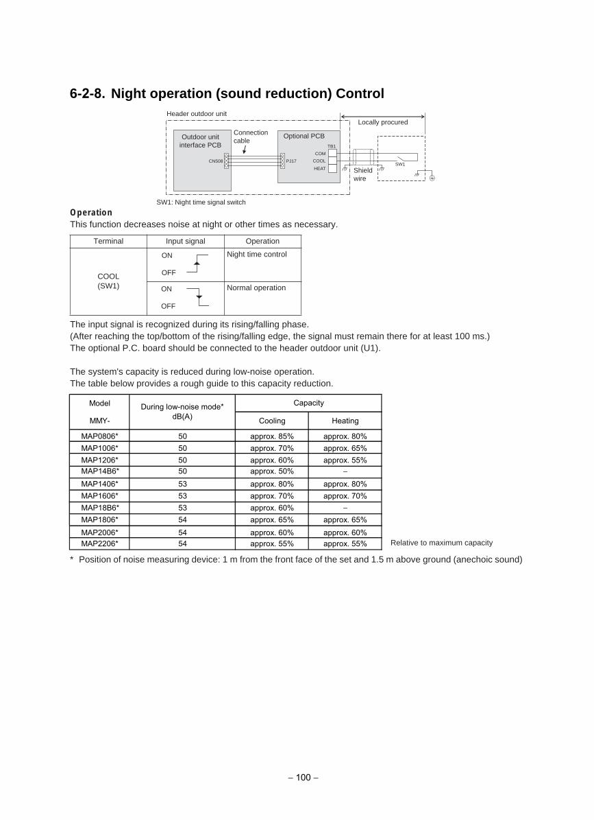
6-2-8. Night operation (sound reduction) Control
OperationThis function decreases noise at night or other times as necessary.
The input signal is recognized during its rising/falling phase.(After reaching the top/bottom of the rising/falling edge, the signal must remain there for at least 100 ms.)The optional P.C. board should be connected to the header outdoor unit (U1).
The system's capacity is reduced during low-noise operation.The table below provides a rough guide to this capacity reduction.
* Position of noise measuring device: 1 m from the front face of the set and 1.5 m above ground (anechoic sound)
Terminal Input signal Operation
COOL(SW1)
Night time control
Normal operation
Relative to maximum capacity
SW1: Night time signal switch
71JP805NC
TB1
SW1
COM
HEAT
COOL
Locally procured
Optional PCB
Header outdoor unit
Outdoor unit interface PCB
Connectioncable
Shieldwire
ON
OFF
ON
OFF
Model
MMY- Cooling Heating
MAP0806* 50 approx. 85% approx. 80%MAP1006* 50 approx. 70% approx. 65%MAP1206* 50 approx. 60% approx. 55%
MAP1406* 53 approx. 80% approx. 80%MAP1606* 53 approx. 70% approx. 70%
MAP1806* 54 approx. 65% approx. 65%MAP2006* 54 approx. 60% approx. 60%MAP2206* 54 approx. 55% approx. 55%
During low-noise mode*dB(A)
Capacity
− 100 −
MAP14B6* 50 approx. 50% −
MAP18B6* 53 approx. 60% −
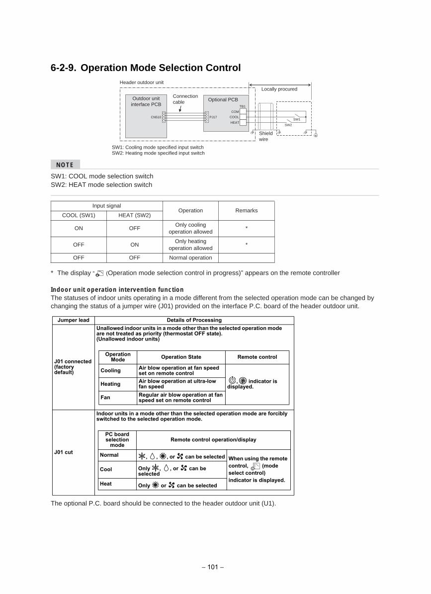
6-2-9. Operation Mode Selection Control
NOTE
SW1: COOL mode selection switchSW2: HEAT mode selection switch
* The display “ (Operation mode selection control in progress)” appears on the remote controller
Indoor unit operation intervention function The statuses of indoor units operating in a mode different from the selected operation mode can be changed by changing the status of a jumper wire (J01) provided on the interface P.C. board of the header outdoor unit.
The optional P.C. board should be connected to the header outdoor unit (U1).
Input signalOperation Remarks
COOL (SW1) HEAT (SW2)
ON OFFOnly cooling
operation allowed*
OFF ONOnly heating
operation allowed*
OFF OFF Normal operation
SW1: Cooling mode specified input switchSW2: Heating mode specified input switch
71JP015NC
TB1
SW1
SW2
COM
HEAT
COOL
Locally procured
Optional PCB
Header outdoor unit
Shieldwire
Connectioncable
Outdoor unit interface PCB
Jumper lead Details of Processing
J01 connected (factory default)
Unallowed indoor units in a mode other than the selected operation mode are not treated as priority (thermostat OFF state).(Unallowed indoor units)
J01 cut
Indoor units in a mode other than the selected operation mode are forcibly switched to the selected operation mode.
Operation Mode Operation State Remote control
Cooling Air blow operation at fan speed set on remote control
, indicator is displayed.Heating Air blow operation at ultra-low
fan speed
Fan Regular air blow operation at fan speed set on remote control
PC board selection
mode Remote control operation/display
Normal , , , or can be selected When using the remote control, (mode select control) indicator is displayed.
Cool Only , , or can be selected
Heat Only or can be selected
− 101 −
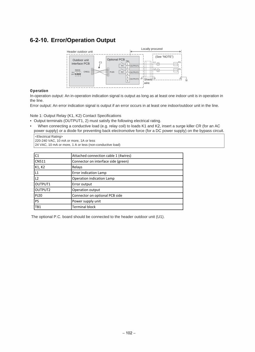
6-2-10. Error/Operation Output
OperationIn-operation output: An in-operation indication signal is output as long as at least one indoor unit is in operation in the line.Error output: An error indication signal is output if an error occurs in at least one indoor/outdoor unit in the line.
Note 1: Output Relay (K1, K2) Contact Specifications• Output terminals (OUTPUT1, 2) must satisfy the following electrical rating.• When connecting a conductive load (e.g. relay coil) to loads K1 and K2, insert a surge killer CR (for an AC
power supply) or a diode for preventing back electromotive force (for a DC power supply) on the bypass circuit.
The optional P.C. board should be connected to the header outdoor unit (U1).
<Electrical Rating>220-240 VAC, 10 mA or more, 1A or less24 VAC, 10 mA or more, 1 A or less (non-conductive load)
OUTPUT1
CN511 PJ20 OUTPUT2
OUTPUT3
TB1 L1
L2
12
56
43
C1 PS
PS
K1
K2
1 2 3 4
ONOFF
SW16
Optional PCB
Locally procured
(See “NOTE”)
Header outdoor unit
Outdoor unit interface PCB
Shieldwire
C1 Attached connection cable 1 (4wires)
CN511 Connector on interface side (green)
K1, K2 Relays
L1 Error indication Lamp
L2 Operation indication Lamp
OUTPUT1 Error output
OUTPUT2 Operation output
PJ20 Connector on optional PCB side
PS Power supply unit
TB1 Terminal block
− 102 −
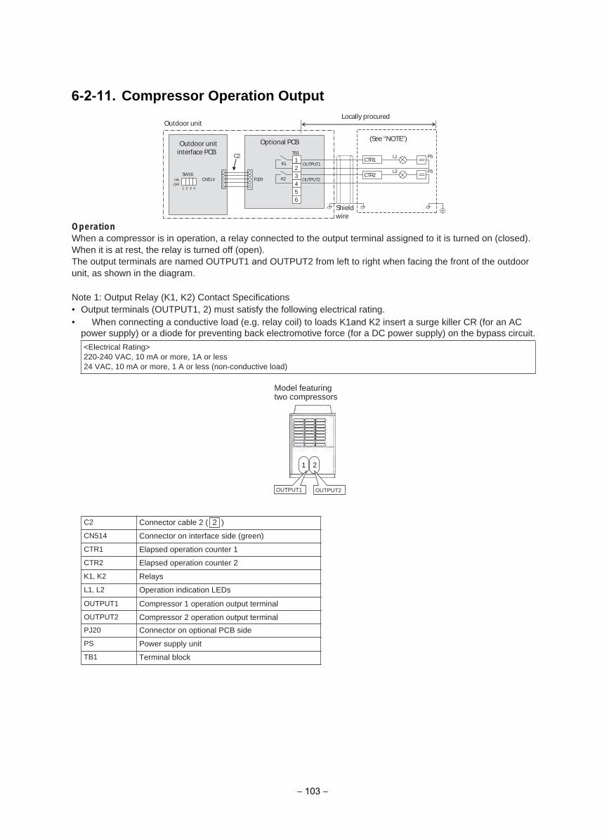
6-2-11. Compressor Operation Output
OperationWhen a compressor is in operation, a relay connected to the output terminal assigned to it is turned on (closed). When it is at rest, the relay is turned off (open).The output terminals are named OUTPUT1 and OUTPUT2 from left to right when facing the front of the outdoor unit, as shown in the diagram.
Note 1: Output Relay (K1, K2) Contact Specifications• Output terminals (OUTPUT1, 2) must satisfy the following electrical rating.• When connecting a conductive load (e.g. relay coil) to loads K1and K2 insert a surge killer CR (for an AC
power supply) or a diode for preventing back electromotive force (for a DC power supply) on the bypass circuit.
<Electrical Rating>220-240 VAC, 10 mA or more, 1A or less24 VAC, 10 mA or more, 1 A or less (non-conductive load)
1 2
OUTPUT1 OUTPUT2
Model featuring two compressors
Locally procuredOutdoor unit
Optional PCB (See “NOTE”)
TB1C2 L1 PS1 CTR1
K1 OUTPUT12
L2 PSSW16 3 CTR2
CN514 PJ20 K2 OUTPUT24
1 2 3 456
Outdoor unit interface PCB
ONOFF
Shieldwire
C2 Connector cable 2 ( 2 )
CN514 Connector on interface side (green)
CTR1 Elapsed operation counter 1
CTR2 Elapsed operation counter 2
K1, K2 Relays
L1, L2 Operation indication LEDs
OUTPUT1 Compressor 1 operation output terminal
OUTPUT2 Compressor 2 operation output terminalPJ20 Connector on optional PCB side
PS Power supply unit
TB1 Terminal block
− 103 −
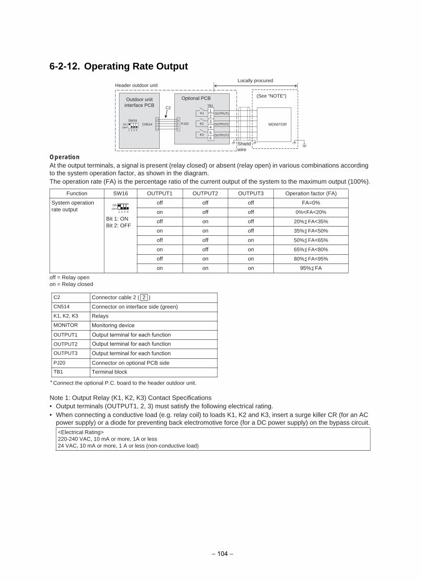
6-2-12. Operating Rate Output
OperationAt the output terminals, a signal is present (relay closed) or absent (relay open) in various combinations according to the system operation factor, as shown in the diagram.The operation rate (FA) is the percentage ratio of the current output of the system to the maximum output (100%).
off = Relay openon = Relay closed
* Connect the optional P.C. board to the header outdoor unit.
Note 1: Output Relay (K1, K2, K3) Contact Specifications• Output terminals (OUTPUT1, 2, 3) must satisfy the following electrical rating.• When connecting a conductive load (e.g. relay coil) to loads K1, K2 and K3, insert a surge killer CR (for an AC
power supply) or a diode for preventing back electromotive force (for a DC power supply) on the bypass circuit.
Function SW16 OUTPUT1 OUTPUT2 OUTPUT3 Operation factor (FA)
System operation rate output
Bit 1: ONBit 2: OFF
off off off FA=0%
on off off 0%<FA<20%
off on off 20% FA<35%
on on off 35% FA<50%
off off on 50% FA<65%
on off on 65% FA<80%
off on on 80% FA<95%
on on on 95% FA
<Electrical Rating>220-240 VAC, 10 mA or more, 1A or less24 VAC, 10 mA or more, 1 A or less (non-conductive load)
OUTPUT1
CN514 PJ20 OUTPUT2
OUTPUT3
TB1
12
56
43
C2K1
K2
K3
1 2 3 4
ONOFF
SW16MONITOR
Optional PCB
Locally procured
(See “NOTE”)
Header outdoor unit
Outdoor unit interface PCB
Shieldwire
1
ONOFF
2 3 4
C2 Connector cable 2 ( 2 )
CN514 Connector on interface side (green)K1, K2, K3 Relays
MONITOR Monitoring device
OUTPUT1
OUTPUT2
PJ20 Connector on optional PCB sideTB1 Terminal block
OUTPUT3 Output terminal for each function
Output terminal for each functionOutput terminal for each function
− 104 −
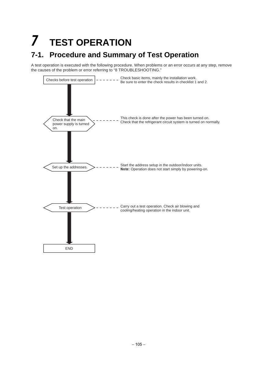
7 TEST OPERATION7-1. Procedure and Summary of Test OperationA test operation is executed with the following procedure. When problems or an error occurs at any step, remove the causes of the problem or error referring to “8 TROUBLESHOOTING.”
Checks before test operation
Check that the main power supply is turned on.
Check basic items, mainly the installation work.Be sure to enter the check results in checklist 1 and 2.
This check is done after the power has been turned on.Check that the refrigerant circuit system is turned on normally.
Set up the addresses. Start the address setup in the outdoor/indoor units.Note: Operation does not start simply by powering-on.
Test operation
END
Carry out a test operation. Check air blowing and cooling/heating operation in the indoor unit.
− 105 −
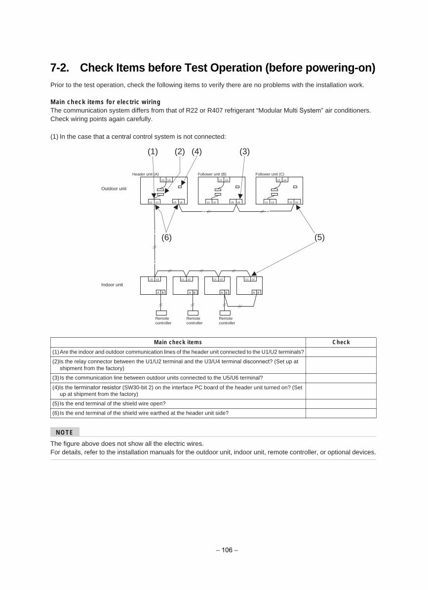
7-2. Check Items before Test Operation (before powering-on)Prior to the test operation, check the following items to verify there are no problems with the installation work.
Main check items for electric wiringThe communication system differs from that of R22 or R407 refrigerant “Modular Multi System” air conditioners. Check wiring points again carefully.
(1) In the case that a central control system is not connected:
NOTE
The figure above does not show all the electric wires.For details, refer to the installation manuals for the outdoor unit, indoor unit, remote controller, or optional devices.
kcehCsmeti kcehc niaM
(1)Are the indoor and outdoor communication lines of the header unit connected to the U1/U2 terminals?
(2)Is the relay connector between the U1/U2 terminal and the U3/U4 terminal disconnect? (Set up at shipment from the factory)
(3) Is the communication line between outdoor units connected to the U5/U6 terminal?
(4)Is the terminator resistor (SW30-bit 2) on the interface PC board of the header unit turned on? (Set up at shipment from the factory)
(5) Is the end terminal of the shield wire open?
(6) Is the end terminal of the shield wire earthed at the header unit side?
U1 U2
U1 U2 U1 U2 U1 U2 U1 U2
U5 U6
U3 U4
U1 U2 U5 U6
U3 U4
U1 U2 U5 U6
U3 U4
A B A B A B A B
(1) (2) (4) (3)
(5)(6)
Outdoor unit
Indoor unit
Remotecontroller
Remotecontroller
Remotecontroller
Header unit (A) Follower unit (B) Follower unit (C)
− 106 −
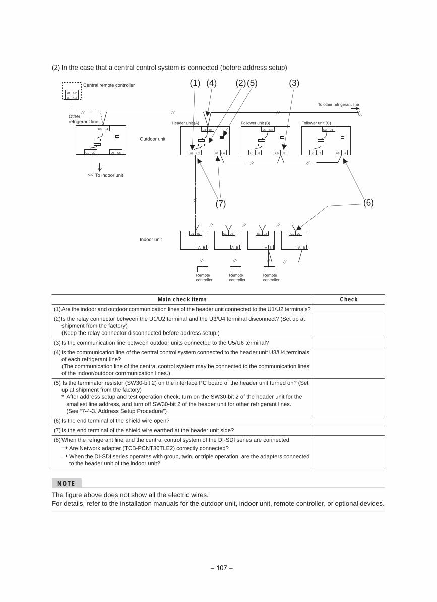
(2) In the case that a central control system is connected (before address setup)
NOTE
The figure above does not show all the electric wires.For details, refer to the installation manuals for the outdoor unit, indoor unit, remote controller, or optional devices.
kcehCsmeti kcehc niaM
(1)Are the indoor and outdoor communication lines of the header unit connected to the U1/U2 terminals?
(2)Is the relay connector between the U1/U2 terminal and the U3/U4 terminal disconnect? (Set up at shipment from the factory)(Keep the relay connector disconnected before address setup.)
(3) Is the communication line between outdoor units connected to the U5/U6 terminal?
(4) Is the communication line of the central control system connected to the header unit U3/U4 terminals of each refrigerant line?(The communication line of the central control system may be connected to the communication lines of the indoor/outdoor communication lines.)
(5) Is the terminator resistor (SW30-bit 2) on the interface PC board of the header unit turned on? (Set up at shipment from the factory)* After address setup and test operation check, turn on the SW30-bit 2 of the header unit for the
smallest line address, and turn off SW30-bit 2 of the header unit for other refrigerant lines.(See “7-4-3. Address Setup Procedure”)
(6) Is the end terminal of the shield wire open?
(7) Is the end terminal of the shield wire earthed at the header unit side?
(8)When the refrigerant line and the central control system of the DI-SDI series are connected:
Are Network adapter (TCB-PCNT30TLE2) correctly connected?
When the DI-SDI series operates with group, twin, or triple operation, are the adapters connected to the header unit of the indoor unit?
U1 U2
U1 U2 U1 U2 U1 U2 U1 U2
U5 U6
U3 U4
U1 U2 U5 U6
U3 U4
U1 U2 U5 U6
A B A B A B A B
(1) (4) (2)
(7) (6)
(5) (3)Central remote controller
U1 U2
U3 U4
U3 U4
U1 U2 U5 U6
U3 U4
Otherrefrigerant line
To indoor unit
Outdoor unit
Indoor unit
)C( tinu rewolloF)B( tinu rewolloF)A( tinu redaeH
Remotecontroller
Remotecontroller
Remotecontroller
To other refrigerant line
− 107 −
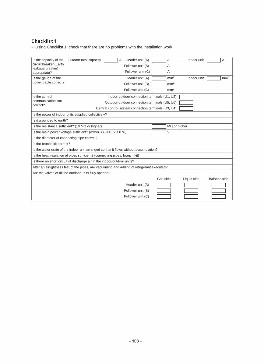
Checklist 1• Using Checklist 1, check that there are no problems with the installation work.
Is the capacity of the circuit breaker (Earth leakage breaker) appropriate?
Outdoor total capacity A Indoor unit A
A
A
A Header unit (A)
Follower unit (B)
Follower unit (C)
Is the gauge of the power cable correct?
mm2 Indoor unit mm2
mm2
mm2
Header unit (A)
Follower unit (B)
Follower unit (C)
Is the control communication line correct?
Indoor-outdoor connection terminals (U1, U2)
Outdoor-outdoor connection terminals (U5, U6)
Central control system connection terminals (U3, U4)
Is the power of indoor units supplied collectively?
Is it grounded to earth?
Is the resistance sufficient? (10 M M )rehgih ro or higher
V )%01± V 514-083 nihtiw( ?tneiciffus egatlov rewop niam eht sI
Is the diameter of connecting pipe correct?
Is the branch kit correct?
Is the water drain of the indoor unit arranged so that it flows without accumulation?
Is the heat insulation of pipes sufficient? (connecting pipes, branch kit)
Is there no short circuit of discharge air in the indoor/outdoor units?
After an airtightness test of the pipes, are vacuuming and adding of refrigerant executed?
Are the valves of all the outdoor units fully opened?
Gas side Liquid side Balance side
Header unit (A)
Follower unit (B)
Follower unit (C)
− 108 −
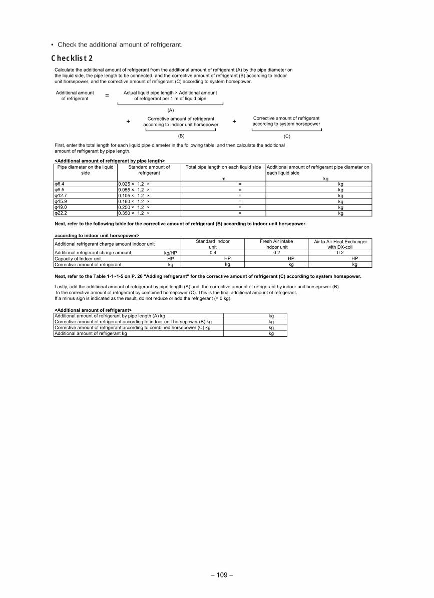
• Check the additional amount of refrigerant.
Checklist 2Calculate the additional amount of refrigerant from the additional amount of refrigerant (A) by the pipe diameter onthe liquid side, the pipe length to be connected, and the corrective amount of refrigerant (B) according to Indoorunit horsepower, and the corrective amount of refrigerant (C) according to system horsepower.
(A)
First, enter the total length for each liquid pipe diameter in the following table, and then calculate the additionalamount of refrigerant by pipe length.
<Additional amount of refrigerant by pipe length>
Next, refer to the following table for the corrective amount of refrigerant (B) according to indoor unit horsepower.
according to indoor unit horsepower>
kg/HPCapacity of Indoor unit HPCorrective amount of refrigerant kg
Lastly, add the additional amount of refrigerant by pipe length (A) and the corrective amount of refrigerant by indoor unit horsepower (B) to the corrective amount of refrigerant by combined horsepower (C). This is the final additional amount of refrigerant.If a minus sign is indicated as the result, do not reduce or add the refrigerant (= 0 kg).
<Additional amount of refrigerant>
Additional amountof refrigerant = Actual liquid pipe length × Additional amount
of refrigerant per 1 m of liquid pipe
+ Corrective amount of refrigerantaccording to indoor unit horsepower +
φ6.4 0.025 × 1.2 × = kgφ9.5 0.055 × 1.2 × = kg
(B)
Pipe diameter on the liquidside
Standard amount ofrefrigerant
Total pipe length on each liquid side
m
Additional amount of refrigerant pipe diameter on each liquid side
kg
φ19.0 0.250 × 1.2 × = kgφ22.2 0.350 × 1.2 × = kg
φ12.7 0.105 × 1.2 × = kgφ15.9 0.160 × 1.2 × = kg
HP HP HPkg kg kg
Additional refrigerant charge amount Indoor unit Standard Indoorunit
Fresh Air intakeIndoor unit
Air to Air Heat Exchangerwith DX-coil
Additional refrigerant charge amount 0.4 0.2 0.2
Additional amount of refrigerant kg kg
Additional amount of refrigerant by pipe length (A) kg kgCorrective amount of refrigerant according to indoor unit horsepower (B) kg kgCorrective amount of refrigerant according to combined horsepower (C) kg kg
− 109 −
(C)
Next, refer to the Table 1-1~1-5 on P. 20 "Adding refrigerant" for the corrective amount of refrigerant (C) according to system horsepower.
Corrective amount of refrigerant according to system horsepower
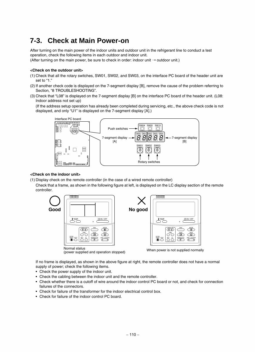
After turning on the main power of the indoor units and outdoor unit in the refrigerant line to conduct a test operation, check the following items in each outdoor and indoor unit.(After turning on the main power, be sure to check in order: indoor unit outdoor unit.)
<Check on the outdoor unit>(1) Check that all the rotary switches, SW01, SW02, and SW03, on the interface PC board of the header unit are
set to “1.”(2) If another check code is displayed on the 7-segment display [B], remove the cause of the problem referring to
Section, “8 TROUBLESHOOTING”.(3) Check that “L08” is displayed on the 7-segment display [B] on the interface PC board of the header unit. (L08:
Indoor address not set up)(If the address setup operation has already been completed during servicing, etc., the above check code is not displayed, and only “U1” is displayed on the 7-segment display [A].)
<Check on the indoor unit>(1) Display check on the remote controller (in the case of a wired remote controller)
Check that a frame, as shown in the following figure at left, is displayed on the LC display section of the remote controller.
If no frame is displayed, as shown in the above figure at right, the remote controller does not have a normal supply of power; check the following items.
Check the power supply of the indoor unit.Check the cabling between the indoor unit and the remote controller.Check whether there is a cutoff of wire around the indoor control PC board or not, and check for connection failures of the connectors.Check for failure of the transformer for the indoor electrical control box.Check for failure of the indoor control PC board.
Interface PC board
SW01 SW02 SW03
SW04
D600 D601 D602 D603 D604
SW15SW05
Push switches
Rotary switches
7-segment display [A]
7-segment display [B]
SET
TIME
TIMER SET
TESTFILTERRESET
TEMP.
CL
FAN
SAVE
SWING/FIX
VENT
MODE
ON / OFF
UNIT LOUVER SET
TIME
TIMER SET
TESTFILTERRESET
TEMP.
CL
FAN
SAVE
SWING/FIX
VENT
MODE
ON / OFF
UNIT LOUVER
Normal status (power supplied and operation stopped) When power is not supplied normally
doog oNdooG
7-3. Check at Main Power-on
− 110 −
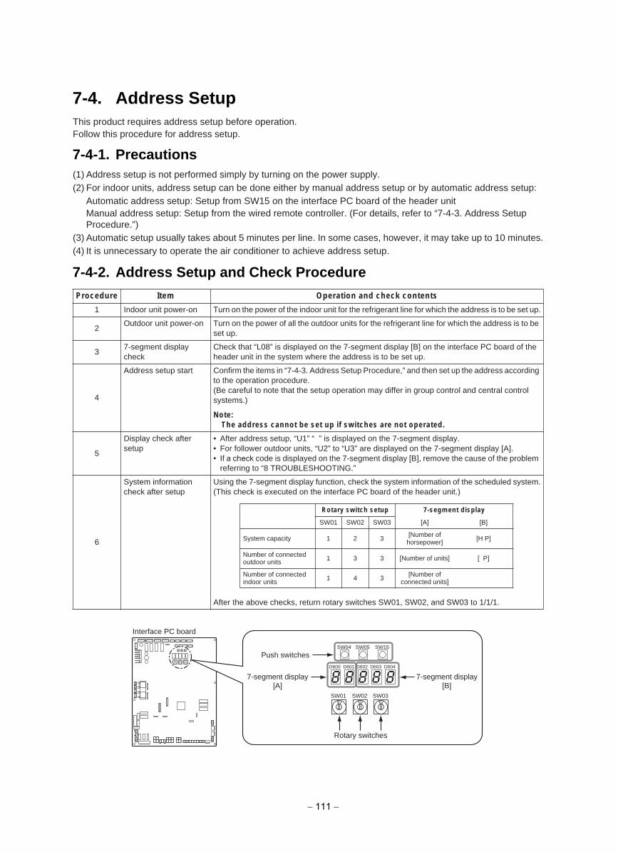
This product requires address setup before operation.Follow this procedure for address setup.
(1) Address setup is not performed simply by turning on the power supply.(2) For indoor units, address setup can be done either by manual address setup or by automatic address setup:
Automatic address setup: Setup from SW15 on the interface PC board of the header unitManual address setup: Setup from the wired remote controller. (For details, refer to “7-4-3. Address Setup Procedure.”)
(3) Automatic setup usually takes about 5 minutes per line. In some cases, however, it may take up to 10 minutes.(4) It is unnecessary to operate the air conditioner to achieve address setup.
stnetnoc kcehc dna noitarepOmetIerudecorP
1 Indoor unit power-on Turn on the power of the indoor unit for the refrigerant line for which the address is to be set up.
2Outdoor unit power-on Turn on the power of all the outdoor units for the refrigerant line for which the address is to be
set up.
37-segment display check
Check that “L08” is displayed on the 7-segment display [B] on the interface PC board of the header unit in the system where the address is to be set up.
4
Address setup start Confirm the items in “7-4-3. Address Setup Procedure,” and then set up the address according to the operation procedure.(Be careful to note that the setup operation may differ in group control and central control systems.)
Note:The address cannot be set up if switches are not operated.
5
Display check after setup
• After address setup, “U1” “ ” is displayed on the 7-segment display.• For follower outdoor units, “U2” to “U3” are displayed on the 7-segment display [A].• If a check code is displayed on the 7-segment display [B], remove the cause of the problem
referring to “8 TROUBLESHOOTING.”
6
System information check after setup
Using the 7-segment display function, check the system information of the scheduled system.(This check is executed on the interface PC board of the header unit.)
After the above checks, return rotary switches SW01, SW02, and SW03 to 1/1/1.
Rotary switch setup 7-segment display
SW01 SW02 SW03 [A] [B]
System capacity 1 2 3 [Number of horsepower] [H P]
Number of connected outdoor units 1 3 3 [Number of units] [ P]
Number of connected indoor units
1 4 3 [Number of connected units]
Interface PC board
SW01 SW02 SW03
SW04
D600 D601 D602 D603 D604
SW15SW05
Push switches
Rotary switches
7-segment display [A]
7-segment display [B]
7-4. Address Setup
7-4-1. Precautions
7-4-2. Address Setup and Check Procedure
− 111 −
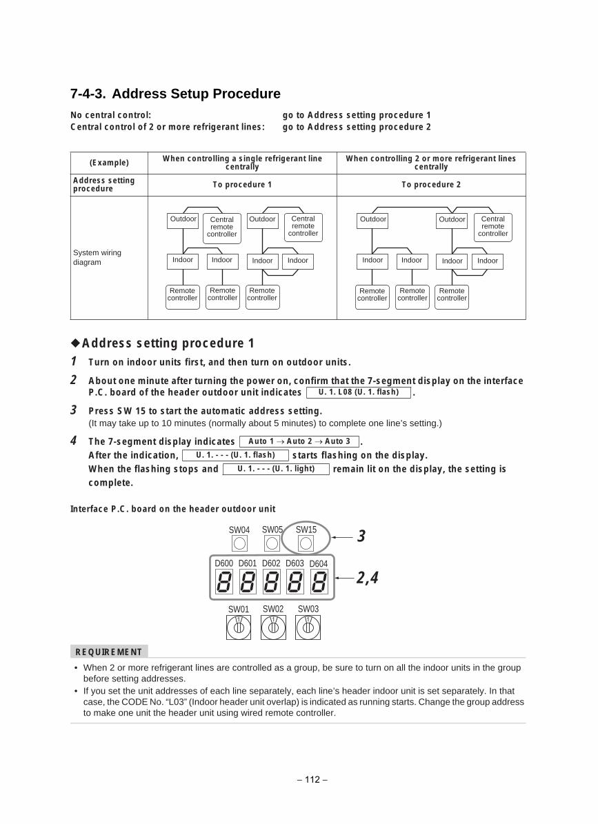
7-4-3. Address Setup Procedure
Address setting procedure 11 Turn on indoor units first, and then turn on outdoor units.
2 About one minute after turning the power on, confirm that the 7-segment display on the interface. setacidni tinu roodtuo redaeh eht fo draob .C.P
3 Press SW 15 to start the automatic address setting.(It may take up to 10 minutes (normally about 5 minutes) to complete one line’s setting.)
4 .setacidni yalpsid tnemges-7 ehT .yalpsid eht no gnihsalf strats ,noitacidni eht retfA
si gnittes eht ,yalpsid eht no til niamer dna spots gnihsalf eht nehWcomplete.
Interface P.C. board on the header outdoor unit
REQUIREMENT
• When 2 or more refrigerant lines are controlled as a group, be sure to turn on all the indoor units in the groupbefore setting addresses.
• If you set the unit addresses of each line separately, each line’s header indoor unit is set separately. In thatcase, the CODE No. “L03” (Indoor header unit overlap) is indicated as running starts. Change the group address to make one unit the header unit using wired remote controller.
1 erudecorp gnittes sserddA ot og:lortnoc lartnec oNCentral control of 2 or more refrigerant lines: go to Address setting procedure 2
(Example) When controlling a single refrigerant line centrally
When controlling 2 or more refrigerant lines centrally
Address setting procedure 2 erudecorp oT1 erudecorp oT
System wiring diagram
Outdoor
Indoor Indoor Indoor Indoor
OutdoorCentral remote
controller
Central remote
controller
Remote controller
Remote controller
Remote controller
Outdoor
Indoor Indoor Indoor Indoor
Outdoor Central remote
controller
Remote controller
Remotecontroller
Remotecontroller
U. 1. L08 (U. 1. flash)
Auto 1 Auto 2 Auto 3
U. 1. - - - (U. 1. flash)
U. 1. - - - (U. 1. light)
SW04 SW05 SW15
SW01 SW02 SW03
D600 D601 D602 D603 D604
3
2,4
− 112 −
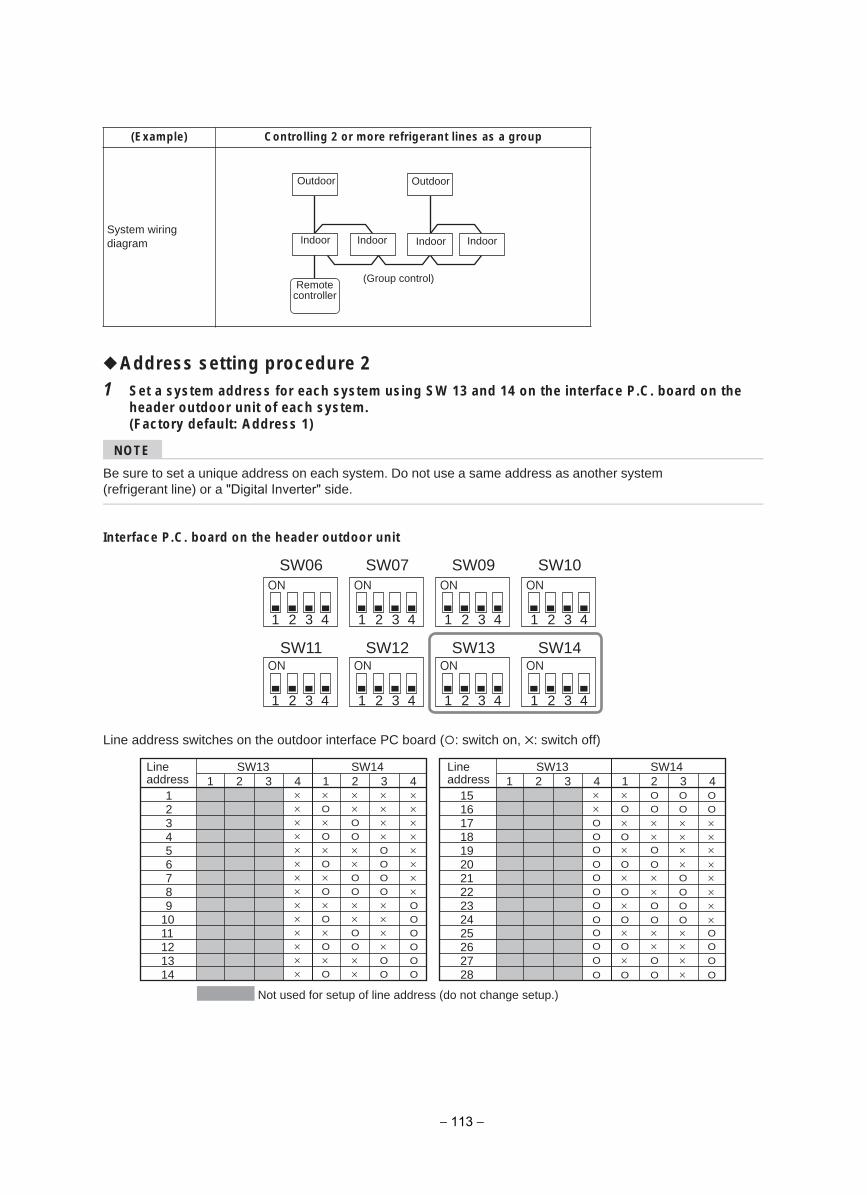
Address setting procedure 21 Set a system address for each system using SW 13 and 14 on the interface P.C. board on the
header outdoor unit of each system.(Factory default: Address 1)
NOTE
Be sure to set a unique address on each system. Do not use a same address as another system (refrigerant line) or a "Digital Inverter" side.
Interface P.C. board on the header outdoor unit
Line address switches on the outdoor interface PC board ( : switch on, : switch off)
(Example) Controlling 2 or more refrigerant lines as a group
System wiring diagram
Outdoor
Indoor Indoor Indoor Indoor
Outdoor
Remote controller
(Group control)
SW06 SW07 SW09 SW10
SW11 SW12 SW13 SW14
1 2 3 4 1 2 3 4 1 2 3 4 1 2 3 4
1 2 3 4 1 2 3 4 1 2 3 4 1 2 3 4
SW13 SW141
123456789
1011121314
××××××××××××××
×O
×O
×O
×O×O
×O×O
××O
O××O
O××O
O
××
××××O
O
O
O××××O
O
××××××××O
O
O
O
O
O
2 3 4 1 2 3 4SW13 SW14
11516171819202122232425262728
××O
OO
OO
O
O
OOO
O
O
×O
×O×O×O×O×O
×O
O
O
××O
O××O
O××O
O
O
O
××××O
O
O
O××××
O
O
××××××××OO
O
O
2 3 4 1 2 3 4
Not used for setup of line address (do not change setup.)
Lineaddress
Lineaddress
− 113 −
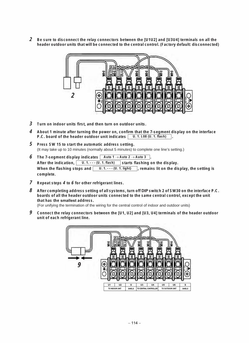
2 Be sure to disconnect the relay connectors between the [U1U2] and [U3U4] terminals on all theheader outdoor units that will be connected to the central control. (Factory default: disconnected)
3 Turn on indoor units first, and then turn on outdoor units.
4 About 1 minute after turning the power on, confirm that the 7-segment display on the interface. setacidni tinu roodtuo redaeh eht fo draob .C.P
5 Press SW 15 to start the automatic address setting.(It may take up to 10 minutes (normally about 5 minutes) to complete one line’s setting.)
6 .setacidni yalpsid tnemges-7 ehT.yalpsid eht no gnihsalf strats ,noitacidni eht retfA
si gnittes eht ,yalpsid eht no til sniamer , dna spots gnihsalf eht nehWcomplete.
7 Repeat steps 4 to 6 for other refrigerant lines.
8 After completing address setting of all systems, turn off DIP switch 2 of SW30 on the interface P.C.boards of all the header outdoor units connected to the same central control, except the unit that has the smallest address.(For unifying the termination of the wiring for the central control of indoor and outdoor units)
9 Connect the relay connectors between the [U1, U2] and [U3, U4] terminals of the header outdoorunit of each refrigerant line.
2
U. 1. L08 (U. 1. flash)
Auto 1 Auto 2 Auto 3
U. 1. - - - (U. 1. flash)
U. 1. - - - (U. 1. light)
U1 U2 S U3 U4 U5 U6 S
SHIELD SHIELDTO CENTRAL CONTROLLER TO OUTDOOR UNITTO INDOOR UNIT
− 114 −
9
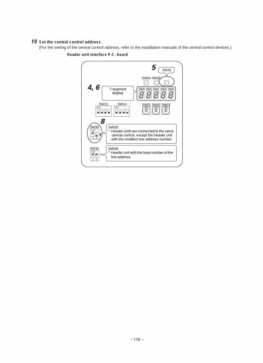
10 Set the central control address.(For the setting of the central control address, refer to the installation manuals of the central control devices.)
Header unit interface P.C. board
SW15
SW04
1 2
SW13
SW30
SW14 SW01 SW02 SW03
D600 D601 D602 D603 D604
SW05
7-segment display
SW30* Header units are connected to the same
central control, except the header unit with the smallest line address number.
8
1 2
SW30 SW30* Header unit with the least number of the
line address.
4, 6
5
− 115 −
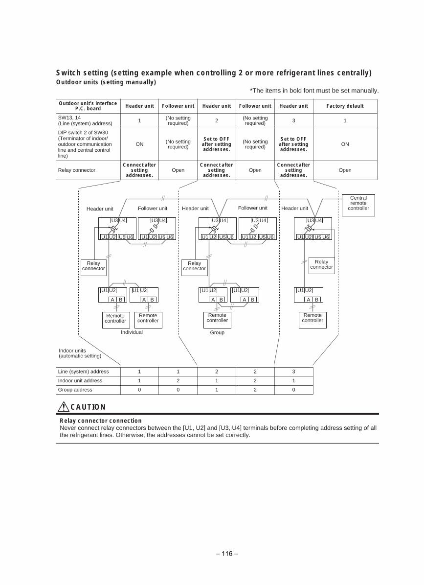
Switch setting (setting example when controlling 2 or more refrigerant lines centrally)Outdoor units (setting manually)
*The items in bold font must be set manually.
CAUTION
Relay connector connectionNever connect relay connectors between the [U1, U2] and [U3, U4] terminals before completing address setting of all the refrigerant lines. Otherwise, the addresses cannot be set correctly.
Outdoor unit’s interface P.C. board Header unit Follower unit Header unit Follower unit Header unit Factory default
SW13, 14(Line (system) address) 1 (No setting
required) 2 (No setting required) 13
DIP switch 2 of SW30 (Terminator of indoor/outdoor communication line and central control line)
ON (No setting required)
Set to OFF after setting addresses.
(No setting required)
Set to OFF after setting addresses.
ON
Relay connectorConnect after
setting addresses.
OpenConnect after
setting addresses.
OpenConnect after
setting addresses.
Open
Line (system) address 1 1 2 2 3
Indoor unit address 1 2 1 2 1
Group address 0 0 1 2 0
A
U1 U2
U3 U4 U3 U4 U3 U4 U3 U4 U3 U4
U5 U6 U1 U2 U5 U6 U1 U2 U5 U6 U1 U2 U5 U6 U1 U2
U1 U2U1 U2U1 U2U1 U2U1 U2
U5 U6
A BA BA BA BB
Central remote
controller
Relay connector
Relay connector
Relayconnector
Header unit Header unit Header unitFollower unitFollower unit
Remote controller
Remotecontroller
Remote controller
Remotecontroller
Individual Group
Indoor units (automatic setting)
− 116 −
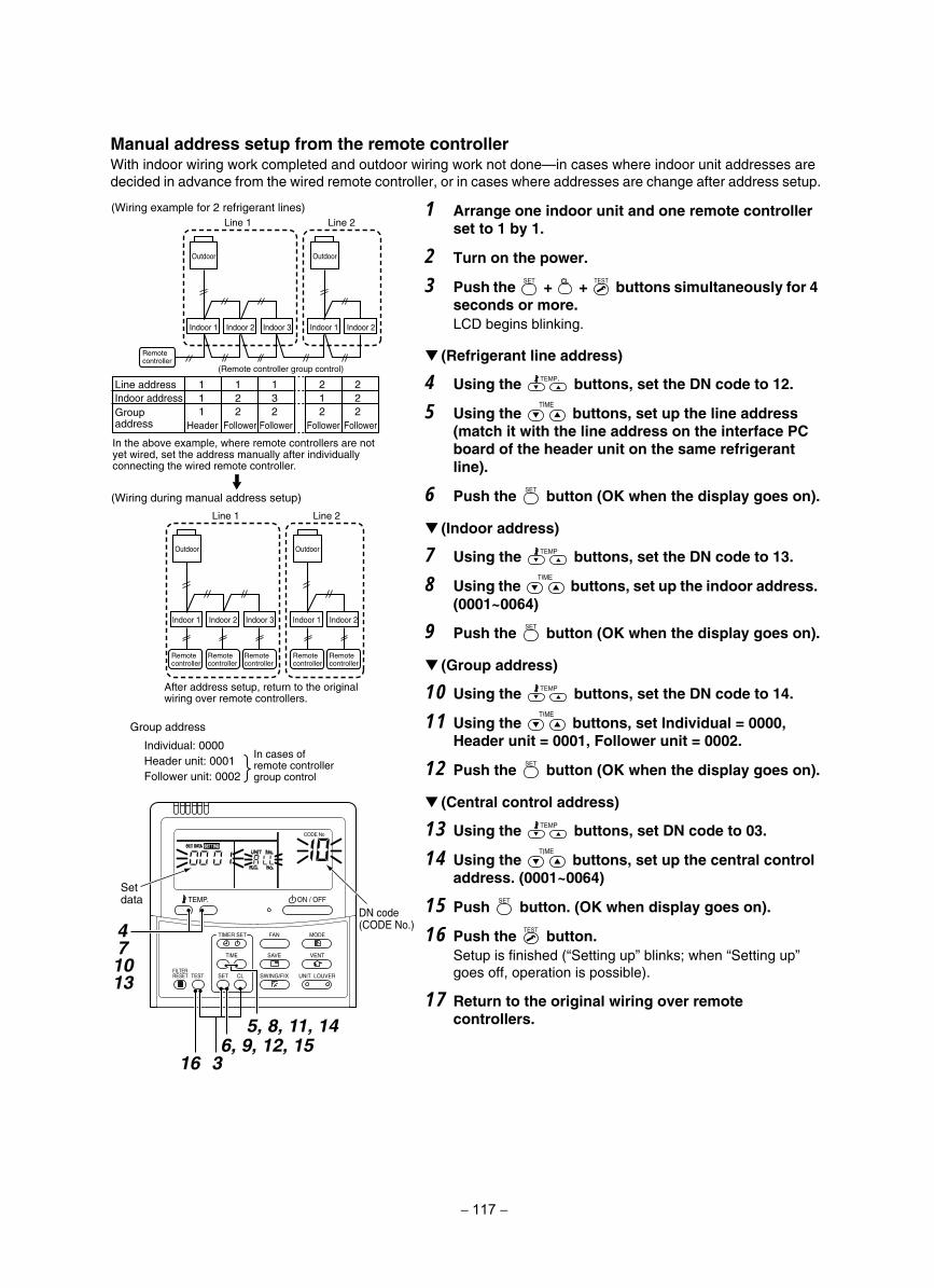
Manual address setup from the remote controllerWith indoor wiring work completed and outdoor wiring work not done—in cases where indoor unit addresses are decided in advance from the wired remote controller, or in cases where addresses are change after address setup.
Group address
Individual: 0000Header unit: 0001Follower unit: 0002
(Wiring example for 2 refrigerant lines)Line 1 Line 2
Line 1 Line 2
Outdoor
Indoor 1 Indoor 2Indoor 1
(Remote controller group control)
Indoor 2 Indoor 3
Indoor 1 Indoor 2Indoor 1 Indoor 2 Indoor 3
Line address Indoor address
111
Header
122
Follower Follower Follower Follower
132
212
222
Outdoor
OutdoorOutdoor
(Wiring during manual address setup)
Remotecontroller
Remotecontroller
Remotecontroller
Remotecontroller
Remotecontroller
Remotecontroller
Groupaddress
In the above example, where remote controllers are not yet wired, set the address manually after individually connecting the wired remote controller.
After address setup, return to the original wiring over remote controllers.
In cases of remote controller group control
SET
TIME
TIMER SET
TESTFILTERRESET
TEMP.
CL
FAN
SAVE
SWING/FIX
VENT
MODE
ON / OFF
UNIT LOUVER
DN code(CODE No.)
Setdata
5, 8, 11, 146, 9, 12, 15
16
471013
3
1 Arrange one indoor unit and one remote controllerset to 1 by 1.
2 Turn on the power.
3 Push the + + buttons simultaneously for 4 seconds or more.LCD begins blinking.
(Refrigerant line address)
4 Using the buttons, set the DN code to 12.
5 Using the buttons, set up the line address (match it with the line address on the interface PC board of the header unit on the same refrigerant line).
6 Push the button (OK when the display goes on).
(Indoor address)
7 Using the buttons, set the DN code to 13.
8 Using the buttons, set up the indoor address. (0001~0064)
9 Push the button (OK when the display goes on).
(Group address)
10 Using the buttons, set the DN code to 14.
11 Using the buttons, set Individual = 0000, Header unit = 0001, Follower unit = 0002.
12 Push the button (OK when the display goes on).
(Central control address)
13 Using the buttons, set DN code to 03.
14 Using the buttons, set up the central control address. (0001~0064)
15 Push button. (OK when display goes on).
16 Push the button.Setup is finished (“Setting up” blinks; when “Setting up” goes off, operation is possible).
17 Return to the original wiring over remotecontrollers.
− 117 −
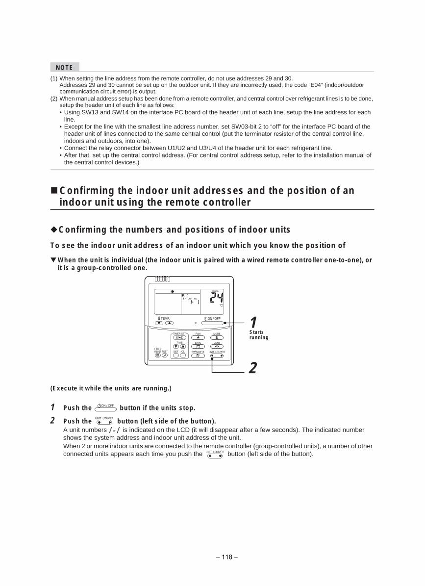
NOTE
(1) When setting the line address from the remote controller, do not use addresses 29 and 30.Addresses 29 and 30 cannot be set up on the outdoor unit. If they are incorrectly used, the code “E04” (indoor/outdoor communication circuit error) is output.
(2) When manual address setup has been done from a remote controller, and central control over refrigerant lines is to be done, setup the header unit of each line as follows:• Using SW13 and SW14 on the interface PC board of the header unit of each line, setup the line address for each
line.• Except for the line with the smallest line address number, set SW03-bit 2 to “off” for the interface PC board of the
header unit of lines connected to the same central control (put the terminator resistor of the central control line, indoors and outdoors, into one).
• Connect the relay connector between U1/U2 and U3/U4 of the header unit for each refrigerant line.• After that, set up the central control address. (For central control address setup, refer to the installation manual of
the central control devices.)
Confirming the indoor unit addresses and the position of an indoor unit using the remote controller
Confirming the numbers and positions of indoor units
To see the indoor unit address of an indoor unit which you know the position of
When the unit is individual (the indoor unit is paired with a wired remote controller one-to-one), or it is a group-controlled one.
(Execute it while the units are running.)
1 Push the button if the units stop.
2 Push the button (left side of the button).A unit numbers is indicated on the LCD (it will disappear after a few seconds). The indicated number shows the system address and indoor unit address of the unit. When 2 or more indoor units are connected to the remote controller (group-controlled units), a number of other connected units appears each time you push the button (left side of the button).
1
2
ON / OFFTEMP.
TIME
SET CLFILTERRESET TEST
TIMER SET
CODE No.
UNIT No.
Starts running
UNIT LOUVER
UNIT LOUVER
− 118 −
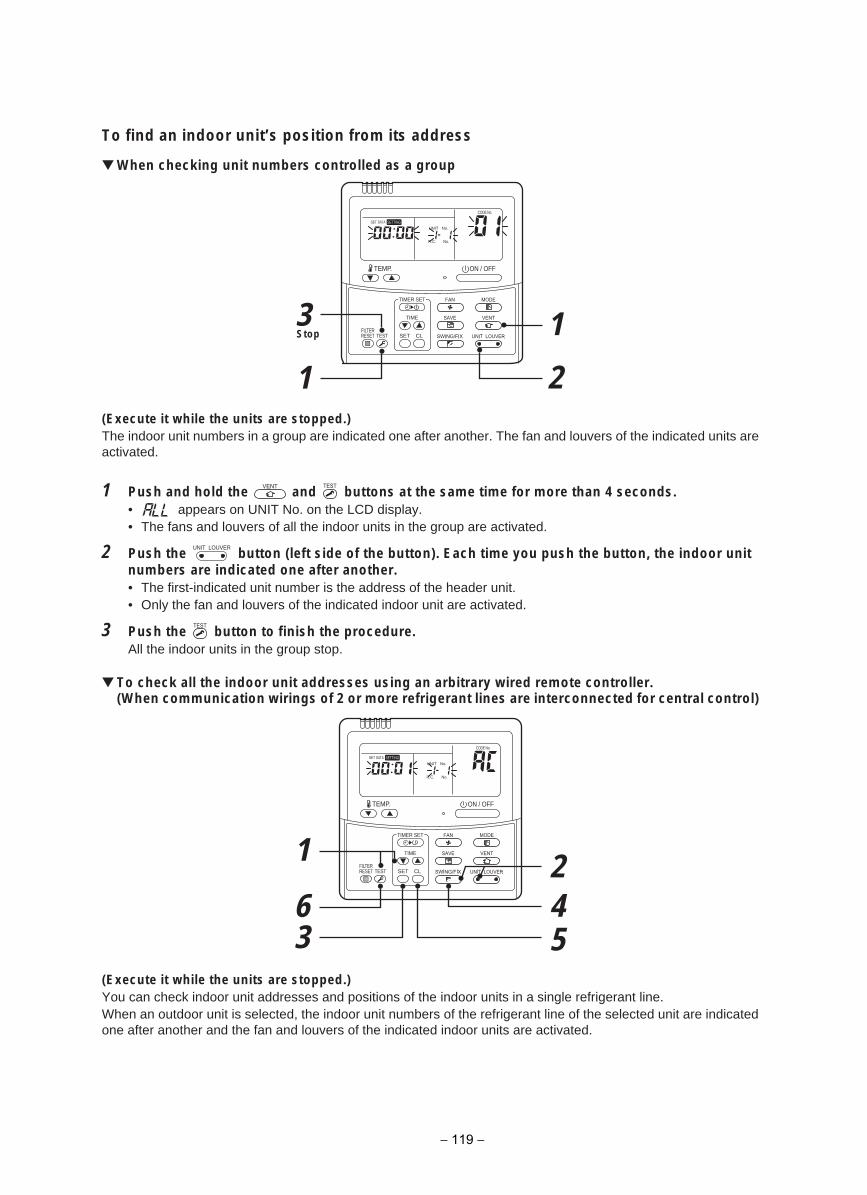
To find an indoor unit’s position from its address
When checking unit numbers controlled as a group
(Execute it while the units are stopped.)The indoor unit numbers in a group are indicated one after another. The fan and louvers of the indicated units are activated.
1 Push and hold the and buttons at the same time for more than 4 seconds.• appears on UNIT No. on the LCD display.• The fans and louvers of all the indoor units in the group are activated.
2 Push the button (left side of the button). Each time you push the button, the indoor unit numbers are indicated one after another.• The first-indicated unit number is the address of the header unit.• Only the fan and louvers of the indicated indoor unit are activated.
3 Push the button to finish the procedure.All the indoor units in the group stop.
To check all the indoor unit addresses using an arbitrary wired remote controller.(When communication wirings of 2 or more refrigerant lines are interconnected for central control)
(Execute it while the units are stopped.)You can check indoor unit addresses and positions of the indoor units in a single refrigerant line.When an outdoor unit is selected, the indoor unit numbers of the refrigerant line of the selected unit are indicated one after another and the fan and louvers of the indicated indoor units are activated.
3
1 2
1
ON / OFFTEMP.
TIME
SET CLFILTERRESET TEST
TIMER SET
CODE No.
UNIT No.SETTINGDATASET
R.C. No.
Stop
UNIT LOUVER
56
1
342
ON / OFFTEMP.
TIME
SET CLFILTERRESET TEST
TIMER SET
CODE No.
UNIT No.SETTINGDATASET
R.C. No.
− 119 −
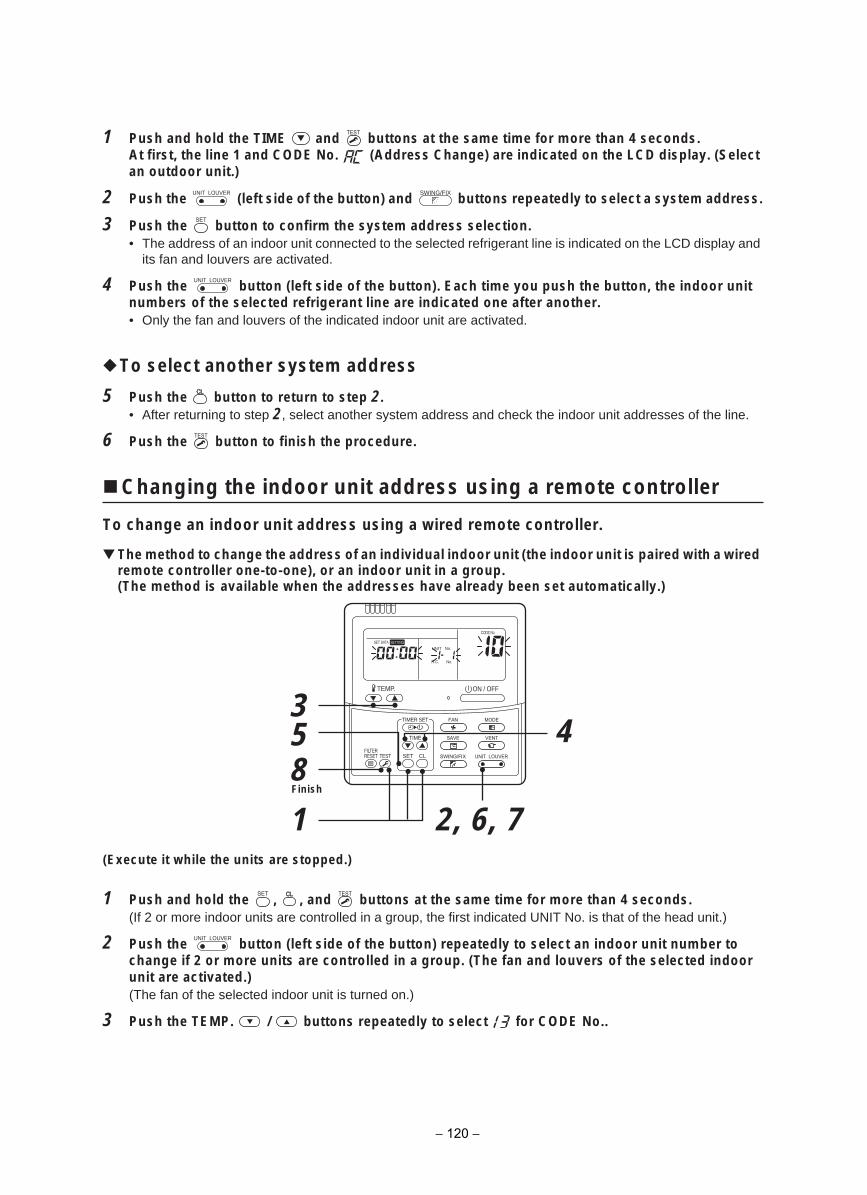
1 Push and hold the TIME and buttons at the same time for more than 4 seconds.At first, the line 1 and CODE No. (Address Change) are indicated on the LCD display. (Select an outdoor unit.)
2 Push the (left side of the button) and buttons repeatedly to select a system address.
3 Push the button to confirm the system address selection.• The address of an indoor unit connected to the selected refrigerant line is indicated on the LCD display and
its fan and louvers are activated.
4 Push the button (left side of the button). Each time you push the button, the indoor unit numbers of the selected refrigerant line are indicated one after another.• Only the fan and louvers of the indicated indoor unit are activated.
To select another system address
5 Push the button to return to step 2.• After returning to step 2, select another system address and check the indoor unit addresses of the line.
6 Push the button to finish the procedure.
Changing the indoor unit address using a remote controller
To change an indoor unit address using a wired remote controller.
The method to change the address of an individual indoor unit (the indoor unit is paired with a wired remote controller one-to-one), or an indoor unit in a group.(The method is available when the addresses have already been set automatically.)
(Execute it while the units are stopped.)
1 Push and hold the , , and buttons at the same time for more than 4 seconds.(If 2 or more indoor units are controlled in a group, the first indicated UNIT No. is that of the head unit.)
2 Push the button (left side of the button) repeatedly to select an indoor unit number tochange if 2 or more units are controlled in a group. (The fan and louvers of the selected indoor unit are activated.)(The fan of the selected indoor unit is turned on.)
3 Push the TEMP. / buttons repeatedly to select for CODE No..
UNIT LOUVER SWING/FIX
UNIT LOUVER
358
1
4
2, 6, 7
ON / OFFTEMP.
TIME
SET CLFILTERRESET TEST
TIMER SET
CODE No.
UNIT No.SETTINGDATASET
R.C. No.
Finish
UNIT LOUVER
− 120 −
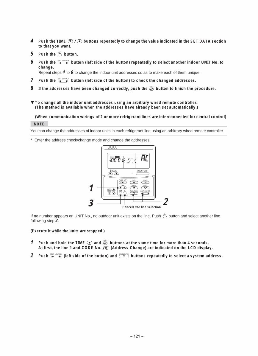
4 Push the TIME / buttons repeatedly to change the value indicated in the SET DATA section to that you want.
5 Push the button.
6 Push the button (left side of the button) repeatedly to select another indoor UNIT No. to change.Repeat steps 4 to 6 to change the indoor unit addresses so as to make each of them unique.
7 Push the button (left side of the button) to check the changed addresses.
8 If the addresses have been changed correctly, push the button to finish the procedure.
To change all the indoor unit addresses using an arbitrary wired remote controller.(The method is available when the addresses have already been set automatically.)
(When communication wirings of 2 or more refrigerant lines are interconnected for central control)
NOTE
You can change the addresses of indoor units in each refrigerant line using an arbitrary wired remote controller.
* Enter the address check/change mode and change the addresses.
If no number appears on UNIT No., no outdoor unit exists on the line. Push button and select another line following step 2.
(Execute it while the units are stopped.)
1 Push and hold the TIME and buttons at the same time for more than 4 seconds.At first, the line 1 and CODE No. (Address Change) are indicated on the LCD display.
2 Push (left side of the button) and buttons repeatedly to select a system address.
UNIT LOUVER
UNIT LOUVER
3
12
ON / OFFTEMP.
TIME
SET CLFILTERRESET TEST
TIMER SET
CODE No.
UNIT No.SETTINGDATASET
R.C. No.
Cancels the line selection
UNIT LOUVER SWING/FIX
− 121 −
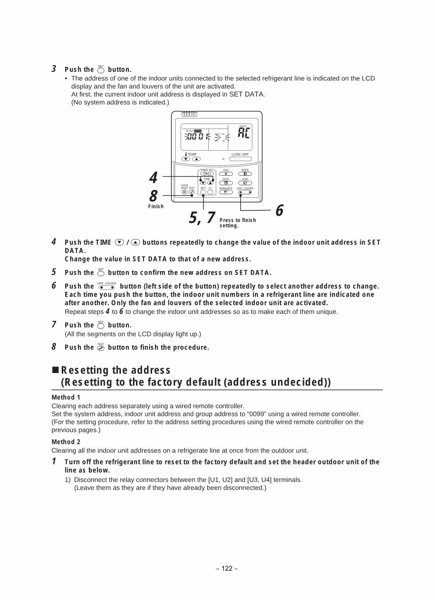
3 Push the button.• The address of one of the indoor units connected to the selected refrigerant line is indicated on the LCD
display and the fan and louvers of the unit are activated.At first, the current indoor unit address is displayed in SET DATA.(No system address is indicated.)
4 Push the TIME / buttons repeatedly to change the value of the indoor unit address in SET DATA.Change the value in SET DATA to that of a new address.
5 Push the button to confirm the new address on SET DATA.
6 Push the button (left side of the button) repeatedly to select another address to change. Each time you push the button, the indoor unit numbers in a refrigerant line are indicated one after another. Only the fan and louvers of the selected indoor unit are activated. Repeat steps 4 to 6 to change the indoor unit addresses so as to make each of them unique.
7 Push the button.(All the segments on the LCD display light up.)
8 Push the button to finish the procedure.
Resetting the address(Resetting to the factory default (address undecided))
Method 1Clearing each address separately using a wired remote controller.Set the system address, indoor unit address and group address to “0099” using a wired remote controller.(For the setting procedure, refer to the address setting procedures using the wired remote controller on the previous pages.)
Method 2Clearing all the indoor unit addresses on a refrigerate line at once from the outdoor unit.
1 Turn off the refrigerant line to reset to the factory default and set the header outdoor unit of theline as below.1) Disconnect the relay connectors between the [U1, U2] and [U3, U4] terminals.
(Leave them as they are if they have already been disconnected.)
48
5, 7 6
ON / OFFTEMP.
TIME
SET CLFILTERRESET TEST
TIMER SET
CODE No.
UNIT No.SETTINGDATASET
R.C. No.
Press to finish setting.
Finish
UNIT LOUVER
− 122 −
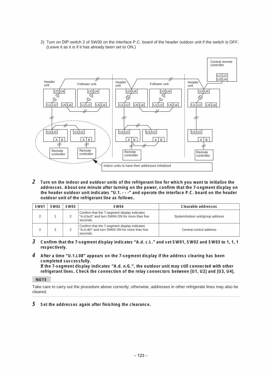
2) Turn on DIP switch 2 of SW30 on the interface P.C. board of the header outdoor unit if the switch is OFF.(Leave it as it is if it has already been set to ON.)
2 Turn on the indoor and outdoor units of the refrigerant line for which you want to initialize theaddresses. About one minute after turning on the power, confirm that the 7-segment display on the header outdoor unit indicates “U.1. - - -” and operate the interface P.C. board on the header outdoor unit of the refrigerant line as follows.
3 Confirm that the 7-segment display indicates “A.d. c.L.” and set SW01, SW02 and SW03 to 1, 1, 1respectively.
4 After a time “U.1.L08” appears on the 7-segment display if the address clearing has beencompleted successfully.If the 7-segment display indicates “A.d. n.G.”, the outdoor unit may still connected with other refrigerant lines. Check the connection of the relay connectors between [U1, U2] and [U3, U4].
NOTE
Take care to carry out the procedure above correctly; otherwise, addresses in other refrigerate lines may also be cleared.
5 Set the addresses again after finishing the clearance.
sesserdda elbaraelC40WS30WS20WS10WS
2 1 2Confirm that the 7-segment display indicates “A.d.buS” and turn SW04 ON for more than five seconds.
System/indoor unit/group address
2 2 2Confirm that the 7-segment display indicates “A.d.nEt” and turn SW04 ON for more than five seconds.
Central control address
U3 U4
U1 U2 U5 U6
U1 U2
A B
U3 U4
U1 U2 U5 U6
U1 U2
A B
U3 U4
U1 U2 U5 U6
U1 U2
A B
U3 U4
U1 U2 U5 U6
U1 U2
A B
U3 U4
U1 U2
U1U3
U2U4
U5 U6
U1 U2
A B
Central remote controller
Header unit Follower unitFollower unit
Remote controller
Remotecontroller
Remotecontroller
Remotecontroller
Indoor units to have their addresses initialized
Header unit
Header unit
− 123 −
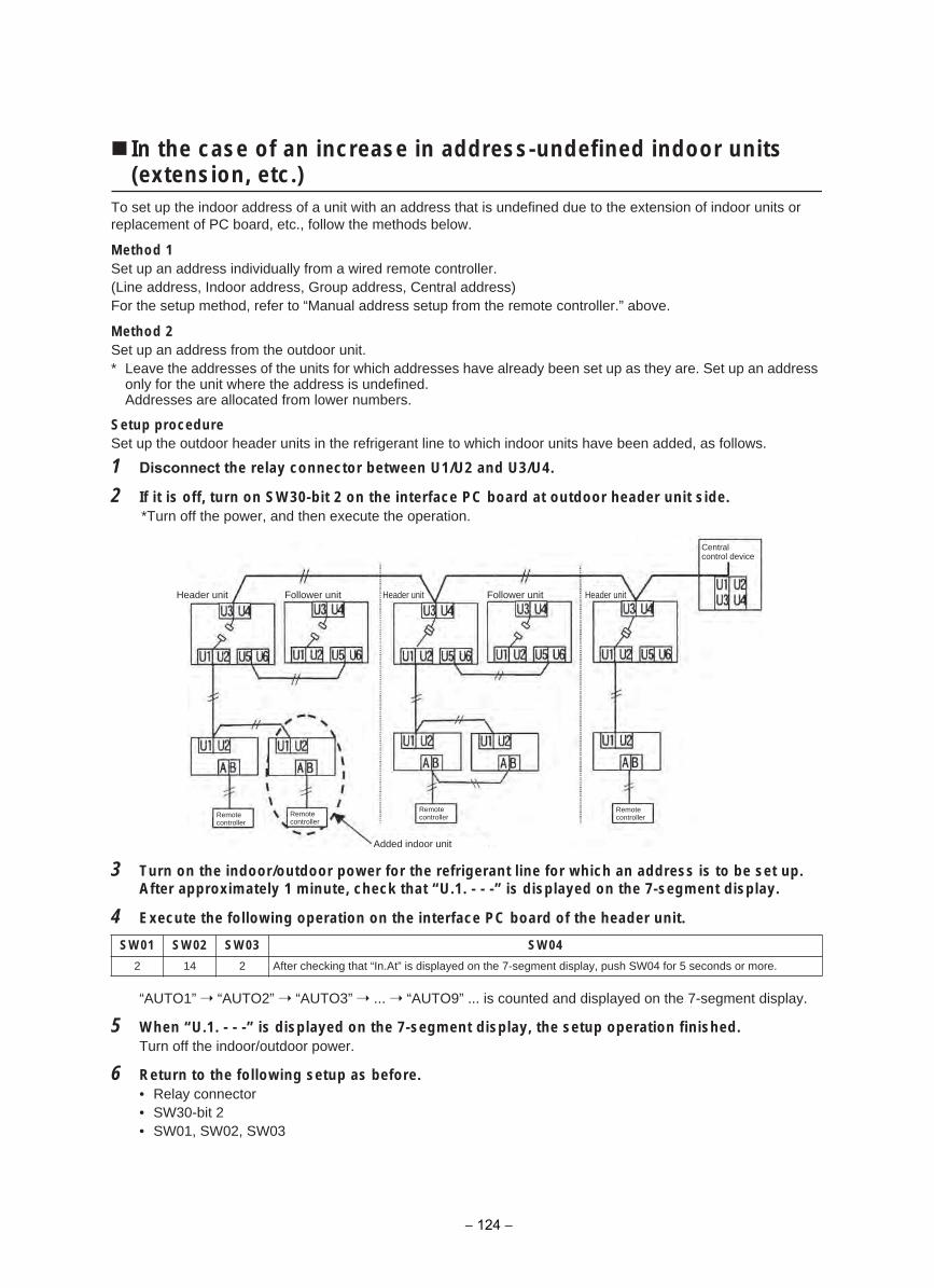
In the case of an increase in address-undefined indoor units (extension, etc.)
To set up the indoor address of a unit with an address that is undefined due to the extension of indoor units or replacement of PC board, etc., follow the methods below.
Method 1Set up an address individually from a wired remote controller.(Line address, Indoor address, Group address, Central address)For the setup method, refer to “Manual address setup from the remote controller.” above.
Method 2Set up an address from the outdoor unit.* Leave the addresses of the units for which addresses have already been set up as they are. Set up an address
only for the unit where the address is undefined.Addresses are allocated from lower numbers.
Setup procedureSet up the outdoor header units in the refrigerant line to which indoor units have been added, as follows.
1 Disconnect the relay connector between U1/U2 and U3/U4.
2 If it is off, turn on SW30-bit 2 on the interface PC board at outdoor header unit side.*Turn off the power, and then execute the operation.
3 Turn on the indoor/outdoor power for the refrigerant line for which an address is to be set up.After approximately 1 minute, check that “U.1. - - -” is displayed on the 7-segment display.
4 Execute the following operation on the interface PC board of the header unit.
“AUTO1” “AUTO2” “AUTO3” ... “AUTO9” ... is counted and displayed on the 7-segment display.
5 When “U.1. - - -” is displayed on the 7-segment display, the setup operation finished.Turn off the indoor/outdoor power.
6 Return to the following setup as before.• Relay connector• SW30-bit 2• SW01, SW02, SW03
40WS30WS20WS10WS
2 14 2 After checking that “In.At” is displayed on the 7-segment display, push SW04 for 5 seconds or more.
Header unit Follower unit tinu redaeHtinu redaeH Follower unit
Centralcontrol device
Remotecontroller
Remotecontroller
Remotecontroller
Remotecontroller
Added indoor unit
− 124 −
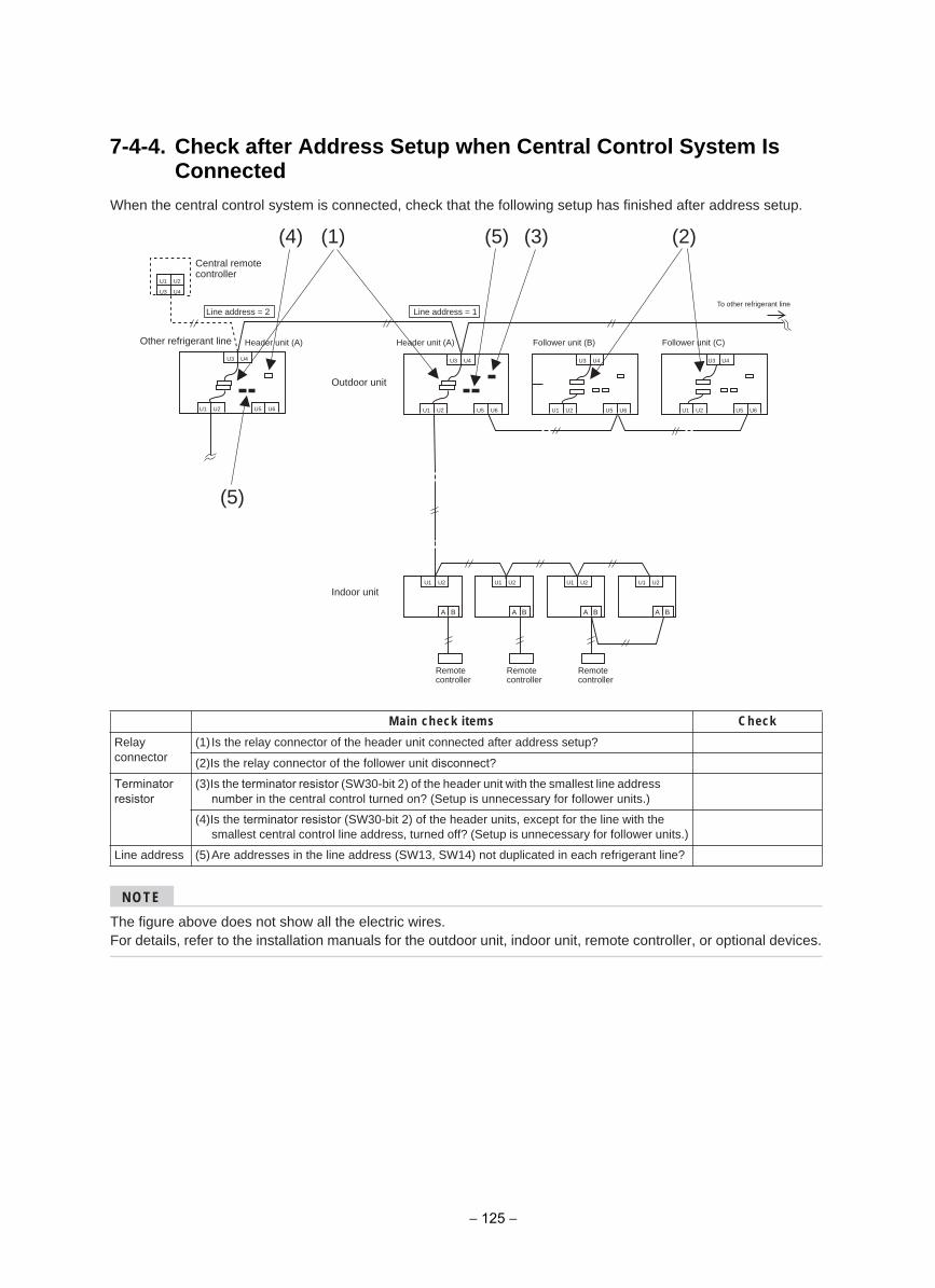
7-4-4. Check after Address Setup when Central Control System Is Connected
When the central control system is connected, check that the following setup has finished after address setup.
NOTE
The figure above does not show all the electric wires.For details, refer to the installation manuals for the outdoor unit, indoor unit, remote controller, or optional devices.
kcehCsmeti kcehc niaM
Relayconnector
(1) Is the relay connector of the header unit connected after address setup?
(2)Is the relay connector of the follower unit disconnect?
Terminator resistor
(3)Is the terminator resistor (SW30-bit 2) of the header unit with the smallest line address number in the central control turned on? (Setup is unnecessary for follower units.)
(4)Is the terminator resistor (SW30-bit 2) of the header units, except for the line with the smallest central control line address, turned off? (Setup is unnecessary for follower units.)
Line address (5)Are addresses in the line address (SW13, SW14) not duplicated in each refrigerant line?
U1 U2
U1 U2 U1 U2 U1 U2 U1 U2
U5 U6
U3 U4
)A( tinu redaeH)A( tinu redaeH
U1 U2 U5 U6
U3 U4
U1 U2 U5 U6
A B A B A B A B
(5)(4)
(5)
)2()1( (3)
Other refrigerant line
U1 U2
U3 U4
U3 U4
U1 U2 U5 U6
To other refrigerant line
U3 U4
Line address = 1Line address = 2
Central remote controller
Follower unit (B) Follower unit (C)
Outdoor unit
Indoor unit
Remotecontroller
Remotecontroller
Remotecontroller
− 125 −
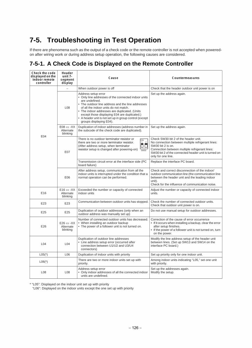
If there are phenomena such as the output of a check code or the remote controller is not accepted when powered-on after wiring work or during address setup operation, the following causes are considered.
* “L05”: Displayed on the indoor unit set up with priority“L06”: Displayed on the indoor units except the one set up with priority
Check the code displayed on the indoor remote
controller
Headerunit 7-
segment display
serusaemretnuoCesuaC
E04
no si rewop tinu roodtuo redaeh eht taht kcehCffo si rewop roodtuo nehW–
L08
Address setup error• Only line addresses of the connected indoor units
are undefined.• The outdoor line address and the line addresses
of all the indoor units do not match.• The indoor addresses are duplicated. (Units
except those displaying E04 are duplicated.)• A header unit is not set up in group control (except
groups displaying E04).
Set up the address again.
E08 -XXAlternate blinking
Duplication of indoor addresses (address number in the subcode of the check code are duplicated).
Set up the address again.
E07
There is no outdoor terminator resistor or there are two or more terminator resistor.(After address setup, when terminator resistor setup is changed after powering-on)
Check SW30 bit 2 of the header unit.No connection between multiple refrigerant lines: SW30 bit 2 is on.Connection between multiple refrigerant lines: SW30 bit 2 of the connected header unit is turned on only for one line.
Transmission circuit error at the interface side (PC board failure)
Replace the interface PC board.
E06
After address setup, communication from all the indoor units is interrupted under the condition that a normal operation can be performed.
Check and correct disconnection of the indoor/outdoor communication line (the communication line between the header unit and the leading indoor unit).Check for the influence of communication noise.
E16E16 -XXAlternate blinking
Exceeded the number or capacity of connected indoor units
Adjust the number or capacity of connected indoor units.
E23 E23 Communication between outdoor units has stopped. Check the number of connected outdoor units.Check that outdoor unit power is on.
E25 E25 Duplication of outdoor addresses (only when an outdoor address was manually set up)
Do not use manual setup for outdoor addresses.
E26E26 -XXAlternate blinking
Number of connected outdoor units has decreased.• When installing an outdoor backup• The power of a follower unit is not turned on.
Correction of the cause of error occurrence• If it occurs when installing a backup, clear the error
after setup finishes.• If the power of a follower unit is not turned on, turn
on the power.
L04 L04
Duplication of outdoor line addresses• Line address setup error (occurred after
connection between U1/U2 and U3/U4 connectors)
Modify the line address setup of the header unit between lines. (Set up SW13 and SW14 on the interface PC board.)
L05(*) L06 Duplication of indoor units with priority Set up priority only for one indoor unit.
L06(*) There are two or more indoor units set up with priority.
Among indoor units indicating “L05,” set one unit with priority.
L08 L08Address setup error• Only indoor addresses of all the connected indoor
units are undefined.
Set up the addresses again.Modify the setup.
ON1 2
SW30
7-5. Troubleshooting in Test Operation
7-5-1. A Check Code is Displayed on the Remote Controller
− 126 −
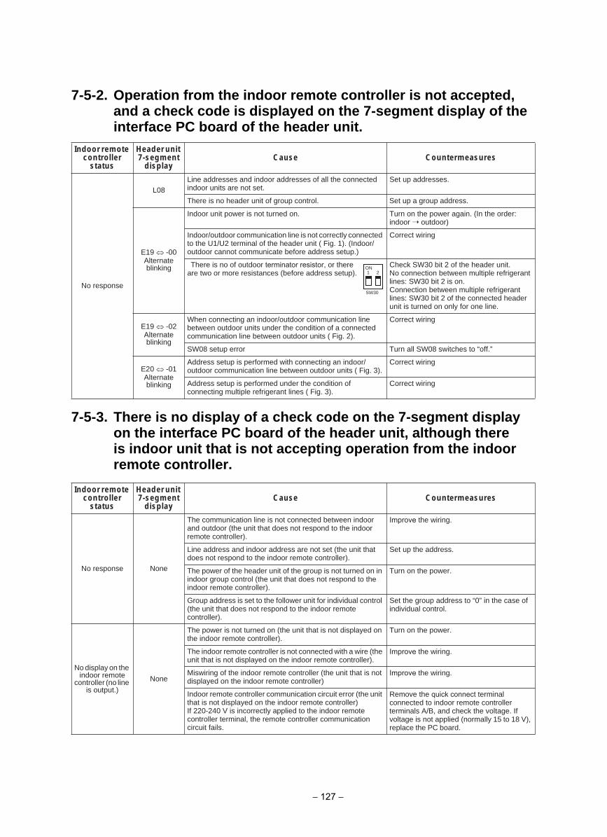
Indoor remote controller
status
Header unit 7-segment
displayserusaemretnuoCesuaC
No response
L08Line addresses and indoor addresses of all the connected indoor units are not set.
Set up addresses.
There is no header unit of group control. Set up a group address.
E19 -00Alternate blinking
:redro eht nI( .niaga rewop eht no nruT.no denrut ton si rewop tinu roodnIindoor outdoor)
Indoor/outdoor communication line is not correctly connected to the U1/U2 terminal of the header unit ( Fig. 1). (Indoor/outdoor cannot communicate before address setup.)
Correct wiring
There is no of outdoor terminator resistor, or there are two or more resistances (before address setup).
Check SW30 bit 2 of the header unit.No connection between multiple refrigerant lines: SW30 bit 2 is on.Connection between multiple refrigerant lines: SW30 bit 2 of the connected header unit is turned on only for one line.
E19 -02Alternate blinking
When connecting an indoor/outdoor communication line between outdoor units under the condition of a connected communication line between outdoor units ( Fig. 2).
Correct wiring
”.ffo“ ot sehctiws 80WS lla nruTrorre putes 80WS
E20 -01Alternate blinking
Address setup is performed with connecting an indoor/outdoor communication line between outdoor units ( Fig. 3).
Correct wiring
Address setup is performed under the condition of connecting multiple refrigerant lines ( Fig. 3).
Correct wiring
Indoor remote controller
status
Header unit 7-segment
displayserusaemretnuoCesuaC
No response None
The communication line is not connected between indoor and outdoor (the unit that does not respond to the indoor remote controller).
Improve the wiring.
Line address and indoor address are not set (the unit that does not respond to the indoor remote controller).
Set up the address.
The power of the header unit of the group is not turned on in indoor group control (the unit that does not respond to the indoor remote controller).
Turn on the power.
Group address is set to the follower unit for individual control (the unit that does not respond to the indoor remote controller).
Set the group address to “0” in the case of individual control.
No display on the indoor remote
controller (no line is output.)
None
The power is not turned on (the unit that is not displayed on the indoor remote controller).
Turn on the power.
The indoor remote controller is not connected with a wire (the unit that is not displayed on the indoor remote controller).
Improve the wiring.
Miswiring of the indoor remote controller (the unit that is not displayed on the indoor remote controller)
Improve the wiring.
Indoor remote controller communication circuit error (the unit that is not displayed on the indoor remote controller)If 220-240 V is incorrectly applied to the indoor remote controller terminal, the remote controller communication circuit fails.
Remove the quick connect terminal connected to indoor remote controller terminals A/B, and check the voltage. If voltage is not applied (normally 15 to 18 V), replace the PC board.
ON1 2
SW30
7-5-2. Operation from the indoor remote controller is not accepted, and a check code is displayed on the 7-segment display of the interface PC board of the header unit.
7-5-3. There is no display of a check code on the 7-segment display on the interface PC board of the header unit, although there is indoor unit that is not accepting operation from the indoor remote controller.
− 127 −
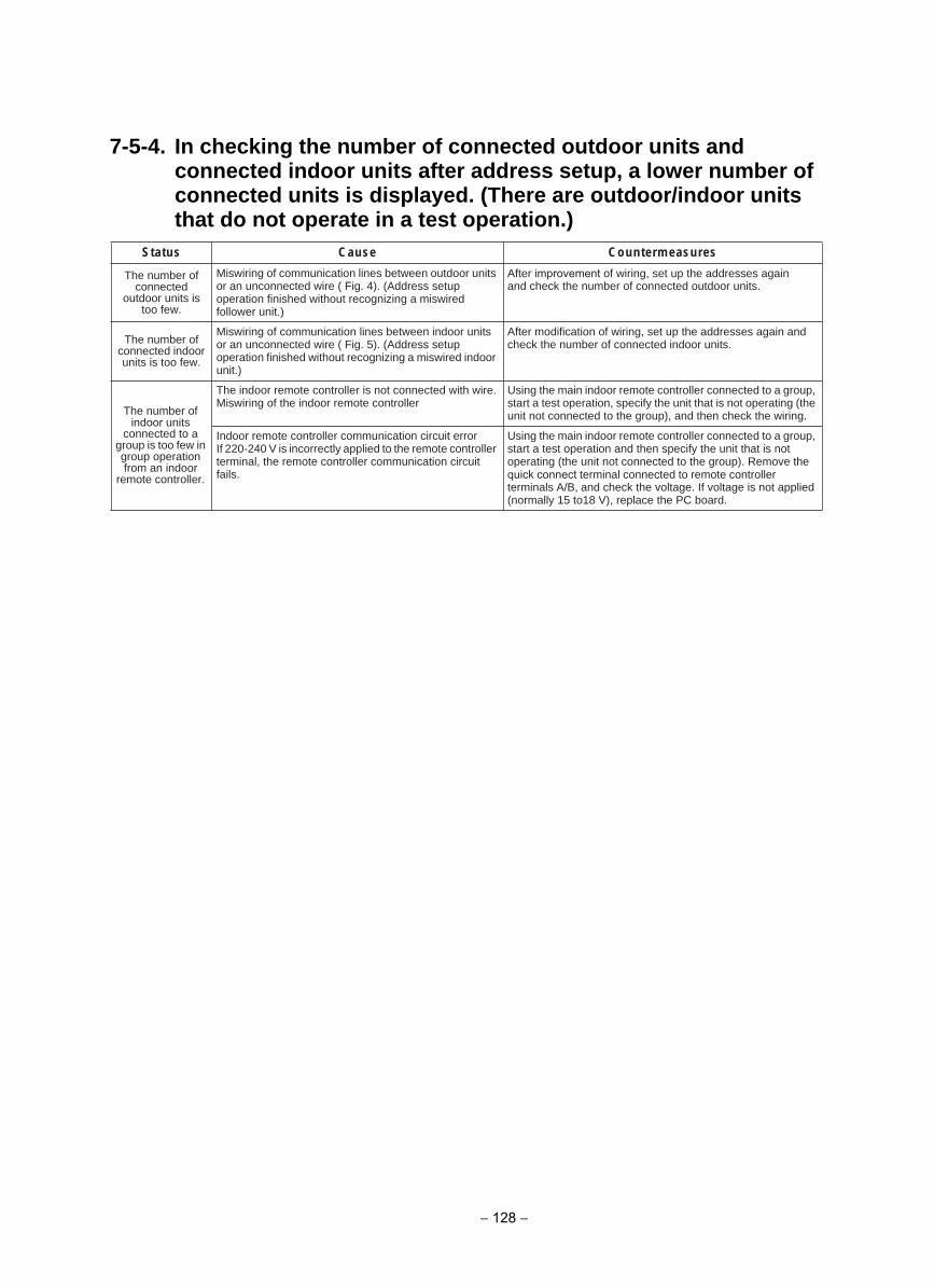
7-5-4. In checking the number of connected outdoor units and connected indoor units after address setup, a lower number of connected units is displayed. (There are outdoor/indoor units that do not operate in a test operation.)
serusaemretnuoCesuaCsutatS
The number of connected
outdoor units is too few.
Miswiring of communication lines between outdoor units or an unconnected wire ( Fig. 4). (Address setup operation finished without recognizing a miswired follower unit.)
After improvement of wiring, set up the addresses again and check the number of connected outdoor units.
The number of connected indoor units is too few.
Miswiring of communication lines between indoor units or an unconnected wire ( Fig. 5). (Address setup operation finished without recognizing a miswired indoor unit.)
After modification of wiring, set up the addresses again and check the number of connected indoor units.
The number of indoor units
connected to a group is too few in group operation from an indoor
remote controller.
The indoor remote controller is not connected with wire.Miswiring of the indoor remote controller
Using the main indoor remote controller connected to a group, start a test operation, specify the unit that is not operating (the unit not connected to the group), and then check the wiring.
Indoor remote controller communication circuit errorIf 220-240 V is incorrectly applied to the remote controller terminal, the remote controller communication circuit fails.
Using the main indoor remote controller connected to a group, start a test operation and then specify the unit that is not operating (the unit not connected to the group). Remove the quick connect terminal connected to remote controller terminals A/B, and check the voltage. If voltage is not applied (normally 15 to18 V), replace the PC board.
− 128 −
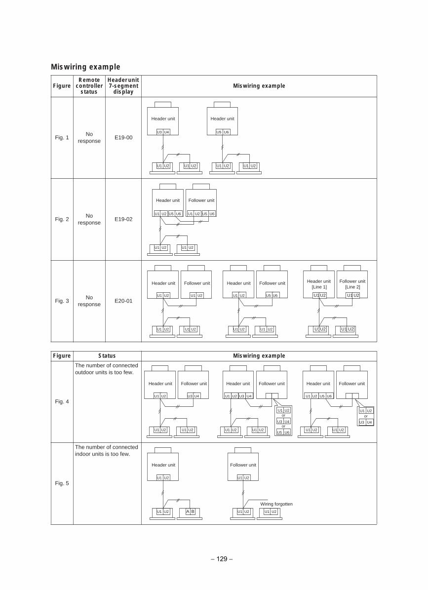
Miswiring example
FigureRemote
controller status
Header unit 7-segment
displayMiswiring example
Fig. 1No
responseE19-00
Fig. 2No
responseE19-02
Fig. 3No
responseE20-01
elpmaxe gniriwsiMsutatSerugiF
Fig. 4
The number of connected outdoor units is too few.
Fig. 5
The number of connected indoor units is too few.
U3 U4 U5 U6
U1 U2 U1 U2 U1 U2 U1 U2
Header unit Header unit
U1 U2
Header unit
U1 U2 U1 U2
U5 U6 U1 U2 U5 U6
Follower unit
U1 U2
U1 U2 U1 U2
U1 U2 U1 U2
U1 U2 U1 U2
U5 U6 U1 U2
U1U2 U1 U2
[Line 1]
U1 U2
Header unit Follower unit Header unit Follower unit Header unit Follower unit[Line 2]
U1 U2
U1 U2 U1 U2
U3 U4U1 U2
U1 U2 U1 U2
U3 U4 U1 U2
U1 U2 U1 U2
U5 U6
U5 U6
U3 U4
U1 U2or
orU3 U4
U1 U2
Header unit Follower unit Header unit Follower unit Header unit Follower unit
or
Wiring forgotten
U1 U2
U1 U2 A B
U1 U2
U1 U2 U1 U2
tinu rewolloFtinu redaeH
− 129 −
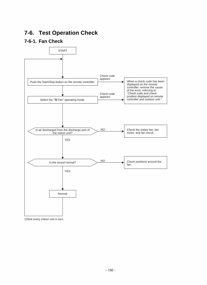
7-6. Test Operation Check7-6-1. Fan Check
START
NO
NO
YES
YES
Push the Start/Stop button on the remote controller.
Select the " Fan" operating mode.
Normal
Check every indoor unit in turn.
Is air discharged from the discharge port of the indoor unit?
Is the sound normal?
When a check code has been displayed on the remote controller, remove the cause of the error, referring to "Check code and check position displayed on remote controller and outdoor unit."
Check the indoor fan, fan motor, and fan circuit.
Check positions around the fan.
Check code appears
Check code appears
− 130 −
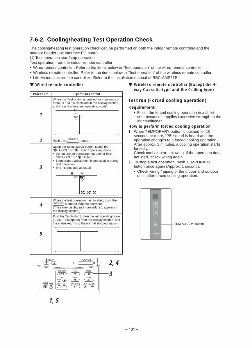
7-6-2. Cooling/heating Test Operation CheckThe cooling/heating test operation check can be performed on both the indoor remote controller and the outdoor header unit interface PC board.(1) Test operation start/stop operationTest operation from the indoor remote controller• Wired remote controller: Refer to the items below in “Test operation” of the wired remote controller.• Wireless remote controller: Refer to the items below in “Test operation” of the wireless remote controller.• Lite-Vision plus remote controller : Refer to the installation manual of RBC-AMS51E
Wired remote controller Wireless remote controller (Except the 4-way Cassette type and the Ceiling type)
Test run (Forced cooling operation)Requirement:
• Finish the forced cooling operation in a shorttime because it applies excessive strength to theair conditioner.
How to perform forced cooling operation1. When TEMPORARY button is pushed for 10
seconds or more, “Pi!” sound is heard and theoperation changes to a forced cooling operation.After approx. 3 minutes, a cooling operation startsforcedly.Check cool air starts blowing. If the operation doesnot start, check wiring again.
2. To stop a test operation, push TEMPORARYbutton once again (Approx. 1 second).• Check wiring / piping of the indoor and outdoor
units after forced cooling operation.
1, 5
3
2, 4
Operation contentProcedure
1
2
When the Test button is pushed for 4 seconds ormore, “TEST” is displayed in the display section,and the unit enters test operating mode.
5
Push the Test button to clear the test operating mode.(“TEST” disappears from the display section, andthe status returns to the normal stopped status.)
3
Using the Select Mode button, select the“ COOL” or “ HEAT” operating mode.• Do not use an operating mode other than “ COOL” or “ HEAT”.• Temperature adjustment is unavailable during test operation.• Error is detected as usual.
Push the button.
4When the test operation has finished, push the
button to stop the operation.(The same display as in procedure 1 appears inthe display section.)
TEMPORARY-Button
− 131 −
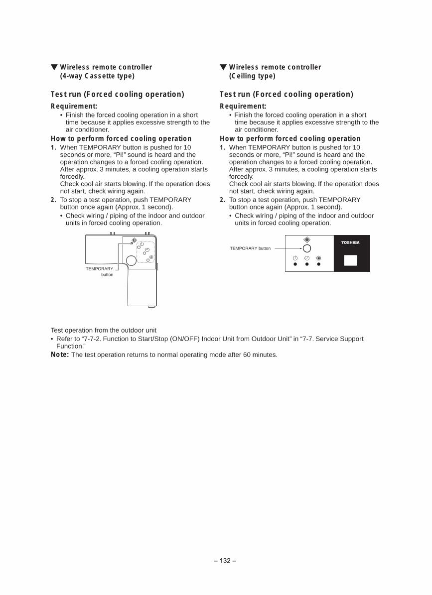
Wireless remote controller(4-way Cassette type)
Test run (Forced cooling operation)Requirement:
• Finish the forced cooling operation in a shorttime because it applies excessive strength to theair conditioner.
How to perform forced cooling operation1. When TEMPORARY button is pushed for 10
seconds or more, “Pi!” sound is heard and theoperation changes to a forced cooling operation.After approx. 3 minutes, a cooling operation startsforcedly.Check cool air starts blowing. If the operation doesnot start, check wiring again.
2. To stop a test operation, push TEMPORARYbutton once again (Approx. 1 second).• Check wiring / piping of the indoor and outdoor
units in forced cooling operation.
Wireless remote controller(Ceiling type)
Test run (Forced cooling operation)Requirement:
• Finish the forced cooling operation in a shorttime because it applies excessive strength to theair conditioner.
How to perform forced cooling operation1. When TEMPORARY button is pushed for 10
seconds or more, “Pi!” sound is heard and theoperation changes to a forced cooling operation.After approx. 3 minutes, a cooling operation startsforcedly.Check cool air starts blowing. If the operation doesnot start, check wiring again.
2. To stop a test operation, push TEMPORARYbutton once again (Approx. 1 second).• Check wiring / piping of the indoor and outdoor
units in forced cooling operation.
Test operation from the outdoor unit• Refer to “7-7-2. Function to Start/Stop (ON/OFF) Indoor Unit from Outdoor Unit” in “7-7. Service Support
Function.”Note: The test operation returns to normal operating mode after 60 minutes.
TEMPORARYbutton
TEMPORARY button
− 132 −
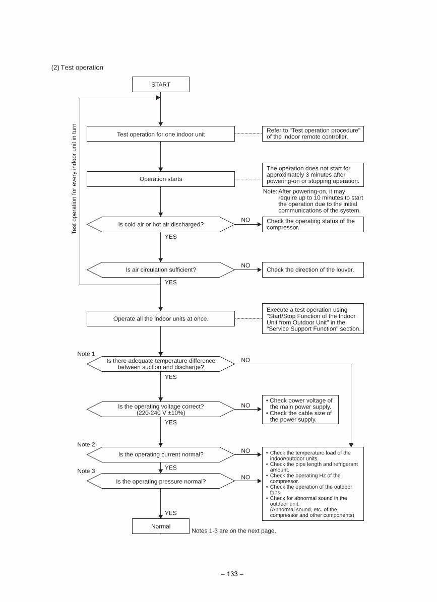
(2) Test operation
Note 1
Note 2
Note 3
START
NormalNotes 1-3 are on the next page.
NO
YES
NO
YES
NO
YES
NO
YES
NO
YES
NO
YES
Test operation for one indoor unit
Operation starts
Is cold air or hot air discharged?
Is air circulation sufficient?
Operate all the indoor units at once.
Is there adequate temperature difference between suction and discharge?
Is the operating voltage correct? (220-240 V ±10%)
Is the operating current normal?
Is the operating pressure normal?
Refer to "Test operation procedure" of the indoor remote controller.
Check the operating status of the compressor.
Execute a test operation using "Start/Stop Function of the Indoor Unit from Outdoor Unit" in the "Service Support Function" section.
• Check power voltage ofthe main power supply.
• Check the cable size ofthe power supply.
• Check the temperature load of theindoor/outdoor units.
• Check the pipe length and refrigerantamount.
• Check the operating Hz of thecompressor.
• Check the operation of the outdoorfans.
• Check for abnormal sound in theoutdoor unit.(Abnormal sound, etc. of thecompressor and other components)
Check the direction of the louver.
The operation does not start for approximately 3 minutes after powering-on or stopping operation.
Note: After powering-on, it may require up to 10 minutes to start the operation due to the initial communications of the system.
Test
ope
ratio
n fo
r ev
ery
indo
or u
nit i
n tu
rn
− 133 −
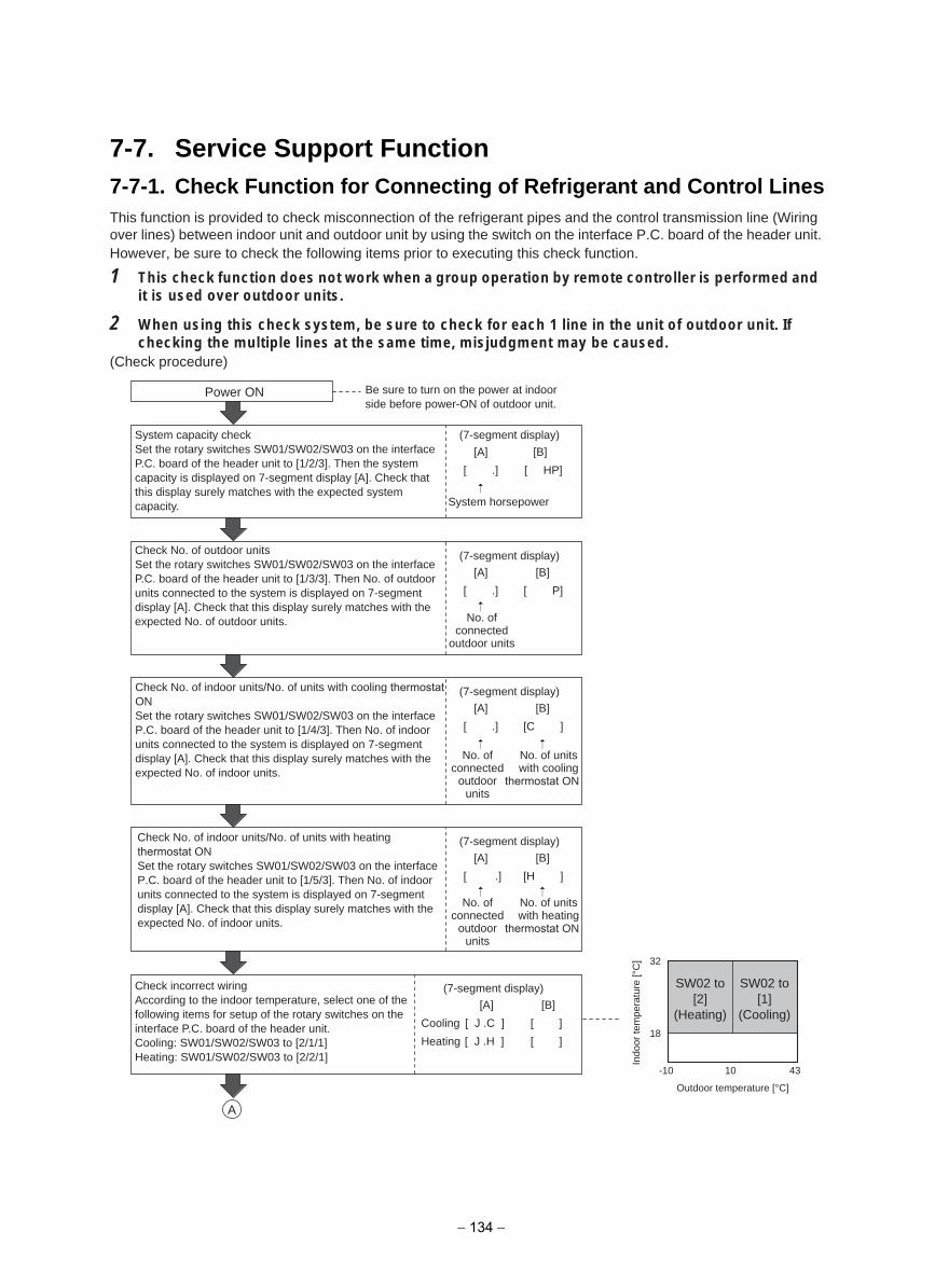
7-7. Service Support Function7-7-1. Check Function for Connecting of Refrigerant and Control LinesThis function is provided to check misconnection of the refrigerant pipes and the control transmission line (Wiring over lines) between indoor unit and outdoor unit by using the switch on the interface P.C. board of the header unit.However, be sure to check the following items prior to executing this check function.
1 This check function does not work when a group operation by remote controller is performed andit is used over outdoor units.
2 When using this check system, be sure to check for each 1 line in the unit of outdoor unit. Ifchecking the multiple lines at the same time, misjudgment may be caused.
(Check procedure)
Power ON
Outdoor temperature [°C]
-10
18
32
10 43
(7-segment display)
[A]
[ .]
System horsepower
[B]
[ HP]
(7-segment display)
[A]
[ .]
[B]
[ P]
(7-segment display)
[A]
[ .]
[B]
[C ]
(7-segment display)
[A]
[ .]
[B]
[H ]
(7-segment display)
[A]
[ J .C ]
[ J .H ]
Cooling
Heating
[B]
[ ]
[ ]
A
Be sure to turn on the power at indoor side before power-ON of outdoor unit.
System capacity checkSet the rotary switches SW01/SW02/SW03 on the interface P.C. board of the header unit to [1/2/3]. Then the system capacity is displayed on 7-segment display [A]. Check that this display surely matches with the expected system capacity.
Check No. of outdoor unitsSet the rotary switches SW01/SW02/SW03 on the interface P.C. board of the header unit to [1/3/3]. Then No. of outdoor units connected to the system is displayed on 7-segment display [A]. Check that this display surely matches with the expected No. of outdoor units.
Check No. of indoor units/No. of units with cooling thermostat ONSet the rotary switches SW01/SW02/SW03 on the interface P.C. board of the header unit to [1/4/3]. Then No. of indoor units connected to the system is displayed on 7-segment display [A]. Check that this display surely matches with the expected No. of indoor units.
Check No. of indoor units/No. of units with heating thermostat ONSet the rotary switches SW01/SW02/SW03 on the interface P.C. board of the header unit to [1/5/3]. Then No. of indoor units connected to the system is displayed on 7-segment display [A]. Check that this display surely matches with the expected No. of indoor units.
Check incorrect wiringAccording to the indoor temperature, select one of the following items for setup of the rotary switches on the interface P.C. board of the header unit.Cooling: SW01/SW02/SW03 to [2/1/1]Heating: SW01/SW02/SW03 to [2/2/1]
No. of connected
outdoor units
No. of connected
outdoorunits
No. of units with cooling
thermostat ON
No. of connected
outdoorunits
No. of units with heating
thermostat ON
Indo
or te
mpe
ratu
re [°
C]
SW02 to [2]
(Heating)
SW02 to [1]
(Cooling)
− 134 −
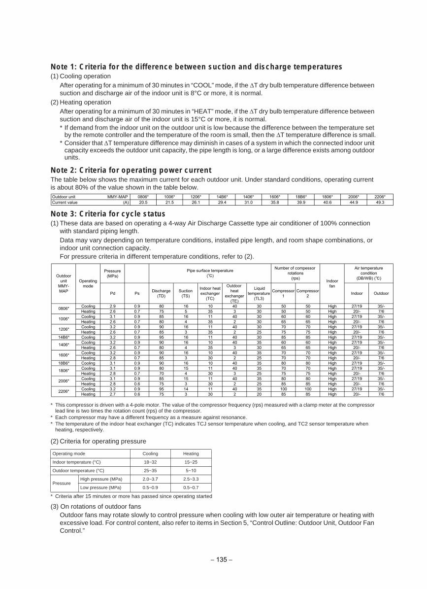
Note 1: Criteria for the difference between suction and discharge temperatures(1) Cooling operation
After operating for a minimum of 30 minutes in “COOL” mode, if the T dry bulb temperature difference between suction and discharge air of the indoor unit is 8°C or more, it is normal.
(2) Heating operationAfter operating for a minimum of 30 minutes in “HEAT” mode, if the T dry bulb temperature difference between suction and discharge air of the indoor unit is 15°C or more, it is normal.* If demand from the indoor unit on the outdoor unit is low because the difference between the temperature set
by the remote controller and the temperature of the room is small, then the T temperature difference is small.* Consider that T temperature difference may diminish in cases of a system in which the connected indoor unit
capacity exceeds the outdoor unit capacity, the pipe length is long, or a large difference exists among outdoor units.
Note 2: Criteria for operating power currentThe table below shows the maximum current for each outdoor unit. Under standard conditions, operating current is about 80% of the value shown in the table below.
Note 3: Criteria for cycle status(1) These data are based on operating a 4-way Air Discharge Cassette type air conditioner of 100% connection
with standard piping length.Data may vary depending on temperature conditions, installed pipe length, and room shape combinations, or indoor unit connection capacity.For pressure criteria in different temperature conditions, refer to (2).
* This compressor is driven with a 4-pole motor. The value of the compressor frequency (rps) measured with a clamp meter at the compressorlead line is two times the rotation count (rps) of the compressor.
* Each compressor may have a different frequency as a measure against resonance.* The temperature of the indoor heat exchanger (TC) indicates TCJ sensor temperature when cooling, and TC2 sensor temperature when
heating, respectively.
(2) Criteria for operating pressure
* Criteria after 15 minutes or more has passed since operating started
(3) On rotations of outdoor fansOutdoor fans may rotate slowly to control pressure when cooling with low outer air temperature or heating with excessive load. For control content, also refer to items in Section 5, “Control Outline: Outdoor Unit, Outdoor Fan Control.”
gnitaeHgnilooCedom gnitarepO
Indoor temperature (°C) 18~32 15~25
Outdoor temperature (°C) 25~35 5~10
PressureHigh pressure (MPa) 2.0~3.7 2.5~3.3
Low pressure (MPa) 0.5~0.9 0.5~0.7
− 135 −
Outdoor unit MMY-MAP 0806* 1006* 1206* 14B6* 1406* 1606* 18B6* 1806* 2006* 2206*Current value (A) 20.5 21.5 26.1 29.4 31.0 35.8 39.9 40.6 44.9 49.3
Pressure(MPa)
Pd Ps Discharge(TD)
Suction(TS)
Indoor heatexchanger
(TC)
Outdoor heat
exchanger(TE)
Liquidtemperature
(TL3)
Compressor1
Compressor2 Indoor Outdoor
Cooling 2.9 0.9 80 16 10 40 30 50 50 High 27/19 35/-Heating 2.6 0.7 75 5 35 3 30 50 50 High 20/- 7/6Cooling 3.1 0.9 85 16 11 40 30 60 60 High 27/19 35/-Heating 2.6 0.7 80 4 35 2 30 65 65 High 20/- 7/6Cooling 3.2 0.9 90 16 11 40 30 70 70 High 27/19 35/-Heating 2.6 0.7 85 3 35 2 25 75 75 High 20/- 7/6
14B6* Cooling 3.2 0.9 95 16 11 40 30 85 85 High 27/19 35/-Cooling 3.2 0.9 90 16 10 40 35 60 60 High 27/19 35/-Heating 2.6 0.7 80 4 35 3 30 65 65 High 20/- 7/6Cooling 3.2 0.9 90 16 10 40 35 70 70 High 27/19 35/-Heating 2.8 0.7 85 3 30 2 25 70 70 High 20/- 7/6
18B6* Cooling 3.1 0.9 90 16 10 40 35 80 80 High 27/19 35/-Cooling 3.1 0.9 80 15 11 40 35 70 70 High 27/19 35/-Heating 2.8 0.7 70 4 30 3 25 75 75 High 20/- 7/6Cooling 3.1 0.9 85 15 11 40 35 80 80 High 27/19 35/-Heating 2.8 0.6 75 3 30 2 25 85 85 High 20/- 7/6Cooling 3.2 0.9 95 14 11 40 35 100 100 High 27/19 35/-Heating 2.7 0.6 75 3 30 2 20 85 85 High 20/- 7/6
Outdoorunit
MMY-MAP
Operatingmode
Pipe surface temperature()
Number of compessor rotations
(rps) Indoorfan
Air temperaturecondition
(DB/WB) ()
2006*
2206*
0806*
1006*
1206*
1406*
1606*
1806*
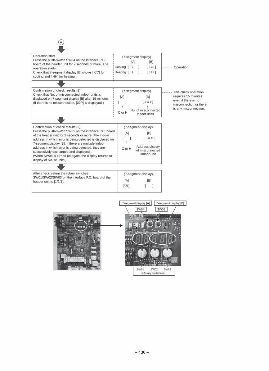
Operation
(7-segment display)
[A]
[ C ]
[ H ]
Cooling
Heating
[B]
[ CC ]
[ HH ]
(7-segment display)
[A]
[ ]
C or H
[B]
[ # # P]
(7-segment display)
[A]
[ ]
C or H
[B]
[ # # ]
(7-segment display)
[A]
[U1]
[B]
[ ]
A
Operation startPress the push-switch SW04 on the interface P.C. board of the header unit for 2 seconds or more. The operation starts.Check that 7-segment display [B] shows [ CC] for cooling and [ HH] for heating.
Confirmation of check results (1)Check that No. of misconnected indoor units is displayed on 7-segment display [B] after 15 minutes.(If there is no misconnection, [00P] is displayed.)
Confirmation of check results (2)Press the push-switch SW05 on the interface P.C. board of the header unit for 2 seconds or more. The indoor address in which error is being detected is displayed on 7-segment display [B]. If there are multiple indoor address in which error is being detected, they are successively exchanged and displayed.(When SW05 is turned on again, the display returns to display of No. of units.)
After check, return the rotary switches SW01/SW02/SW03 on the interface P.C. board of the header unit to [1/1/1].
No. of misconnected indoor units
This check operation requires 15 minutes even if there is no misconnection or there is any misconnection.
Address display of misconnected
indoor unit
7-segment display [A] 7-segment display [B]
SW04 SW05
<Rotary switches>SW02 SW03SW01
− 136 −
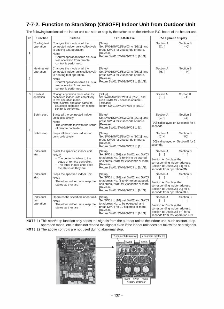
7-7-2. Function to Start/Stop (ON/OFF) Indoor Unit from Outdoor UnitThe following functions of the indoor unit can start or stop by the switches on the interface P.C. board of the header unit.
NOTE 1) This start/stop function only sends the signals from the outdoor unit to the indoor unit, such as start, stop, operation mode, etc. It does not resend the signals even if the indoor unit does not follow the sent signals.
NOTE 2) The above controls are not used during abnormal stop.
uteSeniltuOnoitcnuFoN p/Release 7-segment display
1
Cooling test operation
Changes the mode of all the connected indoor units collectively to cooling test operation.Note)
Control operation same as usual test operation from remote control is performed.
[Setup]Set SW01/SW02/SW03 to [2/5/1], and press SW04 for 2 seconds or more.[Release]Return SW01/SW02/SW03 to [1/1/1].
Section A[C. ]
Section B[ – C]
2
Heating test operation
Changes the mode of all the connected indoor units collectively to heating test operation.Note)
Control operation same as usual test operation from remote control is performed.
[Setup]Set SW01/SW02/SW03 to [2/6/1], and press SW04 for 2 seconds or more.[Release]Return SW01/SW02/SW03 to [1/1/1].
Section A[H. ]
Section B[ – H]
4
Batch start Starts all the connected indoor units collectively.Note)
The contents follow to the setup of remote controller.
[Setup]Set SW01/SW02/SW03 to [2/7/1], and press SW04 for 2 seconds or more.[Release]Return SW01/SW02/SW03 to [1].
Section A[C.H]
Section B[ 11]
[ 00] is displayed on Section B for 5 seconds.
Batch stop Stops all the connected indoor units collectively.
[Setup]Set SW01/SW02/SW03 to [2/7/1], and press SW05 for 2 seconds or more.[Release]Return SW01/SW02/SW03 to [1].
Section A[C.H]
Section B[ 00]
[ 00] is displayed on Section B for 5 seconds.
5
Individual start
Starts the specified indoor unit.Notes)
• The contents follow to thesetup of remote controller.
• The other indoor units keepthe status as they are.
[Setup]Set SW01 to [16], set SW02 and SW03 to address No. (1 to 64) to be started, and press SW04 for 2 seconds or more.[Release]Return SW01/SW02/SW03 to [1/1/1].
Section A[ ]
Section B[ ]
Section A: Displays the corresponding indoor address.Section B: Displays [ 11] for 5 seconds from operation-ON.
Individual stop
Stops the specified indoor unit.Note)
The other indoor units keep the status as they are.
[Setup]Set SW01 to [16], set SW02 and SW03 to address No. (1 to 64) to be stopped, and press SW05 for 2 seconds or more.[Release]Return SW01/SW02/SW03 to [1/1/1].
Section A[ ]
Section B[ ]
Section A: Displays the corresponding indoor address.Section B: Displays [ 00] for 5 seconds from operation-OFF.
Individual testoperation
Operates the specified indoor unit.Note)
The other indoor units keep the status as they are.
[Setup]Set SW01 to [16], set SW02 and SW03 to address No. to be operated, and press SW04 for 10 seconds or more.[Release]Return SW01/SW02/SW03 to [1/1/1].
Section A[ ]
Section B[ ]
Section A: Displays the corresponding indoor address.Section B: Displays [ FF] for 5 seconds from test operation-ON.
SW02 SW03SW01
SW04 SW05
7-segment display [A] 7-segment display [B]
<Rotary switches>
3 Fan testoperation
Changes operation mode of all theconnected indoor units collectivelyto test operation mode.Note) Control operation same as usual test operation from remote control is performed.
[Setup]Set SW01/SW02/SW03 to [2/9/1], andpush SW04 for 2 seconds or more.[Release]Return SW01/SW02/SW03 to [1/1/1].
Section A[F. ]
Section B[ – F]
− 137 −

(1) Cooling test operation functionThis function is provided to change collectively the mode of all the indoor units connected to the same system for the cooling test operation mode, by using switches on the interface board of the header unit.<Operation procedure>
NOTE) The test operation returns to the normal operation after 60 minutes.
Power ON
Start
Operation check
[A]
[C. ]
[B]
[ – C]
Stop/End
Be sure to turn on power at the indoor side before power-ON of outdoor unit.
Set SW01/SW02/SW03 on the interface P.C. board of the header unit to [2/5/1]. ([C. ] is displayed on 7-segment display [A].)
[Test run] is displayed on the remote controller of the indoor unit to be operated.Check that [ – C] is displayed on 7-segment display [B] on the interface P.C. board of the header unit.
Press SW04 on the same board for 2 seconds or more.
Return SW01/SW02/SW03 on the interface P.C. board of the header unit to [1/1/1], or press the push-switch SW05 for 2 seconds or more.
7-segment display [A] 7-segment display [B]
SW04 SW05
<Rotary switches>SW02 SW03SW01
− 138 −
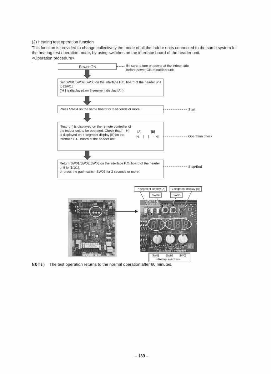
(2) Heating test operation functionThis function is provided to change collectively the mode of all the indoor units connected to the same system for the heating test operation mode, by using switches on the interface board of the header unit.<Operation procedure>0
NOTE) The test operation returns to the normal operation after 60 minutes.
[A]
[H. ]
[B]
[ – H]
Power ON
Start
Operation check
Stop/End
Press SW04 on the same board for 2 seconds or more.
[Test run] is displayed on the remote controller of the indoor unit to be operated. Check that [ – H] is displayed on 7-segment display [B] on the interface P.C. board of the header unit.
Set SW01/SW02/SW03 on the interface P.C. board of the header unit to [2/6/1].([H ] is displayed on 7-segment display [A].)
Be sure to turn on power at the indoor side before power-ON of outdoor unit.
Return SW01/SW02/SW03 on the interface P.C. board of the header unit to [1/1/1], or press the push-switch SW05 for 2 seconds or more.
7-segment display [A] 7-segment display [B]
SW04 SW05
<Rotary switches>SW02 SW03SW01
− 139 −
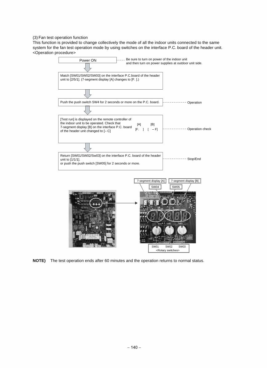
(3) Fan test operation functionThis function is provided to change collectively the mode of all the indoor units connected to the same system for the fan test operation mode by using switches on the interface P.C. board of the header unit.<Operation procedure>
NOTE) The test operation ends after 60 minutes and the operation returns to normal status.
[A]
[F. ]
[B]
[ – F]
Power ON
Operation
Operation check
Stop/End
Push the push switch SW4 for 2 seconds or more on the P.C. board.
[Test run] is displayed on the remote controller of the indoor unit to be operated. Check that7-segment display [B] on the interface P.C. board of the header unit changed to [– C]
Match [SW01/SW02/SW03] on the interface P.C.board of the header unit to [2/5/1]. (7-segment display [A] changes to [F. ].)
Be sure to turn on power of the indoor unitand then turn on power supplies at outdoor unit side.
Return [SW01/SW02/Sw03] on the interface P.C. board of the header unit to [1/1/1].or push the push switch [SW05] for 2 seconds or more.
7-segment display [A] 7-segment display [B]
SW04 SW05
<Rotary switches>SW01 SW02 SW03
− 140 −
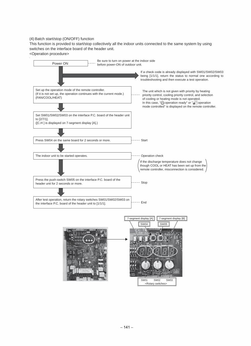
(4) Batch start/stop (ON/OFF) functionThis function is provided to start/stop collectively all the indoor units connected to the same system by using switches on the interface board of the header unit.<Operation procedure>0
Power ON
Start
Stop
End
Operation check
Be sure to turn on power at the indoor side before power-ON of outdoor unit.
If a check code is already displayed with SW01/SW02/SW03 being [1/1/1], return the status to normal one according to troubleshooting and then execute a test operation.
The unit which is not given with priority by heating priority control, cooling priority control, and selection of cooling or heating mode is not operated.In this case, " operation ready" or " operation mode controlled" is displayed on the remote controller.
If the discharge temperature does not change though COOL or HEAT has been set up from the remote controller, misconnection is considered.
Press SW04 on the same board for 2 seconds or more.
The indoor unit to be started operates.
Press the push-switch SW05 on the interface P.C. board of the header unit for 2 seconds or more.
After test operation, return the rotary switches SW01/SW02/SW03 on the interface P.C. board of the header unit to [1/1/1].
Set up the operation mode of the remote controller.(If it is not set up, the operation continues with the current mode.)(FAN/COOL/HEAT)
Set SW01/SW02/SW03 on the interface P.C. board of the header unit to [2/7/1].([C.H ] is displayed on 7-segment display [A].)
7-segment display [A] 7-segment display [B]
SW04 SW05
<Rotary switches>SW02 SW03SW01
− 141 −
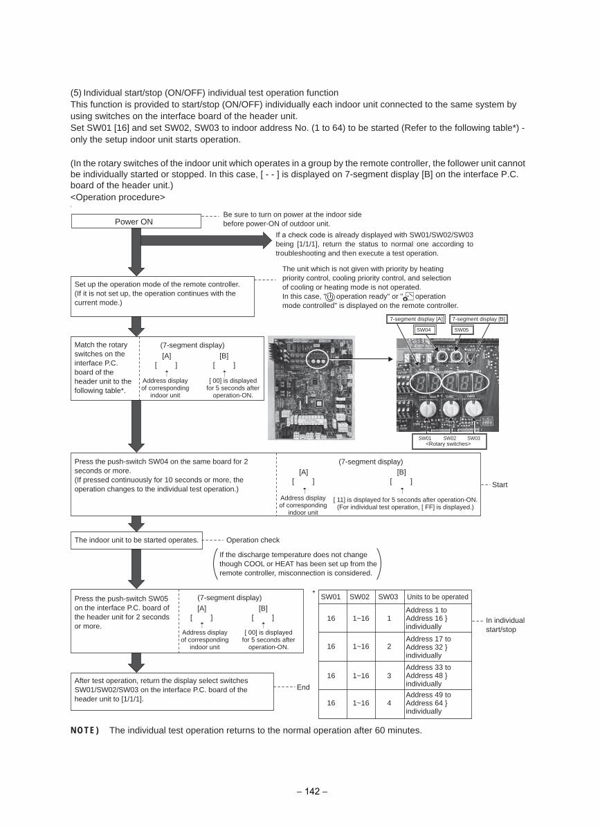
(5) Individual start/stop (ON/OFF) individual test operation functionThis function is provided to start/stop (ON/OFF) individually each indoor unit connected to the same system by using switches on the interface board of the header unit.Set SW01 [16] and set SW02, SW03 to indoor address No. (1 to 64) to be started (Refer to the following table*) - only the setup indoor unit starts operation.
(In the rotary switches of the indoor unit which operates in a group by the remote controller, the follower unit cannot be individually started or stopped. In this case, [ - - ] is displayed on 7-segment display [B] on the interface P.C. board of the header unit.)<Operation procedure>0
NOTE) The individual test operation returns to the normal operation after 60 minutes.
* SW01 SW02 SW03 Units to be operated
16 1
16 2
16 3
16 4
Address 1 to Address 16 individually
Address 17 to Address 32 individually
Address 33 to Address 48 individually
Address 49 to Address 64 individually
In individual start/stop
1~16
1~16
1~16
1~16
Power ON
Start
End
(7-segment display)
[A][ ]
[B][ ]
(7-segment display)
[A][ ]
[B][ ]
(7-segment display)[A]
[ ][B]
[ ]
Be sure to turn on power at the indoor side before power-ON of outdoor unit.
Set up the operation mode of the remote controller.(If it is not set up, the operation continues with the current mode.)
Press the push-switch SW04 on the same board for 2 seconds or more.(If pressed continuously for 10 seconds or more, the operation changes to the individual test operation.)
Match the rotary switches on the interface P.C. board of the header unit to the following table*.
If a check code is already displayed with SW01/SW02/SW03 being [1/1/1], return the status to normal one according to troubleshooting and then execute a test operation.
The unit which is not given with priority by heating priority control, cooling priority control, and selection of cooling or heating mode is not operated.In this case, " operation ready" or " operation mode controlled" is displayed on the remote controller.
Address display of corresponding
indoor unit
Address display of corresponding
indoor unit
[ 11] is displayed for 5 seconds after operation-ON.(For individual test operation, [ FF] is displayed.)
[ 00] is displayed for 5 seconds after
operation-ON.
Address display of corresponding
indoor unit
[ 00] is displayed for 5 seconds after
operation-ON.
Operation check
If the discharge temperature does not change though COOL or HEAT has been set up from the remote controller, misconnection is considered.
The indoor unit to be started operates.
Press the push-switch SW05 on the interface P.C. board of the header unit for 2 seconds or more.
After test operation, return the display select switches SW01/SW02/SW03 on the interface P.C. board of the header unit to [1/1/1].
SW04 SW05
SW02 SW03SW01
7-segment display [A] 7-segment display [B]
<Rotary switches>
− 142 −
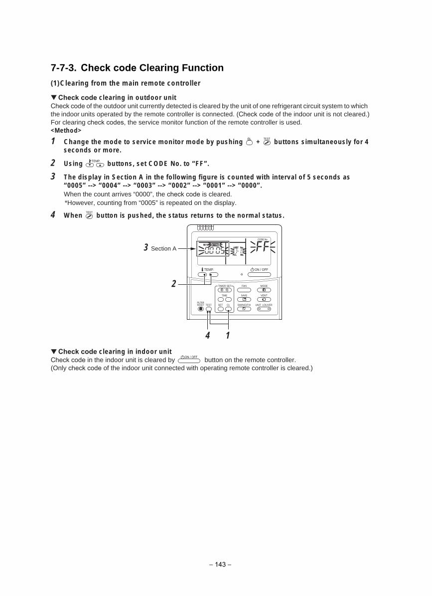
7-7-3. Check code Clearing Function(1)Clearing from the main remote controller
Check code clearing in outdoor unitCheck code of the outdoor unit currently detected is cleared by the unit of one refrigerant circuit system to which the indoor units operated by the remote controller is connected. (Check code of the indoor unit is not cleared.)For clearing check codes, the service monitor function of the remote controller is used.<Method>
1 Change the mode to service monitor mode by pushing + buttons simultaneously for 4 seconds or more.
2 Using buttons, set CODE No. to “FF”.
3 The display in Section A in the following figure is counted with interval of 5 seconds as“0005” --> “0004” --> “0003” --> “0002” --> “0001” --> “0000”. When the count arrives “0000”, the check code is cleared. *However, counting from “0005” is repeated on the display.
4 When button is pushed, the status returns to the normal status.
Check code clearing in indoor unitCheck code in the indoor unit is cleared by button on the remote controller.(Only check code of the indoor unit connected with operating remote controller is cleared.)
SET
TIME
TIMER SET
TESTFILTERRESET
TEMP.
CL
FAN
SAVE
SWING/FIX
VENT
MODE
ON / OFF
UNIT LOUVER
14
2
3 Section A
− 143 −
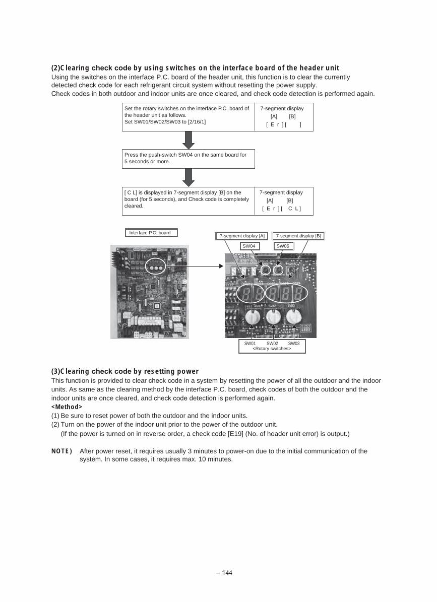
(2)Clearing check code by using switches on the interface board of the header unitUsing the switches on the interface P.C. board of the header unit, this function is to clear the currently detected check code for each refrigerant circuit system without resetting the power supply.Check codes in both outdoor and indoor units are once cleared, and check code detection is performed again.
(3)Clearing check code by resetting powerThis function is provided to clear check code in a system by resetting the power of all the outdoor and the indoor units. As same as the clearing method by the interface P.C. board, check codes of both the outdoor and the indoor units are once cleared, and check code detection is performed again.<Method>(1) Be sure to reset power of both the outdoor and the indoor units.(2) Turn on the power of the indoor unit prior to the power of the outdoor unit.
(If the power is turned on in reverse order, a check code [E19] (No. of header unit error) is output.)
NOTE) After power reset, it requires usually 3 minutes to power-on due to the initial communication of the system. In some cases, it requires max. 10 minutes.
7-segment display
[A] [B]
[ E r ] [ ]
7-segment display
[A] [B]
[ E r ] [ C L ]
Set the rotary switches on the interface P.C. board of the header unit as follows.Set SW01/SW02/SW03 to [2/16/1]
Press the push-switch SW04 on the same board for 5 seconds or more.
[ C L] is displayed in 7-segment display [B] on the board (for 5 seconds), and Check code is completely cleared.
Interface P.C. board
SW04 SW05
SW02 SW03SW01
7-segment display [A] 7-segment display [B]
<Rotary switches>
− 144
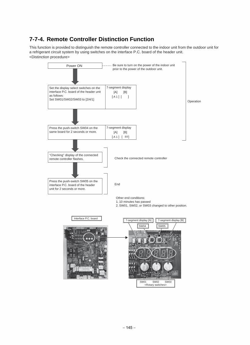
7-7-4. Remote Controller Distinction FunctionThis function is provided to distinguish the remote controller connected to the indoor unit from the outdoor unit for a refrigerant circuit system by using switches on the interface P.C. board of the header unit.<Distinction procedure>
Power ON
End
Check the connected remote controller
Operation
7-segment display
[A] [B]
[ A 1 ] [ ]
7-segment display
[A] [B]
[ A 1 ] [ FF]
Be sure to turn on the power of the indoor unit prior to the power of the outdoor unit.
Set the display select switches on the interface P.C. board of the header unit as follows:Set SW01/SW02/SW03 to [2/4/1]
Press the push-switch SW04 on the same board for 2 seconds or more.
"Checking" display of the connected remote controller flashes.
Press the push-switch SW05 on the interface P.C. board of the header unit for 2 seconds or more.
Other end conditions:1. 10 minutes has passed2. SW01, SW02, or SW03 changed to other position.
Interface P.C. board
SW04 SW05
SW02 SW03SW01
7-segment display [A] 7-segment display [B]
<Rotary switches>
− 145 −
This function is provided to open or close forcedly PMV for 2 minutes in all the indoor units by the switch operation on the interface P.C. board of the header unit.This function is also used to open PMV fully when turning off the power and executing an operation.
<Operation>
[Open fully]Set the switches SW01/SW02/SW03 on the interface P.C. board of the header unit to [2/3/1], and press SW04 for 2 seconds or more.(Display appears on 7-segment display for 2 minutes as follows.) [P ] [ FF]
[Close fully]Set the switches SW01/SW02/SW03 on the interface P.C. board of the header unit to [2/3/1], and press SW05 for 2 seconds or more.(Display appears on 7-segment display for one minute as follows.) [P ] [ 00]
[Clear]After 2 minutes (1 minutes for “Close fully”) after setting up, the opening automatically returns to the normal opening.
This function is provided to forcedly open or close fully P.M.V. (PMV1/PMV3, PMV4) used in the outdoor unit for 2 minutes.
[PMV1 Open fully]On the interface board of the outdoor unit, set the DIP switch [SW12·bit1] to [OFF], [SW12·bit2] to [OFF], and short-circuit CN30.
[PMV1 Close fully]On the interface board of the outdoor unit, set the DIP switch [SW12·bit1] to [OFF], [SW12·bit2] to [OFF], and short-circuit CN31.
[PMV3 Open fully]On the interface P.C. board of the outdoor unit, set the DIP switch [SW12·bit1] to [ON], [SW12·bit2] to [OFF], and shortcircuit CN30.
[PMV3 Close fully]On the interface P.C. board of the outdoor unit, set the DIP switch [SW12·bit1] to [ON], [SW12·bit2] to [OFF], and shortcircuit CN31.
[Clear]For both open fully and close fully, after 2 minutes, the opening returns to the normal opening.Be sure to remove the cord used for short-circuit after confirmation, and set the DIP switch [SW12·bit1] to [OFF] and [SW12·bit2] to [OFF].
7-7-5. Pulse Motor Valve (PMV) Forced Open/Close Function in Indoor Unit
7-7-6. Pulse Motor Valve (PMV) Forced Open Fully/Close fully Function in Outdoor Unit
[PMV4 Open fully]On the interface board of the outdoor unit, set the DIP switch [SW12·bit1] to [OFF], [SW12·bit2] to [ON], and short-circuit CN30.
[PMV4 Close fully]On the interface board of the outdoor unit, set the DIP switch [SW12·bit1] to [OFF], [SW12·bit2] to [ON], and short-circuit CN31.
− 146 −
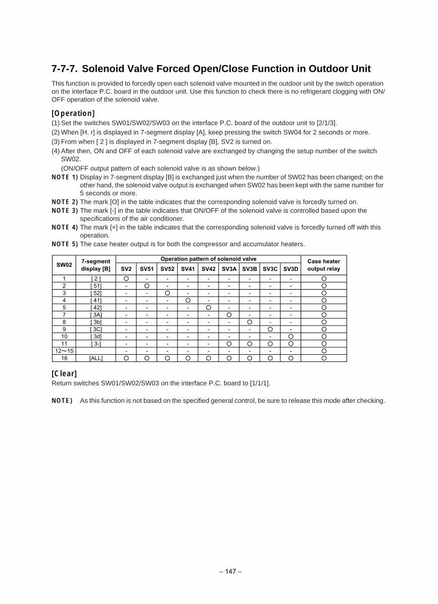
7-7-7. Solenoid Valve Forced Open/Close Function in Outdoor UnitThis function is provided to forcedly open each solenoid valve mounted in the outdoor unit by the switch operation on the interface P.C. board in the outdoor unit. Use this function to check there is no refrigerant clogging with ON/OFF operation of the solenoid valve.
[Operation](1) Set the switches SW01/SW02/SW03 on the interface P.C. board of the outdoor unit to [2/1/3].(2) When [H. r] is displayed in 7-segment display [A], keep pressing the switch SW04 for 2 seconds or more.(3) From when [ 2 ] is displayed in 7-segment display [B], SV2 is turned on.(4) After then, ON and OFF of each solenoid valve are exchanged by changing the setup number of the switch
SW02.(ON/OFF output pattern of each solenoid valve is as shown below.)
NOTE 1) Display in 7-segment display [B] is exchanged just when the number of SW02 has been changed; on the other hand, the solenoid valve output is exchanged when SW02 has been kept with the same number for 5 seconds or more.
NOTE 2) The mark [O] in the table indicates that the corresponding solenoid valve is forcedly turned on.NOTE 3) The mark [-] in the table indicates that ON/OFF of the solenoid valve is controlled based upon the
specifications of the air conditioner.NOTE 4) The mark [×] in the table indicates that the corresponding solenoid valve is forcedly turned off with this
operation.NOTE 5) The case heater output is for both the compressor and accumulator heaters.
[Clear]Return switches SW01/SW02/SW03 on the interface P.C. board to [1/1/1].
NOTE) As this function is not based on the specified general control, be sure to release this mode after checking.
SV2 SV51 SV52 SV41 SV42 SV3A SV3B SV3C SV3D1 [ 2 ] - - - - - - - - 2 [ 51] - - - - - - - - 3 [ 52] - - - - - - - - 4 [ 41] - - - - - - - - 5 [ 42] - - - - - - - - 7 [ 3A] - - - - - - - - 8 [ 3b] - - - - - - - - 9 [ 3C] - - - - - - - - 10 [ 3d] - - - - - - - - 11 [ 3-] - - - - -
12~15 - - - - - - - - - 16 [ALL]
SW02 7-segmentdisplay [B]
Case heateroutput relay
Operation pattern of solenoid valve
− 147 −
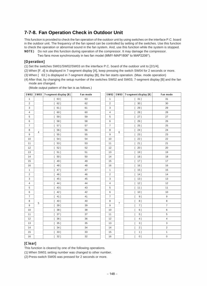
7-7-8. Fan Operation Check in Outdoor UnitThis function is provided to check the fan operation of the outdoor unit by using switches on the interface P.C. board in the outdoor unit. The frequency of the fan speed can be controlled by setting of the switches. Use this function to check the operation or abnormal sound in the fan system. And, use this function while the system is stopped.NOTE) Do not use this function during operation of the compressor. It may damage the compressor.
[Operation](1) Set the switches SW01/SW02/SW03 on the interface P.C. board of the outdoor unit to [2/1/4].(2) When [F. d] is displayed in 7-segment display [A], keep pressing the switch SW04 for 2 seconds or more.(3) When [ 63 ] is displayed in 7-segment display [B], the fan starts operation. (Max. mode operation)(4) After that, by changing the setup number of the switches SW02 and SW03, 7-segment display [B] and the fan
mode are changed.(Mode output pattern of the fan is as follows.)
[Clear]This function is cleared by one of the following operations.(1) When SW01 setting number was changed to other number.(2) Press-switch SW05 was pressed for 2 seconds or more.
SW02 SW03 7-segment display [B] Fan mode
1
4
[ 63 ] 63
2 [ 62 ] 62
3 [ 61 ] 61
4 [ 60 ] 60
5 [ 59 ] 59
6 [ 58 ] 58
7 [ 57 ] 57
8 [ 56 ] 56
9 [ 55 ] 55
10 [ 54 ] 54
11 [ 53 ] 53
12 [ 52 ] 52
13 [ 51 ] 51
14 [ 50 ] 50
15 [ 49 ] 49
16 [ 48 ] 48
1
5
[ 47 ] 47
2 [ 46 ] 46
3 [ 45 ] 45
4 [ 44 ] 44
5 [ 43 ] 43
6 [ 42 ] 42
7 [ 41 ] 41
8 [ 40 ] 40
9 [ 39 ] 39
10 [ 38 ] 38
11 [ 37 ] 37
12 [ 36 ] 36
13 [ 35 ] 35
14 [ 34 ] 34
15 [ 33 ] 33
16 [ 32 ] 32
SW02 SW03 7-segment display [B] Fan mode
1
6
[ 31 ] 31
2 [ 30 ] 30
3 [ 29 ] 29
4 [ 28 ] 28
5 [ 27 ] 27
6 [ 26 ] 26
7 [ 25 ] 25
8 [ 24 ] 24
9 [ 23 ] 23
10 [ 22 ] 22
11 [ 21 ] 21
12 [ 20 ] 20
13 [ 19 ] 19
14 [ 18 ] 18
15 [ 17 ] 17
16 [ 16 ] 16
1
7
[ 15 ] 15
2 [ 14 ] 14
3 [ 13 ] 13
4 [ 12 ] 12
5 [ 11 ] 11
6 [ 10 ] 10
7 [ 9 ] 9
8 [ 8 ] 8
9 [ 7 ] 7
10 [ 6 ] 6
11 [ 5 ] 5
12 [ 4 ] 4
13 [ 3 ] 3
14 [ 2 ] 2
15 [ 1 ] 1
16 [ 0 ] 0
Two fans move synchronously in two fan model (MMY-MAP1806* to MAP2206*).
− 148 −
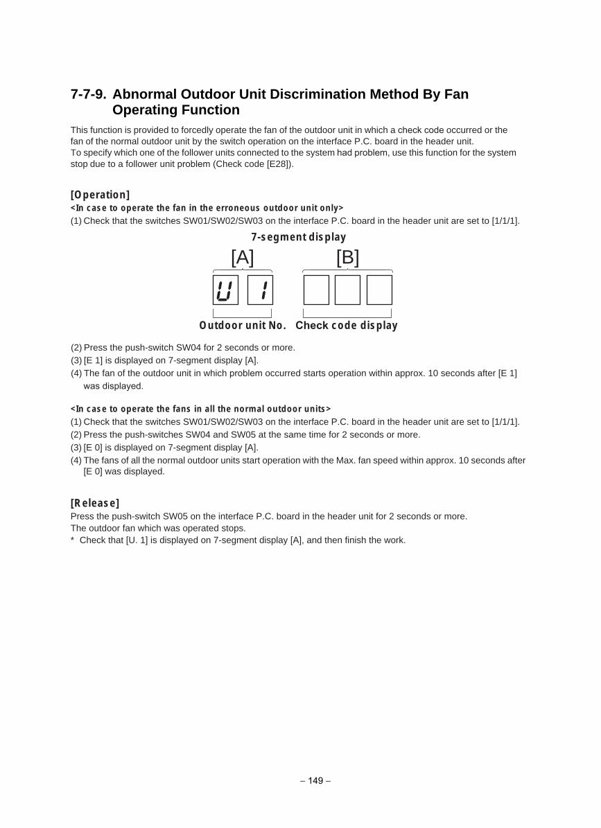
7-7-9. Abnormal Outdoor Unit Discrimination Method By Fan Operating Function
This function is provided to forcedly operate the fan of the outdoor unit in which a check code occurred or the fan of the normal outdoor unit by the switch operation on the interface P.C. board in the header unit.To specify which one of the follower units connected to the system had problem, use this function for the system stop due to a follower unit problem (Check code [E28]).
[Operation]<In case to operate the fan in the erroneous outdoor unit only>(1) Check that the switches SW01/SW02/SW03 on the interface P.C. board in the header unit are set to [1/1/1].
(2) Press the push-switch SW04 for 2 seconds or more.(3) [E 1] is displayed on 7-segment display [A].(4) The fan of the outdoor unit in which problem occurred starts operation within approx. 10 seconds after [E 1] was displayed.
<In case to operate the fans in all the normal outdoor units>(1) Check that the switches SW01/SW02/SW03 on the interface P.C. board in the header unit are set to [1/1/1].(2) Press the push-switches SW04 and SW05 at the same time for 2 seconds or more.(3) [E 0] is displayed on 7-segment display [A].(4) The fans of all the normal outdoor units start operation with the Max. fan speed within approx. 10 seconds after
[E 0] was displayed.
[Release]Press the push-switch SW05 on the interface P.C. board in the header unit for 2 seconds or more.The outdoor fan which was operated stops.* Check that [U. 1] is displayed on 7-segment display [A], and then finish the work.
[A] [B]7-segment display
Outdoor unit No. Check code display
− 149 −
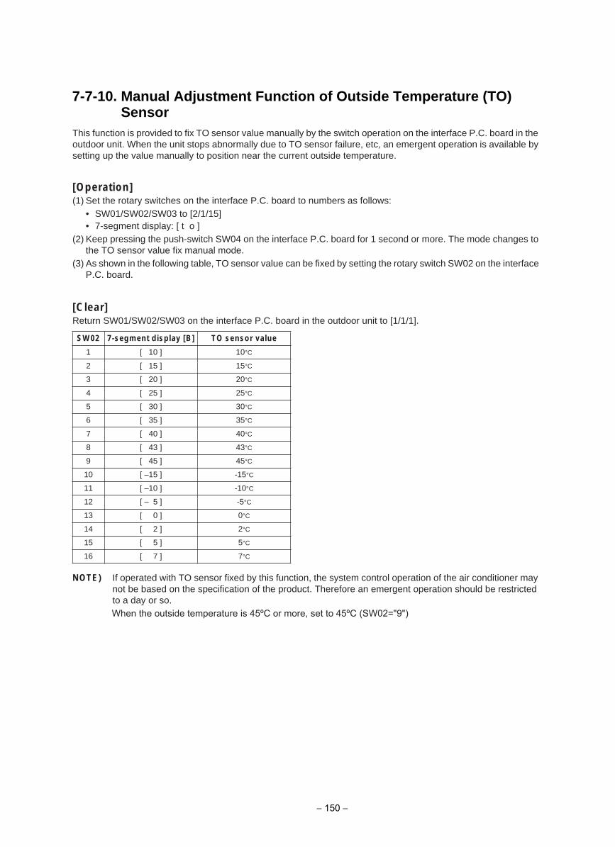
7-7-10. Manual Adjustment Function of Outside Temperature (TO) Sensor
This function is provided to fix TO sensor value manually by the switch operation on the interface P.C. board in the outdoor unit. When the unit stops abnormally due to TO sensor failure, etc, an emergent operation is available by setting up the value manually to position near the current outside temperature.
[Operation](1) Set the rotary switches on the interface P.C. board to numbers as follows:
• SW01/SW02/SW03 to [2/1/15]• 7-segment display: [ t o ]
(2) Keep pressing the push-switch SW04 on the interface P.C. board for 1 second or more. The mode changes to the TO sensor value fix manual mode.
(3) As shown in the following table, TO sensor value can be fixed by setting the rotary switch SW02 on the interface P.C. board.
[Clear]Return SW01/SW02/SW03 on the interface P.C. board in the outdoor unit to [1/1/1].
NOTE) If operated with TO sensor fixed by this function, the system control operation of the air conditioner may not be based on the specification of the product. Therefore an emergent operation should be restricted to a day or so.
SW02 7-segment display [B] TO sensor value
1 [ 10 ] 10°C
2 [ 15 ] 15°C
3 [ 20 ] 20°C
4 [ 25 ] 25°C
5 [ 30 ] 30°C
6 [ 35 ] 35°C
7 [ 40 ] 40°C
8 [ 43 ] 43°C
9 [ 45 ] 45°C
10 [ –15 ] -15°C
11 [ –10 ] -10°C
12 [ – 5 ] -5°C
13 [ 0 ] 0°C
14 [ 2 ] 2°C
15 [ 5 ] 5°C
16 [ 7 ] 7°C
When the outside temperature is 45ºC or more, set to 45ºC (SW02="9")
− 150 −
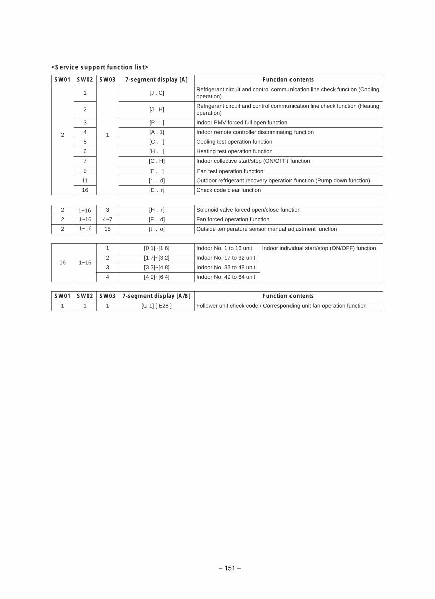
<Service support function list>
stnetnoc noitcnuF]A[ yalpsid tnemges-730WS20WS10WS
2
1
1
[J . C]Refrigerant circuit and control communication line check function (Cooling operation)
]H . J[2Refrigerant circuit and control communication line check function (Heating operation)
noitcnuf nepo lluf decrof VMP roodnI] . P[3
noitcnuf gnitanimircsid rellortnoc etomer roodnI]1 . A[4
noitcnuf noitarepo tset gnilooC] . C[5
noitcnuf noitarepo tset gnitaeH] . H[6
noitcnuf )FFO/NO( pots/trats evitcelloc roodnI]H . C[7
)noitcnuf nwod pmuP( noitcnuf noitarepo yrevocer tnaregirfer roodtuO]d. r[11
Check code clear function]r.E[61
2
1~16
3 [H . r] Solenoid valve forced open/close function
2 4~7 [F . d] Fan forced operation function
2 15 [t . o] Outside temperature sensor manual adjustment function
16 1~16
1 [0 1]~[1 6] Indoor No. 1 to 16 unit Indoor individual start/stop (ON/OFF) function
2 [1 7]~[3 2] Indoor No. 17 to 32 unit
3 [3 3]~[4 8] Indoor No. 33 to 48 unit
4 [4 9]~[6 4] Indoor No. 49 to 64 unit
stnetnoc noitcnuF]B/A[ yalpsid tnemges-730WS20WS10WS
1 1 1 [U 1] [ E28 ] Follower unit check code / Corresponding unit fan operation function
1~16
1~16
− 151 −
9 [F . ] Fan test operation function
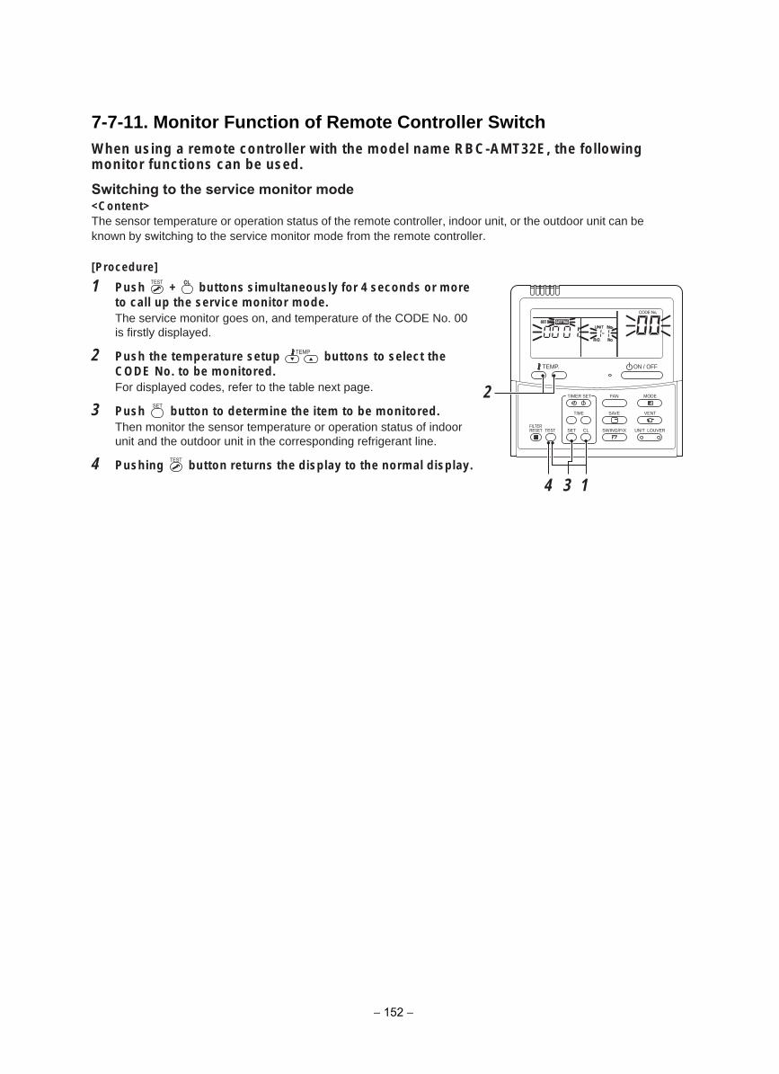
7-7-11. Monitor Function of Remote Controller SwitchWhen using a remote controller with the model name RBC-AMT32E, the following monitor functions can be used.
Switching to the service monitor mode<Content>The sensor temperature or operation status of the remote controller, indoor unit, or the outdoor unit can be known by switching to the service monitor mode from the remote controller.
[Procedure]
1 Push + buttons simultaneously for 4 seconds or more to call up the service monitor mode. The service monitor goes on, and temperature of the CODE No. 00 is firstly displayed.
2 Push the temperature setup buttons to select the CODE No. to be monitored. For displayed codes, refer to the table next page.
3 Push button to determine the item to be monitored.Then monitor the sensor temperature or operation status of indoor unit and the outdoor unit in the corresponding refrigerant line.
4 Pushing button returns the display to the normal display.
SET
TIME
TIMER SET
TESTFILTERRESET
TEMP.
CL
FAN
SAVE
SWING/FIX
VENT
MODE
ON / OFF
UNIT LOUVER
14
2
3
− 152 −
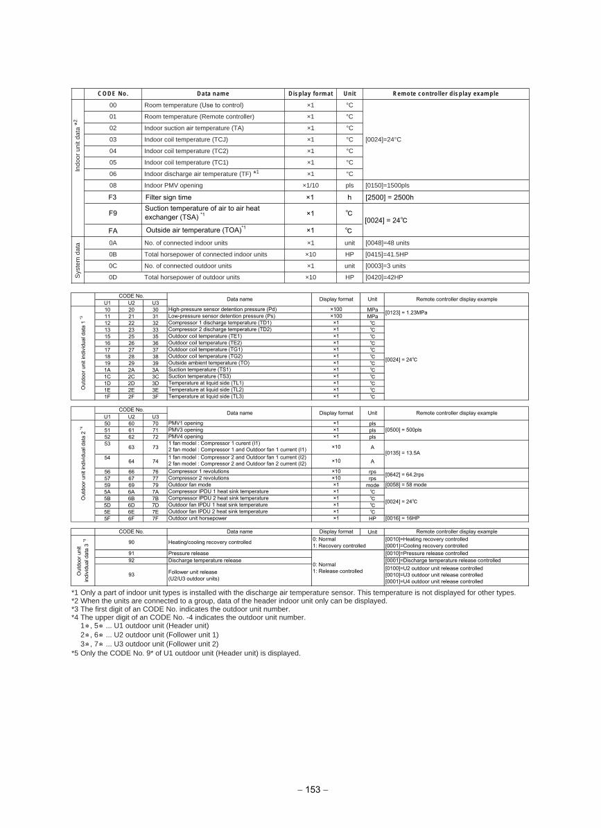
*1 Only a part of indoor unit types is installed with the discharge air temperature sensor. This temperature is not displayed for other types.*2 When the units are connected to a group, data of the header indoor unit only can be displayed.*3 The first digit of an CODE No. indicates the outdoor unit number.*4 The upper digit of an CODE No. -4 indicates the outdoor unit number.
1 , 5 ... U1 outdoor unit (Header unit) 2 , 6 ... U2 outdoor unit (Follower unit 1) 3 , 7 ... U3 outdoor unit (Follower unit 2)
*5 Only the CODE No. 9* of U1 outdoor unit (Header unit) is displayed.
tamrof yalpsiDeman ataD.oN EDOC Unit Remote controller display example
Indo
or u
nit d
ata
*2
00 Room temperature (Use to control) ×1 °C
[0024]=24°C
01 Room temperature (Remote controller) ×1 °C
C°1×Indoor suction air temperature (TA)20
C°1×)JCT( erutarepmet lioc roodnI30
C°1×)2CT( erutarepmet lioc roodnI40
C°1×)1CT( erutarepmet lioc roodnI50
06 Indoor discharge air temperature (TF) *1 ×1 °C
slp0051=]0510[slp01/1×gninepo VMP roodnI80
Sys
tem
dat
a stinu 84=]8400[tinu1×stinu roodni detcennoc fo .oNA0
0B Total horsepower of connected indoor units ×10 HP [0415]=41.5HP
[0003]=3 unitstinu1×stinu roodtuo detcennoc fo .oNC0
PH24=]0240[PH01×stinu roodtuo fo rewopesroh latoTD0
F9Suction temperature of air to air heat exchanger (TSA) *1 ×1
[0024] = 24FA Outside air temperature (TOA)*1 ×1
U1 U2 U310 20 30 MPa11 21 31 MPa12 22 32 13 23 33 15 25 35 16 26 36 17 27 37 18 28 38 19 29 39 1A 2A 3A 1C 2C 3C 1D 2D 3D 1E 2E 3E 1F 2F 3F
U1 U2 U350 60 70 pls51 61 71 pls52 62 72 pls53
63 73 A
5464 74 A
56 66 76 rps57 67 77 rps59 69 79 mode5A 6A 7A 5B 6B 7B 5D 6D 7D 5E 6E 7E 5F 6F 7F HP
Unit
Out
door
uni
t in
divi
dual
dat
a 3
*5 90 Heating/cooling recovery controlled 0: Normal1: Recovery controlled
[0010]=Heating recovery controlled[0001]=Cooling recovery controlled
91 Pressure release
0: Normal1: Release controlled
[0010]=Pressure release controlled92
CODE No. Data name Display format Remote controller display example
Discharge temperature release [0001]=Discharge temperature release controlled
93 Follower unit release(U2/U3 outdoor units)
[0100]=U2 outdoor unit release controlled[0010]=U3 outdoor unit release controlled[0001]=U4 outdoor unit release controlled
Compressor IPDU 2 heat sink temperature ×1Outdoor fan IPDU 1 heat sink temperature ×1Outdoor fan IPDU 2 heat sink temperature ×1Outdoor unit horsepower ×1 [0016] = 16HP
[0135] = 13.5A1 fan model : Compressor 2 and Outdoor fan 1 current (I2)2 fan model : Compressor 2 and Outdoor fan 2 current (I2) ×10
Compressor 1 revolutions ×10 [0642] = 64.2rpsCompressor 2 revolutions ×10
Out
door
uni
t ind
ivid
ual d
ata
2 *4
PMV1 opening ×1[0500] = 500plsPMV3 opening ×1
PMV4 opening ×11 fan model : Compressor 1 curent (I1)2 fan model : Compressor 1 and Outdoor fan 1 current (I1) ×10
Outdoor fan mode ×1 [0058] = 58 modeCompressor IPDU 1 heat sink temperature ×1
[0024] = 24
CODE No. Data name Display format Unit Remote controller display example
Temperature at liquid side (TL1) ×1Temperature at liquid side (TL2) ×1Temperature at liquid side (TL3) ×1
Out
door
uni
t ind
ivid
ual d
ata
1 *3
High-pressure sensor detention pressure (Pd) ×100 [0123] = 1.23MPaLow-pressure sensor detention pressure (Ps) ×100Compressor 1 discharge temperature (TD1) ×1
×1Outside ambient temperature (TO) ×1Suction temperature (TS1) ×1Suction temperature (TS3) ×1
[0024] = 24
Compressor 2 discharge temperature (TD2) ×1Outdoor coil temperature (TE1) ×1Outdoor coil temperature (TE2) ×1Outdoor coil temperature (TG1) ×1Outdoor coil temperature (TG2)
CODE No. Data name Display format Unit Remote controller display example
− 153 −
F3 Filter sign time ×1 h [2500] = 2500h
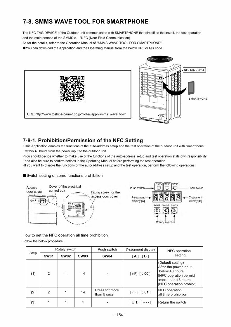
– 119 –
7-8. SMMS WAVE TOOL FOR SMARTPHONEThe NFC TAG DEVICE of the Outdoor unit communicates with SMARTPHONE that simplifies the install, the test operation and the maintenance of the SMMS-e. *NFC (Near Field Communication)As for the details, refer to the Operation Manual of "SMMS WAVE TOOL FOR SMARTPHONE" You can download the Application and the Operating Manual from the below URL or QR code.
QR code
URL:http://www.toshiba-carrier.co.jp/global/appli/smms_wave_tool/
7-8-1. Prohibition/Permission of the NFC Setting・This Application enables the functions of the auto-address setup and the test operation of the outdoor unit with Smartphone
within 48 hours from the power input to the outdoor unit.・You should decide whether to make use of the functions of the auto-address setup and test operation at its own responsibility and also be sure to confirm notices in the Operating Manual before performing the test operation.・If you want to disable the functions of the auto-address setup and the test operation, perform the following operations.
Switch setting of some functions prohibition
How to set the NFC operation all time prohibitionFollow the below procedure.
Push switch 7-segment display
SW01 SW02 SW03 SW04 [ A ] [ B ]
(1) 2 1 14 - [ nF] [ c.00 ]
(Default setting)After the power input,:below 48 hours[NFC operation permit]:more than 48 hours[NFC operation prohibit]
(2) 2 1 14 Press for more than 5 secs [ nF] [ c.01 ] NFC operation
all time prohibition
(3) 1 1 1 - [ U.1. ] [ - - - ] Return the switch
StepRotaly switch NFC operation
setting
NFC TAG DEVICE
SMARTPHONE
− 154 −
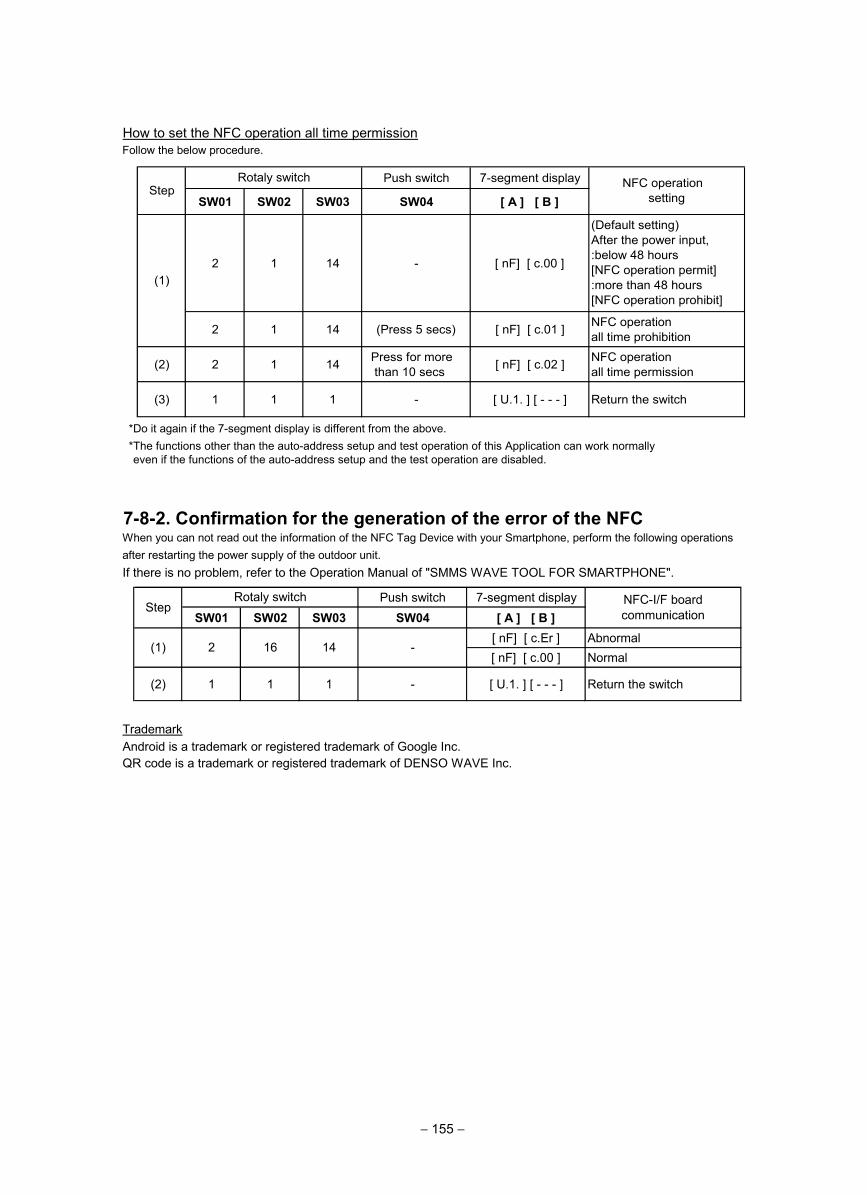
How to set the NFC operation all time permissionFollow the below procedure.
*Do it again if the 7-segment display is different from the above.*The functions other than the auto-address setup and test operation of this Application can work normallyeven if the functions of the auto-address setup and the test operation are disabled.
7-8-2. Confirmation for the generation of the error of the NFCWhen you can not read out the information of the NFC Tag Device with your Smartphone, perform the following operations after restarting the power supply of the outdoor unit.If there is no problem, refer to the Operation Manual of "SMMS WAVE TOOL FOR SMARTPHONE".
TrademarkAndroid is a trademark or registered trademark of Google Inc.QR code is a trademark or registered trademark of DENSO WAVE Inc.
Push switch 7-segment displaySW01 SW02 SW03 SW04 [ A ] [ B ]
[ nF] [ c.Er ] Abnormal[ nF] [ c.00 ] Normal
(2) 1 1 1 - [ U.1. ] [ - - - ] Return the switch
StepRotaly switch NFC-I/F board
communication
(1) 2 16 14 -
Push switch 7-segment display
SW01 SW02 SW03 SW04 [ A ] [ B ]
2 1 14 - [ nF] [ c.00 ]
(Default setting)After the power input,:below 48 hours[NFC operation permit]:more than 48 hours[NFC operation prohibit]
2 1 14 (Press 5 secs) [ nF] [ c.01 ] NFC operationall time prohibition
(2) 2 1 14 Press for more than 10 secs [ nF] [ c.02 ] NFC operation
all time permission
(3) 1 1 1 - [ U.1. ] [ - - - ] Return the switch
(1)
StepRotaly switch NFC operation
setting
− 155 −
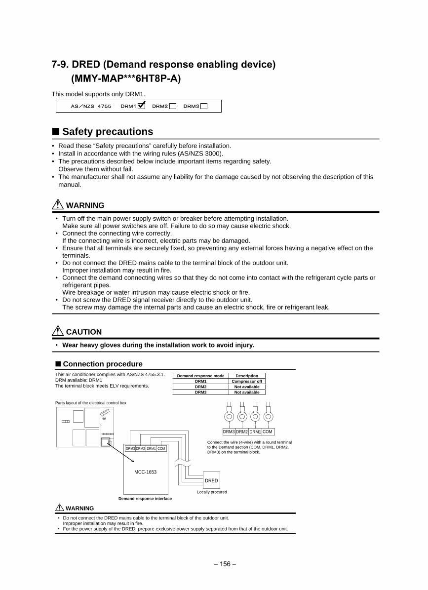
7-9. DRED (Demand response enabling device) (MMY-MAP***6HT8P-A) This model supports only DRM1.
Safety precautions• Read these “Safety precautions” carefully before installation.• Install in accordance with the wiring rules (AS/NZS 3000).• The precautions described below include important items regarding safety.
Observe them without fail.• The manufacturer shall not assume any liability for the damage caused by not observing the description of this
manual.
WARNING• Turn off the main power supply switch or breaker before attempting installation.
Make sure all power switches are off. Failure to do so may cause electric shock.• Connect the connecting wire correctly.
If the connecting wire is incorrect, electric parts may be damaged.• Ensure that all terminals are securely fi xed, so preventing any external forces having a negative effect on the
terminals.• Do not connect the DRED mains cable to the terminal block of the outdoor unit.
Improper installation may result in fi re.• Connect the demand connecting wires so that they do not come into contact with the refrigerant cycle parts or
refrigerant pipes.Wire breakage or water intrusion may cause electric shock or fi re.
• Do not screw the DRED signal receiver directly to the outdoor unit.The screw may damage the internal parts and cause an electric shock, fi re or refrigerant leak.
CAUTION• Wear heavy gloves during the installation work to avoid injury.
Connection procedureThis air conditioner complies with AS/NZS 4755.3.1.DRM available: DRM1The terminal block meets ELV requirements.
DRM3 DRM2 DRM1 COM
MCC-1653
DRED
DRM3 DRM2 DRM1 COM
WARNING• Do not connect the DRED mains cable to the terminal block of the outdoor unit.
Improper installation may result in fi re.• For the power supply of the DRED, prepare exclusive power supply separated from that of the outdoor unit.
Demand response mode DescriptionDRM1 Compressor offDRM2 Not availableDRM3 Not available
Demand response interfaceLocally procured
Connect the wire (4-wire) with a round terminalto the Demand section (COM, DRM1, DRM2,DRM3) on the terminal block.
Parts layout of the electrical control box
− 156 −
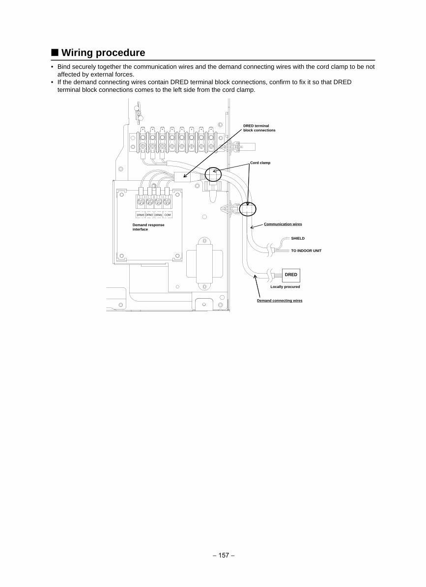
Wiring procedure• Bind securely together the communication wires and the demand connecting wires with the cord clamp to be not
affected by external forces.• If the demand connecting wires contain DRED terminal block connections, confi rm to fi x it so that DRED
terminal block connections comes to the left side from the cord clamp.
DRED
DRM3 DRM2 DRM1 COM
DRED terminalblock connections
Cord clamp
Demand responseinterface
Communication wires
Locally procured
Demand connecting wires
SHIELD
TO INDOOR UNIT
− 157 −
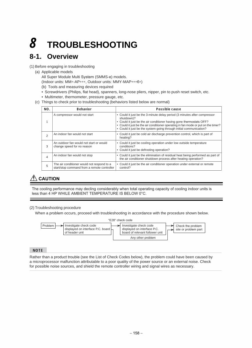
8 TROUBLESHOOTING8-1. Overview(1) Before engaging in troubleshooting
(a) Applicable modelsAll Super Module Multi System (SMMS-e) models.(Indoor units: MM∗-AP∗∗∗, Outdoor units: MMY-MAP∗∗∗6∗)(b) Tools and measuring devices required• Screwdrivers (Philips, flat head), spanners, long-nose pliers, nipper, pin to push reset switch, etc.• Multimeter, thermometer, pressure gauge, etc.
(c) Things to check prior to troubleshooting (behaviors listed below are normal)
(2) Troubleshooting procedureWhen a problem occurs, proceed with troubleshooting in accordance with the procedure shown below.
NOTE
Rather than a product trouble (see the List of Check Codes below), the problem could have been caused by a microprocessor malfunction attributable to a poor quality of the power source or an external noise. Check for possible noise sources, and shield the remote controller wiring and signal wires as necessary.
esuac elbissoProivaheB.ON
1
A compressor would not start • Could it just be the 3-minute delay period (3 minutes after compressorshutdown)?
• Could it just be the air conditioner having gone thermostats OFF?• Could it just be the air conditioner operating in fan mode or put on the timer?• Could it just be the system going through initial communication?
2 An indoor fan would not start • Could it just be cold air discharge prevention control, which is part ofheating?
3An outdoor fan would not start or would change speed for no reason
• Could it just be cooling operation under low outside temperatureconditions?
• Could it just be defrosting operation?
4 An indoor fan would not stop • Could it just be the elimination of residual heat being performed as part ofthe air conditioner shutdown process after heating operation?
5 The air conditioner would not respond to a start/stop command from a remote controller
• Could it just be the air conditioner operation under external or remotecontrol?
Problem
Any other problem
Investigate check code displayed on interface P.C. board of header unit
Investigate check code displayed on interface P.C. board of relevant follower unit
Check the problem site or problem part
"E28" check code
CAUTION
The cooling performance may decling considerably when total operating capacity of cooling indoor units is less than 4 HP WHILE AMBIENT TEMPERATURE IS BELOW 0°C.
− 158 −
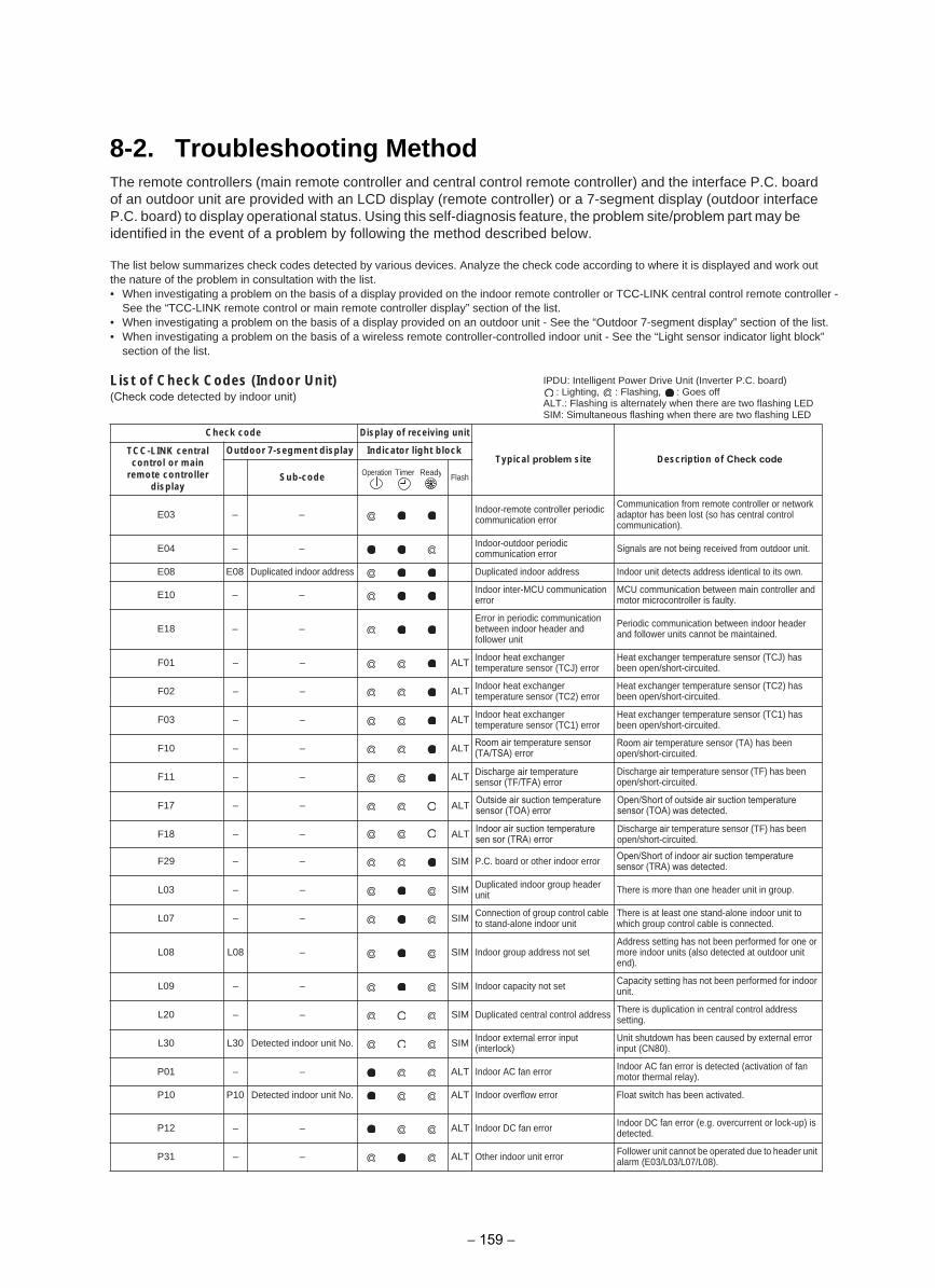
8-2. Troubleshooting MethodThe remote controllers (main remote controller and central control remote controller) and the interface P.C. board of an outdoor unit are provided with an LCD display (remote controller) or a 7-segment display (outdoor interface P.C. board) to display operational status. Using this self-diagnosis feature, the problem site/problem part may be identified in the event of a problem by following the method described below.
The list below summarizes check codes detected by various devices. Analyze the check code according to where it is displayed and work out the nature of the problem in consultation with the list.• When investigating a problem on the basis of a display provided on the indoor remote controller or TCC-LINK central control remote controller -
See the “TCC-LINK remote control or main remote controller display” section of the list.• When investigating a problem on the basis of a display provided on an outdoor unit - See the “Outdoor 7-segment display” section of the list.• When investigating a problem on the basis of a wireless remote controller-controlled indoor unit - See the “Light sensor indicator light block”
section of the list.
List of Check Codes (Indoor Unit)(Check code detected by indoor unit)
Check code Display of receiving unit
Typical problem site Description of Check codeOutdoor 7-segment display Indicator light block
Sub-code Flash
E03 Indoor-remote controller periodic communication error
Communication from remote controller or network adaptor has been lost (so has central control communication).
E04
– –
– – Indoor-outdoor periodic communication error Signals are not being received from outdoor unit.
E08 E08 .nwo sti ot lacitnedi sserdda stceted tinu roodnIsserdda roodni detacilpuDsserdda roodni detacilpuD
E10 Indoor inter-MCU communication error
MCU communication between main controller and motor microcontroller is faulty.
E18Error in periodic communication between indoor header and follower unit
Periodic communication between indoor header and follower units cannot be maintained.
TLA––10F Indoor heat exchanger temperature sensor (TCJ) error
Heat exchanger temperature sensor (TCJ) has been open/short-circuited.
TLA––20F Indoor heat exchanger temperature sensor (TC2) error
Heat exchanger temperature sensor (TC2) has been open/short-circuited.
TLA––30F Indoor heat exchanger temperature sensor (TC1) error
Heat exchanger temperature sensor (TC1) has been open/short-circuited.
TLA––01FRoom air temperature sensor (TA/TSA) error
Room air temperature sensor (TA) has been open/short-circuited.
TLA––11F Discharge air temperature sensor (TF/TFA) error
Discharge air temperature sensor (TF) has been open/short-circuited.
MIS––92F P.C. board or other indoor error Open/Short of indoor air suction temperature sensor (TRA) was detected.
MIS––30L Duplicated indoor group header unit There is more than one header unit in group.
MIS––70L Connection of group control cable to stand-alone indoor unit
There is at least one stand-alone indoor unit to which group control cable is connected.
MIS–80L80L Indoor group address not setAddress setting has not been performed for one or more indoor units (also detected at outdoor unit end).
MIS––90L Indoor capacity not set Capacity setting has not been performed for indoor unit.
MIS––02L Duplicated central control address There is duplication in central control address setting.
L30 Detected indoor unit No. SIM Indoor external error input (interlock)
Unit shutdown has been caused by external error input (CN80).
TLA––10P Indoor AC fan error Indoor AC fan error is detected (activation of fan motor thermal relay).
P10
– –
– –
L30
P10 Detected indoor unit No. ALT Indoor overflow error Float switch has been activated.
TLA––21P Indoor DC fan error Indoor DC fan error (e.g. overcurrent or lock-up) is detected.
TLA––13P Other indoor unit error Follower unit cannot be operated due to header unit alarm (E03/L03/L07/L08).
IPDU: Intelligent Power Drive Unit (Inverter P.C. board): Lighting, : Flashing, : Goes off
ALT.: Flashing is alternately when there are two flashing LEDSIM: Simultaneous flashing when there are two flashing LED
Operation Timer Ready
TCC-LINK central control or main
remote controller display
ALT Outside air suction temperaturesensor (TOA) error
Open/Short of outside air suction temperature sensor (TOA) was detected.
ALT Indoor air suction temperature sen sor (TRA) error
Discharge air temperature sensor (TF) has been open/short-circuited.
––F17
––F18
− 159 −
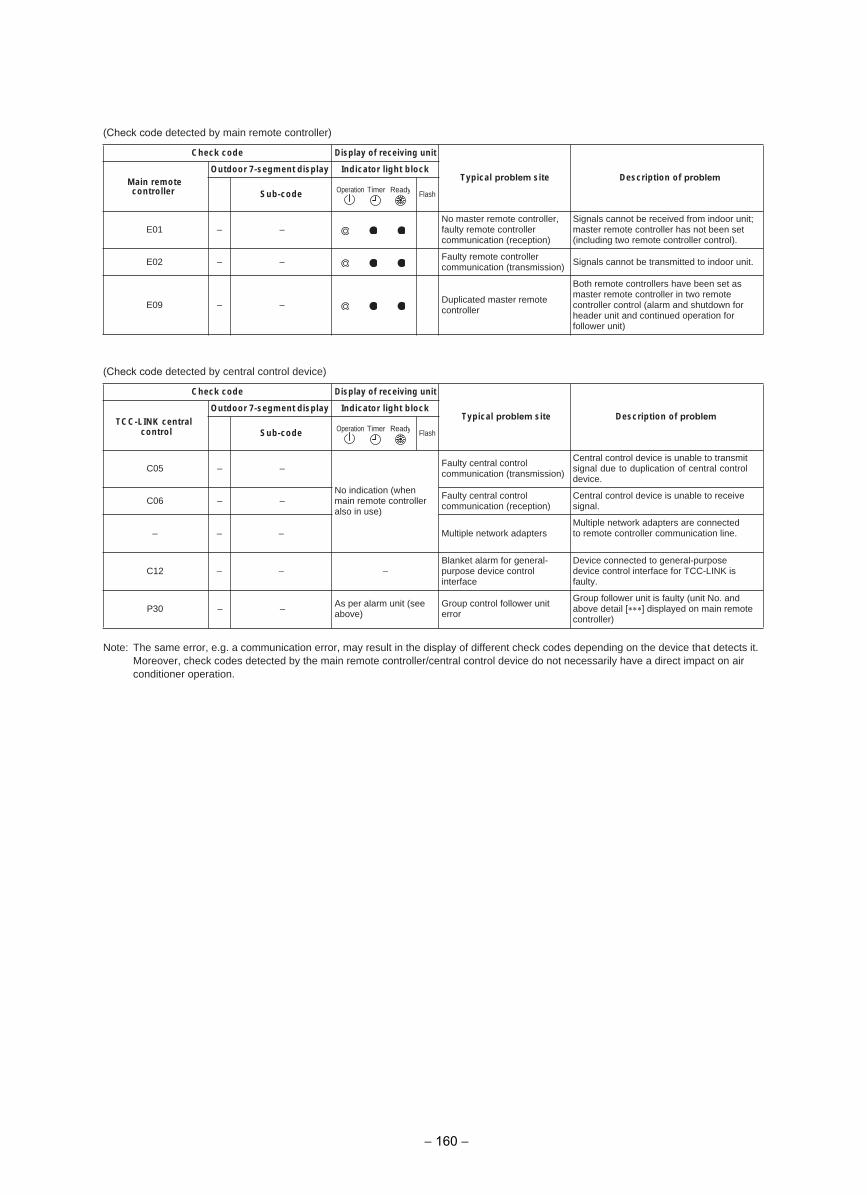
(Check code detected by main remote controller)
(Check code detected by central control device)
Note: The same error, e.g. a communication error, may result in the display of different check codes depending on the device that detects it. Moreover, check codes detected by the main remote controller/central control device do not necessarily have a direct impact on airconditioner operation.
Check code Display of receiving unit
Typical problem site Description of problemMain remotecontroller
Outdoor 7-segment display Indicator light block
Sub-code Flash
E01 – –No master remote controller, faulty remote controller communication (reception)
Signals cannot be received from indoor unit; master remote controller has not been set (including two remote controller control).
E02 – – Faulty remote controller communication (transmission) Signals cannot be transmitted to indoor unit.
E09 – – Duplicated master remote controller
Both remote controllers have been set as master remote controller in two remote controller control (alarm and shutdown for header unit and continued operation for follower unit)
Check code Display of receiving unit
Typical problem site Description of problemTCC-LINK central control
Outdoor 7-segment display Indicator light block
Sub-code Flash
C05 – –
No indication (when main remote controller also in use)
Faulty central control communication (transmission)
Central control device is unable to transmit signal due to duplication of central control device.
C06 – – Faulty central control communication (reception)
Central control device is unable to receive signal.
sretpada krowten elpitluM–––Multiple network adapters are connected to remote controller communication line.
–––21CBlanket alarm for general-purpose device control interface
Device connected to general-purpose device control interface for TCC-LINK is faulty.
P30 – – As per alarm unit (see above)
Group control follower unit error
Group follower unit is faulty (unit No. and above detail [ ] displayed on main remote controller)
Operation Timer Ready
Operation Timer Ready
− 160 −
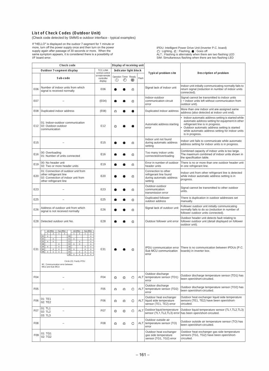
List of Check Codes (Outdoor Unit)(Check code detected by SMMS-e outdoor interface - typical examples)
Check code Display of receiving unit
Typical problem site Description of problemOutdoor 7-segment display TCC-LINK
central control or main remote
controller display
Indicator light block
Sub-code Flash
E06 Number of indoor units from which signal is received normally
Signal lack of indoor unit60EIndoor unit initially communicating normally fails to return signal (reduction in number of indoor units connected).
E07 – (E04)Indoor-outdoor communication circuit error
Signal cannot be transmitted to indoor units ( indoor units left without communication from outdoor unit).
E08 Duplicated indoor address (E08) Duplicated indoor addressMore than one indoor unit are assigned same address (also detected at indoor unit end).
E1201: Indoor-outdoor communication02: Outdoor-outdoor communication
E12 Automatic address starting error
• Indoor automatic address setting is started while automatic address setting for equipment in other refrigerant line is in progress.
• Outdoor automatic address setting is startedwhile automatic address setting for indoor units is in progress.
E15 – E15Indoor unit not found during automatic address setting
Indoor unit fails to communicate while automatic address setting for indoor units is in progress.
E16 00: Overloading01: Number of units connected E16 Too many indoor units
connected/overloading
Combined capacity of indoor units is too large.The maximum combined of indoor units shown in the specification table.
E19 00: No header unit02: Two or more header units E19 Error in number of outdoor
header unitsThere is no or more than one outdoor header unit in one refrigerant line.
E20
01: Connection of outdoor unit from other refrigerant line02: Connection of indoor unit from other refrigerant line
E20
Connection to other refrigerant line found during automatic address setting
Indoor unit from other refrigerant line is detected while indoor automatic address setting is in progress.
E23 – E23Outdoor-outdoor communication transmission error
Signal cannot be transmitted to other outdoor units.
E25 – E25 Duplicated follower outdoor address
There is duplication in outdoor addresses set manually.
E26 Address of outdoor unit from which signal is not received normally E26 Signal lack of outdoor unit
Follower outdoor unit initially communicating normally fails to do so (reduction in number of follower outdoor units connected).
rorre tinu rewollof roodtuO82E.oN tinu roodtuo detceteD82EOutdoor header unit detects fault relating to follower outdoor unit (detail displayed on follower outdoor unit).
13E13E There is no communication between IPDUs (P.C. boards) in inverter box.
TLA40F–40FOutdoor discharge temperature sensor (TD1) error
Outdoor discharge temperature sensor (TD1) has been open/short-circuited.
F05 – F05 ALTOutdoor discharge temperature sensor (TD2) error
Outdoor discharge temperature sensor (TD2) has been open/short-circuited.
F06 01: TE102: TE2 TLA60F
Outdoor heat exchanger liquid side temperature sensor (TE1, TE2) error
Outdoor heat exchanger liquid side temperature sensors (TE1, TE2) have been open/short-circuited.
TLA70F–70F Outdoor liquid temperature sensor (TL1,TL2,TL3) error
Outdoor liquid temperature sensor (TL1,TL2,TL3) has been open/short-circuited.
TLA80F–80FOutdoor outside air temperature sensor (TO) error
Outdoor outside air temperature sensor (TO) has been open/short-circuited.
Outdoor heat exchanger gas side temperaturesensor (TG1, TG2) error
Outdoor heat exchanger gas side temperaturesensors (TG1, TG2) have been open/short-circuited.
IPDU: Intelligent Power Drive Unit (Inverter P.C. board): Lighting, : Flashing, : Goes off
ALT.: Flashing is alternately when there are two flashing LEDSIM: Simultaneous flashing when there are two flashing LED
Operation Timer Ready
Circle (O): Faulty IPDU
01: TL102: TL203: TL3
F09 01: TG102: TG2
IPDU communication error Sub MCU communication error
80 : Communication error between MCU and Sub MCU
If "HELLO" is displayed on the oudoor 7-segment for 1 minute or more, turn off the power supply once and then turn on the power supply again after passage of 30 seconds or more. When the same symptom appears, it is considered there is a possibility of I/F board error.
1 2 1 2 1 2 1 2
01 10
02 11
03 12
08 13
09 18
0A 19
0B 1A
1B
A3-IPDU A3-IPDU Fan-IPDUFan-IPDU
− 161 −
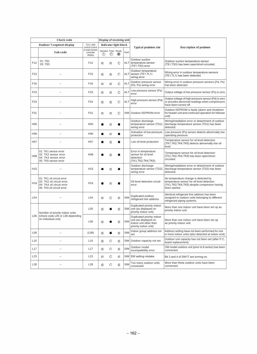
TLA21F21FOutdoor suction temperature sensor (TS1,TS3) error
Outdoor suction temperature sensor (TS1,TS3) has been open/short-circuited.
TLA51F–51FOutdoor temperature sensor (TE1,TL1) wiring error
Wiring error in outdoor temperature sensors (TE1,TL1) has been detected.
TLA61F–61F Outdoor pressure sensor (Pd, Ps) wiring error
Wiring error in outdoor pressure sensors (Pd, Ps) has been detected.
– TLA32F32F Low pressure sensor (Ps) error Output voltage of low pressure sensor (Ps) is zero.
TLA42F–42F High pressure sensor (Pd) error
Output voltage of high pressure sensor (Pd) is zero or provides abnormal readings when compressors have been turned off.
rorre MORPEE roodtuOMIS13F–13FOutdoor EEPROM is faulty (alarm and shutdown for header unit and continued operation for follower unit)
H05 – H05Outdoor discharge temperature sensor (TD1) wiring error
Wiring/installation error or detachment of outdoor discharge temperature sensor (TD1) has been detected.
H06 – H06 Activation of low-pressure protection
Low pressure (Ps) sensor detects abnormally low operating pressure.
noitcetorp level lio woL70H–70H Temperature sensor for oil level detection (TK1,TK2,TK4,TK5) detects abnormally low oil level.
H08
01: TK1 sensor error 02: TK2 sensor error 04: TK4 sensor error 05: TK5 sensor error
H08Error in temperature sensor for oil level detection (TK1,TK2,TK4,TK5)
Temperature sensor for oil level detection (TK1,TK2,TK4,TK5) has been open/short-circuited.
H15 – H15Outdoor discharge temperature sensor (TD2) wiring error
Wiring/installation error or detachment of outdoor discharge temperature sensor (TD2) has been detected.
H16
01: TK1 oil circuit error 02: TK2 oil circuit error 04: TK4 oil circuit error 05: TK5 oil circuit error
H16 Oil level detection circuit error
No temperature change is detected by temperature sensor for oil level detection (TK1,TK2,TK4,TK5) despite compressor having been started.
MIS40L–40L Duplicated outdoor refrigerant line address
Identical refrigerant line address has been assigned to outdoor units belonging to different refrigerant piping systems.
L06Number of priority indoor units(check code L05 or L06 depending on individual unit)
MIS50LDuplicated priority indoor unit (as displayed on priority indoor unit)
More than one indoor unit have been set up as priority indoor unit.
MIS60L
Duplicated priority indoor unit (as displayed on indoor unit other than priority indoor unit)
More than one indoor unit have been set up as priority indoor unit.
MIS)80L(–80LIndoor group address not set
Address setting have not been performed for one or more indoor units (also detected at indoor end).
tes ton yticapac roodtuOMIS01L–01L Outdoor unit capacity has not been set (after P.C. board replacement).
MIS71L–71L Outdoor model incompatibility error
Old model outdoor unit (prior to 6 series) has been connected.
MIS82L–82L Too many outdoor units connected
More than three outdoor units have been connected.
Check code Display of receiving unit
Typical problem site Description of problemOutdoor 7-segment display TCC-LINK
central control or main remote
controller display
Indicator light block
Sub-code FlashOperation Timer Ready
01: TS103: TS3
SIML23–L23 SW setting mistake Bit 3 and 4 of SW17 are turning on.
− 162 −
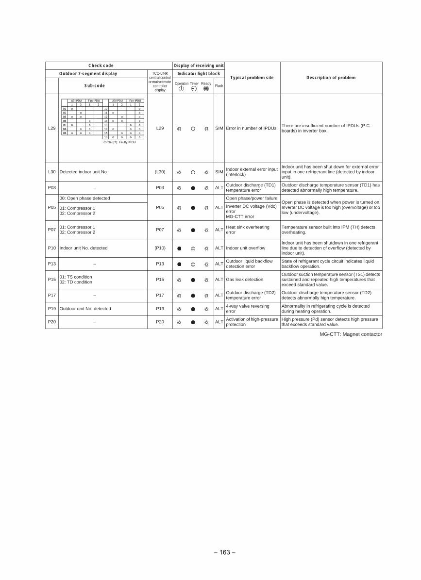
MG-CTT: Magnet contactor
sUDPI fo rebmun ni rorrEMIS92L92L There are insufficient number of IPDUs (P.C. boards) in inverter box.
MIS)03L(.oN tinu roodni detceteD03L Indoor external error input (interlock)
Indoor unit has been shut down for external error input in one refrigerant line (detected by indoor unit).
TLA30P–30P Outdoor discharge (TD1) temperature error
Outdoor discharge temperature sensor (TD1) has detected abnormally high temperature.
P05
00: Open phase detected
TLA50P
Open phase/power failureOpen phase is detected when power is turned on.Inverter DC voltage is too high (overvoltage) or too low (undervoltage).
01: Compressor 102: Compressor 2
Inverter DC voltage (Vdc) errorMG-CTT error
P07 01: Compressor 102: Compressor 2 TLA70P Heat sink overheating
errorTemperature sensor built into IPM (TH) detects overheating.
wolfrevo tinu roodnITLA)01P(detceted .oN tinu roodnI01PIndoor unit has been shutdown in one refrigerant line due to detection of overflow (detected by indoor unit).
TLA31P–31P Outdoor liquid backflow detection error
State of refrigerant cycle circuit indicates liquid backflow operation.
P15 01: TS condition02: TD condition noitceted kael saGTLA51P
Outdoor suction temperature sensor (TS1) detects sustained and repeated high temperatures that exceed standard value.
TLA71P–71P Outdoor discharge (TD2) temperature error
Outdoor discharge temperature sensor (TD2) detects abnormally high temperature.
TLA91Pdetceted .oN tinu roodtuO91P 4-way valve reversing error
Abnormality in refrigerating cycle is detected during heating operation.
TLA02P–02P Activation of high-pressure protection
High pressure (Pd) sensor detects high pressure that exceeds standard value.
Check code Display of receiving unit
Typical problem site Description of problemOutdoor 7-segment display TCC-LINK
central control or main remote
controller display
Indicator light block
Sub-code FlashOperation Timer Ready
Circle (O): Faulty IPDU
1 2 1 2 1 2 1 2
01 10
02 11
03 12
08 13
09 18
0A 19
0B 1A
1B
A3-IPDU A3-IPDU Fan-IPDUFan-IPDU
− 163 −
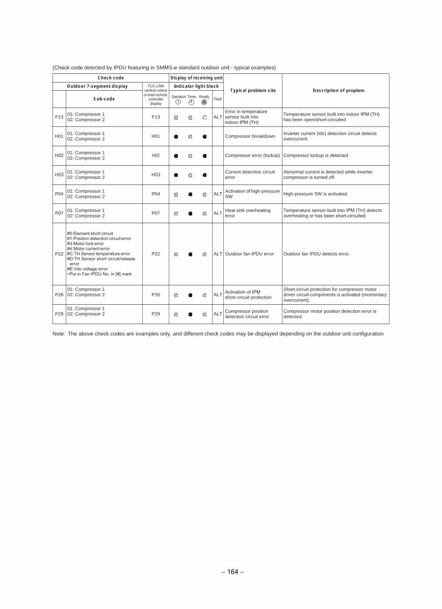
(Check code detected by IPDU featuring in SMMS-e standard outdoor unit - typical examples)
Note: The above check codes are examples only, and different check codes may be displayed depending on the outdoor unit configuration
Check code Display of receiving unit
Typical problem site Description of proplemOutdoor 7-segment display TCC-LINK
central control or main remote
controller display
Indicator light block
Sub-code Flash
F13 01: Compressor 102: Compressor 2 TLA31F
Error in temperature sensor built into indoor IPM (TH)
Temperature sensor built into indoor IPM (TH) has been open/short-circuited.
H01 01: Compressor 102: Compressor 2 nwodkaerb rosserpmoC10H Inverter current (Idc) detection circuit detects
overcurrent.
H02 01: Compressor 102: Compressor 2 H02 Compressor error (lockup) Compressor lockup is detected
H03 01: Compressor 102: Compressor 2 H03 Current detection circuit
errorAbnormal current is detected while inverter compressor is turned off.
P04 01: Compressor 102: Compressor 2 TLA40P Activation of high-pressure
SW High-pressure SW is activated.
P07 01: Compressor 102: Compressor 2 TLA70P Heat sink overheating
errorTemperature sensor built into IPM (TH) detects overheating or has been short-circuited.
P22
#0:Element short circuit#1:Position detection circuit error #3:Motor lock error#4:Motor current error#C:TH Sensor temperature error #D:TH Sensor short circuit/release error#E:Vdc voltage error∗Put in Fan IPDU No. in [#] mark
.rorre stceted UDPI naf roodtuOrorre UDPI naf roodtuOTLA22P
P2601: Compressor 102: Compressor 2 TLA62P Activation of IPM
short-circuit protection
Short-circuit protection for compressor motor driver circuit components is activated (momentary overcurrent).
P2901: Compressor 102: Compressor 2 TLA92P Compressor position
detection circuit errorCompressor motor position detection error is detected.
Operation Timer Ready
− 164 −
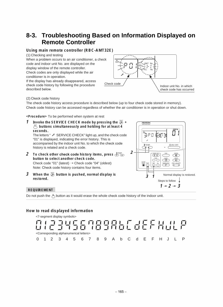
8-3. Troubleshooting Based on Information Displayed on Remote Controller
Using main remote controller (RBC-AMT32E)(1) Checking and testingWhen a problem occurs to an air conditioner, a check code and indoor unit No. are displayed on the display window of the remote controller.Check codes are only displayed while the air conditioner is in operation.If the display has already disappeared, access check code history by following the procedure described below.
(2) Ckeck code historyThe check code history access procedure is described below (up to four check code stored in memory). Check code history can be accessed regardless of whether the air conditioner is in operation or shut down.
<Procedure> To be performed when system at rest
1 Invoke the SERVICE CHECK mode by pressing the + buttons simultaneously and holding for at least 4
seconds.The letters “ SERVICE CHECK” light up, and the check code “01” is displayed, indicating the error history. This is accompanied by the indoor unit No. to which the check code history is related and a check code.
2 To check other check code history items, press thebutton to select another check code.Check code “01” (latest) Check code “04” (oldest) Note: Check code history contains four items.
3 When the button is pushed, normal display is restored.
REQUIREMENT
Do not push the button as it would erase the whole check code history of the indoor unit.
How to read displayed information
Check codeIndoor unit No. in which check code has occurred
SET
TIME
TIMER SET
TESTFILTERRESET
TEMP.
CL
FAN
SAVE
SWING/FIX
VENT
MODE
ON / OFF
UNIT LOUVER
13
321
2
Normal display is restored.
Steps to follow
0 1 2 3 4 5 6 7 8 9 A b C d E F H J L P
<7-segment display symbols>
<Corresponding alphanumerical letters>
− 165 −
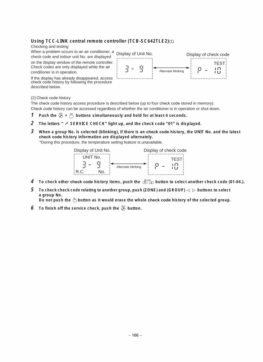
Using TCC-LINK central remote controller (TCB-SC642TLE2)(1) Checking and testingWhen a problem occurs to an air conditioner, a Display of Unit No.check code and indoor unit No. are displayed on the display window of the remote controller. UNIT No.Check codes are only displayed while the air conditioner is in operation. Alternate blinking
If the display has already disappeared, access R.C. No.check code history by following the procedure described below.
(2) Check code historyThe check code history access procedure is described below (up to four check code stored in memory). Check code history can be accessed regardless of whether the air conditioner is in operation or shut down.
1 Push the + buttons simultaneously and hold for at least 4 seconds.
2 The letters “ SERVICE CHECK” light up, and the check code “01” is displayed.
3 When a group No. is selected (blinking), if there is an check code history, the UNIT No. and the latestcheck code history information are displayed alternately.*During this procedure, the temperature setting feature is unavailable.
4 To check other check code history items, push the button to select another check code (01-04.).
5 To check check code relating to another group, push (ZONE) and (GROUP) buttons to select a group No.Do not push the button as it would erase the whole check code history of the selected group.
6 To finish off the service check, push the button.
TEST
Display of check code
Display of Unit No.
Alternate blinking
UNIT No.
No.R.C.
TEST
Display of check code
− 166 −
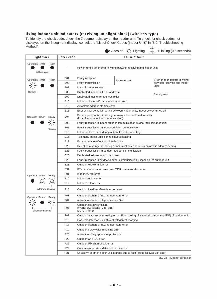
Using indoor unit indicators (receiving unit light block) (wireless type)To identify the check code, check the 7-segment display on the header unit. To check for check codes not displayed on the 7-segment display, consult the “List of Check Codes (Indoor Unit)” in “8-2. Troubleshooting Method”.
: Goes off : Lighting : Blinking (0.5 seconds)
tluaf fo esuaCedoc kcehCkcolb thgiL
– Power turned off or error in wiring between receiving and indoor units
E01 Faulty receptionReceiving unit Error or poor contact in wiring
between receiving and indoor units
E02 Faulty transmission
E03 Loss of communication
E08 Duplicated indoor unit No. (address)Setting error
E09 Duplicated master remote controller
E10 Indoor unit inter-MCU communication error
E12 Automatic address starting error
E18 Error or poor contact in wiring between indoor units, indoor power turned off
E04 Error or poor contact in wiring between indoor and outdoor units(loss of indoor-outdoor communication)
E06 Faulty reception in indoor-outdoor communication (Signal lack of indoor unit)
E07 Faulty transmission in indoor-outdoor communication
E15 Indoor unit not found during automatic address setting
E16 Too many indoor units connected/overloading
E19 Error in number of outdoor header units
E20 Detection of refrigerant piping communication error during automatic address setting
E23 Faulty transmission in outdoor-outdoor communication
E25 Duplicated follower outdoor address
E26 Faulty reception in outdoor-outdoor communication, Signal lack of outdoor unit
E28 Outdoor follower unit error
E31 IPDU communication error, sub MCU communication error
P01 Indoor AC fan error
P10 Indoor overflow error
P12 Indoor DC fan error
P13 Outdoor liquid backflow detection error
P03 Outdoor discharge (TD1) temperature error
P04 Activation of outdoor high-pressure SW
P05Open phase/power failureInverter DC voltage (Vdc) errorMG-CTT error
P07 Outdoor heat sink overheating error - Poor cooling of electrical component (IPM) of outdoor unit
P15 Gas leak detection - insufficient refrigerant charging
P17 Outdoor discharge (TD2) temperature error
P19 Outdoor 4-way valve reversing error
P20 Activation of high-pressure protection
P22 Outdoor fan IPDU error
P26 Outdoor IPM short-circuit error
P29 Compressor position detection circuit error
P31 Shutdown of other indoor unit in group due to fault (group follower unit error)
Operation Timer Ready
All lights out
Blinking
Operation Timer Ready
Blinking
Operation Timer Ready
Alternate blinking
Operation Timer Ready
Alternate blinking
Operation Timer Ready
MG-CTT: Magnet contactor
− 167 −
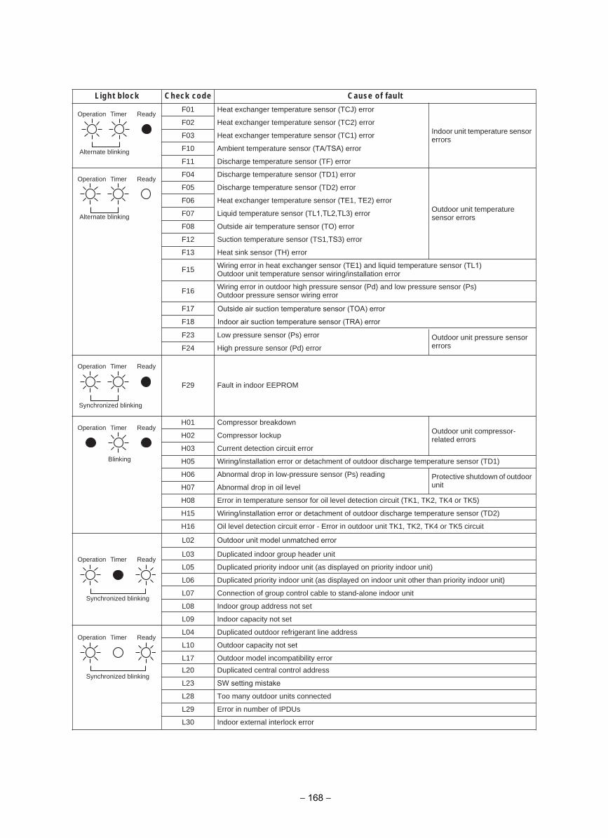
F01
Indoor unit temperature sensor errors
F02
F03
F10
F11
Heat exchanger temperature sensor (TCJ) error
Heat exchanger temperature sensor (TC2) error
Heat exchanger temperature sensor (TC1) error
Ambient temperature sensor (TA/TSA) error
Discharge temperature sensor (TF) error
F04
Outdoor unit temperature sensor errors
F05
F06
F07
F08
F12
F13
Discharge temperature sensor (TD1) error
Discharge temperature sensor (TD2) error
Heat exchanger temperature sensor (TE1, TE2) error
Liquid temperature sensor (TL1,TL2,TL3) error
Outside air temperature sensor (TO) error
Suction temperature sensor (TS1,TS3) error
Heat sink sensor (TH) error
F15 Wiring error in heat exchanger sensor (TE1) and liquid temperature sensor (TL1) Outdoor unit temperature sensor wiring/installation error
F16 Wiring error in outdoor high pressure sensor (Pd) and low pressure sensor (Ps)Outdoor pressure sensor wiring error
F23 Low pressure sensor (Ps) error Outdoor unit pressure sensor errorsF24 High pressure sensor (Pd) error
F29 Fault in indoor EEPROM
H01 Compressor breakdownOutdoor unit compressor-related errorsH02 Compressor lockup
H03 Current detection circuit error
H05 Wiring/installation error or detachment of outdoor discharge temperature sensor (TD1)
H06 Abnormal drop in low-pressure sensor (Ps) reading Protective shutdown of outdoor unitH07 Abnormal drop in oil level
H08 Error in temperature sensor for oil level detection circuit (TK1, TK2, TK4 or TK5)
H15 Wiring/installation error or detachment of outdoor discharge temperature sensor (TD2)
H16 Oil level detection circuit error - Error in outdoor unit TK1, TK2, TK4 or TK5 circuit
L03 Duplicated indoor group header unit
L05 Duplicated priority indoor unit (as displayed on priority indoor unit)
L06 Duplicated priority indoor unit (as displayed on indoor unit other than priority indoor unit)
L07 Connection of group control cable to stand-alone indoor unit
L08 Indoor group address not set
L09 Indoor capacity not set
L04 Duplicated outdoor refrigerant line address
L10 Outdoor capacity not set
L17 Outdoor model incompatibility error
L20 Duplicated central control address
L28 Too many outdoor units connected
L29 Error in number of IPDUs
L30 Indoor external interlock error
tluaf fo esuaCedoc kcehCkcolb thgiL
Alternate blinking
Operation Timer Ready
Alternate blinking
Operation Timer Ready
Operation
Synchronized blinking
Timer Ready
Operation Timer Ready
Blinking
Operation
Synchronized blinking
Timer Ready
Operation
Synchronized blinking
Timer Ready
L23 SW setting mistake
F17
F18
Outside air suction temperature sensor (TOA) error
Indoor air suction temperature sensor (TRA) error
L02 Outdoor unit model unmatched error
− 168 −
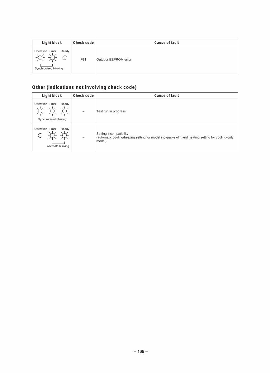
Other (indications not involving check code)
F31 Outdoor EEPROM error
tluaf fo esuaCedoc kcehCkcolb thgiL
– Test run in progress
–Setting incompatibility(automatic cooling/heating setting for model incapable of it and heating setting for cooling-only model)
tluaf fo esuaCedoc kcehCkcolb thgiL
Operation
Synchronized blinking
Timer Ready
Operation Timer
Synchronized blinking
Ready
Alternate blinking
Operation Timer Ready
− 169 −
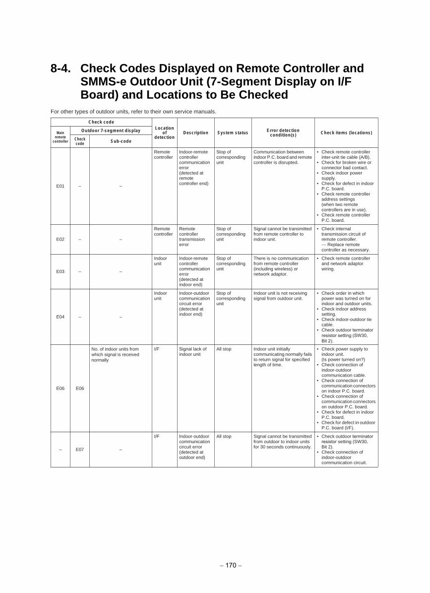
8-4. Check Codes Displayed on Remote Controller and SMMS-e Outdoor Unit (7-Segment Display on I/F Board) and Locations to Be Checked
For other types of outdoor units, refer to their own service manuals.
Check codeLocation
ofdetection
Description System status Error detection condition(s) Check items (locations)Main
remote controller
Outdoor 7-segment display
Checkcode Sub-code
E01 – –
Remotecontroller
Indoor-remote controller communication error(detected at remote controller end)
Stop of corresponding unit
Communication between indoor P.C. board and remote controller is disrupted.
• Check remote controller inter-unit tie cable (A/B).
• Check for broken wire or connector bad contact.
• Check indoor power supply.
• Check for defect in indoor P.C. board.
• Check remote controller address settings(when two remote controllers are in use).
• Check remote controller P.C. board.
E02 – –
Remotecontroller
Remote controller transmission error
Stop of corresponding unit
Signal cannot be transmitted from remote controller to indoor unit.
• Check internal transmission circuit of remote controller.--- Replace remote controller as necessary.
E03 – –
Indoor unit
Indoor-remote controller communication error(detected at indoor end)
Stop of corresponding unit
There is no communication from remote controller (including wireless) or network adaptor.
• Check remote controller and network adaptor wiring.
E04 – –
Indoor unit
Indoor-outdoor communication circuit error(detected at indoor end)
Stop of corresponding unit
Indoor unit is not receiving signal from outdoor unit.
• Check order in which power was turned on for indoor and outdoor units.
• Check indoor address setting.
• Check indoor-outdoor tie cable.
• Check outdoor terminator resistor setting (SW30,Bit 2).
E06 E06
I/F Signal lack of indoor unit
All stop Indoor unit initially communicating normally fails to return signal for specified length of time.
• Check power supply to indoor unit.(Is power turned on?)
• Check connection of indoor-outdoor communication cable.
• Check connection of communication connectors on indoor P.C. board.
• Check connection of communication connectors on outdoor P.C. board.
• Check for defect in indoorP.C. board.
• Check for defect in outdoor P.C. board (I/F).
– E07 –
I/F Indoor-outdoor communication circuit error(detected at outdoor end)
All stop Signal cannot be transmitted from outdoor to indoor units for 30 seconds continuously.
• Check outdoor terminator resistor setting (SW30, Bit 2).
• Check connection of indoor-outdoor communication circuit.
No. of indoor units from which signal is received normally
− 170 −
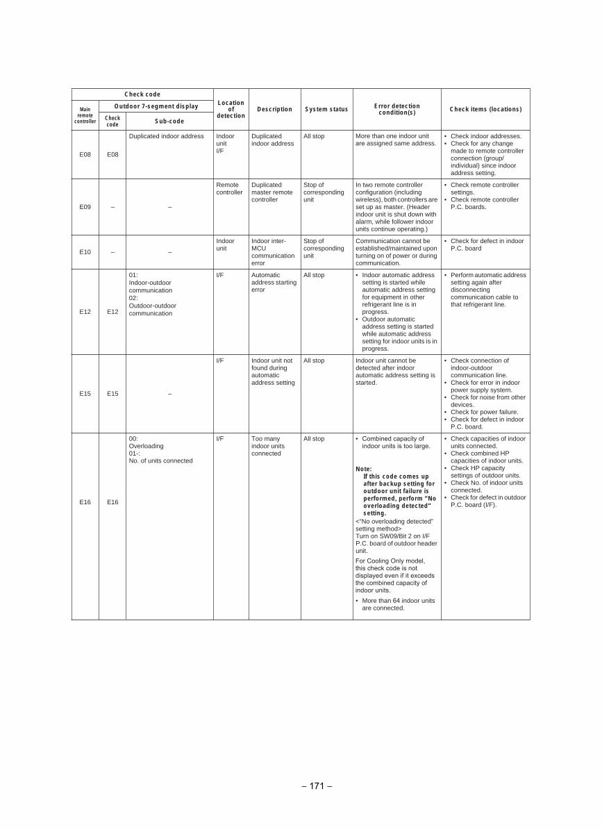
Check codeLocation
ofdetection
Description System status Error detection condition(s) Check items (locations)Main
remote controller
Outdoor 7-segment display
Checkcode Sub-code
E08 E08
Duplicated indoor address Indoor unitI/F
Duplicated indoor address
All stop More than one indoor unit are assigned same address.
• Check indoor addresses.• Check for any change
made to remote controller connection (group/individual) since indoor address setting.
E09 – –
Remote controller
Duplicated master remote controller
Stop of corresponding unit
In two remote controller configuration (including wireless), both controllers are set up as master. (Header indoor unit is shut down with alarm, while follower indoor units continue operating.)
• Check remote controller settings.
• Check remote controller P.C. boards.
E10 – –
Indoor unit
Indoor inter-MCUcommunication error
Stop of corresponding unit
Communication cannot be established/maintained upon turning on of power or during communication.
• Check for defect in indoorP.C. board
E12 E12
I/F Automatic address starting error
All stop • Indoor automatic address setting is started while automatic address setting for equipment in other refrigerant line is in progress.
• Outdoor automatic address setting is started while automatic address setting for indoor units is in progress.
• Perform automatic address setting again after disconnecting communication cable to that refrigerant line.
E15 E15 –
I/F Indoor unit not found during automatic address setting
All stop Indoor unit cannot be detected after indoor automatic address setting is started.
• Check connection of indoor-outdoor communication line.
• Check for error in indoor power supply system.
• Check for noise from other devices.
• Check for power failure.• Check for defect in indoor
P.C. board.
E16 E16
00: Overloading01-: No. of units connected
I/F Too many indoor units connected
All stop • Combined capacity of indoor units is too large.
Note: If this code comes up after backup setting for outdoor unit failure is performed, perform “No overloading detected” setting.
<“No overloading detected” setting method> Turn on SW09/Bit 2 on I/F P.C. board of outdoor header unit.
• More than 64 indoor units are connected.
• Check capacities of indoor units connected.
• Check combined HP capacities of indoor units.
• Check HP capacity settings of outdoor units.
• Check No. of indoor units connected.
• Check for defect in outdoor P.C. board (I/F).
01:Indoor-outdoorcommunication02:Outdoor-outdoorcommunication
− 171 −
For Cooling Only model, this check code is not displayed even if it exceeds the combined capacity of indoor units.
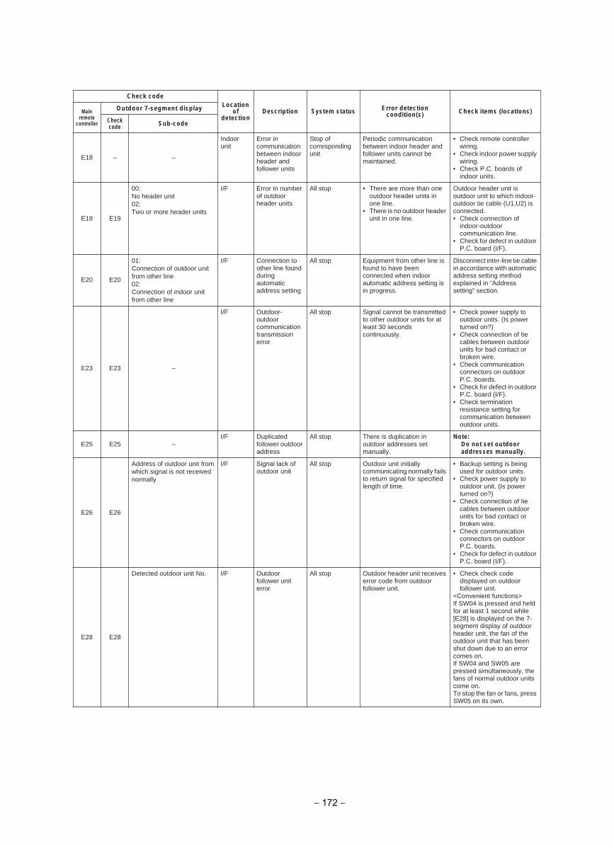
Check codeLocation
ofdetection
Description System status Error detection condition(s) Check items (locations)Main
remote controller
Outdoor 7-segment display
Checkcode Sub-code
E18 – –
Indoor unit
Error in communication between indoor header and follower units
Stop of corresponding unit
Periodic communication between indoor header and follower units cannot be maintained.
• Check remote controller wiring.
• Check indoor power supply wiring.
• Check P.C. boards of indoor units.
E19 E19
00:No header unit02:Two or more header units
I/F Error in number of outdoor header units
All stop • There are more than one outdoor header units in one line.
• There is no outdoor header unit in one line.
Outdoor header unit is outdoor unit to which indoor-outdoor tie cable (U1,U2) is connected.• Check connection of
indoor-outdoor communication line.
• Check for defect in outdoor P.C. board (I/F).
E20 E20
01:Connection of outdoor unitfrom other line02:Connection of indoor unit from other line
I/F Connection to other line found during automatic address setting
All stop Equipment from other line is found to have been connected when indoor automatic address setting is in progress.
Disconnect inter-line tie cable in accordance with automatic address setting method explained in “Address setting” section.
E23 E23 –
I/F Outdoor-outdoor communication transmission error
All stop Signal cannot be transmitted to other outdoor units for at least 30 seconds continuously.
• Check power supply to outdoor units. (Is power turned on?)
• Check connection of tie cables between outdoor units for bad contact or broken wire.
• Check communication connectors on outdoor P.C. boards.
• Check for defect in outdoor P.C. board (I/F).
• Check termination resistance setting for communication between outdoor units.
E25 E25 –I/F Duplicated
follower outdoor address
All stop There is duplication in outdoor addresses set manually.
Note: Do not set outdoor addresses manually.
E26 E26
Address of outdoor unit from which signal is not receivednormally
I/F Signal lack of outdoor unit
All stop Outdoor unit initially communicating normally fails to return signal for specified length of time.
• Backup setting is being used for outdoor units.
• Check power supply to outdoor unit. (Is power turned on?)
• Check connection of tie cables between outdoor units for bad contact or broken wire.
• Check communication connectors on outdoor P.C. boards.
• Check for defect in outdoor P.C. board (I/F).
E28 E28
I/F Outdoor follower unit error
All stop Outdoor header unit receives error code from outdoor follower unit.
• Check check code displayed on outdoor follower unit.
<Convenient functions>If SW04 is pressed and held for at least 1 second while [E28] is displayed on the 7-segment display of outdoor header unit, the fan of the outdoor unit that has been shut down due to an error comes on.If SW04 and SW05 are pressed simultaneously, the fans of normal outdoor units come on.To stop the fan or fans, press SW05 on its own.
Detected outdoor unit No.
− 172 −
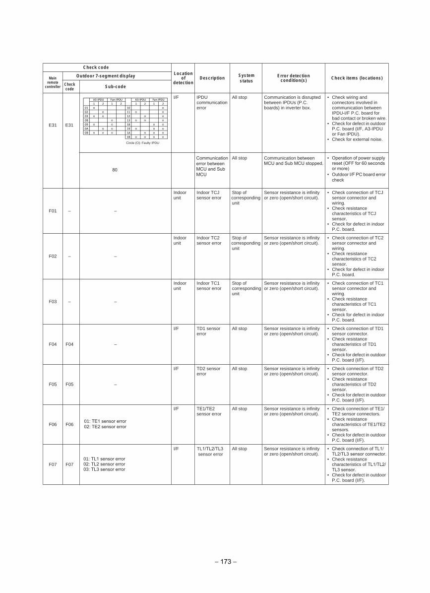
Check codeLocation
ofdetection
Description System status
Error detection condition(s) Check items (locations)Main
remote controller
Outdoor 7-segment display
Checkcode Sub-code
E31 E31
I/F IPDU communication error
All stop Communication is disrupted between IPDUs (P.C. boards) in inverter box.
• Check wiring and connectors involved in communication between IPDU-I/F P.C. board for bad contact or broken wire.
• Check for defect in outdoor P.C. board (I/F, A3-IPDU or Fan IPDU).
• Check for external noise.
F01 – –
Indoor unit
Indoor TCJ sensor error
Stop of corresponding unit
Sensor resistance is infinity or zero (open/short circuit).
• Check connection of TCJ sensor connector and wiring.
• Check resistance characteristics of TCJ sensor.
• Check for defect in indoor P.C. board.
F02 – –
Indoor unit
Indoor TC2 sensor error
Stop of corresponding unit
Sensor resistance is infinity or zero (open/short circuit).
• Check connection of TC2 sensor connector and wiring.
• Check resistance characteristics of TC2 sensor.
• Check for defect in indoor P.C. board.
F03 – –
Indoor unit
Indoor TC1 sensor error
Stop of corresponding unit
Sensor resistance is infinity or zero (open/short circuit).
• Check connection of TC1 sensor connector and wiring.
• Check resistance characteristics of TC1 sensor.
• Check for defect in indoor P.C. board.
F04 F04 –
I/F TD1 sensor error
All stop Sensor resistance is infinity or zero (open/short circuit).
• Check connection of TD1 sensor connector.
• Check resistance characteristics of TD1 sensor.
• Check for defect in outdoor P.C. board (I/F).
F05 F05 –
I/F TD2 sensor error
All stop Sensor resistance is infinity or zero (open/short circuit).
• Check connection of TD2 sensor connector.
• Check resistance characteristics of TD2 sensor.
• Check for defect in outdoor P.C. board (I/F).
F06 F0601: TE1 sensor error02: TE2 sensor error
I/F TE1/TE2 sensor error
All stop Sensor resistance is infinity or zero (open/short circuit).
• Check connection of TE1/TE2 sensor connectors.
• Check resistance characteristics of TE1/TE2 sensors.
• Check for defect in outdoor P.C. board (I/F).
F07 F07
I/F TL1/TL2/TL3 sensor error
All stop Sensor resistance is infinity or zero (open/short circuit).
• Check connection of TL1/TL2/TL3 sensor connector.
• Check resistance characteristics of TL1/TL2/TL3 sensor.
• Check for defect in outdoor P.C. board (I/F).
Circle (O): Faulty IPDU
01: TL1 sensor error02: TL2 sensor error03: TL3 sensor error
Communication error between MCU and Sub MCU
All stop Communication between MCU and Sub MCU stopped.
• Operation of power supply reset (OFF for 60 seconds or more)
• Outdoor I/F PC board error check
80
1 2 1 2 1 2 1 2
01 10
02 11
03 12
08 13
09 18
0A 19
0B 1A
1B
A3-IPDU A3-IPDU Fan-IPDUFan-IPDU
− 173 −
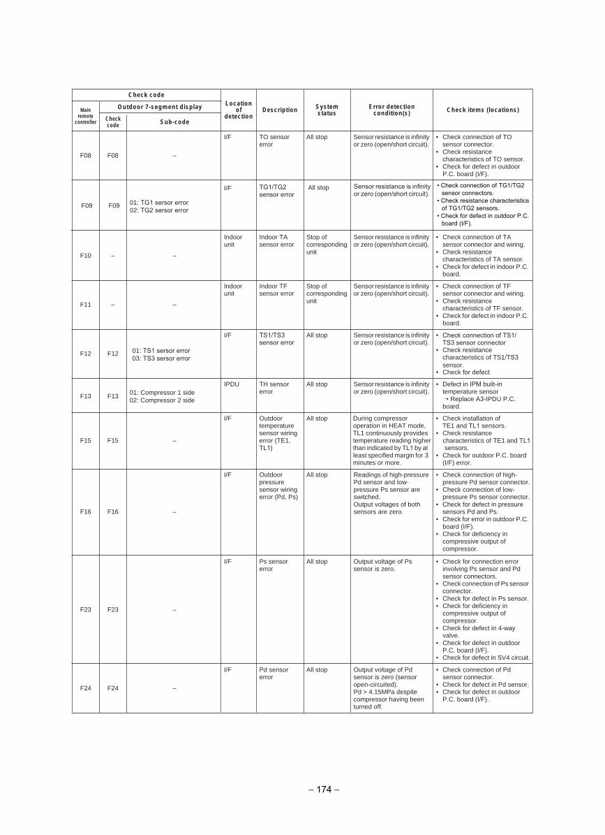
Check codeLocation
ofdetection
Description System status
Error detection condition(s) Check items (locations)Main
remote controller
Outdoor 7-segment display
Checkcode Sub-code
F08 F08 –
I/F TO sensor error
All stop Sensor resistance is infinity or zero (open/short circuit).
• Check connection of TO sensor connector.
• Check resistance characteristics of TO sensor.
• Check for defect in outdoor P.C. board (I/F).
F10 – –
Indoor unit
Indoor TA sensor error
Stop of correspondingunit
Sensor resistance is infinity or zero (open/short circuit).
• Check connection of TA sensor connector and wiring.
• Check resistance characteristics of TA sensor.
• Check for defect in indoor P.C. board.
F11 – –
Indoor unit
Indoor TF sensor error
Stop of correspondingunit
Sensor resistance is infinity or zero (open/short circuit).
• Check connection of TF sensor connector and wiring.
• Check resistance characteristics of TF sensor.
• Check for defect in indoor P.C. board.
F12 F12
I/F TS1/TS3 sensor error
All stop Sensor resistance is infinity or zero (open/short circuit).
• Check connection of TS1/TS3 sensor connector
• Check resistance characteristics of TS1/TS3sensor.
• Check for defect
F13 F13 01: Compressor 1 side 02: Compressor 2 side
IPDU TH sensor error
All stop Sensor resistance is infinity or zero (open/short circuit).
• Defect in IPM built-in temperature sensor
Replace A3-IPDU P.C. board.
F15 F15 –
I/F Outdoor temperature sensor wiring error (TE1, TL1)
All stop During compressor operation in HEAT mode, TL1 continuously provides temperature reading higher than indicated by TL1 by at least specified margin for 3 minutes or more.
• Check installation of TE1 and TL1 sensors.
• Check resistance characteristics of TE1 and TL1 sensors.
• Check for outdoor P.C. board (I/F) error.
F16 F16 –
I/F Outdoor pressure sensor wiring error (Pd, Ps)
All stop Readings of high-pressure Pd sensor and low-pressure Ps sensor are switched.Output voltages of both sensors are zero.
• Check connection of high-pressure Pd sensor connector.
• Check connection of low-pressure Ps sensor connector.
• Check for defect in pressure sensors Pd and Ps.
• Check for error in outdoor P.C. board (I/F).
• Check for deficiency in compressive output of compressor.
F23 F23 –
I/F Ps sensor error
All stop Output voltage of Ps sensor is zero.
• Check for connection error involving Ps sensor and Pd sensor connectors.
• Check connection of Ps sensor connector.
• Check for defect in Ps sensor.• Check for deficiency in
compressive output of compressor.
• Check for defect in 4-way valve.
• Check for defect in outdoor P.C. board (I/F).
• Check for defect in SV4 circuit.
F24 F24 –
I/F Pd sensor error
All stop Output voltage of Pd sensor is zero (sensor open-circuited). Pd > 4.15MPa despite compressor having been turned off.
• Check connection of Pd sensor connector.
• Check for defect in Pd sensor.• Check for defect in outdoor
P.C. board (I/F).
• Check connection of TG1/TG2sensor connectors.
• Check resistance characteristicsof TG1/TG2 sensors.
• Check for defect in outdoor P.C.board (I/F).
Sensor resistance is infinityor zero (open/short circuit).
All stopTG1/TG2sensor error
I/F
F09 F09 01: TG1 sersor error 02: TG2 sersor error
01: TS1 sersor error03: TS3 sersor error
− 174 −
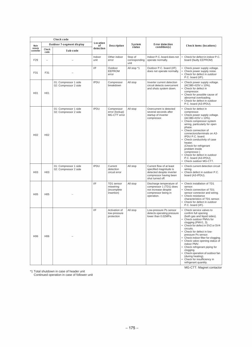
MG-CTT: Magnet contactor*1 Total shutdown in case of header unit
Continued operation in case of follower unit
Check codeLocation
ofdetection
Description System status
Error detection condition(s) Check items (locations)Main
remote controller
Outdoor 7-segment display
Checkcode Sub-code
F29 – –Indoor unit
Other indoor error
Stop of correspondingunit
Indoor P.C. board does not operate normally.
• Check for defect in indoor P.C. board (faulty EEPROM)
F31 F31 –
I/F Outdoor EEPROM error
All stop *1 Outdoor P.C. board (I/F) does not operate normally.
• Check power supply voltage.• Check power supply noise.• Check for defect in outdoor
P.C. board (I/F).
H01 H01
01: Compressor 1 side 02: Compressor 2 side
IPDU Compressor breakdown
All stop Inverter current detection circuit detects overcurrent and shuts system down.
• Check power supply voltage. (AC380-415V ± 10%).
• Check for defect in compressor.
• Check for possible cause ofabnormal overloading.
• Check for defect in outdoor P.C. board (A3-IPDU).
H02 H02
01: Compressor 1 side 02: Compressor 2 side
IPDU Compressor error (lockup)MG-CTT error
All stop Overcurrent is detected several seconds after startup of inverter compressor.
• Check for defect in compressor.
• Check power supply voltage. (AC380-415V ± 10%).
• Check compressor system wiring, particularly for open phase.
• Check connection of connectors/terminals on A3-IPDU P.C. board.
• Check conductivity of case heater.(Check for refrigerant problem inside compressor.)
• Check for defect in outdoor P.C. board (A3-IPDU).
• Check outdoor MG-CTT.
H03 H03
01: Compressor 1 side 02: Compressor 2 side
IPDU Current detection circuit error
All stop Current flow of at least specified magnitude is detected despite inverter compressor having been shut turned off.
• Check current detection circuit wiring.
• Check defect in outdoor P.C. board (A3-IPDU).
H05 H05 –
I/F TD1 sensor miswiring (incomplete insertion)
All stop Discharge temperature of compressor 1 (TD1) does not increase despite compressor being in operation.
• Check installation of TD1 sensor.
• Check connection of TD1 sensor connector and wiring.
• Check resistance characteristics of TD1 sensor.
• Check for defect in outdoor P.C. board (I/F).
H06 H06 –
I/F Activation of low-pressure protection
All stop Low-pressure Ps sensor detects operating pressure lower than 0.02MPa.
• Check service valves to confirm full opening(both gas and liquid sides).
• Check outdoor PMVs for clogging (PMV1, 3).
• Check for defect in SV2 or SV4 circuits.
• Check for defect in low-pressure Ps sensor.
• Check indoor filter for clogging.• Check valve opening status of
indoor PMV.• Check refrigerant piping for
clogging.• Check operation of outdoor fan
(during heating).• Check for insufficiency in
refrigerant quantity.
− 175 −
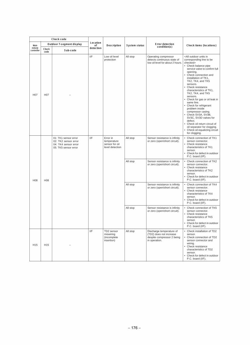
Check codeLocation
ofdetection
Description System status Error detection condition(s) Check items (locations)Main
remote controller
Outdoor 7-segment display
Checkcode Sub-code
H07 H07 –
I/F Low oil level protection
All stop Operating compressor detects continuous state of low oil level for about 2 hours.
<All outdoor units in corresponding line to be checked>• Check balance pipe
service valve to confirm full opening.
• Check connection and installation of TK1, TK2, TK4, and TK5 sensors.
• Check resistance characteristics of TK1, TK2, TK4, and TK5 sensors.
• Check for gas or oil leak insame line.
• Check for refrigerant problem inside compressor casing.
• Check SV3A, SV3B, SV3C, SV3D valves for defect.
• Check oil return circuit of oil separator for clogging.
• Check oil equalizing circuit for clogging.
H08 H08
01: TK1 sensor error 02: TK2 sensor error 04: TK4 sensor error 05: TK5 sensor error
I/F Error in temperature sensor for oil level detection
All stop Sensor resistance is infinity or zero (open/short circuit).
• Check connection of TK1 sensor connector.
• Check resistance characteristics of TK1 sensor.
• Check for defect in outdoor P.C. board (I/F).
All stop Sensor resistance is infinity or zero (open/short circuit).
• Check connection of TK2 sensor connector.
• Check resistance characteristics of TK2 sensor.
• Check for defect in outdoor P.C. board (I/F).
All stop Sensor resistance is infinity or zero (open/short circuit).
• Check connection of TK4 sensor connector.
• Check resistance characteristics of TK4 sensor.
• Check for defect in outdoor P.C. board (I/F).
All stop Sensor resistance is infinity or zero (open/short circuit).
• Check connection of TK5 sensor connector.
• Check resistance characteristics of TK5 sensor.
• Check for defect in outdoor P.C. board (I/F).
H15 H15 –
I/F TD2 sensor miswiring (incomplete insertion)
All stop Discharge temperature of (TD2) does not increase despite compressor 2 being in operation.
• Check installation of TD2 sensor.
• Check connection of TD2 sensor connector and wiring.
• Check resistance characteristics of TD2 sensor.
• Check for defect in outdoor P.C. board (I/F).
− 176 −
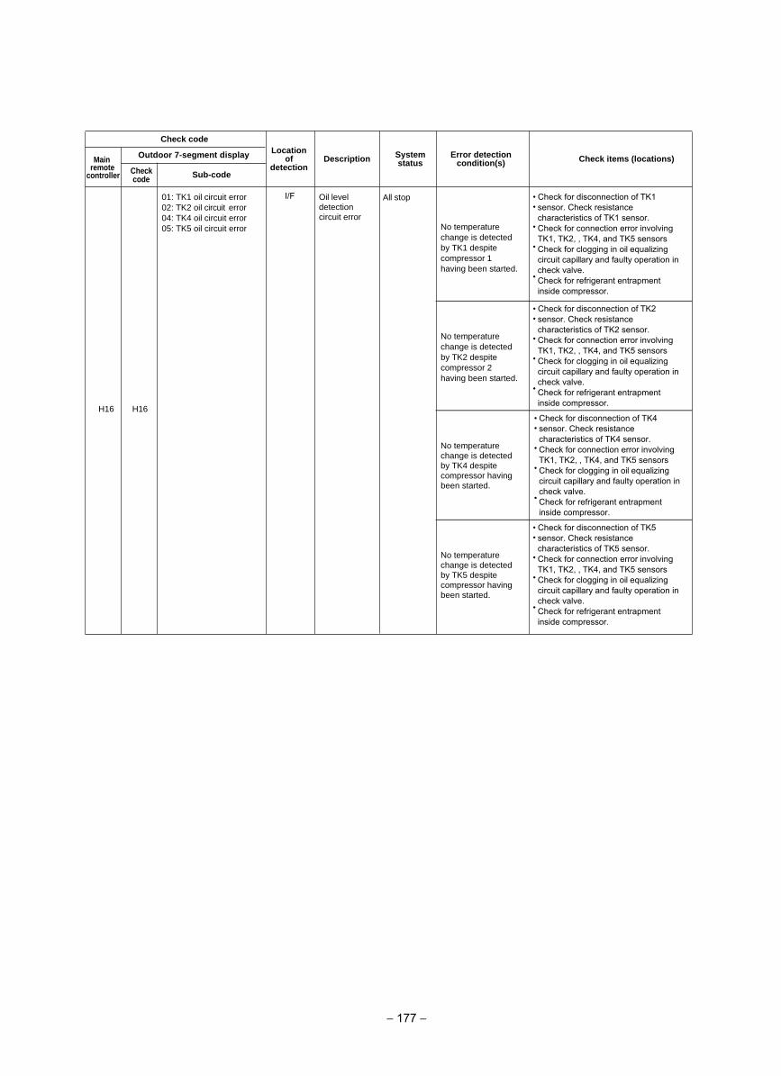
Check codeLocation
ofdetection
Description System status
Error detection condition(s)Main Check items (locations)
remote Outdoor 7-segment display
controller Checkcode Sub-code
Oil leveldetectioncircuit error
All stop01: TK1 oil circuit error02: TK2 oil circuit error 04: TK4 oil circuit error 05: TK5 oil circuit error
• •
No temperature change is detected by TK1 despite compressor 1 having been started.
•
•
•
Check for disconnection of TK1 sensor. Check resistance characteristics of TK1 sensor.Check for connection error involving TK1, TK2, , TK4, and TK5 sensorsCheck for clogging in oil equalizing circuit capillary and faulty operation in check valve.Check for refrigerant entrapment inside compressor.
• •
No temperature change is detected by TK2 despite compressor 2 having been started.
•
•
•
Check for disconnection of TK2 sensor. Check resistance characteristics of TK2 sensor.Check for connection error involving TK1, TK2, , TK4, and TK5 sensorsCheck for clogging in oil equalizing circuit capillary and faulty operation in check valve.Check for refrigerant entrapment inside compressor.
I/F
No temperaturechange is detectedby TK4 despitecompressor having
•
been started.
•
•
•
•
Check for disconnection of TK4 sensor. Check resistance characteristics of TK4 sensor.Check for connection error involving TK1, TK2, , TK4, and TK5 sensorsCheck for clogging in oil equalizing circuit capillary and faulty operation in check valve.Check for refrigerant entrapment inside compressor.
No temperaturechange is detectedby TK5 despitecompressor having
•
been started.
•
•
•
•
H16
Check for disconnection of TK5 sensor. Check resistance characteristics of TK5 sensor.Check for connection error involving TK1, TK2, , TK4, and TK5 sensorsCheck for clogging in oil equalizing circuit capillary and faulty operation in check valve.Check for refrigerant entrapment inside compressor.
H16
− 177 −
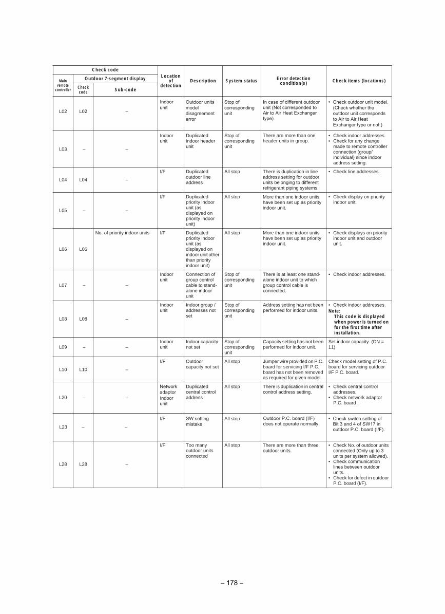
Check codeLocation
ofdetection
Description System status Error detection condition(s) Check items (locations)Main
remote controller
Outdoor 7-segment display
Checkcode Sub-code
L03 – –
Indoor unit
Duplicated indoor header unit
Stop of corresponding unit
There are more than one header units in group.
• Check indoor addresses.• Check for any change
made to remote controller connection (group/individual) since indoor address setting.
L04 L04 –
I/F Duplicated outdoor line address
All stop There is duplication in line address setting for outdoor units belonging to different refrigerant piping systems.
• Check line addresses.
L05 – –
I/F Duplicated priority indoor unit (as displayed on priority indoor unit)
All stop More than one indoor units have been set up as priority indoor unit.
• Check display on priorityindoor unit.
L06 L06
No. of priority indoor units I/F Duplicated priority indoor unit (as displayed on indoor unit other than priority indoor unit)
All stop More than one indoor units have been set up as priority indoor unit.
• Check displays on priority indoor unit and outdoor unit.
L07 – –
Indoor unit
Connection of group control cable to stand-alone indoor unit
Stop of corresponding unit
There is at least one stand-alone indoor unit to which group control cable is connected.
• Check indoor addresses.
L08 L08 –
Indoor unit
Indoor group / addresses not set
Stop of corresponding unit
Address setting has not been performed for indoor units.
• Check indoor addresses.Note:
This code is displayed when power is turned onfor the first time after installation.
L09 – –Indoor unit
Indoor capacity not set
Stop of corresponding unit
Capacity setting has not been performed for indoor unit.
Set indoor capacity. (DN = 11)
L10 L10 –
I/F Outdoor capacity not set
All stop Jumper wire provided on P.C. board for servicing I/F P.C. board has not been removed as required for given model.
Check model setting of P.C. board for servicing outdoor I/F P.C. board.
L20 – –
Network adaptorIndoor unit
Duplicated central control address
All stop There is duplication in central control address setting.
• Check central control addresses.
• Check network adaptor P.C. board .
L28 L28 –
I/F Too many outdoor units connected
All stop There are more than three outdoor units.
• Check No. of outdoor units connected (Only up to 3units per system allowed).
• Check communication lines between outdoor units.
• Check for defect in outdoor P.C. board (I/F).
Check switch setting of Bit 3 and 4 of SW17 in outdoor P.C. board (I/F).
Outdoor P.C. board (I/F) does not operate normally.
All stopSW setting mistake
I/F
––L23
•
L02 L02 –
Indoor unit
Outdoor units model disagreement error
Stop of corresponding unit
In case of different outdoor unit (Not corresponded to Air to Air Heat Exchanger type)
• Check outdoor unit model.(Check whether the outdoor unit corresponds to Air to Air Heat Exchanger type or not.)
− 178 −
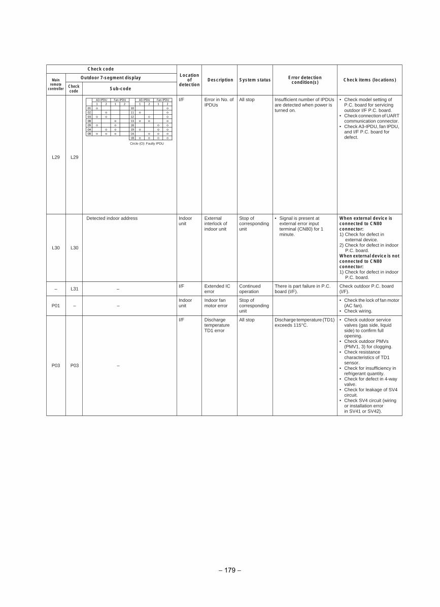
Check codeLocation
ofdetection
Description System status Error detection condition(s) Check items (locations)Main
remote controller
Outdoor 7-segment display
Checkcode Sub-code
L29 L29
I/F Error in No. of IPDUs
All stop Insufficient number of IPDUs are detected when power is turned on.
• Check model setting of P.C. board for servicing outdoor I/F P.C. board.
• Check connection of UARTcommunication connector.
• Check A3-IPDU, fan IPDU, and I/F P.C. board for defect.
L30 L30
Detected indoor address Indoor unit
External interlock of indoor unit
Stop of corresponding unit
• Signal is present at external error input terminal (CN80) for 1 minute.
When external device is connected to CN80 connector:1) Check for defect in
external device.2) Check for defect in indoor
P.C. board.When external device is not connected to CN80 connector:1) Check for defect in indoor
P.C. board.
– L31 – I/F Extended IC error
Continued operation
There is part failure in P.C. board (I/F).
Check outdoor P.C. board (I/F).
P01 – –Indoor unit
Indoor fan motor error
Stop of corresponding unit
• Check the lock of fan motor (AC fan).
• Check wiring.
P03 P03 –
I/F Discharge temperature TD1 error
All stop Discharge temperature (TD1) exceeds 115°C.
• Check outdoor service valves (gas side, liquid side) to confirm full opening.
• Check outdoor PMVs (PMV1, 3) for clogging.
• Check resistance characteristics of TD1 sensor.
• Check for insufficiency in refrigerant quantity.
• Check for defect in 4-way valve.
• Check for leakage of SV4 circuit.
• Check SV4 circuit (wiring or installation error in SV41 or SV42).
Circle (O): Faulty IPDU
1 2 1 2 1 2 1 2
01 10
02 11
03 12
08 13
09 18
0A 19
0B 1A
1B
A3-IPDU A3-IPDU Fan-IPDUFan-IPDU
− 179 −
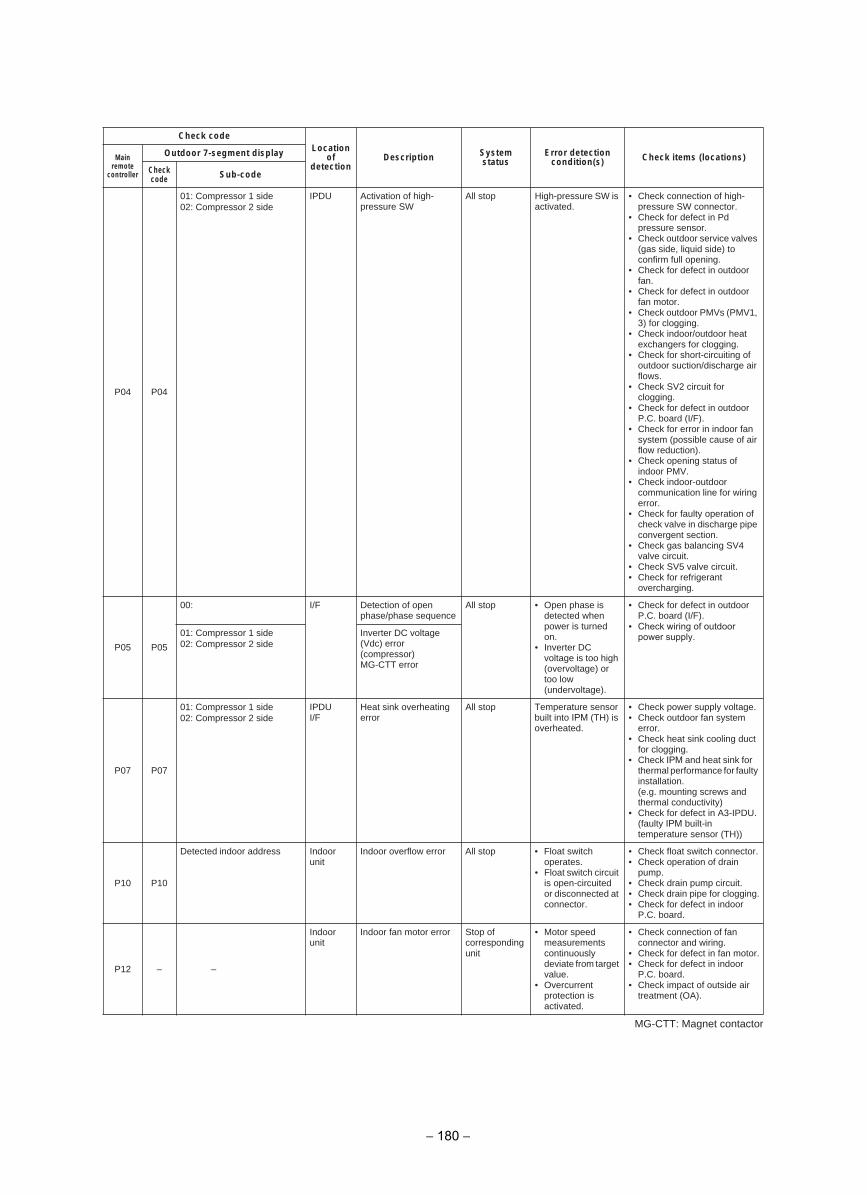
MG-CTT: Magnet contactor
Check codeLocation
ofdetection
Description System status
Error detection condition(s) Check items (locations)Main
remote controller
Outdoor 7-segment display
Check code Sub-code
P04 P04
01: Compressor 1 side 02: Compressor 2 side
IPDU Activation of high-pressure SW
All stop High-pressure SW is activated.
• Check connection of high-pressure SW connector.
• Check for defect in Pdpressure sensor.
• Check outdoor service valves (gas side, liquid side) to confirm full opening.
• Check for defect in outdoor fan.
• Check for defect in outdoor fan motor.
• Check outdoor PMVs (PMV1, 3) for clogging.
• Check indoor/outdoor heat exchangers for clogging.
• Check for short-circuiting ofoutdoor suction/discharge air flows.
• Check SV2 circuit for clogging.
• Check for defect in outdoor P.C. board (I/F).
• Check for error in indoor fan system (possible cause of air flow reduction).
• Check opening status ofindoor PMV.
• Check indoor-outdoor communication line for wiring error.
• Check for faulty operation of check valve in discharge pipe convergent section.
• Check gas balancing SV4 valve circuit.
• Check SV5 valve circuit.• Check for refrigerant
overcharging.
P05 P05
00: I/F Detection of open phase/phase sequence
All stop • Open phase is detected when power is turned on.
• Inverter DCvoltage is too high (overvoltage) or too low (undervoltage).
• Check for defect in outdoor P.C. board (I/F).
01: Compressor 1 side 02: Compressor 2 side
Inverter DC voltage (Vdc) error (compressor)MG-CTT error
P07 P07
01: Compressor 1 side 02: Compressor 2 side
IPDUI/F
Heat sink overheating error
All stop Temperature sensor built into IPM (TH) is overheated.
• Check power supply voltage.• Check outdoor fan system
error.• Check heat sink cooling duct
for clogging.• Check IPM and heat sink for
thermal performance for faulty installation.(e.g. mounting screws and thermal conductivity)
• Check for defect in A3-IPDU.(faulty IPM built-in temperature sensor (TH))
P10 P10
Detected indoor address Indoor unit
Indoor overflow error All stop • Float switch operates.
• Float switch circuit is open-circuited or disconnected atconnector.
• Check float switch connector.• Check operation of drain
pump.• Check drain pump circuit.• Check drain pipe for clogging.• Check for defect in indoor
P.C. board.
P12 – –
Indoor unit
Indoor fan motor error Stop of corresponding unit
• Motor speed measurements continuously deviate from target value.
• Overcurrent protection is activated.
• Check connection of fan connector and wiring.
• Check for defect in fan motor.• Check for defect in indoor
P.C. board.• Check impact of outside air
treatment (OA).
• Check wiring of outdoor power supply.
− 180 −
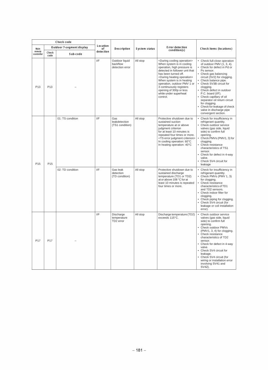
Check codeLocation
ofdetection
Description System status Error detection condition(s) Check items (locations)Main
remote controller
Outdoor 7-segment display
Checkcode Sub-code
P13 P13 –
I/F Outdoor liquid backflow detection error
All stop <During cooling operation> When system is in cooling operation, high pressure is detected in follower unit that has been turned off.<During heating operation> When system is in heating operation, outdoor PMV 1 or 3 continuously registers opening of 300p or less while under superheat control.
• Check full-close operation of outdoor PMV (1, 3, 4).
• Check for defect in Pd or Ps sensor.
• Check gas balancing circuit (SV2) for clogging.
• Check balance pipe.• Check SV3B circuit for
clogging.• Check defect in outdoor
P.C. board (I/F).• Check capillary of oil
separator oil return circuit for clogging.
• Check for leakage of check valve in discharge pipe convergent section.
P15 P15
01: TS condition I/F Gas leakdetection(TS1 condition)
All stop Protective shutdown due to sustained suction temperature at or above judgment criterionfor at least 10 minutes is repeated four times or more.<TS error judgment criterion>In cooling operation: 60°CIn heating operation: 40°C
• Check for insufficiency inrefrigerant quantity.
• Check outdoor service valves (gas side, liquid side) to confirm full opening.
• Check PMVs (PMV1, 3) for clogging.
• Check resistance characteristics of TS1 sensor.
• Check for defect in 4-way valve.
• Check SV4 circuit for leakage
02: TD condition I/F Gas leak detection(TD condition)
All stop Protective shutdown due to sustained discharge temperature (TD1 or TD2) at or above 108 °C for at least 10 minutes is repeated four times or more.
• Check for insufficiency inrefrigerant quantity.
• Check PMVs (PMV 1, 3) for clogging.
• Check resistance characteristics of TD1and TD2 sensors.
• Check indoor filter for clogging.
• Check piping for clogging.• Check SV4 circuit (for
leakage or coil installation error).
P17 P17 –
I/F Discharge temperature TD2 error
All stop Discharge temperature (TD2) exceeds 115°C.
• Check outdoor service valves (gas side, liquid side) to confirm full opening.
• Check outdoor PMVs (PMV1, 3, 4) for clogging.
• Check resistance characteristics of TD2 sensor.
• Check for defect in 4-way valve.
• Check SV4 circuit for leakage.
• Check SV4 circuit (for wiring or installation error involving SV41 and SV42).
− 181 −
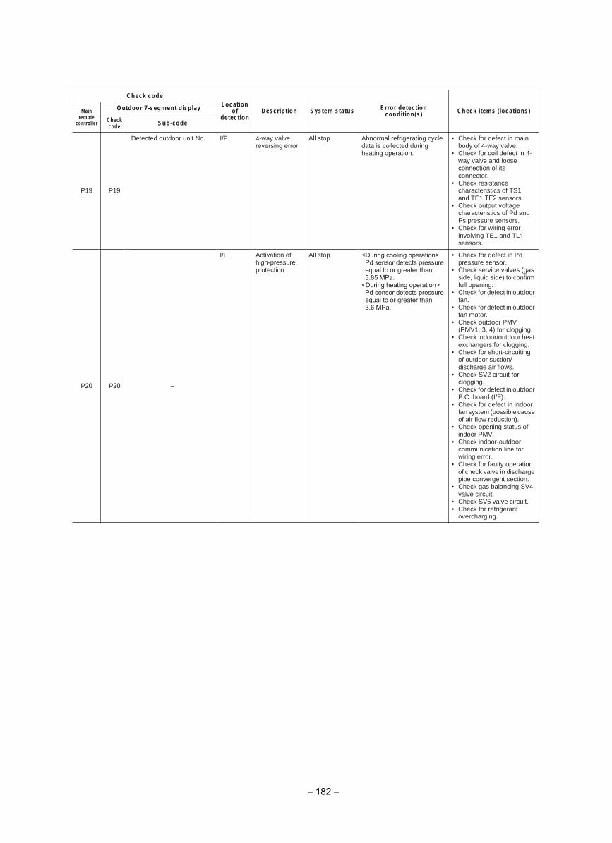
Check codeLocation
ofdetection
Description System status Error detection condition(s) Check items (locations)Main
remote controller
Outdoor 7-segment display
Checkcode Sub-code
P19 P19
Detected outdoor unit No. I/F 4-way valve reversing error
All stop Abnormal refrigerating cycle data is collected during heating operation.
• Check for defect in main body of 4-way valve.
• Check for coil defect in 4-way valve and loose connection of its connector.
• Check resistance characteristics of TS1 and TE1,TE2 sensors.
• Check output voltage characteristics of Pd and Ps pressure sensors.
• Check for wiring error involving TE1 and TL1sensors.
P20 P20 –
I/F Activation of high-pressure protection
All stop <During cooling operation> Pd sensor detects pressure equal to or greater than 3.85 MPa.<During heating operation> Pd sensor detects pressure equal to or greater than 3.6 MPa.
• Check for defect in Pd pressure sensor.
• Check service valves (gas side, liquid side) to confirm full opening.
• Check for defect in outdoor fan.
• Check for defect in outdoor fan motor.
• Check outdoor PMV (PMV1, 3, 4) for clogging.
• Check indoor/outdoor heat exchangers for clogging.
• Check for short-circuiting of outdoor suction/discharge air flows.
• Check SV2 circuit for clogging.
• Check for defect in outdoor P.C. board (I/F).
• Check for defect in indoor fan system (possible cause of air flow reduction).
• Check opening status of indoor PMV.
• Check indoor-outdoor communication line for wiring error.
• Check for faulty operation of check valve in discharge pipe convergent section.
• Check gas balancing SV4 valve circuit.
• Check SV5 valve circuit.• Check for refrigerant
overcharging.
− 182 −
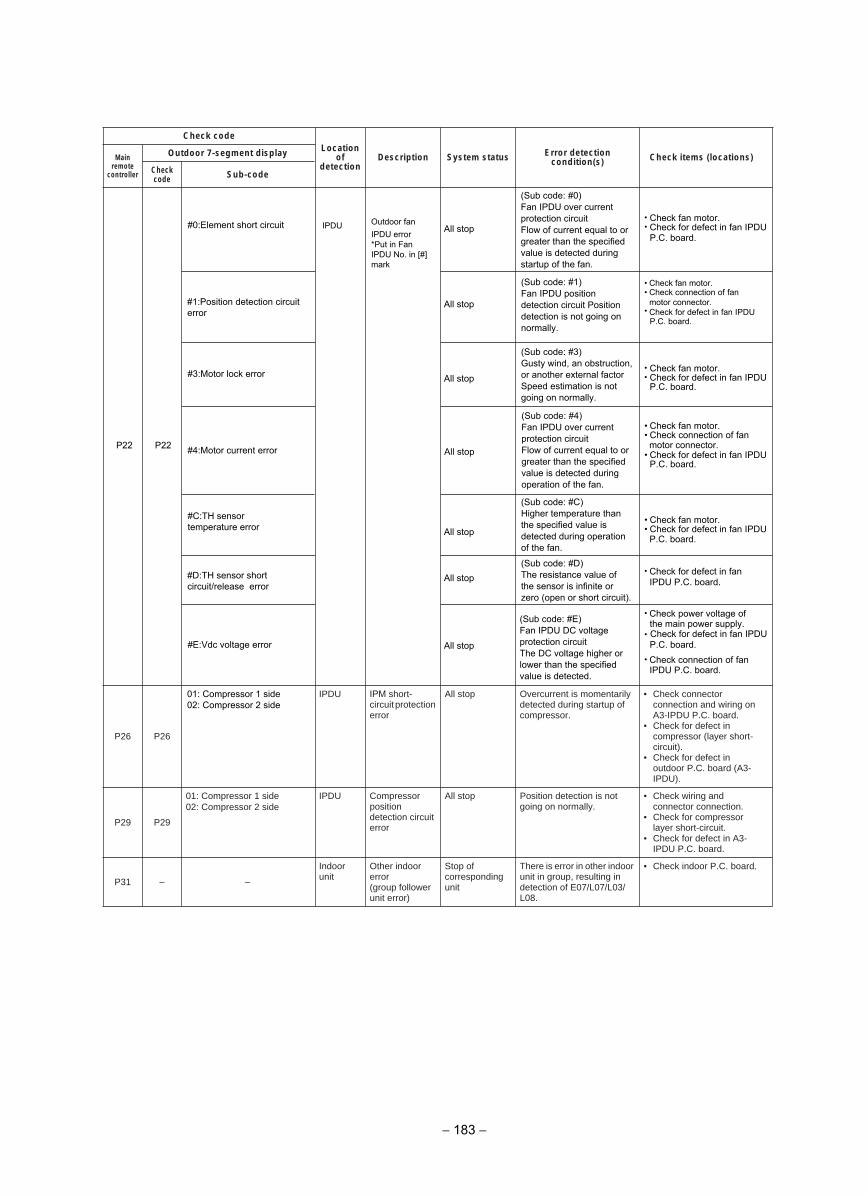
Check codeLocation
ofdetection
Description System status Error detection condition(s) Check items (locations)Main
remote controller
Outdoor 7-segment display
Checkcode Sub-code
P26 P26
01: Compressor 1 side 02: Compressor 2 side
IPDU IPM short-circuit protection error
All stop Overcurrent is momentarily detected during startup of compressor.
• Check connector connection and wiring on A3-IPDU P.C. board.
• Check for defect in compressor (layer short-circuit).
• Check for defect in outdoor P.C. board (A3-IPDU).
P29 P29
01: Compressor 1 side 02: Compressor 2 side
IPDU Compressor positiondetection circuit error
All stop Position detection is not going on normally.
• Check wiring and connector connection.
• Check for compressor layer short-circuit.
• Check for defect in A3-IPDU P.C. board.
– P31 –
Indoor unit
Other indoor error(group follower unit error)
Stop of corresponding unit
There is error in other indoor unit in group, resulting in detection of E07/L07/L03/L08.
• Check indoor P.C. board.
• Check fan motor.• Check for defect in fan IPDU
P.C. board.
• Check fan motor.• Check connection of fan
motor connector.• Check for defect in fan IPDU
P.C. board.
• Check fan motor.• Check for defect in fan IPDU
P.C. board.
• Check fan motor.• Check connection of fan motor connector.
• Check for defect in fan IPDU P.C. board.
• Check fan motor.• Check for defect in fan IPDU
•
• Check power voltage of the main power supply.
• Check for defect in fan IPDU
• Check connection of fanIPDU P.C. board.
(Sub code: #0)Fan IPDU over current protection circuitFlow of current equal to or greater than the specified value is detected during startup of the fan.
(Sub code: #1)Fan IPDU position detection circuit Position detection is not going on normally.
(Sub code: #3)Gusty wind, an obstruction, or another external factor Speed estimation is not going on normally.
(Sub code: #4)Fan IPDU over current protection circuitFlow of current equal to or greater than the specified value is detected during operation of the fan.
(Sub code: #C)Higher temperature than the specified value is detected during operation of the fan.
(Sub code: #D)The resistance value of the sensor is infinite or zero (open or short circuit).
(Sub code: #E)Fan IPDU DC voltage protection circuitThe DC voltage higher or lower than the specified value is detected.
All stop
All stop
All stop
All stop
All stop
All stop
All stop
IPDU Outdoor fanIPDU error*Put in Fan IPDU No. in [#] mark
#0:Element short circuit
#1:Position detection circuit error
#3:Motor lock error
#4:Motor current error
#C:TH sensor temperature error
#D:TH sensor short circuit/release error
#E:Vdc voltage error
P22 P22
P.C. board.
Check for defect in fan IPDU P.C. board.
P.C. board.
− 183 −
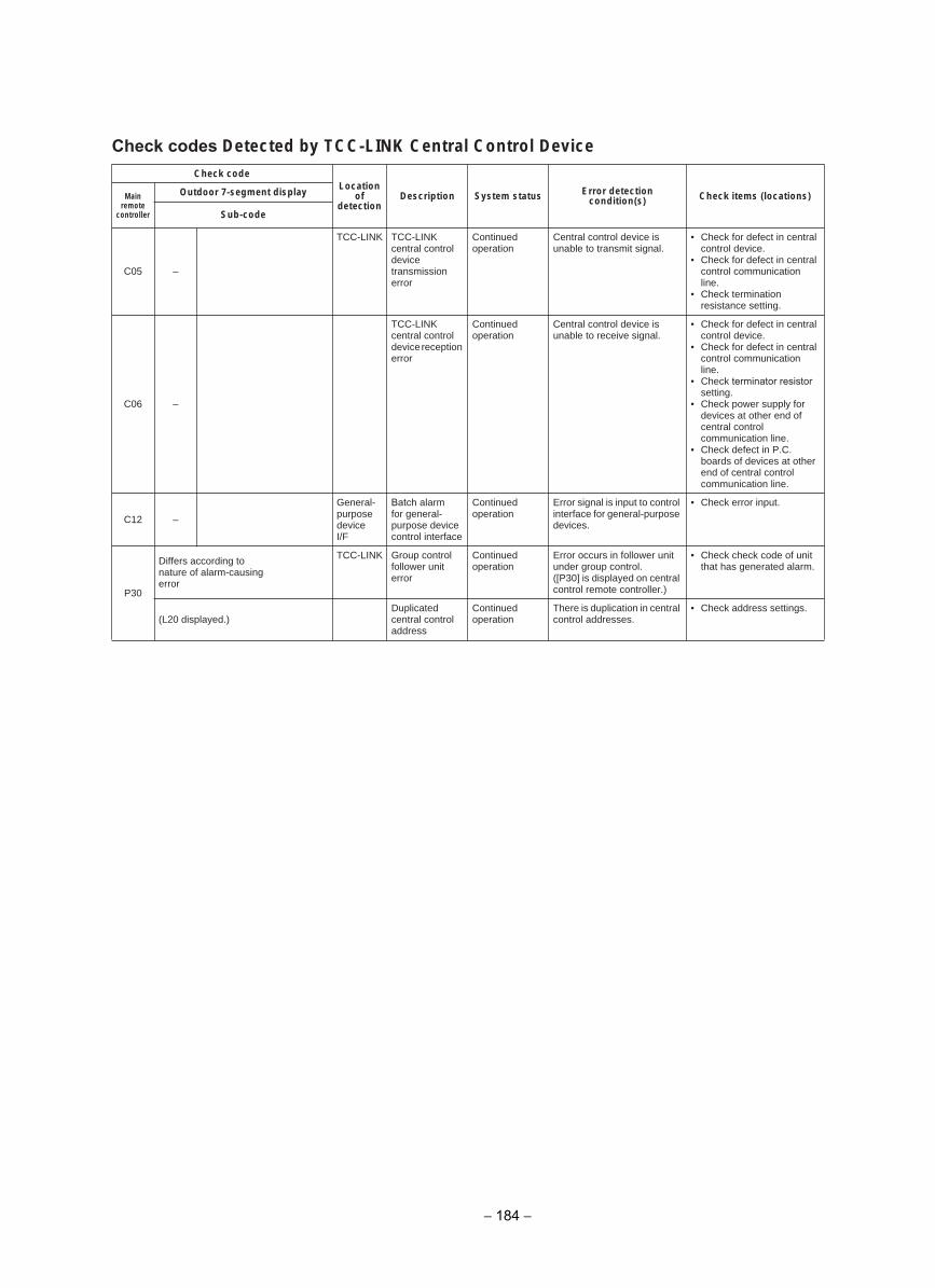
Check codes Detected by TCC-LINK Central Control DeviceCheck code
Locationof
detectionDescription System status Error detection
condition(s) Check items (locations)Main remote
controller
Outdoor 7-segment display
Sub-code
–50C
TCC-LINK TCC-LINK central control device transmission error
Continued operation
Central control device is unable to transmit signal.
• Check for defect in central control device.
• Check for defect in central control communication line.
• Check termination resistance setting.
–60C
TCC-LINKcentral control device reception error
Continued operation
Central control device is unable to receive signal.
• Check for defect in central control device.
• Check for defect in central control communication line.
• Check terminator resistorsetting.
• Check power supply for devices at other end of central control communication line.
• Check defect in P.C. boards of devices at other end of central control communication line.
–21C
General-purpose deviceI/F
Batch alarm for general-purpose device control interface
Continued operation
Error signal is input to control interface for general-purpose devices.
• Check error input.
P30
Differs according to nature of alarm-causing error
TCC-LINK Group control follower unit error
Continued operation
Error occurs in follower unit under group control.([P30] is displayed on central control remote controller.)
• Check check code of unit that has generated alarm.
(L20 displayed.)Duplicated central control address
Continued operation
There is duplication in central control addresses.
• Check address settings.
− 184 −
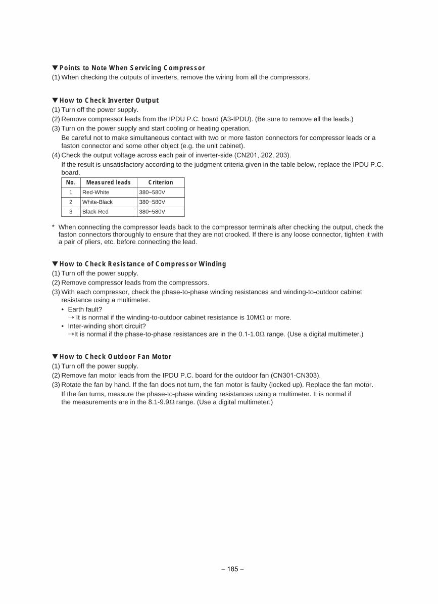
Points to Note When Servicing Compressor(1) When checking the outputs of inverters, remove the wiring from all the compressors.
How to Check Inverter Output(1) Turn off the power supply.(2) Remove compressor leads from the IPDU P.C. board (A3-IPDU). (Be sure to remove all the leads.)(3) Turn on the power supply and start cooling or heating operation.
Be careful not to make simultaneous contact with two or more faston connectors for compressor leads or a faston connector and some other object (e.g. the unit cabinet).
(4) Check the output voltage across each pair of inverter-side (CN201, 202, 203).If the result is unsatisfactory according to the judgment criteria given in the table below, replace the IPDU P.C. board.
* When connecting the compressor leads back to the compressor terminals after checking the output, check thefaston connectors thoroughly to ensure that they are not crooked. If there is any loose connector, tighten it witha pair of pliers, etc. before connecting the lead.
How to Check Resistance of Compressor Winding(1) Turn off the power supply.(2) Remove compressor leads from the compressors.(3) With each compressor, check the phase-to-phase winding resistances and winding-to-outdoor cabinet
resistance using a multimeter.• Earth fault?
It is normal if the winding-to-outdoor cabinet resistance is 10M or more.• Inter-winding short circuit?
It is normal if the phase-to-phase resistances are in the 0.1-1.0 range. (Use a digital multimeter.)
How to Check Outdoor Fan Motor(1) Turn off the power supply.(2) Remove fan motor leads from the IPDU P.C. board for the outdoor fan (CN301-CN303).(3) Rotate the fan by hand. If the fan does not turn, the fan motor is faulty (locked up). Replace the fan motor.
If the fan turns, measure the phase-to-phase winding resistances using a multimeter. It is normal if the measurements are in the 8.1-9.9 range. (Use a digital multimeter.)
No. Measured leads Criterion
1 Red-White 380~580V
2 White-Black 380~580V
3 Black-Red 380~580V
− 185 −
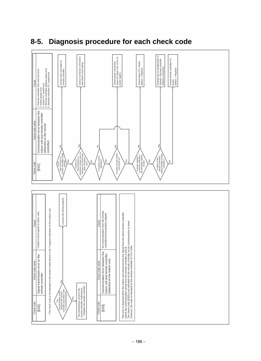
8-5. Diagnosis procedure for each check code
Yes
No
Yes
Yes
Yes
No
Yes
No
No
No
Yes
No
[E01
]esua
Cedoc kceh
CC
heck
cod
e na
me
esuaC
edoc kcehC
Che
ck c
ode
nam
e
Che
ck c
ode
Cau
seC
heck
cod
e na
me
* T
he c
heck
cod
e is
not
indi
cate
d on
the
cent
ral c
ontr
ol d
evic
e or
the
7-se
gmen
t ind
icat
ion
on th
e ou
tdoo
r un
it.
Yes
No
[E02
]
[E03
]
Com
mun
icat
ion
erro
r be
twee
n th
e in
door
uni
t and
rem
ote
cont
rolle
r (d
etec
ted
on th
e re
mot
e co
ntro
ller)
Sig
nal t
rans
mis
sion
err
or o
n th
e re
mot
e co
ntro
ller
Com
mun
icat
ion
erro
r be
twee
n th
e in
door
uni
t and
rem
ote
cont
rolle
r (d
etec
ted
on th
e in
door
uni
t)
1. R
emot
e co
ntro
ller
inte
r-un
it w
ire e
rror
2. In
door
pow
er e
rror
3. In
door
P.C
. boa
rd e
rror
4. R
emot
e co
ntro
ller
addr
ess
setu
p er
ror
5. R
emot
e co
ntro
ller
P.C
. boa
rd e
rror
Una
ble
to s
end
sign
als
to in
door
uni
ts
No
com
mun
icat
ion
from
the
rem
ote
cont
rolle
r/co
mm
unic
atio
n ad
apte
r
Is th
ein
ter-
unit
wire
of
rem
ote
cont
rolle
rs (
A/B
) no
rmal
?
The
com
mun
icat
ion
wiri
ng
betw
een
the
rem
ote
cont
rolle
r an
d in
door
uni
ts
is c
onne
cted
pro
perly
.
Is th
ere
nodi
scon
nect
ion
orco
nnec
tor
cont
act e
rror
on
harn
ess
out o
f ter
min
albl
ock
of in
door
unit?
Is a
gro
up c
ontr
ol
oper
atio
n?
Is p
ower
of e
ach
indo
or
unit
turn
ed o
n?
Is p
ower
app
lied
to r
emot
e co
ntro
ller?
AB
term
inal
s: A
ppro
x.
DC
18V
Is s
etup
of t
wo
rem
ote
cont
rolle
rs
with
out h
eade
r re
mot
e co
ntro
ller?
Cor
rect
inte
r-un
it ca
ble
of
rem
ote
cont
rolle
r.C
onne
ct th
e w
iring
pro
perly
.
The
tran
smis
sion
circ
uit i
n th
e re
mot
e co
ntro
ller
mal
func
tions
. R
epla
ce th
e re
mot
e co
ntro
ller.
Cor
rect
con
nect
or c
onne
ctio
n an
d ch
eck
circ
uit w
iring
.
Che
ck p
ower
con
nect
ion
stat
us o
f ind
oor
unit.
(Tu
rn o
n po
wer
aga
in.)
Che
ck in
door
P.C
. boa
rd.
Def
ect
Rep
lace
Che
ck r
emot
e co
ntro
ller
P.C
. bo
ard.
Def
ect
Rep
lace
Cha
nge
one
to h
eade
r/ot
her
to
follo
wer
. (R
emot
e co
ntro
ller
addr
ess
conn
ecto
r)
The
err
or is
det
ecte
d w
hen
the
indo
or u
nit c
anno
t rec
eive
the
sign
al fr
om th
e w
ired
rem
ote
cont
rolle
r. C
heck
the
com
mun
icat
ion
wiri
ng fr
om th
e re
mot
e co
ntro
ller A
and
B.
The
che
ck c
ode
[E03
] is
not i
ndic
ated
on
the
rem
ote
cont
rolle
r as
its
com
mun
icat
ion
is d
own.
H
owev
er, t
he c
ode
is in
dica
ted
on th
e ce
ntra
l con
trolle
r of T
CC
-LIN
K.
− 186 −
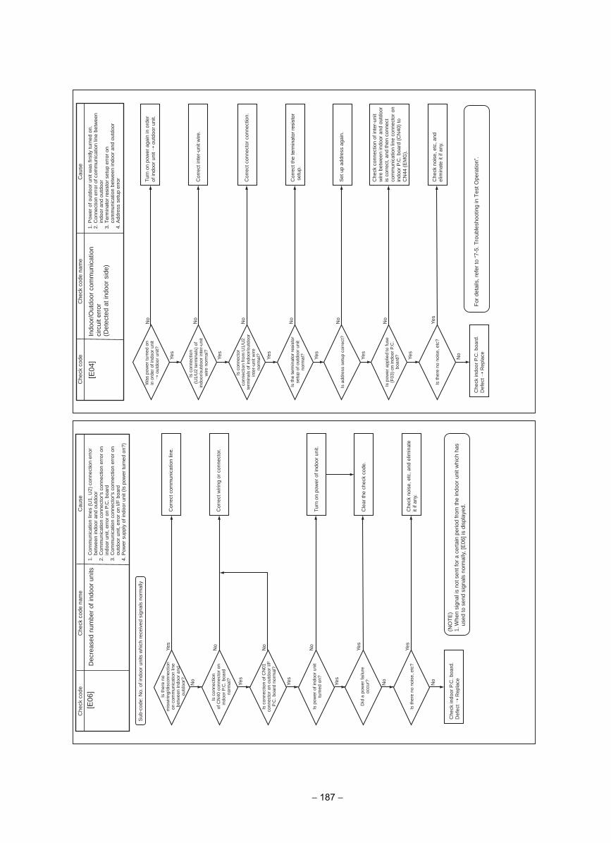
No
Yes
Yes
No
Yes
No
Yes
No
Yes
No
Yes
No
No
Yes
[E04
]
No
Yes
No
Yes
Yes
No
Yes
No
No
Yes
No
Yes
[E06
]
Sub
-cod
e: N
o. o
f ind
oor
units
whi
ch r
ecei
ved
sign
als
norm
ally
esuaC
edoc kcehC
Che
ck c
ode
nam
eesua
Cedoc kceh
CC
heck
cod
e na
me
Dec
reas
ed n
umbe
r of
indo
or u
nits
Indo
or/O
utdo
or c
omm
unic
atio
n ci
rcui
t err
or
(Det
ecte
d at
indo
or s
ide)
1. C
omm
unic
atio
n lin
es (
U1,
U2)
con
nect
ion
erro
r be
twee
n in
door
and
out
door
2. C
omm
unic
atio
n co
nnec
tor's
con
nect
ion
erro
r on
in
door
uni
t, er
ror
on P
.C. b
oard
3. C
omm
unic
atio
n co
nnec
tor's
con
nect
ion
erro
r on
ou
tdoo
r un
it, e
rror
on
I/F b
oard
4. P
ower
sup
ply
of in
door
uni
t (Is
pow
er tu
rned
on?
)
1. P
ower
of o
utdo
or u
nit w
as fi
rstly
turn
ed o
n.2.
Con
nect
ion
erro
r of
com
mun
icat
ion
line
betw
een
indo
or a
nd o
utdo
or3.
Ter
min
ator
resi
stor
set
up e
rror
on
com
mun
icat
ion
betw
een
indo
or a
nd o
utdo
or4.
Add
ress
set
up e
rror
Is th
ere
no
mis
wiri
ng/d
isco
nnec
tion
on c
omm
unic
atio
n lin
e be
twee
n in
door
and
ou
tdoo
r?
Was
pow
er tu
rned
on
in o
rder
of i
ndoo
r un
it o
utdo
or u
nit?
Is c
onne
ctio
n(U
1/U
2 te
rmin
als)
of
indo
or/o
utdo
or in
ter-
unit
wire
nor
mal
?
Is c
onne
ctor
conn
ectio
n fr
om U
1/U
2 te
rmin
als
of in
door
/out
door
in
ter-
unit
wire
norm
al?
Is th
e te
rmin
ator
resi
stor
se
tup
of o
utdo
or u
nit
norm
al?
Is p
ower
app
lied
to fu
se
(F03
) on
indo
or P
.C.
boar
d?
Is a
ddre
ss s
etup
cor
rect
?
Is th
ere
no n
oise
, etc
?
Is c
onne
ctio
nof
CN
40 c
onne
ctor
on
indo
or P
.C. b
oard
no
rmal
?
Is c
onne
ctio
n of
CN
01
conn
ecto
r on
out
door
I/F
P.
C. b
oard
nor
mal
?
Is p
ower
of i
ndoo
r un
it tu
rned
on?
Did
a p
ower
failu
re
occu
r?
Is th
ere
no n
oise
, etc
?
Cor
rect
com
mun
icat
ion
line.
Turn
on
pow
er a
gain
in o
rder
of
indo
or u
nit
out
door
uni
t.
Cor
rect
inte
r-un
it w
ire.
Cor
rect
con
nect
or c
onne
ctio
n.
Cor
rect
the
term
inat
or re
sist
or
set
up.
Set
up
addr
ess
agai
n.
Che
ck n
oise
, etc
, and
el
imin
ate
it if
any.
Che
ck c
onne
ctio
n of
inte
r-un
it w
ire b
etw
een
indo
or a
nd o
utdo
or
is c
orre
ct, a
nd th
en c
onne
ct
com
mun
icat
ion
line
conn
ecto
r on
in
door
P.C
. boa
rd (
CN
40)
to
CN
44 (
EM
G).
Cor
rect
wiri
ng o
r co
nnec
tor.
Turn
on
pow
er o
f ind
oor
unit.
Cle
ar th
e ch
eck
code
.
Che
ck n
oise
, etc
, and
elim
inat
e it
if an
y.
Che
ck in
door
P.C
. boa
rd.
Def
ect
Rep
lace
Che
ck in
door
P.C
. boa
rd.
Def
ect
Rep
lace
(NO
TE
)1.
Whe
n si
gnal
is n
ot s
ent f
or a
cer
tain
per
iod
from
the
indo
or u
nit w
hich
has
us
ed to
sen
d si
gnal
s no
rmal
ly, [
E06
] is
disp
laye
d.
For
det
ails
, ref
er to
“7-
5. T
roub
lesh
ootin
g in
Tes
t Ope
ratio
n”.
− 187 −
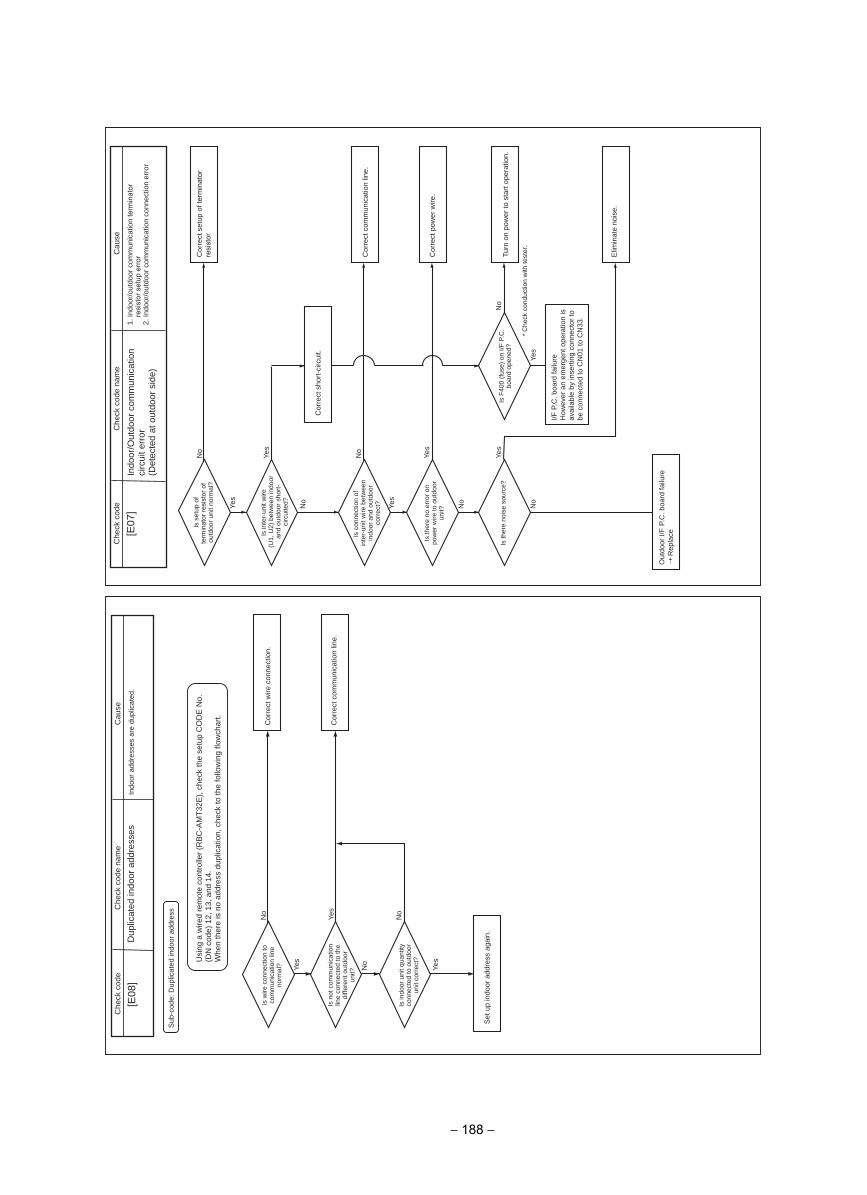
Yes
Yes
No
No
No
Yes
[E08
]
Sub
-cod
e: D
uplic
ated
indo
or a
ddre
ss
Yes
No
Yes
No
Yes
No
No
Yes
No
Yes
Yes
No
[E07
]esua
Cedoc kceh
CC
heck
cod
e na
me
esuaC
edoc kcehC
Che
ck c
ode
nam
e
Indo
or/O
utdo
or c
omm
unic
atio
n ci
rcui
t err
or(D
etec
ted
at o
utdo
or s
ide)
Dup
licat
ed in
door
add
ress
es1.
Indo
or/o
utdo
or c
omm
unic
atio
n te
rmin
ator
re
sist
or s
etup
err
or2.
Indo
or/o
utdo
or c
omm
unic
atio
n co
nnec
tion
erro
r
Indo
or a
ddre
sses
are
dup
licat
ed.
Is s
etup
of
term
inat
or re
sist
or o
f ou
tdoo
r un
it no
rmal
?
Is w
ire c
onne
ctio
n to
co
mm
unic
atio
n lin
e no
rmal
?
Is n
ot c
omm
unic
atio
n lin
e co
nnec
ted
to th
e di
ffere
nt o
utdo
or
unit?
Is in
door
uni
t qua
ntity
co
nnec
ted
to o
utdo
or
unit
corr
ect?
Is in
ter-
unit
wire
(U1,
U2)
bet
wee
n in
door
an
d ou
tdoo
r sh
ort-
circ
uite
d?
Is c
onne
ctio
n of
inte
r-un
it w
ire b
etw
een
indo
or a
nd o
utdo
or
corr
ect?
Is th
ere
no e
rror
on
pow
er w
ire to
out
door
un
it?
Is th
ere
nois
e so
urce
?Is
F40
0 (f
use)
on
I/F P
.C.
boar
d op
ened
?
Cor
rect
set
up o
f ter
min
ator
resi
stor
Cor
rect
wire
con
nect
ion.
Cor
rect
com
mun
icat
ion
line.
Set
up
indo
or a
ddre
ss a
gain
.
Cor
rect
com
mun
icat
ion
line.
Cor
rect
pow
er w
ire.
Turn
on
pow
er to
sta
rt o
pera
tion.
Elim
inat
e no
ise.
Out
door
I/F
P.C
. boa
rd fa
ilure
Rep
lace
I/F P
.C. b
oard
failu
reH
owev
er a
n em
erge
nt o
pera
tion
is
avai
labl
e by
inse
rtin
g co
nnec
tor
to
be c
onne
cted
to C
N01
to C
N33
.
* C
heck
con
duct
ion
with
test
er.
Cor
rect
sho
rt-c
ircui
t.
Usi
ng a
wire
d re
mot
e co
ntro
ller
(RB
C-A
MT
32E
), c
heck
the
setu
p C
OD
E N
o.
(DN
cod
e) 1
2, 1
3, a
nd 1
4.W
hen
ther
e is
no
addr
ess
dupl
icat
ion,
che
ck to
the
follo
win
g flo
wch
art.
− 188 −
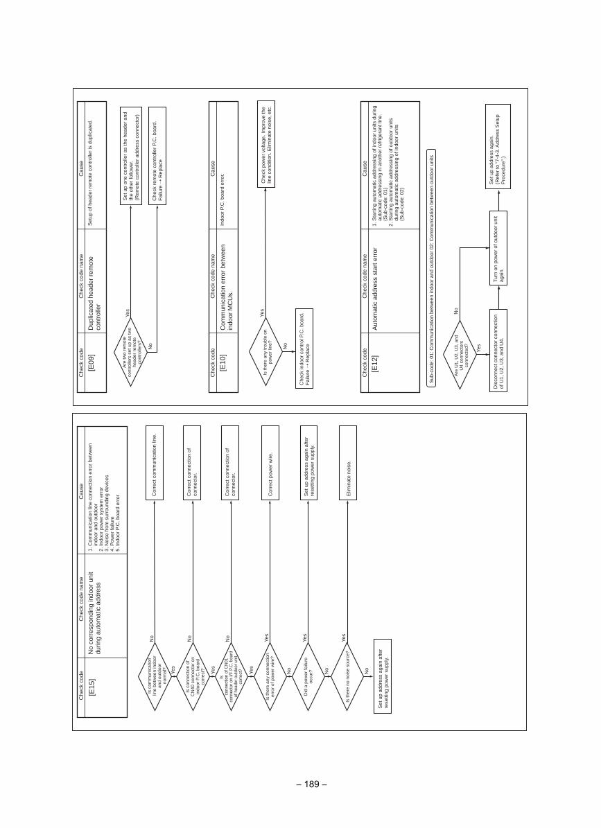
No
Yes
[E09
]
Yes
Yes
No
No
Yes
No
No
No
Yes
No
Yes
Yes
[E15
]
No
Yes
[E10
]
[E12
]
Sub
-cod
e: 0
1: C
omm
unic
atio
n be
twee
n in
door
and
out
door
02:
Com
mun
icat
ion
betw
een
outd
oor
units
Yes
No
esuaC
edoc kcehC
Che
ck c
ode
nam
eesua
Cedoc kceh
CC
heck
cod
e na
me
esuaC
edoc kcehC
Che
ck c
ode
nam
e
esuaC
edoc kcehC
Che
ck c
ode
nam
e
Dup
licat
ed h
eade
r re
mot
e co
ntro
ller
No
corr
espo
ndin
g in
door
uni
t du
ring
auto
mat
ic a
ddre
ssS
etup
of h
eade
r re
mot
e co
ntro
ller
is d
uplic
ated
.
Com
mun
icat
ion
erro
r be
twee
n in
door
MC
Us.
Aut
omat
ic a
ddre
ss s
tart
err
or
Indo
or P
.C. b
oard
err
or.
Are
two
rem
ote
cont
rolle
rs s
et u
p as
two
head
er r
emot
e co
ntro
llers
?
Is c
omm
unic
atio
n lin
e be
twee
n in
door
an
d ou
tdoo
r no
rmal
?
Is c
onne
ctio
n of
C
N40
con
nect
or o
n in
door
P.C
. boa
rd
corr
ect?
Isco
nnec
tion
of C
N01
co
nnec
tor o
n I/F
P.C
. boa
rd
of h
eade
r out
door
uni
t co
rrec
t?
Is th
ere
any
conn
ectio
n er
ror
of p
ower
wire
?
Did
a p
ower
failu
re
occu
r?
Is th
ere
no n
oise
sou
rce?
Set
up
addr
ess
agai
n af
ter
rese
tting
pow
er s
uppl
y.
Is th
ere
any
trou
ble
on
pow
er li
ne?
Are
U1,
U2,
U3,
and
U
4 co
nnec
tors
co
nnec
ted?
Set
up
one
cont
rolle
r as
the
head
er a
nd
the
othe
r fo
llow
er.
(Rem
ote
cont
rolle
r ad
dres
s co
nnec
tor)
Cor
rect
com
mun
icat
ion
line.
Cor
rect
con
nect
ion
of
conn
ecto
r.
Cor
rect
con
nect
ion
of
conn
ecto
r.
Cor
rect
pow
er w
ire.
Set
up
addr
ess
agai
n af
ter
rese
tting
pow
er s
uppl
y.
Elim
inat
e no
ise.
Che
ck r
emot
e co
ntro
ller
P.C
. boa
rd.
Fai
lure
Rep
lace
Che
ck p
ower
vol
tage
. Im
prov
e th
e lin
e co
nditi
on. E
limin
ate
nois
e, e
tc.
Che
ck in
door
con
trol
P.C
. boa
rd.
Fai
lure
Rep
lace
Dis
conn
ect c
onne
ctor
con
nect
ion
of U
1, U
2, U
3, a
nd U
4.Tu
rn o
n po
wer
of o
utdo
or u
nit
agai
n.
1. S
tart
ing
auto
mat
ic a
ddre
ssin
g of
indo
or u
nits
dur
ing
auto
mat
ic a
ddre
ssin
g in
ano
ther
ref
riger
ant l
ine.
(S
ub-c
ode:
01)
2.
Sta
rtin
g au
tom
atic
add
ress
ing
of o
utdo
or u
nits
du
ring
auto
mat
ic a
ddre
ssin
g of
indo
or u
nits
(Sub
-cod
e: 0
2)
1. C
omm
unic
atio
n lin
e co
nnec
tion
erro
r be
twee
n in
door
and
out
door
2. In
door
pow
er s
yste
m e
rror
3. N
oise
from
sur
roun
ding
dev
ices
4. P
ower
failu
re5.
Indo
or P
.C. b
oard
err
or
Set
up
addr
ess
agai
n.(R
efer
to “
7-4-
3. A
ddre
ss S
etup
P
roce
dure
”.)
− 189 −
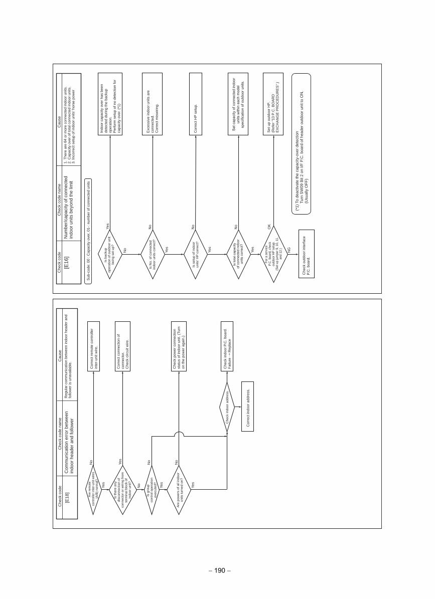
Yes
No
Yes
Yes
Yes
No
No
No
[E18
]
No
Yes
No
Yes
No
NG
OK
Yes
No
Yes
[E16
]
Sub
-cod
e: 0
0 : C
apac
ity o
ver,
01-:
num
ber
of c
onne
cted
uni
ts
esuaC
edoc kcehC
Che
ck c
ode
nam
eesua
Cedoc kceh
CC
heck
cod
e na
me
Num
ber/
capa
city
of c
onne
cted
in
door
uni
ts b
eyon
d th
e lim
it1.
The
re a
re 6
4 or
mor
e co
nnec
ted
indo
or u
nits
.2.
Cap
acity
ove
r of
tota
l con
nect
ed in
door
uni
ts.
3. In
corr
ect s
etup
of i
ndoo
r un
its' h
orse
pow
er
Com
mun
icat
ion
erro
r be
twee
n in
door
hea
der
and
follo
wer
Reg
ular
com
mun
icat
ion
betw
een
indo
or h
eade
r an
d fo
llow
er is
una
vaila
ble.
Is b
acku
pop
erat
ion
of o
utdo
or u
nit
bein
g se
t up?
Are
rem
ote
cont
rolle
r int
er-u
nit w
ires
(A/B
) nor
mal
?
Is th
ere
any
disc
onne
ctio
n of
co
nnec
tor
or w
iring
from
te
rmin
al b
lock
of
indo
or u
nit?
Is g
roup
cont
rol o
pera
tion
exec
uted
?
Are
pow
ers
of a
ll in
door
un
its tu
rned
on?
Che
ck in
door
add
ress
.
Is N
o. o
f con
nect
ed
indo
or u
nits
cor
rect
?
Is s
etup
of i
ndoo
r un
its' H
P c
orre
ct?
Is to
tal c
apac
ityof
con
nect
ed in
door
un
its c
orre
ct?
For a
ser
vice
P.C
. boa
rd, c
heck
ou
tdoo
r HP
set
up.
(Set
up
jum
per 9
, 10,
11,
an
d 12
.)
Indo
or c
apac
ity o
ver
has
been
de
tect
ed d
urin
g th
e ba
ckup
op
erat
ion.
Per
form
set
up o
f no
dete
ctio
n fo
r ca
paci
ty o
ver.
(*1)
Cor
rect
rem
ote
cont
rolle
r in
ter-
unit
wire
.
Cor
rect
con
nect
ion
of
conn
ecto
r.C
heck
circ
uit w
ire.
Che
ck p
ower
con
nect
ion
stat
us o
f ind
oor
unit.
(Tu
rn
on th
e po
wer
aga
in.)
Che
ck in
door
P.C
. boa
rd.
Fai
lure
Rep
lace
Cor
rect
indo
or a
ddre
ss.
Exc
essi
ve in
door
uni
ts a
re
conn
ecte
d.C
orre
ct m
isw
iring
.
Cor
rect
HP
set
up.
Set
cap
acity
of c
onne
cted
indo
or
units
with
in e
ach
mod
el
spec
ifica
tion
of o
utdo
or u
nits
.
Che
ck o
utdo
or in
terf
ace
P.C
. boa
rd.
(*1)
To
deac
tivat
e th
e ca
paci
ty-o
ver
dete
ctio
nTu
rn S
W09
Bit
2 on
I/F
P.C
. boa
rd o
f hea
der
outd
oor
unit
to O
N.
(Usu
ally
OF
F)
Set
up
outd
oor
HP
.(R
efer
“13
P.C
. BO
AR
D
EX
CH
AN
GE
PR
OC
ED
UR
ES
”.)
− 190 −
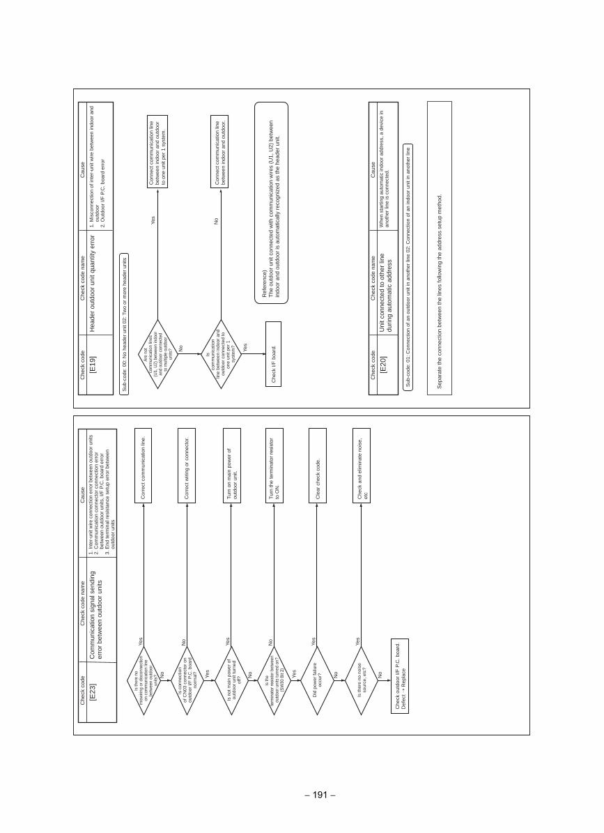
Sub
-cod
e: 0
0: N
o he
ader
uni
t 02:
Tw
o or
mor
e he
ader
uni
ts
No
Yes
Yes
No
[E19
]
[E20
]
Sub
-cod
e: 0
1: C
onne
ctio
n of
an
outd
oor
unit
in a
noth
er li
ne 0
2: C
onne
ctio
n of
an
indo
or u
nit i
n an
othe
r lin
e
No
Yes
No
No
Yes
Yes
Yes
No
No
Yes
No
Yes
[E23
]esua
Cedoc kceh
CC
heck
cod
e na
me
esuaC
edoc kcehC
Che
ck c
ode
nam
e
esuaC
edoc kcehC
Che
ck c
ode
nam
e
Hea
der
outd
oor
unit
quan
tity
erro
r1.
Mis
conn
ectio
n of
inte
r-un
it w
ire b
etw
een
indo
or a
nd
outd
oor
2. O
utdo
or I/
F P
.C. b
oard
err
or
Com
mun
icat
ion
sign
al s
endi
ng
erro
r be
twee
n ou
tdoo
r un
its
1.In
ter-
unit
wire
con
nect
ion
erro
r be
twee
n ou
tdoo
r un
its2.
Com
mun
icat
ion
conn
ecto
r co
nnec
tion
erro
r be
twee
n ou
tdoo
r un
its, I
/F P
.C. b
oard
err
or3.
End
term
inal
res
ista
nce
setu
p er
ror
betw
een
outd
oor
units
Uni
t con
nect
ed to
oth
er li
ne
durin
g au
tom
atic
add
ress
Whe
n st
artin
g au
tom
atic
indo
or a
ddre
ss, a
dev
ice
in
anot
her
line
is c
onne
cted
.
Are
not
com
mun
icat
ion
lines
(U
1, U
2) b
etw
een
indo
or
and
outd
oor c
onne
cted
to
mul
tiple
out
door
un
its?
Isco
mm
unic
atio
nlin
e be
twee
n in
door
and
ou
tdoo
r co
nnec
ted
to
one
unit
per
1sy
stem
?
Is c
onne
ctio
nof
CN
03 c
onne
ctor
on
outd
oor
I/F P
.C. b
oard
no
rmal
?
Is n
ot m
ain
pow
er o
f ou
tdoo
r un
it tu
rned
of
f?
Did
pow
er fa
ilure
oc
cur?
Is th
ere
no n
oise
so
urce
, etc
?
Is th
e te
rmin
ator
resis
tor b
etw
een
outd
oor u
nits
turn
ed o
n?(S
W30
Bit
2)
Is th
ere
nom
isw
iring
or d
isco
nnec
tion
on c
omm
unic
atio
n lin
e be
twee
n ou
tdoo
run
its?
Con
nect
com
mun
icat
ion
line
betw
een
indo
or a
nd o
utdo
or
to o
ne u
nit p
er 1
sys
tem
.
Cor
rect
com
mun
icat
ion
line.
Cor
rect
wiri
ng o
r co
nnec
tor.
Turn
on
mai
n po
wer
of
outd
oor
unit.
Tur
n th
e te
rmin
ator
resi
stor
to
ON
.
Cle
ar c
heck
cod
e.
Che
ck a
nd e
limin
ate
nois
e,
etc
Che
ck o
utdo
or I/
F P
.C. b
oard
.D
efec
t R
epla
ce
Con
nect
com
mun
icat
ion
line
betw
een
indo
or a
nd o
utdo
or.
Ref
eren
ce)
The
out
door
uni
t con
nect
ed w
ith c
omm
unic
atio
n w
ires
(U1,
U2)
bet
wee
n in
door
and
out
door
is a
utom
atic
ally
rec
ogni
zed
as th
e he
ader
uni
t.C
heck
I/F
boa
rd.
Sep
arat
e th
e co
nnec
tion
betw
een
the
lines
follo
win
g th
e ad
dres
s se
tup
met
hod.
− 191 −
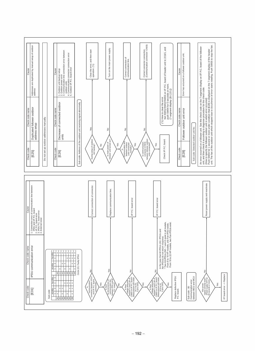
Do
not s
et u
p ou
tdoo
r ad
dres
ses
man
ually
.
[E25
]
No
Yes
No
Yes
No
Yes
No
Yes
[E26
]
Sub
-cod
e: A
ddre
ss o
f the
out
door
uni
t rec
eivi
ng s
igna
l abn
orm
ally
Yes
No
Yes
Yes
No
No
Yes
No
[E31
]
[E28
]
Sub
-cod
e: D
etec
ted
outd
oor
unit
No.
esuaC
edoc kcehC
Che
ck c
ode
nam
eesua
Cedoc kceh
CC
heck
cod
e na
me
esuaC
edoc kcehC
Che
ck c
ode
nam
e
esuaC
edoc kcehC
Che
ck c
ode
nam
e
Dup
licat
ed fo
llow
er o
utdo
or
addr
ess
setu
pA
ddre
sses
are
dup
licat
ed b
y m
anua
l set
up o
f out
door
ad
dres
s
Fol
low
er o
utdo
or u
nit e
rror
Err
or h
as o
ccur
red
on a
follo
wer
out
door
uni
t.
Dec
reas
e of
con
nect
ed o
utdo
or
units
1. O
utdo
or u
nit b
acku
p se
tup
2. O
utdo
or p
ower
err
or3.
Com
mun
icat
ion
line
conn
ectio
n er
ror
betw
een
outd
oor
units
4. C
omm
unic
atio
n co
nnec
tor
conn
ectio
n er
ror
5. O
utdo
or I/
F P
.C. b
oard
err
or
IPD
U c
omm
unic
atio
n er
ror
1. C
onne
ctio
n er
ror
of c
omm
unic
atio
n lin
e be
twee
n IP
DU
and
I/F
P.C
. boa
rd2.
I/F
P.C
. boa
rd e
rror
3. IP
DU
P.C
. boa
rd e
rror
4. E
xter
nal n
oise
Dur
ing
setu
p of
out
door
un
it ba
ckup
?
Isco
mm
unic
atio
nco
nnec
tor
betw
een
IPD
U
and
I/F P
.C. b
oard
co
nnec
ted?
Is th
ere
no d
isco
nnec
tion
on
com
mun
icat
ion
line
betw
een
IPD
U a
nd I/
F P.
C. b
oard
?
Is th
ere
volta
ge d
efle
ctio
n be
twee
n 4
and
5 pi
n of
C
N60
0 on
I/F
P.C
. boa
rd?
(Mea
sure
men
t with
test
er:
DC
0 to
5V,
5
pins
GN
D)
Is th
ere
volta
ge d
efle
ctio
n be
twee
n 3
and
5 pi
n of
C
N60
0 on
I/F
P.C
. boa
rd?
(Mea
sure
men
t with
test
er:
DC
0 to
5V,
5
pins
GN
D)
Is m
ain
pow
er o
f fo
llow
er u
nit t
urne
d on
?
Isco
mm
unic
atio
n lin
e be
twee
n ou
tdoo
r un
its c
onne
cted
no
rmal
ly?
Is c
omm
unic
atio
n co
nnec
tor
(CN
03)
betw
een
follo
wer
out
door
un
its c
onne
cted
?
Cle
ar th
e er
ror,
and
then
sta
rt
oper
atio
n. (
*1)
Cor
rect
con
nect
ion
of c
onne
ctor
.
Rep
lace
com
mun
icat
ion
line.
I/F P
.C. b
oard
err
or
I/F P
.C. b
oard
err
or
Rep
lace
def
ectiv
e IP
DU
P.
C. b
oard
.
Turn
on
the
mai
n po
wer
sup
ply.
Cor
rect
con
nect
ion
of
com
mun
icat
ion
line.
Cor
rect
con
nect
or c
onne
ctio
n.(C
omm
unic
atio
n co
nnec
tor:
CN
03)
(*1)
How
to c
lear
the
erro
rS
et S
W01
/SW
02/S
W03
on
I/F P
.C. b
oard
of h
eade
r un
it to
2/1
6/1,
and
pu
sh S
W04
for
5 se
cond
s or
mor
e.(7
-seg
men
t dis
play
: [E
r.] [C
L])
Che
ck I/
F P
.C. b
oard
.
An
erro
r oc
curr
ed o
n a
follo
wer
uni
t. S
ee th
e ch
eck
code
on
the
7-se
gmen
t dis
play
on
I/F P
.C. b
oard
of t
he fo
llow
er
unit,
and
then
che
ck it
acc
ordi
ng to
dia
gnos
e pr
oced
ure
for
the
chec
k co
de.
(How
to s
peci
fy th
e fo
llow
er o
utdo
or u
nit i
n w
hich
err
or o
ccur
red)
Pus
h S
W04
for
1 se
cond
or
mor
e un
der
cond
ition
that
[E28
] is
disp
laye
d on
the
7-se
gmen
t dis
play
of t
he h
eade
r un
it. T
he fa
n of
the
outd
oor
unit
whi
ch s
topp
ed d
ue to
occ
urre
nce
of e
rror
sta
rts
rota
ting.
Pus
h S
W05
to s
top
the
fan.
In th
e ca
se th
at A
ll IP
DU
s (A
3- IP
DU
s an
d fa
n IP
DU
s) d
o no
t ret
urn
resp
onse
. *
Two
A3-
IPD
Us
(NO
. 1 a
nd 2
) exi
st in
all
mod
els.
From
8 to
16
HP
mod
els,
one
Fan
-IPD
U e
xist
s.
From
18
to 2
2 H
P m
odel
s, tw
o Fa
n-IP
DU
s ex
ist.
Sub
-cod
e
Circ
le (O
): Fa
ulty
IPD
U
No
Res
et p
ower
sup
ply
and
reac
tivat
e.
Yes
I/F b
oard
err
or --
> R
epla
ce
Was
pow
ersu
pply
corre
ctly
rese
t?(P
ower
sup
ply
OFF
for
60 s
econ
ds o
r mor
e)
Sub
-cod
e : 8
0C
omm
unic
atio
n er
ror
betw
een
MC
U a
nd M
CU
12
12
12
12
01
10
02
11
03
12
08
13
09
18
0A
19
0B
1A
1B
A3-IPDU
A3-IPDU
Fan-IPDU
Fan-IPDU
− 192 −
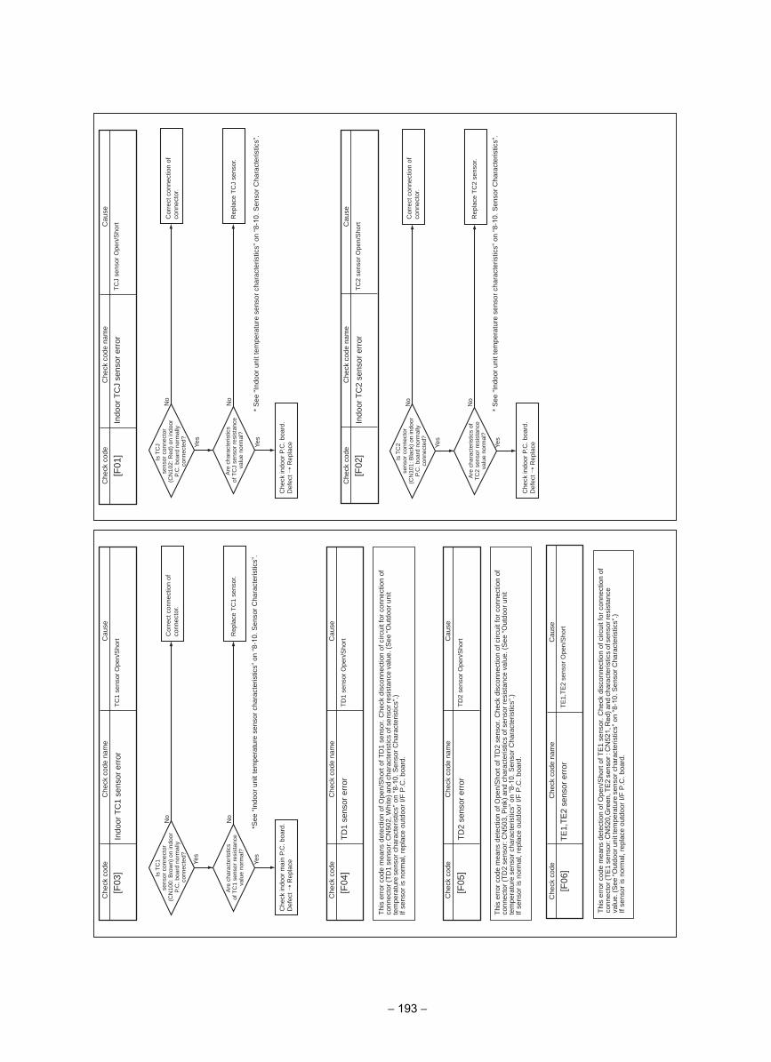
Yes
No
Yes
No
[F03
]
Yes
No
Yes
No
[F01
]
Yes
No
Yes
No
[F02
]
[F04
]
[F05
]
esuaC
edoc kcehC
Che
ck c
ode
nam
eesua
Cedoc kceh
CC
heck
cod
e na
me
esuaC
edoc kcehC
Che
ck c
ode
nam
e
esuaC
edoc kcehC
Che
ck c
ode
nam
e
esuaC
edoc kcehC
Che
ck c
ode
nam
e
Indo
or T
CJ
sens
or e
rror
TC
J se
nsor
Ope
n/S
hort
Indo
or T
C1
sens
or e
rror
TC
1 se
nsor
Ope
n/S
hort
TD
1 se
nsor
err
orT
D1
sens
or O
pen/
Sho
rt
TD
2 se
nsor
err
orT
D2
sens
or O
pen/
Sho
rt
[F06
]edoc kceh
CC
heck
cod
e na
me
TE
1,TE
2 se
nsor
err
or
Cau
se
TE
1,TE
2 se
nsor
Ope
n/S
hort
Indo
or T
C2
sens
or e
rror
TC
2 se
nsor
Ope
n/S
hort
Is T
CJ
se
nsor
con
nect
or
(CN
102:
Red
) on
indo
or
P.C
. boa
rd n
orm
ally
co
nnec
ted?
Is T
C1
se
nsor
con
nect
or(C
N10
0: B
row
n) o
n in
door
P.
C. b
oard
nor
mal
ly
conn
ecte
d?
Are
cha
ract
eris
tics
of T
CJ
sens
or r
esis
tanc
e va
lue
norm
al?
Are
cha
ract
eris
tics
of T
C1
sens
or r
esis
tanc
e va
lue
norm
al?
Is T
C2
se
nsor
con
nect
or
(CN
101:
Bla
ck)
on in
door
P.
C. b
oard
nor
mal
ly
conn
ecte
d?
Are
cha
ract
eris
tics
of
TC
2 se
nsor
res
ista
nce
valu
e no
rmal
?
Cor
rect
con
nect
ion
of
conn
ecto
r.C
orre
ct c
onne
ctio
n of
co
nnec
tor.
Rep
lace
TC
1 se
nsor
.R
epla
ce T
CJ
sens
or.
Cor
rect
con
nect
ion
of
conn
ecto
r.
Rep
lace
TC
2 se
nsor
.
Che
ck in
door
P.C
. boa
rd.
Def
ect
Rep
lace
Che
ck in
door
mai
n P.
C. b
oard
.D
efec
t R
epla
ce
Che
ck in
door
P.C
. boa
rd.
Def
ect
Rep
lace
* S
ee “
Indo
or u
nit t
empe
ratu
re s
enso
r ch
arac
teris
tics”
on
“8-1
0. S
enso
r C
hara
cter
istic
s”.
* S
ee “
Indo
or u
nit t
empe
ratu
re s
enso
r ch
arac
teris
tics”
on
“8-1
0. S
enso
r C
hara
cter
istic
s”.
* See
“In
door
uni
t tem
pera
ture
sen
sor
char
acte
ristic
s” o
n “8
-10.
Sen
sor
Cha
ract
eris
tics”
.
Thi
s er
ror
code
mea
ns d
etec
tion
of O
pen/
Sho
rt o
f TD
1 se
nsor
. Che
ck d
isco
nnec
tion
of c
ircui
t for
con
nect
ion
of
conn
ecto
r (T
D1
sens
or: C
N50
2, W
hite
) and
cha
ract
eris
tics
of s
enso
r res
ista
nce
valu
e. (S
ee “O
utdo
or u
nit
tem
pera
ture
sen
sor
char
acte
ristic
s” o
n “8
-10.
Sen
sor
Cha
ract
eris
tics”
.)If
sens
or is
nor
mal
, rep
lace
out
door
I/F
P.C
. boa
rd.
Thi
s er
ror
code
mea
ns d
etec
tion
of O
pen/
Sho
rt o
f TD
2 se
nsor
. Che
ck d
isco
nnec
tion
of c
ircui
t for
con
nect
ion
of
conn
ecto
r (T
D2
sens
or: C
N50
3, P
ink)
and
cha
ract
eris
tics
of s
enso
r re
sist
ance
val
ue. (
See
“O
utdo
or u
nit
tem
pera
ture
sen
sor
char
acte
ristic
s” o
n “8
-10.
Sen
sor
Cha
ract
eris
tics”
.)If
sens
or is
nor
mal
, rep
lace
out
door
I/F
P.C
. boa
rd.
Thi
s er
ror
code
mea
ns d
etec
tion
of O
pen/
Sho
rt o
f TE
1 se
nsor
. Che
ck d
isco
nnec
tion
of c
ircui
t for
con
nect
ion
of
conn
ecto
r (T
E1
sens
or: C
N52
0,G
reen
, TE
2 se
nsor
: C
N52
1, R
ed) a
nd c
hara
cter
istic
s of
sen
sor r
esis
tanc
e va
lue.
(See
“Out
door
uni
t tem
pera
ture
sen
sor
char
acte
ristic
s” o
n “8
-10.
Sen
sor
Cha
ract
eris
tics”
.)If
sens
or is
nor
mal
, rep
lace
out
door
I/F
P.C
. boa
rd.
− 193 −
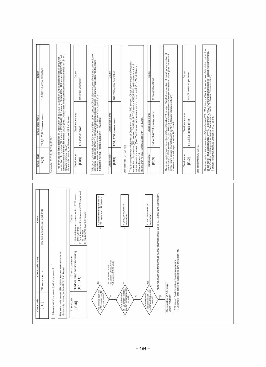
Yes
Out
door
I/F
P.C
. boa
rd
TE
1 se
nsor
: C
N52
0, G
reen
T
L1 s
enso
r : C
N52
3, W
hite
No
No
Yes
No
Yes
[F15
][F
08]
[F10
]
[F12
]
[F07
][F
13]
Sub
-cod
e: 0
1: C
ompr
esso
r 1,
02:
Com
pres
sor
2
edoc kcehC
esuaC
edoc kcehC
esuaC
edoc kcehC
Che
ck c
ode
nam
e
esuaC
edoc kcehC
edoc kcehC
edoc kcehC
Che
ck c
ode
nam
eC
heck
cod
e na
me
TL1
,TL2
,TL3
sen
sor
erro
r
Che
ck c
ode
nam
e O
utdo
or te
mp
sens
or m
isw
iring
(T
E1,
TL1
)
Cau
se
TL1
,TL2
,TL3
sen
sor
Ope
n/S
hort
TO
sen
sor
erro
rT
O s
enso
r O
pen/
Sho
rt
Che
ck c
ode
nam
e
Indo
or T
A/T
SA
sen
sor
erro
rTA
sen
sor
Ope
n/S
hort
Che
ck c
ode
nam
e
TS
1,TS
3 se
nsor
err
or
Cau
se
TS
1,TS
3 se
nsor
Ope
n/S
hort
TH
sen
sor
erro
r
Cau
se
IPM
bui
lt-in
sen
sor
erro
r in
A3-
IPD
U
Thi
s er
ror
code
mea
ns IP
M b
uilt-
in te
mpe
ratu
re s
enso
r er
ror.
If s
enso
r is
nor
mal
, rep
lace
IPD
U P
.C. b
oard
.
1. M
isin
stal
latio
n an
d m
isco
nnec
tion
of T
E1
sens
or
and
TL1
sen
sor
2. R
esis
tanc
e ch
arac
teris
tics
erro
r of
TE
1 se
nsor
and
T
L1 s
enso
r3.
Out
door
P.C
. boa
rd (
I/F)
erro
r
Are
inst
alle
d po
sitio
ns
of T
E1
sens
or a
nd T
L1
sens
or c
orre
ct?
Are
con
nect
ion
of T
E1
sens
or c
onne
ctor
an
d T
L1 s
enso
r con
nect
or
norm
al?
Are
res
ista
nce
char
acte
ristic
s of
TL1
se
nsor
and
TE
1 se
nsor
no
rmal
?
Cor
rect
inst
alle
d po
sitio
ns o
f T
E1
sens
or a
nd T
L1 s
enso
r.
Cor
rect
con
nect
ion
of
conn
ecto
rs.
Cor
rect
con
nect
ion
of
conn
ecto
rs.
Che
ck o
utdo
or I/
F P
.C. b
oard
.D
efec
t R
epla
ce
TE
1 se
nsor
: Out
door
hea
t exc
hang
er te
mp
sens
orT
L1 s
enso
r: T
emp
sens
or b
etw
een
liqui
d ta
nk o
f out
door
PM
V
* See
“O
utdo
or u
nit t
empe
ratu
re s
enso
r ch
arac
teris
tics”
on
“8-1
0. S
enso
r C
hara
cter
istic
s”.
Thi
s er
ror
code
mea
ns d
etec
tion
of O
pen/
Sho
rt o
f TL1
,TL2
,TL3
sen
sor.
Che
ck d
isco
nnec
tion
of c
ircui
t for
co
nnec
tion
of c
onne
ctor
(T
L1 s
enso
r: C
N52
3WH
I, TL
2se
nsor
: C
N52
4 G
RY
, TL3
sen
sor:
CN
902
PN
K)
and
char
acte
ristic
s of
sen
sor
resi
stan
ce v
alue
. (S
ee “
Out
door
uni
t tem
pera
ture
sen
sor
char
acte
ristic
s” o
n “8
-10.
S
enso
r C
hara
cter
istic
s”.)
If se
nsor
is n
orm
al, r
epla
ce o
utdo
or I/
F P
.C. b
oard
.
Thi
s er
ror
code
mea
ns d
etec
tion
of O
pen/
Sho
rt o
f TO
sen
sor.
Che
ck d
isco
nnec
tion
of c
ircui
t for
con
nect
ion
of
conn
ecto
r (T
O s
enso
r: C
N50
7, Y
ello
w) a
nd c
hara
cter
istic
s of
sen
sor r
esis
tanc
e va
lue.
(See
“Out
door
uni
t te
mpe
ratu
re s
enso
r ch
arac
teris
tics”
on
“8-1
0. S
enso
r C
hara
cter
istic
s”.)
If se
nsor
is n
orm
al, r
epla
ce o
utdo
or I/
F P
.C. b
oard
.
Thi
s er
ror
code
mea
ns d
etec
tion
of O
pen/
Sho
rt o
f TA
sen
sor.
Che
ck d
isco
nnec
tion
of c
ircui
t for
con
nect
ion
of
conn
ecto
r (T
A /T
SA
sen
sor:
CN
104,
Yel
low
) an
d ch
arac
teris
tics
of s
enso
r re
sist
ance
val
ue. (
See
“In
door
uni
t te
mpe
ratu
re s
enso
r ch
arac
teris
tics”
on
“8-1
0. S
enso
r C
hara
cter
istic
s”.)
If se
nsor
is n
orm
al, r
epla
ce in
door
P.C
. boa
rd.
Thi
s er
ror
code
mea
ns d
etec
tion
of O
pen/
Sho
rt o
f TS
1,TS
3 se
nsor
. Che
ck d
isco
nnec
tion
of c
ircui
t for
con
nect
ion
of c
onne
ctor
(TS
1 se
nsor
: CN
505
WH
I, TS
3 se
nsor
: CN
903
PU
R) a
nd c
hara
cter
istic
s of
sen
sor r
esis
tanc
e va
lue.
(S
ee “O
utdo
or u
nit t
empe
ratu
re s
enso
r ch
arac
teris
tics”
on
“8-1
0. S
enso
r C
hara
cter
istic
s”.)
If se
nsor
is n
orm
al, r
epla
ce o
utdo
or I/
F P
.C. b
oard
.
Sub
-cod
e: 0
1:TL
1, 0
2;TL
2, 0
3;TL
3
[F09
]
Che
ck c
ode
Che
ck c
ode
nam
e
TG1,
TG
2 se
nsor
err
or
Cau
se
TG
1, T
G2
sens
or O
pen/
Sho
rt
Sub
-cod
e: 0
1:TS
1, 0
3:TS
3
Sub
-cod
e: 0
1: T
G1,
02:
TG
2
This
err
or c
ode
mea
ns d
etec
tion
of O
pen/
Sho
rt of
TG
1, T
G2
sens
or.
Che
ck d
isco
nnec
tion
of c
ircui
t for
co
nnec
tion
of c
onne
ctor
(TG
1 se
nsor
: CN
525
BLU
, TG
2 se
nsor
: CN
526
WH
I) an
d ch
arac
teris
tics
of
sens
or re
sist
ance
val
ue.
(See
"Out
door
uni
t tem
pera
ture
sen
sor c
hara
cter
istic
s" o
n "8
-10.
Sen
sor
Cha
ract
eris
tics"
.)If
sens
or is
nor
mal
, rep
lace
out
door
I/F
F.C
. boa
rd.
− 194 −
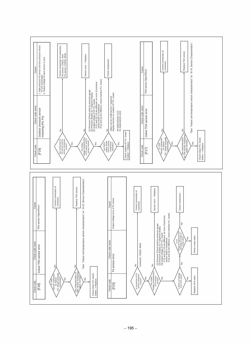
Yes
No
No
Yes
No
Yes
[F16
]esua
Cedoc kceh
CC
heck
cod
e na
me
Out
door
pre
ssur
e se
nsor
m
isw
iring
(P
d, P
s)1.
Hig
h-pr
essu
re P
d se
nsor
and
low
pre
ssur
e se
nsor
P
s ar
e ex
chan
ged.
2. O
utpu
t vol
tage
of e
ach
sens
or is
zer
o.
Are
con
nect
ion
of
Pd
sens
or a
nd P
s se
nsor
con
nect
ors
corr
ect?
Are
out
put
volta
ge c
hara
cter
istic
s of
Pd
sens
or a
nd P
s se
nsor
nor
mal
?
Are
Pd/
Ps
outp
ut v
alue
s P
d>P
s du
ring
com
pres
sor
oper
atio
n?
Cor
rect
con
nect
ion
of c
onne
ctor
s.P
d se
nsor
: CN
501,
Red
Ps
sens
or: C
N50
0, W
hite
Sen
sor
erro
r R
epla
ce
Che
ck c
ompr
esso
r.
Che
ck o
utdo
or I/
F P
.C. b
oard
.D
efec
t R
epla
ce
(1)
Pre
ssur
e (C
heck
join
t) b
y pr
essu
re g
auge
(2)
Pre
ssur
e di
spla
y on
7-s
egm
ent d
ispl
ay(3
) O
utpu
t vol
tage
of I
/F P
.C. b
oard
If (1
) an
d (2
), (
3) a
re d
iffer
ent,
an e
rror
of p
ress
ure
sens
or it
self
is c
onsi
dere
d.If
(2)
and
(3)
are
diffe
rent
, che
ck in
terf
ace
P.C
. boa
rd.
Val
ue c
an b
e co
nfirm
ed b
y 7-
segm
ent
disp
lay
func
tion
on o
utdo
or I/
F P
.C. b
oard
.
Pd
SW
01/0
2/03
=1/
1/2
Ps
SW
01/0
2/03
=1/
2/2
Yes
No
Yes
No
[F17
]C
heck
cod
eC
heck
cod
e na
me
Indo
or T
OA
sen
sor
erro
r
Cau
se
TOA
sen
sor
Ope
n/S
hort
Is T
OA
sens
or c
onne
ctor
on
indo
orP.
C. b
oard
nor
mal
lyco
nnec
ted?
Are
cha
ract
eris
tics
of T
OA
sen
sor
resi
stan
ceva
lue
norm
al?
Cor
rect
con
nect
ion
ofco
nnec
tor.
Rep
lace
T O
A s
enso
r.
Che
ck in
door
P.C
. boa
rd.
Def
ect →
Rep
lace
* See
"In
door
uni
t tem
pera
ture
sen
sor
char
acte
ristic
s" o
n "
8-10
. Sen
sor
Cha
ract
eris
tics"
.
Yes
Yes
No
No
[F18
]C
heck
cod
eC
heck
cod
e na
me
Indo
or T
RA
sen
sor
erro
r
Cau
se
TR
A s
enso
r O
pen/
Sho
rt
sens
or c
onne
ctor
on
indo
orP.
C. b
oard
nor
mal
lyco
nnec
ted?
Is T
RA
Are
cha
ract
eris
tics
ofT
RA
sen
sor
resi
stan
ceva
lue
norm
al?
Cor
rect
con
nect
ion
ofco
nnec
tor.
Rep
lace
TR
A
se
nsor
.
Che
ck in
door
P.C
. boa
rd.
Def
ect →
Rep
lace
* See
"In
door
uni
t tem
pera
ture
sen
sor
char
acte
ristic
s" o
n "
8-10
. Sen
sor
Cha
ract
eris
tics"
.
Yes
Yes
Yes
No
No
Yes
No
[F23
]
No
Con
nect
or: C
N50
0, W
hite
Che
ck c
ode
Che
ck c
ode
nam
e
Ps
sens
or e
rror
Cau
se
Out
put v
olta
ge e
rror
of P
s se
nsor
Is c
onne
ctio
n of
Ps
sens
or c
onne
ctor
co
rrec
t?
Are
out
put
volta
ge c
hara
cter
istic
s of
Ps
sens
orno
rmal
?
Is th
ere
no le
akag
e fr
om S
V4
valv
e?
Is n
otre
frige
rant
byp
asse
d fro
m
disc
harg
e to
suc
tion
of4-
way
val
ve?
Cor
rect
con
nect
ion
of
conn
ecto
r.
Sen
sor
erro
r R
epla
ce
Che
ck c
ompr
esso
r.
Che
ck 4
-way
val
ve.
Rep
lace
SV
4 va
lve.
(1)
Pre
ssur
e (C
heck
join
t) b
y pr
essu
re g
auge
(2)
Pre
ssur
e di
spla
y on
7-s
egm
ent d
ispl
ay(3
) O
utpu
t vol
tage
of I
/F P
.C. b
oard
If (1
) an
d (2
), (
3) a
re d
iffer
ent,
an e
rror
of p
ress
ure
sens
or it
self
is c
onsi
dere
d.If
(2)
and
(3)
are
diffe
rent
, che
ck in
terf
ace
P.C
. boa
rd.
− 195 −
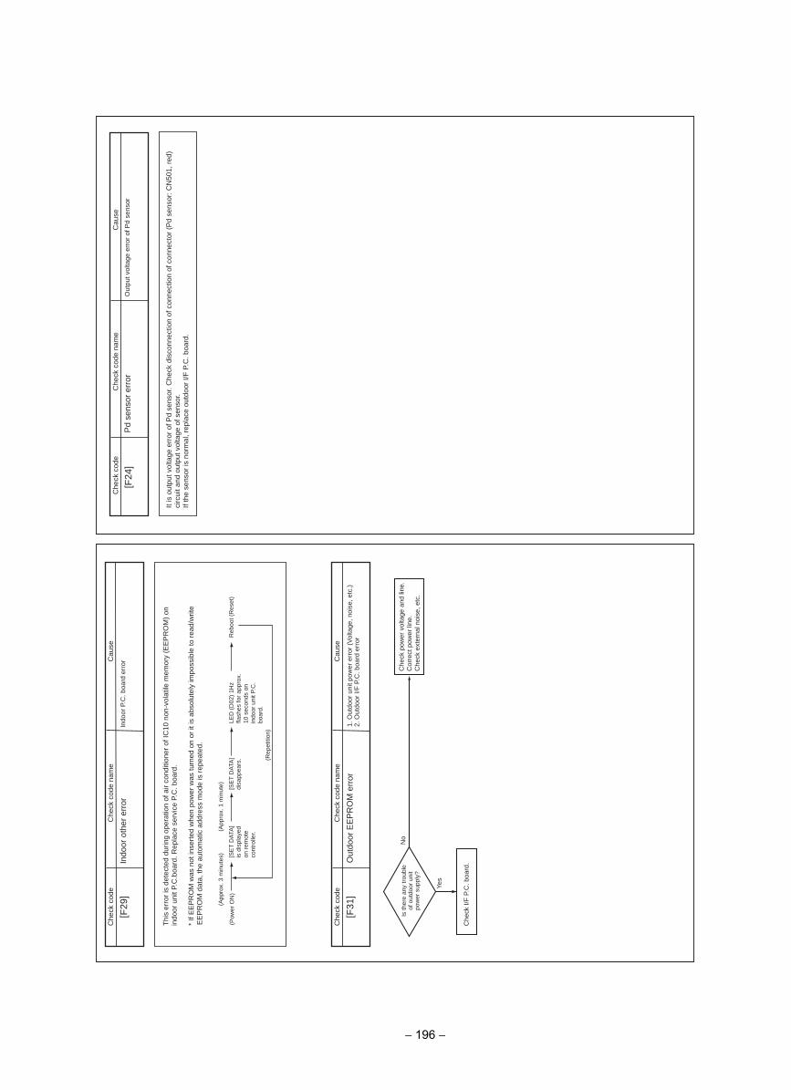
[F29
]
(Pow
er O
N)
(Rep
etiti
on)
(App
rox.
3 m
inut
es)
(App
rox.
1 m
inut
e)
Yes
No
[F31
]
esuaC
edoc kcehC
Che
ck c
ode
nam
e
esuaC
edoc kcehC
Che
ck c
ode
nam
e
Indo
or o
ther
err
orIn
door
P.C
. boa
rd e
rror
Thi
s er
ror
is d
etec
ted
durin
g op
erat
ion
of a
ir co
nditi
oner
of I
C10
non
-vol
atile
mem
ory
(EE
PR
OM
) on
in
door
uni
t P.C
.boa
rd. R
epla
ce s
ervi
ce P
.C. b
oard
.
* If
EE
PR
OM
was
not
inse
rted
whe
n po
wer
was
turn
ed o
n or
it is
abs
olut
ely
impo
ssib
le to
rea
d/w
rite
EE
PR
OM
dat
a, th
e au
tom
atic
add
ress
mod
e is
rep
eate
d.
[SE
T D
ATA
] is
dis
play
ed
on r
emot
e co
ntro
ller.
[SE
T D
ATA
] di
sapp
ears
.LE
D (
D02
) 1H
z fla
shes
for
appr
ox.
10 s
econ
ds o
n in
door
uni
t P.C
. bo
ard.
Reb
oot (
Res
et)
Out
door
EE
PR
OM
err
or1.
Out
door
uni
t pow
er e
rror
(V
olta
ge, n
oise
, etc
.)2.
Out
door
I/F
P.C
. boa
rd e
rror
Is th
ere
any
trou
ble
of o
utdo
or u
nit
pow
er s
uppl
y?
Che
ck p
ower
vol
tage
and
line
.C
orre
ct p
ower
line
.C
heck
ext
erna
l noi
se, e
tc.
Che
ck I/
F P
.C. b
oard
.
[F24
]C
heck
cod
eC
heck
cod
e na
me
Pd
sens
or e
rror
Cau
se
Out
put v
olta
ge e
rror
of P
d se
nsor
It is
out
put v
olta
ge e
rror
of P
d se
nsor
. Che
ck d
isco
nnec
tion
of c
onne
ctio
n of
con
nect
or (
Pd
sens
or: C
N50
1, r
ed)
circ
uit a
nd o
utpu
t vol
tage
of s
enso
r.If
the
sens
or is
nor
mal
, rep
lace
out
door
I/F
P.C
. boa
rd.
− 196 −
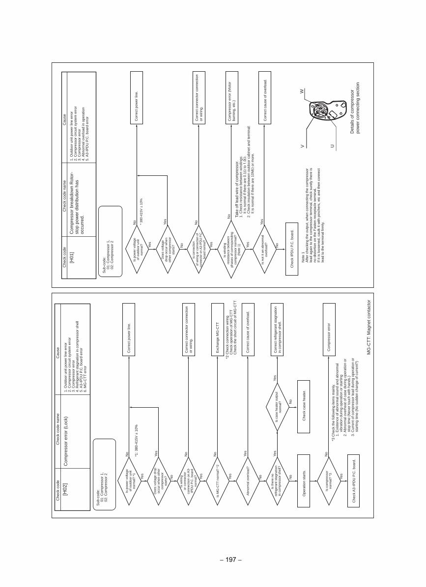
Yes
No
Yes
No
*1: 3
80-4
15V
± 1
0%
Yes
No
No
No
Yes
No
Yes
No
Yes
Yes
[H02
]C
ause
Che
ck c
ode
Che
ck c
ode
nam
e
Com
pres
sor
erro
r (L
ock)
MG
-CT
T: M
agne
t con
tact
or
1. O
utdo
or u
nit p
ower
line
err
or2.
Com
pres
sor
circ
uit s
yste
m e
rror
3. C
ompr
esso
r er
ror
4. R
efrig
eran
t sta
gnat
ion
in c
ompr
esso
r sh
ell
5. A
3-IP
DU
P.C
. boa
rd e
rror
6. M
G-C
TT
err
or
Sub
-cod
e:01
: Com
pres
sor
1,02
: Com
pres
sor
2
Is p
ower
vol
tage
of
out
door
uni
t no
rmal
? *1
Doe
s vo
ltage
dro
p oc
cur
whe
n ot
her
com
pres
sor
star
ts?
Is w
iring
or c
onne
ctor
co
nnec
tion
on A
3-IP
DU
P.C
. boa
rd
norm
al?
Is M
G-C
TT
nor
mal
? *2
Is th
ere
nore
frig
eran
t sta
gnat
ion
in c
ompr
esso
r sh
ell?
Is c
ompr
esso
r no
rmal
? *3
Is c
ase
heat
er o
utpu
t no
rmal
?
Cor
rect
pow
er li
ne.
Cor
rect
con
nect
or c
onne
ctio
n or
wiri
ng.
Exc
hang
e M
G-C
TT
No
Yes
Abn
orm
al o
verlo
ad?
Cor
rect
cau
se o
f ove
rload
.
Cor
rect
ref
riger
ant s
tagn
atio
n in
com
pres
sor
shel
l.
Che
ck c
ase
heat
er.
Ope
ratio
n st
arts
.
Com
pres
sor
erro
r
Che
ck A
3-IP
DU
P.C
. boa
rd.
*3 C
heck
the
follo
win
g ite
ms
mai
nly.
1. E
xist
ence
of a
bnor
mal
sou
nd a
nd a
bnor
mal
vi
brat
ion
durin
g op
erat
ion
or s
tart
ing
2. A
bnor
mal
ove
rhea
t of c
ase
durin
g op
erat
ion
or
stop
tim
e (N
ever
touc
h w
ith h
ands
.)3.
Cur
rent
of c
ompr
esso
r le
ad d
urin
g op
erat
ion
or
star
ting
time
(No
sudd
en c
hang
e of
cur
rent
?)
2 C
heck
con
nect
ion
wiri
ng
*C
heck
ope
ratio
n of
MG
-CT
T
Che
ck th
e sh
ort c
ircui
t of M
G-C
TT
Yes
No
Yes
No
* 38
0-41
5V ±
10%
Yes
No
Yes
No
Yes
[H01
]
V U
W
Cau
seC
heck
cod
eC
heck
cod
e na
me
Is p
ower
vol
tage
of
out
door
uni
t no
rmal
?
Doe
s vo
ltage
dr
op o
ccur
whe
n ot
her
com
pres
sor
star
ts?
Is w
indi
ngre
sist
ance
bet
wee
nph
ases
of c
orre
spon
ding
co
mpr
esso
r no
rmal
? (N
ote
1)
Is n
ot it
an
abno
rmal
ov
erlo
ad?
Is c
onne
ctio
nof
wiri
ng o
r con
nect
ion
of
conn
ecto
r on
A3-
IPD
U P
.C.
boar
d no
rmal
?
Cor
rect
pow
er li
ne.
Cor
rect
con
nect
or c
onne
ctio
n or
wiri
ng.
Com
pres
sor
erro
r (M
otor
bu
rnin
g, e
tc.)
Cor
rect
cau
se o
f ove
rload
.
Che
ck IP
DU
P.C
. boa
rd.
Com
pres
sor
brea
kdow
n R
otor
-st
op p
ower
dis
tribu
tion
has
occu
rred
.
1. O
utdo
or u
nit p
ower
line
err
or2.
Com
pres
sor
circ
uit s
yste
m e
rror
3. C
ompr
esso
r er
ror
4. A
bnor
mal
ove
rload
in o
pera
tion
5. A
3-IP
DU
P.C
. boa
rd e
rror
Sub
-cod
e:01
: Com
pres
sor
1,02
: Com
pres
sor
2
No Ta
ke o
ff le
ad w
ire o
f com
pres
sor.
Che
ck r
esis
tanc
e be
twee
n w
indi
ngs:
1.It
is n
orm
al if
ther
e ar
e 0.
1Ω to
1.0
Ω.
2. C
heck
insu
latio
n be
twee
n ou
tdoo
r ca
bine
t and
term
inal
:It
is n
orm
al if
ther
e ar
e 10
MΩ
or
mor
e.
Not
e 1
Afte
r ch
ecki
ng th
e ou
tput
, whe
n co
nnec
ting
the
com
pres
sor
lead
aga
in to
the
com
pres
sor
term
inal
, che
ck s
urel
y th
ere
is
no d
isto
rtio
n on
the
Fas
ten
rece
ptac
le te
rmin
al.
If it
is lo
osen
ed, c
aulk
it w
ith p
inch
ers,
etc
and
then
con
nect
le
ad to
the
term
inal
firm
ly.
Det
ails
of c
ompr
esso
r po
wer
con
nect
ing
sect
ion
− 197 −
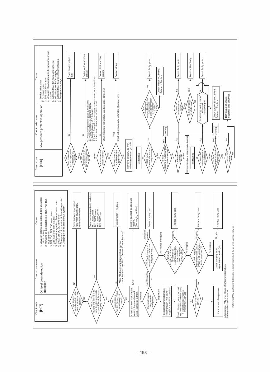
[H07
]esua
Cedoc kceh
CC
heck
cod
e na
me
Oil
leve
l dow
n de
tect
ion
prot
ectio
n1.
Val
ves
of b
alan
ce p
ipes
clo
sed.
(O
n al
l out
door
un
its in
a li
ne)
2. M
isw
iring
or
mis
inst
alla
tion
of T
K1,
TK
2, T
K4,
TK
5 se
nsor
s3.
TK
1, T
K2,
TK
4, T
K5
sens
or e
rror
4. G
as le
ak o
r oi
l lea
k in
a li
ne5.
Ref
riger
ant s
tagn
atio
n of
com
pres
sor
case
6. S
V3A
, 3B
, 3C
, 3D
val
ve e
rror
7. C
logg
ing
of o
il re
turn
circ
uit f
rom
oil
sepa
rato
r8.
Clo
ggin
g of
oil-
equa
tion
circ
uit s
yste
m
Indo
or/o
utdo
or P
MV
err
or (
Cau
se o
f ref
riger
ant s
tagn
atio
n),
disc
harg
e ch
eck
valv
e er
ror,
etc.
(Ref
eren
ce)
Whe
n re
frig
eran
t sta
gnat
es in
com
pres
sor
shel
l, th
e oi
l lev
el s
hort
age
may
be
No
Ope
n ba
lanc
e pi
pe v
alve
s fu
lly, r
eset
pow
er s
uppl
y,
and
star
t ope
ratio
n.
No
Sens
or e
rror
Rep
lace
Spe
cify
gas
leak
pos
ition
and
re
pair
it.(R
echa
rgin
g, re
fill o
il)E
rror
No
stag
natio
nR
epla
ce fa
ulty
par
t.
No
leak
age
or c
logg
ing
Clo
ggin
gR
epla
ce fa
ulty
par
t.Ch
eck
oil le
vel ju
dgm
ent o
f eac
h un
it.Th
e ch
eck
resu
lt is
indi
cate
d on
the
7-se
gmen
t disp
lay
by s
ettin
g [S
W01
/02/
03] t
o [1
/16/
1].
Clo
ggin
gN
oR
epla
ce fa
ulty
par
t.
No
clog
ging
Clo
ggin
gC
lear
cau
se o
f sta
gnat
ion.
Rep
lace
faul
ty p
art.
Are
bala
nce
pipe
val
ves
of a
ll ou
tdoo
r un
its in
sam
e lin
e fu
lly
open
ed?
Yes
Are
TK1,
TK2
, TK
4 an
d TK
5 se
nsor
s of
the
erro
r-det
ecte
d un
it co
rrect
ly co
nnec
ted?
Are
all t
he s
enso
rs
prop
erly
conn
ecte
d?
Yes
Yes
Che
ck g
as le
ak o
f all
outd
oor
units
in th
e sa
me
line
and
chec
k so
aked
oil
in th
em.
No
erro
r
Leak
age
or
clog
ging
Sta
gnat
ion
Corre
ct re
frige
rant
sta
gnat
ion
in c
ompr
esso
r, re
set p
ower
su
pply,
and
sta
rt th
e op
erat
ion.
(*1)
Che
ck le
akag
e of
va
lves
(SV
3A, S
V3C
) and
cl
oggi
ng (S
V3B
).
(*2)
Che
ckcl
oggi
ng o
f oil
retu
rn
circ
uit f
rom
oil
sepa
rato
r. (C
apill
ary
tube
, stra
iner
)C
heck
clo
ggin
g of
S
V3D
val
ve.
No
clog
ging
Are
all
oil l
evel
s co
rrec
t? Yes
Che
ck c
logg
ing
of s
olen
oid
valv
es (S
V3A
, S
V3C
) of a
ll ou
tdoo
r uni
ts
in th
e sa
me
line.
(*3)
Che
ck c
logg
ing
of o
il eq
ualiz
atio
n ci
rcui
t. (*
4)
Are
char
acte
ristic
s of
TK
1, T
K2, T
K4 a
nd T
K5 o
f er
ror-d
etec
ted
unit
norm
al?
Che
ck re
frige
rant
st
agna
tion
in
com
pres
sor.
Cor
rect
mis
wiri
ng a
nd m
isin
stal
latio
n.
TK1:
CN
531,
bla
ckTK
2: C
N53
2, g
reen
TK4:
CN
534,
yel
low
TK5:
CN
535,
red
No *S
ee“O
utdo
orun
itte
mpe
ratu
rese
nsor
ch
arac
teris
tics”
on
“8-1
0. S
enso
r Cha
ract
eris
tics”
.
No
No
No
Yes
Yes
Yes Ye
s
No
No
Yes
No
Yes
(Che
ck w
ith m
isw
iring
che
ck fu
nctio
n of
out
door
uni
t.)
Yes
No
No
Yes
No
Yes
No
Yes
Yes
No
No
Cle
anin
g
Cle
anin
g
[H06
]
Cau
seC
heck
cod
eC
heck
cod
e na
me
Low
-pre
ssur
e pr
otec
tive
oper
atio
n1.
Ser
vice
val
ve c
lose
2. P
s se
nsor
err
or3.
SV
2, S
V4
circ
uit e
rror
4. M
isw
iring
of c
omm
unic
atio
n be
twee
n in
door
and
ou
tdoo
r5.
Indo
or/o
utdo
or fa
n an
d co
nden
ser
erro
r6.
Indo
or/o
utdo
or P
MV
clo
ggin
g7.
Indo
or/o
utdo
or h
eat e
xcha
nger
clo
ggin
g8.
Ref
riger
ant s
hort
age
Are
serv
ice
valv
es o
fga
s an
d liq
uid
pipe
of
outd
oor u
nit f
ully
op
ened
?
Are
char
acte
ristic
s of
lo
w-p
ress
ure
sens
or
norm
al?
Are
SV
2 an
d S
V4
circ
uits
nor
mal
?
Is a
ny in
door
uni
t in
a d
iffer
ent l
ine
conn
ecte
d?
Doe
s in
door
fan
norm
ally
ope
rate
in
coo
ling
seas
on?
Is th
ere
clog
ging
of i
ndoo
r ai
r fil
ter
or h
eat e
xcha
nger
?
Is in
door
PM
V
norm
al?
Is o
utdo
or fa
n no
rmal
ly o
pera
ted
in
heat
ing
seas
on?
Is th
ere
clog
ging
of o
utdo
or h
eat
exch
ange
r?
Is o
utdo
or P
MV
no
rmal
?
Is c
onne
ctor
conn
ectio
n or
coi
l no
rmal
?
Is th
ere
clog
ging
on
who
le v
alve
?
Are
follo
win
g ite
ms
conc
erne
d to
indo
or fa
n m
otor
nor
mal
?1.
Con
nect
or c
onne
ctio
n2.
Con
dens
er3.
Mot
or4.
Fan
Ope
n se
rvic
e va
lves
fu
lly.
Exc
hang
e lo
w-p
ress
ure
sens
or.
Cor
rect
SV
2 an
d S
V4
circ
uits
.
Cor
rect
wiri
ng.
Rep
air
faul
ty p
arts
.
Che
ck in
door
P.C
. boa
rd.
Fai
lure
Rep
lace
Yes
Ref
riger
ant s
horta
ge o
r clo
ggin
g or
pip
e de
form
ed
Rep
air
faul
ty p
arts
.
Rep
air
faul
ty p
arts
.
Ref
riger
ant s
hort
age,
cl
oggi
ng, p
ipe
defo
rmed
Rep
lace
PM
V b
ody.
Che
ck o
utdo
or I/
F P
.C. b
oard
.F
ailu
re R
epla
ce
In c
oolin
g se
ason
, go
to (
A)
In h
eatin
g se
ason
, go
to (
B)
(A)
Coo
ling
(B)
Hea
ting
No
Che
ck m
isw
iring
, mis
inst
alla
tion
and
conn
ecto
r co
nnec
tion.
No
* 1. P
ress
ure
by p
ress
ure
gaug
e (C
heck
join
t) P
ress
ure
disp
lay
on 7
-seg
men
t dis
play
2. 3. O
utpu
t vol
tage
of I
/F P
.C. b
oard
If 1
and
2, 3
are
diff
eren
t, an
err
or o
f pre
ssur
e se
nsor
err
or is
con
side
red.
If 2
and
3 ar
e di
ffere
nt, c
heck
I/F
P.C
. boa
rd.
Is in
door
fan
syst
em n
orm
al?
Fan
cra
ck•
• F
an c
omin
g-of
f
− 198 −
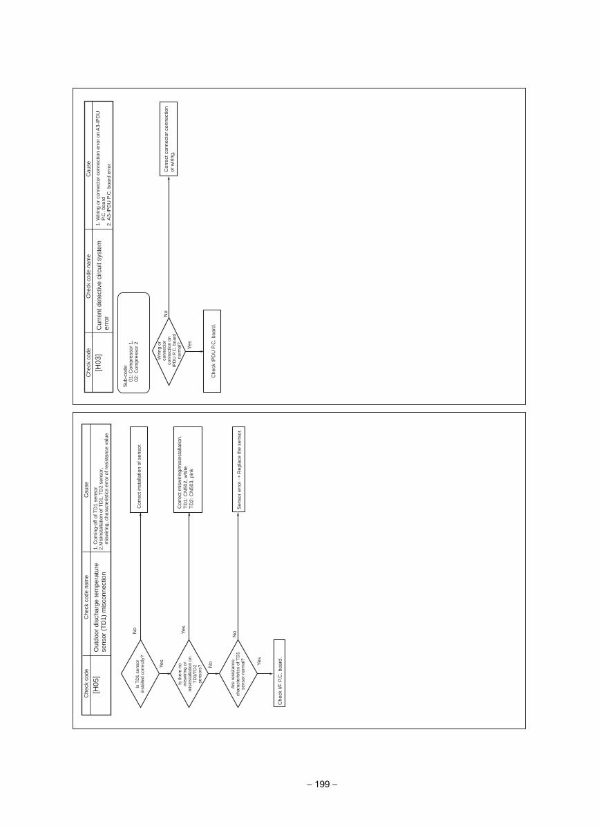
[H05
]
Yes
Yes
No
No
esuaC
edoc kcehC
Che
ck c
ode
nam
e
Out
door
dis
char
ge te
mpe
ratu
re
sens
or (
TD
1) m
isco
nnec
tion
1. C
omin
g-of
f of T
D1
sens
or2.
Mis
inst
alla
tion
of T
D1,
TD
2 se
nsor
, m
isw
iring
, cha
ract
eris
tics
erro
r of
res
ista
nce
valu
e
Is th
ere
no
mis
wiri
ng o
r m
isin
stal
latio
n on
T
D1/
TD
2 se
nsor
s?
Are
res
ista
nce
char
acte
ristic
s of
TD
1 se
nsor
nor
mal
?
Cor
rect
mis
wiri
ng/m
isin
stal
latio
n.
TD
1: C
N50
2, w
hite
TD
2: C
N50
3, p
ink
No
Yes
Is T
D1
sens
or
inst
alle
d co
rrec
tly?
Cor
rect
inst
alla
tion
of s
enso
r.
Che
ck I/
F P
.C. b
oard
.
Sen
sor
erro
r R
epla
ce th
e se
nsor
.
Yes
No
[H03
]C
ause
Che
ck c
ode
Che
ck c
ode
nam
e
Cur
rent
det
ectiv
e ci
rcui
t sys
tem
er
ror
1. W
iring
or
conn
ecto
r co
nnec
tion
erro
r on
A3-
IPD
U
P.C
. boa
rd2.
A3-
IPD
U P
.C. b
oard
err
or
Sub
-cod
e:01
: Com
pres
sor
1,02
: Com
pres
sor
2
Wiri
ng o
r co
nnec
tor
conn
ectio
n on
IP
DU
P.C
. boa
rd
norm
al?
Cor
rect
con
nect
or c
onne
ctio
n or
wiri
ng.
Che
ck IP
DU
P.C
. boa
rd.
− 199 −
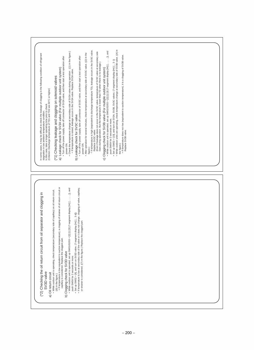
(*2
) C
heck
ing
the
oil r
etur
n ci
rcui
t fro
m o
il se
para
tor
and
clog
ging
in
SV
3D v
alve
a)
Oil
retu
rn c
ircui
t•
Whi
le o
utdo
or u
nit i
s op
erat
ing,
che
ck te
mpe
ratu
re (
seco
ndar
y si
de o
f cap
illar
y) o
n oi
l ret
urn
circ
uit.
((6)
in th
e fig
ure.
) If
tem
pera
ture
is lo
w e
quiv
alen
t to
suct
ion
tem
pera
ture
), a
clo
ggin
g of
str
aine
r of
oil
retu
rn c
ircui
t or
capi
llary
is c
onsi
dere
d. R
epla
ce th
e cl
ogge
d pa
rt.
b)C
logg
ing
chec
k fo
r S
V3D
val
ve•
Whi
le o
utdo
or u
nit i
s op
erat
ed, s
et u
p S
W01
/02/
03 =
[2] [
1] [3
] (7-
segm
ent d
ispl
ay [H
r] [.
.. ...
...])
, and
pu
sh S
W04
for
2 se
cond
s or
mor
e.•
Set
up
SW
02 =
[9],
and
turn
on
SV
3D v
alve
. (7-
segm
ent d
ispl
ay [H
r] [.
.. 3
d])
• If
tem
pera
ture
is lo
w a
t sec
onda
ry s
ide
of th
e va
lve
or it
doe
s no
t cha
nge,
clo
ggin
g of
val
ve, c
apill
ary,
or
str
aine
r is
con
side
red.
((7
) in
the
figur
e.)
Rep
lace
the
clog
ged
part
.
In s
ome
case
s, it
may
be
diffi
cult
to c
heck
the
leak
age
of c
logg
ing
in th
e fo
llow
ing
cond
ition
of r
efrig
eran
t st
agna
tion
in lo
w a
mbi
ent t
empe
ratu
re c
ondi
tion.
In th
is c
ase,
take
a lo
nger
ope
ratin
g tim
e pr
ior
to c
heck
.(C
riter
ion:
Dis
char
ge te
mpe
ratu
re o
f TD
1 an
d T
D2
are
60°C
or
high
er)
(*1)
Che
ckin
g le
akag
e an
d cl
oggi
ng o
n so
leno
id v
alve
sa)
Leak
age
chec
k fo
r S
V3A
val
ve (
For
mul
tiple
out
door
uni
t sys
tem
)•
Turn
off
the
pow
er s
uppl
y, ta
ke o
ff co
nnec
tor
of S
V3A
val
ve, a
nd th
en s
tart
a te
st o
pera
tion
afte
r po
wer
-ON
.•
Che
ck th
e te
mpe
ratu
re c
hang
e at
sec
onda
ry s
ide
of S
V3A
val
ve d
urin
g op
erat
ion
. ((1
) in
the
figur
e.)
If t
empe
ratu
re is
rai
sed,
leak
age
occu
rs in
the
SV
3A v
alve
. Rep
lace
SV
3A v
alve
.
b)Le
akag
e ch
eck
for
SV
3C v
alve
• Tu
rn o
ff th
e po
wer
sup
ply,
take
off
conn
ecto
r of
SV
3C v
alve
, and
then
sta
rt a
test
ope
ratio
n af
ter
pow
er-O
N.
• A
fter
oper
atio
n fo
r se
vera
l min
utes
, che
ck te
mpe
ratu
re a
t sec
onda
ry s
ide
of S
V3C
val
ve. (
(2)
in th
e fig
ure.
) If
tem
pera
ture
is h
igh
(equ
ival
ent t
o di
scha
rge
tem
pera
ture
TD
), le
akag
e oc
curs
in th
e S
V3C
val
ve.
Rep
lace
SV
3C v
alve
.(E
ven
if le
akag
e do
es n
ot o
ccur
in th
e S
V3C
val
ve, t
empe
ratu
re o
f SV
3C v
alve
at s
econ
dary
sid
e ris
es d
urin
g op
erat
ion.
But
the
tem
pera
ture
is lo
wer
than
TD
whe
n th
ere
is n
o le
akag
e.)
c)C
logg
ing
chec
k fo
r S
V3B
val
ve (
For
mul
tiple
out
door
uni
t sys
tem
)•
Whi
le o
utdo
or u
nit i
s op
erat
ed, s
et u
p S
W01
/02/
03 =
[2] [
1] [3
] (7-
segm
ent d
ispl
ay [H
r] [.
.. ...
...])
, and
pu
sh S
W04
for
2 se
cond
s or
mor
e.•
Set
up
SW
02 =
[10]
, and
turn
on
SV
3A, S
V3B
, SV
3C v
alve
s. (
7-se
gmen
t dis
play
[Hr]
[...
3 -]
)•
Whi
le o
utdo
or u
nits
are
ope
ratin
g, c
heck
tem
pera
ture
cha
nge
at s
econ
dary
sid
e of
SV
3B v
alve
. ((4
) in
th
e fig
ure.
) If
tem
pera
ture
doe
s no
t ris
e (e
quiv
alen
t to
suct
ion
tem
pera
ture
), it
is a
clo
ggin
g of
SV
3B v
alve
. R
epla
ce S
V3B
val
ve.
− 200 −
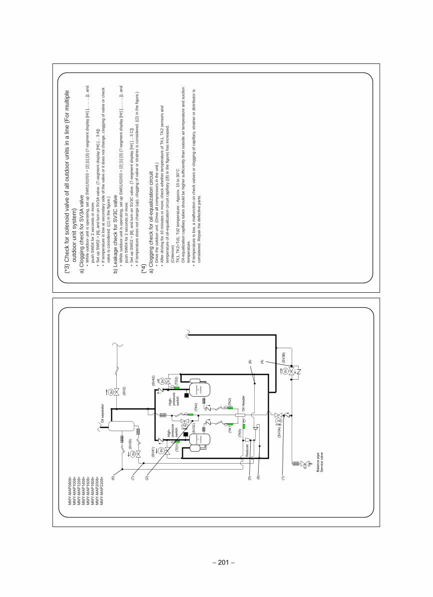
MM
Y-M
AP
0806
∗M
MY
-MA
P10
06∗
MM
Y-M
AP
1206
∗M
MY
-MA
P14
06∗
MM
Y-M
AP
1606
∗M
MY
-MA
P18
06∗
MM
Y-M
AP
2006
∗M
MY
-MA
P22
06∗
(TD
2)
(TK
2)
(TK
1)
(TD
1)
(TK
4)
SV
SV
SV
SV
SV SV
(TK
5)
(SV
3B)
(SV
3A)
(SV
2)
(SV
3D)
(SV
42)
(SV
41)
(SV
3C) O
il se
para
tor
Oil
Hea
der
Hig
h-
pres
sure
sw
itch
Hig
h-
pres
sure
sw
itch
Bal
ance
pip
e S
ervi
ce v
alve
Red
ucer
Com
pres
sor
1 (In
verte
r)
Com
pres
sor
2 (In
verte
r)
SV
(6)
(7)
(2)
(5)
(8)
(1)
(8)
(4)
(*3)
Che
ck fo
r so
leno
id v
alve
of a
ll ou
tdoo
r un
its in
a li
ne (
For
mul
tiple
ou
tdoo
r un
it sy
stem
)a)
Clo
ggin
g ch
eck
for
SV
3A v
alve
• W
hile
out
door
uni
t is
oper
atin
g, s
et u
p S
W01
/02/
03 =
[2] [
1] [3
] (7-
segm
ent d
ispl
ay [H
r] [.
.. ...
...])
, and
pu
sh S
W04
for
2 se
cond
s or
mor
e.•
Set
up
SW
02 =
[6],
and
turn
on
SV
3A v
alve
. (7-
segm
ent d
ispl
ay [H
r] [.
.. 3
A])
• If
tem
pera
ture
is lo
w a
t sec
onda
ry s
ide
of th
e va
lve
or it
doe
s no
t cha
nge,
clo
ggin
g of
val
ve o
r ch
eck
valv
e is
con
side
red.
((1
) in
the
figur
e.)
b)Le
akag
e ch
eck
for
SV
3C v
alve
• W
hile
out
door
uni
t is
oper
atin
g, s
et u
p S
W01
/02/
03 =
[2] [
1] [3
] (7-
segm
ent d
ispl
ay [H
r] [.
.. ...
...])
, and
pu
sh S
W04
for
2 se
cond
s or
mor
e.•
Set
up
SW
02 =
[8],
and
turn
on
SV
3C v
alve
. (7-
segm
ent d
ispl
ay [H
r] [.
.. 3
C])
• If
tem
pera
ture
doe
s no
t cha
nge
(up)
, clo
ggin
g of
val
ve o
r st
rain
er is
con
side
red.
((2
) in
the
figur
e.)
(*4)
a)C
logg
ing
chec
k fo
r oi
l-equ
aliz
atio
n ci
rcui
t•
Driv
e th
e ou
tdoo
r un
it. (
Driv
e al
l com
pres
sors
in th
e un
it.)
• A
fter
driv
ing
for
10 m
inut
es o
r m
ore,
che
ck w
heth
er te
mpe
ratu
re o
f TK
1, T
K2
sens
ors
and
tem
pera
ture
of o
il-eq
ualiz
atio
n ci
rcui
t cap
illar
y ((
8) in
the
figur
e) h
as in
crea
sed.
(Crit
erio
n)T
K1,
TK
2=T
d1, T
d2 te
mpe
ratu
re -
App
rox.
10
to 3
0°C
Oil-
equa
lizat
ion
capi
llary
tube
s sh
ould
be
high
er s
uffic
ient
ly th
an o
utsi
de a
ir te
mpe
ratu
re a
nd s
uctio
n te
mpe
ratu
re.
• If
tem
pera
ture
is lo
w, a
mal
func
tion
on c
heck
val
ves
or c
logg
ing
of c
apill
ary,
str
aine
r or
dis
trib
utor
is
cons
ider
ed. R
epai
r th
e de
fect
ive
part
s.
− 201 −
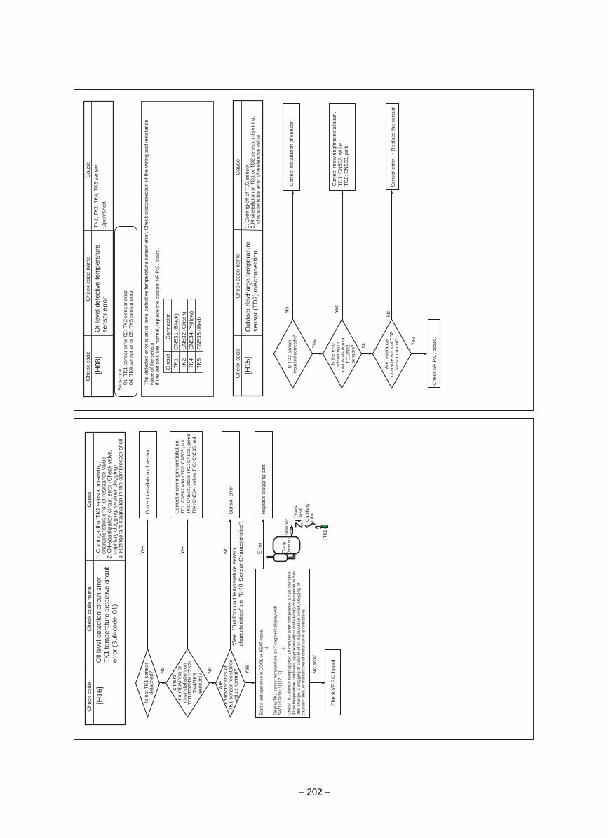
Circ
uit
TK
1T
K2
TK
4T
K5
Con
nect
orC
N53
1 (B
lack
)C
N53
2 (G
reen
)C
N53
4 (Y
ello
w)
CN
535
(Red
)
[H08
]C
heck
cod
eC
heck
cod
e na
me
Oil
leve
l det
ectiv
e te
mpe
ratu
re
sens
or e
rror
Cau
se
TK
1, T
K2,
TK
4, T
K5
sens
or
Ope
n/S
hort
Sub
-cod
e:01
: TK
1 se
nsor
err
or 0
2: T
K2
sens
or e
rror
04: T
K4
sens
or e
rror
05:
TK
5 se
nsor
err
or
The
det
ecte
d er
ror
is a
n oi
l lev
el d
etec
tive
tem
pera
ture
sen
sor
erro
r. C
heck
dis
conn
ectio
n of
the
wiri
ng a
nd r
esis
tanc
e va
lue
of th
e se
nsor
.If
the
sens
ors
are
norm
al, r
epla
ce th
e ou
tdoo
r I/F
P.C
. boa
rd.
[H15
]
Yes
Yes
No
No
Cau
seC
heck
cod
eC
heck
cod
e na
me
Out
door
dis
char
ge te
mpe
ratu
re
sens
or (
TD
2) m
isco
nnec
tion
1. C
omin
g-of
f of T
D2
sens
or2.
Mis
inst
alla
tion
of T
D1
or T
D2
sens
or, m
isw
iring
, ch
arac
teris
tics
erro
r of
res
ista
nce
valu
e
Is th
ere
no
mis
wiri
ng o
r m
isin
stal
latio
n on
T
D1/
TD
2 se
nsor
s?
Are
res
ista
nce
char
acte
ristic
s of
TD
2 se
nsor
nor
mal
?
Cor
rect
mis
wiri
ng/m
isin
stal
latio
n.
TD
1: C
N50
2, w
hite
TD
2: C
N50
3, p
ink
No
Yes
Is T
D2
sens
or
inst
alle
d co
rrec
tly?
Cor
rect
inst
alla
tion
of s
enso
r.
Che
ck I/
F P
.C. b
oard
.
Sen
sor
erro
r R
epla
ce th
e se
nsor
.
No
Yes
Yes
No
erro
r
No
Err
or
No
Yes
[H16
]C
heck
cod
eC
ause
Che
ck c
ode
nam
e
Oil
leve
l det
ectio
n ci
rcui
t err
orT
K1
tem
pera
ture
det
ectiv
e ci
rcui
ter
ror
(Sub
-cod
e: 0
1)
1. C
omin
g-of
f of T
K1
sens
or, m
isw
iring
, ch
arac
teris
tics
erro
r of
res
ista
nce
valu
e2.
Oil-
equa
lizat
ion
circ
uit e
rror
(C
heck
val
ve,
capi
llary
clo
ggin
g, s
trai
ner
clog
ging
)3.
Ref
riger
ant s
tagn
atio
n in
the
com
pres
sor
shel
l
Is n
ot T
K1
sens
orde
tach
ed?
Is th
ere
no m
isw
iring
or
mis
inst
alla
tion
onT
D1/
TD
2/T
K1/
TK
2/T
K4/
TK
5se
nsor
s?
Are
char
acte
ristic
s of
TK
1 se
nsor
res
ista
nce
valu
e no
rmal
?
Cor
rect
inst
alla
tion
of s
enso
r.
Sen
sor
erro
r
Rep
lace
clo
ggin
g pa
rt.
Che
ck I/
F P
.C. b
oard
Cor
rect
mis
wiri
ng/m
isin
stal
latio
n.
TD
1: C
N50
2 w
hite
TD
2: C
N50
3 pi
nk
TK
1: C
N53
1, b
lack
TK
2: C
N53
2, g
reen
T
K4:
CN
534,
yel
low
TK
5: C
N53
5, r
ed
Sta
rt a
test
ope
ratio
n in
CO
OL
or H
EAT
mod
e.
Dis
play
TK
1 se
nsor
tem
pera
ture
on
7-se
gmen
t dis
play
with
SW
01/0
2/03
=[1
] [12
] [2]
.
Che
ck T
K1
sens
or te
mp
appr
ox. 1
0 m
inut
es a
fter
com
pres
sor
1 ha
s op
erat
ed.
If lo
w te
mpe
ratu
re c
ontin
ues
(app
roxi
mat
ely
outs
ide
tem
p) o
r te
mpe
ratu
re h
aslit
tle c
hang
e, a
clo
ggin
g of
str
aine
r of
oil-
equa
lizat
ion
circ
uit,
clog
ging
of
capi
llary
tube
, or
mal
func
tion
of c
heck
val
ve is
con
side
red.
*See
"O
utdo
or u
nit t
empe
ratu
re s
enso
rch
arac
teris
tics"
on
"8-
10. S
enso
r C
hara
cter
istic
s".
↓↓
Com
p. 1
(inve
rter
)S
trai
ner C
heck
va
lve
Cap
illar
y tu
be
(TK
1)
− 202 −
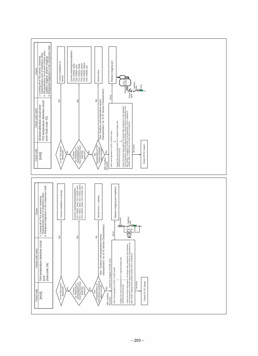
No
Yes
Yes
Yes
No
No
No
erro
r
Err
or
[H16
]
Che
ck c
ode
Cau
seC
heck
cod
e na
me
Oil
leve
l det
ectio
n ci
rcui
t err
orT
K2
tem
pera
ture
det
ectiv
e ci
rcui
ter
ror
(Sub
-cod
e: 0
2)
1. C
omin
g-of
f of T
K2
sens
or, m
isw
iring
, ch
arac
teris
tics
erro
r of
res
ista
nce
valu
e2.
Oil-
equa
lizat
ion
circ
uit e
rror
(C
heck
val
ve,
capi
llary
clo
ggin
g, s
trai
ner
clog
ging
)3.
Ref
riger
ant s
tagn
atio
n in
the
com
pres
sor
shel
l
Is n
ot T
K2
sens
orde
tach
ed?
Is th
ere
no m
isw
iring
or
mis
inst
alla
tion
onT
D1/
TD
2/T
K1/
TK
2/T
K4/
TK
5se
nsor
s?
Are
char
acte
ristic
s of
TK
2se
nsor
resi
stan
ceva
lue
norm
al?
Cor
rect
inst
alla
tion
ofse
nsor
.
Sen
sor
erro
r
Rep
lace
clo
ggin
g pa
rt.
Che
ck I/
F P
.C. b
oard
Cor
rect
mis
wiri
ng/m
isin
stal
latio
n.
TD
1: C
N50
2, w
hite
TD
2: C
N50
3, p
ink
TK
1: C
N53
1, b
lack
TK
2: C
N53
2, g
reen
TK
4: C
N53
4, y
ello
wT
K5:
CN
535,
red
Sta
rt a
test
ope
ratio
n in
CO
OL
or H
EAT
mod
e.
Dis
play
TK
2 se
nsor
tem
pera
ture
on
7-se
gmen
t dis
play
with
SW
01/0
2/03
=[1
] [13
] [2]
.
Che
ck T
K2
sens
or te
mp
appr
ox. 1
0 m
inut
es a
fter
com
pres
sor
2 ha
s op
erat
ed.
If lo
w te
mpe
ratu
re c
ontin
ues
(app
roxi
mat
ely
outs
ide
tem
p) o
r te
mpe
ratu
re h
aslit
tle c
hang
e, a
clo
ggin
g of
str
aine
r of
oil-
equa
lizat
ion
circ
uit,
clog
ging
of
capi
llary
tube
, or
mal
func
tion
of c
heck
val
ve is
con
side
red.
Afte
r re
setti
ngth
e po
wer
*See
"O
utdo
or u
nit t
empe
ratu
re s
enso
rch
arac
teris
tics"
on
"8-1
0. S
enso
r C
hara
cter
istic
s".
↓ ↓
(TK
2)
Cap
illar
y tu
be
Str
aine
rC
omp.
2(in
vert
er)
Che
ck
valv
e
Yes
Yes
Yes
No C
heck
the
clog
ging
of S
V3E
val
ve.
No
No
No
erro
r
Err
or
[H16
] C
heck
cod
eC
ause
Che
ck c
ode
nam
e
TK
4 te
mpe
ratu
re d
etec
tive
circ
uit
erro
r(S
ub-c
ode:
04)
1. C
omin
g-of
f of T
K4
sens
or, m
isw
iring
, ch
arac
teris
tics
erro
r of
res
ista
nce
valu
e2.
Ref
riger
ant s
tagn
atio
n in
the
com
pres
sor
shel
l
Is n
ot T
K4
sens
orde
tach
ed?
Is th
ere
no m
isw
iring
or
mis
inst
alla
tion
onT
D1/
TD
2/T
K1/
TK
2/T
K4/
TK
5se
nsor
s?
Are
char
acte
ristic
s of
TK
4 se
nsor
res
ista
nce
valu
e no
rmal
?
Cor
rect
inst
alla
tion
of s
enso
rr..
Sen
sor
erro
r →
repl
ace
Che
ck I/
F P
.C. b
oard
Cor
rect
mis
wiri
ng/m
isin
stal
latio
n.
TD
1: C
N50
2, w
hite
, TD
2: C
N50
3, p
ink
TK
1: C
N53
1, b
lack
, TK
2: C
N53
2, g
reen
T
K4:
CN
534,
yel
low
TK
5: C
N53
5, r
ed
Sta
rt a
test
ope
ratio
n in
CO
OL
or H
EAT
mod
e.
Dis
play
TK
4 se
nsor
tem
pera
ture
on
7-se
gmen
t dis
play
with
SW
01/0
2/03
=[1
] [15
] [2]
.
Che
ck T
K4
sens
or te
mp
appr
ox. 1
0 m
inut
es a
fter
com
pres
sor
has
oper
ated
.If
low
tem
pera
ture
con
tinue
s (a
ppro
xim
atel
y ou
tsid
e te
mp)
or
tem
pera
ture
has
little
cha
nge,
clo
ggin
g of
the
para
llel c
apill
ary
tube
is c
onsi
dere
d.
Afte
r re
setti
ngth
e po
wer
*
See
"O
utdo
or u
nit t
empe
ratu
re s
enso
r ch
arac
teris
tics"
on
"8-1
0. S
enso
r C
hara
cter
istic
s".
↓ ↓(SV3C)
SV
(TK
4)
Cap
illar
y tu
be
Rep
lace
clo
ggin
g pa
rt (
capi
llary
).
Str
aine
r
− 203 −
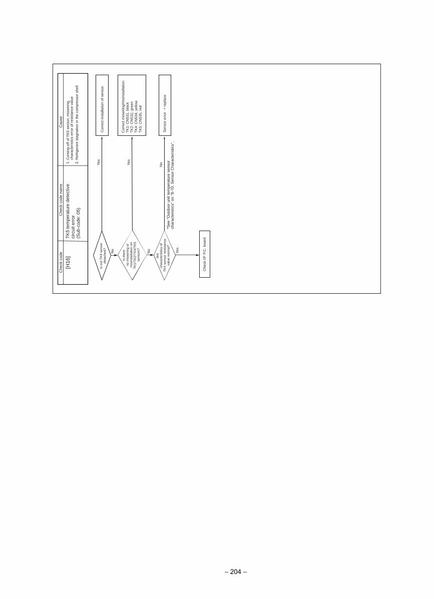
No
Yes
No
Yes
NoYe
s
[H16
]C
ause
Che
ck c
ode
Che
ck c
ode
nam
e
TK5
tem
pera
ture
det
ectiv
e ci
rcui
t err
or(S
ub-c
ode:
05)
1. C
omin
g-of
f of T
K5
sens
or, m
isw
iring
, ch
arac
teris
tics
erro
r of
res
ista
nce
valu
e2.
Ref
riger
ant s
tagn
atio
n in
the
com
pres
sor
shel
l
Is n
ot T
K4
sens
or
deta
ched
?
Is th
ere
no m
isw
iring
or
mis
inst
alla
tion
on
TK
1/T
K2/
TK
4/T
K5
sens
ors?
Are
char
acte
ristic
s of
TK
4 se
nsor
res
ista
nce
valu
e no
rmal
?
Cor
rect
inst
alla
tion
of s
enso
r.
Sen
sor
erro
r r
epla
ce
Che
ck I/
F P
.C. b
oard
Cor
rect
mis
wiri
ng/m
isin
stal
latio
n.
TK
1: C
N53
1, b
lack
TK
2: C
N53
2, g
reen
TK
4: C
N53
4, y
ello
wT
K5:
CN
535,
red
*See
“O
utdo
or u
nit t
empe
ratu
re s
enso
r ch
arac
teris
tics”
on
“8-1
0. S
enso
r C
hara
cter
istic
s”.
− 204 −
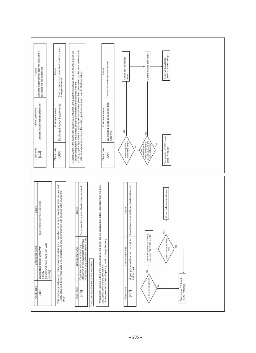
[L06
]
Sub
-cod
e: a
mou
nt o
f ind
oor
units
with
prio
rity
[L07
]
Yes
Yes
No
No
Che
ck c
ode
Che
ck c
ode
nam
e
Che
ck c
ode
Dup
licat
ed in
door
uni
ts w
ith p
riorit
y(D
ispl
ayed
on
the
indo
or u
nits
oth
er th
an
ones
with
prio
rity
and
on th
e ou
tdoo
r uni
t)
Cau
se
Two
or m
ore
indo
or u
nits
with
prio
rity
are
dupl
icat
ed.
Cau
se
A g
roup
line
is c
onne
cted
to a
n in
divi
dual
indo
or u
nit.
Whe
n pr
iorit
y is
giv
en to
two
or m
ore
indo
or u
nits
, thi
s ch
eck
code
is d
ispl
ayed
on
indo
or u
nits
oth
er th
an th
e un
its
set a
s pr
ior
ones
and
the
outd
oor
unit.
• A
s on
ly o
ne in
door
uni
t with
prio
rity
is v
alid
, cha
nge
the
setu
p.
Che
ck c
ode
nam
e
A g
roup
line
exi
sts
in a
n in
divi
dual
in
door
uni
t
Is th
ere
grou
p ca
blin
g?
The
re is
indi
vidu
al in
door
un
it.
Che
ck th
e ad
dres
ses
of s
etup
ite
m c
ode
DN
12,
13,
and
14.
Cor
rect
indo
or g
roup
add
ress
.
Che
ck in
door
P.C
. boa
rd.
Fai
lure
Rep
lace
[L03
]
[L04
]
Yes
Yes
No
No
[L05
]
Che
ck c
ode
Che
ck c
ode
Che
ck c
ode
Che
ck c
ode
nam
e
1) C
heck
whe
ther
the
conn
ectio
n on
rem
ote
cont
rolle
rs (
grou
p an
d/or
indi
vidu
al)
has
been
cha
nged
sin
ce th
e gr
oup
conf
igur
atio
n an
d ad
dres
s ch
ecki
ng o
n th
e re
mot
e co
ntro
llers
fini
shed
.2)
If th
e gr
oup
conf
igur
atio
n an
d ad
dres
s ar
e no
rmal
whe
n po
wer
has
bee
n tu
rned
on,
the
mod
e au
tom
atic
ally
sh
ifts
to a
ddre
ss s
etup
mod
e. F
or s
ettin
g up
add
ress
es a
gain
, ref
er to
"A
ddre
ss s
etup
".
Che
ck c
ode
nam
e
Dup
licat
ed in
door
hea
der
units
Cau
se
The
re a
re tw
o or
mor
e in
door
hea
der
units
in a
gro
up
durin
g gr
oup
cont
rol.
Che
ck c
ode
nam
e
Dup
licat
ed s
etup
of o
utdo
or li
ne
addr
ess
Cau
se
Out
door
line
add
ress
es a
re d
uplic
ated
.
Dup
licat
ed in
door
uni
ts w
ith
prio
rity
(Dis
play
ed o
n in
door
uni
t with
pr
iorit
y)
Thi
s ch
eck
code
is d
ispl
ayed
on
the
indo
or u
nit s
et a
s a
prio
r on
e w
hen
two
or m
ore
prio
r in
door
uni
ts a
re d
etec
ted.
• P
riorit
y se
tup
with
two
or m
ore
units
is n
ot a
vaila
ble.
As
only
one
indo
or u
nit w
ith p
riorit
y is
val
id, c
hang
e th
e se
tup.
Cau
se
Two
or m
ore
prio
r in
door
uni
ts e
xist
.
Is th
ere
dupl
icat
ed
line
addr
ess
setu
p?
Are
com
mun
icat
ion
wire
con
nect
ions
of
[U1.
U2]
, [U
3.U
4], a
nd
[U5,
U6]
nor
mal
?
Cor
rect
the
line
addr
ess
setu
p.
Che
ck o
utdo
or I/
F P
.C. b
oard
.F
ailu
re R
epla
ce
Cor
rect
the
wire
con
nect
ion.
Re-
set u
p th
e ad
dres
s.(R
efer
to "
Add
ress
set
up".
)
[L02
]C
heck
cod
eC
ause
Whe
n th
e in
door
uni
t tha
t doe
s no
t cor
resp
ond
is
conn
ecte
d w
ith th
e ou
tdoo
r uni
t
Che
ck c
ode
nam
e
Out
door
uni
ts m
odel
dis
agre
ed e
rror
− 205 −
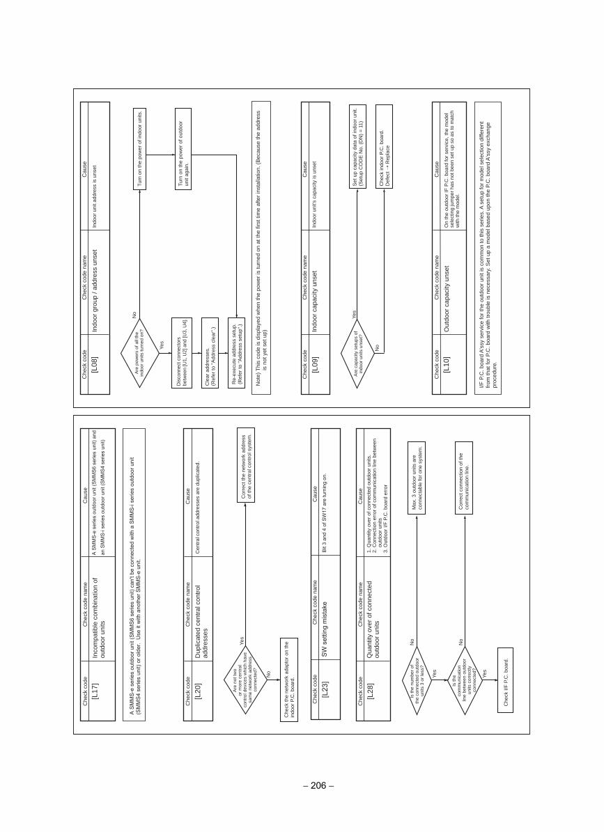
[L17
]
No
Yes
[L20
]
Yes
No
Yes
No
[L28
]
Che
ck c
ode
Che
ck c
ode
Cau
seC
heck
cod
e
Che
ck c
ode
nam
e
Inco
mpa
tible
com
bina
tion
of
outd
oor
units
Cau
se
Cen
tral
con
trol
add
ress
es a
re d
uplic
ated
.
Che
ck c
ode
nam
e
Dup
licat
ed c
entr
al c
ontr
ol
addr
esse
s
Che
ck c
ode
nam
e
Qua
ntity
ove
r of
con
nect
ed
outd
oor
units
A S
MM
S-e
ser
ies
outd
oor u
nit (
SM
MS
6 se
ries
unit)
can
't be
con
nect
ed w
ith a
SM
MS
-i se
ries
outd
oor u
nit
(SM
MS
4 se
ries
unit)
or o
lder
. U
se it
with
ano
ther
SM
MS
-e u
nit.
Are
not
two
or m
ore
cent
ral
cont
rol d
evic
es w
hich
hav
e sa
me
netw
ork
addr
ess
conn
ecte
d?
Is th
e nu
mbe
r of
the
conn
ecte
d ou
tdoo
r un
its 3
or
less
?
Is th
eco
mm
unic
atio
nlin
e be
twee
n ou
tdoo
r un
its c
orre
ctly
co
nnec
ted?
Cor
rect
the
netw
ork
addr
ess
of th
e ce
ntra
l con
trol
sys
tem
.
Max
. 3 o
utdo
or u
nits
are
co
nnec
tabl
e fo
r on
e sy
stem
.
Cor
rect
con
nect
ion
of th
e co
mm
unic
atio
n lin
e.
Che
ck I/
F P
.C. b
oard
.
Che
ck th
e ne
twor
k ad
apto
r on
the
indo
or P
.C. b
oard
.
1. Q
uant
ity o
ver
of c
onne
cted
out
door
uni
ts.
2. C
onne
ctio
n er
ror
of c
omm
unic
atio
n lin
e be
twee
n ou
tdoo
r un
its3.
Out
door
I/F
P.C
. boa
rd e
rror
[L08
]
Yes
No
No
Yes
[L09
]
[L10
]
Che
ck c
ode
Che
ck c
ode
Cau
seC
heck
cod
e
I/F P
.C. b
oard
A's
sy s
ervi
ce fo
r th
e ou
tdoo
r un
it is
com
mon
to th
is s
erie
s. A
set
up fo
r m
odel
sel
ectio
n di
ffere
nt
from
that
for
P.C
. boa
rd w
ith tr
oubl
e is
nec
essa
ry. S
et u
p a
mod
el b
ased
upo
n th
e P.
C. b
oard
A's
sy e
xcha
nge
proc
edur
e.
Cau
se
Indo
or u
nit a
ddre
ss is
uns
et
Che
ck c
ode
nam
e
Indo
or g
roup
/ ad
dres
s un
set
Cau
se
Indo
or u
nit's
cap
acity
is u
nset
Che
ck c
ode
nam
e
Indo
or c
apac
ity u
nset
On
the
outd
oor
IF P
.C. b
oard
for
serv
ice,
the
mod
el
sele
ctin
g ju
mpe
r ha
s no
t bee
n se
t up
so a
s to
mat
ch
with
the
mod
el.
Che
ck c
ode
nam
e
Out
door
cap
acity
uns
et
Are
pow
ers
of a
ll th
e in
door
uni
ts tu
rned
on?
Are
cap
acity
set
ups
of
indo
or u
nits
uns
et?
Turn
on
the
pow
er o
f ind
oor
units
.
Turn
on
the
pow
er o
f out
door
un
it ag
ain.
Set
up
capa
city
dat
a of
indo
or u
nit.
(Set
up C
OD
E N
o. (
DN
) =
11)
Che
ck in
door
P.C
. boa
rd.
Def
ect
Rep
lace
Re-
exec
ute
addr
ess
setu
p.(R
efer
to "
Add
ress
set
up".
)
Dis
conn
ect c
onne
ctor
s be
twee
n [U
1, U
2] a
nd [U
3, U
4].
Cle
ar a
ddre
sses
.(R
efer
to "
Add
ress
cle
ar".
)
Not
e) T
his
code
is d
ispl
ayed
whe
n th
e po
wer
is tu
rned
on
at th
e fir
st ti
me
afte
r in
stal
latio
n. (
Bec
ause
the
addr
ess
is n
ot y
et s
et u
p)
Cau
se
A S
MM
S-e
ser
ies
outd
oor u
nit (
SM
MS
6 se
ries
unit)
and
an S
MM
S-i
serie
s ou
tdoo
r uni
t (S
MM
S4
serie
s un
it)
[L23
]
Che
ck c
ode
Cau
se
Bit
3 an
d 4
of S
W17
are
turn
ing
on.
Che
ck c
ode
nam
e
SW
set
ting
mis
take
− 206 −
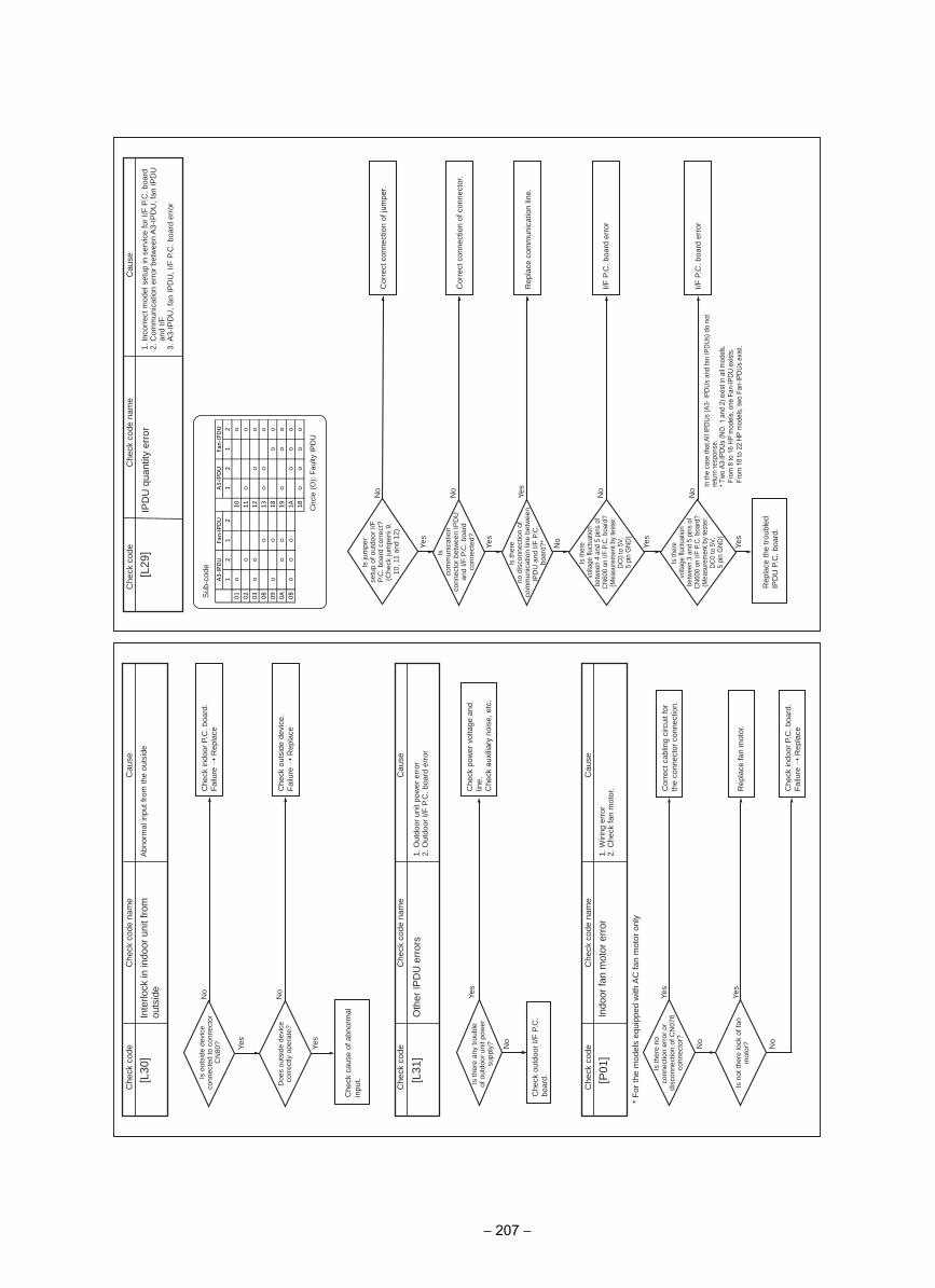
No
Yes
[L31
]
No
No
Yes
Yes
[P01
]
* F
or th
e m
odel
s eq
uipp
ed w
ith A
C fa
n m
otor
onl
y
Yes
Yes
No
No
[L30
]C
heck
cod
e
Cau
seC
heck
cod
e
Cau
seC
heck
cod
e
Cau
se
Abn
orm
al in
put f
rom
the
outs
ide
Che
ck c
ode
nam
e
Inte
rlock
in in
door
uni
t fro
m
outs
ide
Che
ck c
ode
nam
e
Oth
er IP
DU
err
ors
Is o
utsi
de d
evic
e co
nnec
ted
to c
onne
ctor
C
N80
?
Doe
s ou
tsid
e de
vice
co
rrec
tly o
pera
te?
Is th
ere
any
trou
ble
of o
utdo
or u
nit p
ower
su
pply
?
Is th
ere
noco
nnec
tion
erro
r or
disc
onne
ctio
n of
CN
076
conn
ecto
r?
Is n
ot th
ere
lock
of f
an
mot
or?
Che
ck in
door
P.C
. boa
rd.
Fai
lure
Rep
lace
Che
ck o
utsi
de d
evic
e.F
ailu
re R
epla
ce
Che
ck p
ower
vol
tage
and
lin
e.C
heck
aux
iliar
y no
ise,
etc
.
Cor
rect
cab
ling
circ
uit f
or
the
conn
ecto
r co
nnec
tion.
Rep
lace
fan
mot
or.
Che
ck in
door
P.C
. boa
rd.
Fai
lure
Rep
lace
Che
ck o
utdo
or I/
F P
.C.
boar
d.
Che
ck c
ause
of a
bnor
mal
in
put.
1. O
utdo
or u
nit p
ower
err
or2.
Out
door
I/F
P.C
. boa
rd e
rror
Che
ck c
ode
nam
e
Indo
or fa
n m
otor
err
or1.
Wiri
ng e
rror
2. C
heck
fan
mot
or.
[L29
]
Yes
No
Yes
Yes
No
No
Yes
No
Yes
No
Cau
seC
heck
cod
e
Is ju
mpe
rse
tup
of o
utdo
or I/
F
P.C
. boa
rd c
orre
ct?
(Che
ck ju
mpe
rs 9
, 10
, 11
and
12)
Isco
mm
unic
atio
nco
nnec
tor
betw
een
IPD
U
and
I/F P
.C. b
oard
co
nnec
ted?
Is th
ere
no d
isco
nnec
tion
of
com
mun
icat
ion
line
betw
een
IPD
U a
nd I/
F P
.C.
boar
d?*
Is th
ere
volta
ge fl
uctu
atio
n be
twee
n 4
and
5 pi
ns o
f C
N60
0 on
I/F
P.C
. boa
rd?
(Mea
sure
men
t by
test
er:
DC
0 to
5V,
5
pin
GN
D)
Is th
ere
volta
ge fl
uctu
atio
n be
twee
n 3
and
5 pi
ns o
f C
N60
0 on
I/F
P.C
. boa
rd?
(Mea
sure
men
t by
test
er:
DC
0 to
5V,
5
pin
GN
D)
Cor
rect
con
nect
ion
of ju
mpe
r.
Cor
rect
con
nect
ion
of c
onne
ctor
.
Rep
lace
com
mun
icat
ion
line.
I/F P
.C. b
oard
err
or
I/F P
.C. b
oard
err
or
Rep
lace
the
trou
bled
IP
DU
P.C
. boa
rd.
Che
ck c
ode
nam
e
IPD
U q
uant
ity e
rror
1. In
corr
ect m
odel
set
up in
ser
vice
for
I/F P
.C. b
oard
2. C
omm
unic
atio
n er
ror
betw
een
A3-
IPD
U, f
an IP
DU
an
d I/F
3. A
3-IP
DU
, fan
IPD
U, I
/F P
.C. b
oard
err
or
In th
e ca
se th
at A
ll IP
DU
s (A
3- IP
DU
s an
d fa
n IP
DU
s) d
o no
t re
turn
resp
onse
. *
Two
A3-IP
DUs
(NO
. 1 a
nd 2
) exis
t in
all m
odel
s.Fr
om 8
to 1
6 HP
mod
els,
one
Fan
-IPDU
exis
ts.
From
18
to 2
2 HP
mod
els,
two
Fan-
IPDU
s ex
ist.
Sub
-cod
e
Circ
le (O
): Fa
ulty
IPD
U
12
12
12
12
01
10
02
11
03
12
08
13
09
18
0A
19
0B
1A
1B
A3-IPDU
A3-IPDU
Fan-IPDU
Fan-IPDU
− 207 −
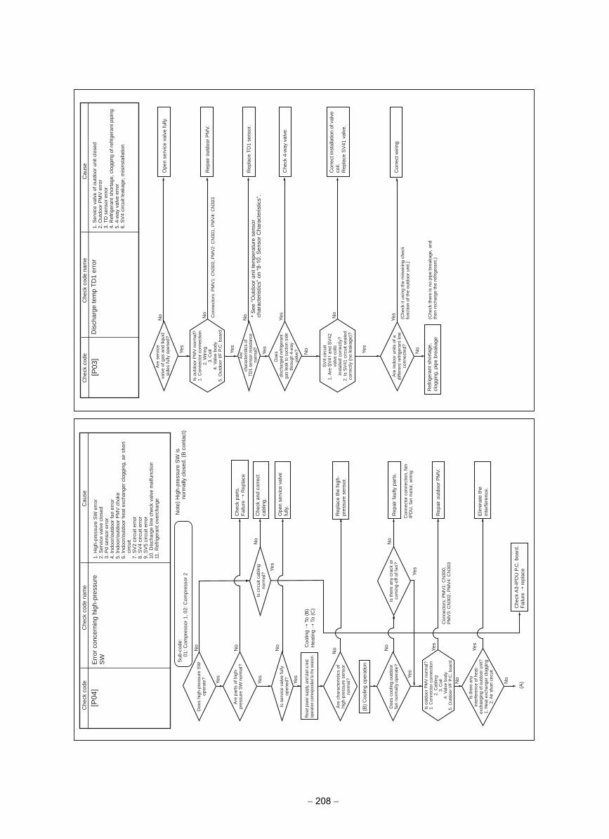
(A)Ye
s
Yes
Yes Ye
s
No
No
No
No
No
Yes
Yes
Yes
No
Yes
No
No
No
[P04
]C
ause
Che
ck c
ode
Che
ck c
ode
nam
e
Err
or c
once
rnin
g hi
gh-p
ress
ure
SW
1. H
igh-
pres
sure
SW
err
or2.
Ser
vice
val
ve c
lose
d3.
Pd
sens
or e
rror
4. In
door
/out
door
fan
erro
r5.
Indo
or/o
utdo
or P
MV
cho
ke6.
Indo
or/o
utdo
or h
eat e
xcha
nger
clo
ggin
g, a
ir sh
ort
circ
uit
7. S
V2
circ
uit e
rror
8. S
V4
circ
uit e
rror
9. S
V5
circ
uit e
rror
Dis
char
ge li
ne c
heck
val
ve m
alfu
nctio
n10
.11
. Ref
riger
ant o
verc
harg
e
Sub
-cod
e:01
: Com
pres
sor
1, 0
2: C
ompr
esso
r 2
Not
e) H
igh-
pres
sure
SW
is
norm
ally
clo
sed.
(B
con
tact
)
Doe
s hi
gh-p
ress
ure
SW
op
erat
e?
Are
par
ts o
f hig
h-pr
essu
re S
W n
orm
al?
Is s
ervi
ce v
alve
fully
op
ened
?
Are
cha
ract
eris
tics
of
high
-pre
ssur
e se
nsor
no
rmal
?
Doe
s co
olin
g ou
tdoo
r fa
n no
rmal
ly o
pera
te?
Is th
ere
any
inte
rfer
ence
of h
eat-
exch
angi
ng o
f out
door
uni
t?1.
Hea
t exc
hang
er c
logg
ing
2. A
ir sh
ort c
ircui
t
Is th
ere
any
crac
k or
co
min
g-of
f of f
an?
Con
nect
or c
onne
ctio
n, fa
n IP
DU
, fan
mot
or, w
iring
Con
nect
ors:
PM
V1:
CN
300,
P
MV
3: C
N30
2, P
MV
4: C
N30
3
Is c
ircui
t cab
ling
norm
al?
Che
ck p
arts
.F
ailu
re R
epla
ce
Che
ck a
nd c
orre
ct
cabl
ing.
Ope
n se
rvic
e va
lve
fully
.
Rep
lace
the
high
-pr
essu
re s
enso
r.
Rep
air
faul
ty p
arts
.
Rep
air
outd
oor
PM
V.
Elim
inat
e th
e in
terf
eren
ce.
Che
ck A
3-IP
DU
P.C
. boa
rd.
Fai
lure
rep
lace
(B)
Coo
ling
oper
atio
n
Coo
ling
To
(B)
Hea
ting
To
(C)
Rese
t pow
er s
uppl
y, an
d st
art a
test
op
erat
ion
corre
spon
ded
to th
e se
ason
.
Is o
utdo
or P
MV
nor
mal
?1.
Con
nect
or c
onne
ctio
n2.
Cab
ling
3. C
oil
4. V
alve
bod
y5.
Out
door
I/F
P.C
. boa
rd
Yes
Yes
Yes
No
Yes
No
No
No
Yes
No
[P03
]C
ause
Che
ck c
ode
Che
ck c
ode
nam
e
Dis
char
ge te
mp
TD
1 er
ror
Are
ser
vice
valv
e of
gas
and
liqu
id
side
s fu
lly o
pene
d?O
pen
serv
ice
valv
e fu
lly.
Rep
air
outd
oor
PM
V.
Rep
lace
TD
1 se
nsor
.
Che
ck 4
-way
val
ve.
Cor
rect
inst
alla
tion
of v
alve
co
il.R
epla
ce S
V41
val
ve.
Cor
rect
wiri
ng
Ref
riger
ant s
hort
age,
cl
oggi
ng, p
ipe
brea
kage
1. S
ervi
ce v
alve
of o
utdo
or u
nit c
lose
d2.
Out
door
PM
V e
rror
3. T
D s
enso
r er
ror
4. R
efrig
eran
t sho
rtag
e, c
logg
ing
of r
efrig
eran
t pip
ing
5. 4
-way
val
ve e
rror
6. S
V4
circ
uit l
eaka
ge, m
isin
stal
latio
n
Are
char
acte
ristic
s of
TD1
sens
or re
sist
ance
no
rmal
?
Doe
sdi
scha
rged
ref
riger
ant
gas
leak
to s
uctio
n si
de
thro
ugh
4-w
ayva
lve?
Are
indo
or u
nits
of a
di
ffere
nt r
efrig
eran
t lin
e co
nnec
ted?
No
Con
nect
ors:
PM
V1:
CN
300,
PM
V2:
CN
301,
PM
V4:
CN
303
Yes
(Che
ck it
usi
ng th
e m
isw
iring
che
ck
func
tion
of th
e ou
tdoo
r un
it.)
(Che
ck th
ere
is n
o pi
pe b
reak
age,
and
th
en r
echa
rge
the
refr
iger
ant.)
Is o
utdo
or P
MV
nor
mal
? C
onne
ctor
con
nect
ion
1.2.
Wiri
ng C
oil
3.4.
Val
ve b
ody
5. O
utdo
or I/
F P
.C. b
oard
SV
4 ci
rcui
t1.
Are
SV
41 a
nd S
V42
valv
e co
ils
inst
alle
d co
rrec
tly?
2. Is
SV
41 c
ircui
t sea
led
corr
ectly
(no
leak
age)
?
* S
ee “
Out
door
uni
t tem
pera
ture
sen
sor
char
acte
ristic
s” o
n “8
-10.
Sen
sor
Cha
ract
eris
tics”
.
− 208 −
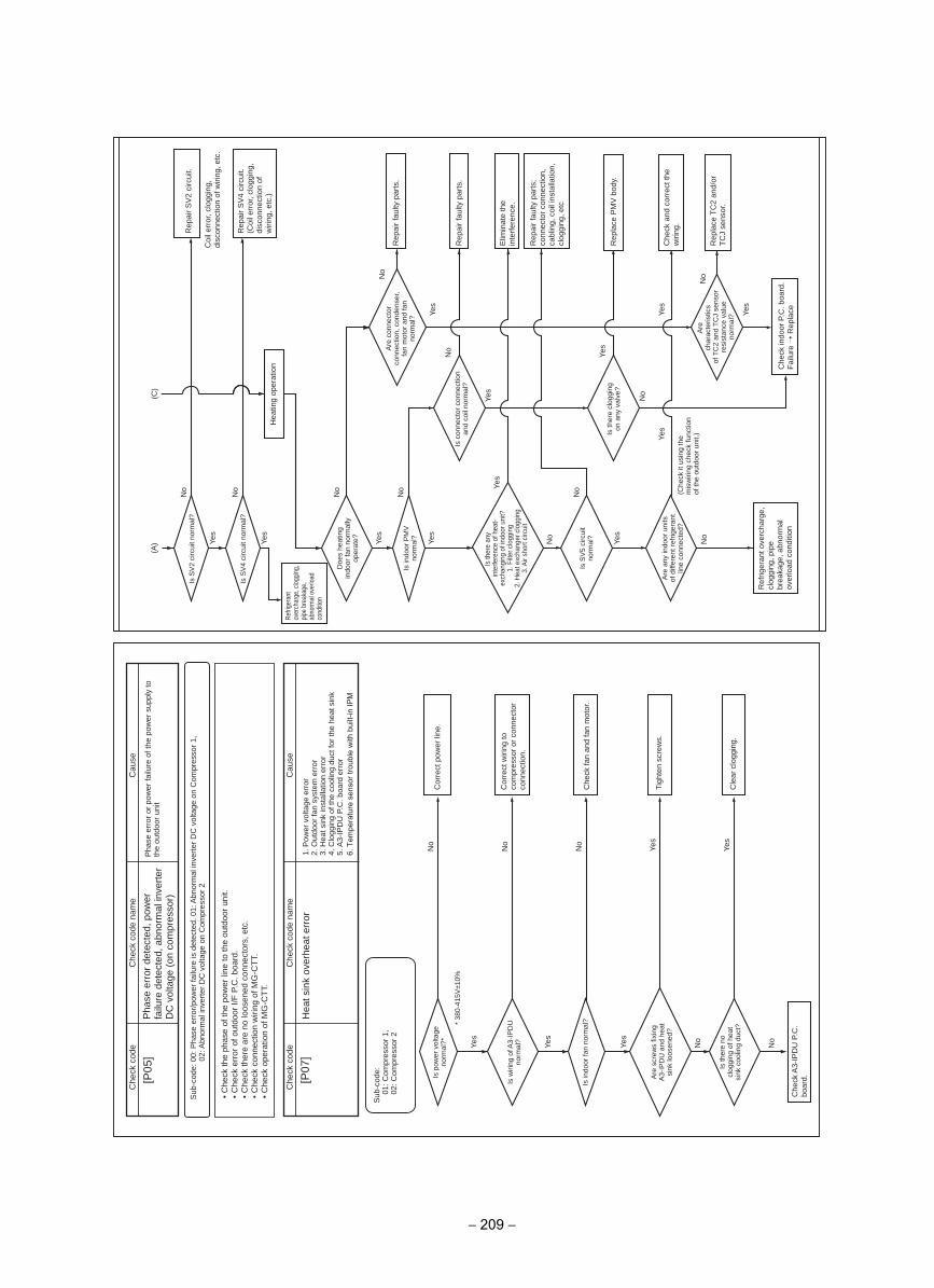
[P05
]
Yes
* 38
0-41
5V±1
0%
Yes
No
No
No
Yes
Yes
No
Yes
No
[P07
]
Che
ck c
ode
Che
ck c
ode
nam
e
Cau
seC
heck
cod
e
Pha
se e
rror
det
ecte
d, p
ower
fa
ilure
det
ecte
d, a
bnor
mal
inve
rter
D
C v
olta
ge (
on c
ompr
esso
r)
Cau
se
Pha
se e
rror
or
pow
er fa
ilure
of t
he p
ower
sup
ply
to
the
outd
oor
unit
Sub
-cod
e: 0
0: P
hase
err
or/p
ower
failu
re is
det
ecte
d. 0
1: A
bnor
mal
inve
rter
DC
vol
tage
on
Com
pres
sor
1,
02: A
bnor
mal
inve
rter
DC
vol
tage
on
Com
pres
sor
2
Sub
-cod
e:01
: Com
pres
sor
1,
02: C
ompr
esso
r 2
• C
heck
the
phas
e of
the
pow
er li
ne to
the
outd
oor
unit.
• C
heck
err
or o
f out
door
I/F
P.C
. boa
rd.
• C
heck
ther
e ar
e no
loos
ened
con
nect
ors,
etc
. •
Che
ck c
onne
ctio
n w
iring
of M
G-C
TT.
•
Che
ck o
pera
tion
of M
G-C
TT.
Che
ck c
ode
nam
e
Hea
t sin
k ov
erhe
at e
rror
1. P
ower
vol
tage
err
or2.
Out
door
fan
syst
em e
rror
3. H
eat s
ink
inst
alla
tion
erro
r4.
Clo
ggin
g of
the
cool
ing
duct
for
the
heat
sin
k5.
A3-
IPD
U P
.C. b
oard
err
or
Is p
ower
vol
tage
no
rmal
?*
Is w
iring
of A
3-IP
DU
no
rmal
?
Is in
door
fan
norm
al?
Are
scr
ews
fixin
g A
3-IP
DU
and
hea
t si
nk lo
osen
ed?
Is th
ere
no
clog
ging
of h
eat
sink
coo
ling
duct
?
Cor
rect
pow
er li
ne.
Cor
rect
wiri
ng to
co
mpr
esso
r or
con
nect
or
conn
ectio
n.
Che
ck fa
n an
d fa
n m
otor
.
Tigh
ten
scre
ws.
Cle
ar c
logg
ing.
Che
ck A
3-IP
DU
P.C
. bo
ard.
Yes
Yes
Yes
No
No
Yes
No
Yes
No
No
No
No
No
Yes
No
Yes
Yes
Yes
Yes
Yes
Yes
No
No
(C)
(A)
Is S
V2
circ
uit n
orm
al?
Is S
V4
circ
uit n
orm
al?
Doe
s he
atin
g in
door
fan
norm
ally
op
erat
e?
Are
con
nect
or
conn
ectio
n, c
onde
nser
, fa
n m
otor
and
fan
norm
al?
Is c
onne
ctor
con
nect
ion
and
coil
norm
al?
Is th
ere
clog
ging
on
any
val
ve?
Are
char
acte
ristic
sof
TC
2 an
d T
CJ
sens
or
resi
stan
ce v
alue
no
rmal
?
Is in
door
PM
V
norm
al?
Is S
V5
circ
uit
norm
al?
(Che
ck it
usi
ng th
e m
isw
iring
che
ck fu
nctio
n of
the
outd
oor
unit.
)
Are
any
indo
or u
nits
of
diff
eren
t ref
riger
ant
line
conn
ecte
d?
Is th
ere
any
inte
rfere
nce
of h
eat-
exch
angi
ng o
f ind
oor u
nit?
Filt
er c
logg
ing
1.2.
Hea
t exc
hang
er c
logg
ing
3. A
ir sh
ort c
ircui
t
Rep
air
SV
4 ci
rcui
t.(C
oil e
rror
, clo
ggin
g,
disc
onne
ctio
n of
w
iring
, etc
.)
Rep
air
faul
ty p
arts
.
Rep
air
faul
ty p
arts
.
Elim
inat
e th
e in
terf
eren
ce.
Rep
lace
PM
V b
ody.
Che
ck a
nd c
orre
ct th
e w
iring
.
Rep
lace
TC
2 an
d/or
T
CJ
sens
or.
Rep
air
faul
ty p
arts
; co
nnec
tor
conn
ectio
n,
cabl
ing,
coi
l ins
talla
tion,
cl
oggi
ng, e
tc
Ref
riger
ant o
verc
harg
e,
clog
ging
, pip
e br
eaka
ge, a
bnor
mal
ov
erlo
ad c
ondi
tion
Che
ck in
door
P.C
. boa
rd.
Fai
lure
Rep
lace
Hea
ting
oper
atio
n
Refri
gera
ntov
erch
arge
, clo
ggin
g,
pipe
bre
akag
e,
abno
rmal
ove
rload
co
nditio
n
Rep
air
SV
2 ci
rcui
t.
Coi
l err
or, c
logg
ing,
di
scon
nect
ion
of w
iring
, etc
.
6. T
empe
ratu
re s
enso
r tro
uble
with
bui
lt-in
IPM
− 209 −
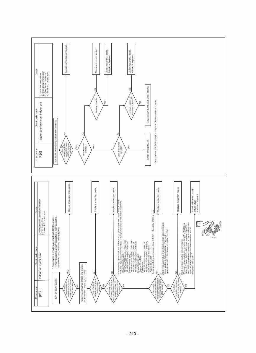
No
Yes
Yes
No
Yes
No
Yes
Is n
ot g
roun
ded
betw
een
cabi
net a
nd 1
, 3, 5
? S
houl
d be
10M
Ω o
r m
ore.
No
Yes
No
[P12
]
CN
333
CN
334
Cau
seC
heck
cod
eC
heck
cod
e na
me
Indo
or fa
n m
otor
err
or1.
Wiri
ng e
rror
of f
an m
otor
con
nect
or2.
Fan
mot
or e
rror
3. In
door
P.C
. boa
rd e
rror
Turn
off
pow
er s
uppl
y.*
Det
ecta
ble
in m
odel
equ
ippe
d w
ith D
C fa
n m
otor
(4-w
ay c
asse
tte, 2
-way
cas
sette
, 1-w
ay c
asse
tte,
conc
eale
d du
ct, w
all a
nd c
eilin
g ty
pes)
Is th
ere
conn
ectio
n er
ror o
r di
scon
nect
ion
on c
onne
ctor
C
N33
3, C
N33
4 of
indo
or P
.C.
boar
d (M
CC
-140
2)?
Doe
s fa
n tu
rn
with
out t
roub
le w
hen
turn
ing
it w
ith
hand
s?
Isre
sist
ance
val
uebe
twee
n ea
ch p
hase
at
mot
or s
ide
of fa
n m
otor
con
nect
or
CN
333
on in
door
P.C
. bo
ard
(MC
C-1
402)
corr
ect?
*1
Is re
sist
ance
valu
e at
mot
or s
ide
of fa
n m
otor
con
nect
or C
N33
4 on
in
door
P.C
. boa
rd (M
CC
-14
02) c
orre
ct?
*2
Is o
utpu
tof
indo
or fa
n m
otor
po
sitio
n de
tect
ive
sign
al
corr
ect?
*3
Cor
rect
con
nect
or c
onne
ctio
n.
Rep
lace
indo
or fa
n m
otor
.
Rep
lace
indo
or fa
n m
otor
.
Rep
lace
indo
or fa
n m
otor
.
Rep
lace
indo
or fa
n m
otor
.
Che
ck in
door
P.C
. boa
rd
(MC
C-1
402)
.F
ailu
re R
epla
ce
Rem
ove
conn
ecto
rs C
N33
3 an
d C
N33
4 on
indo
or P
.C. b
oard
(M
CC
-140
2).
1* • Is
not
win
ding
1 (
Red
lead
) to
3 (
Whi
te le
ad),
3 (
Whi
te le
ad)
to 5
(B
lack
lead
), 5
(B
lack
le
ad)
to 1
(R
ed le
ad)
open
ed/s
hort
ed?
Res
ista
nce
valu
e sh
ould
sat
isfy
the
follo
ws.
[4-w
ay C
asse
tte ty
pe]
AP
007
to A
P03
0: A
ppro
x. 7
0 to
100
ΩA
P03
6 to
AP
056:
App
rox.
35
to 5
0Ω[2
-way
Cas
sette
type
]A
P00
7 to
AP
015:
App
rox.
70
to 1
00Ω
AP
018
to A
P03
0: A
ppro
x. 3
0 to
70Ω
AP
036
to A
P05
6: A
ppro
x. 2
0 to
50Ω
[1-w
ay C
asse
tte ty
pe]
App
rox.
30
to 7
0Ω[C
eilin
g ty
pe]
AP
015
to A
P02
7: A
ppro
x. 3
0 to
70Ω
AP
036
to A
P05
6: A
ppro
x. 2
0 to
50Ω
[Wal
l and
con
ceal
ed d
uct t
ypes
]A
ppro
x. 1
5 to
35Ω
• *2 Che
ck r
esis
tanc
e va
lue
of fa
n m
otor
pos
ition
det
ectiv
e ci
rcui
t.•
Is n
ot w
indi
ng 1
(Ye
llow
lead
) to
4 (
Pin
k le
ad)
open
ed/s
hort
ed?
Res
ista
nce
shou
ld b
e 5
to 2
0kΩ
.
3* Che
ck fa
n m
otor
pos
ition
det
ectiv
e si
gnal
.•
Mea
sure
vol
tage
with
test
er b
etw
een
1 an
d 5
of C
N33
4 on
in
door
P.C
. boa
rd (
MC
C-1
402)
und
er c
ondi
tion
of C
N33
3 an
d C
N33
4 in
stal
led
and
pow
er-O
N.
Tur
n fa
n sl
owly
with
ha
nds
so th
at p
in v
olta
ge fl
uctu
ates
bet
wee
n 0
and
5V.
• B
etw
een
4 an
d 5:
5V
Yes
Yes
Yes
Yes
No
No
No
Yes
No
No
* C
heck
ther
e is
220
-240
V v
olta
ge o
f 1-3
pin
of C
N68
on
indo
or P
.C. b
oard
.
[P10
]
Sub
-cod
e: O
verf
low
ing
indo
or u
nit's
add
ress
Cau
seC
heck
cod
e
Is fl
oat S
W
conn
ecto
r (In
door
co
ntro
l P.C
. boa
rd
CN
34) c
onne
cted
no
rmal
ly?
Doe
s flo
at S
W
oper
ate?
Is w
iring
nor
mal
?
Doe
s dr
ain
pum
p op
erat
e?
Is p
ower
sup
ply
to
drai
n pu
mp
norm
al?*
Cor
rect
con
nect
or c
onne
ctio
n.
Che
ck a
nd c
orre
ct w
iring
.
Che
ck in
door
P.C
. boa
rd.
Fai
lure
Rep
lace
Che
ck in
door
P.C
. boa
rd.
Fai
lure
Rep
lace
Che
ck d
rain
pip
e, e
tc.
Rep
lace
dra
in p
ump,
and
che
ck c
ablin
g.
Che
ck c
ode
nam
e
Wat
er o
verf
low
in a
n in
door
uni
t1.
Flo
at S
W m
alfu
nctio
n2.
Dra
in p
ump
mal
func
tion
3. C
logg
ing
of d
rain
pip
e4.
Indo
or P
.C. b
oard
err
or
− 210 −
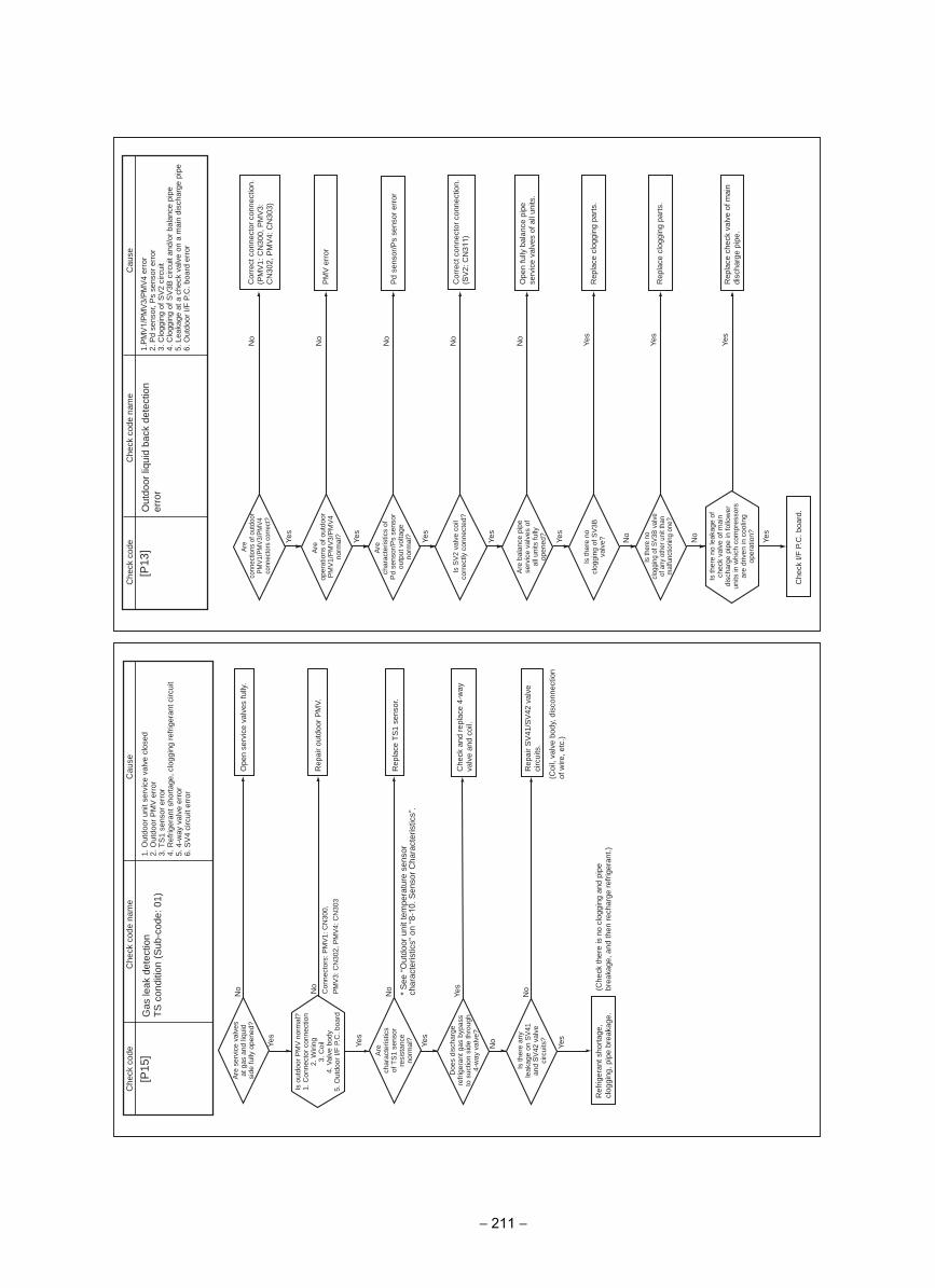
Yes
Yes
No
No
Yes
Yes
No
Yes
No
[P15
]C
ause
Che
ck c
ode
Che
ck c
ode
nam
e
Gas
leak
det
ectio
nT
S c
ondi
tion
(Sub
-cod
e: 0
1)1.
Out
door
uni
t ser
vice
val
ve c
lose
d2.
Out
door
PM
V e
rror
3. T
S1
sens
or e
rror
4. R
efrig
eran
t sho
rtag
e, c
logg
ing
refr
iger
ant c
ircui
t5.
4-w
ay v
alve
err
or6.
SV
4 ci
rcui
t err
or
Are
ser
vice
val
ves
at g
as a
nd li
quid
si
de fu
lly o
pene
d?O
pen
serv
ice
valv
es fu
lly.
Rep
air
outd
oor
PM
V.
Rep
lace
TS
1 se
nsor
.
Che
ck a
nd r
epla
ce 4
-way
va
lve
and
coil.
Rep
air
SV
41/S
V42
val
ve
circ
uits
.
Ref
riger
ant s
hort
age,
cl
oggi
ng, p
ipe
brea
kage
.(C
heck
ther
e is
no
clog
ging
and
pip
e br
eaka
ge, a
nd th
en r
echa
rge
refr
iger
ant.)
(Coi
l, va
lve
body
, dis
conn
ectio
n of
wire
, etc
.)
Are
char
acte
ristic
sof
TS
1 se
nsor
re
sist
ance
norm
al?
Doe
s di
scha
rge
refr
iger
ant g
as b
ypas
s to
suc
tion
side
thro
ugh
4-w
ay v
alve
?
Is th
ere
any
leak
age
on S
V41
an
d S
V42
val
ve
circ
uits
?
No
Con
nect
ors:
PM
V1:
CN
300,
PM
V3:
CN
302,
PM
V4:
CN
303
Is o
utdo
or P
MV
nor
mal
?1.
Con
nect
or c
onne
ctio
n W
iring
2. C
oil
3.4.
Val
ve b
ody
5. O
utdo
or I/
F P
.C. b
oard
Yes
Yes
No
No
No
Yes
No
Yes
No
Yes
Yes
No
Yes
No
Yes
Yes
[P13
]C
heck
cod
eC
heck
cod
e na
me
Out
door
liqu
id b
ack
dete
ctio
n er
ror
Cau
se
1. P
MV
1/P
MV
3/P
MV
4 er
ror
2. P
d se
nsor
, Ps
sens
or e
rror
3. C
logg
ing
of S
V2
circ
uit
4. C
logg
ing
of S
V3B
circ
uit a
nd/o
r ba
lanc
e pi
pe5.
Lea
kage
at a
che
ck v
alve
on
a m
ain
disc
harg
e pi
pe6.
Out
door
I/F
P.C
. boa
rd e
rror
Are
conn
ectio
ns o
f out
door
P
MV
1/P
MV
3/P
MV
4co
nnec
tors
cor
rect
?
Are
oper
atio
ns o
f out
door
P
MV
1/P
MV
3/P
MV
4no
rmal
?
Are
char
acte
ristic
s of
Pd
sens
or/P
s se
nsor
ou
tput
vol
tage
no
rmal
?
Is S
V2
valv
e co
il co
rrec
tly c
onne
cted
?
Are
bal
ance
pip
e se
rvic
e va
lves
of
all u
nits
fully
op
ened
?
Is th
ere
no
clog
ging
of S
V3B
va
lve?
Is th
ere
nocl
oggi
ng o
f SV
3B v
alve
of
any
oth
er u
nit t
han
mal
func
tioni
ng o
ne?
Cor
rect
con
nect
or c
onne
ctio
n.
(PM
V1:
CN
300,
PM
V3:
C
N30
2, P
MV
4: C
N30
3)
PM
V e
rror
Pd
sens
or/P
s se
nsor
err
or
Cor
rect
con
nect
or c
onne
ctio
n.
(SV
2: C
N31
1)
Ope
n fu
lly b
alan
ce p
ipe
serv
ice
valv
es o
f all
units
.
Rep
lace
clo
ggin
g pa
rts.
Rep
lace
clo
ggin
g pa
rts.
Rep
lace
che
ck v
alve
of m
ain
disc
harg
e pi
pe.
Che
ck I/
F P
.C. b
oard
.
Is th
ere
no le
akag
e of
ch
eck
valv
e of
mai
n di
scha
rge
pipe
in fo
llow
er
units
in w
hich
com
pres
sors
ar
e dr
iven
in c
oolin
g op
erat
ion?
* S
ee “
Out
door
uni
t tem
pera
ture
sen
sor
char
acte
ristic
s” o
n “8
-10.
Sen
sor
Cha
ract
eris
tics”
.
− 211 −
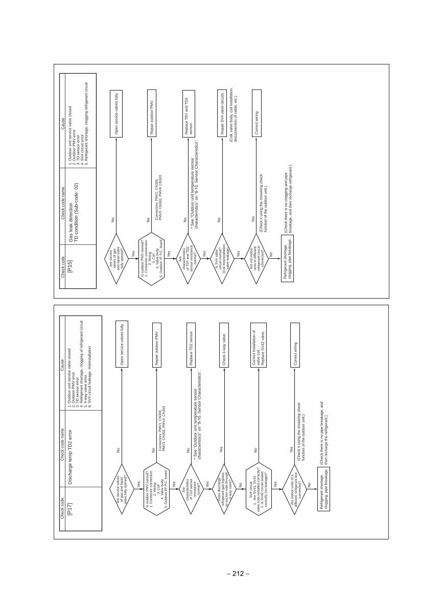
Yes
Yes
No
No
No
No
Yes
Yes
No
No
Yes
[P17
]C
ause
Che
ck c
ode
Che
ck c
ode
nam
e
Dis
char
ge te
mp
TD
2 er
ror
1. O
utdo
or u
nit s
ervi
ce v
alve
clo
sed
2. O
utdo
or P
MV
err
or3.
TD
sen
sor
erro
r4.
Ref
riger
ant s
hort
age,
clo
ggin
g of
ref
riger
ant c
ircui
t5.
4-w
ay v
alve
err
or6.
SV
4 ci
rcui
t lea
kage
, mis
inst
alla
tion
Are
ser
vice
val
ves
of g
as a
nd li
quid
si
des
fully
ope
ned?
Ope
n se
rvic
e va
lves
fully
.
Rep
air
outd
oor
PM
V.
Rep
lace
TD
2 se
nsor
.
Che
ck 4
-way
val
ve.
Cor
rect
inst
alla
tion
of
valv
e co
il.R
epla
ce S
V42
val
ve.
Cor
rect
wiri
ng
Ref
riger
ant s
hort
age,
cl
oggi
ng, p
ipe
brea
kage
Are
indo
or u
nits
of a
di
ffere
nt r
efrig
eran
t lin
e co
nnec
ted?
Are
char
acte
ristic
sof
TD
2 se
nsor
re
sist
ance
norm
al?
Doe
s di
scha
rge
refr
iger
ant g
as b
ypas
s to
suc
tion
side
thro
ugh
4-w
ay v
alve
?
Con
nect
ors:
PM
V1:
CN
300,
P
MV
3: C
N30
2, P
MV
4: C
N30
3
Yes
(Che
ck it
usi
ng th
e m
isw
iring
che
ck
func
tion
of th
e ou
tdoo
r un
it.)
(Che
ck th
ere
is n
o pi
pe b
reak
age,
and
th
en r
echa
rge
the
refr
iger
ant.)
Is o
utdo
or P
MV
nor
mal
?1.
Con
nect
or c
onne
ctio
n2.
Wiri
ng C
oil
3.4.
Val
ve b
ody
5. O
utdo
or I/
F P
.C. b
oard
SV
4 ci
rcui
t1.
Are
SV
41, S
V42
va
lve
coils
inst
alle
d co
rrec
tly?
Is S
V42
circ
uit s
eale
d 2. co
rrec
tly (
no le
akag
e)?
Yes
Yes
No
No
No
Yes
No
No
Yes
[P15
]C
ause
Che
ck c
ode
Che
ck c
ode
nam
e
Gas
leak
det
ectio
nT
D c
ondi
tion
(Sub
-cod
e: 0
2)1.
Out
door
uni
t ser
vice
val
ve c
lose
d2.
Out
door
PM
V e
rror
3. T
D s
enso
r er
ror
4. S
V4
circ
uit e
rror
5. R
efrig
eran
t sho
rtag
e, c
logg
ing
refr
iger
ant c
ircui
t
Are
ser
vice
va
lves
of g
as
and
liqui
d si
des
fully
ope
ned?
Ope
n se
rvic
e va
lves
fully
.
Rep
air
outd
oor
PM
V.
Rep
lace
TD
1 an
d TD
2 se
nsor
.
Cor
rect
wiri
ng.
Ref
riger
ant s
hort
age,
cl
oggi
ng, p
ipe
brea
kage
.
Rep
air
SV
4 va
lve
circ
uits
.
(Coi
l, va
lve
body
, coi
l ins
talla
tion,
di
scon
nect
ion
of c
able
, etc
.)
Yes
(Che
ck it
usi
ng th
e m
isw
iring
che
ck
func
tion
of th
e ou
tdoo
r un
it.)
(Che
ck th
ere
is n
o cl
oggi
ng a
nd p
ipe
brea
kage
, and
then
rec
harg
e re
frig
eran
t.)
Con
nect
ors:
PM
V1:
CN
300,
P
MV
3: C
N30
2, P
MV
4: C
N30
3
Are
char
acte
ristic
sof
TD
1 an
d TD
2 se
nsor
res
ista
nce
norm
al?
Is S
V4
valv
eci
rcui
t nor
mal
?(C
oil m
isin
stal
latio
n,
valv
e le
akag
e)
Are
not
indo
or
units
in d
iffer
ent
refr
iger
ant c
ircui
t co
nnec
ted?
Is o
utdo
or P
MV
nor
mal
? C
onne
ctor
con
nect
ion
1. W
iring
2. C
oil
3.4.
Val
ve b
ody
5. O
utdo
or I/
F P
.C. b
oard
* S
ee “
Out
door
uni
t tem
pera
ture
sen
sor
char
acte
ristic
s” o
n “8
-10.
Sen
sor
Cha
ract
eris
tics”
.
* S
ee “
Out
door
uni
t tem
pera
ture
sen
sor
char
acte
ristic
s” o
n “8
-10.
Sen
sor
Cha
ract
eris
tics”
.
− 212 −
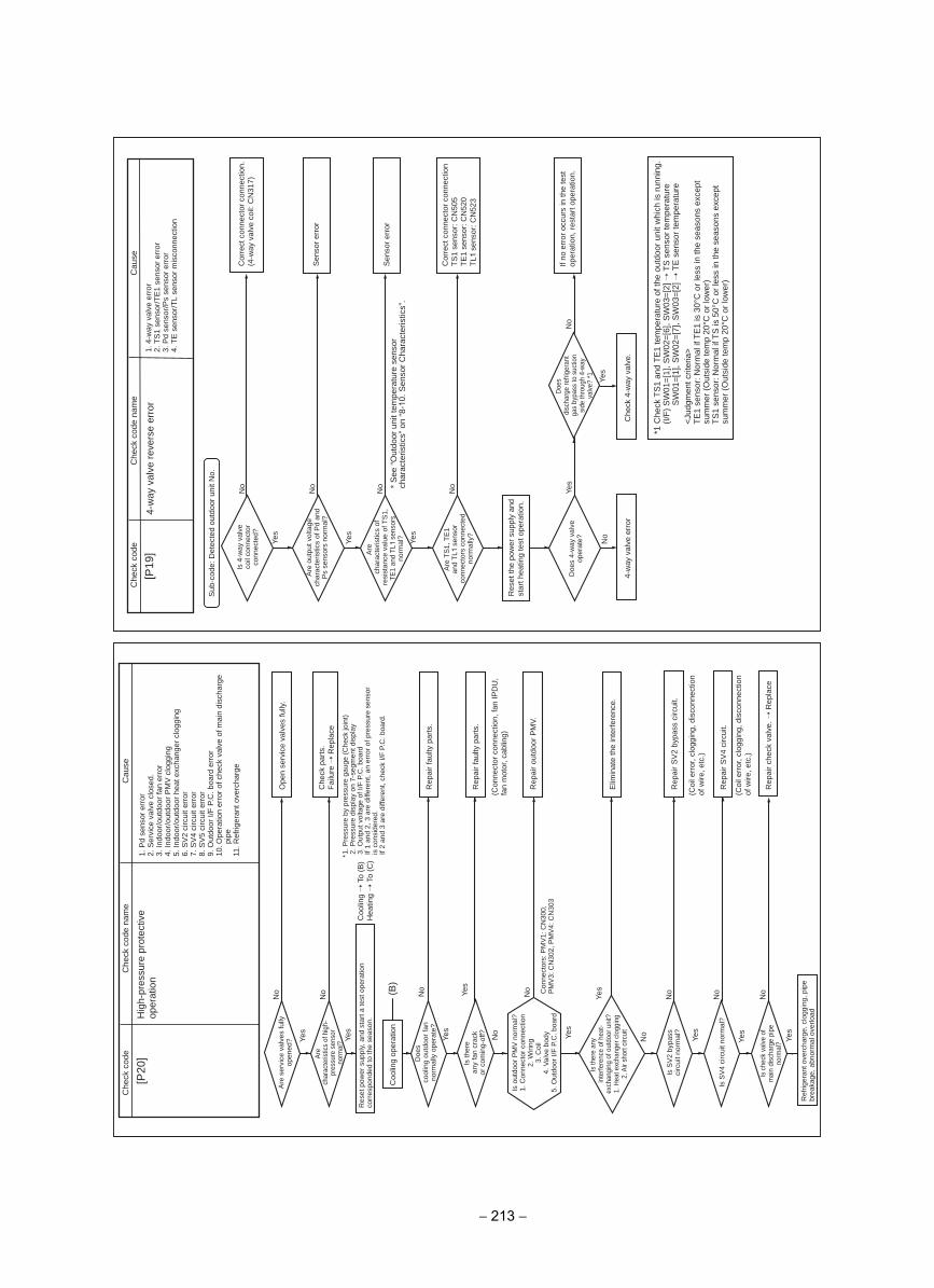
Yes
Yes
Yes
No
Yes
No
No
Yes
No
Yes
NoNo
Yes
No
[P20
]
Coo
ling
oper
atio
n(B
)
No
Yes
No
esuaC
edoc kcehC
Che
ck c
ode
nam
e
Hig
h-pr
essu
re p
rote
ctiv
e op
erat
ion
1. P
d se
nsor
err
or2.
Ser
vice
val
ve c
lose
d.3.
Indo
or/o
utdo
or fa
n er
ror
4. In
door
/out
door
PM
V c
logg
ing
5. In
door
/out
door
hea
t exc
hang
er c
logg
ing
6. S
V2
circ
uit e
rror
7. S
V4
circ
uit e
rror
8. S
V5
circ
uit e
rror
9. O
utdo
or I/
F P
.C. b
oard
err
or10
. Ope
ratio
n er
ror
of c
heck
val
ve o
f mai
n di
scha
rge
pipe
11. R
efrig
eran
t ove
rcha
rge
Are
ser
vice
val
ves
fully
op
ened
?
Doe
sco
olin
g ou
tdoo
r fa
n no
rmal
ly o
pera
te?
Is th
ere
any
fan
crac
k or
com
ing-
off?
Is S
V2
bypa
ss
circ
uit n
orm
al?
Is S
V4
circ
uit n
orm
al?
Is c
heck
val
ve o
f m
ain
disc
harg
e pi
pe
norm
al?
Are
char
acte
ristic
s of
hig
h-pr
essu
re s
enso
r no
rmal
?
Ope
n se
rvic
e va
lves
fully
.
Rep
air
faul
ty p
arts
.
Rep
air
faul
ty p
arts
.
Rep
air
outd
oor
PM
V.
Elim
inat
e th
e in
terf
eren
ce.
Rep
air
SV
2 by
pass
circ
uit.
Rep
air
SV
4 ci
rcui
t.
Rep
air
chec
k va
lve.
R
epla
ce
Ref
riger
ant o
verc
harg
e, c
logg
ing,
pip
e br
eaka
ge, a
bnor
mal
ove
rload
(Con
nect
or c
onne
ctio
n, fa
n IP
DU
, fa
n m
otor
, cab
ling)
(Coi
l err
or, c
logg
ing,
dis
conn
ectio
n of
wire
, etc
.)
(Coi
l err
or, c
logg
ing,
dis
conn
ectio
n of
wire
, etc
.)
Che
ck p
arts
.F
ailu
re R
epla
ce
Res
et p
ower
sup
ply,
and
sta
rt a
test
ope
ratio
n co
rres
pond
ed to
the
seas
on.
Coo
ling
To
(B)
Hea
ting
To
(C)
* 1. P
ress
ure
by p
ress
ure
gaug
e (C
heck
join
t)2.
Pre
ssur
e di
spla
y on
7-s
egm
ent d
ispl
ay3.
Out
put v
olta
ge o
f I/F
P.C
. boa
rdIf
1 an
d 2,
3 a
re d
iffer
ent,
an e
rror
of p
ress
ure
sens
or
is c
onsi
dere
d.If
2 an
d 3
are
diffe
rent
, che
ck I/
F P
.C. b
oard
.
Is th
ere
any
inte
rfere
nce
of h
eat-
exch
angi
ng o
f out
door
uni
t?1.
Hea
t exc
hang
er c
logg
ing
2. A
ir sh
ort c
ircui
t
Con
nect
ors:
PM
V1:
CN
300,
P
MV
3: C
N30
2, P
MV
4: C
N30
3
Yes
Is o
utdo
or P
MV
nor
mal
?1.
Con
nect
or c
onne
ctio
n2.
Wiri
ng3.
Coi
l4.
Val
ve b
ody
5. O
utdo
or I/
F P
.C. b
oard
Yes
No
Yes
No
Yes
No
No
No
Yes
No
Yes
[P19
]
Sub
-cod
e: D
etec
ted
outd
oor
unit
No.
Cau
seC
heck
cod
eC
heck
cod
e na
me
4-w
ay v
alve
rev
erse
err
or1.
4-w
ay v
alve
err
or2.
TS
1 se
nsor
/TE
1 se
nsor
err
or3.
Pd
sens
or/P
s se
nsor
err
or4.
TE
sen
sor/
TL
sens
or m
isco
nnec
tion
Is 4
-way
val
ve
coil
conn
ecto
r co
nnec
ted?
Are
out
put v
olta
ge
char
acte
ristic
s of
Pd
and
Ps
sens
ors
norm
al?
Are
char
acte
ristic
s of
re
sist
ance
val
ue o
f TS
1,
TE
1 an
d T
L1 s
enso
rs
norm
al?
Are
TS
1, T
E1
an
d T
L1 s
enso
r co
nnec
tors
con
nect
ed
norm
ally
?
Doe
sdi
scha
rge
refri
gera
nt
gas
bypa
ss to
suc
tion
side
thro
ugh
4-w
ay
valv
e? *
1
Doe
s 4-
way
val
ve
oper
ate?
Cor
rect
con
nect
or c
onne
ctio
n.
(4-w
ay v
alve
coi
l: C
N31
7)
Sen
sor
erro
r
Sen
sor
erro
r
Cor
rect
con
nect
or c
onne
ctio
n T
S1
sens
or: C
N50
5T
E1
sens
or: C
N52
0T
L1 s
enso
r: C
N52
3
If no
err
or o
ccur
s in
the
test
op
erat
ion,
res
tart
ope
ratio
n.
Che
ck 4
-way
val
ve.
4-w
ay v
alve
err
or
Res
et th
e po
wer
sup
ply
and
star
t hea
ting
test
ope
ratio
n.
*1 C
heck
TS
1 an
d T
E1
tem
pera
ture
of t
he o
utdo
or u
nit w
hich
is r
unni
ng.
(I/F
) S
W01
=[1
], S
W02
=[6
], S
W03
=[2
] T
S s
enso
r te
mpe
ratu
re
SW
01=
[1],
SW
02=
[7],
SW
03=
[2]
TE
sen
sor
tem
pera
ture
<Ju
dgm
ent c
riter
ia>
TE
1 se
nsor
: Nor
mal
if T
E1
is 3
0°C
or
less
in th
e se
ason
s ex
cept
su
mm
er (
Out
side
tem
p 20
°C o
r lo
wer
)T
S1
sens
or: N
orm
al if
TS
is 5
0°C
or
less
in th
e se
ason
s ex
cept
su
mm
er (
Out
side
tem
p 20
°C o
r lo
wer
)
* S
ee “
Out
door
uni
t tem
pera
ture
sen
sor
char
acte
ristic
s” o
n “8
-10.
Sen
sor
Cha
ract
eris
tics”
.
− 213 −
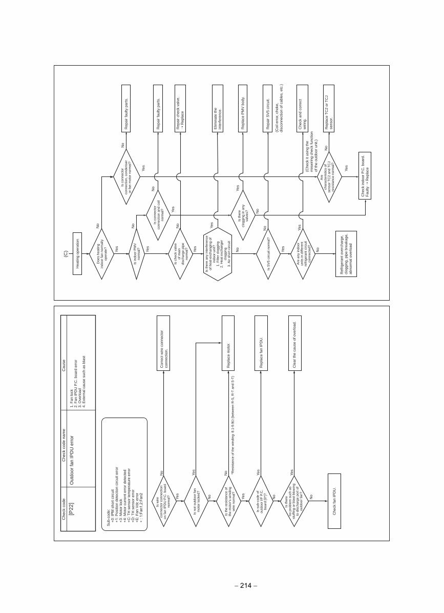
Yes
Yes
No
No
No
Yes
No
Yes
No
Yes
* Res
ista
nce
of th
e w
indi
ng: 8
.1-9
.9Ω
(be
twee
n R
-S, R
-T a
nd S
-T)
[P22
]esua
Cedoc kceh
CC
heck
cod
e na
me
Out
door
fan
IPD
U e
rror
1. F
an lo
ck2.
Fan
IPD
U P
.C. b
oard
err
or3.
Ove
rload
4. E
xter
nal c
ause
suc
h as
bla
st
Sub
-cod
e:∗0
: s
hort
circ
uit
∗1: P
ositi
on d
etec
tion
circ
uit e
rror
∗3
: Mot
or lo
ck
∗4: M
otor
cur
rent
err
or d
etec
ted
∗C: T
H s
enso
r te
mpe
ratu
re e
rror
∗D
: TH
sen
sor
erro
r∗E
: Fan
Vdc
err
or∗
: Fa
n1,2
:Fan
2
Is w
ireco
nnec
tor
conn
ectio
n on
fan
IPD
U P
.C. b
oard
no
rmal
?
Is n
ot o
utdo
or fa
n m
otor
lock
ed?
Is th
e re
sist
ance
of
the
mot
or's
win
ding
w
ire n
orm
al?
Is s
ub-c
ode
of
outd
oor
I/F P
.C.
boar
d [0
*]?
Is th
ere
no p
robl
em s
uch
as
stuf
fing
or b
last
blo
win
g to
dis
char
ge p
ort o
f ou
tdoo
r fa
n?
Cor
rect
wire
con
nect
or
conn
ectio
n.
Rep
lace
mot
or.
Rep
lace
fan
IPD
U.
Cle
ar th
e ca
use
of o
verlo
ad.
Che
ck fa
n IP
DU
.
Yes
Yes
No
No
No
No
Yes
No
Yes
Yes
No
Yes
Yes
Yes
No
No
Yes
No
(C) Ye
s
No
Hea
ting
oper
atio
n
Doe
s he
atin
g in
door
fan
norm
ally
op
erat
e?
Is in
door
PM
V
norm
al?
Is c
heck
val
ve
of m
ain
disc
harg
e pi
pe
norm
al?
Is th
ere
clog
ging
in a
ny
valv
es?
Is S
V5
circ
uit n
orm
al?
Are
any
indo
or
units
in d
iffer
ent
refr
iger
ant c
ircui
t co
nnec
ted?
Are
char
acte
ristic
s of
se
nsor
TC
2 an
d T
CJ
resi
stan
ce n
orm
al?
Is c
onne
ctor
co
nnec
tion
and
coil
norm
al?
Is c
onne
ctor
co
nnec
tion,
con
dens
er
or fa
n m
otor
nor
mal
?R
epai
r fa
ulty
par
ts.
Rep
air
faul
ty p
arts
.
Rep
air
chec
k va
lve.
R
epla
ce
Elim
inat
e th
e in
terf
eren
ce.
Rep
lace
PM
V b
ody.
Che
ck a
nd c
orre
ct
wiri
ng.
Rep
lace
TC
2 or
TC
J se
nsor
.
Ref
riger
ant o
verc
harg
e,
clog
ging
, pip
e br
eaka
ge,
abno
rmal
ove
rload
Che
ck in
door
P.C
. boa
rd.
Fau
lty R
epla
ce
Rep
air
SV
5 ci
rcui
t.
(Coi
l err
or, c
hoke
, di
scon
nect
ion
of c
able
s, e
tc.)
(Che
ck it
usi
ng th
e m
isw
iring
che
ck fu
nctio
n of
the
outd
oor
unit.
)
Is th
ere
any
inte
rfer
ence
of
hea
t-ex
chan
ging
of
indo
or u
nit?
1. F
ilter
clo
ggin
g H
eat e
xcha
nger
2.
clog
ging
3. A
ir sh
ort c
ircui
t
− 214 −
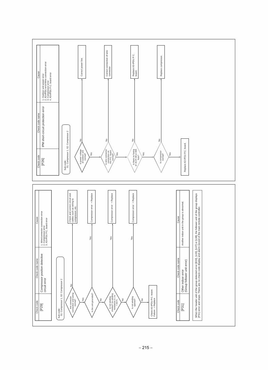
Yes
No
No
No
Yes
No
Yes
Yes
[P29
]
[P31
]
esuaC
edoc kcehC
Che
ck c
ode
nam
e
esuaC
edoc kcehC
Che
ck c
ode
nam
e
Com
pres
sor
posi
tion
dete
ctiv
e ci
rcui
t err
or1.
Wire
/con
nect
or c
onne
ctio
n er
ror
2. C
ompr
esso
r er
ror
3. A
3-IP
DU
P.C
. boa
rd e
rror
Oth
er in
door
err
or(G
roup
follo
wer
uni
t err
or)
Ano
ther
indo
or u
nit i
n th
e gr
oup
is a
bnor
mal
.
Sub
-cod
e:01
: Com
pres
sor
1, 0
2: C
ompr
esso
r 2
Are
con
nect
or
conn
ectio
n an
d w
iring
no
rmal
?
Is th
e un
it gr
ound
ed?
Is n
ot w
indi
ng
shor
ted?
(Is
win
ding
re
sist
ance
0.1
to
1.0Ω
?)
Is n
ot w
indi
ng
open
ed?
Che
ck a
nd c
orre
ct c
ircui
t and
ca
bles
suc
h as
wiri
ng to
co
mpr
esso
r, et
c.
Com
pres
sor
erro
r R
epla
ce
Com
pres
sor
erro
r R
epla
ce
Com
pres
sor
erro
r R
epla
ce
Che
ck A
3-IP
DU
P.C
. boa
rd.
Fai
lure
Rep
lace
Whe
n th
e he
ader
uni
t of t
he g
roup
det
ecte
d er
ror
[E03
], [L
03],
[L07
] or
[L08
], th
e fo
llow
er u
nit o
f the
gro
up d
ispl
ays
[P31
] err
or a
nd s
tops
. The
re a
re n
o ch
eck
code
dis
play
and
ala
rm r
ecor
d of
the
mai
n re
mot
e co
ntro
ller.
Yes
No
Yes
No
Yes
No
Yes
No
[P26
]C
ause
Che
ck c
ode
Che
ck c
ode
nam
e
IPM
sho
rt-c
ircui
t pro
tect
ion
erro
r1.
Out
door
uni
t pow
er e
rror
2. A
3-IP
DU
err
or/W
ire c
onne
ctio
n er
ror
3. C
ompr
esso
r er
ror
4. A
3-IP
DU
P.C
. boa
rd e
rror
Is p
ower
vol
tage
of
out
door
uni
t no
rmal
?
Is w
ire c
onne
ctor
co
nnec
tion
on
INV
P.C
. boa
rd
norm
al?
Is th
ere
no fu
sing
of
AC
31.5
A o
r 40A
fuse
?
Is c
ompr
esso
r no
rmal
?
Cor
rect
pow
er li
ne.
Cor
rect
con
nect
ion
of w
ire
conn
ecto
r.
Rep
lace
A3-
IPD
U P
.C.
boar
d.
Rep
lace
com
pres
sor.
Rep
lace
A3-
IPD
U P
.C. b
oard
.
Sub
-cod
e:01
: Com
pres
sor
1, 0
2: C
ompr
esso
r 2
− 215 −
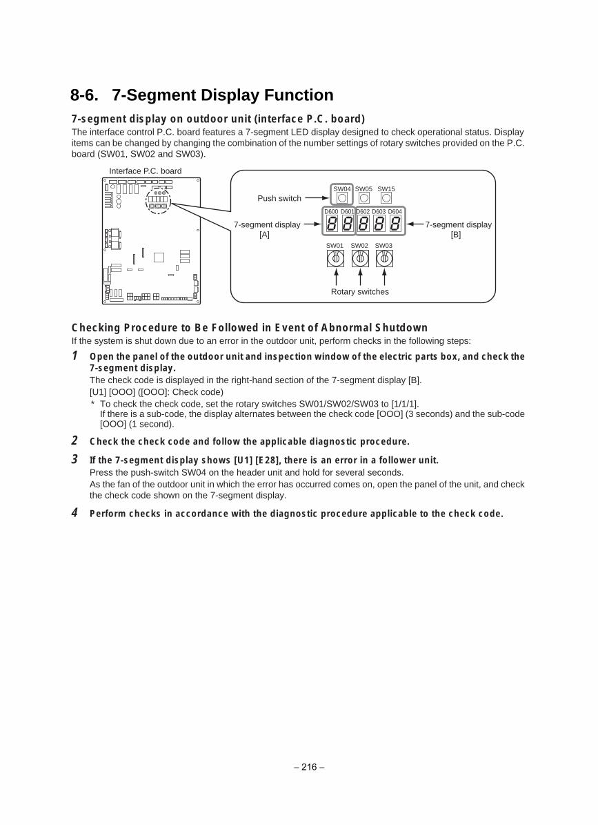
8-6. 7-Segment Display Function7-segment display on outdoor unit (interface P.C. board)The interface control P.C. board features a 7-segment LED display designed to check operational status. Display items can be changed by changing the combination of the number settings of rotary switches provided on the P.C. board (SW01, SW02 and SW03).
Checking Procedure to Be Followed in Event of Abnormal ShutdownIf the system is shut down due to an error in the outdoor unit, perform checks in the following steps:
1 Open the panel of the outdoor unit and inspection window of the electric parts box, and check the7-segment display.The check code is displayed in the right-hand section of the 7-segment display [B].[U1] [OOO] ([OOO]: Check code)* To check the check code, set the rotary switches SW01/SW02/SW03 to [1/1/1].
If there is a sub-code, the display alternates between the check code [OOO] (3 seconds) and the sub-code [OOO] (1 second).
2 Check the check code and follow the applicable diagnostic procedure.
3 If the 7-segment display shows [U1] [E28], there is an error in a follower unit.Press the push-switch SW04 on the header unit and hold for several seconds.As the fan of the outdoor unit in which the error has occurred comes on, open the panel of the unit, and check the check code shown on the 7-segment display.
4 Perform checks in accordance with the diagnostic procedure applicable to the check code.
Interface P.C. board
SW01 SW02 SW03
SW04
D600 D601 D602 D603 D604
SW15SW05
7-segment display[A]
Push switch
7-segment display[B]
Rotary switches
− 216 −
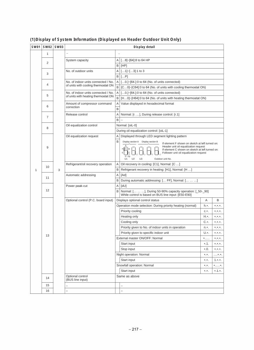
(1)Display of System Information (Displayed on Header Outdoor Unit Only)
liated yalpsiD30WS20WS10WS
1
1
3
−
2System capacity A […8]~[64]:8 to 64 HP
B [HP]
3No. of outdoor units A […1]~[…3]:1 to 3
B […P]
4No. of indoor units connected / No. of units with cooling thermostat ON
A […0.]~[64.]:0 to 64 (No. of units connected)
B [C…0]~[C64]:0 to 64 (No. of units with cooling thermostat ON)
5No. of indoor units connected / No. of units with heating thermostat ON
A […0.]~[64.]:0 to 64 (No. of units connected)
B [H…0]~[H64]:0 to 64 (No. of units with heating thermostat ON)
6Amount of compressor command correction
A Value displayed in hexadecimal format
B
7Release control A Normal: [r. …], During release control: [r.1]
B –
8Oil equalization control Normal: [oiL-0]
During oil equalization control: [oiL-1]
9
Oil equalization request A Displayed through LED segment lighting pattern
B
10Refrigerant/oil recovery operation A Oil recovery in cooling: [C1], Normal: [C …]
B Refrigerant recovery in heating: [H1], Normal: [H …]
11Automatic addressing A [Ad]
B During automatic addressing: [… FF], Normal: [… … …]
12Power peak-cut A [dU]
B Normal: [… … …], During 50-90% capacity operation: [_50-_90]While control is based on BUS line input: [E50-E90]
13
BAsutats lortnoc lanoitpo syalpsiD)tupni draob .C.P( lortnoc lanoitpO
Operation mode selection: During priority heating (normal) h. . . . .
.cgnilooc ytiroirP . . . .
.Hylno gnitaeH . . . .
.Cylno gnilooC . . . .
Priority given to No. of indoor units in operation n. . . . .
.Utinu roodni cificeps ot nevig ytiroirP . . . .
External master ON/OFF: Normal .…. . . .
Start input .1. . . .
Stop input .0. . . .
Night operation: Normal . . …. . .
Start input . . 1. . .
Snowfall operation: Normal . . .…. .
Start input . . .1. .
14 Optional control (BUS line input)
Same as above
15
16
–
–
F G
A
DU2U1 U3
Dp
B
E C
Display section A Display section B
Outdoor unit No.
If element F shown on sketch at left turned on: Header unit oil equalization requestIf element C shown on sketch at left turned on: Follower unit oil equalization request
−
–
–
− 217 −
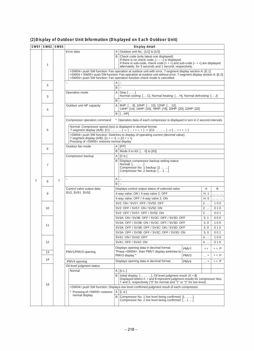
(2)Display of Outdoor Unit Information (Displayed on Each Outdoor Unit)
liated yalpsiD30WS20WS10WS
1
1
1
Outdoor unit No.: [U1] to [U3]Aatad rorrE
B Check code (only latest one displayed)If there is no check code, [– – –] is displayed.If there is sub-code, check code [ ] and sub-code [– ] are displayed alternately, for 3 seconds and 1 second, respectively.
<SW04> push SW function: Fan operation at outdoor unit with error. 7-segment display section A: [E.1]<SW04 + SW05> push SW function: Fan operation at outdoor unit without error. 7-segment display section A: [E.0]<SW05> push SW function: Fan operation function check mode is cancelled.
2–A–
B –
3Operation mode A Stop [… …]
Normal cooling: [… C], Normal heating: [… H], Normal defrosting: [… J]
B –
4Outdoor unit HP capacity A 8HP: [… 8], 10HP: [… 10], 12HP: [… 12],
14HP: [14], 16HP: [16], 18HP: [18], 20HP: [20], 22HP: [22]B […HP]
5
Compressor operation command * Operation data of each compressor is displayed in turn in 2 second intervals.
Normal: Compressor speed (rps) is displayed in decimal format.7-segment display (A/B): [C1. ... ... ... ] [ ... ∗ ∗ ∗, ∗ ] [C2. ... ... ... ] [ ... ∗ ∗ ∗, ∗ ] <SW04> push SW function: Switches to display of operating current (decimal value). 7-segment display (A/B): [i1. ] [i2. ] Pressing of <SW05> restores normal display.
6Outdoor fan mode A [FP]
B Mode 0 to 63: [… 0] to [63]
7
Compressor backup A [C.b.]
B Displays compressor backup setting status Normal: [… … …]Compressor No. 1 backup: [1 … …] Compressor No. 2 backup: [… 1 …]
8–A–
B –
9
Control valve output data Displays control output status of solenoid valve A B
… … …1 .HFFO :2 evlav yaw-4 / NO :evlav yaw-4
… … …0 .HNO :2 evlav yaw-4 / FFO :evlav yaw-4
10
0 0 1… .2SV2: ON / SV51: OFF / SV52: OFF
0 1 0… .2SV2: OFF / SV51: ON / SV52: ON
1 0 0… .2SV2: OFF / SV51: OFF / SV52: ON
11
SV3A: ON / SV3B: OFF / SV3C: OFF / SV3D: OFF 3. 1 0 0 0
SV3A: OFF / SV3B: ON / SV3C: OFF / SV3D: OFF 3. 0 1 0 0
SV3A: OFF / SV3B: OFF / SV3C: ON / SV3D: OFF 3. 0 0 1 0
SV3A: OFF / SV3B: OFF / SV3C: OFF / SV3D: ON 3. 0 0 0 1
12
0 0 1… .4SV41: ON / SV42: OFF
0 1 0… .4SV41: OFF / SV42: ON
13 PMV1/PMV3 opening
Displays opening data in decimal format.
. P
…gninepo 4VMP14 . P
15
Oil level judgment status
].L o[AlamroN
B Initial display: [… … …], Oil level judgment result: [#. .$]Displayed letters #, and $ represent judgment results for compressor Nos. 1 and 2, respectively (“0” for normal and “1” or “2” for low level).
<SW04> push SW function: Displays low level confirmed judgment result of each compressor.
* Pressing of <SW05> restores normal display.
A [L d.]
B Compressor No. 1 low level being confirmed: [L … …] Compressor No. 2 low level being confirmed: [… L …]
SV2, SV51, SV52
PMV4
PMV1
…
. P
PMV3
Displays opening data in decimal format."Press <SW04>, then PMV1 display switches to PMV3 display."
− 218 −
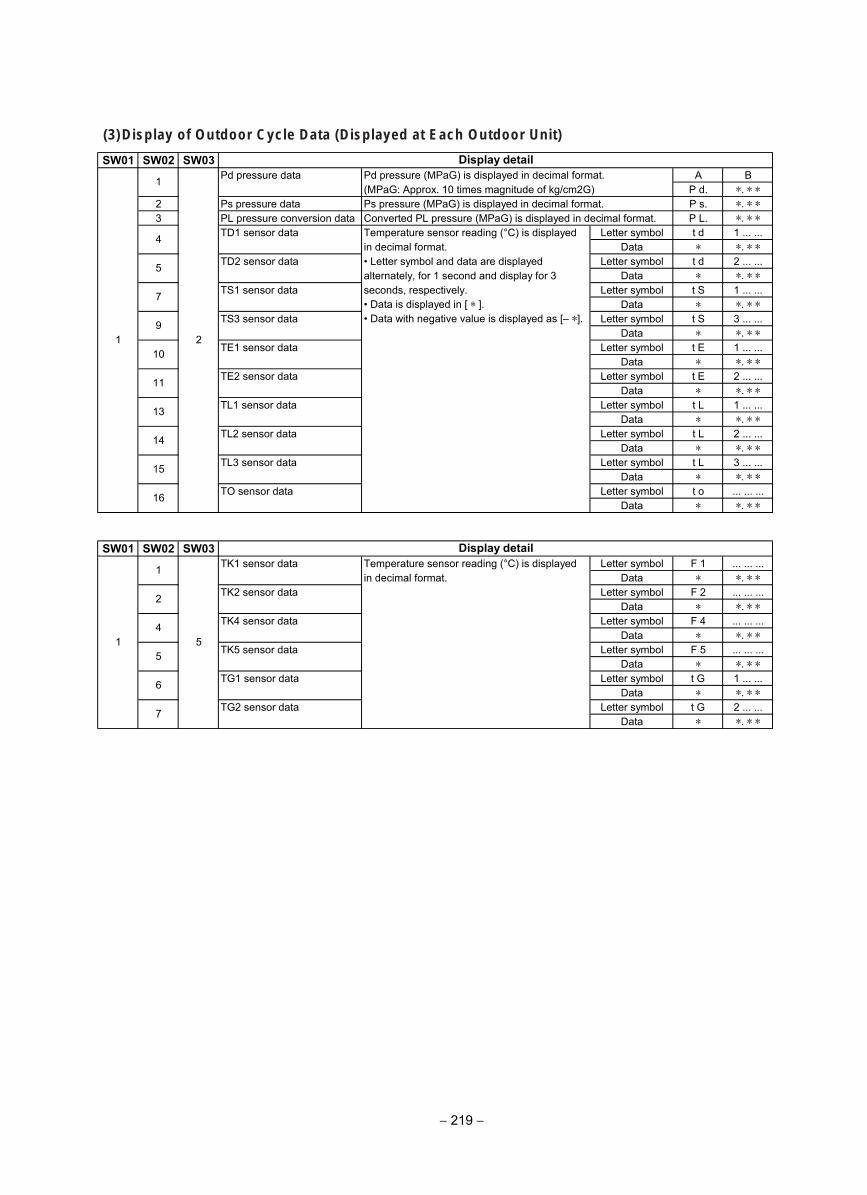
(3)Display of Outdoor Cycle Data (Displayed at Each Outdoor Unit)
SW01 SW02 SW03Pd pressure data A BPd pressure (MPaG) is displayed in decimal format.
(MPaG: Approx. 10 times magnitude of kg/cm2G) P d. ∗. ∗ ∗2 Ps pressure data Ps pressure (MPaG) is displayed in decimal format. P s. ∗. ∗ ∗3 PL pressure conversion data Converted PL pressure (MPaG) is displayed in decimal format. P L. ∗. ∗ ∗
TD1 sensor data Letter symbol t d 1 ... ...Temperature sensor reading (°C) is displayedin decimal format. Data ∗ ∗. ∗ ∗
TD2 sensor data • Letter symbol and data are displayed Letter symbol t d 2 ... ...Data ∗ ∗. ∗ ∗
TS1 sensor dataalternately, for 1 second and display for 3seconds, respectively. Letter symbol t S 1 ... ...• Data is displayed in [ ∗ ]. Data ∗ ∗. ∗ ∗
TS3 sensor data • Data with negative value is displayed as [– ∗]. Letter symbol t S 3 ... ...Data ∗ ∗. ∗ ∗
TE1 sensor data Letter symbol t E 1 ... ...Data ∗ ∗. ∗ ∗
TE2 sensor data Letter symbol t E 2 ... ...Data ∗ ∗. ∗ ∗
TL1 sensor data Letter symbol t L 1 ... ...Data ∗ ∗. ∗ ∗
TL2 sensor data Letter symbol t L 2 ... ...Data ∗ ∗. ∗ ∗
TL3 sensor data Letter symbol t L 3 ... ...Data ∗ ∗. ∗ ∗
TO sensor data Letter symbol t o ... ... ...Data ∗ ∗. ∗ ∗
SW01 SW02 SW03TK1 sensor data Letter symbol F 1 ... ... ...Temperature sensor reading (°C) is displayed
in decimal format. Data ∗ ∗. ∗ ∗TK2 sensor data Letter symbol F 2 ... ... ...
Data ∗ ∗. ∗ ∗TK4 sensor data Letter symbol F 4 ... ... ...
Data ∗ ∗. ∗ ∗TK5 sensor data Letter symbol F 5 ... ... ...
Data ∗ ∗. ∗ ∗TG1 sensor data Letter symbol t G 1 ... ...
Data ∗ ∗. ∗ ∗TG2 sensor data Letter symbol t G 2 ... ...
Data ∗ ∗. ∗ ∗
Display detail
5
7
91 2
Display detail
1
2
10
11
13
14
15
16
1
4
5
6
7
514
− 219 −
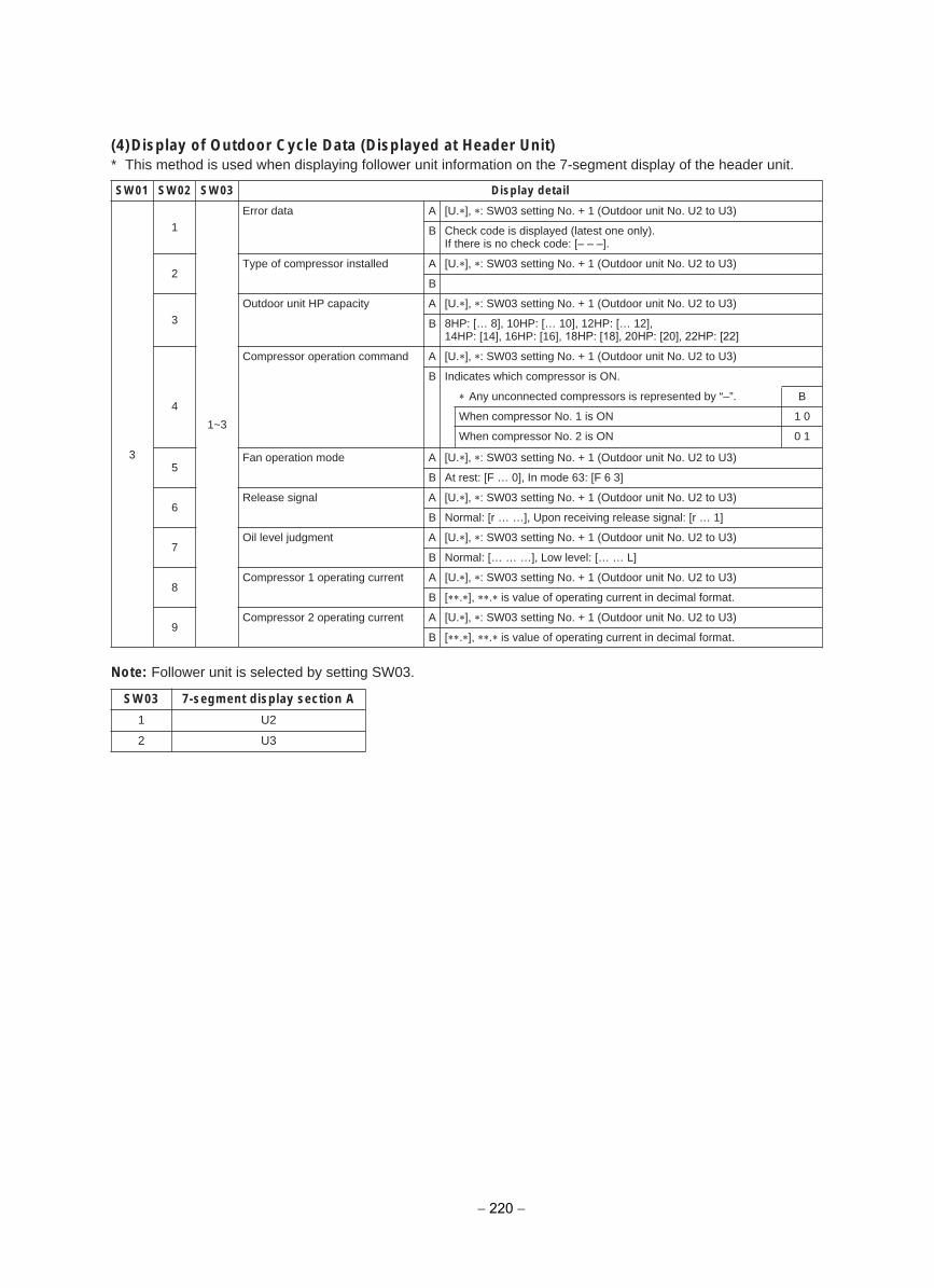
(4)Display of Outdoor Cycle Data (Displayed at Header Unit)* This method is used when displaying follower unit information on the 7-segment display of the header unit.
Note: Follower unit is selected by setting SW03.
liated yalpsiD30WS20WS10WS
3
1
1~3
Aatad rorrE [U. ], : SW03 setting No. + 1 (Outdoor unit No. U2 to U3)
B Check code is displayed (latest one only). If there is no check code: [– – –].
2Type of compressor installed A [U. ], : SW03 setting No. + 1 (Outdoor unit No. U2 to U3)
B
3Outdoor unit HP capacity A [U. ], : SW03 setting No. + 1 (Outdoor unit No. U2 to U3)
B 8HP: [… 8], 10HP: [… 10], 12HP: [… 12], 14HP: [14], 16HP: [16], 18HP: [18], 20HP: [20], 22HP: [22]
4
Compressor operation command A [U. ], : SW03 setting No. + 1 (Outdoor unit No. U2 to U3)
B Indicates which compressor is ON.
Any unconnected compressors is represented by “–”. B
1 0 NO si 1 .oN rosserpmoc nehW
0 1NO si 2 .oN rosserpmoc nehW
5Fan operation mode A [U. ], : SW03 setting No. + 1 (Outdoor unit No. U2 to U3)
B At rest: [F … 0], In mode 63: [F 6 3]
6Release signal A [U. ], : SW03 setting No. + 1 (Outdoor unit No. U2 to U3)
B Normal: [r … …], Upon receiving release signal: [r … 1]
7Oil level judgment A [U. ], : SW03 setting No. + 1 (Outdoor unit No. U2 to U3)
B Normal: [… … …], Low level: [… … L]
8Compressor 1 operating current A [U. ], : SW03 setting No. + 1 (Outdoor unit No. U2 to U3)
B [ . ], . is value of operating current in decimal format.
9Compressor 2 operating current A [U. ], : SW03 setting No. + 1 (Outdoor unit No. U2 to U3)
B [ . ], . is value of operating current in decimal format.
SW03 7-segment display section A
1 U2
2 U3
− 220 −
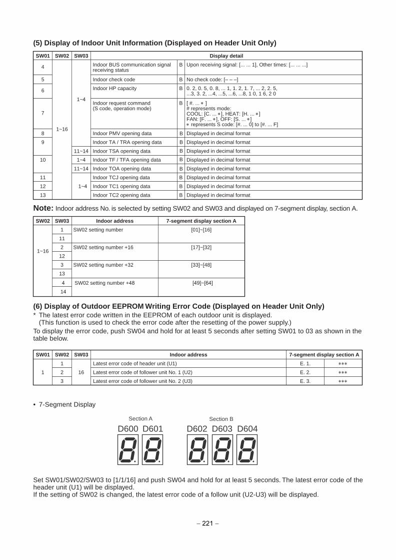
B4 Indoor BUS communication signalreceiving status
Upon receiving signal: [... ... 1], Other times: [... ... ...]
B5 Indoor check code No check code: [– – –]
B6 Indoor HP capacity 0. 2, 0. 5, 0. 8, ... 1, 1. 2, 1. 7, ... 2, 2. 5,...3, 3. 2, ...4, ...5, ...6, ...8, 1 0, 1 6, 2 0
8 Indoor PMV opening data Displayed in decimal format
9
1~4
1~16
Indoor TA / TRA opening data Displayed in decimal format
11~14 Indoor TSA opening data Displayed in decimal format
10 Displayed in decimal format1~4 Indoor TF / TFA opening data
11~14 Indoor TOA opening data Displayed in decimal format
B11 Indoor TCJ opening data Displayed in decimal format
B12 Displayed in decimal format
B13
1~4 Indoor TC1 opening data
Indoor TC2 opening data Displayed in decimal format
B
7
Indoor request command(S code, operation mode)
[ #. ... ∗ ]# represents mode:COOL: [C. ... ∗], HEAT: [H. ... ∗]FAN: [F. ... ∗], OFF: [S. ... ∗]∗ represents S code: [#. ... 0] to [#. ... F]
SW01 SW02 SW03 Display detail
SW02
1~16
SW03
1
11
2
12
3
13
Indoor address
SW02 setting number
SW02 setting number +16
SW02 setting number +32
7-segment display section A
[01]~[16]
[17]~[32]
[33]~[48]
(5) Display of Indoor Unit Information (Displayed on Header Unit Only)
Note: Indoor address No. is selected by setting SW02 and SW03 and displayed on 7-segment display, section A.
(6) Display of Outdoor EEPROM Writing Error Code (Displayed on Header Unit Only)* The latest error code written in the EEPROM of each outdoor unit is displayed.
(This function is used to check the error code after the resetting of the power supply.)To display the error code, push SW04 and hold for at least 5 seconds after setting SW01 to 03 as shown in thetable below.
• 7-Segment Display
SW01 SW02 SW03 Indoor address 7-segment display section A
1 E. 1. ∗∗∗Latest error code of header unit (U1)
1 2 16 E. 2. ∗∗∗Latest error code of follower unit No. 1 (U2)
3 E. 3. ∗∗∗Latest error code of follower unit No. 2 (U3)
Section A Section B
D600 D601 D602 D603 D604
Set SW01/SW02/SW03 to [1/1/16] and push SW04 and hold for at least 5 seconds. The latest error code of theheader unit (U1) will be displayed.If the setting of SW02 is changed, the latest error code of a follow unit (U2-U3) will be displayed.
4
14
SW02 setting number +48 [49]~[64]
− 221 −
B
B
B
B
B

8-7. Oil Level Judgment DisplayThe current compressor oil level judgment results can be accessed by setting the switches provided on the interface P.C. board of an outdoor unit.Perform the checks in accordance with the procedure described below.
1 Operation Procedure(1) Start the operation.(2) Set the switches provided on the interface P.C. board of the outdoor unit for which oil level judgment results are
required as follows: SW01/SW02/SW03 = 1/16/1
(3) The oil level judgment result will be displayed on the 7-segment display.7-segment display: [oL] [#. .$]The letters #, and $ are digits that represent judgment results for compressor Nos. 1 and 2, respectively.(See the table below for the interpretation of the judgment results.)
(4) When checking is completed, revert the SW01/SW02/SW03 setting to [1/1/1].
2 Oil Level Judgment Results
Display example
Displayed digit Judgmen noitpircseDtluser t
O Normal The amount of oil in the compressor is sufficient.
12
Low levelThe amount of oil in the compressor is insufficient. (Both “1” and “2” stand for insufficiency.)If this result persists, the system will turn itself off in a protective shutdown.
1Start operation.
3
2 4
Interface P.C. board of outdoor unit for which oil level judgment results are
Oil level judgment results are displayed
Set SW01/SW02/SW03 to 1/16/1.
Upon completion of checking, revert SW01/SW02/SW03 setting to 1/1/1.
7-segment display [ oL ][ oL ][ oL ]
Oil level is normal for compressors 1 and 2.Oil level is low for compressors 1 and 2.Oil level is low for compressor 2 and normal for compressors 1.
Judgment result for compressor 2 Judgment result for compressor 1
[ 0 0 ][ 2 2 ][ 0 2 ]
− 222 −
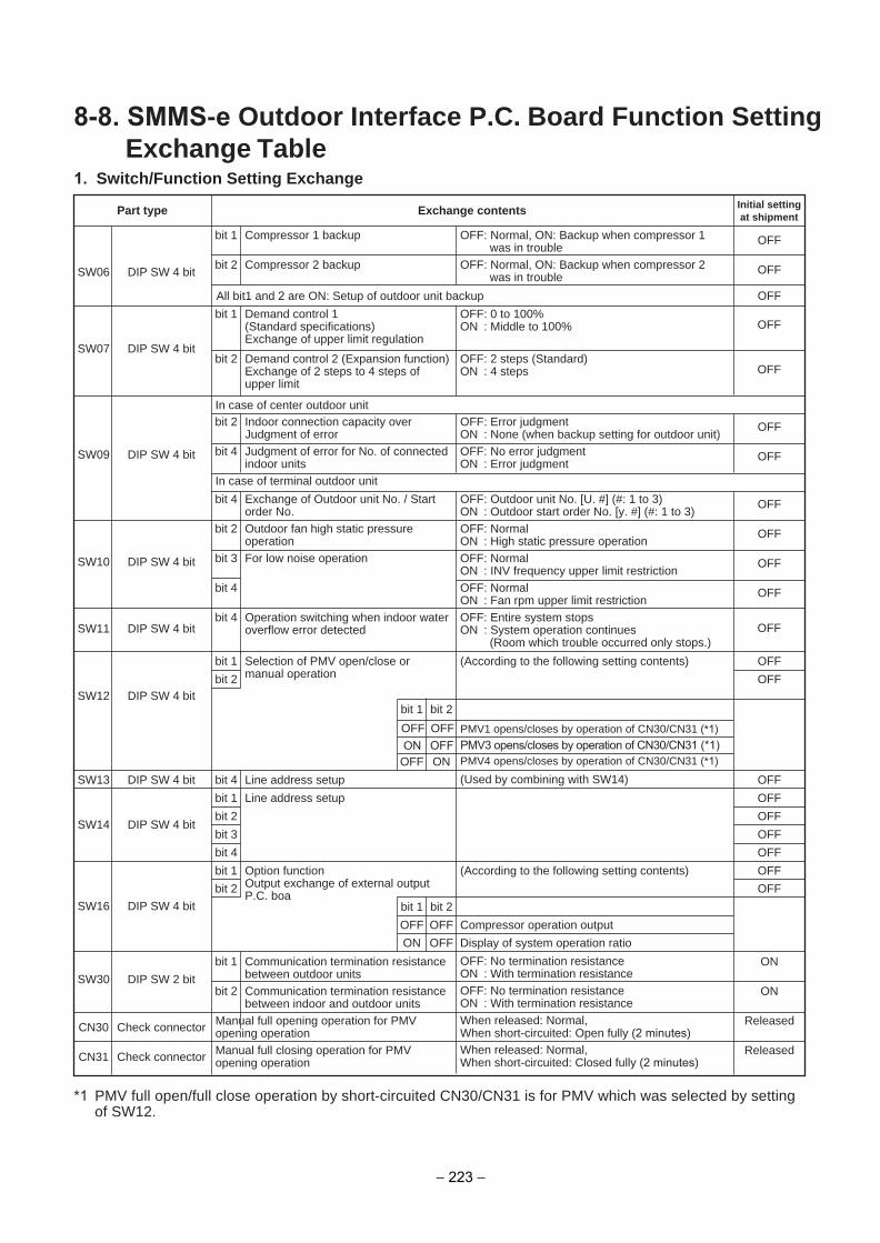
8-8. SMMS-e Outdoor Interface P.C. Board Function Setting Exchange Table
1. Switch/Function Setting Exchange
SW06 DIP SW 4 bit
bit 1 Compressor 1 backup OFF: Normal, ON: Backup when compressor 1 was in trouble
Part type Exchange contents Initial settingat shipment
OFF
SW07 DIP SW 4 bit
bit 1 Demand control 1(Standard specifications) Exchange of upper limit regulation
OFF: 0 to 100%ON : Middle to 100% OFF
SW09 DIP SW 4 bit
In case of center outdoor unit
bit 2 Demand control 2 (Expansion function)Exchange of 2 steps to 4 steps ofupper limit
OFF: 2 steps (Standard)ON : 4 steps OFF
bit 2 Compressor 2 backup OFF: Normal, ON: Backup when compressor 2 was in trouble
OFF
In case of terminal outdoor unit
bit 2 Indoor connection capacity over Judgment of error
OFF: Error judgmentON : None (when backup setting for outdoor unit)
OFF
bit 4 Judgment of error for No. of connectedindoor units
OFF: No error judgmentON : Error judgment
OFF
SW10 DIP SW 4 bit
bit 2 Outdoor fan high static pressureoperation
OFF: NormalON : High static pressure operation
OFF
SW12 DIP SW 4 bit
bit 1 Selection of PMV open/close ormanual operation
(According to the following setting contents) OFF
bit 1 bit 2
OFF OFF
OFF ON
PMV1 opens/closes by operation of CN30/CN31 (*1) PMV3 opens/closes by operation of CN30/CN31 (*1)PMV4 opens/closes by operation of CN30/CN31 (*1)
bit 2 OFF
SW11 DIP SW 4 bitbit 4 Operation switching when indoor water
overflow error detectedOFF: Entire system stopsON : System operation continues (Room which trouble occurred only stops.)
OFF
SW16 DIP SW 4 bit
bit 1 Option functionOutput exchange of external outputP.C. boa
(According to the following setting contents) OFF
SW14 DIP SW 4 bit
bit 1 Line address setup OFF
bit 1 bit 2
OFF OFF Compressor operation output
ON OFF
bit 2 OFF
bit 2 OFF
bit 3 OFF
bit 4 OFF
SW13 DIP SW 4 bit bit 4 Line address setup (Used by combining with SW14) OFF
Display of system operation ratio
CN30 Check connector Manual full opening operation for PMVopening operation
When released: Normal,When short-circuited: Open fully (2 minutes)
Released
SW30 DIP SW 2 bit
bit 1 Communication termination resistancebetween outdoor units
OFF: No termination resistanceON : With termination resistance
ON
CN31 Check connector Manual full closing operation for PMVopening operation
When released: Normal,When short-circuited: Closed fully (2 minutes)
Released
bit 2 Communication termination resistancebetween indoor and outdoor units
OFF: No termination resistanceON : With termination resistance
ON
bit 3 For low noise operation OFF: NormalON : INV frequency upper limit restriction
OFF
bit 4 OFF: NormalON : Fan rpm upper limit restriction
OFF
bit 4 Exchange of Outdoor unit No. / Startorder No.
OFF: Outdoor unit No. [U. #] (#: 1 to 3)ON : Outdoor start order No. [y. #] (#: 1 to 3)
OFF
All bit1 and 2 are ON: Setup of outdoor unit backup OFF
*1 PMV full open/full close operation by short-circuited CN30/CN31 is for PMV which was selected by settingof SW12.
ON OFF
− 223 −
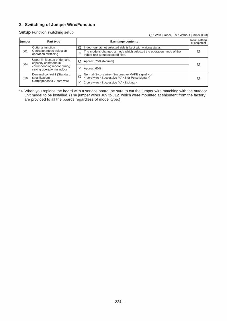
O : With jumper, × : Without jumper (Cut)
2. Switching of Jumper Wire/Function
Setup Function switching setup
jumper Part type Exchange contents Initial settingat shipment
J01 OOOptional function
Operation mode selectionoperation switching
Indoor unit at not selected side is kept with waiting status.
J16 OODemand control 1 (Standardspecification)Corresponds to 2-core wire
Normal (3-core wire <Successive MAKE signal> or4-core wire <Successive MAKE or Pulse signal>)
× 2-core wire <Successive MAKE signal>
O Approx. 75% (Normal)
× The mode is changed a mode which selected the operation mode of theindoor unit at not selected side.
× Approx. 60%J04 O
Upper limit setup of demandcapacity command incorresponding indoor duringsaving operation in indoor
*4 When you replace the board with a service board, be sure to cut the jumper wire matching with the outdoorunit model to be installed. (The jumper wires J09 to J12 which were mounted at shipment from the factoryare provided to all the boards regardless of model type.)
− 224 −
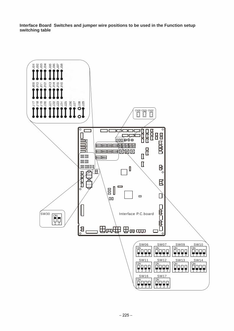
Interface Board Switches and jumper wire positions to be used in the Function setupswitching table
1 3 42
SW16ON
1 2
SW30ON
1 3 42
SW17ON
1 3 42
SW11ON
1 3 42
SW12ON
1 3 42
SW13ON
1 3 42
SW14ON
1 3 42
SW06ON
1 3 42
SW07ON
1 3 42
SW09
CN30 CN31 CN32
Interface P.C.board
ON
1 3 42
SW10ON
− 225 −
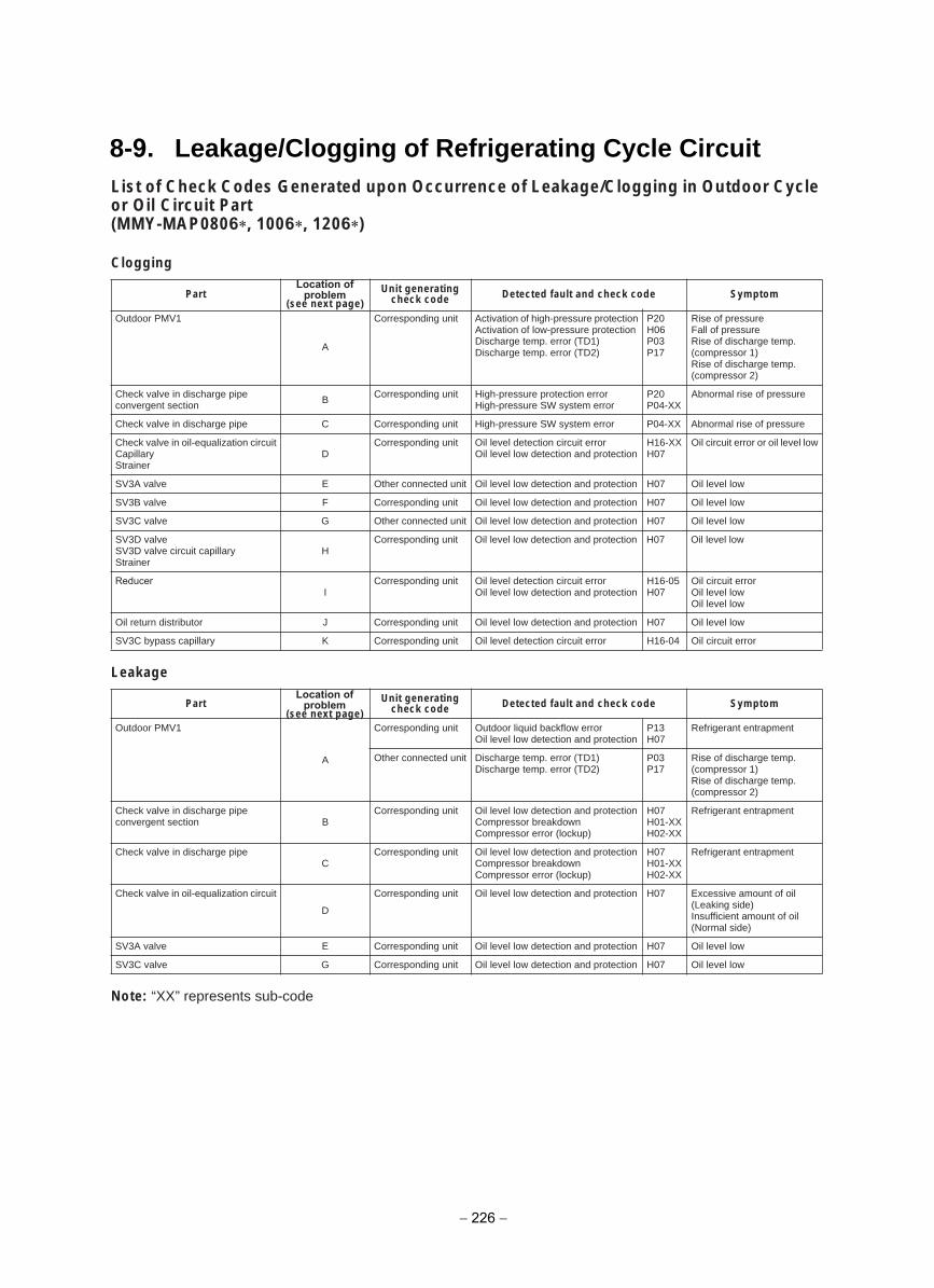
8-9. Leakage/Clogging of Refrigerating Cycle CircuitList of Check Codes Generated upon Occurrence of Leakage/Clogging in Outdoor Cycle or Oil Circuit Part(MMY-MAP0806 , 1006 , 1206 )
Clogging
Leakage
Note: “XX” represents sub-code
PartLocation of
problem(see next page)
Unit generating check code Detected fault and check code Symptom
Outdoor PMV1
A
Corresponding unit Activation of high-pressure protectionActivation of low-pressure protectionDischarge temp. error (TD1)Discharge temp. error (TD2)
P20H06P03P17
Rise of pressureFall of pressureRise of discharge temp. (compressor 1)Rise of discharge temp. (compressor 2)
Check valve in discharge pipe convergent section B Corresponding unit High-pressure protection error
High-pressure SW system errorP20P04-XX
Abnormal rise of pressure
Check valve in discharge pipe C Corresponding unit High-pressure SW system error P04-XX Abnormal rise of pressure
Check valve in oil-equalization circuitCapillaryStrainer
DCorresponding unit Oil level detection circuit error
Oil level low detection and protectionH16-XXH07
Oil circuit error or oil level low
wol level liO70Hnoitcetorp dna noitceted wol level liOtinu detcennoc rehtOEevlav A3VS
wol level liO70Hnoitcetorp dna noitceted wol level liOtinu gnidnopserroCFevlav B3VS
wol level liO70Hnoitcetorp dna noitceted wol level liOtinu detcennoc rehtOGevlav C3VS
SV3D valveSV3D valve circuit capillaryStrainer
HCorresponding unit Oil level low detection and protection H07 Oil level low
ReducerI
Corresponding unit Oil level detection circuit errorOil level low detection and protection
H16-05H07
Oil circuit errorOil level lowOil level low
wol level liO70Hnoitcetorp dna noitceted wol level liOtinu gnidnopserroCJrotubirtsid nruter liO
rorre tiucric liO40-61Hrorre tiucric noitceted level liOtinu gnidnopserroCKyrallipac ssapyb C3VS
Part Unit generating check code Detected fault and check code Symptom
Outdoor PMV1
A
Corresponding unit Outdoor liquid backflow errorOil level low detection and protection
P13H07
Refrigerant entrapment
Other connected unit Discharge temp. error (TD1)Discharge temp. error (TD2)
P03P17
Rise of discharge temp. (compressor 1)Rise of discharge temp. (compressor 2)
Check valve in discharge pipe Bnoitces tnegrevnoc
Corresponding unit Oil level low detection and protectionCompressor breakdownCompressor error (lockup)
H07H01-XXH02-XX
Refrigerant entrapment
Check valve in discharge pipeC
Corresponding unit Oil level low detection and protectionCompressor breakdownCompressor error (lockup)
H07H01-XXH02-XX
Refrigerant entrapment
Check valve in oil-equalization circuit
D
Corresponding unit Oil level low detection and protection H07 Excessive amount of oil(Leaking side)Insufficient amount of oil(Normal side)
wol level liO70Hnoitcetorp dna noitceted wol level liOtinu gnidnopserroCEevlav A3VS
wol level liO70Hnoitcetorp dna noitceted wol level liOtinu gnidnopserroCGevlav C3VS
Location of problem
(see next page)
− 226 −
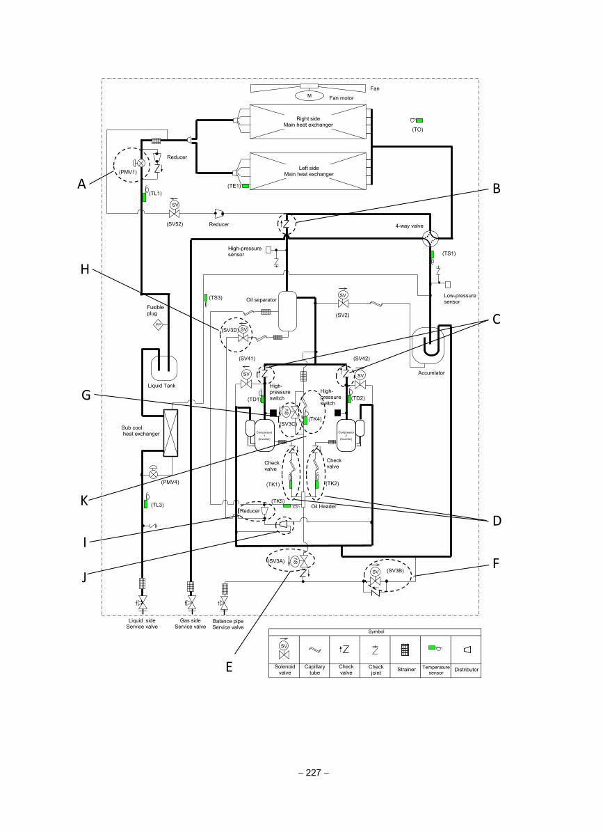
(TD2)
(TE1)
(TK2) (TK1)
(TD1)
(TK4)
(TO)
(SV3D) SV
SV
SV SV
M
(TL1)
SV
SV
SV
(TK5)
(TS3)
(TL3)
Reducer
(SV3A)
(SV2)
(SV42) (SV41)
(SV3C)
(PMV4)
(TS1)
(SV3B)
Fan
Fan motor
Right side Main heat exchanger
Left side Main heat exchanger (PMV1)
4-way valve
High-pressure sensor
Low-pressure sensor Oil separator
Fusible plug
Liquid Tank
Accumlator
High- pressure switch
High- pressure switch
Check valve
Check valve
Compressor 1
(Inverter)
Oil Header
Liquid side Service valve
Gas side Service valve
Balance pipe Service valve
Sub cool heat exchanger
SV
(SV52) Reducer
FP
Compressor 2
(Inverter)
SV
Solenoid valve
Capillary tube
Check valve
Check joint Strainer Temperature
sensor
Symbol
Distributor
Reducer
A
H
G
K
I
J
E
F
D
C
B
− 227 −
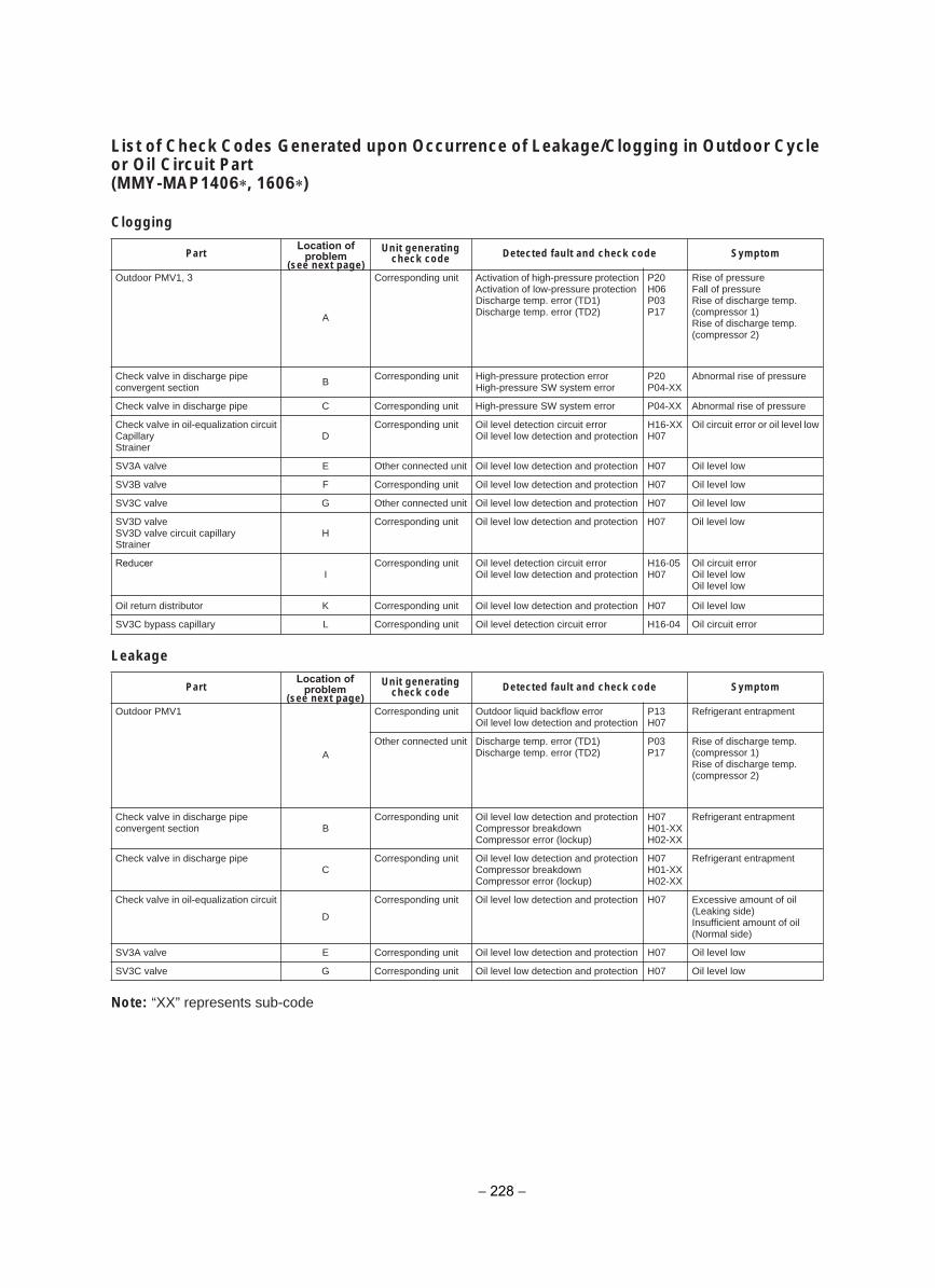
List of Check Codes Generated upon Occurrence of Leakage/Clogging in Outdoor Cycle or Oil Circuit Part(MMY-MAP1406 , 1606 )
Clogging
Leakage
Note: “XX” represents sub-code
Part Unit generating check code Detected fault and check code Symptom
Outdoor PMV1, 3
A
Corresponding unit Activation of high-pressure protectionActivation of low-pressure protectionDischarge temp. error (TD1) Discharge temp. error (TD2)
P20H06P03P17
Rise of pressureFall of pressureRise of discharge temp. (compressor 1)Rise of discharge temp. (compressor 2)
Check valve in discharge pipe convergent section B Corresponding unit High-pressure protection error
High-pressure SW system errorP20P04-XX
Abnormal rise of pressure
Check valve in discharge pipe C Corresponding unit High-pressure SW system error P04-XX Abnormal rise of pressure
Check valve in oil-equalization circuitCapillaryStrainer
DCorresponding unit Oil level detection circuit error
Oil level low detection and protectionH16-XXH07
Oil circuit error or oil level low
wol level liO70Hnoitcetorp dna noitceted wol level liOtinu detcennoc rehtOEevlav A3VS
wol level liO70Hnoitcetorp dna noitceted wol level liOtinu gnidnopserroCFevlav B3VS
wol level liO70Hnoitcetorp dna noitceted wol level liOtinu detcennoc rehtOGevlav C3VS
SV3D valveSV3D valve circuit capillaryStrainer
HCorresponding unit Oil level low detection and protection H07 Oil level low
ReducerI
Corresponding unit Oil level detection circuit errorOil level low detection and protection
H16-05H07
Oil circuit errorOil level lowOil level low
wol level liO70Hnoitcetorp dna noitceted wol level liOtinu gnidnopserroCKrotubirtsid nruter liO
rorre tiucric liO40-61Hrorre tiucric noitceted level liOtinu gnidnopserroCLyrallipac ssapyb C3VS
Part Unit generating check code Detected fault and check code Symptom
Outdoor PMV1
A
Corresponding unit Outdoor liquid backflow errorOil level low detection and protection
P13H07
Refrigerant entrapment
Other connected unit Discharge temp. error (TD1) Discharge temp. error (TD2)
P03P17
Rise of discharge temp. (compressor 1)Rise of discharge temp. (compressor 2)
Check valve in discharge pipe Bnoitces tnegrevnoc
Corresponding unit Oil level low detection and protectionCompressor breakdownCompressor error (lockup)
H07H01-XXH02-XX
Refrigerant entrapment
Check valve in discharge pipeC
Corresponding unit Oil level low detection and protectionCompressor breakdownCompressor error (lockup)
H07H01-XXH02-XX
Refrigerant entrapment
Check valve in oil-equalization circuit
D
Corresponding unit Oil level low detection and protection H07 Excessive amount of oil(Leaking side)Insufficient amount of oil(Normal side)
wol level liO70Hnoitcetorp dna noitceted wol level liOtinu gnidnopserroCEevlav A3VS
wol level liO70Hnoitcetorp dna noitceted wol level liOtinu gnidnopserroCGevlav C3VS
Location of problem
(see next page)
Location of problem
(see next page)
− 228 −
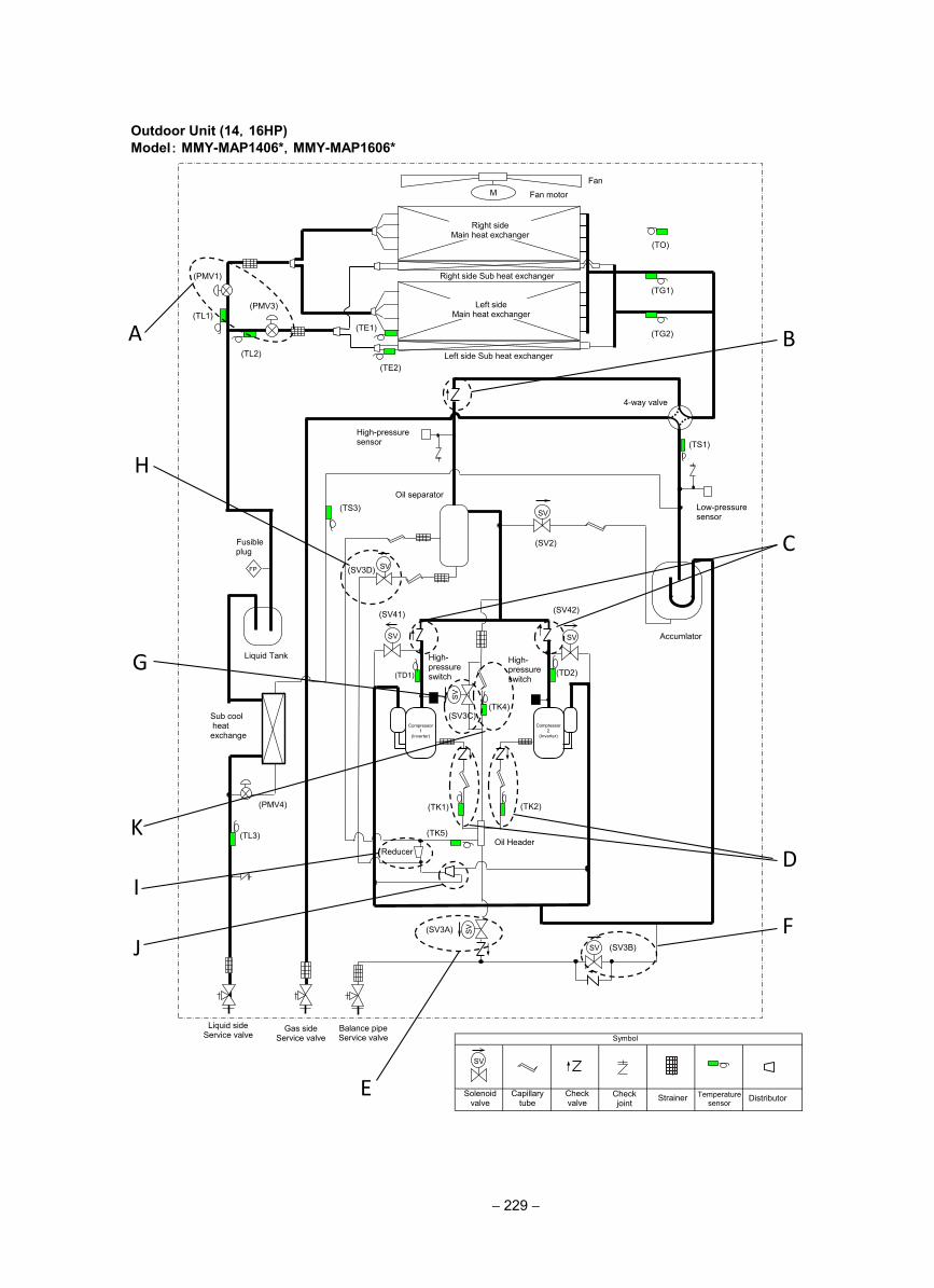
仮
(TD2)
(TS1)
(TE1)
(TK2) (TK1)
(TD1)
(TK4)
(TE2)
(TO)
SV
SV
SV SV
M
(TG2)
(TG1)
(TL3)
SV
SV
SV
(TK5)
(TS3)
(TL1)
(TL2)
(SV3B)
(SV3A)
(SV2)
(SV3D)
(SV42) (SV41)
(SV3C)
(PMV4)
Fan
Fan motor
Right side Main heat exchanger
Left side Main heat exchanger
Right side Sub heat exchanger
Left side Sub heat exchanger
(PMV1)
(PMV3)
4-way valve
High-pressure sensor
Low-pressure sensor
Oil separator
Accumlator
Liquid Tank
Liquid side Service valve
Gas side Service valve
Balance pipe Service valve
Oil Header
High- pressure switch
High- pressure switch
Reducer
Fusible plug
FP
Sub cool heat exchange
Compressor 1
(Inverter)
Compressor 2
(Inverter)
SV
Solenoid valve
Capillary tube
Check valve
Check joint Strainer Temperature
sensor
Symbol
Distributor
H
G
K
I
J
E
F
D
C
B A
Outdoor Unit (14,16HP)Model: MMY-MAP1406*,MMY-MAP1606*
− 229 −
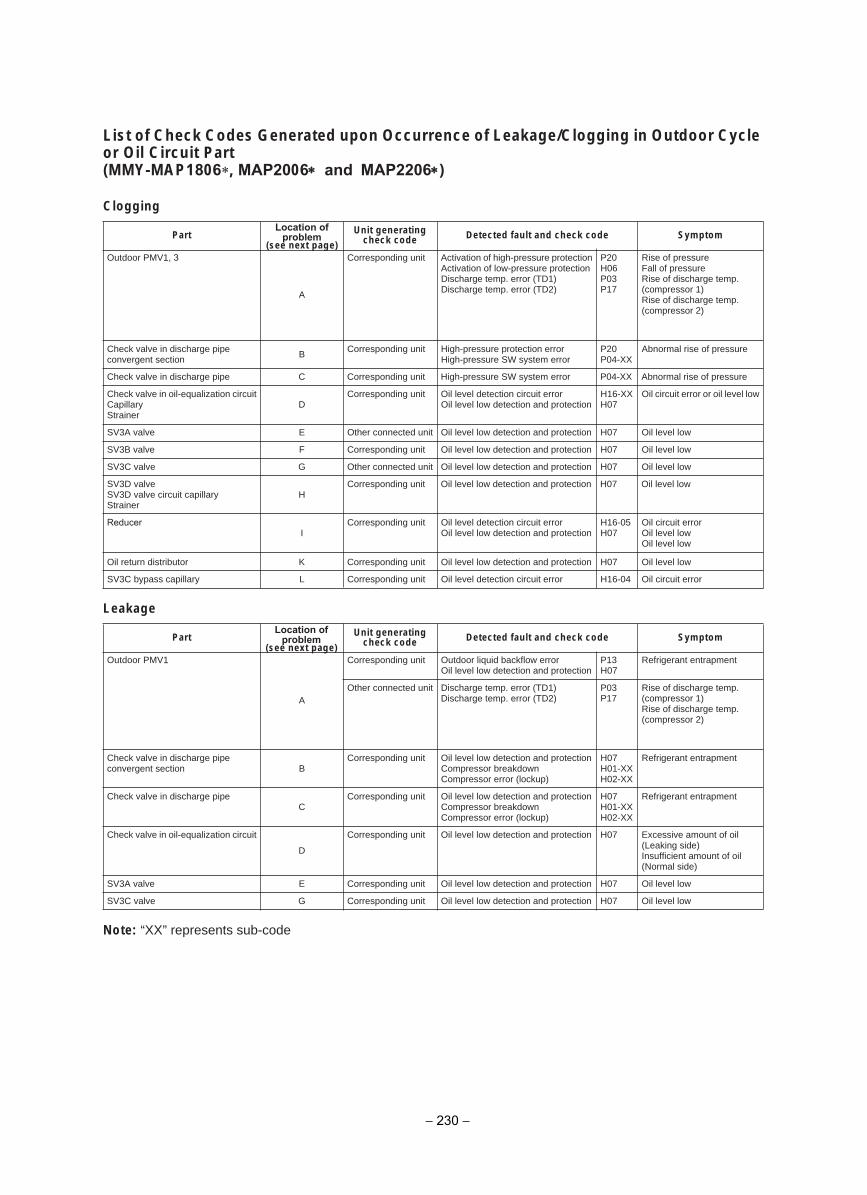
List of Check Codes Generated upon Occurrence of Leakage/Clogging in Outdoor Cycle or Oil Circuit Part(MMY-MAP1806 , MAP2006∗ and MAP2206∗)
Clogging
Leakage
Note: “XX” represents sub-code
Part Unit generating check code Detected fault and check code Symptom
Outdoor PMV1, 3
A
Corresponding unit Activation of high-pressure protectionActivation of low-pressure protectionDischarge temp. error (TD1) Discharge temp. error (TD2)
P20H06P03P17
Rise of pressureFall of pressureRise of discharge temp. (compressor 1)Rise of discharge temp. (compressor 2)
Check valve in discharge pipe convergent section B Corresponding unit High-pressure protection error
High-pressure SW system errorP20P04-XX
Abnormal rise of pressure
Check valve in discharge pipe C Corresponding unit High-pressure SW system error P04-XX Abnormal rise of pressure
Check valve in oil-equalization circuitCapillaryStrainer
DCorresponding unit Oil level detection circuit error
Oil level low detection and protectionH16-XXH07
Oil circuit error or oil level low
wol level liO70Hnoitcetorp dna noitceted wol level liOtinu detcennoc rehtOEevlav A3VS
wol level liO70Hnoitcetorp dna noitceted wol level liOtinu gnidnopserroCFevlav B3VS
wol level liO70Hnoitcetorp dna noitceted wol level liOtinu detcennoc rehtOGevlav C3VS
SV3D valveSV3D valve circuit capillaryStrainer
HCorresponding unit Oil level low detection and protection H07 Oil level low
ReducerI
Corresponding unit Oil level detection circuit errorOil level low detection and protection
H16-05H07
Oil circuit errorOil level lowOil level low
wol level liO70Hnoitcetorp dna noitceted wol level liOtinu gnidnopserroCKrotubirtsid nruter liO
rorre tiucric liO40-61Hrorre tiucric noitceted level liOtinu gnidnopserroCLyrallipac ssapyb C3VS
Part Unit generating check code Detected fault and check code Symptom
Outdoor PMV1
A
Corresponding unit Outdoor liquid backflow errorOil level low detection and protection
P13H07
Refrigerant entrapment
Other connected unit Discharge temp. error (TD1) Discharge temp. error (TD2)
P03P17
Rise of discharge temp. (compressor 1)Rise of discharge temp. (compressor 2)
Check valve in discharge pipe Bnoitces tnegrevnoc
Corresponding unit Oil level low detection and protectionCompressor breakdownCompressor error (lockup)
H07H01-XXH02-XX
Refrigerant entrapment
Check valve in discharge pipeC
Corresponding unit Oil level low detection and protectionCompressor breakdownCompressor error (lockup)
H07H01-XXH02-XX
Refrigerant entrapment
Check valve in oil-equalization circuit
D
Corresponding unit Oil level low detection and protection H07 Excessive amount of oil(Leaking side)Insufficient amount of oil(Normal side)
wol level liO70Hnoitcetorp dna noitceted wol level liOtinu gnidnopserroCEevlav A3VS
wol level liO70Hnoitcetorp dna noitceted wol level liOtinu gnidnopserroCGevlav C3VS
Location of problem
(see next page)
Location of problem
(see next page)
− 230 −
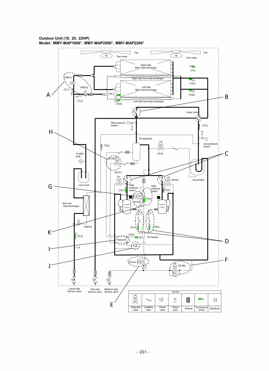
Outdoor Unit (18,20,22HP)Model: MMY-MAP1806*,MMY-MAP2006*,MMY-MAP2206*
仮
(TD2)
(TS1)
(TE1)
(TK2) (TK1)
(TD1)
(TK4)
(TE2)
(TO)
SV
SV
SV SV
M M
(TG2)
(TG1)
(TL3)
SV
SV
SV
(TK5)
(TS3)
(TL1)
(TL2)
(SV3B) (SV3A)
(SV2)
(SV3D)
(SV42)
(SV41)
(SV3C)
(PMV4)
Fan Fan
Fan motor Fan motor
Right side Main heat exchanger
Left side Main heat exchanger
Right side Sub heat exchanger
Left side Sub heat exchanger
(PMV1)
(PMV3)
4-way valve
High-pressure sensor
Low-pressure sensor
Oil separator
Accumlator
Liquid Tank
Oil Header
High- pressure switch
High- pressure switch
Sub cool heat exchanger
Fusible plug
FP
Liquid side Service valve
Gas side Service valve
Balance pipe Service valve
SV
Solenoid valve
Capillary tube
Check valve
Check joint Strainer Temperature
sensor
Symbol
Distributor
Reducer
Compressor 1
(Inverter)
Compressor 2
(Inverter)
A
H
G
K
I
J
E
F
D
C
B
− 231 −
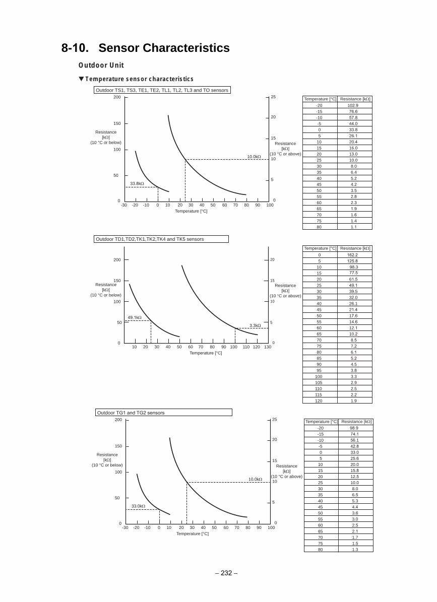
8-10. Sensor CharacteristicsOutdoor Unit
Temperature sensor characteristics
Temperature [°C]
-20-15-10-505
101520253035404550556065707580
Resistance [kΩ]
Temperature [°C] Resistance [kΩ]
102.976.657.844.033.826.120.416.013.010.08.06.45.24.23.52.82.31.91.61.41.1
05
101520253035404550556065707580859095
100105110115120
162.2125.8
98.377.561.549.139.532.026.121.417.614.612.110.28.57.26.15.24.53.83.32.92.52.21.9
Outdoor TD1,TD2,TK1,TK2,TK4 and TK5 sensors
Resistance[kΩ]
(10 °C or below) Resistance[kΩ]
(10 °C or above)
Resistance[kΩ]
(10 °C or below)
Resistance[kΩ]
(10 °C or above)
10
15
25
5
20
010 20 30 40 50 60 70-10 0
Temperature [°C]80 90 100-20-30
100
150
50
33.8kΩ
49.1kΩ
10.0kΩ
3.3kΩ
200
Temperature [°C]
200
0
10
20
5
15
040302010 70 80 90 100 110 120 13050 60
100
150
50
0
Outdoor TS1, TS3, TE1, TE2, TL1, TL2, TL3 and TO sensors
Temperature [°C]
-20-15-10-505
101520253035404550556065707580
Resistance [kΩ]
98.974.156.142.833.025.620.015.812.510.08.06.55.34.43.63.02.52.11.71.51.3
Resistance[kΩ]
(10 °C or below) Resistance[kΩ]
(10 °C or above)10
15
25
5
20
0-10 0 10 20 30 40 50 60 70
Temperature [°C]80 90 100-30 -20
100
150
50
33.0kΩ
10.0kΩ
200
0
Outdoor TG1 and TG2 sensors
− 232 −
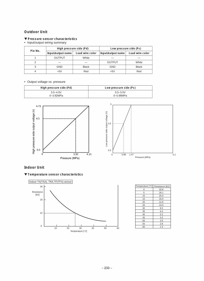
Outdoor Unit
Pressure sensor characteristics• Input/output wiring summary
• Output voltage vs. pressure
Indoor Unit
Temperature sensor characteristics
Pin No.High pressure side (Pd) Low pressure side (Ps)
Input/output name Lead wire color Input/output name Lead wire color
1 OUTPUT White — —
2 — — OUTPUT White
3 GND Black GND Black
4 +5V Red +5V Red
)sP( edis erusserp woL)dP( edis erusserp hgiH
0.5~4.5V0~3.92MPa
0.5~3.5V0~0.98MPa
1.574.189.00
0.5
3.5
5Lo
w p
ress
ure-
side
out
put v
olta
ge (
V)
)aPM( erusserP4.15 3.92
Pressure (MPa)
4.5
4.73
0.5
0 Hig
h pr
essu
re-s
ide
outp
ut v
olta
ge (V
)
05
1015202530354045505560
33.826.120.416.012.610.08.06.45.24.23.52.82.3
Temperature [°C]
Indoor TA(TSA), TRA,TF(TFA) sensor
Resistance[kΩ]
Temperature [°C]6010 20 30 40 50
20
30
10
0
Resistance [kΩ]
− 233 −
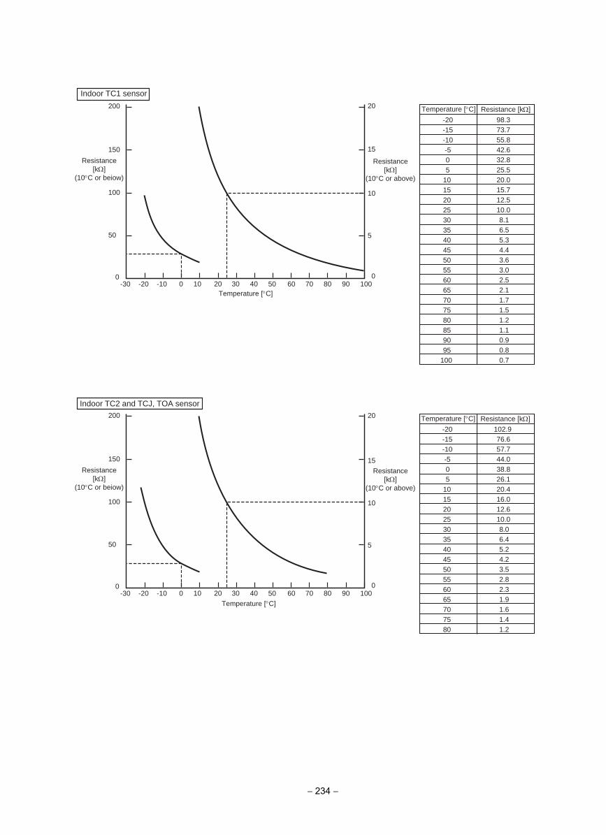
-20-15-10-505
101520253035404550556065707580859095
100
98.373.755.842.632.825.520.015.712.510.08.16.55.34.43.63.02.52.11.71.51.21.10.90.80.7
-20-15-10-505
101520253035404550556065707580
102.976.657.744.038.826.120.416.012.610.08.06.45.24.23.52.82.31.91.61.41.2
Temperature [°C]
10
15
5
20
0-30 -20 -10 0 10 20 30 40 50 60 70 80 90 100
100
150
50
200
0
10
15
5
20
0-30 -20 -10 0 10 20 30 40 50 60 70 80 90 100
100
150
50
200
0
Resistance[kΩ]
(10°C or beiow)
Resistance[kΩ]
(10°C or above)
Resistance[kΩ]
(10°C or beiow)
Resistance[kΩ]
(10°C or above)
Temperature [°C]
Temperature [°C]
Indoor TC1 sensor
Indoor TC2 and TCJ, TOA sensor
Resistance [kΩ]
Temperature [°C] Resistance [kΩ]
− 234 −
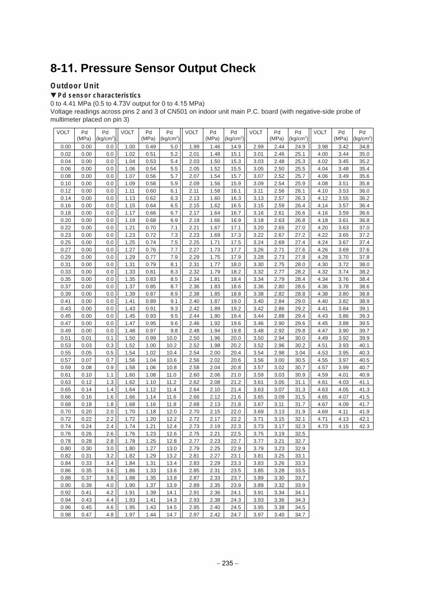
8-11. Pressure Sensor Output CheckOutdoor Unit
Pd sensor characteristics0 to 4.41 MPa (0.5 to 4.73V output for 0 to 4.15 MPa)Voltage readings across pins 2 and 3 of CN501 on indoor unit main P.C. board (with negative-side probe of multimeter placed on pin 3)
0.000.020.040.060.080.100.120.140.160.180.200.220.230.250.270.290.310.330.350.370.390.410.430.450.470.490.510.530.550.570.590.610.630.650.660.680.700.720.740.760.780.800.820.840.860.880.900.920.940.960.98
0.000.000.000.000.000.000.000.000.000.000.000.000.000.000.000.000.000.000.000.000.000.000.000.000.000.000.010.030.050.070.080.100.120.140.160.180.200.220.240.260.280.300.310.330.350.370.390.410.430.450.47
0.00.00.00.00.00.00.00.00.00.00.00.00.00.00.00.00.00.00.00.00.00.00.00.00.00.00.10.30.50.70.91.11.31.41.61.82.02.22.42.62.83.03.23.43.63.84.04.24.44.64.8
VOLT Pd(MPa)
Pd(kg/cm2) (kg/cm2) (kg/cm2) (kg/cm2) (kg/cm2)
1.001.021.041.061.071.091.11 1.131.151.171.191.211.231.251.271.291.311.331.351.371.391.411.431.451.471.481.501.521.541.561.581.601.621.641.661.681.701.721.741.761.781.801.821.841.861.881.901.911.931.951.97
0.490.510.530.540.560.580.600.620.640.660.680.700.720.740.760.770.790.810.830.850.870.890.910.930.950.970.991.001.021.041.061.081.101.121.141.161.181.201.211.231.251.271.291.311.331.351.371.391.411.431.44
5.05.25.45.55.75.96.16.36.56.76.97.17.37.57.77.98.18.38.58.78.99.19.39.59.69.8
10.010.210.410.610.811.0 11.2 11.4 11.6 11.8 12.012.212.412.612.813.013.213.413.613.813.914.114.314.514.7
VOLT Pd(MPa)
Pd
1.992.012.032.052.072.092.11 2.132.152.172.192.212.232.252.272.292.312.322.342.362.382.402.422.442.462.482.502.522.542.562.582.602.622.642.662.682.702.722.732.752.772.792.812.832.852.872.892.912.932.952.97
1.461.481.501.521.541.561.581.601.621.641.661.671.691.711.731.751.771.791.811.831.851.871.891.901.921.941.961.982.002.022.042.062.082.102.122.132.152.172.192.212.232.252.272.292.312.332.352.362.382.402.42
14.915.115.315.515.715.916.116.316.516.716.917.117.317.517.717.918.018.218.418.618.819.019.219.419.619.820.020.220.420.620.821.021.221.421.621.822.022.222.322.522.722.923.123.323.523.723.924.124.324.524.7
VOLT Pd(MPa)
Pd
2.993.013.033.053.073.093.11 3.133.153.163.183.203.223.243.263.283.303.323.343.363.383.403.423.443.463.483.503.523.543.563.573.593.613.633.653.673.693.713.733.753.773.793.813.833.853.893.893.913.933.953.97
2.442.462.482.502.522.542.562.572.592.612.632.652.672.692.712.732.752.772.792.802.822.842.862.882.902.922.942.962.983.003.023.033.053.073.093.11 3.133.153.173.193.213.233.253.263.283.303.323.343.363.383.40
24.925.125.325.525.725.926.126.326.426.626.827.027.227.427.627.828.028.228.428.628.829.029.229.429.629.830.030.23.0430.530.730.931.131.331.531.731.932.132.332.532.732.933.133.333.533.733.934.134.334.534.7
VOLT Pd(MPa)
Pd
3.984.004.024.044.064.084.104.124.144.164.184.204.224.244.264.284.304.324.344.364.384.404.414.434.454.474.494.514.534.554.574.594.614.634.654.674.694.714.73
3.423.443.453.483.493.513.533.553.573.593.613.633.653.673.693.703.723.743.763.783.803.823.843.863.883.903.923.933.953.973.994.014.034.054.074.094.11 4.134.15
34.835.035.235.435.635.836.036.236.436.636.837.037.237.437.637.838.038.238.438.638.838.939.139.339.539.739.940.140.340.540.740.941.141.341.541.741.942.142.3
VOLT Pd(MPa)
Pd
− 235 −
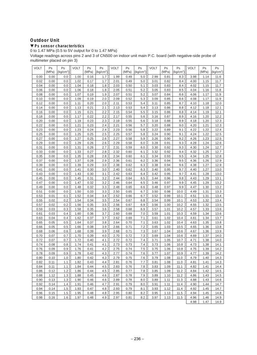
Outdoor UnitPs sensor characteristics
0 to 1.47 MPa (0.5 to 5V output for 0 to 1.47 MPa)Voltage readings across pins 2 and 3 of CN500 on indoor unit main P.C. board (with negative-side probe of multimeter placed on pin 3)
0.000.020.040.060.080.100.120.140.160.180.200.220.230.250.270.290.310.330.350.370.390.410.430.450.470.490.510.530.550.570.590.610.630.650.660.680.700.720.740.760.780.800.820.840.860.880.900.920.940.960.98
0.000.000.000.000.000.000.000.000.000.000.000.000.000.000.000.000.000.000.000.000.000.000.000.000.000.000.000.010.020.020.030.030.040.050.050.060.070.070.080.090.090.100.11 0.11 0.121.120.130.140.140.150.16
0.00.00.00.00.00.00.00.00.00.00.00.00.00.00.00.00.00.00.00.00.00.00.00.00.00.00.00.10.20.20.30.40.40.50.50.60.70.70.80.90.91.01.11.11.21.31.31.41.51.51.6
VOLT Ps Ps
1.001.021.041.061.071.091.11 1.131.151.171.191.211.231.251.271.291.311.331.351.371.391.411.431.451.471.481.501.521.541.561.581.601.621.641.661.681.701.721.741.761.781.801.821.841.861.881.901.911.931.951.97
0.160.170.180.180.190.190.200.210.210.220.230.230.240.250.250.260.260.270.280.280.290.300.300.310.320.320.330.340.340.350.350.360.370.370.380.390.390.400.410.410.420.420.430.440.440.450.460.460.470.480.48
1.71.71.81.81.92.02.02.12.22.22.32.42.42.52.62.62.72.82.82.93.03.03.13.23.23.33.33.43.53.53.63.73.73.83.93.94.04.14.14.24.34.34.44.54.54.64.64.74.84.84.9
VOLT Ps Ps
1.992.012.032.052.072.092.11 2.132.152.172.192.212.232.252.272.292.312.322.342.362.382.402.422.442.462.482.502.522.542.562.582.602.622.642.662.682.702.722.732.752.772.792.812.832.852.872.892.912.932.952.97
0.490.490.500.510.510.520.530.530.540.550.550.560.560.570.580.580.590.600.600.610.620.620.630.640.640.650.650.660.670.670.680.690.690.700.710.710.720.720.730.740.740.750.760.760.770.780.780.790.790.800.81
5.05.05.15.25.25.35.45.45.55.65.65.75.85.85.96.06.06.16.16.26.36.36.46.56.56.66.76.76.86.96.97.07.17.17.27.37.37.47.47.57.67.67.77.87.87.98.08.08.18.28.2
VOLT Ps Ps
2.993.013.033.053.073.093.11 3.133.153.163.183.203.223.243.263.283.303.323.343.363.383.403.423.443.463.483.503.523.543.563.573.593.613.633.653.673.693.713.733.753.773.793.813.833.853.893.893.913.933.953.97
0.810.820.830.830.840.850.850.860.860.870.880.880.890.900.900.910.920.920.930.940.940.950.950.960.970.970.980.990.991.001.011.011.021.021.031.041.041.051.061.061.071.081.081.091.091.101.11 1.11 1.121.131.13
8.38.48.48.58.68.68.78.88.88.98.99.09.19.19.29.39.39.49.59.59.69.79.79.89.99.9
10.010.110.110.210.210.310.410.410.510.610.610.710.810.810.911.0 11.0 11.1 11.2 11.2 11.3 11.4 11.4 11.5 11.5
VOLT Ps Ps
3.984.004.024.044.064.084.104.124.144.164.184.204.224.244.264.284.304.324.344.364.384.404.414.434.454.474.494.514.534.554.574.594.614.634.654.674.694.714.734.754.774.794.814.824.844.864.884.904.924.944.964.98
1.141.151.151.161.171.171.181.181.191.201.201.211.221.221.231.241.241.251.251.261.271.271.281.291.291.301.311.311.321.321.331.341.341.351.361.361.371.381.381.391.391.401.411.411.421.431.431.441.451.451.461.47
11.6 11.7 11.7 11.8 11.9 11.9 12.012.112.112.212.312.312.412.512.512.612.712.712.812.912.913.013.013.113.213.213.313.413.413.513.613.613.713.813.813.914.014.014.114.214.214.314.314.414.514.514.614.714.714.814.914.9
VOLT Ps Ps(MPa) (kg/cm2) (kg/cm2) (kg/cm2) (kg/cm2) (kg/cm2)(MPa) (MPa) (MPa) (MPa)
− 236 −
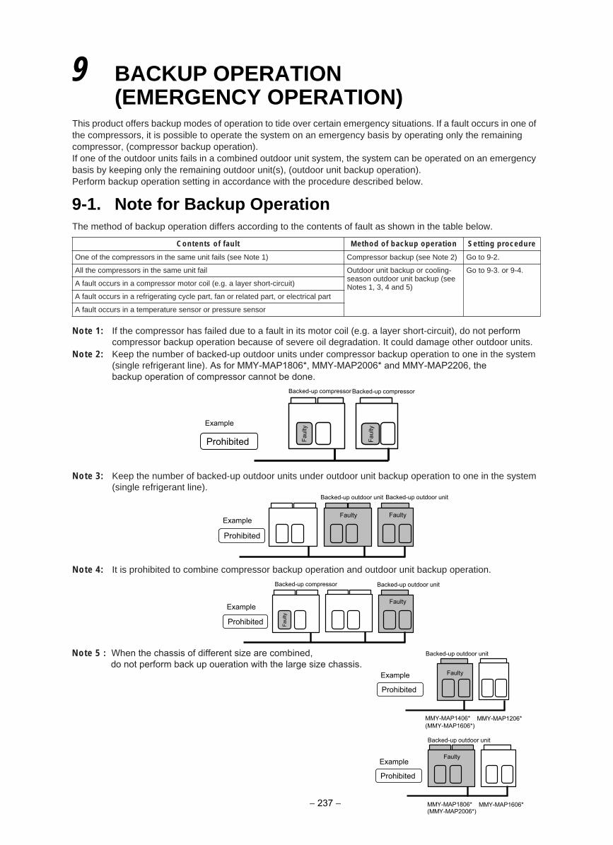
This product offers backup modes of operation to tide over certain emergency situations. If a fault occurs in one of the compressors, it is possible to operate the system on an emergency basis by operating only the remaining compressor, (compressor backup operation).If one of the outdoor units fails in a combined outdoor unit system, the system can be operated on an emergency basis by keeping only the remaining outdoor unit(s), (outdoor unit backup operation).Perform backup operation setting in accordance with the procedure described below.
The method of backup operation differs according to the contents of fault as shown in the table below.
Note 1: If the compressor has failed due to a fault in its motor coil (e.g. a layer short-circuit), do not perform compressor backup operation because of severe oil degradation. It could damage other outdoor units.
Note 2: Keep the number of backed-up outdoor units under compressor backup operation to one in the system (single refrigerant line). As for MMY-MAP1806*, MMY-MAP2006* and MMY-MAP2206, the backup operation of compressor cannot be done.
Note 3: Keep the number of backed-up outdoor units under outdoor unit backup operation to one in the system (single refrigerant line).
Note 4: It is prohibited to combine compressor backup operation and outdoor unit backup operation.
Note 5 : When the chassis of different size are combined,do not perform back up oueration with the large size chassis.
ukcab fo dohteMtluaf fo stnetnoC p operation Setting procedure
.2-9 ot oG)2 etoN ees( pukcab rosserpmoC)1 etoN ees( sliaf tinu emas eht ni srosserpmoc eht fo enO
-gnilooc ro pukcab tinu roodtuOliaf tinu emas eht ni srosserpmoc eht llAseason outdoor unit backup (see Notes 1, 3, 4 and 5)
Go to 9-3. or 9-4.
A fault occurs in a compressor motor coil (e.g. a layer short-circuit)
A fault occurs in a refrigerating cycle part, fan or related part, or electrical part
A fault occurs in a temperature sensor or pressure sensor
9 BACKUP OPERATION(EMERGENCY OPERATION)
9-1. Note for Backup Operation
Faul
ty
Faul
ty
Prohibited
Example
Backed-up compressor Backed-up compressor
Faulty Faulty
Prohibited
Example
Backed-up outdoor unit Backed-up outdoor unit
Faulty
Prohibited
Example
Backed-up outdoor unit
Faul
ty
Backed-up compressor
Faulty
Prohibited
Example
Backed-up outdoor unit
MMY-MAP1806* (MMY-MAP2006*)
MMY-MAP1606*
Prohibited
Example
Backed-up outdoor unit
MMY-MAP1406* MMY-MAP1206*(MMY-MAP1606*)
Faulty
− 237 −
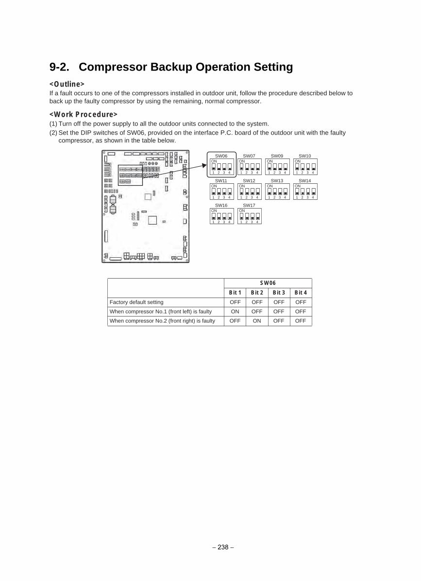
9-2. Compressor Backup Operation Setting<Outline>If a fault occurs to one of the compressors installed in outdoor unit, follow the procedure described below to back up the faulty compressor by using the remaining, normal compressor.
<Work Procedure>(1) Turn off the power supply to all the outdoor units connected to the system.(2) Set the DIP switches of SW06, provided on the interface P.C. board of the outdoor unit with the faulty
compressor, as shown in the table below.
SW06
Bit 1 Bit 2 Bit 3 Bit 4
FFOFFOFFOFFOgnittes tluafed yrotcaF
When compressor No.1 (front left) is faulty ON OFF OFF OFF
When compressor No.2 (front right) is faulty OFF ON OFF OFF
1 2 3 4 1 2 3 4 1 2 3 4 1 2 3 4
1 2 3 4 1 2 3 4 1 2 3 4 1 2 3 4
SW06 SW07 SW09 SW10
SW11 SW12
1 2 3 4 1 2 3 4
SW16 SW17
SW13 SW14
− 238 −
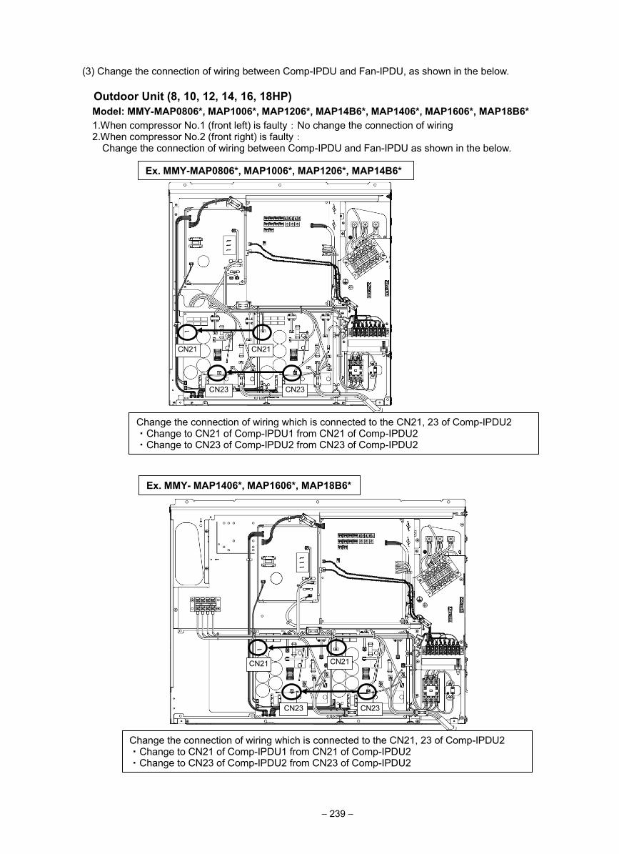
(3) Change the connection of wiring between Comp-IPDU and Fan-IPDU, as shown in the below.
Outdoor Unit (8, 10, 12, 14, 16, 18HP) Model: MMY-MAP0806*, MAP1006*, MAP1206*, MAP14B6*, MAP1406*, MAP1606*, MAP18B6* 1.When compressor No.1 (front left) is faulty:No change the connection of wiring 2.When compressor No.2 (front right) is faulty:
Change the connection of wiring between Comp-IPDU and Fan-IPDU as shown in the below.
CN21
CN23
CN21
CN23
CN21
CN23
CN21
CN23
Change the connection of wiring which is connected to the CN21, 23 of Comp-IPDU2 ・Change to CN21 of Comp-IPDU1 from CN21 of Comp-IPDU2 ・Change to CN23 of Comp-IPDU2 from CN23 of Comp-IPDU2
Change the connection of wiring which is connected to the CN21, 23 of Comp-IPDU2 ・Change to CN21 of Comp-IPDU1 from CN21 of Comp-IPDU2 ・Change to CN23 of Comp-IPDU2 from CN23 of Comp-IPDU2
Ex. MMY-MAP0806*, MAP1006*, MAP1206*, MAP14B6*
Ex. MMY- MAP1406*, MAP1606*, MAP18B6*
− 239 −
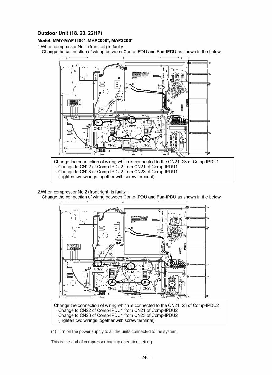
Outdoor Unit (18, 20, 22HP) Model: MMY-MAP1806*, MAP2006*, MAP2206* 1.When compressor No.1 (front left) is faulty:
Change the connection of wiring between Comp-IPDU and Fan-IPDU as shown in the below.
2.When compressor No.2 (front right) is faulty: Change the connection of wiring between Comp-IPDU and Fan-IPDU as shown in the below.
CN22
CN23
CN21
CN23
Change the connection of wiring which is connected to the CN21, 23 of Comp-IPDU1 ・Change to CN22 of Comp-IPDU2 from CN21 of Comp-IPDU1 ・Change to CN23 of Comp-IPDU2 from CN23 of Comp-IPDU1
(Tighten two wirings together with screw terminal)
Change the connection of wiring which is connected to the CN21, 23 of Comp-IPDU2 ・Change to CN22 of Comp-IPDU1 from CN21 of Comp-IPDU2 ・Change to CN23 of Comp-IPDU1 from CN23 of Comp-IPDU2
(Tighten two wirings together with screw terminal)
CN22
CN23
CN21
CN23
(4) Turn on the power supply to all the units connected to the system.
This is the end of compressor backup operation setting.
− 240 −
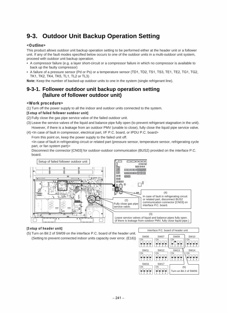
<Outline>This product allows outdoor unit backup operation setting to be performed either at the header unit or a follower unit. If any of the fault modes specified below occurs to one of the outdoor units in a multi-outdoor unit system, proceed with outdoor unit backup operation.• A compressor failure (e.g. a layer short-circuit or a compressor failure in which no compressor is available to
back up the faulty compressor)• A failure of a pressure sensor (Pd or Ps) or a temperature sensor (TD1, TD2, TS1, TS3, TE1, TE2, TG1, TG2,
TK1, TK2, TK4, TK5, TL1, TL2 or TL3)Note: Keep the number of backed-up outdoor units to one in the system (single refrigerant line).
<Work procedure>(1) Turn off the power supply to all the indoor and outdoor units connected to the system.[Setup of failed follower outdoor unit](2) Fully close the gas pipe service valve of the failed outdoor unit.(3) Leave the service valves of the liquid and balance pipe fully open (to prevent refrigerant stagnation in the unit).
However, if there is a leakage from an outdoor PMV (unable to close), fully close the liquid pipe service valve.(4) <In case of fault in compressor, electrical part, I/F P.C. board, or IPDU P.C. board>
From this point on, keep the power supply to the failed unit off.<In case of fault in refrigerating circuit or related part (pressure sensor, temperature sensor, refrigerating cycle part, or fan system part)>Disconnect the connector [CN03] for outdoor-outdoor communication (BUS2) provided on the interface P.C. board.
[Setup of header unit](5) Turn on Bit 2 of SW09 on the interface P.C. board of the header unit.
(Setting to prevent connected indoor units capacity over error. (E16))
Setup of failed follower outdoor unit
(2)
(3)
(4)
CN
03B
US
2
Fully close gas pipe service valve.
Leave service valves of liquid and balance pipes fully open.(if there is leakage from outdoor PMV, fully close liquid pipe.)
In case of fault in refrigerating circuit or related part, disconnect BUS2 communication connector [CN03] on interface P.C. board.
1 2 3 4 1 2 3 4 1 2 3 4 1 2 3 4
1 2 3 4 1 2 3 4 1 2 3 4 1 2 3 4
SW06 SW07 SW09 SW10
SW11 SW12
1 2 3 4 1 2 3 4
SW16 SW17
SW13 SW14
Interface P.C. board of header unit
(5)
Turn on Bit 2 of SW09.
9-3. Outdoor Unit Backup Operation Setting
9-3-1. Follower outdoor unit backup operation setting (failure of follower outdoor unit)
− 241 −
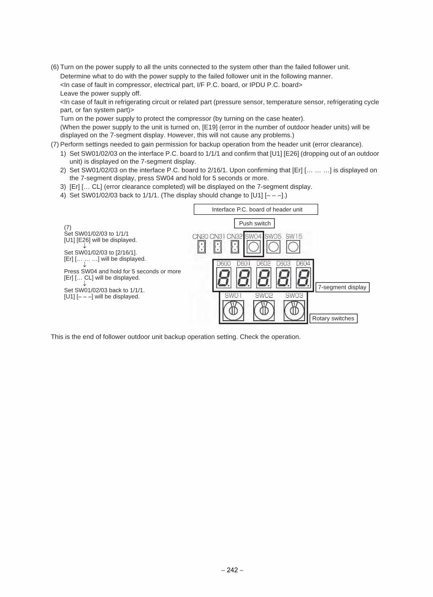
(6) Turn on the power supply to all the units connected to the system other than the failed follower unit.Determine what to do with the power supply to the failed follower unit in the following manner.<In case of fault in compressor, electrical part, I/F P.C. board, or IPDU P.C. board>Leave the power supply off.<In case of fault in refrigerating circuit or related part (pressure sensor, temperature sensor, refrigerating cycle part, or fan system part)>Turn on the power supply to protect the compressor (by turning on the case heater). (When the power supply to the unit is turned on, [E19] (error in the number of outdoor header units) will be displayed on the 7-segment display. However, this will not cause any problems.)
(7) Perform settings needed to gain permission for backup operation from the header unit (error clearance).1) Set SW01/02/03 on the interface P.C. board to 1/1/1 and confirm that [U1] [E26] (dropping out of an outdoor
unit) is displayed on the 7-segment display.2) Set SW01/02/03 on the interface P.C. board to 2/16/1. Upon confirming that [Er] [… … …] is displayed on
the 7-segment display, press SW04 and hold for 5 seconds or more.3) [Er] [… CL] (error clearance completed) will be displayed on the 7-segment display.4) Set SW01/02/03 back to 1/1/1. (The display should change to [U1] [– – –].)
This is the end of follower outdoor unit backup operation setting. Check the operation.
Push switch
7-segment display
Rotary switches
Interface P.C. board of header unit
(7)Set SW01/02/03 to 1/1/1[U1] [E26] will be displayed.
Set SW01/02/03 to [2/16/1].[Er] [… … …] will be displayed.
Press SW04 and hold for 5 seconds or more[Er] [… CL] will be displayed.
Set SW01/02/03 back to 1/1/1.[U1] [– – –] will be displayed.
− 242 −
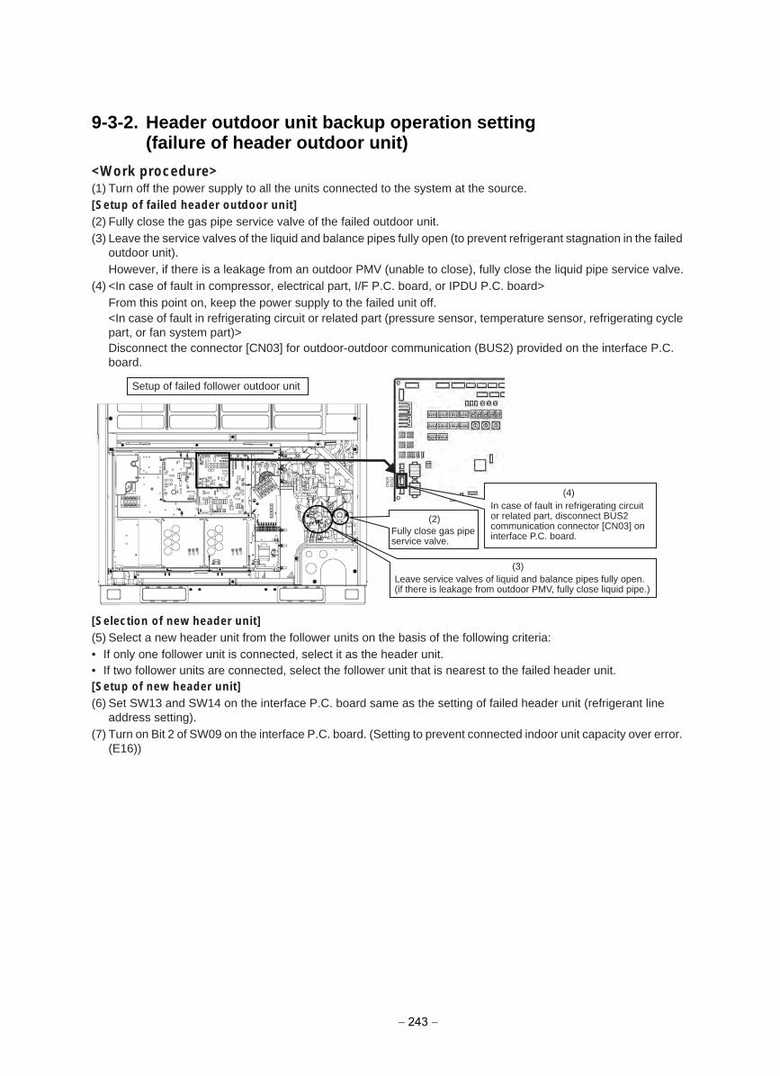
9-3-2. Header outdoor unit backup operation setting(failure of header outdoor unit)
<Work procedure>(1) Turn off the power supply to all the units connected to the system at the source.[Setup of failed header outdoor unit](2) Fully close the gas pipe service valve of the failed outdoor unit.(3) Leave the service valves of the liquid and balance pipes fully open (to prevent refrigerant stagnation in the failed
outdoor unit). However, if there is a leakage from an outdoor PMV (unable to close), fully close the liquid pipe service valve.
(4) <In case of fault in compressor, electrical part, I/F P.C. board, or IPDU P.C. board>From this point on, keep the power supply to the failed unit off.<In case of fault in refrigerating circuit or related part (pressure sensor, temperature sensor, refrigerating cycle part, or fan system part)>Disconnect the connector [CN03] for outdoor-outdoor communication (BUS2) provided on the interface P.C. board.
[Selection of new header unit](5) Select a new header unit from the follower units on the basis of the following criteria:• If only one follower unit is connected, select it as the header unit.• If two follower units are connected, select the follower unit that is nearest to the failed header unit.[Setup of new header unit](6) Set SW13 and SW14 on the interface P.C. board same as the setting of failed header unit (refrigerant line
address setting).(7) Turn on Bit 2 of SW09 on the interface P.C. board. (Setting to prevent connected indoor unit capacity over error.
(E16))
Setup of failed follower outdoor unit
(2)
(3)
(4)
CN
03B
US
2
Fully close gas pipe service valve.
Leave service valves of liquid and balance pipes fully open.(if there is leakage from outdoor PMV, fully close liquid pipe.)
In case of fault in refrigerating circuit or related part, disconnect BUS2 communication connector [CN03] on interface P.C. board.
− 243 −
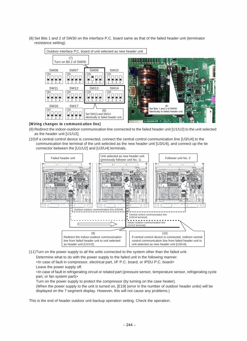
(8) Set Bits 1 and 2 of SW30 on the interface P.C. board same as that of the failed header unit (terminatorresistance setting).
[Wiring changes to communication line](9) Redirect the indoor-outdoor communication line connected to the failed header unit [U1/U2] to the unit selected
as the header unit [U1/U2].(10)If a central control device is connected, connect the central control communication line [U3/U4] to the
communication line terminal of the unit selected as the new header unit [U3/U4], and connect up the tieconnector between the [U1/U2] and [U3/U4] terminals.
(11)Turn on the power supply to all the units connected to the system other than the failed unit.Determine what to do with the power supply to the failed unit in the following manner.<In case of fault in compressor, electrical part, I/F P.C. board, or IPDU P.C. board>Leave the power supply off.<In case of fault in refrigerating circuit or related part (pressure sensor, temperature sensor, refrigerating cyclepart, or fan system part)>Turn on the power supply to protect the compressor (by turning on the case heater).(When the power supply to the unit is turned on, [E19] (error in the number of outdoor header units) will be displayed on the 7-segment display. However, this will not cause any problems.)
This is the end of header outdoor unit backup operation setting. Check the operation.
1 2 3 4 1 2 3 4 1 2 3 4 1 2 3 4
1 2 3 4 1 2 3 4 1 2 3 4 1 2 3 4
SW06 SW07 SW09 SW10
SW11 SW12
1 2 3 4 1 2 3 4
SW16 SW17
SW13 SW14
(6)
Outdoor interface P.C. board of unit selected as new header unit
(7)Turn on Bit 2 of SW09.
Set SW13 and SW14 identically to failed header unit.
(10)
Failed header unit
Outdoor-outdoor communication line (U5/U6)
(9)Redirect the indoor-outdoor communication line from failed header unit to unit selected as header unit [U1/U2].
If central control device is connected, redirect central control communication line from failed header unit to unit selected as new header unit [U3/U4].
Unit selected as new header unit (previously follower unit No. 1)
Central control communication line (U3/U4 terminal)
Indoor-outdoor communication line (U1/U2 terminal)
Follower unit No. 2
(8) Set Bits 1 and 2 of SW30 identically to failed header unit.
− 244 −
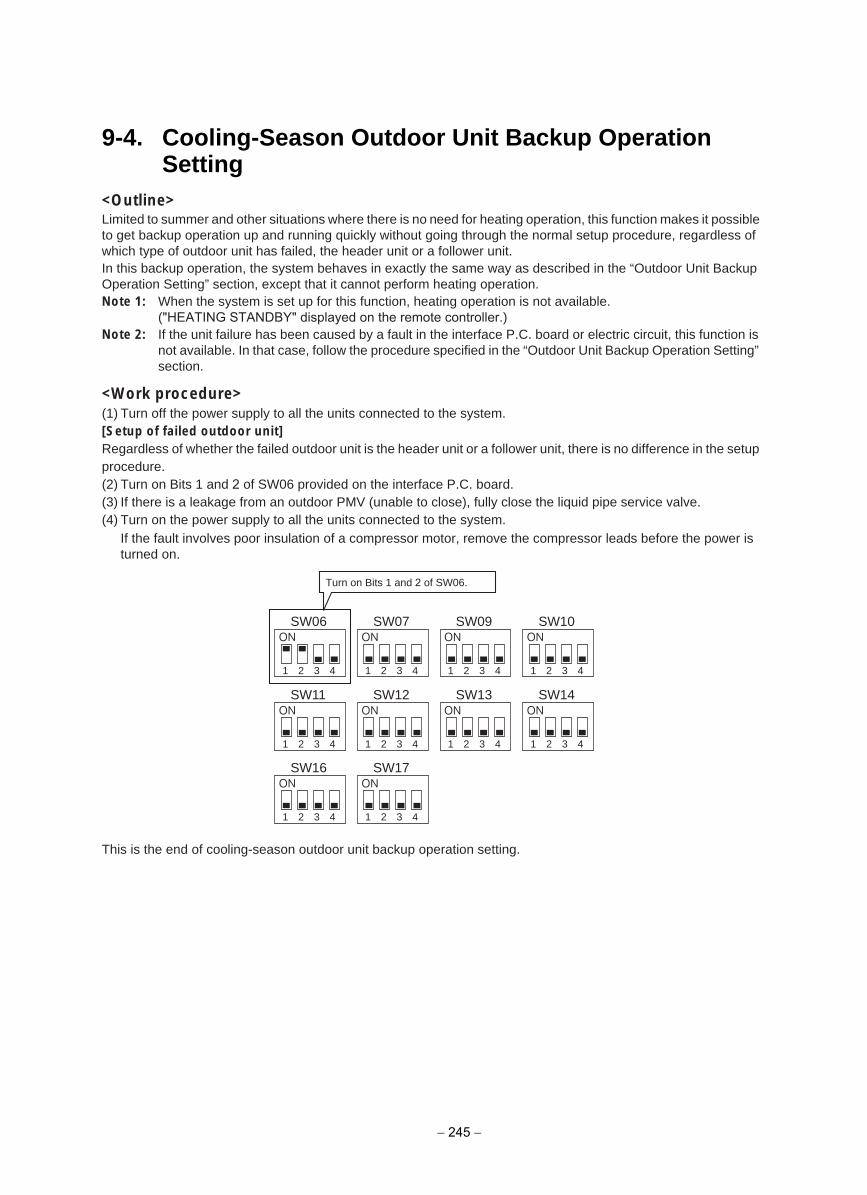
9-4. Cooling-Season Outdoor Unit Backup Operation Setting
<Outline>Limited to summer and other situations where there is no need for heating operation, this function makes it possible to get backup operation up and running quickly without going through the normal setup procedure, regardless of which type of outdoor unit has failed, the header unit or a follower unit.In this backup operation, the system behaves in exactly the same way as described in the “Outdoor Unit Backup Operation Setting” section, except that it cannot perform heating operation.Note 1: When the system is set up for this function, heating operation is not available.
("HEATING STANDBY" displayed on the remote controller.)Note 2: If the unit failure has been caused by a fault in the interface P.C. board or electric circuit, this function is
not available. In that case, follow the procedure specified in the “Outdoor Unit Backup Operation Setting” section.
<Work procedure>(1) Turn off the power supply to all the units connected to the system.[Setup of failed outdoor unit]Regardless of whether the failed outdoor unit is the header unit or a follower unit, there is no difference in the setup procedure.(2) Turn on Bits 1 and 2 of SW06 provided on the interface P.C. board.(3) If there is a leakage from an outdoor PMV (unable to close), fully close the liquid pipe service valve.(4) Turn on the power supply to all the units connected to the system.
If the fault involves poor insulation of a compressor motor, remove the compressor leads before the power is turned on.
This is the end of cooling-season outdoor unit backup operation setting.
1 2 3 4 1 2 3 4 1 2 3 4 1 2 3 4
1 2 3 4 1 2 3 4 1 2 3 4 1 2 3 4
SW06 SW07 SW09 SW10
SW11 SW12
1 2 3 4 1 2 3 4
SW16 SW17
SW13 SW14
Turn on Bits 1 and 2 of SW06.
− 245 −
This product supports refrigerant pump-down, a function which allows refrigerant to be recovered from an outdoor unit in need of repair using a normal outdoor unit in a system featuring multiple outdoor units.
When performing pump-down operation, take note of the following matters: Note 1: The pump-down refrigerant recovery rate changes with outside temperature and other factors.
After pump-down is completed, recover any residual gas using a refrigerant recovery device, etc., and be sure to measure the amount of recovered refrigerant. (The refrigerant recovery rate can be improved by heating the accumulator of the outdoor unit to be repaired during pump-down operation.)
Note 2: If pump-down has been performed, the system cannot be operated until the faulty outdoor unit is repaired.(Continued operation would be impossible due to a refrigerant overcharge.)
Note 3: If outdoor PMVs 1 and 3 both happen to be faulty (unable to open) the refrigerant in the heat exchangers cannot be recovered. In that case, recover any residual gas in the heat exchangers using a tube piercing valve or some other tool. After a pump-down operation, do not perform any brazing until the residual gas in the heat exchangers is recovered.
<Work procedure>Turn on the power supply to the system at the source, but leave the system switched off.If the fault involves poor insulation of a compressor motor, remove the motor leads before the power is turned on.[Setup of failed outdoor unit](1) Connect the check joint of liquid pipe and the low pressure-side check joint using a charge hose, and purge the
hose of air (to recover refrigerant from the liquid tank and heat exchangers).(2) Fully close the liquid pipe service valve of the failed outdoor unit.
(Leave the service valves of the gas and balance pipes fully open.)(3) If the oil is likely to has degraded due to a compressor fault, disconnect the SV3A valve connector of the failed
outdoor unit (to prevent the degraded oil from flowing into other outdoor units).(4) Set SW01/02/03 on the interface P.C. board of the failed outdoor unit to 2/11/1. After [rd] [… … …] is displayed
on the 7-segment display, press SW04 and hold for 5 seconds or more.
10 OUTDOOR UNIT REFRIGERANTRECOVERY METHOD
10-1. Refrigerant Recovery from Failed Outdoor Unit (Pump-Down)
10-1-1. Note for refrigerant recovery operation
10-1-2. Refrigerant recovery procedure A (Case of no outdoor unit backup operation setting)
− 246 −
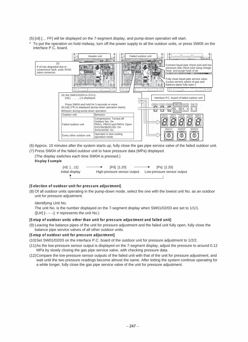
(5) [rd] [… FF] will be displayed on the 7-segment display, and pump-down operation will start.* To put the operation on hold midway, turn off the power supply to all the outdoor units, or press SW05 on the
interface P.C. board.
(6) Approx. 10 minutes after the system starts up, fully close the gas pipe service valve of the failed outdoor unit.(7) Press SW04 of the failed outdoor unit to have pressure data (MPa) displayed.
(The display switches each time SW04 is pressed.)Display Example
[Selection of outdoor unit for pressure adjustment](8) Of all outdoor units operating in the pump-down mode, select the one with the lowest unit No. as an outdoor
unit for pressure adjustment.
Identifying Unit No.The unit No. is the number displayed on the 7-segment display when SW01/02/03 are set to 1/1/1.([U#] [– – –]: # represents the unit No.)
[Setup of outdoor units other than unit for pressure adjustment and failed unit](9) Leaving the balance pipes of the unit for pressure adjustment and the failed unit fully open, fully close the
balance pipe service valves of all other outdoor units.[Setup of outdoor unit for pressure adjustment](10)Set SW01/02/03 on the interface P.C. board of the outdoor unit for pressure adjustment to 1/2/2.(11)As the low-pressure sensor output is displayed on the 7-segment display, adjust the pressure to around 0.12
MPa by slowly closing the gas pipe service valve, with checking pressure data.(12)Compare the low-pressure sensor outputs of the failed unit with that of the unit for pressure adjustment, and
wait until the two pressure readings become almost the same. After letting the system continue operating fora while longer, fully close the gas pipe service valve of the unit for pressure adjustment.
Failed outdoor unitHeader unit
Interface P.C. board of failed outdoor unit
(3)Connect liquid pipe check joint and low pressure-side check joint using charge hose, and purge hose of air
Fully close liquid pipe service valve.(Leave service valves of gas and balance pipes fully open.)
If oil has degraded due to compressor fault, undo SV3Avalve connector.
(4) Set SW01/02/03 to 2/11/1.[rd] [… … …] is displayed.
Press SW04 and hold for 5 seconds or more.(5) [rd] [ FF] is displayed (pump-down operation starts).Behavior during pump-down operationOutdoor unit Behavior
Failed outdoor unit
Compressors: Turned off Outdoor fan: OnPMV1, PMV3 and PMV4: Open SV2/3A/3B/3C/3D: On SV41/42/52: On
Every other outdoor unit Operates in test coolingoperation mode
[rd] […11]Initial display
[Pd] [1.20]High-pressure sensor output
[Ps] [1.20]Low-pressure sensor output
− 247 −
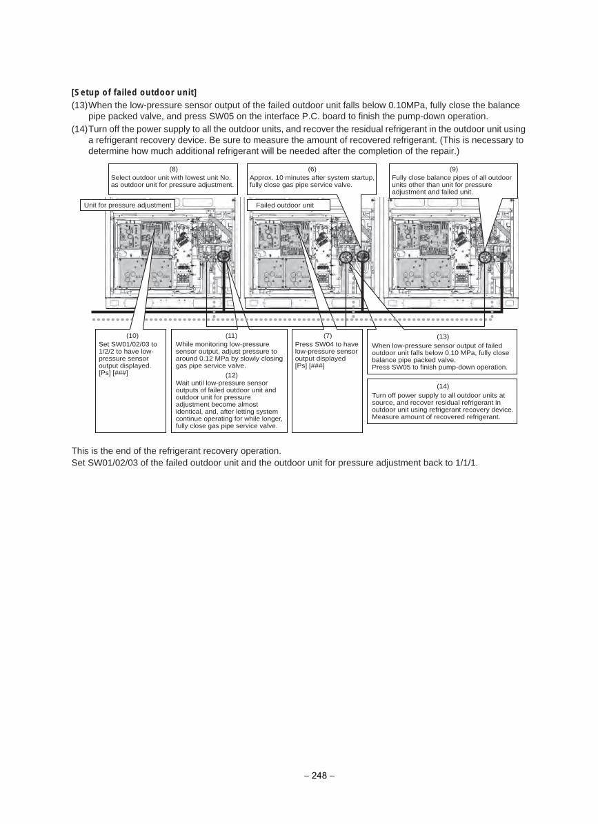
[Setup of failed outdoor unit](13)When the low-pressure sensor output of the failed outdoor unit falls below 0.10MPa, fully close the balance
pipe packed valve, and press SW05 on the interface P.C. board to finish the pump-down operation.(14)Turn off the power supply to all the outdoor units, and recover the residual refrigerant in the outdoor unit using
a refrigerant recovery device. Be sure to measure the amount of recovered refrigerant. (This is necessary todetermine how much additional refrigerant will be needed after the completion of the repair.)
This is the end of the refrigerant recovery operation.Set SW01/02/03 of the failed outdoor unit and the outdoor unit for pressure adjustment back to 1/1/1.
Failed outdoor unitUnit for pressure adjustment
(9)(6)
(11)
(12)
(14)
(13)
Approx. 10 minutes after system startup, fully close gas pipe service valve.
(8)Select outdoor unit with lowest unit No. as outdoor unit for pressure adjustment.
Fully close balance pipes of all outdoor units other than unit for pressure adjustment and failed unit.
While monitoring low-pressure sensor output, adjust pressure to around 0.12 MPa by slowly closing gas pipe service valve.
When low-pressure sensor output of failed outdoor unit falls below 0.10 MPa, fully close balance pipe packed valve.Press SW05 to finish pump-down operation.
Turn off power supply to all outdoor units at source, and recover residual refrigerant in outdoor unit using refrigerant recovery device. Measure amount of recovered refrigerant.
Wait until low-pressure sensor outputs of failed outdoor unit and outdoor unit for pressure adjustment become almost identical, and, after letting system continue operating for while longer,fully close gas pipe service valve.
(7)Press SW04 to have low-pressure sensor output displayed[Ps] [###]
(10)Set SW01/02/03 to 1/2/2 to have low-pressure sensor output displayed.[Ps] [###]
− 248 −
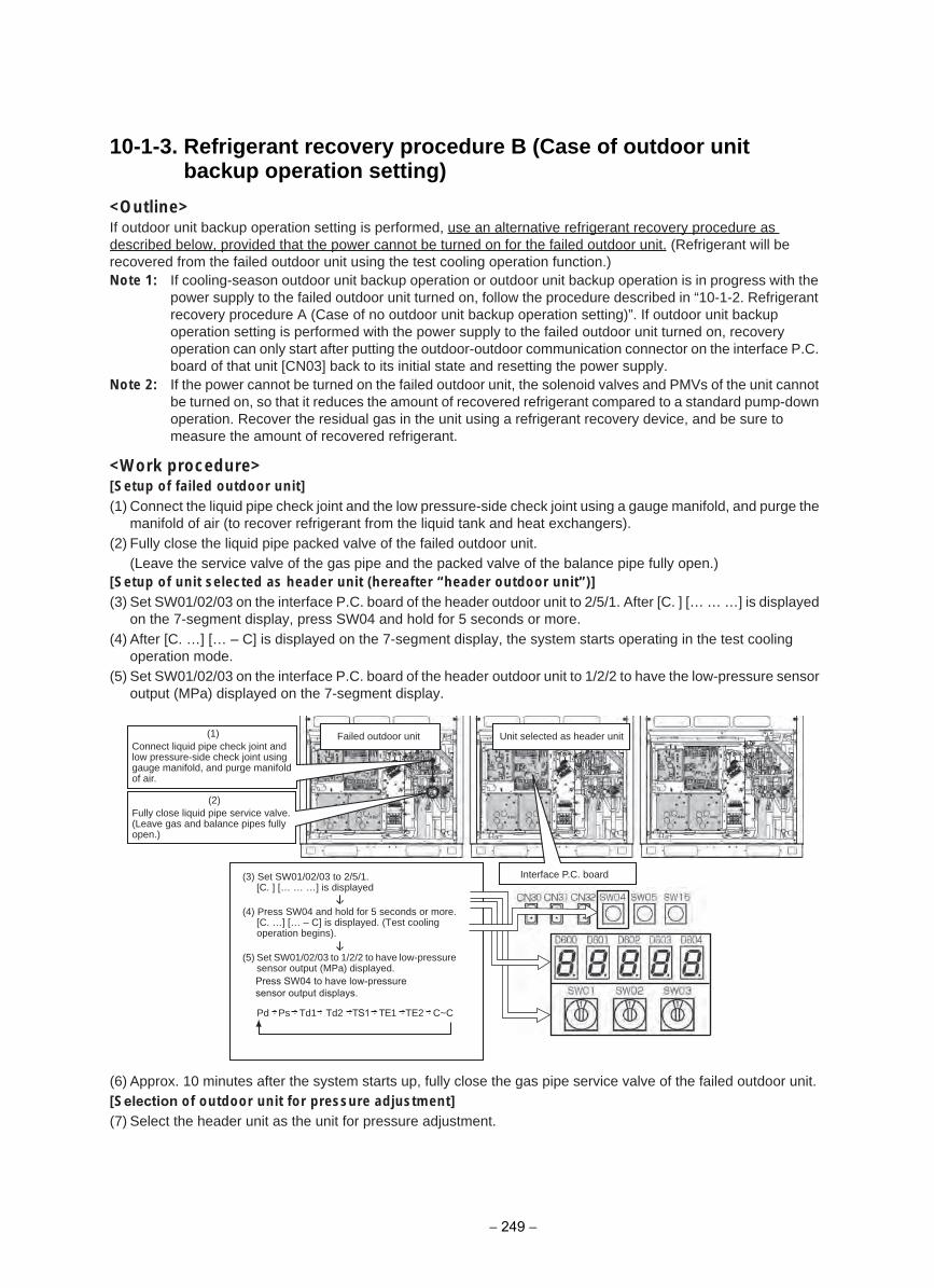
10-1-3. Refrigerant recovery procedure B (Case of outdoor unit backup operation setting)
<Outline>If outdoor unit backup operation setting is performed, use an alternative refrigerant recovery procedure as described below, provided that the power cannot be turned on for the failed outdoor unit. (Refrigerant will be recovered from the failed outdoor unit using the test cooling operation function.)Note 1: If cooling-season outdoor unit backup operation or outdoor unit backup operation is in progress with the
power supply to the failed outdoor unit turned on, follow the procedure described in “10-1-2. Refrigerantrecovery procedure A (Case of no outdoor unit backup operation setting)”. If outdoor unit backupoperation setting is performed with the power supply to the failed outdoor unit turned on, recoveryoperation can only start after putting the outdoor-outdoor communication connector on the interface P.C. board of that unit [CN03] back to its initial state and resetting the power supply.
Note 2: If the power cannot be turned on the failed outdoor unit, the solenoid valves and PMVs of the unit cannotbe turned on, so that it reduces the amount of recovered refrigerant compared to a standard pump-downoperation. Recover the residual gas in the unit using a refrigerant recovery device, and be sure to measure the amount of recovered refrigerant.
<Work procedure>[Setup of failed outdoor unit](1) Connect the liquid pipe check joint and the low pressure-side check joint using a gauge manifold, and purge the
manifold of air (to recover refrigerant from the liquid tank and heat exchangers).(2) Fully close the liquid pipe packed valve of the failed outdoor unit.
(Leave the service valve of the gas pipe and the packed valve of the balance pipe fully open.)[Setup of unit selected as header unit (hereafter “header outdoor unit”)](3) Set SW01/02/03 on the interface P.C. board of the header outdoor unit to 2/5/1. After [C. ] [… … …] is displayed
on the 7-segment display, press SW04 and hold for 5 seconds or more.(4) After [C. …] [… – C] is displayed on the 7-segment display, the system starts operating in the test cooling
operation mode.(5) Set SW01/02/03 on the interface P.C. board of the header outdoor unit to 1/2/2 to have the low-pressure sensor
output (MPa) displayed on the 7-segment display.
(6) Approx. 10 minutes after the system starts up, fully close the gas pipe service valve of the failed outdoor unit.[Selection of outdoor unit for pressure adjustment](7) Select the header unit as the unit for pressure adjustment.
(1)
(2)
Pd Ps Td1 Td2 TS1 TE1 TE2 C~C
Connect liquid pipe check joint and low pressure-side check joint using gauge manifold, and purge manifold of air.
Failed outdoor unit Unit selected as header unit
Interface P.C. board
Fully close liquid pipe service valve.(Leave gas and balance pipes fully open.)
(3) Set SW01/02/03 to 2/5/1.[C. ] [… … …] is displayed
(4) Press SW04 and hold for 5 seconds or more.[C. …] [… – C] is displayed. (Test coolingoperation begins).
(5) Set SW01/02/03 to 1/2/2 to have low-pressuresensor output (MPa) displayed.Press SW04 to have low-pressure sensor output displays.
− 249 −
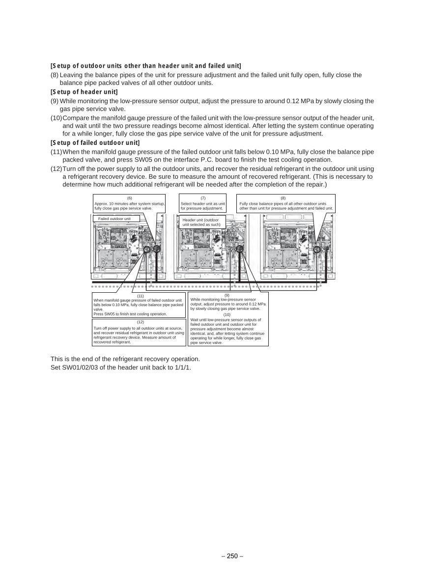
[Setup of outdoor units other than header unit and failed unit](8) Leaving the balance pipes of the unit for pressure adjustment and the failed unit fully open, fully close the
balance pipe packed valves of all other outdoor units.[Setup of header unit](9) While monitoring the low-pressure sensor output, adjust the pressure to around 0.12 MPa by slowly closing the
gas pipe service valve.(10)Compare the manifold gauge pressure of the failed unit with the low-pressure sensor output of the header unit,
and wait until the two pressure readings become almost identical. After letting the system continue operatingfor a while longer, fully close the gas pipe service valve of the unit for pressure adjustment.
[Setup of failed outdoor unit](11)When the manifold gauge pressure of the failed outdoor unit falls below 0.10 MPa, fully close the balance pipe
packed valve, and press SW05 on the interface P.C. board to finish the test cooling operation.(12)Turn off the power supply to all the outdoor units, and recover the residual refrigerant in the outdoor unit using
a refrigerant recovery device. Be sure to measure the amount of recovered refrigerant. (This is necessary todetermine how much additional refrigerant will be needed after the completion of the repair.)
This is the end of the refrigerant recovery operation.Set SW01/02/03 of the header unit back to 1/1/1.
(8)(6) (7)
(9)
(10)
(12)
(11)
Approx. 10 minutes after system startup, fully close gas pipe service valve.
Select header unit as unit for pressure adjustment.
Fully close balance pipes of all other outdoor units other than unit for pressure adjustment and failed unit.
Header unit (outdoor unit selected as such)
Wait until low-pressure sensor outputs of failed outdoor unit and outdoor unit for pressure adjustment become almost identical, and, after letting system continue operating for while longer, fully close gas pipe service valve.
While monitoring low-pressure sensor output, adjust pressure to around 0.12 MPa by slowly closing gas pipe service valve.
Turn off power supply to all outdoor units at source, and recover residual refrigerant in outdoor unit using refrigerant recovery device. Measure amount of recovered refrigerant.
When manifold gauge pressure of failed outdoor unit falls below 0.10 MPa, fully close balance pipe packed valve.Press SW05 to finish test cooling operation.
Failed outdoor unit
− 250 −
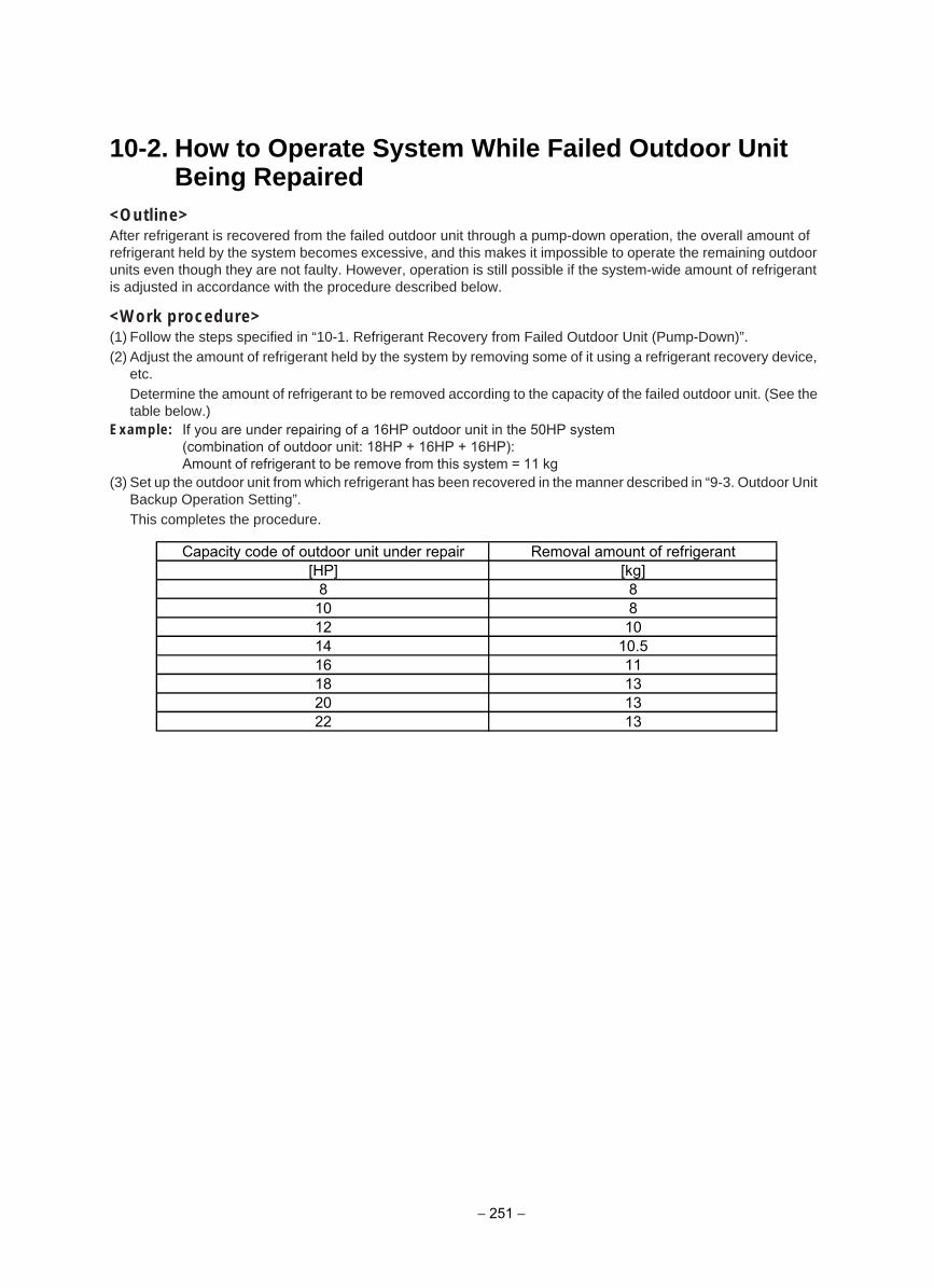
10-2. How to Operate System While Failed Outdoor Unit Being Repaired
<Outline>After refrigerant is recovered from the failed outdoor unit through a pump-down operation, the overall amount of refrigerant held by the system becomes excessive, and this makes it impossible to operate the remaining outdoor units even though they are not faulty. However, operation is still possible if the system-wide amount of refrigerant is adjusted in accordance with the procedure described below.
<Work procedure>(1) Follow the steps specified in “10-1. Refrigerant Recovery from Failed Outdoor Unit (Pump-Down)”.(2) Adjust the amount of refrigerant held by the system by removing some of it using a refrigerant recovery device,
etc.Determine the amount of refrigerant to be removed according to the capacity of the failed outdoor unit. (See the table below.)
Example: If you are under repairing of a 16HP outdoor unit in the 50HP system(combination of outdoor unit: 18HP + 16HP + 16HP):Amount of refrigerant to be remove from this system = 11 kg
(3) Set up the outdoor unit from which refrigerant has been recovered in the manner described in “9-3. Outdoor Unit Backup Operation Setting”.This completes the procedure.
Capacity code of outdoor unit under repair Removal amount of refrigerant[HP] [kg]
8 810 812 1014 10.516 1118 1320 1322 13
− 251 −
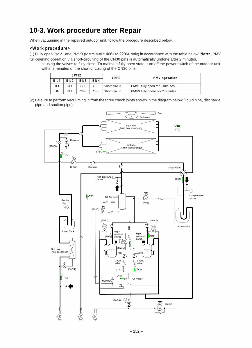
10-3. Work procedure after RepairWhen vacuuming in the repaired outdoor unit, follow the procedure described below.
<Work procedure>(1) Fully open PMV1 and PMV3 (MMY-MAP1406∗ to 2206∗ only) in accordance with the table below. Note: PMV full-opening operation via short-circuiting of the CN30 pins is automatically undone after 2 minutes,
causing the valves to fully close. To maintain fully open state, turn off the power switch of the outdoor unit within 2 minutes of the short-circuiting of the CN30 pins.
(2) Be sure to perform vacuuming in from the three check joints shown in the diagram below (liquid pipe, discharge pipe and suction pipe).
SW12CN30 PMV operation
Bit 1 Bit 2 Bit 3 Bit 4
OFF OFF OFF OFF Short-circuit PMV1 fully open for 2 minutes.
ON OFF OFF OFF Short-circuit PMV3 fully opens for 2 minutes.
(TD2)
(TE1)
(TK2) (TK1)
(TD1)
(TK4)
(TO)
SV
SV
SV SV
M
(TL1)
SV
SV
SV
(TK5)
(TS3)
(TL3)
Reducer
(SV3A)
(SV2)
(SV3D)
(SV42) (SV41)
(SV3C)
(PMV4)
(TS1)
(SV3B)
Fan Fan motor
Right side Main heat exchanger
Left side Main heat exchanger (PMV1)
4-way valve
High-pressure sensor
Low-pressure sensor Oil Separator
Fusible plug
Liquid Tank
Accumulator
High- pressure switch
High- pressure switch
Check valve
Check valve
Compressor 1
Oil Header
Sub cool heat exchanger
SV
(SV52) Reducer
FP
Compressor 2
Reducer
− 252 −
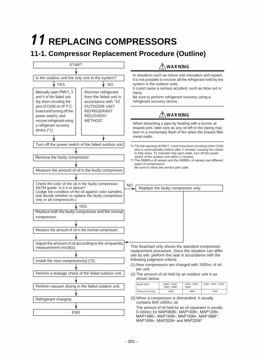
11 REPLACING COMPRESSORS11-1. Compressor Replacement Procedure (Outline)
NOYES
NO
START
Is the outdoor unit the only one in the system?
Recover refrigerant from the failed unit in accordance with “10 OUTDOOR UNIT REFRIGERANTRECOVERYMETHOD”.
Manually open PMV1, 3 and 4 of the failed unit (by short-circuiting the pins of CN30 on I/F P.C. board and turning off the power switch), and recover refrigerant using a refrigerant recovery device (*1).
Turn off the power switch of the failed outdoor unit.
Remove the faulty compressor.
Check the color of the oil in the faulty compressor.ASTM grade: Is it 4 or above?(Judge the condition of the oil against color samples, and decide whether to replace the faulty compressor only or all compressors.)
YESReplace both the faulty compressor and the normal compressor.
Measure the amount of oil in the normal compressor.
Adjust the amount of oil according to the oil quantity measurement result(s).
Install the new compressor(s) (*2).
Perform a leakage check of the failed outdoor unit.
Perform vacuum drying in the failed outdoor unit.
Refrigerant charging
END
Measure the amount of oil in the faulty compressor.
Replace the faulty compressor only.
WARNING
In situations such as indoor unit relocation and repairs, it is not possible to recover all the refrigerant held by the system in the outdoor units.It could cause a serious accident, such as blow out or injury.Be sure to perform refrigerant recovery using a refrigerant recovery device.
WARNING
When detaching a pipe by heating with a burner at brazed joint, take care as any oil left in the piping may burn in a momentary flash of fire when the brazed filler metal melts.
*1 The full-opening of PMV1, 3 and 4 via short-circuiting of the CN30 pins is automatically undone after 2 minutes, causing the valves to fully close. To maintain fully open state, turn off the power switch of the outdoor unit within 2 minutes.
*2 The SMMS-e (6 series) and the SMMS-i (4 series) use differenttypes of compressors.Be sure to check the service part code.
This flowchart only shows the standard compressor replacement procedure. Since the situation can differ site by site, perform the task in accordance with the following judgment criteria: (1) New compressors are charged with 1900cc of oil
per unit.(2) The amount of oil held by an outdoor unit is as
shown below.
(3) When a compressor is dismantled, it usually contains 800-1400cc oil.The amount of oil held by an oil separator is usually 0-1000cc for MAP0806∗, MAP1006∗, MAP1206∗, MAP14B6∗, MAP1406∗, MAP1606∗, MAP18B6*, MAP1806∗, MAP2006∗ and MAP2206*
Model MAP- 1806*, 2006*, 2206*
Amount of oil [cc] 4300 4800 5300
0806*, 1006*, 1206*, 14B6*
1406*, 1606*,18B6*
− 253 −
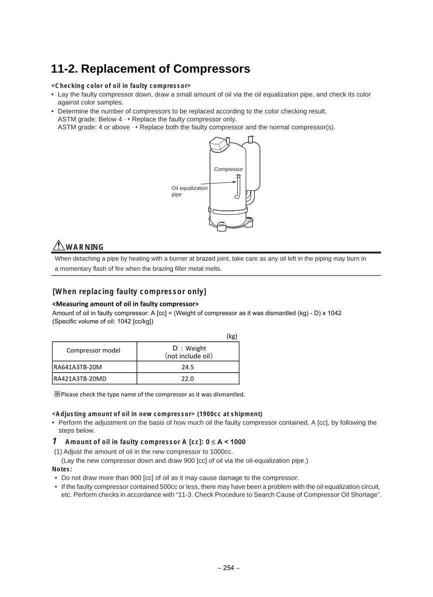
11-2. Replacement of Compressors<Checking color of oil in faulty compressor>• Lay the faulty compressor down, draw a small amount of oil via the oil equalization pipe, and check its color
against color samples.• Determine the number of compressors to be replaced according to the color checking result.
ASTM grade: Below 4 Replace the faulty compressor only.ASTM grade: 4 or above Replace both the faulty compressor and the normal compressor(s).
WARNINGWhen detaching a pipe by heating with a burner at brazed joint, take care as any oil left in the piping may burn in
a momentary flash of fire when the brazing filler metal melts.
<Adjusting amount of oil in new compressor> (1900cc at shipment)• Perform the adjustment on the basis of how much oil the faulty compressor contained, A [cc], by following the
steps below.
1 Amount of oil in faulty compressor A [cc]: 0 ≤ A < 1000(1) Adjust the amount of oil in the new compressor to 1000cc.
(Lay the new compressor down and draw 900 [cc] of oil via the oil-equalization pipe.)Notes:• Do not draw more than 900 [cc] of oil as it may cause damage to the compressor.• If the faulty compressor contained 500cc or less, there may have been a problem with the oil equalization circuit,
etc. Perform checks in accordance with “11-3. Check Procedure to Search Cause of Compressor Oil Shortage”.
Compressor
Oil equalization pipe
<Measuring amount of oil in faulty compressor>Amount of oil in faulty compressor: A [cc] = (Weight of compressor as it was dismantled (kg) - D) x 1042 (Specific volume of oil: 1042 [cc/kg])
(kg)
Compressor model
RA641A3TB-20M 24.5
RA421A3TB-20MD 22.0
※Please check the type name of the compressor as it was dismantled.
D:Weight
[When replacing faulty compressor only]
(not include oil)
− 254 −
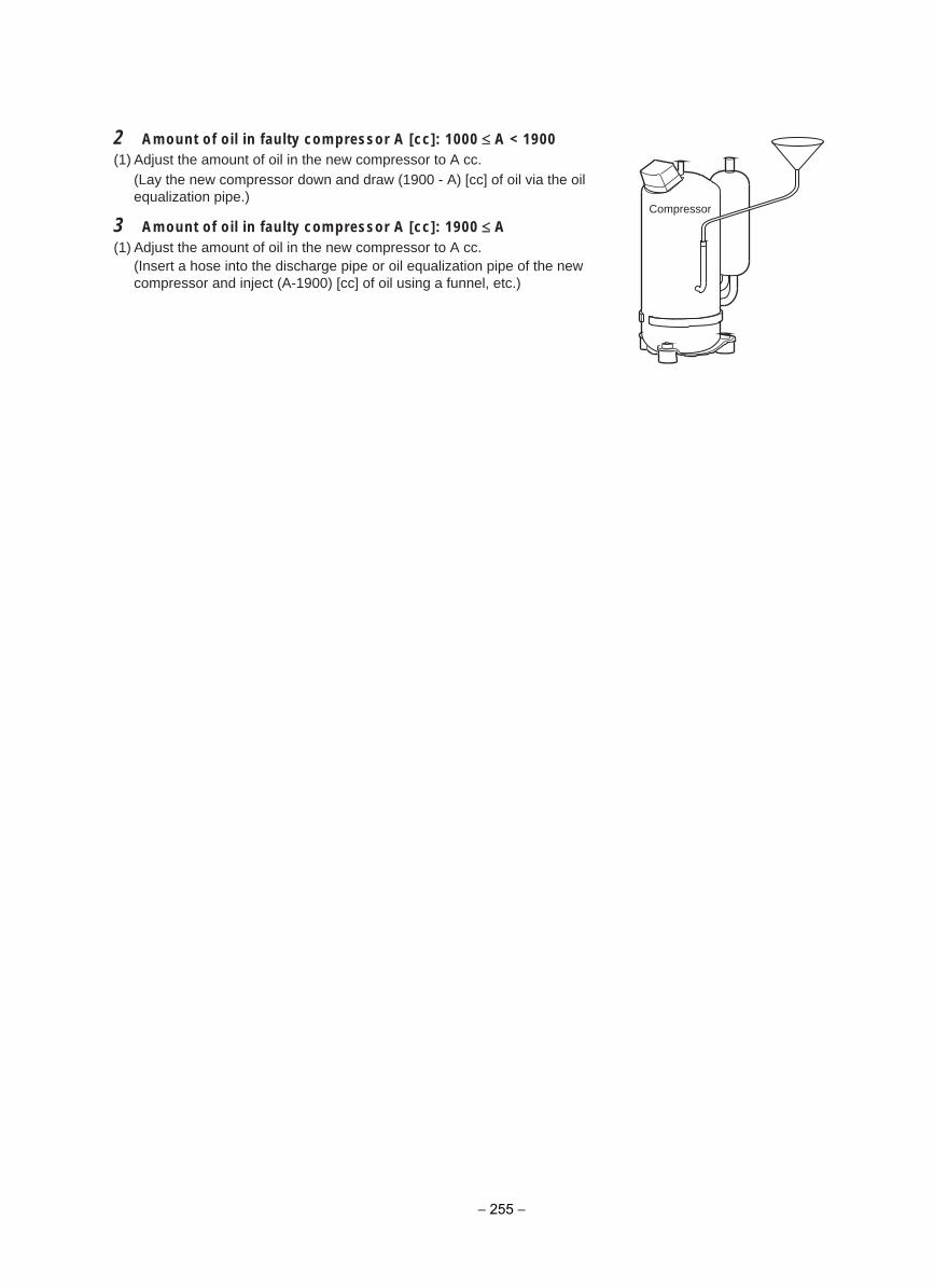
2 Amount of oil in faulty compressor A [cc]: 1000 ≤ A < 1900 (1) Adjust the amount of oil in the new compressor to A cc.
(Lay the new compressor down and draw (1900 - A) [cc] of oil via the oil equalization pipe.)
3 Amount of oil in faulty compressor A [cc]: 1900 ≤ A (1) Adjust the amount of oil in the new compressor to A cc.
(Insert a hose into the discharge pipe or oil equalization pipe of the new compressor and inject (A-1900) [cc] of oil using a funnel, etc.)
Compressor
− 255 −
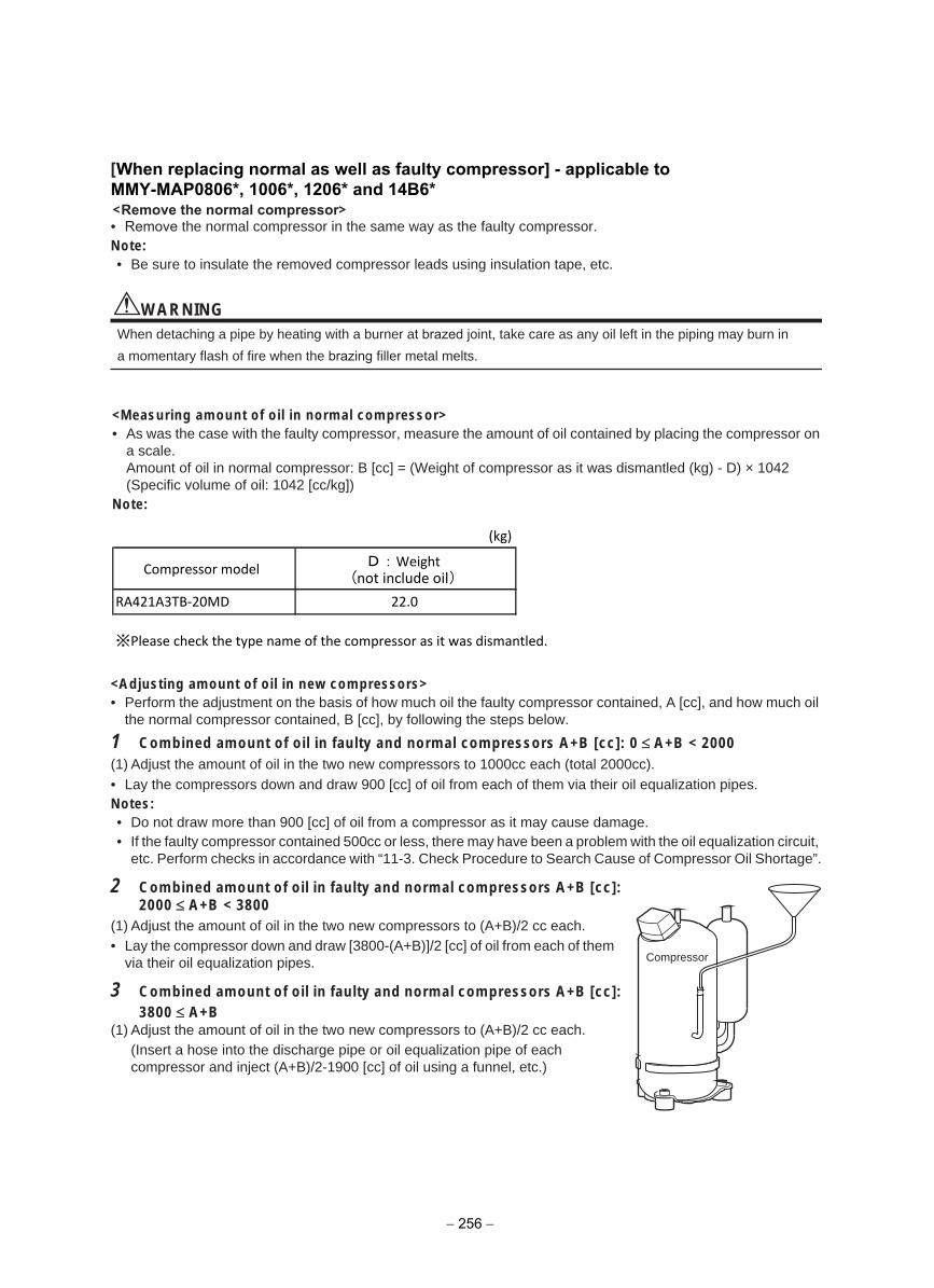
[When replacing normal as well as faulty compressor] - applicable toMMY-MAP0806*, 1006*, 1206* and 14B6*
• Remove the normal compressor in the same way as the faulty compressor.Note:• Be sure to insulate the removed compressor leads using insulation tape, etc.
WARNINGWhen detaching a pipe by heating with a burner at brazed joint, take care as any oil left in the piping may burn in
a momentary flash of fire when the brazing filler metal melts.
<Measuring amount of oil in normal compressor>• As was the case with the faulty compressor, measure the amount of oil contained by placing the compressor on
a scale.Amount of oil in normal compressor: B [cc] = (Weight of compressor as it was dismantled (kg) - D) × 1042(Specific volume of oil: 1042 [cc/kg])
Note:
(kg)
Compressor model
RA421A3TB-20MD 22.0
※Please check the type name of the compressor as it was dismantled.
<Adjusting amount of oil in new compressors>• Perform the adjustment on the basis of how much oil the faulty compressor contained, A [cc], and how much oil
the normal compressor contained, B [cc], by following the steps below.
1 Combined amount of oil in faulty and normal compressors A+B [cc]: 0 ≤ A+B < 2000 (1) Adjust the amount of oil in the two new compressors to 1000cc each (total 2000cc).• Lay the compressors down and draw 900 [cc] of oil from each of them via their oil equalization pipes.Notes:• Do not draw more than 900 [cc] of oil from a compressor as it may cause damage.• If the faulty compressor contained 500cc or less, there may have been a problem with the oil equalization circuit,
etc. Perform checks in accordance with “11-3. Check Procedure to Search Cause of Compressor Oil Shortage”.
2 Combined amount of oil in faulty and normal compressors A+B [cc]:2000 ≤ A+B < 3800
(1) Adjust the amount of oil in the two new compressors to (A+B)/2 cc each.• Lay the compressor down and draw [3800-(A+B)]/2 [cc] of oil from each of them
via their oil equalization pipes.
3 Combined amount of oil in faulty and normal compressors A+B [cc]:3800 ≤ A+B
(1) Adjust the amount of oil in the two new compressors to (A+B)/2 cc each.(Insert a hose into the discharge pipe or oil equalization pipe of each compressor and inject (A+B)/2-1900 [cc] of oil using a funnel, etc.)
Compressor
D:Weight (not include oil)
− 256 −
<Remove the normal compressor>
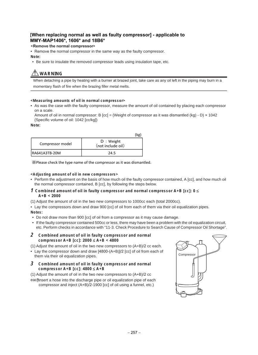
• Remove the normal compressor in the same way as the faulty compressor.Note:• Be sure to insulate the removed compressor leads using insulation tape, etc.
WARNINGWhen detaching a pipe by heating with a burner at brazed joint, take care as any oil left in the piping may burn in a
momentary flash of fire when the brazing filler metal melts.
<Measuring amounts of oil in normal compressor>• As was the case with the faulty compressor, measure the amount of oil contained by placing each compressor
on a scale.Amount of oil in normal compressor: B [cc] = (Weight of compressor as it was dismantled (kg) - D) × 1042 (Specific volume of oil: 1042 [cc/kg])
Note:
(kg)
Compressor model
RA641A3TB-20M 24.5
※Please check the type name of the compressor as it was dismantled.
<Adjusting amount of oil in new compressors>• Perform the adjustment on the basis of how much oil the faulty compressor contained, A [cc], and how much oil
the normal compressor contained, B [cc], by following the steps below.
1 Combined amount of oil in faulty compressor and normal compressor A+B [cc]: 0 ≤A+B < 2000
(1) Adjust the amount of oil in the two new compressors to 1000cc each (total 2000cc).• Lay the compressors down and draw 900 [cc] of oil from each of them via their oil equalization pipes.Notes:• Do not draw more than 900 [cc] of oil from a compressor as it may cause damage.• If the faulty compressor contained 500cc or less, there may have been a problem with the oil equalization circuit,
etc. Perform checks in accordance with “11-3. Check Procedure to Search Cause of Compressor Oil Shortage”.
2 Combined amount of oil in faulty compressor and normalcompressor A+B [cc]: 2000 ≤ A+B < 4800
(1) Adjust the amount of oil in the two new compressors to (A+B)/2 cc each.• Lay the compressor down and draw [4800-(A+B)]/2 [cc] of oil from each of
them via their oil equalization pipes.
3 Combined amount of oil in faulty compressor and normalcompressor A+B [cc]: 4800 ≤ A+B
(1) Adjust the amount of oil in the two new compressors to (A+B)/2 cc each.(Insert a hose into the discharge pipe or oil equalization pipe of each
compressor and inject (A+B)/2-1900 [cc] of oil using a funnel, etc.)
Compressor
D:Weight (not include oil)
− 257 −
[When replacing normal as well as faulty compressor] - applicable toMMY-MAP1406*, 1606* and 18B6*<Remove the normal compressor>
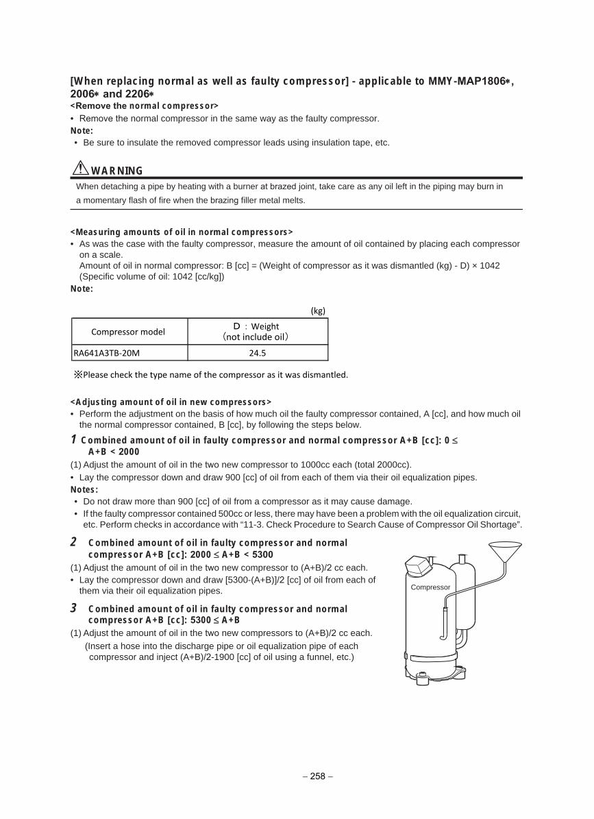
[When replacing normal as well as faulty compressor] - applicable to MMY-MAP1806∗,2006∗ and 2206∗<Remove the normal compressor>• Remove the normal compressor in the same way as the faulty compressor.Note:• Be sure to insulate the removed compressor leads using insulation tape, etc.
WARNINGWhen detaching a pipe by heating with a burner at brazed joint, take care as any oil left in the piping may burn in
a momentary flash of fire when the brazing filler metal melts.
<Measuring amounts of oil in normal compressors>• As was the case with the faulty compressor, measure the amount of oil contained by placing each compressor
on a scale.Amount of oil in normal compressor: B [cc] = (Weight of compressor as it was dismantled (kg) - D) × 1042 (Specific volume of oil: 1042 [cc/kg])
Note:
(kg)
Compressor model
RA641A3TB-20M 24.5
※Please check the type name of the compressor as it was dismantled.
<Adjusting amount of oil in new compressors>• Perform the adjustment on the basis of how much oil the faulty compressor contained, A [cc], and how much oil
the normal compressor contained, B [cc], by following the steps below.
1 Combined amount of oil in faulty compressor and normal compressor A+B [cc]: 0 ≤A+B < 2000
(1) Adjust the amount of oil in the two new compressor to 1000cc each (total 2000cc).• Lay the compressor down and draw 900 [cc] of oil from each of them via their oil equalization pipes.Notes:• Do not draw more than 900 [cc] of oil from a compressor as it may cause damage.• If the faulty compressor contained 500cc or less, there may have been a problem with the oil equalization circuit,
etc. Perform checks in accordance with “11-3. Check Procedure to Search Cause of Compressor Oil Shortage”.
2 Combined amount of oil in faulty compressor and normalcompressor A+B [cc]: 2000 ≤ A+B < 5300
(1) Adjust the amount of oil in the two new compressor to (A+B)/2 cc each.• Lay the compressor down and draw [5300-(A+B)]/2 [cc] of oil from each of
them via their oil equalization pipes.
3 Combined amount of oil in faulty compressor and normalcompressor A+B [cc]: 5300 ≤ A+B
(1) Adjust the amount of oil in the two new compressors to (A+B)/2 cc each.
(Insert a hose into the discharge pipe or oil equalization pipe of each compressor and inject (A+B)/2-1900 [cc] of oil using a funnel, etc.)
Compressor
D:Weight (not include oil)
− 258 −
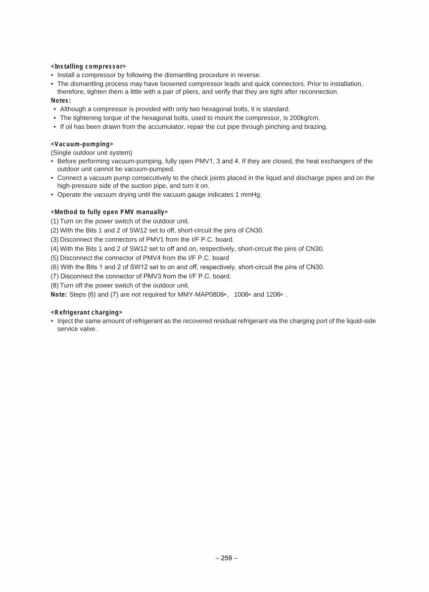
<Installing compressor>• Install a compressor by following the dismantling procedure in reverse.• The dismantling process may have loosened compressor leads and quick connectors. Prior to installation,
therefore, tighten them a little with a pair of pliers, and verify that they are tight after reconnection.Notes:• Although a compressor is provided with only two hexagonal bolts, it is standard.• The tightening torque of the hexagonal bolts, used to mount the compressor, is 200kg/cm.• If oil has been drawn from the accumulator, repair the cut pipe through pinching and brazing.
<Vacuum-pumping>(Single outdoor unit system)• Before performing vacuum-pumping, fully open PMV1, 3 and 4. If they are closed, the heat exchangers of the
outdoor unit cannot be vacuum-pumped.• Connect a vacuum pump consecutively to the check joints placed in the liquid and discharge pipes and on the
high-pressure side of the suction pipe, and turn it on.• Operate the vacuum drying until the vacuum gauge indicates 1 mmHg.
<Method to fully open PMV manually>(1) Turn on the power switch of the outdoor unit.(2) With the Bits 1 and 2 of SW12 set to off, short-circuit the pins of CN30.(3) Disconnect the connectors of PMV1 from the I/F P.C. board.(4) With the Bits 1 and 2 of SW12 set to off and on, respectively, short-circuit the pins of CN30.(5) Disconnect the connector of PMV4 from the I/F P.C. board(6) With the Bits 1 and 2 of SW12 set to on and off, respectively, short-circuit the pins of CN30.(7) Disconnect the connector of PMV3 from the I/F P.C. board.(8) Turn off the power switch of the outdoor unit.Note: Steps (6) and (7) are not required for MMY-MAP0806∗, 1006∗ and 1206∗ .
<Refrigerant charging>• Inject the same amount of refrigerant as the recovered residual refrigerant via the charging port of the liquid-side
service valve.
− 259 −
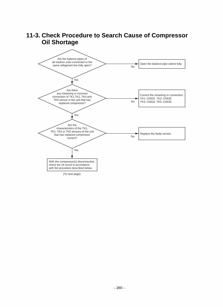
11-3. Check Procedure to Search Cause of Compressor Oil Shortage
Are there any miswiring or incorrect
connection of TK1, TK2, TK4 and TK5 sensor in the unit that has
replaced compressor?
Are the balance pipes of all outdoor units connected to the same refrigerant line fully open?
Are the characteristics of the TK1,
TK2, TK4 or TK5 sensors of the unit that has replaced compressor
correct?
(To next page)
No
No
No
Yes
Correct the miswiring or connection. TK1: CN531 TK2: CN532TK4: CN534 TK5: CN535
Yes
Yes
With the compressor(s) disconnected, check the oil circuit in accordance with the procedure described below.
Open the balance pipe valves fully.
Replace the faulty sensor.
− 260 −
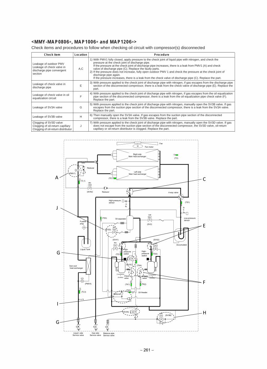
<MMY-MAP0806 , MAP1006 and MAP1206 >Check items and procedures to follow when checking oil circuit with compressor(s) disconnected
erudecorPnoitacoLmeti kcehC
Leakage of outdoor PMVLeakage of check valve in discharge pipe convergent section
A,C
1) With PMV1 fully closed, apply pressure to the check joint of liquid pipe with nitrogen, and check the pressure at the check joint of discharge pipe.If the pressure at the check joint of discharge pipe increases, there is a leak from PMV1 (A) and check valve of discharge pipe (C). Replace the faulty parts.
2) If the pressure does not increase, fully open outdoor PMV 1 and check the pressure at the check joint of discharge pipe again.If the pressure increases, there is a leak from the check valve of discharge pipe (C). Replace the part.
Leakage of check valve in discharge pipe E
3) With pressure applied to the check joint of discharge pipe with nitrogen, if gas escapes from the discharge pipe section of the disconnected compressor, there is a leak from the check valve of discharge pipe (E). Replace the part.
Leakage of check valve in oil equalization circuit F
4) With pressure applied to the check joint of discharge pipe with nitrogen, if gas escapes from the oil equalization pipe section of the disconnected compressor, there is a leak from the oil equalization pipe check valve (F). Replace the part.
Leakage of SV3A valve G5) With pressure applied to the check joint of discharge pipe with nitrogen, manually open the SV3B valve. If gas
escapes from the suction pipe section of the disconnected compressor, there is a leak from the SV3A valve. Replace the part.
Leakage of SV3B valve H 6) Then manually open the SV3A valve. If gas escapes from the suction pipe section of the disconnected compressor, there is a leak from the SV3B valve. Replace the part.
Clogging of SV3D valveClogging of oil-return capillaryClogging of oil-return distributor
J7) With pressure applied to the check joint of discharge pipe with nitrogen, manually open the SV3D valve. If gas
does not escape from the suction pipe section of the disconnected compressor, the SV3D valve, oil-return capillary or oil-return distributor is clogged. Replace the part.
(TD2)
(TE1)
(TK2) (TK1)
(TD1)
(TK4)
(TO)
SV
SV
SV SV
M
(TL1)
SV
SV
SV
(TK5)
(TS3)
(TL3)
Reducer
(SV3A)
(SV2)
(SV3D)
(SV42) (SV41)
(SV3C)
(PMV4)
(TS1)
(SV3B)
Fan
Fan motor
Right side Main heat exchanger
Left side Main heat exchanger (PMV1)
4-way valve
High-pressure sensor
Low-pressure sensor
Oil separator Fusible plug
Liquid Tank
Accumulator
High- pressure switch
High- pressure switch
Check valve
Check valve
Compressor 1
(Inverter)
Oil Header
Liquid side Service valve
Gas side Service valve
Balance pipe Service valve
Sub cool heat exchanger
SV
(SV52) Reducer
FP
Compressor 2
(Inverter)
Reducer
A
J
G
I
G
H
F
E
C
− 261 −
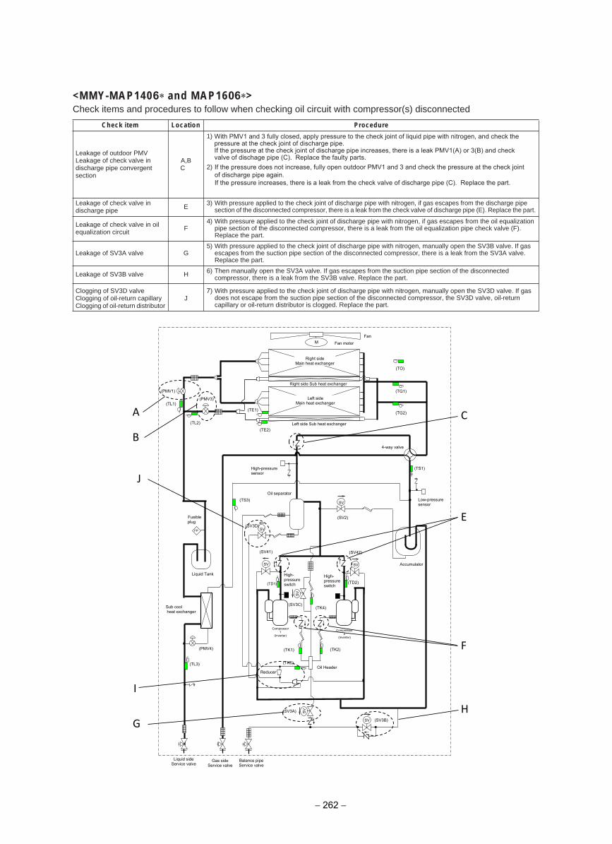
<MMY-MAP1406 and MAP1606 >Check items and procedures to follow when checking oil circuit with compressor(s) disconnected
erudecorPnoitacoLmeti kcehC
Leakage of outdoor PMVLeakage of check valve in discharge pipe convergent section
A,BC
1) With PMV1 and 3 fully closed, apply pressure to the check joint of liquid pipe with nitrogen, and check thepressure at the check joint of discharge pipe.If the pressure at the check joint of discharge pipe increases, there is a leak PMV1(A) or 3(B) and check valve of dischage pipe (C). Replace the faulty parts.
2) If the pressure does not increase, fully open outdoor PMV1 and 3 and check the pressure at the check joint of discharge pipe again.If the pressure increases, there is a leak from the check valve of discharge pipe (C). Replace the part.
Leakage of check valve in discharge pipe E 3) With pressure applied to the check joint of discharge pipe with nitrogen, if gas escapes from the discharge pipe
section of the disconnected compressor, there is a leak from the check valve of discharge pipe (E). Replace the part.
Leakage of check valve in oil equalization circuit F
4) With pressure applied to the check joint of discharge pipe with nitrogen, if gas escapes from the oil equalization pipe section of the disconnected compressor, there is a leak from the oil equalization pipe check valve (F). Replace the part.
Leakage of SV3A valve G5) With pressure applied to the check joint of discharge pipe with nitrogen, manually open the SV3B valve. If gas
escapes from the suction pipe section of the disconnected compressor, there is a leak from the SV3A valve. Replace the part.
Leakage of SV3B valve H 6) Then manually open the SV3A valve. If gas escapes from the suction pipe section of the disconnected compressor, there is a leak from the SV3B valve. Replace the part.
Clogging of SV3D valveClogging of oil-return capillaryClogging of oil-return distributor
J7) With pressure applied to the check joint of discharge pipe with nitrogen, manually open the SV3D valve. If gas
does not escape from the suction pipe section of the disconnected compressor, the SV3D valve, oil-return capillary or oil-return distributor is clogged. Replace the part.
仮
(TD2)
(TS1)
(TE1)
(TK2) (TK1)
(TD1)
(TK4)
(TE2)
(TO)
SV
SV
SV SV
M
(TG2)
(TG1)
(TL3)
SV
SV
SV
(TK5)
(TS3)
(TL1)
(TL2)
(SV3B)
(SV3A)
(SV2)
(SV3D)
(SV42) (SV41)
(SV3C)
(PMV4)
Fan
Fan motor
Right side Main heat exchanger
Left side Main heat exchanger
Right side Sub heat exchanger
Left side Sub heat exchanger
(PMV1)
(PMV3)
4-way valve
High-pressure sensor
Low-pressure sensor
Oil separator
Accumulator
Liquid Tank
Liquid side Service valve
Gas side Service valve
Balance pipe Service valve
Oil Header
High- pressure switch
High- pressure switch
Reducer
Fusible plug
FP
Sub cool heat exchanger
Compressor 1
(Inverter)
Compressor 2
(Inverter)
A
J
I
G H
F
E
C
B
− 262 −
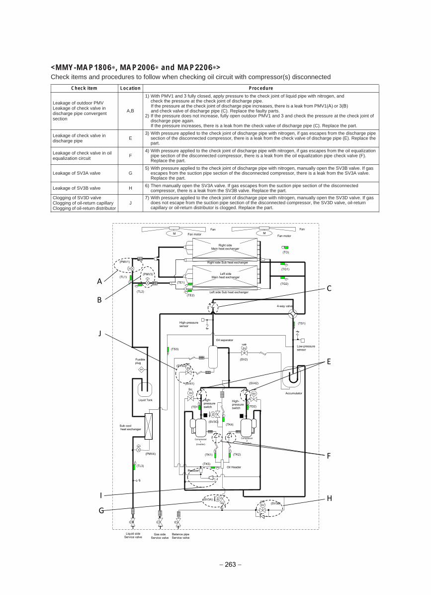
<MMY-MAP1806 , MAP2006 and MAP2206 >Check items and procedures to follow when checking oil circuit with compressor(s) disconnected
erudecorPnoitacoLmeti kcehC
Leakage of outdoor PMVLeakage of check valve in discharge pipe convergent section
A,B
1) With PMV1 and 3 fully closed, apply pressure to the check joint of liquid pipe with nitrogen, and check the pressure at the check joint of discharge pipe.If the pressure at the check joint of discharge pipe increases, there is a leak from PMV1(A) or 3(B)and check valve of discharge pipe (C). Replace the faulty parts.
2) If the pressure does not increase, fully open outdoor PMV1 and 3 and check the pressure at the check joint of discharge pipe again.If the pressure increases, there is a leak from the check valve of discharge pipe (C). Replace the part.
Leakage of check valve in discharge pipe E
3) With pressure applied to the check joint of discharge pipe with nitrogen, if gas escapes from the discharge pipe section of the disconnected compressor, there is a leak from the check valve of discharge pipe (E). Replace the part.
Leakage of check valve in oil equalization circuit F
4) With pressure applied to the check joint of discharge pipe with nitrogen, if gas escapes from the oil equalization pipe section of the disconnected compressor, there is a leak from the oil equalization pipe check valve (F). Replace the part.
Leakage of SV3A valve G5) With pressure applied to the check joint of discharge pipe with nitrogen, manually open the SV3B valve. If gas
escapes from the suction pipe section of the disconnected compressor, there is a leak from the SV3A valve. Replace the part.
Leakage of SV3B valve H 6) Then manually open the SV3A valve. If gas escapes from the suction pipe section of the disconnected compressor, there is a leak from the SV3B valve. Replace the part.
Clogging of SV3D valveClogging of oil-return capillaryClogging of oil-return distributor
J7) With pressure applied to the check joint of discharge pipe with nitrogen, manually open the SV3D valve. If gas
does not escape from the suction pipe section of the disconnected compressor, the SV3D valve, oil-return capillary or oil-return distributor is clogged. Replace the part.
仮
(TD2)
(TS1)
(TE1)
(TK2) (TK1)
(TD1)
(TK4)
(TE2)
(TO)
SV
SV
SV SV
M M
(TG2)
(TG1)
(TL3)
SV
SV
SV
(TK5)
(TS3)
(TL1)
(TL2)
(SV3B) (SV3A)
(SV2)
(SV3D)
(SV42) (SV41)
(SV3C)
(PMV4)
Fan Fan
Fan motor Fan motor
Right side Main heat exchanger
Left side Main heat exchanger
Right side Sub heat exchanger
Left side Sub heat exchanger
(PMV1)
(PMV3)
4-way valve
High-pressure sensor
Low-pressure sensor
Oil separator
Accumulator
Liquid Tank
Oil Header
High- pressure switch
High- pressure switch
Sub cool heat exchanger
Fusible plug
FP
Liquid side Service valve
Gas side Service valve
Balance pipe Service valve
Reducer
Compressor 1
(Inverter)
Compressor 2
(Inverter)
J
I
G
H
E
C
F
A
B
− 263 −
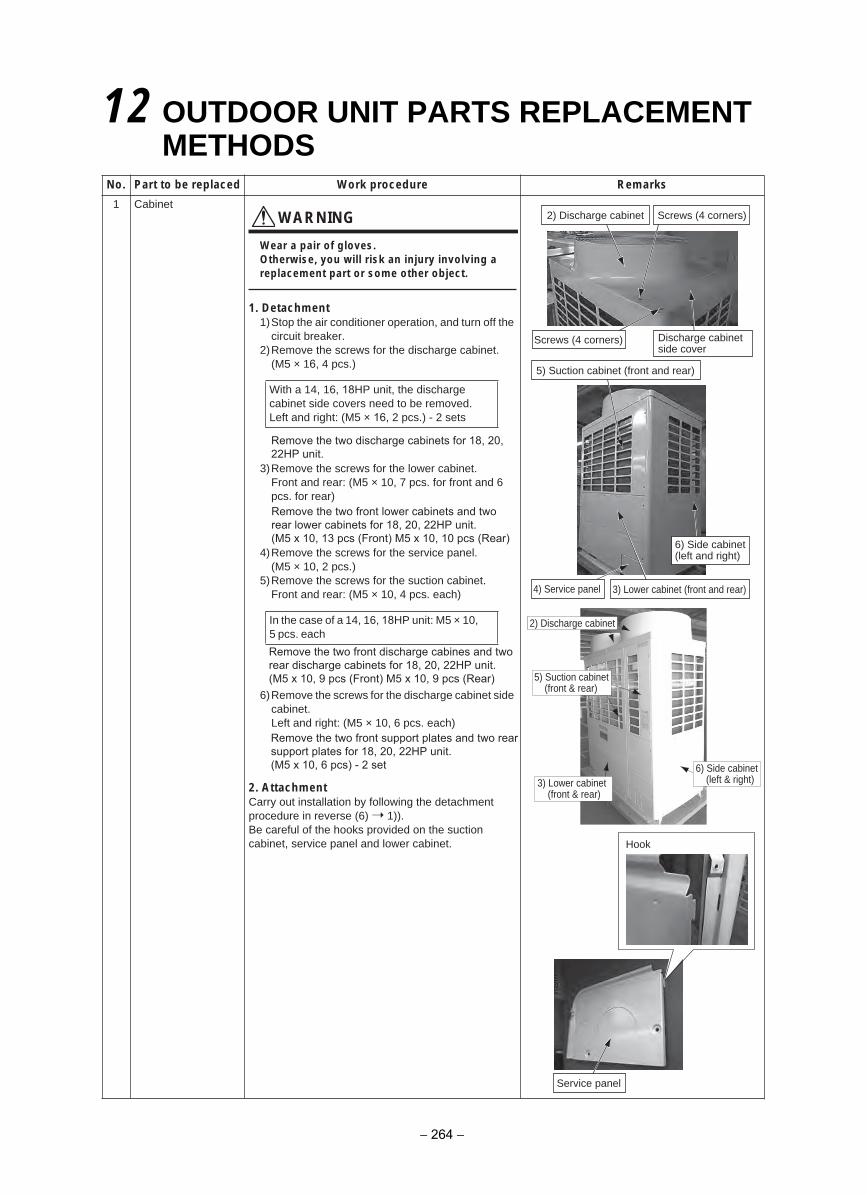
12 OUTDOOR UNIT PARTS REPLACEMENTMETHODS
Remove the two discharge cabinets for 18, 20, 22HP unit.
Remove the two front lower cabinets and two rear lower cabinets for 18, 20, 22HP unit.(M5 x 10, 13 pcs (Front) M5 x 10, 10 pcs (Rear)
Remove the two front discharge cabines and two rear discharge cabinets for 18, 20, 22HP unit.(M5 x 10, 9 pcs (Front) M5 x 10, 9 pcs (Rear)
Remove the two front support plates and two rear support plates for 18, 20, 22HP unit.(M5 x 10, 6 pcs) - 2 set
skrameRerudecorp kroWdecalper eb ot traP.oN
1 CabinetWARNING
Wear a pair of gloves.Otherwise, you will risk an injury involving a replacement part or some other object.
1. Detachment1)Stop the air conditioner operation, and turn off the
circuit breaker.2)Remove the screws for the discharge cabinet.
(M5 × 16, 4 pcs.)
3)Remove the screws for the lower cabinet.Front and rear: (M5 × 10, 7 pcs. for front and 6pcs. for rear)
4)Remove the screws for the service panel.(M5 × 10, 2 pcs.)
5)Remove the screws for the suction cabinet.Front and rear: (M5 × 10, 4 pcs. each)
6)Remove the screws for the discharge cabinet side cabinet.Left and right: (M5 × 10, 6 pcs. each)
2. AttachmentCarry out installation by following the detachment procedure in reverse (6) 1)).Be careful of the hooks provided on the suction cabinet, service panel and lower cabinet.
With a 14, 16, 18HP unit, the discharge cabinet side covers need to be removed.Left and right: (M5 × 16, 2 pcs.) - 2 sets
In the case of a 14, 16, 18HP unit: M5 × 10, 5 pcs. each
2) Discharge cabinet Screws (4 corners)
Screws (4 corners)
5) Suction cabinet (front and rear)
6) Side cabinet(left and right)
Discharge cabinet side cover
Hook
Service panel
4)
6) Side cabinet(left & right)3) Lower cabinet
(front & rear)
5) Suction cabinet(front & rear)
2) Discharge cabinet
Service panel 3) Lower cabinet (front and rear)
− 264 −
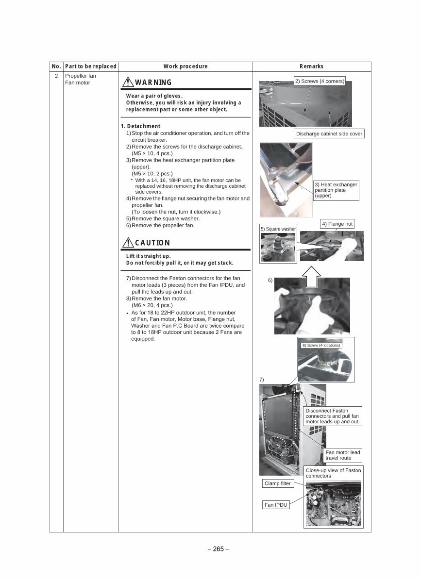
2 Propeller fanFan motor WARNING
Wear a pair of gloves.Otherwise, you will risk an injury involving a replacement part or some other object.
1. Detachment1)Stop the air conditioner operation, and turn off the
circuit breaker.2)Remove the screws for the discharge cabinet.
(M5 × 10, 4 pcs.)3)Remove the heat exchanger partition plate
(upper).(M5 × 10, 2 pcs.)* With a 14, 16, 18HP unit, the fan motor can be
replaced without removing the discharge cabinetside covers.
4)Remove the flange nut securing the fan motor and propeller fan.(To loosen the nut, turn it clockwise.)
5)Remove the square washer.6)Remove the propeller fan.
CAUTION
Lift it straight up.Do not forcibly pull it, or it may get stuck.
7)Disconnect the Faston connectors for the fanmotor leads (3 pieces) from the Fan IPDU, andpull the leads up and out.
8)Remove the fan motor.(M6 × 20, 4 pcs.)
skrameRerudecorp kroWdecalper eb ot traP.oN
Discharge cabinet side cover
4) Flange nut
6)
7)
8) Screw (4 locations)
5) Square washer
2) Screws (4 corners)
3) Heat exchangerpartition plate (upper)
Disconnect Faston connectors and pull fan motor leads up and out.
Fan motor lead travel route
Close-up view of Faston connectors
Fan IPDU
Clamp filter
• As for 18 to 22HP outdoor unit, the numberof Fan, Fan motor, Motor base, Flange nut, Washer and Fan P.C Board are twice compare to 8 to 18HP outdoor unit because 2 Fans are equipped.
− 265 −
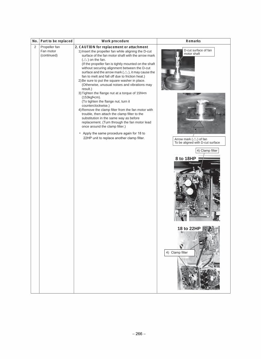
2 Propeller fan Fan motor(continued)
2. CAUTION for replacement or attachment1) Insert the propeller fan while aligning the D-cut
surface of the fan motor shaft with the arrow mark ( ) on the fan.(If the propeller fan is tightly mounted on the shaftwithout securing alignment between the D-cutsurface and the arrow mark ( ), it may cause the fan to melt and fall off due to friction heat.)
2)Be sure to put the square washer in place.(Otherwise, unusual noises and vibrations mayresult.)
3)Tighten the flange nut at a torque of 15N•m(153kgf•cm).(To tighten the flange nut, turn itcounterclockwise.)
4)Remove the clamp filter from the fan motor withtrouble, then attach the clamp filter to thesubstitution in the same way as beforereplacement. (Turn through the fan motor leadonce around the clamp filter.)
skrameRerudecorp kroWdecalper eb ot traP.oN
D-cut surface of fan motor shaft
Arrow mark ( ) of fanTo be aligned with D-cut surface
4) Clamp filter
8 to 18HP
18 to 22HP
4) Clamp filter
• Apply the same procedure again for 18 to22HP unit to replace another clamp filter.
− 266 −
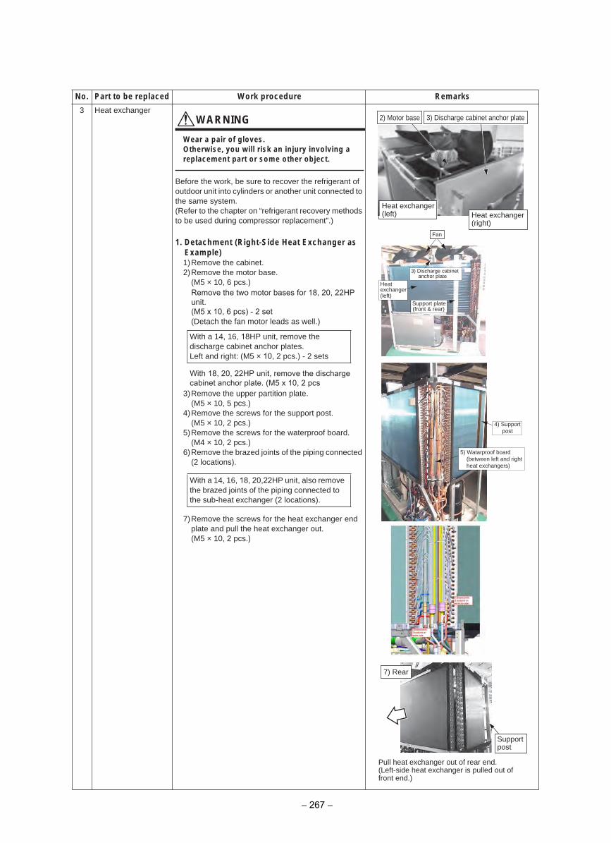
3 Heat exchangerWARNING
Wear a pair of gloves.Otherwise, you will risk an injury involving a replacement part or some other object.
Before the work, be sure to recover the refrigerant of outdoor unit into cylinders or another unit connected to the same system.(Refer to the chapter on “refrigerant recovery methods to be used during compressor replacement”.)
1. Detachment (Right-Side Heat Exchanger asExample)1)Remove the cabinet.2)Remove the motor base.
(M5 × 10, 6 pcs.)
(Detach the fan motor leads as well.)
3)Remove the upper partition plate.(M5 × 10, 5 pcs.)
4)Remove the screws for the support post.(M5 × 10, 2 pcs.)
5)Remove the screws for the waterproof board.(M4 × 10, 2 pcs.)
6)Remove the brazed joints of the piping connected (2 locations).
7)Remove the screws for the heat exchanger endplate and pull the heat exchanger out.(M5 × 10, 2 pcs.)
skrameRerudecorp kroWdecalper eb ot traP.oN
With a 14, 16, 18HP unit, remove the discharge cabinet anchor plates.Left and right: (M5 × 10, 2 pcs.) - 2 sets
With a 14, 16, 18, 20,22HP unit, also remove the brazed joints of the piping connected to the sub-heat exchanger (2 locations).
3) Discharge cabinet anchor plate
Fan
3)
4)
5)
Discharge cabinetanchor plate
Heat exchanger (left)
Support post
Watarproof board(between left and rightheat exchangers)
2) Motor base
7) Rear
Heat exchanger (right)
Heat exchanger (left)
Supportpost
Pull heat exchanger out of rear end.(Left-side heat exchanger is pulled out of front end.)
Remove the two motor bases for 18, 20, 22HPunit.(M5 x 10, 6 pcs) - 2 set
With 18, 20, 22HP unit, remove the discharge cabinet anchor plate. (M5 x 10, 2 pcs
Support plate(front & rear)
− 267 −
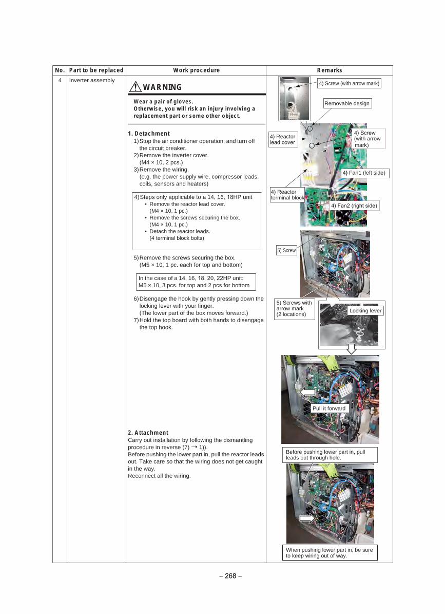
4 Inverter assemblyWARNING
Wear a pair of gloves.Otherwise, you will risk an injury involving a replacement part or some other object.
1. Detachment1)Stop the air conditioner operation, and turn off
the circuit breaker.2)Remove the inverter cover.
(M4 × 10, 2 pcs.)3)Remove the wiring.
(e.g. the power supply wire, compressor leads,coils, sensors and heaters)
5)Remove the screws securing the box.(M5 × 10, 1 pc. each for top and bottom)
6)Disengage the hook by gently pressing down thelocking lever with your finger.(The lower part of the box moves forward.)
7)Hold the top board with both hands to disengagethe top hook.
2. AttachmentCarry out installation by following the dismantling procedure in reverse (7) 1)).Before pushing the lower part in, pull the reactor leads out. Take care so that the wiring does not get caught in the way.Reconnect all the wiring.
skrameRerudecorp kroWdecalper eb ot traP.oN
4)Steps only applicable to a 14, 16, 18HP unit• Remove the reactor lead cover.
(M4 × 10, 1 pc.)• Remove the screws securing the box.
(M4 × 10, 1 pc.)• Detach the reactor leads.
(4 terminal block bolts)
In the case of a 14, 16, 18, 20, 22HP unit: M5 × 10, 3 pcs. for top and 2 pcs for bottom
5) Screw
Pull it forward
Locking lever
4) Screw (with arrow mark)
5) Screws witharrow mark(2 locations)
7)
Before pushing lower part in, pull leads out through hole.
When pushing lower part in, be sure to keep wiring out of way.
Removable design
4) Screw4) Reactorlead cover
4)) Fan1 (left side)
4) Reactorterminal block
(with arrow mark)
4) Fan2 (right side)
− 268 −
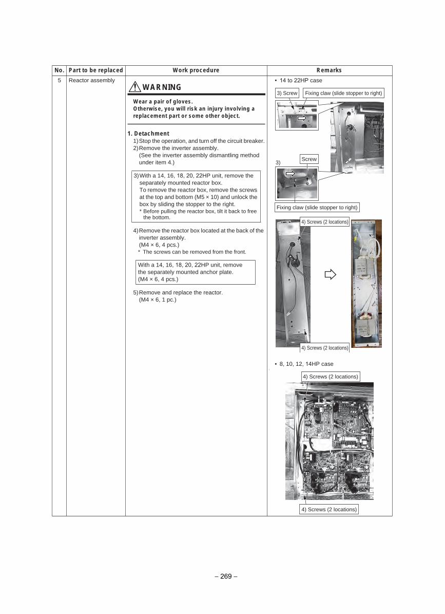
5 Reactor assemblyWARNING
Wear a pair of gloves.Otherwise, you will risk an injury involving a replacement part or some other object.
1. Detachment1)Stop the operation, and turn off the circuit breaker.2)Remove the inverter assembly.
(See the inverter assembly dismantling methodunder item 4.)
4)Remove the reactor box located at the back of the inverter assembly.(M4 × 6, 4 pcs.)* The screws can be removed from the front.
5)Remove and replace the reactor.(M4 × 6, 1 pc.)
• 14 to 22HP case
• 8, 10, 12, 14HP case[
skrameRerudecorp kroWdecalper eb ot traP.oN
3)With a 14, 16, 18, 20, 22HP unit, remove theseparately mounted reactor box.To remove the reactor box, remove the screwsat the top and bottom (M5 × 10) and unlock thebox by sliding the stopper to the right.* Before pulling the reactor box, tilt it back to free
the bottom.
With a 14, 16, 18, 20, 22HP unit, remove the separately mounted anchor plate.(M4 × 6, 4 pcs.)
3) Screw
3)
Fixing claw (slide stopper to right)
Fixing claw (slide stopper to right)
Screw
4) Screws (2 locations)
4) Screws (2 locations)
4) Screws (2 locations)
4) Screws (2 locations)
− 269 −
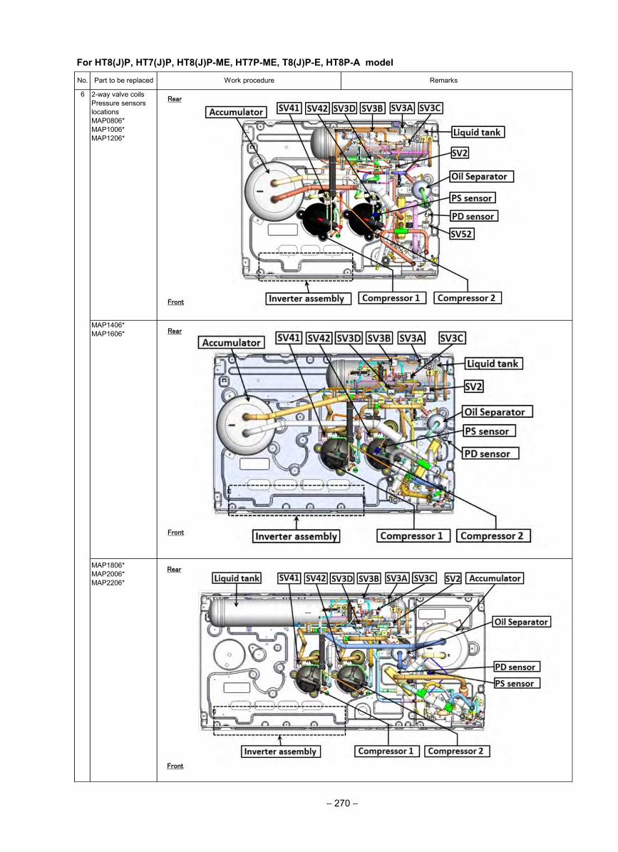
6 2-way valve coilsPressure sensorslocationsMAP0806*MAP1006*MAP1206*
No. Part to be replaced Work procedure
MAP1806*MAP2006*MAP2206*
Remarks
MAP1406*MAP1606*
Rear
Front
Rear
Front
Front
Rear
For HT8(J)P, HT7(J)P, HT8(J)P-ME, HT7P-ME, T8(J)P-E, HT8P-A model
− 270 −
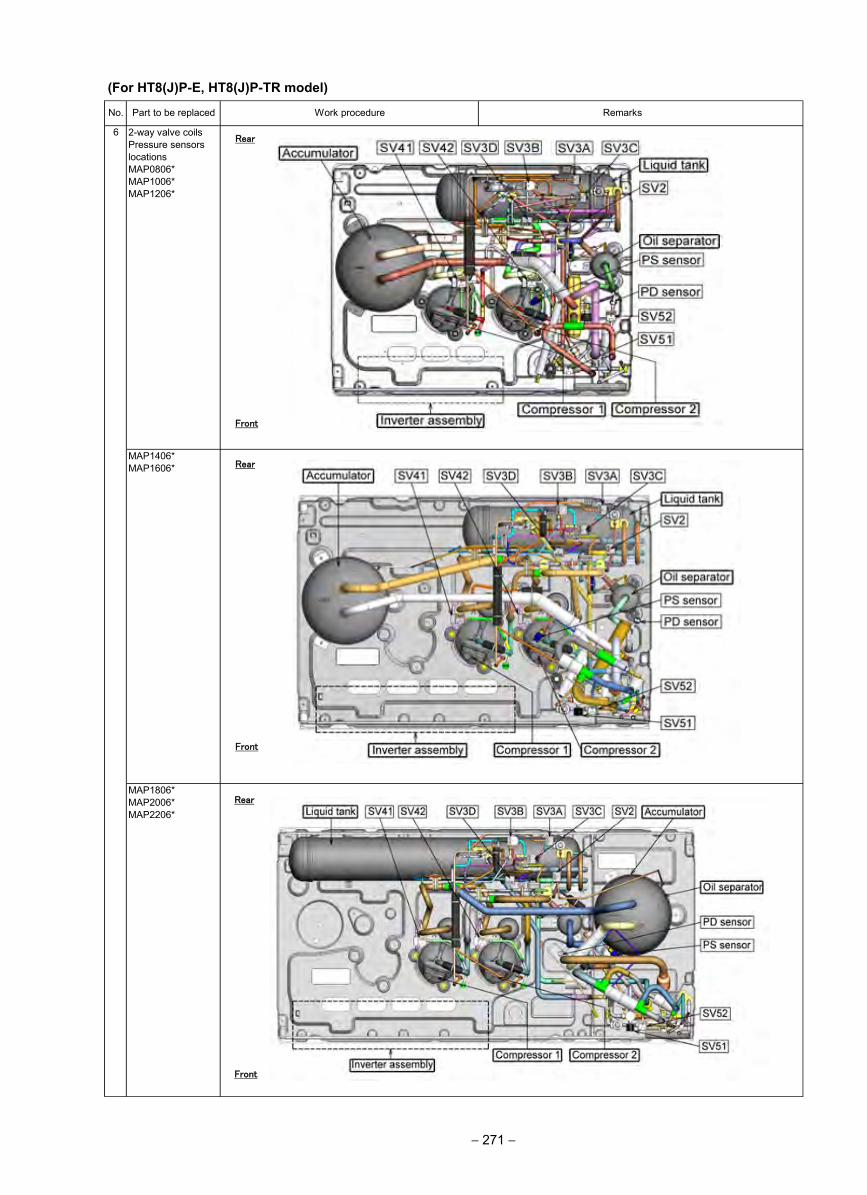
6 2-way valve coilsPressure sensorslocationsMAP0806*MAP1006*MAP1206*
No. Part to be replaced Work procedure
MAP1806*MAP2006*MAP2206*
Remarks
MAP1406*MAP1606*
Rear
Front
Rear
Front
Front
Rear
(For HT8(J)P-E, HT8(J)P-TR model)
− 271 −
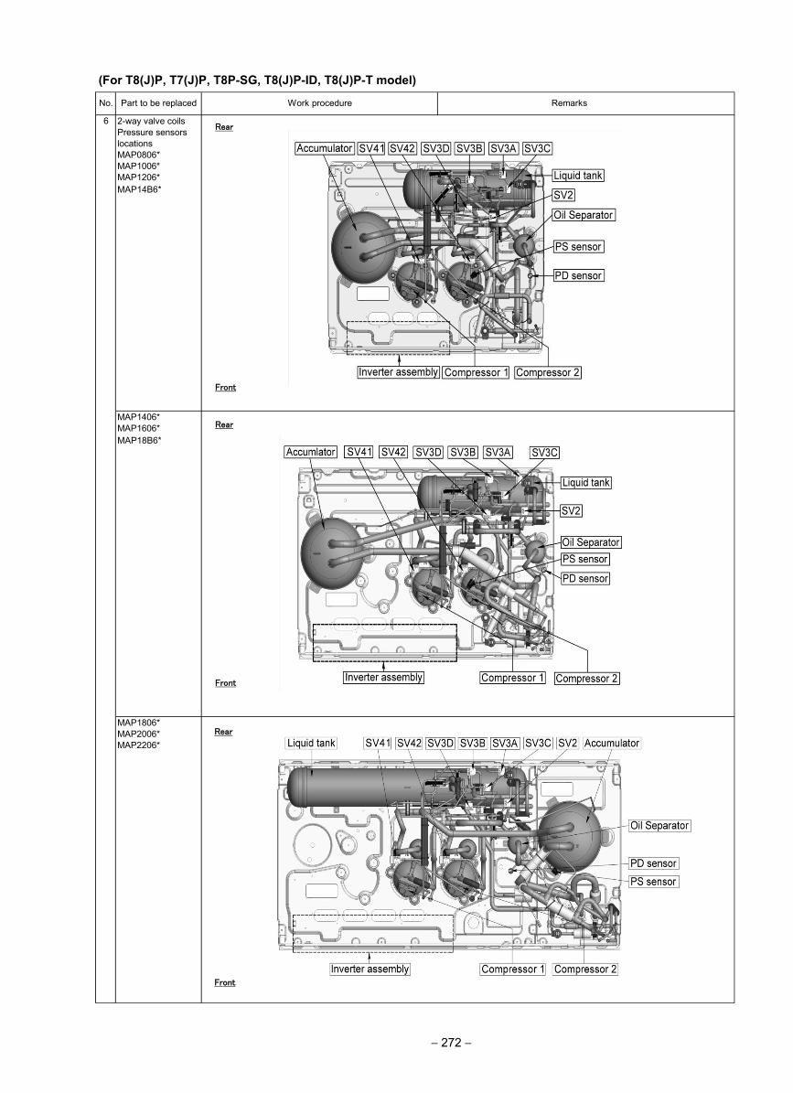
6 2-way valve coilsPressure sensorslocationsMAP0806*MAP1006*MAP1206*
No. Part to be replaced Work procedure
MAP1806*MAP2006*MAP2206*
Remarks
MAP1406*MAP1606*
Rear
Front
Rear
Front
Front
Rear
(For T8(J)P, T7(J)P, T8P-SG, T8(J)P-ID, T8(J)P-T model)
− 272 −
MAP14B6*
MAP18B6*
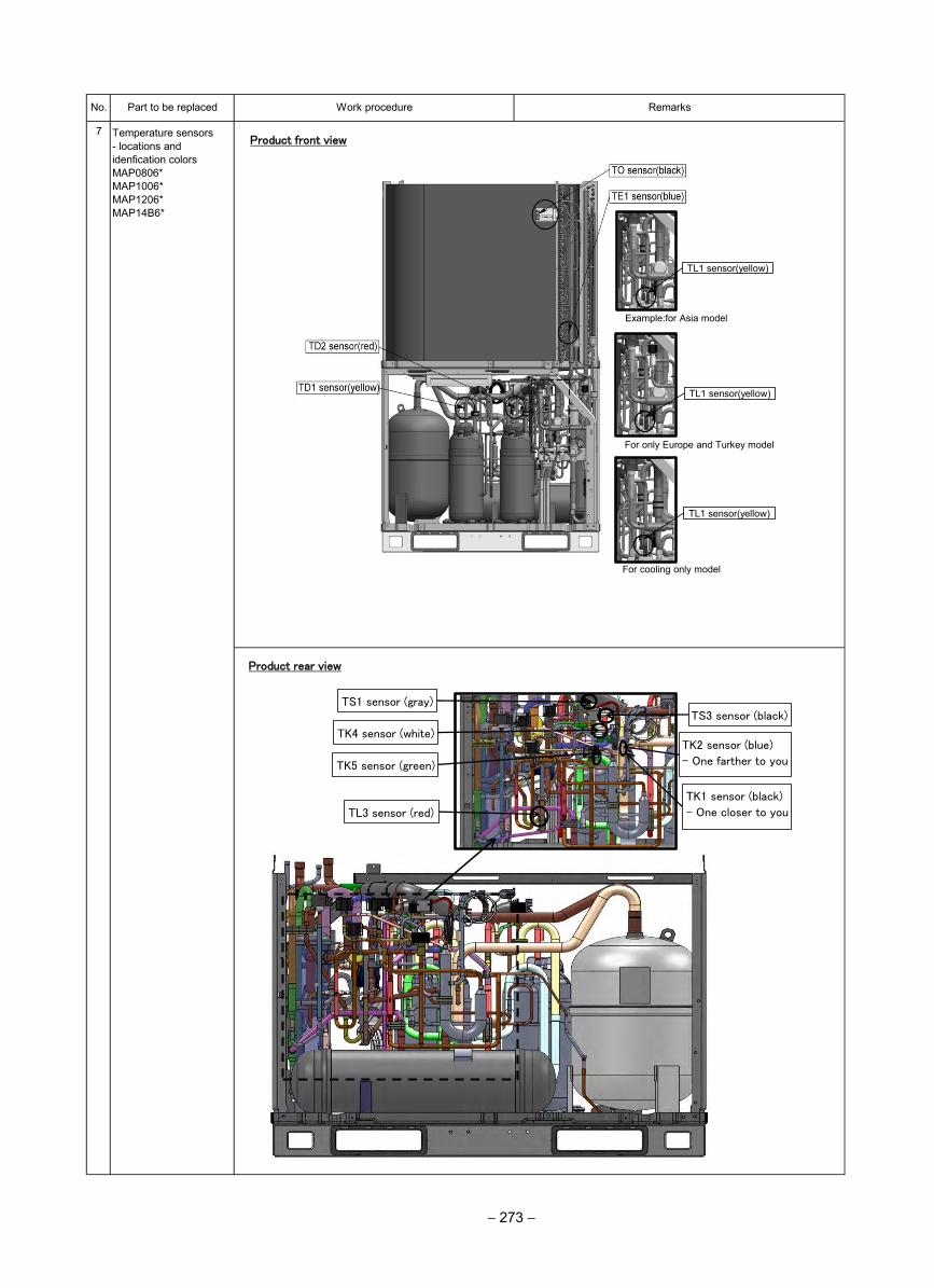
TL1 sensor(yellow)
TL1 sensor(yellow)
TL1 sensor(yellow)
Example:for Asia model
For only Europe and Turkey model
For cooling only model
Work procedure RemarksNo. Part to be replaced
7 Temperature sensors- locations and idenfication colorsMAP0806* MAP1006* MAP1206*MAP14B6*
Product front view
TS1 sensor (gray)
TK4 sensor (white)
TK5 sensor (green)
TL3 sensor (red)
TK1 sensor (black)
- One closer to you
TS3 sensor (black)
TK2 sensor (blue)
- One farther to you
Product rear view
− 273 −
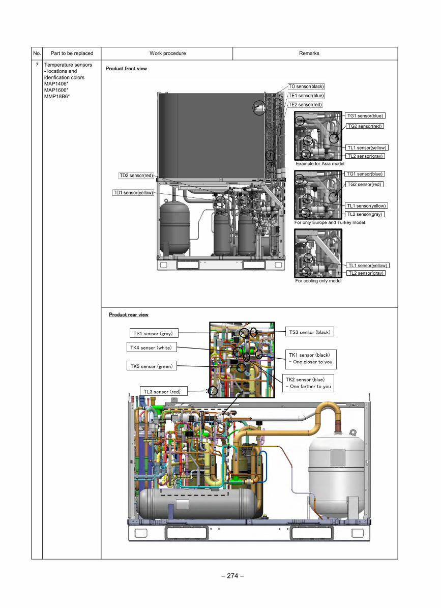
No. Part to be replaced Work procedure Remarks
7Product front view
Product rear view
TL3 sensor (red)
TK5 sensor (green)
TS3 sensor (black)
TK1 sensor (black)
- One closer to you
TK2 sensor (blue)
- One farther to you
TS1 sensor (gray)
TK4 sensor (white)
Temperature sensors - locations and idenfication colors MAP1406* MAP1606*MMP18B6*
− 274 −
TL2 sensor(gray)
TG1 sensor(blue)
TG2 sensor(red)
TL1 sensor(yellow)
TG1 sensor(blue)
TG2 sensor(red)
TL1 sensor(yellow)
TL2 sensor(gray)
TL1 sensor(yellow)
Example:for Asia model
TL2 sensor(gray)
For only Europe and Turkey model
For cooling only model
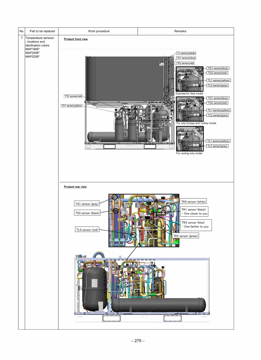
No. Part to be replaced Work procedure Remarks
7 Temperature sensors- locations and idenfication colorsMAP1806*MAP2006*MAP2206*
Product front view
Product rear view
TK4 sensor (white)
TK5 sensor (green)
TK1 sensor (black)
- One closer to you
TK2 sensor (blue)
- One farther to you
TS1 sensor (gray)
TS3 sensor (black)
TL3 sensor (red)
− 275 −
TL2 sensor(gray)
TG1 sensor(blue)
TG2 sensor(red)
TL1 sensor(yellow)
TL2 sensor(gray)
TG1 sensor(blue)
TG2 sensor(red)
TL1 sensor(yellow)
TL2 sensor(gray)
TL1 sensor(yellow)
Example:for Asia model
For only Europe and Turkey model
For cooling only model
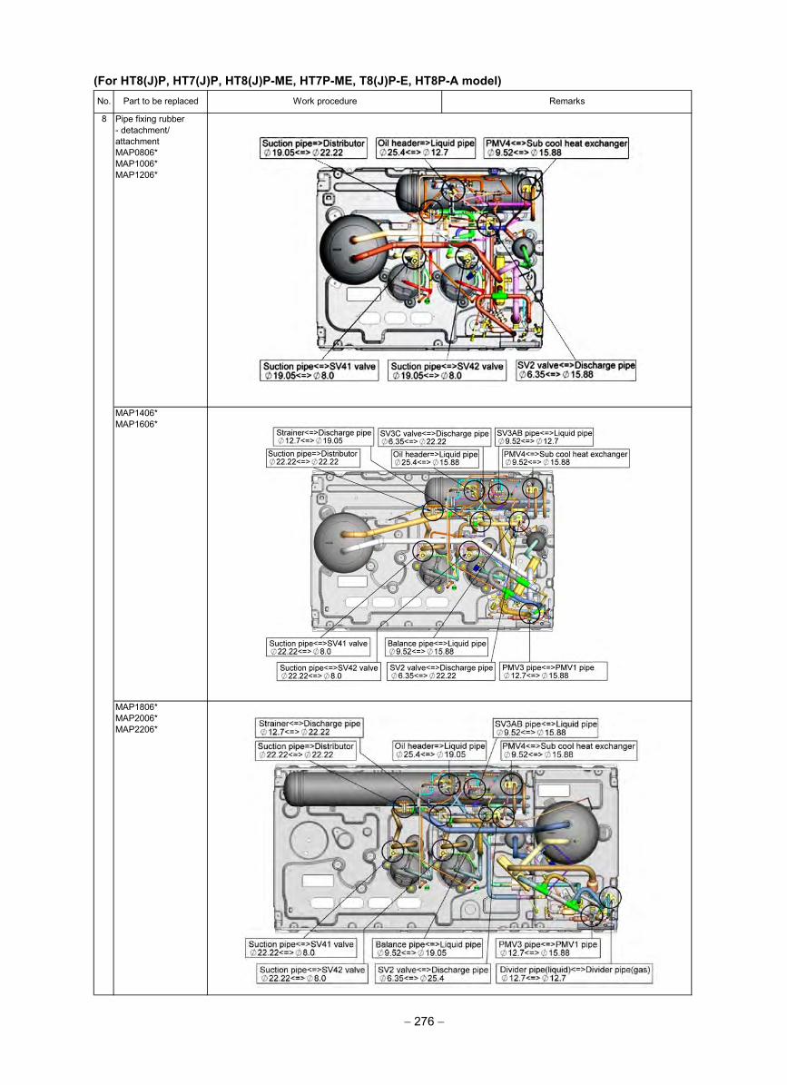
Remarks
MAP1406*MAP1606*
8 Pipe fixing rubber- detachment/attachmentMAP0806*MAP1006*MAP1206*
Work procedureNo. Part to be replaced
MAP1806*MAP2006*MAP2206*
(For HT8(J)P, HT7(J)P, HT8(J)P-ME, HT7P-ME, T8(J)P-E, HT8P-A model)
− 276 −
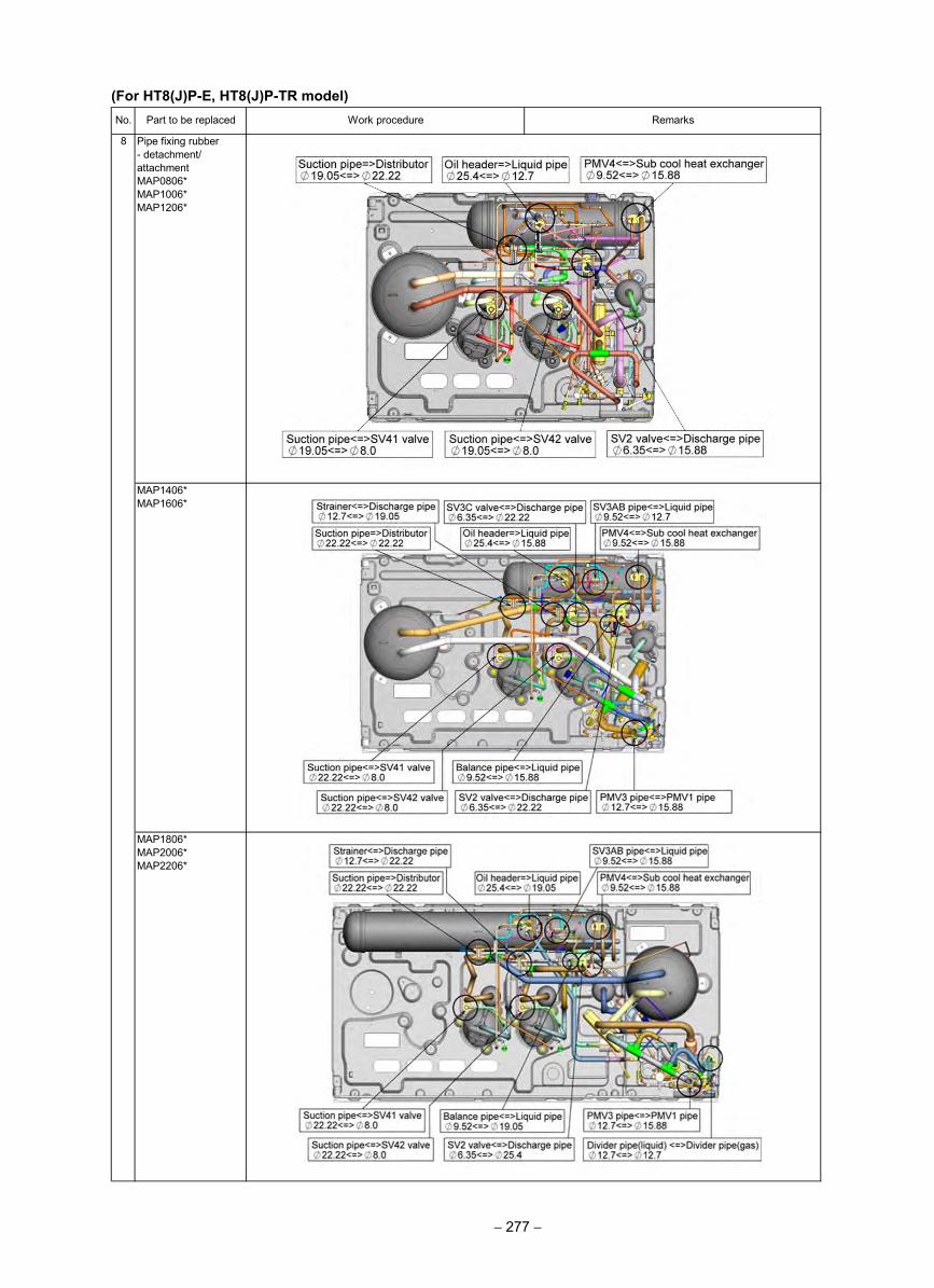
Remarks
MAP1406*MAP1606*
8 Pipe fixing rubber- detachment/attachmentMAP0806*MAP1006*MAP1206*
Work procedureNo. Part to be replaced
MAP1806*MAP2006*MAP2206*
(For HT8(J)P-E, HT8(J)P-TR model)
− 277 −
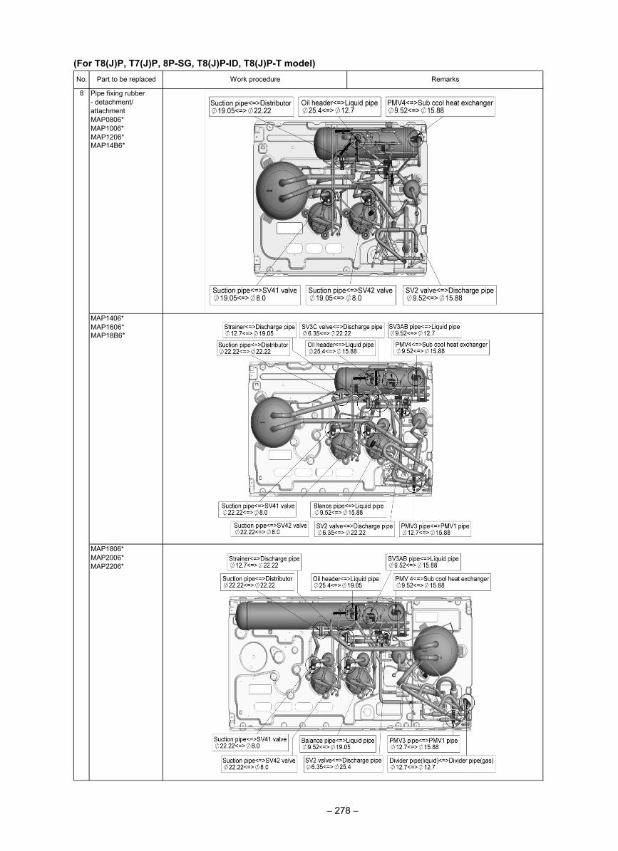
Remarks
MAP1406*MAP1606*MAP18B6*
8 Pipe fixing rubber- detachment/attachmentMAP0806*MAP1006*MAP1206*MAP14B6*
Work procedureNo. Part to be replaced
MAP1806*MAP2006*MAP2206*
(For T8(J)P, T7(J)P, 8P-SG, T8(J)P-ID, T8(J)P-T model)
− 278 −
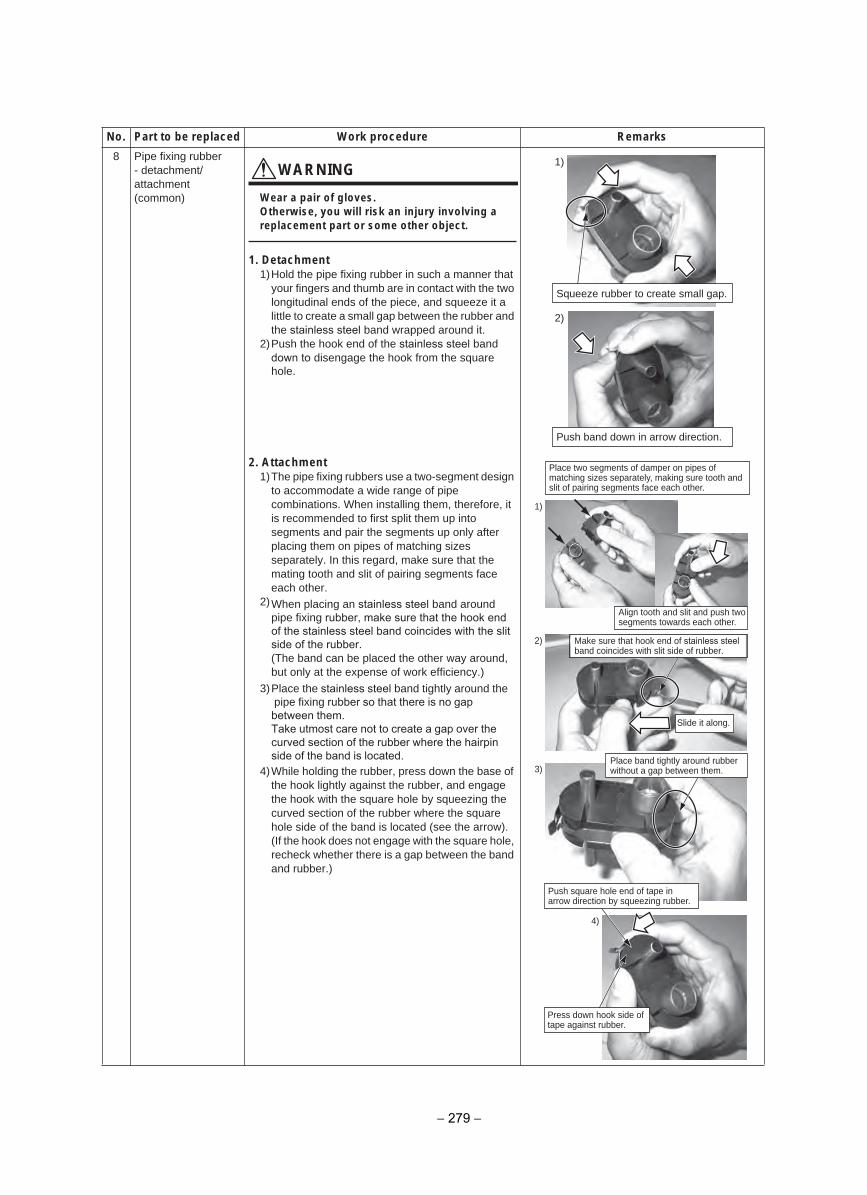
8 Pipe fixing rubber- detachment/attachment(common)
WARNING
Wear a pair of gloves.Otherwise, you will risk an injury involving a replacement part or some other object.
1. Detachment1)Hold the pipe fixing rubber in such a manner that
your fingers and thumb are in contact with the two longitudinal ends of the piece, and squeeze it alittle to create a small gap between the rubber and the stainless steel band wrapped around it.
2)Push the hook end of the stainless steel banddown to disengage the hook from the squarehole.
2. Attachment1)The pipe fixing rubbers use a two-segment design
to accommodate a wide range of pipecombinations. When installing them, therefore, itis recommended to first split them up intosegments and pair the segments up only afterplacing them on pipes of matching sizesseparately. In this regard, make sure that themating tooth and slit of pairing segments faceeach other.
2)When placing an stainless steel band aroundpipe fixing rubber, make sure that the hook endof the stainless steel band coincides with the slitside of the rubber.(The band can be placed the other way around,but only at the expense of work efficiency.)
3)Place the stainless steel band tightly around thepipe fixing rubber so that there is no gapbetween them.Take utmost care not to create a gap over thecurved section of the rubber where the hairpinside of the band is located.
4)While holding the rubber, press down the base ofthe hook lightly against the rubber, and engagethe hook with the square hole by squeezing thecurved section of the rubber where the squarehole side of the band is located (see the arrow).(If the hook does not engage with the square hole, recheck whether there is a gap between the bandand rubber.)
skrameRerudecorp kroWdecalper eb ot traP.oN
Squeeze rubber to create small gap.
1)
2)
Push band down in arrow direction.
Slide it along.
Place two segments of damper on pipes of matching sizes separately, making sure tooth and slit of pairing segments face each other.
1)
2)
3)
4)
Make sure that hook end of stainless steel band coincides with slit side of rubber.
Place band tightly around rubber without a gap between them.
Push square hole end of tape in arrow direction by squeezing rubber.
Press down hook side of tape against rubber.
Align tooth and slit and push two segments towards each other.
− 279 −
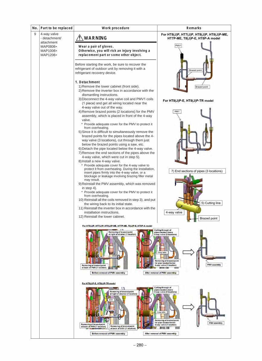
9 4-way valve- detachment/attachmentMAP0806MAP1006MAP1206
WARNING
Wear a pair of gloves.Otherwise, you will risk an injury involving a replacement part or some other object.
Before starting the work, be sure to recover the refrigerant of outdoor unit by removing it with a refrigerant recovery device.
1. Detachment1)Remove the lower cabinet (front side).2)Remove the inverter box in accordance with the
dismantling instructions.3)Disconnect the 4-way valve coil and PMV1 coils
(1 piece) and get all wiring located near the4-way valve out of the way.
4)Remove brazed points (2 locations) for the PMVassembly, which is placed in front of the 4-wayvalve.* Provide adequate cover for the PMV to protect it
from overheating.5)Since it is difficult to simultaneously remove the
brazed points for the pipes located above the 4-way valve (3 locations), cut through them justbelow the brazed points using a saw, etc.
6)Detach the pipe located below the 4-way valve.7)Remove the end sections of the pipes above the
4-way valve, which were cut in step 5).8) Install a new 4-way valve.
* Provide adequate cover for the 4-way valve toprotect it from overheating. During the installation,insert pipes firmly into the 4-way valve, or ablockage or leakage involving brazing filler metalmay result.
9)Reinstall the PMV assembly, which was removedin step 4).* Provide adequate cover for the PMV to protect it
from overheating.10) Reinstall all the coils removed in step 3), and put
the wiring back to its initial state.11) Reinstall the inverter box in accordance with the
installation instructions.12) Reinstall the lower cabinet.
skrameRerudecorp kroWdecalper eb ot traP.oN
PMV1
Brazed point
Brazed point
7) End sections of pipes (3 locations)
5) Cutting line
Brazed point
4-way valve
For HT8(J)P, HT7(J)P, HT8(J)P, HT8(J)P-ME, HT7P-ME, T8(J)P-E, HT8P-A model
For HT8(J)P-E, HT8(J)P-TR model
− 280 −
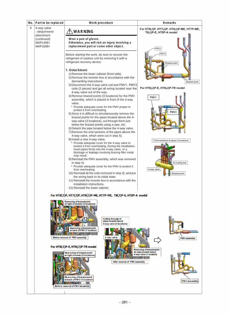
9 4-way valve- detachment/attachment(continued)MAP1406MAP1606
WARNING
Wear a pair of gloves.Otherwise, you will risk an injury involving a replacement part or some other object.
Before starting the work, be sure to recover the refrigerant of outdoor unit by removing it with a refrigerant recovery device.
1. Detachment1)Remove the lower cabinet (front side).2)Remove the inverter box in accordance with the
dismantling instructions.3)Disconnect the 4-way valve coil and PMV1, PMV3
coils (2 pieces) and get all wiring located near the4-way valve out of the way.
4)Remove brazed points (3 locations) for the PMVassembly, which is placed in front of the 4-wayvalve.* Provide adequate cover for the PMV proper to
protect it from overheating.5)Since it is difficult to simultaneously remove the
brazed points for the pipes located above the 4-way valve (3 locations), cut through them justbelow the brazed points using a saw, etc.
6)Detach the pipe located below the 4-way valve.7)Remove the end sections of the pipes above the
4-way valve, which were cut in step 5).8) Install a new 4-way valve.
* Provide adequate cover for the 4-way valve toprotect it from overheating. During the installation,insert pipes firmly into the 4-way valve, or ablockage or leakage involving brazing filler metalmay result.
9)Reinstall the PMV assembly, which was removedin step 4).* Provide adequate cover for the PMV to protect it
from overheating.10) Reinstall all the coils removed in step 3), and put
the wiring back to its initial state.11) Reinstall the inverter box in accordance with the
installation instructions.12) Reinstall the lower cabinet.
skrameRerudecorp kroWdecalper eb ot traP.oN
7) End sections of pipes (3 locations)
5) Cutting line
Brazed point
4-way valve
Brazed point
Brazed point
PMV1
PMV3
For HT8(J)P, HT7(J)P, HT8(J)P-ME, HT7P-ME, T8(J)P-E, HT8P-A model
− 281 −
For HT8(J)P-E, HT8(J)P-TR model
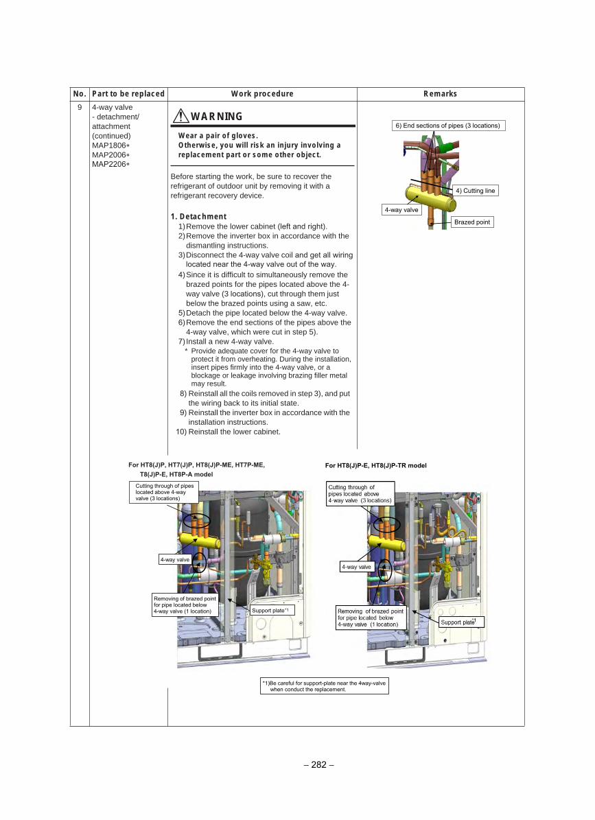
9 4-way valve- detachment/attachment(continued)MAP1806MAP2006MAP2206
WARNING
Wear a pair of gloves.Otherwise, you will risk an injury involving a replacement part or some other object.
Before starting the work, be sure to recover the refrigerant of outdoor unit by removing it with a refrigerant recovery device.
1. Detachment1)Remove the lower cabinet (left and right).2)Remove the inverter box in accordance with the
dismantling instructions.3)Disconnect the 4-way valve coil and get all wiring
located near the 4-way valve out of the way.4)Since it is difficult to simultaneously remove the
brazed points for the pipes located above the 4-way valve (3 locations), cut through them justbelow the brazed points using a saw, etc.
5)Detach the pipe located below the 4-way valve.6)Remove the end sections of the pipes above the
4-way valve, which were cut in step 5).7) Install a new 4-way valve.
* Provide adequate cover for the 4-way valve toprotect it from overheating. During the installation,insert pipes firmly into the 4-way valve, or ablockage or leakage involving brazing filler metalmay result.
8) Reinstall all the coils removed in step 3), and put the wiring back to its initial state.
9) Reinstall the inverter box in accordance with theinstallation instructions.
10) Reinstall the lower cabinet.
skrameRerudecorp kroWdecalper eb ot traP.oN
6) End sections of pipes (3 locations)
4) Cutting line
Brazed point
4-way valve
Cutting through of pipes located above 4-way valve (3 locations)
4-way valve
Removing of brazed point for pipe located below 4-way valve (1 location) Support plate *1
*1)Be careful for support-plate near the 4way-valve when conduct the replacement.
For HT8(J)P, HT7(J)P, HT8(J)P-ME, HT7P-ME, T8(J)P-E, HT8P-A model
For HT8(J)P-E, HT8(J)P-TR model
− 282 −
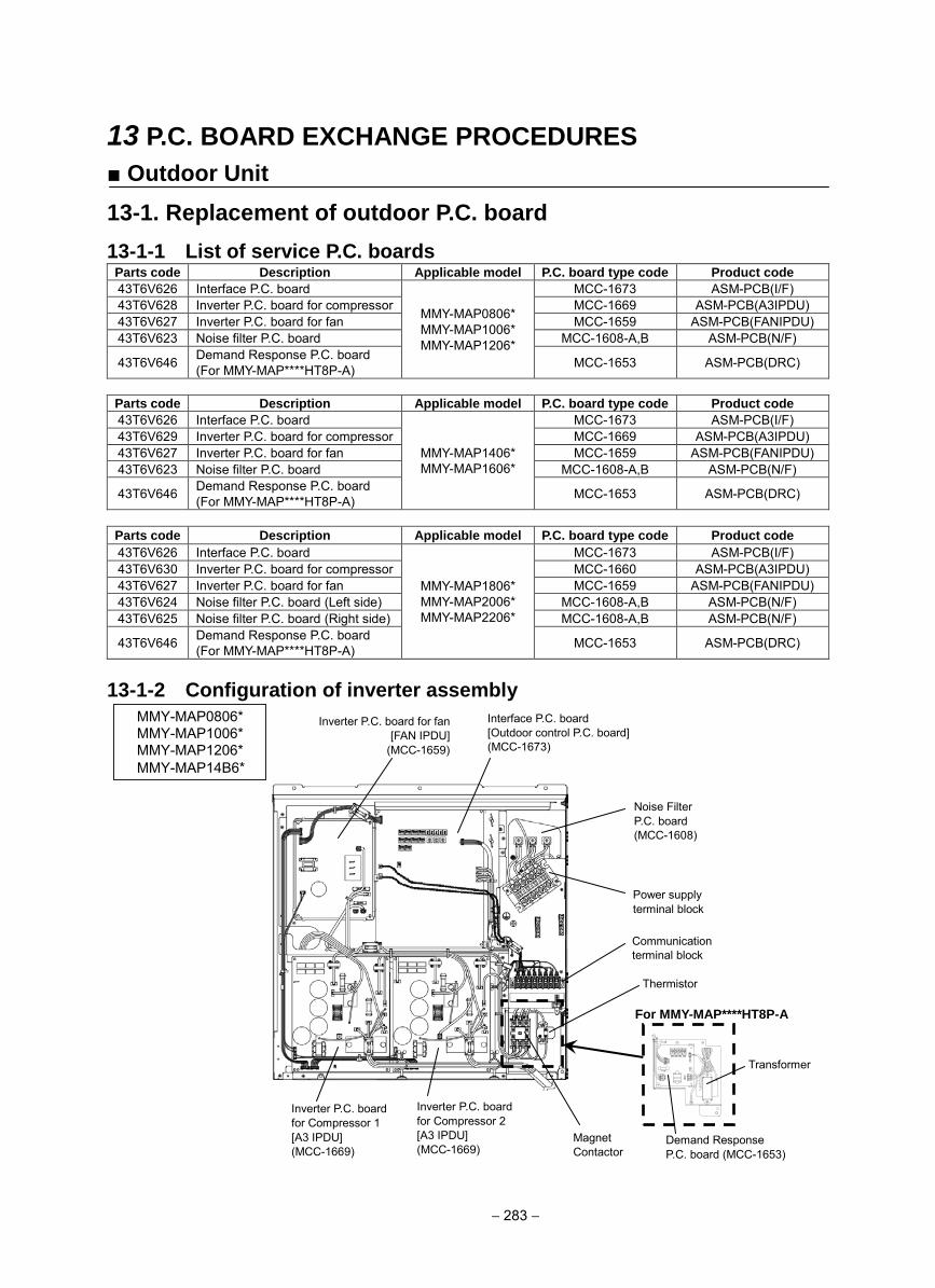
13 P.C. BOARD EXCHANGE PROCEDURES
Outdoor Unit
13-1. Replacement of outdoor P.C. board
13-1-1 List of service P.C. boards Parts code Description Applicable model P.C. board type code Product code
43T6V626 Interface P.C. board
MMY-MAP0806* MMY-MAP1006* MMY-MAP1206*
MCC-1673 ASM-PCB(I/F) 43T6V628 Inverter P.C. board for compressor MCC-1669 ASM-PCB(A3IPDU) 43T6V627 Inverter P.C. board for fan MCC-1659 ASM-PCB(FANIPDU) 43T6V623 Noise filter P.C. board MCC-1608-A,B ASM-PCB(N/F)
43T6V646 Demand Response P.C. board (For MMY-MAP****HT8P-A) MCC-1653 ASM-PCB(DRC)
Parts code Description Applicable model P.C. board type code Product code
43T6V626 Interface P.C. board
MMY-MAP1406* MMY-MAP1606*
MCC-1673 ASM-PCB(I/F) 43T6V629 Inverter P.C. board for compressor MCC-1669 ASM-PCB(A3IPDU) 43T6V627 Inverter P.C. board for fan MCC-1659 ASM-PCB(FANIPDU) 43T6V623 Noise filter P.C. board MCC-1608-A,B ASM-PCB(N/F)
43T6V646 Demand Response P.C. board (For MMY-MAP****HT8P-A) MCC-1653 ASM-PCB(DRC)
Parts code Description Applicable model P.C. board type code Product code
43T6V626 Interface P.C. board
MMY-MAP1806* MMY-MAP2006* MMY-MAP2206*
MCC-1673 ASM-PCB(I/F) 43T6V630 Inverter P.C. board for compressor MCC-1660 ASM-PCB(A3IPDU) 43T6V627 Inverter P.C. board for fan MCC-1659 ASM-PCB(FANIPDU) 43T6V624 Noise filter P.C. board (Left side) MCC-1608-A,B ASM-PCB(N/F) 43T6V625 Noise filter P.C. board (Right side) MCC-1608-A,B ASM-PCB(N/F)
43T6V646 Demand Response P.C. board (For MMY-MAP****HT8P-A) MCC-1653 ASM-PCB(DRC)
13-1-2 Configuration of inverter assembly
Inverter P.C. board for fan [FAN IPDU]
(MCC-1659)
Interface P.C. board [Outdoor control P.C. board] (MCC-1673)
Power supply terminal block
Communication terminal block
Inverter P.C. board for Compressor 2 [A3 IPDU] (MCC-1669)
Inverter P.C. board for Compressor 1 [A3 IPDU] (MCC-1669)
Noise Filter P.C. board (MCC-1608)
MMY-MAP0806* MMY-MAP1006* MMY-MAP1206*MMY-MAP14B6*
Thermistor
Magnet Contactor
For MMY-MAP****HT8P-A
Demand Response P.C. board (MCC-1653)
Transformer
− 283 −
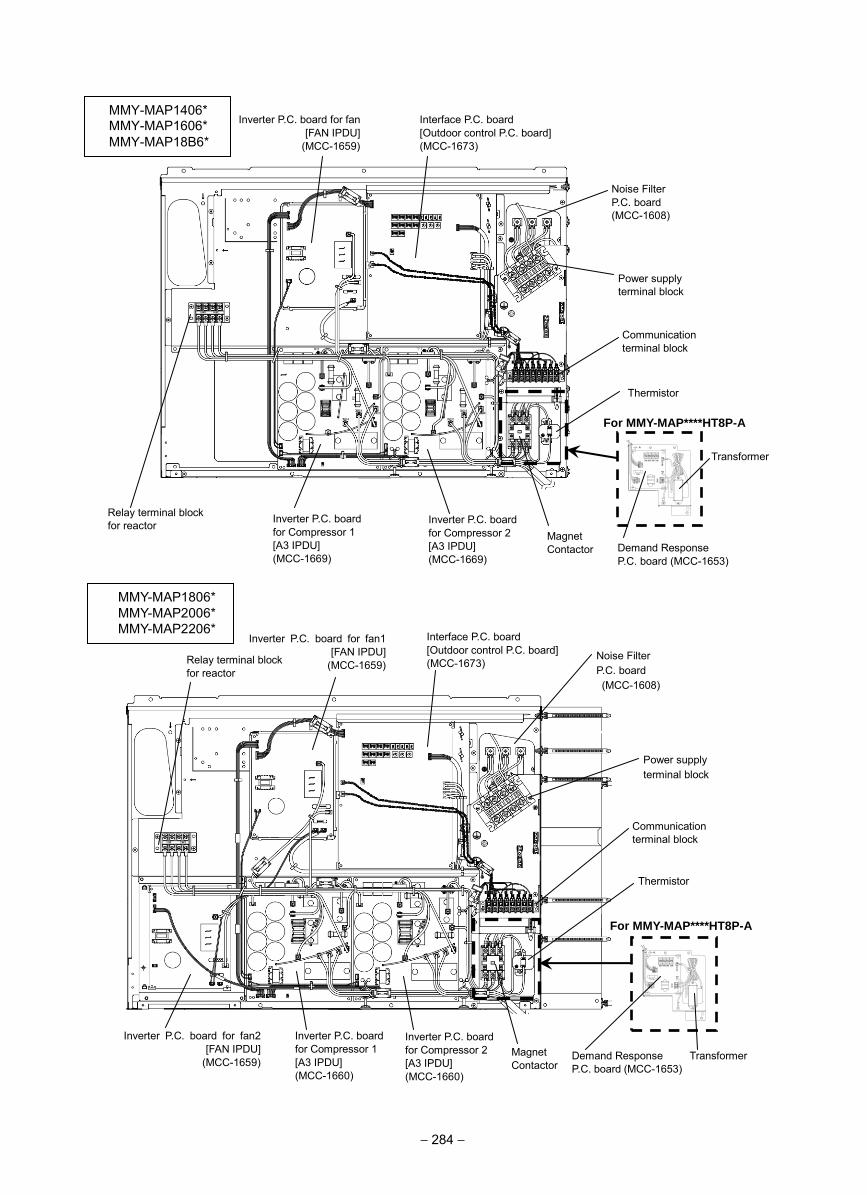
Noise Filter P.C. board (MCC-1608)
Thermistor
Inverter P.C. board for fan [FAN IPDU]
(MCC-1659)
Interface P.C. board [Outdoor control P.C. board] (MCC-1673)
Power supply terminal block
Inverter P.C. board for Compressor 2 [A3 IPDU] (MCC-1669)
Inverter P.C. board for Compressor 1 [A3 IPDU] (MCC-1669)
Inverter P.C. board for fan1 [FAN IPDU]
(MCC-1659)
Interface P.C. board [Outdoor control P.C. board] (MCC-1673)
Power supply terminal block
Inverter P.C. board for Compressor 1 [A3 IPDU] (MCC-1660)
Inverter P.C. board for fan2 [FAN IPDU]
(MCC-1659)
Inverter P.C. board for Compressor 2 [A3 IPDU] (MCC-1660)
Communication terminal block
Noise Filter P.C. board (MCC-1608)
MMY-MAP1806* MMY-MAP2006* MMY-MAP2206*
Relay terminal block for reactor
Magnet Contactor
Communication terminal block
Thermistor
Magnet Contactor
Relay terminal block for reactor
For MMY-MAP****HT8P-A
Demand Response P.C. board (MCC-1653)
Transformer
For MMY-MAP****HT8P-A
Demand Response P.C. board (MCC-1653)
Transformer
− 284 −
MMY-MAP1406* MMY-MAP1606* MMY-MAP18B6*
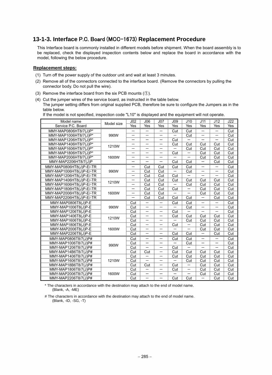
− 285 −
13-1-3. Interface P.C. Board (MCC-1673) Replacement Procedure
This Interface board is commonly installed in different models before shipment. When the board assembly is to be replaced, check the displayed inspection contents below and replace the board in accordance with the model, following the below procedure.
Replacement steps:
(1) Turn off the power supply of the outdoor unit and wait at least 3 minutes. (2) Remove all of the connectors connected to the interface board. (Remove the connectors by pulling the
connector body. Do not pull the wire).
(3) Remove the interface board from the six PCB mounts (①). (4) Cut the jumper wires of the service board, as instructed in the table below.
The jumper setting differs from original supplied PCB, therefore be sure to configure the Jumpers as in the table below. If the model is not specified, inspection code "L10" is displayed and the equipment will not operate.
Model name Model size J02 J06 J07 J09 J10 J11 J12 J22 Service P.C. Board Yes Yes Yes Yes Yes Yes Yes Yes
MMY-MAP0806HT8/7(J)P* 990W
- - - Cut Cut - - Cut MMY-MAP1006HT8/7(J)P* - - - - Cut - - Cut MMY-MAP1206HT8/7(J)P* - - - Cut - - - Cut MMY-MAP1406HT8/7(J)P* 1210W - - - Cut Cut Cut Cut Cut MMY-MAP1606HT8/7(J)P* - - - - Cut Cut Cut Cut MMY-MAP1806HT8/7(J)P*
1600W - - - Cut - Cut Cut Cut
MMY-MAP2006HT8/7(J)P* - - - - - Cut Cut Cut MMY-MAP2206HT8/7(J)P - - - Cut Cut - Cut Cut
MMY-MAP0806HT8(J)P-E/-TR 990W
- Cut Cut Cut Cut - - Cut MMY-MAP1006HT8(J)P-E/-TR - Cut Cut - Cut - - Cut MMY-MAP1206HT8(J)P-E/-TR - Cut Cut Cut - - - Cut MMY-MAP1406HT8(J)P-E/-TR 1210W - Cut Cut Cut Cut Cut Cut Cut MMY-MAP1606HT8(J)P-E/-TR - Cut Cut - Cut Cut Cut Cut MMY-MAP1806HT8(J)P-E/-TR
1600W - Cut Cut Cut - Cut Cut Cut
MMY-MAP2006HT8(J)P-E/-TR - Cut Cut - - Cut Cut Cut MMY-MAP2206HT8(J)P-E/-TR - Cut Cut Cut Cut - Cut Cut
MMY-MAP0806T8(J)P-E 990W
Cut - - Cut Cut - - Cut MMY-MAP1006T8(J)P-E Cut - - - Cut - - Cut MMY-MAP1206T8(J)P-E Cut - - Cut - - - Cut MMY-MAP1406T8(J)P-E 1210W Cut - - Cut Cut Cut Cut Cut MMY-MAP1606T8(J)P-E Cut - - - Cut Cut Cut Cut MMY-MAP1806T8(J)P-E
1600W Cut - - Cut - Cut Cut Cut
MMY-MAP2006T8(J)P-E Cut - - - - Cut Cut Cut MMY-MAP2206T8(J)P-E Cut - - Cut Cut - Cut Cut MMY-MAP0806T8/7(J)P#
990W
Cut - - Cut Cut - - Cut MMY-MAP1006T8/7(J)P# Cut - - - Cut - - Cut MMY-MAP1206T8/7(J)P# Cut - - Cut - - - Cut MMY-MAP14B6T8/7(J)P# Cut Cut - Cut Cut Cut Cut Cut MMY-MAP1406T8/7(J)P#
1210W Cut - - Cut Cut Cut Cut Cut
MMY-MAP1606T8/7(J)P# Cut - - - Cut Cut Cut Cut MMY-MAP18B6T8/7(J)P# Cut Cut - Cut - Cut Cut Cut MMY-MAP1806T8/7(J)P#
1600W Cut - - Cut - Cut Cut Cut
MMY-MAP2006T8/7(J)P# Cut - - - - Cut Cut Cut MMY-MAP2206T8/7(J)P# Cut - - Cut Cut - Cut Cut
* The characters in accordance with the destination may attach to the end of model name. (Blank, -A, -ME)
# The characters in accordance with the destination may attach to the end of model name. (Blank, -ID, -SG, -T)
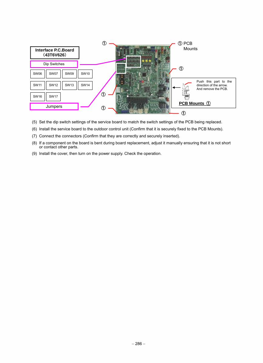
− 286 −
(5) Set the dip switch settings of the service board to match the switch settings of the PCB being replaced.
(6) Install the service board to the outdoor control unit (Confirm that it is securely fixed to the PCB Mounts).
(7) Connect the connectors (Confirm that they are correctly and securely inserted).
(8) If a component on the board is bent during board replacement, adjust it manually ensuring that it is not short or contact other parts.
(9) Install the cover, then turn on the power supply. Check the operation.
Jumpers
SW06 SW07
SW11 SW12
SW17
SW13 SW14
SW16
SW10 SW09
① ①
①
①
① PCBMounts
①
Push this part to the direction of the arrow. And remove the PCB.
PCB Mounts ①
Interface P.C.Board (43T6V626)
Dip Switches
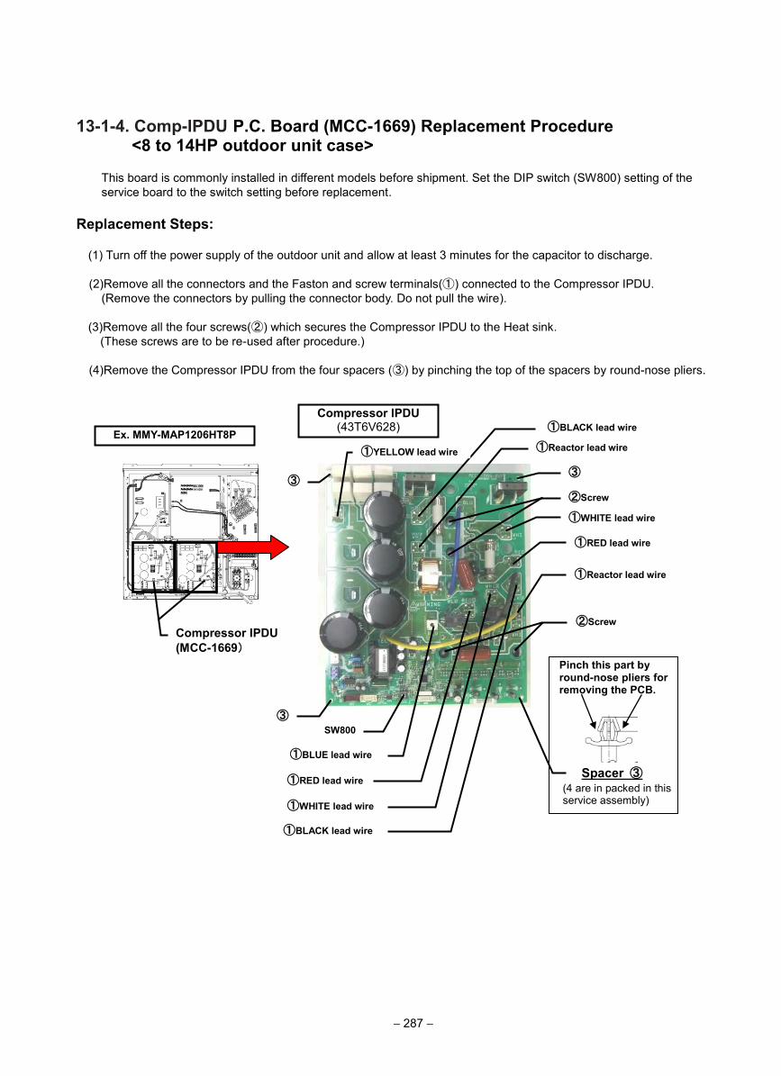
13-1-4. Comp-IPDU P.C. Board (MCC-1669) Replacement Procedure <8 to 14HP outdoor unit case>
This board is commonly installed in different models before shipment. Set the DIP switch (SW800) setting of the service board to the switch setting before replacement.
Replacement Steps:
(1) Turn off the power supply of the outdoor unit and allow at least 3 minutes for the capacitor to discharge.
(2)Remove all the connectors and the Faston and screw terminals(①) connected to the Compressor IPDU. (Remove the connectors by pulling the connector body. Do not pull the wire).
(3)Remove all the four screws(②) which secures the Compressor IPDU to the Heat sink. (These screws are to be re-used after procedure.)
(4)Remove the Compressor IPDU from the four spacers (③) by pinching the top of the spacers by round-nose pliers.
③ ③
②Screw
①RED lead wire
①Reactor lead wire
③
Compressor IPDU (43T6V628)
Compressor IPDU (MCC-1669)
①WHITE lead wire
①BLACK lead wire
①Reactor lead wire
①RED lead wire
①WHITE lead wire
①BLACK lead wire
②Screw
SW800
Ex. MMY-MAP1206HT8P
Pinch this part by round-nose pliers for removing the PCB.
Spacer ③(4 are in packed in this service assembly)
①BLUE lead wire
①YELLOW lead wire
− 287 −
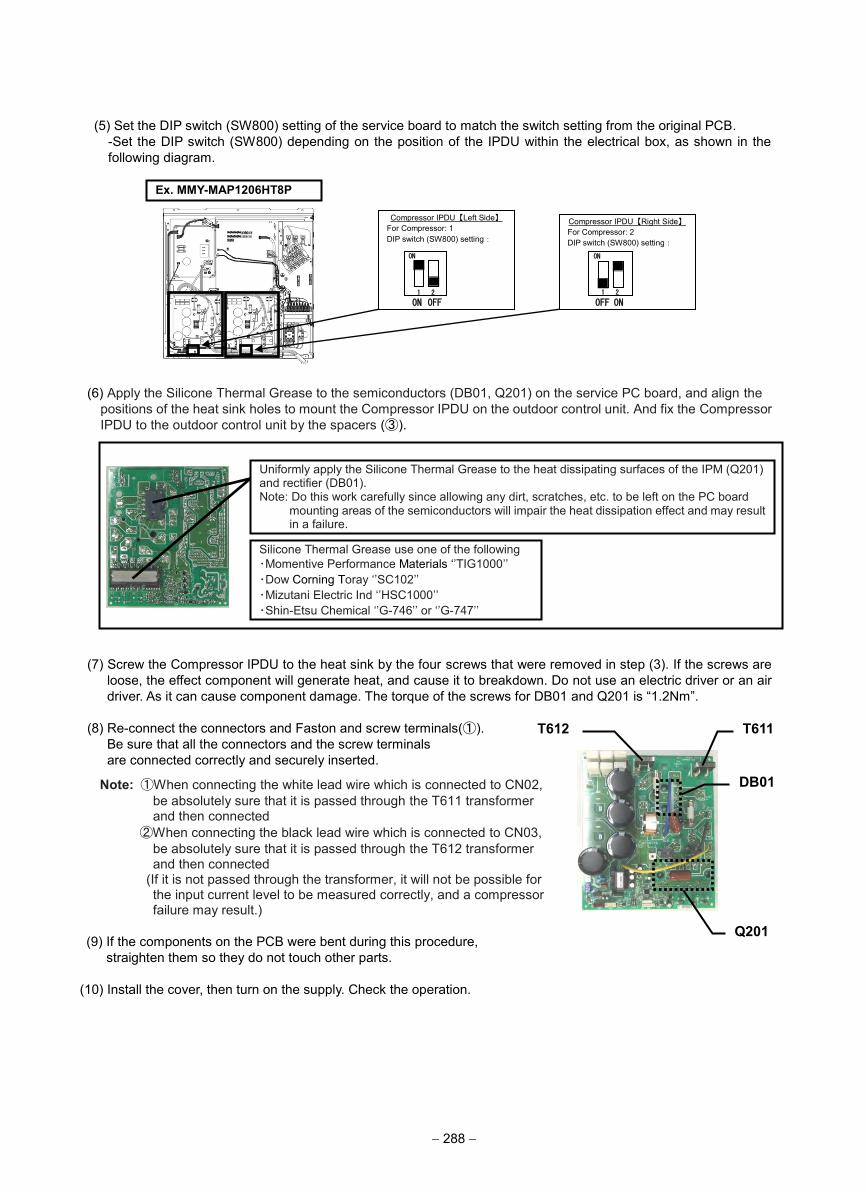
(5) Set the DIP switch (SW800) setting of the service board to match the switch setting from the original PCB. -Set the DIP switch (SW800) depending on the position of the IPDU within the electrical box, as shown in the following diagram.
(6) Apply the Silicone Thermal Grease to the semiconductors (DB01, Q201) on the service PC board, and align the positions of the heat sink holes to mount the Compressor IPDU on the outdoor control unit. And fix the Compressor IPDU to the outdoor control unit by the spacers (③).
(7) Screw the Compressor IPDU to the heat sink by the four screws that were removed in step (3). If the screws are loose, the effect component will generate heat, and cause it to breakdown. Do not use an electric driver or an air driver. As it can cause component damage. The torque of the screws for DB01 and Q201 is “1.2Nm”.
(8) Re-connect the connectors and Faston and screw terminals(①). Be sure that all the connectors and the screw terminals are connected correctly and securely inserted.
Note: ①When connecting the white lead wire which is connected to CN02, be absolutely sure that it is passed through the T611 transformer and then connected ②When connecting the black lead wire which is connected to CN03,
be absolutely sure that it is passed through the T612 transformerand then connected
(If it is not passed through the transformer, it will not be possible for the input current level to be measured correctly, and a compressor failure may result.)
(9) If the components on the PCB were bent during this procedure, straighten them so they do not touch other parts.
(10) Install the cover, then turn on the supply. Check the operation.
Compressor IPDU【Left Side】 For Compressor: 1 DIP switch (SW800) setting:
Compressor IPDU【Right Side】 For Compressor: 2 DIP switch (SW800) setting:
ON
Ex. MMY-MAP1206HT8P
ON
OFF OFF ON 1 2 1 2
ON
Uniformly apply the Silicone Thermal Grease to the heat dissipating surfaces of the IPM (Q201) and rectifier (DB01). Note: Do this work carefully since allowing any dirt, scratches, etc. to be left on the PC board
mounting areas of the semiconductors will impair the heat dissipation effect and may result in a failure.
Silicone Thermal Grease use one of the following ・Momentive Performance Materials ‘’TIG1000’’ ・Dow Corning Toray ‘’SC102’’ ・Mizutani Electric Ind ‘’HSC1000’’ ・Shin-Etsu Chemical ‘’G-746’’ or ‘’G-747’’
T612 T611
DB01
Q201
− 288 −
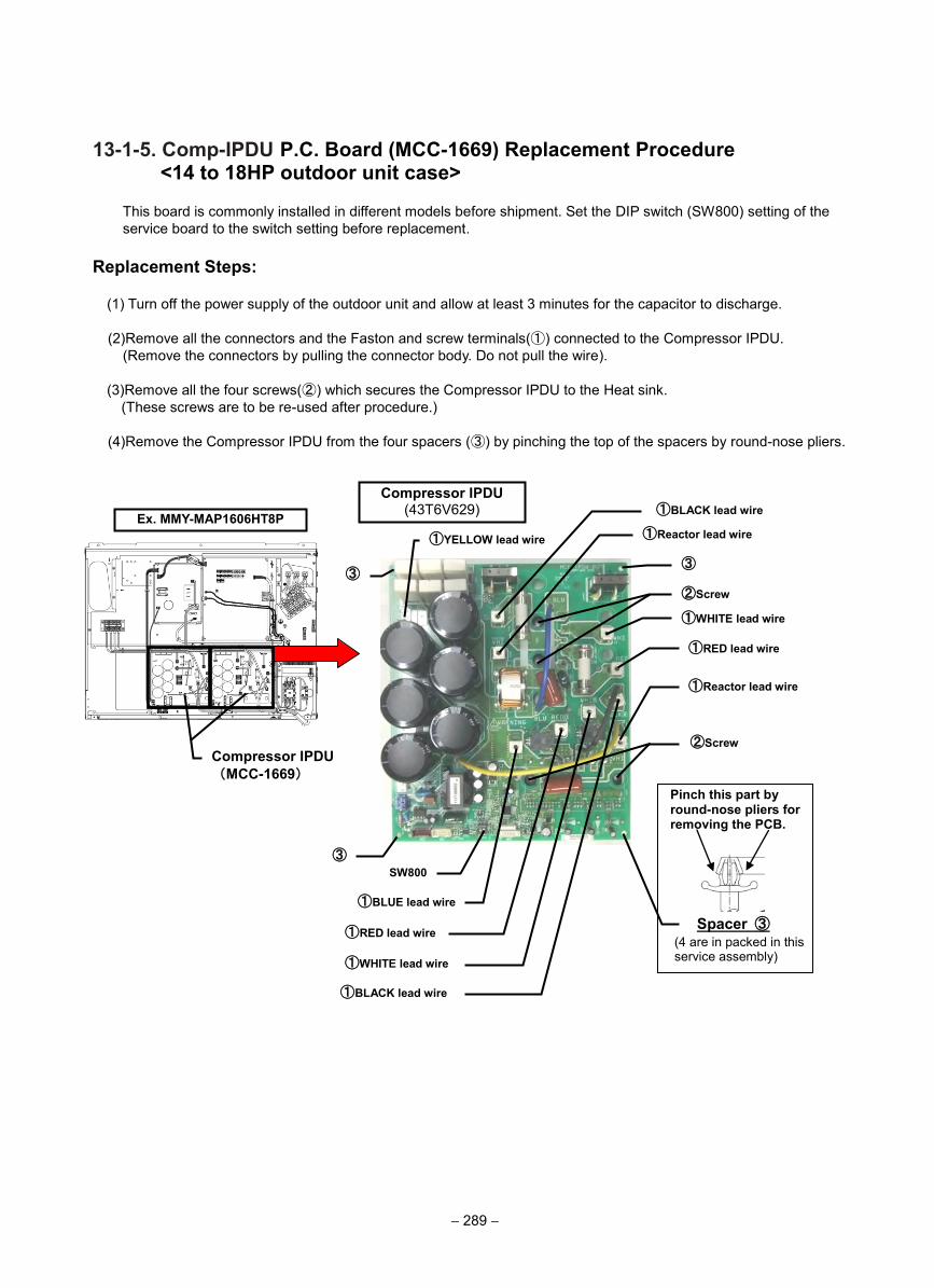
13-1-5. Comp-IPDU P.C. Board (MCC-1669) Replacement Procedure <14 to 18HP outdoor unit case>
This board is commonly installed in different models before shipment. Set the DIP switch (SW800) setting of the service board to the switch setting before replacement.
Replacement Steps:
(1) Turn off the power supply of the outdoor unit and allow at least 3 minutes for the capacitor to discharge.
(2)Remove all the connectors and the Faston and screw terminals(①) connected to the Compressor IPDU. (Remove the connectors by pulling the connector body. Do not pull the wire).
(3)Remove all the four screws(②) which secures the Compressor IPDU to the Heat sink. (These screws are to be re-used after procedure.)
(4)Remove the Compressor IPDU from the four spacers (③) by pinching the top of the spacers by round-nose pliers.
③ ③
②Screw
①RED lead wire
①Reactor lead wire
③
Compressor IPDU (43T6V629)
Compressor IPDU (MCC-1669)
①WHITE lead wire
①BLACK lead wire
①Reactor lead wire
①RED lead wire
①WHITE lead wire
①BLACK lead wire
②Screw
SW800
Ex. MMY-MAP1606HT8P
Pinch this part by round-nose pliers for removing the PCB.
Spacer ③(4 are in packed in this service assembly)
①BLUE lead wire
①YELLOW lead wire
− 289 −
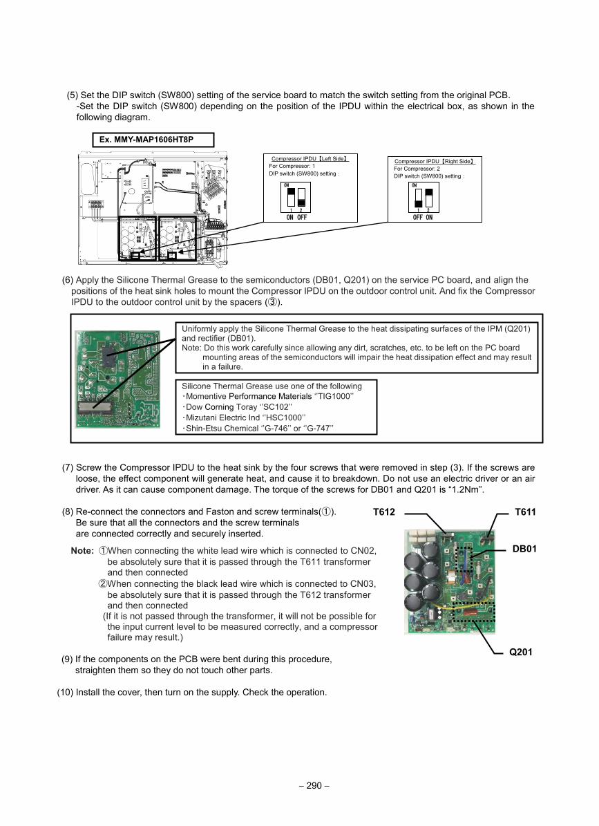
(5) Set the DIP switch (SW800) setting of the service board to match the switch setting from the original PCB. -Set the DIP switch (SW800) depending on the position of the IPDU within the electrical box, as shown in the following diagram.
(6) Apply the Silicone Thermal Grease to the semiconductors (DB01, Q201) on the service PC board, and align the positions of the heat sink holes to mount the Compressor IPDU on the outdoor control unit. And fix the Compressor IPDU to the outdoor control unit by the spacers (③).
(7) Screw the Compressor IPDU to the heat sink by the four screws that were removed in step (3). If the screws are loose, the effect component will generate heat, and cause it to breakdown. Do not use an electric driver or an air driver. As it can cause component damage. The torque of the screws for DB01 and Q201 is “1.2Nm”.
(8) Re-connect the connectors and Faston and screw terminals(①). Be sure that all the connectors and the screw terminals are connected correctly and securely inserted.
Note: ①When connecting the white lead wire which is connected to CN02, be absolutely sure that it is passed through the T611 transformer and then connected ②When connecting the black lead wire which is connected to CN03,
be absolutely sure that it is passed through the T612 transformerand then connected
(If it is not passed through the transformer, it will not be possible for the input current level to be measured correctly, and a compressor failure may result.)
(9) If the components on the PCB were bent during this procedure, straighten them so they do not touch other parts.
(10) Install the cover, then turn on the supply. Check the operation.
Compressor IPDU【Left Side】 For Compressor: 1 DIP switch (SW800) setting:
Compressor IPDU【Right Side】 For Compressor: 2 DIP switch (SW800) setting:
ON
Ex. MMY-MAP1606HT8P
ON
OFF OFF ON 1 2 1 2
ON
Uniformly apply the Silicone Thermal Grease to the heat dissipating surfaces of the IPM (Q201) and rectifier (DB01). Note: Do this work carefully since allowing any dirt, scratches, etc. to be left on the PC board
mounting areas of the semiconductors will impair the heat dissipation effect and may result in a failure.
Silicone Thermal Grease use one of the following ・Momentive Performance Materials ‘’TIG1000’’ ・Dow Corning Toray ‘’SC102’’ ・Mizutani Electric Ind ‘’HSC1000’’ ・Shin-Etsu Chemical ‘’G-746’’ or ‘’G-747’’
T612 T611
DB01
Q201
− 290 −
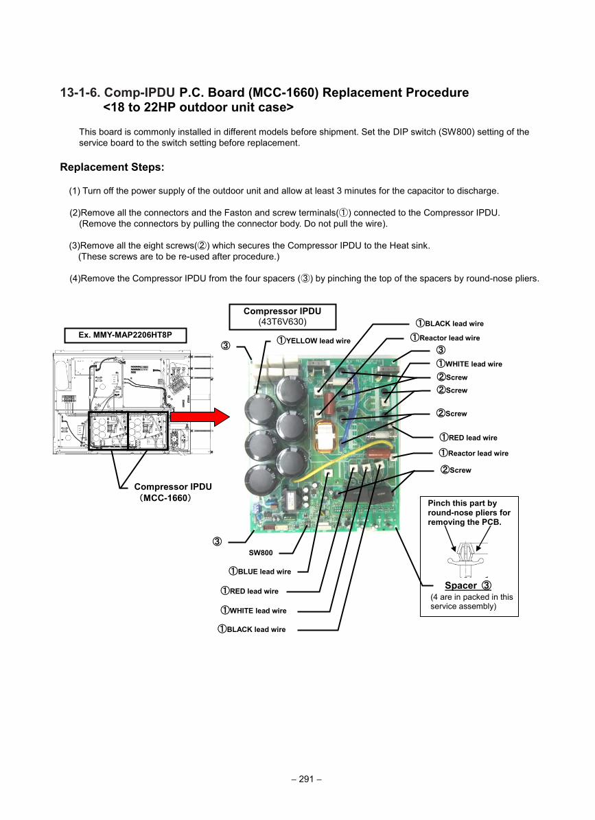
13-1-6. Comp-IPDU P.C. Board (MCC-1660) Replacement Procedure <18 to 22HP outdoor unit case>
This board is commonly installed in different models before shipment. Set the DIP switch (SW800) setting of the service board to the switch setting before replacement.
Replacement Steps:
(1) Turn off the power supply of the outdoor unit and allow at least 3 minutes for the capacitor to discharge.
(2)Remove all the connectors and the Faston and screw terminals(①) connected to the Compressor IPDU. (Remove the connectors by pulling the connector body. Do not pull the wire).
(3)Remove all the eight screws(②) which secures the Compressor IPDU to the Heat sink. (These screws are to be re-used after procedure.)
(4)Remove the Compressor IPDU from the four spacers (③) by pinching the top of the spacers by round-nose pliers.
③ ③
②Screw
①RED lead wire
①Reactor lead wire
③
Compressor IPDU (43T6V630)
Compressor IPDU (MCC-1660)
①WHITE lead wire
①BLACK lead wire
①Reactor lead wire
①RED lead wire
①WHITE lead wire
①BLACK lead wire
②Screw
SW800
Ex. MMY-MAP2206HT8P
Pinch this part by round-nose pliers for removing the PCB.
Spacer ③(4 are in packed in this service assembly)
①BLUE lead wire
①YELLOW lead wire
②Screw
②Screw
− 291 −
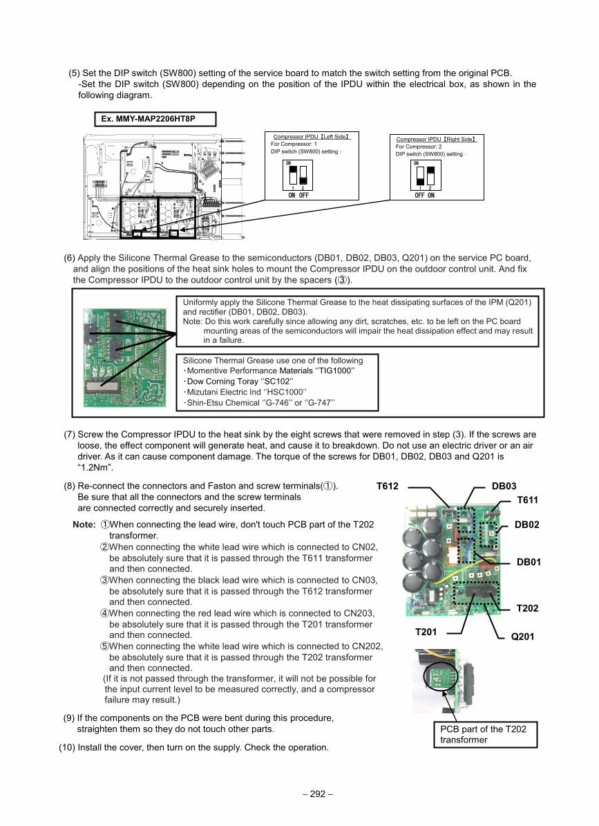
(5) Set the DIP switch (SW800) setting of the service board to match the switch setting from the original PCB. -Set the DIP switch (SW800) depending on the position of the IPDU within the electrical box, as shown in the following diagram.
(6) Apply the Silicone Thermal Grease to the semiconductors (DB01, DB02, DB03, Q201) on the service PC board, and align the positions of the heat sink holes to mount the Compressor IPDU on the outdoor control unit. And fix the Compressor IPDU to the outdoor control unit by the spacers (③).
(7) Screw the Compressor IPDU to the heat sink by the eight screws that were removed in step (3). If the screws are loose, the effect component will generate heat, and cause it to breakdown. Do not use an electric driver or an air driver. As it can cause component damage. The torque of the screws for DB01, DB02, DB03 and Q201 is “1.2Nm”.
(8) Re-connect the connectors and Faston and screw terminals(①). Be sure that all the connectors and the screw terminals are connected correctly and securely inserted.
Note: ①When connecting the lead wire, don't touch PCB part of the T202 transformer.
②When connecting the white lead wire which is connected to CN02,be absolutely sure that it is passed through the T611 transformerand then connected.
③When connecting the black lead wire which is connected to CN03,be absolutely sure that it is passed through the T612 transformerand then connected.④When connecting the red lead wire which is connected to CN203,
be absolutely sure that it is passed through the T201 transformerand then connected.⑤When connecting the white lead wire which is connected to CN202,
be absolutely sure that it is passed through the T202 transformerand then connected.
(If it is not passed through the transformer, it will not be possible for the input current level to be measured correctly, and a compressor failure may result.)
(9) If the components on the PCB were bent during this procedure, straighten them so they do not touch other parts.
(10) Install the cover, then turn on the supply. Check the operation.
Compressor IPDU【Left Side】 For Compressor: 1 DIP switch (SW800) setting:
Compressor IPDU【Right Side】 For Compressor: 2 DIP switch (SW800) setting:
ON
Ex. MMY-MAP2206HT8P
ON
OFF OFF ON 1 2 1 2
ON
Uniformly apply the Silicone Thermal Grease to the heat dissipating surfaces of the IPM (Q201) and rectifier (DB01, DB02, DB03). Note: Do this work carefully since allowing any dirt, scratches, etc. to be left on the PC board
mounting areas of the semiconductors will impair the heat dissipation effect and may result in a failure.
Silicone Thermal Grease use one of the following ・Momentive Performance Materials ‘’TIG1000’’ ・Dow Corning Toray ‘’SC102’’ ・Mizutani Electric Ind ‘’HSC1000’’ ・Shin-Etsu Chemical ‘’G-746’’ or ‘’G-747’’
T612 T611
DB03
Q201
DB02
DB01
T201
T202
PCB part of the T202 transformer
− 292 −
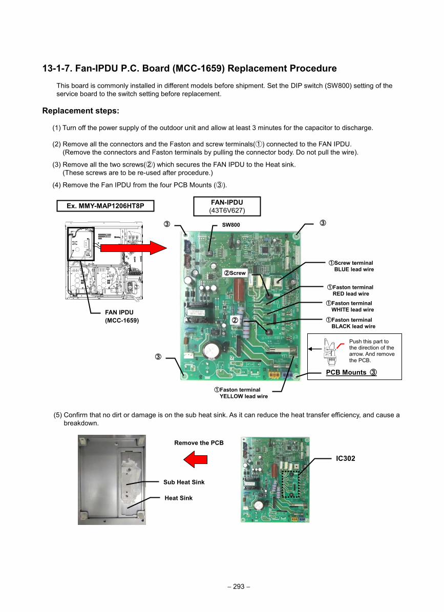
13-1-7. Fan-IPDU P.C. Board (MCC-1659) Replacement ProcedureThis board is commonly installed in different models before shipment. Set the DIP switch (SW800) setting of the service board to the switch setting before replacement.
Replacement steps:
(1) Turn off the power supply of the outdoor unit and allow at least 3 minutes for the capacitor to discharge.
(2) Remove all the connectors and the Faston and screw terminals(①) connected to the FAN IPDU. (Remove the connectors and Faston terminals by pulling the connector body. Do not pull the wire).
(3) Remove all the two screws(②) which secures the FAN IPDU to the Heat sink. (These screws are to be re-used after procedure.)
(4) Remove the Fan IPDU from the four PCB Mounts (③).
(5) Confirm that no dirt or damage is on the sub heat sink. As it can reduce the heat transfer efficiency, and cause a breakdown.
PCB Mounts ③
②
②Screw
①Faston terminalWHITE lead wire
③
FAN IPDU (MCC-1659)
Remove the PCB
IC302
Push this part to the direction of the arrow. And remove the PCB.
Ex. MMY-MAP1206HT8P FAN-IPDU (43T6V627)
③
①Faston terminalRED lead wire
①Faston terminalBLACK lead wire
③
①Screw terminalBLUE lead wire
SW800
Sub Heat Sink
Heat Sink
①Faston terminalYELLOW lead wire
− 293 −
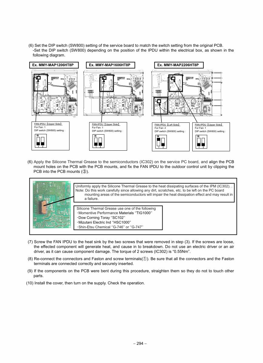
(6) Set the DIP switch (SW800) setting of the service board to match the switch setting from the original PCB. -Set the DIP switch (SW800) depending on the position of the IPDU within the electrical box, as shown in the following diagram.
(6) Apply the Silicone Thermal Grease to the semiconductors (IC302) on the service PC board, and align the PCB mount holes on the PCB with the PCB mounts, and fix the FAN IPDU to the outdoor control unit by clipping the PCB into the PCB mounts (③).
(7) Screw the FAN IPDU to the heat sink by the two screws that were removed in step (3). If the screws are loose, the effected component will generate heat, and cause in to breakdown. Do not use an electric driver or an air driver, as it can cause component damage. The torque of 2 screws (IC302) is “0.55Nm”.
(8) Re-connect the connectors and Faston and screw terminals(①). Be sure that all the connectors and the Faston terminals are connected correctly and securely inserted.
(9) If the components on the PCB were bent during this procedure, straighten them so they do not to touch other parts.
(10) Install the cover, then turn on the supply. Check the operation.
Ex. MMY-MAP1206HT8P Ex. MMY-MAP1606HT8P
FAN-IPDU【Upper Side】 For Fan: 1 DIP switch (SW800) setting:
ON
1 2
FAN-IPDU【Upper Side】 For Fan: 1 DIP switch (SW800) setting:
ON
1 2
Ex. MMY-MAP2206HT8P
FAN-IPDU【Upper Side】 For Fan: 1 DIP switch (SW800) setting:
ON
1 2
FAN-IPDU【Left Side】 For Fan: 2 DIP switch (SW800) setting:
ON
1 2
Uniformly apply the Silicone Thermal Grease to the heat dissipating surfaces of the IPM (IC302). . Note: Do this work carefully since allowing any dirt, scratches, etc. to be left on the PC board
mounting areas of the semiconductors will impair the heat dissipation effect and may result in a failure.
Silicone Thermal Grease use one of the following ・Momentive Performance Materials ‘’TIG1000’’ ・Dow Corning Toray ‘’SC102’’ ・Mizutani Electric Ind ‘’HSC1000’’ ・Shin-Etsu Chemical ‘’G-746’’ or ‘’G-747’’
− 294 −
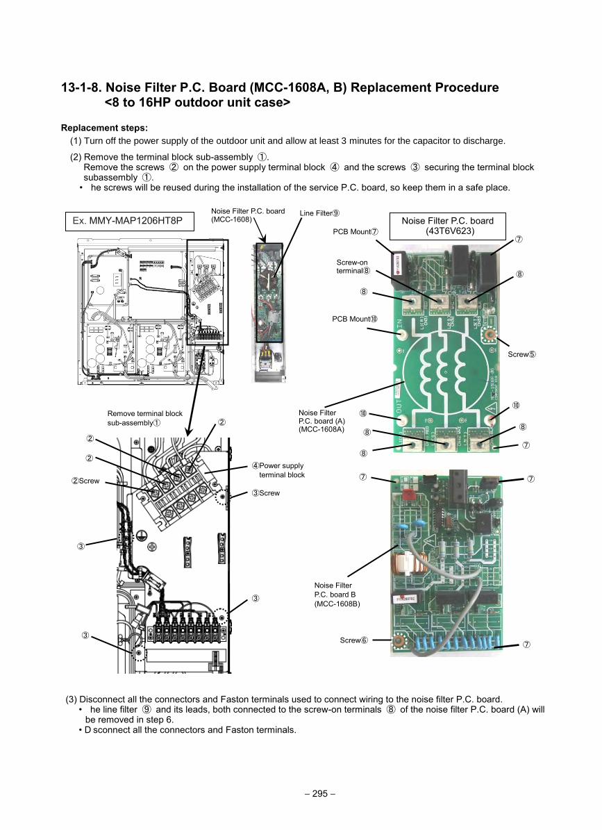
13-1-8. Noise Filter P.C. Board (MCC-1608A, B) Replacement Procedure <8 to 16HP outdoor unit case>
Replacement steps: (1) Turn off the power supply of the outdoor unit and allow at least 3 minutes for the capacitor to discharge.
(2) Remove the terminal block sub-assembly ①. Remove the screws ② on the power supply terminal block ④ and the screws ③ securing the terminal block subassembly ①.
• he screws will be reused during the installation of the service P.C. board, so keep them in a safe place.
(3) Disconnect all the connectors and Faston terminals used to connect wiring to the noise filter P.C. board. • he line filter ⑨ and its leads, both connected to the screw-on terminals ⑧ of the noise filter P.C. board (A) will
be removed in step 6.• D sconnect all the connectors and Faston terminals.
Ex. MMY-MAP1206HT8P Noise Filter P.C. board(MCC-1608) Noise Filter P.C. board
(43T6V623) PCB Mount⑦⑦
⑦
Screw⑤
⑧
Screw-on terminal⑧ ⑧
⑧
⑧
⑧
Noise Filter P.C. board (A) (MCC-1608A)
Noise Filter P.C. board B (MCC-1608B)
⑦
Line Filter⑨
Remove terminal block sub-assembly①
②Screw③Screw
④Power supplyterminal block
③
③
Screw⑥
PCB Mount⑩
⑦
⑦
②
②
③
⑩ ⑩
②
− 295 −
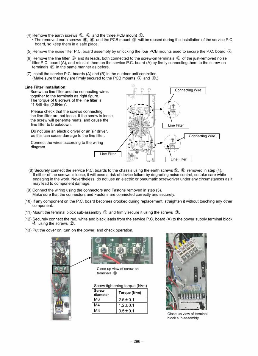
(4) Remove the earth screws ⑤, ⑥ and the three PCB mount ⑩. • The removed earth screws ⑤, ⑥ and the PCB mount ⑩ will be reused during the installation of the service P.C.
board, so keep them in a safe place.
(5) Remove the noise filter P.C. board assembly by unlocking the four PCB mounts used to secure the P.C. board ⑦.
(6) Remove the line filter ⑨ and its leads, both connected to the screw-on terminals ⑧ of the just-removed noise filter P.C. board (A), and reinstall them on the service P.C. board (A) by firmly connecting them to the screw-on terminals ⑧ in the same manner as before.
(7) Install the service P.C. boards (A) and (B) in the outdoor unit controller. (Make sure that they are firmly secured to the PCB mounts ⑦ and ⑩.)
Line Filter installation: Screw the line filter and the connecting wires together to the terminals as right figure. The torque of 6 screws of the line filter is “1.84ft・lbs (2.5Nm)”.
Please check that the screws connecting the line filter are not loose. If the screw is loose, the screw will generate heats, and cause the line filter to breakdown.
Do not use an electric driver or an air driver, as this can cause damage to the line filter.
Connect the wires according to the wiring diagram.
(8) Securely connect the service P.C. boards to the chassis using the earth screws ⑤, ⑥ removed in step (4). If either of the screws is loose, it will pose a risk of device failure by degrading noise control, so take care while engaging in the work. Nevertheless, do not use an electric or pneumatic screwdriver under any circumstances as it may lead to component damage.
(9) Connect the wiring using the connectors and Fastons removed in step (3). Make sure that the connectors and Fastons are connected correctly and securely.
(10) If any component on the P.C. board becomes crooked during replacement, straighten it without touching any other component.
(11) Mount the terminal block sub-assembly ① and firmly secure it using the screws ③.
(12) Securely connect the red, white and black leads from the service P.C. board (A) to the power supply terminal block ④ using the screws ②.
(13) Put the cover on, turn on the power, and check operation.
Connecting Wire
Line Filter
Line Filter
Connecting Wire
Line Filter
Screw tightening torque (N•m) Screw diameter Torque (N•m)
M6 2.5±0.1 M4 1.2±0.1 M3 0.5±0.1
Close-up view of terminal block sub-assembly
Close-up view of screw-on terminals ⑧
− 296 −
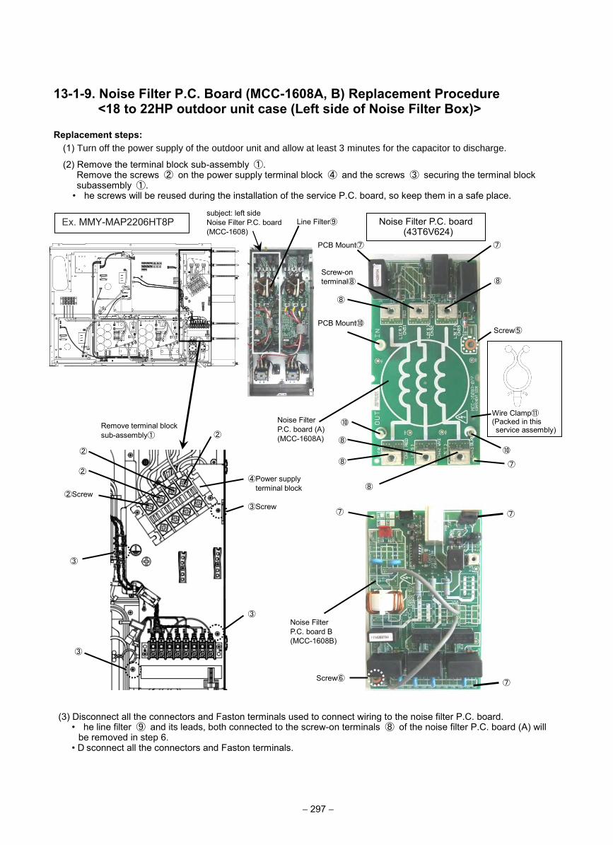
13-1-9. Noise Filter P.C. Board (MCC-1608A, B) Replacement Procedure <18 to 22HP outdoor unit case (Left side of Noise Filter Box)>
Replacement steps: (1) Turn off the power supply of the outdoor unit and allow at least 3 minutes for the capacitor to discharge.
(2) Remove the terminal block sub-assembly ①. Remove the screws ② on the power supply terminal block ④ and the screws ③ securing the terminal block subassembly ①.
• he screws will be reused during the installation of the service P.C. board, so keep them in a safe place.
(3) Disconnect all the connectors and Faston terminals used to connect wiring to the noise filter P.C. board. • he line filter ⑨ and its leads, both connected to the screw-on terminals ⑧ of the noise filter P.C. board (A) will
be removed in step 6.• D sconnect all the connectors and Faston terminals.
Ex. MMY-MAP2206HT8P subject: left side Noise Filter P.C. board(MCC-1608)
Noise Filter P.C. board (43T6V624)
PCB Mount⑦ ⑦
Screw⑤
⑧
Screw-on terminal⑧ ⑧
⑧
⑧
⑧
Noise Filter P.C. board (A) (MCC-1608A)
Noise Filter P.C. board B (MCC-1608B)
⑦
Line Filter⑨
Remove terminal block sub-assembly①
②Screw③Screw
④Power supplyterminal block
③
③
Screw⑥
PCB Mount⑩
⑦
⑦
②
②
③
⑩
⑩
②
⑦
Wire Clamp⑪ (Packed in this service assembly)
− 297 −
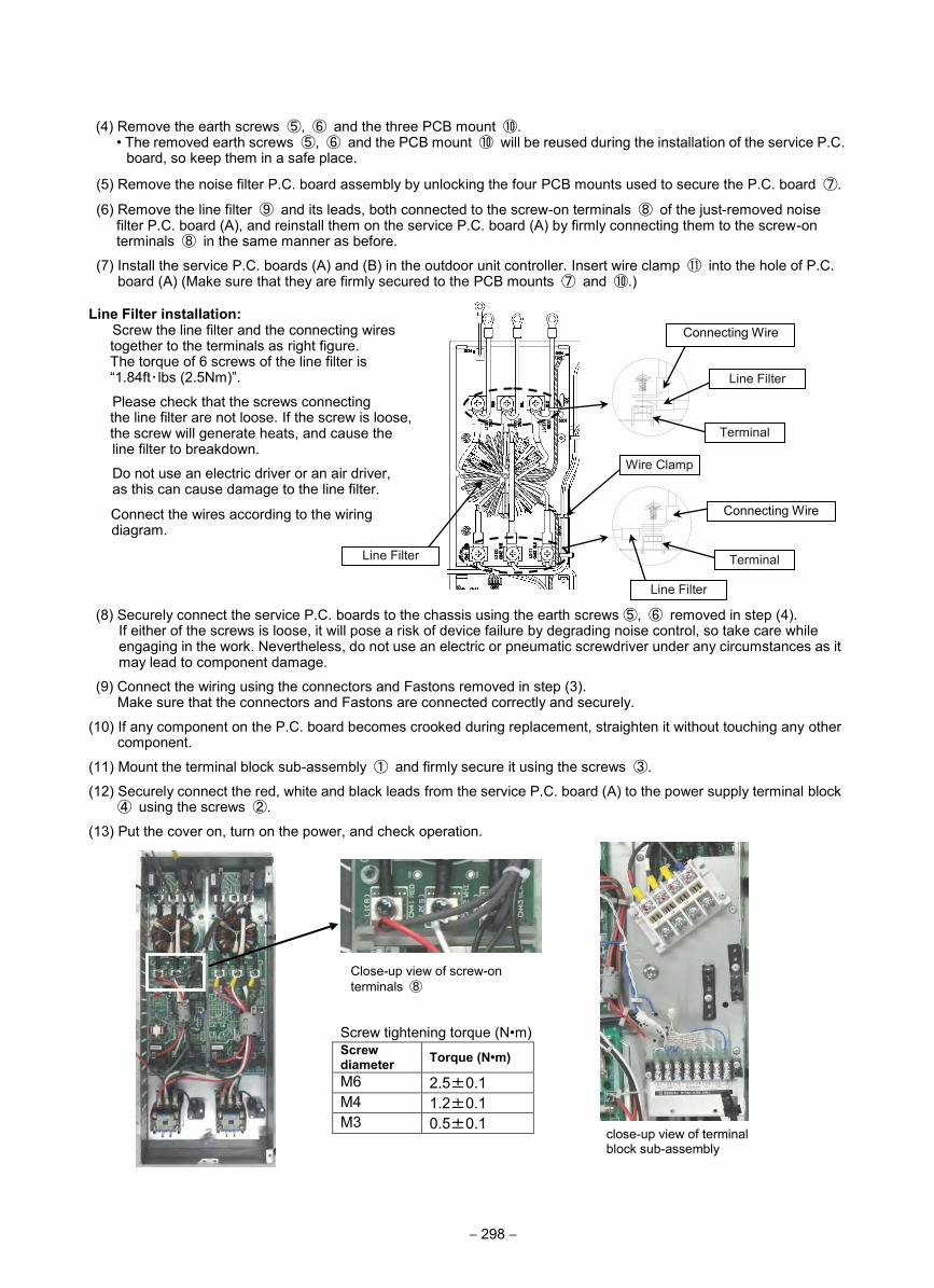
(4) Remove the earth screws ⑤, ⑥ and the three PCB mount ⑩. • The removed earth screws ⑤, ⑥ and the PCB mount ⑩ will be reused during the installation of the service P.C.
board, so keep them in a safe place.
(5) Remove the noise filter P.C. board assembly by unlocking the four PCB mounts used to secure the P.C. board ⑦.
(6) Remove the line filter ⑨ and its leads, both connected to the screw-on terminals ⑧ of the just-removed noise filter P.C. board (A), and reinstall them on the service P.C. board (A) by firmly connecting them to the screw-on terminals ⑧ in the same manner as before.
(7) Install the service P.C. boards (A) and (B) in the outdoor unit controller. Insert wire clamp ⑪ into the hole of P.C. board (A) (Make sure that they are firmly secured to the PCB mounts ⑦ and ⑩.)
Line Filter installation: Screw the line filter and the connecting wires together to the terminals as right figure. The torque of 6 screws of the line filter is “1.84ft・lbs (2.5Nm)”.
Please check that the screws connecting the line filter are not loose. If the screw is loose, the screw will generate heats, and cause the line filter to breakdown.
Do not use an electric driver or an air driver, as this can cause damage to the line filter.
Connect the wires according to the wiring diagram.
(8) Securely connect the service P.C. boards to the chassis using the earth screws ⑤, ⑥ removed in step (4). If either of the screws is loose, it will pose a risk of device failure by degrading noise control, so take care while engaging in the work. Nevertheless, do not use an electric or pneumatic screwdriver under any circumstances as it may lead to component damage.
(9) Connect the wiring using the connectors and Fastons removed in step (3). Make sure that the connectors and Fastons are connected correctly and securely.
(10) If any component on the P.C. board becomes crooked during replacement, straighten it without touching any other component.
(11) Mount the terminal block sub-assembly ① and firmly secure it using the screws ③.
(12) Securely connect the red, white and black leads from the service P.C. board (A) to the power supply terminal block ④ using the screws ②.
(13) Put the cover on, turn on the power, and check operation.
Connecting Wire
Line Filter
Line Filter
Connecting Wire
Line Filter
Screw tightening torque (N•m) Screw diameter Torque (N•m)
M6 2.5±0.1 M4 1.2±0.1 M3 0.5±0.1
close-up view of terminal block sub-assembly
Close-up view of screw-on terminals ⑧
Terminal
Terminal
Wire Clamp
− 298 −
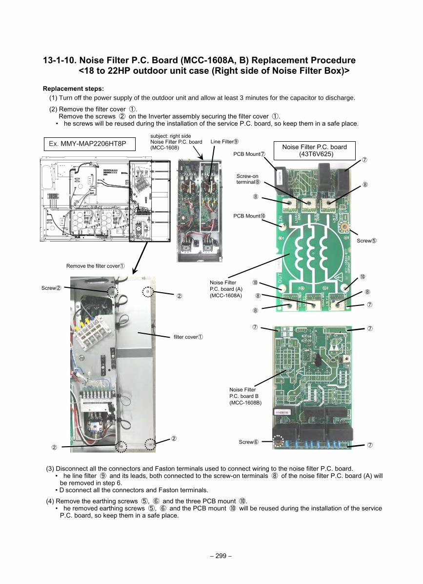
13-1-10. Noise Filter P.C. Board (MCC-1608A, B) Replacement Procedure <18 to 22HP outdoor unit case (Right side of Noise Filter Box)>
Replacement steps: (1) Turn off the power supply of the outdoor unit and allow at least 3 minutes for the capacitor to discharge.
(2) Remove the filter cover ①. Remove the screws ② on the Inverter assembly securing the filter cover ①.
• he screws will be reused during the installation of the service P.C. board, so keep them in a safe place.
(3) Disconnect all the connectors and Faston terminals used to connect wiring to the noise filter P.C. board. • he line filter ⑨ and its leads, both connected to the screw-on terminals ⑧ of the noise filter P.C. board (A) will
be removed in step 6.• D sconnect all the connectors and Faston terminals.
(4) Remove the earthing screws ⑤, ⑥ and the three PCB mount ⑩. • he removed earthing screws ⑤, ⑥ and the PCB mount ⑩ will be reused during the installation of the service
P.C. board, so keep them in a safe place.
Ex. MMY-MAP2206HT8P subject: right side Noise Filter P.C. board(MCC-1608) Noise Filter P.C. board
(43T6V625) PCB Mount⑦⑦
⑦
Screw⑤
⑧
Screw-on terminal⑧
⑧
⑧
⑧
⑧
Noise Filter P.C. board (A) (MCC-1608A)
Noise Filter P.C. board B (MCC-1608B)
⑦
Line Filter⑨
Remove the filter cover①
② Screw⑥
PCB Mount⑩
⑦
⑦
S crew②
②
⑩ ⑩
②
filter cover①
− 299 −
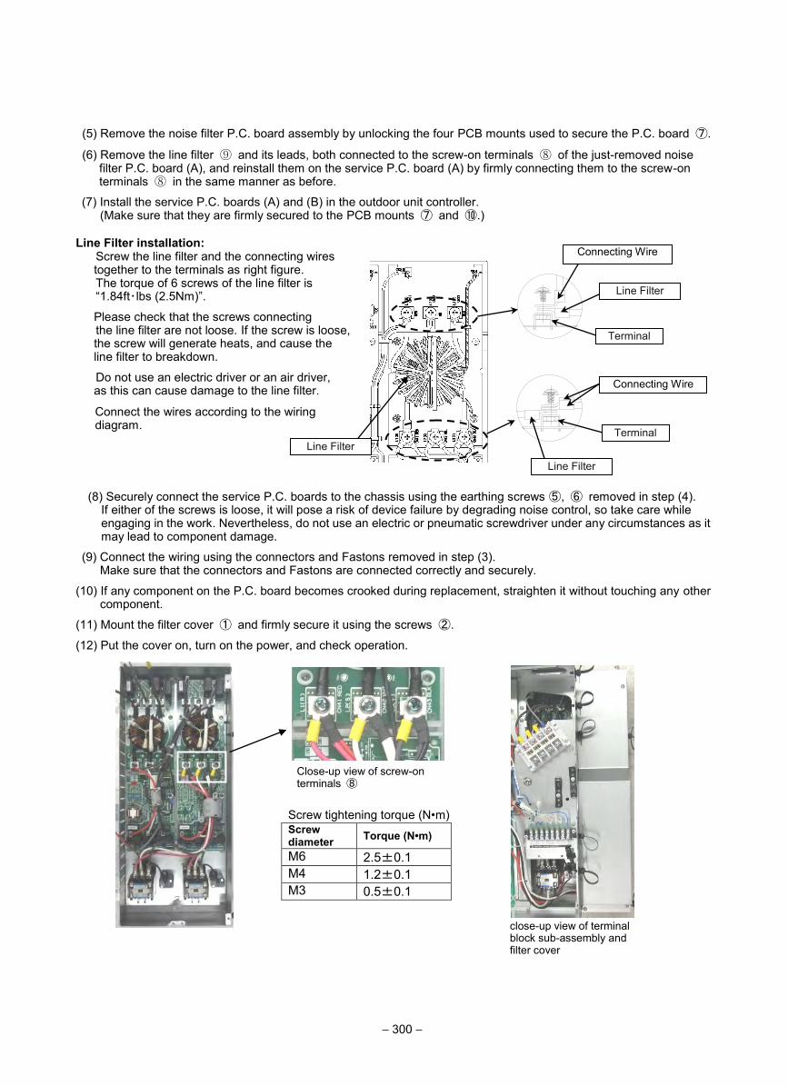
(5) Remove the noise filter P.C. board assembly by unlocking the four PCB mounts used to secure the P.C. board ⑦.
(6) Remove the line filter ⑨ and its leads, both connected to the screw-on terminals ⑧ of the just-removed noise filter P.C. board (A), and reinstall them on the service P.C. board (A) by firmly connecting them to the screw-on terminals ⑧ in the same manner as before.
(7) Install the service P.C. boards (A) and (B) in the outdoor unit controller. (Make sure that they are firmly secured to the PCB mounts ⑦ and ⑩.)
Line Filter installation: Screw the line filter and the connecting wires together to the terminals as right figure. The torque of 6 screws of the line filter is “1.84ft・lbs (2.5Nm)”.
Please check that the screws connecting the line filter are not loose. If the screw is loose, the screw will generate heats, and cause the line filter to breakdown.
Do not use an electric driver or an air driver, as this can cause damage to the line filter.
Connect the wires according to the wiring diagram.
(8) Securely connect the service P.C. boards to the chassis using the earthing screws ⑤, ⑥ removed in step (4). If either of the screws is loose, it will pose a risk of device failure by degrading noise control, so take care while engaging in the work. Nevertheless, do not use an electric or pneumatic screwdriver under any circumstances as it may lead to component damage.
(9) Connect the wiring using the connectors and Fastons removed in step (3). Make sure that the connectors and Fastons are connected correctly and securely.
(10) If any component on the P.C. board becomes crooked during replacement, straighten it without touching any other component.
(11) Mount the filter cover ① and firmly secure it using the screws ②.
(12) Put the cover on, turn on the power, and check operation.
Connecting Wire
Line Filter
Line Filter
Connecting Wire
Line Filter
Screw tightening torque (N•m) Screw diameter Torque (N•m)
M6 2.5±0.1 M4 1.2±0.1 M3 0.5±0.1
close-up view of terminal block sub-assembly and filter cover
Close-up view of screw-on terminals ⑧
Terminal
Terminal
− 300 −
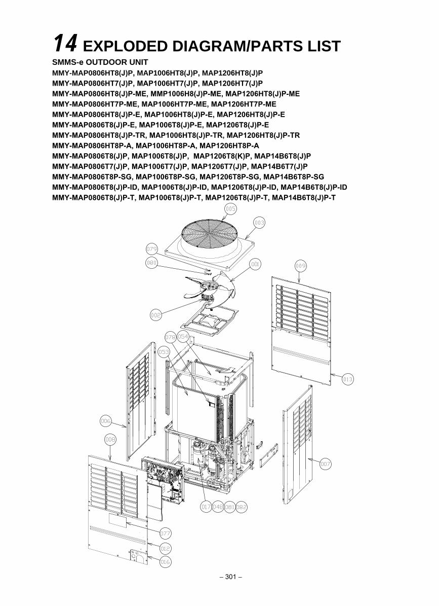
14 EXPLODED DIAGRAM/PARTS LISTSMMS-e OUTDOOR UNITMMY-MAP0806HT8(J)P, MAP1006HT8(J)P, MAP1206HT8(J)PMMY-MAP0806HT7(J)P, MAP1006HT7(J)P, MAP1206HT7(J)PMMY-MAP0806HT8(J)P-ME, MMP1006H8(J)P-ME, MAP1206HT8(J)P-MEMMY-MAP0806HT7P-ME, MAP1006HT7P-ME, MAP1206HT7P-MEMMY-MAP0806HT8(J)P-E, MAP1006HT8(J)P-E, MAP1206HT8(J)P-EMMY-MAP0806T8(J)P-E, MAP1006T8(J)P-E, MAP1206T8(J)P-EMMY-MAP0806HT8(J)P-TR, MAP1006HT8(J)P-TR, MAP1206HT8(J)P-TRMMY-MAP0806HT8P-A, MAP1006HT8P-A, MAP1206HT8P-AMMY-MAP0806T8(J)P, MAP1006T8(J)P, MAP1206T8(K)P, MAP14B6T8(J)PMMY-MAP0806T7(J)P, MAP1006T7(J)P, MAP1206T7(J)P, MAP14B6T7(J)PMMY-MAP0806T8P-SG, MAP1006T8P-SG, MAP1206T8P-SG, MAP14B6T8P-SGMMY-MAP0806T8(J)P-ID, MAP1006T8(J)P-ID, MAP1206T8(J)P-ID, MAP14B6T8(J)P-IDMMY-MAP0806T8(J)P-T, MAP1006T8(J)P-T, MAP1206T8(J)P-T, MAP14B6T8(J)P-T
− 301 −
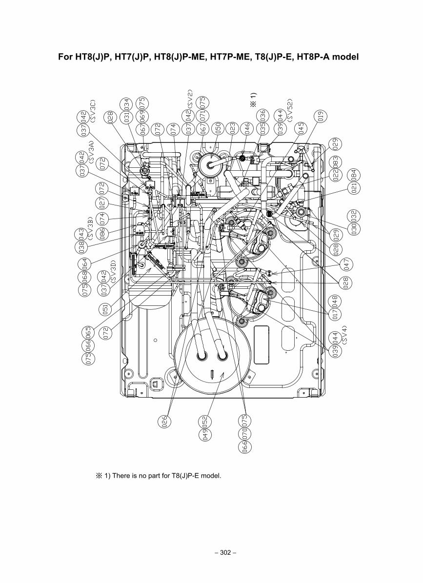
For HT8(J)P, HT7(J)P, HT8(J)P-ME, HT7P-ME, T8(J)P-E, HT8P-A model
※ 1) There is no part for T8(J)P-E model.
※ 1
)
− 302 −
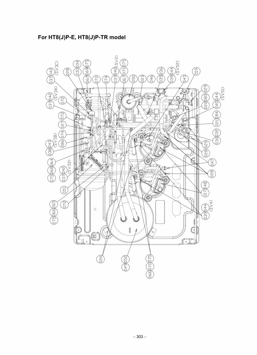
For HT8(J)P-E, HT8(J)P-TR model
− 303 −
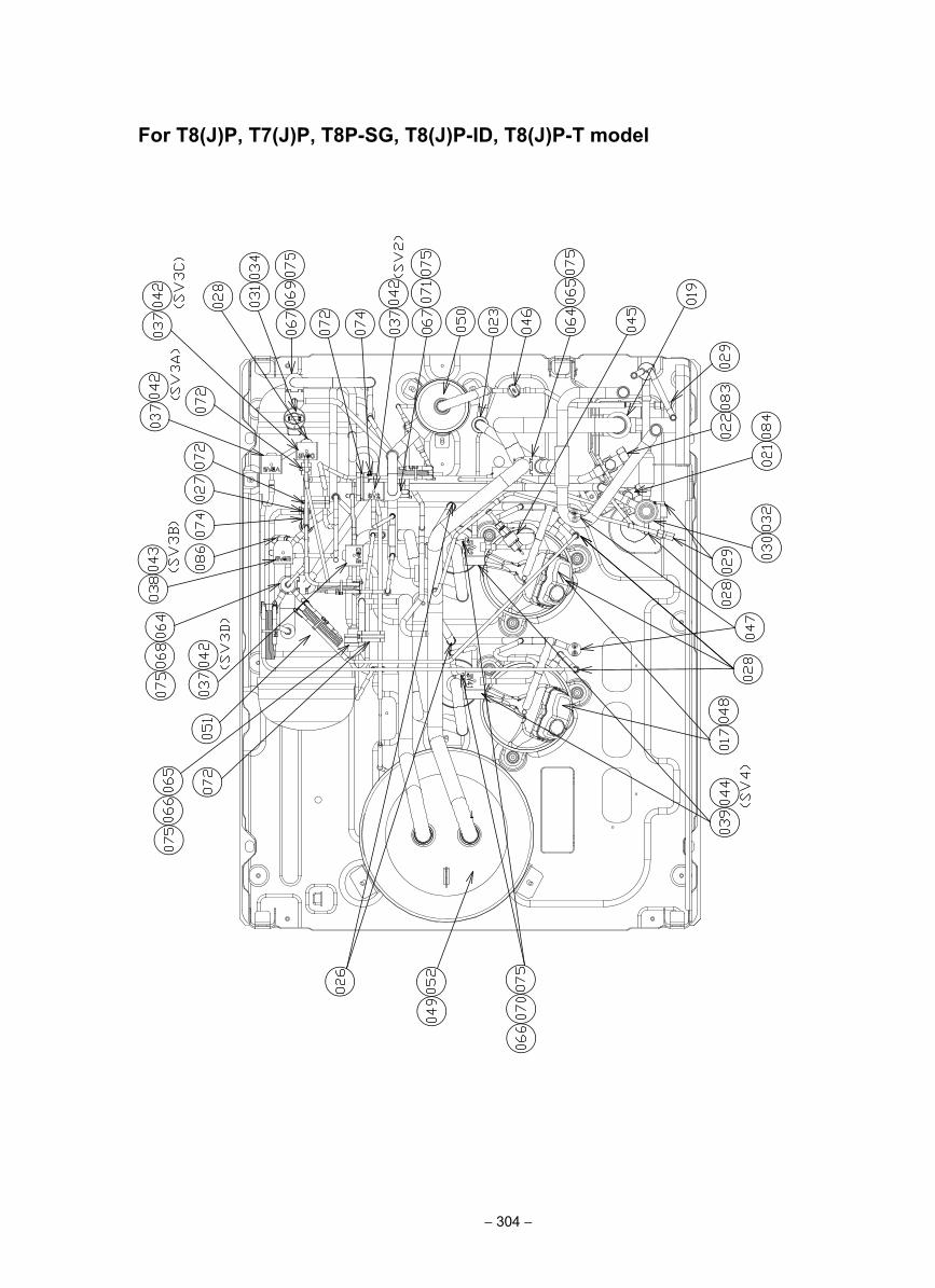
For T8(J)P, T7(J)P, T8P-SG, T8(J)P-ID, T8(J)P-T model
− 304 −
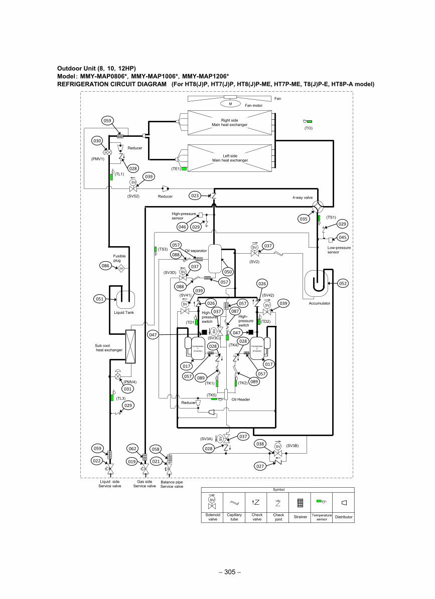
Outdoor Unit (8,10,12HP)Model: MMY-MAP0806*,MMY-MAP1006*,MMY-MAP1206* REFRIGERATION CIRCUIT DIAGRAM
(TD2)
(TE1)
(TK2) (TK1)
(TD1)
(TK4)
(TO)
SV
SV
SV SV
M
(TL1)
SV
SV
SV
(TK5)
(TS3)
(TL3)
Reducer
(SV3A)
(SV2)
(SV3D)
(SV42) (SV41)
(SV3C)
(PMV4)
(TS1)
(SV3B)
Fan
Fan motor
Right side Main heat exchanger
Left side Main heat exchanger (PMV1)
4-way valve
High-pressure sensor
Low-pressure sensor Oil separator
Fusible plug
Liquid Tank
Accumulator
High- pressure switch
High- pressure switch
Compressor 1
(Inverter)
Oil Header
Liquid side Service valve
Gas side Service valve
Balance pipe Service valve
Sub cool heat exchanger
SV
(SV52) Reducer
FP
Compressor 2
(Inverter)
SV
Solenoid valve
Capillary tube
Check valve
Check joint Strainer Temperature
sensor
Symbol
Distributor
Reducer
059
028
030
039
023
046 029
035 029
045
052
037
088
057
086
051
031
029
059
022
062
019
058
021
028
037
027
038
037
088 057
050
039
026
026
039 057
087 037
047 047
017 017
057 057
089
028 028
089
(For HT8(J)P, HT7(J)P, HT8(J)P-ME, HT7P-ME, T8(J)P-E, HT8P-A model)
− 305 −
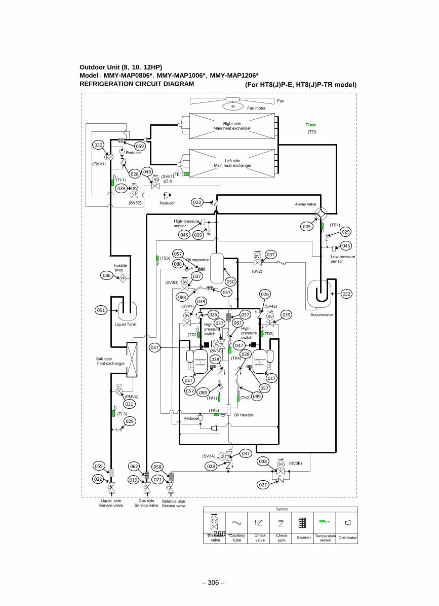
– 260 –
(For HT8(J)P-E, HT8(J)P-TR model)
Outdoor Unit (8,10,12HP)
Model: MMY-MAP0806*,MMY-MAP1006*,MMY-MAP1206*
REFRIGERATION CIRCUIT DIAGRAM
(TD2)
(TE1)
(TK2) (TK1)
(TD1)
(TK4)
(TO)
SV
SV
SV SV
M
(TL1)
SV
SV
SV
(TK5)
(TS3)
(TL3)
Reducer
(SV3A)
(SV2)
(SV3D)
(SV42) (SV41)
(SV3C)
(PMV4)
(TS1)
(SV3B)
Fan
Fan motor
Right side Main heat exchanger
Left side Main heat exchanger (PMV1)
4-way valve
High-pressure sensor
Low-pressure sensor Oil separator
Fusible plug
Liquid Tank
Accumulator
High- pressure switch
High- pressure switch
Compressor 1
(Inverter)
Oil Header
Liquid side Service valve
Gas side Service valve
Balance pipe Service valve
Sub cool heat exchanger
SV
(SV52) Reducer
FP
Compressor 2
(Inverter)
SV
Solenoid valve
Capillary tube
Check valve
Check joint Strainer Temperature
sensor
Symbol
Distributor
Reducer
059
028
030
039
023
046 029
035 029
045
052
037
088
057
086
051
031
029
059
022
062
019
058
021
028
037
027
038
037
088 057
050
039
026
026
039 057
087 037
047 047
017 017
057 057
089
028 028
089
SV (SV51) φ5.8
040
− 306 −
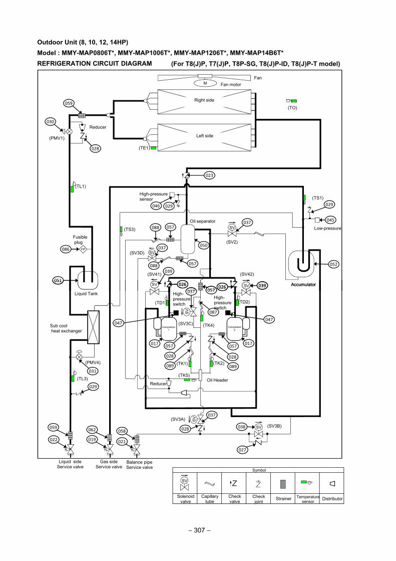
(TE1)
(TO)
SV
SV
SVSV
M
(TL1)
(TS3)
Reducer
(SV2)
(SV3D)
(SV42)(SV41)
(TS1)
FanFan motor
Right side
Left side(PMV1)
High-pressuresensor
Low-pressureOil separator
Fusibleplug
Accumulator
FP
059
030
028
023
086
051
029
045
052
037
046 029
088 057
037050
057088
039
026
057037
026 039
Outdoor Unit (8, 10, 12, 14HP)Model : MMY-MAP0806T*, MMY-MAP1006T*, MMY-MAP1206T*, MMY-MAP14B6T* REFRIGERATION CIRCUIT DIAGRAM
(TD2)
(TK2)(TK1)
(TD1)
(TK4)
SVSV
SV
SV
SV
(TK5)(TL3)
(SV3A)
(SV3C)
(PMV4)
(SV3B)
Liquid Tank
Accumulator
High-pressureswitch
High-pressureswitch
Compressor1
Oil Header
Liquid sideService valve
Gas sideService valve
Balance pipeService valve
Sub coolheat exchanger
Compressor2
SV
Solenoidvalve
Capillarytube
Checkvalve
Checkjoint
Strainer Temperaturesensor
Symbol
Distributor
Reducer
051
031
029
059
022
062
019
058
021
027
038028
037
026
047
057
087
037
026 039
017057
028
089
047
017057
028
089
(For T8(J)P, T7(J)P, T8P-SG, T8(J)P-ID, T8(J)P-T model)
− 307 −
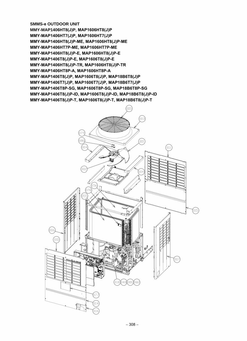
SMMS-e OUTDOOR UNITMMY-MAP1406HT8(J)P, MAP1606HT8(J)P MMY-MAP1406HT7(J)P, MAP1606HT7(J)P MMY-MAP1406HT8(J)P-ME, MAP1606HT8(J)P-ME MMY-MAP1406HT7P-ME, MAP1606HT7P-ME MMY-MAP1406HT8(J)P-E, MAP1606HT8(J)P-E MMY-MAP1406T8(J)P-E, MAP1606T8(J)P-E MMY-MAP1406HT8(J)P-TR, MAP1606HT8(J)P-TR MMY-MAP1406HT8P-A, MAP1606HT8P-AMMY-MAP1406T8(J)P, MAP1606T8(J)P, MAP18B6T8(J)PMMY-MAP1406T7(J)P, MAP1606T7(J)P, MAP18B6T7(J)PMMY-MAP1406T8P-SG, MAP1606T8P-SG, MAP18B6T8P-SGMMY-MAP1406T8(J)P-ID, MAP1606T8(J)P-ID, MAP18B6T8(J)P-IDMMY-MAP1406T8(J)P-T, MAP1606T8(J)P-T, MAP18B6T8(J)P-T
− 308 −
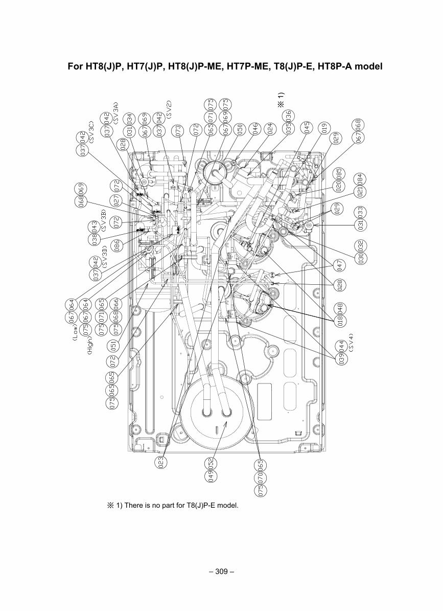
– 309 –
For HT8(J)P, HT7(J)P, HT8(J)P-ME, HT7P-ME, T8(J)P-E, HT8P-A model
※ 1) There is no part for T8(J)P-E model.
※ 1
)
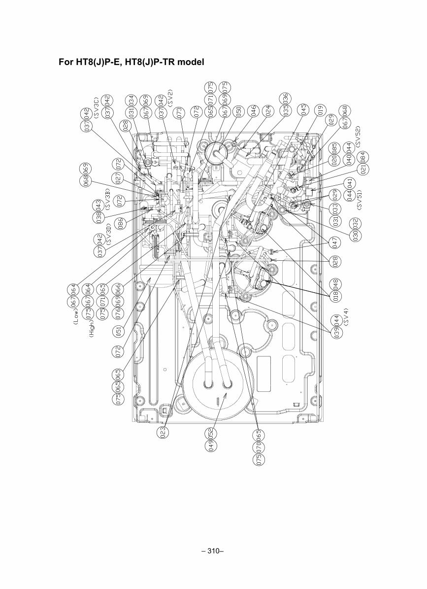
– 310–
For HT8(J)P-E, HT8(J)P-TR model
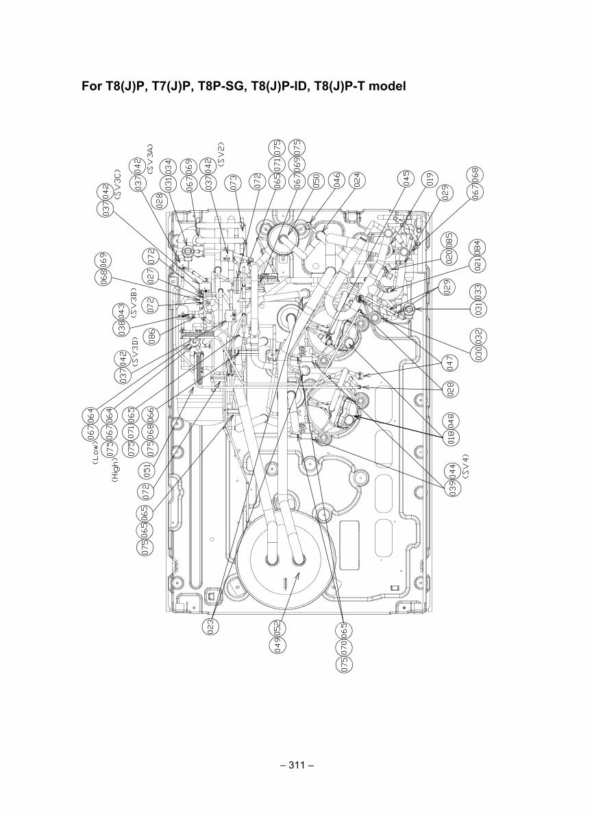
– 311 –
For T8(J)P, T7(J)P, T8P-SG, T8(J)P-ID, T8(J)P-T model
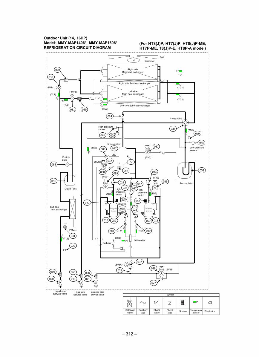
– 312 –
Outdoor Unit (14,16HP)Model: MMY-MAP1406*,MMY-MAP1606*REFRIGERATION CIRCUIT DIAGRAM
仮
(TD2)
(TS1)
(TE1)
(TK2) (TK1)
(TD1)
(TK4)
(TE2)
(TO)
SV
SV
SV SV
M
(TG2)
(TG1)
(TL3)
SV
SV
SV
(TK5)
(TS3)
(TL1)
(TL2)
(SV3B)
(SV3A)
(SV2)
(SV3D)
(SV42) (SV41)
(SV3C)
(PMV4)
Fan
Fan motor
Right side Main heat exchanger
Left side Main heat exchanger
Right side Sub heat exchanger
Left side Sub heat exchanger
(PMV1)
(PMV3)
4-way valve
High-pressure sensor
Low-pressure sensor
Oil separator
Accumulator
Liquid Tank
Liquid side Service valve
Gas side Service valve
Balance pipe Service valve
Oil Header
High- pressure switch
High- pressure switch
Reducer
Fusible plug
FP
Sub cool heat exchanger
Compressor 1
(Inverter)
Compressor 2
(Inverter)
SV
Solenoid valve
Capillary tube
Check valve
Check joint Strainer Temperature
sensor
Symbol
Distributor
060
030
031 059
024
035
029
045
037
046 029
057 088
052
037 050
057 088 039
023
023
039 057
087
047 047
037
018 018 057 057
089 089
028 028
037
028 038
027
086
051
031
029
060
020
063
019
058
021
(For HT8(J)P, HT7(J)P, HT8(J)P-ME, HT7P-ME, T8(J)P-E, HT8P-A model)
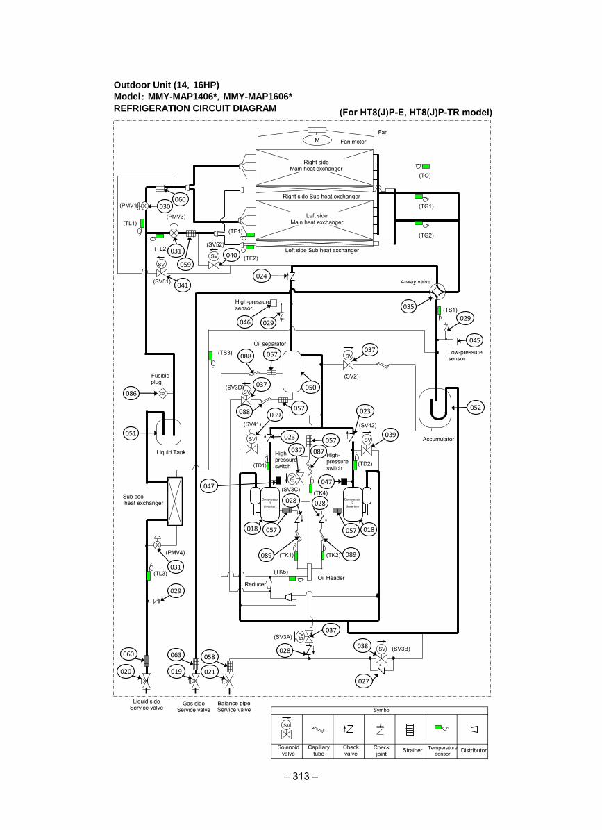
– 313 –
Outdoor Unit (14,16HP)
Model: MMY-MAP1406*,MMY-MAP1606*
REFRIGERATION CIRCUIT DIAGRAM
仮
(TD2)
(TS1)
(TE1)
(TK2) (TK1)
(TD1)
(TK4)
(TE2)
(TO)
SV
SV
SV SV
M
(TG2)
(TG1)
(TL3)
SV
SV
SV
(TK5)
(TS3)
(TL1)
(TL2)
(SV3B)
(SV3A)
(SV2)
(SV3D)
(SV42) (SV41)
(SV3C)
(PMV4)
Fan
Fan motor
Right side Main heat exchanger
Left side Main heat exchanger
Right side Sub heat exchanger
Left side Sub heat exchanger
(PMV1)
(PMV3)
4-way valve
High-pressure sensor
Low-pressure sensor
Oil separator
Accumulator
Liquid Tank
Liquid side Service valve
Gas side Service valve
Balance pipe Service valve
Oil Header
High- pressure switch
High- pressure switch
Reducer
Fusible plug
FP
Sub cool heat exchanger
Compressor 1
(Inverter)
Compressor 2
(Inverter)
SV
Solenoid valve
Capillary tube
Check valve
Check joint Strainer Temperature
sensor
Symbol
Distributor
060 030
031
059
024
035
029
045
037
046 029
057 088
052
037 050
057 088 039
023
023
039 057
087
047 047
037
018 018 057 057
089 089
028 028
037
028 038
027
086
051
031
029
060
020
063
019
058
021
SV SV
(SV51)
(SV52)
041
040
(For HT8(J)P-E, HT8(J)P-TR model)
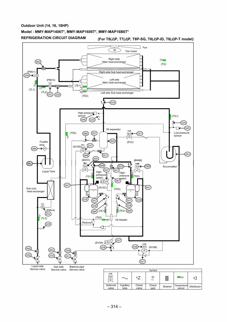
仮仮仮仮
(TS1)
(TE1)
(TE2)
(TO)
SV
SV
SVSV
M
(TS3)
(TL1)(TL2)
(SV2)
(SV3D)
(SV42)(SV41)
FanFan motor
Right sideMain heat exchanger
Left sideMain heat exchanger
Right side Sub heat exchanger
Left side Sub heat exchanger
(PMV1)
(PMV3)
High-pressuresensor
Low-pressuresensor
Oil separator
Accumulator
Fusibleplug
FP
060
030
031 059
086
051
029
045
052
024
046 029
037057088
037
088 057
050
039
023 023 039
Outdoor Unit (14, 16, 18HP)Model : MMY-MAP1406T*, MMY-MAP1606T*, MMY-MAP16B6T*REFRIGERATION CIRCUIT DIAGRAM
(TD2)
(TK2)(TK1)
(TD1)
(TK4)
SVSV
(TL3)
SV
SV
SV
(TK5)
(SV3B)
(SV3A)
(SV42)(SV41)
(SV3C)
(PMV4)
Accumulator
Liquid Tank
Liquid sideService valve
Gas sideService valve
Balance pipeService valve
Oil Header
High-pressureswitch
High-pressureswitch
Reducer
Sub coolheat exchanger
Compressor1
Compressor2
SV
Solenoidvalve
Capillarytube
Checkvalve
Checkjoint Strainer Temperature
sensor
Symbol
Distributor
051
031
029
060
020
063
019
058
021
037
028 038
027
023 023
057037
047
018057
028
089
087
047
018057
028
089
039
(For T8(J)P, T7(J)P, T8P-SG, T8(J)P-ID, T8(J)P-T model)
– 314 –
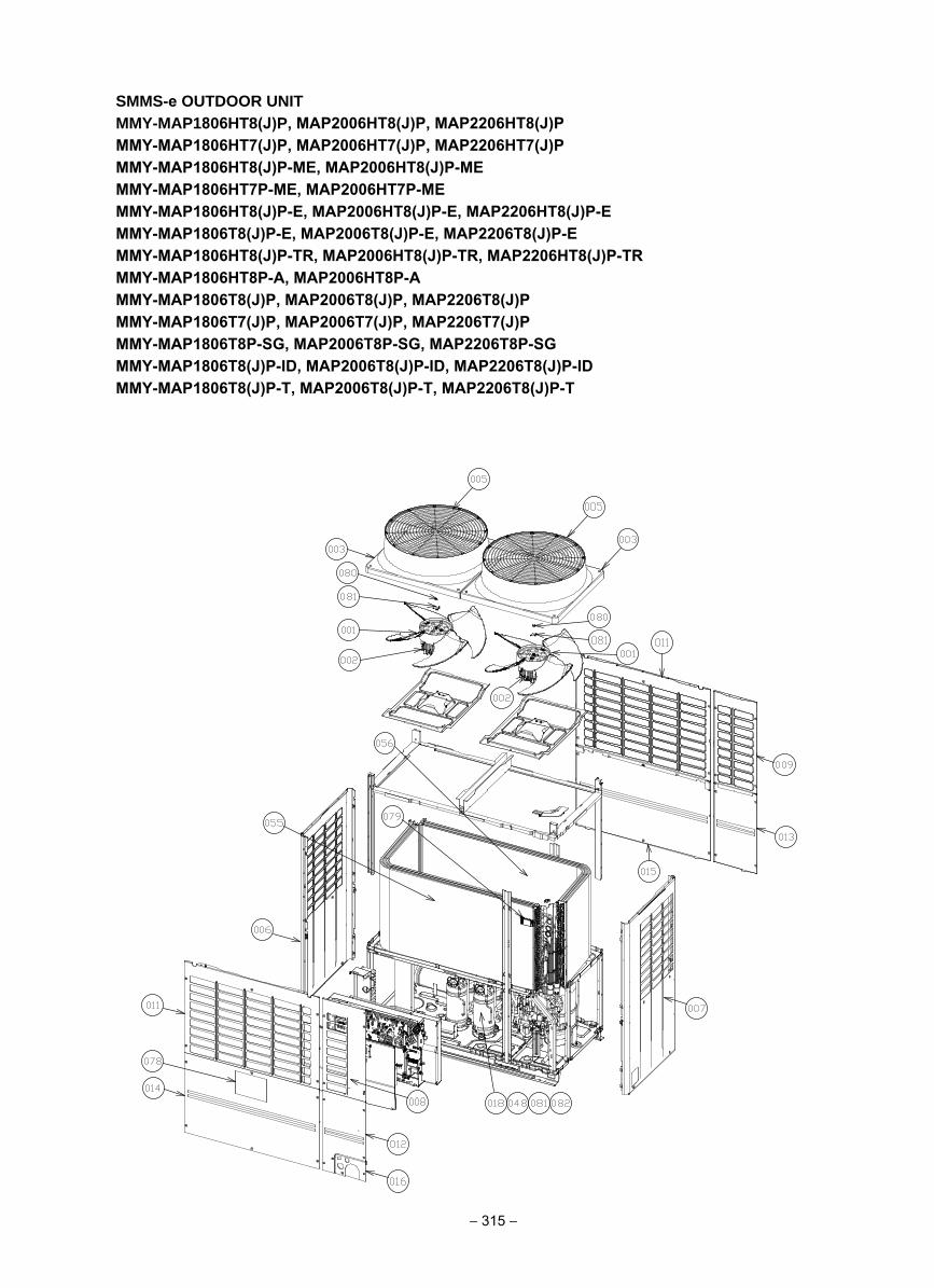
SMMS-e OUTDOOR UNITMMY-MAP1806HT8(J)P, MAP2006HT8(J)P, MAP2206HT8(J)P MMY-MAP1806HT7(J)P, MAP2006HT7(J)P, MAP2206HT7(J)P MMY-MAP1806HT8(J)P-ME, MAP2006HT8(J)P-MEMMY-MAP1806HT7P-ME, MAP2006HT7P-MEMMY-MAP1806HT8(J)P-E, MAP2006HT8(J)P-E, MAP2206HT8(J)P-E MMY-MAP1806T8(J)P-E, MAP2006T8(J)P-E, MAP2206T8(J)P-EMMY-MAP1806HT8(J)P-TR, MAP2006HT8(J)P-TR, MAP2206HT8(J)P-TR MMY-MAP1806HT8P-A, MAP2006HT8P-AMMY-MAP1806T8(J)P, MAP2006T8(J)P, MAP2206T8(J)PMMY-MAP1806T7(J)P, MAP2006T7(J)P, MAP2206T7(J)PMMY-MAP1806T8P-SG, MAP2006T8P-SG, MAP2206T8P-SGMMY-MAP1806T8(J)P-ID, MAP2006T8(J)P-ID, MAP2206T8(J)P-ID MMY-MAP1806T8(J)P-T, MAP2006T8(J)P-T, MAP2206T8(J)P-T
− 315 −
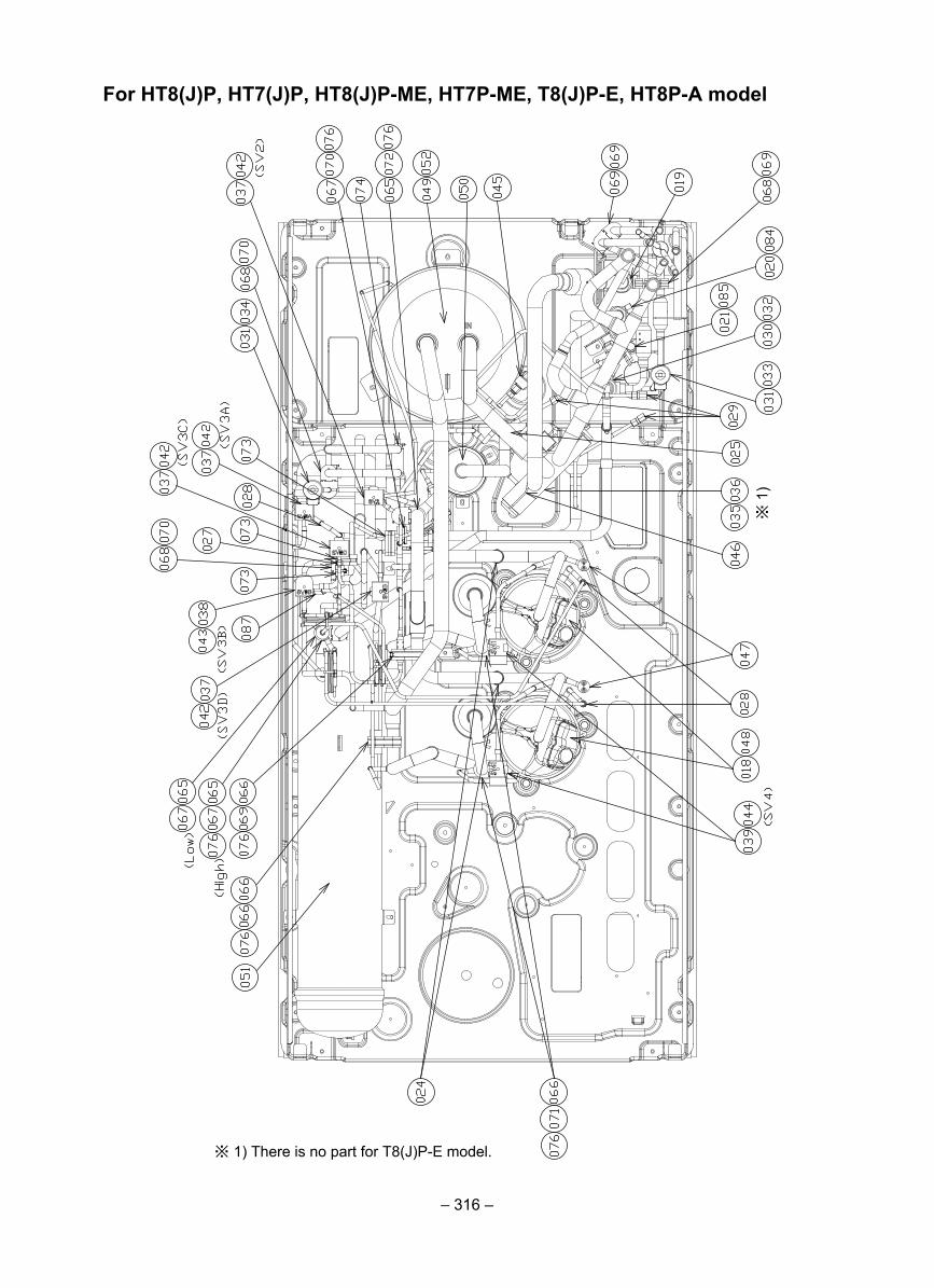
– 316 –
For HT8(J)P, HT7(J)P, HT8(J)P-ME, HT7P-ME, T8(J)P-E, HT8P-A model
※ 1) There is no part for T8(J)P-E model.
※ 1
)
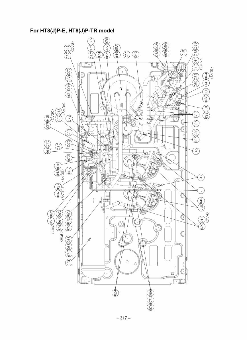
– 317 –
For HT8(J)P-E, HT8(J)P-TR model
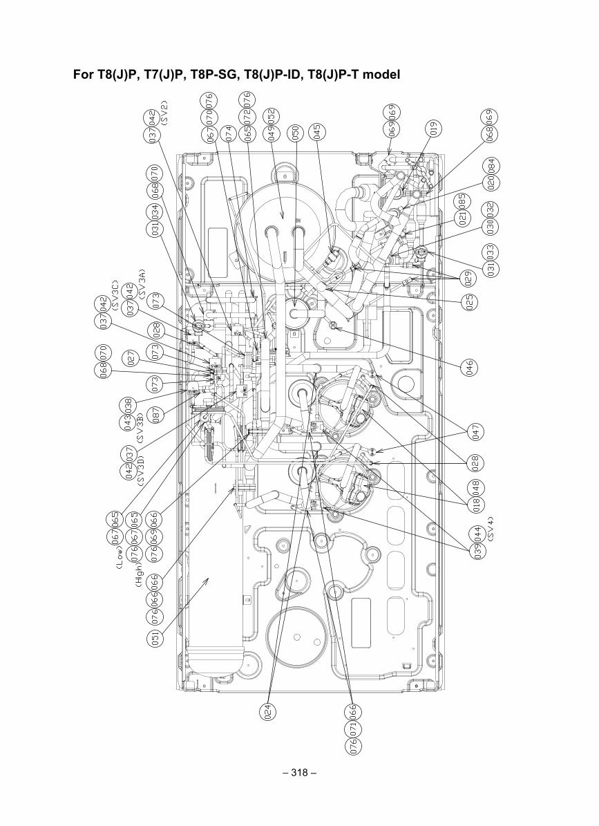
– 318 –
For T8(J)P, T7(J)P, T8P-SG, T8(J)P-ID, T8(J)P-T model
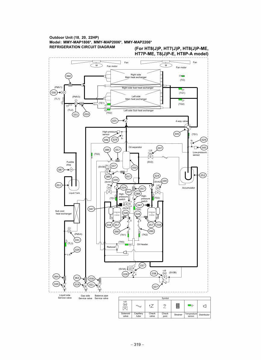
Outdoor Unit (18,20,22HP)Model: MMY-MAP1806*,MMY-MAP2006*,MMY-MAP2206*REFRIGERATION CIRCUIT DIAGRAM
仮
(TD2)
(TS1)
(TE1)
(TK2) (TK1)
(TD1)
(TK4)
(TE2)
(TO)
SV
SV
SV SV
M M
(TG2)
(TG1)
(TL3)
SV
SV
SV
(TK5)
(TS3)
(TL1)
(TL2)
(SV3B) (SV3A)
(SV2)
(SV3D)
(SV42) (SV41)
(SV3C)
(PMV4)
Fan Fan
Fan motor Fan motor
Right side Main heat exchanger
Left side Main heat exchanger
Right side Sub heat exchanger
Left side Sub heat exchanger
(PMV1)
(PMV3)
4-way valve
High-pressure sensor
Low-pressure sensor
Oil separator
Accumulator
Liquid Tank
Oil Header
High- pressure switch
High- pressure switch
Sub cool heat exchanger
Fusible plug
FP
Liquid side Service valve
Gas side Service valve
Balance pipe Service valve
SV
Solenoid valve
Capillary tube
Check valve
Check joint Strainer Temperature
sensor
Symbol
Distributor
Reducer
Compressor 1
(Inverter)
Compressor 2
(Inverter)
060
030
031 059
025
046 029
057 089
037
089 057
050
039
024
024
039
037 057
088
047
047
018 018 057 057
028 028
090 090
037
087
051
031
029
064
020
063
019
058
021
028
037
027
038
052
045
029
035
(For HT8(J)P, HT7(J)P, HT8(J)P-ME, HT7P-ME, T8(J)P-E, HT8P-A model)
− 319 −
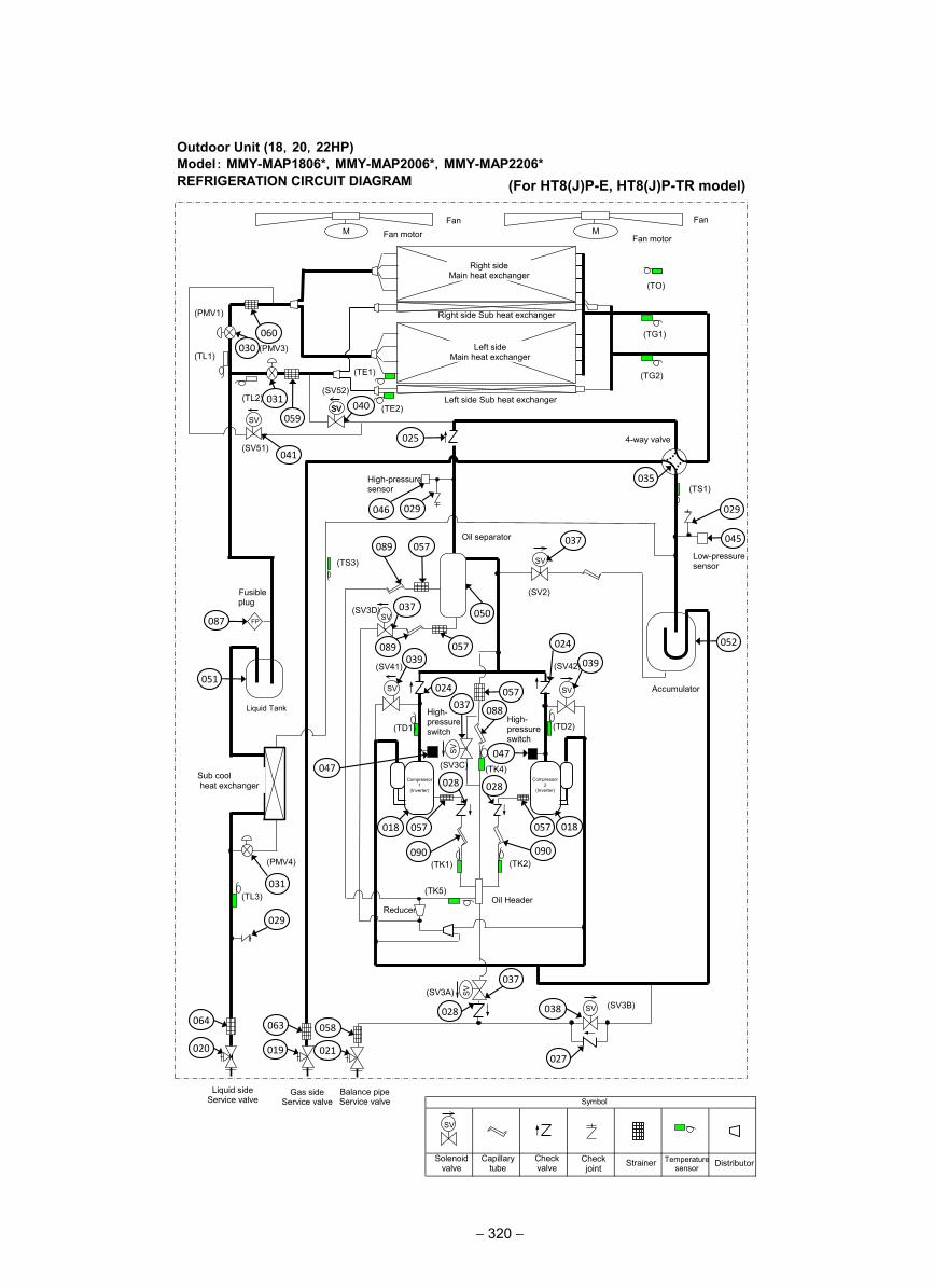
Outdoor Unit (18,20,22HP)Model: MMY-MAP1806*,MMY-MAP2006*,MMY-MAP2206*REFRIGERATION CIRCUIT DIAGRAM
仮
(TD2)
(TS1)
(TE1)
(TK2) (TK1)
(TD1)
(TK4)
(TE2)
(TO)
SV
SV
SV SV
M M
(TG2)
(TG1)
(TL3)
SV
SV
SV
(TK5)
(TS3)
(TL1)
(TL2)
(SV3B) (SV3A)
(SV2)
(SV3D)
(SV42)(SV41)
(SV3C)
(PMV4)
Fan Fan
Fan motor Fan motor
Right side Main heat exchanger
Left side Main heat exchanger
Right side Sub heat exchanger
Left side Sub heat exchanger
(PMV1)
(PMV3)
4-way valve
High-pressure sensor
Low-pressure sensor
Oil separator
Accumulator
Liquid Tank
Oil Header
High- pressure switch
High- pressure switch
Sub cool heat exchanger
Fusible plug
FP
Liquid side Service valve
Gas side Service valve
Balance pipe Service valve
SV
Solenoid valve
Capillary tube
Check valve
Check joint Strainer Temperature
sensor
Symbol
Distributor
Reducer
Compressor 1
(Inverter)
Compressor 2
(Inverter)
060
030
031
059
025
046 029
057 089
037
089 057
050
039
024
024
039
037 057
088
047
047
018 018 057 057
028 028
090 090
037
087
051
031
029
064
020
063
019
058
021
028
037
027
038
052
045
029
SV SVSV
(SV51)
(SV52)
041
040
(For HT8(J)P-E, HT8(J)P-TR model)
− 320 −
035
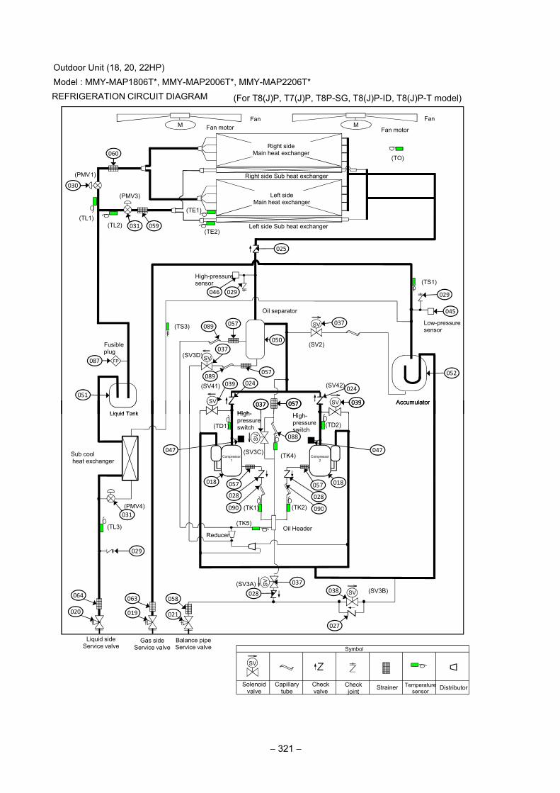
仮仮仮仮
(TS1)
(TE1)
(TE2)
(TO)
SV
SV
SVSV
M M
(TS3)
(TL1)(TL2)
(SV2)
(SV3D)
(SV42)(SV41)
Fan FanFan motor Fan motor
Right sideMain heat exchanger
Left sideMain heat exchanger
Right side Sub heat exchanger
Left side Sub heat exchanger
(PMV1)
(PMV3)
High-pressuresensor
Low-pressuresensor
Oil separator
Accumulator
Liquid Tank High- High-
Fusibleplug
FP
030
060
031 059
025
046 029
089057 037
050
057
037
089
039 024
087
051
029
045
052
024
039037 057
Outdoor Unit (18, 20, 22HP)Model : MMY-MAP1806T*, MMY-MAP2006T*, MMY-MAP2206T* REFRIGERATION CIRCUIT DIAGRAM
(TD2)
(TK2)(TK1)
(TD1)
(TK4)
SVSV
(TL3)
SV
SV
SV
(TK5)
(SV3B)(SV3A)
(SV3C)
(PMV4)
Accumulator
Liquid Tank
Oil Header
High-pressureswitch
High-pressureswitch
Sub coolheat exchanger
Liquid sideService valve
Gas sideService valve
Balance pipeService valve
SV
Solenoidvalve
Capillarytube
Checkvalve
Checkjoint
Strainer Temperaturesensor
Symbol
Distributor
Reducer
Compressor1
Compressor2
031
029
064
020
063
019
058
021
028
037
038
027
039
047
018057
028
090
047
018057
028
090
037 057
088
(For T8(J)P, T7(J)P, T8P-SG, T8(J)P-ID, T8(J)P-T model)
− 321 −
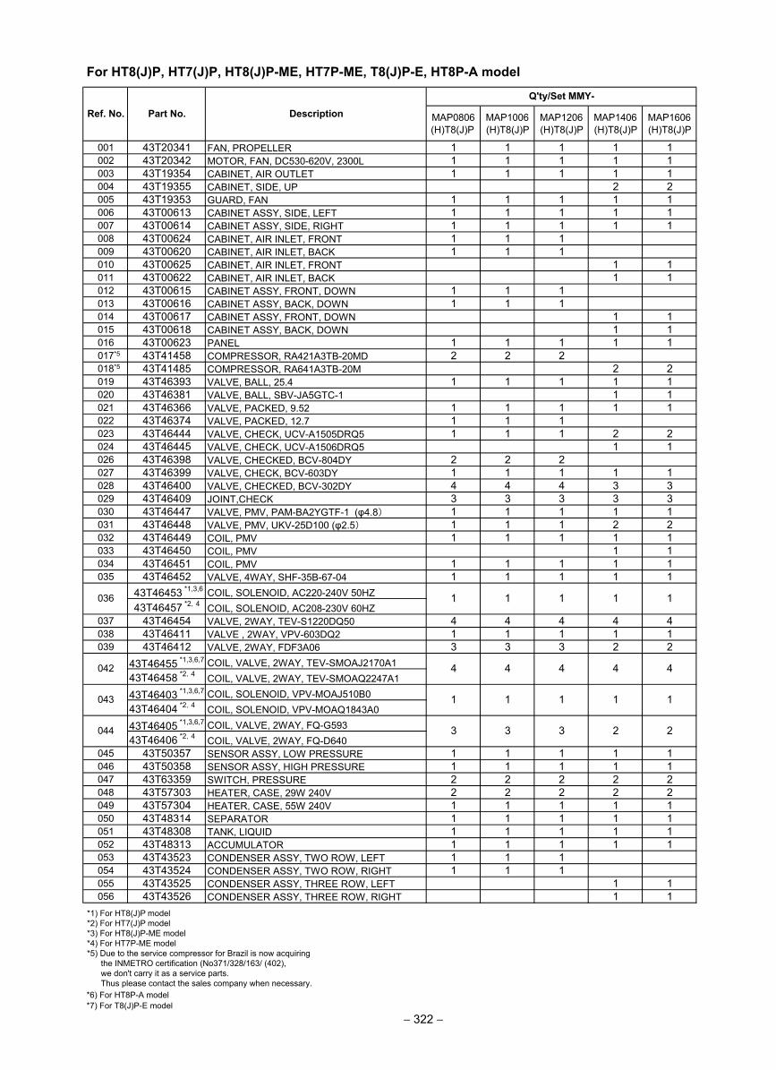
MAP0806(H)T8(J)P
MAP1006(H)T8(J)P
MAP1206(H)T8(J)P
MAP1406(H)T8(J)P
MAP1606(H)T8(J)P
001 43T20341 FAN, PROPELLER 1 1 1 1 1002 43T20342 MOTOR, FAN, DC530-620V, 2300L 1 1 1 1 1003 43T19354 CABINET, AIR OUTLET 1 1 1 1 1004 43T19355 CABINET, SIDE, UP 2 2005 43T19353 GUARD, FAN 1 1 1 1 1006 43T00613 CABINET ASSY, SIDE, LEFT 1 1 1 1 1007 43T00614 CABINET ASSY, SIDE, RIGHT 1 1 1 1 1008 43T00624 CABINET, AIR INLET, FRONT 1 1 1009 43T00620 CABINET, AIR INLET, BACK 1 1 1010 43T00625 CABINET, AIR INLET, FRONT 1 1011 43T00622 CABINET, AIR INLET, BACK 1 1012 43T00615 CABINET ASSY, FRONT, DOWN 1 1 1013 43T00616 CABINET ASSY, BACK, DOWN 1 1 1014 43T00617 CABINET ASSY, FRONT, DOWN 1 1015 43T00618 CABINET ASSY, BACK, DOWN 1 1016 43T00623 PANEL 1 1 1 1 1017*5 43T41458 COMPRESSOR, RA421A3TB-20MD 2 2 2018*5 43T41485 COMPRESSOR, RA641A3TB-20M 2 2019 43T46393 VALVE, BALL, 25.4 1 1 1 1 1020 43T46381 VALVE, BALL, SBV-JA5GTC-1 1 1021 43T46366 VALVE, PACKED, 9.52 1 1 1 1 1022 43T46374 VALVE, PACKED, 12.7 1 1 1023 43T46444 VALVE, CHECK, UCV-A1505DRQ5 1 1 1 2 2024 43T46445 VALVE, CHECK, UCV-A1506DRQ5 1 1026 43T46398 VALVE, CHECKED, BCV-804DY 2 2 2027 43T46399 VALVE, CHECK, BCV-603DY 1 1 1 1 1028 43T46400 VALVE, CHECKED, BCV-302DY 4 4 4 3 3029 43T46409 JOINT,CHECK 3 3 3 3 3030 43T46447 VALVE, PMV, PAM-BA2YGTF-1 (φ4.8) 1 1 1 1 1031 43T46448 VALVE, PMV, UKV-25D100 (φ2.5) 1 1 1 2 2032 43T46449 COIL, PMV 1 1 1 1 1033 43T46450 COIL, PMV 1 1034 43T46451 COIL, PMV 1 1 1 1 1035 43T46452 VALVE, 4WAY, SHF-35B-67-04 1 1 1 1 1
43T46453 *1,3,6 COIL, SOLENOID, AC220-240V 50HZ43T46457 *2,4 COIL, SOLENOID, AC208-230V 60HZ
037 43T46454 VALVE, 2WAY, TEV-S1220DQ50 4 4 4 4 4038 43T46411 VALVE , 2WAY, VPV-603DQ2 1 1 1 1 1039 43T46412 VALVE, 2WAY, FDF3A06 3 3 3 2 2
43T46455 *1,3,6,7 COIL, VALVE, 2WAY, TEV-SMOAJ2170A143T46458 *2,4 COIL, VALVE, 2WAY, TEV-SMOAQ2247A1
43T46403 *1,3,6,7 COIL, SOLENOID, VPV-MOAJ510B043T46404 *2,4 COIL, SOLENOID, VPV-MOAQ1843A0
43T46405 *1,3,6,7 COIL, VALVE, 2WAY, FQ-G59343T46406 *2,4 COIL, VALVE, 2WAY, FQ-D640
045 43T50357 SENSOR ASSY, LOW PRESSURE 1 1 1 1 1046 43T50358 SENSOR ASSY, HIGH PRESSURE 1 1 1 1 1047 43T63359 SWITCH, PRESSURE 2 2 2 2 2048 43T57303 HEATER, CASE, 29W 240V 2 2 2 2 2049 43T57304 HEATER, CASE, 55W 240V 1 1 1 1 1050 43T48314 SEPARATOR 1 1 1 1 1051 43T48308 TANK, LIQUID 1 1 1 1 1052 43T48313 ACCUMULATOR 1 1 1 1 1053 43T43523 CONDENSER ASSY, TWO ROW, LEFT 1 1 1054 43T43524 CONDENSER ASSY, TWO ROW, RIGHT 1 1 1055 43T43525 CONDENSER ASSY, THREE ROW, LEFT 1 1056 43T43526 CONDENSER ASSY, THREE ROW, RIGHT 1 1
2
1 1
4
1 1
044 3 3 3
4
043 1 1 1
042 4 4 4
2
Ref. No. Part No. Description
036 1
Q'ty/Set MMY-
1 1
*1) For HT8(J)P model *2) For HT7(J)P model *3) For HT8(J)P-ME model *4) For HT7P-ME model *5) Due to the service compressor for Brazil is now acquiring the INMETRO certification (No371/328/163/ (402), we don't carry it as a service parts. Thus please contact the sales company when necessary.*6) For HT8P-A model
For HT8(J)P, HT7(J)P, HT8(J)P-ME, HT7P-ME, T8(J)P-E, HT8P-A model
− 322 −*7) For T8(J)P-E model
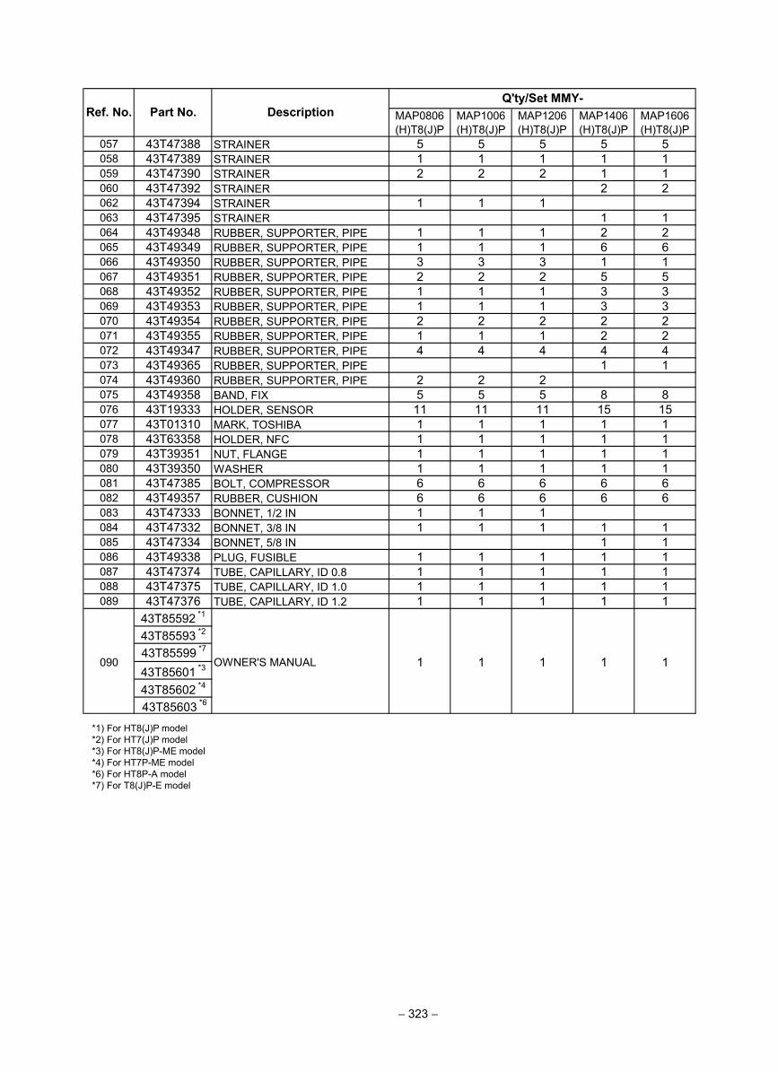
MAP0806(H)T8(J)P
MAP1006(H)T8(J)P
MAP1206(H)T8(J)P
MAP1406(H)T8(J)P
MAP1606(H)T8(J)P
057 43T47388 STRAINER 5 5 5 5 5058 43T47389 STRAINER 1 1 1 1 1059 43T47390 STRAINER 2 2 2 1 1060 43T47392 STRAINER 2 2062 43T47394 STRAINER 1 1 1063 43T47395 STRAINER 1 1064 43T49348 RUBBER, SUPPORTER, PIPE 1 1 1 2 2065 43T49349 RUBBER, SUPPORTER, PIPE 1 1 1 6 6066 43T49350 RUBBER, SUPPORTER, PIPE 3 3 3067 43T49351 RUBBER, SUPPORTER, PIPE 2 2 2 5 5068 43T49352 RUBBER, SUPPORTER, PIPE 1 1 1 3 3069 43T49353 RUBBER, SUPPORTER, PIPE 1 1 1 3 3070 43T49354 RUBBER, SUPPORTER, PIPE 2 2 2 2 2071 43T49355 RUBBER, SUPPORTER, PIPE 1 1 1 2 2072 43T49347 RUBBER, SUPPORTER, PIPE 4 4 4 4 4073 43T49365 RUBBER, SUPPORTER, PIPE 1 1074 43T49360 RUBBER, SUPPORTER, PIPE 2 2 2075 43T49358 BAND, FIX 5 5 5 8 8076 43T19333 HOLDER, SENSOR 11 11 11 15 15077 43T01310 MARK, TOSHIBA 1 1 1 1 1078 43T63358 HOLDER, NFC 1 1 1 1 1079 43T39351 NUT, FLANGE 1 1 1 1 1080 43T39350 WASHER 1 1 1 1 1081 43T47385 BOLT, COMPRESSOR 6 6 6 6 6082 43T49357 RUBBER, CUSHION 6 6 6 6 6083 43T47333 BONNET, 1/2 IN 1 1 1084 43T47332 BONNET, 3/8 IN 1 1 1 1 1085 43T47334 BONNET, 5/8 IN 1 1086 43T49338 PLUG, FUSIBLE 1 1 1 1 1087 43T47374 TUBE, CAPILLARY, ID 0.8 1 1 1 1 1088 43T47375 TUBE, CAPILLARY, ID 1.0 1 1 1 1 1089 43T47376 TUBE, CAPILLARY, ID 1.2 1 1 1 1 1
43T85592 *1
43T85593 *2
43T85601 *3
43T85602 *4
1 1 1
Ref. No. Part No. DescriptionQ'ty/Set MMY-
090 OWNER'S MANUAL 1 1
*1) For HT8(J)P model *2) For HT7(J)P model *3) For HT8(J)P-ME model *4) For HT7P-ME model *6) For HT8P-A model*7) For T8(J)P-E model
1 1
43T85603 *6
− 323 −
43T85599 *7
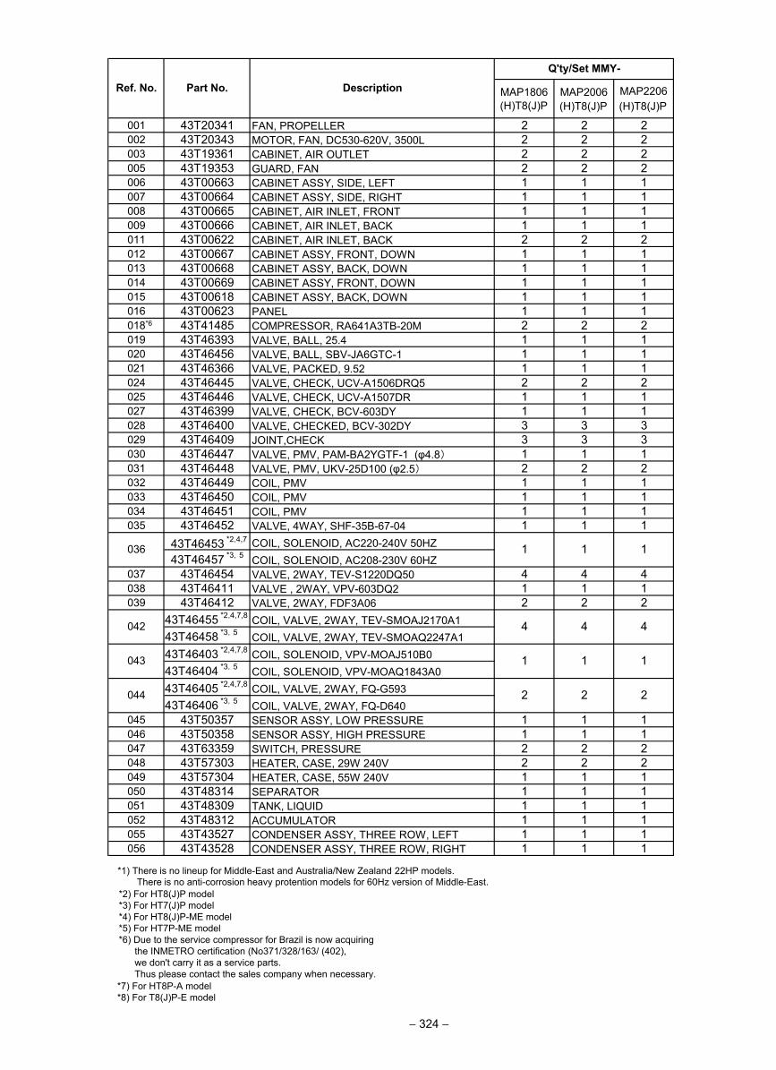
MAP1806(H)T8(J)P
MAP2006 MAP2206
001 43T20341 FAN, PROPELLER 2 2 2002 43T20343 MOTOR, FAN, DC530-620V, 3500L 2 2 2003 43T19361 CABINET, AIR OUTLET 2 2 2005 43T19353 GUARD, FAN 2 2 2006 43T00663 CABINET ASSY, SIDE, LEFT 1 1 1007 43T00664 CABINET ASSY, SIDE, RIGHT 1 1 1008 43T00665 CABINET, AIR INLET, FRONT 1 1 1009 43T00666 CABINET, AIR INLET, BACK 1 1 1011 43T00622 CABINET, AIR INLET, BACK 2 2 2012 43T00667 CABINET ASSY, FRONT, DOWN 1 1 1013 43T00668 CABINET ASSY, BACK, DOWN 1 1 1014 43T00669 CABINET ASSY, FRONT, DOWN 1 1 1015 43T00618 CABINET ASSY, BACK, DOWN 1 1 1016 43T00623 PANEL 1 1 1
6018* 43T41485 COMPRESSOR, RA641A3TB-20M 2 2 2019 43T46393 VALVE, BALL, 25.4 1 1 1020 43T46456 VALVE, BALL, SBV-JA6GTC-1 1 1 1021 43T46366 VALVE, PACKED, 9.52 1 1 1024 43T46445 VALVE, CHECK, UCV-A1506DRQ5 2 2 2025 43T46446 VALVE, CHECK, UCV-A1507DR 1 1 1027 43T46399 VALVE, CHECK, BCV-603DY 1 1 1028 43T46400 VALVE, CHECKED, BCV-302DY 3 3 3029 43T46409 JOINT,CHECK 3 3 3030 43T46447 VALVE, PMV, PAM-BA2YGTF-1 (φ4.8) 1 1 1031 43T46448 VALVE, PMV, UKV-25D100 (φ2.5) 2 2 2032 43T46449 COIL, PMV 1 1 1033 43T46450 COIL, PMV 1 1 1034 43T46451 COIL, PMV 1 1 1035 43T46452 VALVE, 4WAY, SHF-35B-67-04 1 1 1
43T46453 *2,4,7 COIL, SOLENOID, AC220-240V 50HZ43T46457 *3,5 COIL, SOLENOID, AC208-230V 60HZ
037 43T46454 VALVE, 2WAY, TEV-S1220DQ50 4 4 4038 43T46411 VALVE , 2WAY, VPV-603DQ2 1 1 1039 43T46412 VALVE, 2WAY, FDF3A06 2 2 2
43T46455 *2,4,7,8 COIL, VALVE, 2WAY, TEV-SMOAJ2170A143T46458 *3,5 COIL, VALVE, 2WAY, TEV-SMOAQ2247A143T46403 *2,4,7,8 COIL, SOLENOID, VPV-MOAJ510B043T46404 *3,5 COIL, SOLENOID, VPV-MOAQ1843A043T46405 *2,4,7,8 COIL, VALVE, 2WAY, FQ-G59343T46406 *3,5 COIL, VALVE, 2WAY, FQ-D640
045 43T50357 SENSOR ASSY, LOW PRESSURE 1 1 1046 43T50358 SENSOR ASSY, HIGH PRESSURE 1 1 1047 43T63359 SWITCH, PRESSURE 2 2 2048 43T57303 HEATER, CASE, 29W 240V 2 2 2049 43T57304 HEATER, CASE, 55W 240V 1 1 1050 43T48314 SEPARATOR 1 1 1051 43T48309 TANK, LIQUID 1 1 1052 43T48312 ACCUMULATOR 1 1 1055 43T43527 CONDENSER ASSY, THREE ROW, LEFT 1 1 1056 43T43528 CONDENSER ASSY, THREE ROW, RIGHT 1 1 1
Q'ty/Set MMY-
2 2 2
1 1 1
1 1 1
4 4 4
Ref. No. Part No. Description
036
044
043
042
*1) There is no lineup for Middle-East and Australia/New Zealand 22HP models. There is no anti-corrosion heavy protention models for 60Hz version of Middle-East.
*2) For HT8(J)P model *3) For HT7(J)P model *4) For HT8(J)P-ME model *5) For HT7P-ME model *6) Due to the service compressor for Brazil is now acquiring the INMETRO certification (No371/328/163/ (402), we don't carry it as a service parts. Thus please contact the sales company when necessary.*7) For HT8P-A model*8) For T8(J)P-E model
− 324 −
(H)T8(J)P (H)T8(J)P
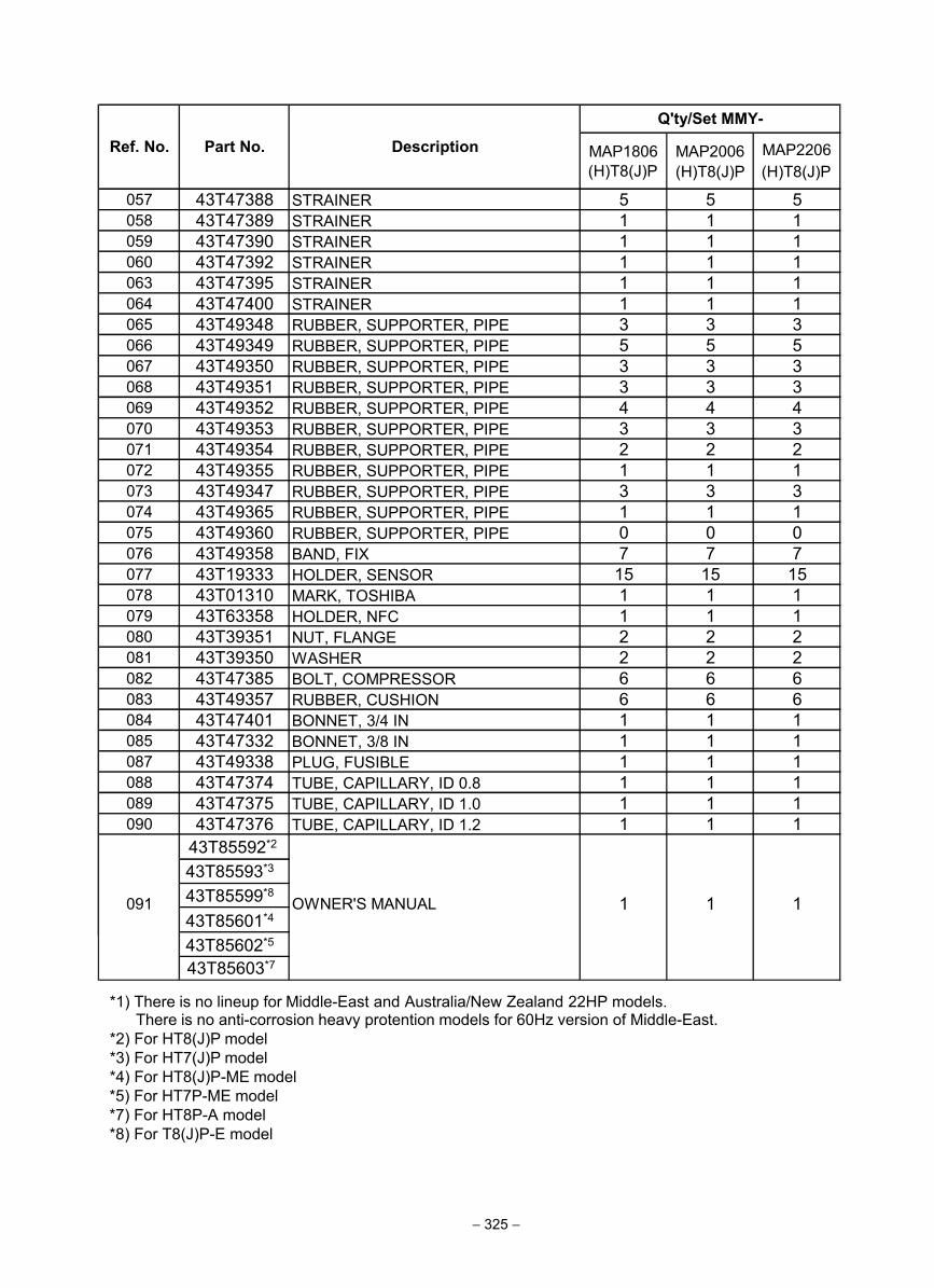
MAP1806(H)T8(J)P
MAP2006 MAP2206
057 43T47388 STRAINER 5 5 5058 43T47389 STRAINER 1 1 1059 43T47390 STRAINER 1 1 1060 43T47392 STRAINER 1 1 1063 43T47395 STRAINER 1 1 1064 43T47400 STRAINER 1 1 1065 43T49348 RUBBER, SUPPORTER, PIPE 3 3 3066 43T49349 RUBBER, SUPPORTER, PIPE 5 5 5067 43T49350 RUBBER, SUPPORTER, PIPE 3 3 3068 43T49351 RUBBER, SUPPORTER, PIPE 3 3 3069 43T49352 RUBBER, SUPPORTER, PIPE 4 4 4070 43T49353 RUBBER, SUPPORTER, PIPE 3 3 3071 43T49354 RUBBER, SUPPORTER, PIPE 2 2 2072 43T49355 RUBBER, SUPPORTER, PIPE 1 1 1073 43T49347 RUBBER, SUPPORTER, PIPE 3 3 3074 43T49365 RUBBER, SUPPORTER, PIPE 1 1 1075 43T49360 RUBBER, SUPPORTER, PIPE 0 0 0076 43T49358 BAND, FIX 7 7 7077 43T19333 HOLDER, SENSOR 15 15 15078 43T01310 MARK, TOSHIBA 1 1 1079 43T63358 HOLDER, NFC 1 1 1080 43T39351 NUT, FLANGE 2 2 2081 43T39350 WASHER 2 2 2082 43T47385 BOLT, COMPRESSOR 6 6 6083 43T49357 RUBBER, CUSHION 6 6 6084 43T47401 BONNET, 3/4 IN 1 1 1085 43T47332 BONNET, 3/8 IN 1 1 1087 43T49338 PLUG, FUSIBLE 1 1 1088 43T47374 TUBE, CAPILLARY, ID 0.8 1 1 1089 43T47375 TUBE, CAPILLARY, ID 1.0 1 1 1090 43T47376 TUBE, CAPILLARY, ID 1.2 1 1 1
43T85592*2
Ref. No. Part No. Description
Q'ty/Set MMY-
091 OWNER'S MANUAL 1 1 1
*1) There is no lineup for Middle-East and Australia/New Zealand 22HP models.
43T85593*3
43T85601*4
43T85602*5
There is no anti-corrosion heavy protention models for 60Hz version of Middle-East. *2) For HT8(J)P model *3) For HT7(J)P model *4) For HT8(J)P-ME model *5) For HT7P-ME model *7) For HT8P-A model*8) For T8(J)P-E model
43T85603*7
− 325 −
(H)T8(J)P (H)T8(J)P
43T85599*8
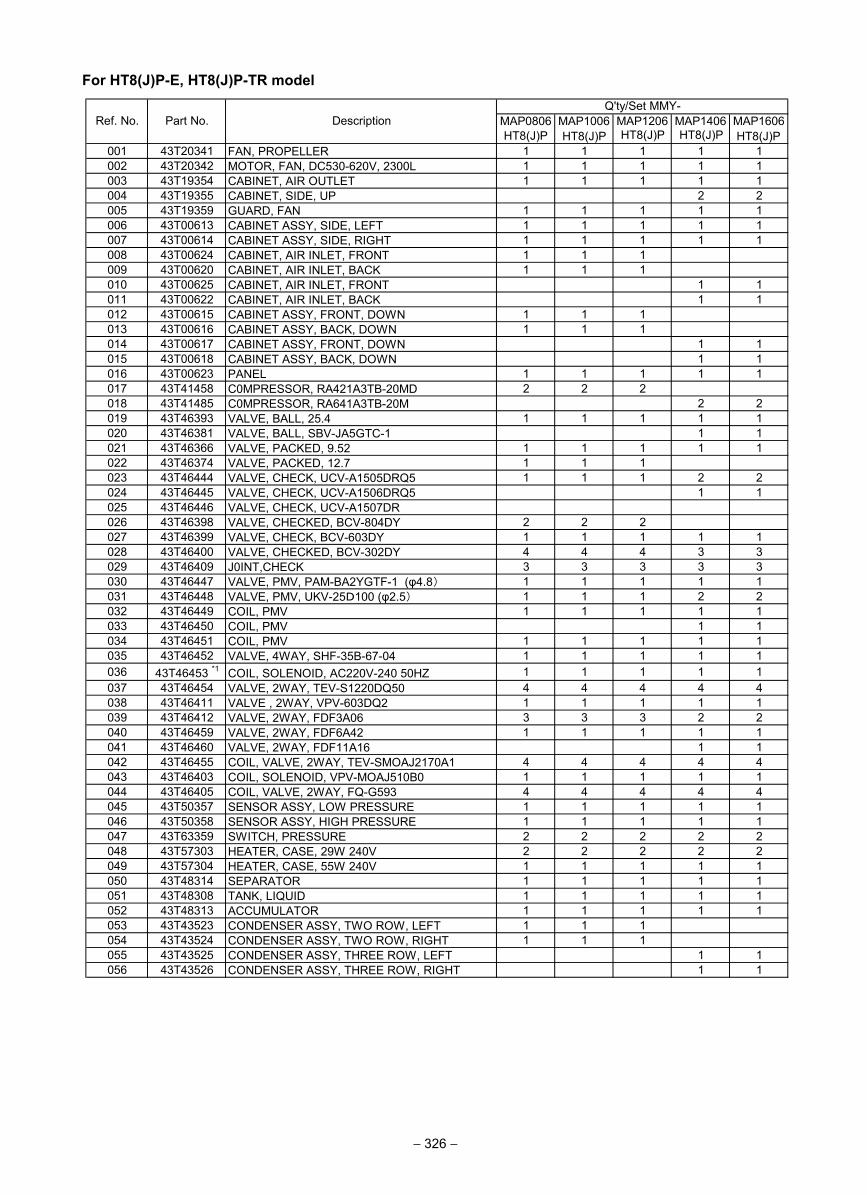
For HT8(J)P-E, HT8(J)P-TR model
001 43T20341 FAN, PROPELLER 1 1 1 1 1002 43T20342 MOTOR, FAN, DC530-620V, 2300L 1 1 1 1 1003 43T19354 CABINET, AIR OUTLET 1 1 1 1 1004 43T19355 CABINET, SIDE, UP 2 2005 43T19359 GUARD, FAN 1 1 1 1 1006 43T00613 CABINET ASSY, SIDE, LEFT 1 1 1 1 1007 43T00614 CABINET ASSY, SIDE, RIGHT 1 1 1 1 1008 43T00624 CABINET, AIR INLET, FRONT 1 1 1009 43T00620 CABINET, AIR INLET, BACK 1 1 1010 43T00625 CABINET, AIR INLET, FRONT 1 1011 43T00622 CABINET, AIR INLET, BACK 1 1012 43T00615 CABINET ASSY, FRONT, DOWN 1 1 1013 43T00616 CABINET ASSY, BACK, DOWN 1 1 1014 43T00617 CABINET ASSY, FRONT, DOWN 1 1015 43T00618 CABINET ASSY, BACK, DOWN 1 1016 43T00623 PANEL 1 1 1 1 1017 43T41458 C0MPRESSOR, RA421A3TB-20MD 2 2 2018 43T41485 C0MPRESSOR, RA641A3TB-20M 2 2019 43T46393 VALVE, BALL, 25.4 1 1 1 1 1020 43T46381 VALVE, BALL, SBV-JA5GTC-1 1 1021 43T46366 VALVE, PACKED, 9.52 1 1 1 1 1022 43T46374 VALVE, PACKED, 12.7 1 1 1023 43T46444 VALVE, CHECK, UCV-A1505DRQ5 1 1 1 2 2024 43T46445 VALVE, CHECK, UCV-A1506DRQ5 1 1025 43T46446 VALVE, CHECK, UCV-A1507DR026 43T46398 VALVE, CHECKED, BCV-804DY 2 2 2027 43T46399 VALVE, CHECK, BCV-603DY 1 1 1 1 1028 43T46400 VALVE, CHECKED, BCV-302DY 4 4 4 3 3029 43T46409 J0INT,CHECK 3 3 3 3 3030 43T46447 VALVE, PMV, PAM-BA2YGTF-1 (φ4.8) 1 1 1 1 1031 43T46448 VALVE, PMV, UKV-25D100 (φ2.5) 1 1 1 2 2032 43T46449 COIL, PMV 1 1 1 1 1033 43T46450 COIL, PMV 1 1034 43T46451 COIL, PMV 1 1 1 1 1035 43T46452 VALVE, 4WAY, SHF-35B-67-04 1 1 1 1 1036 43T46453 *1 COIL, SOLENOID, AC220V-240 50HZ 1 1 1 1 1037 43T46454 VALVE, 2WAY, TEV-S1220DQ50 4 4 4 4 4038 43T46411 VALVE , 2WAY, VPV-603DQ2 1 1 1 1 1039 43T46412 VALVE, 2WAY, FDF3A06 3 3 3 2 2040 43T46459 VALVE, 2WAY, FDF6A42 1 1 1 1 1041 43T46460 VALVE, 2WAY, FDF11A16 1 1042 43T46455 COIL, VALVE, 2WAY, TEV-SMOAJ2170A1 4 4 4 4 4043 43T46403 COIL, SOLENOID, VPV-MOAJ510B0 1 1 1 1 1044 43T46405 COIL, VALVE, 2WAY, FQ-G593 4 4 4 4 4045 43T50357 SENSOR ASSY, LOW PRESSURE 1 1 1 1 1046 43T50358 SENSOR ASSY, HIGH PRESSURE 1 1 1 1 1047 43T63359 SWITCH, PRESSURE 2 2 2 2 2048 43T57303 HEATER, CASE, 29W 240V 2 2 2 2 2049 43T57304 HEATER, CASE, 55W 240V 1 1 1 1 1050 43T48314 SEPARATOR 1 1 1 1 1051 43T48308 TANK, LIQUID 1 1 1 1 1052 43T48313 ACCUMULATOR 1 1 1 1 1053 43T43523 CONDENSER ASSY, TWO ROW, LEFT 1 1 1054 43T43524 CONDENSER ASSY, TWO ROW, RIGHT 1 1 1055 43T43525 CONDENSER ASSY, THREE ROW, LEFT 1 1056 43T43526 CONDENSER ASSY, THREE ROW, RIGHT 1 1
MAP1206 MAP1406 MAP1606Q'ty/Set MMY-
Ref. No. Part No. Description MAP0806HT8(J)P
MAP1006
− 326 −
HT8(J)P HT8(J)P HT8(J)P HT8(J)P
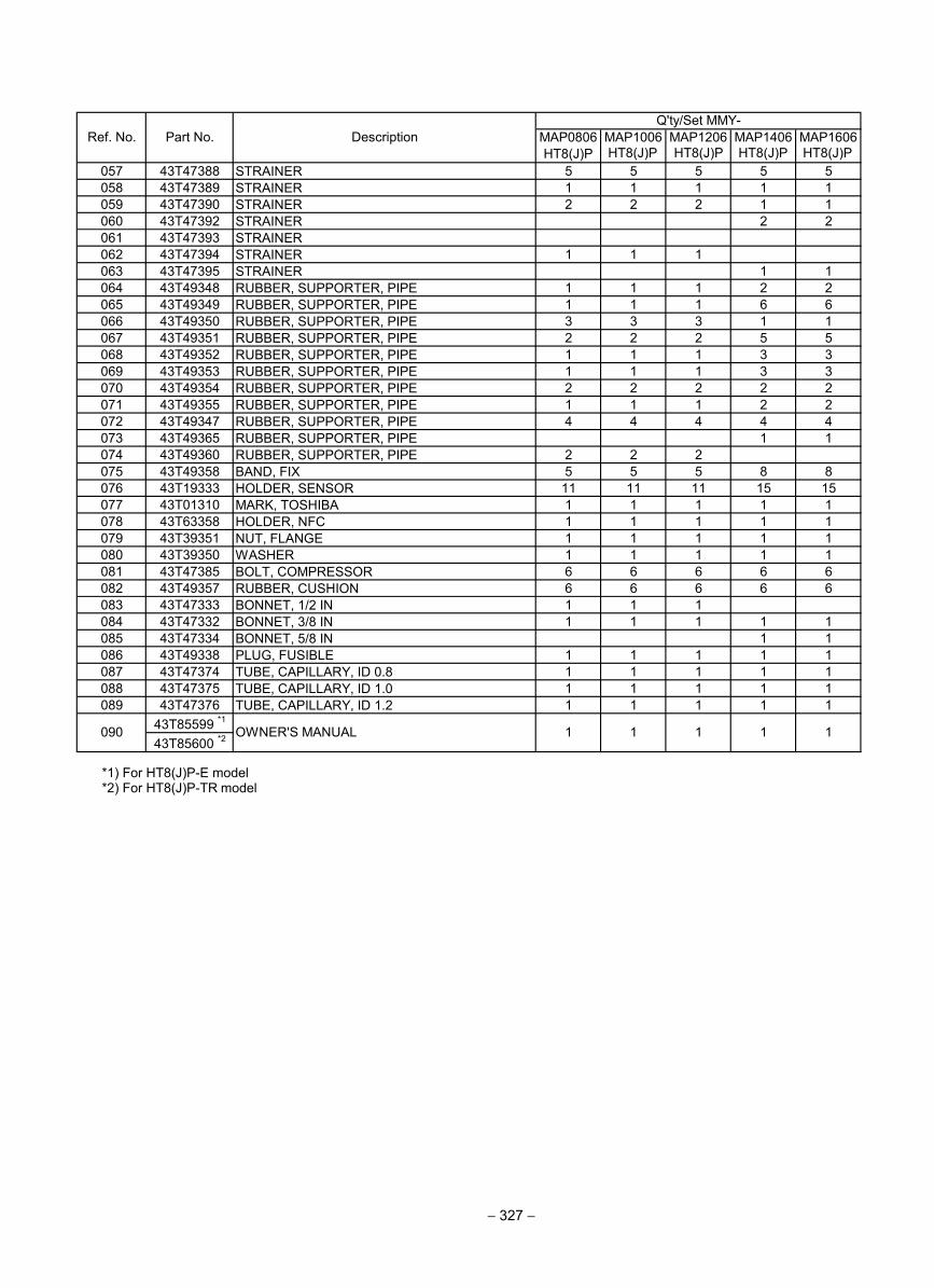
057 43T47388 STRAINER 5 5 5 5 5058 43T47389 STRAINER 1 1 1 1 1059 43T47390 STRAINER 2 2 2 1 1060 43T47392 STRAINER 2 2061 43T47393 STRAINER062 43T47394 STRAINER 1 1 1063 43T47395 STRAINER 1 1064 43T49348 RUBBER, SUPPORTER, PIPE 1 1 1 2 2065 43T49349 RUBBER, SUPPORTER, PIPE 1 1 1 6 6066 43T49350 RUBBER, SUPPORTER, PIPE 3 3 3 1 1067 43T49351 RUBBER, SUPPORTER, PIPE 2 2 2 5 5068 43T49352 RUBBER, SUPPORTER, PIPE 1 1 1 3 3069 43T49353 RUBBER, SUPPORTER, PIPE 1 1 1 3 3070 43T49354 RUBBER, SUPPORTER, PIPE 2 2 2 2 2071 43T49355 RUBBER, SUPPORTER, PIPE 1 1 1 2 2072 43T49347 RUBBER, SUPPORTER, PIPE 4 4 4 4 4073 43T49365 RUBBER, SUPPORTER, PIPE 1 1074 43T49360 RUBBER, SUPPORTER, PIPE 2 2 2075 43T49358 BAND, FIX 5 5 5 8 8076 43T19333 HOLDER, SENSOR 11 11 11 15 15077 43T01310 MARK, TOSHIBA 1 1 1 1 1078 43T63358 HOLDER, NFC 1 1 1 1 1079 43T39351 NUT, FLANGE 1 1 1 1 1080 43T39350 WASHER 1 1 1 1 1081 43T47385 BOLT, COMPRESSOR 6 6 6 6 6082 43T49357 RUBBER, CUSHION 6 6 6 6 6083 43T47333 BONNET, 1/2 IN 1 1 1084 43T47332 BONNET, 3/8 IN 1 1 1 1 1085 43T47334 BONNET, 5/8 IN 1 1086 43T49338 PLUG, FUSIBLE 1 1 1 1 1087 43T47374 TUBE, CAPILLARY, ID 0.8 1 1 1 1 1088 43T47375 TUBE, CAPILLARY, ID 1.0 1 1 1 1 1089 43T47376 TUBE, CAPILLARY, ID 1.2 1 1 1 1 1
43T85599 *1
43T85600 *2
Ref. No. Part No. DescriptionQ'ty/Set MMY-
MAP0806HT8(J)P
MAP1006 MAP1206 MAP1406 MAP1606
1 1090 OWNER'S MANUAL 1 1 1
*1) For HT8(J)P-E model*2) For HT8(J)P-TR model
− 327 −
HT8(J)P HT8(J)P HT8(J)P HT8(J)P
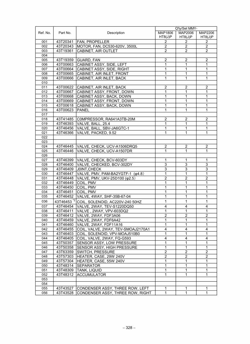
001 43T20341 FAN, PROPELLER 2 2 2002 43T20343 MOTOR, FAN, DC530-620V, 3500L 2 2 2003 43T19361 CABINET, AIR OUTLET 2 2 2004005 43T19359 GUARD, FAN 2 2 2006 43T00663 CABINET ASSY, SIDE, LEFT 1 1 1007 43T00664 CABINET ASSY, SIDE, RIGHT 1 1 1008 43T00665 CABINET, AIR INLET, FRONT 1 1 1009 43T00666 CABINET, AIR INLET, BACK 1 1 1010011 43T00622 CABINET, AIR INLET, BACK 2 2 2012 43T00667 CABINET ASSY, FRONT, DOWN 1 1 1013 43T00668 CABINET ASSY, BACK, DOWN 1 1 1014 43T00669 CABINET ASSY, FRONT, DOWN 1 1 1015 43T00618 CABINET ASSY, BACK, DOWN 1 1 1016 43T00623 PANEL 1 1 1017018 43T41485 C0MPRESSOR, RA641A3TB-20M 2 2 2019 43T46393 VALVE, BALL, 25.4 1 1 1020 43T46456 VALVE, BALL, SBV-JA6GTC-1 1 1 1021 43T46366 VALVE, PACKED, 9.52 1 1 1022023024 43T46445 VALVE, CHECK, UCV-A1506DRQ5 2 2 2025 43T46446 VALVE, CHECK, UCV-A1507DR 1 1 1026027 43T46399 VALVE, CHECK, BCV-603DY 1 1 1028 43T46400 VALVE, CHECKED, BCV-302DY 3 3 3029 43T46409 J0INT,CHECK 3 3 3030 43T46447 VALVE, PMV, PAM-BA2YGTF-1 (φ4.8) 1 1 1031 43T46448 VALVE, PMV, UKV-25D100 (φ2.5) 2 2 2032 43T46449 COIL, PMV 1 1 1033 43T46450 COIL, PMV 1 1 1034 43T46451 COIL, PMV 1 1 1035 43T46452 VALVE, 4WAY, SHF-35B-67-04 1 1 1036 43T46453 *2 COIL, SOLENOID, AC220V-240 50HZ 1 1 1037 43T46454 VALVE, 2WAY, TEV-S1220DQ50 4 4 4038 43T46411 VALVE , 2WAY, VPV-603DQ2 1 1 1039 43T46412 VALVE, 2WAY, FDF3A06 2 2 2040 43T46459 VALVE, 2WAY, FDF6A42 1 1 1041 43T46460 VALVE, 2WAY, FDF11A16 1 1 1042 43T46455 COIL, VALVE, 2WAY, TEV-SMOAJ2170A1 4 4 4043 43T46403 COIL, SOLENOID, VPV-MOAJ510B0 1 1 1044 43T46405 COIL, VALVE, 2WAY, FQ-G593 4 4 4045 43T50357 SENSOR ASSY, LOW PRESSURE 1 1 1046 43T50358 SENSOR ASSY, HIGH PRESSURE 1 1 1047 43T63359 SWITCH, PRESSURE 2 2 2048 43T57303 HEATER, CASE, 29W 240V 2 2 2049 43T57304 HEATER, CASE, 55W 240V 1 1 1050 43T48314 SEPARATOR 1 1 1051 43T48309 TANK, LIQUID 1 1 1052 43T48312 ACCUMULATOR 1 1 1053054055 43T43527 CONDENSER ASSY, THREE ROW, LEFT 1 1 1056 43T43528 CONDENSER ASSY, THREE ROW, RIGHT 1 1 1
MAP2206Q'ty/Set MMY-
Ref. No. Part No. Description MAP1806HT8(J)P
MAP2006
− 328 −
HT8(J)P HT8(J)P
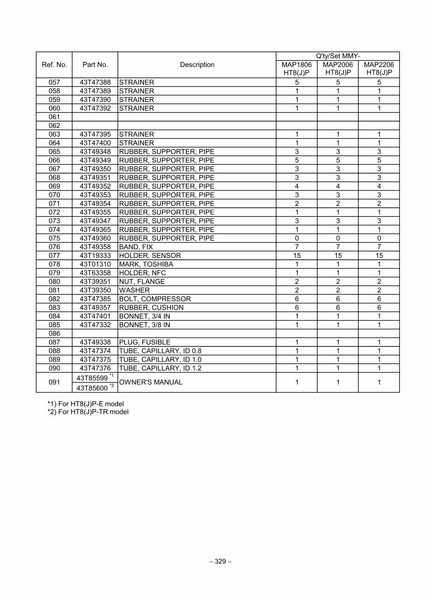
057 43T47388 STRAINER 5 5 5058 43T47389 STRAINER 1 1 1059 43T47390 STRAINER 1 1 1060 43T47392 STRAINER 1 1 1061062063 43T47395 STRAINER 1 1 1064 43T47400 STRAINER 1 1 1065 43T49348 RUBBER, SUPPORTER, PIPE 3 3 3066 43T49349 RUBBER, SUPPORTER, PIPE 5 5 5067 43T49350 RUBBER, SUPPORTER, PIPE 3 3 3068 43T49351 RUBBER, SUPPORTER, PIPE 3 3 3069 43T49352 RUBBER, SUPPORTER, PIPE 4 4 4070 43T49353 RUBBER, SUPPORTER, PIPE 3 3 3071 43T49354 RUBBER, SUPPORTER, PIPE 2 2 2072 43T49355 RUBBER, SUPPORTER, PIPE 1 1 1073 43T49347 RUBBER, SUPPORTER, PIPE 3 3 3074 43T49365 RUBBER, SUPPORTER, PIPE 1 1 1075 43T49360 RUBBER, SUPPORTER, PIPE 0 0 0076 43T49358 BAND, FIX 7 7 7077 43T19333 HOLDER, SENSOR 15 15 15078 43T01310 MARK, TOSHIBA 1 1 1079 43T63358 HOLDER, NFC 1 1 1080 43T39351 NUT, FLANGE 2 2 2081 43T39350 WASHER 2 2 2082 43T47385 BOLT, COMPRESSOR 6 6 6083 43T49357 RUBBER, CUSHION 6 6 6084 43T47401 BONNET, 3/4 IN 1 1 1085 43T47332 BONNET, 3/8 IN 1 1 1086087 43T49338 PLUG, FUSIBLE 1 1 1088 43T47374 TUBE, CAPILLARY, ID 0.8 1 1 1089 43T47375 TUBE, CAPILLARY, ID 1.0 1 1 1090 43T47376 TUBE, CAPILLARY, ID 1.2 1 1 1
43T85599 *1
43T85600 *2
Ref. No. Part No. DescriptionQ'ty/Set MMY-
MAP1806HT8(J)P
MAP2006 MAP2206
091 OWNER'S MANUAL 1 1 1
*1) For HT8(J)P-E model *2) For HT8(J)P-TR model
− 329 −
HT8(J)P HT8(J)P
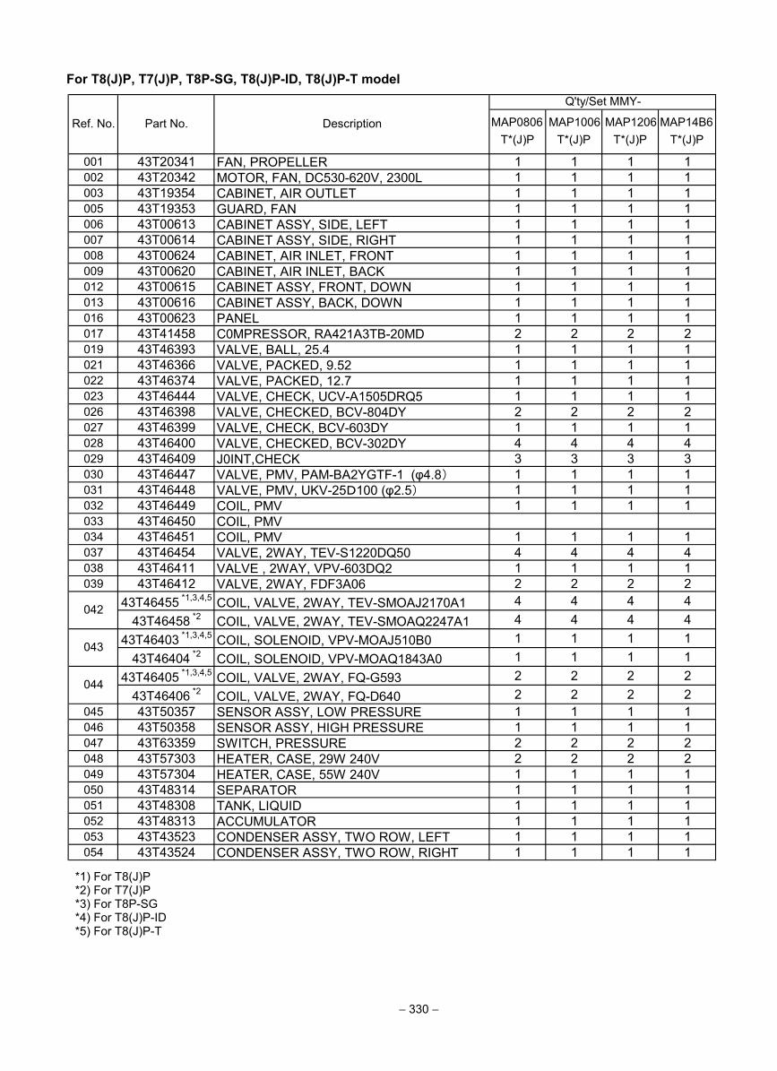
− 330 −
For T8(J)P, T7(J)P, T8P-SG, T8(J)P-ID, T8(J)P-T model
MAP0806T*(J)P
MAP1006T*(J)P
MAP1206T*(J)P
MAP14B6T*(J)P
001 43T20341 FAN, PROPELLER 1 1 1 1002 43T20342 MOTOR, FAN, DC530-620V, 2300L 1 1 1 1003 43T19354 CABINET, AIR OUTLET 1 1 1 1005 43T19353 GUARD, FAN 1 1 1 1006 43T00613 CABINET ASSY, SIDE, LEFT 1 1 1 1007 43T00614 CABINET ASSY, SIDE, RIGHT 1 1 1 1008 43T00624 CABINET, AIR INLET, FRONT 1 1 1 1009 43T00620 CABINET, AIR INLET, BACK 1 1 1 1012 43T00615 CABINET ASSY, FRONT, DOWN 1 1 1 1013 43T00616 CABINET ASSY, BACK, DOWN 1 1 1 1016 43T00623 PANEL 1 1 1 1017 43T41458 C0MPRESSOR, RA421A3TB-20MD 2 2 2 2019 43T46393 VALVE, BALL, 25.4 1 1 1 1021 43T46366 VALVE, PACKED, 9.52 1 1 1 1022 43T46374 VALVE, PACKED, 12.7 1 1 1 1023 43T46444 VALVE, CHECK, UCV-A1505DRQ5 1 1 1 1026 43T46398 VALVE, CHECKED, BCV-804DY 2 2 2 2027 43T46399 VALVE, CHECK, BCV-603DY 1 1 1 1028 43T46400 VALVE, CHECKED, BCV-302DY 4 4 4 4029 43T46409 J0INT,CHECK 3 3 3 3030 43T46447 VALVE, PMV, PAM-BA2YGTF-1 (φ4.8) 1 1 1 1031 43T46448 VALVE, PMV, UKV-25D100 (φ2.5) 1 1 1 1032 43T46449 COIL, PMV 1 1 1 1033 43T46450 COIL, PMV034 43T46451 COIL, PMV 1 1 1 1037 43T46454 VALVE, 2WAY, TEV-S1220DQ50 4 4 4 4038 43T46411 VALVE , 2WAY, VPV-603DQ2 1 1 1 1039 43T46412 VALVE, 2WAY, FDF3A06 2 2 2 2
43T46455 *1,3,4,5 COIL, VALVE, 2WAY, TEV-SMOAJ2170A1 4 4 4 443T46458 *2 COIL, VALVE, 2WAY, TEV-SMOAQ2247A1 4 4 4 4
43T46403 *1,3,4,5 COIL, SOLENOID, VPV-MOAJ510B0 1 1 1 143T46404 *2 COIL, SOLENOID, VPV-MOAQ1843A0 1 1 1 1
43T46405 *1,3,4,5 COIL, VALVE, 2WAY, FQ-G593 2 2 2 243T46406 *2 COIL, VALVE, 2WAY, FQ-D640 2 2 2 2
045 43T50357 SENSOR ASSY, LOW PRESSURE 1 1 1 1046 43T50358 SENSOR ASSY, HIGH PRESSURE 1 1 1 1047 43T63359 SWITCH, PRESSURE 2 2 2 2048 43T57303 HEATER, CASE, 29W 240V 2 2 2 2049 43T57304 HEATER, CASE, 55W 240V 1 1 1 1050 43T48314 SEPARATOR 1 1 1 1051 43T48308 TANK, LIQUID 1 1 1 1052 43T48313 ACCUMULATOR 1 1 1 1053 43T43523 CONDENSER ASSY, TWO ROW, LEFT 1 1 1 1054 43T43524 CONDENSER ASSY, TWO ROW, RIGHT 1 1 1 1
Ref. No. Part No. Description
Q'ty/Set MMY-
042
043
044
*1) For T8(J)P *2) For T7(J)P *3) For T8P-SG *4) For T8(J)P-ID *5) For T8(J)P-T
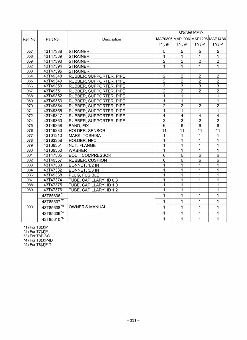
− 331 −
MAP0806T*(J)P
MAP1006T*(J)P
MAP1206T*(J)P
MAP14B6T*(J)P
057 43T47388 STRAINER 5 5 5 5058 43T47389 STRAINER 1 1 1 1059 43T47390 STRAINER 2 2 2 2062 43T47394 STRAINER 1 1 1 1063 43T47395 STRAINER064 43T49348 RUBBER, SUPPORTER, PIPE 2 2 2 2065 43T49349 RUBBER, SUPPORTER, PIPE 2 2 2 2066 43T49350 RUBBER, SUPPORTER, PIPE 3 3 3 3067 43T49351 RUBBER, SUPPORTER, PIPE 2 2 2 2068 43T49352 RUBBER, SUPPORTER, PIPE 1 1 1 1069 43T49353 RUBBER, SUPPORTER, PIPE 1 1 1 1070 43T49354 RUBBER, SUPPORTER, PIPE 2 2 2 2071 43T49355 RUBBER, SUPPORTER, PIPE 1 1 1 1072 43T49347 RUBBER, SUPPORTER, PIPE 4 4 4 4074 43T49360 RUBBER, SUPPORTER, PIPE 2 2 2 2075 43T49358 BAND, FIX 6 6 6 6076 43T19333 HOLDER, SENSOR 11 11 11 11077 43T01310 MARK, TOSHIBA 1 1 1 1078 43T63358 HOLDER, NFC 1 1 1 1079 43T39351 NUT, FLANGE 1 1 1 1080 43T39350 WASHER 1 1 1 1081 43T47385 BOLT, COMPRESSOR 6 6 6 6082 43T49357 RUBBER, CUSHION 6 6 6 6083 43T47333 BONNET, 1/2 IN 1 1 1 1084 43T47332 BONNET, 3/8 IN 1 1 1 1086 43T49338 PLUG, FUSIBLE 1 1 1 1087 43T47374 TUBE, CAPILLARY, ID 0.8 1 1 1 1088 43T47375 TUBE, CAPILLARY, ID 1.0 1 1 1 1089 43T47376 TUBE, CAPILLARY, ID 1.2 1 1 1 1
43T85606 *1 1 1 1 143T85607 *2 1 1 1 143T85608 *3 1 1 1 143T85609 *4 1 1 1 143T85610 *5 1 1 1 1
Ref. No. Part No. Description
Q'ty/Set MMY-
OWNER'S MANUAL090
*1) For T8(J)P *2) For T7(J)P *3) For T8P-SG *4) For T8(J)P-ID *5) For T8(J)P-T
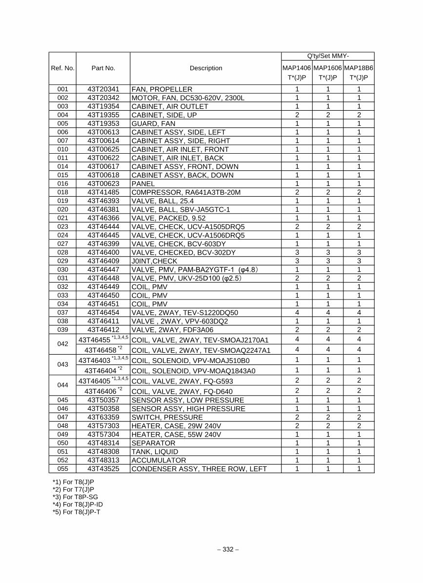
− 332 −
MAP1406T*(J)P
MAP1606T*(J)P
MAP18B6T*(J)P
001 43T20341 FAN, PROPELLER 1 1 1
002 43T20342 MOTOR, FAN, DC530-620V, 2300L 1 1 1
003 43T19354 CABINET, AIR OUTLET 1 1 1
004 43T19355 CABINET, SIDE, UP 2 2 2
005 43T19353 GUARD, FAN 1 1 1
006 43T00613 CABINET ASSY, SIDE, LEFT 1 1 1
007 43T00614 CABINET ASSY, SIDE, RIGHT 1 1 1
010 43T00625 CABINET, AIR INLET, FRONT 1 1 1
011 43T00622 CABINET, AIR INLET, BACK 1 1 1
014 43T00617 CABINET ASSY, FRONT, DOWN 1 1 1
015 43T00618 CABINET ASSY, BACK, DOWN 1 1 1
016 43T00623 PANEL 1 1 1
018 43T41485 C0MPRESSOR, RA641A3TB-20M 2 2 2
019 43T46393 VALVE, BALL, 25.4 1 1 1
020 43T46381 VALVE, BALL, SBV-JA5GTC-1 1 1 1
021 43T46366 VALVE, PACKED, 9.52 1 1 1
023 43T46444 VALVE, CHECK, UCV-A1505DRQ5 2 2 2
024 43T46445 VALVE, CHECK, UCV-A1506DRQ5 1 1 1
027 43T46399 VALVE, CHECK, BCV-603DY 1 1 1
028 43T46400 VALVE, CHECKED, BCV-302DY 3 3 3
029 43T46409 J0INT,CHECK 3 3 3
030 43T46447 VALVE, PMV, PAM-BA2YGTF-1 (φ4.8) 1 1 1
031 43T46448 VALVE, PMV, UKV-25D100 (φ2.5) 2 2 2
032 43T46449 COIL, PMV 1 1 1
033 43T46450 COIL, PMV 1 1 1
034 43T46451 COIL, PMV 1 1 1
037 43T46454 VALVE, 2WAY, TEV-S1220DQ50 4 4 4
038 43T46411 VALVE , 2WAY, VPV-603DQ2 1 1 1
039 43T46412 VALVE, 2WAY, FDF3A06 2 2 2
43T46455 *1,3,4,5
COIL, VALVE, 2WAY, TEV-SMOAJ2170A1 4 4 4
43T46458 *2
COIL, VALVE, 2WAY, TEV-SMOAQ2247A1 4 4 4
43T46403 *1,3,4,5
COIL, SOLENOID, VPV-MOAJ510B0 1 1 1
43T46404 *2
COIL, SOLENOID, VPV-MOAQ1843A0 1 1 1
43T46405 *1,3,4,5
COIL, VALVE, 2WAY, FQ-G593 2 2 2
43T46406 *2
COIL, VALVE, 2WAY, FQ-D640 2 2 2
045 43T50357 SENSOR ASSY, LOW PRESSURE 1 1 1
046 43T50358 SENSOR ASSY, HIGH PRESSURE 1 1 1
047 43T63359 SWITCH, PRESSURE 2 2 2
048 43T57303 HEATER, CASE, 29W 240V 2 2 2
049 43T57304 HEATER, CASE, 55W 240V 1 1 1
050 43T48314 SEPARATOR 1 1 1
051 43T48308 TANK, LIQUID 1 1 1
052 43T48313 ACCUMULATOR 1 1 1
055 43T43525 CONDENSER ASSY, THREE ROW, LEFT 1 1 1
Q'ty/Set MMY-
Ref. No. Part No. Description
042
043
044
*1) For T8(J)P *2) For T7(J)P *3) For T8P-SG *4) For T8(J)P-ID *5) For T8(J)P-T
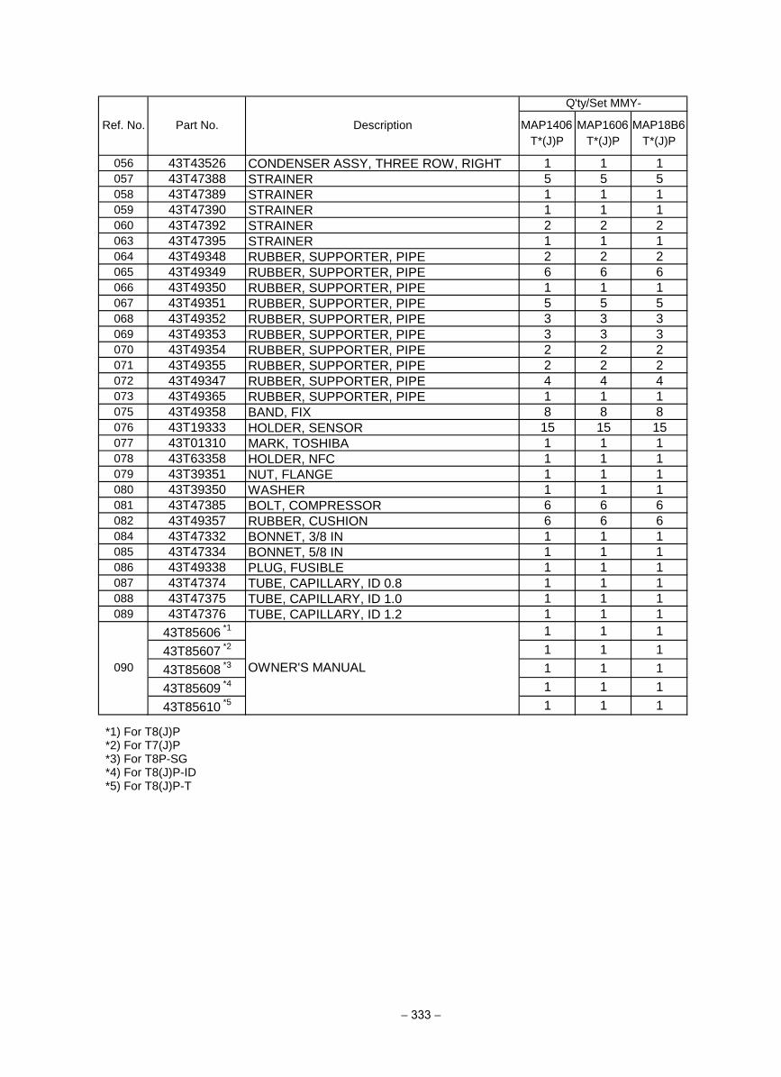
− 333 −
MAP1406T*(J)P
MAP1606T*(J)P
MAP18B6T*(J)P
056 43T43526 CONDENSER ASSY, THREE ROW, RIGHT 1 1 1
057 43T47388 STRAINER 5 5 5
058 43T47389 STRAINER 1 1 1
059 43T47390 STRAINER 1 1 1
060 43T47392 STRAINER 2 2 2
063 43T47395 STRAINER 1 1 1
064 43T49348 RUBBER, SUPPORTER, PIPE 2 2 2
065 43T49349 RUBBER, SUPPORTER, PIPE 6 6 6
066 43T49350 RUBBER, SUPPORTER, PIPE 1 1 1
067 43T49351 RUBBER, SUPPORTER, PIPE 5 5 5
068 43T49352 RUBBER, SUPPORTER, PIPE 3 3 3
069 43T49353 RUBBER, SUPPORTER, PIPE 3 3 3
070 43T49354 RUBBER, SUPPORTER, PIPE 2 2 2
071 43T49355 RUBBER, SUPPORTER, PIPE 2 2 2
072 43T49347 RUBBER, SUPPORTER, PIPE 4 4 4
073 43T49365 RUBBER, SUPPORTER, PIPE 1 1 1
075 43T49358 BAND, FIX 8 8 8
076 43T19333 HOLDER, SENSOR 15 15 15
077 43T01310 MARK, TOSHIBA 1 1 1
078 43T63358 HOLDER, NFC 1 1 1
079 43T39351 NUT, FLANGE 1 1 1
080 43T39350 WASHER 1 1 1
081 43T47385 BOLT, COMPRESSOR 6 6 6
082 43T49357 RUBBER, CUSHION 6 6 6
084 43T47332 BONNET, 3/8 IN 1 1 1
085 43T47334 BONNET, 5/8 IN 1 1 1
086 43T49338 PLUG, FUSIBLE 1 1 1
087 43T47374 TUBE, CAPILLARY, ID 0.8 1 1 1
088 43T47375 TUBE, CAPILLARY, ID 1.0 1 1 1
089 43T47376 TUBE, CAPILLARY, ID 1.2 1 1 1
43T85606 *1 1 1 1
43T85607 *2 1 1 1
43T85608 *3 1 1 1
43T85609 *4 1 1 1
43T85610 *5 1 1 1
Ref. No. Part No. Description
Q'ty/Set MMY-
090 OWNER'S MANUAL
*1) For T8(J)P *2) For T7(J)P *3) For T8P-SG *4) For T8(J)P-ID *5) For T8(J)P-T
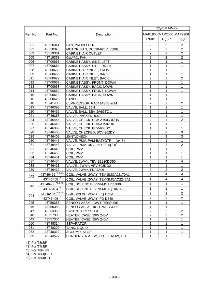
− 334 −
MAP1806T*(J)P
MAP2006T*(J)P
MAP2206T*(J)P
001 43T20341 FAN, PROPELLER 2 2 2
002 43T20343 MOTOR, FAN, DC530-620V, 3500L 2 2 2
003 43T19361 CABINET, AIR OUTLET 2 2 2
005 43T19353 GUARD, FAN 2 2 2
006 43T00663 CABINET ASSY, SIDE, LEFT 1 1 1
007 43T00664 CABINET ASSY, SIDE, RIGHT 1 1 1
008 43T00665 CABINET, AIR INLET, FRONT 1 1 1
009 43T00666 CABINET, AIR INLET, BACK 1 1 1
011 43T00622 CABINET, AIR INLET, BACK 2 2 2
012 43T00667 CABINET ASSY, FRONT, DOWN 1 1 1
013 43T00668 CABINET ASSY, BACK, DOWN 1 1 1
014 43T00669 CABINET ASSY, FRONT, DOWN 1 1 1
015 43T00618 CABINET ASSY, BACK, DOWN 1 1 1
016 43T00623 PANEL 1 1 1
018 43T41485 C0MPRESSOR, RA641A3TB-20M 2 2 2
019 43T46393 VALVE, BALL, 25.4 1 1 1
020 43T46456 VALVE, BALL, SBV-JA6GTC-1 1 1 1
021 43T46366 VALVE, PACKED, 9.52 1 1 1
024 43T46445 VALVE, CHECK, UCV-A1506DRQ5 2 2 2
025 43T46446 VALVE, CHECK, UCV-A1507DR 1 1 1
027 43T46399 VALVE, CHECK, BCV-603DY 1 1 1
028 43T46400 VALVE, CHECKED, BCV-302DY 3 3 3
029 43T46409 J0INT,CHECK 3 3 3
030 43T46447 VALVE, PMV, PAM-BA2YGTF-1 (φ4.8) 1 1 1
031 43T46448 VALVE, PMV, UKV-25D100 (φ2.5) 2 2 2
032 43T46449 COIL, PMV 1 1 1
033 43T46450 COIL, PMV 1 1 1
034 43T46451 COIL, PMV 1 1 1
037 43T46454 VALVE, 2WAY, TEV-S1220DQ50 4 4 4
038 43T46411 VALVE , 2WAY, VPV-603DQ2 1 1 1
039 43T46412 VALVE, 2WAY, FDF3A06 2 2 2
43T46455 *1,3,4,5
COIL, VALVE, 2WAY, TEV-SMOAJ2170A1 4 4 4
43T46458 *2
COIL, VALVE, 2WAY, TEV-SMOAQ2247A1 4 4 4
43T46403 *1,3,4,5
COIL, SOLENOID, VPV-MOAJ510B0 1 1 1
43T46404 *2
COIL, SOLENOID, VPV-MOAQ1843A0 1 1 1
43T46405 *1,3,4,5
COIL, VALVE, 2WAY, FQ-G593 2 2 2
43T46406 *2
COIL, VALVE, 2WAY, FQ-D640 2 2 2
045 43T50357 SENSOR ASSY, LOW PRESSURE 1 1 1
046 43T50358 SENSOR ASSY, HIGH PRESSURE 1 1 1
047 43T63359 SWITCH, PRESSURE 2 2 2
048 43T57303 HEATER, CASE, 29W 240V 2 2 2
049 43T57304 HEATER, CASE, 55W 240V 1 1 1
050 43T48314 SEPARATOR 1 1 1
051 43T48309 TANK, LIQUID 1 1 1
052 43T48312 ACCUMULATOR 1 1 1
055 43T43527 CONDENSER ASSY, THREE ROW, LEFT 1 1 1
043
Ref. No. Part No. Description
Q'ty/Set MMY-
042
044
*1) For T8(J)P *2) For T7(J)P *3) For T8P-SG *4) For T8(J)P-ID *5) For T8(J)P-T
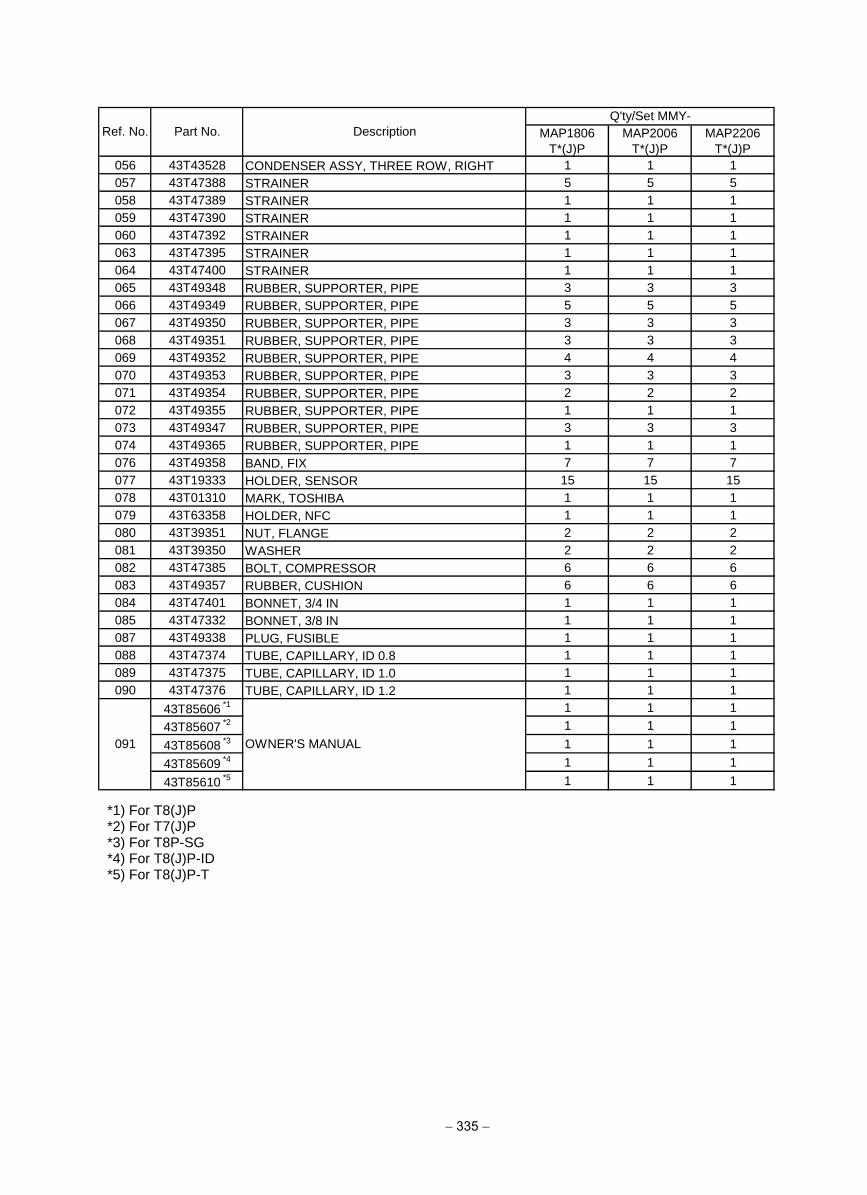
− 335 −
MAP1806
T*(J)P
MAP2006
T*(J)P
MAP2206
T*(J)P
056 43T43528 CONDENSER ASSY, THREE ROW, RIGHT 1 1 1
057 43T47388 STRAINER 5 5 5
058 43T47389 STRAINER 1 1 1
059 43T47390 STRAINER 1 1 1
060 43T47392 STRAINER 1 1 1
063 43T47395 STRAINER 1 1 1
064 43T47400 STRAINER 1 1 1
065 43T49348 RUBBER, SUPPORTER, PIPE 3 3 3
066 43T49349 RUBBER, SUPPORTER, PIPE 5 5 5
067 43T49350 RUBBER, SUPPORTER, PIPE 3 3 3
068 43T49351 RUBBER, SUPPORTER, PIPE 3 3 3
069 43T49352 RUBBER, SUPPORTER, PIPE 4 4 4
070 43T49353 RUBBER, SUPPORTER, PIPE 3 3 3
071 43T49354 RUBBER, SUPPORTER, PIPE 2 2 2
072 43T49355 RUBBER, SUPPORTER, PIPE 1 1 1
073 43T49347 RUBBER, SUPPORTER, PIPE 3 3 3
074 43T49365 RUBBER, SUPPORTER, PIPE 1 1 1
076 43T49358 BAND, FIX 7 7 7
077 43T19333 HOLDER, SENSOR 15 15 15
078 43T01310 MARK, TOSHIBA 1 1 1
079 43T63358 HOLDER, NFC 1 1 1
080 43T39351 NUT, FLANGE 2 2 2
081 43T39350 WASHER 2 2 2
082 43T47385 BOLT, COMPRESSOR 6 6 6
083 43T49357 RUBBER, CUSHION 6 6 6
084 43T47401 BONNET, 3/4 IN 1 1 1
085 43T47332 BONNET, 3/8 IN 1 1 1
087 43T49338 PLUG, FUSIBLE 1 1 1
088 43T47374 TUBE, CAPILLARY, ID 0.8 1 1 1
089 43T47375 TUBE, CAPILLARY, ID 1.0 1 1 1
090 43T47376 TUBE, CAPILLARY, ID 1.2 1 1 1
43T85606 *1 1 1 1
43T85607 *2 1 1 1
43T85608 *3 1 1 1
43T85609 *4 1 1 1
43T85610 *5 1 1 1
Ref. No. Part No. Description
Q'ty/Set MMY-
091 OWNER'S MANUAL
*1) For T8(J)P *2) For T7(J)P *3) For T8P-SG *4) For T8(J)P-ID *5) For T8(J)P-T
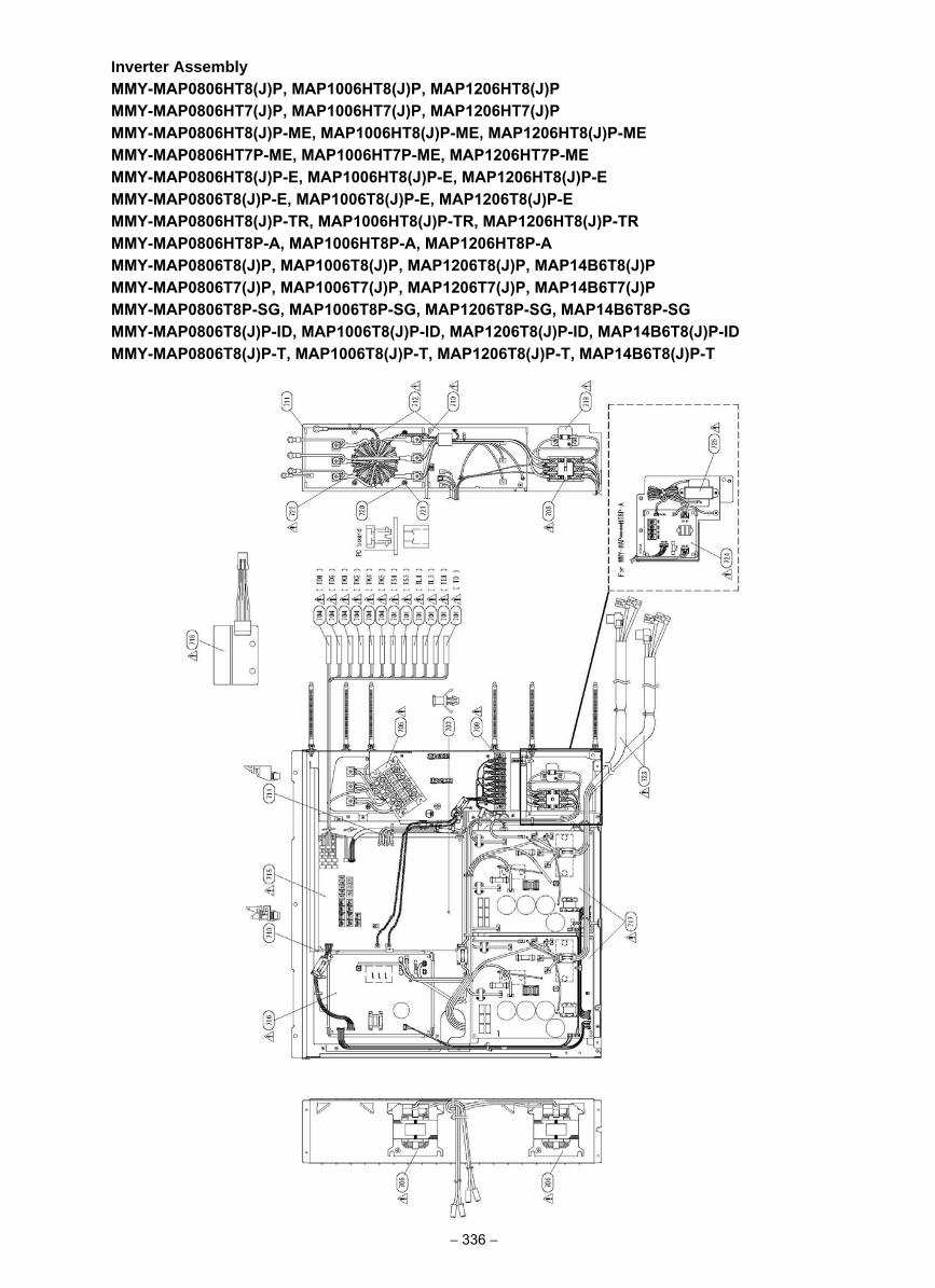
Inverter AssemblyMMY-MAP0806HT8(J)P, MAP1006HT8(J)P, MAP1206HT8(J)PMMY-MAP0806HT7(J)P, MAP1006HT7(J)P, MAP1206HT7(J)PMMY-MAP0806HT8(J)P-ME, MAP1006HT8(J)P-ME, MAP1206HT8(J)P-ME MMY-MAP0806HT7P-ME, MAP1006HT7P-ME, MAP1206HT7P-ME MMY-MAP0806HT8(J)P-E, MAP1006HT8(J)P-E, MAP1206HT8(J)P-E MMY-MAP0806T8(J)P-E, MAP1006T8(J)P-E, MAP1206T8(J)P-EMMY-MAP0806HT8(J)P-TR, MAP1006HT8(J)P-TR, MAP1206HT8(J)P-TR MMY-MAP0806HT8P-A, MAP1006HT8P-A, MAP1206HT8P-AMMY-MAP0806T8(J)P, MAP1006T8(J)P, MAP1206T8(J)P, MAP14B6T8(J)PMMY-MAP0806T7(J)P, MAP1006T7(J)P, MAP1206T7(J)P, MAP14B6T7(J)PMMY-MAP0806T8P-SG, MAP1006T8P-SG, MAP1206T8P-SG, MAP14B6T8P-SGMMY-MAP0806T8(J)P-ID, MAP1006T8(J)P-ID, MAP1206T8(J)P-ID, MAP14B6T8(J)P-IDMMY-MAP0806T8(J)P-T, MAP1006T8(J)P-T, MAP1206T8(J)P-T, MAP14B6T8(J)P-T
− 336 −
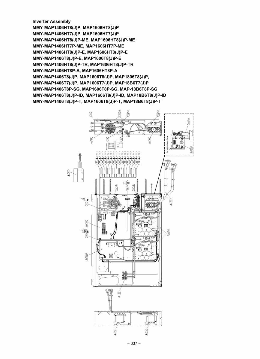
Inverter AssemblyMMY-MAP1406HT8(J)P, MAP1606HT8(J)P MMY-MAP1406HT7(J)P, MAP1606HT7(J)P MMY-MAP1406HT8(J)P-ME, MAP1606HT8(J)P-ME MMY-MAP1406HT7P-ME, MAP1606HT7P-ME MMY-MAP1406HT8(J)P-E, MAP1606HT8(J)P-E MMY-MAP1406T8(J)P-E, MAP1606T8(J)P-E MMY-MAP1406HT8(J)P-TR, MAP1606HT8(J)P-TR MMY-MAP1406HT8P-A, MAP1606HT8P-AMMY-MAP1406T8(J)P, MAP1606T8(J)P, MAP1806T8(J)P, MMY-MAP1406T7(J)P, MAP1606T7(J)P, MAP18B6T7(J)PMMY-MAP1406T8P-SG, MAP1606T8P-SG, MAP-18B6T8P-SGMMY-MAP1406T8(J)P-ID, MAP1606T8(J)P-ID, MAP18B6T8(J)P-ID MMY-MAP1406T8(J)P-T, MAP1606T8(J)P-T, MAP18B6T8(J)P-T
− 337 −
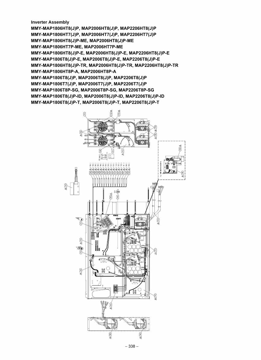
Inverter AssemblyMMY-MAP1806HT8(J)P, MAP2006HT8(J)P, MAP2206HT8(J)P MMY-MAP1806HT7(J)P, MAP2006HT7(J)P, MAP2206HT7(J)P MMY-MAP1806HT8(J)P-ME, MAP2006HT8(J)P-MEMMY-MAP1806HT7P-ME, MAP2006HT7P-MEMMY-MAP1806HT8(J)P-E, MAP2006HT8(J)P-E, MAP2206HT8(J)P-E MMY-MAP1806T8(J)P-E, MAP2006T8(J)P-E, MAP2206T8(J)P-EMMY-MAP1806HT8(J)P-TR, MAP2006HT8(J)P-TR, MAP2206HT8(J)P-TR MMY-MAP1806HT8P-A, MAP2006HT8P-AMMY-MAP1806T8(J)P, MAP2006T8(J)P, MAP2206T8(J)PMMY-MAP1806T7(J)P, MAP2006T7(J)P, MAP2206T7(J)PMMY-MAP1806T8P-SG, MAP2006T8P-SG, MAP2206T8P-SGMMY-MAP1806T8(J)P-ID, MAP2006T8(J)P-ID, MAP2206T8(J)P-IDMMY-MAP1806T8(J)P-T, MAP2006T8(J)P-T, MAP2206T8(J)P-T
− 338 −
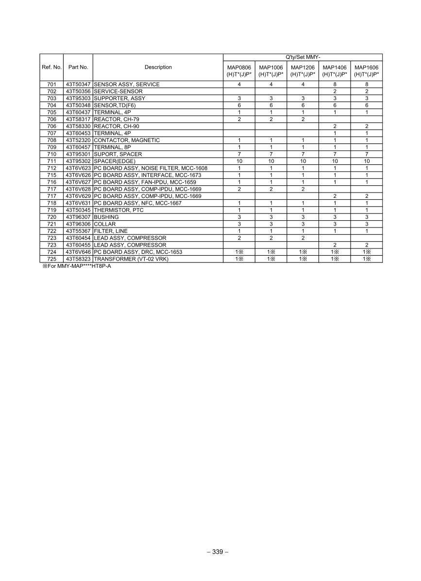
MAP0806(H)T*(J)P*
MAP1006(H)T*(J)P*
MAP1206(H)T*(J)P*
MAP1406(H)T*(J)P*
MAP1606(H)T*(J)P*
701 43T50347 SENSOR ASSY, SERVICE 4 4 4 8 8702 43T50356 SERVICE-SENSOR 2 2703 43T95303 SUPPORTER, ASSY 3 3 3 3 3704 43T50348 SENSOR,TD(F6) 6 6 6 6 6705 43T60437 TERMINAL, 4P 1 1 1 1 1706 43T58317 REACTOR, CH-79 2 2 2706 43T58330 REACTOR, CH-90 2 2707 43T60453 TERMINAL, 4P 1 1708 43T52320 CONTACTOR, MAGNETIC 1 1 1 1 1709 43T60457 TERMINAL, 8P 1 1 1 1 1710 43T95301 SUPORT, SPACER 7 7 7 7 7711 43T95302 SPACER(EDGE) 10 10 10 10 10712 43T6V623 PC BOARD ASSY, NOISE FILTER, MCC-1608 1 1 1 1 1715 43T6V626 PC BOARD ASSY, INTERFACE, MCC-1673 1 1 1 1 1716 43T6V627 PC BOARD ASSY, FAN-IPDU, MCC-1659 1 1 1 1 1717 43T6V628 PC BOARD ASSY, COMP-IPDU, MCC-1669 2 2 2717 43T6V629 PC BOARD ASSY, COMP-IPDU, MCC-1669 2 2718 43T6V631 PC BOARD ASSY, NFC, MCC-1667 1 1 1 1 1719 43T50345 THERMISTOR, PTC 1 1 1 1 1720 43T96307 BUSHING 3 3 3 3 3721 43T96306 COLLAR 3 3 3 3 3722 43T55367 FILTER, LINE 1 1 1 1 1723 43T60454 LEAD ASSY, COMPRESSOR 2 2 2723 43T60455 LEAD ASSY, COMPRESSOR 2 2724 43T6V646 PC BOARD ASSY, DRC, MCC-1653 1※ 1※ 1※ 1※ 1※725 43T58323 TRANSFORMER (VT-02 VRK) 1※ 1※ 1※ 1※ 1※
※For MMY-MAP****HT8P-A
Q'ty/Set MMY-
Ref. No. Part No. Description
− 339 −
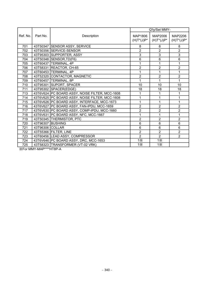
MAP1806(H)T*(J)P*
MAP2006(H)T*(J)P*
MAP2206(H)T*(J)P*
701 43T50347 SENSOR ASSY, SERVICE 8 8 8702 43T50356 SERVICE-SENSOR 2 2 2703 43T95303 SUPPORTER, ASSY 3 3 3704 43T50348 SENSOR,TD(F6) 6 6 6705 43T60437 TERMINAL, 4P 1 1 1706 43T58331 REACTOR, CH-65 2 2 2707 43T60453 TERMINAL, 4P 1 1 1708 43T52320 CONTACTOR, MAGNETIC 2 2 2709 43T60457 TERMINAL, 8P 1 1 1710 43T95301 SUPORT, SPACER 10 10 10711 43T95302 SPACER(EDGE) 18 18 18713 43T6V624 PC BOARD ASSY, NOISE FILTER, MCC-1608 1 1 1714 43T6V625 PC BOARD ASSY, NOISE FILTER, MCC-1608 1 1 1715 43T6V626 PC BOARD ASSY, INTERFACE, MCC-1673 1 1 1716 43T6V627 PC BOARD ASSY, FAN-IPDU, MCC-1659 2 2 2717 43T6V630 PC BOARD ASSY, COMP-IPDU, MCC-1660 2 2 2718 43T6V631 PC BOARD ASSY, NFC, MCC-1667 1 1 1719 43T50345 THERMISTOR, PTC 2 2 2720 43T96307 BUSHING 6 6 6721 43T96306 COLLAR 6 6 6722 43T55366 FILTER, LINE 2 2 2723 43T60456 LEAD ASSY, COMPRESSOR 2 2 2724 43T6V646 PC BOARD ASSY, DRC, MCC-1653 1※ 1※725 43T58323 TRANSFORMER (VT-02 VRK) 1※ 1※
※For MMY-MAP****HT8P-A
Ref. No. Part No. Description
Q'ty/Set MMY-
− 340 −
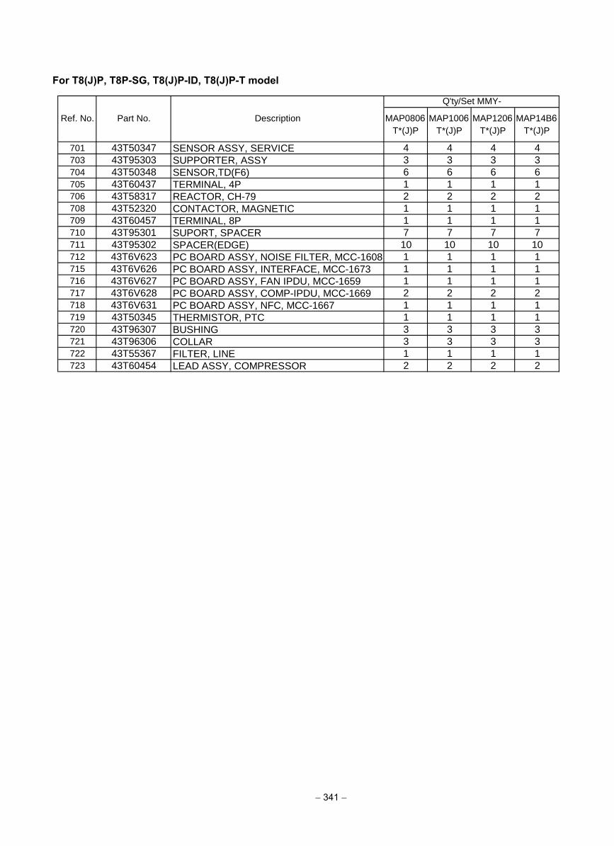
− 341 −
For T8(J)P, T8P-SG, T8(J)P-ID, T8(J)P-T model
MAP0806T*(J)P
MAP1006T*(J)P
MAP1206T*(J)P
MAP14B6T*(J)P
701 43T50347 SENSOR ASSY, SERVICE 4 4 4 4
703 43T95303 SUPPORTER, ASSY 3 3 3 3
704 43T50348 SENSOR,TD(F6) 6 6 6 6
705 43T60437 TERMINAL, 4P 1 1 1 1
706 43T58317 REACTOR, CH-79 2 2 2 2
708 43T52320 CONTACTOR, MAGNETIC 1 1 1 1
709 43T60457 TERMINAL, 8P 1 1 1 1
710 43T95301 SUPORT, SPACER 7 7 7 7
711 43T95302 SPACER(EDGE) 10 10 10 10
712 43T6V623 PC BOARD ASSY, NOISE FILTER, MCC-1608 1 1 1 1
715 43T6V626 PC BOARD ASSY, INTERFACE, MCC-1673 1 1 1 1
716 43T6V627 PC BOARD ASSY, FAN IPDU, MCC-1659 1 1 1 1
717 43T6V628 PC BOARD ASSY, COMP-IPDU, MCC-1669 2 2 2 2
718 43T6V631 PC BOARD ASSY, NFC, MCC-1667 1 1 1 1
719 43T50345 THERMISTOR, PTC 1 1 1 1
720 43T96307 BUSHING 3 3 3 3
721 43T96306 COLLAR 3 3 3 3
722 43T55367 FILTER, LINE 1 1 1 1
723 43T60454 LEAD ASSY, COMPRESSOR 2 2 2 2
Q'ty/Set MMY-
Ref. No. Part No. Description
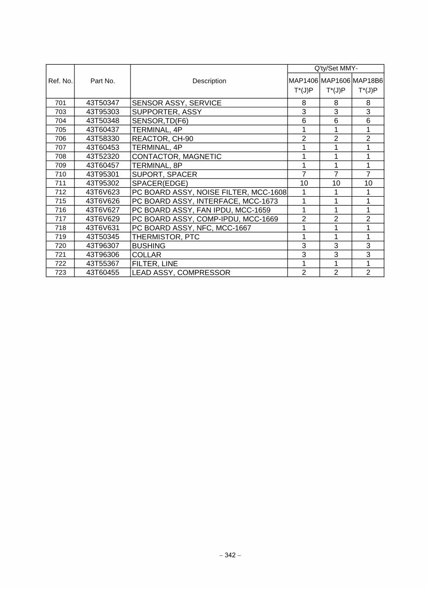
− 342 −
MAP1406T*(J)P
MAP1606T*(J)P
MAP18B6T*(J)P
701 43T50347 SENSOR ASSY, SERVICE 8 8 8
703 43T95303 SUPPORTER, ASSY 3 3 3
704 43T50348 SENSOR,TD(F6) 6 6 6
705 43T60437 TERMINAL, 4P 1 1 1
706 43T58330 REACTOR, CH-90 2 2 2
707 43T60453 TERMINAL, 4P 1 1 1
708 43T52320 CONTACTOR, MAGNETIC 1 1 1
709 43T60457 TERMINAL, 8P 1 1 1
710 43T95301 SUPORT, SPACER 7 7 7
711 43T95302 SPACER(EDGE) 10 10 10
712 43T6V623 PC BOARD ASSY, NOISE FILTER, MCC-1608 1 1 1
715 43T6V626 PC BOARD ASSY, INTERFACE, MCC-1673 1 1 1
716 43T6V627 PC BOARD ASSY, FAN IPDU, MCC-1659 1 1 1
717 43T6V629 PC BOARD ASSY, COMP-IPDU, MCC-1669 2 2 2
718 43T6V631 PC BOARD ASSY, NFC, MCC-1667 1 1 1
719 43T50345 THERMISTOR, PTC 1 1 1
720 43T96307 BUSHING 3 3 3
721 43T96306 COLLAR 3 3 3
722 43T55367 FILTER, LINE 1 1 1
723 43T60455 LEAD ASSY, COMPRESSOR 2 2 2
Ref. No. Part No. Description
Q'ty/Set MMY-
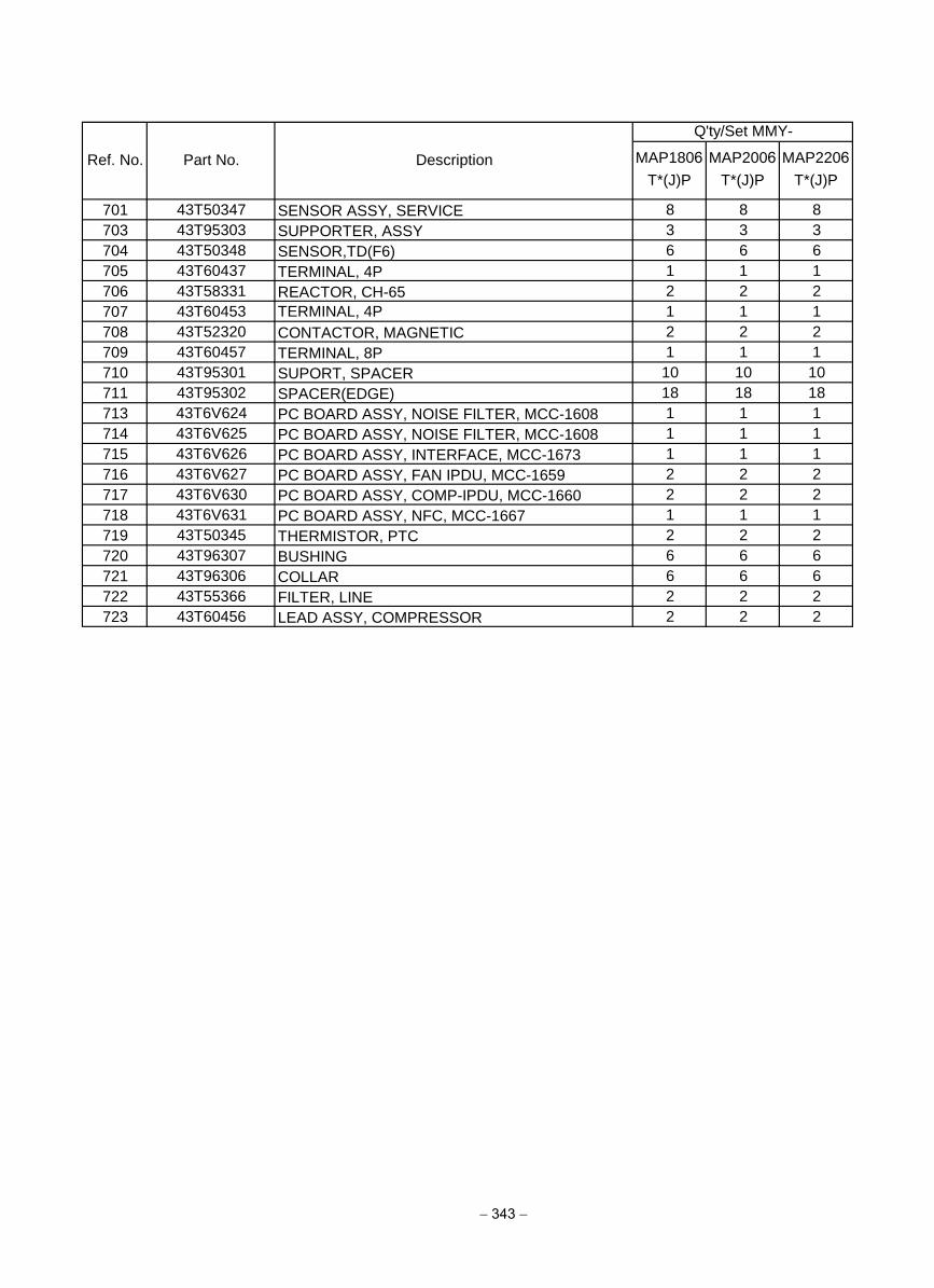
− 343 −
MAP1806T*(J)P
MAP2006T*(J)P
MAP2206T*(J)P
701 43T50347 SENSOR ASSY, SERVICE 8 8 8
703 43T95303 SUPPORTER, ASSY 3 3 3
704 43T50348 SENSOR,TD(F6) 6 6 6
705 43T60437 TERMINAL, 4P 1 1 1
706 43T58331 REACTOR, CH-65 2 2 2
707 43T60453 TERMINAL, 4P 1 1 1
708 43T52320 CONTACTOR, MAGNETIC 2 2 2
709 43T60457 TERMINAL, 8P 1 1 1
710 43T95301 SUPORT, SPACER 10 10 10
711 43T95302 SPACER(EDGE) 18 18 18
713 43T6V624 PC BOARD ASSY, NOISE FILTER, MCC-1608 1 1 1
714 43T6V625 PC BOARD ASSY, NOISE FILTER, MCC-1608 1 1 1
715 43T6V626 PC BOARD ASSY, INTERFACE, MCC-1673 1 1 1
716 43T6V627 PC BOARD ASSY, FAN IPDU, MCC-1659 2 2 2
717 43T6V630 PC BOARD ASSY, COMP-IPDU, MCC-1660 2 2 2
718 43T6V631 PC BOARD ASSY, NFC, MCC-1667 1 1 1
719 43T50345 THERMISTOR, PTC 2 2 2
720 43T96307 BUSHING 6 6 6
721 43T96306 COLLAR 6 6 6
722 43T55366 FILTER, LINE 2 2 2
723 43T60456 LEAD ASSY, COMPRESSOR 2 2 2
Ref. No. Part No. Description
Q'ty/Set MMY-