Embed Size (px)
Citation preview

Eaton® Transmission
Service ManualFSO-2106 / 2506February 2015Rev. 0
IntroductionPurpose and Scope of the Manual .................................................................................................................... 1How to Use this Manual .................................................................................................................................... 1Warnings and Precautions ................................................................................................................................ 2Identification ...................................................................................................................................................... 3
Model Designation........................................................................................................................................ 3Gear Ratio .................................................................................................................................................... 4
Exploded Views ................................................................................................................................................. 5Gear Shift Lever Housing (Direct Control) (4x2 and 4x4)............................................................................. 5Shift Yokes and Rails (4x2 and 4x4)............................................................................................................. 6Transmission Case Assembly (4x2) ............................................................................................................. 7Transmission Case Assembly (4x4) ............................................................................................................. 8Input Shaft and Mainshaft Assembly (4x2 and 4x4) ..................................................................................... 9Countershaft Assembly (4x2 and 4x4) ....................................................................................................... 10
Lubrication Information .................................................................................................................................... 11Operation ......................................................................................................................................................... 13
Gear shift lever pattern ............................................................................................................................... 13Power Flow ...................................................................................................................................................... 14Sealant and Torque Specification .................................................................................................................... 20Precautions ..................................................................................................................................................... 24Special Tools ................................................................................................................................................... 27
Gear Shift Lever HousingGear Shift Lever Housing - Disassembly ........................................................................................................ 29Gear Shift Lever Housing - Assembly ............................................................................................................. 32
Rear SectionRear Seal Replacement .................................................................................................................................. 35Rear Section - Disassembly ............................................................................................................................ 36Rear Section - Assembly ................................................................................................................................. 44
Table of Contents
Front SectionFront Seal Replacement .................................................................................................................................. 49
Front Section - Disassembly ........................................................................................................................... 51Mainshaft .................................................................................................................................................... 55Input Shaft .................................................................................................................................................. 58Countershaft ............................................................................................................................................... 59Synchronizers............................................................................................................................................. 60Shift Rails ................................................................................................................................................... 63Front Bearing Cups - Removal and Installation.......................................................................................... 64Rear Bearing Cups - Removal and Installation .......................................................................................... 65
Front Section - Assembly ................................................................................................................................ 66
End Play Adjustment ....................................................................................................................................... 74
Table of Contents
IntroductionIntroduction
1
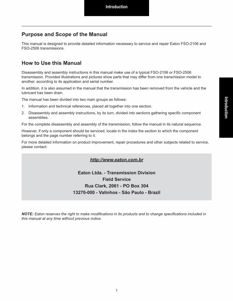
Purpose and Scope of the ManualThis manual is designed to provide detailed information necessary to service and repair Eaton FSO-2106 and FSO-2506 transmissions.
How to Use this ManualDisassembly and assembly instructions in this manual make use of a typical FSO-2106 or FSO-2506 transmission. Provided illustrations and pictures show parts that may differ from one transmission model to another, according to its application and serial number.
In addition, it is also assumed in the manual that the transmission has been removed from the vehicle and the lubricant has been drain.
The manual has been divided into two main groups as follows:
1. Information and technical references, placed all together into one section.
2. Disassembly and assembly instructions, by its turn, divided into sections gathering specific component assemblies.
For the complete disassembly and assembly of the transmission, follow the manual in its natural sequence.
However, if only a component should be serviced, locate in the index the section to which the component belongs and the page number referring to it.
For more detailed information on product improvement, repair procedures and other subjects related to service, please contact:
http://www.eaton.com.br
Eaton Ltda. - Transmission DivisionField Service
Rua Clark, 2061 - PO Box 30413270-000 - Valinhos - São Paulo - Brazil
NOTE: Eaton reserves the right to make modifications in its products and to change specifications included in this manual at any time without previous notice.
Warnings and Precautions
2
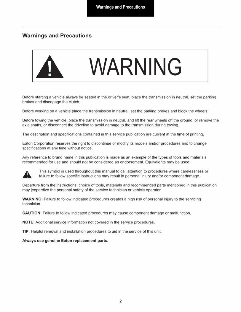
Warnings and Precautions
WARNINGBefore starting a vehicle always be seated in the driver’s seat, place the transmission in neutral, set the parking brakes and disengage the clutch.
Before working on a vehicle place the transmission in neutral, set the parking brakes and block the wheels.
Before towing the vehicle, place the transmission in neutral, and lift the rear wheels off the ground, or remove the axle shafts, or disconnect the driveline to avoid damage to the transmission during towing.
The description and specifications contained in this service publication are current at the time of printing.
Eaton Corporation reserves the right to discontinue or modify its models and/or procedures and to change specifications at any time without notice.
Any reference to brand name in this publication is made as an example of the types of tools and materials recommended for use and should not be considered an endorsement. Equivalents may be used.
This symbol is used throughout this manual to call attention to procedures where carelessness or failure to follow specific instructions may result in personal injury and/or component damage.
Departure from the instructions, choice of tools, materials and recommended parts mentioned in this publication may jeopardize the personal safety of the service technician or vehicle operator.
WARNING: Failure to follow indicated procedures creates a high risk of personal injury to the servicing technician.
CAUTION: Failure to follow indicated procedures may cause component damage or malfunction.
NOTE: Additional service information not covered in the service procedures.
TIP: Helpful removal and installation procedures to aid in the service of this unit.
Always use genuine Eaton replacement parts.
IdentificationIdentification
3
FSO-2105/01
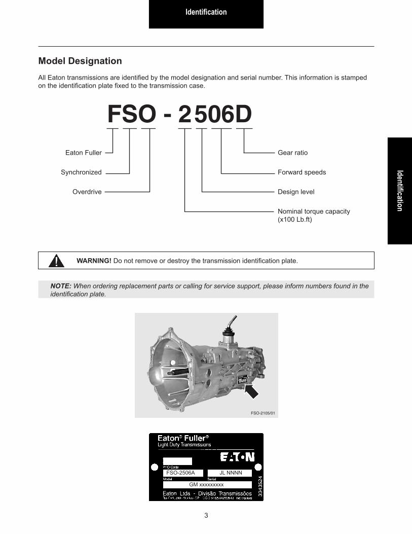
Model DesignationAll Eaton transmissions are identified by the model designation and serial number. This information is stamped on the identification plate fixed to the transmission case.
Eaton Fuller
Synchronized
Overdrive
FSO - 2506DGear ratio
Forward speeds
Design level
Nominal torque capacity (x100 Lb.ft)
WARNING! Do not remove or destroy the transmission identification plate.
FSO-2506A JL NNNN
GM xxxxxxxxx
NOTE: When ordering replacement parts or calling for service support, please inform numbers found in the identification plate.
Identification
4
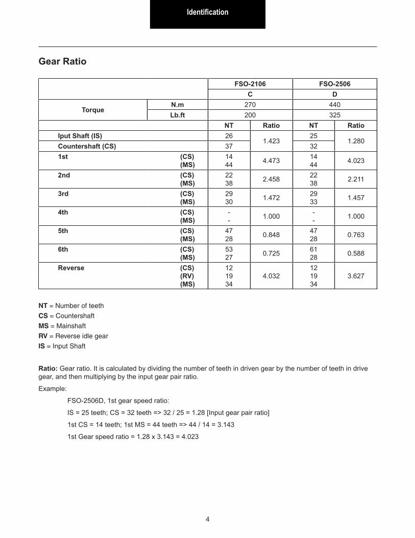
Ratio: Gear ratio. It is calculated by dividing the number of teeth in driven gear by the number of teeth in drive gear, and then multiplying by the input gear pair ratio.
Example:
FSO-2506D, 1st gear speed ratio:
IS = 25 teeth; CS = 32 teeth => 32 / 25 = 1.28 [Input gear pair ratio]
1st CS = 14 teeth; 1st MS = 44 teeth => 44 / 14 = 3.143
1st Gear speed ratio = 1.28 x 3.143 = 4.023
FSO-2106 FSO-2506C D
TorqueN.m 270 440Lb.ft 200 325
NT Ratio NT RatioIput Shaft (IS) 26
1.42325
1.280Countershaft (CS) 37 321st (CS) (MS)
14 44 4.473 14
44 4.023
2nd (CS) (MS)
22 38 2.458 22
38 2.211
3rd (CS) (MS)
29 30 1.472 29
33 1.457
4th (CS) (MS)
- - 1.000 -
- 1.000
5th (CS) (MS)
47 28 0.848 47
28 0.763
6th (CS) (MS)
53 27 0.725 61
28 0.588
Reverse (CS) (RV) (MS)
12 19 34
4.03212 19 34
3.627
NT = Number of teeth
CS = Countershaft
MS = Mainshaft
RV = Reverse idle gear
IS = Input Shaft
Gear Ratio
Exploded ViewsExploded Views
5
FSO-2106/explo1
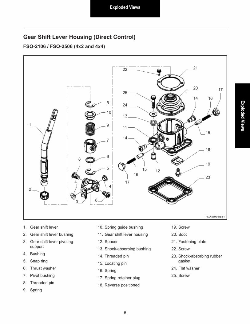
Gear Shift Lever Housing (Direct Control)FSO-2106 / FSO-2506 (4x2 and 4x4)
1. Gear shift lever
2. Gear shift lever bushing
3. Gear shift lever pivoting support
4. Bushing
5. Snap ring
6. Thrust washer
7. Pivot bushing
8. Threaded pin
9. Spring
10. Spring guide bushing
11. Gear shift lever housing
12. Spacer
13. Shock-absorbing bushing
14. Threaded pin
15. Locating pin
16. Spring
17. Spring retainer plug
18. Reverse positioned
19. Screw
20. Boot
21. Fastening plate
22. Screw
23. Shock-absorbing rubber gasket
24. Flat washer
25. Screw
1
2
5
10
9
7
6
5
8
44
8
17
1615 12
23
19
18
15
17
1614
20
21
25
24
13
11
14
22
3
Exploded Views
6
FSO-2106/explo2
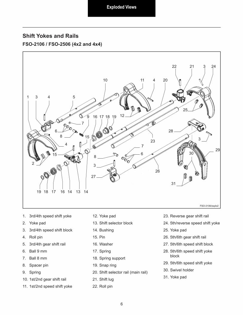
Shift Yokes and RailsFSO-2106 / FSO-2506 (4x2 and 4x4)
1. 3rd/4th speed shift yoke
2. Yoke pad
3. 3rd/4th speed shift block
4. Roll pin
5. 3rd/4th gear shift rail
6. Ball 9 mm
7. Ball 8 mm
8. Spacer pin
9. Spring
10. 1st/2nd gear shift rail
11. 1st/2nd speed shift yoke
12. Yoke pad
13. Shift selector block
14. Bushing
15. Pin
16. Washer
17. Spring
18. Spring support
19. Snap ring
20. Shift selector rail (main rail)
21. Shift lug
22. Roll pin
23. Reverse gear shift rail
24. 5th/reverse speed shift yoke
25. Yoke pad
26. 5th/6th gear shift rail
27. 5th/6th speed shift block
28. 5th/6th speed shift yoke block
29. 5th/6th speed shift yoke
30. Swivel holder
31. Yoke pad
1 3
4
2
4
6
7
8
9
10
5
11
12
13 1414
15
15
16171819
20
2122
23
24
25
2627
28
2930
31
3
7
68
3
16 17 18 19
3
4
Exploded ViewsExploded Views
7
FSO-2106/explo3
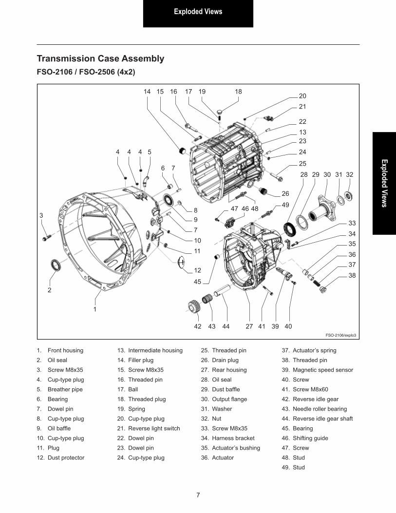
Transmission Case AssemblyFSO-2106 / FSO-2506 (4x2)
1. Front housing
2. Oil seal
3. Screw M8x35
4. Cup-type plug
5. Breather pipe
6. Bearing
7. Dowel pin
8. Cup-type plug
9. Oil baffle
10. Cup-type plug
11. Plug
12. Dust protector
13. Intermediate housing
14. Filler plug
15. Screw M8x35
16. Threaded pin
17. Ball
18. Threaded plug
19. Spring
20. Cup-type plug
21. Reverse light switch
22. Dowel pin
23. Dowel pin
24. Cup-type plug
25. Threaded pin
26. Drain plug
27. Rear housing
28. Oil seal
29. Dust baffle
30. Output flange
31. Washer
32. Nut
33. Screw M8x35
34. Harness bracket
35. Actuator’s bushing
36. Actuator
37. Actuator’s spring
38. Threaded pin
39. Magnetic speed sensor
40. Screw
41. Screw M8x60
42. Reverse idle gear
43. Needle roller bearing
44. Reverse idle gear shaft
45. Bearing
46. Shifting guide
47. Screw
48. Stud
49. Stud
1
2
3
4 4 4
6 7
5
8971011
12
45
42 43 44 27 41 39 40
35363738
3334
28 29 30 31 32
26
494847 46
25
24
23
22
2120
181917161514
13
Exploded Views
8
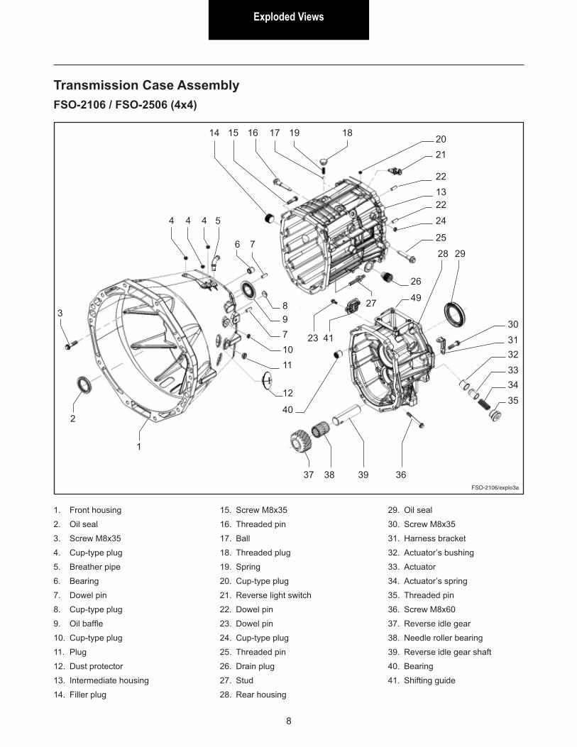
Transmission Case AssemblyFSO-2106 / FSO-2506 (4x4)
1. Front housing
2. Oil seal
3. Screw M8x35
4. Cup-type plug
5. Breather pipe
6. Bearing
7. Dowel pin
8. Cup-type plug
9. Oil baffle
10. Cup-type plug
11. Plug
12. Dust protector
13. Intermediate housing
14. Filler plug
15. Screw M8x35
16. Threaded pin
17. Ball
18. Threaded plug
19. Spring
20. Cup-type plug
21. Reverse light switch
22. Dowel pin
23. Dowel pin
24. Cup-type plug
25. Threaded pin
26. Drain plug
27. Stud
28. Rear housing
29. Oil seal
30. Screw M8x35
31. Harness bracket
32. Actuator’s bushing
33. Actuator
34. Actuator’s spring
35. Threaded pin
36. Screw M8x60
37. Reverse idle gear
38. Needle roller bearing
39. Reverse idle gear shaft
40. Bearing
41. Shifting guide
FSO-2106/explo3a
1
2
3
4 4 4
6 7
5
8971011
12
40
37 38 39 36
32333435
3031
28 29
26
4927
23 41
25
24
22
22
2120
181917161514
13
Exploded ViewsExploded Views
9
FSO-2106/explo4
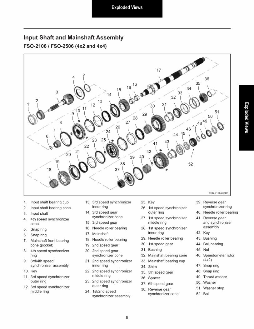
Input Shaft and Mainshaft AssemblyFSO-2106 / FSO-2506 (4x2 and 4x4)
1. Input shaft bearing cup2. Input shaft bearing cone3. Input shaft4. 4th speed synchronizer
cone5. Snap ring6. Snap ring7. Mainshaft front bearing
cone (pocket)8. 4th speed synchronizer
ring9. 3rd/4th speed
synchronizer assembly10. Key11. 3rd speed synchronizer
outer ring12. 3rd speed synchronizer
middle ring
13. 3rd speed synchronizer inner ring
14. 3rd speed gear synchronizer cone
15. 3rd speed gear16. Needle roller bearing17. Mainshaft18. Needle roller bearing19. 2nd speed gear20. 2nd speed gear
synchronizer cone21. 2nd speed synchronizer
inner ring22. 2nd speed synchronizer
middle ring23. 2nd speed synchronizer
outer ring24. 1st/2nd speed
synchronizer assembly
25. Key26. 1st speed synchronizer
outer ring27. 1st speed synchronizer
middle ring28. 1st speed synchronizer
inner ring29. Needle roller bearing30. 1st speed gear31. Bushing32. Mainshaft bearing cone33. Mainshaft bearing cup34. Shim35. 5th speed gear36. Spacer37. 6th speed gear38. Reverse gear
synchronizer cone
12
3
45
67
8
910
2122
23
1314
15 1616
17
18
19
20
24
25
30 31
3233
34
3738
39 4042
44
43
4546
49
52
5051
41
2827
26
29
39. Reverse gear synchronizer ring
40. Needle roller bearing41. Reverse gear
and synchronizer assembly
42. Key43. Bushing44. Ball bearing45. Nut46. Speedometer rotor
(4x2)47. Snap ring48. Snap ring49. Thrust washer50. Washer51. Washer stop52. Ball
1112
3536
4748
Exploded Views
10
FSO-2106/explo5
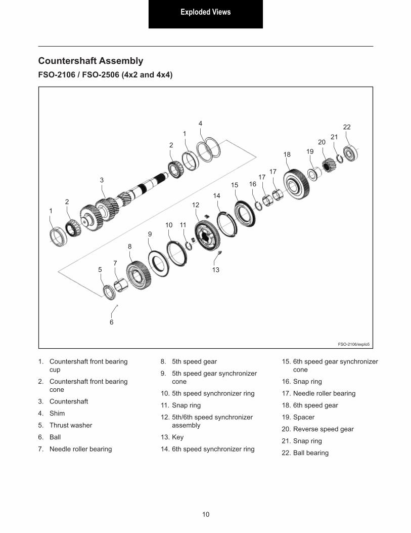
Countershaft AssemblyFSO-2106 / FSO-2506 (4x2 and 4x4)
1. Countershaft front bearing cup
2. Countershaft front bearing cone
3. Countershaft
4. Shim
5. Thrust washer
6. Ball
7. Needle roller bearing
8. 5th speed gear
9. 5th speed gear synchronizer cone
10. 5th speed synchronizer ring
11. Snap ring
12. 5th/6th speed synchronizer assembly
13. Key
14. 6th speed synchronizer ring
15. 6th speed gear synchronizer cone
16. Snap ring
17. Needle roller bearing
18. 6th speed gear
19. Spacer
20. Reverse speed gear
21. Snap ring
22. Ball bearing
12
3
2
14
5
6
7
8
910 11
1214
15 1617
17
18 1920
2122
13
Lubrication Information
Lubrication Information
11
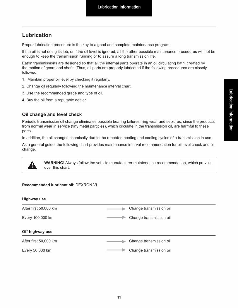
Highway use
After first 50,000 km Change transmission oil
Every 100,000 km Change transmission oil
Off-highway use
After first 50,000 km Change transmission oil
Every 50,000 km Change transmission oil
LubricationProper lubrication procedure is the key to a good and complete maintenance program.
If the oil is not doing its job, or if the oil level is ignored, all the other possible maintenance procedures will not be enough to keep the transmission running or to assure a long transmission life.
Eaton transmissions are designed so that all the internal parts operate in an oil circulating bath, created by the motion of gears and shafts. Thus, all parts are properly lubricated if the following procedures are closely followed:
1. Maintain proper oil level by checking it regularly.
2. Change oil regularly following the maintenance interval chart.
3. Use the recommended grade and type of oil.
4. Buy the oil from a reputable dealer.
Oil change and level checkPeriodic transmission oil change eliminates possible bearing failures, ring wear and seizures, since the products from normal wear in service (tiny metal particles), which circulate in the transmission oil, are harmful to these parts.
In addition, the oil changes chemically due to the repeated heating and cooling cycles of a transmission in use.
As a general guide, the following chart provides maintenance interval recommendation for oil level check and oil change.
WARNING! Always follow the vehicle manufacturer maintenance recommendation, which prevails over this chart.
Recommended lubricant oil: DEXRON VI
Lubrication Information
12
DrainingDrain transmission oil while the oil is warm.
To drain oil, remove the magnetic drain plug. Clean the drain plug before reinstalling it.
Refilling
FSO-2106/02
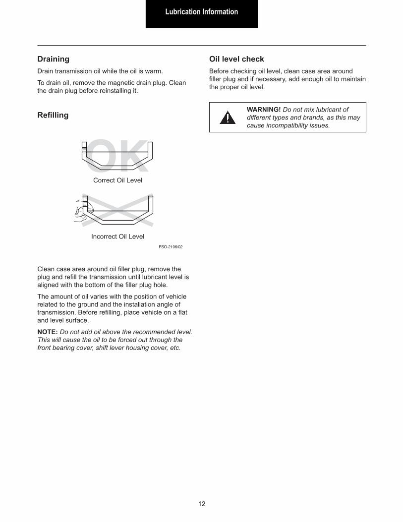
Clean case area around oil filler plug, remove the plug and refill the transmission until lubricant level is aligned with the bottom of the filler plug hole.
The amount of oil varies with the position of vehicle related to the ground and the installation angle of transmission. Before refilling, place vehicle on a flat and level surface.
NOTE: Do not add oil above the recommended level. This will cause the oil to be forced out through the front bearing cover, shift lever housing cover, etc.
Correct Oil Level
Incorrect Oil Level
Oil level checkBefore checking oil level, clean case area around filler plug and if necessary, add enough oil to maintain the proper oil level.
WARNING! Do not mix lubricant of different types and brands, as this may cause incompatibility issues.
OperationOperation
13
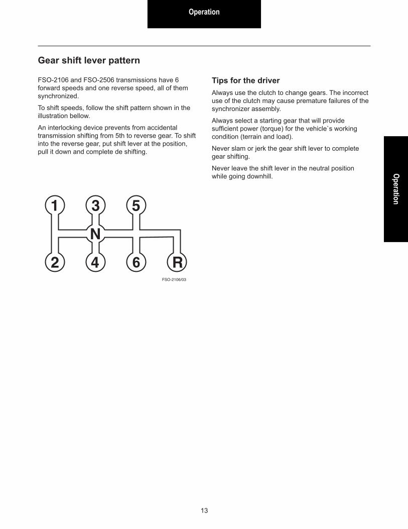
Gear shift lever pattern
FSO-2106/03
FSO-2106 and FSO-2506 transmissions have 6 forward speeds and one reverse speed, all of them synchronized.
To shift speeds, follow the shift pattern shown in the illustration bellow.
An interlocking device prevents from accidental transmission shifting from 5th to reverse gear. To shift into the reverse gear, put shift lever at the position, pull it down and complete de shifting.
Tips for the driverAlways use the clutch to change gears. The incorrect use of the clutch may cause premature failures of the synchronizer assembly.
Always select a starting gear that will provide sufficient power (torque) for the vehicle`s working condition (terrain and load).
Never slam or jerk the gear shift lever to complete gear shifting.
Never leave the shift lever in the neutral position while going downhill.
Power Flow
14
Power FlowThe transmission must efficiently transfer the engine’s power or torque to the vehicle’s driveline.
It is essential to know what takes place in the transmission during torque transfer when troubleshooting or making repairs.
FSO-2106/04
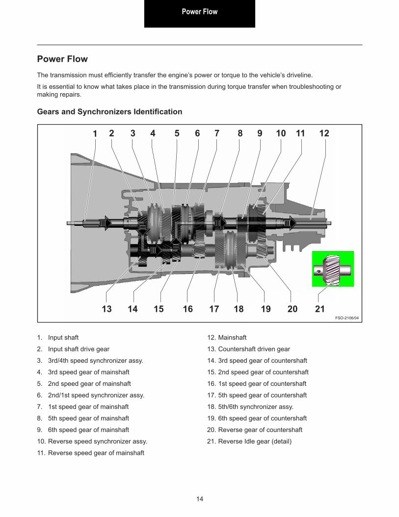
Gears and Synchronizers Identification
1. Input shaft
2. Input shaft drive gear
3. 3rd/4th speed synchronizer assy.
4. 3rd speed gear of mainshaft
5. 2nd speed gear of mainshaft
6. 2nd/1st speed synchronizer assy.
7. 1st speed gear of mainshaft
8. 5th speed gear of mainshaft
9. 6th speed gear of mainshaft
10. Reverse speed synchronizer assy.
11. Reverse speed gear of mainshaft
12. Mainshaft
13. Countershaft driven gear
14. 3rd speed gear of countershaft
15. 2nd speed gear of countershaft
16. 1st speed gear of countershaft
17. 5th speed gear of countershaft
18. 5th/6th synchronizer assy.
19. 6th speed gear of countershaft
20. Reverse gear of countershaft
21. Reverse Idle gear (detail)
1 2 3 4 5 6 7 8 9 10 11 12
13 14 15 16 17 18 19 20 21
Power FlowPower Flow
15
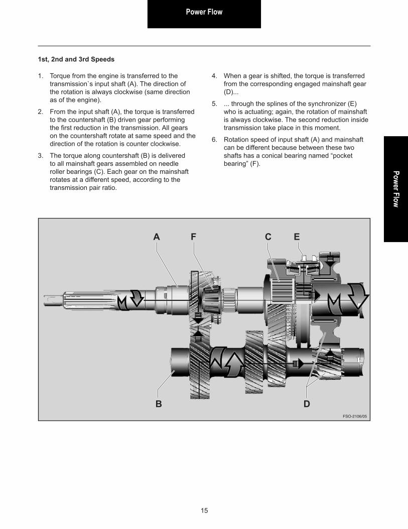
1. Torque from the engine is transferred to the transmission`s input shaft (A). The direction of the rotation is always clockwise (same direction as of the engine).
2. From the input shaft (A), the torque is transferred to the countershaft (B) driven gear performing the first reduction in the transmission. All gears on the countershaft rotate at same speed and the direction of the rotation is counter clockwise.
3. The torque along countershaft (B) is delivered to all mainshaft gears assembled on needle roller bearings (C). Each gear on the mainshaft rotates at a different speed, according to the transmission pair ratio.
FSO-2106/05
A
B
C
D
EF
4. When a gear is shifted, the torque is transferred from the corresponding engaged mainshaft gear (D)...
5. ... through the splines of the synchronizer (E) who is actuating; again, the rotation of mainshaft is always clockwise. The second reduction inside transmission take place in this moment.
6. Rotation speed of input shaft (A) and mainshaft can be different because between these two shafts has a conical bearing named “pocket bearing” (F).
1st, 2nd and 3rd Speeds
Power Flow
16
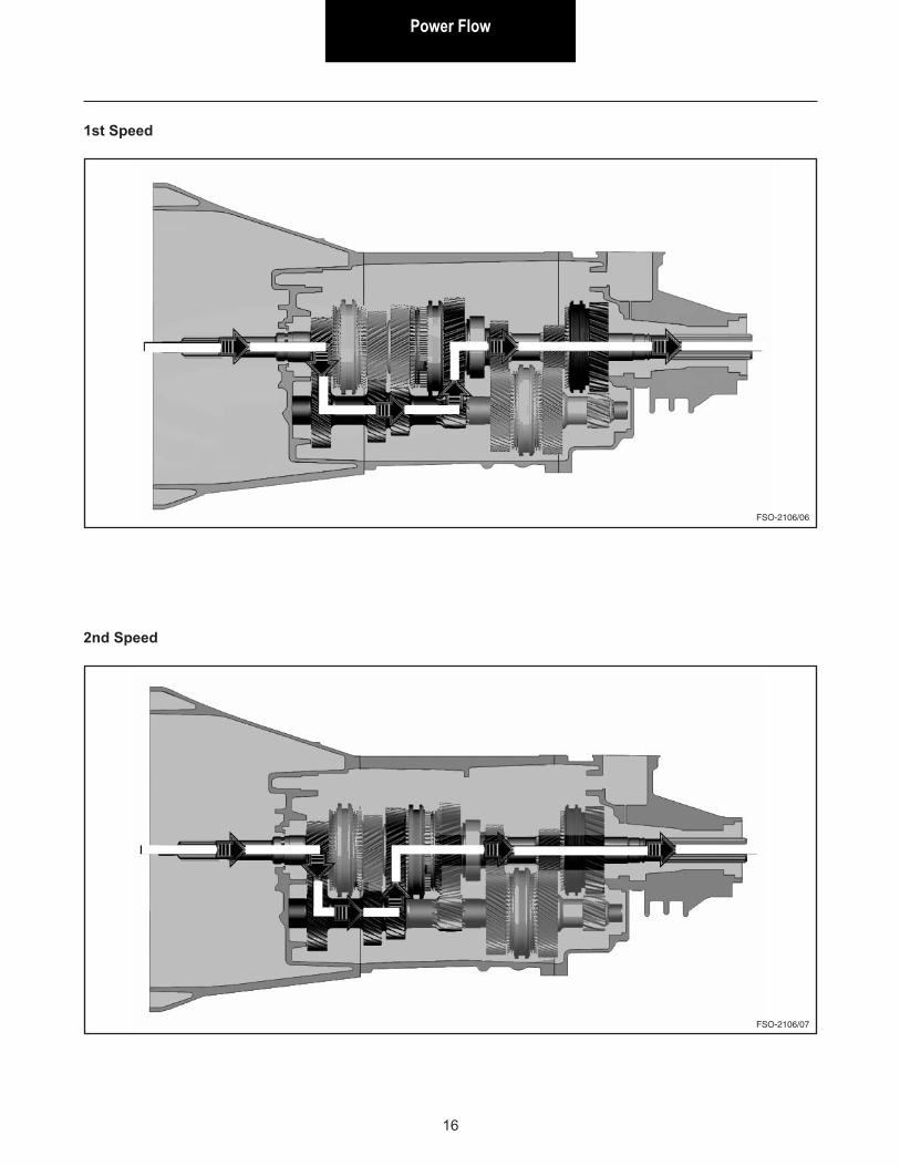
1st Speed
FSO-2106/06
2nd Speed
FSO-2106/07
Power FlowPower Flow
17
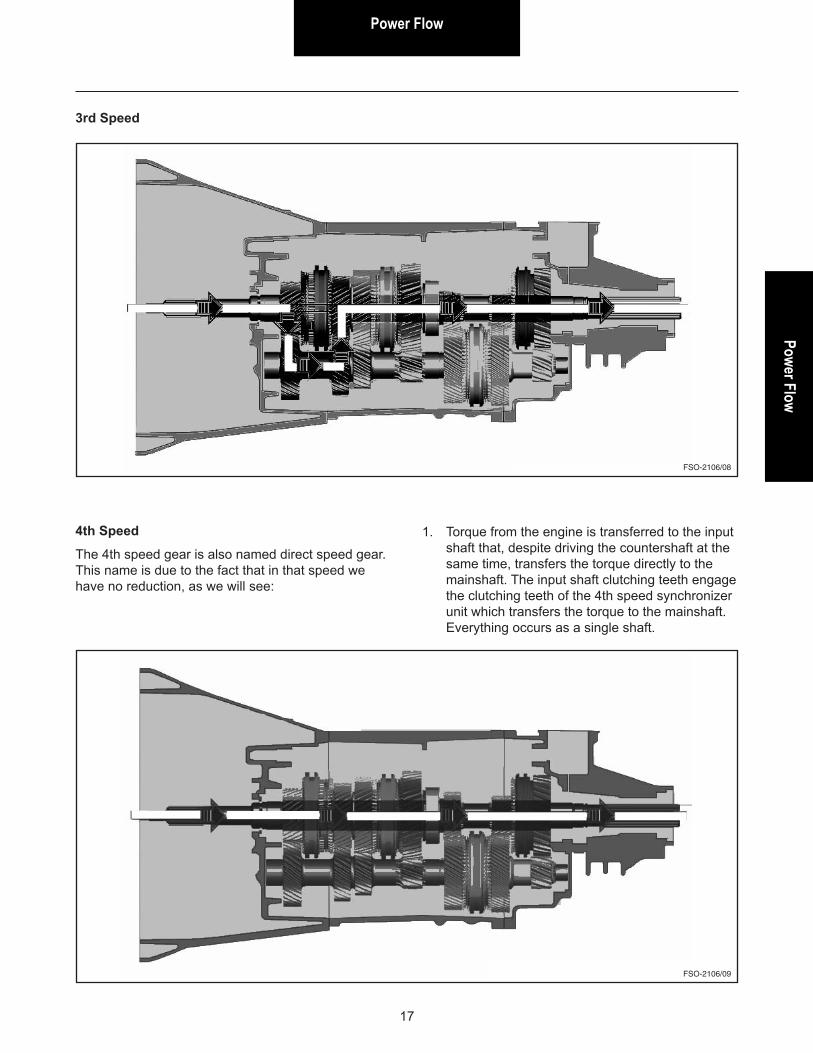
3rd Speed
FSO-2106/08
4th Speed
The 4th speed gear is also named direct speed gear. This name is due to the fact that in that speed we have no reduction, as we will see:
FSO-2106/09
1. Torque from the engine is transferred to the input shaft that, despite driving the countershaft at the same time, transfers the torque directly to the mainshaft. The input shaft clutching teeth engage the clutching teeth of the 4th speed synchronizer unit which transfers the torque to the mainshaft. Everything occurs as a single shaft.
Power Flow
18
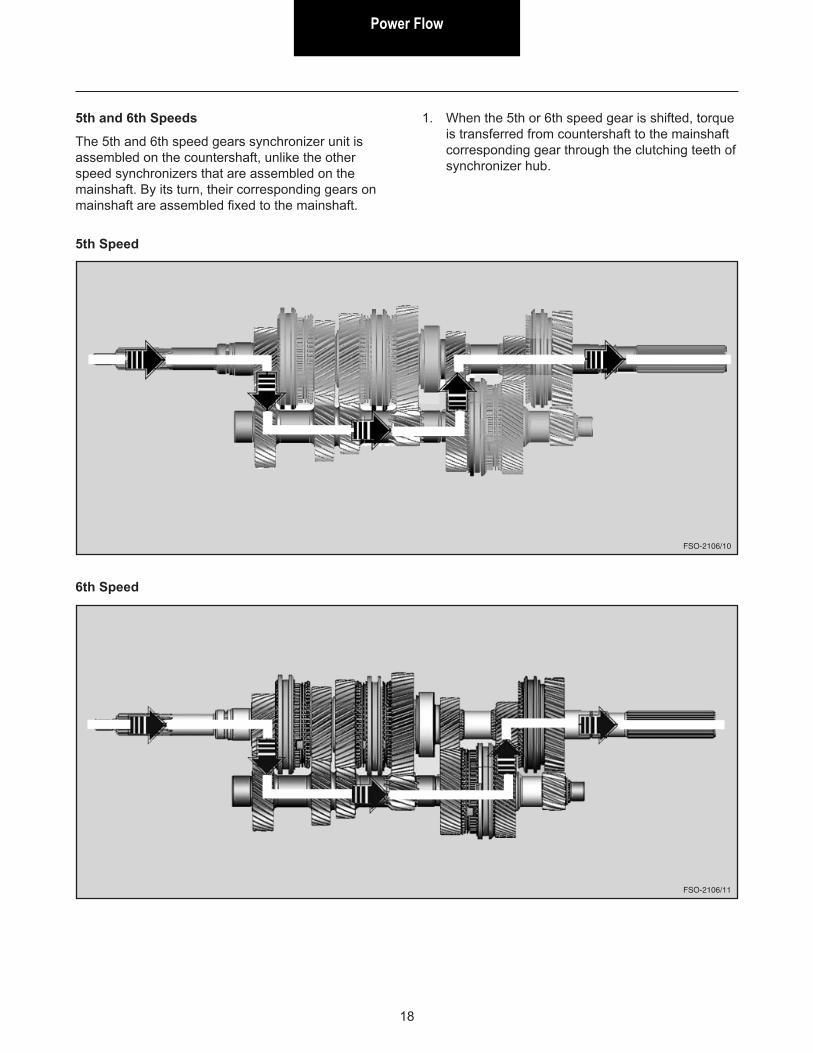
5th Speed
FSO-2106/10
6th Speed
FSO-2106/11
5th and 6th Speeds
The 5th and 6th speed gears synchronizer unit is assembled on the countershaft, unlike the other speed synchronizers that are assembled on the mainshaft. By its turn, their corresponding gears on mainshaft are assembled fixed to the mainshaft.
1. When the 5th or 6th speed gear is shifted, torque is transferred from countershaft to the mainshaft corresponding gear through the clutching teeth of synchronizer hub.
Power FlowPower Flow
19
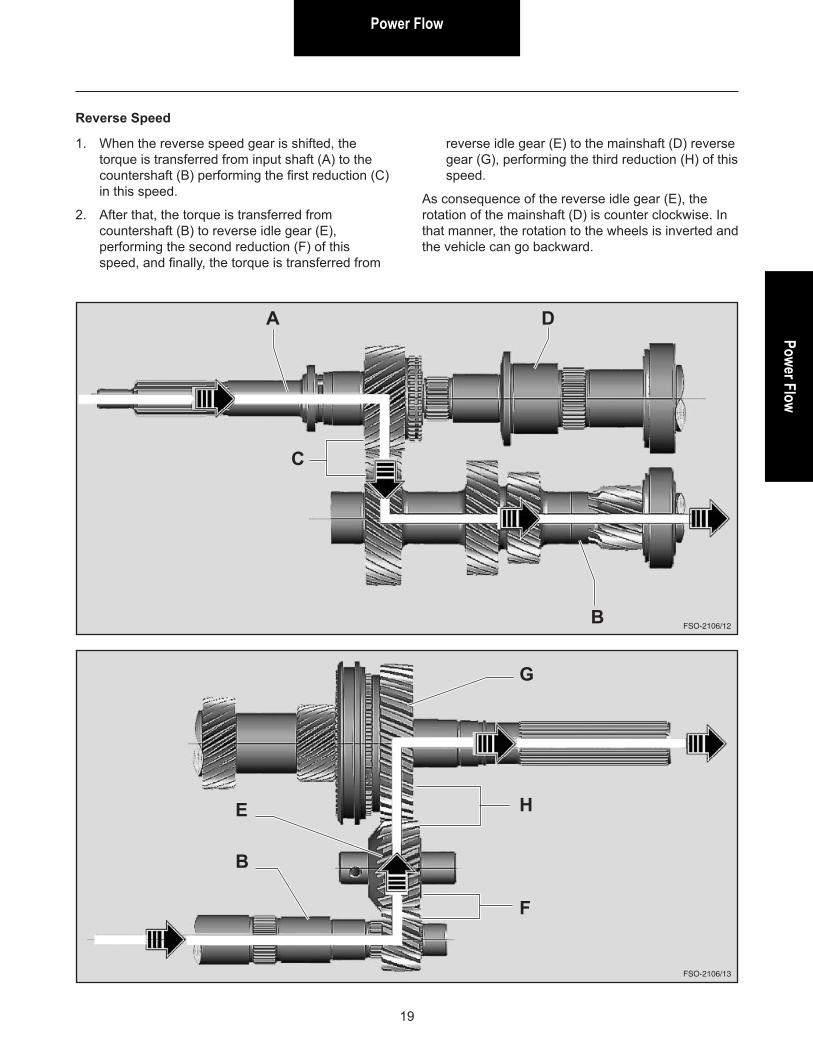
Reverse Speed
FSO-2106/12
FSO-2106/13
1. When the reverse speed gear is shifted, the torque is transferred from input shaft (A) to the countershaft (B) performing the first reduction (C) in this speed.
2. After that, the torque is transferred from countershaft (B) to reverse idle gear (E), performing the second reduction (F) of this speed, and finally, the torque is transferred from
reverse idle gear (E) to the mainshaft (D) reverse gear (G), performing the third reduction (H) of this speed.
As consequence of the reverse idle gear (E), the rotation of the mainshaft (D) is counter clockwise. In that manner, the rotation to the wheels is inverted and the vehicle can go backward.
A D
C
B
B
E
F
G
H
Sealant and Torque Specification
20
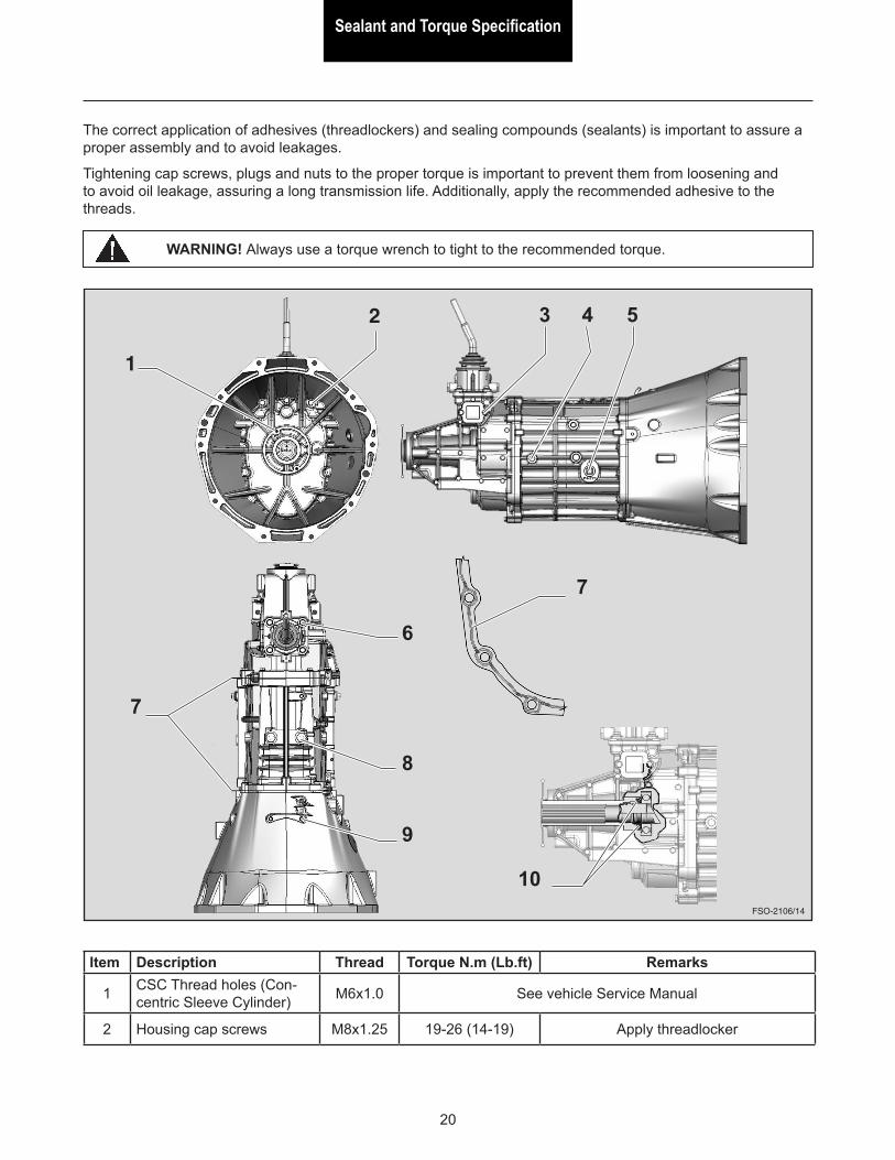
The correct application of adhesives (threadlockers) and sealing compounds (sealants) is important to assure a proper assembly and to avoid leakages.
Tightening cap screws, plugs and nuts to the proper torque is important to prevent them from loosening and to avoid oil leakage, assuring a long transmission life. Additionally, apply the recommended adhesive to the threads.
1
Item Description Thread Torque N.m (Lb.ft) Remarks
1 CSC Thread holes (Con-centric Sleeve Cylinder) M6x1.0 See vehicle Service Manual
2 Housing cap screws M8x1.25 19-26 (14-19) Apply threadlocker
FSO-2106/14
WARNING! Always use a torque wrench to tight to the recommended torque.
2 3 4 5
8
9
6
7
7
10
Sealant and Torque SpecificationSealant and Torque Specification
21
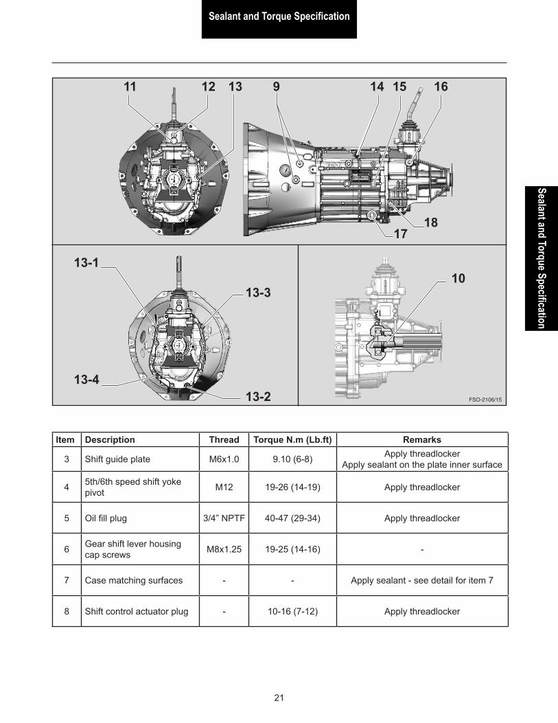
Item Description Thread Torque N.m (Lb.ft) Remarks
3 Shift guide plate M6x1.0 9.10 (6-8) Apply threadlocker Apply sealant on the plate inner surface
4 5th/6th speed shift yoke pivot M12 19-26 (14-19) Apply threadlocker
5 Oil fill plug 3/4” NPTF 40-47 (29-34) Apply threadlocker
6 Gear shift lever housing cap screws M8x1.25 19-25 (14-16) -
7 Case matching surfaces - - Apply sealant - see detail for item 7
8 Shift control actuator plug - 10-16 (7-12) Apply threadlocker
FSO-2106/15
1211 13 9 14 15 16
1718
13-1
13-4
13-3
13-2
10
Sealant and Torque Specification
22
Item Description Thread Torque N.m (Lb.ft) Remarks
9 Cup-type plug - - Apply threadlocker
10 Mainshaft nut M37 217-270 (160-200) Apply threadlocker Lock the nut with a center punch
11 Gear shift lever housing actuator plug M16 14-20 (10-15) Apply sealant on the matching surface
12 Gear shift lever pivot M12 14-20 (10-15) Apply sealant on the matching surface
13 Housing cap screws M8x125 19-26 (14-19) Apply threadlocker Use criss/cross pattern - see detail
14 Reverse light switch M14 14-20 (10-15) Apply sealant on the matching surface
15 5th/6th speed shift yoke pivot M12 19-26 (14-19) Apply threadlocker
16 Position control actuator plug M24 7-12 (10-16) Apply sealant on the matching surface
17 Oil drain plug 3/4” NPTF 40-47 (29-34) Apply threadlocker
18 Reverse idle gear shaft cap screw - 25-32 (18-23) Apply sealant on the matching surface
Sealant and Torque SpecificationSealant and Torque Specification
23
Recommended threadlocker and sealantThreadlocker: E677
Chemical adhesives can fulfill more than one function:
1. Thread locking, which prevents loose screws by vibration or improper torque.
2. Screw lock and seal, preventing loose screws while ensuring that no lubricant leakage will occur through the holes.
3. Sealing between matching surfaces, replacing gaskets made of other materials and reducing the number of spare parts.
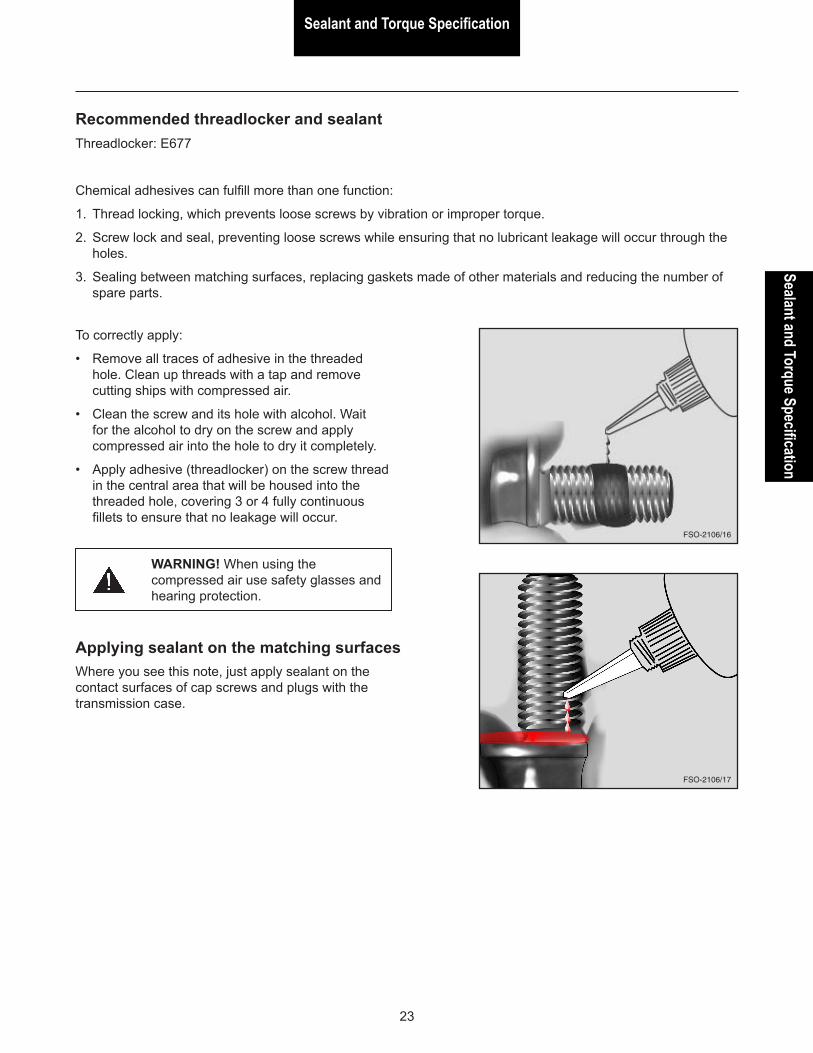
To correctly apply:
• Remove all traces of adhesive in the threaded hole. Clean up threads with a tap and remove cutting ships with compressed air.
• Clean the screw and its hole with alcohol. Wait for the alcohol to dry on the screw and apply compressed air into the hole to dry it completely.
• Apply adhesive (threadlocker) on the screw thread in the central area that will be housed into the threaded hole, covering 3 or 4 fully continuous fillets to ensure that no leakage will occur.
FSO-2106/16
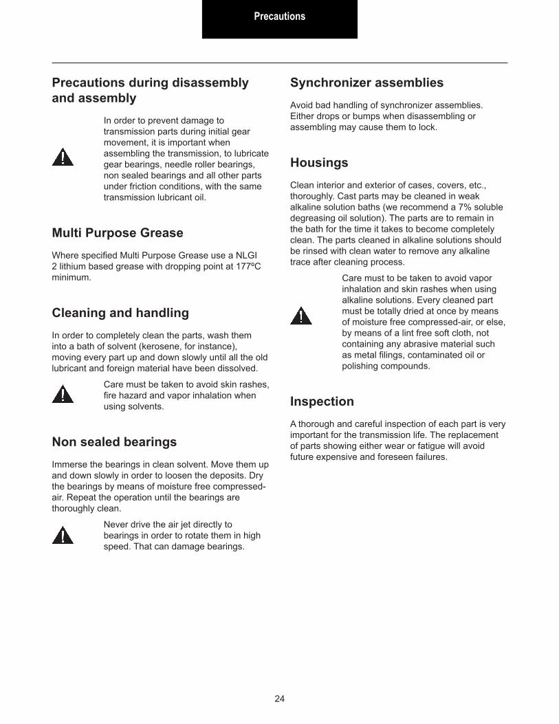
Applying sealant on the matching surfacesWhere you see this note, just apply sealant on the contact surfaces of cap screws and plugs with the transmission case.
FSO-2106/17
WARNING! When using the compressed air use safety glasses and hearing protection.
Precautions
24
Precautions during disassembly and assembly
In order to prevent damage to transmission parts during initial gear movement, it is important when assembling the transmission, to lubricate gear bearings, needle roller bearings, non sealed bearings and all other parts under friction conditions, with the same transmission lubricant oil.
Multi Purpose GreaseWhere specified Multi Purpose Grease use a NLGI 2 lithium based grease with dropping point at 177ºC minimum.
Cleaning and handlingIn order to completely clean the parts, wash them into a bath of solvent (kerosene, for instance), moving every part up and down slowly until all the old lubricant and foreign material have been dissolved.
Care must be taken to avoid skin rashes, fire hazard and vapor inhalation when using solvents.
Non sealed bearingsImmerse the bearings in clean solvent. Move them up and down slowly in order to loosen the deposits. Dry the bearings by means of moisture free compressed-air. Repeat the operation until the bearings are thoroughly clean.
Never drive the air jet directly to bearings in order to rotate them in high speed. That can damage bearings.
Synchronizer assembliesAvoid bad handling of synchronizer assemblies. Either drops or bumps when disassembling or assembling may cause them to lock.
HousingsClean interior and exterior of cases, covers, etc., thoroughly. Cast parts may be cleaned in weak alkaline solution baths (we recommend a 7% soluble degreasing oil solution). The parts are to remain in the bath for the time it takes to become completely clean. The parts cleaned in alkaline solutions should be rinsed with clean water to remove any alkaline trace after cleaning process.
Care must to be taken to avoid vapor inhalation and skin rashes when using alkaline solutions. Every cleaned part must be totally dried at once by means of moisture free compressed-air, or else, by means of a lint free soft cloth, not containing any abrasive material such as metal filings, contaminated oil or polishing compounds.
InspectionA thorough and careful inspection of each part is very important for the transmission life. The replacement of parts showing either wear or fatigue will avoid future expensive and foreseen failures.
PrecautionsPrecautions
25
Gears, shafts and synchronizer assembliesCheck carefully gear teeth for wear, pitting, chipping and cracks. If gear teeth show areas where the case hardening is worn through or cracked, the gear should be replaced.
Check shafts for warping and excessive wear or damaged splines.
Cases, covers, etc.Make sure cases, covers, etc. are completely clean and that mounting surfaces and bearing bores are free from nicks or burrs. Check carefully every part for cracks, excessive wear or for any other condition that may cause oil leak or a future failure.
Needle roller bearingsCheck carefully every needle roller for wear, pitting, cracks or spalled areas to determine whether they are suitable for reuse or replacement. After inspection, dip the needle roller bearings in an oil bath and then wrap them in a lint-free cloth or paper, so as to protect them until they are ready for assembling.
Parts replacementWhen replacement is necessary, use only genuine Eaton transmission parts to assure continued performance and extended life from the transmission. The use of either non-genuine or remanufactured parts, besides have not the factory’s warranty, may lead to severe damage of the unit.
Since the cost of a new part is generally a small fraction of the total cost of downtime and labor, do not reuse a questionable part which could lead to additional repairs and expense soon after assembly.
To aid in determining the reuse or replacement of any transmission part, consideration should also be given to the unit’s history, mileage, application, etc.
Precautions
26
Oil seals and snap ringsAny oil seal, snap ring, etc. damaged during maintenance, should be replaced by a new one. Replacement of oil seals and snap rings is cheaper when unit is disassembled than a premature overhaul to replace these parts in a future time.
An oil leakage through a worn seal may result in failures of other more expensive components of the transmission. The sealing elements should be handled carefully, particularly during assembly. Cuts, scratches or rolled up seal lips decrease the sealing efficiency.
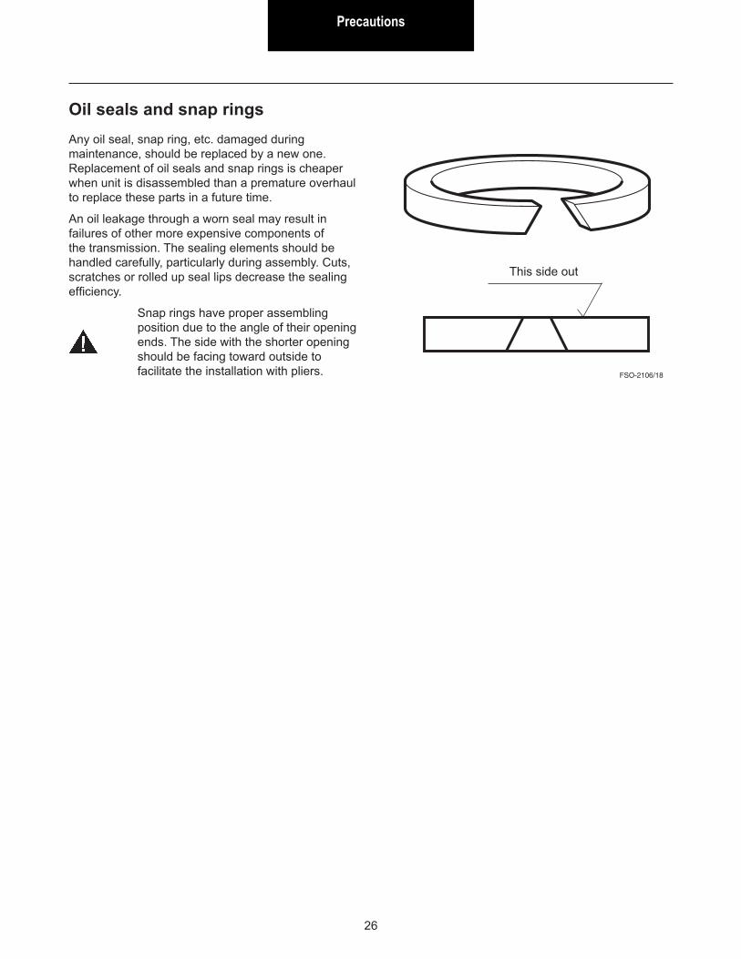
Snap rings have proper assembling position due to the angle of their opening ends. The side with the shorter opening should be facing toward outside to facilitate the installation with pliers. FSO-2106/18
This side out
Special ToolsSpecial Tools
27
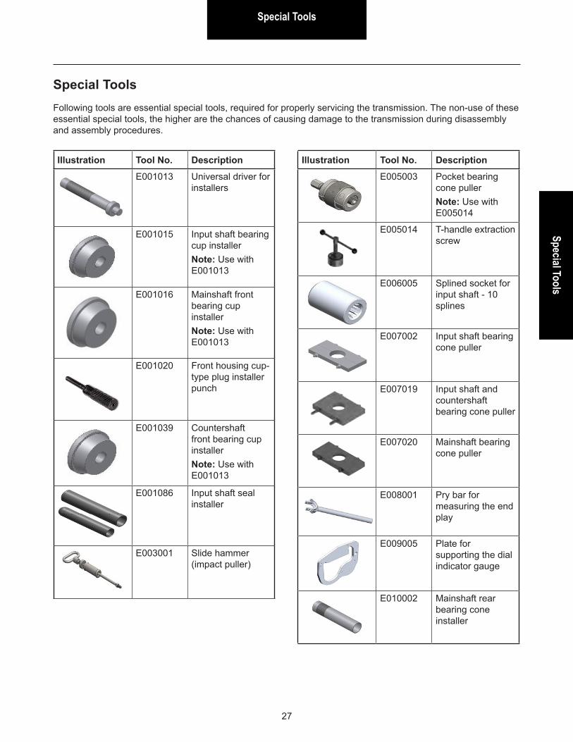
Special ToolsFollowing tools are essential special tools, required for properly servicing the transmission. The non-use of these essential special tools, the higher are the chances of causing damage to the transmission during disassembly and assembly procedures.
Illustration Tool No. Description
E001013 Universal driver for installers
E001015 Input shaft bearing cup installerNote: Use with E001013
E001016 Mainshaft front bearing cup installerNote: Use with E001013
E001020 Front housing cup-type plug installer punch
E001039 Countershaft front bearing cup installerNote: Use with E001013
E001086 Input shaft seal installer
E003001 Slide hammer (impact puller)
Illustration Tool No. Description
E005003 Pocket bearing cone pullerNote: Use with E005014
E005014 T-handle extraction screw
E006005 Splined socket for input shaft - 10 splines
E007002 Input shaft bearing cone puller
E007019 Input shaft and countershaft bearing cone puller
E007020 Mainshaft bearing cone puller
E008001 Pry bar for measuring the end play
E009005 Plate for supporting the dial indicator gauge
E010002 Mainshaft rear bearing cone installer
Special Tools
28
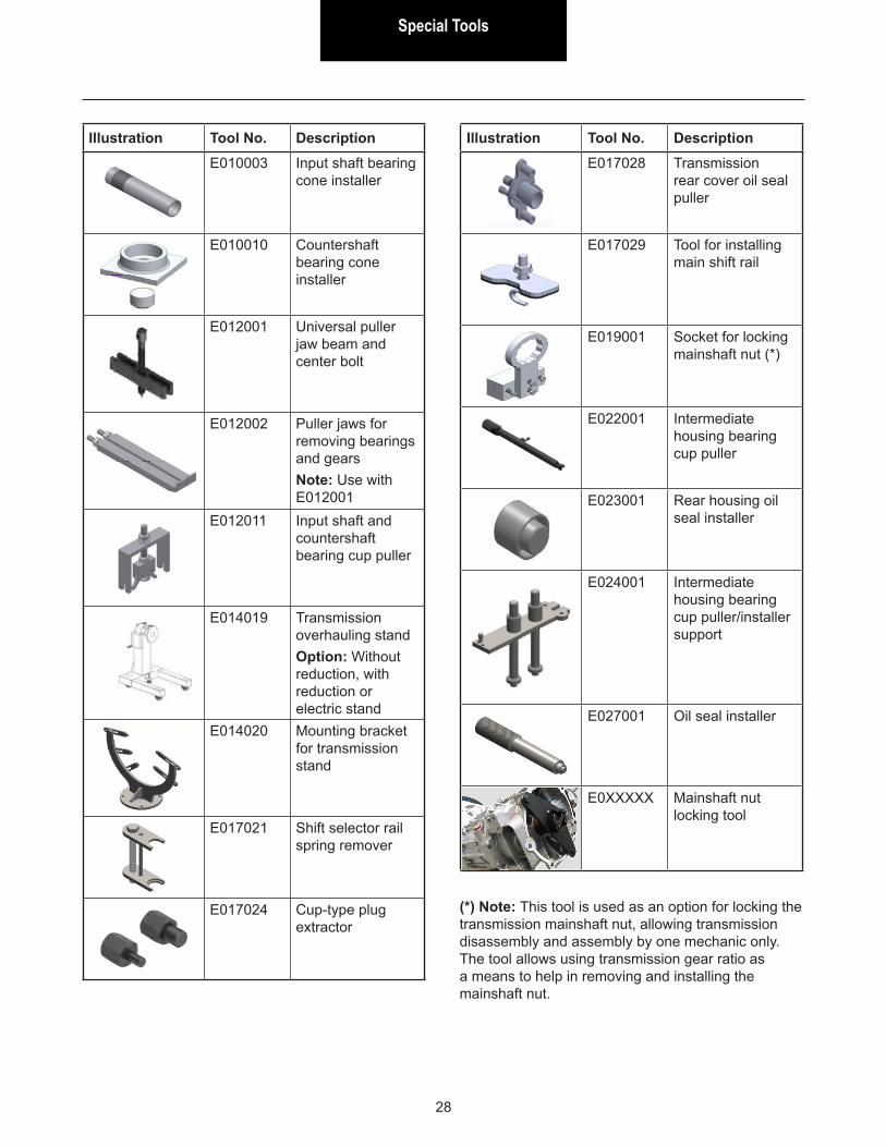
(*) Note: This tool is used as an option for locking the transmission mainshaft nut, allowing transmission disassembly and assembly by one mechanic only. The tool allows using transmission gear ratio as a means to help in removing and installing the mainshaft nut.
Illustration Tool No. DescriptionE010003 Input shaft bearing
cone installer
E010010 Countershaft bearing cone installer
E012001 Universal puller jaw beam and center bolt
E012002 Puller jaws for removing bearings and gearsNote: Use with E012001
E012011 Input shaft and countershaft bearing cup puller
E014019 Transmission overhauling standOption: Without reduction, with reduction or electric stand
E014020 Mounting bracket for transmission stand
E017021 Shift selector rail spring remover
E017024 Cup-type plug extractor
Illustration Tool No. DescriptionE017028 Transmission
rear cover oil seal puller
E017029 Tool for installing main shift rail
E019001 Socket for locking mainshaft nut (*)
E022001 Intermediate housing bearing cup puller
E023001 Rear housing oil seal installer
E024001 Intermediate housing bearing cup puller/installer support
E027001 Oil seal installer
E0XXXXX Mainshaft nut locking tool
Gear Shift Lever HousingGear Shift Lever Housing
29
Gear Shift Lever Housing - Disassembly
When disassembling, check all components for wear.
When assembling, replace any parts if necessary.
The shift lever housing is not sold separately, so if damaged, obtain the full assembly from your dealer.
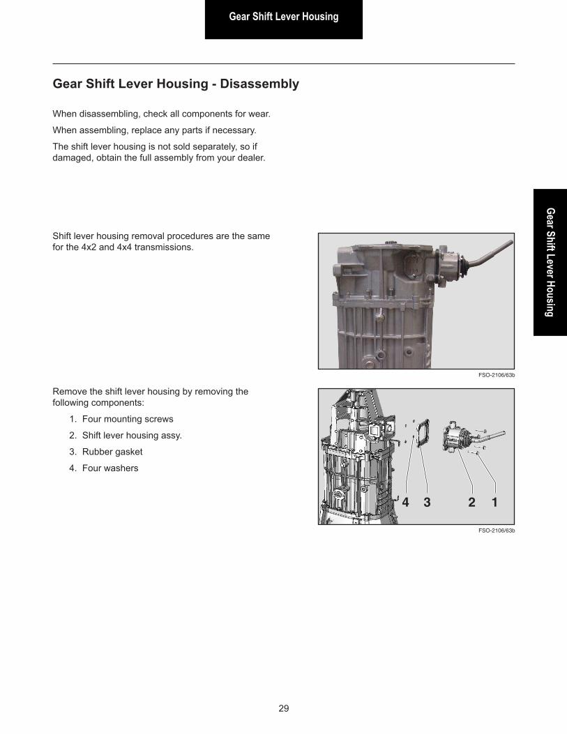
Remove the shift lever housing by removing the following components:
1. Four mounting screws
2. Shift lever housing assy.
3. Rubber gasket
4. Four washers
FSO-2106/63b
1234
Shift lever housing removal procedures are the same for the 4x2 and 4x4 transmissions.
FSO-2106/63b
Gear Shift Lever Housing
30
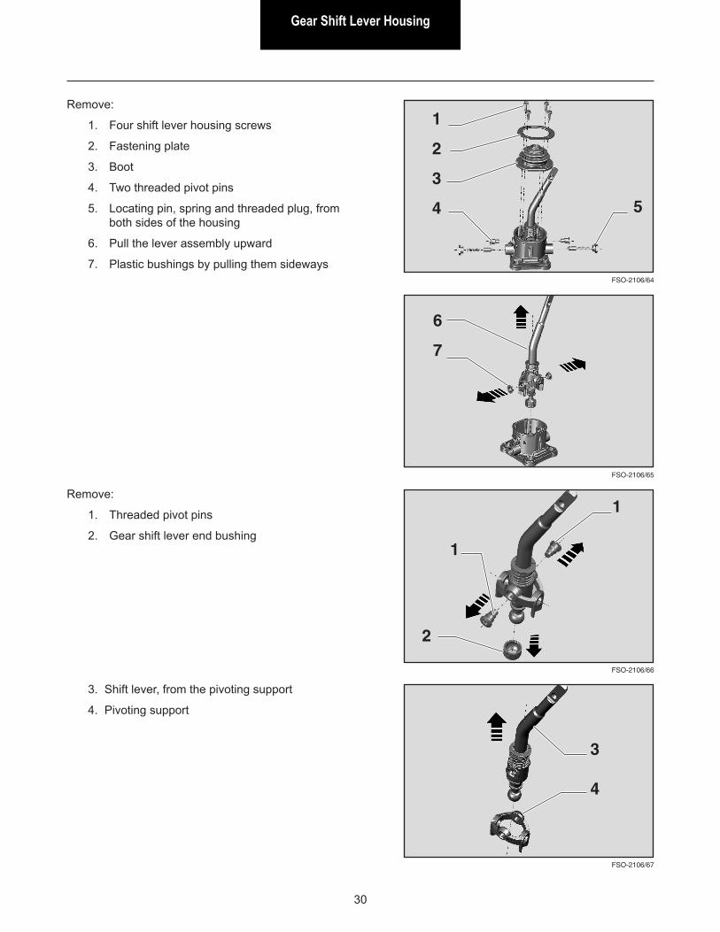
Remove:
1. Threaded pivot pins
2. Gear shift lever end bushing
FSO-2106/66
FSO-2106/67
1
3. Shift lever, from the pivoting support
4. Pivoting support
3
2
1
4
FSO-2106/65
FSO-2106/64
Remove:
1. Four shift lever housing screws
2. Fastening plate
3. Boot
4. Two threaded pivot pins
5. Locating pin, spring and threaded plug, from both sides of the housing
6. Pull the lever assembly upward
7. Plastic bushings by pulling them sideways
1
2
3
4
6
7
5
Gear Shift Lever HousingGear Shift Lever Housing
31
FSO-2106/69
FSO-2106/68
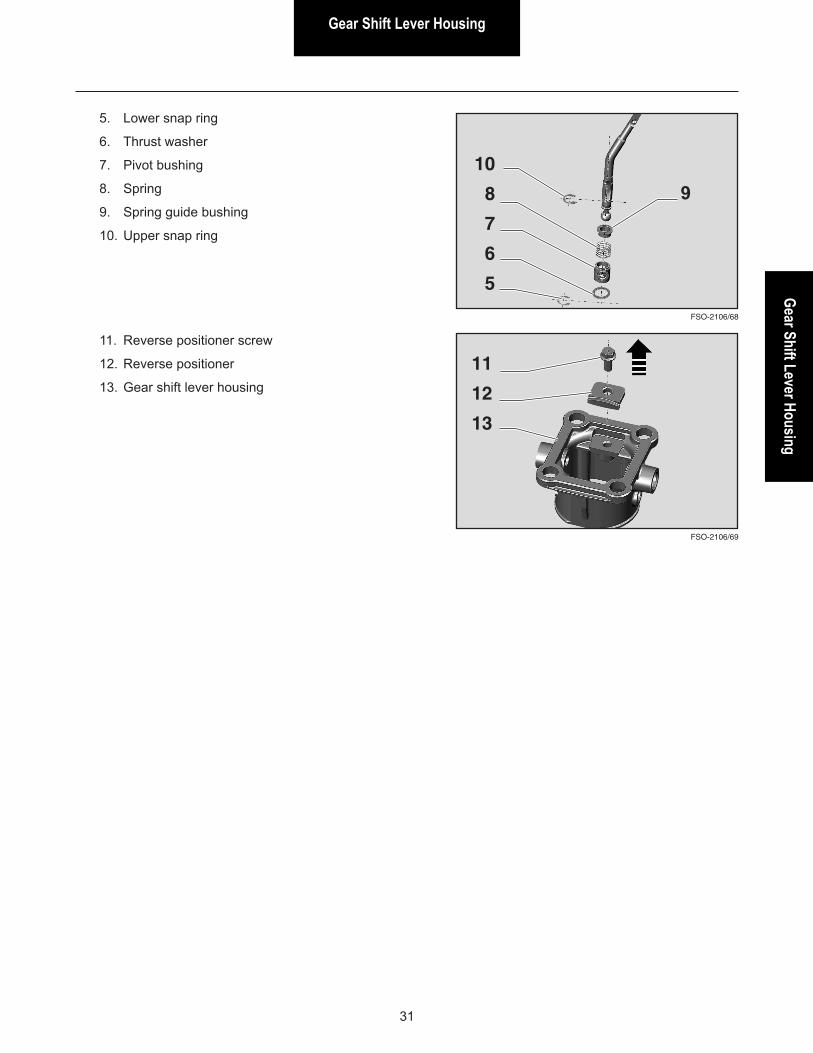
5. Lower snap ring
6. Thrust washer
7. Pivot bushing
8. Spring
9. Spring guide bushing
10. Upper snap ring
10
8
7
6
5
11
12
13
11. Reverse positioner screw
12. Reverse positioner
13. Gear shift lever housing
9
Gear Shift Lever Housing
32
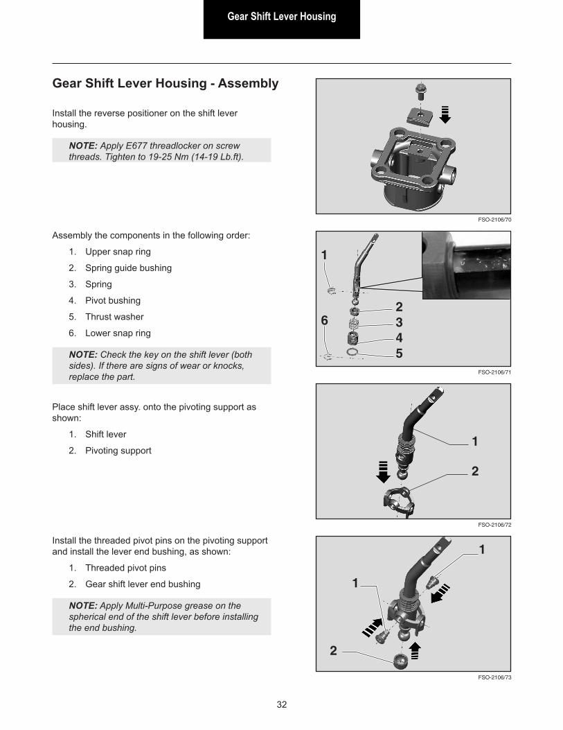
Gear Shift Lever Housing - Assembly
Install the reverse positioner on the shift lever housing.
NOTE: Apply E677 threadlocker on screw threads. Tighten to 19-25 Nm (14-19 Lb.ft).
FSO-2106/70
FSO-2106/72
FSO-2106/71
Assembly the components in the following order:
1. Upper snap ring
2. Spring guide bushing
3. Spring
4. Pivot bushing
5. Thrust washer
6. Lower snap ring
NOTE: Check the key on the shift lever (both sides). If there are signs of wear or knocks, replace the part.
1
Place shift lever assy. onto the pivoting support as shown:
1. Shift lever
2. Pivoting support
Install the threaded pivot pins on the pivoting support and install the lever end bushing, as shown:
1. Threaded pivot pins
2. Gear shift lever end bushing
NOTE: Apply Multi-Purpose grease on the spherical end of the shift lever before installing the end bushing.
1
2345
6
2
FSO-2106/73
1
2
1
Gear Shift Lever HousingGear Shift Lever Housing
33
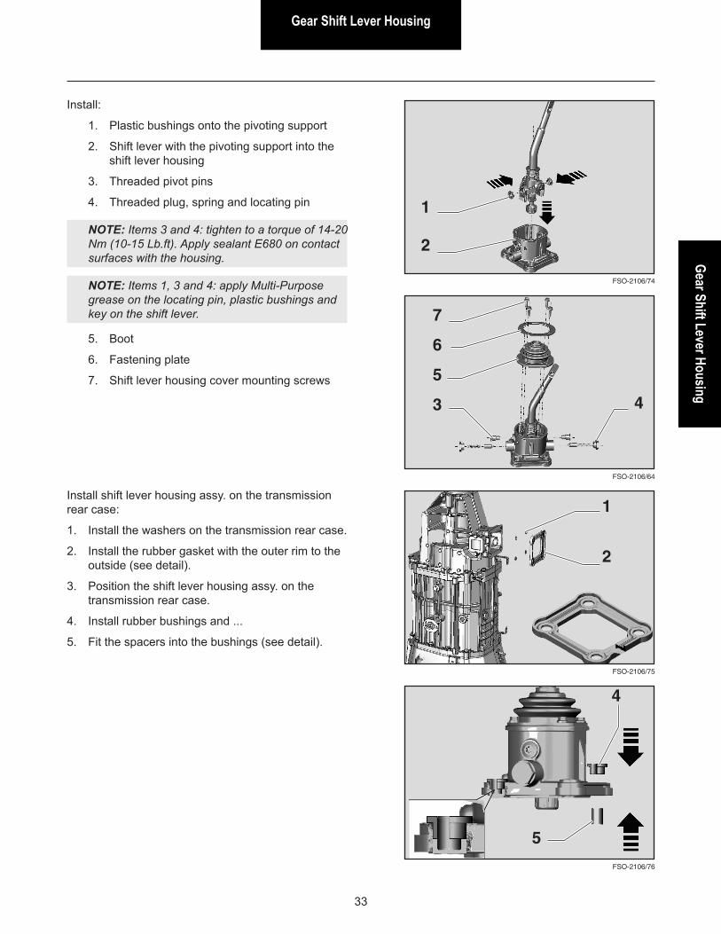
Install:
1. Plastic bushings onto the pivoting support
2. Shift lever with the pivoting support into the shift lever housing
3. Threaded pivot pins
4. Threaded plug, spring and locating pin
NOTE: Items 3 and 4: tighten to a torque of 14-20 Nm (10-15 Lb.ft). Apply sealant E680 on contact surfaces with the housing.
NOTE: Items 1, 3 and 4: apply Multi-Purpose grease on the locating pin, plastic bushings and key on the shift lever.
FSO-2106/76
FSO-2106/75
5. Boot
6. Fastening plate
7. Shift lever housing cover mounting screws
Install shift lever housing assy. on the transmission rear case:
1. Install the washers on the transmission rear case.
2. Install the rubber gasket with the outer rim to the outside (see detail).
3. Position the shift lever housing assy. on the transmission rear case.
4. Install rubber bushings and ...
5. Fit the spacers into the bushings (see detail).
1
4
FSO-2106/74
2
1
FSO-2106/64
7
6
5
3 4
2
5
Gear Shift Lever Housing
34
FSO-2106/77
1
2
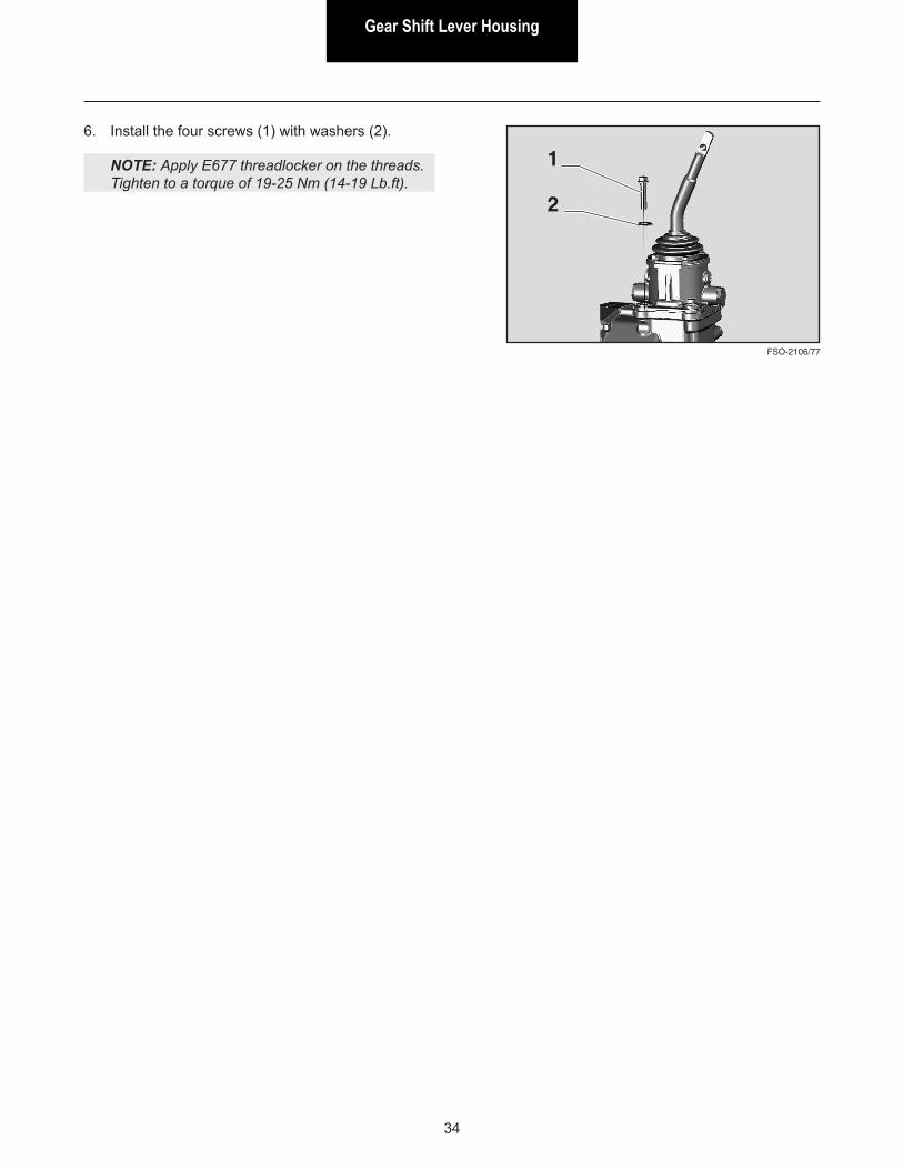
6. Install the four screws (1) with washers (2).
NOTE: Apply E677 threadlocker on the threads.Tighten to a torque of 19-25 Nm (14-19 Lb.ft).
Rear SectionRear Section
35
Rear Seal Replacement
FSO-2106/24
FSO-2106/136
FSO-2106/135
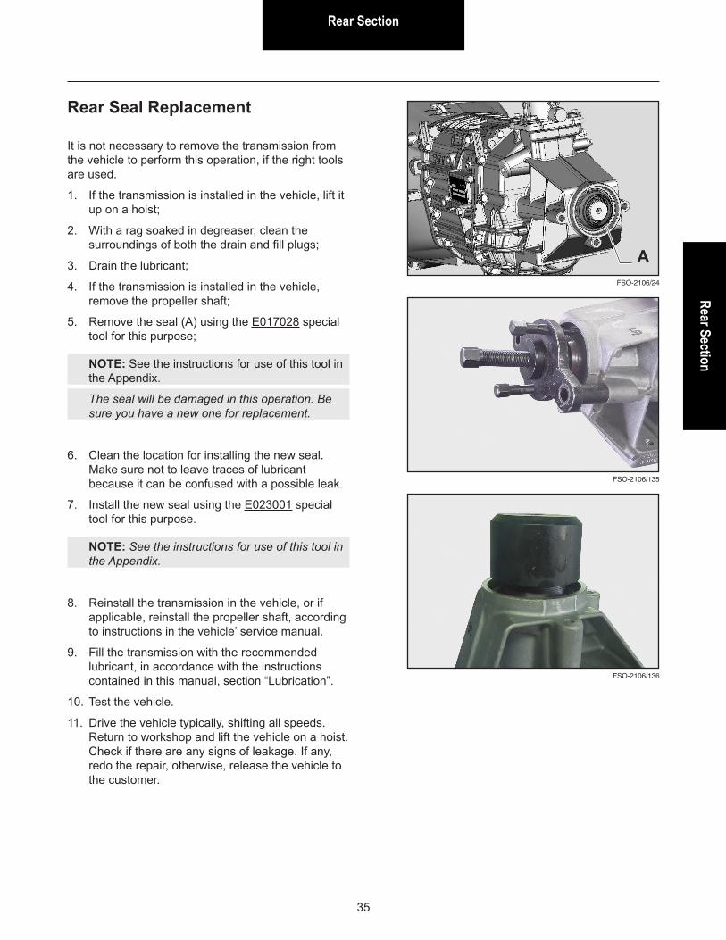
It is not necessary to remove the transmission from the vehicle to perform this operation, if the right tools are used.
1. If the transmission is installed in the vehicle, lift it up on a hoist;
2. With a rag soaked in degreaser, clean the surroundings of both the drain and fill plugs;
3. Drain the lubricant;
4. If the transmission is installed in the vehicle, remove the propeller shaft;
5. Remove the seal (A) using the E017028 special tool for this purpose;
NOTE: See the instructions for use of this tool in the Appendix.
The seal will be damaged in this operation. Be sure you have a new one for replacement.
6. Clean the location for installing the new seal. Make sure not to leave traces of lubricant because it can be confused with a possible leak.
7. Install the new seal using the E023001 special tool for this purpose.
NOTE: See the instructions for use of this tool in the Appendix.
8. Reinstall the transmission in the vehicle, or if applicable, reinstall the propeller shaft, according to instructions in the vehicle’ service manual.
9. Fill the transmission with the recommended lubricant, in accordance with the instructions contained in this manual, section “Lubrication”.
10. Test the vehicle.
11. Drive the vehicle typically, shifting all speeds. Return to workshop and lift the vehicle on a hoist. Check if there are any signs of leakage. If any, redo the repair, otherwise, release the vehicle to the customer.
A
Rear Section
36
Rear Section - Disassembly
FSO-2106/25
FSO-2106/28
FSO-2106/27
FSO-2106/26
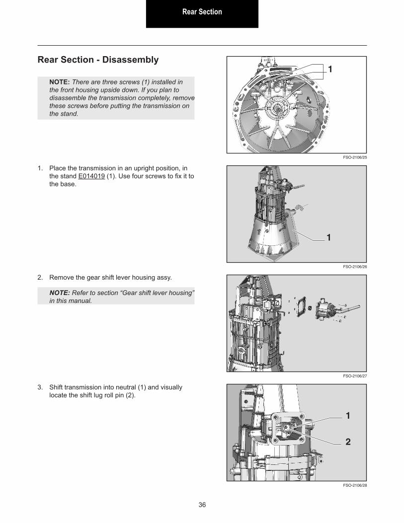
NOTE: There are three screws (1) installed in the front housing upside down. If you plan to disassemble the transmission completely, remove these screws before putting the transmission on the stand.
1. Place the transmission in an upright position, in the stand E014019 (1). Use four screws to fix it to the base.
2. Remove the gear shift lever housing assy.
NOTE: Refer to section “Gear shift lever housing” in this manual.
1
1
3. Shift transmission into neutral (1) and visually locate the shift lug roll pin (2).
1
2
Rear SectionRear Section
37
FSO-2106/29
FSO-2106/32
FSO-2106/31
FSO-2106/30
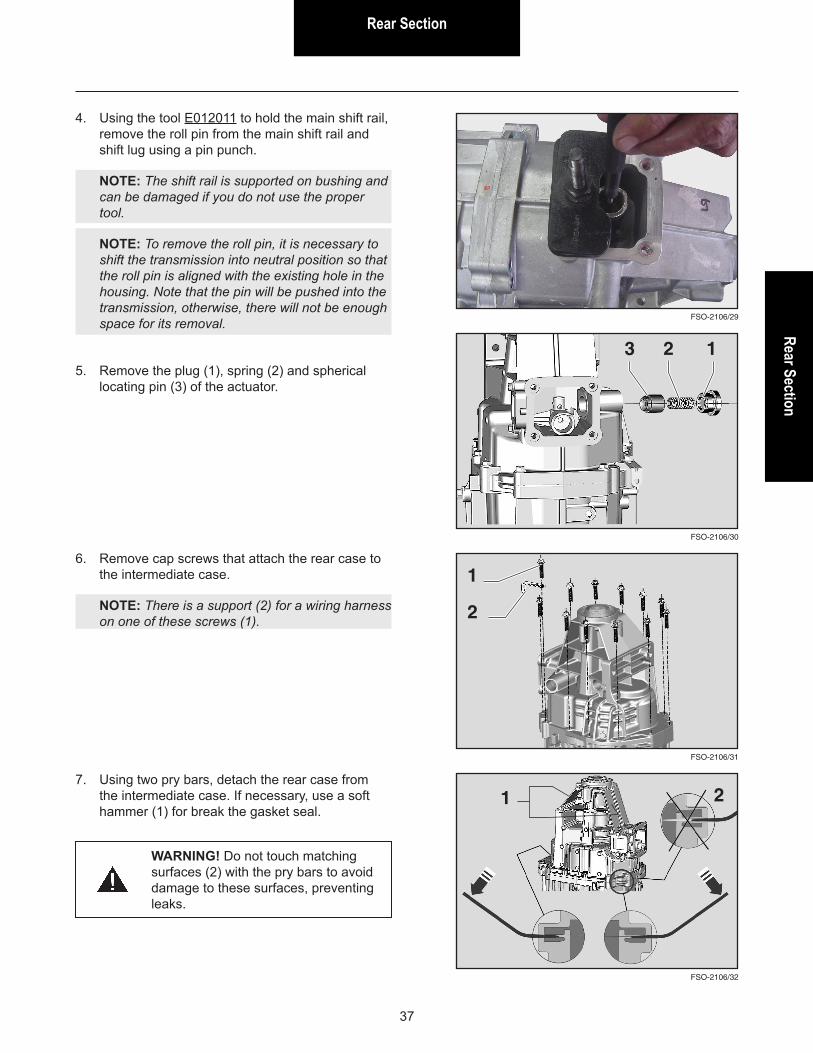
4. Using the tool E012011 to hold the main shift rail, remove the roll pin from the main shift rail and shift lug using a pin punch.
NOTE: The shift rail is supported on bushing and can be damaged if you do not use the proper tool.
NOTE: To remove the roll pin, it is necessary to shift the transmission into neutral position so that the roll pin is aligned with the existing hole in the housing. Note that the pin will be pushed into the transmission, otherwise, there will not be enough space for its removal.
5. Remove the plug (1), spring (2) and spherical locating pin (3) of the actuator.
1
6. Remove cap screws that attach the rear case to the intermediate case.
NOTE: There is a support (2) for a wiring harness on one of these screws (1).
1
7. Using two pry bars, detach the rear case from the intermediate case. If necessary, use a soft hammer (1) for break the gasket seal.
1
WARNING! Do not touch matching surfaces (2) with the pry bars to avoid damage to these surfaces, preventing leaks.
23
2
2
Rear Section
38
FSO-2106/33
FSO-2106/36
FSO-2106/35
FSO-2106/34
1
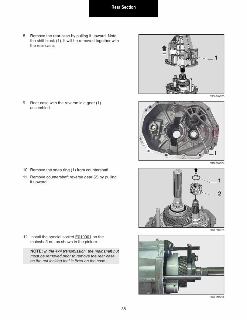
8. Remove the rear case by pulling it upward. Note the shift block (1). It will be removed together with the rear case.
1
9. Rear case with the reverse idle gear (1) assembled.
10. Remove the snap ring (1) from countershaft.
11. Remove countershaft reverse gear (2) by pulling it upward.
2
12. Install the special socket E019001 on the mainshaft nut as shown in the picture.
NOTE: In the 4x4 transmission, the mainshaft nut must be removed prior to remove the rear case, as the nut locking tool is fixed on the case.
1
Rear SectionRear Section
39
FSO-2106/37
FSO-2106/38
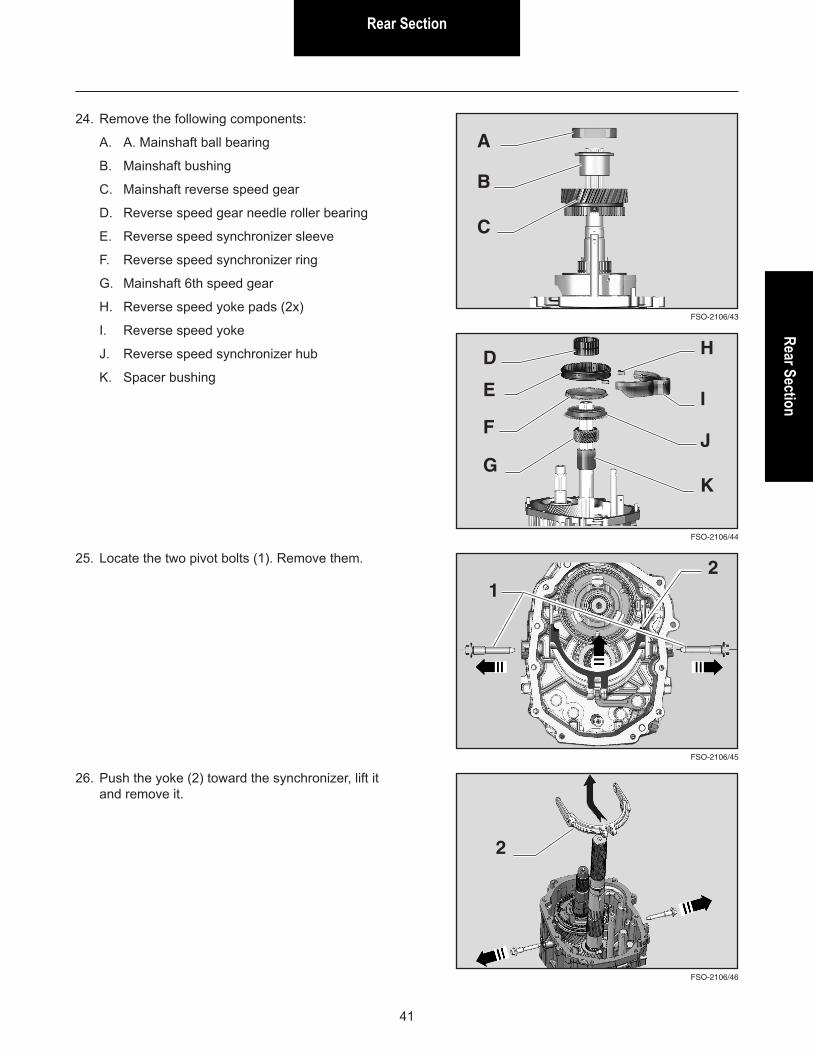
16. Shift transmission into 1st gear:
A. Using a pin punch inserted in the hole of the shift rail, rotate the shift rail to the right and ...
B. Pull the rail up.
If necessary for completing the shift into the 1st gear, rotate the input shaft slowly at the same time you pull the shift rail upward.
In the 4x4 transmission, shifting into the 1st gear can be performed by using the gear shift lever if it was not removed yet, or by means of the main shift rail if the shift lever was already removed.
A
B
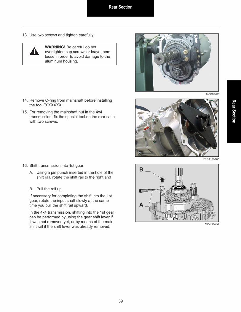
13. Use two screws and tighten carefully.
WARNING! Be careful do not overtighten cap screws or leave them loose in order to avoid damage to the aluminum housing.
FSO-2106/162
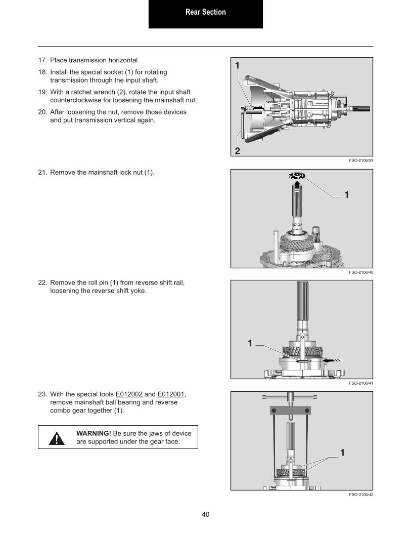
14. Remove O-ring from mainshaft before installing the tool E0XXXXX.
15. For removing the mainshaft nut in the 4x4 transmission, fix the special tool on the rear case with two screws.
Rear Section
40
22. Remove the roll pin (1) from reverse shift rail, loosening the reverse shift yoke.
FSO-2106/41
FSO-2106/42
1
23. With the special tools E012002 and E012001, remove mainshaft ball bearing and reverse combo gear together (1).
1
WARNING! Be sure the jaws of device are supported under the gear face.
FSO-2106/40
21. Remove the mainshaft lock nut (1).
1
FSO-2106/39
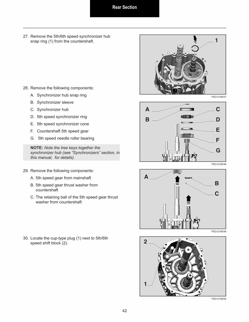
17. Place transmission horizontal.
18. Install the special socket (1) for rotating transmission through the input shaft.
19. With a ratchet wrench (2), rotate the input shaft counterclockwise for loosening the mainshaft nut.
20. After loosening the nut, remove those devices and put transmission vertical again.
1
2
Rear SectionRear Section
41
FSO-2106/44
FSO-2106/43
24. Remove the following components:
A. A. Mainshaft ball bearing
B. Mainshaft bushing
C. Mainshaft reverse speed gear
D. Reverse speed gear needle roller bearing
E. Reverse speed synchronizer sleeve
F. Reverse speed synchronizer ring
G. Mainshaft 6th speed gear
H. Reverse speed yoke pads (2x)
I. Reverse speed yoke
J. Reverse speed synchronizer hub
K. Spacer bushing
A
D
B
C
E
F
G
H
I
J
K
25. Locate the two pivot bolts (1). Remove them.
FSO-2106/45
FSO-2106/46
1
2
2
26. Push the yoke (2) toward the synchronizer, lift it and remove it.
Rear Section
42
FSO-2106/48
FSO-2106/47
27. Remove the 5th/6th speed synchronizer hub snap ring (1) from the countershaft. 1
28. Remove the following components:
A. Synchronizer hub snap ring
B. Synchronizer sleeve
C. Synchronizer hub
D. 5th speed synchronizer ring
E. 5th speed synchronizer cone
F. Countershaft 5th speed gear
G. 5th speed needle roller bearing
NOTE: Note the tree keys together the synchronizer hub (see “Synchronizers” section, in this manual, for details).
A
B
C
D
E
F
G
FSO-2106/49
FSO-2106/50
29. Remove the following components:
A. 5th speed gear from mainshaft
B. 5th speed gear thrust washer from countershaft
C. The retaining ball of the 5th speed gear thrust washer from countershaft
30. Locate the cup-type plug (1) next to 5th/6th speed shift block (2).
A
1
B
C
2
Rear SectionRear Section
43
FSO-2106/52
FSO-2106/51
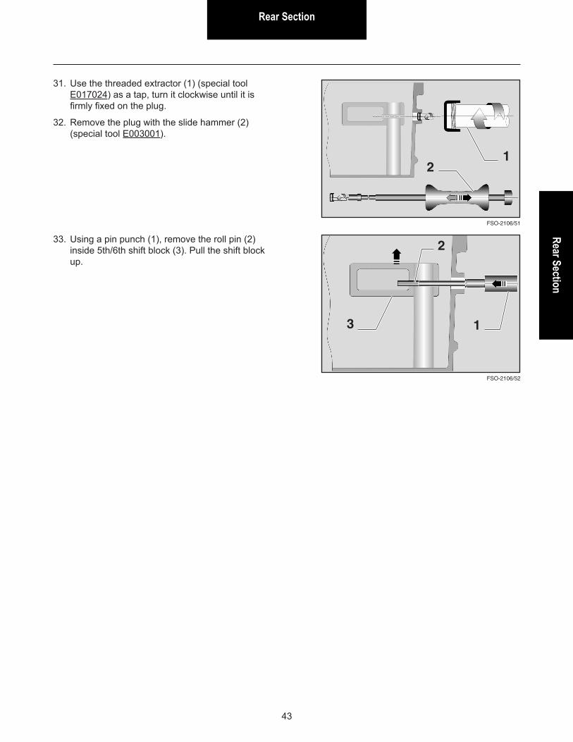
31. Use the threaded extractor (1) (special tool E017024) as a tap, turn it clockwise until it is firmly fixed on the plug.
32. Remove the plug with the slide hammer (2) (special tool E003001).
33. Using a pin punch (1), remove the roll pin (2) inside 5th/6th shift block (3). Pull the shift block up.
1
1
2
2
3
Rear Section
44
Rear Section - Assembly
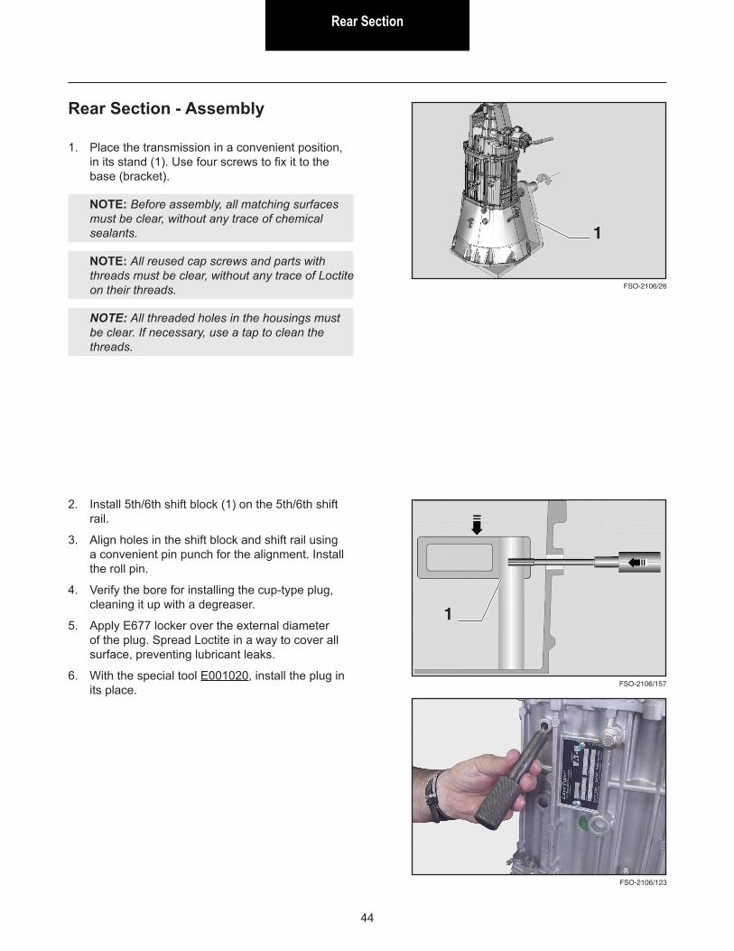
1. Place the transmission in a convenient position, in its stand (1). Use four screws to fix it to the base (bracket).
NOTE: Before assembly, all matching surfaces must be clear, without any trace of chemical sealants.
NOTE: All reused cap screws and parts with threads must be clear, without any trace of Loctite on their threads.
NOTE: All threaded holes in the housings must be clear. If necessary, use a tap to clean the threads.
2. Install 5th/6th shift block (1) on the 5th/6th shift rail.
3. Align holes in the shift block and shift rail using a convenient pin punch for the alignment. Install the roll pin.
4. Verify the bore for installing the cup-type plug, cleaning it up with a degreaser.
5. Apply E677 locker over the external diameter of the plug. Spread Loctite in a way to cover all surface, preventing lubricant leaks.
6. With the special tool E001020, install the plug in its place.
FSO-2106/26
1
FSO-2106/157
1
FSO-2106/123

Rear SectionRear Section
45
7. Install the following components:
A. Retaining ball of the 5th speed gear thrust washer onto countershaft
NOTE: Use grease in order to keep the ball in its place.
B. 5th speed gear thrust washer onto countershaft
C. 5th speed gear onto mainshaft
D. Countershaft 5th speed gear needle roller bearing
E. Countershaft 5th speed gear
F. Countershaft 5th speed synchronizer cone
G. Countershaft 5th speed synchronizer ring
H. Countershaft 5th/6th synchronizer hub
I. Countershaft 5th/6th synchronizer sleeve
J. Countershaft 5th/6th synchronizer hub snap ring
For reference, see section “Synchronizers”.
FSO-2106/49a
CB
A
FSO-2106/48
J
I
H
G
F
E
D

Rear Section
46
8. Install the following components:
A. Retaining ball on the countershaft
NOTE: Use grease to keep the ball in its place.
B. 5th speed gear thrust washer
NOTE: Make sure to fit correctly the retaining ball into the washer slot (1).
NOTE: Note that the chamfered side (2) is downward.
C. Mainshaft 5th speed gear
NOTE: Note that side with the smaller external diameter is downward.
FSO-2106/53
FSO-2106/54
FSO-2106/55
A
1
F
E
D
D. 5th speed gear needle roller bearing on the countershaft
E. 5th speed gear on the countershaft
NOTE: Note that side with splines is upward.
F. 5th speed synchronizer cone on the gear
BC
2

Rear SectionRear Section
47
On the bench:
9. Place the synchronizer ring (1) with the conical external diameter surface facing even speed gears.
10. Install the synchronizer hub (2) over the synchronizer ring so that the slots on the hub fits the protruding parts on the synchronizer ring.
11. Install the three locator keys (3) in their slots on the synchronizer cone, aligning with slots in the sleeve.
NOTE: Use grease to keep keys in their places.
FSO-2106/56
FSO-2106/59
FSO-2106/58
FSO-2106/57
112. Place the synchronizer sleeve over the hub and ...
NOTE: Note the synchronizer sleeve: with transmission vertical, chamfered side is upward (1).
13. Pull it down firmly.
14. Install the 5th/6th synchronizer, previously assembled on the bench, on the countershaft.
15. Install snap ring (2).
WARNING! Install snap ring in the proper position as shown below.
1
FSO-2106/18
This side up
2 3
2
Rear Section
48
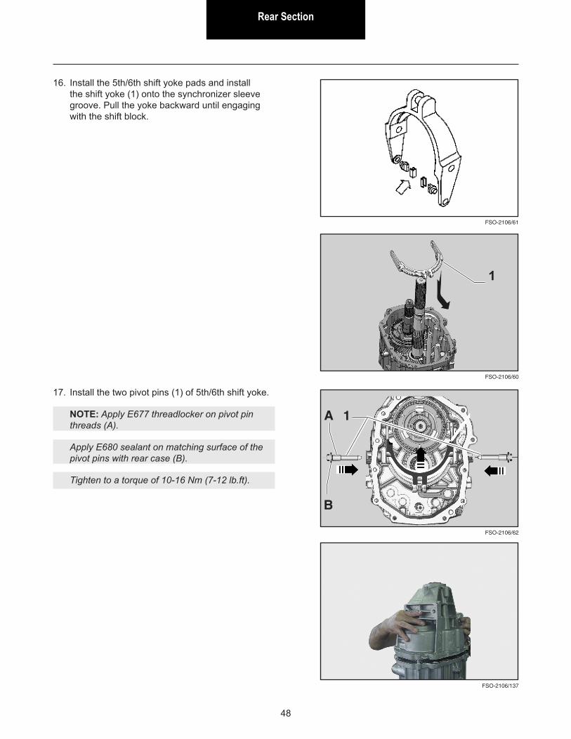
16. Install the 5th/6th shift yoke pads and install the shift yoke (1) onto the synchronizer sleeve groove. Pull the yoke backward until engaging with the shift block.
FSO-2106/61
17. Install the two pivot pins (1) of 5th/6th shift yoke.
NOTE: Apply E677 threadlocker on pivot pin threads (A).
Apply E680 sealant on matching surface of the pivot pins with rear case (B).
Tighten to a torque of 10-16 Nm (7-12 lb.ft).
A
FSO-2106/62
1
B
FSO-2106/137
FSO-2106/60
1
Front SectionFront Section
49
Front Seal Replacement
FSO-2106/19
FSO-2106/20
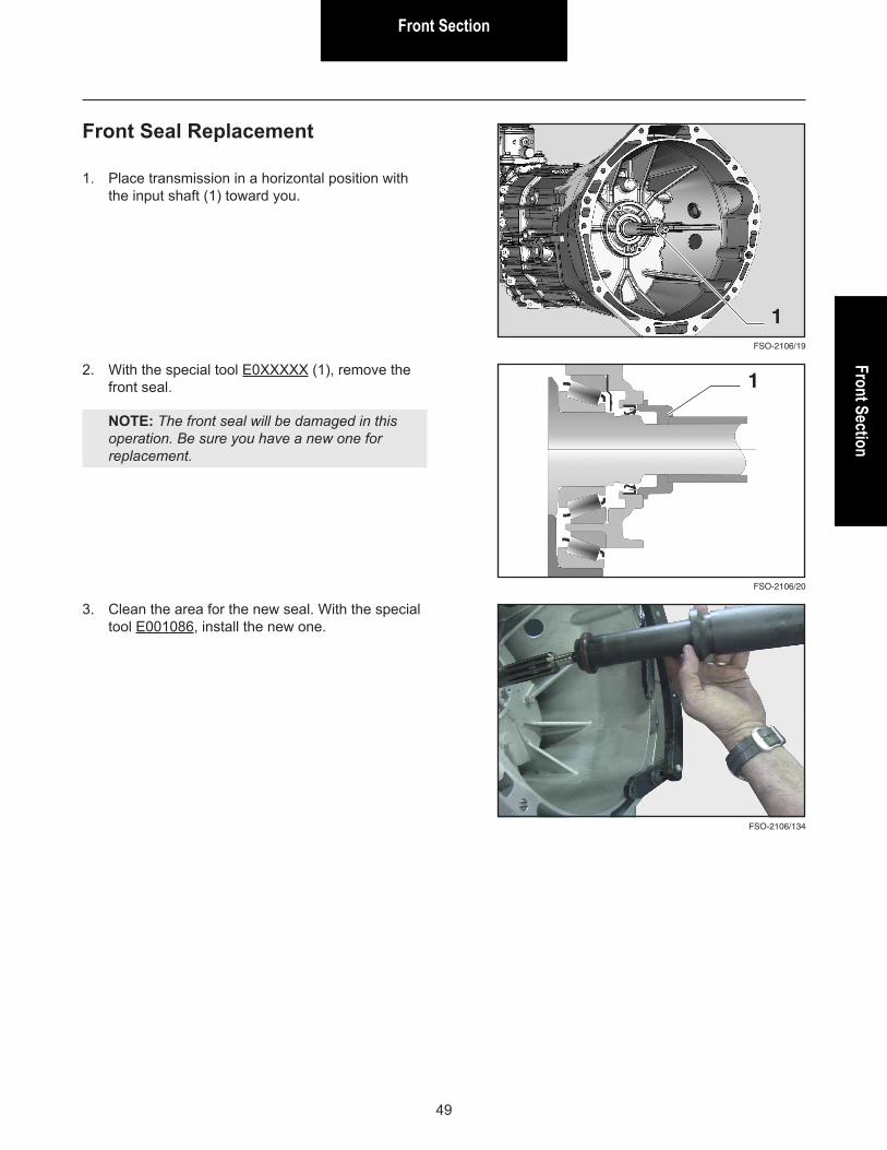
1. Place transmission in a horizontal position with the input shaft (1) toward you.
1
2. With the special tool E0XXXXX (1), remove the front seal.
NOTE: The front seal will be damaged in this operation. Be sure you have a new one for replacement.
1
3. Clean the area for the new seal. With the special tool E001086, install the new one.
FSO-2106/134
Front Section
50
FSO-2106/23
FSO-2106/21
FSO-2106/22
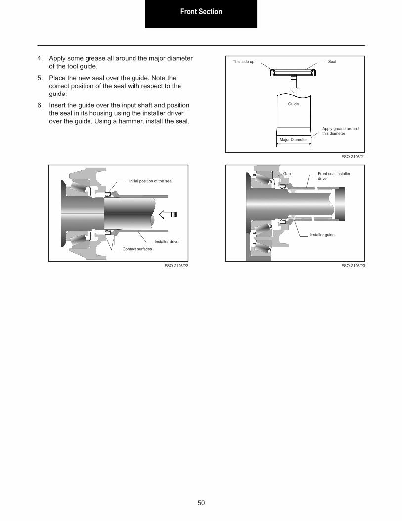
This side up Seal
Guide
Major Diameter
Apply grease around this diameter
Initial position of the seal
Installer driver
Contact surfaces
Gap Front seal installer driver
Installer guide
4. Apply some grease all around the major diameter of the tool guide.
5. Place the new seal over the guide. Note the correct position of the seal with respect to the guide;
6. Insert the guide over the input shaft and position the seal in its housing using the installer driver over the guide. Using a hammer, install the seal.
Front SectionFront Section
51
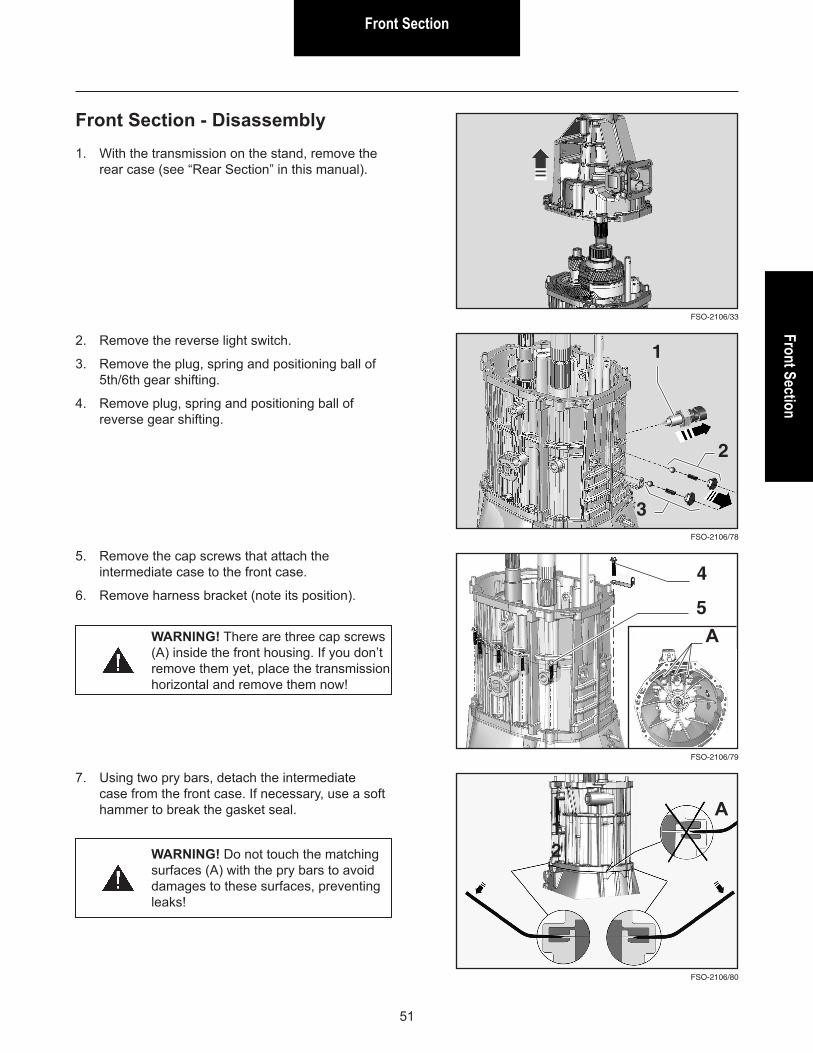
Front Section - Disassembly
2. Remove the reverse light switch.
3. Remove the plug, spring and positioning ball of 5th/6th gear shifting.
4. Remove plug, spring and positioning ball of reverse gear shifting.
FSO-2106/78
FSO-2106/80
FSO-2106/79
1
12
5. Remove the cap screws that attach the intermediate case to the front case.
6. Remove harness bracket (note its position).4
7. Using two pry bars, detach the intermediate case from the front case. If necessary, use a soft hammer to break the gasket seal.
WARNING! There are three cap screws (A) inside the front housing. If you don’t remove them yet, place the transmission horizontal and remove them now!
WARNING! Do not touch the matching surfaces (A) with the pry bars to avoid damages to these surfaces, preventing leaks!
2
3
A5
A
1. With the transmission on the stand, remove the rear case (see “Rear Section” in this manual).
FSO-2106/33
Front Section
52
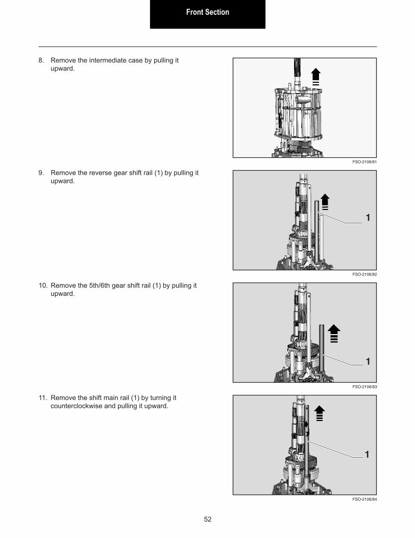
9. Remove the reverse gear shift rail (1) by pulling it upward.
10. Remove the 5th/6th gear shift rail (1) by pulling it upward.
11. Remove the shift main rail (1) by turning it counterclockwise and pulling it upward.
FSO-2106/82
FSO-2106/84
FSO-2106/83
1
1
1
FSO-2106/81
8. Remove the intermediate case by pulling it upward.
Front SectionFront Section
53
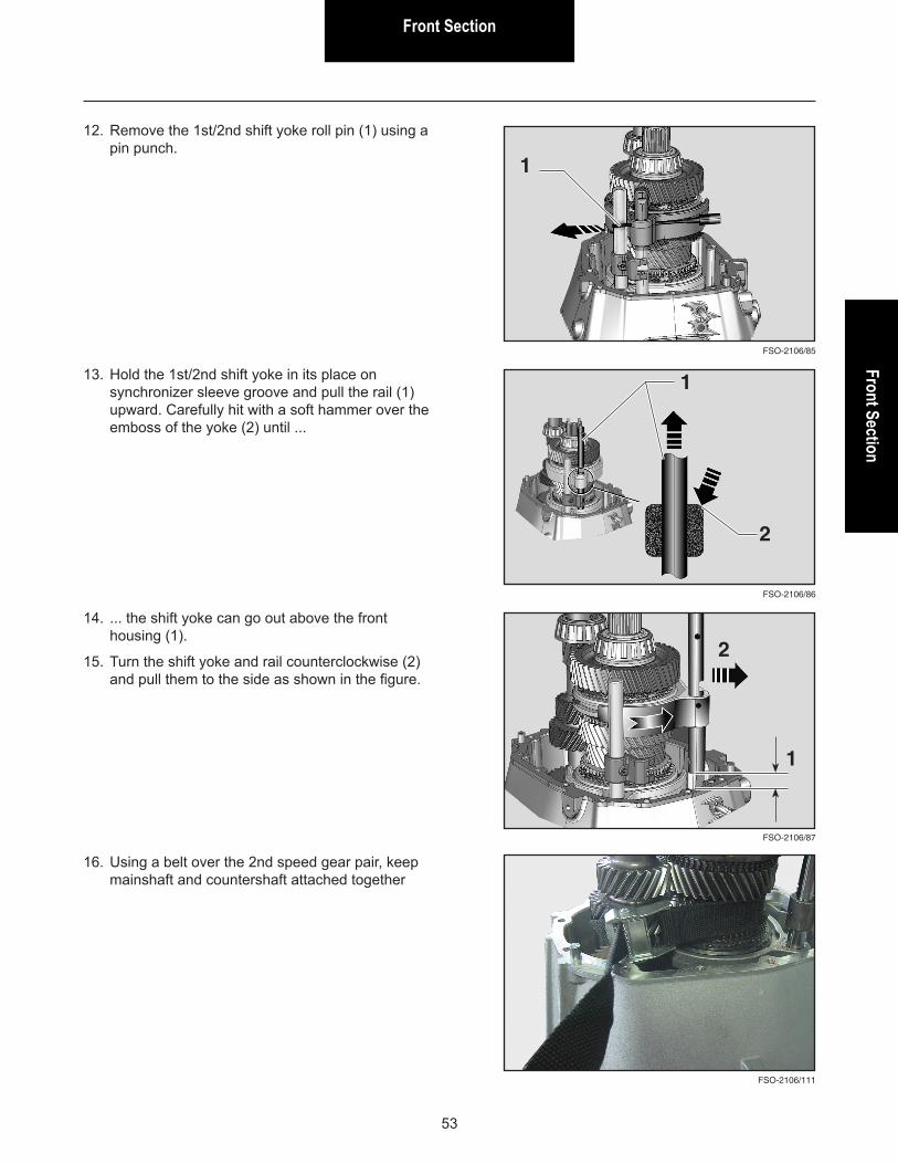
12. Remove the 1st/2nd shift yoke roll pin (1) using a pin punch.
FSO-2106/85
1
FSO-2106/86
FSO-2106/87
1
1
13. Hold the 1st/2nd shift yoke in its place on synchronizer sleeve groove and pull the rail (1) upward. Carefully hit with a soft hammer over the emboss of the yoke (2) until ...
14. ... the shift yoke can go out above the front housing (1).
15. Turn the shift yoke and rail counterclockwise (2) and pull them to the side as shown in the figure.
16. Using a belt over the 2nd speed gear pair, keep mainshaft and countershaft attached together
2
2
FSO-2106/111
Front Section
54
FSO-2106/89
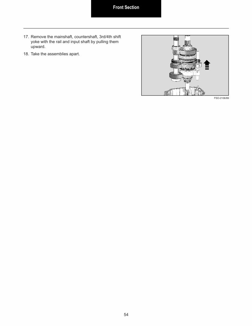
17. Remove the mainshaft, countershaft, 3rd/4th shift yoke with the rail and input shaft by pulling them upward.
18. Take the assemblies apart.
Front SectionFront Section
55
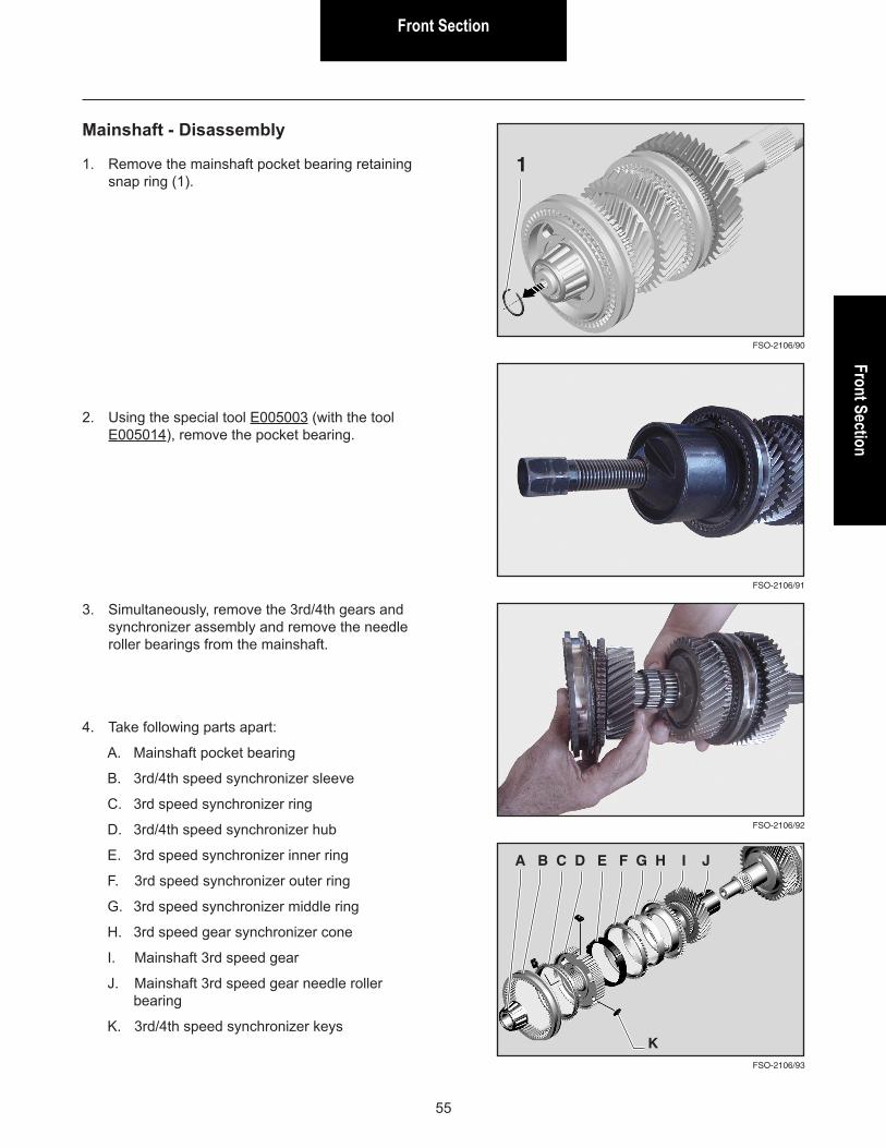
Mainshaft - Disassembly
1. Remove the mainshaft pocket bearing retaining snap ring (1).
FSO-2106/90
FSO-2106/93
FSO-2106/92
FSO-2106/91
1
A B C D E F G H I J
2. Using the special tool E005003 (with the tool E005014), remove the pocket bearing.
3. Simultaneously, remove the 3rd/4th gears and synchronizer assembly and remove the needle roller bearings from the mainshaft.
4. Take following parts apart:
A. Mainshaft pocket bearing
B. 3rd/4th speed synchronizer sleeve
C. 3rd speed synchronizer ring
D. 3rd/4th speed synchronizer hub
E. 3rd speed synchronizer inner ring
F. 3rd speed synchronizer outer ring
G. 3rd speed synchronizer middle ring
H. 3rd speed gear synchronizer cone
I. Mainshaft 3rd speed gear
J. Mainshaft 3rd speed gear needle roller bearing
K. 3rd/4th speed synchronizer keysK
Front Section
56
FSO-2106/94
FSO-2106/97
FSO-2106/96
FSO-2106/95
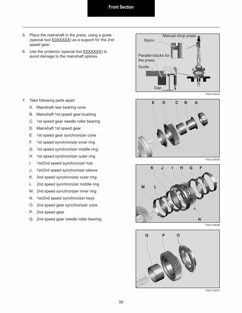
5. Place the mainshaft in the press, using a guide (special tool E0XXXXX) as a support for the 2nd speed gear.
6. Use the protector (special tool E0XXXXX) to avoid damage to the mainshaft splines.
7. Take following parts apart:
A. Mainshaft rear bearing cone
B. Mainshaft 1st speed gear bushing
C. 1st speed gear needle roller bearing
D. Mainshaft 1st speed gear
E. 1st speed gear synchronizer cone
F. 1st speed synchronizer inner ring
G. 1st speed synchronizer middle ring
H. 1st speed synchronizer outer ring
I. 1st/2nd speed synchronizer hub
J. 1st/2nd speed synchronizer sleeve
K. 2nd speed synchronizer outer ring
L. 2nd speed synchronizer middle ring
M. 2nd speed synchronizer inner ring
N. 1st/2nd speed synchronizer keys
O. 2nd speed gear synchronizer cone
P. 2nd speed gear
Q. 2nd speed gear needle roller bearing
A
F
O
G
NylonManual shop press
Gap
Guide
Parallel blocks for the press
BCDE
HIJK
LM
N
PQ
Front SectionFront Section
57
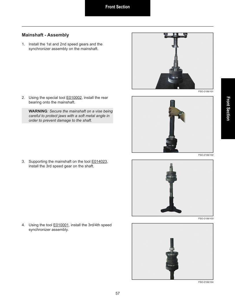
Mainshaft - Assembly
1. Install the 1st and 2nd speed gears and the synchronizer assembly on the mainshaft.
FSO-2106/101
FSO-2106/102
FSO-2106/104
FSO-2106/103
2. Using the special tool E010002, install the rear bearing onto the mainshaft.
WARNING: Secure the mainshaft on a vise being careful to protect jaws with a soft metal angle in order to prevent damage to the shaft.
3. Supporting the mainshaft on the tool E014023, install the 3rd speed gear on the shaft.
4. Using the tool E010001, install the 3rd/4th speed synchronizer assembly.
Front Section
58
FSO-2106/105
FSO-2106/106
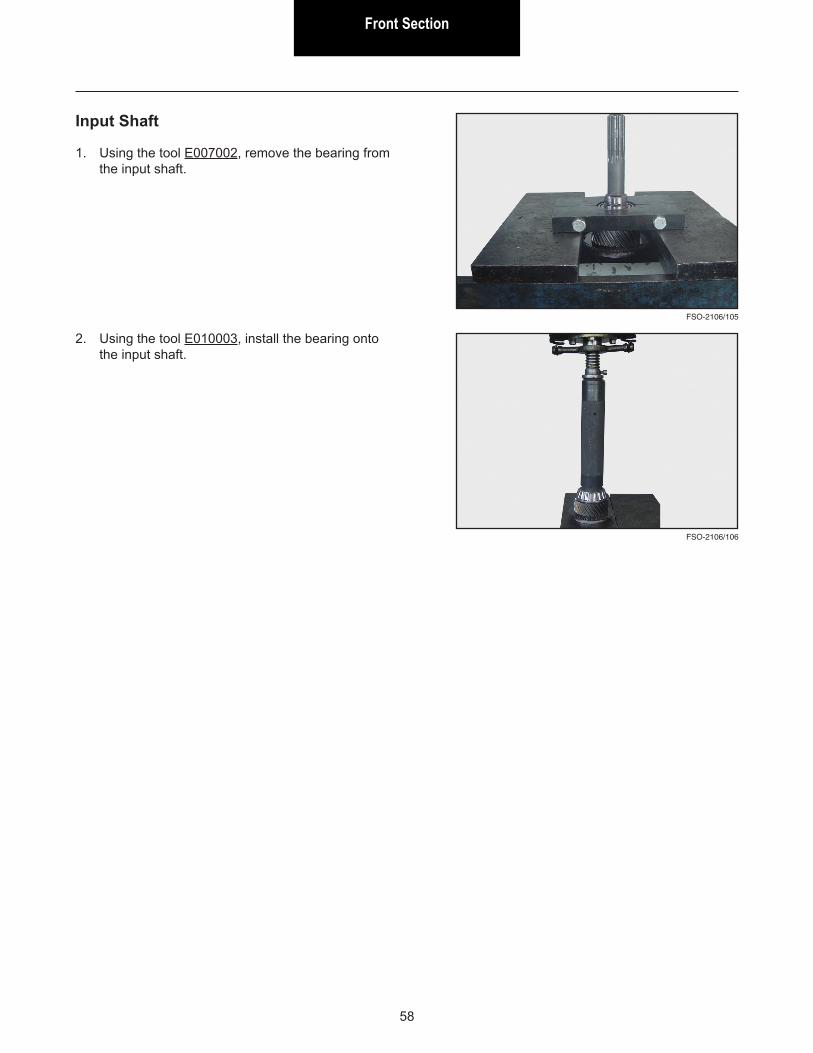
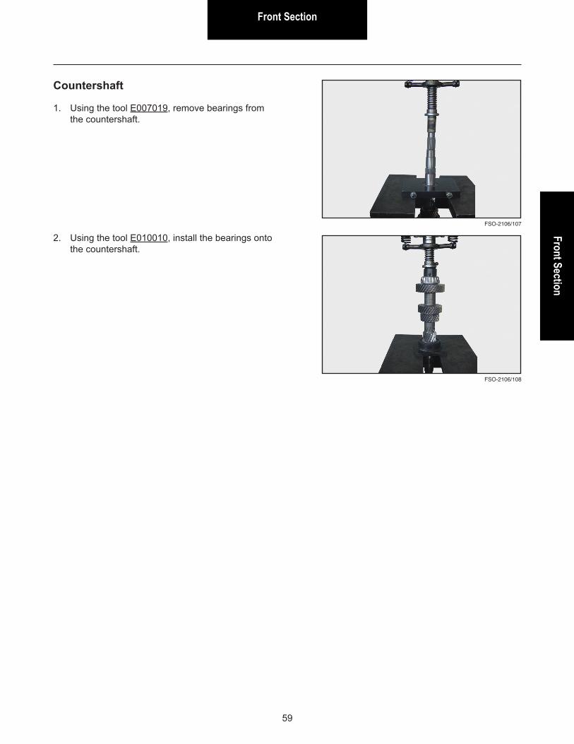
Input Shaft
1. Using the tool E007002, remove the bearing from the input shaft.
2. Using the tool E010003, install the bearing onto the input shaft.
Front SectionFront Section
59
FSO-2106/108
FSO-2106/107
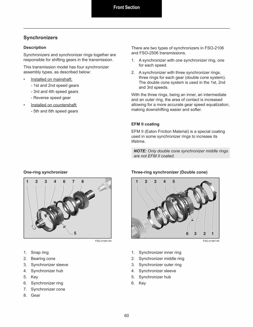
Countershaft
1. Using the tool E007019, remove bearings from the countershaft.
2. Using the tool E010010, install the bearings onto the countershaft.
Front Section
60
Synchronizers
Description
Synchronizers and synchronizer rings together are responsible for shifting gears in the transmission.
This transmission model has four synchronizer assembly types, as described below:
• Installed on mainshaft:- 1st and 2nd speed gears- 3rd and 4th speed gears- Reverse speed gear
• Installed on countershaft:- 5th and 6th speed gears
There are two types of synchronizers in FSO-2106 and FSO-2506 transmissions.
1. A synchronizer with one synchronizer ring, one for each speed.
2. A synchronizer with three synchronizer rings, three rings for each gear (double cone system). The double cone system is used in the 1st, 2nd and 3rd speeds.
With the three rings, being an inner, an intermediate and an outer ring, the area of contact is increased allowing for a more accurate gear speed equalization, making downshifting easier and softer.
EFM II coating
EFM II (Eaton Friction Material) is a special coating used in some synchronizer rings to increase its lifetime.
NOTE: Only double cone synchronizer middle rings are not EFM II coated.
FSO-2106/144
One-ring synchronizer
1 2 3 4 6 7 8
1. Snap ring2. Bearing cone3. Synchronizer sleeve4. Synchronizer hub5. Key6. Synchronizer ring7. Synchronizer cone8. Gear
5
FSO-2106/145
Three-ring synchronizer (Double cone)
1 2 3 4 5
1. Synchronizer inner ring2. Synchronizer middle ring3. Synchronizer outer ring4. Synchronizer sleeve5. Synchronizer hub6. Key
6 3 2 1
Front SectionFront Section
61
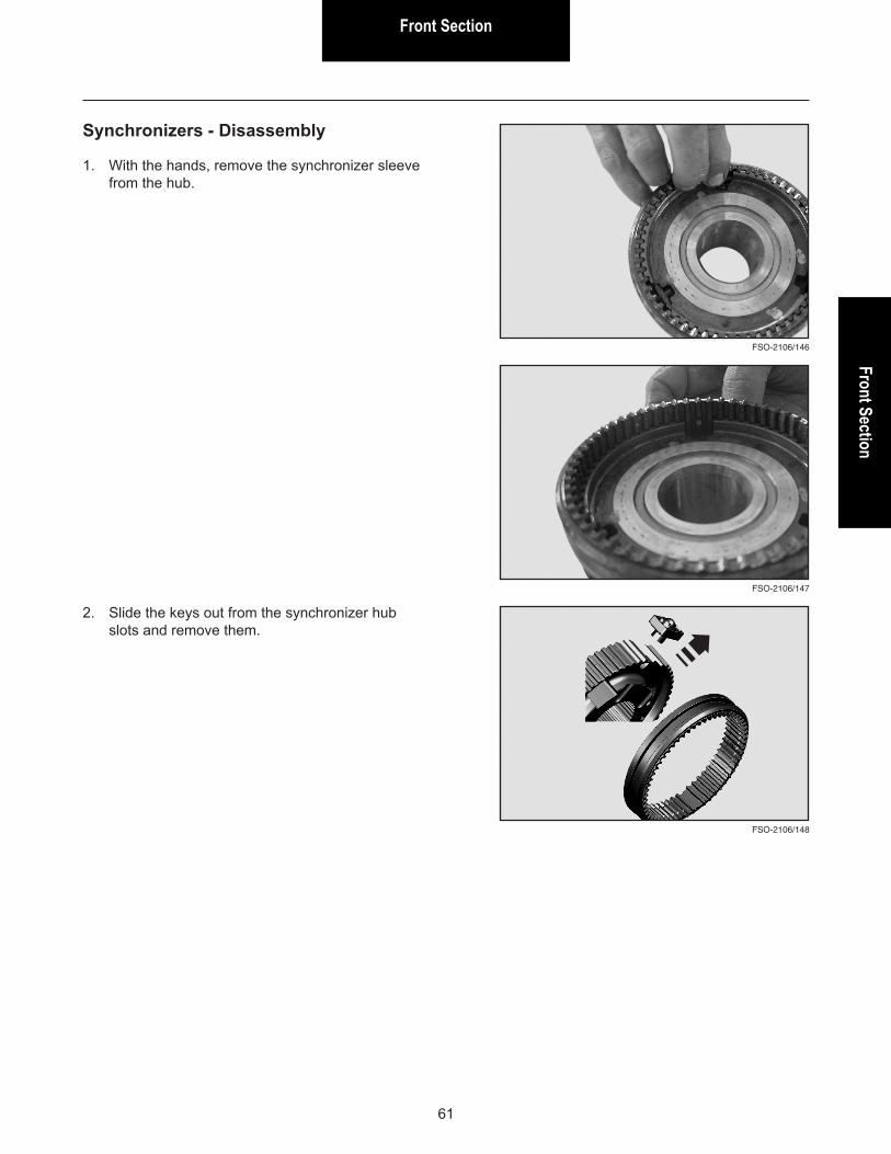
Synchronizers - Disassembly
1. With the hands, remove the synchronizer sleeve from the hub.
FSO-2106/147
FSO-2106/146
2. Slide the keys out from the synchronizer hub slots and remove them.
FSO-2106/148
Front Section
62
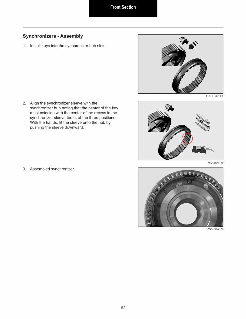
Synchronizers - Assembly
1. Install keys into the synchronizer hub slots.
FSO-2106/149
2. Align the synchronizer sleeve with the synchronizer hub noting that the center of the key must coincide with the center of the recess in the synchronizer sleeve teeth, at the three positions. With the hands, fit the sleeve onto the hub by pushing the sleeve downward.
FSO-2106/150
FSO-2106/148a
3. Assembled synchronizer.
Front SectionFront Section
63
FSO-2106/109
FSO-2106/110
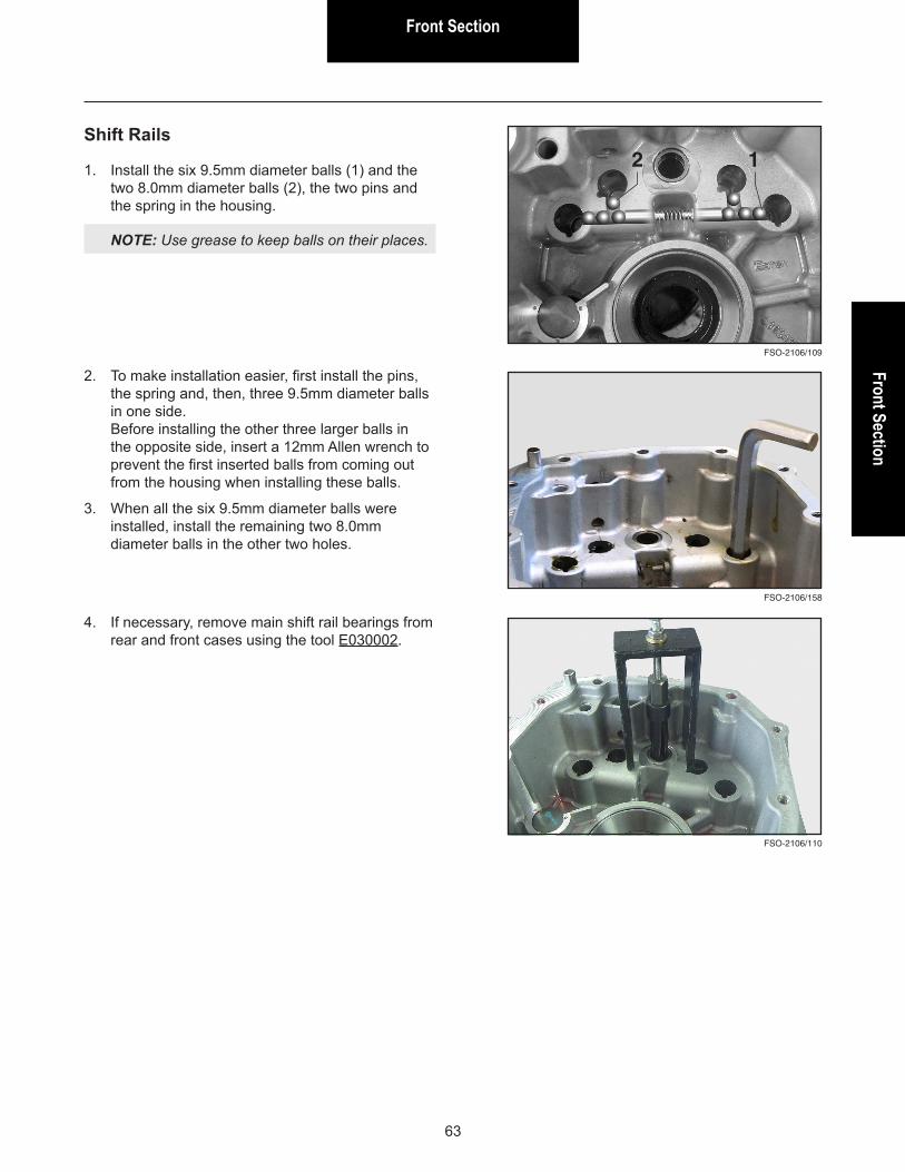
Shift Rails
1. Install the six 9.5mm diameter balls (1) and the two 8.0mm diameter balls (2), the two pins and the spring in the housing.
NOTE: Use grease to keep balls on their places.
4. If necessary, remove main shift rail bearings from rear and front cases using the tool E030002.
2 1
FSO-2106/158
2. To make installation easier, first install the pins, the spring and, then, three 9.5mm diameter balls in one side. Before installing the other three larger balls in the opposite side, insert a 12mm Allen wrench to prevent the first inserted balls from coming out from the housing when installing these balls.
3. When all the six 9.5mm diameter balls were installed, install the remaining two 8.0mm diameter balls in the other two holes.
Front Section
64
FSO-2106/98
FSO-2106/100
FSO-2106/99
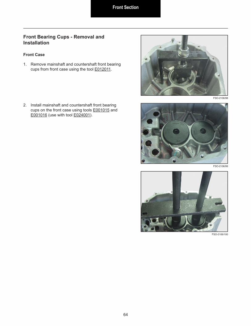
Front Bearing Cups - Removal and Installation
Front Case
1. Remove mainshaft and countershaft front bearing cups from front case using the tool E012011.
2. Install mainshaft and countershaft front bearing cups on the front case using tools E001015 and E001016 (use with tool E024001).
Front SectionFront Section
65
FSO-2106/114
FSO-2106/115
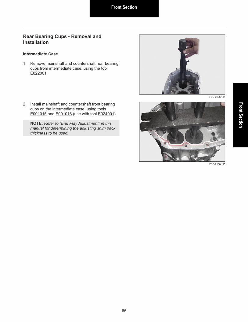
Rear Bearing Cups - Removal and Installation
Intermediate Case
1. Remove mainshaft and countershaft rear bearing cups from intermediate case, using the tool E022001.
2. Install mainshaft and countershaft front bearing cups on the intermediate case, using tools E001015 and E001016 (use with tool E024001).
NOTE: Refer to “End Play Adjustment” in this manual for determining the adjusting shim pack thickness to be used.
Front Section
66
FSO-2106/112
FSO-2106/111
Front Section - Assembly
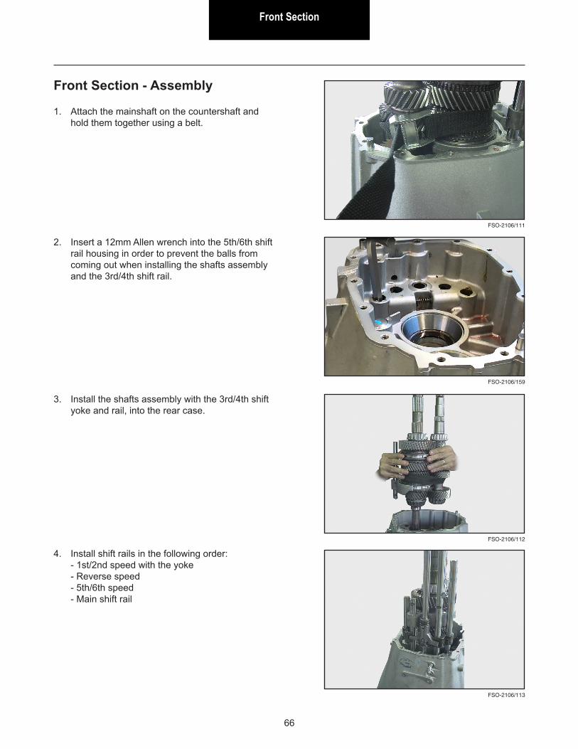
1. Attach the mainshaft on the countershaft and hold them together using a belt.
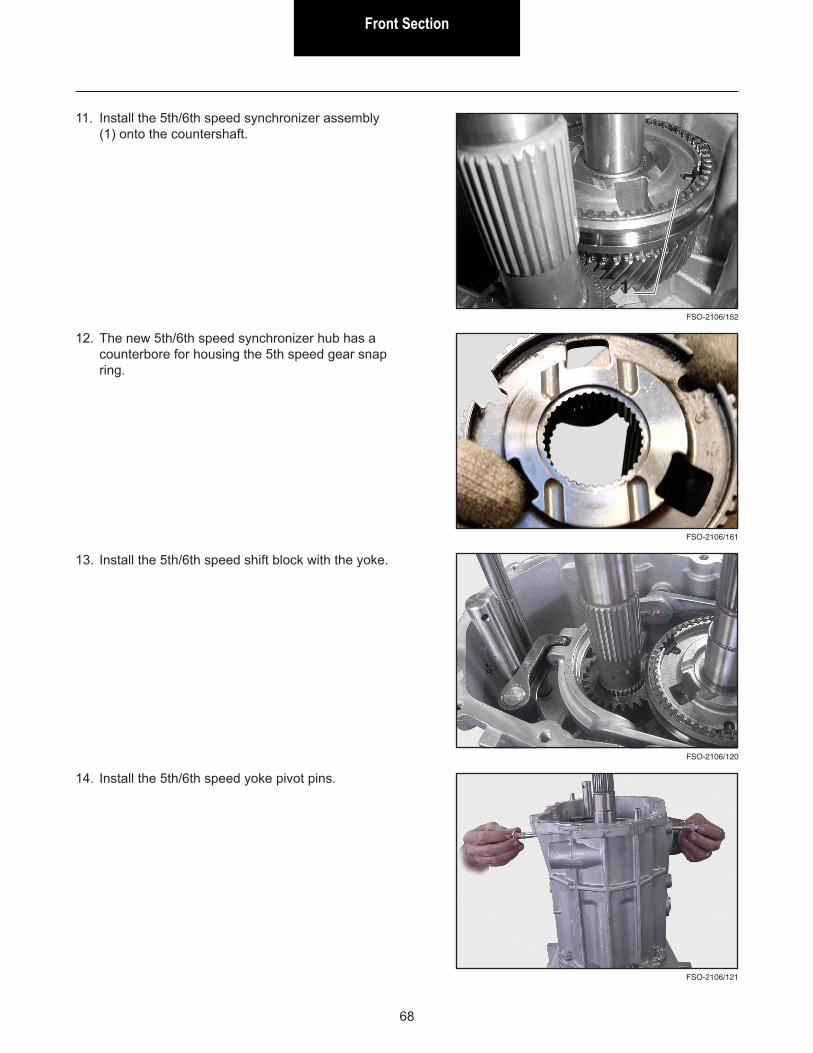
3. Install the shafts assembly with the 3rd/4th shift yoke and rail, into the rear case.
FSO-2106/113
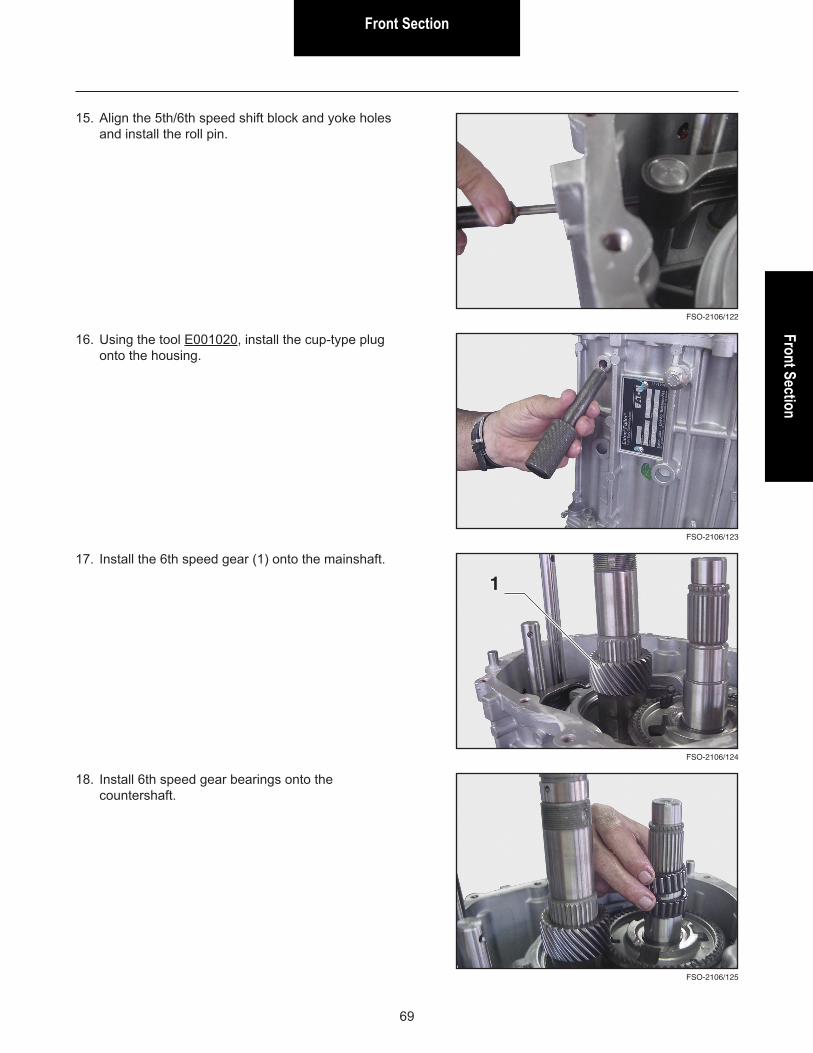
4. Install shift rails in the following order: - 1st/2nd speed with the yoke - Reverse speed - 5th/6th speed - Main shift rail
FSO-2106/159
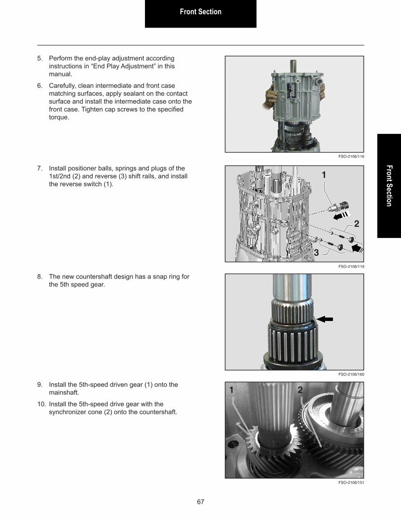
2. Insert a 12mm Allen wrench into the 5th/6th shift rail housing in order to prevent the balls from coming out when installing the shafts assembly and the 3rd/4th shift rail.
Front SectionFront Section
67
FSO-2106/116
5. Perform the end-play adjustment according instructions in “End Play Adjustment” in this manual.
6. Carefully, clean intermediate and front case matching surfaces, apply sealant on the contact surface and install the intermediate case onto the front case. Tighten cap screws to the specified torque.
FSO-2106/119
7. Install positioner balls, springs and plugs of the 1st/2nd (2) and reverse (3) shift rails, and install the reverse switch (1).
1
2
3
FSO-2106/160
8. The new countershaft design has a snap ring for the 5th speed gear.
FSO-2106/151
9. Install the 5th-speed driven gear (1) onto the mainshaft.
10. Install the 5th-speed drive gear with the synchronizer cone (2) onto the countershaft.
1 2
Front Section
68
FSO-2106/120
13. Install the 5th/6th speed shift block with the yoke.
FSO-2106/152
11. Install the 5th/6th speed synchronizer assembly (1) onto the countershaft.
1
FSO-2106/121
14. Install the 5th/6th speed yoke pivot pins.
FSO-2106/161
12. The new 5th/6th speed synchronizer hub has a counterbore for housing the 5th speed gear snap ring.
Front SectionFront Section
69
FSO-2106/122
FSO-2106/123
15. Align the 5th/6th speed shift block and yoke holes and install the roll pin.
16. Using the tool E001020, install the cup-type plug onto the housing.
FSO-2106/124
17. Install the 6th speed gear (1) onto the mainshaft.
FSO-2106/125
18. Install 6th speed gear bearings onto the countershaft.
1
Front Section
70
FSO-2106/126
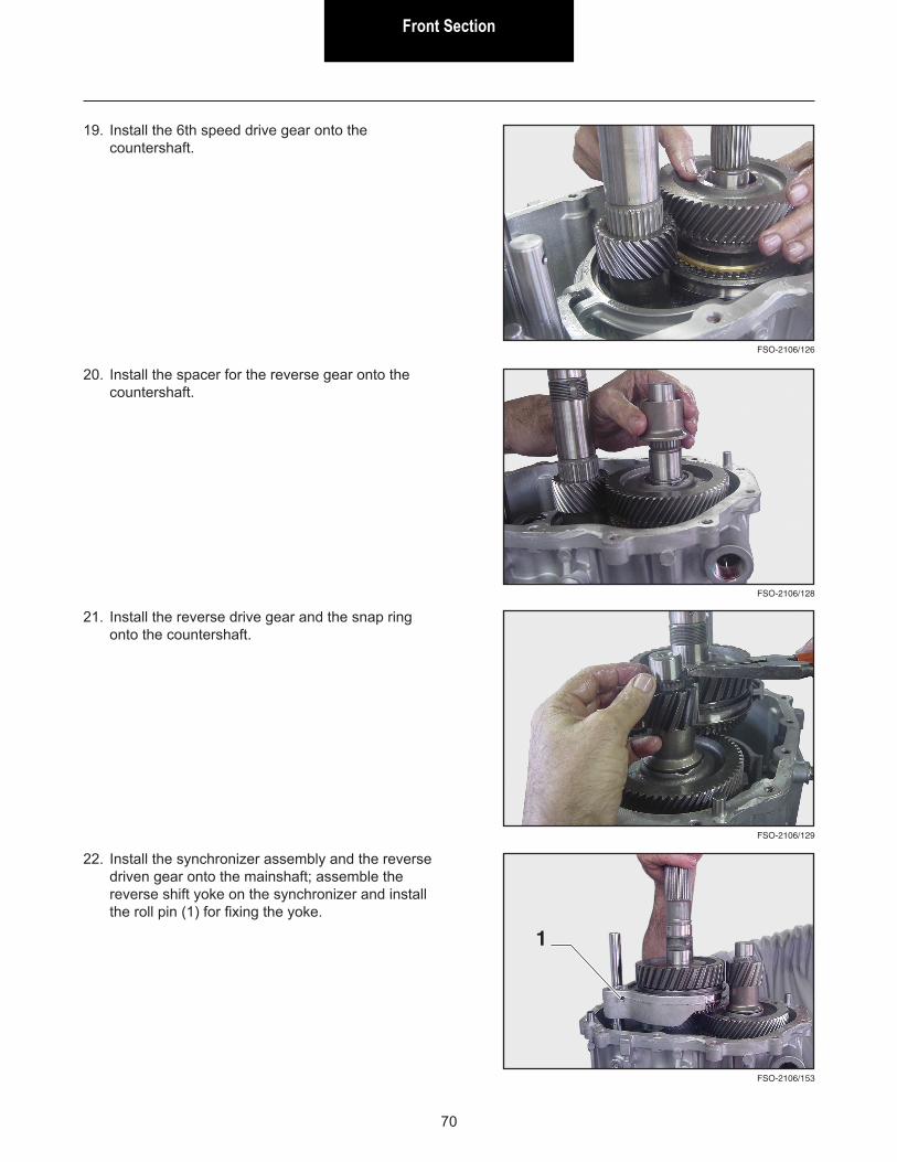
19. Install the 6th speed drive gear onto the countershaft.
20. Install the spacer for the reverse gear onto the countershaft.
FSO-2106/129
FSO-2106/128
21. Install the reverse drive gear and the snap ring onto the countershaft.
22. Install the synchronizer assembly and the reverse driven gear onto the mainshaft; assemble the reverse shift yoke on the synchronizer and install the roll pin (1) for fixing the yoke.
FSO-2106/153
1
Front SectionFront Section
71
FSO-2106/130
FSO-2106/131
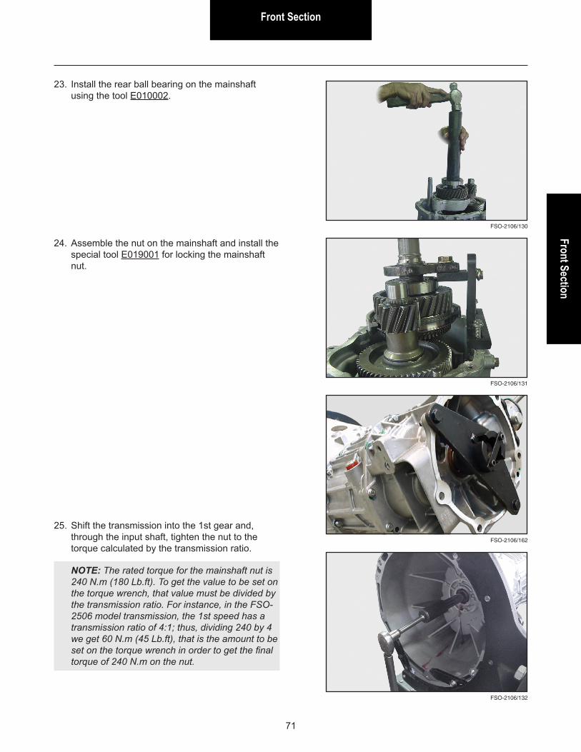
23. Install the rear ball bearing on the mainshaft using the tool E010002.
24. Assemble the nut on the mainshaft and install the special tool E019001 for locking the mainshaft nut.
FSO-2106/132
25. Shift the transmission into the 1st gear and, through the input shaft, tighten the nut to the torque calculated by the transmission ratio.
NOTE: The rated torque for the mainshaft nut is 240 N.m (180 Lb.ft). To get the value to be set on the torque wrench, that value must be divided by the transmission ratio. For instance, in the FSO-2506 model transmission, the 1st speed has a transmission ratio of 4:1; thus, dividing 240 by 4 we get 60 N.m (45 Lb.ft), that is the amount to be set on the torque wrench in order to get the final torque of 240 N.m on the nut.
FSO-2106/162
Front Section
72
FSO-2106/133
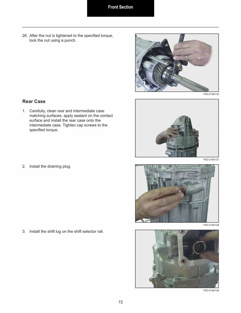
26. After the nut is tightened to the specified torque, lock the nut using a punch.
FSO-2106/138
FSO-2106/137
Rear Case
1. Carefully, clean rear and intermediate case matching surfaces, apply sealant on the contact surface and install the rear case onto the intermediate case. Tighten cap screws to the specified torque.
2. Install the draining plug.
3. Install the shift lug on the shift selector rail.
FSO-2106/139
Front SectionFront Section
73
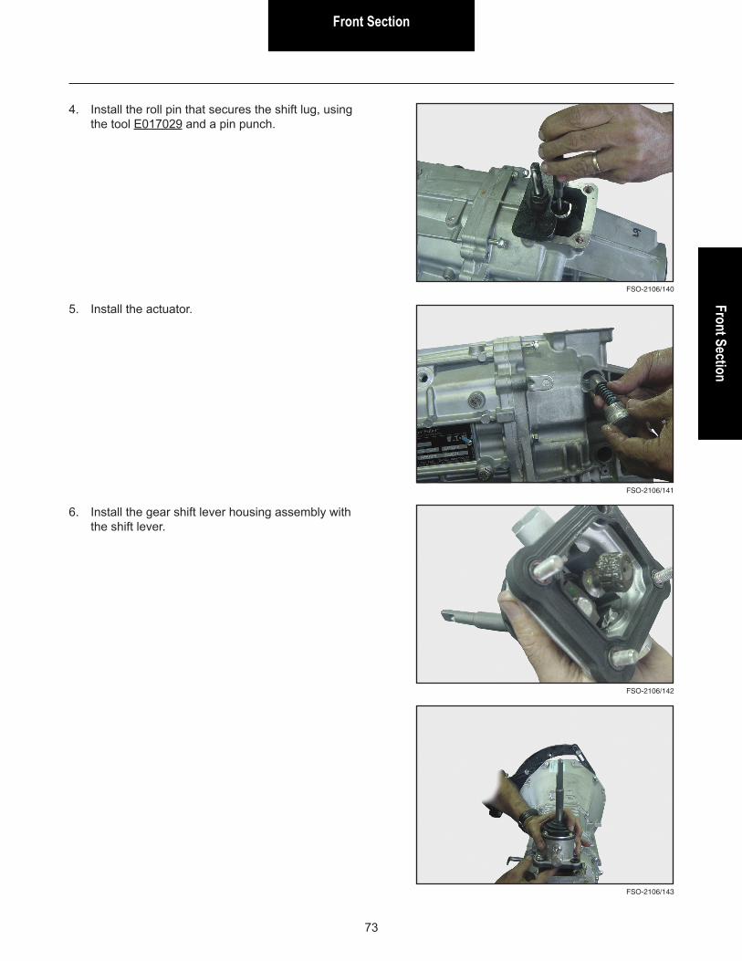
4. Install the roll pin that secures the shift lug, using the tool E017029 and a pin punch.
FSO-2106/140
FSO-2106/141
5. Install the actuator.
6. Install the gear shift lever housing assembly with the shift lever.
FSO-2106/142
FSO-2106/143
Front Section
74
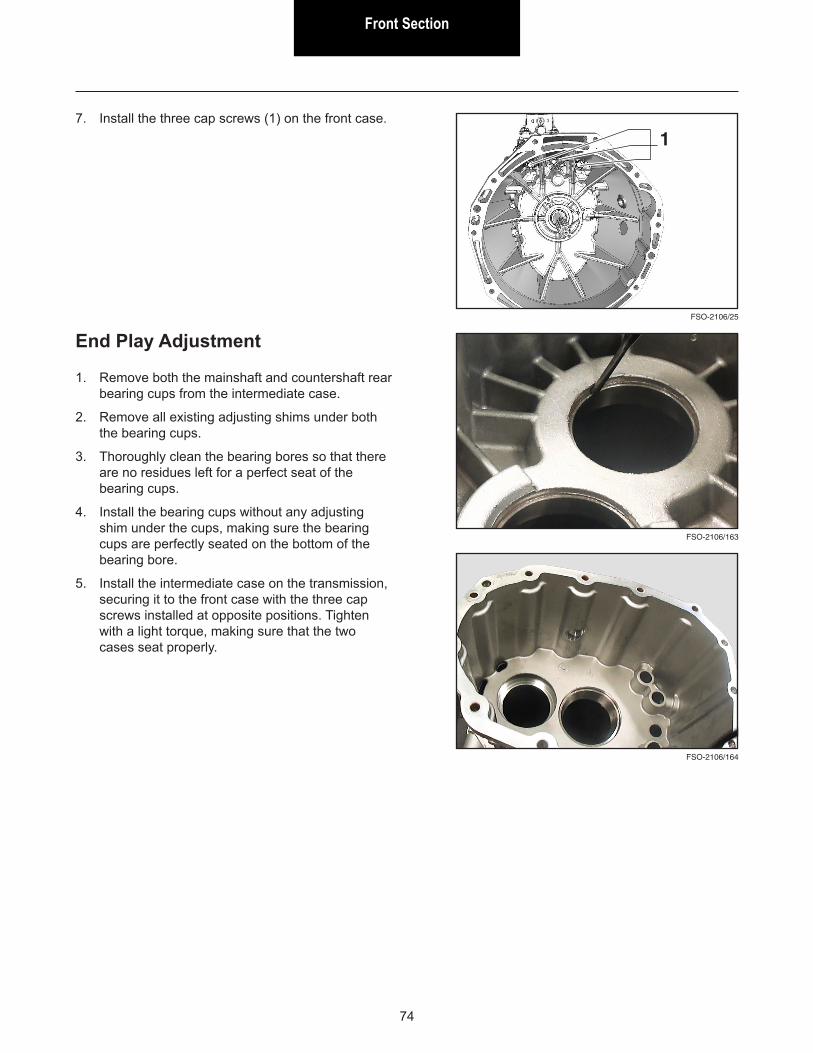
7. Install the three cap screws (1) on the front case.
FSO-2106/25
1
FSO-2106/164
FSO-2106/163
End Play Adjustment
1. Remove both the mainshaft and countershaft rear bearing cups from the intermediate case.
2. Remove all existing adjusting shims under both the bearing cups.
3. Thoroughly clean the bearing bores so that there are no residues left for a perfect seat of the bearing cups.
4. Install the bearing cups without any adjusting shim under the cups, making sure the bearing cups are perfectly seated on the bottom of the bearing bore.
5. Install the intermediate case on the transmission, securing it to the front case with the three cap screws installed at opposite positions. Tighten with a light torque, making sure that the two cases seat properly.
Front SectionFront Section
75
FSO-2106/117
FSO-2106/118
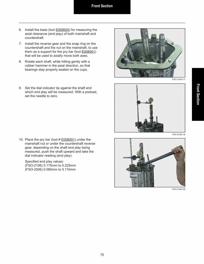
6. Install the base (tool E009005) for measuring the axial clearance (end play) of both mainshaft and countershaft.
7. Install the reverse gear and the snap ring on the countershaft and the nut on the mainshaft, to use them as a support for the pry bar (tool E008001) that will be used to axially move both axes.
8. Rotate each shaft, while hitting gently with a rubber hammer in the axial direction, so that bearings stay properly seated on the cups.
9. Set the dial indicator tip against the shaft end which end play will be measured. With a preload, set the needle to zero.
FSO-2106/156
10. Place the pry bar (tool # E008001) under the mainshaft nut or under the countershaft reverse gear, depending on the shaft end play being measured, push the shaft upward and take the dial indicator reading (end play).
Specified end play values: (FSO-2106) 0.175mm to 0.225mm (FSO-2506) 0.060mm to 0.110mm
Front Section
76
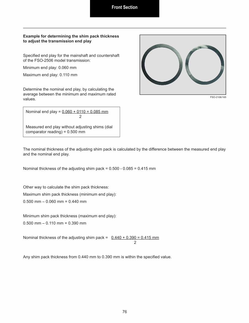
Example for determining the shim pack thickness to adjust the transmission end play
Specified end play for the mainshaft and countershaft of the FSO-2506 model transmission:
Minimum end play: 0.060 mm
Maximum end play: 0.110 mm
Determine the nominal end play, by calculating the average between the minimum and maximum rated values. FSO-2106/165
The nominal thickness of the adjusting shim pack is calculated by the difference between the measured end play and the nominal end play.
Nominal thickness of the adjusting shim pack = 0.500 - 0.085 = 0.415 mm
Nominal end play = 0.060 + 0110 = 0.085 mm 2
Measured end play without adjusting shims (dial comparator reading) = 0.500 mm
Other way to calculate the shim pack thickness:
Maximum shim pack thickness (minimum end play):
0.500 mm – 0.060 mm = 0.440 mm
Minimum shim pack thickness (maximum end play):
0.500 mm – 0.110 mm = 0.390 mm
Nominal thickness of the adjusting shim pack = 0.440 + 0.390 = 0.415 mm 2
Any shim pack thickness from 0.440 mm to 0.390 mm is within the specified value.

Copyright Eaton Corporation 2015.Eaton hereby grants their customers,vendors, and distributors permission to freelycopy, reproduce and/or distribute thisdocument in printed format. It may be copiedonly in its entirety without any changes ormodifications. THIS INFORMATION IS NOTINTENDED FOR SALE OR RESALE, ANDTHIS NOTICE MUST REMAIN ON ALLCOPIES.
© 2015 Eaton Corporation · All rights reserved.


