Embed Size (px)
Citation preview

SEMESTER V
MECHATRONICS
CODE MET301
COURSE NAME MECHANICS OF MACHINERY
CATEGORY L T P CREDIT PCC 3 1 0 4
Preamble:
This course aims to introduce the students to the fundamentals of the kinematics of various mechanisms and also its analysis for its displacement, velocity, and acceleration. The course will also cover the design of cams, theory and analysis of gears, gear trains and synthesis of mechanisms. The static force analysis of planar mechanisms and concept of gyroscopic couple along with its effect has also been included. This course also aids students in estimating unbalance in rotating and reciprocating masses and suggesting methods to overcome it.
Prerequisite: Engineering Mechanics (EST 100)
Course Outcomes: After the completion of the course the student will be able to
CO 1 Explain the fundamentals of kinematics, various planar mechanisms and interpret the basic principles of mechanisms and machines
CO 2 Perform analysis and synthesis of mechanisms
CO 3 Solve the problem on cams and gear drives, including selection depending on requirement.
CO 4 Calculate the gyroscopic effect in various situations
CO 5 Analyse rotating and reciprocating masses for its unbalance
Mapping of course outcomes with program outcomes
PO 1
PO 2 PO 3 PO 4 PO 5 PO 6 PO 7 PO 8 PO 9 PO 10
PO 12
CO 1 2
CO 2 3 3 3 2 2
CO 3 3 3 2 2 2
CO 4 3 2 1 1 1
CO 5 3 2 2 1 2
MECHATRONICS
Assessment Pattern
Bloom’s Category Continuous Assessment Tests End Semester Examination 1 2
Remember 10 10 10 Understand 20 20 20 Apply 20 20 70 Analyse Evaluate Create
Mark distribution
Total Marks CIE ESE ESE Duration
150 50 100 3 hours
Continuous Internal Evaluation Pattern:
Attendance : 10 marks Continuous Assessment Test (2 numbers) : 25 marks Assignment/Quiz/Course project : 15 marks End Semester Examination Pattern: There will be two parts; Part A and Part B. Part A contain 10 questions with 2 questions from each module, having 3 marks for each question. Students should answer all questions. Part B contains 2 questions from each module of which student should answer any one. Each question can have maximum 2 sub-divisions and carry 14 marks.
Course Level Assessment Questions
Course Outcome 1 (CO1): Explain the fundamentals of kinematics, various planar mechanisms and their components
1. Define the terms Link, Kinematic chain, Mechanism & Machine.
2. Explain Grashof’s law.
3 Apply Kutzbach criterion to find the mobility of mechanisms.
4.Sketch and explain the various inversions of slider crank chain/fourbar chain
Course Outcome 2 (CO2) : Perform analysis and synthesis of mechanisms 1. Find out the velocity and acceleration of links of various planar mechanisms
2. State and prove the Arnold Kennedy’s three centre theorem
2. Derive an expression for the magnitude and direction of Coriolis component of acceleration
MECHATRONICS

3. Design a four bar mechanism to generate a given function accurate upto 3 positions
4. Do the static force analysis of four bar/slider crank mechanisms with different loading
conditions
Course Outcome 3 (CO3): Solve the problem on cams and gear drives, including selection depending on requirement
1. Why is a roller follower preferred over knife edge follower
2. Design a cam profile to suit the situations for the follower such as SHM, dwell, constant velocity, uniform acceleration cycloidal motion etc
3. What do you understand by the term “interference” as applied to gears
4. Find out the gear train values of simple ,compound and epicyclic gear trains
Course Outcome 4 (CO4): Calculate the gyroscopic effect in various situations
1. What do you understand by Gyroscopic couple? Derive its formula for its magnitude.
2. Explain the effect of the gyroscopic couple on the reaction of the four wheels of a vehicle negotiating a curve.
3. Describe the working of a gyroscope.
4. How does gyroscopes help in guidance?
Course Outcome 5 (CO5): Analyse rotating and reciprocating masses for its unbalance
1. Distinguish between static balancing and dynamic balancing
2. Find out the magnitude and position of balancing masses required to balance unbalanced masses rotating in different planes.
3. What do you mean by primary and secondary unbalanced forces?
4. Find out the value of unbalanced primary force, primary couple, secondary force and secondary couple.
MECHATRONICS
MODEL QUESTION PAPER
APJ ABDUL KALAM TECHNOLOGICAL UNIVERSITY
FIFTH SEMESTER B. TECH DEGREE EXAMINATION
Course Code: MET301
Course Name: MECHANICS OF MACHINERY
Max. Marks: 100 Duration: 3 Hours
PART – A
(ANSWER ALL QUESTIONS, EACH QUESTION CARRIES 3 MARKS)
1. Find out the degree of freedom in the following cases.
2. Describe the motion of the following items as pure rotation, pure translation or complexplanar motion.a) The hand of a clock b) The pen in an XY plotter c) connecting rod of an IC engine
3. A rod of length 1m with its one end fixed at origin is oriented in the positive Xdirection. It rotates in the XY plane with an angular velocity of 10rad/s clockwisedirection and angular acceleration of 10rad/s2 in the counter clock wise direction at aparticular instant. Find out the total acceleration experienced at the free end.
4. Obtain the expression for velocity when the cam follower motion is cycloidal in nature.
5. How do we bring interchangeability of gears?
6. What do you mean by type synthesis?
7. Define the term ‘friction circle’
8. How does a gyroscope help in guidance of aircrafts?
9. Does a rotor which is statically balanced require dynamic balancing?
10. Why do we go for partial balancing in the case of balancing of reciprocating masses?
Part B
(ANSWER ONE FULL QUESTION FROM EACH MODULE)
MODULE – I
11. a) Draw the inversions of the mechanism shown in Figure 1 which leads to double crank,
MECHATRONICS
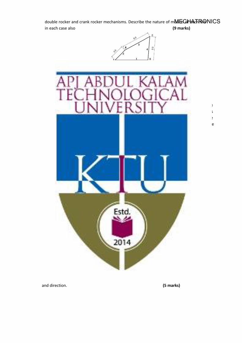
double rocker and crank rocker mechanisms. Describe the nature of motion of each link in each case also (9 marks)
Figure-1
b) What are binary, ternary and quaternary links? (5 marks)
12. In the figure 2 given below the angular velocity of the crank OA is 600 r.p.m. Determine thelinear velocity of the slider and angular velocity of all other links. The dimensions of various links are: OA=28 mm; AB = 44 mm; BC = 49 mm and BD = 46 mm. The centre distance between centres of rotation O and C is 65mm.The path of travel of slider is 11 mm below the fixed-point C (14 marks)
Figure-2
MODULE – II
13. a) What is meant by Coriolis component of acceleration. In which case does it occur? How is its direction determined? (9 marks)
b) A link OB rotating with a constant angular velocity of 2 rad/s in the counter clockwise direction and a block is sliding radially outwards on it with a uniform velocity of 0.75 m/s with respect to the rod as shown in the figure 3 below. Given OA =1 m and link OB is inclined to the positive X axis by 45°.Find out the absolute acceleration of block at A in magnitude and direction. (5 marks)
MECHATRONICS

Figure-3
14. A cam rotating at 150 rpm operates a reciprocating follower of radius 2.5 cm. The followeraxis is offset by 2.5 cm to the right. The least radius of the cam is 5 cm and the stroke of the follower is 5 cm. ascent and descent with take place by uniform acceleration and retardation. Ascent take place during 75° and descent during 90° of cam rotation. Dwell between ascent and descent is 60°. Draw the cam profile. Also sketch velocity and acceleration diagrams and mark salient values. (14 marks)
MODULE – III
15. In an epicyclic gear train as shown in Figure 4 the internal wheels A and B and the compoundwheels C & D rotate independently about axis O. The wheels E and F rotate on pins fixed tothe arm G.E gears with A and C and F gears with B and D. All wheels have the same moduleand the number of teeth are:Tc = 28, TD = 26, TE = TF = 18
i) Sketch the arrangement
ii) Find the number of teeth on A and B
iii) If the arm G makes 100 r.p.m clockwise and A is fixed, find the speed B
iv) If the arm G makes 100 r.p.m clockwise and wheel A makes 10 r.p.m counter clockwise,find the speed of wheel B (14 marks)
Figure-4
MECHATRONICS
16. a) Design a four bar crank rocker to give 45° of rocker motion with a time ratio of 1:1.25 with 45° output rocker motion. (9 marks)
b) Design a slider crank mechanism to coordinate two positions of the input link and the slider for the following angular and linear displacement of the input link and slider respectively.
θ12 = 30° & S12 = 100 mm (5 marks)
MODULE – IV
17. The applied load on the piston of an offset slider-crank linkage shown in Fig. is 100 N, and the coefficient of friction between the slider and the guide is 0.27, using any method ,determine the magnitude and sense of torque T2 applied on OA for the static equilibrium of the linkage. (14 marks)
Figure-5
18 a) The wheels of a motor cycle have a moment of inertia of 5 kg m2 and the engine parts, a moment of inertia of 0.35 kgm2. The wheel axles and the crank shaft of the engine are all parallel to each other. If the ratio of reduction gears is 4:1, the wheel diameter is 700 mm, determine the magnitude and direction of the gyroscopic couple when the motor cycle negotiates a curve of 50 m radius at a speed of 50 km/hr. If the mass of the motor cycle with rider is 250 kg with centre of gravity at 65 cm above the ground in vertical position, determine the speed of the motor cycle rounding a curve of 60 m if the road condition permits an angle of heel of 45°. (10 marks)
b) Explain spin vector, precession vector, gyroscopic applied torque vector and gyroscopic reactive torque vector. (4 marks)
MODULE – V
19. A shaft carries four masses A, B, C and D which are placed in parallel planes perpendicular to the longitudinal axis. Th unbalanced masses at planes B and C are 3.6 kg and 2.6kg respectively and both are assumed to be concentrated at a radius of 25mm while the masses in planed A and D are both at a radius of 40mm.The angle between the planes B and C is 100° and that between B and A is 190°, both angles being measured in counter clock wise direction from the plane B .The planes containing A and B are 250mm apart and those containing B and C are 500mm.If the shaft is to be completely balanced ,determine
i) Masses at the planes A and D
ii) the distance between the planes C and D
MECHATRONICS
iii) the angular position of the mass D (14 marks)
20. A five cylinder in-line engine running at 750 r.p.m. has successive cranks 144° apart, the distancebetween the cylinder centre lines being 375 mm. The piston stroke is 225mm and the ratio of theconnecting rod to the crank is 4. Examine the engine for balance of primary and secondary forcesand couples. Find the maximum values of these and the position of the central crank at which thesemaximum values occur. The reciprocating mass for each cylinder is 15 kg. (14 marks)
Syllabus
Module 1
Introduction to kinematics and mechanisms - various mechanisms, kinematic diagrams, degree of freedom- Grashof’s criterion, inversions, coupler curves mechanical advantage, transmission angle. straight line mechanisms exact, approximate. Displacement, velocity analysis– relative motion - relative velocity. Instantaneous centre -Kennedy’s theorem.
Module 2
Acceleration analysis- Relative acceleration - Coriolis acceleration - graphical and analytical methods. Cams - classification of cam and followers - displacement diagrams, velocity and acceleration analysis of SHM, uniform velocity, uniform acceleration, cycloidal motion Graphical cam profile synthesis, pressure angle.
Module 3
Gears – Classification- terminology of spur gears – law of gearing -tooth profiles- involute spur gears- contact ratio - interference - backlash - gear standardization – interchangeability. Gear trains - simple and compound gear trains - planetary gear trains.
Kinematic synthesis (planar mechanisms) - type, number and dimensional synthesis – precision points. Graphical synthesis for motion - path and prescribed timing - function generator. 2 position and 3 position synthesis – overlay Method. Freudenstein's equation.
Module 4
Static force analysis- Analysis of four bar linkages and slider crank mechanism, graphical method, Matrix method, principle of virtual work. Analysis of four bar and slider crank mechanisms with sliding and pin friction.
Gyroscopic couples-spin, precession and applied gyroscopic couple vectors-effects on the stability of two wheelers, four wheelers, sea vessels and air crafts, application of gyroscopes
Module 5
MECHATRONICS
Static balancing-dynamic balancing-balancing of several masses in the same plane-several masses in different planes-graphical and analytical method-force and couple polygons. Balancing of reciprocating masses -Single cylinder engine-multi cylinder engine -V-engine
Text Books
1. Ballaney P. L., Theory of Machines and Mechanisms, Khanna Publishers,2005
2 . S. S. Rattan, Theory of Machines, Tata Mc Graw Hill,2009
Reference Books
1. C. E. Wilson, P. Sadler, Kinematics and Dynamics of Machinery, Pearson Education,2005. 2. D.H. Myskza, Machines and Mechanisms Applied Kinematic Analysis,
Pearson Education,2013 3. G. Erdman, G. N. Sandor, Mechanism Design: Analysis and synthesis Vol I & II, Prentice Hall of
India,1984. 4. Ghosh, A. K. Malik, Theory of Mechanisms and Machines, Affiliated East West Press,1988 5. J. E. Shigley, J. J. Uicker, Theory of Machines and Mechanisms, McGraw Hill,2010 6. Norton, Kinematics and Dynamics of Machinery, Tata McGraw Hill,2009
Course Contents and Lecture Schedule
No
1
Topic
Module-1-
No. of lectures
10 Hours
1.1 Introduction to kinematics and mechanisms 1 Hr
1.2 Various mechanisms 2 Hr
1.3 Kinematic diagrams, degree of freedom, Grashof’s criterion 2 Hr
1.4 Inversions 1 Hr
1.5 Coupler curves mechanical advantage, transmission angle. 1 Hr
1.6 Straight line mechanisms exact, approximate 1 Hr
1.7 Displacement, velocity analysis, Kennedy’s theorem. 2 Hr
2 Module 2- 10 Hours
2.1 Acceleration analysis- Relative acceleration - Coriolis acceleration -
1 Hr
2.2 Graphical and analytical methods. .
2Hr
MECHATRONICS
2.3 Cams - classification of cam and followers 1 Hr
2.4 Displacement diagrams, velocity and acceleration analysis of SHM,
2 Hr
2.5 Uniform velocity,uniform acceleration and cycloidal motion 1 Hr
2.5 Graphical cam profile synthesis, pressure angle. 2 Hr
2.6 Analysis of tangent cam with roller follower and circular cam with flat follower
1 Hr
3 Module-3 9 Hours
3.1 Gears – terminology of spur gears – law of Gearing 1 Hr
3.2 involute spur gears - contact ratio- interference - backlash - gear standardization-interchangeability
1 Hr
3.3 Gear trains - simple and compound gear trains - planetary gear trains
2 Hr
3.4 Kinematic synthesis (planar mechanisms) - type, number and dimensional synthesis – precision points.
2 Hr
3.5 Graphical synthesis for motion - path and prescribed timing - function generator. 2 position and 3 position synthesis
2 Hr
3.6 Overlay Method. Freudenstein's equation 1 Hr
4 Module-4- 8 Hours
4.1 Static force analysis- Analysis of four bar linkages and slider crank mechanism
2 Hr
4.2 Graphical method, Matrix method 1 Hr
4.3 principle of virtual work 1 Hr
4.4 Analysis of four bar and slider crank mechanisms with sliding and pin friction.
1 Hr
4.4 Gyroscopic couples-spin, precession and applied gyroscopic couple vectors
2 Hr
4.5 Effects on the stability of two wheelers , Four wheelers, sea vessals and air crafts
1 Hr
5 Module-5- Kinematics-synthesis 8 Hours
5.1 Static balancing-dynamic balancing- 2 Hr
MECHATRONICS

5.2 balancing of several masses in the same plane 1 Hr
5.3 several masses in different planes-graphical and analytical method
1 Hr
5.4 force and couple polygons 1 Hr
5.5 Balancing of reciprocating masses -Single cylinder engine 1 Hr
5.6 multi cylinder engine-v engine-inline engine 2 Hr
MECHATRONICS
MRT303 LINEAR CONTROL SYSTEMS CATEGORY L T P CREDIT
PCC 3 1 0 4
Preamble: This course enables students to systematically study the principles of system modelling, analysis and feedback control, and use them to design and evaluate feedback control systems.
Prerequisite: Linear Differential Equations, Laplace Transform
Course Outcomes: After the completion of the course the student will be able to
CO 1 Understand control systems in the design of dynamic systems. CO 2 Identify a set of equations for representing and modelling physical systems. CO 3 Perform analysis of control systems in time and frequency domains CO 4 Analyse the stability of control systems. CO 5 Identify different controllers and compensation techniques CO 6 Apply the knowledge of control systems in real time control applications
Mapping of course outcomes with program outcomes
PO1 PO2 PO3 PO4 PO5 PO6 PO7 PO8 PO9 PO10 PO11 PO12 CO 1 3 2 2 CO 2 3 2 2 2 2 CO 3 3 3 CO 4 3 3 2 2 2 CO 5 3 2 2 CO 6 3 2 2 2
Assessment Pattern
Bloom’s Category Continuous Assessment Tests End Semester Examination 1 2
Remember 10 10 10 Understand 20 20 20 Apply 10 10 30 Analyse 10 10 40 Evaluate Create
Mark distribution
Total Marks CIE ESE ESE Duration
150 50 100 3 hours
MECHATRONICS
Continuous Internal Evaluation Pattern:
Attendance : 10 marks Continuous Assessment Test (2 numbers) : 25 marks Assignment/Quiz/Course project : 15 marks End Semester Examination Pattern: There will be two parts; Part A and Part B. Part A contain 10 questions with 2 questions from each module, having 3 marks for each question. Students should answer all questions. Part B contains 2 questions from each module of which student should answer any one. Each question can have maximum 2 sub-divisions and carry 14 marks. Course Level Assessment Questions
Course Outcome 1 (CO1):
1. Differentiate between open loop and closed loop control systems with examples.
2. What do you mean by transfer function of a system?
3. What is Mason’s Gain Formula?
Course Outcome 2 (CO2)
1. Obtain the value of current in an RC circuit excited with a constant voltage source.
2. Obtain the transfer function of an armature controlled DC motor.
3. What do you mean by analogous systems?
Course Outcome 3(CO3):
1. What are the standard test signals?
2. Obtain the step response of a second order system.
3. Obtain the polar plot of the system 10(𝑠𝑠+1)(𝑠𝑠+2)(𝑠𝑠+5)
.
Course Outcome 4 (CO4):
1. Determine the RH stability of given characteristic equation, s4+8s3+18s2+16s+5=0.
2. Determine the limiting value of ‘K’ for stability 𝐺𝐺(𝑠𝑠)𝐻𝐻(𝑠𝑠) = 𝐾𝐾(𝑠𝑠+4)𝑠𝑠(𝑠𝑠−2)
3. Sketch the root locus of the unity feedback system with 𝐺𝐺(𝑠𝑠) = 𝐾𝐾𝑠𝑠2+2𝑠𝑠+2
for positive values of K.
Course Outcome 5 (CO5):
1. What is a Phase Lag compensator and why is it used?
2. What is the need of PID controller?
3. Describe the design procedure for a lag compensator.
MECHATRONICS
Course Outcome 6 (CO6):
1. Describe the role of control system in mechatronics.
2. Illustrate an Automatic temperature control system suitable for automation.
3. Describe the working of an automatic traffic light control system.
Model Question paper
Course Code: MRT303
Course Name: LINEAR CONTROL SYSTEMS
Max. Marks: 100 Duration: 3 Hours
PART A
Answer all Questions. Each question carries 3 Marks
1. What is the difference between type and order of a system?
2. What do you mean by transfer function?
3. A unity feedback system has an open loop transfer function 20(𝑆𝑆+5)𝑆𝑆2(𝑆𝑆+0.1)(𝑆𝑆+3)
. Determine steady
state error for unit parabolic input?
4. Explain the effect of adding poles and zeros on root locus?
5. Derive an expression for resonant frequency and resonant peak of a second order system.
6. Determine the phase cross over frequency of a system with open loop transfer
function𝐺𝐺(𝑠𝑠) = 1(1+2𝑠𝑠)(1+𝑠𝑠)
.
7. Give two examples of non-minimum phase transfer function. Explain why they are callednon-minimum phase system?
8. Give a physical example of transportation lag. How can it be represented?
9. What is the need for cascade compensation?
10. With an example explain the role of control systems in Mechatronics.
PART B
Answer any one full question from each module. Each question carries 14 Marks
MECHATRONICS
Module 1
11. (a) Differentiate between open loop control system & closed loop control system. (6)
(b) Obtain the transfer function of a series RLC circuit. (8)
12. (a) Find the overall transfer function of the signal flow graph shown in Figure (1) using Mason’s gain formula (7)
(b) Obtain the value of current in an RC circuit excited with a constant voltage source(7)
Module 2
13. (a)Obtain the force voltage analogy of a general mechanical translation system (4)
(b) Obtain the transfer function of a field controlled DC Motor (8)
14. (a) Obtain the transfer function of an armature controlled DC Motor. (10)
(b) Explain the force-current analogy. (4)
Module 3
15. (a) The forward path transfer function of a unity feedback control system is given by
𝐺𝐺(𝑠𝑠) = 2𝑠𝑠(𝑠𝑠+3). Obtain an expression for unit step response of the system.(10)
(b) What do you mean by PID control? (4)
16. (a) Evaluate the static error coefficients and steady state error for a unity feedback system
having a forward path transfer function𝐺𝐺(𝑠𝑠) = 50𝑠𝑠(𝑠𝑠+10)for the input 𝑟𝑟(𝑡𝑡) = 1 + 2𝑡𝑡 + 𝑡𝑡2 .
(10)
(b) What are the standard test signals? (4)
Module 4
17. The open loop transfer function of a unity feedback system is 10𝐾𝐾𝑠𝑠(𝑠𝑠2+2𝑠𝑠+2)
. Find the open loop
poles.Draw the root locus. Find the range of values of K for which the system is stable. Find all the closed loop poles corresponding to a damping ratio of 0.7. (14)
18. (a) Ascertain stability of the system whose characteristic equation is
𝑠𝑠6 + 3𝑠𝑠5 + 5𝑠𝑠4 + 9𝑠𝑠3 + 8𝑠𝑠2 + 6𝑠𝑠 + 4 = 0. (5)
(b) The open loop transfer function of a unity feedback system is 10𝑠𝑠(𝑠𝑠+2)(𝑠𝑠+5)
. Draw the Bode
plot and find Gain margin and phase margin (9)
MECHATRONICS

Module 5
19. Illustrate an Automatic temperature control system suitable for automation. (14)
20. Describe the working of an automatic traffic light control system. (14)
Syllabus
Module 1 (10 Hours)
Introduction: Principle of Automatic control- Open loop and closed loop systems – examples System modelling & approximations -modelling of electrical systems – dynamic equations using KCL & KVL of RL, RC and RLC circuits – Transfer functions- development of block diagrams of simple electrical networks - block diagram reduction -signal flow graphs - Mason's gain formula.
Module 2 (9 Hours)
Modelling and analogy of other physical systems: Modelling of translational and rotational mechanical systems –differential equations for mass, spring, and dashpot elements -D'Alembert’s principle – dynamic equations & transfer function for typical mechanical systems - analogous systems –force voltage & force-current analogy - toque-voltage & torque-current analogy – electromechanical systems - transfer function of armature controlled dc motor & field controlled dc motor
Module 3 (9 Hours)
Time domain analysis:Continuous systems -standard test signals - step, ramp, parabolic, impulse - transient and steady state response –first order systems - unit impulse, step responses of first order systems and second order systems - under damped and over damped systems - time domain specifications - steady state error – static position, velocity & acceleration error constants. Control structures: PID control, feed forward, ratio control and predictive control.
Module 4 (9 Hours)
Stability of control systems and Frequency Domain Analysis: Concept of stability - stability & location of the poles in S-plane - Routh-Hurwitz stability criterion-Root Locus Method, Construction of root locus- Effect of poles and zeros and their location on the root locus. Frequency Response representation- Polar Plot- Logarithmic Plots-Frequency Domain Specifications - Non-Minimum Phase Systems
Module 5 (8 Hours)
Compensation techniques and Case studies in Mechatronics: Need for Cascade compensation-Cascade Compensation- PI, PD and PID controllers – tuning of PID Controller- Lead, Lag and Lead- Lag compensation- Role of control system in mechatronics-case studies Automatic temperature control, automatic traffic light control-Automatic street light control
MECHATRONICS
Text Books
1. I. J. Nagrath and M. Gopal, “Control Systems Engineering”, New Age International Pvt Ltd, 6/e.
2. Katsuhiko Ogata, “Modern Control Engineering”, Pearson Education India, 5/e.
3. A. Nagoorkani, “Control Systems”, RBA Publications.
Reference Books
1.Kuo, “Automatic Control Systems”, Prentice Hall.
2. Norman S. Nise, “Control Systems Engineering”, Wiley India Pvt. Ltd.
3. K. Ogata, “Discrete- Time Control Systems”, Pearson Education .
Course Contents and Lecture Schedule
No Topic No. of Lectures 1 Introduction 1.1 Principle of Automatic control- Open loop and closed loop systems –
examples System modelling & approximations 2 Hours
1.2 Modelling of electrical systems – dynamic equations using KCL & KVL of RL, RC and RLC circuits
4 Hours
1.3 Transfer functions- development of block diagrams of simple electrical networks - block diagram reduction -signal flow graphs - Mason's gain formula
4 Hours
2 Modelling and analogy of other physical systems 2.1 Modelling of translational and rotational mechanical systems –
differential equations for mass, spring, and dashpot elements -D'Alembert’s principle – dynamic equations & transfer function for typical mechanical systems
3 Hours
2.2 Analogous systems –force voltage & force-current analogy - toque-voltage & torque-current analogy
3 Hours
2.3 Electromechanical systems - transfer function of armature controlled dc motor & field controlled dc motor
3 Hours
3 Time domain analysis 3.1 Continuous systems -standard test signals - step, ramp, parabolic,
impulse. 2 Hours
3.2 Transient and steady state response –first order systems - unit impulse, step responses of first order systems and second order systems
3 Hours
3.3 Under damped and over damped systems - time domain specifications - steady state error – static position, velocity & acceleration error constants
2 Hours
3.4 Control structures: PID control, feed forward, ratio control and predictive control
2 Hours
4 Stability of control systems and Frequency Domain Analysis 4.1 Concept of stability - stability & location of the poles in S-plane - 2 Hours
MECHATRONICS
Routh-Hurwitz stability criterion 4.2 Root Locus Method, Construction of root locus- Effect of poles and
zeros and their location on the root locus. 4 Hours
4.3 Frequency Response representation- Polar Plot- Logarithmic Plots-Frequency Domain Specifications - Non-Minimum Phase Systems
3 Hours
5 Compensation techniques and Case studies in Mechatronics 5.1 Need for Cascade compensation-Cascade Compensation- PI, PD and
PID controllers 2 Hours
5.2 Tuning of PID Controller- Lead, Lag and Lead- Lag compensation- 3 Hours 5.3 Role of control system in mechatronics-case studies Automatic
temperature control, automatic traffic light control-Automatic street light control
3 Hours
MECHATRONICS
Preamble: In simple terms PLC is a solid-state industrial control device which receives signals from user supplied controlled devices, such as sensors and switches, implements them in a precise pattern determined by ladder-diagram based application progress stored in user memory, and provides outputs for control of processes or user supplied devices, such as relays or motor starters. Industry needs less manpower, more and accurate throughput. Accuracy enhances by exact reading of data from sources which further uses to control the whole system.
Prerequisite: Nil
Course Outcomes: After the completion of the course the student will be able to
CO 1 Study the evolution and advantages of PLC. CO 2 Understand the various PLC instructions.
CO 3 Design specific applications using PLC CO 4 Understand the need of computer control in automation. CO 5 Study data acquisition systems.
Mapping of course outcomes with program outcomes
PO 1 PO 2 PO 3 PO 4 PO 5 PO 6 PO 7 PO 8 PO 9 PO 10 PO 11 PO 12 CO 1 3 1 2 - - 2 - - - 3 - 3
CO 2 3 3 2 - - 2 - - - 3 - 3
CO 3 3 3 3 3 3 2 - - 3 3 - 3
CO 4 3 2 2 - 3 2 - - 3 3 - 3
CO 5 3 2 2 - - 2 - - - 3 - 3
Assessment Pattern
Bloom’s Category Continuous Assessment Tests End Semester Examination 1 2
Remember 10 10 10 Understand 20 20 20 Apply 20 20 70 Analyse Evaluate Create
MRT305 PLC & DATA ACQUISITION SYSTEMS CATEGORY L T P CREDIT
PCC 3 1 0 4
MECHATRONICS

Mark distribution
Total Marks CIE ESE ESE Duration
150 50 100 3 hours
Continuous Internal Evaluation Pattern:
Attendance : 10 marks Continuous Assessment Test (2 numbers) : 25 marks Assignment/Quiz/Course project : 15 marks End Semester Examination Pattern: There will be two parts; Part A and Part B. Part A contain 10 questions with 2 questions from each module, having 3 marks for each question. Students should answer all questions. Part B contains 2 questions from each module of which student should answer any one. Each question can have maximum 2 sub-divisions and carry 14 marks.
Course Level Assessment Questions
Course Outcome 1 (CO1):
1. State the functionality of Programmable Logic Controllers.
2. List the different configurations used.
3. Define the different capabilities & advantages of PLCs.
Course Outcome 2 (CO2)
1. Demonstrate the different programs using PLCs
2. Give example for real time programming using PLCs
3. Describe the functionality of the different instructions.
Course Outcome 3(CO3):
1. Demonstrate different applications of PLC.
2. Give example for different control using PLC
3. Describe the functionality of automation.
Course Outcome 4 (CO4):
1. State the functionality of the data acquisition system.
2. List the functionality of a digital control interfacing.
3. Define the functionality of SCADA systems.
MECHATRONICS
Course Outcome 5 (CO5):
1. State the signal conversions.
2. List the Practical implementation of sampling and digitizing.
3. Develop the ADC and DAC interfacing with microprocessors.
Model Question Paper
Course Code: MRT305
Course Name: PLC & DATA ACQUISITION SYSTEMS
Max.Marks:100 Duration: 3 Hours
PARTA
Answer all Questions. Each question carries 3 Marks
1. Explain opto isolator in PLC input output module 2. Explain ladder logic in PLC 3. What are various arithmetic functions used in PLC? 4. Explain the functions of retentive timer 5. Brief out the data handling functions in PLC 6. List out any three program control instructions in PLC 7. Explain the need of computer in control system 8. Explain data logger in computer control 9. The analog input signal ranges from -5v to +5v for a 9 bit ADC
(a) How many step intervals are available within an ADC (b) What is the resolution in volt/increment
10. Explain the term aliasing
PART B
Answer any one full question from each module. Each question carries 14 Marks
Module 1
11. (a) Explain the architecture of a PLC system with neat diagrams
(b)Define PLC and explain how it is helpful in automated process.
12. a)Draw a ladder diagram for liquid level controller
(b) State and explain advantages and disadvantages of PLC in detail.
Module 2
13. Develop a PLC adder diagram from the following sequence . Start the motor with push switch, and then after delay of 90 sec , start the pump. When the motor is switched off, the pump will get switched off after a delay of 5 sec. Mention the logic used for each rung in the program to substantiate the answer
MECHATRONICS
14. Timers and counters in the PLC with suitable example
Module 3
15. Design a ladder logic for the bottle filling systems for the following sequencei. Start the program by processing the start push button
ii. Once the start push button is pressed the conveyor belt should be startmoving.
iii. If the proximity sensor senses the bottle in the conveyor belt. The belts haveto stop moving.
16. Enumerate data transfer and program control instruction used in PLC
Module 4
17. (a) Draw and explain SCADA architecture in detail.
(b) State applications of SCADA.
18. (a) Explain advantages and disadvantages of SCADA systems.
(b) Explain first, second and third generations of SCADA architecture.
Module 5
19. Discuss in detail about analog to digital conversion procedure20. How a DAC is interfaced to microprocessor.Explain the procedure with necessary block
diagram
Syllabus
Module 1. BASICS OF PLC (9hrs)
Definition and History of PLC-PLC advantage and disadvantages- Over all PLC systems-CPU and Programmer/Monitors-PLC input and output models – Architecture- PLC Programming language – Relay logic – Ladder logic – Programming of Gates – Flow charting as a programming method – connecting PLC to computer - PLC Troubleshooting and Maintenance.
Module 2. PLC PROGRAMMING (9hrs)
Programming of Timers – Introduction - ON delay, OFF delay, Retentive Timers – PLC Timer functions – Examples of timer function Industrial application. Programming Counters –up/down counter –Combining counter - Examples of counter function Industrial application. PLC Arithmetic Functions –PLC number Comparison function
Module 3. PLC DATA HANDLING FUNCTIONS (9hrs)
PLC Program Control Instructions: Master Control Reset - Skip – Jump and Move Instruction. Sequencer instructions - Types of PLC Analog modules and systems, PLC analog signal processing – BCD or multi bit data processing – Case study of Tank level control system, bottle filling system and Sequential switching of motors
MECHATRONICS
Module 4. COMPUTER CONTROL – INTRODUCTION (9hrs)
Need of computer in a control system-Functional block diagram of a computer control system-Data loggers- Supervisory computer control- Direct digital control-Digital control interfacing-SCADA.
Module 5. DATA ACQUISITION SYSTEMS (9hrs)
Sampling theorem – Sampling and digitizing – Aliasing – Sample and hold circuit – Practical implementation of sampling and digitizing – Definition, design and need for data acquisition systems – Interfacing ADC and DAC with Microprocessor / Multiplexer - Multiplexed channel operation –Microprocessor/PC based acquisition systems.
TEXT BOOKS: [1] Petrezeulla, “Programmable Logic Controllers”, McGraw Hill, 1989.
[2] Curtis D. Johnson,” Process Control Instrumentation Technology”, 8th edition Prentice Hall June2005[3] D.Roy Choudhury and Shail B.Jain, “ Linear Integrated Circuits”, New age International Pvt. Ltd,
REFERENCES: [1] Hughes .T, “Programmable Logic Controllers”, ISA Press, 1989.
[2] G.B.Clayton,” Data Converters”, The Mac Millian Press Ltd., 1982.
[3] John w.Webb & Ronald A.Reis., “Programmable logic controllers- principles and applications”,5th Edition – PHI Learning Pvt. LTd, New Delhi -2010.
Course Contents and Lecture Schedule
No Topic No. of Lectures 1 Basics of PLC 1.1 Definition and History of PLC 1
1.2 PLC advantage and disadvantages 1 1.3 Over all PLC systems-CPU and Programmer/Monitors-PLC input and
output models 1
1.4 Architecture 1 1.5 PLC Programming language 1 1.6 Relay logic – Ladder logic – Programming of Gates 1 1.7 Flow charting as a programming method 1 1.8 connecting PLC to computer 1 1.9 PLC Troubleshooting and Maintenance. 1 2 PLC Programming 2.1 Programming of Timers – Introduction - ON delay, OFF delay 1
2.2 Retentive Timers 1 2.3 PLC Timer functions 1 2.4 Examples of timer function Industrial application. 1 2.5 Programming Counters –up/down counter 1
MECHATRONICS
2.6 Combining counter 1 2.7 Examples of counter function Industrial application. 1 2.8 PLC Arithmetic Functions 1 2.9 PLC number Comparison function 1 3 PLC Data Handling Functions 3.1 PLC Program Control Instructions: Master Control Reset 2
3.2 Skip – Jump and Move Instruction 1 3.3 Sequencer instructions - 1 3.4 Types of PLC Analog modules and systems 1 3.5 PLC analog signal processing 1 3.6 BCD or multi bit data processing 1 3.7 Case study of Tank level control system, bottle filling system and
Sequential switching of motors 2
4 Computer Control – Introduction 4.1 Need of computer in a control system 1
4.2 Functional block diagram of a computer control system- 1
4.3 Data loggers- 2
4.4 Supervisory computer control 1
4.5 Direct digital control 1
4.6 Digital control interfacing. 2
4.7 SCADA 2 5 Data Acquisition Systems 5.1 Sampling theorem – Sampling and digitizing 2 5.2 Aliasing – Sample and hold circuit. 1 5.3 Practical implementation of sampling and digitizing – 1 5.4 Definition, design and need for data acquisition systems – 1 5.5 Interfacing ADC and DAC with Microprocessor / Multiplexer -
Multiplexed channel operation – 2
5.6 Microprocessor/PC based acquisition systems 2
MECHATRONICS
MRT307 SOFT COMPUTING TECHNIQUES CATEGORY L T P CREDIT
PCC 3 1 0 4
Preamble: This course aims the students to learn about the introduction of all basics soft computing and basic concept of geneticalgorithms
Prerequisite: EST-102PROGRAMMING IN C
Course Outcomes: After the completion of the course the student will be able to
CO 1 Explain the basic concept of Fuzzy set theory
CO 2 Be familiar with concepts of fuzzy inference model
CO 3 Understand the basic concepts of geneticalgorithms and simulated annealing
CO 4 Understand basic concept of Competitive Learning Networks
CO 5 Understand the basic concept of Adaptive Networks and various application of soft computing
Mapping of course outcomes with program outcomes
PO1 PO2 PO3 PO4 PO5 PO6 PO7 PO8 PO9 PO10 PO11 PO12
CO1 3 - 3 - - - - - - - - -
CO2 3 3 3 - - - - - - - - -
CO3 3 3 3 3 - - - - - - - -
CO4 3 - 3 3 - - - - - - - -
CO5 3 - 2 - 3 - 3 - - - - -
Assessment Pattern
Bloom’s Category Continuous Assessment Tests End Semester Examination
1 2
Remember 10 10 10
Understand 20 20 20
Apply 20 20 70
Analyse
MECHATRONICS
Evaluate
Create
Mark distribution
Total Marks CIE ESE ESE Duration
150 50 100 3 hours
Continuous Internal Evaluation Pattern:
Attendance : 10 marks
Continuous Assessment Test (2 numbers) : 25 marks
Assignment/Quiz/Course project : 15 marks
End Semester Examination Pattern: There will be two parts; Part A and Part B. Part A contain 10 questions with 2 questions from each module, having 3 marks for each question. Students should answer all questions. Part B contains 2 questions from each module of which student should answer any one. Each question can have maximum 2 sub-divisions and carry 14 marks.
Course Level Assessment Questions
Course Outcome 1 (CO1):
1. What do you mean by FIS?
2. What is the advantage of fuzzy systems over conventional methods?
3. How do you customize a membership function?
Course Outcome 2 (CO2)
1. What is a fuzzy inference model?
2. Explain about Mamdani Fuzzy Model.
3. Write a note on Sugeno Fuzzy Model.
Course Outcome 3(CO3):
1. What do you mean by Simulated Annealing?
2. Explain concept of genetic algorithm.
3. Explain Random Search.
Course Outcome 4 (CO4):
1. Discuss about Neural networks as solution provider.
MECHATRONICS
2. Explain about RBF.
3. Briefly explain about Supervised Learning.
Course Outcome 5 (CO5):
1. Explain the steps in Hybrid Learning Algorithm.
2. Give an application of adaptive networks?
3. Explain how adaptive networks function.
Model Question paper
Course code: MRT307
Max. Marks: 100 Duration: 3 Hours
SOFT COMPUTING TECHNIQUES (2019- Scheme)
PART A
(Answer all the questions, each question carries 3 marks)
1 .Define Soft Computing and list out its constituents.
2. Explain fuzzy set theory with example.
3. Illustrate with diagram the working of fuzzy inference system.
4. Explain Mamdani model with neat diagram.
5. Draw the diagram which represents various units of perceptron network?
6. Differentiate between supervised and unsupervised learning?
7. Write applications for adaptive systems?
8. Draw a flow diagram which depicts ANFIS procedure?
9. Write a short note on character recognition using neural network?
10. What is the difference between forward and inverse kinematics problem?
PART B
(Answer one full question from each module .each question carries 14 marks)
Module 1
11. (a) Write a note on characteristics of Soft computing. (10 marks)
(b) Explain the term: a) Fuzzy number b) open-right. (4 marks)
12. (a) Explain the set theoretic operations . (10 marks)
MECHATRONICS
(b) Analyse the importance of neural networking. (4 marks)
Module 2
13. (a) Explain the mamdani fuzzy model with example. (10 marks)
(b) Define the term inference model. (4 marks)
14. Explain the sugeno model and tsukamoto model . (14 marks)
Module 3
15. (a) Explain concept of genetic algorithm. . (10 marks)
(b) Define the term perceptron’s. (4 marks)
16. Narrate the steps for supervised Learning neural networks. (14 marks)
Module 4
17. Explain radial basis function networks. (14 marks)
18. (a)Explain the kohonen self-learning networks. (10 marks)
(b) Explain the basic concept of Hebbian learning. (4 marks)
Module 5
19. Explain with the term Hybrid learning algorithms. (14 marks)
20. Explain in detail about ANFIS and RBFN. (14 marks)
Syllabus
SOFT COMPUTING TECHNIQUES
Module 1 (9 Hours)
Introduction to Neuro – Fuzzy and Soft Computing – Fuzzy Sets – Basic Definition and Terminology – Set-theoretic Operations – Member Function Formulation and Parameterization – Fuzzy Rules and Fuzzy Reasoning –Extension Principle and Fuzzy Relations
Module 2 (9 Hours)
Fuzzy Inference Systems – Mamdani Fuzzy Models – Sugeno Fuzzy Models – Tsukamoto Fuzzy Models. Derivative-based Optimization
Module 3 (9 Hours)
Genetic Algorithms – Simulated Annealing – Random Search – Downhill Simplex Search. Supervised Learning Neural Networks – Perceptrons - Adaline – Back propagation Mutilayer Perceptrons
MECHATRONICS
Module 4 (9 Hours)
Radial Basis Function Networks – Unsupervised Learning Neural Networks – Competitive Learning Networks – Kohonen Self-Organizing Networks – Learning Vector Quantization –Hebbian learning.
Module 5 (9 Hours)
Adaptive Neuro-Fuzzy Inference Systems – Architecture – Hybrid Learning Algorithm – Learning Methods that Cross- fertilize ANFIS and RBFN – Coactive Neuro Fuzzy Modeling–– Printed Character Recognition – Inverse Kinematics Problems– Automobile Fuel Efficiency Prediction – Soft Computing for Color Recipe Prediction
Text Books
1. J.S.R.Jang, C.T.Sun and E.Mizutani, “Neuro-Fuzzy and Soft Computing”, PHI, 2004, PearsonEducation 2004.
2. S.N.Sivanandam&S.N.Deepa “Principles of Soft Computing” Wiley India Pvt. Ltd., 2007
Reference Books
1. Timothy J.Ross, “Fuzzy Logic with Engineering Applications”, McGraw-Hill, 1997.2. Davis E.Goldberg, “Genetic Algorithms: Search, Optimization and Machine Learning”,
Addison Wesley, N.Y., 1989.3. S. Rajasekaran and G.A.V.Pai, “Neural Networks, Fuzzy Logic and Genetic Algorithms”, PHI,
2003.4. R.Eberhart, P.Simpson and R.Dobbins, “Computational Intelligence - PC Tools”, AP
Professional, Boston, 1996.
Course Contents and Lecture Schedule
No Topic No. of Lectures
1 Introduction to Neuro
1.1 Fuzzy and Soft Computing 1 Hour
1.2 Fuzzy Sets ,Basic Definition and Terminology 1 Hour
1.3 Set-theoretic Operations 1 Hour
1.4 Member Function Formulation and Parameterization 2 Hours
1.5 Fuzzy Rules and Fuzzy Reasoning 2 Hours
1.6 Extension Principle and Fuzzy Relations 2 Hours
2 Fuzzy Inference Systems
2.1 Mamdani Fuzzy Models 2 Hours
2.2 Sugeno Fuzzy Models 2 Hours
2.3 Tsukamoto Fuzzy Models 2 Hours
MECHATRONICS
2.4 Derivative-based Optimization 3 Hours
3 Genetic Algorithms
3.1 Genetic Algorithms 1 Hour
3.2 Simulated Annealing 1 Hour
3.3 Random Search ,Downhill Simplex Search 2 Hours
3.4 Learning Neural Networks , Perceptrons 2 Hours
3.5 Adaline 1 Hour
3.6 Back propagation MutilayerPerceptrons 2 Hours
4 Radial Basis Function Network
4.1 Unsupervised Learning Neural Networks 2 Hours
4.2 Competitive Learning Networks 2 Hours
4.3 Kohonen Self-Organizing Networks 1 Hour
4.4 Learning Vector Quantization 2 Hours
4.5 Hebbian learning 2 Hours
5 Adaptive Neuro-Fuzzy Inference Systems
5.1 Architecture 1 Hour
5.2 Hybrid Learning Algorithm ,Learning Methods 1 Hour
5.3 fertilize ANFIS and RBFN 2 Hours
5.4 Coactive Neuro Fuzzy Modeling 1 Hour
5.5 Printed Character Recognition – Inverse Kinematics Problems 1 Hour
5.6 Automobile Fuel Efficiency Prediction 1 Hour
5.7 Soft Computing for Color Recipe Prediction 2 Hours
MECHATRONICS
CODE MRL331
COURSE NAME PLC AND DATA ACQUISITION LAB
CATEGORY L T P CREDIT PCC 0 0 3 2
Preamble: This course enables students to students to practice the applications of data acquisition and PLC systems experimentally.
Prerequisite: MRT 305 PLC AND DATA ACQUISITION SYSTEMS
Course Outcomes:After the completion of the course the student will be able to
CO 1 Experimentally test and familiarize the characteristics of strain gauge , load cell, LVDT, thermocouple, thermostat and LDR using measurements kits
CO 2 Understand about basics of PLC CO 3 Implement the PLC program for logic gates and flipflops and apply in hardware and
simulation CO 4 Simulate and implement various control operations using PLC hardware and software
Mapping of course outcomes with program outcomes
PO 1 PO 2 PO 3 PO 4 PO 5 PO 6 PO 7 PO 8 PO 9 PO 10
PO 11
PO 12
CO 1 3 - 2 - - - - - 3 - - 2 CO 2 3 - 2 - - - - - 3 - - 2 CO 3 3 2 3 2 3 - - - 3 - - 3 CO 4 3 3 3 3 3 - - - 3 - - 3
Assessment Pattern
Mark distribution
Total Marks CIE ESE ESE Duration
150 75 75 2.5 hours
Continuous Internal Evaluation Pattern:
Attendance : 15 marks Continuous Assessment : 30 marks Internal Test (Immediately before the second series test) : 30 marks
End Semester Examination Pattern: The following guidelines should be followed regarding award of marks (a) Preliminary work : 15 Marks
MECHATRONICS
(b) Implementing the work/Conducting the experiment : 10 Marks (c) Performance, result and inference (usage of equipments and trouble shooting) : 25 Marks (d) Viva voce : 20 marks (e) Record : 5 Marks
General instructions: Practical examination to be conducted immediately after the second series test covering entire syllabus given below. Evaluation is a serious process that is to be conducted under the equal responsibility of both the internal and external examiners. The number of candidates evaluated per day should not exceed 20. Students shall be allowed for the University examination only on submitting the duly certified record. The external examiner shall endorse the record.
Course Level Assessment Questions
Course Outcome 1 (CO1):
1. What is the role of LVDT in data acquisition? What are its characteristics?2. What do you infer from the strain gauge characteristics?3. How can you make use of thermocouple in data acquisition?
Course Outcome 2 (CO2) 1. Draw and explain a ladder diagram.2. What are the commercially available PLCs?3. Explain the working of a PLC.
Course Outcome 3(CO3): 1. Implement a universal gate using PLC.2. Implement a counter using PLC.3. Implement the SR flip flop using PLC.
Course Outcome 4 (CO4): 1. Implement a timer circuit for traffic signal control using PLC.2. Implement a level control circuit for an overhead tank using PLC.3. Develop a controller for stepper motor control using PLC.
LIST OF EXPERIMENTS :( Minimum 12 experiments is mandatory)
1. Strain gauge characteristics
2. Load cell characteristics
3. LVDT characteristics
4. Characteristics of thermocouples
5. Characteristics of RTD
6. Characteristics of thermostats
MECHATRONICS
7. LDR and opto coupler characteristics
8. AD590 Characteristics
9. Capacitive transducer characteristics
10. Study of PLC
11. Implementation of logic gates using PLC
12. Implementation of Flip flops using PLC
13. Implementation of timers and counters using PLC
14. Tank level control using PLC – simulation
15. Sequential switching of motors using PLC simulation
16. To construct sequencer using bit logic instruction only
Text Books
1. Hughes . T, “Programmable Logic Controllers” , ISA press, 19892. Petrezeulla, “Programmable Logic Controllers”, McGraw Hill, 1989.3. Curtis D. Johnson,” Process Control Instrumentation Technology”, 8th edition Prentice Hall
June 2005
MECHATRONICS

CODE MRL333
INSRTUMENTATION LAB CATEGORY L T P CREDIT
PCC 0 0 3 2
Preamble:This course enables students to students to familiarize various instruments and practice them for applications in automation.
Prerequisite: Nil
Course Outcomes:After the completion of the course the student will be able to
CO 1 Understand the calibration and use of different measuring instruments CO 2 Evaluate the uncertainties involved in any measurement CO 3 Understand and analyze construction and operational aspects of different electro-
mechanical measuring instruments along with their application domains CO 4 Explain the need of various modern measuring instruments and precision measurement
techniques CO 5 Develop knowledge on the fundamental concepts and principles of metrology CO 6 Study the operating principle and analyse the output characteristics of different electronics
instruments
Mapping of course outcomes with program outcomes
PO 1 PO 2 PO 3 PO 4 PO 5 PO 6 PO 7 PO 8 PO 9 PO 10
PO 11
PO 12
CO 1 3
CO 2 3 2 2 2
CO 3 3 2 2
CO 4 3 2 2 2
CO 5 3 2 2
CO 6 3 2 2 2
Assessment Pattern
Mark distribution
Total Marks CIE ESE ESE Duration
150 75 75 2.5 hours
MECHATRONICS
Continuous Internal Evaluation Pattern:
Attendance : 15 marks Continuous Assessment : 30 marks Internal Test (Immediately before the second series test) : 30 marks
End Semester Examination Pattern: The following guidelines should be followed regarding award of marks (a) Preliminary work : 15 Marks (b) Implementing the work/Conducting the experiment : 10 Marks (c) Performance, result and inference (usage of equipment and trouble shooting) : 25 Marks (d) Viva voce : 20 marks (e) Record : 5 Marks
General instructions: Practical examination to be conducted immediately after the second series test covering entire syllabus given below. Evaluation is a serious process that is to be conducted under the equal responsibility of both the internal and external examiners. The number of candidates evaluated per day should not exceed 20. Students shall be allowed for the University examination only on submitting the duly certified record. The external examiner shall endorse the record.
Course Level Assessment Questions
Course Outcome 1 (CO1):
1. Mention some of the transducers.
2. The temperature coefficient of material should be high or low?
3. What is the value of excitationvoltage?
Course Outcome 2 (CO2)
1. Define Skin effect?
2. what are errors in this instrument?
3. Define self heating property of thermistor?
Course Outcome 3(CO3):
1. Give commonly used pressure sensitive devices?
2. What is the working principle of mercury in glass thermometer?
3. What is the nature of EMF induced in thermocouple?
Course Outcome 4 (CO4):
MECHATRONICS
1. Why calibration is essential and how it is performed for a strain gauge?
2. What is Torque?
3. Are RTDs and thermocouples intrinsically safe?
Course Outcome 5 (CO5):
1. What is the relation between variation due to observation, manufacturing process and measuringprocess of a product?
2. What is the least count of clinometer which is used to check reading of column rotation used forsetting of helix angles in universal micro meter?
3.What is the difference unilateral and bilateral system of tolerance? Discuss the least count of averniercalliper? Course Outcome 6 (CO6):
1.What do you meant by Basic size?
2. What is the sensitivity of Wheatstone bridge
3. The characteristics of thermistor in linear or non-linear?
LIST OF EXPERIMENTS ( Minimum 12 experiments is mandatory)
1) Calibration of Bourdon tube pressure gauge using dead weight pressure gauge tester.
2) Calibration of strain gauge pressure cell
3) Measurement of temperature using Radiation pyrometer and infrared pyrometer
4] Time constant of temperature measuring device
5) Measurement of vibration using Piezoelectric Accelerometers
6) Measurement of vibration using vibrometers
7) Measurement of torque and force
Measurement of cutting force during turning, drilling and milling using tool force dynamometer
8) Acoustic measurement using Sound level meter and octave band filter
9) Preparation of noise Contours
10) Calibration of tachometers
11) Measurement of rotation speed using tachometer, tacho generator and stroboscopictachometer
MECHATRONICS

12) Metrology
Measurement of surface finish using stylus type surface roughness measuring device
13) Measurement of tool wear using tool makers microscope
14) Study and use of linear and angular measuring devices-verniercaliper, outside and insidemicrometer, vernier depth gauge, vernier height gauge, feeler gauge, screw pitch gauge, sine bar,slip gauge- bevel protractor- profile projector
15) Measurements of gears and screw threads
16) Analysis of exhaust gases and flue gases with the help of orsats apparatus, Gas chromatograph,paramagnetic oxygen analyser, smoke meter etc.
Reference Books
1.Advanced laboratory manual of parasitology and immunopharmacology by MANNA
2. Electrical Measurements in the Laboratory Practice ByBartiromo, Rosario, De Vincenzi, Mario
3. Basic Theory and Laboratory Experiments in Measurement and Instrumentation:by Cataldo,A., Giaquinto, N., De Benedetto, E., Masciullo, A., Cannazza, G., Lorenzo, I., Nicolazzo, J., Meo, M.T., Monte, A.D., Parisi, G., Gaetani, F.
MECHATRONICS

SEMESTER V MINOR
MECHATRONICS
MRT381 EMBEDDEED SYSTEMS CATEGORY L T P CREDIT
VAC 3 1 0 4
Preamble:
To mould students into high calibre embedded real time application designers by enhancing their knowledge and skills in various system design aspects of embedded real time system.
Prerequisite:
Strong Electronics fundamentals, C/C++ programming, Microcontroller/Microprocessor programming, Communication Engineering
Course Outcomes:
After the completion of the course the student will be able to
CO 1 Explain Embedded System, its challenges, technologies.
CO 2 Optimize the processor design.
CO 3 Design systems with a microprocessor having a superscalar architecture.
CO 4 Program a PIC microcontroller, CCP modules.
CO 5 Explain various protocols associated with an Embedded system.
Mapping of course outcomes with program outcomes
PO 1 PO 2 PO 3 PO 4 PO 5 PO 6 PO 7 PO 8 PO 9 PO 10 PO 11 PO 12 CO 1 2 2 CO 2 3 3 CO 3 3 3 3 CO 4 3 3 3 CO 5 2 2
Assessment Pattern
Bloom’s Category Continuous Assessment Tests End Semester Examination 1 2
Remember 3 3 Understand 47 45 92 Apply 5 5 Analyse Evaluate Create
MECHATRONICS

Mark distribution
Total Marks CIE ESE ESE Duration
150 50 100 3 hours
Continuous Internal Evaluation Pattern:
Attendance : 10 marks Continuous Assessment Test (2 numbers) : 25 marks Assignment/Quiz/Course project : 15 marks
End Semester Examination Pattern: There will be two parts; Part A and Part B. Part A contains 10 questions with 2 questions from each module, having 3 marks for each question. Students should answer all questions. Part B contains 2 questions from each module of which student should answer any one. Each question can have maximum 2 sub-divisions and carry 14 marks.
Course Level Assessment Questions
Course Outcome 1 (CO1):
1. State Embedded system.
2. List the IC technologies.
3. Describe the design challenges.
Course Outcome 2 (CO2):
1. State the custom single purpose processor design.
2. List the RT level combinational components.
3. Describe optimizing custom single purpose processors.
Course Outcome 3 (CO3):
1. Demonstrate pipelining, superscalar and VLIW architecture.
2. Give example for ASIP.
3. Describe the features of the microcontroller, and DSP.
Course Outcome 4 (CO4):
1. Demonstrate the addressing mode of PIC Microcontroller.
MECHATRONICS
2. Give example for Timers, Interrupt logic.
3. Describe about CCP modules and ADC circuitry.
Course Outcome 5 (CO5):
1. Illustrate about parallel, serial and wireless communication.
2. Describe about serial protocols.
3. Explain parallel and wireless protocol.
Model Question paper
Course Code: MRT 381
Course Name: EMBEDDED SYSTEMS
Max.Marks:100 Duration: 3 Hours
PARTA
Answer all Questions. Each question carries 3 Marks
1. Define an Embedded System with an example. 2. Distinguish between the IC technologies. 3. Write a short note on RT level sequential components. 4. Define optimization in FSMD. 5. Explain about pipelining. 6. Write short note on superscalar architecture in an Embedded System. 7. Explain Timers in PIC microcontrollers. 8. Compare the different addressing modes in a PIC microcontroller. 9. Write short note on AMBA Bus. 10. Explain with specific reason the relevance of IrDA bus.
PART B
Answer any one full question from each module. Each question carries 14 Marks
Module 1
11. (a) Describe briefly the IC technologies. (10) (b) State the design challenges associated in Embedded System. (4)
12. Describe PLDs and its trends associated with a system.
Module 2
13. (a) Explain the formation of custom single purpose processors. (10) (b) How a custom single purpose processor is optimized? Explain. (4)
14. Compare the optimization process involved in FSMD and FSM.
MECHATRONICS

Module 3
15. (a) Describe the architecture of general purpose processors. (10)
(b) Illustrate VLIW and superscalar architecture with an application. (4)
16. Classify ASIP with an example program and how a microprocessor selected accordingly.
Module 4
17. Briefly explain the architecture of PIC microcontroller with a neat diagram. 18. (a) State interrupt logic associated in an Embedded System. (4)
(b) With a neat diagram, explain the CCP modules in PIC microcontrollers. (10)
Module 5
19. (a) Show how a data or information is transmitted in a different manner in a communication system with few examples and list down the standards associated with it. (10) (b) Write a short note on communication protocols in an Embedded System. (4)
20. (a) Differentiate I2C bus and CAN bus with neat sketches. (10) (b) Explain IEEE802.11 standard and its relevance in a communication system. (4)
Syllabus
EMBEDDED SYSTEM DESIGN
Module 1 (8 Hours)
Introduction
Embedded system overview- Design challenges: optimizing design metrics, IC technology: Full-custom/VLSI, Semi-custom ASIC, PLD, Trends, Design technology.
Module 2 (9 Hours)
Custom Single purpose processors
RT- level combinational components, RT level sequential components, custom single purpose processor design, RT level custom single purpose processor design
Optimizing custom single purpose processors, the original program, FSMD, Datapath and FSM.
Module 3 (9 Hours)
General purpose processors
Basic architecture, Datapath, control unit, memory, pipelining, superscalar and VLIW architecture, Application-Specific Instruction Set Processor(ASIP), Microcontrollers, DSP, selecting a microprocessor/general purpose processor design.
MECHATRONICS
Module 4 (9 Hours)
PIC Microcontroller
Basic concept of PIC microcontroller and architecture, Instruction Set, Addressing mode, Timers, Interrupt logic, CCP modules, ADC.
Module 5 (10 Hours)
Advanced communication principles Parallel, serial, wireless communication; serial protocols: I2C Bus, CAN Bus, firewire Bus, USB; Parallel protocols: PCI Bus, AMBA Bus; wireless protocols: IrDA, Bluetooth, and IEEE802.11.
Text Books
1. Frank Vahid And Tony Givargis, “Embedded System Design - A Unified Hardware/Software Introduction”, John Wiley & Sons, 2002
2. Rajkamal, “Embedded System- Architecture, programming, Design”, Tata McGraw Hill, 2011.
3. John B. Peatman, “Design with PIC Microcontroller”, Prentice Hall, 2003.
Reference Books
1. Steve Health, “Embedded System Design”, Butteworth Heinemann.
2. Gajski and Vahid, “Specification and Design of Embedded System”, Prentice Hall.
Course Contents and Lecture Schedule
No Topic No. of Lectures 1 Introduction(8 Hours)
1.1 Embedded system overview- Design challenges. 1 Hour 1.2 Optimizing design metrics. 2 Hour 1.3 IC technology: Full-custom/VLSI, Semi-custom ASIC. 2 Hours 1.4 PLD, Trends, Design technology. 3 Hours 2 Custom Single Purpose Processors (9 Hours)
2.1 RT- level combinational components, RT level sequential components.
2 Hour
2.2 Custom single purpose processor design, RT level custom single purpose processor design.
2 Hours
2.3 Optimizing custom single purpose processors, optimizing the original program.
2 Hours
2.4 Optimizing FSMD, optimizing data path, optimizing FSM. 3 Hours 3 General Purpose Processors (9 Hours)
MECHATRONICS
3.1 Basic architecture, data path, control unit, memory. 2 Hours 3.2 Pipelining, superscalar and VLIW architecture. 2 Hours 3.3 Application-Specific Instruction Set Processor (ASIP),
Microcontrollers, DSP. 2 Hours
3.4 Selecting a microprocessor/general purpose processor design. 3 Hours 4 PIC Microcontroller (9 Hours)
4.1 Architecture, Instruction Set. 2 Hours 4.2 Addressing mode, Timers, Interrupt logic. 3 Hours 4.3 CCP modules. 2 Hour 4.4 ADC. 2 Hour 5 Advanced Communication Principles (10 Hours) 5.1 Parallel, serial, wireless communication. 2 Hour 5.2 Serial protocols: I2C Bus, CAN Bus, fire wire Bus, USB. 2 Hours 5.3 Parallel protocols: PCI Bus, AMBA Bus. 3 Hours 5.4 Wireless protocols: IrDA, Bluetooth, and IEEE802.11. 3 Hours
MECHATRONICS
MRT383 DATA AQUISTION & PLC SYSTEMS CATEGORY L T P CREDIT
VAC 3 1 0 4
Preamble:
In simple terms PLC is a solid-state industrial control device which receives signals from user supplied controlled devices, such as sensors and switches, implements them in a precise pattern determined by ladder-diagram based application progress stored in user memory, and provides outputs for control of processes or user supplied devices, such as relays or motor starters. . Industry needs less manpower, more and accurate throughput. Accuracy enhances by exact reading of data from sources which further uses to control the whole system.
Prerequisite: NIL
Course Outcomes: After the completion of the course the student will be able to
CO 1 Study the evolution and advantages of PLC. CO 2 Understand the various PLC instructions.
CO 3 Design specific applications using PLC CO 4 Understand the need of computer control in automation. CO 5 Study data acquisition systems.
Mapping of course outcomes with program outcomes
PO 1 PO 2 PO 3 PO 4 PO 5 PO 6 PO 7 PO 8 PO 9 PO 10 PO 11 PO 12 CO 1 3 1 2 - - 2 - - - 3 - 3
CO 2 3 3 2 - - 2 - - - 3 - 3
CO 3 3 3 3 3 3 2 - - 3 3 - 3
CO 4 3 2 2 - 3 2 - - 3 3 - 3
CO 5 3 2 2 - - 2 - - - 3 - 3
Assessment Pattern
Bloom’s Category Continuous Assessment Tests End Semester Examination 1 2
Remember 10 10 10 Understand 20 20 20 Apply 20 20 70 Analyse Evaluate Create
MECHATRONICS
Mark distribution
Total Marks CIE ESE ESE Duration
150 50 100 3 hours
Continuous Internal Evaluation Pattern:
Attendance : 10 marks Continuous Assessment Test (2 numbers) : 25 marks Assignment/Quiz/Course project : 15 marks End Semester Examination Pattern: There will be two parts; Part A and Part B. Part A contain 10 questions with 2 questions from each module, having 3 marks for each question. Students should answer all questions. Part B contains 2 questions from each module of which student should answer any one. Each question can have maximum 2 sub-divisions and carry 14 marks. Course Level Assessment Questions
Course Outcome 1 (CO1):
1. State the functionality of Programmable Logic Controllers.
2. List the different configurations used.
3. Define the different capabilities & advantages of PLCs.
Course Outcome 2 (CO2)
1.Demonstrate the different programs using PLCs
2. Give example for real time programming using PLCs
3. Describe the functionality of the different instructions.
Course Outcome 3(CO3):
1. Demonstrate different applications of PLC.
2. Give example for different control using PLC
3. Describe the functionality of automation.
Course Outcome 4 (CO4):
1. State the functionality of the data acquisition system.
2. List the functionality of a digital control interfacing.
3. Define the functionality of SCADA systems.
MECHATRONICS
Course Outcome 5 (CO5):
1. State the signal conversions.
2. List the Practical implementation of sampling and digitizing.
3. Develop the ADC and DAC interfacing with microprocessors.
Model Question Paper
Course Code: MRT383
Course Name: DATA ACQUISITION & PLC SYSTEMS
Max.Marks:100 Duration: 3 Hours
PARTA
Answer all Questions. Each question carries 3 Marks
1. Explain opto isolator in PLC input output module 2. Explain ladder logic in PLC 3. What are various arithmetic functions used in PLC? 4. Explain the functions of retentive timer 5. Brief out the data handling functions in PLC 6. List out any three program control instructions in PLC 7. Explain the need of computer in control system 8. Explain data logger in computer control 9. The analog input signal ranges from -5v to +5v for a 9 bit ADC
(a) How many step intervals are available within an ADC (b) What is the resolution in volt/increment
10. Explain the term aliasing
PART B
Answer any one full question from each module. Each question carries 14 Marks
Module 1
11. (a) Explain the architecture of a PLC system with neat diagrams
(b)Define PLC and explain how it is helpful in automated process.
12. a)Draw a ladder diagram for liquid level controller
(b) State and explain advantages and disadvantages of PLC in detail.
Module 2
13. Develop a PLC adder diagram from the following sequence . Start the motor with push switch, and then after delay of 90 sec , start the pump. When the motor is switched off, the
MECHATRONICS
pump will get switched off after a delay of 5 sec. Mention the logic used for each rung in the program to substantiate the answer
14. Timers and counters in the PLC with suitable example
Module 3
15. Design a ladder logic for the bottle filling systems for the following sequence i. Start the program by processing the start push button
ii. Once the start push button is pressed the conveyor belt should be start moving.
iii. If the proximity sensor senses the bottle in the conveyor belt. The belts have to stop moving.
16. Enumerate data transfer and program control instruction used in PLC
Module 4
17. (a) Draw and explain SCADA architecture in detail.
(b) State applications of SCADA.
18. (a) Explain advantages and disadvantages of SCADA systems.
(b) Explain first, second and third generations of SCADA architecture.
Module 5
19. Discuss in detail about analog to digital conversion procedure 20. How a DAC is interfaced to microprocessor. Explain the procedure with necessary block
diagram
Syllabus
Module 1. BASICS OF PLC (9hrs)
Definition and History of PLC-PLC advantage and disadvantages- Over all PLC systems-CPU and Programmer/Monitors-PLC input and output models – Architecture- PLC Programming language – Relay logic – Ladder logic – Programming of Gates – Flow charting as a programming method – connecting PLC to computer - PLC Troubleshooting and Maintenance.
Module 2. PLC PROGRAMMING (9hrs)
Programming of Timers – Introduction - ON delay, OFF delay, Retentive Timers – PLC Timer functions – Examples of timer function Industrial application. Programming Counters –up/down counter – Combining counter - Examples of counter function Industrial application. PLC Arithmetic Functions – PLC number Comparison function
Module 3. PLC DATA HANDLING FUNCTIONS (9hrs)
PLC Program Control Instructions: Master Control Reset - Skip – Jump and Move Instruction. Sequencer instructions - Types of PLC Analog modules and systems, PLC analog signal processing –
MECHATRONICS

BCD or multi bit data processing – Case study of Tank level control system, bottle filling system and Sequential switching of motors
Module 4. COMPUTER CONTROL – INTRODUCTION (9hrs)
Need of computer in a control system-Functional block diagram of a computer control system-Data loggers- Supervisory computer control- Direct digital control-Digital control interfacing-SCADA.
Module 5. DATA ACQUISITION SYSTEMS (9hrs)
Sampling theorem – Sampling and digitizing – Aliasing – Sample and hold circuit – Practical implementation of sampling and digitizing – Definition, design and need for data acquisition systems – Interfacing ADC and DAC with Microprocessor / Multiplexer - Multiplexed channel operation –Microprocessor/PC based acquisition systems.
TEXT BOOKS: [1] Petrezeulla, “Programmable Logic Controllers”, McGraw Hill, 1989.
[2] Curtis D. Johnson,” Process Control Instrumentation Technology”, 8th edition Prentice Hall June 2005 [3] D.Roy Choudhury and Shail B.Jain, “ Linear Integrated Circuits”, New age International Pvt. Ltd, REFERENCES: [1] Hughes .T, “Programmable Logic Controllers”, ISA Press, 1989.
[2] G.B.Clayton,” Data Converters”, The Mac Millian Press Ltd., 1982.
[3] John w.Webb & Ronald A.Reis., “Programmable logic controllers- principles and applications”, 5th Edition – PHI Learning Pvt. LTd, New Delhi -2010. Course Contents and Lecture Schedule
No Topic No. of Lectures 1 Basics of PLC 1.1 Definition and History of PLC 1
1.2 PLC advantage and disadvantages 1 1.3 Over all PLC systems-CPU and Programmer/Monitors-PLC input and
output models 1
1.4 Architecture 1 1.5 PLC Programming language 1 1.6 Relay logic – Ladder logic – Programming of Gates 1 1.7 Flow charting as a programming method 1 1.8 connecting PLC to computer 1 1.9 PLC Troubleshooting and Maintenance. 1 2 PLC Programming 2.1 Programming of Timers – Introduction - ON delay, OFF delay 1
2.2 Retentive Timers 1 2.3 PLC Timer functions 1 2.4 Examples of timer function Industrial application. 1 2.5 Programming Counters –up/down counter 1 2.6 Combining counter 1
MECHATRONICS

2.7 Examples of counter function Industrial application. 1 2.8 PLC Arithmetic Functions 1 2.9 PLC number Comparison function 1 3 PLC Data Handling Functions 3.1 PLC Program Control Instructions: Master Control Reset 2
3.2 Skip – Jump and Move Instruction 1 3.3 Sequencer instructions - 1 3.4 Types of PLC Analog modules and systems 1 3.5 PLC analog signal processing 1 3.6 BCD or multi bit data processing 1 3.7 Case study of Tank level control system, bottle filling system and
Sequential switching of motors 2
4 Computer Control – Introduction 4.1 Need of computer in a control system 1
4.2 Functional block diagram of a computer control system- 1
4.3 Data loggers- 2
4.4 Supervisory computer control 1
4.5 Direct digital control 1
4.6 Digital control interfacing. 2
4.7 SCADA 2 5 Data Acquisition Systems 5.1 Sampling theorem – Sampling and digitizing 2 5.2 Aliasing – Sample and hold circuit. 1 5.3 Practical implementation of sampling and digitizing – 1 5.4 Definition, design and need for data acquisition systems – 1 5.5 Interfacing ADC and DAC with Microprocessor / Multiplexer -
Multiplexed channel operation – 2
5.6 Microprocessor/PC based acquisition systems 2
MECHATRONICS

SEMESTER V HONOURS
MECHATRONICS
MRT 393 DRIVES & CONTROL SYSTEM FOR
AUTOMATION CATEGORY L T P CREDIT
VAC 4 1 0 4
Preamble: To introduce to the students the different types of drives, and their control in automation.
Prerequisite: Knowledge of drives and linear control theory
Course Outcomes: After the completion of the course the student will be able to:
CO 1 Understand working principles of various types of motors, their characteristics and selection criteria for various industrial applications.
CO 2 Explain control methods of special drives.
CO 3 Elucidate various linear and rotary motion principles and methods and apply them for industrial automation.
CO 4 Carry out programming of PLC and use them for automation in industries.
CO 5 Discuss supervisory control and data acquisition method and use the same in complex automation applications.
CO 6 Understand and use logical elements and use of Human Machine Interfacing (HMI) devices to enhance control & communication aspects of automation.
Mapping of course outcomes with program outcomes
PO 1 PO 2 PO 3 PO 4 PO 5 PO 6 PO 7 PO 8 PO 9 PO 10 PO 11 PO 12 CO 1 3 2 2 CO 2 3 2 2 CO 3 3 2 2 CO 4 3 2 2 CO 5 3 2 2 CO 6 3 2 2
Assessment Pattern
Bloom’s Category Continuous Assessment Tests
End Semester Examination 1 2
Remember 10 10 10 Understand 20 20 20 Apply 20 20 70 Analyse Evaluate Create
Mark distribution
Total Marks CIE ESE ESE Duration 150 50 100 3 hours
MECHATRONICS
Continuous Internal Evaluation Pattern: Attendance : 10 marks Continuous Assessment Test (2 numbers) : 25 marks Assignment/Quiz/Course project : 15 marks
End Semester Examination Pattern: There will be two parts; Part A and Part B. Part A contain 10 questions with 2 questions from each module, having 3 marks for each question. Students should answer all questions. Part B contains 2 questions from each module of which student should answer any one. Each question can have maximum 2 sub-divisions and carry 14 marks.
Course Level Assessment Questions
Course Outcome 1 (CO1): 1. Explain with diagram the working of a multi stack variable reluctance stepper motor2. What is micro stepping? Determine the step angle of a variable reluctance stepper motorwith 12 teeth in stator and 8 rotor teeth.3. A 3-phase, 400 V, 50 Hz induction motor has a rotor resistance of 0.1 Ω and standstillreactance of 0.9 Ω per phase. The full load slip is 4%, Calculate (i) Full load torque as apercentage of maximum torque and the value of extra resistance to be added in the rotorcircuit to have 80% of maximum torque at start.
Course Outcome 2 (CO2) 1. With suitable block diagrams explain the control of stepper motors.2. A microprocessor based control scheme is required to be implemented with DCseparately excited motor to keep the speed of the motor at desired speed. Give thescheme and outline the steps in software design.3. Explain the principle of speed control of a 3-phase induction motor by V/F method anddraw the corresponding torque-speed characteristics and discuss the applications andlimitations of these methods.
Course Outcome 3(CO3): 1.Under what circumstances chain drives are preferred over V belt drives.2.With the help of a sketch, indicate the normal pitch and axial pitch in a helical gear.Nametwo important modes of failure in gear.3. Write notes on chordal action in chain drives. What do you understand by simplex,duplex and triplex chains?
Course Outcome 4 (CO4): 1. Develop a ladder diagram of OR and EX-OR Logic gates.2. What is the importance of PLC scanning? Explain PLC scanning with the help of necessaryfigures.3.What is the use of interrupt instructions in PLC? Explain anyone instruction.
Course Outcome 5 (CO5): 1. With a neat diagram, explain signal sources and O/P loads of SCADA.
MECHATRONICS
2. What do you mean by off-line configuration in DCS? What is software wiring in contextof DCS?3. Briefly explain PROFIBUS, its BUS access method, features & acceptance.
Course Outcome 6 (CO6): 1. Explain working of HMI with sketch.2. What is RTU? Explain various types of RTUs in the context of SCADA.3. Explain in short: (i) Relay Instruction (ii) Data Handling Instruction.
Model Question Paper Course Code: MRT 393
Course Name: DRIVES & CONTROL SYSTEM FOR AUTOMATION Max. Marks: 100Duration: 3 Hours
PART A Answer all the questions. Each question carries 3 Marks
1. Discuss briefly any two assumptions made in Potier method. 2. Define synchronizing power coefficient and also mention its units. 3. Explain, why the speed of 3-phase induction motor cannot be equal to
synchronous speed? 4. Show that a Synchronous motor has no net starting torque? Explain different
methods of starting synchronous motor? 5. What are the effects of centrifugal tension on flat belt. 6. Express the following equation in ladder logic program:
(i)4 to 1 line multiplexer(ii)F (a,b,c) = Σ (2,4,6,7)
7. Describe various move instructions: BIT,BYTE,WORD,DOUBLEWORD, REAL. 8. How will you implements communication network for PLC? Explain with
industrial communication.
9. List the shift Register in PLC. Explain Shift Register function with suitable application.
10. Name the three forms of PLC counter instructions, and explain the basic operation of each.
PART B Answer any one full question from each module. Each question carries 14 Marks
Module 1 11 (a) The frequency of the e.m.f in the stator of a 4 pole induction motor is 50Hz,
and that in the rotor is 1.5 Hz. What is the slip, and at what speed is the motorrunning?(b) Explain the procedure of drawing the circle diagram of an induction motor.What information can be drawn from the circle diagram?(c) A 4-pole, 50 Hz, 3-phase induction motor develops a maximum torque of120 Nmat1460r.p.m.Theresistanceofthestarconnectedrotoris0.35Ω/phase.
3 4 7
MECHATRONICS
Determine the value of resistance that must be inserted in series, with each rotor phase to produce a starting torque equal to half the maximum torque.
12 (a)Compare voltage source inverter and current source inverter as applied totheir use in speed control of induction motor(b) Explain with a neat circuit diagram rheostatic braking of DC shunt motor.Sketch also the braking characteristics.(c) Draw the circle diagram from no-load and short circuit test on a 3-phase,14.92 kW, 440V, 6-pole induction motor from the following results:No-load: 400V, 11A, PF=0.2Short-circuit test : 100V, 25A, PF=0.4Rotor Cu losses at stand still is half the total Cu losses from the circle diagram,find(i) Line current, slip, efficiency and PF at full load(ii) Maximum torque.
4 3 7
Module2 13 (a)Draw the V and inverted V curves and explain the effect of excitation on
armature current and power factor of synchronous motor.(b) What are the conditions for regenerative braking of an induction motor tobe possible ?(c) A 50 KW motor with a heating time constant of 100 minutes has a finaltemperature rise of 50°C on continuous rating. Find the half-an hour rating ofthe motor for this temperature rise assuming that it cools down completelybetween each load period. the motor has maximum efficiency of 80% at fullload.
4 3 7
14 (a) Describe the operation of dynamic braking for a 3 phase squirrel cageinduction motor.(b)A three phase induction motor has 2 poles and is connected to 400 V, 50 Hzsupply. Calculate the actual rotor speed and rotor frequency when slip is 4%.(c)A 1000 kVA, 11,000 V, 3-Phase star connected synchronous motor has anarmature resistance and reactance per phase of 3 Ω and 40 Ω respectively.Determine the induced emf and angular retardation of the motor when fullyloaded at(i) unity PF(ii) 0.9 PF leadDiscuss how the dynamic braking can be made in a single phase inductionmotor.
4 3 7
Module 3 15 (a) What are the effects of increasing or decreasing the pressure angle in gear
design?(b) Draw a block diagram of a PLC showing the main functional items and howbuses link them, explaining the functions of each block.(c) Write a PLC ladder logic equivalent for NAND and NOR as universal gates.
3 4 7
16 (a) Write notes on chordal action in chain drives. What do you understand bysimplex, duplex and triplex chains?(b) Draw and explain the three phase motor control in forward and reversedirection with PLC.(c) Describe PID function of PLC in detail.
3 4 7
MECHATRONICS
Module 4 17 (a) Describe how each of the five common types of PLC registers is used in PLC
operation.(b) Describe the networking in PLC(c) Explain the following functions in PLC with examples of each.(i) ADDITION(ii) SQUARE ROOT(iii) Conversion of INTEGER TO DOUBLE INTEGER(iv) SET & RESET BIT(iv) MOV_W
3 3 8
18 (a) Why Latch and Unlatch Instruction required in PLC Programming? How it isclose to retentive timer operation.(b) Setup a PLC program to obtain an output, P, in registerOR0055. The outputis to give a value based on two inputs, M and N. P equals the square of M plusthe square root of N.(c) There are 30 bit patterns of 27 bits each to be moved sequentially into or0011 one every 7 seconds. Design a double tr function program with a timer toaccomplish the data transfer. Two tr functions are required because there aremore than 16 bits (the amount available in one register) to be transferred.
3 5 6
Module 5 19 (a) What is sub-commutation and super-commutation in context of
Multiplexer system?(b) Explain in detail MODBUS bus access methods, transmission modes,application services and acceptance(c) Explain about Integration of PLCs and DCS with Direct I/O.
4 3 7
20 (a) What is controller function configuration in context of DCS? Discuss SAMAsymbology and ISA symbology.(b) What is Profibus? Explain its access methods, application services andacceptance(c) Describe the system architecture of a SCADA system. Explain and justifyhow it is an open ended system architecture comprising of the systemhardware, the system software and the human machine interface (HMI), HCI(Human-Computer Interface).
4 4 6
Syllabus
Module 1 (8 Hours) Working principle of synchronous, asynchronous & stepper motors: difference between induction and servo motors, torque v/s speed characteristics, power v/s. speed characteristics, vector duty induction motors, concepts of linear and frameless motors, selection of feedback system, duty cycle, V/F control, flux vector control, sensor less vector control, digital technique in speed control, advantages and limitations, microprocessor based control of drives.
Module 2 (7 Hours) Industrial drives:DC and AC motors operation and selection, method of control and application of brushless DC motor, Permanent Magnet Synchronous Motor (PMSM),
MECHATRONICS
stepper motor, AC servomotor, selection criteria for servo motor and servo amplifier, universal motor, electric drive, types of industrial drives, the characteristics of drive, advantages of drives over other prime movers, motor rating, heating effects, electric braking, rheostatic and regenerative braking principles in power converters, hydraulic motor.
Module 3 (10 Hours) Motion laws for rotary and linear systems, converting rotary to linear system, concepts and principles of ball screws, rack and pinion, belt and pulley, chain drives, gear drives, selection of converting systems, dynamic response, gearing, and control approaches of robots, control loops using current amplifier, control loops using voltage amplifier. Introduction to Programmable Logic Controllers (PLC):Definitions of PLC, basic structure of PLC, working principles, conventional Ladder v/s PLC ladder, instructions & application of PLC, series and parallel function of OR, AND, NOT logic, EXOR logic, analysis of rung, timer and counter Instructions; on delay and off delay and retentive timer instructions, PLC counter up and down instructions, combining counters and timers.
Module 4 (10 Hours) Methods of PLC programming (LD, ST, FBD & SFC), function blocks logical/ mathematical operators & data types, array & data structure, data storage methods, inputs/ outputs flag processing, types of variables, definition of firmware, software, programming software tool and interfacing with PC (RS232 & TCP-IP), PID, types of tasks and configuration, selection of PLC controller (case study), centralized concept, types of field bus systems, comparison and data handling instructions, sequencer instruction, visualization systems, types of visualization system, PC based controller, applications of HMI’s, and interfacing of HMI with controllers, programming of HMI and its implementation.
Module 5 (11 Hours) Introduction to supervisory control & data acquisitions: Distributed Control System (DCS):computer networks and communication in DCS, different BUS configurations used for industrial automation, GPIB, HART and OLE protocol, industrial field bus, Factory Instrumentation Protocol (FIP), PROFIBUS (Process field bus), bit bus. interfacing of SCADA with controllers, basic programming of SCADA, SCADA in PC based controller/ HMI.
Text Books 1. G. K. Dubey, Fundamentals of Electrical Drives, CRC Press, 2002.2. R. Krishnan, Electric Motor Drives Modeling, Analysis, and Control, 2nd Ed., Prentice Hall,2012.3. W. Leonhard, Control of Electric Drive, Springer Science & Business Media, 2001.4. V. Subramaniam, Electric Drives: Concepts and Applications, Tata McGraw Hill, 2011.5. B. K. Bose, Modern Power Electronics and AC Drive, Pearson Education, 2002.6. N. K. De, P. K. Sen, Electric Drives, PHI, New Delhi 2001.7. S. K. Bhattacharya, Electrical Machines, Tata McGraw-Hill, 2nd Ed., 1999.8. J. Nagrath, D. P. Kothari, Electric machines, 3rd Ed., Tata McGraw Hill, 2011.9. W. Bolton, Programmable Logic Controllers10. V. B. Bhandari, Design of Machine Elements, 2nd Ed., Tata McGraw-Hill, 2007.11. R. L. Norton Machine Design - An Integrated Approach, 2nd Ed., Prentice Hall, 2004.
MECHATRONICS
12. R. C. Juvenile, K. M. Marshek, Fundamentals of Machine Component Design, 3rd Ed.,John Wiley, 2000.
Reference Books: 1. J. D. Edwards, Electrical Machines and Drives, Macmillan publications, 3rd Ed., 1991.2. G. Dunning, Introduction to Programmable Logic Controllers, 3rd Ed., Delmar Cengage,2005.3. A. Parr, Industrial drives, Butterworth-Heineamann.4. A. E. Fitzerald, C. Kingsley, S. D. Umans, Electric Machinery, McGraw Hill5. S. K. Pillai, A First course on electric drives, Wiley Eastern, 1990.6. P. C. Sen, Principles of Electrical Machines and Power Electronics, 2nd Ed., John Wiley &Sons.7. B. R. Gupta, V. Singhal, Fundamentals of Electrical Machines, New Age International,2001.8. M. G. Say, Alternating Current Machines, 5th Ed., Pitman.9. T. Wildi, Electrical Machines, Drives and Power Systems, 6th Ed., Pearson Education.10. H. Jack, Programmable Logic Controllers.
Course Contents and Lecture Schedule
No Topic No. of Lectures
Module 1 1.1 Working principle of synchronous, asynchronous & stepper motors 1 1.2 difference between Induction and servo motors, torque v/s speed
characteristics, power v/s. speed characteristics 1
1.3 Vector duty induction motors, concepts of linear and frameless motors 2 1.4 selection of feedback system, duty cycle, V/F control, flux vector control,
sensor less vector control 2
1.5 Digital technique in speed control, Advantages and limitations, Microprocessor based control of drives
2
2 Module 2 2.1 Industrial drives, DC and AC motors operation and selection 1 2.2 method of control and application of brushless DC motor, PMSM, stepper
motor 1
2.3 AC servomotor, selection criteria for servo motor and servo amplifier, universal motor
2
2.4 electric drive, types of industrial drives, the characteristics of drive, advantages of drives over other prime movers, motor rating, heating effects
1
2.5 electric braking, rheostatic and regenerative braking principles in power converters, hydraulic motor
2
3 Module 3 3.1 Motion laws for rotary and linear systems, converting rotary to linear
system, concepts and principles of ball screws, rack and pinion, belt and pulley, chain drives, gear drives, selection of converting systems,
1
MECHATRONICS

3.2 dynamic response, gearing and control approaches of Robots, control loops using current amplifier, control loops using voltage amplifier.
2
3.3 Introduction to Programmable Logic Controllers (PLC), Definitions of PLC, basic structure of PLC, working principles, Conventional Ladder v/s PLC ladder
1
3.4 instructions & application of PLC, series and parallel function of OR, AND, NOT logic, EXOR logic, analysis of rung, timer and counter Instructions
3
3.5 on delay and off delay and retentive timer instructions, PLC counter up and down instructions, combining counters and timers
3
4 Module 4 4.1 Methods of PLC programming (LD, ST, FBD & SFC), function blocks logical/
mathematical operators & data types, array & data structure, data storage methods, inputs/ outputs flag processing, types of variables,
3
4.2 definition of firmware, software, programming software tool and interfacing with PC (RS232 & TCP-IP), PID, types of tasks and configuration
2
4.3 selection of PLC controller (case study), centralized concept, types of field bus systems, comparison and data handling instructions, sequencer instruction
2
4.4 visualization systems, types of visualization system, PC based controller, applications of HMI’s, and interfacing of HMI with controllers, programming of HMI and its implementation.
3
5 Module 5 5.1 Introduction to supervisory control & data acquisitions, Distributed Control
System (DCS): computer networks and communication in DCS 2
5.2 different BUS configurations used for industrial automation, GPIB, HART and OLE protocol, industrial field bus
2
5.3 Factory Instrumentation Protocol (FIP), PROFIBUS (Process field bus), bit bus.
3
5.4 interfacing of SCADA with controllers, basic programming of SCADA, SCADA in PC based controller/ HMI.
3
*****
MECHATRONICS
MRT395 ADVANCED CONTROL SYSTEMS CATEGORY L T P CREDIT
VAC 3 1 0 4
Preamble: This course aims the student to analyse stability of linear and non-linear control systems.
Prerequisite: LINEAR CONTROL SYSTEMS
Course Outcomes: After the completion of the course the student will be able to
CO 1 Design a compensator. CO 2 Analyse a linear system using state space analysis technique. CO 3 Design feedback controllers and observers, analyse sampled data systems. CO 4 The basic concept of nonlinearities. CO 5 Analyse a nonlinear system and basic concept of stability of nonlinear systems
Mapping of course outcomes with program outcomes
PO 1 PO 2 PO 3 PO 4 PO 5 PO 6 PO 7 PO 8 PO 9 PO 10 PO 11 PO 12 CO 1 3 2 3 2 2 2 3 CO 2 3 2 3 2 2 2 3 CO 3 3 2 3 2 2 2 3 CO 4 3 2 3 2 2 2 3 CO 5 3 2 3 2 2 2 2
Assessment Pattern
Bloom’s Category Continuous Assessment Tests End Semester Examination 1 2
Remember 10 10 10 Understand 20 20 20 Apply 20 20 70 Analyse Evaluate Create
Mark distribution
Total Marks CIE ESE ESE Duration
150 50 100 3 hours
Continuous Internal Evaluation Pattern:
Attendance : 10 marks Continuous Assessment Test (2 numbers) : 25 marks Assignment/Quiz/Course project : 15 marks
MECHATRONICS

End Semester Examination Pattern: There will be two parts; Part A and Part B. Part A contain 10 questions with 2 questions from each module, having 3 marks for each question. Students should answer all questions. Part B contains 2 questions from each module of which student should answer any one. Each question can have maximum 2 sub-divisions and carry 14 marks. Course Level Assessment Questions
Course Outcome 1 (CO1):
1. State the functions of a compensator.
2. Design of various compensators.
3. Explain types of controllers.
Course Outcome 2 (CO2)
1. Define state transition matrix.
2. Obtain state model.
3. Transformation from canonical form to phase variable form.
Course Outcome 3(CO3):
1. Define controllability and observability
2. Design state feedback controllers and observers.
3. Check stability of sampled data systems.
Course Outcome 4 (CO4):
1. List different types of nonlinearities.
2. Determine the describing function of nonlinear system.
3. Analyse nonlinear systems.
Course Outcome 5 (CO5):
1. Classify singular points.
2. Concept of stability in the sense of Liapunov.
3.Analyse the stability using Liapunov.
MECHATRONICS

Model Question paper
Course code: MRT 395
ADVANCED CONTROL SYSTEMS Max. Marks: 100 Duration: 3 Hours
(2019- Scheme)
PART A
(Answer all the questions, each question carries 3 marks)
1. What are the effects of Lag, Lead, Lag-Lead compensator? 2. Compare the effects and performance of P, PI, PID controllers in a closed loop system. 3. Define a) state b) state variables c) state vectors d) state model e) state space. 4. What are the advantages of state space analysis? 5. State and explain sampling theorem. 6. The characteristic polynomial of certain sampled data system is given by
P (z) = z4- 1.2z3+ 0.07z2+ 0.3z - 0.08 = 0, test the stability of the system using Jury’s stability test.
7. Mention any two characteristics of Nonlinear systems. What are limit cycles? 8. What is the difference between describing function and phase plane method of stability
analysis? 9. Define Singular point. Explain the nature of Eigen values of system matrix for any five types
of singular points. 10. Explain Liapunov direct method of stability for nonlinear systems.
PART B
(Answer one full question from each module .each question carries 14 marks)
Module 1
11. (a) The open loop transfer function of a unity feedback control system is given by G(S) = K/[S(1+0.5S)(1+0.2S)]. It is desired that (i) the steady state error to unit ramp input is less than 0.125 (ii) Phase margin≥300 (iii) Gain margin≥10 db. Design a suitable compensator. (10)
(b) What is a lead compensator? Obtain its frequency response characteristics? (4)
12. (a) Explain the Ziegler-Nichols method of tuning a PID controller when (a) dynamic model is known (b) dynamic model is not known. (10) (b) Explain the effects of adding PID controller to a system. (4)
Module 2
MECHATRONICS
13. (a) Selecting i1(t) =x1(t) and i2(t) =x2(t) as state variables, obtain state equation and output equation of the network shown in Fig. below.
(7) (b) Obtain the state model of the system whose transfer function is given by
Y(s)/U(s)= 10/[s3+4s2+2s+1] (7)
14. (a)A discrete time system is described by the difference equation y(k+2)+5y(k+1)+6y(k)=u(k) y(0)=y(1)=0; T=1 sec. (a) Determine state model in a canonical form (b) Find the state transition matrix . (10)
(b) Derive the state model of an R-L-C series circuit (4)
Module 3
15. (a) Derive the transfer function of a ZOH circuit. (4)
(b) Transform the system in to controllable canonical form
(10)
16. (a)Consider a linear system described by the transfer function Y(s)/U(s) =10/[S(S+1)(S+2)].
Design a feedback controller with a state feedback so that the closed loop poles are placed at -2, -1±j1. (10)
(b) Define controllability and observability. Explain any method to check controllability and observability. (4)
Module 4
17. (a) Derive the Describing function of saturation with relay. (7)
(b) A common form of an electronic oscillator is represented as shown in Fig. . For what value of K, the possibility of limit cycle predicted? If K=3, determine amplitude and frequency of limit cycle. Also find the maximum value of K for the system is stable.
MECHATRONICS

(7)
18. (a) Derive the Describing function of saturation with deadzone. (7)
(b)Identify the following non linearity and derive a describing function for the same
(7)
Module 5
19. (a) A linear second order system is described by the equation 𝑒 + 2𝛿𝛿𝜔𝜔𝑛𝑛𝑒 + 𝜔𝜔𝑛𝑛2e=0 Where𝛿𝛿 = 0.15, 𝜔𝜔𝑛𝑛 = 1rad/sec, e(0)=1.5, and 𝑒(0) = 0 .Determine the singular point and state the stability by constructing the phase trajectory using the method of isoclines. (10) (b) What is the difference between describing function and phase plane method of stability analysis? (4)
20. (a) Explain Liapunov direct method of stability for nonlinear systems. (4)
(b)Test the stability of the system using Lyapunov stability theorem
(10) ********************
MECHATRONICS
Syllabus
Module 1 (9 Hours)
Compensator design: Realization of compensators – lag, lead and lag-lead -Design of compensator using bode plot. Design of compensator using rootlocus. Types of controller- Feedforward-feedback-cascade-P, PI and PID .Design of P, PI and PID controller using Ziegler-Nichols tuning method.
Module 2 (11 Hours)
State space analysis of systems: Introduction to state concept-definition-state ,state variables ,state vectors, state model - state equation of linear continuous time systems, matrix representation of state equations. Phase variable and canonical forms of state representation-controllable, observable, diagonal and Jordan canonical forms- solution of time invariant autonomous systems, forced system-state transition matrix-relationship between state equations and transfer function. Properties of state transition matrix-Computation of state transition matrix using Laplace transform-Cayley-Hamilton method. Conversion from canonical form to phase variable form.
Module 3 (8 Hours)
State feedback controller design: Controllability & observability. State feed-back design via pole placement technique. State observers. Sampled data control system: Pulse Transfer function-sampler circuits with ZOH and FOH. Analysis of sampled data systems using Z-transform. Stability of sampled data system -Routh Hurwitz criterion and Jury's test. Introduction to state-space representation of sampled data systems. Module 4 (8 Hours)
Nonlinear systems: Introduction - characteristics of nonlinear systems. Types of nonlinearities. Analysis through harmonic linearisation - Determination of describing function of nonlinearities (relay, dead zone and saturation only) - application of describing function for stability analysis of autonomous system with single nonlinearity. Module 5 (9 Hours)
Phase Plane Analysis: Concepts- Construction of phase trajectories for nonlinear systems and linear systems with static nonlinearities - Singular points – Classification of singular points. Definition of stability- asymptotic stability and instability Liapunov methods to stability of linear and nonlinear, continuous time systems.
MECHATRONICS
Stability of Nonlinear Systems - Liapunov stability - local stability - local linearization and stability in the small- Direct method of Liapunov - generation of Liapunov function for linear and nonlinear systems – variable gradient method.
Text Books
1. Nise N. S., Control Systems Engineering, 6/e, Wiley Eastern, 2010.2. Nagarath I. J. and Gopal M., Control System Engineering, Wiley Eastern, 2008.3. Hassan K Khalil, Nonlinear Systems, Prentice - Hall International (UK), 2002.4. Ogata K., Modern Control Engineering, Prentice Hall of India, New Delhi, 2010.5. Kuo B.C, Analysis and Synthesis of Sampled Data Systems, Prentice Hall Publications.
Reference Books
1. Alberto Isidori, Nonlinear Control Systems, Springer Verlag, 1995.2. Gibson J. E., F.B. Tuteur and J. R. Ragazzini, Control System Components, Tata McGraw Hill,
20133. Gopal M., Control Systems Principles and Design, Tata McGraw Hill, 2008.4. Jean-Jacques E. Slotine & Weiping Li, Applied Nonlinear Control, Prentice-Hall., NJ, 1991.5. Shankar Sastry, “Nonlinear System Analysis, Stability and Control”, Springer, 1999.
Course Contents and Lecture Schedule No Topic No. of Lectures 1 Compensator design: 1.1 Realization of compensators – lag, lead and lag-lead -Design of
compensator using bode plot. 3
1.2 Design of compensator using rootlocus. 3 1.3 Types of controller- Feedforward-feedback-cascade-P, PI and PID . 1 1.4 Design of P, PI and PID controller using Ziegler-Nichols tuning method. 2 2 State space analysis of systems: 2.1 Introduction to state concept - state equation of linear continuous time
systems, matrix representation of state equations. 2
2.2 Phase variable and canonical forms of state representation-controllable, observable, diagonal and Jordan canonical forms-
3
2.3 solution of time invariant autonomous systems, forced system- 2 2.4 state transition matrix-relationship between state equations and
transfer function. Properties of state transition matrix-Computation of state transition matrix using Laplace transform-Cayley-Hamilton method
3
2.5 Conversion from canonical form to phase variable form. 1 3 State feedback controller design: 3.1 Controllability & observability. State feed-back design via pole
placement technique. 2
3.2 State observers. 1 Sampled data control system:
MECHATRONICS
3.3 Pulse Transfer function-sampler circuits with ZOH and FOH. 2 3.4 Analysis of sampled data systems using Z-transform 1 3.5 Stability of sampled data system -Routh Hurwitz criterion and Jury's test 1 3.6 Introduction to state-space representation of sampled data systems 1 4 Nonlinear systems: 4.1 Introduction - characteristics of nonlinear systems. Types of
nonlinearities. 2
4.2 Analysis through harmonic linearisation 1 4.3 Determination of describing function of nonlinearities (relay, dead zone
and saturation only) - 3
4.4 Application of describing function for stability analysis of autonomous system with single nonlinearity.
2
5 Phase Plane Analysis: 5.1 Concepts- Construction of phase trajectories for nonlinear systems and
linear systems with static nonlinearities - Singular points – Classification of singular points.
3
5.2 Definition of stability- asymptotic stability and instability Liapunov methods to stability of linear and nonlinear, continuous time systems.
2
Stability of Nonlinear Systems 5.3 Liapunov stability - local stability - local linearization and stability in the
small- 1
5.4 Direct method of Liapunov - generation of Liapunov function for linear and nonlinear systems
2
5.5 variable gradient method. 1
MECHATRONICS

SEMESTER VI
MECHATRONICS
MRT302 ROBOTICS & AUTOMATION CATEGORY L T P CREDIT
PCC 3 1 0 4
Preamble: This course aims at imparting knowledge about the robotics as well as automation. This will include basics of robots, sensors, kinematics as well as control and industrial automation.
Prerequisite: NIL
Course Outcomes: After the completion of the course the student will be able to
CO 1 Understand the robot actuators and controls CO 2 Get knowledge on robot sensors for robotic application CO 3 Understand the kinematics of robots and adaptive control CO 4 Understand the basics of Programming Logic Circuits CO 5 Acquire proficiency in programming Programmable Logic Circuits
Mapping of course outcomes with program outcomes
PO 1 PO 2 PO 3 PO 4 PO 5 PO 6 PO 7 PO 8 PO 9 PO 10 PO 11 PO 12 CO 1 3 2 2 CO 2 3 2 2 2 2 CO 3 3 3 CO 4 3 3 2 2 2 CO 5 3 2 2
Assessment Pattern
Bloom’s Category Continuous Assessment Tests End Semester Examination 1 2
Remember 10 10 10 Understand 20 20 20 Apply 20 20 70 Analyse Evaluate Create
Mark distribution
Total Marks CIE ESE ESE Duration
150 50 100 3 hours
MECHATRONICS

Continuous Internal Evaluation Pattern:
Attendance : 10 marks Continuous Assessment Test (2 numbers) : 25 marks Assignment/Quiz/Course project : 15 marks End Semester Examination Pattern: There will be two parts; Part A and Part B. Part A contain 10 questions with 2 questions from each module, having 3 marks for each question. Students should answer all questions. Part B contains 2 questions from each module of which student should answer any one. Each question can have maximum 2 sub-divisions and carry 14 marks. Course Level Assessment Questions
Course Outcome 1 (CO1):
1. How do you classify robotic structures? 2. Define roll, pitch and yaw. 3. Which are the drives used in Robotics?
Course Outcome 2 (CO2):
1. What is the necessity of sensors in robotics? 2. Why is machine vision a superior sensor in robotics? 3. Mention few sensors used in robotics.
Course Outcome 3 (CO3):
1. What do you mean by forward kinematics? 2. Explain the inverse kinematics of robots. 3. What is the advantage of adaptive control structures?
Course Outcome 4 (CO4):
1. What is a PLC? 2. What is a ladder program? What are its components? 3. Explain the architecture of PLC.
Course Outcome 5 (CO5):
1. What are the advantages and capabilities of a PLC 2. Explain a PLC based system for automation 3. Explain alarms an interlocks.
MECHATRONICS
Model Question paper
QP CODE:
Reg. No: ____________________
Name: ______________________
APJ ABDUL KALAM TECHNOLOGICAL UNIVERSITY SIXTH SEMESTER B.TECH DEGREE EXAMINATION, MONTH & YEAR
COURSE CODE: MRT 302 Duration: 3 hours
ROBOTICS & AUTOMATION
Mechatronics Branch
PART A (Answer all the questions, each question carries 3 marks)
1. What are the advantages of PLC over electromechanical relay control? (3 marks) 2. With suitable example explain latching in PLC Ladder logic? (3 mark) 3. What is the scope of industrial automation? (3 mark) 4. What are the applications of Motion Actuators? (3 mark) 5. Differentiate between a serial and parallel robot (3 marks) 6. Write a short note on encoders. (3 marks) 7. Write a short note on Force-Torque sensors. (3 marks) 8. Draw and explain the components and structure of robotic arm? (3 marks) 9. When will hydraulic drive be preferred in robot? (3 marks) 10. Explain the common kinematic arrangements of robots based on various coordinate
System? (3 marks)
PART B (Answer one full question from each module .each question carries 14 marks)
Module 1
11. Explain different types of stepper motor (14 marks) 12. With illustrations, explain the basic robotic configurations. (14 marks)
Module 2
13 Explain different types of robot End effectors?(14 marks) 14 Illustrate the working principle of various position sensors used in a robotic system? (14
marks)
Module 3
15 Explain the structure of robot programming language (14 marks) 16 Explain about joint angle, joint distance, link length and link twist with the help of
D-H representation. (14 marks)
MECHATRONICS
Module 4
17 (a) Illustrate the architecture of PLC? (8 marks) (b)What are the different types of PLC? (6 marks)
18 What are the advantages and capabilities of a PLC? (14 marks) Module 5
19 Explain a PLC based system for automation. Explain its ladder diagram. (14 marks) 20 (a) Explain the requirement of communication system in a PLC? (4 marks)
(b) Illustrate the importance of Alarms and Interlocks in a PLC program? (10 marks)
SYLLABUS
Module 1 (8 Marks)
Robotics –Introduction –Basic Structure-Classification of Robot and Robotic System-Law of Robotics-Robot Motion-Wrist Configuration-Motion – Roll –Pitch-Yaw-Drives-Hydraulic Motors-DC Motor-Stepper Motor-Power Transmission Systems
Module 2 (9 Marks)
Sensors in Robotics: Position Sensor-Potentiometer-Encoders-LVDT-Velocity Sensor-Acceleration Sensor-Force-Pressure and Torque Sensor-Touch and Tactile Sensor-Proximity –Range and Sniff Sensor-Robot End Effectors-Types of End Effectors- Mechanical Gripper –Types of Gripper Mechanism
Module 3 (12 Marks)
Position Orientation-Frames-Mapping-Changing Description from Frames to Frames. Transformation arithmetic’s -Translation-rotation-transformation- transforms equations- transformation of the vectors-.Introduction to manipulations Forward Kinematics and inverse Kinematics- D-H representation-Method of Robotic Programming (Qualitative Treatment Only).
Module 4 (7 Marks)
Basics of PLC-Advantage- Capabilities of PLC-Architecture of PLC- Scan Cycle-Types of PLC-Types of I/O modules-Configuring of PLC –PLC wiring
Module 5 (9 Marks)
Simple process control programme using ladder logic- PLC arithmetic functions- Timer and Counters-Data transfer-comparison and manipulation instructions-Interlocks and Alarms-Requirement of communication networks in PLC –connecting PLC to computer.
Text Books
1. M.P Groover, “Industrial Robotics-Technology, Programming and Applications”, McGraw-Hill USA,1986
MECHATRONICS
2.John Craig, “Introduction to Robotics”,Macmillan, 19853. Curtis Johnson,“Process Control Instrumentation Tech” 8 TH Edition Prentice Hall June 20054. Petrezeulla, “Programmable Controllers”, McGraw Hills, 1989
Reference Books 1. D Roy Choudhury and shaail B. jain, “Linear Integrated circuits”, New age international Pvt.Ltd20032.Boltans w. ”Mechatronics” Pearson Education , 2009
Course Contents and Lecture Schedule No Topic No. of Lectures
1 Robotics: Introduction 1.1 Basic Structure- Law of Robotics 1 1.2 Classification of Robot and Robotic System 1 1.3 Robot Motion 1 1.4 Wrist Configuration-Motion – Roll –Pitch-Yaw 1 1.5 Drives-Hydraulic Motors 1 1.6 DC Motor 1 1.7 Stepper Motor 1 1.8 Power Transmission Systems 1 2 Sensors in Robotics 2.1 Position Sensor-Potentiometer-Encoders-LVDT- 1
2.2 Velocity Sensor 1 2.3 Acceleration Sensor 1 2.4 Force-Pressure and Torque Sensor 1 2.5 Touch and Tactile Sensor 1 2.6 Proximity –Range and Sniff Sensor 1 2.7 Robot End Effectors 1 2.8 Types of End Effectors 1 2.9 Mechanical Gripper –Types of Gripper Mechanism 1 3 Robotics Kinematics 3.1 Description-Position 1 3.2 Orientation-Frames- Mapping 1 3.3 Changing Description from Frames to Frames. 1 3.4 Translation-rotation-transformation 1 3.5 Transformation arithmetic’s- transforms equations 1 3.6 transformation of the vectors 1 3.7 Introduction to manipulations Forward Kinematics and inverse
Kinematics 2
3.8 D-H representation 2 3.9 Method of Robotic Programming (Qualitative Treatment Only). 2 4 Basics of PLC 4.1 Advantage of PLC 1
MECHATRONICS
4.2 Architecture of PLC 2 4.3 Scan Cycle-Types of PLC 1 4.4 Types of I/O modules 1 4.5 Configuring of PLC 1 4.6 PLC wiring 1 5 PLC programming
5.1 Simple process control programme using ladder logic 1 5.2 PLC arithmetic functions- Timer and Counters 2 5.3 Data transfer 1 5.4 comparison and manipulation instructions 1 5.5 Interlocks and Alarms 2 5.6 Requirement of communication networks in PLC 1 5.7 connecting PLC to computer 1
MECHATRONICS
MRT304 DIGITAL IMAGE PROCESSING &MACHINE
VISION CATEGORY L T P CREDIT
PCC 3 1 0 4
Preamble:
This course enables the students to systematically study the image processing techniques and familiarises them with enhancement, restoration, compression and segmentation techniques. Students also study the concept of machine vision, an advanced sensor for robotics and automation.
Prerequisite: A knowledge of different transforms
Course Outcomes: After the completion of the course the student will be able to
CO 1 Explainthe basic concepts of image processing and various transforms used. CO 2 Summarize image enhancement techniques. CO 3 Perform image restoration procedures. CO 4 Apply image compression and segmentation techniques. CO 5 Apply image representation techniques CO 6 Identify machine vision as an advanced sensor for automation.
Mapping of course outcomes with program outcomes
PO1 PO2 PO3 PO4 PO5 PO6 PO7 PO8 PO9 PO10 PO11 PO12 CO 1 3 1 1 CO 2 3 2 1 2 2 CO 3 3 3 CO 4 3 3 2 2 2 CO 5 3 2 2 CO 6 3 1 1 2
Assessment Pattern
Bloom’s Category Continuous Assessment Tests End Semester Examination 1 2
Remember 10 10 10 Understand 20 20 20 Apply 10 10 30 Analyse 10 10 40 Evaluate Create
Mark distribution
Total Marks CIE ESE ESE Duration
150 50 100 3 hours
MECHATRONICS
Continuous Internal Evaluation Pattern:
Attendance : 10 marks Continuous Assessment Test (2 numbers) : 25 marks Assignment/Quiz/Course project : 15 marks End Semester Examination Pattern: There will be two parts; Part A and Part B. Part A contain 10 questions with 2 questions from each module, having 3 marks for each question. Students should answer all questions. Part B contains 2 questions from each module of which student should answer any one. Each question can have maximum 2 sub-divisions and carry 14 marks.
Course Level Assessment Questions
Course Outcome 1 (CO1):
1. Write short notes on selective filtering.
2. What is the need for image transform? Explain.
3. What are the advantages and disadvantages of local histogram processing when compared to global histogram processing?
Course Outcome 2 (CO2)
1. What is meant by image restoration?
2. Write the difference between image restoration and image enhancement.
3. Write the drawback of inverse filtering
Course Outcome 3(CO3):
1. Explain the different types of blurs.
2. List out different noises in images.
3. Explain about periodic noise reduction using frequency domain filtering.
Course Outcome 4 (CO4):
1. What is the need of compression?
2. Prove that erosion and dilation are dual to each other.
3. Define image segmentation. Give classification.
Course Outcome 5 (CO5):
1. What is the advantage of machine vision?
2. What is meant by visual servoing?
3. Explain an industrial application utilising machine vision.
MECHATRONICS
Course Outcome 6 (CO6):
1. Describe the role of control system in mechatronics.
2. Illustrate an Automatic temperature control system suitable for automation.
3. Describe the working of an automatic traffic light control system.
Model Question paper
Course Code: MRT 304
Course Name: DIGITAL IMAGE PROCESSING AND MACHINE VISION
Max. Marks: 100 Duration: 3 Hours
PART A
Answer all Questions. Each question carries 3 Marks
1. Explain different level processes in image processing.
2. Define neighbours of a pixel.
3. Write short notes on selective filtering.
4. Write the difference between image restoration and image enhancement.
5. What is meant by digital image water marking?
6. Write the drawback of inverse filtering.
7. Define gradient of an image.
8. Compare orthogonal and bi-orthogonal wavelets.
9. What is the advantage of machine vision?
10. How does a bar code reader work?
PART B
Answer any one full question from each module. Each question carries 14 Marks
Module 1
11. (a) Explain the theory of sampling of an image. (8)
(b) Explain convolution and correlation. (6)
12. (a)Define histogram equalization. Explain the procedure for histogram equalization(7)
MECHATRONICS

(b) Derive the basis function of Walsh transform.(7)
Module 2
13. (a)What are the advantages of adaptive filters? Explain about adaptive median filter.(8)
(b) What is constrained least mean square filtering (6)
14. (a) Define blur of an image. Explain the different types of blurs. (8)
(b) Explain inverse filtering method. (6)
Module 3
15. (a) Define compression and explain the general compression system model (8).
(b) Explain watermarking in Frequency domain (6).
16. (a)What are the different image compression standards? Explain. (8)
(b) Explain the application of wavelet in image processing. (6)
Module 4
17. (a) Explain about Boundary Extraction and Region Filling Algorithm.(10)
(b) Discuss about region based segmentation (4)
18. (a) What o you mean by texture? (4)
(b) Explain boundary extraction and hole filling (10)
Module 5
19. Illustrate an Industrial automation system employing machine vision. (14)
20. (a) How do you classify vision systems based on their level of complexity? (6)
(b) Which are the different cameras used in machine vision systems? (8).
MECHATRONICS
Syllabus
Module 1 (10 Hours)
Introduction to image processing : Fundamentals of image processing – Image sampling and quantization- Basic relationship between pixels – Basicgeometric transformations-Introduction to Fourier Transform-Properties of 2D Fourier Transform – Separable Image Transforms –Walsh – Discrete Cosine Transform- Haar Transform-Spatial Domain methods: Basic grey level transformation – Histogram equalization – Image subtraction – Image averaging
Module 2 (8 Hours)
Image enhancement: Spatial filtering: Smoothing- sharpening filters –Frequency domain filters: Smoothing – Sharpening filters – Homomorphic filtering
Model of Image Degradation/restoration process – Noise models – Inverse filtering –Least mean square filtering – Constrained least mean square filtering – Blind image restoration – Pseudo inverse
Module 3 (9 Hours)
Image compression:Lossless compression: Variable length coding – LZW coding – Bit plane coding- predictive coding-DPCM. Lossy Compression: Wavelet coding-Digital Image Watermarking. – Basics of Image compression standards: JPEG- MPEG.
Module 4 (9 Hours)
Representation and description :Edge detection – Thresholding - Region Based segmentation – Boundary representation: chain codes– Boundary segments – boundary descriptors: Simple descriptors-Fourier descriptors - Regional descriptors –Simple descriptors- Texture
Module 5 (9 Hours)
Machine Vision:Machine Vision as a sensor - low and higher level vision- 1D and 3D vision-image acquisition and digitization- cameras- CCD- CID- CPD illumination and types- image processing and analysis- feature extraction- Applications of vision in industrial automation – Control systems using vision for decision making and feedback-Visual Servoing
Text Books
1..RafelC.Gonzalez and Richard E.Woods. Digital Image Processing, Addison Wesley, 1993.
2. Anil K. Jain, Fundamentals of Digital Image Processing, Prentice Hall of India, 1997
3. Vernon D, Machine Vision – Automated Visual Inspection and Robot Vision, Prentice Hall, International Ltd., 1991
4. Ramesh Jain, RangacharKasturi, Brain G. Schunk, Machine Vision, McGraw Hill International Editions, Computer Science Series. Reference Books
1. William K. Pratt, Digital Image Processing, John Wiley, NY, 1987.
2. Sid Ahmed M.A., Image Processing Theory, Algorithms and Architectures, McGraw Hill, 1995
MECHATRONICS
Course Contents and Lecture Schedule
No Topic No. of Lectures 1 Introduction to image processing 1.1 Fundamentals of image processing – Image sampling and
quantization- Basic relationship between pixels 2
1.2 Basicgeometric transformations-Introduction to Fourier Transform Properties of 2D Fourier Transform – Separable Image Transforms –Walsh – Discrete Cosine Transform- Haar Transform-
4
1.3 Spatial Domain methods: Basic grey level transformation – Histogram equalization – Image subtraction – Image averaging
4
2 Image enhancement 2.1 Spatial filtering: Smoothing- sharpening filters –Frequency domain
filters: Smoothing – Sharpening filters – Homomorphic filtering 2
2.2 Model of Image Degradation/restoration process – Noise models 3 2.3 Inverse filtering –Least mean square filtering – Constrained least
mean square filtering – Blind image restoration – Pseudo inverse 3
3 Image compression 3.1 Lossless compression: Variable length coding – LZW coding – Bit plane
coding- predictive coding-DPCM. 3
3.2 Lossy Compression: Wavelet coding 2 3.3 Digital Image Watermarking 2 3.4 Basics of Image compression standards: JPEG- MPEG 2 4 Representation and description 4.1 Edge detection – Thresholding - Region Based segmentation – 2
4.2 Boundary representation: chain codes– Boundary segments 2 4.3 Boundary descriptors: Simple descriptors-Fourier descriptors -
Regional descriptors –Simple descriptors- Texture 5
5 Machine Vision 5.1 Machine Vision as a sensor - low and higher level vision- 1D and 3D
vision-image acquisition and digitization- cameras- CCD- CID- CPD illumination and types
3
5.2 image processing and analysis- feature extraction 2 5.3 Applications of vision in industrial automation 2 5.4 Control systems using vision for decision making and feedback-Visual
Servoing 2
MECHATRONICS
MRT306 INDUSTRIAL HYDRAULICS & PNEUMATICS CATEGORY L T P CREDIT
PCC 3 1 0 4 Preamble: The course aims at giving adequate exposure to hydraulic and pneumatic systems and designs them. The course also demonstrates relay control systems and PLC systems and their programming. Prerequisite: Nil Course Outcomes:After the completion of the course the student will be able to CO 1 Understand various components of fluid power systems,their advantages and select
them for various applications. CO 2 Differentiate the merits between the hydraulic and pneumatic power systems. CO 3 Design and simulate fluidpowersystems for automation of machine tools and other
equipments. CO 4 Select the appropriate control system like electrical, electronics, and PLC to control the
fluid power system. CO 5 Applythefundamentalconceptsoffluidpowerandtoobtainsolutiontoengineering problems. CO 6 Troubleshoot and identify maintenance problems associated with fluid power systems. Mapping of course outcomes with program outcomes
PO 1 PO 2 PO 3 PO 4 PO 5 PO 6 PO 7 PO 8 PO 9 PO 10 PO 11 PO 12 CO 1 3 2 CO 2 3 2 CO 3 3 3 2 2 CO 4 3 2 2 CO 5 3 3 2 CO 6 3 2 Assessment Pattern Bloom’s Category Continuous Assessment Tests End Semester
Examination 1 2 Remember 10 10 10 Understand 20 20 20 Apply 20 20 70 Analyse Evaluate Create
MECHATRONICS
Mark distribution Total Marks CIE ESE ESE Duration 150 50 100 3 Hours Continuous Internal Evaluation Pattern: Attendance : 10 marks Continuous Assessment Test (2 numbers) : 25 marks Assignment/Quiz/Course project : 15 marks End Semester Examination Pattern: There will be two parts; Part A and Part B. Part A contain 10 questions with 2 questions from each module, having 3 marks for each question. Students should answer all questions. Part B contains 2 questions from each module of which student should answer any one. Each question can have maximum 2 sub-divisions and carry 14 marks. Course Level Assessment Questions Course Outcome 1 (CO1): 1. Brief the various components of pneumatic system and its fluid power symbol. 2. Write short notes on direction control valve and its types with neat sketches. 3. With a neat sketch, describe the construction and working of pressure compensated flow control valve. Course Outcome 2 (CO2) 1. Analyze the circuit shown in Fig
2. Explain 4-way spool valve. 3. Explain following functions generated in Pneumatic systems,
(i) OR gate (ii) AND gate (iii) NOT gate.
Course Outcome 3(CO3): 1. Draw and explain the working principle of a fail-safe circuit with overload protection.
MECHATRONICS
2. A hydraulic motor has a displacement of 130 cm , operates with a pressure of 105 bar and has a speed of 2000 rpm. Ifthe actual flow rate consumed by the motor is 0.05 m3/s and the actual torque delivered by the motor is 200 N-m, Estimate:
(i) Volumetric efficiency (ii) Mechanical efficiency (iii) Overall efficiency (iv) Power developed by motor in kW
3. A hydraulic cylinder is used to operate a machine. The load during the forward stroke is 20 kN and that during the return stroke is approx. 10 kN. The forward and return speeds are about 3.5 m/min. and 5.5 m/min respectively. Total stroke of the cylinder is 300 mm. Provision is required to hold the cylinder anywhere between the end positions. Develop a suitable hydraulic circuit and select different components from the data given. Specify the ratings of the components in case it is not available in the given data. Course Outcome 4 (CO4): 1. Discuss the applications of Programmable Logic Controllers in fluid power control. 2. State and explain Open loop and Closed loop control systems. Also, compare their merits and demerits. 2. What is the advantage of using sequencing circuit? 3. Construct a ladder logic for the following Boolean equations and explain (i) Y = (Xl+X2).X3 (ii) Y = (Xl+X2).(X3+X4) (iii) Y = (Xl.X2)+X3 (iv) Y = (Xl+X2+X3)+X4
Course Outcome 5 (CO5): 1. What is an actuator? Draw hydraulic system operating double acting actuator with 3/2 DCV 2. Explain electropneumatic control of double acting cylinder with a neat sketch 3. A hydraulic motor has a 100 cm3 volumetric displacement. If it has a pressure rating of 140 bar and receives oil from a 0.001 m3/sec theoretical flow rate pump, find the motor:
(i) Speed (ii) Theoretical torque (iii) Theoretical KW power
Course Outcome 6 (CO6): 1. List the electric devices used in the control of fluid power system. 2. What could be the reasons for failure in fluid power systems? 3. Discuss the applications of Programmable logic controllers in fluid power control.
MECHATRONICS
Model Question Paper Course Code: MRT 306
Course Name: INDUSTRIAL HYDRAULICS AND PNEUMATICS Max.Marks: 100 Duration: 3 Hours
PART A
Answer all the questions. Each question carries 3 Marks
1. Write symbols for: (i) Pressure relief valve. (ii) Pressure reducing valve. (iii) Counter balance valve.
2. With neat sketches, explain the advantages of 'Tandem center' over a 'Closed center' design in a DCV.
3. Explain the working principle of 4-way spool valve with a neat schematic. 4. Draw the ISO symbols of any 4 DCV’s. 5. Write the PID controller equation. 6. Define: Gain Margin 7. Explain the basic structure of a PLC. 8. What is the function of Karnaugh map? 9. Define the terms “Lap” and “Null” with respect to servo valves 10. Define underlap and overlap in the context of servo valve spools.
PART B Answer any one full question from each module. Each question carries 14 Marks
Module 1 11 (a)What is the function of pressure reducing valve? sketch & explain with neat
sketch the working of pressure reducing valve. (b)Draw and explain the internal architecture of a 4-way DCV with its symbol. (c) How an electro-hydraulic servo valve works?
3 4 7
12 (a)Using two-way, two-position DCV, show how the following logic-functions can be achieved in pneumatics? (i) AND (ii) OR. (b)A gear pump has a 75 mm outside diameter a 50 mm inside diameter and a 25 mm width. If the volumetric efficiency is 90% at rated pressure, what is the corresponding actual flow rate? The pump speed is 1000 rpm. (c)What are the different types of Servo valves? Explain in detail.
3 4 7
Module 2
13 (a)How do servo valves differ from proportional control valves? (b) State the use of twin pressure valve and shuttle valve (c) With a neat sketch describe the construction and operation of a pressure compensated flow control valve.
4 4 6
14 (a) Explain the working of a pilot operated pressure relief valve with neat sketch. (b)Explain the working of metering in hydraulic circuit with a suitable sketch. (c) Explain the regenerative circuit and its application.
3 4 7
MECHATRONICS
Module 3
15 (a) What are advantages of frequency response analysis? (b) Explain the block diagram and components of closed loop electro-hydraulic servo system. (c) Explain the reaction curve technique for tuning of controller. What are its limitations?
4 4 6
16 (a)State the advantages of frequency domain analysis. (b)How is phase margin determined from Bode plots? (c)State and explain open loop and closed loop control systems. Also comparetheir merits and demerits.
3 7
Module 4
17 (a)Explain the principle of cascade control systems. (b) Differentiate between relays and solenoids. (c)Draw a ladder logic program for generating the activation sequence A+B−A−B+ for the 2 cylinders A and B. Four limit switches a−, a+, b−, and b+ are connected to the cylinders A and B. Assume a starting switch “START” to start operation and that initially switch b− is active. After all 4 sequences one alarm should ring for 5 seconds.
4 3 7
18 (a)Illustrate the use of sequence valve with a simple hydraulic circuit. (b) Explain with neat sketch coordinated sequence motion of two cylinders. (c)Develop an electro pneumatic circuit by cascade method for the following sequence: A+B+B−A where A and B stands for cylinders, (+) indicates extension and (−) retraction of cylinders.
3 4 7
Module 5
19 (a)What is the advantage of using servo systems? (b) Explain the working of a 2-stage servo valve. (c) Design and draw a hydraulic circuit to achieve following objectives (i) piston advances with uniform speed in the first half of forward stroke, (ii) with reduced speed in the next half of forward stroke and (iii) return quickly
3 4 7
20 (a) Explain the working of a pilot operated sequence valve. (b) How speed control is done with the help of meter-in, meter-out and bleed-off circuits. (c)Explain in detail about the control of a hydraulic cylinder using limit switch with neat sketches and explain about different electrical components used in the system with its symbols. Draw the ladder logic for the same.
3 4 7
MECHATRONICS
Syllabus
Module 1 (9 Hours) Fluid power generating/ utilizing elements: Hydraulic pumps and motor gears, vane, piston pumps-motors-selection and specification-drive characteristics-Linear actuator- types, mounting details, cushioning-power packs-construction, reservoir capacity, heat dissipation, accumulators-standard circuit symbols, circuit (flow) analysis. Control and regulation elements: Direction flow and pressure control valves- method of actuation, types, sizing of ports-pressure and temperature compensation, overlapped and under lapped spool valves- operating characteristics-electro-hydraulic systems, electro-hydraulic servo valves- different types characteristics and performance. Module 2 (9 Hours) Comparison of hydraulics and pneumatics: Need for automation, hydraulic and pneumatic comparison-ISO symbols for fluid power elements, hydraulic, pneumatics-selection criteria and examples related to selection criteria. Advanced Hydraulics:Types of proportional control devices-pressure relief, flow control, directional control, hydraulic symbols, spool configurations, electrical operation, basic electrical circuit and operation, solenoid design, comparison between conventional and proportional valves. Module 3 (9 Hours) Method of control : Comparison between analogue and digital control, proportional attributes, ramp, gain, dead band, dither, pulse width modulation, amplifier cards, principles of operation, design and application, analogue and digital, closed loop, internal and external feedback devices, operation and application of closed loop system, integrated electronics option frequency response, principles of operation, Bode diagrams and their use in manufacturer’s data,PID control, practical exercises, commissioning and set up procedures, open loop circuits, closed loop circuits, interface to the control. Module 4 (9 Hours) Electrical control of fluid power: Electrical control of hydraulics and pneumatics, use of relays, timers, counters, PLC ladder diagram for various circuits, motion controllers, use of field busses incircuits,Electronic circuits for various open loop control and closed loop(servo) control of hydraulics and pneumatics. Circuit Design: Typical industrial hydraulic circuit design methodology- ladder diagram-cascade, method- truth table- Karnaugh map method-sequencing circuits- combinational and logic circuit. Module 5 (9 Hours) Servo systems: Hydro mechanical servo systems, electro hydraulic servo systems and proportional valves, velocity control, position control and directional control and applications (process industry, printing, extrusionpress,continuouscasting,foodand packaging, injection moulding, solar energy, automobile etc.). Pneumatic PID circuits: PLC applications in fluid power control, ladder diagrams, timers and counters. Low cost automation using pneumatics and flexible manufacturing system. fluid power circuits; failure and troubleshooting
MECHATRONICS
Text Books 1.S.R.Majumdar, “Pneumatic System-Principles and Maintenance”, McGraw Hill, 2017. 2.A. Esposito, “Fluid Power with Applications”, 7thEd., Pearson Hall, 2008. 3.R.Srinivasan, “Hydraulic and Pneumatics control”, McGraw Hill, 2008. 4.A. Parr, “Hydraulic and Pneumatics”, Jaico Publishing House, 1993. Reference Books 1.H. E. Merritt,“Hydraulic control systems”, John Wiley& Sons, NewYork,1967. 2.D. A. Peace, “Basic fluid power”, Prentice Hall Inc,1987. 3.P. Rohner, “Fluid Power logic circuit design”, Macmillan,1979. 4.S. R. Majumdar, “Oil hydraulic Systems”, McGraw-Hill, 2002. 5. H. L. Stewart, “Practical Guide to Fluid Power”, 2ndEd., Audel, 1968 6. M. J. Pinches, J. G. Ashby, “Power Hydraulics”, Longman, 1988. 7. D. A. Pease, J.J. Pippenger, “Basic Fluid Power”, 2nd Ed., Pearson, 1986. Course Contents and Lecture Schedule No Topic No. of
Lectures Module 1 1.1 Fluid power generating/utilizing elements: Hydraulic pumps and motor gears,
vane, piston pumps-motors- selection and specification- drive characteristics 3
1.2 Linear actuator- types, mounting details, cushioning- power packs- construction, reservoir capacity, heat dissipation, accumulators- standard circuit symbols, circuit (flow) analysis
2
1.3 Control and regulation elements: Direction flow and pressure control valves- method of actuation, types, sizing of ports- pressure and temperature compensation, overlapped and under lapped spool valves-
3
1.4 operating characteristics- electro hydraulic systems, electro hydraulic servo valves- different typescharacteristics and performance
1
Module 2 2.1 Comparison of hydraulics and pneumatics: Need for automation, hydraulic
and pneumatic comparison 2
2.2 ISO symbols for fluid power elements, hydraulic, pneumatics- selection criteria and examples related to selection criteria
2
2.3 Advanced Hydraulics: Types of proportional control devices- pressure relief, flow control, directional control, hydraulic symbols, spool configurations
3
2.4 Electrical operation, basic electrical circuit and operation, solenoid design, comparison between conventional and proportional valves
2
Module 3 3.1 Method of control : Comparison between analogue and digital control,
proportional attributes, ramp, gain, dead band, dither, pulse width modulation, amplifier cards
3
3.2 principles of operation, design and application, analogue and digital, closed loop, Internal and external feedback devices, operation and application of
3
MECHATRONICS
closed loop system, integrated electronics option frequency response, principles of operation, Bode diagrams and their use in manufacturer’s data
3.3 PID control, practical exercises, commissioning and set up procedures, open loop circuits, closed loop circuits, interface to the control
3
Module 4 4.1 Electrical control of fluid power: Electrical control of hydraulics and
pneumatics, use of relays, timers, counters, PLC ladder diagram for various circuits,
3
4.2 motion controllers, use of field busses in circuits, Electronic circuits for various open loop control and closed loop (servo) control of hydraulics and pneumatics.
2
4.3 Circuit Design: Typical industrial hydraulic circuit design methodology- ladder diagram- cascade, method- truth table- Karnaugh map method- sequencing circuits- combinational and logic circuit.
4
Module 5 5.1 Servo systems: Hydro mechanical servo systems, electro hydraulic servo
systems and proportional valves 2
5.2 velocity control, position control and directional control and applications (process industry, printing, extrusion press, continuous casting, food and packaging, injection moulding, solar energy, automobile etc.)
3
5.3 Pneumatic PID circuits: PLC applications in fluid power control, ladder diagrams, timers and counters.
2
5.4 Low cost automation using pneumatics and flexible manufacturing system. fluid power circuits; failure and troubleshooting
2
*****
MECHATRONICS
MRT308 COMPREHENSIVE COURSE WORK CATEGORY L T P CREDIT
PCC 1 0 0 1
Preamble: The course is designed to ensure that the students have firmly grasped the fundamental knowledge in Mechatronics Engineering familiar enough with the technological concepts. It provides an opportunity for the students to demonstrate their knowledge in various Instrumentation and Control Engineering subjects.
Pre-requisite: Nil
Course outcomes: After the course, the student will able to:
CO1 Learn to prepare for a competitive examination
CO2 Comprehend the questions in Mechatronics Engineering field and answer them with confidence
CO3 Communicate effectively with faculty in scholarly environments
CO4 Analyze the comprehensive knowledge gained in basic courses in the field of Mechatronics Engineering
Mapping of course outcomes with program outcomes
PO1
PO2
PO3
PO4
PO5
PO6
PO7
PO8
PO9
PO10
PO11
PO12
PSO1
PSO2
PSO3
PSO 4
CO1 3 1 1 2
CO2 3 1 2 3 1 1 1 1
CO3 3 1 1 2 3
CO4 3 3 1 2 1 1 1 1
Assessment pattern
Bloom’s Category End Semester Examination (Marks)
Understand 15 Apply 5 Analyze 5 Evaluate Create
End Semester Examination Pattern:
A written examination will be conducted by the University at the end of the sixth semester. The
MECHATRONICS
written examination will be of objective type similar to the GATE examination. Syllabus for the comprehensive examination is based on following five Mechatronics Engineering core courses.
MRT 201- ELECTRICAL MACHINES & DRIVES
MRT 203- ANALOG AND DIGITAL ELECTRONICS
MRT 204- SENSORS AND ACTUATORS
MRT 206- MICROPROCESSOR & EMBEDDED SYSTEMS
MRT 303–LINEAR CONTROL SYSTEMS
The written test will be of 50 marks with 50 multiple choice questions (10 questions from each module) with 4 choices of 1 mark each covering all the five core courses. There will be no negative marking. The pass minimum for this course is 25. The course should be mapped with a faculty and classes shall be arranged for practicing questions based on the core courses listed above.
Written examination : 50marks
Total : 50 marks
Course Level Assessment and Sample Questions: 1) No-load speed of which of the following motor is highest?
a. Differentially compound motor b. Cumulative compound motor c. Series Motor d. Shunt Motor
2) A three-point starter is suitable for a. Shunt Motor b. Series Motor c. Shunt & Compound Motor d. Shunt, Series, and compound motor
3) The speed of a dc shunt motor is required be more than full load speed. This may be achieved by a. Increasing the armature current b. Decreasing the armature current c. Increasing the excitation current d. Reducing the field current
4) The output impedance of an ideal op-amp is a. Zero b. Low c. High d. infinite
MECHATRONICS
5) A 2-bit binary multiplier can be implemented using a. 2 input AND gates only. b. 2 number of 2 input XOR gates and 6 number of 2 input AND gates. c. Two 2-input NOR gates and one XNOR gate. d. XOR gates and shift registers.
6) 11001, 1001 and 111001 correspond to the 2's complement representation of which one of the following sets of numbers
a. 25, 9 and 57 respectively b. -6, -6 and -6 respectively c. -7, -7 and -7 respectively d. -25, -9 and -57 respectively
7) A stable linear time invariant (LTI) system has a transfer function H(s)=1/s2+s−6. To make this system causal it needs to be cascaded with another LTI system having a transfer function H1(s). A correct choice for H1(s) among the following options is
a. s+3 b. s-2 c. s-6 d. s+1
10) What will be the nature of time response if the roots of the characteristic equation are located on the s-plane imaginary axis?
a. Oscillations b. Damped oscillations c. No oscillations d. Under damped oscillations
11) Consider a system with transfer function G(s) = s+6/Ks2+s+6. Its damping ratio will be 0.5 when the values of k is:
a. 2/6 b. 3 c. 1/6 d. 6
12) The unit step response of a second order system is = 1-e-5t-5te-5t . Consider the following statements: 1. The under damped natural frequency is 5 rad/s. 2. The damping ratio is 1. 3. The impulse response is 25te-5t. Which of the statements given above are correct?
a. Only 1 and 2 b. Only 2 and 3 c. Only 1 and 3
MECHATRONICS

d. 1,2 and 3 13) An 8-bit microprocessor can process _____ data at a time.
a. 4-bit b. 8-bit c. 16-bit d. All of the above
14) The external system bus architecture is created using from? a. Pascal b. Dennis Ritchie c. Charles Babbage d. Von Neumann
15) Single-bit indicators that may be set or cleared to show the results of logical or arithmetic operations are the
a. Flags b. Monitors c. Registers d. Decisions
Course Code: MRT 308
Comprehensive Course Work
MODULE 1: ELECTRICAL MACHINES & DRIVES
DC generator - Working principle – EMF equation – types of dc generators –DC motor - Working principle - back emf – types of dc motor - equations for torque - power starters- Transformers-Working principle - emf equation – voltage transformation ratio– losses-3-pahse induction motors types – operation – concept of rotating magnetic field – slip - torque equation– starting -1-phase induction motors- Working principle –types-Aletrnators - working principle - emf equation –voltage regulation- Synchronous motor- special electrical machines- Basic concepts of Rectifier and inverter-Electrical Drives - Parts of electrical drives - Choice of electric drives- 3-pahse induction motors speed control MODULE 2: ANALOG AND DIGITAL ELECTRONICS
BJT -FET- JFET & MOSFET-. Power amplifiers-class A, B, AB & C amplifiers.Oscillators-Barkhausen criteria-Classification- RC phase shift oscillators- Hartley and Colpitts Oscillator. Op-amp characteristics –offset voltage & offset current –frequency response- Integrator, Differentiator- Comparator, S/H, Isolation amplifier, V/I & I/V Converter.Active Filters- Analysis of first order LPF & HPF filter- Band Pass & Band stop Filters- Timer IC 555 – Astable and Monostable modes. Phase Locked Loops-Principles- building blocks of PLL-VCO- Logic gates-De-Morgan’s theorem –K-Map and Quine Mc Cluskey method. Combinational Circuits- Adder, Subtractor, Code converters Encoders, Decoders, Multiplexers, De-
MECHATRONICS

multiplexers .Flip Flop –SR,D,JK,T and master slave flip flop- Shift Registers- Counters –Synchronous and asynchronous- Counter, Sequence detector.
MODULE 3:SENSORS AND ACTUATORS
Sensors and Actuators - Magnetic Sensors - Linear and Latching Solenoid Actuators - Stepper Motors - Special Magnetic Devices - Rotary and Linear Actuators - Magnetic Materials - Magnetic Sensors - VR Sensors - Solid-State Sensors - Magnetic Sensor Applications - Magnetic Speed Sensor Requirements - Applications - Magnetic Position Sensor -VR Sensor NoiseLinear Actuators - Fast-Acting Actuators - Solenoids –types and applications - Long Stroke Solenoid Fuel Pump –Fuel Injectors - Solenoids- Disk Rotary Actuators , Claw Pole Rotary Actuators , Cylindrical Rotary Actuators - Theory and applications-Controls in NC Machines and fluidic control- stepping motors- feedback devices- encoders - resolvers – Tacho-generators - fluid logic control -Coanda effect - basic fluidic devices - fluidic logic gates - bistable flipflop - OR and NOR gates - exclusive OR gates - fluidic sensors - backpressure sensor –jet sensors
MODULE 4: MICROPROCESSOR & EMBEDDED SYSTEMS
8085 Microprocessor - Addressing modes- Instruction set- Interrupts-Timing and control–Machine cycles, instruction cycle and T states–fetch and execute cycles–IO and memory interfacing –Address decoding–I/O ports – Programmable peripheral interface PPI 8255 -Modes of operation. Microprocessor Vs Microcontroller, Tool Chain System, Assemblers, Compilers, linkers, Loaders, Debuggers Profilers & Test Coverage Tools-8051 Microcontroller - Architecture-Memory organization –Special function registers –Addressing modes – Instruction set –Interrupts -Embedded C Programming -Peripheral Programming- A/D and D/A converters.
MODULE 5: LINEAR CONTROL SYSTEMS
Feedback principles, signal flow graphs, transient response, time domain analysis of first and second order systems, steady-state-errors, Bode plot, phase and gain margins, Routh and Nyquist criteria, root loci, design of lead, lag and lead-lag compensators, state-space representation of systems; time-delay systems
MECHATRONICS
CODE: MRL332
MECHATRONIC SYSTEMS LAB CATEGORY L T P CREDIT
PCC 0 0 3 2
Preamble: Mechatronic Systems lab aims at giving hands on experience to students in the practical aspects of hydraulic kits, and operation of robots as well as sensors. System modelling using dedicated software like MATLAB and LABVIEW provides simulation studies. PLC programming gives introduction to automation.
Prerequisite:NIL
Course Outcomes: After the completion of the course the student will be able to
CO 1 Acquire the basic knowledge in using electro- pneumatic kits and assemble them CO 2 Operate a robot for applications like pick and place CO 3 Experimentally apply the virtual instrumentation technique using LABVIEW CO 4 Develop automation modules using PLC CO 5 Use platforms like MATLAB or Python for data processing CO 6 Acquire the basic knowledge in various sensors used inautomotive.
Mapping of course outcomes with program outcomes
PO 1
PO 2
PO 3
PO 4
PO 5
PO 6
PO 7
PO 8
PO 9
PO 10
PO 11
PO 12
PSO 13
PSO 14
CO 1 3
2 2 2 2 2 2 2
CO 2 2 2 2 3 CO 3 3 2 2 3 2 3 3 3 CO4 3 2 2 2 2 2 2 2 CO5 3 2 2 2 2 2 2 3 3 CO6 3 2 2 2 2 2 2 2 Assessment Pattern
Mark distribution
Total Marks CIE ESE ESE Duration
150 75 75 2.5 hours
Continuous Internal Evaluation Pattern:
Attendance : 15 marks Continuous Assessment : 30 marks Internal Test (Immediately before the second series test) : 30 marks
MECHATRONICS
End Semester Examination Pattern: The following guidelines should be followed regarding award of marks (a) Preliminary work : 15 Marks (b) Implementing the work/Conducting the experiment : 10 Marks (c) Performance, result and inference (usage of equipment and troubleshooting) : 25 Marks (d) Viva voce : 20 marks (e) Record : 5 Marks
General instructions: Practical examination to be conducted immediately after the second series test covering entire syllabus given below. Evaluation is a serious process that is to be conducted under the equal responsibility of both the internal and external examiners. The number of candidates evaluated per day should not exceed 20. Students shall be allowed for the University examination only on submitting the duly certified record. The external examiner shall endorse the record.
Course Level Assessment Questions
Course Outcome 1 (CO1):
1. What are various components of a pneumatic systems?2. Draw a circuit representing a pneumatic system with a double acting cylinder and a 3/2
solenoid valve?3. Explain about different types of control valves and cylinders used in a pneumatic System?
Course Outcome 2 (CO2) 1. How do you program a robot?2. What are the end effectors used in robots?3. Perform pick and place operation using the given manipulator
Course Outcome 3 (CO3): 1. What are the applications of LABVIEW?2. Develop virtual instrumentation panel for the control of a servomotor.3. Develop virtual instrumentation panel for signal monitoring
Course Outcome 4 (CO4): 1. What are the inputs and Outputs required for an automatic door opening and closing system
using PLC?2. Draw the ladder diagram for an automatic door opening and closing system using PLC?3. What is a ladder program?
Course Outcome 5(CO5): 1. Use MATLAB for image recognition.2. Use Python application for image rotation and enhancing3. What is the use of filters in image processing?
Course Outcome 6 (CO6) 1. Enlist various sensors used in automotive2. Validate the significance of Electronic control unit in a vehicle.
MECHATRONICS
3. Explain the working of an Exhaust Oxygen Sensor?
LIST OF EXPERIMENTS ( Minimum 12 experiments is mandatory)
1 Design and assembly of pneumatic/hydraulic kit
2 Study of different type of pneumatic and hydraulic valve.
3 Study of reciprocating movement of double acting cylinder using pneumatic direction control valve.
4 Programming Robot (Pick and place robot)
5 Sensors for automotive
6 PID Controller
7 Automatic door opening and closing
8 Data acquisition for Virtual Instrumentation
9 Image acquisition techniques
10 Control of stepper motor
11 Control of servomotor
12 Signal conditioning of strain gauge. LVDT, Thermocouple, pressure transducer
13 A/D and D/A conversion
14 Machine Vision system
15 Study of robot end effectors
16 Image Processing Examples using Python
17 Image Processing Examples using MATLAB
Text Books
1. R.K. Jain ,Engineering Metrology, Khanna Publishers, 19942. Andrew Parr, “Hydraulics and Pneumatics” (Third Edition),Butterworth-Heinemann,2011,3. Roy Choudhary,’ Linear Integrated Circuits.‘ Publisher, New Age International (P) Limited,
20074. Devadas Shetty, Richard A.Kolkm, “Mechatronics system design, PWS publishing
company,2009.5. Bolton, “Mechatronics – Electronic control systems in mechanical and electrical
engineering,2nd edition, Addison Wesley Longman Ltd., 2009.6. D. Patranabis, “Principles of Industrial Instrumentation”, Tata McGraw-Hill, eleventh
reprint(2004).
MECHATRONICS
CODE COURSE NAME CATEGORY L T P CREDIT
MRD334 MINIPROJECT PWS 0 0 3 2
Preamble: This course is designed for enabling the students to apply the knowledge to address the real-world situations/problems and find solutions. The course is also intended to estimate the ability of the students in transformingtheoretical knowledge studied as part of the curriculum so far in to a working model. The students are expected to design and develop a software/hardware project to innovatively solve a real-world problem.
Prerequisites: Subjects studied up to sixth semester.
Course Outcomes: After the completion of the course the student will be able to
CO No.
Course Outcome (CO) Bloom's Category Level
CO 1 Make use of acquired knowledge within the selected area of technology for project development.
Level 3: Apply
CO 2 Identify, discuss and justify the technical aspects and design aspects of the project with a systematic approach.
Level 3: Apply
CO 3 Interpret, improve and refine technical aspects for engineering projects.
Level 3: Apply
CO 4 To exercise their creative and innovative qualities in a group project environment
Level 3: Apply
CO 5 Report effectively theproject related activities and findings. Level2: Understand
Mapping of course outcomes with program outcomes
POs COs
PO 1
PO 2
PO 3
PO 4
PO 5
PO 6
PO 7
PO 8
PO 9
PO 10
PO 11
PO 12
CO 1 3 3 3 3 3 3 3 3 - - - 3 CO 2 3 3 3 3 3 - 2 3 - 3 2 3 CO 3 3 3 3 3 3 2 3 3 - 2 3 3 CO 4 3 3 2 2 - - - 3 3 3 3 3 CO 5 3 - - - 2 - - 3 2 3 2 3
Assessment Pattern
The End Semester Evaluation (ESE) will be conducted as an internal evaluation based on the product/project, the report and a viva- voce examination, conducted by a 3-member committee appointed by Head of the Department comprising HoD or a senior faculty member, academic coordinator for that program and project guide/coordinator. The Committee will be evaluating the level of completion and demonstration of functionality/specifications, presentation, oral examination, working knowledge and involvement.
MECHATRONICS
The Continuous Internal Evaluation (CIE) is conducted by evaluating the progress of the miniproject through minimum of TWO reviews. At the time of the 1st review, students are supposed to propose a new system/design/idea, after a thorough literature study of the existing systems underthe chosen area. In the 2nd review students are expected to highlight the implementation details of the proposed solution. The review committee should assess the extent to which the implementation reflects the proposed design. The final CIE mark is the average of 1st and 2nd review marks.
A zeroth review may be conducted before the beginning of the project to give a chance for the students to present their area of interest or problem domain or conduct open brain storming sessions for innovative ideas.Zeroth review will not be apart of the CIE evaluation process.
In the final review students are expected to demonstrate the product with its full specification along with a final report. A well coded, assembled and completely functional product is the expected output during the end of the semester.
Marks Distribution
Total Marks CIE ESE
150 75 75
Continuous Internal Evaluation Pattern: Attendance : 10 marks Marks awarded by Guide : 15 marks Project Report: 10 marks Evaluation by the Committee : 40 Marks End Semester Examination Pattern: The following guidelines should be followed regarding award of marks. (a) Demonstration : 50 Marks (b) Project report: 10 Marks (d) Viva voce : 15marks Course Plan
In this course, each group consisting of three/four members is expected to design and develop a moderately complex software/hardware system with practical applications. This should be a working model. The basic concept of product design may be taken into consideration.
Students should identify a topic of interest in consultation with Faculty-in-charge of miniproject/Advisor. Review the literature and gather information pertaining to the chosen topic. State the objectives and develop a methodology to achieve the objectives. Carryout the design/fabrication or develop codes/programs to achieve the objectives. Demonstrate the novelty of the project through the results and outputs. The progress of the mini project is evaluated based on a minimum of two reviews.
The review committee may be constituted by the Head of the Department. A project report is required at the end of the semester. The product has to be demonstrated for its full design
MECHATRONICS

specifications. Innovative design concepts, reliability considerations, aesthetics/ergonomic aspects taken care of in the project shall be given due weight.
MECHATRONICS

SEMESTER VI PROGRAM ELECTIVE I
MECHATRONICS
MRT312 OBJECT ORIENTED PROGRAMMING CATEGORY L T P CREDIT
PEC 2 1 0 3
Preamble:
The purpose of this course is to enable learners to solve problems by breaking it down to object level while designing software and to implement it using Java. This course covers Object Oriented Principles, Object Oriented Programming in Java, Inheritance, Exception handling, Event handling, multithreaded programming and working with window-based graphics. This course helps the learners to develop Desktop GUI Applications, Mobile applications, Enterprise Applications, Scientific Applications and Web based Applications
Prerequisite:
EST 102- Programming in C
Course Outcomes: After the completion of the course the student will be able to
CO 1 Familiarize the concepts of Object-Oriented Programming CO 2 Understand the components of Java for better programming skills CO 3 Understand file management with java CO 4 Design java applet and execute jar file CO 5 Familiarize the database with java application
Mapping of course outcomes with program outcomes
PO 1 PO 2 PO 3 PO 4 PO 5 PO 6 PO 7 PO 8 PO 9 PO 10
PO 11
PO 12
CO 1 3 2 2 2 3 2 3 CO 2 3 3 3 3 3 2 3 CO 3 3 2 2 2 2 2 3 CO 4 3 3 3 3 3 2 3 CO 5 3 3 3 3 3 2 3
Assessment Pattern
Bloom’s Category Continuous Assessment Tests End Semester Examination 1 2
Remember 10 10 10 Understand 20 20 20 Apply 20 20 70 Analyse Evaluate Create
MECHATRONICS
Mark distribution
Total Marks CIE ESE ESE Duration
150 50 100 3 hours
Continuous Internal Evaluation Pattern:
Attendance : 10 marks Continuous Assessment Test (2 numbers) : 25 marks Assignment/Quiz/Course project : 15 marks End Semester Examination Pattern: There will be two parts; Part A and Part B. Part A contain 10 questions with 2 questions from each module, having 3 marks for each question. Students should answer all questions. Part B contains 2 questions from each module of which student should answer any one. Each question can have maximum 2 sub-divisions and carry 14 marks.
Course Level Assessment Questions
Course Outcome 1 (CO1):
1. Develop a program to read the student’s detail and print the result
2. What do you mean by access specifier?
Course Outcome 2 (CO2)
1. Develop a java program to demonstrate multilevel inheritance.
2. What o you mean by inner class?
Course Outcome 3(CO3):
1. Write a program to demonstrate the start, run, sleep and join methods in Thread class.
2. What are the aspects of file management in Java?
Course Outcome 4 (CO4):
1. Write a GUI based program with separate buttons to add, delete and display student details i.e. name, student ID, current semester and branch of study based on student ID.
2. What is an applet?
Course Outcome 5 (CO5):
1. Design a java application to take students marks of a class, store it and display the result.
2. What do you mean by data base management?
MECHATRONICS
Model Question paper
Course Code: MRT312
Course Name: OBJECT ORIENTED PROGRAMMING
Max.Marks:100 Duration: 3 Hours
PARTA
Answer all Questions. Each question carries 3 Marks
1. Compare data hiding and data abstraction in Java.
2. Define method overloading
3. Define the use of final key word
4. How a single inheritance is differ from multilevel inheritance
5. What is a package? How is it created, imported and used in Java?
6. Distinguish between InputStream and Reader classes and OutputStream
7. What is thread synchronisation?
8. How thread priority is set in Java?
9. Give the syntax of SELECT and UPDATE SQL commands with examples.
10. What is JDBC? List out three interfaces/ classes in JDBC API.
PART B
Answer any one full question from each module. Each question carries 14 Marks
Module 1
11. (a) Describe the concepts of object and class with a suitable Java program
(b) Compare and contrast object-oriented paradigm with procedure-oriented paradigm.
12. (a) Why is Java considered to be platform independent? What is the role of Bytecode in making Java platform independent?
(b) Illustrate how protected members in a class can be accessed in Java.
Module 2
13. (a) What is inheritance? Explain the advantages of inheritance.
(b) What is the importance of abstract class
14. (a) Discuss any two type of inheritance with real time example
MECHATRONICS
(b) Compare method overloading and method overriding
Module 3
15. (a) What is a stream? Illustrate how the concept of streams is used in java.
(b) What is a thread explain its properties
16. (a) Explain object streams in Java. Explain the role of Serializable interface with a suitable code sample.
(b) Write a program that creates two threads. Fist thread prints the numbers from 1 to 100 and the other thread prints the numbers from 100 to 1.
Module 4
17. (a) Write an applet program that displays an image in the applet panel
(b) Compare Application and Applet.
18. (a) Design a simple calculator to run in applet panel
(b) Explain the applet life cycle.
Module 5
19. (a) Write a Java Program to create a student table and to add student details to it using JDBC.
(b ) Differentiate between yield() and sleep() methods.
20. What is a JDBC Connection? Explain steps to get database connection in a java program.
(b) Explain the JDBC architecture.
Syllabus
Module Topics Hr
1 Object Oriented Programming using Java –Objects, classes, methods, access specifiers-static methods– constructors, Arrays – Strings -Packages
7
2 Inheritance – class hierarchy – polymorphism – dynamic binding – final keyword – abstract classes – the Object class – Reflection – interfaces – inner classes
7
3 Streams and Files -Use of Streams, Object Streams, File Management Multithreaded programming– Thread properties – Creating a thread -Interrupting threads –Thread priority- thread synchronization – Synchronized method -Inter thread communication
7
4 Applet Basics-The Applet HTML Tags and Attributes, Multimedia, The Applet Context, JAR Files.
7
MECHATRONICS

5 Database Programming -The Design of JDBC, The Structured Query Language, JDBC Installation, Basic JDBC Programming Concepts, Query Execution
7
Text Books
1. Cay S. Horstmann and Gary Cornell, “Core Java: Volume I & II– Fundamentals”,Pearson Education, 2008.
2. Herbert Schildt , The Complete Reference Java2, Eighth Edition, Tata McGraw Hill
Reference Books
1. Balagurusamy E., Programming JAVA a Primer, 5/e, McGraw Hill, 2014.
2. Doug Lea, Concurrent programming in Java Design Principles and Patterns, Pearson Education.
3. K. Arnold and J. Gosling, “The JAVA programming language”, Pearson Education.
4. Timothy Budd, “Understanding Object-oriented programming with Java”, Pearson Education.
Course Contents and Lecture Schedule
No Topic No. of Lectures 1 Principles of Object-Oriented Programming 1.1 Object Oriented Programming using Java 1 1.2 Objects, classes, methods, 1 1.3 access specifiers 1 1.4 static methods 1 1.5 constructors, Arrays 1 1.6 Strings 1 1.7 Packages 1 2 Inheritance 2.1 Inheritance - class hierarchy 1 2.2 polymorphism 1 2.3 dynamic binding 1 2.4 final keyword - abstract classes 1 2.5 the Object class – Reflection 1 2.6 Interfaces 1 2.7 inner classes 1 3 Streams and Files 3.1 Use of Streams, Object Streams 1 3.2 File Management Multithreaded programming 1 3.3 Thread properties – Creating a thread 1 3.4 Interrupting threads 1 3.5 Thread priority- thread synchronization 1
MECHATRONICS

3.6 Synchronized method 1 3.7 Inter thread communication 1 4 Applet Basics 4.1 The Applet HTML Tags and Attributes 2
4.2 Multimedia 2 4.3 The Applet Context 2 4.4 JAR Files. 1 5 Database Programming 5.1 The Design of JDBC, 1 5.2 The Structured Query Language 2 5.3 JDBC Installation, 1 5.4 Basic JDBC Programming Concepts, 2 5.5 Query Execution 1
MECHATRONICS
CODE MRT322
BIOMEDICAL INSTRUMENTATION CATEGORY L T P CREDIT
PEC 2 1 0 3
Preamble:
To give a brief introduction to human physiology and various instrumentations system for measurement and analysis of physiological parameters
Prerequisite: Nil
Course Outcomes: After the completion of the course the student will be able to
CO 1 List different biopotential and its propagation.
CO 2 Explain the physiology of biological system CO 3 Measure biomedical and physiological information CO 4 Explain the different electrode placement for various physiological recording CO 5 Discuss the application of Electronics in diagnostics and therapeutic area
Mapping of course outcomes with program outcomes
PO 1 PO 2 PO 3 PO 4 PO 5 PO 6 PO 7 PO 8 PO 9 PO 10 PO 11 PO 12 CO 1 2 CO 2 3 2 CO 3 2 2 2 CO 4 2 2 2 CO 5 2 2
Assessment Pattern
Bloom’s Category Continuous Assessment Tests End Semester Examination 1 2
Remember 10 10 10 Understand 20 20 20 Apply 20 20 70 Analyse Evaluate Create
Mark distribution
Total Marks CIE ESE ESE Duration
150 50 100 3 hours
MECHATRONICS
Continuous Internal Evaluation Pattern:
Attendance : 10 marks Continuous Assessment Test (2 numbers) : 25 marks Assignment/Quiz/Course project : 15 marks End Semester Examination Pattern: There will be two parts; Part A and Part B. Part A contain 10 questions with 2 questions from each module, having 3 marks for each question. Students should answer all questions. Part B contains 2 questions from each module of which student should answer any one. Each full question carry 14 marks. Course Level Assessment Questions
Course Outcome 1 (CO1):
1. What do you mean by bio potential?
2. What are the different components of a biomedical systems?
3. How is bio potential propagated in human body?
Course Outcome 2 (CO2)
1. What is the role of neurons in nervous system?
2. Explain the nervous system functioning.
3. What are the basic components of a biomedical system?
Course Outcome 3(CO3):
1. List the types of electrodes in biomedical systems.
2. What is the role of amplifiers in biomedical systems?
3. Explain EEG and ECG.
Course Outcome 4 (CO4):
1. Explain the importance of electrode placement for various physiological recording
2. Explain a method for measurements and recording of cardiac output.
Course Outcome 5 (CO5):
1. Discuss in detail the application of Electronics in diagnostics and therapeutic area.
2. What is radiation therapy?
3. Discuss about the electrical safety in medical environment.
MECHATRONICS
Model Question paper
QP CODE:
Reg. No:------------------- Name: ---------------------
APJ ABDUL KALAM TECHNOLOGICAL UNIVERSITY SIXTH SEMESTER B.TECH DEGREE EXAMINATION, MONTH & YEAR
Course code: MRT322 Duration: 3hours
BIOMEDICAL INSTRUMENTATION (2019- Scheme)
Mechatronics Branch
PART A (Answer all the questions, each question carries 3 marks)
1. What are the different components of a biomedical systems?
2. Give a brief note on fiber optic temperature sensor.
3. List the types of electrodes in biomedical systems
4. Draw the typical wave forms of a normal ECG
5. Differentiate systolic and diastolic pressure.
6. Give a short note on respiration rate and pulse ate
7. Write the uses of X-rays in biomedical.
8. What is the basic principle of computed tomography?
9. Write a short note about the shock hazards in biomedical systems
10. What are the instruments used for checking safety parameters of biomedical equipment?
PART B (Answer one full question from each module .each question carries 14 marks)
Module 1
11. (a) Explain with neat sketch the human nervous system, neurons and synapse . (10 marks)
(b) Give a brief note on a ultrasonic transducer. (4 marks)
12. (a) What is bio-potential and its propagation .(7 marks)
(b) Give brief note on cardio vascular system. (7 marks)
Module 2
13. (a) Explain detailed about chopper amplifier and isolation amplifier. (10 marks)
(b) Give a short note on limb electrode. (4 marks)
MECHATRONICS

14. (a) Explain with neat sketch the lead systems and various recording methods. (14 marks)
Module 3
15. (a) Explain how ultra sound blood flow measurements works. (10 marks)
(b) What are the different dilution methods? (4 marks)
16. Explain the direct and indirect methods for measuring blood pressure with neat diagrams. (14 marks)
Module 4
17. Give a brief note on angiography and endoscopy. (14 marks)
18. (a) List the advantages and disadvantages of radiation therapy.(8 marks)
(b) What is the need for infant incubators.(6 marks)
Module 5
19. Explain the important of tele-medicine in the modern medical era . (14 marks)
20. Write a detailed study of electrical safety in medical environment. (14 marks)
Syllabus
Module 1 (7 Hours)
Physiology and transducers –Cell and its structure, Resting and Action Potential, Origin of bio potential and its propagation , Nervous system – Functional organization of the nervous system, Structure of nervous system, neurons, synapse, transmitters and neural communication, Cardio vascular system, respiratory system, Basic components of a biomedical system, Transducers, selection criteria, Piezo-electric, ultrasonic transducers- Fiber optic temperature sensors.
Module 2 (7 Hours)
Electro–Physiological measurements- Electrodes, Types of electrodes , Limb electrodes, floating electrodes, pre-gelled disposable electrodes, Micro, needle and surface electrodes. Amplifiers: Preamplifiers, differential amplifiers, chopper amplifiers, Isolation amplifier. ECG,EEG,EMG,Lead systems and recording methods, Typical waveforms.
Module 3 (7 Hours)
Measurement of Non-Electrical parameters-Temperature, respiration rate and pulse rate measurements. Blood Pressure: indirect methods - Auscultatory method, direct methods: electronic manometer, Systolic, diastolic pressure, Blood flow and cardiac output measurement: Indicator dilution and dye dilution method, ultrasound blood flow measurement
Module 4 (7 Hours)
Assisting and the rapeutic equipments -Ventilators, heart lung machine, hemodialysis, lithotripsy, infant incubators X-rays- principles of generation, uses of X-rays- diagnostic still
MECHATRONICS
picture, fluoroscopy, angiography, endoscopy, diathermy. Basic principle of computed tomography, magnetic resonance imaging system and nuclear medicine system – radiation therapy.
Module 5 (7 Hours)
Instruments For Clinical Laboratory- test on blood cells – chemical tests - Electrical safety in medical environment: shock hazards, leakage current-Instruments for checking safety parameters of biomedical equipment– method of accident prevention, introduction to tele- medicine.
Text Books
1. J. G. Webster, “Medical Instrumentation, Application and Design”, John Wiley and Sons
2. L. Cromwell, F. J. Weibell and L. A. Pfeiffer, “Biomedical Instrumentation Measurements”, Pearson education, Delhi, 1990.
Reference Books
1. R. S. Khandpur, “Handbook of Biomedical Instrumentation”, Tata Mc Graw Hill
2. J. J. Carr and J. M. Brown, “Introduction to Biomedical Equipment Technology”, Pearson Education
Course Contents and Lecture Schedule No Topic No. of
Lectures
1 Physiology and transducers
1.1 Cell and its structure, Resting and Action Potential, 1
1.2 Nervous system , Functional organization of the nervous system, Structure of nervous system, neurons, synapse, transmitters and neural communication,
3
1.3 Cardio vascular system, respiratory system, Basic components of a biomedical system, Transducers, selection criteria, Piezo-electric, ultrasonic transducers.
2
1.4 Fiber optic temperature sensors 1
2 Electro–Physiological measurements
2.1 Electrodes, Origin of bio potential and its propagation. Types of electrodes , Limbelectrodes,floatingelectrodes,pre-gelleddisposableelectrodes, Micro, needle and surface electrodes.
2
2.2 Amplifiers:Preamplifiers,differentialamplifiers,chopperamplifiers,Isolationamplifier
2
2.3 ECG,EEG,EMG, Lead systems and recording methods, Typical waveforms. 3
3 Measurement Of Non-Electrical parameters 3.1 Temperature, respiration rate and pulse rate measurements 1 3.2 Blood Pressure: indirect methods - Auscultatory method, direct methods:
electronic manometer, Systolic, diastolic pressure 3
3.3 Blood flow and cardiac output measurement: Indicator dilution and dye dilution 2
MECHATRONICS
method 3.4 ultrasound blood flow measurement 1 4 Assisting and therapeutic equipments 4.1 Ventilators, heart lung machine, hemodialysis, lithotripsy, infant incubators X-
rays- principles of generation, uses of X-rays- diagnostic still picture, fluoroscopy, angiography, endoscopy, diathermy
4
4.2 Basic principle of computed tomography, magnetic resonance imaging system and nuclear medicine system – radiation therapy.
3
5 Instruments for clinical laboratory 5.1 test on blood cells – chemical tests 1 5.2 Electrical safety in medical environment: shock hazards, leakage current 2 5.3 Instruments for checking safety parameters of biomedical equipment– method
of accident prevention, 3
5.4 Introduction to tele- medicine. 1
MECHATRONICS
CODE COURSE NAME CATEGORY L T P CREDITS
MRT332 POWER ELECTRONICS PEC 2 1 0 3
Preamble:
To impart knowledge about the power semiconductor devices, the operation of various power converters and its applications.
Prerequisite:
Basics of Electrical Engineering / Introduction to Electrical Engineering/ Basics of Electronics Engineering
Course Outcomes:
After the completion of the course the student will be able to:
CO 1 Explain the operation of modern power semiconductor devices and its characteristics. CO 2 Analyse the working of controlled rectifiers. CO 3 Explain the working of AC voltage controllers, inverters and PWM techniques. CO 4 Compare the performance of different dc-dc converters. CO 5 Describe basic drive schemes for ac and dc motors.
Mapping of course outcomes with program outcomes
PO 1 PO 2 PO 3 PO 4 PO 5 PO 6 PO 7 PO 8 PO 9 PO 10 PO 11 PO 12 CO 1 3 2 2 CO 2 3 2 2 2 2 CO 3 3 3 CO 4 3 3 2 2 2 CO 5 3 2 2
Assessment Pattern
Bloom’s Category Continuous Assessment Tests
End Semester Examination 1 2
Remember 10 10 20 Understand 20 20 30 Apply 10 10 30 Analyse 10 10 20 Evaluate - - - Create - - -
Mark distribution
MECHATRONICS
Total Marks CIE ESE ESE Duration
150 50 100 3 hours
Continuous Internal Evaluation Pattern:
Attendance : 10 marks Continuous Assessment Test (2 numbers) : 25 marks Assignment/Quiz/Course project : 15 marks End Semester Examination Pattern: There will be two parts; Part A and Part B. Part A contain 10 questions with 2 questions from each module, having 3 marks for each question. Students should answer all questions. Part B contains 2 questions from each module of which student should answer any one. Each full question carry 14 marks. Course Level Assessment Questions
Course Outcome 1 (CO1):
1. Explain the working and switching characteristics of SCR, MOSFET, IGBT 2. Give a brief description on wide band-gap power devices 3. Draw and explain the switching characteristics of SCR
Course Outcome 2 (CO2):
1. Describe the working with waveforms of single phase half wave rectifiers for different firing angles.
2. Describe the working with waveforms of single phase fully controlled rectifiers for different firing angles and loads.
3. Describe the working with waveforms of single phase half controlled rectifiers for different firing angles and loads.
Course Outcome 3 (CO3):
1. Explain single phase inverter for R and RL loads, problems in finding the output voltage, THD of inverter.
2. Explain 3 phase mode 120° and 180° conduction modes. 3. Explain single phase current source inverter PWM Inverter.
Course Outcome 4 (CO4):
1. Problems related to step up and step down converters. 2. Analyse the working of Buck, Boost & Buck Boost regulators. 3. Design the value of filter inductor & capacitance in regulators.
Course Outcome 5 (CO5):
1. Explain the block diagram of an electric drive
MECHATRONICS
2. Explain the working of single phase rectifier fed DC drive 3. Explain the chopper controller DC drive
Model Question paper QP CODE:
PAGES:2 Reg.No:______________ Name:______________
APJ ABDUL KALAM TECHNOLOGICAL UNIVERSITY SIXTH SEMESTER B.TECH DEGREE EXAMINATION,
MONTH & YEAR Course Code: MRT 332
Course Name: POWER ELECTRONICS
Max. Marks: 100 Duration: 3 Hours
PART A (3 x 10 = 30 Marks)
Answer all Questions. Each question carries 3 Marks
1. What are the different turn on methods of SCR?
2. Describe the reverse recovery characteristics of a power diode.
3. Draw the input and output voltage waveforms of single phase half controlled rectifier feeding RL load in continuous conduction mode.
4. Explain with neat sketches, the input and output voltage waveforms of 3ø half controlled rectifier with R load for a firing angle of 300.
5. What is the difference between voltage source and current source inverters?
6. What do you mean by pulse width modulation?
7. Explain time ratio control method to vary the output voltage in choppers.
8. Derive the expression for output voltage of a Buck Converter.
9. What are the advantages of electric drives?
10. Explain regenerative braking control in drives.
PART B (14 x 5 = 70 Marks) Answer any one full question from each module. Each question carries 14 Marks
Module 1
11. a) Explain the two transistor analogy of SCR. (6)
MECHATRONICS
b) Explain the switching characteristics of IGBT. (8)
12. a) Explain the structural details of MOSFET. (8)
b) Write short note on wideband gap devices. (6)
Module 2 13. a) Explain the operation of single phase full wave controlled rectifier without freewheeling
diode, when feeding RL load. (14)
14. a)The full-wave controlled bridge rectifier has an AC input of 220 V rms at 50 Hz and a 20 ohmload resistor. The delay angle is 400. Determine the average current in the load, the power absorbed by the load, and the source volt-amperes. (7)
b) Draw the circuit of 3 phase fully controlled rectifier with RLE load and explain the working for α=600 with necessary waveforms. Derive the expression for output voltage. (7)
Module 3
15. a) Explain the 120° conduction mode of a three-phase bridge inverter with output voltage waveforms, indicating the devices conducting in each state. (14)
16. a) Explain the PWM technique for varying the magnitude of output voltage in a single-phase inverter. (6)
b) Briefly explain current source inverter (8)
Module 4
17. a) Explain the working of a Buck-Boost regulator, showing relevant waveforms and derive the expression for its output voltage. (8)
b) Design a DC-DC Converter with 12 V input and 200 V output at upto 50 W. The ripple in the output voltage and input current should not exceed +- 5% and +- 20% respectively. Select suitable device and switching frequency. (6)
18. a) Describe the working of four quadrant chopper in all the four quadrants with relevant circuit diagrams. (14)
Module 5
19. a) Explain the working of a single phase full converter drive (8) b) Explain the working of a chopper drive (6)
20. a) Explain the stator voltage control for Induction motor drive (8) b) Explain the working of v/f control of Induction motor drive (6)
Syllabus
MECHATRONICS
Module 1 (7 Hours)
Introduction to Power Electronics-Scope and applications-power electronics vs signal electronics - Structure and principle of operation ofpower devices- Power diode, Power MOSFET & IGBT – switching characteristics - comparison. SCR- Structure, Static characteristics & Switching (turn-on & turn-off) characteristics - di/dt& dv/dt protection – Turn-on methods of SCR - Two transistor analogy Gate triggering circuits – Requirements of isolation and synchronization in gate drive circuits
Module 2 (7 Hours)
Controlled Rectifiers- Single Phase Controlled Rectifiers – Half-wave controlled rectifier with R load– Fully controlled and half controlled bridge rectifier with R, RL and RLE loads (continuous & discontinuous conduction) – Output voltage equation 3-phase half-wave controlled rectifier with R load – Fully controlled & half-controlled bridge converter with RLE load (continuous conduction, ripple free) (detailed mathematical analysis not required)
Module 3 (7 Hours)
AC Voltage Controllers and Inverters- AC voltage controllers (ACVC) – 1-phase full-wave ACVC with R load Inverters – Voltage Source Inverters– 1-phase half-bridge & full bridge inverter with R and RL loads –3-phase bridge inverter with R load – 120° and 180° conduction modes Current Source Inverters-1-phase capacitor commutated CSI.Voltage control in 1-phase inverters – Pulse width modulation- Modulation Index - Frequency modulation ratio.
Module 4 (7 Hours)
DC-DC converters – Step down and Step up choppers – Single-quadrant and Two-quadrant chopper – control schemes Switching regulators – Buck, Boost & Buck-boost –Operation with continuous conduction mode – Waveforms
Module 5 (7 Hours)
Electric Drive: Introduction to electric drives – Block diagram – advantages of electric drives- types of load – classification of load torque DC Drives: Single phase semi converter and single phase fully controlled converter drives. Dual Converters for Speed control of DC motor- Chopper controlled DC drives AC Drives: Three phase induction motor speed control. Stator voltage control – stator frequency control - Stator voltage and frequency control
Text Books
1. Muhammad H. Rashid, “Power Electronics Circuits, Devices and Applications”, Pearson Education
2. Daniel W. Hart, “Power Electronics”, Tata McGraw-Hill Education 3. P.S. Bimbhra, “Power Electronics”, Khanna Publishers, New Delhi
References:
1. Mohan N., T. M. Undeland and W. P. Robbins., Power Electronics, Converters, Applications & Design, Wiley-India
2. Fundamentals of Power Electronics, Erickson, Robert W., and Maksimovic, Dragan. 3. Krein P. T., Elements of Power Electronics, Oxford University Press, 1998.
MECHATRONICS
4. L. Umanand, Power Electronics – Essentials & Applications, Wiley-India 5. Singh M. D. and K. B. Khanchandani, Power Electronics, Tata McGraw Hill, New
Delhi, 2008. 6. Joseph Vithayathil, Power Electronics: Principles and Applications, McGraw-Hill College;
International edition ,1995 7. Application notes on SiC and GaN, www.infineon.com. [online] 8. Evolution of wide Band-gap Semi-conductors for power devices expanding field of
applications. Technical review, Vol 4, Toshiba Corporation, 2018 9. Milligan, J. W., Sheppard, S., Pribble, W., Wu, Y.-F., Muller, G., &Palmour, J. W. (2007). SiC
and GaN Wide Bandgap Device Technology Overview, 2007 IEEE Radar Conference. doi:10.1109/radar.2007.374395.
10. VedamSubramaniam “Electric drives (concepts and applications)”, Tata McGraw-Hill, 2001. 11. G. K. Dubey, Fundamentals of Electric Drives, Narosa publishers, second edition, 2010.
Course Contents and Lecture Schedule:
No. Topic No. of
Lectures 1 Power Devices (7 hours)
1.1 Introduction to Power Electronics: Scope and applications-power electronics vs signal electronics.
1
1.2 Structure, principle of operation, switching characteristicsof Power Devices- Power Diode, Power MOSFET & IGBT – Comparison
2
1.3 Basic principles of wideband gap devices-SiC, GaN 1
1.4 SCR- Structure, Static characteristics & Switching (turn-on & turn-off) characteristics - di/dt& dv/dt protection – Turn-on methods of SCR - Two transistor analogy
2
1.5 Requirements of isolation and synchronization in gate drive circuits- Opto and pulse transformer based isolation
1
2 Single phase and three phase controlled rectifiers (7 hours)
2.1 Half-wave controlled rectifier with R load 1
2.2 1-phase fully controlled bridge rectifier with R, RL and RLE loads (continuous & discontinuous conduction) – Output voltage equation
1
2.3 1-phase half controlled bridge rectifier with R, RL and RLE loads 1
2.4 3-phase half-wave controlled rectifier with R load 2
2.5 3-phase fully controlled & half-controlled converter with RLE load (continuous conduction, ripple free)
2
3 Inverters and Voltage control in single phase inverters (7 Hours)
3.1 Applications of AC-AC converters – Single phase full-wave AC voltage controllers with R, & RL loads- Waveforms
1
3.2 RMS output voltage, Input power factor with R load 1
MECHATRONICS
3.3 Voltage Source Inverters– 1-phase Half-bridge & Full bridge inverter with R and RL loads– THD in output voltage
1
3.4 3-phase bridge inverter with R load – 120° and 180° conduction modes 1 3.5 Current Source Inverters-1-phase capacitor commutated CSI. 1
3.6 Pulse Width Modulation – Single pulse width, Multiple pulse width and Sine-triangle PWM (bipolar modulation) – Modulation Index - Frequency modulation ratio.
2
4 DC-DC converters (7 Hours) 4.1 Step down and Step up choppers – Single-quadrant chopper 2
4.2 Two-quadrant and Four-quadrant chopper – Pulse width modulation ¤t limit control in dc-dc converters.
2
4.3 Buck, Boost & Buck-boost –Operation with continuous conduction mode – Waveforms
2
4.4 Design of Power circuits (switch selection, filter inductance and capacitance) 1
5 Electric drives (7 Hours)
5.1 Electric Drive: Introduction to electric drives – Block diagram – advantages of electric drives- types of load – classification of load torque 1
5.2
DC Drives: Single phase semi converter and single phase fully controlled converter drives. Dual Converters for Speed control of DC motor-1-phase and 3-phase configurations; Simultaneous and Non-simultaneous operation.
2
5.3 Chopper controlled DC drives. Single quadrant chopper drives. Two quadrant chopper drives. 2
5.4 AC Drives: Three phase induction motor speed control. Stator voltage control – stator frequency control - Stator voltage and frequency control (v/f) (3 hrs)
2
MECHATRONICS
CODE COURSE NAME CATEGORY L T P CREDIT
MRT342 AUTOMOBILE ENGINEERING PEC 2 1 0 3
Preamble: The objective of this course is
• To know the anatomy of automobile in general• To understand the working of different automotive systems and subsystems• To update the latest developments in automobiles
Prerequisite: Basics of Mechanical Engineering
Course Outcomes: After the completion of the course the student will be able to
CO 1 Explain different automotive systems and subsystems. CO 2 Illustrate the principles of transmission, suspension, steering and braking systems of an
automobile. CO 3 Build a basic knowledge about the technology in electric vehicles. CO 4 Summarize the concept of aerodynamics in automobiles.
Mapping of course outcomes with program outcomes
PO 1 PO 2 PO 3 PO 4 PO 5 PO 6 PO 7 PO 8 PO 9 PO 10 PO 11 PO 12 CO 1 3 3 CO 2 3 3 CO 3 3 3 CO 4 3 3
Assessment Pattern
Bloom’s Category Continuous Assessment Tests End Semester Examination 1 2
Remember 10 10 10 Understand 20 20 20 Apply 20 20 70 Analyse Evaluate Create Mark distribution
Total Marks CIE ESE ESE Duration
150 50 100 3 hours
MECHATRONICS
Continuous Internal Evaluation Pattern:
Attendance : 10 marks Continuous Assessment Test (2 numbers) : 25 marks Assignment/Quiz/Course project : 15 marks End Semester Examination Pattern: There will be two parts; Part A and Part B. Part A contain 10 questions with 2 questions from each module, having 3 marks for each question. Students should answer all questions. Part B contains 2 questions from each module of which student should answer any one. Each question can have maximum 2 sub-divisions and carry 14 marks.
Course Level Assessment Questions
Course Outcome 1 (CO1):
1. What are the different types of frames?
2. What are the different types of chassis?
3. What is the need of gear box?
Course Outcome 2 (CO2)
1. Explain the automatic transmission system.
2. What do you mean by braking efficiency?
3. How does a height correction suspension work?
Course Outcome 3(CO3):
1. What is ABS in vehicles?
2. What is the advantage of regenerative braking system?
3. What is a hybrid vehicle?
Course Outcome 4 (CO4):
1. Explain a method of reducing aerodynamic drag in vehicles
2. What is hatch back drag?
3. What is aerodynamic lift? How do you control it?
MECHATRONICS
Max. Marks: 100 Model Question paper
Duration: 3 Hours
PART A (30 marks)
Answer all questions, each carries 3 marks.
1. List the three types of chassis construction.
2. Explain the loads coming on a chassis frame.
3. Differentiate body roll couple and body overturning couple.
4. Explain the features of Double Wish Bone suspension system.
5. Describe any type of a regenerative brake system.
6. Illustrate the desirable properties of brake pad materials.
7. Define the terms under steer and over steer in automobiles.
8. Explain the advantages of power assisted steering system.
9. Explain the functions of negative lift aerofoil wings.
10. List out the advantages of rear end spoiler in a vehicle.
PART B (70 marks)
Answer any one question from each module, each carries 14 marks.
Module 1
11. a) Explain the working of worm and roller steering gearbox system with the help of a neat sketch.
(7)
b) Explain the common troubles encountered in gear boxes and suggest suitable remedies.
(7)
12. Compare hydraulic, mechanical, electrical and vacuum methods of operating clutches. Describe a hydraulic operated clutch in detail with help of simple diagram.
(14)
Module 2
13. a) Explain the features of McPherson strut suspension system with a neat sketch. ( 8)
b) Explain the function of an antiroll bar in a four wheeled vehicle. (6)
14. a) Illustrate the working of swing arm rear wheel drive independent suspension. (8)
MECHATRONICS
Syllabus
Module 1 (7 hours)
Components of an automobile. General classification. Conventional Chassis construction- Types of frames- Frameless constructions.
Friction clutch: Principle, dry friction clutches- Pull type diaphragm clutch, multiple diaphragm clutch, multi-plate hydraulically operated automatic transmission clutch, semi centrifugal clutch, fully automatic centrifugal clutch, and integral single plate diaphragm clutch. Electromagnetic clutch operation. wet clutch.
Manual transmission- Need of gear box, power to weight ratio, speed operating range-, constant mesh, and synchromesh gear boxes. Automatic transmission- Epicyclic gear box - torque convertor – Over drives. Automated manual transmission.
b) Explain the features of De Dion axle rear wheel suspension. (6)
Module 3
15. a) Explain how the braking efficiency of a vehicle is evaluated? Also detail the parameters that affect the braking efficiency.
(7)
b) Derive an expression for the brakes applied on front and rear wheels. (7)
16. a) Discuss the working and advantages of ABS over conventional systems. (8)
b) Explain the working of a brake caliper with a neat sketch. (6)
Module 4
17. a) Explain the working and advantages of turbocharger with a neat sketch. (8)
b) Explain how oil control ring helps in piston lubrication. (6)
18. a) Explain the basic principle of a hydrogen fuel cell and its efficiency. (8)
b) Explain the technology of high speed electric trains. (6)
Module 5
19. a) Differentiate between fast back drag and hatch back drag. (7)
b) Explain the methods to control the aerodynamic lift in vehicles. (7)
20. a) Illustrate the influence of shape of vehicles on drag coefficients. (7)
b) Explain how profile edge chamfering improves drag in vehicles. (7)
MECHATRONICS
Module 2 (8hours)
Suspension: - suspension geometry, terminology- Macpherson strut friction and spring offset - suspension roll centers: -roll centers, roll axis, roll centre height, short swing arm suspension, transverse double wishbone, Macpherson strut suspension, body roll stability analysis: - body roll couple, body roll stiffness, body over turning couple.
Rear suspension: - live rigid axle suspension, non-drive rear suspension- swing arm rear wheel drive independent suspension. Low pivot split axle coil spring wheel drive independent suspension, trailing and semi trailing arm rear wheel drive independent suspension. Transverse double link arm rear wheel drive independent suspension, De Dion axle rear wheel suspension - hydro-pneumatic automatic height correction suspension.
Module 3 (6 hours)
Brakes: mechanical and hydraulic brakes (review only) – properties of friction lining and pad materials, theory of internal shoe brake, equations –effect of expanding mechanism of shoes on total braking torque, equations.
Anti-Lock Braking system (ABS):- hydro-mechanical ABS - hydro-electric ABS - air-electric ABS. Brake servos: - direct acting suspended vacuum assisted brake servo unit operation - hydraulic servo assisted brake systems. Pneumatic operated disc brakes – electronic-pneumatic brakes. Regenerative braking system.
Module 4 (7 hours)
Steering: -basic principle of a steering system– Ackermann –over steer and under steer – slip angle, camber, king pin inclination, caster, toe-in and toe-out .Steering gear box:-worm and roller type steering gear box – Re-circulating ball nut and rocker lever– need of power assisted steering. External direct coupled - rack and pinion - integrated -steering power cylinder Fuel injection systems: multiport fuel injection (MPFI) and common rail direct injection (CRDI) systems. Module 5 (7 hours)
Electric Vehicle Technology (EVT): EV Architecture, types of batteries, battery parameters, super capacitors. Fuel cells and its efficiency. EV Chassis – requirements, suspension for EVs. Recent Electric vehicles- Electric mobility aids. Future of electric vehicles –Tesla S, Maglev trains, Electric rail road systems.
Aerodynamic drag: pressure drag, air resistance, opposing motion of a vehicle, equations, after flow wake, drag coefficients, various body shapes, base drag, vortices, trailing vortex drag, attached transverse vortices. Aerodynamic lift: -lift coefficients, vehicle lift, underbody floor height versus aerodynamic lift and drag, aerofoil lift and drag, front end nose shape. Car body drag reduction, Aerodynamic lift control, After body drag.
MECHATRONICS

Text Books
1. Heinz Heisler, Vehicle and engine technology, Butterworth-Heinemann, 2nd edition,1998.
2. R.B. Gupta., Auto design, Satya Prakashan Publishers, New Delhi, 2016.
3. James Larminie and John Lowry, Electric vehicle technology explained, Wiley publications, 2nd edition, 2015.
4. Kirpal Singh, Automobile Engineering Vol.1 & Vol.2, Standard Publishers, 13th edition, 2020.
Reference Books
1. V.A.W. Hillier, Fundamentals of modern vehicle technology, Butterworth-Heinemann, 2nd edition,1998.
2. Tom Denton, Electric and Hybrid Vehicles, Routledge Publishers, 2nd edition, 2020.
Course Contents and Lecture Schedule
No Topic No. of Lectures 1 Clutch and transmission 1.1 Introduction, Chassis construction- Types of frames, Frameless
construction 1
1.2 Principle of dry friction clutches- Single plate, Multi plate. 1
1.3 Semi centrifugal clutch, fully automatic centrifugal clutch, and Integral single plate diaphragm clutch.
1
1.4 Electromagnetic clutch operation.wet clutches. 1
1.5 Sliding mesh, constant mesh, synchromesh gear boxes, 1
1.6 Epicyclic gear box, Torque convertor 1
1.7 Over drives, Automated manual transmission. 1
2 Suspension 2.1 Suspension: - suspension geometry, terminology. Macpherson strut
friction and spring offset. 1
2.2 Suspension roll centers:-roll centers, roll axis, roll centre height, short swing arm suspension.
1
2.3 Transverse double wishbone, Macpherson strut suspension 1
2.4 Body roll stability analysis: - body roll couple, body roll stiffness, body over turning couple.
1
MECHATRONICS
2.5 Rear suspension: - live rigid axle suspension, non-drive rear suspension- swing arm rear wheel drive independent suspension.
1
2.6 Low pivot split axle coil spring wheel drive independent suspension, trailing and semi trailing arm rear wheel drive independent suspension.
1
2.7 Transverse double link arm rear wheel drive independent suspension, De Dion axle rear wheel suspension.
1
2.9 hydro-pneumatic automatic height correction suspension. 1
3 Brakes 3.1 Types of Brakes, Properties of friction lining and pad materials. 1
3.2 Theory of internal shoe brake, equations 1
3.3 Effect of expanding mechanism of shoes on total braking torque, equations.
1
3.4 Hydro-mechanical ABS - hydro-electric ABS 1
3.5 Air-electric ABS. Brake servos: -direct acting suspended vacuum assisted brake servo unit operation - Hydraulic servo assisted brake systems.
1
3.6 Pneumatic operated disc brakes – electronic-pneumatic brakes. Regenerative braking systems.
1
4 Steering, Engine 4.1 Ackermann steering mechanism, over steer and under steer. 1
slip angle, camber, , king pin inclination, caster, toe-in and toe-out 1
4.2 Steering gear box:-Worm and roller type steering gear box, 1
4.3 Re-circulating ball nut and rocker lever, power assisted steering. 1 4.4 External direct coupled - rack and pinion - integrated -steering power 1 4.5 Fuel injection systems multiport fuel injection (MPFI) and common rail
direct injection (CRDI) systems. 2
5 EVT & Aerodynamics 5.1 EV Architecture, types of batteries, battery parameters, super
capacitors. Fuel cells and its efficiency. 1
5.2 EV Chassis – requirements, suspension for EVs. Recent Electric vehicles- Electric mobility aids.
1
5.3 Future of electric vehicles –Tesla S, Maglev trains, Electric rail road 1
MECHATRONICS

systems.
5.4 Aerodynamic drag: pressure drag, air resistance, opposing motion of a vehicle. Flow wake, drag coefficients, various body shapes, base drag, vortices, trailing vortex drag, attached transverse vortices.
2
5.5 Aerodynamic lift: -lift coefficients, vehicle lift. Under body floor height versus aerodynamic lift and drag. Aerofoil lift and drag, front end nose shape.
1
5.6 Car body drag reduction, Aerodynamic lift control, After body drag 1
MECHATRONICS
MRT352 INDUSTRIAL ENGINEERING
CATEGORY L T P CREDIT
PEC 2 1 0 3
Preamble: This course helps an engineering student to understand the functions and techniques of Industrial Engineering. It addresses economic aspects of the business decision and the concepts of human factors in design. The course involves productivity improvement methods, Work study, Method study and Time study. Industrial Engineering Tools and Techniques for Plant management including Plant layout and Material handling are also covered in this course. The students also will able understand Production Planning and Control process, and procedures. The other focus areas of Industrial Engineering, Quality practices, Project Management and Replacement technique are also part of this course.
Prerequisite: NIL
Course Outcomes: After the completion of the course the student will be able to
CO 1 Understand the functions of Industrial Engineering, Economic aspects of business and Human factors in design
CO 2 Apply Principles of Work study, Method study and Work measurement techniques.
CO 3 Develop layout for a manufacturing/service system and apply plant management and Material handling techniques.
CO 4 Evaluate Production Planning and Control techniques and Inventory control
CO 5 Analyse Quality practices, and Apply Project Management and Replacement techniques.
Mapping of course outcomes with program outcomes
PO 1 PO 2 PO 3 PO 4 PO 5 PO 6 PO 7 PO 8 PO 9 PO 10 PO 11 PO 12
CO 1 2 3 3 3
CO 2 3 3 3
CO 3 3 3 3
CO 4 3 3 3 3 3
CO 5 3 3 3 3 3 3
Assessment Pattern
Bloom’s Category Continuous Assessment Tests End Semester Examination
1 2
Remember 10 10 10
Understand 20 20 20
Apply 20 20 70
MECHATRONICS

Analyse
Evaluate
Create
Mark distribution
Total Marks CIE ESE ESE Duration
150 50 100 3 hours
Continuous Internal Evaluation Pattern:
Attendance : 10 marks
Continuous Assessment Test (2 numbers) : 25 marks
Assignment/Quiz/Course project : 15 marks
End Semester Examination Pattern: There will be two parts; Part A and Part B. Part A contain 10 questions with 2 questions from each module, having 3 marks for each question. Students should answer all questions. Part B contains 2 questions from each module of which student should answer any one. Each question can have maximum 2 sub-divisions and carry 14 marks.
Course Level Assessment Questions
Course Outcome 1 (CO1):
1. State functions of an Industrial Engineer which will lead to improvement in productivity?
2. How the productivity of s system can be improved? List factors affecting productivity that can be controlled.
3. Asian industries specialize in the manufacture of small capacity motors. The cost structure of the motor is as under
Material Rs 50/-
Labour Rs 80/-
Variable overhead 75% of labour cost
Fixed cost of the company amount 2,40,000 Rs/annum
The sales price of the motor is Rs 230/- each
Determine the number of motors to be manufactured to break even How many motors are to be sold to make a profit of Rs 1 Lakh
If the sale price is reduced by Rs. 15/- how many motors are to sold to break even
Course Outcome 2 (CO2)
1. What is the concept of work content? What are reasons for excess of work content?
MECHATRONICS
2. Differentiate between Two hand process chart and Multiple Activity chart.
3. The following data refers to the study conducted for an operation. The table shows the actual time for elements in minutes.
Cycle elements 1 2 3 4 5
1 2.5 2.6 2.4 2.5 2.5
2 6.0 6.2 6.1 5.9 6.0
3 2.3 2.1 2.4 2.2 2.3
4 2.4 2.5 2.6 2.8 2.5
i) Element 3 is machine elements
ii)Take performance rating as 110
Take following personal allowance of 30 minutes in shift of 8 hours, fatigue allowance 15%, contingency allowance 2%. Estimate the standard time for the operation and production per 8 hour shift.
Course Outcome 3(CO3):
1. List the different types of layout. Differentiate between Product and process layout based any five parameters.
2. Consider the following assembly network relationships of a product. The number of shifts per day is two and the number of working hours per shift is 8. The company aims to produce 80 units of the product per day. Group the activities into work stations using Ranking Positional Weight method and compute balancing efficiency.
Operation Number Immediate predecessor
Duration (Min)
1 - 7
2 1 2
3 1 2
4 1 5
5 2,3 8
6 3,4 3
7 5 4
8 5,6 7
9 4,6 9
10 7,8,9 8
MECHATRONICS

3. The initial cost of an equipment is Rs 21000/- expected salvage value Rs 1000 and expected useful life of 10 years. Calculate the depreciation and book value after 1 year and 9 years using sinking fund method and straight line method. Take interest rate as 6%
Course Outcome 4 (CO4):
1. Explain the steps of Production planning Process,
2. Describe the importance Product Life cycle in Product development and Management.
3. A manufacturer has to supply his customer a 2400 units of his products per year. Shortages are not permitted. Inventory carrying cost amounts to Rs. 0.8/- per unit per annum. The setup cost per run is Rs 60/- . Find
i. EOQ
ii. Optimum number of order per annum
iii. Average annual inventory cost(min)
iv. Optimum period of supply per order
Course Outcome 5 (CO5):
1. Explain the Procedure of X and R chart .
2. The mortality rate are given in the table below for certain type of electric bulb. There are 2000 bulb in use and it costs Rs 12/- to replace an individual bulb that has burnt. If all the bulbs are replaced simultaneously, it would cost Rs. 4/- per bulb. It is proposed to replace all the bulbs in fixed intervals, whether or not they have burnt out and to continue replacing burnt bulbs out bulbs if they fail. At what intervals should all the bulbs be replaced?
Week 1 2 3 4 5 6
Probability of failure
0.05 0.2 0.25 0.3 0.15 0.05
MECHATRONICS
Model Question paper
APJ ABDUL KALAM TECHNOLOGICAL UNIVERSITY SIXTH SEMESTER B.TECH DEGREE EXAMINATION
Course Code : MRT352
Course Name : INDUSTRIAL ENGINEERING
Max. Marks : 100 Duration : 3 Hours
Part A
(ANSWER ALL QUESTIONS, EACH QUESTION CARRIES 3 MARKS) 1. What are the factors influencing productivity? 2. Explain the role ergonomics plays in environmental man-machine interface
3. What is micro motion study? What are the steps involved?
4. Explain flow diagram with example 5. Explain REL Chart 6. Explain the criteria for selecting Material handling equipment 7. How order promising is done during Production planning 8. Briefly explain any three selective inventory control techniques 9. Explain the significance of Bathtub curve 10. Briefly explain the stages of TQM implementation
Part B
(ANSWER ONE FULL QUESTION FROM EACH MODULE)
Module 1
11. a) Explain the factors affecting make or buy decisions. (7marks) b) ABC company plans to sell an article at local market. The articles are purchased at Rs 5 on the condition that all unsold items shall be returned. The rent for the space Rs 2000. The article will be sold at Rs 9 . Determine the number of articles which must be sold to i) to break even ii) to earn Rs 400 profit iii)if the company sells 750 articles . Calculate the margin of Safety (7 marks)
12. a) Explain the principles in the application of Anthropometric data. How it can be used in work
place design? (8 marks) b) Explain the functions of Industrial Engineering (6 Marks)
Module 2
13. a) Explain the use recording techniques in method study. Differentiate between Operations Process chart and Flow process chart. (7 Marks)
b) The observed time and the performance rating for five elements are given. Compute the standard time assuming rest and personal allowance as 15% and contingency as 2% of basic time.
MECHATRONICS
Element 1 2 3 4 5 Observed time
0.2 0.08 0.50 0.12 0.10
Performance rating
85 80 90 85 80
(7 Marks)
14 a) Explain the different techniques used for work measurement. (7 Marks)
b) The following data refers to the study conducted for an operation. The table shows the actual time for elements in minutes.
Cycle elements
1 2 3 4 5
1 2.5 2.6 2.4 2.5 2.5
2 6.0 6.2 6.1 5.9 6.0
3 2.3 2.1 2.4 2.2 2.3
4 2.4 2.5 2.6 2.8 2.5
i) Element 3 is machine elements
ii)Take performance rating as 110
Take following personal allowance of 30 minutes in shift of 8 hours, fatigue allowance 15%, contingency allowance 2%. Estimate the standard time for the operation and production per 8 hour shift.
(7 Marks)
Module 3
15. a) Explain Systematic Layout planning with the help of block diagram. (6 Marks)
b) Consider the following assembly network relationship of a product. The number of shifts per day is two and the number of working hours per shift is 12. The company aims to produce 100 units of the product per day. Group the activities into work stations using Rank Positional Weight Method and compute balancing efficiency.
Operation number Immediate preceding Tasks Duration (Min)
1 - 7
2 1 2
3 1 2
4 1 5
MECHATRONICS
5 2,3 8
6 3,4 3
7 5 4
8 5,6 7
9 4,6 9
10 7,8,9 8
(8 Marks)
16 a) The initial cost of an equipment is Rs 21000/- expected salvage value Rs 1000 and expected useful life of 10 years. Calculate the depreciation and book value after 1 year and 9 years using sinking fund method and straight line method. Take interest rate as 6%. (6 Marks)
b)The price of an office equipment is Rs 2.5 lakhs the salvage value at the end of 10 years is Rs 25,000/ Calculate the amortised value after 5 years by using i) sinking fund method ii) declining balance method. (8 Marks)
Module 4
17 a) What are the different types of Production system, explain (7 Marks)
b)Consider the following 3 machine and 5 jobs flow shop problem. Check whether Johnson’s can be extended to this problem. What is the optimal schedule for this problem and corresponding makespan? Draw the Gantt chart.
Job Machine 1 Machine 2 Machine 3 1 11 10 12
2 13 8 20
3 15 6 15
4 12 7 19
5 20 9 7
(7 Marks)
18 a) Explain the Product Life cycle and its importance in Product management. (7 Marks)
b) ABC industry needs 15,000 units/year of a bought out component which will be used in its main product. The ordering cost is Rs. 125 per order and holding cost per unit per year is 20% of the purchase price per unit which is Rs. 75.
i. Find economic order quantity
ii. Number of order per year
iii. Time between successive orders
MECHATRONICS
The activities involved in ABC manufacturing company are listed below with their time estimates. Draw the network for the given activities and carry out critical path calculations.
(7 Marks)
Module 5
19 a) Differentiate between PERT and CPM, Specify the difference in application (6 Marks)
b) Consider the following data of the project
Activity Predecessor
Duration (Weeks)
a m b
A _ 3 5 8 B _ 6 7 9 C A 4 5 9 D B 3 5 8 E A 4 6 9 F C,D 5 8 11 G C,D,E 3 6 9 H F 1 2 9
i. Construct the project network
ii. Find expected duration and variance of each activity
iii. What is the probability of completing the project in 30 weeks?
(8 Marks)
20 a) What is Process Capability? Explain the significance Process capability Index
(7 Marks)
b)The cost of a machine is Rs. 60,000/-. The salvage value and the running costs of a machine are shown in the table. Depreciation is cumulative. Find the most economical replacement age of the machine. (7 marks)
Year 1 2 3 4 5 6 Running cost in Rs.
12050 14100 16375 18875 20500 24550
Resale value in Rs
40000 30000 25000 15000 10500 7000
MECHATRONICS

Syllabus
Module 1
Introduction to Industrial Engineering - Evolution of modern Concepts in Industrial Engineering - Functions of Industrial Engineering. Production costs concepts – Manufacturing Vs Purchase- problems- Economic aspects- C-V-P analysis – simple problems. Ergonomics Man-Machine Systems-Anthropometry Work place design and ergonomics - Value Engineering. Module 2 Work study-procedure-concept of work content- techniques to reduce work content. Method Study-steps-recording techniques-operation process chart-flow process chart-two hand process chart-multiple activity chart. Diagrams- Flow diagrams -String diagrams. Micro-motion study-SIMO chart- critical examination. Principle of motion economy. Work measurement- techniques of work measurement - Time Study- - Steps in time study- calculation of standard time (problems)- allowances. Module 3 Plant location, plant layout and material handling- Type of layouts–Tools and techniques for plant layout- travel chart – REL chart- Computer algorithms for layout design CRAFT-ALDEP (methods only)- Systematic layout planning -Line balancing–RPW (problem). Principles of material handling- Unit load concept- Automated Material Handling Systems- AGVs. Depreciation -Method of providing for depreciation- straight line method- Declining balance method- Sinking fund methods (Problems) Module 4 Production Planning and control - Types of Production systems. Demand forecasting- Forecasting methods, Gantt charts. Introduction and need for a new product-product life cycle. Inventory Control, Inventory models – Basic model -price discounts -problems – determination of safety stock - Selective inventory control techniques Module 5 Quality control - Statistical quality control –causes of variation in quality- control charts for X and R. Process Capability- process capability index- Reliability-causes of failures- Bath tub curve. -System reliability. Introduction to concepts of, TQM, ISO, Six Sigma and Quality circles. Project management- Critical Path Method, PERT. Determination of economic life -Replacement policy-- Methods of replacement analysis. (simple Problems)
Text Books
1. Martand Telsang, Industrial Engineering & Production Management, S. Chand, Third revised edition 2018.
2. B. Kumar, Industrial Engineering Khanna Publishers, Tenth Edition 2015
MECHATRONICS
3. Thomas E Vollmann , William L Berry , D Clay Whybark, F Robert Jacobs, Manufacturing Planning and Control for Supply Chain Management, McGraw Hill Education (India) Private Limited, Fifth Edition 2017
4. M Mahajan, Industrial Engineering & Production Management, Dhanpat Rai, 2015
5. O. P. Khanna, Industrial Engineering and Management, Dhanpat Rai, 2018
Reference Books
1. E. S. Buffa, Modern Production management, John Wiley, 1983
2. Grant and Ieven Worth, Statistical Quality Control, McGraw Hill, 2000
3. Ralph M Barnes, Motion and Time Study, Wiley, 1980
4. Richard L. Francis, F. McGinnis Jr., John A. White, Facility Layout and Location: An Analytical Approach, 2nd Edition,1991
Course Contents and Lecture Schedule
No Topic No. of Lectures
1
Introduction to Industrial Engineering - Evolution of modern Concepts in Industrial Engineering - Functions of Industrial Engineering. Production costs concepts – Manufacturing Vs Purchase- problems- Economic aspects- C-V-P analysis – simple problems. Ergonomics Man-Machine Systems-Anthropometry Work place design and ergonomics - Value Engineering
6-1-0
2
Work study-procedure-concept of work content- techniques to reduce work content. Method Study-steps-recording techniques-operation process chart-flow process chart-two hand process chart-multiple activity chart. Diagrams- Flow Diagrams-String diagrams. Micro-motion study-SIMO chart- critical examination. Principle of motion economy. Work measurement- techniques of work measurement - Time Study- - Steps in time study- calculation of standard time (problems)- allowances
6-1-0
3
Plant location, plant layout and material handling- Type of layouts–Tools and techniques for plant layout- travel chart – REL chart- Computer algorithms for layout design CRAFT-ALDEP (methods only)- Systematic layout planning -Line balancing–RPW (problem). Principles of material handling- Unit load concept- Automated Material Handling Systems- AGVs. Depreciation -Method of providing for depreciation- straight line method- Declining balance method- Sinking fund methods (Problems)
6-1-0
4 Production Planning and control- Types of Production systems. Demand forecasting- Forecasting methods, Gantt charts. Introduction and need for a new product-product life cycle. Inventory Control, Inventory models – Basic model -
6-1-0
MECHATRONICS
price discounts -problems – determination of safety stock - Selective inventory control techniques
5
Quality control - Statistical quality control –causes of variation in quality- control charts for X and R. Process Capability- process capability index- Reliability-causes of failures- Bath tub curve.System reliability. Introduction to concepts of, TQM, ISO, Six Sigma and Quality circles. Project management- Critical Path Method, PERT. Determination of economic life -Replacement policy-- Methods of replacement analysis (Simple Problems).
6-1-0
MECHATRONICS
MRT362 DESIGN FOR MANUFACTURING CATEGORY L T P CREDIT
PEC 2 1 0 4
Preamble:
General design principles for manufacturability- Factors Influencing form Design-Process capability- Design for castings-Design for welding-Design for machining-Design for the environment.
Prerequisite: Knowledge of Manufacturing Process, Machine tool technology
Course Outcomes: After the completion of the course the student will be able to
CO 1 Apply the knowledge of General design principles for manufacturability CO 2 Identify Factors Influencing form Design, improve process capability and use Selective and
Interchangeable assembly to simplify designs. CO 3 Identify uneconomical design of casting and welding, Modify the design, and design better
castings, welded joints and brazing and soldering joints.
CO 4 Simplify Design features to facilitate simplicity in different machining processes and apply design principles for machinability, assembly and disassembly.
CO 5 Apply the knowledge of Design for energy efficiency and less environmental impact.
Mapping of course outcomes with program outcomes
PO 1
PO 2
PO 3
PO 4
PO 5
PO 6
PO 7
PO 8
PO 9
PO 1
0
PO 1
1
PO 1
2
CO 1 3 3 CO 2 3 3 CO 3 2 2 CO 4 2 3 2 CO 5 3 2 2
Assessment Pattern
Bloom’s Category Continuous Assessment Tests End Semester Examination 1 2
Remember 20 20 20 Understand 10 10 10 Apply 30 30 40 Analyse 20 20 20 Evaluate 10 10 10 Create 10 10
MECHATRONICS
Mark distribution
Total Marks CIE ESE ESE Duration
150 50 100 3 hours
Continuous Internal Evaluation Pattern:
Attendance : 10 marks Continuous Assessment Test (2 numbers) : 25 marks Assignment/Quiz/Course project : 15 marks End Semester Examination Pattern: There will be two parts; Part A and Part B. Part A contain 10 questions with 2 questions from each module, having 3 marks for each question. Students should answer all questions. Part B contains 2 questions from each module of which student should answer any one. Each question can have maximum 2 sub-divisions and carry 14 marks. Course Outcome 1 (CO1):
List out and explain the general design rules for manufacturability
Course Outcome 2 (CO2)
Discuss the rules for selective and interchangeable assembly
Course Outcome 3(CO3):
Discuss the general design considerations for casting process
Course Outcome 4 (CO4):
What are the design recommendations that you can suggest for machining non- rotational parts?
Course Outcome 5 (CO5):
Discuss the design principles for energy efficiency
.
MECHATRONICS
MODEL QUESTION PAPER
DESIGN FOR MANUFACTURING
Time: 3 hours Max Marks: 100
PART A
Answer all Questions 10 x 3= 30 Marks
1. Differentiate between DFM, DFA and DFMS.2. What is the effect of blow hole in design for casting?3. What is manufacturability?4. List out general design for machining rules.5. What are the good design practices for joining?6. Explain the behaviour of cast iron during solidification.7. List 3 design features to facilitate machining using drills.8. List 3 Design rules for assembly.9. What do you mean by Environmentally responsible product assessment?10. What do you mean by Lifecycle assessment?
Part B - Answer any one full question from each module (14 X 5 = 70 marks)
Module 1
11 (a)List out and explain the general design rules for manufacturability (7 marks) .
(b ) Explain the selection of materials for economical production. (7 marks)
12 (a) Explain the order in which one should progress with a design. (7 marks) (b) Discuss briefly the basic principles of designing for economical production. (7 marks)
Module 2
13(a) Discuss the factors Influencing form Design (7 marks) (b) What are the design recommendations that you can suggest for machining non- rotational
parts? (7 marks) 14 (a) Discuss the rules for selective and interchangeable assembly (7 marks)
(b). Explain Process capability analysis (7 marks) Module-3
MECHATRONICS

15(a) Discuss the general design considerations for casting process. (7 marks)
(b). Briefly explain the design guidelines for brazed joints. (7marks)
16 (a) Explain briefly the design rules for welding (7 marks)
(b). Why pre and post treatment of welds are done? Explain (7 marks)
. Module-4
17 (a). Explain the concept of redesign of components for machining ease. (7 marks)
(b).What are the general problems we come across while designing for machining operations? Explain how one can overcome those problems (7 marks)
18 (a) Design features to facilitate machining using milling cutters (7 marks)
(b). Discuss the rules for Design for clampability . (7 marks) Module 5
19(a) List the Design principles to minimize material usage (7 marks)
(b) Discuss the design principles for energy efficiency (7 marks)
20(a) Explain Techniques to reduce environmental impact in design process (7 marks)
(b) Design for recyclability (7 marks)
MECHATRONICS

Syllabus
Module 1
Engineering design: Concept – Kinds of design – Design process steps – Factors influencing design – Concurrent Engineering – Material selection process – Evaluation methods for material selection. General design principles for manufacturability: strength and mechanical factors, mechanisms selection, evaluation method.
Module 2
Factors Influencing form Design: Working principle, Material, Manufacture, Design- Possible solutions, Materials choice, Influence of materials on form design.
Process capability: Feature tolerances, Geometric tolerances, Assembly limits, Datum features, and Tolerance stacks. Process capability analysis – Centrality analysis – Compound assembly – Selective and Interchangeable assembly – Grouped Datum systems.
Module 3
Design for castings: Redesign of castings based on parting line considerations, Minimizing core requirements. Identification of uneconomical design.
Design for recommendation for welding process, Design recommendations for solder and brazed assembly, Design recommendations for adhesive joint
Module 4
Design for machining: Design features to facilitate machining using drills, milling cutters, keyways, Doweling procedures, Reduction of machined area, simplification by separation, simplification by amalgamation, Design for machinability, Design for economy, Design for accessibility, Design for assembly, Design for disassembly.
Module 5
Design for the Environment: Introduction, Basic DFE methods, Design guide lines, Example application, Lifecycle assessment, Basic method, Environmentally responsible product assessment, Weighted sum assessment method, Lifecycle assessment method, Techniques to reduce environmental impact, Design to minimize material usage, Design for recyclability, Design for remanufacture, Design for energy efficiency.
Text Books
Dieter, G.E., Engineering Design: A Materials and processing Approach, McGraw Hill Co. Ltd, 2000.
Boothroyd, G., Assembly, Automation and product design, CRC press, 2005.
Kevien Otto and Kristin Wood, Product Design. Pearson Publication, 2004.
Ulrich, K.T. and Eppinger, S.D., Product design and development, Tata McGraw Hill
James G. Bralla (1998) Design for Manufacturability Handbook, Second Edition, McGraw-Hill companies, New York, USA
MECHATRONICS
Fixel, J., Design for the Environment McGraw Hill., 1996.
Reference books
Boothroyd, G, Heartz and Nike, Product Design for Manufacture, Marcel Dekker, 1994.
Dickson, John. R, and Corroda Poly, Engineering Design and Design for Manufacture and Structural Approach, Field Stone Publisher, USA, 1995.
Graedel T. Allen By. B, Design for the Environment Angle Wood Cliff, Prentice Hall. Reason Pub.1996.
Eggert, R.J., Engineering Design, Pearson Education, Inc. New Jersey, 2005.
KalandarSaheb, S.D and Prabhakar, O., Engineering Design for Manufacture, ISPE 1999.
Course Contents and Lecture Schedule
No Topic No. of
Lectures 1 Module I (7)
1.1 Engineering design: Concept – Kinds of design 1
1.2 Design process steps – Factors influencing design 1 1.3 Concurrent Engineering 1 1.4 Material selection process 1 1.5 Evaluation methods for material selection. 1 1.6 General design principles for manufacturability 1 1.7 strength and mechanical factors, mechanisms selection, evaluation method 1
2 Module II (8) 2.1 Factors Influencing form Design 1
2.2 Working principle, Material, Manufacture 1 2.3 Design- Possible solutions, Materials choice 1 2.4 Influence of materials on form design 1
2.5 Process capability: Feature tolerances, Geometric tolerances 1 2.6 Assembly limits, Datum features, and Tolerance stacks. 1 2.7 Process capability analysis – Centrality analysis – Compound assembly 1 2.8 Selective and Interchangeable assembly – Grouped Datum systems 1
3 Module III (6) 3.1 Design for castings: Redesign of castings based on parting line considerations 1
3.2 Minimizing core requirements, Identification of uneconomical design, 2
3.3 Design for recommendation for welding process 1 3.4 Design recommendations for solder and brazed assembly, Design
recommendations for adhesive joint. 2
MECHATRONICS
4 Module IV(7) 4.1 Design for machining: Design features to facilitate machining using drills,
milling cutters, keyways 1
4.2 Doweling procedures. Reduction of machined area, 1 4.3 simplification by separation, simplification by amalgamation 2 4.4 Design for machinability, Design for economy 1 4.5 Design for accessibility, Design for assembly 1 4.8 Design for disassembly 1 5 Module V (7) 5.1 Design for the Environment: Introduction, Basic DFE methods, Design guide
lines, Example application 2
5.2 Lifecycle assessment, Basic method, environmentally responsible product assessment
1
5.3 Weighted sum assessment method, Lifecycle assessment method, 2 5.4 Techniques to reduce environmental impact, Design to minimize material
usage 1
5.5 Design for recyclability, Design for remanufacture, Design for energy efficiency. 1
MECHATRONICS
MRT372 OPERATIONS RESEARCH CATEGORY L T P CREDIT
PEC 2 1 0 3
Preamble:
Introduction to linear programming problem, Simplex Method. Big M method-Two phase Method. Dual of Linear programming problems, Transportation problem:- North west corner method - Least cost Method - Vogel’s Approximation Method. Assignment Problem, Queuing Theory-Sequencing-Project management technique:-Critical path method (CPM), Project evaluation and review technique (PERT), Game Teory-Simulation Prerequisite: NIL Course Outcomes: After the completion of the course the student will be able to
CO1 Solve different type of LPP
CO2 Apply the concept of O.R in real life problems
CO3 Solve different type of queuing and sequencing type problems
CO4 Understand design and analysis of algorithms in network techniques and project management.
Mapping of course outcomes with program outcomes
PO1 PO2 PO3 PO4 PO5 PO6 PO7 PO8 PO9 PO10 PO11 PO12 PSO1 PSO2 PSO3
CO1 3 2 3 2 2 3 3
CO2 2 2 1 2 1
CO3 3 3 3 3 3 2
CO4 3 2 3 3 2
3- Strong Correlation, 2 – Moderate Correlation, 1 – Weak Correlation, Blank – No correlation
Assessment Pattern
Bloom’s Category Continuous Assessment Tests End Semester Examination 1 2
Remember 20 20 20 Understand 10 10 10 Apply 30 30 40 Analyse 20 20 20 Evaluate 10 10 10 Create 10 10
MECHATRONICS
Mark distribution
Total Marks CIE ESE ESE Duration
150 50 100 3 hours
Continuous Internal Evaluation Pattern:
Attendance : 10 marks Continuous Assessment Test (2 numbers) : 25 marks Assignment/Quiz/Course project : 15 marks End Semester Examination Pattern: There will be two parts; Part A and Part B. Part A contain 10 questions with 2 questions from each module, having 3 marks for each question. Students should answer all questions. Part B contains 2 questions from each module of which student should answer any one. Each question can have maximum 2 sub-divisions and carry 14 marks.
COURSE LEVEL ASSESSMENT QUESTIONS
Course Outcome 1 (CO1):
1. Solve the following problem by Simplex method and comment on the result. Max. Z=40x+60y
Subjected to the constraints
3x+3y ≤ 36 5x+2y ≤ 60 2x+6y ≤ 60 x, y ≥0
Course Outcome 2 (CO2)
1. A student has to select one elective in each semester and the same should not be selected in different semesters. The expected grade in each subject in different semester varies as given below. The grade points are S=10, A=9, B=8, C=7, D=6, E=5, F=4. Solve the Assignment problem. Elective 1 Elective 2 Elective 3 Elective 4
Sem 1 F E D C
Sem 2 E E C C
Sem 3 C D C A
Sem 4 B A S S
MECHATRONICS

Course Outcome 3(CO3):
Arrivals at a telephone booth are considered to be Poisson with an average time of 10 minutes between one arrival and next. The length of the phone call is assumed to be distributed exponentially with mean three minutes i) What is the probability that a person arriving at booth will have to wait ii) What is the average length of the queue iii) The telephone department will install a second booth when convinced that an arrival would have to wait at least 3 minutes for the phone. By how much time must be the flow of arrivals be increased in order to justify for a second booth
Course Outcome 4 (CO4):
The following refers to a project network
Activity A B C D E F G H I J
Immediate Predecessor
- A A A A E D G,F C,H B
Duration in days
1 4 2 3 2 3 2 1 3 2
i) Draw the network
ii) Find the total float, free float and independent float of each activity
iii) Determine the critical path and project completion time
MECHATRONICS
MODEL QUESTION PAPER MRT 372 OPERATIONS RESEARCH
Time: 3 hours Max Marks: 100
PART A
Answer all Questions 10x 3= 30 Marks
1. Write down the applications of OR with examples. 2. Explain the concept of duality as applied to LPP. 3. Discuss how an unbalanced assignment problem can be solved. 4. Explain the differences between transportation and assignment problems 5. Explain Kendall’s Notation. 6. List the assumptions of sequencing problems. 7. Give the important differences between PERT and CPM. 8. Explain the terms: i) Critical activity ii) Total Float iii)Free Float 9. Mention the properties of a two-person zerosum game. 10. List the application areas of simulation
PART B Answer any one question from each module (14x5=70 marks)
Module 1
11 . Solve the following problem by Simplex method and comment on the result. (14) Max. Z=40x+60y, subjected to the constraints
3x+3y ≤ 36, 5x+2y ≤ 60 , 2x+6y ≤ 60 and x, y ≥0
12. Use 2 Phase method to solve. Maximize Z= 5x-4y+3z Subject to 2x+y-6z=20; 6x+5y+10z≤76; 8x-3y+6z≤50; x, y, z≥0 (14)
Module 2
13. Use the concept of Vogel’s Approximation method and North west corner method to solve the following transportation problem and find the optimum distribution pattern and the optimum cost. (14)
Warehouse 1
Warehouse 2
Warehouse 3
Warehouse 4
Supply
Plant A 10 22 10 20 8
Plant B 15 20 12 8 13
Plant C 20 12 10 15 11
Demand 7 10 6 9
MECHATRONICS

14. A student has to select one elective in each semester and the same should not be selected in different semesters. The expected grade in each subject in different semester varies as given below. The grade points are S=10, A=9, B=8, C=7, D=6, E=5, F=4. Solve the Assignment problem.
Elective 1 Elective 2 Elective 3 Elective 4
Sem 1 F E D C
Sem 2 E E C C
Sem 3 C D C A
Sem 4 B A S S
(14)
Module-3
15. a) The time to repair electronic equipment is distributed exponentially with mean 30 minutes. The equipment arrives for repair at an average rate of ten per eight hour day. Determine the average time the repairman is idle in each day? What is the average number of items in the repair shop? (7)
b) Arrivals at a telephone booth are considered to be Poisson wth an average time of 10 minutes between one arrival and next. The length of the phone call is assumed to be distributed exponentially with mean three minutes i) What is the probability that a person arriving at booth will have to wait ii) What is the average length of the queue iii) The telephone department will install a second booth when convinced that an arrival would have to wait at least 3 minutes for the phone. By how much time must be the flow of arrivals be increased in order to justify for a second booth (7)
16.A machine operator has to perform three operations, turning, threading and knurling on a number of different jobs. The time required to perform these operations (in minutes) on each job is known. Find the order in which the jobs should be processed in order to minimize the total time. Find minimal elapsed time and idle time for each machine. (14) Job 1 2 3 4 5 6 Turning 3 12 5 2 9 11 Threading 8 6 4 6 3 1 Knurling 13 14 9 12 8 13
Module-4
17. The following refers to a project network
Activity A B C D E F G H I J
MECHATRONICS

Immediate Predecessor
- A A A A E D G,F C,H B
Duration in days
1 4 2 3 2 3 2 1 3 2
i) Draw the network ii) Find the total float, free float and independent float of each activity iii) Determine the critical path and project completion time (14)
18. Construct the PERT network-Determine the critical path. Find the project duration at 95 percent probability. What is the probability deviation of the project if the project is completed in i) 3 weeks earlier than the expected time ii) 3 weeks later than the expected time.
Activity Optimistic Time ,a (Weeks)
Most Likely Time, m (Weeks)
Pessimistic Time, b (Weeks)
1-2 1 3 5
2-3 3 4.5 9
2-4 2 3 4
3-5 2 4 6
4-5 4 7 16
4-6 1 1.5 5
5-7 2.5 3.5 7.5
6-7 1 2 3
7-8 4 5 6
7-9 1.5 3 4.5
8-9 1 3.5 3
(14)
Module 5
19. a) Explain maximin and minimax principle applied to games (4)
b) Explain the terms 1) Saddle point 2) Value for a game (4)
c) Solve the following 2x2 game. (6)
A= [ 2 −3−3 4 ]
MECHATRONICS
20. a) Explain the steps involved in the development of a simulation model (6)
b) Mention the advantages and disadvantages of simulation (4)
c) Discuss any four advantages and disadvantages of using decision trees in
decision making situations. (4)
Syllabus
Module 1
Basics of operations research–OR models–applications. Linear programming-Problem Formulation-Graphical Method-Simplex Method-Big-M Method -Dual of Linear programming problems- Duality principle-Degeneracy
Module 2
Transportation problem – Balanced and Unbalanced transportation problems - Initial basic solution - North west corner method - Least cost Method - Vogel’s Approximation Method - Test for optimality – Modi Method.
Assignment Problem-Formation-Optimal Solution -Hungarian Assignment Method. Travelling Salesman problem.
Module 3
Introduction to queuing theory–terminologies– Kendall’s Notation -classification of queuing models-Single server problems. Sequencing problem– terminology and notations – assumptions – – problems with n jobs through one machine - problems with n jobs through two machines -Problems with n jobs through m machines. Module 4
Project management: Network analysis – basic terms – network construction – time analysis Critical path method (CPM) Programme evaluation and review technique (PERT)- Concepts and uses of PERT-Probability of completion Cost considerations in network analysis – crashing. Differences between PERT and CPM Module 5
Game theory –Introduction-Classification of games – games with saddle points. Games without saddle points – 2 x 2 games
MECHATRONICS
Simulation modeling (Basic concepts only), types of simulation – phases of simulation –applications– advantages and disadvantages. Decision theory – steps in decision theory approach – decision making conditions-Decision tree analysis (Description only)
Text Books
1. G Hadley, Linear programming, Narosa Publishing House, New Delhi, 2002 2. Kanti Swarup, P.K.Guptha, Man Mohan, Operations Research, Sultan Chand & Sons, New Delhi, 2010. 3. Taha.H.A, OperationResearch, Pearson, 2004 References: 1. Francis & White, Facility Layout & Location, Prentice Hall Inc., 1974 2. Hillier & Lieberman, Introduction to Operations Research, Holden Day Inc., 1996 3. R Panneerselvam, Operation Research. PHI, 2006 4. Samuel Eilon, Elements of Production Planning & Control, Universal Book, 1991.
Corporation 5. D.S.Hira, Operations Research, S Chand,2014 Course Contents and Lecture Schedule
No Topic No. of Lectures
1 Module I
1.1 Basics of operations research–OR models–applications 1 1.2 Linear programming-Problem Formulation 1 1.3 Graphical Method- 1
1.4 Simplex Method- 2 1.5 Big-M Method - 1 1.6 Dual of Linear programming problems- Duality principle-Degeneracy 1 2 Module II 2.1 Transportation problem – Balanced and Unbalanced transportation
problems 1
2.2 Initial basic solution - North west corner method - Least cost Method 2
2.3 Vogel’s Approximation Method - 1
2.4 Test for optimality – Modi Method 1
2.5 Assignment Problem-Formation-Optimal Solution -Hungarian Assignment Method
1
2.6 Travelling Salesman problem 1
3 Module III 3.1 Introduction to queuing theory–terminologies- Kendall’s Notation 1
MECHATRONICS
3.2 Classification of queuing models-Single server problems (Derivations not required).
2
3.3 Sequencing problem– terminology and notations – assumptions 1 3.4 Problems with n jobs through 1 machine - 1 3.5 Problems with n jobs through two machines 1 3.6 Problems with n jobs through m machines 1 4 Module IV 4.1 Project management: Network analysis – basic terms – network
construction – time analysis 2
4.2 Critical path method (CPM) 1 4.3 Programme evaluation and review technique (PERT)- Concepts and
uses of PERT-Probability of completion 2
4.4 Cost considerations in network analysis – crashing. 1 4.5 Differences between PERT and CPM 1 5 Module V 5.1 Game theory – games with saddle points. 2 5.2 Games without saddle points – 2 x 2 games 1 5.3 Simulation modeling (Basic concepts only), 1 5.4 Types of simulation – phases of simulation – Applications–
advantages and disadvantages 1
5.5 Decision theory – steps in decision theory approach – 1 5.6 Decision making conditions-Decision Tree Analysis 1
MECHATRONICS

SEMESTER VI MINOR
MECHATRONICS
MRT382 INTRODUCTION TO ROBOTICS & AUTOMATION
CATEGORY L T P CREDIT VAC 3 1 0 4
Preamble: This course aims at imparting knowledge about the robotics as well as automation. This will include basics of robots, sensors, kinematics as well as control and industrial automation.
Prerequisite: NIL
Course Outcomes: After the completion of the course the student will be able to
CO 1 Understand the robot actuators and controls CO 2 Get knowledge on robot sensors for robotic application CO 3 Understand the kinematics of robots and adaptive control CO 4 Understand the basics of Programming Logic Circuits CO 5 Acquire proficiency in programming Programmable Logic Circuits
Mapping of course outcomes with program outcomes
PO 1 PO 2 PO 3 PO 4 PO 5 PO 6 PO 7 PO 8 PO 9 PO 10 PO 11 PO 12 CO 1 3 2 2
CO 2 3 2 2 2 2
CO 3 3 3
CO 4 3 3 2 2 2
CO 5 3 2 2
Assessment Pattern
Bloom’s Category Continuous Assessment Tests End Semester Examination 1 2
Remember 10 10 10 Understand 20 20 20 Apply 20 20 70 Analyse Evaluate Create
Mark distribution
Total Marks CIE ESE ESE Duration
150 50 100 3 hours
MECHATRONICS

Continuous Internal Evaluation Pattern:
Attendance : 10 marks Continuous Assessment Test (2 numbers) : 25 marks Assignment/Quiz/Course project : 15 marks
End Semester Examination Pattern: There will be two parts; Part A and Part B. Part A contain 10 questions with 2 questions from each module, having 3 marks for each question. Students should answer all questions. Part B contains 2 questions from each module of which student should answer any one. Each question can have maximum 2 sub-divisions and carry 14 marks.
Course Level Assessment Questions
Course Outcome 1 (CO1):
1. How do you classify robotic structures?2. Define roll, pitch and yaw.3. Which are the drives used in Robotics?
Course Outcome 2 (CO2):
1. What is the necessity of sensors in robotics?2. Why is machine vision a superior sensor in robotics?3. Mention few sensors used in robotics.
Course Outcome 3 (CO3):
1. What do you mean by forward kinematics?2. Explain the inverse kinematics of robots.3. What is the advantage of adaptive control structures?
Course Outcome 4 (CO4):
1. What is a PLC?2. What is a ladder program? What are its components?3. Explain the architecture of PLC.
Course Outcome 5 (CO5):
1. What are the advantages and capabilities of a PLC2. Explain a PLC based system for automation3. Explain alarms an interlocks.
MECHATRONICS
Model Question paper
QP CODE:
Reg. No: ____________________
Name: ______________________
APJ ABDUL KALAM TECHNOLOGICAL UNIVERSITY SIXTH SEMESTER B.TECH DEGREE EXAMINATION, MONTH & YEAR
COURSE CODE: MRT 382 Duration: 3 hours
ROBOTICS & AUTOMATION
Mechatronics Branch
PART A (Answer all the questions, each question carries 3 marks)
1. What are the advantages of PLC over electromechanical relay control? (3 marks) 2. With suitable example explain latching in PLC Ladder logic? (3 mark) 3. What is the scope of industrial automation? (3 mark) 4. What are the applications of Motion Actuators? (3 mark) 5. Differentiate between a serial and parallel robot (3 marks) 6. Write a short note on encoders. (3 marks) 7. Write a short note on Force-Torque sensors. (3 marks) 8. Draw and explain the components and structure of robotic arm? (3 marks) 9. When will hydraulic drive be preferred in robot? (3 marks) 10. Explain the common kinematic arrangements of robots based on various coordinate
System? (3 marks)
PART B (Answer one full question from each module .each question carries 14 marks)
Module 1
11. Explain different types of stepper motor (14 marks) 12. With illustrations, explain the basic robotic configurations. (14 marks)
Module 2
13 Explain different types of robot End effectors?(14 marks) 14 Illustrate the working principle of various position sensors used in a robotic system? (14
marks)
Module 3
15 Explain the structure of robot programming language (14 marks) 16 Explain about joint angle, joint distance, link length and link twist with the help of
MECHATRONICS

D-H representation. (14 marks)
Module 4
17 (a) Illustrate the architecture of PLC? (8 marks) (b)What are the different types of PLC? (6 marks)
18 What are the advantages and capabilities of a PLC? (14 marks) Module 5
19 Explain a PLC based system for automation. Explain its ladder diagram. (14 marks) 20 (a) Explain the requirement of communication system in a PLC? (4 marks)
(b) Illustrate the importance of Alarms and Interlocks in a PLC program? (10 marks)
SYLLABUS
Module 1 (9 Marks)
Robotics –Introduction –Basic Structure-Classification of Robot and Robotic System-Law of Robotics-Robot Motion-Wrist Configuration-Motion – Roll –Pitch-Yaw-Drives-Hydraulic Motors-DC Motor-Stepper Motor-Power Transmission Systems
Module 2 (9 Marks)
Sensors in Robotics: Position Sensor-Potentiometer-Encoders-LVDT-Velocity Sensor-Acceleration Sensor-Force-Pressure and Torque Sensor-Touch and Tactile Sensor-Proximity –Range and Sniff Sensor-Robot End Effectors-Types of End Effectors- Mechanical Gripper –Types of Gripper Mechanism
Module 3 (11 Marks)
Position Orientation-Frames-Mapping-Changing Description from Frames to Frames. Transformation arithmetic’s -Translation-rotation-transformation- transforms equations- transformation of the vectors-.Introduction to manipulations Forward Kinematics and inverse Kinematics- D-H representation-Method of Robotic Programming (Qualitative Treatment Only).
Module 4 (7 Marks)
Basics of PLC-Advantage- Capabilities of PLC-Architecture of PLC- Scan Cycle-Types of PLC-Types of I/O modules-Configuring of PLC –PLC wiring
Module 5 (9 Marks)
Simple process control programme using ladder logic- PLC arithmetic functions- Timer and Counters-Data transfer-comparison and manipulation instructions-Interlocks and Alarms-Requirement of communication networks in PLC –connecting PLC to computer.
MECHATRONICS
Text Books
1. M.P Groover, Industrial Robotics-Technology, Programming and Applications, McGraw-Hill USA, 1986 2.John Craig, “Introduction to Robotics”,Macmillan, 1985 3. Curtis Johnson Process Control Instrumentation Tech 8 TH Edition Prentice Hall June 2005 4. Petrezeulla, Programmable Controllers, McGraw Hills, 1989 Reference Books 1. D Roy Choudhury and shaail B. jain, Linear Integrated circuits New age international Pvt.Ltd 2003 2. Boltans w. ”Mechatronics” Pearson Education , 2009
Course Contents and Lecture Schedule No Topic No. of Lectures
1 Robotics: Introduction 1.1 Basic Structure- Law of Robotics 1 1.2 Classification of Robot and Robotic System 1 1.3 Robot Motion 1 1.4 Wrist Configuration-Motion – Roll –Pitch-Yaw 1 1.5 Drives-Hydraulic Motors 1 1.6 DC Motor 1 1.7 Stepper Motor 1 1.8 Power Transmission Systems 2 2 Sensors in Robotics 2.1 Position Sensor-Potentiometer-Encoders-LVDT- 1
2.2 Velocity Sensor 1 2.3 Acceleration Sensor 1 2.4 Force-Pressure and Torque Sensor 1 2.5 Touch and Tactile Sensor 1 2.6 Proximity –Range and Sniff Sensor 1 2.7 Robot End Effectors 1 2.8 Types of End Effectors 1 2.9 Mechanical Gripper –Types of Gripper Mechanism 1 3 Robotics Kinematics 3.1 Description-Position 1 3.2 Orientation-Frames- Mapping 1 3.3 Changing Description from Frames to Frames. 1 3.4 Translation-rotation-transformation 1 3.5 Transformation arithmetic’s- transforms equations 1 3.6 transformation of the vectors 1 3.7 Introduction to manipulations Forward Kinematics and inverse
Kinematics 1
3.8 D-H representation 2 3.9 Method of Robotic Programming (Qualitative Treatment Only). 2
MECHATRONICS
4 Basics of PLC 4.1 Advantage of PLC 1
4.2 Architecture of PLC 2 4.3 Scan Cycle-Types of PLC 1 4.4 Types of I/O modules 1 4.5 Configuring of PLC 1 4.6 PLC wiring 1 5 PLC programming
5.1 Simple process control programme using ladder logic 1 5.2 PLC arithmetic functions- Timer and Counters 2 5.3 Data transfer 1 5.4 comparison and manipulation instructions 1 5.5 Interlocks and Alarms 2 5.6 Requirement of communication networks in PLC 1 5.7 connecting PLC to computer 1
MECHATRONICS

MRT384 ADVANCED AUTOMATION SYSTEMS CATEGORY L T P CREDIT VAC 3 1 0 4
Preamble: To make students familiar with automation and control technologies in modern manufacturing
To provide knowledge on the elements of modern manufacturing systems Examine the mechanisms of CMM and FMS To determine the modern application of automation systems in manufacturing industry
Prerequisite: Nil
Course Outcomes - At the end of the course students will be able to
CO1: Understand the principles of automation systems and to determine the relationship between product and production. CO2: Analyze the different elements of automation system and to find the importance of control systems in automation. CO3: Classify the manufacturing systems and what are the components of manufacturing systems. CO4: Define Group technology and understand about CMM CO5: Explain about Machine vision in manufacturing system and FMS
Mapping of course outcomes with program outcomes (Minimum requirements)
PO 1
PO 2
PO 3
PO 4
PO 5
PO 6
PO 7
PO 8
PO 9
PO 10
PO 11
PO 12
CO 1 2 - - - - - - - - - - CO 2 2 - 2 - - - - - - - - - CO 3 2 - - - - - - - - - - - CO 4 2 - 2 - - - - - - - - - CO 5 3 - - 2 - - - - - - - -
ASSESSMENT PATTERN
Bloom's taxonomy
Continuous Assessment Tests End Semester Examination (Marks)
Test 1 (Marks) Test 11 (Marks)
Remember 25 25 25 Understand 15 15 45 Apply 10 10 30 Analyze Evaluate Create
MECHATRONICS
Mark distribution
Total Marks CIE marks ESE marks ESE duration
150 50 100 3 Hours
Continuous Internal Evaluation (CIE) Pattern:
Attendance 10 marks
Regular class work/tutorials/assignments 15 marks
Continuous Assessment Test(Minimum 2 numbers) 25 marks
End semester pattern:- There will be two parts; Part A and Part B. Part A contain 10 questions with 2 questions from each module, having 3 marks for each question. Students should answer all questions. Part B contains 2 questions from each module of which student should answer any one. Each question can have maximum 2 sub-divisions and carry 14 marks.
COURSE LEVEL ASSESSMENT QUESTIONS Part -A Course Outcome 1 (CO1):
1. Explain different types of production system facilities?2. What do you mean by USA principle?3. Describe product/production relationship with an example?4. Manual labor is unavoidable in manufacturing? Justify5. What are the limitation and capabilities of manufacturing plant?
Course Outcome 2 (CO2): 1. Describe about advanced automation function in manufacturing system2. What are the elements of automated systems?3. Explain about different types of control systems in manufacturing system?4. Define levels of automation? Explain in detail?
Course Outcome 3 (CO3) 1. What are the components of manufacturing system?2. Explain about learning curve?3. How we can classify manufacturing systems?
MECHATRONICS

Course Outcome 4 (CO4):
1. Define group technology? Explain how it’s done? 2. Explain about contact and non-contact inspection techniques? 3. With neat sketch explain about CMM construction? Explain its application?
Course Outcome 5 (CO5): 1. With neat sketch explain in detail about machine vision? Explain its importance in manufacturing
system? 2. What is meant by FMS? Explain its components and application? 3. Differentiate between lean and agile manufacturing?
SYLLABUS
MODULE – 1 (9 Hours)
Production system facilities-Manufacturing support systems-Automation in production systems-manual labor in production systems-automaton principles and strategies-USA principle-ten strategies of Automation and Production Systems-Automation Migration strategy-manufacturing industries and products-manufacturing operations-processing and assembly operations-product /production relationships- production quantity and product variety-limitations and capabilities of a manufacturing plant
MODULE – II (9 Hours) Elements of an automated system- power to accomplish the Automated process-program of Instructions- control systems-advanced automation functions-safety monitoring-maintenance and repair diagnostics- Error detection and Recovery-levels of automation, variables and parameters in process industries and discrete manufacturing industries-continuous and discrete control systems-computer process control- control requirements-capabilities of computer control and levels of industrial process control-computer process monitoring-direct digital control-numerical control and robotics-PLC MODULE – III (9 Hours) Components of a manufacturing system-production machines-material handling system-computer control system-human resources-classification of manufacturing systems-types of operations performed-number of work stations-automation levels-part or product variety-Type I type II and type III manufacturing systems-manufacturing progress functions-learning curves MODULE – IV (9 Hours) Part families-parts classification and coding-features and examples of part classification and coding systems-production flow analysis-cellular manufacturing-application of group technology. Inspection metrology-contact and non-contact inspection techniques-conventional measuring and gauging techniques-coordinate measuring machines-CMM construction-CMM operation and planning-CMM softwares-CMM applications and benefits.
MECHATRONICS

MODULE – V(9 Hours) Machine vision-image acquisition and digitizing-image processing, digitizing analysis and interpretation- machine vision applications. Flexible manufacturing systems-types of FMS-FMS components-workstations-material handling and storage systems-computer control systems-human resources-FMS applications and benefits-FMS planning and implementation issues-FMS planning and design issues-FMS operational issues. Comparison of lean and agile manufacturing.
Text Books
1. Mikell P Groover, Automation, Production Systems and Computer –Integrated Manufacturing, PearsonEducation
Reference
1. Groover , Automation , Production systems and CIM , Prentice Hall ofIndia
2. Radhakrishnan, P Subramanian S,CAD/CAM and CIM ,WileyEastern
3. HMT Mechatronics, TATA Mc GrawHill
MECHATRONICS

MODEL QUESTION PAPER
ADVANCED AUTOMATION SYSTEMS – MRT384
Max. Marks: 100 Duration : 3 Hours Part – A
Answer all questions. Answer all questions, each question carries 3 marks
1. Explain the ten strategies of automation systems? 2. What are the limitation and capabilities of manufacturing plant?
3. Explain how safety monitoring is done in manufacturing systems? 4. Differentiate between continuous and discrete control systems?
5. Describe about the objectives of material handling systems?
6. Classify FMS workstations and give its feature?
7. List down the advantages of cellular manufacturing?
8. Differentiate between contact and non-contact inspection technique with the help of examples?
9. What are the applications of machine vision?
10. Explain material handling system?
PART -B
Answer one full question from each module.
MODULE – 1
11. a. Write short note on manual labor in production system? (4 marks)
b. Explain in detail about the ten strategies of automation systems? (10 marks)
OR
12. a. Explain about automation migration strategy? (5 marks).
b. Discuss the factors that are determining how the products are being manufactured? (9 marks) MODULE – 2
13. a. Write short note on error detection and recovery in an automated system? (8 marks).
MECHATRONICS

b. Differentiate between different modes of control systems with the help of diagrams? (6 marks).
OR
14. a. Explain in detail about the elements of an automated systems? (10 marks).
b. Explain why advanced automation functions are implemented in manufacturing systems? (4 marks) MODULE – 3
15. What are the components of manufacturing systems? Explain the role of human resources inmanufacturing systems? (14 marks)
OR
16. a. Briefly explain classification of manufacturing systems? (8marks).b. Define learning curves? Explain its importance in manufacturing systems? (6marks)
MODULE – 4
17. a. Explain group technology? List the application of group technology? (10marks).
b. List any four CMM softwares? (4marks)
OR
18. a. Define CMM? (4 marks).b. Describe about six types of mechanical structure of CMM? (
MODULE – 5
19. a Describe about image acquisition and digitalization, image processing and analysis and interpretation (10 marks)
b. Explain the importance of machine vision in manufacturing? (4 marks).
OR
20. a. Define FMS (5marks).b. Describe about the types of flexible manufacturing systems and mentioned its features(10
marks)
MECHATRONICS
COURSE CONTENT AND LECTURE SCHEDULES.
CO1CC
Module
TOPIC
No. of hours
Course outcomes
1.1
Production system facilities-Manufacturing support systems-Automation in production systems
2
CO1
1.2
Manual labor in production systems-automaton principles and strategies-USA principle-ten strategies of Automation and Production Systems.
2
CO1
1.3 Automation Migration strategy-manufacturing industries and products 1 CO1
1.4 manufacturing operations-processing and assembly operations
1
CO1
1.5 product /production relationships-production quantity and product variety 2 CO1
C
1.6 Limitations and capabilities of manufacturing plant
1
CO1
2.1 Elements of an automated system- power to accomplish the Automated process-program of Instructions-control systems 1
CO2
2.2 advanced automation functions-safety monitoring-maintenance and repair diagnostics-Error detection and Recovery 2
2.3
levels of automation, variables and parameters in process industries and discrete manufacturing industries
1
CO2 2.4
continuous and discrete control systems-computer process control-control requirements
11
2.5 capabilities of computer control and levels of industrial process control- computer process monitoring-direct digital control
2
CO2
2.6 direct digital control-numerical control and robotics-PLC 2
MECHATRONICS
3.1
Components of a manufacturing system-production machines-material handling system-computer control system-human resources
2
CO3 3.2
classification of manufacturing systems-types of operations performed-number of work stations 3
3.3
automation levels-part or product variety-Type I type II and type III manufacturing systems
2
CO3 3.4 manufacturing progress functions-learning curves
2
4.1
Part families-parts classification and coding-features and examples of part classification and coding systems
3 CO4
4.2
production flow analysis-cellular manufacturing-application of group technology
1
CO4
4.3 Inspection metrology-contact and non-contact inspection techniques- conventional measuring and gauging techniques
2
CO4
4.4 Coordinate measuring machines-CMM construction-CMM operation and planning-
CMM softwares-CMM applications and benefits. 3 CO4
5.1
Machine vision-image acquisition and digitizing-image processing, digitizing analysis and interpretation- machine vision applications
3 CO5
5.2 Flexible manufacturing systems-types of FMS-FMS components-workstations
1 CO5
5.3
material handling and storage systems-computer control systems-human resources-FMS applications and benefits
2
CO5
5.4 FMS planning and implementation issues-FMS planning and design issues- FMS operational issues 2
CO5
5.5 Comparison of lean and agile manufacturing.
1 CO5
MECHATRONICS

SEMESTER VI HONOURS
MECHATRONICS
MRT394 ARTIFICIAL INTELLIGENCE & EXPERT
SYSTEM IN AUTOMATION CATEGORY L T P CREDIT
VAC 3 1 0 4
Preamble:
Artificial intelligence (AI) refers to the simulation of human intelligence in machines that are programmed to think like humans and mimic their actions. Expert systems in Artificial Intelligence are a prominent domain for research in AI. The main purpose of offering this course is to elaborate the theoretical and practical aspects of Artificial intelligence (AI)& expert system in day to day life.
Prerequisite: Nil
Course Outcomes:After the completion of the course the student will be able to
CO 1 Get an exposure to the basics of Artificial intelligence
CO 2 Understand the concepts of Searching algorithms
CO 3 Interpret about Prediction logic
CO 4 Identify various learning methods of AI
CO 5 Acquire knowledge on expert systems
Mapping of course outcomes with program outcomes
PO 1 PO 2 PO 3 PO 4 PO 5 PO 6 PO 7 PO 8 PO 9 PO 10
PO 11
PO 12
CO 1 3 2 2 3 3
CO 2 3 2 2 3 3
CO 3 3 2 2 3 3
CO 4 3 2 2 3 3
CO 5 3 2 2 3 3
Assessment Pattern
Bloom’s Category Continuous Assessment Tests
End Semester Examination 1 2
Remember 10 10 10
Understand 20 20 20
Apply 20 20 70
Analyse
Evaluate
Create
MECHATRONICS
Mark distribution
Total Marks CIE ESE ESE Duration
150 50 100 3 hours
Continuous Internal Evaluation Pattern:
Attendance : 10 marks Continuous Assessment Test (2 numbers) : 25 marks Assignment/Quiz/Course project : 15 marks
End Semester Examination Pattern: There will be two parts; Part A and Part B. Part A contain 10 questions with 2 questions from each module, having 3 marks for each question. Students should answer all questions. Part B contains 2 questions from each module of which student should answer any one. Each question can have maximum 2 sub-divisions and carry 14 marks.
Course Level Assessment Questions
Course Outcome 1 (CO1):
1. What are the various AI techniques?
2. Compare Supervised and Unsupervised learning
3. Explain various Mathematical foundations of machine learning.
Course Outcome 2 (CO2)
1. Distinguish between breadth first search & depth first search.
2. Explain about A* & AO* Algorithms
3. Write a short note on Alpha-Beta pruning.
Course Outcome 3(CO3):
1. What are the various knowledge representation issues
2. Write a short note on Baye’s probabilistic interferences.
3. Define Dempster-Shafer theory
Course Outcome 4 (CO4):
1. Discuss about Inference in first order logic.
2. Explain about Statistical Learning methods.
3. Briefly explain about Reinforcement Learning.
Course Outcome 5 (CO5):
1. Explain the structure of expert systems.
MECHATRONICS
2. How can we select an appropriate knowledge acquisition method?
3. Explain how expert system works.
Model Question paper
Course Code: MRT 394
Course Name: ARTIFICIAL INTELLIGENCE & EXPERT SYSTEM IN AUTOMATION
Max.Marks:100 Duration: 3 Hours
PART A
Answer all Questions. Each question carries 3 Marks
1. Write a short note on various AI techniques.
2. Distinguish between Supervised and Unsupervised learning.
3. Give a brief description about uniformed search strategies.
4. What do you meant by Alpha-Beta pruning.
5. What are the various knowledge representation issues?
6. Define Dempster-Shafer theory.
7. Summarize about first order logic.
8. What do you meant by forward chaining?
9. Explain the basic concept of expert systems.
10. List out the problem areas addressed by expert systems.
PART B
Answer any one full question from each module. Each question carries 14 Marks
Module 1
11. Explain about Regression and its classification 12. Differentiate between Supervised and Unsupervised learning.
Module 2
13. Explain about Breadth first search & depth first Search algorithms. 14. Explain about A* & AO* Algorithms.
Module 3
15. How can werepresent knowledge using rules and explain rules based deduction systems. 16. Describe in detail aboutBaye’s probabilistic interferences.
Module 4
MECHATRONICS
17. Explain in detail about Reinforcement Learning.
18. Identify the various Statistical Learning methods. Explain in detail.
Module 5
19. Explain aboutscope of knowledge and difficulties in knowledge acquisition methods.
20. Distinguish between model based reasoning & case based reasoning.
Syllabus
Module 1 (9 Hours)
Defining Artificial Intelligence, Defining AI techniques, Using Predicate Logic and Representing Knowledge as Rules, Representing simple facts in logic, Computable functions and predicates, Procedural vs Declarative knowledge, Logic Programming, Mathematical foundations: Matrix Theory and Statistics for Machine Learning, Idea of Machines learning from data, Classification of problem –Regression and Classification, Supervised and Unsupervised learning
Module 2(9 Hours)
Searching- Searching for solutions, uniformed search strategies – Breadth first search, depth first Search. Search with partial information (Heuristic search) Hill climbing, A* ,AO* Algorithms, Problem reduction, Game Playing-Adversial search, Games, mini-max algorithm, optimal decisions in multiplayer games, Problem in Game playing, Alpha-Beta pruning, Evaluation functions.
Module 3 (9 Hours)
Knowledge representation issues, predicate logic- logic programming, semantic nets- frames and inheritance, constraint propagation, representing knowledge using rules, rules based deduction systems. Reasoning under uncertainty, review of probability, Baye’s probabilistic interferences and Dempster-Shafer theory.
Module 4 (9 Hours)
First order logic. Inference in first order logic, propositional vs. first order inference, unification & lifts forward chaining, Backward chaining, Resolution, Learning from observation Inductive learning, decision trees, Explanation based learning, Statistical Learning methods, Reinforcement Learning.
Module 5 (9 Hours)
Expert systems:- Introduction, basic concepts, structure of expert systems, the human element in expert systems how expert systems works, problem areas addressed by expert systems, expert systems success factors, types of expert systems, expert systems and the internet interacts web, knowledge engineering, scope of knowledge, difficulties, in knowledge acquisition methods of knowledge acquisition, machine learning, intelligent agents, selecting an appropriate knowledge acquisition method, societal impacts reasoning in artificial intelligence, inference with rules, with frames: model based reasoning, case based reasoning, explanation & meta knowledge inference with uncertainty representing uncertainty.
MECHATRONICS
Test book: 1. S. Russel and P. Norvig, “Artificial Intelligence – A Modern Approach”, Second Edition,
Pearson Education 2. Anindita Das Bhattacharjee, “Practical Workbook Artificial Intelligence and Soft Computing
for beginners, Shroff Publisher-X team Publisher. 3. Saroj Kaushik, Artificial Intelligence, Cengage Learning, 1st Edition 2011
Reference Books:-
1. David Poole, Alan Mackworth, Randy Goebel, ”Computational Intelligence : a logical approach”, Oxford University Press.
2. G. Luger, “Artificial Intelligence: Structures and Strategies for complex problem-solving”, Fourth Edition, Pearson Education.
3. J. Nilsson, “Artificial Intelligence: A new Synthesis”, Elsevier Publishers. Course Contents and Lecture Schedule
No Topic No. of Lectures 1 Introduction to Artificial intelligence
1.1 Defining Artificial Intelligence, Defining AI techniques 1 1.2 Using Predicate Logic and Representing Knowledge as Rules,
Representing simple facts in logic 1
1.3 Computable functions and predicates, Procedural vs Declarative knowledge, Logic Programming
2
1.4 Mathematical foundations: Matrix Theory and Statistics for Machine Learning
2
1.5 Idea of Machines learning from data 1 1.6 Classification of problem –Regression and its classification 1 1.7 Supervised and Unsupervised learning 1 2 Searching algorithms
2.1 Searching for solutions 1 2.2 Uniformed search strategies – Breadth first search, depth first Search 2 2.3 Search with partial information (Heuristic search) Hill climbing 1 2.4 A* ,AO* Algorithms, Problem reduction 2 2.5 Game Playing-Adversial search, Games, mini-max algorithm 1 2.6 Optimal decisions in multiplayer games 1 2.7 Problem in Game playing, Alpha-Beta pruning, Evaluation functions 1 3 Prediction logic
3.1 Knowledge representation issues, predicate logic 1 3.2 Logic programming, semantic nets 1 3.3 Frames and inheritance, constraint propagation 1 3.4 Representing knowledge using rules, rules based deduction systems 2 3.5 Reasoning under uncertainty 1 3.6 Review of probability 1 3.7 Baye’s probabilistic interferences and Dempster-Shafer theory. 2 4 Learning methods of AI
4.1 First order logic. Inference in first order logic, propositional vs first order inference,
2
4.2 Unification & lifts, forward chaining, Backward chaining 2 4.3 Resolution, Learning from observation Inductive learning, decision 3
MECHATRONICS

trees, Explanation based learning 4.4 Statistical Learning methods, Reinforcement Learning 2 5 Expert systems
5.1 Expert systems:- Introduction, basic concepts, structure of expert systems, the human element in expert systems
1
5.2 How expert systems works, problem areas addressed by expert systems, expert systems success factors
2
5.3 Types of expert systems, expert systems and the internet interacts web 1 5.4 Knowledge engineering, scope of knowledge, difficulties, in knowledge
acquisition methods of knowledge acquisition 2
5.5 Machine learning, intelligent agents, selecting an appropriate knowledge acquisition method, societal impacts, reasoning in artificial intelligence
1
5.6 Inference with rules, with frames: model based reasoning, case based reasoning
1
5.7 Explanation & meta knowledge inference with uncertainty representing uncertainty
1
MECHATRONICS
MRT 396 ADVANCED COMPUTER CONCEPT FOR AUTOMATION
CATEGORY L T P CREDIT
VAC 3 1 0 4
Preamble: Introduction of automated machines into production systems helped them to achieve improved efficiency and productivity. Computer controlled systems and automated machines took over manual production systems and became common in almost all types of production systems. Hence it is a necessity to learn about automated systems and application of computers in automation.
Prerequisite: Basic knowledge about computers and programming languages
Course Outcomes: After the completion of the course the student will be able to
CO 1 Understand the principles and types of automated production systems
CO 2 Learn about object-oriented concepts of programming language
CO 3 Acquire the knowledge of object-oriented programming and JAVA and their application in automation
CO 4 Understand principles and designing of database management system
CO 5 Develop awareness about basic operating system principles and real time systems
Mapping of course outcomes with program outcomes
PO 1 PO 2 PO 3 PO 4 PO 5 PO 6 PO 7 PO 8 PO 9 PO 10
PO 11
PO 12
CO 1 3 2 2 2
CO 2 3 2 2 2
CO 3 3 2 2 2
CO 4 3 2 2 2
CO 5 3 2 2 2 Assessment Pattern
Bloom’s Category Continuous Assessment Tests
End Semester Examination 1 2
Remember 10 10 10
Understand 20 20 20
Apply 20 20 70
Analyse
Evaluate
Create Mark distribution
Total Marks CIE ESE ESE Duration
150 50 100 3 hours
MECHATRONICS
Continuous Internal Evaluation Pattern:
Attendance : 10 marks Continuous Assessment Test (2 numbers) : 25 marks Assignment/Quiz/Course project : 15 marks End Semester Examination Pattern: There will be two parts; Part A and Part B. Part A contain 10 questions with 2 questions from each module, having 3 marks for each question. Students should answer all questions. Part B contains 2 questions from each module of which student should answer any one. Each question can have maximum 2 sub-divisions and carry 14 marks. Course Level Assessment Questions
Course Outcome 1 (CO1):
1. What is the function of a display adaptor?
2. What are the different types of Automations?
3. Explain about – Open loop and Closed group systems?
Course Outcome 2 (CO2)
1. What is the use of creating an Object?
2. Compare procedural and object oriented approach.
3. Explain a brief on OOPS concepts.
Course Outcome 3(CO3):
1. Explain C++ input and output concepts?
2. Explain the working of exception handling in C++.
3. Discuss the application of oops in automation.
Course Outcome 4 (CO4):
1. Enlist and explain characteristic Features of Database Management Systems?
2. Briefly explain about the Relational Database system.
3. Compare File System and Database Management System-.
Course Outcome 5 (CO5):
1. Write a short note on the components of an operating system
2. Compare Distributed system and Real Time systems.
3. Write short notes on the following: i) FTP ii) TCP/IP
MECHATRONICS
Model Question paper
Course Code: MRT 236
Course Name: ADVANCED COMPUTER COMMUNICATION SYSTEM FOR AUTOMATION
Max.Marks:100 Duration: 3 Hours
PARTA
Answer all Questions. Each question carries 3 Marks
3. What is the function of a display adaptor?
4. What are the different types of Automations?
5. What is the use of creating an Object?
6. What do you mean modularity in terms of OOPS?
7. What are the functions of JVM?
8. Define the term template.
9. What do you mean by a Data Warehouse?
10. Explain how authorisation helps in providing security for a database?
11. Define Time sharing system.
12. Write a short note on the components of an operating system.
PART B
Answer any one full question from each module. Each question carries 14 Marks
Module 1
13. Explain about – Open loop and Closed group systems 14. Differentiate VGA and XGA.
Module 2
15. Compare procedural and object oriented approach. 16. Explain a brief on OOPS concepts.
Module 3
17. Explain the working of exception handling in C++. 18. Discuss the OOPS features that makes JAVA a purely object-oriented language.
MECHATRONICS
Module 4
19. Compare File System and Database Management System-.
20. Explain briefly about the Relational Database system.
Module 5
21. Compare Distributed system and Real Time systems.
22. Write short notes on the following: i) FTP ii) TCP/IP
Syllabus
Module 1 (9 Hours)
Introduction to computer Automation-Elements of Automation and Types of Automation-Importance of Computers in Automation-Computer Networks and Topology Types. Computer Graphics-Display Adapters-Video Display Modes.
Module 2 (9 Hours)
Object Oriented Programming Introduction: Necessity of Object-Oriented Programming-Procedural Language and Object Oriented Approach-Characteristics of Object Oriented Languages. OOP’s Concepts: Objects, Classes, Inheritance, Overloading, Virtual Functions, and Polymorphism.
Module 3 (9 Hours)
OOP’s features for Automation: Templates and Exceptions-C++ Input and output concepts,-OOPSfor Automation. Introduction to JAVA -Features of JAVA-OOPS through JAVA
Module 4 (9 Hours)
Database Management System Introduction: Comparison of File System-Database Management System-Characteristic Features of Database Management Systems. Database Design: Relational Database- Logical Database Design-Data Base Models-DBMS Languages and Interfaces. Data Base Security and Authorization. Data Ware House
Module 5 (9 Hours)
Operating Systems and Protocols: Basic Concepts of batch Systems-Multi Programming, Time Sharing-Distributed and Real Time Systems. Operating System Structures: Operating System Components and Services & brief discussion about protocols-FTP, TCP/IP & HTTP.
Text Books
1. Object Oriented Programming with C++ - E. Balaguruswamy, TMH 2. C++ Programming-BjarneStroustrup, Addison Wesley. 3. Operating System Concepts – Silberschatz, Galvin, Gagne, Sixth edition, John Wiley.
Reference Books
1. Fundamentals of DBMS – RamezElmasri and Navathe, Addison Wesley.
MECHATRONICS
2. Computer Graphics, C version – Donald Hearn, M. Pauline Baker, Pearson Education. 3. Object Oriented Programming with C++ - Robert Lafore, PHI 4. Operating Systems-A concept based approach”, D M Dhamdhere, TMH 5. Internet Working with TCP/IP – Douglas, PHI 9. Introduction to DBMS – Date C.J. Addison
Wesley
Course Contents and Lecture Schedule No Topic No. of Lectures 1 Introduction to computer Automation-
1.1 Elements of Automation 1 1.2 Types of Automation 1 1.3 Importance of Computers in Automation 1 1.4 Computer Networks 1 1.5 Topology Types 2 1.6 Computer Graphics 2 1.7 Display Adapters and Video Display Modes 1 2 Object Oriented Programming Introduction
2.1 Necessity of Object Oriented Programming 1 2.2 Procedural Language and Object Oriented Approach 2 2.3 Characteristics of Object Oriented Languages 1 2.4 OOP’s Concepts: Objects, Classes 1 2.5 Inheritance, Overloading 2 2.6 Virtual Functions 1 2.7 Polymorphism 1 3 OOP’s features for Automation
3.1 Templates and Exceptions 1 3.2 C++ Input and output concepts 2 3.3 OOPS for Automation. 1 3.4 Introduction to JAVA 2 3.5 Features of JAVA 1 3.6 OOPS through JAVA 2 4 Database Management System Introduction
4.1 Comparison of File System-Database Management System 2 4.2 Characteristic Features of Database Management Systems 2 4.3 Database Design: Relational Database- Logical Database Design 2 4.4 Logical Database Design-Data Base Models-DBMS Languages and
Interfaces 2
4.5 Data Base Security and Authorization. Data Ware House 1
5 Operating Systems and Protocols 5.1 Basic Concepts of batch Systems-Multi Programming, Time Sharing-
Distributed and Real Time Systems 3
5.2 Operating System Structures: Operating System Components and Services
3
5.3 Brief discussion about protocols-FTP, TCP/IP & HTTP. 3
MECHATRONICS