Embed Size (px)
Citation preview

Materials and Design 30 (2009) 4273–4285
Contents lists available at ScienceDirect
Materials and Design
journal homepage: www.elsevier .com/locate /matdes
Seat-cushion and soft-tissue material modeling and a finite element investigationof the seating comfort for passenger-vehicle occupants
M. Grujicic *, B. Pandurangan, G. Arakere, W.C. Bell, T. He, X. XieInternational Center for Automotive Research CU-ICAR, Department of Mechanical Engineering, Clemson University, 241 Engineering Innovation Building,Clemson SC 29634-0921, USA
a r t i c l e i n f o
Article history:Received 24 February 2009Accepted 19 April 2009Available online 3 May 2009
Keywords:Material modelingSeatingComfortFinite element modelingCar seat design
0261-3069/$ - see front matter � 2009 Elsevier Ltd. Adoi:10.1016/j.matdes.2009.04.028
* Corresponding author. Tel.: +1 864 656 5639; faxE-mail address: [email protected] (M
a b s t r a c t
Improved seating comfort is an important factor that most car manufacturers use to distinguish theirproducts from those of their competitors. In today’s automotive engineering practice, however, designand development of new, more comfortable car seats is based almost entirely on empiricism, legacyknowledge and extensive, time-consuming and costly prototyping and experimental/field testing. To helpaccelerate and economize the design/development process of more-comfortable car seats, more exten-sive use of various computer aided engineering (CAE) tools will be necessary. However, before the CAEtools can be used more successfully by car-seat manufacturers, issues associated with the availabilityof realistic computer models for the seated human, the seat and the seated-human/seat interactions aswell as with the establishment of objective seating-comfort quantifying parameters must be resolved.
In the present work, detailed finite element models of a prototypical car seat and of a seated human aredeveloped and used in the investigation of seated-human/seat interactions and the resulting seatingcomfort. To obtain a fairly realistic model for the human, a moderately detailed skeletal model containing16 bone assemblies and 15 joints has been combined with an equally detailed ‘‘skin” model of the human.The intersection between the two models was then used to define the muscular portion of the human.Special attention in the present work has been given to realistically representing/modeling the materialspresent in different sections of the car seat and the seated human. The models developed in the presentwork are validated by comparing the computational results related to the pressure distribution over theseated-human/seat interface with their open-literature counterparts obtained in experimental studiesinvolving human subjects.
� 2009 Elsevier Ltd. All rights reserved.
1. Introduction
Today, in the industrialized world, sitting is the most commonworking posture and perhaps the most frequent leisure posture. Itis well-recognized that constrained sitting postures can lead to dis-comfort and health disorders (e.g. back, neck and shoulder pain,etc.) which translates into a major cost to society through missedwork and reduced work-effectiveness/productivity [1]. Conse-quently, furniture manufacturers and car-seats manufacturers areforced to more aggressively address seating ergonomics in orderto gain a competitive edge. In the automotive industry, the everincreasing customer demand for vehicles with improved perfor-mance has been complimented by an equally strong demand forvehicles with improved comfort. As a result, vehicle manufacturersuse car-seat/interior comfort as an important selling point and away to distinguish themselves from their competitors. (Vehicleseats and the comfort level they can offer to the seated individual
ll rights reserved.
: +1 864 656 4435.. Grujicic).
are the subject of the present work.) The current state of the car-seat manufacturing industry is such that development and intro-duction of new, more-comfortable car seats is based almost entirelyon empiricism, legacy knowledge and extensive, time-consumingand costly prototyping and experimental/field testing.
Considering the fact that Computer Aided Engineering (CAE) hasmade major contribution and has become a indispensible tool tomany industries, one should expect that CAE should be used moreaggressively by the car-seat manufacturing industry in order toaddress the issue of seating comfort. That is, the use of computermodels of a human and seat, and the analysis of their interactionscould facilitate, accelerate and economize the process of develop-ment and introduction of new, more comfortable car seats. Specif-ically, in the early stages of the seat-design process, a new designcan be tested for its degree of comfort by carrying out computersimulations of the seated-human interactions with the seat. How-ever, before these computer simulations can become reliable,high-fidelity seating-comfort assessment tools, a critical problemof identifying/defining the objectives and measurable comfort-quantifying parameters/measures and the establishment of their

4274 M. Grujicic et al. / Materials and Design 30 (2009) 4273–4285
correlation with the subjective feeling of comfort has to be solved.Among the comfort-quantifying parameters, the ones most fre-quently cited are: (a) the average human/seat contact pressure;(b) the maximum human/seat contact pressure; (c) the human/seatcontact-area size and (d) the extent of symmetry of the human/seatcontact-area [2–14]. All of these comfort-quantifying parametersare based on measurements of the distribution of human/seat con-tact pressure over the contact area and these measurements com-monly suffer from several limitations, e.g. [15,16]: (a) they arerelatively difficult to perform reproducibly and with high accuracy;(b) the obtained contact-pressure distributions do not provide anyinformation about internal stresses and deformations of the humansoft tissues and (c) the contact pressure distributions measuredprovide only information about the normal stresses at the contacthuman/seat interface whereas it is well established that significantshear stresses can be present at the human/seat interface, e.g. [17–22]. In addition, the contact-pressure distribution-measurementapproach has major deficiencies in its ability (or total lack thereof)to provide information about the level of muscular activity andabout the magnitude of joint forces, two quantities which are cer-tainly related to the seating comfort.
To address some of the shortcomings of the contact-pressuredistribution-measurement approach, various human-body/seatcoupled computer models and computational analyses were pro-posed. For example, a finite-element based modeling approachwas introduced by Verver et al. [23] and a rigid-body mechanicalbased model was suggested by Langford et al. [24], etc. While theseapproaches were able to provide estimates for some of the param-eters that are either difficult or impossible to obtain via direct mea-surements, so far however, it has not been possible to create amodel that can calculate how muscular activity and joint forcesare affected by changes in sitting conditions. The main reason forthis is that the human body, in general, and its muscular and skel-etal systems, specifically, are quite challenging mechanical sys-tems to model.
To address the limitations of the seating-comfort assessmentcomputer modeling schemes mentioned above, the AnyBody Re-search Group [25] at Aalborg University in Denmark in collabora-tion with three furniture manufacturers recently initiated aresearch project entitled ‘‘The Seated Human’’. The main objectiveof this project is to define a set of seating-comfort design criteriafor chairs and to devise the means (based on rigorous computermodeling of the human musculoskeletal system) for reliableassessment of these criteria. Within the project, the recently-developed novel technology for computer modeling of the hu-man-body mechanics and dynamics, namely the AnyBody Model-ing System [25] and its associated public domain library of bodymodels are being fully utilized and further developed. In its mostrecent rendition [26], the AnyBody Modeling System enables crea-tion of a detailed computer model for a human body (including allimportant components of the musculoskeletal system) as well asexamination of the influence of different postures and the environ-ment on the internal joint forces and muscle activity.
The earliest public-domain report related to the human body ina seated posture can be traced back to the pioneering analyticalinvestigation conducted by Mandal [27,28] who used simple phys-ics-based reasoning in place of the traditional empirical and sub-jective approaches. The main outcome of Mandal’s work was thatit is beneficial from the spinal-loads reduction point of view to re-duce the pelvic rotation (i.e. flexion between the pelvis and thethorax) below a normal value of 90o in the seated-human posture(by tilting the seat-pan forward and/or the backrest backward). In arecent multi-body dynamics based work carried out by Rasmussenet al. [29–32] it was shown that forward seat-pan inclination in-deed can reduce the spinal-joint loads. However, forward seat-pan inclination was also found to increase the maximum muscle
activity (i.e. muscle fatigue) unless sufficient friction is present atthe human-buttocks/seat interface in which case its spinal-jointload-reduction beneficial effect diminishes and is replaced withan comfort-compromising/harmful effect of inducing shear forcesin the human soft tissue.
While the work of Rasmussen et al. [29–32] has made majorcontributions to the field of seating comfort/discomfort, it has alsorevealed some of the limitations of the multi-body dynamics mus-culoskeletal approach with respect to modeling the interactionsbetween the seated human and the seat. Simply stated, while themulti-body dynamics approach can in general capture the overallmagnitudes of normal and shear interaction forces between theseated human and the seat, the distribution of the forces overthe contact interface and their penetration into the human soft tis-sue could not be addressed. It appears clear that further progress inthe area of seating-comfort modeling and simulation will comethrough additional advances in both the multi-body dynamicsmusculoskeletal and finite-element analyses of the seated-hu-man/seat interactions and by finding ways to cooperatively andinteractively engage these two modeling/simulation approaches.
The main purpose of the present work is to introduce a fairlydetailed finite-element model for a seated human and for a genericcar seat and to carry out a preliminary computational finite ele-ment analysis of the seated-human/seat interactions in order tohelp identify the factors which affect seating comfort/discomfort.A review of the literature carried out as part of the present workrevealed several finite-element models of the seated human. How-ever, all these models suffer from one or more serious limitationssuch as: (a) over-simplification of the geometry of the skeletaland/or muscular portions of the model [16,19,33–35]. As explainedbefore, the maximum human/seat contact pressure and its distri-bution are related to the seating comfort. It is well-established thatthe maximum contact pressure occurs under the ischial tuberositiesand for a finite-element model to correctly predict the location ofthe maximum contact pressure it must provide an accurate geo-metrical description of the skeletal system of the human body;(b) excessive coarseness of the finite-element mesh used in orderto reduce the computational cost [36–38] which yields to lessaccurate computational results and (c) geometrical details of theskeletal and the muscular systems are obtained from differentsources and they are somewhat inconsistent [39].
2. Modeling and computational procedures
2.1. Finite element model of the car seat
A generic car-seat finite element model was constructed withinthis work, Fig. 1. First, a solid-geometrical model was developedusing CATIA V5, a CAD computer program [40]. Then, the CADmodel was pre-processed using HyperMesh, a general purposeanalysis pre-processing software [41] to construct a meshed modelwith all the required sections, materials, joints, initial and bound-ary condition definitions.
The car-seat model comprised five shell components (foot-rest,seat-base, seat-pan back-face, back-rest back-face and head-restback-face) and three solid components (seat-pan, back-rest andhead-rest), Fig. 1. The shell components were meshed using3,220 three-node first-order shell finite elements while the solidsections were discretized using 21,200 four-node first-order tetra-hedron solid finite elements.
The shell sections of the car seat were constructed using low-car-bon steel with a Young’s modulus of 210 GPa and a Poisson’s ratio of0.3. Since the loading experienced by the seat is solely caused by theweight of the seat occupant, and is hence not excessively high, plas-ticity of the steel components of the seat was not considered.

Fig. 1. Finite element model for the car seat used in the present work.
Nominal Compressive Strain
Nom
inal
Com
pres
sive
Stre
ss,M
Pa
-0.8 -0.7 -0.6 -0.5 -0.4 -0.3 -0.2 -0.1 0
-0.25
-0.2
-0.15
-0.1
-0.05
0
(a)
Nominal Shear Strain
Nom
inal
Shea
rStre
ss,M
Pa
0.1 0.2 0.3 0.4 0.5 0.6 0.7 0.8 0.9
0.05
0.1
0.15
0.2
0.25
0.3
0.35
(b)
Fig. 2. (a) Uniaxial compression and (b) Simple shear test data used in theconstruction of the non-linear elastic part of the hyperfoam material model.
M. Grujicic et al. / Materials and Design 30 (2009) 4273–4285 4275
Solid sections of the seat were constructed using a hyperelasticfoam (a poly-urethane seat-cushion like) material. This materialwas represented using a non-linear isotropic compressible hyper-elastic foam (i.e., a ‘‘hyperfoam”) material model. Within the hyper-elastic foam material model formulation, the unique (generallynon-linear) relation between the stress and the strain measuresis represented using an elastic strain-energy potential function,W, in the form:
W ¼XN
i¼1
2li
a2i
k̂ai1 þ k̂ai
2 þ k̂ai3 � 3þ 1
biððJelÞ�aibi � 1Þ
� �ð1Þ
where N (=1, 2, 3) is the polynomial model order li, ai and bi aretemperature-dependent material parameters; k̂i ¼ ðJthÞ�
13ki;
k̂1 k̂2 k̂3 ¼ Jel and kis are the principal stretches. Jel is the elastic-defor-mation volume-change ratio and Jth is the thermal-strain volume-change ratio. The coefficient bi controls the degree of compressibilityand is related to the Poisson’s ratio, mi. It should be further noted thatin order to account for the thin cell-wall closed-cell structure of thefoam which allows wall buckling under pressure without lateralresistance/constraints, principal stresses/strains are assumed to befully de-coupled. In other words, the Poisson’s effect was neglectedand the Poisson’s ratio set to zero.
In the present work, a second order (i.e. N = 2) strain energyhyperfoam potential function was used. Parameterization of thismodel was done by providing to ABAQUS/Standard (the general-purpose finite-element package used in the present work [50]) uni-axial-compression and simple-shear nominal stress vs. nominalstrain experimental test data, Fig. 2a and b. The data were obtainedin an experimental investigation carried out in accordance withASTM 3574-01 [48]. ABAQUS/Standard then performs a non-linearleast-squares fit of the provided test data to determine the hyper-foam model parameters li, ai and bi. This procedure yielded the fol-lowing results: l1 = 164.861 kPa, a1 = 8.88413, and b1 = 0.0, andl2 = 0.023017 kPa, a2 = �4.81798, and b2 = 0.0. Within the hyper-foam material model used in the present work, principal compo-nents of the stress (more precisely, principal components of theCauchy stress tensor, r) are obtained by differentiating the strainenergy function W with respect to the principal stretches, kis, as:
ri ¼ Jel �1ki@W@ki
ð2Þ
Since the polyurethane foam modeled in the present work falls intothe class of elastomeric-foam materials, which displays viscoelasticbehavior, viscoelasticity was added to the hyperelastic model de-scribed above. To define the viscoelastic portion of the seat-cushionfoam model, a time-based Prony-series model for the shear modu-lus was used. Since time dependency of the bulk modulus is gener-ally quite weak in this type of material, the viscoelastic portion ofthe material model was confined to the shear modulus. Within thismodel, the time-dependent shear modulus, G(t), is defined in termsof the instantaneous shear modulus, G0, as:
GðtÞ ¼ G0 �XN
i¼1
Gið1� e�tsi Þ ð3Þ
where Gi (the relaxation magnitude) and si (the relaxation time) arematerial dependent parameters and N is the order of the Prony-ser-ies (N = 2 in the present work).
The viscoelastic portion of the foam model is defined in the pres-ent work by providing ABAQUS/Standard with the experimentalnormalized shear modulus, G(t)/G0 vs. time relaxation data, Fig. 3.

4276 M. Grujicic et al. / Materials and Design 30 (2009) 4273–4285
These data are filled using a non-linear least squares procedure todefine the viscoelastic material parameters, Gi and si. This proce-dure yielded the following results: G1 = 0.3003 and s1 = 0.010014s, and G2 = 0.1997 and s2 = 0.1002 s. It should be noted that whilethe viscoelastic part of the elastomeric-foam material; model wasdeveloped and parameterized in the present work, due to static nat-ure of the computational analysis used, the role of viscoelasticitywas immaterial.
2.2. Finite element model of the seated human
A new finite element model of the seated human was developedwithin the present work. The model was constructed by (some-
Time, sec
Nor
mal
ized
Rel
axat
ion
Shea
rMod
ulus
0.1 0.2 0.3 0.4 0.5 0.6 0.7 0.8
0.5
0.6
0.7
0.8
0.9
1
Fig. 3. Normalized shear modulus relaxation data used in the construction of theviscoelastic portion of the hyperfoam material model.
Fig. 4. Finite element model for the skeletal portion of the seated human analyzedin the present work.
what) simplifying and re-posturing the human-body skeletonmodel downloaded from the AnyBody Repository [42], Fig. 4, andcombining it with a human-body shell model developed by F. Sum-mer [43], Fig. 5. The human-body skeleton model used included afairly detailed anatomical description of the main bony structures(e.g. the iliac wings comprising the ischial tuberosities, sacrum, coc-cyx and femora). The intersection of the two models was used todefine the portion of the human body filled with soft tissue
Fig. 5. Finite element model for the muscular portion of the seated human analyzedin the present work.
Fig. 6. A typical configuration of the seated-human/car-seat assembly used in thepresent work.

M. Grujicic et al. / Materials and Design 30 (2009) 4273–4285 4277
(muscles, ligaments and fat). The outer surface of the model wascovered with skin while the skeletal portion of the model was filledwith (hollow) bones. The skin portion of the human body modelwas meshed using ca. 60,000 three-node shell elements, the soft-tissue portion with ca. 135,000 four-node first-order tetrahedronelements while the bones were meshed using ca. 30,000 three-node shell elements. Equivalent nodes were used between the skinand the soft tissue as well as between the soft tissue and the bones.
Three different materials (bones, soft-tissue muscle/fat andskin) are used in the construction of the seated-human finite-ele-ment model.
Following the work done in Refs. [44,45], the skin was modeledas a linearly-elastic isotropic nearly-incompressible material witha Young’s modulus of 0.15 MPa, a Poisson’s ratio of 0.46 and anaverage density of 1100 kg/m3.
Individual bones of the skeletal portion of the human-bodymodel are constructed using a rigid (non-deformable) material
Fig. 7. A comparison between the contact pressure distribution over the seat-pan top surfwork.
with densities adjusted to yield accurate bone masses. The use ofthe rigid-material approximation was justified by the fact thatthe extents of deformation experienced by the bones are so smallin comparison to that experienced by the soft tissue, that it canbe ignored. Various (e.g. spherical, revolute, etc.) connectors wereused to represent the joints connecting adjacent bones. For exam-ple, a spherical joint was placed between the lumbar spine and thepelvis, two spherical joints representing hips were placed betweenthe iliac wings and the two femur bones, two revolute (knee) jointswere placed between the femora and the lower legs, etc. A total of15 connectors/joints were used in the skeletal portion of the hu-man-body model.
The muscular portion of the human-body was modeled using aMooney–Rivlin hyperelastic isotropic material model. This modelis capable of accounting for large (non-linear) elastic deformationsthat soft tissue of the seated human can be subjected to, due to hu-man/seat interactions. In the literature, it is well-established that a
ace obtained: (a) experimentally, in Ref. [23] and (b) computationally, in the present

4278 M. Grujicic et al. / Materials and Design 30 (2009) 4273–4285
non-linear hyperelastic isotropic material model is a best compro-mise between physical reality and computational efficiency whendealing with the human-body soft tissue. However, the type(s) ofthe hyperelastic isotropic material model and their parameteriza-tions vary widely [15,16,19,39,45–47]. Within the hyperelasticisotropic material model formulation, the unique (generally non-linear) relation between the stress and the strain measures isrepresented using an elastic strain-energy potential function.Within the Mooney–Rivlin model used in the present work, thestrain-energy potential function, W, is defined as:
W ¼ A1ðJ1 � 3Þ þ A2ðJ2 � 3Þ þ A3ðJ�23 � 1Þ þ A4ðJ3 � 1Þ2 ð4Þ
where J1, J2 and J3 are the three invariants of the Cauchy–Greenstrain tensor, C, defined as:
C ¼ FT F ð5Þ
with F being the deformation-gradient tensor and superscript ‘‘T”denotes a transverse of the tensor in question. The three invariantsof the C tensor are defined respectively as:
J1 ¼ traceðCÞ ð6Þ
J2 ¼12½trace2ðCÞ � traceðC2Þ� ð7Þ
J3 ¼ detðCÞ ð8Þ
Fig. 8. Typical contact pressure distribution over the human-body/car-seat interfac
In Eq. (4), the material-dependent parameters A3 and A4 are relatedto the other two parameters, A1 and A2, as:
A3 ¼12
A1 þ A2 ð9Þ
and
A4 ¼A1ð5m� 2Þ þ A2ð11m� 5Þ
2ð1� 2mÞ ð10Þ
Following the investigations described in Refs. [15,16,19,39,45–47],using the experimental compression-force vs. displacement rigidflat-ended cylindrical-punch data reported in Ref. [49] and the fi-nite-element/optimization procedure described in Appendix, A1,A2 and m were determined and respectively assigned the followingvalues: 1.65 kPa, 3.35 kPa and 0.49.
Stress (more precisely, the second Piola–Kirchhoff stress tensor,S) is obtained by differentiating the strain energy function W withrespect to the right Cauchy–Green strain tensor, C, as:
S ¼ 2@W@C
ð11Þ
The (true) Cauchy stress, r, can then be computed from the corre-sponding second Piola–Kirchoff stress, S, using the following com-ponent-form relation:
rrk ¼ FriSijFkjJel;�1 ð12Þ
e for the case of a seat-human with: (a) supported feet and (b) dangling feet.
M. Grujicic et al. / Materials and Design 30 (2009) 4273–4285 4279
2.3. Seated-human/seat contact/interactions
In the seated-human/car-seat interaction analyses carried outin the present work, the shell sections of the seat are first posi-tioned to obtain the desired seat-pan and back-rest inclination an-gles. Subsequently, their positions are kept fixed.
The loading present in the seated-human/car-seat interactionanalyses is associated solely with the weight of the seated-human.In other words, only the distributed gravity-based body forceswere used to prescribe the loading.
The interactions between the seated human and the seat, be-tween human feet and the foot-rest as well as potential humansoft-tissue and seat self-interactions are analyzed in ABAQUS/Stan-dard using a ‘‘penalty” contact method within which the penetra-tion of the surfaces into each other is resisted by linear springforces/contact-pressures with values proportional to the depth ofpenetration. These forces, hence, tend to pull the surfaces into anequilibrium position with no penetration. Contact pressures be-tween two bodies are not transmitted unless the nodes on the‘‘slave surface” contact the ‘‘master surface”. There is no limit tothe magnitude of the contact pressure that could be transmittedwhen the surfaces are in contact. Transmission of shear stressesacross the contact interfaces is defined in terms of a static and a ki-netic/sliding friction coefficient and an upper-bound shear stresslimit (a maximum value of shear stress which can be transmittedbefore the contacting surfaces begin to slide). A typical seated-hu-
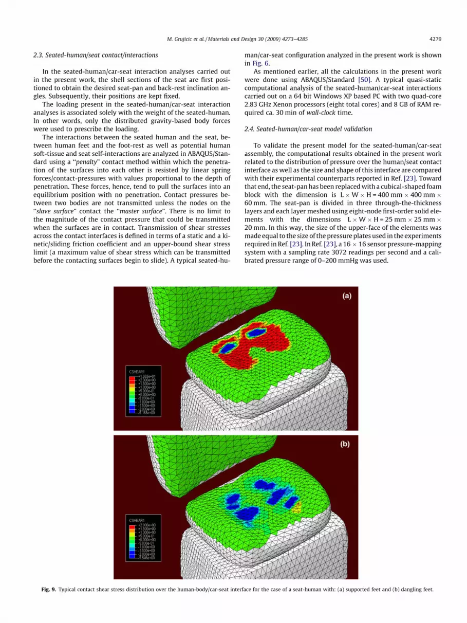
Fig. 9. Typical contact shear stress distribution over the human-body/car-seat interf
man/car-seat configuration analyzed in the present work is shownin Fig. 6.
As mentioned earlier, all the calculations in the present workwere done using ABAQUS/Standard [50]. A typical quasi-staticcomputational analysis of the seated-human/car-seat interactionscarried out on a 64 bit Windows XP based PC with two quad-core2.83 GHz Xenon processors (eight total cores) and 8 GB of RAM re-quired ca. 30 min of wall-clock time.
2.4. Seated-human/car-seat model validation
To validate the present model for the seated-human/car-seatassembly, the computational results obtained in the present workrelated to the distribution of pressure over the human/seat contactinterface as well as the size and shape of this interface are comparedwith their experimental counterparts reported in Ref. [23]. Towardthat end, the seat-pan has been replaced with a cubical-shaped foamblock with the dimension is L �W � H = 400 mm � 400 mm �60 mm. The seat-pan is divided in three through-the-thicknesslayers and each layer meshed using eight-node first-order solid ele-ments with the dimensions L �W � H = 25 mm � 25 mm �20 mm. In this way, the size of the upper-face of the elements wasmade equal to the size of the pressure plates used in the experimentsrequired in Ref. [23]. In Ref. [23], a 16 � 16 sensor pressure-mappingsystem with a sampling rate 3072 readings per second and a cali-brated pressure range of 0–200 mmHg was used.
ace for the case of a seat-human with: (a) supported feet and (b) dangling feet.
4280 M. Grujicic et al. / Materials and Design 30 (2009) 4273–4285
An example of the comparison of the computational andthe experimental results from Ref. [23] is displayed in Fig. 7aand b. Due to copyright restrictions, the experimental resultsreported in Ref. [23], had to be read-off from this reference andre-plotted Fig. 7a. A comparison between the results presented inFig. 7a and b suggest that there is a quite good agreement betweenthe experimental findings and the present modeling approach.Specifically, in both cases the maximum pressure is around30 kPa and it is located under the ischial tuberosities while the over-all size and shape of the contact-surface patches are quite compa-rable. Thus, to a first order of approximation, the present modelcan be relied on for further investigation of seated-human/car-seatinteractions.
3. Results and discussion
The car-seat and the seated-human finite element models (aswell as the seat-cushion and the human soft-tissue material mod-els) developed in the present work and reported in the previoussection and in the Appendix enable preliminary investigation ofcomfort of the seated human. Two specific seating postures wereconsidered: (a) a seating posture in which the feet of the humanwere supported by the foot rest (referred to as the ‘‘supported feetcase”), and (b) a seating posture where the feet were not supportedby the foot rest (referred to as the ‘‘dangling feet case”). The results
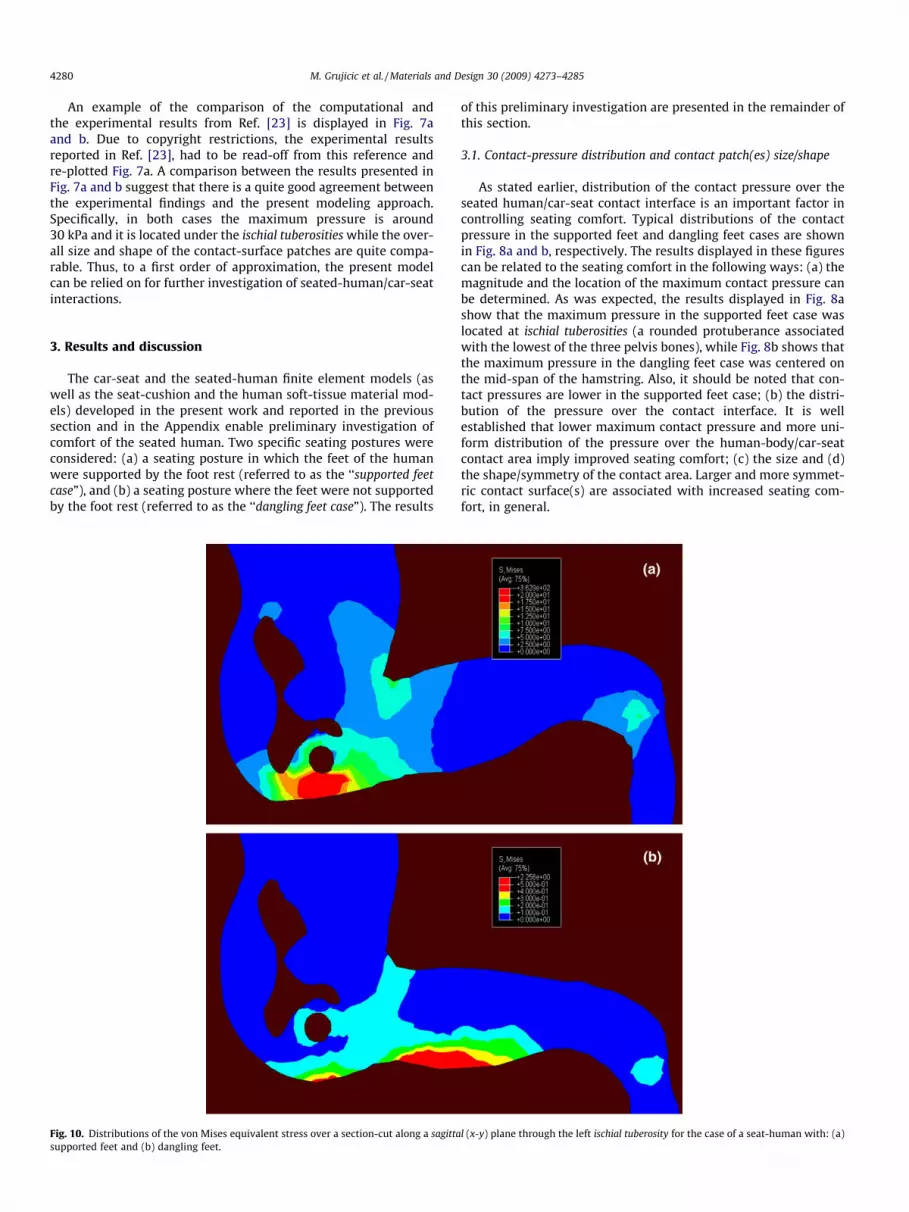
Fig. 10. Distributions of the von Mises equivalent stress over a section-cut along a sagittasupported feet and (b) dangling feet.
of this preliminary investigation are presented in the remainder ofthis section.
3.1. Contact-pressure distribution and contact patch(es) size/shape
As stated earlier, distribution of the contact pressure over theseated human/car-seat contact interface is an important factor incontrolling seating comfort. Typical distributions of the contactpressure in the supported feet and dangling feet cases are shownin Fig. 8a and b, respectively. The results displayed in these figurescan be related to the seating comfort in the following ways: (a) themagnitude and the location of the maximum contact pressure canbe determined. As was expected, the results displayed in Fig. 8ashow that the maximum pressure in the supported feet case waslocated at ischial tuberosities (a rounded protuberance associatedwith the lowest of the three pelvis bones), while Fig. 8b shows thatthe maximum pressure in the dangling feet case was centered onthe mid-span of the hamstring. Also, it should be noted that con-tact pressures are lower in the supported feet case; (b) the distri-bution of the pressure over the contact interface. It is wellestablished that lower maximum contact pressure and more uni-form distribution of the pressure over the human-body/car-seatcontact area imply improved seating comfort; (c) the size and (d)the shape/symmetry of the contact area. Larger and more symmet-ric contact surface(s) are associated with increased seating com-fort, in general.
l (x-y) plane through the left ischial tuberosity for the case of a seat-human with: (a)

M. Grujicic et al. / Materials and Design 30 (2009) 4273–4285 4281
3.2. Distribution of contact shear stresses
As pointed out earlier, conventional experiments aimed atquantifying the interactions between a seated human and a carseat can only deal with normal contact stresses. However, contactshear stresses can also develop at the contact interface(s) (particu-larly in the case when the backrest is reclined backward and thehuman is leaning against it). It is commonly known that prolongedexposure to contact shear stresses can cause soft-tissue trauma inwheel-chair bound disabled people, elderly or diabetic patients. Inthese individuals, the consequences of soft-tissue trauma can bequite severe and can lead to ulcers and tissue necrosis. Whilehealthy individuals with proper skin sensation generally changetheir position/posture before significant tissue trauma occurs, con-tact shear stresses clearly contribute to the perception of seatingdiscomfort in these individuals.
Typical distributions of the longitudinal contact shear stressin the supported feet and dangling feet cases are shown inFig. 9a and b, respectively. It should be noted that the resultsdisplayed in Fig. 9a and b were obtained under the constantstatic friction coefficient condition of 0.5 (corresponding roughlyto the case of a clothed human body sitting on a fabric uphol-stered car seat.) Clearly, in the absence of friction, no contactshear stresses can be developed at the seated-human/car-seatinterface. In should be further observed that somewhat higher
Fig. 11. Distributions of the von Mises equivalent stress over a sagittal plane cut througfeet.
longitudinal contact shear stresses exist in the supported feetcase, the case for which the contact normal stresses were foundto be lower.
3.3. Stresses within the human body
The results presented in the previous two sections deal withcontact normal and shear stresses, i.e. with the stresses present atthe seated-human/car-seat contact interfaces. It is generally recog-nized that not only these contact stresses but also the stresses dis-tributed within the human body in the regions adjacent to thecontact interface can greatly contribute to the perception of seatingdiscomfort. While at the present time these in-body stresses cannotbe measured experimentally, they can be readily computed usingfinite element analyses of the human-body/car-seat interactions,like the one developed in the present work. Examples of the com-puted results of in-body stresses are displayed in Figs. 10–12. Inthese figures, the distribution of von Mises equivalent stress overthree vertical sections of the human body model is displayed fortwo seating posture cases. The results displayed in Fig. 10a and bcorrespond to the case of a section-cut along a sagittal (x-y) planethrough the left ischial tuberosity. A comparison of the resultsdisplayed in Fig. 10a and b reveals that the in-body stresses aresomewhat higher and concentrated around the ischial tuberosityin the supported feet case. While, in the dangling feet case, the
h the coccyx for the case of a seat-human with: (a) supported feet, and (b) dangling

4282 M. Grujicic et al. / Materials and Design 30 (2009) 4273–4285
stresses are mainly localized under the hamstring. Fig. 11a and bcorrespond to the case of a sagittal plane cut through the coccyx(the tailbone, i.e. the final segment of the human vertebral column).The results displayed in these Figures show relatively low levels ofthe in-body stresses. This is justified by the fact that there is limitedcontact between the human soft tissue just below the coccyx andthe seat pan, in both seating postures. Fig. 12a and b display thecase of a coronal (y-z) plane cut through the ischial tuberosities. Acomparison of the results displayed in Fig. 12a and b reveal signif-icantly higher in-body stresses for the case of supported feet. Thisfinding is reasonable considering the fact that in the supported feetcase the majority of the human upper-body weight is supported bythe contact interfaces located directly below the ischial tuberosities.
Again, it should be recalled that within the coordinate systemchosen, x-axis is pointing forward, y-axis upward, and z-axis fromleft to right.
3.4. Seating comfort evaluation
To make the results displayed in Figs. 8–12 useful, they shouldbe compared with the (subjective) corresponding results of the hu-man-subjects’ perception of the seating comfort. In such studies,the human-body model should be customized in order to most
Fig. 12. Distributions of the von Mises equivalent stress over a coronal (y–z) plane cut thrdangling feet.
accurately describe the stature, physical build, weight, and thephysical condition of the human test subject in question. Thiscan be done through proper scaling of the generic human-bodymodel like the one developed in the present work.
It should be noted that, as mentioned earlier, maximum mus-cle activity also contributes to the perception of comfort. That is,if the voluntary muscle forces (controlled by the human centralnervous system) required to maintain the given seating postureof the human are higher, then there will be an increased percep-tion of discomfort. At the present time muscles are not treated ascontractile actuation elements within the finite element models,like the one developed in the present work. However, muscleactivities can be computed via the use of musculoskeletal mul-ti-body dynamics programs like AnyBody Modeling System [25].An example of the muscle activation results which can beobtained through the use of the AnyBody Modeling System isshown in Fig. 13. In Fig. 13, muscles are depicted as purple-greylines while the extent of muscle activation can be denoted picto-rially by the extent of muscle bulging. The results shown inFig. 13 were generated in our ongoing musculoskeletal investiga-tion of seating comfort [51]. The two computational approachesto seating comfort analysis, i.e. the finite-element approach andthe musculoskeletal multi-body dynamics approach, will be
ough ischial tuberosities for the case of a seat-human with: (a) supported feet, and (b)

Fig. 13. A musculoskeletal model used in the ongoing AnyBody System Modelinginvestigation of seating comfort [51].
P
h Soft Tissue
a
w
Punch
Rigid Substrate
Fig. A1. Schematic of typical flat-head cylindrical rigid-punch indentation exper-iment used to determine the mechanical properties of soft tissue.
M. Grujicic et al. / Materials and Design 30 (2009) 4273–4285 4283
combined in our future work to construct a seating comfortmetric. The starting point in this effort will be the so-calleddiscomfort function proposed by Rasmussen and de Zee [31]which combines properly-weighted squared total shear force be-tween the seat-pan and the human buttocks and the maximummuscle activity.
4. Summary and conclusions
Based on the results obtained in the present work, the followingmain summary remarks and conclusions can be drawn:
1. In order to investigate seated-human/car-seat interactions andtheir effect on human perception of seating comfort and fatigue,fairly detailed and anatomically correct finite element modelshave been developed for an average male human body and fora prototypical car seat.
2. One of the critical steps in development of the human-bodymodel was a material-modeling of human soft tissue (skin,muscle and fat). This was accomplished through the use of asimple optimization procedure in conjunction with experimen-tal and computational results pertaining to the force vs. dis-placement curves obtained in flat-head cylindrical rigid-punchindentation tests.
3. The seated-human/car-seat assembly was validated by match-ing the available contact pressure experimental results fromthe literature with the computational results obtained in thepresent work.
4. A computational finite-element investigation of the seated-human/car-seat interaction was used to compute a number ofquantities (contact pressure, contact shear stresses, and in-bodystresses) which can be related to the seat-occupant’s perceptionof seating comfort.
Acknowledgements
A portion of the material presented in this paper is based on theuse of the AnyBody Modeling System, a musculoskeletal multi-body dynamics software [25]. The authors are indebted to OzenEngineering for donating an AnyBody Modeling System license toClemson University.
Appendix A. Parameterization of the human soft-tissueMooney–Rivlin hyperelastic material model
It is well-established that human soft-tissue behaves as a non-linear hyperelastic, viscoelastic, anisotropic and inhomogeneousmaterial. To simplify mathematical modeling of the mechanical re-sponse of human soft-tissue (while retaining the physical reality)various assumptions are often utilized. Among these assumptionsthe following will be employed in the present work: (a) initialisotropy; (b) local homogeneity; and (c) time-invariant (i.e. non-viscoelastic) material behavior (mainly due to a lack of reliabledata).
In accordance with the assumptions listed above, soft tissue ismodeled using a Mooney–Rivlin hyperelastic material modelwhich, in accordance with Eqs. (4), (9), and (10) contains threematerial-dependent parameters: A1, A2, and m. These parameterswere determined in the present work by fitting the compression-force vs. compression-strain data obtained in Ref. [48] (using aflat-head cylindrical rigid-punch indentation procedure) to thecorresponding results obtained computationally in the presentwork (via the use of a finite element analysis). Details of this fittingprocedure are described below.
A simple schematic of the flat-head cylindrical rigid-punchindentation soft-tissue mechanical-property characterization testis depicted in Fig. A1. In Fig. A1, the key experimental quantitiesare denoted as: P – indentation force, h – specimen thickness, w– depth of indentation and a – the punch radius.
To determine the three unknown Mooney–Rivlin hyperelasticsoft-tissue material parameters (A1, A2, and m), an axisymmetric fi-nite element model of the flat-head cylindrical rigid-punch inden-tation experiment was constructed, Fig. A2a and b. To ensure thatthe finite-element results are not significantly affected by the meshsize, a mesh-convergence analysis was undertaken for each choiceof material parameters A1, A2, and m. Additional details of the finite-element procedure used are provided below. The (static) finite ele-ment analysis yielded a unique P vs. w/h curve. To determine theoptimal values of A1, A2, and m, the finite-element analysis of theflat-head cylindrical rigid-punch indentation test was coupled witha simple gradient-free Nelder-Mead simplex optimization algo-rithm in which the sum of squares of the differences betweenthe measure and computed indentation force, P, at a given levelof indentation, w, was treated as the objective function and mini-mized. Additional details of the optimization procedure used are
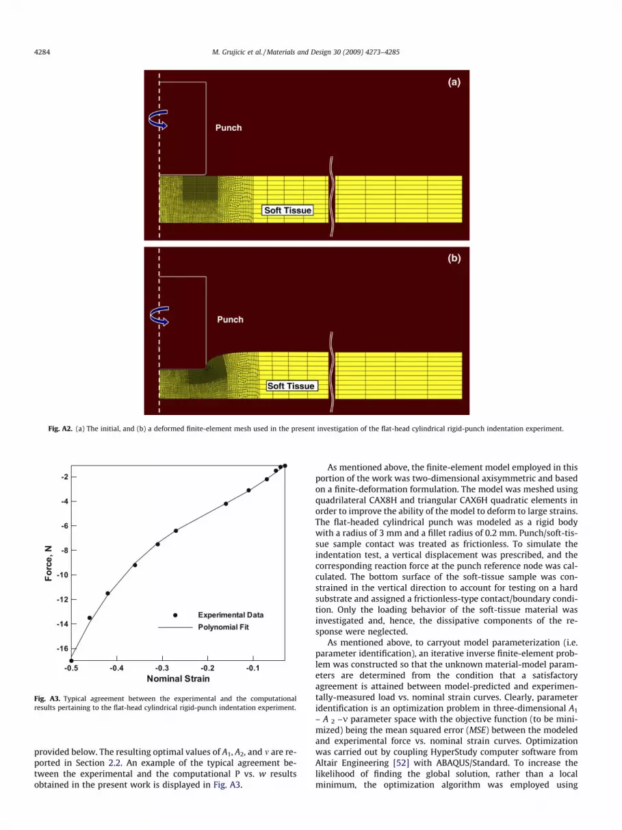
Fig. A2. (a) The initial, and (b) a deformed finite-element mesh used in the present investigation of the flat-head cylindrical rigid-punch indentation experiment.
Nominal Strain
Forc
e,N
-0.5 -0.4 -0.3 -0.2 -0.1
-16
-14
-12
-10
-8
-6
-4
-2
Experimental DataPolynomial Fit
Fig. A3. Typical agreement between the experimental and the computationalresults pertaining to the flat-head cylindrical rigid-punch indentation experiment.
4284 M. Grujicic et al. / Materials and Design 30 (2009) 4273–4285
provided below. The resulting optimal values of A1, A2, and m are re-ported in Section 2.2. An example of the typical agreement be-tween the experimental and the computational P vs. w resultsobtained in the present work is displayed in Fig. A3.
As mentioned above, the finite-element model employed in thisportion of the work was two-dimensional axisymmetric and basedon a finite-deformation formulation. The model was meshed usingquadrilateral CAX8H and triangular CAX6H quadratic elements inorder to improve the ability of the model to deform to large strains.The flat-headed cylindrical punch was modeled as a rigid bodywith a radius of 3 mm and a fillet radius of 0.2 mm. Punch/soft-tis-sue sample contact was treated as frictionless. To simulate theindentation test, a vertical displacement was prescribed, and thecorresponding reaction force at the punch reference node was cal-culated. The bottom surface of the soft-tissue sample was con-strained in the vertical direction to account for testing on a hardsubstrate and assigned a frictionless-type contact/boundary condi-tion. Only the loading behavior of the soft-tissue material wasinvestigated and, hence, the dissipative components of the re-sponse were neglected.
As mentioned above, to carryout model parameterization (i.e.parameter identification), an iterative inverse finite-element prob-lem was constructed so that the unknown material-model param-eters are determined from the condition that a satisfactoryagreement is attained between model-predicted and experimen-tally-measured load vs. nominal strain curves. Clearly, parameteridentification is an optimization problem in three-dimensional A1
– A 2 –m parameter space with the objective function (to be mini-mized) being the mean squared error (MSE) between the modeledand experimental force vs. nominal strain curves. Optimizationwas carried out by coupling HyperStudy computer software fromAltair Engineering [52] with ABAQUS/Standard. To increase thelikelihood of finding the global solution, rather than a localminimum, the optimization algorithm was employed using

M. Grujicic et al. / Materials and Design 30 (2009) 4273–4285 4285
different initial points in the parameter space. An optimizationtermination condition was defined as either a maximum of 1000iterations or the normalized simplex diameter smaller than0.0001. A typical parameter identification analysis carried out ona 64 bit Windows XP based PC with two quad-core 2.83 GHz Xenonprocessors (eight total cores) and 8 GB of RAM required ca. 40 minof wall-clock time.
References
[1] Johansen U, Johren A. Personalekonomi idag. Uppsala Publishing House; 2002.ISBN: 9170052026.
[2] Ebe K, Griffin MJ. Factors effecting static and seat cushion comfort. Ergonomics2001;41(10):901–92.
[3] Inagaki H, Taguchi T, Yasuda E, Iizuka Y. Evaluation of riding comfort: from theviewpoint of interaction of human body and seat for static, dynamic and longtime driving. In: SAE conference, SAE no. 2000-02-0643; 2000.
[4] Kamijo K, Tsujimura H, Obara H, Katsumata M. Evaluation of seating comfort.In: SAE conference, no. 820761; 1982.
[5] Lee J, Grohs T, Milosic M. Evaluation of objective measurement techniques forautomotive seat comfort. In: SAE conference, SAE no. 950142; 1995.
[6] Milvojevich A, Stanciu R, Russ A, Blair GR, van Heumen JD. Investigatingpsychometric and body pressure distribution responses to automotive seatingcomfort. In: SAE conference, SAE no. 2000-01-0626; 2000.
[7] Park SJ, Kim CB. The evaluation of seating comfort by objective measures. In:SAE conference, SAE no. 970595; 1997.
[8] Park SJ, Lee YS, Nahm YE, Lee JW, Kim JS. Seating physical characteristics andsubjective comfort: design considerations. In: SAE conference, SAE no. 980653;1998.
[9] Reed MP, Saito M, Kakishima Y, Lee NS, Schneider LW. An investigation ofdriver discomfort and related seat design factors in extended-duration driving.In: SAE conference, SAE no. 910117; 1991.
[10] Tewari VK, Prasad N. Optimum seat pan and back-rest parameters for acomfortable tractor seat. Ergonomics 2000;43(2):167–86.
[11] Thakurta K, Koester D, Bush N, Bachle S. Evaluating short and long term seatingcomfort. In: SAE conference, SAE no. 950144; 1995.
[12] Uenishi K, Fujihashi K, Imai H. A seat ride evaluation method for transientvibrations. In: SAE conference, SAE no. 2000-01-0641; 2000.
[13] Yun MH, Donjes L, Freivalds A. Using force sensitive resistors to evaluate thedriver seating comfort. Adv Ind Ergon Safety IV 1992:403–10.
[14] Zhao LQ, Xia QS, Wu XT. Study of sitting comfort of automotive seats. SAEconference, SAE no. 945243; 1994.
[15] Bader DL, Bowder P. Mechanical characteristics of skin and underlying tissuesin vivo. Biomaterials 1980;4:305–8.
[16] Oomens CWJ, Bosboom EMH, Bressers OFJT, Bouten CVC, Bader DL. Can loadedinterface characteristics influence strain distribution in muscles adjacent tobony prominences. Comput Methods Biomech Eng 2003;6(3):171–80.
[17] Bader DL, Bowder P. Ischial pressure distribution under the seated person. In:Bader DL, editor. Pressure stores – clinical practice and scientific approach;1990. p. 223–33.
[18] Bennett L, Kauver D, Lee BY, Trainor FA. Shear vs. pressure as causative factorsin skin blood flow occlusion. Arch Phys Med Rehab 1979;60:309–14.
[19] Chow WW, Odell EI. Deformation and stresses in soft body tissues of a sittingperson. J Biomech Eng 1978;100:79–87.
[20] Krouskop TA, Garber SL, Noble P. Pressure management and the recumbentperson. In: Bader DL editor. Pressure sores – clinical practice and scientificapproach; 1990. p. 235–48.
[21] Reichel SM. shear force as a factor in decubitus ulcers in paraplegics. J Am MedAssoc 1958;166:762–3.
[22] Scales J. Pressure sore prevention. Care Sci Pract 1982;1:9–17.[23] Verver MM, van Hoof J, Oomens CW, Wismans JS, Baaijens FP. A finite element
model of the human buttocks for prediction of seat pressure distributions.Comput Methods Biomech Biomed Eng 2004;7:193–203.
[24] Langsfeld M, Frank A, van Deursen DL, Griss P. Lumbar spine curvature duringoffice chair sitting. Med Eng Phys 2000;22:665–9.
[25] AnyBody 3.1. Aalborg, Denmark: AnyBody Technology A/S; 2008.[26] Damsgaard M, Rasmussen J, Christensen ST, Surma E, de Zee M. Analysis of
musculoskeletal systems in the anybody modeling system. Simulat ModelPract Theory 2006;14:1100–11.
[27] Mandal AC. The seated man (homosedens) – the seated work position: theoryand practice. Appl Ergonom 1984;12:19–26.
[28] Mandal AC. The influence of furniture height on back pain. Behav InformTechnol 1987;6:347–52.
[29] Karlsson D, Osvalder A-L, Rasmussen J. Towards better seating design – adiscussion and comparison between office chairs and car seats. In: Proceedingsof the 39th nordic ergonomics society conference, Sweden; 2007.
[30] Rasmussen J, de Zee M, Torholm S. Muscle relaxation and shear force reductionmay be conflicting: a computational model of seating. In: SAE conference, SAEno. 2007-01-2456; 2007.
[31] Rasmussen J, de Zee M. Design optimization of airline seats. In: SAEconference, SAE no. 2008-01-1863; 2008.
[32] Rasmussen J, Torholm S, de Zee M. Computational analysis of the influence ofseat pan inclination and friction on muscle activity and spinal joint forces. Int JInd Ergonom 2009;39:52–7.
[33] Brosch T, Arcan M. Modeling the body/chair interaction – an integrativeexperimental–numerical approach. Clin Biomech 2000;15:217–9.
[34] Dabnichki PA, Crocombe AD, Hughes SC. Deformation and stress analysis ofsupported buttock contact. Proc Inst Mech Eng. J Eng Med 1995;208:9–17.
[35] Todd BA, Thacker JG. Three dimensional computer model of human buttocksin-vivo. J Rehab Res Dev 1994;31(2):111–9.
[36] Besnault B, Guillemot H, Robin S, Lavaste F. A parameteric finite element (FE)model of the human pelvis. In: Proceedings of the 42nd STAPP car crashconference, SAE no. 983147; November 1998. p. 33–46.
[37] Hoof J, van Happee R, Meijer R, Bours R. MADYMO FE human body model forautomotive impact conditions. In: Proceedings of the JSAE spring convention,no. 20015336; 2001.
[38] Lizee E, Robin S, Song E, Bertholon N, Le coz JY, Besnault B. Development of a3D finite element (FE) model of the human body. In: Proceedings of the 42ndSTAPP car crash conference, SAE no. 983152; November 1998.
[39] Moens, Horvath. Using finite element models of the human body for shapeoptimization of seats: optimization material properties. In: Proceedings of theinternational design conference, Dubrovnik, Yugoslavia; 2002.
[40] CATIA V5. Vélizy-Villacoublay, France: Dassault Systemes Inc.; 2009.[41] HyperWorks 9.0. Troy (MI, USA): Altair Engineering Inc.; 2009.[42] AnyScript Model Repository 7.1. AnyBody 3.0. Aalborg, Denmark: AnyBody
Technology A/S; 2009.[43] Summer F. Model no. 1045. Hampshire (UK): 3D Club; 2009.
<www.3Dcadbrowser.com>.[44] Hendricks FM, Brokken D, Oomens CWJ, Baaijens FPT, Horsten JBAM. A
numerical–experimental method to characterize the non-linear mechanicalbehavior of human skin. Skin Res Technol 2003;9:274–83.
[45] Adams D, Morgan GB, Nghi T, Salloum MJ, O’Bannon T. Creating a biofidelicseating surrogate. In: SAE conference no. 1999-01-0627; 1999.
[46] Bosboom EMH, Hesselink MKC, Oomens CWJ, Bouten CVC, Drost MR, BaaijensFPT. Passive transverse mechanical properties of skeletal muscle under in-vivocompression. J Biomech 2001;34:1365–8.
[47] Setyabudhi RS, Ali A, Hubbard RP, Beckett C, Averill RC. Measuring andmodeling of human soft tissue and seat interaction. In: SAE conference, SAE no.970593; 1997.
[48] ASTM D 3574 Document Information. Standard test methods for flexiblecellular materials—slab, bonded, and molded urethane foams. ASTMInternational; July 1, 2008.
[49] Zhang M, Zheng YP, Mak AF. Estimating the effective young’s modulus ofsofttissues from indentation tests – nonlinear finite element analysis of effectsof friction and large deformation. Med. Eng. Phys. 1997;19:512–7.
[50] ABAQUS version 6.8-1. User documentation. Dassault Systems; 2008.[51] Grujicic M. Clemson University; February 2009 [Work in Progress].[52] HyperStudy user manual. Troy (MI): Altair Engineering Inc.; 2009.


