Embed Size (px)
Citation preview
Inst
alla
tion
and
Ope
ratio
n G
uide
MDS 05-3490A01, Rev. DJUNE 2005
MDS P70
SCADA-Telemetry Series
Universal Package Model
QUICK START GUIDE
Below are the basic steps for installing the MDS P70 Packaged Radio System. Detailed installa-tion instructions are given in this manual starting on Page 12.
1. Install transceivers (if not already installed) and customer-supplied equipment, if any
• Open the P70 enclosure.• Place the transceiver(s) in the mounting bracket (transceiver front panel and heatsink facing out).• Secure the bracket.• Install customer-supplied equipment. See “Product Specifications” on Page 4 for mounting plate
dimensions.
2. Connect wiring
• Connect ground, antenna feedline(s), data interface, power, and any alarm circuits. Installation wir-ing is described fully in
Cable Connections
on Page 17.
3. Connect Backup Battery
• Battery is disconnected during shipment to avoid discharge.• Plug battery cable into J3 on the Power Board.
4. Apply primary power (see label on power supply for proper input voltage)
5. Configure the P-70 for desired operation
• In many cases, the P70 is shipped with the internal radios already configured for customer require-ments. If so, no further configuration is required.
• If radio configuration is required, program each transceiver with a terminal connected to the DIAG. modular connector (RJ-12) or the DATA INTERFACE (DB-25) connector. (If DB-25 is used, you must first remove the ribbon cable leading to the P70 Logic Board.) See transceiver manual for a list of radio commands.
• Set Logic Board DIP switches as required (See
Field Configuration of the P70
on Page 25).• Record all parameters on a label and affix to the chassis.
6. Verify proper operation
• Observe LEDs on transceiver front panel(s).• Refer to the transceiver manual for a description of the status LEDs.• Refine directional antenna headings for maximum received signal strength using the
RSSI
com-mand. (Spread spectrum remotes must be synchronized with the master station for use of this com-mand.)
Refer to the transceiver manual shipped with your P70 for radio-specific information.
MDS 05-3490A01, Rev. D P70 I/O Guide i
TABLE OF CONTENTS
1.0 INTRODUCTION.....................................................................................1
2.0 PRODUCT DESCRIPTION.....................................................................1
2.1 Model Number Codes & Features ....................................................2Mounting Configurations ...................................................................2Transceiver Complement ..................................................................3Power Supplies .................................................................................3Logic Boards .....................................................................................3Duplexer............................................................................................3
2.2 Options and Accessories .................................................................42.3 Product Specifications ......................................................................42.4 Functional Configurations ................................................................5
➊
Single Remote ..............................................................................6
➋
Duplex MAS Remote/Master/Polling Remote ...............................7
➌
Duplex MAS Repeater ..................................................................8
➍
Tail-End Link Repeater ..................................................................9
➎
&
➏
Peer-to-Peer Repeater/Spread Spectrum Repeater ............10
➐
Dual RTU Interface......................................................................11
➑
Redundant Remote.....................................................................11
3.0 INSTALLATION .....................................................................................12
3.1 Unpacking and Inspection ..............................................................123.2 Installation Considerations .............................................................123.3 Mounting the Enclosure .................................................................13
Wall Mounting Instructions..............................................................14Pole Mounting Instructions..............................................................15Rack Mount Option .........................................................................16
3.4 Cable Connections .........................................................................17Ground Connection.........................................................................18Connections to the Power Board (03-3950A01) .............................18Antenna Cable Connection .............................................................19
3.5 Logic Board Connections ...............................................................20Connections to Interface Logic Board (ILB) ....................................20Connections to Redundant Logic Board (RLB)...............................23
3.6 Field Configuration of the P70 ........................................................25Logic Board DIP Switch Settings (ILB) ...........................................26SW1 & SW2 Switch Functions (ILB) ...............................................29Data Synchronizer Board (03-1389A01).........................................30VOX Board (03-1098A03) ...............................................................32Radio Configuration ........................................................................33
3.7 Final Installation Tasks ...................................................................34
ii P70 I/O Guide MDS 05-3490A01, Rev. D
4.0 OPERATION .........................................................................................35
4.1 Introduction ....................................................................................354.2 Initial Power-up ...............................................................................35
Radio Selection Switch—Redundant units only..............................35Battery Backup Operation—AC-powered units only .......................36
4.3 Logic Board Features and Indicators .............................................384.4 Connecting an Orderwire Handset .................................................384.5 Connecting a Hand-Held Terminal (HHT) ......................................39
HHT Connection .............................................................................39
5.0 MAINTENANCE ....................................................................................40
5.1 Preventive Maintenance .................................................................405.2 Backup Battery—AC-powered units ...............................................40
Battery Test .....................................................................................40Backup Battery Replacement .........................................................41Battery Charging Check..................................................................41
5.3 Fuse Replacement .........................................................................425.4 Troubleshooting ..............................................................................435.5 Interpreting Alarms .........................................................................44
Interface Logic Board (03-3900A02)...............................................44Redundant Logic Board (03-3306A02) ...........................................44
5.6 P70 Interconnect Cabling ...............................................................455.7 Replaceable Assemblies ................................................................46
Copyright Notice
This Installation and Operation Guide and all software described herein are protected by
Copyright: 2005 Microwave Data Systems Inc.
All rights reserved.
Microwave Data Systems Inc. reserves its right to correct any errors and omissions in this publication.
Operational Safety Notices
The radio equipment described in this guide emits radio frequency energy. Although the power level is low, the concentrated energy from a directional antenna may pose a health hazard. Do not allow people to come in close proximity to the antenna when the transmitter is oper-ating. Refer to the transceiver manual supplied with your P70 for further recommendations.
This manual is intended to guide a professional installer to install, operate and perform basic system maintenance on the described radio.
RF Exposure

MDS 05-3490A01, Rev. D P70 I/O Guide iii
ISO 9001 Registration
Microwave Data Systems adheres to this internationally accepted quality system standard.
Quality Policy Statement
We, the employees of Microwave Data Systems Inc., are committed to understanding and exceeding our customer’s needs and expectations.
• We appreciate our customer’s patronage. They are our business.
• We promise to serve them and anticipate their needs.
• We are committed to providing solutions that are cost effective, innovative and reliable, with consistently high levels of quality.
• We are committed to the continuous improvement of all of our systems and processes, to improve product quality and increase customer satisfaction.
Revision Notice
While every reasonable effort has been made to ensure the accuracy of this manual, product improvements may result in minor differences between the manual and the product shipped to you. If you have addi-tional questions or need an exact specification for a product, please con-tact our Customer Service Team using the information at the back of this guide. In addition, manual updates can often be found on our Web site at
www.microwavedata.com
.
FCC Warning
In the U.S.A., the 406 to 406.1 MHz band is reserved for use by distress beacons. Since some models of this product are capable of transmitting in this band, take precautions to prevent the radio from transmitting between 406 to 406.1 MHz for U.S. applications.
Environmental Information
The manufacture of this equipment has required the extraction and use of natural resources. Improper disposal may contaminate the environ-ment and present a health risk due to hazardous substances contained within. To avoid dissemination of these substances into our environ-ment, and to diminish the demand on natural resources, we encourage you to use the appropriate recycling systems for disposal. These systems will reuse or recycle most of the materials found in this equipment in a sound way. Please contact MDS or your supplier for more information on the proper disposal of this equipment.

iv P70 I/O Guide MDS 05-3490A01, Rev. D
MDS 05-3490A01, Rev. D P70 I/O Guide 1
1.0 INTRODUCTION
This guide explains how to install and operate the P70 Universal Package Model radio system. It is a companion to the transceiver instruction manual that is shipped with our Package Models. Following installation, we suggest that you keep this manual and the transceiver manual near the equipment for future reference.
NOTE:
Remember that this is a
system level
guide to the PackagedRadio System. Radio model numbers, and information aboutspecific radios installed in the P70 are
not
included unlessthere is an exception to installation or operation. For specificradio information, always refer to the transceiver manual
shipped with your P70.
2.0 PRODUCT DESCRIPTION
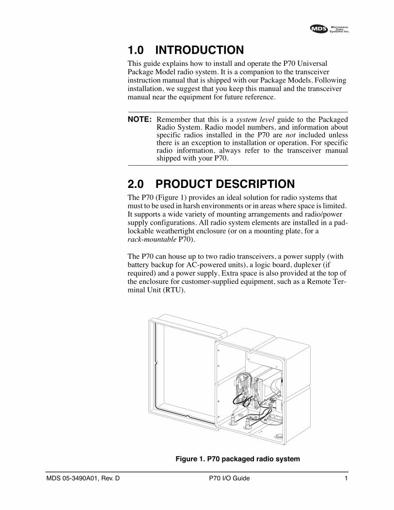
The P70 (Figure 1) provides an ideal solution for radio systems that must to be used in harsh environments or in areas where space is limited. It supports a wide variety of mounting arrangements and radio/power supply configurations. All radio system elements are installed in a pad-lockable weathertight enclosure (or on a mounting plate, for a
rack-mountable
P70).
The P70 can house up to two radio transceivers, a power supply (with battery backup for AC-powered units), a logic board, duplexer (if required) and a power supply. Extra space is also provided at the top of the enclosure for customer-supplied equipment, such as a Remote Ter-minal Unit (RTU).
Invisible place holder
Figure 1. P70 packaged radio system
2 P70 I/O Guide MDS 05-3490A01, Rev. D
The only customer connections required for P70 operation are primary power, antenna and data cabling. These connections are made inside the P70 enclosure leaving no terminals exposed to rain, moisture or corro-sive environments.
2.1 Model Number Codes & Features
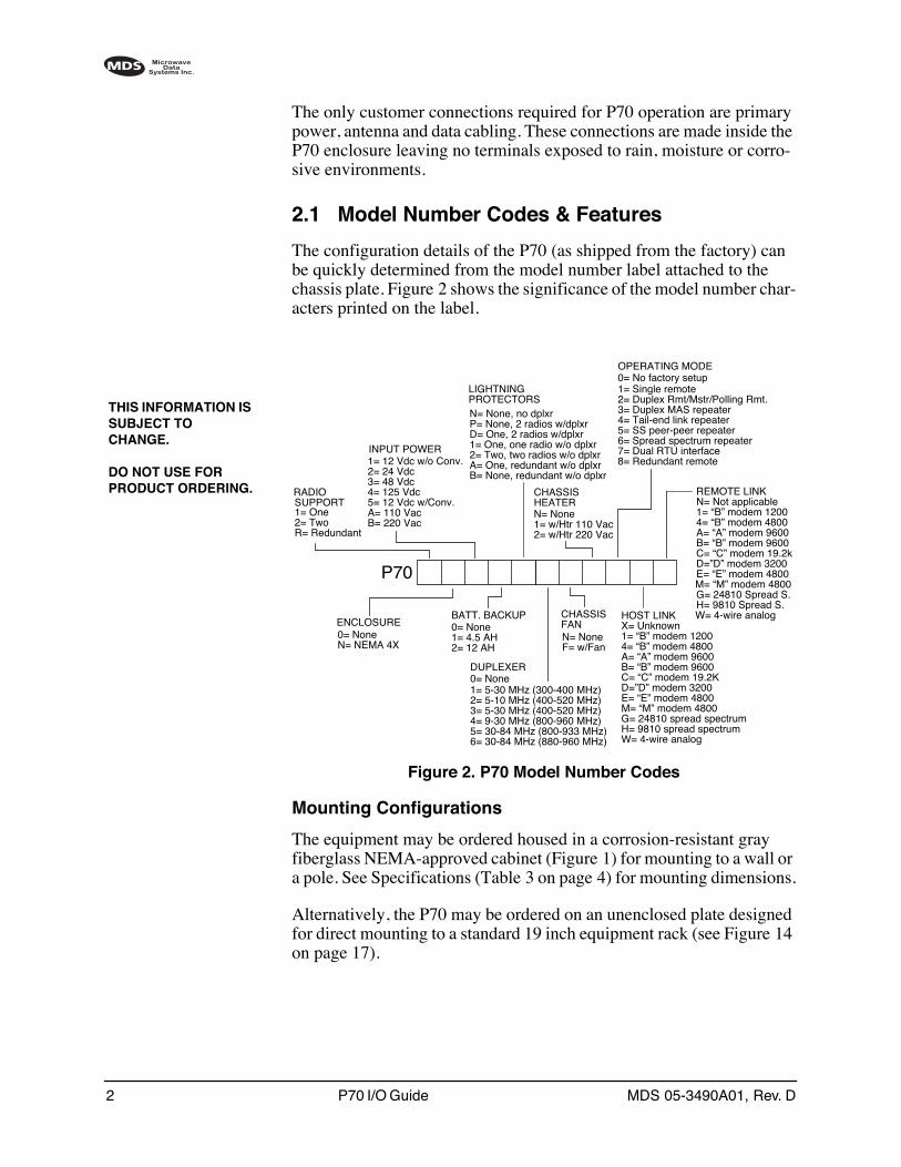
The configuration details of the P70 (as shipped from the factory) can be quickly determined from the model number label attached to the chassis plate. Figure 2 shows the significance of the model number char-acters printed on the label.
Invisible place holder
Figure 2. P70 Model Number Codes
Mounting Configurations
The equipment may be ordered housed in a corrosion-resistant gray fiberglass NEMA-approved cabinet (Figure 1) for mounting to a wall or a pole. See Specifications (Table 3 on page 4) for mounting dimensions.
Alternatively, the P70 may be ordered on an unenclosed plate designed for direct mounting to a standard 19 inch equipment rack (see Figure 14 on page 17).
THIS INFORMATION IS SUBJECT TO CHANGE.
DO NOT USE FOR PRODUCT ORDERING.
P70
RADIO
ENCLOSURE
INPUT POWER1= 12 Vdc w/o Conv.
BATT. BACKUP0= None
DUPLEXER
1= One2= TwoR= Redundant
1= 5-30 MHz (300-400 MHz)0= None
0= NoneN= NEMA 4X
2= 24 Vdc
2= 5-10 MHz (400-520 MHz)
1= 4.5 AH2= 12 AH
3= 48 Vdc4= 125 Vdc5= 12 Vdc w/Conv.A= 110 VacB= 220 Vac
3= 5-30 MHz (400-520 MHz)4= 9-30 MHz (800-960 MHz)5= 30-84 MHz (800-933 MHz)6= 30-84 MHz (880-960 MHz)
LIGHTNING
N= None, no dplxrP= None, 2 radios w/dplxrD= One, 2 radios w/dplxr
PROTECTORS
1= One, one radio w/o dplxr2= Two, two radios w/o dplxrA= One, redundant w/o dplxrB= None, redundant w/o dplxr
CHASSIS
N= NoneF= w/Fan
CHASSIS
N= None1= w/Htr 110 Vac2= w/Htr 220 Vac
HEATER
OPERATING MODE
1= Single remote0= No factory setup
2= Duplex Rmt/Mstr/Polling Rmt.3= Duplex MAS repeater4= Tail-end link repeater5= SS peer-peer repeater6= Spread spectrum repeater7= Dual RTU interface8= Redundant remote
FANHOST LINKX= Unknown1= “B” modem 12004= “B” modem 4800A= “A” modem 9600B= “B” modem 9600C= “C” modem 19.2KD=”D” modem 3200E= “E” modem 4800M= “M” modem 4800G= 24810 spread spectrumH= 9810 spread spectrumW= 4-wire analog
REMOTE LINKN= Not applicable1= “B” modem 12004= “B” modem 4800A= “A” modem 9600B= “B” modem 9600C= “C” modem 19.2kD=”D” modem 3200E= “E” modem 4800M= “M” modem 4800G= 24810 Spread S.H= 9810 Spread S.W= 4-wire analog
SUPPORT
MDS 05-3490A01, Rev. D P70 I/O Guide 3
Transceiver Complement
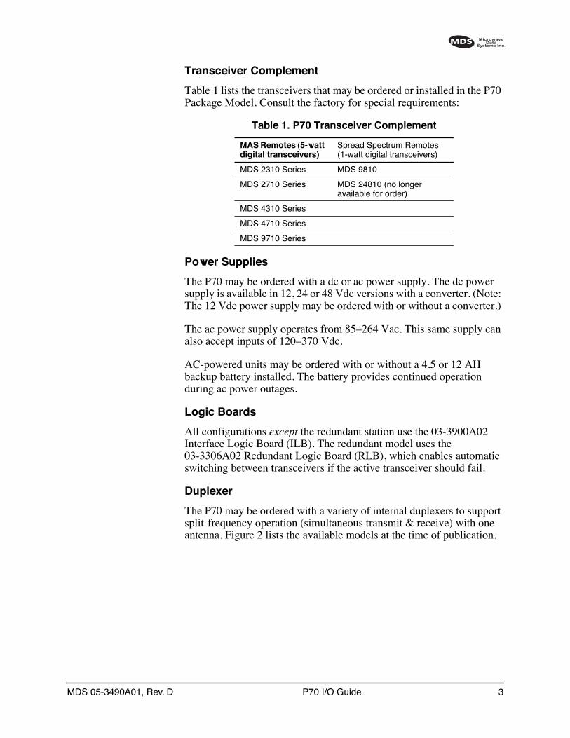
Table 1 lists the transceivers that may be ordered or installed in the P70 Package Model. Consult the factory for special requirements:
Power Supplies
The P70 may be ordered with a dc or ac power supply. The dc power supply is available in 12, 24 or 48 Vdc versions with a converter. (Note: The 12 Vdc power supply may be ordered with or without a converter.)
The ac power supply operates from 85–264 Vac. This same supply can also accept inputs of 120–370 Vdc.
AC-powered units may be ordered with or without a 4.5 or 12 AH backup battery installed. The battery provides continued operation during ac power outages.
Logic Boards
All configurations
except
the redundant station use the 03-3900A02 Interface Logic Board (ILB). The redundant model uses the 03-3306A02 Redundant Logic Board (RLB), which enables automatic switching between transceivers if the active transceiver should fail.
Duplexer
The P70 may be ordered with a variety of internal duplexers to support split-frequency operation (simultaneous transmit & receive) with one antenna. Figure 2 lists the available models at the time of publication.
Table 1. P70 Transceiver Complement
MAS Remotes (5-watt digital transceivers)
Spread Spectrum Remotes (1-watt digital transceivers)
MDS 2310 Series MDS 9810
MDS 2710 Series MDS 24810 (no longer available for order)
MDS 4310 Series
MDS 4710 Series
MDS 9710 Series
4 P70 I/O Guide MDS 05-3490A01, Rev. D
2.2 Options and Accessories
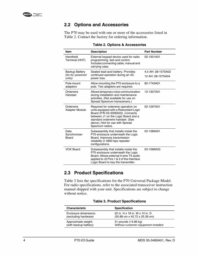
The P70 may be used with one or more of the accessories listed in Table 2. Contact the factory for ordering information.
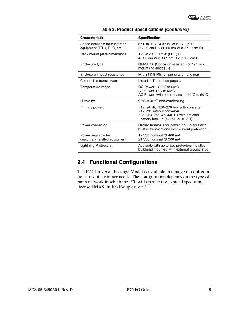
2.3 Product Specifications
Table 3 lists the specifications for the P70 Universal Package Model. For radio specifications, refer to the associated transceiver instruction manual shipped with your unit. Specifications are subject to change without notice.
Table 2. Options & Accessories
Item Description Part Number
Handheld Terminal (HHT)
External keypad device used for radio programming, test and control. Includes connecting cable, manual and carrying case.
02-1501A01
Backup Battery
(for AC-powered units)
Sealed lead-acid battery. Provides continued operation during an AC power loss.
4.5 AH: 28-1575A02
12 AH: 28-1575A04
Pole-mount adapters
Allow mounting the P70 enclosure to a pole. Two adapters are required.
82-1743A01
Orderwire Handset
Allows temporary voice communication during installation and maintenance activities. (Not available for use on Spread Spectrum transceivers.)
12-1307A01
Orderwire Adapter Module
Required for orderwire operation on units equipped with a Redundant Logic Board (P/N 03-3306A02). Connects between J1 on the Logic Board and a standard orderwire handset. (See above.) Not for use with Spread Spectrum radios.
02-1297A01
Data Synchronizer Board
Subassembly that installs inside the P70 enclosure underneath the Logic Board. Improves transmission reliability in 4800 bps repeater configurations.
03-1389A01
VOX Board Subassembly that installs inside the P70 enclosure underneath the Logic Board. Allows external 4-wire TX audio applied to J5 Pins 1 & 2 of the Interface Logic Board to key the transmitter.
03-1098A03
Table 3. Product Specifications
Characteristic Specification
Enclosure dimensions:(excluding hardware)
22 in. H x 18 in. W x 10 in. D(55.88 cm x 45.72 x 25.39 cm)
Approximate weight:(with backup battery)
31 pounds (14.86 kg)
Without customer equipment installed
MDS 05-3490A01, Rev. D P70 I/O Guide 5
2.4 Functional Configurations
The P70 Universal Package Model is available in a range of configura-tions to suit customer needs. The configuration depends on the type of radio network in which the P70 will operate (i.e., spread spectrum, licensed MAS, full/half-duplex, etc.)
Space available for customer equipment (RTU, PLC, etc.)
6.90 in. H x 14.37 in. W x 8.70 in. D(17.50 cm H x 36.50 cm W x 22.00 cm D)
Rack mount plate dimensions 19” W x 15” D x 9” (6RU) H48.26 cm W x 38.1 cm D x 22.86 cm H
Enclosure type NEMA 4X (Corrosion resistant) or 19” rack mount (no enclosure).
Enclosure impact resistance MIL STD 810E (shipping and handling)
Compatible transceivers Listed in Table 1 on page 3
Temperature range DC Power: –30°C to 60°CAC Power: 0°C to 60°CAC Power (w/internal heater): –40°C to 60°C
Humidity: 95% at 40°C non-condensing
Primary power: • 12, 24, 48, 120–370 Vdc with converter• 12 Vdc without converter• 85–264 Vac, 47–440 Hz with optional battery backup (4.5 AH or 12 AH).
Power connector Barrier terminals for power input/output with built-in transient and over-current protection
Power available for customer-installed equipment
12 Vdc nominal @ 400 mA24 Vdc nominal @ 300 mA
Lightning Protectors Available with up to two protectors installed, bulkhead mounted, with external ground stud
Table 3. Product Specifications (Continued)
Characteristic Specification
6 P70 I/O Guide MDS 05-3490A01, Rev. D
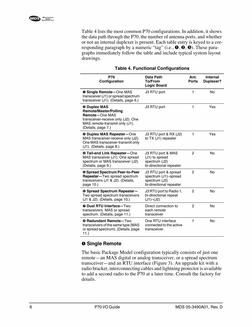
Table 4 lists the most common P70 configurations. In addition, it shows the data path through the P70, the number of antenna ports, and whether or not an internal duplexer is present. Each table entry is keyed to a cor-responding paragraph by a numeric “tag” (i.e., ➊, ➋, ➌). These para-graphs immediately follow the table and include typical system layout drawings.
➊ Single Remote
The basic Package Model configuration typically consists of just one remote—an MAS digital or analog transceiver, or a spread spectrum transceiver—and an RTU interface (Figure 3). An upgrade kit with a radio bracket, interconnecting cables and lightning protector is available to add a second radio to the P70 at a later time. Consult the factory for details.
Table 4. Functional Configurations
P70Configuration
Data PathTo/FromLogic Board
Ant.Ports
InternalDuplexer?
➊ Single Remote—One MAS transceiver (J1) or spread spectrum transceiver (J1). (Details, page 6.)
J3 RTU port 1 No
➋ Duplex MAS Remote/Master/Polling Remote—One MAS transceiver-receive only (J2). One MAS remote-transmit only (J1). (Details, page 7.)
J3 RTU port 1 Yes
➌ Duplex MAS Repeater—One MAS transceiver-receive only (J2). One MAS transceiver-transmit only (J1). (Details, page 8.)
J3 RTU port & RX (J2) to TX (J1) repeater
1 Yes
➍ Tail-end Link Repeater—One MAS transceiver (J1). One spread spectrum or MAS transceiver (J2). (Details, page 9.)
J3 RTU port & MAS (J1) to spread spectrum (J2) bi-directional repeater
2 No
➎ Spread Spectrum Peer-to-Peer Repeater—Two spread spectrum transceivers (J1 & J2). (Details, page 10.)
J3 RTU port & spread spectrum (J1)–spread spectrum (J2) bi-directional repeater
2 No
➏ Spread Spectrum Repeater—Two spread spectrum transceivers (J1 & J2). (Details, page 10.)
J3 RTU port to Radio 1, bi-directional repeat (J1)–(J2)
2 No
➐ Dual RTU Interface—Two transceivers. MAS or spread spectrum. (Details, page 11.)
Direct connection to each remote transceiver
2 No
➑ Redundant Remote—Two transceivers of the same type (MAS or spread spectrum). (Details, page 11.)
One RTU interface connected to the active transceiver.
1 No
MDS 05-3490A01, Rev. D P70 I/O Guide 7
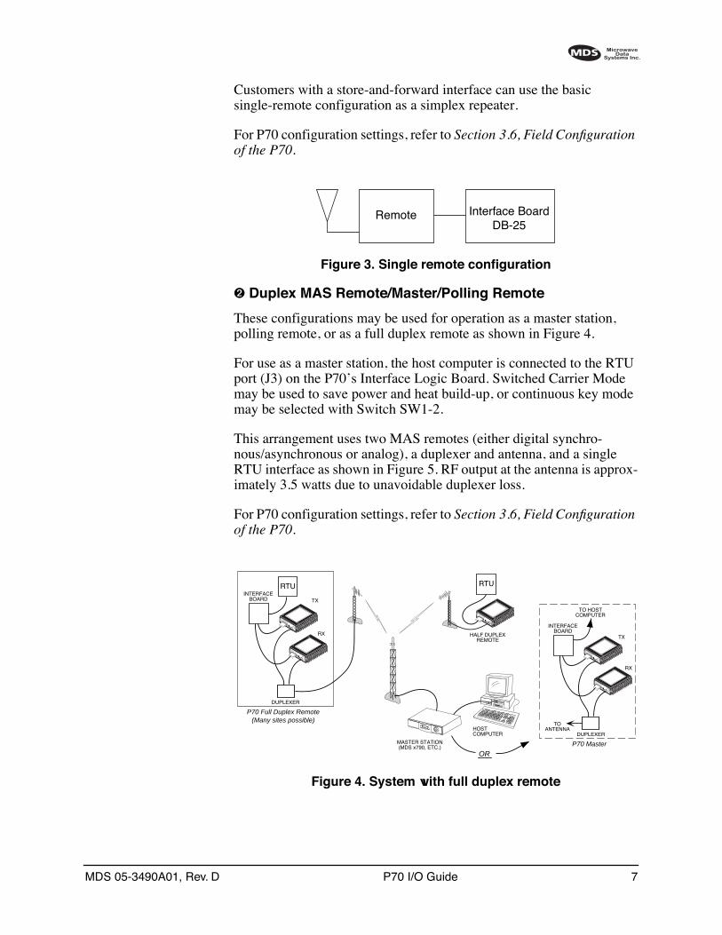
Customers with a store-and-forward interface can use the basic single-remote configuration as a simplex repeater.
For P70 configuration settings, refer to Section 3.6, Field Configuration of the P70.
Invisible place holder
Figure 3. Single remote configuration
➋ Duplex MAS Remote/Master/Polling Remote
These configurations may be used for operation as a master station, polling remote, or as a full duplex remote as shown in Figure 4.
For use as a master station, the host computer is connected to the RTU port (J3) on the P70’s Interface Logic Board. Switched Carrier Mode may be used to save power and heat build-up, or continuous key mode may be selected with Switch SW1-2.
This arrangement uses two MAS remotes (either digital synchro-nous/asynchronous or analog), a duplexer and antenna, and a single RTU interface as shown in Figure 5. RF output at the antenna is approx-imately 3.5 watts due to unavoidable duplexer loss.
For P70 configuration settings, refer to Section 3.6, Field Configuration of the P70.
Invisible place holder
Figure 4. System with full duplex remote
Remote Interface BoardDB-25
RTU
–
I D I A G 13.8 VDC
P W R
+ –
–
I D I A G 13.8 VDC
P W R
+ –
–
I D I A G 13.8 VDC
P W R
+ –
DUPLEXER
INTERFACEBOARD
RTU
P70 Full Duplex Remote(Many sites possible)
TX
RX
MASTER STATION(MDS x790, ETC.)
HOSTCOMPUTER
–
I D I A G 13.8 VDC
P W R
+ –
–
I D I A G 13.8 VDC
P W R
+ –
DUPLEXER
INTERFACEBOARD
P70 Master
TOANTENNA
TX
RX
TO HOSTCOMPUTER
OR
HALF DUPLEXREMOTE
8 P70 I/O Guide MDS 05-3490A01, Rev. D
Invisible place holder
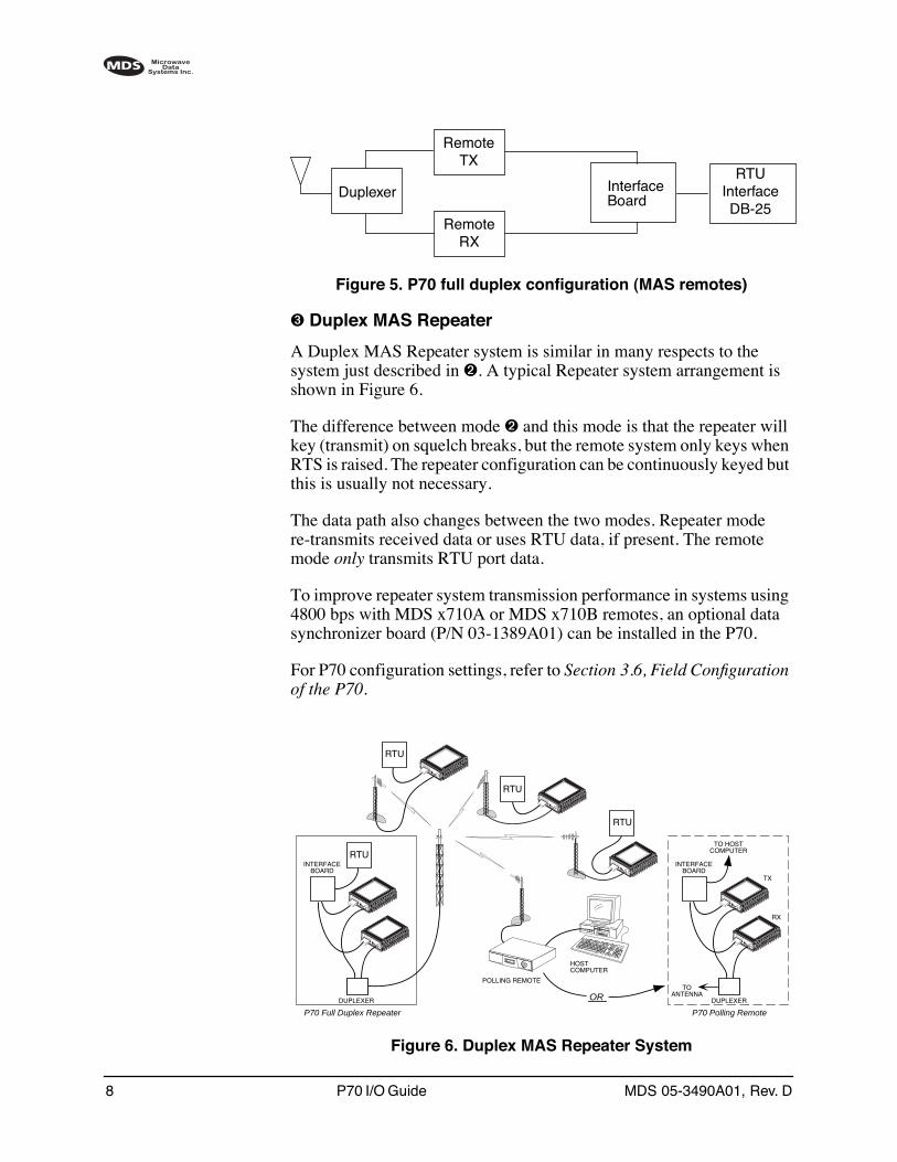
Figure 5. P70 full duplex configuration (MAS remotes)
➌ Duplex MAS Repeater
A Duplex MAS Repeater system is similar in many respects to the system just described in ➋. A typical Repeater system arrangement is shown in Figure 6.
The difference between mode ➋ and this mode is that the repeater will key (transmit) on squelch breaks, but the remote system only keys when RTS is raised. The repeater configuration can be continuously keyed but this is usually not necessary.
The data path also changes between the two modes. Repeater mode re-transmits received data or uses RTU data, if present. The remote mode only transmits RTU port data.
To improve repeater system transmission performance in systems using 4800 bps with MDS x710A or MDS x710B remotes, an optional data synchronizer board (P/N 03-1389A01) can be installed in the P70.
For P70 configuration settings, refer to Section 3.6, Field Configuration of the P70.
Invisible place holder
Figure 6. Duplex MAS Repeater System
RemoteTX
RemoteRX
RTUInterfaceDB-25
Duplexer InterfaceBoard
RTU
–
I D I A G 13.8 VDC
P W R
+ –
RTU
–
I D I A G 13.8 VDC
P W R
+ –
–
I D I A G 13.8 VDC
P W R
+ –
RTU
POLLING REMOTE
HOSTCOMPUTER
–
I D I A G 13.8 VDC
P W R
+ –
–
I D I A G 13.8 VDC
P W R
+ –
DUPLEXER
INTERFACEBOARD
RTU
P70 Full Duplex Repeater
–
I D I A G 13.8 VDC
P W R
+ –
–
I D I A G 13.8 VDC
P W R
+ –
DUPLEXER
INTERFACEBOARD
P70 Polling Remote
ORTO
ANTENNA
TX
RX
TO HOSTCOMPUTER
MDS 05-3490A01, Rev. D P70 I/O Guide 9
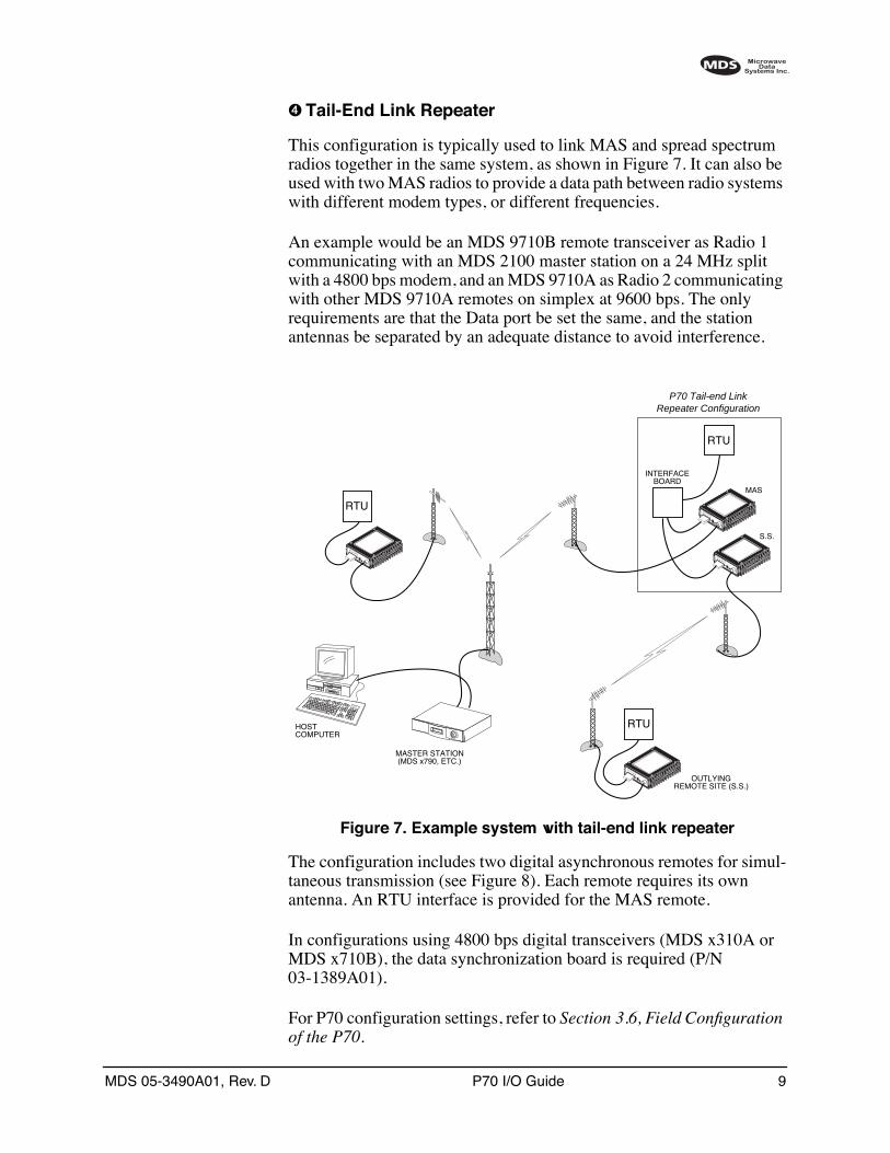
➍ Tail-End Link Repeater
This configuration is typically used to link MAS and spread spectrum radios together in the same system, as shown in Figure 7. It can also be used with two MAS radios to provide a data path between radio systems with different modem types, or different frequencies.
An example would be an MDS 9710B remote transceiver as Radio 1 communicating with an MDS 2100 master station on a 24 MHz split with a 4800 bps modem, and an MDS 9710A as Radio 2 communicating with other MDS 9710A remotes on simplex at 9600 bps. The only requirements are that the Data port be set the same, and the station antennas be separated by an adequate distance to avoid interference.
Invisible place holder
Figure 7. Example system with tail-end link repeater
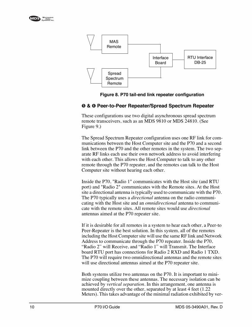
The configuration includes two digital asynchronous remotes for simul-taneous transmission (see Figure 8). Each remote requires its own antenna. An RTU interface is provided for the MAS remote.
In configurations using 4800 bps digital transceivers (MDS x310A or MDS x710B), the data synchronization board is required (P/N 03-1389A01).
For P70 configuration settings, refer to Section 3.6, Field Configuration of the P70.
MASTER STATION(MDS x790, ETC.)
HOSTCOMPUTER
–
I D I A G 13.8 VDC
P W R
+ –
–
I D I A G 13.8 VDC
P W R
+ –
–
I D I A G 13.8 VDC
P W R
+ –
INTERFACEBOARD
P70 Tail-end LinkRepeater Configuration
MAS
S.S.
–
I D I A G 13.8 VDC
P W R
+ –
OUTLYINGREMOTE SITE (S.S.)
RTU
RTU
RTU
10 P70 I/O Guide MDS 05-3490A01, Rev. D
Invisible place holder
Figure 8. P70 tail-end link repeater configuration
➎ & ➏ Peer-to-Peer Repeater/Spread Spectrum Repeater
These configurations use two digital asynchronous spread spectrum remote transceivers, such as an MDS 9810 or MDS 24810. (See Figure 9.)
The Spread Spectrum Repeater configuration uses one RF link for com-munications between the Host Computer site and the P70 and a second link between the P70 and the other remotes in the system. The two sep-arate RF links each use their own network address to avoid interfering with each other. This allows the Host Computer to talk to any other remote through the P70 repeater, and the remotes can talk to the Host Computer site without hearing each other.
Inside the P70, "Radio 1" communicates with the Host site (and RTU port) and "Radio 2" communicates with the Remote sites. At the Host site a directional antenna is typically used to communicate with the P70. The P70 typically uses a directional antenna on the radio communi-cating with the Host site and an omnidirectional antenna to communi-cate with the remote sites. All remote sites would use directional antennas aimed at the P70 repeater site.
If it is desirable for all remotes in a system to hear each other, a Peer-to Peer-Repeater is the best solution. In this system, all of the remotes including the Host Computer site will use the same RF link and Network Address to communicate through the P70 repeater. Inside the P70, “Radio 2” will Receive, and “Radio 1” will Transmit. The Interface board RTU port has connections for Radio 2 RXD and Radio 1 TXD. The P70 will require two omnidirectional antennas and the remote sites will use directional antennas aimed at the P70 repeater site.
Both systems utilize two antennas on the P70. It is important to mini-mize coupling between these antennas. The necessary isolation can be achieved by vertical separation. In this arrangement, one antenna is mounted directly over the other, separated by at least 4 feet (1.22 Meters). This takes advantage of the minimal radiation exhibited by ver-
MASRemote
SpreadSpectrum Remote
RTU InterfaceDB-25
InterfaceBoard

MDS 05-3490A01, Rev. D P70 I/O Guide 11
tically polarized antennas directly above and below one another. Addi-tional isolation can be achieved for the Spread Spectrum Repeater by changing the antenna polarization to horizontal for the link between the P70 and the Host site.
Figure 9. P70 full duplex repeater (spread spectrum remotes)
For P70 configuration settings, refer to Section 3.6, Field Configuration of the P70.
➐ Dual RTU Interface
This mode is intended for customers who wish to construct a Store and Forward system by connecting their data equipment directly to the DB-25 DATA INTERFACE connectors on the P70 remote transceivers. In this arrangement, an Interface board is furnished, but its only purpose is to supply power to the remote transceivers.
For P70 configuration settings, refer to Section 3.6, Field Configuration of the P70.
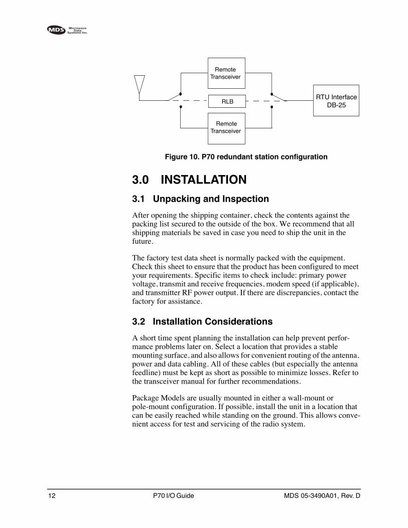
➑ Redundant Remote
A redundant station configuration uses two identical remote trans-ceivers. One remote is active, and the other is used as a standby unit. The configuration is equipped with a single antenna and relay to switch between the two remotes. A single RTU interface is included (Figure 10) as well as a single power supply and optional battery. Redundant stations are typically used in critical applications where uninterrupted service is required.
For P70 configuration settings, refer to Section 3.6, Field Configuration of the P70.
InterfaceBoard
RTU InterfaceDB-25
Spreadspectrum Remote
Spreadspectrum Remote
12 P70 I/O Guide MDS 05-3490A01, Rev. D
Invisible place holder
Figure 10. P70 redundant station configuration
3.0 INSTALLATION
3.1 Unpacking and Inspection
After opening the shipping container, check the contents against the packing list secured to the outside of the box. We recommend that all shipping materials be saved in case you need to ship the unit in the future.
The factory test data sheet is normally packed with the equipment. Check this sheet to ensure that the product has been configured to meet your requirements. Specific items to check include: primary power voltage, transmit and receive frequencies, modem speed (if applicable), and transmitter RF power output. If there are discrepancies, contact the factory for assistance.
3.2 Installation Considerations
A short time spent planning the installation can help prevent perfor-mance problems later on. Select a location that provides a stable mounting surface, and also allows for convenient routing of the antenna, power and data cabling. All of these cables (but especially the antenna feedline) must be kept as short as possible to minimize losses. Refer to the transceiver manual for further recommendations.
Package Models are usually mounted in either a wall-mount or pole-mount configuration. If possible, install the unit in a location that can be easily reached while standing on the ground. This allows conve-nient access for test and servicing of the radio system.
RTU InterfaceDB-25
RemoteTransceiver
RemoteTransceiver
RLB
MDS 05-3490A01, Rev. D P70 I/O Guide 13
If the unit must be installed in a location that is not easily accessible, it may be desirable to first operate the unit on a test bench to verify proper operation with customer-supplied equipment and to set any program-mable parameters before final installation. However, installation tasks such as antenna aiming and SWR checks should be done with the unit in its permanent operating position.
NOTE: The use of stainless steel mounting hardware is recommendedfor outdoor installations.
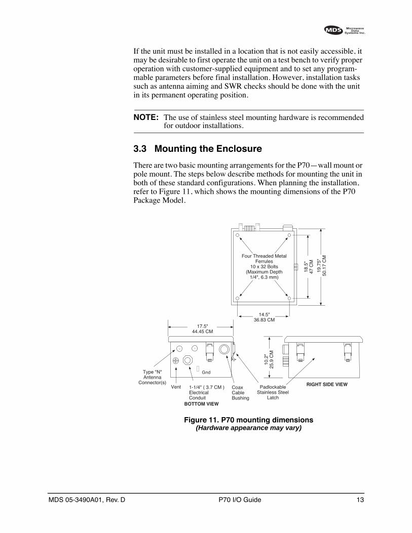
3.3 Mounting the Enclosure
There are two basic mounting arrangements for the P70—wall mount or pole mount. The steps below describe methods for mounting the unit in both of these standard configurations. When planning the installation, refer to Figure 11, which shows the mounting dimensions of the P70 Package Model.
Invisible place holder
Figure 11. P70 mounting dimensions(Hardware appearance may vary)
10.2
"25
.9 C
M
RIGHT SIDE VIEW
17.5"44.45 CM
PadlockableStainless Steel
Latch
CoaxCable Bushing
1-1/4" ( 3.7 CM )Electrical ConduitCoupling
Vent
BOTTOM VIEW
Four Threaded Metal Ferrules
10 x 32 Bolts(Maximum Depth
1/4", 6.3 mm)
19.7
5"50
.17
CM
18.5
"47
CM
14.5"36.83 CM
Type "N"Antenna
Connector(s)
Gnd
14 P70 I/O Guide MDS 05-3490A01, Rev. D
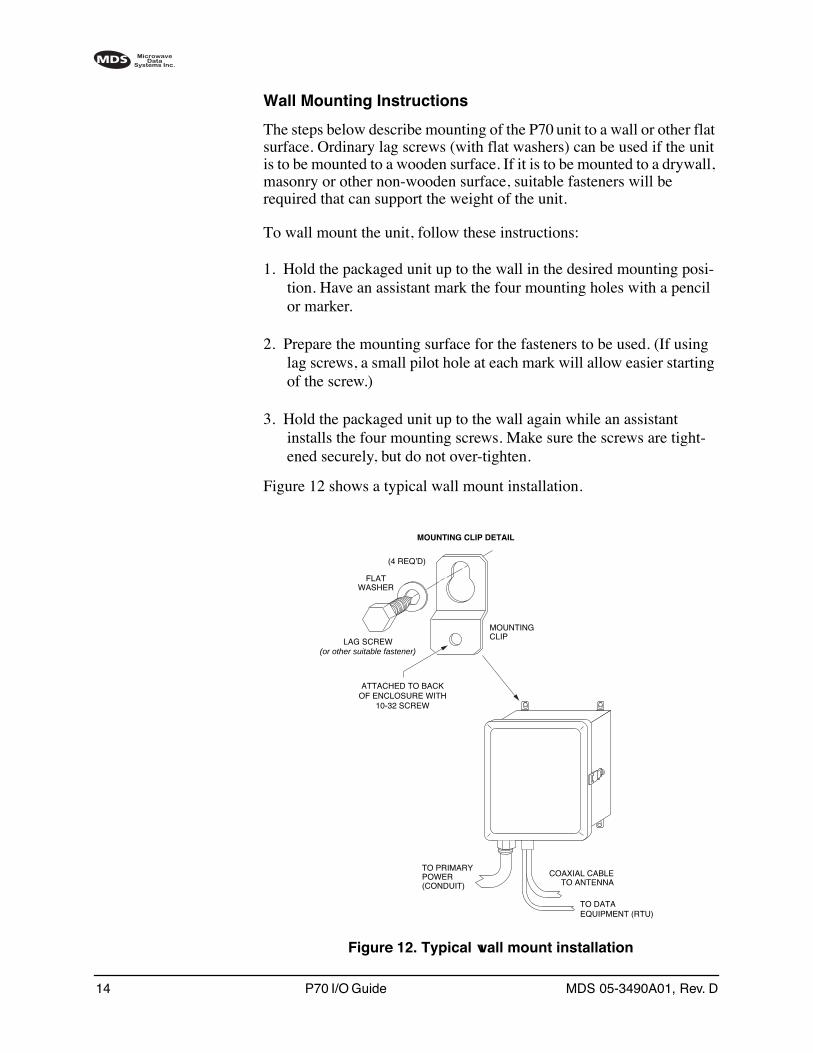
Wall Mounting Instructions
The steps below describe mounting of the P70 unit to a wall or other flat surface. Ordinary lag screws (with flat washers) can be used if the unit is to be mounted to a wooden surface. If it is to be mounted to a drywall, masonry or other non-wooden surface, suitable fasteners will be required that can support the weight of the unit.
To wall mount the unit, follow these instructions:
1. Hold the packaged unit up to the wall in the desired mounting posi-tion. Have an assistant mark the four mounting holes with a pencil or marker.
2. Prepare the mounting surface for the fasteners to be used. (If using lag screws, a small pilot hole at each mark will allow easier starting of the screw.)
3. Hold the packaged unit up to the wall again while an assistant installs the four mounting screws. Make sure the screws are tight-ened securely, but do not over-tighten.
Figure 12 shows a typical wall mount installation.
Invisible place holder
Figure 12. Typical wall mount installation
TO PRIMARYPOWER(CONDUIT)
COAXIAL CABLETO ANTENNA
TO DATAEQUIPMENT (RTU)
LAG SCREW
ATTACHED TO BACKOF ENCLOSURE WITH
10-32 SCREW
FLATWASHER
MOUNTINGCLIP
MOUNTING CLIP DETAIL
(4 REQ’D)
(or other suitable fastener)
MDS 05-3490A01, Rev. D P70 I/O Guide 15
Pole Mounting Instructions
Pole mounting requires the use of two pole-mount adapters (P/N 82-1743A01). These brackets must first be bolted to the P70 enclosure. The complete assembly can then be mounted to a wooden utility pole with two lag screws or with two long bolts that extend through the pole. (Threaded rod can also be used for through-the-pole mounting.) In either case, it is important to use flat washers with the attaching hard-ware (fasteners are not supplied).
To pole mount the unit, follow these instructions:
1. Attach the two pole mount adapter brackets to the P70 enclosure with suitable nut and bolt assemblies, as shown in Figure 13.
2. With the help of an assistant, position the P70 enclosure on the pole at the desired mounting point.
3. Install the attaching hardware (with flat washers) in the center hole of the two brackets.
4. Tighten the fasteners securely, but do not over-tighten.
Figure 13 shows a typical pole-mount installation using lag screws.

16 P70 I/O Guide MDS 05-3490A01, Rev. D
Invisible place holder
Figure 13. Typical pole-mounted installation
Other pole-mount configurations are available for the P70, including a mounting bracket with a sun shield (for use in extremely hot climates), a tower mounting bracket, and other arrangements to meet special needs. Contact the factory for more information.
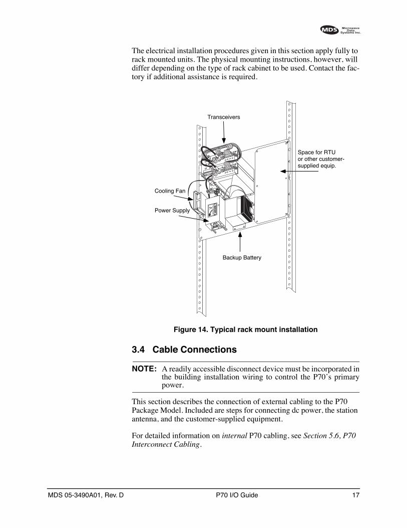
Rack Mount Option
In addition to wall and pole mounting, the internal chassis of the Package Model can also be mounted in a standard 19 inch equipment rack for indoor installations. The rack-mounted model is normally shipped without an enclosure and is supplied with hardware for mounting the chassis plate to the rack cabinet. Figure 14 shows a typical rack mount installation.
!"#
$
!
MDS 05-3490A01, Rev. D P70 I/O Guide 17
The electrical installation procedures given in this section apply fully to rack mounted units. The physical mounting instructions, however, will differ depending on the type of rack cabinet to be used. Contact the fac-tory if additional assistance is required.
Invisible place holder
Figure 14. Typical rack mount installation
3.4 Cable Connections
NOTE: A readily accessible disconnect device must be incorporated inthe building installation wiring to control the P70’s primarypower.
This section describes the connection of external cabling to the P70 Package Model. Included are steps for connecting dc power, the station antenna, and the customer-supplied equipment.
For detailed information on internal P70 cabling, see Section 5.6, P70 Interconnect Cabling.
P70 ARt to be supplied
Transceivers
Space for RTUor other customer-supplied equip.
Backup Battery
Power Supply
Cooling Fan
18 P70 I/O Guide MDS 05-3490A01, Rev. D
Ground Connection
A ground clamp is provided on the bottom of the P70 enclosure (outside edge). Connect an earth ground (ground rod or plate) to this point in accordance with local electrical codes. If the P70 is to be rack-mounted without an enclosure, an earth ground connection must be made to the mounting plate.
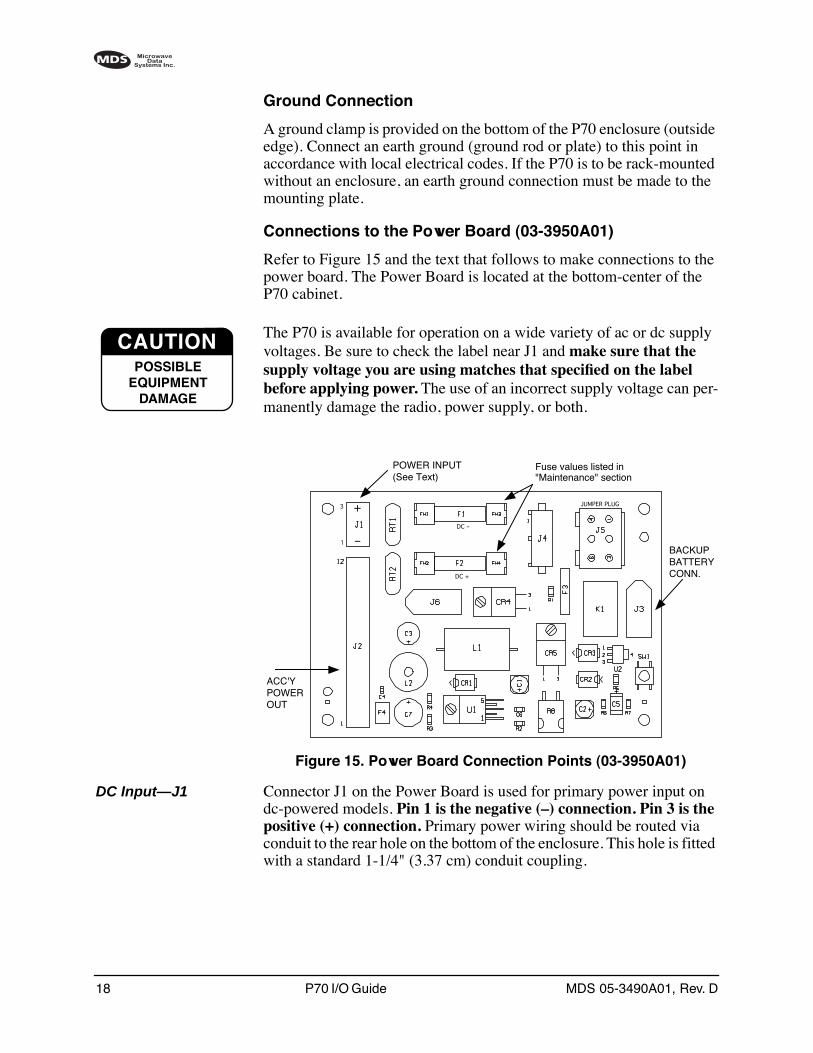
Connections to the Power Board (03-3950A01)
Refer to Figure 15 and the text that follows to make connections to the power board. The Power Board is located at the bottom-center of the P70 cabinet.
The P70 is available for operation on a wide variety of ac or dc supply voltages. Be sure to check the label near J1 and make sure that the supply voltage you are using matches that specified on the label before applying power. The use of an incorrect supply voltage can per-manently damage the radio, power supply, or both.
Invisible place holder
Figure 15. Power Board Connection Points (03-3950A01)
DC Input—J1 Connector J1 on the Power Board is used for primary power input on dc-powered models. Pin 1 is the negative (–) connection. Pin 3 is the positive (+) connection. Primary power wiring should be routed via conduit to the rear hole on the bottom of the enclosure. This hole is fitted with a standard 1-1/4" (3.37 cm) conduit coupling.
CAUTIONPOSSIBLE
EQUIPMENTDAMAGE
POWER INPUT(See Text)
BACKUPBATTERYCONN.
ACC'YPOWEROUT
1
3
–
+DC –
DC +
Fuse values listed in"Maintenance" section
JUMPER PLUG
MDS 05-3490A01, Rev. D P70 I/O Guide 19
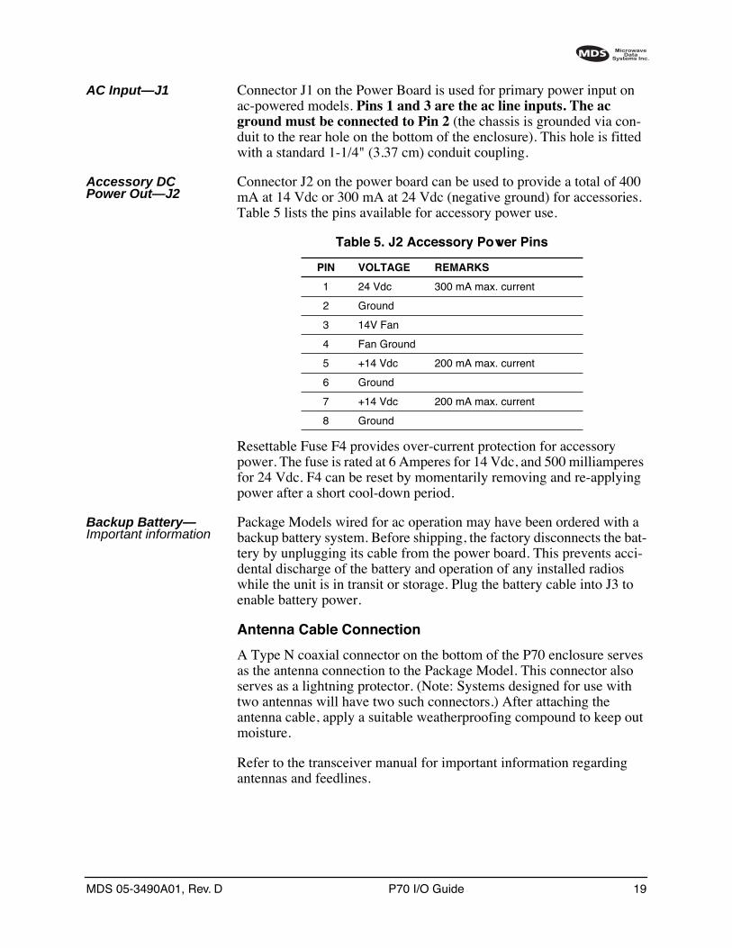
AC Input—J1 Connector J1 on the Power Board is used for primary power input on ac-powered models. Pins 1 and 3 are the ac line inputs. The ac ground must be connected to Pin 2 (the chassis is grounded via con-duit to the rear hole on the bottom of the enclosure). This hole is fitted with a standard 1-1/4" (3.37 cm) conduit coupling.
Accessory DC Power Out—J2
Connector J2 on the power board can be used to provide a total of 400 mA at 14 Vdc or 300 mA at 24 Vdc (negative ground) for accessories. Table 5 lists the pins available for accessory power use.
Resettable Fuse F4 provides over-current protection for accessory power. The fuse is rated at 6 Amperes for 14 Vdc, and 500 milliamperes for 24 Vdc. F4 can be reset by momentarily removing and re-applying power after a short cool-down period.
Backup Battery—Important information
Package Models wired for ac operation may have been ordered with a backup battery system. Before shipping, the factory disconnects the bat-tery by unplugging its cable from the power board. This prevents acci-dental discharge of the battery and operation of any installed radios while the unit is in transit or storage. Plug the battery cable into J3 to enable battery power.
Antenna Cable Connection
A Type N coaxial connector on the bottom of the P70 enclosure serves as the antenna connection to the Package Model. This connector also serves as a lightning protector. (Note: Systems designed for use with two antennas will have two such connectors.) After attaching the antenna cable, apply a suitable weatherproofing compound to keep out moisture.
Refer to the transceiver manual for important information regarding antennas and feedlines.
Table 5. J2 Accessory Power Pins
PIN VOLTAGE REMARKS
1 24 Vdc 300 mA max. current
2 Ground
3 14V Fan
4 Fan Ground
5 +14 Vdc 200 mA max. current
6 Ground
7 +14 Vdc 200 mA max. current
8 Ground
20 P70 I/O Guide MDS 05-3490A01, Rev. D
3.5 Logic Board Connections
The Logic Board serves as the connection point for all data interface cabling to the P70 Package Model. One of two Logic Boards will be installed; An Interface Logic Board (ILB)—P/N 03-3900A02, or a Redundant Logic Board (RLB)—P/N 03-3306A02. The ILB is installed unless the P70 is configured for redundant operation with two transceivers. The RLB is used for all redundant applications.
In either case, the Logic Board will be mounted at the lower left-hand side of the P70.
When making Logic Board connections, route the cabling to the board through the weathertight bushing at the bottom of the enclosure. Tighten the bushing after installing the interface cable(s).
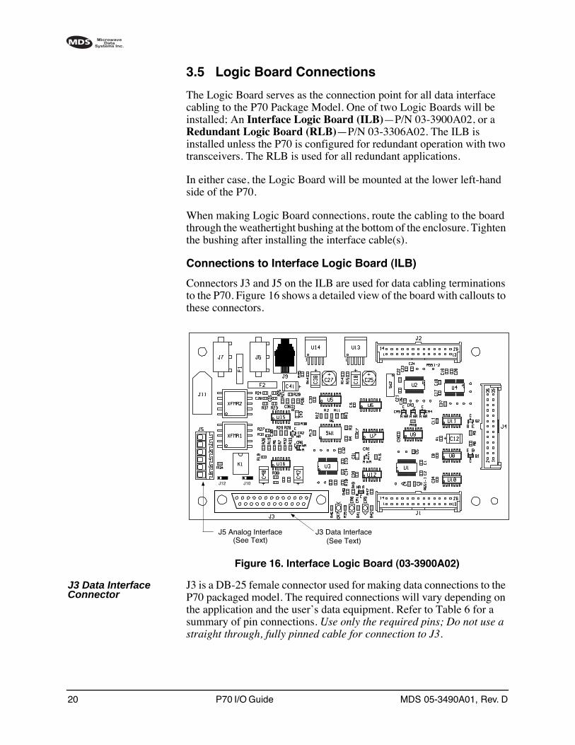
Connections to Interface Logic Board (ILB)
Connectors J3 and J5 on the ILB are used for data cabling terminations to the P70. Figure 16 shows a detailed view of the board with callouts to these connectors.
Figure 16. Interface Logic Board (03-3900A02)
J3 Data Interface Connector
J3 is a DB-25 female connector used for making data connections to the P70 packaged model. The required connections will vary depending on the application and the user’s data equipment. Refer to Table 6 for a summary of pin connections. Use only the required pins; Do not use a straight through, fully pinned cable for connection to J3.
J3 Data Interface(See Text)
J5 Analog Interface(See Text)
J12 J10
MDS 05-3490A01, Rev. D P70 I/O Guide 21
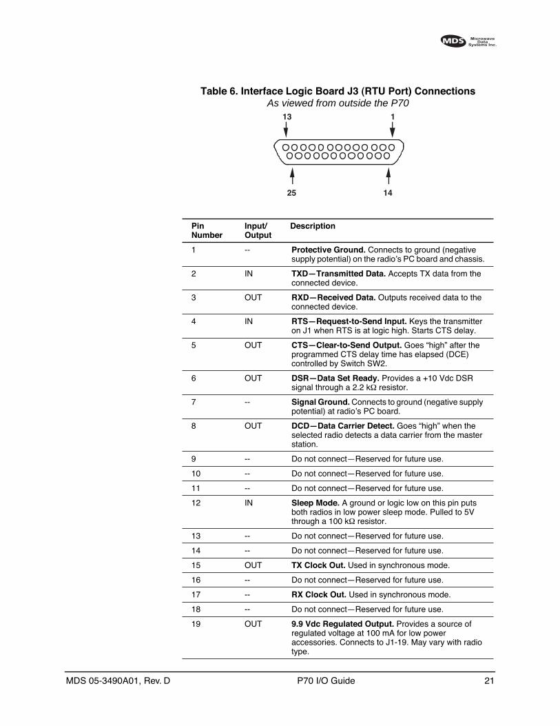
Table 6. Interface Logic Board J3 (RTU Port) Connections As viewed from outside the P70
PinNumber
Input/Output
Description
1 -- Protective Ground. Connects to ground (negative supply potential) on the radio’s PC board and chassis.
2 IN TXD—Transmitted Data. Accepts TX data from the connected device.
3 OUT RXD—Received Data. Outputs received data to the connected device.
4 IN RTS—Request-to-Send Input. Keys the transmitter on J1 when RTS is at logic high. Starts CTS delay.
5 OUT CTS—Clear-to-Send Output. Goes “high” after the programmed CTS delay time has elapsed (DCE) controlled by Switch SW2.
6 OUT DSR—Data Set Ready. Provides a +10 Vdc DSR signal through a 2.2 kΩ resistor.
7 -- Signal Ground. Connects to ground (negative supply potential) at radio’s PC board.
8 OUT DCD—Data Carrier Detect. Goes “high” when the selected radio detects a data carrier from the master station.
9 -- Do not connect—Reserved for future use.
10 -- Do not connect—Reserved for future use.
11 -- Do not connect—Reserved for future use.
12 IN Sleep Mode. A ground or logic low on this pin puts both radios in low power sleep mode. Pulled to 5V through a 100 kΩ resistor.
13 -- Do not connect—Reserved for future use.
14 -- Do not connect—Reserved for future use.
15 OUT TX Clock Out. Used in synchronous mode.
16 -- Do not connect—Reserved for future use.
17 -- RX Clock Out. Used in synchronous mode.
18 -- Do not connect—Reserved for future use.
19 OUT 9.9 Vdc Regulated Output. Provides a source of regulated voltage at 100 mA for low power accessories. Connects to J1-19. May vary with radio type.
13 1
25 14

22 P70 I/O Guide MDS 05-3490A01, Rev. D
J5 Analog Interface Connector
J5, a six pin connector, provides an Analog Interface to the P70. A removable plug is provided which has screw terminals for wire attach-ment. Pins 1 & 2 are the 600 ohm balanced Transmitter Input for Radio 1, and Pins 3 & 4 are the balanced 600 ohm output from the receiver selected by SW1-8. These are transformer coupled, floating interfaces. For best results, set the Transmitter analog input level to match the level supplied by the external modem or audio source. For the MDS x710 series radios the diagnostic command will typically be TXLEVEL –10 for a –10 dBm source. The default receiver level is –10 dBm, but it can be set to match your application as required. Consult your radio manual for further details.
Pins 5 & 6 are the keyline input. For all boards up to Revision D, Pin 5 keys the transmitter when grounded. Pin 6 provides a convenient ground connection. For board revisions starting at E, an optional floating key-line input is available. It is controlled by two 3-pin jumpers J10 & J 12. With both jumpers installed on pins 1 & 2, grounding Pin 5 (to Pin 6) will key the radio as before. Moving both jumpers over to Pins 2 & 3 will change to the floating keyline mode. When a voltage is applied to Pins 5 (-) and 6 (+) Radio 1 will key. The voltage range is 10 to 25 Vdc with a corresponding current of approximately 5 to 15 mA. Remember to observe the voltage polarity and keep both J10 & J12 set the same.
20 -- Do not connect—Reserved for future use.
21 -- Do not connect—Reserved for future use.
22 -- Do not connect—Reserved for future use.
23 - Not used.
24 IN TX Clock In. Used in synchronous mode.
25 OUT Alarm. A logic low (less than 0.5 volts) on this pin indicates normal operation. A logic high (greater than 4 volts) indicates that some alarm condition is present. This pin can be used as an alarm output, provided the internal series resistance of 1 kΩ is considered.
Table 6. Interface Logic Board J3 (RTU Port) Connections (Continued)
As viewed from outside the P70
PinNumber
Input/Output
Description
13 1
25 14
MDS 05-3490A01, Rev. D P70 I/O Guide 23
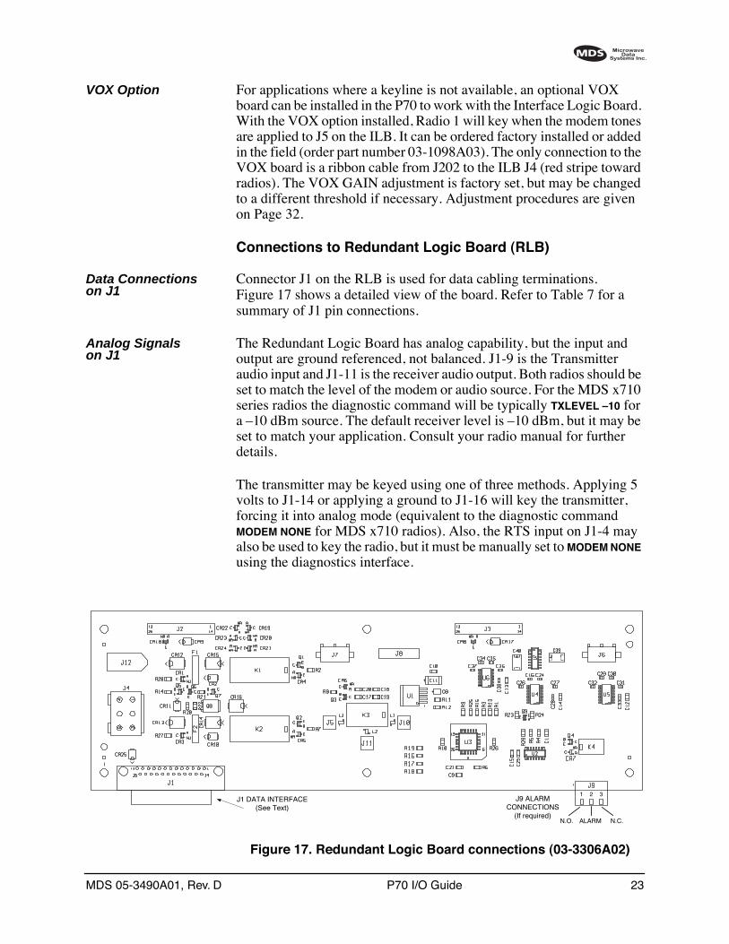
VOX Option For applications where a keyline is not available, an optional VOX board can be installed in the P70 to work with the Interface Logic Board. With the VOX option installed, Radio 1 will key when the modem tones are applied to J5 on the ILB. It can be ordered factory installed or added in the field (order part number 03-1098A03). The only connection to the VOX board is a ribbon cable from J202 to the ILB J4 (red stripe toward radios). The VOX GAIN adjustment is factory set, but may be changed to a different threshold if necessary. Adjustment procedures are given on Page 32.
Connections to Redundant Logic Board (RLB)
Data Connections on J1
Connector J1 on the RLB is used for data cabling terminations. Figure 17 shows a detailed view of the board. Refer to Table 7 for a summary of J1 pin connections.
Analog Signals on J1
The Redundant Logic Board has analog capability, but the input and output are ground referenced, not balanced. J1-9 is the Transmitter audio input and J1-11 is the receiver audio output. Both radios should be set to match the level of the modem or audio source. For the MDS x710 series radios the diagnostic command will be typically TXLEVEL –10 for a –10 dBm source. The default receiver level is –10 dBm, but it may be set to match your application. Consult your radio manual for further details.
The transmitter may be keyed using one of three methods. Applying 5 volts to J1-14 or applying a ground to J1-16 will key the transmitter, forcing it into analog mode (equivalent to the diagnostic command MODEM NONE for MDS x710 radios). Also, the RTS input on J1-4 may also be used to key the radio, but it must be manually set to MODEM NONE using the diagnostics interface.
Invisible place holder
Figure 17. Redundant Logic Board connections (03-3306A02)
J1 DATA INTERFACE(See Text)
1 2 3J9 ALARM
CONNECTIONS(If required)
N.O. ALARM N.C.
24 P70 I/O Guide MDS 05-3490A01, Rev. D
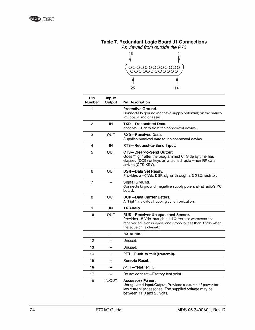
Table 7. Redundant Logic Board J1 Connections As viewed from outside the P70
PinNumber
Input/Output Pin Description
1 -- Protective Ground. Connects to ground (negative supply potential) on the radio’s PC board and chassis.
2 IN TXD—Transmitted Data.Accepts TX data from the connected device.
3 OUT RXD—Received Data.Supplies received data to the connected device.
4 IN RTS—Request-to-Send Input.
5 OUT CTS—Clear-to-Send Output.Goes “high” after the programmed CTS delay time has elapsed (DCE) or keys an attached radio when RF data arrives (CTS KEY).
6 OUT DSR—Data Set Ready.Provides a +6 Vdc DSR signal through a 2.5 kΩ resistor.
7 -- Signal Ground.Connects to ground (negative supply potential) at radio’s PC board.
8 OUT DCD—Data Carrier Detect.A “high” indicates hopping synchronization.
9 IN TX Audio.
10 OUT RUS—Receiver Unsquelched Sensor.Provides +8 Vdc through a 1 kΩ resistor whenever the receiver squelch is open, and drops to less than 1 Vdc when the squelch is closed.)
11 -- RX Audio.
12 -- Unused.
13 -- Unused.
14 -- PTT—Push-to-talk (transmit).
15 -- Remote Reset.
16 -- /PTT—”Not” PTT.
17 -- Do not connect—Factory test point.
18 IN/OUT Accessory Power.Unregulated Input/Output. Provides a source of power for low current accessories. The supplied voltage may be between 11.0 and 25 volts.
13 1
25 14
MDS 05-3490A01, Rev. D P70 I/O Guide 25
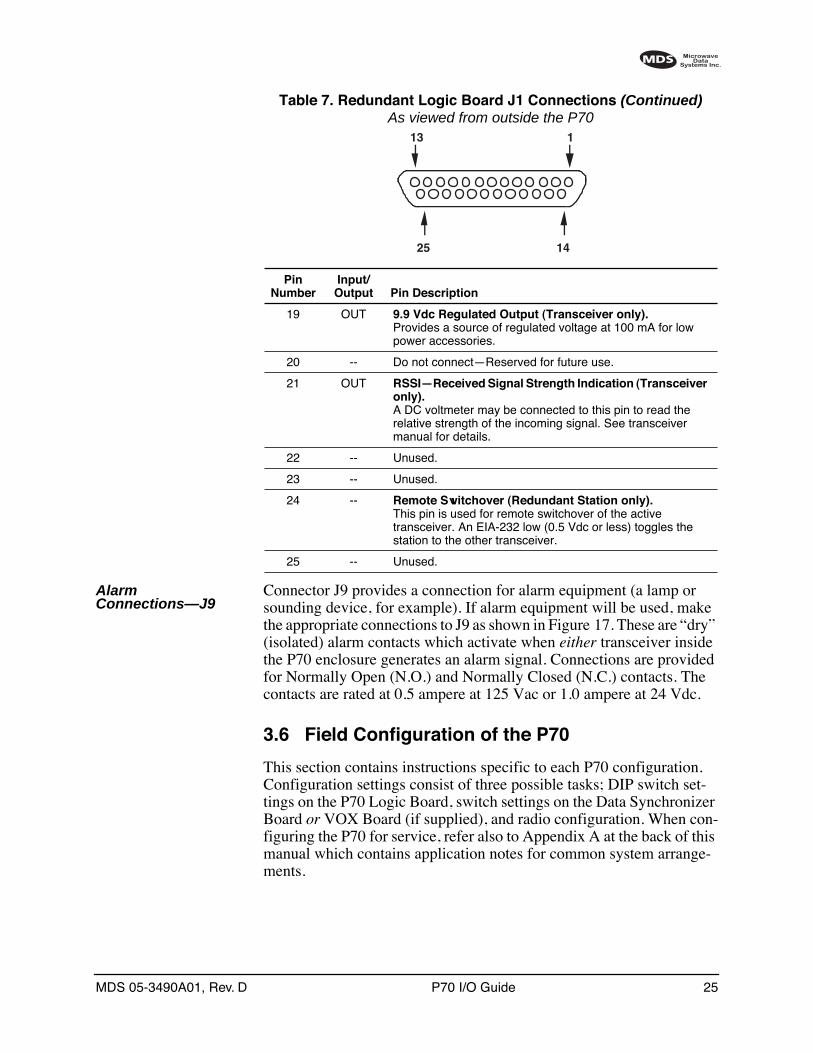
Alarm Connections—J9
Connector J9 provides a connection for alarm equipment (a lamp or sounding device, for example). If alarm equipment will be used, make the appropriate connections to J9 as shown in Figure 17. These are “dry” (isolated) alarm contacts which activate when either transceiver inside the P70 enclosure generates an alarm signal. Connections are provided for Normally Open (N.O.) and Normally Closed (N.C.) contacts. The contacts are rated at 0.5 ampere at 125 Vac or 1.0 ampere at 24 Vdc.
3.6 Field Configuration of the P70
This section contains instructions specific to each P70 configuration. Configuration settings consist of three possible tasks; DIP switch set-tings on the P70 Logic Board, switch settings on the Data Synchronizer Board or VOX Board (if supplied), and radio configuration. When con-figuring the P70 for service, refer also to Appendix A at the back of this manual which contains application notes for common system arrange-ments.
19 OUT 9.9 Vdc Regulated Output (Transceiver only).Provides a source of regulated voltage at 100 mA for low power accessories.
20 -- Do not connect—Reserved for future use.
21 OUT RSSI—Received Signal Strength Indication (Transceiver only).A DC voltmeter may be connected to this pin to read the relative strength of the incoming signal. See transceiver manual for details.
22 -- Unused.
23 -- Unused.
24 -- Remote Switchover (Redundant Station only).This pin is used for remote switchover of the active transceiver. An EIA-232 low (0.5 Vdc or less) toggles the station to the other transceiver.
25 -- Unused.
Table 7. Redundant Logic Board J1 Connections (Continued)As viewed from outside the P70
PinNumber
Input/Output Pin Description
13 1
25 14
26 P70 I/O Guide MDS 05-3490A01, Rev. D
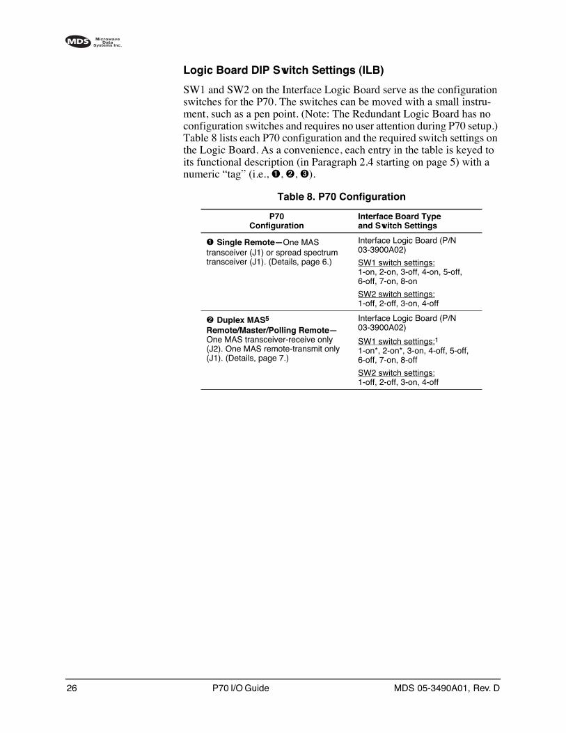
Logic Board DIP Switch Settings (ILB)
SW1 and SW2 on the Interface Logic Board serve as the configuration switches for the P70. The switches can be moved with a small instru-ment, such as a pen point. (Note: The Redundant Logic Board has no configuration switches and requires no user attention during P70 setup.) Table 8 lists each P70 configuration and the required switch settings on the Logic Board. As a convenience, each entry in the table is keyed to its functional description (in Paragraph 2.4 starting on page 5) with a numeric “tag” (i.e., ➊, ➋, ➌).
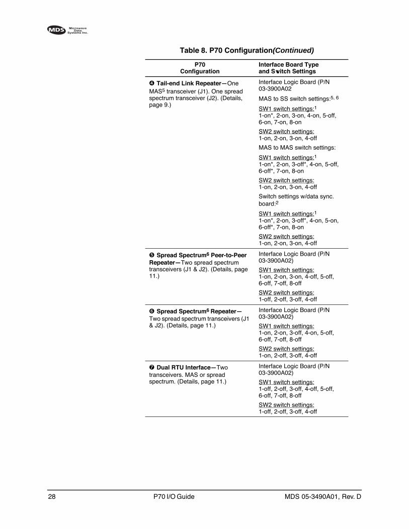
Table 8. P70 Configuration
P70Configuration
Interface Board Typeand Switch Settings
➊ Single Remote—One MAS transceiver (J1) or spread spectrum transceiver (J1). (Details, page 6.)
Interface Logic Board (P/N 03-3900A02)
SW1 switch settings:1-on, 2-on, 3-off, 4-on, 5-off, 6-off, 7-on, 8-on
SW2 switch settings:1-off, 2-off, 3-on, 4-off
➋ Duplex MAS5
Remote/Master/Polling Remote—One MAS transceiver-receive only (J2). One MAS remote-transmit only (J1). (Details, page 7.)
Interface Logic Board (P/N 03-3900A02)
SW1 switch settings:11-on*, 2-on*, 3-on, 4-off, 5-off, 6-off, 7-on, 8-off
SW2 switch settings:1-off, 2-off, 3-on, 4-off
MDS 05-3490A01, Rev. D P70 I/O Guide 27
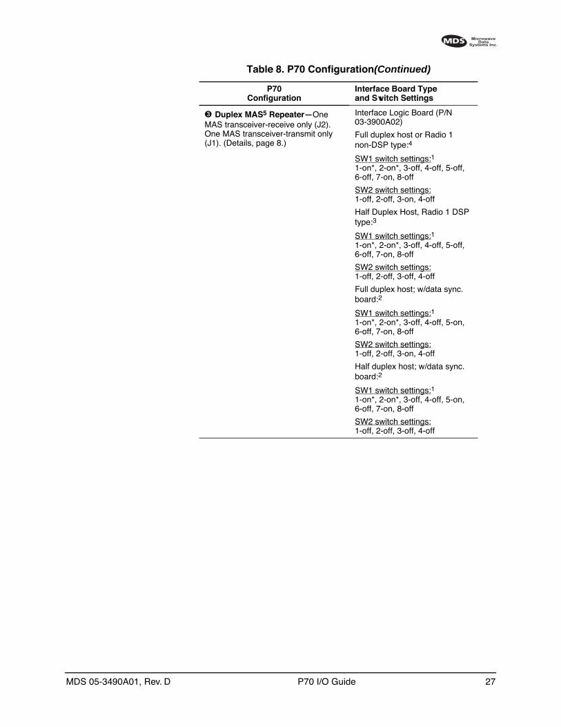
➌ Duplex MAS5 Repeater—One MAS transceiver-receive only (J2). One MAS transceiver-transmit only (J1). (Details, page 8.)
Interface Logic Board (P/N 03-3900A02)
Full duplex host or Radio 1 non-DSP type:4
SW1 switch settings:11-on*, 2-on*, 3-off, 4-off, 5-off, 6-off, 7-on, 8-off
SW2 switch settings:1-off, 2-off, 3-on, 4-off
Half Duplex Host, Radio 1 DSP type:3
SW1 switch settings:11-on*, 2-on*, 3-off, 4-off, 5-off, 6-off, 7-on, 8-off
SW2 switch settings:1-off, 2-off, 3-off, 4-off
Full duplex host; w/data sync. board:2
SW1 switch settings:11-on*, 2-on*, 3-off, 4-off, 5-on, 6-off, 7-on, 8-off
SW2 switch settings:1-off, 2-off, 3-on, 4-off
Half duplex host; w/data sync. board:2
SW1 switch settings:11-on*, 2-on*, 3-off, 4-off, 5-on, 6-off, 7-on, 8-off
SW2 switch settings:1-off, 2-off, 3-off, 4-off
Table 8. P70 Configuration(Continued)
P70Configuration
Interface Board Typeand Switch Settings
28 P70 I/O Guide MDS 05-3490A01, Rev. D
➍ Tail-end Link Repeater—One MAS5 transceiver (J1). One spread spectrum transceiver (J2). (Details, page 9.)
Interface Logic Board (P/N 03-3900A02
MAS to SS switch settings:5, 6
SW1 switch settings:11-on*, 2-on, 3-on, 4-on, 5-off, 6-on, 7-on, 8-on
SW2 switch settings:1-on, 2-on, 3-on, 4-off
MAS to MAS switch settings:
SW1 switch settings:11-on*, 2-on, 3-off*, 4-on, 5-off, 6-off*, 7-on, 8-on
SW2 switch settings:1-on, 2-on, 3-on, 4-off
Switch settings w/data sync. board:2
SW1 switch settings:11-on*, 2-on, 3-off*, 4-on, 5-on, 6-off*, 7-on, 8-on
SW2 switch settings:1-on, 2-on, 3-on, 4-off
➎ Spread Spectrum6 Peer-to-Peer Repeater—Two spread spectrum transceivers (J1 & J2). (Details, page 11.)
Interface Logic Board (P/N 03-3900A02)
SW1 switch settings:1-on, 2-on, 3-on, 4-off, 5-off, 6-off, 7-off, 8-off
SW2 switch settings:1-off, 2-off, 3-off, 4-off
➏ Spread Spectrum6 Repeater—Two spread spectrum transceivers (J1 & J2). (Details, page 11.)
Interface Logic Board (P/N 03-3900A02)
SW1 switch settings:1-on, 2-on, 3-off, 4-on, 5-off, 6-off, 7-off, 8-off
SW2 switch settings:1-on, 2-off, 3-off, 4-off
➐ Dual RTU Interface—Two transceivers. MAS or spread spectrum. (Details, page 11.)
Interface Logic Board (P/N 03-3900A02)
SW1 switch settings:1-off, 2-off, 3-off, 4-off, 5-off, 6-off, 7-off, 8-off
SW2 switch settings:1-off, 2-off, 3-off, 4-off
Table 8. P70 Configuration(Continued)
P70Configuration
Interface Board Typeand Switch Settings
MDS 05-3490A01, Rev. D P70 I/O Guide 29
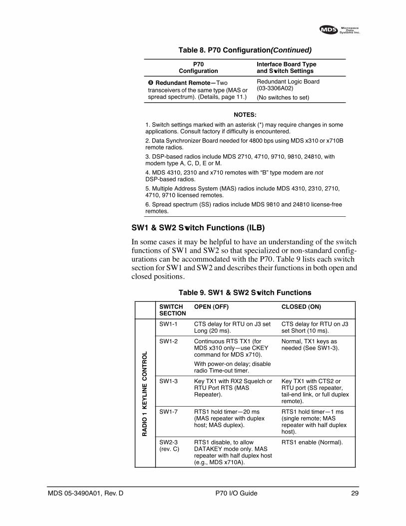
SW1 & SW2 Switch Functions (ILB)
In some cases it may be helpful to have an understanding of the switch functions of SW1 and SW2 so that specialized or non-standard config-urations can be accommodated with the P70. Table 9 lists each switch section for SW1 and SW2 and describes their functions in both open and closed positions.
➑ Redundant Remote—Two transceivers of the same type (MAS or spread spectrum). (Details, page 11.)
Redundant Logic Board (03-3306A02)
(No switches to set)
NOTES:
1. Switch settings marked with an asterisk (*) may require changes in some applications. Consult factory if difficulty is encountered.
2. Data Synchronizer Board needed for 4800 bps using MDS x310 or x710B remote radios.
3. DSP-based radios include MDS 2710, 4710, 9710, 9810, 24810, with modem type A, C, D, E or M.
4. MDS 4310, 2310 and x710 remotes with “B” type modem are not DSP-based radios.
5. Multiple Address System (MAS) radios include MDS 4310, 2310, 2710, 4710, 9710 licensed remotes.
6. Spread spectrum (SS) radios include MDS 9810 and 24810 license-free remotes.
Table 8. P70 Configuration(Continued)
P70Configuration
Interface Board Typeand Switch Settings
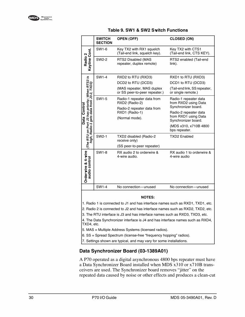
Table 9. SW1 & SW2 Switch Functions
SWITCH SECTION
OPEN (OFF) CLOSED (ON)
SW1-1 CTS delay for RTU on J3 set Long (20 ms).
CTS delay for RTU on J3 set Short (10 ms).
SW1-2 Continuous RTS TX1 (for MDS x310 only—use CKEY command for MDS x710).
With power-on delay; disable radio Time-out timer.
Normal, TX1 keys as needed (See SW1-3).
SW1-3 Key TX1 with RX2 Squelch or RTU Port RTS (MAS Repeater).
Key TX1 with CTS2 or RTU port (SS repeater, tail-end link, or full duplex remote).
SW1-7 RTS1 hold timer—20 ms (MAS repeater with duplex host; MAS duplex).
RTS1 hold timer—1 ms (single remote; MAS repeater with half duplex host).
SW2-3(rev. C)
RTS1 disable, to allow DATAKEY mode only. MAS repeater with half duplex host (e.g., MDS x710A).
RTS1 enable (Normal).
RA
DIO
1K
EY
LIN
EC
ON
TR
OL
30 P70 I/O Guide MDS 05-3490A01, Rev. D
Data Synchronizer Board (03-1389A01)
A P70 operated as a digital asynchronous 4800 bps repeater must have a Data Synchronizer Board installed when MDS x310 or x710B trans-ceivers are used. The Synchronizer board removes “jitter” on the repeated data caused by noise or other effects and produces a clean-cut
SW1-6 Key TX2 with RX1 squelch (Tail-end link, squelch key).
Key TX2 with CTS1 (Tail-end link, CTS KEY).
SW2-2 RTS2 Disabled (MAS repeater, duplex remote)
RTS2 enabled (Tail-end link).
SW1-4 RXD2 to RTU (RXD3)
DCD2 to RTU (DCD3)
(MAS repeater, MAS duplex or SS peer-to-peer repeater.)
RXD1 to RTU (RXD3)
DCD1 to RTU (DCD3)
(Tail-end link, SS repeater, or single remote.)
SW1-5 Radio-1 repeater data from RXD2 (Radio-2)
Radio-2 repeater data from RXD1 (Radio-1)
(Normal mode).
Radio-1 repeater data from RXD2 using Data Synchronizer board.
Radio-2 repeater data from RXD1 using Data Synchronizer board.
(MDS x310, x710B 4800 bps repeater.
SW2-1 TXD2 disabled (Radio-2 receive only)
(SS peer-to-peer repeater)
TXD2 Enabled
SW1-8 RX audio 2 to orderwire & 4-wire audio.
RX audio 1 to orderwire & 4-wire audio
SW1-4 No connection—unused No connection—unused
NOTES:
1. Radio 1 is connected to J1 and has interface names such as RXD1, TXD1, etc.
2. Radio 2 is connected to J2 and has interface names such as RXD2, TXD2, etc.
3. The RTU interface is J3 and has interface names such as RXD3, TXD3, etc.
4. The Data Synchronizer interface is J4 and has interface names such as RXD4, TXD4, etc.
5. MAS = Multiple Address Systems (licensed radios).
6. SS = Spread Spectrum (license-free “frequency hopping” radios).
7. Settings shown are typical, and may vary for some installations.
Table 9. SW1 & SW2 Switch Functions
SWITCH SECTION
OPEN (OFF) CLOSED (ON)
Rad
io 2
Key
line
Co
nt.
Dat
a C
on
tro
l(T
he
RT
U o
n P
ort
J3
has
pri
ori
ty;
Wh
en R
TS
3 is
h
igh
, Rad
io-1
get
s d
ata
fro
m J
3-2,
TX
D3)
Ord
erw
ire
& 4
-wir
eau
dio
co
ntr
ol

MDS 05-3490A01, Rev. D P70 I/O Guide 31
signal going back out. If the Data Synchronizer Board is supplied, it is mounted beneath the logic board, and connects to the logic board via a short ribbon cable. Figure 18 shows a top view of the Data Synchronizer Board.
Invisible place holder
Figure 18. Data Synchronizer Board(Required in 4800 bps digital asynchronous repeaters with MDS x310
or x710B Transceivers installed)
Before the Data Synchronizer Board is placed in service, it must be con-figured to match the peak baud rate and word length used in the system. These parameters are set using a DIP switch, SW1 on the Data Synchro-nizer Board (see Figure 18). The switch sections can be moved with a small instrument, such as a pen point.
The first section of SW1 is set to match the data word length used in the system. A word consists of the start bit, data bits, stop bit and parity bit. Table 10 lists the proper settings for 10 and 11 Bit words.
The next three sections of SW1 are used to set the baud rate at which data will pass through the system. The P70 can be configured to pass data at one of seven speeds between 150 bps and 9600 bps. Table 11 lists the proper settings for these speeds.
R6
R5
R4
R3
R2
R1
C8 1 2 3 4
SW1
J1
J2
1
26
1
26
IC1IC2
C6
+
C5 VR2 C4
+
C11 C1
+
C9
C10
R7
XT1
C7
IC3
R8
C3
C2
+VR1
SW1:Word Length (Section 1)& Baud Rate (Sections 2-4)J2: Not Used
J1: To JJ4 on Logic Board via Ribbon Cable
Table 10. Word Length Settings for Data Sync. Board
WORD LENGTH SWITCH SW1-1
10 Bits Closed
11 Bits Open
32 P70 I/O Guide MDS 05-3490A01, Rev. D
Switch Legend: C = Closed O = Open
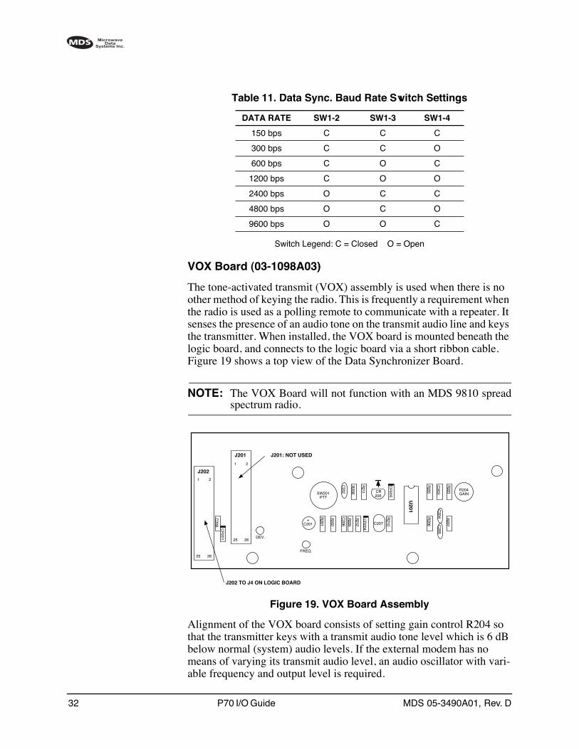
VOX Board (03-1098A03)
The tone-activated transmit (VOX) assembly is used when there is no other method of keying the radio. This is frequently a requirement when the radio is used as a polling remote to communicate with a repeater. It senses the presence of an audio tone on the transmit audio line and keys the transmitter. When installed, the VOX board is mounted beneath the logic board, and connects to the logic board via a short ribbon cable. Figure 19 shows a top view of the Data Synchronizer Board.
NOTE: The VOX Board will not function with an MDS 9810 spreadspectrum radio.
Invisible place holder
Figure 19. VOX Board Assembly
Alignment of the VOX board consists of setting gain control R204 so that the transmitter keys with a transmit audio tone level which is 6 dB below normal (system) audio levels. If the external modem has no means of varying its transmit audio level, an audio oscillator with vari-able frequency and output level is required.
Table 11. Data Sync. Baud Rate Switch Settings
DATA RATE SW1-2 SW1-3 SW1-4
150 bps C C C
300 bps C C O
600 bps C O C
1200 bps C O O
2400 bps O C C
4800 bps O C O
9600 bps O O C
J2021
25 26
2
J201
1
25 26
2
DEV.
FREQ.
R204GAIN
C208
CR
201
SW201PTT
CR206
U201
C207
R207
R206 C
205C
204
R203
C203
R205
C202
R208
R211
CR
205
R210
CR
204
R212
R209
C206
R202
R201
+C201
J201: NOT USED
J202 TO J4 ON LOGIC BOARD
MDS 05-3490A01, Rev. D P70 I/O Guide 33
If adjustment of the VOX Board gain is required, proceed as follows:
1. Rotate R204 fully counterclockwise.
2. Apply a 1200 Hz tone to J5 Pins 1 & 2 on the Logic Board. Set the amplitude of the audio oscillator 6 dB lower than the normal system level.
3. Rotate R204 slowly clockwise until CR206 begins to flicker.
4. Carefully continue to adjust R204 until CR206 glows steadily with-out flickering. This completes the VOX gain adjustment.
Radio Configuration
In many cases, the P70 is shipped with the internal radios already con-figured for customer requirements. If so, no further configuration will be needed. However, if a system change is being made, or a new trans-ceiver is installed, changes may be required. Radio configuration is per-formed with a Hand-Held Terminal or PC connected to the radio. (See Connecting a Hand-Held Terminal (HHT) on page 39.)
The transceiver manual shipped with your P70 contains a detailed list of radio commands and explains their functions. Always consult the trans-ceiver manual when making programming changes.
NOTE: All MDS x710 and x810 radios must have their alarm outputset to respond to Major alarms, and ignore Minor alarms. Thisis set at the factory for radios installed in a P70 but not forradios shipped separately. The diagnostic command AMASKFFFF0000 must be entered into a radio to set this mode. Refer toyour radio manual for complete diagnostic information.
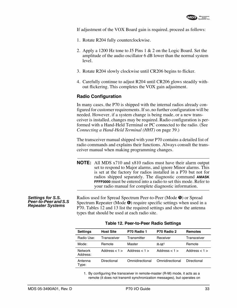
Settings for S.S. Peer-to-Peer and S.S Repeater Systems
Radios used for Spread Spectrum Peer-to-Peer (Mode ➎) or Spread Spectrum Repeater (Mode ➏) require specific settings when used in a P70. Tables 12 and 13 list the required settings and show the antenna types that should be used at each radio site.
1. By configuring the transceiver in remote-master (R-M) mode, it acts as a remote (it does not transmit synchronization messages), but operates on
Table 12. Peer-to-Peer Radio Settings
Settings Host Site P70 Radio 1 P70 Radio 2 Remotes
Radio Use: Transceiver Transmitter Receiver Transceiver
Mode: Remote Master R-M1 Remote
NetworkAddress:
Address < 1 > Address < 1 > Address < 1 > Address < 1 >
Antenna Type:
Directional Omnidirectional Omnidirectional Directional
34 P70 I/O Guide MDS 05-3490A01, Rev. D
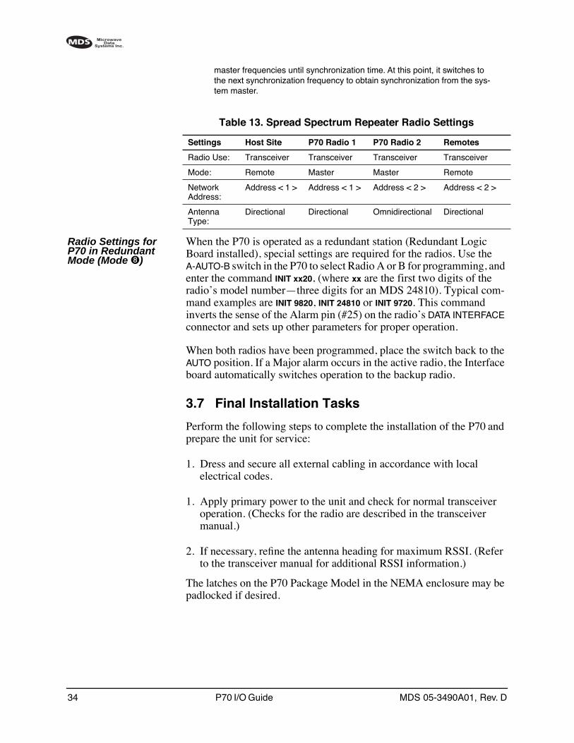
master frequencies until synchronization time. At this point, it switches to the next synchronization frequency to obtain synchronization from the sys-tem master.
Radio Settings for P70 in Redundant Mode (Mode ➑)
When the P70 is operated as a redundant station (Redundant Logic Board installed), special settings are required for the radios. Use the A-AUTO-B switch in the P70 to select Radio A or B for programming, and enter the command INIT xx20, (where xx are the first two digits of the radio’s model number—three digits for an MDS 24810). Typical com-mand examples are INIT 9820, INIT 24810 or INIT 9720. This command inverts the sense of the Alarm pin (#25) on the radio’s DATA INTERFACE connector and sets up other parameters for proper operation.
When both radios have been programmed, place the switch back to the AUTO position. If a Major alarm occurs in the active radio, the Interface board automatically switches operation to the backup radio.
3.7 Final Installation Tasks
Perform the following steps to complete the installation of the P70 and prepare the unit for service:
1. Dress and secure all external cabling in accordance with local electrical codes.
1. Apply primary power to the unit and check for normal transceiver operation. (Checks for the radio are described in the transceiver manual.)
2. If necessary, refine the antenna heading for maximum RSSI. (Refer to the transceiver manual for additional RSSI information.)
The latches on the P70 Package Model in the NEMA enclosure may be padlocked if desired.
Table 13. Spread Spectrum Repeater Radio Settings
Settings Host Site P70 Radio 1 P70 Radio 2 Remotes
Radio Use: Transceiver Transceiver Transceiver Transceiver
Mode: Remote Master Master Remote
NetworkAddress:
Address < 1 > Address < 1 > Address < 2 > Address < 2 >
Antenna Type:
Directional Directional Omnidirectional Directional

MDS 05-3490A01, Rev. D P70 I/O Guide 35
4.0 OPERATION
4.1 Introduction
The P70 Package Model is designed for unattended field operation. The only normal operator interaction is to apply power at the time of instal-lation and observe the unit for proper LED indications. This section dis-cusses the steps for initial power-up and also describes the connection of accessory equipment to the Package Model.
These instructions assume that the unit has been installed in accordance with the installation procedures given in Section 3.0, INSTALLATION.
4.2 Initial Power-up
Follow these steps to begin operation of the P70 Package Model:
1. Apply primary power to the unit.
2. Observe LEDs for normal operation. Typically, the radio will be transmitting intermittently in response to polling signals from the master station. The transceiver instruction manual provides a detailed description of each LED on the Transceiver front panel.
Radio Selection Switch—Redundant units only
SW1 on the battery bracket provides selection of the active radio trans-ceiver in redundant configurations (Redundant Logic Board installed—P/N 03-3306A02).
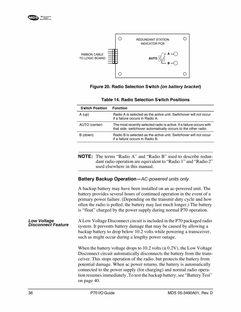
Figure 20 shows a view of the selection switch. Select the active radio by setting the switch up for Radio A, down for Radio B or to the center for automatic switchover. Corresponding LEDs indicate selection of Radio A or B. Refer to Table 14 for a detailed explanation of the switch settings. Manually selecting A or B will keep that radio active so that alarms can be checked and corrected.
36 P70 I/O Guide MDS 05-3490A01, Rev. D
Invisible place holder
Figure 20. Radio Selection Switch (on battery bracket)
NOTE: The terms “Radio A” and “Radio B” used to describe redun-dant radio operation are equivalent to “Radio 1” and “Radio 2”used elsewhere in this manual.
Battery Backup Operation—AC-powered units only
A backup battery may have been installed on an ac-powered unit. The battery provides several hours of continued operation in the event of a primary power failure. (Depending on the transmit duty cycle and how often the radio is polled, the battery may last much longer.) The battery is “float” charged by the power supply during normal P70 operation.
Low Voltage Disconnect Feature
A Low Voltage Disconnect circuit is included in the P70 packaged radio system. It prevents battery damage that may be caused by allowing a backup battery to drop below 10.2 volts while powering a transceiver, such as might occur during a lengthy power outage.
When the battery voltage drops to 10.2 volts (± 0.2V), the Low Voltage Disconnect circuit automatically disconnects the battery from the trans-ceiver. This stops operation of the radio, but protects the battery from potential damage. When ac power returns, the battery is automatically connected to the power supply (for charging) and normal radio opera-tion resumes immediately. To test the backup battery, see “Battery Test” on page 40.
INDICATOR PCB
AUTO
B
A
REDUNDANT STATION
RIBBON CABLETO LOGIC BOARD
Table 14. Radio Selection Switch Positions
Switch Position Function
A (up) Radio A is selected as the active unit. Switchover will not occur if a failure occurs in Radio A.
AUTO (center) The most recently selected radio is active. If a failure occurs with that side, switchover automatically occurs to the other radio.
B (down) Radio B is selected as the active unit. Switchover will not occur if a failure occurs in Radio B.
MDS 05-3490A01, Rev. D P70 I/O Guide 37
NOTE: For proper operation of the Low Voltage Disconnect feature,14.10 Vdc (±0.1 V) must be present at the battery connector onthe logic board (with the battery disconnected). If adjustmentis required, see Battery Charging Check on page 41.
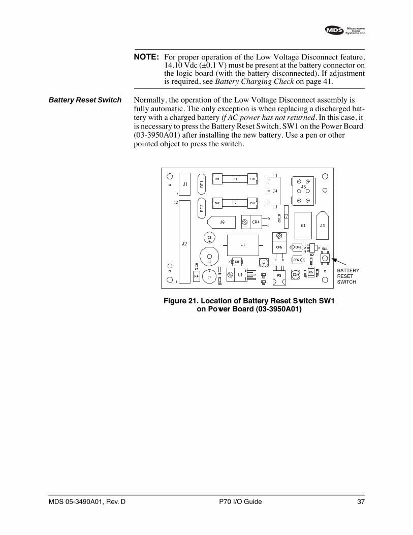
Battery Reset Switch Normally, the operation of the Low Voltage Disconnect assembly is fully automatic. The only exception is when replacing a discharged bat-tery with a charged battery if AC power has not returned. In this case, it is necessary to press the Battery Reset Switch, SW1 on the Power Board (03-3950A01) after installing the new battery. Use a pen or other pointed object to press the switch.
Invisible place holder
Figure 21. Location of Battery Reset Switch SW1 on Power Board (03-3950A01)
BATTERYRESETSWITCH
38 P70 I/O Guide MDS 05-3490A01, Rev. D
4.3 Logic Board Features and Indicators
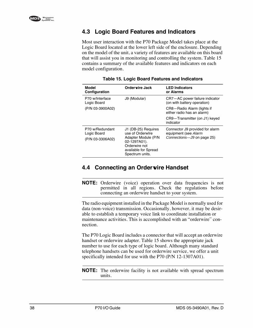
Most user interaction with the P70 Package Model takes place at the Logic Board located at the lower left side of the enclosure. Depending on the model of the unit, a variety of features are available on this board that will assist you in monitoring and controlling the system. Table 15 contains a summary of the available features and indicators on each model configuration.
4.4 Connecting an Orderwire Handset
NOTE: Orderwire (voice) operation over data frequencies is notpermitted in all regions. Check the regulations beforeconnecting an orderwire handset to your system.
The radio equipment installed in the Package Model is normally used for data (non-voice) transmission. Occasionally, however, it may be desir-able to establish a temporary voice link to coordinate installation or maintenance activities. This is accomplished with an “orderwire” con-nection.
The P70 Logic Board includes a connector that will accept an orderwire handset or orderwire adapter. Table 15 shows the appropriate jack number to use for each type of logic board. Although many standard telephone handsets can be used for orderwire service, we offer a unit specifically intended for use with the P70 (P/N 12-1307A01).
NOTE: The orderwire facility is not available with spread spectrumunits.
Table 15. Logic Board Features and Indicators
ModelConfiguration
Orderwire Jack LED Indicatorsor Alarms
P70 w/Interface Logic Board
(P/N 03-3900A02)
J9 (Modular) CR7—AC power failure indicator (on with battery operation)
CR8—Radio Alarm (lights if either radio has an alarm)
CR9—Transmitter (on J1) keyed indicator
P70 w/Redundant Logic Board
(P/N 03-3306A02)
J1 (DB-25) Requires use of OrderwIre Adapter Module (P/N 02-1297A01). Orderwire not available for Spread Spectrum units.
Connector J9 provided for alarm equipment (see Alarm Connections—J9 on page 25)
MDS 05-3490A01, Rev. D P70 I/O Guide 39
To use the orderwire feature:
1. Plug the orderwire handset into the appropriate connector on the logic board. (See Table 15.)
2. Key the transmitter by speaking into the handset (VOX).
NOTE: Unintentional sound picked up by the orderwire handset maykey the transmitter and interrupt the normal data flow throughthe transceiver. To prevent erratic operation of the system,remove the orderwire handset when the orderwire is not in use.
4.5 Connecting a Hand-Held Terminal (HHT)
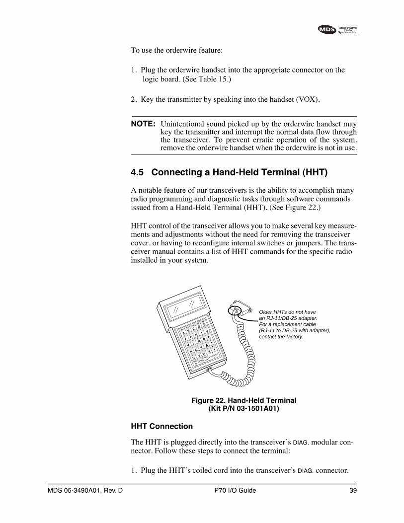
A notable feature of our transceivers is the ability to accomplish many radio programming and diagnostic tasks through software commands issued from a Hand-Held Terminal (HHT). (See Figure 22.)
HHT control of the transceiver allows you to make several key measure-ments and adjustments without the need for removing the transceiver cover, or having to reconfigure internal switches or jumpers. The trans-ceiver manual contains a list of HHT commands for the specific radio installed in your system.
Invisible place holder
Figure 22. Hand-Held Terminal(Kit P/N 03-1501A01)
HHT Connection
The HHT is plugged directly into the transceiver’s DIAG. modular con-nector. Follow these steps to connect the terminal:
1. Plug the HHT’s coiled cord into the transceiver’s DIAG. connector.
ZCTRLU
+
–K*
F/
AF1
V,
Q#
)G
(B
F2
SHIFT
ESC
W=
R7
M4
H1
CF3
BKSP
X0
S8
N5
I2
DF4
SPACE
Y
T9
O6
3E
F5
ENTER
J
L
P
Older HHTs do not havean RJ-11/DB-25 adapter.For a replacement cable(RJ-11 to DB-25 with adapter),contact the factory.
40 P70 I/O Guide MDS 05-3490A01, Rev. D
2. The HHT starts a self-check routine. When the test is finished, the HHT is ready to accept commands. Refer to the transceiver manual for radio-specific commands.
NOTE: Some older transceivers (i.e., MDS x310 Series do not have amodular DIAG. connector. In these cases it will be necessary toconnect the HHT to the transceiver’s INTERFACE connector bytemporarily disconnecting the ribbon cable. When testing isfinished, be sure to re-install the ribbon cable.
5.0 MAINTENANCEThis section contains information for keeping the Package Model in peak operating condition, as well as procedures for performing minor field adjustments and troubleshooting. This service information is intended to augment the transceiver manual shipped with your system.
5.1 Preventive Maintenance
Package Models are designed for long life and trouble-free operation. However, because these units are frequently installed in outdoor envi-ronments, periodic inspection of the equipment is more important than it would be for equipment mounted indoors.
The unit should be checked occasionally for loose or corroded hard-ware, loose cable connections, and damage to the exterior housing. The door seals and cable entrances should also be checked for signs of leakage or other damage. When performing preventive maintenance, it is also a good idea to check related equipment, such as the antenna system and remote terminal unit, for signs of damage or loose connec-tions. Consult the applicable instruction manual(s) for maintenance rec-ommendations.
The transceiver instruction manual contains many transceiver mainte-nance checks that can be made with an HHT. Specific items to check include RF power output, received signal strength (RSSI) and supply voltage.
5.2 Backup Battery—AC-powered units
Battery Test
Units equipped with a backup battery should be tested occasionally for proper backup operation. To do this, temporarily shut off the ac power to the station and check for continued radio operation. (If possible, the system should be tested for 30 minutes or more on backup power.) If a battery is found to be defective, refer to Backup Battery Replacement below for replacement instructions. Steps are also given later in this sec-tion for checking and adjusting the battery charging rate.
MDS 05-3490A01, Rev. D P70 I/O Guide 41
Backup Battery Replacement
Backup batteries have a limited service life. The length of time a battery lasts depends on many factors, including the battery size (4.5 AH or 12 AH), charge rate, number of discharge cycles and the ambient tempera-ture. If a backup battery is found to be defective, follow these steps to replace it:
1. Turn off the primary power to the station.
2. Unplug the battery cable from J3 (BATT.) on the Power Board.
3. Remove the battery bracket screws and the battery pack. Properly discard the defective battery.
When removing the battery bracket on Redundant units, use care not to damage the Radio Selection Switch (SW1) or its associated wiring har-ness. Also, be sure the switch remains set to the position it was originally in.
4. Install the new battery pack and re-install the battery bracket.
5. Connect the cable assembly between the battery and J3 on the Power Board.
6. Re-apply primary power to the station.
Battery Charging Check
For proper charging of the battery, the power supply must be set at the correct output voltage. To check for the correct charger output, perform the following procedure:
1. Disconnect the positive (+) lead from the battery and connect a volt-meter to the lead. The voltage should be 14.10 Vdc.
2. If not, the power supply voltage should be adjusted to produce 14.10 Vdc on the battery lead. The voltage can be adjusted using a small flat blade tool at VR1 on the edge of the ac power supply—see Figure 23. (The chassis plate may need to be removed from the enclosure to gain access to VR1.
CAUTIONPOSSIBLE
EQUIPMENTDAMAGE
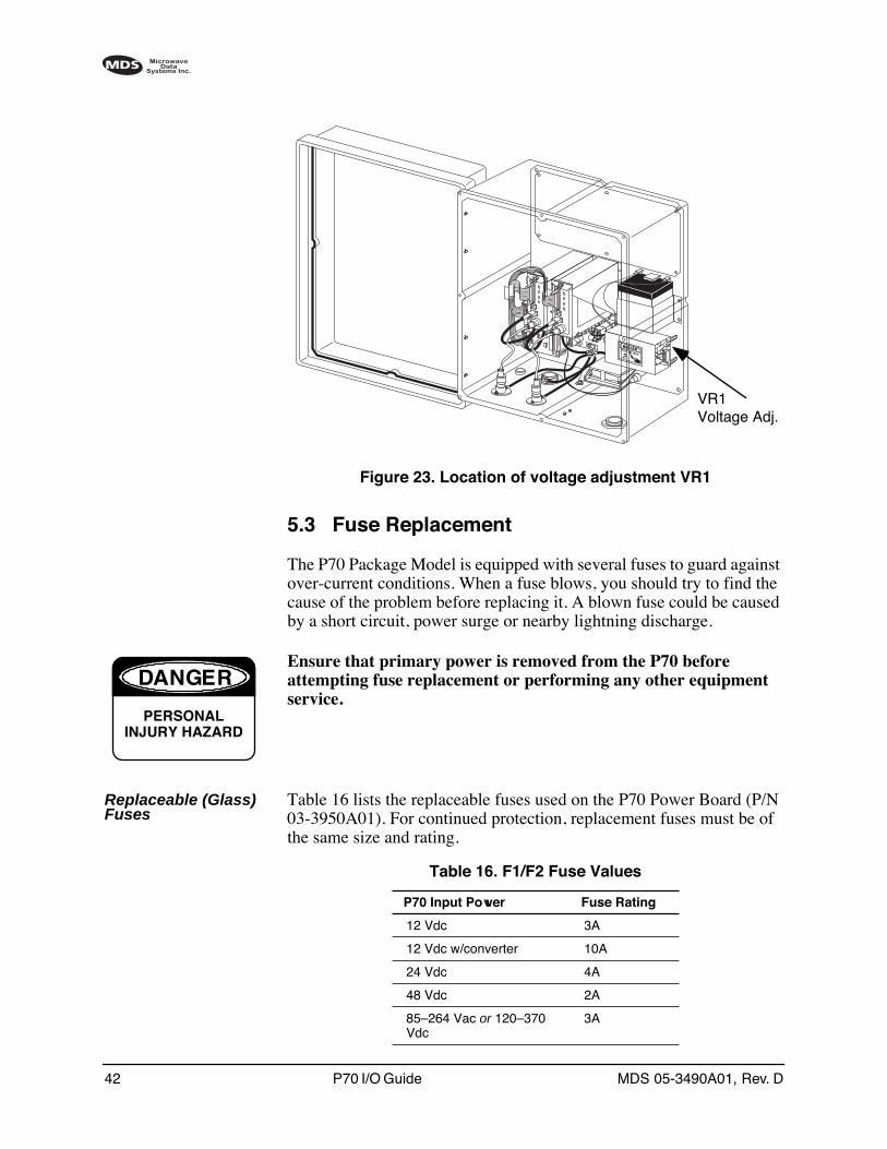
42 P70 I/O Guide MDS 05-3490A01, Rev. D
Invisible place holder
Figure 23. Location of voltage adjustment VR1
5.3 Fuse Replacement
The P70 Package Model is equipped with several fuses to guard against over-current conditions. When a fuse blows, you should try to find the cause of the problem before replacing it. A blown fuse could be caused by a short circuit, power surge or nearby lightning discharge.
Ensure that primary power is removed from the P70 before attempting fuse replacement or performing any other equipment service.
Replaceable (Glass) Fuses
Table 16 lists the replaceable fuses used on the P70 Power Board (P/N 03-3950A01). For continued protection, replacement fuses must be of the same size and rating.
VR1Voltage Adj.
DANGER
PERSONALINJURY HAZARD
Table 16. F1/F2 Fuse Values
P70 Input Power Fuse Rating
12 Vdc 3A
12 Vdc w/converter 10A
24 Vdc 4A
48 Vdc 2A
85–264 Vac or 120–370 Vdc
3A
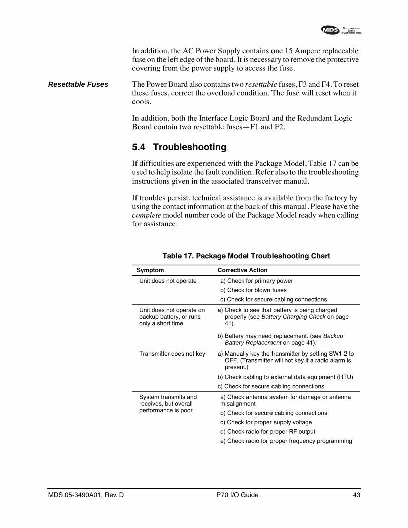
MDS 05-3490A01, Rev. D P70 I/O Guide 43
In addition, the AC Power Supply contains one 15 Ampere replaceable fuse on the left edge of the board. It is necessary to remove the protective covering from the power supply to access the fuse.
Resettable Fuses The Power Board also contains two resettable fuses, F3 and F4. To reset these fuses, correct the overload condition. The fuse will reset when it cools.
In addition, both the Interface Logic Board and the Redundant Logic Board contain two resettable fuses—F1 and F2.
5.4 Troubleshooting
If difficulties are experienced with the Package Model, Table 17 can be used to help isolate the fault condition. Refer also to the troubleshooting instructions given in the associated transceiver manual.
If troubles persist, technical assistance is available from the factory by using the contact information at the back of this manual. Please have the complete model number code of the Package Model ready when calling for assistance.
Table 17. Package Model Troubleshooting Chart
Symptom Corrective Action
Unit does not operate a) Check for primary power
b) Check for blown fuses
c) Check for secure cabling connections
Unit does not operate on backup battery, or runs only a short time
a) Check to see that battery is being charged properly (see Battery Charging Check on page 41).
b) Battery may need replacement. (see Backup Battery Replacement on page 41).
Transmitter does not key a) Manually key the transmitter by setting SW1-2 to OFF. (Transmitter will not key if a radio alarm is present.)
b) Check cabling to external data equipment (RTU)
c) Check for secure cabling connections
System transmits and receives, but overall performance is poor
a) Check antenna system for damage or antenna misalignment
b) Check for secure cabling connections
c) Check for proper supply voltage
d) Check radio for proper RF output
e) Check radio for proper frequency programming
44 P70 I/O Guide MDS 05-3490A01, Rev. D
5.5 Interpreting Alarms
Interface Logic Board (03-3900A02)
AC LED AC LED (CR7) indicates the loss of 14 V power from the Internal Power Supply Module, and shows that the system is operating on the battery power. System operation will continue until the battery is depleted. Check the power source and fuses.
RAD LED RAD LED (CR8) Indicates that one of the radios is reporting a failure. The radio with the alarm may have a flashing PWR light. Use a Hand Held Terminal or computer terminal to check the radio status (see trans-ceiver manual). Radio 1 RTS is disabled until the fault is corrected. The radio must have the Alarm Sense HIGH for alarm, and LOW for normal. Some radios allow this to be programmed. See the transceiver manual for details.
RTS LED RTS LED (CR9) Indicates Radio 1 is receiving RTS from the Logic Board. The presence of a radio alarm from either radio will block Radio 1 RTS.
RTU Port (J3)Pin 25 Checks
RTU Port J3 pin 25: 5V CMOS logic level output with 1kΩ series resistor. Low indicates normal operation. High indicates the presence of a Radio Alarm or an AC Fail alarm.
Redundant Logic Board (03-3306A02)
LEDs The LEDs on this board indicate the presence of DC power for Radio A (CR1) and Radio B (CR3).
Alarm Contacts (J9) The Alarm connector J9 provides access to relay contacts. Pin 1 is nor-mally closed, Pin 2 is the common terminal, and Pin 3 is normally open. An alarm condition in either radio will activate the alarm. The radio must have the Alarm Sense set to LOW for alarm, and HIGH for normal. Some radios allow the alarm sense to be programmed. See the radio manual for details.
MDS 05-3490A01, Rev. D P70 I/O Guide 45
5.6 P70 Interconnect Cabling
During maintenance tasks that involve board removal, there is a possi-bility of making improper cable connections during re-assembly. The tables provided below list the connectors on each board and indicate what they connect to.
* Optional Assemblies
Table 18. Interface Logic Board (P/N 03-3900A02) Cabling
Connector Function Connects To
J1 Radio 1 data & control Radio 1 DB-25
J2 Radio 2 data & control Radio 2 DB-25
J3 RTU Interface RTU / PLC
J4 Data Synchronization Data Synchronization Board* J1 (at edge of board). Make sure red stripe on ribbon cable is towards the transceiver mtg. brackets. Note: J2 on Data Sync. Board is not used.
J4 VOX Board connection VOX Board* J202 (at edge of board). Make sure red stripe on ribbon cable is towards the transceiver mtg. brackets. Note: J201 on VOX Board is not used.
J5 4 Wire Analog User Analog Interface
J6 12V Power (Radio 1) Radio 1 Power
J7 12V Power (Radio 2) Radio 2 Power
J9 Orderwire Orderwire Handset (optional)
J11 12V Power Input Power Board (03-3950A01) J6
Table 19. Redundant Logic Board (P/N 03-3306A01) Cabling
Connector Function Connects To
J1 RTU Interface RTU / PLC
J2 Radio B, data & control Radio B DB-25
J3 Radio A, data & control Radio A DB-25
J4 Power Supply Module AC or DC power supply
J5 Radio B, RF Radio B, Antenna Jack
J6 DC Power A Radio A Power
J7 DC Power B Radio B Power
J8 A – B Select Indicator PCB J1
J9 Alarm Relay User alarm interface
J10 Radio A, RF Radio A, Antenna Jack
J11 Antenna Lightning protector & Antenna
J12 Battery Backup Not used
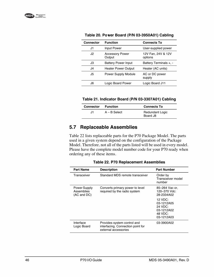
46 P70 I/O Guide MDS 05-3490A01, Rev. D
5.7 Replaceable Assemblies
Table 22 lists replaceable parts for the P70 Package Model. The parts used in a given system depend on the configuration of the Package Model. Therefore, not all of the parts listed will be used in every model. Please have the complete model number code for your P70 ready when ordering any of these items.
Table 20. Power Board (P/N 03-3950A01) Cabling
Connector Function Connects To
J1 Input Power User-supplied power
J2 Accessory Power Output
12V Fan, 24V & 12V options
J3 Battery Power Input Battery Terminals +, -
J4 Heater Power Output Heater (AC units)
J5 Power Supply Module AC or DC power supply
J6 Logic Board Power Logic Board J11
Table 21. Indicator Board (P/N 03-3307A01) Cabling
Connector Function Connects To
J1 A – B Select Redundant Logic Board J8
Table 22. P70 Replacement Assemblies
Part Name Description Part Number
Transceiver Standard MDS remote transceiver Order by Transceiver model number
Power Supply Assemblies(AC and DC)
Converts primary power to level required by the radio system
85–264 Vac or, 120–370 Vdc:28-2334A02
12 VDC: 03-1212A0524 VDC: 03-1212A0248 VDC: 03-1212A03
Interface Logic Board
Provides system control and interfacing. Connection point for external accessories
03-3900A02
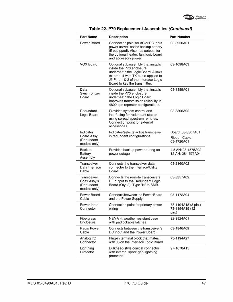
MDS 05-3490A01, Rev. D P70 I/O Guide 47
Power Board Connection point for AC or DC input power as well as the backup battery (if equipped). Also has outputs for the optional heater, fan, logic board and accessory power.
03-3950A01
VOX Board Optional subassembly that installs inside the P70 enclosure underneath the Logic Board. Allows external 4-wire TX audio applied to J5 Pins 1 & 2 of the Interface Logic Board to key the transmitter.
03-1098A03
Data Synchronizer Board
Optional subassembly that installs inside the P70 enclosure underneath the Logic Board. Improves transmission reliability in 4800 bps repeater configurations.
03-1389A01
Redundant Logic Board
Provides system control and interfacing for redundant station using spread spectrum remotes. Connection point for external accessories
03-3306A02
Indicator Board Assy.(Redundant models only)
Indicates/selects active transceiver in redundant configurations.
Board: 03-3307A01
Ribbon Cable: 03-1726A01
Backup Battery Assembly
Provides backup power during ac power outage
4.5 AH: 28-1575A0212 AH: 28-1575A04
Transceiver Data Interface Cable
Connects the transceiver data connector to the Interface/Utility Board
03-2160A02
Transceiver Coax Assy’s(Redundant models only)
Connects the remote transceivers RF output to the Redundant Logic Board (Qty. 3). Type “N” to SMB.
03-3357A02
Power Board Cable
Connects between the Power Board and the Power Supply
03-1172A04
Power Input Connector
Connection point for primary power wiring
73-1194A18 (3 pin.)73-1194A19 (12 pin.)
Fiberglass Enclosure
NEMA 4, weather resistant case with padlockable latches
82-3924A01
Radio Power Cable
Connects between the transceiver’s DC input and the Power Board.
03-1846A09
Analog I/OConnector
Plug-in terminal block that mates with J5 on the Interface Logic Board
73-1194A27
Lightning Protector
Bulkhead-style coaxial connector with internal spark-gap lightning protector
97-1678A15
Table 22. P70 Replacement Assemblies (Continued)
Part Name Description Part Number
48 P70 I/O Guide MDS 05-3490A01, Rev. D
APPENDIX AP70 APPLICATION NOTES
The following pages contain application notes with detailed information for configuring a P70 in a desired system. A review of the note(s) appli-cable to your system is recommended to assure proper operation and interfacing with external equipment.
These application notes are current as of the date of manual publication, however, you may wish to visit www.microwavedata.com on the World Wide Web to check for additional notes or revisions to this mate-rial.
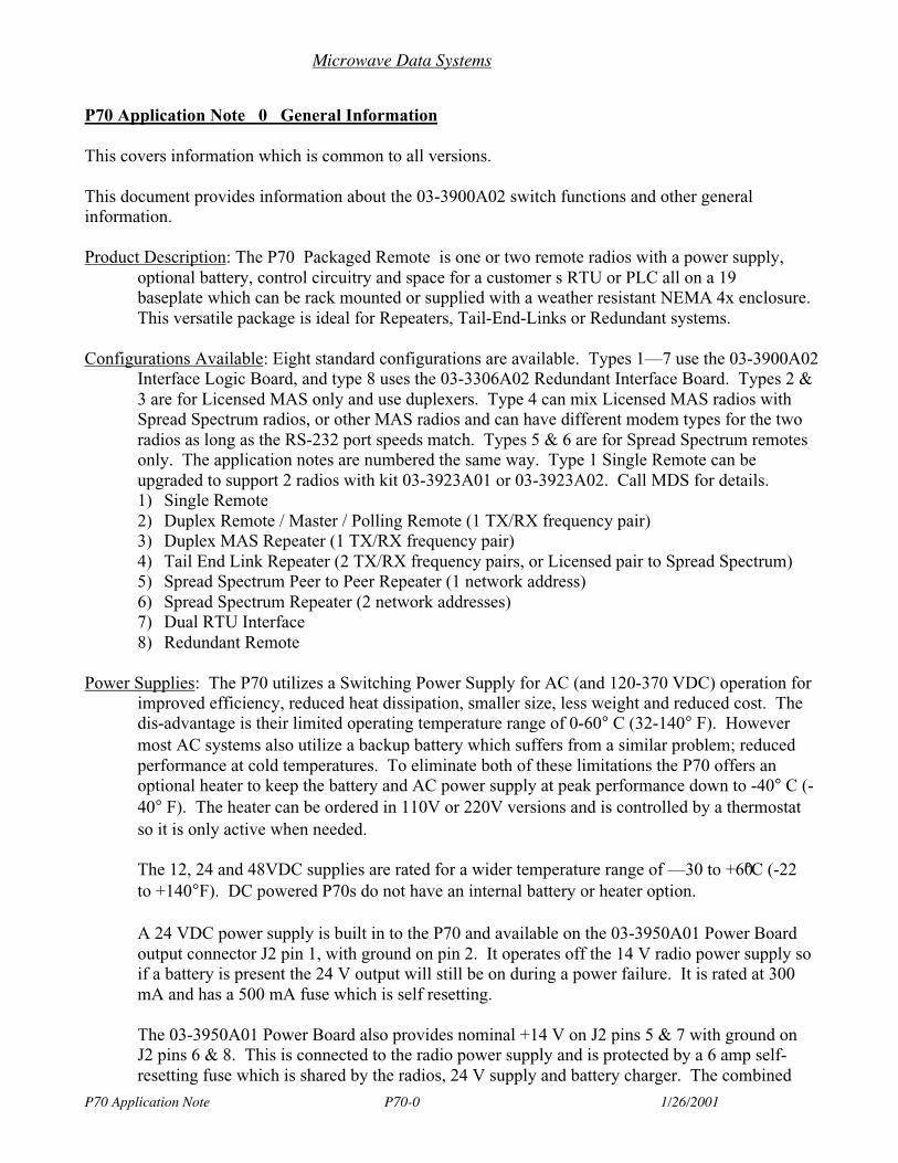
Microwave Data Systems
P70 Application Note P70-0 1/26/2001
P70 Application Note 0 General Information
This covers information which is common to all versions.
This document provides information about the 03-3900A02 switch functions and other generalinformation.
Product Description: The P70 Packaged Remote is one or two remote radios with a power supply,optional battery, control circuitry and space for a customer s RTU or PLC all on a 19baseplate which can be rack mounted or supplied with a weather resistant NEMA 4x enclosure.This versatile package is ideal for Repeaters, Tail-End-Links or Redundant systems.
Configurations Available: Eight standard configurations are available. Types 1—7 use the 03-3900A02Interface Logic Board, and type 8 uses the 03-3306A02 Redundant Interface Board. Types 2 &3 are for Licensed MAS only and use duplexers. Type 4 can mix Licensed MAS radios withSpread Spectrum radios, or other MAS radios and can have different modem types for the tworadios as long as the RS-232 port speeds match. Types 5 & 6 are for Spread Spectrum remotesonly. The application notes are numbered the same way. Type 1 Single Remote can beupgraded to support 2 radios with kit 03-3923A01 or 03-3923A02. Call MDS for details.1) Single Remote2) Duplex Remote / Master / Polling Remote (1 TX/RX frequency pair)3) Duplex MAS Repeater (1 TX/RX frequency pair)4) Tail End Link Repeater (2 TX/RX frequency pairs, or Licensed pair to Spread Spectrum)5) Spread Spectrum Peer to Peer Repeater (1 network address)6) Spread Spectrum Repeater (2 network addresses)7) Dual RTU Interface8) Redundant Remote
Power Supplies: The P70 utilizes a Switching Power Supply for AC (and 120-370 VDC) operation forimproved efficiency, reduced heat dissipation, smaller size, less weight and reduced cost. Thedis-advantage is their limited operating temperature range of 0-60° C (32-140° F). Howevermost AC systems also utilize a backup battery which suffers from a similar problem; reducedperformance at cold temperatures. To eliminate both of these limitations the P70 offers anoptional heater to keep the battery and AC power supply at peak performance down to -40° C (-40° F). The heater can be ordered in 110V or 220V versions and is controlled by a thermostatso it is only active when needed.
The 12, 24 and 48VDC supplies are rated for a wider temperature range of —30 to +60°C (-22to +140°F). DC powered P70s do not have an internal battery or heater option.
A 24 VDC power supply is built in to the P70 and available on the 03-3950A01 Power Boardoutput connector J2 pin 1, with ground on pin 2. It operates off the 14 V radio power supply soif a battery is present the 24 V output will still be on during a power failure. It is rated at 300mA and has a 500 mA fuse which is self resetting.
The 03-3950A01 Power Board also provides nominal +14 V on J2 pins 5 & 7 with ground onJ2 pins 6 & 8. This is connected to the radio power supply and is protected by a 6 amp self-resetting fuse which is shared by the radios, 24 V supply and battery charger. The combined
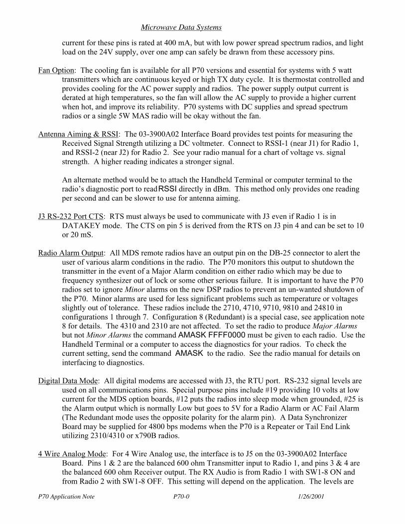
Microwave Data Systems
P70 Application Note P70-0 1/26/2001
current for these pins is rated at 400 mA, but with low power spread spectrum radios, and lightload on the 24V supply, over one amp can safely be drawn from these accessory pins.
Fan Option: The cooling fan is available for all P70 versions and essential for systems with 5 watttransmitters which are continuous keyed or high TX duty cycle. It is thermostat controlled andprovides cooling for the AC power supply and radios. The power supply output current isderated at high temperatures, so the fan will allow the AC supply to provide a higher currentwhen hot, and improve its reliability. P70 systems with DC supplies and spread spectrumradios or a single 5W MAS radio will be okay without the fan.
Antenna Aiming & RSSI: The 03-3900A02 Interface Board provides test points for measuring theReceived Signal Strength utilizing a DC voltmeter. Connect to RSSI-1 (near J1) for Radio 1,and RSSI-2 (near J2) for Radio 2. See your radio manual for a chart of voltage vs. signalstrength. A higher reading indicates a stronger signal.
An alternate method would be to attach the Handheld Terminal or computer terminal to theradio’s diagnostic port to read RSSI directly in dBm. This method only provides one readingper second and can be slower to use for antenna aiming.
J3 RS-232 Port CTS: RTS must always be used to communicate with J3 even if Radio 1 is inDATAKEY mode. The CTS on pin 5 is derived from the RTS on J3 pin 4 and can be set to 10or 20 mS.
Radio Alarm Output: All MDS remote radios have an output pin on the DB-25 connector to alert theuser of various alarm conditions in the radio. The P70 monitors this output to shutdown thetransmitter in the event of a Major Alarm condition on either radio which may be due tofrequency synthesizer out of lock or some other serious failure. It is important to have the P70radios set to ignore Minor alarms on the new DSP radios to prevent an un-wanted shutdown ofthe P70. Minor alarms are used for less significant problems such as temperature or voltagesslightly out of tolerance. These radios include the 2710, 4710, 9710, 9810 and 24810 inconfigurations 1 through 7. Configuration 8 (Redundant) is a special case, see application note8 for details. The 4310 and 2310 are not affected. To set the radio to produce Major Alarmsbut not Minor Alarms the command AMASK FFFF0000 must be given to each radio. Use theHandheld Terminal or a computer to access the diagnostics for your radios. To check thecurrent setting, send the command AMASK to the radio. See the radio manual for details oninterfacing to diagnostics.
Digital Data Mode: All digital modems are accessed with J3, the RTU port. RS-232 signal levels areused on all communications pins. Special purpose pins include #19 providing 10 volts at lowcurrent for the MDS option boards, #12 puts the radios into sleep mode when grounded, #25 isthe Alarm output which is normally Low but goes to 5V for a Radio Alarm or AC Fail Alarm(The Redundant mode uses the opposite polarity for the alarm pin). A Data SynchronizerBoard may be supplied for 4800 bps modems when the P70 is a Repeater or Tail End Linkutilizing 2310/4310 or x790B radios.
4 Wire Analog Mode: For 4 Wire Analog use, the interface is to J5 on the 03-3900A02 InterfaceBoard. Pins 1 & 2 are the balanced 600 ohm Transmitter input to Radio 1, and pins 3 & 4 arethe balanced 600 ohm Receiver output. The RX Audio is from Radio 1 with SW1-8 ON andfrom Radio 2 with SW1-8 OFF. This setting will depend on the application. The levels are
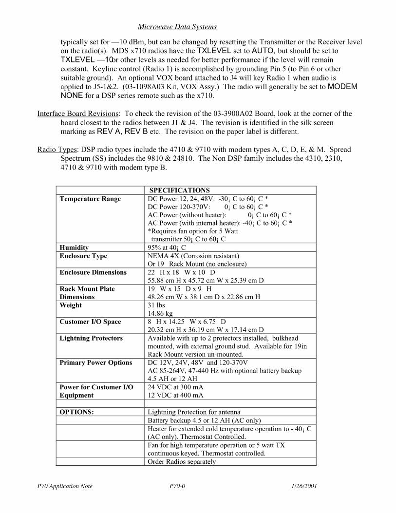
Microwave Data Systems
P70 Application Note P70-0 1/26/2001
typically set for —10 dBm, but can be changed by resetting the Transmitter or the Receiver levelon the radio(s). MDS x710 radios have the TXLEVEL set to AUTO, but should be set toTXLEVEL —10 or other levels as needed for better performance if the level will remainconstant. Keyline control (Radio 1) is accomplished by grounding Pin 5 (to Pin 6 or othersuitable ground). An optional VOX board attached to J4 will key Radio 1 when audio isapplied to J5-1&2. (03-1098A03 Kit, VOX Assy.) The radio will generally be set to MODEMNONE for a DSP series remote such as the x710.
Interface Board Revisions: To check the revision of the 03-3900A02 Board, look at the corner of theboard closest to the radios between J1 & J4. The revision is identified in the silk screenmarking as REV A, REV B etc. The revision on the paper label is different.
Radio Types: DSP radio types include the 4710 & 9710 with modem types A, C, D, E, & M. SpreadSpectrum (SS) includes the 9810 & 24810. The Non DSP family includes the 4310, 2310,4710 & 9710 with modem type B.
SPECIFICATIONSTemperature Range DC Power 12, 24, 48V: -30¡ C to 60¡ C *
DC Power 120-370V: 0¡ C to 60¡ C *AC Power (without heater): 0¡ C to 60¡ C *AC Power (with internal heater): -40¡ C to 60¡ C **Requires fan option for 5 Watt transmitter 50¡ C to 60¡ C
Humidity 95% at 40¡ CEnclosure Type NEMA 4X (Corrosion resistant)
Or 19 Rack Mount (no enclosure)Enclosure Dimensions 22 H x 18 W x 10 D
55.88 cm H x 45.72 cm W x 25.39 cm DRack Mount PlateDimensions
19 W x 15 D x 9 H48.26 cm W x 38.1 cm D x 22.86 cm H
Weight 31 lbs14.86 kg
Customer I/O Space 8 H x 14.25 W x 6.75 D20.32 cm H x 36.19 cm W x 17.14 cm D
Lightning Protectors Available with up to 2 protectors installed, bulkheadmounted, with external ground stud. Available for 19inRack Mount version un-mounted.
Primary Power Options DC 12V, 24V, 48V and 120-370VAC 85-264V, 47-440 Hz with optional battery backup4.5 AH or 12 AH
Power for Customer I/OEquipment
24 VDC at 300 mA12 VDC at 400 mA
OPTIONS: Lightning Protection for antennaBattery backup 4.5 or 12 AH (AC only)Heater for extended cold temperature operation to - 40¡ C(AC only). Thermostat Controlled.Fan for high temperature operation or 5 watt TXcontinuous keyed. Thermostat controlled.Order Radios separately
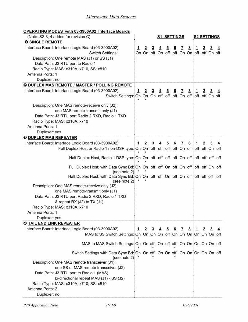
Microwave Data Systems
P70 Application Note P70-0 1/26/2001
OPERATING MODES with 03-3900A02 Interface Boards(Note: S2-3, 4 added for revision C) S1 SETTINGS S2 SETTINGS
SINGLE REMOTEInterface Board: Interface Logic Board (03-3900A02) 1 2 3 4 5 6 7 8 1 2 3 4
Switch Settings: On On off On off off On On off off On offDescription: One remote MAS (J1) or SS (J1)Data Path: J3 RTU port to Radio 1
Radio Type: MAS: x310A, x710, SS: x810Antenna Ports: 1
Duplexer: no DUPLEX MAS REMOTE / MASTER / POLLING REMOTE
Interface Board: Interface Logic Board (03-3900A02) 1 2 3 4 5 6 7 8 1 2 3 4Switch Settings: On
*On
*On off off off On off off off On off
Description: One MAS remote-receive only (J2);one MAS remote-transmit only (J1)
Data Path: J3 RTU port Radio 2 RXD, Radio 1 TXDRadio Type: MAS: x310A, x710
Antenna Ports: 1Duplexer: yes
DUPLEX MAS REPEATERInterface Board: Interface Logic Board (03-3900A02) 1 2 3 4 5 6 7 8 1 2 3 4
Full Duplex Host or Radio 1 non-DSP type: On*
On*
off off off off On off off off On off
Half Duplex Host, Radio 1 DSP type: On*
On*
off off off off On off off off off off
Full Duplex Host; with Data Sync Bd:(see note 2)
On*
On*
off off On off On off off off On off
Half Duplex Host; with Data Sync Bd:(see note 2)
On*
On*
off off On off On off off off off off
Description: One MAS remote-receive only (J2);one MAS remote-transmit only (J1)
Data Path: J3 RTU port Radio 2 RXD, Radio 1 TXD& repeat RX (J2) to TX (J1)
Radio Type: MAS: x310A, x710Antenna Ports: 1
Duplexer: yes TAIL END LINK REPEATER
Interface Board: Interface Logic Board (03-3900A02) 1 2 3 4 5 6 7 8 1 2 3 4MAS to SS Switch Settings: On
*On On On off On On On On On On off
MAS to MAS Switch Settings: On*
On off*
On off off*
On On On On On off
Switch Settings with Data Sync Bd:(see note 2)
On*
On off*
On On off*
On On On On On off
Description: One MAS remote transceiver (J1);one SS or MAS remote transceiver (J2)
Data Path: J3 RTU port to Radio 1 (MAS)bi-directional repeat MAS (J1) - SS (J2)
Radio Type: MAS: x310A, x710; SS: x810Antenna Ports: 2
Duplexer: no
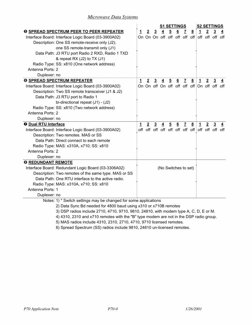
Microwave Data Systems
P70 Application Note P70-0 1/26/2001
S1 SETTINGS S2 SETTINGS SPREAD SPECTRUM PEER TO PEER REPEATER 1 2 3 4 5 6 7 8 1 2 3 4
Interface Board: Interface Logic Board (03-3900A02) On On On off off off off off off off off offDescription: One SS remote-receive only (J2);
one SS remote-transmit only (J1)Data Path: J3 RTU port Radio 2 RXD, Radio 1 TXD
& repeat RX (J2) to TX (J1)Radio Type: SS: x810 (One network address)
Antenna Ports: 2Duplexer: no
SPREAD SPECTRUM REPEATER 1 2 3 4 5 6 7 8 1 2 3 4Interface Board: Interface Logic Board (03-3900A02) On On off On off off off off On off off off
Description: Two SS remote transceiver (J1 & J2)Data Path: J3 RTU port to Radio 1
bi-directional repeat (J1) - (J2)Radio Type: SS: x810 (Two network address)
Antenna Ports: 2Duplexer: no
Dual RTU Interface 1 2 3 4 5 6 7 8 1 2 3 4Interface Board: Interface Logic Board (03-3900A02) off off off off off off off off off off off off
Description: Two remotes. MAS or SSData Path: Direct connect to each remote
Radio Type: MAS: x310A, x710; SS: x810Antenna Ports: 2
Duplexer: no REDUNDANT REMOTE
Interface Board: Redundant Logic Board (03-3306A02) (No Switches to set)Description: Two remotes of the same type. MAS or SSData Path: One RTU interface to the active radio.
Radio Type: MAS: x310A, x710; SS: x810Antenna Ports: 1
Duplexer: noNotes: 1) * Switch settings may be changed for some applications
2) Data Sync Bd needed for 4800 baud using x310 or x710B remotes3) DSP radios include 2710, 4710, 9710, 9810, 24810, with modem type A, C, D, E or M.4) 4310, 2310 and x710 remotes with the "B" type modem are not in the DSP radio group.5) MAS radios include 4310, 2310, 2710, 4710, 9710 licensed remotes.6) Spread Spectrum (SS) radios include 9810, 24810 un-licensed remotes.
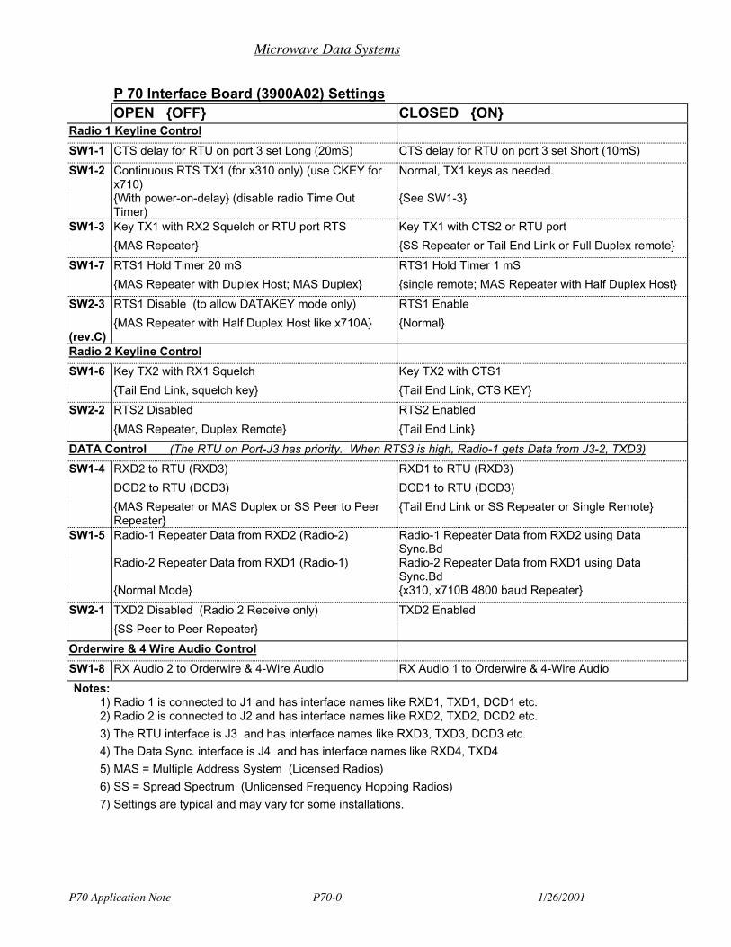
Microwave Data Systems
P70 Application Note P70-0 1/26/2001
P 70 Interface Board (3900A02) SettingsOPEN OFF CLOSED ON
Radio 1 Keyline Control
SW1-1 CTS delay for RTU on port 3 set Long (20mS) CTS delay for RTU on port 3 set Short (10mS)
SW1-2 Continuous RTS TX1 (for x310 only) (use CKEY forx710)
Normal, TX1 keys as needed.
With power-on-delay (disable radio Time OutTimer)
See SW1-3
SW1-3 Key TX1 with RX2 Squelch or RTU port RTS Key TX1 with CTS2 or RTU port
MAS Repeater SS Repeater or Tail End Link or Full Duplex remote
SW1-7 RTS1 Hold Timer 20 mS RTS1 Hold Timer 1 mS
MAS Repeater with Duplex Host; MAS Duplex single remote; MAS Repeater with Half Duplex Host
SW2-3 RTS1 Disable (to allow DATAKEY mode only) RTS1 Enable
(rev.C)MAS Repeater with Half Duplex Host like x710A Normal
Radio 2 Keyline Control
SW1-6 Key TX2 with RX1 Squelch Key TX2 with CTS1
Tail End Link, squelch key Tail End Link, CTS KEY
SW2-2 RTS2 Disabled RTS2 Enabled
MAS Repeater, Duplex Remote Tail End Link
DATA Control (The RTU on Port-J3 has priority. When RTS3 is high, Radio-1 gets Data from J3-2, TXD3)
SW1-4 RXD2 to RTU (RXD3) RXD1 to RTU (RXD3)
DCD2 to RTU (DCD3) DCD1 to RTU (DCD3)
MAS Repeater or MAS Duplex or SS Peer to PeerRepeater
Tail End Link or SS Repeater or Single Remote
SW1-5 Radio-1 Repeater Data from RXD2 (Radio-2) Radio-1 Repeater Data from RXD2 using DataSync.Bd
Radio-2 Repeater Data from RXD1 (Radio-1) Radio-2 Repeater Data from RXD1 using DataSync.Bd
Normal Mode x310, x710B 4800 baud Repeater
SW2-1 TXD2 Disabled (Radio 2 Receive only) TXD2 Enabled
SS Peer to Peer Repeater
Orderwire & 4 Wire Audio Control
SW1-8 RX Audio 2 to Orderwire & 4-Wire Audio RX Audio 1 to Orderwire & 4-Wire Audio
Notes:1) Radio 1 is connected to J1 and has interface names like RXD1, TXD1, DCD1 etc.2) Radio 2 is connected to J2 and has interface names like RXD2, TXD2, DCD2 etc.
3) The RTU interface is J3 and has interface names like RXD3, TXD3, DCD3 etc.
4) The Data Sync. interface is J4 and has interface names like RXD4, TXD4
5) MAS = Multiple Address System (Licensed Radios)
6) SS = Spread Spectrum (Unlicensed Frequency Hopping Radios)
7) Settings are typical and may vary for some installations.
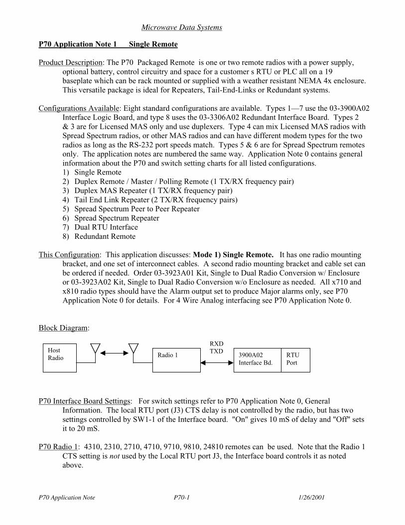
Microwave Data Systems
P70 Application Note P70-1 1/26/2001
P70 Application Note 1 Single Remote
Product Description: The P70 Packaged Remote is one or two remote radios with a power supply,optional battery, control circuitry and space for a customer s RTU or PLC all on a 19baseplate which can be rack mounted or supplied with a weather resistant NEMA 4x enclosure.This versatile package is ideal for Repeaters, Tail-End-Links or Redundant systems.
Configurations Available: Eight standard configurations are available. Types 1—7 use the 03-3900A02Interface Logic Board, and type 8 uses the 03-3306A02 Redundant Interface Board. Types 2& 3 are for Licensed MAS only and use duplexers. Type 4 can mix Licensed MAS radios withSpread Spectrum radios, or other MAS radios and can have different modem types for the tworadios as long as the RS-232 port speeds match. Types 5 & 6 are for Spread Spectrum remotesonly. The application notes are numbered the same way. Application Note 0 contains generalinformation about the P70 and switch setting charts for all listed configurations.1) Single Remote2) Duplex Remote / Master / Polling Remote (1 TX/RX frequency pair)3) Duplex MAS Repeater (1 TX/RX frequency pair)4) Tail End Link Repeater (2 TX/RX frequency pairs)5) Spread Spectrum Peer to Peer Repeater6) Spread Spectrum Repeater7) Dual RTU Interface8) Redundant Remote
This Configuration: This application discusses: Mode 1) Single Remote. It has one radio mountingbracket, and one set of interconnect cables. A second radio mounting bracket and cable set canbe ordered if needed. Order 03-3923A01 Kit, Single to Dual Radio Conversion w/ Enclosureor 03-3923A02 Kit, Single to Dual Radio Conversion w/o Enclosure as needed. All x710 andx810 radio types should have the Alarm output set to produce Major alarms only, see P70Application Note 0 for details. For 4 Wire Analog interfacing see P70 Application Note 0.
Block Diagram:
P70 Interface Board Settings: For switch settings refer to P70 Application Note 0, GeneralInformation. The local RTU port (J3) CTS delay is not controlled by the radio, but has twosettings controlled by SW1-1 of the Interface board. "On" gives 10 mS of delay and "Off" setsit to 20 mS.
P70 Radio 1: 4310, 2310, 2710, 4710, 9710, 9810, 24810 remotes can be used. Note that the Radio 1CTS setting is not used by the Local RTU port J3, the Interface board controls it as notedabove.
Radio 1 3900A02Interface Bd.
RTUPort
HostRadio
RXDTXD
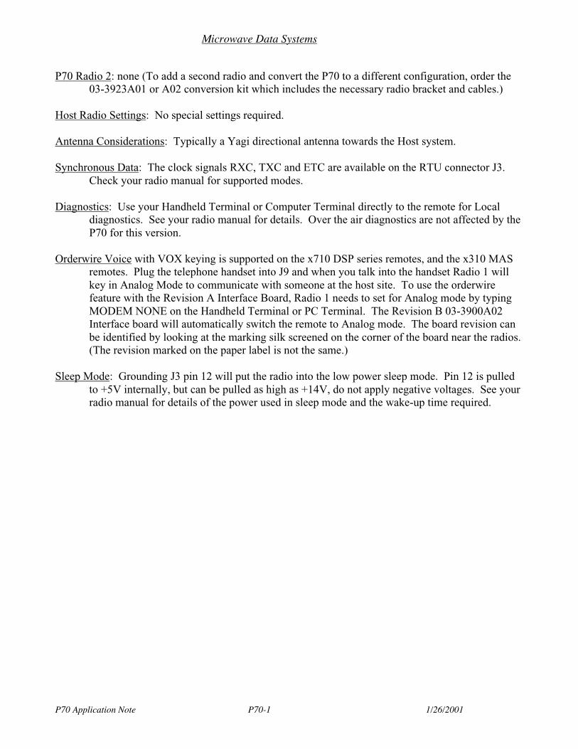
Microwave Data Systems
P70 Application Note P70-1 1/26/2001
P70 Radio 2: none (To add a second radio and convert the P70 to a different configuration, order the03-3923A01 or A02 conversion kit which includes the necessary radio bracket and cables.)
Host Radio Settings: No special settings required.
Antenna Considerations: Typically a Yagi directional antenna towards the Host system.
Synchronous Data: The clock signals RXC, TXC and ETC are available on the RTU connector J3.Check your radio manual for supported modes.
Diagnostics: Use your Handheld Terminal or Computer Terminal directly to the remote for Localdiagnostics. See your radio manual for details. Over the air diagnostics are not affected by theP70 for this version.
Orderwire Voice with VOX keying is supported on the x710 DSP series remotes, and the x310 MASremotes. Plug the telephone handset into J9 and when you talk into the handset Radio 1 willkey in Analog Mode to communicate with someone at the host site. To use the orderwirefeature with the Revision A Interface Board, Radio 1 needs to set for Analog mode by typingMODEM NONE on the Handheld Terminal or PC Terminal. The Revision B 03-3900A02Interface board will automatically switch the remote to Analog mode. The board revision canbe identified by looking at the marking silk screened on the corner of the board near the radios.(The revision marked on the paper label is not the same.)
Sleep Mode: Grounding J3 pin 12 will put the radio into the low power sleep mode. Pin 12 is pulledto +5V internally, but can be pulled as high as +14V, do not apply negative voltages. See yourradio manual for details of the power used in sleep mode and the wake-up time required.
Microwave Data Systems
P70 Application Note P70-2 1/26/2001
P70 Application Note 2 Duplex Remote / Master / Polling Remote
Product Description: The P70 Packaged Remote is one or two remote radios with a power supply,optional battery, control circuitry and space for a customer s RTU or PLC all on a 19baseplate which can be rack mounted or supplied with a weather resistant NEMA 4x enclosure.This versatile package is ideal for Repeaters, Tail-End-Links or Redundant systems.
Configurations Available: Eight standard configurations are available. Types 1—7 use the 03-3900A02Interface Logic Board, and type 8 uses the 03-3306A02 Redundant Interface Board. Types 2& 3 are for Licensed MAS only and use duplexers. Type 4 can mix Licensed MAS radios withSpread Spectrum radios, or other MAS radios and can have different modem types for the tworadios as long as the RS-232 port speeds match. Types 5 & 6 are for Spread Spectrum remotesonly. The application notes are numbered the same way. Application Note 0 contains generalinformation about the P70 and switch setting charts for all listed configurations.1) Single Remote2) Duplex Remote / Master / Polling Remote (1 TX/RX frequency pair)3) Duplex MAS Repeater (1 TX/RX frequency pair)4) Tail End Link Repeater (2 TX/RX frequency pairs)5) Spread Spectrum Peer to Peer Repeater6) Spread Spectrum Repeater7) Dual RTU Interface8) Redundant Remote
This Configuration: This application discusses: Mode 2) Duplex Remote / Master / Polling Remote.For this version Radio 2 is used as a Receiver and Radio 1 is used as a Transmitter. All Datapasses through the J3 RTU port to the user’s RTU or PLC. All x710 radio types should havethe Alarm output set to produce Major alarms only, see P70 Application Note 0 for details. For4 Wire Analog interfacing see P70 Application Note 0.
Block Diagram:
P70 Interface Board Settings: For switch settings refer to P70 Application Note 0, GeneralInformation. This configuration typically sets the CTS delay for the RTU port to 10 mS andthe Transmitter to Switched-Carrier Mode. The transmitter can be continuous keyed if theoptional cooling fan is installed, and the proper technique is used. For the 4310 & 2310 seriesradios SW1-2 can be set to OFF to apply continuous RTS to Radio 1. For the 4710 & 9710with modem types A, C, D, E, or M, set SW1-2 to ON and use the diagnostic command CKEYON instead of SW1-2 for keying.
Radio 2(Receiver)
3900A02InterfaceBd.
RTUPort
Radio 1(Transmitter)
RXD
TXD
HostRadio
Duplexer

Microwave Data Systems
P70 Application Note P70-2 1/26/2001
P70 Radio 1: x710 or x310 MAS remotes. Radio 1 is the Transmitter for this version. Operation inswitched carrier mode is generally recommended to reduce the power consumption and heatgeneration. DSP series MAS radios like the x710 can key from J3-4 RTS or use DATAKEYmode. Older x310 radios only key on RTS for digital data. Continuous keying is possible, ifthe optional Fan is installed, by setting SW1-2 off for the x310 radios, or by the commandCKEY ON for the x710 DSP series radios. Transmit Data is from J3-2 TXD. The TXfrequency must match the installed Duplexer, the RX frequency is not important for Radio 1 asit is used for Transmit only. (For best performance with a 2310 series remote set the RXfrequency 23 MHz higher than TX.)
P70 Radio 2: Same type as Radio 1. Radio 2 is the Receiver for this version. Data is on J3-3 RXD,and carrier detect is on J3-8 DCD. The RX frequency must match the installed Duplexer, theTX frequency is not important for Radio 2 as it is used for Receive only.
Host Radio Settings: Compatible MDS Master Station or Remote with the same modem type.
Remote Radios: n/a for this version.
Antenna Considerations: If the P70 is a Remote use a directional antenna aimed toward the Hostradio site; If the P70 is a Master use an omnidirectional antenna.
Synchronous Data: The clock signals RXC (Radio 2), TXC and ETC (radio 1) are available on theRTU connector J3. Check your radio manual for supported modes.
Diagnostics: Use your Handheld Terminal or Computer Terminal directly to the remote for Localdiagnostics. See your radio manual for details. Over the air diagnostics is not supported onthis version P70.
Orderwire Voice with VOX keying is supported on the x710 DSP series remotes, and the x310 MASremotes. Plug the telephone handset into J9 and when you talk into the handset Radio 1 willkey in Analog Mode to communicate with someone at the host site. To use the orderwirefeature with the Revision A Interface Board, Radio 1 needs to set for Analog mode by typingMODEM NONE on the Handheld Terminal or PC Terminal. The Revision B 03-3900A02Interface board will automatically switch the remote to Analog mode. The board revision canbe identified by looking at the marking silk screened on the corner of the board near the radios.(The revision marked on the paper label is not the same.)
Sleep Mode: Grounding J3 pin 12 will put both radios into their low power sleep mode. Pin 12 ispulled to +5V internally, but can be pulled as high as +14V, do not apply negative voltages.See your radio manual for details of the power used in sleep mode and the wake-up timerequired.
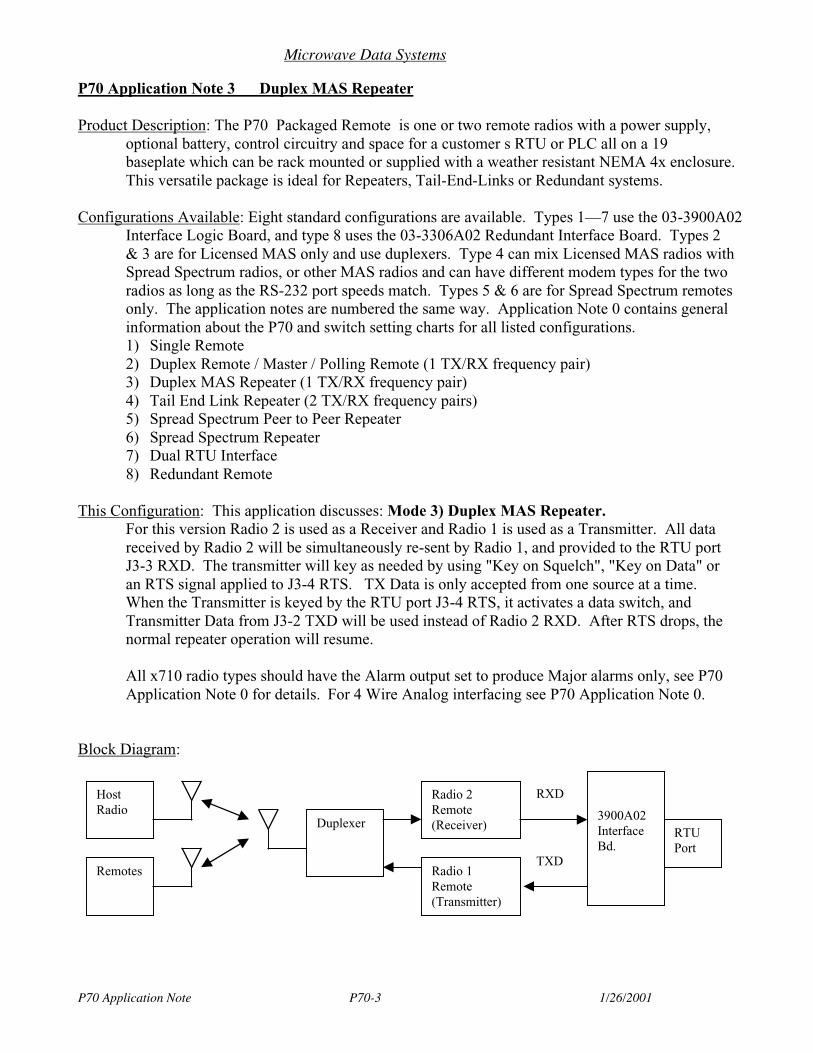
Microwave Data Systems
P70 Application Note P70-3 1/26/2001
P70 Application Note 3 Duplex MAS Repeater
Product Description: The P70 Packaged Remote is one or two remote radios with a power supply,optional battery, control circuitry and space for a customer s RTU or PLC all on a 19baseplate which can be rack mounted or supplied with a weather resistant NEMA 4x enclosure.This versatile package is ideal for Repeaters, Tail-End-Links or Redundant systems.
Configurations Available: Eight standard configurations are available. Types 1—7 use the 03-3900A02Interface Logic Board, and type 8 uses the 03-3306A02 Redundant Interface Board. Types 2& 3 are for Licensed MAS only and use duplexers. Type 4 can mix Licensed MAS radios withSpread Spectrum radios, or other MAS radios and can have different modem types for the tworadios as long as the RS-232 port speeds match. Types 5 & 6 are for Spread Spectrum remotesonly. The application notes are numbered the same way. Application Note 0 contains generalinformation about the P70 and switch setting charts for all listed configurations.1) Single Remote2) Duplex Remote / Master / Polling Remote (1 TX/RX frequency pair)3) Duplex MAS Repeater (1 TX/RX frequency pair)4) Tail End Link Repeater (2 TX/RX frequency pairs)5) Spread Spectrum Peer to Peer Repeater6) Spread Spectrum Repeater7) Dual RTU Interface8) Redundant Remote
This Configuration: This application discusses: Mode 3) Duplex MAS Repeater.For this version Radio 2 is used as a Receiver and Radio 1 is used as a Transmitter. All datareceived by Radio 2 will be simultaneously re-sent by Radio 1, and provided to the RTU portJ3-3 RXD. The transmitter will key as needed by using "Key on Squelch", "Key on Data" oran RTS signal applied to J3-4 RTS. TX Data is only accepted from one source at a time.When the Transmitter is keyed by the RTU port J3-4 RTS, it activates a data switch, andTransmitter Data from J3-2 TXD will be used instead of Radio 2 RXD. After RTS drops, thenormal repeater operation will resume.
All x710 radio types should have the Alarm output set to produce Major alarms only, see P70Application Note 0 for details. For 4 Wire Analog interfacing see P70 Application Note 0.
Block Diagram:
Radio 2Remote(Receiver)
3900A02InterfaceBd.
RTUPort
Radio 1Remote(Transmitter)
RXD
TXD
HostRadio
Remotes
Duplexer
Microwave Data Systems
P70 Application Note P70-3 1/26/2001
P70 Interface Board Settings: For switch settings refer to P70 Application Note 0, GeneralInformation. These set the CTS delay for the RTU port to 10 mS and the Transmitter toSwitched-Carrier Mode. It is best to let the P70 key as needed to send data rather than operatecontinuously keyed to avoid the additional heat and power consumption. Operation with thetransmitter continuously keyed is possible if the optional Fan is installed, and the proper keyingmethod is used for the radio type.
SW1-1 controls the RTU port (J3) CTS Delay of 10 mS (on) or 20 mS (off) and will need tochange for some applications.
SW1-2 sets the RTS for Radio 1 to Continuous (off) or Switched (on). Setting SW1-2 On willallow Radio 1 to key as needed when RTS at J3-4 is asserted, or when Radio 2 receives asignal. In this mode SW1-7 will provide an RTS hold time of either 1 mS (on) or 20 mS (off)to keep the transmitter keyed briefly after the keying source drops. This helps keep the RF linkactive and prevents short carrier dropouts between messages to reduce errors in P70 Repeatersusing x310 or x710B radios.
Setting SW1-2 Off will provide continuous RTS to Radio 1. This is only valid with 2310,4310 and x710B remotes and requires the optional cooling fan to prevent heat buildup in theAC supply and transmitter. (For x710A, C, D, E or M remotes see the discussion below.)Continuous RTS will keep the repeater continuously keyed after a short delay when power isfirst applied. The Time Out Timer must be disabled for this mode by issuing the diagnosticcommand DTOT to the radio. Refer to your radio manual for additional details.
SW1-2 must be On for MDS x710A, C, D, E or M DSP series remotes. The keying modewhich works best for most installations is to "key on data". This setting is required if the P70is communicating with a Half-Duplex Host such as an x710A remote. Radio 1 should be set toDATAKEY ON, and RTS1 disabled on the Interface board by setting SW2-3 off (revision C orlater Interface Boards). In this mode, the RX data from Radio 2 will automatically key Radio 1and be re-transmitted. The local RTU port J3 can also send data to Radio 1 but must useRTS/CTS handshaking to activate the RTU port.
When the P70 Repeater is used with a Full Duplex Master Station, another keying optionwould be to set Radio 1 DATAKEY OFF and enable the Radio 1 RTS input by setting SW2-3On. (All board revisions support this mode.) Duplex Masters are compatible with RTS Hold(SW1-7) set for either 1 or 20 mS. Radio 1 will key when Radio 2 squelch opens.
The MDS x710A, C, D, E or M DSP series remotes can be continuously keyed if necessary byissuing the CKEY ON command for Radio 1 and requires the optional cooling fan to preventheat buildup in the AC supply and transmitter. This command also disables the Time OutTimer. See your radio manual for diagnostic commands and procedures.
P70 Radio 1: Any x710 or x310 Licensed MAS remotes. Radio 1 is the Transmitter for this version.It will key when Radio 2 receives a signal, or from J3-4 RTS, or can be continuous keyed asdescribed above if the optional fan is installed. Transmit Data is from Radio 2 RXD or if J3-4RTS is high, from J3-2 TXD. The TX frequency must match the installed Duplexer, the RXfrequency is not important for Radio 1 as it is used for Transmit only. It is typically set thesame as Radio 2 to make them interchangeable. (For best performance with a 2310 series

Microwave Data Systems
P70 Application Note P70-3 1/26/2001
remote set the RX frequency 23 MHz higher than TX.) The radio CTS is not used and can beset to 0.
P70 Radio 2: Always the same modem type as Radio 1. (Radios could be mixed such a 4310 and4710B as long as they have the same modem type.) Radio 2 is the Receiver for this version.Radio 2 data is available on J3-3 RXD, and is connected to Radio 1 TXD. Carrier detect is onJ3-8 DCD. The RX frequency must match the installed Duplexer, the TX frequency is notimportant for Radio 2 as it is used for Receive only. It is typically set the same as Radio 1 tomake them interchangeable. For radios with programmable RS-232 port rates, the two radiosmust be set the same. For x310 or x710B remotes, set the receiver to handle Switched Carriersignals. (See your radio manual for the command or switch setting)
Host Radio Settings: This section will be divided into two parts, first the newer DSP based radiossuch as the x710A, C, D, E or M. Secondly, the x310 radios including the x710B will becovered. The Host radio will have the same TX & RX frequencies as the Remotes and the P70Repeater will have the frequencies reversed from them. The Host must not be continuouslykeyed. It will only key to send data then unkey to allow another radio to use the P70 repeater.
1) Using a x790 Full Duplex Master Station as a Host, or Half Duplex x710, the CTS, PTTand SCD can be at the default of 0 mS with the P70 repeater either continuous keyed orswitched carrier mode using modem types A, C, D, E or M.
2) To use the P70 repeater with a 2100 or 4100 Host system, there are several things toconsider. First, the radios in the P70 must be either x310 type or x710B "Inter-operable" tohave a compatible modem type of 9600, 4800 or 1200 bps. Set up your 2100/4100 Master as a"Polling Remote" with 10 mS CTS delay if the P70 is continuous keyed or use 20 mS CTS ifthe P70 is in switched carrier mode. See your Master Station manual — CTS is a jumper settingfor the 9600 baud modem and a resistor change for the 4800 and 1200 bps modems.
Remote Radios: The remotes will typically be the same radio type as the P70 radios. If they arex710A, C, D, E or M, no special settings are needed.
If the system is utilizing the x310 or x710B radios, and the P70 is in switched carrier TX mode,the CTS delay must be set to 20 mS and the receiver must be set to handle switched carriersignals. (See your radio manual for the command or switch setting.) Also for x710B radios,10 mS PTT delay is needed at the remotes. For a continuous keyed P70 repeater, 10 mS CTSdelay, and 5 mS PTT delay is needed at the remotes and the receiver must be set for a"continuous keyed master". (See your radio manual for the command or switch setting.)
Data Synchronizer Board: This is a plug in addition to the 3900A02 Interface Board which removesany jitter or timing imperfections in the received data before sending it to the transmitter. Theprimary need for this is when the receiver is a 4800 baud x310 or x710B. (The Data Sync Bd.switches for 4800 bps 10 bits is: SW1-1&3 Closed, 2&4 open). To enable the 3900A02Interface board to use the D.S. Bd. SW1-5 must be On. To compensate for the delay in theD.S. board additional CTS delay may be needed in the Host and Remotes. The Rev. AInterface board requires the Host Transmitter to have an additional 5 mS of SCD delay to keepthe transmitter keyed for a brief time and allow the Data Sync board buffer to clear before
Microwave Data Systems
P70 Application Note P70-3 1/26/2001
dropping the carrier. The revision B and later boards will work with the default SCD of theHost.
Synchronous Data: Not supported on this configuration.
4 Wire Analog: With the receiver analog output jumpered to the transmitter input (J5-1&3, 2&4) theP70 will function as an analog repeater. Both radios must be set up for analog data (MODEMNONE for x710) and have the audio levels set compatible. For the x710 use the diagnosticcommand TXLEVEL —10 and RXLEVEL —10. If a local RTU is tied into the J5 audio jumpers,the TX level must be compensated to provide the proper transmitter deviation for both audiosources.
Antenna Considerations: Typically an omnidirectional antenna will be used.
Diagnostics: Use your Handheld Terminal or Computer Terminal directly to the remote for Localdiagnostics. See your radio manual for details. Over the air diagnostics is not supported on thefull duplex P70.
Orderwire Voice with VOX keying is supported on the x710 DSP series remotes, and the x310 MASremotes. Plug the telephone handset into J9 and when you talk into the handset Radio 1 willkey in Analog Mode to communicate with someone at the host site. To use the orderwirefeature with the Revision A Interface Board, Radio 1 needs to set for Analog mode by typingMODEM NONE on the Handheld Terminal or PC Terminal. The Revision B 03-3900A02Interface board will automatically switch the remote to Analog mode. The board revision canbe identified by looking at the marking silk screened on the corner of the board near the radios.(The revision marked on the paper label is not the same.)
Sleep Mode: Grounding J3 pin 12 will put both radios into their low power sleep mode. Pin 12 ispulled to +5V internally, but can be pulled as high as +14V, do not apply negative voltages.See your radio manual for details of the power used in sleep mode and the wake-up timerequired.
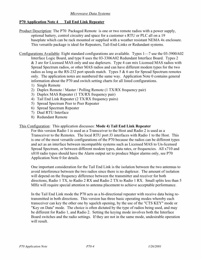
Microwave Data Systems
P70 Application Note P70-4 1/26/2001
P70 Application Note 4 Tail End Link Repeater
Product Description: The P70 Packaged Remote is one or two remote radios with a power supply,optional battery, control circuitry and space for a customer s RTU or PLC all on a 19baseplate which can be rack mounted or supplied with a weather resistant NEMA 4x enclosure.This versatile package is ideal for Repeaters, Tail-End-Links or Redundant systems.
Configurations Available: Eight standard configurations are available. Types 1—7 use the 03-3900A02Interface Logic Board, and type 8 uses the 03-3306A02 Redundant Interface Board. Types 2& 3 are for Licensed MAS only and use duplexers. Type 4 can mix Licensed MAS radios withSpread Spectrum radios, or other MAS radios and can have different modem types for the tworadios as long as the RS-232 port speeds match. Types 5 & 6 are for Spread Spectrum remotesonly. The application notes are numbered the same way. Application Note 0 contains generalinformation about the P70 and switch setting charts for all listed configurations.1) Single Remote2) Duplex Remote / Master / Polling Remote (1 TX/RX frequency pair)3) Duplex MAS Repeater (1 TX/RX frequency pair)4) Tail End Link Repeater (2 TX/RX frequency pairs)5) Spread Spectrum Peer to Peer Repeater6) Spread Spectrum Repeater7) Dual RTU Interface8) Redundant Remote
This Configuration: This application discusses: Mode 4) Tail End Link RepeaterFor this version Radio 1 is used as a Transceiver to the Host and Radio 2 is used as aTransceiver to the Remotes. The local RTU port J3 interfaces with Radio 1 to the Host. Thisis one of the most versatile configurations of the P70 because the radios can be different typesand act as an interface between incompatible systems such as Licensed MAS to Un-licensedSpread Spectrum, or between different modem types, data rates, or frequencies. All x710 andx810 radio types should have the Alarm output set to produce Major alarms only, see P70Application Note 0 for details.
One important consideration for the Tail End Link is the isolation between the two antennas toavoid interference between the two radios since there is no duplexer. The amount of isolationwill depend on the frequency difference between the transmitter and receiver for bothdirections, Radio 1 TX, to Radio 2 RX and Radio 2 TX to Radio 1 RX. Small splits less than 5MHz will require special attention to antenna placement to achieve acceptable performance.
In the Tail End Link mode the P70 acts as a bi-directional repeater with receive data being re-transmitted in both directions. This version has three basic operating modes whereby eachtransceiver can key the other one by squelch opening, by the use of the "CTS KEY" mode or"Key on Data" mode. The choice is often dictated by the type of radios being used, and maybe different for Radio 1, and Radio 2. Setting the keying mode involves both the InterfaceBoard switches and the radio settings. If they are not in the same mode, undesirable operationwill result.
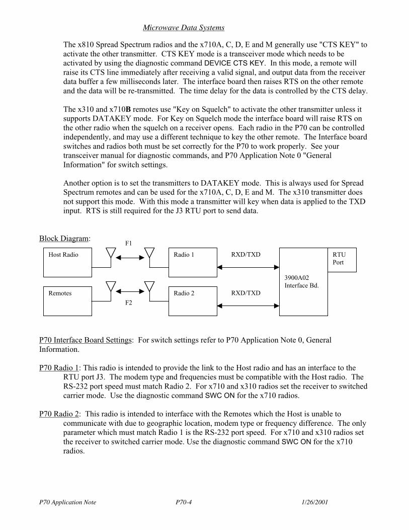
Microwave Data Systems
P70 Application Note P70-4 1/26/2001
The x810 Spread Spectrum radios and the x710A, C, D, E and M generally use "CTS KEY" toactivate the other transmitter. CTS KEY mode is a transceiver mode which needs to beactivated by using the diagnostic command DEVICE CTS KEY. In this mode, a remote willraise its CTS line immediately after receiving a valid signal, and output data from the receiverdata buffer a few milliseconds later. The interface board then raises RTS on the other remoteand the data will be re-transmitted. The time delay for the data is controlled by the CTS delay.
The x310 and x710B remotes use "Key on Squelch" to activate the other transmitter unless itsupports DATAKEY mode. For Key on Squelch mode the interface board will raise RTS onthe other radio when the squelch on a receiver opens. Each radio in the P70 can be controlledindependently, and may use a different technique to key the other remote. The Interface boardswitches and radios both must be set correctly for the P70 to work properly. See yourtransceiver manual for diagnostic commands, and P70 Application Note 0 "GeneralInformation" for switch settings.
Another option is to set the transmitters to DATAKEY mode. This is always used for SpreadSpectrum remotes and can be used for the x710A, C, D, E and M. The x310 transmitter doesnot support this mode. With this mode a transmitter will key when data is applied to the TXDinput. RTS is still required for the J3 RTU port to send data.
Block Diagram:
P70 Interface Board Settings: For switch settings refer to P70 Application Note 0, GeneralInformation.
P70 Radio 1: This radio is intended to provide the link to the Host radio and has an interface to theRTU port J3. The modem type and frequencies must be compatible with the Host radio. TheRS-232 port speed must match Radio 2. For x710 and x310 radios set the receiver to switchedcarrier mode. Use the diagnostic command SWC ON for the x710 radios.
P70 Radio 2: This radio is intended to interface with the Remotes which the Host is unable tocommunicate with due to geographic location, modem type or frequency difference. The onlyparameter which must match Radio 1 is the RS-232 port speed. For x710 and x310 radios setthe receiver to switched carrier mode. Use the diagnostic command SWC ON for the x710radios.
Radio 1
3900A02Interface Bd.
RTUPort
Radio 2
RXD/TXD
RXD/TXD
Host Radio
Remotes
F1
F2

Microwave Data Systems
P70 Application Note P70-4 1/26/2001
Host Radio Settings: This section will be divided into two parts, first the newer 9790 & 4790 DSPbased Master Stations. Secondly, the 2100 & 4100 Master Stations. The Host radio must havecompatible frequencies and modem type for P70 Radio 1.
Using a x790 Master Station as a Host, the CTS, PTT and SCD delays can generally be at thedefault of 0 mS. The transmitter must operate in switched carrier mode with CKEY OFF.
To use the P70 with a 2100 or 4100 Host system, there are several things to consider. First, theradios in the P70 must be either x310 type or x710B "Inter-operable" to have a compatiblemodem type of 9600, 4800 or 1200 bps. Set up your x100 Master using Switched Carrier TX,not continuous keyed. The required CTS delay will vary depending on the radio types for theP70 and remotes, 20-25 mS will typically be needed. See your Master Station manual — CTS isa jumper setting for the 9600 baud modem and a resistor change for the 4800 and 1200 bpsmodems.
Remote Radios: Same type as Radio 2. Depending on the radio types in the system the CTS delaymay need to be increased to 20 mS or greater to allow time for the P70 repeater to key.
Data Synchronizer Board: This is a plug in addition to the 3900A02 Interface Board which removesany jitter or timing imperfections in the received data before sending it to the transmitter. Theprimary need for this is when the receiver is a 4800 baud x310 or x710B. The data is bufferedin both directions, from Radio 1 to 2 and Radio 2 to 1 automatically. (The D.S. Bd. switchesfor 4800 bps, 10 bits is: SW1-1, & 3 Closed). To enable the 3900A02 Interface board to usethe D.S. Bd. SW1-5 must be On. The Rev. A Interface board requires the Host Transmitter tohave an additional 5 mS of SCD delay to keep the transmitter keyed for a brief time and allowthe Data Sync board buffer to clear before dropping the carrier. The revision B and laterboards will work with the default SCD of the Host.
Synchronous Data: Not supported on this configuration.
Antenna Considerations: Radio 1 should use a directional antenna to the Host and Radio 2 will use anomnidirectional antenna with vertical separation to avoid interference. The Host and Remotesuse directional antennas toward the P70.
Diagnostics: Use your Handheld Terminal or Computer Terminal directly to the remote for Localdiagnostics. See your radio manual for details. This mode supports Network WideDiagnostics from the Host to the P70 and Remotes when the diagnostic ports on Radio 1 andRadio 2 are connected utilizing the white Null Modem RJ11 Diagnostic cable (03-2198A15).DTMF diagnostics is not supported as used on the 2100 and 4100 Masters.
Orderwire Voice with VOX keying is supported on the x710 DSP series remotes, and the x310 MASremotes. Plug the telephone handset into J9 and when you talk into the handset Radio 1 willkey in Analog Mode to communicate with someone at the host site. To use the orderwirefeature with the Revision A Interface Board, Radio 1 needs to set for Analog mode by typingMODEM NONE on the Handheld Terminal or PC Terminal. The Revision B 03-3900A02Interface board will automatically switch the remote to Analog mode. The board revision can

Microwave Data Systems
P70 Application Note P70-4 1/26/2001
be identified by looking at the marking silk screened on the corner of the board near the radios.(The revision marked on the paper label is not the same.)
Sleep Mode: Grounding J3 pin 12 will put both radios into their low power sleep mode. Pin 12 ispulled to +5V internally, but can be pulled as high as +14V, do not apply negative voltages.See your radio manual for details of the power used in sleep mode and the wake-up timerequired.
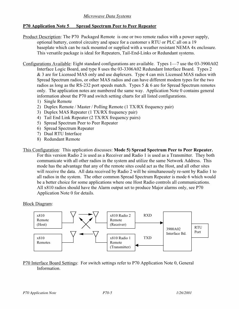
Microwave Data Systems
P70 Application Note P70-5 1/26/2001
P70 Application Note 5 Spread Spectrum Peer to Peer Repeater
Product Description: The P70 Packaged Remote is one or two remote radios with a power supply,optional battery, control circuitry and space for a customer s RTU or PLC all on a 19baseplate which can be rack mounted or supplied with a weather resistant NEMA 4x enclosure.This versatile package is ideal for Repeaters, Tail-End-Links or Redundant systems.
Configurations Available: Eight standard configurations are available. Types 1—7 use the 03-3900A02Interface Logic Board, and type 8 uses the 03-3306A02 Redundant Interface Board. Types 2& 3 are for Licensed MAS only and use duplexers. Type 4 can mix Licensed MAS radios withSpread Spectrum radios, or other MAS radios and can have different modem types for the tworadios as long as the RS-232 port speeds match. Types 5 & 6 are for Spread Spectrum remotesonly. The application notes are numbered the same way. Application Note 0 contains generalinformation about the P70 and switch setting charts for all listed configurations.1) Single Remote2) Duplex Remote / Master / Polling Remote (1 TX/RX frequency pair)3) Duplex MAS Repeater (1 TX/RX frequency pair)4) Tail End Link Repeater (2 TX/RX frequency pairs)5) Spread Spectrum Peer to Peer Repeater6) Spread Spectrum Repeater7) Dual RTU Interface8) Redundant Remote
This Configuration: This application discusses: Mode 5) Spread Spectrum Peer to Peer Repeater.For this version Radio 2 is used as a Receiver and Radio 1 is used as a Transmitter. They bothcommunicate with all other radios in the system and utilize the same Network Address. Thismode has the advantage that any of the remote sites could act as the Host, and all other siteswill receive the data. All data received by Radio 2 will be simultaneously re-sent by Radio 1 toall radios in the system. The other common Spread Spectrum Repeater is mode 6 which wouldbe a better choice for some applications where one Host Radio controls all communications.All x810 radios should have the Alarm output set to produce Major alarms only, see P70Application Note 0 for details.
Block Diagram:
P70 Interface Board Settings: For switch settings refer to P70 Application Note 0, GeneralInformation.
x810 Radio 2Remote(Receiver)
3900A02Interface Bd.
RTUPort
x810 Radio 1Remote(Transmitter)
RXD
TXD
x810Remote(Host)
x810Remotes
Microwave Data Systems
P70 Application Note P70-5 1/26/2001
P70 Radio 1: 9810, 24810. Same Network Address as all remotes in the system. Set to Mode Master.
P70 Radio 2: Same type as radio 1. Same Network Address as radio 1. Set to Mode R-M.
Host Radio Settings: Same type as radio 1. Same Network Address as radio 1. Set to Mode Remote.
Remote Radios: Same type as radio 1. Same Network Address as radio 1. Set to Mode Remote.
Antenna Considerations: Radio 1 and Radio 2 each will use omnidirectional antennas with verticalseparation to avoid interfering with each other. Host and Remotes use directional antennastoward the P70.
Synchronous Data: Not supported for this version.
Diagnostics: Not supported on this version.
Sleep Mode: Grounding J3 pin 12 will put both radios into their low power sleep mode. Pin 12 ispulled to +5V internally, but can be pulled as high as +14V, do not apply negative voltages.See your radio manual for details of the power used in sleep mode and the wake-up timerequired.
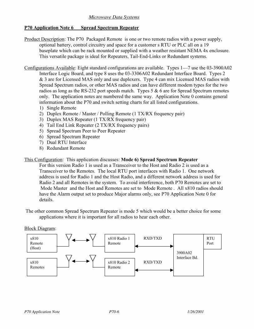
Microwave Data Systems
P70 Application Note P70-6 1/26/2001
P70 Application Note 6 Spread Spectrum Repeater
Product Description: The P70 Packaged Remote is one or two remote radios with a power supply,optional battery, control circuitry and space for a customer s RTU or PLC all on a 19baseplate which can be rack mounted or supplied with a weather resistant NEMA 4x enclosure.This versatile package is ideal for Repeaters, Tail-End-Links or Redundant systems.
Configurations Available: Eight standard configurations are available. Types 1—7 use the 03-3900A02Interface Logic Board, and type 8 uses the 03-3306A02 Redundant Interface Board. Types 2& 3 are for Licensed MAS only and use duplexers. Type 4 can mix Licensed MAS radios withSpread Spectrum radios, or other MAS radios and can have different modem types for the tworadios as long as the RS-232 port speeds match. Types 5 & 6 are for Spread Spectrum remotesonly. The application notes are numbered the same way. Application Note 0 contains generalinformation about the P70 and switch setting charts for all listed configurations.1) Single Remote2) Duplex Remote / Master / Polling Remote (1 TX/RX frequency pair)3) Duplex MAS Repeater (1 TX/RX frequency pair)4) Tail End Link Repeater (2 TX/RX frequency pairs)5) Spread Spectrum Peer to Peer Repeater6) Spread Spectrum Repeater7) Dual RTU Interface8) Redundant Remote
This Configuration: This application discusses: Mode 6) Spread Spectrum RepeaterFor this version Radio 1 is used as a Transceiver to the Host and Radio 2 is used as aTransceiver to the Remotes. The local RTU port interfaces with Radio 1. One networkaddress is used for Radio 1 and the Host Radio, and a different network address is used forRadio 2 and all Remotes in the system. To avoid interference, both P70 Remotes are set toMode Master and the Host and Remotes are set to Mode Remote . All x810 radios shouldhave the Alarm output set to produce Major alarms only, see P70 Application Note 0 fordetails.
The other common Spread Spectrum Repeater is mode 5 which would be a better choice for someapplications where it is important for all radios to hear each other.
Block Diagram:
x810 Radio 1Remote
3900A02Interface Bd.
RTUPort
x810 Radio 2Remote
RXD/TXD
RXD/TXD
x810Remote(Host)
x810Remotes
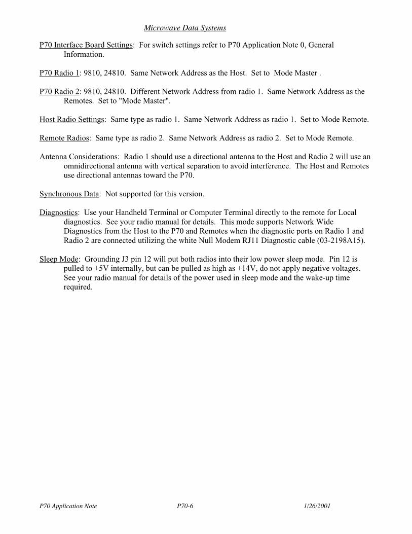
Microwave Data Systems
P70 Application Note P70-6 1/26/2001
P70 Interface Board Settings: For switch settings refer to P70 Application Note 0, GeneralInformation.
P70 Radio 1: 9810, 24810. Same Network Address as the Host. Set to Mode Master .
P70 Radio 2: 9810, 24810. Different Network Address from radio 1. Same Network Address as theRemotes. Set to "Mode Master".
Host Radio Settings: Same type as radio 1. Same Network Address as radio 1. Set to Mode Remote.
Remote Radios: Same type as radio 2. Same Network Address as radio 2. Set to Mode Remote.
Antenna Considerations: Radio 1 should use a directional antenna to the Host and Radio 2 will use anomnidirectional antenna with vertical separation to avoid interference. The Host and Remotesuse directional antennas toward the P70.
Synchronous Data: Not supported for this version.
Diagnostics: Use your Handheld Terminal or Computer Terminal directly to the remote for Localdiagnostics. See your radio manual for details. This mode supports Network WideDiagnostics from the Host to the P70 and Remotes when the diagnostic ports on Radio 1 andRadio 2 are connected utilizing the white Null Modem RJ11 Diagnostic cable (03-2198A15).
Sleep Mode: Grounding J3 pin 12 will put both radios into their low power sleep mode. Pin 12 ispulled to +5V internally, but can be pulled as high as +14V, do not apply negative voltages.See your radio manual for details of the power used in sleep mode and the wake-up timerequired.
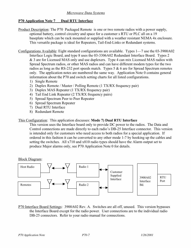
Microwave Data Systems
P70 Application Note P70-7 1/26/2001
P70 Application Note 7 Dual RTU Interface
Product Description: The P70 Packaged Remote is one or two remote radios with a power supply,optional battery, control circuitry and space for a customer s RTU or PLC all on a 19baseplate which can be rack mounted or supplied with a weather resistant NEMA 4x enclosure.This versatile package is ideal for Repeaters, Tail-End-Links or Redundant systems.
Configurations Available: Eight standard configurations are available. Types 1—7 use the 03-3900A02Interface Logic Board, and type 8 uses the 03-3306A02 Redundant Interface Board. Types 2& 3 are for Licensed MAS only and use duplexers. Type 4 can mix Licensed MAS radios withSpread Spectrum radios, or other MAS radios and can have different modem types for the tworadios as long as the RS-232 port speeds match. Types 5 & 6 are for Spread Spectrum remotesonly. The application notes are numbered the same way. Application Note 0 contains generalinformation about the P70 and switch setting charts for all listed configurations.1) Single Remote2) Duplex Remote / Master / Polling Remote (1 TX/RX frequency pair)3) Duplex MAS Repeater (1 TX/RX frequency pair)4) Tail End Link Repeater (2 TX/RX frequency pairs)5) Spread Spectrum Peer to Peer Repeater6) Spread Spectrum Repeater7) Dual RTU Interface8) Redundant Remote
This Configuration: This application discusses: Mode 7) Dual RTU InterfaceThis version uses the Interface board only to provide DC power to the radios. The Data andControl connections are made directly to each radio’s DB-25 Interface connector. This versionis intended only for customers who need access to both radios for a special application. Ifordered in this fashion it can be converted to any other mode 1-7 by hooking up the cables andsetting the switches. All x710 and x810 radio types should have the Alarm output set toproduce Major alarms only, see P70 Application Note 0 for details.
Block Diagram:
P70 Interface Board Settings: 3900A02 Rev. A. Switches are all off, unused. This version bypassesthe Interface Board except for the radio power. User connections are to the individual radioDB-25 connectors. Refer to your radio manual for connections.
Radio 1
3900A02InterfaceBd.
RTUPort
Radio 2
Host Radio
Remotes
CustomerSuppliedInterface
Microwave Data Systems
P70 Application Note P70-7 1/26/2001
P70 Radio 1: x710, x810, x310
P70 Radio 2: x710, x810, x310
Host Radio Settings: No special settings.
Remote Radios: No special settings.
Synchronous Data: The clock signals RXC, TXC and ETC are available on the radio DB-25connectors. Check your radio manual for supported modes.
Antenna Considerations: No special requirements.
Diagnostics: Diagnostics are the same as the individual remote. Orderwire not supported becausethe Interface board is not used.
Sleep Mode: As supported by the Remotes used.
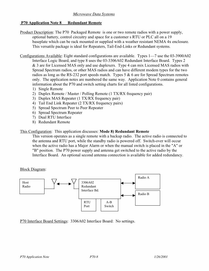
Microwave Data Systems
P70 Application Note P70-8 1/26/2001
P70 Application Note 8 Redundant Remote
Product Description: The P70 Packaged Remote is one or two remote radios with a power supply,optional battery, control circuitry and space for a customer s RTU or PLC all on a 19baseplate which can be rack mounted or supplied with a weather resistant NEMA 4x enclosure.This versatile package is ideal for Repeaters, Tail-End-Links or Redundant systems.
Configurations Available: Eight standard configurations are available. Types 1—7 use the 03-3900A02Interface Logic Board, and type 8 uses the 03-3306A02 Redundant Interface Board. Types 2& 3 are for Licensed MAS only and use duplexers. Type 4 can mix Licensed MAS radios withSpread Spectrum radios, or other MAS radios and can have different modem types for the tworadios as long as the RS-232 port speeds match. Types 5 & 6 are for Spread Spectrum remotesonly. The application notes are numbered the same way. Application Note 0 contains generalinformation about the P70 and switch setting charts for all listed configurations.1) Single Remote2) Duplex Remote / Master / Polling Remote (1 TX/RX frequency pair)3) Duplex MAS Repeater (1 TX/RX frequency pair)4) Tail End Link Repeater (2 TX/RX frequency pairs)5) Spread Spectrum Peer to Peer Repeater6) Spread Spectrum Repeater7) Dual RTU Interface8) Redundant Remote
This Configuration: This application discusses: Mode 8) Redundant RemoteThis version operates as a single remote with a backup radio. The active radio is connected tothe antenna and RTU port, while the standby radio is powered off. Switch-over will occurwhen the active radio has a Major Alarm or when the manual switch is placed in the "A" or"B" position. The P70 power supply and antenna get switched to the active radio by theInterface Board. An optional second antenna connection is available for added redundancy.
Block Diagram:
P70 Interface Board Settings: 3306A02 Interface Board: No settings.
Radio A
3306A02RedundantInterface Bd.
RTUPort
Radio B
HostRadio
A-BSwitch
Microwave Data Systems
P70 Application Note P70-8 1/26/2001
P70 Radio 1: Any MDS x710 or x810 remote. Special settings are required. Use the HHT or terminalto enter the command: INIT xx20 (Where xx are the first two digits of the MDS transceivermodel number, three digits for the 24810) to invert the sense of the Alarm pin 25 on the DATAINTERFACE connector and set up other parameters. Use the "A-AUTO-B" switch to selectradio A or B for programming, then place the switch back into AUTO. If a Major alarm occursin the active radio, the Interface board will automatically switch operation to the backup radio.(Examples: INIT 9820 or INIT 24820 or INIT 9720)
P70 Radio 2: Same as radio 1.
Host Radio Settings: No special settings.
Remote Radios: n/a.
Antenna Considerations: Typically the Remote will use a directional antenna to the Host radio. As anoption, this version can be ordered with two antennas for additional redundancy.
Synchronous Data: Not supported for this version.
Diagnostics: Diagnostics are the same as the individual remote. An Alarm output is available on J9 ofthe 3306A02 Interface Board. Pin 1 is the normally closed relay contact, Pin 3 is the normallyopen contact, and Pin 2 is common. These contacts are rated for 0.5 ampere at 125 VAC or 1.0ampere at 24 VDC.
This version utilizes the 02-1297A01 Orderwire Module with the 12-1307A01 Handset forvoice communications on radios which support analog audio such as the x710 and x310 seriesremotes. Not for use with x810 Spread Spectrum radio.
Sleep Mode: Not supported on this version.
05-3490A01, Rev. D P70 I/O Guide I-1
INDEX
AAlarm interface (Pin 25)—interface logic board 22Application notes (see Appendix A)Assemblies, list of replaceable 46
BBattery
backup operation 36backup, replacement 41backup, testing 40charging check/adjustment 41low-voltage disconnect feature 36
CCable connections 17–25
antenna cable 19ground 18hand-held terminal 39logic board 20
interface logic board (ILB) 20redundant logic board (RLB) 23
orderwire handset 38power board 18
CTS interface (Pin 5)interface logic board 21redundant logic board 24
DDCD interface (Pin 8)
interface logic board 21redundant logic board 24
DSR interface (Pin 6)interface logic board 21redundant logic board 24
FFuses
amperage ratings vs. P70 input voltage 42replacement 42
GGround
Earth connection 18signal ground (Pin 7)
interface logic board 21redundant logic board 24
HHand-held terminal
connecting to P70 39illustrated 39
IIllustrations
data synchronizer board 31duplex mas repeater system 8example system w/tail-end link rptr. 9full duplex configuration (MAS remotes) 8full duplex repeater (spread spectrum remotes) 11hand-held terminal 39interface logic board 20loc. of battery reset switch SW1 37loc. of voltage adjustment VR1 42model number codes 2P70 mounting dimensions 13P70 Packaged Radio System 1power board connection points 18radio selection switch 36redundant logic board connections 23redundant station configuration 12single remote configuration 7system with full duplex remote 7tail-end link repeater configuration 10typical pole-mounted installation 16typical rack mount installation 17typical wall mount installation 14vox board assembly 32
Installation 12–22cable connections 17–25final tasks 34general considerations 12mounting the P70 enclosure 13pole mounting instructions 15rack mount alternative 16wall mounting instructions 14
LLEDs
on interface logic board 44on radio selection switch 35on redundant logic board 44on transceiver (see radio manual)
Low-voltage disconnect feature 36
MMaintenance
battery charging check/adjustment 41battery replacement 41fuse replacement 42list of replaceable assemblies 46preventive 40
Mounting dimensions 13
I-2 P70 I/O Guide 05-3490A01, Rev. D
Mounting the P70 enclosure 13
OOperation
battery backup 36battery reset switch 37connecting an HHT 39initial power-up 35logic board features & indicators 38radio selection switch 35
Orderwireconnecting a handset 38
PPole mounting instructions 15Power
AC Input 19accessory power out 19backup battery 19check supply voltage before applying (caution) 18DC Input 18initial power-up 35low-voltage disconnect feature 36
RRack mounting instructions 16RTS interface connection (Pin 4)
interface logic board 21redundant logic board 24
RXD interface connection (Pin 3)interface logic board 21redundant logic board 24
TTables
data sync. baud rate switch settings 32F1/F2 fuse values 42functional configurations 6indicator board cabling 46interface logic board cabling 45interface logic board J3 (RTU port) connections 21J2 accessory power pins 19logic board features and indicators 38options & accessories 4P70 configuration 26P70 replacement assemblies 46P70 transceiver complement 3peer-to-peer radio settings 33power board cabling 46product specifications 4radio selection switch positions 36redundant logic board cabling 45redundant logic board J1 connections 24spread spectrum repeater radio settings 34SW1 & SW2 switch functions 29troubleshooting chart 43word length settings for data sync. board 31
Troubleshooting 43table of symptoms and corrective actions 43
TXD interface connection (Pin 2)
interface logic board 21redundant logic board 24
UUnpacking and inspection 12
WWall mounting instructions 14

IN CASE OF DIFFICULTY...
MDS products are designed for long life and trouble-free operation. However, this equipment, as with all electronic equipment, may have an occasional component failure. The following infor-mation will assist you in the event that servicing becomes necessary.
FACTORY TECHNICAL ASSISTANCE
Assistance for MDS products is available from our Technical Services group during business hours (8:00 A.M.–5:30 P.M. Eastern Time). When calling, please give the complete model number of the radio, along with a description of the trouble symptom(s) that you are experiencing. In many cases, problems can be resolved over the telephone, without the need for returning the unit to the factory.
Please use the following telephone numbers for product assistance:
Phone: 585-241-5510 E-Mail: [email protected]: 585-242-8369 Web: www.microwavedata.com
FACTORY REPAIRS
Component level repair of radio equipment is not recommended in the field. Many components are installed using surface mount technology, which requires specialized training and equipment for proper servicing. For this reason, the equipment should be returned to the factory for any PC board repairs. The factory is best equipped to diagnose, repair and align your radio to its proper operating specifications.
If return of the equipment is necessary, you will be issued a Service Request Order (SRO) number. The SRO number will help expedite the repair so that the equipment can be repaired and returned to you as quickly as possible. Please be sure to include the SRO number on the outside of the ship-ping box, and on any correspondence relating to the repair. No equipment will be accepted for repair without an SRO number.
A statement should accompany the radio describing, in detail, the trouble symptom(s), and a description of any associated equipment normally connected to the radio. It is also important to include the name and telephone number of a person in your organization who can be contacted if additional information is required.
The radio must be properly packed for return to the factory. The original shipping container and packaging materials should be used whenever possible. All factory returns should be addressed to:
When repairs have been completed, the equipment will be returned to you by the same shipping method used to send it to the factory. Please specify if you wish to make different shipping arrangements. To inquire about an in-process repair, you may contact our Product Services Group at 585-241-5540 (FAX: 585-242-8400), or via e-mail at [email protected].
Microwave Data Systems Inc.Customer Service Department(SRO No. XXXX)175 Science ParkwayRochester, NY 14620 USA

Microwave Data Systems Inc.
Rochester, NY 14620General Business: +1 585 242-9600
FAX: +1 585 242-9620Web: www.microwavedata.com
175 Science Parkway
A product of Microwave Data Systems Inc.


