Embed Size (px)
Citation preview
CRANFIELD UNIVERSITY
SCHOOL OF APPLIED SCIENCES
PhD THESIS
ACQUISITION AND SHARING OF INNOVATIVE MANUFACTURINGKNOWLEDGE FOR PRELIMINARY DESIGN
S L MOUNTNEY
Supervisors: J X Gao and R Roy
2009
This thesis is submitted in partial fulfilment of the requirementsfor the degree of Doctor of Philosophy
© Cranfield University 2009. All rights reserved. No part of this publication maybe reproduced without the written permission of the copyright owner.

2
3
Abstract
This study investigates the identification, acquisition and sharing of innovativemanufacturing knowledge for the preliminary design of complex mechanicalcomponents. Such components need to satisfy multiple, often conflicting design andperformance requirements. Some degree of innovation may be required, involving thedevelopment of new manufacturing processes. The innovative nature of thismanufacturing knowledge makes it difficult to define, codify and share, especially duringpreliminary design, where this can present significant risks in the design process. Currentmethods of knowledge sharing do not account for the immature nature of innovativemanufacturing knowledge and the combined explicit and tacit elements needed to expressit.
A flexible interpretive research study with inductive and hypothesis testing elements wasundertaken to explore this novel knowledge management problem. During the inductivephase, two data collection activities were undertaken to investigate the manufacturingknowledge required for the preliminary design of gas turbine engines. Using a data drivenapproach, the main findings which emerged were: the need to include an assessment ofthe maturity of the design process; the need to use a range of tacit and explicit knowledgeto effectively share this and the need to manage knowledge across different domainboundaries. A conceptual framework of the findings was used to develop a hypothesis ofknowledge requirements for preliminary design.
For the hypothesis testing phase, a systematic methodology to identify, acquire and shareinnovative manufacturing knowledge for preliminary design was developed from theknowledge requirements. This approach allowed both explicit and tacit knowledgesharing. An evaluation of the methodology took place using three different industrialcases, each with a different component / manufacturing process. The evaluationsdemonstrated that using the range of knowledge types for transferring knowledge waseffective for the specific cases studied and confirmed the hypothesis developed.

4

5
Acknowledgements
I would like to thank my supervisors Dr James Gao and Professor Rajkumar Roy atCranfield University for their advice and ongoing support.
At Rolls-Royce I would like to thank my project sponsor, Peter Hill and my industrialsupervisor Dr Steve Wiseall. I would particularly like to thank Steve for his ongoingsupport, ideas and quality control.
I would also like to acknowledge the assistance of others at my sponsoring company fortheir ideas and interest, particularly Dr Steven Halliday, Dr Michael Moss and DrMichael Ward. I would also like to thank the anonymous contributors to the datacollection and evaluation sessions who made the research a fascinating and engagingprocess.
To my wider community of fellow researchers, I would like to thank David, Marianne,Melissa and Dan. I’d also like to thank the founding members of INDOC – Charlie,Dharm, Mairi, Hamish and Tom.
I would also like to thank my colleagues at Sheffield Hallam University for their supportand patience during the writing of this thesis.
At home I would like to thank Duncan for his love and support, my parents, family andfriends.
This thesis is dedicated to the engineers in my family.

6
7
Related Publications
1. MOUNTNEY, S. and GAO, J., 2005. Manufacturing knowledge to supportpreliminary design - a case study, J.X. GAO, D.I. BAXTER and P.J. SACKETT,eds. In: Advances in Manufacturing Technology and Management: Proceedings ofthe 3rd International Conference on Manufacturing Research, 6-8 September2005, Cranfield University.
2. MOUNTNEY, S. and GAO, J., 2006. Manufacturing knowledge management:requirements for preliminary design. In: P. GHODOUS, R. ROSE DIENG-KUNTZ and G. LOUREIRO, eds, Leading the Web in Concurrent Engineering:Next Generation Concurrent Engineering. IOS Press, pp. 515-525.
3. MOUNTNEY, S.L., GAO, J.X. and WISEALL, S., 2007. A knowledge system tosupport manufacturing knowledge during preliminary design. InternationalJournal of Production Research, 45(7), pp. 1521-1537.

8
9
Contents
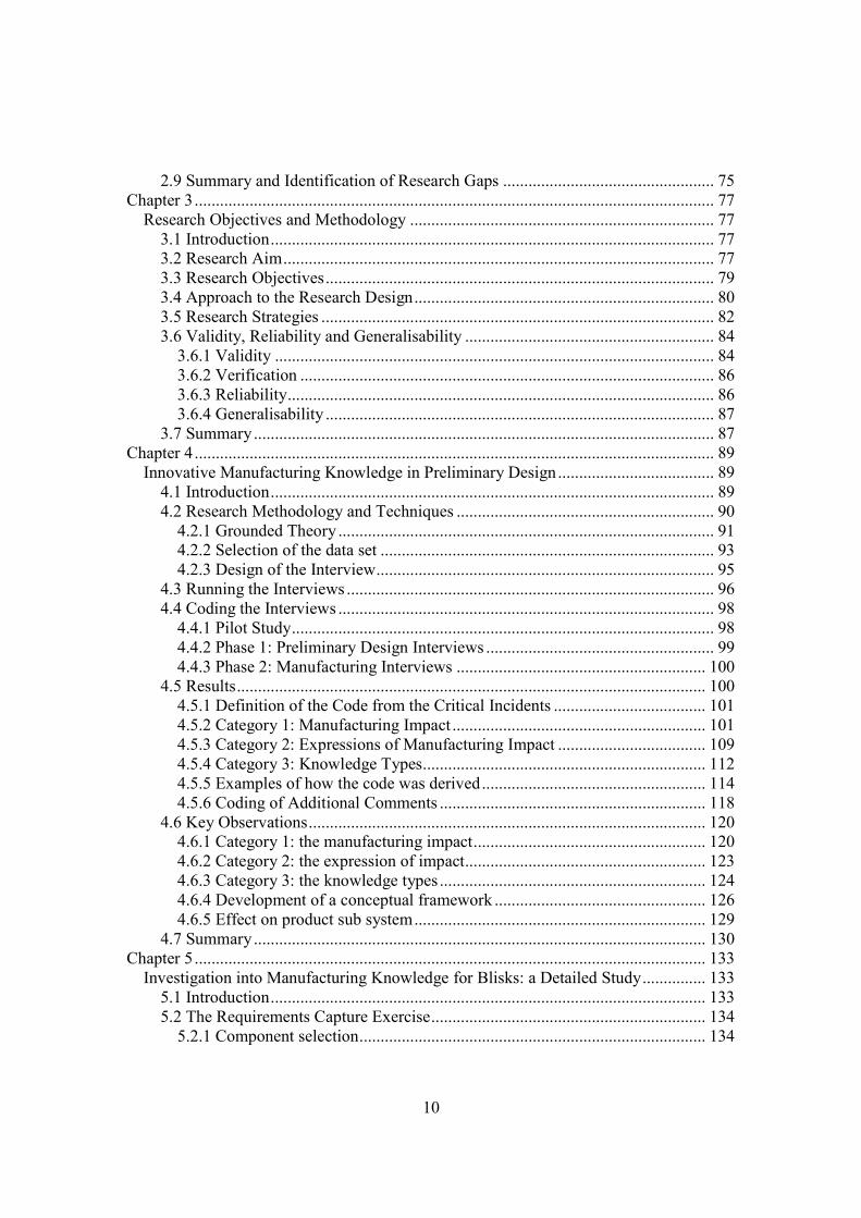
Abstract ........................................................................................................................... 3Acknowledgements......................................................................................................... 5Related Publications........................................................................................................ 7Contents .......................................................................................................................... 9List of Figures ............................................................................................................... 13List of Tables ................................................................................................................ 15List of Terms and Abbreviations .................................................................................. 17
Chapter 1........................................................................................................................... 19Introduction................................................................................................................... 19
1.1 Research Background ......................................................................................... 191.2 Research Aims .................................................................................................... 241.3 Research Design.................................................................................................. 241.5 Research Context ................................................................................................ 241.6 Thesis Structure .................................................................................................. 27
Chapter 2........................................................................................................................... 31Literature Review.......................................................................................................... 31
2.1 Introduction......................................................................................................... 312.2 Knowledge Management and Definitions of Knowledge................................... 32
2.2.1 Data – information – knowledge hierarchy ................................................. 322.2.2 Tacit and explicit knowledge ....................................................................... 332.2.3 Declarative and procedural knowledge........................................................ 332.2.4 Comparison of the theories .......................................................................... 34
2.3 Knowledge and Innovation ................................................................................. 352.4 Key Observations................................................................................................ 372.5 Knowledge in the Engineering Design Process .................................................. 39
2.5.1 Content......................................................................................................... 392.5.2 Comparison with knowledge management definitions................................ 432.5.3 Key observations.......................................................................................... 45
2.6 Commodity Approach......................................................................................... 462.6.1 Knowledge sharing using features ............................................................... 472.6.2 Knowledge sharing using information models ............................................ 502.6.3 Examples of the commodity approach......................................................... 512.6.4 Key Observations......................................................................................... 58
2.7 Community Approach......................................................................................... 582.7.1 Criticism of the Commodity Approach........................................................ 582.7.2 Examples of the Community Approach....................................................... 622.7.3 Key Observations......................................................................................... 68
2.8 Towards a Combined Commodity and Community Approach .......................... 682.8.1 Sociotechnology........................................................................................... 682.8.2 Ontology ...................................................................................................... 692.8.3 Business Methods ........................................................................................ 70
10
2.9 Summary and Identification of Research Gaps .................................................. 75Chapter 3........................................................................................................................... 77
Research Objectives and Methodology ........................................................................ 773.1 Introduction......................................................................................................... 773.2 Research Aim...................................................................................................... 773.3 Research Objectives............................................................................................ 793.4 Approach to the Research Design....................................................................... 803.5 Research Strategies ............................................................................................. 823.6 Validity, Reliability and Generalisability ........................................................... 84
3.6.1 Validity ........................................................................................................ 843.6.2 Verification .................................................................................................. 863.6.3 Reliability..................................................................................................... 863.6.4 Generalisability ............................................................................................ 87
3.7 Summary............................................................................................................. 87Chapter 4........................................................................................................................... 89
Innovative Manufacturing Knowledge in Preliminary Design..................................... 894.1 Introduction......................................................................................................... 894.2 Research Methodology and Techniques ............................................................. 90
4.2.1 Grounded Theory ......................................................................................... 914.2.2 Selection of the data set ............................................................................... 934.2.3 Design of the Interview................................................................................ 95
4.3 Running the Interviews ....................................................................................... 964.4 Coding the Interviews ......................................................................................... 98
4.4.1 Pilot Study.................................................................................................... 984.4.2 Phase 1: Preliminary Design Interviews ...................................................... 994.4.3 Phase 2: Manufacturing Interviews ........................................................... 100
4.5 Results............................................................................................................... 1004.5.1 Definition of the Code from the Critical Incidents .................................... 1014.5.2 Category 1: Manufacturing Impact ............................................................ 1014.5.3 Category 2: Expressions of Manufacturing Impact ................................... 1094.5.4 Category 3: Knowledge Types................................................................... 1124.5.5 Examples of how the code was derived..................................................... 1144.5.6 Coding of Additional Comments ............................................................... 118
4.6 Key Observations.............................................................................................. 1204.6.1 Category 1: the manufacturing impact....................................................... 1204.6.2 Category 2: the expression of impact......................................................... 1234.6.3 Category 3: the knowledge types ............................................................... 1244.6.4 Development of a conceptual framework .................................................. 1264.6.5 Effect on product sub system..................................................................... 129
4.7 Summary........................................................................................................... 130Chapter 5......................................................................................................................... 133
Investigation into Manufacturing Knowledge for Blisks: a Detailed Study............... 1335.1 Introduction....................................................................................................... 1335.2 The Requirements Capture Exercise................................................................. 134
5.2.1 Component selection.................................................................................. 134
11
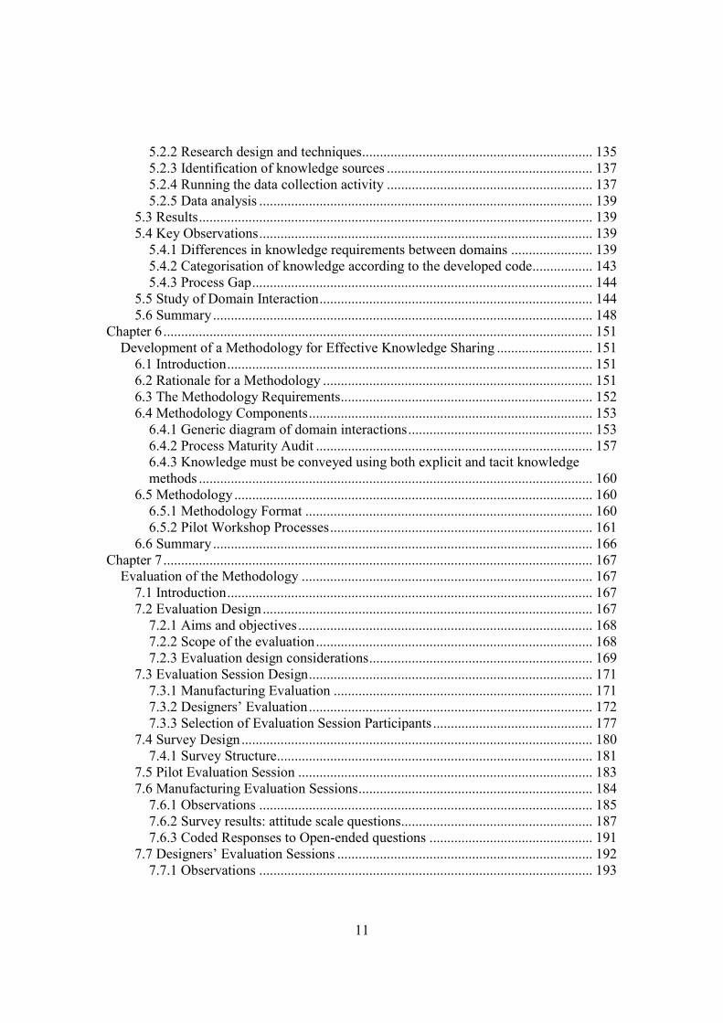
5.2.2 Research design and techniques................................................................. 1355.2.3 Identification of knowledge sources .......................................................... 1375.2.4 Running the data collection activity .......................................................... 1375.2.5 Data analysis .............................................................................................. 139
5.3 Results............................................................................................................... 1395.4 Key Observations.............................................................................................. 139
5.4.1 Differences in knowledge requirements between domains ....................... 1395.4.2 Categorisation of knowledge according to the developed code................. 1435.4.3 Process Gap................................................................................................ 144
5.5 Study of Domain Interaction............................................................................. 1445.6 Summary........................................................................................................... 148
Chapter 6......................................................................................................................... 151Development of a Methodology for Effective Knowledge Sharing ........................... 151
6.1 Introduction....................................................................................................... 1516.2 Rationale for a Methodology ............................................................................ 1516.3 The Methodology Requirements....................................................................... 1526.4 Methodology Components................................................................................ 153
6.4.1 Generic diagram of domain interactions.................................................... 1536.4.2 Process Maturity Audit .............................................................................. 1576.4.3 Knowledge must be conveyed using both explicit and tacit knowledgemethods ............................................................................................................... 160
6.5 Methodology ..................................................................................................... 1606.5.1 Methodology Format ................................................................................. 1606.5.2 Pilot Workshop Processes.......................................................................... 161
6.6 Summary........................................................................................................... 166Chapter 7......................................................................................................................... 167
Evaluation of the Methodology .................................................................................. 1677.1 Introduction....................................................................................................... 1677.2 Evaluation Design............................................................................................. 167
7.2.1 Aims and objectives................................................................................... 1687.2.2 Scope of the evaluation.............................................................................. 1687.2.3 Evaluation design considerations............................................................... 169
7.3 Evaluation Session Design................................................................................ 1717.3.1 Manufacturing Evaluation ......................................................................... 1717.3.2 Designers’ Evaluation................................................................................ 1727.3.3 Selection of Evaluation Session Participants ............................................. 177
7.4 Survey Design................................................................................................... 1807.4.1 Survey Structure......................................................................................... 181
7.5 Pilot Evaluation Session ................................................................................... 1837.6 Manufacturing Evaluation Sessions.................................................................. 184
7.6.1 Observations .............................................................................................. 1857.6.2 Survey results: attitude scale questions...................................................... 1877.6.3 Coded Responses to Open-ended questions .............................................. 191
7.7 Designers’ Evaluation Sessions ........................................................................ 1927.7.1 Observations .............................................................................................. 193
12
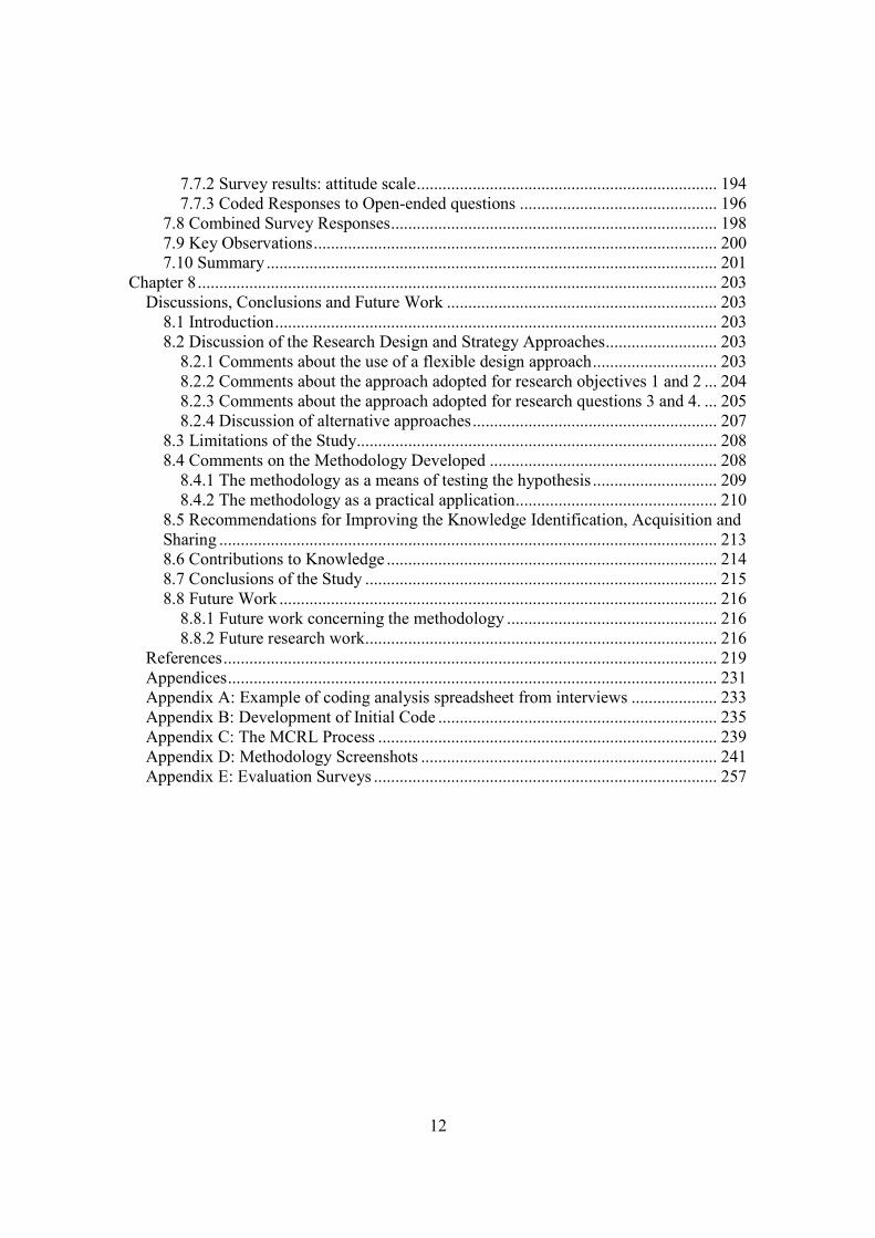
7.7.2 Survey results: attitude scale...................................................................... 1947.7.3 Coded Responses to Open-ended questions .............................................. 196
7.8 Combined Survey Responses............................................................................ 1987.9 Key Observations.............................................................................................. 2007.10 Summary ......................................................................................................... 201
Chapter 8......................................................................................................................... 203Discussions, Conclusions and Future Work ............................................................... 203
8.1 Introduction....................................................................................................... 2038.2 Discussion of the Research Design and Strategy Approaches.......................... 203
8.2.1 Comments about the use of a flexible design approach............................. 2038.2.2 Comments about the approach adopted for research objectives 1 and 2 ... 2048.2.3 Comments about the approach adopted for research questions 3 and 4. ... 2058.2.4 Discussion of alternative approaches......................................................... 207
8.3 Limitations of the Study.................................................................................... 2088.4 Comments on the Methodology Developed ..................................................... 208
8.4.1 The methodology as a means of testing the hypothesis ............................. 2098.4.2 The methodology as a practical application............................................... 210
8.5 Recommendations for Improving the Knowledge Identification, Acquisition andSharing .................................................................................................................... 2138.6 Contributions to Knowledge ............................................................................. 2148.7 Conclusions of the Study .................................................................................. 2158.8 Future Work ...................................................................................................... 216
8.8.1 Future work concerning the methodology ................................................. 2168.8.2 Future research work.................................................................................. 216
References................................................................................................................... 219Appendices.................................................................................................................. 231Appendix A: Example of coding analysis spreadsheet from interviews .................... 233Appendix B: Development of Initial Code ................................................................. 235Appendix C: The MCRL Process ............................................................................... 239Appendix D: Methodology Screenshots ..................................................................... 241Appendix E: Evaluation Surveys ................................................................................ 257

13
List of Figures
Figure 1.1: Structure of the thesis ..................................................................................... 29Figure 2.1: The Two Stages of Preliminary Design (Pahl and Beitz, 1988, p.41) ........... 40Figure 2.2: Perspectives on Knowledge Management...................................................... 44Figure 2.3: Wong and Radcliffe’s knowledge schema (Wong and Radcliffe, 2000) ....... 45Figure 2.4: Lovatt and Shercliff’s Methodology .............................................................. 55Figure 2.5: Carlile’s Framework for Managing Knowledge Across Boundaries (Carlile,2004) ................................................................................................................................. 67Figure 2.6: Hall and Andriani’s Knowledge Space .......................................................... 71Figure 2.7: Hall and Andriani’s Innovation Plot .............................................................. 72Figure 2.8: Strategic Vulnerability Map ........................................................................... 72Figure 3.1: Positioning of Research (following from McMahon et al., 2004 and Bohn,1994) ................................................................................................................................. 78Figure 3.2: Research Objectives, Design Approaches and Strategies .............................. 81Figure 4.1: Timeline for study .......................................................................................... 90Figure 4.2 Summary of coding categories developed and their relationships ................ 121Figure 4.3: The impact of the manufacturing process on the component configuration 122Figure 4.4: Impact of the manufacturing process on the component configuration from theperspective of preliminary design................................................................................... 123Figure 4.5: Maturity of manufacturing process and expressions of impact................... 124Figure 4.6: A conceptual framework of manufacturing knowledge in preliminary design......................................................................................................................................... 128Figure 4.7: Effect of the manufacturing impact on sub system ...................................... 130Figure 5.1: Example of a blisk assembly (reproduced with permission from Rolls-Royceplc) .................................................................................................................................. 135Figure 5.2: Acquisition and sharing of knowledge: domain concerns and interactionduring preliminary design process .................................................................................. 142Figure 5.3: Initial diagram of domain interaction for manufacturing assessment(expanding LFW as an example) .................................................................................... 146Figure 5.4: Diagram of domain interaction following feedback..................................... 147Figure 6.1: Generalisation of blisk diagram of interactions ........................................... 155Figure 6.2: The manufacturing impact and material, process and geometriccharacteristics.................................................................................................................. 157Figure 6.3: Pilot Workshop Processes for the Methodology .......................................... 162Figure 6.4: Select Process Steps ..................................................................................... 163Figure 6.5: Create Process ‘Decide Knowledge’ process steps ...................................... 164Figure 6.6: Create Process ‘Record Knowledge’ process steps...................................... 164Figure 7.1: Output from Select Process .......................................................................... 173Figure 7.2: Output from Create Process ......................................................................... 174Figure 7.3: Output from Select Process .......................................................................... 175Figure 7.4: Designers’ Evaluation form 1....................................................................... 176

14
Figure 7.5: Designers’ Evaluation form 1 (continued) ................................................... 176Figure 7.6: Designers’ Evaluation form 1 (continued) ................................................... 177
15
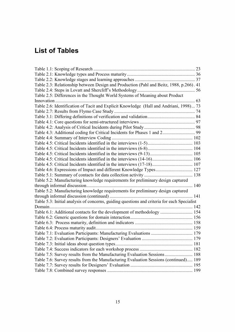
List of Tables
Table 1.1: Scoping of Research ........................................................................................ 23Table 2.1: Knowledge types and Process maturity........................................................... 36Table 2.2: Knowledge stages and learning approaches .................................................... 37Table 2.3: Relationship between Design and Production (Pahl and Beitz, 1988, p.266) . 41Table 2.4: Steps in Lovatt and Shercliff’s Methodology.................................................. 56Table 2.5: Differences in the Thought World Systems of Meaning about ProductInnovation ......................................................................................................................... 63Table 2.6: Identification of Tacit and Explicit Knowledge (Hall and Andriani, 1998)... 73Table 2.7: Results from Flymo Case Study ...................................................................... 74Table 3.1: Differing definitions of verification and validation......................................... 84Table 4.1: Core questions for semi-structured interviews ................................................ 97Table 4.2: Analysis of Critical Incidents during Pilot Study ............................................ 98Table 4.3: Additional coding for Critical Incidents for Phases 1 and 2............................ 99Table 4.4: Summary of Interview Coding ...................................................................... 102Table 4.5: Critical Incidents identified in the interviews (1-5)....................................... 103Table 4.5: Critical Incidents identified in the interviews (6-8)....................................... 104Table 4.5: Critical Incidents identified in the interviews (9-13)..................................... 105Table 4.5: Critical Incidents identified in the interviews (14-16)................................... 106Table 4.5: Critical Incidents identified in the interviews (17-18)................................... 107Table 4.6: Expressions of Impact and different Knowledge Types................................ 127Table 5.1: Summary of contacts for data collection activity .......................................... 138Table 5.2: Manufacturing knowledge requirements for preliminary design capturedthrough informal discussion............................................................................................ 140Table 5.2: Manufacturing knowledge requirements for preliminary design capturedthrough informal discussion (continued) ........................................................................ 141Table 5.3: Initial analysis of concerns, guiding questions and criteria for each SpecialistDomain............................................................................................................................ 142Table 6.1: Additional contacts for the development of methodology ............................ 154Table 6.2: Generic questions for domain interaction...................................................... 156Table 6.3: Process maturity, definition and indicators .................................................. 158Table 6.4: Process maturity audit.................................................................................... 159Table 7.1: Evaluation Participants: Manufacturing Evaluations .................................... 179Table 7.2: Evaluation Participants: Designers’ Evaluation ............................................ 179Table 7.3: Initial ideas about question types................................................................... 181Table 7.4: Success indicators for each workshop process .............................................. 182Table 7.5: Survey results from the Manufacturing Evaluation Sessions ........................ 188Table 7.6: Survey results from the Manufacturing Evaluation Sessions (continued)..... 189Table 7.7: Survey results for Designers’ Evaluation ...................................................... 195Table 7.8: Combined survey responses .......................................................................... 199

16
17
List of Terms and Abbreviations
CE Concurrent EngineeringKM Knowledge ManagementCAD/CAM Computer Aided Design / Computer Aided ManufacturingCoP Community of PracticeIPT Integrated Product TeamGA General ArrangementAPSD Advanced Propulsion System DesignOBU Operating Business UnitDFM / DFMA Design For Manufacture / Design For Manufacture and AssemblyGE General ElectricSECI Socialisation / Externalisation / Combination / Internalisation
(model of knowledge generation and transfer)STEP Standard for the Exchange of Product model dataCORBA Common Object Requesting Broker ArchitectureCAPP Computer Aided Process PlanningMFVM Multiple Feature View ModellingPLM Product Lifecycle ManagementKBE Knowledge Based EngineeringEXPRESS Data modelling language for STEPUML Universal Mark-Up LanguageXML Extensive Mark-Up LanguagePSL Process Specification LanguageERP Enterprise Resource PlanningNPD New Product DevelopmentCp Cpk Process capability indices, measures of process capabilityCAE Computer Aided EngineeringICT Information and Communication TechnologiesIT Information TechnologyQFD Quality Function DeploymentR&D Research and DevelopmentAET Advanced Engineering TeamLFW Linear Friction WeldingMFS Machining From SolidMCRL Manufacturing Capability Readiness LevelEIS Entry In ServiceR-R Rolls-Royce

18

19
Chapter 1
Introduction
1.1 Research Background
This study is concerned with the effective identification, acquisition and sharing ofinnovative manufacturing knowledge requirements between design and manufacture forthe preliminary design stage of complex mechanical components.
The terms ‘manufacturing knowledge requirements’ and ‘complex mechanicalcomponents’ need to be defined clearly in order to determine the scope of the study,particularly as these definitions can be used in different contexts.
The term 'innovative manufacturing' has up to three meanings. The first describes thedevelopment and use of innovative technologies in manufacturing systems engineering inorder to integrate and automate aspects of the design and manufacturing processes, thusimproving the efficiency of the process. Examples include agile manufacturing, andcomputer integrated manufacturing (CIM). The second describes the development ofnew, or improvements in, existing manufacturing processes (Bessant and Tidd, 2007).Examples of such processes are high speed machining (as a development of conventionalmachining) and direct laser deposition as a method of creating intricate componentshapes. The final meaning considers technology management, where the emphasis is onthe strategic management of innovation within companies, through mergers andacquisitions and technology transfer from research led institutions into commercialorganisations (for examples of research in this area, see Fraser et al., 2002; Farrukh et al.,2007 and Grant and Gregory, 1997). Consequently it is important to define how theconsiderations of this research study fit into these areas. Essentially it considers aspectsof all three meanings.
In this study, innovative manufacturing knowledge is defined as knowledge about amanufacturing process which is undergoing some element of development work withinan organisation (second definition). Therefore, some initial research and developmentwork has taken place and some technology transfer has taken place between a researchand development department (either internal or external to the organisation) and theprocess has been proven within that environment. However, the process may not yet havebeen applied in the organisation, or may have been applied for a different application (i.e.using a different material or component). Further development is therefore required (thirddefinition). Finally, the knowledge about the manufacturing process under developmentneeds to be integrated into the design process in order to mitigate the risks involved in itsintroduction (first definition).
20
A complex mechanical product is a component in a large assembly which incorporatesmechanical, electrical and software systems. The product is termed ‘complex’ because itis an optimisation of a number of competing engineering requirements. Theserequirements satisfy multiple operating conditions such as changing static and dynamicforces and environmental conditions. Often, the resulting geometry of the componentitself can be complex. Such components are often examples of adaptive design, where anew product is a significant adaptation of an existing product configuration.
Careful management of the design process is required to address the multiplerequirements and co-ordinate the emerging design solution. This presents a significantknowledge management challenge. Knowledge about the new product and associatedprocesses may be innovative and therefore difficult to define, categorise or quantify. Thissituation is further compounded by the increasing need to reduce time to market andconsequently manage more risk earlier in the design process.
Pahl and Beitz’s Systematic Design Process is a design process model typically used forand suited to complex mechanical component (Pahl and Beitz, 1988). This processconsiders design as the successful management of constraints to achieve an appropriatesolution which satisfies the relationships between form and function. This is achieved bydividing the process into four stages which sequentially deal with progressively moredetailed product knowledge at increasing levels of granularity. The four stages are 1) theclarification of the task, in which the need for a solution is explored and defined; 2)conceptual design, where the solution is defined in terms of a design specification andrequired functional attributes; 3) preliminary (also called embodiment) design, where aninitial realisation of the solution in the form of a engineered product takes place and 4)detail design, where detailed component drawings and production documents areproduced.
The successful use of manufacturing knowledge during the design process is essential torealise a successful, cost-effective end product. Historically this has been an area ofweakness for the Systematic Design Process. Manufacturing analysis would not takeplace until the detail design stage, when the geometry of the component had already beenlargely determined, making changes for manufacturing at such a late stage costly. UsingConcurrent Engineering (CE) techniques in the process has alleviated this by enablingmanufacturing assessments to take place earlier in the design process. Additionally thestaged gate method of managing the process allows the effective management of changesand consultations.
The theoretical definitions of knowledge from the KM community have shaped thedevelopment of the tools and techniques for manufacturing knowledge. Two models havebeen found to be most relevant.
The first model is the data-information-knowledge hierarchy (Young et al., 2004). Data iswords and numbers, information is data with context and knowledge is information withmeaning. This definition assumes that knowledge is an external commodity which can be

21
move through these states independently of the original source. Therefore a prerequisiteto this definition is that knowledge can be coded and is therefore explicit. This model inparticular has been used to underpin research into information systems for knowledgemanagement.
The second model was initially proposed by Polanyi and later developed by Nonaka froman organisational perspective (Polanyi, 1966; Nonaka,1994). Organisational knowledgefor innovation is created from the combination of knowledge held by the organisationalworkers. This knowledge can be expressed in explicit and tacit dimensions. Explicitknowledge can be codified, and hence recorded and transmitted. Tacit knowledge is theknowledge which resides ‘in peoples’ heads’ but cannot be easily articulated, hence it isdifficult to express and share and not possible to codify. Other research has proposed thatknowledge becomes increasingly codifiable as it becomes more mature and quantifiable.
There are two general approaches to knowledge management which are driven by thesetwo theories. The first is the commodity approach which references the data –information – knowledge hierarchy model. This approach is concerned with codifyingdata and sharing it through the use of information systems. The second approach is thecommunity approach which is concerned with the sharing of tacit knowledge. Thisapproach concentrates on the creation of social networks and other processes toencourage the transfer of tacit knowledge.
When defining knowledge for the engineering design process three things are considered:the content of the knowledge, the theory of knowledge applied and the relevant stage ofthe design process. The theory of knowledge used has a direct effect on the knowledgecontent. There are examples of both knowledge theories being applied to definingknowledge for the engineering design process.
Manufacturing knowledge has been defined as knowledge about the process, itscapability and cost. Despite the involvement and use of manufacturing knowledge at allstages of the design process, there has been little research to differentiate betweenmanufacturing knowledge required for specific design process stages. The consensusappears to be that such knowledge is ‘more abstract’ at the start of the project and gainsmore detail in line with each process stage, although the extent of this abstraction has notbeen fully defined.
Tools and techniques for managing manufacturing knowledge in the design processmainly follow the commodity approach. They are concerned with the definition, capture,representation and re-use of the knowledge in successive projects. This research area isconcerned with transferring manufacturing data across different platforms to make itunderstood from a design perspective. Examples of techniques used for this are featuresand knowledge models.
Features have proved to be a popular method of exchanging design and manufacturingknowledge used within CAD/CAM platforms. A feature is defined as a collection of
22
geometry to which some engineering significance can be assigned. Such representationenables knowledge pertaining to that feature to be structured and represented for differentlifecycle domains, such as design or manufacturing. However, the domain-specific natureof features limits their ability to be used in knowledge sharing across different domains,even with multiple-view feature modelling, where a different product model is requiredfor each domain. Information models are now the preferred approach for sharing andrepresenting manufacturing and design knowledge. The information is shown in the formof a product model and an additional process model for manufacturing knowledge. Oftenrepresented as class-based UML diagrams, the models enable different domains to bemodelled and translated. Features are sometimes used in the product structure to representmanufacturing-specific geometry.
Both features and information models require the component to have reached a stage ofgeometric maturity before they can be successfully applied. Consequently, their mosteffective use has been at the later, detail stage of the process. In order to be able to definemanufacturing knowledge for repeated use, these techniques depend on the knowledgeabout the manufacturing process itself being fully defined and stable. There has not beenany research into situations where the geometry has not yet been finalised and there maybe some uncertainty in the process.
A further complication is that the main purpose of features and information modelresearch is to successfully resolve the technical barriers of communicating knowledgeacross different domain interfaces. Therefore the components used as examples havebeen deliberately simplified to achieve this. The application of these models to complexmechanical products is therefore another gap in current research.
Research from the management and work psychology communities has criticised theextensive development of information systems tools for knowledge management support,arguing that this has led to an unbalanced focus on explicit knowledge management at theexpense of tacit knowledge. Tacit knowledge is required for two reasons. Firstly,innovation (and hence the sharing of innovative knowledge) requires the use of both tacitand explicit knowledge. Secondly, tacit knowledge is also required to share knowledgeacross different domain barriers.
Examples of techniques which enable the sharing of tacit manufacturing knowledge areCommunities of Practice (CoPs) and cross-functional teams. CoPs are concerned withsocial knowledge sharing within the same domain, whereas cross-functional teams areused for knowledge sharing across domain barriers. The latter has commonly beenadopted for the design process as part of CE (concurrent engineering) philosophy, oftencalled IPTs (integrated product teams). However, there has been little research from aknowledge management perspective on these teams. There have been observations madeon how the different ‘thought worlds’ of each domain’s can inhibit knowledge sharing(Dougherty, 1992), but little proposed in the form of practical tools and techniques.
23
This study takes the view that a community approach in itself is not enough to shareinnovative manufacturing knowledge in preliminary design. There will be an additionalrequirement to define and codify technical knowledge. An approach which combineselements of both the commodity and community approaches would be beneficial in thissituation. There is evidence of approaches being used to define tacit and explicit elementsof knowledge in new product design and to explore sharing knowledge across domainboundaries, however such an approach has not yet been adopted for the context of thiswork.
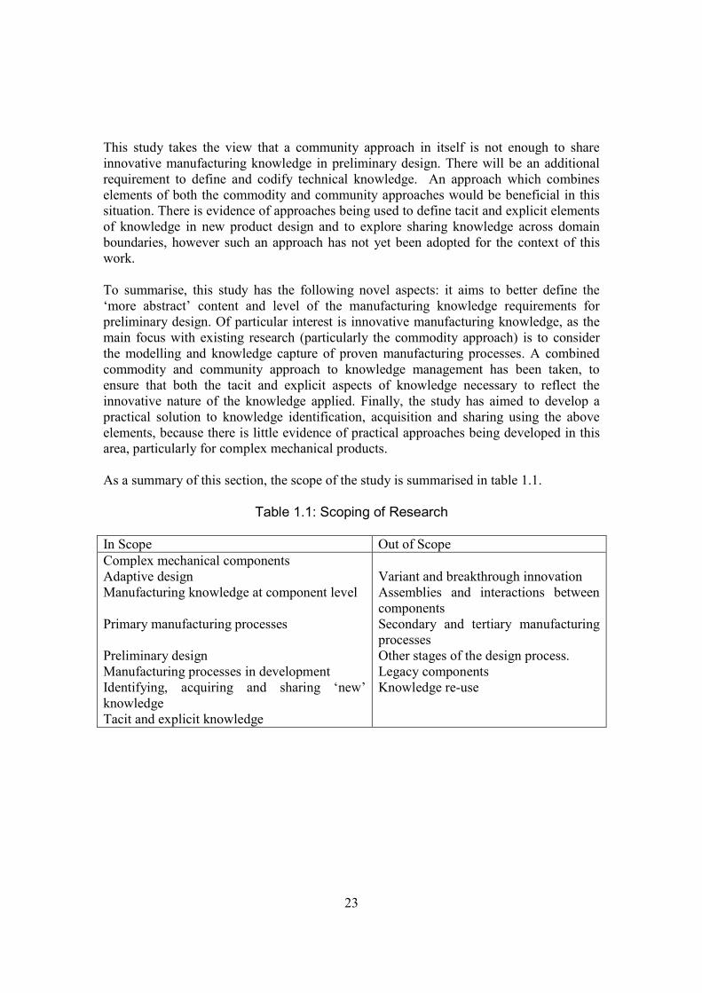
To summarise, this study has the following novel aspects: it aims to better define the‘more abstract’ content and level of the manufacturing knowledge requirements forpreliminary design. Of particular interest is innovative manufacturing knowledge, as themain focus with existing research (particularly the commodity approach) is to considerthe modelling and knowledge capture of proven manufacturing processes. A combinedcommodity and community approach to knowledge management has been taken, toensure that both the tacit and explicit aspects of knowledge necessary to reflect theinnovative nature of the knowledge applied. Finally, the study has aimed to develop apractical solution to knowledge identification, acquisition and sharing using the aboveelements, because there is little evidence of practical approaches being developed in thisarea, particularly for complex mechanical products.
As a summary of this section, the scope of the study is summarised in table 1.1.
Table 1.1: Scoping of Research
In Scope Out of ScopeComplex mechanical componentsAdaptive designManufacturing knowledge at component level
Primary manufacturing processes
Preliminary designManufacturing processes in developmentIdentifying, acquiring and sharing ‘new’knowledgeTacit and explicit knowledge
Variant and breakthrough innovationAssemblies and interactions betweencomponentsSecondary and tertiary manufacturingprocessesOther stages of the design process.Legacy componentsKnowledge re-use
24
1.2 Research Aims
The aim of this research study is to investigate the nature of manufacturing knowledgerequired for preliminary design and how these requirements can be identified, acquiredand shared effectively between the specialist design and manufacturing domains. Theresearch is specifically concerned with innovative manufacturing knowledge for thepreliminary design of complex mechanical components. It takes place within acollaborating company (see section 1.4).
1.3 Research Design
The research design approach has been determined by the exploratory nature of theresearch aim. It is flexible and interpretive, with an inductive phase and a hypothesistesting phase. The inductive phase uses semi-structured and unstructured interviews tocollect data concerning manufacturing knowledge requirements and qualitative codingtechniques for analysis. A hypothesis emerges to describe the requirements for innovativemanufacturing knowledge in preliminary design. This hypothesis is then tested throughthe development of a methodology which is then subjected to a qualitative evaluationusing observations and qualitative surveys.
An in-depth appreciation of the design of complex mechanical components was requiredto undertake a full exploration of knowledge sharing requirements. To achieve this, thestudy takes place in a single organisation which designs and manufactures complexmechanical components. As such, it is a single critical case because it aptly demonstratesthe factors which influence the design of these components. The rationale for this is toyield results and conclusions from this specialised case with the intention of contributingto the overall knowledge in this area.
The next section introduces the organisation selected as the critical case and outlines thecontext of the research undertaken.
1.5 Research Context
Rolls-Royce plc designs and manufactures gas turbine engines for military and civilaviation, industrial and marine applications. It is the second largest UK aerospacecompany (after BAE Systems), employing around 38,000 people across fifty sitesworldwide. It is currently ranked the world number two engine producer after GE and isnumber one in large turbofans.

25
The research for this thesis took place over a three year period at the organisation’s Derbysite, which is the headquarters of the civil aviation business. The main engineering andmanufacturing operations are based at this site and cater for the majority of stages withinthe product lifecycle. They are also supplemented by sales and marketing and in-servicesupport divisions. The focus of this research is the design process for new gas turbineengines from the Trent family of products, which have a 50% market share in their sector.
It must be noted that the organisational research took place at a certain point in time. Theremainder of this section outlines the design processes and organisational structureswhich were in place at the time of the study and as such contributed heavily to theresearch findings. Such processes and structures may have since undergone changes orimprovements.
The Trent family of aviation engines are variants of a three-shaft compressor and turbineconfiguration. This configuration was first developed nearly forty years ago with theRB211, originally developed for the Lockheed Tristar and used on the Boeing 747.Subsequent products include the Trent 500 (developed for Airbus), Trent 800, Trent 900(Airbus A380) and Trent 1000 (Boeing 787). Each engine development is tailoredspecifically to the range and requirements of the aircraft.
The gas turbine engine is a complex systems integration of mechanical, electrical andsoftware systems. The main systems are the compressor, combustion and turbine, thetransmissions systems and auxiliary power systems. As an original equipmentmanufacturer, the company is responsible for providing the complete system to theairframe manufacturer.
The components which are integral to these systems are suitable examples of complexmechanical components for the following reasons. Firstly, the gas turbine engine issubject to a number of requirements essential from an operational and environmentalpoint of view. The weight must be minimised for maximum fuel efficiency. The thrust,power and fuel consumption requirements dictate the temperatures and speeds at whichthe engine is run. Secondly, the resulting in-service environment is an essentialconsideration in the engine design. The resulting component configurations are complexin shape, for example a turbine or compressor blade. This presents challenges in terms ofdimensioning and tolerancing and stress analysis. The manufacturing knowledge requiredfor these components will be complex, reflecting the design situation. It may take anumber of forms, may be uncertain and not that easy to codify.
The design process for the gas turbine engine needs to be systematic to address all therequired design variables. The product configuration and maturity need to be tightlycontrolled at all stages of the process with a rigorous sign-off procedure and changemanagement process. This is managed using a staged gate process with a gated reviewprocess at the end of each stage.
26
The product introduction process for civil engines is referred to as the ‘Derwent Process’and is analogous with Pahl and Beitz’ systematic design approach. There are four stageswith gate reviews at the end of each stage. Stage 0 is the Concept stage, in which aperformance cycle is produced. This specifies the performance requirements andfunctions for the engine based on customer specification. Stage 1 is early preliminarydesign, where an initial mechanical design solution which satisfies the performance cyclefor the whole engine is produced. This is shown as a 2D General Arrangement (GA).Stage 2 is also preliminary design and is the optimisation of each of the major sub-systems of the engine: the compressor, combustor, turbine and transmission. Detailedcomponent design and optimisation takes place during this stage, includingmanufacturing optimisation. Finally in stage 3, detailed production layouts are producedto enable manufacturing to commence.
As the product matures, the number of people in the design process increases. Stages 0and 1 are carried out by a small central team known as APSD (Advanced PropulsionSystem Design). From stage 2 onwards, the design of each major sub-system and itscomponents is handed over to an Operating Business Unit (OBU) responsible for thatsystem. Each business unit contains 200+ design and manufacturing engineers. Stage 1involves some collaboration between APSD and each of the OBUs. Design iterations takeplace and the GA is updated accordingly. At stage 1 exit, the engine design is effectivelyhanded over to the sub-system business units, who then own the design and manufactureof their system.
The concurrent engineering ethos is built into the design process in a number of ways.The gate review process by its very nature ensures that multi-disciplinary collaborationtakes place during the design process. Formal approaches to concurrent engineering takeplace from stage 2 onwards through Design For Manufacture (DFM) sessions and the useof Integrated Product Teams (IPTs) for specific components. The former creates a forumin which the detail design of a component can be examined against manufacturing criteriafor cost savings. The latter creates a forum where conflicting design issues can beexamined. Manufacturing is represented alongside other disciplines. Design andmanufacturing engineers for specific component families are co-located in the sameOBUs.
Unlike stage 2 and beyond, stage 1 of the design process does not appear to have anyformalised support tools for sharing manufacturing knowledge. It is evident that someexchange is taking place at this level, but further investigation is required to define theknowledge required.
Different information system support tools are used at different stages of the designprocess. Many tools have been developed in-house to meet the specific requirements ofthe process at that particular stage.
The main output of stages 0-1 is the first mechanical engineering schematic of the engineproject. This is represented as a whole engine in 2D with the main dimensions and co-
27
ordinates shown. The General Arrangement (GA) is then passed to the OperatingBusiness Units for stage 2, which is carried out by 3D modelling. Some business unitshave carried out experiments with feature-based design using ‘standard features’ withinherent manufacturing capability, although the most success has been found with thelater, detail stages of design. Other tools used include knowledge-based engineeringsystems for optimising the engineering of certain components, intranet-based referencematerial and reference folders which contain the main recorded documentation onspecific engine projects.
The advent of digital technology has greatly reduced the lead time for a new airframe. Inline with their main competitor GE, Rolls-Royce now advocate a 24 month developmenttime for a new engine.
Simultaneously, legislation is continuously adding further restrictions to noise andemissions and increasing fuel efficiency. Consequently engines need to be designed torun at higher speeds and temperatures, creating a need for new materials, coatings andtreatments and manufacturing processes which can deliver them. The design envelope ofthe three-shaft turbine engine is being stretched to its limits in order to incorporate theserequirements.
By combining these two factors – more development in a shorter lead time – it can beseen that the risk in new engine introduction is increasing, especially in the introductionof new manufacturing processes. When should these be assessed? The existing designprocess caters for this in stage 2, however DFM will only examine the final details, notthe primary process. If a major problem is found during stage 2 then it will be costly interms of time and finance to resolve. It is clear that such issues need to be resolved earlierin the design process, i.e. before stage 2.
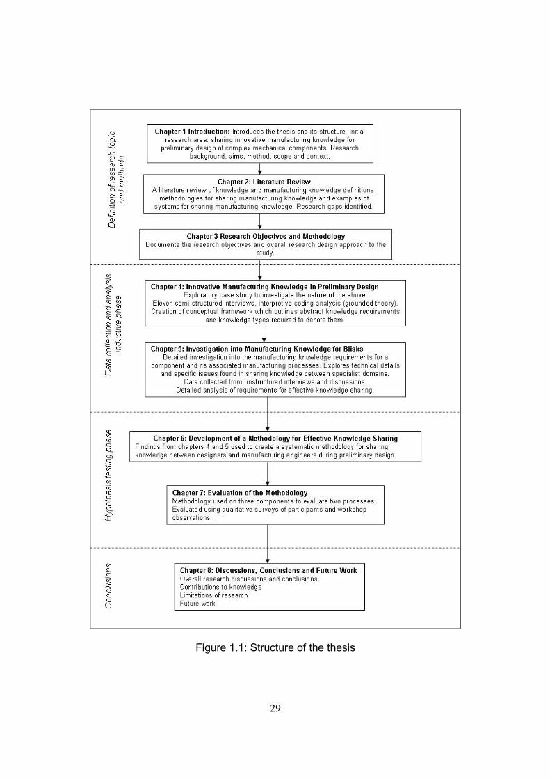
1.6 Thesis Structure
Chapter 1 Introduction
This chapter introduces the research background and context, discussing the researchaims and the thesis structure.
Chapter 2 Literature Review
This is a literature review chapter which investigates research in knowledge managementrequirements, techniques and tools. The topics covered are definitions of knowledge,definitions of manufacturing knowledge and techniques for sharing manufacturingknowledge. Research gaps are identified and discussed.
28
Chapter 3 Research Objectives and Methodology
This chapter identifies the research objectives resulting from the gaps identified in theliterature review. The research design approach to achieve these objectives is thenintroduced.
Chapter 4 Innovative Manufacturing Knowledge in Preliminary Design
This chapter documents the first of two data collection activities for the study, aninvestigation into the nature of manufacturing knowledge for preliminary design usingsemi-structured interviews. A grounded theory analysis was used to develop a conceptualframework of the knowledge requirements for preliminary design and the types ofknowledge needed to represent them.
Chapter 5 Investigation into Manufacturing Knowledge for Blisks
This chapter demonstrates the second data collection activity for the study. This was anexploration of the manufacturing knowledge requirements for an innovativemanufacturing process using unstructured interviews and a review of companydocumentation. This activity resulted in a more detailed understanding of the acquisitionand sharing of knowledge for the type of situation which emerged as being of particularimportance during the first data collection.
Chapter 6 Development of a Methodology for Effective Knowledge Sharing
In this chapter, the findings from the two collection activities are developed into asystematic methodology for the identification and effective sharing of manufacturingknowledge requirements during preliminary design.
Chapter 7 Evaluation of the Methodology
This chapter documents the qualitative evaluation of the methodology using threedifferent components and processes. The results are analysed and discussed.
Chapter 8 Discussions, Conclusions and Future Work
This chapter discusses key findings, contributions to knowledge, research limitations andrecommendations for further work.
This structure is illustrated in figure 1.1.
29
Figure 1.1: Structure of the thesis

30

31
Chapter 2
Literature Review
2.1 Introduction
This chapter reviews and discusses the academic literature relevant to the research aimsand themes. It highlights the research gap to be addressed by the thesis.
The literature review is concentrated on three topics which are central to the study and itscontext. These are knowledge sharing, the preliminary stage of the engineering designprocess and manufacturing knowledge. Around 250 papers have been reviewed, withthose most relevant discussed in this chapter. These papers are from the fields ofknowledge management, information systems and business management research, themajority having been published since 1990.
Firstly, some theoretical considerations of knowledge were explored as a foundation forthe remainder of the review. These were the theoretical definitions of knowledge,approaches to knowledge management and approaches to knowledge sharing. Aparticular interest in this part of the review was the treatment of innovative technicalknowledge. The engineering design process was then investigated as the theoreticalbackground to the study. Of particular concern was the definition of the preliminarydesign stage and how this differed from other stages of the design process. Next,manufacturing knowledge and its application in the engineering design process wasreviewed. Two angles were explored. The first was the content of manufacturingknowledge and how this differs depending on the stage of the design process. The secondwas how it has been defined in practice and how the theoretical definitions of knowledgehave been applied in this context.
Approaches to knowledge sharing were then investigated, with the emphasis on practicalexamples relating to the engineering design process and the sharing of manufacturingknowledge. The preliminary design stage was explored along with other stages, again tocompare and contrast the use of manufacturing knowledge. The suitability of theseapproaches in incorporating technical innovative knowledge were also considered.
Key observations from each part of the review produced a series of research gaps for thesharing of innovative manufacturing knowledge during the preliminary stage of design.To conclude, these gaps are outlined together with the decision for the focus of the study.

32
2.2 Knowledge Management and Definitions of Knowledge
The study of Knowledge Management within the organisation is a relatively new subjectarea, dating from the early 1990s. However, some of the philosophical references dateback to the discussions of Plato and Socrates (Alavi and Leidner, 2001). Other morerecent philosophers have also added to the debate, especially in (Polanyi, 1966) whounderpins much of the theory in organisational knowledge creation originated in(Nonaka, 1994).
Knowledge Management as a subject of study and practice arose as a consequence of thedefinition of the Knowledge Economy. This concept states that the value of theorganisation lies not within the commodities (product or service) that it produces, butwithin the knowledge applied within the organisation to produce it. This has becomeincreasingly important during the birth of the digital age and the internet, where thecommodity has become less tangible, yet an embedded knowledge value is inherent(Alavi and Leidner, 2001).
Several definitions of knowledge have arisen within the knowledge managementdiscipline. The origin of the definition depends on how knowledge is categorised and canconsequently affect the way in which it can be used (Alavi and Leidner, 2001).
The three most popular and cited definitions are the data-information–knowledgehierarchy, tacit and explicit knowledge and declarative and procedural knowledge. Eachof these definitions will be discussed in turn.
2.2.1 Data – information – knowledge hierarchy
A typical definition is found in (Young et al., 2004). Data is text or numbers. Informationis data with added context to explain the data. Knowledge is the interpretation ofinformation in order to assign meaning. Initial observations can therefore be interpretedas data, context added to give the facts and ultimately interpreted at a higher level asknowledge. A hierarchy is created where data and information become lower level pieceswhich create the building blocks for the next level (information and knowledgerespectively). This interpretation presents the idea that knowledge can be reduced toblocks which can be coded, shared and used. Consequently, this definition has originatedfrom and is mostly used for developing information systems for knowledge management.
33
2.2.2 Tacit and explicit knowledge
Tacit and explicit knowledge were originally defined in (Polanyi, 1966). Explicitknowledge can be articulated and represented as a formal language (codified).Consequently it can be shared between sources without losing its integrity. Tacitknowledge is rooted in an individual's own personal experience and beliefs and has twocomponents. The first is a technical component, which is the knowledge which isdemonstrated in practical skills such as craft. The second is a cognitive element from theindividual’s own beliefs and viewpoints. The personalised nature of tacit knowledgemakes it more difficult to express, codify and therefore share.
Polanyi's concept of knowledge with tacit and explicit components has been adapted andpopularised mainly through the work of Nonaka, in which knowledge is defined as beinga 'justified true belief’ (Nonaka, 1994). Information is defined as the flow and exchangeof messages. These messages have syntactic and semantic aspects. These are concernedwith information capture and attributing meaning respectively. The latter is important increating organisational knowledge. Furthermore, the organisational knowledge itself iscreated by the exchange of knowledge in its tacit and explicit elements (Nonaka, 1994).
This definition is fundamentally different from the data – information – knowledgehierarchy knowledge. Knowledge is seen as residing in and originating from individualswithin the organisation. It is this combination of business-specific individual knowledgewhich forms the collective knowledge of the organisation. Therefore knowledge mayhave explicit or tacit (and often both) elements at any time, but it is not a commoditywhich exists independently from its creators. Explicit knowledge may be captured andrepresented in a database, however the data itself needs to be interpreted and understoodwithin the context of the organisation (tacit knowledge) so that it may be usedsuccessfully.
2.2.3 Declarative and procedural knowledge
The tacit and explicit components of knowledge are useful in an explanation of the natureof knowledge and how it can be defined, transformed, transferred and applied. However,the third definition has a more pragmatic approach. Here knowledge is defined in termsof its source and its application and is categorised as being declarative, procedural orcausal (Zack, 1999). Declarative knowledge, or ‘know-what’ is the content of theknowledge. Procedural knowledge, or ‘know-how’, refers to the processes necessary inthe use of the knowledge. Causal knowledge, or ‘know-why’ refers to the underlyingrecognition of where it is appropriate to apply the knowledge. Zack recognises the tacitelement of knowledge but declares that the above can be and should be made explicit inorder to obtain the maximum organisational benefit. The nature of the knowledge canrange from being broad (and consequently easier to codify and share) to specific, in

34
which context becomes important and definition and codification is more difficult unlessthere is a common domain.
2.2.4 Comparison of the theories
Research has attempted to compare and contrast these three theories and to examine thelinks between them. Although Zack’s definition is treated here as a separate theory itdoes draw on and include some elements of the first two. However, no universalunderstanding has emerged and each research perspective has yielded an individualresponse.
Tuomi’s research is critical of the data - information – knowledge hierarchy model,asserting that it does not truly address the complex nature of knowledge. In order toderive knowledge from data, some initial knowledge of that context of data in the worldmust first be appreciated. A reverse hierarchy model is presented as an alternative. In thiscase, data is the end point of a transformation process rather than the start. The act ofadding structure to knowledge to produce information and data externalises and codifiesthat knowledge, thus creating explicit knowledge. A link is established between thehierarchy and the tacit / explicit dimension (Tuomi, 1999).
Hicks et al, in their work to illustrate knowledge types and methods for management, alsoassert that knowledge does not behave in accordance with the data-information-knowledge approach. Their belief is that data can be transformed into knowledge andknowledge can become data when used in another domain. Other components such asbehaviour aspects, organisational knowledge and learning are also missing from thehierarchy. They therefore present an alternative which incorporates both the data-information-knowledge approach and the tacit / explicit definition can be seen in (Hickset al., 2007). Their model, Explicit Islands in a Tacit Sea (EITS), again draws onNonaka’s tacit / explicit model. Explicit knowledge heads the model because, like Zack,it is seen as being the most important. The data component is acknowledged as beinglarger. Bridges between these support a two-way transformation of knowledge. The ‘seaof tacit knowledge’ exists to enable the creation of data, information and explicitknowledge and to select the tools for best practice. The model is designed to support themain models defined. However, it remains a concept representation and does not seem toadd anything in addition to Tuomi’s work (which has greater citations) and Nonaka’sSECI model (see section 2.4).
35
2.3 Knowledge and Innovation
Within the Knowledge Management discipline, the generation and use of knowledge forinnovation is seen as being necessary for organisational success and therefore pivotal tothe Knowledge Economy (Grant, 1996). This section reviews how some researchers haveconsidered knowledge for innovation in relation to the definitions of knowledgediscussed in section 2.3.
Nonaka's theory of organisational knowledge creation is concerned with the creation oforganisational knowledge for the purposes of innovation. Here, innovation is defined as aprocess in which problems are defined within the organisation and knowledge sought tosolve them (Nonaka, 1994).
Knowledge must move between tacit and explicit states for the creation of organisationalknowledge. This is illustrated by the SECI model which has four interacting mechanismsof explicit and tacit knowledge which are generated in a continuous spiral. Knowledge isinitially created by socialisation (a tacit to tacit knowledge transfer); then externalisation,where this knowledge is codified (tacit it to explicit); combination, where explicitknowledge is transformed into other formats of explicit knowledge and finallyinternalisation, where explicit knowledge is absorbed to become tacit knowledge. Thetacit element is at the heart of the knowledge, but this must be interpreted using theexplicit element. Furthermore, both knowledge elements need to interact in order to buildthis knowledge creation. There can be limitations to the creation of and use of newknowledge if it remains in the same state.
Senker’s discussion paper on tacit knowledge and innovation also references Polanyi butpre-dates Nonaka’s work (Senker, 1993). Her particular interest is in the methods used tocapture ‘tacit knowledge of a scientific and technological nature’ within and outside theorganisation. In a study based on industry and university links for biotechnology,advanced engineering ceramics and parallel processing, she investigated how tacitknowledge contributed to innovation activities, whether it could be codified and whetherit had limitations. She found that although science tended not to acknowledge tacitknowledge and skills, much tacit knowledge was involved in learning about science, itsanalysis and scientific research. Technology firms acknowledged it more. Like Nonaka,she found that an important factor in sharing tacit knowledge was interdisciplinarypersonal interaction, noting that ‘both scientific and technological inputs to innovationembody a considerable tacit component which can only be acquired by practicalexperience.’
She identified four reasons why tacit knowledge was important: it improves learning; it isused to solve technical problems; it is a necessity for understanding the complexity ofsystems and it is fundamental for new emerging technologies. She also identified threemain routes to the codification of tacit knowledge: the science push, where theoretical
36
underpinnings are applied; the technology pull, where industrial problems are exploredand automation (although this was limiting for innovation).
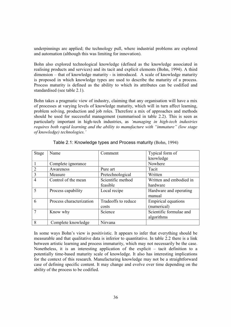
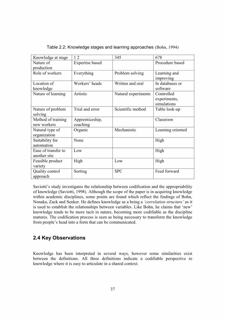
Bohn also explored technological knowledge (defined as the knowledge associated inrealising products and services) and its tacit and explicit elements (Bohn, 1994). A thirddimension – that of knowledge maturity - is introduced. A scale of knowledge maturityis proposed in which knowledge types are used to describe the maturity of a process.Process maturity is defined as the ability to which its attributes can be codified andstandardised (see table 2.1).
Bohn takes a pragmatic view of industry, claiming that any organisation will have a mixof processes at varying levels of knowledge maturity, which will in turn affect learning,problem solving, production and job roles. Therefore a mix of approaches and methodsshould be used for successful management (summarised in table 2.2). This is seen asparticularly important in high-tech industries, as ‘managing in high-tech industriesrequires both rapid learning and the ability to manufacture with “immature” (low stageof knowledge) technologies.’
Table 2.1: Knowledge types and Process maturity (Bohn, 1994)
Stage Name Comment Typical form ofknowledge
1 Complete ignorance Nowhere2 Awareness Pure art Tacit3 Measure Pretechnological Written4 Control of the mean Scientific method
feasibleWritten and embodied inhardware
5 Process capability Local recipe Hardware and operatingmanual
6 Process characterization Tradeoffs to reducecosts
Empirical equations(numerical)
7 Know why Science Scientific formulae andalgorithms
8 Complete knowledge Nirvana
In some ways Bohn’s view is positivistic. It appears to infer that everything should bemeasurable and that qualitative data is inferior to quantitative. In table 2.2 there is a linkbetween artistic learning and process immaturity, which may not necessarily be the case.Nonetheless, it is an interesting application of the explicit – tacit definition to apotentially time-based maturity scale of knowledge. It also has interesting implicationsfor the context of this research. Manufacturing knowledge may not be a straightforwardcase of defining specific content. It may change and evolve over time depending on theability of the process to be codified.
37
Table 2.2: Knowledge stages and learning approaches (Bohn, 1994)
Knowledge at stage 1 2 345 678Nature ofproduction
Expertise based Procedure based
Role of workers Everything Problem solving Learning andimproving
Location ofknowledge
Workers’ heads Written and oral In databases orsoftware
Nature of learning Artistic Natural experiments Controlledexperiments,simulations
Nature of problemsolving
Trial and error Scientific method Table look-up
Method of trainingnew workers
Apprenticeship,coaching
Classroon
Natural type oforganization
Organic Mechanistic Learning oriented
Suitability forautomation
None High
Ease of transfer toanother site
Low High
Feasible productvariety
High Low High
Quality controlapproach
Sorting SPC Feed forward
Saviotti’s study investigates the relationship between codification and the appropriabilityof knowledge (Saviotti, 1998). Although the scope of the paper is in acquiring knowledgewithin academic disciplines, some points are found which reflect the findings of Bohn,Nonaka, Zack and Senker. He defines knowledge as a being a ‘correlation structure’ as itis used to establish the relationships between variables. Like Bohn, he claims that ‘new’knowledge tends to be more tacit in nature, becoming more codifiable as the disciplinematures. The codification process is seen as being necessary to transform the knowledgefrom people’s head into a form that can be communicated.
2.4 Key Observations
Knowledge has been interpreted in several ways, however some similarities existbetween the definitions. All three definitions indicate a codifiable perspective toknowledge where it is easy to articulate in a shared context.
38
A common emerging theme is that of sharing information. Alavi and Leidner stress that aknowledge management system must be able to capture the knowledge bases ofindividuals yet assign meaning which is relevant for the organisation (Alavi and Leidner,2001). Fahey and Prusak also highlight the importance of creating a ‘shared context’,which they define as an understanding of the world of the organisation as seen by theshared ‘world views’ of the individuals (Fahey and Prusak, 1998). As these ‘individual’sworld views’ are the basis of their decision making, it is necessary to establish a commoncontext to enable knowledge to be ‘an activity that brings individuals to deeperunderstanding through dialogue’. Nonaka and Grant see organisational knowledge asbeing the combination of elements of individual knowledge for the benefit of theorganisation (Grant, 1996; Nonaka, 1994). Tuomi acknowledges that establishing ashared understanding between individuals can be difficult as ‘the original articulator andthe sensemaker need to have overlapping meaning structure. One could say they have toshare some world where the data can make sense’ (Tuomi, 1999).
The need for the shared context governs the appropriate knowledge type. Leidner andAlavi support the uses of both tacit and explicit knowledge as they are mutuallydependent and reinforce each other. This point is reinforced by Nonaka’s SECI model.Zack stresses that tacit knowledge should be made explicit because it is only then thatknowledge can be a competitive advantage. Fahey and Prusak see tacit knowledge asbeing fundamental to the creation and use of explicit knowledge. Tuomi proposes waysin which tacit and explicit knowledge could be exploited for different purposes. Thestrength in explicit knowledge would be in articulating and codifying routine operationsin a shared context. Where the context is not as shared, the exploitation of tacitknowledge through a social approach is proposed.
Another emerging theme is the importance of tacit knowledge in the generation ofinnovative knowledge (Senker, 1993). However, it must be combined with explicitknowledge in order to generate innovative knowledge (Nonaka, 1994), or be increasinglycodifiable as it matures (Bohn, 1994; Saviotti, 1998).
What emerges from the research is how the definition of knowledge governs the way inwhich it can be represented and managed.
Two main approaches are adopted in knowledge management. The first is concerned withcodifiable knowledge and the development of a mainly information system-basedperspective in supporting this. The second is a more social perspective evident whereknowledge is not so easy to articulate and a shared context needs to be established inaddition to the knowledge. These two diverse approaches are referred to as the‘community’ and ‘commodity’ approaches (McMahon et al., 2004). Their definitions areimportant to this study because they define the two main ways in which knowledgesharing methods have been applied practically for the context of this thesis. Acomparative analysis of these two approaches takes place in sections 2.7, 2.8 and 2.9.
39
2.5 Knowledge in the Engineering Design Process
The theories of knowledge and knowledge management are applicable to the designprocess. Hicks et al refer to the engineering design process as an ‘informationtransformation process’ (Hicks et al., 2002). The decisions necessary to move a designfrom one state to the next are driven by knowledge and information. Therefore it isimportant to consider the stages of the design process and the content and nature ofmanufacturing engineering knowledge. It is also important to explore how the theoreticaldefinitions of knowledge discussed in section 2.3 apply to this particular situation.
2.5.1 Content
Pahl and Beitz’ systematic approach to engineering design defines the design process asmanaging the constraints from a number of factors to produce the best solution (Pahl andBeitz, 1988). A successful design solution will satisfy the relationships between functionand form.
There are three stages to the design process: concept, preliminary (also termedembodiment) and detail. The concept design stage is concerned with the product function.During this stage the intended functions of the product and potential solutions to achievethem are explored. The outcome of this stage is a defined list of product targets which thesolution is expected to achieve. The preliminary design stage is concerned with therelationship between function and form. The requirements and functions finalised duringthe concept stage are transformed into an initial engineering general arrangement (i.e. aphysical representation) during this stage. The detail design stage is concerned with thedetail form of every component in the product. The arrangement from the preliminarystage is optimised and finalised, each part is fully defined (including geometricdimensions and tolerances), the final material selection takes place and the product isassessed for technical and economic viability. The necessary documentation is alsocreated to enable the product to be produced and maintained.
The authors also differentiate between different types of design. An original design is acompletely new solution and product. An adaptive design will satisfy an existing solutionin a new way (therefore requiring new or substantial changes to existing components andpossibly assemblies). Variant design is the modification of an existing product to meetthe same solution. The emphasis on each stage of the design process may changeaccording to the type of product being considered. A large one-off or adaptive productwill feature all the stages, but will need to build in controls along the process to managethe risk, particular if there is an element of innovation involved.
The preliminary stage is of specific interest to this thesis. This stage of the process issignified by the following characteristics. It has multiple design activities runningconcurrently. These activities can be interdependent – a change in one area will require a

40
number of changes in other areas. Some activities will need to be worked at a higher levelthan others, however ‘higher level’ knowledge is not defined. The process has thefollowing steps: identifying the requirements which have the main influence on theoverall design, the requirements which affect the overall size, the requirements whichaffect the overall arrangement and the requirements which may affect the materialselection. Other requirements – safety, ergonomics and production will affect all thesefactors. There are two preliminary design stages. These are summarised in figure 2.1(Pahl and Beitz, 1988, p. 41)
The designer is encouraged to reduce risks in the design as far as possible and also to‘design for production’ which is defined as being able to maintain quality at the lowestpossible cost. Consequently, the production impact is seen primarily as a cost impact.Production is defined as knowledge about manufacturing processes, assembly, quality,materials handling and operations planning. Pahl and Beitz do not relate the level andcontent of manufacturing knowledge directly to the stage of the design process. Rather, itis linked to particular activities. Table 2.3 (reproduced) summarises the factors whichneed to be considered by design and product. As the overall layout design is primarily theconcern of the preliminary stage, perhaps the production considerations for that activityare relevant. However, there are no guidelines for the content and level of knowledge tobe communicated at that stage.
Figure 2.1: The Two Stages of Preliminary Design (Pahl and Beitz, 1988, p.41)
Develop preliminary layout and form designsSelect best preliminary layoutDefine and evaluate against technical and economic criteria
Preliminary layout
Optimise and complete form designsCheck for errors and cost effectivenessPrepare the preliminary parts list and production documents
Definitive layout

41
Table 2.3: Relationship between Design and Production (Pahl and Beitz, 1988, p.266)
Design considers:- Production considers:-Overall layout design Assemblies
ComponentsBought-out partsStandard partsJoining and assyTransport aidsQuality control
Production procedureAssy and transportpossibilitiesBatch size of similarcomponentsProportion of in-house andbought-out itemsQuality control
Component form design Shapes and dimensionsSurface finishesTolerancesLimits and fits
Production procedureManufacturing methods,machine toolsMeasuring instrumentsIn-house and bought-outcomponentsQuality control
Materials selection Type of materialTreatmentQuality controlSemi-finished materialsAvailability
Production procedureManufacturing methods,machine tools.Materials handling(purchase, shape).In-house and bought-outparts.Quality control
Standard and bought-outcomponents.
Repeat partsStandard partsBought-out parts
PurchaseStorageStock control
Production documentation Workshop drawingsParts listData processingprogrammesAssembly instructionsTesting instructions
Execution of ordersProduction planningProduction controlQuality control
The DFMA (Design for Manufacture and Assembly) methodology originated to enablegreater consideration of production and assembly requirements before the detail designstage (Boothroyd et al., 2002). The aim is to design products which are easier tomanufacture and assemble which can consequently be produced at a lower cost.Examination of suitable manufacturing processes is again encouraged early in the designprocess as a process selection needs to have taken place in order to progress to the detaildesign stage. As with the systematic approach, process also needs to be considered in

42
conjunction with the material. The tools in the methodology are aimed at creating ateamwork approach.
During material and process selection, the product attributes need to be matched to thecapabilities of the process to meet them. There are three process types: the primaryprocess, which initially creates the product shape and ideally satisfies as many productattributes as possible; the secondary process, which is used to create the main shape,features and refined features and the tertiary process which is used to generate productproperties rather than shape. There is no differentiation of manufacturing knowledgerequirements between different stages of the process.
A practical application of the DFM methodology is seen in (O'Driscoll, 2002). With thisapplication a number of checkpoints were built into the existing design process to ensurethat the required knowledge had been supplied. Their design process does not fit themodel of Pahl and Beitz but does have some similarities. There are three stages ofincreasing detail – definition, development and validation/scale up. Initial process list andperformance indices (process capabilities) are considered from the definition stage. Thetype of manufacturing product considered was not discussed.
Lovatt and Shercliff also considered process selection in mechanical engineering design,the main driver again being minimum cost assuming all relevant technologies areavailable. Again the importance of the process and material link is established, but alsolinked to governance of shape. They do however note that in practice the shape is usuallydecided first. They note that material selection is often based on technical considerations,however the considerations for production are usually economic (Lovatt and Shercliff,1998a).
Chen investigated extending the DFMA methodology to improve support for designers,noting that they often lacked the relevant experience and knowledge to make informationdecisions about process selection (Chen, 1999). Again, the influence of process, materialand shape was acknowledged.
The research looked at production feasibility (the capability of the process to meet designattributes) and cost. For the earlier stages of the design process, this was seen as a‘screening out’ process for unsuitable processes rather than a calculation. Themanufacturing information to be used was phase-specific and depends on the designinformation which is available during the phase. A conceptual framework for amanufacturing decision support system was developed, which was in essence about‘information interaction between designers and manufacturing engineers’ and itscomponents. A case study example was created using machining as an example, and theresearch did not acknowledge the tacit and explicit elements of knowledge. The researchre-iterates the themes identified so far: where knowledge comes from (the individual) andhow it interacts. This research considered knowledge from another domain being framedso that it could be accessed by another domain.
43
Nowack specifically explored the assessment of ‘manufacturability’ during the earlystages of the design process, developing guidelines to assist in initial assessments(Nowack, 1997). Manufacturability was defined as being a capable process to meet theproduct attributes.
All the references refer to the relationship between the product form, the material and theprocess in process selection. They also stress the need to convey information about theprocess, its capability and its cost. The desired situation is that the manufacturing processis mature and stable in that it has a known capability that matches the product attributes.There is no information on how to handle innovative manufacturing processes and theirassociated risks. Also, the manufacturing knowledge for each stage – its content, the levelrequired and the best ways to involve the design and manufacturing functions – has notbeen defined in detail.
2.5.2 Comparison with knowledge management definitions
The data / information / knowledge interpretation of knowledge has been adopted in(Hicks et al., 2002) for creating a framework to relate information and knowledge. Theneed for explicit information and the importance of representing this electronically iscertainly acknowledged. Although they do not reference Nonaka or any other research ontacit and explicit knowledge, they also acknowledge that such explicit information needsadditional support and interpretation from designers’ own experience and knowledge.Information is interpreted as being either formal or informal. Formal information isstructured and can be represented. Informal information is less structured and usuallyobtained from discussions. Knowledge is inferred from information, the preference beingtowards informal information. Because of its unstructured and personalised nature,informal knowledge is seen as being possibly unreliable due to bias.
An example of the use of the declarative / procedural approach to knowledge can be seenin research by Fu et al, who investigated the knowledge content required for design in theaerospace industry (Fu et al, 2006). They carried out research to determine the knowledgecontent required for design. The results were high-level and categorised into market,human, technology and procedural knowledge. However, the resulting categories did notinclude manufacturing or production knowledge.
Both examples demonstrate that within engineering design, content and knowledge formare inextricably linked. This has been developed by (McMahon et al., 2004) todemonstrate how the knowledge form can influence the type of support systems used.
They discuss the personalisation (tacit) and codification (explicit) definitions ofknowledge, linking this with the community and commodity approaches to knowledgemanagement. The product type itself is also presented as a major influence on thesuitability of the approaches. The commodity approach, which promotes the capture, use

44
and re-use of knowledge, is presented as being advantageous for standardised, mass-produced products. Conversely, the community approach is suited to customisedproducts. However, the need for both approaches is acknowledged in the engineeringdesign process.
A number of approaches to knowledge management are then reviewed and rated on ascale of suitability for personalised vs. codified knowledge in the context of aerospaceand automotive industry applications. The output of this is shown in figure 2.2.
Other research has also considered the tacit and explicit components of knowledge, forexample when analysing the product development of automotive products (Ferrari andToledo, 2004). The tacit nature of production in particular is also highlighted in (Grantand Gregory, 1997) because it requires a wide range of knowledge from a number ofdifferent people.
Research into the Hong Kong jewellery industry also has interesting results concerningtacit and explicit knowledge (Siu and Dilnot, 2001). The research was carried during thetransition of the industry from being mainly highly-craft based to mass production.During the transition three points were noted. The first was that experience andknowledge previously carried out by artisans was segregated into design andmanufacturing specialisms, resulting in some loss of tacit knowledge. The second wasthat the artisans needed to adapt their skills in order that new digital technology could beused successfully during the design-make process. Thirdly, the full extent of the artisan’stacit knowledge and skills could not be successfully coded into a digital system,particularly in initial model-making.
Figure 2.2: Perspectives on Knowledge Management (McMahon et al., 2004)
Wong and Radcliffe (Wong and Radcliffe, 2000) investigated tacit and explicitknowledge used in the design process of small hydraulic cylinders in an SME from a

45
knowledge retention perspective, developing a knowledge schema to identify andsegregate explicit and tacit knowledge (figure 2.3). The aim of the schema was tounderstand the relationship of various knowledge types in an engineering design context.It could be applied to any design situation and provided a framework to identify tacitcomponents. Most of the knowledge identified in the design activities was explicit. Thetacit element, know-x, was concerned with knowing what theory to use and knowingwhen to apply it. It can define rules such as if…then rules, but involves judgement whichcannot be articulated. They suggest that this thought process can only currently bemanaged by people and cannot be automated. They concluded that the capture of ‘know-x’ is necessary to retain knowledge and design efficiency but paradoxically this cannot beachieved because it cannot be articulated.
Figure 2.3: Wong and Radcliffe’s knowledge schema (Wong and Radcliffe, 2000)
2.5.3 Key observations
In terms of content, manufacturing knowledge tends to be defined as method, capabilityand cost. The link between material, shape and process is strongly defined. There isrecognition that such knowledge may be less detailed earlier in the design process, butthis has not been defined specifically. Design knowledge and manufacturing knowledgehave been noted as separated specialist domain areas with a need to share knowledgebetween them.
As with section 2.3, the themes of knowledge sharing and the need to support this withina knowledge management environment are apparent. Engineering knowledge is viewedas being, or needing to be explicit. However, the importance of support through tacitknowledge has also been acknowledged. The knowledge type and appropriate systems of
Societalknowledge
Know-x
Professionalknowledge
Formal knowledge
Linguistic knowledge Can be developed once onehas linguistic knowledge.Supports development ofprof and soc knowledge
Pulls together all the necessary knowledge to complete thetask (oversees entire knowledge groupings)
Comes first
46
support have also been linked to the nature of the engineering product and processes byMcMahon et al.
Although new processes are acknowledged in both the Systematic Approach and DFMA(Pahl and Beitz, 1988; Boothroyd et al., 2002), the inherent nature of both methodologiesis to select capable processes to reduce risk. Chen uses machining – a mature, stable andwell-documented process – as a case study example for his system (Chen, 1999).Innovative manufacturing processes which are still in development and are thereforeimmature have not been considered. Bohn has discussed how processes are not inherentlycapable, particularly in high-tech industries. They require development work. Usingprocesses at the lower stages of the table (4 and below) is labour-intensive and requireseffort. It takes time to develop such processes to a capable standard (Bohn, 1994). Thisstance is echoed by Grant and Gregory in their study of the global transfer ofmanufacturing processes, noting that manufacturing processes will change over timeaccording to their maturity (Grant and Gregory, 1997). Additionally, the tacit knowledgeelements of these processes also require management.
The definitions of design process knowledge, particularly manufacturing knowledge, dofit with the definitions of knowledge management. The need to develop systems to dealwith tacit and explicit knowledge is documented. However, there are two emerging gaps:the definition of manufacturing knowledge specifically for preliminary design and theconsideration of innovative knowledge associated with manufacturing processes whendesigning knowledge management systems to support the engineering design process.
Section 2.5 highlighted the commodity and community approaches seen in knowledgemanagement. The next sections will consider how these have been applied within theengineering design process, particularly for manufacturing knowledge.
2.6 Commodity Approach
The commodity approach is concerned with the capture, representation, use and re-use ofknowledge, primarily within information systems. It is particularly applicable tosituations where benefit is gained from re-use, particularly where there is some degree ofstandardisation in processes and / or knowledge use. In design it is particularly suited tovariant design, although adaptive design can also be addressed using case-basedreasoning systems.
Successful knowledge sharing is at the heart of the commodity approach. This isknowledge sharing from two perspectives. The main perspective is interoperability. Inorder for knowledge to be shared and successfully interpreted across different platforms,then it must be defined and represented in a standardised manner. From a technical pointof view this requires the definition of knowledge exchange standards, protocols and
47
languages, such as STEP, CORBA, UML and ontologies to define the knowledgerequirements.
In this particular review the main interest in knowledge sharing is from a secondperspective. This is concerned with the techniques used to define knowledge from aspecific domain perspective and interpret this knowledge from the point of view of otherdomain perspectives. Two techniques which are of particular interest are features andinformation models, as both have been used extensively to represent design andmanufacturing engineering. These two techniques, and systems using them, will bebriefly reviewed.
2.6.1 Knowledge sharing using features
Features originated during the development of CAD/CAM systems as a means ofconveying product data in a format which could be interpreted for manufacturingpurposes. They were originally defined as attributes which sit above the pure geometryof a component to convey information which is of use in an engineering setting (Parry-Banuck and Bowyer, 1993) and early research into features investigated their use in thedesign and manufacturing domains, primarily focusing on the detail design stage of theproduct design process. As research progressed, the role of the feature expanded to otherstages of the design process and other knowledge domains, such as assembly, conceptdesign and tolerancing. Consequently the definition of a feature has also expanded to thatof an information carrier to be used across the entire design process.
Two main techniques have been developed to exploit features: feature-recognition (alsocalled feature extraction) and feature-based (also known as design-by-features). Infeature recognition, manufacturing features are extracted from a model based on thegeometry and topology. Research using this technique typically yields an automated NC/ process plan generating system for manufacturing. With the feature-based approach, theproduct model is constructed from a number of pre-defined features enabling a product tobe modelled relatively quickly. Pre-defined engineering information can also beconveyed within the features and be evident right from the start of the design phase. Theaim is to embed process capability in the product during the design phase.
A third technique in features is feature conversion, also known as feature transformationor feature mapping. It is a features technique which is used to map features from onedomain to another. This technique is used in multiple-feature view modelling, where anumber of feature views relevant to particular domain activities can be createdsimultaneously. This technique is required to support multiple domain views forconcurrent engineering.
In any system developed to use features, a clear, structured hierarchal definition – ataxonomy - is required, such as that presented in (Zha and Du, 2002) and (Gindy, 1989).
48
Information systems to support design and manufacturing analysis have been developedusing the three feature technique methods, at varying stages of the design process and fora number of applications. Examples of the application of feature recognition to determineprocess capability are seen in (Naish et al., 1997) and (Dong and Vijayan, 1997) and bothare concerned with machining processes. Examples of the use of a feature-basedtechnique are seen in (Gao et al., 2000) for sheet metal work and in (Gayretli andAbdalla, 1999) and (Sharma and Gao, 2002) for machining. The latter is of particularinterest because of the scope of the engineering design process in which it is used.Information systems using features have been mainly concerned with the detail designstage. With this example, there is a move into using features for a concept design system.However, as some initial geometry needs to be defined in order to use a feature-basedtechnique, it does not follow the Pahl and Beitz definition of concept design. It may bebetter interpreted as an example of preliminary variant design for a re-use situation.
Brunetti and Golob’s approach to adapting features to concept design was developed withreference to Pahl and Beitz (Brunetti and Golob, 2000). They concentrated on modellingthe functional behaviour of a product using a working principle model so that it can bedirectly linked to the product geometry generated later in the design process. The authorsproposed using a feature-based modelling of product semantics (especially in productfunction) approach to achieve this (Stork et al., 1996).
Bradley and Maropoulos also developed a product model using hybrid features torepresent concept and embodiment for early design manufacturing analysis (Bradley andMaropoulos, 1995). The product model is tailored for embodiment stage by representingsome overall dimensions but not detailed geometry. The main functions of theConcurrent Engineering Support System (CESS) developed are to generate a productspecification, perform early manufacturability assessment during concept andembodiment and estimate costs. The system was demonstrated using a solenoid as aproduct example. Further work by Maropoulos widened the scope of manufacturingknowledge included. The CESS was supplemented by a rough-cut capacity planner forshop floor scheduling and a Computer Aided Process Planning (CAPP) system for detaildesign stage process planning, capacity and scheduling. The resulting system was calledCAPABLE (Concurrent Assembly and Process Assessment Blocks for Engineeringmanufacture) (Maropoulos et al., 1998).
Examples of feature-based systems also developed to include more than one domaininclude Liang and O’Grady’s feature-based distributed concurrent engineering (FBDCE)system to support the sharing and integration of design, engineering and manufacturingknowledge (Liang and O'Grady, 2002), Zhang and Xue’s series of web-based databasesfor different stages of the product lifecycle using design and manufacturing features(Zhang and Xue, 2002) and Borg and Giannini’s consideration of artefact features andlife-cycle characteristics in addition to shape features (Borg and Giannini, 2003). Theyfound that the quality of the evaluation was dependent on how much of the product it waspossible to define.
49
A major limitation in the expansion of features has been the ability to model and viewmore than one feature view at a time. Feature conversion, and the resulting technique ofmultiple feature-view modelling (MFVM) can be used to create features at differentstages of the product cycle and map them across. The method used to achieve conversionfrom one set of features to another is similar to feature recognition, however in this caseone set of features is derived from another set of features (Bronsvoort and Jansen, 1993).The design view is accepted as the primary model view, with all model changes beingdriven through this view.
An example of such a system using MFVM can be seen in (De Martino et al., 1998). Anintermediate model (IM) created by a design-by-features approach is the hub of thesystem and provides a shared product model providing different views of the productdepending on the required application. The model is flexible and is able to view differentindependent self-contained subsets of the entire model depending on the applicationrequired. However, the feature transformation is one-way and if any updates are required,they need to be made via the primary model. De Kraker et al introduced the SPIFFsystem in 1995 as a means of addressing this issue (de Kraker et al., 1995). Theirapproach is to support all feature views simultaneously and to perform multiple featureconversions between these views.
The approach adopted could be said to work the opposite way to the typical featureconversion approach. The starting point for the system is the creation of a domain-specific view with a feature-based approach. This would probably be design but couldequally be any other domain view. Any subsequent feature views can then be created byother domains using the original view as a basis – the geometry must be consistent.Updates carried out in one view can also be propagated across to other views. In this way,the system is designed to support dispersed collaboration in a concurrent engineeringenvironment.
The use of feature semantics (the meaning attributed to a feature for a specific stage ofthe product lifecycle) has also been explored in the SPIFF system (Bidarra andBronsvoort, 2000), presenting a semantic feature modelling approach as a solution. Thisobject-oriented approach created feature classes as structured descriptions of all theproperties of a given feature type (including validity conditions), known as semantics. Itis user-interactive in that the users can define their own feature classes. The SPIFFsystem was developed further to become a web-based collaborative feature modellingsystem (WebSPIFF) which incorporates concept and assembly design, ensuring that afeature based model can be fully associative across the entire assembly rather thanfocussing on a single part. The developed system has the following functionality forcollaborative design: concept design, assembly design, detail design and manufacturingplanning (Bidarra et al., 2001; Bronsvoort and Noort, 2004).
Features have proved themselves to be useful in modelling stages in the design process.Their application has been primarily to products which are machined (although sheetmetal work has also been demonstrated). There are however two limitations with features
50
which are due to the way in which they are explicitly linked to component geometry.Although features are designed to show more than geometry, one must question whetherthey do fulfil that purpose given that they are formed from and linked to geometry. Thesecond weakness is that in order to derive a feature it must already be based on someknown geometry, therefore the design itself must have reached some stage of maturity inorder for the feature to be derived. The success of their use in early design must thereforebe questioned. Was it early design or showing a more mature product earlier? From atechnical perspective, the number of feature views and their synchronisation would makean industrial application to a complex mechanical component prohibitive.
An alternative method of sharing knowledge which is not so tied to geometry, yet stilloffers some standardised knowledge sharing is sought. Such a method can be found ininformation models.
2.6.2 Knowledge sharing using information models
Information models are a formal method of standardising, structuring and representingknowledge. Developed to improve interoperability, they are usually modelled usingstandard languages such as UML. They are an attractive option for modelling knowledgein the design process because they are not as tied to geometry as features. Certainlygeometric information is included and this can include features, but there is scope toinclude other wider sources of information.
The work by Young and a number of researchers define three types of informationmodels for sharing design and manufacturing knowledge. These are the product model,the manufacturing model and the product range model. A product model contains all theinformation specific to the design of the product, with different views to represent eachfunction. Consequently it has a manufacturing-specific view. A manufacturing modelcontains the information relating to the process capability and manufacturing resourceavailability (Lee and Young, 1998). Manufacturing information can be categorised intohow to produce a part (product model) or how to use the manufacturing facilities in anenterprise (manufacturing model) (Young et al., 2000). A product range model provides alink between the product and manufacturing views, associating functional informationwith potential design solutions (Costa and Young, 2001). Information is shared betweenthe different viewpoints of the different models using a knowledge transformation layer(Young et al., 2004).
The work has been primarily applied to support design for manufacture for injectionmoulding (Canciglieri and Young, 2003; Costa and Young, 2001; Lee and Young, 1998),although this work has also branched out into machining and assembly processes (Younget al., 2000) and consideration of global manufacturing facilities (Liu and Young, 2004).The work is primarily aimed at variant design, particularly for knowledge use – reusesituations, however Costa and Young also explored its application to adaptive design.

51
More recent work has been concerned with creating a shared meaning for design andmanufacturing knowledge in an ontology (Young et al., 2007). The approach consideredhas been to use Process Specification Language (PSL) as the ontology language, as beingmathematically based, it can provide a more rigorous definition when compared to text-based languages such as UML. The results have shown limitations but research iscontinuing to define a single foundation ontology. Keqin and Shurong have also recentlycreated an ontology of manufacturing knowledge to support design decisions, working tothe first four stages of Pahl and Beitz’ approach. Here manufacturing knowledge has beenmodelled as relating to materials, machines and methods (Keqin and Shurong, 2008).
An example of an extended parametric information model can be seen in (Kleiner et al.,2003) in their development of a constraints-based approach to design and analysis. Theprinciple was implemented in a system called Colibri (Constraint linking bridge) andapplied to a mechatronics example, producing models for design in a CAD system, finiteelement analysis, multi-body system simulation and control design. The integration ofdata takes place via the properties shared by the constraints, meaning that the integrationtakes place within the geometry.
Information models are more flexible than features, however the information they containmust be codifiable to be expressed in a standardised language. Some attempts have beenmade by Young et al to classify knowledge as being explicit or tacit as a way ofdetermining the best method for handling the knowledge (Young et al., 2004).Knowledge classified as explicit (i.e. tables, procedures and graphs) could be processedby information systems, tacit knowledge could not, except perhaps as a video clip. Theexamples of successful manufacturing models have also been created for maturemanufacturing processes.
2.6.3 Examples of the commodity approach
Many examples of the commodity approach are collaborative systems for supporting aconcurrent engineering environment. The focus of this research tends to be on solvinginteroperability problems and the integration of different platforms to support theengineering process. The platforms tend to be CADCAM, CAPP and PLM systems,sometimes with some KBE capability included. The most popular approach is to create aweb-enabled system linking together either PLM and / or CAD systems using STEP forproduct data exchange and CORBA as a standard for object-oriented integration. Amodelling language has also been used in the implementation – EXPRESS (modellinglanguage created for STEP), Smalltalk, UML and XML have all featured. These systemsmay or may not use features and / or information models. One question is whether tohave a large system with ‘one size fits all’ functionality (similar to the off-the-shelf ERPpackages currently available) or whether to have a suite of product development toolswhich could be successfully integrated. This conundrum is discussed by Szykman et alwith the latter approach being favoured for greater flexibility (Szykman et al., 2001).

52
Regarding interoperability, the challenge for the developers is ‘to use the relevant modelfor each task (the right abstraction and granularity) and to communicate the results in asuitable form to the various parties involved, whose needs are different and interests arediverse’ (Wang and Zhang, 2002). Examples of collaborative systems to supportconcurrent engineering can be seen in (Chen and Liang, 2000; Chen et al., 1998; Gao etal., 2003; Gu and Chan, 1995; Jiang et al., 2002; Oh et al., 2001; Wolff et al., 2001 andYe, 2002).
Early Design Support
Examples of collaborative systems developed to support the early stages of design can beseen in (Cera et al., 2002; Rodgers et al., 2001 and Haque et al., 2000).
Cera et al proposed a collaborative system to support knowledge based concept designusing an integration of computer-aided design methods and a semantic webrepresentation framework (Cera et al., 2002). Design semantics are defined as ‘groundedrepresentations of product and process knowledge.’ The system is designed to be used insituations where a design team is geographically dispersed. The semantics are intended asa method of communicating meaning which would normally be discussed in a co-locatedenvironment. They can also be used to represent information about the product in lieu ofdetailed geometry which can be added later, hence the suitability of the system for earlystage design. Early stage design in this case is defined as a combination of two knownapproaches – functional modeling (as seen in mechanical engineering design) andfreeform sketching (as seen in more consumer-based products). This system combinesboth approaches with ‘controlled sketching…to capture the functional representation.’Hence it is suited to less complex products where there is a functional and aestheticconsideration (perhaps consumer products), where a number of alternative solutions needto be created quickly for comparison to the design brief.
WebCADET is an internet-based knowledge server intended to support designers duringconcept design, however they do not define their interpretation of this (Rodgers et al.,2001). A case-based reasoning approach to decision making in concurrent engineering isalso presented in (Haque et al., 2000). This approach is promoted as a means ofstrengthening early decisions. Some of the problems cited with end user needs includebias from memory recall, past product information may be dispersed or not available, theright person may not be available, lack of formal decision support, the iterative nature ofdesign and lack of knowledge of the consequences of design decisions.
Consequently a knowledge-based support system is proposed for the early phases ofNPD. A case –based reasoning approach was selected because of its ability to deal withmultiple domains and the ability to carry out ‘what-if’ analyses. They used nearestneighbour algorithms to compare cases. One of the issues they found was in casesimilarity. The vocabulary may differ to describe same thing, despite standardisedterminology and this may not be considered by the algorithm. ‘the similarity percentageoffered for each case in the results might not reflect the ‘real’ similarity of the cases, as
53
understood by the user. The software does not show enough transparency and can affectthe users’ trust.’
Complex Products
There are examples of design support systems and collaborative systems being developedto support early stage design for more complex products, primarily in the aerospacesector. Clarkson and Hamilton presented a parametric-driven task model of the designprocess called ‘Signposting’ (Clarkson and Hamilton, 2000). The aim of the tool was tosupport the iterative nature of the aircraft design process. The requirements for thesystem were that it should be relevant to all levels of skills and experience; able tocapture, store and reuse data in a flexible manner within an iterative process; supportmultiple design tasks and guide the order of these tasks; have an integrated designenvironment; be useful and cost-effective. The model provides guidance on the nextprocess to be followed rather than integrating the process itself. It has four tiers: theparameter level, which includes the parameters used to describe the design; the task level,which shows the tasks available to be used; the process level, which organises the tasksand finally, an interface level which enables users’ access to the tasks. Guidance isachieved by scoring confidence in the maturity of a specific task.
Fujita and Kikuchi’s research is concerned with the concurrent support of preliminaryaircraft design (Fujita and Kikuchi, 2003). Their definition of preliminary design is moreprecise than many of the examples discussed in this section. It is seen as the stagebetween concept design and detail design, where the main dimensions which size theproduct (in this case, an aircraft) are set to meet the performance criteria. The sub-systems are then considered in increasing detail. This definition is comparative to theprocess described by Pahl and Beitz. Three concepts within the design process areconsidered: the management of trade-offs between different disciplines to give acompromise solution (called ‘satisficing’); the ability of the product to be decomposedinto a number of subsystems to focus design efforts and the increasing detail (granularity)in the design as it moves from preliminary to detail stages. Consequently an abstractionof a large complicated design problem is required to develop a general system of solution.They propose a distributed design support system which is develop in a CAD system,using knowledge-based techniques and agent-based distribution of tasks.
Savci and Kayis took a risk management approach to concurrent engineering, developingthe IRMAS (Intelligent Risk Mapping and Assessment System) to consider thecumulative risks generated by the interdependency of tasks (Savci and Kayis, 2006). Thesystem was trialled in the aerospace industry, looking specifically at advanced compositemanufacture and aerospace design. Of particular concern were risks encountered duringpreliminary design, defined as ‘incomplete preliminary manufacturing engineeringvalidation, tooling design, and customer requirements analysis.’
54
Manufacturability Assessment
Other researchers have used the commodity approach to develop systems whichspecifically consider the manufacturability of a product. Lovatt and Shercliff extendedtheir earlier work on process selection into a task-based methodology (Lovatt andShercliff, 1998b). However, the preliminary design stage is fixed prior to the use of themethodology. The requirement for the task-based selection is to determine viablematerial / process combinations in terms of technical feasibility and cost effectiveness.Therefore design and material ‘performance’ and ‘processability’ (process capability andcost) were considered. The starting point is a matrix of all possible process / materialcombinations. Each stage is then used to screen out the non-feasible options. As thematerial and process selection becomes more refined at each stage, more detail can thenbe introduced. At the initial screening, all the obviously unfeasible combinations areeliminated. During a primary assessment, the possible combinations are compared withtechnical process feasibility and screened on these requirements. Then during aperformance assessment the ‘processability’ of the filtered combinations is examinedtogether with performance and cost criteria. Finally an economic evaluation takes place.A scheme of the methodology is shown in the figure 2.4 (reproduced). The detail of eachphase is summarised in table 2.4. Qualitative process comments are included during thepreliminary and performance assessment. The methodology was built into a softwarepackage and was demonstrated in carbon steel cutting, aluminium casting and carbonsteel welding, although the details of this were out of scope of the paper.
Zha considered the selection of materials and manufacturing processes in a concurrentDFM environment (Zha, 2005). The focus again was on the early stage of design,although again this was not defined. Design requirements were categorised as materialproperties, form requirements and production requirements (lead-time, rate and quantity).They claimed that these categories could also be used for the categorisation of processrequirements. The rationale for process selection was cost-based with a systematicsolution of suitable materials and processes. Process capability and material propertydata were used to carry out assessments using a fuzzy knowledge-based approach.
Bordegoni and Cugini developed a design support system to capture process and rationale(Bordegoni and Cugini, 2002). It is designed to support the capture and representation ofdesign and manufacturing knowledge for re-use. The rule-based system is based on amulti-level knowledge model for design and manufacturing knowledge managementincorporating the product structure, starting with the physical principle level (whichcontained general design rules), the architecture level (parametric modelling ofconstraints imposed by the physical principles), solution families (division of architectureinto sub-systems ) and instances (specific projects). The design and manufacturingconstraints capture rules and parameters mainly related to the selected shape and materialof the component.
A knowledge management database was developed to support the manufacturingassessment of gas turbine engines (Balogun et al., 2004). The database used a feature-
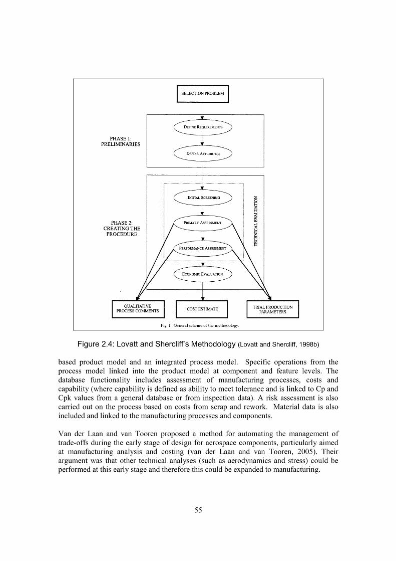
55
Figure 2.4: Lovatt and Shercliff’s Methodology (Lovatt and Shercliff, 1998b)
based product model and an integrated process model. Specific operations from theprocess model linked into the product model at component and feature levels. Thedatabase functionality includes assessment of manufacturing processes, costs andcapability (where capability is defined as ability to meet tolerance and is linked to Cp andCpk values from a general database or from inspection data). A risk assessment is alsocarried out on the process based on costs from scrap and rework. Material data is alsoincluded and linked to the manufacturing processes and components.
Van der Laan and van Tooren proposed a method for automating the management oftrade-offs during the early stage of design for aerospace components, particularly aimedat manufacturing analysis and costing (van der Laan and van Tooren, 2005). Theirargument was that other technical analyses (such as aerodynamics and stress) could beperformed at this early stage and therefore this could be expanded to manufacturing.
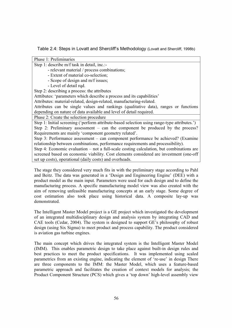
56
Table 2.4: Steps in Lovatt and Shercliff’s Methodology (Lovatt and Shercliff, 1998b)
Phase 1: PreliminariesStep 1: describe m/f task in detail, inc.:-
- relevant material / process combinations;- Extent of material co-selection;- Scope of design and m/f issues;- Level of detail rqd.
Step 2: describing a process: the attributesAtttibutes: ‘parameters which describe a process and its capabilities’Attributes: material-related, design-related, manufacturing-related.Attributes can be single values and rankings (qualitative data), ranges or functionsdepending on nature of data available and level of detail required.Phase 2: Create the selection procedureStep 1: Initial screening (‘perform attribute-based selection using range-type attributes.’)Step 2: Preliminary assessment – can the component be produced by the process?Requirements are mainly ‘component geometry related’.Step 3: Performance assessment – can component performance be achieved? (Examinerelationship between combinations, performance requirements and processibility).Step 4: Economic evaluation – not a full-scale costing calculation, but combinations arescreened based on economic viability. Cost elements considered are investment (one-offset up costs), operational (daily costs) and overheads.
The stage they considered very much fits in with the preliminary stage according to Pahland Beitz. The data was generated in a ‘Design and Engineering Engine’ (DEE) with aproduct model as the main input. Parameters were used for each design and to define themanufacturing process. A specific manufacturing model view was also created with theaim of removing unfeasible manufacturing concepts at an early stage. Some degree ofcost estimation also took place using historical data. A composite lay-up wasdemonstrated.
The Intelligent Master Model project is a GE project which investigated the developmentof an integrated multidisciplinary design and analysis system by integrating CAD andCAE tools (Cedar, 2004). The system is designed to support GE’s philosophy of robustdesign (using Six Sigma) to meet product and process capability. The product consideredis aviation gas turbine engines.
The main concept which drives the integrated system is the Intelligent Master Model(IMM). This enables parametric design to take place against built-in design rules andbest practices to meet the product specifications. It was implemented using scaledparametrics from an existing engine, indicating the element of ‘re-use’ in design Thereare three components to the IMM: the Master Model, which uses a feature-basedparametric approach and facilitates the creation of context models for analysis; theProduct Component Structure (PCS) which gives a ‘top down’ high-level assembly view

57
of the product and enables component geometric changes to be associative throughout thewhole assembly and the Product Assembly (PA), which is a ‘bottom up’ detailed view ofthe components within the assembly. Updates within this structure are associativethroughout the product due to the link with the PCS and the Context Model Architecture(CMA), which is an intermediate model created from a copy of the master model whichcan be viewed as different context-specific models for different analysis activities. Thereis also an additional Link Model Environment (LME) which is an integrationenvironment. The modelling was implemented during the later stages of preliminarydesign and detailed design. Originally, the aim was to introduce it during earlier stages ofpreliminary design but it did not have sufficient flexibility. Two pilots were reported: theconstruction and analysis of a 3D solid geometry model for a compressor assembly(Bailey, and VerDuin, 2000). Two models were demonstrated – a heat transfer model anda manufacturing model. The latter was used in conjunction with a 3D master model togenerate process plans, tooling and CNC data and a CMM model. The second pilot wasfocussed on the creation and validation of four context models for analysis – a 3Dconjugate heat transfer module (combines aerodynamic, combustion, heat transfer andmechanical analyses in one model), a 2D mechanical model, a 3D stress model and a 2Dsub-system dynamics model (Seeley et al., 2001).
Recent Examples
Two more recent examples of research have implemented mathematically modelledmethodologies as object-oriented solutions. Xiao et al developed the CollaborativeMultidisciplinary Decision-making Methodology (CMDM) to enable ‘collaboration byseparation’ (Xiao et al., 2007). Here, design and manufacturing teams workindependently to solve their relevant problems associated with the design of a newproduct. The CMDM seeks to reduce the amount of iteration between the two areas byacting as a decision support system which reduces the degrees of freedom available forthe solution at each stage, thus eliminating unsuitable design solutions early in theprocess. There are three elements to the CMDM: a compromise Decision SupportProgram which is a mathematical model represented by a XML object-oriented datamodel, to enable information to be transferred without iteration, game theory to model themost effective interactions between design and manufacturing and design capabilityindices to specify target design values.
Du et al also presented an example using stream of variation (SoV) methodology duringproduct design to make early predictions of product quality (Du et al., 2008). Thismethodology was a framework with three elements: multivariable statistics, controltheory and design and manufacturing knowledge. The methodology was designed toevaluate the product design and process variables and in doing so predict anymanufacturing problems which may occur later in the later stages of the design process.The stages of design and manufacture considered are not defined, but appear to be basedon detail design, with modelling of the product features and geometry and processoperation details and sequences.
58
2.6.4 Key Observations
The commodity approach has been very successful in developing structured andstandardised examples of knowledge representation. The strength of the approach andhence focus of research is the ability to automate and therefore improve the efficiency ofroutine design process tasks and analyses. For this to be successful, the systems need todeal with ‘known’ knowledge - the design product considered is usually variant, itsparameters are known and the manufacturing process is mature. Conversely, knowledgewhich is immature, has some degree of being ‘unknown’ and comes from people is seenas undefined, incomplete and unreliable. The automated approach is seen as being moretechnically rigorous and therefore preferable.
The issue of interoperability is well recognised and is a prime focus of research activity.Therefore the emphasis tends to be on the technical issues rather than the definition of theknowledge itself. Consequently many systems are demonstrated using simplisticexamples which cannot reflect the design issues associated with complex mechanicalcomponents. Also, although many systems are aimed at ‘concept’ or ‘early stage’ designthere is no real definition of this in terms of design process and knowledge requirements.There are some examples applied specifically to complex mechanical components,however. These have been important in defining how knowledge is required to managethe trade-off for requirements from multiple engineering disciplines.
2.7 Community Approach
2.7.1 Criticism of the Commodity Approach
The business management sector of research has been critical of the ‘commodity’approach to knowledge management. Walsham maintains that information systems do notimprove communication between people (Walsham, 2001). There are two reasons forthis. The first is because the explicit and tacit elements of the knowledge are divorced.Walsham suggests that the commodity approach misunderstands and misrepresents tacitknowledge. It is seen as something which can be converted into explicit knowledge andthen stored, i.e. as a transferable object, contrary to Polanyi’s original definition.Consequently, explicit knowledge has been promoted at the expense of instilling meaningfrom tacit knowledge and such systems have ignored the need to manage knowledgesimultaneously at both the explicit and tacit levels. The second reason is concerned withthe sense-reading and sense-giving aspects of tacit knowledge transfer, again referring toPolanyi’s original definition. An example of this is illustrated by the writing of a letterabout new experiences. ‘this is not a simple process of “knowledge transfer” as depictedby the “knowledge as a commodity” literature. The sense-reading of person A is notperfectly depicted in the attempt at sense-giving in the letter, and is certainly not the
59
same as the sense-reading which is then carried out by person B.’ Thus Walsham isillustrating the importance of the tacit element of knowledge in sharing knowledge acrossdifferent domains.
Walsham does not reject the use of ICTs in knowledge management, recognising thatthey do serve an important purpose. He suggests that instead knowledge systems shouldbe designed to promote the value of the sense reading and sense giving activities – thiswill give them value. Two methods are suggested – communities of practice within ashared boundary and organisational translators across domain boundaries.
Roberts also examines the issue of knowledge transfer through the use of ICTs and issuessurrounding explicit and tacit knowledge transfer (Roberts, 2000). She shares the sameknowledge definitions and perspectives as Walsham, again citing Polanyi and Nonaka’sdefinitions of tacit and explicit knowledge. Knowledge transfer is defined as the diffusionof knowledge from an individual to others. The knowledge transfer process is achievedby socialisation, education and learning which can either occur deliberately or as a by-product of another activity. She notes that person-to-person (and preferably face-to-face)communication is the most critical element of technology transfer.
Roberts also raises the issue of trust in knowledge transfer, stating that this is important inthe exchange of tacit knowledge and that this can be achieved by initial social contact,particularly across different social backgrounds. She concludes that this can only beinitiated from face-to-face contact and is something that is not acknowledged in ICTsystem development. She suggests that even video conferencing is insufficient for tacitknowledge transfer and trust building as the process of digitisation codifies the humanelement of the contact. Furthermore, initial tacit knowledge transfer is an essential pre-requisite for explicit knowledge transfer.
Johannessen et al, noting that increasing investment in IT does not appear to have reapedthe benefits, were also concerned about the focus on explicit knowledge being to thedetriment of tacit knowledge transfer (Johannessen et al., 2001). Like Walsham andRoberts, the focus of their research was to improve understanding of tacit knowledge andgive guidance on how to handle the relationship between tacit knowledge and IT. Theywere specifically concerned with the influence of tacit knowledge on the use of ITsystems and vice versa. They saw the organisational challenge as being to transformpersonal tacit knowledge into organisational explicit knowledge. Processes for buildingtrust and relationships are seen as being pivotal to this, illustrated by their case study at aNorwegian shipyard.
The company was organised into teams based on an instructor-apprentice model whichenabled job rotation to take place so everybody had at least a basic appreciation of eachother’s jobs. Consequently they became more inclined to share knowledge. This led tosome teams proposing changes to the design philosophy which would improve efficiencywithin the process. The top management structure was disinclined to implement this, asthey had proposed the original philosophy, however the changes were eventually
60
implemented after a process change procedure was instigated. This work highlighted twoimplications of enabling tacit knowledge transfer: the first is that it can haveconsequences for the organisational structure and philosophies of an organisation andsecondly, that not everybody is always willing to acknowledge or permit theconsequences of tacit knowledge transfer.
They too see the exchange of tacit and explicit knowledge as being necessary forinnovation, arguing that tacit knowledge by itself will only lead to continuousimprovement at the most because it can be conservative and subject to internal barriers.Their conclusions are similar to those seen in Nonaka’s SECI model, however littleevidence is offered in this particular research work to support the claim.
Swan et al also acknowledge the benefits of IT for knowledge re-use situations, but notethat IT-based knowledge management projects which focus primarily on codifyingknowledge will not be able to deal with innovative knowledge (Swan et al., 1999). Theyview innovation as a time-phased multi-function communication process within anorganisation, therefore knowledge sharing is essential for this process and thedevelopment of new innovative approaches. They also share the stance that tacitknowledge cannot be codified because of its personal and context-specific elements. Itmay be too uncertain; it may be too context dependent and therefore irrelevant; it may betoo politically sensitive and it may be inaccurate. Consequently networking, a socialcommunication process, is promoted as a major requirement of a successful process-based approach to innovation. The main challenge in achieving this is successfulcommunication across different organisational boundaries and the development oforganisational mechanisms to achieve this. They argue that a ‘common stock ofknowledge’ needs to be built to facilitate this, hence this is no longer a straightforwardknowledge transfer process. Therefore the traditional knowledge management /commodity (called cognitive) approach no longer applies. Furthermore, the developmentof systems for the capture and re-use of explicit knowledge (IT-based) may inhibit thedevelopment and benefits of social networks. There needs to be more development ofcommunities of practice and social networking to promote interactive approaches forinnovation alongside the IT emphasis. However, they do acknowledge that developingtacit knowledge networks can take time and be difficult in an organisation withgeographically-dispersed sites.
Addressing these criticisms
Some researchers whose prime focus is the commodity approach have more recentlyattempted to recognise and address tacit knowledge requirements. Some examplesinclude those considered by Perez-Araos et al, Cheung et al and Koh and Gunasekaran.
Perez-Arao et al acknowledge that IT-based systems have managed explicit knowledge atthe expense of tacit knowledge (Perez-Araos et al., 2007). However, their response is thattacit methods are not particularly prescriptive and therefore useful in fully harnessing thisapproach. They acknowledge Nonaka’s theory of knowledge creation but their

61
interpretation of tacit knowledge appears to be flawed, as they demonstrate themisconception that tacit knowledge can be converted into explicit knowledge. Bolisanoand Scarso also attempted to map knowledge captured to Nonaka’s SECI model(Bolisano and Scarso, 1999). They carried out four case studies, each of which mapped toone of the mechanisms in the model. The examples used were electronic data exchange(explicit – explicit transfer), a CD-ROM spare parts catalogue (explicit – tacit transfer),CADCAM (tacit – explicit) and design databanks (of graphical images) for shoe design(tacit – tacit transfer). Some of these selections do not agree with some of the examplesseen elsewhere in this review. The CADCAM example could be construed as explicit –explicit as tacit knowledge is lost in codification. This was demonstrated in (Siu andDilnot, 2001). Similarly, it is argued that the design databanks of graphics for shoe designare also examples of codified and therefore explicit knowledge. The authors againpropose that tacit knowledge can be converted into explicit knowledge. Their examplesdemonstrate that this is not a straightforward conversion. They appear to miss thesubtleties in their examples of knowledge transfer and understanding of the definition ofknowledge.
Cheung et al acknowledge the necessity of tacit knowledge for knowledge sharing andseek to codify employee tacit knowledge and experience as part of ‘know-how’ in theirlatest development of an internet-based PDM system for collaborative productdevelopment (Cheung et al., 2006). Although not directly relevant to the research beingreviewed in this chapter, Koh and Gunasekaran’s work on managing uncertainty inmanufacturing operations planning and scheduling is another demonstration of attemptsto convert tacit knowledge into explicit knowledge (Koh and Gunasekaran, 2006). Ahypothesis of human factors considerations in the development of a collaborative systemwas presented in (Harvey and Koubek, 2000). Although tacit and explicit knowledgewere not specifically discussed, the work is more in keeping with the accepteddefinitions.
The papers in this section have contributed some interesting definitions and discussionson the appropriate uses, strengths and weaknesses of explicit and tacit knowledge. Theimportance of tacit knowledge has been shown in particular to be strong for twopurposes: for sharing knowledge between across different specialist domains and forsharing innovative knowledge. Many of the cases included here have been investigativeand explanatory. The importance of tacit knowledge has been documented, but not themeans to achieve it. The next section discusses methods by which the communityapproach has been applied to sharing knowledge and particularly design andmanufacturing engineering knowledge.

62
2.7.2 Examples of the Community Approach
Bresnen investigated enablers and barriers to knowledge transfer in a process-changeproject to improve knowledge management (Bresnen et al., 2003). The aim of theresearch was to investigate social practices to find effective community approaches tosharing tacit knowledge. The focus of the research was the introduction of a newmanagement job role to facilitate knowledge sharing and best practices in engineeringacross the company.
The modes of networking and communication for the job role were reported as networksof personal contacts, email, but with face-to-face and word of mouth dominating. Sixenablers and barriers to knowledge capture and diffusion were identified which weremainly concerned with social processes and organisational factors: the effects oforganisational structure; cultural context; the manager’s own skills and capabilities;communication, networks and information flows; technology mechanisms and therigidity of objectives. As the knowledge transfer activities took place within the samediscipline (engineering) then there was no examination of cross-functional boundaries.
Cross-functional boundaries
In a review of teamworking and knowledge management, Sapsed et al focused on thebenefits of using cross-functional teams for exchanging knowledge across organisationalboundaries (Sapsed et al., 2002). An example of creative benefits in this style of workingwas in new product introduction. The benefits of such teams are in knowledge integrationrather than the teams themselves.
Dougherty offered some explanations as to why problems are found with knowledgesharing across different organisational boundaries, particularly concerning innovation inlarge firms (Dougherty, 1992). The focus of her research was the investigation of barrierswhich may hinder the success of new product introduction. From carrying out a multiplecase study of eighteen new products in five firms, she proposes two reasons why this maybe the case: different ‘thought worlds’ and ‘organisational routines’.
She uses the term ‘thought worlds’ from research by Fleck (1979) and defines the term as‘a community of persons engaged in a certain domain of activity who have a sharedunderstanding about that activity’. It is necessary within the innovation process to be ableto combine the perspectives of several ‘thought worlds’. Collectively the differentthought worlds identified in her case study research had the same organisation goal.However within each ‘thought world’ she identified not only different shared commonknowledge but different ways of processing the knowledge, which she called knowledgesystems. A summary of the results is reproduced in table 2.5. She concludes that it isnecessary for management to understand the importance of collective perspectives as theytranscend what may be perceived as goal or political conflicts.

63
Table 2.5: Differences in the Thought World Systems of Meaning about Product Innovation (Dougherty, 1992)
Themes thatdifferentiate thoughtworlds
The technical people The field people The manufacturingpeople
The planning people
What is seen whenlooking into future /uncertainties
Future comprisesemergence of thetechnologies underlyingthe new product: designproblems and theirsolution, new technicalpossibilities to include,new trends which mightchange development.Uncertainties comprisefinding out what thedesign parameters are.
Future comprises shifts ortrends in the users’ uses ofand need for this and relatedproducts. Uncertaintiescompromise how to get tobuyers, discern if they likeproduct, and how to adjustproduct for user.
Future limited tocapabilities in plant, needcareful shifts inoperations. Uncertaintiesconcern if manufacture ispossible, what are thevolumes.
Future comprisesemerging businessopportunities, competitivechanges, new niches.Uncertainties concerndeveloping marketforecasts and incomeprojections.
Aspects ofdevelopmentconsidered mostcritical
Focus on devising theproduct, specifying what itshould do. Want to knowwhat users want inproduct specifications.Market is seen as whatthe product does, and assuch is rather obvious.
Focus on matching products tousers, adjusting the productquickly to meet their shiftingneeds, creating the sale. Wantto know who makes buyingdecision, what problemscustomers want to solve.Market is seen as what thebuyer wants, and as such isdifficult to develop.
Focus on the product’sdurability, quality, howmany types of product.Want to know how goodis good enough in productquality. The market isseen in abstract terms asproduct’s performance.
Focus on developing thebusiness case andgeneral marketing plans.Want to know the bestsegment to be in, how toposition the product inthis segment. Market isseen as a generalbusiness opportunity.
How developmenttask is understood
Task is to build theproduct – a hands-on,tactile activity. Product isreal, has a physicalpresence and is ‘neat’.
Task is to developrelationships with buyers,which occurs when productschange to meet their needs.Sense of task is one ofurgency. Also hands-on butproduct is not real – it is apossibility.
Task is to build thecapacity to build theproduct. Also hands-on,tactile, product is wellbuilt.
Task is to analyzealternative possibilities,determine incomepotential – a conceptual,abstract activity. Productis a business

64
After identifying the thought worlds, the research then considered organisationalroutines, their effect on product innovation and their effect on collective ‘thoughtworld’ activities. Three routines were identified: interdepartmental relations, marketdefinitions and product standards. All three were capable of hindering the innovationprocess. Strictly defined roles (interdepartmental relations) could hinder mutuallearning, market definitions would constrain the impact of technology on newproducts and therefore discourage the use of new innovative ideas and productstandards could impose existing standards on new products which were incompatible.The organisations which were able to break away from or subvert these routines wereshown to have the most success in innovation and new product introduction.
Huang and Newell investigated the phenomena of cross-functional teams further(Huang and Newell, 2003). Their research concentrated on identifying andunderstanding the mechanisms within cross-functional teams which led to successfulknowledge sharing and integration. This took place in four companies, investigating aproject from each. The projects studied were the development of software for productinnovation in an investment bank; the implementation of an ERP system in anengineering company; the introduction of Business Process Re-engineering in a retailcompany and the implementation of a Knowledge Management process in apetrochemicals company. The data was collected from observations, semi-structuredinterviews, information dialogue and documentation and a qualitative code developedto analyse the results. A model of knowledge integration in the context of cross-functional teams was developed from the code which covered the scope, efficiencyand flexibility of integration. The components contributing to these were projectawareness, common knowledge, embedded practice, past integration experience andsocial capital.
Fernie et al investigated sharing context by exploring knowledge sharing of bestpractice between the aerospace and construction industries (Fernie et al., 2003). Theyfocused on tacit knowledge with no attempt at codifying knowledge. Socialisationwas seen as being key to the sharing of tacit knowledge. For this particular case, somedegree of debate and controversy was also necessary for successful knowledgesharing. They suggest that tacit knowledge is paradigm-dependent which can make itdifficult to generalise or apply to other contexts. Much of this is influenced by thefactors which influence context in cross-industrial sector knowledge sharing. Thesefactors can be political, economic, social, technological, legal, environmental andstructural. Much content is also historical.
They found that knowledge could not be separated from its context. For the subjectconsidered (supply chain management), there were some considerable differencesbetween the two sectors in terms of numbers of the number of companies in thesupply chain, the way in which they competed and the way in which they functionedin the two industries. This made it difficult to identify knowledge applicable to bothsectors. In fact, it made the researchers and participants question the assumption thatknowledge can be shared and be applicable across different sectors. It was alsoconcluded that the approach had been an alternative socialisation technique whichchallenged that approach of codifying knowledge.

65
The main method by which the community approach has been adopted in design andmanufacturing engineering has been through the use of cross-functional teams. Suchteams are an important part of the CE philosophy, called multi-disciplinary teams,tiger teams, process action teams and integrated product development teams (Pawarand Sharifi, 1997). However, it is important to note that much of the literature on suchteams pre-dates the ascendance of knowledge management as a research discipline(and the community and commodity approaches) or has not been subjected to aknowledge management analysis. There appears to be a general consensus that theseteams have been effective (for examples see Medhat and Rook, 1997; Deitz, 1995;Laufer et al., 1996), but very little literature could be found on investigations into howand why this should be the case.
A typical example of the literature is seen in (Deitz, 1995), which reports on theorganisation of departments in a CE environment for Westinghouse gas turbineengines. Their multi-disciplinary design teams are cited as one of the main reasons forsuccess with CE (the other being integrated computer support), because they enable acontinuous process of product development and immediate feedback. Smith takes ahistorical view of CE, claiming that the main tenets of the philosophy have beenrecognised as engineering best practice since the early 20th century and that CE is theintegration of all of these rather than a purely new practice (Smith, 1997). Again,cross-functional teams are recognised as probably the most effective method ofachieving integration.
Potential obstacles to achieving teamwork in CE are discussed in (Nicholas, 1994).One such problem cited is the differing attitudes, goals and viewpoints betweenmembers from different functions (echoing Dougherty’s ‘thought worlds’). These canbe overcome with effective organisation, leadership and instilled behaviours. Pawarand Sharifi compared virtual and co-located teams, arguing that for the latter case,intra-team communication becomes a major factor in the performance of the team dueto their different domain interpretations (Pawar and Sharifi, 1997). The study foundthat the co-located team were able to communicate more effectively betweenthemselves but found it more difficult to access information and to interact outsidetheir group. The virtual group found the lack of immediate contact for discussingideas and issues frustrating and ultimately demotivating.
Hauptmann and Hirji reported on a large global study of cross-functional teams in CE(Hauptmann and Hirji, 1996). The aims were to ascertain the processes andbehaviours which influence concurrency and how these contribute to the outcome ofthe projects. The four processes / behaviours identified were ‘two-waycommunication; overlapping problem solving’ and being able to use and release‘incomplete and uncertain information’. These contributed to ‘team satisfaction,project cost and schedule and product cost and quality.’
Cross-functional teams and innovation
More recently Love and Roper carried out research to investigate the importance ofcross-functional teams and innovation (Love and Roper, 2009). Of particular interestwas the issue of complimentarity, which considered the codification and transfer of
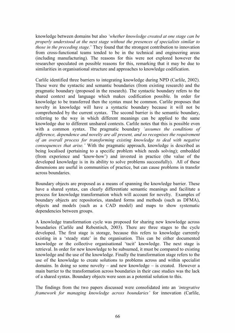
66
knowledge between domains but also ‘whether knowledge created at one stage can beproperly understood at the next stage without the presences of specialists similar tothose in the preceding stage.’ They found that the strongest contribution to innovationfrom cross-functional teams tended to be in the technical and engineering areas(including manufacturing). The reasons for this were not explored however theresearcher speculated on possible reasons for this, remarking that it may be due tosimilarities in organisational structure and approaches to knowledge codification.
Carlile identified three barriers to integrating knowledge during NPD (Carlile, 2002).These were the syntactic and semantic boundaries (from existing research) and thepragmatic boundary (proposed in the research). The syntactic boundary refers to theshared context and language which makes codification possible. In order forknowledge to be transferred then the syntax must be common. Carlile proposes thatnovelty in knowledge will have a syntactic boundary because it will not becomprehended by the current syntax. The second barrier is the semantic boundary,referring to the way in which different meanings can be applied to the sameknowledge due to different unshared contexts. Carlile notes that this is possible evenwith a common syntax. The pragmatic boundary ‘assumes the conditions ofdifference, dependence and novelty are all present, and so recognises the requirementof an overall process for transforming existing knowledge to deal with negativeconsequences that arise.’ With the pragmatic approach, knowledge is described asbeing localised (pertaining to a specific problem which needs solving); embedded(from experience and ‘know-how’) and invested in practice (the value of thedeveloped knowledge is in its ability to solve problems successfully). All of thesedimensions are useful in communities of practice, but can cause problems in transferacross boundaries.
Boundary objects are proposed as a means of spanning the knowledge barrier. Thesehave a shared syntax, can clearly differentiate semantic meanings and facilitate aprocess for knowledge transformation which will account for novelty. Examples ofboundary objects are repositories, standard forms and methods (such as DFMA),objects and models (such as a CAD model) and maps to show systematicdependencies between groups.
A knowledge transformation cycle was proposed for sharing new knowledge acrossboundaries (Carlile and Rebentisch, 2003). There are three stages to the cycledeveloped. The first stage is storage, because this refers to knowledge currentlyexisting in a ‘steady state’ in the organisation. This can be either documentedknowledge or the collective organisational ‘tacit’ knowledge. The next stage isretrieval. In order for new knowledge to be subsumed, it must be compared to existingknowledge and the use of the knowledge. Finally the transformation stage refers to theuse of the knowledge to create solutions to problems across and within specialistdomains. In doing so some novelty – and new knowledge – is created. However amain barrier to the transformation across boundaries in their case studies was the lackof a shared syntax. Boundary objects were seen as a potential solution to this.
The findings from the two papers discussed were consolidated into an ‘integrativeframework for managing knowledge across boundaries’ for innovation (Carlile,
67
2004). The framework, seen in figure 2.5 (reproduced) is demonstrated using anexample of new product development in the automotive industry.
Where there is a joint syntax across the boundary, knowledge integration is possible.As novelty increases, other boundaries gain importance. The semantic boundary isuseful in creating a shared meaning, using activities such as cross-functional teamsand activities. However, Carlile makes the point that when there are different contexts‘creating common meaning is not possible; what is required is a process in whichactors negotiate and are willing to change the knowledge and interests from their owndomain.’ The pragmatic boundary occurs when the presence of novelty results indifferent interests. Hence the shared meaning needs to be renegotiated and boundaryobjects must be able to represent ‘trade-offs’. This framework is not intended to be amathematical model because only the syntactic boundary can be expressed in thisway.
Figure 2.5: Carlile’s Framework for Managing Knowledge Across Boundaries(Carlile, 2004)
An empirical case was then presented to illustrate the framework (not as a means ofvalidation). It dealt with the early automotive development. This involves the earlydefinition of constraints on the product which are vehicle styling, engine / power train,climate control and safety. The study explored the results of implementing a recentlydeveloped simulation tool. The most challenging part of the development was foundto be relating the consequences of changes in one engineering domain on otherengineering domains. Problems arose when a novelty in the design was wronglyinterpreted during simulation. The authors interpret the findings as the ability of thetool to manage the syntactic and semantic boundaries, but not the pragmaticboundary.
68
2.7.3 Key Observations
As advocated in (McMahon et al., 2004), engineering in the design process needs toconsider tacit and explicit knowledge. This section has expanded on this claim toillustrate why the inclusion of tacit knowledge is important and some methods whichmay be used to achieve this. The tacit element has been shown to be important forboth sharing knowledge, particularly between different domains and particularly insharing innovative knowledge. The methods to achieve this are primarily of a socialnature and include networking and cross-functional teams. Tacit knowledge isvaluable because it deals with trust, shared context and makes sense of the different‘thought worlds’ encountered in a knowledge sharing environment. However, it isimportant to note that these can also be active barriers to successful knowledgesharing. The Concurrent Engineering approach has advocated the use of cross-functional teams for effective knowledge sharing prior to any analysis of explicit andtacit knowledge.
Those who support the community approach do not do so at the expense of thecommodity approach, recognising that a combination of both is required for theeffective sharing of innovative knowledge. There is evidence too that those who workin the commodity field are also beginning to consider tacit knowledge, although therehave been misrepresentations of tacit knowledge. The next section discusses potentialmethods by which a combined approach could be achieved.
2.8 Towards a Combined Commodity and CommunityApproach
There does not seem to be much literature published in this area. This sectiondiscusses four relevant contributions that were found. The first is concerned with asociotechnical approach to aerospace design. The second is the use of an ontology.The final two are methods to be used in business which have more structuredapproaches to capturing and structuring strategic knowledge gaps using explicit andtacit knowledge methods.
2.8.1 Sociotechnology
The sociotechnology approach has been promoted as a potential solution to deal withthe need to span the community and commodity approaches. Sociotechnical theory isdefined as follows: ‘(it) has at its core the notion that the design and performance ofnew systems can be improved, and indeed can only work satisfactorily if the ‘social’and ‘technical’ are brought together and treated as interdependent aspects of a worksystem’(Clegg et al., 2000).
The sociotechnical approach has been applied to system design (Waterson et al.,2002) and design of work systems (Clegg, 2000). An application of particularrelevance to this project is knowledge management in aerospace design (Kerr et al.,2001).
69
The research used a socio-technical approach to study knowledge management indesign from a multi-disciplinary perspective. The objective was to understand the‘human, social, organisational and technological aspects of current knowledgecapture, sharing and reuse activities.’ The rationale for the research is that design canbe viewed as a ‘sociotechnical enterprise’ because it incorporates teams, technologyand the individual. A particular motivation was the knowledge managementchallenges in engineering design, particularly whether knowledge can be re-used in anenvironment which is often uncertain.
The research took place in two major UK aerospace companies. Twelve in-depthinterviews were conducted in both companies. Each interviewee talked through adesign scenario with which they were involved to determine processes and activitiesin relation to capture, share and reuse of knowledge. These scenarios could be amodification, a change due to failure, a novel design or a revised design for a newproduct. Of particular interest were sources of information, channels ofcommunication, critical problems and potential solutions.
Three barriers - technological, capture / storage and sharing / retrieval / reuse - wereidentified in the results. Technological barriers were due to lack of stability, durabilityand robustness in the systems. This resulted in a preference for face-to-facecommunication. Capture and storage barriers related to knowing what to capture, therequired level and the relevance. Only design rationale with a successful outcometended to be documented. A large amount of knowledge tended to be retained in theheads of the designers. Sharing, retrieval and reuse barriers were mainly due toorganisational, social and cultural reasons. These included trust in the design andperceived ownership of the design and the preference of designers to design ratherthan reuse. Where reuse information was available, there was a tendency for it not totransfer to other projects. Design knowledge itself is located in a number of systems,both social and technical. However, informal networks and communities of practicewere shown to be very important in the distribution of information.
Thirty four requirements were generated from the interviews to satisfy social andtechnical requirements. The three considered for the next stage of research were to‘build confidence in data / knowledge captured’, ‘classification to enable informationto be indexed for reuse’ and ‘allow identification and finding of expertise.’ AKnowledge Tool for Designers (KTFD) was proposed and in the process ofdevelopment to support this, which was a database with multiple views (product,process, etc.). An important consideration in further developments was allocationbetween technology and human. The development of a pilot system was planned forfurther work.
2.8.2 Ontology
Bradfield and Gao developed an ontology for knowledge sharing during new productintroduction (Bradfield and Gao, 2007). Unlike the other examples of ontologydiscussed previously, the emphasis was on creating a common understanding for thebenefit of the people within the organisation rather than software compatibility. They

70
used the creation of an ontology as a means of standardising (and hence creating ashared understanding) the knowledge about and pertaining to the new productintroduction process. The issues of ‘thought worlds’ was not specifically referencedbut was noted, with this being seen as a problem to be solved.
2.8.3 Business Methods
The work by Speel et al and Hall and Andriani present a more structured approach toidentifying strategic knowledge gaps. Speel et al’s is aimed at business knowledge ingeneral; whereas Hall and Andriani’s is aimed specifically at new productdevelopment. Neither approach considers manufacturing knowledge or thepreliminary design stage specifically, however their approaches are worthy of note.
Speel et al demonstrate the technique of ‘knowledge structuring’ and its use increating knowledge maps in Unilever to determine the extent of known and unknownbusiness knowledge (Speel et al., 1999). The objective of the technique is to take asystematic approach to capturing and representing explicit knowledge. Theknowledge is represented graphically in a ‘knowledge map’. This graphical formathas been found to be useful for human – human communication, for the investigationof modelling techniques by knowledge engineers, to validate knowledgerequirements, to specify knowledge-based system requirements and for discussionswith business managers.
The two methods used for capturing knowledge are Quality Function Deployment(QFD) and the Causal Knowledge Framework. QFD is a quality managementtechnique used to translate customer requirements into product requirements and tospecify the technology options required for the realisation of the product. Therequirements are summarised and visualised as a matrix of product attributes againstmethods for their achievement. In the context of this research they have been adapted.They are used to identify ‘what is known’ against ‘what is not known’. If the space onthe matrix cannot be filled, it is defined as a knowledge gap, which is then assessedand ranked. The causal knowledge framework is another matrix which comparesproblems to causes. The aim of the framework is to give an overview of theknowledge required for strategic development of the chosen area. Both techniques areused in interactive workshop sessions which are facilitated by knowledge engineerswith contributions from cross-functional domain experts.
The original purpose of the workshops and the knowledge capture tools were tocapture explicit knowledge. However, it was found that ad-hoc tacit knowledgesharing was also occurring outside the main workshop, for example during breaks.They therefore concluded that it was important to create an environment in which thiscould occur, acknowledging that not all knowledge can be created explicitly. Somefactors which influence this environment were a mutual benefit to all participants, theinvolvement of the ‘best experts’ in their field, the allowance for differentperspectives and the reaching of a consensus.
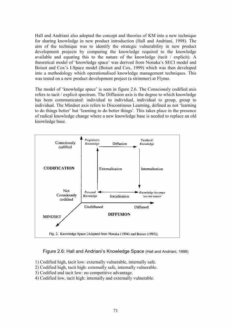
71
Hall and Andriani also adopted the concept and theories of KM into a new techniquefor sharing knowledge in new product introduction (Hall and Andriani, 1998). Theaim of the technique was to identify the strategic vulnerability in new productdevelopment projects by comparing the knowledge required to the knowledgeavailable and equating this to the nature of the knowledge (tacit / explicit). Atheoretical model of ‘knowledge space’ was derived from Nonaka’s SECI model andBoisot and Cox’s I-Space model (Boisot and Cox, 1999) which was then developedinto a methodology which operationalised knowledge management techniques. Thiswas tested on a new product development project (a strimmer) at Flymo.
The model of ‘knowledge space’ is seen in figure 2.6. The Consciously codified axisrefers to tacit / explicit spectrum. The Diffusion axis is the degree to which knowledgehas been communicated: individual to individual, individual to group, group toindividual. The Mindset axis refers to Discontinous Learning, defined as not ‘learningto do things better’ but ‘learning to do better things’. This takes place in the presenceof radical knowledge change where a new knowledge base is needed to replace an oldknowledge base.
Figure 2.6: Hall and Andriani’s Knowledge Space (Hall and Andriani, 1998)
1) Codified high, tacit low: externally vulnerable, internally safe.2) Codified high, tacit high: externally safe, internally vulnerable.3) Codified and tacit low: no competitive advantage.4) Codified low, tacit high: internally and externally vulnerable.

72
Figure 2.7: Hall and Andriani’s Innovation Plot (Hall and Andriani, 1998)
Figure 2.8: Strategic Vulnerability Map (Hall and Andriani, 1998)
Major incrementalinnovation
Major radical innovation(involving much unlearning)
Minor incrementalinnovation
Minor radical innovation(involving a little unlearning)
Am
oun
to
fne
wk
now
ledg
eto
be
acqu
ired
and
supp
lied
High
Low
Additive Substitutive
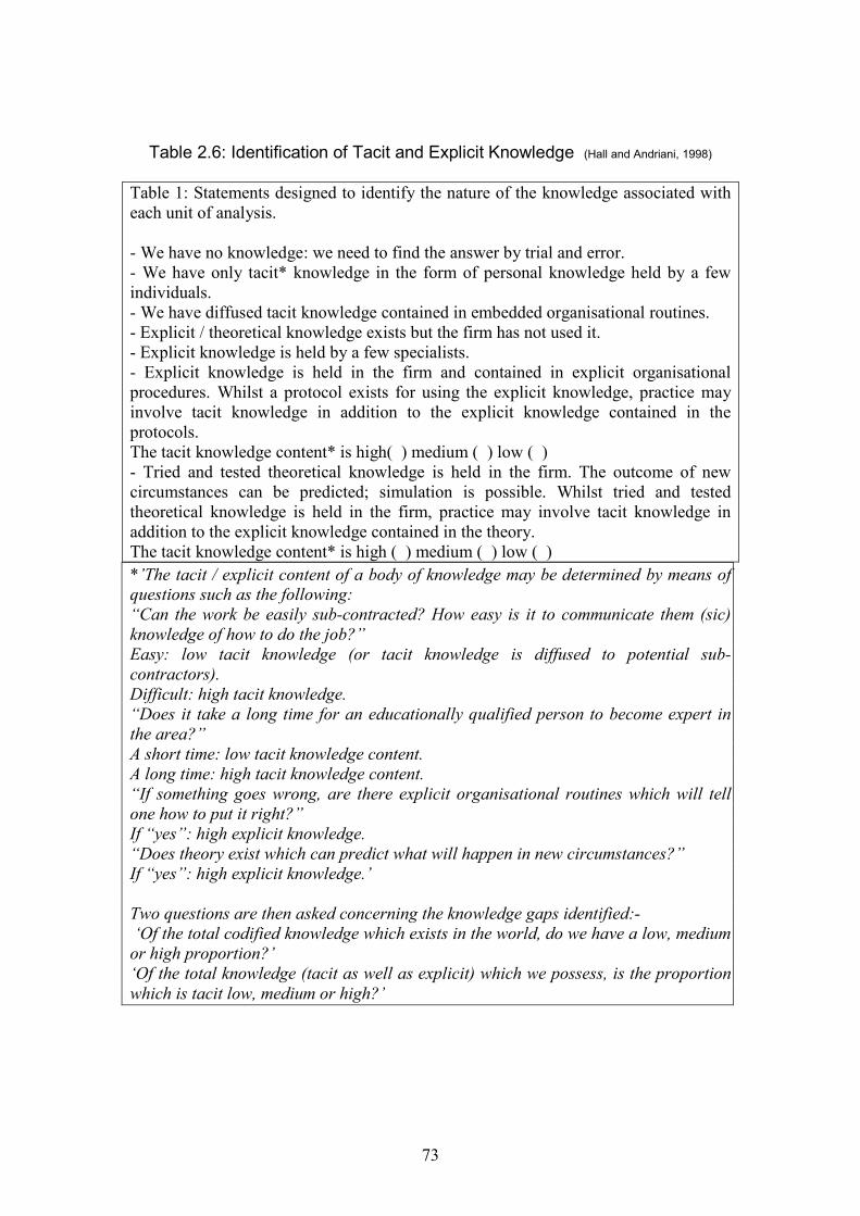
73
Table 2.6: Identification of Tacit and Explicit Knowledge (Hall and Andriani, 1998)
Table 1: Statements designed to identify the nature of the knowledge associated witheach unit of analysis.
- We have no knowledge: we need to find the answer by trial and error.- We have only tacit* knowledge in the form of personal knowledge held by a fewindividuals.- We have diffused tacit knowledge contained in embedded organisational routines.- Explicit / theoretical knowledge exists but the firm has not used it.- Explicit knowledge is held by a few specialists.- Explicit knowledge is held in the firm and contained in explicit organisationalprocedures. Whilst a protocol exists for using the explicit knowledge, practice mayinvolve tacit knowledge in addition to the explicit knowledge contained in theprotocols.The tacit knowledge content* is high( ) medium ( ) low ( )- Tried and tested theoretical knowledge is held in the firm. The outcome of newcircumstances can be predicted; simulation is possible. Whilst tried and testedtheoretical knowledge is held in the firm, practice may involve tacit knowledge inaddition to the explicit knowledge contained in the theory.The tacit knowledge content* is high ( ) medium ( ) low ( )
*’The tacit / explicit content of a body of knowledge may be determined by means ofquestions such as the following:“Can the work be easily sub-contracted? How easy is it to communicate them (sic)knowledge of how to do the job?”Easy: low tacit knowledge (or tacit knowledge is diffused to potential sub-contractors).Difficult: high tacit knowledge.“Does it take a long time for an educationally qualified person to become expert inthe area?”A short time: low tacit knowledge content.A long time: high tacit knowledge content.“If something goes wrong, are there explicit organisational routines which will tellone how to put it right?”If “yes”: high explicit knowledge.“Does theory exist which can predict what will happen in new circumstances?”If “yes”: high explicit knowledge.’
Two questions are then asked concerning the knowledge gaps identified:-‘Of the total codified knowledge which exists in the world, do we have a low, mediumor high proportion?’‘Of the total knowledge (tacit as well as explicit) which we possess, is the proportionwhich is tacit low, medium or high?’

74
Table 2.7: Results from Flymo Case Study (Hall and Andriani, 1998)
Units of analysis Type of knowledgeIndustrial design challenge
Technical challenges
Communication challengeswith customers:-Business to business
End-usersCAD communicationchallengePartnership challenge
Explicit knowledge is held in the firm…it issupported by a large base of tacit knowledge.Diffused tacit knowledge contained in embeddedorganisation routines.
There is only tacit knowledge held by a fewindividuals.There is no knowledge – it had to be created.Explicit knowledge exists – it is held by a fewindividuals.What little knowledge exists was tacit and held by afew individuals who had experienced partnering withsuppliers.
Three areas of the project are analysed in the operationalised technique: the brieforiginating from marketing or a supplier, depending on whether the situation is‘market pull’ or ‘technology push’; the features required to deliver the vision (wherenew knowledge needs to be created and these need to be identified early) and theknowledge gaps which represent the missing knowledge which is needed to produceeach feature. The researchers stress that successful identification of these ‘unknowns’(which may require iteration) is critical to the success of the project. Additionally twoother factors are considered: the extent of innovation and the nature of knowledge.The first is defined according to radical and incremental according to the innovationplot shown in figure 2.7. The top right hand corner can indicate difficult / riskyprojects which have a higher risk of failure. The second is assessed using table 2.6.The results are then plotted on two axes against each other on a two-by-two matrix togive an innovation plot with the following four sectors (see fig 2.8).
Relevant knowledge communities are also identified within the organisationaccording to the extent of innovation. Where innovation is incremental, thecommunities may be part of the organisational structure. Communities for ‘radicalinnovation’ may be more informal.
The technique was tested on a case study with Flymo. A new industrial designer hadcreated a dual function tool. Table 2.7 shows the units of analysis (knowledge gaps)identified and the related types of knowledge (reproduced). They then plotted theresults on a strategic vulnerability map. Examples of knowledge transformation seenwere knowledge transfer and knowledge creation, primarily from tacit to explicit. Ascan be seen, the knowledge types ranged. ‘The fact that the knowledge associated withthe Technical Challenges was classed as largely tacit appears to be paradoxical,however, it was identified as tacit because the original explicit knowledge had beeninternalised and had become “second nature”. Indeed, in subsequent discussion withthe R&D Director of Flymo, he explained that they preferred to operate in the tacitdomain as progress was faster and more flexible.’
75
Although this research considered the whole product introduction process, somefindings are relevant to this thesis. In particular, the innovation plot in figure 2.7 canbe used to scope of manufacturing process innovation considered. Depending on theprocess development required, it can be classified as either major incremental(introduction of a production process not previously used) or minor incremental(development of an existing manufacturing process for new components and / ormaterials).
2.9 Summary and Identification of Research Gaps
The literature review has highlighted the following areas:-
There are three main definitions of knowledge which define how knowledge ismanaged and used. Furthermore, the suitability for specific knowledge typesin specific situations varies according to the situation.
There is evidence of each of the three definitions of knowledge being appliedto an engineering design process, particularly for sharing manufacturingknowledge. Again, the way in which knowledge is defined affects how itshould be used. Two key themes emerge: the ability to share knowledge acrossdifferent domains and the ability of the knowledge to describe innovation.
Manufacturing knowledge content has been mainly been described as process,process capability and cost. Other researchers have expanded this to considermanufacturing resource facilities.
It is recognised that manufacturing knowledge will become more abstractedearlier in the design process although this is not defined to any extent.
The two approaches to knowledge management – commodity and community– have both been applied to the design process.
The commodity approach is effective for knowledge representation in aknowledge re-use or process automation situation. It is also very strong insolving problems in interoperability. It is best suited to a stable product and /or process environment and variant design. It has limitations in a situationwhere innovation is required, for example in product adaptation or processdevelopment.
The community approach discusses some techniques for tacit knowledgesharing and acknowledges the need for tacit knowledge in innovation. Animportant aspect of this approach is the sharing of knowledge across cross-functional boundaries which has been demonstrated, for example, by the useof cross-functional teams in concurrent engineering.

76
The development of complex mechanical products requires knowledgemanagement techniques which incorporate the sharing of tacit and explicitknowledge. Tacit knowledge is particularly important during the preliminarystage of the design process where there may be inherent risks due to theadaptive nature of the design, innovation requirements and other ‘unknowns’.However, engineering knowledge is also systematic and quantitative natureand needs to be captured, processed and controlled by codification. Anapproach which combines aspects of both the commodity and communityapproaches is therefore required.
Two methods of combining the commodity and community approaches havebeen explored. The first - sociotechnical design – is primarily concerned withthe allocation of knowledge to appropriate methods and ways of working. Itdoes not provide a prescribed solution to knowledge management in a specificprocess. The second, a more structured approach, could present a potentialsolution in terms of the rigorous and systematic capture of explicitinformation. This method could also be designed to incorporate methods oftacit knowledge sharing. However, it has not been demonstrated for innovativemanufacturing knowledge in preliminary design.
The following research gaps have been identified:-
1. A detailed definition of the content and level of manufacturing knowledgerequired for the preliminary design stage of the design process.
2. The need to incorporate knowledge about the development of newmanufacturing processes (hereafter referred to as ‘innovative manufacturingknowledge’) Such processes are categorised in this thesis as ‘immature’because their capabilities cannot be codified.
3. Although a combined commodity / community approach would be a suitablesolution for managing the sharing of innovative manufacturing knowledgeduring the preliminary design stage, there is no evidence of any techniquesbeing developed specifically for this purpose.
As seen from the literature, these research gaps are particularly relevant totechnology-intensive industries and the nature of the components (complex andmechanical) which they produce. This is for two reasons. The first is that thedevelopment of new products within these organisations requires some degree ofadaptive design and innovation, often with manufacturing processes. The secondreason is the need for more effective knowledge management to deal with thecomplexity of the components produced and the procedures used in theirdevelopment. In the next chapter the research aims and objectives to address theseresearch gaps are formulated and discussed, together with an overview of theapproach to and design of the research study.
77
Chapter 3
Research Objectives and Methodology
3.1 Introduction
In this chapter, the research gaps identified in the literature are formulated into theresearch aims and objectives for the study. The methods by which these objectivescan be addressed are then considered, discussed and selected.
Three research gaps had emerged from the literature review which warranted furtherinvestigation. The first gap was the difference in detail in knowledge requirements fordifferent stages of the design process. The literature had defined knowledge for thepreliminary design stage as being ‘more abstract’. What did this mean in terms ofmanufacturing knowledge, particularly in the context of complex mechanicalcomponents? In order to define this ‘abstract’ preliminary manufacturing knowledgecontent, one needed to understand its impact on a design during the preliminarydesign stage. This in turn would lead to a greater understanding of the manufacturingknowledge requirements needed to support this stage of the design process.
The second research gap was concerned with how to manage knowledge aboutinnovative manufacturing processes and was particularly important for complexmechanical components. The final research gap was concerned with the use of acombined commodity and community approach for sharing manufacturing knowledgefor preliminary design. Both of these research gaps emerged because innovativeknowledge was seen as requiring both explicit and tacit elements of knowledge for itssuccessful management. Consequently, not only was the knowledge contentrequirements important, but also a better understanding of the knowledge typesrequired to convey it. The research aim therefore emerged from these research gaps,addressing the need to explore the nature of manufacturing knowledge for preliminarydesign and its effective sharing in more detail.
3.2 Research Aim
The aim of this research study is to investigate the nature of manufacturing knowledgerequired for preliminary design and how these requirements can be identified,acquired and shared effectively between the specialist design and manufacturingdomains. The research is specifically concerned with innovative manufacturingknowledge for the preliminary design of complex mechanical components. It takesplace within the collaborating company.
Highlighting the scope of the project:-
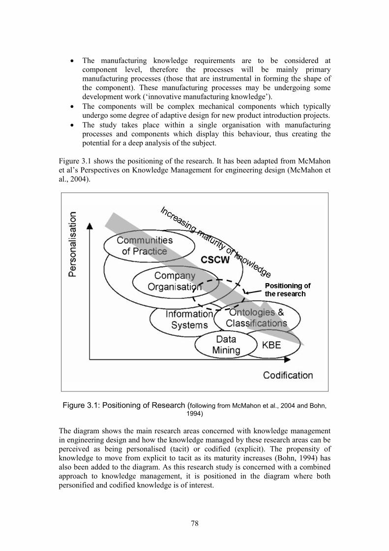
78
The manufacturing knowledge requirements are to be considered atcomponent level, therefore the processes will be mainly primarymanufacturing processes (those that are instrumental in forming the shape ofthe component). These manufacturing processes may be undergoing somedevelopment work (‘innovative manufacturing knowledge’).
The components will be complex mechanical components which typicallyundergo some degree of adaptive design for new product introduction projects.
The study takes place within a single organisation with manufacturingprocesses and components which display this behaviour, thus creating thepotential for a deep analysis of the subject.
Figure 3.1 shows the positioning of the research. It has been adapted from McMahonet al’s Perspectives on Knowledge Management for engineering design (McMahon etal., 2004).
Figure 3.1: Positioning of Research (following from McMahon et al., 2004 and Bohn,1994)
The diagram shows the main research areas concerned with knowledge managementin engineering design and how the knowledge managed by these research areas can beperceived as being personalised (tacit) or codified (explicit). The propensity ofknowledge to move from explicit to tacit as its maturity increases (Bohn, 1994) hasalso been added to the diagram. As this research study is concerned with a combinedapproach to knowledge management, it is positioned in the diagram where bothpersonified and codified knowledge is of interest.
79
Rather than being situated in a single area of expertise, this research is positioned atan intersection of several research areas: company organisation, computer-supportedcollaborative working, information systems and ontologies and classifications. This isbecause the research aim encompasses features from each of these areas. Firstly, thestudy will investigate methods which can be utilised using the company organisationand business processes to promote knowledge identification, acquisition and sharing.Such methods could have the potential to be developed into an information system.Furthermore, the identification of the manufacturing knowledge requirements couldform a foundation for the development of an ontology.
3.3 Research Objectives
The research aim contains elements of investigation, synthesis and evaluation:- Investigation: identification of knowledge requirements, their acquisition and
sharing; Synthesis: development of a method to achieve this; Evaluation: evaluating the method developed.
The research aim therefore needed to be sub-divided into several research objectivesin order to achieve each of these elements. Four research objectives were thereforeformulated in order to achieve the overall aim. The first two objectives are concernedwith identifying the knowledge requirements for the context of the study. The thirdand fourth objectives are concerned with demonstrating effective knowledge sharing.
The research objectives are:-
1. To investigate the nature of manufacturing knowledge required for preliminarydesign.
2. To investigate the manufacturing knowledge requirements for an innovativemanufacturing process during the preliminary stage of design.
3. To develop a method of effectively identifying, acquiring and sharing theknowledge requirements (derived through objectives 1 and 2) between domainexperts.
4. To evaluate whether the method developed in objective 3 presents an effectiveway of identifying, acquiring and sharing the knowledge requirementsbetween domain experts.
Research objectives 1 and 2 are inductive, creating a hypothesis of manufacturingknowledge requirements. Objectives 3 and 4 test the hypothesis by creating andevaluating a methodology generated from the first two objectives. Each researchobjective was established as a consequence of the analysis of the previous objectiveand emerged over time. Thus a flexible, data-driven design was adopted. The researchstrategies employed for each research objective were decided in the context of thisoverall approach to the research design. The outcome of each objective then governedthe formation of the next objective and its research strategy. The research design

80
approaches and strategies are shown in figure 3.2, together with the research outcomefor each objective. They will be discussed in the subsequent sections.
3.4 Approach to the Research Design
As described by Robson, the approach to research design can be fixed or flexible(Robson, 2002). With a fixed design, the details of the study, such as the theory to beused, the details of each case, unit of analysis and methods of collection and analysisare decided before the data collection commences. Consequently any changes to theapproach or research design may be difficult later and may result in a redesign of thestudy. With a flexible design, there may be some initial planning and investigation todesign an initial outline study, however subsequent research strategies are shaped bythe analysis of data collection. The research design is said to emerge during datacollection and analysis.
There are two main approaches to the way in which a study should be conducted. Thefirst approach is often described as positivist (Robson, 2002; Easterby-Smith et al.,1991). This approach has originated from research in science and is seen as thescientific method. The purpose of the approach is to establish facts, which are anabsolute truth, value free and independent of social construct. A series of experimentsare designed to test a hypothesis. During the experimentation certain conditions arespecified and controlled within a laboratory environment. Data is usually quantitativeand subject to statistical analysis to either prove or disprove the hypothesis. Typicallya causal link will be established. The archetypal scientific laboratory experiment is anexample of a fixed research design.
The second approach has various terms – Robson uses interpretive and inductive,Easterby-Smith et al phenomenological (Robson, 2002; Easterby-Smith et al., 1991).With this approach, facts and values are inter-related and subject to social construct,therefore there is no concept of absolute truth and the facts are relative to the context.The purpose of this method is to examine the meaning of situations in great depth,acknowledging that situations in the real world cannot be subject to control as in thelaboratory. With this approach, hypotheses are constructed from the collection andanalysis of data. Data is usually qualitative and the approach is suited a flexibleresearch design.
Two factors were considered in the selection of the research approach. The first wasthe nature of the research objectives. They seek an increased understanding of aparticular situation and are consequently exploratory in nature. The second factor wasthe type of data likely to be explored during the study. This thesis adopts Nonaka’sview of organisational knowledge in that it is created from the knowledge ofindividuals. Although technical knowledge is often seen as fact, this study recognisesthat during the design process it is likely to be derived from the knowledge ofengineers associated with design and manufacturing. Consequently a qualitative andinterpretive approach would be beneficial in exploring the themes and interactionsemerging from these exchanges to create technical knowledge. Therefore a flexibleresearch design has been adopted.

81
Figure 3.2: Research Objectives, Design Approaches and Strategies
82
3.5 Research Strategies
The appropriate research strategy depends on the overall research design adopted forthe study. For a flexible design, there are three main strategies: ethnography, casestudy and grounded theory (Robson, 2002). Ethnography is the study of a specificgroup or community for the purpose of discovering specific features about life in thecommunity. Such study takes place over a prolonged period of time and ofteninvolves observation methods to collect the data. The researcher is embedded in thecommunity during the data collection period. Case study research is the detailed studyof a pre-defined number of cases. The aim of case study is to examine the applicationof a specific theory in context, in order to generate a deeper understanding of asituation than can be obtained by other methods (Yin, 2003). A range of datacollection and analysis techniques may be used. Grounded theory is used to buildtheory using several systematic coding techniques from the analysis of data, usuallyobtained from interviews. This typically involves detailed line-by-line examination ofinterview transcripts (Strauss and Corbin).
In selecting a suitable research strategy, four influencing factors were considered: thenature of each of the research objectives; the context in which the research was to takeplace; access and exposure to suitable data and the resulting analysis and use of thedata collected.
For research objectives 1 and 2 an exploratory approach was required for a greaterunderstanding of the nature of manufacturing knowledge within the context of thestudy. Although guidelines could be taken from the literature, there were no pre-existing theories to shape the study.
The decision was taken to concentrate the study within the context of a singleorganisation. This is recognised as a risk because it limits how the findings can begeneralised (see section 3.5.3). However it also created an opportunity in that asituation could be explored in great depth with both inductive and hypothesis testingelements built to the study within the time limitations of the project. Consequently theresearch strategies adopted would need to be able to generate rich sources of data forsubsequent analysis.
The researcher was in a position of being based within the organisation. Theoreticallythis presented an ideal opportunity for prolonged data from a number of sources. Inpractice, it was found that this could be curtailed by the availability of data sourcesdue to the demands on staff resources due to the organisation’s ongoing projects.Access to data very much depended on the presence of a strong gatekeeper who coulduse the informal social network within the organisation to make suitable contacts (seechapter 4). Being based in a specific department did not automatically mean thataccess to other departments would be granted.
In terms of the analysis and subsequent use of the data, the need to utilise strategies toproduce rich data sources has already been discussed.

83
Grounded theory was selected as the most suitable research strategy in which toaddress objective 1. This strategy is compatible with both the exploratory nature ofthe research question and the organisational scope for the study. In grounded theory,analysis is interspersed with interviews. The number of required interviews is alsoflexible and depends on reaching a saturation of data (Strauss and Corbin, 1998). Thisgives flexibility in scheduling interviews with company resources. This strategy isdiscussed further in section 4.2.1.
The ethnographic approach, although attractive, was discounted due to thepracticalities of being involved with different departments for the extended durationrequired for the approach. The use of case study for the first research objective wasalso unsuitable. Despite Robson referring to the use of case study as a method for aflexible research design, when Yin’s definition is examined it appears almost as afixed design (Yin, 2003). A pre-requisite to the undertaking of a case study is anexisting theory, even in the sketchiest terms for an exploratory study. This was notapplicable for the first research question.
The subsequent research objectives demanded different approaches using the sameselection criteria. The second objective was also exploratory, capturing a range ofknowledge requirements. It did not fit rigidly with the grounded theory strategy usedin objective 1 and required a more flexible approach to data collection from theresearcher. Unstructured interviews were therefore selected to provide this flexibility.The analysis necessitated the organisation of manufacturing knowledge requirementsinto a coherent and organised structure. Further categorisation of the data was alsoundertaken using the code developed from the analysis of the first data collection.
Together, the analyses from research objectives 1 and 2 generated a hypothesis in theform of a conceptual framework of manufacturing knowledge requirements forpreliminary design. This concluded the inductive phase of the study. The conceptualframework therefore needed evaluation during the hypothesis testing part of the study.A methodology was therefore developed using the requirements generated from theconceptual framework to address research objective 3.
For the final objective, an approach was required which was suitable for an evaluationof the methodology, which would in turn evaluate the conceptual framework. Asingle-case embedded case study approach was therefore selected as a suitablestrategy for the evaluation exercise (Yin, 2003). Three units of analysis wereconsidered for the case study. Each unit of analysis was a component and twomethods of manufacture for the component. The evaluation techniques used werequalitative and are discussed further in chapter 7.
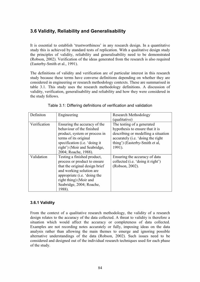
84
3.6 Validity, Reliability and Generalisability
It is essential to establish ‘trustworthiness’ in any research design. In a quantitativestudy this is achieved by standard tests of replication. With a qualitative design studythe principles of validity, reliability and generalisability need to be demonstrated(Robson, 2002). Verification of the ideas generated from the research is also required(Easterby-Smith et al., 1991).
The definitions of validity and verification are of particular interest in this researchstudy because these terms have converse definitions depending on whether they areconsidered in engineering or research methodology contexts. These are summarised intable 3.1. This study uses the research methodology definitions. A discussion ofvalidity, verification, generalisability and reliability and how they were considered inthe study follows.
Table 3.1: Differing definitions of verification and validation
Definiton Engineering Research Methodology(qualitative)
Verification Ensuring the accuracy of thebehaviour of the finishedproduct, system or process interms of its originalspecification (i.e. ‘doing itright’) (Moir and Seabridge,2004; Roache, 1988).
The testing of a generatedhypothesis to ensure that it isdescribing or modelling a situationaccurately (i.e. ‘doing the rightthing’) (Easterby-Smith et al,1991).
Validation Testing a finished product,process or product to ensurethat the original design briefand working solution areappropriate (i.e. ‘doing theright thing) (Moir andSeabridge, 2004; Roache,1988).
Ensuring the accuracy of datacollected (i.e. ‘doing it right’)(Robson, 2002).
3.6.1 Validity
From the context of a qualitative research methodology, the validity of a researchdesign relates to the accuracy of the data collected. A threat to validity is therefore asituation which would affect the accuracy or completeness of data collected.Examples are not recording notes accurately or fully, imposing ideas on the dataanalysis rather than allowing the main themes to emerge and ignoring possiblealternative understandings of the data (Robson, 2002). Such issues need to beconsidered and designed out of the individual research techniques used for each phaseof the study.
85
Validity can also be affected by the presence of bias, of which there are three types –reactive, respondent and researcher. Bias is said to be reactive where the researchsituation itself can interfere with the validity of the data collected. Data can also beaffected by the attitude of the respondent and indeed the researcher themselves interms of their understandings and assumptions about the research situation (Robson,2002).
In line with suggestions from Robson, the following techniques have been built intothe research design to minimise bias.
Prolonged involvement
The researcher was based within the collaborating company for 2 ½ years during theresearch project. This assisted in reducing both reactive and respondent bias bybuilding up relationships based on trust with a number of key stakeholders during thistime. However, it is recognised that this technique can increase researcher bias as theresearcher can find it difficult to retain objectivity for the duration of the study.Therefore other techniques are also required.
Triangulation
Triangulation is the use of more than one perspective in order to retain objectivityduring the research study. It is intended to reduce all three types of bias.
There are four main techniques for triangulation. Data triangulation is defined byRobson as using more than one method of data collection (Robson, 2002), howeverPatton interprets data collection as meaning ‘the use of a variety of data sources in astudy, for example, interviewing people in different status positions or with differentpoints of view’ (Patton, 1987, p.60). Observer triangulation refers to the use of morethan one researcher for data collection. Methodological triangulation refers to a mix ofqualitative and quantitative methods. Theory triangulation refers to using more thanone theory.
In the case of this research design, data triangulation was employed in the techniquesfor research objectives 1 -3 by the selection of people from a mix of disciplines –preliminary design, sub-system design, manufacturing technology, manufacturingengineering and other stakeholder disciplines. This was also the case for researchquestion 4 (an evaluation study), however observations were also recorded in additionto respondent surveys for data collection purposes.
Peer debriefing and support
This technique was also used in the research design to reduce the possible researcherbias created by long-term involvement with the collaborating company. This entailsfeeding back the results of the data collection and analysis to the original participantsas an additional check.

86
For research objective 1, data was collected through the use of semi-structuredinterviews which were recorded and transcribed. Each interviewee checked thetranscription. Following the analysis of the results, two feedback sessions were held,one for each set of interviewees. Here the results were presented and discussed withthe interviewees for their feedback and to see if they were in agreement with theresults as a ‘check’.
For the second and third research objectives, peer debriefing also took place, albeit ina more informal and iterative way. As ideas for the methodology developed (researchobjective 3), a number of feedback sessions took place with the stakeholdersfollowing initial data collection.
3.6.2 Verification
There were three main ways in which the hypothesis generated from researchobjectives 1 and 2 was verified. The first was during the data analysis itself.Following on from suggestions by (Easterby-Smith et al., 1991), data was activelyinterrogated to seek examples which directly contradicted the developing code. Thepeer debriefing sessions which followed the data collection also presented anopportunity to confirm the emerging ideas. The evaluation of the methodology(research objective 4) was also an example of verifying the hypothesis.
3.6.3 Reliability
Reliability in research design can be demonstrated by an accurate and thorough use ofresearch design methods and techniques (Robson, 2002). This can be established bythe use of an ‘audit trail’ to trace back the results to the original data sources.
The following techniques have been employed within this project to establishreliability:-
Reliability of the research design: a consideration of the researchmethodologies available and their selection based on the research objectivesand the practical constraints of the project.
Reliability of data collection: recording and transcription of interviews,recording of notes of discussions and feedback with participants as researchideas progressed.
Reliability of analysis: establishing links in the spreadsheets used for dataanalysis to link the original interview quotation / survey score back to theoriginal data source.
The use of a log book throughout the project to record notes on meetings,feedback, observations, thoughts and ideas as the research emerged.

87
3.6.4 Generalisability
Generalisability is the extent to which research findings can be applied to a generalsituation. There are two types – internal and external generalisability (Robson, 2002).
Internal generalisability refers to the extent to which the conclusions can begeneralised within the setting investigated. External generalisability is the extent towhich the conclusions can be extended beyond the scope of the original study.
For research objective 1, the saturation of data determined the number of peopleinterviewed. Due to the saturation of data it is proposed that the findings of this part ofthe research could reasonably apply to other designers and manufacturing specialistswithin the civil aviation division. Thus, some degree of internal generalisability hasbeen obtained.
This is also the case for the evaluation of the methodology. Three units of analysis(different components and associated processes) were selected in a single-caseembedded case study. Purposeful sampling was employed in order to select specificcases for which the methodology was deemed to be suitable (see chapter 7). Thereforethe results of the case study can be generalised internally to apply to a range ofcomponents which would fulfil the criteria of the purposeful sampling.
Because the research study has taken an in-depth approach to a specific company thenthe results of the study are only applicable within that case. That said, it isacknowledged that the opportunity to study such a specific case in the amount ofdepth has contributed to a greater understanding of the generation and use ofmanufacturing knowledge within that specific setting. It would be an interestingopportunity to extend the study to more aerospace and other industrial settings. This isdiscussed further in chapter 8.
3.7 Summary
This chapter has presented the main considerations and decisions for the overallresearch design for the project. The main points of the research design are:-
1. A flexible approach to the research design used to address the exploratorynature of the research objectives.
2. An inductive component of the study, using grounded theory analysistechniques to analyse semi-structured interviews and unstructured interviewnotes respectively.
3. The creation of a methodology, the requirements for which are guided by thehypothesis proposed by the inductive component.
4. The evaluation of the methodology using a single embedded case study as a‘hypothesis testing’ component of the overall research design.

88
The data collection and analysis activities for research objectives 1 and 2 arediscussed in chapters 4 and 5 respectively. The creation of the methodology forresearch objective 3 is featured in chapter 6 and the final evaluation (researchobjective 4) in chapter 7.
89
Chapter 4
Innovative Manufacturing Knowledge inPreliminary Design
4.1 Introduction
This chapter deals with the investigative study into manufacturing knowledge inpreliminary design which was undertaken to achieve the first research objective.
In terms of the manufacturing knowledge required for preliminary design, theliterature review demonstrated the following:-
Knowledge has tacit and explicit elements. The tacit element is particularlyimportant for knowledge sharing, especially innovative knowledge.
There is a scale of maturity associated with knowledge. Preliminary knowledge is referred to as being ‘more abstract’ but there is no
indication of why this is the case, or how this knowledge differs in detail whencompared to manufacturing knowledge at other stages of the design process.
Assumptions could therefore potentially be made about the manufacturing knowledgerequirements for preliminary design from the existing literature. Many of theseassumptions had arisen as a consequence of investigating other phases of the designprocess, especially detail design. It was therefore possible that a suitable solution at adetail design level would be inferred as being appropriate for preliminary design whenthis may not be the case. The author was therefore wary of making these assumptionswithout exploring them further. Additionally, although assumptions had been found,the review into current research indicated that there were no pre-existing modelswhich could be used as a starting point for further investigation.
The decision was taken to conduct an exploratory case study for the first researchobjective. In doing this, the research would uncover the definition of manufacturingknowledge required for preliminary design as applicable to the organisation beingstudied. This could then be compared with prior research in this area.
Alongside the research gaps identified in the literature, the nature of manufacturingknowledge for preliminary design equally emerged as a topic for further investigationin an industrial context at the sponsoring company. The organisation employed manytechniques associated with 'best practice' in engineering design: a systematic designprocess, concurrent engineering processes (including DFM activities and IPTs) andstaged gate reviews. However, the majority of their understanding of manufacturingknowledge and its transfer was during the later, detail design stage. There was an
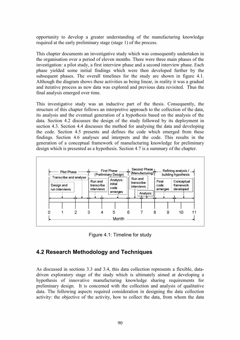
90
opportunity to develop a greater understanding of the manufacturing knowledgerequired at the early preliminary stage (stage 1) of the process.
This chapter documents an investigative study which was consequently undertaken inthe organisation over a period of eleven months. There were three main phases of theinvestigation: a pilot study, a first interview phase and a second interview phase. Eachphase yielded some initial findings which were then developed further by thesubsequent phases. The overall timelines for the study are shown in figure 4.1.Although the diagram shows these activities as being linear, in reality it was a gradualand iterative process as new data was explored and previous data revisited. Thus thefinal analysis emerged over time.
This investigative study was an inductive part of the thesis. Consequently, thestructure of this chapter follows an interpretive approach to the collection of the data,its analysis and the eventual generation of a hypothesis based on the analysis of thedata. Section 4.2 discusses the design of the study followed by its deployment insection 4.3. Section 4.4 discusses the method for analysing the data and developingthe code. Section 4.5 presents and defines the code which emerged from thesefindings. Section 4.6 analyses and interprets and the code. This results in thegeneration of a conceptual framework of manufacturing knowledge for preliminarydesign which is presented as a hypothesis. Section 4.7 is a summary of the chapter.
Figure 4.1: Timeline for study
4.2 Research Methodology and Techniques
As discussed in sections 3.3 and 3.4, this data collection represents a flexible, data-driven exploratory stage of the study which is ultimately aimed at developing ahypothesis of innovative manufacturing knowledge sharing requirements forpreliminary design. It is concerned with the collection and analysis of qualitativedata. The following aspects required consideration in designing the data collectionactivity: the objective of the activity, how to collect the data, from whom the data
91
should be collected and how it should be analysed. Additionally, research reliabilityneeded to be considered and built into the activity.
Research objective 1 is concerned with exploring the nature of the knowledge. It isconcerned with identifying the requirements for knowledge content and examiningmethods of sharing. Not only is the content important, but also the means by whichthe knowledge transfer takes place.
This thesis acknowledges and equally considers both the data-information-knowledgehierarchy definition of knowledge and Nonaka’s theory of organisational knowledgecreation. Manufacturing knowledge for the engineering design process is technical. Itis borne from scientific and engineering theorem. It is concerned with establishingfact. However, the mechanisms by which this knowledge is transferred during thedesign process may be social and have both tacit and explicit components. Theknowledge may have therefore have qualitative elements, particularly if it is immature(Bohn, 1994) and may require several modes (including social) for transfer.
The research approach for this part of the study therefore needed to consider these twoways in which knowledge can be defined and also the nature of the problem beingconsidered. The technique selected was grounded theory (discussed in sections 3.5and 4.2.1), with semi-structured interviews as the technique for collecting the data.These were selected because they would enable the further definition ofmanufacturing knowledge using a qualitative exploratory technique. The subsequentdata-driven analysis would enable a hypothesis to emerge for further development insubsequent research activities towards the investigation of effective knowledgesharing.
4.2.1 Grounded Theory
Grounded theory is a qualitative research technique in which theory emerges from theanalysis of data. The aim of the technique is for interpretation and greaterunderstanding of the situation being studied. Consequently it is suited to theinvestigation of phenomena which have not been defined or interpreted in detail. It isalso suited to the phenomenological environment where more than one reality mayexist. The technique was developed from social studies and has therefore been usedextensively in that area, particularly in healthcare. However, it has also been appliedin organisational research (Chell, 1998). It is proposed that this technique is suited tothe use in an engineering environment and to this specific study. Although factual andtechnical knowledge is ultimately sought, research has shown that this may havedifferent interpretations from different departments (Dougherty, 1992). It is alsoconsidered to be a useful approach to a situation where there may be a degree ofuncertainty in the phenomena being studied.
Grounded theory is an approach to analysing qualitative situations, primarily throughthe analysis of interviews (although other forms of data collection may also be used).It aims to develop and reveal the meaning behind the occurrence of situations ratherthan to collate and comment on the purely narrative. It looks for the 'why' in a

92
situation. The way in which the meaning emerges is through a process called coding.Coding is a term used to describe the categorising of the data into particular themes.The connections and relationships between these themes are then explored. Thisprocess builds a hypothesis, which can be used to explain how and why specificsituations arise and the outcomes which may result. Consequently the hypothesisemerges from the data examined. This hypothesis generally has some degree ofabstraction from the actual situations studied because the overall aim is to provide ageneralised explanation which is valid for the sample studied.
The process of coding data is approached in a flexible but systematic way. There arethree main steps to coding according to the method proposed by Strauss and Corbin:open, axial and selective (Strauss and Corbin, 1998).
Open Coding
This is the initial examination of the data collected from the transcripts of interviews.The transcripts are read and re-read a number of times. The analyst finds that ideasemerge concerning the key points of interest during the interview. Often these arerecorded in commentaries alongside the original transcript known as memos.Common patterns begin to emerge in these key points of interest. These can begrouped into specific, identifiable themes. These themes can then be used to grouptogether situations and concepts within the transcript. Thus a theme can be used tocategorise these occurrences and highlight their similarities. Being able to describe thedata in these more general terms makes the data easier to manage and begins todemonstrate how the themes can potentially apply universally within the samplingcontext. In developing a theme which is valid across the sampling context, aconsensus is sought in all the transcripts by examining whether the phenomena inother interviews also conforms to the emerging themes.
Axial Coding
Once the initial identified themes have been developed into a series of categories,each category is explored and developed in turn. The range of data attributed to eachcategory is investigated. From this, the boundaries of each category are established.This establishes the criteria by which data becomes 'eligible for membership' to thatcategory. As this exploration continues, the dimensions of the category emerge. Itmay be found that the data in the initial category can be classified further into smallersub-categories with common dimensions. The boundaries of these sub-categories aretherefore also derived, determining when one starts and the other finishes.Consequently, the original category can be sub-divided into a series of sub-categories.
Selective Coding
The first two stages of the coding process consider the abstraction and categorisationof data which separates this data from its original source and context. This final stageof the coding process is concerned with bringing the abstract categories back togetherin order to create an explanation of the originally documented phenomena.

93
During this stage the relationships between each category and sub-category areexplored. Does one category occur in the same instance as another, for example?What does this say about when and how that instance occurs? By relating thesecategories to each other, a hypothesis emerges from the data to explain how and whyparticular situations arise.
Obtaining reliability and validity of the data
In practice, the coding process is very difficult to describe in terms of logicalprogression and outcomes. Much of it emerges from the coder's own backgroundknowledge and experience. Consequently, some elements of the coding process canbe intuitive in that the analyst is relying on their own 'gut instincts' (or perhaps tacitknowledge) as to what constitutes a valid theme and hypothesis. This is accepted byStrauss and Corbin who nonetheless note that there still needs to be some confidencein the validity of the results obtained. They maintain that researchers need to be awareof objectivity and sensitivity in grounded theory and obtaining a balance between thetwo (Strauss and Corbin, 1998).
Objectivity is required to give an accurate and balanced interpretation of the data. Inorder to achieve this, the researcher must be able to distance his or herself from thedata source and activity. Lack of objectivity can lead to bias. Triangulation from theinvestigation of multiple viewpoints can be used to achieve objectivity, as canfeedback. The researcher must also be sensitive to the data and its subtle meanings inorder to identify and link the concepts. The researcher’s own experience andknowledge can be successfully used to develop sensitivity if this is appliedappropriately, i.e. used as a foundation for the development of the coding rather thanto actively form its development (Strauss and Corbin, 1998).
4.2.2 Selection of the data set
As discussed in section 3.6, in any qualitative study it is necessary to confirm thereliability of the data by achieving saturation, validity and triangulation. The selectionof the data set was deliberately designed to achieve this.
The selection of a suitable data set required a different approach to that of quantitativeresearch, where the emphasis is on obtaining a suitable sample size and profile fromwhich the results may be applied to the general population. The reason for thedifference is due to the nature of a qualitative study. Qualitative data collection andanalysis is concerned with the in-depth exploration of specific situations. The samplesselected for analysis are specifically selected to be pertinent to the topic being studiedand to be a rich source of data. This is known as theoretical sampling (Strauss andCorbin, 1998). Qualitative data sets are typically smaller than those for quantitativestudies. Whereas a quantitative study would seek an ideally representative number ofresponses, in a qualitative study representation is achieved by data saturation. Data issaid to be saturated when no new lines of enquiry are emerging from subsequentdatasets. Thus, where quantitative analysis would insist on a statistically valid sample
94
size, the sample size required for a qualitative analysis would be determined by thenecessary quantity to achieve saturation.
The data collection activity was designed to be an in-depth study of part of the designprocess. Therefore the number of interviewees was limited to a small scale study.Two main areas were targeted for the interviews within the collaborating company.The first area targeted was the preliminary design team. Here, interviews were carriedout with five preliminary designers, selected from a list. The author did not know anyof the team members prior to the interviews. The experience of the interviewees, bothprior to and within the preliminary design department varied widely. Usually each ofthe designers had significant specialist experience with a sub-system design teambefore moving to the preliminary design team. However, this has not been exploredfurther in the thesis for two reasons. The first reason is that on analysis the differingbackgrounds did not have any bearing on the key factors which emerged and weretherefore not considered to be relevant for this study. The interest was in specificsituations rather than specific people. The second reason is to protect the identity ofthe participants, who were assured anonymity. As the preliminary design departmentis relatively small to reveal the background of each of the participants couldunwittingly reveal their identity. In the subsequent discussion and analysis of theinterviews, the interviewees are referred to as Preliminary Design 1 to 5.
The first analysis and coding took place after the first five interviews. Furtherinterviews were then required to validate and expand this code to other departmentswhich interfaced with the preliminary design department, therefore a second area wastargeted. Six interviews were therefore carried out with representatives fromdepartments which interacted with the preliminary design team during the productintroduction process. They were four members of the Manufacturing Technologyteam (a team of manufacturing specialists involved with the development of newmethods of manufacturing and technology management) and two representatives froma sub-system design team: a designer and a manufacturing engineer. Theseparticipants are referred to in the analysis as Mantech 1 to 4, sub-system designer andsub-system manufacturing engineer respectively. The participants from the secondgroup were often identified by other interviewees as people with whom they hadworked and whose experience would be relevant for the interviews. From the secondgroup, only one interviewee was previously known to the author. Again, for the samereasons as the preliminary designers, the range of experience varied but was found tobe immaterial and all the participants remained anonymous.
The five preliminary designers were selected to give the preliminary design ‘worldview’. The additional six interviewees were selected to investigate whether thepreliminary designers’ view was particular to that group or common across theproduct introduction process. By selecting the two groups data triangulation wasachieved. The subsequent six interviews also achieved saturation in the developmentof the code.
Before running the two phases of the study, a pilot study was first run which had threeobjectives. The first was to develop the interview questions. The second was topractice running the interview, its timing, the use of recording equipment and

95
transcribing. The final objective was to begin to develop ideas on how to code eachinterview. Five interviews were run for this phase. The interviewees were colleaguesor friends who were familiar with the research project and were keen to help. Twodesigners and three people with varying manufacturing experience were interviewedto gauge the range of responses which would emerge from each specialist domain.The first designer had a strong history of design in aerospace components withexperience of design at all stages (concept, preliminary and detail) of the designprocess. The second designer had experience of detail design in large mechanicalengineering components. Neither designer had been employed by the sponsoringcompany, however their generic design knowledge proved to be useful for practicingthe interviews and gauging the type of data which may emerge. The three remaininginterviewees represented manufacturing and all worked in some capacity for thesponsoring organisation. The first was a manufacturing engineer involved withestablishing the manufacturing processes for new components, the second hadexperience in improving existing manufacturing process methods and the third wasinvolved in the development of new manufacturing technology. Between them, thescope of the interviewees' knowledge covered all stages of the design process anddevelopment of manufacturing technology and processes. Anonymity was granted andthe data was used purely for the benefit of the researcher in developing the study.
4.2.3 Design of the Interview
The objective of the data collection process was to capture rich qualitative dataeffectively in a time frame mutually acceptable to the interviewer and interviewee.Semi-structured interviews were selected (see section 3.5) because they were aflexible method of exploring the required discussion points. A core list of questionscould be asked but there would be scope to discuss any additional points of interestwhich could arise during the interview. This technique was also well-suited to agrounded theory-based qualitative coding analysis. The interviews would beconducted face to face and were designed to take place within a time frame of amaximum of an hour and a half. This time was judged to be a compromise incollecting sufficient interview data without too much impact on the interviewee’swork commitments.
The interview itself needed to define the manufacturing knowledge required forpreliminary design and the methods by which this knowledge was transferred. Thisneeded to be carried out in a way which would address the main concern of the studyand enable the designers to identify with the importance of the knowledge.Manufacturing knowledge was therefore defined as an impact (positive or negative)on the design requirements or design outcome due to some aspect of manufacturingand the knowledge required to describe this. During the interview, the intervieweeswere asked to recall incidents where they had been aware of this impact. This servedtwo purposes. The first was to generate a significant amount of rich data for analysis.The second purpose was to aid effective recollection from the interviewees. Theapproach used for the interviews is an adaptation of the Critical Incident Technique,originally developed by Flanagan for use in psychology but also applied toorganisational research (Flanagan, 1954; Chell, 1998). Chell defines it as:

96
‘a qualitative interview procedure which facilitates the investigation of significantoccurrences (events, incidents, processes or issues) identified by the respondent, theway they are managed, and the outcome in terms of perceived effects. The objective isto gain an understanding of the incident from the perspective of the individual, takinginto account cognitive, affective and behavioural elements.’ (Chell, 1998, p.56).
The approach used in this research is an adaptation of this technique because ratherthan seeking to interpret the behaviours and actions of the individuals, it seeks todevelop a greater understanding of the ‘behaviour’ of knowledge identification andtransfer as a process during design. Because organisational knowledge stems from theinteraction of individuals, it is important to understand the contribution of interactionsbetween individuals to overall knowledge generation. The technique has furtheradvantages in that the focus of the interview is on the specific issue to be exploredwhich aids recall from the interviewee. This creates a data-rich source for analysis.The method is also truly data-driven because the interviewees control what is revealedwhich shapes the outcome of the session and ultimately the emerging theory. It istherefore useful as a comparative tool for more than one interview and can also be asuitable source for developing grounded theory (Chell, 1998).
A set of core questions were developed and refined during the pilot phase and areshown in table 4.1. The purpose of the background questions were to firstly establishthe interviewee’s background and level of experience (typically preliminary designershave had specialist roles elsewhere in the company first) and to also serve as an‘icebreaker’ and establish a rapport with the interviewee. The set of questions aresmall, however they invoke in-depth replies and also offer scope for expansion toother areas of interest if required.
4.3 Running the Interviews
The methods used to run the interviews were the same for all three stages of theactivity. All the interviews were recorded and transcribed to maximise validity. Eachrecord was therefore the interviewee’s own words and not the interviewer’s initialinterpretation. The questions in the interview script were checked for neutrality andthe script was adhered to for all interviews.
It was important to solicit as wide a range of responses from the interviewees aspossible. It was imperative for the interviewees to not merely ‘toe the party line’.Thus, some attempts at establishing neutrality were made in the interview setting. Theinterviews did take place within the organisation, but in private meeting rooms awayfrom interruptions and away from where answers may be overheard. The author (asinterviewer) dressed neutrally, not wearing company-branded workwear. Anonymityof the interviews was guaranteed and permission to record the interview sought beforeit commenced. There were no refusals. As far as can be ascertained, the responses tothe interview appeared to be honest, open and credible.
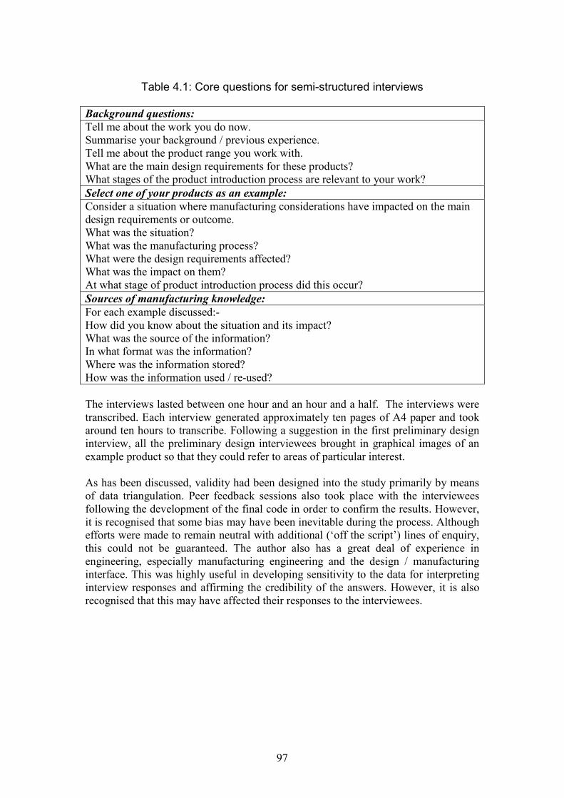
97
Table 4.1: Core questions for semi-structured interviews
Background questions:Tell me about the work you do now.Summarise your background / previous experience.Tell me about the product range you work with.What are the main design requirements for these products?What stages of the product introduction process are relevant to your work?Select one of your products as an example:Consider a situation where manufacturing considerations have impacted on the maindesign requirements or outcome.What was the situation?What was the manufacturing process?What were the design requirements affected?What was the impact on them?At what stage of product introduction process did this occur?Sources of manufacturing knowledge:For each example discussed:-How did you know about the situation and its impact?What was the source of the information?In what format was the information?Where was the information stored?How was the information used / re-used?
The interviews lasted between one hour and an hour and a half. The interviews weretranscribed. Each interview generated approximately ten pages of A4 paper and tookaround ten hours to transcribe. Following a suggestion in the first preliminary designinterview, all the preliminary design interviewees brought in graphical images of anexample product so that they could refer to areas of particular interest.
As has been discussed, validity had been designed into the study primarily by meansof data triangulation. Peer feedback sessions also took place with the intervieweesfollowing the development of the final code in order to confirm the results. However,it is recognised that some bias may have been inevitable during the process. Althoughefforts were made to remain neutral with additional (‘off the script’) lines of enquiry,this could not be guaranteed. The author also has a great deal of experience inengineering, especially manufacturing engineering and the design / manufacturinginterface. This was highly useful in developing sensitivity to the data for interpretinginterview responses and affirming the credibility of the answers. However, it is alsorecognised that this may have affected their responses to the interviewees.

98
4.4 Coding the Interviews
This section demonstrates how the analysis evolved during the study.
4.4.1 Pilot Study
The development of the coding was not the main focus of the pilot study, howeversome preliminary coding activities did take place as practice. There were differencesin the industrial contexts sampled between the pilot interviewees and the officialinterview stages. Consequently the coding was not developed in much detail, with justsome preliminary open coding activities being undertaken during this phase.However, there is some worth in commenting on this activity because this did shapethe way in which the coding would take place for the official interviews.
Each transcript was read through several times to examine the main themes whichwere emerging. In line with the question format, two key elements of the dataemerged:-
i. The impact of manufacturing on component design.ii. The way in which this was communicated.
Consequently, two initial categories emerged from a preliminary open-coding activity.The boundaries and dimensions of these categories (axial coding) were not exploredany further however. The identification of these two categories led to the developmentof a template to capture the relevant data from each identified critical incidentdiscussed during phases 1 and 2 of the interviews. The data to be recorded - and therationale for this - is shown in table 4.2.
Table 4.2: Analysis of Critical Incidents during Pilot Study
a. The interview (anonymously defined by an interview number);b. Years experience of the interviewee (discounted in later interviews);c. The design stage at which the incident occurred (this was coded in line with
the company understanding of the design process – stage 0 for concept, stage 1for preliminary, stage 2 for detail design);
d. The component affected;e. The manufacturing process involved;f. The situation that occurred;g. What action was taken;h. How this impacted on the component design;i. How the interviewee heard about the situation.
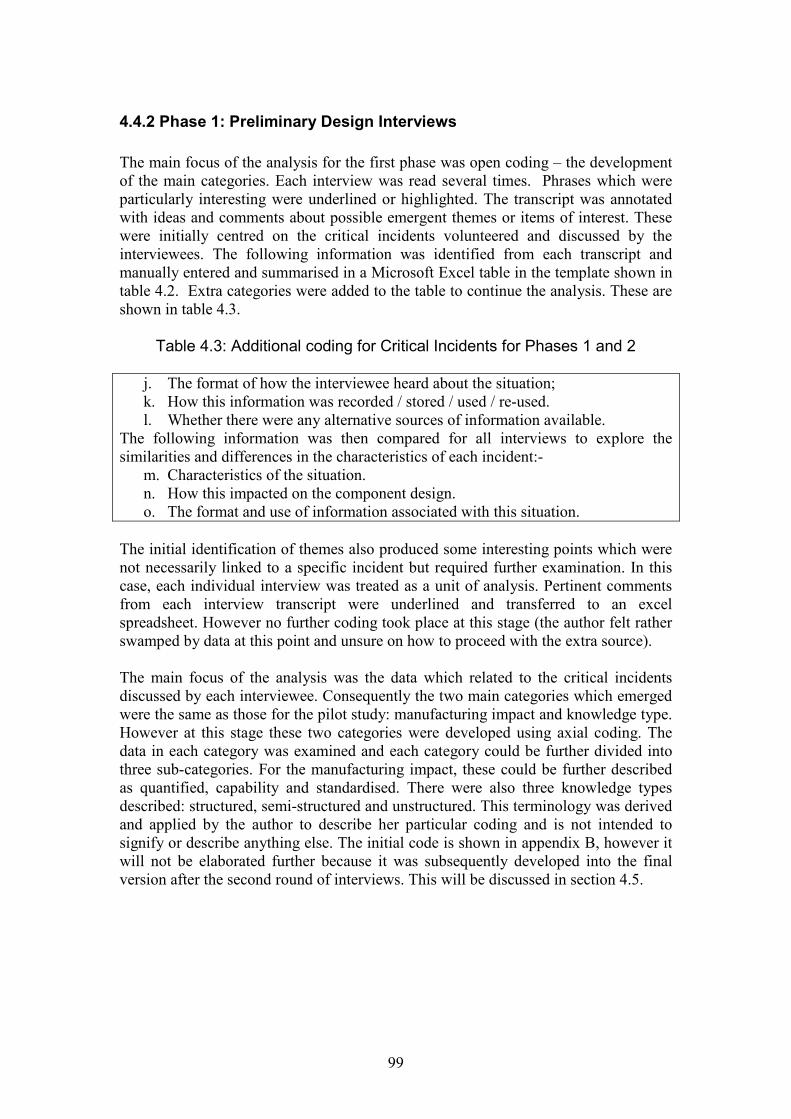
99
4.4.2 Phase 1: Preliminary Design Interviews
The main focus of the analysis for the first phase was open coding – the developmentof the main categories. Each interview was read several times. Phrases which wereparticularly interesting were underlined or highlighted. The transcript was annotatedwith ideas and comments about possible emergent themes or items of interest. Thesewere initially centred on the critical incidents volunteered and discussed by theinterviewees. The following information was identified from each transcript andmanually entered and summarised in a Microsoft Excel table in the template shown intable 4.2. Extra categories were added to the table to continue the analysis. These areshown in table 4.3.
Table 4.3: Additional coding for Critical Incidents for Phases 1 and 2
j. The format of how the interviewee heard about the situation;k. How this information was recorded / stored / used / re-used.l. Whether there were any alternative sources of information available.
The following information was then compared for all interviews to explore thesimilarities and differences in the characteristics of each incident:-
m. Characteristics of the situation.n. How this impacted on the component design.o. The format and use of information associated with this situation.
The initial identification of themes also produced some interesting points which werenot necessarily linked to a specific incident but required further examination. In thiscase, each individual interview was treated as a unit of analysis. Pertinent commentsfrom each interview transcript were underlined and transferred to an excelspreadsheet. However no further coding took place at this stage (the author felt ratherswamped by data at this point and unsure on how to proceed with the extra source).
The main focus of the analysis was the data which related to the critical incidentsdiscussed by each interviewee. Consequently the two main categories which emergedwere the same as those for the pilot study: manufacturing impact and knowledge type.However at this stage these two categories were developed using axial coding. Thedata in each category was examined and each category could be further divided intothree sub-categories. For the manufacturing impact, these could be further describedas quantified, capability and standardised. There were also three knowledge typesdescribed: structured, semi-structured and unstructured. This terminology was derivedand applied by the author to describe her particular coding and is not intended tosignify or describe anything else. The initial code is shown in appendix B, however itwill not be elaborated further because it was subsequently developed into the finalversion after the second round of interviews. This will be discussed in section 4.5.
100
4.4.3 Phase 2: Manufacturing Interviews
The coding process also followed the same method as the first phase. Again, eachtranscript was read repeatedly, with pertinent comments underlined and highlighted.Annotations were added to the transcript to highlight what were judged to beimportant comments. The critical incidents were added to the table with the data fromthe first phase of interviews. Again, there were a number of additional commentswhich were of interest, but not directly related to the critical incidents. These werecopied and pasted into the excel spreadsheet together with the additional commentsfrom the first phase.
There were two parts to the coding process for the second phase of interviews. Thefirst was developing the code relating to the critical incidents. The second was makingsense of all the additional comments (not directly related to the critical incidents) fromboth phases of the interview process. Each shall be discussed in turn.
In some ways the coding of the critical incidents was more straightforward for thesecond phase. This was because the initial set of categories (an initial code) had beendeveloped for the first set of interviews. The purpose of coding in this case was toinvestigate how the data collected in the second phase fitted the code developed fromthe first phase. This would confirm or reject the six categories which had beendeveloped for the code. It would also potentially expand the number of sub-categories. In fact, on further examination of the data, the initial categories wereexpanded to three main categories (and nine subcategories) for the final code. Theseare presented and discussed in section 4.5.
Open coding was also used to analyse the list of additional comments. Each commentwas read and re-read, commented upon and gradually sorted until six main themesemerged. Although they were not directly tied to a specific critical incident, thesethemes gave some useful background information and were therefore used to supportthe further development of the critical incident code. They were useful for examiningand interpreting the meaning of the developed code and in building the relationshipsbetween the three main categories to give the final conceptual framework. This isdiscussed further in section 4.6.
4.5 Results
This section describes the main outcomes of the open and axial coding stages of theanalysis. It describes the categories and subcategories derived from the criticalincident data and the main themes to emerge from the additional comments.
As the analysis is data driven, these sections present the definition of the categoriesfrom the data supplied in the transcripts. These categories will be explored andinterpreted further in section 4.6 to develop a conceptual framework of manufacturingknowledge in preliminary design.
101
4.5.1 Definition of the Code from the Critical Incidents
Three main categories emerged from the open coding of the interview transcripts. Thefirst was how the selection of the manufacturing process impacts on the componentconfiguration being designed. The second was how the maturity of the manufacturingprocess (how far it had been developed and how well the process capabilities wereknown) influenced decisions in manufacturing assessments during preliminary design.The third was how the knowledge had been communicated, with verbalcommunication featuring strongly. These categories were named the ‘ManufacturingImpact’, the ‘Expression of Manufacturing Impact’ and ‘Knowledge Type’respectively. Through axial coding, each category was subdivided into three sub-categories. A summary of the code developed is illustrated in table 4.4.
These categories were derived from the data of eighteen critical incidents which wereidentified in the interviews and are summarised in table 4.5. The incidents aredescribed in terms of the categories developed for each incident (the manufacturingimpact, expression of impact and knowledge type). Each incident has a manufacturingimpact, an expression of impact and at least one knowledge type associated with it. Insome cases all the knowledge types were used to firstly represent and calculate theknowledge and then communicate it to other team members.
The definition of each main category and its associated subcategories follow insections 4.5.2 to 4.5.4 with quotations from the interviews to illustrate examples oftheir occurrence. The meaning of each main category and how they inter-relate arediscussed in section 4.6.
4.5.2 Category 1: Manufacturing Impact
The manufacturing process ultimately constrains the size and shape of a componentbeing designed. The extent of this constraint can be described in increasing levels ofdetail. The three sub-themes relate to the level of detail of knowledge described forthe manufacturing process.
Sub-category 1: Configuration impact
The configuration manufacturing impact occurs to the exclusion of other impacts inpreliminary design. It is suggested that this is because the preliminary design teamrequire knowledge of the effects of the manufacturing process at a component level.More detailed process knowledge (see ‘tooling’ and ‘manufacturing geometry’impacts) is relevant at the stage where production planning needs to be considered butmay not be relevant to the preliminary stage. This is illustrated by the commentbelow, from a preliminary designer, comparing design activities in preliminary designto a previous role as a designer in a business unit:-
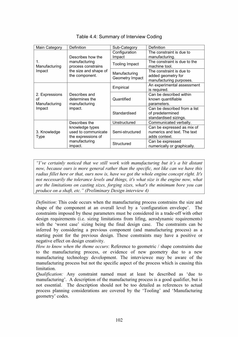
102
Table 4.4: Summary of Interview Coding
Main Category Definition Sub-Category Definition
1.ManufacturingImpact
Describes how themanufacturingprocess constrainsthe size and shape ofthe component.
ConfigurationImpact
The constraint is due tomanufacturing.
Tooling ImpactThe constraint is due to themachine tool.
ManufacturingGeometry Impact
The constraint is due toadded geometry formanufacturing purposes.
2. ExpressionsofManufacturingImpact
Describes anddetermines themanufacturingimpact.
EmpiricalAn experimental assessmentis required.
QuantifiedCan be described withinknown quantifiableparameters.
StandardisedCan be described from a listof predeterminedstandardised sizings.
3. KnowledgeType
Describes theknowledge typesused to communicatethe expressions ofmanufacturingimpact.
Unstructured Communicated verbally.
Semi-structuredCan be expressed as mix ofnumerics and text. The textadds context.
StructuredCan be expressednumerically or graphically.
“I’ve certainly noticed that we still work with manufacturing but it’s a bit distantnow, because ours is more general rather than the specific, not like can we have thisradius fillet here or that, ours now is, have we got the whole engine concept right. It'snot necessarily the tolerance levels and things, it's what size is the engine now, whatare the limitations on casting sizes, forging sizes, what's the minimum bore you canproduce on a shaft, etc.” (Preliminary Design interview 4)
Definition: This code occurs when the manufacturing process constrains the size andshape of the component at an overall level by a ‘configuration envelope’. Theconstraints imposed by these parameters must be considered in a trade-off with otherdesign requirements (i.e. sizing limitations from lifing, aerodynamic requirements)with the ‘worst case’ sizing being the final design case. The constraints can beinferred by considering a previous component (and manufacturing process) as astarting point for the previous design. These constraints may have a positive ornegative effect on design creativity.How to know when the theme occurs: Reference to geometric / shape constraints dueto the manufacturing process, or evidence of new geometry due to a newmanufacturing technology development. The interviewee may be aware of themanufacturing process but not the specific aspect of the process which is causing thislimitation.Qualification: Any constraint named must at least be described as ‘due tomanufacturing’. A description of the manufacturing process is a good qualifier, but isnot essential. The description should not be too detailed as references to actualprocess planning considerations are covered by the ‘Tooling’ and ‘Manufacturinggeometry’ codes.

103
Table 4.5: Critical Incidents identified in the interviews (1-5)
Criticalincident
Interview oforigin
DesignStage
Product / featureaffected
Manufacturingprocess
Impact Impact type (coding) Expression ofimpact (coding)
Knowledge type(coding)
1 PreliminaryDesign 1
0 - 1 Shrouded HPturbine blade
Casting(inferred, notdirectly stated).
Manufacturing minimums.Design thicker than preferredin order to manufacture,therefore weight penaltywhich transfers through todiscs and containment.
Manufacturing processlimits geometry(configuration impact)
Recorded asdimensional rules(quantified)
Verbalconversation withmanufacturingprocess expert(unstructured)
2 PreliminaryDesign 1
0 - 1 Casing Not stated Manufacturing minimums:Trade-off: Thickest dimensionfrom blade off design vs.pressure design vs.manufacturing minimums vs.whole engine modelling loads
Manufacturing processlimits geometry(configuration impact)
Recorded asdimensional rules(quantified)
Plum folders -document designrules (structured)
3 PreliminaryDesign 1
0 - 1 Firtree Not stated Manufacturing bandtolerances. Tolerancesinfluence how design ismodelled. Series of lines andarcs used instead of asmoothline fillet.
Manufacturing processlimits geometry(configuration impact)
Recorded astolerance bandrules (quantified)
Not stated -interviewee talksin general abouta network(unstructured).
4 PreliminaryDesign 1
0 - 1 Cover plate Not stated Manufacturing bandtolerances more relaxed thandesigned tolerances. Designintent cannot be achieved,therefore design changed.
Manufacturing processlimits geometry(configuration impact)
Recorded astolerance bandrules (quantified)
Not stated -interviewee talksin general abouta network(unstructured).
5 PreliminaryDesign 1
0 -1 Curvic coupling Not stated Cost of machine tooling limitsdesign sizes, selected fromprevious designs.
Manufacturing processlimits geometry(configuration impact)
Re-use of previouscomponent(standardised).
Not stated -interviewee talksin general abouta network(unstructured).
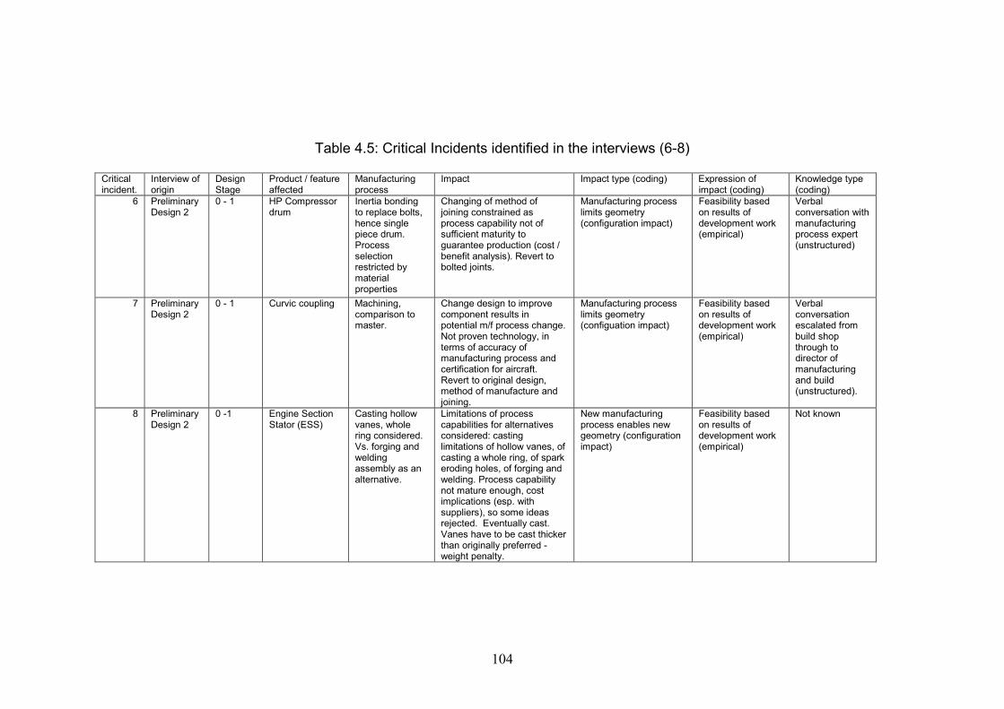
104
Table 4.5: Critical Incidents identified in the interviews (6-8)
Criticalincident.
Interview oforigin
DesignStage
Product / featureaffected
Manufacturingprocess
Impact Impact type (coding) Expression ofimpact (coding)
Knowledge type(coding)
6 PreliminaryDesign 2
0 - 1 HP Compressordrum
Inertia bondingto replace bolts,hence singlepiece drum.Processselectionrestricted bymaterialproperties
Changing of method ofjoining constrained asprocess capability not ofsufficient maturity toguarantee production (cost /benefit analysis). Revert tobolted joints.
Manufacturing processlimits geometry(configuration impact)
Feasibility basedon results ofdevelopment work(empirical)
Verbalconversation withmanufacturingprocess expert(unstructured)
7 PreliminaryDesign 2
0 - 1 Curvic coupling Machining,comparison tomaster.
Change design to improvecomponent results inpotential m/f process change.Not proven technology, interms of accuracy ofmanufacturing process andcertification for aircraft.Revert to original design,method of manufacture andjoining.
Manufacturing processlimits geometry(configuation impact)
Feasibility basedon results ofdevelopment work(empirical)
Verbalconversationescalated frombuild shopthrough todirector ofmanufacturingand build(unstructured).
8 PreliminaryDesign 2
0 -1 Engine SectionStator (ESS)
Casting hollowvanes, wholering considered.Vs. forging andweldingassembly as analternative.
Limitations of processcapabilities for alternativesconsidered: castinglimitations of hollow vanes, ofcasting a whole ring, of sparkeroding holes, of forging andwelding. Process capabilitynot mature enough, costimplications (esp. withsuppliers), so some ideasrejected. Eventually cast.Vanes have to be cast thickerthan originally preferred -weight penalty.
New manufacturingprocess enables newgeometry (configurationimpact)
Feasibility basedon results ofdevelopment work(empirical)
Not known
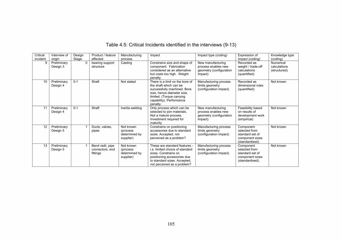
105
Table 4.5: Critical Incidents identified in the interviews (9-13)
Criticalincident
Interview oforigin
DesignStage
Product / featureaffected
Manufacturingprocess
Impact Impact type (coding) Expression ofimpact (coding)
Knowledge type(coding)
9 PreliminaryDesign 3
0 bearing supportstructure
Casting Constrains size and shape ofcomponent. Fabricationconsidered as an alternativebut costs too high. Weightpenalty.
New manufacturingprocess enables newgeometry (configurationimpact)
Recorded asweight / trade-offcalculations(quantified)
Numericalcalculations(structured).
10 PreliminaryDesign 4
0-1 Shaft Not stated There is a limit on the bore ofthe shaft which can besuccessfully machined. Boresize, hence diameter size,limited. (Torque carryingcapability). Performancepenalty.
Manufacturing processlimits geometry(configuration impact)
Recorded asdimensional rules(quantified).
Not known
11 PreliminaryDesign 4
0-1 Shaft Inertia welding Only process which can beselected to join materials.Not a mature process.Investment required formaturity
New manufacturingprocess enables newgeometry (configurationimpact)
Feasibility basedon results ofdevelopment work(empirical)
Not known
12 PreliminaryDesign 5
1 Ducts, valves,pipes
Not known(processdetermined bysupplier)
Constrains on positioningaccessories due to standardsizes. Accepted, notperceived as a problem?
Manufacturing processlimits geometry(configuration impact)
Componentselected fromstandard set ofcomponent sizes(standardised).
Not known
13 PreliminaryDesign 5
1 Bend radii, pipeconnectors, endfittings
Not known(processdetermined bysupplier)
These are standard features -i.e. limited choice of standardsizes. Constrains onpositioning accessories dueto standard sizes. Accepted,not perceived as a problem?
Manufacturing processlimits geometry(configuration impact)
Componentselected fromstandard set ofcomponent sizes(standardised).
Not known

106
Table 4.5: Critical Incidents identified in the interviews (14-16)
Criticalincident
Interview oforigin
DesignStage
Product / featureaffected
Manufacturingprocess
Impact Impact type (coding) Expression ofimpact (coding)
Knowledge type(coding)
14 PreliminaryDesign 5
1 Rear fan case Composite lay-up typeprocedure(determined bysupplier).
Supplier can select one oftwo options - a plain skin witha rear stiffener, or a sandwichstructure (thicker, stiffer so noneed for stiffener). Rearstiffener limits positioning ofgearbox and otheraccessories. Affects howaccessories are mounted andaccess to them.
Manufacturing processlimits geometry(configuration impact)
Componentselected fromstandard set ofcomponent sizes(standardised).
Not known
15 Mantech3 1-2 HP Compressordrum
Inertia welding Replaced bolted geometry fortwo stages
New manufacturingprocess enables newgeometry (configurationimpact)
Feasibility basedon results ofdevelopment work(empirical)
Verbaldiscussion andmeeting minutesvia IPT (Semiandunstructured)
16 Mantech4 1-2 Blade (for blisk) Linear frictionwelding
The fillet rad size is ideallydetermined by theaerodynamic requirements ofthe vane, however there's achordal geometry constraintin the process which mustachieved.
Manufacturing processlimits geometry(configuration impact)
Expressed asdimensional rules(quantified).
All. Rule chordalgeometry vs. filletsize recordedand processed ina key system(structured),recorded in IPTminutes and anddiscussed inmeeting (semi-andunstructured)

107
Table 4.5: Critical Incidents identified in the interviews (17-18)
Criticalincident
Interviewof origin
DesignStage
Product / featureaffected
Manufacturingprocess
Impact Impact type (coding) Expression ofimpact (coding)
Knowledge type(coding)
17 Mantech4
1-2 Blisk Linear frictionwelding
Minimum requirements fortooling clearance impact onnumber of blades which canbe fitted on a blisk.
Manufacturing process -specifically toolingaccess - limits geometry(tooling impact)
Feasibility basedon results ofdevelopment work(empirical)
All. Calculationcarried out todeterminenumber of blades(structured),recorded in IPTminutes and anddiscussed inmeeting (semi-andunstructured)
18 Sub-systemdesigner
1-3 IP fixed vanes,shrouds andblades
Machining Aerofoil is forged withoversize blocks on each sidefor workholding. Designers tryto use same block sizes forstandardised workholding
Manufacturing process -specifically addedgeometry for workholding - limits geometry(manufacturinggeometry impact)
Work-holdinggeometry re-usedfrom previouscomponent(standardised).
Not known.
108
An example of a situation where the code occurs:-Minimum allowed wall thickness of a component due to the casting process. Aprevious assembly becomes a single component.An example of a situation where the code does not occur:-A component is shaped a certain way due to tooling access. Additional material isadded for work holding.
The effect of the configuration impact will vary according to specific manufacturingprocesses and components. The main feature of this category is that the designers areaware of the impact but not necessarily its cause. As an illustration, critical incident 5in table 4.5 refers a configuration impact as seen in a component called the curviccoupling. This product has a set of standard sizes to which are used, due tomanufacturing process constraints. The design engineers are aware of the sizelimitations on the component, but not the specific reasons why the manufacturingprocess has caused this limitation. Investment in new equipment or a differentmanufacturing process would change these limitations.
Sub-category 1: Tooling Impact
This impact is evident during the detail design stage, where individual processoperations are under consideration.
The two following quotations illustrate how tooling access and usage can limitgeometry in component design. They are both concerned with the detail stages ofdesign and are from the interview with the sub-system Designer:-
‘There are a lot of implications in terms of tooling, fixtures, the way the actualmachine tools come in and have to get access to various parts of the component tomachine it.’
‘As the tool wears down, they don’t want to machine it all in one go, but because it’svery difficult to get it lined up exactly with all the previous cuts, there are mismatcheson there, and with this material being a lot harder than it was in the past, the tool’swearing down a lot quicker, so we had to allow more mismatches. But rather thanjust allow them anywhere we had to understand with stress, that the best way to havethe thickness varying is according to the position of these mismatches.’
Definition: This code occurs when the manufacturing process constrains the size andshape of the component due to tooling clearance limitations at component level.How to know when the theme occurs: Reference to geometric / shape constraints dueto tooling access. The interviewee will have a detailed knowledge of themanufacturing process.Qualification: An in-depth discussion of the manufacturing process highlightingtooling access constraints.An example of a situation where the code occurs:-The geometry of the component is changed to allow clearance for machine tools.
109
Sub-category 1: Manufacturing Geometry Impact
This manufacturing impact was also identified during the later stages of detail sub-system design where individual process operations are under consideration.
This comment illustrates clearly how the addition of geometry for manufacturing canimpact on the design:-
‘…and our requirements for work holding…mean that sometimes we will compromiseor impact the design of that aerofoil, and most definitely impact the design of what wecall the final fillet.’ (Manufacturing Technology Interview 4)
These comments are two other examples of manufacturing geometry:-
‘So we’ve had to put this ‘sacrificial flange’ on the shaft and then clamped and boltedaround it and then sunk that into the machine rather than use that backspace for acollet device.’ (Manufacturing Technology Interview 3, describing the addition ofgeometry to a component for workholding purposes).
‘I guess from the manufacturing side of things, the way these components aremanufactured is they’re forged and then machined. So the aerofoil shape is actuallyforged with oversized blocks of metal in each end, then that part is clamped and theouter blocks are machined to give us the correct geometry which will then fit into thecasing.’ (Sub-system designer)
Definition: This code occurs when reference is made to additional geometry whichneeds to be added to the component geometry to facilitate the manufacturing process.How to know when the theme occurs: Reference to added material. The intervieweewill have a detailed knowledge of the manufacturing process. References to this codewill typically be made by designers and manufacturing engineers involved in thedetail design stages of the design process, therefore this geometry is ‘hidden’ fromstage 1 preliminary.Qualification: An in-depth discussion of the manufacturing process highlightingadditional geometry to be added, typically for work holding.An example of a situation where the code occurs:-The geometry of the component is impacted by additional blocks which are addedeither side for work holding.
4.5.3 Category 2: Expressions of Manufacturing Impact
The first theme was a judgement of the impact of a manufacturing process on the sizeand shape of a component. The second theme is a consideration of how thatmanufacturing process can be expressed during the product introduction process.
110
Sub-category 2: Expression of impact - Empirical
Definition: occurs when there is evidence of experimentation in determining theimpact of a manufacturing process on the size and shape of a component.How to know when the theme occurs: the overriding factor in identifying this sub-theme is that the manufacturing process intended to produce the component willrequire some development work in order to meet the design requirements. Theoutcome of this work can be either successful or unsuccessful. Assessment of theprocess constraints on the product geometry will be from the results of experimentalwork or investigations.Qualification: The theme will be qualified if the manufacturing process is adevelopment of existing manufacturing technology, or the application of existingmanufacturing technology to a new situation.Disqualification: The theme will be disqualified if there is no consideration of thefeasibility of the manufacturing process.The following are situations where this theme occurs:--Change of a bolted joint to a bonded joint.The joining of two different materials which have not been previously joined usingthe specific process.Change of the profile or shape of a component to improve its function, withconsiderations of how the manufacturing should take place.The following is an example of a situation where this theme would not occur:-The proposed manufacturing process is not feasible. A proven manufacturing processis used.
This example refers to the development of manufacturing technology and howdiffering project requirements feed a requirement to investigate process development:-
‘Now what we’re finding is that from one engine programme to the next, everythingseems to change, so we don’t seem to have a consistent joint thickness or a consistentmaterial, so somebody will say to us, this seems very similar to this one we did before,either in this development programme or in this production phase. Yes, to look at it isvery similar, but that’s different, that’s different and that’s different, given our verylimited knowledge, sorry guys, but we’ve now got to investigate everything again,because now we’ve got to develop it at that, that and that which have changed’ (Sub -system Design - manufacturing engineer)
Sub-category 2 : Expression of impact - Quantified
Definition: This code occurs when the manufacturing process constrains the size ofthe component to certain parameters. These parameters are expressed numerically.How to know when the theme occurs: Reference to maximum or minimum alloweddimensions due to manufacturing. These dimensions are applicable to currentmanufacturing processes. These dimensional constraints can be seen across mostcomponents in the general arrangement. They will be considered routinely as part ofthe design process. The interviewee may or may not be aware of the manufacturingprocess which constrains the dimensions.
111
Qualification: Any constraint named must at least be described as ‘due tomanufacturing’. A description of the manufacturing process is a good qualifier, but isnot essential.Examples of situations where this code occurs:-Minimum allowed wall thickness of a component due to the casting process.Maximum forging size allowed for bought-in component of finished material.Manufacturing maximums and minimums.Examples of situations where this code does not occur:-Minimum allowed component thickness.Maximum casing size. (reasons for maximum / minimum not given).This example illustrates the use of rules in the manufacturing assessment of a specificcomponent and process.
‘Right, so they take their fillet radius from there (structural and aerodynamicrequirements) and then it would be a case of aligning it with the manufacturing, yourmanufacturing rules for fillets and the chordal geometry.’ (ManufacturingTechnology interview 4)
Sub-category 2: Expression of impact - Standardised
Definition: this code occurs when component or component features are selected froma predetermined list of standard sizes. These standard sizes are fixed by themanufacturing process, or the supplier (and their manufacturing process).How to know when this theme occurs: the interviewee will indicate that thecomponent or feature is standardised. The interviewee may or may not know thedetails of the manufacturing process or reasons for the standardisation. Onecharacteristic of this impact is there are rarely issues associated with it, as if thestandardisation is accepted. Often the part will be bought-in and the standardisationwill be defined by the supplier.Qualification: The theme will be qualified if there is discussion of standardisation.Disqualification: It will be disqualified if some parameterisation or customisation isallowed to the component.Examples of situations where this theme occurs:-‘Standard range of pipes and fittings’.‘Use of a previous part as standard’.Example of a situation where this themed does not occur:-‘We’ll select an existing part from a previous assembly and modify the sizings’.
This example is from preliminary design and concerns a component known as thecurvic coupling:-
‘…at the beginning, you have the curvic there, so these are very expensive to make, orvery expensive to produce the tooling to make, so you tend to pick one that’s alreadybeen manufactured, so rather than optimising the radius to – you know – the nearestthou, you’ll pick one from a previous engine and use that if you possibly can.’(Preliminary Design interview 1)

112
4.5.4 Category 3: Knowledge Types
The final set of sub-themes demonstrates how the expression of impact iscommunicated throughout the product introduction process.
Sub-category 3: Knowledge Type – Structured
Definition: Examples of manufacturing engineering knowledge which can beexpressed numerically, by algorithms or numerical rules. Information is generated andused during the design process. This information is repeatable across projects. Theyare documented in the form of parameters, dimensions, spreadsheet calculations oralgorithms in expert systems. They can also be expressed graphically. Knowledge issaid to be ‘abstracted’ – it is possible (although not always preferable) to apply itwithout fully appreciating the circumstances in which it was created. This is anexample of explicit knowledge.How to know when it occurs: Design requirements and/or information are expressednumerically. The format is stand-alone and can be repeatedly be used as a tool.Details of the manufacturing process which forms the knowledge may or may not beincluded.Qualification: The theme is qualified if the knowledge can definitely be quantifiedand is document based.Disqualification: It is disqualified if there is a degree of qualitative knowledge and/orif the knowledge is not documented.Example of situations where the theme occurs:-Manufacturing minimums and maximums.Graphically-represented parameterised feature.Example of a situation where the theme does not occur:-Reference material (such as material properties) referred to, but not generated as partof the design process.
Example of a knowledge-based engineering system for linear friction welding:-
‘And we also knew that to support that we need this blisk key system which is alsowhere we recognised during the PD (product development) work that we needed todevelop this blisk key system to support the vast number of iterations that we wouldneed to be going through’ (Manufacturing Technology interview 4)
An example of the importance of graphics in the communication process:-
‘…the main deliverable of the designer is the solution drawing of the part.’ (Sub-system designer)
This quotation is an example of structured knowledge created internally within thepreliminary design department for assistance in managing the trade-off of designrequirements:-

113
‘One of the lads in the area, when he first joined he put together a guide for anengine. It’s got certain criteria, you know, where you match certain parametersaround the engine - performance and, as I said, it touches on the manufacturingthings’ (Preliminary design interview 4)
Sub-category 3: Knowledge type - semi-structured
Definition: Examples of manufacturing engineering knowledge which can beexpressed quantitatively or qualitatively. They are referenced during the designprocess and support, but are not integral to the design process. The need to referencewill depend on the situation, the context and the designer’s own experience. They aredocumented in text documents. Knowledge is said to be ‘embedded’ – the designerneeds to be able to browse and understand the context of the knowledge in order to beable to use it. Often the knowledge referenced is from outside the department. This isalso an example of explicit knowledge because it is codified in text and numerics.How to know when it occurs: Examples of numerical or descriptive information asseen in text documents.Qualification: The theme is qualified if the knowledge is not documented as anabstracted rule or algorithm or graphical image.Disqualification: The theme is disqualified if there is no documented evidence of theknowledge.Examples of a situation where this theme occurs:-An intranet website of material properties.Descriptions of manufacturing processes.Example of a situation where this theme does not occur:-Conversational discussions.
Examples of semi-structured knowledge: minutes, emails, reports and presentations:-
‘…the minutes – we’re under a lot of time constraints, so the minutes tend to recordthe actions more often than the discussion. So it may not be possible to go back andfind the particular conversation, merely the outcome.’ (Manufacturing TechnologyInterview 3)
‘I’m generally reliant on individuals copying the relevant people in on emailcommunications.’ (Manufacturing Technology interview 3)
Reports:-
‘But there’s also a DDR, which is the Design Definition Report, which you writewhich is basically a report that records why a design is how it is.’ (Sub-systemdesigner)
Presentations:-
114
(We’re) ‘trying to develop a one-page, simple foil that can be shown to seniors to saylook, this is what we want to do with the technology, this is where we want to developit’ (Sub-system design - manufacturing engineer)
Sub-category 3: Knowledge type – unstructured
Definition: Essentially, unstructured knowledge is the same as semi-structuredknowledge. It is manufacturing engineering knowledge which can be expressedquantitatively or qualitatively, which is referenced during and supports the designprocess. Again, the need to reference will depend on the situation, the context and thedesigner’s own experience. Knowledge is again ‘embedded’ – the designer needs tobe able to browse and understand the context of the knowledge in order to be able touse it. Often the knowledge referenced is from outside the department. The differencelies in the media by which the knowledge is transferred. In this case, knowledge is notrecorded and is communicated via social networks, hence the expert being questionedcan supply some context. The theme can occur inside and outside the department, andbe formal and informal communication methods. The current method of knowledgetransfer is therefore tacit.How to know when the theme occurs: the knowledge is communicated socially.Qualification: The qualification of this theme is the manner in which it iscommunicated, i.e. socially. The content of semi-structured and unstructuredknowledge is often similar, however the method of communication differs.Examples of situations where this theme occurs:-Discussions with people, group meetings.
Two examples which demonstrate the use of unstructured knowledge:-
‘The guys from casting didn’t like it but because of a different reason, because theydidn’t see any added value of the roadmap because they had all the information intheir heads.’ (Manufacturing Technology 2, technology roadmapping)
‘We work on a slow turnover rate in this office. There always tend to be someonewho knows what’s happened before. I think if a whole new batch of guys were to comein and say we all went off elsewhere, then it’s quite possible that they’d struggle, wellnot struggle, they wouldn’t be able to get the same learning curve, if you like, as thepeople, as if the experience was in the vicinity. It’s generally a matter of who do youask? Who do I ask about this subject? And within half an hour you’ll get a goodunderstanding of what the issues are. Generally that’s the way we work. It’s not aknowledge-based system in that respect.’ (Preliminary Design interview 2)
4.5.5 Examples of how the code was derived
The purpose of this section is to demonstrate how the coding was derived from thecritical incidents listed. Two of the eighteen critical incidents have been selected asexamples to illustrate this: a similar method was applied for all of the incidents.
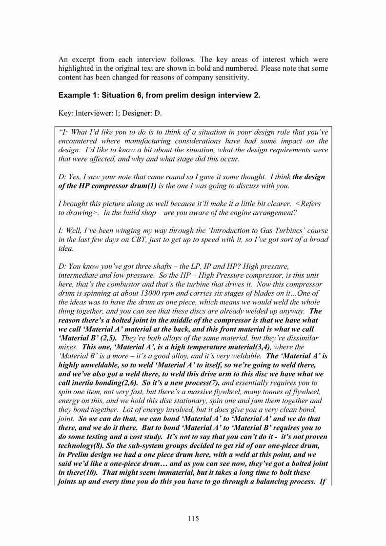
115
An excerpt from each interview follows. The key areas of interest which werehighlighted in the original text are shown in bold and numbered. Please note that somecontent has been changed for reasons of company sensitivity.
Example 1: Situation 6, from prelim design interview 2.
Key: Interviewer: I; Designer: D.
“I: What I’d like you to do is to think of a situation in your design role that you’veencountered where manufacturing considerations have had some impact on thedesign. I’d like to know a bit about the situation, what the design requirements werethat were affected, and why and what stage did this occur.
D: Yes, I saw your note that came round so I gave it some thought. I think the designof the HP compressor drum(1) is the one I was going to discuss with you.
I brought this picture along as well because it’ll make it a little bit clearer. <Refersto drawing>. In the build shop – are you aware of the engine arrangement?
I: Well, I’ve been winging my way through the ‘Introduction to Gas Turbines’ coursein the last few days on CBT, just to get up to speed with it, so I’ve got sort of a broadidea.
D: You know you’ve got three shafts – the LP, IP and HP? High pressure,intermediate and low pressure. So the HP – High Pressure compressor, is this unithere, that’s the combustor and that’s the turbine that drives it. Now this compressordrum is spinning at about 13000 rpm and carries six stages of blades on it…One ofthe ideas was to have the drum as one piece, which means we would weld the wholething together, and you can see that these discs are already welded up anyway. Thereason there’s a bolted joint in the middle of the compressor is that we have whatwe call ‘Material A’ material at the back, and this front material is what we call‘Material B’ (2,5). They’re both alloys of the same material, but they’re dissimilarmixes. This one, ‘Material A’, is a high temperature material(3,4), where the‘Material B’ is a more – it’s a good alloy, and it’s very weldable. The ‘Material A’ ishighly unweldable, so to weld ‘Material A’ to itself, so we’re going to weld there,and we’ve also got a weld there, to weld this drive arm to this disc we have what wecall inertia bonding(2,6). So it’s a new process(7), and essentially requires you tospin one item, not very fast, but there’s a massive flywheel, many tonnes of flywheel,energy on this, and we hold this disc stationary, spin one and jam them together andthey bond together. Lot of energy involved, but it does give you a very clean bond,joint. So we can do that, we can bond ‘Material A’ to ‘Material A’ and we do thatthere, and we do it there. But to bond ‘Material A’ to ‘Material B’ requires you todo some testing and a cost study. It’s not to say that you can’t do it - it’s not proventechnology(8). So the sub-system groups decided to get rid of our one-piece drum,in Prelim design we had a one piece drum here, with a weld at this point, and wesaid we’d like a one-piece drum… and as you can see now, they’ve got a bolted jointin there(10). That might seem immaterial, but it takes a long time to bolt thesejoints up and every time you do this you have to go through a balancing process. If
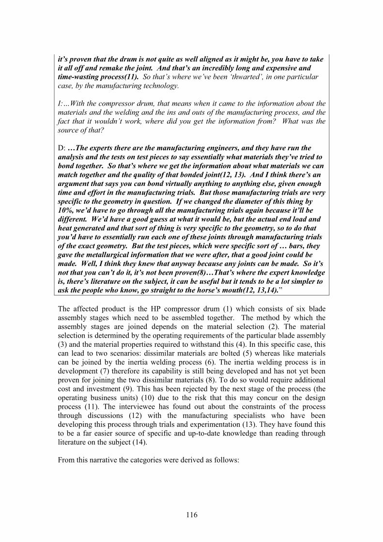
116
it’s proven that the drum is not quite as well aligned as it might be, you have to takeit all off and remake the joint. And that’s an incredibly long and expensive andtime-wasting process(11). So that’s where we’ve been ‘thwarted’, in one particularcase, by the manufacturing technology.
I:…With the compressor drum, that means when it came to the information about thematerials and the welding and the ins and outs of the manufacturing process, and thefact that it wouldn’t work, where did you get the information from? What was thesource of that?
D: …The experts there are the manufacturing engineers, and they have run theanalysis and the tests on test pieces to say essentially what materials they’ve tried tobond together. So that’s where we get the information about what materials we canmatch together and the quality of that bonded joint(12, 13). And I think there’s anargument that says you can bond virtually anything to anything else, given enoughtime and effort in the manufacturing trials. But those manufacturing trials are veryspecific to the geometry in question. If we changed the diameter of this thing by10%, we’d have to go through all the manufacturing trials again because it’ll bedifferent. We’d have a good guess at what it would be, but the actual end load andheat generated and that sort of thing is very specific to the geometry, so to do thatyou’d have to essentially run each one of these joints through manufacturing trialsof the exact geometry. But the test pieces, which were specific sort of … bars, theygave the metallurgical information that we were after, that a good joint could bemade. Well, I think they knew that anyway because any joints can be made. So it’snot that you can’t do it, it’s not been proven(8)…That’s where the expert knowledgeis, there’s literature on the subject, it can be useful but it tends to be a lot simpler toask the people who know, go straight to the horse’s mouth(12, 13,14).”
The affected product is the HP compressor drum (1) which consists of six bladeassembly stages which need to be assembled together. The method by which theassembly stages are joined depends on the material selection (2). The materialselection is determined by the operating requirements of the particular blade assembly(3) and the material properties required to withstand this (4). In this specific case, thiscan lead to two scenarios: dissimilar materials are bolted (5) whereas like materialscan be joined by the inertia welding process (6). The inertia welding process is indevelopment (7) therefore its capability is still being developed and has not yet beenproven for joining the two dissimilar materials (8). To do so would require additionalcost and investment (9). This has been rejected by the next stage of the process (theoperating business units) (10) due to the risk that this may concur on the designprocess (11). The interviewee has found out about the constraints of the processthrough discussions (12) with the manufacturing specialists who have beendeveloping this process through trials and experimentation (13). They have found thisto be a far easier source of specific and up-to-date knowledge than reading throughliterature on the subject (14).
From this narrative the categories were derived as follows:
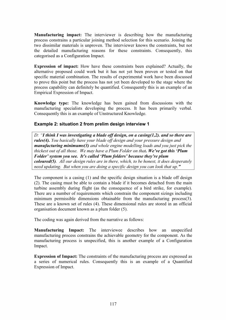
117
Manufacturing impact: The interviewer is describing how the manufacturingprocess constrains a particular joining method selection for this scenario. Joining thetwo dissimilar materials is unproven. The interviewer knows the constraints, but notthe detailed manufacturing reasons for these constraints. Consequently, thiscategorised as a Configuration Impact.
Expression of impact: How have these constraints been explained? Actually, thealternative proposed could work but it has not yet been proven or tested on thatspecific material combination. The results of experimental work have been discussedto prove this point but the process has not yet been developed to the stage where theprocess capability can definitely be quantified. Consequently this is an example of anEmpirical Expression of Impact.
Knowledge type: The knowledge has been gained from discussions with themanufacturing specialists developing the process. It has been primarily verbal.Consequently this is an example of Unstructured Knowledge.
Example 2: situation 2 from prelim design interview 1
D: “I think I was investigating a blade off design, on a casing(1,2). and so there arerules(4). You basically have your blade off design and your pressure design andmanufacturing minimums(3) and whole engine modelling loads and you just pick thethickest out of all those. We may have a Plum Folder on that. We’ve got this ‘PlumFolder’ system you see. It’s called ‘Plum folders’ because they’re plumcoloured(5). All our design rules are in there, which, to be honest, it does desperatelyneed updating. But when you are doing a specific design you can look that up.”
The component is a casing (1) and the specific design situation is a blade off design(2). The casing must be able to contain a blade if it becomes detached from the mainturbine assembly during flight (as the consequence of a bird strike, for example).There are a number of requirements which constrain the component sizings includingminimum permissible dimensions obtainable from the manufacturing process(3).These are a known set of rules (4). These dimensional rules are stored in an officialorganisation document known as a plum folder (5).
The coding was again derived from the narrative as follows:
Manufacturing Impact: The interviewee describes how an unspecifiedmanufacturing process constrains the achievable geometry for the component. As themanufacturing process is unspecified, this is another example of a ConfigurationImpact.
Expression of Impact: The constraints of the manufacturing process are expressed asa series of numerical rules. Consequently this is an example of a QuantifiedExpression of Impact.
118
Knowledge Type: the interviewee refers to an official organisational method ofdocumentation for design rules. As the rules are numerical and are recorded in thisway, the Plum Folder is an example of a Structured knowledge type.
4.5.6 Coding of Additional Comments
The six additional themes identified through the open coding of the additionalcomments were:-
a. Impact and knowledge types.
These were direct quotations associated with the categories and sub-categoriesdiscussed in sections 4.5.2 – 4.5.4 and were examples of each. Quotations typical tothis category have been used in that section to illustrate examples of each category.
b. Business benefits.
These were quotations which supported and highlighted the benefits of betterintegration between manufacturing and preliminary design.
The majority of comments were concerned with the need to link the future enginestrategy and future technology development strategies in the preliminary designdepartment in a better, more formal way, earlier on. The benefits of this would be thatpreliminary design would have a greater awareness of the actual technologiesavailable during preliminary design, and would be better able to influence thetechnologies being developed to be more in line with their requirements. There wouldbe benefits for Manufacturing Technology in that they would have greater, moreformal visibility of future requirements and be able to feedback their developments toinfluence those requirements. Much of the discussion was concerned with theTechnology Roadmapping initiative which was under development within theManufacturing Technology department at the time of the study and was in the processof being rolled out to engine projects. This initiative would address this issue. Therewas a consensus that needed to be addressed by both design and manufacturingcollectively.
An example from the interview of when this has worked well is with specifying thenumber of blades in a blisk. The manufacturing process limits the permissiblenumber of blades due to allowances for tooling clearances. In this case, themanufacturing technology team were able to due some initial calculations on thepreferred number of blades prior to the stage 2 IPT launch. They found that they wereable to remove two blades and this was communicated during the IPT launch.
The better integration of manufacturing and design at the early stages is primarilyseen as a reduction of risk, as illustrated by this comment:-

119
“So there’s a feeling overall I think that it would be nice to have a better visibility ofwhat was on the horizon in a more formal way. Even if there was no money beingspent, but just that you can understand at a level perhaps two or three enginerequirements with a similar volume of inertia welding that we’ve seen on the [engineproject]. But perhaps these new materials might be required, or it might be arequirement on this new component. Just so development programmes can be put inplace early enough to de-risk those new engines. Because I don’t think it’s breakinggreat confidences or any sensitivities, it’s just a better appreciation of companystrategy, essentially.” (Manufacturing Technology interview 3)
c. Size and shape drivers.
These quotations offered evidence that the method of manufacture influences the sizeand shape of the component and were used to develop the Manufacturing Impact sub-categories.
An example is given in this comment, referring to how geometry required to supportthe component during a joining process can compromise the design geometry:-
“So, the fact that we need that blade foot on there compromises that aerofoilhollowness. The fact that we need that foot on there compromises that fillet radius.To some extent, it could compromise the chord length. In terms of stagger as well,there is a maximum stagger that we can weld on so we could not have the bladestaggered right round here, we just could not weld that with the machine that we’vegot.” (Manufacturing Technology interview 4)
d. Commonality of purpose of design and manufacturing.
These quotations demonstrated that although strategic issues in communication wererecognised and were being addressed (for example through TechnologyRoadmapping), there was a commonality of purpose across the groups involved in thedifferent stages of the design process. All ultimately wanted to achieve the sameoutcome, particularly regarding future technology strategies.
“Historically, it appears that nobody has owned the process, for one reason oranother. I’m working with Man Tech closely at the moment to try and develop aroadmap of what we are going to do with the technologies, trying to speak to the(business units) and (preliminary design) to see, what do we need to develop in theforthcoming years.” (Sub-system design - Manufacturing Engineer)
e. Maturity of manufacturing impact
These quotations demonstrated a link between the expressions of impact used for amanufacturing process and a time-based view of the development of the process. Theempirical impact of expression appeared to be used primarily for processes whichwere under development. Sometimes quantifiable rules could be expressed for knownprocess parameters, other times it was clear that experimentation was required. This isdiscussed further in section 4.6.
120
“…although we had done some tests on some smaller diameter test pieces, to guidehow well it bonded together, there was still some uncertainty in terms of what speedsand force was required to bond it together. So although we had a good idea, theinertia welding team still didn’t feel comfortable committing to more than an extra ±xover the length of the component which, if you think about it, is still pretty accurate.But, on a similar component with a more established material, the tolerance was N±0.25x, I think it was. So that gives you an idea of the difference it had. That waspurely down to new material that hadn’t been tested before. That’s really where theuncertainty came from.” (Sub-system designer)
f. Knowledge sharing and use of knowledge types.
This category was primarily concerned with examples of the different knowledge typesubcategories shown in section 4.5.4. The preferences and limitations for differentknowledge types, and their importance in knowledge transfer, were also investigated.These are discussed further in section 4.6.
4.6 Key Observations
Having defined the data-driven codes through open and axial coding analysis, thefinal stage in the coding process was selective coding. There were two activitiesinvolved in this. The first was to examine and interpret the coding categories as adefinition of the manufacturing knowledge requirements for preliminary design. Thiswas achieved by reviewing the themes from the additional comments. It was foundthat these themes were related to the main categories derived from the analysis of thecritical incidents. Consequently the themes were used to understand and interpret themain categories. Figure 4.2 illustrates the relationships between the main codingcategories and the additional themes.
The second activity evolved from the first. As the meanings of each category wereexplored, relationships between them began to emerge. These relationships wererepresented as a conceptual framework of manufacturing knowledge for preliminarydesign.
Sections 4.6.1 – 4.6.3 discuss the meaning of each of the main categories. Section4.6.4 explores the links between the main categories and presents and summarises theconceptual framework generated from this.
4.6.1 Category 1: the manufacturing impact
The optimum design outcome from preliminary design is a trade-off for a number ofdesign requirements (Pahl and Beitz, 1988, p.2). This was clearly demonstrated bythe interview data, particularly for preliminary design. For preliminary design in thecollaborating company, the functional design requirements (performance,aerodynamics, stress, weight, noise, emissions, safety, etc.) are the mainconsiderations during the design process, with perhaps performance being the most

121
Figure 4.2 Summary of coding categories developed and their relationships
important because this needs to be satisfied or exceeded for the solution to beconsidered by the customer. Satisfaction of the functional requirements determinesmaterial selection for each of the components. The selected material then determinesthe options for manufacturing process selection. Therefore manufacturability isassessed indirectly as a consequence of other requirements. Historicallymanufacturing has been considered at this stage due to its impact on component cost.However, the feasibility of the manufacturing process fundamentally decides whethera component design is a realistic solution.
As seen in (Pahl and Beitz, 1988; Lovatt and Shercliff, 1998a; Chen, 1999; Nowack,1997, Boothroyd et al., 2002), there is a relationship between the functionalrequirements, material selection, process selection and shape. This was also clearfrom the interview data.
In the analysis of this data, the selected method of manufacture was interpreted ascreating a configuration envelope which places limitations on the size and shape of acomponent (the Manufacturing Impact). This method of manufacture may have afurther effect on the material properties. The configuration envelope is specific to aparticular method of manufacture and if more than one method is available, then theresulting configuration envelope may be different. This is shown in figure 4.3, whichis an illustration of the manufacturing impact on a component. The original functionaldesign requirements drive the component material selection which drives themanufacturing process selection. The configuration impact is shown by the differingconfiguration envelopes for processes A and B. The additional tooling impact and

122
manufacturing geometry categories are additional process detailed process knowledgewhich drive the creation of the configuration envelope.
Two key findings were found from the analysis of the data. The first is the way inwhich a method of manufacture can have a positive effect on the configurationenvelope of a component. Historically the manufacturing process has been viewed asa constraint or a limitation. During preliminary design method of manufacture hasbeen inferred by selecting and modifying a previous component. The fact that thecomponent was successfully produced infers that the manufacturing process iscapable.
Figure 4.3: The impact of the manufacturing process on the componentconfiguration
However, if new manufacturing technology becomes available, the scope of what canbe achieved in terms of size and shape is directly altered, leading to new creativepossibilities and a new potential configuration envelope. An example of this given inthe interviews was the creation of the blisk component to replace the conventionalblade and disk assembly. The conventional assembly features for the blade and diskswere no longer required, giving weight and stress advantages. This development wasmade possible by developments in a joining method called linear friction welding.
The second key finding is the extent to which the manufacturing impact is defined atspecific stages of design. It has been demonstrated that knowledge of theconfiguration envelope boundaries alone has been used in preliminary design, as seenby instances of the configuration impact. It is only at subsequent, more detailed stagesof the design process that the reasons for these configuration boundaries are explored.The results of this can be seen in the descriptions of the tooling impact and thegeometric impact. In the case of the geometric impact, where additional material
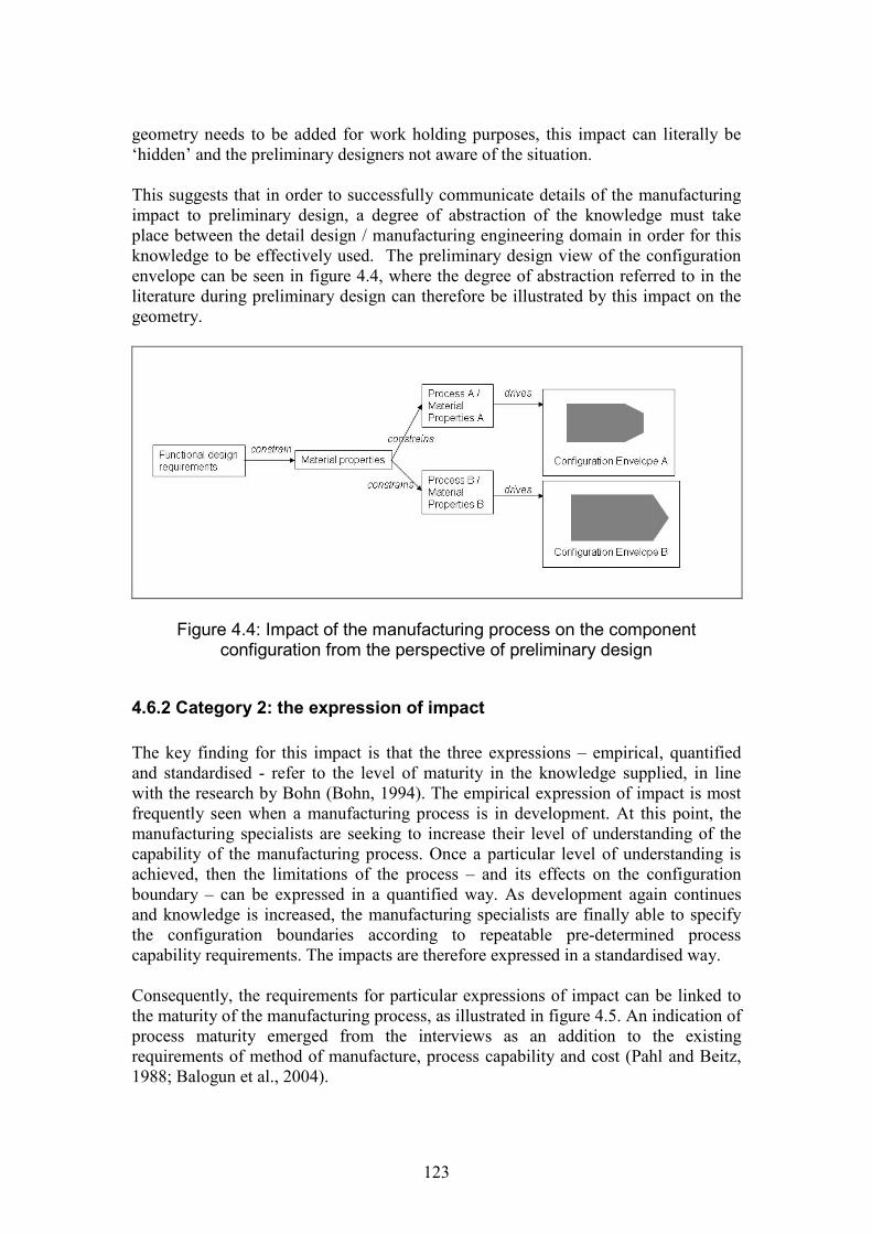
123
geometry needs to be added for work holding purposes, this impact can literally be‘hidden’ and the preliminary designers not aware of the situation.
This suggests that in order to successfully communicate details of the manufacturingimpact to preliminary design, a degree of abstraction of the knowledge must takeplace between the detail design / manufacturing engineering domain in order for thisknowledge to be effectively used. The preliminary design view of the configurationenvelope can be seen in figure 4.4, where the degree of abstraction referred to in theliterature during preliminary design can therefore be illustrated by this impact on thegeometry.
Figure 4.4: Impact of the manufacturing process on the componentconfiguration from the perspective of preliminary design
4.6.2 Category 2: the expression of impact
The key finding for this impact is that the three expressions – empirical, quantifiedand standardised - refer to the level of maturity in the knowledge supplied, in linewith the research by Bohn (Bohn, 1994). The empirical expression of impact is mostfrequently seen when a manufacturing process is in development. At this point, themanufacturing specialists are seeking to increase their level of understanding of thecapability of the manufacturing process. Once a particular level of understanding isachieved, then the limitations of the process – and its effects on the configurationboundary – can be expressed in a quantified way. As development again continuesand knowledge is increased, the manufacturing specialists are finally able to specifythe configuration boundaries according to repeatable pre-determined processcapability requirements. The impacts are therefore expressed in a standardised way.
Consequently, the requirements for particular expressions of impact can be linked tothe maturity of the manufacturing process, as illustrated in figure 4.5. An indication ofprocess maturity emerged from the interviews as an addition to the existingrequirements of method of manufacture, process capability and cost (Pahl and Beitz,1988; Balogun et al., 2004).

124
Figure 4.5: Maturity of manufacturing process and expressions of impact
4.6.3 Category 3: the knowledge types
This final category explores the combination of methods by which the expressions ofimpact can be communicated. It is proposed that the definitions of ‘structured’ and‘semi-structured’ knowledge conform to existing definitions of knowledge as being‘explicit’ or ‘codified’. The definition of ‘unstructured’ knowledge correlates with thedefinition of ‘tacit’ or ‘personalised’ knowledge (Nonaka, 1994; McMahon et al.,2004). In the interviews, a number of opinions were raised on the validity and use ofthe different knowledge types. From the data, the advantages and disadvantages ofthe different knowledge types follow.
Structured
The strength of structured knowledge is the extent to, ease with and speed with whichit can be re-used. For example, once a spreadsheet of performance values is compiled,the effect of different design configurations can be updated almost instantly.
Two major disadvantages of structured knowledge were highlighted in the data. Thefirst is the effort required to reach the situation where knowledge can be captured andabstracted in this way. The second disadvantage is the effort required to actuallycapture, effectively store the knowledge and to keep it updated. The abstraction ofstructured knowledge, that is, its separation from its context creates two risks. Thefirst is that the knowledge may be used wrongly because the user does not know thecircumstances in which it has been created (i.e. a standard bolt may be used for thewrong type of joint). The second is that structured knowledge may be used for manyyears when it is actually out of date (standard tolerances, for example).
The adaptive design environment does not give many opportunities for directknowledge reuse, particularly where new process developments are taking place:
125
“…whilst when we do a new engine this technology's from a previous one and thisone's from a previous one, this isn't, these aren't, that probably isn't that much like theother one…” (Preliminary Design interview 4)
However, there appears to be a need to attempt to define and communicate knowledgein a structured way, perhaps because results can be generated and interpreted quicklyand easily:
‘What designers can't do brilliantly is design to meet a cost, a weight target. I can dothis, and this is what happens. I could do this, and this is what happens. But it keepsbouncing numbers at me. And I'd probably want to work to something like this(spreadsheet shown cost comparison of changing a number of parameters), where youwork up to an overall thing.’ (Preliminary Design interview 4)
Semi-structured
Semi-structured knowledge is useful in that it can supply the context which is notpresent in structured knowledge. Because it requires less precise definition whencompared to structured knowledge, it can be compiled more quickly and morecomprehensively. However, the sheer volume of information available can affect thefeasibility of capturing it in its entirety. A large amount of documentation can begenerated which may be difficult to interpret and search, especially if the knowledgeis not so well organized. The user therefore needs to be aware of the context of theknowledge before their search. In the case where the user is looking to improve theirknowledge of a particular subject, it may be difficult for them to define the context.Even if the user is aware of the context, they may find that the level or content ofknowledge contained in the document is insufficient for their requirements.
An additional limitation is the effort required in keeping the knowledge content up todate, which may well be a more cumbersome task than that for structured knowledge.As a consequence, mistrust in the recorded knowledge and its accuracy may beexpressed. This was certainly the case in the interviews. That said, semi-structuredknowledge remains useful for documenting complex situations and reasons whichcannot be expressed by structured knowledge alone.
‘It gives you an insight into the way they approach things, which is very useful, often,if you don’t know how or why something’s been designed in a certain way. It doesn’treally help you to apply that component or assembly in another situation…’(Preliminary Design interview 3)
Unstructured
Reasons for the use of unstructured knowledge varied. Asking an expert in a differentspecialist area may supply the context which is missing in searching for semi-structured information. In the interviews, trust played an important part in determiningthe accuracy of knowledge, with people often being trusted more than documentation:
126
‘Certainly, in accessing information there are reports, but particularly the view ofmanufacturing that I guess you’re looking at in more detail – purely by talking topeople, because they’ve got the best experience and the best knowledge of how theprocess works.’(Sub-system designer).
Other reasons cited for using unstructured knowledge were because the knowledgedid not exist in any other format, to communicate sensitive knowledge which they didnot want to record and personal preference.
The form of unstructured knowledge used most often by those involved in the laterdetail design stages was via the formalised social network of the IPT (integratedproject team). For the preliminary designers, social networking was also of greatimportance, however their involvement in IPTs was not so evident (typically IPTswere formed at the next stage of the design process) and they had greater reliance oninformal social networks. The limitations in this are the validity and strength of thesocial networks.
4.6.4 Development of a conceptual framework
The three main categories are inter-related, with each describing a particular elementof manufacturing knowledge for preliminary design. The manufacturing impactdepicts the knowledge of manufacturing required during preliminary design as animpact on the component configuration. For the preliminary stage this impact isdemonstrated by the constraints on the component configuration. The detailedmanufacturing knowledge to give the reasons for this impact becomes more evident inlater stages of the design process.
If the manufacturing impact identifies the configuration envelope for a component andthe resulting configuration boundaries which may result, then the expression ofimpact demonstrates how knowledge about the configuration boundaries may becommunicated. The analysis of the data showed a one-to-one relationship between themanufacturing impact and the expression of the impact.
This expression of impact can be expressed in one of three ways depending on thematurity of the manufacturing process. If the process is in development then theexpression of impact will be empirical, based on experimentation and expert opinion.If developments have progressed to the stage where some rules can be applied thenthe expression of impact will be quantified. Finally, if process capability has beenestablished within desirable limits then the component standardisation may beacquired.
The three different knowledge types can be used to communicate the differentexpressions of impact. This is a one-to-many relationship: more than one knowledgetype can be used for one expression of impact. No preferences for specific knowledgetypes for particular expressions of impacts were apparent except for the standardisedexamples, where the knowledge type was primarily structured (table 4.6).Consequently the advantages and disadvantages of the knowledge types couldhighlight the strength of their use at various stages of process maturity.
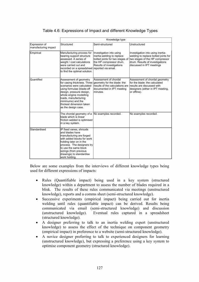
127
Table 4.6: Expressions of Impact and different Knowledge Types
Knowledge type
Expression ofmanufacturing impact
Structured Semi-structured Unstructured
Empirical Manufacturing process forbearing support structureassessed. A series ofweight / cost calculationswere carried out andrecorded on a spreadsheetto find the optimal solution.
Investigation into usinginertia-welding to replacebolted joints for two stages ofthe HP compressor drum.Results of investigationsreported via email.
Investigation into using inertia-welding to replace bolted joints fortwo stages of the HP compressordrum. Results of investigationsdiscussed in IPT meetings
Quantified Assessment of geometryfor casing thickness. Threescenarios were calculatedusing formulae (blade-offdesign, pressure design,whole engine modellingloads, manufacturingminimums) and thethickest dimension takenas the design case.
Assessment of chordalgeometry for the blade: theresults of the calculations aredocumented in IPT meetingminutes.
Assessment of chordal geometryfor the blade: the calculatedresults are discussed withdesigners (either in IPT meeting,or offline).
The chordal geometry of ablade which is linearfriction welded is optimisedin a key system.
No examples recorded. No examples recorded.
Standardised IP fixed vanes, shroudsand blades havemanufacturing are forgedwith added blocks for workholding later on in theprocess. The designers tryto use the same blocksizings (from previousdrawings) to standardisework holding.
Below are some examples from the interviews of different knowledge types beingused for different expressions of impacts:
Rules (Quantifiable impact) being used in a key system (structuredknowledge) within a department to assess the number of blades required in ablisk. The results of these rules communicated via meetings (unstructuredknowledge), reports and a comms sheet (semi-structured knowledge).
Successive experiments (empirical impact) being carried out for inertiawelding until rules (quantifiable impact) can be derived. Results beingcommunicated via email (semi-structured knowledge) and discussion(unstructured knowledge). Eventual rules captured in a spreadsheet(structured knowledge).
A designer preferring to talk to an inertia welding expert (unstructuredknowledge) to assess the effect of the technique on component geometry(empirical impact) in preference to a website (semi-structured knowledge).
A novice designer preferring to talk to experienced designers for learning(unstructured knowledge), but expressing a preference using a key system tooptimise component geometry (structured knowledge).
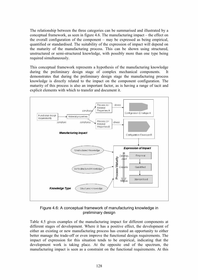
128
The relationship between the three categories can be summarised and illustrated by aconceptual framework, as seen in figure 4.6. The manufacturing impact – the effect onthe overall configuration of the component – may be expressed as being empirical,quantified or standardised. The suitability of the expression of impact will depend onthe maturity of the manufacturing process. This can be shown using structured,unstructured or semi-structured knowledge, with possibly more than one type beingrequired simultaneously.
This conceptual framework represents a hypothesis of the manufacturing knowledgeduring the preliminary design stage of complex mechanical components. Itdemonstrates that during the preliminary design stage the manufacturing processknowledge is directly related to the impact on the component configuration. Thematurity of this process is also an important factor, as is having a range of tacit andexplicit elements with which to transfer and document it.
Figure 4.6: A conceptual framework of manufacturing knowledge inpreliminary design
Table 4.5 gives examples of the manufacturing impact for different components atdifferent stages of development. Where it has a positive effect, the development ofeither an existing or new manufacturing process has created an opportunity to eitherbetter manage the trade-off or even improve the functional design requirements. Theimpact of expression for this situation tends to be empirical, indicating that thedevelopment work is taking place. At the opposite end of the spectrum, themanufacturing impact is seen as a constraint on the functional requirements. At this
129
point the expression tends to be quantified or standardised, indicating a maturemanufacturing process. There may be little incentive to develop the manufacturingprocess in this case. This may because there would be little benefit in the cost ofmanufacture to do so, alternatively it could mean that the component is beingproduced to the desired process capability. It can therefore be seen that a new productwill be composed of a series of components at different stages of development. Somecomponents may be undergoing development and hence be changing theirconfiguration envelope. Others may be legacy components which are re-used insuccessive engine projects. These are in line with Pahl and Beitz’ categories ofadaptive and variant design respectively (Pahl and Beitz, 1988).
The extent to which a new product is composed of components under developmentand legacy components must therefore be considered when assessing risk for newproduct introduction. Although out of scope of this study, it is noted that theorganisation has strategies to deal with this situation. It tends to be governed byproject budget and lead time. Consequently some initial risk mitigation takes place asthe project commences, with contingency funding and time built into the project plan.
The components undergoing development work regarding manufacturing processesstand out as a case worthy of further exploration. The way in which the manufacturingprocess knowledge (and its maturity) needs to be compiled is of particular interest andimportant in mitigating the risk.
4.6.5 Effect on product sub system
As discussed in section 3, the scope of this study is concerned with the impact of aninnovative manufacturing process at component level. However, it is important toacknowledge change propagation: that the change may have an impact on othercomponents both within the immediate assembly and sub systems (Eckhert et al.,2004; Flanagan et al., 2003).
The change in component configuration in this study is due to change caused by adevelopment in the manufacturing technology. Eckhert et al (2004) categorise thischange as an innovation, which is a type of initiated change because such changesarise as a consequence of customer requirements, which are either known at the startof a design project or during the design process.
Figure 4.7 illustrates the effect of a change in the configuration envelope due to themanufacturing impact. Here, two components X and Y are shown which are part ofthe same sub-system and have the same functional requirements. Component X hashad a change to the configuration envelope as a consequence of developing themanufacturing process. Component Y is a legacy component with no changes. Thechanges to the configuration envelope for component X affect the sub system in twoways. Firstly, there is a change in the functional requirements. This may affect theconfiguration envelope for component Y. Secondly, the configuration change itselfimpacts on component Y. Consequently, although component Y had been a legacy

130
component, there may be a possibility of further developments to this componentwhich would need to be assessed.
Figure 4.7: Effect of the manufacturing impact on sub system
For the purpose of this work, it is assumed that the change to the configurationenvelope as a consequence of the manufacturing impact is managed throughsubsequent analysis work. Therefore the risk is concerned with the readiness of themanufacturing technology.
4.7 Summary
An exploratory study was undertaken into the nature of manufacturing knowledge forpreliminary design. The objective of the study was to address the research gapsidentified in the literature by seeking a better understanding of the impact ofmanufacturing on the preliminary design stage and how this can determine therequirements for manufacturing knowledge at this stage.
A series of semi-structured interviews were carried out with design and manufacturingspecialists concerned with the preliminary stage of the design process to collect datafor analysis. The analysis was data-driven, seeking to identify a number of key themesfrom the data. Grounded theory coding techniques were used to define three maincategories, each of which could be described in more detail by three sub-categories.
Three main categories emerged from the data: the manufacturing impact whichdescribes how the method of manufacture ultimately impacts on the configuration ofthe component; the expression of impact, which describes the knowledge about theconfiguration boundaries as being derived empirically, quantified or standardised andfinally the knowledge types which can be used to communicate the expression ofimpact. These three categories can be related together as a conceptual frameworkwhich forms a hypothesis for the requirements for manufacturing knowledge duringpreliminary design.
131
In addition the analysis uncovered the following key findings:-
1. The impact of manufacturing is represented by its impact on the configurationenvelope during preliminary design; at later stages of the design process thereasons for those impacts are detailed and considered.
2. It is important for manufacturing processes in development to be consideredduring the preliminary design process, because this can change theconfiguration envelope in such a way to have a positive effect on what can beachieved in terms of the functional design requirements.
3. The expressions of impact used to describe the manufacturing impact varyaccording to the maturity of the manufacturing process being considered.Consequently the empirical impact of expression is useful when considering amanufacturing process under development.
By constructing the conceptual framework, manufacturing knowledge for preliminarydesign was identified, together with mechanisms for sharing it. However, the conceptframework was an abstract view of the requirements which required further detailedinvestigation. As the maturity of the manufacturing process had also emerged as a keyarea of interest, further investigation was again required to explore this observation inmore detail. A further investigation into acquiring detailed innovative manufacturingknowledge would also enable a validation of the conceptual framework.

132

133
Chapter 5
Investigation into Manufacturing Knowledge forBlisks: a Detailed Study
5.1 Introduction
The first data collection activity (chapter 4) investigated the nature of manufacturingknowledge used in preliminary design for complex mechanical components. Theoutput of this activity was a conceptual framework which gave an abstract view of theknowledge requirements and also the types of knowledge which should be used todepict them. Combinations of knowledge types were required depending on thematurity of the manufacturing process being investigated. This activity identified themanufacturing knowledge requirements for preliminary design.
The decision was taken to undertake a second, more detailed study to follow on fromthe first data collection. The objective of this study was to develop a more detailedunderstanding of the manufacturing knowledge requirements and how they wereacquired and shared within the preliminary design process. This was with a view tothe future development of a systematic methodology. The decision was taken to focuson a narrow case where the requirements could be investigated extensively. A suitablesubject for this activity would highlight and further develop the main findings fromthe first study. It would be a complex mechanical component with more than onemethod of manufacture, with at least one of these methods being in development.
This second study also developed the themes which emerged from the previous study,focussing on identifying examples of manufacturing impacts, expressions of impactand knowledge types. Having identified examples of these at a general level in thefirst activity, examples of each could be explored in more depth to see how theyapplied to the situations which would be encountered during the preliminary designprocess. Consequently this detailed data collection activity would also be an initialvalidation of the conceptual framework.
This chapter discusses this second data collection activity which addresses researchobjective 2 and begins to address research objective 3. There were two parts to thisdata collection. The first was a ‘requirements capture’ exercise in which themanufacturing knowledge requirements relating to a specific component wereidentified and collated from various sources within the organisation. This exerciseidentified three things: the technical knowledge required, the rationale for thattechnical knowledge and knowledge sharing issues which arose from theidentification of the knowledge. The manufacturing knowledge collected was alsoanalysed according the code developed in chapter 4. The second part of the activityconcentrated how this knowledge had been acquired by identifying the knowledge
134
flow and rationale during the data collection, resulting in a study of the interactionbetween different specialist domains.
This activity took place over a period of six months. The first three months wereconcerned with gathering and verifying the knowledge requirements collated and thesecond three months with analysing and organising the knowledge requirements.
5.2 The Requirements Capture Exercise
5.2.1 Component selection
The objective of the requirements capture exercise was to investigate a specificcomponent in detail and its manufacturing impacts, thus continuing to develop thenotable findings from the first data collection. A suitable component would thereforemeet the following criteria:-
1. The component would be an important consideration during the preliminarydesign process.
2. The component would have more than one method of manufacture in order tomake a comparison (and therefore have more than one potential configurationenvelope).
3. At least one method of manufacture would be a new method in development(therefore expressions of impact would vary).
Such a component could therefore be considered as a purposeful sample because itwould be deliberately selected to exhibit these criteria.
The component selected from the collaborating company for investigation was theblisk, a component specific to the design of gas turbine engines. This component hadbeen highlighted during the first data collection as being of particular importanceduring preliminary design. The name is derived as a shortened term for a ‘bladeddisk’. The conventional compressor assembly is a disk into which a number of bladesare manually slotted during assembly. Both the disk and blades have a series ofcomplex assembly features to enable this manual assembly to take place. These addweight at the core of the disc which affects the rotational speed of the compressor, itsoperating temperature and consequently the performance of the engine. The methodsof manufacture involved in the conventional compressor assembly are primarilyforging for the disk and a proprietary casting process for the blades.
A considerable performance improvement can be gained by treating the disc / bladeassembly as a single component – the blisk. This results in a weight saving at the coreas the assembly features are no longer required. An illustration of a blisk is shown infigure 5.1.
For small diameter blisks, the component can be machined from solid (MFS).However, as the diameter increases the economic viability of this solution decreases.
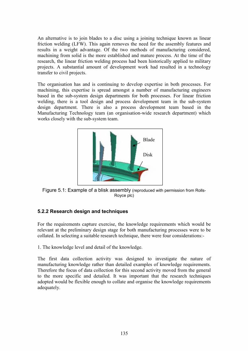
135
An alternative is to join blades to a disc using a joining technique known as linearfriction welding (LFW). This again removes the need for the assembly features andresults in a weight advantage. Of the two methods of manufacturing considered,machining from solid is the more established and mature process. At the time of theresearch, the linear friction welding process had been historically applied to militaryprojects. A substantial amount of development work had resulted in a technologytransfer to civil projects.
The organisation has and is continuing to develop expertise in both processes. Formachining, this expertise is spread amongst a number of manufacturing engineersbased in the sub-system design departments for both processes. For linear frictionwelding, there is a tool design and process development team in the sub-systemdesign department. There is also a process development team based in theManufacturing Technology team (an organisation-wide research department) whichworks closely with the sub-system team.
Figure 5.1: Example of a blisk assembly (reproduced with permission from Rolls-Royce plc)
5.2.2 Research design and techniques
For the requirements capture exercise, the knowledge requirements which would berelevant at the preliminary design stage for both manufacturing processes were to becollated. In selecting a suitable research technique, there were four considerations:-
1. The knowledge level and detail of the knowledge.
The first data collection activity was designed to investigate the nature ofmanufacturing knowledge rather than detailed examples of knowledge requirements.Therefore the focus of data collection for this second activity moved from the generalto the more specific and detailed. It was important that the research techniquesadopted would be flexible enough to collate and organise the knowledge requirementsadequately.
Blade
Disk
136
2. Sources of knowledge and the identification of these.
A relatively small number of people within the organisation were involved in thedesign and manufacturing assessment of this component. It was important to ensurethat they were correctly identified and able to contribute to the requirements captureactivity. Further exploration of the job roles associated with the component andprocess were therefore required to identify suitable sources (people and documents) ofthe knowledge.
3. The author’s own experience of the component and processes.
For the first data collection the author was able to draw on their own generalknowledge of design and manufacturing engineering within an aerospace context.This second activity involved the collection of specialist process and componentknowledge which was outside the scope of the author’s own knowledge. This wouldtherefore again require an exploratory approach, however validation from the processexperts would be of high importance to verify the requirements captured.
4. Other knowledge perspectives which may be required.
The research technique selected would also need to be flexible in order to capture anyother perspectives of the requirements capture, such as the knowledge rationale or anynotable experiences in knowledge sharing.
The technique selected for the data collection was again face-to-face interviews withdesign and manufacturing engineers within the organisation. However, for thisactivity the approach adopted was more unstructured than the first set of interviewswith a flexible set of topics for discussion. Each interview was initially arrangedaround the topic of blisk design and manufacture requirements, with a view tocreating a manufacturing advisory system. The actual topics discussed were thentailored to the specific interviewee, often being generated by the intervieweethemselves. This flexibility was deliberately used to enable the capture of both thetechnical requirements and also the rationale and additional knowledge sharingrequirements from the point of view of each interviewee. Informal notes were takenfor each interview. An overview of the topics discussed for each interview is shown insection 5.2.4.
The activity was designed to achieve research validity and reduce bias in thefollowing ways:-
1. By peer feedback. Following each initial discussion a follow-up session took placewith each individual interviewee to check the author’s understanding and accuracy ofthe data collected.
2. By data triangulation. Two methods of data triangulation were employed in thisactivity. The first was by collecting the data from a number of different sources withinthe organisation. For the linear friction welding process, an additional documentsource was used to compare the data collected in the interviews with that recorded.
137
This was an internal technical report, published in 2001, which documented eachstage of the linear friction welding process in detail.
5.2.3 Identification of knowledge sources
A comprehensive view of the manufacturing knowledge requirements needed toassess the blisk during preliminary design was required. From discussions about theinformal and formal social networking for knowledge sharing identified during thefirst set of interviews, it was recognised that this knowledge often existed outside thepreliminary design department and was sourced by them during the design process.Consequently it was important to identify these main sources, where they were placedwithin the organisation and their role in the design process. This was achieved byapplying the informal social network. Potential candidates were identified fromdiscussions with the interviewees from the first set of interviews and departmentcolleagues. Two of the candidates had been interviewed during the first datacollection activity and they were able to identify other relevant people, usually peoplewith whom they had worked or consulted on current and previous engine projects.These were design or manufacturing engineers from the sub-system design teams, orspecialist manufacturing technologists who would be involved in the manufacturingprocess assessment. A total of four main contacts and two additional contacts wereestablished. Each contact was concerned with a particular aspect of the componentand process assessment and became involved at varying stages of the design process.Each of these contacts is therefore considered to have a specific domain of knowledgeand be a specialist in that domain. The contacts are summarised in table 5.1. Theactual names and details of the interviewees have remained anonymous in order toavoid identification, however they are placed according to their particular domainspecialism. As with the first data collection activity, the interviewee’s details were notconsidered to be significant because the focus was on identifying the manufacturingknowledge itself.
5.2.4 Running the data collection activity
There were two interviews with each domain – one to gather knowledge and thesecond as a follow-up to verify the knowledge collected. Each discussion took aroundone and a half hours. Notes were recorded by the interviewer and written upafterwards. Below is a summary of each first, main interview and the discussiontopics which featured.
1. Interviewees: 4 (Manufacturing technologist for LFW), 5 (Tool designer for LFW)and 6 (Manufacturing Engineer for LFW).This took place as a group discussion rather than individual interviews. The mainconsideration for the meeting was the development of a manufacturing advisorysystem and the LFW manufacturing knowledge which would be required for this:identification of manufacturing concerns, parameters, dimensions and constraintswhich would be required for an initial manufacturing assessment. These were thencompared to the tool design report.
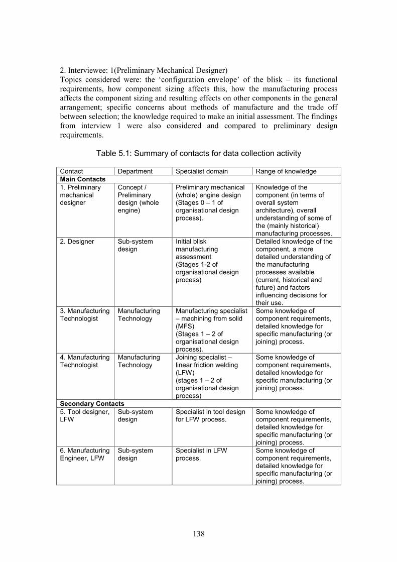
138
2. Interviewee: 1(Preliminary Mechanical Designer)Topics considered were: the ‘configuration envelope’ of the blisk – its functionalrequirements, how component sizing affects this, how the manufacturing processaffects the component sizing and resulting effects on other components in the generalarrangement; specific concerns about methods of manufacture and the trade offbetween selection; the knowledge required to make an initial assessment. The findingsfrom interview 1 were also considered and compared to preliminary designrequirements.
Table 5.1: Summary of contacts for data collection activity
Contact Department Specialist domain Range of knowledgeMain Contacts1. Preliminarymechanicaldesigner
Concept /Preliminarydesign (wholeengine)
Preliminary mechanical(whole) engine design(Stages 0 – 1 oforganisational designprocess).
Knowledge of thecomponent (in terms ofoverall systemarchitecture), overallunderstanding of some ofthe (mainly historical)manufacturing processes.
2. Designer Sub-systemdesign
Initial bliskmanufacturingassessment(Stages 1-2 oforganisational designprocess)
Detailed knowledge of thecomponent, a moredetailed understanding ofthe manufacturingprocesses available(current, historical andfuture) and factorsinfluencing decisions fortheir use.
3. ManufacturingTechnologist
ManufacturingTechnology
Manufacturing specialist– machining from solid(MFS)(Stages 1 – 2 oforganisational designprocess).
Some knowledge ofcomponent requirements,detailed knowledge forspecific manufacturing (orjoining) process.
4. ManufacturingTechnologist
ManufacturingTechnology
Joining specialist –linear friction welding(LFW)(stages 1 – 2 oforganisational designprocess)
Some knowledge ofcomponent requirements,detailed knowledge forspecific manufacturing (orjoining) process.
Secondary Contacts5. Tool designer,LFW
Sub-systemdesign
Specialist in tool designfor LFW process.
Some knowledge ofcomponent requirements,detailed knowledge forspecific manufacturing (orjoining) process.
6. ManufacturingEngineer, LFW
Sub-systemdesign
Specialist in LFWprocess.
Some knowledge ofcomponent requirements,detailed knowledge forspecific manufacturing (orjoining) process.

139
3. Interviewee: 2 (Designer)The topics discussed were the design issues with the blisk component and theresulting effects on manufacturing; manufacturing considerations for the blisk anddifferent method of manufacture options. There were also some discussions about thedesign process, the type of assessment work being carried out during the process andrecent changes and initiatives which had been put into place to improve this.
4. Interviewee: 4. (Manufacturing Technologist, MFS)The main topic discussed was the important manufacturing knowledge relating toMFS and cost models which had been created based on that knowledge.
5.2.5 Data analysis
Initially, the knowledge requirements were extracted from the interview notes andlisted for each interview for comparison. These were then verified during the secondfollow-up discussion.
The requirements for each interview were analysed and categorised according to thetype of manufacturing impact and expression of impact as derived in chapter 4. Thepotential knowledge types used in each case were also considered. This initial analysisled to some conclusions about the knowledge requirements and their rationale. Theresults are presented in section 5.3 and discussed in section 5.4.
5.3 Results
A summary of the manufacturing knowledge requirements is shown in table 5.2 and iscategorised according to manufacturing impact, expression of impact and knowledgetypes. The requirements recorded for each domain are also shown separately.
5.4 Key Observations
Three key observations emerged from the results. These were the differences betweenthe different domains, the categorisation of the knowledge according to the developedcode and the resulting apparent existence of a gap in the design process. These arediscussed in turn.
5.4.1 Differences in knowledge requirements between domains
Although the initial aim of the interviews had been to consider knowledge for amanufacturing advisory system, it became clear during the review of the interviewsthat there were differences in the manufacturing requirements from the perspective ofeach domain. Consequently the focus was not on knowledge identification as such,
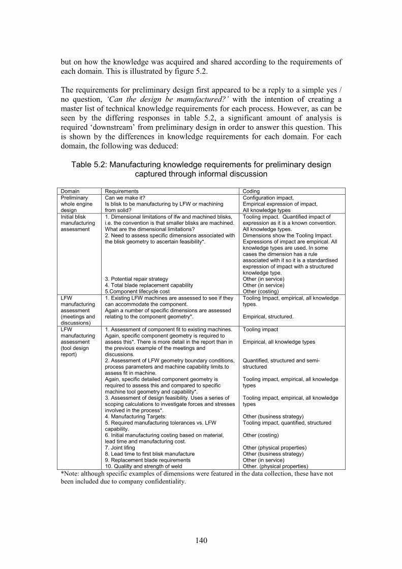
140
but on how the knowledge was acquired and shared according to the requirements ofeach domain. This is illustrated by figure 5.2.
The requirements for preliminary design first appeared to be a reply to a simple yes /no question, ‘Can the design be manufactured?’ with the intention of creating amaster list of technical knowledge requirements for each process. However, as can beseen by the differing responses in table 5.2, a significant amount of analysis isrequired ‘downstream’ from preliminary design in order to answer this question. Thisis shown by the differences in knowledge requirements for each domain. For eachdomain, the following was deduced:
Table 5.2: Manufacturing knowledge requirements for preliminary designcaptured through informal discussion
Domain Requirements CodingPreliminarywhole enginedesign
Can we make it?Is blisk to be manufacturing by LFW or machiningfrom solid?
Configuration impact,Empirical expression of impact,All knowledge types
Initial bliskmanufacturingassessment
1. Dimensional limitations of lfw and machined blisks,i.e. the convention is that smaller blisks are machined.What are the dimensional limitations?2. Need to assess specific dimensions associated withthe blisk geometry to ascertain feasibility*.
3. Potential repair strategy4. Total blade replacement capability5.Component lifecycle cost
Tooling impact. Quantified impact ofexpression as it is a known convention.All knowledge types.Dimensions show the Tooling Impact.Expressions of impact are empirical. Allknowledge types are used. In somecases the dimension has a ruleassociated with it so it is a standardisedexpression of impact with a structuredknowledge type.Other (in service)Other (in service)Other (costing)
LFWmanufacturingassessment(meetings anddiscussions)
1. Existing LFW machines are assessed to see if theycan accommodate the component.Again a number of specific dimensions are assessedrelating to the component geometry*.
Tooling Impact, empirical, all knowledgetypes.
Empirical, structured.
LFWmanufacturingassessment(tool designreport)
1. Assessment of component fit to existing machines.Again, specific component geometry is required toassess this*. There is more detail in the report than inthe previous example of the meetings anddiscussions.2. Assessment of LFW geometry boundary conditions,process parameters and machine capability limits.toassess fit in machine.Again, specific detailed component geometry isrequired to assess this and compared to specificmachine tool geometry and capability*.3. Assessment of design feasibility. Uses a series ofscoping calculations to investigate forces and stressesinvolved in the process*.4. Manufacturing Targets:5. Required manufacturing tolerances vs. LFWcapability.6. Initial manufacturing costing based on material,lead time and manufacturing cost.7. Joint lifing8. Lead time to first blisk manufacture9. Replacement blade requirements10. Qualilty and strength of weld
Tooling impact
Empirical, all knowledge types
Quantified, structured and semi-structured
Tooling impact, empirical, all knowledgetypes
Tooling impact, empirical, all knowledgetypes
Other (business strategy)Tooling impact, quantified, structured
Other (costing)
Other (physical properties)Other (business strategy)Other (in service)Other. (physical properties)
*Note: although specific examples of dimensions were featured in the data collection, these have notbeen included due to company confidentiality.
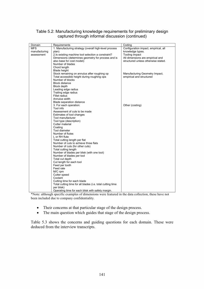
141
Table 5.2: Manufacturing knowledge requirements for preliminary designcaptured through informal discussion (continued)
Domain Requirements CodingMFSmanufacturingassessment
1. Manufacturing strategy (overall high-level processplan)2.Is existing machine tool selection a constraint?Dimensions (determines geometry for process and isalso base for cost model):Number of bladesChord lengthBlade heightStock remaining on annulus after roughing opTotal accessible height during roughing opsNumber of blocksBlock distanceBlock depthLeading edge radiusTrailing edge radiusFillet radiusAnnulus widthBlade separation distance3. For each operation:Tool infoAssessment of cuts to be madeEstimates of tool changesTool manufacturerTool type (description)Cutter materialCoatingTool diameterNumber of flutesL or RH fluteTotal cutting length per flatNumber of cuts to achieve three flatsNumber of cuts (for other cuts)Total cutting lengthNumber of blades per blisk (with one tool)Number of blades per toolTotal cut depthCut length for each toolFeed per toothFeed rateM/C rpmCutter speedCoolantCutting time for each bladeTotal cutting time for all blades (i.e. total cutting timeper blisk)Operating time for each blisk with safety margin.
Configuration impact, empirical, allknowledge types.Tooling impactAll dimensions are empirical andstructured unless otherwise stated.
Manufacturing Geometry Impact,empirical and structured
Other (costing)
*Note: although specific examples of dimensions were featured in the data collection, these have notbeen included due to company confidentiality.
Their concerns at that particular stage of the design process. The main question which guides that stage of the design process.
Table 5.3 shows the concerns and guiding questions for each domain. These werededuced from the interview transcripts.
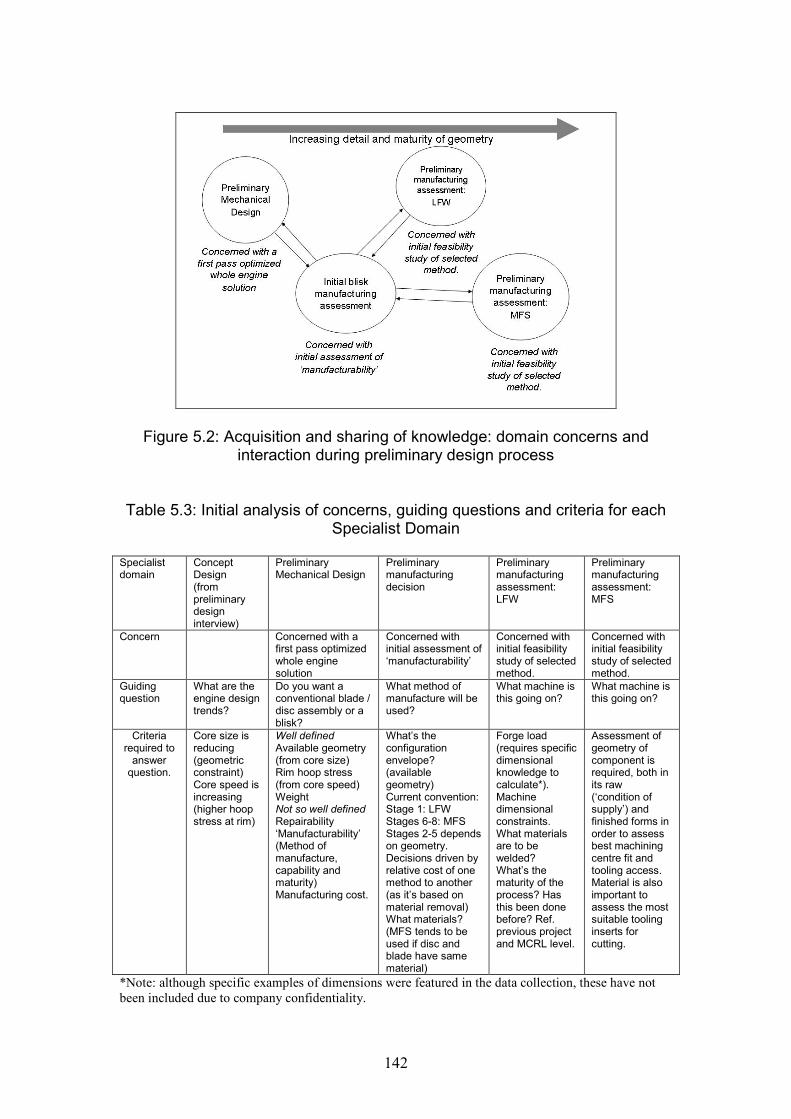
142
Figure 5.2: Acquisition and sharing of knowledge: domain concerns andinteraction during preliminary design process
Table 5.3: Initial analysis of concerns, guiding questions and criteria for eachSpecialist Domain
Specialistdomain
ConceptDesign(frompreliminarydesigninterview)
PreliminaryMechanical Design
Preliminarymanufacturingdecision
Preliminarymanufacturingassessment:LFW
Preliminarymanufacturingassessment:MFS
Concern Concerned with afirst pass optimizedwhole enginesolution
Concerned withinitial assessment of‘manufacturability’
Concerned withinitial feasibilitystudy of selectedmethod.
Concerned withinitial feasibilitystudy of selectedmethod.
Guidingquestion
What are theengine designtrends?
Do you want aconventional blade /disc assembly or ablisk?
What method ofmanufacture will beused?
What machine isthis going on?
What machine isthis going on?
Criteriarequired to
answerquestion.
Core size isreducing(geometricconstraint)Core speed isincreasing(higher hoopstress at rim)
Well definedAvailable geometry(from core size)Rim hoop stress(from core speed)WeightNot so well definedRepairability‘Manufacturability’(Method ofmanufacture,capability andmaturity)Manufacturing cost.
What’s theconfigurationenvelope?(availablegeometry)Current convention:Stage 1: LFWStages 6-8: MFSStages 2-5 dependson geometry.Decisions driven byrelative cost of onemethod to another(as it’s based onmaterial removal)What materials?(MFS tends to beused if disc andblade have samematerial)
Forge load(requires specificdimensionalknowledge tocalculate*).Machinedimensionalconstraints.What materialsare to bewelded?What’s thematurity of theprocess? Hasthis been donebefore? Ref.previous projectand MCRL level.
Assessment ofgeometry ofcomponent isrequired, both inits raw(‘condition ofsupply’) andfinished forms inorder to assessbest machiningcentre fit andtooling access.Material is alsoimportant toassess the mostsuitable toolinginserts forcutting.
*Note: although specific examples of dimensions were featured in the data collection, these have notbeen included due to company confidentiality.
143
The different requirements for each domain have been interpreted as examples ofdifferent ‘thought worlds’ (Dougherty, 1992). To determine the reasons for thesethought worlds would require additional investigation, however from the requirementscapture results, the following potential reasons are suggested: the design processitself; the various tasks within the design process which are required to assessmanufacturability; the knowledge and experience of individuals within each domain;the resulting incompatibility of maturity of geometry at each stage and the limitationsin dealing with changing design requirements. Each ‘thought world’ is illustrated bythe concerns and rationale of each domain in table 5.3. The interactions of thedomains are clearly of prime importance in knowledge sharing, as illustrated by theexistence of the process gap (see section 5.4.3) and the actions that were taken toresolve it.
5.4.2 Categorisation of knowledge according to the developed code
The increasing detail and analysis as the design progresses (see table 5.2) can beillustrated by categorising the manufacturing knowledge requirements according tomanufacturing impacts and impacts of expression, in line with the developed code.
During preliminary design, the designers are primarily interested in knowing thedefinition of the configuration envelope (configuration impact) for the availablemethods of manufacture (LFW and machining in this case). The definition of theconfiguration envelope takes place in further domains and is primarily illustrated inall further cases by a tooling impact. Hence, the main driver for the configurationenvelope for the blisk is the ability of the component to fit into a specific machinetool. However, a complete assessment of this requires far more assessment of thegeometry than is available during the preliminary design. In table 5.2, the majority ofthese dimensional assessments are termed as ‘empirical’ to reflect the iterative andongoing assessment of the component at this stage. However, the required knowledgeis termed as ‘structured’ because ultimately the knowledge (dimension) is required ina numerical form.
In some cases the tooling impact has been quantified. An example of this (referencetable 5.2) is with the assessment for LFW as outlined in the tool design report. In thiscase, some dimensional limitations on the available machines were quantified andshown in the tool design report as structured and semi-structured knowledge (numericwith supporting text).
As the manufacturing assessment became more detailed it appeared that more of thesemanufacturing impacts needed to be expressed in a quantitative way. Whenconsidering a process in development it may not be possible to quantify the impactsimmediately. However, this could be a useful guide to the main knowledge attributeswhich need to be repeatedly assessed. By identifying these impacts it may be possibleto increase awareness of the knowledge that needs to be known and quantified ‘in thefuture’, hence the design and manufacturing assessment teams could focus onidentifying and obtaining that knowledge for more effective knowledge sharing.
144
A further observation is the existence of other impacts on the configuration envelopethat are not strictly manufacturing-related but also need to be considered. These havebeen marked as ‘other’ in table 5.2, but mainly appear to address physical properties(such as stress and lifing requirements), cost implications and in service supportrequirements. Although out of scope of this particular study, they may be worthinvestigating at a later date.
5.4.3 Process Gap
The differences between the domain requirements indicate that a suitablemanufacturing feasibility analysis appears to depend on a state of design maturitygreater than that available as an output from the preliminary design stage. This wasexpressed by the need for quantified expressions of impact and structured knowledge.This can be illustrated by comparing the output at the end of stage 1 preliminarydesign (the 2D GA) with the inputs required at the beginning of stage 2 for linearfriction welding. The GA did not provide all the level of detail necessary for the initialmanufacturing assessment at the next stage. Consequently the additional detailrequired was initially assessed by scaling a previous design. This difference inrequirements therefore appears to create a ‘gap’ in manufacturing knowledge in theproduct introduction process.
Historically, the project would have progressed as expected and these manufacturingknowledge gaps would be addressed in the later detail design stage (beyond stage 2)of the process. However, in line with market competitors, the lead time for newengine development has been reduced to 24 months. This has created a need for evengreater concurrency between domain specialities. Therefore, in order to mitigate riskin the design solution, potential manufacturability problems need to be addressedearlier in the design process. It is suggested that this does not appear to be addressedby the current product introduction process, hence the process gap. Consequently theorganisation has created an additional new process step to bridge this gap through theinitial manufacturability assessment carried out by the sub-system team. This is a newinformal process step created specifically for a new engine project. The need for suchactivities is greatest for risk mitigation for components in the engine architecture withnew configurations, new materials and / or new manufacturing processes. Perhapsknowledge sharing could be improved by considering the manufacturing knowledgerequirements necessary to address this process gap.
5.5 Study of Domain Interaction
The requirements capture activity for the blisk component revealed a gap in the designprocess during the preliminary design stage. It has been suggested that the reason forthis was the reduction in the lead time for new engine projects driving the need for thedesign process to evolve. Consequently the knowledge sharing requirement hadevolved but had not been formally reflected in the design process. The presence of theprocess gap had highlighted the different ‘thought worlds’ quite significantly. Byexamining the rationale for each specialist domain, the requirements activity was ableto provide some explanation for the different ‘thought worlds’. However, for an

145
engineer working within a specific domain, the rationale for other domains whichinteracted with theirs was not evident.
The study therefore needed to consider a method of identifying and acquiringmanufacturing knowledge for assessment during preliminary design in order that itcould be shared between the specialist domains effectively. The difference inspecialist domain knowledge requirements due to differing rationale would alwaysexist and would be required to compile and manage the manufacturing knowledge toassess a process for a component. Conversely, defining the manufacturing knowledgeaccording to a specific stage of the design process may not be effective because thiswould not allow for any changes if the design process needed to evolve.
The approach therefore adopted by this study is to utilise the different perspectives(‘thought worlds’) of the domain specialists to build the required knowledge. Ratherthan define knowledge prescriptively for different stages of the project, a moreflexible method would be to consider the interactions between the different domainsto specify the knowledge according to each specialist’s rationale. A way to knowledgeacquisition would be to map out a schematic diagram to show the knowledgerequirements for each domain and how they interact. Consequently the knowledgewould be better organised and have the following advantages:
1. It would provide a view of the overall knowledge requirements for initialmanufacturing assessment and its variations between specialist domains. This wouldbe available to all involved in the assessment and give an appreciation of how eachdomain – specific assessment influenced the final outcome of the assessment.2. As the knowledge flow would be shown between specialist domains rather thanspecific design process stages, the resulting knowledge schematic would not be tied tospecific stages of the process. This means that it would be independent of the designprocess and therefore more flexible and adaptable to any future process changes.3. By categorising the knowledge requirements as ‘configuration impacts’ and‘tooling impacts’ an assessment of the necessary detail to define the knowledge couldbe included.
The data collected for the requirements capture was therefore analysed as a study ofdomain interaction as a first step to investigating more effective methods of sharingknowledge.
The starting point was the guiding questions as shown in table 5.3. However, it wasclear that a number of questions (sub-questions) were required in order to obtain theanswers to the overall guiding question for each domain. By doing this, the list ofknowledge obtained from the study of the blisks was formatted into a list of questionswhich could be specifically asked for the component and process. For each question, anumber of sub-questions were deduced, the answers to which would provide theanswer to the overall question. Each sub-question was then sub-divided further intomore levels of detail to provide the answers where necessary. In doing this, thepurpose of the framework of questions was to create a set of repeatable questionswhich could be used for the blisk component to provide an initial manufacturingassessment in preliminary design. This would create a repeatable method of compiling
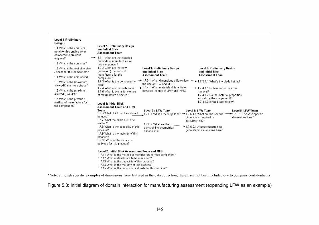
146
*Note: although specific examples of dimensions were featured in the data collection, these have not been included due to company confidentiality.
Figure 5.3: Initial diagram of domain interaction for manufacturing assessment (expanding LFW as an example)

147
*Note: although specific examples of dimensions were featured in the data collection, these have not been included due to company confidentiality.
Figure 5.4: Diagram of domain interaction following feedback
148
the knowledge and a method to solve the difference in requirements and knowledgematurity at preliminary and detail design. These questions were then represented as adiagram flowing from left to right. The initial findings are shown in figure 5.3.
This initial version was then fed back to and iteratively discussed with each of thedomain specialists to verify that the knowledge recorded was complete and correctand to make changes where necessary. A main finding was that the ‘levels’ at couldbe applied to particular strategy levels: business drivers, whole engine strategy,component strategy, manufacturing process (decision) strategy and sub-processstrategy. A further level of parameters and constraints was introduced wherenumerical answers to the questions could be specified. The final version of domaininteraction after iterative feedback is shown in figure 5.3. Here, the manufacturingimpact categories have been superimposed on top of the diagram by the author for thebenefit of assessing the knowledge requirements.
For the specific component and manufacturing processes investigated, the diagram isa useful method of illustrating the level of detail required to answer what may beinitially perceived as a simple question. For sub-questions where the answers can bederived as numerical constraints (such as machine tool selection for linear frictionwelding) there can be up to five sub-levels of questions. For answers where thecriteria is more qualitative and perhaps more uncertain, there are fewer levels of sub-questions.
5.6 Summary
The starting point for the work in this chapter was the results of the first datacollection. As the conceptual framework developed was abstract, further investigationwas carried out into the blisk, a component specifically selected as a component ofparticular importance during preliminary design because it affected the sizing andperformance of the engine. The manufacturing processes for the blisk also affected thecomponent configuration envelope, especially as one of the processes, linear frictionwelding, was in development. Consequently the case exhibited criteria which hadbeen highlighted as of interest in chapter 4. The activity also presented theopportunity to carry out an initial validation on the hypothesis of knowledgerequirements which had resulted from the first data collection activity.
The analysis of the second data collection demonstrated that far from being astraightforward activity, the acquisition of manufacturing knowledge requirementscan vary due to differences in specialist domains and the knowledge required therein,identified as different ‘thought worlds’. For the particular case explored in this thesis,i.e. innovative manufacturing knowledge, this creates an element of risk in assessingmanufacturing feasibility during preliminary design. A further contributing factor tothis risk is the difference in the maturity of the design geometry between thepreliminary and detail stages of the processes. The external influence of the reductionof the time to market had led to a ‘gap’ in the existing design process where moremanufacturing assessment was required earlier in the process in order to address the

149
risk of introducing new methods of manufacturing. This gap had been informallyaddressed by the introduction of a new manufacturing feasibility assessment team,however it was concluded that the design process had not sufficiently evolved to caterfor this change in the time to market.
The knowledge identified could be expressed using the coding developed in the firstdata collection activity. It was expressed as a configuration impact at the morestrategic levels of the process, yet required additional quantified and therefore moredetailed knowledge (tooling impacts) as the design activity progressed. This was ademonstration of the hypothesis of knowledge requirements developed from the firstdata collection activity, showing that knowledge is expressed differently as it maturesand that different knowledge types were required to show this.
It became clear that manufacturing knowledge acquisition depended on interactionbetween different domain specialists to bridge any gaps in the design process whichmay evolve. A method to acquire knowledge for the particular component andmethods of manufacturing investigated was therefore considered. A study intointeractions between the different specialist domains gave an overall picture of thequestions which needed to be answered in order to supply the knowledge for eachdomain. This could be used flexibly rather than tying the identification of knowledgeto specific stages of the design process.
This activity demonstrated that a collation activity of technical knowledge isinsufficient for successful knowledge management. Successful knowledgemanagement instead depends on being able to identify and acquire the content andlevel of knowledge which can be commonly shared between specialist domains inorder to carry out an initial manufacturing assessment during preliminary design andhence mitigate the risk during this stage. Having explored this for a specificcomponent and manufacturing processes, the next stage of the study will be todevelop this work into a practical methodology to be used for effective knowledgesharing. This will be developed primarily for components of particular importance topreliminary design which use manufacturing processes in development and will beexplored in chapter 6.

150
151
Chapter 6
Development of a Methodology for EffectiveKnowledge Sharing
6.1 Introduction
The two data collection activities outlined in chapters 4 and 5 provided a detailedinvestigation of the nature of manufacturing knowledge required during thepreliminary design process. The first data collection produced an abstract conceptualframework identifying the manufacturing knowledge required, highlighting theimportance of considering the maturity of the manufacturing process and the need touse both explicit and tacit components of knowledge for innovative manufacturingprocesses under development. The second data collection explored these findingsfurther, considering the acquisition of manufacturing knowledge for a specificcomponent with an innovative manufacturing process. These findings highlighted theneed to combine the views of a number of specialist domains to effectively identifyand share the knowledge content requirements. As an output of the analysis, adiagram of domain interactions was created to provide a means of sharing theknowledge more effectively between these different domains.
This chapter consolidates the findings of the two data collection activities andinvestigates how they can be used for effective knowledge sharing, thus addressingresearch objective 3. A systematic methodology is created for use at an operationallevel by designers and manufacturing engineers to identify, acquire and sharemanufacturing knowledge requirements during the preliminary stage of the designprocess. The rationale for the methodology is discussed, followed by an assessment ofthe methodology requirements and a discussion of its components. This is thenfollowed by a description and example screenshots of the pilot methodology to beused in a validation study.
6.2 Rationale for a Methodology
The first step for this part of the study was to consider the findings from the two datacollection activities. For the first data collection activity, the manufacturingknowledge requirements were analysed and categorised as manufacturing impacts (theeffect on the configuration of a component) at varying levels of detail depending onwhether they were being assessed during preliminary design (size and shape only) orat more detailed levels (in terms of tooling and manufacturing geometry impacts).These impacts were expressed in terms of how the knowledge was derived, fromempirical (new process development) to standardised (repeatable process capability).These expressions were on a scale depending on the maturity of the process and a

152
range of knowledge types on the explicit-taciet scale were needed to support them.Manufacturing processes in development also emerged as a key finding because theyopened up new opportunities in terms of design capability, yet they were also riskybecause, being in development, the knowledge was less ‘known’.
Consequently the manufacturing knowledge of such a component was explored indetail for the second data collection activity. In this case, it was found that theknowledge requirements were a compilation of requirements from several specialistdomains. Each domain had its own concerns and knowledge perspectives whichguided its knowledge requirements. The knowledge requirements become moredetailed (with an increasing need for more quantifiable knowledge) throughinteractions with domains from the later stages of the design process, however theresults of these assessments need to be presented back at a more abstract level withinthe manufacturing assessment activity during preliminary design. This domaininteraction was especially important in the specific case investigated (the blisk) inorder to adapt to the demands of a reduced project lead time. This showed that moredetailed analysis was initially needed during preliminary design in order to reduce therisk (i.e. make the knowledge more mature and ‘known’). A pragmatic approach wasadopted for more effective domain interaction. Following from the example of thework by Hall and Andriani, and the research gap identified in chapter 2, some methodof operationalising the conceptual framework was considered to be a suitable wayforward (Hall and Andriani, 1998). Hence an operational methodology wasdeveloped.
6.3 The Methodology Requirements
The aim of the methodology is to enable the effective sharing of manufacturingknowledge during preliminary design by facilitating the interactions between thespecialist domains which are necessary for identifying and acquiring the knowledgerequirements and subsequent content. The methodology is aimed primarily atcomponents that have undergone some degree of configuration change betweensubsequent design projects and therefore carry an element of risk. It is designed togive an initial feasibility assessment during the preliminary design stage.
There are two intended outcomes to this work. The first is that such a methodologywill embody the findings identified during the data collection and analysis activitiesand consequently act as a means of testing the developed hypothesis. The second isthat the work results in a systematic operational methodology to be tested on a rangeof components and processes within the organisation studied.
The requirements of the methodology are as follows:-
1. The level of knowledge required is that which indicates how the processimpacts on the configuration envelope of the component. Each specialistdomain has their own preferred level for discussing the manufacturing
153
requirements. However, the methodology should collate these to reach adesired level of common understanding and usage.
2. The content of the knowledge (for the purpose of sharing) must include someassessment of process maturity in addition to process feasibility, capability andestimated cost.
3. Knowledge must be conveyed using a mix of explicit and tacit knowledgemethods.
Three components of the methodology were developed to fulfil these requirements:-
1. A generic domain interaction diagram to identify the relevant knowledgerequirements.2. A process maturity audit to assess the manufacturing processes.3. A workshop-based pilot process to be used for tacit and explicit knowledge sharing.
These components originated from the findings of the data collections. They, and themethods used to develop them will be discussed in the next section.
6.4 Methodology Components
6.4.1 Generic diagram of domain interactions
The generic diagram of domain interactions was designed to fulfil requirement 1. Itspurpose was to identify the knowledge content requirements required at theappropriate level for an initial manufacturing assessment, while accounting for thevariation in the content and level of knowledge according to each domain.
The foundation for the generic diagram was the diagram of domain interactionscreated from the blisk case study. However, being specific to that component andprocess, it required further development. The process for creating a generic diagramof domain interactions was similar to that used for the creation of the blisk-specificdiagram of domain interactions. Iterative modifications were made to the blisk-specific diagram which were then fed back to stakeholders for their review andcomments. These stakeholders were the same as for the second data collection, withtwo additional contacts. These contacts were consulted due to their business processknowledge and are summarised in table 6.1.
The first step was to modify the blisk domain interaction diagram into a list of genericquestions, which is shown in figure 6.1. This was used as an initial template ofquestions used in the pilot evaluation of the methodology and evaluation session 1(see sections 7.5 and 7.6). The subsequent feedback received suggested that thesequestions were still too tied to the linear friction welding and/or machining processes.A preceding step was required. The questions for identifying the knowledge variedaccording to the manufacturing process and would first need to be defined themselves.On closer examination of the generic questions, it appeared that all potentialmanufacturability issues fell into one of three categories – material properties, process
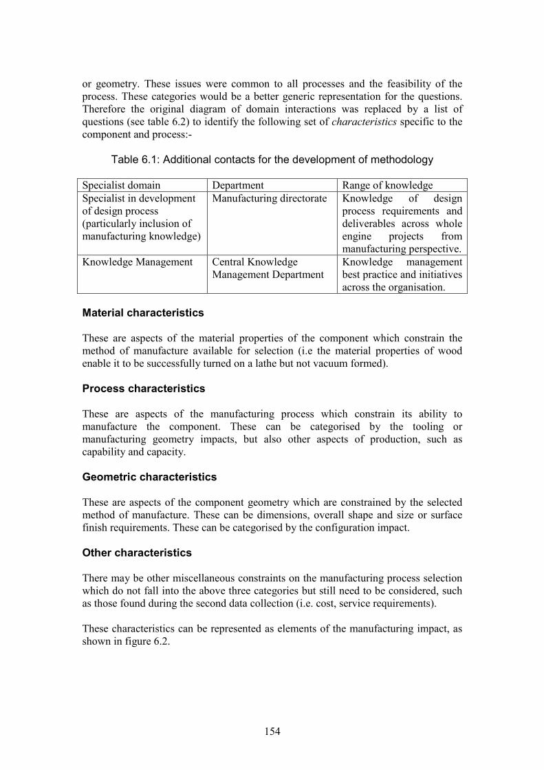
154
or geometry. These issues were common to all processes and the feasibility of theprocess. These categories would be a better generic representation for the questions.Therefore the original diagram of domain interactions was replaced by a list ofquestions (see table 6.2) to identify the following set of characteristics specific to thecomponent and process:-
Table 6.1: Additional contacts for the development of methodology
Specialist domain Department Range of knowledgeSpecialist in developmentof design process(particularly inclusion ofmanufacturing knowledge)
Manufacturing directorate Knowledge of designprocess requirements anddeliverables across wholeengine projects frommanufacturing perspective.
Knowledge Management Central KnowledgeManagement Department
Knowledge managementbest practice and initiativesacross the organisation.
Material characteristics
These are aspects of the material properties of the component which constrain themethod of manufacture available for selection (i.e the material properties of woodenable it to be successfully turned on a lathe but not vacuum formed).
Process characteristics
These are aspects of the manufacturing process which constrain its ability tomanufacture the component. These can be categorised by the tooling ormanufacturing geometry impacts, but also other aspects of production, such ascapability and capacity.
Geometric characteristics
These are aspects of the component geometry which are constrained by the selectedmethod of manufacture. These can be dimensions, overall shape and size or surfacefinish requirements. These can be categorised by the configuration impact.
Other characteristics
There may be other miscellaneous constraints on the manufacturing process selectionwhich do not fall into the above three categories but still need to be considered, suchas those found during the second data collection (i.e. cost, service requirements).
These characteristics can be represented as elements of the manufacturing impact, asshown in figure 6.2.
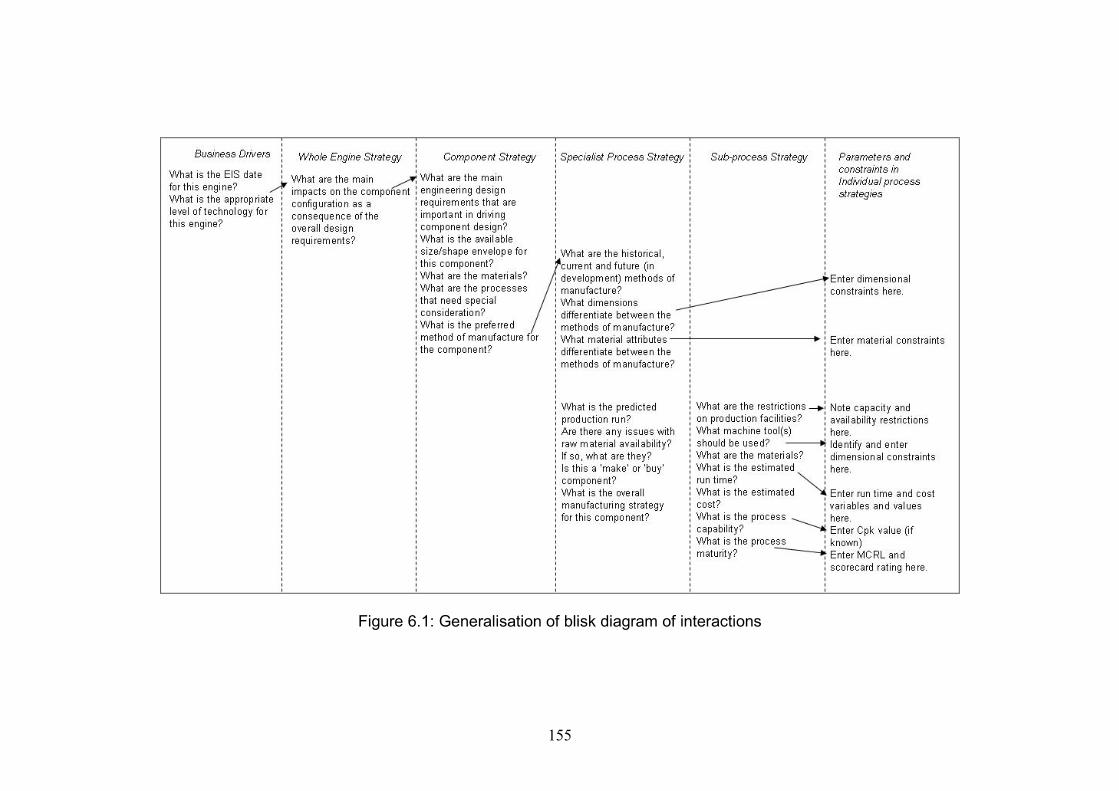
155
Figure 6.1: Generalisation of blisk diagram of interactions

156
Table 6.2: Generic questions for domain interaction
Comparing methods of manufacture / assembly:
What are the historical, current and future (in development) methods of manufacture / assembly to be considered andassessed in this workshop?What are the characteristics of the component / assembly that differentiate between methods of manufacture / assembly?What are the geometric characteristics?What are the material characteristics?Are there other characteristics? If so, record them at this point.What are the characteristics of the process which influence the selection of the method of manufacture / assembly?What is the predicted production run?Are there any issues with raw material availability? If so, what are they?
Knowledge about specific methods of manufacture / assembly:
What are the characteristics of the component / assembly which determine the machine to be used?What are the geometric characteristics?What are the material characteristics?Are there other characteristics? If so, record them at this point.What are the influencing characteristics of process selection?What are the restrictions on production facilities?What are the capacity restrictions?What are the availability restrictions?Are there other restrictions? If so, record them at this point.For run-time and cost estimation:What is the estimated lead time? (Enter run time variables here).What is the estimated cost? (Enter cost variables and values here).What is the process capability? (Enter Cpk value if known here).What is the process maturity? (refer to MCRL and process maturity audit here if known).
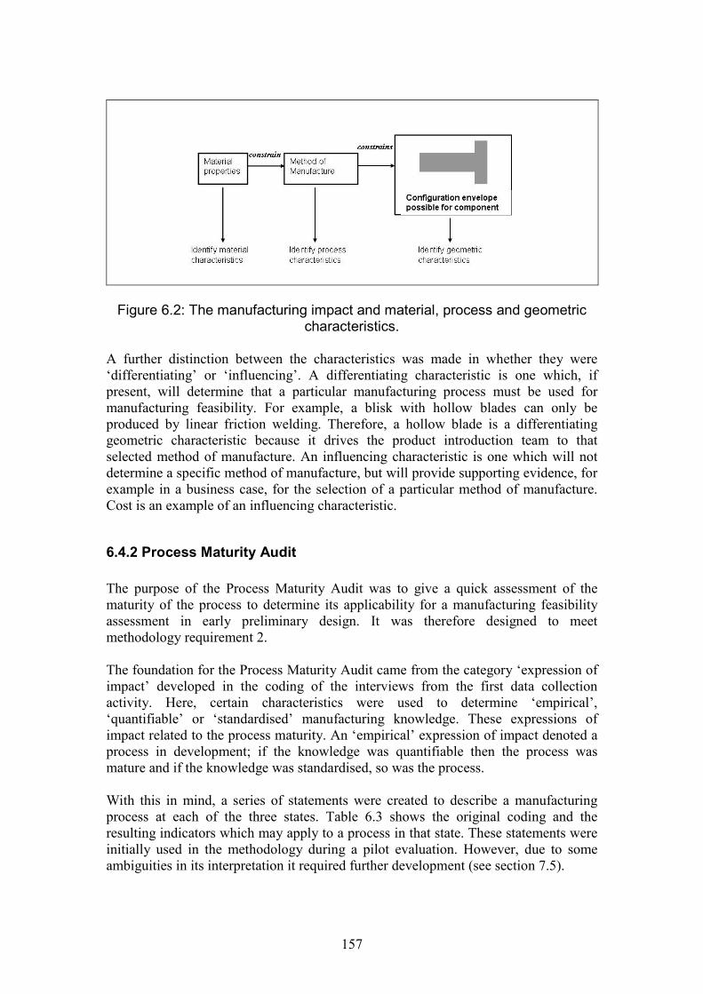
157
Figure 6.2: The manufacturing impact and material, process and geometriccharacteristics.
A further distinction between the characteristics was made in whether they were‘differentiating’ or ‘influencing’. A differentiating characteristic is one which, ifpresent, will determine that a particular manufacturing process must be used formanufacturing feasibility. For example, a blisk with hollow blades can only beproduced by linear friction welding. Therefore, a hollow blade is a differentiatinggeometric characteristic because it drives the product introduction team to thatselected method of manufacture. An influencing characteristic is one which will notdetermine a specific method of manufacture, but will provide supporting evidence, forexample in a business case, for the selection of a particular method of manufacture.Cost is an example of an influencing characteristic.
6.4.2 Process Maturity Audit
The purpose of the Process Maturity Audit was to give a quick assessment of thematurity of the process to determine its applicability for a manufacturing feasibilityassessment in early preliminary design. It was therefore designed to meetmethodology requirement 2.
The foundation for the Process Maturity Audit came from the category ‘expression ofimpact’ developed in the coding of the interviews from the first data collectionactivity. Here, certain characteristics were used to determine ‘empirical’,‘quantifiable’ or ‘standardised’ manufacturing knowledge. These expressions ofimpact related to the process maturity. An ‘empirical’ expression of impact denoted aprocess in development; if the knowledge was quantifiable then the process wasmature and if the knowledge was standardised, so was the process.
With this in mind, a series of statements were created to describe a manufacturingprocess at each of the three states. Table 6.3 shows the original coding and theresulting indicators which may apply to a process in that state. These statements wereinitially used in the methodology during a pilot evaluation. However, due to someambiguities in its interpretation it required further development (see section 7.5).

158
Table 6.3: Process maturity, definition and indicators
Process maturity (anddefinition)
Original coding definition Process indicators
In development(occurs when there isevidence ofexperimentation indetermining theprocess limits andcapability).
(Empirical expression ofimpact)The manufacturingprocess will require somedevelopment work inorder to meet the designrequirements. Assessmentof the process constraintson the product geometrywill be from the results ofexperimental work orinvestigations.
- The process requiresdevelopment.- The process capability isassessed via results ofexperimentation work.- Process is a development ofexisting manufacturingtechnology and is ready forproductionisation.- This process is being appliedto a new situation.
Mature(Occurs when thecomponent size can berestricted to pre-determined numericallimits which can bemeasured for processcapability).
(Quantifiable expressionof impact)Reference to maximum orminimum alloweddimensions (or otherlimits) due tomanufacturing. Thesedimensions are applicableto current manufacturingprocesses. Thesedimensional constraintscan be seen across mostcomponents in the generalarrangement. They willbe considered routinely aspart of the design process.
- Manufacturing minimums andmaximums.- Limitations expressed asformulae, tooling sizerestrictions, algorithms,constrained dimensions.
Standardised(Occurs when thecomponent or featureconfiguration isrestricted to a set ofdiscrete values whichhave been pre-determined by themanufacturing processand may be linked to aprescribed processcapability).
(Standardised impact ofexpression)There will be anindication of astandardised componentor feature. The reasonsfor standardisation maynot be fully known.
- Problems associated with themanufacturing problem may besignificantly reduced.- No customization ispermitted.- The component / feature mayhave been manufactured for anumber of years and a standardprocess / tooling may apply forall examples.- No further development of themanufacturing process isrequired.
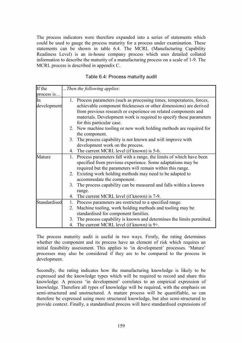
159
The process indicators were therefore expanded into a series of statements whichcould be used to gauge the process maturity for a process under examination. Thesestatements can be shown in table 6.4. The MCRL (Manufacturing CapabilityReadiness Level) is an in-house company process which uses detailed collatedinformation to describe the maturity of a manufacturing process on a scale of 1-9. TheMCRL process is described in appendix C.
Table 6.4: Process maturity audit
If theprocess is…
…Then the following applies:
Indevelopment
1. Process parameters (such as processing times, temperatures, forces,achievable component thicknesses or other dimensions) are derivedfrom previous research or experience on related components andmaterials. Development work is required to specify these parametersfor this particular case.
2. New machine tooling or new work holding methods are required forthe component.
3. The process capability is not known and will improve withdevelopment work on the process.
4. The current MCRL level (if known) is 5-6.Mature 1. Process parameters fall with a range, the limits of which have been
specified from previous experience. Some adaptations may berequired but the parameters will remain within this range.
2. Existing work holding methods may need to be adapted toaccommodate the component.
3. The process capability can be measured and falls within a knownrange.
4. The current MCRL level (if known) is 7-9.Standardised 1. Process parameters are restricted to a specified range.
2. Machine tooling, work holding methods and tooling may bestandardised for component families.
3. The process capability is known and determines the limits permitted.4. The current MCRL level (if known) is 9+.
The process maturity audit is useful in two ways. Firstly, the rating determineswhether the component and its process have an element of risk which requires aninitial feasibility assessment. This applies to ‘in development’ processes. ‘Mature’processes may also be considered if they are to be compared to the process indevelopment.
Secondly, the rating indicates how the manufacturing knowledge is likely to beexpressed and the knowledge types which will be required to record and share thisknowledge. A process ‘in development’ correlates to an empirical expression ofknowledge. Therefore all types of knowledge will be required, with the emphasis onsemi-structured and unstructured. A mature process will be quantifiable, so cantherefore be expressed using more structured knowledge, but also semi-structured toprovide context. Finally, a standardised process will have standardised expressions of
160
impact and can rely primarily on structured knowledge (although it would also beprudent to have some degree of semi-structured knowledge present).
6.4.3 Knowledge must be conveyed using both explicit and tacitknowledge methods
The purpose of this component (which fulfils the third requirement) was to determinethe necessary formats for the methodology. Suitable media were required for theeffective transfer of structured, semi-structured and unstructured knowledge. As seenin both the literature review and the data collections, the ability to express knowledgeacross the full explicit – tacit range was an important requirement. This was to enablethe full range of manufacturing knowledge to be expressed depending on its maturity.
As has been discussed in chapter 2, this thesis takes the view that it is not possible totransfer unstructured (tacit) knowledge through an information system and the onlypossible method of transfer is person to person contact. Unstructured knowledgetransfer requires face-to-face contact by domain experts. Therefore the methodproposed for running the methodology was a series of workshops with guideddiscussion for effective knowledge requirement identification.
In addition to the tacit sharing environment during the workshops, knowledge relevantfor sharing also would need to be recorded in both structured and semi-structuredforms as follows:-Structured: some knowledge may need to be expressed numerically (i.e. in astructured way).Semi-structured: additional explanatory notes may also be required, both assupporting notes to the structured knowledge or in cases where knowledge cannot bequantified.
A series of pilot processes were therefore designed to be run in a series of workshopsituations to guide them towards the desired outcome (see section 6.5). The finalformat of the methodology was therefore suited to a mix of guidance notes throughthe workshops and forms for recording and displaying the required manufacturingknowledge for feasibility assessments.
6.5 Methodology
This section introduces the main methodology and demonstrates how the threecomponents (as discussed in section 6.4) were put together with a systematic process.
6.5.1 Methodology Format
The eventual ideal format for a practical methodology in use would be a combinationof a database in which relevant knowledge may be recorded and a web-based front-end. This would consist of a series of database forms to capture and present the
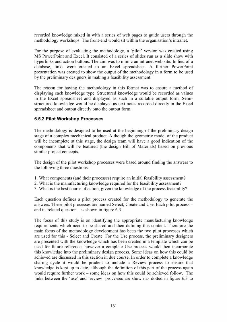
161
recorded knowledge mixed in with a series of web pages to guide users through themethodology workshops. The front-end would sit within the organisation’s intranet.
For the purpose of evaluating the methodology, a ‘pilot’ version was created usingMS PowerPoint and Excel. It consisted of a series of slides run as a slide show withhyperlinks and action buttons. The aim was to mimic an intranet web site. In lieu of adatabase, links were created to an Excel spreadsheet. A further PowerPointpresentation was created to show the output of the methodology in a form to be usedby the preliminary designers in making a feasibility assessment.
The reason for having the methodology in this format was to ensure a method ofdisplaying each knowledge type. Structured knowledge would be recorded as valuesin the Excel spreadsheet and displayed as such in a suitable output form. Semi-structured knowledge would be displayed as text notes recorded directly in the Excelspreadsheet and output directly onto the output form.
6.5.2 Pilot Workshop Processes
The methodology is designed to be used at the beginning of the preliminary designstage of a complex mechanical product. Although the geometric model of the productwill be incomplete at this stage, the design team will have a good indication of thecomponents that will be featured (the design Bill of Materials) based on previoussimilar project concepts.
The design of the pilot workshop processes were based around finding the answers tothe following three questions:-
1. What components (and their processes) require an initial feasibility assessment?2. What is the manufacturing knowledge required for the feasibility assessment?3. What is the best course of action, given the knowledge of the process feasibility?
Each question defines a pilot process created for the methodology to generate theanswers. These pilot processes are named Select, Create and Use. Each pilot process –and its related question – is shown in figure 6.3.
The focus of this study is on identifying the appropriate manufacturing knowledgerequirements which need to be shared and then defining this content. Therefore themain focus of the methodology development has been the two pilot processes whichare used for this - Select and Create. For the Use process, the preliminary designersare presented with the knowledge which has been created in a template which can beused for future reference, however a complete Use process would then incorporatethis knowledge into the preliminary design process. Some ideas on how this could beachieved are discussed in this section in due course. In order to complete a knowledgesharing cycle it would be prudent to include a Review process to ensure thatknowledge is kept up to date, although the definition of this part of the process againwould require further work – some ideas on how this could be achieved follow. Thelinks between the ‘use’ and ‘review’ processes are shown as dotted in figure 6.3 to
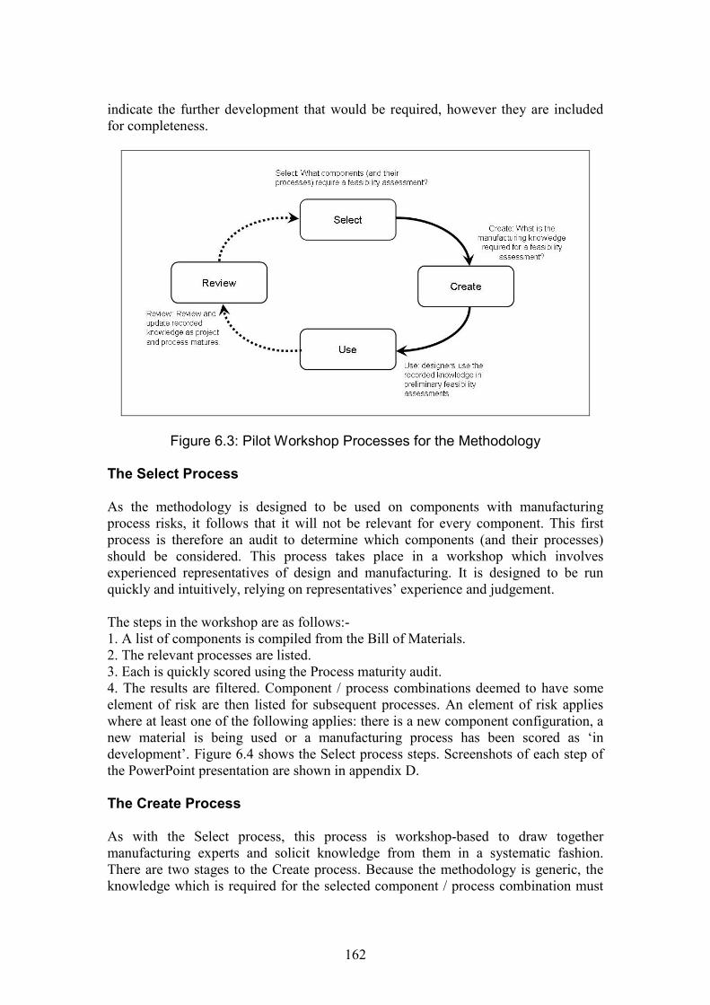
162
indicate the further development that would be required, however they are includedfor completeness.
Figure 6.3: Pilot Workshop Processes for the Methodology
The Select Process
As the methodology is designed to be used on components with manufacturingprocess risks, it follows that it will not be relevant for every component. This firstprocess is therefore an audit to determine which components (and their processes)should be considered. This process takes place in a workshop which involvesexperienced representatives of design and manufacturing. It is designed to be runquickly and intuitively, relying on representatives’ experience and judgement.
The steps in the workshop are as follows:-1. A list of components is compiled from the Bill of Materials.2. The relevant processes are listed.3. Each is quickly scored using the Process maturity audit.4. The results are filtered. Component / process combinations deemed to have someelement of risk are then listed for subsequent processes. An element of risk applieswhere at least one of the following applies: there is a new component configuration, anew material is being used or a manufacturing process has been scored as ‘indevelopment’. Figure 6.4 shows the Select process steps. Screenshots of each step ofthe PowerPoint presentation are shown in appendix D.
The Create Process
As with the Select process, this process is workshop-based to draw togethermanufacturing experts and solicit knowledge from them in a systematic fashion.There are two stages to the Create process. Because the methodology is generic, theknowledge which is required for the selected component / process combination must
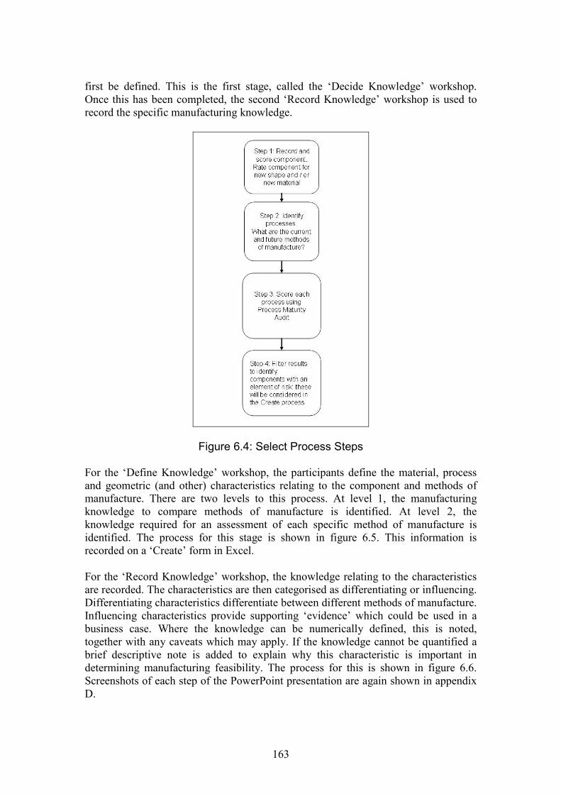
163
first be defined. This is the first stage, called the ‘Decide Knowledge’ workshop.Once this has been completed, the second ‘Record Knowledge’ workshop is used torecord the specific manufacturing knowledge.
Figure 6.4: Select Process Steps
For the ‘Define Knowledge’ workshop, the participants define the material, processand geometric (and other) characteristics relating to the component and methods ofmanufacture. There are two levels to this process. At level 1, the manufacturingknowledge to compare methods of manufacture is identified. At level 2, theknowledge required for an assessment of each specific method of manufacture isidentified. The process for this stage is shown in figure 6.5. This information isrecorded on a ‘Create’ form in Excel.
For the ‘Record Knowledge’ workshop, the knowledge relating to the characteristicsare recorded. The characteristics are then categorised as differentiating or influencing.Differentiating characteristics differentiate between different methods of manufacture.Influencing characteristics provide supporting ‘evidence’ which could be used in abusiness case. Where the knowledge can be numerically defined, this is noted,together with any caveats which may apply. If the knowledge cannot be quantified abrief descriptive note is added to explain why this characteristic is important indetermining manufacturing feasibility. The process for this is shown in figure 6.6.Screenshots of each step of the PowerPoint presentation are again shown in appendixD.
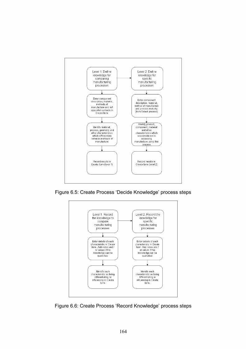
164
Figure 6.5: Create Process ‘Decide Knowledge’ process steps
Figure 6.6: Create Process ‘Record Knowledge’ process steps
165
The Use Process
A form was designed to display the knowledge recorded during Create process to thepreliminary designers. It was designed to acquire the knowledge from each of thespecialist domains and present it collectively to give a comprehensive view of themanufacturing knowledge requirements for preliminary design. The form wasdesigned to present the knowledge in a user-friendly way for future investigation andfeasibility assessment work. Example screenshots of ‘dummy’ forms (used todemonstrate the methodology to the organisation) are shown in appendix D.
The intention behind the form is that it could be actively used for an initialmanufacturing assessment. To fully integrate the knowledge identified and acquiredinto the design process, some ideas must be generated on the potential ways in whichthis knowledge could be used and the formats in which it could be used effectively. Itwould not be suitable, for example, to integrate this knowledge with a KBE system orsimilar as the knowledge is not yet suitably mature for such a system. Other morereference-type systems would be a better option. However, the risk is that the formitself would become out of date very quickly if it were to be used just as a referencetool and the credibility of the recorded knowledge would become undermined. Activeuse would therefore have to be combined with an ongoing Review process tomaximise its value.
Review Process
The review process for this methodology would be concerned with the review andupdate of the knowledge recorded. The maturity of a manufacturing process is a time-based activity. As time and a project progress, processes originally recorded as being‘in development’ will become ‘mature’. Knowledge relating to the characteristics maygo from being notes to quantified parameters. Knowledge which was originallyquantified may have changed parameters due to the results of development work. Areview activity, possibly again workshop based, would need to be developed in orderto keep the knowledge updated. The main emphasis of this would be to keep thereview sessions timely but ideally not too time-consuming, as again there may be atendency for the activity to reduce and the methodology to fall out of use. Once theknowledge relating to a specific project had been defined during the ‘decideknowledge’ workshop, the initial identified characteristics could be reused forsubsequent projects and comparisons made between previous projects. Over time, thismay actually reduce the amount of time required for the methodology sessions.

166
6.6 Summary
The hypothesis of manufacturing knowledge requirements generated from the twodata collections was integrated into an operational methodology to be used to identify,acquire and share the manufacturing knowledge requirements for an early assessmentof manufacturing during preliminary design. This methodology draws on both themanufacturing impacts, assessment of process maturity and knowledge types from thefirst data collection and the interactions between the different specialised domainsfrom the second data collection. A pilot version of the methodology was developedusing a combination of MS PowerPoint slides which directed the users through aseries of workshops and MS Excel spreadsheets to capture the knowledgerequirements and contents. The methodology now requires evaluation for two reasons.The first is as a means of validating the hypothesis of manufacturing knowledgerequirements generated. The second is to evaluate the methodology as an operationaltool within an industrial setting. The evaluation will be discussed in chapter 7.
167
Chapter 7
Evaluation of the Methodology
7.1 Introduction
The previous chapter discussed the development of a methodology to identify, acquireand share innovative manufacturing knowledge between designers and manufacturingspecialists during the preliminary design process. This work formed the first part ofthe hypothesis-testing phase of the study. The methodology had been created as theembodiment of a hypothesis of innovative manufacturing knowledge requirements.This hypothesis had been developed during inductive phase of the study from theanalysis of two data collection activities - from exploratory interviews and aninvestigation into a component with an innovative manufacturing process.
To conclude the hypothesis-testing phase of the study, the methodology requiredevaluation for two reasons: firstly, to verify (or otherwise) the hypothesis developedand secondly to evaluate the effectiveness of the process, highlight its strengths andseek suggestions for future improvements. In doing this, the work addressed researchobjective four: To evaluate whether the method developed in objective 3 presents aneffective way of identifying, acquiring and sharing the knowledge requirementsbetween domain experts.
This chapter discusses the design considerations, execution and results of threeevaluation sessions using different components and manufacturing technologies. Itdetails the aim and scope of the evaluation, the considerations for the evaluationdesign, the design of a survey to elicit data for evaluation and the subsequent analysisand findings. The evaluation sessions took place over a four month period.
7.2 Evaluation Design
There were three factors which needed to be considered in designing a suitablemethod of evaluation for the methodology. These were:-
1. The aims and objectives to be achieved by evaluating the methodology;2. Evaluation scope: the methodology processes to be included within the
evaluation and the range of organisational activities to which they should beapplied;
3. General evaluation design considerations.
Each factor is addressed in the next three sub-sections.
168
7.2.1 Aims and objectives
The evaluation aims originated from research objective four. The first was to verifythe hypothesis developed. If the hypothesis was confirmed, then the following idealoutcomes would result from the evaluation:-
1. The manufacturing knowledge requirements identified (specified by thematerial, process and geometric characteristics) would be sufficient to enablean initial feasibility assessment of the manufacturing process to be completedduring the preliminary design stage.
2. The manufacturing knowledge level would be appropriate for an initialfeasibility assessment during the preliminary design stage
3. The manufacturing process could be expressed in different ways according tothe process maturity.
4. Combinations of different knowledge types could be used to express thisprocess maturity.
5. The above combinations would be an effective way of knowledge sharingbetween the specialist domains of design and manufacturing.
6. The use of the methodology would enable the effective compilation of themanufacturing knowledge.
A definition of ‘effective’ in this case meant that the methodology was user-friendlyand that all the knowledge required across different domains was identified andcollected quickly and efficiently.
The second aim was to examine the suitability of the methodology in effectivelyidentifying, acquiring and sharing innovative manufacturing knowledge for apreliminary design assessment. This aim indicated that some application of amethodology would be required in a practical situation.
The objectives of the evaluation session were therefore:-
1. To design a suitable evaluation scenario which would enable the methodologyto be applied to a suitable range and number of situations where appropriatemanufacturing knowledge could be generated and shared. This would evaluateboth the hypothesis and the general use of the methodology.
2. To design and implement a method of data collection during the evaluationsession to confirm the success (or otherwise) of the six outcomes above.
These aims and objectives influenced both the scope of the evaluation and theevaluation design.
7.2.2 Scope of the evaluation
The scope of the evaluation encompassed two elements. The first was themethodology processes which would be relevant for the evaluation. The second was
169
the application of the methodology in the wider, organisational context, in line withthe aim to evaluate it in a practical situation.
To achieve the ideal outcomes in section 7.2.1, innovative manufacturing knowledgewould need to be identified and acquired. Consequently the Select and Createprocesses required evaluation. The knowledge acquired would then need to beevaluated on its suitability for use in preliminary design. It would therefore need to beevaluated by preliminary designers on its suitability for use, although this would notinvolve the full Use process.
As the methodology was developed for the product introduction process of a specificcompany, it would be prudent for the evaluation to take place within the same context.The decision was taken to explore the use of the methodology for three differentcomponents, comparing two manufacturing processes for each. In doing this, theevaluation would take the form of a single embedded case study (Yin, 2003).
7.2.3 Evaluation design considerations
The evaluation activity was designed to examine the methodology with a view tofurther improvement and development. This fits the requirements of a formativeevaluation as defined by Patton (Patton, 1987). Central to this was an evaluation oftwo of the methodology processes – Select and Create – in compiling the requiredknowledge, which entails a process evaluation strategy. Both strategies require the useof qualitative data in order to ‘provide depth and detail about the program’s strengthsand weaknesses’ (Patton, 1987, p.29).
Patton lists three important considerations for evaluation design (Patton, 1987, p.166):
‘What is worth knowing about the program? What data will be most useful? How canthe design be appropriately matched to the evaluation situation, the stage of programdevelopment and the primary information needs of stakeholders?’
The evaluation aims considered the first question for the entire methodology. Inaddition to this the Select and Create processes needed consideration at a moredetailed level. For the Select process, the concerns were:
Is this a quick and effective way of highlighting components which willrequire further scrutiny?
Is the process maturity useful knowledge?
For the Create process, the following questions were important:
Do the characteristics capture the knowledge requirements for an initialfeasibility assessment?
Are they to the correct level of detail? How does the use of different knowledge types and ‘expressions of impact’
affect knowledge collection and recording?
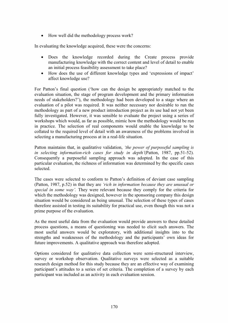
170
How well did the methodology process work?
In evaluating the knowledge acquired, these were the concerns:
Does the knowledge recorded during the Create process providemanufacturing knowledge with the correct content and level of detail to enablean initial process feasibility assessment to take place?
How does the use of different knowledge types and ‘expressions of impact’affect knowledge use?
For Patton’s final question (‘how can the design be appropriately matched to theevaluation situation, the stage of program development and the primary informationneeds of stakeholders?’), the methodology had been developed to a stage where anevaluation of a pilot was required. It was neither necessary nor desirable to run themethodology as part of a new product introduction project as its use had not yet beenfully investigated. However, it was sensible to evaluate the project using a series ofworkshops which would, as far as possible, mimic how the methodology would be runin practice. The selection of real components would enable the knowledge to becollated to the required level of detail with an awareness of the problems involved inselecting a manufacturing process at in a real-life situation.
Patton maintains that, in qualitative validation, ‘the power of purposeful sampling isin selecting information-rich cases for study in depth’(Patton, 1987, pp.51-52).Consequently a purposeful sampling approach was adopted. In the case of thisparticular evaluation, the richness of information was determined by the specific casesselected.
The cases were selected to conform to Patton’s definition of deviant case sampling(Patton, 1987, p.52) in that they are ‘rich in information because they are unusual orspecial in some way’. They were relevant because they comply for the criteria forwhich the methodology was designed, however in the sponsoring company this designsituation would be considered as being unusual. The selection of these types of casestherefore assisted in testing its suitability for practical use, even though this was not aprime purpose of the evaluation.
As the most useful data from the evaluation would provide answers to these detailedprocess questions, a means of questioning was needed to elicit such answers. Themost useful answers would be exploratory, with additional insights into to thestrengths and weaknesses of the methodology and the participants’ own ideas forfuture improvements. A qualitative approach was therefore adopted.
Options considered for qualitative data collection were semi-structured interview,survey or workshop observation. Qualitative surveys were selected as a suitableresearch design method for this study because they are an effective way of examiningparticipant’s attitudes to a series of set criteria. The completion of a survey by eachparticipant was included as an activity in each evaluation session.
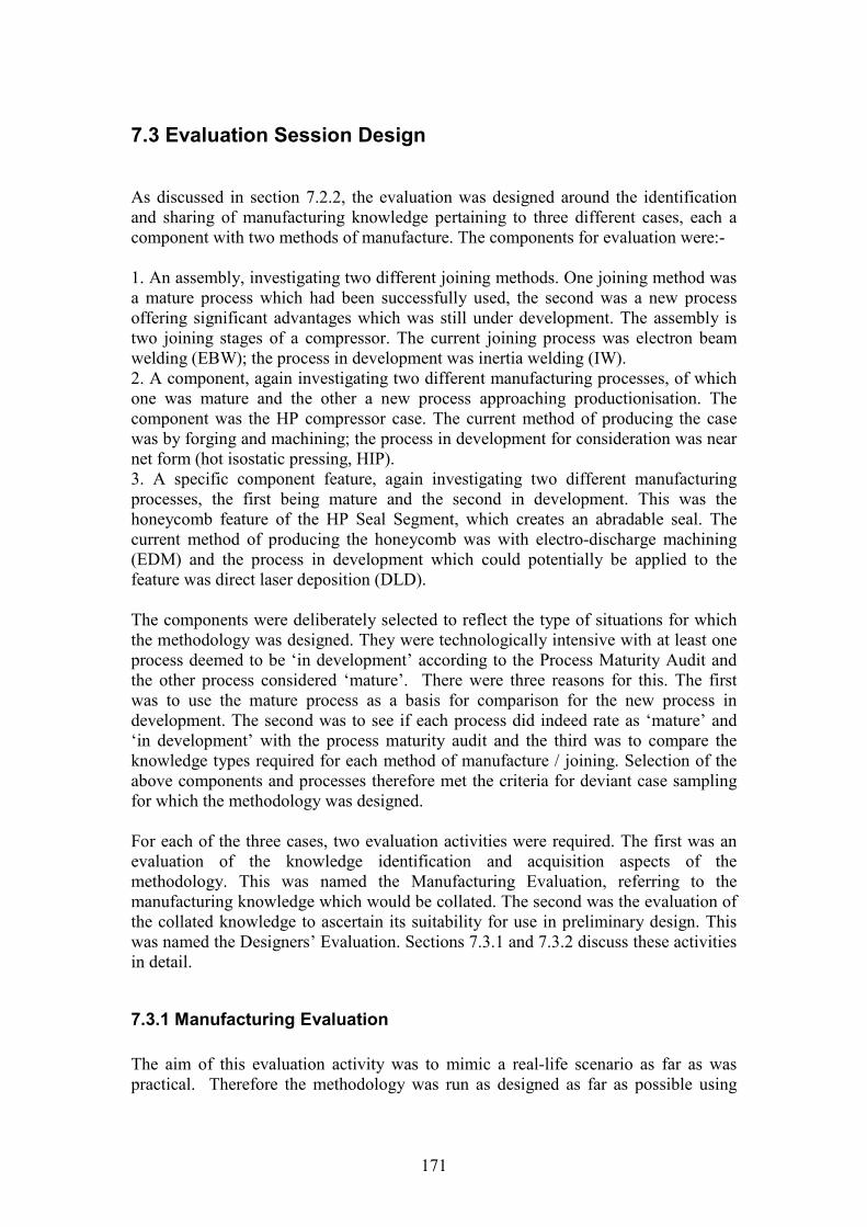
171
7.3 Evaluation Session Design
As discussed in section 7.2.2, the evaluation was designed around the identificationand sharing of manufacturing knowledge pertaining to three different cases, each acomponent with two methods of manufacture. The components for evaluation were:-
1. An assembly, investigating two different joining methods. One joining method wasa mature process which had been successfully used, the second was a new processoffering significant advantages which was still under development. The assembly istwo joining stages of a compressor. The current joining process was electron beamwelding (EBW); the process in development was inertia welding (IW).2. A component, again investigating two different manufacturing processes, of whichone was mature and the other a new process approaching productionisation. Thecomponent was the HP compressor case. The current method of producing the casewas by forging and machining; the process in development for consideration was nearnet form (hot isostatic pressing, HIP).3. A specific component feature, again investigating two different manufacturingprocesses, the first being mature and the second in development. This was thehoneycomb feature of the HP Seal Segment, which creates an abradable seal. Thecurrent method of producing the honeycomb was with electro-discharge machining(EDM) and the process in development which could potentially be applied to thefeature was direct laser deposition (DLD).
The components were deliberately selected to reflect the type of situations for whichthe methodology was designed. They were technologically intensive with at least oneprocess deemed to be ‘in development’ according to the Process Maturity Audit andthe other process considered ‘mature’. There were three reasons for this. The firstwas to use the mature process as a basis for comparison for the new process indevelopment. The second was to see if each process did indeed rate as ‘mature’ and‘in development’ with the process maturity audit and the third was to compare theknowledge types required for each method of manufacture / joining. Selection of theabove components and processes therefore met the criteria for deviant case samplingfor which the methodology was designed.
For each of the three cases, two evaluation activities were required. The first was anevaluation of the knowledge identification and acquisition aspects of themethodology. This was named the Manufacturing Evaluation, referring to themanufacturing knowledge which would be collated. The second was the evaluation ofthe collated knowledge to ascertain its suitability for use in preliminary design. Thiswas named the Designers’ Evaluation. Sections 7.3.1 and 7.3.2 discuss these activitiesin detail.
7.3.1 Manufacturing Evaluation
The aim of this evaluation activity was to mimic a real-life scenario as far as waspractical. Therefore the methodology was run as designed as far as possible using
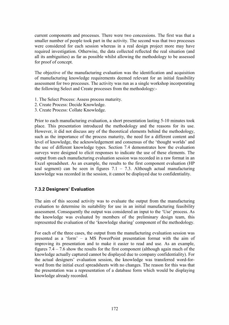
172
current components and processes. There were two concessions. The first was that asmaller number of people took part in the activity. The second was that two processeswere considered for each session whereas in a real design project more may haverequired investigation. Otherwise, the data collected reflected the real situation (andall its ambiguities) as far as possible whilst allowing the methodology to be assessedfor proof of concept.
The objective of the manufacturing evaluation was the identification and acquisitionof manufacturing knowledge requirements deemed relevant for an initial feasibilityassessment for two processes. The activity was run as a single workshop incorporatingthe following Select and Create processes from the methodology:-
1. The Select Process: Assess process maturity.2. Create Process: Decide Knowledge.3. Create Process: Collate Knowledge.
Prior to each manufacturing evaluation, a short presentation lasting 5-10 minutes tookplace. This presentation introduced the methodology and the reasons for its use.However, it did not discuss any of the theoretical elements behind the methodology,such as the importance of the process maturity, the need for a different content andlevel of knowledge, the acknowledgement and consensus of the ‘thought worlds’ andthe use of different knowledge types. Section 7.4 demonstrates how the evaluationsurveys were designed to elicit responses to indicate the use of these elements. Theoutput from each manufacturing evaluation session was recorded in a raw format in anExcel spreadsheet. As an example, the results to the first component evaluation (HPseal segment) can be seen in figures 7.1 – 7.3. Although actual manufacturingknowledge was recorded in the session, it cannot be displayed due to confidentiality.
7.3.2 Designers’ Evaluation
The aim of this second activity was to evaluate the output from the manufacturingevaluation to determine its suitability for use in an initial manufacturing feasibilityassessment. Consequently the output was considered an input to the ‘Use’ process. Asthe knowledge was evaluated by members of the preliminary design team, thisrepresented the evaluation of the ‘knowledge sharing’ component of the methodology.
For each of the three cases, the output from the manufacturing evaluation session waspresented as a ‘form’ – a MS PowerPoint presentation format with the aim ofimproving its presentation and to make it easier to read and use. As an example,figures 7.4 – 7.6 show the results for the first component (although again much of theknowledge actually captured cannot be displayed due to company confidentiality). Forthe actual designers’ evaluation session, the knowledge was transferred word-for-word from the initial excel spreadsheets with no changes. The reason for this was thatthe presentation was a representation of a database form which would be displayingknowledge already recorded.

173
Figure 7.1: Output from Select Process

174
Figure 7.2: Output from Create Process
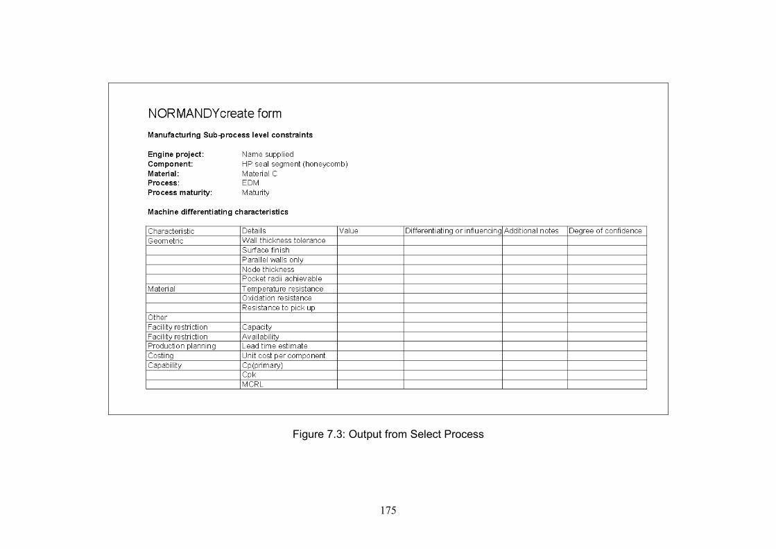
175
Figure 7.3: Output from Select Process
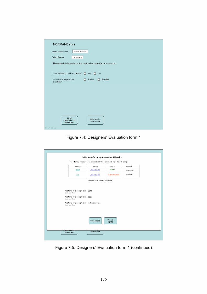
176
Figure 7.4: Designers’ Evaluation form 1
Figure 7.5: Designers’ Evaluation form 1 (continued)

177
Figure 7.6: Designers’ Evaluation form 1 (continued)
The format of each evaluation session again included a short introductory presentationwith information about the methodology, its format, and use. As with themanufacturing evaluation, no information about the theoretical elements of themethodology was offered, yet the survey design ensured that the use of these wasexamined.
Two designers’ evaluation sessions took place. In the first session the two formsrepresenting the outcomes of the first two manufacturing evaluation sessions werepresented. In the second session two forms were again presented. These bothcontained the knowledge captured in the third evaluation session. However, two viewswere presented of the same knowledge, with the second form deliberately lessdetailed.
7.3.3 Selection of Evaluation Session Participants
In order for the methodology to be effective and to recognise the need for sharingknowledge across the specialist domains, it was recognised that both design andmanufacturing specialists would need to participate in the evaluation sessions.
The following candidates were therefore sought for each evaluation:-
Manufacturing Evaluation session: At least one manufacturing domain specialist for each process being
considered.
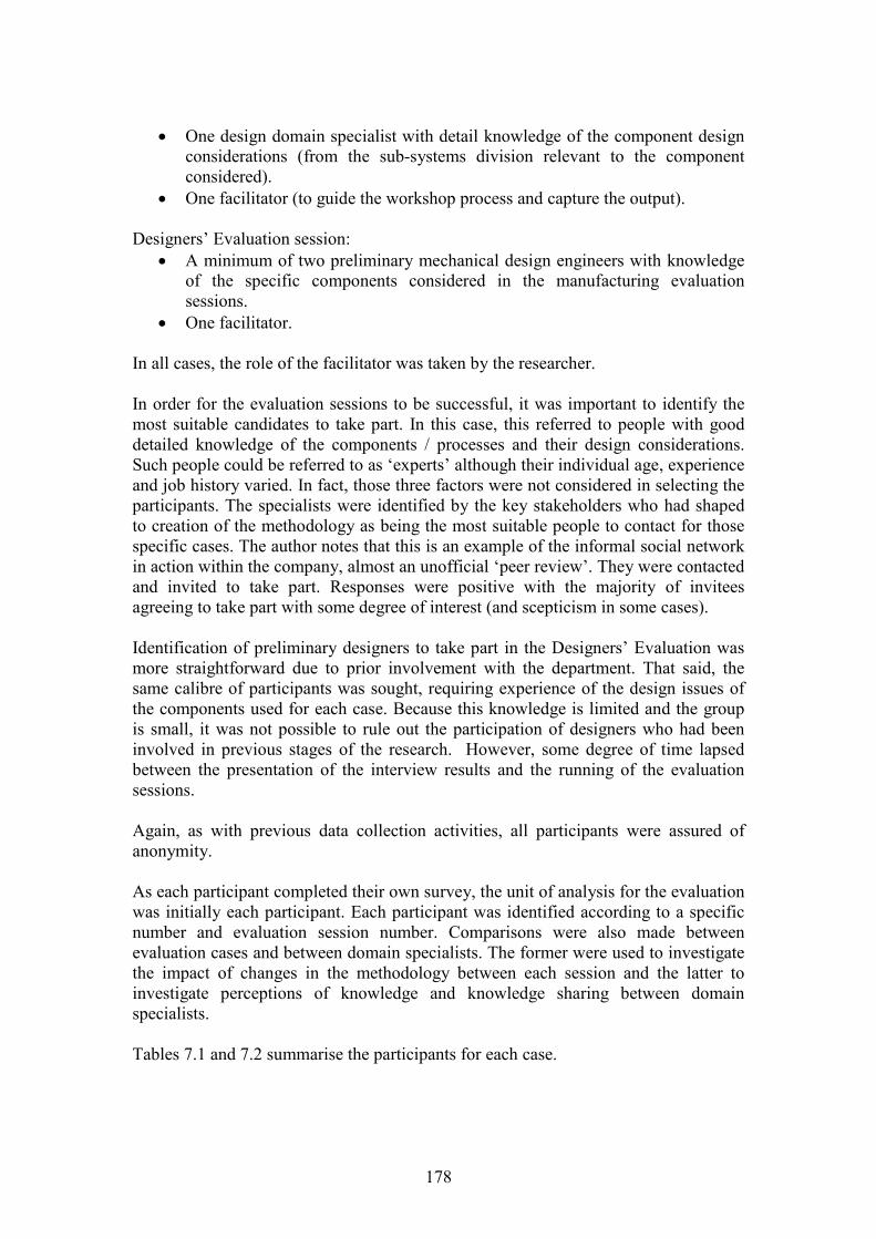
178
One design domain specialist with detail knowledge of the component designconsiderations (from the sub-systems division relevant to the componentconsidered).
One facilitator (to guide the workshop process and capture the output).
Designers’ Evaluation session: A minimum of two preliminary mechanical design engineers with knowledge
of the specific components considered in the manufacturing evaluationsessions.
One facilitator.
In all cases, the role of the facilitator was taken by the researcher.
In order for the evaluation sessions to be successful, it was important to identify themost suitable candidates to take part. In this case, this referred to people with gooddetailed knowledge of the components / processes and their design considerations.Such people could be referred to as ‘experts’ although their individual age, experienceand job history varied. In fact, those three factors were not considered in selecting theparticipants. The specialists were identified by the key stakeholders who had shapedto creation of the methodology as being the most suitable people to contact for thosespecific cases. The author notes that this is an example of the informal social networkin action within the company, almost an unofficial ‘peer review’. They were contactedand invited to take part. Responses were positive with the majority of inviteesagreeing to take part with some degree of interest (and scepticism in some cases).
Identification of preliminary designers to take part in the Designers’ Evaluation wasmore straightforward due to prior involvement with the department. That said, thesame calibre of participants was sought, requiring experience of the design issues ofthe components used for each case. Because this knowledge is limited and the groupis small, it was not possible to rule out the participation of designers who had beeninvolved in previous stages of the research. However, some degree of time lapsedbetween the presentation of the interview results and the running of the evaluationsessions.
Again, as with previous data collection activities, all participants were assured ofanonymity.
As each participant completed their own survey, the unit of analysis for the evaluationwas initially each participant. Each participant was identified according to a specificnumber and evaluation session number. Comparisons were also made betweenevaluation cases and between domain specialists. The former were used to investigatethe impact of changes in the methodology between each session and the latter toinvestigate perceptions of knowledge and knowledge sharing between domainspecialists.
Tables 7.1 and 7.2 summarise the participants for each case.
179
Table 7.1: Evaluation Participants: Manufacturing Evaluations
Case Participant1. HP Seal Segment 1. Component Designer from sub-systems unit.
2. Manufacturing specialist, DLD3. Manufacturing specialist, casting (Took part becausethis is the primary process for this product and participanthad good understanding of associated design andmanufacturing issues.4 and 5. Manufacturing specialists, EDM
2. Compressorassembly stages
1. Component designer from sub-systems unit2. Manufacturing specialist, EBW.3. Manufacturing specialist, IW4. Team leader, IW (left early).
3. Compressor case 1. Manufacturing specialist, forging and machining.2. Manufacturing specialist, HIP.
Total participants 10
Table 7.2: Evaluation Participants: Designers’ Evaluation
Case Participants1. HP Seal Segment2. Compressorassembly stages(evaluated together)
1. Preliminary design team leader2. Design capability manager3 and 4. Preliminary mechanical designers.
3. Compressor case 1 and 2 Preliminary mechanical designers (same asprevious session).
Total participants 6 (second evaluation considered as a separate case).
The evaluation sessions were designed to use these participants for two reasons. Thefirst is that, as each participant was considered a domain expert, they were a rich andcredible source of data. The second is that each participant could provide a viewpointfrom each domain. These multiple viewpoints were also a source of data triangulation.Further triangulation was also provided by additional facilitator’s observations whichwere noted during the evaluation sessions.
The three types of bias were also addressed. Researcher bias was reduced by ensuringthat the participants completed the surveys individually and in their own words.Reactive bias was difficult to address as the researcher was an integral part of theevaluation session. Activities included identifying and recruiting participants, briefingthem, facilitating the sessions and analysing the survey material. It is recognised thatreactive bias may easily occur in the situation therefore the researcher attempted tokeep an open mind to the investigations as far as possible. It was also difficult toaddress the possibility of respondent bias. The researcher attempted as far as possibleto monitor for this by comparing the survey responses with comments made by andobservations of the participants during the evaluation sessions. A situation occurred inManufacturing Evaluation Session 1 where these did not match and therefore thesurvey was withdrawn from analysis.
180
7.4 Survey Design
As was seen in section 7.2.1, a series of ideal outcomes needed to be considered inevaluating the methodology. The survey would need to be designed to demonstrate ifthese outcomes had been achieved. Below is a list of six questions which relatedirectly to the ideal outcomes. Each question is designed to evaluate each part of themethodology against its original requirements:-
1. How useful is the manufacturing knowledge content collated in terms of carryingout an initial feasibility assessment in preliminary design?2. How useful is the level of manufacturing knowledge collated in terms of carryingout an initial feasibility assessment in preliminary design?3. Can the manufacturing process be expressed in different ways according to theprocess maturity?4. Do the combinations of different knowledge types effectively express the processmaturity?5. Does a methodology with the features above present an effective way of knowledgesharing between the specialist domains of design and manufacturing?6. Does the methodology enable an effective compilation of manufacturingknowledge?
This list of questions was then used to generate some initial ideas of the types ofsurvey questions required to answer them. The results can be seen in table 7.3. Thesequestions met one of two criteria:-
A. The effectiveness of the methodology in sharing manufacturing knowledgebetween designers and manufacturing engineers (i.e. validates the hypothesis).
B. Criteria which evaluate the effectiveness of the methodology design (i.e.validates the use of the methodology).
Many of the initial thoughts included some measure of ‘success’ with themethodology. Therefore a definition of ‘success’ for the methodology was required.Table 7.4 indicates what would be expected from the manufacturing and designerevaluation sessions if the methodology is said to be ‘successful’.
The survey therefore needed to elicit responses to rate the participants’ attitudes whencompared to these indications of success. An attitude survey format was selected asbeing the most appropriate method of comparing the participants’ views of thesuccess of the methodology against the indicators in table 7.4. Attempts were taken tokeep each statement as neutral as possible to reduce potential bias in the wording ofthe survey.
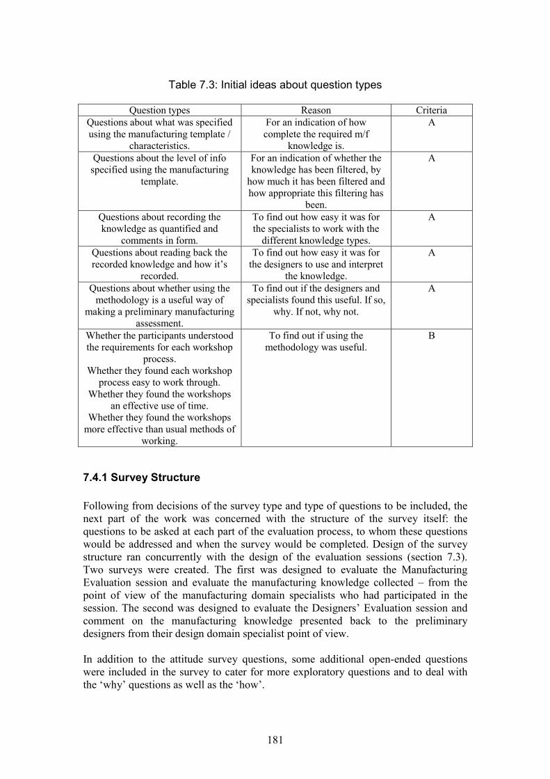
181
Table 7.3: Initial ideas about question types
Question types Reason CriteriaQuestions about what was specifiedusing the manufacturing template /
characteristics.
For an indication of howcomplete the required m/f
knowledge is.
A
Questions about the level of infospecified using the manufacturing
template.
For an indication of whether theknowledge has been filtered, by
how much it has been filtered andhow appropriate this filtering has
been.
A
Questions about recording theknowledge as quantified and
comments in form.
To find out how easy it was forthe specialists to work with the
different knowledge types.
A
Questions about reading back therecorded knowledge and how it’s
recorded.
To find out how easy it was forthe designers to use and interpret
the knowledge.
A
Questions about whether using themethodology is a useful way of
making a preliminary manufacturingassessment.
To find out if the designers andspecialists found this useful. If so,
why. If not, why not.
A
Whether the participants understoodthe requirements for each workshop
process.Whether they found each workshop
process easy to work through.Whether they found the workshops
an effective use of time.Whether they found the workshops
more effective than usual methods ofworking.
To find out if using themethodology was useful.
B
7.4.1 Survey Structure
Following from decisions of the survey type and type of questions to be included, thenext part of the work was concerned with the structure of the survey itself: thequestions to be asked at each part of the evaluation process, to whom these questionswould be addressed and when the survey would be completed. Design of the surveystructure ran concurrently with the design of the evaluation sessions (section 7.3).Two surveys were created. The first was designed to evaluate the ManufacturingEvaluation session and evaluate the manufacturing knowledge collected – from thepoint of view of the manufacturing domain specialists who had participated in thesession. The second was designed to evaluate the Designers’ Evaluation session andcomment on the manufacturing knowledge presented back to the preliminarydesigners from their design domain specialist point of view.
In addition to the attitude survey questions, some additional open-ended questionswere included in the survey to cater for more exploratory questions and to deal withthe ‘why’ questions as well as the ‘how’.
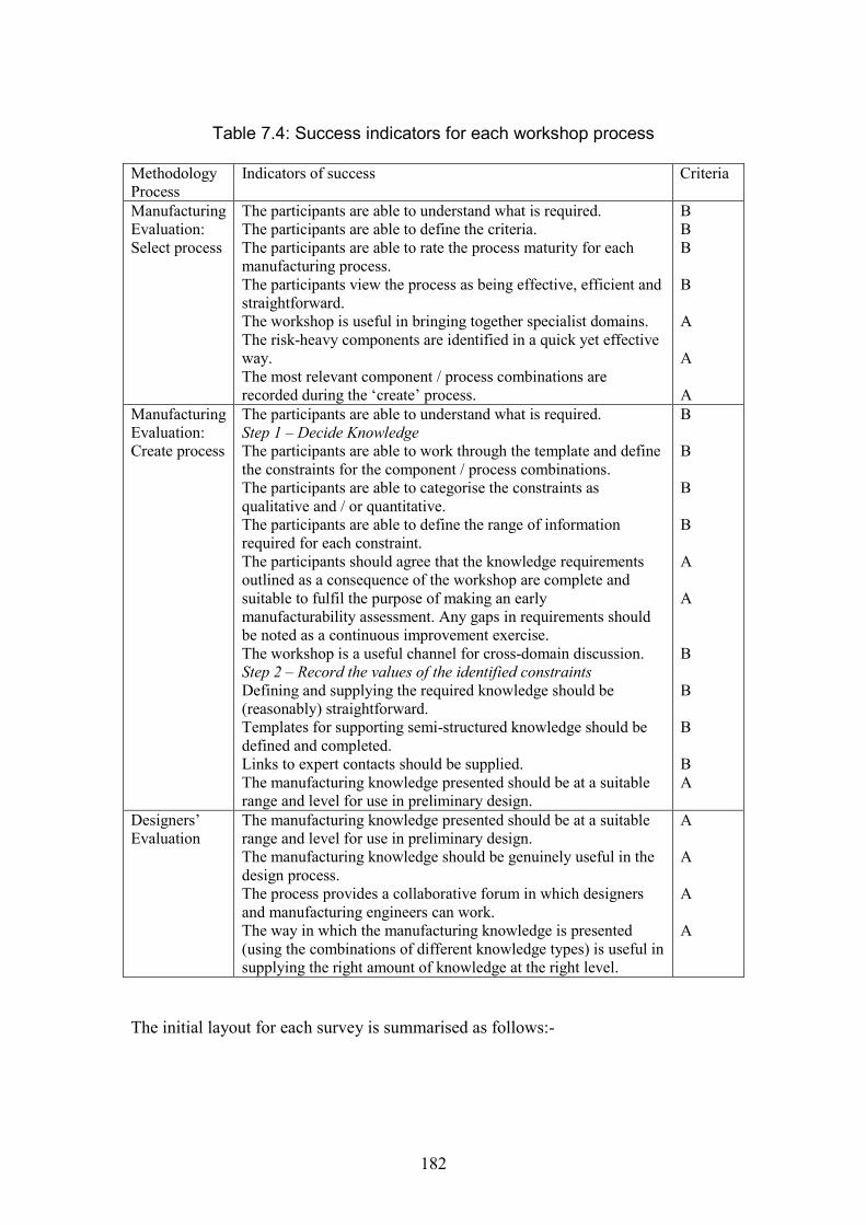
182
Table 7.4: Success indicators for each workshop process
MethodologyProcess
Indicators of success Criteria
ManufacturingEvaluation:Select process
The participants are able to understand what is required.The participants are able to define the criteria.The participants are able to rate the process maturity for eachmanufacturing process.The participants view the process as being effective, efficient andstraightforward.The workshop is useful in bringing together specialist domains.The risk-heavy components are identified in a quick yet effectiveway.The most relevant component / process combinations arerecorded during the ‘create’ process.
BBB
B
A
A
AManufacturingEvaluation:Create process
The participants are able to understand what is required.Step 1 – Decide KnowledgeThe participants are able to work through the template and definethe constraints for the component / process combinations.The participants are able to categorise the constraints asqualitative and / or quantitative.The participants are able to define the range of informationrequired for each constraint.The participants should agree that the knowledge requirementsoutlined as a consequence of the workshop are complete andsuitable to fulfil the purpose of making an earlymanufacturability assessment. Any gaps in requirements shouldbe noted as a continuous improvement exercise.The workshop is a useful channel for cross-domain discussion.Step 2 – Record the values of the identified constraintsDefining and supplying the required knowledge should be(reasonably) straightforward.Templates for supporting semi-structured knowledge should bedefined and completed.Links to expert contacts should be supplied.The manufacturing knowledge presented should be at a suitablerange and level for use in preliminary design.
B
B
B
B
A
A
B
B
B
BA
Designers’Evaluation
The manufacturing knowledge presented should be at a suitablerange and level for use in preliminary design.The manufacturing knowledge should be genuinely useful in thedesign process.The process provides a collaborative forum in which designersand manufacturing engineers can work.The way in which the manufacturing knowledge is presented(using the combinations of different knowledge types) is useful insupplying the right amount of knowledge at the right level.
A
A
A
A
The initial layout for each survey is summarised as follows:-
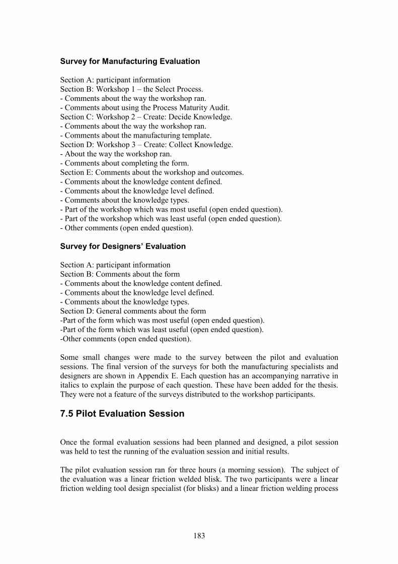
183
Survey for Manufacturing Evaluation
Section A: participant informationSection B: Workshop 1 – the Select Process.- Comments about the way the workshop ran.- Comments about using the Process Maturity Audit.Section C: Workshop 2 – Create: Decide Knowledge.- Comments about the way the workshop ran.- Comments about the manufacturing template.Section D: Workshop 3 – Create: Collect Knowledge.- About the way the workshop ran.- Comments about completing the form.Section E: Comments about the workshop and outcomes.- Comments about the knowledge content defined.- Comments about the knowledge level defined.- Comments about the knowledge types.- Part of the workshop which was most useful (open ended question).- Part of the workshop which was least useful (open ended question).- Other comments (open ended question).
Survey for Designers’ Evaluation
Section A: participant informationSection B: Comments about the form- Comments about the knowledge content defined.- Comments about the knowledge level defined.- Comments about the knowledge types.Section D: General comments about the form-Part of the form which was most useful (open ended question).-Part of the form which was least useful (open ended question).-Other comments (open ended question).
Some small changes were made to the survey between the pilot and evaluationsessions. The final version of the surveys for both the manufacturing specialists anddesigners are shown in Appendix E. Each question has an accompanying narrative initalics to explain the purpose of each question. These have been added for the thesis.They were not a feature of the surveys distributed to the workshop participants.
7.5 Pilot Evaluation Session
Once the formal evaluation sessions had been planned and designed, a pilot sessionwas held to test the running of the evaluation session and initial results.
The pilot evaluation session ran for three hours (a morning session). The subject ofthe evaluation was a linear friction welded blisk. The two participants were a linearfriction welding tool design specialist (for blisks) and a linear friction welding process

184
specialist. Both specialists had been previously involved in the first blisk knowledgecapture meeting.
The objective of the session was to use the methodology to carry out an initial processmaturity audit of linear friction welding and to capture the relevant manufacturingknowledge relating to the blisk. In doing this, two things would be evaluated:-1. The actual knowledge collected, especially when compared to the knowledgecaptured in the previous meeting. Was the methodology more effective?2. How the evaluation session ran – the briefing session, timings, etc. – in order tomake any final changes before the three evaluation sessions.
Observations from the workshop
The timings ran approximately as planned. The initial briefing ran well – in factquicker than planned – and the information was presented clearly. There were noadditional questions.
Select Process: the Process Maturity Audit
The pilot process maturity audit (PMA) was a series of questions, the answers towhich were meant to determine the process maturity. It was found that the questionswere ambiguous and open to too much interpretation. Following the session, the PMAwas reworked into a list of applicable statements to remove the ambiguity. This waspresented as the final version in this thesis. It was also noted that the term‘standardised’ within the company applied to ‘the way we’ve always done it’ ratherthan a mature process where the process capability can be predetermined, thereforethis required more clarification.
Create Processes: Decide and Capture Knowledge
No changes were made to the process – the manufacturing template content stayedfixed for the first main evaluation session (it was then changed between sessions 2and 3). However, comments were received that the slides were ‘too wordy’, thereforethe process was broken down into a further number of slides with less text to make theinstructions clearer.
7.6 Manufacturing Evaluation Sessions
This section presents and analyses the results of the three manufacturing evaluationsessions. Section 7.6.1 discusses the observations made for each session, section 7.6.2discusses the attitude scale survey answers and section 7.6.3 discusses the surveyanswers to the open-ended questions.
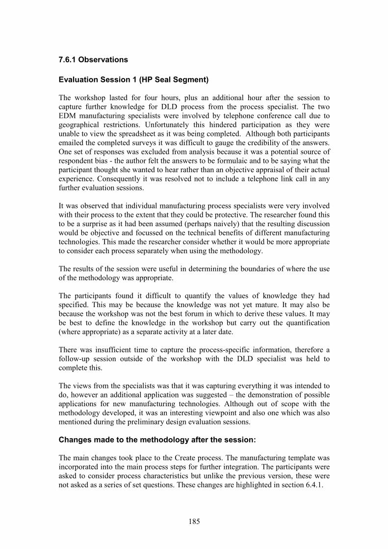
185
7.6.1 Observations
Evaluation Session 1 (HP Seal Segment)
The workshop lasted for four hours, plus an additional hour after the session tocapture further knowledge for DLD process from the process specialist. The twoEDM manufacturing specialists were involved by telephone conference call due togeographical restrictions. Unfortunately this hindered participation as they wereunable to view the spreadsheet as it was being completed. Although both participantsemailed the completed surveys it was difficult to gauge the credibility of the answers.One set of responses was excluded from analysis because it was a potential source ofrespondent bias - the author felt the answers to be formulaic and to be saying what theparticipant thought she wanted to hear rather than an objective appraisal of their actualexperience. Consequently it was resolved not to include a telephone link call in anyfurther evaluation sessions.
It was observed that individual manufacturing process specialists were very involvedwith their process to the extent that they could be protective. The researcher found thisto be a surprise as it had been assumed (perhaps naively) that the resulting discussionwould be objective and focussed on the technical benefits of different manufacturingtechnologies. This made the researcher consider whether it would be more appropriateto consider each process separately when using the methodology.
The results of the session were useful in determining the boundaries of where the useof the methodology was appropriate.
The participants found it difficult to quantify the values of knowledge they hadspecified. This may be because the knowledge was not yet mature. It may also bebecause the workshop was not the best forum in which to derive these values. It maybe best to define the knowledge in the workshop but carry out the quantification(where appropriate) as a separate activity at a later date.
There was insufficient time to capture the process-specific information, therefore afollow-up session outside of the workshop with the DLD specialist was held tocomplete this.
The views from the specialists was that it was capturing everything it was intended todo, however an additional application was suggested – the demonstration of possibleapplications for new manufacturing technologies. Although out of scope with themethodology developed, it was an interesting viewpoint and also one which was alsomentioned during the preliminary design evaluation sessions.
Changes made to the methodology after the session:
The main changes took place to the Create process. The manufacturing template wasincorporated into the main process steps for further integration. The participants wereasked to consider process characteristics but unlike the previous version, these werenot asked as a series of set questions. These changes are highlighted in section 6.4.1.

186
Evaluation session 2 (Compressor stages)
There were initially four participants in this session, however the team leader had toleave after the first workshop (the ‘select’ process), therefore his survey responseswere discounted. The workshop lasted for four hours, plus two additional hours afterthe session to capture further knowledge for both process.
Despite having a set workshop, there were a number of deviations from the requiredtopic. The facilitator decided to allow this as she was interested to see what else wasdiscussed, especially in terms of tacit knowledge transfer. The topics discussed werecategorised as follows:-
Discussions of viable current and potential future processes in addition to thetwo being compared in the workshop.
Discussions about what suppliers have been doing. Discussions about assumptions about material selection and component
design, new processes and how this can affect design requirements (for thebetter), process considerations, etc.
Hypothetical discussions around what could be done with various processes(ref. G/A).
Correction of ‘hearsay’ – the full story concerning supplier capability. Discussion on current design / process considerations on this and related
components. Political issues (“which we shouldn’t really be talking about”).
As with the first session, the involvement of the manufacturing specialists with theirparticular processes was noted. The design specialist in particular appeared to gainsome value in finding out about the processes, especially inertia welding where he hadless experience (however his response in the survey indicated that manufacturingknowledge was something that he believed he would not use). Somemisinterpretations and misconceptions were corrected.
The session appeared to be the smoothest running to date and appeared to besomething where there was a benefit to the participants. However, the author’sopinion was that it was still not running how she would ideally envisage it, yet it wasdifficult to pinpoint where changes were required.
Changes to the methodology after the session:
No changes were made to the methodology itself, however the author decided toinvite a member of the preliminary design team to the next session to see if this wouldstream the information better for preliminary design use.
Evaluation Session 3 (Compressor case)
The preliminary design team were approached to see if they were interested ininvolvement but this was not possible at the time due to project constraints; a
187
component design specialist was invited and accepted but did not attend on the day.The workshop lasted three hours.
This session was more focussed in adhering to the methodology therefore there wasless ‘off topic discussion’. However, it appeared that much of the opportunity for thiswas lost with no designer being present.
There was a good suggestion for improving the methodology from one of themanufacturing specialists. He recommended that the session should be split intofirstly focussing around the component and then the process characteristics.
7.6.2 Survey results: attitude scale questions
Tables 7.5 and 7.6 summarise the results of the attitude scale questions. The unit ofanalysis was initially each participant, however as can be seen the responses havebeen compared according to workshop attended and the domain specialism of eachparticipant (design or manufacturing). Counts of attitude responses on the scale of 1 –6 were taken. In most cases (unless shown in tables 7.5 and 7.6) this corresponds to 1:strongly disagree – 6: strongly agree, where a score of 3.5 would indicate a neutralresponse. In order to gain some idea of the consensus for each question, the meanscore was taken. This was intended as a guideline rather than a rigorous statisticalanalysis, as this type which would have no meaning in the context of a qualitativeanalysis where a purposeful sample has been used. The analyses were taken usingMicrosoft Excel pivot tables.
In order to facilitate a discussion of the results the responses for each question havebeen grouped according to the reason for the question. These are now discussed inturn.
Questions concerning the Process Maturity Audit
The responses to this question were reasonable, indicating that perhaps some furtherdevelopment of this aspect of the methodology was required.
For both questions, the manufacturing specialists rated the process higher than thedesigners – 4.00 compared with 4.25 for B1 (both ‘slightly agree’) and 3.5 (‘neutral’)compared with 4.13 (‘slightly agree’) for B3. This may be because the language usedto indicate the process maturity was written from the manufacturing point of view.However, only two surveys from design specialists were analysed compared to sevenfrom the manufacturing specialists, therefore it is difficult to draw a definiteconclusion based on this. A weakness with the survey was that an additional questionabout the usefulness of the process maturity audit was omitted. Therefore the onlymethod of gauging this was from the open-ended questions in the survey.
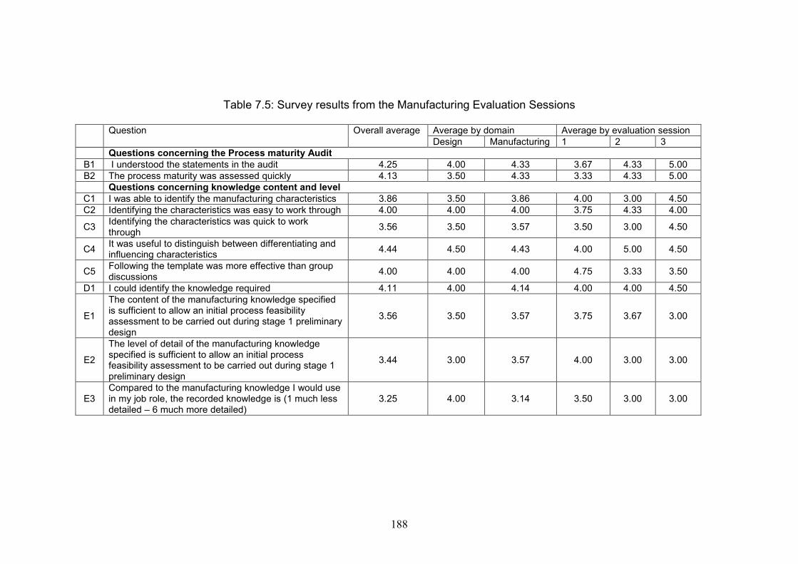
188
Table 7.5: Survey results from the Manufacturing Evaluation Sessions
Question Overall average Average by domain Average by evaluation sessionDesign Manufacturing 1 2 3
Questions concerning the Process maturity AuditB1 I understood the statements in the audit 4.25 4.00 4.33 3.67 4.33 5.00B2 The process maturity was assessed quickly 4.13 3.50 4.33 3.33 4.33 5.00
Questions concerning knowledge content and levelC1 I was able to identify the manufacturing characteristics 3.86 3.50 3.86 4.00 3.00 4.50C2 Identifying the characteristics was easy to work through 4.00 4.00 4.00 3.75 4.33 4.00
C3Identifying the characteristics was quick to workthrough
3.56 3.50 3.57 3.50 3.00 4.50
C4It was useful to distinguish between differentiating andinfluencing characteristics
4.44 4.50 4.43 4.00 5.00 4.50
C5Following the template was more effective than groupdiscussions
4.00 4.00 4.00 4.75 3.33 3.50
D1 I could identify the knowledge required 4.11 4.00 4.14 4.00 4.00 4.50
E1
The content of the manufacturing knowledge specifiedis sufficient to allow an initial process feasibilityassessment to be carried out during stage 1 preliminarydesign
3.56 3.50 3.57 3.75 3.67 3.00
E2
The level of detail of the manufacturing knowledgespecified is sufficient to allow an initial processfeasibility assessment to be carried out during stage 1preliminary design
3.44 3.00 3.57 4.00 3.00 3.00
E3Compared to the manufacturing knowledge I would usein my job role, the recorded knowledge is (1 much lessdetailed – 6 much more detailed)
3.25 4.00 3.14 3.50 3.00 3.00
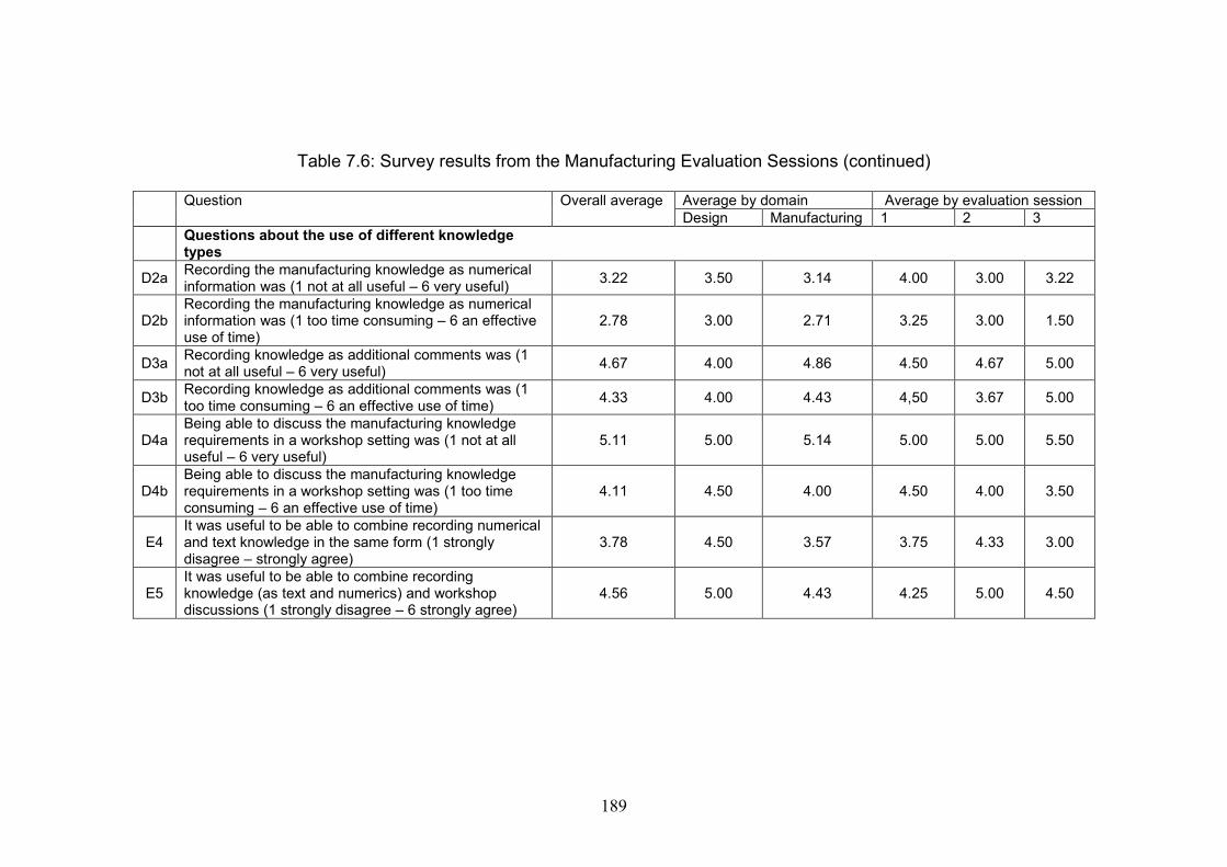
189
Table 7.6: Survey results from the Manufacturing Evaluation Sessions (continued)
Question Overall average Average by domain Average by evaluation sessionDesign Manufacturing 1 2 3
Questions about the use of different knowledgetypes
D2aRecording the manufacturing knowledge as numericalinformation was (1 not at all useful – 6 very useful)
3.22 3.50 3.14 4.00 3.00 3.22
D2bRecording the manufacturing knowledge as numericalinformation was (1 too time consuming – 6 an effectiveuse of time)
2.78 3.00 2.71 3.25 3.00 1.50
D3aRecording knowledge as additional comments was (1not at all useful – 6 very useful)
4.67 4.00 4.86 4.50 4.67 5.00
D3bRecording knowledge as additional comments was (1too time consuming – 6 an effective use of time)
4.33 4.00 4.43 4,50 3.67 5.00
D4aBeing able to discuss the manufacturing knowledgerequirements in a workshop setting was (1 not at alluseful – 6 very useful)
5.11 5.00 5.14 5.00 5.00 5.50
D4bBeing able to discuss the manufacturing knowledgerequirements in a workshop setting was (1 too timeconsuming – 6 an effective use of time)
4.11 4.50 4.00 4.50 4.00 3.50
E4It was useful to be able to combine recording numericaland text knowledge in the same form (1 stronglydisagree – strongly agree)
3.78 4.50 3.57 3.75 4.33 3.00
E5It was useful to be able to combine recordingknowledge (as text and numerics) and workshopdiscussions (1 strongly disagree – 6 strongly agree)
4.56 5.00 4.43 4.25 5.00 4.50
190
Questions concerning the knowledge content and level
These questions examined the following aspects of compiling the manufacturingknowledge: whether the methodology could be followed easily, whether there was abenefit in using it and whether the knowledge identified was applicable and suitablefor an initial feasibility assessment.
Questions C1, C2, C3 and C5 were concerned with the use of the methodology itself.For C1, the response was largely neutral (3.78), indicating that further work may berequired to improve the definition of the knowledge content. Answers were consistentbetween the design and manufacturing domains, however there were somefluctuations between workshop sessions. In terms of the ease of working through themethodology, the response to C2 was a ‘slightly agree’. This is consistent between thedesign and manufacturing domains (both 4.00) yet fluctuates between workshopsessions. The change in format between workshops 1 and 2 may account for thechange in scores (although it drops on content).The reply to C3 (the speed to work through the process ) is neutral.Question C5 is an important question because it compares the use of the methodologywith normal working practices. The consensus appears to be ‘slightly agree’ althoughthis does vary between workshops.The responses to the questions indicate that further work would be required to developthe methodology for practical use.
Questions C4, D1, E1, E2 and E3 address the more fundamental question of whetherthe methodology effectively met the requirements it was designed to address.Question C4 consistently scored on the ‘slightly agree’ scale for all average responses,indicating the differentiating and influencing characteristics definitely appeared to beuseful. The response to D1 – identifying the knowledge – again scored ‘slightly agree’for all responses. E1 and E2 scored mainly ‘neutral’ with some ‘slight disagreements’indicating that despite identifying knowledge, the methodology was not identifyingeverything required to carry out its purpose. The answer to E3 was aimed atcomparing the level of knowledge required for different domains. If preliminarydesign knowledge is at a more abstract level than that with which manufacturingspecialists would be expected to work, then some disagreement would be expectedwith this answer. Responses ranged from slightly agree to slightly disagree, possiblyindicating that this had not been successful.
To summarise, given that there was no strong opinions of disagreement with themethodology, one could say that it is successfully addressing some of therequirements but requires further refinement.
Questions about the use of different knowledge types
Questions D2a and b are about the use of structured knowledge in the workshop. Theyscore the two lowest scores of the survey. The scores for questions D3a and b – aboutthe use of semi-structured knowledge improve significantly. The score of 4.67 forquestion D3a is the second-highest score in the survey. The answer for D4a – aboutthe use of unstructured knowledge (in the form of workshop discussions) is the
191
highest score in the survey at 5.11. Question D4b, about the effective use of timeknowledge sharing of this type scores 4.11. There appears to be some ambivalenceabout its use.
Question E4 concerned the use of explicit knowledge, defined here as the combinationof structured and semi-structured knowledge. Overall the response appeared to beneutral. Question E5 concerned the use of both the explicit and tacit knowledge in themethodology. This scored overall 4.56, the third highest score in the survey.
7.6.3 Coded Responses to Open-ended questions
For the open-ended questions, the answers to each question were analysed toinvestigate common themes. The themes were then categorised into general codes.This was effectively an open coding exercise, similar to that seen in the analysis of thedata collections.
E6. What was the most useful part of the workshop for you and why?
Knowledge sharing: 5Knowledge content: 1Manufacturing impact: 1Process maturity: 1Not answered: 1
The ‘knowledge sharing’ responses can be further categorised:-
Sharing of m/f knowledge between different domains: 2Clarification of manufacturing knowledge: 1Understanding others’ thought processes: 1Review and revision: 1
The categories identified were consistent with those identified in the conceptualframework and framework of questions. The attempt at sharing knowledge acrossdifferent specialist domains was also recognised.
E7. What was the least useful part of the workshop for you and why?
Structured knowledge: 3Process maturity: 1Time required to run: 1Scope of the methodology: 1Nothing specific: 1Not answered: 2
Six answers were provided which could be analysed. The scope of the methodologyand timing were related to small amendments of the methodology content and timing.The structured knowledge was interesting, with comments that it was difficult to
192
identify, valuate and verify. This may be due to the developmental nature of theprocess. Process maturity was also listed by one participant (a designer), although thiscould be because they already knew about it and did not see its relevance to them inthe workshop.
E8 What changes would you recommend to the methodology and why?
Terminology: 3Methodology design: 2Methodology content: 1Usability: 1Not answered: 2
The responses to this question appear to support the findings from the survey – thatthe methodology is a ‘step in the right direction’ but developments are required.
E9 Would you be interested in using any aspect of this methodology in your job role?
Yes: 5No: 2Don’t know: 1Not answered: 1
‘Yes’ responses:-Systematic approach: 3Design / m/f interface: 1Business case: 1
‘No’ responses:-Already have tools: 1No reason given: 1
‘Don’t know’ responses:-Would want another trial: 1
The reasons for using the methodology appear to match some of the original aims ofthe research and the initial generated requirements. There also appears to be somebenefit found with the use of a systematic approach to sharing knowledge.
7.7 Designers’ Evaluation Sessions
This section presents and analyses the results of the two designers’ evaluationsessions in a similar format to section 7.6. Section 7.7.1 discusses the observationsmade for each session, section 7.7.2 discusses the attitude scale survey answers andsection 7.7.3 discusses the survey answers to the open-ended questions.
193
7.7.1 Observations
Designers’ Evaluation Session 1 (HP seal segment and compressorassembly stages)
This first evaluation session considered the results of the first two manufacturingevaluation sessions. It was deliberately held before the final manufacturing evaluationso that any further changes could be made to the methodology if required. Thefollowing concerns were raised:
The content and level of manufacturing knowledge displayed was far toodetailed for an assessment at stage 1.
There was some debate over the component level at which the methodologyshould be aimed. The second form, featuring the compressor assembly wasmore useful than the first, which was a detailed manufacturing feature (the sealsegment).
There were concerns over the resources and time required to firstly compilethe knowledge and then keep it updated. This would detract them from usingit.
There were concerns over how this methodology could actually be used andthe benefits to be gained from it.
There were some good points:
There was genuine interest in the manufacturing knowledge displayed. There were attempts to see how this could be applied to their situation. There
were, for example, thoughts that this could be useful as a database for newmanufacturing engineers.
They were open to the consideration of using new manufacturing processes asa means of investigating new shapes for components.
They liked the combination of manufacturing knowledge and process maturity(MCRL).
Feedback between evaluation sessions
Following the first evaluation session, a feedback discussion took place with thepreliminary design team leader, who was one of the evaluators in the first session. Theaim of the session was to discuss the requirements further. The following weregenerated as a consequence of the discussion:-
Any links to life and performance. Material limitations (where possible). MCRL Anything that affects component sizing.
Two forms were produced for the final evaluation session. Both were an output fromManufacturing Evaluation 3. The second form was modified to remove any additional
194
manufacturing detailed knowledge which did not relate directly to the requirementslisted.
A preliminary designer was invited to the final evaluation session to see if this wouldhave an additional effect on the content and level of manufacturing knowledgegenerated. Unfortunately they were unable to participate.
Designers’ Evaluation Session 2 (compressor case)
There were some concerns over the accuracy of some of the claims made in themanufacturing knowledge with the opinion raised that some independent validationwould be required for recorded knowledge. The approach that would be relevant forpreliminary design was to show the knowledge at the functional / generic componentlevel, a method of exploring different combinations of materials and methods forgeneric components. Preliminary designers are not interested in manufacturingknowledge at the feature level.
In both designer evaluation sessions and the feedback session in between,requirements and perceptions of requirements appeared to be based on the thencurrent preliminary design process.
7.7.2 Survey results: attitude scale
Initially the surveys were analysed according to participant. They have been groupedtogether and compared by case. For each case, one form was presented, except forforms 3 and 4 which are two versions for the same case. Form 4 contained essentiallythe same knowledge as form 3, but with the content and level slightly amended to bemore in line with the perceived requirements of preliminary design.
There is a significant difference in the mean scores between forms 1 and 2 and forms3 and 4. This may be due to two additional evaluators being present in the firstsession.
As with the manufacturing evaluation results, the answers are indicated on a scale of 1– 6 where 1: strongly disagree and 6: strongly agree (unless otherwise stated in table7.7). The same method of analysis has also been applied, taking the average score foreach question as an indicator of opinion rather than a statistical result. Again theresults were compiled using pivot tables in MS Excel.
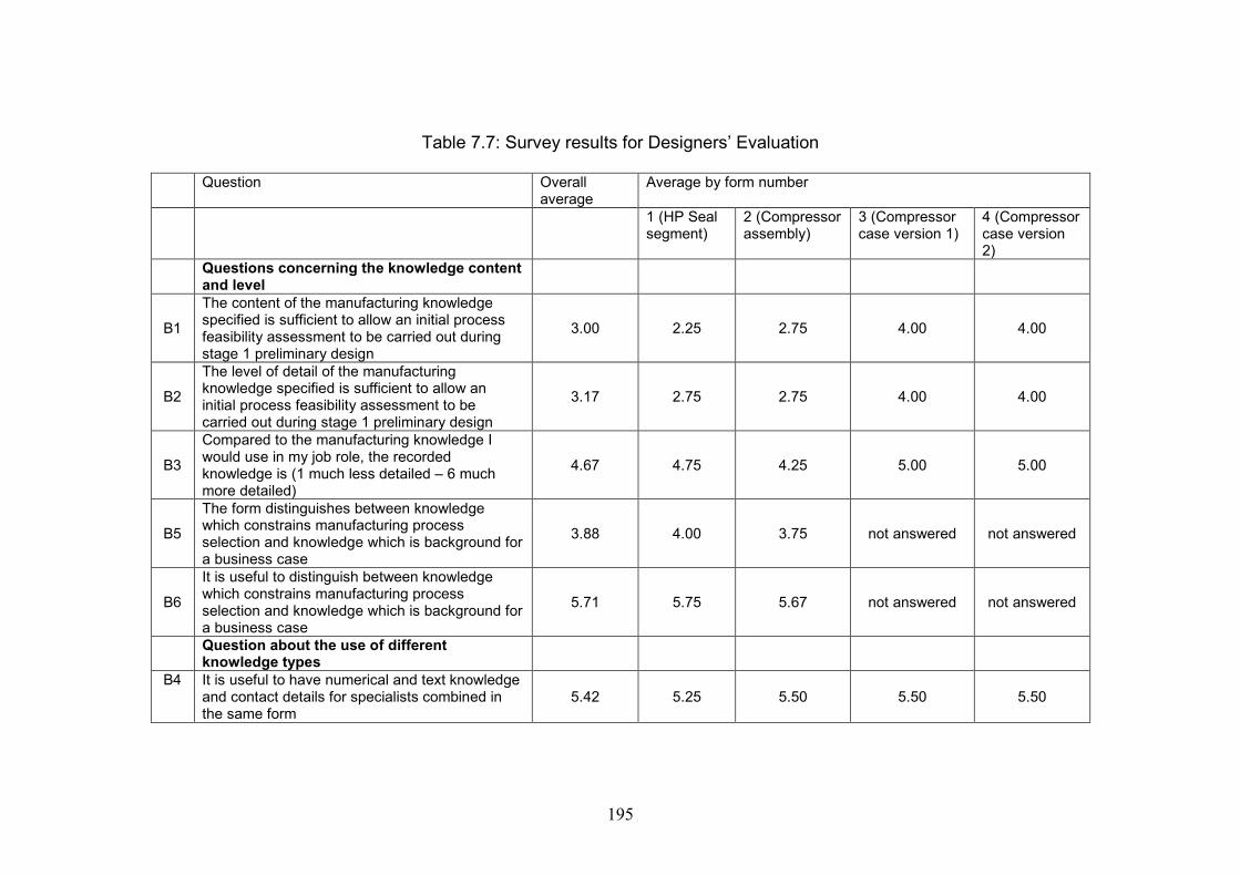
195
Table 7.7: Survey results for Designers’ Evaluation
Question Overallaverage
Average by form number
1 (HP Sealsegment)
2 (Compressorassembly)
3 (Compressorcase version 1)
4 (Compressorcase version2)
Questions concerning the knowledge contentand level
B1
The content of the manufacturing knowledgespecified is sufficient to allow an initial processfeasibility assessment to be carried out duringstage 1 preliminary design
3.00 2.25 2.75 4.00 4.00
B2
The level of detail of the manufacturingknowledge specified is sufficient to allow aninitial process feasibility assessment to becarried out during stage 1 preliminary design
3.17 2.75 2.75 4.00 4.00
B3
Compared to the manufacturing knowledge Iwould use in my job role, the recordedknowledge is (1 much less detailed – 6 muchmore detailed)
4.67 4.75 4.25 5.00 5.00
B5
The form distinguishes between knowledgewhich constrains manufacturing processselection and knowledge which is background fora business case
3.88 4.00 3.75 not answered not answered
B6
It is useful to distinguish between knowledgewhich constrains manufacturing processselection and knowledge which is background fora business case
5.71 5.75 5.67 not answered not answered
Question about the use of differentknowledge types
B4 It is useful to have numerical and text knowledgeand contact details for specialists combined inthe same form
5.42 5.25 5.50 5.50 5.50
196
Questions concerning the knowledge content and level
For questions B1 and B2, there is slight disagreement overall with the ability of theknowledge content and level in providing knowledge to perform an initial feasibilityassessment. The reason for this may perhaps lie in the responses to question B3. Theknowledge accumulated is more than ‘slightly more detailed’ for their perceivedrequirements. Despite amendments being made between forms 3 and 4 to cater forthis, this does not affect the overall scores.
In terms of distinguishing between constraints and business case knowledge (calleddifferentiating and influencing characteristics in the Create process of themethodology), the opinion as to whether this is achieved is neutral (3.88). However,this was rated very highly (5.71) as a requirement for the knowledge.
Questions about the use of different knowledge types
The purpose of this question was to enquire about the use of both explicit and tacitknowledge. The explicit knowledge – structured and semi-structured – is provided byway of the output form. The form itself cannot supply tacit knowledge, however thenamed contact in the form provides a link to a network of experts for tacit knowledgetransfer if so required. This scored very highly in agreement.
7.7.3 Coded Responses to Open-ended questions
Again, an open-coding approach was taken to the results in that similar answers weregrouped together under common themes. There are more categorised answers thannumber of participants because some participants listed more than one answer to eachquestion.
D1. What was the most useful part of the form for you?Responses:-Knowledge content: 3Process maturity: 2Manufacturing impact: 2‘Useability’: 1Additional contact links (unstructured knowledge): 1
Despite concerns as to whether the knowledge was supplied at the ‘correct’ contentand level, it was rated as useful by three respondents. The indication of processmaturity was rated by two participants which was interesting as this was not explicitlycovered in the attitude response questions. The demonstration of manufacturingimpact was also listed by two respondents. These responses tie back to the originalmodel of requirements, so demonstrates that these are useful to both designers andmanufacturing specialists. The ease of use of the output form was also mentioned.
197
D2. What was the least useful part of the form for you?Responses:-Content not appropriate to preliminary design: 1Issues with resources to keep database updated: 1Duplication of knowledge in existing R-R systems: 1No perceived advantage for preliminary design: 1Info on standard process info: 1Accuracy of knowledge: 1Not answered /specified: 2
Some of the responses show concern with the methodology itself – the content itdefines and the advantage of this. Standard process information is not considered tobe useful because it is well defined elsewhere. Because the methodology wasdeveloped in isolation there are concerns that it duplicates knowledge in existingsystems. There were other concerns about the accuracy of knowledge, how it wouldbe updated and who would take responsibility for this. Many of these concerns canbe addressed with future development work, however some, such as the requirementfor a methodology of this type, are more fundamental. It is noted that the view of thebenefit / use appears to come from the perception of what is required from thepreliminary design team at the moment (i.e. their thought world).
D3. What changes would you recommend to the form? Why?
Business readiness: 1Methodology scope: 5
Breakdown of methodology scope:-Knowledge other than manufacturing: 1Process knowledge: 1Focussed around preliminary design: 1Application to generic component families rather than specific component families: 1Link to existing systems / knowledge: 1
The ‘business readiness’ response recognises that further development within thebusiness would be required to prepare the methodology for practical use. Theremaining responses are concerned with the scope of the system – that it should befocussed more towards preliminary design and that the knowledge should be moregeneric at this stage. This could take two forms: either generic process knowledgewhich could then be investigated as potentially new manufacturing solutions, orlinking the manufacturing knowledge at a higher, generic component level rather thanlinking to actual project components. Both of these would enable more investigativework to be undertaken before a project commences. Perhaps the requirement shouldbe before stage 1 design. Other comments would be to see a methodology such as thisexpanded to disciplines other than manufacturing and a better link to existing systemsand knowledge.

198
D4 Would you be interested in using any aspect of this form in your job role?Yes: 3No: 0Don’t know: 3
Yes responses:-
For specialised components which directly influence engine architecture: 1As a prompt for discussions with a specialist: 1For generic knowledge about new processes: 1
Don’t know responses:-Not sure it’s what I need: 2Don’t see how it relates to a conversation with an expert: 1
These comments again support earlier responses. The first concerns the componentswhich require the most input from preliminary design. The second supports the tacitknowledge transfer requirement (although in the ‘don’t know’ responses onerespondent is not sure about this). Others are not so sure of the requirements withanother urging a more generic approach.
D6. Any other comments?Two concerns about keeping the spreadsheet updated.
7.8 Combined Survey Responses
Five questions in each survey were designed to enquire about the same phenomena,although in some cases the wording used was slightly different. The manufacturingresponses and preliminary design feedback responses were therefore compared. Thesimilar questions have been called questions 1, 2, 3 and 4. The key is as follows:-
Questions concerning the knowledge content and level
The response for questions 1 and 2 is slightly disagree. The response for question 3demonstrates the difference in requirements for both specialist domains. Formanufacturing engineers the response is ‘slightly less detailed’, however this is stilltoo much detail for preliminary design. Ideally the ‘correct’ response for this wouldbe neutral for the preliminary designers. Both domains are in some degree ofagreement – preliminary design especially – with question 4 and the need todifferentiate between different types of knowledge and its potential use. However, thedesigners’ overall opinion was that this wasn’t really achieved (ref. q B5/B6) so thisindicates another area where the methodology should be improved.
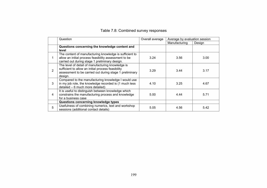
199
Table 7.8: Combined survey responses
Question Overall average Average by evaluation sessionManufacturing Design
Questions concerning the knowledge content andlevel
1The content of manufacturing knowledge is sufficient toallow an initial process feasibility assessment to becarried out during stage 1 preliminary design.
3.24 3.56 3.00
2
The level of detail of manufacturing knowledge issufficient to allow an initial process feasibilityassessment to be carried out during stage 1 preliminarydesign.
3.29 3.44 3.17
3Compared to the manufacturing knowledge I would usein my job role, the knowledge recorded is (1 much lessdetailed – 6 much more detailed)
4.10 3.25 4.67
4It is useful to distinguish between knowledge whichconstrains the manufacturing process and knowledgefor a business case
5.00 4.44 5.71
Questions concerning knowledge types
5Usefulness of combining numerics, text and workshopsessions (additional contact details)
5.05 4.56 5.42
200
Questions concerning knowledge types
There were differing levels of agreement to question 5 with the prelim designersrating it more highly. Overall the reply was ‘agree’.
7.9 Key Observations
It is evident that differences do exist between the appropriate levels of manufacturingknowledge for the two specialist domains who participated in the evaluation sessions.It appears that the appropriate level is unknown to the domain members themselves,especially in preliminary design. The knowledge appears to be very subjective in thatsense. It appears to be very challenging to find the most appropriate level ofgranularity of the knowledge. Furthermore, the knowledge required appears to varydepending on stage of the design process, the required manufacturing assessmentrequired at that stage and perceptions of the knowledge required at that stage. If theprocess is altered in any way then the required manufacturing knowledge required isalso altered. It is possible that the different ‘thought worlds’ are created by thesegregation of activities and job roles according to the stages of the design process.
There appears to be evidence that the methodology achieved some success in bringingtogether the requirements of both domains in a systematic way. However, it is alsoevident that further work is required in order to investigate the granularity ofknowledge that is required. This appears to be an iterative and refining activity. A pre-requisite to this work would be another iterative definition of manufacturingknowledge requirements for preliminary design. This became evident from theevaluation sessions with preliminary design. It seemed apparent that this had been afirst attempt to define manufacturing knowledge for preliminary design. The valuethat the designers derived from the session appeared to be not so much the actualevaluation form, but more that the session had acted as a catalyst to generating ideasand thoughts on the nature of manufacturing knowledge for preliminary design. Thesessions in this respect were useful in generating such ideas. However, in isolationthese requirements would be very much in line with the preliminary design specialistdomain. The knowledge content needs to be defined across domains.
The effect of political issues was not considered during the design of the methodologyand consequently came as a surprise during the evaluation sessions. It is clear that thismay need to be considered if the methodology is defined further. However, the aim ofthe methodology in providing an objective technical comparison of processes mustnot be diluted.
The process maturity element of manufacturing definition definitely appears to havean advantage for two reasons. Firstly, it is a valid method of showing inherent risk inprocess selection. Secondly, as hypothesised, it governs the extent to whichknowledge can be quantified and the appropriate types of knowledge to be used. Thisbecame apparent from the ratings of different knowledge types for processes ‘indevelopment’. Structured knowledge was rated the lowest because it was difficult to
201
quantify certain aspects of the processes. Semi and unstructured knowledge wererated as being more useful.
The evaluation sessions have therefore partially validated the requirements for amethodology for sharing manufacturing knowledge. Process maturity is important andgoverns the way manufacturing knowledge should be expressed. Different knowledgetypes are required for this, both tacit and explicit. The knowledge level and contentdefinitely needs to be at a more generalised and abstract level for preliminary design,with further investigation required into granularity.
These results appear to support and validate the conceptual framework and the need toexplore the knowledge-sharing aspects of the preliminary design process. One couldquestion whether the need for tacit knowledge sharing would be required as much ifthe knowledge requirements were better defined. It is suggested that it is thisuncertainty drives the requirement for tacit knowledge exchange.
However the evaluation does illustrate the importance of the manufacturing impact(on size and shape), importance of process maturity, and requirements of differentknowledge types in the preliminary stage. Consequently these results can be used toshape future knowledge management strategy for this area.
7.10 Summary
The methodology developed in chapter 6 was evaluated by a single embedded casestudy. Its use was trialled using three cases of different combinations of componentsand manufacturing processes. Each case was deliberately selected as an example ofpurposeful sampling. Each evaluation session was observed and a qualitative surveycompleted by each participant to gauge the success of the methodology in sharingmanufacturing knowledge effectively.
The results of each session were then fed back to and evaluated by the preliminarydesign team, to investigate if the appropriate knowledge requirements had beenidentified and collated. Again, qualitative surveys were used in the evaluation.
The findings identified that there was some success in the methodology in enablingknowledge to be identified and shared appropriately, thus confirming the earlierhypothesis of manufacturing requirements. However, further work was required todevelop the methodology into a practical format which could be applied in anorganisational setting.

202

203
Chapter 8
Discussions, Conclusions and Future Work
8.1 Introduction
Previous chapters have recorded the development and testing of a hypothesis whichoutlines the manufacturing knowledge requirements for preliminary design and howthey can be shared effectively between designers and manufacturing engineers. Thishypothesis was derived from two interpretive data collection activities, the first ofwhich generated a conceptual framework of manufacturing knowledge requirementsand the second which highlighted how knowledge requirements need to be generatedfrom and shared across different specialist domains for specific components andprocesses. A methodology was then created which embodied these requirements as ameans of testing the hypothesis which was then evaluated using a sub-assembly, acomponent and a feature.
This chapter draws together and discusses the conclusions from each stage of thestudy. A number of factors need consideration in its conclusion. The research designapproach and strategies used are appraised and the limitations of the study areconsidered. The practicalities of the resulting methodology are considered. Theconclusions of the study and contributions to knowledge from this work are thenhighlighted and opportunities for further research work discussed.
8.2 Discussion of the Research Design and StrategyApproaches
The aim of this study was to examine manufacturing knowledge in a real-life study ofcomplex mechanical components and the problems encountered in sharing thisknowledge between different specialist departments. The main method of knowledgesharing was by human interaction for the benefit of a number of different domainspecialists. In practice it was found that the knowledge was often messy, incompleteor difficult to define. Consequently an approach to the research design was requiredwhich would account for this. A flexible design approach was used with specificexploratory strategies for each research objective. This approach and the strategiesrequire evaluation.
8.2.1 Comments about the use of a flexible design approach
As discussed in chapter 3, the selection of the research design and strategy approachwas based on the exploratory nature of the first research question as there was no pre-
204
existing theory or model on which to frame the enquiry. As the study progressed,subsequent research questions emerged from the results of the previous section ofwork. This enabled a fully flexible approach to be taken to the study. However,typically each section of work created more questions than answers and it took time todecide the most effective approach and research question for the next section. Thisresulted in some work being started and then abandoned to better orientate theresearch objectives. However, there were also definite benefits in the approach as theauthor was in a better position to react to the results from an activity which wereunforeseen but formed an important part of the findings. An example of this is thedata collection activity for the second research activity. It was originally assumed thatthis would be a straightforward technical data collection activity, however the effectof the different specialist domains emerged as a critical aspect of the study.
8.2.2 Comments about the approach adopted for research objectives 1and 2
Research objectives 1 and 2 constituted the inductive part of the study. In bothobjectives, a hypothesis emerged from the analysis of qualitative data. Researchobjective 1 used the grounded theory techniques of open, axial and selective codingfor analysis. For the second objective open coding (categorisation into differentthemes) was mainly used to classify data collected through ad-hoc discussions. It wasfound that there were strengths and weaknesses in using this approach.
In terms of strengths, the approach adopted appeared to be very effective forcollecting knowledge about critical cases where such a theory does not currently exist.This was due to the method used for coding. This was a rigorous line-by-lineexamination of interview transcripts. There was evidence of triangulation becauseexamples of the emergent themes could be seen across the responses. This was laterconfirmed with the feedback session held with the interviewees. The analysis wasbased on recorded data and was not reliant purely on the interviewer’s notes andmemory, which may have been incomplete or prone to research bias.
The main weakness in adopting a data-driven approach is that there is a risk ofdescribing known phenomena and not contributing anything new. This was certainlythe case with research question 1. It is acknowledged that some of the themes whichemerged from the data analysis were not novel. These were the relationship betweencomponent, material and manufacturing process, expressions of tacit and explicitknowledge and the link between the codification of knowledge and the maturity ofknowledge and process. All these themes were previously reviewed in chapter 2. It istherefore suggested that the contribution to knowledge from the hypothesis creation istwofold. Firstly, because the themes emerged independently from other research workfrom the coding process, it is suggested that the analysis work acts as a consolidation(or triangulation) of the previous research work. Secondly, the creation of theconceptual framework demonstrated how these previously unrelated themes connectfor the definition of manufacturing knowledge for preliminary design for the specificcase in consideration. The hypothesis also added process maturity as requiredknowledge content for preliminary design in addition to method, capability and cost.
205
The conceptual framework developed from the first research question formed thefoundation of the requirements for the methodology. However, this model itself wasabstract as the aim of grounded theory is to create a generalised theory to describe arange of situations. Although the responses were valuable in forming the model, itbecame apparent that further investigation was needed into a specific component inorder to produce some tangible evidence of the manufacturing knowledge.
The second research objective was therefore formulated to carry out this investigation,with the expectation that a neat set of technical requirements would be generated. Theresults yielded not only the manufacturing knowledge required but also the problemsencountered in sharing this knowledge due to the different ‘thought worlds’ within thedomain specialties. The data collection involved in reaching these conclusions wasless formalised than for research objective 1 and involved a series of ad-hocunstructured discussion with a series of specialists in different departments. As withresearch objective 1, this approach had strengths and weaknesses.
In terms of strengths, the ad-hoc approach was pivotal in providing evidence of thedifferent ‘thought worlds’. As each discussion was unstructured it became led by thespecialist’s knowledge and allowed a recording of their specific knowledge sharingrequirements and problems. Indeed, the ‘thought worlds’ result took some time toemerge, with the researcher’s initial thoughts being, “Why is everybody telling mesomething different?” during the discussions. The ‘thought world’ phenomenatherefore emerged from the analysis of the notes recorded.
However, it is acknowledged that the ad-hoc and informal nature of this datacollection made it vulnerable to respondent bias. Also, despite the intentions of theresearcher to remain impartial and take complete notes, there may have been somedegree of researcher bias, i.e. in selective note taking and by prioritising issues whichwere in line with their own inherent experience and views. However, this may havebeen mitigated in that many of the issues encountered were of a technical nature, weretherefore factual and not open to interpretation (although the reason for theiroccurrence may be).
Overall, the strength of the approach for this objective outweighed its weakness interms of the resulting data analysis. Indeed, it could be argued that some degree ofrespondent bias was necessary in order to show evidence of the differing requirementsof the thought worlds. However, this could have been better mitigated by a morerigorous approach to questioning and a method of recording other than by researchernotes.
8.2.3 Comments about the approach adopted for research questions 3and 4.
Research questions 3 and 4 constituted the hypothesis testing part of the study. Duringresearch objective 3, a methodology was created to test the hypothesis generatedduring the first half of the study. Consequently, no new data was collected for this
206
phase of the work, however the conclusions from the objectives 1 and 2 were the basisfor the creation of the methodology.
The methodology emerged from the analysis of the data collected during phases 1 and2. Therefore, once again it conformed to a flexible, data-driven qualitative design. Aset of systematic processes were then designed around the two parts of themethodology (the process maturity audit and the characteristics) to create a series oflogical steps which could be realised in a workshop format. These also formed thebasis of a series of requirements for an ICT support system which were envisaged asan interactive intranet site linked to a database for recording the knowledge.
Feedback from the key stakeholders was very important during this stage as a peerdebriefing / support activity to reduce researcher bias. The use of several stakeholdersat various stages of the design process was also effective in triangulating themethodology requirements and hence reducing researcher bias.
The focus of this objective was on creating processes for identifying, collating andsharing knowledge. This resulted in two processes – the ‘Use’ and ‘Review’ processes– being deemed out of scope for completion. This is a weakness in this objective, as itwould have been useful to work these through to check viability of the methodologyproposed. It may also have allayed some of the issues concerned with maintenanceand support which were noted during the evaluation session.
The final research objective was an evaluation of the methodology creating duringresearch objective 3. Use a single-case embedded case study, three components wereevaluated using the methodology. The components were critical cases in that theywere deliberately selected to be relevant to the methodology. The processes wereexamined at assembly, component and feature level respectively and this proved to bea useful differentiator for the preliminary designers’ feedback.
The analysis was qualitative, using a survey with a combination of attitude scale andopen-ended questions and additional observations to triangulate the survey results.
The limitations in the attitude scales questions were frustrating in that they provided ameasure of the participant’s reaction but not the reasons for this. On a scale of 1-6 themajority of replies were in the 3-4 range which meant that many results wereinconclusive. The open-ended questions were found to be far more useful ingenerating responses and a more effective addition to the attitude scale questions.
The observations were useful in interpreting the survey results as the responses couldbe compared with participants’ attitudes during the workshop session. However,more formalised methods of recording and analysing the observations would haveadded additional rigour to this process.
A further unfortunate but major weakness in the evaluation was the involvement fromthe preliminary design team. The involvement of more of the group would have beenuseful from two perspectives: evaluation of the output of the workshops and
207
participation in the workshops. The latter would have been very useful particularly forevaluating tacit knowledge transfer between all the domain specialists.
8.2.4 Discussion of alternative approaches
The strength of this research study is that it was able to expose and examine the finerdetails and complexities of defining and sharing the knowledge. It is the author’sopinion that the research approach adopted was instrumental in achieving this. Thereare certainly different ways in which this research problem could have beenapproached. However, it is important to note that this would have completely changedthe enquiry. Some examples of possible alternative approaches follow.
Rather than accounting for the different ‘thought worlds’ of the domain specialists, amore fixed approach could have been used. An ontology of preliminarymanufacturing knowledge could have been developed as an initial model and testedon several components to see if this was a fit for the ‘real world’. In a way, this wasthe original purpose of capturing the blisk knowledge. It was through this work thatthe researcher experienced in practice the way in which data can be ‘messy’ andpertaining to that thought world. The developed methodology could perhaps beinterpreted as an initial attempt to bring the thought worlds together to create such anontology. Approaching the problem as a test of an initial model may have givenbetter initial guidance to the study, however the ‘messiness’ and complexityexperienced in this project may have been missed.
In chapter 2, a comparison was made to the two different approaches taken byresearch in this area – as a method of supporting the specialists or by automating theprocess. This project adopted the former approach. In attempting to develop a tool toautomate the process the same issues of maturity of process and (more importantly)the knowledge relating to that process may have arisen (for an example of this see(Haque et al., 2000)). However, problems may have been encountered in attemptingto standardise and automate knowledge which cannot be standardised and automated.Attempting this problem using this approach would be an interesting exercise.
A flexible approach to the study could have been used with the emphasis on differentparts of the problem. Research objectives 1 and 2 could have been expanded toinclude other organisations responsible for complex mechanical components toincrease the external generalisability of the study. However this would have againchanged the focus of the study to become purely inductive. Further evaluation of thehypothesis would be required in an additional study.
In terms of the research strategies adopted, other methods of data collection againwould have yielded different results. An ethnographic study of the preliminary designteam would have provided data on knowledge interactions between the team, but notacross the team boundaries and with the other specialist domains. Also not all designproblems are manufacturing-related and this may not have proved to be a beneficialuse of time. As previously discussed in 8.2.2, a more rigorous data collection methodfor research objective 2 would have strengthened the study.

208
8.3 Limitations of the Study
It is recognised that a major limitation with this study is that it took place within oneorganisation. This creates difficulties in externally generalising the results. Theorganisation was selected because it exhibited certain characteristics which made it asuitable subject for the research area. These were:-
The nature of the product as an assembly of complex mechanical components. The nature of the design process. For successful control of the product design
both within the organisation and in the tiered supply network, a staged gatereview process is used to control the maturity of the design. This segregatesthe process into a series of stages which approximately conform to theconceptual, embodiment (preliminary) and detail stages of design.
The size of the organisation, the number of people involved in the productdesign and problems with geographical co-location.
The combination of engineering processes required during the design processand the trade-off which is required as a consequence of all these factors.
Arguably, the results of this research could therefore be applied to other organisationsexhibiting similar characteristics, although this would need further study.
However, this organisation limitation can also be construed as a benefit. It enabled avery detailed examination of knowledge sharing issues to be undertaken betweendifferent domains. The knowledge relating to actual engineering components couldbe examined in depth. In total, 38 people from the organisation took part in theresearch at some stage. The qualitative methods of data collection yielded a richanalysis and examination of the issues involved. Such findings were the need for theprocess maturity and the identification of the different ‘thought worlds’. These resultswould not have been identified in a broader study involving less people in moreorganisations. Carrying out the research in this way identified research areas relevantand unique to this sector which could be explored further. By limiting the context ofthe research, the research design could encompass both inductive and hypothesistesting elements. Broadening the context would have resulted in the focus of theenquiry changing to one of these elements.
8.4 Comments on the Methodology Developed
The purpose of the methodology was to create a vehicle for testing the requirementsof the hypothesis proposed from research objectives 1 and 2. However, in doing thisthe methodology also became a prototype practical tool for sharing knowledge withinthe industrial environment. Certainly, it was presented as such to the key stakeholdersand evaluators. Therefore a discussion on the success of the methodology must be anevaluation from both of these perspectives.

209
8.4.1 The methodology as a means of testing the hypothesis
To be perceived as a successful test vehicle, the methodology needed to be a credibleembodiment of the hypothesis requirements as discussed in section 6.3. Theknowledge requirements were defined by the process, material, geometric and othercharacteristics. The intention of these characteristics was to ensure the assessment ofprocess feasibility, capability and cost. The addition of influencing and differentiatingcharacteristics were designed as a measure of process feasibility.
The identification and capture of knowledge requirements was enabled by a series ofworkshops attended by domain specialists key to the knowledge sharing. This use ofworkshops and knowledge recording enabled both tacit and explicit knowledge to beused. Thus, the requirements were certainly catered for in the design. The questiontherefore is how well did these work in practice to successfully evaluate themethodology?
Capturing Requirements
The requirements to be specified in the methodology related to the method ofmanufacture, capability and maturity, i.e. the feasibility of the process in being able tocreate the component configuration specified. Although cost was also an initialrequirement this was deemed out of scope because this would involve an additionalinvestigation into the nature of costing during the preliminary design stage. Such aninvestigation requires further work. The requirements to be specified depended on theinterpretation and provision of the process, material and geometric characteristics andtheir categorisation as influencing or differentiating.
Some results were output from the methodology workshop which could be used in itsevaluation. However, the results showed that this area required further development.Despite briefings, there was some ambiguity in the definition of the characteristicsand consequently this impaired the knowledge requirements supplied. It is not clearwhether the difficulty in capturing the requirements was due to the nature of theknowledge itself, or that the requirements had inbuilt uncertainties which made itdifficult to define. More development work is required in this area.
Process Maturity
This was carried out by the Process Maturity Audit during the Select process, the firstprocess in the methodology. During the evaluation sessions, the components weredeliberately selected so that two methods of manufacture – one in development andone mature – could be compared. This appeared to work out as intended. The exercisewas intended as a first initial assessment often based on intuitive attitudes towards theprocess and therefore it required experienced specialists’ input. This worked quitewell in practice although it could constrain use of the methodology as a practicalapplication (see next section). In terms of the knowledge that was captured, one wouldhave expected the more mature process to have been easier to quantify, although thisdid not necessarily seem to be the case. This may have been due to the knowledgecapture activities within the methodology.
210
Use of Tacit and Explicit Knowledge
From observations, the evaluation workshops proved to be an excellent forum forexchanging knowledge about the component and its methods of manufacture. Muchanecdotal knowledge was included, out of scope of the methodology requirements, thenature of which was recorded during the second evaluation workshop. Although notstrictly relevant to the purpose of the methodology, such additional knowledge couldbe perceived as adding useful background and context to the knowledge. Hence, theworkshops were successful in meeting the criteria for tacit knowledge sharing and thisability was appreciated as being valuable by the participants in the evaluation surveyratings. However, they were not so sure of the value of this knowledge transferactivity as an effective use of time. Perhaps conversational exchanges are notrecognised as being part of the project work breakdown structure. Alternatively, itcould be seen as an appraisal of the actual knowledge collected during the respectiveevaluation sessions.
Due to the difficulties in quantifying knowledge in the time constraints of theworkshop, it is questioned whether this was the most appropriate forum for capturingnumerically codified explicit knowledge (or ‘structured knowledge’ as it was termedin this study). Perhaps the workshop should be limited to brainstorming the requiredcharacteristics and their rationale. The quantification could then take place as afollow-up activity, where the knowledge could be referenced or computed, with afurther workshop afterwards to view the results.
A major disadvantage of the evaluation is that preliminary design domain specialistswere unavailable to take part in the workshop sessions. This would have been usefulin examining the tacit knowledge exchanges. Such exchanges may have furtherassisted in creating a shared context between preliminary design and manufacturingspecialists which may have better specified the level of knowledge required. Furtherwork is required to verify this.
8.4.2 The methodology as a practical application
This section discusses how appropriate the developed methodology is as a practicaltool which can be used to capture and share manufacturing knowledge for preliminarydesign in an industrial setting. It is therefore important to consider whether thisdiscussion can be limited to the organisation featured in the research, or to include thepossibility of the methodology’s use in other organisations. Here, there is a benefit inthat the methodology does not feature a prescriptive design process, therefore it has adegree of flexibility which lends itself to being tailored to fit different organisationsand design processes.
There are two ways to approach this:-
1. The methodology could be adapted to fit a specific organisation and design process(for the purposes of this thesis, the sponsoring organisation).or
211
2. The methodology remains independent and can be incorporated into differentorganisations and types of design processes.
Each approach has advantages and disadvantages and will be discussed in turn.
Adopting the methodology to fit a specific organisation
In this case, the methodology would be integrated with the organisational designprocess. The method of recording and recalling the knowledge captured would need tobe integrated with existing organisational systems.
The advantages of this approach would be:-
1. The knowledge-sharing activity between preliminary design and manufacturingwould become an integral part of the design process of the engine project andtherefore be included by default. This should pave the way for a more rigorous riskassessment of new manufacturing processes during early preliminary design.
2. In order to introduce a new business process or system it is essential that the usercommunity has ‘buy-in’, that is, actively participates in its creation and use.Integration with the existing business process would by default result in greater buy-in.
3. By linking to existing systems there would be less duplication of data.
The major disadvantage with this approach is that there may be a mismatch betweenthe methodology and existing processes and systems. A major part of themethodology implementation would entail the closing of this gap. In doing so, theimplementation team would need to ensure that this did not dilute the intentions andbenefits in implementing the methodology.
Implementing the methodology as an integrated part of the design process andsystems would require the following major project phases:-
1. Further development of the methodology. This would require a further userrequirements capture stage to ensure that the methodology would work in a waysympathetic with the users’ task. This requirements capture would be from a practicalusers’ perspective rather than the research perspective adopted for this thesis. Duringthis stage it is essential to set clear boundaries for the scope of the implementation inorder to have a timely roll-out.
2. Analysis of the methodology and current design process. This would be undertakento understand how and where the methodology fits with the current design processand how to best tailor it to fit with the process. At this stage it is essential to ensurethat the methodology intentions and benefits stand up.
212
3. Analysis of current design support systems. This would be a similar activity to 2but undertaken from a systems perspective. The outcome of this stage would specifywhether the system to support the methodology would be an enhancement of anexisting system or an additional tool. Investigations would need to examine how bestto present, record and re-use the relevant knowledge. System support and maintenancewould also be an important factor (see point 6).
The first three stages can be partitioned into individual segments of work, however itwould be beneficial to run them concurrently as the results of all will impact on eachother. Several iterations of the requirements may be required.
4. Methodology and system implementation. This stage features the usual expectedstages of ICT project implementation: the configuration (or creation) of the softwaresystem (depending on the solution selected) and business processes, documentation ofthese, testing, user acceptance testing and user training.
5. Roll-out. A decision would need to be made early in the project to determine thescope of the eventual roll-out. It is suggested that this is carried out on a small pilotinitially before commitment to a larger-scale deployment. The scope of the initial roll-out could be confined to a specific subset of components for an engine project.
6. Ongoing support and maintenance. This was an issue which was highlighted duringthe methodology evaluation sessions, especially by the preliminary design team. It isvital that the knowledge in the system is kept updated and current in order for it to beused successfully for risk assessments during preliminary design. Ensuring that this iscarried out and making this process transparent to the users is necessary to establishtrust and therefore maximise buy-in into the knowledge recorded. The methodologyincludes the Review process, out of scope of this study, which would need to becreated and implemented as part of this. The requirements for methodology / systemsupport and maintenance - what needs to be done, when and by whom - wouldinitially need to be explored and specified during activity 3 above. This would ensurethat the requirements are manageable within the scope of day-to-day work.
Using the methodology independently of the organisational processes
With this second approach, the methodology would continue to function in the formatseen in its development and evaluation in this study, that is, as a set of processessitting alongside but independently of the main preliminary design process. Thesupporting ICT system would also be independent of other organisational tools.
The advantages of this approach are:-
1. Implementation and roll-out could take place in a short time frame because theanalysis of the methodology and current systems and processes (steps 2 and 3 of theimplementation for the first approach) are no longer required.2. The methodology would be more flexible and adaptable to future changes to thedesign process.

213
3. Methodology and system maintenance and support would be easier. Moreintegration between systems and processes can result in potentially more and complexproblems, i.e. being affected by a patch upgrade in COTS software.
The disadvantages are:-
1. Because the methodology is not closely integrated with the design process, there isthe risk that it will be seen as an optional activity. This could reduce user buy-inwhich, as discussed previously, is essential to the success of any process or system.
2. The knowledge recorded may be duplicated in other systems, especially structuredknowledge. This is problematic for the entire design process, is a waste of user effortand may reduce trust (and hence use) in the system.
The implementation of the methodology as an independent set of processes andsupporting ICT system would require the following project stages:-
1. Further work on the methodology. This would be further development to ensurethat the methodology will meet requirements from a user’s perspective rather than aresearch perspective. This would probably involve a re-appraisal of the ‘Select’ and‘Create’ processes, further work on the most appropriate ‘Use’ process and thecreation of the ‘Review’ process. The outcome of this stage would ideally be a clearlydefined and ‘ready to use’ set of methodology processes.
2. Specification of the methodology ICT support system. This could be either asystem written in-house tailored to the specific methodology requirements, such as adatabase linked to intranet web pages. Alternatively a COTS solution may be the bestoption. The system requirements would need to be scoped and specified, including notonly functionality but also support and maintenance requirements.
3. Implementation.4. Roll-out5. Ongoing support and maintenance
These follow the same format and hence the same issues as steps 4, 5 and 6respectively for the integrated methodology.
8.5 Recommendations for Improving the KnowledgeIdentification, Acquisition and Sharing
Outside the boundaries of the methodology, the findings of the study have furtherimplications for the management of manufacturing knowledge during preliminarydesign, particularly concerning the ways in which knowledge identification,acquisition and sharing can be improved. The recommendations are:-

214
1. In terms of knowledge identification, it is important to identify thecharacteristics of a product or process where there is an element of immaturityin the knowledge associated with the product or manufacturing process. Thisdemonstrates an element of risk in the product which will need to be managedand mitigated.
2. In terms of knowledge acquisition, cross-functional approaches have beenverified as being critical. The intended use of the knowledge to be acquiredwill vary according to the domain specialism. It is important for thoseinvolved in such an activity to be aware of this, as the knowledge to besupplied may not necessarily be that which would be perceived as being mostrelevant. Clarifying the knowledge required and the rationale for thatknowledge in such activities would be a simple but effective step.
3. In terms of knowledge sharing, other knowledge transfer activities should beimplemented to improve the links between preliminary design and thefunctions which are responsible for manufacturing process developments. Thiscould increase the awareness of how these processes can impact on componentconfigurations and increase the options explored at the beginning of a newengine project. This would be an important activity to operationaliserecommendation 1. Such knowledge transfer activities should embrace boththe tacit and explicit elements of knowledge and be a formal method withinthe process, similar to the formal social network of the IPTs used in laterstages of the design process.
4. The configuration impact attributed to a new manufacturing process remainsconstant as a manufacturing process matures, although the extent of thatimpact will become more quantifiable. The assessment of the geometriccharacteristics in the methodology defines that size and shape. This would be auseful early exercise to identify manufacturing features - the attributes fromwhich process capability could be measured as the process matures. As theprocess matures, these features could become standardised.
8.6 Contributions to Knowledge
1. An investigation into engineering knowledge management has been carriedout using an interpretive, flexible research design and phenomenologicalenquiry techniques. This type of research design has not conventionally beenapplied to this subject area. The use of this methodology complements and (toa certain extent) triangulates research in this area which has used more‘conventional’ techniques. However, it has also emphasised the socialknowledge sharing aspects and requirements needed in an industrial setting.
2. A hypothesis has been developed which defines the requirements forinnovative manufacturing knowledge during the preliminary stage of designfor complex mechanical components. This hypothesis supports and
215
consolidates previous research themes of tacit and explicit knowledge,codification and maturity of knowledge.
3. A practical methodology has been created from the hypothesis whichdemonstrates a combined tacit and explicit approach for knowledgemanagement for innovative manufacturing knowledge during the preliminarydesign stage of complex mechanical components.
8.7 Conclusions of the Study
1. The preliminary design stage in the case studied for this research is concerned withan initial feasibility assessment before the more detailed DFM – type activitiescommence in the next stage. The reason for this it to mitigate risks which will becomemore costly to correct at a later stage.
2. The content for manufacturing knowledge at preliminary design level is similar tothat of the more detailed stages in that it encompasses method of manufacture, processcapability and cost. However, an additional key requirement at preliminary stage isknowledge about the maturity of the manufacturing processes available because this isthe main risk to be mitigated. The manufacturing knowledge is abstracted in that ageometrical impact is sufficient to explain the manufacturing effect for this stage ofthe design process. The reasons for this geometrical impact become relevant for laterdesign stages.
2. The main driver for manufacturing knowledge in preliminary design is the impactof the manufacturing process on the component configuration, hence the feasibility ofachieving this configuration is key. This can be directly related to the componentfunction and material selected.
3. The impact on component configuration as described in point 2 can beadvantageous as it leads to the possibility of exploring new component configurationswhich can better satisfy or even improve on functional requirements. However, therisks must be appreciated, especially in situations where the process is new toproduction and hence the associated knowledge is uncertain.
4. Hence, methods of collating and sharing knowledge which has some degree ofuncertainty is key in sharing manufacturing knowledge between the design andmanufacturing specialist domains during preliminary design, Expressing knowledgein both tacit and explicit ways with varying degrees of codification are instrumental inthis.
5. The design process puts artificial barriers in place of the flow of knowledge due tothe required product (geometric) maturity at each process stage. Additionally,differing perceptions of knowledge requirements create different ‘thought worlds’ fordesign and manufacturing specialists. These impede knowledge flow, creating‘knowledge gaps’ which impact on the effectiveness of the design process. This may

216
well be why manufacturing problems are encountered despite the introduction ofConcurrent Engineering techniques.
6. Therefore knowledge management techniques should concentrate on cross-domainknowledge sharing methods for improvements in preliminary design. The findingsfrom the study are the requirements for such a technique.
7. A pilot methodology was developed incorporating these requirements and tested.This demonstrated some effectiveness, especially regarding the process maturity andknowledge types used.
8.8 Future Work
8.8.1 Future work concerning the methodology
Further development and definition of the methodology is required, particularly in thedefinition of the characteristics and the means by which this can be successfullyachieved. However, it is recognised that this requires the more effective definition ofsomething which is, by nature, difficult to define.
A case which was not tested during the evaluation session was the tacit knowledgesharing between preliminary designers and manufacturing engineers. This could takeplace during the workshop systems and is recommended as further work to betterdefined the manufacturing knowledge content required.
The above would assist in preparing the methodology to be applied practically in anindustrial setting. However, other aspects also need to be examined for businessreadiness. These are:-
The integration of the methodology with existing business process. Selection and implementation of suitable ICT systems to support the
methodology.
8.8.2 Future research work
1. The hypothesis created as part of this research can be investigated and tested inother situations to test whether it applies and the limits at which it applies. Suitablecandidates could include other companies in the aerospace sector or other industrysectors which also produce complex mechanical engineering systems (such asenergy). The hypothesis could also be tested across component complexity toinvestigate the limits to which it can be used.
2. A main conclusion of this research was the need to use different knowledge typesand strategies to deal with the uncertainty of knowledge generated. Research shouldbe carried out to examine whether this is also the case for other types of knowledgerequired during the preliminary design stage. An area of current research and

217
therefore a good candidate for consideration for this specific case would be serviceconsiderations.
3. Research could also be carried out to further investigate whether the ‘knowledgematurity’ aspect is unique to preliminary design or whether it does actually also existfor later stages of the design process. This may have not been previously investigateddue to simplification of the product and process for later stages of design. Ideally, thisresearch would take place in a sector responsible for complex mechanical engineeringsystems.
4. The hypothesis could be extended in the future to investigate how changes atcomponent level (due to the development of manufacturing processes) affect changepropagation within the sub system of a complex mechanical component.

218
219
References
ALAVI, M. and LEIDNER, D.E., 2001. Knowledge management and knowledgemanagement systems: conceptual foundations and research issues. MIS Quarterly,25(1), pp. 107-136.
BAILEY, M.W. and VERDUIN, W.H., 2000. FIPER: An intelligent system for theoptimal design of highly engineered products, Measuring the Performance andIntelligence of Systems: Proceedings of the 2000 PERMIS workshop, 14-16 August2000, Gaithersburg USA, NIST, USA, pp. 467-477.
BALOGUN, O., HAWISA, H. and TANNOCK, J., 2004. Knowledge managementfor manufacturing: the product and process database. Journal of ManufacturingTechnology Management, 15(7), pp. 575-584.
BESSANT, J. and TIDD, J. 2007. Innovation and Entrepreneurship. Wiley.
BIDARRA, R. and BRONSVOORT, W.F., 2000. Semantic feature modelling.Computer-Aided Design, 32(3), pp. 201-225.
BIDARRA, R., VAN DEN BERG, E. and BRONSVOORT, W.F., 2001.Collaborative modelling with features. Proceedings of DETC ’01, ASME 2001 DesignEngineering Technical Conference and Computers in Information in EngineeringConference, 9 – 12 September 2001, Pittsburgh USA, ASME USA, pp. 535-545.
BOHN, R.E., 1994. Measuring and managing technological knowledge. SloanManagement Review, Fall 1994, pp. 61-73.
BOISOT, M. and COX, B., 1999. The I-Space: a framework for analyzing theevolution of social computing. Technovation, 19(9), pp. 525-536.
BOLISANO, E. and SCARSO, E., 1999. Information technology management: aknowledge based approach. Technovation, 19(4), pp. 209-217,
BOOTHROYD, G., DEWHURST, P. and KNIGHT, W., 2002. Product Design forManufacture and Assembly. 2nd edn. New York: Marcel Dekker.
BORDEGONI, M. and CUGINI, U., 2002. Design and manufacturing knowledgemanagement, Seventh International Conference on Manufacturing and Management(PCM 2002), 27-29 November 2002, Bangkok Thailand, PCMM, pp.476-481.
220
BORG, J.C. and GIANNINI, F., 2003. Exploiting integrated 'product' and 'life-phase'features, R. SOENEN and G.J. OLLING, eds. In: Feature Based Product Life-CycleModelling (Conference on feature modelling and advanced design-for-the-life-cycle-systems FEATS 2001), 12-14 June 2001, Valenciennes, France. Kluwer AcademicPublishers, pp. 1-18.
BRADFIELD, D.J. and GAO, J.X., 2007. A methodology to facilitate knowledgesharing in the new product development process. International Journal of ProductionResearch, 45(7), pp. 1489-1504.
BRADLEY, H.D. and MAROPOULOS, P.G., 1995. A concurrent engineeringsupport system for the assessment of manufacturing options at early design stages.Proceedings of the thirty first MATADOR conference, 20-21 April 1995, ManchesterUK, Palgrave Macmillan, UK.
BRESNEN, M., EDELMAN, L., NEWELL, S., SCARBROUGH, H. and SWAN, J.,2003. Social practices and the management of knowledge in project environments.International Journal of Project Management, 21(3), pp. 157-166.
BRONSVOORT, W.F. and JANSEN, F.W., 1993. Feature modelling and conversionkey concepts to concurrent engineering. Computers in Industry, 21, pp. 61-86.
BRONSVOORT, W.F. and NOORT, A., 2004. Multiple-view feature modelling forintegral product development. Computer-Aided Design, 36(10), pp. 929-946.
BRUNETTI, G. and GOLOB, B., 2000. A feature-based approach towards anintegrated product model including conceptual design information. Computer-AidedDesign, 32, pp. 877-887.
CANCIGLIERI, O.J. and YOUNG, R.I.M., 2003. Information sharing inmultiviewpoint injection moulding design and manufacturing. International Journalof Production Research, 41(7), pp. 1565-1586.
CARLILE, P.R., 2004. Transferring, translating, and transforming: An integrativeframework for managing knowledge across boundaries. Organization Science, 15(5),pp. 555-568.
CARLILE, P.R., 2002. A pragmatic view of knowledge and boundaries: Boundaryobjects in new product development. Organization Science, 13(4), pp. 442-456.
CARLILE, P.R. and REBENTISCH, E.S., 2003. Into the Black Box: The KnowledgeTransformation Cycle. Management Science, 49(9), pp. 1180-1195.
CEDAR, R., 2004-last update, the intelligent master model process for achievingfunctional design [Homepage of CPD Associates], [Online]. Available: https://cpd-associates.com/doc_viewer.cfm?SUBSID=104024005&ID=174691422&FILEID=172185984
221
CERA, C.D., REGLI, W.C., BRAUDE, I., SHAPIRSTEIN, Y. and FOSTER, C.V.,2002. A collaborative 3D environment for authoring design semantics. IEEEComputer Graphics and Applications, 22(3), pp. 43-55.
CHELL, E., 1998. Critical Incident Technique. In: G. SYMON and C. CASSELL,eds, Qualitative methods and analysis in organizational research: a practical guide.Sage.
CHEN, W.J., 1999. Manufacturing information for engineering design (PhD Thesis),University of Cambridge, Cambridge.
CHEN, Y. and LIANG, M., 2000. Design and implementation of a collaborativeengineering information system for allied concurrent engineering. InternationalJournal of Computer Integrated Manufacturing, 13(1), pp. 11-30.
CHEN, Y., LIAO, C. and PRASAD, B., 1998. A systematic approach of virtualenterprising through knowledge management techniques. Concurrent Engineering:Research and Applications, 6(3), pp. 225-244.
CHEUNG, W.M., BRAMALL, D.G., MAROPOULOS, P.G., GAO, J.X. and AZIZ,H., 2006. Organizational knowledge encapsulation and re-use in collaborative productdevelopment. International Journal of Computer Integrated Manufacturing, 19(7),pp. 736-750.
CLARKSON, P. and HAMILTON, J., 2000. ‘Signposting’: A parameter-driven task-based model of the design process. Research in Engineering Design, 12, pp. 18-39.
CLEGG, C.W., 2000. Sociotechnical principles for system design. AppliedErgonomics, 31(5), pp. 463-477.
CLEGG, C.W., GRAY, M.O. and WATERSON, P.E., 2000. The "Charge of the ByteBrigade" and a socio-technical response. International Journal of Human ComputerStudies, 52(2), pp. 235-251.
COSTA, C.A. and YOUNG, R.I.M., 2001. Product range models supporting designknowledge reuse. Proceedings of the Institution of Mechanical Engineers Part B:Journal of Engineering Manufacture, 215, pp. 323-337.
DE KRAKER, K., DOHMEN, M. and BROONSVOORT, W.F., 1995. Multiple-wayfeature conversion to support concurrent engineering, Third Symposium on SolidModeling and Applications, 17-19 May 1995, Salt Lake City USA, ACM, IEEEComputer Soc, pp.105-114.
DE MARTINO, T., FALCIDIENO, B. and HASSINGER, S., 1998. Design andengineering process integration through a multiple view intermediate modeller in adistributed object-oriented system environment. Computer-Aided Design, 30(6), pp.437-452.
222
DEITZ, D., 1995. An infrastructure for integration. Mechanical Engineering, 117(3),pp. 78-80.
DONG, J. and VIJAYAN, S., 1997. Features extraction with the consideration ofmanufacturing processes. International Journal of Production Research, 35(8), pp.2135-2155.
DOUGHERTY, D., 1992. Interpretive barriers to successful product innovation inlarge firms. Organization Science, 3(2), pp. 179-202.
DU, S., XI, L., NI, J., ERSHUN, P. and LIU, C.R., 2008. Product lifecycle-orientedquality and productivity improvement based on stream of variation methodology.Computers in Industry, 59(2-3), pp. 180-192.
EASTERBY-SMITH, M., THORPE, R. and LOWE, A., 1991. ManagementResearch: An introduction. Sage.
ECKHERT, C.; CLARKSON, P.J.; ZANKER, W. 2004. Change and customization incomplex engineering domains. Research in Engineering Design , 15, pp. 1-21.
FAHEY, L. and PRUSAK, L., 1998. The eleven deadliest sins of knowledgemanagement. California management review, 40(3), pp. 265-276.
FARRUKH, C.P., MOULTRIE, J., PHAAL, R., HUNT, F. and MITCHELL, R. 2007.Risk Management in Innovation in: REUVID, J., ed. Managing Business Risk (4th
Ed). Kogan Page.
FERNIE, S., GREEN, S.D., WELLER, S.J. and NEWCOMBE, R., 2003. Knowledgesharing: context, confusion and controversy. International Journal of ProjectManagement, 21(3), pp. 177-187.
FERRARI, F.M. and TOLEDO, J.C.D., 2004. Analyzing the knowledge managementthrough the product development process. Journal of Knowledge Management, 8(1),pp. 117-129.
FLANAGAN, J.C., 1954. The Critical Incident Technique. Psychological bulletin,51(4), pp. 327-358.
FLANAGAN, T.L., ECKHERT, C.M., SMITH, J., EGER, T. and CLARKSON, P.J.2003. A functional analysis of change propogation. International Conference onEngineering Design, Stockholm, 19-21 August 2003.
FRASER, P., MOULTRIE, J. and GREGORY, M. 2002. The use of maturity models /grids as a tool in assessing product development capability: a review. IEEEInternational Engineering Management Conference, Cambridge UK, 18 – 20 Aug2002.
223
FU, Q.Y., CHUI, Y.P. and HELANDER, M.G., 2006. Knowledge identification andmanagement in product design. Journal of Knowledge Management, 10(6), pp. 50-63.
FUJITA, K. and KIKUCHI, S., 2003. Distributed design support system forconcurrent process of preliminary aircraft design. Concurrent Engineering Researchand Applications, 11(2), pp. 93-106.
GAO, J.X., TANG, Y.S. and SHARMA, R., 2000. A feature model editor and processplanning system for sheet metal products. Journal of Materials ProcessingTechnology, 107, pp. 88-95.
GAO, J.X., AZIZ, H., MAROPOULOS, P.G. and CHEUNG, W.M., 2003.Application of PDM technologies for enterprise integration. International Journal ofComputer Integrated Manufacturing, 16(7-8), pp. 491-500.
GAYRETLI, A. and ABDALLA, H.S., 1999. An object-oriented constraints-basedsystem for concurrent product development. Robotics and Computer-IntegratedManufacturing, 15, pp. 133-144.
GINDY, N.N.Z., 1989. A hierarchical structure for form features. InternationalJournal of Production Research, 27(12), pp. 2089-2103.
GRANT, R.M., 1996. Prospering in dynamically-competitive environments:organizational capability as knowledge integration. Organization Science, 7(4), pp.375-387.
GRANT, E.B. and GREGORY, M.J., 1997. Tacit knowledge, the life cycle andinternational manufacturing transfer. Technology Analysis & Strategic Management,9(2), pp. 149.
GU, P. and CHAN, K., 1995. Product modelling using STEP. Computer-AidedDesign, 27(3), pp. 163-179.
HALL, R. and ANDRIANI, P., 1998. Operationalising knowledge managementconcepts: The development of a technique for sharing knowledge in new productdevelopment projects. Int J Innovation Mngt, 3, pp. 307-333.
HAQUE, B.U., BELECHEANU, R.A., BARSON, R.J. and PAWAR, K.S., 2000.Towards the application of case based reasoning to decision-making in concurrentproduct development (concurrent engineering). Knowledge-Based Systems, 13(2), pp.101-112.
HARVEY, C.M. and KOUBEK, R.J., 2000. Cognitive, social and environmentalattributes of distributed engineering collaboration: a review and proposed model ofcollaboration. Human Factors and Ergonomics in Manufacturing, 10(4), pp. 369-393.
224
HAUPTMANN, O. and HIRJI, K.K., 1996. The influence of process concurrency onproject outcomes in project development: an empirical study of cross-functionalteams. IEEE Transactions on Engineering Management, 43(2), pp. 153-164.
HICKS, B.J., CULLEY, S.J., ALLEN, R.D. and MULLINEUX, G., 2002. Aframework for the requirements of capturing, storing and reusing information andknowledge in engineering design. International Journal of Information Management,22, pp. 263-280.
HICKS, R.C., DATTERO, R. and GALUP, S., 2007. A metaphor for knowledgemanagement: Explicit islands in a tacit sea. Journal of Knowledge Management,11(1), pp. 5-16.
HUANG, J.C. and NEWELL, S., 2003. Knowledge integration processes anddynamics within the context of cross-functional projects. International Journal ofProject Management, 21(3), pp. 167-176.
JIANG, Z., HARRISON, D.K. and CHENG, K., 2002. An integrated concurrentengineering approach to the design and manufacture of complex components.International Journal of Advanced Manufacturing Technology, 20(5), pp. 319-325.
JOHANNESSEN, J., OLAISEN, J. and OLSEN, B., 2001. Mismanagement of tacitknowledge: the importance of tacit knowledge, the danger of information technology,and what to do about it. International Journal of Information Management, 21, pp. 3-20.
KEQIN, W. and SHURONG, T., 2008. An ontology of manufacturing knowledge fordesign decision support, The 4th International Conference on WirelessCommunications, Networking and Mobile Computing (WiCOM 2008), 12-14 October2008, Dalian, China, IEEE, USA.
KERR, M.P., WATERSON, P.E. and CLEGG, C.W., 2001. DETC2001/CIE - 21254:A socio-technical approach to knowledge capture, sharing and reuse in aerospacedesign, Proceedings of DETC ’01, ASME 2001 Design Engineering TechnicalConference and Computers in Information in Engineering Conference, 9 – 12September 2001, Pittsburgh USA, ASME USA, pp.1-7.
KLEINER, S., ANDERL, R. and GRAB, R., 2003. A collaborative design system forproduct data integration. Journal of Engineering Design, 14(4), pp. 421-428.
KOH, S.C.L. and GUNASEKARAN, A., 2006. A knowledge management approachfor managing uncertainty in manufacturing. Industrial Management and DataSystems, 106(4), pp. 439-459.
LAUFER, A., DENKER, G.R. and SHENHAR, A.J., 1996. Simultaneousmanagement: the key to excellence in capital projects. International Journal ofProject Management, 14(4), pp. 189-199.
225
LEE, R.J.V. and YOUNG, R.I.M., 1998. Information supported design formanufacture of injection-moulded rotational products. International Journal ofProduction Research, 36(12), pp. 3347-3366.
LIANG, W. and O'GRADY, P., 2002. An object-oriented formalism for feature-baseddistributed concurrent engineering. Concurrent Engineering: Research andApplications, 10(1), pp. 41-53.
LIU, S. and YOUNG, R.I.M., 2004. Utilizing information and knowledge models tosupport global manufacturing co-ordination decisions. International Journal ofComputer Integrated Manufacturing, 17(6), pp. 479-492.
LOVATT, A.M. and SHERCLIFF, H.R., 1998a. Manufacturing process selection inengineering design. Part 1: The role of process selection. Materials and Design, 19(5-6), pp. 205-215.
LOVATT, A.M. and SHERCLIFF, H.R., 1998b. Manufacturing process selection inengineering design. Part 2: A methodology for creating task-based process selectionprocedures. Materials and Design, 19(5-6), pp. 217-230.
LOVE, J.H. and ROPER, S., 2009. Organizing innovation: Complementaritiesbetween cross-functional teams. Technovation, 29(3), pp. 192-203.
MAROPOULOS, P.G., BRADLEY, H.D. and YAO, Z., 1998. CAPABLE: anaggregate process planning system for integrated product development. Journal ofMaterials Processing Technology, 76, pp. 16-22.
MCMAHON, C., LOWE, A. and CULLEY, S., 2004. Knowledge management inengineering design: personalization and codification. Journal of Engineering Design,15(4), pp. 307-325.
MEDHAT, S.S. and ROOK, J.L., 1997. Concurrent Engineering - processes andtechniques for the agile manufacturing enterprise, 5th International Conference onFACTORY 2000, 2-4 April 1997, IEEE, pp. 9-14.
MOIR, I. and SEABRIDGE, A. 2004. Design and Development of Aircraft Systems:An Introduction. London: Professional Engineering Publishing Ltd.
NAISH, J.C., MILL, F.G. and SALMON, J.C., 1997. Implementation of processcapability models to support computer aided process planning. Advances inManufacturing Technology XI, , pp. 375-379.
NICHOLAS, J.M., 1994. Concurrent Engineering: overcoming obstacles toteamwork. Production and Inventory Management Journal, 35(3), pp. 18-22.
NONAKA, I., 1994. A dynamic theory of organizational knowledge creation.Organization Science, 5(1), pp. 14-37.
226
NOWACK, M.L., 1997. Design guideline support for manufacturability (PhDThesis), University of Cambridge, Cambridge.
O'DRISCOLL, M., 2002. Design for manufacture. Journal of Materials Processing,125, pp. 318-321.
OH, Y., HAN, S. and SUH, H., 2001. Mapping product structures between CAD andPDM systems using UML. Computer-Aided Design, 33, pp. 521-529.
PAHL, G. and BEITZ, W., 1988. Engineering Design: A Systematic Approach.Revised edn. London, Berlin: London: Design Council; Berlin: Springer-Verlag.
PARRY-BANUCK, S. and BOWYER, A., 1993. Feature Technology. 001/1993.University of Bath: University of Bath.
PATTON, M.Q., 1987. How to use Qualitative Methods in Evaluation. Sage.
PAWAR, K.S. and SHARIFI, S., 1997. Physical or virtual team collocation: does itmatter? International Journal of Production Economics, 52, pp. 283-290.
PEREZ-ARAOS, A., BARBER, K.D., MUNIVE-HERNANDEZ, J.E. andELDRIDGE, S., 2007. Designing a knowledge management tool to supportknowledge sharing networks. Journal of Manufacturing Technology Management,18(2), pp. 153-168.
POLANYI, M., 1966. The Tacit Dimension. New York: Doubleday.
ROACHE, P.J. 1988. Verification and Validation in Computational Science andEngineering. Hermosa.
ROBERTS, J., 2000. From know-how to show-how? Questioning the role ofinformation and communication technologies in knowledge transfer. TechnologyAnalysis and Strategic Management, 12(4), pp. 429-443.
ROBSON, C., 2002. Real World Research. 2nd edn. Oxford: Blackwell.
RODGERS, P.A., CALDWELL, N.H.M., CLARKSON, P.J. and HUXOR, A.P.,2001. The management of concept design knowledge in modern product developmentorganizations. International Journal of Computer Integrated Manufacturing, 14(1),pp. 108-115.
SAPSED, J., BESSANT, J., PARTINGTON, D., TRANFIELD, D. and YOUNG, M.,2002. Teamworking and knowledge management: A review of converging themes.International Journal of Management Reviews, 4(1), pp. 71-85.
SAVCI, S. and KAYIS, B., 2006. Knowledge elicitation for risk mapping inconcurrent engineering projects. International Journal of Production Research, 44(9),pp. 1739-1755.

227
SAVIOTTI, P.P., 1998. On the dynamics of appropriability, of tacit and of codifiedknowledge. Research Policy, 26(7-8), pp. 843-856.
SEELEY, C.E., TANGIRALA, V., MIKA, D., SOBOLEWSKI, M. and KOLONAY,R., 2001. Multidisciplinary analysis and optimisation of combustion sub-system usinga network-centric approach, 42nd AIAA/ASME/ASCE/AHS/ASC Structures, StructuralDynamics and Materials Conference, 16-19 April 2001, Seattle USA, AIAA pp. 665-676.
SENKER, J., 1993. The contribution of tacit knowledge to innovation. AI & Society,7(3), pp. 208-224.
SHARMA, R. and GAO, J.X., 2002. A progressive design and manufacturingevaluation system incorporating STEP AP224. Computers in Industry, 47, pp. 155-167.
SIU, N.W.C. and DILNOT, C., 2001. The challenge of the codification of tacitknowledge in designing and making: A case study of CAD systems in the Hong Kongjewellery industry. Automation in Construction, 10(6), pp. 701-714.
SMITH, R.P., 1997. The historical roots of concurrent engineering fundamentals.IEEE Transactions on Engineering Management, 44(1), pp. 67-78.
SPEEL, P.H., SHADBOLT, N., DE VRIES, W., VAN DAM, P.H. and O’HARA, K.,1999. Knowledge Mapping for industrial purposes, Conférence KAW99. 16-22October 1999, Banff, Canada.
STORK, A., BRUNETTI, G. and VIEIRA, A.S., 1996. Intuitive semanticallyconstrained interaction in feature-based parametric design, CAD'96: Verteilte undintelligente CAD-Systeme (Distributed and Intelligent CAD Systems), 7-8 March1996, Kaiserlautern Germany, Deutsches Forschungszentrum fur KunstlicheIntelligenz pp. 77-91.
STRAUSS, A. and CORBIN, J., 1998. Basics of Qualitative Research: Techniquesand Procedures for Developing Grounded Theory. 2nd edn. Sage.
SWAN, J., NEWELL, S., SCARBROUGH, H. and HISLOP, D., 1999. Knowledgemanagement and innovation: Networks and networking. Journal of KnowledgeManagement, 3(4), pp. 262-275.
SZYKMAN, S., FENVES, S.J., KEIROUZ, W. and SHOOTER, S.B., 2001. Afoundation for interoperability in next-generation product development systems.Computer-Aided Design, 33, pp. 545-559.
TUOMI, I., 1999. Data Is More Than Knowledge: Implications of the ReversedKnowledge Hierarchy for Knowledge Management and Organizational Memory.Journal of Management Information Systems, 16(3), pp. 103-117.
228
VAN DER LAAN, A.H. and VAN TOOREN, M.J.L., 2005. Manufacturabilityanalysis of aircraft movables in a multi disciplinary design environment. FirstInternational Conference on Innovation and Integration in Aerospace Sciences, 4- 6August 2005, Belfast UK, RAeS, AIAA.
WALSHAM, G., 2001. Knowledge management: the benefits and limitations ofcomputer systems. European Management Journal, 19(6), pp. 599-608.
WANG, H. and ZHANG, Y., 2002. CAD/CAM integrated system in collaborativedevelopment environment. Robotics and Computer Integrated Manufacturing, 18, pp.135-145.
WATERSON, P.E., OLDER GRAY, M.T. and CLEGG, C.W., 2002. Asociotechnical method for designing work systems. Human Factors, 44(3), pp. 376-391.
WOLFF, V., GHODOUS, P., RIGAL, J. and MARINEZ, M., 2001. Design andmachining data integration, ETFA 2001. 8th International Conference on EmergingTechnologies and Factory Automation, 15-18 Oct 2001, Antibes-Juan les Pins France,IEEE USA, pp. 483-491.
WONG, W.L.P. and RADCLIFFE, D.F., 2000. The tacit nature of design knowledge.Technology Analysis and Strategic Management, 12(4), pp. 493-512.
XIAO, A., SEEPERSAD, C.C., ALLEN, J.K., ROSEN, D.W. and MISTREE, F.,2007. Design for manufacturing: Application of collaborative multidisciplinarydecision-making methodology. Engineering Optimization, 39(4), pp. 429-451.
YE, N., 2002. Information infrastructure of engineering collaboration in a distributedvirtual enterprise. International Journal of Computer Integrated Manufacturing,15(3), pp. 265-273.
YIN, R.K., 2003. Case Study Research: Design and Methods. 3rd edn. Sage.
YOUNG, B., CUTTING-DECELLE, A., GUERRA, D., GUNENDRAN, G., DAS, B.and COCHRANE, S., 2004. Sharing manufacturing information and knowledge indesign decision and support, IDMME 2004, 5-7 April 2004, Bath UK. pp.1-13.
YOUNG, R.I.M., CANCIGLIERI JR, O., COSTA, C.J., DORADOR, J.M., ZHAO, J.and CHEUNG, W.M., 2000. Information support in an integrated productdevelopment system, 3rd International Conference on Integrated Design andManufacture in Mechanical Engineering (IDMME'2000), 2000 Montreal Canada,pp.14.
YOUNG, R.I.M., GUNENDRAN, A.G., CUTTING-DECELLE, A.F. andGRUNINGER, M., 2007. Manufacturing knowledge sharing in PLM: A progressiontowards the use of heavy weight ontologies. International Journal of ProductionResearch, 45(7), pp. 1505-1519.

229
ZACK, M.H., 1999. Managing codified knowledge. Sloan Management Review,40(4), pp. 45-58.
ZHA, X.F. and DU, H., 2002. A PDES/STEP-based model and system for concurrentintegrated design and assembly planning. Computer-Aided Design, 34, pp. 1087-1110.
ZHA, X.F., 2005. A web-based advisory system for process and material selection inconcurrent product design for a manufacturing environment. International Journal ofAdvanced Manufacturing Technology, 25, pp. 233-243.
ZHANG, F. and XUE, D., 2002. Distributed database and knowledge base modelingfor concurrent design. Computer-Aided Design, 34, pp. 27-40.

230

231
Appendices

232
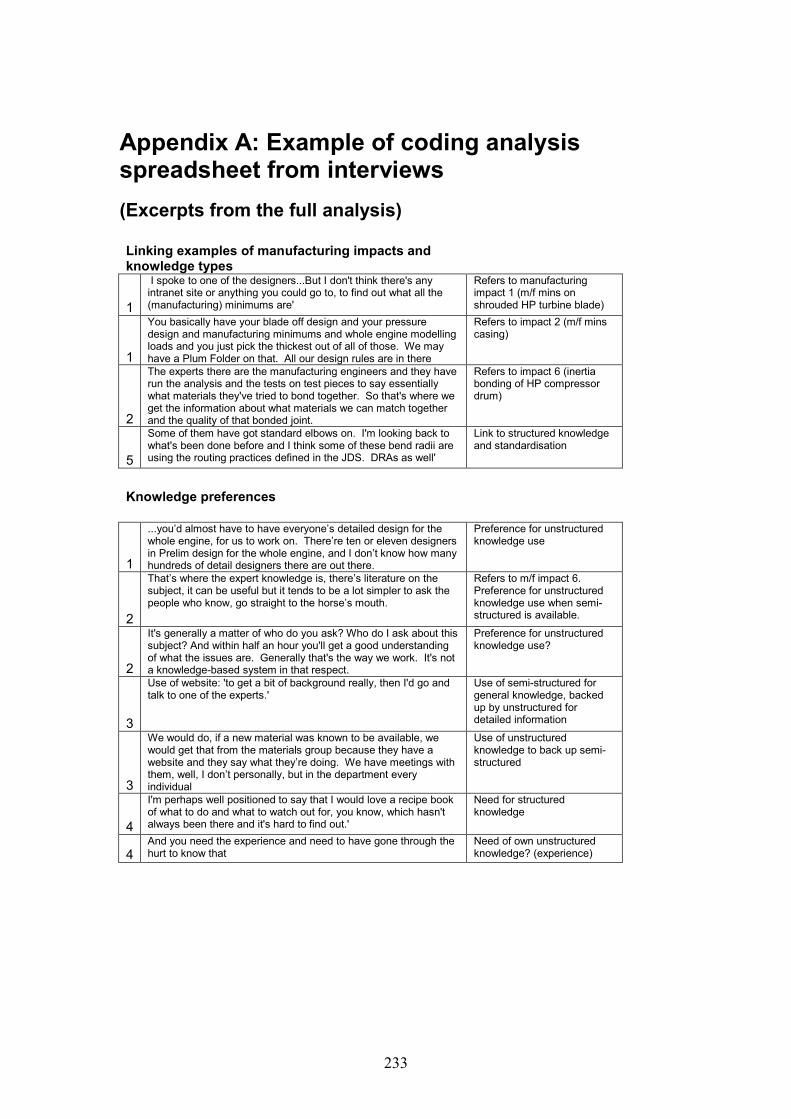
233
Appendix A: Example of coding analysisspreadsheet from interviews
(Excerpts from the full analysis)
Linking examples of manufacturing impacts andknowledge types
1
I spoke to one of the designers...But I don't think there's anyintranet site or anything you could go to, to find out what all the(manufacturing) minimums are'
Refers to manufacturingimpact 1 (m/f mins onshrouded HP turbine blade)
1
You basically have your blade off design and your pressuredesign and manufacturing minimums and whole engine modellingloads and you just pick the thickest out of all of those. We mayhave a Plum Folder on that. All our design rules are in there
Refers to impact 2 (m/f minscasing)
2
The experts there are the manufacturing engineers and they haverun the analysis and the tests on test pieces to say essentiallywhat materials they've tried to bond together. So that's where weget the information about what materials we can match togetherand the quality of that bonded joint.
Refers to impact 6 (inertiabonding of HP compressordrum)
5
Some of them have got standard elbows on. I'm looking back towhat's been done before and I think some of these bend radii areusing the routing practices defined in the JDS. DRAs as well'
Link to structured knowledgeand standardisation
Knowledge preferences
1
...you’d almost have to have everyone’s detailed design for thewhole engine, for us to work on. There’re ten or eleven designersin Prelim design for the whole engine, and I don’t know how manyhundreds of detail designers there are out there.
Preference for unstructuredknowledge use
2
That’s where the expert knowledge is, there’s literature on thesubject, it can be useful but it tends to be a lot simpler to ask thepeople who know, go straight to the horse’s mouth.
Refers to m/f impact 6.Preference for unstructuredknowledge use when semi-structured is available.
2
It's generally a matter of who do you ask? Who do I ask about thissubject? And within half an hour you'll get a good understandingof what the issues are. Generally that's the way we work. It's nota knowledge-based system in that respect.
Preference for unstructuredknowledge use?
3
Use of website: 'to get a bit of background really, then I'd go andtalk to one of the experts.'
Use of semi-structured forgeneral knowledge, backedup by unstructured fordetailed information
3
We would do, if a new material was known to be available, wewould get that from the materials group because they have awebsite and they say what they’re doing. We have meetings withthem, well, I don’t personally, but in the department everyindividual
Use of unstructuredknowledge to back up semi-structured
4
I'm perhaps well positioned to say that I would love a recipe bookof what to do and what to watch out for, you know, which hasn'talways been there and it's hard to find out.'
Need for structuredknowledge
4And you need the experience and need to have gone through thehurt to know that
Need of own unstructuredknowledge? (experience)

234

235
Appendix B: Development of Initial Code
(Developed after first set of interviews)
The interviews were transcribed and a data driven code developed. The unit ofanalysis was each interview; the unit of coding was each critical incident. In additionto the critical incident, salient points about knowledge, knowledge sources andknowledge uses were also analysed.
A manifest-content analysis code was developed which identified two main themes:manufacturing impact and knowledge type. Each them was further subdivided, tocreate a total of six themes:-
Manufacturing Impact – QuantifiedManufacturing Impact – CapabilityManufacturing Impact – StandardisationKnowledge type – structuredKnowledge type – semi-structuredKnowledge type - unstructured
The full list of coding and associated features is as follows:-
Manufacturing Impact - Quantified
Definition: This code occurs when the current manufacturing process constrains thesize of the component to certain parameters. These parameters are expressednumerically. The constraints imposed by these parameters must be considered in atrade-off with other design requirements (i.e. sizing limitations from lifing) with the‘worst case’ sizing being the final design case.How to know when the theme occurs: Reference to maximum or minimum alloweddimensions due to manufacturing. These dimensions are applicable to currentmanufacturing processes. These dimensional constraints can be seen across mostcomponents in the general arrangement. They will be considered routinely as part ofthe design process. The interviewee may or may not be aware of the manufacturingprocess with constrains the dimensions.Qualification: Any constraint named must at least be described as ‘due tomanufacturing’. A description of the manufacturing process is a good qualifier, but isnot essential.Positive examples:-Minimum allowed wall thickness of a component due to the casting process.Maximum forging size allowed for bought-in component of finished material.Manufacturing maximums and minimums.Negative examples:-Minimum allowed component thickness.Maximum casing size. (reasons for maximum / minimum not given).

236
Manufacturing Impact - Capability
Definition: occurs when the results of a design improvement exercise arecompromised by the immaturity of the manufacturing capability to produce theproduct. This can also include assembly or joining techniques.How to know when the theme occurs: interviewee will discuss a number of options fora design change. At least one of the options will not be feasible due to the capablemanufacturing process being unavailable.Qualification: The theme will be qualified if the manufacturing process is adevelopment of existing manufacturing technology, or the application of existingmanufacturing technology to a new situation, i.e. it is deemed in some way to betheoretically feasible. Disqualification: The theme will be disqualified if there is noconsideration of the feasibility of the manufacturing process.Positive examples of this theme:-Change of a bolted joint to an inertia bonded joint.Change of the profile or shape of a component to improve its function, withconsiderations of how the manufacturing should take place.Negative example:-The proposed manufacturing process is not feasible.
Manufacturing Impact - Standardisation
Definition: this code occurs when component or component features are selected froma predetermined list of standard sizes. These standard sizes are fixed by themanufacturing process, or the supplier (and their manufacturing process?).How to know when this theme occurs: the interviewee will indicate that thecomponent or feature is standardised. The interviewee may or may not know thedetails of the manufacturing process or reasons for the standardisation. Onecharacteristic of this impact is that there very rarely seem to be many issues relating toit, as if the standardisation is accepted. Often the part will be bought-in and thestandardisation will be defined by the supplier.Qualification: The theme will be qualified if there is discussion of standardisation.Disqualification: It will be disqualified if some parameterisation or customisation isallowed to the component.Positive examples:-‘Standard range of pipes and fittings’.‘Use of a previous part as standard’.Negative examples:-‘We’ll select an existing part from a previous assembly and modify the sizings’.
Knowledge Type – Structured
Definition: Examples of manufacturing engineering knowledge which can beexpressed numerically, by algorithms or numerical rules. Information is generated andused during the design process. This information is repeatable across projects.Documented in the form of parameters, dimensions, spreadsheet calculations oralgorithms in expert systems. Can also be expressed graphically. Knowledge is said
237
to be ‘abstracted’ – it is possible (although not always preferable) to apply it withoutfully appreciating the circumstances in which it was created.How to know when it occurs: Design requirements and/or information is expressednumerically. The format is stand-alone and can be repeatedly be used as a tool.Details of the manufacturing process which forms the knowledge may or may not beincluded.Qualification: The theme is qualified if the knowledge can definitely be quantifiedand is document based.Disqualification: It is disqualified if there is a degree of qualitative knowledge and/orif the knowledge is not documented.Positive examples:-Manufacturing minimums and maximums.Graphically-represented parameterised feature.Negative examples:-Reference material (such as material properties) referred to, but not generated as partof the design process.
Knowledge type - semi-structured
Definition: Examples of manufacturing engineering knowledge which can beexpressed quantitatively or qualitatively. Referenced during the design process –supports, but is not integral to the design process. Need to reference will depend onthe situation, the context and the designer’s own experience. Documented in textdocuments. Knowledge is said to be ‘embedded’ – the designer needs to be able tobrowse and understand the context of the knowledge in order to be able to use it.Often the knowledge referenced is from outside the department.How to know when it occurs: Examples of numerical or descriptive information asseen in text documents.Qualification: The theme is qualified if the knowledge is not documented as anabstracted rule or algorithm or graphical image.Disqualification: The theme is disqualified if there is no documented evidence of theknowledge.Positive examples:-Material propertiesDescriptions of manufacturing processes.Negative examples:-Conversational discussions.
Knowledge type – unstructured
Definition: Examples of manufacturing engineering knowledge which can beexpressed quantitatively or qualitatively. Referenced during the design process –supports, but is not integral to the design process. Need to reference will depend onthe situation, the context and the designer’s own experience. Knowledge is said to be‘embedded’ – the designer needs to be able to browse and understand the context ofthe knowledge in order to be able to use it. Often the knowledge referenced is fromoutside the department. Knowledge is not recorded and is communicated via socialnetworks, hence the expert being questioned can supply some context. Theme can

238
occur inside and outside the department, and be formal and informal communicationmethods.How to know when the theme occurs: the knowledge is communicated socially.Qualification: The qualification of this theme is the manner in which it iscommunicated, i.e. socially. The content of semi-structured and unstructuredknowledge is the same, it is the vehicle of communication which differs.Positive examples:-Discussions with people, group meetings.
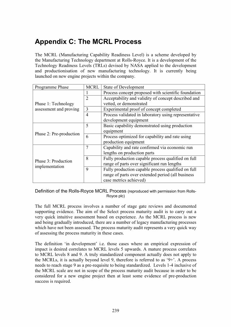
239
Appendix C: The MCRL Process
The MCRL (Manufacturing Capability Readiness Level) is a scheme developed bythe Manufacturing Technology department at Rolls-Royce. It is a development of theTechnology Readiness Levels (TRLs) devised by NASA applied to the developmentand productionisation of new manufacturing technology. It is currently beinglaunched on new engine projects within the company.
Programme Phase MCRL State of Development
Phase 1: Technologyassessment and proving
1 Process concept proposed with scientific foundation2 Acceptability and validity of concept described and
vetted, or demonstrated3 Experimental proof of concept completed4 Process validated in laboratory using representative
development equipment
Phase 2: Pre-production
5 Basic capability demonstrated using productionequipment
6 Process optimized for capability and rate usingproduction equipment
Phase 3: Productionimplementation
7 Capability and rate confirmed via economic runlengths on production parts
8 Fully production capable process qualified on fullrange of parts over significant run lengths
9 Fully production capable process qualified on fullrange of parts over extended period (all businesscase metrics achieved)
Definition of the Rolls-Royce MCRL Process (reproduced with permission from Rolls-Royce plc)
The full MCRL process involves a number of stage gate reviews and documentedsupporting evidence. The aim of the Select process maturity audit is to carry out avery quick intuitive assessment based on experience. As the MCRL process is newand being gradually introduced, there are a number of legacy manufacturing processeswhich have not been assessed. The process maturity audit represents a very quick wayof assessing the process maturity in these cases.
The definition ‘in development’ i.e. those cases where an empirical expression ofimpact is desired correlates to MCRL levels 5 upwards. A mature process correlatesto MCRL levels 8 and 9. A truly standardized component actually does not apply tothe MCRLs, it is actually beyond level 9, therefore is referred to as ‘9+’. A processneeds to reach stage 9 as a pre-requisite to being standardized. Levels 1-4 inclusive ofthe MCRL scale are not in scope of the process maturity audit because in order to beconsidered for a new engine project then at least some evidence of pre-productionsuccess is required.

240

241
Appendix D: Methodology Screenshots

242
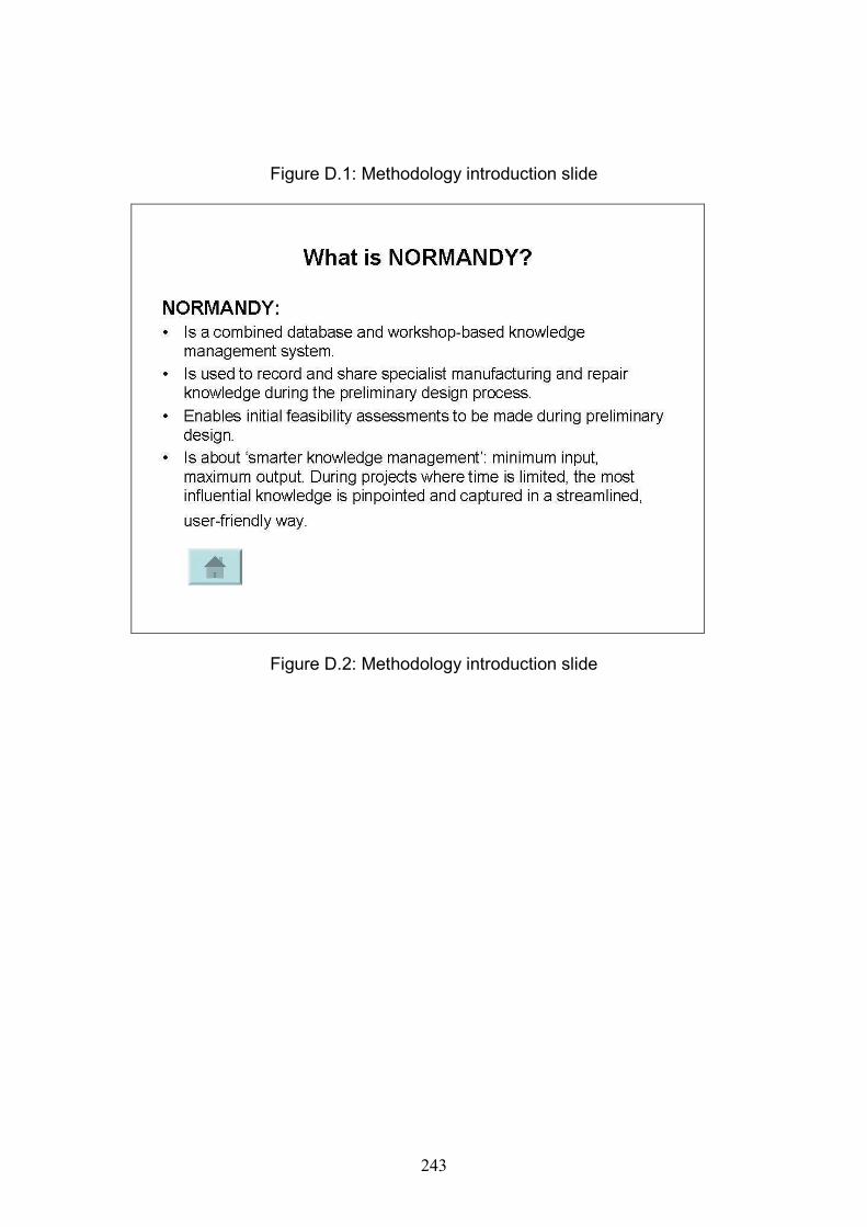
243
Figure D.1: Methodology introduction slide
Figure D.2: Methodology introduction slide

244
Figure D.3: Methodology processes slide
NORMANDYSelect
Workshop details
• NORMANDY is designed to be used on components in new projects wherethere are manufacturing and / or repairability risks which need to beassessed during the preliminary stage. It may not be necessary to captureknowledge for every single component.
• The Select process is a workshop audit to determine which componentsand which processes should be considered using NORMANDY.
• The workshop involves experienced representatives of design, repair andmanufacturing. It should be run quickly and intuitively, relying onrepresentatives’ experience and judgement
Figure D.4: Select process introductory slide
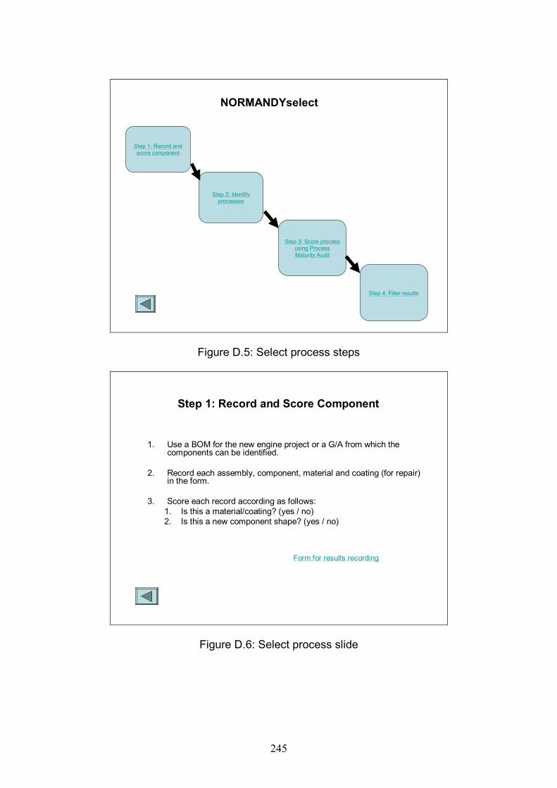
245
Step 1: Record andscore component
Step 2: Identifyprocesses
Step 3: Score processusing ProcessMaturity Audit
Step 4: Filter results
NORMANDYselect
Figure D.5: Select process steps
Step 1: Record and Score Component
1. Use a BOM for the new engine project or a G/A from which thecomponents can be identified.
2. Record each assembly, component, material and coating (for repair)in the form.
3. Score each record according as follows:1. Is this a material/coating? (yes / no)2. Is this a new component shape? (yes / no)
Form for results recording
Figure D.6: Select process slide
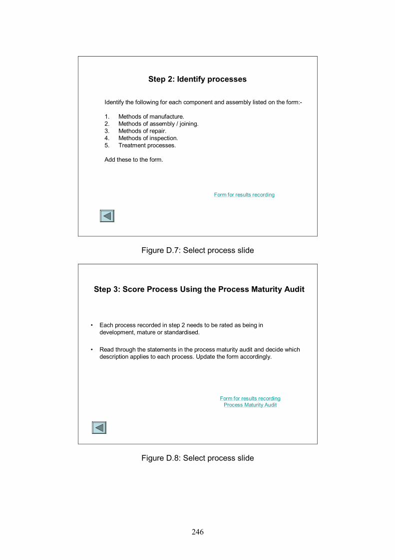
246
Step 2: Identify processes
Identify the following for each component and assembly listed on the form:-
1. Methods of manufacture.2. Methods of assembly / joining.3. Methods of repair.4. Methods of inspection.5. Treatment processes.
Add these to the form.
Form for results recording
Figure D.7: Select process slide
Step 3: Score Process Using the Process Maturity Audit
• Each process recorded in step 2 needs to be rated as being indevelopment, mature or standardised.
• Read through the statements in the process maturity audit and decide whichdescription applies to each process. Update the form accordingly.
Form for results recordingProcess Maturity Audit
Figure D.8: Select process slide

247
Figure D.9: Select process slide (process maturity audit)
Figure D.10: Select process slide

248
Figure D.11: Create process slide
Figure D.12: Create process slide
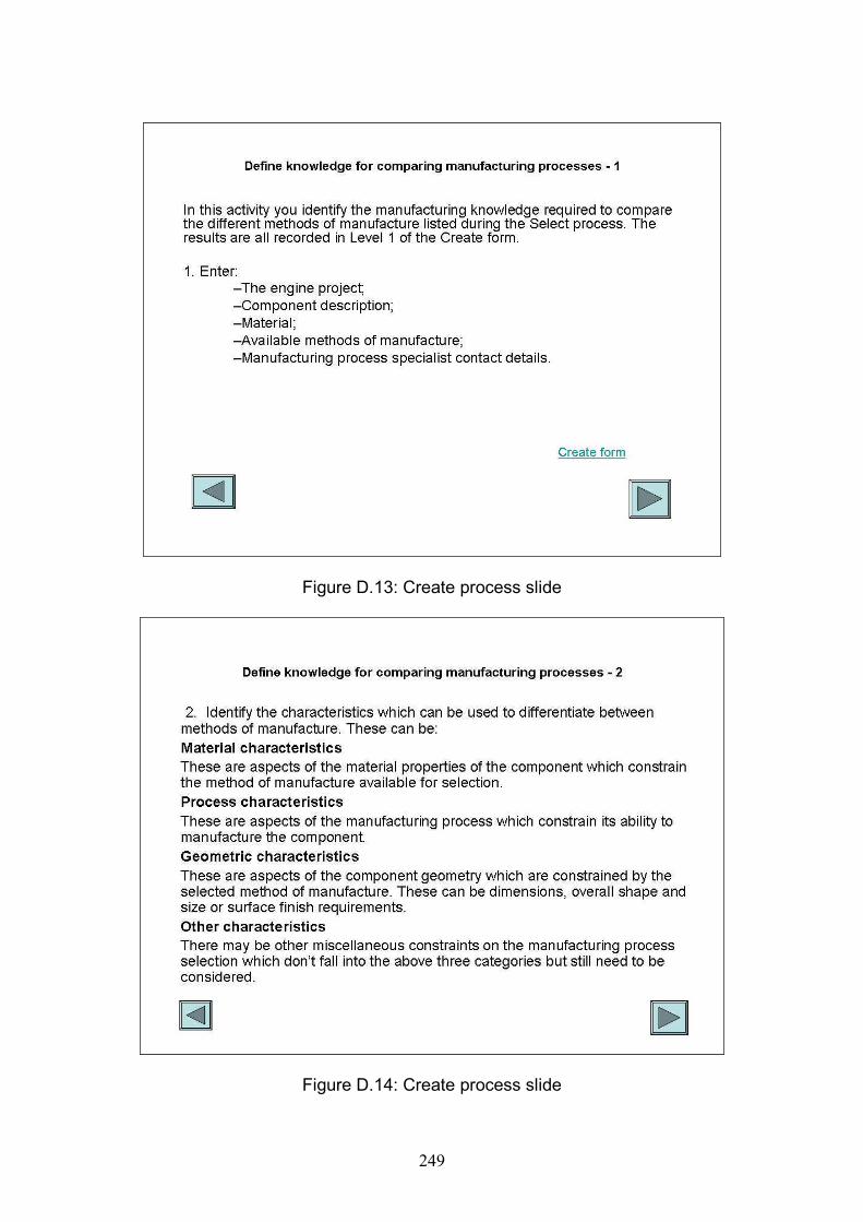
249
Figure D.13: Create process slide
Figure D.14: Create process slide

250
Figure D.15: Create process slide
Figure D.16: Create process slide
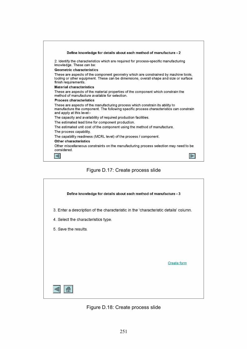
251
Figure D.17: Create process slide
Figure D.18: Create process slide

252
Figure D.19: Create process slide
Figure D.20: Create process slide
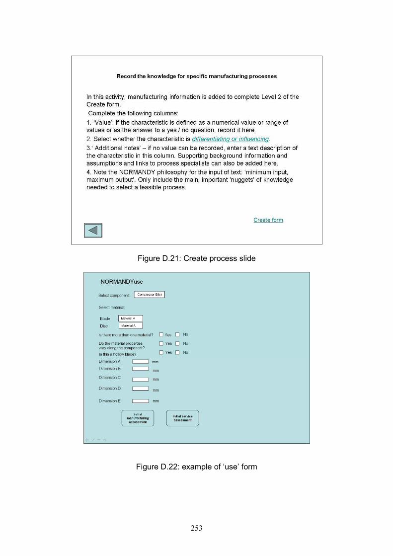
253
Figure D.21: Create process slide
Figure D.22: example of ‘use’ form
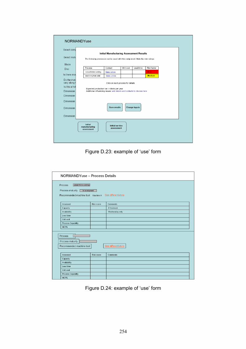
254
Figure D.23: example of ‘use’ form
Figure D.24: example of ‘use’ form
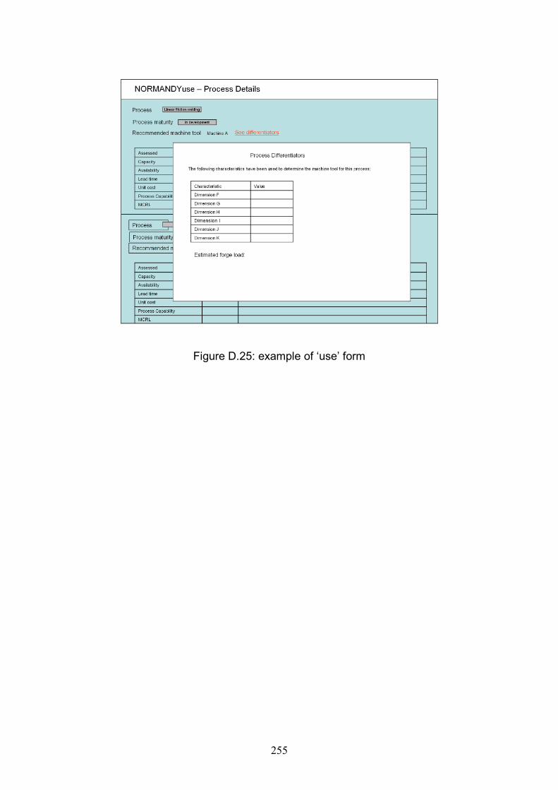
255
Figure D.25: example of ‘use’ form

256

257
Appendix E: Evaluation Surveys
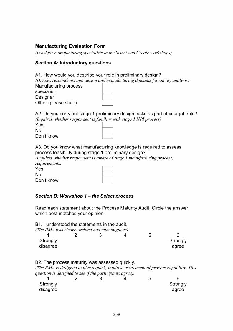
258
Manufacturing Evaluation Form
(Used for manufacturing specialists in the Select and Create workshops)
Section A: Introductory questions
A1. How would you describe your role in preliminary design?(Divides respondents into design and manufacturing domains for survey analysis)Manufacturing processspecialistDesignerOther (please state)
A2. Do you carry out stage 1 preliminary design tasks as part of your job role?(Inquires whether respondent is familiar with stage 1 NPI process)YesNoDon’t know
A3. Do you know what manufacturing knowledge is required to assessprocess feasibility during stage 1 preliminary design?(Inquires whether respondent is aware of stage 1 manufacturing process)requirements)Yes.NoDon’t know
Section B: Workshop 1 – the Select process
Read each statement about the Process Maturity Audit. Circle the answerwhich best matches your opinion.
B1. I understood the statements in the audit.(The PMA was clearly written and unambiguous)
1 2 3 4 5 6Stronglydisagree
Stronglyagree
B2. The process maturity was assessed quickly.(The PMA is designed to give a quick, intuitive assessment of process capability. Thisquestion is designed to see if the participants agree).
1 2 3 4 5 6Stronglydisagree
Stronglyagree

259
Section C: Workshop 2 - The Create Process (Decide Knowledge)
Read each statement and circle the number which best matches your opinion.
C1. I was able to understand what was required from the workshop.(The workshop guidance notes should be clearly written and unambiguous. Thisquestion tests this).
1 2 3 4 5 6Stronglydisagree
Stronglyagree
C2. Identifying the characteristics was easy to work through.(Again, tests how clear and ambiguous the required task is).
1 2 3 4 5 6Stronglydisagree
Stronglyagree
C3. Identifying the characteristics was quick to work through.(Tests if the workshop can be run quickly as designed).
1 2 3 4 5 6Stronglydisagree
Stronglyagree
C5. Listing the characteristics was more effective than general discussions(The methodology is designed as a systematic process to gather knowledge moreeffectively and comprehensively than a discussion. Question added to see ifparticipants agree if this is the case).
1 2 3 4 5 6Stronglydisagree
Stronglyagree
Section D: Workshop 3 – The Create Process (Record the Knowledge)
Read each statement and circle the number which best matches your opinion.
D1. I could identify the knowledge required.(Inquires whether the participant was able to identify the required knowledge contentby identifying examples of the characteristics).
1 2 3 4 5 6Stronglydisagree
Stronglyagree
C4. It was useful to distinguish between differentiating and influencingcharacteristics.(Inquires if there was any use in differentiating between constraints which woulddrive a process decision, and constraints that would be supporting evidence in a
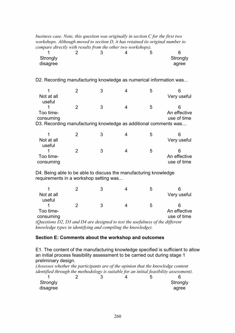
260
business case. Note, this question was originally in section C for the first twoworkshops. Although moved to section D, it has retained its original number tocompare directly with results from the other two workshops).
1 2 3 4 5 6Stronglydisagree
Stronglyagree
D2. Recording manufacturing knowledge as numerical information was...
1 2 3 4 5 6Not at all
usefulVery useful
1 2 3 4 5 6Too time-
consumingAn effectiveuse of time
D3. Recording manufacturing knowledge as additional comments was…
1 2 3 4 5 6Not at all
usefulVery useful
1 2 3 4 5 6Too time-
consumingAn effectiveuse of time
D4. Being able to be able to discuss the manufacturing knowledgerequirements in a workshop setting was...
1 2 3 4 5 6Not at all
usefulVery useful
1 2 3 4 5 6Too time-
consumingAn effectiveuse of time
(Questions D2, D3 and D4 are designed to test the usefulness of the differentknowledge types in identifying and compiling the knowledge).
Section E: Comments about the workshop and outcomes
E1. The content of the manufacturing knowledge specified is sufficient to allowan initial process feasibility assessment to be carried out during stage 1preliminary design.(Assesses whether the participants are of the opinion that the knowledge contentidentified through the methodology is suitable for an initial feasibility assessment).
1 2 3 4 5 6Stronglydisagree
Stronglyagree
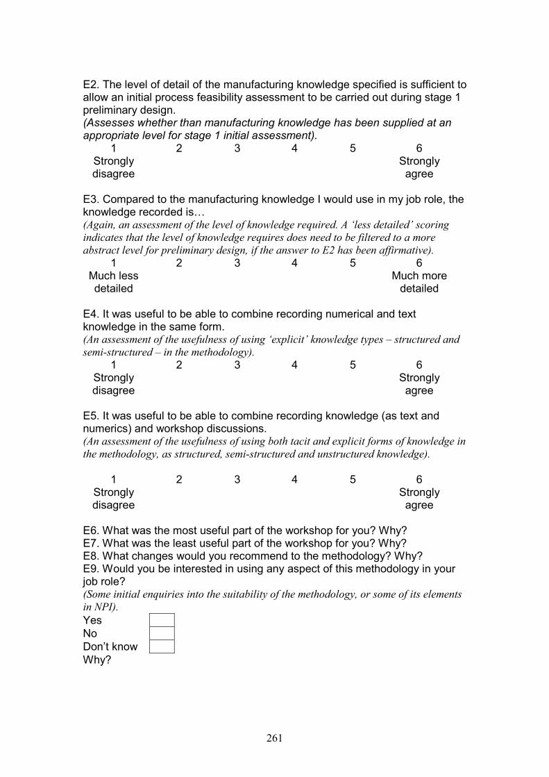
261
E2. The level of detail of the manufacturing knowledge specified is sufficient toallow an initial process feasibility assessment to be carried out during stage 1preliminary design.(Assesses whether than manufacturing knowledge has been supplied at anappropriate level for stage 1 initial assessment).
1 2 3 4 5 6Stronglydisagree
Stronglyagree
E3. Compared to the manufacturing knowledge I would use in my job role, theknowledge recorded is…(Again, an assessment of the level of knowledge required. A ‘less detailed’ scoringindicates that the level of knowledge requires does need to be filtered to a moreabstract level for preliminary design, if the answer to E2 has been affirmative).
1 2 3 4 5 6Much lessdetailed
Much moredetailed
E4. It was useful to be able to combine recording numerical and textknowledge in the same form.(An assessment of the usefulness of using ‘explicit’ knowledge types – structured andsemi-structured – in the methodology).
1 2 3 4 5 6Stronglydisagree
Stronglyagree
E5. It was useful to be able to combine recording knowledge (as text andnumerics) and workshop discussions.(An assessment of the usefulness of using both tacit and explicit forms of knowledge inthe methodology, as structured, semi-structured and unstructured knowledge).
1 2 3 4 5 6Stronglydisagree
Stronglyagree
E6. What was the most useful part of the workshop for you? Why?E7. What was the least useful part of the workshop for you? Why?E8. What changes would you recommend to the methodology? Why?E9. Would you be interested in using any aspect of this methodology in yourjob role?(Some initial enquiries into the suitability of the methodology, or some of its elementsin NPI).YesNoDon’t knowWhy?

262
E10. Look back at your original answer to question A3. Having completed thisworkshop, has your opinion changed?
Yes.NoDon’t know
Why?
E11. Any further comments?
Thank you for your participation.
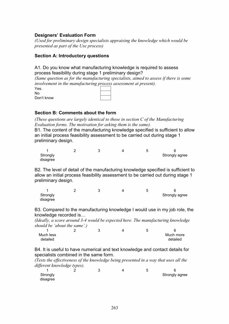
263
Designers’ Evaluation Form(Used for preliminary design specialists appraising the knowledge which would bepresented as part of the Use process)
Section A: Introductory questions
A1. Do you know what manufacturing knowledge is required to assessprocess feasibility during stage 1 preliminary design?(Same question as for the manufacturing specialists, aimed to assess if there is someinvolvement in the manufacturing process assessment at present).Yes.NoDon’t know
Section B: Comments about the form
(These questions are largely identical to those in section C of the ManufacturingEvaluation forms. The motivation for asking them is the same).B1. The content of the manufacturing knowledge specified is sufficient to allowan initial process feasibility assessment to be carried out during stage 1preliminary design.
1 2 3 4 5 6Stronglydisagree
Strongly agree
B2. The level of detail of the manufacturing knowledge specified is sufficient toallow an initial process feasibility assessment to be carried out during stage 1preliminary design.
1 2 3 4 5 6Stronglydisagree
Strongly agree
B3. Compared to the manufacturing knowledge I would use in my job role, theknowledge recorded is…(Ideally, a score around 3-4 would be expected here. The manufacturing knowledgeshould be ‘about the same’.)
1 2 3 4 5 6Much lessdetailed
Much moredetailed
B4. It is useful to have numerical and text knowledge and contact details forspecialists combined in the same form.(Tests the effectiveness of the knowledge being presented in a way that uses all thedifferent knowledge types).
1 2 3 4 5 6Stronglydisagree
Strongly agree
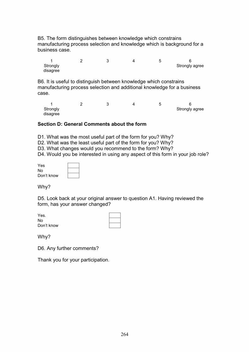
264
B5. The form distinguishes between knowledge which constrainsmanufacturing process selection and knowledge which is background for abusiness case.
1 2 3 4 5 6Stronglydisagree
Strongly agree
B6. It is useful to distinguish between knowledge which constrainsmanufacturing process selection and additional knowledge for a businesscase.
1 2 3 4 5 6Stronglydisagree
Strongly agree
Section D: General Comments about the form
D1. What was the most useful part of the form for you? Why?D2. What was the least useful part of the form for you? Why?D3. What changes would you recommend to the form? Why?D4. Would you be interested in using any aspect of this form in your job role?
YesNoDon’t know
Why?
D5. Look back at your original answer to question A1. Having reviewed theform, has your answer changed?
Yes.NoDon’t know
Why?
D6. Any further comments?
Thank you for your participation.


