Embed Size (px)
Citation preview
SACHIN NAYAK
SOFTWARE AND HARDWARE VARIATION IN SYMBIAN
CAMERA SYSTEM
Master of Science Thesis
Examiners: Professor Jarmo Harju (TUT) M.Sc. Henri Puhto (Nokia Oyj) Examiner and topic approved in the Faculty of Computing and Electrical Engineering Council meeting on 7th December 2011
I
ABSTRACT
TAMPERE UNIVERSITY OF TECHNOLOGY Master’s Degree Programme in Information Technology NAYAK, SACHIN: Software and hardware variation in Symbian camera system Master of Science Thesis, 51 pages May 2012 Major: Communications Engineering Examiners: Professor Jarmo Harju, M.Sc. Henri Puhto Keywords: Software variation, configuration, mobile device, camera system, Symbian OS
During the past decade, multimedia features in mobile phones have become common.
Even the low-end category mobile phones are equipped with camera in order to capture
digital images and record videos. Mobile phones are giving tough competition to stand-
alone camera devices by providing quality imaging experience to the consumers. In
order to lead and compete with the pack of global mobile device manufacturers, Nokia
has to differentiate its mobile device offerings across the wide price range addressing
different market requirements. This necessitates them to use different types of cameras
and flash hardware modules across their mobile phone range resulting in different cam-
era system configurations. To support the range of mobile phones with a single software
operating system platform, effective software variation is required.
Some of the possibilities with mobile phone camera system configurations are de-
vices equipped with one or two camera modules along with multiple or no flash HW,
camera sensors with resolutions ranging from VGA to 41 megapixels, camera modules
with autofocus or fixed focus lenses, flash modules based on Xenon or LED technology
and the camera system controlled by either application processor or dedicated image
signal processor. Symbian OS is the software platform capable of supporting various
Nokia mobile devices with different hardware configurations. This is possible due to
extensive software variation mechanisms that the Symbian OS supports.
This thesis is an effort in describing various camera system configurations within
the Nokia Symbian mobile phones and the software variation being used in supporting
those.
II
PREFACE
This thesis has been written while working in Symbian Devices Imaging organization,
first as a part of Nokia Oyj and later Accenture Services Oy, in Tampere, Finland.
I would like to thank my colleagues in the Imaging organization for creating an
encouraging and inspiring atmosphere. Special thanks to Henri Puhto for suggesting the
subject matter for the thesis, for providing his time, effort and patience in supervising
this work and for guiding me throughout the process. Thanks to my manager Petri
Soininen from Nokia Oyj for his encouragement and valuable comments on my work. I
am thankful to Professor Jarmo Harju for guiding my work with his valuable
suggestions and review comments.
Last but not the least, thanks to my family for their continuous support and
encouragement.
Tampere 23rd
April 2012
SACHIN GAJANAN NAYAK
III
CONTENTS
1 Introduction.............................................................................................................. 1
2 Camera System ........................................................................................................ 2
2.1 Digital Imaging System ............................................................................... 2
2.1.1 Optics ............................................................................................. 3
2.1.2 Image Sensor ................................................................................. 4
2.1.3 Flash ............................................................................................... 5
2.1.4 Imaging Pipe in a Mobile Device .................................................. 6
2.2 Nokia Camera Phones .................................................................................. 7
2.3 Camera and Flash Hardware ........................................................................ 8
2.3.1 Camera Modules ............................................................................ 9
2.3.2 Application Processor Engine...................................................... 10
2.3.3 Imaging and Video Engine .......................................................... 11
2.3.4 Flash Module & Privacy Indicator .............................................. 11
2.3.5 Flash Driver ................................................................................. 11
2.4 SMIA (Standard Mobile Imaging Architecture) ........................................ 12
3 Symbian OS ........................................................................................................... 13
3.1 Introduction to Symbian OS ...................................................................... 13
3.2 The Scope of Symbian OS ......................................................................... 14
3.3 Dynamically Loadable Components .......................................................... 14
3.3.1 DLL Entry Points ......................................................................... 14
3.3.2 Static Interface DLLs ................................................................... 15
3.3.3 Polymorphic Interface DLLs ....................................................... 15
3.3.4 Symbian ECom Architecture ....................................................... 15
3.4 The Software Architecture of Symbian OS ............................................... 16
3.4.1 UI Framework .............................................................................. 17
3.4.2 Application Services .................................................................... 18
3.4.3 Java ME ....................................................................................... 18
3.4.4 OS Services .................................................................................. 18
3.4.5 Base Services ............................................................................... 19
3.4.6 Kernel Services & Hardware Interface ........................................ 19
3.5 Camera and Video System Architecture .................................................... 19
3.5.1 Camera Driver ............................................................................. 19
3.5.2 Multimedia Framework ............................................................... 20
3.5.3 Image Conversion Library ........................................................... 21
3.5.4 Onboard Camera API .................................................................. 21
3.5.5 Camera APP Engine .................................................................... 22
3.5.6 Camera Application ..................................................................... 22
IV
4 Software variation .................................................................................................. 23
4.1 Production Line Engineering ..................................................................... 23
4.2 Software Variation in Production Line Engineering ................................. 24
4.3 Variation Point ........................................................................................... 25
4.3.1 Types of Variation Points ............................................................ 25
4.3.2 Variation Points in Symbian Platform SW .................................. 26
4.4 Software Variation Methods in Symbian OS ............................................ 27
4.4.1 Software Build System for Symbian OS ..................................... 27
4.4.2 Feature Flag Settings ................................................................... 29
4.4.3 Feature Discovery API ................................................................ 30
4.4.4 Central Repository ....................................................................... 31
4.4.5 Dynamic Configuration Files ...................................................... 32
5 Variation in Camera system................................................................................... 33
5.1 Purpose for Variation ................................................................................. 33
5.2 Camera and Flash Hardware Configurations ............................................. 33
5.2.1 Single Processor Configuration ................................................... 34
5.2.2 Multi Processor Configuration .................................................... 35
5.2.3 System on Chip Configuration .................................................... 36
5.2.4 Types of Camera and Flash Modules .......................................... 36
5.3 Variation with Camera Application ........................................................... 37
5.4 Variation with Onboard Camera API ........................................................ 38
5.5 Variation in Camera Driver ....................................................................... 40
5.5.1 Flash Module Specific Flags ....................................................... 40
5.5.2 Flags for Configuring Primary Camera ....................................... 40
5.5.3 Flags for Configuring Secondary Camera ................................... 41
5.5.4 Algorithm Specific Configuration Flags ..................................... 42
5.6 Case Study with Symbian^3 Products ....................................................... 42
6 Conclusion ............................................................................................................. 49
References ...................................................................................................................... 50
V
TERMS AND ABBREVIATIONS
APE Application Processor Engine
API Application Programming Interface. An interface that specifies the
functionality and usage of the underlying software component.
ARM Advanced RISC Machines
ASIC Application-Specific Integrated Circuit
CCD Charge Coupled Device
CMOS Complementary Metal Oxide Semiconductor
DSC Digital Still Camera
DSP Digital Signal Processor
DLL Dynamic Link Library
EDoF Extended Depth of Field
GUI Graphical User Interface
HW Hardware
IQ Image Quality
ISP Image Signal Processor. A hardware component that offers image
and video processing capability.
VI
IVE Imaging and Video Engine; HW accelerator for camera, flash and
optionally display.
JPEG Joint Photographic Experts Group. A lossy compression method
used for multiple image file formats.
LDD Logical Device Driver
MMF Multimedia Framework
OS Operating System
PDD Physical Device Driver
Raw Bayer An uncompressed image format where the information from the
image sensor is not processed.
RISC Reduced Instruction Set Computer
ROM Read Only Memory
SW Software
VGA Video Graphics Array. 680x480 resolution.
YUV A color space and compressed image format, which separates the
luminance and chrominance components from the image infor-
mation.
1
1 INTRODUCTION
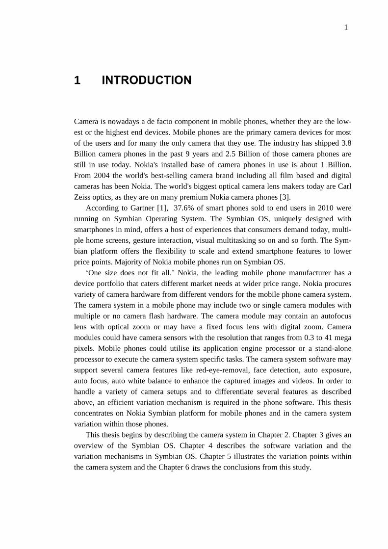
Camera is nowadays a de facto component in mobile phones, whether they are the low-
est or the highest end devices. Mobile phones are the primary camera devices for most
of the users and for many the only camera that they use. The industry has shipped 3.8
Billion camera phones in the past 9 years and 2.5 Billion of those camera phones are
still in use today. Nokia's installed base of camera phones in use is about 1 Billion.
From 2004 the world's best-selling camera brand including all film based and digital
cameras has been Nokia. The world's biggest optical camera lens makers today are Carl
Zeiss optics, as they are on many premium Nokia camera phones [3].
According to Gartner [1], 37.6% of smart phones sold to end users in 2010 were
running on Symbian Operating System. The Symbian OS, uniquely designed with
smartphones in mind, offers a host of experiences that consumers demand today, multi-
ple home screens, gesture interaction, visual multitasking so on and so forth. The Sym-
bian platform offers the flexibility to scale and extend smartphone features to lower
price points. Majority of Nokia mobile phones run on Symbian OS.
‘One size does not fit all.’ Nokia, the leading mobile phone manufacturer has a
device portfolio that caters different market needs at wider price range. Nokia procures
variety of camera hardware from different vendors for the mobile phone camera system.
The camera system in a mobile phone may include two or single camera modules with
multiple or no camera flash hardware. The camera module may contain an autofocus
lens with optical zoom or may have a fixed focus lens with digital zoom. Camera
modules could have camera sensors with the resolution that ranges from 0.3 to 41 mega
pixels. Mobile phones could utilise its application engine processor or a stand-alone
processor to execute the camera system specific tasks. The camera system software may
support several camera features like red-eye-removal, face detection, auto exposure,
auto focus, auto white balance to enhance the captured images and videos. In order to
handle a variety of camera setups and to differentiate several features as described
above, an efficient variation mechanism is required in the phone software. This thesis
concentrates on Nokia Symbian platform for mobile phones and in the camera system
variation within those phones.
This thesis begins by describing the camera system in Chapter 2. Chapter 3 gives an
overview of the Symbian OS. Chapter 4 describes the software variation and the
variation mechanisms in Symbian OS. Chapter 5 illustrates the variation points within
the camera system and the Chapter 6 draws the conclusions from this study.
2
2 CAMERA SYSTEM
This chapter provides introduction to the optics, image sensors, flash and to the whole
camera system used in mobile devices.
2.1 Digital Imaging System
Consumers have been enjoying digital imaging since 1995 when the first consumer digi-
tal still camera, Casio QV-10 was made available in market [15 p.9]. During last 15
years digital imaging has generalized and markets for digital still cameras (DSC) have
grown rapidly. In addition to DSCs, digital imaging technologies have become common
in multiple other applications such as mobile phones, web cameras, medical imaging
and surveillance systems.
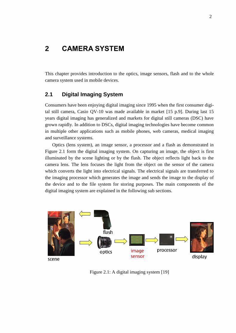
Optics (lens system), an image sensor, a processor and a flash as demonstrated in
Figure 2.1 form the digital imaging system. On capturing an image, the object is first
illuminated by the scene lighting or by the flash. The object reflects light back to the
camera lens. The lens focuses the light from the object on the sensor of the camera
which converts the light into electrical signals. The electrical signals are transferred to
the imaging processor which generates the image and sends the image to the display of
the device and to the file system for storing purposes. The main components of the
digital imaging system are explained in the following sub sections.
Figure 2.1: A digital imaging system [19]
2. CAMERA SYSTEM 3
2.1.1 Optics
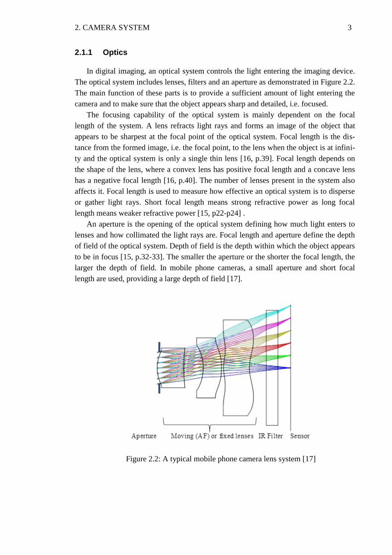
In digital imaging, an optical system controls the light entering the imaging device.
The optical system includes lenses, filters and an aperture as demonstrated in Figure 2.2.
The main function of these parts is to provide a sufficient amount of light entering the
camera and to make sure that the object appears sharp and detailed, i.e. focused.
The focusing capability of the optical system is mainly dependent on the focal
length of the system. A lens refracts light rays and forms an image of the object that
appears to be sharpest at the focal point of the optical system. Focal length is the dis-
tance from the formed image, i.e. the focal point, to the lens when the object is at infini-
ty and the optical system is only a single thin lens [16, p.39]. Focal length depends on
the shape of the lens, where a convex lens has positive focal length and a concave lens
has a negative focal length [16, p.40]. The number of lenses present in the system also
affects it. Focal length is used to measure how effective an optical system is to disperse
or gather light rays. Short focal length means strong refractive power as long focal
length means weaker refractive power [15, p22-p24] .
An aperture is the opening of the optical system defining how much light enters to
lenses and how collimated the light rays are. Focal length and aperture define the depth
of field of the optical system. Depth of field is the depth within which the object appears
to be in focus [15, p.32-33]. The smaller the aperture or the shorter the focal length, the
larger the depth of field. In mobile phone cameras, a small aperture and short focal
length are used, providing a large depth of field [17].
Figure 2.2: A typical mobile phone camera lens system [17]
2. CAMERA SYSTEM 4
To reach the optimal focus for each use case, there are several optical solutions used
in mobile phone cameras. Fixed focus cameras include an optical system where the
lenses are stationary and aperture diameter is constant, thus providing fixed focal length
and depth of field. This means that lenses are typically stationed so that the object ap-
pears to be in focus from the distance of 30cm to infinity.
Automatic focus (AF) cameras are used when it is required to be able to focus to
near distances (macro photography) or otherwise alter the focal length and the depth of
field. AF cameras use electrical motors to alter the distance of the lenses and the size of
the aperture enabling focusing to as near as 10cm from the object. AF is the most so-
phisticated solution, which provides the best image quality, but with a higher price tag
and larger physical size of the system. Larger size of the camera module throws chal-
lenge for the mobile phone design as the devices are expected to be thin and sleek.
Extended depth of field (EDoF), also known as digital focus, cameras use signal
processing software to reach fixed focus from the distance of even 10cm to infinity
without moving the lenses. This digital focusing offers a cost effective solution to reach
a large depth of field, often with the expense of the image quality in macro mode image
captures. Physical size of the camera module with this solution tends to be smaller than
modules with AF lens.
2.1.2 Image Sensor
An image sensor is a light-sensitive semiconductor device that converts the image
formed by the lens into electrical signals [15, p.54]. This is called a photo conversion,
and it takes place in the pixels from which the image sensor is formed. A pixel is sensi-
tive to photons and it is capable of transforming the energy of photons into electrical
voltage (photo conversion). A photon is a particle that contains a small amount of ener-
gy (approximately 2eV with the wavelength of 600nm) and has a wavelike behavior.
Visible light consists of photons. However, to be able to produce a visible image for the
human eye, only photons with wavelengths from 380nm to 780nm are allowed to enter
the pixels of the image sensor [15, p.54].
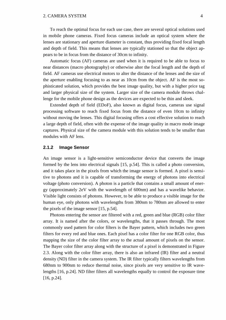
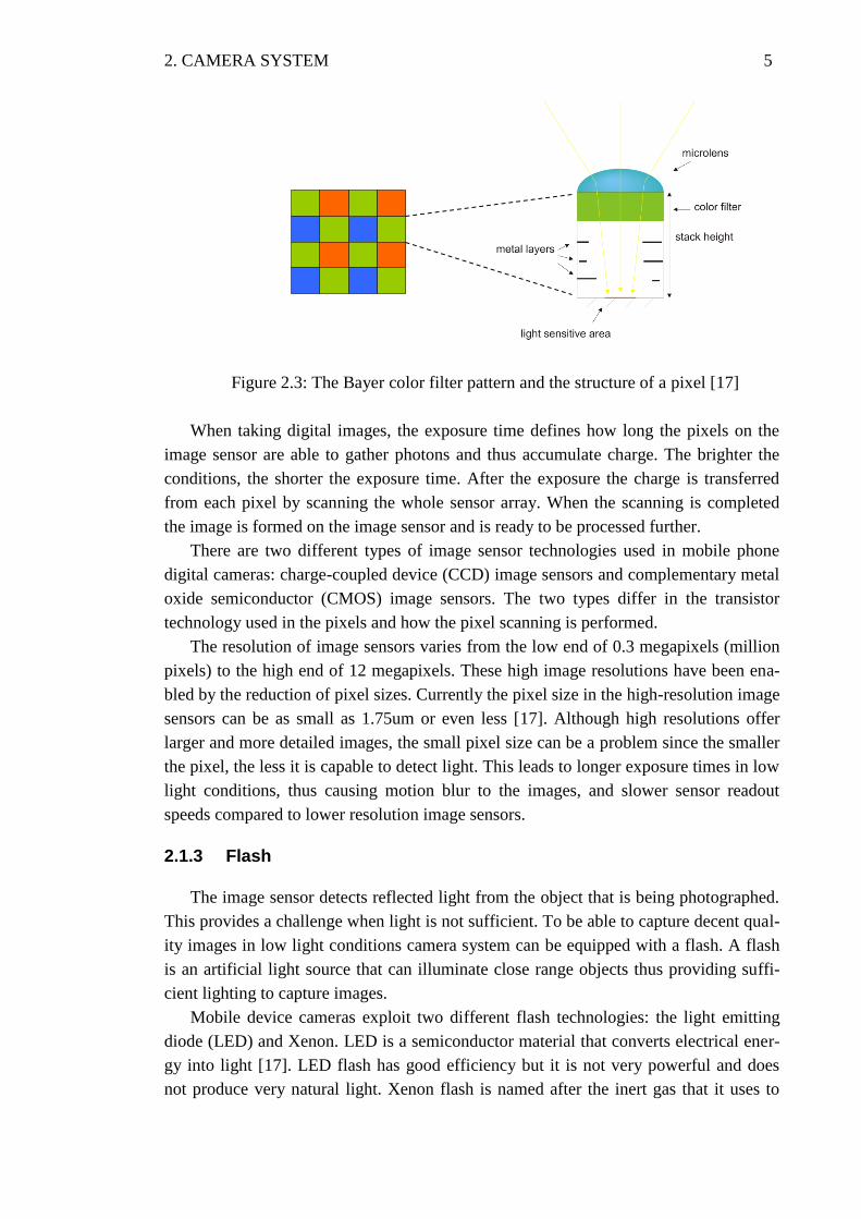
Photons entering the sensor are filtered with a red, green and blue (RGB) color filter
array. It is named after the colors, or wavelengths, that it passes through. The most
commonly used pattern for color filters is the Bayer pattern, which includes two green
filters for every red and blue ones. Each pixel has a color filter for one RGB color, thus
mapping the size of the color filter array to the actual amount of pixels on the sensor.
The Bayer color filter array along with the structure of a pixel is demonstrated in Figure
2.3. Along with the color filter array, there is also an infrared (IR) filter and a neutral
density (ND) filter in the camera system. The IR filter typically filters wavelengths from
680nm to 900nm to reduce thermal noise, since pixels are very sensitive to IR wave-
lengths [16, p.24]. ND filter filters all wavelengths equally to control the exposure time
[16, p.24].
2. CAMERA SYSTEM 5
Figure 2.3: The Bayer color filter pattern and the structure of a pixel [17]
When taking digital images, the exposure time defines how long the pixels on the
image sensor are able to gather photons and thus accumulate charge. The brighter the
conditions, the shorter the exposure time. After the exposure the charge is transferred
from each pixel by scanning the whole sensor array. When the scanning is completed
the image is formed on the image sensor and is ready to be processed further.
There are two different types of image sensor technologies used in mobile phone
digital cameras: charge-coupled device (CCD) image sensors and complementary metal
oxide semiconductor (CMOS) image sensors. The two types differ in the transistor
technology used in the pixels and how the pixel scanning is performed.
The resolution of image sensors varies from the low end of 0.3 megapixels (million
pixels) to the high end of 12 megapixels. These high image resolutions have been ena-
bled by the reduction of pixel sizes. Currently the pixel size in the high-resolution image
sensors can be as small as 1.75um or even less [17]. Although high resolutions offer
larger and more detailed images, the small pixel size can be a problem since the smaller
the pixel, the less it is capable to detect light. This leads to longer exposure times in low
light conditions, thus causing motion blur to the images, and slower sensor readout
speeds compared to lower resolution image sensors.
2.1.3 Flash
The image sensor detects reflected light from the object that is being photographed.
This provides a challenge when light is not sufficient. To be able to capture decent qual-
ity images in low light conditions camera system can be equipped with a flash. A flash
is an artificial light source that can illuminate close range objects thus providing suffi-
cient lighting to capture images.
Mobile device cameras exploit two different flash technologies: the light emitting
diode (LED) and Xenon. LED is a semiconductor material that converts electrical ener-
gy into light [17]. LED flash has good efficiency but it is not very powerful and does
not produce very natural light. Xenon flash is named after the inert gas that it uses to
2. CAMERA SYSTEM 6
produce a short and bright light burst [17]. Xenon flash requires capacitors with large
physical size for holding electric charge needed to fire the flash. It is capable of emitting
very natural color temperature range. LED flash technology is cheaper to manufacture,
smaller in physical size and more common in mobile devices than Xenon flash technol-
ogy.
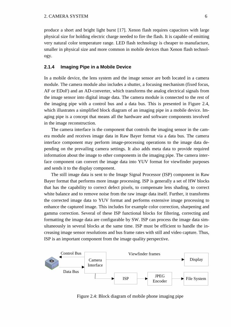
2.1.4 Imaging Pipe in a Mobile Device
In a mobile device, the lens system and the image sensor are both located in a camera
module. The camera module also includes a shutter, a focusing mechanism (fixed focus,
AF or EDoF) and an AD-converter, which transforms the analog electrical signals from
the image sensor into digital image data. The camera module is connected to the rest of
the imaging pipe with a control bus and a data bus. This is presented in Figure 2.4,
which illustrates a simplified block diagram of an imaging pipe in a mobile device. Im-
aging pipe is a concept that means all the hardware and software components involved
in the image reconstruction.
The camera interface is the component that controls the imaging sensor in the cam-
era module and receives image data in Raw Bayer format via a data bus. The camera
interface component may perform image-processing operations to the image data de-
pending on the prevailing camera settings. It also adds meta data to provide required
information about the image to other components in the imaging pipe. The camera inter-
face component can convert the image data into YUV format for viewfinder purposes
and sends it to the display component.
The still image data is sent to the Image Signal Processor (ISP) component in Raw
Bayer format that performs more image processing. ISP is generally a set of HW blocks
that has the capability to correct defect pixels, to compensate lens shading, to correct
white balance and to remove noise from the raw image data itself. Further, it transforms
the corrected image data to YUV format and performs extensive image processing to
enhance the captured image. This includes for example color correction, sharpening and
gamma correction. Several of these ISP functional blocks for filtering, correcting and
formatting the image data are configurable by SW. ISP can process the image data sim-
ultaneously in several blocks at the same time. ISP must be efficient to handle the in-
creasing image sensor resolutions and bus frame rates with still and video capture. Thus,
ISP is an important component from the image quality perspective.
Figure 2.4: Block diagram of mobile phone imaging pipe
Control Bus
Data Bus
ISPJPEG
EncoderFile System
Display
Viewfinder frames
Camera
Interface
2. CAMERA SYSTEM 7
The resulting YUV image from the ISP needs to be compressed so it is transferred
to the JPEG encoder component. The JPEG encoder encodes the image into JPEG for-
mat and transfers it to the file system. This is a basic example on how the imaging pipe
functions in the still imaging use case in a mobile device.
2.2 Nokia Camera Phones
Camera phones are not just improving on the sensors and resolutions, they are also
improving on the lenses, flashes, focusing capabilities and zooming capabilities too. We
are witnessing today the usage of xenon flash, dual-LED flash, carl-zeiss lens on camera
phones. What makes the camera phones unique is the convergence. Camera phone
hardware is surpassing the hardware specifications of stand-alone digital cameras. With
the increased availability of raw processing power, location-awareness, vibrant and
bright touchscreen displays, today's camera phones are equipped to handle blink-
detection, face-detection, smile-detection, touch-focus (ability to focus on a particular
spot on the frame by just tapping the touch-screen), geo-tagging (GPS capabilities),
image stabilizer, video stabilizer, high quality image resolutions and HD quality video
recording capabilities.
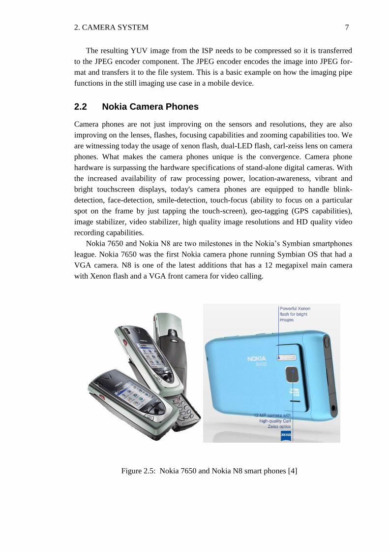
Nokia 7650 and Nokia N8 are two milestones in the Nokia’s Symbian smartphones
league. Nokia 7650 was the first Nokia camera phone running Symbian OS that had a
VGA camera. N8 is one of the latest additions that has a 12 megapixel main camera
with Xenon flash and a VGA front camera for video calling.
Figure 2.5: Nokia 7650 and Nokia N8 smart phones [4]
2. CAMERA SYSTEM 8
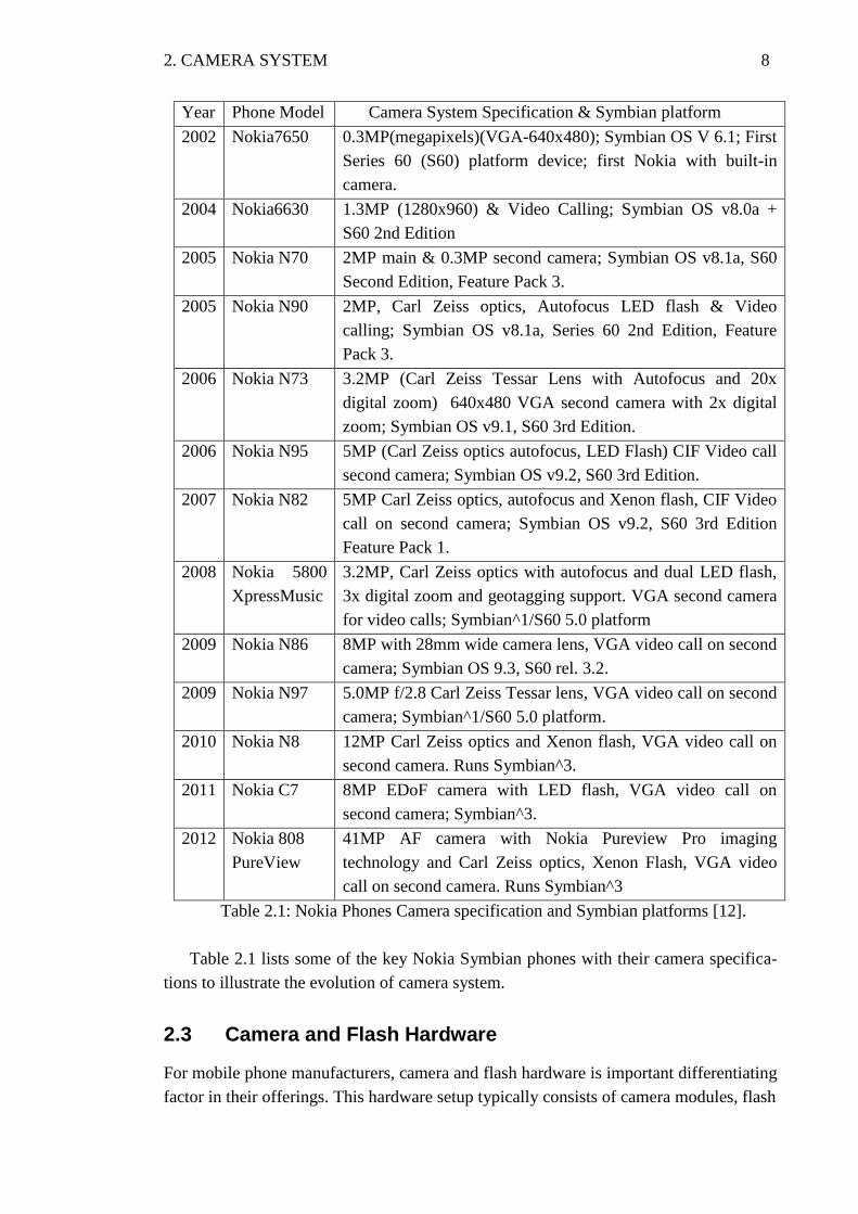
Year Phone Model Camera System Specification & Symbian platform
2002 Nokia7650 0.3MP(megapixels)(VGA-640x480); Symbian OS V 6.1; First
Series 60 (S60) platform device; first Nokia with built-in
camera.
2004 Nokia6630 1.3MP (1280x960) & Video Calling; Symbian OS v8.0a +
S60 2nd Edition
2005 Nokia N70 2MP main & 0.3MP second camera; Symbian OS v8.1a, S60
Second Edition, Feature Pack 3.
2005 Nokia N90 2MP, Carl Zeiss optics, Autofocus LED flash & Video
calling; Symbian OS v8.1a, Series 60 2nd Edition, Feature
Pack 3.
2006 Nokia N73
3.2MP (Carl Zeiss Tessar Lens with Autofocus and 20x
digital zoom) 640x480 VGA second camera with 2x digital
zoom; Symbian OS v9.1, S60 3rd Edition.
2006 Nokia N95 5MP (Carl Zeiss optics autofocus, LED Flash) CIF Video call
second camera; Symbian OS v9.2, S60 3rd Edition.
2007
Nokia N82
5MP Carl Zeiss optics, autofocus and Xenon flash, CIF Video
call on second camera; Symbian OS v9.2, S60 3rd Edition
Feature Pack 1.
2008 Nokia 5800
XpressMusic
3.2MP, Carl Zeiss optics with autofocus and dual LED flash,
3x digital zoom and geotagging support. VGA second camera
for video calls; Symbian^1/S60 5.0 platform
2009 Nokia N86 8MP with 28mm wide camera lens, VGA video call on second
camera; Symbian OS 9.3, S60 rel. 3.2.
2009 Nokia N97 5.0MP f/2.8 Carl Zeiss Tessar lens, VGA video call on second
camera; Symbian^1/S60 5.0 platform.
2010 Nokia N8 12MP Carl Zeiss optics and Xenon flash, VGA video call on
second camera. Runs Symbian^3.
2011 Nokia C7 8MP EDoF camera with LED flash, VGA video call on
second camera; Symbian^3.
2012 Nokia 808
PureView
41MP AF camera with Nokia Pureview Pro imaging
technology and Carl Zeiss optics, Xenon Flash, VGA video
call on second camera. Runs Symbian^3
Table 2.1: Nokia Phones Camera specification and Symbian platforms [12].
Table 2.1 lists some of the key Nokia Symbian phones with their camera specifica-
tions to illustrate the evolution of camera system.
2.3 Camera and Flash Hardware
For mobile phone manufacturers, camera and flash hardware is important differentiating
factor in their offerings. This hardware setup typically consists of camera modules, flash
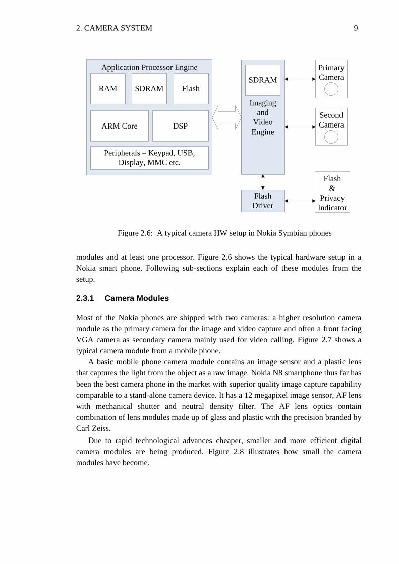
2. CAMERA SYSTEM 9
Figure 2.6: A typical camera HW setup in Nokia Symbian phones
modules and at least one processor. Figure 2.6 shows the typical hardware setup in a
Nokia smart phone. Following sub-sections explain each of these modules from the
setup.
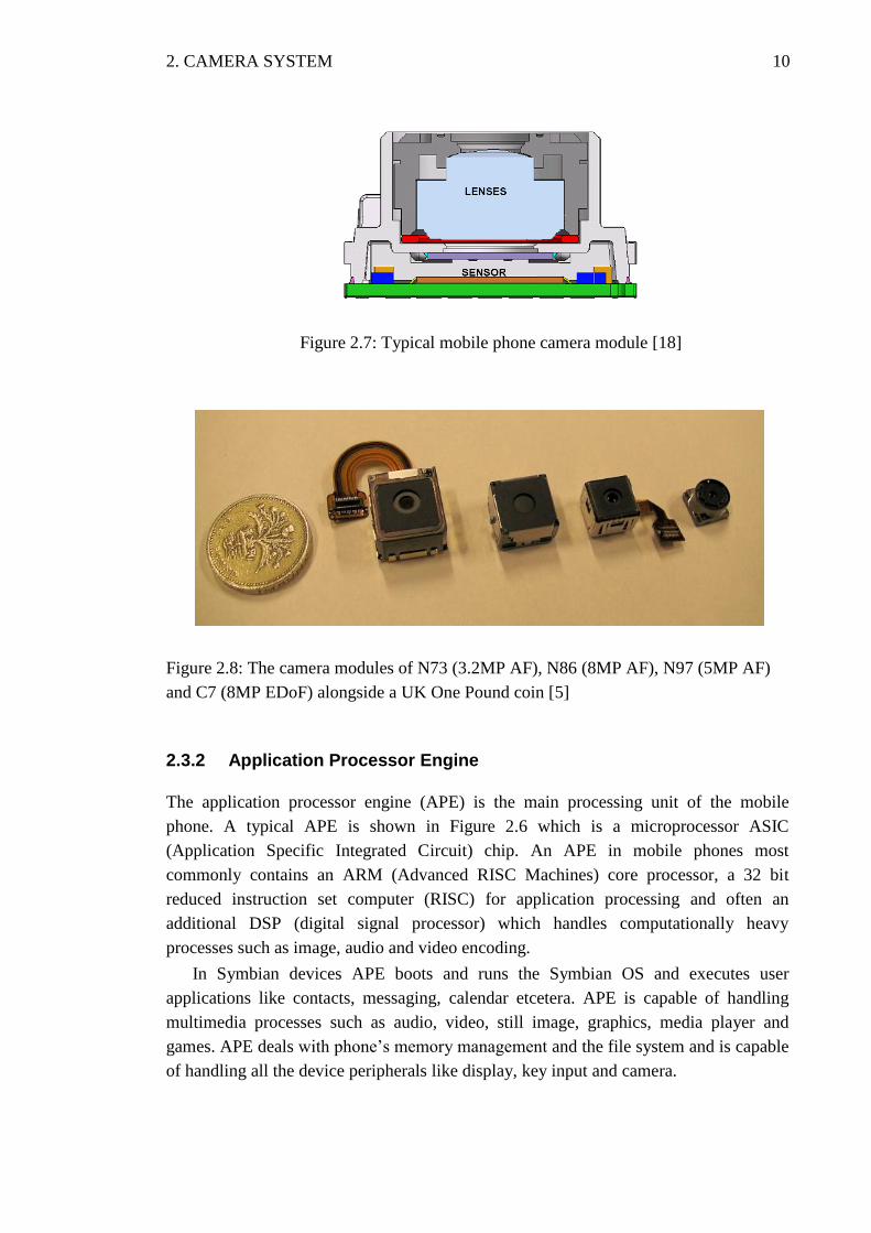
2.3.1 Camera Modules
Most of the Nokia phones are shipped with two cameras: a higher resolution camera
module as the primary camera for the image and video capture and often a front facing
VGA camera as secondary camera mainly used for video calling. Figure 2.7 shows a
typical camera module from a mobile phone.
A basic mobile phone camera module contains an image sensor and a plastic lens
that captures the light from the object as a raw image. Nokia N8 smartphone thus far has
been the best camera phone in the market with superior quality image capture capability
comparable to a stand-alone camera device. It has a 12 megapixel image sensor, AF lens
with mechanical shutter and neutral density filter. The AF lens optics contain
combination of lens modules made up of glass and plastic with the precision branded by
Carl Zeiss.
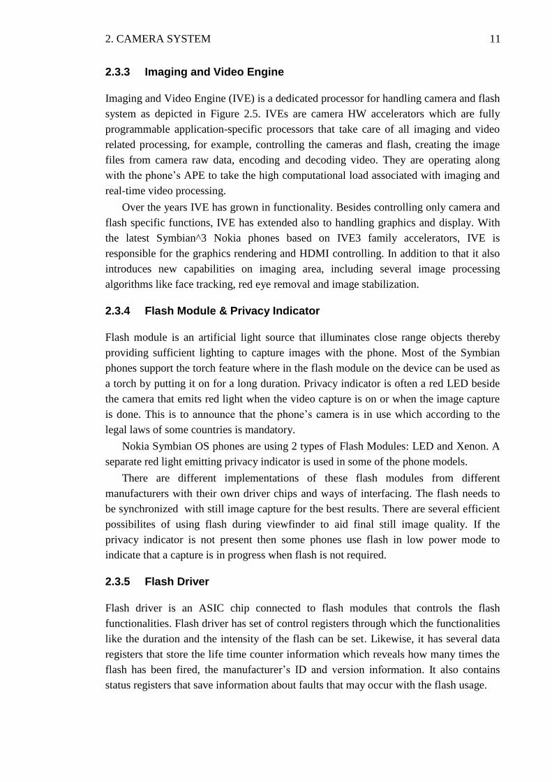
Due to rapid technological advances cheaper, smaller and more efficient digital
camera modules are being produced. Figure 2.8 illustrates how small the camera
modules have become.
Application Processor Engine
RAM SDRAM Flash
ARM Core DSP
Peripherals – Keypad, USB,
Display, MMC etc.
Imaging
and
Video
Engine
Flash
Driver
Primary
Camera
Second
Camera
Flash
&
Privacy
Indicator
SDRAM
2. CAMERA SYSTEM 10
Figure 2.7: Typical mobile phone camera module [18]
Figure 2.8: The camera modules of N73 (3.2MP AF), N86 (8MP AF), N97 (5MP AF)
and C7 (8MP EDoF) alongside a UK One Pound coin [5]
2.3.2 Application Processor Engine
The application processor engine (APE) is the main processing unit of the mobile
phone. A typical APE is shown in Figure 2.6 which is a microprocessor ASIC
(Application Specific Integrated Circuit) chip. An APE in mobile phones most
commonly contains an ARM (Advanced RISC Machines) core processor, a 32 bit
reduced instruction set computer (RISC) for application processing and often an
additional DSP (digital signal processor) which handles computationally heavy
processes such as image, audio and video encoding.
In Symbian devices APE boots and runs the Symbian OS and executes user
applications like contacts, messaging, calendar etcetera. APE is capable of handling
multimedia processes such as audio, video, still image, graphics, media player and
games. APE deals with phone’s memory management and the file system and is capable
of handling all the device peripherals like display, key input and camera.
2. CAMERA SYSTEM 11
2.3.3 Imaging and Video Engine
Imaging and Video Engine (IVE) is a dedicated processor for handling camera and flash
system as depicted in Figure 2.5. IVEs are camera HW accelerators which are fully
programmable application-specific processors that take care of all imaging and video
related processing, for example, controlling the cameras and flash, creating the image
files from camera raw data, encoding and decoding video. They are operating along
with the phone’s APE to take the high computational load associated with imaging and
real-time video processing.
Over the years IVE has grown in functionality. Besides controlling only camera and
flash specific functions, IVE has extended also to handling graphics and display. With
the latest Symbian^3 Nokia phones based on IVE3 family accelerators, IVE is
responsible for the graphics rendering and HDMI controlling. In addition to that it also
introduces new capabilities on imaging area, including several image processing
algorithms like face tracking, red eye removal and image stabilization.
2.3.4 Flash Module & Privacy Indicator
Flash module is an artificial light source that illuminates close range objects thereby
providing sufficient lighting to capture images with the phone. Most of the Symbian
phones support the torch feature where in the flash module on the device can be used as
a torch by putting it on for a long duration. Privacy indicator is often a red LED beside
the camera that emits red light when the video capture is on or when the image capture
is done. This is to announce that the phone’s camera is in use which according to the
legal laws of some countries is mandatory.
Nokia Symbian OS phones are using 2 types of Flash Modules: LED and Xenon. A
separate red light emitting privacy indicator is used in some of the phone models.
There are different implementations of these flash modules from different
manufacturers with their own driver chips and ways of interfacing. The flash needs to
be synchronized with still image capture for the best results. There are several efficient
possibilites of using flash during viewfinder to aid final still image quality. If the
privacy indicator is not present then some phones use flash in low power mode to
indicate that a capture is in progress when flash is not required.
2.3.5 Flash Driver
Flash driver is an ASIC chip connected to flash modules that controls the flash
functionalities. Flash driver has set of control registers through which the functionalities
like the duration and the intensity of the flash can be set. Likewise, it has several data
registers that store the life time counter information which reveals how many times the
flash has been fired, the manufacturer’s ID and version information. It also contains
status registers that save information about faults that may occur with the flash usage.
2. CAMERA SYSTEM 12
2.4 SMIA (Standard Mobile Imaging Architecture)
Following are the demands created by ever growing mobile imaging devices:
The rapidly increasing image sensor resolution necessitates the data interfaces to
be capable of handling high data rates.
The camera must be small in size and may be flex mounted. Therefore a low pin
count is desirable.
High volume mobile application favour second sourcable components with a
standardized electrical and mechanical interfaces.
Second sourcing requires that camera modules also have similar optical
performance. A common way of measuring performance is needed to truly
compare different products.
Rapidly changing consumer markets for mobile products require a fast design
and industrialization cycle. The use of standards speeds up both the component
design cycle and the design-in process at the end user.
To address these demands Nokia together with ST Microelectronics has setup SMIA
which is an imaging architecture standard especially suitable for mobile devices. The
scope of SMIA covers a Raw Bayer output image sensor head. It specifies housing,
mechanical interconnection, functionality, register set and electrical interface for camera
modules. Control of camera sensor is done by reading from and writing to registers
within the sensor, a pre-defined set of registers is specified so that any SMIA
compatible sensor may be setup and controlled in a standard fashion. It also allows
flexibility by allowing of Manufacturer Specific Registers (MSRs). Most of the Nokia
Camera phones follow this standard [7]. SMIA++ is the new version of SMIA that
includes a lot of detail that was not available during SMIA design such as Auto Focus
(AF), Extended Depth of Field (EDoF) as well as handling larger pixel amount sensors
better by introducing a standard to increase image bus speed capabilities.
13
3 SYMBIAN OS
Symbian OS is a software platform for smartphones; the purpose of the platform is to
provide a foundation for smartphone software, including an integrated application suite
and a number of software libraries, frameworks, and APIs. A common platform for
smartphones has several advantages. Firstly, it enables rapid software development for
new smartphone products and reduces time-to-market. Secondly, it improves software
compatibility across devices from different manufacturers and enables native 3rd party
application development. This chapter explains the main characteristics of Symbian
operating system and the multimedia architecture within it.
3.1 Introduction to Symbian OS
Symbian Ltd was founded in 1998 lead by a consortium including Nokia, Ericsson,
Motorola and Psion to develop and supply an open and standard mobile device
platform, Symbian OS. Roots of Symbian OS go back to 1980’s when Psion created a
16-bit operating system for small mobile devices with long operating times. In the mid-
dle of 1990’s they discovered the limitations of 16-bit architecture and started rewriting
the system. The new 32-bit operating system called EPOC was ready to be released in
1997. The first operating system release Symbian made was EPOC release 5 in June
1999. After that release the operating system was named as Symbian OS. Series 60
(S60) is Nokia’s graphical user interface framework that runs on top of Symbian OS.
The terms S60 and Symbian OS are quite often used interchangably.
Nokia acquired Symbian and in 2009, Symbian Foundation was established to make
the Symbian platform available open source and royalty-free. Further in November
2010 the foundation ramped down its operational activities as a result of changes in
global economic and market conditions. Symbian^2 was the last Symbian OS release
from the foundation for smartphone manufacturers outside Nokia. The foundation is
transitioned from a non-profit organisation responsible for governing the open
development and curation of the Symbian platform, to a licensing entity with no
permanent staff. It is responsible only for specific licensing and legal frameworks put in
place during the open sourcing of the platform. Nokia launched the current and the
latest platform release Symbian^3 in 2010. Currently there is a huge consumer base of
Nokia Symbian smartphones that is based on S60 3.2, S60 5.0 aka Symbian^1 and
Symbian^3 platform releases in the market that Nokia together with Accenture are
supporting.
3. SYMBIAN OS 14
3.2 The Scope of Symbian OS
The Symbian platform includes a customizable user interface, a rich set of applications,
common user interface components and development tools for implementing new appli-
cations. It also includes tools and documentation that enables device manufacturers and
application developers to create feature-rich devices and applications. The whole sys-
tem, down to the lowest level of the operating system (kernel), is based on the object-
oriented design and is implemented in C++. Only the lowest level hardware specific and
most time critical functions are written in assembly language.
The processor’s power and memory size are limited in small devices. This demands
the operating system to be stingy with the system resources. Reliability is one of the key
requirements of mobile and handheld devices. They must be as resilient as paper diaries
and agendas. This is a very strict assumption, because any data loss in a personal mobile
phone may cause a loss of trust for that product or even for the whole company. Symbi-
an OS aims to achieve the robustness and stinginess in resources by using its own pro-
cess handling mechanisms, an easy-to-use error handling framework that is also respon-
sible for out-of-memory errors, an effective memory management that is handled by a
memory management unit (MMU), and by encouraging the developers to object orient-
ed SW development.
The devices in which Symbian OS runs operate in wireless environment, where the
connectivity is usually episodic by nature and network coverage can change dramatical-
ly from one area to another. This is why Symbian OS has to support multiple protocols
dependent on the available network. Symbian OS includes many layers of network op-
erability and it supports many different network standards such as Bluetooth, infrared
and wireless LAN. Symbian OS supports also a lot of other functionality that multime-
dia devices need.
Symbian’s goal is to provide openness for third party SW developers. This means
that it provides application-programming interfaces (API) to the resources so that third
parties can develop software on the Symbian platform. These APIs are released for de-
velopers in software development kits (SDK).
3.3 Dynamically Loadable Components
Just like almost any modern operating system Symbian OS provides a way to load
application components dynamically at run-time. In Symbian OS there are basically
three different ways to do that: static interface DLLs, polymorphic interface DLLs and
ECom components.
3.3.1 DLL Entry Points
DLLs in Symbian OS always have an entry point that is usually called when the library
is loaded and unloaded. The entry point E32Main() has to be implemented by the
developer but usually its implementation is left empty. It is possible, however, to put
3. SYMBIAN OS 15
some global initialisation or cleanup code into the entry point of DLL but it is not
recommended.
3.3.2 Static Interface DLLs
Static interface DLLs in Symbian OS are exactly the same kind of dynamically loadable
DLLs that exist in many other operating systems. They are called static interface DLLs
because they export a static table of functions that can be used in other applications.
Static interface DLLs can be used by linking the application against import library
(.lib file) that corresponds to the used DLL. Operating system then guarantees that cor-
rect libraries are loaded when an application is run.
Static interface DLLs are very efficient when there are multiple applications that
need the same functionality. That functionality can be wrapped inside a static interface
DLL and the operating system loads only one instance of the library into memory even
though there are multiple applications using it. If the DLL is located on ROM it can be
even executed directly from there without loading it to RAM at all. In addition to im-
proving memory usage of applications, static interface DLLs also provide abstraction
and modularization for project because a piece of logical design can be encapsulated
inside a library.
3.3.3 Polymorphic Interface DLLs
Static interface DLLs expose multiple entry points to the outside world but polymorphic
interface DLLs provide only one. The only exported function can be of any kind but
usually it is a factory method that can be used to create an implementation object of a
well-known interface with one or more pure virtual functions. Created object is often a
factory that can be used to further create new objects. This way polymorphic DLLs can
be used as a certain kind of an extension point for application. [2]
Polymorphic DLLs are identified using unique identifiers (UIDs). DLLs having a
specific UID are known to implement a specific interface. That way applications are
able to know if a DLL implements the needed interface.
Polymorphic DLLs are used quite extensively in Symbian OS. For example all ap-
plication EXEs are polymorphic DLLs that the framework loads when the application is
started. Also device drivers and many other operating system level components are pol-
ymorphic DLLs.
Normally the single exported function of a polymorphic DLL is called by the oper-
ating system only. This is the case in applications and polymorphic components of the
operating system. However, it is possible to load the DLLs programmatically using
loading facilities provided by the operating system.
3.3.4 Symbian ECom Architecture
In C++, the existence of abstract base classes and virtual functions allows the programs
to call, or access interfaces without knowing the actual implementation.
3. SYMBIAN OS 16
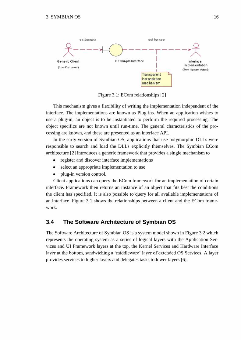
Figure 3.1: ECom relationships [2]
This mechanism gives a flexibility of writing the implementation independent of the
interface. The implementations are known as Plug-ins. When an application wishes to
use a plug-in, an object is to be instantiated to perform the required processing. The
object specifics are not known until run-time. The general characteristics of the pro-
cessing are known, and these are presented as an interface API.
In the early version of Symbian OS, applications that use polymorphic DLLs were
responsible to search and load the DLLs explicitly themselves. The Symbian ECom
architecture [2] introduces a generic framework that provides a single mechanism to
register and discover interface implementations
select an appropriate implementation to use
plug-in version control.
Client applications can query the ECom framework for an implementation of certain
interface. Framework then returns an instance of an object that fits best the conditions
the client has specified. It is also possible to query for all available implementations of
an interface. Figure 3.1 shows the relationships between a client and the ECom frame-
work.
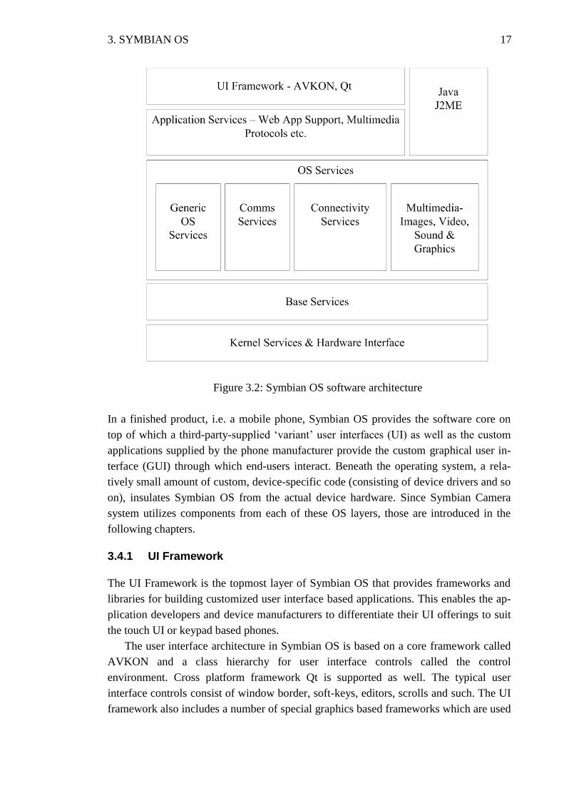
3.4 The Software Architecture of Symbian OS
The Software Architecture of Symbian OS is a system model shown in Figure 3.2 which
represents the operating system as a series of logical layers with the Application Ser-
vices and UI Framework layers at the top, the Kernel Services and Hardware Interface
layer at the bottom, sandwiching a ‘middleware’ layer of extended OS Services. A layer
provides services to higher layers and delegates tasks to lower layers [6].
3. SYMBIAN OS 17
Figure 3.2: Symbian OS software architecture
In a finished product, i.e. a mobile phone, Symbian OS provides the software core on
top of which a third-party-supplied ‘variant’ user interfaces (UI) as well as the custom
applications supplied by the phone manufacturer provide the custom graphical user in-
terface (GUI) through which end-users interact. Beneath the operating system, a rela-
tively small amount of custom, device-specific code (consisting of device drivers and so
on), insulates Symbian OS from the actual device hardware. Since Symbian Camera
system utilizes components from each of these OS layers, those are introduced in the
following chapters.
3.4.1 UI Framework
The UI Framework is the topmost layer of Symbian OS that provides frameworks and
libraries for building customized user interface based applications. This enables the ap-
plication developers and device manufacturers to differentiate their UI offerings to suit
the touch UI or keypad based phones.
The user interface architecture in Symbian OS is based on a core framework called
AVKON and a class hierarchy for user interface controls called the control
environment. Cross platform framework Qt is supported as well. The typical user
interface controls consist of window border, soft-keys, editors, scrolls and such. The UI
framework also includes a number of special graphics based frameworks which are used
3. SYMBIAN OS 18
by the user interface but which are also available to applications including the
Animation framework, the Front End Processor (FEP) base framework and Grid.
3.4.2 Application Services
The Application Services layer provides user interface independent support for applica-
tions on Symbian OS. Services from this layer are used by all applications but mediated
by the UI Framework layer, for example, application installation and launching, view
switching, and the basic application architecture relationships. The Java ME layer also
uses the frameworks and services from Application Services layer.
Services provided by this layer range from those used by all applications like basic
application frameworks, text handling and secure software install to those providing
technology specific logic like for example support for device management, messaging
and multimedia protocols, to services targeting specific individual applications namely
Camera Application Engine and office applications support.
3.4.3 Java ME
Java Micro Edition (J2ME) layer spans the UI Framework and Application Services
layers, abstracting as well as implementing elements of both for Java applications. This
layer encapsulates Symbian OS for Java J2ME applications (MIDlets), and includes a
Java virtual machine, the Mobile Information Device Profile, and packages that provide
functionality such as communications and multimedia support.
3.4.4 OS Services
In terms of the number of components, OS Services is the largest single layer of the
Symbian OS. OS Services layer is the middleware layer of the Symbian OS that pro-
vides the servers, frameworks and libraries that implement the core operating system
support for graphics, communications, connectivity, and multimedia, as well as some
generic system frameworks and libraries (Certificate and Key Management, the C
Standard Library) and other system-level utilities (logging services). In effect, it is the
layer that extends the minimal base layers of the system (the kernel and the low-level
system libraries that implement the basic OS primitives and idioms) into an extensible,
programmable, and useful operating system.
The Multimedia and Graphics is one of the functional blocks from OS Services that
provides support for graphics and audio, from simple drawing primitives to playing and
recording multimedia formats. This block includes Multimedia Framework and
Onboard Camera API which are the key components in Camera Software architecture.
3. SYMBIAN OS 19
3.4.5 Base Services
Base Services layer extends the bare kernel into a basic software platform that provides
the foundation for the remaining operating system services, and effectively encapsulates
the user side of the ‘base’ operating system.
In particular, the Base Services layer includes the File Server and the User Library.
The Base Services layer also includes the components needed to create a fully
functioning base port without requiring any further high-level services with the Text
Window Server and the Text Shell. Other important system frameworks provided by
this layer include the ECom Plug-in Framework, which implements the standard man-
agement interface used by all Symbian OS framework plug-ins, the Store which pro-
vides the persistence model, the Central Repository, the DBMS framework and Cryp-
tography Library and Camera Adaptation.
3.4.6 Kernel Services & Hardware Interface
Kernel Services & Hardware Interface layer performs the fundamental operating system
tasks of interacting with hardware, managing access to device resources and booting the
device thereby insulating all higher layers from the hardware.
A multi-tasking, real-time operating system kernel is the main component in this
layer that manages the fundamental OS tasks, threads, processes, memory management,
and scheduling. Access to the kernel by user-side programs (program that are not run as
part of the kernel) is through the user library from the Base Services layer. The kernel
contains both generic code, and code that must be customized to work on particular
hardware platforms.
This layer provides the physical and logical device drivers that abstract device
hardware into logical devices. Camera PDD and camera LDD are part of this layer.
3.5 Camera and Video System Architecture
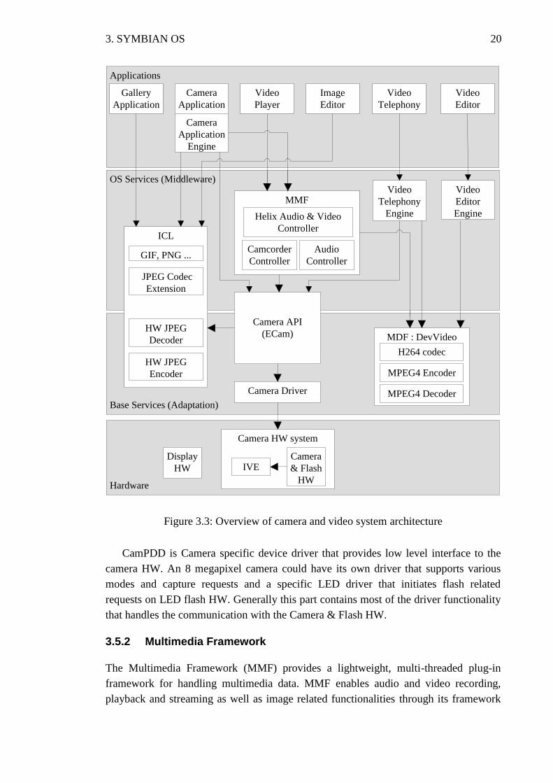
The generic software components within the camera and video system architecture
in Symbian OS are shown in Figure 3.3 and the following sections introduce the com-
ponents relevant to camera system.
3.5.1 Camera Driver
Camera driver provides low level interface for controlling camera modules, flash
modules and camera HW accelerators. As HW accelerators grow in functionality, they
have been extended to support video playback and image decoding as well.
The Camera driver follows the Symbian two tier driver architecture with Camera
Logical Device Driver (CamLDD) and Camera Physical Device Driver (CamPDD).
CamLDD provides an abstracted interface to the camera hardware and supports the
functionality common to a product variant.
3. SYMBIAN OS 20
Figure 3.3: Overview of camera and video system architecture
CamPDD is Camera specific device driver that provides low level interface to the
camera HW. An 8 megapixel camera could have its own driver that supports various
modes and capture requests and a specific LED driver that initiates flash related
requests on LED flash HW. Generally this part contains most of the driver functionality
that handles the communication with the Camera & Flash HW.
3.5.2 Multimedia Framework
The Multimedia Framework (MMF) provides a lightweight, multi-threaded plug-in
framework for handling multimedia data. MMF enables audio and video recording,
playback and streaming as well as image related functionalities through its framework
Applications
OS Services (Middleware)
Base Services (Adaptation)
Gallery
Application
Camera
Application
Camera
Application
Engine
Video
Player
Video
Telephony
Video
Editor
Image
Editor
MMF
Helix Audio & Video
Controller
Camcorder
Controller
Audio
Controller
ICL
GIF, PNG ...
JPEG Codec
Extension
HW JPEG
Decoder
HW JPEG
Encoder
Video
Telephony
Engine
Video
Editor
Engine
MDF : DevVideo
Camera API
(ECam)
Camera Driver
MPEG4 Encoder
MPEG4 Decoder
H264 codec
Hardware
Display
HW
Camera HW system
IVECamera
& Flash
HW
3. SYMBIAN OS 21
of controller plug-ins. The MMF controller plug-in provides support for one or more
multimedia formats, for example MP3 or AVI. In addition to controller plug-ins, the
MMF can also be extended through format encoder, decoder, codec and sink plug-ins.
The player and recorder interfaces of both audio and video as well as the audio con-
verter interface use the controller plug-ins provided by the MMF. These plug-ins pro-
vide the functionality to convert, to interpret and to play audio and video data. The re-
sultant data from the plug-ins can then be directed to one or more sink such as a file, or
directly to the display screen or lower level device driver
MMF also provides enablers for a tone player interface that enables playing tones
such as DTMF (Dual-Tone Multi-Frequency) and an audio streaming interface that ena-
bles recording and playing audio streams such as audio from a web address. The tone
player and the audio streaming interfaces do not require controller plug-in for encoding
or decoding since the input and output data formats with these are already known. As a
result they bypass MMF controller framework [2].
3.5.3 Image Conversion Library
Image conversion library (ICL) is a lightweight still image framework that supports
many features like encoding, decoding, scaling, rotating, producing mirror image, flip-
ping and cropping images [2]. It supports these features through variety of APIs that
applications and ECam can make use of. ICL supports various formats, like JPEG, GIF,
BMP, MBM, TIFF and ICO. ICL is extensible in nature since it is developed as a Sym-
bian ECom framework. Third party plug-ins can be added to the Symbian camera sys-
tem that extends and supports more image conversion options via ICL.
3.5.4 Onboard Camera API
Symbian Onboard Camera API, also known as ECam driver, provides an extensible set
of APIs that allows applications to utilize the camera and the flash hardware on
Symbian devices. ECam provides access to basic camera related functions such as using
real-time viewfinder, capturing still images and giving frame data information for video
encoding. The APIs allow application software to enumerate available camera devices
and query for supported image formats and features. White balance, flash mode, and
several other image capture parameters may be adjusted using the API. A client using
the API needs to reserve the camera hardware for exclusive use. Having multiple clients
using the same physical camera is not allowed, but there may be several physical
cameras on the device. The clients for ECam are the UI applications and the Multimedia
framework.
The basic version of Symbian ECam provides stub interface, i.e. custom interface
mechanism which allows extensions to be added into the API without breaking
compatibility with older clients. In practice this means that the ECam APIs, which are
actually virtual functions defining basic common operations, can be extended by incor-
porating proprietary properties as actual function implementations.
3. SYMBIAN OS 22
3.5.5 Camera APP Engine
Camera Application Engine provides the functionality of view finding, still image cap-
turing, video recording, and the related settings to the Camera Application. Apart from
fetching the information from the Onboard Camera API (ECam) it also requests meth-
ods to handle bitmap images from Symbian’s Font & Bitmap Server API. The basic
engine can be extended using Custom Interfaces and plug-in extension modules.
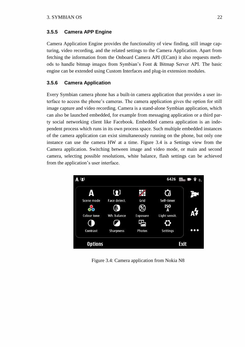
3.5.6 Camera Application
Every Symbian camera phone has a built-in camera application that provides a user in-
terface to access the phone’s cameras. The camera application gives the option for still
image capture and video recording. Camera is a stand-alone Symbian application, which
can also be launched embedded, for example from messaging application or a third par-
ty social networking client like Facebook. Embedded camera application is an inde-
pendent process which runs in its own process space. Such multiple embedded instances
of the camera application can exist simultaneously running on the phone, but only one
instance can use the camera HW at a time. Figure 3.4 is a Settings view from the
Camera application. Switching between image and video mode, or main and second
camera, selecting possible resolutions, white balance, flash settings can be achieved
from the application’s user interface.
Figure 3.4: Camera application from Nokia N8
23
4 SOFTWARE VARIATION
A mobile phone platform should be capable of supporting mobile devices with varying
hardware configurations and different software based feature variants. This would ena-
ble the mobile phone manufacturers to differentiate their offerings in order to cater to
different markets. Supporting such varying and vast configurations with one OS plat-
form release could be possible by using software variation mechanism.
This chapter introduces the reader to the topic of software variation. First production
line engineering is discussed to show why flexible software variation is important in the
context of platform development. Then different software variation techniques are pre-
sented and their advantages and disadvantages are considered.
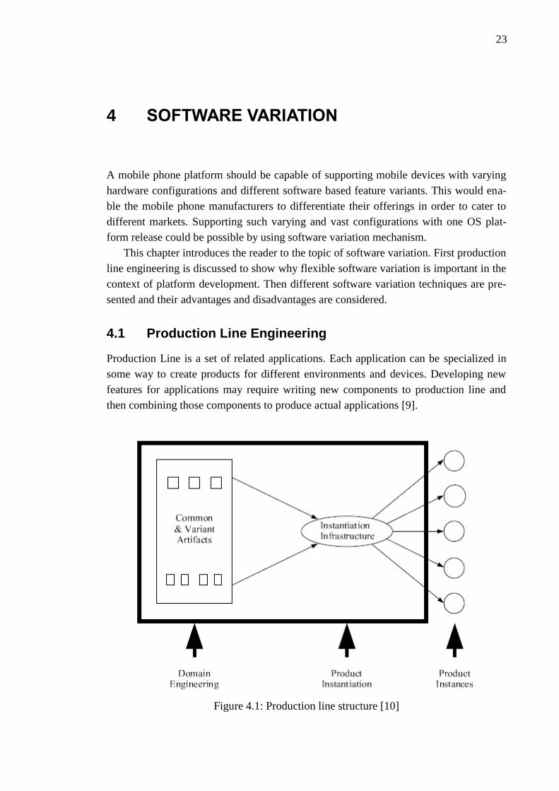
4.1 Production Line Engineering
Production Line is a set of related applications. Each application can be specialized in
some way to create products for different environments and devices. Developing new
features for applications may require writing new components to production line and
then combining those components to produce actual applications [9].
Figure 4.1: Production line structure [10]
4. SOFTWARE VARIATION 24
Production line can be thought of as a pool of reusable components that can be then
combined to form actual products using a specific instantiation infrastructure. However,
production line does not contain the individual products that are instantiated. Figure 4.1
shows the structure of production line. The idea behind production line engineering is
that “individual products should be treated as transient outputs of the production line
that can be discarded and re-instantiated as needed” [10].
Good software variation techniques are important to enable efficient product instan-
tiation infrastructure. Software has to be designed for variation from the beginning to
make it possible to instantiate different versions of the software with selected feature
sets. There are several variation techniques that can be used to accomplish needed varia-
tion level for production line engineering. Chosen variation techniques affect the instan-
tiation infrastructure and therefore the whole production line.
4.2 Software Variation in Production Line Engineering
Software variation in conventional software development is about managing the evolu-
tion of software over time. Management of variation over time is also known as config-
uration management or version management. Sequential and parallel time variations are
both supported by many configuration management tools and there are well known
management methods for them. For normal software development managing only varia-
tion over time is normally enough because software is usually developed for a known
hardware configuration and platform. However, in software production line engineering
something else is needed to manage the multitude of different devices [11].
Software variation in production line engineering is multi-dimensional. In addition
to managing variation over time, also variation management in space is needed. Varia-
tion in space is about managing the different features of one product at any fixed point
in time. This is closely related to production line engineering because it also addresses
the problem of instantiating concrete products with specific feature sets from varied
components [10].
Designing for variation differs significantly depending on which kind of variation
we are designing for. Designing for variation over time means anticipating future re-
quirement changes and new requirements so that the existing system structure may easi-
ly adapt to changes. Separating components clearly and building a sound architecture is
necessary to enable flexibility in software and therefore help variation over time. That
kind of design is relatively well understood and many design patterns have been devel-
oped to support it [13].
Designing for variation in space on the other hand is completely different because it
has to be possible to instantiate the same product with multiple different feature sets at
any time. Variation in space is the variation type that is needed to enable production line
engineering. Of course also variation in time is important for efficient software devel-
opment processes that are used also in production line engineering. However, without
good methods for variation in space the whole instantiation infrastructure would be ex-
4. SOFTWARE VARIATION 25
tremely hard to build and therefore the production line would not be complete. Also, the
instantiation infrastructure would be very hard to configure and therefore it would be
hard to build same application with different feature sets.
4.3 Variation Point
Variation point is some point in an application in which the execution of the application
may take different paths depending on what features are enabled or disabled. Variation
points may be specific to one application, span multiple applications or even the whole
platform. For example enabling Bluetooth feature may add menu items in several appli-
cations but enabling MMS messages possibly affects only on messaging application.
Even though there are variation points that may span the whole platform each applica-
tion still has to take care that it behaves correctly with each of the possible feature com-
binations.
4.3.1 Types of Variation Points
When implementing variation points and choosing an appropriate variation method it is
essential to know what kind of variation is being implemented. In general there are three
types of features that may be varied. In addition to these three types there is naturally
one more type which is a feature that is always included in an application.
The first type of a feature is an optional feature. An optional feature may be enabled
or disabled in an application. This is the simplest type of variable features and also the
easiest to implement. This kind of feature is for example a search feature in a file man-
agement application: searching of files from the file system is either enabled or disa-
bled.
The second type is an alternative feature. An alternative feature is chosen from a set
of features from which only one feature may be enabled at a time. All others are disa-
bled. An example of an alternative feature is selecting a language variant: even though a
mobile phone may contain support for multiple languages only one of them may be en-
abled at a time.
The third and last type of a feature is a generalization of the alternative feature type.
This is so called multi-feature where there can be multiple features enabled from a set of
features. The different variants of the feature are not therefore mutually exclusive. Ex-
ample for this kind of feature is a file sending feature in a file management application:
it is possible to send files over infrared, Bluetooth, or MMS. Each of those features may
be enabled or disabled independently of each other.
In the source code variation points may be implemented using several techniques.
Variation point may be a conditional statement where one branch of execution is taken
if a feature is enabled and the other is taken if the feature is disabled. A variation point
that most closely resembles the object oriented thinking is a virtual function call. Virtual
function call replaces conditional with polymorphism [14]. In that case the variation is
4. SOFTWARE VARIATION 26
decided by creating a different implementation for an abstract interface depending on
whether a feature is enabled or not.
In addition to previously mentioned variation type, also variation binding time dis-
tinguishes variation points from each other. Variation binding time may be compile-
time, link-time, ROM image creation time or run-time. Of these four the compile-time
and link-time variation can be discussed together as static binding times and run-time
variation uses dynamic binding time.
ROM image creation uses actually static binding time but depending on the situation
it can also be understood as dynamic variation, because sometimes DLLs that are put to
the ROM image are loaded by applications as extension components during run-time.
So the configuration is decided statically when ROM image is built but the software
adapts dynamically to that configuration at run-time [8].
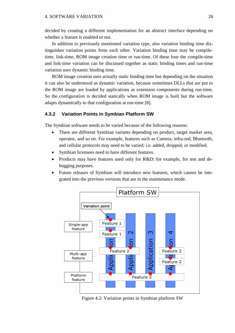
4.3.2 Variation Points in Symbian Platform SW
The Symbian software needs to be varied because of the following reasons:
There are different Symbian variants depending on product, target market area,
operator, and so on. For example, features such as Camera, infra-red, Bluetooth,
and cellular protocols may need to be varied; i.e. added, dropped, or modified.
Symbian licensees need to have different features.
Products may have features used only for R&D; for example, for test and de-
bugging purposes.
Future releases of Symbian will introduce new features, which cannot be inte-
grated into the previous versions that are in the maintenance mode.
Figure 4.2: Variation points in Symbian platform SW
Application
1
Application
2
Application
3
Application
4
Feature 1Feature 1
Feature 2Feature 2
Feature 3Feature 3
Variation pointVariation point
Platform SW
Feature 2Feature 2
Feature 1Feature 1
Feature 2Feature 2
Single-app
feature
Multi-app
feature
Platform
feature
4. SOFTWARE VARIATION 27
Variation is controlled at various locations in the Symbian software build. These
variation points determine how features are included or excluded in the build. A feature
may have an effect on only a single application, on multiple applications or on all appli-
cations in the Symbian OS platform SW on which a set of products run. Again, a feature
change may affect only a single application, many applications or all applications in the
platform. Figure 4.2 illustrates and variation points across the Symbian platform SW.
Application here means any component from the software stack, device driver, applica-
tion engines or a GUI application.
4.4 Software Variation Methods in Symbian OS
This section provides an overview of the Symbian build system and introduces different
variation mechanisms available in Symbian OS. Depending on the intended variation
type and binding time, different variation mechanisms can be chosen. Some of the var-
iation mechanisms support multiple variation types or even all of them. However, the
most important issue when selecting a variation type is to keep the design of an applica-
tion clear and code maintainable.
4.4.1 Software Build System for Symbian OS
Symbian platform release supports several device families. A device family consists of
products belonging to the same HW platform, which is mainly decided by the used APE
ASIC and possibly by other key ASICs like IVE. A device family typically consists of
tens of products and their variants. If including all the operator and market specific vari-
ants with different language and localized content options, the number of different vari-
ants gets easily to several hundreds.
The build environment for Nokia Symbian phones usually covers one or several de-
vice families. To be able to handle the whole build system with reasonable effort, effi-
cient variation mechanisms are required. For example to keep the amount of files in
control, roughly half a million files currently, files must not be duplicated for each
product but instead the different requirements must be supported in the same files
through configuration options as far as possible. In order to keep the compiling and
building times feasible, it must be possible to build common parts of the system only
once and reuse the build products throughout the product range. All this especially as
the same build system is used both in dedicated build servers and in individual develop-
ers' local computers.
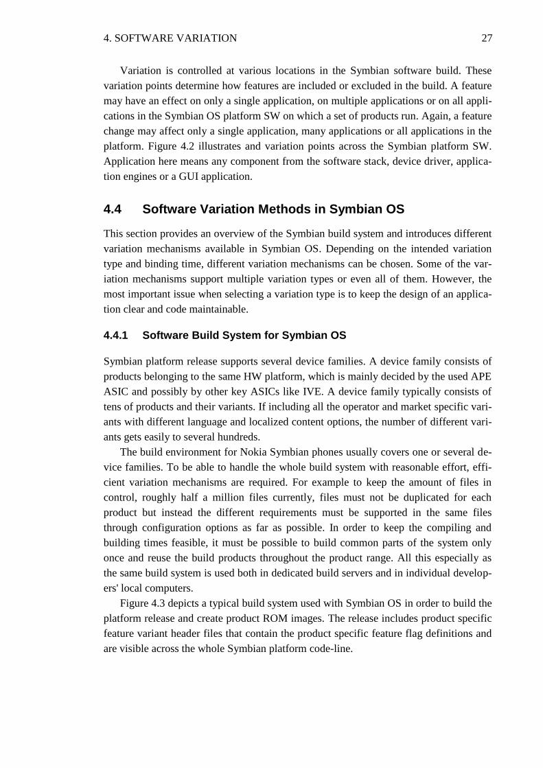
Figure 4.3 depicts a typical build system used with Symbian OS in order to build the
platform release and create product ROM images. The release includes product specific
feature variant header files that contain the product specific feature flag definitions and
are visible across the whole Symbian platform code-line.
4. SOFTWARE VARIATION 28
Figure 4.3: Software build system for Symbian OS
For example the feature variant header file for product A, productA_settings.hrh that
includes product specific definition:
#undef INFRARED_ENABLED //Infra-red not supported
#define CAMERA1_TYPE 12mpix_Cam //Primary camera is 12megapixel
#define SEC_CAM //Secondary camera supported
These flags could be either static or run-time feature flags. Usually flags are given either
boolean or integer values. Run-time flags are assigned a 32 bit unique identifiers and
during the build process they are fetched into a product specific .dat file along with their
values. For example, the feature data file for N8 under the Symbian release would be
“\epoc32\ release\data\N8\features.dat” file that gets into the N8’s ROM image. Feature
discovery APIs are used by the Symbian OS components for querying whether a partic-
ular feature is supported or not, during run-time.
Central repository key value pairs from the Symbian .confml files are fetched into
certain binary repository files with file extension .cre during the ROM image creation
time. These .cre files reside in the product ROM image. The central repository APIs are
used during the run-time by Symbian OS components to query the value that a key
holds.
4. SOFTWARE VARIATION 29
On building Symbian platform, the build system compiles individual component
source code, i.e. different applications, API libraries and device drivers across the Sym-
bian platform layers. This produces binary files intended to be part of the product’s
ROM image under the EPOC32 folder structure of the Symbian release on build com-
puters. The binary files are a set of executable with extension exe, libraries with exten-
sions dll, pdd and ldd and resource files with extension rsc. The created binaries are of
two types, common to all product variants or specific to only certain product variants.
The camera application binary “\epoc32\release\CameraApp.exe”, typically com-
mon for all the products, uses central repository and run-time feature flag discovery
variation methods. The onboard camera API plug-in and the camera driver LDD files
are generally product specific, both using static feature flag definitions for variation. For
example for N8 they would be “\epoc32\release\N8\ecamplugin.dll” and
“\epoc32\release\N8\camdriver_IVE3.ldd”. Thus, the system builds a different ROM
image for each product variant that it supports.
Apart from these variation techniques during different stages of build process, the
dynamic configuration (DC) files can also be used in the post image creation phase.
These DC files can be loaded into the product file system separately from the ROM
image. These files contain certain tuning values for camera, display or any other product
specific peripheral, thus enhancing the overall product quality. The values from these
DC files override the original values that are in the ROM image.
4.4.2 Feature Flag Settings
The software functionality can be varied by flagging some of its code so that the flagged
parts of the code are only compiled if a feature flag has a certain value. The feature flags
are generally defined or undefined in a high level product specific header file, namely
feature_settings.hrh, which is visible to the whole Symbian code line. The software
functionality in the code is therefore selected at compile-time and can not be changed
unless the code is recompiled. Programme 4.1 shows how the feature flag variation is
normally implemented.
void CVariedClass::Function() {
// Common code for all variants
#ifdef __FEATURE_A_ENABLED__
// Implementation with feature A enabled
#else
// Standard implementation
#endif // __FEATURE_A_ENABLED__
// Common code for all variants
}
Programme 4.1: Compile-time variation
Feature flags are often used in IBY and OBY, the ROM image component include
files. For example in cameradriver.iby file that includes specific camera driver
4. SOFTWARE VARIATION 30
component to the ROM image, the required driver can be chosen into the image
depending on the feature flag definition as follows:
#ifdef CAM_HWA // if camera HW accelerator feature is supported
// Include HW accelerator version of the camera driver
\epoc32\release\armv5\camHWAdrv.dll \library\camdrv.dll
#else
//Include the generic camera driver to the image.
\epoc32\release\armv5\camdrv.dll \library\camdrv.dll
#endif
Using feature flags can be problematic for version controlling and testability of the
software. If there are several feature flags then all the possible combination of the flags
should be tested. Increasing the number of flags increases the time needed for testing
exponentially. Also when making changes, for example fixing bugs in the software,
each part enclosed within a feature flag has to be carefully considered to make sure that
the change is included in all possible feature flag combinations.
4.4.3 Feature Discovery API
Symbian software provides Feature Discovery APIs to fetch the feature flag values.
These values are then used to determine programmatically which optional features are
present on the device executing the application. For example using the secondary
camera with the video call is possible only if the secondary camera feature is supported
on the device. Programme 4.2 illustrates the variation meachnism using the feature
discovery API. SEC_CAM is a run-time feature flag with a unique identifier within the
Symbian OS and is defined for a particular product if it supports secondary camera
feature.
void CVideoCall::CameraHandle()
{
// Common code for all variants
if( featureManager.IsSupported(SEC_CAM)) {
// Implementation to get handle to sec cam
}
else
{
// Standard implementation; get handle to primary camera
}
// Common code for all variants
}
Programme 4.2: Run-time variation
However, this is not dynamic variation as such since the flag values can only be
changed in the ROM image creation phase. Using this mechanism brings the same
challenges to testing as feature flags.
4. SOFTWARE VARIATION 31
4.4.4 Central Repository
Symbian OS’s Central Repository (CenRep) can be used to store the functionality flags
and the value of the flags can be changed dynamically. This does not require rebuilding
of the code. Central repository is basically a key – value pair system and one of the
biggest limitations of this system is that the keys have to be pre-defined. Also central
repository can not be used for storing large amounts of data like for example bitmaps.
Conceptually the Central Repository (CenRep) is comparable to a folder, an
individual repository to a file and a setting to a line in a file. In fact, repositories are
implemented as binary files held at various locations in memory and are accessed
through C++ classes which encapsulate them with a single API. Repositories are created
with the applications to which they refer at device build time or at installation by the
Application Installer on runtime. The Central Repository APIs are available for
applications to access repositories, fetch and update the values of a particular flag.
Consider a case where the camera shutter sound which has to be played on image
capture should never be muted but kept at minimum volume level. CamShutterSound is
one among many keys defined in the central repository definition file for the camera
application. This CenRep Key represents the camera shutter sound which can have
values 0 or 1. In the camera application’s CenRep definition file cameraApp.confml,
<feature ref="CameraAppSettings" name="Camera Application Settings">
<setting ref="CamShutterSound" name="Force Shutter Sound Always"
type="selection">
<desc> If enabled, the shutter and video start/stop sounds are
played in all profiles.If disabled, camera sounds are disabled in si-
lent profile.</desc>
<option name="Disabled" value="0"/>
<option name="Enabled" value="1"/>
</setting>
</feature>
Considering a product for which this key is set as “Enabled”
<CameraAppSettings>
<CamShutterSound>1</CamShutterSound>
</CameraAppSettings>
The binary file productA.cre that gets into the product ROM image would include
this setting. The camera application that runs on scores of different Symbian OS
products can query the value using the relevant CenRep API as follows:
TInt value;
// Create CenRep client object
CRepository* repository = CRepository::NewLC(CameraAppSettings);
// and fetch the value of a key.
repository->Get(CamShutterSound, value);
if(!value) //silent profile {
// Implementation not to mute but have the volume
// set to a minimum level.
}
4. SOFTWARE VARIATION 32
4.4.5 Dynamic Configuration Files
Though a particular mobile device is made with a certain type of camera module, there
may be deviation in the quality of image it produces. The same type of camera modules
may be using different versions of image sensors from different manufacturers or there
could be slight variation within the optics causing the image quality (IQ) tuning values
to deviate. A set of dynamic configuration files that contain the IQ tuning values for
different cameras could be placed in a separate secure flashable image that is burnt on to
the mobile phones having a certain type of camera modules. These files can be loaded to
the phone during manufacturing process or afterwards by the end user as software
updates.
33
5 VARIATION IN CAMERA SYSTEM
The competition in the multimedia area has motivated mobile phone manufacturers to
use multiple multimedia platforms and solutions. Camera system is an integral part of
multimedia that should provide a seamless user experience across the variety of devices
across mobile phone portfolio. This requires different camera and flash hardware
configurations and software variation in the camera system. This chapter explains how
this is being achieved in the Symbian platform for Nokia phones.
5.1 Purpose for Variation
The products range from multimedia imaging centric high end mobile devices to
entry level smart phones with basic level of imaging requirements. Irrespective of the
phone category, its camera solution is subject to the same rapid development in the
imaging technology within mobile phone arena.
The camera optical system is improving all the time with more precise lens system
that is capable of collecting and focusing increasing amount of light from the object.
The autofocus mechanism is getting better with less power and space consuming stepper
motor that sits in the camera module. Apart from the increasing number of pixels on the
image sensor of the camera, the individual pixel size is getting smaller. The control
circuit on individual pixel which converts the light data in digital form is getting
smaller, thereby leaving more area for the light sensitive part of the pixel. This has
resulted in most efficient image sensor that can collect good amount of light to produce
sharper images. All these have resulted in the smaller physical size of the camera
module at lower price point. Similarly the flash system is getting better as well. The
Xenon flash capacitors are getting smaller in size, which has so far been the limiting
factor for utilising Xenon flash technology more widely. Flash modules with multiple
LEDs are advancing by producing more natural colours and more intensive light while
requiring less power than before.
The speed with which the camera technology is advancing necessitates Nokia to
renew its camera portfolio in fast cycle. Nokia need to have efficient variation
mechanism that supports the constant update in the camera and flash hardware
configurations and in the Symbian camera software.
5.2 Camera and Flash Hardware Configurations
Nokia Camera phones are based on different types of hardware configurations to control
the camera system and to handle the image and video functionalities. In the camera
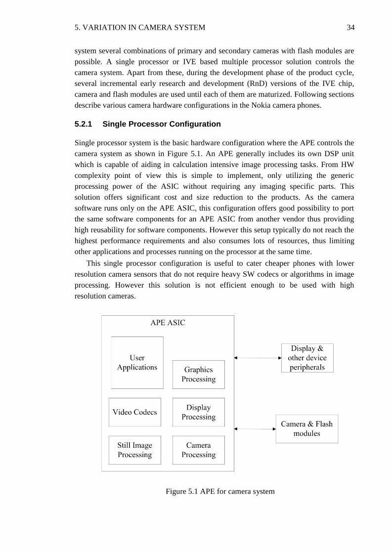
5. VARIATION IN CAMERA SYSTEM 34
system several combinations of primary and secondary cameras with flash modules are
possible. A single processor or IVE based multiple processor solution controls the
camera system. Apart from these, during the development phase of the product cycle,
several incremental early research and development (RnD) versions of the IVE chip,
camera and flash modules are used until each of them are maturized. Following sections
describe various camera hardware configurations in the Nokia camera phones.
5.2.1 Single Processor Configuration
Single processor system is the basic hardware configuration where the APE controls the
camera system as shown in Figure 5.1. An APE generally includes its own DSP unit
which is capable of aiding in calculation intensive image processing tasks. From HW
complexity point of view this is simple to implement, only utilizing the generic
processing power of the ASIC without requiring any imaging specific parts. This
solution offers significant cost and size reduction to the products. As the camera
software runs only on the APE ASIC, this configuration offers good possibility to port
the same software components for an APE ASIC from another vendor thus providing
high reusability for software components. However this setup typically do not reach the
highest performance requirements and also consumes lots of resources, thus limiting
other applications and processes running on the processor at the same time.
This single processor configuration is useful to cater cheaper phones with lower
resolution camera sensors that do not require heavy SW codecs or algorithms in image
processing. However this solution is not efficient enough to be used with high
resolution cameras.
Figure 5.1 APE for camera system
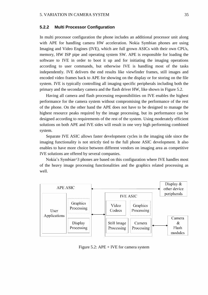
5. VARIATION IN CAMERA SYSTEM 35
5.2.2 Multi Processor Configuration
In multi processor configuration the phone includes an additional processor unit along
with APE for handling camera HW acceleration. Nokia Symbian phones are using
Imaging and Video Engines (IVE), which are full grown ASICs with their own CPUs,
memory, HW ISP pipe and operating system SW. APE is responsible for loading the
software to IVE in order to boot it up and for initiating the imaging operations
according to user commands, but otherwise IVE is handling most of the tasks
independently. IVE delivers the end results like viewfinder frames, still images and
encoded video frames back to APE for showing on the display or for storing on the file
system. IVE is typically controlling all imaging specific peripherals including both the
primary and the secondary camera and the flash driver HW, like shown in Figure 5.2.
Having all camera and flash processing responsibilities on IVE enables the highest
performance for the camera system without compromising the performance of the rest
of the phone. On the other hand the APE does not have to be designed to manage the
highest resource peaks required by the image processing, but its performance can be
designed according to requirements of the rest of the system. Using moderately efficient
solutions on both APE and IVE sides will result in one very high performing combined
system.
Separate IVE ASIC allows faster development cycles in the imaging side since the
imaging functionality is not strictly tied to the full phone ASIC development. It also
enables to have more choice between different vendors on imaging area as competitive
IVE solutions are offered by several companies.
Nokia’s Symbian^3 phones are based on this configuration where IVE handles most
of the heavy image processing functionalities and the graphics related processing as
well.
Figure 5.2: APE + IVE for camera system
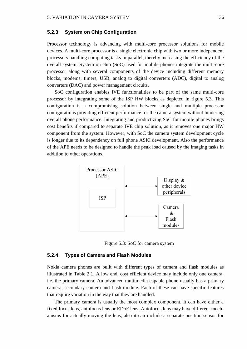
5. VARIATION IN CAMERA SYSTEM 36
5.2.3 System on Chip Configuration
Processor technology is advancing with multi-core processor solutions for mobile
devices. A multi-core processor is a single electronic chip with two or more independent
processors handling computing tasks in parallel, thereby increasing the efficiency of the
overall system. System on chip (SoC) used for mobile phones integrate the multi-core
processor along with several components of the device including different memory
blocks, modems, timers, USB, analog to digital converters (ADC), digital to analog
converters (DAC) and power management circuits.
SoC configuration enables IVE functionalities to be part of the same multi-core
processor by integrating some of the ISP HW blocks as depicted in figure 5.3. This
configuration is a compromising solution between single and multiple processor
configurations providing efficient performance for the camera system without hindering
overall phone performance. Integrating and productizing SoC for mobile phones brings
cost benefits if compared to separate IVE chip solution, as it removes one major HW
component from the system. However, with SoC the camera system development cycle
is longer due to its dependency on full phone ASIC development. Also the performance
of the APE needs to be designed to handle the peak load caused by the imaging tasks in
addition to other operations.
Figure 5.3: SoC for camera system
5.2.4 Types of Camera and Flash Modules
Nokia camera phones are built with different types of camera and flash modules as
illustrated in Table 2.1. A low end, cost efficient device may include only one camera,
i.e. the primary camera. An advanced multimedia capable phone usually has a primary
camera, secondary camera and flash module. Each of these can have specific features
that require variation in the way that they are handled.
The primary camera is usually the most complex component. It can have either a
fixed focus lens, autofocus lens or EDoF lens. Autofocus lens may have different mech-
anisms for actually moving the lens, also it can include a separate position sensor for
5. VARIATION IN CAMERA SYSTEM 37
more accurate lens positioning. Mechanical shutter and ND filter are options for high
end cameras. Image sensor resolutions vary from few to tens of megapixels. Camera
modules may contain non-volatile memory for storing tuning values that are used for
enhancing the images. The secondary camera is simpler, usually varying only in image
sensor resolution. The flash system typically includes a flash driver, which is a separate
HW component capable of controlling the flash module. The type of the flash driver
changes according to the flash module that it is controlling, there are different flash
drivers for LED or Xenon based flash solutions. The capabilities of the flash drivers are
also varying, from merely switching the LEDs on or off to gracefully controlling low
battery charge or system power consumption peak situations. Depending on the LED
type used, the system needs to drive a different amount of current through the LEDs in
order to achieve the same level of illumination. In Xenon based systems, the charging of
the capacitors is handled either by the flash driver or by IVE. Additionally one product
line may include same kind of camera or flash module but from different vendors.
5.3 Variation with Camera Application
Apart from the default Camera Application there can be several applications on a Sym-
bian device that need access to the camera. Camera application provides the graphical
user interface to capture still images, video recording and videophone (video teleconfer-
encing). Both the primary and secondary camera can be used with these use cases. A 3rd
party developed social networking application such as Facebook may access the camera
in order to take a picture for the purpose of uploading it to an internet server for sharing.
Typically, a mobile phone application is intended to be hardware independent so
that the application can run on scores of devices running on Symbian platform. This
way the application does not have to be re-written or ported for a device. In order to
achieve interoperability the applications that interact with camera make use of run-time
feature queries to check whether a particular camera functionality is supported or not.
For example, on run-time camera application can query the number of cameras present
on the device using ECam API and based on the result it can provide the UI options for
the end users to choose the camera.
Programme 5.1 is camera application’s implementation for switching camera object
from primary to secondary camera. It makes use of ECam’s CamerasAvailable method
that returns the number of cameras present on the device.
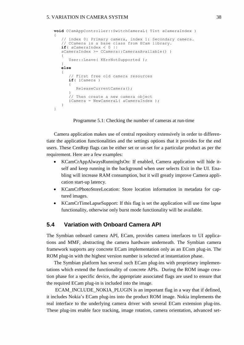
5. VARIATION IN CAMERA SYSTEM 38
void CCamAppController::SwitchCameraL( TInt aCameraIndex ) {
// index 0: Primary camera, index 1: Secondary camera.
// CCamera is a base class from ECam library.
if( aCameraIndex < 0 ||
aCameraIndex >= CCamera::CamerasAvailable() )
{
User::Leave( KErrNotSupported );
}
else
{
// First free old camera resources
if( iCamera )
{
ReleaseCurrentCamera();
}
// Then create a new camera object
iCamera = NewCameraL( aCameraIndex );
}
}
Programme 5.1: Checking the number of cameras at run-time
Camera application makes use of central repository extensively in order to differen-
tiate the application functionalities and the settings options that it provides for the end
users. These CenRep flags can be either set or un-set for a particular product as per the
requirement. Here are a few examples:
KCamCrAppAlwaysRunningIsOn: If enabled, Camera application will hide it-
self and keep running in the background when user selects Exit in the UI. Ena-
bling will increase RAM consumption, but it will greatly improve Camera appli-
cation start-up latency.
KCamCrPhotoStoreLocation: Store location information in metadata for cap-
tured images.
KCamCrTimeLapseSupport: If this flag is set the application will use time lapse
functionality, otherwise only burst mode functionality will be available.
5.4 Variation with Onboard Camera API
The Symbian onboard camera API, ECam, provides camera interfaces to UI applica-
tions and MMF, abstracting the camera hardware underneath. The Symbian camera
framework supports any concrete ECam implementation only as an ECom plug-in. The
ROM plug-in with the highest version number is selected at instantiation phase.
The Symbian platform has several such ECam plug-ins with proprietary implemen-
tations which extend the functionality of concrete APIs. During the ROM image crea-
tion phase for a specific device, the appropriate associated flags are used to ensure that
the required ECam plug-in is included into the image.
ECAM_INCLUDE_NOKIA_PLUGIN is an important flag in a way that if defined,
it includes Nokia’s ECam plug-ins into the product ROM image. Nokia implements the
real interface to the underlying camera driver with several ECam extension plug-ins.
These plug-ins enable face tracking, image rotation, camera orientation, advanced set-
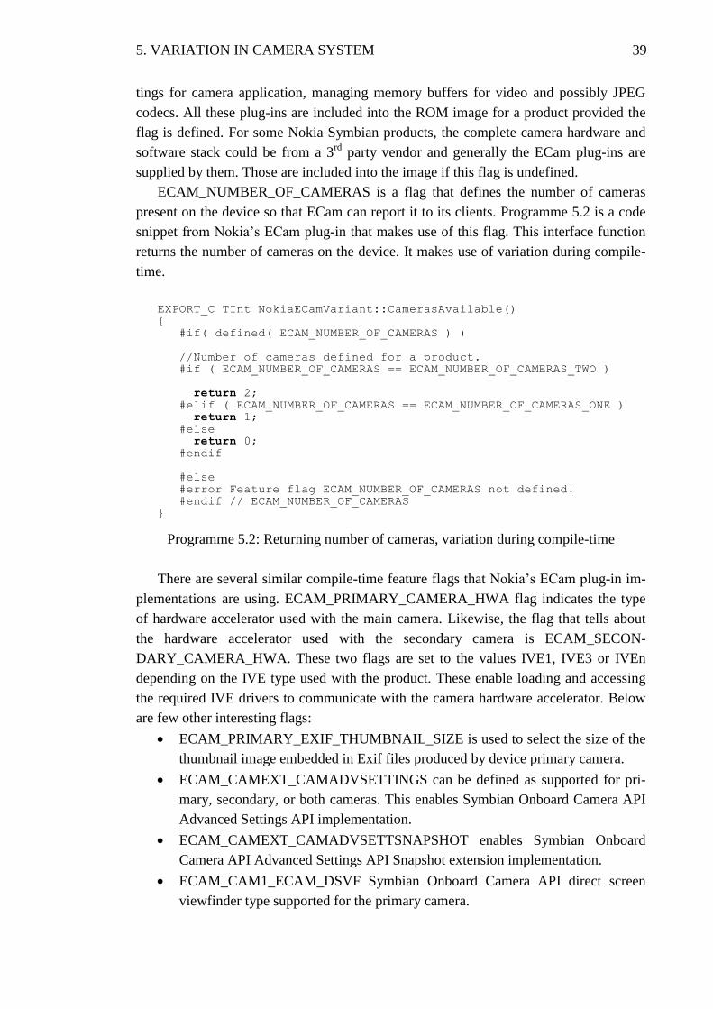
5. VARIATION IN CAMERA SYSTEM 39
tings for camera application, managing memory buffers for video and possibly JPEG
codecs. All these plug-ins are included into the ROM image for a product provided the
flag is defined. For some Nokia Symbian products, the complete camera hardware and
software stack could be from a 3rd
party vendor and generally the ECam plug-ins are
supplied by them. Those are included into the image if this flag is undefined.
ECAM_NUMBER_OF_CAMERAS is a flag that defines the number of cameras
present on the device so that ECam can report it to its clients. Programme 5.2 is a code
snippet from Nokia’s ECam plug-in that makes use of this flag. This interface function
returns the number of cameras on the device. It makes use of variation during compile-
time.
EXPORT_C TInt NokiaECamVariant::CamerasAvailable()
{
#if( defined( ECAM_NUMBER_OF_CAMERAS ) )
//Number of cameras defined for a product.
#if ( ECAM_NUMBER_OF_CAMERAS == ECAM_NUMBER_OF_CAMERAS_TWO )
return 2;
#elif ( ECAM_NUMBER_OF_CAMERAS == ECAM_NUMBER_OF_CAMERAS_ONE )
return 1;
#else
return 0;
#endif
#else
#error Feature flag ECAM_NUMBER_OF_CAMERAS not defined!
#endif // ECAM_NUMBER_OF_CAMERAS
}
Programme 5.2: Returning number of cameras, variation during compile-time
There are several similar compile-time feature flags that Nokia’s ECam plug-in im-
plementations are using. ECAM_PRIMARY_CAMERA_HWA flag indicates the type
of hardware accelerator used with the main camera. Likewise, the flag that tells about
the hardware accelerator used with the secondary camera is ECAM_SECON-
DARY_CAMERA_HWA. These two flags are set to the values IVE1, IVE3 or IVEn
depending on the IVE type used with the product. These enable loading and accessing
the required IVE drivers to communicate with the camera hardware accelerator. Below
are few other interesting flags:
ECAM_PRIMARY_EXIF_THUMBNAIL_SIZE is used to select the size of the
thumbnail image embedded in Exif files produced by device primary camera.
ECAM_CAMEXT_CAMADVSETTINGS can be defined as supported for pri-
mary, secondary, or both cameras. This enables Symbian Onboard Camera API
Advanced Settings API implementation.
ECAM_CAMEXT_CAMADVSETTSNAPSHOT enables Symbian Onboard
Camera API Advanced Settings API Snapshot extension implementation.
ECAM_CAM1_ECAM_DSVF Symbian Onboard Camera API direct screen
viewfinder type supported for the primary camera.

5. VARIATION IN CAMERA SYSTEM 40
5.5 Variation in Camera Driver
Different camera and flash setups for products within a product family, which are based
on the same Symbian OS platform, require variation in the camera application and
camera driver software. Compile-time variation flags, which are the pre-processor
#define flags, are used to vary the camera driver. This enables a smaller size of the
driver DLLs by including only the necessary code into the final driver DLL, thereby
causing a smaller memory footprint on the product ROM image. Following are the
compile-time variation flags used to configure the camera driver.
5.5.1 Flash Module Specific Flags
From flash module perspective, the types of the flash module and the flash driver are the
variation points for the camera driver. Generally it is not possible to detect by SW
which kind of flash modules are present in the system. Instead this information must be
given by using static configuration flags that will control the software execution during
the run-time. Following are the configuration flags to enable or disable the functionali-
ties specific to flash modules for a particular product.
Different flash types enable different use cases for imaging purposes. If the flash
module is Xenon type then it can be used only for still imaging. Xenon type requires
recharging of the Xenon capacitors after each usage. On the other hand LED type can be
additionally used for video light purposes as well as for autofocus assistance in low light
conditions. LED flash can also be used as a torch light. To tell the system whether it has
Xenon, LED, both or no flash at all there is a flag CAMDRV_MAIN_FLASH_TYPE.
Different LED and Xenon types produce different colour and intensity of light. This
needs to be compensated by using image quality tuning values specific to this flash type
when capturing images with flash. To give SW the exact flash HW model information
there is a configuration flag called CAMDRV_MAIN_FLASH_HW.
For privacy purposes it is required that the phone gives some indication when
capturing an image. In some products this is done with a separate indicator LED that
blinks during the capture. As it is not possible to detect the presence of the indicator
LED by SW, the configuration flag CAMDRV_SEPARATE_INDICATOR_LED is
needed.
5.5.2 Flags for Configuring Primary Camera
The type of the camera, the camera sensor resolution and the type of the camera lens are
the primary camera specific variation points for the camera driver. Static configuration
flags are used to handle the variation.
A Symbian platform supports several products with varying primary camera HW
setup. The primary camera functionality may be handled by either IVE or APE based
on the product configuration. The platform contains different set of camera PDDs for
each setup. The configuration flag CAMDRV_MAIN_CAMERA_PDD provides the
5. VARIATION IN CAMERA SYSTEM 41
information whether the camera HW is handled by a particular IVE processor or by
APE. Based on this information the specific primary camera PDD files are picked into
the product ROM image.
Different types of camera sensors pose challenges to the quality of the image that
they produce. The image signal processing requires image quality (IQ) tuning
parameters to be used in order to correct the anomalies in the images produced by the
camera. These image tuning parameters are specific to the camera sensor type.
Configuration flag CAMDRV_PRIMARY_CAMERA_SENSOR_TYPE provides the
information needed to include the correct IQ tuning files into the product ROM image.
Camera LDD must know various camera configuration values like the still image
width and height, the camera preview width and height as well as the video resolutions.
Based on these configuration values, the driver has to reserve and initialize memory
buffers to hold and transfer the image data requested by its clients. The available resolu-
tion options for still images and video are queried on run-time from IVE, but the
memory buffers must be pre-allocated during compile-time in order to be able to calcu-
late the memory budget required by the imaging components. For example, still image
memory buffers are reserved according to the maximum camera sensor resolution de-
fined by flag CAMDRV_PRIMARY_CAMERA_SENSOR_RESOLUTION.
CAMDRV_PRIMARY_CAMERA_FOCUS_SUPPORT is a Boolean flag that indi-
cates whether the primary camera supports focus feature. This configuration flag is de-
fined only for cameras with AF lens. If this flag is defined then the camera driver ena-
bles the focus feature for the main camera and allows its clients to configure different
focus modes.
5.5.3 Flags for Configuring Secondary Camera
Camera driver has a set of static configuration flags similar to the ones used with the
primary camera at its disposal for the secondary camera variation purpose.
The product HW setup could have the secondary camera connected either to APE or
to IVE. To fetch the specific camera driver PDD that handles secondary camera on the
product the value of the flag CAMDRV_SECONDARY_CAMERA_PDD is used.
The flag CAMDRV_SECONDARY_CAMERA_SENSOR_TYPE, like its primary
camera counterpart, provides the camera driver the information about the type of sec-
ondary camera sensor being used on the product. Based on this information the relevant
IQ tuning files are included into the product ROM image.
The secondary camera sensor generally has a low pixel count, the typical resolution
with Nokia phones being VGA. This information is needed by the camera driver to ini-
tialize memory buffers in order to transfer image data from the secondary camera.
CAMDRV_SECONDARY_CAMERA_SENSOR_RESOLUTION is the flag that pro-
vides the sensor pixel count from the secondary camera.
5. VARIATION IN CAMERA SYSTEM 42
5.5.4 Algorithm Specific Configuration Flags
The Symbian platform provides scores of image enhancing and correction algorithm
implementations and several options with each of those to choose from. This includes
Nokia’s in-house implementations and 3rd
party commercial ISP implementations from
various vendors. Based on the product’s price point, 3rd
party algorithm license fee,
processing capacity and the type of camera sensors in use a particular product may opt
for a specific algorithm implementation.
Below is a list of algorithms and associated variation flags:
Auto Exposure: CAMDRV_AE_ALGORITHM
Auto Focus: CAMDRV_AF_ALGORITHM
Auto While Balance: CAMDRV_AWB_ALGORITHM
Automatic Motion Blur Reduction: CAMDRV_AMBR_ALGORITHM
Face Detection: CAMDRV_FD_ALGORITHM
Red Eye Removal: CAMDRV_RER_ALGORITHM
Smart ISO: CAMDRV_SMART_ISO_ALGORITHM
Each of these flags could be set to a vendor specific value, so that the ROM image
would include that vendor specific implementation into the camera driver. In case that a
particular algorithm flag is not defined for a product then the implementation will not be
part of the product ROM image.
5.6 Case Study with Symbian^3 Products
Symbian^3 products Nokia N8, Nokia 701 and Nokia 603 are considered for the case
study. N8 is made with 680MHz APE host processor and the camera HW accelerator
from the IVE3 family, whereas Nokia 701 and Nokia 603 are using 1GHz APE with
latest version of accelerator chip from IVE3 family namely IVE3.5. The striking feature
of N8 is its state of the art camera and the imaging experience it provides to the end
user. The N8's primary camera features 12 megapixel image sensor with large pixel
size, autofocus lens, mechanical shutter and neutral density filter. The cost of using this
uncompromising camera comes as a bigger physical size that causes challenges for the
overall design of the phone. The slender Nokia 701 and Nokia 603 are shipped with
EDoF cameras with image sensor resolutions 8 and 5 megapixels respectively. While
N8 has a powerful Xenon flash to assist still capturing, Nokia 701 has a dual LED flash
and Nokia 603 has no flash module at all. N8 and Nokia 701 have front facing
secondary camera for video calling, whereas Nokia 603 does not have a front facing
camera [20].
This thesis work was done as part of IVE3 software team, so this case study concen-
trates mostly on the variation of IVE3 software and adaptation layers for it on the APE,
alternatively called as the host that runs the Symbian OS. Issues closer to the application
layer are handled only superficially. IVE3 and IVE3.5 are collectively known as multi-
media accelerator chips from IVE3 family.
5. VARIATION IN CAMERA SYSTEM 43
IVE3 is the generation of camera and graphics accelerator chip that Nokia incorpo-
rates into its Symbian^3 based products. One of the set goals for the IVE3 was to enable
the freedom to select any combination from the supported primary cameras, secondary
cameras, flash drivers and flash modules in order to vary new camera phones. To give
background information on why the software modularity and effective variation was
sought with IVE3, the lack of these with IVE1 is considered briefly here.
IVE1 was the earlier camera accelerator chip solution that Nokia used across its de-
vice portfolio based on S60 3.x, and S60 5.0 (Symbian^1). IVE1 accelerator chips are
Texas Instrument’s OMAP digital multimedia co-processors. The problem with IVE1
was that each different combination of cameras, flash drivers and flash modules caused
a software branch being created for that particular combination. This led to a situation
where making one common correction or update to the IVE software required changes
to practically same code over different software branches. Furthermore, a complete test-
ing round was required for each of these software branches. This resulted in high
maintenance cost that caused restrictions in making minor improvements and error fixes
to the software. As the time went on there were bound to be cases where some of the
fixes were forgotten or missed out from some of the software branches. In the end, there
were several IVE1 accelerator chip configurations and each of these had their own
branches for each camera component combinations. On the other hand, the long life of
the IVE1 family camera phones proved the competitiveness of this kind of stand-alone
camera accelerator solution at the time. Changing to the next generation of accelerator
chip, called as IVE3 inside Nokia, was largely due to its ability to function as complete
multimedia co-processor that includes graphics acceleration and display controlling
apart from handling camera and flash modules. IVE3 is Brodcom’s multimedia proces-
sor that provides high quality multimedia features for mobile phones while retaining the
long battery life [20]. IVE3 chip based devices can support HD video camcorder and
playback, professional high-resolution cameras with advanced ISP, and high-
performance 3D for advanced user interfaces, navigation displays, and mobile gaming.
To avoid the huge software maintenance cost that IVE1 family of products posed, the
software for IVE3 had to be designed to be highly modular using common interfaces
between various parts of the system.
The software running in IVE3 multimedia co-processor has been separated from the
rest of the phone SW as it is running completely inside the accelerator’s own memory
and processor. The software is delivered as independent binaries to the phone’s Symbi-
an software build, residing in the phone’s file system mostly as separate files. The soft-
ware for IVE3 is built separately from the rest of the phone software using a non-
Symbian compiler, thus most of the software variation mechanisms provided by Symbi-
an build process are not statically available when building the IVE3 software. However,
for example certain variation flags are sent to IVE3 during the run-time to make certain
decisions static in nature. These are for example details relating to flash modules, which
are not able to identify themselves through any command interface.
5. VARIATION IN CAMERA SYSTEM 44
The control and data buses towards the camera and flash driver peripherals are using
standardized hardware interfaces and are thus able to use common software device driv-
ers for accessing them. Furthermore, Nokia requires its camera vendors to use standard-
ized, SMIA (and SMIA++) compatible power up sequences so that all cameras can be
powered up in a similar manner. The software can then identify the camera dynamically
by reading its model and revision identifier registers. After that the camera is known
and IVE will request the host to send the appropriate driver file for handling it.
The camera driver resides on top of the bus control layers, and is responsible for
handling one certain camera model. It must be able to handle all the different develop-
ment versions of that camera module. The purpose of the camera driver is to provide
access to the camera specific features but at the same time hide the implementation de-
tails from the upper SW layers. Despite the SMIA compatibility, the camera modules
have usually also some manufacturer specific settings that need to be adjusted according
to the use case. These are changing during the development time of the camera module
and might be specific to a certain version of the camera. These are handled in the cam-
era driver by having static settings tables separately for each version of the camera. All
the camera device drivers implement a common interface through which they can adver-
tise their capabilities to the common imaging framework. For example the camera driv-
er lists the supported camera modes for different use cases like video and still imaging.
The mode settings consist of available resolutions and frame rates with binning, crop-
ping and frame output format information.
Camera modules with auto focus lens are equipped with the specific control logic
and motor mechanism for actually moving the lens, which is called a lens driver. This
same mechanism handles also other moving parts like mechanical shutter and ND filter
in case of N8. Similar to the camera driver that handles the camera sensor there is a sep-
arate lens driver SW for controlling the lens specific tasks. The required lens driver
software for each camera has been listed in the static table of supported cameras. Nokia
701 and Nokia 603 are using EDoF cameras without AF mechanism, so the lens driver
has not been specified for them.
For identifying the flash driver HW there is a similar mechanism to the identifica-
tion of the camera. The requirements for the powering up mechanism are the same for
all the flash driver HWs. After powered up the flash driver HW can be queried for its
model ID, based on which the correct driver SW can be selected. On the other hand, the
actual flash module cannot be identified on run-time by SW, as the flash modules do not
generally provide any identification mechanism. Instead, IVE gets the flash module
information from the host through static configuration flags.
All these parts of the IVE SW are specific to certain camera component types, yet
the major part of the SW implementation is common for all combinations of those. In a
central role is the common imaging framework that takes care of general flow of the
imaging tasks and loading of the device specific drivers. This framework leaves han-
dling of the device specific requirements for the PDD level, but it must be aware of the
specific features that the actual peripherals support. For example it must time the Xenon
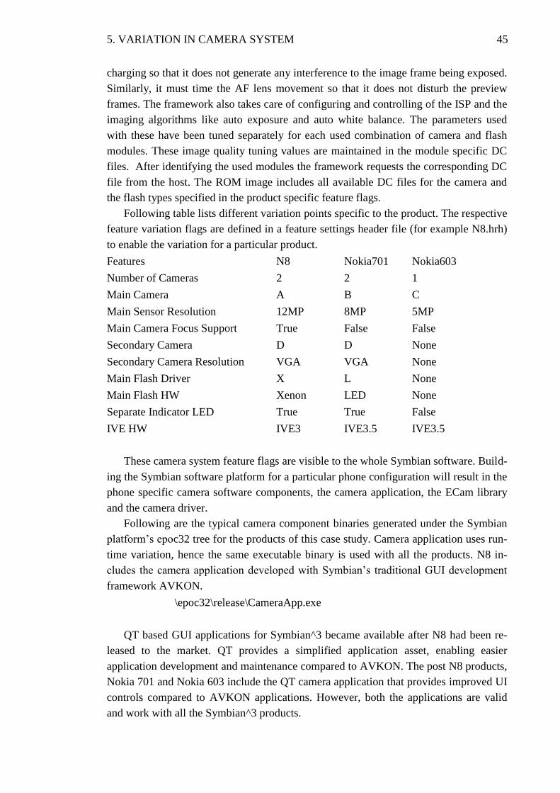
5. VARIATION IN CAMERA SYSTEM 45
charging so that it does not generate any interference to the image frame being exposed.
Similarly, it must time the AF lens movement so that it does not disturb the preview
frames. The framework also takes care of configuring and controlling of the ISP and the
imaging algorithms like auto exposure and auto white balance. The parameters used
with these have been tuned separately for each used combination of camera and flash
modules. These image quality tuning values are maintained in the module specific DC
files. After identifying the used modules the framework requests the corresponding DC
file from the host. The ROM image includes all available DC files for the camera and
the flash types specified in the product specific feature flags.
Following table lists different variation points specific to the product. The respective
feature variation flags are defined in a feature settings header file (for example N8.hrh)
to enable the variation for a particular product.
Features N8 Nokia701 Nokia603
Number of Cameras 2 2 1
Main Camera A B C
Main Sensor Resolution 12MP 8MP 5MP
Main Camera Focus Support True False False
Secondary Camera D D None
Secondary Camera Resolution VGA VGA None
Main Flash Driver X L None
Main Flash HW Xenon LED None
Separate Indicator LED True True False
IVE HW IVE3 IVE3.5 IVE3.5
These camera system feature flags are visible to the whole Symbian software. Build-
ing the Symbian software platform for a particular phone configuration will result in the
phone specific camera software components, the camera application, the ECam library
and the camera driver.
Following are the typical camera component binaries generated under the Symbian
platform’s epoc32 tree for the products of this case study. Camera application uses run-
time variation, hence the same executable binary is used with all the products. N8 in-
cludes the camera application developed with Symbian’s traditional GUI development
framework AVKON.
\epoc32\release\CameraApp.exe
QT based GUI applications for Symbian^3 became available after N8 had been re-
leased to the market. QT provides a simplified application asset, enabling easier
application development and maintenance compared to AVKON. The post N8 products,
Nokia 701 and Nokia 603 include the QT camera application that provides improved UI
controls compared to AVKON applications. However, both the applications are valid
and work with all the Symbian^3 products.
5. VARIATION IN CAMERA SYSTEM 46
\epoc32\release\QTCameraApp.exe
ECam typically includes several plugins that provide interface to its clients such as
UI applications.
\epoc32\release\N8\ECamPlugin.dll
\epoc32\release\N8\ECamExtPlugin.dll
\epoc32\release\Nokia701\ECamPlugin.dll
\epoc32\release\Nokia701\ECamExtPlugin.dll
\epoc32\release\Nokia603\ECamPlugin.dll
\epoc32\release\Nokia603\ECamExtPlugin.dll
The camera driver LDDs provide an abstract interface to the IVE HW, the camera
and the flash modules.
\epoc32\release\N8\CamDriver_IVE3.ldd
\epoc32\release\Nokia701\CamDriver_IVE3.ldd
\epoc32\release\Nokia603\CamDriver_IVE3.ldd
PDDs that provide interface to the IVE HW and its peripherals:
\epoc32\release\IVE3\IVEDriver.pdd
\epoc32\release\IVE3.5\IVEDriver.pdd
The camera PDDs that provide interface to a particular camera:
\epoc32\release\IVE3\MainCamA.pdd
\epoc32\release\IVE3\MainCamALens.pdd
\epoc32\release\IVE3.5\MainCamC.pdd
\epoc32\release\IVE3\SecCamD.pdd
\epoc32\release\IVE3.5\SecCamD.pdd
Procuring camera modules from several vendors benefits Nokia to have a second
source for cameras. This helps Nokia to increase the camera volumes if required more
easily when there is more capacity on the vendor side. Though the camera manufactur-
ers follow SMIA standard and the cameras are of the same type, they may offer differ-
ent programming registers and hence require different vendor specific PDD camera
drivers. With the current variation setup, all the vendor specific camera PDDs are in-
cluded into the ROM image. Thus Nokia 701, which utilizes the 8MP EDoF cameras
from vendorX and vendorY, requires camera specific PDDs for both of them. This in-
creases the ROM image size of the product, but it cannot be avoided because it must be
possible to use either of the cameras on the production line or in the service center. Us-
ing different SW in each case would be too expensive from the SW logistics point of
view. Here are the vendor specific PDD files:
5. VARIATION IN CAMERA SYSTEM 47
\epoc32\release\IVE3.5\XMainCamB.pdd
\epoc32\release\IVE3.5\YMainCamB.pdd
The dynamic configuration (DC) files for different camera setups:
\epoc32\release\dc\camA_Xenon.dc
\epoc32\release\dc\camB_LED.dc
\epoc32\release\dc\camC.dc
\epoc32\release\dc\camD.dc
On ROM image creation for Nokia 701, only the product specific binaries are
picked in to the image. Those executables and libraries sit into the ROM aka Z: drive of
the device.
\epoc32\release\QTCameraApp.exe z:\system\bin\QTCameraApp.exe
\epoc32\release\Nokia701\ECamPlugin.dll z:\system\bin\ECamPlugin.dll
\epoc32\release\ Nokia701\ECamExtPlugin.dll z:\system\bin\ECamExtPlugin.dll
\epoc32\release\ Nokia701\CamDriver_IVE3.ldd z:\system\bin\CamDriver_IVE3.ldd
\epoc32\release\IVE3.5\IVEDriver.pdd z:\system\bin\IVEDriver.pdd
\epoc32\release\IVE3.5\XMainCamB.pdd z:\system\bin\XMainCamB.pdd
\epoc32\release\IVE3.5\YMainCamB.pdd z:\system\bin\YMainCamB.pdd
\epoc32\release\IVE3.5\SecCamD.pdd z:\system\bin\SecCamD.pdd
\epoc32\release\dc\camB_LED.dc z:\system\dcc\camB_LED.dc
\epoc32\release\dc\camD.dc z:\system\dcc\camD.dc
Figure 5.4 illustrates the Symbian^3 camera system as viewed from HW and SW
sides. The HW setup for the three products differ as explained earlier in this section.
From the SW perspective there is a clear process execution boundary between IVE and
APE. All the PDDs, codecs and algorithms run on IVE side whereas the LDD, the
ECam plugins and the components from the application level run on APE side. The
camera system LDD runs in the kernel privileged mode on APE and rest of the
components run in the user privileged mode.
Symbian^3 application framework evolved radically with QT based application de-
velopment support. QT applications provide intuitive user interface with improved UI
icons compared to Symbian’s traditional AVKON framework. However, applications
for Symbian^3 products can be developed with either of the UI frameworks independent
from the rest of the Symbian SW stack. N8, being the product from pre QT times, con-
tains the AVKON based camera application and associated application engines. Nokia
701 and Nokia 603 include the QT based GUI application for accessing camera.
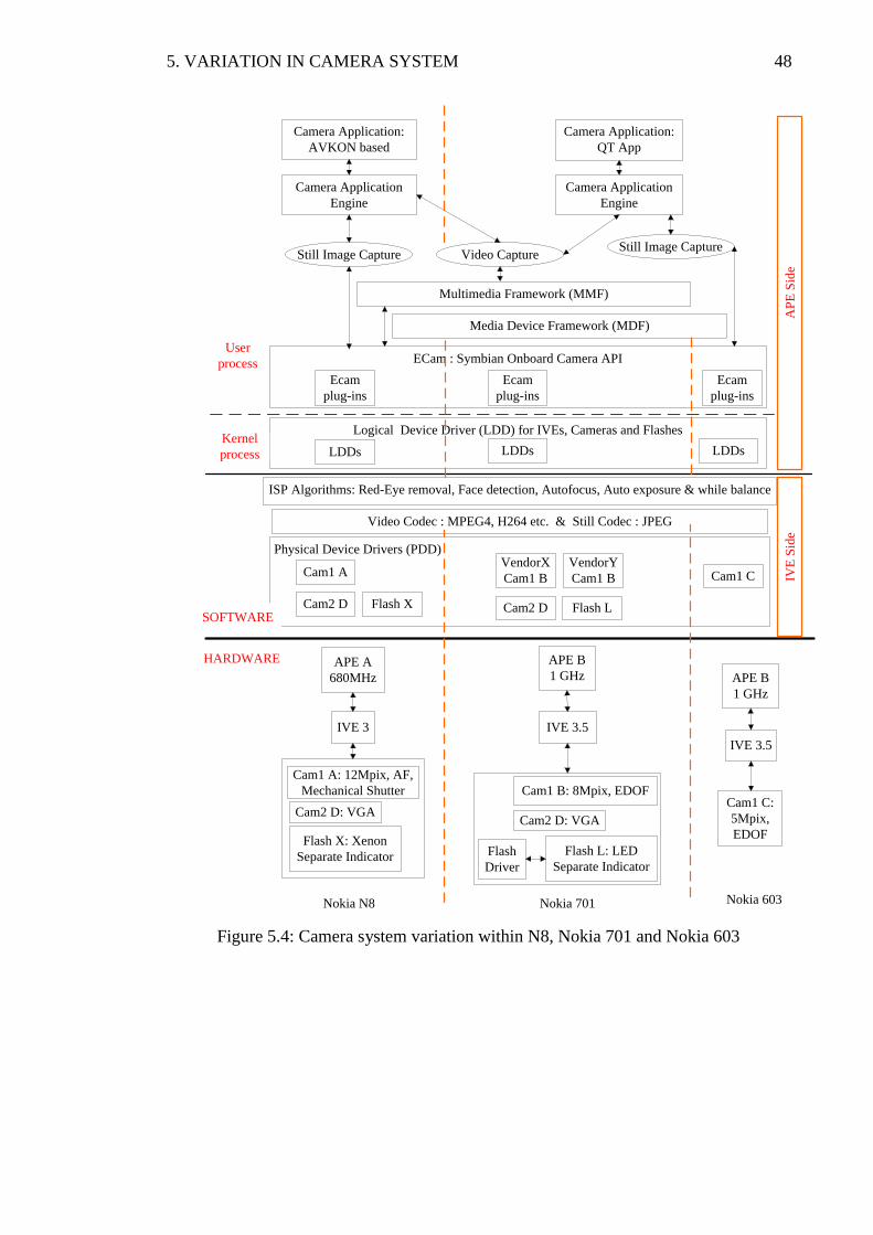
5. VARIATION IN CAMERA SYSTEM 48
Figure 5.4: Camera system variation within N8, Nokia 701 and Nokia 603
Logical Device Driver (LDD) for IVEs, Cameras and Flashes
Physical Device Drivers (PDD)
APE A
680MHz
IVE 3
APE B
1 GHz
IVE 3.5
Cam1 A: 12Mpix, AF,
Mechanical Shutter
Cam2 D: VGA
Flash X: Xenon
Separate Indicator
Cam1 B: 8Mpix, EDOF
Cam2 D: VGA
Flash L: LED
Separate Indicator
Flash
Driver
Cam1 C:
5Mpix,
EDOF
HARDWARE
SOFTWARE
Cam1 A
Cam2 D Flash X
VendorX
Cam1 B
Cam2 D Flash L
Cam1 C
APE B
1 GHz
IVE 3.5
Video Codec : MPEG4, H264 etc. & Still Codec : JPEG
IVE
Sid
eA
PE
Sid
e
Kernel
process
User
process ECam : Symbian Onboard Camera API
Multimedia Framework (MMF)
Media Device Framework (MDF)
Camera Application:
AVKON based
Camera Application:
QT App
Camera Application
Engine
Camera Application
Engine
Still Image Capture Video Capture
Nokia N8 Nokia 701 Nokia 603
ISP Algorithms: Red-Eye removal, Face detection, Autofocus, Auto exposure & while balance
LDDs LDDs LDDs
VendorY
Cam1 B
Ecam
plug-ins
Ecam
plug-ins
Ecam
plug-ins
Still Image Capture
49
6 CONCLUSION
Nokia has to differentiate its mobile phone offerings in order to provide devices across
wider price range with different market requirements and thereby to lead the competi-
tion. Besides, the rapidly advancing camera and flash HW technology necessitates
Nokia to be fast enough in updating its camera system within its devices.
The Symbian OS platform for mobile phones has evolved over the time adapting to
changing HW configurations and application frameworks. Symbian OS supports several
SW variation mechanisms through the static (compile-time) and the dynamic (run-time)
variation principles. This has enabled the components from Symbian SW stack to vary
in order to support the products with differing HW configurations and application
frameworks. The aim of this thesis was to describe different possible camera system
hardware configurations that Nokia incorporates in its Symbian OS based mobile
phones and to explain how the OS platform variation mechanisms are used for support-
ing those configurations.
The main software components of the Symbian camera system are the camera appli-
cation providing the user interface, the ECam library providing the APIs to access the
onboard cameras and the camera device drivers handling the camera HW. The Symbian
camera application is made portable across scores of devices with different camera sys-
tem configurations by using CenRep, feature discovery APIs as well as ECam's APIs so
as to decide the variation points at run-time. On the other hand, the ECam and the cam-
era device drivers make use of the product specific static feature flags during compile-
time, thereby creating product specific binaries. The compile-time variation produces
smaller sized modular binary files of ECam and camera device drivers, thereby taking
less memory space in the product’s ROM image. Building the whole Symbian platform
produces ROM images for each of the product variants that it supports.
Symbian^3 platform introduced IVE3 range of imaging and video engines support-
ing variety of camera system configurations for Nokia’s premium mobile devices. The
goals set for IVE3 in variation point of view were reached quite well. The phone pro-
grams are free to select their camera system setup from the supported camera and flash
HW options. Though adding support for a new type of camera or flash HW is not a mi-
nor effort, it can be done isolated from the rest of the system. From testing point of
view, each camera and flash type needs to be fully tested only in one product. For other
products with the same camera or flash it is sufficient to run a quick sanity check by
executing a reduced test set. This helped in speeding up the updates and in ensuring the
testing capability required for the devices.
50
REFERENCES
[1] Gartner Newsroom Press Releases [WWW]. Accessed: 23rd
June 2011.
http://www.gartner.com/it/page.jsp?id=1543014
[2] Nokia Symbian^3 Developer’s library v1.1 and S60 5th Edition C++ Developer’s
Library v2.1 [WWW]. Accessed: 23rd June 2011.
http://library.developer.nokia.com
[3] Insider Guide to Mobile. The Customers, Services, Apps, Phones and Business of
the Newest Trillion Dollar Market. By Tomi T Ahonen. Published by
TomiAhonen Consulting, 20.10.2010. Free eBook, downloaded from web store:
www.lulu.com
[4] Nokia Products [WWW]. Accessed: 23rd June 2011.
http://europe.nokia.com/find-products
[5] Nokia C7 camera review from all about Symbian. Accessed on 23rd June 2011.
http://www.allaboutsymbian.com/reviews/item/12253_Nokia_C7_review_part_2_
Camera_.php
[6] The Symbian OS Architecture Sourcebook - Design and Evolution of a Mobile
Phone OS. By Ben Morris (ISBN: 978-0-470-01846-0)
[7] SMIA Overview [WWW]. Accessed 23rd June 2011
http://read.pudn.com/downloads95/doc/project/382834/SMIA/SMIA_Introduction
_and_overview_1.0.pdf
[8] CZARNECKI, K., AND EISENECKER, U. Generative Programming: Methods,
Tools, and Applications. Addison-Wesley, 2000.
[9] SOMMERVILLE, I. Software Engineering, 6th ed. Addison-Wesley, 2001.
[10] KRUEGER, C. Variation management for software production lines. In
Proceedings of the 2nd International Software Product Line Conference (San
Diego, California,USA, August 2002), Lecture Notes in Computer Science. Vol.
2379, pp. 37–48.
REFERENCES 51
[11] BERCZUK, S. P., AND APPLETON, B. Software Configuration Management
Patterns: Effective Teamwork, Practical Integration. Addison-Wesley, 2002.
[12] Nokia product camera specifications [WWW]. Accessed: 20th June 2011.
http://blogs.nokia.com/nseries/
[13] MARTIN, R. C. Agile Software Development, 2nd ed. Addison-Wesley, 2002.
[14] FOWLER, M. Refactoring: Improving the Design of Existing Code. Addison-
Wesley, 1999.
[15] J. Nakamura, Image Sensors and Signal Processing for Digital Still Cameras. CRC
Press, 2006.
[16] G. Saxby, The Science of Imaging: An Introduction. IoP Publishing, 2002.
[17] O. Kalevo. (2008) Advanced Camera and Optics. Nokia. Training material.
[18] V. Nummela. (2008) Camera Lenses. Nokia. Training material.
[19] O. Kalevo. (2008) Imaging Pipe Description: From Sensor Data to an Image.
Nokia. Training material.
[20] Nokia Device specifications [WWW]. Find the phone you want to develop for.
Accessed: 20th January 2012
http://www.developer.nokia.com/Devices/Device_specifications/


