Embed Size (px)
Citation preview

EN 1 EN
DISCUSSION PAPER DRAFT CONCEPT RVCR T-Cat v3
This document does not represent an official position of the European Commission. It is a tool to explore the views of interested parties. The suggestions contained in this document do not prejudge the form and content of any possible future proposal by the European Commission.

EN 2 EN
EXPLANATORY MEMORANDUM …..
EN 3 EN
COMMISSION DELEGATED REGULATION (EU) No …/..
of XXX
supplementing Regulation (EU) No 167/2013 of the European Parliament and of the Council with regard to vehicle construction and general requirements for the approval
and market surveillance of agricultural and forestry vehicles
(Text with EEA relevance)
THE EUROPEAN COMMISSION,
Having regard to the Treaty on the Functioning of the European Union, and in particular Article 290 thereof,
Having regard to Regulation (EU) No 167/2013 of the European Parliament and of the Council of 5 February 2013 on the approval and market surveillance of agricultural and forestry vehicles1, and in particular Articles 18(4), 20(8), 27(6), 28(6), 53(12) and 61 thereto,
Whereas:
(1) The internal market comprises an area without internal frontiers in which the free movement of goods, persons, services and capital is ensured. To that end, comprehensive EU type-approval and a strengthened market surveillance system for agricultural and forestry vehicles and its systems, components and separate technical units, as defined by Regulation (EU) No 167/2013 apply.
(2) By Council Decision 97/836/EC2, the Union acceded to the Agreement of the United Nations Economic Commission for Europe concerning the adoption of uniform technical prescriptions for wheeled vehicles, equipment and parts which can be fitted to and/or be used on wheeled vehicles and the conditions for reciprocal recognition of approvals granted on the basis of these prescriptions (‘Revised 1958 Agreement’).
(3) In the Union legislation most requirements on vehicle parts are taken over from the corresponding UNECE regulations. UNECE regulations are constantly amended in line with technological progress and the respective Union regulations have to be regularly updated accordingly. In order to avoid this duplication, the CARS 21 High Level Group recommended the replacement of several Union directives by way of the incorporation and compulsory application of the corresponding UNECE regulations in Union law.
(4) As an alternative, the Codes established by the Organisation for Economic Cooperation and Development (OECD) or to CEN/Cenelec or ISO standards which are directly available to the public can be employed as references.
(5) Pursuant to the provisions of Regulation (EU) No 167/2013, the agricultural and forestry vehicles, systems, components and separate technical units covered by this Regulation may not be placed or made available on the market or enter into service in the Member States unless they comply with the provisions of this Regulation.
1 OJ L 60, 2.3.2013, p 1. 2 OJ L 346, 17.12.1997, p. 78.
EN 4 EN
(6) On board diagnostics is essential for effective and efficient repair and maintenance of vehicles. Accurate diagnostics allows the repairer to identify fast which smallest exchangeable unit has to be repaired or replaced.
(7) Unrestricted access to vehicle repair information, via a standardised format which can be used to retrieve the technical information, and effective competition on the market for vehicle repair and maintenance information services are necessary to improve the functioning of the internal market, particularly as regards the free movement of goods, freedom of establishment and freedom to provide services. A great proportion of such information relates to on-board diagnostic (OBD) systems and their interaction with other vehicle systems. It is appropriate to lay down technical specifications that manufacturers’ websites should follow, along with targeted measures to ensure reasonable access for small and medium-sized enterprises (SMEs). Common standards agreed with the involvement of stakeholders can facilitate the exchange of information between manufacturers and service providers. It is therefore appropriate that manufacturers use the technical specifications of the OASIS format and that the Commission will request in due course CEN/ISO to develop this format into a standard with a view to replacing the OASIS format.
(8) In order to further pursue the harmonized approach for access to RMI in all pillars of type-approval legislation taken in Chapter XV of Regulation (EU) No. 167/2013 whose provisions are based on Regulations (EC) No 595/2009 and 715/2007 , it is appropriate to carry over to this Regulation the provisions on access to repair and maintenance information set out in the implementing regulations to those Regulation, namely Regulation (EC) No 64/2012, and adapt them to the specificities of the agricultural and forestry vehicles sector.
(9) In particular, it is appropriate to adopt specific procedures for access to vehicle repair and maintenance information in accordance with Article 6(1) of Regulation (EC) No 595/2009 in the case of multi-stage type-approval. It is also appropriate to adopt specific requirements and procedures for access to vehicle repair and maintenance information in the case of customer adaptations and small volume production. Finally, it is appropriate to make reference to the specific standards for reprogramming developed for agricultural and forestry vehicles.
(10) In order to exclude that the application of the provisions on access to repair and maintenance information imposes too much burden upon vehicle manufacturers in the short term with respect to certain systems which are carried over from old to new vehicle types, it is appropriate to introduce certain limited derogations from the general provisions on access to vehicle OBD and vehicle repair and maintenance information as exhaustively listed in this Regulation.
(11) Provisions on access to OBD and vehicle repair and maintenance information for the purposes of the design and manufacture of automotive equipment for alternative fuel vehicles should be set once type-approval for such equipment becomes possible.
(12) Since there is currently no common structured process for the exchange of vehicle component data between vehicle manufacturers and independent operators, it is appropriate to develop principles for such an exchange of data. A future common structured process on the standardised format of the data exchanged should be developed by the European Committee for Standardisation (CEN) formally, on the basis of a mandate that does not predetermine the level of detail this standard will provide. The CEN’s work should, in particular, reflect the interests and needs of agricultural and forestry vehicles manufacturers and independent operators alike and
EN 5 EN
also investigate solutions such as open data formats described by well-defined metadata to accommodate existing IT infrastructures.
(13) When examining the major policy areas which affect the competitiveness of the European automotive industry, the ‘CARS 21 High Level Group’ agreed on a number of recommendations aimed at enhancing the industry’s global competitiveness and employment while sustaining further progress in safety and environmental performance. In the area of simplification, the High Level Group proposed inter alia two legislative measures, introducing the possibility of manufacturers conducting approval tests themselves, i.e. to be designated as a technical service (‘self-testing’), and the possibility of using computer simulations instead of physical tests (‘virtual testing’). This regulation thus sets out the detailed conditions with respect to virtual and self-testing as set out in Articles 27 and 60 of Regulation (EU) No 167/2013.
(14) Computer-Aided-x techniques (CAx), in particular Computer-Aided-Design (CAD), are used widely throughout the engineering process from conceptual design and layout of components and equipment, through strength and dynamic analysis of assemblies to definition of manufacturing methods. Available software makes possible the use of virtual testing methods based on such techniques, the introduction of which was identified by the ‘CARS 21 High Level Group’ as a means of reducing manufacturers’ costs by no longer obliging them to build prototypes for the purposes of type-approval. Manufacturers not wishing to take advantage of virtual testing methods should be allowed to continue to use the existing physical test methods.
(15) Type-approval tests are conducted by technical services duly notified by the type-approval authorities of the Member States after their skills and competence have been assessed under the relevant international standards. Those standards contain the necessary requirements to allow a manufacturer or a subcontracting party acting on his behalf to be designated as a technical service by the approval authority within the meaning of the Framework Directive. However, in order to prevent potential conflicts of interest, the responsibilities of the manufacturers should be specified. In addition, the conditions under which a manufacturer may subcontract tests should be clarified.
(16) One of the main features of the Union type-approval system is the high level of confidence which should exist between the approval authority and the technical services it has appointed. It is therefore important that the information exchange between technical services and approval authority is marked by transparency and clarity.
(17) A virtual testing method should provide for the same level of confidence in the results as a physical test. Therefore, it is appropriate to lay down relevant conditions to ensure that the manufacturer or the technical service can properly validate the mathematical models used.
(18) Checks on the conformity of vehicles, components or separate technical units throughout the production process are an essential part of the Union type-approval process. These checks for conformity are carried out through conducting physical tests on vehicles, components or separate technical units taken from the production line. Virtual methods should not be permissible for the purposes of conformity of production testing, even if they have been used for type-approval purposes.
(19) This Regulation should apply from the date of application of Regulation (EU) No 167/2013.
EN 6 EN
HAS ADOPTED THIS REGULATION:
CHAPTER I SUBJECT MATTER AND DEFINITIONS
Article 1
Subject matter This Regulation establishes the detailed technical requirements and test procedures regarding vehicle design, construction and assembly for the approval and market surveillance of agricultural and forestry vehicles and their systems, components and separate technical units in accordance with Article18(4) of Regulation (EU) No 167/2013. It also lays down generic type-approval procedures in accordance with its Article 20(8) and 27(6), as well as conformity of production requirements as set-out in Article 28(6) of the mentioned Regulation. Finally it lays down the technical specifications with regard to access to repair and maintenance information pursuant to Article 53(12) and the performance standards and criteria for the assessment of technical services as laid down in Article 61 of that Regulation.
Article 2
Definitions The definitions of Regulation (EU) No 167/2013 apply. In addition, the following definitions shall apply:
(1) ‘roll-over protection structure (safety cab or frame)’ means the structure on a tractor the essential purpose of which is to avoid or limit risks to the driver resulting from roll-over of the tractor during normal use and characterised by the fact that, in the event of roll-over, they ensure an unobstructed space inside them large enough to protect the driver.
(1) ‘roll-over protective structure (safety cab or frame)’, hereinafter called “protective structure”, means the structure on a tractor the essential purpose of which is to avoid or limit risks to the driver resulting from roll-over of the tractor during normal use.
The roll-over protective structure is characterized by the provision of space for a clearance zone large enough to protect the driver when seated either inside the envelope of the structure or within a space bounded by a series of straight lines from the outer edges of the structure to any part of the tractor that might come into contact with flat ground and that is capable of supporting the tractor in that position if the tractor overturns.
(2) ‘track for wheeled tractors’ means the vertical plane through the wheel axis intersects its median plane along a straight line which meets the supporting surface at one point. If A and B are the two points thus defined for the wheels on the same axle of the tractor, then the track width is the distance between points A and B. The track may be thus defined for both front and rear wheels. Where there are twin wheels, the track is the distance between two planes each being the median plane of the pairs of wheels.
EN 7 EN
(3) ‘track for track-laid tractors’, means the distance between the median planes of the tracks.
(4) ‘wheelbase’ means the distance between the vertical planes passing through the two lines AB as defined above, one for the front wheels and one for the rear-wheels.
(5) ‘falling object protective structure (FOPS)’ means an assembly providing reasonable overhead protection to an operator in driving position from falling objects.
(6) ‘cab’ means any structure built of rigid components, transparent or not, which totally encloses the driver and isolates him from the outside, and is capable of being kept permanently closed during service.
(7) ‘seat’ means a structure which may or may not be integral with the vehicle structure complete with trim, intended to seat one adult person. The term covers both an individual seat or part of a bench seat intended to seat one person;
(8) ‘front passenger seat’ means any seat where the ‘foremost H-point’ of the seat in question is in or in front of the vertical tranverse plane through the drivers R-point.
(9) ‘bench seat’ means a structure complete with trim, intended to seat at least two adults;
(10) ‘group of seats’ means either a bench-type seat, or seats which are separate but side by side (i.e. fixed so that the front seat anchorages of one of these seats are in line with the front or rear anchorages of the other or between the anchorages of the other seat) and seat one or more adults;
(11) ‘seat type’ means a category of seats which do not differ in such essential respects as:
a) the shape, dimensions and materials of the seat structure,
b) the types and dimensions of the adjustment systems and all locking systems,
c) the type and dimensions of the belt anchorages on the seat, of the seat anchorage and of the affected parts of the vehicle structure.
(12) ‘seat anchorage’ means the system by which the seat assembly is secured to the vehicle structure, including the affected parts of the vehicle structure;
(13) ‘adjustment system’ means the device by which the seat or its parts can be adjusted to a position suited to the morphology of the seated occupant; this device may, in particular, allow:
a) longitudinal displacement,
b) vertical displacement,
c) angular displacement,
(14) ‘displacement system’ means a device enabling the seat or one of its parts to be displaced angularly or longitudinally, without a fixed intermediate position, to facilitate passenger access;
(15) ‘locking system’ means any device ensuring that the seat and its parts are maintained in any position of use and includes both devices to lock the seat back relative to the seat and the seat relative to the vehicle.
(16) ‘reference zone’ means the space between two vertical longitudinal planes, 400 mm apart and symmetrical with respect to the H-point, and defined by rotation of the head-form apparatus, described in Annex II of Directive 74/60/EEC, from vertical to
EN 8 EN
horizontal. The apparatus shall be positioned as described in that annex and set to the maximum length of 840 mm.
(17) ‘driver's seat’ means that seat capable of accommodating one person only, provided for the use of the driver when driving the tractor.
(18) ‘seat surface’ means the almost horizontal area of the seat which supports the driver when seated.
(19) ‘backrest’ means the almost vertical area of the seat supporting the driver's back when seated.
(20) ‘lateral seat supports’ means the devices or forms of the seat surface which prevent the driver from sliding sideways.
(21) ‘seat armrests’ means the devices on either side of the seat which support the driver's arms when he is seated.
(22) ‘Seat Index Point (SIP)’ means the point determined in accordance with method indicated in Appendix to Annex VI.
(23) ‘reference plane’ means the plane parallel to the median longitudinal plane of the tractor passing through the Seat Index Point.
(24) ‘depth of the seat surface’ means the horizontal distance between the Seat Index Point and the front edge of the seat surface.
(25) ‘width of the seat surface’ means the horizontal distance between the outside edges of the seat surface measured in a plane perpendicular to the median plane of the seat.
(26) ‘load adjustment range’ means the range between the two loads corresponding to the mean positions in the suspension system curves plotted for the heaviest and lightest driver.
(27) ‘suspension travel’ means the vertical distance between the highest position and the position at a given moment of a point situated on the seat surface 200 mm in front of the Seat Index Point in the median longitudinal plane.
(28) ‘vibration’ means the vertical movement up and down of the driver's seat.
(29) ‘vibration acceleration (a)’ means the second differential of the vibration displacement with respect to time.
(30) ‘rms value of the acceleration (aeff)’ means the square root of the mean square of the accelerations.
(31) ‘spectral power density (Ø)’
(32) ‘weighted vibration acceleration (aw)’ means the weighted vibration acceleration determined with the help of a weighting filter in accordance with 2.5.3.3.5.2 of Annex XIV. According to the following possibilities:
a) awS = rms value of the weighted seat vibration acceleration measured during a bench test or a standard roadway test;
b) awB = rms value of the weighted vibration acceleration measured at the seat attachment during a bench test;
c) awB* = reference rms value of the weighted vibration acceleration measured at the seat attachment;
EN 9 EN
d) awS* = corrected rms value of the weighted seat vibration acceleration measured during a bench test;
e) awF* = rms value of the weighted vibration acceleration measured at the seat attachment during a standard roadway test.
(33) ‘vibration ratio’ means the ratio of the weighted vibration acceleration measured on the driver's seat to that measured at the seat attachment in accordance with 2.5.3.3.2 of Annex II.
(34) ‘vibration class’ means the class or group of tractors which show the same vibration characteristics.
(35) ‘Operating space’ means the minimum volume of space between any fixed parts of the structure which is available to the driver of the tractor to enable him to operate the tractor from his seat in any way required with complete safety.
(36) ‘power take-off (PTO)’ means the projecting part of the tractor drive shaft which transmits motion to a machine.
(37) ‘protective device’ means a device intended to protect dangerous parts. Within the meaning of this Regulaton, protective devices include shields, covers or guards.
(38) ‘shield’ means a protective device located immediately in front of a dangerous part and which, either on its own or with other parts of the machine, protects on all sides against contact with the dangerous part.
(39) ‘hood or cowl’ means a protective device located in front of the dangerous part and which protects against contact with the dangerous part on the covered side.
(40) ‘guard’ means a protective device which, by means of a rail, grille or similar device, provides the necessary safety distance preventing contact with the dangerous part.
(41) ‘dangerous part’ means any point which, owing to the arrangements or design of the fixed or movable part of a tractor, involves a risk of injury. The dangerous parts are, in particular, pinching, shearing, cutting, piercing, penetrating, snatching, entry and attack points.
(42) ‘pinching point’ means any dangerous point where parts move in relation to each other or to fixed parts in such a way as may cause persons or certain parts of their bodies to be pinched.
(43) ‘shear point’ means any dangerous point where parts move along each other or along other parts in such a way as may cause persons or certain parts of their bodies to be pinched or shorn.
(44) ‘cutting, piercing or penetration point’ means any dangerous point where parts, either moving or fixed, sharp-edged, pointed or blunt, may injure persons or certain parts of their bodies.
(45) ‘snatching point’ means any dangerous point where sharp-edged projections, teeth, pins, screws and bolts, grease nipples, shafts, shaft ends and other parts move in such a way that persons, certain parts of their bodies or clothing may be snatched and pulled along.
(46) ‘entry or attack point’ means any dangerous point whose parts, by moving, narrow an aperture in which persons, certain parts of their bodies or clothes may be caught.
EN 10 EN
(47) ‘reach’ means the maximum distance which can be reached by persons or certain parts of their bodies upwards, downwards, inwards, above, around or across without the aid of any object (Annex XIV, Appendix 1, Figure 1).
(48) ‘safety distance’ means the distance corresponding to the reach or to the body dimension plus a safety margin (Annex XIV, Appendix 1, Figure 1).
(49) ‘control’ means any device whose direct actuation enables the state or operation of the tractor or of any equipment linked to it to be altered.
(50) ‘normal operation’ means the use of the tractor for the purpose intended by the manufacturer and by an operator familiar with the tractor characteristics and complying with the information for operation, service and safe practices, as specified by the manufacturer in the operator's manual and by signs on the tractor.
(51) ‘inadvertent contact’ means unplanned contact between a person and a hazard location resulting from the person's action during normal operation and service of the tractor.
(52) ‘clearance zone around the drive wheels’ means the space which must remain clear around the tyres of the drive wheels in relation to the adjacent parts of the vehicle.
‘vehicle type’ as regards safety belt anchorages means a category of vehicles which do not differ in such essential respects as the dimensions, lines and constituent materials of the components of the vehicle structure or seat structure or any other part of the vehicle to which the belt anchorages are attached;
(53) ‘belt anchorages’ means the parts of the vehicle structure or seat structure or any other part of the vehicle to which the safety belt assemblies are to be secured;
(54) ‘safety belt’ (or ‘seat belt’ or ‘belt’)means an arrangement of straps with a securing buckle, adjusting devices and attachments which is capable of being anchored to a vehicle and is designed to diminish the risk of injury to its wearer, in the event of collision or abrupt vehicle deceleration, by limiting the mobility of the wearer's body. Such an arrangement is generally referred to as a ‘belt assembly’, a term also embracing any device for energy absorption or belt retraction;
(55) ‘strap guide’ means a deivce which alters the lie of the strap in relation to the wearer of the belt assembly.
(56) ‘effective belt anchorage’ means the point used to determine, as specified in point 4.4, the angle of each part of the safety belt in relation to the wearer, that is, the point to which a strap would need to be attached to provide the same lie as the intended lie of the belt when worn, and which may or may not be the actual belt anchorage depending on the configuration of the safety belt hardware at its attachment to the belt anchorage, for example, in the case:
a) where a safety belt incorporates a rigid part which is attached to a lower belt anchorage and which is either fixed or free to swivel, the effective belt anchorage for all positions of seat adjustment is the point at which the strap is attached to that rigid part,
b) where a strap guide is used on the vehicle structure or on the seat structure, the middle point of the guide at the place where the strap leaves the guide on the belt wearer's side shall be regarded as the effective belt anchorage; the strap shall lie in a straight line between the effective belt anchorage and the wearer,
EN 11 EN
c) where the belt runs directly from the wearer to a retractor attached to the vehicle structure or the seat structure without an intervening strap guide, the effective belt anchorage shall be considered as being the intersection of the axis of the reel for storing the strap with the plane passing through the centre line of the strap on the reel;
(57) ‘interchangeability of parts’ means the interchangeability of parts which are not identical;
(58) ‘intake system’ means the combination of the inlet conduit and the intake silencer;
(59) ‘exhaust system’ means the combination of the exhaust pipe, the expansion box, the exhaust silencer and pollution control device(s);
(60) ‘special tools’ means tools which are made available only to distributors authorised by the vehicle manufacturer and are not available to the general public;
(61) ‘self-testing’ means the conducting of approval tests by the manufacturer itself, which is thus designated as technical service;
(62) ‘conformity of production’ (CoP) means the ability to ensure that each series of products produced is in conformity with the specification, performance and marking requirements in the type-approval;
(63) ‘quality assurance’ means a set of activities intended to establish confidence that quality requirements will be met and which is an aspect of quality management;
(64) ‘quality control’ means a set of activities intended to ensure that quality requirements are actually being met; it is an aspect of quality management;
(65) ‘quality management system’ means a set of interrelated or interacting elements that organisations use to direct and control how quality policies are implemented and quality objectives are achieved;
(66) ‘audit’ means an evidence-gathering process used to evaluate how well audit criteria are being applied; it should be objective, impartial and independent, and the audit process should be both systematic and documented;
(67) ‘corrective actions’ means a problem-solving process with subsequent steps taken to remove the causes of a nonconformity or undesirable situation and designed to prevent their recurrence;
(68) ‘certification’ or ‘accreditation’ means an attestation by a national accreditation body that an organisation meets the requirements set by harmonised standards and, where applicable, any additional requirements, including those set out in relevant sectorial schemes, for carrying out a specific conformity assessment activity;
(69) ‘type of vehicle with regard to devices to prevent unauthorised use’ means a category of vehicles which do not differ in such essential respects as the design characteristics of the protective device preventing the unauthorised use of the vehicle;
(70) ‘type of vehicle with regard to electromagnetic compatibility’ means a category of vehicles which do not differ in such essential respects as the design characteristics of the electronic components, spark-plugs and their wire harnesses, and their method of attachment and location on the vehicle;
(71) ‘type of vehicle with regard to external projections’ means a category of vehicles which do not differ in such essential respects as the design characteristics of the
EN 12 EN
exterior surface, external shape, the arrangement of components and devices, and their material hardness;
(72) ‘plate edge’ means the outline of a plate which would have a total of four clearly identifiable edges if its shape were flat and square and of an overall material thickness not exceeding 10 mm;
(73) ‘stem’ means any projection or part which appears to have a round or virtually round shape, including bolt and screw heads, with a relatively constant overall diameter and which has a free end that can be contacted;
(74) ‘corner’ means the three-dimensional shape of a surface which is not a plate edge or a stem;
(75) ‘type of vehicle with regard to fuel storage’ means a category of vehicles which do not differ in such essential respects as shape, size and material characteristics, and the method of mounting and location of the fuel tank on the vehicle;
(76) ‘mesh size’ means the number of openings per (linear) inch of mesh;
(77) ‘type of vehicle with regard to handholds and footrests’ means a category of vehicles which do not differ in such essential respects as shape, size, material and mounting characteristics of the passenger handhold and footrests of the vehicle;
(78) ‘load platform’ means a platform attached to the structure of the agricultural and forestry vehicle for the carriage of load;
(79) ‘standard equipment’ means the basic configuration of a vehicle equipped with all the features required under the regulatory acts referred to in Annex I to Regulation (EU) No 167/2013, including all features that are fitted without giving rise to any further specifications on configuration or equipment level;
(80) ‘mass of the propellant’ means:
(a) in the case of hybrid or fully electric vehicles, the mass of the propulsion batteries;
(b) in the case of mono-, bi- or multi-fuel vehicles, the mass of a gaseous-fuelling system and the mass of storage tanks for gaseous fuel;
(c) in the case of vehicles propelled by pre-compressed air, the mass of storage tank(s) to store the compressed air; and
(d) if a vehicle is propelled by a gaseous fuel, a liquefied gaseous fuel or compressed air, 90% of the capacit(y)(ies) of ‘fuel’ mass in the gaseous fuel tank(s) if this ‘fuel’ is not taken into account in the mass in running order;
(81) ‘optional equipment’ means features that are not included in the standard equipment and may be fitted to a vehicle under the responsibility of the manufacturer if ordered by the customer;
(82) ‘mass of the optional equipment’ means the mass of the equipment which may be fitted to the vehicle in addition to the standard equipment, in accordance with the manufacturer’s specifications;
(83) ‘actual mass of the vehicle’ means the mass in running order of the vehicle, plus the mass of the driver (75 kg) and one passenger (65 kg), plus, if applicable, the mass of the propellant, plus the mass of the propulsion battery if fitted to the vehicle;
EN 13 EN
(84) ‘driver mass’ means the mass of a rider as referred to in paragraph of Point 2.5.3.3.1 to Annex XIV;
(85) ‘technically permissible maximum laden mass’ (M) means the maximum mass allocated to a vehicle on the basis of its construction features and design performances;
(86) ‘technically permissible maximum towable mass’ (TM) means the maximum mass capable of being towed by a towing vehicle;
(87) ‘axle’ means the common axis of rotation of two or more wheels whether power driven or freely rotating, and whether in one or more segments located in the same plane perpendicular to the longitudinal centre-line of the vehicle;
(88) ‘technically permissible maximum mass on the axle’ (m) means the mass corresponding to the maximum permissible static vertical load transmitted to the ground by the wheels of the axle, on the basis of the construction features of the axle and the vehicle and their design performances;
(89) ‘pay-mass’ means the difference between the technically permissible maximum laden mass and the actual mass;
(90) ‘length’ means the distance between two vertical planes perpendicular to the longitudinal plane of the vehicle and tangent to the front and rear of the vehicle, respectively;
(91) ‘length of the loading bed’ means the distance from the foremost internal point to the rearmost internal point of the cargo area, measured horizontally in the longitudinal plane of the vehicle;
(92) ‘width’ means the distance between two planes parallel to the longitudinal plane of the vehicle and tangent to the vehicle on either side of that plane;
(93) ‘height’ means the distance between the plane supporting the vehicle and a parallel plane tangent to the upper part of the vehicle;
(94) ‘longitudinal plane’ means a vertical plane running parallel to the straight-ahead direction of travel of the vehicle;
(95) ‘emission control system’ means the electronic engine management controller and any emission-related component in the exhaust or evaporative system which supplies an input to or receives an output from this controller;
(96) ‘power take-off unit’ means an engine-driven output provision for the purposes of powering auxiliary, vehicle-mounted equipment;
(97) ‘access’ means the availability of all emission-related OBD data including all fault codes required for the inspection, diagnosis, servicing or repair of environmental or functional-safety-related parts of the vehicle, via the serial interface for the standard diagnostic connection, pursuant to paragraph 6.5.3.5. of Appendix 1 to Annex XII.
(98) ‘unrestricted access’ means:
(a) access not dependent on an access code obtainable only from the manufacturer, or a similar device; or
(b) access allowing evaluation of the data produced without the need for any unique decoding information, unless that information itself is standardised;
EN 14 EN
(99) ‘standardised information’ means that all data stream information, including all fault codes used, produced only in accordance with industry standards which, by virtue of the fact that their format and their permitted options are clearly defined, provide for a maximum level of harmonisation in the agricultural and forestry vehicles industry, and the use of which is expressly permitted in this Regulation;
(100) ‘deficiency’, in respect of vehicle OBD systems, means a situation in which up to two separate components or systems that are monitored contain temporary or permanent operating characteristics that impair their otherwise efficient OBD monitoring or do not meet all other detailed requirements for OBD. Agricultural and forestry vehicles may be type-approved, registered and made available with such deficiencies in accordance with the requirements of paragraph 4 of Annex XII;
(101) ‘significant reduction of propulsion torque’ means a propulsion torque less than or equal to 90 % of torque in normal operation mode;
(102) ‘type of vehicle with regard to handholds and footrests’ means a category of vehicles which do not differ in such essential respects as shape, size, material and mounting characteristics of the passenger handhold and footrests of the vehicle;
(103) ‘vehicle type with regard to registration plate space’ means a category of vehicles which do not differ in such essential respects as the dimensions of the space for mounting and fixing the registration plate(s), the location of that space and the design characteristics of the surface for mounting and fixing the front registration plate, if applicable;
(104) ‘virtually flat surface’ means a surface of solid material, which may also consist of patterned mesh or grille, with a radius of curvature of at least 5000 mm;
(105) ‘surface of patterned mesh’ means a surface consisting of a pattern of shapes, such as round, oval, diamond, rectangular or square holes, spread evenly at intervals not exceeding 15 mm;
(106) ‘surface of grille’ means a surface consisting of parallel bars spread evenly and not more than 15 mm apart;
(107) ‘nominal surface’ means a theoretical geometrically perfect surface without taking into account surface irregularities such as protrusions or indentations;
(108) ‘inclination’ means the degree of angular deviation in relation to a vertical plane;
(109) ‘customer adaptation’ means any change to a vehicle, system, component or separate technical unit made at the request of a customer and subject to approval;
(110) ‘vehicle OBD information’ means information relating to an on-board diagnostic system for any electronic system on the vehicle;
(111) ‘designation of a technical service’ means an authorisation process by an approval authority in accordance with Article 57 of Regulation (EU) No 167/2013 to designate a laboratory to act as a technical service for testing or supervising the testing of vehicles, systems, components separate technical units.
EN 15 EN
CHAPTER II OBLIGATIONS OF MANUFACTURERS
Article 3 Manufacturer’s general obligations regarding vehicle construction
1. Manufacturers shall equip agricultural and forestry vehicles with systems, components and separate technical units affecting occupational safety that are designed, constructed and assembled so as to enable the vehicle in normal use and maintained according to the prescriptions of the manufacturer to comply with the detailed technical requirements and testing procedures. In accordance with Articles 4 to 32, manufacturers shall demonstrate by means of physical demonstration testing to the approval authority that the agricultural and forestry vehicles made available on the market, registered or entering into service in the Union comply with the vehicle construction requirements of Chapter III to Regulation (EU) No 167/2013 and comply with the detailed technical requirements and test procedures laid down in this Regulation.
2. Manufacturers shall ensure that replacement components that are made available on the market or are entering into service in the Union are compliant with the relevant requirements of Regulation (EU) No 167/2013, as specified by the detailed technical requirements and test procedures referred to in this Regulation. An approved agricultural and forestry vehicle equipped with such a replacement component shall meet the same test requirements and performance limit values as a vehicle equipped with an original component satisfying endurance requirements up to and including those set out in Chapter III of Regulation (EU) No 167/2013.
3. The manufacturer shall also ensure that type-approval procedures for verifying conformity of production are followed as regards to the vehicle construction requirements laid down in Chapter V of Regulation (EU) No 167/2013 and the detailed technical requirements in this Regulation.
4. To comply with the obligations with regard to provide non-discriminatory access to vehicle repair and maintenance information laid down in Chapter XV of Regulation (EU) No 167/2013 the manufacturer shall fulfil the detailed technical specifications in this Regulation
Article 4 List of UNECE regulations which shall be part of the requirements for EU type-approval of
a vehicle
The UNECE regulations and amendments thereto set out in Annex I to this Regulation shall apply to type-approval.
Article 5 Application of OECD Codes which shall be recognised for the purpose of EU type approval
The OECD Codes thereto set out in Annex II to this Regulation shall be recognised for the purpose of EU type approval as laid down in Article 50 to Regulation (EU) No 167/2013.
EN 16 EN
Article 6 Requirements regarding arrangements for type-approval procedures
The test procedures and arrangements for type-approval procedures referred to in Articles 20 (8) and 27(6) of Regulation (EU) No 167/2013 shall be conducted and verified in accordance with Annex III to this Regulation.
Article 7 Requirements applying to conformity of production
The test procedures and requirements applying to conformity of production referred to in Article 28(6) of Regulation (EU) No 167/2013 shall be conducted and verified in accordance with Annex IV to this Regulation.
Article 8 Requirements applying to access to repair and maintenance information
The test procedures and requirements applying to access to repair and maintenance information referred to in Article 53 (12) of Regulation (EU) No 167/2013 shall be conducted and verified in accordance with Annex V to this Regulation.
Article 9
Requirements applying to roll over protection structures within the application field of OECD Code 3 (dynamic testing), as amended
The dynamic testing procedures and requirements applying to roll-over protection structures for T1, T4.2 and T4.3 agricultural and forestry wheeled tractors, referred to in Annex I (35) to Regulation (EU) No 167/2013 shall be conducted and verified in accordance with Annex VI to this Regulation.
Article 10
Requirements applying to roll over protection structures within the application field of OECD Code 8 (track-laid tractors), as amended
The test procedures and requirements applying to roll-over protection structures for agricultural and forestry track-laid tractors (category C) referred as in Annex I (36) to Regulation (EU) No 167/2013 shall be conducted and verified in accordance with Annex VII to this Regulation.
Article 11
Requirements applying to roll over protection structures within the application field of OECD Code 4 (static test), as amended
As an alternative to the requirements laid down in Article 9 and Article 10 respectively, manufacturers may choose to comply with the requirements of this Article when applicable. The static testing procedures and requirements applying to roll-over protection structures for T1/C1, T4.2/C4.2 and T4.3/C4.3 agricultural and forestry wheeled and track-laid tractors, referred to as in Annex I (37) to Regulation (EU) No 167/2013 shall be conducted and verified in accordance with Annex VIII to this Regulation.
EN 17 EN
Article 12
Requirements applying to roll over protection structures within the application field of OECD Code 6 (front mounted narrow track tractors), as amended
The test procedures and requirements applying to front mounted roll-over protective structures for T2, T3 and T4.3 agricultural and forestry wheeled tractors, referred to as in Annex I (38) to Regulation (EU) No 167/2013 shall be conducted and verified in accordance with Annex IX to this Regulation.
Article 13
Requirements applying to roll over protection structures within the application field of OECD Code 7 (rear mounted narrow track tractors), as amended
The test procedures and requirements applying to rear mounted roll-over protective structures for T2/C2, T3/C3 and T4.3/C4.3 agricultural and forestry wheeled and track-laid tractors propelled by a combination of wheels and endless tracks, referred to as in Annex I (39) to Regulation (EU) No 167/2013 shall be conducted and verified in accordance with Annex X to this Regulation.
Article 14
Requirements applying to falling objects protection structures within the application field of OECD Code 10, as amended
The test procedures and requirements applying to falling objects protection structures for agricultural and forestry tractors, referred to as in Annex I (40) to Regulation (EU) No 167/2013 shall be conducted and verified in accordance with Annex XI to this Regulation.
Article 15
Requirements applying to passenger seats The test procedures and requirements applying to passenger seats for agricultural and forestry wheeled and track-laid tractors with the exception of T2 tractors, referred in Annex I (41) to Regulation (EU) No 167/2013 shall be conducted and verified in accordance with Annex XII to this Regulation.
Article 16
Requirements applying to the driver’s exposure to noise level The test procedures and requirements applying to the driver’s exposure to noise level for agricultural and forestry wheeled and track-laid tractors, referred in Annex I (42) to Regulation (EU) No 167/2013 shall be conducted and verified in accordance with Annex XIII to this Regulation.
Article 17
Requirements applying to the driving seat and position The test procedures and requirements applying to the driving seat and position for agricultural and forestry wheeled and track-laid tractors, referred in Annex I (43) to
EN 18 EN
Regulation (EU) No 167/2013 shall be conducted and verified in accordance with Annex XIV to this Regulation.
Article 18
Requirements applying to operating space, access to the driving position and emergency exit
The test procedures and requirements applying to operating space, access to the driving position and emergency exit for agricultural and forestry wheeled and track-laid tractors, referred in Annex I (44) and Annex I (58) to Regulation (EU) No 167/2013 shall be conducted and verified in accordance with Annex XV to this Regulation.
Article 19
Requirements applying to power take-offs The test procedures and requirements applying to power take-offs for agricultural and forestry wheeled and track-laid tractors, referred in Annex I (45) to Regulation (EU) No 167/2013 shall be conducted and verified in accordance with Annex XVI to this Regulation.
Article 20
Requirements applying to the protection of drive components The test procedures and requirements applying to protection of drive components for agricultural and forestry wheeled and track-laid tractors, referred in Annex I (46) to Regulation (EU) No 167/2013 shall be conducted and verified in accordance with Annex XVII to this Regulation.
Article 21
Requirements applying to seat-belt anchorages The test procedures and requirements applying to seat-belt anchorages for agricultural and forestry wheeled and track-laid tractors, referred in Annex I (47) to Regulation (EU) No 167/2013 shall be conducted and verified in accordance with Annex XVIII to this Regulation.
Article 22
Requirements applying to safety belts The test procedures and requirements applying to safety belts for agricultural and forestry wheeled and track-laid tractors, referred in Annex I (48) to Regulation (EU) No 167/2013 shall be conducted and verified in accordance with Annex XIX to this Regulation.
Article 23
Requirements applying to the protection against penetrating objects
EN 19 EN
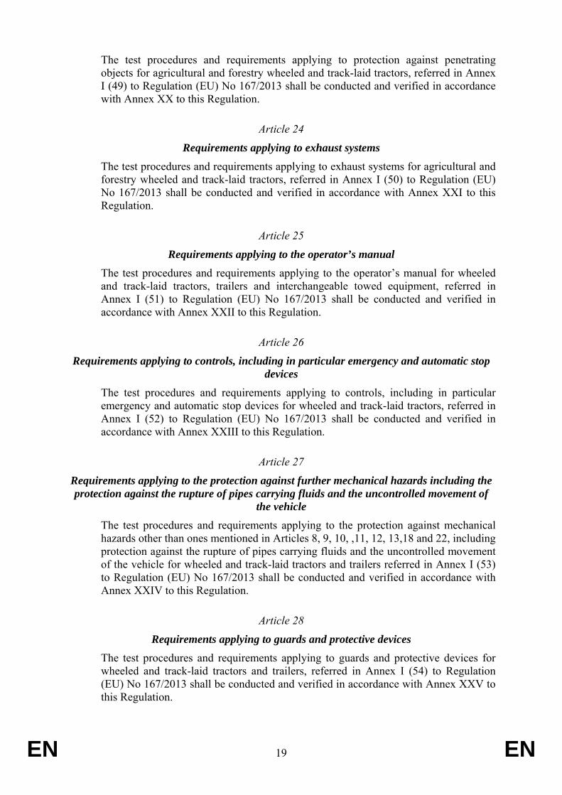
The test procedures and requirements applying to protection against penetrating objects for agricultural and forestry wheeled and track-laid tractors, referred in Annex I (49) to Regulation (EU) No 167/2013 shall be conducted and verified in accordance with Annex XX to this Regulation.
Article 24
Requirements applying to exhaust systems The test procedures and requirements applying to exhaust systems for agricultural and forestry wheeled and track-laid tractors, referred in Annex I (50) to Regulation (EU) No 167/2013 shall be conducted and verified in accordance with Annex XXI to this Regulation.
Article 25
Requirements applying to the operator’s manual The test procedures and requirements applying to the operator’s manual for wheeled and track-laid tractors, trailers and interchangeable towed equipment, referred in Annex I (51) to Regulation (EU) No 167/2013 shall be conducted and verified in accordance with Annex XXII to this Regulation.
Article 26
Requirements applying to controls, including in particular emergency and automatic stop devices
The test procedures and requirements applying to controls, including in particular emergency and automatic stop devices for wheeled and track-laid tractors, referred in Annex I (52) to Regulation (EU) No 167/2013 shall be conducted and verified in accordance with Annex XXIII to this Regulation.
Article 27
Requirements applying to the protection against further mechanical hazards including the protection against the rupture of pipes carrying fluids and the uncontrolled movement of
the vehicle The test procedures and requirements applying to the protection against mechanical hazards other than ones mentioned in Articles 8, 9, 10, ,11, 12, 13,18 and 22, including protection against the rupture of pipes carrying fluids and the uncontrolled movement of the vehicle for wheeled and track-laid tractors and trailers referred in Annex I (53) to Regulation (EU) No 167/2013 shall be conducted and verified in accordance with Annex XXIV to this Regulation.
Article 28
Requirements applying to guards and protective devices The test procedures and requirements applying to guards and protective devices for wheeled and track-laid tractors and trailers, referred in Annex I (54) to Regulation (EU) No 167/2013 shall be conducted and verified in accordance with Annex XXV to this Regulation.
EN 20 EN
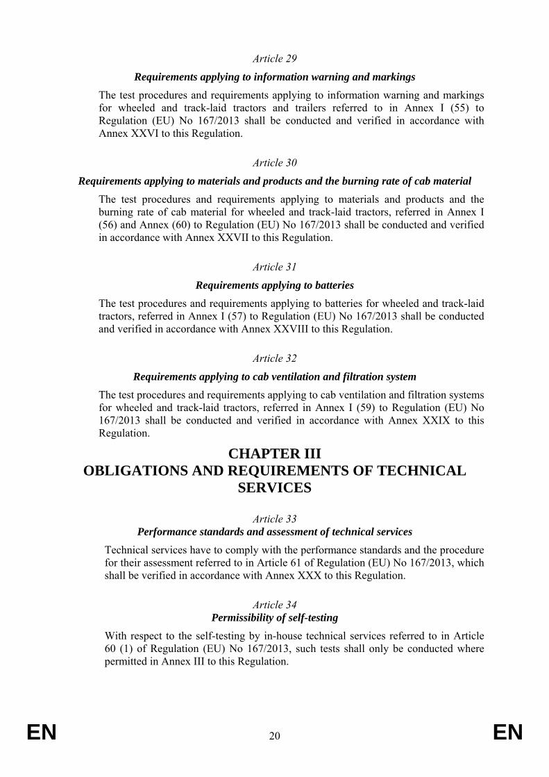
Article 29
Requirements applying to information warning and markings The test procedures and requirements applying to information warning and markings for wheeled and track-laid tractors and trailers referred to in Annex I (55) to Regulation (EU) No 167/2013 shall be conducted and verified in accordance with Annex XXVI to this Regulation.
Article 30
Requirements applying to materials and products and the burning rate of cab material The test procedures and requirements applying to materials and products and the burning rate of cab material for wheeled and track-laid tractors, referred in Annex I (56) and Annex (60) to Regulation (EU) No 167/2013 shall be conducted and verified in accordance with Annex XXVII to this Regulation.
Article 31
Requirements applying to batteries The test procedures and requirements applying to batteries for wheeled and track-laid tractors, referred in Annex I (57) to Regulation (EU) No 167/2013 shall be conducted and verified in accordance with Annex XXVIII to this Regulation.
Article 32
Requirements applying to cab ventilation and filtration system The test procedures and requirements applying to cab ventilation and filtration systems for wheeled and track-laid tractors, referred in Annex I (59) to Regulation (EU) No 167/2013 shall be conducted and verified in accordance with Annex XXIX to this Regulation.
CHAPTER III OBLIGATIONS AND REQUIREMENTS OF TECHNICAL
SERVICES
Article 33 Performance standards and assessment of technical services
Technical services have to comply with the performance standards and the procedure for their assessment referred to in Article 61 of Regulation (EU) No 167/2013, which shall be verified in accordance with Annex XXX to this Regulation.
Article 34 Permissibility of self-testing
With respect to the self-testing by in-house technical services referred to in Article 60 (1) of Regulation (EU) No 167/2013, such tests shall only be conducted where permitted in Annex III to this Regulation.
EN 21 EN
CHAPTER IV FINAL PROVISIONS
Article 35
This Regulation shall enter into force on the twentieth day following that of its publication in the Official Journal of the European Union. It shall apply from 1 January 2016.
This Regulation shall be binding in its entirety and directly applicable in the Member States in accordance with the Treaties.
Done at Brussels,
For the Commission The President
EN 22 EN
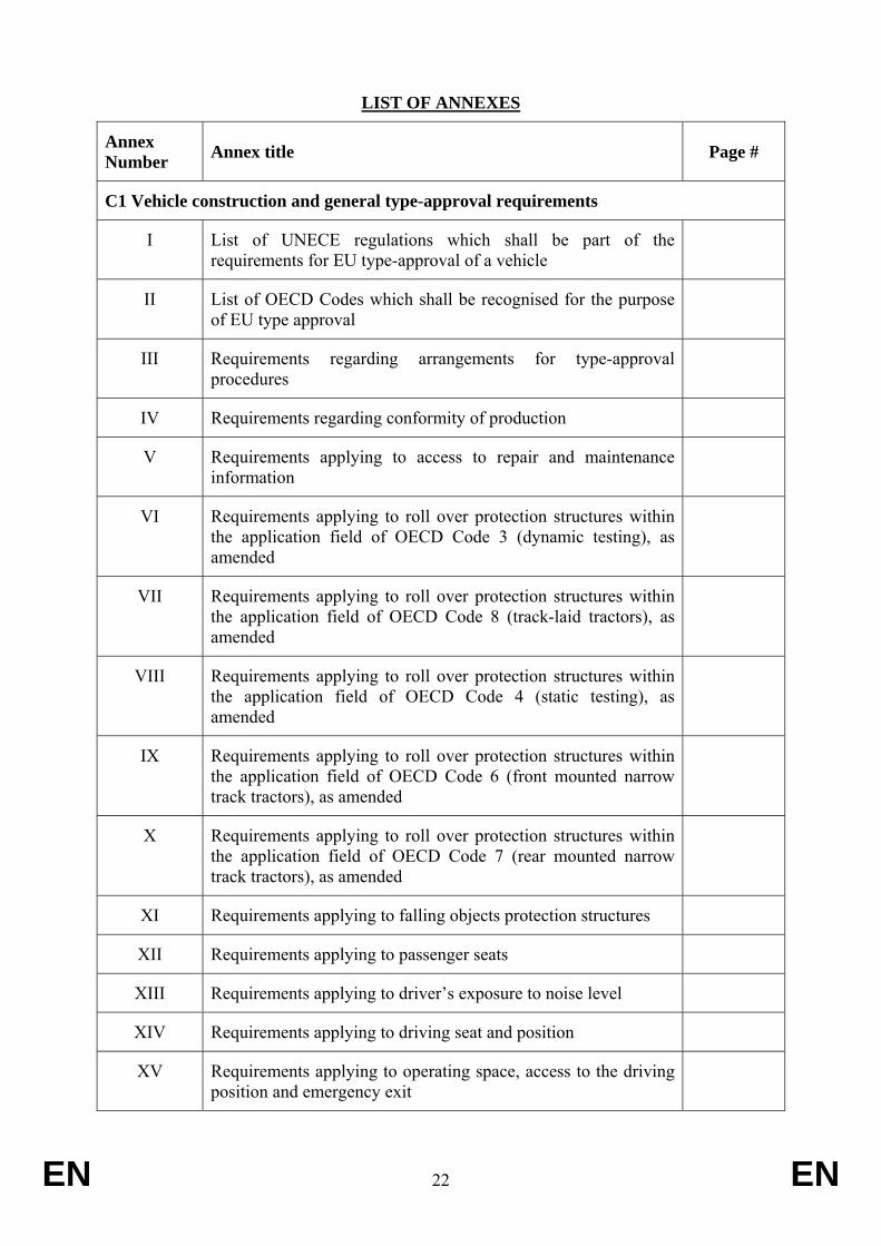
LIST OF ANNEXES
Annex Number Annex title Page #
C1 Vehicle construction and general type-approval requirements
I List of UNECE regulations which shall be part of the requirements for EU type-approval of a vehicle
II List of OECD Codes which shall be recognised for the purpose of EU type approval
III Requirements regarding arrangements for type-approval procedures
IV Requirements regarding conformity of production
V Requirements applying to access to repair and maintenance information
VI Requirements applying to roll over protection structures within the application field of OECD Code 3 (dynamic testing), as amended
VII Requirements applying to roll over protection structures within the application field of OECD Code 8 (track-laid tractors), as amended
VIII Requirements applying to roll over protection structures within the application field of OECD Code 4 (static testing), as amended
IX Requirements applying to roll over protection structures within the application field of OECD Code 6 (front mounted narrow track tractors), as amended
X Requirements applying to roll over protection structures within the application field of OECD Code 7 (rear mounted narrow track tractors), as amended
XI Requirements applying to falling objects protection structures
XII Requirements applying to passenger seats
XIII Requirements applying to driver’s exposure to noise level
XIV Requirements applying to driving seat and position
XV Requirements applying to operating space, access to the driving position and emergency exit
EN 23 EN
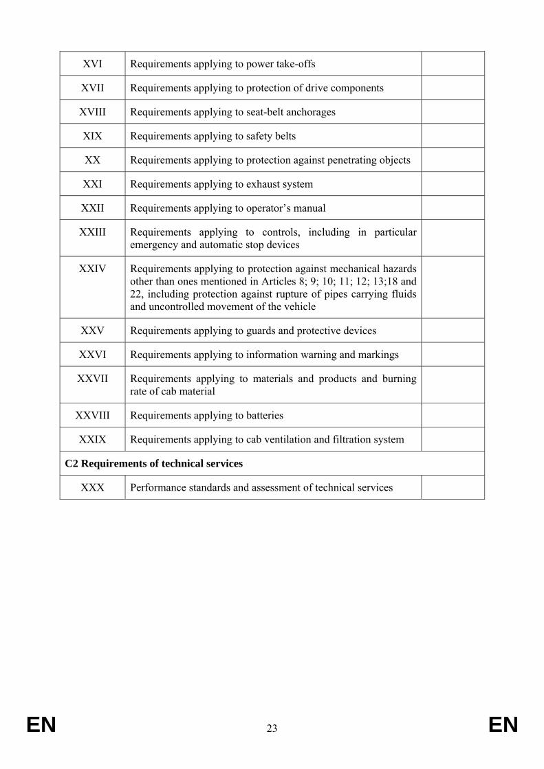
XVI Requirements applying to power take-offs
XVII Requirements applying to protection of drive components
XVIII Requirements applying to seat-belt anchorages
XIX Requirements applying to safety belts
XX Requirements applying to protection against penetrating objects
XXI Requirements applying to exhaust system
XXII Requirements applying to operator’s manual
XXIII Requirements applying to controls, including in particular emergency and automatic stop devices
XXIV Requirements applying to protection against mechanical hazards other than ones mentioned in Articles 8; 9; 10; 11; 12; 13;18 and 22, including protection against rupture of pipes carrying fluids and uncontrolled movement of the vehicle
XXV Requirements applying to guards and protective devices
XXVI Requirements applying to information warning and markings
XXVII Requirements applying to materials and products and burning rate of cab material
XXVIII Requirements applying to batteries
XXIX Requirements applying to cab ventilation and filtration system
C2 Requirements of technical services
XXX Performance standards and assessment of technical services
EN 24 EN
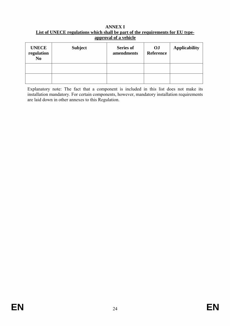
ANNEX I List of UNECE regulations which shall be part of the requirements for EU type-
approval of a vehicle
UNECE regulation
No
Subject Series of amendments
OJ Reference
Applicability
Explanatory note: The fact that a component is included in this list does not make its installation mandatory. For certain components, however, mandatory installation requirements are laid down in other annexes to this Regulation.

EN 25 EN
ANNEX II List of OECD Codes which shall be recognised for the purpose of EU type approval
OECD Code No
Subject Series of amendments
Applicability
EN 26 EN
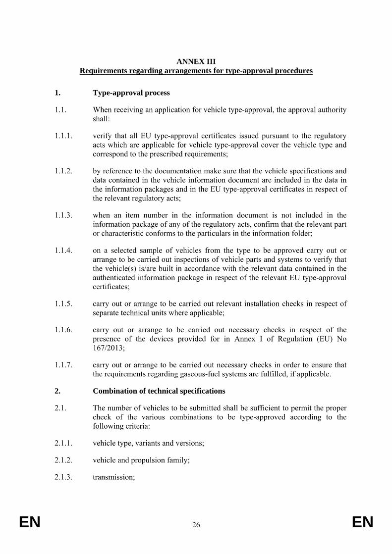
ANNEX III Requirements regarding arrangements for type-approval procedures
1. Type-approval process
1.1. When receiving an application for vehicle type-approval, the approval authority shall:
1.1.1. verify that all EU type-approval certificates issued pursuant to the regulatory acts which are applicable for vehicle type-approval cover the vehicle type and correspond to the prescribed requirements;
1.1.2. by reference to the documentation make sure that the vehicle specifications and data contained in the vehicle information document are included in the data in the information packages and in the EU type-approval certificates in respect of the relevant regulatory acts;
1.1.3. when an item number in the information document is not included in the information package of any of the regulatory acts, confirm that the relevant part or characteristic conforms to the particulars in the information folder;
1.1.4. on a selected sample of vehicles from the type to be approved carry out or arrange to be carried out inspections of vehicle parts and systems to verify that the vehicle(s) is/are built in accordance with the relevant data contained in the authenticated information package in respect of the relevant EU type-approval certificates;
1.1.5. carry out or arrange to be carried out relevant installation checks in respect of separate technical units where applicable;
1.1.6. carry out or arrange to be carried out necessary checks in respect of the presence of the devices provided for in Annex I of Regulation (EU) No 167/2013;
1.1.7. carry out or arrange to be carried out necessary checks in order to ensure that the requirements regarding gaseous-fuel systems are fulfilled, if applicable.
2. Combination of technical specifications
2.1. The number of vehicles to be submitted shall be sufficient to permit the proper check of the various combinations to be type-approved according to the following criteria:
2.1.1. vehicle type, variants and versions;
2.1.2. vehicle and propulsion family;
2.1.3. transmission;
EN 27 EN
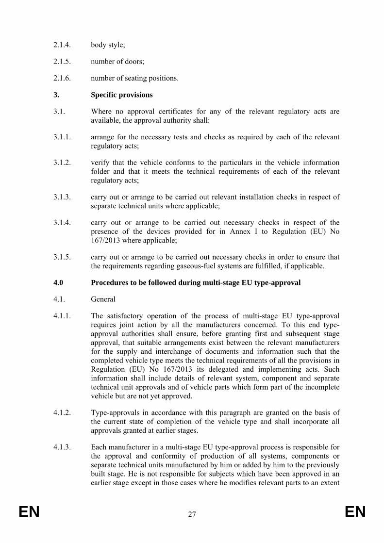
2.1.4. body style;
2.1.5. number of doors;
2.1.6. number of seating positions.
3. Specific provisions
3.1. Where no approval certificates for any of the relevant regulatory acts are available, the approval authority shall:
3.1.1. arrange for the necessary tests and checks as required by each of the relevant regulatory acts;
3.1.2. verify that the vehicle conforms to the particulars in the vehicle information folder and that it meets the technical requirements of each of the relevant regulatory acts;
3.1.3. carry out or arrange to be carried out relevant installation checks in respect of separate technical units where applicable;
3.1.4. carry out or arrange to be carried out necessary checks in respect of the presence of the devices provided for in Annex I to Regulation (EU) No 167/2013 where applicable;
3.1.5. carry out or arrange to be carried out necessary checks in order to ensure that the requirements regarding gaseous-fuel systems are fulfilled, if applicable.
4.0 Procedures to be followed during multi-stage EU type-approval
4.1. General
4.1.1. The satisfactory operation of the process of multi-stage EU type-approval requires joint action by all the manufacturers concerned. To this end type-approval authorities shall ensure, before granting first and subsequent stage approval, that suitable arrangements exist between the relevant manufacturers for the supply and interchange of documents and information such that the completed vehicle type meets the technical requirements of all the provisions in Regulation (EU) No 167/2013 its delegated and implementing acts. Such information shall include details of relevant system, component and separate technical unit approvals and of vehicle parts which form part of the incomplete vehicle but are not yet approved.
4.1.2. Type-approvals in accordance with this paragraph are granted on the basis of the current state of completion of the vehicle type and shall incorporate all approvals granted at earlier stages.
4.1.3. Each manufacturer in a multi-stage EU type-approval process is responsible for the approval and conformity of production of all systems, components or separate technical units manufactured by him or added by him to the previously built stage. He is not responsible for subjects which have been approved in an earlier stage except in those cases where he modifies relevant parts to an extent
EN 28 EN
that the previously granted approval becomes invalid.
4.2. Procedures.
The approval authority shall:
4.2.1. verify that all EU type-approval certificates issued pursuant to the regulatory acts which are applicable for vehicle type-approval cover the vehicle type at its state of completion and correspond to the prescribed requirements;
4.2.2. verify, in accordance with Article 20 (6) of Regulation (EU) No 167/2013 that the vehicle type-approved at the final stage meets at that time all applicable technical requirements. That shall include a documentary check of all requirements covered by a type-approval for an incomplete vehicle granted in the course of a multistage procedure, even where granted for a different (sub-) category of vehicle.
4.2.3. ensure, in accordance with Article 20 (7) of Regulation (EU) No 167/2013, that the choice of approval procedure does not affect the applicable substantive requirements with which the approved vehicle type has to comply at the time of issuing of the whole-vehicle type-approval.
4.2.2. ensure that all the relevant data, taking account of the state of completion of the vehicle, is included in the information folder;
4.2.3. by reference to the documentation make sure that the vehicle specification(s) and data contained in the vehicle information folder are included in the data in the information packages and in the EU type-approval certificates, in respect of the relevant regulatory acts; and in the case of a completed vehicle, where an item number in the information folder is not included in the information package of any of the regulatory acts, confirm that the relevant part of characteristic conforms to the particulars in the information folder;
4.2.4. on a selected sample of vehicles from the type to be approved carry out or arrange to be carried out inspections of vehicle parts and systems to verify that the vehicle(s) is/are built in accordance with the relevant data contained in the authenticated information package in respect of all relevant regulatory acts;
4.2.5. carry out or arrange to be carried out relevant installation checks in respect of separate technical units where applicable.
4.3. The number of vehicles to be inspected for the purposes of paragraph 4.2.4. shall be sufficient to permit the proper control of the various combinations to be EU type-approved according to the state of completion of the vehicle and the criteria set-out in 2.1.
5. Specific conditions required of virtual testing methods and regulatory acts for which virtual and/or self-testing methods may be used by a manufacturer or a technical service
5.0. Objectives and scope
5.0.1. This paragraph lays down appropriate provisions concerning virtual testing in
EN 29 EN
accordance with Article 27(6) of Regulation (EU) No 167/2013. It shall not apply to the second subparagraph of Article 27(3).
5.0.2. This paragraph also sets out topics for self-testing in accordance with the requirements in paragraph 5.0 of Annex XXX.
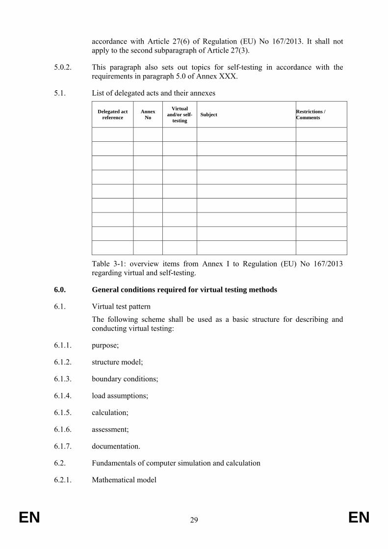
5.1. List of delegated acts and their annexes
Delegated act reference
Annex No
Virtual and/or self-
testing Subject Restrictions /
Comments
Table 3-1: overview items from Annex I to Regulation (EU) No 167/2013 regarding virtual and self-testing.
6.0. General conditions required for virtual testing methods
6.1. Virtual test pattern
The following scheme shall be used as a basic structure for describing and conducting virtual testing:
6.1.1. purpose;
6.1.2. structure model;
6.1.3. boundary conditions;
6.1.4. load assumptions;
6.1.5. calculation;
6.1.6. assessment;
6.1.7. documentation.
6.2. Fundamentals of computer simulation and calculation
6.2.1. Mathematical model
EN 30 EN
The mathematical model shall be supplied by the manufacturer. It shall reflect the complexity of the structure of the vehicle, system and components to be tested in relation to the requirements of the regulatory act and its boundary conditions. The same provisions shall apply mutatis mutandis for testing components or technical units independently from the vehicle.
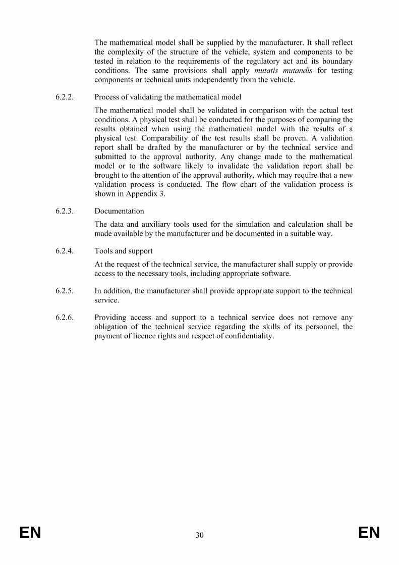
6.2.2. Process of validating the mathematical model
The mathematical model shall be validated in comparison with the actual test conditions. A physical test shall be conducted for the purposes of comparing the results obtained when using the mathematical model with the results of a physical test. Comparability of the test results shall be proven. A validation report shall be drafted by the manufacturer or by the technical service and submitted to the approval authority. Any change made to the mathematical model or to the software likely to invalidate the validation report shall be brought to the attention of the approval authority, which may require that a new validation process is conducted. The flow chart of the validation process is shown in Appendix 3.
6.2.3. Documentation
The data and auxiliary tools used for the simulation and calculation shall be made available by the manufacturer and be documented in a suitable way.
6.2.4. Tools and support
At the request of the technical service, the manufacturer shall supply or provide access to the necessary tools, including appropriate software.
6.2.5. In addition, the manufacturer shall provide appropriate support to the technical service.
6.2.6. Providing access and support to a technical service does not remove any obligation of the technical service regarding the skills of its personnel, the payment of licence rights and respect of confidentiality.
EN 31 EN
7.0. Validation process virtual testing
7.1.
Figure 3-1: Virtual testing validation process flow chart.
EN 32 EN
ANNEX IV Requirements regarding conformity of production
0. Objectives
0.1. The conformity of production procedure aims to ensure that each vehicle, system, component, separate technical unit, part or equipment produced is in conformity with the approved type.
0.2. Procedures include inseparably the assessment of quality-assurance management systems, referred to below as ‘initial assessment’ and verification and production-related controls, referred to as ‘product conformity arrangements’.
1. Initial assessment
1.1. Before granting type-approval, the approval authority shall verify the existence of satisfactory arrangements and procedures established by the manufacturer for ensuring effective control so that vehicles, systems, components or separate technical units when in production conform to the approved type.
1.2. Guidance for conducting assessments may be found in the EN ISO 19011:2011 standard — Guidelines for quality and/or environmental management systems auditing.
1.3. The requirement in point 1.1.shall be verified to the satisfaction of the approval authority granting type-approval. The approval authority shall be satisfied with the initial assessment and the product conformity arrangements in section 2 below, taking account — as necessary — of one of the arrangements described in points 1.3.1. to 1.3.3. or a combination of those arrangements in full or in part as appropriate.
1.3.1. The initial assessment and/or verification of product conformity arrangements shall be carried out by the approval authority granting the approval or by a technical service designated to act on behalf of that authority.
1.3.1.1. When considering the extent of the initial assessment to be carried out, the approval authority may take account of available information relating to:
1.3.1.1.1. the manufacturer’s certification described in point 1.3.3. below, which has not been qualified or recognised under that point;
1.3.1.1.2. in the case of type-approval of systems, components or separate technical units, quality system assessments performed by vehicle manufacturer(s) on the premises of the manufacturer(s) of the system, component or separate technical units, according to one or more of the industry sector specifications satisfying the requirements in the EN ISO 9001:2008 or ISO/TS16949:2009 standards.
EN 33 EN
1.3.2. The initial assessment and/or verification of product conformity arrangements may be carried out by the approval authority of another Member State, or the technical service designated for this purpose by that authority.
1.3.2.1. In such a case, the approval authority of the other Member State shall prepare a statement of compliance outlining the areas and production facilities it has covered as relevant to the product(s) to be type-approved and to the Regulations according to which these products are to be type-approved.
1.3.2.2. On receiving an application for a compliance statement from the approval authority granting type-approval, the approval authority of another Member State shall send forthwith the statement of compliance or advise that it is not in a position to provide such a statement.
1.3.2.3. The statement of compliance shall include at least the following:
1.3.2.3.1. group or company (e.g. XYZ automotive);
1.3.2.3.2. particular organisation (e.g. regional division);
1.3.2.3.3. plants/sites (e.g. engine plant 1 (in country A) — vehicle plant 2 ( in country B));
1.3.2.3.4. vehicle/component range (e.g. all category LXe models);
1.3.2.3.5. areas assessed (e.g. engine assembly, body pressing and assembly, vehicle assembly);
1.3.2.3.6. documents examined (e.g. company and site quality manual and procedures);
1.3.2.3.7. date of the assessment (e.g. audit conducted from dd/mm/yyyy to dd/mm/yyyy );
1.3.2.3.8. planned monitoring visit (e.g. mm/yyyy);
1.3.3. The approval authority may also accept the manufacturer’s certification to the international EN ISO 9001:2008 or ISO/TS16949:2009 standard (the scope of this certification shall in that case cover the product(s) to be approved) or an equivalent accreditation standard as satisfying the initial assessment requirements of point 1.1., provided that conformity of production is indeed covered by the quality management system. The manufacturer shall provide details of the certification and undertake to inform the approval authority of any revisions to its validity or scope of that certification.
1.4. For the purpose of vehicle type-approval, the initial assessments carried out for granting approvals for systems, components and separate technical units of the vehicle need not be repeated but shall be complemented by an assessment covering the locations and activities relating to the assembly of the whole vehicle not covered by the former assessments.
EN 34 EN
2. Product conformity arrangements
2.1. Every vehicle, system, component, separate technical unit, part or item of equipment pursuant to a UN Regulation annexed to the revised 1958 Agreement, to an OECD Code and to Regulation (EU) No 167/2013 shall be so manufactured as to conform to the type approved by meeting the requirements of this Annex, the said UN Regulation(s) and Regulation (EU) No 167/2013.
2.2. Before granting a type-approval pursuant to Regulation (EU) No 167/2013, to an OECD Code and to a UN regulation annexed to the revised 1958 Agreement, the approval authority shall verify the existence of adequate arrangements and documented control plans, to be agreed with the manufacturer for each approval, to carry out at specified intervals those tests or associated checks necessary to verify continued conformity with the approved type, including, where applicable, tests specified in Regulation (EU) No 167/2013, the OECD Code and the said UN regulation.
2.3. The holder of the type-approval shall, in particular:
2.3.1. ensure the existence and application of procedures for effective control of the conformity of products (vehicles, systems, components, separate technical units, parts or equipment) to the approved type;
2.3.2. have access to the testing or other appropriate equipment necessary for checking conformity to each approved type;
2.3.3. ensure that test or check result data are recorded and that annexed documents remain available for a period of up to 10 years to be determined in agreement with the approval authority;
2.3.4. analyse the results of each type of test or check, in order to verify and ensure the stability of the product characteristics, making allowance for variation in industrial production;
2.3.5. ensure that for each type of product, at least the checks and the tests prescribed in Regulation (EU) No 167/2013 and its delegated and implementing acts as well as set out in the referenced and applicable, OECD Code or UN Regulation therein are carried out;
2.3.6. ensure that any set of samples or test pieces giving evidence of non-conformity in the type of test in question gives rise to a further sampling and test. All the necessary steps shall be taken to restore the production process to ensure conformity with the approved type.
2.4. In the case of step-by-step, mixed or multi-stage type-approvals, the approval authority granting whole vehicle type-approval may request specific details regarding compliance with the conformity of production requirements set out in this Annex from any approval authority that granted type-approval of any relevant system, component or separate technical unit.
EN 35 EN
2.5. If the approval authority granting whole vehicle type-approval is not satisfied with the reported information referred to in point 2.4. and has communicated this in writing to the manufacturer in question and the approval authority granting type-approval for the system, component or separate technical unit, the approval authority granting whole vehicle type-approval shall demand additional conformity of production audits or checks to be performed at the site of the manufacturer(s) of those systems, components or separate technical units and the results shall immediately be made available to the approval authority concerned.
2.6. If points 2.4. and 2.5. apply and the further audit or check results are deemed not to be satisfactory in the opinion of the approval authority granting whole vehicle type-approval, the manufacturer shall ensure that conformity of production is restored as soon as possible by corrective actions to the satisfaction of the approval authority granting whole vehicle type-approval and to the satisfaction of the approval authority granting type-approval of the system, component or separate technical unit.
3. Continued verification arrangements
3.1 The authority which has granted type-approval may at any time verify the conformity of production control methods applied in each production facility by means of periodic audits. The manufacturer shall for that purpose allow access to the manufacture, inspection, testing, storage and distribution sites and shall provide all necessary information with regard to the quality management system documentation and records.
3.1.1. The normal approach for such periodic audits shall be to monitor the continued effectiveness of the procedures laid down in sections 1 and 2 (initial assessment and product conformity arrangements).
3.1.1.1. Surveillance activities carried out by the technical services (qualified or recognised as required in point 1.3.3) shall be accepted as satisfying the requirements of point 3.1.1 with regard to the procedures established at initial assessment.
3.1.1.2. The normal frequency of these verifications by the approval authority (other than those referred to in point 3.1.1.1.) shall be such as to ensure that the relevant conformity of production controls applied in accordance with sections 1 and 2 are reviewed over a period consistent with the climate of trust established by the approval authority.
3.2. At every review, the records of tests and checks and production records, in particular records of those tests or checks documented as required in point 2.2., shall be available to the inspector;
3.3. The inspector may select random samples to be tested in the manufacturer’s laboratory or in the facilities of the technical service, in which case only physical tests shall be carried out. The minimum number of samples may be determined according to the results of the manufacturer’s own verification.
EN 36 EN
3.4. Where the level of control appears unsatisfactory, or when it seems necessary to verify the validity of the tests carried out in application of point 3.2., the inspector shall select samples to be sent to the technical service to perform physical tests according to the CoP requirements set out in paragraph 4 and in the OECD Code or the UN Regulations referred to in Regulation (EU) No 167/2013 or in its delegated acts.
3.5. Where unsatisfactory results are found during an inspection or a monitoring review, the approval authority shall ensure that all necessary steps are taken to restore conformity of production as rapidly as possible.
3.6. In cases where compliance with OECD Codes or UNECE regulations is required by Regulation (EU) No 167/2013 or its delegated acts, the manufacturer may choose to apply the provisions of this Annex as an equivalent alternative to the conformity of production requirements in the respective UNECE regulations. However, if points 3.5. or 3.6. apply, all separate conformity of production requirements in the OECD Code or UN Regulations have to be complied with to the satisfaction of the approval authority until it decides that conformity of production has been restored.
EN 37 EN
ANNEX V Requirements applying to access to repair and maintenance information
1. Purpose
1.1. Access to information means the availability of all OBD and repair and maintenance information required for the inspection, diagnosis, servicing or repair of the vehicle.
1.2. When applying for EU type-approval or national type-approval, the manufacturer shall provide the approval authority with proof of compliance with this Regulation as regards access to vehicle repair and maintenance information and to the information referred to in paragraph 2(6).
2. Compliance with access to vehicle OBD and vehicle repair and maintenance information requirements in the type-approval procedure
2.1. Approval authorities shall grant type-approval only after receiving from the manufacturer a Certificate on Access to Vehicle OBD and Vehicle Repair and Maintenance Information.
2.2. The Certificate on Access to Vehicle OBD and Vehicle Repair and Maintenance Information shall serve as the proof of compliance with Chapter XV of Regulation (EU) No 167/2013.
2.3. The Certificate on Access to Vehicle OBD and Vehicle Repair and Maintenance Information shall be drawn up in accordance with the model referred to in Article 53 (8) (3) to Regulation (EU) No 167/2013.
2.4. The manufacturer shall ensure compliance with the technical requirements in Appendix 1 regarding access to vehicle OBD and vehicle repair and maintenance information.
3. Fees for access
3.1. In addition to time-based access under Article 55 of Regulation (EU) No 167/2013, manufacturers may offer transaction-based access for which fees are charged per transaction and not based on the time for which access is granted. Where manufacturers offer both time-based and transaction-based access systems, independent repairers shall choose a preferred access system, either time-based or transaction based.
4. Service parts, diagnostic tools and test equipment
4.1. In the context of Article 53 (6) of Regulation 167/2013, the manufacturer shall make the following information available to interested parties on the basis of individual arrangements to which the principle of Article 55 of Regulation 167/2013 apply and to provide contact details on its website:
EN 38 EN
4.2. relevant information to enable the development of replacement components which are critical to the correct functioning of the OBD system;
4.3. information to enable the development of generic diagnostic tools as listed in Annex I Appendix I Point 3 to Regulation 692/2008.
4.4. For the purposes of point 4.1.1., the development of replacement components shall not be restricted by any of the following:
4.4.1. the unavailability of pertinent information;
4.4.2. the technical requirements relating to malfunction indication strategies if the OBD thresholds are exceeded or if the OBD system is unable to fulfil the basic OBD monitoring requirements of this Regulation;
4.4.3. specific modifications to the handling of OBD information to deal independently with vehicle operation on liquid or gaseous fuels;
4.4.4. the type-approval of gaseous-fuelled vehicles that contain a limited number of minor deficiencies.
4.5. For the purposes of point 4.6.2., where manufacturers use diagnostic and test tools in accordance with ISO 22900-2:2009 regarding Modular Vehicle Communication Interface (MVCI) and ISO 22901-2:2011 on Open Diagnostic Data Exchange (ODX) in their franchised networks, the ODX files shall be accessible to independent operators via the manufacturer’s website.
5. Multi-stage type-approval
5.1. In the case of multi-stage type-approval, as defined in Article 20 of Regulation (EU) No 167/2013, the final manufacturer shall be responsible for providing access to vehicle OBD and vehicle repair and maintenance information regarding its own manufacturing stage(s) and the link to the previous stage(s).
5.2. In addition, the final manufacturer shall on its website provide independent operators with the following information:
5.2.1. website address of the manufacturer(s) responsible for the previous stage(s);
5.2.2. name and address of all the manufacturers responsible for the previous stage(s);
5.2.3. type-approval number(s) of the previous stage(s);
5.2.4. the engine number.
5.3. Manufacturers responsible for a particular stage or stages of type-approval shall be responsible for providing through their website access to vehicle OBD and vehicle repair and maintenance information regarding the stage(s) of type-approval for which they are responsible and the link to the previous stage(s).
5.4. The manufacturer responsible for a particular stage or stages of type-approval shall
EN 39 EN
provide the following information to the manufacturer responsible for the next stage:
5.4.1. the Certificate of Conformity relating to the stage(s) for which it is responsible;
5.4.2. the Certificate on Access to Vehicle OBD and Vehicle Repair and Maintenance Information, including its appendices;
5.4.3. the type-approval number corresponding to the stage(s) for which it is responsible;
5.4.4. the documents referred to in points 3.4.1., 3.4.2. and 3.4.3. as provided by the manufacturer(s) involved in the previous stage(s).
5.5. Each manufacturer shall authorise the manufacturer responsible for the next stage to pass the documents to the manufacturers responsible for subsequent and final stages.
5.6. In addition, on a contractual basis, the manufacturer responsible for a particular stage or stages of type-approval shall:
5.6.1. provide the manufacturer responsible for the next stage with access to OBD and repair and maintenance information and interface information corresponding to the particular stage(s) for which it is responsible;
5.6.2. provide, at the request of a manufacturer responsible for a subsequent stage of type-approval, with access to vehicle OBD and vehicle repair and maintenance information and interface information corresponding to the particular stage(s) for which he is responsible.
5.7. A manufacturer, including a final manufacturer, may charge fees in accordance with Article 55 of Regulation (EU) No 167/2013 only in respect of the particular stage(s) for which he is responsible.
5.8. A manufacturer, including a final manufacturer, shall not charge fees for providing information relating to the website address or contact details of any other manufacturer.
6. Small volume manufacturers
6.1. Manufacturers whose world-wide annual production of a type of vehicle, system, component or separate technical unit covered by this Regulation is less than 250 units shall provide access to repair and maintenance information in a readily accessible and prompt manner, and in a manner which is non-discriminatory as compared with the provisions given or access granted to authorised dealers and repairers in accordance with Article 53 (13) of Regulation 167/2013.
6.2. Vehicles, systems, components and separate technical units covered by paragraph 1 shall be listed on the manufacturer’s repair and maintenance information website.
6.3. The approval authority shall inform the Commission of all type-approvals granted
EN 40 EN
to small-volume manufacturers.
7. Compliance with the obligations regarding access to vehicle OBD and vehicle repair and maintenance information
7.1. An approval authority may, at any time, on their own initiative, or on the basis of a complaint or of an assessment by a technical service, check a manufacturer’s compliance with its obligations under Regulation (EU) No 167/2013, this Regulation and the terms of the Certificate on Access to Vehicle OBD and Vehicle Repair and Maintenance Information.
7.2. Where an approval authority finds that a manufacturer has failed to comply with its obligations regarding access to vehicle OBD and vehicle repair and maintenance information, the approval authority which granted the relevant type-approval shall take appropriate measures to remedy the situation.
7.3. Such measures may include withdrawal or suspension of type-approval, fines or other measures adopted in accordance with Regulation (EU) No 167/2013.
7.4. If an independent operator or a trade association representing independent operators files a complaint to the approval authority, the authority shall carry out an audit to verify the manufacturer’s compliance with obligations concerning access to vehicle OBD and vehicle repair and maintenance information.
7.5. When carrying out the audit, the approval authority may ask a technical service or any other independent expert to carry out an assessment to verify whether these obligations are met.
7.6. If the vehicle OBD and vehicle repair and maintenance information is not available when the application for type-approval is made, the manufacturer shall provide that information within six months of the date of type-approval.
7.7. Where the vehicle is placed on the market more than six months after type-approval, the information shall be provided on the date on which the vehicle is placed on the market.
7.8. The approval authority may presume on the basis of a completed Certificate on Access to Vehicle OBD and Vehicle Repair and Maintenance Information that the manufacturer has put in place satisfactory arrangements and procedures with regard to access to vehicle OBD and vehicle repair and maintenance information, provided that no complaint was made and that the manufacturer provides the certificate within the periods referred to in paragraph 7.7.
7.9. If the certificate of compliance is not provided within that period, the approval authority shall take appropriate measures to ensure compliance.
8. Information requirements for granting access to independent operators to non-secure areas
8.1. For access to any OBD and repair and maintenance information other than that relating to secure areas of the vehicle, registration requirements for use of the
EN 41 EN
manufacturer’s website by an independent operator shall require only such information as is necessary to confirm how payment for the information is to be made.
9. Information requirements for granting access to independent operators to secure areas
9.1. For access to any OBD and repair and maintenance information concerning access to secure areas of the vehicle, the independent operator shall be approved and authorised for this purpose on the basis of documents demonstrating that it pursues a legitimate business activity and has not been convicted of relevant criminal activity.
9.2. Independent operators shall be given access to vehicle security features used by
authorised dealers and repair shops under protection of security technology concerning the exchange of data to ensure confidentiality, integrity and protection against replay.
.3. The Forum on Access to Vehicle Information provided for by Article 56 of Regulation (EU) No 167/2013 will specify state-of-the-art parameters for fulfilling these requirements.
9.4. For information concerning access to secure areas of the vehicle, the independent
operator shall present a certificate in accordance with ISO 20828:2006 to identify itself and the organisation to which it belongs. The manufacturer shall respond with its own certificate in accordance with ISO 20828:2006 to confirm to the independent operator that it is accessing a legitimate site of the manufacturer in question. Both parties shall keep a log of any such transactions indicating the vehicles and changes made to them under this provision.
EN 42 EN
Appendix 1 Access to vehicle OBD and vehicle repair and maintenance information
1. Introduction
1.1. This Appendix lays down technical requirements for the accessibility of vehicle OBD and vehicle repair and maintenance information.
2. Requirements
2.1. The manufacturer shall provide vehicle repair and maintenance information using only open text and graphic formats or formats which can be viewed and printed using only standard software plug-ins that are freely available, easy to install, and which run with computer operating systems commonly in use.
2.1.1. Vehicle OBD and vehicle repair and maintenance information available through websites shall follow the common standard referred to in paragraph 2 of Article 53 of Regulation (EC) No 167/2013
2.1.2. Where possible, keywords in the metadata shall conform to ISO 15031-2:2010. Such information shall be always available, except as required for website maintenance purposes.
Those requiring the right to duplicate or re-publish the information should negotiate directly with the manufacturer concerned. Information for training material shall also be available, but may be presented through media other than websites.
2.2. Information on all parts of the vehicle, with which the vehicle, as identified by the model and serial number of the vehicle and any additional criteria such as wheelbase, engine output, trim level or options, is equipped by the vehicle manufacturer and which can be replaced by spare parts offered by the vehicle manufacturer to its authorised repairers or dealers or third parties by means of reference to original equipment (OE) parts numbers, may be made available in a database easily accessible to independent operators.. For information on … ., the information has to be provided on the basis of the VIN number
2.3. This database or alternative accessible format shall comprise the VIN, Original Equipment (OE) parts numbers, OE naming of the parts, validity attributes (valid-from and valid-to dates), fitting attributes and, where applicable, structuring characteristics.
2.4. The information on the database or available in another accessible format shall be regularly updated. In particular, the updates shall include all modifications to individual vehicles after their production if this information is available to authorised dealers.
2.5. Reprogramming of control units for the purposes of, e.g. recalibration after a repair or loading software to a replacement ECU, shall be conducted using non-proprietary hardware. Ethernet, serial cable or Local Area Network (LAN) interface and alternative media like Compact Disc (CD), Digital Versatile Disc (DVD) or solid state memory device for infotainment systems (e.g. navigation
EN 43 EN
systems, telephone) may also be used, but on the condition that no proprietary communication software (e.g. drivers or plug-ins) and hardware is required. For the validation of the compatibility of the manufacturer-specific application and the vehicle communication interfaces (VCI) the manufacturer shall offer either a validation of independently developed VCIs or the information, and loan of any special hardware, required for a VCI manufacturer to conduct such validation himself. The conditions of Article 55 of Regulation (EU) No 167/2013 shall apply to fees for such validation or information and hardware
2.6. Manufacturers’ repair information websites shall indicate type-approval numbers by model.
2.7. Manufacturers shall establish reasonable and proportionate fees for hourly, daily, monthly, annual and if applicable per-transaction access to their repair and maintenance information websites.
EN 44 EN
ANNEX VI Requirements applying to roll over protection structures within the application field of OECD
Code 3 (dynamic testing), as amended
The following test requirements are applicable to roll-over protective structures fitted to T1, T4.2 and T4.3 agricultural and forestry wheeled and tracklaying tractors propelled by a combination of wheels and endless tracks having the following characteristics:
• mass greater than 600 kg but less than 6000 kg, corresponding to the unballasted / unladen mass of the tractor (as defined in the information document as established in Article 68(a) to Regulation (EU) 167/2013), including the roll-over protective structure and tyres of the largest size recommended by the manufacturer;
• fixed or adjustable track width of one of the driving axles of 1150 mm or more; • ground clearance beneath the rear axle of not more than 1000 mm.
1. DEFINITIONS
1.1 [Not applicable]
1.2 Roll-Over Protective Structure (ROPS) Roll-over protective structure (safety cab or frame), hereinafter called “protective structure”, means the structure on a tractor the essential purpose of which is to avoid or limit risks to the driver resulting from roll-over of the tractor during normal use.
The roll-over protective structure is characterized by the provision of space for a clearance zone large enough to protect the driver when seated either inside the envelope of the structure or within a space bounded by a series of straight lines from the outer edges of the structure to any part of the tractor that might come into contact with flat ground and that is capable of supporting the tractor in that position if the tractor overturns.
1.3 Track
1.3.1 Preliminary definition: median plane of the wheel
The median plane of the wheel is equidistant from the two planes containing the periphery of the rims at their outer edges.
1.3.2 Definition of track
The vertical plane through the wheel axis intersects its median plane along a straight line which meets the supporting surface at one point. If A and B are the two points thus defined for the wheels on the same axle of the tractor, then the track width is the distance between points A and B. The track may be thus defined for both front and rear wheels. Where there are twin wheels, the track is the distance between two planes each being the median plane of the pairs of wheels.
For tracklaying tractors, the track is the distance between the median planes of the tracks.
1.3.3 Additional definition: median plane of the tractor
EN 45 EN
Take the extreme positions of points A and B for the tractor rear axle, which gives the maximum possible value for the track. The vertical plane at right angles to the line AB at its centre point is the median plane of the tractor.
1.4 Wheelbase The distance between the vertical planes passing through the two lines AB as defined above, one for the front wheels and one for the rear-wheels.
1.5. Method for determining the Seat Index Point (SIP) 1.5.1. The Seat Index Point shall be determined in accordance with the method indicated in
Appendix 1.
1.6 Seat location and adjustment for test 1.6.1 where the inclination of the backrest and seat pan is adjustable, these must be adjusted so
that the Seat Index Point is in its rear uppermost position;
1.6.2 Where the seat is equipped with suspension, the latter must be blocked at mid-travel, unless this is contrary to the instructions clearly laid down by the seat manufacturer;
1.6.3 Where the position of the seat is adjustable only lengthwise and vertically, the longitudinal axis passing through the Seat Index Point shall be parallel with the vertical longitudinal plane of the tractor passing through the centre of the steering wheel and not more than 100 mm from that plane.
1.7 Clearance zone 1.7.1 Reference plane
The clearance zone is illustrated in Figures 3.8 to 3.10 and Table 3.3. The zone is defined in relation to the reference plane and the Seat Index Point. The reference plane is a vertical plane, generally longitudinal to the tractor and passing through the Seat Index Point and the centre of the steering wheel. Normally the reference plane coincides with the longitudinal median plane of the tractor. This reference plane shall be assumed to move horizontally with the seat and steering wheel during loading but to remain perpendicular to the tractor or the floor of the roll-over protective structure. The clearance zone shall be defined on the basis of sub clauses 1.6.2 and 1.6.3.
1.7.2 Determination of clearance zone for tractors with a non-reversible seat
The clearance zone for tractors with a non-reversible seat is defined in 1.6.2.1 to 1.6.2.10 below and is bounded by the following planes, the tractor being on a horizontal surface, the seat, where adjustable, adjusted to its rear uppermost position1, and the steering wheel, where adjustable, adjusted to the mid position for seated driving:
1.7.2.1 a horizontal plane A1 B1 B2 A2, (810 + av) mm above the Seat Index Point with line B1B2 located (ah - 10) mm behind the SIP;
1.7.2.2 an inclined plane G1 G2 I2 I1, perpendicular to the reference plane, including both a point 150 mm behind line B1B2 and the rearmost point of the seat backrest;
1.7.2.3 a cylindrical surface A1 A2 I2 I1 perpendicular to the reference plane, having a radius of 120 mm, tangential to the planes defined in 1.6.2.1 and 1.6.2.2 above;
1 Users are reminded that the Seat Index Point is determined according to ISO 5353 and is a fixed point with respect to
the tractor that does not move as the seat is adjusted away from the mid-position. For purposes of determining the clearance zone, the seat shall be placed in the rear and uppermost position.
EN 46 EN
1.7.2.4 a cylindrical surface B1 C1 C2 B2, perpendicular to the reference plane, having a radius of 900 mm extending forward for 400 mm and tangential to the plane defined in 1.6.2.1 above along line B1B2;
1.7.2.5 an inclined plane C1 D1 D2 C2, perpendicular to the reference plane, joining the surface defined in 1.6.2.4 above and passing 40 mm from the forward external edge of the steering wheel. In the case of a high steering wheel position, this plane extends forward from line B1B2 tangentially to the surface defined in 1.6.2.4 above;
1.7.2.6 a vertical plane D1 E1 E2 D2 perpendicular to the reference plane 40 mm forward of the external edge of the steering wheel;
1.7.2.7 a horizontal plane E1 F1 F2 E2 passing through a point (90 - av) mm below the Seat Index Point (SIP);
1.7.2.8 a surface G1 F1 F2 G2, if necessary curved from the bottom limit of the plane defined in 1.6.2.2 above to the horizontal plane defined in 1.6.2.7 above, perpendicular to the reference plane, and in contact with the seat backrest throughout its length;
1.7.2.9 vertical planes J1 E1 F1 G1 H1 and J2 E2 F2 G2 H2. These vertical planes shall extend upwards from plane E1 F1 F2 E2 for 300 mm; the distances E1 E0 and E2 E0 shall be 250 mm;
1.7.2.10 parallel planes A1 B1 C1 D1 J1 H1 I1 and A2 B2 C2 D2 J2 H2 I2 inclined so that the plane upper edge of the plane on the side on which the force is applied is at least 100 mm from the vertical reference plane.
1.7.3 Determination of clearance zone for tractors with a reversible driver’s position
For tractors with a reversible driver’s position (reversible seat and steering wheel), the clearance zone is the envelope of the two clearance zones defined by the two different positions of the steering wheel and the seat.
1.7.4 Optional seats
1.7.4.1 In case of tractors that could be fitted with optional seats, the envelope comprising the Seat Index Points of all options offered shall be used during the tests. The protective structure shall not enter the larger clearance zone which takes account of these different Seat Index Points.
1.7.4.2 In the case where a new seat option is offered after the test has been performed, a determination shall be made to see whether the clearance zone around the new SIP falls within the envelope previously established. If it does not, a new test must be performed.
1.8 Unballasted mass The mass of the tractor without ballasting devices and, in the case of tractors with
pneumatic tyres, without liquid ballast in the tyres. The tractor shall be in running order with tanks, circuits and radiator full, protective structure with cladding and any track equipment or additional front wheel drive components required for normal use. The operator is not included.
1.9 Permissible measurement tolerances
Distance ± 0.5 %
Force ± 1.0 %
Mass ± 0.5 %
EN 47 EN
Tyre pressure ± 5.0 %
1.10 Symbols
ah (mm) Half of the horizontal seat adjustment
av (mm) Half of the vertical seat adjustment
E (J) Energy input during test
F (N) Static load force
H (mm) Height of lift of the centre of gravity of the pendulum block
I (kg.m2) Moment of inertia about rear axle, excluding wheels used for calculating rear impact energy
L (mm) Wheelbase used for calculating rear impact energy
M (kg) Mass used for calculating energy and crushing forces
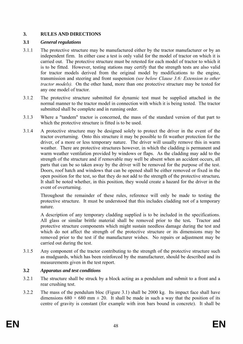
EN 48 EN
3. RULES AND DIRECTIONS
3.1 General regulations 3.1.1 The protective structure may be manufactured either by the tractor manufacturer or by an
independent firm. In either case a test is only valid for the model of tractor on which it is carried out. The protective structure must be retested for each model of tractor to which it is to be fitted. However, testing stations may certify that the strength tests are also valid for tractor models derived from the original model by modifications to the engine, transmission and steering and front suspension (see below Clause 3.6: Extension to other tractor models). On the other hand, more than one protective structure may be tested for any one model of tractor.
3.1.2 The protective structure submitted for dynamic test must be supplied attached in the normal manner to the tractor model in connection with which it is being tested. The tractor submitted shall be complete and in running order.
3.1.3 Where a "tandem" tractor is concerned, the mass of the standard version of that part to which the protective structure is fitted is to be used.
3.1.4 A protective structure may be designed solely to protect the driver in the event of the tractor overturning. Onto this structure it may be possible to fit weather protection for the driver, of a more or less temporary nature. The driver will usually remove this in warm weather. There are protective structures however, in which the cladding is permanent and warm weather ventilation provided by windows or flaps. As the cladding may add to the strength of the structure and if removable may well be absent when an accident occurs, all parts that can be so taken away by the driver will be removed for the purpose of the test. Doors, roof hatch and windows that can be opened shall be either removed or fixed in the open position for the test, so that they do not add to the strength of the protective structure. It shall be noted whether, in this position, they would create a hazard for the driver in the event of overturning.
Throughout the remainder of these rules, reference will only be made to testing the protective structure. It must be understood that this includes cladding not of a temporary nature.
A description of any temporary cladding supplied is to be included in the specifications. All glass or similar brittle material shall be removed prior to the test. Tractor and protective structure components which might sustain needless damage during the test and which do not affect the strength of the protective structure or its dimensions may be removed prior to the test if the manufacturer wishes. No repairs or adjustment may be carried out during the test.
3.1.5 Any component of the tractor contributing to the strength of the protective structure such as mudguards, which has been reinforced by the manufacturer, should be described and its measurements given in the test report.
3.2 Apparatus and test conditions
3.2.1 The structure shall be struck by a block acting as a pendulum and submit to a front and a rear crushing test.
3.2.2 The mass of the pendulum bloc (Figure 3.1) shall be 2000 kg. Its impact face shall have dimensions 680 × 680 mm ± 20. It shall be made in such a way that the position of its centre of gravity is constant (for example with iron bars bound in concrete). It shall be
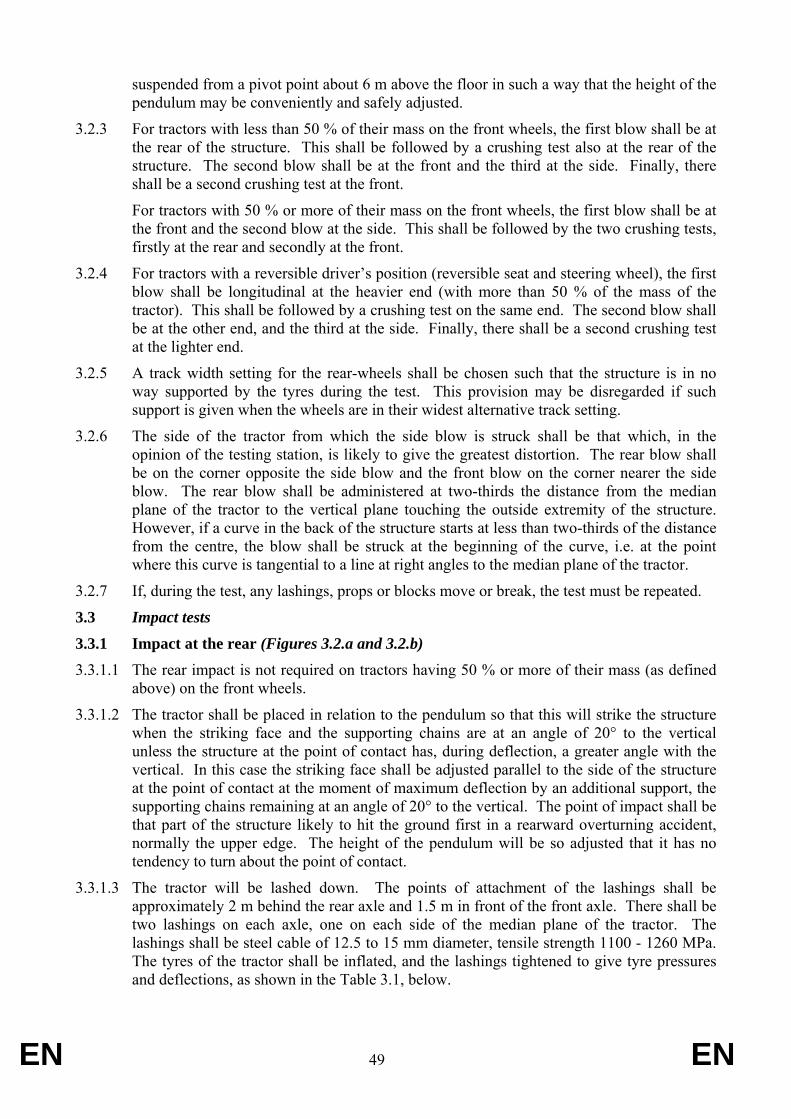
EN 49 EN
suspended from a pivot point about 6 m above the floor in such a way that the height of the pendulum may be conveniently and safely adjusted.
3.2.3 For tractors with less than 50 % of their mass on the front wheels, the first blow shall be at the rear of the structure. This shall be followed by a crushing test also at the rear of the structure. The second blow shall be at the front and the third at the side. Finally, there shall be a second crushing test at the front.
For tractors with 50 % or more of their mass on the front wheels, the first blow shall be at the front and the second blow at the side. This shall be followed by the two crushing tests, firstly at the rear and secondly at the front.
3.2.4 For tractors with a reversible driver’s position (reversible seat and steering wheel), the first blow shall be longitudinal at the heavier end (with more than 50 % of the mass of the tractor). This shall be followed by a crushing test on the same end. The second blow shall be at the other end, and the third at the side. Finally, there shall be a second crushing test at the lighter end.
3.2.5 A track width setting for the rear-wheels shall be chosen such that the structure is in no way supported by the tyres during the test. This provision may be disregarded if such support is given when the wheels are in their widest alternative track setting.
3.2.6 The side of the tractor from which the side blow is struck shall be that which, in the opinion of the testing station, is likely to give the greatest distortion. The rear blow shall be on the corner opposite the side blow and the front blow on the corner nearer the side blow. The rear blow shall be administered at two-thirds the distance from the median plane of the tractor to the vertical plane touching the outside extremity of the structure. However, if a curve in the back of the structure starts at less than two-thirds of the distance from the centre, the blow shall be struck at the beginning of the curve, i.e. at the point where this curve is tangential to a line at right angles to the median plane of the tractor.
3.2.7 If, during the test, any lashings, props or blocks move or break, the test must be repeated.
3.3 Impact tests
3.3.1 Impact at the rear (Figures 3.2.a and 3.2.b) 3.3.1.1 The rear impact is not required on tractors having 50 % or more of their mass (as defined
above) on the front wheels.
3.3.1.2 The tractor shall be placed in relation to the pendulum so that this will strike the structure when the striking face and the supporting chains are at an angle of 20° to the vertical unless the structure at the point of contact has, during deflection, a greater angle with the vertical. In this case the striking face shall be adjusted parallel to the side of the structure at the point of contact at the moment of maximum deflection by an additional support, the supporting chains remaining at an angle of 20° to the vertical. The point of impact shall be that part of the structure likely to hit the ground first in a rearward overturning accident, normally the upper edge. The height of the pendulum will be so adjusted that it has no tendency to turn about the point of contact.
3.3.1.3 The tractor will be lashed down. The points of attachment of the lashings shall be approximately 2 m behind the rear axle and 1.5 m in front of the front axle. There shall be two lashings on each axle, one on each side of the median plane of the tractor. The lashings shall be steel cable of 12.5 to 15 mm diameter, tensile strength 1100 - 1260 MPa. The tyres of the tractor shall be inflated, and the lashings tightened to give tyre pressures and deflections, as shown in the Table 3.1, below.
EN 50 EN
After the lashings have been tightened a wood beam 150 x 150 mm shall be clamped in front of the rear-wheels, driven tight against them.
3.3.1.4 The pendulum shall be pulled back so that the height H of its centre of gravity above that at the point of impact is given by one of the following formulae at the option of the manufacturer:
H = 2.165 x 10⁻⁸ ML2 or H = 5.73 x 10⁻² I 3.3.1.5 The pendulum shall be released and allowed to crash against the structure. The quick
release mechanism must be so positioned that it does not tilt the weight in relation to the chains supporting it at the moment of release.
Tyre pressures
kPa (*)
Deflection
mm
Four-wheel drive tractors with front and rear wheels of the same size:
Front 100 25
Rear 100 25
Four-wheel drive tractors with front wheels smaller than rear wheels:
Front 150 20
Rear 100 25
Two-wheel drive tractors:
Front 200 15
Rear 100 25
(*) No water ballast is to be used
Table 3.1 Tyre Pressures
EN 51 EN
3.3.2 Impact at the front (Figures 3.3.a and 3.3.b) 3.3.2.1 This shall be carried out in the same way as the impact at the rear. The lashings shall be
the same but the wooden beam shall be behind the rear-wheels. The height of fall of the centre of gravity of the pendulum shall be given by the following formula:
H = 125 + 0.02 M 3.3.2.2. The point of impact shall be that part of the structure that would hit the ground first when
turning over sideways while travelling forward, normally the top of the front corner.
3.3.3 Impact at the side (Figure 3.4) 3.3.3.1 The tractor shall be placed in relation to the pendulum so that this will strike the structure
when the striking face and the supporting chains are vertical unless the structure at the point of contact is, during deflection, other than vertical. In this case the striking face shall be adjusted so that it is approximately parallel to the structure at the point of contact at the moment of maximum deflection. This adjustment shall be made by an additional support, the supporting chains remaining vertical at the moment of impact. The point of impact shall be that part of the structure likely to hit the ground first in a sideways overturning accident, normally the upper edge.
3.3.3.2 Unless it is certain that any other part of this edge would hit the ground first, the point of impact shall be in the plane at right angles to the median plane of the tractor and passing 60 mm in front of the Seat Index Point, the seat being at its mid-point of longitudinal adjustment. The height of the pendulum will be so adjusted that it has no tendency to turn about the point of contact.
3.3.3.3 For tractors with a reversible driver’s position, the point of impact shall be in the plane at right angles to the median plane of the tractor and at the mid-point between the two Seat Index Points.
3.3.3.4 The rear-wheel of the tractor on the side to be struck shall be lashed down. The tension in the lashings shall be determined as for the impact at the rear. After lashing, a beam 150 x 150 mm shall be clamped against the side of the rear-wheel opposite the blow, and driven hard against the tyre. A beam shall be placed as a prop against this wheel and secured on the floor so that it is held tight against the wheel during impact. The length of this beam shall be chosen so that when in position against the wheel it makes an angle of 25 to 40° with the horizontal. Furthermore its length shall be 20 to 25 times its thickness and its width 2 to 3 times its thickness.
3.3.3.5 The pendulum shall be pulled back as in the previous tests so that the height H of its centre of gravity above that at the moment of impact is determined by the following formula:
H = 125 + 0.15 M 3.3.3.6 During the side impact test the difference between the maximum momentary deflection
and the residual deflection at a height of (810 + av) mm above the Seat Index Point shall be recorded. This may be done with a device on which a moving friction collar shall be fitted on a horizontal rod. One end of the rod shall be attached to the top member of the structure and the other will pass through a hole in a vertical bar attached to tractor chassis. The collar will be positioned against the vertical bar attached to tractor chassis before the blow and its distance from it after the blow will give the difference between the maximum momentary deflection and the residual deflection.
3.4 Crushing tests
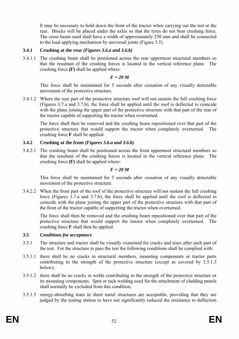
EN 52 EN
It may be necessary to hold down the front of the tractor when carrying out the test at the rear. Blocks will be placed under the axles so that the tyres do not bear crushing force. The cross beam used shall have a width of approximately 250 mm and shall be connected to the load applying mechanism by universal joints (Figure 3.5).
3.4.1 Crushing at the rear (Figures 3.6.a and 3.6.b) 3.4.1.1 The crushing beam shall be positioned across the rear uppermost structural members so
that the resultant of the crushing forces is located in the vertical reference plane. The crushing force (F) shall be applied where:
F = 20 M This force shall be maintained for 5 seconds after cessation of any visually detectable
movement of the protective structure.
3.4.1.2 Where the rear part of the protective structure roof will not sustain the full crushing force (Figures 3.7.a and 3.7.b), the force shall be applied until the roof is deflected to coincide with the plane joining the upper part of the protective structure with that part of the rear of the tractor capable of supporting the tractor when overturned.
The force shall then be removed and the crushing beam repositioned over that part of the protective structure that would support the tractor when completely overturned. The crushing force F shall be applied.
3.4.2 Crushing at the front (Figures 3.6.a and 3.6.b) 3.4.2.1 The crushing beam shall be positioned across the front uppermost structural members so
that the resultant of the crushing forces is located in the vertical reference plane. The crushing force (F) shall be applied where:
F = 20 M This force shall be maintained for 5 seconds after cessation of any visually detectable
movement of the protective structure.
3.4.2.2 When the front part of the roof of the protective structure will not sustain the full crushing force (Figures 3.7.a and 3.7.b), the force shall be applied until the roof is deflected to coincide with the plane joining the upper part of the protective structure with that part of the front of the tractor capable of supporting the tractor when overturned.
The force shall then be removed and the crushing beam repositioned over that part of the protective structure that would support the tractor when completely overturned. The crushing force F shall then be applied.
3.5 Conditions for acceptance 3.5.1 The structure and tractor shall be visually examined for cracks and tears after each part of
the test. For the structure to pass the test the following conditions shall be complied with:
3.5.1.1 there shall be no cracks in structural members, mounting components or tractor parts contributing to the strength of the protective structure (except as covered by 3.5.1.3 below);
3.5.1.2 there shall be no cracks in welds contributing to the strength of the protective structure or its mounting components. Spot or tack welding used for the attachment of cladding panels shall normally be excluded from this condition;
3.5.1.3 energy-absorbing tears in sheet metal structures are acceptable, providing that they are judged by the testing station to have not significantly reduced the resistance to deflection
EN 53 EN
of the protective structure. Tears in sheet metal components caused by edges of the pendulum weight shall be ignored;
3.5.1.4 the required force must be sustained in both crushing tests;
3.5.1.5 the difference between the maximum momentary deflection and the residual deflection in the side impact test must not exceed 250 mm (Figure 3.11);
3.5.1.6 no part shall enter the clearance zone during any part of the tests. No part may strike the seat during the tests. Furthermore, the clearance zone shall not be outside the protection of the protective structure. For this purpose, it shall be considered to be outside the protection of the structure if any part of it would come in contact with flat ground if the tractor overturned towards the direction from which the test load is applied. For estimating this, the tyres and track width setting shall be the smallest standard fitting specified by the manufacturer.
3.5.1.7 for the articulated tractors, the median planes of the two parts shall be assumed to be in line.
3.5.2 After the final crushing test, the permanent deformation of the protective structure shall be recorded. For this purpose, before the start of the test, the position of the main members in relation to the Seat Index Point must be recorded. Then any movement of the members struck in the tests and any change of the height of the front and back members of the roof shall be recorded.
3.6 Extension of the structural test results to other tractor models 3.6.1 The holder of EC component type-approval may request its extension to other tractor
types. The competent authority which has granted the original EC component type-approval shall grant the extension if the approved roll-over protective structure and the type(s) of tractor for which the extension is requested comply with the conditions referred to hereunder 3.6.1.1 to 3.6.1.5:
EN 54 EN
3.6.1.1 The structure shall be identical to the one tested;
3.6.1.2 The required energy shall not exceed the energy calculated for the original test by more than 5 %. The 5 % limit shall also apply to extensions in the case of substituting tracks for wheels on the same tractor;
3.6.1.3 The method of attachment and the tractor components to which the attachment is made shall be identical;
3.6.1.4 Any components such as mudguards and bonnet that may provide support for the protective structure shall be identical;
3.6.1.5 The position and critical dimensions of the seat in the protective structure and the relative position of the protective structure on the tractor shall be such that the clearance zone would have remained within the protection of the deflected structure throughout all tests (this shall be checked by using the same reference of clearance zone as in the original test report.
3.7 [Not applicable]
3.8 Cold weather performance of protective structures 3.8.1 If the protective structure is claimed to have properties resistant to cold weather
embrittlement, the manufacturer shall give details that shall be included in the report.
3.8.2 The following requirements and procedures are intended to provide strength and resistance to brittle fracture at reduced temperatures. It is suggested that the following minimum material requirements shall be met in judging the protective structure's suitability at reduced operating temperatures in those countries requiring this additional operating protection.
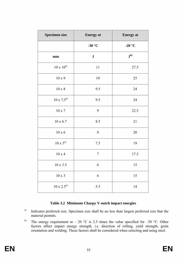
EN 55 EN
Specimen size Energy at Energy at
-30 °C -20 °C
mm J Jb)
10 x 10a) 11 27.5
10 x 9 10 25
10 x 8 9.5 24
10 x 7,5a) 9.5 24
10 x 7 9 22.5
10 x 6.7 8.5 21
10 x 6 8 20
10 x 5a) 7.5 19
10 x 4 7 17.5
10 x 3.5 6 15
10 x 3 6 15
10 x 2.5a) 5.5 14
Table 3.2 Minimum Charpy V-notch impact energies
a) Indicates preferred size. Specimen size shall be no less than largest preferred size that the material permits.
b) The energy requirement at – 20 °C is 2.5 times the value specified for –30 °C. Other factors affect impact energy strength, i.e. direction of rolling, yield strength, grain orientation and welding. These factors shall be considered when selecting and using steel.
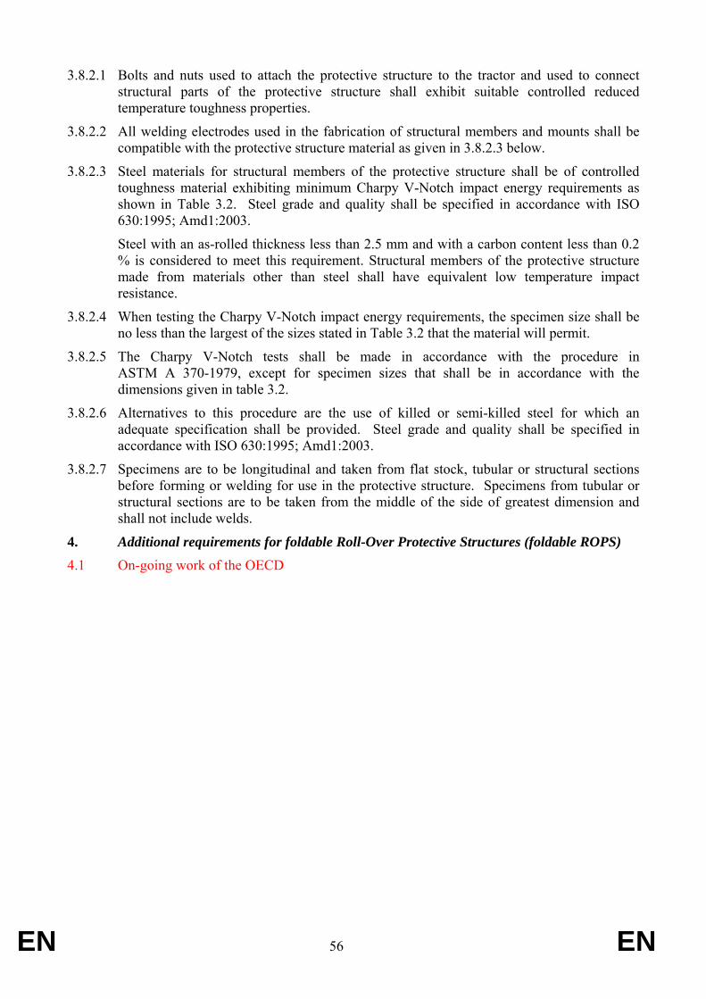
EN 56 EN
3.8.2.1 Bolts and nuts used to attach the protective structure to the tractor and used to connect structural parts of the protective structure shall exhibit suitable controlled reduced temperature toughness properties.
3.8.2.2 All welding electrodes used in the fabrication of structural members and mounts shall be compatible with the protective structure material as given in 3.8.2.3 below.
3.8.2.3 Steel materials for structural members of the protective structure shall be of controlled toughness material exhibiting minimum Charpy V-Notch impact energy requirements as shown in Table 3.2. Steel grade and quality shall be specified in accordance with ISO 630:1995; Amd1:2003.
Steel with an as-rolled thickness less than 2.5 mm and with a carbon content less than 0.2 % is considered to meet this requirement. Structural members of the protective structure made from materials other than steel shall have equivalent low temperature impact resistance.
3.8.2.4 When testing the Charpy V-Notch impact energy requirements, the specimen size shall be no less than the largest of the sizes stated in Table 3.2 that the material will permit.
3.8.2.5 The Charpy V-Notch tests shall be made in accordance with the procedure in ASTM A 370-1979, except for specimen sizes that shall be in accordance with the dimensions given in table 3.2.
3.8.2.6 Alternatives to this procedure are the use of killed or semi-killed steel for which an adequate specification shall be provided. Steel grade and quality shall be specified in accordance with ISO 630:1995; Amd1:2003.
3.8.2.7 Specimens are to be longitudinal and taken from flat stock, tubular or structural sections before forming or welding for use in the protective structure. Specimens from tubular or structural sections are to be taken from the middle of the side of greatest dimension and shall not include welds.
4. Additional requirements for foldable Roll-Over Protective Structures (foldable ROPS) 4.1 On-going work of the OECD
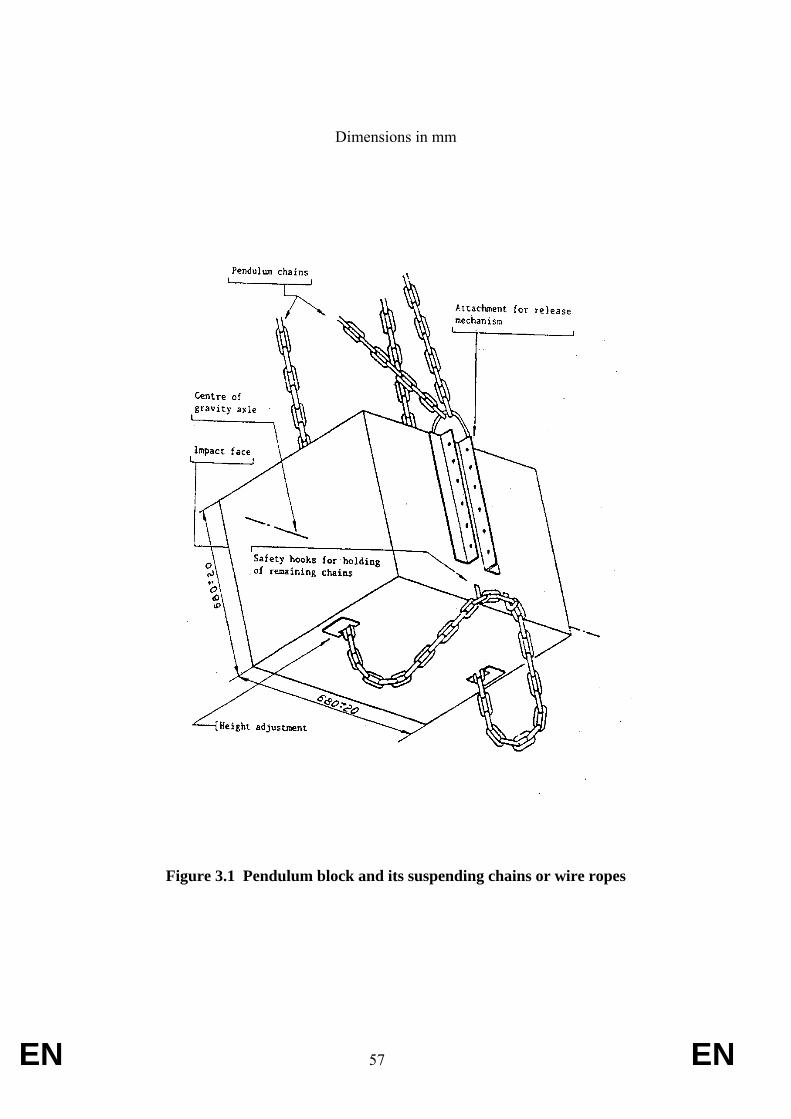
EN 57 EN
Dimensions in mm
Figure 3.1 Pendulum block and its suspending chains or wire ropes
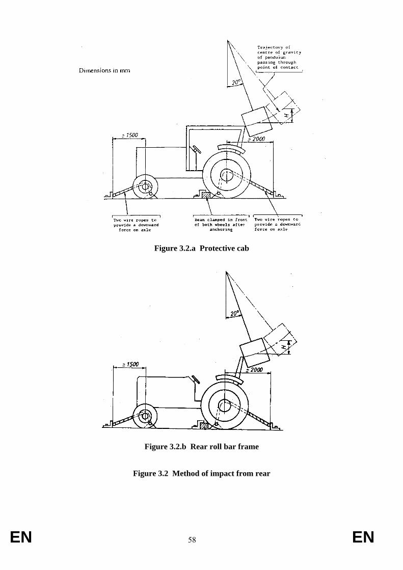
EN 58 EN
Figure 3.2.a Protective cab
Figure 3.2.b Rear roll bar frame
Figure 3.2 Method of impact from rear
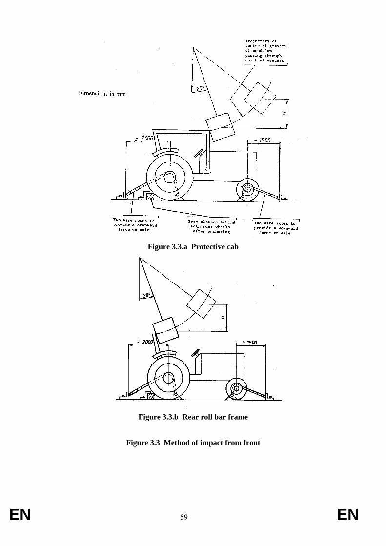
EN 59 EN
Figure 3.3.a Protective cab
Figure 3.3.b Rear roll bar frame
Figure 3.3 Method of impact from front
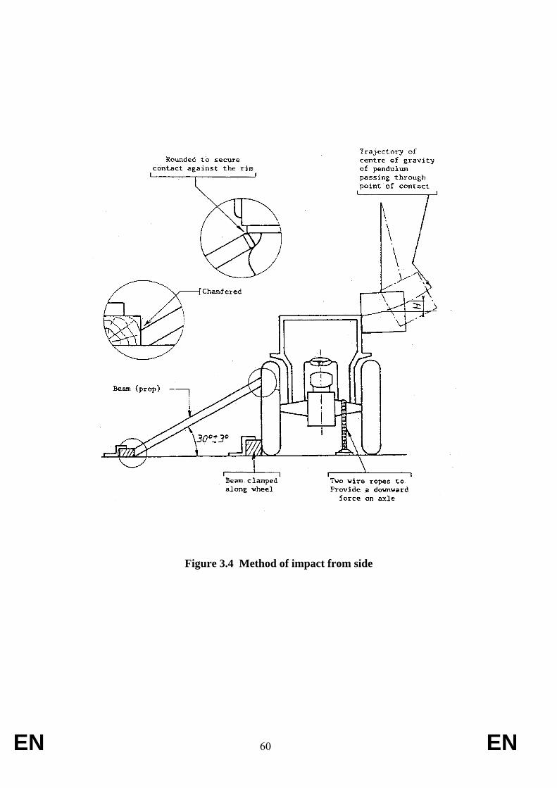
EN 60 EN
Figure 3.4 Method of impact from side
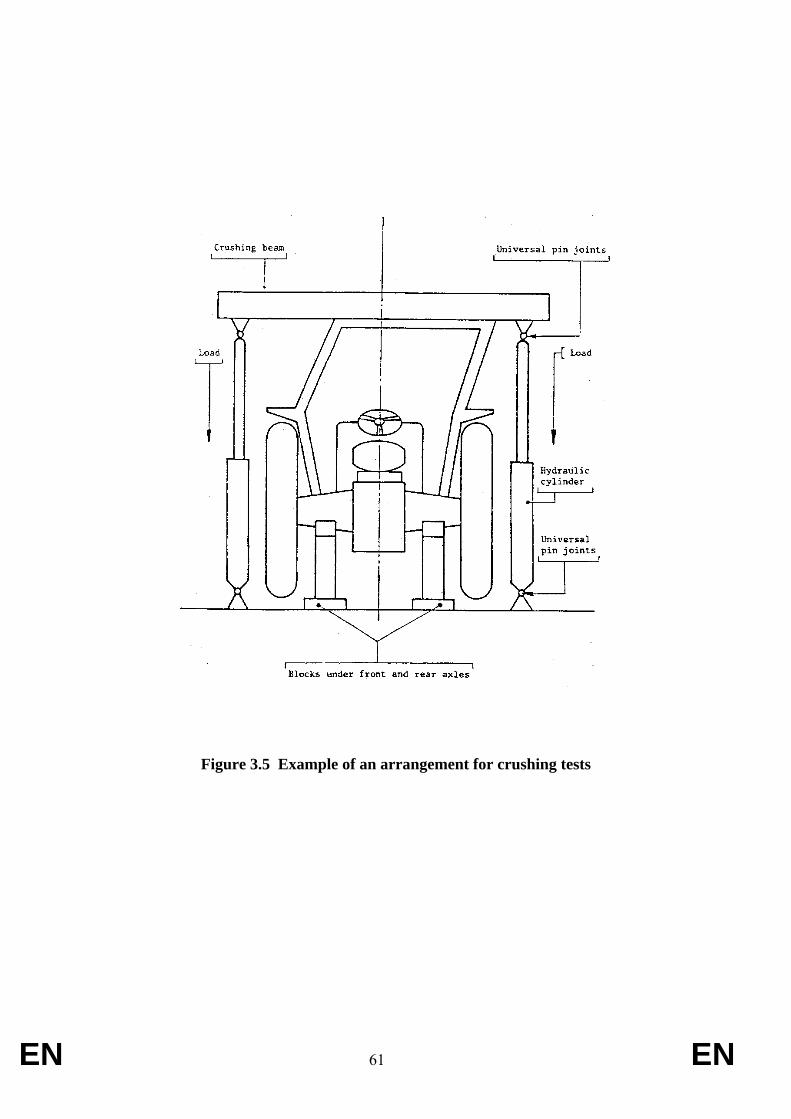
EN 61 EN
Figure 3.5 Example of an arrangement for crushing tests
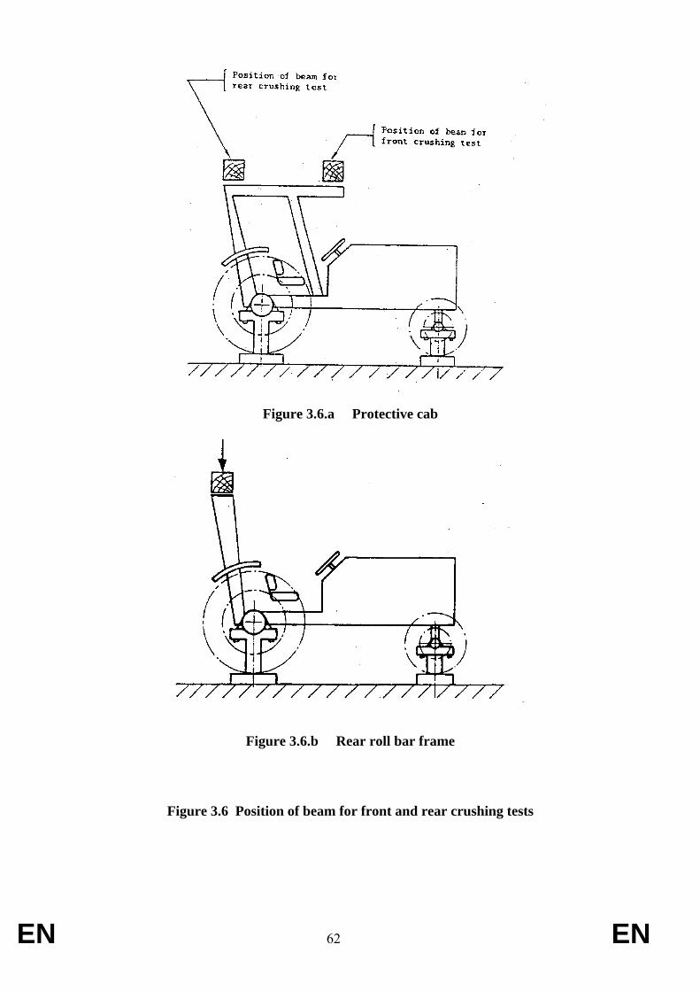
EN 62 EN
Figure 3.6.a Protective cab
Figure 3.6.b Rear roll bar frame
Figure 3.6 Position of beam for front and rear crushing tests
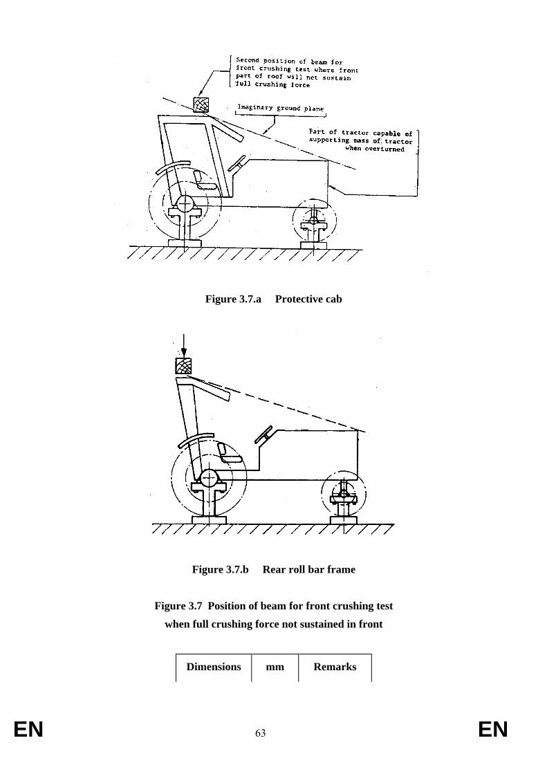
EN 63 EN
Figure 3.7.a Protective cab
Figure 3.7.b Rear roll bar frame
Figure 3.7 Position of beam for front crushing test
when full crushing force not sustained in front
Dimensions mm Remarks
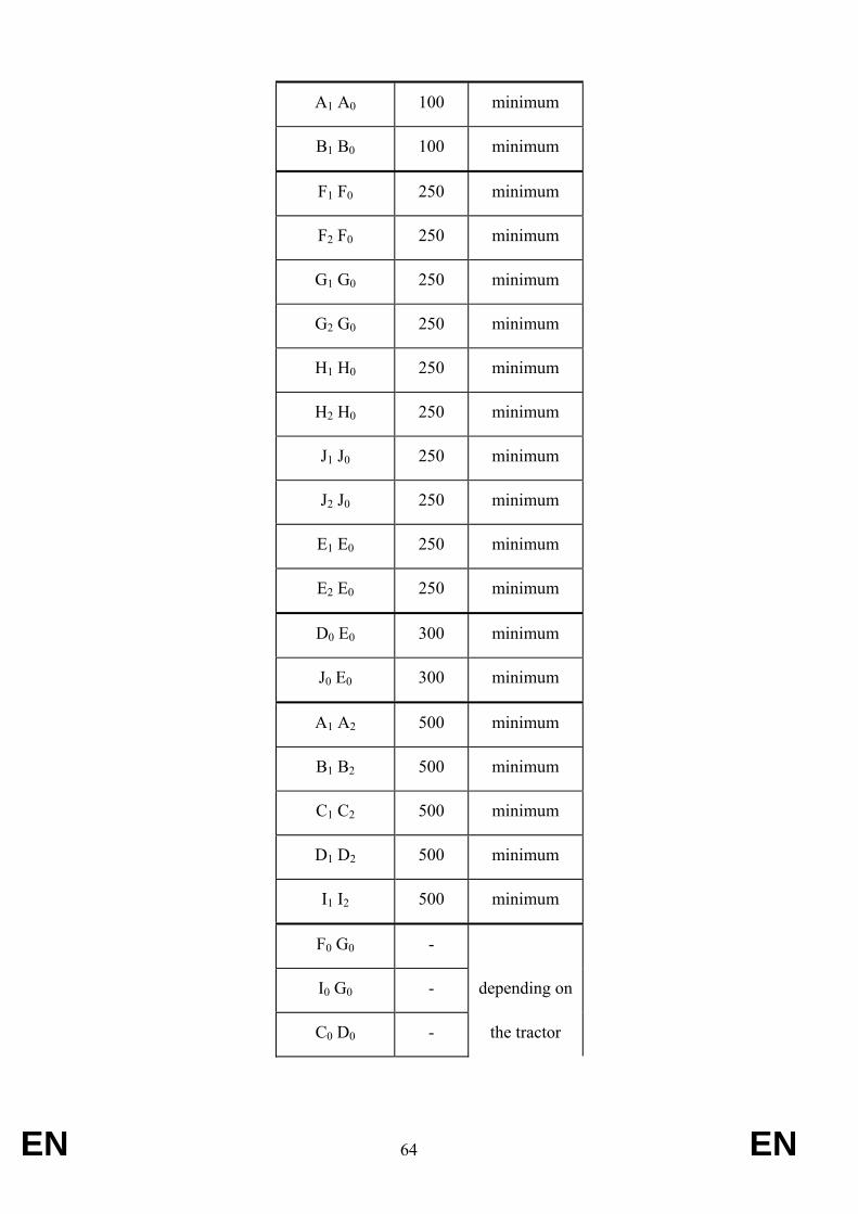
EN 64 EN
A1 A0 100 minimum
B1 B0 100 minimum
F1 F0 250 minimum
F2 F0 250 minimum
G1 G0 250 minimum
G2 G0 250 minimum
H1 H0 250 minimum
H2 H0 250 minimum
J1 J0 250 minimum
J2 J0 250 minimum
E1 E0 250 minimum
E2 E0 250 minimum
D0 E0 300 minimum
J0 E0 300 minimum
A1 A2 500 minimum
B1 B2 500 minimum
C1 C2 500 minimum
D1 D2 500 minimum
I1 I2 500 minimum
F0 G0 -
I0 G0 - depending on
C0 D0 - the tractor

EN 65 EN
E0 F0 -
Table 3.3 Dimensions of the clearance zone
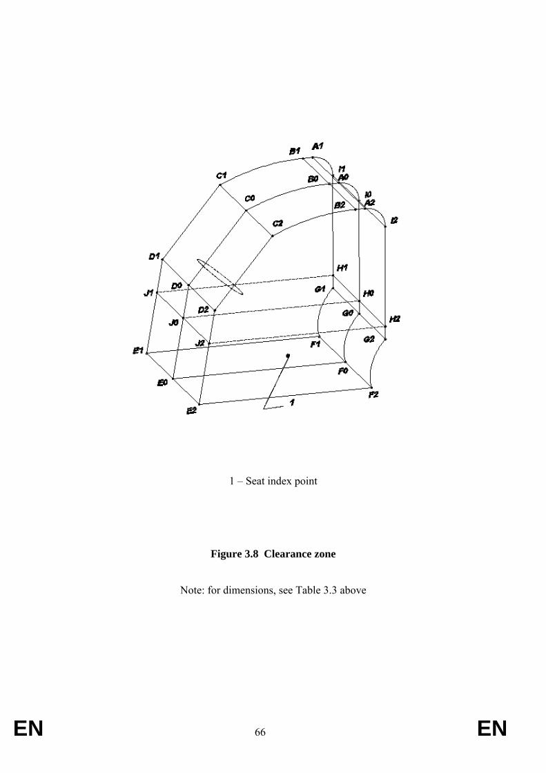
EN 66 EN
1 – Seat index point
Figure 3.8 Clearance zone
Note: for dimensions, see Table 3.3 above
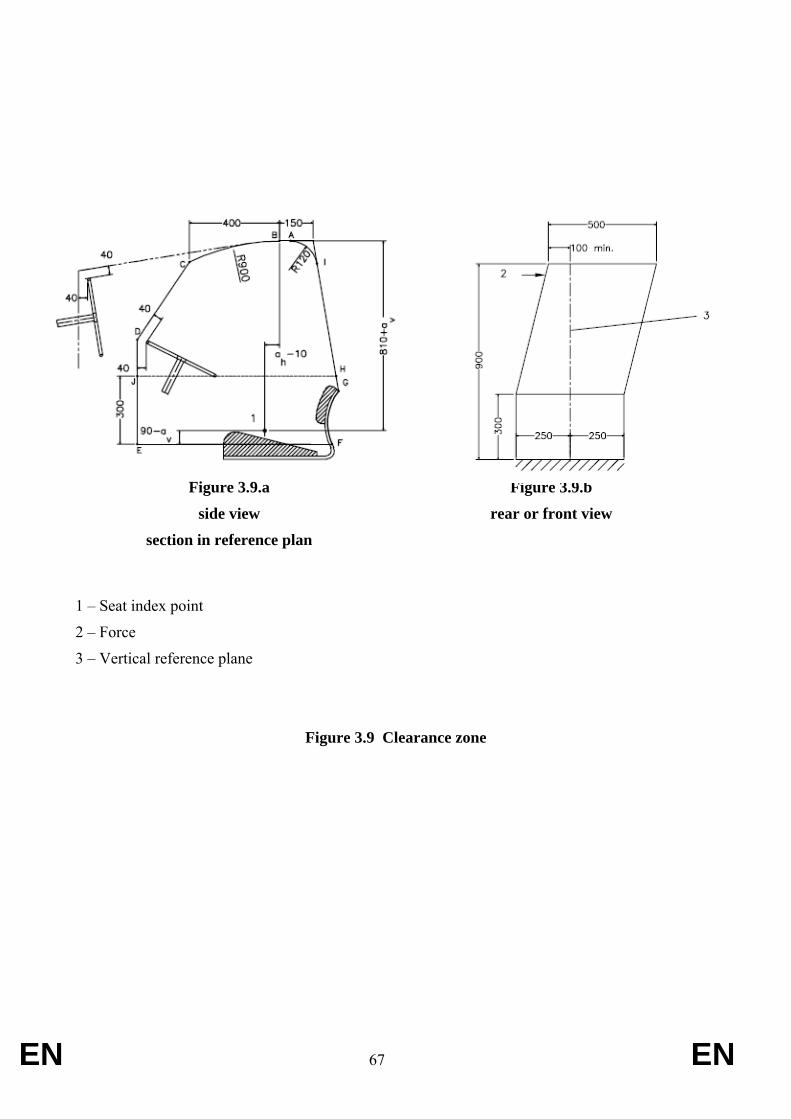
EN 67 EN
Figure 3.9.a
side view
section in reference plan
Figure 3.9.b
rear or front view
1 – Seat index point
2 – Force
3 – Vertical reference plane
Figure 3.9 Clearance zone
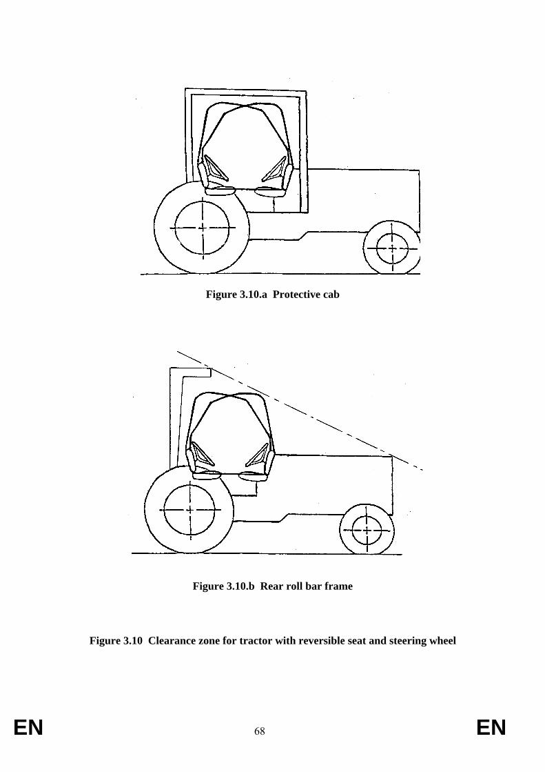
EN 68 EN
Figure 3.10.a Protective cab
Figure 3.10.b Rear roll bar frame
Figure 3.10 Clearance zone for tractor with reversible seat and steering wheel
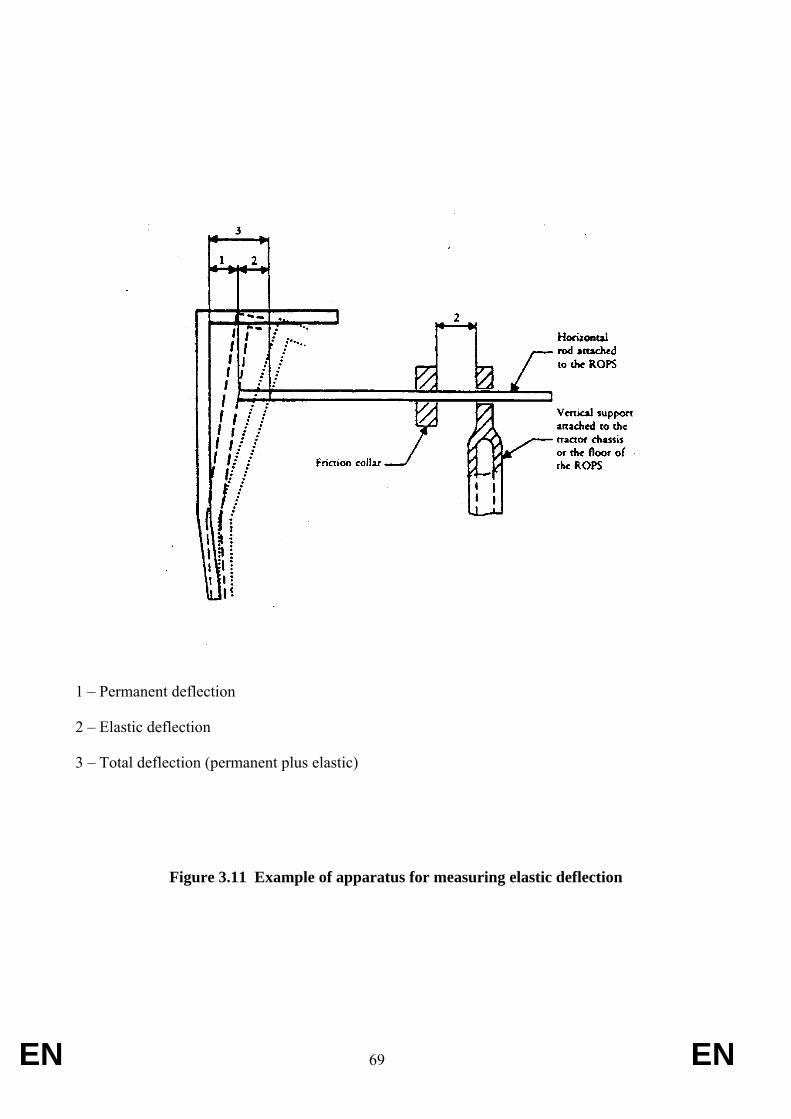
EN 69 EN
1 – Permanent deflection
2 – Elastic deflection
3 – Total deflection (permanent plus elastic)
Figure 3.11 Example of apparatus for measuring elastic deflection
EN 70 EN
Appendix 1
Method of determining the seat index point
1.1. General
The method and device used in defining the index point for any type of upholstered seat are described below.
1.2. Definitions
Seat index point (SIP):
Point situated in the vertical median longitudinal plane of the SIP locating device represented in Figure 1 whichis placed on the driving seat in accordance with points 1.4 and 1.6.
The seat index point is established in relation to the vehicle and does not move as a function of the seat adjustments and/or oscillations.
1.3. Device for determining the seat index point (SIP)
The device for determining the SIP must be as shown in Figure 1. The mass of that device is 6 ± 1 kg and its underside must be flat and polished.
1.4. Seat setting for determination of index point (SIP)
Where a seat and its suspension can be regulated, the seat is regulated as follows before the index point is determined:
(a) all of the adjustments - back/forth, height and rake - must be in their mid-position. If this is not the case, the closest adjustment either above or below the mid-position should be used;
(b) adjustable suspension must be adjusted in such a way that the suspension is at mid-travel with the locating device in position and loaded. The suspension may be locked mechanically in that position while the index point (SIP) is determined;
(c) non-adjustable suspension may be locked in the vertical position that is achieved with the locating device in place and loaded;
(d) if the adjustments mentioned above conflict with the manufacturer's specific instructions, these must be followed in such a way as to obtain the setting recommended for a 75 kg driver.
NB: A 75 kg driver offers an approximation of the locating device in position on the seat and loaded with a mass of 65 kg.
1.5. Determination of the three reference axes x′, y′, and z′ for the SIP
The coordinates must be established as follows:
(a) location, on one side of the seat mounting, of the attachment hole that is in the most rear position;
(b) if the axis of this hole is parallel to the pivot axis defined on the device, it is taken as axis y′ (pointing from left to right in relation to a seated driver — see Figure 2);
(c) if the axis of this hole is parallel to the vertical plane passing through the centre line of the seat, the straight line is taken as axis y′ which runs parallel to the pivot axis referred to and passes through the point of intersection between the supporting plane of the seat and the hole axis referred to above (see Figure 3);
EN 71 EN
(d) in all other cases, axis y′ is established in accordance with the parameters relating to the seat being measured;
(e) axes x′ and z′ are defined as intersections of the horizontal and vertical planes passing through y′ with the vertical plane through the seat centre line. Axes x′ and z′ point forwards and upwards (see Figures 2 and 3).
1.6. Method of determining the seat index point (SIP)
The seat index point (SIP) is determined by using the device shown in Figure 1 and by proceeding in the following manner:
(a) the seat is covered with a piece of cloth in order to facilitate correct positioning of the device;
(b) the device is positioned on the seat cushion (without additional mass) by pushing it rearwards against the backrest;
(c) masses are added to bring the total mass of the device from 6 ± 1 kg to 26 ± 1 kg. The centre of vertical force must be 40 mm ahead of the seat index point mark on the horizontal part of the device (see Figure 1);
(d) a horizontal force of about 100 N is applied twice to the device on the seat index point, as set out in Figure 1;
(e) other masses are added to bring the total mass of the device from 26 ± 1 kg to 65 ± 1 kg. The centre of the vertical force of the masses added must be 40 mm ahead of the seat index point mark on the horizontal part of the device (see Figure 1);
(f) on both sides of the seat in two vertical planes, equidistant from the median longitudinal line of the seat, the coordinates, as defined in point 1.5, of the intersections of those planes on the axis of the seat index point marked by the device must be measured to ±1 mm.
The arithmetical mean values of the measurements taken in the two planes are recorded as SIP coordinates;
(g) the conditions resulting from the method of determination, and which diverge from the procedure set out in this Appendix, or which may be the source of errors as regards their results, may be noted, as may their causes.
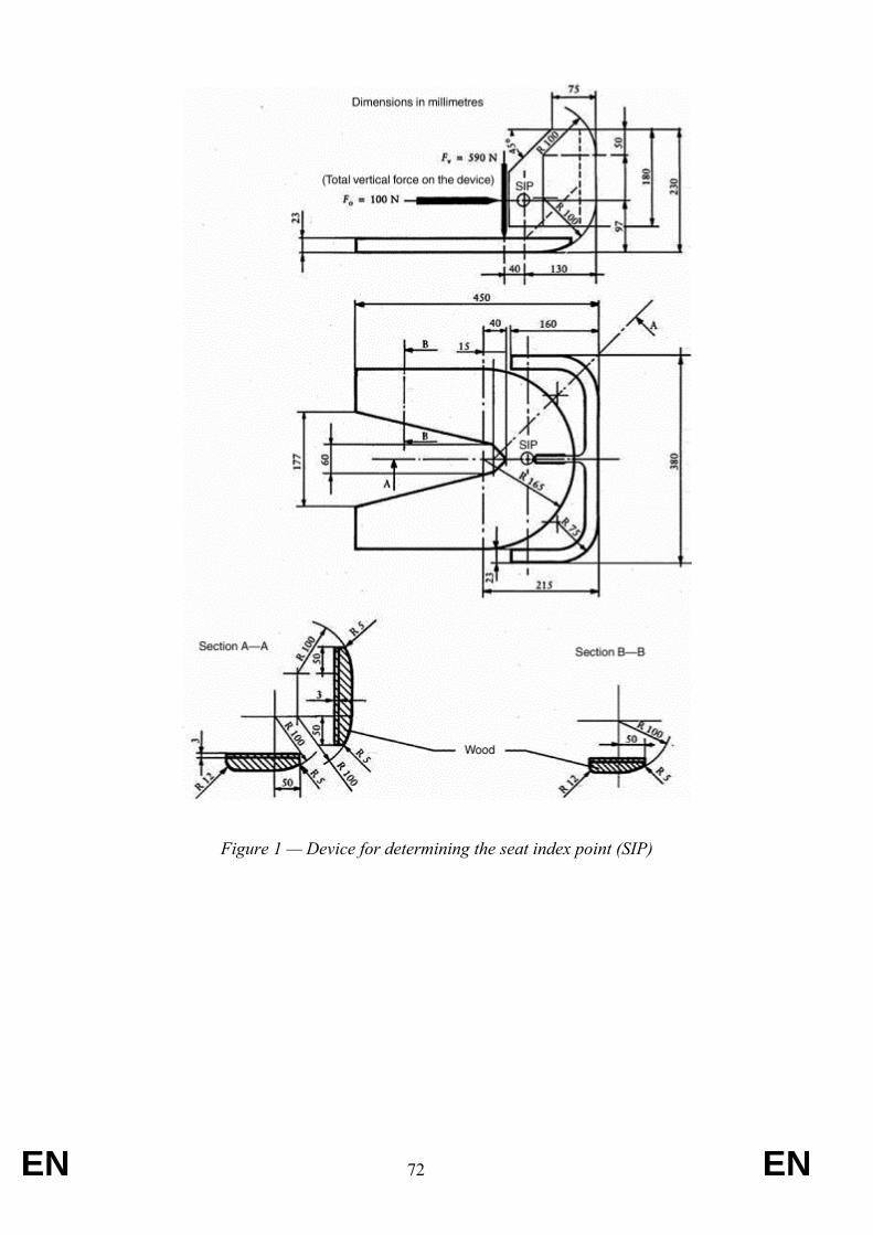
EN 72 EN
Figure 1 — Device for determining the seat index point (SIP)
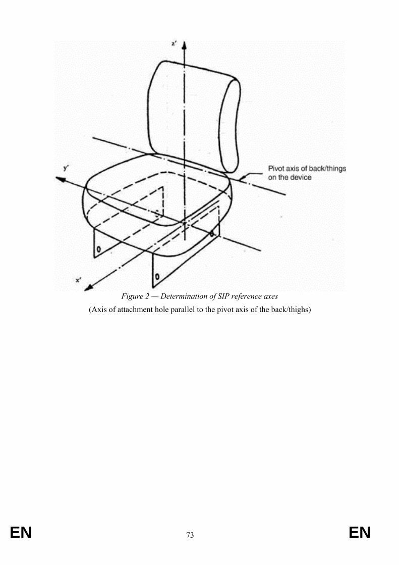
EN 73 EN
Figure 2 — Determination of SIP reference axes
(Axis of attachment hole parallel to the pivot axis of the back/thighs)
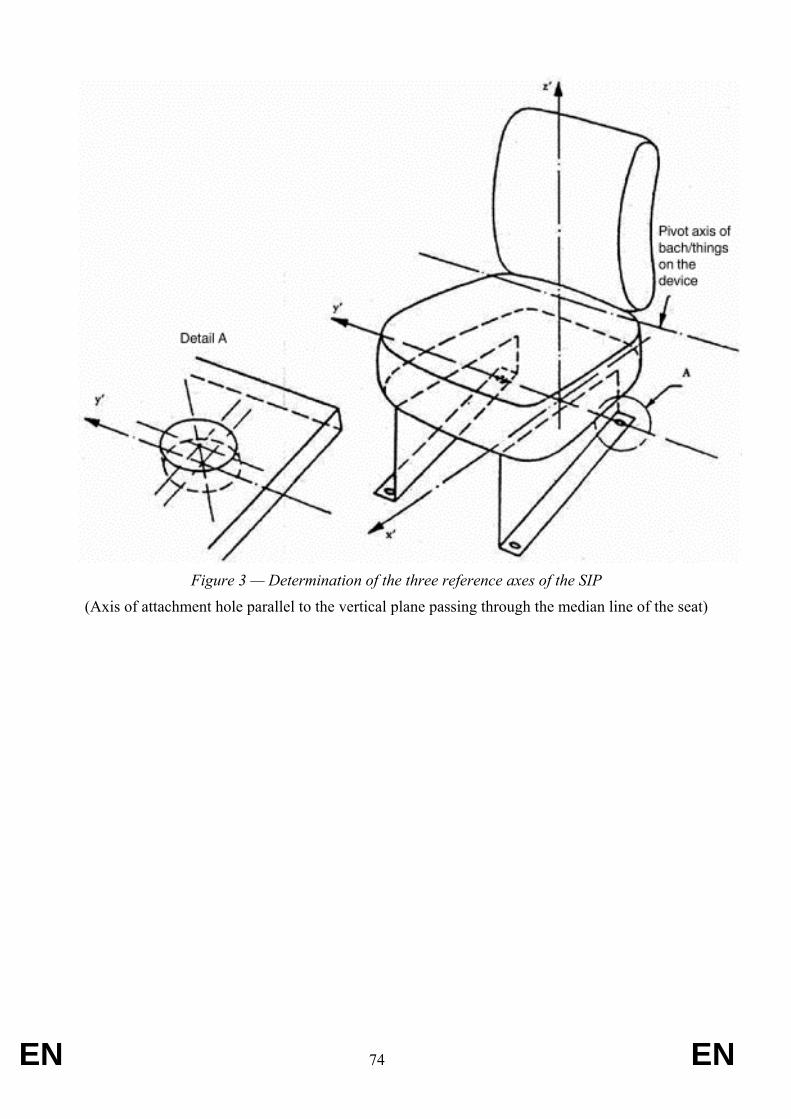
EN 74 EN
Figure 3 — Determination of the three reference axes of the SIP
(Axis of attachment hole parallel to the vertical plane passing through the median line of the seat)
EN 75 EN
ANNEX VII Requirements applying to roll over protection structures within the application field of OECD
Code 8 (track-laid tractors), as amended
1. Scope
1.1. The following test requirements are applicable to roll-over protective structures fitted to agricultural and forestry track-laid tractors (C category) having the following characteristics:
- at least two axles with track attachments
an unballasted tractor mass not less than 600 kg;
- the ground clearance not more than 600 mm beneath the lowest point of the front and rear axles.
1. Requirements
1.1. C1, C2, C4.2 and C4.3 agricultural and forestry track-laid tractors which have been tested and granted a test report on the basis of the OECD Code nº 8 in accordance with Appendix 1 to the Decision of the OECD Council of February 2012 revising the OECD standard Codes for the official testing of agricultural and forestry tractors, as amended, shall be deemed to be complying with this Annex.
EN 76 EN
ANNEX VIII Requirements applying to roll over protection structures within the application field of OECD
Code 4 (static testing), as amended
1. Scope
The following test requirements are applicable to T1/C1, T4.2/C4.2 and T4.3/C4.3 agricultural and forestry tractors having the following characteristics:
- at least two axles for pneumatic tyred wheels or having tracks instead of wheels
- an unballasted tractor mass not less than 600 kg.
- the Mass Ratio (Maximum Permissible Mass / Reference Mass) must not be greater than 1.75.
- the minimum track width of the rear-wheels should generally be greater than 1 150 mm.
1. DEFINITIONS
1.1 [Not applicable]
1.2 Roll-Over Protective Structure (ROPS) Roll-over protective structure (safety cab or frame), hereinafter called “protective structure”, means the structure on a tractor the essential purpose of which is to avoid or limit risks to the driver resulting from roll-over of the tractor during normal use.
The roll-over protective structure is characterized by the provision of space for a clearance zone large enough to protect the driver when seated either inside the envelope of the structure or within a space bounded by a series of straight lines from the outer edges of the structure to any part of the tractor that might come into contact with flat ground and that is capable of supporting the tractor in that position if the tractor overturns.
1.3 Track
1.3.1 Preliminary definition: median plane of the wheel or track
The median plane of the wheel or track is equidistant from the two planes containing the periphery of the rims or tracks at their outer edges.
1.3.2 Definition of track
The vertical plane through the wheel axis intersects its median plane along a straight line which meets the supporting surface at one point. If A and B are the two points thus defined for the wheels on the same axle of the tractor, then the track width is the distance between points A and B. The track may be thus defined for both front and rear wheels. Where there are twin wheels, the track is the distance between two planes each being the median plane of the pairs of wheels.
For tracklaying tractors, the track is the distance between the median planes of the tracks.
EN 77 EN
1.3.3 Additional definition: median plane of the tractor
Take the extreme positions of points A and B for the tractor rear axle, which gives the maximum possible value for the track. The vertical plane at right angles to the line AB at its centre point is the median plane of the tractor.
1.4 Wheelbase
The distance between the vertical planes passing through the two lines AB as defined above, one for the front wheels and one for the rear-wheels.
1.5 Seat location and adjustment for test
1.5.1 where the seat position is adjustable, the seat must be adjusted to its rear uppermost position;
1.5.2 where the inclination of the backrest is adjustable, it must be adjusted to the mid position;
1.5.3 where the seat is equipped with suspension, the latter must be blocked at mid-travel, unless this is contrary to the instructions clearly laid down by the seat manufacturer;
1.5.4 where the position of the seat is adjustable only lengthwise and vertically, the longitudinal axis passing through the Seat Index Point shall be parallel with the vertical longitudinal plane of the tractor passing through the centre of the steering wheel and not more than 100 mm from that plane.
1.6 Clearance zone
1.6.1 Reference plane
The clearance zone is illustrated in Appendix 1, figures 4.9 to 4.11 and Table 4.2. The zone is defined in relation to the reference plane and the Seat Index Point. The reference plane is defined at the beginning of the series of tests; it is a vertical plane, generally longitudinal to the tractor and passing through the Seat Index Point and the centre of the steering wheel. Normally the reference plane coincides with the longitudinal median plane of the tractor. This reference plane shall be assumed to move horizontally with the seat and steering wheel during loading but to remain perpendicular to the tractor or the floor of the roll-over protective structure. The clearance zone shall be defined on the basis of Sections 1.6.2 and 1.6.3 below.
1.6.2 Determination of the clearance zone for tractors with a non-reversible seat
The clearance zone for tractors with a non-reversible seat is defined in 1.6.2.1 to 1.6.2.10 below and is bounded by the following planes, the tractor being on a horizontal surface, the seat adjusted and located as specified in Sections 1.5.2.1 to 1.5.2.42, and the steering wheel, where adjustable, adjusted to the mid position for seated driving:
1.6.2.1 a horizontal plane A1 B1 B2 A2, (810 + av) mm above the Seat Index Point with line B1B2 located (ah - 10) mm behind the SIP;
1.6.2.2 an inclined plane G1 G2 I2 I1, perpendicular to the reference plane, including both a point 150 mm behind line B1B2 and the rearmost point of the seat backrest;
2 Users are reminded that the Seat Index Point is determined according to ISO 5353 and is a fixed point with respect to
the tractor that does not move as the seat is adjusted away from the midposition.
EN 78 EN
1.6.2.3 a cylindrical surface A1 A2 I2 I1 perpendicular to the reference plane, having a radius of 120 mm, tangential to the planes defined in 1.6.2.1 and 1.6.2.2 above;
1.6.2.4 a cylindrical surface B1 C1 C2 B2, perpendicular to the reference plane, having a radius of 900 mm extending forward for 400 mm and tangential to the plane defined in 1.6.2.1 above along line B1B2;
1.6.2.5 an inclined plane C1 D1 D2 C2, perpendicular to the reference plane, joining the surface defined in 1.6.2.4 above and passing 40 mm from the forward external edge of the steering wheel. In the case of a high steering wheel position, this plane extends forward from line B1B2 tangentially to the surface defined in 1.6.2.4 above;
1.6.2.6 a vertical plane D1 E1 E2 D2 perpendicular to the reference plane 40 mm forward of the external edge of the steering wheel;
1.6.2.7 a horizontal plane E1 F1 F2 E2 passing through a point (90 - av) mm below the Seat Index Point;
1.6.2.8 a surface G1 F1 F2 G2, if necessary curved from the bottom limit of the plane defined in 1.6.2.2 above to the horizontal plane defined in 1.6.2.7 above, perpendicular to the reference plane, and in contact with the seat backrest throughout its length;
1.6.2.9 vertical planes J1 E1 F1 G1 H1 and J2 E2 F2 G2 H2. These vertical planes shall extend upwards from plane E1 F1 F2 E2 for 300 mm; the distances E1 E0 and E2 E0 shall be 250 mm;
1.6.2.10 parallel planes A1 B1 C1 D1 J1 H1 I1 and A2 B2 C2 D2 J2 H2 I2 inclined so that the plane upper edge of the plane on the side on which the force is applied is at least 100 mm from the vertical reference plane.
1.6.3 Determination of clearance zone for tractors with a reversible driver’s position
For tractors with a reversible driver’s position (reversible seat and steering wheel), the clearance zone is the envelope of the two clearance zones defined by the two different positions of the steering wheel and the seat.
1.6.4 Optional seats
1.6.4.1 In case of tractors that could be fitted with optional seats, the envelope comprising the Seat Index Points of all options offered shall be used during the tests. The protective structure shall not enter the larger clearance zone which takes account of these different Seat Index Points.
1.6.4.2 In the case where a new seat option is offered after the test has been performed, a determination shall be made to see whether the clearance zone around the new SIP falls within the envelope previously established. If it does not, a new test must be performed.
1.7 Mass
1.7.1 Unballasted Mass
The mass of the tractor without ballasting devices and, in the case of tractors with pneumatic tyres, without liquid ballast in the tyres. The tractor shall be in running order
EN 79 EN
with tanks, circuits and radiator full, protective structure with cladding and any track equipment or additional front wheel drive components required for normal use. The operator is not included.
1.7.2 Maximum Permissible Mass
The maximum mass of the tractor stated by the manufacturer to be technically permissible and declared on the vehicle’s identification plate and/or in the Operator’s Handbook;
1.7.3 Reference Mass
The mass selected by the manufacturer for calculation of the energy inputs and crushing forces to be used in the tests. Must not be less than the unballasted mass and must be sufficient to ensure the Mass Ratio does not exceed 1.75 (see Section 1.7.4).
1.7.4 Mass Ratio The ratio of ….. This must not be greater than 1.75.
1.8 Permissible measurement tolerances
Time ± 0.2 s Distance ± 0.5 % Force ± 1.0 % Mass ± 0.5 %
1.9 Symbols
ah (mm) Half of the horizontal seat adjustment av (mm) Half of the vertical seat adjustment D (mm) Deflection of the protective structure at the point of and in line with
the load application D' (mm) Deflection of the protective structure for the calculated energy
required EIS (J) Energy input to be absorbed during side loading EIL1 (J) Energy input to be absorbed during longitudinal loading EIL2 (J) Energy input to be absorbed in case of a second longitudinal loading F (N) Static load force Fmax (N) Maximum static load force occurring during loading, with the
exception of the overload F' (N) Force for the calculated energy required M (kg) Reference mass used for calculating energy inputs and crushing forces
3. RULES AND DIRECTIONS
3.1 General regulations
3.1.1 The protective structure may be manufactured either by the tractor manufacturer or by an independent firm. In either case a test is only valid for the model of tractor on which it is carried out. The protective structure must be retested for each model of tractor to which it is to be fitted. However, testing stations may certify that the strength tests are also valid
⎟⎟⎠
⎞⎜⎜⎝
⎛Mass Reference
MassePermissiblMax.
EN 80 EN
for tractor models derived from the original model by modifications to the engine, transmission and steering and front suspension. On the other hand, more than one protective structure may be tested for any one model of tractor.
3.1.2 The protective structure submitted for static test must be supplied attached in the normal manner to the tractor or tractor chassis on which it is used. The tractor chassis shall be complete including attaching brackets and other parts of the tractor that may be affected by loads imposed on the protective structure.
3.1.3 Where a "tandem" tractor is concerned, the mass of the standard version of that part to which the protective structure is fitted is to be used.
3.1.4 A protective structure may be designed solely to protect the driver in the event of the tractor overturning. Onto this structure it may be possible to fit weather protection for the driver, of a more or less temporary nature. The driver will usually remove this in warm weather. There are protective structures however, in which the cladding is permanent and warm weather ventilation provided by windows or flaps. As the cladding may add to the strength of the structure and if removable may well be absent when an accident occurs, all parts that can be so taken away by the driver will be removed for the purpose of the test. Doors, roof hatch and windows that can be opened shall be either removed or fixed in the open position for the test, so that they do not add to the strength of the protective structure. It shall be noted whether, in this position, they would create a hazard for the driver in the event of overturning.
Throughout the remainder of these rules, reference will only be made to testing the protective structure. It must be understood that this includes cladding not of a temporary nature.
A description of any temporary cladding supplied is to be included in the specifications. All glass or similar brittle material shall be removed prior to the test. Tractor and protective structure components which might sustain needless damage during the test and which do not affect the strength of the protective structure or its dimensions may be removed prior to the test if the manufacturer wishes. No repairs or adjustment may be carried out during the test.
3.1.5 Any component of the tractor contributing to the strength of the protective structure such as mudguards, which has been reinforced by the manufacturer, should be described and its measurements given in the test report.
3.2 Apparatus
For verifying that the clearance zone has not been entered during the test, means shall be used as described in point 1.6, Appendix 1, figures 4.9 to 4.11 and Table 4.2.
3.2.1 Horizontal loading tests (Appendix 1, figures 4.1 to 4.5)
The following shall be used in horizontal loading tests:
3.2.1.1 material, equipment and means of attachment to ensure that the tractor chassis is firmly fixed to the ground and supported independently of the tyres;
3.2.1.2 device for applying a horizontal force to the protective structure; provision shall be made so that the load can be uniformly distributed normal to the direction of loading :
EN 81 EN
3.2.1.2.1 a beam of length not less than 250 mm nor more than 700 mm in exact multiples of 50 mm between these lengths shall be used. The beam shall have a vertical dimension of 150 mm;
3.2.1.2.2 the edges of the beam in contact with the protective structure shall be curved with a maximum radius of 50 mm;
3.2.1.2.3 universal joints or the equivalent shall be incorporated to ensure that the loading device does not constrain the protective structure in rotation or translation in any direction other than the direction of loading;
3.2.1.2.4 where the straight line defined by the appropriate beam on the protective structure is not normal to the direction of application of load the space shall be packed so as to distribute the load over the full length;
3.2.1.3 equipment for measuring force and deflection in the load direction, relative to the tractor chassis. To ensure accuracy, measurements shall be taken as continuous readings. The measuring devices shall be located so as to record the force and deflection at the point of, and along the line of, loading.
3.2.2 Crushing tests (Appendix 1, figures 4.6 to 4.8)
The following shall be used in crushing tests:
3.2.2.1 material, equipment and means of attachment to ensure that the tractor chassis is firmly fixed to the ground and supported independently of the tyres ;
3.2.2.2 device for applying a downward force to the protective structure, including a stiff beam with a width of 250 mm ;
3.2.2.3 equipment for measuring the total vertical force applied.
3.3 Test conditions
3.3.1 The protective structure shall be to production specifications and shall be fitted to the appropriate tractor model chassis in accordance with the manufacturer's declared method of attachment.
3.3.2 The assembly shall be secured to the bedplate so that the members connecting the assembly and the bedplate do not deflect significantly in relation to the protective structure under load. The assembly shall not receive any support under load other than that due to the initial attachment.
3.3.3 An adjustable track width setting for the wheels or tracks, if present, shall be chosen such that no interference exists with the protective structure during the tests.
3.3.4 The protective structure shall be instrumented with the necessary equipment to obtain the required force-deflection data.
3.3.5 All tests shall be performed on the same protective structure. No repairs or straightening of any members shall be carried out between any parts of the test.
3.3.6 On completion of all tests, permanent deflections of the protective structure shall be measured and recorded.
EN 82 EN
3.4 Sequence of tests Tests shall be conducted in the following sequence:
3.4.1 Longitudinal loading
For a wheeled tractor with at least 50 % of its mass on the rear axle and for tracklaying tractors, the longitudinal loading shall be applied from the rear. For other tractors the longitudinal loading shall be applied from the front.
3.4.2 First crushing test
The first crushing test shall be applied at the same end of the protective structure as the longitudinal loading.
3.4.3 Loading from the side
In the case of an offset seat or non-symmetrical strength of the protective structure, the side loading shall be on the side most likely to lead to infringement of the clearance zone.
3.4.4 Second crushing test
The second crushing test shall be applied at the end of the protective structure opposite from that receiving the first longitudinal loading. In the case of two-post designs, the second crush may be at the same point as the first crush.
3.4.5 Second longitudinal loading
3.4.5.1 A second longitudinal loading shall be applied to tractors fitted with a folding (e.g. two posts) or tiltable (e.g. non-two posts) protective structure, if one or more of the following conditions exists:
Temporary folding for special operating conditions;
Structures designed to tilt for service, unless the tilt mechanism is independent from the structural integrity of the roll-over protective structure.
3.4.5.2 For folding protective structures, if the first longitudinal loading was applied in the folding direction then a second longitudinal loading is not required.
3.5 Horizontal loading tests from the rear, front and side
3.5.1 General provisions
3.5.1.1 The load applied to the protective structure shall be distributed uniformly by means of a stiff beam, normal to the direction of load application (see 3.2.1.2). The stiff beam may be equipped with a means of preventing its sideways displacement. The rate of load application shall be such that it can be considered static. As the load is applied, force and deflection shall be recorded as a continuous record to ensure accuracy. Once the initial application has commenced, the load shall not be reduced until the test has been completed. The direction of the applied force shall be within the following limits:
at start of test (no load): ± 2°;
during test (under load): 10° above and 20° below the horizontal.
EN 83 EN
The rate of load application shall be considered static if the rate of deflection under loading is not greater than 5 mm/s.
3.5.1.2 If no structural cross member exists at the point of load application, a substitute test beam which does not add strength will be utilised.
3.5.2 Longitudinal loading (Appendix 1, figures 4.1 and 4.2)
The load shall be applied horizontally and parallel to the median plane of the tractor. If the load is applied from the rear (Section 3.4.1), the longitudinal load and the lateral load shall be applied on different sides of the median plane of the tractor. If the longitudinal load is applied from the front, it shall be on the same side as the side load.
The load shall be applied to the uppermost transverse structural member of the protective structure (i.e. that part which would be likely to strike the ground first in an overturn).
The point of application of the load shall be located at one sixth of the width of the top of the protective structure inwards from the outside corner. The width of the protective structure shall be taken as the distance between two lines parallel to the median plane of the tractor touching the outside extremities of the protective structure in the horizontal plane touching the top of the uppermost transverse structural members.
In the event that the ROPS is formed of curved members and no appropriate corners exist, the following general procedure shall apply for determining W. The test engineer shall identify the curved member most likely to first strike ground in the event of an asymmetrical rear or front overturn (e.g. an overturn to the front or rear where one side of the ROPS is likely to bear the initial loading). The endpoints of W shall be the mid-points of the external radii created between other straight or curved members which form the uppermost ROPS structure. In the event that multiple curved members could be selected, the test engineer shall establish ground lines for each possible member to determine which surface is most likely to strike ground first. See Appendix 1, figures 4.3 a) and b) for examples.
NOTE In the event of curved members, only the width at the end of the structure to which the longitudinal load is to be applied need be considered
The length of the load distribution device (see 3.2.1.2) shall be not less than one third of the width of the protective structure and not more than 49 mm greater than this minimum.
The longitudinal loading shall be stopped when:
3.5.2.1 the energy absorbed by the protective structure is equal to or greater than the required energy input, EIL1 where:
EIL1 = 1.4 M
3.5.2.2 the protective structure infringes on the clearance zone or leaves the clearance zone unprotected (Condition of acceptance in 3.8 below).
3.5.3 Side loading (Appendix 1, figures 4.4 and 4.5)
The side loading shall be applied horizontally at 90° to the median plane of the tractor. It shall be applied to the upper extremity of the protective structure at a point (160 - ah) mm forward of the Seat Index Point.
EN 84 EN
For tractors with a reversible driver's position (reversible seat and steering wheel), it shall be applied to the upper extremity of the protective structure at the mid-point between the two Seat Index Points.
If it is certain that any particular part of the protective structure will touch ground first when the tractor overturns sideways, the loading shall be applied at that point, provided that this permits uniform distribution of the load as specified in 3.5.1.1. In the case of a two-post protective structure, side loading shall be applied at the structural member uppermost on the side, regardless of the seat index position.
Specifications for the load distribution beam are given in Section 3.2.1.2.1.
The side loading shall be stopped when:
3.5.3.1 The energy absorbed by the protective structure is equal to or greater than the required energy, EIS , where:
EIS = 1.75 M
3.5.3.2 The protective structure infringes on the clearance zone or leaves the clearance zone unprotected (Condition of acceptance in 3.8 below).
3.6 Crushing tests
3.6.1 Crushing at the rear (Appendix 1, figures 4.6, 4.7.a and 4.7.b)
3.6.1.1 The crushing beam shall be positioned across the rear uppermost structural members so that the resultant of the crushing forces is located in the vertical reference plane. The crushing force F shall be applied where:
F = 20 M
This force shall be maintained for 5 seconds after cessation of any visually detectable movement of the protective structure.
3.6.1.2 Where the rear part of the protective structure roof will not sustain the full crushing force, the force shall be applied until the roof is deflected to coincide with the plane joining the upper part of the protective structure with that part of the rear of the tractor capable of supporting the tractor when overturned. The force shall then be removed and the crushing beam repositioned over that part of the protective structure that would support the tractor when completely overturned. The crushing force F = 20 M shall then be applied.
3.6.2 Crushing at the front (Appendix 1, figures 4.6 to 4.8)
3.6.2.1 The crushing beam shall be positioned across the front uppermost structural members so that the resultant of the crushing forces is located in the vertical reference plane. The crushing force F shall be applied where:
F = 20 M.
This force shall be maintained for 5 seconds after cessation of any visually detectable movement of the protective structure.
EN 85 EN
3.6.2.2 Where the front part of the roof of the protective structure will not sustain the full crushing force (Appendix 1, figures 4.8.a and 4.8.b), the force shall be applied until the roof is deflected to coincide with the plane joining the upper part of the protective structure with that part of the front of the tractor capable of supporting the tractor when overturned. The force shall then be removed and the crushing beam repositioned over that part of the protective structure that would support the tractor when completely overturned. The crushing force F = 20 M shall then be applied.
3.7 Second longitudinal loading test
The load shall be applied in the opposite direction to and at the corner farthest from the point of application of the first longitudinal load (Appendix 1, figures 4.1 and 4.2).
The longitudinal loading shall be stopped when:
3.7.1 The energy absorbed by the protective structure is equal to or greater than the required energy, EIL2 , where :
E IL2 = 0.35 M
3.7.2 The protective structure infringes on the clearance zone or leaves the clearance zone unprotected (Condition of acceptance in 3.8 below).
3.8 Conditions for acceptance
For the protective structure to be accepted it shall fulfil the following conditions during and after completion of the tests:
3.8.1 no part shall enter the clearance zone during any part of the tests. No part may strike the seat during the tests. Furthermore, the clearance zone shall not be outside the protection of the protective structure. For this purpose, it shall be considered to be outside the protection of the structure if any part of it would come in contact with flat ground if the tractor overturned towards the direction from which the test load is applied. For estimating this, the tyres and track width setting shall be the smallest standard fitting specified by the manufacturer;
3.8.2 for the articulated tractors, the median planes of the two parts shall be assumed to be in line;
3.8.3 after the final crushing test, the permanent deflection of the protective structure shall be recorded. For this purpose, before the start of the test, the position of the main protective structure members in relation to the Seat Index Point must be recorded. Then any displacement of the members resulting from the loading tests and any change of the height of the front and back members of the roof of the protective structure shall be recorded;
3.8.4 at the point where the required energy absorption is met in each of the specified horizontal loading tests the force shall exceed 0.8 Fmax;
3.8.5 an overload test shall be required if the applied force decreases by more than 3 % over the last 5 % of the deflection attained when the energy required is absorbed by the structure (Appendix 1, figures 4.12 to 4.14). Description of the overload test:
EN 86 EN
3.8.5.1 an overload test shall consist of continuing the horizontal loading in increments of 5 % of the original required energy, up to a maximum of 20 % additional energy;
3.8.5.2 the overload test shall be successfully completed if after the absorption of 5, 10 or 15 % additional energy the force drops by less than 3 % for each 5 % energy increment whilst remaining greater than 0.8 Fmax or if, after the absorption of 20 % additional energy the force is greater than 0.8 Fmax ;
3.8.5.3 additional cracks or tears or entry into or lack of protection of the clearance zone, due to elastic deformation, are permitted during the overload test. After removing the load, however, the protective structure shall not infringe on the clearance zone, which shall be completely protected;
3.8.6 the required force must be sustained in both crushing tests;
3.8.7 there shall be no protruding member or component which would be likely to cause serious injury during an overturning accident or which, through the deformation occurring, might trap the operator, for example by the leg or foot;
3.8.8 there shall be no other components presenting a serious hazard to the operator.
3.9 Extension to other tractor models
3.9.1 [Not applicable]
3.9.2 Technical extension
When technical modifications occur on the tractor, the protective structure or the method of attachment of the protective structure to the tractor, the testing station that has carried out the original test can issue a “technical extension report” in the following cases:
3.9.2.1 Extension of the structural test results to other models of tractors
The loading and crushing tests need not be carried out on each model of tractor, provided that the protective structure and tractor comply with the conditions referred to hereunder 3.9.2.1.1 to 3.9.2.1.5.
3.9.2.1.1 The structure shall be identical to the one tested;
3.9.2.1.2 The required energy shall not exceed the energy calculated for the original test by more than 5 %. The 5 % limit shall also apply to extensions in the case of substituting tracks for wheels on the same tractor;
3.9.2.1.3 The method of attachment and the tractor components to which the attachment is made shall be identical;
3.9.2.1.4 Any components such as mudguards and bonnet that may provide support for the protective structure shall be identical;
3.9.2.1.5 The position and critical dimensions of the seat in the protective structure and the relative position of the protective structure on the tractor shall be such that the clearance zone would have remained within the protection of the deflected structure throughout all tests
EN 87 EN
(this shall be checked by using the same reference of clearance zone as in the original test report, Seat Index Point).
3.9.2.2 Extension of the structural test results to modified models of the protective structure
This procedure has to be followed when the provisions of paragraph 3.9.2.1 are not fulfilled, it may not be used when the method of attachment of the protective structure to the tractor does not remain of the same principle (e.g. rubber supports replaced by a suspension device):
3.9.2.2.1 Modifications having no impact on the results of the initial test (e.g. weld attachment of the mounting plate of an accessory in a non-critical location on the structure), addition of seats with different SIP location in the protective structure (subject to checking that the new clearance zone(s) remain(s) within the protection of the deflected structure throughout all tests).
3.9.2.2.2 Modifications having a possible impact on the results of the original test without calling into question the acceptability of the protective structure (e.g. modification of a structural component, modification of the method of attachment of the protective structure to the tractor). A validation test can be carried out and the test results will be drafted in the extension report.
The following limits for this type extension are fixed:
3.9.2.2.2.1 No more than 5 extensions may be accepted without a validation test;
3.9.2.2.2.2 The results of the validation test will be accepted for extension if all the acceptance conditions of this Annex are fulfilled and if the force measured when the required energy level has been reached in the various horizontal load tests does not deviate from the force measured when the required energy has been reached in the original test by more than ± 7% and the deflection measured3 when the required energy level has been reached in the various horizontal load tests does not deviate from the deflection measured when the required energy has been reached in the original test report by more than ± 7%.
3.9.2.2.2.3 More than one protective structure modifications may be included in a single extension report if they represent different options of the same protective structure, but only one validation test can be accepted in a single extension report. The options not tested shall be described in a specific section of the extension report.
3.9.2.2.3 Increase of the reference mass declared by the manufacturer for a protective structure already tested. If the manufacturer wants to keep the same approval number it is possible to issue an extension report after having carried out a validation test (the limits of ± 7% specified in 3.9.2.2.2.2 are not applicable in such a case).
3 Permanent + elastic deflection measured at the point when the required energy level is obtained.
EN 88 EN
3.10 [Not applicable]
3.11 Cold weather performance of protective structures
3.11.1 If the protective structure is claimed to have properties resistant to cold weather embrittlement, the manufacturer shall give details that shall be included in the report.
3.11.2 The following requirements and procedures are intended to provide strength and resistance to brittle fracture at reduced temperatures. It is suggested that the following minimum material requirements shall be met in judging the protective structure's suitability at reduced operating temperatures in those countries requiring this additional operating protection.
3.11.2.1 Bolts and nuts used to attach the protective structure to the tractor and used to connect structural parts of the protective structure shall exhibit suitable controlled reduced temperature toughness properties.
3.11.2.2 All welding electrodes used in the fabrication of structural members and mounts shall be compatible with the protective structure material as given in 3.11.2.3 below.
3.11.2.3 Steel materials for structural members of the protective structure shall be of controlled toughness material exhibiting minimum Charpy V-Notch loading energy requirements as shown in Table 4.1. Steel grade and quality shall be specified in accordance with ISO 630:1995; Amd1:2003.
Steel with an as-rolled thickness less than 2.5 mm and with a carbon content less than 0.2 % is considered to meet this requirement. Structural members of the protective structure made from materials other than steel shall have equivalent low temperature loading resistance.
3.11.2.4 When testing the Charpy V-Notch loading energy requirements, the specimen size shall be no less than the largest of the sizes stated in Table 4.1 that the material will permit.
3.11.2.5 The Charpy V-Notch tests shall be made in accordance with the procedure in ASTM A 370-1979, except for specimen sizes that shall be in accordance with the dimensions given in Table 4.1.
3.11.2.6 Alternatives to this procedure are the use of killed or semi-killed steel for which an adequate specification shall be provided. Steel grade and quality shall be specified in accordance with ISO 630:1995; Amd1:2003.
3.11.2.7 Specimens are to be longitudinal and taken from flat stock, tubular or structural sections before forming or welding for use in the protective structure. Specimens from tubular or structural sections are to be taken from the middle of the side of greatest dimension and shall not include welds.
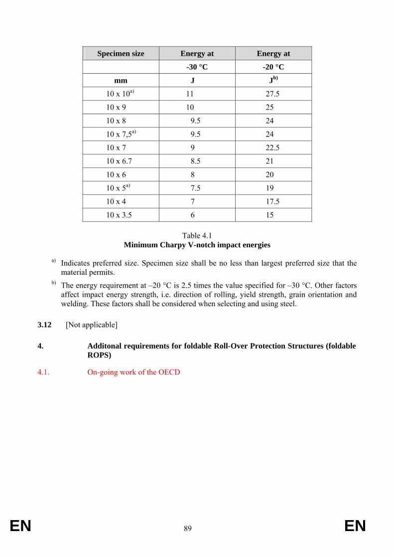
EN 89 EN
Specimen size Energy at Energy at
-30 °C -20 °C
mm J Jb)
10 x 10a) 11 27.5
10 x 9 10 25
10 x 8 9.5 24
10 x 7,5a) 9.5 24
10 x 7 9 22.5
10 x 6.7 8.5 21
10 x 6 8 20
10 x 5a) 7.5 19
10 x 4 7 17.5
10 x 3.5 6 15
Table 4.1 Minimum Charpy V-notch impact energies
a) Indicates preferred size. Specimen size shall be no less than largest preferred size that the
material permits. b) The energy requirement at –20 °C is 2.5 times the value specified for –30 °C. Other factors
affect impact energy strength, i.e. direction of rolling, yield strength, grain orientation and welding. These factors shall be considered when selecting and using steel.
3.12 [Not applicable]
4. Additonal requirements for foldable Roll-Over Protection Structures (foldable ROPS)
4.1. On-going work of the OECD
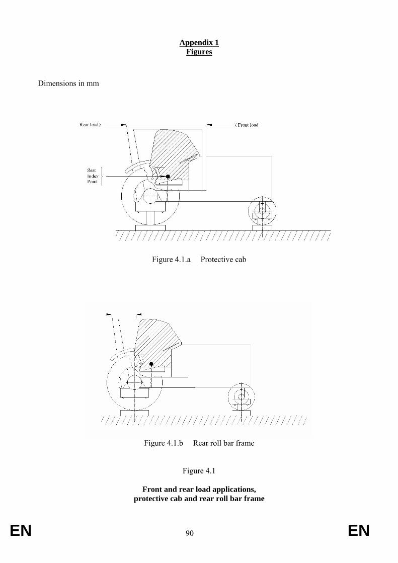
EN 90 EN
Appendix 1 Figures
Dimensions in mm
Figure 4.1.a Protective cab
Figure 4.1.b Rear roll bar frame
Figure 4.1
Front and rear load applications, protective cab and rear roll bar frame
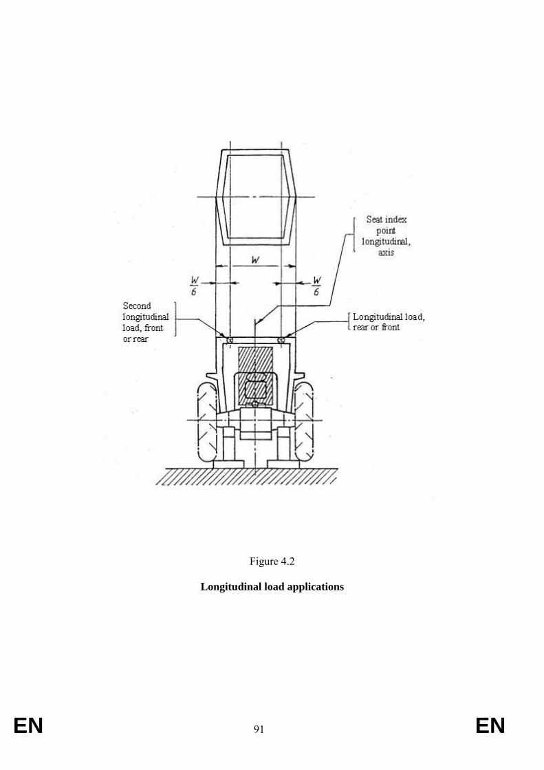
EN 91 EN
Figure 4.2
Longitudinal load applications
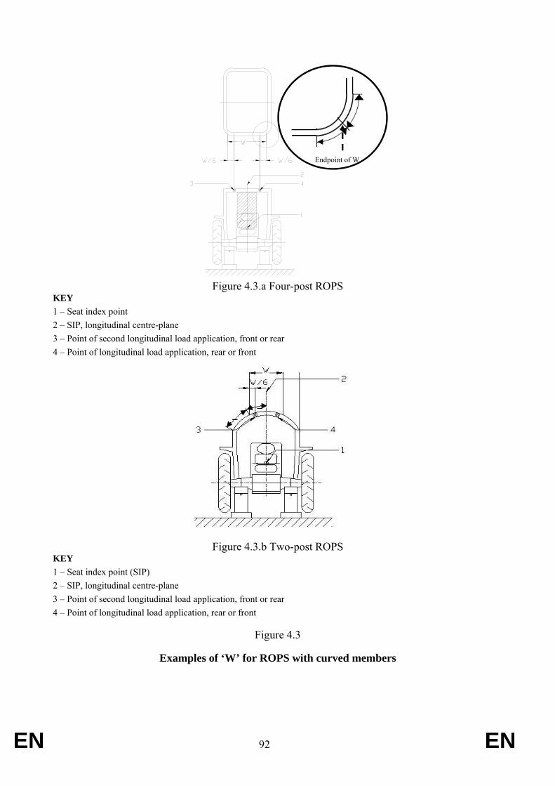
EN 92 EN
Figure 4.3.a Four-post ROPS
KEY 1 – Seat index point 2 – SIP, longitudinal centre-plane 3 – Point of second longitudinal load application, front or rear 4 – Point of longitudinal load application, rear or front
Figure 4.3.b Two-post ROPS
Figure 4.3.b Two-post ROPS KEY 1 – Seat index point (SIP) 2 – SIP, longitudinal centre-plane 3 – Point of second longitudinal load application, front or rear 4 – Point of longitudinal load application, rear or front
Figure 4.3
Examples of ‘W’ for ROPS with curved members
==
Endpoint of W
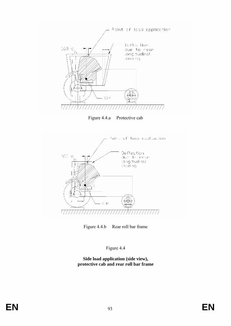
EN 93 EN
Figure 4.4.a Protective cab
Figure 4.4.b Rear roll bar frame
Figure 4.4
Side load application (side view), protective cab and rear roll bar frame
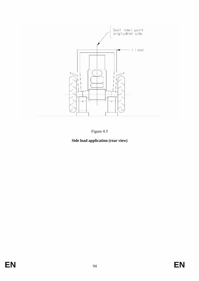
EN 94 EN
Figure 4.5
Side load application (rear view)
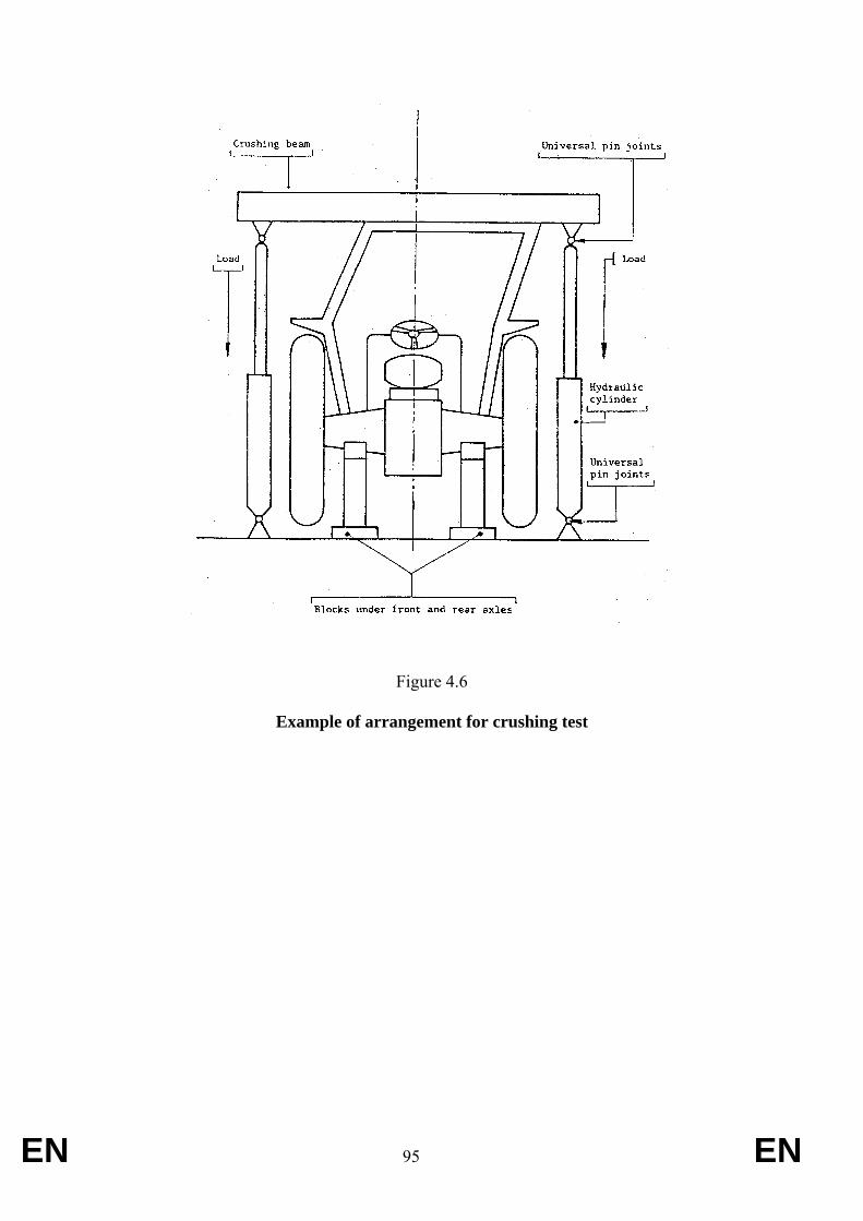
EN 95 EN
Figure 4.6
Example of arrangement for crushing test
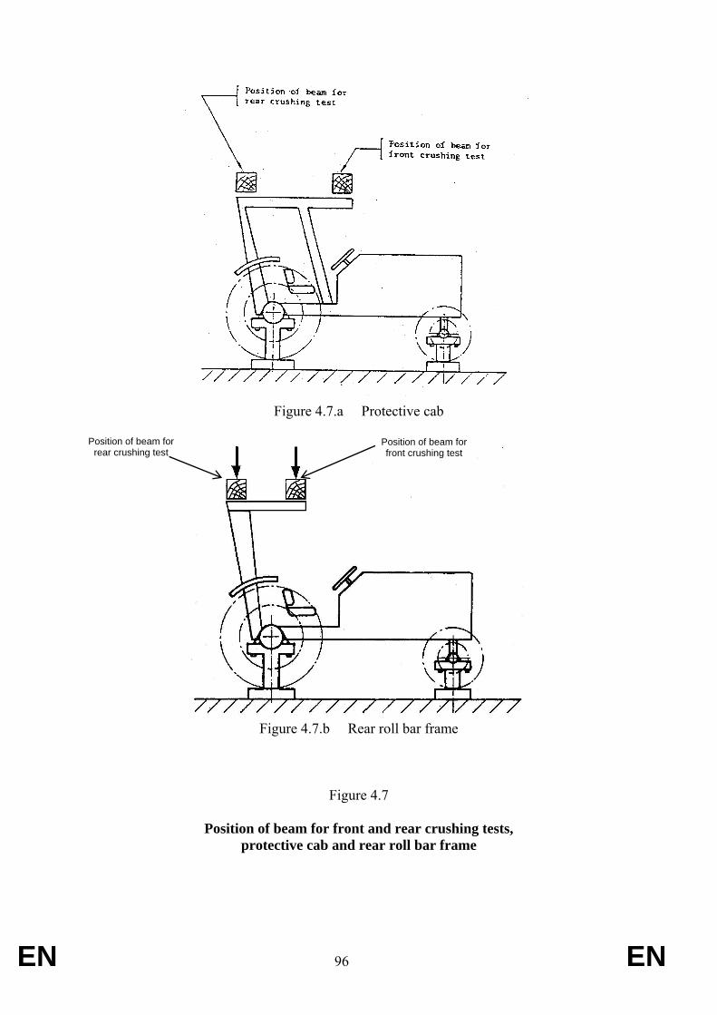
EN 96 EN
Figure 4.7.a Protective cab
Figure 4.7.b Rear roll bar frame
Figure 4.7
Position of beam for front and rear crushing tests, protective cab and rear roll bar frame
Position of beam for rear crushing test
Position of beam for front crushing test
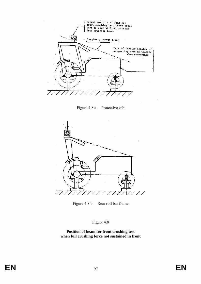
EN 97 EN
Figure 4.8.a Protective cab
Figure 4.8.b Rear roll bar frame
Figure 4.8
Position of beam for front crushing test when full crushing force not sustained in front
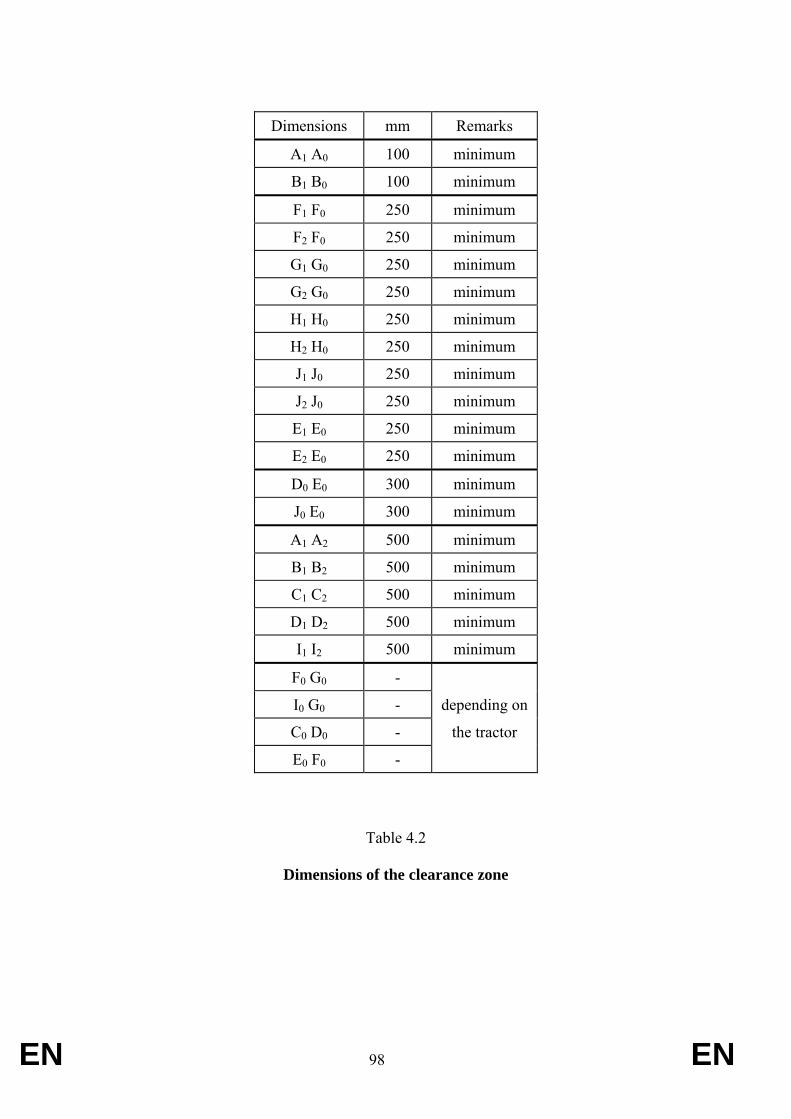
EN 98 EN
Dimensions mm Remarks
A1 A0 100 minimum
B1 B0 100 minimum
F1 F0 250 minimum
F2 F0 250 minimum
G1 G0 250 minimum
G2 G0 250 minimum
H1 H0 250 minimum
H2 H0 250 minimum
J1 J0 250 minimum
J2 J0 250 minimum
E1 E0 250 minimum
E2 E0 250 minimum
D0 E0 300 minimum
J0 E0 300 minimum
A1 A2 500 minimum
B1 B2 500 minimum
C1 C2 500 minimum
D1 D2 500 minimum
I1 I2 500 minimum
F0 G0 -
I0 G0 - depending on
C0 D0 - the tractor
E0 F0 -
Table 4.2
Dimensions of the clearance zone
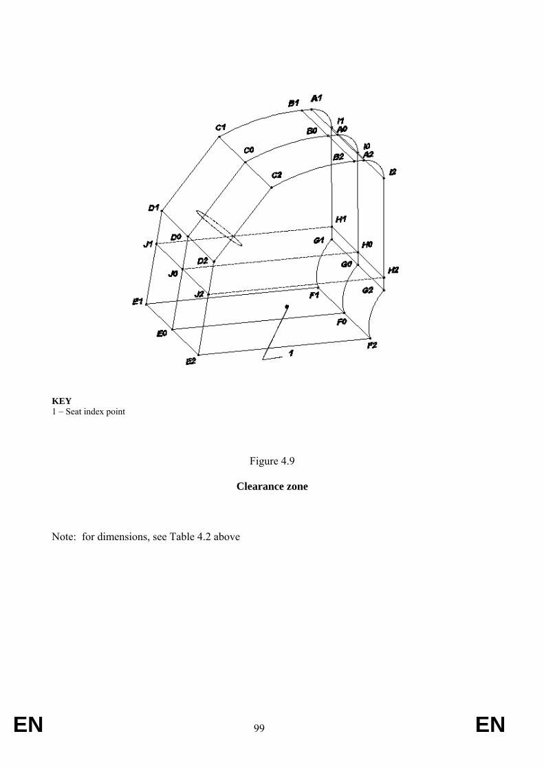
EN 99 EN
KEY 1 – Seat index point
Figure 4.9
Clearance zone Note: for dimensions, see Table 4.2 above
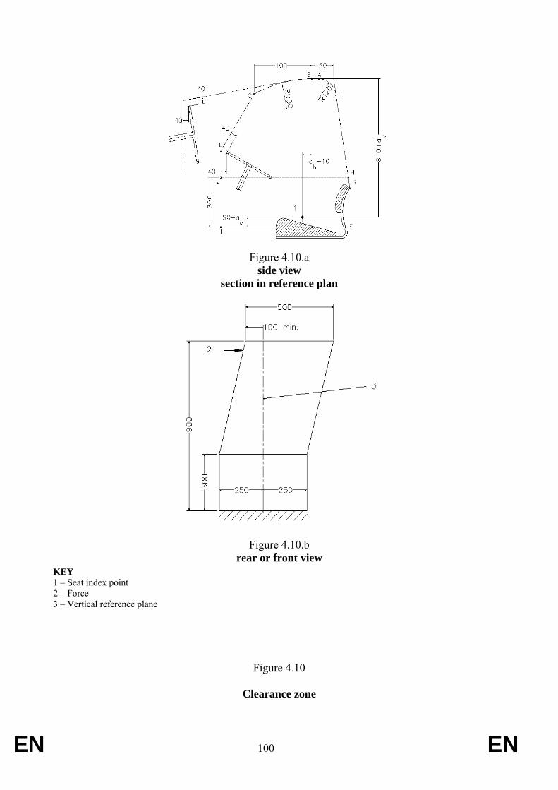
EN 100 EN
Figure 4.10.a
side view section in reference plan
Figure 4.10.b
rear or front viewKEY 1 – Seat index point 2 – Force 3 – Vertical reference plane
Figure 4.10
Clearance zone
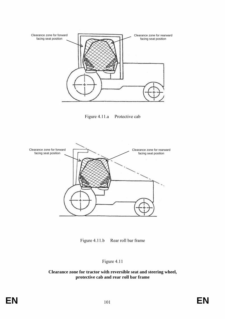
EN 101 EN
Figure 4.11.a Protective cab
Figure 4.11.b Rear roll bar frame
Figure 4.11
Clearance zone for tractor with reversible seat and steering wheel, protective cab and rear roll bar frame
Clearance zone for forward facing seat position
Clearance zone for rearward facing seat position
Clearance zone for forward facing seat position
Clearance zone for rearward facing seat position
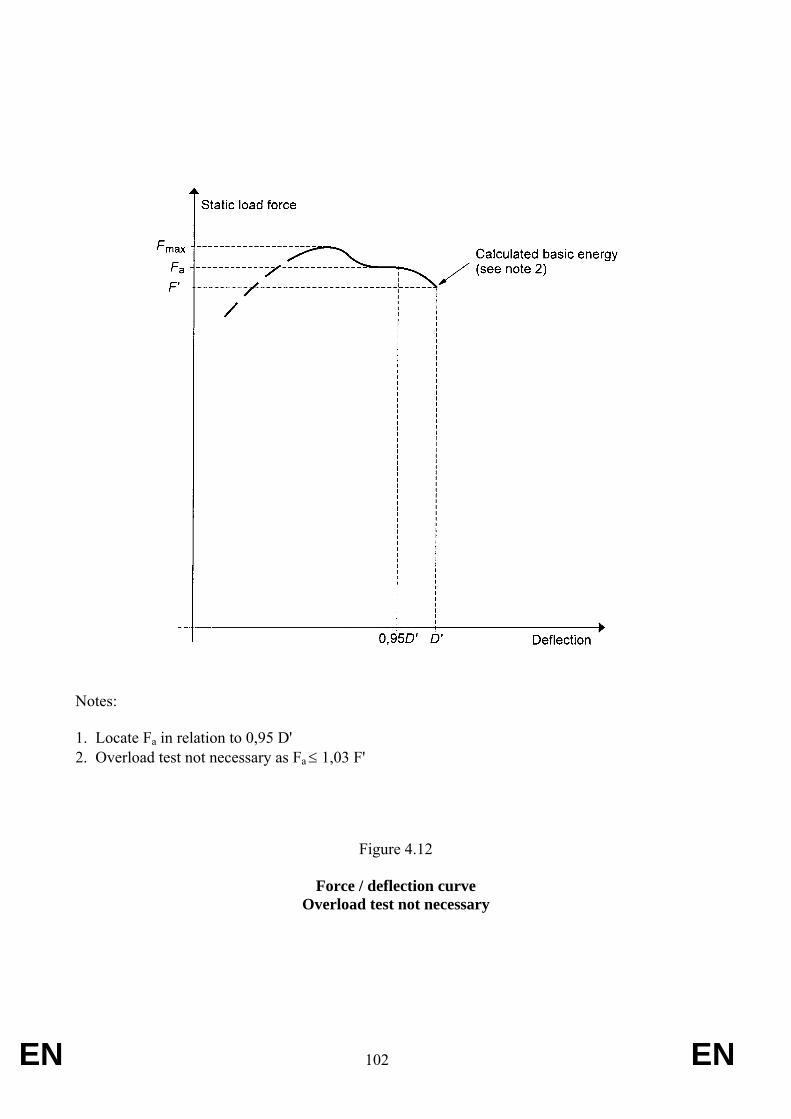
EN 102 EN
Notes: 1. Locate Fa in relation to 0,95 D' 2. Overload test not necessary as Fa ≤ 1,03 F'
Figure 4.12
Force / deflection curve Overload test not necessary
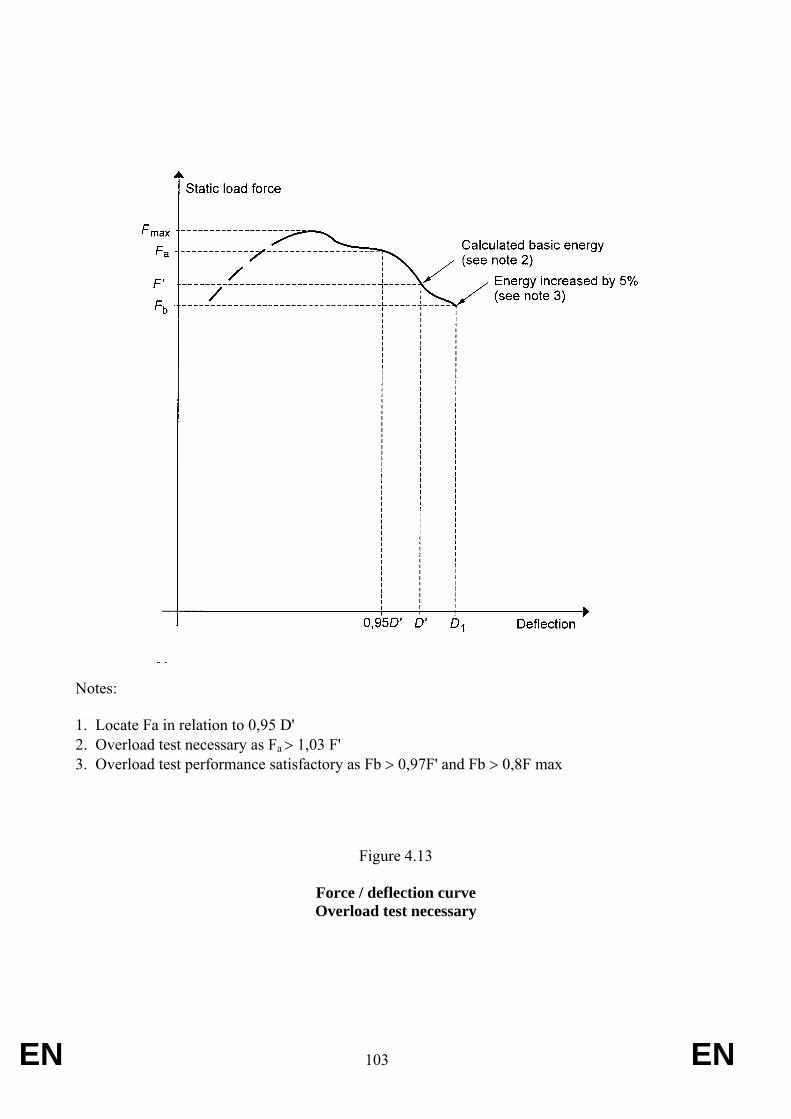
EN 103 EN
Notes: 1. Locate Fa in relation to 0,95 D' 2. Overload test necessary as Fa > 1,03 F' 3. Overload test performance satisfactory as Fb > 0,97F' and Fb > 0,8F max
Figure 4.13
Force / deflection curve Overload test necessary
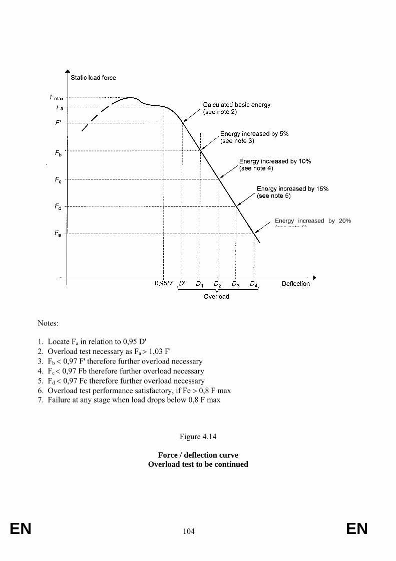
EN 104 EN
Notes: 1. Locate Fa in relation to 0,95 D' 2. Overload test necessary as Fa > 1,03 F' 3. Fb < 0,97 F' therefore further overload necessary 4. Fc < 0,97 Fb therefore further overload necessary 5. Fd < 0,97 Fc therefore further overload necessary 6. Overload test performance satisfactory, if Fe > 0,8 F max 7. Failure at any stage when load drops below 0,8 F max
Figure 4.14
Force / deflection curve Overload test to be continued
Energy increased by 20% (see note 6)
EN 105 EN
ANNEX IX Requirements applying to roll over protection structures within the application field of OECD
Code 6 (front mounted narrow track tractors), as amended
The following test requirements are applicable to to front mounted roll-over protective structures for T2, T3 and T4.3 tractors wheeled agricultural and forestry tractors having the following characteristics:
• ground clearance of not more than 600 mm beneath the lowest points of the front and rear axles, allowing for the differential;
• fixed or adjustable minimum track width with one of the axles less than 1 150 mm fitted with tyres of a larger size. It is assumed that the axle mounted with the wider tyres is set at a track width of not more than 1 150 mm. It must be possible to set the track width of the other axle in such a way that the outer edges of the narrower tyres do not go beyond the outer edges of the tyres of the other axle. Where the two axles are fitted with rims and tyres of the same size, the fixed or adjustable track width of the two axles must be less than 1 150 mm;
• mass greater than 400 kg but less than 3 500 kg, corresponding to the unladen mass of the tractor, including the roll-over protective structure and tyres of the largest size recommended by the manufacturer. The maximum permissible mass shall not exceed 5250 kg and the Mass Ratio (Maximum Permissible Mass/Reference Mass) must not be greater than 1.75;
• and being fitted with roll-over protective structures of the dual-pillar type mounted only in front of the Seat Index Point and characterised by a reduced clearance zone attributable to the tractor silhouette, thus rendering it inadvisable, under any circumstances, to impede access to the driving position.
1. DEFINITIONS
1.1 [Not applicable]
1.2 Roll-Over Protective Structure (ROPS) Roll-over protective structure (safety cab or frame), hereinafter called “protective structure”, means the structure on a tractor the essential purpose of which is to avoid or limit risks to the driver resulting from roll-over of the tractor during normal use.
The roll-over protective structure is characterized by the provision of space for a clearance zone large enough to protect the driver when seated either inside the envelope of the structure or within a space bounded by a series of straight lines from the outer edges of the structure to any part of the tractor that might come into contact with flat ground and that is capable of supporting the tractor in that position if the tractor overturns.
1.3 Track
1.3.1 Preliminary definition: median plane of the wheel
The median plane of the wheel is equidistant from the two planes containing the periphery of the rims at their outer edges.
EN 106 EN
1.3.2 Definition of track
The vertical plane through the wheel axis intersects its median plane along a straight line which meets the supporting surface at one point. If A and B are the two points thus defined for the wheels on the same axle of the tractor, then the track width is the distance between points A and B. The track may be thus defined for both front and rear wheels. Where there are twin wheels, the track is the distance between two planes each being the median plane of the pairs of wheels.
1.3.3 Additional definition: median plane of the tractor
Take the extreme positions of points A and B for the tractor rear axle, which gives the maximum possible value for the track. The vertical plane at right angles to the line AB at its centre point is the median plane of the tractor.
1.4 Wheelbase The distance between the vertical planes passing through the two lines AB as defined above, one for the front wheels and one for the rear-wheels.
1.5 Seat location and adjustment for test
1.5.1 where the seat position is adjustable, the seat must be adjusted to its rear uppermost position;
1.5.2 where the inclination of the backrest is adjustable, it must be adjusted to the mid position;
1.5.3 where the seat is equipped with suspension, the latter must be blocked at mid-travel, unless this is contrary to the instructions clearly laid down by the seat manufacturer;
1.5.4 where the position of the seat is adjustable only lengthwise and vertically, the longitudinal axis passing through the Seat Index Point shall be parallel with the vertical longitudinal plane of the tractor passing through the centre of the steering wheel and not more than 100 mm from that plane.
1.6 Clearance zone
1.6.1 Reference vertical plane and line
The clearance zone (Appendix 2, figure 6.1) is defined on the basis of a vertical reference plane and a reference line:
1.6.1.1 The reference plane is a vertical plane, generally longitudinal to the tractor and passing through the Seat Index Point and the centre of the steering wheel. Normally the reference plane coincides with the longitudinal median plane of the tractor. This reference plane shall be assumed to move horizontally with the seat and steering wheel during loading but to remain perpendicular to the tractor or the floor of the roll-over protective structure.
1.6.1.2 The reference line is the line contained in the reference plane that passes through a point located 140 + ah rearward and 90 – av below the Seat Index Point and the first point on the steering wheel rim that it intersects when brought to the horizontal.
1.6.2 Determination of the clearance zone for tractors with a non-reversible seat
The clearance zone for tractors with a non-reversible seat is defined in 1.6.2.1 to1.6.2.11 below and is bounded by the following planes, the tractor being on a horizontal surface, the
EN 107 EN
seat adjusted and located as specified in sections 1.5.2.1 to 1.5.2.44, and the steering wheel, where adjustable, adjusted to the mid position for seated driving:
1.6.2.1 two vertical planes 250 mm on either side of the reference plane, these vertical planes extending 300 mm upwards from the plane defined in 1.6.2.8 below and longitudinally at least 550 mm in front of the vertical plane perpendicular to the reference plane passing (210 – ah) mm in front of the Seat Index Point;
1.6.2.2 two vertical planes 200 mm on either side of the reference plane, these vertical planes extending 300 mm upwards from the plane defined in 1.6.2.8 below and longitudinally from the surface defined in 1.6.2.11 below to the vertical plane perpendicular to the reference plane passing (210 – ah ) mm in front of the Seat Index Point;
1.6.2.3 an inclined plane perpendicular to the reference plane, parallel with and 400 mm above the reference line, extending backwards to the point where it intersects the vertical plane which is perpendicular to the reference plane and which passes through a point (140 + ah) mm rearward of the Seat Index Point;
1.6.2.4 an inclined plane, perpendicular to the reference plane which meets the plane defined in 1.6.2.3 above at its rearmost edge and rests on the top of the seat back rest;
1.6.2.5 a vertical plane perpendicular to the reference plane, passing at least 40 mm forward of the steering wheel and at least 760 – ah forward of the Seat Index Point;
1.6.2.6 a cylindrical surface with its axis perpendicular to the reference plane, having a radius of 150 mm and tangential to the planes defined in 1.6.2.3 and 1.6.2.5;
1.6.2.7 two parallel inclined planes passing through the upper edges of the planes defined in 1.6.2.1 above with the inclined plane on the side where the impact is applied no closer than 100 mm to the reference plane above the zone of clearance;
1.6.2.8 a horizontal plane passing through a point 90 – av below the Seat Index Point;
1.6.2.9 two portions of the vertical plane perpendicular to the reference plane passing 210 – ah forward of the Seat Index Point, both these part planes joining respectively the rearmost limits of the planes defined in 1.6.2.1 above to the foremost limits of the planes defined in 1.6.2.2 above;
1.6.2.10 two portions of the horizontal plane passing 300 mm above plane defined in 1.6.2.8 above, both these part planes joining respectively the uppermost limits of the vertical planes defined in 1.6.2.2 above to the lowermost limits of the oblique planes defined in 1.6.2.7 above;
1.6.2.11 a surface, curved if necessary, whose generating line is perpendicular to the reference plane and rests on the back of the seat backrest.
1.6.3 Determination of the clearance zone for tractors with a reversible driver’s position
For tractors with a reversible driver’s position (reversible seat and steering wheel), the clearance zone is the envelope of the two clearance zones defined by the two different
4 Users are reminded that the Seat Index Point is determined according to ISO 5353 and is a fixed point with respect to
the tractor that does not move as the seat is adjusted away from the mid-position.
EN 108 EN
positions of the steering wheel and the seat. For each position of steering wheel and the seat the clearance zone shall respectively be defined on the basis of above sections 1.6.1 and 1.6.2 of RVCR Annex V(a) for driver’s position in normal position and on the basis of sections 1.6.1 and 1.6.2 of RVCR Annex V(b) for driver’s position in reverse position (see Appendix 2, figure 6.2).
1.6.4 Optional seats
1.6.4.1 In case of tractors that could be fitted with optional seats, the envelope comprising the Seat Index Points of all options offered shall be used during the tests. The protective structure shall not enter the larger clearance zone which takes account of these different Seat Index Points.
1.6.4.2 In the case where a new seat option is offered after the test has been performed, a determination shall be made to see whether the clearance zone around the new SIP falls within the envelope previously established. If it does not, a new test must be performed.
1.7 Mass
1.7.1 Unballasted / Unladen Mass
The mass of the tractor excluding optional accessories but including coolant, oils, fuel, tools plus the protective structure. Not included are optional front or rear weights, tyre ballast, mounted implements, mounted equipment or any specialised components;
1.7.5 Maximum Permissible Mass
The maximum mass of the tractor stated by the manufacturer to be technically permissible and declared on the vehicle’s identification plate and/or in the Operator’s Handbook;
1.7.6 Reference Mass
The mass, selected by the manufacturer, used in formulae to calculate the height of fall of the pendulum block, the energy inputs and crushing forces to be used in the tests. Must not be less than the unballasted mass and must be sufficient to ensure the Mass Ratio does not exceed 1.75 (see Section 1.7.4);
1.7.7 Mass Ratio The ratio of ….. This must not be greater than 1.75
1.8 Permissible measurement tolerances
Linear dimensions: ± 3 mm except for: -- tyre deflection: ± 1 mm -- structure deflection during horizontal loadings: ± 1 mm -- height of fall of the pendulum block: ± 1 mm Masses: ± 1 % Forces: ± 2 % Angles: ± 2 °
1.9 Symbols
ah (mm) Half of the horizontal seat adjustment
⎟⎟⎠
⎞⎜⎜⎝
⎛Mass Reference
MassePermissiblMax.
EN 109 EN
av (mm) Half of the vertical seat adjustment B (mm) Minimum overall width of the tractor; Bb (mm) Maximum outer width of the protective structure; D (mm) Deflection of the structure at the point of impact (dynamic tests) or at the
point of, and in line with, the load application (static tests); D' (mm) Deflection of the structure for the calculated energy required; Ea (J) Strain energy absorbed at point when load is removed. Area contained
within F-D curve; Ei (J) Strain energy absorbed. Area under F-D curve; E'i (J) Strain energy absorbed after additional loading following a crack or tear; E''i (J) Strain energy absorbed in overload test in the event of the load having
been removed before starting this overload test. Area under F-D curve; Eil (J) Energy input to be absorbed during longitudinal loading; Eis (J) Energy input to be absorbed during side loading; F (N) Static load force; F' (N) Loading force for calculated energy required, corresponding to E'i ; F-D Force/deflection diagram; Fi (N) Force applied to rear hard fixture; Fmax (N) Maximum static load force occurring during loading, with the exception
of the overload; Fv (N) Vertical crushing force; H (mm) Falling height of the pendulum block (dynamic tests); H’ (mm) Falling height of the pendulum block for additional test (dynamic tests); I (kg.m2) Tractor reference moment of inertia about the centre line of the rear
wheels, whatever the mass of these rear wheels may be; L (mm) Tractor reference wheelbase; M (kg) Tractor reference mass during strength tests.
3. RULES AND DIRECTIONS
3.1 Prior conditions for the strength tests
3.1.1 Completion of two preliminary tests
The protective structure may only be subjected to the strength tests if both the Lateral Stability Test and the Non-Continuous Rolling Test have been satisfactorily completed (see flow diagram as Appendix 2, figure 6.3).
3.1.2 Preparation for the preliminary tests
3.1.2.1 The tractor must be equipped with the protective structure in its safety position.
3.1.2.2 The tractor must be fitted with tyres having the greatest diameter indicated by the manufacturer and the smallest cross-section for tyres of that diameter. The tyres must not be liquid-ballasted and must be inflated to the pressure recommended for field work.
3.1.2.3 The rear wheels must be set to the narrowest track width; the front wheels must be set as closely as possible to the same track width. If it is possible to have two front track settings which differ equally from the narrowest rear track setting, the wider of these two front track settings must be selected.
EN 110 EN
3.1.2.4 All the tractor's tanks must be filled or the liquids must be replaced by an equivalent mass in the corresponding position.
3.1.2.5 All attachments used in the series production shall be fixed to the tractor in the normal position.
3.1.3 Lateral stability test
3.1.3.1 The tractor, prepared as specified above, is placed on a horizontal plane so that the tractor front-axle pivot point or, in the case of an articulated tractor, the horizontal pivot point between the two axles can move freely.
3.1.3.2 Using a jack or a hoist, tilt the part of the tractor which is rigidly connected to the axle that bears more than 50 pour cent of the tractor's weight, while constantly measuring the angle of inclination. This angle must be at least 38° at the moment when the tractor is resting in a state of unstable equilibrium on the wheels touching the ground. Perform the test once with the steering wheel turned to full right lock and once with the steering wheel turned to full left lock
3.1.4 Non-continuous rolling test
3.1.4.1 General remarks
This test is intended to check whether a structure fitted to the tractor for the protection of the driver can satisfactorily prevent continuous roll-over of the tractor in the event of its overturning laterally on a slope with a gradient of 1 in 1.5 (Appendix 2, figure 6.4).
Evidence of non-continuous rolling can be provided in accordance with one of the two methods described in 3.1.4.2 and 3.1.4.3.
3.1.4.2 Demonstration of non-continuous rolling behaviour by means of the overturning test
3.1.4.2.1 The overturning test must be carried out on a test slope at least four metres long (see Appendix 2, figure 6.4). The surface must be covered with an 18-cm layer of a material that, as measured in accordance with Standards ASAE S313.3 FEB1999 and ASAE EP542 FEB1999 relating to soil cone penetrometer, has a cone penetration index of:
A = 235 ± 20 or
B = 335 ± 20
3.1.4.2.2 The tractor (prepared as described in paragraph 3.1.2) is tilted laterally with zero initial speed. For this purpose, it is placed at the start of the test slope in such a way that the wheels on the downhill side rest on the slope and the tractor's median plane is parallel with the contour lines. After striking the surface of the test slope, the tractor may lift itself from the surface by pivoting about the upper corner of the protective structure, but it must not roll over. It must fall back on the side which it first struck.
3.1.4.3 Demonstration of non-continuous rolling behaviour by calculation
3.1.4.3.1 For the purpose of verifying non-continuous rolling behaviour by calculation, the following characteristic tractor data must be ascertained (see Appendix 2, figure 6.5):
EN 111 EN
B0 (m) Rear tyre width; B6 (m) Width of protective structure between the right and left points of
impact; B7 (m) Width of engine bonnet; D0 (rad) Front-axle swing angle from zero position to end of travel; D2 (m) Height of front tyres under full axle load; D3 (m) Height of rear tyres under full axle load; H0 (m) Height of the front-axle pivot point; H1 (m) Height of centre of gravity; H6 (m) Height at the point of impact; H7 (m) Height of engine bonnet; L2 (m) Horizontal distance between the centre of gravity and front axle; L3 (m) Horizontal distance between the centre of gravity and rear axle; L6 (m) Horizontal distance between the centre of gravity and the leading
point of intersection of the protective structure (to be preceded by a minus sign if this point lies in front of the plane of the centre of gravity);
L7 (m) Horizontal distance between the centre of gravity and the front corner of the engine bonnet;
Mc (kg) Tractor mass used for calculation; Q (kgm2) Moment of inertia about the longitudinal axis through the centre of
gravity; S (m) Rear track width.
The sum of the track (S) and tyre (B0) widths must be greater than the width B6 of the protective structure.
3.1.4.3.2 For the purposes of calculation, the following simplifying assumptions can be made:
3.1.4.3.2.1 the stationary tractor overturns on a slope with a 1/1.5 gradient with a balanced front axle, as soon as the centre of gravity is vertically above the axis of rotation;
3.1.4.3.2.2 the axis of rotation is parallel to the tractor's longitudinal axis and passes through the centre of the contact surfaces of the downhill front and rear wheel;
3.1.4.3.2.3 the tractor does not slide downhill;
3.1.4.3.2.4 impact on the slope is partly elastic, with a coefficient of elasticity of:
U = 0.2
3.1.4.3.2.5 the depth of penetration into the slope and the deformation of the protective structure together amount to:
T = 0.2 m
3.1.4.3.2.6 no other components of the tractor penetrate into the slope.
EN 112 EN
3.1.4.3.3 The computer programme (BASIC) for determining the continuous or interrupted roll-over behaviour of a laterally overturning narrow-track tractor with a front-mounted roll-over protective structure is in Appendix 1, wich includes examples 6.1 to 6.11.
3.1.5 Measurement methods
3.1.5.1 Horizontal distances between the centre of gravity and rear (L3) or front (L2) axles
The distance between the rear and front axles on both sides of the tractor shall be measured in order to verify there is no steering angle.
The distances between the centre of gravity and the rear axle (L3) or the front axle (L2) shall be calculated from the mass distribution of the tractor between the rear and the front wheels.
3.1.5.2 Heights of rear (D3) and front (D2) tyres
The distance from the highest point of the tyre to the ground plane shall be measured (Appendix 2, figure 6.5), and the same method shall be used for the front and rear tyres.
3.1.5.3 Horizontal distance between the centre of gravity and the leading point of intersection of the protective structure (L6).
The distance between the centre of gravity and the leading point of intersection of the protective structure shall be measured (Appendix 2, figures 6.6.a, 6.6.b and 6.6.c). If the protective structure is in front of the plane of the centre of gravity, the recorded measure will be preceded by a minus sign (-L6).
3.1.5.4 Width of the protective structure (B6)
The distance between the right and left points of impact of the two vertical posts of the structure shall be measured.
The point of impact is defined by the plane tangent to the protective structure passing through the line made by the top outer points of the front and rear tyres (Appendix 2, figure 6.7).
3.1.5.5 Height of the protective structure (H6)
The vertical distance from the point of impact of the structure to the ground plane shall be measured.
3.1.5.6 Height of the engine bonnet (H7)
The vertical distance from the point of impact of the engine bonnet to the ground plane shall be measured.
The point of impact is defined by the plane tangent to the engine bonnet and the protective structure passing through the top outer points of the front tyre (Appendix 2, figure 6.7). The measurement shall be made on both sides of the engine bonnet.
3.1.5.7 Width of the engine bonnet (B7)
The distance between the two points of impact of the engine bonnet as defined previously shall be measured.
EN 113 EN
3.1.5.8 Horizontal distance between the centre of gravity and the front corner of the engine bonnet (L7)
The distance from the point of impact of the engine bonnet, as defined previously, to the centre of gravity shall be measured.
3.1.5.9 Height of the front-axle pivot point (H0)
The vertical distance between the centre of the front-axle pivot point to the centre of axle of the front tyres (H01) shall be included in the manufacturer’s technical report and shall be checked.
The vertical distance from the centre of the front tyres axle to the ground plane (H02) shall be measured (Appendix 2, figure 6.8).
The height of the front-axle pivot (H0) is the sum of both previous values.
3.1.5.10 Rear track width (S)
The minimum rear track width fitted with tyres of the largest size, as specified by the manufacturer, shall be measured (Appendix 2, figure 6.9).
3.1.5.11 Rear tyre width (B0)
The distance between the outer and the inner vertical planes of a rear tyre in its upper part shall be measured (Appendix 2, figure 6.9).
3.1.5.12 Front axle swinging angle (D0)
The largest angle defined by the swinging of the front axle from the horizontal position to the maximum deflection shall be measured on both sides of the axle, taking into account any end-stroke shock absorber. The maximum angle measured shall be used.
3.1.5.13 Tractor Mass
The tractor mass shall be determined according to the conditions specified in section 1.7.1.
3.2 Conditions for testing the strength of protective structures and of their attachment to tractors
3.2.1 General requirements
3.2.1.1 Test purposes
Tests made using special rigs are intended to simulate such loads as are imposed on a protective structure, when the tractor overturns. These tests enable observations to be made on the strength of the protective structure and any brackets attaching it to the tractor and any parts of the tractor which transmit the test load.
3.2.1.2 Test methods
Tests may be performed in accordance with the static procedure or the dynamic procedure (see Annex A). The two methods are deemed equivalent.
3.2.1.3 General rules governing preparation for tests
EN 114 EN
3.2.1.3.1 The protective structure must conform to the series production specifications. It shall be attached in accordance with the manufacturer's recommended method to one of the tractors for which it is designed.
Note: A complete tractor is not required for the static strength test; however, the protective structure and parts of the tractor to which it is attached represent an operating installation, hereinafter referred to as « the assembly ».
3.2.1.3.2 For both the static test and the dynamic test the tractor as assembled (or the assembly) must be fitted with all series production components which may affect the strength of the protective structure or which may be necessary for the strength test.
Components which may create a hazard in the clearance zone must also be fitted on the tractor (or the assembly) so that they may be examined to see whether the requirements of the Acceptance Conditions in 3.2.3 have been fulfilled.
All components of the tractor or the protective structure including weather protective must be supplied or described on drawings.
3.2.1.3.3 For the strength tests, all panels and detachable non-structural components must be removed so that they may not contribute to the strengthening of the protective structure.
3.2.1.3.4 The track width must be adjusted so that the protective structure will, as far as possible, not be supported by the tyres during the strength tests. If these tests are conducted in accordance with the static procedure, the wheels may be removed.
3.2.2 Tests
3.2.2.1 Sequence of tests according to the Static Procedure
The sequence of tests, without prejudice to the additional tests mentioned in sections 3.3.1.6, and 3.3.1.7 is as follows:
(1) loading at the rear of the structure (see 3.3. 1.1); (2) rear crushing test (see 3.3.1.4); (3) loading at the front of the structure (see 3.3. 1.2); (4) loading at the side of the structure (see 3.3.1.3); (5) crushing at the front of the structure (see 3.3. 1.5).
3.2.2.2 General requirements
3.2.2.2.1 If, during the test, any part of the tractor restraining equipment breaks or moves, the test shall be restarted.
EN 115 EN
3.2.2.2 2 No repairs or adjustments of the tractor or protective structure may be carried out during the tests.
3.2.2.2.3 The tractor gear box shall be in neutral and the brakes off during the tests.
3.2.2.2.4 If the tractor is fitted with a suspension system between the tractor body and the wheels, it shall be blocked during the tests.
3.2.2.2.5 The side chosen for application of the first load on the rear of the structure shall be that which, in the opinion of the testing authorities, will result in the application of the series of loads under the most unfavourable conditions for the structure. The lateral load and the rear load shall be applied on both sides of the longitudinal median plane of the protective structure. The front load shall be applied on the same side of the longitudinal median plane of the protective structure as the lateral load.
3.2.3 Acceptance conditions
3.2.3.1 A protective structure is regarded as having satisfied the strength requirements if it fulfils the following conditions:
3.2.3.1.1 After each part-test it must be free from cracks or tears within the meaning of section 3.3.2.1 or
3.2.3.1.2 If, during one of the crushing tests, significant cracks or tears appear, an additional test, in accordance with section 3.3.1.7, must be applied immediately after the crushing which caused cracks or tears to appear;
3.2.3.1.3 during the tests other than the overload test, no part of the protective structure must enter the clearance zone as defined in 1.6;
3.2.3.1.4 during the tests other than the overload test, all parts of the clearance zone shall be secured by the structure, in accordance with 3.3.2.2;
3.2.3.1.5 during the tests the protective structure must not impose any constraints on the seat structure;
3.2.3.1.6 the elastic deflection, measured in accordance with 3.3.2.4 shall be less than 250 mm.
3.2.3.2 There shall be no accessories presenting a hazard for the driver. There shall be no projecting part or accessory which is liable to injure the driver should the tractor overturn, or any accessory or part which is liable to trap him – for example by the leg or the foot – as a result of the deflections of the structure.
3.2.4 [Not applicable]
3.2.5 Test apparatus and equipment
3.2.5.1 Static testing rig
3.2.5.1.1 The static testing rig must be designed in such a way as to permit thrusts or loads to be applied to the protective structure.
EN 116 EN
3.2.5.1.2 Provision must be made so that the load can be uniformly distributed normal to the direction of loading and along a flange having a length of one of the exact multiples of 50 between 250 and 700 mm. The stiff beam shall have a vertical face dimension of 150 mm. The edges of the beam in contact with the protective structure shall be curved with a maximum radius of 50 mm.
3.2.5.1.3 The pad shall be capable of being adjusted to any angle in relation to the load direction, in order to be able to follow the angular variations of the structure's load-bearing surface as the structure deflects.
3.2.5.1.4 Direction of the force (deviation from horizontal and vertical):
− at start of test, under zero load: ± 2°;
− during test, under load: 10° above and 20° below the horizontal. These variations must be kept to a minimum.
3.2.5.1.5 The deflection rate shall be sufficiently slow, less than 5 mm/s so that the load may at all moments be considered as static.
3.2.5.2 Apparatus for measuring the energy absorbed by the structure
3.2.5.2.1 The force versus deflection curve shall be plotted in order to determine the energy absorbed by the structure. There is no need to measure the force and deflection at the point where the load is applied to the structure; however, force and deflection shall be measured simultaneously and co-linearly.
3.2.5.2.2 The point of origin of deflection measurements shall be selected so as to take account only of the energy absorbed by the structure and/or by the deflection of certain parts of the tractor. The energy absorbed by the deflection and/or the slipping of the anchoring must be ignored.
3.2.5.3 Means of anchoring the tractor to the ground
3.2.5.3.1 Anchoring rails with the requisite track width and covering the necessary area for anchoring the tractor in all the cases illustrated must be rigidly attached to a non-yielding base near the testing rig.
3.2.5.3.2 The tractor must be anchored to the rails by any suitable means (plates, wedges, wire ropes, jacks, etc.) so that it cannot move during the tests. This requirement shall be checked during the test, by means of the usual devices for measuring length.
If the tractor moves, the entire test shall be repeated, unless the system for measuring the deflections taken into account for plotting the force versus deflection curve is connected to the tractor.
3.2.5.4 Crushing rig
A rig as shown in Appendix 2, figure 6.10 shall be capable of exerting a downward force on a protective structure through a rigid beam approximately 250 mm wide, connected to the load-applying mechanism by means of universal joints. Suitable axle stands must be provided so that the tractor tyres do not bear the crushing force.
EN 117 EN
3.2.5.5 Other measuring apparatus
The following measuring devices are also needed:
3.2.5.5.1 A device for measuring the elastic deflection (the difference between the maximum momentary deflection and the permanent deflection, (see Appendix 2, figure 6.11).
3.2.5.5.2 A device for checking that the protective structure has not entered the clearance zone and that the latter has remained within the structure's protection during the test (section 3.3.2.2).
3.3 Static test procedure
3.3.1 Loading and crushing tests
3.3.1.1 Loading at the rear
3.3.1.1.1 The load shall be applied horizontally in a vertical plane parallel to the tractor's median plane.
The load application point shall be that part of the roll-over protective structure likely to hit the ground first in a rearward overturning accident, normally the upper edge. The vertical plane in which the load is applied shall be located at a distance of 1/6 of the width of the top of the protective structure inwards from a vertical plane, parallel to the median plane of the tractor, touching the outside extremity of the top of the protective structure.
If the structure is curved or protruding at this point, wedges enabling the load to be applied thereon shall be added, without thereby reinforcing the structure.
3.3.1.1.2 The assembly shall be lashed to the ground as described in 3.2.6.3.
3.3.1.1.3 The energy absorbed by the protective structure during the test shall be at least:
Ei l = 500 + 0.5 M
3.3.1.1.4 For tractors with a reversible driver’s position (reversible seat and steering wheel), the same formula shall apply.
3.3.1.2 Loading at the front
3.3.1.2.1 The load shall be applied horizontally, in a vertical plane parallel to the tractor's median plane and located at a distance of 1/6 of the width of the top of the protective structure inwards from a vertical plane, parallel to the median plane of the tractor, touching the outside extremity of the top of the protective structure.
The load application point shall be that part of the roll-over protective structure likely to hit the ground first if the tractor overturned sideways while travelling forward, normally the upper edge.
If the structure is curved or protruding at this point, wedges enabling the load to be applied thereon shall be added, without thereby reinforcing the structure.
3.3.1.2.2 The assembly shall be lashed to the ground as described in 3.2.5.3.
EN 118 EN
3.3.1.2.3 The energy absorbed by the protective structure during the test shall be at least:
Ei l = 500 + 0.5 M
3.3.1.2.4 For tractors with a reversible driver’s position (reversible seat and steering wheel), the energy shall be whichever is the higher of the above or either of the following as selected:
Eil = 2.165 x 10 - 7M x L2 or
Eil = 0.574 I
3.3.1.3 Loading from the side
3.3.1.3.1 The side loading shall be applied horizontally, in a vertical plane perpendicular to the tractor's median plane. The load application point shall be that part of the roll-over protective structure likely to hit the ground first in a sideways overturning accident, normally the upper edge.
3.3.1.3.2 The assembly shall be lashed to the ground as described in 3.2.5.3.
3.3.1.3.3 The energy absorbed by the protective structure during the test shall be at least:
Ei s = 1.75 M(B6+B) / 2B
3.3.1.3.4 For tractors with a reversible driver’s position (reversible seat and steering wheel), the energy shall be whichever is higher of the above or the following:
Eis = 1.75 M
3.3.1.4 Crushing at the rear
The beam shall be positioned over the rear uppermost structural member(s) and the resultant of crushing forces shall be located in the tractor's median plane. A force Fv shall be applied where:
Fv = 20 M
The force Fv shall be maintained for five seconds after cessation of any visually detectable movement of the protective structure.
Where the rear part of the protective structure roof will not sustain the full crushing force, the force shall be applied until the roof is deflected to coincide with the plane joining the upper part of the protective structure with that part of the rear of the tractor capable of supporting the tractor when overturned.
The force shall then be removed, and the crushing beam repositioned over that part of the protective structure which would support the tractor when completely overturned. The crushing force Fv shall then be applied again.
3.3.1.5 Crushing at the front
The beam shall be positioned across the front uppermost structural member(s) and the resultant of crushing forces shall be located in the tractor's median plane. A force Fv shall be applied where:
EN 119 EN
Fv = 20 M
The force Fv shall be maintained for five seconds after the cessation of any visually detectable movement of the protective structure.
Where the front part of the protective structure roof will not sustain the full crushing force, the force shall be applied until the roof is deflected to coincide with the plane joining the upper part of the protective structure with that part of the front of the tractor capable of supporting the tractor when overturned.
The force shall then be removed, and the crushing beam repositioned over that part of the protective structure which would support the tractor when completely overturned. The crushing force Fv shall then be applied again.
3.3.1.6 Additional overload test (Appendix 2, figures 6.14 to 6.16)
An overload test shall be carried out in all cases where the force decreases by more than 3 per cent during the last 5 per cent of the deflection reached when the energy required is absorbed by the structure (see Appendix 2, figure 6.15).
The overload test involves the gradual increase of the horizontal load by increments of 5 per cent of the initial energy requirement up to a maximum of 20 per cent of energy added (see Appendix 2, figure 6.16).
The overload test is satisfactory if, after each increase by 5, 10, or 15 per cent in the energy required, the force decreases by less than 3 per cent for a 5 per cent increment and remains greater than 0.8 Fmax.
The overload test is satisfactory if, after the structure has absorbed 20 per cent of the added energy, the force exceeds 0.8 Fmax.
Additional cracks or tears and/or entry into or lack of protection of the clearance zone due to elastic deflection are permitted during the overload test. However, after the removal of the load, the structure shall not enter the clearance zone, which shall be completely protected.
3.3.1.7 Additional crushing tests
If cracks or tears which cannot be considered as negligible appear during a crushing test, a second, similar crushing, but with a force of 1.2 Fv shall be applied immediately after the crushing test which caused the cracks or tears to appear.
3.3.2 Measurements to be made
3.3.2.1 Fractures and cracks
After each test all structural members, joints and attachment systems shall be visually examined for fractures or cracks, any small cracks in unimportant parts being ignored.
3.3.2.2 Entry into the clearance zone
During each test the protective structure shall be examined to see whether any part of it has entered the clearance zone as defined in 1.6 above.
Furthermore, the clearance zone shall not be outside the protection of the protective structure. For this purpose, it shall be considered to be outside the protection of the structure if any part of it would come in contact with flat ground if the tractor overturned towards the direction from which the test load is applied. For estimating this, the front and
EN 120 EN
rear tyres and track width setting shall be the smallest standard fitting specified by the manufacturer.
3.3.2.3 Rear hard fixture tests
If the tractor is fitted with a rigid section, a housing or other hard fixture placed behind the driver's seat, this fixture shall be regarded as a protective point, in the event of sideways or rear overturning. This hard fixture placed behind the driver’s seat shall be capable of withstanding, without breaking or entering the clearance zone, a downward force Fi , where:
Fi = 15 M
applied perpendicularly to the top of the frame in the central plane of the tractor. The initial angle of application of force shall be 40° calculated from a parallel to the ground as shown in Appendix 2, figure 6.12. The minimum width of this rigid section shall be 500 mm (see Appendix 2, figure 6.13).
In addition, it shall be sufficiently rigid and firmly attached to the rear of the tractor.
3.3.2.4 Elastic deflection under side loading
The elastic deflection shall be measured (810+av) mm above the Seat Index Point, in the vertical plane in which the load is applied. For this measurement, any apparatus similar to that illustrated in Appendix 2, figure 6.11 shall be used.
3.3.2.5 Permanent deflection
After the final crushing test the permanent deflection of the protective structure shall be recorded. For this purpose, before the start of the test, the position of the main roll-over protective structure members in relation to the Seat Index Point shall be recorded.
3.4 Extension to other tractor models
3.4.1 [Not applicable]
3.4.2 Technical extension
When technical modifications occur on the tractor, the protective structure or the method of attachment of the protective structure to the tractor, the testing station that has carried out the original test can issue a “technical extension report” if the tractor and protective structure satisfied preliminary tests of lateral stability and non-continuous rolling as defined in 3.1.3 and 3.1.4 and if the rear hard fixture as described in paragraph 3.3.2.3., when fitted, has been tested in accordance with the procedure described in this paragraph (except 3.4.2.2.4) in the following cases:
3.4.2.1 Extension of the structural test results to other models of tractors
The impact or loading and crushing tests need not be carried out on each model of tractor, provided that the protective structure and tractor comply with the conditions referred to hereunder in 3.4.2.1.1 to 3.4.2.1.5.
3.4.2.1.1 The structure (including rear hard fixture) shall be identical to the one tested;
EN 121 EN
3.4.2.1.2 The required energy shall not exceed the energy calculated for the original test by more than 5 per cent;
3.4.2.1.3 The method of attachment and the tractor components to which the attachment is made shall be identical;
3.4.2.1.4 Any components such as mudguards and bonnet that may provide support for the protective structure shall be identical;
3.4.2.1.5 The position and critical dimensions of the seat in the protective structure and the relative position of the protective structure on the tractor shall be such that the clearance zone would have remained within the protection of the deflected structure throughout all tests (this shall be checked by using the same reference of clearance zone as in the original test report, Seat Index Point).
3.4.2.2 Extension of the structural test results to modified models of the protective structure
This procedure has to be followed when the provisions of section 3.4.2.1 are not fulfilled, it may not be used when the method of attachment of the protective structure to the tractor does not remain of the same principle (e.g. rubber supports replaced by a suspension device):
3.4.2.2.1 Modifications having no impact on the results of the initial test (e.g. weld attachment of the mounting plate of an accessory in a non-critical location on the structure), addition of seats with different SIP location in the protective structure (subject to checking that the new clearance zone(s) remain(s) within the protection of the deflected structure throughout all tests).
3.4.2.2.2 Modifications having a possible impact on the results of the original test without calling into question the acceptability of the protective structure (e.g. modification of a structural component, modification of the method of attachment of the protective structure to the tractor). A validation test can be carried out and the test results will be drafted in the extension report.
The following limits for this type extension are fixed:
3.4.2.2.2.1 no more than 5 extension may be accepted without a validation test;
3.4.2.2.2.2 the results of the validation test will be accepted for extension if all the acceptance conditions of this Annex are fulfilled and :
− if the deflection measured after each impact test does not deviate from the deflection measured after each impact test in the original test report by more than ± 7% (in the case of dynamic tests);
− if the force measured when the required energy level has been reached in the various horizontal load tests does not deviate from the force measured when the required energy has been reached in the original test by more than ± 7% and the deflection measured5 when the required energy level has been reached in the various horizontal load tests does not deviate from the deflection measured when the required energy
5 Permanent + elastic deflection measured at the point when the required energy level is obtained.
EN 122 EN
has been reached in the original test report by more than ± 7% (in the case of static tests).
3.4.2.2.2.3 more than one protective structure modification may be included in a single extension report if they represent different options of the same protective structure, but only one validation test can be accepted in a single extension report. The options not tested shall be described in a specific section of the extension report.
3.4.2.2.3 Increase of the reference mass declared by the manufacturer for a protective structure already tested. If the manufacturer wants to keep the same approval number it is possible to issue an extension report after having carried out a validation test (the limits of ± 7% specified in 3.4.2.2.2.2 are not applicable in such a case).
3.4.2.2.4 Modification of the rear hard fixture or addition of a new rear hard fixture. It has to be checked that the clearance zone remains within the protection of the deflected structure throughout all test taking into account the new or modified rear hard fixture. A validation of the rear hard fixture consisting in the test described in 3.3.2.3has to be carried out and the test results will be drafted in the extension report.
3.5 [Not applicable]
3.6 Cold weather performance of protective structures
3.6.1 If the protective structure is claimed to have properties resistant to cold weather embrittlement, the manufacturer shall give details that shall be included in the report.
3.6.2 The following requirements and procedures are intended to provide strength and resistance to brittle fracture at reduced temperatures. It is suggested that the following minimum material requirements shall be met in judging the protective structure's suitability at reduced operating temperatures in those countries requiring this additional operating protection.
3.6.2.1 Bolts and nuts used to attach the protective structure to the tractor and used to connect structural parts of the protective structure shall exhibit suitable controlled reduced temperature toughness properties.
3.6.2.2 All welding electrodes used in the fabrication of structural members and mounts shall be compatible with the protective structure material as given in 3.6.2.3 below.
3.6.2.3 Steel materials for structural members of the protective structure shall be of controlled toughness material exhibiting minimum Charpy V-Notch impact energy requirements as shown in Table 6.1. Steel grade and quality shall be specified in accordance with ISO 630:1995.
Steel with an as-rolled thickness less than 2.5 mm and with a carbon content less than 0.2 per cent is considered to meet this requirement.
Structural members of the protective structure made from materials other than steel shall have equivalent low temperature impact resistance.
3.6.2.4 When testing the Charpy V-Notch impact energy requirements, the specimen size shall be no less than the largest of the sizes stated in Table 6.1 that the material will permit.
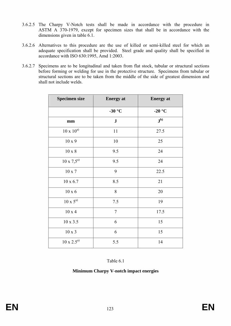
EN 123 EN
3.6.2.5 The Charpy V-Notch tests shall be made in accordance with the procedure in ASTM A 370-1979, except for specimen sizes that shall be in accordance with the dimensions given in table 6.1.
3.6.2.6 Alternatives to this procedure are the use of killed or semi-killed steel for which an adequate specification shall be provided. Steel grade and quality shall be specified in accordance with ISO 630:1995, Amd 1:2003.
3.6.2.7 Specimens are to be longitudinal and taken from flat stock, tubular or structural sections before forming or welding for use in the protective structure. Specimens from tubular or structural sections are to be taken from the middle of the side of greatest dimension and shall not include welds.
Specimen size Energy at Energy at
-30 °C -20 °C
mm J Jb)
10 x 10a) 11 27.5
10 x 9 10 25
10 x 8 9.5 24
10 x 7,5a) 9.5 24
10 x 7 9 22.5
10 x 6.7 8.5 21
10 x 6 8 20
10 x 5a) 7.5 19
10 x 4 7 17.5
10 x 3.5 6 15
10 x 3 6 15
10 x 2.5a) 5.5 14
Table 6.1
Minimum Charpy V-notch impact energies

EN 124 EN
a) Indicates preferred size. Specimen size shall be no less than largest preferred size that the material permits.
b) The energy requirement at –20 °C is 2.5 times the value specified for –30 °C. Other factors affect impact energy strength, i.e. direction of rolling, yield strength, grain orientation and welding. These factors shall be considered when selecting and using steel.
4. Additonal requirements for foldable Roll-Over Protection Structures (foldable ROPS)
4.1. On-going work of the OECD
EN 125 EN
Appendix 1 Computer programme (BASIC) for determining the continuous or interrupted roll-over behaviour in case of a laterally overturning narrow-track tractor with a protective frame
mounted in front of the driver’s seat
Preliminary note: The following programme is valid for its calculation methods. Presentation of the printed text as proposed (English language and layout) is indicative; the user will adapt the programme to available printing and other requirements specific to the testing station. 10 CLS 20 REM REFERENCE OF THE PROGRAM COD6ABAS.BAS 08/02/96 30 FOR I = 1 TO 10: LOCATE I, 1, 0: NEXT I 40 COLOR 14, 8, 4 50 PRINT "************************************************************************************" 60 PRINT "* CALCULATION FOR DETERMINING THE NON-CONTINUOUS ROLLING BEHAVIOUR *" 70 PRINT "*OF A LATERAL OVERTURNING NARROW TRACTOR WITH A ROLL-OVER PROTECTIVE *" 80 PRINT "* STRUCTURE MOUNTED IN FRONT OF THE DRIVER'S SEAT *" 90 PRINT "************************************************************************************" 100 A$ = INKEY$: IF A$ = "" THEN 100 110 COLOR 10, 1, 4 120 DIM F(25), C(25), CAMPO$(25), LON(25), B$(25), C$(25), X(6, 7), Y(6, 7), Z(6, 7) 130 DATA 6,10,10,14,14,17,19,21,11,11,12,12,13,13,14,14,15,15,16,16,17,17,18,18,19 140 DATA 54,8,47,8,47,12,8,12,29,71,29,71,29,71,29,71,29,71,29,71,29,71,29,71,29 150 DATA 12,30,31,30,31,25,25,25,9,9,9,9,9,9,9,9,9,9,9,9,9,9,9,9,9 160 FOR I = 1 TO 25: READ F(I): NEXT 170 FOR I = 1 TO 25: READ C(I): NEXT 180 FOR I = 1 TO 25: READ LON(I): NEXT 190 CLS 200 FOR I = 1 TO 5: LOCATE I, 1, 0: NEXT I 210 PRINT "In case of misprint, push on the enter key up to the last field" 220 PRINT :LOCATE 6, 44: PRINT " TEST NR: ": PRINT 230 LOCATE 8, 29: PRINT " FRONT MOUNTED- PROTECTIVE STRUCTURE:": PRINT 240 PRINT " MAKE: ": LOCATE 10, 40: PRINT " TYPE: ": PRINT 250 LOCATE 12, 29: PRINT " TRACTOR :": PRINT : PRINT " MAKE: " 260 LOCATE 14, 40: PRINT " TYPE: ": PRINT : PRINT 270 PRINT " LOCATION: ": PRINT 280 PRINT " DATE: ": PRINT : PRINT " ENGINEER: " 290 NC = 1: GOSUB 4400 300 PRINT : PRINT : PRINT " In case of misprint, it is possible to acquire the data again" 310 PRINT : INPUT " Do you wish to acquire again the data ? (Y/N)"; Z$ 320 IF Z$ = "Y" OR Z$ = "y" THEN 190
EN 126 EN
330 IF Z$ = "N" OR Z$ = "n" THEN 340 340 FOR I=1 TO 3:LPRINT : NEXT: LPRINT ; " TEST NR: "; TAB(10); CAMPO$(1) 350 LPRINT : LPRINT TAB(24); " FRONT MOUNTED PROTECTIVE STRUCTURE:" 360 LL = LEN(CAMPO$(2) + CAMPO$(3)) 370 LPRINT TAB(36 - LL / 2); CAMPO$(2) + " - " + CAMPO$(3) : LPRINT 380 LPRINT TAB(32); " OF THE NARROW TRACTOR": LL = LEN(CAMPO$(4) + CAMPO$(5)) 390 LPRINT TAB(36 - LL / 2); CAMPO$(4) + " - " + CAMPO$(5) : LPRINT 400 CLS 410 PRINT "In case of mistype, push on the enter key up to the last field" 420 PRINT 430 FOR I = 1 TO 7: LOCATE I, 1, 0: NEXT 440 LOCATE 8, 1: PRINT " CHARACTERISTIC UNITS: " 450 LOCATE 8, 29: PRINT "LINEAR (m): MASS (kg):MOMENT OF INERTIA (kg⋅m2):" 460 LOCATE 9, 1: PRINT " ANGLE (radian)" 470 LPRINT : PRINT 480 PRINT "HEIGHT OF COG H1=": LOCATE 11, 29: PRINT " " 490 LOCATE 11, 40: PRINT "H. DIST. COG-REAR AXLE L3=" 500 LOCATE 11, 71: PRINT " " 510 PRINT "H. DIST. COG-FRT AXLE L2=": LOCATE 12, 29: PRINT " " 520 LOCATE 12, 40: PRINT "HEIGHT OF THE REAR TYRES D3=" 530 LOCATE 12, 71: PRINT " " 540 PRINT "HEIGHT OF THE FRT TYRES D2=": LOCATE 13, 29: PRINT " " 550 LOCATE 13, 40: PRINT "OVERALL HEIGHT(PT IMPACT) H6=" 560 LOCATE 13, 71: PRINT " " 570 PRINT "H.DIST.COG-LEAD.PT INTER.L6=": LOCATE 14, 29: PRINT " " 580 LOCATE 14, 40: PRINT "PROTECTIVE STRUCT. WIDTH B6=" 590 LOCATE 14, 71: PRINT " " 600 PRINT "HEIGHT OF THE ENG.B. H7=": LOCATE 15, 29: PRINT " " 605 LOCATE 15, 40: PRINT "WIDTH OF THE ENG. B. B7=" 610 LOCATE 15, 71: PRINT " " 615 PRINT "H.DIST.COG-FRT COR.ENG.B.L7=": LOCATE 16, 29: PRINT " " 620 LOCATE 16, 40: PRINT "HEIGHT FRT AXLE PIVOT PT H0=" 630 LOCATE 16, 71: PRINT " " 640 PRINT "REAR TRACK WIDTH S =": LOCATE 17, 29: PRINT " " 650 LOCATE 17, 40: PRINT "REAR TYRE WIDTH B0=" 660 LOCATE 17, 71: PRINT " " 670 PRINT "FRT AXLE SWING ANGLE D0=": LOCATE 18, 29: PRINT " " 680 LOCATE 18, 40: PRINT "TRACTOR MASS Mc =" 690 LOCATE 18, 71: PRINT " " 700 PRINT "MOMENT OF INERTIA Q =": LOCATE 19, 29: PRINT " " 710 LOCATE 19, 40: PRINT " " 720 LOCATE 19, 71: PRINT " ": PRINT : PRINT 730 H1 = 0: L3 = 0: L2 = 0: D3 = 0: D2 = 0: H6 = 0: L6 = 0: B6 = 0 740 H7 = 0: B7 = 0: L7 = 0: H0 = 0: S = 0: B0 = 0: D = 0: Mc = 0: Q = 0 750 NC = 9: GOSUB 4400 760 FOR I = 1 TO 3: PRINT "": NEXT 770 H1 = VAL(CAMPO$(9)): L3 = VAL(CAMPO$(10)): L2 = VAL(CAMPO$(11)) 780 D3 = VAL(CAMPO$(12)): D2 = VAL(CAMPO$(13)): H6 = VAL(CAMPO$(14)) 790 L6 = VAL(CAMPO$(15)): B6 = VAL(CAMPO$(16)): H7 = VAL(CAMPO$(17))
EN 127 EN
800 B7 = VAL(CAMPO$(18)): L7 = VAL(CAMPO$(19)): H0 = VAL(CAMPO$(20)) 810 S = VAL(CAMPO$(21)): B0 = VAL(CAMPO$(22)): D0 = VAL(CAMPO$(23)) 820 Mc = VAL(CAMPO$(24)): Q = VAL(CAMPO$(25)): PRINT : PRINT 830 PRINT "In case of mistype, it is possible to acquire again the data": PRINT 840 INPUT " Do you wish to acquire again the data ? (Y/N)"; X$ 850 IF X$ = "Y" OR X$ = "y" THEN 400 860 IF X$ = "n" OR X$ = "N" THEN 870 870 FOR I = 1 TO 3: LPRINT : NEXT 880 LPRINT TAB(20); "CHARACTERISTIC UNITS :": LOCATE 8, 29 890 LPRINT "LINEAR (m) : MASS (kg) : MOMENT OF INERTIA (kg⋅m2) : ANGLE (radian)" 900 LPRINT 910 LPRINT "HEIGHT OF THE COG H1="; 920 LPRINT USING "####.####"; H1; 930 LPRINT TAB(40); "H. DIST. COG-REAR AXLE L3="; 940 LPRINT USING "####.####"; L3 950 LPRINT "H.DIST. COG-FRT AXLE L2="; 960 LPRINT USING "####.####"; L2; 970 LPRINT TAB(40); "HEIGHT OF THE REAR TYRES D3="; 975 LPRINT USING "####.####"; D3 980 LPRINT "HEIGHT OF THE FRT TYRES D2="; 990 LPRINT USING "####.####"; D2; 1000 LPRINT TAB(40); "OVERALL HEIGHT(PT IMPACT)H6="; 1010 LPRINT USING "####.####"; H6 1020 LPRINT "H.DIST.COG-LEAD PT INTER.L6="; 1030 LPRINT USING "####.####"; L6; 1040 LPRINT TAB(40); "PROTECTIVE STRUCT. WIDTH B6="; 1050 LPRINT USING "####.####"; B6 1060 LPRINT "HEIGHT OF THE ENG.B. H7="; 1070 LPRINT USING "####.####"; H7; 1080 LPRINT TAB(40); "WIDTH OF THE ENG. B. B7="; 1090 LPRINT USING "####.####"; B7 1100 LPRINT "H.DIST.COG-FRT COR.ENG.B.L7="; 1110 LPRINT USING "####.####"; L7; 1120 LPRINT TAB(40); "HEIGHT FRT AXLE PIVOT PT H0="; 1130 LPRINT USING "####.####"; H0 1140 LPRINT "REAR TRACK WIDTH S ="; 1150 LPRINT USING "####.####"; S; 1160 LPRINT TAB(40); "REAR TYRE WIDTH B0="; 1170 LPRINT USING "####.####"; B0 1180 LPRINT "FRT AXLE SWING ANGLE D0="; 1185 LPRINT USING "####.####"; D0; 1190 LPRINT TAB(40); "TRACTOR MASS Mc = "; 1200 LPRINT USING "####.###"; Mc 1210 LPRINT "MOMENT OF INERTIA Q ="; 1215 LPRINT USING "####.####"; Q 1220 FOR I = 1 TO 10: LPRINT : NEXT 1230 A0 = .588: U = .2: T = .2: GOSUB 4860 1240 REM * THE SIGN OF L6 IS MINUS IF THE POINT LIES IN FRONT 1250 REM * OF THE PLANE OF THE CENTRE OF GRAVITY. 1260 IF B6 > S + B0 THEN 3715
EN 128 EN
1265 IF B7 > S + B0 THEN 3715 1270 G = 9.8 1280 REM *************************************************************************** 1290 REM *B2 VERSION (POINT OF IMPACT OF THE ROPS NEAR OF EQUILIBRIUM POINT)* 1300 REM *************************************************************************** 1310 B = B6: H = H6 1320 REM -----POSITION OF CENTER OF GRAVITY IN TILTED POSITION ------------ 1330 R2 = SQR(H1 * H1 + L3 * L3) 1340 C1 = ATN(H1 / L3) 1350 L0 = L3 + L2 1360 L9 = ATN(H0 / L0) 1370 H9 = R2 * SIN(C1 - L9) 1380 W1 = H9 / TAN(C1 - L9) 1390 W2 = SQR(H0 * H0 + L0 * L0): S1 = S / 2 1400 F1 = ATN(S1 / W2) 1410 W3 = (W2 - W1) * SIN(F1) 1420 W4 = ATN(H9 / W3) 1430 W5 = SQR(H9 * H9 + W3 * W3) * SIN(W4 + D0) 1440 W6 = W3 - SQR(W3 * W3 + H9 * H9) * COS(W4 + D0) 1450 W7 = W1 + W6 * SIN(F1) 1460 W8 = ATN(W5 / W7) 1470 W9 = SIN(W8 + L9) * SQR(W5 * W5 + W7 * W7) 1480 W0 = SQR(W9 * W9 + (S1 - W6 * COS(F1)) ^ 2) 1490 G1 = SQR(((S + B0) / 2) ^ 2 + H1 * H1) 1500 G2 = ATN(2 * H1 / (S + B0)) 1510 G3 = W0 - G1 * COS(A0 + G2) 1520 O0 = SQR(2 * Mc * G * G3 / (Q + Mc * (W0 + G1) * (W0 + G1) / 4)) 1530 F2 = ATN(((D3 - D2) / L0) / (1 - ((D3 - D2) / (2 * L3 + 2 * L2)) ^ 2)) 1540 L8 = -TAN(F2) * (H - H1) 1550 REM-------- COORDINATES IN POSITION 1 ------------- 1560 X(1, 1) = H1 1570 X(1, 2) = 0: X(1, 3) = 0 1580 X(1, 4) = (1 + COS(F2)) * D2 / 2 1590 X(1, 5) = (1 + COS(F2)) * D3 / 2 1600 X(1, 6) = H 1610 X(1, 7) = H7 1620 Y(1, 1) = 0 1630 Y(1, 2) = L2 1640 Y(1, 3) = -L3 1650 Y(1, 4) = L2 + SIN(F2) * D2 / 2 1660 Y(1, 5) = -L3 + SIN(F2) * D3 / 2 1670 Y(1, 6) = -L6 1680 Y(1, 7) = L7 1690 Z(1, 1) = (S + B0) / 2 1700 Z(1, 2) = 0: Z(1, 3) = 0: Z(1, 4) = 0: Z(1, 5) = 0 1710 Z(1, 6) = (S + B0) / 2 - B / 2 1720 Z(1, 7) = (S + B0) / 2 - B7 / 2 1730 O1 = 0: O2 = 0: O3 = 0: O4 = 0: O5 = 0: O6 = 0: O7 = 0: O8 = 0: O9 = 0
EN 129 EN
1740 K1 = Y(1, 4) * TAN(F2) + X(1, 4) 1750 K2 = X(1, 1) 1760 K3 = Z(1, 1) 1770 K4 = K1 - X(1, 1): DD1 = Q + Mc * K3 * K3 + Mc * K4 * K4 1780 O1 = (Q + Mc * K3 * K3 - U * Mc * K4 * K4 - (1 + U) * Mc * K2 * K4) * O0 / DD1 1790 REM----TRANSFORMATION OF THE COORDINATES FROM THE POSITION 1 TO 2 1800 FOR K = 1 TO 7 STEP 1 1810 X(2, K) = COS(F2) * (X(1, K) - H1) + SIN(F2) * Y(1, K) - K4 * COS(F2) 1820 Y(2, K) = Y(1, K) * COS(F2) - (X(1, K) - H1) * SIN(F2) 1830 Z(2, K) = Z(1, K) 1840 NEXT K 1850 O2 = O1 * COS(F2) 1860 A2 = ATN(TAN(A0) / SQR(1 + (TAN(F2)) ^ 2 / (COS(A0)) ^ 2)) 1870 C2 = ATN(Z(2, 6) / X(2, 6)) 1880 T2 = T 1890 V0 = SQR(X(2, 6) ^ 2 + Z(2, 6) ^ 2) 1900 E1 = T2 / V0 1910 E2 = (V0 * Y(2, 4)) / (Y(2, 4) - Y(2, 6)) 1920 T3 = E1 * E2 1930 E4 = SQR(X(2, 1) * X(2, 1) + Z(2, 1) * Z(2, 1)) 1940 V6 = ATN(X(2, 1) / Z(2, 1)) 1950 REM--------ROTATION OF THE TRACTOR FROM THE POSITION 2 TO 3 --- 1960 FOR K = 1 TO 7 STEP 1 1970 IF Z(2, K) = 0 THEN 2000 1980 E3 = ATN(X(2, K) / Z(2, K)) 1990 GOTO 2010 2000 E3 = -3.14159 / 2 2010 X(3, K) = SQR(X(2, K) * X(2, K) + Z(2, K) * Z(2, K)) * SIN(E3 + C2 + E1) 2020 Y(3, K) = Y(2, K) 2030 Z(3, K) = SQR(X(2, K) ^ 2 + Z(2, K) ^ 2) * COS(E3 + C2 + E1) 2040 NEXT K 2050 IF Z(3, 7) < 0 THEN 3680 2060 Z(3, 6) = 0 2070 Q3 = Q * (COS(F2)) ^ 2 + 3 * Q * (SIN(F2)) ^ 2 2080 V5 = (Q3 + Mc * E4 * E4) * O2 * O2 / 2 2090 IF -V6 > A2 THEN 2110 2100 GOTO 2130 2110 V7 = E4 * (1 - COS(-A2 - V6)) 2120 IF V7 * Mc * G > V5 THEN 2320 2130 V8 = E4 * COS(-A2 - V6) - E4 * COS(-A2 - ATN(X(3, 1) / Z(3, 1))) 2140 O3 = SQR(2 * Mc * G * V8 / (Q3 + Mc * E4 * E4) + O2 * O2) 2150 K9 = X(3, 1) 2160 K5 = Z(3, 1) 2170 K6 = Z(3, 1) + E1 * V0 2180 K7 = V0 - X(3, 1) 2190 K8 = U: DD2 = Q3 + Mc * K6 * K6 + Mc * K7 * K7 2200 O4 = (Q3 + Mc * K5 * K6 - K8 * Mc * K7 * K7 - (1 + K8) * Mc * K9 * K7) * O3 / DD2 2210 N3 = SQR((X(3, 6) - X(3, 1)) ^ 2 + (Z(3, 6) - Z(3, 1)) ^ 2) 2220 N2 = ATN(-(X(3, 6) - X(3, 1)) / Z(3, 1)) 2230 Q6 = Q3 + Mc * N3 ^ 2 2240 IF -N2 <= A2 THEN 2290
EN 130 EN
2250 N4 = N3 * (1 - COS(-A2 - N2)) 2260 N5 = (Q6) * O4 * O4 / 2 2270 IF N4 * Mc * G > N5 THEN 2320 2280 O9 = SQR(-2 * Mc * G * N4 / (Q6) + O4 * O4) 2290 GOSUB 3740 2300 GOSUB 4170 2310 GOTO 4330 2320 GOSUB 3740 2330 IF L6 > L8 THEN 2790 2340 REM * 2350 REM ******************************************************************************* 2355 REM *B3 VERSION (POINT OF IMPACT OF THE ROPS IN FRONT OF EQUILIBRIUM POINT)* 2360 REM ******************************************************************************* 2370 O3 = 0: O4 = 0: O5 = 0: O6 = 0: O7 = 0: O8 = 0: O9 = 0 2380 E2 = (V0 * Y(2, 5)) / (Y(2, 5) - Y(2, 6)) 2390 T3 = E2 * E1 2400 Z(3, 6) = 0 2410 Q3 = Q * (COS(F2)) ^ 2 + 3 * Q * (SIN(F2)) ^ 2 2420 V5 = (Q3 + Mc * E4 * E4) * O2 * O2 / 2 2430 IF -V6 > A2 THEN 2450 2440 GOTO 2470 2450 V7 = E4 * (1 - COS(-A2 - V6)) 2460 IF V7 * Mc * G > V5 THEN 2760 2470 V8 = E4 * COS(-A2 - V6) - E4 * COS(-A2 - ATN(X(3, 1) / Z(3, 1))) 2480 O3 = SQR((2 * Mc * G * V8) / (Q3 + Mc * E4 * E4) + O2 * O2) 2490 K9 = X(3, 1) 2500 K5 = Z(3, 1) 2510 K6 = Z(3, 1) + T3 2520 K7 = E2 - X(3, 1) 2530 K8 = U: DD2 = Q3 + Mc * K6 * K6 + Mc * K7 * K7 2540 O4 = (Q3 + Mc * K5 * K6 - K8 * Mc * K7 * K7 - (1 + K8) * Mc * K9 * K7) * O3 / DD2 2550 F3 = ATN(V0 / (Y(3, 5) - Y(3, 6))) 2560 O5 = O4 * COS(F3) 2570 REM------TRANSFORMATION OF THE COORDINATES FROM THE POSITION 3 TO 4 ---- 2580 REM------POSITION 4 2590 FOR K = 1 TO 7 STEP 1 2600 X(4, K) = X(3, K) * COS(F3) + (Y(3, K) - Y(3, 5)) * SIN(F3) 2610 Y(4, K) = (Y(3, K) - Y(3, 5)) * COS(F3) - X(3, K) * SIN(F3) 2620 Z(4, K) = Z(3, K) 2630 NEXT K 2640 A4 = ATN(TAN(A0) / SQR(1 + (TAN(F2 + F3)) ^ 2 / (COS(A0)) ^ 2)) 2650 M1 = SQR(X(4, 1) ^ 2 + Z(4, 1) ^ 2) 2660 M2 = ATN(X(4, 1) / Z(4, 1)) 2670 Q5 = Q * (COS(F2 + F3)) ^ 2 + 3 * Q * (SIN(F2 + F3)) ^ 2 2680 IF -M2 < A4 THEN 2730 2690 M3 = M1 * (1 - COS(-A4 - M2)) 2700 M4 = (Q5 + Mc * M1 * M1) * O5 * O5 / 2
EN 131 EN
2710 IF M3 * Mc * G > M4 THEN 2760 2720 O9 = SQR(O5 * O5 - 2 * Mc * G * M3 / (Q5 + Mc * M1 * M1)) 2730 GOSUB 3740 2740 GOSUB 4170 2750 GOTO 4330 2760 GOSUB 3740 2770 GOSUB 4240 2780 GOTO 4330 2790 REM ***************************************************************************** 2795 REM *B1 VERSION (POINT OF IMPACT OF THE ROPS BEHIND OF EQUILIBRIUM POINT)* 2800 REM ***************************************************************************** 2810 REM * 2820 O3 = 0: O4 = 0: O5 = 0: O6 = 0: O7 = 0: O8 = 0: O9 = 0 2830 Z(3, 6) = 0 2840 Q3 = Q * (COS(F2)) ^ 2 + 3 * Q * (SIN(F2)) ^ 2 2850 V5 = (Q3 + Mc * E4 * E4) * O2 * O2 / 2 2860 IF -V6 > A2 THEN 2880 2870 GOTO 2900 2880 V7 = E4 * (1 - COS(-A2 - V6)) 2890 IF V7 * Mc * G > V5 THEN 3640 2900 V8 = E4 * COS(-A2 - V6) - E4 * COS(-A2 - ATN(X(3, 1) / Z(3, 1))) 2910 O3 = SQR(2 * Mc * G * V8 / (Q3 + Mc * E4 * E4) + O2 * O2) 2920 K9 = X(3, 1) 2930 K5 = Z(3, 1) 2940 K6 = Z(3, 1) + T3 2950 K7 = E2 - X(3, 1) 2960 K8 = U: DD2 = Q3 + Mc * K6 * K6 + Mc * K7 * K7 2970 O4 = (Q3 + Mc * K5 * K6 - K8 * Mc * K7 * K7 - (1 + K8) * Mc * K9 * K7) * O3 / DD2 2980 F3 = ATN(V0 / (Y(3, 4) - Y(3, 6))) 2990 O5 = O4 * COS(F3) 3000 REM----TRANSFORMATION OF THE COORDINATES FROM 3 TO 4 --- 3010 FOR K = 1 TO 7 STEP 1 3020 X(4, K) = X(3, K) * COS(F3) + (Y(3, K) - Y(3, 4)) * SIN(F3) 3030 Y(4, K) = (Y(3, K) - Y(3, 4)) * COS(F3) - X(3, K) * SIN(F3) 3040 Z(4, K) = Z(3, K) 3050 NEXT K 3060 A4 = ATN(TAN(A0) / SQR(1 + (TAN(F2 + F3)) ^ 2 / (COS(A0)) ^ 2)) 3070 C3 = ATN(Z(4, 7) / X(4, 7)) 3080 C4 = 0 3090 C5 = SQR(X(4, 7) * X(4, 7) + Z(4, 7) * Z(4, 7)) 3100 C6 = C4 / C5 3110 C7 = C5 * (Y(4, 6) - Y(4, 1)) / (Y(4, 6) - Y(4, 7)) 3120 C8 = C6 * C7 3130 M1 = SQR(X(4, 1) ^ 2 + Z(4, 1) ^ 2) 3140 M2 = ATN(X(4, 1) / Z(4, 1)) 3150 REM ----ROTATION OF THE TRACTOR FROM THE POSITION 4 TO 5 --- 3160 FOR K = 1 TO 7 STEP 1 3170 IF Z(4, K) <> 0 THEN 3200
EN 132 EN
3180 C9 = -3.14159 / 2 3190 GOTO 3210 3200 C9 = ATN(X(4, K) / Z(4, K)) 3210 X(5, K) = SQR(X(4, K) ^ 2 + Z(4, K) ^ 2) * SIN(C9 + C3 + C6) 3220 Y(5, K) = Y(4, K) 3230 Z(5, K) = SQR(X(4, K) ^ 2 + Z(4, K) ^ 2) * COS(C9 + C3 + C6) 3240 NEXT K 3250 Z(5, 7) = 0 3260 Q5 = Q * (COS(F2 + F3)) ^ 2 + 3 * Q * (SIN(F2 + F3)) ^ 2 3270 IF -M2 > A4 THEN 3290 3280 GOTO 3320 3290 M3 = M1 * (1 - COS(-A4 - M2)) 3300 M4 = (Q5 + Mc * M1 * M1) * O5 * O5 / 2 3310 IF M3 * Mc * G > M4 THEN 3640 3315 MM1 = M1 * COS(-A4 - ATN(X(5, 1) / Z(5, 1))) 3320 M5 = M1 * COS(-A4 - ATN(X(4, 1) / Z(4, 1))) - MM1 3330 O6 = SQR(2 * Mc * G * M5 / (Q5 + Mc * M1 * M1) + O5 * O5) 3340 M6 = X(5, 1) 3350 M7 = Z(5, 1) 3360 M8 = Z(5, 1) + C8 3370 M9 = C7 - X(5, 1) 3380 N1 = U: DD3 = (Q5 + Mc * M8 * M8 + Mc * M9 * M9) 3390 O7 = (Q5 + Mc * M7 * M8 - N1 * Mc * M9 * M9 - (1 + N1) * Mc * M6 * M9) * O6 / DD3 3400 F5 = ATN(C5 / (Y(5, 6) - Y(5, 7))) 3410 A6 = ATN(TAN(A0) / SQR(1 + (TAN(F2 + F3 + F5)) ^ 2 / (COS(A0)) ^ 2)) 3420 REM----TRANSFORMATION OF THE COORDINATES FROM THE POSITION 5 TO 6 --- 3430 FOR K = 1 TO 7 STEP 1 3440 X(6, K) = X(5, K) * COS(F5) + (Y(5, K) - Y(5, 6)) * SIN(F5) 3450 Y(6, K) = (Y(5, K) - Y(5, 6)) * COS(F5) - X(5, K) * SIN(F5) 3460 Z(6, K) = Z(5, K) 3470 NEXT K 3480 O8 = O7 * COS(-F5) 3490 N2 = ATN(X(6, 1) / Z(6, 1)) 3500 N3 = SQR(X(6, 1) ^ 2 + Z(6, 1) ^ 2) 3510 Q6 = Q * (COS(F2 + F3 + F5)) ^ 2 + 3 * Q * (SIN(F2 + F3 + F5)) ^ 2 3520 IF -N2 > A6 THEN 3540 3530 GOTO 3580 3540 N4 = N3 * (1 - COS(-A6 - N2)) 3550 N5 = (Q6 + Mc * N3 * N3) * O8 * O8 / 2 3560 P9 = (N4 * Mc * G - N5) / (N4 * Mc * G) 3570 IF N4 * Mc * G > N5 THEN 3640 3580 IF -N2 < A6 THEN 3610 3590 N6 = -N4 3600 O9 = SQR(2 * Mc * G * N6 / (Q6 + Mc * N3 * N3) + O8 * O8) 3610 GOSUB 3740 3620 GOSUB 4170 3630 GOTO 4330 3640 GOSUB 3740 3650 GOSUB 4240 3660 GOTO 4330
EN 133 EN
3670 REM 3680 IF Z(3, 7) > -.2 THEN 2060 3685 CLS : PRINT : PRINT : PRINT STRING$(80, 42): LOCATE 24, 30, 0 3690 PRINT " THE ENGINE BONNET TOUCHES THE GROUND BEFORE THE ROPS" 3695 LPRINT STRING$(80, 42) 3700 LPRINT "THE ENGINE BONNET TOUCHES THE GROUND BEFORE THE ROPS " 3710 PRINT : PRINT " METHOD OF CALCULATION NOT FEASIBLE" : GOTO 3720 3715 CLS : PRINT : PRINT " METHOD OF CALCULATION NOT FEASIBLE" 3720 LPRINT "METHOD OF CALCULATION NOT FEASIBLE " 3725 LPRINT STRING$(80, 42) 3730 GOTO 4330 3740 REM ******************************************************************* 3750 CLS : LOCATE 13, 15, 0: PRINT "VELOCITY O0=" 3755 LOCATE 13, 31, 0: PRINT USING "#.###"; O0: LOCATE 13, 40, 0: PRINT "rad/s" 3760 LOCATE 14, 15, 0: PRINT "VELOCITY O1=" 3765 LOCATE 14, 31, 0: PRINT USING "#.###"; O1 3770 LOCATE 15, 15, 0: PRINT "VELOCITY O2=" 3775 LOCATE 15, 31, 0: PRINT USING "#.###"; O2 3780 LOCATE 16, 15, 0: PRINT "VELOCITY O3=" 3785 LOCATE 16, 31, 0: PRINT USING "#.###"; O3 3790 LOCATE 17, 15, 0: PRINT "VELOCITY O4=" 3795 LOCATE 17, 31, 0: PRINT USING "#.###"; O4 3800 LOCATE 18, 15, 0: PRINT "VELOCITY O5=" 3805 LOCATE 18, 31, 0: PRINT USING "#.###"; O5 3810 LOCATE 19, 15, 0: PRINT "VELOCITY O6=" 3815 LOCATE 19, 31, 0: PRINT USING "#.###"; O6 3820 LOCATE 20, 15, 0: PRINT "VELOCITY O7=" 3825 LOCATE 20, 31, 0: PRINT USING "#.###"; O7 3830 LOCATE 21, 15, 0: PRINT "VELOCITY O8=" 3835 LOCATE 21, 31, 0: PRINT USING "#.###"; O8 3840 LOCATE 22, 15, 0: PRINT "VELOCITY O9=" 3845 LOCATE 22, 31, 0: PRINT USING "#.###"; O9 3850 LPRINT "VELOCITY O0="; 3860 LPRINT USING "#.###"; O0; 3870 LPRINT " rad/s"; 3880 LPRINT TAB(40); "VELOCITY O1="; 3890 LPRINT USING "#.###"; O1; 3900 LPRINT " rad/s" 3910 LPRINT "VELOCITY O2="; 3920 LPRINT USING "#.###"; O2; 3930 LPRINT " rad/s"; 3940 LPRINT TAB(40); "VELOCITY O3="; 3950 LPRINT USING "#.###"; O3; 3960 LPRINT " rad/s" 3970 LPRINT "VELOCITY O4="; 3980 LPRINT USING "#.###"; O4; 3990 LPRINT " rad/s"; 4000 LPRINT TAB(40); "VELOCITY O5="; 4010 LPRINT USING "#.###"; O5; 4020 LPRINT " rad/s" 4030 LPRINT "VELOCITY O6=";
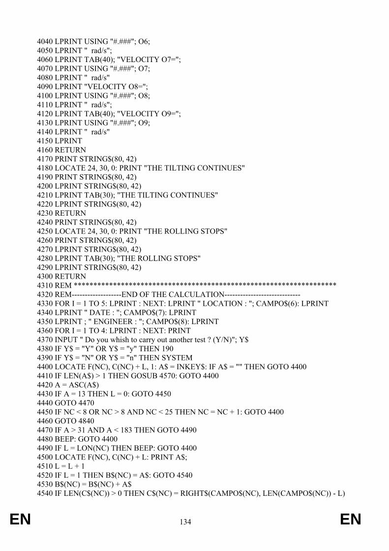
EN 134 EN
4040 LPRINT USING "#.###"; O6; 4050 LPRINT " rad/s"; 4060 LPRINT TAB(40); "VELOCITY O7="; 4070 LPRINT USING "#.###"; O7; 4080 LPRINT " rad/s" 4090 LPRINT "VELOCITY O8="; 4100 LPRINT USING "#.###"; O8; 4110 LPRINT " rad/s"; 4120 LPRINT TAB(40); "VELOCITY O9="; 4130 LPRINT USING "#.###"; O9; 4140 LPRINT " rad/s" 4150 LPRINT 4160 RETURN 4170 PRINT STRING$(80, 42) 4180 LOCATE 24, 30, 0: PRINT "THE TILTING CONTINUES" 4190 PRINT STRING$(80, 42) 4200 LPRINT STRING$(80, 42) 4210 LPRINT TAB(30); "THE TILTING CONTINUES" 4220 LPRINT STRING$(80, 42) 4230 RETURN 4240 PRINT STRING$(80, 42) 4250 LOCATE 24, 30, 0: PRINT "THE ROLLING STOPS" 4260 PRINT STRING$(80, 42) 4270 LPRINT STRING$(80, 42) 4280 LPRINT TAB(30); "THE ROLLING STOPS" 4290 LPRINT STRING$(80, 42) 4300 RETURN 4310 REM ******************************************************************* 4320 REM-------------------END OF THE CALCULATION----------------------------- 4330 FOR I = 1 TO 5: LPRINT : NEXT: LPRINT " LOCATION : "; CAMPO$(6): LPRINT 4340 LPRINT " DATE : "; CAMPO$(7): LPRINT 4350 LPRINT ; " ENGINEER : "; CAMPO$(8): LPRINT 4360 FOR I = 1 TO 4: LPRINT : NEXT: PRINT 4370 INPUT " Do you whish to carry out another test ? (Y/N)"; Y$ 4380 IF Y$ = "Y" OR Y$ = "y" THEN 190 4390 IF Y$ = "N" OR Y$ = "n" THEN SYSTEM 4400 LOCATE F(NC), C(NC) + L, 1: A$ = INKEY$: IF A$ = "" THEN GOTO 4400 4410 IF LEN(A$) > 1 THEN GOSUB 4570: GOTO 4400 4420 A = ASC(A$) 4430 IF A = 13 THEN L = 0: GOTO 4450 4440 GOTO 4470 4450 IF NC < 8 OR NC > 8 AND NC < 25 THEN NC = NC + 1: GOTO 4400 4460 GOTO 4840 4470 IF A > 31 AND A < 183 THEN GOTO 4490 4480 BEEP: GOTO 4400 4490 IF L = LON(NC) THEN BEEP: GOTO 4400 4500 LOCATE F(NC), C(NC) + L: PRINT A$; 4510 L = L + 1 4520 IF L = 1 THEN B$(NC) = A$: GOTO 4540 4530 B$(NC) = B$(NC) + A$ 4540 IF LEN(C$(NC)) > 0 THEN C$(NC) = RIGHT$(CAMPO$(NC), LEN(CAMPO$(NC)) - L)
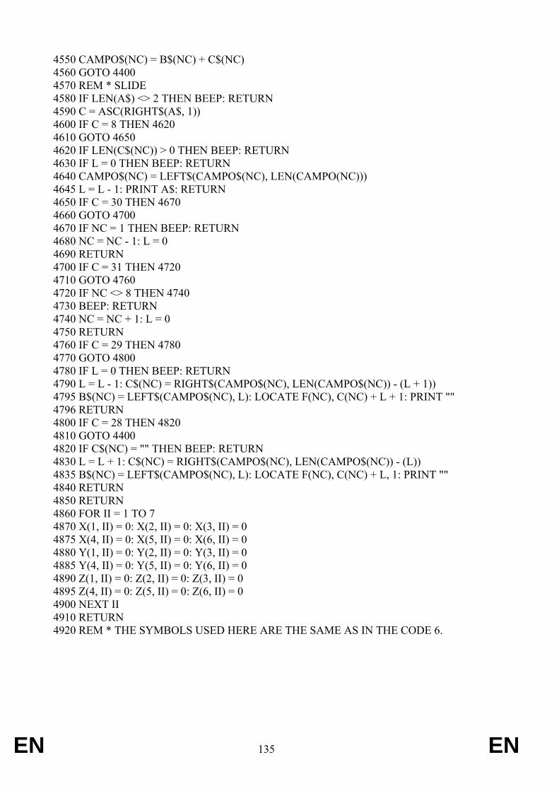
EN 135 EN
4550 CAMPO$(NC) = B$(NC) + C$(NC) 4560 GOTO 4400 4570 REM * SLIDE 4580 IF LEN(A$) <> 2 THEN BEEP: RETURN 4590 C = ASC(RIGHT$(A$, 1)) 4600 IF C = 8 THEN 4620 4610 GOTO 4650 4620 IF LEN(C$(NC)) > 0 THEN BEEP: RETURN 4630 IF L = 0 THEN BEEP: RETURN 4640 CAMPO$(NC) = LEFT$(CAMPO$(NC), LEN(CAMPO(NC))) 4645 L = L - 1: PRINT A$: RETURN 4650 IF C = 30 THEN 4670 4660 GOTO 4700 4670 IF NC = 1 THEN BEEP: RETURN 4680 NC = NC - 1: L = 0 4690 RETURN 4700 IF C = 31 THEN 4720 4710 GOTO 4760 4720 IF NC <> 8 THEN 4740 4730 BEEP: RETURN 4740 NC = NC + 1: L = 0 4750 RETURN 4760 IF C = 29 THEN 4780 4770 GOTO 4800 4780 IF L = 0 THEN BEEP: RETURN 4790 L = L - 1: C$(NC) = RIGHT$(CAMPO$(NC), LEN(CAMPO$(NC)) - (L + 1)) 4795 B$(NC) = LEFT$(CAMPO$(NC), L): LOCATE F(NC), C(NC) + L + 1: PRINT "" 4796 RETURN 4800 IF C = 28 THEN 4820 4810 GOTO 4400 4820 IF C$(NC) = "" THEN BEEP: RETURN 4830 L = L + 1: C$(NC) = RIGHT$(CAMPO$(NC), LEN(CAMPO$(NC)) - (L)) 4835 B$(NC) = LEFT$(CAMPO$(NC), L): LOCATE F(NC), C(NC) + L, 1: PRINT "" 4840 RETURN 4850 RETURN 4860 FOR II = 1 TO 7 4870 X(1, II) = 0: X(2, II) = 0: X(3, II) = 0 4875 X(4, II) = 0: X(5, II) = 0: X(6, II) = 0 4880 Y(1, II) = 0: Y(2, II) = 0: Y(3, II) = 0 4885 Y(4, II) = 0: Y(5, II) = 0: Y(6, II) = 0 4890 Z(1, II) = 0: Z(2, II) = 0: Z(3, II) = 0 4895 Z(4, II) = 0: Z(5, II) = 0: Z(6, II) = 0 4900 NEXT II 4910 RETURN 4920 REM * THE SYMBOLS USED HERE ARE THE SAME AS IN THE CODE 6.

EN 136 EN
TEST NR:
FRONT MOUNTED-OVER PROTECTIVE STRUCTURE
OF THE NARROW TRACTOR:
CHARACTERISTIC UNITS: LINEAR (m): MASS (kg): MOMENT OF INERTIA (kgm2): ANGLE (radian) HEIGHT OF THE COG H1 = 0.7620 H. DIST. COG - FRONT AXLE L2 = 1.1490 HEIGHT OF THE FRT TYRES D2 = 0.8800 H. DIST. COG-LEAD PT INTER.L6 = 0.2800 HEIGHT OF THE ENG. B. H7 = 1.3370 H. DIST. COG-FRT COR. ENG. B.L7 = 1.6390REAR TRACK WIDTH S = 1.1150 FRT AXLE SWING ANGLE D0 = 0.1570 MOMENT OF INERTIA Q =295.0000
H. DIST. COG-REAR AXLE L3 = 0.8970 HEIGHT OF THE REAR TYRESD3 = 1.2930 OVERALL HEIGHT( PT IMPACT)H6 =2.1000 PROTECTIVE STRUCT. WIDTHB6 = 0.7780 WIDTH OF THE ENG. B. B7 = 0.4900 HEIGHT FRT AXLE PIVOT PTH0 = 0.4450 REAR TYRE WIDTH B0 = 0.1950 TRACTOR MASS Mc = 2565.000
VELOCITY O0 = 3.881 rad/s VELOCITY O2 = 1.057 rad/s VELOCITY O4 = 0.731 rad/s VELOCITY O6 = 0.000 rad/s VELOCITY O8 = 0.000 rad/s VELOCITY O0 = 3.881 rad/s VELOCITY O2 = 1.057 rad/s VELOCITY O4 = 1.130 rad/s VELOCITY O6 = 0.810 rad/s VELOCITY O8 = 0.587 rad/s
VELOCITY O1 = 1.078 rad/s VELOCITY O3 = 2.134 rad/s VELOCITY O5 = 0.000 rad/s VELOCITY O7 = 0.000 rad/s VELOCITY O9 = 0.000 rad/s VELOCITY O1 = 1.078 rad/s VELOCITY O3 = 2.134 rad/s VELOCITY O5 = 0.993 rad/s VELOCITY O7 = 0.629 rad/s VELOCITY O9 = 0.219 rad/s
THE TILTING CONTINUES
Location: Date: Engineer:
Example 6.1
The tilting continues
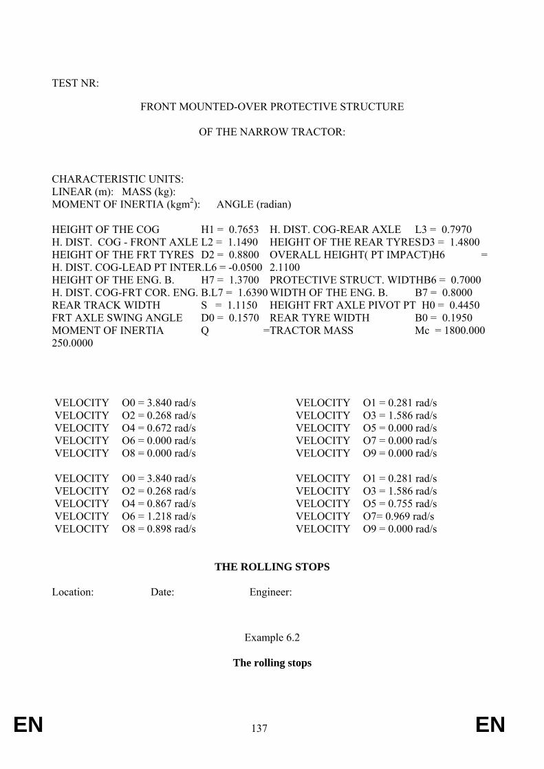
EN 137 EN
TEST NR:
FRONT MOUNTED-OVER PROTECTIVE STRUCTURE
OF THE NARROW TRACTOR:
CHARACTERISTIC UNITS: LINEAR (m): MASS (kg): MOMENT OF INERTIA (kgm2): ANGLE (radian) HEIGHT OF THE COG H1 = 0.7653 H. DIST. COG - FRONT AXLE L2 = 1.1490 HEIGHT OF THE FRT TYRES D2 = 0.8800 H. DIST. COG-LEAD PT INTER.L6 = -0.0500 HEIGHT OF THE ENG. B. H7 = 1.3700 H. DIST. COG-FRT COR. ENG. B.L7 = 1.6390REAR TRACK WIDTH S = 1.1150 FRT AXLE SWING ANGLE D0 = 0.1570 MOMENT OF INERTIA Q =250.0000
H. DIST. COG-REAR AXLE L3 = 0.7970 HEIGHT OF THE REAR TYRES D3 = 1.4800 OVERALL HEIGHT( PT IMPACT)H6 =2.1100 PROTECTIVE STRUCT. WIDTHB6 = 0.7000 WIDTH OF THE ENG. B. B7 = 0.8000 HEIGHT FRT AXLE PIVOT PT H0 = 0.4450 REAR TYRE WIDTH B0 = 0.1950 TRACTOR MASS Mc = 1800.000
VELOCITY O0 = 3.840 rad/s VELOCITY O2 = 0.268 rad/s VELOCITY O4 = 0.672 rad/s VELOCITY O6 = 0.000 rad/s VELOCITY O8 = 0.000 rad/s VELOCITY O0 = 3.840 rad/s VELOCITY O2 = 0.268 rad/s VELOCITY O4 = 0.867 rad/s VELOCITY O6 = 1.218 rad/s VELOCITY O8 = 0.898 rad/s
VELOCITY O1 = 0.281 rad/s VELOCITY O3 = 1.586 rad/s VELOCITY O5 = 0.000 rad/s VELOCITY O7 = 0.000 rad/s VELOCITY O9 = 0.000 rad/s VELOCITY O1 = 0.281 rad/s VELOCITY O3 = 1.586 rad/s VELOCITY O5 = 0.755 rad/s VELOCITY O7= 0.969 rad/s VELOCITY O9 = 0.000 rad/s
THE ROLLING STOPS
Location: Date: Engineer:
Example 6.2
The rolling stops
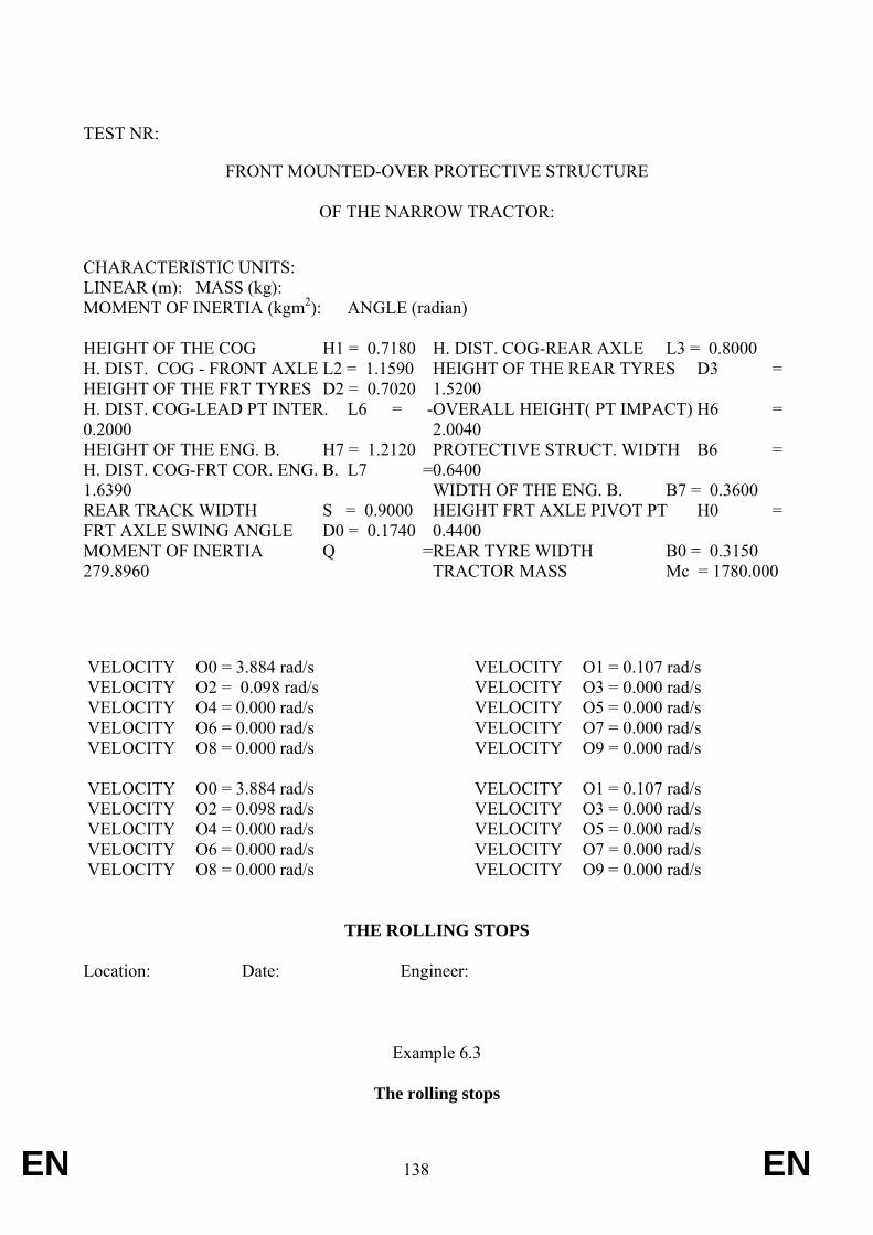
EN 138 EN
TEST NR:
FRONT MOUNTED-OVER PROTECTIVE STRUCTURE
OF THE NARROW TRACTOR:
CHARACTERISTIC UNITS: LINEAR (m): MASS (kg): MOMENT OF INERTIA (kgm2): ANGLE (radian) HEIGHT OF THE COG H1 = 0.7180 H. DIST. COG - FRONT AXLE L2 = 1.1590 HEIGHT OF THE FRT TYRES D2 = 0.7020 H. DIST. COG-LEAD PT INTER. L6 = -0.2000 HEIGHT OF THE ENG. B. H7 = 1.2120 H. DIST. COG-FRT COR. ENG. B. L7 =1.6390 REAR TRACK WIDTH S = 0.9000 FRT AXLE SWING ANGLE D0 = 0.1740 MOMENT OF INERTIA Q =279.8960
H. DIST. COG-REAR AXLE L3 = 0.8000 HEIGHT OF THE REAR TYRES D3 =1.5200 OVERALL HEIGHT( PT IMPACT) H6 =2.0040 PROTECTIVE STRUCT. WIDTH B6 =0.6400 WIDTH OF THE ENG. B. B7 = 0.3600 HEIGHT FRT AXLE PIVOT PT H0 =0.4400 REAR TYRE WIDTH B0 = 0.3150 TRACTOR MASS Mc = 1780.000
VELOCITY O0 = 3.884 rad/s VELOCITY O2 = 0.098 rad/s VELOCITY O4 = 0.000 rad/s VELOCITY O6 = 0.000 rad/s VELOCITY O8 = 0.000 rad/s VELOCITY O0 = 3.884 rad/s VELOCITY O2 = 0.098 rad/s VELOCITY O4 = 0.000 rad/s VELOCITY O6 = 0.000 rad/s VELOCITY O8 = 0.000 rad/s
VELOCITY O1 = 0.107 rad/s VELOCITY O3 = 0.000 rad/s VELOCITY O5 = 0.000 rad/s VELOCITY O7 = 0.000 rad/s VELOCITY O9 = 0.000 rad/s VELOCITY O1 = 0.107 rad/s VELOCITY O3 = 0.000 rad/s VELOCITY O5 = 0.000 rad/s VELOCITY O7 = 0.000 rad/s VELOCITY O9 = 0.000 rad/s
THE ROLLING STOPS
Location: Date: Engineer:
Example 6.3
The rolling stops

EN 139 EN
TEST NR:
FRONT MOUNTED-OVER PROTECTIVE STRUCTURE
OF THE NARROW TRACTOR:
CHARACTERISTIC UNITS: LINEAR (m): MASS (kg): MOMENT OF INERTIA (kgm2): ANGLE (radian) HEIGHT OF THE COG H1 = 0.7180 H. DIST. COG - FRONT AXLE L2 = 1.1590 HEIGHT OF THE FRT TYRES D2 = 0.7020 H. DIST. COG-LEAD PT INTER. L6 = -0.3790 HEIGHT OF THE ENG. B. H7 = 1.2120 H. DIST. COG-FRT COR. ENG. B. L7 =1.6390 REAR TRACK WIDTH S = 0.9000 FRT AXLE SWING ANGLE D0 = 0.1740 MOMENT OF INERTIA Q =279.8960
H. DIST. COG-REAR AXLE L3 = 0.8110 HEIGHT OF THE REAR TYRES D3 =1.2170 OVERALL HEIGHT( PT IMPACT) H6 =2.1900 PROTECTIVE STRUCT. WIDTH B6 =0.6400 WIDTH OF THE ENG. B. B7 = 0.3600 HEIGHT FRT AXLE PIVOT PT H0 =0.4400 REAR TYRE WIDTH B0 = 0.3150 TRACTOR MASS Mc = 1780.000
VELOCITY O0 = 3.884 rad/s VELOCITY O2 = 1.488 rad/s VELOCITY O4 = 0.405 rad/s VELOCITY O6 = 0.000 rad/s VELOCITY O8 = 0.000 rad/s VELOCITY O0 = 3.884 rad/s VELOCITY O2 = 1.488 rad/s VELOCITY O4 = 0.414 rad/s VELOCITY O6 = 0.000 rad/s VELOCITY O8 = 0.000 rad/s
VELOCITY O1 = 1.540 rad/s VELOCITY O3 = 2.162 rad/s VELOCITY O5 = 0.000 rad/s VELOCITY O7 = 0.000 rad/s VELOCITY O9 = 0.000 rad/s VELOCITY O1 = 1.540 rad/s VELOCITY O3 = 2.162 rad/s VELOCITY O5 = 0.289 rad/s VELOCITY O7= 0.000 rad/s VELOCITY O9 = 0.000 rad/s
THE ROLLING STOPS
Location: Date: Engineer:
Example 6.4
The rolling stops
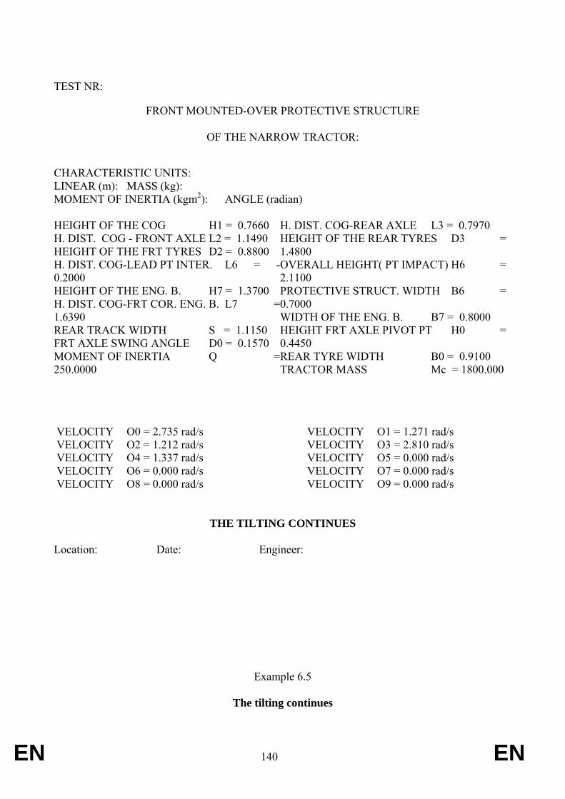
EN 140 EN
TEST NR:
FRONT MOUNTED-OVER PROTECTIVE STRUCTURE
OF THE NARROW TRACTOR:
CHARACTERISTIC UNITS: LINEAR (m): MASS (kg): MOMENT OF INERTIA (kgm2): ANGLE (radian) HEIGHT OF THE COG H1 = 0.7660 H. DIST. COG - FRONT AXLE L2 = 1.1490 HEIGHT OF THE FRT TYRES D2 = 0.8800 H. DIST. COG-LEAD PT INTER. L6 = -0.2000 HEIGHT OF THE ENG. B. H7 = 1.3700 H. DIST. COG-FRT COR. ENG. B. L7 =1.6390 REAR TRACK WIDTH S = 1.1150 FRT AXLE SWING ANGLE D0 = 0.1570 MOMENT OF INERTIA Q =250.0000
H. DIST. COG-REAR AXLE L3 = 0.7970 HEIGHT OF THE REAR TYRES D3 =1.4800 OVERALL HEIGHT( PT IMPACT) H6 =2.1100 PROTECTIVE STRUCT. WIDTH B6 =0.7000 WIDTH OF THE ENG. B. B7 = 0.8000 HEIGHT FRT AXLE PIVOT PT H0 =0.4450 REAR TYRE WIDTH B0 = 0.9100 TRACTOR MASS Mc = 1800.000
VELOCITY O0 = 2.735 rad/s VELOCITY O2 = 1.212 rad/s VELOCITY O4 = 1.337 rad/s VELOCITY O6 = 0.000 rad/s VELOCITY O8 = 0.000 rad/s
VELOCITY O1 = 1.271 rad/s VELOCITY O3 = 2.810 rad/s VELOCITY O5 = 0.000 rad/s VELOCITY O7 = 0.000 rad/s VELOCITY O9 = 0.000 rad/s
THE TILTING CONTINUES
Location: Date: Engineer:
Example 6.5
The tilting continues

EN 141 EN
TEST NR:
FRONT MOUNTED-OVER PROTECTIVE STRUCTURE
OF THE NARROW TRACTOR:
CHARACTERISTIC UNITS: LINEAR (m): MASS (kg): MOMENT OF INERTIA (kgm2): ANGLE (radian) HEIGHT OF THE COG H1 = 0.7653 H. DIST. COG - FRONT AXLE L2 = 1.1490 HEIGHT OF THE FRT TYRES D2 = 0.8800 H. DIST. COG-LEAD PT INTER. L6 = -0.4000 HEIGHT OF THE ENG. B. H7 = 1.3700 H. DIST. COG-FRT COR. ENG. B. L7 =1.6390 REAR TRACK WIDTH S = 1.1150 FRT AXLE SWING ANGLE D0 = 0.1570 MOMENT OF INERTIA Q =275.0000
H. DIST. COG-REAR AXLE L3 = 0.7970 HEIGHT OF THE REAR TYRES D3 =1.2930 OVERALL HEIGHT( PT IMPACT) H6 =1.9600 PROTECTIVE STRUCT. WIDTH B6 =0.7000 WIDTH OF THE ENG. B. B7 = 0.8750 HEIGHT FRT AXLE PIVOT PT H0 =0.4450 REAR TYRE WIDTH B0 = 0.1950 TRACTOR MASS Mc = 1800.000
VELOCITY O0 = 3.815 rad/s VELOCITY O2 = 1.105 rad/s VELOCITY O4 = 0.786 rad/s VELOCITY O6 = 0.000 rad/s VELOCITY O8 = 0.000 rad/s VELOCITY O0 = 3.815 rad/s VELOCITY O2 = 1.105 rad/s VELOCITY O4 = 0.980 rad/s VELOCITY O6 = 0.000 rad/s VELOCITY O8 = 0.000 rad/s
VELOCITY O1 = 1.130 rad/s VELOCITY O3 = 2.196 rad/s VELOCITY O5 = 0.000 rad/s VELOCITY O7 = 0.000 rad/s VELOCITY O9 = 0.000 rad/s VELOCITY O1 = 1.130 rad/s VELOCITY O3 = 2.196 rad/s VELOCITY O5 = 0.675 rad/s VELOCITY O7 = 0.000 rad/s VELOCITY O9 = 0.548 rad/s
THE TILTING CONTINUES
Location: Date: Engineer:
Example 6.6
The tilting continues
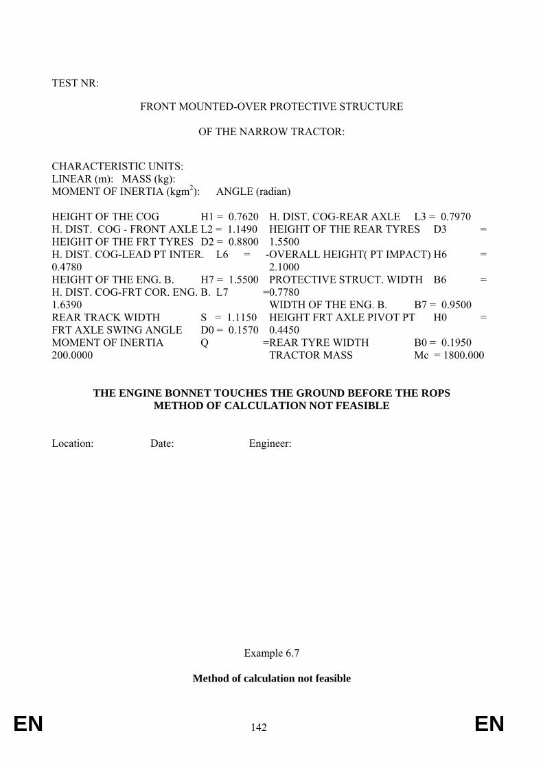
EN 142 EN
TEST NR:
FRONT MOUNTED-OVER PROTECTIVE STRUCTURE
OF THE NARROW TRACTOR:
CHARACTERISTIC UNITS: LINEAR (m): MASS (kg): MOMENT OF INERTIA (kgm2): ANGLE (radian) HEIGHT OF THE COG H1 = 0.7620 H. DIST. COG - FRONT AXLE L2 = 1.1490 HEIGHT OF THE FRT TYRES D2 = 0.8800 H. DIST. COG-LEAD PT INTER. L6 = -0.4780 HEIGHT OF THE ENG. B. H7 = 1.5500 H. DIST. COG-FRT COR. ENG. B. L7 =1.6390 REAR TRACK WIDTH S = 1.1150 FRT AXLE SWING ANGLE D0 = 0.1570 MOMENT OF INERTIA Q =200.0000
H. DIST. COG-REAR AXLE L3 = 0.7970 HEIGHT OF THE REAR TYRES D3 =1.5500 OVERALL HEIGHT( PT IMPACT) H6 =2.1000 PROTECTIVE STRUCT. WIDTH B6 =0.7780 WIDTH OF THE ENG. B. B7 = 0.9500 HEIGHT FRT AXLE PIVOT PT H0 =0.4450 REAR TYRE WIDTH B0 = 0.1950 TRACTOR MASS Mc = 1800.000
THE ENGINE BONNET TOUCHES THE GROUND BEFORE THE ROPS
METHOD OF CALCULATION NOT FEASIBLE Location: Date: Engineer:
Example 6.7
Method of calculation not feasible
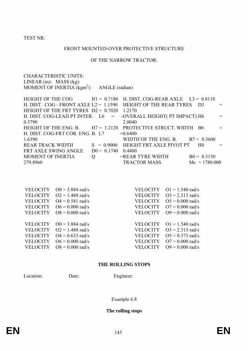
EN 143 EN
TEST NR:
FRONT MOUNTED-OVER PROTECTIVE STRUCTURE
OF THE NARROW TRACTOR:
CHARACTERISTIC UNITS: LINEAR (m): MASS (kg): MOMENT OF INERTIA (kgm2): ANGLE (radian) HEIGHT OF THE COG H1 = 0.7180 H. DIST. COG - FRONT AXLE L2 = 1.1590 HEIGHT OF THE FRT TYRES D2 = 0.7020 H. DIST. COG-LEAD PT INTER. L6 = -0.3790 HEIGHT OF THE ENG. B. H7 = 1.2120 H. DIST. COG-FRT COR. ENG. B. L7 =1.6390 REAR TRACK WIDTH S = 0.9000 FRT AXLE SWING ANGLE D0 = 0.1740 MOMENT OF INERTIA Q =279.8960
H. DIST. COG-REAR AXLE L3 = 0.8110 HEIGHT OF THE REAR TYRES D3 =1.2170 OVERALL HEIGHT( PT IMPACT) H6 =2.0040 PROTECTIVE STRUCT. WIDTH B6 =0.6400 WIDTH OF THE ENG. B. B7 = 0.3600 HEIGHT FRT AXLE PIVOT PT H0 =0.4400 REAR TYRE WIDTH B0 = 0.3150 TRACTOR MASS Mc = 1780.000
VELOCITY O0 = 3.884 rad/s VELOCITY O2 = 1.488 rad/s VELOCITY O4 = 0.581 rad/s VELOCITY O6 = 0.000 rad/s VELOCITY O8 = 0.000 rad/s VELOCITY O0 = 3.884 rad/s VELOCITY O2 = 1.488 rad/s VELOCITY O4 = 0.633 rad/s VELOCITY O6 = 0.000 rad/s VELOCITY O8 = 0.000 rad/s
VELOCITY O1 = 1.540 rad/s VELOCITY O3 = 2.313 rad/s VELOCITY O5 = 0.000 rad/s VELOCITY O7 = 0.000 rad/s VELOCITY O9 = 0.000 rad/s VELOCITY O1 = 1.540 rad/s VELOCITY O3 = 2.313 rad/s VELOCITY O5 = 0.373 rad/s VELOCITY O7 = 0.000 rad/s VELOCITY O9 = 0.000 rad/s
THE ROLLING STOPS
Location: Date: Engineer:
Example 6.8
The rolling stops
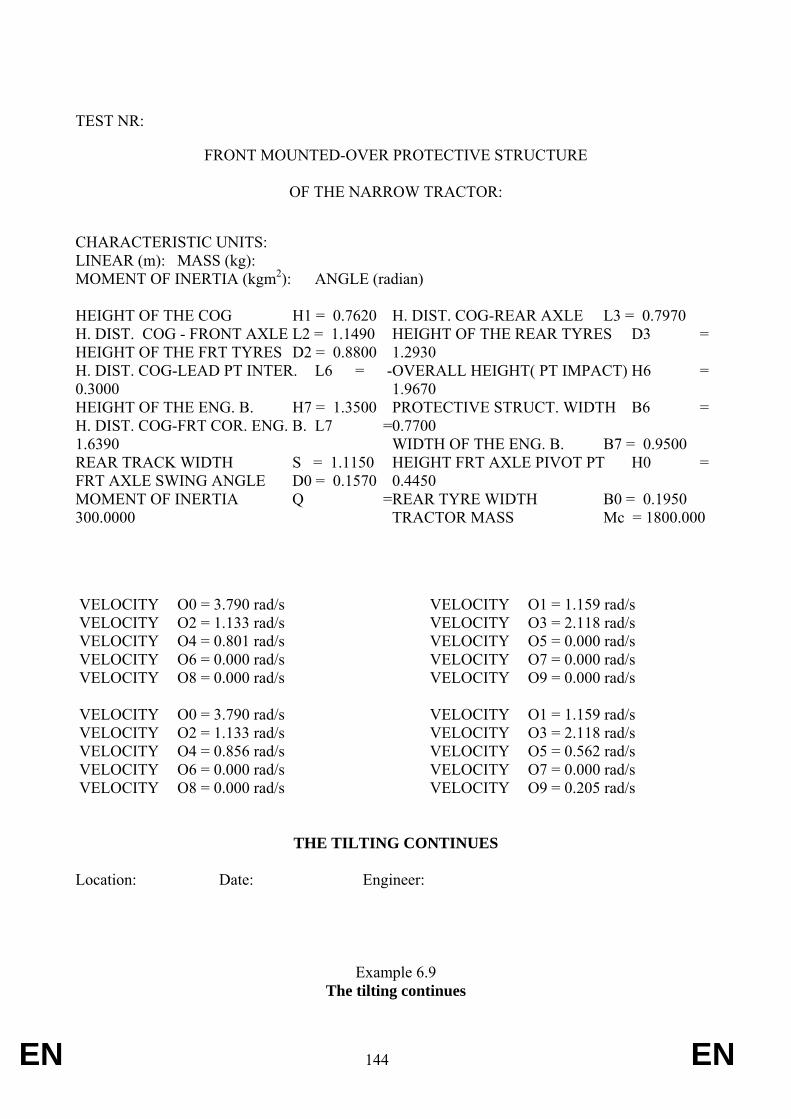
EN 144 EN
TEST NR:
FRONT MOUNTED-OVER PROTECTIVE STRUCTURE
OF THE NARROW TRACTOR:
CHARACTERISTIC UNITS: LINEAR (m): MASS (kg): MOMENT OF INERTIA (kgm2): ANGLE (radian) HEIGHT OF THE COG H1 = 0.7620 H. DIST. COG - FRONT AXLE L2 = 1.1490 HEIGHT OF THE FRT TYRES D2 = 0.8800 H. DIST. COG-LEAD PT INTER. L6 = -0.3000 HEIGHT OF THE ENG. B. H7 = 1.3500 H. DIST. COG-FRT COR. ENG. B. L7 =1.6390 REAR TRACK WIDTH S = 1.1150 FRT AXLE SWING ANGLE D0 = 0.1570 MOMENT OF INERTIA Q =300.0000
H. DIST. COG-REAR AXLE L3 = 0.7970 HEIGHT OF THE REAR TYRES D3 =1.2930 OVERALL HEIGHT( PT IMPACT) H6 =1.9670 PROTECTIVE STRUCT. WIDTH B6 =0.7700 WIDTH OF THE ENG. B. B7 = 0.9500 HEIGHT FRT AXLE PIVOT PT H0 =0.4450 REAR TYRE WIDTH B0 = 0.1950 TRACTOR MASS Mc = 1800.000
VELOCITY O0 = 3.790 rad/s VELOCITY O2 = 1.133 rad/s VELOCITY O4 = 0.801 rad/s VELOCITY O6 = 0.000 rad/s VELOCITY O8 = 0.000 rad/s VELOCITY O0 = 3.790 rad/s VELOCITY O2 = 1.133 rad/s VELOCITY O4 = 0.856 rad/s VELOCITY O6 = 0.000 rad/s VELOCITY O8 = 0.000 rad/s
VELOCITY O1 = 1.159 rad/s VELOCITY O3 = 2.118 rad/s VELOCITY O5 = 0.000 rad/s VELOCITY O7 = 0.000 rad/s VELOCITY O9 = 0.000 rad/s VELOCITY O1 = 1.159 rad/s VELOCITY O3 = 2.118 rad/s VELOCITY O5 = 0.562 rad/s VELOCITY O7 = 0.000 rad/s VELOCITY O9 = 0.205 rad/s
THE TILTING CONTINUES
Location: Date: Engineer:
Example 6.9 The tilting continues
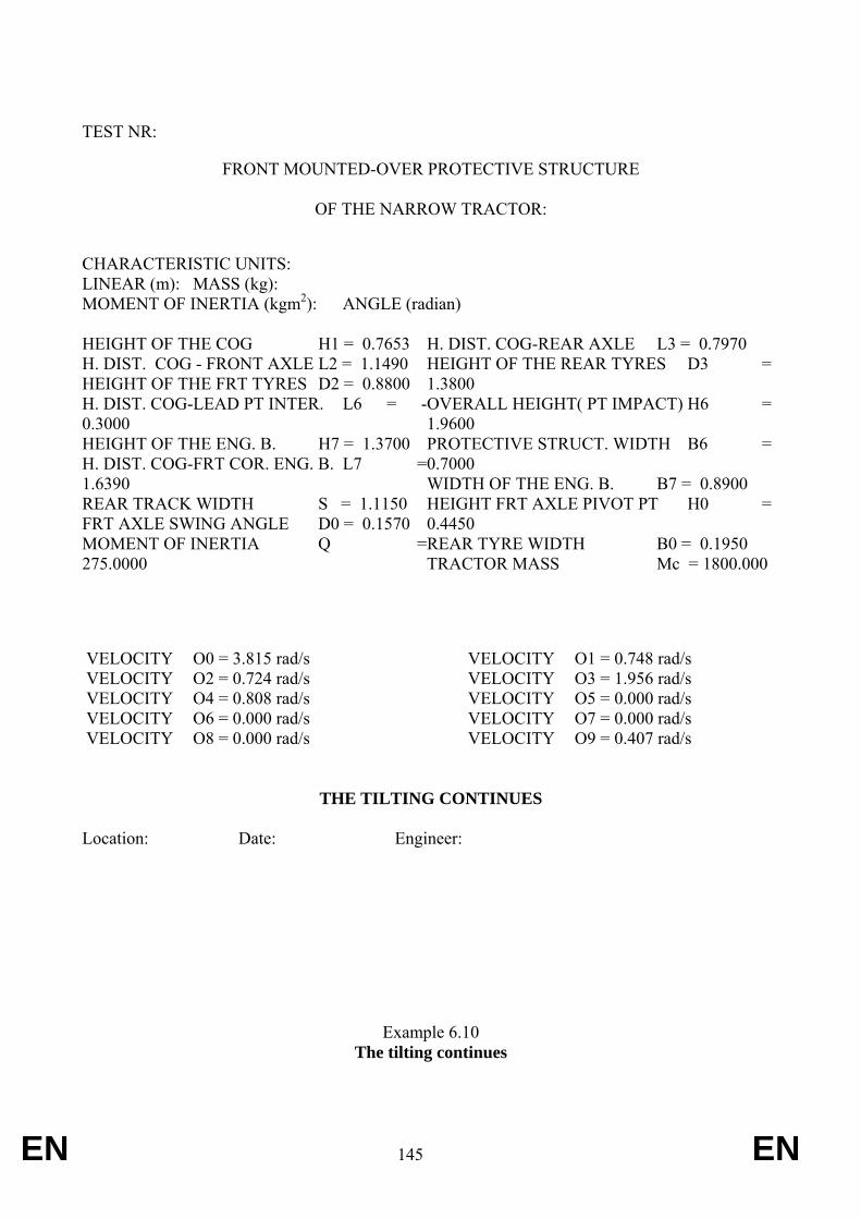
EN 145 EN
TEST NR:
FRONT MOUNTED-OVER PROTECTIVE STRUCTURE
OF THE NARROW TRACTOR:
CHARACTERISTIC UNITS: LINEAR (m): MASS (kg): MOMENT OF INERTIA (kgm2): ANGLE (radian) HEIGHT OF THE COG H1 = 0.7653 H. DIST. COG - FRONT AXLE L2 = 1.1490 HEIGHT OF THE FRT TYRES D2 = 0.8800 H. DIST. COG-LEAD PT INTER. L6 = -0.3000 HEIGHT OF THE ENG. B. H7 = 1.3700 H. DIST. COG-FRT COR. ENG. B. L7 =1.6390 REAR TRACK WIDTH S = 1.1150 FRT AXLE SWING ANGLE D0 = 0.1570 MOMENT OF INERTIA Q =275.0000
H. DIST. COG-REAR AXLE L3 = 0.7970 HEIGHT OF THE REAR TYRES D3 =1.3800 OVERALL HEIGHT( PT IMPACT) H6 =1.9600 PROTECTIVE STRUCT. WIDTH B6 =0.7000 WIDTH OF THE ENG. B. B7 = 0.8900 HEIGHT FRT AXLE PIVOT PT H0 =0.4450 REAR TYRE WIDTH B0 = 0.1950 TRACTOR MASS Mc = 1800.000
VELOCITY O0 = 3.815 rad/s VELOCITY O2 = 0.724 rad/s VELOCITY O4 = 0.808 rad/s VELOCITY O6 = 0.000 rad/s VELOCITY O8 = 0.000 rad/s
VELOCITY O1 = 0.748 rad/s VELOCITY O3 = 1.956 rad/s VELOCITY O5 = 0.000 rad/s VELOCITY O7 = 0.000 rad/s VELOCITY O9 = 0.407 rad/s
THE TILTING CONTINUES
Location: Date: Engineer:
Example 6.10 The tilting continues
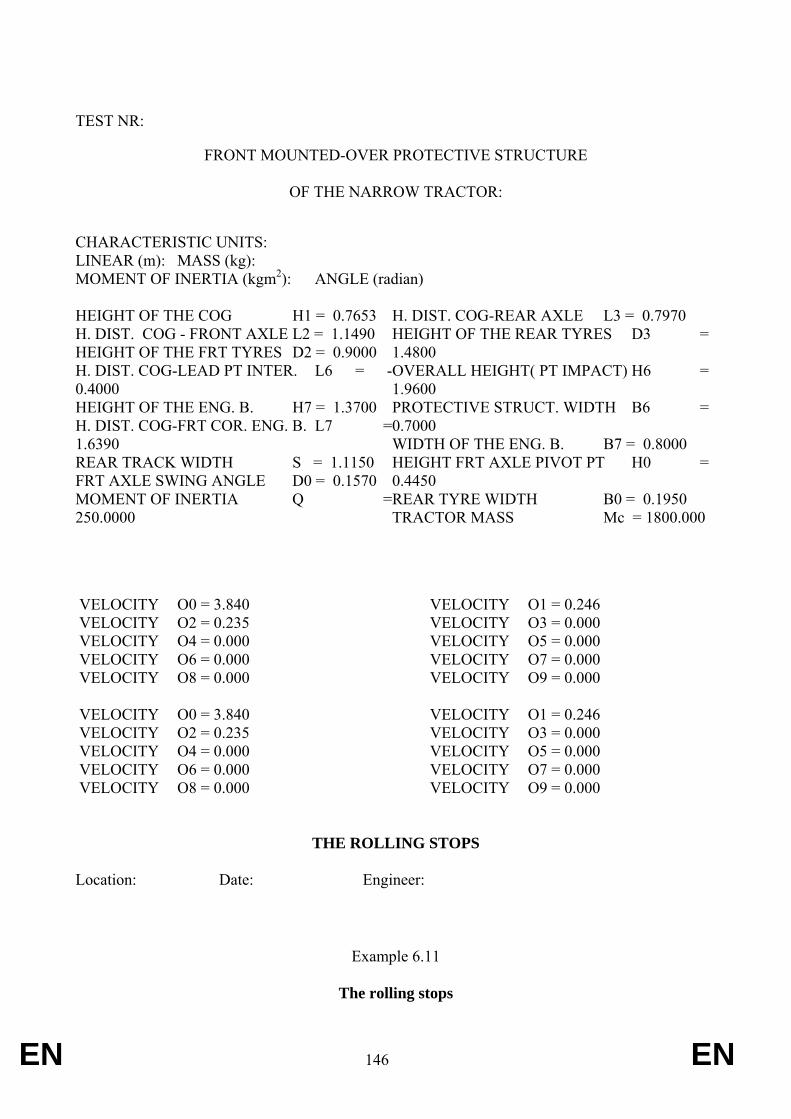
EN 146 EN
TEST NR:
FRONT MOUNTED-OVER PROTECTIVE STRUCTURE
OF THE NARROW TRACTOR:
CHARACTERISTIC UNITS: LINEAR (m): MASS (kg): MOMENT OF INERTIA (kgm2): ANGLE (radian) HEIGHT OF THE COG H1 = 0.7653 H. DIST. COG - FRONT AXLE L2 = 1.1490 HEIGHT OF THE FRT TYRES D2 = 0.9000 H. DIST. COG-LEAD PT INTER. L6 = -0.4000 HEIGHT OF THE ENG. B. H7 = 1.3700 H. DIST. COG-FRT COR. ENG. B. L7 =1.6390 REAR TRACK WIDTH S = 1.1150 FRT AXLE SWING ANGLE D0 = 0.1570 MOMENT OF INERTIA Q =250.0000
H. DIST. COG-REAR AXLE L3 = 0.7970 HEIGHT OF THE REAR TYRES D3 =1.4800 OVERALL HEIGHT( PT IMPACT) H6 =1.9600 PROTECTIVE STRUCT. WIDTH B6 =0.7000 WIDTH OF THE ENG. B. B7 = 0.8000 HEIGHT FRT AXLE PIVOT PT H0 =0.4450 REAR TYRE WIDTH B0 = 0.1950 TRACTOR MASS Mc = 1800.000
VELOCITY O0 = 3.840 VELOCITY O2 = 0.235 VELOCITY O4 = 0.000 VELOCITY O6 = 0.000 VELOCITY O8 = 0.000 VELOCITY O0 = 3.840 VELOCITY O2 = 0.235 VELOCITY O4 = 0.000 VELOCITY O6 = 0.000 VELOCITY O8 = 0.000
VELOCITY O1 = 0.246 VELOCITY O3 = 0.000 VELOCITY O5 = 0.000 VELOCITY O7 = 0.000 VELOCITY O9 = 0.000 VELOCITY O1 = 0.246 VELOCITY O3 = 0.000 VELOCITY O5 = 0.000 VELOCITY O7 = 0.000 VELOCITY O9 = 0.000
THE ROLLING STOPS
Location: Date: Engineer:
Example 6.11
The rolling stops
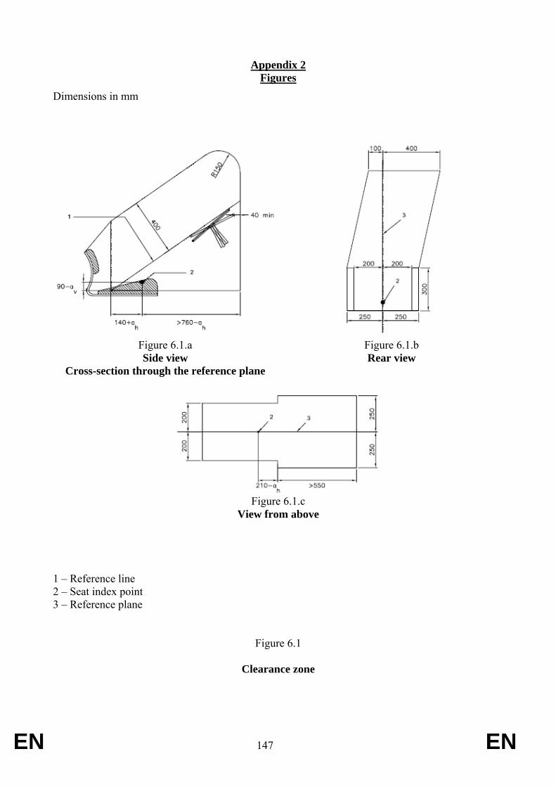
EN 147 EN
Appendix 2 Figures
Dimensions in mm
Figure 6.1.a Side view
Cross-section through the reference plane
Figure 6.1.b Rear view
Figure 6.1.c
View from above
1 – Reference line 2 – Seat index point 3 – Reference plane
Figure 6.1
Clearance zone
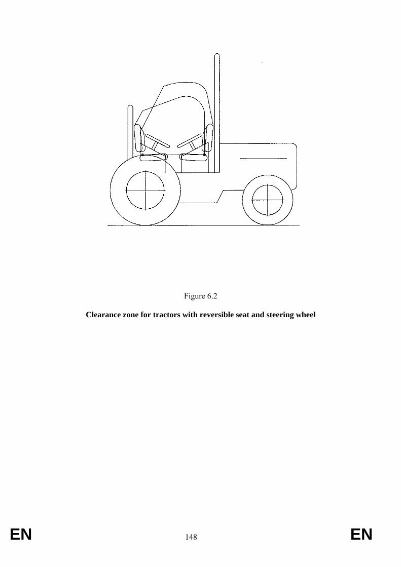
EN 148 EN
Figure 6.2
Clearance zone for tractors with reversible seat and steering wheel
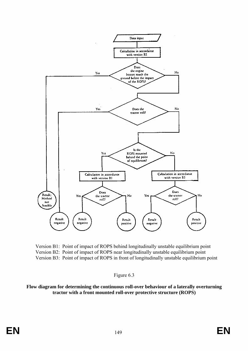
EN 149 EN
Version B1: Point of impact of ROPS behind longitudinally unstable equilibrium point Version B2: Point of impact of ROPS near longitudinally unstable equilibrium point Version B3: Point of impact of ROPS in front of longitudinally unstable equilibrium point
Figure 6.3
Flow diagram for determining the continuous roll-over behaviour of a laterally overturning tractor with a front mounted roll-over protective structure (ROPS)
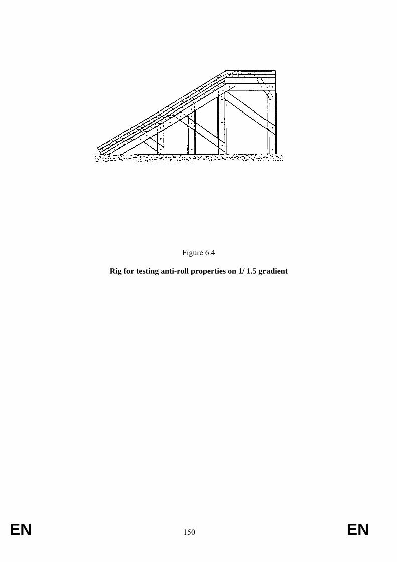
EN 150 EN
Figure 6.4
Rig for testing anti-roll properties on 1/ 1.5 gradient
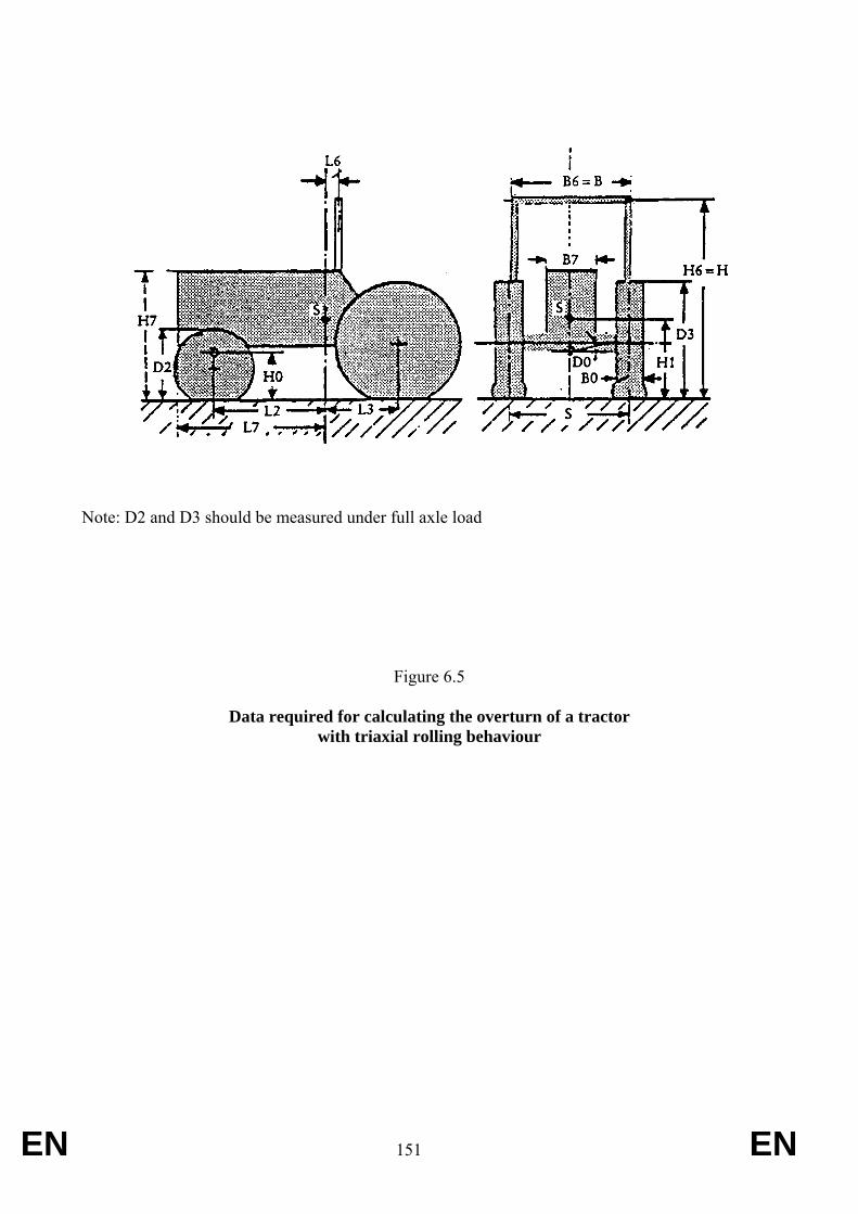
EN 151 EN
Note: D2 and D3 should be measured under full axle load
Figure 6.5
Data required for calculating the overturn of a tractor with triaxial rolling behaviour
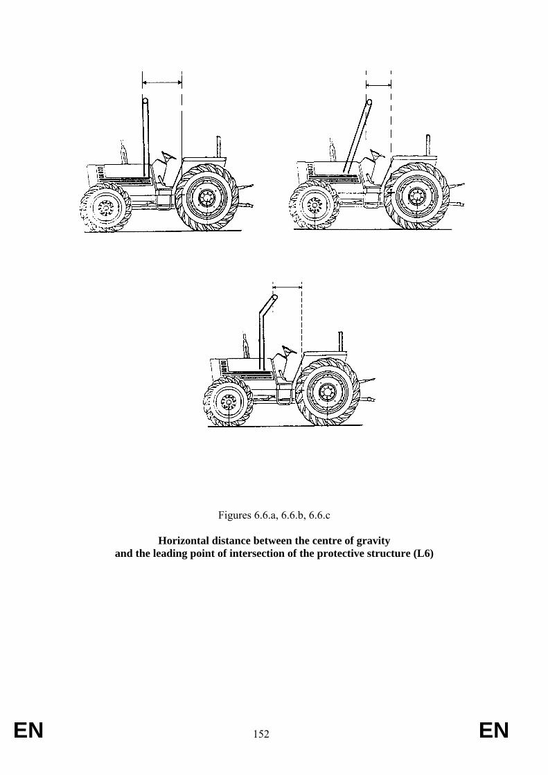
EN 152 EN
Figures 6.6.a, 6.6.b, 6.6.c
Horizontal distance between the centre of gravity and the leading point of intersection of the protective structure (L6)
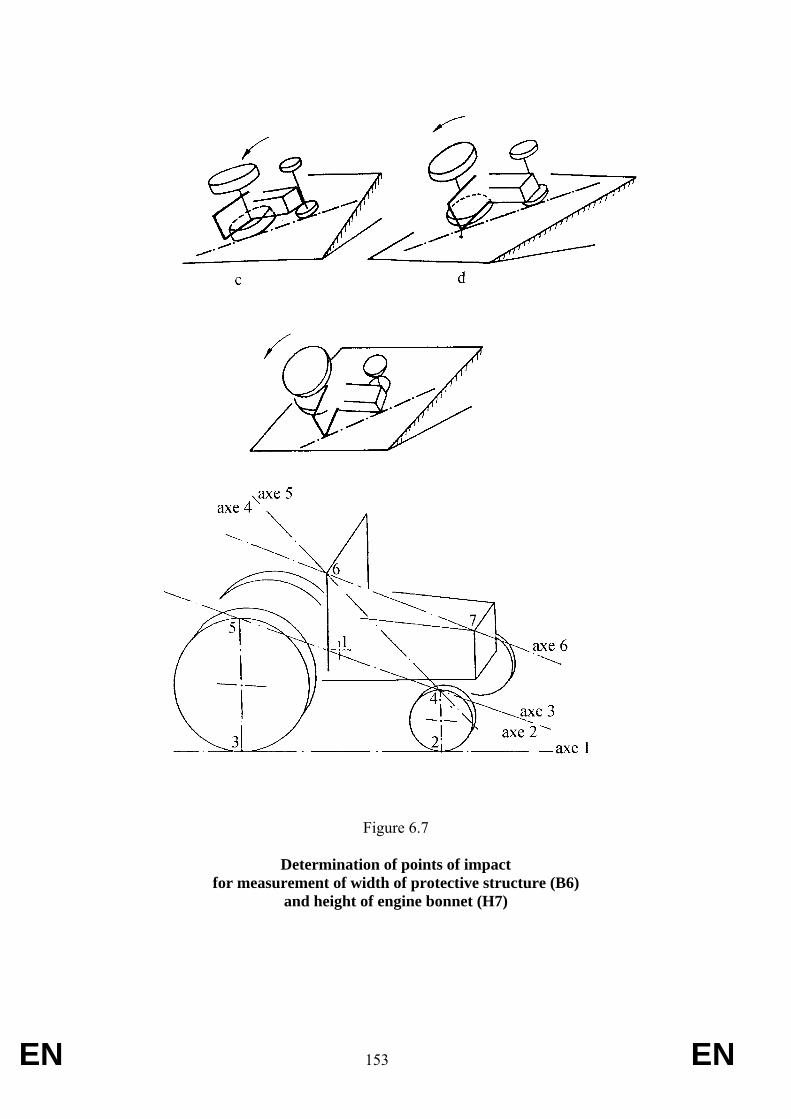
EN 153 EN
Figure 6.7
Determination of points of impact for measurement of width of protective structure (B6)
and height of engine bonnet (H7)
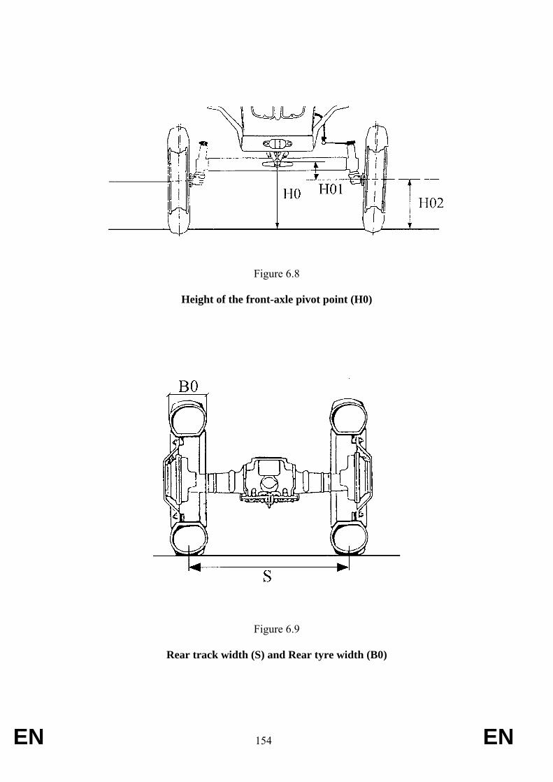
EN 154 EN
Figure 6.8
Height of the front-axle pivot point (H0)
Figure 6.9
Rear track width (S) and Rear tyre width (B0)
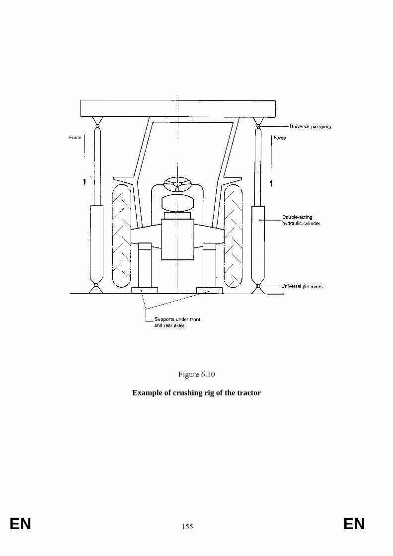
EN 155 EN
Figure 6.10
Example of crushing rig of the tractor
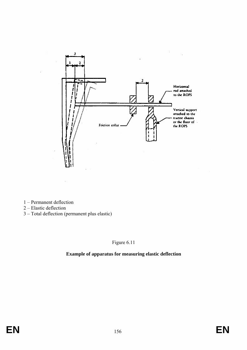
EN 156 EN
1 – Permanent deflection 2 – Elastic deflection 3 – Total deflection (permanent plus elastic)
Figure 6.11
Example of apparatus for measuring elastic deflection
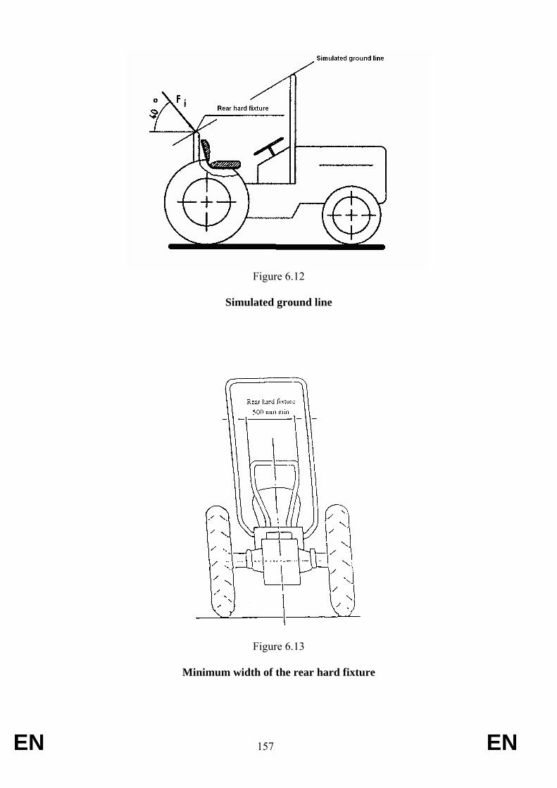
EN 157 EN
Figure 6.12
Simulated ground line
Figure 6.13
Minimum width of the rear hard fixture
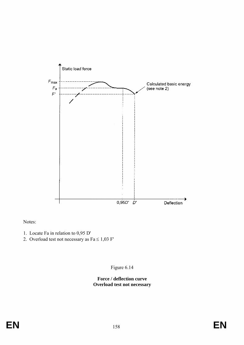
EN 158 EN
Notes: 1. Locate Fa in relation to 0,95 D' 2. Overload test not necessary as Fa ≤ 1,03 F'
Figure 6.14
Force / deflection curve Overload test not necessary
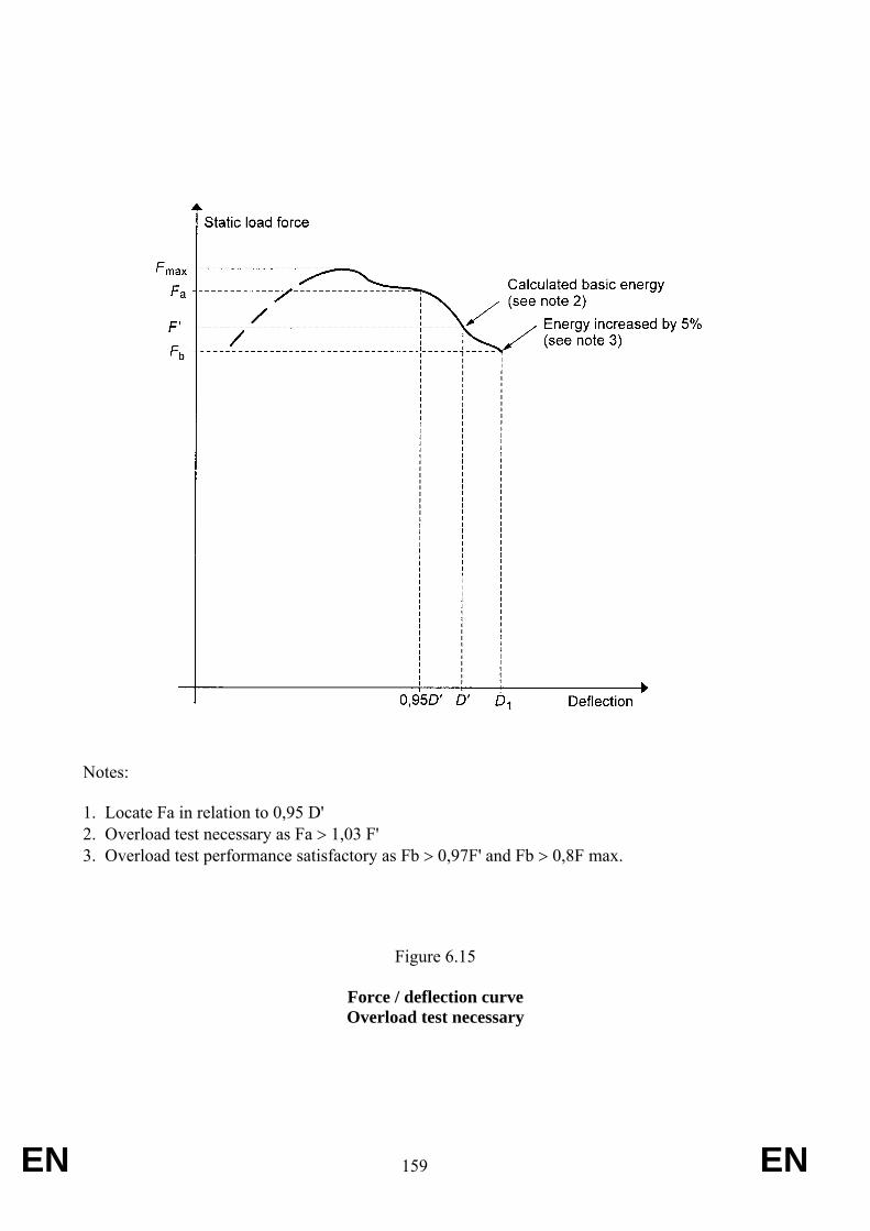
EN 159 EN
Notes: 1. Locate Fa in relation to 0,95 D' 2. Overload test necessary as Fa > 1,03 F' 3. Overload test performance satisfactory as Fb > 0,97F' and Fb > 0,8F max.
Figure 6.15
Force / deflection curve Overload test necessary
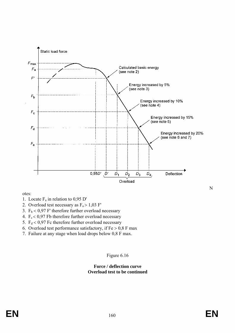
EN 160 EN
Notes: 1. Locate Fa in relation to 0,95 D' 2. Overload test necessary as Fa > 1,03 F' 3. Fb < 0,97 F' therefore further overload necessary 4. Fc < 0,97 Fb therefore further overload necessary 5. Fd < 0,97 Fc therefore further overload necessary 6. Overload test performance satisfactory, if Fe > 0,8 F max 7. Failure at any stage when load drops below 0,8 F max.
Figure 6.16
Force / deflection curve
Overload test to be continued
EN 161 EN
ANNEX IX- Part A
A — Alternative ‘Dynamic’ test procedure
INTRODUCTION
The paragraphs considered in this Annex refer to the Dynamic Testing Procedure. Tests may be performed in accordance with the dynamic or the static test procedure. The two methods are deemed equivalent. In general the numbering of the sections within this Part relates to corresponding sections for the static testing .
3. RULES AND DIRECTIONS
3.1 Prior conditions for the strength tests See requirements stated for static testing.
3.2 Conditions for testing the strength of protective structures and of their attachment to tractors
3.2.1 General requirements
See requirements stated for static testing.
3.2.2 Tests
3.2.2.1 Sequence of tests according to the Dynamic Procedure
The sequence of tests, without prejudice to the additional tests mentioned in sections 3.3.1.6 and 3.3.1.7 is as follows:
(1) impact at the rear of the structure (see 3.3.1.1); (2) rear crushing test (see 3.3.1.4); (3) impact at the front of the structure (see 3.3.1.2); (4) impact at the side of the structure (see 3.3.1.3); (5) crushing at the front of the structure (see 3.3.1.5).
3.2.2.2 General requirements
3.2.2.2.1 If, during the test, any part of the tractor restraining equipment breaks or moves, the test shall be restarted.
EN 162 EN
3.2.2.2 2 No repairs or adjustments of the tractor or protective structure may be carried out during the tests.
3.2.2.2.3 The tractor gear box shall be in neutral and the brakes off during the tests.
3.2.2.2.4 If the tractor is fitted with a suspension system between the tractor body and the wheels, it shall be blocked during the tests.
3.2.2.2.5 The side chosen for application of the first impact on the rear of the structure shall be that which, in the opinion of the testing authorities, will result in the application of the series of impacts or loads under the most unfavourable conditions for the structure. The lateral impact and the rear impact shall be applied on both sides of the longitudinal median plane of the protective structure. The front impact shall be applied on the same side of the longitudinal median plane of the protective structure as the lateral impact.
3.2.3 Acceptance conditions
3.2.3.1 A protective structure is regarded as having satisfied the strength requirements if it fulfils the following conditions:
3.2.3.1.1 After each part-test it must be free from cracks or tears within the meaning of section 3.3.2.1 or
3.2.3.1.2. If, during one of the tests, significant cracks or tears appear, an additional test, as defined in sections 3.3.1.6 or 3.3.1.7, must be applied immediately after the impact or the crushing test which caused cracks or tears to appear;
3.2.3.1.3 during the tests other than the overload test, no part of the protective structure must enter the clearance zone as defined in 1.6;
3.2.3.1.4 during the tests other than the overload test, all parts of the clearance zone shall be secured by the structure, in accordance with 3.3.2.2;
3.2.3.1.5 during the tests the protective structure must not impose any constraints on the seat structure;
3.2.3.1.6 the elastic deflection, measured in accordance with 3.3.2.4 shall be less than 250 mm.
3.2.3.2 There shall be no accessories presenting a hazard for the driver. There shall be no projecting part or accessory which is liable to injure the driver should the tractor overturn, or any accessory or part which is liable to trap him – for example by the leg or the foot – as a result of the deflections of the structure.
3.2.4 [Not applicable}
3.2.5 Apparatus and equipment for dynamic tests
3.2.5.1 Pendulum block
3.2.5.1.1 A block acting as a pendulum must be suspended by two chains or wire ropes from pivot points not less than 6 m above the ground. Means must be provided for adjusting independently the suspended height of the block and the angle between the block and the supporting chains or wire ropes.
EN 163 EN
3.2.5.1.2 The mass of the pendulum block must be 2 000 ± 20 kg excluding the mass of the chains or wire ropes which themselves must not exceed 100 kg. The length of the sides of the impact face must be 680 ± 20 mm (see Appendix 3, figure 6.26). The block must be filled in such a way that the position of its centre of gravity is constant and coincides with the geometrical centre of the parallelepiped.
3.2.5.1.3 The parallelepiped must be connected to the system which pulls it backwards by an instantaneous release mechanism which is so designed and located as to enable the pendulum block to be released without causing the parallelepiped to oscillate about its horizontal axis perpendicular to the pendulum's plane of oscillation.
3.2.5.2 Pendulum supports
The pendulum pivot points must be rigidly fixed so that their displacement in any direction does not exceed 1 per cent of the height of fall.
3.2.5.3 Lashings
3.2.5.3.1 Anchoring rails with the requisite track width and covering the necessary area for lashing the tractor in all the cases illustrated (see Appendix 3, figures 6.23, 6.24 and 6.25) must be rigidly attached to a non-yielding base beneath the pendulum.
3.2.5.3.2 The tractor shall be lashed to the rails by means of wire rope with round strand, fibre core, construction 6 x 19 in accordance with ISO 2408:2004 and a nominal diameter of 13 mm. The metal strands must have an ultimate tensile strength of 1770 MPa.
3.2.5.3.3 The central pivot of an articulated tractor shall be supported and lashed down as appropriate for all tests. For the lateral impact test, the pivot shall also be propped from the side opposite the impact. The front and rear wheels need not be in line if this facilitates the attachment of the wire ropes in the appropriate manner.
3.2.5.4 Wheel prop and beam
3.2.5.4.1 A softwood beam of 150 mm square shall be used as a prop for the wheels during the impact tests (see Appendix 3, figures 6.27, 6.28 and 6.29).
3.2.5.4.2 During the lateral impact tests, a softwood beam shall be clamped to the floor to brace the rim of the wheel opposite the side of impact (see Appendix 3, figure 6.29).
3.2.5.5 Props and lashings for articulated tractors
3.2.5.5.1 Additional props and lashings must be used for articulated tractors. Their purpose is to ensure that the section of the tractor on which the protective structure is fitted is as rigid as that of a non-articulated tractor.
3.2.5.5.2 Additional specific details are given in the section 3.3.1 for the impact and crushing tests.
3.2.5.6 Tyre pressures and deflections
3.2.5.6.1 The tractor tyres shall not be liquid-ballasted and shall be inflated to the pressures prescribed by the tractor manufacturer for field work.
EN 164 EN
3.2.5.6.2 The lashings shall be tensioned in each particular case such that the tyres undergo a deflection equal to 12 per cent of the tyre wall height (distance between the ground and the lowest point of the rim) before tensioning.
3.2.5.7 Crushing rig
A rig as shown in Appendix 3, figure 6.10 shall be capable of exerting a downward force on a protective structure through a rigid beam approximately 250 mm wide connected to the load-applying mechanism by means of universal joints. Suitable axle stands shall be provided so that the tractor tyres do not bear the crushing force.
3.2.5.8 Measuring apparatus
The following measuring apparatus is needed:
3.2.5.8.1 device for measuring the elastic deflection (the difference between the maximum momentary deflection and the permanent deflection, (see Appendix 3, figure 6.11).
3.2.5.8.2 device for checking that the protective structure has not entered the clearance zone and that the latter has remained within the structure's protective during the test (see section 3.3.2.2).
3.3 Dynamic test procedure
3.3.1 Impact and crushing tests
3.3.1.1 Impact at the rear
3.3.1.1.1 The tractor shall be so placed in relation to the pendulum block that the block will strike the protective structure when the impact face of the block and the supporting chains or wire ropes are at an angle with the vertical plane A equal to M/100 with a 20° maximum, unless, during deflection, the protective structure at the point of contact forms a greater angle to the vertical. In this case the impact face of the block shall be adjusted by means of an additional support so that it is parallel to the protective structure at the point of impact at the moment of maximum deflection, the supporting chains or wire ropes remaining at the angle defined above.
The suspended height of the block shall be adjusted and necessary steps taken so as to prevent the block from turning about the point of impact.
The point of impact is that part of the protective structure likely to hit the ground first in a rearward overturning accident, normally the upper edge. The position of the centre of gravity of the block is 1/ 6 of the width of the top of the protective structure inwards from a vertical plan parallel to the median plane of the tractor touching the outside extremity of the top of the protective structure.
If the structure is curved or protruding at this point, wedges enabling the impact to be applied thereon must be added, without thereby reinforcing the structure.
3.3.1.1.2 The tractor must be lashed to the ground by means of four wire ropes, one at each end of both axles, arranged as indicated in Appendix 3, figure 6.27. The spacing between the front and rear lashing points must be such that the wire ropes make an angle of less than 30° with the ground. The rear lashings must in addition be so arranged that the point of
EN 165 EN
convergence of the two wire ropes is located in the vertical plane in which the centre of gravity of the pendulum block travels.
The wire ropes must be tensioned so that the tyres undergo the deflections given in 3.2.5.6.2. With the wire ropes tensioned, the wedging beam shall be placed in front of and tight against the rear wheels and then fixed to the ground.
3.3.1.1.3 If the tractor is of the articulated type, the point of articulation shall, in addition, be supported by a wooden block at least 100 mm square and firmly lashed to the ground.
3.3.1.1.4 The pendulum block shall be pulled back so that the height of its centre of gravity above that at the point of impact is given by one of the following two formulae, to be chosen according to the reference mass of the assembly subjected to the tests:
H = 25 + 0.07 M
for tractor with a reference mass of less than 2 000 kg;
H = 125 + 0.02 M
for tractor with a reference mass of more than 2 000 kg.
The pendulum block is then released and strikes the protective structure.
3.3.1.1.5 For tractors with a reversible driver’s position (reversible seat and steering wheel), the same formulae shall apply.
3.3.1.2 Impact at the front
3.3.1.2.1 The tractor shall be so placed in relation to the pendulum block that the block will strike the protective structure when the impact face of the block and the supporting chains or wire ropes are at an angle with the vertical plane A equal to M/100 with a 20° maximum, unless, during deflection, the protective structure at the point of contact forms a greater angle to the vertical. In this case the impact face of the block shall be adjusted by means of an additional support so that it is parallel to the protective structure at the point of impact at the moment of maximum deflection, the supporting chains or wire ropes remaining at the angle defined above.
The suspended height of the pendulum block shall be adjusted and the necessary steps taken so as to prevent the block from turning about the point of impact.
The point of impact is that part of the protective structure likely to hit the ground first if the tractor overturned sideways while travelling forward, normally the upper edge. The position of the centre of gravity of the block is 1/6 of the width of the top of the protective structure inwards from a vertical plane parallel to the median plane of the tractor touching the outside extremity of the top of the protective structure.
If the structure is curved or protruding at this point, wedges enabling the impact to be applied thereon must be added, without thereby reinforcing the structure.
3.3.1.2.2 The tractor must be lashed to the ground by means of four wire ropes, one at each end of both axles, arranged as indicated in Appendix 3, figure 6.28. The spacing between the front and rear lashing points must be such that the wire ropes make an angle of less than 30° with the ground. The rear lashings shall in addition be so arranged that the point of
EN 166 EN
convergence of the two wire ropes is located in the vertical plane in which the centre of gravity of the pendulum block travels.
The wire ropes must be tensioned so that the tyres undergo the deflections given in 3.2.5.6.2. With the wire ropes tensioned, the wedging beam shall be placed behind and tight against the rear wheels and then fixed to the ground.
3.3.1.2.3 If the tractor is of the articulated type, the point of articulation shall, in addition, be supported by a wooden block at least 100 mm square and firmly lashed to the ground.
3.3.1.2.4 The pendulum block shall be pulled back so that the height of its centre of gravity above that at the point of impact is given by one of the following two formulae, to be chosen according to the reference mass of the assembly subjected to the tests:
H = 25 + 0.07 M
for tractor with a reference mass of less than 2 000 kg.
H = 125 + 0.02 M
for tractor with a reference mass of more than 2 000 kg.
The pendulum block is then released and strikes the protective structure.
3.3.1.2.5 For tractors with a reversible driver’s position (reversible seat and steering wheel), the height shall be whichever is greater from the formula applied above and that selected below:
H = 2.165 x 10 - 8 M x L2
or
H = 5.73 x 10 - 2I
3.3.1.3 Impact from the side
3.3.1.3.1 The tractor shall be so placed in relation to the pendulum block that the block will strike the protective structure when the impact face of the block and the supporting chains or wire ropes are vertical unless, during deflection, the protective structure at the point of contact forms an angle of less than 20° to the vertical. In this case the impact face of the block shall be adjusted by means of an additional support so that it is parallel to the protective structure at the point of impact at the moment of maximum deflection, the supporting chains or wire ropes remaining vertical on impact.
The suspended height of the pendulum block shall be adjusted and necessary steps taken so as to prevent the block from turning about the point of impact.
The point of impact shall be that part of the protective structure likely to hit the ground first in a sideways overturning accident.
3.3.1.3.2 The tractor wheels on the side which is to receive the impact must be lashed to the ground by means of wire ropes passing over the corresponding ends of the front and rear axles. The wire ropes must be tensioned to produce the tyre deflection values given in 3.2.5.6.2.
EN 167 EN
With the wire ropes tensioned, the wedging beam shall be placed on the ground, pushed tight against the tyres on the side opposite that which is to receive the impact and then fixed to the ground. It may be necessary to use two beams or wedges if the outer sides of the front and rear tyres are not in the same vertical plane. The prop shall then be placed as indicated in Appendix 3, figure 6.29 against the rim of the most heavily loaded wheel opposite to the point of impact, pushed firmly against the rim and then fixed at its base. The length of the prop shall be such that it makes an angle of 30 ± 3° with the ground when in position against the rim. In addition, its thickness shall, if possible, be between 20 and 25 times less than its length and between 2 and 3 times less than its width. The props shall be shaped at both ends as shown in the details on Appendix 3, figure 6.29.
3.3.1.3.3 If the tractor is of the articulated type, the point of articulation shall in addition be supported by a wooden block at least 100 mm square and laterally supported by a device similar to the prop pushed against the rear wheel as in 3.3.1.3.2. The point of articulation shall then be lashed firmly to the ground.
3.3.1.3.4 The pendulum block shall be pulled back so that the height of its centre of gravity above that at the point of impact is given by one of the following two formulae, to be chosen according to the reference mass of the assembly subjected to the tests:
H = (25 + 0.20 M) (B6+B) / 2B
for tractor with a reference mass of less than 2 000 kg.
H = (125 + 0.15 M) (B6+B) / 2B
for tractor with a reference mass of more than 2 000 kg.
3.3.1.3.5 For reversible tractors, the height shall be whichever is greater of the results obtained from the formulae applicable above and below:
H = 25 + 0.2 M
for tractor with a reference mass of less than 2 000 kg.
H = 125 + 0.15 M
for tractor with a reference mass of more than 2 000 kg.
The pendulum block is then released and strikes the protective structure.
3.3.1.4 Crushing at the rear
All provisions are identical to those given in section 3.3.1.4 of Annex V(a).
3.3.1.5 Crushing at the front
All provisions are identical to those given in section 3.3.1.5 of Annex V(a).
3.3.1.6 Additional impact tests
If cracks or tears which cannot be considered negligible appear during an impact test, a second, similar test, but with a height of fall of:
EN 168 EN
H’ = (H x 10 - 1) (12 + 4a) (1 + 2a ) -1
shall be performed immediately after the impact tests causing these tears or cracks to appear, “a” being the ratio of the permanent deformation (Dp) to the elastic deformation (De):
a = Dp / De
as measured at the point of impact. The additional permanent deformation due to the second impact shall not exceed 30 per cent of the permanent deformation due to the first impact.
In order to be able to carry out the additional test, it is necessary to measure the elastic deformation during all the impact tests.
3.3.1.7 Additional crushing tests
If during a crushing test, significant cracks or tears appear, a second, similar, crushing test, but with a force equal to 1.2 Fv shall be performed immediately after the crushing tests which caused these tears or cracks to appear.
3.3.2 Measurements to be made
3.3.2.1 Fractures and cracks
After each test all structural members, joints and fastening systems shall be visually examined for fractures or cracks, any small cracks in unimportant parts being ignored.
Any tears caused by the edges of the pendulum weight are to be ignored.
3.3.2.2 Entry into the clearance zone
During each test the protective structure shall be examined to see whether any part of it has entered the clearance zone round the driving seat as defined in 1.6.
Furthermore, the clearance zone shall not be outside the protection of the protective structure. For this purpose, it shall be considered to be outside the protection of the structure if any part of it would come in contact with flat ground if the tractor overturned towards the direction from which the test load is applied. For estimating this, the front and rear tyres and track width setting shall be the smallest standard fitting specified by the manufacturer.
3.3.2.3 Rear hard fixture tests
If the tractor is fitted with a rigid section, a housing or other hard fixture placed behind the driver's seat, this fixture shall be regarded as a protective point, in the event of sideways or rear overturning. This hard fixture placed behind the driver’s seat shall be capable of withstanding, without breaking or entering the clearance zone, a downward force Fi where:
Fi = 15 M
applied perpendicularly to the top of the frame in the central plane of the tractor. The initial angle of application of force shall be 40° calculated from a parallel to the ground as shown in Appendix 3, figure 6.12. The minimum width of this rigid section shall be 500 mm (see Appendix 3, figure 6.13).
EN 169 EN
In addition, it shall be sufficiently rigid and firmly attached to the rear of the tractor.
3.3.2.4 Elastic deflection (under side impact)
The elastic deflection is measured (810 + av) mm above the index point, in the vertical plane passing through the point of impact. For this measurement, apparatus similar to that illustrated in Appendix 3, figure 6.11 shall be used.
3.3.2.5 Permanent deflection
After the final crushing test, the permanent deflection of the protective structure shall be recorded. For this purpose, before the start of the test, the position of the main roll-over protective structure members in relation to the Seat Index Point shall be used.
3.4 Extension to other tractor models See the provisions stated in RVCR Annex V(a).
3.5 [Not applicable]
3.6 Cold weather performance of protective structures See the requirements stated in RVCR Annex V(a).
3.7 [Not applicable]
4. Additonal requirements for foldable Roll-Over Protection Structures (foldable ROPS)
4.1. On-going work of the OECD
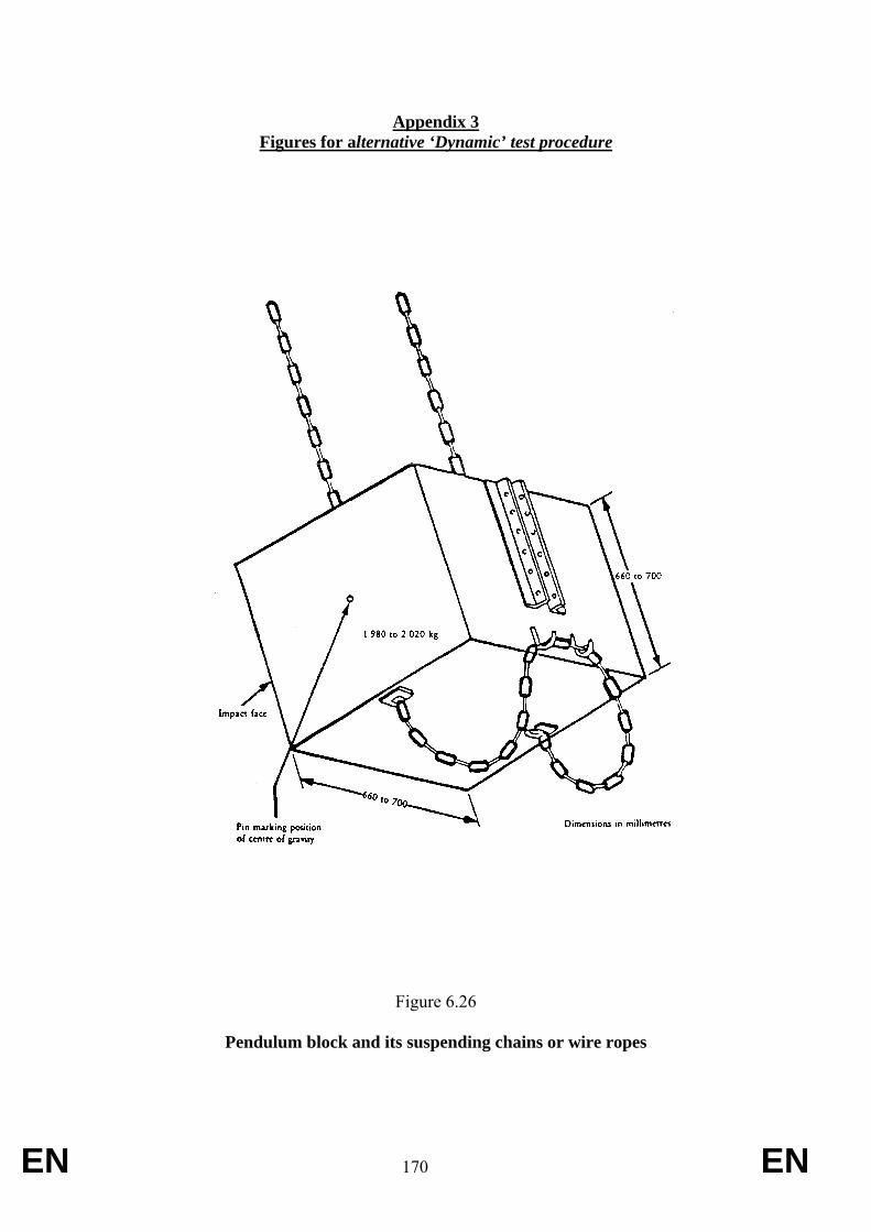
EN 170 EN
Appendix 3 Figures for alternative ‘Dynamic’ test procedure
Figure 6.26
Pendulum block and its suspending chains or wire ropes
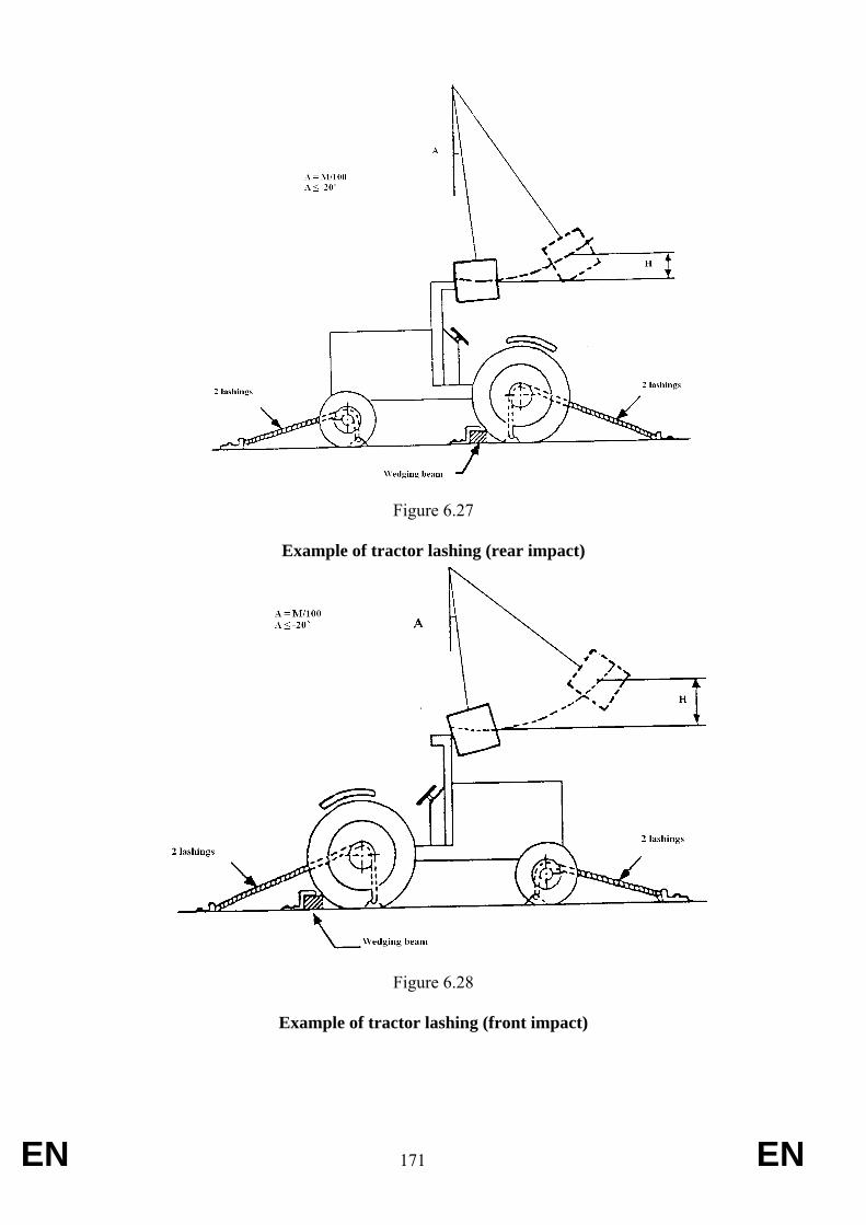
EN 171 EN
Figure 6.27
Example of tractor lashing (rear impact)
Figure 6.28
Example of tractor lashing (front impact)
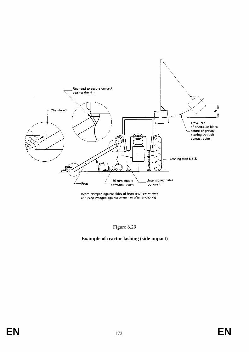
EN 172 EN
Figure 6.29
Example of tractor lashing (side impact)
EN 173 EN
ANNEX X Requirements applying to roll over protection structures within the application field of OECD
Code 7 (rear mounted narrow track tractors), as amended
The following test requirements are applicable to to rear mounted roll-over protective structures for T2, T3 and T4.3 wheeled agricultural and forestry tractors having the following characteristics:
• ground clearance of not more than 600 mm beneath the lowest points of the front and rear axles, allowing for the differential;
• fixed or adjustable minimum track width with one of the axles less than 1 150 mm fitted with tyres of a larger size. It is assumed that the axle mounted with the wider tyres is set at a track width of not more than 1 150 mm. It must be possible to set the track width of the other axle in such a way that the outer edges of the narrower tyres do not go beyond the outer edges of the tyres of the other axle. Where the two axles are fitted with rims and tyres of the same size, the fixed or adjustable track width of the two axles must be less than 1 150 mm;
• mass greater than 400 kg unladen but including the roll-over protective structure and tyres of the largest size recommended by the manufacturer. For tractors with a reversible driver’s position (reversible seat and steering wheel), the unladen mass shall be less than 3 500 kg and the maximum permissible mass shall not exceed 5 250 kg. For all tractors, the Mass Ratio (Maximum Permissible Mass / Reference Mass) must not be greater than 1.75;
• roll-over protective structure of the rollbar, frame or cab type, mounted partly or entirely behind the Seat Index Point and having a zone of clearance whose upper limit is (810 + av) mm above the Seat Index Point in order to provide a sufficiently large area or unobstructed space for the protection of the driver.
1. DEFINITIONS
1.1 [Not applicable]
1.2 Roll-Over Protective Structure (ROPS) Roll-over protective structure (safety cab or frame), hereinafter called “protective structure”, means the structure on a tractor the essential purpose of which is to avoid or limit risks to the driver resulting from roll-over of the tractor during normal use.
The roll-over protective structure is characterized by the provision of space for a clearance zone large enough to protect the driver when seated either inside the envelope of the structure or within a space bounded by a series of straight lines from the outer edges of the structure to any part of the tractor that might come into contact with flat ground and that is capable of supporting the tractor in that position if the tractor overturns.
1.3 Track
1.3.1 Preliminary definition: median plane of the wheel
The median plane of the wheel is equidistant from the two planes containing the periphery of the rims at their outer edges.
EN 174 EN
1.3.2 Definition of track
The vertical plane through the wheel axis intersects its median plane along a straight line which meets the supporting surface at one point. If A and B are the two points thus defined for the wheels on the same axle of the tractor, then the track width is the distance between points A and B. The track may be thus defined for both front and rear wheels. Where there are twin wheels, the track is the distance between two planes each being the median plane of the pairs of wheels.
1.3.3 Additional definition: median plane of the tractor
Take the extreme positions of points A and B for the tractor rear axle, which gives the maximum possible value for the track. The vertical plane at right angles to the line AB at its centre point is the median plane of the tractor.
1.4 Wheelbase The distance between the vertical planes passing through the two lines AB as defined above, one for the front wheels and one for the rear-wheels.
1.5 Seat location and adjustment for test
1.5.1 where the seat position is adjustable, the seat must be adjusted to its rear uppermost position;
1.5.2 where the inclination of the backrest is adjustable, it must be adjusted to the mid position;
1.5.3 where the seat is equipped with suspension, the latter must be blocked at mid-travel, unless this is contrary to the instructions clearly laid down by the seat manufacturer;
1.5.4 where the position of the seat is adjustable only lengthwise and vertically, the longitudinal axis passing through the Seat Index Point shall be parallel with the vertical longitudinal plane of the tractor passing through the centre of the steering wheel and not more than 100 mm from that plane.
1.6 Clearance zone
1.6.1 Reference plane
The clearance zone is illustrated in Appendix 1, figures 7.1 and 7.2. The zone is defined in relation to the reference plane and the Seat Index Point. The reference plane is a vertical plane, generally longitudinal to the tractor and passing through the Seat Index Point and the centre of the steering wheel. Normally the reference plane coincides with the longitudinal median plane of the tractor. This reference plane shall be assumed to move horizontally with the seat and steering wheel during loading but to remain perpendicular to the tractor or the floor of the roll-over protective structure. The clearance zone shall be defined on the basis of Sections 1.6.2 and 1.6.3.
1.6.2 Determination of the clearance zone for tractors with a non-reversible seat
The clearance zone for tractors with a non-reversible seat is defined in 1.6.2.1 to 1.6.2.13 below and is bounded by the following planes, the tractor being on a horizontal surface, the
EN 175 EN
seat adjusted and located as specified in Sections 1.5.2.1 to 1.5.2.41, and the steering wheel, where adjustable, adjusted to the mid position for seated driving:
1.6.2.1 a horizontal plane A1 B1 B2 A2, (810 + av) mm above the Seat Index Point with line B1B2 located (ah-10) mm behind the SIP;
1.6.2.2 an inclined plane H1 H2 G2 G1, perpendicular to the reference plane, including both a point 150 mm behind line B1B2 and the rearmost point of the seat backrest;
1.6.2.3 a cylindrical surface A1 A2 H2 H1 perpendicular to the reference plane, having a radius of 120 mm, tangential to the planes defined in 1.6.2.1 and 1.6.2.2 above;
1.6.2.4 a cylindrical surface B1 C1 C2 B2, perpendicular to the reference plane, having a radius of 900 mm extending forward for 400 mm and tangential to the plane defined in 1.6.2.1 above along line B1B2;
1.6.2.5 an inclined plane C1 D1 D2 C2, perpendicular to the reference plane, joining the surface defined in 1.6.2.4 above and passing 40 mm from the forward external edge of the steering wheel. In the case of a high steering wheel position, this plane extends forward from line B1B2 tangentially to the surface defined in 1.6.2.4 above;
1.6.2.6 a vertical plane D1 K1 E1 E2 K2 D2 perpendicular to the reference plane 40 mm forward of the external edge of the steering wheel;
1.6.2.7 a horizontal plane E1 F1 P1 N1 N2 P2 F2 E2 passing through a point (90-av) mm below the Seat Index Point;
1.6.2.8 a surface G1 L1 M1 N1 N2 M2 L2 G2, if necessary curved from the bottom limit of the plane defined in 1.6.2.2 above to the horizontal plane defined in 1.6.2.7 above, perpendicular to the reference plane, and in contact with the seat backrest throughout its length;
1.6.2.9 two vertical planes K1 I1 F1 E1 and K2 I2 F2 E2 parallel to the reference plane, 250 mm either side of the reference plane, and bounded at the top 300 mm above the plane defined in 1.6.2.7 above;
1.6.2.10 two inclined and parallel planes A1 B1 C1 D1 K1 I1 L1 G1 H1 and A2 B2 C2 D2 K2 I2 L2 G2 H2 starting from the upper edge of the planes defined in 1.6.2.9 above and joining the horizontal plane defined in 1.6.2.1 above at least 100 mm from the reference plane on the side where the loading is applied;
1.6.2.11 two portions of vertical planes Q1 P1 N1 M1 and Q2 P2 N2 M2 parallel to the reference plane, 200 mm either side of the reference plane, and bounded towards the top 300 mm above the horizontal plane defined in 1.6.2.7 above;
1.6.2.12 two portions of I1 Q1 P1 F1 and I2 Q2 P2 F2 of a vertical plane, perpendicular to the reference plane and passing (210-ah) mm in front of the SIP;
1.6.2.13 two portions I1 Q1 M1 L1 and I2 Q2 M2 L2 of the horizontal plane passing 300 mm above the plane defined in 1.6.2.7 above.
1Users are reminded that the Seat Index Point is determined according to ISO 5353 and is a fixed point with respect to
the tractor that does not move as the seat is adjusted away from the mid position.
EN 176 EN
1.6.3 Determination of the clearance zone for tractors with a reversible driver's position
For tractors with a reversible driver’s position (reversible seat and steering wheel), the clearance zone is the envelope of the two clearance zones defined by the two different positions of the steering wheel and the seat.
1.6.3.1 If the protective structure is a of a rear two-post type, for each position of the steering wheel and of the seat, the clearance zone shall respectively be defined on the basis of above sections 1.6.1 and 1.6.2 of Annex V(b) for driver’s position in normal position, and on the basis of sections 1.6.1 and 1.6.2 of AnnexV(a) for driver’s position in reverse position (see Appendix 1, figure 7.2.a).
1.6.3.2 If the protective structure is of another type, for each position of the steering wheel and of the seat, the clearance zone shall be defined on the basis of sections 1.6.1 and 1.6.2 of this Annex (see Appendix 1, figure 7.2.b).
1.6.4 Optional seats
1.6.4.1 In case of tractors that could be fitted with optional seats, the envelope comprising the Seat Index Points of all options offered shall be used during the tests. The protective structure shall not enter the larger clearance zone which takes account of these different Seat Index Points.
1.6.4.2 In the case where a new seat option is offered after the test has been performed, a determination shall be made to see whether the clearance zone around the new SIP falls within the envelope previously established. If it does not, a new test must be performed.
1.7 Mass
1.7.1 Unballasted / Unladen Mass
The mass of the tractor excluding optional accessories but including coolant, oils, fuel, tools plus the protective structure. Not included are optional front or rear weights, tyre ballast, mounted implements, mounted equipment or any specialised components;
1.7.8 Maximum Permissible Mass
The maximum mass of the tractor stated by the manufacturer to be technically permissible and declared on the vehicle’s identification plate and/or in the Operator’s Handbook;
1.7.9 Reference Mass
The mass, selected by the manufacturer, used in formulae to calculate the height of fall of the pendulum block, the energy inputs and crushing forces to be used in the tests. Must not be less than the unballasted mass and must be sufficient to ensure the Mass Ratio does not exceed 1.75 (see Section 1.7.4);
1.7.10 Mass Ratio The ratio of ….. This must not be greater than 1.75
⎟⎟⎠
⎞⎜⎜⎝
⎛Mass Reference
MassePermissiblMax.
EN 177 EN
1.8 Permissible measurement tolerances
Linear dimension: ± 3 mm except for: -- tyre deflection : ± 1 mm -- structure deflection during horizontal loadings: ± 1 mm -- height of fall of the pendulum block: ± 1 mm Masses: ± 1 % Forces: ± 2 % Angles: ± 2 °
1.9 Symbols
ah (mm) Half of the horizontal seat adjustment av (mm) Half of the vertical seat adjustment B (mm) Minimum overall width of the tractor; B6 (mm) Maximum outer width of the protective structure; D (mm) Deflection of the structure at the point of impact (dynamic tests) or at
the point of, and in line with, the load application (static tests); D' (mm) Deflection of the structure for the calculated energy required; Ea (J) Strain energy absorbed at point when load is removed. Area contained
within F-D curve; Ei (J) Strain energy absorbed. Area under F-D curve; E'i (J) Strain energy absorbed after additional loading following a crack or
tear; E''i (J) Strain energy absorbed in overload test in the event of the load having
been removed before starting this overload test. Area under F-D curve;Eil (J) Energy input to be absorbed during longitudinal loading; Eis (J) Energy input to be absorbed during side loading; F (N) Static load force; F' (N) Loading force for calculated energy required, corresponding to E'i ; F-D Force/deflection diagram; Fmax (N) Maximum static load force occurring during loading, with the
exception of the overload; Fv (N) Vertical crushing force; H (mm) Falling height of the pendulum block (dynamic tests); H’ (mm) Falling height of the pendulum block for additional test (dynamic
tests); I (kgm2) Tractor reference moment of inertia about the centre line of the rear
wheels, whatever the mass of these rear wheels may be; L (mm) Tractor reference wheelbase; M (kg) Tractor reference mass during strength tests.
2. Lateral Stability Test
2.1 Preparation for stability test
EN 178 EN
2.1.1 The tractor must be equipped with the protective structure in its safety position.
2.1.2 The tractor must be fitted with tyres having the greatest diameter indicated by the manufacturer and the smallest cross-section for tyres of that diameter. The tyres must not be liquid-ballasted and must be inflated to the pressure recommended for field work.
2.1.3 The rear wheels must be set to the narrowest track width; the front wheels must be set as closely as possible to the same track width. If it is possible to have two front track settings which differ equally from the narrowest rear track setting, the wider of these two front track settings must be selected.
2.1.4 All the tractor's tanks must be filled or the liquids must be replaced by an equivalent mass in the corresponding position.
2.1.5 All attachments used in the series production shall be fixed to the tractor in the normal position.
2.2 Lateral stability test
2.2.1 The tractor, prepared as specified above, is placed on a horizontal plane so that the tractor front-axle pivot point or, in the case of an articulated tractor, the horizontal pivot point between the two axles can move freely.
2.2.2 Using a jack or a hoist, tilt the part of the tractor which is rigidly connected to the axle that bears more than 50 pour cent of the tractor's weight, while constantly measuring the angle of inclination. This angle must be at least 38° at the moment when the tractor is resting in a state of unstable equilibrium on the wheels touching the ground. Perform the test once with the steering wheel turned to full right lock and once with the steering wheel turned to full left lock
In addition the technical requirements of Section 3 of OECD Code 7 (July 2012), with the exception of Sections 3.1.4 (Test report), 3.3.1 (Administrative extension), 3.4 (Labelling) and 3.6 (Seat belt anchorage performance), shall apply, reading as follows:-
3. RULES AND DIRECTIONS
3.1 Conditions for testing the strength of protective structures and of their attachment to tractors
3.1.1 General requirements
3.1.1.1 Test purposes
Tests made using special rigs are intended to simulate such loads as are imposed on a protective structure, when the tractor overturns. These tests enable observations to be made on the strength of the protective structure and any brackets attaching it to the tractor and any parts of the tractor which transmit the test load.
3.1.1.2 Test methods
Tests may be performed in accordance with the static procedure or the dynamic procedure (see Annex A). The two methods are deemed equivalent.
3.1.1.3 General rules governing preparation for tests
EN 179 EN
3.1.1.3.1 The protective structure must conform to the series production specifications. It shall be attached in accordance with the manufacturer's recommended method to one of the tractors for which it is designed.
Note: A complete tractor is not required for the static strength test; however, the protective structure and parts of the tractor to which it is attached represent an operating installation, hereinafter referred to as « the assembly ».
3.1.1.3.2 For both the static test and the dynamic test the tractor as assembled (or the assembly) must be fitted with all series production components which may affect the strength of the protective structure or which may be necessary for the strength test.
Components which may create a hazard in the clearance zone must also be fitted on the tractor (or the assembly) so that they may be examined to see whether the requirements of the Acceptance Conditions in 3.1.3 have been fulfilled. All components of the tractor or the protective structure including weather protective must be supplied or described on drawings.
3.1.1.3.3 For the strength tests, all panels and detachable non-structural components must be removed so that they may not contribute to the strengthening of the protective structure.
3.1.1.3.4 The track width must be adjusted so that the protective structure will, as far as possible, not be supported by the tyres during the strength tests. If these tests are conducted in accordance with the static procedure, the wheels may be removed.
3.1.2 Tests
3.1.2.1 Sequence of tests according to the Static Procedure
The sequence of tests, without prejudice to the additional tests mentioned in sections 3.2.1.6, and 3.2.1.7 is as follows:
(1) loading at the rear of the structure (see 3.2.1.1); (2) rear crushing test (see 3.2.1.4); (3) loading at the front of the structure (see 3.2.1.2); (4) loading at the side of the structure (see 3.2.1.3); (5) crushing at the front of the structure (see 3.2.1.5).
3.1.2.2 General requirements
3.1.2.2.1 If, during the test, any part of the tractor restraining equipment breaks or moves, the test shall be restarted.
EN 180 EN
3.1.2.2 2 No repairs or adjustments of the tractor or protective structure may be carried out during the tests.
3.1.2.2.3 The tractor gear box shall be in neutral and the brakes off during the tests.
3.1.2.2.4 If the tractor is fitted with a suspension system between the tractor body and the wheels, it shall be blocked during the tests.
3.1.2.2.5 The side chosen for application of the first load on the rear of the structure shall be that which, in the opinion of the testing authorities, will result in the application of the series of loads under the most unfavourable conditions for the structure. The lateral load and the rear load shall be applied on both sides of the longitudinal median plane of the protective structure. The front load shall be applied on the same side of the longitudinal median plane of the protective structure as the lateral load.
3.1.3 Acceptance conditions
3.1.3.1 A protective structure is regarded as having satisfied the strength requirements if it fulfils the following conditions:
3.1.3.1.1 during static testing, at the point when the energy required is attained in each horizontal load test prescribed or in the overload test the force must be greater than 0.8 F;
3.1.3.1.2 if during the test, cracks or tears appear as a result of the application of the crushing force, an additional crushing test as defined in 3.2.1.7 must be performed immediately after the crushing test which caused these cracks or tears to appear;
3.1.3.1.3 during the tests other than the overload test, no part of the protective structure must enter the clearance zone as defined in 1.6;
3.1.3.1.4 during the tests other than the overload test, all parts of the clearance zone shall be secured by the structure, in accordance with 3.2.2.2;
3.1.3.1.5 during the tests the protective structure must not impose any constraints on the seat structure;
3.1.3.1.6 the elastic deflection, measured in accordance with 3.2.2.3 shall be less than 250 mm.
3.1.3.2 There shall be no accessories presenting a hazard for the driver. There shall be no projecting part or accessory which is liable to injure the driver should the tractor overturn, or any accessory or part which is liable to trap him – for example by the leg or the foot – as a result of the deflections of the structure.
3.1.4 [Not applicable]
3.1.5 Test apparatus and equipment
3.1.5.1 Static testing rig
3.1.5.1.1 The static testing rig must be designed in such a way as to permit thrusts or loads to be applied to the protective structure.
EN 181 EN
3.1.5.1.2 Provision must be made so that the load can be uniformly distributed normal to the direction of loading and along a flange having a length of one of the exact multiples of 50 between 250 and 700 mm. The stiff beam shall have a vertical face dimension of 150 mm. The edges of the beam in contact with the protective structure shall be curved with a maximum radius of 50 mm.
3.1.5.1.3 The pad shall be capable of being adjusted to any angle in relation to the load direction, in order to be able to follow the angular variations of the structure's load-bearing surface as the structure deflects.
3.1.5.1.4 Direction of the force (deviation from horizontal and vertical):
• at start of test, under zero load: ± 2°;
• during test, under load: 10° above and 20° below the horizontal. These variations must be kept to a minimum.
3.1.5.1.5 The deflection rate shall be sufficiently slow, less than 5 mm/s so that the load may at all moments be considered as static.
3.1.5.2 Apparatus for measuring the energy absorbed by the structure
3.1.5.2.1 The force versus deflection curve shall be plotted in order to determine the energy absorbed by the structure. There is no need to measure the force and deflection at the point where the load is applied to the structure; however, force and deflection shall be measured simultaneously and co-linearly.
3.1.5.2.2 The point of origin of deflection measurements shall be selected so as to take account only of the energy absorbed by the structure and/or by the deflection of certain parts of the tractor. The energy absorbed by the deflection and/or the slipping of the anchoring must be ignored.
3.1.5.3 Means of anchoring the tractor to the ground
3.1.5.3.1 Anchoring rails with the requisite track width and covering the necessary area for anchoring the tractor in all the cases illustrated must be rigidly attached to a non-yielding base near the testing rig.
3.1.5.3.2 The tractor must be anchored to the rails by any suitable means (plates, wedges, wire ropes, jacks, etc.) so that it cannot move during the tests. This requirement shall be checked during the test, by means of the usual devices for measuring length.
If the tractor moves, the entire test shall be repeated, unless the system for measuring the deflections taken into account for plotting the force versus deflection curve is connected to the tractor.
3.1.5.4 Crushing rig
A rig as shown in Appendix 1, figure 7.3 shall be capable of exerting a downward force on a protective structure through a rigid beam approximately 250 mm wide, connected to the load-applying mechanism by means of universal joints. Suitable axle stands must be provided so that the tractor tyres do not bear the crushing force.
EN 182 EN
3.1.5.5 Other measuring apparatus
The following measuring devices are also needed:
3.1.5.5.1 device for measuring the elastic deflection (the difference between the maximum momentary deflection and the permanent deflection, see Appendix 1, figure 7.4).
3.1.5.5.2 device for checking that the protective structure has not entered the clearance zone and that the latter has remained within the structure's protective during the test (section 3.2.2.2).
3.2 Static test procedure
3.2.1 Loading and crushing tests
3.2.1.1 Loading at the rear
3.2.1.1.1 The load shall be applied horizontally, in a vertical plane parallel to the tractor's median plane.
The load application point shall be that part of the roll-over protective structure likely to hit the ground first in a rearward overturning accident, normally the upper edge. The vertical plane in which the load is applied shall be located at a distance of 1/6 of the width of the top of the protective structure inwards from a vertical plane, parallel to the median plane of the tractor, touching the outside extremity of the top of the protective structure.
If the structure is curved or protruding at this point, wedges enabling the load to be applied thereon shall be added, without thereby reinforcing the structure.
3.2.1.1.2 The assembly shall be lashed to the ground as described in 3.1.6.3.
3.2.1.1.3 The energy absorbed by the protective structure during the test shall be at least:
Eil = 2.165 x 10 - 7 M L2
or
Eil = 0.574 x I
3.2.1.1.4 For tractors with a reversible driver’s position (reversible seat and steering wheel), the energy shall be whichever is the higher of the formula selected above or the following:
Eil = 500 + 0.5 M
3.2.1.2 Loading at the front
3.2.1.2.1 The load shall be applied horizontally in a vertical plane parallel to the tractor's median plane. The point of application shall be that part of the protective structure likely to hit the ground first if the tractor overturns sideways while travelling forward, i.e. normally the upper edge. The point of application of the load shall be 1/6 of the width of the top of the protective structure inwards from a vertical plane parallel to the median plane of the tractor touching the outside extremity of the top of the protective structure.
EN 183 EN
If the structure is curved or protruding at this point, wedges enabling the load to be applied thereon shall be added, without thereby reinforcing the structure.
3.2.1.2.2 The assembly shall be lashed to the ground as described in 3.1.6.3.
3.2.1.2.3 The energy absorbed by the protective structure during the test shall be at least:
Eil = 500 + 0.5 M
3.2.1.2.4 In case of tractors with a reversible driver’s position (reversible seat and steering wheel):
• if the protective structure is a rear two-post rollbar the preceding formula shall also apply;
• for other types of protective structures, the energy shall be whichever is the higher of the above or either fo the following as selected:
Eil = 2.165 x 10 - 7 ML2 or
Eil = 0.574 I
3.2.1.3 Loading from the side
3.2.1.3.1 The side loading shall be applied horizontally, in a vertical plane perpendicular to the tractor's median plane passing 60 mm in front of the Seat Index Point, the seat being at the mid position of the longitudinal adjustment. The load application point shall be that part of the roll-over protective structure likely to hit the ground first in a sideways overturning accident, normally the upper edge.
3.2.1.3.2 The assembly shall be lashed to the ground as described in 3.1.6.3.
3.2.1.3.3 The energy absorbed by the protective structure during the test shall be at least:
Eis = 1.75 M
3.2.1.3.4 For tractors with a reversible driver's position (reversible seat and steering wheel), the load application point shall be in the plane at right angles to the median plane and passing at the midpoint of the segment joining the two Seat Index Points defined by joining the two different positions of the seat. For protective structures having a two-post system, the load shall be located on one of the two posts.
3.2.1.3.5 In case of tractors with a reversible driver’s position (reversible seat and steering wheel) where the protective structure is a rear two-post rollbar, the energy shall be whichever is higher of the following:
Eis = 1.75 M
or
Eis = 1.75 M (B6 + B)/2B
3.2.1.4 Crushing at the rear
EN 184 EN
The beam shall be positioned over the rear uppermost structural member(s) and the resultant of crushing forces shall be located in the tractor's median plane A force Fv shall be applied where:
Fv = 20 M
The force Fv shall be maintained for five seconds after the cessation of any visually detectable movement of the protective structure.
Where the rear part of the protective structure roof will not sustain the full crushing force, the force shall be applied until the roof is deflected to coincide with the plane joining the upper part of the protective structure with that part of the rear of the tractor capable of supporting the tractor when overturned.
The force shall then be removed, and the crushing beam repositioned over that part of the protective structure which would support the tractor when completely overturned. The crushing force Fv shall then be applied again.
3.2.1.5 Crushing at the front
The beam shall be positioned across the front uppermost structural member(s) and the resultant of crushing forces shall be located in the tractor's median plane. A force Fv shall be applied where:
Fv = 20 M
The force Fv shall be maintained for five seconds after the cessation of any visually detectable movement of the protective structure.
Where the front part of the protective structure roof will not sustain the full crushing force, the force shall be applied until the roof is deflected to coincide with the plane joining the upper part of the protective structure with that part of the front of the tractor capable of supporting the tractor when overturned.
The force shall then be removed, and the crushing beam repositioned over that part of the protective structure which would support the tractor when completely overturned. The crushing force Fv shall then be applied again.
3.2.1.6 Additional overload test (Appendix 1, figures 7.5 to 7.7)
An overload test shall be carried out in all cases where the force decreases by more than 3 per cent during the last 5 per cent of the deflection reached when the energy required is absorbed by the structure (see Appendix 1, figure 7.6).
The overload test involves the gradual increase of the horizontal load by increments of 5 per cent of the initial energy requirement up to a maximum of 20 per cent of energy added (see Appendix 1, figure 7.7).
The overload test is satisfactory if, after each increase by 5, 10, or 15 per cent in the energy required, the force decreases by less than 3 per cent for a 5 per cent increment and remains greater than 0.8 Fmax.
The overload test is satisfactory if, after the structure has absorbed 20 per cent of the added energy, the force exceeds 0.8 Fmax.
Additional cracks or tears and/or entry into or lack of protective of the clearance zone due to elastic deflection are permitted during the overload test. However, after the removal of
EN 185 EN
the load, the structure shall not enter the clearance zone, which shall be completely protected.
3.2.1.7 Additional crushing tests
If cracks or tears which cannot be considered as negligible appear during a crushing test, a second, similar crushing, but with a force of 1.2 Fv shall be applied immediately after the crushing test which caused the cracks or tears to appear.
3.2.2 Measurements to be made
3.2.2.1 Fractures and cracks
After each test all structural members, joints and attachment systems shall be visually examined for fractures or cracks, any small cracks in unimportant parts being ignored.
3.2.2.2 Entry into the clearance zone
During each test the protective structure shall be examined to see whether any part of it has entered a clearance zone as defined in 1.6 above.
Furthermore, the clearance zone shall not be outside the protection of the protective structure. For this purpose it is considered to be outside the protection of the roll-over protective structure if any part of it would have come in contact with the ground plane if the tractor had overturned in the direction from which the impact came. For this purpose the front and rear tyres and track setting are assumed to be the smallest specified by the manufacturer.
3.2.2.3 Elastic deflection under side loading
The elastic deflection shall be measured (810 + av) mm above the Seat Index Point, in the vertical plane in which the load is applied. For this measurement, any apparatus similar to that illustrated in Appendix 1, figure 7.4 may be used.
3.2.2.4 Permanent deflection
After the final crushing test, the permanent deflection of the protective structure shall be recorded. For this purpose, before the start of the test, the position of the main roll-over protective structure members in relation to the Seat Index Point shall be used.
3.3 Extension to other tractor models
3.3.1 [Not applicable]
3.3.2 Technical extension
When technical modifications occur on the tractor, the protective structure or the method of attachment of the protective structure to the tractor, the testing station that has carried out the original test can issue a “technical extension report” in the following cases:
3.3.2.1 Extension of the structural test results to other models of tractors
Loading and crushing tests need not be carried out on each model of tractor, provided that the protective structure and tractor comply with the conditions referred to hereunder 3.3.2.1.1 to 3.3.2.1.5.
EN 186 EN
3.3.2.1.1 The structure shall be identical to the one tested;
3.3.2.1.2 The required energy shall not exceed the energy calculated for the original test by more than 5 per cent.
3.3.2.1.3 The method of attachment and the tractor components to which the attachment is made shall be identical;
3.3.2.1.4 Any components such as mudguards and bonnet that may provide support for the protective structure shall be identical;
3.3.2.1.5 The position and critical dimensions of the seat in the protective structure and the relative position of the protective structure on the tractor shall be such that the clearance zone would have remained within the protection of the deflected structure throughout all tests (this shall be checked by using the same reference of clearance zone as in the original test report, Seat Index Point).
3.3.2.2 Extension of the structural test results to modified models of the protective structure
This procedure has to be followed when the provisions of paragraph 3.3.2.1 are not fulfilled, it may not be used when the method of attachment of the protective structure to the tractor does not remain of the same principle (e.g. rubber supports replaced by a suspension device):
3.3.2.2.1 Modifications having no impact on the results of the initial test (e.g. weld attachment of the mounting plate of an accessory in a non-critical location on the structure), addition of seats with different SIP location in the protective structure (subject to checking that the new clearance zone(s) remain(s) within the protection of the deflected structure throughout all tests).
3.3.2.2.2 Modifications having a possible impact on the results of the original test without calling into question the acceptability of the protective structure (e.g. modification of a structural component, modification of the method of attachment of the protective structure to the tractor). A validation test can be carried out and the test results will be drafted in the extension report.
The following limits for this type extension are fixed:
3.3.2.2.2.1 no more than 5 extension may be accepted without a validation test;
3.3.2.2.2.2 the results of the validation test will be accepted for extension if all the acceptance conditions of this Annex are fulfilled and:
− if the deflection measured after each impact test does not deviate from the deflection measured after each impact test in the original test report by more than ± 7% (in case of a dynamic test);
− if the force measured when the required energy level has been reached in the various horizontal load tests does not deviate from the force measured when the required energy has been reached in the original test by more than ± 7% and the deflection measured2 when the required energy level has been reached in the various horizontal load tests
2 Permanent + elastic deflection measured at the point when the required energy level is obtained.
EN 187 EN
does not deviate from the deflection measured when the required energy has been reached in the original test by more than ± 7% (in case of a static test).
3.3.2.2.2.3 more than one protective structure modifications may be included in a single extension report if they represent different options of the same protective structure, but only one validation test can be accepted in a single extension report. The options not tested shall be described in a specific section of the extension report.
3.3.2.2.3 Increase of the reference mass declared by the manufacturer for a protective structure already tested. If the manufacturer wants to keep the same approval number it is possible to issue an extension report after having carried out a validation test (the limits of ± 7% specified in 3.3.2.2.2.2 are not applicable in such a case).
3.4 [Not applicable]
3.5 Cold weather performance of protective structures
3.5.1 If the protective structure is claimed to have properties resistant to cold weather embrittlement, the manufacturer shall give details that shall be included in the report.
3.5.2 The following requirements and procedures are intended to provide strength and resistance to brittle fracture at reduced temperatures. It is suggested that the following minimum material requirements shall be met in judging the protective structure's suitability at reduced operating temperatures in those countries requiring this additional operating protection.
3.5.2.1 Bolts and Nuts used to attach the protective structure to the tractor and used to connect structural parts of the protective structure shall exhibit suitable controlled reduced temperature toughness properties.
3.5.2.2 All welding electrodes used in the fabrication of structural members and mounts shall be compatible with the protective structure material as given in 3.5.2.3 below.
3.5.2.3 Steel materials for structural members of the protective structure shall be of controlled toughness material exhibiting minimum Charpy V-Notch impact energy requirements as shown in Table 7.1. Steel grade and quality shall be specified in accordance with ISO 630:1995.
Steel with an as-rolled thickness less than 2.5 mm and with a carbon content less than 0.2 per cent is considered to meet this requirement.
Structural members of the protective structure made from materials other than steel shall have equivalent low temperature impact resistance.
3.5.2.4 When testing the Charpy V-Notch impact energy requirements, the specimen size shall be no less than the largest of the sizes stated in Table 7.1 that the material will permit.
3.5.2.5 The Charpy V-Notch tests shall be made in accordance with the procedure in ASTM A 370-1979, except for specimen sizes that shall be in accordance with the dimensions given in Table 7.1.
Specimen size Energy at Energy at
EN 188 EN
-30 °C -20 °C
mm J Jb)
10 x 10a) 11 27.5
10 x 9 10 25
10 x 8 9.5 24
10 x 7,5a) 9.5 24
10 x 7 9 22.5
10 x 6.7 8.5 21
10 x 6 8 20
10 x 5a) 7.5 19
10 x 4 7 17.5
10 x 3.5 6 15
10 x 3 6 15
10 x 2.5a) 5.5 14
Table 7.1 Minimum Charpy V-notch impact energies
a) Indicates preferred size. Specimen size shall be no less than largest preferred size that the
material permits. b) The energy requirement at –20 °C is 2.5 times the value specified for –30 °C. Other factors
affect impact energy strength, i.e. direction of rolling, yield strength, grain orientation and welding. These factors shall be considered when selecting and using steel.
3.5.2.6 Alternatives to this procedure are the use of killed or semi-killed steel for which an adequate specification shall be provided. Steel grade and quality shall be specified in accordance with ISO 630:1995, Amd 1:2003.
3.5.2.7 Specimens are to be longitudinal and taken from flat stock, tubular or structural sections before forming or welding for use in the protective structure. Specimens from tubular or structural sections are to be taken from the middle of the side of greatest dimension and shall not include welds.
3.6 [Not applicable]
4. Additonal requirements for foldable Roll-Over Protection Structures (foldable ROPS)
4.1. On-going work of the OECD
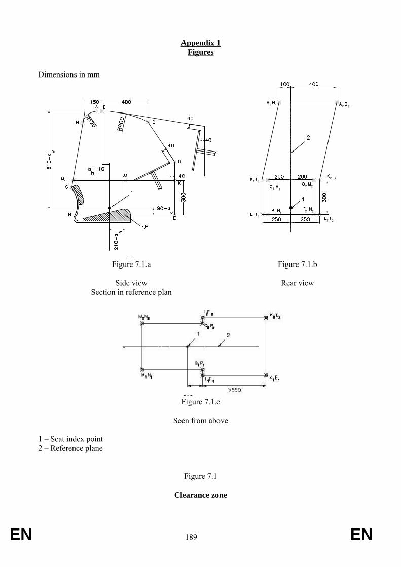
EN 189 EN
Appendix 1 Figures
Dimensions in mm
Figure 7.1.a
Side view Section in reference plan
Figure 7.1.b
Rear view
Figure 7.1.c
Seen from above
1 – Seat index point 2 – Reference plane
Figure 7.1
Clearance zone
210
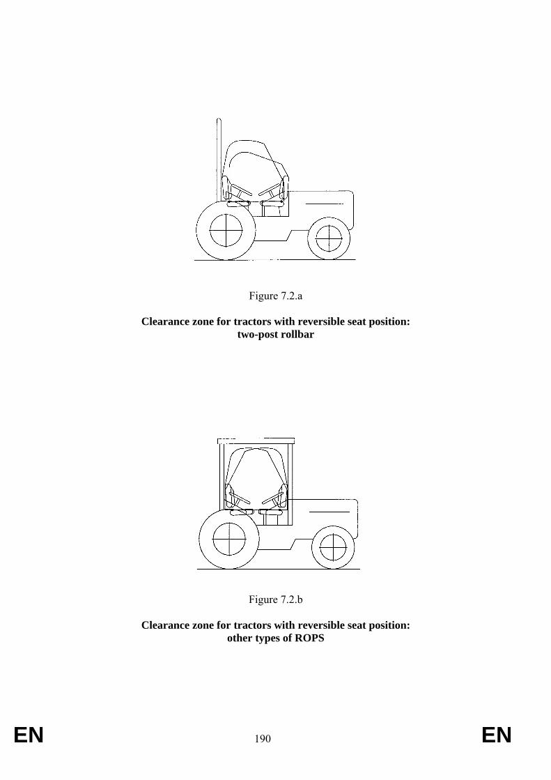
EN 190 EN
Figure 7.2.a
Clearance zone for tractors with reversible seat position: two-post rollbar
Figure 7.2.b
Clearance zone for tractors with reversible seat position: other types of ROPS
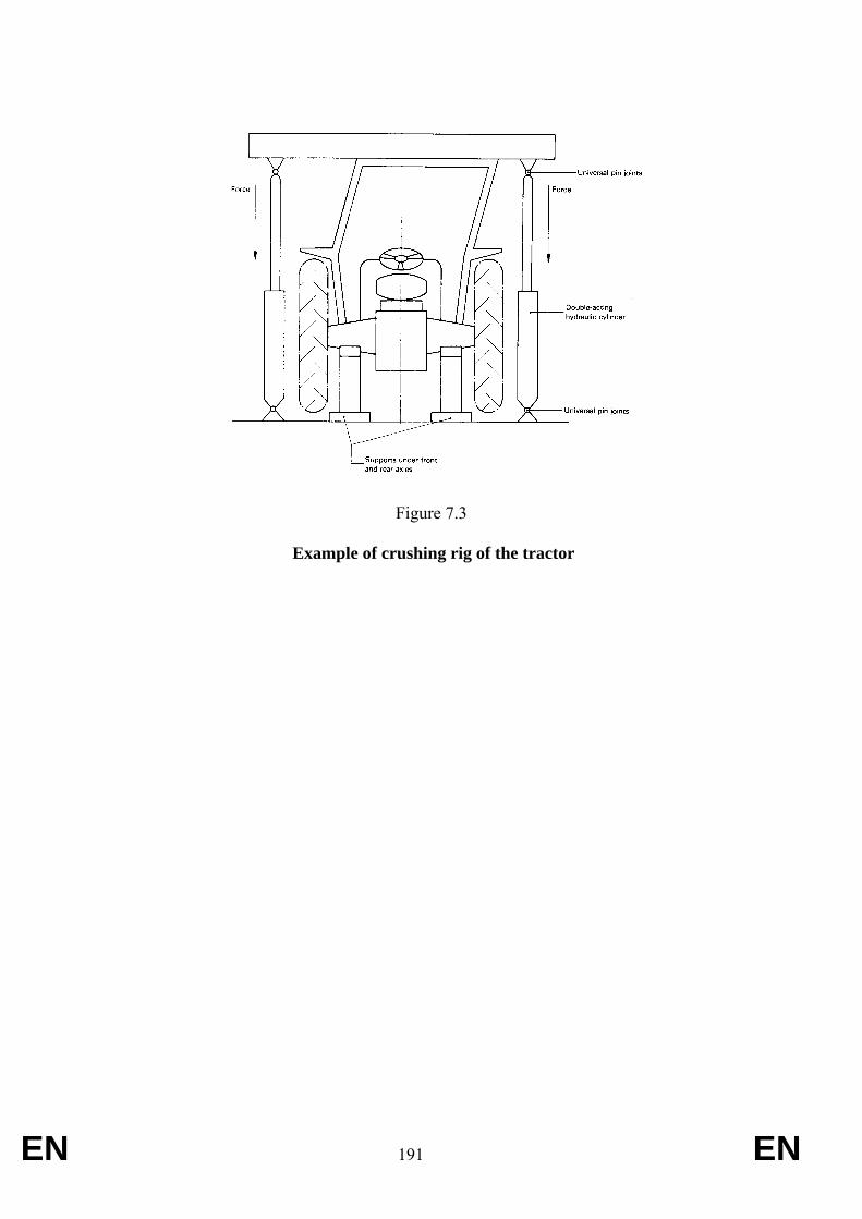
EN 191 EN
Figure 7.3
Example of crushing rig of the tractor
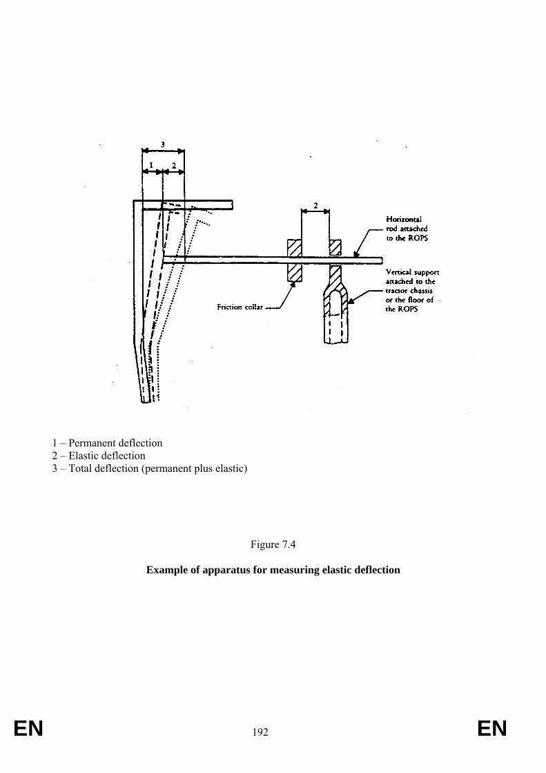
EN 192 EN
1 – Permanent deflection 2 – Elastic deflection 3 – Total deflection (permanent plus elastic)
Figure 7.4
Example of apparatus for measuring elastic deflection
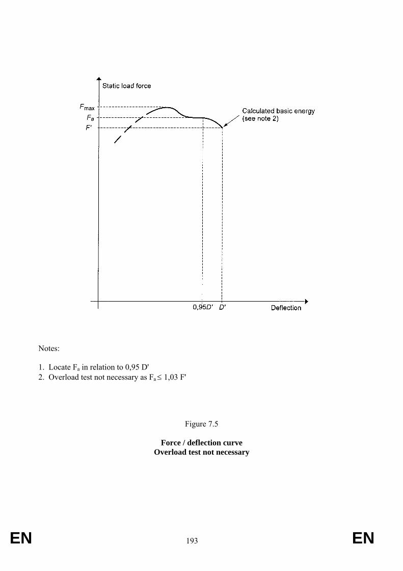
EN 193 EN
Notes: 1. Locate Fa in relation to 0,95 D' 2. Overload test not necessary as Fa ≤ 1,03 F'
Figure 7.5
Force / deflection curve Overload test not necessary
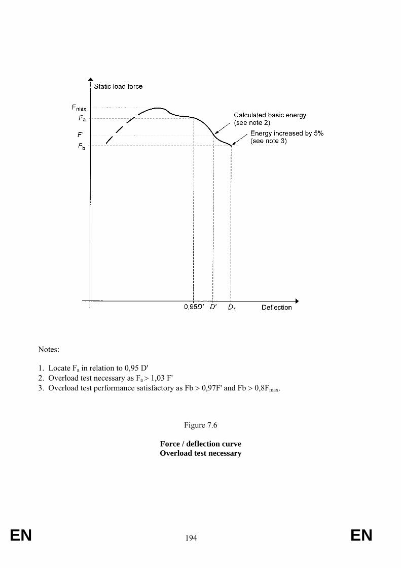
EN 194 EN
Notes: 1. Locate Fa in relation to 0,95 D' 2. Overload test necessary as Fa > 1,03 F' 3. Overload test performance satisfactory as Fb > 0,97F' and Fb > 0,8Fmax.
Figure 7.6
Force / deflection curve Overload test necessary
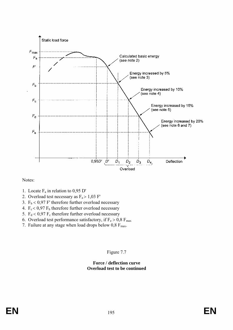
EN 195 EN
Notes: 1. Locate Fa in relation to 0,95 D' 2. Overload test necessary as Fa > 1,03 F' 3. Fb < 0,97 F' therefore further overload necessary 4. Fc < 0,97 Fb therefore further overload necessary 5. Fd < 0,97 Fc therefore further overload necessary 6. Overload test performance satisfactory, if Fe > 0,8 Fmax 7. Failure at any stage when load drops below 0,8 Fmax.
Figure 7.7
Force / deflection curve Overload test to be continued
EN 196 EN
ANNEX X- Part A
A — Alternative ‘Dynamic’ test procedure
INTRODUCTION
The paragraphs considered in this Annex refer to the Dynamic Testing Procedure. Tests may be performed in accordance with the dynamic or the static test procedure. The two methods are deemed equivalent. In general the numbering of the sections within this Annex relates to corresponding sections for static testing.
3. RULES AND DIRECTIONS
3.1 Conditions for testing the strength of protective structures and of their attachment to tractors
3.1.1 General requirements
See requirements stated for static testing.
3.1.2 Tests
3.1.2.1 Sequence of tests according to the Dynamic Procedure
The sequence of tests, without prejudice to the additional tests mentioned in sections 3.2.1.6 and 3.2.1.7 is as follows:
(1) impact at the rear of the structure (see 3.2.1.1); (2) rear crushing test (see 3.2.1.4); (3) impact at the front of the structure (see 3.2.1.2); (4) impact at the side of the structure (see 3.2.1.3); (5) crushing at the front of the structure (see 3.2.1.5).
3.1.2.2 General requirements
3.1.2.2.1 If, during the test, any part of the tractor restraining equipment breaks or moves, the test shall be restarted.
3.1.2.2 2 No repairs or adjustments of the tractor or protective structure may be carried out during the tests.
3.1.2.2.3 The tractor gear box shall be in neutral and the brakes off during the tests.
EN 197 EN
3.1.2.2.4 If the tractor is fitted with a suspension system between the tractor body and the wheels, it shall be blocked during the tests.
3.1.2.2.5 The side chosen for application of the first impact on the rear of the structure shall be that which, in the opinion of the testing authorities, will result in the application of the series of impacts or loads under the most unfavourable conditions for the structure. The lateral impact and the rear impact shall be applied on both sides of the longitudinal median plane of the protective structure. The front impact shall be applied on the same side of the longitudinal median plane of the protective structure as the lateral impact.
3.1.3 Acceptance conditions
3.1.3.1 A protective structure is regarded as having satisfied the strength requirements if it fulfils the following conditions:
3.1.3.1.1 after each test it shall be free from tears or cracks, as defined in 3.2.1.2.1. If significant tears or cracks appear during the test, an additional impact test or crushing test as defined in 3.2.1.6 or 3.2.1.7 must be performed immediately after the test which caused these tears or cracks to appear;
3.1.3.1.2 ;during the tests other than the overload test, no part of the protective structure must enter the clearance zone as defined in 1.6;
3.1.3.1.3 during the tests other than the overload test, all parts of the clearance zone shall be secured by the structure, in accordance with 3.2.2.2;
3.1.3.1.4 during the tests the protective structure must not impose any constraints on the seat structure;
3.1.3.1.5 the elastic deflection, measured in accordance with 3.2.2.3 shall be less than 250 mm.
3.1.3.2 There shall be no accessories presenting a hazard for the driver. There shall be no projecting part or accessory which is liable to injure the driver should the tractor overturn, or any accessory or part which is liable to trap him – for example by the leg or the foot – as a result of the deflections of the structure.
3.1.4 [Not applicable]
3.1.5 Apparatus and equipment for dynamic tests
3.1.5.1 Pendulum block
3.1.5.1.1 A block acting as a pendulum must be suspended by two chains or wire ropes from pivot points not less than 6 m above the ground. Means must be provided for adjusting independently the suspended height of the block and the angle between the block and the supporting chains or wire ropes.
3.1.5.1.2 The mass of the pendulum block must be 2 000 ± 20 kg excluding the mass of the chains or wire ropes which themselves must not exceed 100 kg. The length of the sides of the impact face must be 680 ± 20 mm (see Appendix 2, figure 7.18). The block must be filled in such a way that the position of its centre of gravity is constant and coincides with the geometrical centre of the parallelepiped.
EN 198 EN
3.1.5.1.3 The parallelepiped must be connected to the system which pulls it backwards by an instantaneous release mechanism which is so designed and located as to enable the pendulum block to be released without causing the parallelepiped to oscillate about its horizontal axis perpendicular to the pendulum's plane of oscillation.
3.1.5.2 Pendulum supports
The pendulum pivot points must be rigidly fixed so that their displacement in any direction does not exceed 1 per cent of the height of fall.
3.1.5.3 Lashings
3.1.5.3.1 Anchoring rails with the requisite track width and covering the necessary area for lashing the tractor in all the cases illustrated (see Appendix 2, figures 7.19, 7.20 and 7.21) must be rigidly attached to a non-yielding base beneath the pendulum.
3.1.5.3.2 The tractor shall be lashed to the rails by means of wire rope with round strand, fibre core, construction 6 x 19 in accordance with ISO 2408:2004 and a nominal diameter of 13 mm. The metal strands must have an ultimate tensile strength of 1770 MPa.
3.1.5.3.3 The central pivot of an articulated tractor shall be supported and lashed down as appropriate for all tests. For the lateral impact test, the pivot shall also be propped from the side opposite the impact. The front and rear wheels need not be in line if this facilitates the attachment of the wire ropes in the appropriate manner.
3.1.5.4 Wheel prop and beam
3.1.5.4.1 A softwood beam of 150 mm square shall be used as a prop for the wheels during the impact tests (see Appendix 2, figures 7.19, 7.20 and 7.21).
3.1.5.4.2 During the lateral impact tests, a softwood beam shall be clamped to the floor to brace the rim of the wheel opposite the side of impact (see Appendix 2, figure 7.21).
3.1.5.5 Props and lashings for articulated tractors
3.1.5.5.1 Additional props and lashings must be used for articulated tractors. Their purpose is to ensure that the section of the tractor on which the protective structure is fitted is as rigid as that of a non-articulated tractor.
3.1.5.5.2 Additional specific details are given in section 3.2.1 for the impact and crushing tests.
3.1.5.6 Tyre pressures and deflections
3.1.5.6.1 The tractor tyres shall not be liquid-ballasted and shall be inflated to the pressures prescribed by the tractor manufacturer for field work.
3.1.5.6.2 The lashings shall be tensioned in each particular case such that the tyres undergo a deflection equal to 12 per cent of the tyre wall height (distance between the ground and the lowest point of the rim) before tensioning.
3.1.5.7 Crushing rig
A rig as shown in Appendix 2, figure 7.3 shall be capable of exerting a downward force on a protective structure through a rigid beam approximately 250 mm wide connected to the
EN 199 EN
load-applying mechanism by means of universal joints. Suitable axle stands shall be provided so that the tractor tyres do not bear the crushing force.
3.1.5.8 Measuring apparatus
The following measuring apparatus is needed:
3.1.5.8.1 device for measuring the elastic deflection (the difference between the maximum momentary deflection and the permanent deflection, see Appendix 2, figure 7.4).
3.1.5.8.2 device for checking that the protective structure has not entered the clearance zone and that the latter has remained within the structure's protective during the test (see section 3.2.2.2).
3.2 Dynamic test procedure
3.2.1 Impact and crushing tests
3.2.1.1 Impact at the rear
3.2.1.1.1 The tractor shall be so placed in relation to the pendulum block that the block will strike the protective structure when the impact face of the block and the supporting chains or wire ropes are at an angle with the vertical plane A equal to M/100 with a 20° maximum, unless, during deflection, the protective structure at the point of contact forms a greater angle to the vertical. In this case the impact face of the block shall be adjusted by means of an additional support so that it is parallel to the protective structure at the point of impact at the moment of maximum deflection, the supporting chains or wire ropes remaining at the angle defined above.
The suspended height of the block shall be adjusted and necessary steps taken so as to prevent the block from turning about the point of impact.
The point of impact is that part of the protective structure likely to hit the ground first in a rearward overturning accident, normally the upper edge. The position of the centre of gravity of the block is 1/6 of the width of the top of the protective structure inwards from a vertical plane parallel to the median plane of the tractor touching the outside extremity of the top of the protective structure.
If the structure is curved or protruding at this point, wedges enabling the impact to be applied thereon must be added, without thereby reinforcing the structure.
3.2.1.1.2 The tractor must be lashed to the ground by means of four wire ropes, one at each end of both axles, arranged as indicated in Appendix 2, figure 7.19. The spacing between the front and rear lashing points must be such that the wire ropes make an angle of less than 30° with the ground. The rear lashings must in addition be so arranged that the point of convergence of the two wire ropes is located in the vertical plane in which the centre of gravity of the pendulum block travels.
The wire ropes must be tensioned so that the tyres undergo the deflections given in 3.1.5.6.2. With the wire ropes tensioned, the wedging beam shall be placed in front of and tight against the rear wheels and then fixed to the ground.
3.2.1.1.3 If the tractor is of the articulated type, the point of articulation shall, in addition, be supported by a wooden block at least 100 mm square and firmly lashed to the ground.
EN 200 EN
3.2.1.1.4 The pendulum block shall be pulled back so that the height of its centre of gravity above that at the point of impact is given by one of the following two formulae:
H = 2.165 x 10 - 8 M L2 or
H = 5.73 x 10 - 2 I
The pendulum block is then released and strikes the protective structure.
3.2.1.1.5 For tractors with a reversible driver’s position (reversible seat and steering wheel), the height shall be whichever is greater of either of the above or either of the following:
H = 25 + 0.07 M
for tractor with a reference mass of less than 2 000 kg;
H = 125 + 0.02 M
for tractor with a reference mass of more than 2 000 kg .
3.2.1.2 Impact at the front
3.2.1.2.1 The tractor shall be so placed in relation to the pendulum block that the block will strike the protective structure when the impact face of the block and the supporting chains or wire ropes are at an angle with the vertical plane A equal to M/100 with a 20° maximum, unless, during deflection, the protective structure at the point of contact forms a greater angle to the vertical. In this case the impact face of the block shall be adjusted by means of an additional support so that it is parallel to the protective structure at the point of impact at the moment of maximum deflection, the supporting chains or wire ropes remaining at the angle defined above.
The suspended height of the pendulum block shall be adjusted and the necessary steps taken so as to prevent the block from turning about the point of impact.
The point of impact is that part of the protective structure likely to hit the ground first if the tractor overturned sideways while travelling forward, normally the upper edge. The position of the centre of gravity of the block is 1/6 of the width of the top of the protective structure inwards from a vertical plane parallel to the median plane of the tractor touching the outside extremity of the top of the protective structure.
If the structure is curved or protruding at this point, wedges enabling the impact to be applied thereon must be added, without thereby reinforcing the structure.
3.2.1.2.2 The tractor must be lashed to the ground by means of four wire ropes, one at each end of both axles, arranged as indicated in Appendix 2, figure 7.20. The spacing between the front and rear lashing points must be such that the wire ropes make an angle of less than 30° with the ground. The rear lashings must in addition be so arranged that the point of convergence of the two wire ropes is located in the vertical plane in which the centre of gravity of the pendulum block travels.
The wire ropes must be tensioned so that the tyres undergo the deflections given in 3.1.5.6.2. With the wire ropes tensioned, the wedging beam shall be placed behind and tight against the rear wheels and then fixed to the ground.
EN 201 EN
3.2.1.2.3 If the tractor is of the articulated type, the point of articulation shall, in addition, be supported by a wooden block at least 100 mm square and firmly lashed to the ground.
3.2.1.2.4 The pendulum block shall be pulled back so that the height of its centre of gravity above that at the point of impact is given by one of the following two formulae, to be chosen according to the reference mass of the assembly subjected to the tests:
H = 25 + 0.07 M for tractor with a reference mass of less than 2 000 kg;
H = 125 + 0.02 M
for tractor with a reference mass of more than 2 000 kg.
The pendulum block is then released and strikes the protective structure.
3.2.1.2.5 In case of tractors with a reversible driver’s position (reversible seat and steering wheel):
• if the protective structure is a rear two-post rollbar, the above formula shall apply;
• for other types of protective structure, the height shall be whichever is greater from the formula applied above and that selected below:
H = 2.165 x 10 - 8 ML2
or
H = 5,73 x 10 - 2 I
The pendulum block is then released and strikes the protective structure.
3.2.1.3 Impact from the side
3.2.1.3.1 The tractor shall be so placed in relation to the pendulum block that the block will strike the protective structure when the impact face of the block and the supporting chains or wire ropes are vertical unless, during deflection, the protective structure at the point of contact forms an angle of less than 20° to the vertical. In this case the impact face of the block shall be adjusted by means of an additional support so that it is parallel to the protective structure at the point of impact at the moment of maximum deflection, the supporting chains or wire ropes remaining vertical on impact.
3.2.1.3.2 The suspended height of the pendulum block shall be adjusted and necessary steps taken so as to prevent the block from turning about the point of impact.
3.2.1.3.3 The point of impact shall be that part of the protective structure likely to hit the ground first in a sideways overturning accident, normally the upper edge. Unless it is certain that another part of this edge would hit ground first, the point of impact shall be in the plane at right angles to the median plane and passing 60 mm in front of the Seat Index Point, the seat being set at the mid position of longitudinal adjustment.
3.2.1.3.4 For tractors with a reversible driver's position (reversible seat and steering wheel), the point of impact shall be in the plane at right angles to the median plane and passing at the midpoint of the segment joining the two Seat Index Points defined by joining the two
EN 202 EN
different positions of the seat. For protective structures having a two-post system, the impact shall be located on one of the two posts.
3.2.1.3.5 The tractor wheels on the side which is to receive the impact must be lashed to the ground by means of wire ropes passing over the corresponding ends of the front and rear axles. The wire ropes must be tensioned to produce the tyre deflection values given in 3.1.5.6.2.
With the wire ropes tensioned, the wedging beam shall be placed on the ground, pushed tight against the tyres on the side opposite that which is to receive the impact and then fixed to the ground. It may be necessary to use two beams or wedges if the outer sides of the front and rear tyres are not in the same vertical plane. The prop shall then be placed as indicated in Appendix 2, figure 7.21 against the rim of the most heavily loaded wheel opposite to the point of impact, pushed firmly against the rim and then fixed at its base. The length of the prop shall be such that it makes an angle of 30 ± 3° with the ground when in position against the rim. In addition, its thickness shall, if possible, be between 20 and 25 times less than its length and between 2 and 3 times less than its width. The props shall be shaped at both ends as shown in the details on Appendix 2, figure 7.21.
3.2.1.3.6 If the tractor is of the articulated type, the point of articulation shall in addition be supported by a wooden block at least 100 mm square and laterally supported by a device similar to the prop pushed against the rear wheel as in 3.2.1.3.5. The point of articulation shall then be lashed firmly to the ground.
3.2.1.3.7 The pendulum block shall be pulled back so that the height of its centre of gravity above that at the point of impact is given by one of the following two formulae, to be chosen according to the reference mass of the assembly subjected to the tests:
H = 25 + 0.20 M
for tractors with a reference mass of less than 2 000 kg;
H = 125 + 0.15 M
for tractors with a reference mass of more than 2 000 kg.
3.2.1.3.8 In case of tractors with a reversible driver’s position (reversible seat and steering wheel):
• if the protective structure is a rear two-post rollbar, the selected height shall be whichever is greater from the formulae applicable above and below:
H = (25 + 0.20 M) (B6 + B) / 2B
for tractor with a reference mass of less than 2 000 kg;
H = (125 + 0.15 M) (B6 + B) / 2B
for tractor with a reference mass of more than 2 000 kg.
• for other types of protective structures, the selected height shall be whichever is greater from the formulae applicable above and below:
H = 25 + 0.20 M
EN 203 EN
for tractor with a reference mass less than 2 000 kg;
H = 125 + 0.15 M
for tractor with a reference mass of more than 2 000 kg.
The pendulum block is then released and strikes the protective structure.
3.2.1.4 Crushing at the rear
All provisions are identical to those given in section 3.2.1.4 of RVCR Annex V(b).
3.2.1.5 Crushing at the front
All provisions are identical to those given in section 3.2.1.5 of RVCR Annex V(b).
3.2.1.6 Additional impact tests
If cracks or tears which cannot be considered negligible appear during an impact test, a second, similar test, but with a height of fall of:
H’ = (H x 10 - 1) (12 + 4a) (1 + 2a) - 1
shall be performed immediately after the impact tests causing these tears or cracks to appear, “a” being the ratio of the permanent deformation (Dp) to the elastic deformation (De):
a = Dp / De
as measured at the point of impact. The additional permanent deformation due to the second impact shall not exceed 30 per cent of the permanent deformation due to the first impact.
In order to be able to carry out the additional test, it is necessary to measure the elastic deformation during all the impact tests.
3.2.1.7 Additional crushing tests
If during a crushing test, significant cracks or tears appear, a second, similar, crushing test, but with a force equal to 1.2 Fv shall be performed immediately after the crushing tests which caused these tears or cracks to appear.
3.2.2 Measurements to be made
3.2.2.1 Fractures and cracks
After each test all structural members, joints and fastening systems shall be visually examined for fractures or cracks, any small cracks in unimportant parts being ignored.
Any tears caused by the edges of the pendulum weight are to be ignored.
3.2.2.2 Entry into the clearance zone
During each test the protective structure shall be examined to see whether any part it has entered a clearance zone round the driving seat as defined in 1.6.
EN 204 EN
Furthermore, the clearance zone shall not be outside the protection of the protective structure. For this purpose, it shall be considered to be outside the protection of the structure if any part of it would come in contact with flat ground if the tractor overturned towards the direction from which the test load is applied. For estimating this, the front and rear tyres and track width setting shall be the smallest standard fitting specified by the manufacturer.
3.2.2.3 Elastic deflection (under side impact)
The elastic deflection shall be measured (810 + av) mm above the Seat Index Point, in the vertical plane in which the load is applied. For this measurement, any apparatus similar to that illustrated in Appendix 2, figure 7.4 may be used.
3.2.2.4 Permanent deflection
After the final crushing test, the permanent deflection of the protective structure shall be recorded. For this purpose, before the start of the test, the position of the main roll-over protective structure members in relation to the Seat Index Point shall be used.
3.3 Extension to other tractor models See the provisions stated in RVCR Annex V(b).
3.4 [Not applicable]
3.5 Cold weather performance of protective structures
See the requirements stated in RVCR Annex V(b)..
3.6 [Not applicable]
4. Additonal requirements for foldable Roll-Over Protection Structures (foldable ROPS)
4.1. On-going work of the OECD
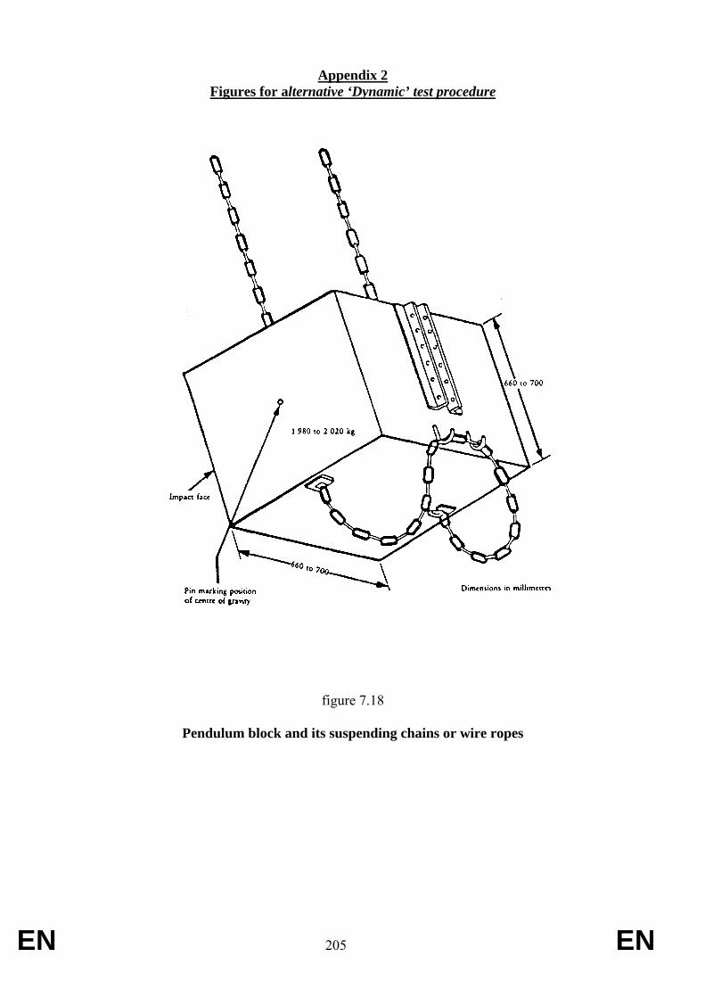
EN 205 EN
Appendix 2 Figures for alternative ‘Dynamic’ test procedure
figure 7.18
Pendulum block and its suspending chains or wire ropes
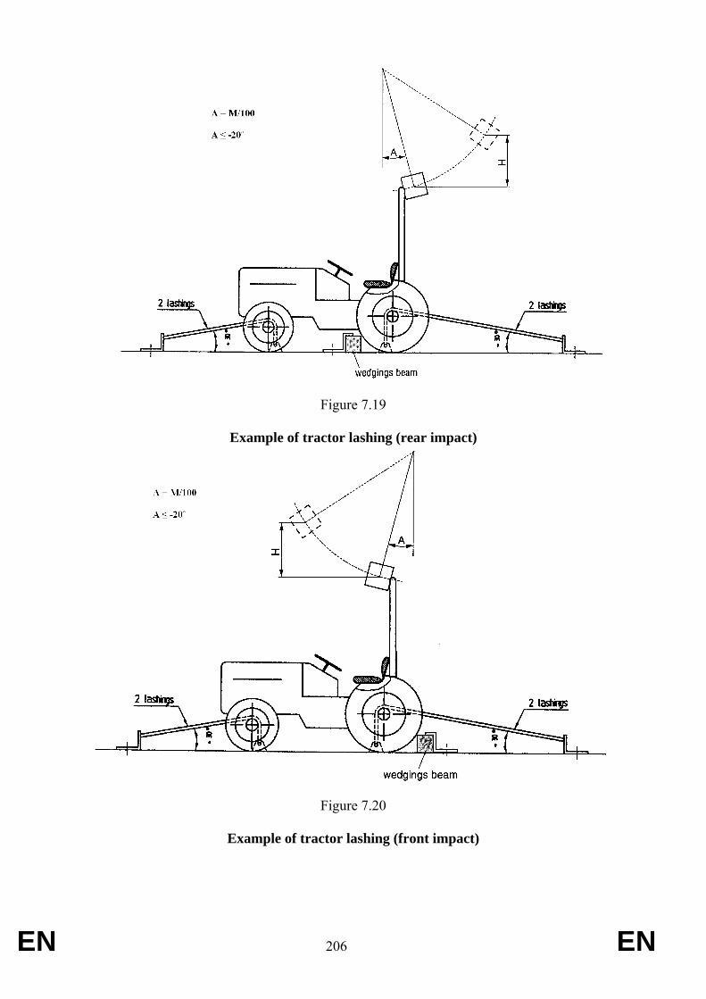
EN 206 EN
Figure 7.19
Example of tractor lashing (rear impact)
Figure 7.20
Example of tractor lashing (front impact)
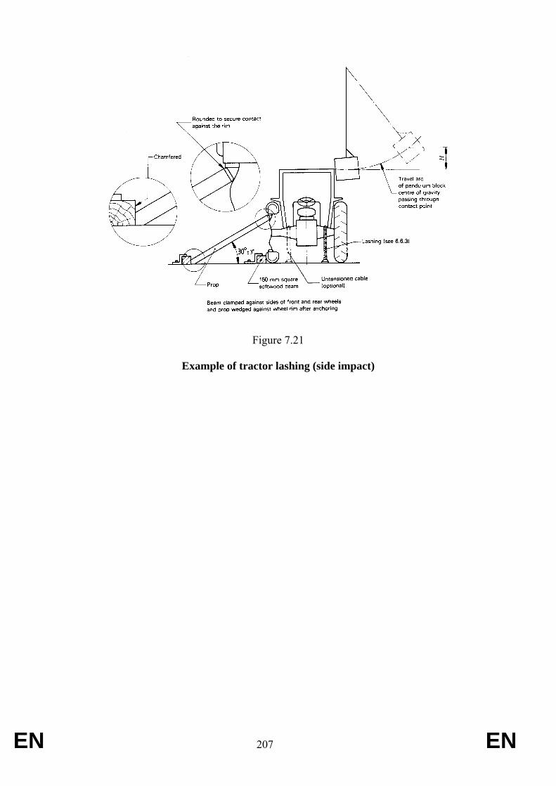
EN 207 EN
Figure 7.21
Example of tractor lashing (side impact)
EN 208 EN
ANNEX XI Requirements applying to falling objects protection structures
1. Scope
1.1. The following test requirements are applicable to agricultural and forestry tractors exposed to potential hazards of falling objects encountered during their normal operation and having the following characteristics:
- at least two axles for pneumatic tyred wheels or having tracks instead of wheels.
2. Requirements
2.1. When agricultural and forestry tractors are subject to installation of falling objects protection structures, the following requirements shall apply:
2.1.1. Agricultural and forestry wheeled and track-laid tractors which have been tested and granted a test report on the basis of the OECD Code nº 10 in accordance with Appendix 1 to the Decision of the OECD Council of February 2012 revising the OECD standard Codes for the official testing of agricultural and forestry tractors, as amended, shall be deemed to be complying with this Annex.
2.1.2. When the particular operating conditions require falling objects protection structures able to support higher energy levels than specified by OECD Code 10, e.g. for such as forestry, ISO 8083:2006 (level I or level II) rquirements may be applied.

EN 209 EN
ANNEX XII Requirements applying to passenger seats
1. Requirements
1.1. Passenger seats, if provided, shall comply with EN 15694:2009.
1.2. A vehicle equipped with a straddle seat and handlebars, and with an unladen mass, in running order, of less than 400 kg, and designed to carry a passenger shall meet the technical requirements for ATV Type II vehicle passenger seats in EN 15997:2011, as an alternative to EN 15694:2009.
EN 210 EN
ANNEX XIII Requirements applying to driver’s exposure to noise level
ANNEX XIII- Part A
A — General requirements
1. Definitions
1.1. For the purposes of this Annex, ‘cab’ means any structure built of rigid components, transparent or not, which totally encloses the driver and isolates him from the outside, and is capable of being kept permanently closed during service.
2. Noise level limits
2.1. – Agricultural and forestry wheeled and track-laid tractors shall have a level driver’s exposure to noise level within the following limits:
– 90 dB(A) in accordance with Part B,
– or
– 86 dB(A) in accordance with Part C.
EN 211 EN
ANNEX XIII- Part B
B — Test method 1
APPARATUS, CONDITIONS AND METHOD OF MEASUREMENT
1. UNIT OF MEASUREMENT AND MEASURING APPARATUS
1.1. Unit of measurement
Noise level LA shall be measured in dB with A-weighting, expressed as dB(A).
1.2. Measuring apparatus
Driver-perceived noise level shall be measured by means of a sound-level meter as described in the first edition of Publication No 179/1965 of the International Electrotechnical Commission.
In the case of variable readings, the average of the maximum values must be taken.
2. CONDITIONS OF MEASUREMENT Measurements shall be made under the following conditions:
2.1. the tractor must be unladen, i.e. without optional accessories, but must include coolant, lubricant, full fuel tank, tools and driver. The latter may not wear any abnormally thick clothing, scarf or hat. There may be no object on the tractor likely to distort the noise level;
2.2. the tyres must be inflated to the pressure recommended by the tractor manufacturer, the engine, transmission and drive axles must be at normal running temperature and radiator blinds when fitted must be kept open during measurements;
2.3. if it is liable to affect the noise level, extra equipment powered by the engine or self-powered such as windscreen wipers, warm air fan or power take-off, may not be in operation when measurements are being made; parts which normally operate at the same time as the engine, such as the engine cooling fan, must be in operation when measurements are being made;
2.4. the test area must be in an open and sufficiently silent location; it may take the form, for instance, of an open space of 50-metre radius, having a central part with a radius of at least 20 m which is practically level, or of a level section having a solid track with as flat a surface and as few gullies as possible. The track must be as clean and dry as possible (e.g. free of gravel, leaves, snow, etc.). Slopes and irregularities are acceptable only if the variations in noise level caused by them lie within the error tolerances of the measuring equipment;
2.5. the surface of the track must be such as not to cause excessive tyre noise;
2.6. the weather must be fine and dry with little or no wind.
The driver-perceived ambient noise level due to the wind or other sources of noise must be at least 10 dB(A) below the noise level of the tractor;
EN 212 EN
2.7. if a vehicle is used for measurements, it must be towed or driven at a sufficient distance from the tractor to avoid all interference. During measurements no object interfering with the measurements or reflective surfaces may be located within 20 m of each side of the test track or less than 20 m to the front or rear of the tractor. This condition can be considered fulfilled if the variations in noise level thus caused remain within the error tolerances; if not, the measurements must be discontinued for the duration of the interference;
2.8. all measurements in a given series must be carried out on the same track.
2.9. Vehicles of category C with an undercarriage on steel tracks, whether or not equipped with rubber pads on the track shoes, and with a maximum design speed below or equal to 15 km/h, (as defined in clause 1.1 of Annex XXXIII of Regulation XX/XXXX [RVCR]) shall be tested on a layer of humid sand as specified by paragraph 5.3.2 of ISO 6395:2008.
3. METHOD OF MEASUREMENT 3.1. The microphone must be located 250 mm to the side of the centre plane of the seat, the side being that on which the higher noise level is encountered.
The microphone diaphragm must face forward and the centre of the microphone must be 790 mm above and 150 mm forward of the Seat Index Point described in Annex III. Excessive vibration of the microphone must be avoided.
3.2. The maximum noise level in dB(A) shall be determined as follows:
3.2.1. all openings (e.g. doors, windows) in tractors having a closed series-produced cab structure must be closed during an initial series of measurements;
3.2.1.1. during a second series of measurements, they must be left open, provided that, when open, they do not create a road safety hazard, but fold-down or fold-up windscreens must remain closed;
3.2.2. noise must be measured using slow sound-level meter response at the load corresponding to the maximum noise in the gear giving the forward speed nearest to 7.5 km/h, or 5 km/h for tractors on steel tracks.
The governor control lever must be fully open. Starting with no load, the load applied must be increased until the maximum noise level is found. After each increase of load, time must be allowed for the noise level to stabilise before making the measurement;
3.2.3. noise must be measured using slow sound-level meter response at the load corresponding to the maximum noise in any gear other than that referred to in point 3.2.2 in which the noise level recorded is at least 1 dB(A) above that recorded in the gear referred to in point 3.2.2.
The governor control lever must be fully open. Starting with no load, the load applied must be increased until the maximum noise level is found. After each increase of load, time must be allowed for the noise
EN 213 EN
level to stabilise before making the measurement;
3.2.4. noise must be measured at the maximum design speed of the unladen tractor.
3.3. For T category tractors and C category tractors with rubber tracks, the test report shall include noise-level measurements carried out under the following conditions:
3.3.1. in the gear giving the speed nearest to 7.5 km/h;
3.3.2. in any gear, if the conditions described in point 3.2.3 are fulfilled;
3.3.3. at maximum design speed.
3.4. For C category tractors with steel tracks, the test report shall include noise-level measurements carried out under the following conditions:
3.4.1. in the gear giving the speed nearest to 5 km/h
3.4.2. at standstill of the tractor
4. ASSESSMENT CRITERIA 4.1. For T category tractors and C category tractors with rubber tracks, The measurements described in points 3.2.1, 3.2.2, 3.2.3 and 3.2.4 may not exceed the values laid down in Article 2.
4.2. For C category tractors with steel tracks, the measurement described in point 3.4.2 may not exceed the values laid down in Article 2. The measurements described in points 3.4.1 and 3.4.2 shall be included in the test report.
EN 214 EN
ANNEX XIII- Part C
C — Test method 2
APPARATUS, CONDITIONS AND METHOD OF MEASUREMENT
1. UNIT OF MEASUREMENT AND MEASURING APPARATUS
1.1. Unit of measurement
Noise level LA shall be measured in dB with A-weighting, expressed as dB(A).
1.2. Measuring apparatus
Driver-perceived noise level shall be measured by means of a sound-level meter as described in the first edition of publication 179/1965 of the International Electrotechnical Commission.
In the case of variable readings, the average of the maximum values must be taken.
2. CONDITIONS OF MEASUREMENT Measurements shall be made under the following conditions:
2.1. the tractor must be unladen, i.e. without optional accessories, but must include coolant, lubricant; full fuel tank, tools and driver. The latter may not wear any abnormally thick clothing, scarf or hat. There may be no object on the tractor likely to distort the noise level;
2.2. the tyres must be inflated to the pressure recommended by the tractor manufacturer, the engine, transmission and drive axles must be at normal running temperature and, if the engine has cooling louvres, these must remain completely open;
2.3. if it is liable to affect the noise level, extra equipment powered by the engine or self-powered such as windscreen wipers, warm air fan or power take-off, for example, may not be in operation when measurements are being made; parts which normally operate at the same time as the engine, such as the engine cooling fan, for example, must be in operation when measurements are being made;
2.4. the test area must be in an open and sufficiently silent location: it may take the form, for instance, of an open space of 50-metre radius, having a central part with a radius of at least 20 m which is practically level, or of a level section having a solid track with as flat a surface and as few gullies as possible. The track must be as clean and dry as possible (e.g. free of gravel, leaves, snow, etc.). Slopes and irregularities are acceptable only if the variations in noise level caused by them lie within the error tolerances of the measuring equipment;
2.5. the surface of the track must be such as not to cause excessive tyre noise;
2.6. the weather must be fine and dry with little or no wind.
The driver-perceived ambient noise level due to the wind or other sources of noise must be at least 10 dB(A) below the noise level of the tractor;
2.7. if a vehicle is used for measurements, it must be towed or driven at a sufficient distance from the tractor to avoid all interference. During measurements no object interfering with the measurements or reflective surfaces may be located within 20 m of each side of the test track or less than 20 m to the front or rear of the tractor. This condition can be considered fulfilled if the variations in noise level thus caused remain within the error tolerances; if not, the measurements must be discontinued for the duration of the interference;
EN 215 EN
2.8. all measurements in a given series must be carried out on the same track.
3. METHOD OF MEASUREMENT 3.1. The microphone must be located 250 mm to the side of the central plane of the seat, the side being that on which the higher noise level is encountered.
The microphone diaphragm must face forward and the centre of the microphone shall be 790 mm above and 150 mm forward of the Seat Index Point described in Annex III. Excessive vibration of the microphone must be avoided.
3.2. Noise level shall be determined as follows:
3.2.1. the tractor must travel along the section at the same test speed at least three times for at least 10 seconds;
3.2.2. all openings (e.g. doors, windows) in tractors having a closed series-produced cab structure must be closed during an initial series of measurements;
3.2.2.1. during a second series of measurements they must be left open, provided that when open they do not create a road safety hazard, but fold-down or fold-up windscreens must remain closed;
3.2.3. noise must be measured at the maximum rpm using slow sound-level meter response i.e. in the gear giving the speed nearest to 7.5 km/h at the rated rpm. The tractor must be unladen when measurements are being made.
4. ASSESSMENT CRITERIA The measurements described in points 3.2.2 and 3.2.3 may not exceed the values laid down in Article 2.
EN 216 EN
ANNEX XIV Requirements applying to driving seat and position
DEFINITIONS For the purpose of this Annex the following defintions shall apply:
1. DRIVER'S SEAT «Driver's seat» means that seat capable of accommodating one person only, provided for the use of the driver when driving the tractor.
2. SEAT SURFACE «Seat surface» means the almost horizontal area of the seat which supports the driver when seated.
3. BACKREST «Backrest» means the almost vertical area of the seat supporting the driver's back when seated.
4. LATERAL SEAT SUPPORTS «Lateral seat supports» means the devices or forms of the seat surface which prevent the driver from sliding sideways.
4.1. Seat armrests «Seat armrests» means the devices on either side of the seat which support the driver's arms when he is seated.
5. DEPTH OF THE SEAT SURFACE «Depth of the seat surface» means the horizontal distance between the Seat Index Point and the front edge of the seat surface.
6. WIDTH OF THE SEAT SURFACE
«Width of the seat surface» means the horizontal distance between the outside edges of the seat surface measured in a plane perpendicular to the median plane of the seat.
7. LOAD ADJUSTMENT RANGE «Load adjustment range» means the range between the two loads corresponding to the mean positions in the suspension system curves plotted for the heaviest and lightest driver.
8. SUSPENSION TRAVEL Suspension travel» means the vertical distance between the highest position and the position at a given moment of a point situated on the seat surface 200 mm in front of the Seat Index Point in the median longitudinal plane.
EN 217 EN
9. VIBRATION «Vibration» means the vertical movement up and down of the driver's seat.
10. VIBRATION ACCELERATION (A) «Vibration acceleration (a)» means the second differential of the vibration displacement with respect to time.
11. RMS VALUE OF THE ACCELERATION (AEFF) «Rms value of the acceleration (aeff)» means the square root of the mean square of the accelerations.
12. WEIGHTED VIBRATION ACCELERATION (AW) «Weighted vibration acceleration (aw)» means the weighted vibration acceleration determined with the help of a weighting filter in accordance with 2.5.3.3.5.2 of Annex II.
«awS = rms value of the weighted seat vibration acceleration measured during a bench test or a standard roadway test;
awB = rms value of the weighted vibration acceleration measured at the seat attachment during a bench test;
awB* = reference rms value of the weighted vibration acceleration measured at the
seat attachment;
awS* = corrected rms value of the weighted seat vibration acceleration measured
during a bench test;
awF* = rms value of the weighted vibration acceleration measured at the seat
attachment during a standard roadway test.»
13. VIBRATION RATIO «Vibration ratio» means the ratio of the weighted vibration acceleration measured on the driver's seat to that measured at the seat attachment in accordance with 2.5.3.3.2 of Annex II.
14. VIBRATION CLASS «Vibration class» means the class or group of tractors which show the same vibration characteristics.
15. CATEGORY A TRACTOR Category A tractor» means a tractor which can be assigned to a given vibration class by reason of similar design features.
15.1. the characteristics of these tractors are as follows:
number of axles: two
Suspension: unsuspended rear axle»
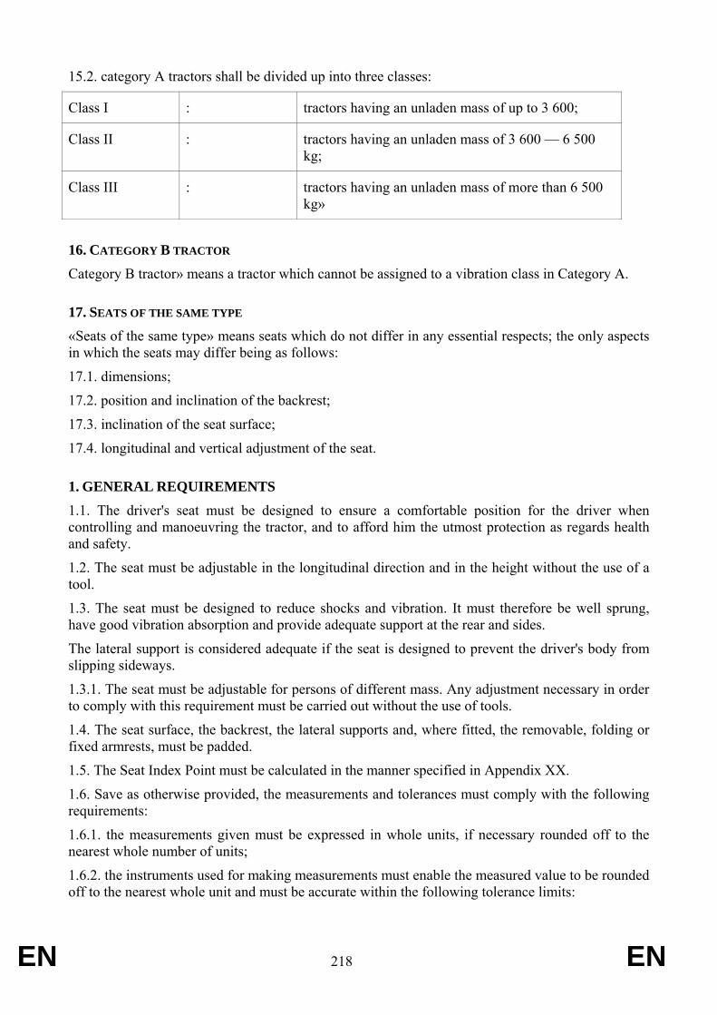
EN 218 EN
15.2. category A tractors shall be divided up into three classes:
Class I : tractors having an unladen mass of up to 3 600;
Class II : tractors having an unladen mass of 3 600 — 6 500 kg;
Class III : tractors having an unladen mass of more than 6 500 kg»
16. CATEGORY B TRACTOR Category B tractor» means a tractor which cannot be assigned to a vibration class in Category A.
17. SEATS OF THE SAME TYPE «Seats of the same type» means seats which do not differ in any essential respects; the only aspects in which the seats may differ being as follows:
17.1. dimensions;
17.2. position and inclination of the backrest;
17.3. inclination of the seat surface;
17.4. longitudinal and vertical adjustment of the seat.
1. GENERAL REQUIREMENTS 1.1. The driver's seat must be designed to ensure a comfortable position for the driver when controlling and manoeuvring the tractor, and to afford him the utmost protection as regards health and safety.
1.2. The seat must be adjustable in the longitudinal direction and in the height without the use of a tool.
1.3. The seat must be designed to reduce shocks and vibration. It must therefore be well sprung, have good vibration absorption and provide adequate support at the rear and sides.
The lateral support is considered adequate if the seat is designed to prevent the driver's body from slipping sideways.
1.3.1. The seat must be adjustable for persons of different mass. Any adjustment necessary in order to comply with this requirement must be carried out without the use of tools.
1.4. The seat surface, the backrest, the lateral supports and, where fitted, the removable, folding or fixed armrests, must be padded.
1.5. The Seat Index Point must be calculated in the manner specified in Appendix XX.
1.6. Save as otherwise provided, the measurements and tolerances must comply with the following requirements:
1.6.1. the measurements given must be expressed in whole units, if necessary rounded off to the nearest whole number of units;
1.6.2. the instruments used for making measurements must enable the measured value to be rounded off to the nearest whole unit and must be accurate within the following tolerance limits:
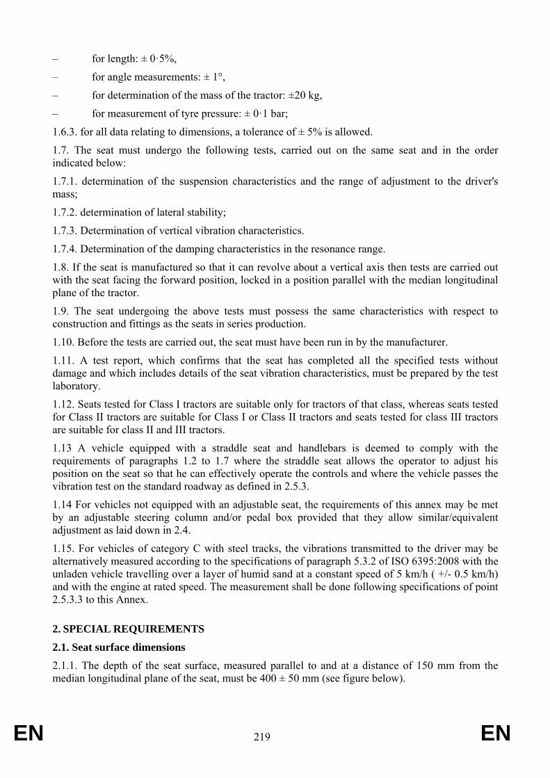
EN 219 EN
– for length: ± 0·5%,
– for angle measurements: ± 1°,
– for determination of the mass of the tractor: ±20 kg,
– for measurement of tyre pressure: ± 0·1 bar;
1.6.3. for all data relating to dimensions, a tolerance of ± 5% is allowed.
1.7. The seat must undergo the following tests, carried out on the same seat and in the order indicated below:
1.7.1. determination of the suspension characteristics and the range of adjustment to the driver's mass;
1.7.2. determination of lateral stability;
1.7.3. Determination of vertical vibration characteristics.
1.7.4. Determination of the damping characteristics in the resonance range.
1.8. If the seat is manufactured so that it can revolve about a vertical axis then tests are carried out with the seat facing the forward position, locked in a position parallel with the median longitudinal plane of the tractor.
1.9. The seat undergoing the above tests must possess the same characteristics with respect to construction and fittings as the seats in series production.
1.10. Before the tests are carried out, the seat must have been run in by the manufacturer.
1.11. A test report, which confirms that the seat has completed all the specified tests without damage and which includes details of the seat vibration characteristics, must be prepared by the test laboratory.
1.12. Seats tested for Class I tractors are suitable only for tractors of that class, whereas seats tested for Class II tractors are suitable for Class I or Class II tractors and seats tested for class III tractors are suitable for class II and III tractors.
1.13 A vehicle equipped with a straddle seat and handlebars is deemed to comply with the requirements of paragraphs 1.2 to 1.7 where the straddle seat allows the operator to adjust his position on the seat so that he can effectively operate the controls and where the vehicle passes the vibration test on the standard roadway as defined in 2.5.3.
1.14 For vehicles not equipped with an adjustable seat, the requirements of this annex may be met by an adjustable steering column and/or pedal box provided that they allow similar/equivalent adjustment as laid down in 2.4.
1.15. For vehicles of category C with steel tracks, the vibrations transmitted to the driver may be alternatively measured according to the specifications of paragraph 5.3.2 of ISO 6395:2008 with the unladen vehicle travelling over a layer of humid sand at a constant speed of 5 km/h ( +/- 0.5 km/h) and with the engine at rated speed. The measurement shall be done following specifications of point 2.5.3.3 to this Annex.
2. SPECIAL REQUIREMENTS
2.1. Seat surface dimensions 2.1.1. The depth of the seat surface, measured parallel to and at a distance of 150 mm from the median longitudinal plane of the seat, must be 400 ± 50 mm (see figure below).
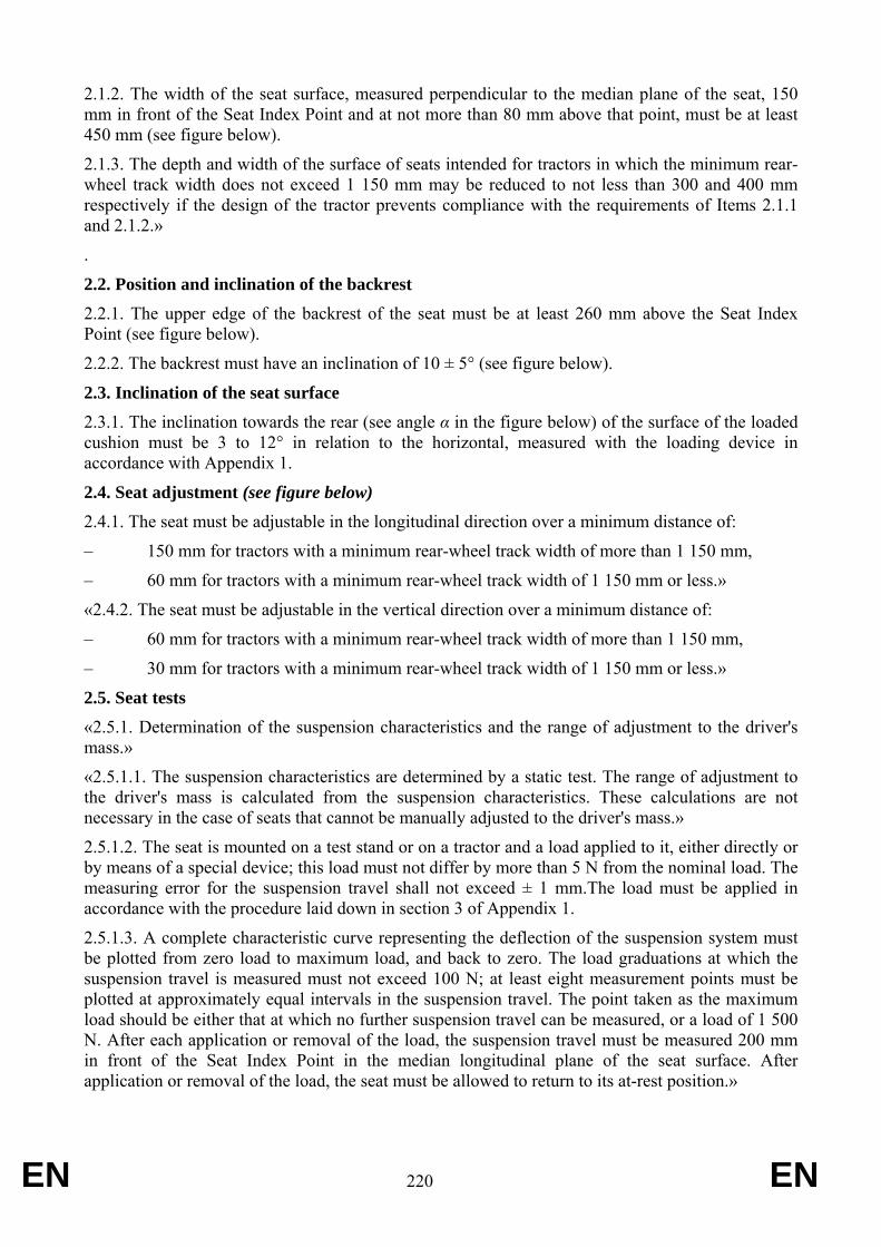
EN 220 EN
2.1.2. The width of the seat surface, measured perpendicular to the median plane of the seat, 150 mm in front of the Seat Index Point and at not more than 80 mm above that point, must be at least 450 mm (see figure below).
2.1.3. The depth and width of the surface of seats intended for tractors in which the minimum rear-wheel track width does not exceed 1 150 mm may be reduced to not less than 300 and 400 mm respectively if the design of the tractor prevents compliance with the requirements of Items 2.1.1 and 2.1.2.»
.
2.2. Position and inclination of the backrest 2.2.1. The upper edge of the backrest of the seat must be at least 260 mm above the Seat Index Point (see figure below).
2.2.2. The backrest must have an inclination of 10 ± 5° (see figure below).
2.3. Inclination of the seat surface 2.3.1. The inclination towards the rear (see angle α in the figure below) of the surface of the loaded cushion must be 3 to 12° in relation to the horizontal, measured with the loading device in accordance with Appendix 1.
2.4. Seat adjustment (see figure below) 2.4.1. The seat must be adjustable in the longitudinal direction over a minimum distance of:
– 150 mm for tractors with a minimum rear-wheel track width of more than 1 150 mm,
– 60 mm for tractors with a minimum rear-wheel track width of 1 150 mm or less.»
«2.4.2. The seat must be adjustable in the vertical direction over a minimum distance of:
– 60 mm for tractors with a minimum rear-wheel track width of more than 1 150 mm,
– 30 mm for tractors with a minimum rear-wheel track width of 1 150 mm or less.»
2.5. Seat tests «2.5.1. Determination of the suspension characteristics and the range of adjustment to the driver's mass.»
«2.5.1.1. The suspension characteristics are determined by a static test. The range of adjustment to the driver's mass is calculated from the suspension characteristics. These calculations are not necessary in the case of seats that cannot be manually adjusted to the driver's mass.»
2.5.1.2. The seat is mounted on a test stand or on a tractor and a load applied to it, either directly or by means of a special device; this load must not differ by more than 5 N from the nominal load. The measuring error for the suspension travel shall not exceed ± 1 mm.The load must be applied in accordance with the procedure laid down in section 3 of Appendix 1.
2.5.1.3. A complete characteristic curve representing the deflection of the suspension system must be plotted from zero load to maximum load, and back to zero. The load graduations at which the suspension travel is measured must not exceed 100 N; at least eight measurement points must be plotted at approximately equal intervals in the suspension travel. The point taken as the maximum load should be either that at which no further suspension travel can be measured, or a load of 1 500 N. After each application or removal of the load, the suspension travel must be measured 200 mm in front of the Seat Index Point in the median longitudinal plane of the seat surface. After application or removal of the load, the seat must be allowed to return to its at-rest position.»
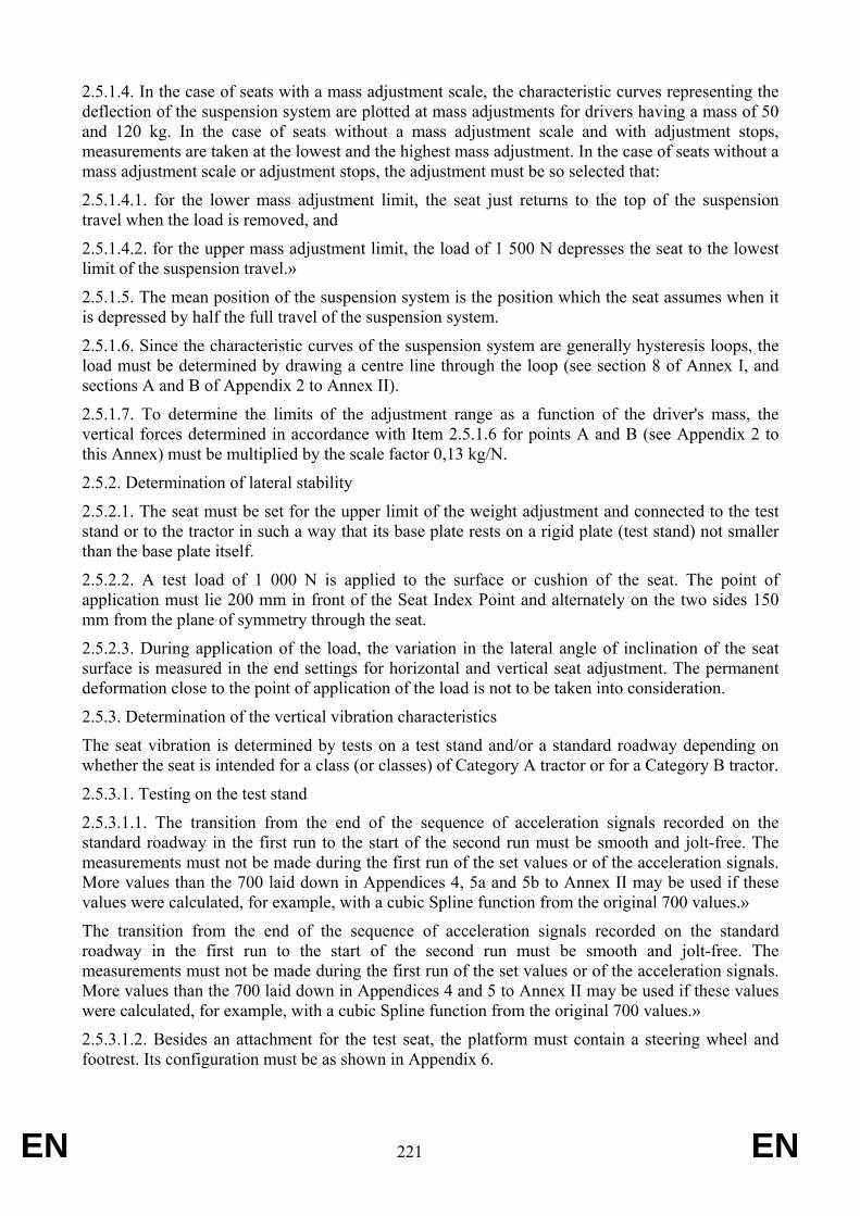
EN 221 EN
2.5.1.4. In the case of seats with a mass adjustment scale, the characteristic curves representing the deflection of the suspension system are plotted at mass adjustments for drivers having a mass of 50 and 120 kg. In the case of seats without a mass adjustment scale and with adjustment stops, measurements are taken at the lowest and the highest mass adjustment. In the case of seats without a mass adjustment scale or adjustment stops, the adjustment must be so selected that:
2.5.1.4.1. for the lower mass adjustment limit, the seat just returns to the top of the suspension travel when the load is removed, and
2.5.1.4.2. for the upper mass adjustment limit, the load of 1 500 N depresses the seat to the lowest limit of the suspension travel.»
2.5.1.5. The mean position of the suspension system is the position which the seat assumes when it is depressed by half the full travel of the suspension system.
2.5.1.6. Since the characteristic curves of the suspension system are generally hysteresis loops, the load must be determined by drawing a centre line through the loop (see section 8 of Annex I, and sections A and B of Appendix 2 to Annex II).
2.5.1.7. To determine the limits of the adjustment range as a function of the driver's mass, the vertical forces determined in accordance with Item 2.5.1.6 for points A and B (see Appendix 2 to this Annex) must be multiplied by the scale factor 0,13 kg/N.
2.5.2. Determination of lateral stability
2.5.2.1. The seat must be set for the upper limit of the weight adjustment and connected to the test stand or to the tractor in such a way that its base plate rests on a rigid plate (test stand) not smaller than the base plate itself.
2.5.2.2. A test load of 1 000 N is applied to the surface or cushion of the seat. The point of application must lie 200 mm in front of the Seat Index Point and alternately on the two sides 150 mm from the plane of symmetry through the seat.
2.5.2.3. During application of the load, the variation in the lateral angle of inclination of the seat surface is measured in the end settings for horizontal and vertical seat adjustment. The permanent deformation close to the point of application of the load is not to be taken into consideration.
2.5.3. Determination of the vertical vibration characteristics
The seat vibration is determined by tests on a test stand and/or a standard roadway depending on whether the seat is intended for a class (or classes) of Category A tractor or for a Category B tractor.
2.5.3.1. Testing on the test stand
2.5.3.1.1. The transition from the end of the sequence of acceleration signals recorded on the standard roadway in the first run to the start of the second run must be smooth and jolt-free. The measurements must not be made during the first run of the set values or of the acceleration signals. More values than the 700 laid down in Appendices 4, 5a and 5b to Annex II may be used if these values were calculated, for example, with a cubic Spline function from the original 700 values.»
The transition from the end of the sequence of acceleration signals recorded on the standard roadway in the first run to the start of the second run must be smooth and jolt-free. The measurements must not be made during the first run of the set values or of the acceleration signals. More values than the 700 laid down in Appendices 4 and 5 to Annex II may be used if these values were calculated, for example, with a cubic Spline function from the original 700 values.»
2.5.3.1.2. Besides an attachment for the test seat, the platform must contain a steering wheel and footrest. Its configuration must be as shown in Appendix 6.
EN 222 EN
2.5.3.1.3. The test stand must have a high degree of flexural and torsional rigidity and its bearings and guides must have no more than the technically necessary clearance. If the platform is carried on an oscillating arm, the dimension R must be not less than 2 000 mm (see Appendix 6). The magnitude of the vibration ratio at frequencies between 0,5 and 5,0 Hz shall be within the range 1,00 ± 0,05, measured at intervals not exceeding 0,5 Hz. The phase shift shall not vary by more than 20° throughout the same frequency range..
2.5.3.2. Testing on a standard roadway
2.5.3.2.1. The roadway consists of two parallel strips spaced according to the wheel track of the tractor. Both strips must be made of a rigid material, such as wood or concrete, and be formed either of blocks set in a base structure or of a continuous smooth surface. The longitudinal profile of each track strip is defined by the ordinates of elevation in relation to a base level; these ordinates are shown in the tables in Appendix 3. With regard to the roadway, the elevation is defined at intervals of 16 cm along each strip.
The roadway must be firmly set in the ground and the distance between the strips must deviate only slightly over its entire length; the tractor's wheels must be fully supported at all times. Where the strips are formed of blocks, these must be 6 to 8 cm thick, with a distance of 16 cm between the centres of the blocks. The length of the standard roadway shall be 100 m.
The measurements must begin as soon as the axis of the rear axle of the tractor is perpendicular to point D = 0 on the roadway, and end as soon as the axis of the front axle of the tractor is perpendicular to point D = 100 of the test roadway (see the table in Appendix 3 to this Annex).
2.5.3.2.2. Measurements shall be taken at a speed of 12 ± 0,5 km/h.
The prescribed speed must be maintained without the use of brakes. The vibrations must be measured on the seat and at the point where the seat is attached to the tractor, with a light and a heavy driver.
The speed of 12 km/h must be reached after a run-up track has been traversed. The surface of this run-up track must be flat and must join the standard roadway without any change in level.
2.5.3.2.3. The seat must be set for the driver's mass in accordance with the manufacturer's instructions.
2.5.3.2.4. The tractor must be fitted with a protective frame and/or cab unless of a type for which this equipment is not required. It must not carry any ancillary equipment. Moreover, there must be no ballast on the wheels or framework, and no fluid in the tyres.
2.5.3.2.5. The tyres used during the test must have the standard dimensions and ply-rating, as specified in the manufacturer's instructions. The depth of the tread must not be less than 65 % of the depth of a new tread.
2.5.3.2.6. The side-walls of the tyres must not be damaged. The pressure of the tyre must correspond to the arithmetical mean of the reference pressures recommended by the tyre manufacturer. The wheel track must correspond to that used under normal working conditions for the tractor model on which the seat is fitted.
2.5.3.2.7. The measurements at the point of seat attachment and on the seat itself must be made during the same run.
For measuring and recording the vibrations, an accelerometer, a measuring amplifier and a magnetic tape recorder or direct-reading vibration meter shall be used. The specifications for these instruments are as laid down in 2.5.3.3.2 to 2.5.3.3.6.
EN 223 EN
2.5.3.3. Specifications for tests on roadway and test stand
«2.5.3.3.1. DRIVER'S MASS The tests must be carried out with two drivers: one with a total mass of 59 ± 1 kg, of which not more than 5 kg may be carried in a weighting belt around the body; the other with a mass of 98 ± 5 kg with a maximum mass of 8 kg in the weighting belt.»
«2.5.3.3.2. POSITION OF THE ACCELEROMETER To measure the vibrations transmitted to the driver, an accelerometer is fixed on a flat plate with a diameter of 250 ± 50 mm, the central part of which must be rigid up to a diameter of 75 mm and must include a rigid device to protect the accelerometer. This plate must be placed in the middle of the seat surface between the seat and the driver and have a non-slip surface.
To measure the vibrations at the seat attachment, an accelerometer must be fixed near to this attachment at a point not more than 100 mm from the median longitudinal plane of the tractor and not outside the vertical projection of the seat surface on the tractor.»
2.5.3.3.3. Measurement of vibration acceleration
The accelerometer and the associated amplifying and transmitting equipment must respond to vibrations with an r.m.s. value of 0·05 m/s2, and be capable of measuring vibrations with an r.m.s. value of 5 m/s2 and a crest factor (ratio of peak to r.m.s. value) of 3 without distortion and with a maximum error of ± 2·5 % over the range 1 to 80 Hz.
2.5.3.3.4. Magnetic tape recorder
If a tape recorder is used, it must have a maximum reproduction error of ± 3·5 % in a frequency range of 1 to 80 Hz, including change of tape speed during replay for analysis.
2.5.3.3.5. Vibration meter
2.5.3.3.5.1. Vibrations of more than 10 Hz may be disregarded. It is therefore permissible to connect upstream of the measuring instrument a low-pass filter with a cut-out frequency of about 10 Hz and an attenuation of 12 dB per octave.
2.5.3.3.5.2. This instrument must incorporate an electronic weighting filter between the sensor and the integrator device. The filter must correspond to the curve shown in Appendix 8 and the margin of error must be ± 0·5 dB in the 2 to 4 Hz frequency band and ± 2 dB for the other frequencies.
2.5.3.3.5.3. The electronic measuring device must be capable of indicating either:
– the integral (I) of the square of the weighted vibration acceleration (aw) for a test time (T) I = (∫To)(aw)2 dt
– or the square root of that integral
– or directly the r.m.s. value of the weighted vibration acceleration (aweff) aweff = 2√I/T = (2√I/2√T)
The inaccuracy of the entire system for measuring the rms value of the acceleration must not exceed ± 5% of the measured value.
2.5.3.3.6. Calibration
All instruments must be regularly calibrated.
2.5.3.3.7. Evaluation of vibration tests
EN 224 EN
2.5.3.3.7.1. During each test, the weighted vibration acceleration for the whole test time must be determined with the vibration meter specified in Item 2.5.3.3.5.
2.5.3.3.7.2. The test report must give the arithmetic mean value of the rms values of the weighted seat vibration acceleration (awS) for both the light driver and the heavy driver. The test report must also give the ratio of the arithmetic mean of the rms values of the weighted vibration acceleration measured on the seat (awS) to the arithmetic mean of the rms values of the weighted vibration acceleration measured at the seat attachment (awB). This ratio shall be given to two decimal places.»
«2.5.3.3.7.3. The ambient temperature during the vibration test must be measured and shown in the report.»
2.5.4. Vibration test for tractor seats in accordance with their intended use
2.5.4.1. A seat intended for use on a class (or classes) of Category A tractors must be tested on a vibration stand using the appropriate set value signals.
2.5.4.2. A seat intended for use on a type of Category B tractor must be tested on a standard roadway with a tractor of that type. However, a simulation test may also be carried out using a set value signal corresponding to the acceleration curve which was determined during the standard roadway test with the type of tractor for which the seat is intended.
2.5.4.3. A seat intended for use only on a particular type of Category A tractor may also be tested in accordance with the requirements of 2.5.4.2. In this case, component type-approval will be granted only for the type of tractor for which the test seat is intended.
2.5.5. Procedure used for determining the weighted vibration acceleration of seats intended for Category A tractors
2.5.5.1. The test on the vibration test stand shall be carried out in accordance with Item 2.5.3.1. the value awB actually occurring at the seat attachment during measurement must be determined. In the case of deviations from the reference value:
«a*wB = 2,05 m/s2 for class I, category A tractors.
a*wB = 1,5 m/s2 for class II, category A tractors.
a*wB = 1,3 m/s2 for class III, category A tractors»
The acceleration awS measured at the driver's seat must be corrected in accordance with the following equation: (awS
*) = (awS)(a(wB*)/(awB))»
2.5.5.2. For each of the two drivers provided for in point 2.5.3.3.1, the weighted acceleration of the vibratory movement shall be measured at the seat for 28 seconds in the case of classes I and III, and for 31 seconds in the case of class II. The measurement must begin at the set value signal corresponding to t = 0 seconds and end at the set value signal corresponding to t = 28 or 31 seconds (see table in Appendices 4, 5a and 5b of this Annex). At least two test runs must be carried out. The measured values must not deviate from the arithmetical mean by more than ± 5 %. Each complete set point sequence must be reproduced in 28 or 31 ± 0,5 s.
2.5.6. Procedure used for determining the weighted vibration acceleration of seats intended for Category B tractors
EN 225 EN
2.5.6.1. In accordance with the requirements of Item 2.5.4.2, the seat vibration tests are not applicable to a class of tractors, but only to each tractor type for which the seat is intended.»
2.5.6.2. The standard roadway test must be carried out in accordance with the requirements of Items 2.5.3.2 and 2.5.3.3. The vibration acceleration measured on the driver's seat (awS) need not be corrected. At least two test runs must be carried out on the standard roadway. The measured values must not deviate from the arithmetic mean by more than ± 10%.
«2.5.6.3. If a bench test is conducted, it must be carried out in association with a standard roadway test pursuant to the requirements of Items 2.5.3.1 and 2.5.3.3.»
22.5.6.4. The vibration test stand shall be adjusted in such a way that the rms value of the weighted vibration acceleration recorded at the seat attachment (awB) deviates by less than ± 5 % from the rms value of the weighted vibration acceleration at the seat attachment recorded on the standard roadway (a*wF).
In the event of deviations from the value (awF*) measured at the seat attachment during the test run,
the weighted vibration acceleration recorded at the driver's seat during the test on the test stand must be corrected as follows: (awS
*) = (awS)((awF*)/(awB))
Each of the tests on the test stand must be carried out twice. The measured values must not deviate from the arithmetic mean by more than ± 5%.»
«2.5.7. TEST FOR DETERMINING THE DAMPING CHARACTERISTICS IN THE RESONANCE RANGE 2.5.7.1. This test is carried out on the test stand as specified in Item 2.5.3.1. However, account must be taken of the following:
2.5.7.2. Instead of the set values specified in the second paragraph of Item 2.5.3.1.1 (see Appendices 4, 5a and 5b to this Annex), sinusoidal oscillations of ± 15 mm amplitude with a frequency of 0,5 to 2 Hz are generated. The frequency range is to be run through with a constant rate of frequency change in not less than 60 seconds or at intervals no greater than 0,05 Hz with increasing frequency, and in an identical manner with decreasing frequency. During this measurement, it is permissible to filter the signals emitted by the accelerometers through a bandpass filter with cut-off frequencies of 0,5 and 2,0 Hz.
2.5.7.3. The seat is to be loaded with a ballast of 40 kg in the first test and with a mass of 80 kg in the second test; the ballast is to be applied on the device illustrated in Figure 1 of Appendix 1, with the same line of action of the force as when determining the Seat Index Point.
2.5.7.4. The ratio of the rms values of the vibration acceleration on the seat surface awS to those at the seat attachment awB: V = (awS)/(awB)
is to be determined in the frequency range from 0,5 to 2,0 Hz at intervals no greater than 0,05 Hz.
2.5.7.5. The ratio measured must be given in the test report to two decimal places.»
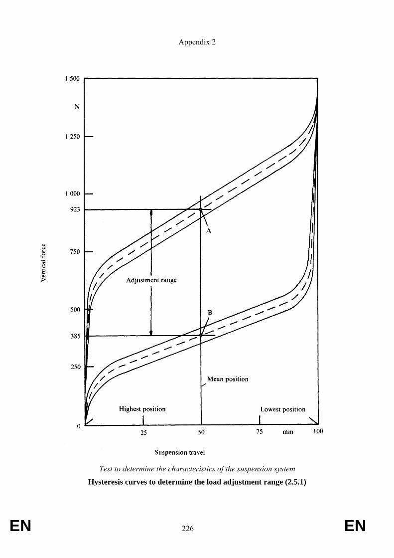
EN 226 EN
Appendix 2
Test to determine the characteristics of the suspension system
Hysteresis curves to determine the load adjustment range (2.5.1)
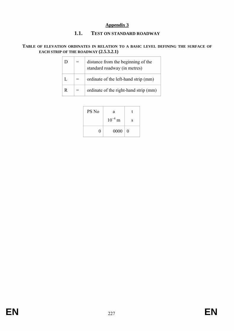
EN 227 EN
Appendix 3
1.1. TEST ON STANDARD ROADWAY
TABLE OF ELEVATION ORDINATES IN RELATION TO A BASIC LEVEL DEFINING THE SURFACE OF EACH STRIP OF THE ROADWAY (2.5.3.2.1)
D = distance from the beginning of the standard roadway (in metres)
L = ordinate of the left-hand strip (mm)
R = ordinate of the right-hand strip (mm)
PS No a
10−4 m
t
s
0 0000 0
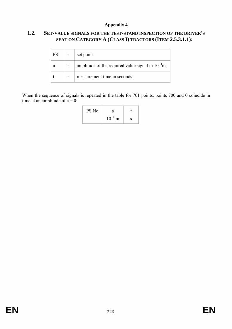
EN 228 EN
Appendix 4
1.2. SET-VALUE SIGNALS FOR THE TEST-STAND INSPECTION OF THE DRIVER'S SEAT ON CATEGORY A (CLASS I) TRACTORS (ITEM 2.5.3.1.1):
PS = set point
a = amplitude of the required value signal in 10−4m,
t = measurement time in seconds
When the sequence of signals is repeated in the table for 701 points, points 700 and 0 coincide in time at an amplitude of a = 0:
PS No a
10−4 m
t
s
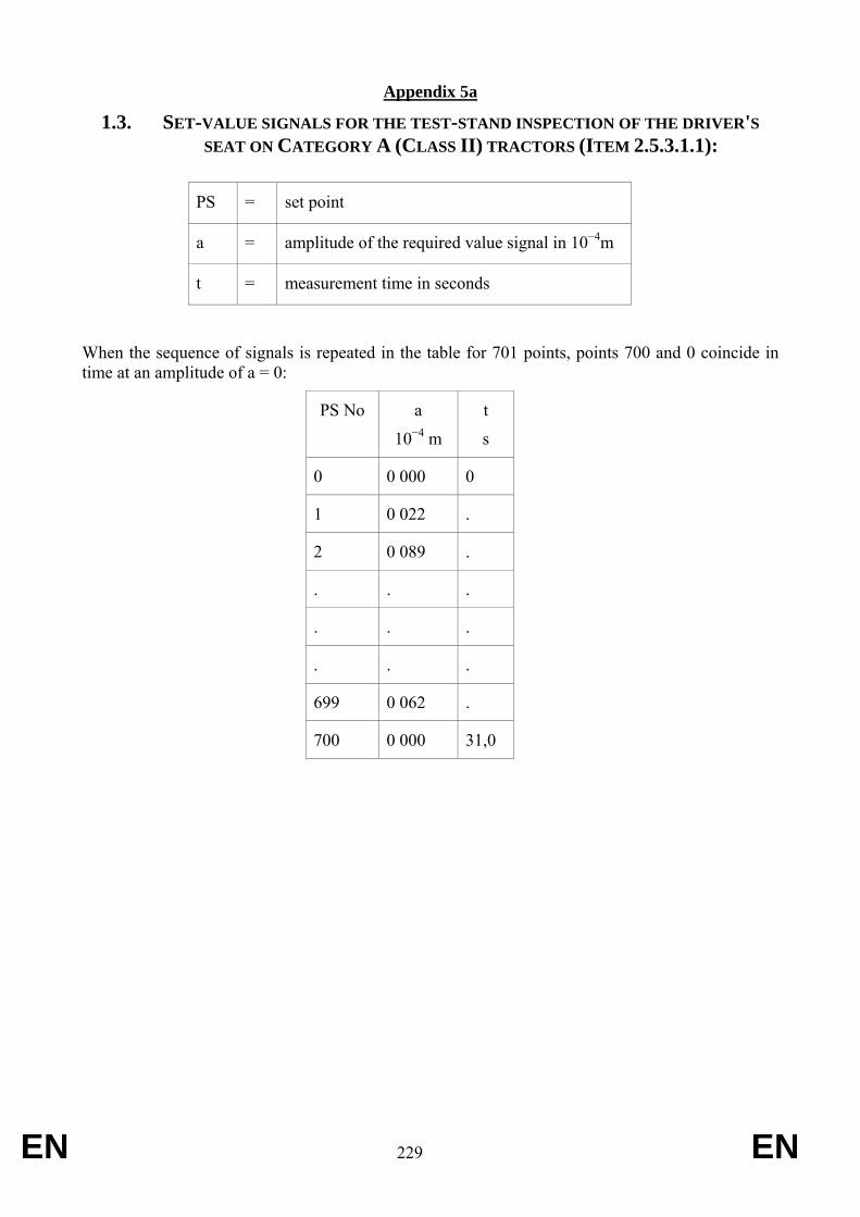
EN 229 EN
Appendix 5a
1.3. SET-VALUE SIGNALS FOR THE TEST-STAND INSPECTION OF THE DRIVER'S SEAT ON CATEGORY A (CLASS II) TRACTORS (ITEM 2.5.3.1.1):
PS = set point
a = amplitude of the required value signal in 10−4m
t = measurement time in seconds
When the sequence of signals is repeated in the table for 701 points, points 700 and 0 coincide in time at an amplitude of a = 0:
PS No a
10−4 m
t
s
0 0 000 0
1 0 022 .
2 0 089 .
. . .
. . .
. . .
699 0 062 .
700 0 000 31,0
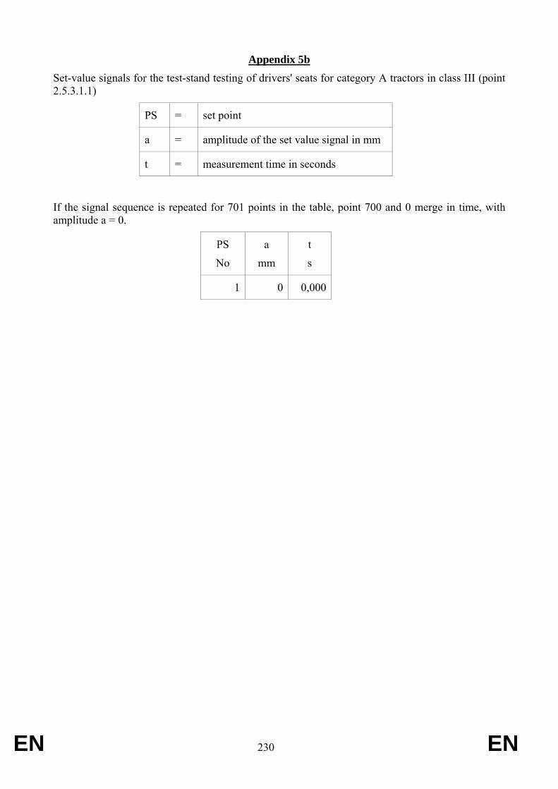
EN 230 EN
Appendix 5b Set-value signals for the test-stand testing of drivers' seats for category A tractors in class III (point 2.5.3.1.1)
PS = set point
a = amplitude of the set value signal in mm
t = measurement time in seconds
If the signal sequence is repeated for 701 points in the table, point 700 and 0 merge in time, with amplitude a = 0.
PS
No
a
mm
t
s
1 0 0,000
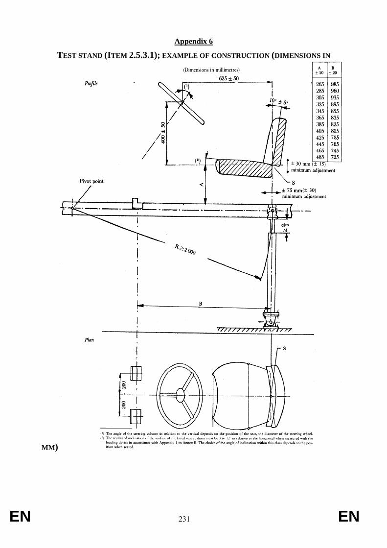
EN 231 EN
Appendix 6
TEST STAND (ITEM 2.5.3.1); EXAMPLE OF CONSTRUCTION (DIMENSIONS IN
MM)
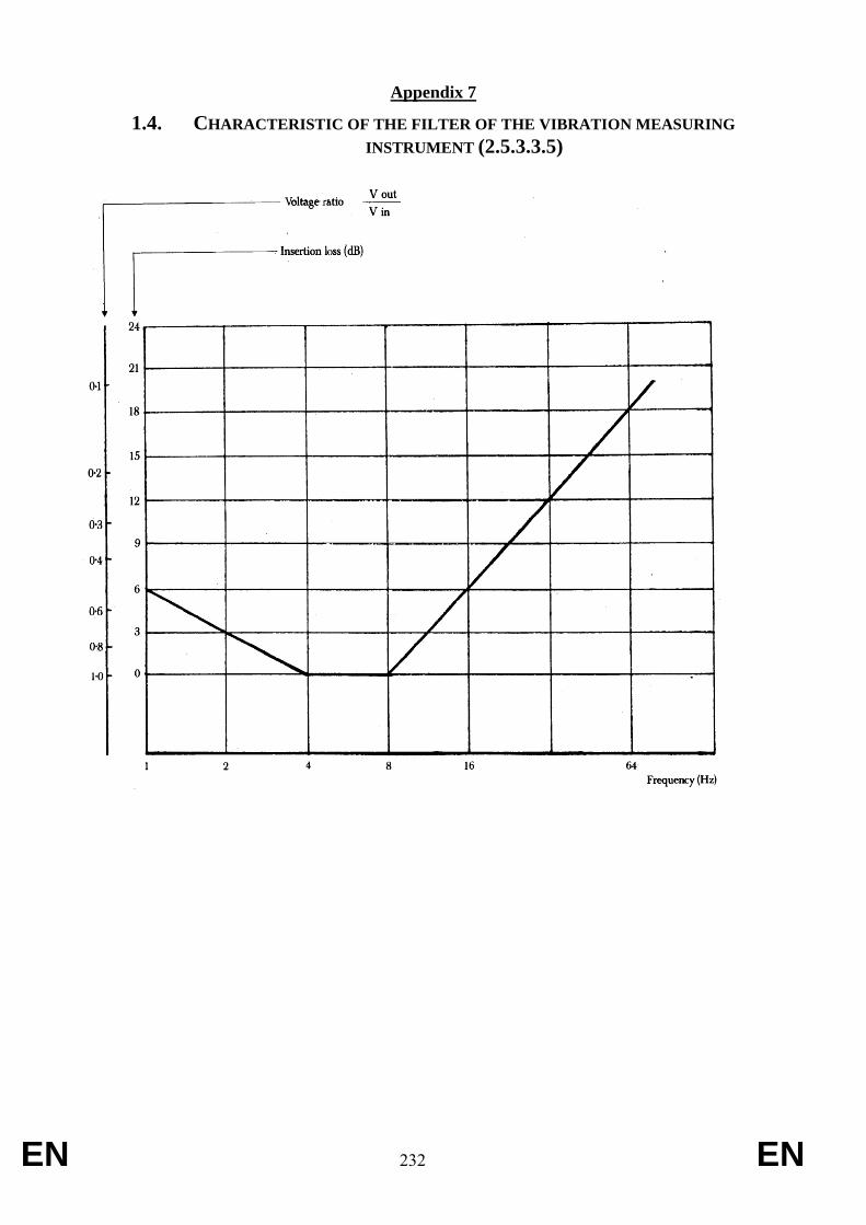
EN 232 EN
Appendix 7
1.4. CHARACTERISTIC OF THE FILTER OF THE VIBRATION MEASURING INSTRUMENT (2.5.3.3.5)
EN 233 EN
Appendix 8
DRIVER'S SEAT INSTALLATION REQUIREMENTS FOR EEC TYPE-APPROVAL OF A TRACTOR
1. Every driver's seat must bear the EU component type-approval mark and comply with the following installation requirements:
1.1. the driver's seat must be installed in such a way that:
1.1.1. the driver is assured of a comfortable position for driving and manoeuvring the tractor;
1.1.2. the seat is easily accessible;
1.1.3. the driver, when seated in the normal driving position, can easily reach the various controls of the tractor that are likely to be actuated during operation;
1.1.4. no part of any of the seat or tractor components is likely to cause the driver to suffer cuts or bruises;
1.1.5. where the position of the seat is adjustable only lengthwise and vertically, the longitudinal axis passing through the Seat Index Point shall be parallel with the vertical longitudinal plane of the tractor passing through the centre of the steering wheel and not more than 100 mm from that plane
1.1.6. where the seat is designed to revolve round a vertical axis it must be capable of being locked in all or certain positions and in any case in the position mentioned in 1.1.5.
2. The holder of the EU type-approval may request that it be extended to other types of seat. The competent authorities must grant this extension on the following conditions:
2.1. the new type of seat has received EU component type-approval;
2.2. it has been designed to be installed on the type of tractor for which the extension of the EU type-approval has been requested;
2.3. it is installed in such a manner as to comply with the installation requirements in this Annex.
3. Seats intended for tractors with a minimum rear-wheel track of not more than 1 150 mm may have the following minimum dimensions in respect of the depth and width of the seat surface:
– depth of seat surface: 300 mm;
– width of seat surface: 400 mm.
This provision is applicable only if the values specified for the depth and the width of the seat surface (i.e. 400 ± 50 mm and at least 450 mm respectively) cannot be adhered to on grounds relating to the tractor.
4. A certificate conforming to the model shown in Annex V is to be attached to the EU type-approval certificate for each type-approval or extension of type-approval granted or refused.
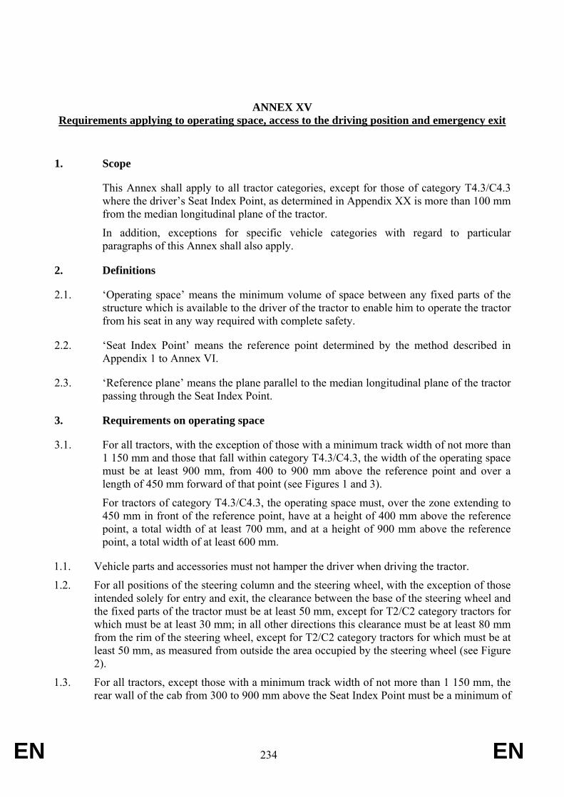
EN 234 EN
ANNEX XV Requirements applying to operating space, access to the driving position and emergency exit
1. Scope
This Annex shall apply to all tractor categories, except for those of category T4.3/C4.3 where the driver’s Seat Index Point, as determined in Appendix XX is more than 100 mm from the median longitudinal plane of the tractor.
In addition, exceptions for specific vehicle categories with regard to particular paragraphs of this Annex shall also apply.
2. Definitions
2.1. ‘Operating space’ means the minimum volume of space between any fixed parts of the structure which is available to the driver of the tractor to enable him to operate the tractor from his seat in any way required with complete safety.
2.2. ‘Seat Index Point’ means the reference point determined by the method described in Appendix 1 to Annex VI.
2.3. ‘Reference plane’ means the plane parallel to the median longitudinal plane of the tractor passing through the Seat Index Point.
3. Requirements on operating space
3.1. For all tractors, with the exception of those with a minimum track width of not more than 1 150 mm and those that fall within category T4.3/C4.3, the width of the operating space must be at least 900 mm, from 400 to 900 mm above the reference point and over a length of 450 mm forward of that point (see Figures 1 and 3).
For tractors of category T4.3/C4.3, the operating space must, over the zone extending to 450 mm in front of the reference point, have at a height of 400 mm above the reference point, a total width of at least 700 mm, and at a height of 900 mm above the reference point, a total width of at least 600 mm.
1.1. Vehicle parts and accessories must not hamper the driver when driving the tractor.
1.2. For all positions of the steering column and the steering wheel, with the exception of those intended solely for entry and exit, the clearance between the base of the steering wheel and the fixed parts of the tractor must be at least 50 mm, except for T2/C2 category tractors for which must be at least 30 mm; in all other directions this clearance must be at least 80 mm from the rim of the steering wheel, except for T2/C2 category tractors for which must be at least 50 mm, as measured from outside the area occupied by the steering wheel (see Figure 2).
1.3. For all tractors, except those with a minimum track width of not more than 1 150 mm, the rear wall of the cab from 300 to 900 mm above the Seat Index Point must be a minimum of
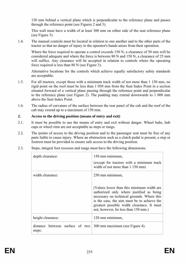
EN 235 EN
150 mm behind a vertical plane which is perpendicular to the reference plane and passes through the reference point (see Figures 2 and 3).
This wall must have a width of at least 300 mm on either side of the seat reference plane (see Figure 3).
1.4. The manual controls must be located in relation to one another and to the other parts of the tractor so that no danger of injury to the operator's hands arises from their operation.
Where the force required to operate a control exceeds 150 N, a clearance of 50 mm will be considered adequate and where the force is between 80 N and 150 N, a clearance of 25 mm will suffice. Any clearance will be accepted in relation to controls where the operating force required is less than 80 N (see Figure 3).
Alternative locations for the controls which achieve equally satisfactory safety standards are acceptable.
1.5. For all tractors, except those with a minimum track width of not more than 1 150 mm, no rigid point on the roof must be less than 1 050 mm from the Seat Index Point in a section situated forward of a vertical plane passing through the reference point and perpendicular to the reference plane (see Figure 2). The padding may extend downwards to 1 000 mm above the Seat Index Point.
1.6. The radius of curvature of the surface between the rear panel of the cab and the roof of the cab may extend up to a maximum of 150 mm.
2. Access to the driving position (means of entry and exit) 2.1. It must be possible to use the means of entry and exit without danger. Wheel hubs, hub
caps or wheel rims are not acceptable as steps or rungs.
2.2. The points of access to the driving position and to the passenger seat must be free of any parts liable to cause injury. Where an obstruction such as a clutch pedal is present, a step or footrest must be provided to ensure safe access to the driving position.
2.3. Steps, integral foot recesses and rungs must have the following dimensions:
depth clearance: 150 mm minimum,
(except for tractors with a minimum track width of not more than 1 150 mm)
width clearance: 250 mm minimum,
(Values lower than this minimum width are authorized only where justified as being necessary on technical grounds. Where this is the case, the aim must be to achieve the greatest possible width clearance. It must not, however, be less than 150 mm.)
height clearance: 120 mm minimum,
distance between surface of two steps:
300 mm maximum (see Figure 4).
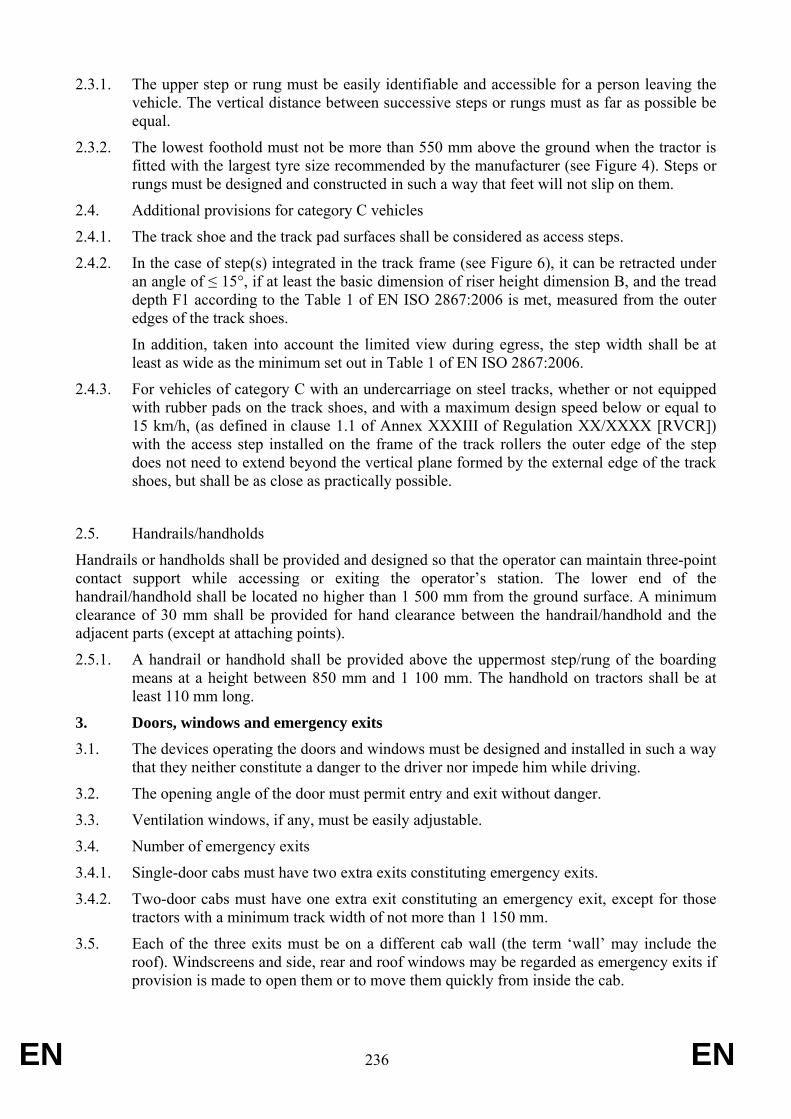
EN 236 EN
2.3.1. The upper step or rung must be easily identifiable and accessible for a person leaving the vehicle. The vertical distance between successive steps or rungs must as far as possible be equal.
2.3.2. The lowest foothold must not be more than 550 mm above the ground when the tractor is fitted with the largest tyre size recommended by the manufacturer (see Figure 4). Steps or rungs must be designed and constructed in such a way that feet will not slip on them.
2.4. Additional provisions for category C vehicles
2.4.1. The track shoe and the track pad surfaces shall be considered as access steps.
2.4.2. In the case of step(s) integrated in the track frame (see Figure 6), it can be retracted under an angle of ≤ 15°, if at least the basic dimension of riser height dimension B, and the tread depth F1 according to the Table 1 of EN ISO 2867:2006 is met, measured from the outer edges of the track shoes.
In addition, taken into account the limited view during egress, the step width shall be at least as wide as the minimum set out in Table 1 of EN ISO 2867:2006.
2.4.3. For vehicles of category C with an undercarriage on steel tracks, whether or not equipped with rubber pads on the track shoes, and with a maximum design speed below or equal to 15 km/h, (as defined in clause 1.1 of Annex XXXIII of Regulation XX/XXXX [RVCR]) with the access step installed on the frame of the track rollers the outer edge of the step does not need to extend beyond the vertical plane formed by the external edge of the track shoes, but shall be as close as practically possible.
2.5. Handrails/handholds
Handrails or handholds shall be provided and designed so that the operator can maintain three-point contact support while accessing or exiting the operator’s station. The lower end of the handrail/handhold shall be located no higher than 1 500 mm from the ground surface. A minimum clearance of 30 mm shall be provided for hand clearance between the handrail/handhold and the adjacent parts (except at attaching points).
2.5.1. A handrail or handhold shall be provided above the uppermost step/rung of the boarding means at a height between 850 mm and 1 100 mm. The handhold on tractors shall be at least 110 mm long.
3. Doors, windows and emergency exits
3.1. The devices operating the doors and windows must be designed and installed in such a way that they neither constitute a danger to the driver nor impede him while driving.
3.2. The opening angle of the door must permit entry and exit without danger.
3.3. Ventilation windows, if any, must be easily adjustable.
3.4. Number of emergency exits
3.4.1. Single-door cabs must have two extra exits constituting emergency exits.
3.4.2. Two-door cabs must have one extra exit constituting an emergency exit, except for those tractors with a minimum track width of not more than 1 150 mm.
3.5. Each of the three exits must be on a different cab wall (the term ‘wall’ may include the roof). Windscreens and side, rear and roof windows may be regarded as emergency exits if provision is made to open them or to move them quickly from inside the cab.
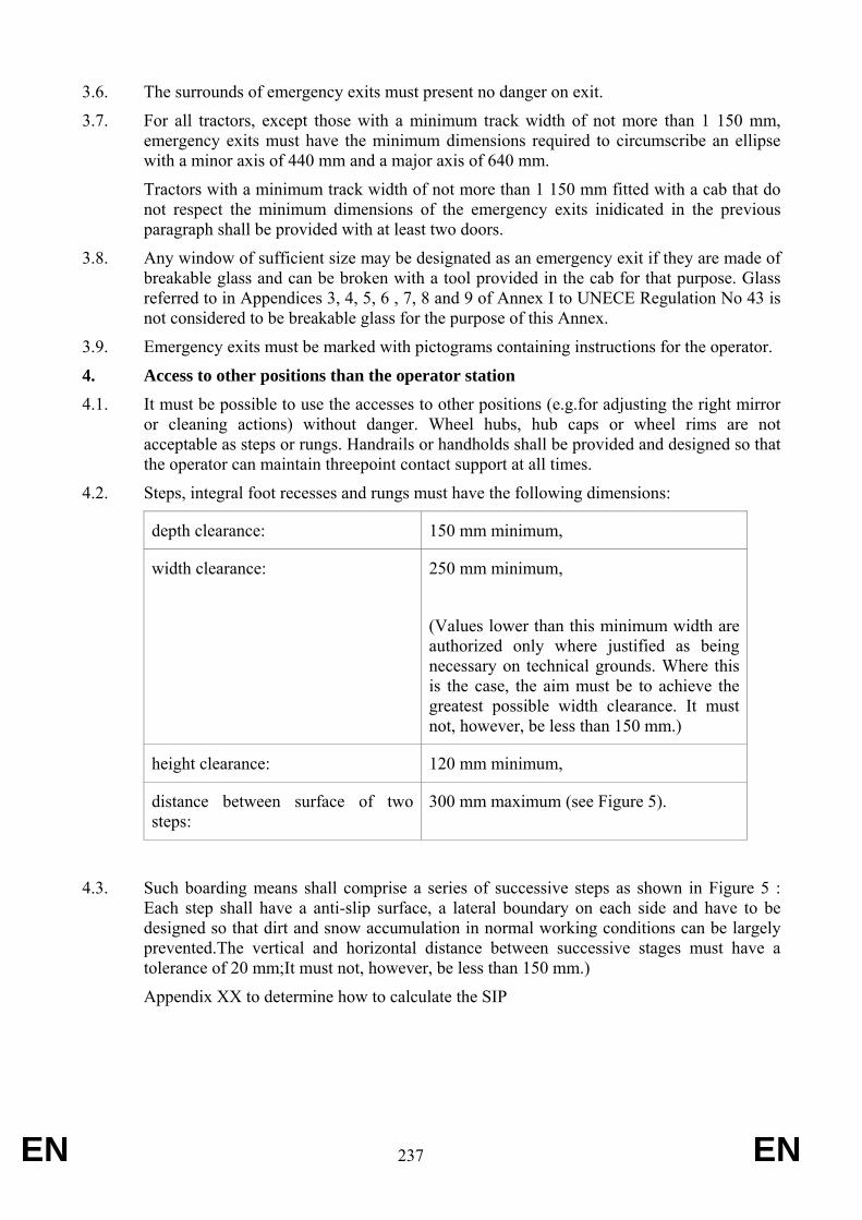
EN 237 EN
3.6. The surrounds of emergency exits must present no danger on exit.
3.7. For all tractors, except those with a minimum track width of not more than 1 150 mm, emergency exits must have the minimum dimensions required to circumscribe an ellipse with a minor axis of 440 mm and a major axis of 640 mm.
Tractors with a minimum track width of not more than 1 150 mm fitted with a cab that do not respect the minimum dimensions of the emergency exits inidicated in the previous paragraph shall be provided with at least two doors.
3.8. Any window of sufficient size may be designated as an emergency exit if they are made of breakable glass and can be broken with a tool provided in the cab for that purpose. Glass referred to in Appendices 3, 4, 5, 6 , 7, 8 and 9 of Annex I to UNECE Regulation No 43 is not considered to be breakable glass for the purpose of this Annex.
3.9. Emergency exits must be marked with pictograms containing instructions for the operator.
4. Access to other positions than the operator station 4.1. It must be possible to use the accesses to other positions (e.g.for adjusting the right mirror
or cleaning actions) without danger. Wheel hubs, hub caps or wheel rims are not acceptable as steps or rungs. Handrails or handholds shall be provided and designed so that the operator can maintain threepoint contact support at all times.
4.2. Steps, integral foot recesses and rungs must have the following dimensions:
depth clearance: 150 mm minimum,
width clearance: 250 mm minimum,
(Values lower than this minimum width are authorized only where justified as being necessary on technical grounds. Where this is the case, the aim must be to achieve the greatest possible width clearance. It must not, however, be less than 150 mm.)
height clearance: 120 mm minimum,
distance between surface of two steps:
300 mm maximum (see Figure 5).
4.3. Such boarding means shall comprise a series of successive steps as shown in Figure 5 : Each step shall have a anti-slip surface, a lateral boundary on each side and have to be designed so that dirt and snow accumulation in normal working conditions can be largely prevented.The vertical and horizontal distance between successive stages must have a tolerance of 20 mm;It must not, however, be less than 150 mm.)
Appendix XX to determine how to calculate the SIP
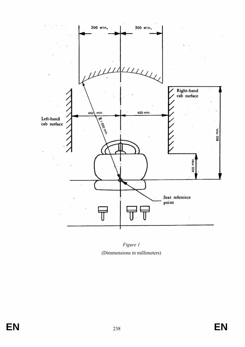
EN 238 EN
Figure 1
(Dimmensions in millimeters)
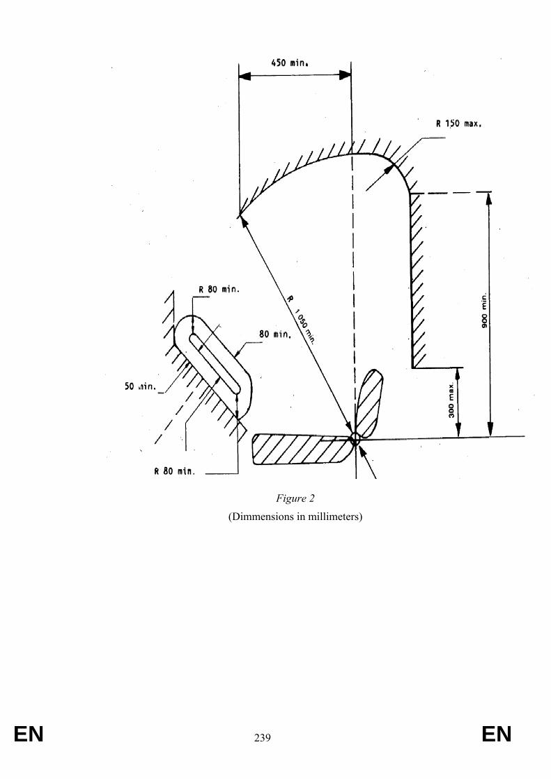
EN 239 EN
Figure 2
(Dimmensions in millimeters)
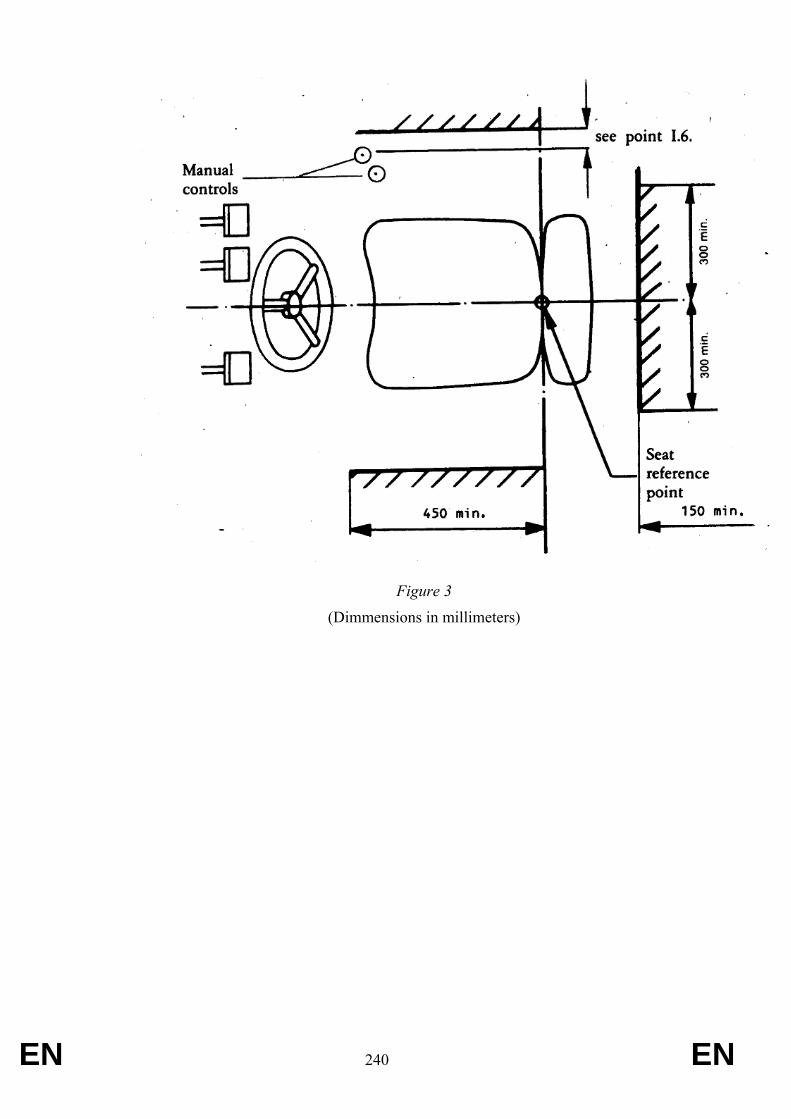
EN 240 EN
Figure 3
(Dimmensions in millimeters)
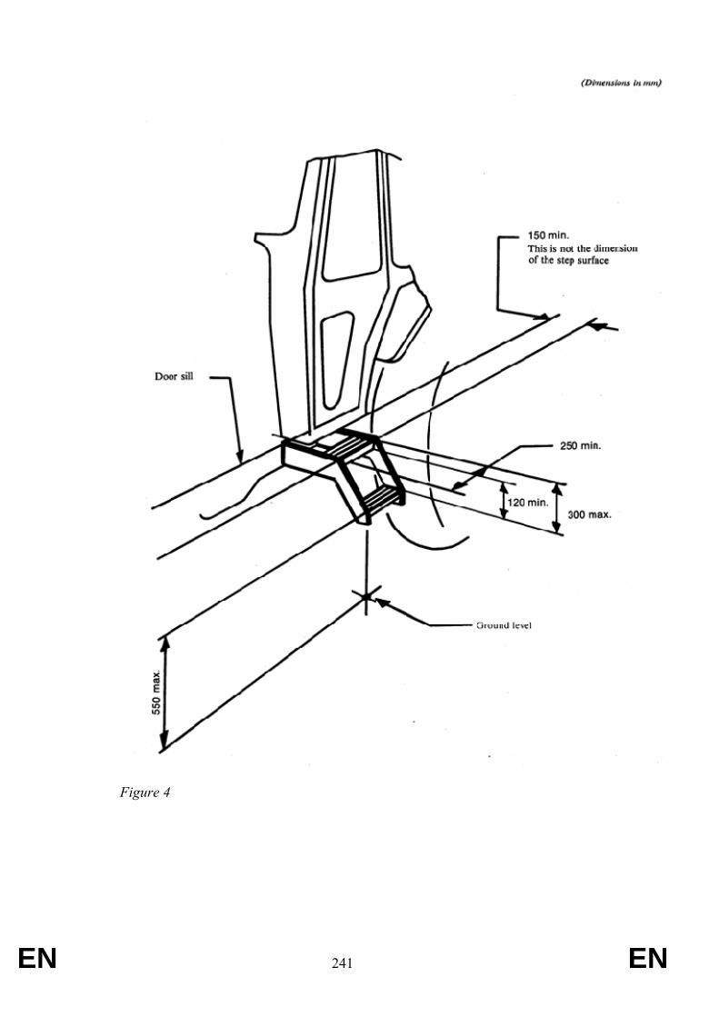
EN 241 EN
Figure 4
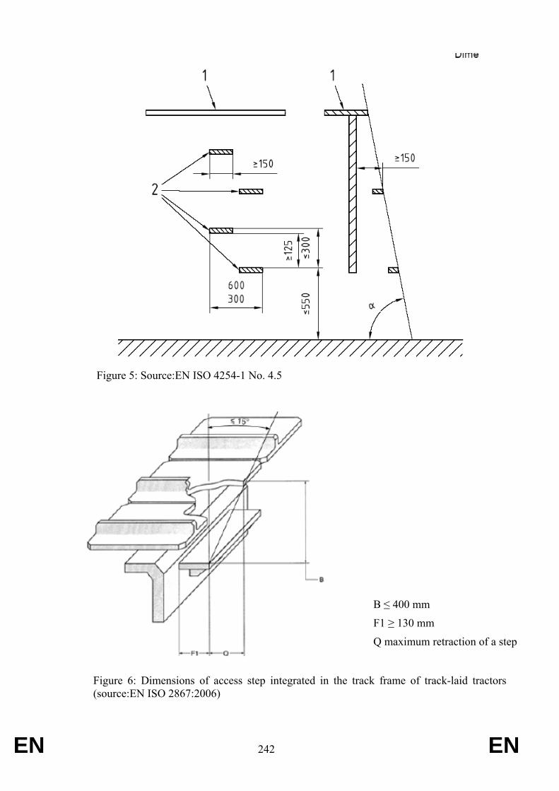
EN 242 EN
Figure 5: Source:EN ISO 4254-1 No. 4.5
B ≤ 400 mm
F1 ≥ 130 mm
Q maximum retraction of a step
Figure 6: Dimensions of access step integrated in the track frame of track-laid tractors (source:EN ISO 2867:2006)

EN 243 EN
EN 244 EN
ANNEX XVI Requirements applying to power take-offs
1. Definition and scope 1.1. “Power take-off” (PTO) means an external shaft of the tractor to provide rotational power to implements.
1.2. The provisions of this Directive apply only to power take-offs as defined in point 1.1 and located at the rear or the front of the tractor.
1.3. For the purposes of this Annex, the standards referred to in points 2. and 3. apply.
2. Provisions for rear power take-offs The specifications of ISO 500-1:2004 together with Technical Corrigendum 1:2005 and ISO 500-2:2004 apply to tractors with rear power take-offs according to Table 1.
Table 1
Application of standards for rear power take-offs of the different tractor categories
Standard applicable
T1
C1
T2
C2
T3
C3
T4.1
C4.1
T4.2
C4.2
T4.3
C4.3
ISO 500-1:2004(*)(***)
X -- X1) X1) X1) X
ISO 500-2:2004(**)
-- X X2) X2) X2) --
X Standard applicable. -- Standard not applicable. X1) Standard applicable for tractors with a track width of more than 1 150 mm. X2) Standard applicable for tractors with a track width of 1 150 mm or less. (*) In the standard ISO 500-1:2004, the last sentence in section 6.2 is not applicable. (**) For the purposes of this Annex, this standard also applies to tractors with a power take-off, the power of which
exceeds 20 kW, measured in accordance with ISO 789-1:1990 (***) For power take-offs of type 3 and where it is possible to reduce the dimension of the opening of the protective
guard in order to adapt to the coupling elements to be used, the user manual must contain the following elements:
– warning relating to the consequences and risks caused by the reduced dimension of the protective guard,
– instructions and specific warnings relating to coupling and releasing the power take-offs,
– instructions and specific warnings relating to the use of tools or machines coupled to the rear power take-off.
3. Provisions for front power take-offs The specifications of ISO 8759-1:1998, with the exception of its clause 4.2, apply to tractors of all T and C categories which are equipped with front power take-offs as specified in this standard
EN 245 EN
5.3. Protection of PTOs
5.3.1. Protection
5.3.1.1. The power take-off must be protected by a guard mounted on the tractor which covers at least the top part and the two sides of the PTO as shown in Figure 1 below, or by other means providing a similar degree of protection such as the location of the PTO in a recess that is part of the tractor or is formed by a separate part (tow-hook mounts, coupling cover, etc.).
5.3.1.2. The dimensions of the protective guard are laid down, as a function of the type of PTO, in Table 3 below.
5.3.1.3. An additional non-rotating protective device which fully covers the PTO must also be supplied with the tractor to protect the PTO when the latter is not in use.
5.3.2. Characteristics of protective guards
5.3.2.1. The protective guard must be designed so as not to impede (or in order to facilitate) the use and maintenance of the tractor.
It must be possible to carry out maintenance operations without removing the protective guard.
5.3.2.2. The materials used must be able to withstand bad weather, must retain their mechanical properties in cold weather and must be sufficiently sturdy.
5.3.2.3. The protective guard must have no points or sharp edges; it must contain no orifices exceeding 8 mm diameter or side of a square or rectangle other than that necessary for attaching the chain of the protective device for the universal-joint drive shaft and must be able to bear a weight of 120 daN, unless it is designed in such a way that it cannot be used as a step.
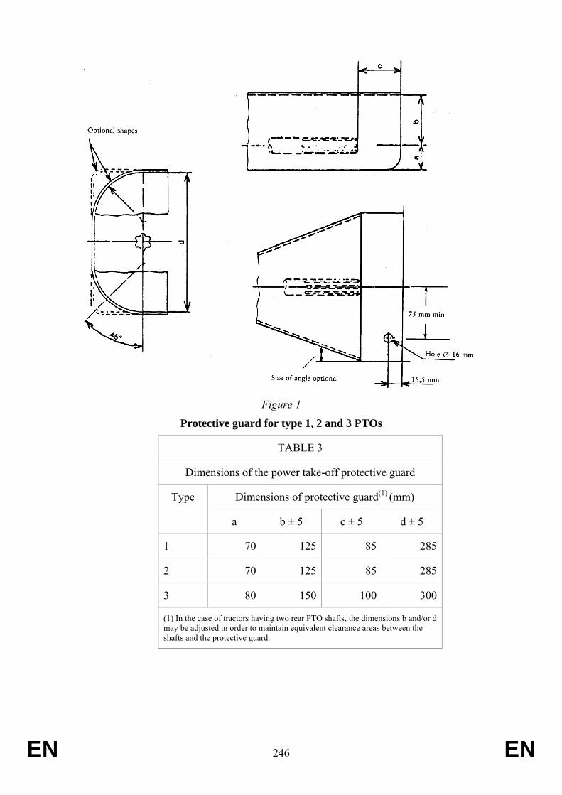
EN 246 EN
Figure 1
Protective guard for type 1, 2 and 3 PTOs
TABLE 3
Dimensions of the power take-off protective guard
Dimensions of protective guard(1) (mm) Type
a b ± 5 c ± 5 d ± 5
1 70 125 85 285
2 70 125 85 285
3 80 150 100 300
(1) In the case of tractors having two rear PTO shafts, the dimensions b and/or d may be adjusted in order to maintain equivalent clearance areas between the shafts and the protective guard.
EN 247 EN
ANNEX XVII Requirements applying to protection of drive components, guards and protective devices
1. General 1.1. Drive components, projections and wheels on tractors must be designed, fitted and
protected in such a way as to prevent accidents to persons under normal conditions of use.
1.2. The requirements of point 1.1 are regarded as being fulfilled if the requirements set out in point 3. have been complied with. Solutions other than those described in point 3. are authorised if the manufacturer provides proof that they are at least equivalent to the requirements of point 3.
1.3. Protective devices must be firmly attached to the tractor. ‘Firmly attached’ means that removal of such devices should be possible only with the aid of tools.
1.4. Cowls, lids and hoods which could cause injury if they are slammed shut must be made in such a way as to preclude their shutting accidentally (e.g. by means of safety devices or suitable mounting or design).
1.5. A single protective device may protect a number of dangerous points. However, if adjustment, maintenance or interference suppression devices - which can be actuated only when the engine is running - are fitted beneath a single protective device, then further protective devices must be fitted.
1.6. Securing devices (e.g. spring clips or flaps)
o to secure quick-release mounting components (e.g. socket pins),
and such components of
o protective devices which open without the aid of tools (e.g. engine cowl)
must be firmly attached either to the tractor mounting or to the protective device.
2. Definitions 2.1. ‘Protective device’ means a device intended to protect dangerous parts. Within the
meaning of this Directive, protective devices include shields, covers or guards. 2.1.1. ‘Shield’ means a protective device located immediately in front of a dangerous part
and which, either on its own or with other parts of the machine, protects on all sides against contact with the dangerous part.
2.1.2. ‘Hood or cowl’ means a protective device located in front of the dangerous part and which protects against contact with the dangerous part on the covered side.
2.1.3. ‘Guard’ means a protective device which, by means of a rail, grille or similar device, provides the necessary safety distance preventing contact with the dangerous part.
2.2. ‘Dangerous part’ means any point which, owing to the arrangements or design of the fixed or movable part of a tractor, involves a risk of injury. The dangerous parts are, in particular, pinching, shearing, cutting, piercing, penetrating, snatching, entry and attack points.
2.2.1. ‘Pinching point’ means any dangerous point where parts move in relation to each other or to fixed parts in such a way as may cause persons or certain parts of their bodies to be pinched.
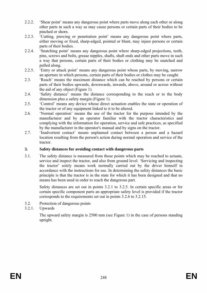
EN 248 EN
2.2.2. ‘Shear point’ means any dangerous point where parts move along each other or along other parts in such a way as may cause persons or certain parts of their bodies to be pinched or shorn.
2.2.3. ‘Cutting, piercing or penetration point’ means any dangerous point where parts, either moving or fixed, sharp-edged, pointed or blunt, may injure persons or certain parts of their bodies.
2.2.4. ‘Snatching point’ means any dangerous point where sharp-edged projections, teeth, pins, screws and bolts, grease nipples, shafts, shaft ends and other parts move in such a way that persons, certain parts of their bodies or clothing may be snatched and pulled along.
2.2.5. ‘Entry or attack point’ means any dangerous point whose parts, by moving, narrow an aperture in which persons, certain parts of their bodies or clothes may be caught.
2.3. ‘Reach’ means the maximum distance which can be reached by persons or certain parts of their bodies upwards, downwards, inwards, above, around or across without the aid of any object (Figure 1).
2.4. ‘Safety distance’ means the distance corresponding to the reach or to the body dimension plus a safety margin (Figure 1).
2.5. ‘Control’ means any device whose direct actuation enables the state or operation of the tractor or of any equipment linked to it to be altered.
2.6. ‘Normal operation’ means the use of the tractor for the purpose intended by the manufacturer and by an operator familiar with the tractor characteristics and complying with the information for operation, service and safe practices, as specified by the manufacturer in the operator's manual and by signs on the tractor.
2.7. ‘Inadvertent contact’ means unplanned contact between a person and a hazard location resulting from the person's action during normal operation and service of the tractor.
3. Safety distances for avoiding contact with dangerous parts 3.1. The safety distance is measured from those points which may be reached to actuate,
service and inspect the tractor, and also from ground level. ‘Servicing and inspecting the tractor’ solely means work normally carried out by the driver himself in accordance with the instructions for use. In determining the safety distances the basic principle is that the tractor is in the state for which it has been designed and that no means has been used in order to reach the dangerous part.
Safety distances are set out in points 3.2.1 to 3.2.5. In certain specific areas or for certain specific component parts an appropriate safety level is provided if the tractor corresponds to the requirements set out in points 3.2.6 to 3.2.15.
3.2. Protection of dangerous points 3.2.1. Upwards
The upward safety margin is 2500 mm (see Figure 1) in the case of persons standing upright.
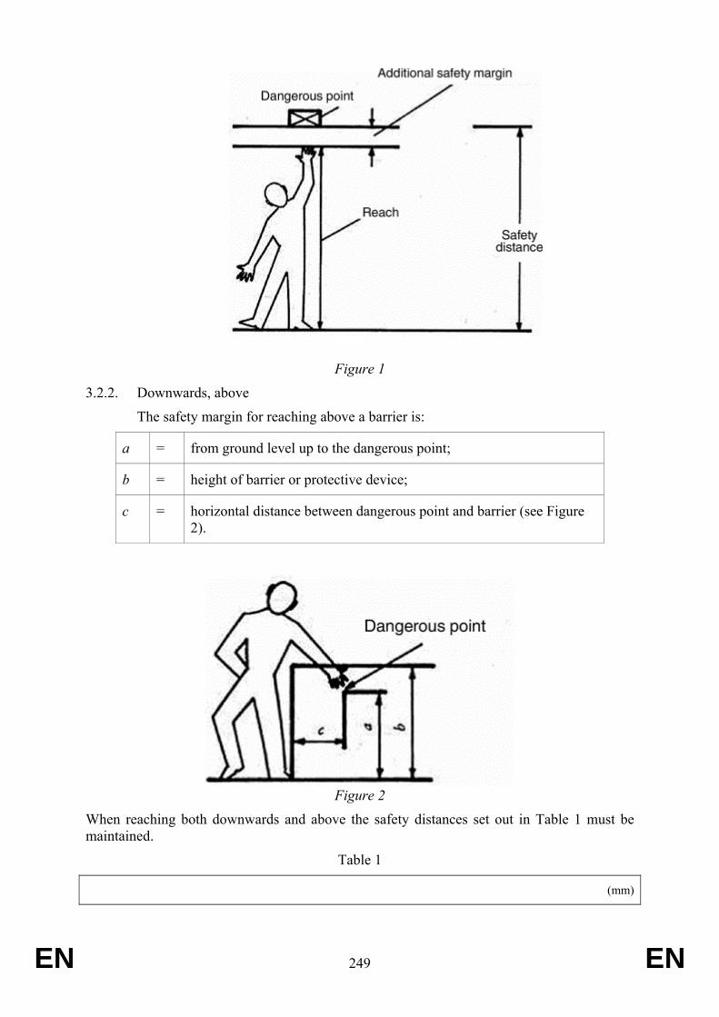
EN 249 EN
Figure 1
3.2.2. Downwards, above
The safety margin for reaching above a barrier is:
a = from ground level up to the dangerous point;
b = height of barrier or protective device;
c = horizontal distance between dangerous point and barrier (see Figure 2).
Figure 2
When reaching both downwards and above the safety distances set out in Table 1 must be maintained.
Table 1
(mm)
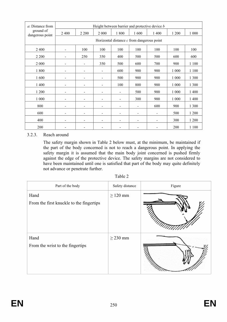
EN 250 EN
Height between barrier and protective device b
2 400 2 200 2 000 1 800 1 600 1 400 1 200 1 000
a: Distance from ground of
dangerous point Horizontal distance c from dangerous point
2 400 - 100 100 100 100 100 100 100
2 200 - 250 350 400 500 500 600 600
2 000 - - 350 500 600 700 900 1 100
1 800 - - - 600 900 900 1 000 1 100
1 600 - - - 500 900 900 1 000 1 300
1 400 - - - 100 800 900 1 000 1 300
1 200 - - - - 500 900 1 000 1 400
1 000 - - - - 300 900 1 000 1 400
800 - - - - - 600 900 1 300
600 - - - - - - 500 1 200
400 - - - - - - 300 1 200
200 - - - - - - 200 1 100
3.2.3. Reach around
The safety margin shown in Table 2 below must, at the minimum, be maintained if the part of the body concerned is not to reach a dangerous point. In applying the safety margin it is assumed that the main body joint concerned is pushed firmly against the edge of the protective device. The safety margins are not considered to have been maintained until one is satisfied that part of the body may quite definitely not advance or penetrate further.
Table 2
Part of the body Safety distance Figure
Hand
From the first knuckle to the fingertips
≥ 120 mm
Hand
From the wrist to the fingertips
≥ 230 mm
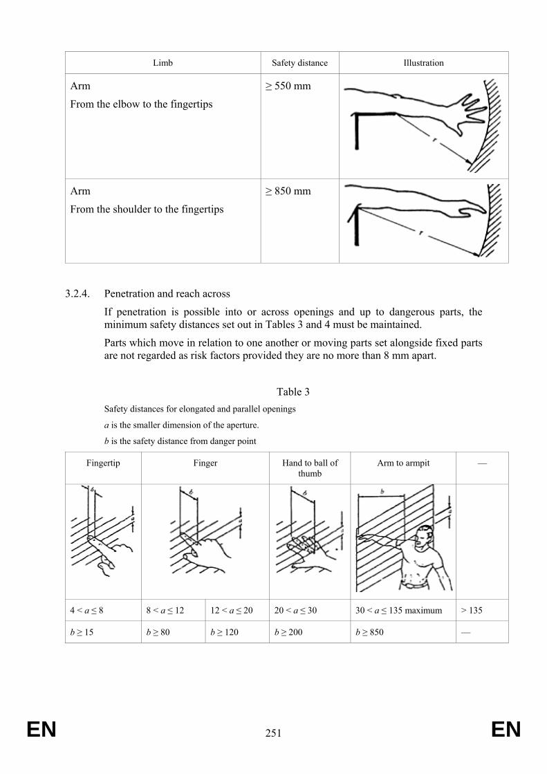
EN 251 EN
Limb Safety distance Illustration
Arm
From the elbow to the fingertips
≥ 550 mm
Arm
From the shoulder to the fingertips
≥ 850 mm
3.2.4. Penetration and reach across
If penetration is possible into or across openings and up to dangerous parts, the minimum safety distances set out in Tables 3 and 4 must be maintained.
Parts which move in relation to one another or moving parts set alongside fixed parts are not regarded as risk factors provided they are no more than 8 mm apart.
Table 3 Safety distances for elongated and parallel openings
a is the smaller dimension of the aperture.
b is the safety distance from danger point
Fingertip Finger Hand to ball of thumb
Arm to armpit —
4 < a ≤ 8 8 < a ≤ 12 12 < a ≤ 20 20 < a ≤ 30 30 < a ≤ 135 maximum > 135
b ≥ 15 b ≥ 80 b ≥ 120 b ≥ 200 b ≥ 850 —
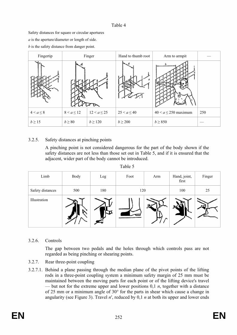
EN 252 EN
Table 4 Safety distances for square or circular apertures
a is the aperture/diameter or length of side.
b is the safety distance from danger point.
Fingertip Finger Hand to thumb root Arm to armpit —
4 < a ≤ 8 8 < a ≤ 12 12 < a ≤ 25 25 < a ≤ 40 40 < a ≤ 250 maximum 250
b ≥ 15 b ≥ 80 b ≥ 120 b ≥ 200 b ≥ 850 —
3.2.5. Safety distances at pinching points
A pinching point is not considered dangerous for the part of the body shown if the safety distances are not less than those set out in Table 5, and if it is ensured that the adjacent, wider part of the body cannot be introduced.
Table 5
Limb Body Leg Foot Arm Hand, joint, first
Finger
Safety distances 500 180 120 100 25
Illustration
3.2.6. Controls
The gap between two pedals and the holes through which controls pass are not regarded as being pinching or shearing points.
3.2.7. Rear three-point coupling
3.2.7.1. Behind a plane passing through the median plane of the pivot points of the lifting rods in a three-point coupling system a minimum safety margin of 25 mm must be maintained between the moving parts for each point or of the lifting device's travel — but not for the extreme upper and lower positions 0,1 n, together with a distance of 25 mm or a minimum angle of 30° for the parts in shear which cause a change in angularity (see Figure 3). Travel n′, reduced by 0,1 n at both its upper and lower ends
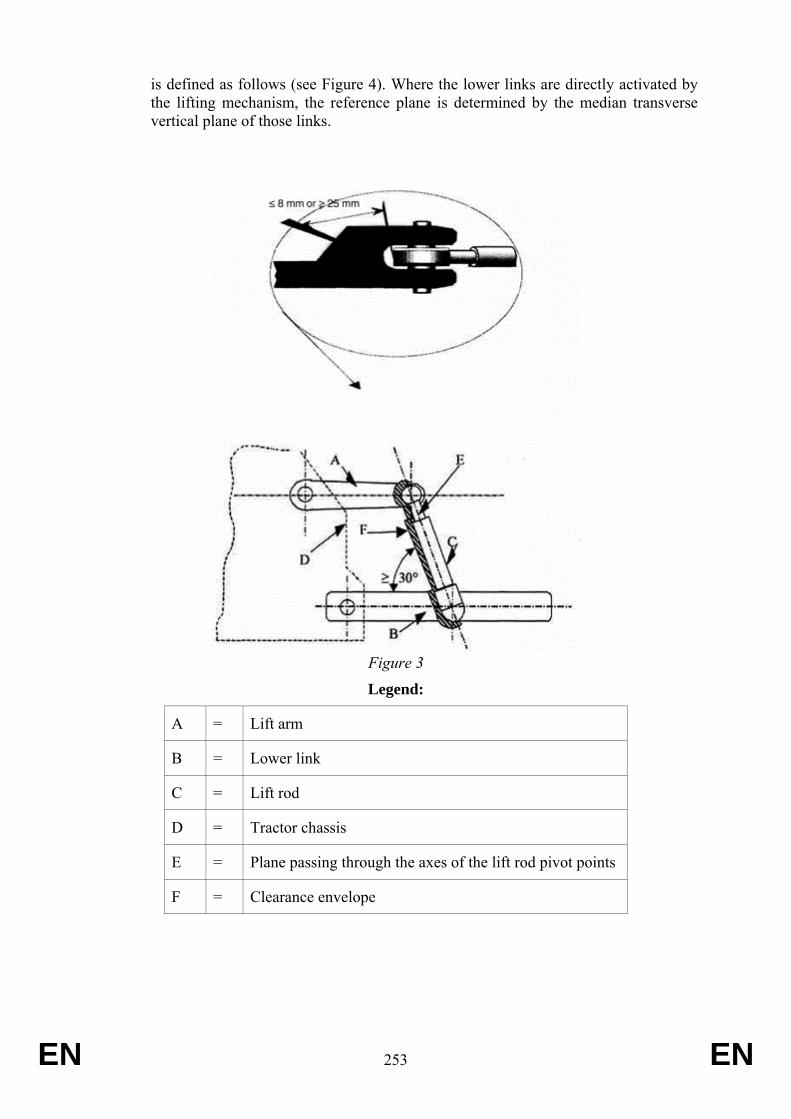
EN 253 EN
is defined as follows (see Figure 4). Where the lower links are directly activated by the lifting mechanism, the reference plane is determined by the median transverse vertical plane of those links.
Figure 3
Legend:
A = Lift arm
B = Lower link
C = Lift rod
D = Tractor chassis
E = Plane passing through the axes of the lift rod pivot points
F = Clearance envelope
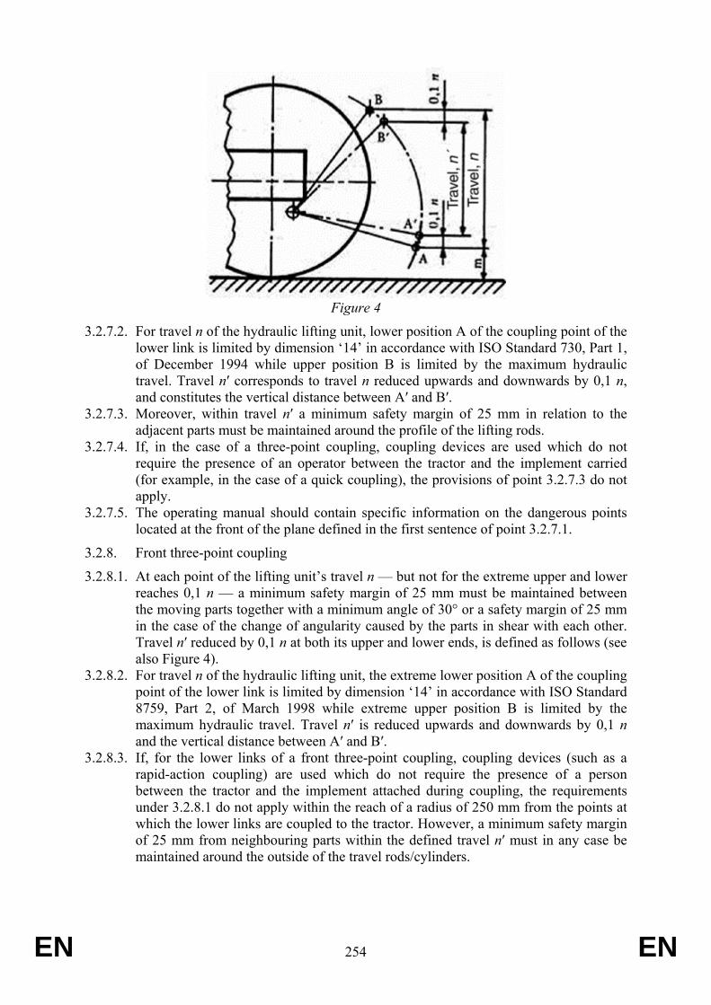
EN 254 EN
Figure 4
3.2.7.2. For travel n of the hydraulic lifting unit, lower position A of the coupling point of the lower link is limited by dimension ‘14’ in accordance with ISO Standard 730, Part 1, of December 1994 while upper position B is limited by the maximum hydraulic travel. Travel n′ corresponds to travel n reduced upwards and downwards by 0,1 n, and constitutes the vertical distance between A′ and B′.
3.2.7.3. Moreover, within travel n′ a minimum safety margin of 25 mm in relation to the adjacent parts must be maintained around the profile of the lifting rods.
3.2.7.4. If, in the case of a three-point coupling, coupling devices are used which do not require the presence of an operator between the tractor and the implement carried (for example, in the case of a quick coupling), the provisions of point 3.2.7.3 do not apply.
3.2.7.5. The operating manual should contain specific information on the dangerous points located at the front of the plane defined in the first sentence of point 3.2.7.1.
3.2.8. Front three-point coupling
3.2.8.1. At each point of the lifting unit’s travel n — but not for the extreme upper and lower reaches 0,1 n — a minimum safety margin of 25 mm must be maintained between the moving parts together with a minimum angle of 30° or a safety margin of 25 mm in the case of the change of angularity caused by the parts in shear with each other. Travel n′ reduced by 0,1 n at both its upper and lower ends, is defined as follows (see also Figure 4).
3.2.8.2. For travel n of the hydraulic lifting unit, the extreme lower position A of the coupling point of the lower link is limited by dimension ‘14’ in accordance with ISO Standard 8759, Part 2, of March 1998 while extreme upper position B is limited by the maximum hydraulic travel. Travel n′ is reduced upwards and downwards by 0,1 n and the vertical distance between A′ and B′.
3.2.8.3. If, for the lower links of a front three-point coupling, coupling devices (such as a rapid-action coupling) are used which do not require the presence of a person between the tractor and the implement attached during coupling, the requirements under 3.2.8.1 do not apply within the reach of a radius of 250 mm from the points at which the lower links are coupled to the tractor. However, a minimum safety margin of 25 mm from neighbouring parts within the defined travel n′ must in any case be maintained around the outside of the travel rods/cylinders.
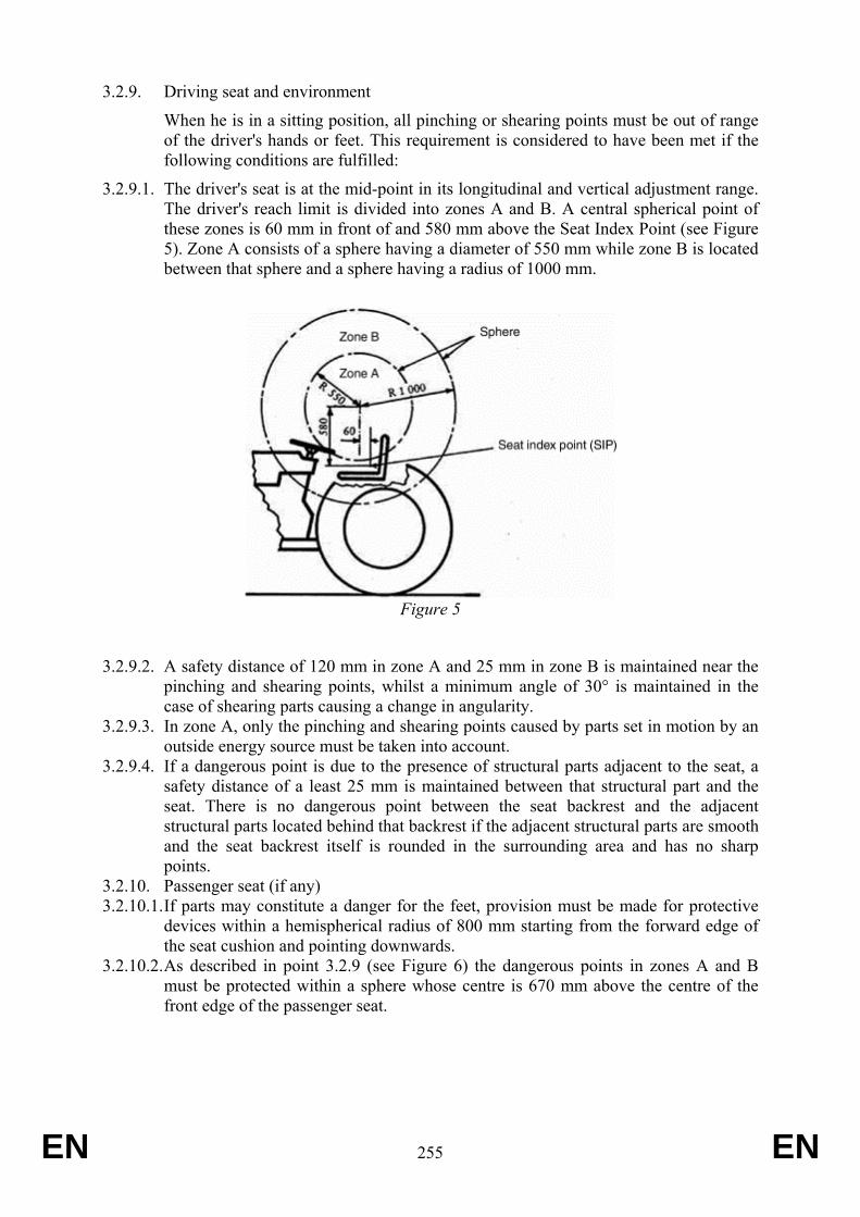
EN 255 EN
3.2.9. Driving seat and environment
When he is in a sitting position, all pinching or shearing points must be out of range of the driver's hands or feet. This requirement is considered to have been met if the following conditions are fulfilled:
3.2.9.1. The driver's seat is at the mid-point in its longitudinal and vertical adjustment range. The driver's reach limit is divided into zones A and B. A central spherical point of these zones is 60 mm in front of and 580 mm above the Seat Index Point (see Figure 5). Zone A consists of a sphere having a diameter of 550 mm while zone B is located between that sphere and a sphere having a radius of 1000 mm.
Figure 5
3.2.9.2. A safety distance of 120 mm in zone A and 25 mm in zone B is maintained near the pinching and shearing points, whilst a minimum angle of 30° is maintained in the case of shearing parts causing a change in angularity.
3.2.9.3. In zone A, only the pinching and shearing points caused by parts set in motion by an outside energy source must be taken into account.
3.2.9.4. If a dangerous point is due to the presence of structural parts adjacent to the seat, a safety distance of a least 25 mm is maintained between that structural part and the seat. There is no dangerous point between the seat backrest and the adjacent structural parts located behind that backrest if the adjacent structural parts are smooth and the seat backrest itself is rounded in the surrounding area and has no sharp points.
3.2.10. Passenger seat (if any) 3.2.10.1. If parts may constitute a danger for the feet, provision must be made for protective
devices within a hemispherical radius of 800 mm starting from the forward edge of the seat cushion and pointing downwards.
3.2.10.2. As described in point 3.2.9 (see Figure 6) the dangerous points in zones A and B must be protected within a sphere whose centre is 670 mm above the centre of the front edge of the passenger seat.
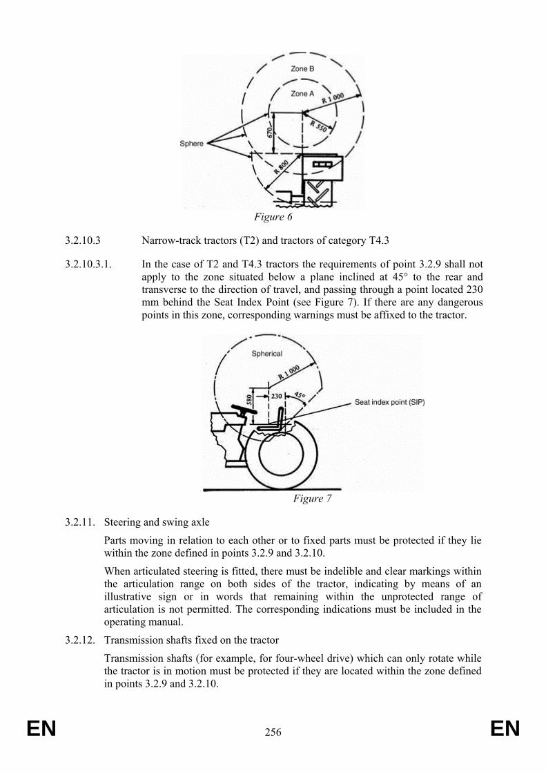
EN 256 EN
Figure 6
3.2.10.3 Narrow-track tractors (T2) and tractors of category T4.3
3.2.10.3.1. In the case of T2 and T4.3 tractors the requirements of point 3.2.9 shall not apply to the zone situated below a plane inclined at 45° to the rear and transverse to the direction of travel, and passing through a point located 230 mm behind the Seat Index Point (see Figure 7). If there are any dangerous points in this zone, corresponding warnings must be affixed to the tractor.
Figure 7
3.2.11. Steering and swing axle
Parts moving in relation to each other or to fixed parts must be protected if they lie within the zone defined in points 3.2.9 and 3.2.10.
When articulated steering is fitted, there must be indelible and clear markings within the articulation range on both sides of the tractor, indicating by means of an illustrative sign or in words that remaining within the unprotected range of articulation is not permitted. The corresponding indications must be included in the operating manual.
3.2.12. Transmission shafts fixed on the tractor
Transmission shafts (for example, for four-wheel drive) which can only rotate while the tractor is in motion must be protected if they are located within the zone defined in points 3.2.9 and 3.2.10.
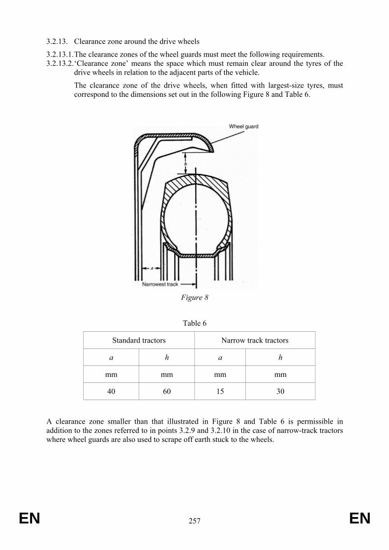
EN 257 EN
3.2.13. Clearance zone around the drive wheels
3.2.13.1. The clearance zones of the wheel guards must meet the following requirements. 3.2.13.2. ‘Clearance zone’ means the space which must remain clear around the tyres of the
drive wheels in relation to the adjacent parts of the vehicle.
The clearance zone of the drive wheels, when fitted with largest-size tyres, must correspond to the dimensions set out in the following Figure 8 and Table 6.
Figure 8
Table 6
Standard tractors Narrow track tractors
a h a h
mm mm mm mm
40 60 15 30
A clearance zone smaller than that illustrated in Figure 8 and Table 6 is permissible in addition to the zones referred to in points 3.2.9 and 3.2.10 in the case of narrow-track tractors where wheel guards are also used to scrape off earth stuck to the wheels.
EN 258 EN
3.2.14. Hot surfaces
3.2.14.1. Hot surfaces which can be reached by the operator during normal operation of the tractor shall be covered or insulated. This applies to hot surfaces which are near to steps, handrails, handholds and integral tractor parts used as boarding means and which may be inadvertently touched.
4. Strength requirements for guards and barriers
4.1. Guards and barriers, and in particular barriers with a vertical height from the ground of up to 550 mm, whose use as access steps during normal use cannot be prevented, shall be designed so that they can withstand a vertical load of 1 200 N. Conformance with this requirement shall be checked using the test given in Annex C of ISO 4254-1:2013 or an equivalent method which fulfils the same test acceptance criteria.
5. Requirements for wheel guards
5.1. The wheel guards shall be designed so that they protect other road users as far as possible from dispersed stones, dirt, ice, snow and water.
5.2. The wheels must have a guard at the top, which covers at least 2/3 of the total width of the tyre. The front and rear edge of the guard shall be dragged down as far as possible.
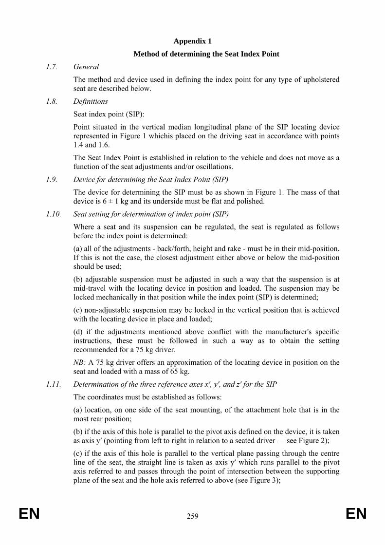
EN 259 EN
Appendix 1
Method of determining the Seat Index Point
1.7. General
The method and device used in defining the index point for any type of upholstered seat are described below.
1.8. Definitions
Seat index point (SIP):
Point situated in the vertical median longitudinal plane of the SIP locating device represented in Figure 1 whichis placed on the driving seat in accordance with points 1.4 and 1.6.
The Seat Index Point is established in relation to the vehicle and does not move as a function of the seat adjustments and/or oscillations.
1.9. Device for determining the Seat Index Point (SIP)
The device for determining the SIP must be as shown in Figure 1. The mass of that device is 6 ± 1 kg and its underside must be flat and polished.
1.10. Seat setting for determination of index point (SIP)
Where a seat and its suspension can be regulated, the seat is regulated as follows before the index point is determined:
(a) all of the adjustments - back/forth, height and rake - must be in their mid-position. If this is not the case, the closest adjustment either above or below the mid-position should be used;
(b) adjustable suspension must be adjusted in such a way that the suspension is at mid-travel with the locating device in position and loaded. The suspension may be locked mechanically in that position while the index point (SIP) is determined;
(c) non-adjustable suspension may be locked in the vertical position that is achieved with the locating device in place and loaded;
(d) if the adjustments mentioned above conflict with the manufacturer's specific instructions, these must be followed in such a way as to obtain the setting recommended for a 75 kg driver.
NB: A 75 kg driver offers an approximation of the locating device in position on the seat and loaded with a mass of 65 kg.
1.11. Determination of the three reference axes x′, y′, and z′ for the SIP
The coordinates must be established as follows:
(a) location, on one side of the seat mounting, of the attachment hole that is in the most rear position;
(b) if the axis of this hole is parallel to the pivot axis defined on the device, it is taken as axis y′ (pointing from left to right in relation to a seated driver — see Figure 2);
(c) if the axis of this hole is parallel to the vertical plane passing through the centre line of the seat, the straight line is taken as axis y′ which runs parallel to the pivot axis referred to and passes through the point of intersection between the supporting plane of the seat and the hole axis referred to above (see Figure 3);
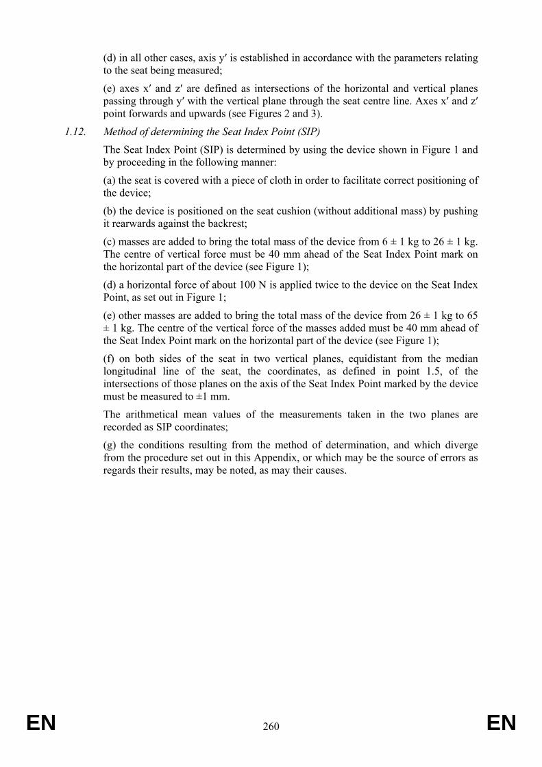
EN 260 EN
(d) in all other cases, axis y′ is established in accordance with the parameters relating to the seat being measured;
(e) axes x′ and z′ are defined as intersections of the horizontal and vertical planes passing through y′ with the vertical plane through the seat centre line. Axes x′ and z′ point forwards and upwards (see Figures 2 and 3).
1.12. Method of determining the Seat Index Point (SIP)
The Seat Index Point (SIP) is determined by using the device shown in Figure 1 and by proceeding in the following manner:
(a) the seat is covered with a piece of cloth in order to facilitate correct positioning of the device;
(b) the device is positioned on the seat cushion (without additional mass) by pushing it rearwards against the backrest;
(c) masses are added to bring the total mass of the device from 6 ± 1 kg to 26 ± 1 kg. The centre of vertical force must be 40 mm ahead of the Seat Index Point mark on the horizontal part of the device (see Figure 1);
(d) a horizontal force of about 100 N is applied twice to the device on the Seat Index Point, as set out in Figure 1;
(e) other masses are added to bring the total mass of the device from 26 ± 1 kg to 65 ± 1 kg. The centre of the vertical force of the masses added must be 40 mm ahead of the Seat Index Point mark on the horizontal part of the device (see Figure 1);
(f) on both sides of the seat in two vertical planes, equidistant from the median longitudinal line of the seat, the coordinates, as defined in point 1.5, of the intersections of those planes on the axis of the Seat Index Point marked by the device must be measured to ±1 mm.
The arithmetical mean values of the measurements taken in the two planes are recorded as SIP coordinates;
(g) the conditions resulting from the method of determination, and which diverge from the procedure set out in this Appendix, or which may be the source of errors as regards their results, may be noted, as may their causes.
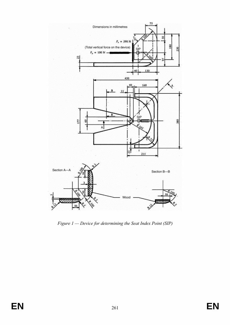
EN 261 EN
Figure 1 — Device for determining the Seat Index Point (SIP)
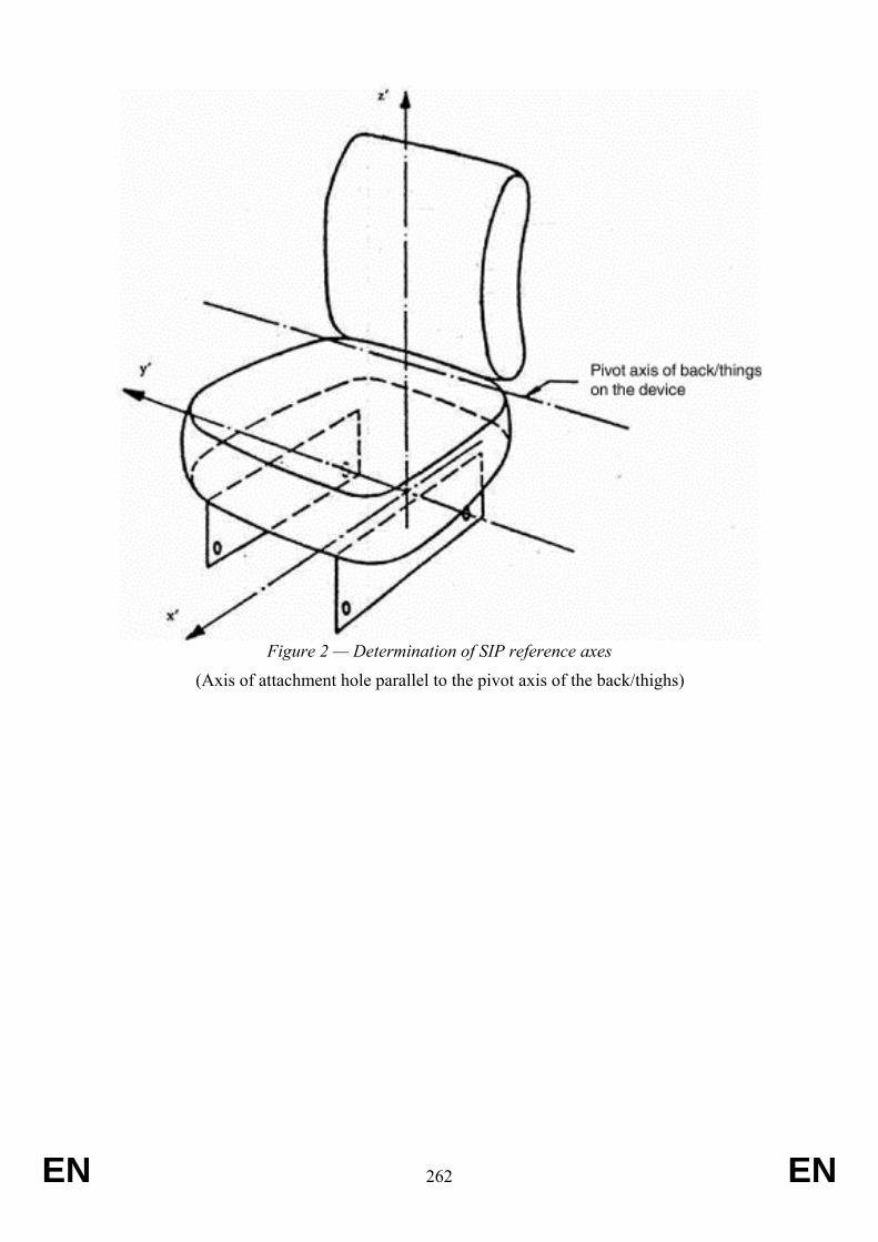
EN 262 EN
Figure 2 — Determination of SIP reference axes
(Axis of attachment hole parallel to the pivot axis of the back/thighs)
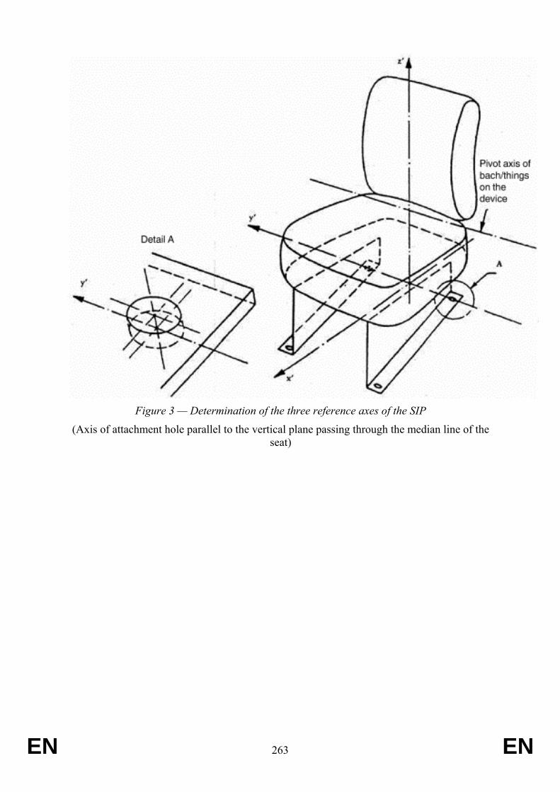
EN 263 EN
Figure 3 — Determination of the three reference axes of the SIP
(Axis of attachment hole parallel to the vertical plane passing through the median line of the seat)
EN 264 EN
ANNEX XVIII Requirements applying to seat-belt anchorages
1. Requirements
When the tractor is fitted with ROPS, seat belt anchorages shall be provided and shall comply with the standard ISO 3776-1:2006 and in addition with one of the requirements set out in points 1.1. to 1.4:
1.1. The minimum number of anchorage points required for tractors of categories T1, T2, T3, C1, C2 and C3 is two, as established in Annex I, Appendix 1 to Directive 76/115/EEC for forward facing centre seats of vehicle category N 3 . The test loads laid down in points 5.4.3 and 5.4.4 of Annex I to that Directive for vehicles of category N 3 shall apply to those tractor categories.
1.2. As an alternative, seat belt anchorages complying with the standard ISO 3776-2:2013 shall be deemed to be complying with this Annex.
1.3. As an alternative, agricultural and forestry wheeled and track-laid tractors which have been tested and granted a test report on the basis of the OECD Code Nos 3, 4, 6, 7 and 8 in accordance with Appendix 1 to the Decision of the OECD Council of February 2012 revising the OECD standard Codes for the official testing of agricultural and forestry tractors, as amended, shall be deemed to be complying with this Annex. The equivalence of these test reports can only be recognised for seat belt anchorages if these have been tested.
1.4. As an alternative agricultural and forestry wheeled and track-laid tractors, fitted with ROPS, which have been tested and granted a test report on the basis of UNECE Regulation Nos 14, shall be deemed to be complying with this Annex.
EN 265 EN
ANNEX XIX Requirements applying to safety belts
1. Requirements
1.1. When the tractor is fitted with ROPS, safety belts shall be provide and shall comply with ISO 3776-3:2009.
1.1.1. As an alternative agricultural and forestry wheeled and track-laid tractors, fitted with ROPS, which have been tested and granted a test report on the basis of the UNECE Regulation No 16, as amended, shall be deemed to be complying with this Annex.
EN 266 EN
ANNEX XX Requirements applying to protection against penetrating objects
1. Requirements
1.1. Operators Protection Structures (OPS) for forestry applications, if provided, shall comply with ISO 8084:200310.
1.2. For other than forestry applications and without prejudice to point 1.1, tractors with glazing according to Council Directive 92/22/EEC11 of 31 March 1992 on safety glazing and glazing materials on motor vehicles and their trailers or in UNECE Regulation No 43, Annex 14, shall be considered to be equipped with Operators Protection Structures (OPS).
10 This document can be found at: http://www.iso.org/iso/en/CatalogueDetailPage.CatalogueDetail?CSNUMBER = 9021&ICS1 =
65&ICS2 = 60&ICS3 = 1 11 OJ L 129,14.5.1992, p. 11
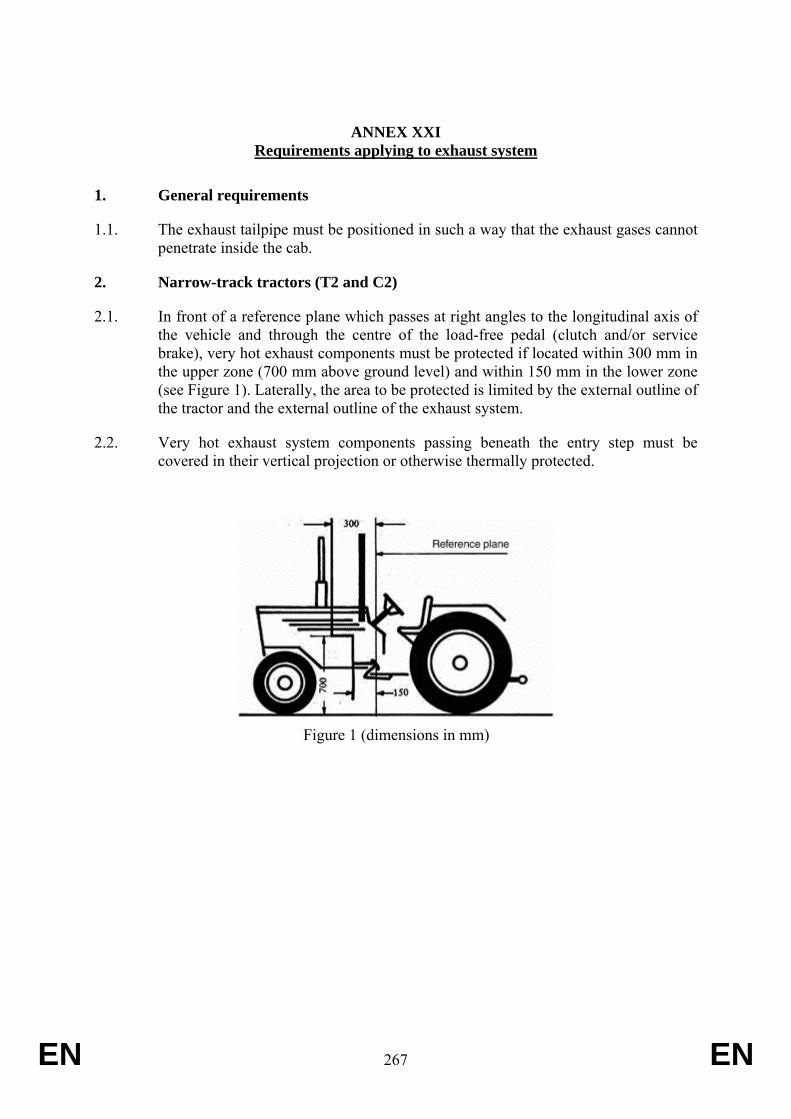
EN 267 EN
ANNEX XXI Requirements applying to exhaust system
1. General requirements
1.1. The exhaust tailpipe must be positioned in such a way that the exhaust gases cannot penetrate inside the cab.
2. Narrow-track tractors (T2 and C2)
2.1. In front of a reference plane which passes at right angles to the longitudinal axis of the vehicle and through the centre of the load-free pedal (clutch and/or service brake), very hot exhaust components must be protected if located within 300 mm in the upper zone (700 mm above ground level) and within 150 mm in the lower zone (see Figure 1). Laterally, the area to be protected is limited by the external outline of the tractor and the external outline of the exhaust system.
2.2. Very hot exhaust system components passing beneath the entry step must be covered in their vertical projection or otherwise thermally protected.
Figure 1 (dimensions in mm)
EN 268 EN
ANNEX XXII Requirements applying to operator’s manual
1. General requirements
1.1. The operator’s manual shall comply with ISO 3600:1996, with the exception of section 4.3 (Machine identification).
1.2. In particular or in addition to the requirements in standard ISO 3600:1996, the operator’s manual shall cover the following:
(a) adjustment of the seat and suspension related to the ergonomic position of the operator with respect to the controls and in order to minimise the risks from whole body vibration;
(b) use and adjustment of the system for heating, ventilation and air-conditioning, when provided;
(c) starting and stopping of the engine;
(d) location and method of opening of emergency exits;
(e) boarding and leaving the tractor;
(f) the hazard area near to the pivot axis of articulated tractors;
(g) use of special tools, if any are provided;
(h) safe methods used for service and maintenance;
(i) information about the interval of inspection of hydraulic hoses;
(j) instructions about how to tow the tractor;
(k) instructions about the safe use of jacks and recommended jacking points;
(l) hazards related to batteries and fuel tank;
(m) prohibited use of the tractor, where overturning hazards exist with mention that the list is not exhaustive;
(n) residual risks, related to hot surfaces, such as filling of oil or coolant in hot engines or transmissions;
(o) the level of protection of the Falling Objects Protective Structure, if applicable;
(p) the level of protection against hazardous substances, if applicable;
(q) the level of protection of the Operators Protection Structure, if applicable.
(r) Overhead power lines
(s) Lightning strikes
EN 269 EN
(t) Regular cleaning of spray suppression valances
(u) Risks from over inflating tyres
(v) Stability degradation when using heavy attached implements at height
(w) Risks of overturning when travelling over rough ground
(x) Carrying of passengers only in approved passenger seats
(y) Use of the vehicle by appropriately trained operators only
(z) information about safe loading of the vehicle.
(aa) Information about towing and free towing: location and conditions for a safe process.
(ab) information about the location and conditions of use of battery isolators (mechanical devices, electrical switches or electronic systmes) .
1.3. Additional information concerning attaching, detaching and working with mounted machinery, trailers and interchangeable towed machinery
The operator’s manual shall include the following:
(a) a warning to strictly follow the instructions outlined in the operator’s manual of the mounted or trailed machinery or trailer, and not to operate the combination tractor — machine or tractor — trailer unless all instructions have been followed;
(b) a warning to stay clear from the area of the three-point linkage when controlling it;
(c) a warning that mounted machinery must be lowered on the ground before leaving the tractor;
(d) speed of the power take-off drive shafts in function of the mounted machinery or trailed vehicle;
(e) a requirement to use only power take-off drive shafts with adequate guards;
(f) information about hydraulic coupling devices and their function;
(g) information about the maximum lift capacity of the three-point linkage;
(h) information about the determination of the total mass, the axle loads, the tyre load carrying capacity and the necessary minimum ballasting;
(i) information on installation, removal and maintenance of ballast weights
(j) information about the available trailer braking systems and their compatibility with the trailed vehicles;
(k) the maximum vertical load on the rear hitch, related to the rear tyre size and type of hitch;
(l) information about using implements with power take-off drive shafts and that the technically possible inclination of the shafts depend on the shape and size of the master shield and/or clearance zone, including the specific information required in case of PTO type 3 with reduced dimension;
(m) a repeat of the data on the statutory plate about maximum allowed
EN 270 EN
trailed masses;
(n) a warning to stay clear from the area between tractor and trailed vehicle.
1.4. Noise declaration
The operator’s manual shall give the value of the noise at the operator’s ear, measured according to Annex XIII to this Regulation.
1.5. Vibration declaration
The operator’s manual shall give the value of the vibration level measured according to Annex XIV to this Regulation.
1.6. Operating modes
Relevant operating modes of a tractor that can reasonably be expected and identified as containing particular hazards are the following:
(a) work with front-end loader (risk of falling objects);
(b) forestry application (risk of falling and/or penetrating objects);
(c) work with crop sprayers, mounted or trailed (risk of hazardous substances).
Particular attention shall be given in the operator’s manual to the use of the tractor in combination with the above equipment.
1.6.1. Front–end loader
1.6.1.1 The operator’s manual shall outline the hazards associated with front-end loader work, and explain how to avoid those hazards.
1.6.1.2. The operator’s manual shall indicate the fixation points on the body of the tractor where the front–end loader must be installed, together with the size and quality of the hardware to be used. If no such attachment points are foreseen, the operator’s manual shall prohibit the installation of a front–end loader.
1.6.1.3. Tractors fitted with programmable hydraulic sequencing functions shall provide information on how to connect the loader hydraulics so that this function is inoperable.
1.6.2. Forestry application
1.6.2.1. In case of use of an agricultural tractor in a forestry application, the identified hazards are the following:
(a) toppling trees, primarily in case a rear-mounted tree grab-crane is mounted at the rear of the tractor;
(b) penetrating objects in the operator’s enclosure, primarily in case a winch is mounted at the rear of the tractor.
1.6.2.2. The operator’s manual shall provide information about the following:
EN 271 EN
(a) the existence of the hazards described in point 1.6.2.1.;
(b) any optional equipment that might be available to deal with those hazards;
(c) fixation points on the tractor where protective structures can be fixed, together with the size and quality of the hardware to be used; when no means are foreseen to fit adequate protective structures, this shall be mentioned;
(d) protective structures may consist of a frame protecting the operating station against toppling trees or (mesh) grids in front of the cab doors, roof and windows;
(e) the Falling Objects Protection System level, if provided.
1.6.3. Work with crop sprayers (risk of hazardous substances)
1.6.3.1. The protection level against hazardous substances, in accordance with EN 15695-1:2009, must be described in the operator’s manual.
EN 272 EN
ANNEX XXIII Requirements applying to controls, including in particular emergency and automatic
stop devices
1. General requirements
1.1. The controls must be easily accessible and must not constitute a danger to the operator, who must be able to actuate them without difficulty or risk; they must be so designed and laid out, or protected, as to preclude any inadvertent switching operation or any unintentional triggering of a movement or any other operation which might be dangerous.
1.2. The controls must satisfy whatever particular requirements, insofar as they apply, are set out in points 1.2.1 to 1.2.3 to as regards the installation, location, operation and identification of controls. Other arrangements are permitted, should a manufacturer provide evidence that they have an effect at least equivalent to the requirements specified in this Annex.
1.2.1. Controls such as steering wheels or steering levers, gear levers, control levers, cranks, pedals and switches shall be chosen, designed, constructed and arranged so that their actuating forces, displacement, locations methods of operation and colour coding are in accordance with ISO 15077:2008, and shall comply with the provisions set out in Annexes A and C of that standard (i.e. these annexes should be considered as normative).
1.2.2. Hand-operated controls shall have minimum clearances in accordance with table 2 of ISO 4252:2007. This requirement does not apply to fingertip operation controls, such as push-buttons, electric switches.
1.2.3. Pedals shall have an appropriate size, space and be adequately spaced. Pedals shall have a slip-resistant surface and shall be easy to clean.
In order to avoid confusing the driver, the pedals (clutch, brake and accelerator) shall have the same function and arrangement as those of a motor vehicle, except for those vehicles equipped with a straddle seat and handlebars which are deemed to comply with the requirements of EN 15997:2011 for throttle control and manual clutch control.
2. Identification of the controls by means of symbols
2.1. For identification of the controls by means of symbols, the symbols used must conform to those shown in Annex XXVI.
2.2. Symbols other than those shown in Annex XXVI may be used for other purposes, provided that there is no danger of confusion with those shown in that Annex.
2.3. Other symbols used for operator controls and other displays should comply with ISO 3767 Parts 1 (1998+A2:2012) and/or 2 (:2008).
EN 273 EN
2.4. Dimensions and location of the symbols
2.4.1. Symbols are deemed to conform if the proportionality of the dimensions shown in Annex XXII, Appendix 1 is respected.
2.4.2. The symbols must appear on or in the immediate proximity of the controls.
2.4.3. The symbols must stand out clearly against the background.
2.5. Pictorials
2.5.1. Hazard pictorials should comply with ISO 11684:1995.
2.5.2. Pictorials for personal protective equipment should comply with ISO 7010:2011.
3. Special requirements
3.1. Starter control
It must not be possible to start the engine if there is a risk that this might cause an uncontrolled movement of the tractor.
This requirement is deemed to be fulfilled if the engine cannot be started unless:
- the gear change lever is in neutral position or in neutral gear, or
- the gear ratio selection lever is in neutral position or in neutral gear, or
- the clutch mechanism is disengaged, or
- the hydrostatic device is in neutral position or depressurized, or
- where hydraulic transmission is fitted, the engagement device reverts automatically to a neutral position.
3.2. Engine shut-off control
Actuating this device must stop the engine without sustained manual effort; it must not be possible for the engine to start again automatically.
When the engine shut-off control is not combined with the starter control, it must be of a colour contrasting clearly with the background and the other controls. If the shut-off control is a button, it must be coloured red.
3.3. Differential lock control
Identification of the control, where fitted, is mandatory. The functioning of the differential lock must be clearly indicated, if this is not apparent from the position of the control.
3.4. Three-point lifting mechanism control
3.4.1. Either the three-point lifting mechanism controls must be fitted in such a way as to ensure that lifting and lowering manœuvres can be carried out safely, and/or automatic coupling parts should be fitted on the attachment devices of the lifting equipment so that the presence of an operator between the tractor and the equipment is not required. The presence of such a control, where fitted, must be
EN 274 EN
indicated.
3.4.2. The safety requirements for the lifting and lowering of the tools being carried are deemed to be fulfilled where the following conditions are met:
3.4.2.1. Main controls
The main controls and any linkage are arranged or protected in such a way that the operator is unable to reach them if he is standing on the ground between the tractor and the mounted implement, or external controls must be fitted;
3.4.2.2. External controls
(a) The controls must be laid out in such a way that the operator can actuate them from a non-dangerous spot, for instance where the three-point hydraulic lift controls or the additional controls for the lifting mechanism are located outside the vertical planes formed by the internal walls of the mudguards,
and
(b) The three-point hydraulic lifting mechanism is actuated by means of controls which restrict the amount of movement to a maximum of 100 millimetres each time the control is actuated. The measurement points in this case are formed by the coupling points on the lower arms of the three-point coupling (see Figure 1),
or
(c) The three-point hydraulic lifting mechanism is actuated by means of controls which operate on the “hold-to-run principle”;
3.4.2.3. The rear external controls of the 3 point hydraulic lifting mechanism, when fitted, shall be laid out in such a way that the operator can actuate them from outside of the hazard zone. This requirement is deemed to be fulfilled if are located outside the area identified by the vertical planes passing on the inner edge of the mudguards (see Figure 3) and at:
(d) a horizontal distance of minimum 550 mm from the PTO axis or, when this is not technically possible, on the outer side of the mudguard/fender.
(e) a maximum height of 1 800 mm from the ground or, when this is not technically possible, 2 000 mm.
In any event, any risk linked to their unintended actuation must be avoided.
3.4.2.4. The front 3 point lift external controls shall be located outside the front danger zone (see Figure 2) and at a maximum height above the ground of 1,800 mm.
3.4.2.5. Narrow tractors
In the case of tractors with one driven axle having a fixed or adjustable minimum track not exceeding 1 150 millimetres, the main controls must be located in front of
EN 275 EN
the vertical plane passing through the Seat Index Point, the seat being in a central position;
Other arrangements are permitted if the manufacturer provides evidence that they have an effect at least equivalent to the requirements set out in 3.4.2.1., 3.4.2.2. and 3.4.2.3.
3.5. Auto-guidance system OPC
3.5. Auto-guidance systems for tractors (categories T and C) shall be in accordance with the requirements of, ISO 10975:2009.
3.6. Complex electronic vehicle control systems
3.6.1. All complex electronic vehicle control systems, as defined by UN(ECE) Regulation No. 79, must comply with the provisions of Annex 6 of that Regulation.
3.7. Operator Presence Control (OPC)
3.7.1. Park brake OPC
All vehicles of categories T and C shall have an audible and visible alarm that alerts the operator when he leaves the driving position with the park brake not applied. This audible and visible alarm shall be activated after the operator has been detected out of the driving position and the park brake is not applied. The time-out of the alarm shall be not less than 10 seconds. The alarm shall be de-activated when the operator is detected to be present againg in the driving position within this time period or when ther park brake is applied within this time period.
3.7.2. Power take-off OPC
For vehicles of categories T and C, the stationary power take-off operation shall be enabled by an intentional command from an operator present at the driving position only when the tractor is not in motion.
When the driver leaves the driving position and the vehicle is not in motion, the drive of the power take-off shaft shall shut off automatically within 7 seconds. The automatic PTO shut off action shall not have negative effects on safety related functions (e.g. breaking). A restart of the Power take-off shall only be possible by an intentional actuation when the operator is present back at the driving position
3.8. Power Take-Off controls
3.8.1. Power take-off controls shall be designed in a way which avoids unintentional actuation.
3.8.2. It shall not be possible to start the engine with the power take-off engaged.
3.8.3. It shall always be possible to shut off the power take-off from the driving position as well as from the associated external control(s). The shut off shall be always an override control.
3.8.4. Additional requirements for the external controls of the Power take-off
EN 276 EN
3.8.4.1. The rear PTO external controls, when fitted, shall be laid out in such a way that the operator can actuate them from outside of the hazard zone. This requirement is deemed fulfilled if the external control(s) are located outside the area identified by the vertical planes passing on the inner edge of the mudguards (see Figure 3) and at:
(a) a horizontal distance of minimum 550 mm from the PTO axis or, when this is not technically possible, on the outer side of the mudguard/fender.
(b) a maximum height of 1 800 mm from the ground or, when this is not technically possible, 2 000 mm.
3.8.4.2. The start control shall operate according to the “hold-to-run principle” for at least the first three seconds of actuation.
3.8.4.3. After actuating the control(s) the time delay to the intended operation shall not be more than the time for the power take-off technical engage/disengage system to operate. If this delay time is exceeded, an automatic deactivation of the power take-off drive shall occur.
3.8.4.4. The front PTO external controls shall be located outside the front danger zone (see Figure 2) and at a maximum height above the ground of 1,800 mm..
3.8.4.5. Interaction between external PTO control and operator’s seat position PTO control shall not be permitted.
3.9. Remote valve controls
3.9.1. The rear remote valve controls, when fitted, shall be laid out in such a way that the operator can actuate them from outside of the hazard zone. This requirement is deemed fulfilled if the external control(s) are located outside the area identified by the vertical planes passing on the inner edge of the mudguards (see Figure 3) and at:
(a) a horizontal distance of minimum 550 mm from the PTO axis or, when this is not technically possible, on the outer side of the mudguard/fender.
(b) a maximum height of 1 800 mm from the ground or, when this is not technically possible, 2 000 mm.
3.9.2. The location of front remote valve controls shall follow the requirements according to ISO 5675:2008.
3.10. Indication of hydraulic couplings
3.10.1. Hydraulic couplings shall be durable indicated with the flow direction Plus (+) for pressure side and Minus (-) for return flow.
Where the tractor is fitted with more than one hydraulic circuit, each Hydraulic circuit shall be clearly indicated by durable colour coding or numbering.
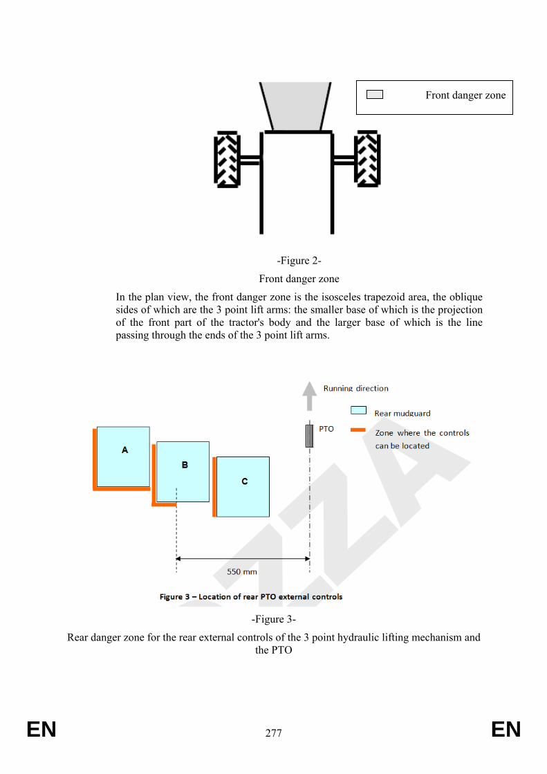
EN 277 EN
-Figure 2-
Front danger zone
In the plan view, the front danger zone is the isosceles trapezoid area, the oblique sides of which are the 3 point lift arms: the smaller base of which is the projection of the front part of the tractor's body and the larger base of which is the line passing through the ends of the 3 point lift arms.
-Figure 3-
Rear danger zone for the rear external controls of the 3 point hydraulic lifting mechanism and the PTO
Front danger zone

EN 278 EN
EN 279 EN
ANNEX XXIV Requirements applying to protection against mechanical hazards other than ones mentioned in Articles 8; 9; 10; 11; 12; 13;18 and 22, including protection against
rupture of pipes carrying fluids and uncontrolled movement of the vehicle
1. Application:
Vehicles of T, C and S categories and trailers (vehicles of R category) which fulfil the following requirements:
Vehicles used in agriculture or forestry which is designed to be towed by a tractor, changes or adds to its functions, permanently incorporates an implement or is designed to process materials, which may include a load platform designed and constructed to receive any tools and applicances needed for those purposes and to store temporarily any materials produced or needed during work and where the ratio of the technically permissible maximum laden mass to the unladen mass of that vehicle is equal to or greater than 3,0.
Requirements
1.1. Layout and marking of flexible hydraulic hoses
Flexible hydraulic hoses must be arranged in such a way as to prevent mechanical and thermal damage.
Flexible hydraulic hoses must be clearly identifiable and indelibly marked with the following information:
- the flexible hose manufacturer’s mark,
- manufacturing date (year and month of manufacture),
- maximum permissible dynamic excess pressure in operation.
Flexible hydraulic hoses in the vicinity of the driver’s or the passenger’s seat must be arranged or protected in such a way that in the event of their failure there can be no danger to any person.
1.2
1.2.1
1.2.1.1
1.2.1.2
R- Category trailers with tipping capability (supports for service and maintenance)
General
When it is necessary for the operator to work under raised parts of the machine in order to carry out maintenance or service, mechanical supports or hydraulic locking devices shall be provided to prevent inadvertent lowering.
Means other than mechanical or hydraulic devices are acceptable, provided an equal or greater level of safety is ensured.
It shall be possible to control hydraulic locking devices and mechanical supports from outside the hazard zones.
Mechanical supports and hydraulic locking devices shall be identified by use of a
EN 280 EN
1.2.1.3
1.2.1.4
1.2.2
1.2.2.1
1.2.2.2
1.2.3
colour that contrasts with the overall machine colour or by a safety sign located either on, or in close proximity to, the device.
When the supports or hydraulic devices are controlled manually, their method of operation shall be explained in the operator's manual and, if such operation is not intuitive, on the machine itself using either a safety or informational sign.
Mechanical supports
Mechanical supporting devices shall withstand a load of 1,5 times the maximum static load to be supported.
Detachable mechanical supports shall have a dedicated and clearly visible and identifiable storage position on the machine.
Hydraulic locking devices
Hydraulic locking devices shall be located on the hydraulic cylinder or connected to the hydraulic cylinder by rigid or flexible lines. In the latter case, the lines connecting the locking device to the hydraulic cylinder shall be designed to withstand a pressure at least four times the rated maximum hydraulic pressure. This rated maximum hydraulic pressure shall be specified in the operator's manual. The conditions for the replacement of such flexible lines shall also be given in the operator's manual.
1.3. Rough surfaces and sharp edges
Parts that are likely to be contacted by the driver or passengers, while driving, shall have no sharp edges or rough surfaces hazardous to the occupants.
EN 281 EN
ANNEX XXV Requirements applying to guards and protective devices
1. Application:
Vehicles of T, C and S categories and trailers (vehicles of R category) which fulfil the following requirements:
Vehicles used in agriculture or forestry which is designed to be towed by a tractor, changes or adds to its functions, permanently incorporates an implement or is designed to process materials, which may include a load platform designed and constructed to receive any tools and applicances needed for those purposes and to store temporarily any materials produced or needed during work and where the ratio of the technically permissible maximum laden mass to the unladen mass of that vehicle is equal to or greater than 3,0.
2. Requirements
(See Annex XVII on requirements applying to protection of drive components.)
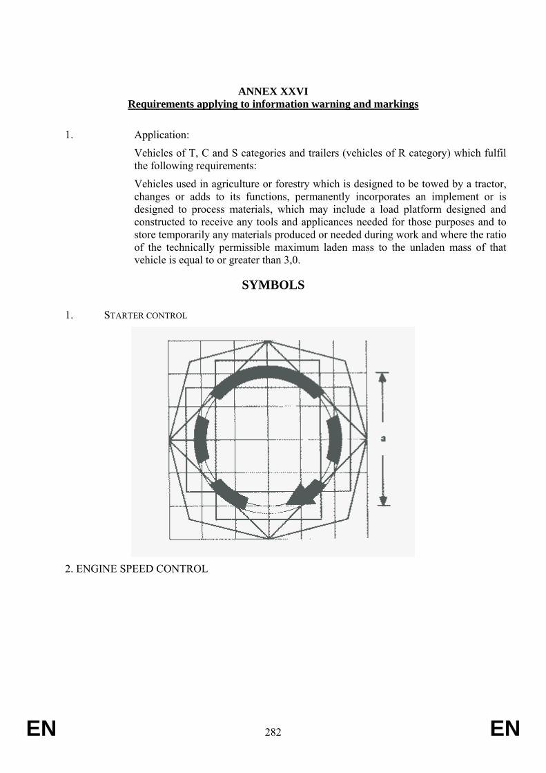
EN 282 EN
ANNEX XXVI Requirements applying to information warning and markings
1. Application:
Vehicles of T, C and S categories and trailers (vehicles of R category) which fulfil the following requirements:
Vehicles used in agriculture or forestry which is designed to be towed by a tractor, changes or adds to its functions, permanently incorporates an implement or is designed to process materials, which may include a load platform designed and constructed to receive any tools and applicances needed for those purposes and to store temporarily any materials produced or needed during work and where the ratio of the technically permissible maximum laden mass to the unladen mass of that vehicle is equal to or greater than 3,0.
SYMBOLS
1. STARTER CONTROL
2. ENGINE SPEED CONTROL
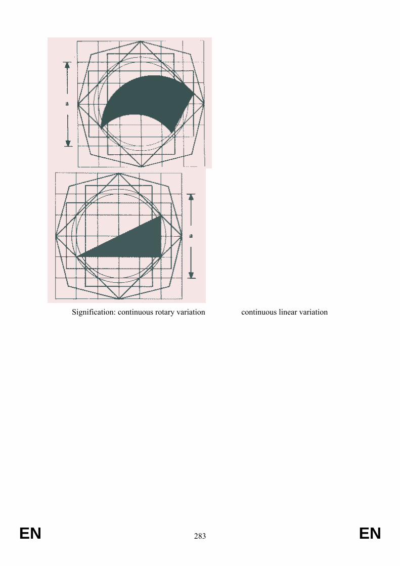
EN 283 EN
Signification: continuous rotary variation continuous linear variation
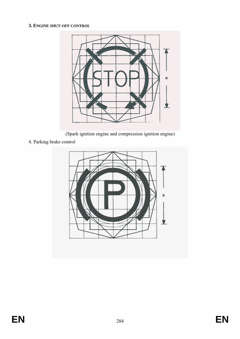
EN 284 EN
3. ENGINE SHUT-OFF CONTROL
(Spark ignition engine and compression ignition engine)
4. Parking brake control
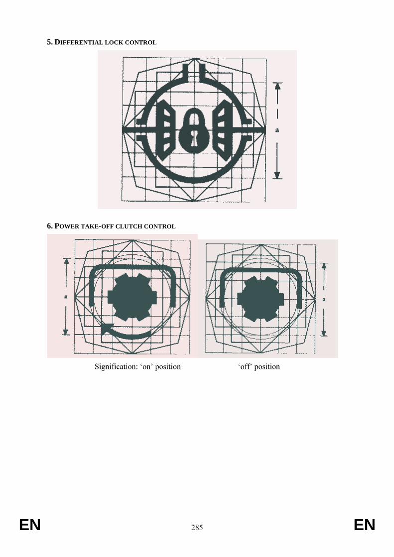
EN 285 EN
5. DIFFERENTIAL LOCK CONTROL
6. POWER TAKE-OFF CLUTCH CONTROL
Signification: ‘on’ position ‘off’ position
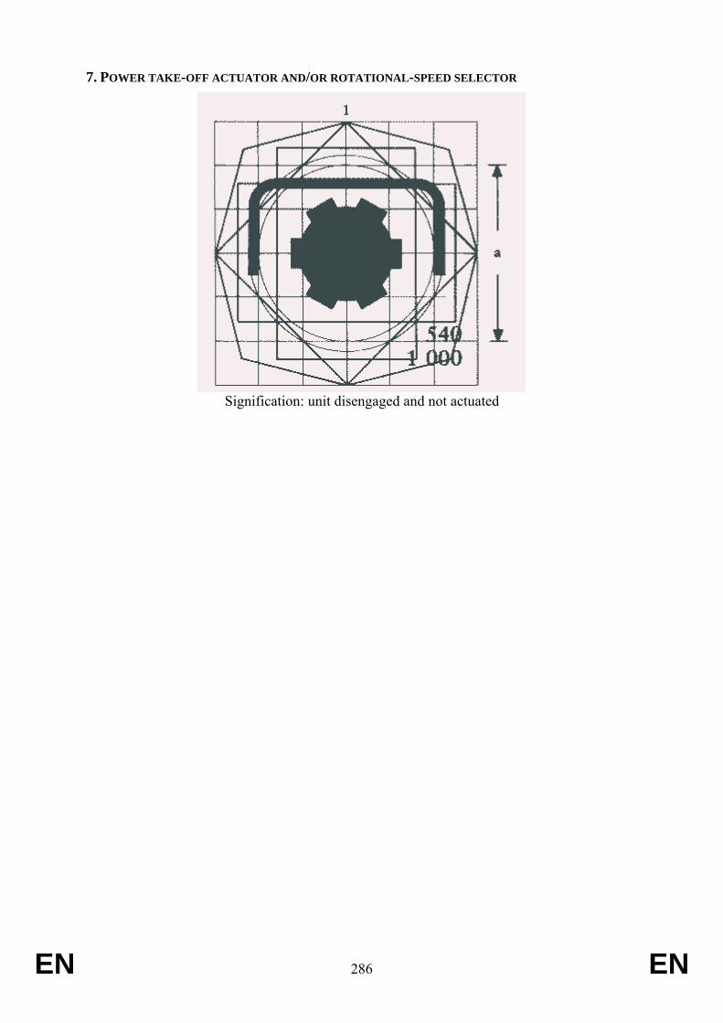
EN 286 EN
7. POWER TAKE-OFF ACTUATOR AND/OR ROTATIONAL-SPEED SELECTOR
Signification: unit disengaged and not actuated
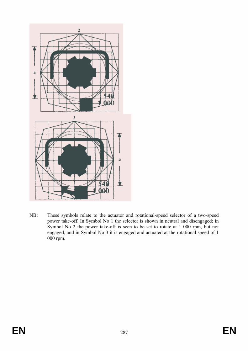
EN 287 EN
NB: These symbols relate to the actuator and rotational-speed selector of a two-speed power take-off. In Symbol No 1 the selector is shown in neutral and disengaged; in Symbol No 2 the power take-off is seen to be set to rotate at 1 000 rpm, but not engaged, and in Symbol No 3 it is engaged and actuated at the rotational speed of 1 000 rpm.
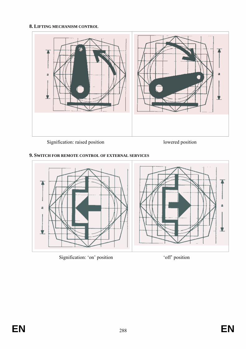
EN 288 EN
8. LIFTING MECHANISM CONTROL
Signification: raised position lowered position
9. SWITCH FOR REMOTE CONTROL OF EXTERNAL SERVICES
Signification: ‘on’ position ‘off’ position
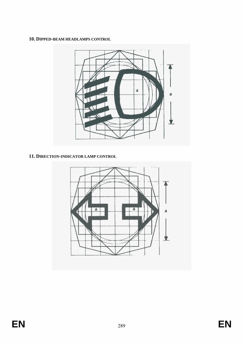
EN 289 EN
10. DIPPED-BEAM HEADLAMPS CONTROL
11. DIRECTION-INDICATOR LAMP CONTROL
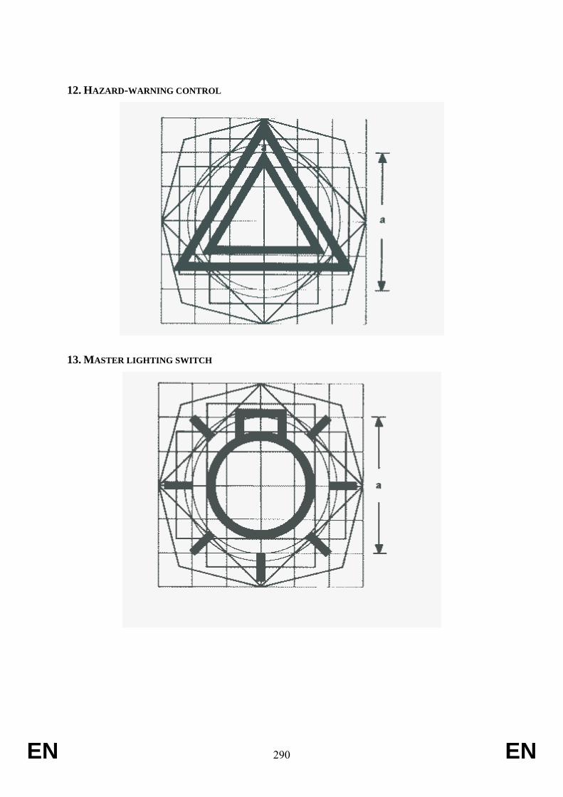
EN 290 EN
12. HAZARD-WARNING CONTROL
13. MASTER LIGHTING SWITCH
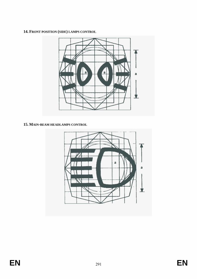
EN 291 EN
14. FRONT POSITION (SIDE) LAMPS CONTROL
15. MAIN-BEAM HEADLAMPS CONTROL
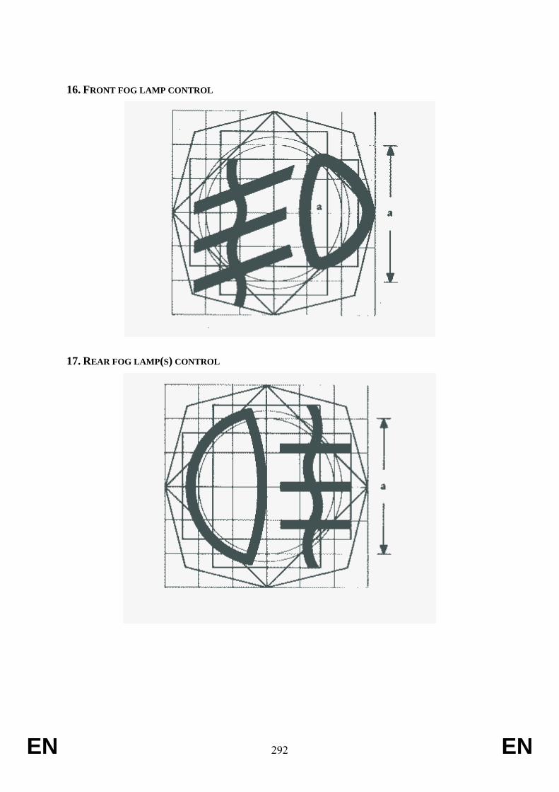
EN 292 EN
16. FRONT FOG LAMP CONTROL
17. REAR FOG LAMP(S) CONTROL
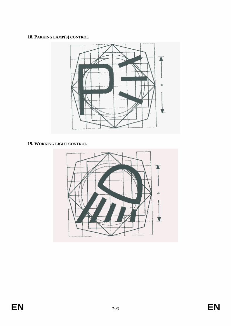
EN 293 EN
18. PARKING LAMP(S) CONTROL
19. WORKING LIGHT CONTROL
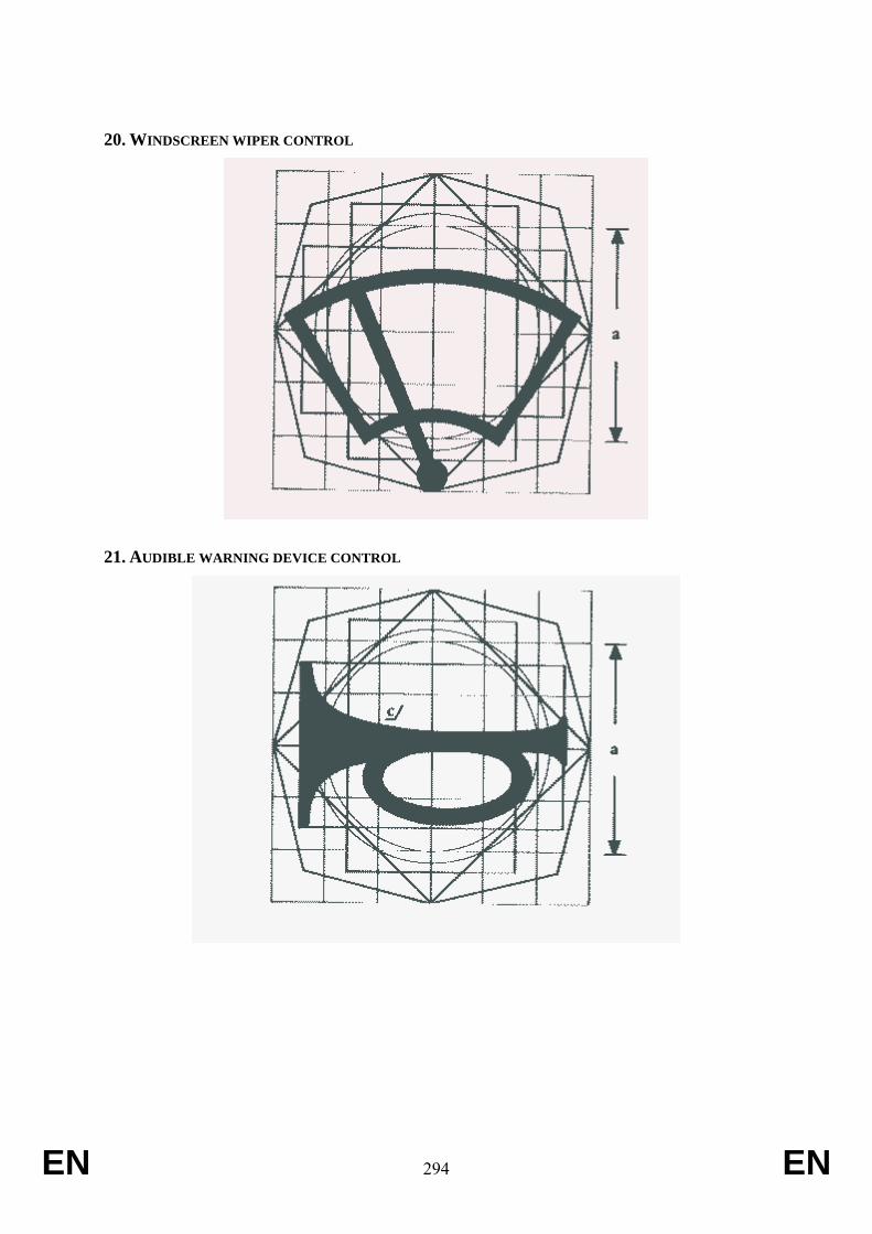
EN 294 EN
20. WINDSCREEN WIPER CONTROL
21. AUDIBLE WARNING DEVICE CONTROL
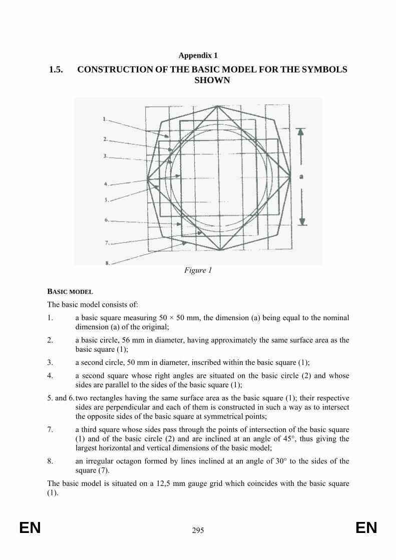
EN 295 EN
Appendix 1
1.5. CONSTRUCTION OF THE BASIC MODEL FOR THE SYMBOLS SHOWN
Figure 1
BASIC MODEL The basic model consists of:
1. a basic square measuring 50 × 50 mm, the dimension (a) being equal to the nominal dimension (a) of the original;
2. a basic circle, 56 mm in diameter, having approximately the same surface area as the basic square (1);
3. a second circle, 50 mm in diameter, inscribed within the basic square (1);
4. a second square whose right angles are situated on the basic circle (2) and whose sides are parallel to the sides of the basic square (1);
5. and 6. two rectangles having the same surface area as the basic square (1); their respective sides are perpendicular and each of them is constructed in such a way as to intersect the opposite sides of the basic square at symmetrical points;
7. a third square whose sides pass through the points of intersection of the basic square (1) and of the basic circle (2) and are inclined at an angle of 45°, thus giving the largest horizontal and vertical dimensions of the basic model;
8. an irregular octagon formed by lines inclined at an angle of 30° to the sides of the square (7).
The basic model is situated on a 12,5 mm gauge grid which coincides with the basic square (1).
EN 296 EN
ANNEX XXVII Requirements applying to materials and products and burning rate of cab material
1. Requirements
1.1.
1.2
Oil reservoirs and coolant systems shall be located, constructed, coated and/or sealed to minimize the risk of spillage that might be injurious to the operator in the event of an overturn.
Burning rate of cab material
The burning rate of cab interior material such as the seat covering, wall, floor and headliner coverings when provided shall not exceed the maximum rate of 150 mm/min when tested in accordance with ISO 3795:1989.
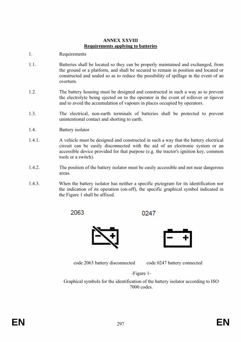
EN 297 EN
ANNEX XXVIII Requirements applying to batteries
1. Requirements
1.1. Batteries shall be located so they can be properly maintained and exchanged, from the ground or a platform, and shall be secured to remain in position and located or constructed and sealed so as to reduce the possibility of spillage in the event of an overturn.
1.2. The battery housing must be designed and constructed in such a way as to prevent the electrolyte being ejected on to the operator in the event of rollover or tipover and to avoid the accumulation of vapours in places occupied by operators.
1.3. The electrical, non-earth terminals of batteries shall be protected to prevent unintentional contact and shorting to earth.
1.4. Battery isolator
1.4.1. A vehicle must be designed and constructed in such a way that the battery electrical circuit can be easily disconnected with the aid of an electronic system or an accessible device provided for that purpose (e.g. the tractor's ignition key, common tools or a switch).
1.4.2. The position of the battery isolator must be easily accessible and not near dangerous areas.
1.4.3. When the battery isolator has neither a specific pictogram for its identification nor the indication of its operation (on-off), the specific graphical symbol indicated in the Figure 1 shall be affixed.
code 2063 battery disconnected code 0247 battery connected
-Figure 1-
Graphical symbols for the identification of the battery isolator according to ISO 7000 codes.

EN 298 EN
EN 299 EN
ANNEX XXIX Requirements applying to cab ventilation and filtration system
Requirements
The requirements of EN 15695-1:2009 shall apply to all tractors indicated in Article 2(a) of Regulation (EU) No 167/2013 when are being used in conditions which may cause the risk of contact with hazardous substances; in such case the cabin has to fulfil the requirements of level 2, 3 or 4 of this standard. The criteria for the choice between the levels must be described and be in line with those indicated in the operator’s manual. For spraying of pesticides the cabin must be of level 4.
EN 300 EN
ANNEX XXX Performance standards and assessment of technical services
General requirements
Technical services shall demonstrate appropriate skills, specific technical knowledge and proven experience in the specific fields of competence covered by Chapter XVI of Regulation (EU) No 167/2013 and Appendices 1 and 2 to Annex V to Directive 2007/46/EC.
Standards with which technical services of the different categories set out in Article 59 of Regulation (EU) No 167/2013 shall comply
The different categories of technical services shall comply with the standards set out in Appendix 1 to Annex V to Directive 2007/46/EC
The reference to Article 41 of Directive 2007/46/EC in that Appendix shall be construed as a reference to Article 59 of Regulation (EU) No 167/2013.
The reference to Annex IV of Directive 2007/46/EC in that Appendix shall be construed as a reference to Annex II to Regulation (EU) No 167/2013.
Procedure for the assessment of the technical services
The technical services are assessed in accordance with the procedure set out in Appendix 2 to Annex V to Directive 2007/46/EC.
References to Article 42 of Directive 2007/46/EC in Appendix 1 to Annex V to Directive 2007/46/EC shall be construed as references to Article 62 of Regulation (EU) No 167/2013.


