Embed Size (px)
Citation preview
RULES FOR INTERCONNECTION OF DISTRIBUTED GENERATION FACILITIES
(Customer-Owned Generation)
A division of IMPERIAL IRRIGATION DISTRICT
Effective August 15, 2007
Rules for Interconnection of Distributed Generation Facilities (Customer-Owned Generation)
______________________________________________________________________________
2
A. APPLICABILITY. These Rules describe the distributive generation interconnection, operating and metering requirements for a Generating Facility (GF) for interconnection to the Distribution System of Imperial Irrigation District (IID). Subject to the requirements of this Rules, IID shall allow the Interconnection of a GF to its Distribution System. A.1. DEFINITIONS. Capitalized terms used in these Rules, and not defined in other IID Rate Schedules and/or Regulations Governing the Sale and Use of Electric Energy (IID Rates and Regulations), shall have the meaning ascribed to such terms in Section H of these Rules. The definitions set forth in Section H of these Rules shall only apply to these Rules. A.2. CONSISTENT WITH IEEE 1547. These Rules were revised to be consistent with the requirements of ANSI/IEEE11547-2003 Standard for Interconnecting Distributed Resources with Electric Power Systems (IEEE 1547). In some cases, IEEE 1547 language was adopted directly; in others, IEEE 1547 requirements were interpreted. These Rules have been devised to maintain the spirit of both documents. Language from IEEE 1547 that was adopted directly (as opposed to paraphrased language or previous language that was determined to be consistent with IEEE 1547) is followed by a citation that lists the Clause from which the language derived. For example, IEEE 1547-4.1.1 is a reference to Clause 4.1.1. In the event of any conflict between these Rules and any of the standards listed herein, the requirements of ths shall take precedence. B. GENERAL REGULATIONS, RIGHTS AND OBLIGATIONS B.1. OPERATING AUTHORIZATION. Producer must comply with these Rules, execute an Interconnection Agreement with IID, and receive IID’s express written permission before Parallel Operation of its GF with IID’s Distribution System. IID shall apply these Rules in a non-discriminatory manner and shall not unreasonably withhold its permission for Parallel Operation of Producer’s GF with IID’s Distribution System. B.2. SEPARATE AGREEMENTS REQUIRED FOR OTHER SERVICES. Producer requiring other electric services from IID including, but not limited to, Distribution Service during periods of curtailment or interruption of Producer’s GF, shall enter into agreements with IID for such services in accordance with IID Rates and Regulations. ___________________________
1 ANSI – American National Standards Institute; IEEE – Institute of Electrical and Electronic Engineers
Rules for Interconnection of Distributed Generation Facilities (Customer-Owned Generation)
______________________________________________________________________________
3
B.3. SERVICES NOT PROVIDED WITH INTERCONNECTION. Interconnection with IID's Distribution System under these Rules does not provide Producer any right to utilize IID's System for the transmission, distribution, or wheeling of electric power, nor does it limit such right. B.4. COMPLIANCE WITH LAWS, REGULATIONS AND RATE SCHEDULES. Producer shall ascertain and comply with IID Rates & Regulations; applicable Federal Energy Regulatory Commission (FERC) approved regulations; and any local, state or federal law, statute or regulation which applies to the design, sitting, construction, installation, operation, or any other aspect of Producer’s GF and/or Interconnection Facility. B.5. DESIGN REVIEWS AND INSPECTIONS. IID shall have the right to review the design of Producer's Generating and/or Interconnection Facility to specify the interface of protective relays; to determine feeder reclosing practice; to identify overcurrent coordination; to identify where to make changes to voltage, regulator, capacitors, and sectionalizing; and to inspect Producer's Generating and/or Interconnection Facility prior to the commencement of Parallel Operation with IID’s Distribution System. IID may require Producer to make modifications as necessary to comply with the requirements of these Rules. IID's review and authorization for Parallel Operation shall not be construed as confirming or endorsing Producer's design or as warranting the safety, durability or reliability of the Generating and/or Interconnection Facility. IID shall not, by reason of such review or lack of review, be responsible for the strength, adequacy or capacity of such equipment. B.6. RIGHT TO ACCESS. Producer’s GF and/or Interconnection Facility shall be reasonably Accessible to IID personnel as necessary for IID to perform its duties and exercise its rights under IID Rates & Regulations and any Interconnection Agreement between IID and Producer. B.7. CONFIDENTIALITY OF INFORMATION. Any information pertaining to a GF and/or Interconnection Facility provided to IID by Producer shall be treated by IID in a confidential manner. IID shall not use information contained in the Application for Interconnection unless authorized to do so by the Customer or the information is provided to IID by the Customer through other means. B.8. PRUDENT OPERATION AND MAINTENANCE REQUIRED. Producer shall operate and maintain its GF and/or Interconnection Facility in accordance with Prudent Electrical Practices and shall maintain compliance with these Rules. B.9. CURTAILMENT AND DISCONNECTION. At any time, IID may, without notice, in the event of an Emergency or to correct Unsafe Operating Conditions: limit operation; disconnect, or; require disconnection; as to Producer’s GF and/or IID’s Distribution System. IID may also limit operation; disconnect, or; require disconnection; as to
Rules for Interconnection of Distributed Generation Facilities (Customer-Owned Generation)
______________________________________________________________________________
4
Producer’s GF and/or IID’s Distribution System upon the provision of reasonable written notice, if one or more of the following criteria apply:
a. For routine maintenance, repairs or modifications to IID’s Distribution System; b. Upon IID’s determination that Producer’s GF is not in compliance with these Rules, or; c. Upon termination of the Interconnection Agreement.
Upon Producer’s written request, IID shall provide a written explanation of the reason for any such curtailment or disconnection. C. APPLICATION AND INTERCONNECTION PROCESS C.1 APPLICATION PROCESS C.1.a. Applicant Initiates Contact with IID. Upon request, IID shall provide information and documents (such as sample agreements, Application, technical information, listing of Certified Equipment, Initial and Supplemental Review fee information, IID Rates and Regulations and Metering requirements) to a potential Applicant. Unless otherwise agreed upon, all such information shall normally be sent to an Applicant within five (5) business days following the initial request from the Applicant. IID shall establish an individual representative as the single point of contact for the Applicant, but may allocate responsibilities among its staff to best coordinate the Interconnection of an Applicant’s GF. C.1.b. Applicant Completes an Application. All Applicants shall complete and file an Application and supply to IID any relevant additional information requested by IID. When applicable per Table C.1, an $800 Initial Review fee shall be included with the Application.
1. Normally, within 10 business days of receiving the Application, IID shall acknowledge receipt and state whether the Application has been completed adequately. If the application is incomplete or additional information is needed, IID and Applicant shall cooperate in a timely manner to establish a satisfactory Application. 2. The Initial Review fee shall be waived for Applications requesting Interconnection pursuant to IID Schedule NM, Net Metering, and for a solar powered GF that does not sell power to the grid. 3. Fifty percent of the fees associated with the Initial Review shall be returned to the Applicant if the Application is rejected by IID or if the Applicant retracts the Application.
Rules for Interconnection of Distributed Generation Facilities (Customer-Owned Generation)
______________________________________________________________________________
5
4. An Application is subject to cancellation if it is over one year old (from the date of IID’s acknowledgement) which is not associated with a signed Interconnection Agreement, or any GF that has not been approved for parallel operation within one year of completion of all applicable review and/or studies. However, IID may not cancel an Application if Producer provides reasonable evidence that the project is still active. 5. IID, at its discretion, may adjust costs for the review of atypical Applications, such as those submitted for multiple Generators, multiple sites, or otherwise as conditions warrant.
C.1.c. IID Performs an Initial and Supplemental Review and Develops Preliminary Cost Estimates and Interconnection Requirements.
1. Upon receipt of a satisfactorily completed Application and any additional information necessary to evaluate the Interconnection of a GF, IID shall perform an Initial Review using the process defined in Section I. The purpose of the Initial Review is to determine if the GF qualifies for Simplified Interconnection; or if the GF requires a Supplemental Review. 2. IID shall complete the Initial Review, absent any extraordinary circumstances, within 10 business days after the determination by IID that the Application is complete. If, as a result of the Initial Review, IID determines the proposed GF can be Interconnected by means of a Simplified Interconnection, IID shall provide the Applicant with an Interconnection Agreement for Applicant’s signature. 3. If a GF does not pass the Initial Review for Simplified Interconnection as proposed, IID shall notify the Applicant and perform a Supplemental Review as described in Section I, Applicant shall pay an additional $600 for the Supplemental Review, unless the Application is withdrawn. As a result of the Supplemental Review, IID shall provide either Interconnection requirements beyond those for a Simplified Interconnection, and an Interconnection Agreement for Applicant’s signature; or a cost estimate and schedule for an Interconnection Study. The Supplemental Review shall be completed, absent any extraordinary circumstances, within 20 business days of receipt of a completed Application and fees.
C.1.d. When Required, Applicant and IID Commit to Additional Interconnection Steps. When the results of a Supplemental Review reveal that the proposed GF cannot be Interconnected to IID’s Distribution System by means of a Simplified Interconnection, or that significant Interconnection Facility installed on IID’s system or Distribution System modifications shall be needed to accommodate an Applicant’s GF, IID and Applicant shall enter into an agreement that provides for IID to perform additional studies, facility design, and engineering and to provide detailed cost estimates for fixed
Rules for Interconnection of Distributed Generation Facilities (Customer-Owned Generation)
______________________________________________________________________________
6
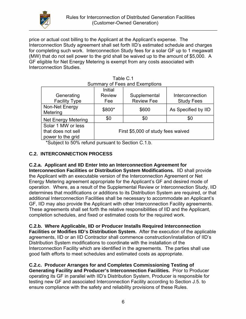
price or actual cost billing to the Applicant at the Applicant’s expense. The Interconnection Study agreement shall set forth IID’s estimated schedule and charges for completing such work. Interconnection Study fees for a solar GF up to 1 megawatt (MW) that do not sell power to the grid shall be waived up to the amount of $5,000. A GF eligible for Net Energy Metering is exempt from any costs associated with Interconnection Studies.
Table C.1 Summary of Fees and Exemptions
Generating
Facility Type
Initial Review
Fee Supplemental Review Fee
Interconnection Study Fees
Non-Net Energy Metering $800* $600 As Specified by IID
Net Energy Metering $0 $0 $0 Solar 1 MW or less that does not sell power to the grid
First $5,000 of study fees waived
*Subject to 50% refund pursuant to Section C.1.b. C.2. INTERCONNECTION PROCESS C.2.a. Applicant and IID Enter Into an Interconnection Agreement for Interconnection Facilities or Distribution System Modifications. IID shall provide the Applicant with an executable version of the Interconnection Agreement or Net Energy Metering agreement appropriate for the Applicant’s GF and desired mode of operation. Where, as a result of the Supplemental Review or Interconnection Study, IID determines that modifications or additions to its Distribution System are required, or that additional Interconnection Facilities shall be necessary to accommodate an Applicant’s GF, IID may also provide the Applicant with other Interconnection Facility agreements. These agreements shall set forth the relative responsibilities of IID and the Applicant, completion schedules, and fixed or estimated costs for the required work. C.2.b. Where Applicable, IID or Producer Installs Required Interconnection Facilities or Modifies IID’s Distribution System. After the execution of the applicable agreements, IID or an IID Contractor shall commence construction/installation of IID’s Distribution System modifications to coordinate with the installation of the Interconnection Facility which are identified in the agreements. The parties shall use good faith efforts to meet schedules and estimated costs as appropriate. C.2.c. Producer Arranges for and Completes Commissioning Testing of Generating Facility and Producer’s Interconnection Facilities. Prior to Producer operating its GF in parallel with IID’s Distribution System, Producer is responsible for testing new GF and associated Interconnection Facility according to Section J.5. to ensure compliance with the safety and reliability provisions of these Rules.
Rules for Interconnection of Distributed Generation Facilities (Customer-Owned Generation)
______________________________________________________________________________
7
In the case of non-Certified Equipment, Producer shall develop a written testing plan to be submitted to IID for review and acceptance. Alternatively, Producer and IID may agree to have IID conduct required testing at Producer’s expense. Where applicable, the test plan shall include the installation test procedures published by the manufacturer of the generation or Interconnection equipment. Facility testing shall be conducted at a mutually agreeable time, and depending on who conducts the test, IID’s designated representative and Producer shall be given the opportunity to witness the tests. C.2.d. IID Authorizes Parallel Operation or Momentary Parallel Operation. IID shall authorize Producer’s GF for Parallel Operation or Momentary Parallel Operation connected to IID’s Distribution System, in writing, within 5 calendar days of satisfactory compliance with the terms of all applicable agreements. Compliance may require provision to IID of required documentation and the satisfactory completion of required inspections or tests, as described herein, or in the agreements formed between Producer and IID. Producer shall not commence Parallel Operation of its GF with IID’s Distribution System unless it has received IID’s express written permission to do so. For a GF qualifying for service under Net Energy Metering, IID authorization for Parallel Operation shall be provided no later than 30 business days following IID’s receipt of items below:
1. Completed Net Energy Metering Application including all supporting documents and required payments; 2. Completed signed Net Energy Metering Interconnection Agreement; and 3. Evidence of Producer’s final inspection clearance from the governmental authority having jurisdiction over the GF.
If the 30-day period cannot be met, IID shall notify the Applicant. D. GENERATING FACILITY DESIGN AND OPERATING REQUIREMENTS. This section has been revised to be consistent with the requirements of ANSI/IEEE 1547-2003 Standard for Interconnecting Distributed Resources with Electric Power Systems (IEEE 1547). Exceptions are taken to IEEE 1547 Clauses 4.1.4.2 Distribution Secondary Spot Networks and Clauses 4.1.8.1 or 5.1.3.1, which address Protection from Electromagnetic Interference. These clauses are being studied for inclusion in a subsequent version of these Rules. Also, Regulation 21 does not adopt the GF power limitation of 10 MW incorporated in IEEE 1547. D.1. GENERAL INTERCONNECTION AND PROTECTIVE FUNCTION REQUIREMENTS. The Protective Functions and requirements of these Rules are
Rules for Interconnection of Distributed Generation Facilities (Customer-Owned Generation)
______________________________________________________________________________
8
designed to protect IID’s Distribution System and not the GF. Producer shall be solely responsible for providing adequate protection for its GF and/or Interconnection Facility. Producer's Protective Functions may not impact the operation of other Protective Functions utilized on IID’s Distribution System in a manner that would affect IID's capability of providing reliable service to IID Customers. D.1.a. Protective Functions Required. A GF operating in parallel with IID’s Distribution System shall be equipped with Protective Functions to sense abnormal conditions on IID’s Distribution System and cause the GF to be automatically disconnected from IID’s Distribution System or prevent the GF from being connected to IID’s Distribution System inappropriately. These Protective Functions are:
1. Over and under voltage trip functions and over and under frequency trip functions; 2. A voltage and frequency sensing and time-delay function to prevent the GF from energizing a de-energized Distribution System circuit and preventing the GF from reconnecting with IID’s Distribution System, unless IID’s Distribution System service voltage and frequency is within the ANSI C84.1-1995 Table 1 Range B Voltage Range of 106 V to 127 V (on a 120 V basis), inclusive, and a frequency range of 59.7 Hz to 60.5 Hz, inclusive, and are stable for at least 60 seconds; and 3. A function to prevent the GF from contributing to the formation of an Unintended Island, and to cease to energize IID’s Distribution System within two seconds of the formation of an Unintended Island.
The GF shall cease to energize IID’s Distribution System for faults on IID’s Distribution System circuit to which it is connected (IEEE 1547-4.2.1). The GF shall cease to energize IID’s Distribution circuit prior to re-closure by IID’s Distribution System equipment (IEEE 1547-4.2.2). D.1.b. Momentary Paralleling Generating Facility. With IID’s approval, the transfer switch or scheme used to transfer Producer’s loads from IID’s Distribution System to Producer’s GF may be used in lieu of the Protective Functions required for Parallel Operation. D.1.c. Suitable Equipment Required. Circuit breakers or other interrupting equipment located at the Point of Common Coupling (PCC) must be Certified or "Listed" (as defined in Article 100, the Definitions Section of the National Electrical Code) as suitable for their intended application. Such equipment must be capable of interrupting the maximum available fault current expected at the PCC. Producer’s GF and/or Interconnection Facility shall be designed so that the failure of any single device or component shall not potentially compromise the safety and reliability of IID’s Distribution System. The GF paralleling-device shall be capable of withstanding 220% of the
Rules for Interconnection of Distributed Generation Facilities (Customer-Owned Generation)
______________________________________________________________________________
9
Interconnection Facility rated voltage (IEEE 1547-4.1.8.3). The Interconnection Facility shall have the capability to withstand voltage and current surges in accordance with the environments defined in IEEE Std C62.41.2-2002 or IEEE Std C37.90.1-2002 as applicable and as described in J.3.e (IEEE 1547-4.1.8.2). D.1.d. Visible Disconnect Required. When required by IID’s operating practices, Producer shall furnish and install a ganged, manually-operated isolating switch (or a comparable device mutually agreed upon by IID and Producer) near the Point of Interconnection to isolate the GF from IID’s Distribution System. The device does not have to be rated for load break nor does it have to provide over-current protection. The device must:
1. Allow visible verification that separation has been accomplished. (This requirement may be met by opening the enclosure to observe contact separation.) 2. Include markings or signage that clearly indicates open and closed positions. 3. Be capable of being reached quickly and conveniently 24 hours a day by IID personnel for construction, operation, maintenance, inspection, testing or reading, without obstacles or requiring those seeking access to obtain keys, special permission, or security clearances. 4. Be capable of being locked in the open position. 5. Be clearly marked on a single-line diagram with the visible disconnect type and location. The diagram shall be submitted to IID and approved by IID prior to installation. If the device is not adjacent to the PCC, permanent signage must be installed at an IID-approved location providing a clear description of the location of the device.
D.1.e. Drawings, Diagrams and Relays Settings Required. Prior to Parallel Operation or Momentary Parallel Operation of the GF, IID shall approve Producer's one-line drawings, three-line drawings with the protective function, control diagrams, wiring diagrams and relays settings. All drawings must be approved by the local jurisdiction and stamped. D.1.f. Generating Facility Conditions Not Identified. In the event these Rules do not address the Interconnection conditions for a particular GF, IID and Producer may agree upon other arrangements. D.2. PREVENTION OF INTERFERENCE. Producer shall not operate a GF and/or Interconnection Facility that superimposes a voltage or current upon IID’s Distribution System that interferes with IID operations, service to IID Customers, or communication facilities. If such interference occurs, Producer must diligently pursue and take corrective action at its own expense after being given notice and reasonable time to do
Rules for Interconnection of Distributed Generation Facilities (Customer-Owned Generation)
______________________________________________________________________________
10
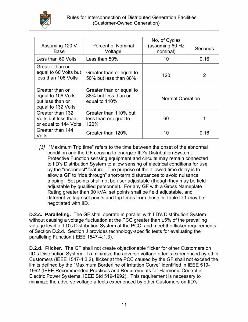
so by IID. If Producer does not take corrective action in a timely manner, or continues to operate the facilities causing interference without restriction or limit, IID may, without liability, disconnect Producer's facilities from IID’s Distribution System, in accordance with Section B.9. of these Rules. To eliminate undesirable interference caused by its operation, each GF shall meet the following criteria: D.2.a. Voltage Regulation. The GF shall not actively regulate the voltage at the PCC while in parallel with IID’s Distribution System. The GF shall not cause the service voltage of other Customers to go outside the requirements of ANSI C84.1-1995, Range A (IEEE 1547-4.1.1). D.2.b. Operating Voltage Range. The voltage ranges in Table D.1 define protective trip limits for the Protective Function and are not intended to define or imply a voltage regulation Function. The GF shall cease to energize IID’s Distribution System within the prescribed trip time whenever the voltage at the PCC deviates from the allowable voltage operating range. The Protective Function shall detect and respond to voltage on all phases to which the GF is connected.
1. Generating Facility 30 kVA or Less. Any GF with a Gross Nameplate Rating of 30 kVA or less shall be capable of operating within the voltage range normally experienced on IID’s Distribution System. The operating range shall be selected in a manner that minimizes nuisance tripping between 106 volts and 132 volts on a 120-volt base (88%-110% of nominal voltage). Voltage shall be detected at either the PCC or the Point of Interconnection. 2. Generating Facility Greater than 30 kVA. IID may have specific operating voltage ranges for any GF with a Gross Nameplate Rating greater than 30 kVA and may require adjustable operating voltage settings. In the absence of such requirements, the GF shall operate at a range between 88% and 110% of the nominal voltage. Voltage shall be detected at either the PCC or the Point of Interconnection with settings compensated to account for the voltage at the PCC. A GF that is Certified Non-Islanding or that meets one of the options on Screen 2 of the review process (Section I.3.b.) may detect voltage at the Point of Interconnection without compensation.
3. Voltage Disturbances. Whenever IID’s Distribution System voltage at the
PCC varies from and remains outside the ranges listed in Table D.1, the GF’s Protective Functions shall cause the Generator(s) to become isolated from IID’s Distribution System.
Table D.1
Over and Under Voltage Trip Settings Voltage at
Point of Common Coupling Maximum Trip Time [1]
Rules for Interconnection of Distributed Generation Facilities (Customer-Owned Generation)
______________________________________________________________________________
11
Assuming 120 V
Base
Percent of Nominal
Voltage
No. of Cycles (assuming 60 Hz
nominal)
Seconds
Less than 60 Volts Less than 50% 10 0.16 Greater than or equal to 60 Volts but less than 106 Volts
Greater than or equal to 50% but less than 88% 120 2
Greater than or equal to 106 Volts but less than or equal to 132 Volts
Greater than or equal to 88% but less than or equal to 110% Normal Operation
Greater than 132 Volts but less than or equal to 144 Volts
Greater than 110% but less than or equal to 120%
60 1
Greater than 144 Volts Greater than 120% 10 0.16
[1] "Maximum Trip time" refers to the time between the onset of the abnormal
condition and the GF ceasing to energize IID’s Distribution System. Protective Function sensing equipment and circuits may remain connected to IID’s Distribution System to allow sensing of electrical conditions for use by the "reconnect" feature. The purpose of the allowed time delay is to allow a GF to “ride through” short-term disturbances to avoid nuisance tripping. Set points shall not be user adjustable (though they may be field adjustable by qualified personnel). For any GF with a Gross Nameplate Rating greater than 30 kVA, set points shall be field adjustable, and different voltage set points and trip times from those in Table D.1 may be negotiated with IID.
D.2.c. Paralleling. The GF shall operate in parallel with IID’s Distribution System without causing a voltage fluctuation at the PCC greater than ±5% of the prevailing voltage level of IID’s Distribution System at the PCC, and meet the flicker requirements of Section D.2.d. Section J provides technology-specific tests for evaluating the paralleling Function (IEEE 1547-4.1.3). D.2.d. Flicker. The GF shall not create objectionable flicker for other Customers on IID’s Distribution System. To minimize the adverse voltage effects experienced by other Customers (IEEE 1547-4.3.2), flicker at the PCC caused by the GF shall not exceed the limits defined by the "Maximum Borderline of Irritation Curve" identified in IEEE 519-1992 (IEEE Recommended Practices and Requirements for Harmonic Control in Electric Power Systems, IEEE Std 519-1992). This requirement is necessary to minimize the adverse voltage affects experienced by other Customers on IID’s
Rules for Interconnection of Distributed Generation Facilities (Customer-Owned Generation)
______________________________________________________________________________
12
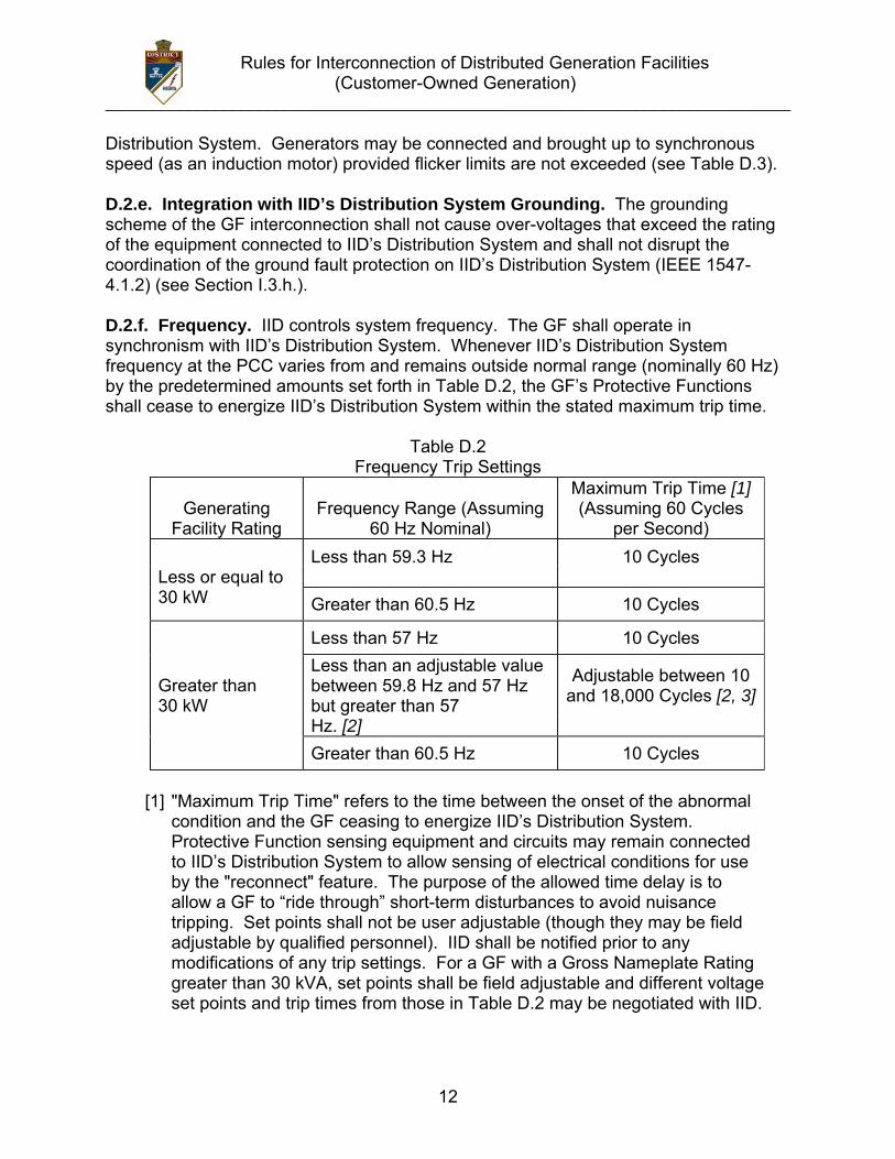
Distribution System. Generators may be connected and brought up to synchronous speed (as an induction motor) provided flicker limits are not exceeded (see Table D.3). D.2.e. Integration with IID’s Distribution System Grounding. The grounding scheme of the GF interconnection shall not cause over-voltages that exceed the rating of the equipment connected to IID’s Distribution System and shall not disrupt the coordination of the ground fault protection on IID’s Distribution System (IEEE 1547-4.1.2) (see Section I.3.h.). D.2.f. Frequency. IID controls system frequency. The GF shall operate in synchronism with IID’s Distribution System. Whenever IID’s Distribution System frequency at the PCC varies from and remains outside normal range (nominally 60 Hz) by the predetermined amounts set forth in Table D.2, the GF’s Protective Functions shall cease to energize IID’s Distribution System within the stated maximum trip time.
Table D.2 Frequency Trip Settings
Generating
Facility Rating
Frequency Range (Assuming
60 Hz Nominal)
Maximum Trip Time [1] (Assuming 60 Cycles
per Second) Less than 59.3 Hz 10 Cycles
Less or equal to 30 kW Greater than 60.5 Hz 10 Cycles Less than 57 Hz 10 Cycles
Greater than 30 kW
Less than an adjustable value between 59.8 Hz and 57 Hz but greater than 57
Adjustable between 10 and 18,000 Cycles [2, 3]
Hz. [2] Greater than 60.5 Hz 10 Cycles
[1] "Maximum Trip Time" refers to the time between the onset of the abnormal
condition and the GF ceasing to energize IID’s Distribution System. Protective Function sensing equipment and circuits may remain connected to IID’s Distribution System to allow sensing of electrical conditions for use by the "reconnect" feature. The purpose of the allowed time delay is to allow a GF to “ride through” short-term disturbances to avoid nuisance tripping. Set points shall not be user adjustable (though they may be field adjustable by qualified personnel). IID shall be notified prior to any modifications of any trip settings. For a GF with a Gross Nameplate Rating greater than 30 kVA, set points shall be field adjustable and different voltage set points and trip times from those in Table D.2 may be negotiated with IID.
Rules for Interconnection of Distributed Generation Facilities (Customer-Owned Generation)
______________________________________________________________________________
13
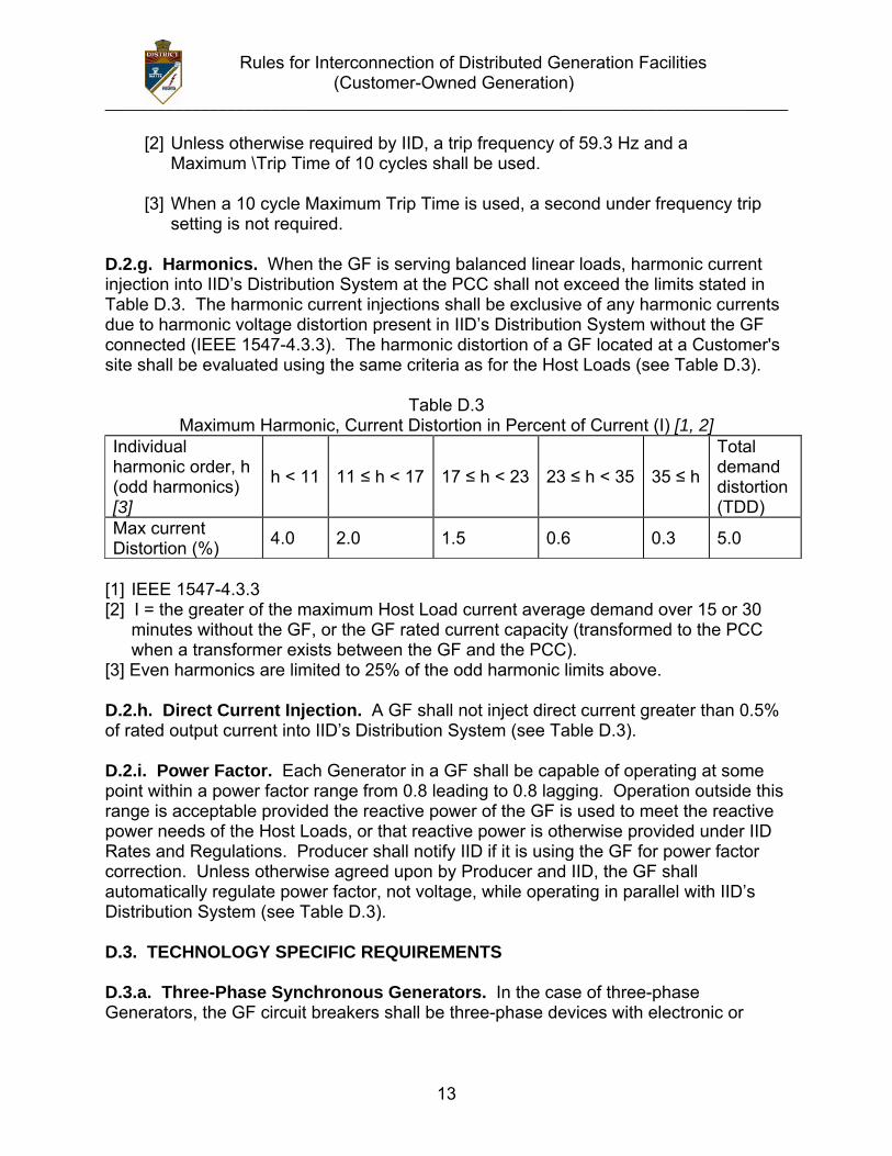
[2] Unless otherwise required by IID, a trip frequency of 59.3 Hz and a Maximum \Trip Time of 10 cycles shall be used.
[3] When a 10 cycle Maximum Trip Time is used, a second under frequency trip
setting is not required. D.2.g. Harmonics. When the GF is serving balanced linear loads, harmonic current injection into IID’s Distribution System at the PCC shall not exceed the limits stated in Table D.3. The harmonic current injections shall be exclusive of any harmonic currents due to harmonic voltage distortion present in IID’s Distribution System without the GF connected (IEEE 1547-4.3.3). The harmonic distortion of a GF located at a Customer's site shall be evaluated using the same criteria as for the Host Loads (see Table D.3).
Table D.3 Maximum Harmonic, Current Distortion in Percent of Current (I) [1, 2]
Individual harmonic order, h (odd harmonics) [3]
h < 11 11 ≤ h < 17 17 ≤ h < 23 23 ≤ h < 35 35 ≤ h
Total demand distortion (TDD)
Max current Distortion (%) 4.0 2.0 1.5 0.6 0.3 5.0
[1] IEEE 1547-4.3.3 [2] I = the greater of the maximum Host Load current average demand over 15 or 30
minutes without the GF, or the GF rated current capacity (transformed to the PCC when a transformer exists between the GF and the PCC).
[3] Even harmonics are limited to 25% of the odd harmonic limits above. D.2.h. Direct Current Injection. A GF shall not inject direct current greater than 0.5% of rated output current into IID’s Distribution System (see Table D.3). D.2.i. Power Factor. Each Generator in a GF shall be capable of operating at some point within a power factor range from 0.8 leading to 0.8 lagging. Operation outside this range is acceptable provided the reactive power of the GF is used to meet the reactive power needs of the Host Loads, or that reactive power is otherwise provided under IID Rates and Regulations. Producer shall notify IID if it is using the GF for power factor correction. Unless otherwise agreed upon by Producer and IID, the GF shall automatically regulate power factor, not voltage, while operating in parallel with IID’s Distribution System (see Table D.3). D.3. TECHNOLOGY SPECIFIC REQUIREMENTS D.3.a. Three-Phase Synchronous Generators. In the case of three-phase Generators, the GF circuit breakers shall be three-phase devices with electronic or
Rules for Interconnection of Distributed Generation Facilities (Customer-Owned Generation)
______________________________________________________________________________
14
electromechanical control. Producer shall be responsible for properly synchronizing its GF with IID’s Distribution System by means of either manual or automatic synchronizing equipment. Automatic synchronizing is required for all synchronous Generators that have a Short Circuit Contribution Ratio (SCCR) exceeding 0.05. Loss of synchronism protection is not required except as may be necessary to meet Section D.2.d. (Flicker) (IEEE 1547-4.2.5). Unless otherwise agreed upon by Producer and IID, synchronous Generators shall automatically regulate power factor, not voltage, while operating in parallel with IID’s Distribution System. A power system stabilization Function is specifically not required for a GF under 10 MW Net Nameplate Rating. D.3.b. Induction Generators. Induction Generators (except self-excited Induction Generators) do not require a synchronizing Function. Starting or rapid load fluctuations on induction generators can adversely impact IID’s Distribution System's voltage. Corrective step-switched capacitors or other techniques may be necessary and may cause undesirable ferro-resonance. When these counter measures (e.g., additional capacitors) are installed on Producer's side of the PCC, IID must review these measures. Additional equipment may be required as determined in a Supplemental Review or an Interconnection Study. D.3.c. Inverters. Utility-interactive inverters do not require separate synchronizing equipment. Non-utility-interactive or “stand-alone” inverters shall not be used for Parallel Operation with IID’s Distribution System. D.3.d. Single-Phase Generators. For a single-phase Generator connected to a shared single-phase secondary system, the maximum Net Nameplate Rating of the GF shall be 20 kVA. A Generator connected to a center-tapped neutral 240-volt service must be installed such that no more than 6 kVA of imbalanced power is applied to the two “legs” of the 240-volt service. For Dedicated Distribution Transformer service, the maximum Net Nameplate Rating of a single-phase GF shall be the transformer nameplate rating. D.4. SUPPLEMENTAL GENERATING FACILITY REQUIREMENTS D.4.a. Fault Detection. A GF with an SCCR exceeding 0.1 or 1 KVA that does not cease to energize IID’s Distribution System within two seconds of the formation of an Unintended Island shall be equipped with Protective Functions designed to detect Distribution System faults, both line-to-line and line-to-ground, and shall cease to energize IID’s Distribution System within two seconds of the initiation of a fault. D.4.b. Transfer Trip. IID may require a Transfer Trip system or an equivalent Protective Function in the case where a GF cannot detect a Distribution System fault (both line-to-line and line-to-ground) or the formation of an Unintended Island where the local loads sufficiently exceed more than 400% of the GF nameplate rating.
Rules for Interconnection of Distributed Generation Facilities (Customer-Owned Generation)
______________________________________________________________________________
15
D.4.c. Reclose Blocking. Where the aggregate GF capacity exceeds 15% of the peak load on any automatic reclosing device, IID may require additional Protective Functions, including, but not limited to recloser-blocking on some of the automatic reclosing devices. E. INTERCONNECTION FACILITY AND DISTRIBUTION SYSTEM MODIFICATIONS OWNERSHIP AND COSTS E.1. SCOPE AND OWNERSHIP OF INTERCONNECTION FACILITY AND DISTRIBUTION SYSTEM MODIFICATIONS. E.1.a. Scope. The Parallel Operation of a GF may require an Interconnection Facility or modifications to IID’s Distribution System (“Distribution System modifications”). The type, extent and costs of Interconnection Facility and Distribution System modification shall be consistent with these Rules and determined through the Supplemental Review and/or Interconnection Studies described in Section C. E.1.b. Ownership. An Interconnection Facility, installed on Producer’s side of the PCC, may be owned, operated and maintained by Producer or IID, Interconnection Facilities installed on IID’s side of the PCC and Distribution System modifications shall be owned, operated and maintained only by IID. E.2. RESPONSIBILITY OF COSTS OF INTERCONNECTING A GENERATING FACILITY E.2.a. Study and Review Costs. A Producer shall be responsible for the reasonably incurred costs of the reviews and studies conducted pursuant to Section C.1. of these Rules. E.2.b. Facility Costs. Producer shall be responsible for all costs associated with Interconnection Facilities owned by Producer. Producer shall also be responsible for any costs reasonably incurred by IID in providing, operating, or maintaining the Interconnection Facilities and Distribution System modifications required solely for the Interconnection of Producer’s GF with IID’s Distribution System. E.2.c. Separation of Costs. Should IID combine the installation of Interconnection Facilities or Distribution System modifications required for the Interconnection of a GF with modifications to IID’s Distribution System to serve other Customers or Producers, IID shall not include the costs of such separate or incremental facilities in the amounts billed to Producer. E.2.d. Reconciliation of Costs and Payments. If Producer selects a fixed price billing for the Interconnection Facilities or Distribution System modifications, no reconciliation shall be necessary. If Producer selects actual cost billing, a true up shall
Rules for Interconnection of Distributed Generation Facilities (Customer-Owned Generation)
______________________________________________________________________________
16
be required. Within a reasonable time after the Interconnection of Producer’s GF, IID shall reconcile its actual costs related to the GF against any advance payments made by Producer. Producer shall receive either a bill for any balance due or a reimbursement for overpayment as determined by IID’s reconciliation. Producer shall be entitled to a reasonably detailed and understandable accounting for the payments. E.3. INSTALLATION OF INTERCONNECTION FACILITIES AND DISTRIBUTION SYSTEM MODIFICATIONS E.3.a. Agreement Required. The costs for Interconnection Facilities and Distribution System modifications shall be paid by Producer pursuant to the provisions contained in the Interconnection Agreement. Where the type and extent of the Interconnection Facilities or Distribution System modifications warrant additional detail, Producer and IID shall execute separate agreement(s) to more fully describe and allocate the parties’ responsibilities for installing, owning, operating and maintaining the Interconnection Facilities and Distribution System modifications. E.3.b. Interconnection Facility and Distribution System Modifications. Except as provided for in Sections E.2.b. and E.3.c. of these Rules, an Interconnection Facility connected to IID’s side of the PCC and Distribution System modifications shall be provided, installed, owned and maintained by IID at Producer’s expense. E.3.c. Reservation of Unused Facilities. When Producer wishes to reserve any IID-owned Interconnection Facility or Distribution System modification, installed and operated as Special Facilities for Producer at Producer’s expense, but idled by a change in the operation of Producer's GF or otherwise, Producer may elect to abandon or reserve such facilities consistent with the terms of its agreement with IID. If Producer elects to reserve idle Interconnection Facilities or Distribution System modifications, IID shall be entitled to continue to charge Producer for the costs related to the ongoing operation and maintenance of the Special Facilities. E.3.d. Refund of Salvage Value. When Producer elects to abandon the Special Facilities for which it has either advanced the installed costs or constructed and transferred to IID, Producer shall not receive credit for the net salvage value of the Special Facilities. F. METERING, MONITORING AND TELEMETRY F.1. GENERAL REQUIREMENTS. All GFs shall be metered in accordance with this Section F and shall meet all applicable standards of IID. F.2. METERING BY NON-IID PARTIES. The ownership, installation, operation, reading and testing of revenue Metering Equipment for a GF shall be by IID except to the extent that IID authorizes any or all these services be performed by others.
Rules for Interconnection of Distributed Generation Facilities (Customer-Owned Generation)
______________________________________________________________________________
17
F.3. NET GENERATION METERING. For purposes of monitoring GF operation to determine standby charges and applicable non-by-passable charges as defined in IID Rates and Regulations, and for Distribution System planning and operations, consistent with Section B.4. of these Rules, IID shall have the right to specify the type, and require the installation of Net Generation Metering equipment. IID shall only require Net Generation Metering to the extent that less intrusive and/or more cost effective options for providing the necessary GF output data are not available. In exercising its discretion to require Net Generation Metering, IID shall consider all relevant factors, including but not limited to:
a. Data requirements in proportion to need for information; b. Producer’s election to install equipment that adequately addresses IID’s operational requirements; c. Accuracy and type of required Metering consistent with purposes of collecting data; d. Cost of Metering relative to the need for and accuracy of the data; e. The GF’s size relative to the cost of the Metering/monitoring; and f. Other means of obtaining the data (e.g., GF logs, proxy data).
F.4. POINT OF COMMON COUPLING METERING. For purposes of assessing IID charges for retail service, Producer’s PCC metering shall be reviewed by IID, and if required, the metering shall be replaced to ensure that it shall appropriately measure electric power according to IID Rates and Regulations. Where required, the Customer’s existing meter may be replaced with a bi-directional meter so that power deliveries to and from Producer’s site can be separately recorded. Alternately, Producer may, at its sole option and cost, require IID to install multi-metering equipment to separately record power deliveries to IID’s Distribution System and retail purchases from IID. Where necessary, such PCC Metering shall be designed to prevent reverse registration. F.5. TELEMETERING. If the nameplate rating of the GF is 1 MW or greater, Telemetering equipment at the Net Generation Metering location may be required, at Producer's expense. If the GF is Interconnected to a portion of IID’s Distribution System operating at a voltage below 10 kV, Telemetering equipment may be required on a GF Facilities 250 kW or greater. IID shall only require Telemetering where less intrusive and/or more cost effective options for providing the necessary data in real time are not available. F.6. LOCATION. In the event that IID-owned Metering is located on Producer’s
Rules for Interconnection of Distributed Generation Facilities (Customer-Owned Generation)
______________________________________________________________________________
18
premises, Producer shall provide, at no expense to IID, a suitable location for all such Metering Equipment. F.7. COSTS OF METERING. Producer shall bear all costs of the Metering required by these Rules, including the incremental costs of operating and maintaining the Metering Equipment. G. DISPUTE RESOLUTION G.1. DISPUTE RESOLUTION REQUIREMENT FOR PRODUCER. Should a dispute, claim or controversy arise between Producer and IID relating to or concerning these Rules or any of IID’s Rates and/or Regulations, the Implementing Agreements, and/or requirements related to the Interconnection of Producer’s facilities pursuant to these Rules (the “Dispute”), then Producer may not initiate any legal claim or action against IID with respect to any such Dispute until Producer has submitted a Dispute Letter, as defined below, to IID and, upon the request of IID, met and conferred with IID, as set forth herein. If Producer fails to comply with the requirements of this Section G, Producer will be deemed to have waived said legal claim, controversy or action against IID with respect to any associated Dispute. G.2. DISPUTE LETTER. In the event of a Dispute, Producer must summit a written document (the “Dispute Letter”) to IID containing a recitation of the nature of the Dispute and describing any relief sought by Producer. The Dispute Letter must be submitted to IID within a reasonable time, but in no later than 120 days, after the creation or accrual of the associated Dispute, claim or controversy. The Dispute Letter shall be personally delivered or mailed by certified mail, postage prepaid, return receipt requested, to IID at the following address:
Assistant Manager, Customer Operations Imperial Irrigation District P.O. Box 937 Imperial, CA 92251
The Dispute Letter shall be deemed submitted (for purposes of determining the timing of submission) at such time that the Dispute Letter is received by IID.
G.3. MEET-AND-CONFER EFFORT. Within 60 calendar days of the date that IID receives the Dispute Letter, IID may require an authorized representative of Producer to meet and confer with IID in an attempt to resolve the dispute. Producer shall respond to IID’s effort to meet and confer and shall negotiate in good faith with IID in an effort to resolve the Dispute.
G.4. DISPUTE RESOLUTION REQUIREMENT IN ALL AGREEMENTS. The instant dispute resolution requirement shall be made a requirement and shall be incorporated into all Implementing Agreements between Producer and IID.
Rules for Interconnection of Distributed Generation Facilities (Customer-Owned Generation)
______________________________________________________________________________
19
H. DEFINITIONS. The definitions in this Section are applicable only these Rules, the Application and Interconnection Agreements. H.1. Accessible: Accessible relates to convenience. A device is Accessible if it can be reached without a ladder or other special equipment. A device may be accessible even in a locked room, if arrangements can be made to ensure that IID will have access to the room. There is no specific requirement that the device be located away from the PCC/revenue meter. The location of the disconnect must be clearly marked on the submitted single-line diagram and permanent signage must be installed at the PCC/meter location providing a clear description of the location of the disconnect. H.2. Anti-Islanding: A control scheme installed as part of the GF or Interconnection Facilities that senses and prevents the formation of an Unintended Island. H.3. Applicant: The entity submitting an Application for Interconnection pursuant to these Rules. H.4. Application: An IID-approved standard form submitted by an Applicant to IID for Interconnection of a GF. H.5. Certification Test: A test pursuant to these Rules that verifies conformance of certain equipment with IID approved standards. H.6. Certification; Certified; Certificate: The documented results of a successful Certification Testing. H.7. Certified Equipment: Equipment that has passed all required Certification Tests. H.8. Commissioning Test: A test performed during the commissioning of all or part of a GF to achieve one or more of the following:
• Verify specific aspects of its performance; • Calibrate instrumentation; or • Establish instrument or Protective Function setpoints.
H.9. Customer: The person or entity that receives or is entitled to receive Distribution Service through IID’s Distribution System. H.10. Date of Initial Operation: The date on which the Generation Facility becomes fully operational. H.11. Dedicated Transformer; Dedicated Distribution Transformer: A transformer that provides electricity service to a single Customer. The Customer may have a GF.
Rules for Interconnection of Distributed Generation Facilities (Customer-Owned Generation)
______________________________________________________________________________
20
H.12. Device: A mechanism or piece of equipment designed to serve a purpose or perform a function. The term may be used interchangeably with the terms “equipment” and “function” without intentional difference in meaning. See also Function and Protective Function. H.13. Distribution Service: All services required by, or provided to, a Customer pursuant to the approved IID Rates and Regulations other than services directly related to the Interconnection of a GF under these Rules. H.14. Distribution System: All electrical wires, equipment, and other facilities owned or provided by IID, other than Interconnection Facilities, by which IID provides Distribution Service to its Customers. H.15. Emergency: An actual or imminent condition or situation, which jeopardizes IID’s Distribution System Integrity. H.16. Field Testing: Testing performed in the field to determine whether equipment meets IID’s requirements for safe and reliable Interconnection. H.17. Function: A combination of hardware and software designed to provide specific features or capabilities. H.18. Generating Facility (GF): All Generators, electrical wires, equipment, and other facilities owned or provided by Producer for the purpose of producing electric power. H.19. Generator: A device which converts mechanical, chemical or solar energy into electrical energy, including all of its protective and control Functions and structural appurtenances. One or more Generators comprise a GF. H.20. Gross Nameplate Rating; Gross Nameplate Capacity: The total gross generating capacity of a Generator or GF as designated by the manufacturer(s) of the Generator(s). H.21. Host Load: The electrical power, less the Generator auxiliary load, consumed by the Customer, to which the GF is connected. H.22. Implementing Agreements: As used herein, Implementing Agreements means the contract agreements necessary to facilitate interconnection between Producer and IID, including the Application, the System and Facility Impact Interconnection Study Agreement (if required pursuant to a Supplemental Review), and the Generating Facility Interconnection Agreement. H.23. Inadvertent Export: The unscheduled and uncompensated export of real power
Rules for Interconnection of Distributed Generation Facilities (Customer-Owned Generation)
______________________________________________________________________________
21
from a GF for a duration exceeding two seconds. H.24. Initial Review: The review by IID, following receipt of an Application, to determine whether:
• the GF qualifies for Simplified Interconnection; or • the GF can be made to qualify for Interconnection with a Supplemental Review determining any additional requirements.
H.25. In-Rush Current: The current determined by the In-Rush Current Test. H.26. Interconnection Agreement: An agreement between IID and Producer providing for the Interconnection of a GF that gives certain rights and obligations to effect or end Interconnection. H.27. Interconnection; Interconnected: The physical connection of a GF in accordance with the requirements of these Rules so that Parallel Operation with IID’s Distribution System can occur (has occurred). H.28. Interconnection Facility: The electrical wires, switches and related equipment that are required in addition to the facilities required to provide electric Distribution Service to a Customer to allow Interconnection. Interconnection Facilities may be located on either side of the PCC as appropriate to their purpose and design. Interconnection Facilities may be integral to a GF or provided separately. H.29. Interconnection Study: A study to establish the requirements for the Interconnection of a GF to IID’s Distribution System. H.30. Island; Islanding: A condition regarding IID’s Distribution System in which one or more GF deliver power to Customers using a portion of IID’s Distribution System that is electrically isolated from the remainder of IID’s Distribution System. H.31. Line Section: That portion of IID’s Distribution System connected to a Customer bounded by automatic sectionalizing devices or the end of the distribution line. H.32. Load Carrying Capability: The maximum electrical load that may be carried by a section of IID’s Distribution System, consistent with reliability and safety. H.33. Metering: The measurement of electrical power in kW and/or energy in kWh, and, if necessary, reactive power in kVAR and/or reactive energy in kVARh, at a point, and its display to IID, as required by these Rules. H.34. Metering Equipment: All equipment, hardware, software including meter cabinets, conduit, etc., that are necessary for Metering.
Rules for Interconnection of Distributed Generation Facilities (Customer-Owned Generation)
______________________________________________________________________________
22
H.35. Momentary Parallel Operation: The interconnection of a GF to the Distribution System for one second (60 cycles) or less. H.36. Nationally Recognized Testing Laboratory (NRTL): A laboratory accredited to perform the Certification Testing required under these Rules. H.37. Net Energy Metering: Metering for the receipt and delivery of electricity between Producer and IID pursuant to IID’s Interconnection and Net Energy Metering rules and requirements and IID’s Rate Schedule “NM”, Net Metering. H.38. Net Generation Metering: Metering of the net electrical power output in kW or energy in kWh, from a given GF. This may also be the measurement of the difference between the total electrical energy produced by a Generator and the electrical energy consumed by the auxiliary equipment necessary to operate the Generator. For a Generator with no Host Load and/or CPUC Section 218 Load (Section 218 Load), this is metering that is located at the PCC. For a Generator with Host Load and/or Section 218 Load, this is metering that is located at the Generator, but after the point of auxiliary load(s), and prior to serving Host Load and/or Section 218 Load. H.39. Net Nameplate Rating: The Gross Nameplate Rating less the consumption of electrical power of a Generator or GF, as designated by the manufacturer(s) of the Generator(s). H.40. Network Service: More than one electrical feeder providing Distribution Service at a PCC. H.41. Non-Export; Non-Exporting: Designed to prevent the transfer of electrical energy from the GF to IID’s Distribution System. H.42. Non-Islanding: Designed to detect and disconnect an Unintended Island with matched load and generation. Reliance solely on under/over voltage and frequency trip is not considered sufficient to qualify as Non-Islanding. H.43. Parallel Operation: The simultaneous operation of a Generator with power delivered or received by IID while interconnected. For the purpose of these Rules, Parallel Operation includes only a GF which is interconnected with IID’s Distribution System for more than 60 cycles (one second). H.44. Permanently Parallel Operation: The interconnection of GF to the distribution system for more than one second. H.45. Paralleling Device: An electrical device, typically a circuit breaker, operating under the control of a synchronization Function or by a qualified operator to connect an energized Generator to an energized electric power system or two energized power
Rules for Interconnection of Distributed Generation Facilities (Customer-Owned Generation)
______________________________________________________________________________
23
systems to each other. H.46. Periodic Test: A test performed on part or all of a GF and/or Interconnection Facilities at pre-determined times or operational intervals to achieve one or more of the following:
• Verify specific aspects of its performance; • Calibrate its instrumentation; or • Verify and re-establish instrument or Protective Function set-points.
H.47. Point of Common Coupling (PCC): The transfer point for electricity between the electrical conductors of IID and the electrical conductors of Producer. H.48. Point of Common Coupling (PCC) Metering: Metering located at the PCC. This is the same Metering as Net Generation Metering for a GF with no Host Load and/or Section 218 Load. H.49. Point of Interconnection: The electrical transfer point between a GF and/or IID’s Distribution System. This may be coincident with the PCC. H.50. Producer: The entity that executes an Interconnection Agreement with IID. Producer may own or operate the GF, but Producer is responsible for the rights and obligations related to the Interconnection Agreement. H.51. Production Test: A test performed on a newly produced device to verify certain aspects of its performance. H.52. Protective Function(s): The equipment, hardware and/or software in a GF (whether discrete or integrated with other functions), the purpose of which is to protect against Unsafe Operating Conditions. H.53. Prudent Electrical Practices: Those practices, methods, and equipment, as changed from time to time, that are commonly used in prudent electrical engineering and operations to design and operate electric equipment lawfully and with safety, dependability, efficiency and economy. H.54. Scheduled Operation Date: The date specified in the Interconnection Agreement when the GF is, by Producer's estimate, expected to begin operation pursuant to these Rules. H.55. Secondary Network: A network supplied by several primary feeders, suitably interlaced through the area in order to achieve acceptable loading of the transformers under emergency conditions and to provide a system of extremely high service reliability. Secondary networks usually operate at 600 volts or lower.
Rules for Interconnection of Distributed Generation Facilities (Customer-Owned Generation)
______________________________________________________________________________
24
H.56. Section 218 Load: Electrical power that is supplied in compliance with CPUC Section 218. CPUC Section 218 defines an “Electric Corporation” and provides conditions under which a transaction involving a GF would not classify Producer as an Electric Corporation. These conditions relate to “over-the-fence” sale of electricity from a GF without using IID’s Distribution System. H.57. Short Circuit (Current) Contribution Ratio (SCCR): The ratio of the GF’s short circuit contribution to IID’s Distribution System short circuit contribution provided through IID’s Distribution System for a three-phase fault at the high-voltage side of the distribution transformer connecting the GF to IID’s system. H.58. Simplified Interconnection: Interconnection conforming to the Initial Review requirements under these Rules, as determined by Section I. H.59. Single Line Diagram; Single Line Drawing: A schematic drawing, showing the major electric switchgear, Protective Function devices, wires, Generators, transformers and other devices, providing sufficient detail to communicate to a qualified engineer the essential design and safety of the system being considered. H.60. Special Facilities: As defined in IID Rates and Regulations. H.61. Starting Voltage Drop: The percentage voltage drop at a specified point resulting from In-Rush Current. The Starting Voltage Drop can also be expressed in volts on a particular base voltage, (e.g., 6 volts on a 120-volt base, yielding a 5% drop). H.62. Supplemental Review: A process wherein IID further reviews an Application that fails one or more of the Initial Review Process screens. The Supplemental Review may result in one of the following:
• approval of Interconnection; • approval of Interconnection with additional requirements; or • cost and schedule for an Interconnection Study.
H.63. System and Facility Impact Interconnection Study Agreement: The contract agreement between Producer and IID that is required if a Supplemental Review is necessary and which embodies the Parties’ agreement concerning such Supplemental Review. H.64. System Integrity: The condition under which IID’s Distribution System is deemed safe and reliable in accordance with IID Rates and Regulations. H.65. Telemetering: The electrical or electronic transmittal of Metering data in real-time to IID. H.66. Transfer Trip: A Protective Function that trips a GF remotely by means of an
Rules for Interconnection of Distributed Generation Facilities (Customer-Owned Generation)
______________________________________________________________________________
25
automated communications link controlled by IID. H.67. Type Test: A test performed on a sample of a particular model of a device to verify specific aspects of its design, construction and performance. H.68. Unintended Island: The creation of an Island without the approval of IID. This condition usually follows a loss of a portion of IID’s Distribution System. H.69. Unsafe Operating Conditions: Conditions that, if left uncorrected, could result in harm to personnel, damage to equipment, loss of System Integrity or operation outside pre-established parameters required by the Interconnection Agreement.
I. REVIEW PROCESS FOR APPLICATIONS TO INTERCONNECT GENERATING FACILITY I.1. INTRODUCTION. This review process allows for rapid approval for the Interconnection of any GF that does not require an Interconnection Study. The review process includes a screening to determine if a Supplemental Review is required. Note: The failure to pass any screen of the review process means only that further review and/or studies are required before the GF can be approved for Interconnection with IID’s Distribution System. It does not mean that the GF cannot be Interconnected. Though not explicitly covered in the Initial Review process, the GF shall be designed to meet all of the applicable requirements in Section D. I.2. PURPOSE. The review determines whether:
a. A GF qualifies for Simplified Interconnection; b. A GF can be made to qualify for Interconnection with a Supplemental Review determining any additional requirements; or c. An Interconnection Study is required, the cost estimate and schedule for performing the Interconnection Study.
(The remainder of this page has been intentionally left blank.)
Rules for Interconnection of Distributed Generation Facilities (Customer-Owned Generation)
______________________________________________________________________________
26
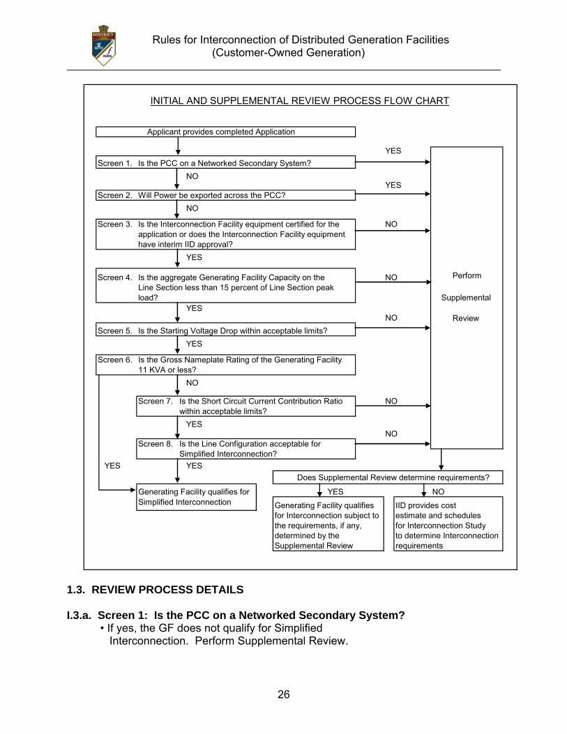
YESScreen 1. Is the PCC on a Networked Secondary System?
NOYES
Screen 2. Will Power be exported across the PCC? NO
Screen 3. Is the Interconnection Facility equipment certified for the NOapplication or does the Interconnection Facility equipment have interim IID approval?
YES
Screen 4. Is the aggregate Generating Facility Capacity on the NO PerformLine Section less than 15 percent of Line Section peak load? Supplemental
YESNO Review
Screen 5. Is the Starting Voltage Drop within acceptable limits? YES
Screen 6. Is the Gross Nameplate Rating of the Generating Facility 11 KVA or less?
NO
Screen 7. Is the Short Circuit Current Contribution Ratio NOwithin acceptable limits? YES
NOScreen 8. Is the Line Configuration acceptable for
Simplified Interconnection? YES YES
Does Supplemental Review determine requirements?
Generating Facility qualifies for YES NOSimplified Interconnection Generating Facility qualifies IID provides cost
for Interconnection subject to estimate and schedules the requirements, if any, for Interconnection Study determined by the to determine InterconnectionSupplemental Review requirements
Applicant provides completed Application
INITIAL AND SUPPLEMENTAL REVIEW PROCESS FLOW CHART
1.3. REVIEW PROCESS DETAILS I.3.a. Screen 1: Is the PCC on a Networked Secondary System?
• If yes, the GF does not qualify for Simplified Interconnection. Perform Supplemental Review.
Rules for Interconnection of Distributed Generation Facilities (Customer-Owned Generation)
______________________________________________________________________________
27
• If no, continue to next screen. Significance: Special considerations must be given to a GF proposed to be installed on networked secondary Distribution Systems because of the design and operational aspects of network protectors. There are no such considerations for radial Distribution Systems. I.3.b. Screen 2: Will power be exported across the PCC?
• If yes, the GF does not qualify for Simplified Interconnection. Perform Supplemental Review.
• If no, the GF must incorporate one of the following four options:
Option 1 (“Reverse Power Protection”): To ensure that power is not exported across the PCC, a reverse power Protective Function may be provided. The default setting for this Protective Function, when used, shall be 0.1% (export) of the service transformer’s rating, with a maximum 2.0 second time delay. Option 2 (“Minimum Power Protection”): To ensure a minimum amount of power is imported across the PCC at all times (and therefore, that power is not exported), an under-power Protective Function may be provided. The default setting for this Protective Function, when used, shall be 5% (import) of the GF’s total Gross Nameplate Rating with a maximum 2.0 second time delay. Option 3 (“Certified Non-Islanding Protection”): To ensure that the incidental export of power across the PCC is limited to acceptable levels, this option, when used, requires that all of the following conditions be met: • The total Gross Nameplate Capacity of the GF must be no more than 25% of
the nominal ampere rating of Producer’s service equipment; • The total Gross Nameplate Capacity of the GF must be no more than 50% of
Producer’s service transformer capacity rating (this capacity requirement does not apply to Customers taking primary service without an intervening transformer); and
• The GF must be certified as Non-Islanding.
The ampere rating of the Customer’s service equipment to be used in this evaluation shall be that rating for which the Customer’s utility service was originally sized or for which an upgrade has been approved. It is not the intent of this provision to allow increased export simply by increasing the size of the Customer’s service panel, without separate approval for the resize. Option 4 (“Relative Generating Facility Rating”): This option, when used, requires Net Nameplate Rating of the GF to be so small in comparison to its host facility’s minimum load, that the use of additional Protective Function is not required to ensure that power shall not be exported to IID’s Distribution System.
Rules for Interconnection of Distributed Generation Facilities (Customer-Owned Generation)
______________________________________________________________________________
28
This option requires the GF capacity to be no greater than 50% of Producer’s verifiable minimum Host Load over the past 12 months. Significance: 1) If it can be ensured that the GF shall not export power, IID’s Distribution
System does not need to be studied for Load-Carrying Capability or GF power flow effects on IID voltage regulators.
2) This Screen permits the use of reverse-power or minimum-power relaying as a Non-Islanding Protective Function (Options 1, 2 and 3).
3) This Screen allows, under certain defined conditions, for a GF that incorporates Certified Non-Islanding protection to qualify for Simplified Interconnection without implementing reverse power or minimum power Protective Functions (Option 3).
I.3.c. Screen 3: Is the Interconnection Facility equipment Certified for the application or does the Interconnection Facility equipment have interim IID approval?
• If yes, continue to next screen. • If no, the GF and/or Interconnection Facility do not qualify for Simplified
Interconnection. Perform Supplemental Review. Interim approval allows IID to treat equipment that has not completed these certification requirements as having met the intent of this screen. Interim approval is granted, at IID’s discretion, on a case-by-case basis, and approval for one GF does not guarantee approval for any other GF. Significance: If the GF and/or Interconnection Facility are Certified or were previously approved by IID, IID does not need to repeat its full review and/or test of the Generating and/or Interconnection Facility’s Protective Functions. Site Commissioning Testing may still be required to ensure that the Protective Functions are working properly. Certification indicates that the criteria in Section J, as appropriate, was tested and verified.
I.3.d. Screen 4: Is the aggregate GF capacity on the Line Section less than 15% of Line Section peak load?
• If yes, continue to next screen. • If no, the GF does not qualify for Simplified Interconnection. Perform
Supplemental Review to determine cumulative impact on Line Section.
Significance: 1) Low penetration of GF installations shall have a minimal impact on the
operation and load restoration efforts of IID’s Distribution System. 2) The operating requirements for a high penetration of a GF may be different
Rules for Interconnection of Distributed Generation Facilities (Customer-Owned Generation)
______________________________________________________________________________
29
since the impact on IID’s Distribution System shall no longer be minimal, therefore, requiring additional study or controls.
I.3.e. Screen 5: Is the Starting Voltage Drop within acceptable limits? • If yes, continue to next screen. • If no, the GF does not qualify for Simplified Interconnection. Perform
Supplemental Review.
Note: This Screen only applies to a GF that starts by motoring the Generator(s). IID has two options in determining whether Starting Voltage Drop is acceptable. The option to be used is at IID’s discretion: Option 1: IID may determine that the GF’s starting In-Rush Current is equal to or less than the continuous ampere rating of the Customer’s service equipment. Option 2: IID may determine the impedances of the service distribution transformer (if present) and the secondary conductors to Customer’s service equipment and perform a voltage drop calculation. Alternatively, IID may use tables or nomographs to determine the voltage drop. Voltage drops caused by starting a Generator as a motor must be less than 2.5% for primary Interconnections and 5% for secondary Interconnections. Significance: 1) This Screen addresses potential voltage fluctuation problems that may be
caused by Generators that start by motoring. 2) When starting, a GF shall have minimal impact on the service voltage to other
IID Customers. 3) Passing this screen does not relieve Producer from ensuring that its GF
complies with the flicker requirements of these Rules, Section D.2.d.
I.3.f. Screen 6: Is the Gross Nameplate Rating of the Generating Facility 11 kVA or less?
• If yes, the GF qualifies for Simplified Interconnection. Skip remaining screens.
• If no, continue to next screen.
Significance: The GF shall have a minimal impact on fault current levels and any potential line over voltages from loss of IID’s Distribution System neutral grounding.
I.3.g. Screen 7: Is the Short Circuit Current Contribution Ratio within acceptable limits?
• If yes, continue to next screen. • If no, the GF does not qualify for Simplified Interconnection. Perform
Rules for Interconnection of Distributed Generation Facilities (Customer-Owned Generation)
______________________________________________________________________________
30
Supplemental Review. The Short Circuit Current Contribution Ratio Screen consists of two criteria; both of which must be met when applicable: 1) When measured at primary side (high side) of a Dedicated Distribution
Transformer serving a GF, the sum of the Short Circuit Contribution Ratios of all GFs connected to IID’s Distribution System circuit that serves the GF must be less than or equal to 0.1; and
2) When measured at the secondary side (low side) of a shared distribution transformer, the short circuit contribution of the proposed GF must be less than or equal to 2.5% of the interrupting rating of Producer’s service equipment.
Significance: If the GF passes this screen, it can be expected that it shall have no significant impact on IID’s Distribution System’s short circuit duty, fault detection sensitivity, relay coordination or fuse-saving schemes.
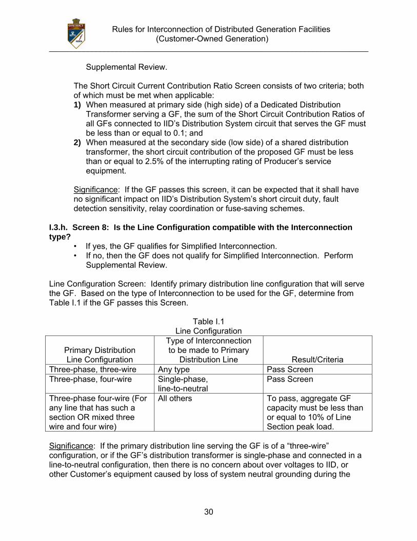
I.3.h. Screen 8: Is the Line Configuration compatible with the Interconnection type? • If yes, the GF qualifies for Simplified Interconnection.
• If no, then the GF does not qualify for Simplified Interconnection. Perform Supplemental Review.
Line Configuration Screen: Identify primary distribution line configuration that will serve the GF. Based on the type of Interconnection to be used for the GF, determine from Table I.1 if the GF passes this Screen.
Table I.1 Line Configuration
Primary Distribution Line Configuration
Type of Interconnection to be made to Primary
Distribution Line
Result/Criteria Three-phase, three-wire Any type Pass Screen Three-phase, four-wire Single-phase,
line-to-neutral Pass Screen
Three-phase four-wire (For any line that has such a section OR mixed three wire and four wire)
All others To pass, aggregate GF capacity must be less than or equal to 10% of Line Section peak load.
Significance: If the primary distribution line serving the GF is of a “three-wire” configuration, or if the GF’s distribution transformer is single-phase and connected in a line-to-neutral configuration, then there is no concern about over voltages to IID, or other Customer’s equipment caused by loss of system neutral grounding during the
Rules for Interconnection of Distributed Generation Facilities (Customer-Owned Generation)
______________________________________________________________________________
31
operating time of the Non-Islanding Protective Function. J. CERTIFICATION AND TESTING CRITERIA J.1. INTRODUCTION. This Section describes the test procedures and requirements for equipment used for the Interconnection of a GF to IID’s Distribution System. Included are Type Testing, Production Testing, Commissioning Testing and Periodic Testing. The procedures listed rely heavily on those described in appropriate Underwriters Laboratory (UL), Institute of Electrical and Electronic Engineers (IEEE), and International Electrotechnical Commission (IEC) documents—most notably UL 1741 and IEEE 929, as well as the testing described in May 1999 New York State Public Services Commission Standardized Interconnection Requirements. As noted in Section A, these Rules has been revised to be consistent with ANSI/IEEE 1547-2003 Standard for Interconnecting Distributed Resources with Electric Power Systems. The tests described here, together with the technical requirements in Section D of these rules, are intended to provide assurance that the GF’s equipment shall not adversely affect IID’s Distribution System and that a GF shall cease providing power to IID’s Distribution System under abnormal conditions. The tests were developed assuming a low level of GF penetration or number of connections to IID’s Distribution System. At high levels of GF penetration, additional requirements and corresponding test procedures may need to be defined. Section J also provides criteria for “Certifying” Generators or inverters. Once a Generator or inverter has been certified per these Rules, it may be considered suitable for Interconnection with IID’s Distribution System. Subject to the exceptions described in Section J, IID shall not repeat the design review or require retesting of such Certified Equipment. It should be noted that the Certification process is intended to facilitate GF Interconnections. Certification is not a prerequisite to Interconnect a GF. J.2. CERTIFIED AND NON-CERTIFIED INTERCONNECTION EQUIPMENT J.2.a. Certified Equipment. Equipment tested and approved (e.g., “Listed”) by an accredited NRTL as having met both the Type Testing and Production Testing requirements described in these Rules is considered to be Certified Equipment for purposes of Interconnection with IID’s Distribution System. Certification may apply to either a pre-packaged system or an assembly of components that address the necessary functions. Type Testing may be done in the manufacturer’s factory or test laboratory, or in the field. At the discretion of the testing laboratory, field certification may apply only to the particular installation tested. In such cases, some or all of the tests may need to be repeated at other installations. When equipment is certified by a NRTL, the NRTL shall provide to the manufacturer, at a minimum, a Certificate with the following information for each device:
Rules for Interconnection of Distributed Generation Facilities (Customer-Owned Generation)
______________________________________________________________________________
32
Administrative: 1) The effective date of Certification or applicable serial number (range or first in series), and/or other proof that Certification is current; 2) Equipment model number(s) of the Certified Equipment; 3) The software version utilized in the equipment, if applicable; 4) Test procedures specified (including date or revision number); and 5) Laboratory accreditation (by whom and to what standard). Technical (as appropriate): 1) Device ratings (kW, kVA, volts, Amps, etc.); 2) Maximum available fault current in Amps; 3) In-Rush Current in Amps; 4) Trip points, if factory set (trip value and timing); 5) Trip point and timing ranges for adjustable settings; 6) Nominal power factor or range if adjustable; 7) If the equipment is Certified for Non-Exporting and the method used (reverse power or under power); and 8) If the equipment is Certified Non-Islanding. It is the responsibility of the equipment manufacturer to ensure that Certification information is made publicly available by the manufacturer, the testing laboratory or by a third party. J.2.b. Non-Certified Equipment. For non-Certified Equipment, some or all of the tests described in these Rules may be required by IID for each GF and/or Interconnection Facility. The manufacturer or a laboratory acceptable to IID may perform these tests. Test results for non-Certified Equipment must be submitted to IID for the Supplemental Review. Approval by IID for equipment used in a particular GF and/or Interconnection Facility does not guarantee IID’s approval for use in other GF and/or Interconnection Facilities. J.3 TYPE TESTING J.3.a. Type Tests and Criteria for Interconnection Equipment Certification. Type Testing provides a basis for determining that equipment meets the specifications for being designated as Certified Equipment under these Rules. The requirements described in this section cover only issues related to Interconnection and are not intended to address equipment safety or other issues. Table J.1 defines the test criteria by Generator or inverter technology. While UL 1741(1) was written specifically for inverters, the requirements are readily adaptable to synchronous Generators, induction Generators, as well as single/multi-function controllers and protection relays. Until a universal test standard is developed, IID or
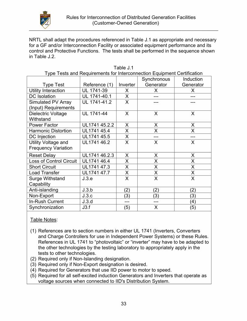
Rules for Interconnection of Distributed Generation Facilities (Customer-Owned Generation)
______________________________________________________________________________
33
NRTL shall adapt the procedures referenced in Table J.1 as appropriate and necessary for a GF and/or Interconnection Facility or associated equipment performance and its control and Protective Functions. The tests shall be performed in the sequence shown in Table J.2.
Table J.1 Type Tests and Requirements for Interconnection Equipment Certification
Type Test
Reference (1)
Inverter
Synchronous Generator
Induction Generator
Utility Interaction UL 1741-39 X X X DC Isolation UL 1741-40.1 X --- --- Simulated PV Array (Input) Requirements
UL 1741-41.2 X --- ---
Dielectric Voltage Withstand
UL 1741-44 X X X
Power Factor UL1741 45.2.2 X X X Harmonic Distortion UL1741 45.4 X X X DC Injection UL1741 45.5 X --- --- Utility Voltage and Frequency Variation
UL1741 46.2 X X X
Reset Delay UL1741 46.2.3 X X X Loss of Control Circuit UL1741 46.4 X X X Short Circuit UL1741 47.3 X X X Load Transfer UL1741 47.7 X X X Surge Withstand Capability
J.3.e X X X
Anti-islanding J.3.b (2) (2) (2) Non-Export J.3.c (3) (3) (3) In-Rush Current J.3.d --- --- (4) Synchronization J3.f (5) X (5) Table Notes: (1) References are to section numbers in either UL 1741 (Inverters, Converters
and Charge Controllers for use in Independent Power Systems) or these Rules. References in UL 1741 to “photovoltaic” or “inverter” may have to be adapted to the other technologies by the testing laboratory to appropriately apply in the tests to other technologies.
(2) Required only if Non-Islanding designation. (3) Required only if Non-Export designation is desired. (4) Required for Generators that use IID power to motor to speed. (5) Required for all self-excited induction Generators and Inverters that operate as
voltage sources when connected to IID's Distribution System.
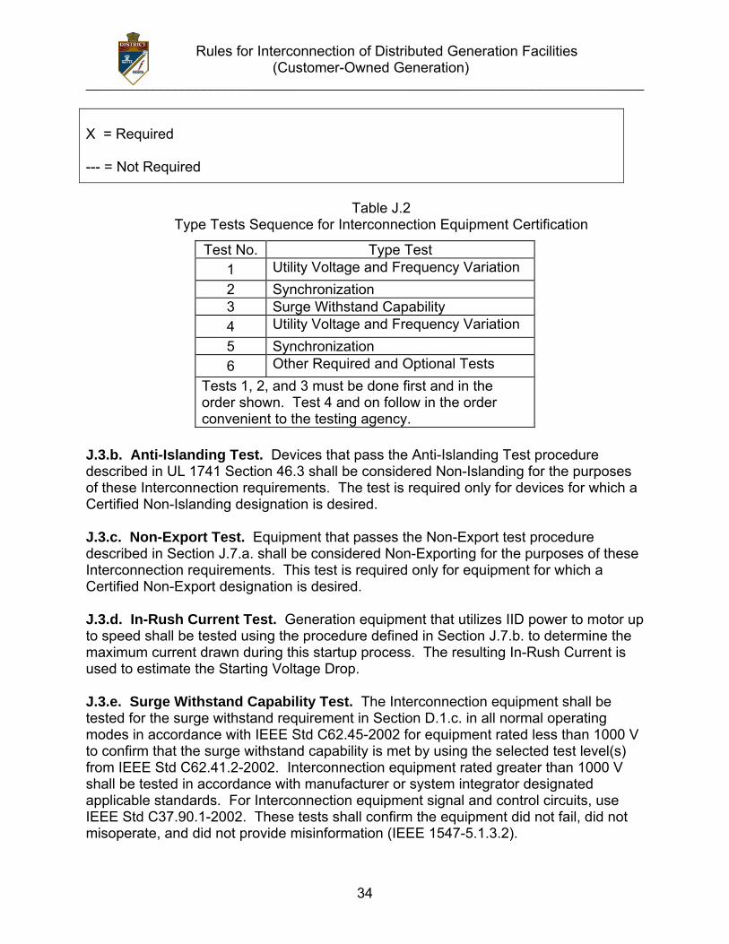
Rules for Interconnection of Distributed Generation Facilities (Customer-Owned Generation)
______________________________________________________________________________
34
X = Required --- = Not Required
Table J.2
Type Tests Sequence for Interconnection Equipment Certification J.3.b. Anti-Islanding Test. Devices that pass the Anti-Islanding Test procedure described in UL 1741 Section 46.3 shall be considered Non-Islanding for the purposes of these Interconnection requirements. The test is required only for devices for which a Certified Non-Islanding designation is desired. J.3.c. Non-Export Test. Equipment that passes the Non-Export test procedure described in Section J.7.a. shall be considered Non-Exporting for the purposes of these Interconnection requirements. This test is required only for equipment for which a Certified Non-Export designation is desired. J.3.d. In-Rush Current Test. Generation equipment that utilizes IID power to motor up to speed shall be tested using the procedure defined in Section J.7.b. to determine the maximum current drawn during this startup process. The resulting In-Rush Current is used to estimate the Starting Voltage Drop. J.3.e. Surge Withstand Capability Test. The Interconnection equipment shall be tested for the surge withstand requirement in Section D.1.c. in all normal operating modes in accordance with IEEE Std C62.45-2002 for equipment rated less than 1000 V to confirm that the surge withstand capability is met by using the selected test level(s) from IEEE Std C62.41.2-2002. Interconnection equipment rated greater than 1000 V shall be tested in accordance with manufacturer or system integrator designated applicable standards. For Interconnection equipment signal and control circuits, use IEEE Std C37.90.1-2002. These tests shall confirm the equipment did not fail, did not misoperate, and did not provide misinformation (IEEE 1547-5.1.3.2).
Test No. Type Test 1 Utility Voltage and Frequency Variation 2 Synchronization 3 Surge Withstand Capability 4 Utility Voltage and Frequency Variation 5 Synchronization 6 Other Required and Optional Tests
Tests 1, 2, and 3 must be done first and in the order shown. Test 4 and on follow in the order convenient to the testing agency.
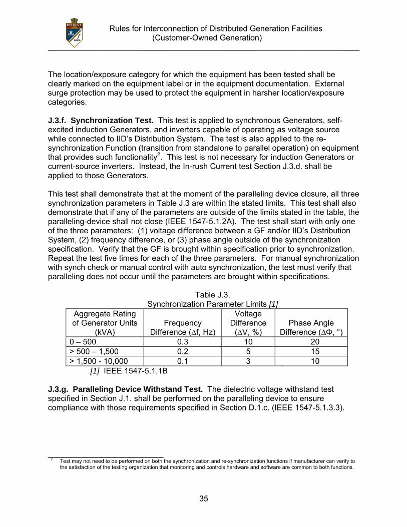
Rules for Interconnection of Distributed Generation Facilities (Customer-Owned Generation)
______________________________________________________________________________
35
The location/exposure category for which the equipment has been tested shall be clearly marked on the equipment label or in the equipment documentation. External surge protection may be used to protect the equipment in harsher location/exposure categories. J.3.f. Synchronization Test. This test is applied to synchronous Generators, self-excited induction Generators, and inverters capable of operating as voltage source while connected to IID’s Distribution System. The test is also applied to the re-synchronization Function (transition from standalone to parallel operation) on equipment that provides such functionality2. This test is not necessary for induction Generators or current-source inverters. Instead, the In-rush Current test Section J.3.d. shall be applied to those Generators. This test shall demonstrate that at the moment of the paralleling device closure, all three synchronization parameters in Table J.3 are within the stated limits. This test shall also demonstrate that if any of the parameters are outside of the limits stated in the table, the paralleling-device shall not close (IEEE 1547-5.1.2A). The test shall start with only one of the three parameters: (1) voltage difference between a GF and/or IID’s Distribution System, (2) frequency difference, or (3) phase angle outside of the synchronization specification. Verify that the GF is brought within specification prior to synchronization. Repeat the test five times for each of the three parameters. For manual synchronization with synch check or manual control with auto synchronization, the test must verify that paralleling does not occur until the parameters are brought within specifications.
Table J.3. Synchronization Parameter Limits [1]
Aggregate Rating of Generator Units
(kVA)
Frequency
Difference (∆f, Hz)
Voltage Difference
(∆V, %)
Phase Angle
Difference (∆Φ, °) 0 – 500 0.3 10 20 > 500 – 1,500 0.2 5 15 > 1,500 - 10,000 0.1 3 10
[1] IEEE 1547-5.1.1B J.3.g. Paralleling Device Withstand Test. The dielectric voltage withstand test specified in Section J.1. shall be performed on the paralleling device to ensure compliance with those requirements specified in Section D.1.c. (IEEE 1547-5.1.3.3). __________________________ 2 Test may not need to be performed on both the synchronization and re-synchronization functions if manufacturer can verify to
the satisfaction of the testing organization that monitoring and controls hardware and software are common to both functions.
Rules for Interconnection of Distributed Generation Facilities (Customer-Owned Generation)
______________________________________________________________________________
36
J.4. PRODUCTION TESTING. As a minimum, each Interconnection system shall be subjected to the Utility Voltage and Frequency Variation Test procedure described in UL1741 under Manufacturing and Production Tests, Section 68 and the Synchronization test specified in Section J.3.f. Interconnection systems with adjustable set points shall be tested at a single set of set points as specified by the manufacturer. This testing may be performed in the factory or as part of Commissioning Testing (Section J.5.). J.5. COMMISSIONING TESTING. Commissioning Testing ensures that the GF has been designed, manufactured, installed, and set properly. A competent installer shall perform a well-defined set of tests at various stages of installation to ensure that the GF is installed and functioning properly and to locate and correct any mistakes as installation progresses rather than having to remobilize and correct the errors at a later time. Commissioning Testing shall provide reassurance that the GF works as intended. Commissioning Testing shall also provide assurance to the utility engineers that the impact upon IID’s Distribution System is acceptable, even under upset conditions. J.5.a. Commissioning Testing, where required, shall be performed on-site to verify protective settings and functionality. Upon initial Parallel Operation of a GF, or any time interface hardware or software is changed that may affect the functions listed below, a Commissioning Testing must be performed. An individual qualified in testing protective equipment (professional engineer, factory-Certified technician, or licensed electrician with experience in testing protective equipment) must perform Commissioning Testing in accordance with the manufacturer’s recommended test procedure to verify the settings and requirements per these Rules. IID may require a written Commissioning Testing procedure be submitted to IID at least ten (10) working days prior to the performance of Commissioning Testing. IID has the right to witness Commissioning Testing. IID may also require written Certification by the installer describing which tests were performed and their results. Protective Functions to be tested during commissioning, particularly with respect to non-Certified Equipment, may consist of the following:
• Over and under-voltage • Over and under frequency • Anti-Islanding Function (if applicable) • Non-Export Function (if applicable) • Inability to energize dead line • Time delay on restart after utility source is stable • Utility system fault detection (if used) • Synchronizing controls (if applicable) • Other Interconnection Protective Functions that may be required as part of the Interconnection Agreement
Commissioning Testing shall include visual inspections of the Interconnection
Rules for Interconnection of Distributed Generation Facilities (Customer-Owned Generation)
______________________________________________________________________________
37
equipment and protective settings to confirm compliance with the Interconnection requirements.
J.5.b. Other checks and tests that may need to be performed include:
• Verifying final Protective Function settings • Trip test (Section J.5.f.) • In-service test (Section J.5.g.)
J.5.c. Certified Equipment. A GF qualifying for Simplified Interconnection incorporate Certified Equipment that has, at a minimum, passed the Type Tests and Production Tests described in these Rules and is judged to have little or no potential impact on IID’s Distribution System. For such a GF, it is necessary to perform only the following tests:
1. Protective Function settings that were changed after Production Testing shall require field verification. Tests shall be performed using injected secondary frequencies, voltages and currents, applied waveforms, at a test connection using a Generator to simulate abnormal utility voltage or frequency, or varying the set points to show that the device trips at the measured (actual) utility voltage or frequency. 2. The Non-Islanding Function shall be checked by operating a load break disconnect switch to verify the Interconnection equipment ceases to energize IID’s Distribution System and does not re-energize it for the required time delay after the switch is closed. 3. The Non-Exporting Function shall be checked using secondary injection techniques. This function may also be tested by adjusting the GF output and local loads to verify that the applicable Non-Exporting criteria (i.e., reverse power or under power) are met.
The Supplemental Review or an Interconnection Study may impose additional components or additional testing. J.5.d. Non-Certified Equipment. Non-Certified Equipment shall be subjected to the appropriate tests described in Type Testing (Section J.3.) as well as those described in Certified Equipment Commissioning Tests (Section J.5.c.). With IID’s approval, these tests may be performed in the factory, in the field as part of commissioning, or a combination of both. IID, at its discretion, may also approve a reduced set of tests for a particular GF or if it determines it has sufficient experience with the equipment. J.5.e. Verification of Settings. At the completion of Commissioning Testing, Producer shall confirm all devices are set to IID approved settings. Verification shall be documented in the Commissioning Testing Certification. J.5.f. Trip Tests. Interconnection Protective Functions and devices (e.g., reverse power relays) that have not previously been tested as part of the Interconnection Facility with its associated interrupting devices (e.g., contactor or circuit breaker) shall be trip
Rules for Interconnection of Distributed Generation Facilities (Customer-Owned Generation)
______________________________________________________________________________
38
tested during commissioning. The trip test shall be adequate to prove that the associated interrupting devices open when the protective devices operate. Interlocking circuits between Protective Function devices or between interrupting devices shall be similarly tested unless they are part of a system that has been tested and approved during manufacturing. J.5.g. In-Service Tests. Interconnection Protective Functions and devices that have not previously been tested as part of the Interconnection Facility with its associated instrument transformers or that are wired in the field shall be given an in-service test during commissioning. This test shall verify proper wiring, polarity, current transformer/potential transformer (CT/PT) ratios, and proper operation of the measuring circuits. The in-service test shall be made with the power system energized and carrying a known level of current. A measurement shall be made of the magnitude and phase angle of each alternating current (AC) voltage and current connected to the protective device and the results compared to expected values. For protective devices with built-in Metering Functions that report current and voltage magnitudes and phase angles, or magnitudes of current, voltage, and real and reactive power, the metered values may be used for in-service testing. Otherwise, portable ammeters, voltmeters, and phase-angle meters shall be used. J.6. PERIODIC TESTING. Periodic Testing of Interconnection-related Protective Functions shall be performed as specified by the manufacturer, or at least every four years. All periodic tests prescribed by the manufacturer shall be performed. Producer shall maintain periodic test reports or a log for inspection by IID. Periodic Testing conforming to IID test intervals for the particular Line Section may be specified by IID under special circumstances, such as high fire hazard areas. Batteries used to activate any Protective Function shall be checked and logged once per month for proper voltage. Once every four years, these batteries must be replaced or a discharge test must be performed. J.7. TYPE-TESTING PROCEDURES NOT DEFINED IN OTHER STANDARDS. This section describes the additional Type Tests necessary to qualify a device as Certified under these Rules. These Type Tests are not contained in UL 1741 Standard Inverters, Converters and Controllers for Use in Independent Power Systems, or other referenced standards.
J.7.a. Non-Exporting Test Procedures. The Non-Exporting Test is intended to verify the operation of relays, controllers and inverters designed to limit the export of power and certify the equipment as meeting the requirements of Options 1 and 2 of Screen 2 of the review process. Tests are provided for discrete relay packages and for controllers and inverters with the intended Functions integrated.
1. Discrete Reverse Power Relay Test This version of the Non-Exporting Test procedure is intended for discrete
Rules for Interconnection of Distributed Generation Facilities (Customer-Owned Generation)
______________________________________________________________________________
39
reverse power and under power relay packages provided to meet the requirements of Options 1 and 2 of Screen 2. In the reverse power application, the relay shall provide a trip output with power flowing in the export (toward IID’s Distribution System) direction. Step 1: Power Flow Test at Minimum, Midpoint and Maximum Pickup Level Settings Determine the corresponding secondary pickup current for the desired export power flow of 0.5 secondary watts (the minimum pickup setting assumes 5 Amps and 120V CT/PT secondary). Apply nominal voltage with minimum current setting at zero (0) degrees phase angle in the trip direction. Increase the current to pickup level. Observe the relay’s (LCD or computer display) indication of power values. Note the indicated power level at which the relay trips. The power indication should be within 2% of the expected power. For relays with adjustable settings, repeat this test at the midpoint, and maximum settings. Repeat at phase angles of 90, 180 and 270 degrees and verify that the relay does not operate (measured watts shall be zero or negative). Step 2: Leading Power Factor Test Apply rated voltage with a minimum pickup current setting (calculated value for system application) and apply a leading power factor load current in the non-trip direction (current lagging voltage by 135 degrees). Increase the current to relay rated current and verify that the relay does not operate. For relays with adjustable settings, repeat this test at the minimum, midpoint and maximum settings. Step 3: Minimum Power Factor Test At nominal voltage and with the minimum pickup (or ranges) determined in Step 1, adjust the current phase angle to 84 or 276 degrees. Increase the current level to pickup (about 10 times higher than at 0 degrees) and verify that the relay operates. Repeat for phase angles of 90, 180 and 270 degrees and verify that the relay does not operate. Step 4: Negative Sequence Voltage Test Using the pickup settings determined in Step 1, apply rated relay voltage and current at 180 degrees from tripping direction to simulate normal load conditions (for three-phase relays, use 1a at 180, 1b at 60 and 1c at 300 degrees). Remove phase 1 voltage and observe that the relay does not operate. Repeat for phases 2 and 3. Step 5: Load Current Test Using the pickup settings determined in Step 1, apply rated voltage and current at 180 degrees from the tripping direction to simulate normal load conditions (use 1a at 180, 1b at 300 and 1c at 60 degrees). Observe that the relay does
Rules for Interconnection of Distributed Generation Facilities (Customer-Owned Generation)
______________________________________________________________________________
40
not operate. Step 6: Unbalanced Fault Test Using the pickup settings determined in Step 1, apply rated voltage and two times rated current to simulate an unbalanced fault in the non-trip direction (use Va at 0 degrees, Vb and Vc at 180 degrees, 1a at 180 degrees, 1b at 0 degrees, and 1c at 180 degrees). Observe that the relay, especially single phase, does operate properly. Step 7: Time Delay Settings Test Apply Step 1 settings and set time delay to minimum setting. Adjust the current source to the appropriate level to determine operating time, and compare against calculated values. Verify that the timer stops when the relay trips. Repeat at midpoint and maximum delay settings. Step 8: Dielectric Test Perform the test described in IEC 414 using 2 kV RMS for one minute. Step 9: Surge Withstand Test Perform the surge withstand test described in IEEE C37.90.1.1989 or the surge withstand capability test described in Section J.3.e. 2. Discrete Under-Power Relay Test This version of the Non-Exporting test procedure is intended for discrete under-power relay packages and meets the requirements of Option 2 of Screen 2. A trip output shall be provided when import power (toward Producer’s Load) drops below the specified level. Note: For an under-power relay, pickup is defined as the highest power level at which the relay indicates that the power is less than the set level. Step 1: Power Flow Test at Minimum, Midpoint and Maximum Pickup Level Settings Determine the corresponding secondary pickup current for the desired power flow pickup level of 5% of peak load minimum pickup setting). Apply rated voltage and current 0 (zero) degrees phase angle in the direction of normal load current. Decrease the current to pickup level. Observe the relay’s (LCD or computer display) indication of power values. Note the indicated power level at which the relay trips. The power indication shall be within 2% of the expected power. For relays with adjustable settings, repeat the test at the midpoint and maximum settings. Repeat at phase angles of 90, 180 and 270 degrees and verify that the relay operates (measured watts shall be zero or negative).
Rules for Interconnection of Distributed Generation Facilities (Customer-Owned Generation)
______________________________________________________________________________
41
Step 2: Leading Power Factor Test Using the pickup current setting determined in Step 1, apply rated voltage and rated leading power factor load current in the normal load direction (current leading voltage by 45 degrees). Decrease the current to 145 percent of the pickup level determined in Step 1 and verify that the relay does not operate. For relays with adjustable settings, repeat this test at the minimum, midpoint and maximum settings. Step 3: Minimum Power Factor Test At nominal voltage and with the minimum pickup (or ranges) determined in Step 1, adjust the current phase angle to 84 or 276 degrees. Decrease the current level to pickup (about 10 percent of the value at 0 degrees) and verify that the relay operates. Repeat at phase angles of 90, 180 and 270 degrees and verify that the relay operates for any current less than rated current. Step 4: Negative Sequence Voltage Test Using the pickup settings determined in Step 1, apply rated relay voltage and 25 percent of rated current in the normal load direction, to simulate light load conditions. Remove Phase 1 voltage and observe that the relay does not operate. Repeat for Phases 2 and 3. Step 5: Unbalanced Fault Test Using the pickup settings determined in Step 1, apply rated voltage and two times rated current, to simulate an unbalanced fault in the normal load direction (use Va at 0 degrees, Vb and Vc at 180 degrees, 1a at 0 degrees, 1b at 180 degrees, and 1c at 0 degrees). Observe that the relay, especially single phase types, operates properly. Step 6: Time Delay Settings Test Apply Step 1 settings and set time delay to minimum setting. Adjust the current source to the appropriate level to determine operating time and compare against calculated values. Verify that the timer stops when the relay trips. Repeat at midpoint and maximum delay settings. Step 7: Dielectric Test Perform the test described in IEC 414 using 2 kV root mean square (RMS) for one minute. Step 8: Surge Withstand Perform the surge withstand test described in IEEE C37.90.1.1989 or the surge withstand test described in Section J.3.e.
Rules for Interconnection of Distributed Generation Facilities (Customer-Owned Generation)
______________________________________________________________________________
42
3. Tests for Inverters and Controllers with Integrated Functions Inverters and controllers designed to provide reverse or under-power Functions shall be tested to certify the intended operation of this function. Two methods are acceptable: Method 1: If the inverter or controller utilizes external current/voltage measurement to determine the reverse or under-power condition, then the inverter or controller shall be functionally tested by application of appropriate secondary currents and potentials as described in the Discrete Reverse Power Relay Test, Section J.7.a.(1) of these Rules. Method 2: If external secondary current or voltage signals are not used, then unit-specific tests must be conducted to verify that power cannot be exported across the PCC for a period exceeding two seconds. These may be factory tests, if the measurement and control points are integral to the unit or they may be performed in the field.
J.7.b. In-rush Current Tests Procedures. This test shall determine the maximum In-rush Current drawn by the Generator.
1. Locked-Rotor Method Use the test procedure defined in NEMA MG-1 (manufacturer’s data is acceptable if available). 2. Start-Up Method Install and setup the GF equipment as specified by the manufacturer. Using a calibrated oscilloscope or data acquisition equipment with appropriate speed and accuracy, measure the current draw at the Point of Interconnection as the GF starts up and parallels with IID’s Distribution System. Startup shall follow the normal, manufacturer-specified procedure. Sufficient time and current resolution and accuracy shall be used to capture the maximum current draw within five percent. In-rush Current is defined as the maximum current draw from IID during the startup process using a 10-cycle moving average. During the test, the utility source, real or simulated, must be capable of maintaining voltage within +/- 5% of rated at the connection to the unit under test. Repeat this test five times. Report the highest 10-cycle current as the In-rush Current. A graphical representation of the time-current characteristic along with the certified In-rush Current must be included in the test report and made available to IID.


