Embed Size (px)
Citation preview
ROOF TYPE AIR CONDITIONER
INSTRUCTIONS FOR
INSTALLATION, COMMISSIONING, MAINTENANCE and USE
Please read these instructions first!
Dear Customer,
Thank you for choosing UNTES. Please be sure that all of our products are produced in modern production
facilities and subjected to a continuous quality control procedure to provide you the highest performance.
For that reason, we ask you to read the whole instruction manual before you use the product and keep it as a
reference guide for future use.
• Read the instruction manual before you install and start-up the product.
• Comply with the information about security.
• Keep the instruction manual for future use.
Yours sincerely,
Untes Air Conditioning Systems
TSB-KK-008 rev.00
TABLE OF CONTENT
TABLE OF CONTENT .................................................................................................................................. 3
1. INTRODUCTION AND GENERAL NOTIFICATIONS ....................................................................... 7
1.1. General Warnings ....................................................................................................................................... 7
1.2. Signs and Marks Used on the Product ...................................................................................................... 10
1.3. Operation Limits ....................................................................................................................................... 11
1.4. List of Spare Parts ..................................................................................................................................... 12
1.5. Documents Provided with the Unit........................................................................................................... 12
2. EQUIPMENT DESCRIPTIONS AND OPERATION PRINCIPLES ................................................. 12
2.1. Data Panel and Microprocessor ................................................................................................................ 12
2.2. Compressors ............................................................................................................................................. 13
2.3. Lubricants ................................................................................................................................................. 13
2.4. Condensers ................................................................................................................................................ 13
2.5. Outer Unit Fans ......................................................................................................................................... 13
2.6. Inner Unit Fans ......................................................................................................................................... 13
2.7. Thermostatic Expansion Valve ................................................................................................................. 14
2.8. Sensors ...................................................................................................................................................... 14
2.9. Filters ........................................................................................................................................................ 14
2.10. Refrigerant (R410A) ............................................................................................................................... 15
2.11. Free Cooling and Heating ....................................................................................................................... 15
3. INSTALLATION ....................................................................................................................................... 15
3.1. Transport and Conservation ...................................................................................................................... 15
3.2. Device placement and Considerations ...................................................................................................... 17
3.3. Installation of Unit Body and Components .............................................................................................. 18
3.4. Montage of Air Ducts ............................................................................................................................... 19
3.5. Conservation Precautions for the Device from External airConditions ................................................... 21
3.6. Assemble of Device Accessories .............................................................................................................. 21
3.7. Drainage Connection ................................................................................................................................ 22
4. SIZE INFORMATION ............................................................................................................................. 23
4.1. Size Data of the Device ............................................................................................................................ 23
4.2. Size Data of Roof Connector .................................................................................................................... 25
4.2.1. Side output ............................................................................................................................................. 25
4.2.2. With Side Output Exhaust Fan .............................................................................................................. 26
4
4.2.3. With Side Output Return Fan ................................................................................................................ 27
4.2.4. Down Output ......................................................................................................................................... 28
4.2.5. With Down Output Exhaust Fan ............................................................................................................ 29
4.2.6. With Down Output Return Fan .............................................................................................................. 30
5. TECHNICAL AND CAPACITY DATA ................................................................................................. 31
5.1. Device Tables ........................................................................................................................................... 31
6. ELECTRICAL DATA ............................................................................................................................... 33
6.1. Power Data of Basic Elements and Options ............................................................................................. 33
6.2. Electricity Connection .............................................................................................................................. 34
6.3. Voltage Phase Instability .......................................................................................................................... 35
6.4. Area Control Cabling ................................................................................................................................ 35
6.5. Motor Tables ............................................................................................................................................. 36
7. ADDITIONAL GAS-FIRED HEATING OPTION ................................................................................ 39
7.1. Introduction ............................................................................................................................................... 39
7.2. Gas Connection ......................................................................................................................................... 40
7.3. Chimney Connection ................................................................................................................................ 41
7.4. Operation Limits ....................................................................................................................................... 42
7.5. Controls to be Considered Before Commissioning .................................................................................. 42
7.6. Commissioning ......................................................................................................................................... 42
7.7. Service and Maintenance .......................................................................................................................... 42
7.8. Failure and Troubleshooting ..................................................................................................................... 42
8. ADDITIONAL HOT WATER COIL OPTION ..................................................................................... 44
8.1. Introduction ............................................................................................................................................... 44
8.2. Pipe Connections of Heating Water ......................................................................................................... 44
8.3. Operation Limits ....................................................................................................................................... 46
8.4. Controls to be Considered Before Commissioning .................................................................................. 46
8.5. Commissioning ......................................................................................................................................... 47
8.6. Service and Maintenance .......................................................................................................................... 47
8.7. Failure and Troubleshooting ..................................................................................................................... 47
9. ADDITIONAL ELECTRIC HEATER OPTION ................................................................................... 47
9.1. Introduction ............................................................................................................................................... 47
9.2. Power Cable Connections of Heating ....................................................................................................... 47
9.3. Operation Limits ....................................................................................................................................... 47
9.4. Controls to be Considered Before Commissioning .................................................................................. 48
5
9.5. Commissioning ......................................................................................................................................... 48
9.6. Service and Maintenance .......................................................................................................................... 48
9.7. Failure and Troubleshooting ..................................................................................................................... 48
10. COMMISSIONING (COOLING ONLY OR HEAT PUMP) ............................................................. 48
10.1. Pre-Controls ............................................................................................................................................ 49
10.1.1. Control of Power Supply Connection .................................................................................................. 49
10.1.2. Control of Additional Heater Connections .......................................................................................... 49
10.1.3. Control of Air Duct Connections and Air Filters ................................................................................ 49
10.1.4. Control of Heat and Humidity Sensors ................................................................................................ 50
10.1.5. If Exists, Control of Remote Control’s Second Interface .................................................................... 50
10.1.6. Control of Electric Equipment ............................................................................................................. 51
10.1.7. Operation Control of Cooling Circuit .................................................................................................. 51
10.1.8.Status of Gas Charge in the Circuit ...................................................................................................... 52
10.1.9. Evaporation Pressure ........................................................................................................................... 53
10.1.10. Condensation Pressure ....................................................................................................................... 53
10.1.11. Dirt Status of Filters in the Liquid Line ............................................................................................. 53
10.1.12. Power Released by the Compressor .................................................................................................. 54
10.1.13. Operation Status of the High-Pressure Switch .................................................................................. 54
10.1.14. Operation Status of the Low-Pressure Switch ................................................................................... 54
10.1.15. Operation Temperature of the Compressor ....................................................................................... 54
10.2. Procedure of Start Up and Operation...................................................................................................... 54
11. ACCESSORIES AND OTHER OPTIONS ........................................................................................... 55
11.1. CO2 Detector .......................................................................................................................................... 55
11.2. Smoke Detector ...................................................................................................................................... 55
11.3. Filter Dirty Warning ............................................................................................................................... 55
11.4. Indoor Air Flow Control ......................................................................................................................... 55
11.5. Speed Control of Condenser Fan ............................................................................................................ 55
11.6. Hydrophilic and Epoxy Coating ............................................................................................................. 55
11.7. Heat Exchanger Protection Grill ............................................................................................................. 55
11.8. Gravity Damper ...................................................................................................................................... 55
11.9. Return Fan .............................................................................................................................................. 55
11.10. Power Exhaust Fan ............................................................................................................................... 55
12. CONTROL PANEL................................................................................................................................. 56
12.1. Installing and Using the Autocontrol Unit .............................................................................................. 56
6
12.2. Adjusting of Set Values of the Unit ........................................................................................................ 60
12.3. Room Control Panel Lock of the Unit .................................................................................................... 60
12.4. Alarm Management of Room Control Unit ............................................................................................ 60
12.5. Logging in PLC User’s Password ........................................................................................................... 64
12.6. Starting and Stopping of the Unit ........................................................................................................... 65
12.7. Changing of Adjustment Points and Setting of Time Program .............................................................. 67
12.8. Reading of Temperature, Pressure and Instantaneous Values ................................................................ 70
12.9. Language Selection ................................................................................................................................. 72
12.10. Alarm Management .............................................................................................................................. 73
12.11. Unit Alarms .......................................................................................................................................... 74
12.12. Use of Frequency Inverter .................................................................................................................... 76
13. MAINTENANCE ..................................................................................................................................... 76
13.1. Maintenance Program ............................................................................................................................. 76
13.2. Monthly Maintenance ............................................................................................................................. 77
13.3. Maintenance per Three/Six Months ........................................................................................................ 77
13.4. Annual Maintenance ............................................................................................................................... 77
13.5. After Two Weeks of Study ..................................................................................................................... 78
13.6. Cleaning the Device ................................................................................................................................ 78
13.6.1. Equipments to Be Used During Cleaning ............................................................................................ 79
13.6.2. Disposal of Wastes to be Generated after Cleaning ............................................................................ 79
13.6.3. Cleaning Method ................................................................................................................................. 79
13.6.3.1 Cleaning Procedure of the Technical Part ......................................................................................... 80
13.6.3.2 Procedure of Inner Cleaning and Disinfection of Operating Parts .................................................... 80
13.6.3.3 Procedure of Exterior Cleaning of Devices ....................................................................................... 81
14. PROBLEM ANALYSIS .......................................................................................................................... 82
14.1. Failure Finding and Troubleshooting Table ........................................................................................... 82
SERVICE STATIONS AND PLACES WHERE SPARE PARTS ARE PROCURED
TSB-KK-008 rev.00
1. INTRODUCTION AND GENERAL NOTIFICATIONS
The manual hereby was prepared according to TS 11823/95 Standard and users need to know these
instructions and the other montage instructions given with this manual before starting-up their
devices. With this manual, a high-security reference guide was envisioned to be prepared for
installation, commissioning, operation and maintenance of roof type devices (URTP). The users must
refer to the information in this manual with high importance for their own safety and comfort.
1.1. General Warnings
Pay attention to the transport and conservation conditions in the instruction manual.
Absolutely comply with EN378 or ISO5149 standards for installation.
After having received and before commissioning the device, certainly perform a damage control. Be sure that
cooling circuits aren’t undamaged and they haven’t and damage to cause leakages. In case any damage is
detected, absolutely contact the relevant departments.
List of spare parts should be requested from the company for use when required.
Temperature values should be between -25 and +55 Celsius at conservation area.
Devices are for outer areas and were designed to operate at a clean environment. Conserving devices at risky
environments for short or long periods may lead to temporary or permanent damages in them: Severely humid
environments (humid basements, near sea, lake and river etc.), environments where a part of the devices may
soak into water and where they may be covered with excessive dust or be earthen up, environments near areas
such as boiler flue kitchen flue, car park flue, cesspool or sewage flue, placements on inclined area more than
15º, under rainwater gutters, under trees where there may sometimes be leakage such as pine and palm trees,
near walls where work is being carried on.
This unit designed for the outdoor conditions, not for use indoor conditions. The unit should be placed
somewhere obstructing access by impotent people, moreover this position should absolutely be away from
ignitable, explosives and inflammables.
Packaging shouldn’t be removed until the device reaches to the installation point so that no damage occurs on
the device.
Personnel to work on these units should be trained and licensed (licensed according to BA4 if IEC 60364
categorization).
In devices with hot water coil, water within the heat exchanger should be drained through drainage valve on
the equipments when water heat exchanger isn’t used and the outer temperature drops under 3ºC.
In devices with hot water coil, plastic plugs shouldn’t be taken away from heat exchanger pipe outlets until
pie connections are ready.
In devices with hot water coil, hot water circulation should be going on even if the device stops at days when
the outer temperature drops under 3ºC.
In devices with hot water coil, water temperature flowing to the heat exchanger shouldn’t be lower than +35
ºC.
Heat exchangers should be controlled against the possibility of having been damaged during transportation, if
required, aluminum lamellas should be corrected by combing (if they have been smashed).
8
Hardness of the water being used exceeds the value of 30ºfH; water should be subjected to hardness reduction
procedure.
PH level of the water being used is between 6 and 8, or at the level of 7.5 if possible.
In drainage piping, drainage pipe diameter should be considered not to be lower than condensation pan outlet
pipe diameter.
Pay attention to necessary conditions for pipe connections of hot water coil.
In winter conditions under 0 ºC, the device should be isolated on return line.
The directions on the gas firing unit are only valid in the countries which are shown in the symbols on the
units. If symbol of the country not shown, please contact us for to make arrangements on the unit for proper
conditions to be used.
For gas firing units, operating gas pressures should be at 20mbar for natural gas. In case the maximum
compressive strength of gas pass is 60mbar and over this value, gas pass equipments of the device will break
down and the device will be out-of-order.
Electrical connections to be provided to the device panel from outer surface should be in compliance with the
rules.
The device cannot be used at environments with explosion hazard.
Never perform any repair or maintenance work on the device when electricity plugged in.
By using a voltmeter, the tag value of voltage should be checked to stay within ±%5 tolerances.
Approximately four hours before the device is commissioned, switch on the electric supply line should be
changed into off (there is electric power) status.
While performing any maintenance on the device, the unit electricity should be unplugged and a warning sign
should be used to state that the device is under maintenance.
Let no unauthorized people to intervene with the parts of the device with electric power.
Don’t touch electrical equipments of the device with bare hands without any protection.
Don’t run the device while electrical and electronic equipments of the device are subjected to the
environmental conditions by opening protective doors and panels.
Never use gas pipes in grounding the device.
Don’t touch hot surfaces and flue pipe of the device while operating.
Gas firing unit and control unit shouldn’t be made wet with water or any other liquids.
Don’t put anything inside or on the gas firing unit to prevent it from operating.
Don’t touch moving parts of the gas firing when operating.
Any maintenance and control procedure on the gas firing unit should be performed according to the rules
defined in the manual.
9
The device involves cooling gas and transporting procedures should be applied by complying with all
conditions of local regulations. In case of gas leakage, gas accumulation inside closed areas causes a high
risk. Gas may lead to suffocation by replacing oxygen (in case it is inhaled for a long period or it is exposed
of, it causes irritation on skin and at eyes, irregular heartbeat, loss of consciousness and even death) or
explosions.
Equipments on cooling circuits are must be checked if they operate right or not.
Global warming potential of R-410A gas in use is (GWP):1975. According to European or local laws,
periodical maintenance and controls need to be carried out for cooling gas leakages. These maintenance and
controls should be performed according to national laws.
NF E29-795 standard regulating the use and collection of halogenated hydrocarbons should absolutely be
known about.
Conditions defined for refrigerant charge should be considered.
The device should have R-410A base and an operation pressure of ~40 bar. While working on the cooling
circuit, special protection equipments should absolutely be used.
Whether there is any bubble formation at the liquid line should be checked from the sight glass to see that the
gas charge is enough, bubble formation shows that gas charge isn’t enough.
Don’t step on refrigerant lines, equipments may break or crack when exposed to load. This situation may lead
to injuries.
When 410A gas or steam causes irritation when touches the eye and/or skin. Therefore, exposure to this gas
should be abstained from.
Hot pipe line, compressor outlet and electric heater are structures with high thermal hazard. These hazards
should be considered.
Caution! If cooling gas contacts with flame, it generates poisonous gas.
Due to electromagnetic effects, the device shouldn’t be operated near sensitive devices. People with cardiac
pacemakers should be cautious about that.
Room-type combines heat or humidity meter should be mounted minimum at 1.5 m.
The device should be taken into pre-controls before commissioning.
In a cooling system working right, extra heating level should be between 4-10 ºC.
Power used by compressor should be measured by the contactor on the panel and checked if the given values
are exceeded.
Operation status of high pressure prosestat should be checked.
Operation status of low pressure sensor should be checked.
While cleaning the device, it shouldn’t be passed over that wrong applications may cause unwanted damage
on the device and/ or operator. Disposed as to solid waste procedure.
Compressed air should be used for fan cleaning, if possible. Air shouldn’t involve possible lubricant particles.
10
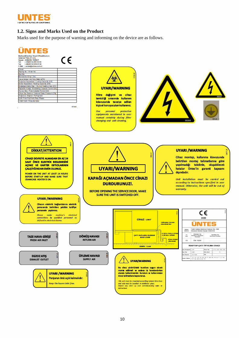
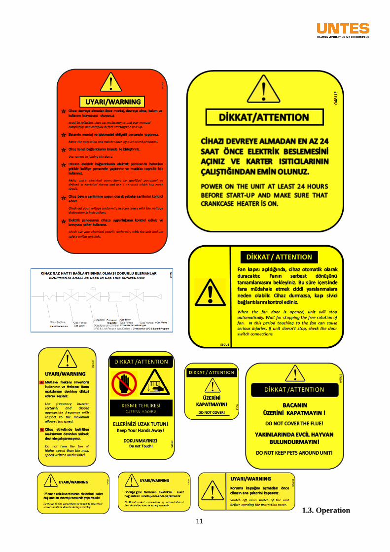
1.2. Signs and Marks Used on the Product
Marks used for the purpose of warning and informing on the device are as follows.
11
1.3. Operation
12
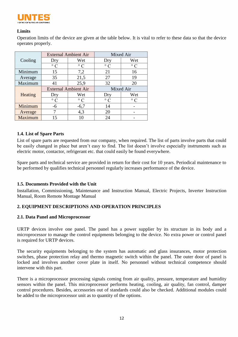
Limits
Operation limits of the device are given at the table below. It is vital to refer to these data so that the device
operates properly.
Cooling
External Ambient Air Mixed Air
Dry Wet Dry Wet
° C ° C ° C ° C
Minimum 15 7,2 21 16
Average 35 21,5 27 19
Maximum 41 25,9 32 20
Heating
External Ambient Air Mixed Air
Dry Wet Dry Wet
° C ° C ° C ° C
Minimum -6 -6,7 14 -
Average 7 4,3 20 -
Maximum 15 10 24 -
1.4. List of Spare Parts
List of spare parts are requested from our company, when required. The list of parts involve parts that could
be easily changed in place but aren’t easy to find. The list doesn’t involve especially instruments such as
electric motor, contactor, refrigerant etc. that could easily be found everywhere.
Spare parts and technical service are provided in return for their cost for 10 years. Periodical maintenance to
be performed by qualifies technical personnel regularly increases performance of the device.
1.5. Documents Provided with the Unit
Installation, Commissioning, Maintenance and Instruction Manual, Electric Projects, Inverter Instruction
Manual, Room Remote Montage Manual
2. EQUIPMENT DESCRIPTIONS AND OPERATION PRINCIPLES
2.1. Data Panel and Microprocessor
URTP devices involve one panel. The panel has a power supplier by its structure in its body and a
microprocessor to manage the control equipments belonging to the device. No extra power or control panel
is required for URTP devices.
The security equipments belonging to the system has automatic and glass insurances, motor protection
switches, phase protection relay and thermo magnetic switch within the panel. The outer door of panel is
locked and involves another cover plate in itself. No personnel without technical competence should
intervene with this part.
There is a microprocessor processing signals coming from air quality, pressure, temperature and humidity
sensors within the panel. This microprocessor performs heating, cooling, air quality, fan control, damper
control procedures. Besides, accessories out of standards could also be checked. Additional modules could
be added to the microprocessor unit as to quantity of the options.
13
Moreover, Modbus providing communication with building automation system is procured as standard.
Along with that, additional modules could be added by the use of other various building automation systems
(Bacnet MS-TP, Bacnet IP, and Lonworks).
2.2. Compressors
In URTP devices, hermetic scroll-type compressors were used.
There are lubricant pans, pan heaters and vibration absorber wedges as standard at compressors for all
models.
2.3. Lubricants
So that compressors could operate without any problems, lubricants defined at compressors’ marks should
be used. Compressors with other brands could be used according to models for these units.
They have lubricant indicators at which the amount of lubricant could be seen. Pay attention to that the
amount of lubricant should absolutely be at the middle level of the indicator.
While low amount causes that compressor works dry and gets heated up, high amount causes operational
problems by leaking into the system. Moreover, lubricant in the compressor may leak to the system when
the device leans sideward during transports, don’t let the device to lean sideward more than 15 degrees
throughout this procedure.
The device won’t need any addition or reduction of lubricant except for the case of being damage.
2.4. Condenser Coil
In URTP devices, temperature changing gas heat exchangers are used for copper tubes, aluminum fins.
These heat exchangers function only as condenser in models working as coolers, while they function as
condenser in summer, evaporator in winter in models with heat-pumps. In case requested, normal aluminum
fins or epoxy-coated aluminum finned coil could be used.
2.5. External Axial Fans
The only purpose of these fans outside of the unit is to enable air flow over condenser coils of the device and
gas temperature within the heat exchanger to change. These fans are exposed to severe air conditions
because they work at outer environments. Fans should be controlled regularly and they should be made sure
to be uncovered by no object. Objects to affect air flow negatively causes that the fan doesn’t function and
accordingly causes to disturb operation of the system.
2.6. Indoor Fans
These fans are found within the device and their purpose is to direct conditioned air needed by user to the
ambient. This is done only by using the inner air or by partially taking from the outer air. The system was
designed to produce pressure and air flow, and for this inner unit fan cycles should be adjusted according to
system requirements. For this, fans could be set into variable cycles by frequency inverter control. The
device could be adjusted to the system in an easy, fast and economic way (optional feature).
14
2.7. Thermostatic Expansion Valve
Thermostatic expansion valves are cooling system elements and have functions for the system to work
correctly. They are connected to the evaporator inlet on liquid line. They enable that right amount of
refrigerant is sent to the evaporator and lowers pressure, evaporation pressure and temperature of refrigerant.
Thermostatic expansion valves enable to have a stable superheating degree at the evaporator. Superheated
refrigerant steam not includes any liquid refrigerant, so liquid leakage risk to the compressor is eliminated.
If superheating degree at the evaporator is high then valve becomes active and opens again.
2.8. Sensors
There are up to 14 sensors according to options and accessories to be used in the system. These are found at
different sections as air and gas sides. They enable that read values are turned into 0-10 voltages by being
sent to the microprocessor and necessary data for the processor are generated.
There are high pressures prostates at both circuit 1 and circuit 2 at gas side of the system. There are also
sensors reading temperature and pressure of gas at absorption side. These are having a vital importance in
continuously monitoring the refrigerant and in that the system operates by a correct regime.
Room temperature sensor is found at the top of room control panel of the device and senses that room
conditions are suitable or not, enables that the device operates within proper capacity by giving right
commands.
Blow temperature sensor which is the sensor that found at air side of the device control temperature degree
of conditioned air.
External air temperature sensor helps control the capacity of device by continuously calculating atmosphere
temperature.
External air humidity sensor measures humidity degree of atmosphere continuously and provides a sensitive
control for free cooling/ heating operation mode.
Room air humidity sensor is found at return air section of the device and increases control sensitiveness for
free cooling/ heating operation mode.
With carbon dioxide sensor that is linked to return air duct, ambient air quality is put under control
constantly. For the desired degree, this sensor enables that the system set to the correct operation point and
to be informed for hazardous conditions.
Smoke detector measures variable air degrees and enables that the system alarms before or right at the
moment of fire.
Freeze thermostat is connected to the device in case there is additional, hot water coil in the device and gives
alarm to the system in case water temperature is decreased under 5 degrees.
High temperature thermostat is used in case an additional electric heater is used in the system and also in
order to deactivate heater in case heating surface temperature exceeds the defined temperature.
Differential pressure sensor is connected to the fan unit and pressure produced by the device and
accordingly flow rate are measured to control the flow.
Differential pressure switch is used for the filter in the system. When the defined values are exceeded,
beside giving alarm for the filter, provides variance for fan cycle continuously as to the constantly changing
filter pressure loss (optional feature).
2.9. Filters
In URTP devices, there are G4 filters as standard. This filter found at the inlet of inner unit of the device is
used with the purpose of protecting the inner equipment. Regular controls and cleanings are of great
importance so that the system operates effectively.
15
2.10. Refrigerant (R410A)
In this URTP device, R410A gas is used as cooling gas. These devices are designed according to
characteristics of this gas and shouldn’t be operated with another kind of gas in no way. Global heating
potential of R410A gas is GWP: 1975. This gas involves fluorinated greenhouse gasses within the
framework of Kyoto Protocol.
2.11. Free Cooling and Heating
In URTP models of ECO series, there are damper and control systems enabling free heating and cooling.
This system is activated in mid-seasons and when desired temperature values could be reached temperature
values of outer ambient air. The system does the necessary conditioning by only sending the outer ambient
air to the area and doesn’t activate heating or cooling systems within its body while doing it or activates
them under partial loads. This enables to reduce user costs and also to protect the environment by protecting
natural resources.
3. INSTALLATION
3.1. Transport and Conservation
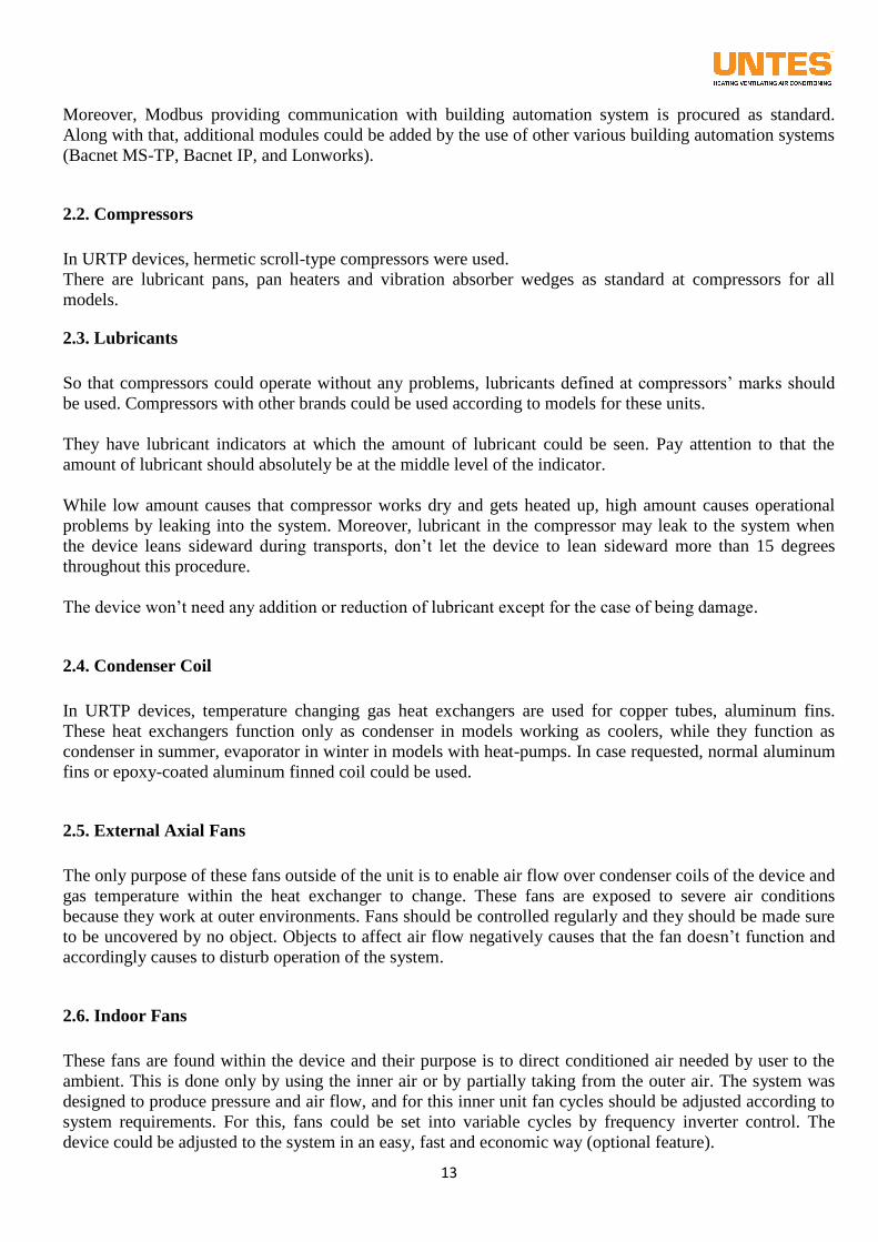
Roof connector should be carried separately from the
device and conserved.
Lift the roof connector from transport points.
The isolation material within roof connection elements at
conservation area should be protected from External air
conditions and possible rodents.
Don’t drag your device to place it on assembly spot while
carrying it. Make use of transport and lifting opening at its
bottom part. The device should be no means be transported
by holding it on pipe connections, door handles or duct
connection points.
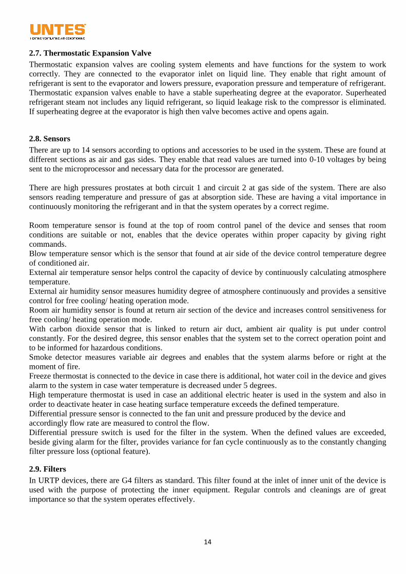
During transport, transport planks (timber bars) should be
put between ropes so that the ropes don’t damage
your device. Otherwise, ropes may damage metal
sheet details or condenser lamellas of your device.
For URTP 55/70/90/110/140, 4 transport points, for
180 and 230 models, 6 transport points should be
utilized. They are shown at figures.
The distance between timber bars and
transport point should be adjusted in balance. When
the device is seen to have no balance in test lift,
connection point should be re-determined to enable
the balance.
The distance between rope connections and
transport point should be adjusted to nearly 5 meters
(base angles between timber bar and lifting point
knot should be lower than 60C). Having this distance
lower may cause the rope to break off.
Don’t put high weights on the device to cause
permanent damage.
16
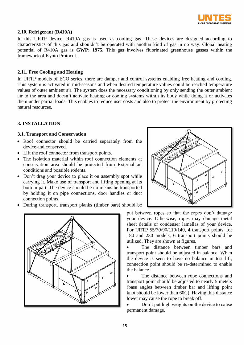
The device shouldn’t be inclined so to lean sideward more
than 15 degrees. This situation damages the device
compressor.
When your device is deactivated, make sure that the
dampers aren’t turned off.
The device should be kept where the relative humidity rate
doesn’t exceed 80% and ambient temperature should be
kept between -25 and 55o C.
Dust, gas, steam and chemical materials such as abrasives
shouldn’t be contacted with the device and device elements.
Roof-type air conditioners might generally get damaged
generally during transport, loading and lowering and especially in case a crane is used. Pallet truck or
forklift should be used while lifting and transporting small devices by considering device weights
determined at tables given on delivery note or size information section.
In transports with forklift, the device should be placed evenly on knives. In case it is placed under knives,
the bottom of device will get damaged.
After placing the device on roof connector, lifting legs (a quantity of four) could be taken off.
Lifting and lowering of big devices should be carried on with a crane by using suitable equipments.
Silk rope suitable to device size and weight should be used for device security and so that the device
doesn’t get damaged while lifting and lowering with the crane, additional profiles should be used to
prevent ropes from tightening on the device body and the device should be transported by considering its
weight and having taken the necessary security precautions to prevent turning over and slipping.
During lifting and transporting the device, no one should stand under the device and at movement area,
crush hazard should be paid attention to.
Before packaging, markings and warning tags showing notification values of the device should have been
placed properly. While lifting the device, the weight defined in KG at the tag should be paid attention to.
Devices should be wrapped with nylon and they should be packaged on lift feet against risks of getting
scratched, getting deflected and deformed while loading, transporting and shipping them. Palletized
boxes used against probable quakes and future damages on them while shipping devices are bigger than
the devices in size. Parts of the devices with low body endurance are supported with styropor
(polystyrene) of 1 cm and rapped with nylon.
If it needs storing for a while before install the device on its place, this storage should be a dry
environment not to get affected by External air conditions.
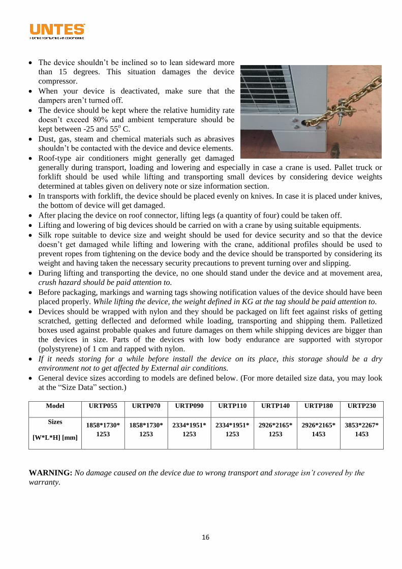
General device sizes according to models are defined below. (For more detailed size data, you may look
at the “Size Data” section.)
Model URTP055 URTP070 URTP090 URTP110 URTP140 URTP180 URTP230
Sizes
[W*L*H] [mm]
1858*1730*
1253
1858*1730*
1253
2334*1951*
1253
2334*1951*
1253
2926*2165*
1253
2926*2165*
1453
3853*2267*
1453
WARNING: No damage caused on the device due to wrong transport and storage isn’t covered by the
warranty.
17
3.2. Device placement and Considerations
The device shouldn’t be unpackaged until it reaches to the installation spot so that no damage emerges.
It is also crucial that where the device will be placed be chosen carefully. Ground should have the nature
to bear weight of the device and dynamic loads to arise during operation of the device.
Necessary lightening should have been provided at the environment where the device is placed so that
maintenance works could be carried out with ease.
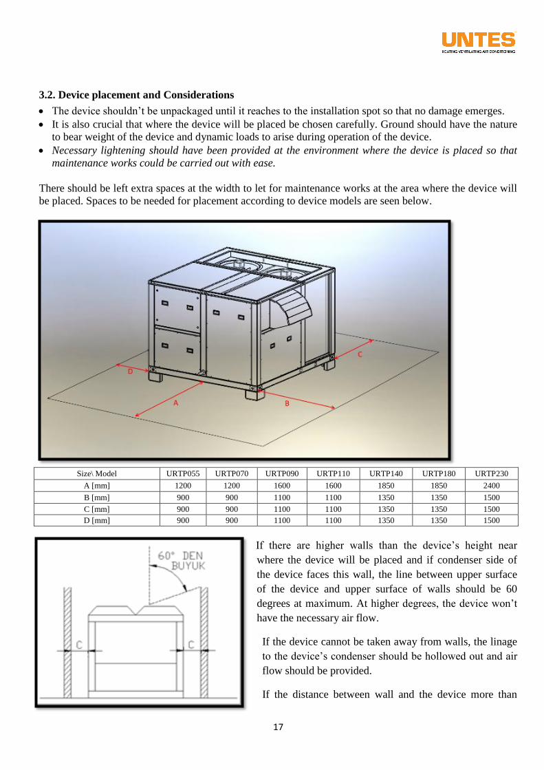
There should be left extra spaces at the width to let for maintenance works at the area where the device will
be placed. Spaces to be needed for placement according to device models are seen below.
Size\ Model URTP055 URTP070 URTP090 URTP110 URTP140 URTP180 URTP230
A [mm] 1200 1200 1600 1600 1850 1850 2400
B [mm] 900 900 1100 1100 1350 1350 1500
C [mm] 900 900 1100 1100 1350 1350 1500 D [mm] 900 900 1100 1100 1350 1350 1500
If there are higher walls than the device’s height near
where the device will be placed and if condenser side of
the device faces this wall, the line between upper surface
of the device and upper surface of walls should be 60
degrees at maximum. At higher degrees, the device won’t
have the necessary air flow.
If the device cannot be taken away from walls, the linage
to the device’s condenser should be hollowed out and air
flow should be provided.
If the distance between wall and the device more than
18
scale of 2 x C, the wall doesn’t obstruct air flow.
If two devices are to work adjacent to each other and condenser and condenser surfaces are to face each
other, the distance in-between should be higher than 2 x C +300 mm.
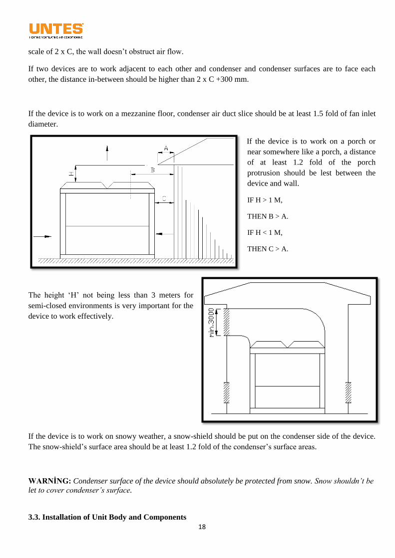
If the device is to work on a mezzanine floor, condenser air duct slice should be at least 1.5 fold of fan inlet
diameter.
If the device is to work on a porch or
near somewhere like a porch, a distance
of at least 1.2 fold of the porch
protrusion should be lest between the
device and wall.
IF H > 1 M,
THEN B > A.
IF H < 1 M,
THEN C > A.
The height ‘H’ not being less than 3 meters for
semi-closed environments is very important for the
device to work effectively.
If the device is to work on snowy weather, a snow-shield should be put on the condenser side of the device.
The snow-shield’s surface area should be at least 1.2 fold of the condenser’s surface areas.
WARNİNG: Condenser surface of the device should absolutely be protected from snow. Snow shouldn’t be
let to cover condenser’s surface.
3.3. Installation of Unit Body and Components
19
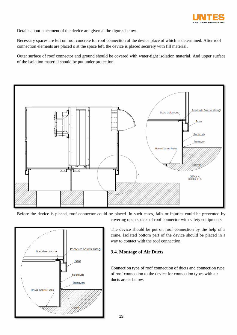
Details about placement of the device are given at the figures below.
Necessary spaces are left on roof concrete for roof connection of the device place of which is determined. After roof
connection elements are placed o at the space left, the device is placed securely with fill material.
Outer surface of roof connector and ground should be covered with water-tight isolation material. And upper surface
of the isolation material should be put under protection.
Before the device is placed, roof connector could be placed. In such cases, falls or injuries could be prevented by
covering open spaces of roof connector with safety equipments.
The device should be put on roof connection by the help of a
crane. Isolated bottom part of the device should be placed in a
way to contact with the roof connection.
3.4. Montage of Air Ducts
Connection type of roof connection of ducts and connection type
of roof connection to the device for connection types with air
ducts are as below.
20
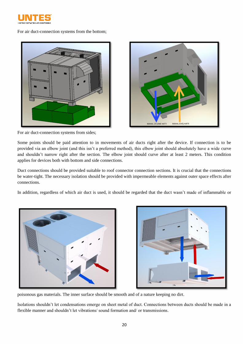
For air duct-connection systems from the bottom;
For air duct-connection systems from sides;
Some points should be paid attention to in movements of air ducts right after the device. If connection is to be
provided via an elbow joint (and this isn’t a preferred method), this elbow joint should absolutely have a wide curve
and shouldn’t narrow right after the section. The elbow joint should curve after at least 2 meters. This condition
applies for devices both with bottom and side connections.
Duct connections should be provided suitable to roof connector connection sections. It is crucial that the connections
be water-tight. The necessary isolation should be provided with impermeable elements against outer space effects after
connections.
In addition, regardless of which air duct is used, it should be regarded that the duct wasn’t made of inflammable or
poisonous gas materials. The inner surface should be smooth and of a nature keeping no dirt.
Isolations shouldn’t let condensations emerge on sheet metal of duct. Connections between ducts should be made in a
flexible manner and shouldn’t let vibrations/ sound formation and/ or transmissions.
21
3.5. Conservation Precautions for the Device from External Air Conditions
Suitable choice of place and placement are required so that the device doesn’t get exposed to External air conditions.
If the device is to operate at an area with high snow fall rate, it should be paid attention to that condenser side of the
device not stay under snow. For that, shelters might be built to distort air flow or precautions could be taken to prevent
snow from accumulating on the surface.
If the device is to operate at an atmosphere close to sea side or with factors to increase corrosion, the heat exchanger
surfaces should be asked to be provided with options preventing corrosion and decreasing water-trap. If this option has
been missed out, necessary precautions should be taken to protect the device from corrosion.
If the area where the device is to be used is an area with a high risk of earthquakes and to get exposed to high speed
winds, it is important that the device is placed away from sides and in the middle.
Besides, if the device has a natural gas firing unit, protecting gas connections against External air conditions and
taking precautions against natural disasters are of the responsibility of users.
Asking the absorption and blow ducts of the device to be provided with rain-proof components will prevent rain and
snow to penetrate the device in long term. Users who didn’t purchase this accessory should protect absorption and
blow ducts of the device. Penetration of snow or water through the device will lead to unwanted results.
The points of URTP device or roof connection element which contact with the ground should be isolated from liquids
according to the details mentioned in 3.3. Liquid penetrations between the device and the ground will lead to both
corrosion of the device and the liquid to reach inner spaces.
3.6. Assemble of Device Accessories
In case the device involves an additional heater (gas, liquid or electric heater), pipe and electricity connections of these
heaters are explained in details in Articles 7th, 8th and 9th. Please pay attention to explanations in the relevant articles
for these connections.
22
3.7. Drainage Connection
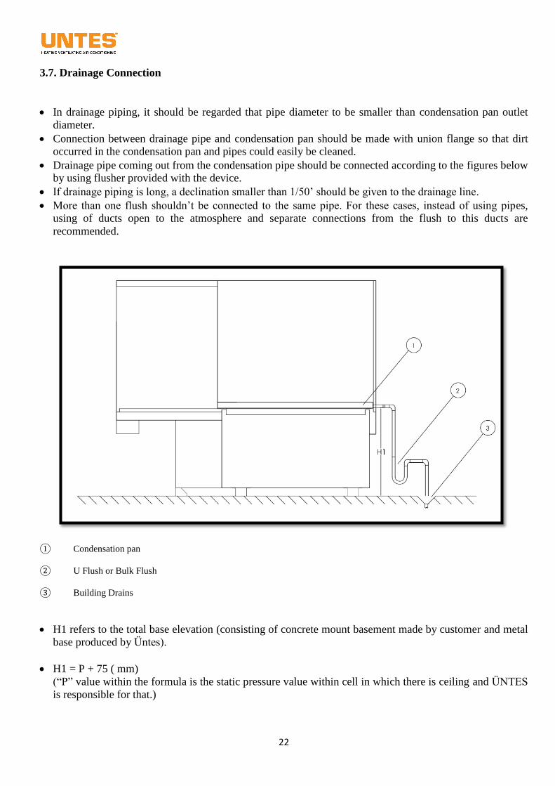
In drainage piping, it should be regarded that pipe diameter to be smaller than condensation pan outlet
diameter.
Connection between drainage pipe and condensation pan should be made with union flange so that dirt
occurred in the condensation pan and pipes could easily be cleaned.
Drainage pipe coming out from the condensation pipe should be connected according to the figures below
by using flusher provided with the device.
If drainage piping is long, a declination smaller than 1/50’ should be given to the drainage line.
More than one flush shouldn’t be connected to the same pipe. For these cases, instead of using pipes,
using of ducts open to the atmosphere and separate connections from the flush to this ducts are
recommended.
① Condensation pan
② U Flush or Bulk Flush
③ Building Drains
H1 refers to the total base elevation (consisting of concrete mount basement made by customer and metal
base produced by Üntes).
H1 = P + 75 ( mm)
(“P” value within the formula is the static pressure value within cell in which there is ceiling and ÜNTES
is responsible for that.)
23
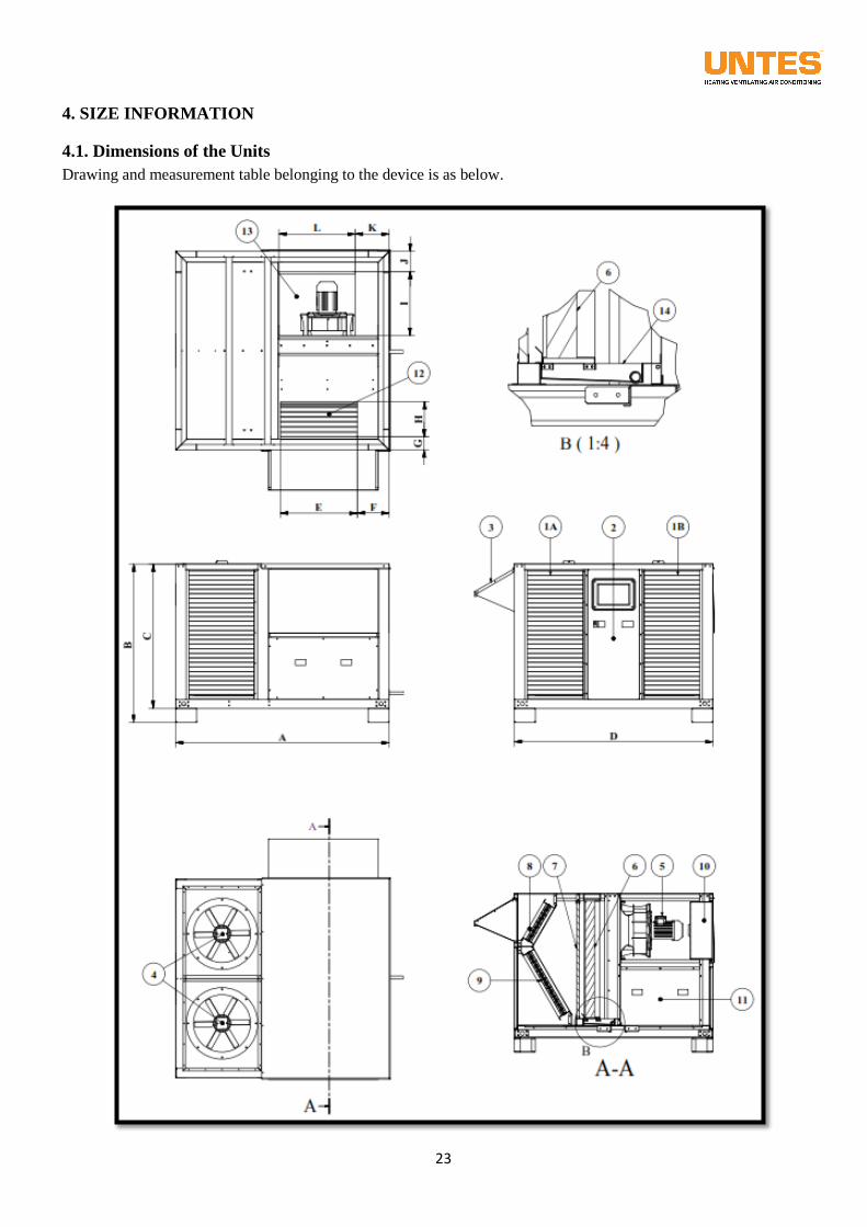
4. SIZE INFORMATION
4.1. Dimensions of the Units
Drawing and measurement table belonging to the device is as below.
24
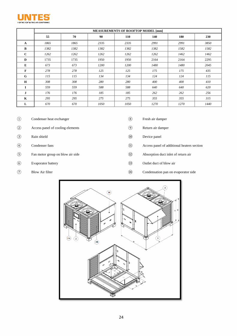
MEASUREMENTS OF ROOFTOP MODEL [mm]
55 70 90 110 140 180 230
A 1865 1865 2335 2335 2991 2991 3850
B 1382 1382 1382 1382 1382 1582 1582
C 1262 1262 1262 1262 1262 1462 1462
D 1735 1735 1950 1950 2164 2164 2295
E 673 673 1200 1200 1480 1480 2045
F 278 278 125 125 175 175 435
G 115 115 134 134 124 124 115
H 308 308 280 280 400 400 410
I 559 559 588 588 640 640 620
J 176 176 185 185 262 262 256
K 295 295 275 275 355 355 315
L 670 670 1050 1050 1270 1270 1440
① Condenser heat exchanger
② Access panel of cooling elements
③ Rain shield
④ Condenser fans
⑤ Fan motor group on blow air side
⑥ Evaporator battery
⑦ Blow Air filter
⑧ Fresh air damper
⑨ Return air damper
⑩ Device panel
⑪ Access panel of additional heaters section
⑫ Absorption duct inlet of return air
⑬ Outlet duct of blow air
⑭ Condensation pan on evaporator side
25
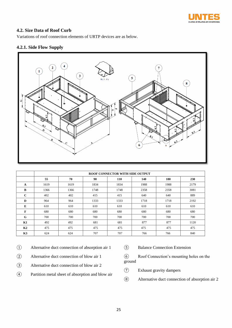
4.2. Size Data of Roof Curb
Variations of roof connection elements of URTP devices are as below.
4.2.1. Side Flow Supply
ROOF CONNECTOR WITH SIDE OUTPUT
55 70 90 110 140 180 230
A 1619 1619 1834 1834 1988 1988 2179
B 1366 1366 1748 1748 2358 2358 3081
C 402 402 415 415 640 640 889
D 964 964 1333 1333 1718 1718 2192
E 610 610 610 610 610 610 610
F 680 680 680 680 680 680 680
G 700 700 700 700 700 700 700
K1 492 492 681 681 877 877 1120
K2 475 475 475 475 475 475 475
K3 624 624 707 707 766 766 840
① Alternative duct connection of absorption air 1
② Alternative duct connection of blow air 1
③ Alternative duct connection of blow air 2
④ Partition metal sheet of absorption and blow air
⑤ Balance Connection Extension
⑥ Roof Connection’s mounting holes on the
ground
⑦ Exhaust gravity dampers
⑧ Alternative duct connection of absorption air 2
26
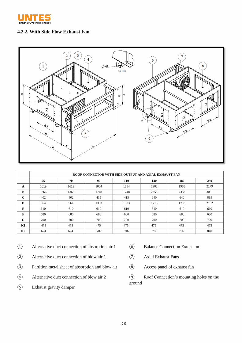
4.2.2. With Side Flow Exhaust Fan
ROOF CONNECTOR WITH SIDE OUTPUT AND AXIAL EXHAUST FAN
55 70 90 110 140 180 230
A 1619 1619 1834 1834 1988 1988 2179
B 1366 1366 1748 1748 2358 2358 3081
C 402 402 415 415 640 640 889
D 964 964 1333 1333 1718 1718 2192
E 610 610 610 610 610 610 610
F 680 680 680 680 680 680 680
G 700 700 700 700 700 700 700
K1 475 475 475 475 475 475 475
K2 624 624 707 707 766 766 840
① Alternative duct connection of absorption air 1
② Alternative duct connection of blow air 1
③ Partition metal sheet of absorption and blow air
④ Alternative duct connection of blow air 2
⑤ Exhaust gravity damper
⑥ Balance Connection Extension
⑦ Axial Exhaust Fans
⑧ Access panel of exhaust fan
⑨ Roof Connection’s mounting holes on the
ground
27
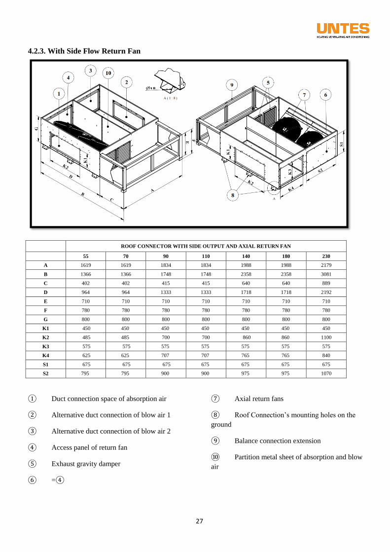
4.2.3. With Side Flow Return Fan
ROOF CONNECTOR WITH SIDE OUTPUT AND AXIAL RETURN FAN
55 70 90 110 140 180 230
A 1619 1619 1834 1834 1988 1988 2179
B 1366 1366 1748 1748 2358 2358 3081
C 402 402 415 415 640 640 889
D 964 964 1333 1333 1718 1718 2192
E 710 710 710 710 710 710 710
F 780 780 780 780 780 780 780
G 800 800 800 800 800 800 800
K1 450 450 450 450 450 450 450
K2 485 485 700 700 860 860 1100
K3 575 575 575 575 575 575 575
K4 625 625 707 707 765 765 840
S1 675 675 675 675 675 675 675
S2 795 795 900 900 975 975 1070
① Duct connection space of absorption air
② Alternative duct connection of blow air 1
③ Alternative duct connection of blow air 2
④ Access panel of return fan
⑤ Exhaust gravity damper
⑥ =④
⑦ Axial return fans
⑧ Roof Connection’s mounting holes on the
ground
⑨ Balance connection extension
⑩ Partition metal sheet of absorption and blow
air
28
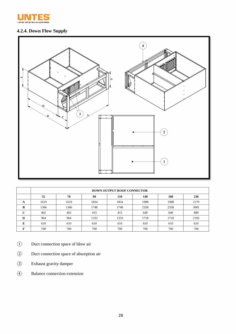
4.2.4. Down Flow Supply
DOWN OUTPUT ROOF CONNECTOR
55 70 90 110 140 180 230
A 1619 1619 1834 1834 1988 1988 2179
B 1366 1366 1748 1748 2358 2358 3081
C 402 402 415 415 640 640 889
D 964 964 1333 1333 1718 1718 2192
E 610 610 610 610 610 610 610
F 700 700 700 700 700 700 700
① Duct connection space of blow air
② Duct connection space of absorption air
③ Exhaust gravity damper
④ Balance connection extension
29
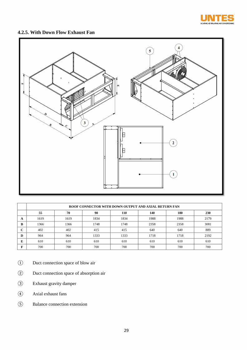
4.2.5. With Down Flow Exhaust Fan
ROOF CONNECTOR WITH DOWN OUTPUT AND AXIAL RETURN FAN
55 70 90 110 140 180 230
A 1619 1619 1834 1834 1988 1988 2179
B 1366 1366 1748 1748 2358 2358 3081
C 402 402 415 415 640 640 889
D 964 964 1333 1333 1718 1718 2192
E 610 610 610 610 610 610 610
F 700 700 700 700 700 700 700
① Duct connection space of blow air
② Duct connection space of absorption air
③ Exhaust gravity damper
④ Axial exhaust fans
⑤ Balance connection extension
30
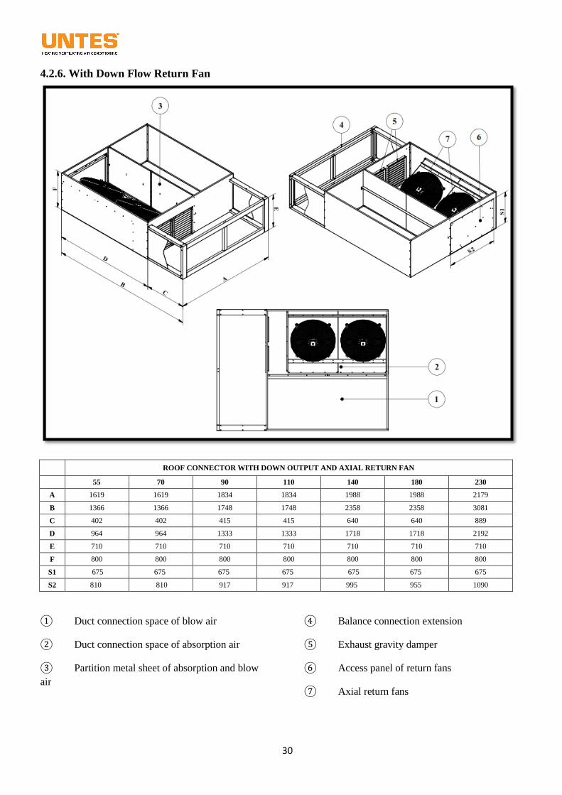
4.2.6. With Down Flow Return Fan
ROOF CONNECTOR WITH DOWN OUTPUT AND AXIAL RETURN FAN
55 70 90 110 140 180 230
A 1619 1619 1834 1834 1988 1988 2179
B 1366 1366 1748 1748 2358 2358 3081
C 402 402 415 415 640 640 889
D 964 964 1333 1333 1718 1718 2192
E 710 710 710 710 710 710 710
F 800 800 800 800 800 800 800
S1 675 675 675 675 675 675 675
S2 810 810 917 917 995 955 1090
① Duct connection space of blow air
② Duct connection space of absorption air
③ Partition metal sheet of absorption and blow
air
④ Balance connection extension
⑤ Exhaust gravity damper
⑥ Access panel of return fans
⑦ Axial return fans
31
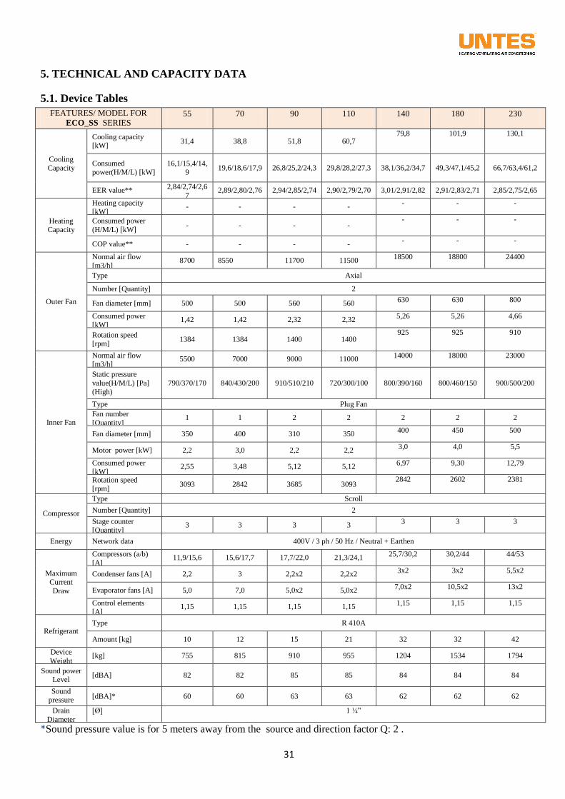
5. TECHNICAL AND CAPACITY DATA
5.1. Device Tables
FEATURES/ MODEL FOR
ECO_SS SERIES 55 70 90 110 140 180 230
Cooling
Capacity
Cooling capacity [kW]
31,4 38,8 51,8 60,7 79,8 101,9 130,1
Consumed
power(H/M/L) [kW]
16,1/15,4/14,
9 19,6/18,6/17,9 26,8/25,2/24,3 29,8/28,2/27,3 38,1/36,2/34,7 49,3/47,1/45,2 66,7/63,4/61,2
EER value** 2,84/2,74/2,6
7 2,89/2,80/2,76 2,94/2,85/2,74 2,90/2,79/2,70 3,01/2,91/2,82 2,91/2,83/2,71 2,85/2,75/2,65
Heating Capacity
Heating capacity
[kW] - - - -
- - -
Consumed power
(H/M/L) [kW] - - - -
- - -
COP value** - - - - - - -
Outer Fan
Normal air flow
[m3/h] 8700 8550 11700 11500
18500 18800 24400
Type Axial
Number [Quantity] 2
Fan diameter [mm] 500 500 560 560 630 630 800
Consumed power
[kW] 1,42 1,42 2,32 2,32
5,26 5,26 4,66
Rotation speed [rpm]
1384 1384 1400 1400 925 925 910
Inner Fan
Normal air flow [m3/h]
5500 7000 9000 11000 14000 18000 23000
Static pressure
value(H/M/L) [Pa]
(High)
790/370/170 840/430/200 910/510/210 720/300/100 800/390/160 800/460/150 900/500/200
Type Plug Fan
Fan number
[Quantity] 1 1 2 2 2 2 2
Fan diameter [mm] 350 400 310 350 400 450 500
Motor power [kW] 2,2 3,0 2,2 2,2 3,0 4,0 5,5
Consumed power
[kW] 2,55 3,48 5,12 5,12
6,97 9,30 12,79
Rotation speed [rpm]
3093 2842 3685 3093 2842 2602 2381
Compressor
Type Scroll
Number [Quantity] 2
Stage counter [Quantity]
3 3 3 3 3 3 3
Energy Network data 400V / 3 ph / 50 Hz / Neutral + Earthen
Maximum Current
Draw
Compressors (a/b)
[A] 11,9/15,6 15,6/17,7 17,7/22,0 21,3/24,1
25,7/30,2 30,2/44 44/53
Condenser fans [A] 2,2 3 2,2x2 2,2x2 3x2 3x2 5,5x2
Evaporator fans [A] 5,0 7,0 5,0x2 5,0x2 7,0x2 10,5x2 13x2
Control elements
[A] 1,15 1,15 1,15 1,15
1,15 1,15 1,15
Refrigerant Type R 410A
Amount [kg] 10 12 15 21 32 32 42
Device
Weight [kg] 755 815 910 955 1204 1534 1794
Sound power Level
[dBA] 82 82 85 85 84 84 84
Sound pressure
Level
[dBA]* 60 60 63 63 62 62 62
Drain
Diameter
[Ø] 1 ¼”
*Sound pressure value is for 5 meters away from the source and direction factor Q: 2 .
32
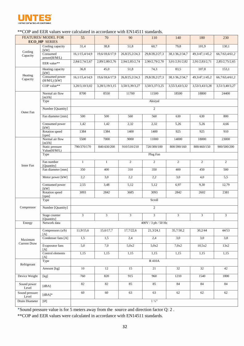
**COP and EER values were calculated in accordance with EN14511 standards.
FEATURES/ MODEL FOR
ECO_HP SERIES 55 70 90 110 140 180 230
Cooling Capacity
Cooling capacity
[kW]
31,4 38,8 51,8 60,7 79,8 101,9 130,1
Consumed
power(H/M/L) [kW]
16,1/15,4/14,9 19,6/18,6/17,9 26,8/25,2/24,3 29,8/28,2/27,3 38,1/36,2/34,7 49,3/47,1/45,2 66,7/63,4/61,2
EER value** 2,84/2,74/2,67 2,89/2,80/2,76 2,94/2,85/2,74 2,90/2,79/2,70 3,01/2,91/2,82 2,91/2,83/2,71 2,85/2,75/2,65
Heating
Capacity
Heating capacity
[kW]
36,8 45,0 51,8 74,3 83,5 107,8 153,1
Consumed power (H/M/L) [kW]
16,1/15,4/14,9 19,6/18,6/17,9 26,8/25,2/24,3 29,8/28,2/27,3 38,1/36,2/34,7 49,3/47,1/45,2 66,7/63,4/61,2
COP value** 3,20/3,10/3,02 3,28/3,19/3,15 3,50/3,39/3,27 3,50/3,37/3,25 3,55/3,43/3,32 3,53/3,43/3,28 3,51/3,40/3,27
Outer Fan
Normal air flow
[m3/h]
8700 8550 11700 11500 18500 18800 24400
Type Aksiyal
Number [Quantity] 2
Fan diameter [mm] 500 500 560 560 630 630 800
Consumed power [kW]
1,42 1,42 2,32 2,32 5,26 5,26 4,66
Rotation speed [rpm]
1384 1384 1400 1400 925 925 910
Inner Fan
Normal air flow
[m3/h]
5500 7000 9000 11000 14000 18000 23000
Static pressure
Value(H/M/L) [mmSS]
790/370/170 840/430/200 910/510/210 720/300/100 800/390/160 800/460/150 900/500/200
Type Plug Fan
Fan number
[Quantity]
1 1 2 2 2 2 2
Fan diameter [mm] 350 400 310 350 400 450 500
Motor power [kW] 2,2 3,0 2,2 2,2 3,0 4,0 5,5
Consumed power
[kW]
2,55 3,48 5,12 5,12 6,97 9,30 12,79
Rotation speed
[rpm]
3093 2842 3685 3093 2842 2602 2381
Compressor
Type Scroll
Number [Quantity] 2
Stage counter [Quantity]
3 3 3 3 3 3 3
Energy Network data 400V / 3 ph / 50 Hz
Maximum Current Draw
Compressors (a/b)
[A]
11,9/15,6 15,6/17,7 17,7/22,6 21,3/24,1 35,7/30,2 30,2/44 44/53
Condenser fans [A] 1,5 1,5 2,4 2,4 3,0 3,0 3,8
Evaporator fans
[A]
5,0 7,0 5,0x2 5,0x2 7,0x2 10,5x2 13x2
Control elements
[A]
1,15 1,15 1,15 1,15 1,15 1,15 1,15
Refrigerant Type R 410A
Amount [kg] 10 12 15 21 32 32 42
Device Weight [kg] 760 820 915 960 1210 1540 1800
Sound power
Level [dBA]
82 82 85 85 84 84 84
Sound pressure Level
[dBA]* 60 60 63 63 62 62 62
Drain Diameter [Ø] 1 ¼”
*Sound pressure value is for 5 meters away from the source and direction factor Q: 2 .
**COP and EER values were calculated in accordance with EN14511 standards.
33
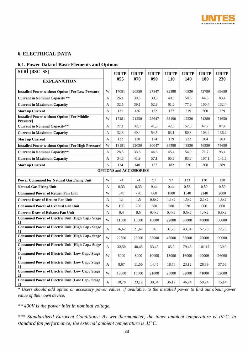
6. ELECTRICAL DATA
6.1. Power Data of Basic Elements and Options
SERİ [BSC_SS]
URTP
055
URTP
070
URTP
090
URTP
110
URTP
140
URTP
180
URTP
230 EXPLANATION
Installed Power without Option [For Low Pressure] W 17081 20550 27847 32390 40830 52780 69650
Current in Nominal Capacity ** A 26,1 30,5 39,9 40,5 50,3 64,5 83,4
Current in Maximum Capacity A 32,5 39,1 52,9 61,6 77,6 100,4 132,4
Start up Current A 121 136 172 177 219 260 279
Installed Power without Option [For Middle
Pressure] W 17481 21250 28647 33190 42230 54380 71650
Current in Nominal Capacity** A 27,1 32,0 41,5 42,6 52,0 67,7 87,4
Current in Maximum Capacity A 32,3 40,4 54,5 63,1 80,3 103,4 136,2
Start up Current A 122 138 174 179 222 264 283
Installed Power without Option [For High Pressure] W 18181 22050 30047 34590 43830 56380 74650
Current in Nominal Capacity** A 28,5 33,6 44,3 45,4 54,9 71,7 93,4
Current in Maximum Capacity A 34,5 41,9 57,1 65,8 83,3 107,1 141,5
Start up Current A 124 140 177 182 226 268 289
OPTIONS and ACCESSORIES
Power Consumed for Natural Gas Firing Unit W 74 74 97 97 123 130 130
Natural Gas Firing Unit A 0,33 0,33 0,44 0,44 0,56 0,59 0,59
Consumed Power of Return Fan Unit W 540 770 860 1080 1540 2140 2000
Current Draw of Return Fan Unit A 1,1 1,5 0,8x2 1,1x2 1,5x2 2,1x2 1,8x2
Consumed Power of Exhaust Fan Unit W 190 260 380 380 520 660 860
Current Draw of Exhaust Fan Unit A 0,4 0,5 0,4x2 0,4x2 0,5x2 1,4x2 0,8x2
Consumed Power of Electric Unit [High Cap./ Stage
1] W 11500 15000 18000 22000 30000 40000 50000
Consumed Power of Electric Unit [High Cap./ Stage
1] A 16,62 21,67 26 31,78 43,34 57,78 72,23
Consumed Power of Electric Unit [High Cap./ Stage
2] W 22500 28000 37000 45000 55000 70000 90000
Consumed Power of Electric Unit [High Cap./ Stage
2] A 32,50 40,45 53,45 65,0 79,45 101,12 130,0
Consumed Power of Electric Unit [Low Cap./ Stage
1] W 6000 8000 10000 13000 16000 20000 26000
Consumed Power of Electric Unit [Low Cap./ Stage
1] A 8,67 11,56 14,45 18,78 23,12 28,89 37,56
Consumed Power of Electric Unit [Low Cap./ Stage
2] W 13000 16000 21000 25000 32000 41000 52000
Consumed Power of Electric Unit [Low Cap./ Stage
2] A 18,78 23,12 30,34 36,12 46,24 59,24 75,14
* Users should add option or accessory power values, if available, to the installed power to find out about power
value of their own device.
** 400V is the power inlet in nominal voltage.
*** Standardized Eurovent Conditions: By wet thermometer, the inner ambient temperature is 19°C, in
standard fan performance; the external ambient temperature is 35°C.
34
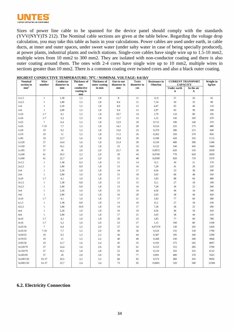
Sizes of power line cable to be spanned for the device panel should comply with the standards
(YVV(NYY)TS 212). The Nominal cable sections are given at the table below. Regarding the voltage drop
calculation, you may take this table as basis in your calculations. Power cables are used under earth, in cable
ducts, at inner and outer spaces, under sweet water (under salty water in case of being specially produced),
at power plants, industrial plants and switch stations. Single-core cables have single wire up to 1.5-10 mm2,
multiple wires from 10 mm2 to 300 mm2. They are isolated with non-conductor coating and there is also
outer coating around them. The ones with 2-4 cores have single wire up to 10 mm2, multiple wires in
sections greater than 10 mm2. There is a common coating over twisted cores and also a black outer coating.
HIGHEST CONDUCTIVE TEMPERATURE: 70oC / NOMINAL VOLTAGE: 0.6/1kV Nominal
section in
mm2
Wire
number
Conductor
diameter in
mm
Thickness of
non-
conductive
coating in
mm
Thickness of
outer coating
in mm
Out-to-out
diameter in
mm
Twist
diameter in
cm
Resistance in
Ohm/km
CURRENT TRANSPORT
CAPACITY
Weight in
kg/km
Under earth
A
In the air
A
1x1,5
1x2,5
1x4
1x6
1x10
1x16
1x25
1x35
1x50
1x70
1x95
1x120
1x150
1x185
1x240
1x300
2x1,5
2x2,5
2x4
2x6
2x10
3x1,5
3x2,5
3x4
3x6
3x10
4,1,5
4x2,5
4x4
4x6
4x10
4x16
3x25/16
3x35/16
3x50/25
3x70/35
3x95/50
3x120/70
3x150/70
3x185/95
3x240/120
3x300/150
1
1
1
1
1-7
1-7
7
7-19
19
19
19
37
37
37
61
61
1
1
1
1
1-7
1
1
1
1
1-7
1
1
1
1
1-7
1-7
7
7-19
19
19
19
37
37
37
61-37
61-37
1,38
1,80
2,26
2,80
4,1
5,2
6,4
7,7
9,2
11
12,7
14,4
16,1
18
20,5
22,7
1,38
1,80
2,26
2,80
4,1
1,38
1,80
2,26
2,80
4,1
1,38
1,80
2,26
2,80
4,1
5,2
6,4
7,7
9,2
11
12,7
14,4
16,1
18
20,5
22,7
1,5
1,5
1,5
1,5
1,5
1,5
1,5
1,5
1,5
1,5
1,6
1,6
1,8
2,0
2,2
2,4
0,3
0,9
1,0
1,0
1,0
0,8
0,9
1,0
1,0
1,0
0,8
10,9
1,0
1,0
1,0
1,0
1,5
1,5
1,5
1,5
1,6
1,6
1,8
2,0
2,2
2,4
1,8
1,8
1,8
1,8
1,8
1,8
1,8
1,8
1,8
1,8
1,8
1,8
1,8
2,0
2,0
2,0
1,8
1,8
1,8
1,8
1,8
1,8
1,8
1,8
1,8
1,8
1,8
1,8
1,8
1,8
1,8
2,0
2,0
2,0
2,2
2,2
2,4
2,6
2,8
3,0
3,2
3,4
8
8,4
8,9
9,4
10,7
11,7
12,9
14,1
15,6
17,2
19,4
21,4
23
25,7
29
32
11
13
14
15
17
12
13
15
16
17
13
14
16
17
20
23
27
30
36
40
45
50
52
59
66
73
11
11
12
13
14
15
18
20
23
26
29
30
33
36
44
48
14
16
17
18
21
15
16
19
20
21
16
17
19
21
23
27
33
36
44
49
55
61
69
77
82
92
11,9
7,14
4,47
2,97
1,79
1,12
0,712
0,514
0,379
0,262
0,189
0,150
0,122
0,0972
0,0740
0,0590
12,1
7,28
4,56
3,03
1,83
12,1
7,28
4,56
2,03
1,83
12,1
7,28
4,56
3,03
1,83
1,15
0,07270
0,524
0,387
0,268
0,193
0,153
0,124
0,991
0,574
0,0601
37
50
65
83
110
145
190
235
280
350
420
480
540
620
770
820
30
41
53
66
88
27
36
46
58
77
27
36
46
58
77
100
130
155
185
230
275
315
355
400
460
520
26
35
46
58
80
105
140
175
215
270
335
390
445
510
620
710
21
29
38
48
66
18
25
34
44
60
18
25
34
44
60
80
105
130
160
200
245
285
325
370
435
500
65
80
110
140
195
270
370
480
640
850
1115
1340
1660
2030
2650
3370
170
220
290
350
480
190
260
340
420
580
230
300
410
510
780
1100
1420
1790
2290
3066
4097
5700
6132
7625
9950
12500
6.2. Electricity Connection
35
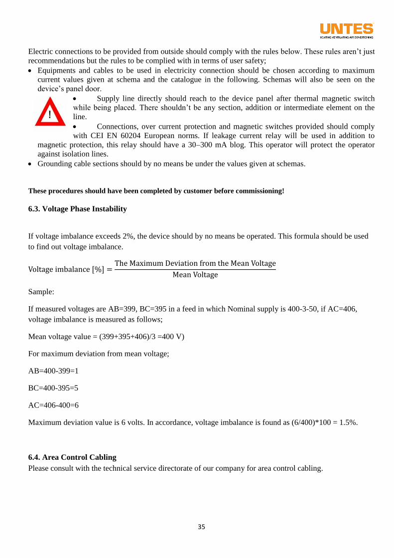
Electric connections to be provided from outside should comply with the rules below. These rules aren’t just
recommendations but the rules to be complied with in terms of user safety;
Equipments and cables to be used in electricity connection should be chosen according to maximum
current values given at schema and the catalogue in the following. Schemas will also be seen on the
device’s panel door.
Supply line directly should reach to the device panel after thermal magnetic switch
while being placed. There shouldn’t be any section, addition or intermediate element on the
line.
Connections, over current protection and magnetic switches provided should comply
with CEI EN 60204 European norms. If leakage current relay will be used in addition to
magnetic protection, this relay should have a 30–300 mA blog. This operator will protect the operator
against isolation lines.
Grounding cable sections should by no means be under the values given at schemas.
These procedures should have been completed by customer before commissioning!
6.3. Voltage Phase Instability
If voltage imbalance exceeds 2%, the device should by no means be operated. This formula should be used
to find out voltage imbalance.
Sample:
If measured voltages are AB=399, BC=395 in a feed in which Nominal supply is 400-3-50, if AC=406,
voltage imbalance is measured as follows;
Mean voltage value = (399+395+406)/3 =400 V)
For maximum deviation from mean voltage;
AB=400-399=1
BC=400-395=5
AC=406-400=6
Maximum deviation value is 6 volts. In accordance, voltage imbalance is found as (6/400)*100 = 1.5%.
6.4. Area Control Cabling
Please consult with the technical service directorate of our company for area control cabling.
36
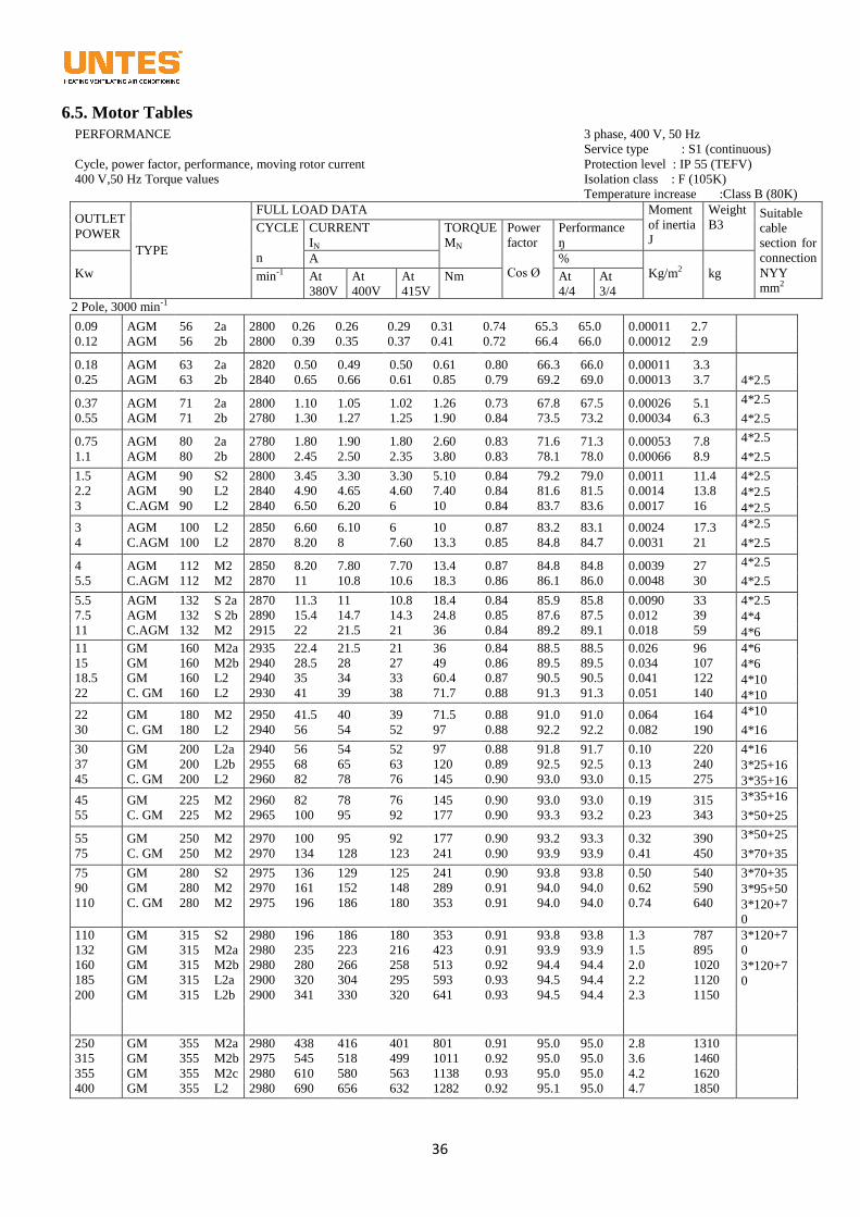
6.5. Motor Tables
PERFORMANCE
Cycle, power factor, performance, moving rotor current
400 V,50 Hz Torque values
3 phase, 400 V, 50 Hz
Service type : S1 (continuous)
Protection level : IP 55 (TEFV)
Isolation class : F (105K)
Temperature increase :Class B (80K)
OUTLET
POWER
TYPE
FULL LOAD DATA Moment
of inertia
J
Weight
B3 Suitable
cable
section for
connection
NYY
mm2
CYCLE
n
CURRENT
IN
TORQUE
MN
Power
factor
Cos Ø
Performance
ŋ
Kw
A %
Kg/m2
kg min-1 At
380V
At
400V
At
415V
Nm At
4/4
At
3/4
2 Pole, 3000 min-1
0.09
0.12
AGM
AGM
56
56
2a
2b
2800
2800
0.26
0.39
0.26
0.35
0.29
0.37
0.31
0.41
0.74
0.72
65.3
66.4
65.0
66.0
0.00011
0.00012
2.7
2.9
0.18
0.25
AGM
AGM
63
63
2a
2b
2820
2840
0.50
0.65
0.49
0.66
0.50
0.61
0.61
0.85
0.80
0.79
66.3
69.2
66.0
69.0
0.00011
0.00013
3.3
3.7
4*2.5
0.37
0.55
AGM
AGM
71
71
2a
2b
2800
2780
1.10
1.30
1.05
1.27
1.02
1.25
1.26
1.90
0.73
0.84
67.8
73.5
67.5
73.2
0.00026
0.00034
5.1
6.3
4*2.5
4*2.5
0.75
1.1
AGM
AGM
80
80
2a
2b
2780
2800
1.80
2.45
1.90
2.50
1.80
2.35
2.60
3.80
0.83
0.83
71.6
78.1
71.3
78.0
0.00053
0.00066
7.8
8.9
4*2.5
4*2.5
1.5
2.2
3
AGM
AGM
C.AGM
90
90
90
S2
L2
L2
2800
2840
2840
3.45
4.90
6.50
3.30
4.65
6.20
3.30
4.60
6
5.10
7.40
10
0.84
0.84
0.84
79.2
81.6
83.7
79.0
81.5
83.6
0.0011
0.0014
0.0017
11.4
13.8
16
4*2.5
4*2.5
4*2.5
3
4
AGM
C.AGM
100
100
L2
L2
2850
2870
6.60
8.20
6.10
8
6
7.60
10
13.3
0.87
0.85
83.2
84.8
83.1
84.7
0.0024
0.0031
17.3
21
4*2.5
4*2.5
4
5.5
AGM
C.AGM
112
112
M2
M2
2850
2870
8.20
11
7.80
10.8
7.70
10.6
13.4
18.3
0.87
0.86
84.8
86.1
84.8
86.0
0.0039
0.0048
27
30
4*2.5
4*2.5
5.5
7.5
11
AGM
AGM
C.AGM
132
132
132
S 2a
S 2b
M2
2870
2890
2915
11.3
15.4
22
11
14.7
21.5
10.8
14.3
21
18.4
24.8
36
0.84
0.85
0.84
85.9
87.6
89.2
85.8
87.5
89.1
0.0090
0.012
0.018
33
39
59
4*2.5
4*4
4*6
11
15
18.5
22
GM
GM
GM
C. GM
160
160
160
160
M2a
M2b
L2
L2
2935
2940
2940
2930
22.4
28.5
35
41
21.5
28
34
39
21
27
33
38
36
49
60.4
71.7
0.84
0.86
0.87
0.88
88.5
89.5
90.5
91.3
88.5
89.5
90.5
91.3
0.026
0.034
0.041
0.051
96
107
122
140
4*6
4*6
4*10
4*10
22
30
GM
C. GM
180
180
M2
L2
2950
2940
41.5
56
40
54
39
52
71.5
97
0.88
0.88
91.0
92.2
91.0
92.2
0.064
0.082
164
190
4*10
4*16
30
37
45
GM
GM
C. GM
200
200
200
L2a
L2b
L2
2940
2955
2960
56
68
82
54
65
78
52
63
76
97
120
145
0.88
0.89
0.90
91.8
92.5
93.0
91.7
92.5
93.0
0.10
0.13
0.15
220
240
275
4*16
3*25+16
3*35+16
45
55
GM
C. GM
225
225
M2
M2
2960
2965
82
100
78
95
76
92
145
177
0.90
0.90
93.0
93.3
93.0
93.2
0.19
0.23
315
343
3*35+16
3*50+25
55
75
GM
C. GM
250
250
M2
M2
2970
2970
100
134
95
128
92
123
177
241
0.90
0.90
93.2
93.9
93.3
93.9
0.32
0.41
390
450
3*50+25
3*70+35
75
90
110
GM
GM
C. GM
280
280
280
S2
M2
M2
2975
2970
2975
136
161
196
129
152
186
125
148
180
241
289
353
0.90
0.91
0.91
93.8
94.0
94.0
93.8
94.0
94.0
0.50
0.62
0.74
540
590
640
3*70+35
3*95+50
3*120+7
0
110
132
160
185
200
GM
GM
GM
GM
GM
315
315
315
315
315
S2
M2a
M2b
L2a
L2b
2980
2980
2980
2900
2900
196
235
280
320
341
186
223
266
304
330
180
216
258
295
320
353
423
513
593
641
0.91
0.91
0.92
0.93
0.93
93.8
93.9
94.4
94.5
94.5
93.8
93.9
94.4
94.4
94.4
1.3
1.5
2.0
2.2
2.3
787
895
1020
1120
1150
3*120+7
0
3*120+7
0
250
315
355
400
GM
GM
GM
GM
355
355
355
355
M2a
M2b
M2c
L2
2980
2975
2980
2980
438
545
610
690
416
518
580
656
401
499
563
632
801
1011
1138
1282
0.91
0.92
0.93
0.92
95.0
95.0
95.0
95.1
95.0
95.0
95.0
95.0
2.8
3.6
4.2
4.7
1310
1460
1620
1850
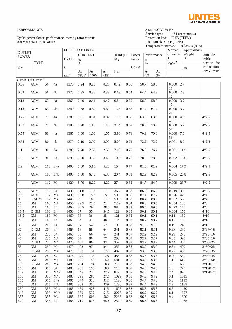
37
PERFORMANCE
Cycle, power factor, performance, moving rotor current
400 V,50 Hz Torque values
3 faz, 400 V, 50 Hz
Service type : S1 (continuous)
Protection level : IP 55 (TEFV)
Isolation class : F (105K)
Temperature increase :Class B (80K)
OUTLET
POWER
TYPE
FULL LOAD DATA Moment
of inertia
J
Approximate
Weight
B3 Suitable
cable
section for
connection
NYY mm2
CYCLE
n
CURRENT
IN
TORQUE
MN
Power
factor
Cos Ø
Performance
ŋ
Kw
A % Kg/m2
kg
min-1 At
380V
At
400V
At
415V
Nm At
4/4
At
3/4
4 Pole 1500 min-1
0.06 AGM 56 4a 1370 0.24 0.25 0.27 0.42 0.56 58.7 58.6 0.000
11
2.7
0.09 AGM 56 4b 1375 0.35 0.36 0.38 0.63 0.54 64.4 64.2 0.000
12
2.8
0.12 AGM 63 4a 1365 0.40 0.41 0.42 0.84 0.65 58.8 58.8 0.000
17
3.2
0.18 AGM 63 4b 1340 0.58 0.60 0.60 1.28 0.65 61.4 61.4 0.000
21
3.7
0.25 AGM 71 4a 1380 0.81 0.81 0.82 1.73 0.68 63.6 63.5 0.000
40
4.9 4*2.5
0.37 AGM 71 4b 1390 1.20 1.15 1.15 2.54 0.69 70.0 70.0 0.000
54
5.9 4*2.5
0.55 AGM 80 4a 1365 1.60 1.60 1.55 3.90 0.71 70.9 70.8 0.000
83
7.6 4*2.5
0.75 AGM 80 4b 1370 2.10 2.00 2.00 5.20 0.74 72.2 72.2 0.001
1
8.7 4*2.5
1.1 AGM 90 S4 1380 2.70 2.60 2.55 7.60 0.79 76.8 76.7 0.001
9
11.5 4*2.5
1.5 AGM 90 L4 1390 3.60 3.50 3.40 10.3 0.78 78.6 78.5 0.002
4
13.6 4*2.5
2.2 AGM 100 L4a 1400 5.30 5.10 5.20 15 0.77 81.3 81.2 0.004
0
17.3 4*2.5
3 AGM 100 L4b 1405 6.60 6.45 6.35 20.4 0.81 82.9 82.9 0.005
2
20.8 4*2.5
4 AGM 112 M4 1420 8.70 8.20 8.20 27 0.82 84.7 84.7 0.009
2
28.7 4*2.5
5.5 AGM 132 S4 1430 11.8 11.3 11 36.7 0.82 86.2 86.2 0.019 39 4*2.5
7.5 AGM 132 M4 1430 15.8 15.3 15 50 0.80 87.4 87.2 0.026 47 4*4
9 C.AGM 132 M4 1445 19 18 17.5 59.5 0.82 88.4 88.0 0.032 56 4*4
11 GM 160 M4 1455 22.5 21.5 21 72.2 0.84 88.6 88.5 0.054 108 4*6
15 GM 160 L4 1460 30.5 29 28.5 98 0.83 89.5 89.5 0.072 140 4*6
18.5 C. GM 160 L4 1450 37 35 34.5 122 0.83 90.1 90.1 0.084 150 4*10
18.5 GM 180 M4 1460 38 36 35 121 0.82 90.1 90.1 0.11 160 4*10
22 GM 180 L4 1460 44 42 40.5 144 0.83 90.7 90.7 0.13 185 4*10
30 GM 200 L4 1460 57 54 52 196 0.88 91.5 91.5 0.19 240 4*16
37 C. GM 200 L4 1465 69 66 64 241 0.88 92.1 92.1 0.23 260 3*25+16
37 GM 225 S4 1465 70 66 64 241 0.87 92.2 92.2 0.29 275 3*25+16
45 GM 225 M4 1465 84 80 77 293 0.87 92.7 92.7 0.35 320 3*35+16
55 C. GM 225 M4 1470 101 96 93 357 0.88 93.2 93.2 0.44 360 3*50+25
55 GM 250 M4 1470 102 97 94 357 0.88 93.0 93.0 0.54 400 3*50+25
75 C. GM 250 M4 1470 138 131 127 487 0.87 93.3 93.6 0.72 455 3*70+35
75 GM 280 S4 1475 140 133 128 485 0.87 93.6 93.6 0.90 530 3*70+35
90 GM 280 M4 1480 166 158 152 581 0.88 93.9 93.9 1.1 610 3*95+50
110 C. GM 280 M4 1480 204 194 183 710 0.87 94.0 94.0 1.3 660 3*120+70
110 GM 315 S4 1480 205 195 189 710 0.87 94.0 94.0 1.9 770 3*120+70
132 GM 315 M4a 1485 245 233 225 849 0.87 94.0 94.0 2.4 890 3*120+70
160 GM 315 M4b 1485 295 280 272 1029 0.88 94.3 94.2 3.1 1015
185 GM 315 L4a 1485 340 323 312 1190 0.88 94.4 94.3 3.6 1115
200 GM 315 L4b 1485 368 350 339 1286 0.87 94.4 94.3 3.9 1165
250 GM 355 M4a 1485 450 428 415 1608 0.88 95.8 95.8 6.5 1450
315 GM 355 M4b 1485 560 532 515 2026 0.89 96.2 96.2 8.1 1657
355 GM 355 M4c 1485 635 603 582 2283 0.88 96.3 96.3 9.4 1800
400 GM 355 L4 1485 710 675 650 2572 0.89 96.3 96.3 10 1965
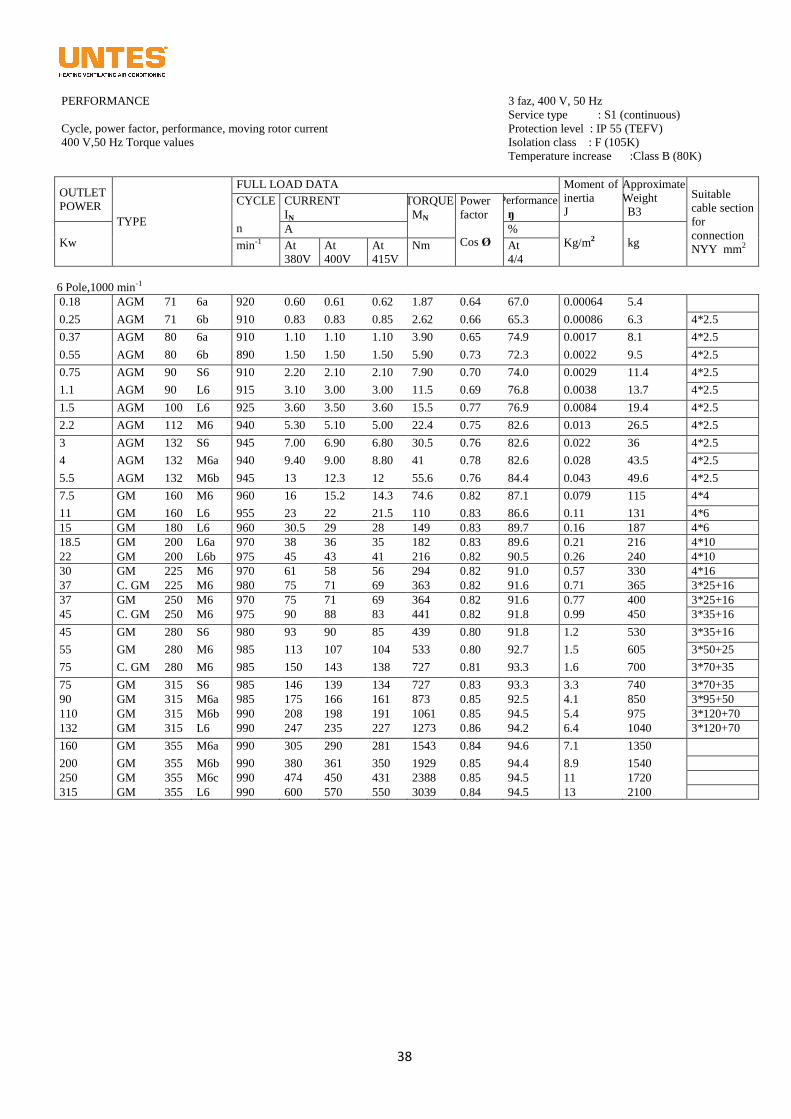
38
PERFORMANCE
Cycle, power factor, performance, moving rotor current
400 V,50 Hz Torque values
3 faz, 400 V, 50 Hz
Service type : S1 (continuous)
Protection level : IP 55 (TEFV)
Isolation class : F (105K)
Temperature increase :Class B (80K)
OUTLET
POWER
TYPE
FULL LOAD DATA Moment of
inertia
J
Approximate
Weight
B3
Suitable
cable section
for
connection
NYY mm2
CYCLE
n
CURRENT
IN
TORQUE
MN
Power
factor
Cos Ø
Performance
ŋ
Kw
A %
Kg/m2
kg min-1 At
380V
At
400V
At
415V
Nm At
4/4
6 Pole,1000 min-1
0.18 AGM 71 6a 920 0.60 0.61 0.62 1.87 0.64 67.0 0.00064 5.4
0.25 AGM 71 6b 910 0.83 0.83 0.85 2.62 0.66 65.3 0.00086 6.3 4*2.5
0.37 AGM 80 6a 910 1.10 1.10 1.10 3.90 0.65 74.9 0.0017 8.1 4*2.5
0.55 AGM 80 6b 890 1.50 1.50 1.50 5.90 0.73 72.3 0.0022 9.5 4*2.5
0.75 AGM 90 S6 910 2.20 2.10 2.10 7.90 0.70 74.0 0.0029 11.4 4*2.5
1.1 AGM 90 L6 915 3.10 3.00 3.00 11.5 0.69 76.8 0.0038 13.7 4*2.5
1.5 AGM 100 L6 925 3.60 3.50 3.60 15.5 0.77 76.9 0.0084 19.4 4*2.5
2.2 AGM 112 M6 940 5.30 5.10 5.00 22.4 0.75 82.6 0.013 26.5 4*2.5
3 AGM 132 S6 945 7.00 6.90 6.80 30.5 0.76 82.6 0.022 36 4*2.5
4 AGM 132 M6a 940 9.40 9.00 8.80 41 0.78 82.6 0.028 43.5 4*2.5
5.5 AGM 132 M6b 945 13 12.3 12 55.6 0.76 84.4 0.043 49.6 4*2.5
7.5 GM 160 M6 960 16 15.2 14.3 74.6 0.82 87.1 0.079 115 4*4
11 GM 160 L6 955 23 22 21.5 110 0.83 86.6 0.11 131 4*6
15 GM 180 L6 960 30.5 29 28 149 0.83 89.7 0.16 187 4*6
18.5 GM 200 L6a 970 38 36 35 182 0.83 89.6 0.21 216 4*10
22 GM 200 L6b 975 45 43 41 216 0.82 90.5 0.26 240 4*10
30 GM 225 M6 970 61 58 56 294 0.82 91.0 0.57 330 4*16
37 C. GM 225 M6 980 75 71 69 363 0.82 91.6 0.71 365 3*25+16
37 GM 250 M6 970 75 71 69 364 0.82 91.6 0.77 400 3*25+16
45 C. GM 250 M6 975 90 88 83 441 0.82 91.8 0.99 450 3*35+16
45 GM 280 S6 980 93 90 85 439 0.80 91.8 1.2 530 3*35+16
55 GM 280 M6 985 113 107 104 533 0.80 92.7 1.5 605 3*50+25
75 C. GM 280 M6 985 150 143 138 727 0.81 93.3 1.6 700 3*70+35
75 GM 315 S6 985 146 139 134 727 0.83 93.3 3.3 740 3*70+35
90 GM 315 M6a 985 175 166 161 873 0.85 92.5 4.1 850 3*95+50
110 GM 315 M6b 990 208 198 191 1061 0.85 94.5 5.4 975 3*120+70
132 GM 315 L6 990 247 235 227 1273 0.86 94.2 6.4 1040 3*120+70
160 GM 355 M6a 990 305 290 281 1543 0.84 94.6 7.1 1350
200 GM 355 M6b 990 380 361 350 1929 0.85 94.4 8.9 1540
250 GM 355 M6c 990 474 450 431 2388 0.85 94.5 11 1720
315 GM 355 L6 990 600 570 550 3039 0.84 94.5 13 2100
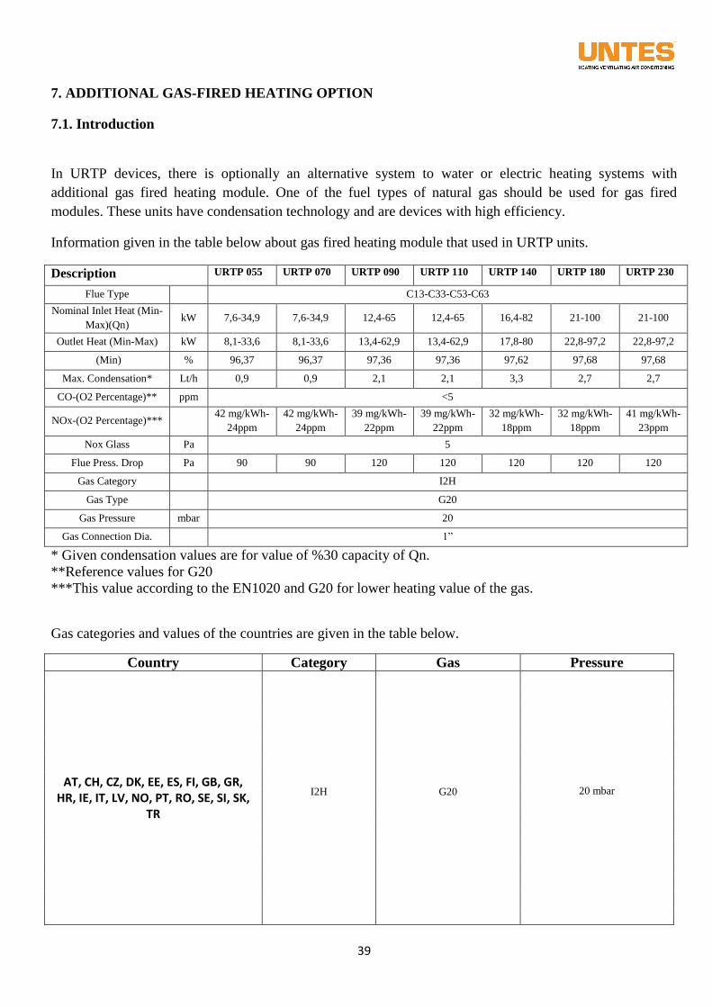
39
7. ADDITIONAL GAS-FIRED HEATING OPTION
7.1. Introduction
In URTP devices, there is optionally an alternative system to water or electric heating systems with
additional gas fired heating module. One of the fuel types of natural gas should be used for gas fired
modules. These units have condensation technology and are devices with high efficiency.
Information given in the table below about gas fired heating module that used in URTP units.
Description URTP 055 URTP 070 URTP 090 URTP 110 URTP 140 URTP 180 URTP 230
Flue Type C13-C33-C53-C63
Nominal Inlet Heat (Min-
Max)(Qn) kW 7,6-34,9 7,6-34,9 12,4-65 12,4-65 16,4-82 21-100 21-100
Outlet Heat (Min-Max) kW 8,1-33,6 8,1-33,6 13,4-62,9 13,4-62,9 17,8-80 22,8-97,2 22,8-97,2
(Min) % 96,37 96,37 97,36 97,36 97,62 97,68 97,68
Max. Condensation* Lt/h 0,9 0,9 2,1 2,1 3,3 2,7 2,7
CO-(O2 Percentage)** ppm <5
NOx-(O2 Percentage)*** 42 mg/kWh-
24ppm
42 mg/kWh-
24ppm
39 mg/kWh-
22ppm
39 mg/kWh-
22ppm
32 mg/kWh-
18ppm
32 mg/kWh-
18ppm
41 mg/kWh-
23ppm
Nox Glass Pa 5
Flue Press. Drop Pa 90 90 120 120 120 120 120
Gas Category I2H
Gas Type G20
Gas Pressure mbar 20
Gas Connection Dia. 1”
* Given condensation values are for value of %30 capacity of Qn.
**Reference values for G20
***This value according to the EN1020 and G20 for lower heating value of the gas.
Gas categories and values of the countries are given in the table below.
Country Category Gas Pressure
AT, CH, CZ, DK, EE, ES, FI, GB, GR, HR, IE, IT, LV, NO, PT, RO, SE, SI, SK,
TR
I2H
G20
20 mbar
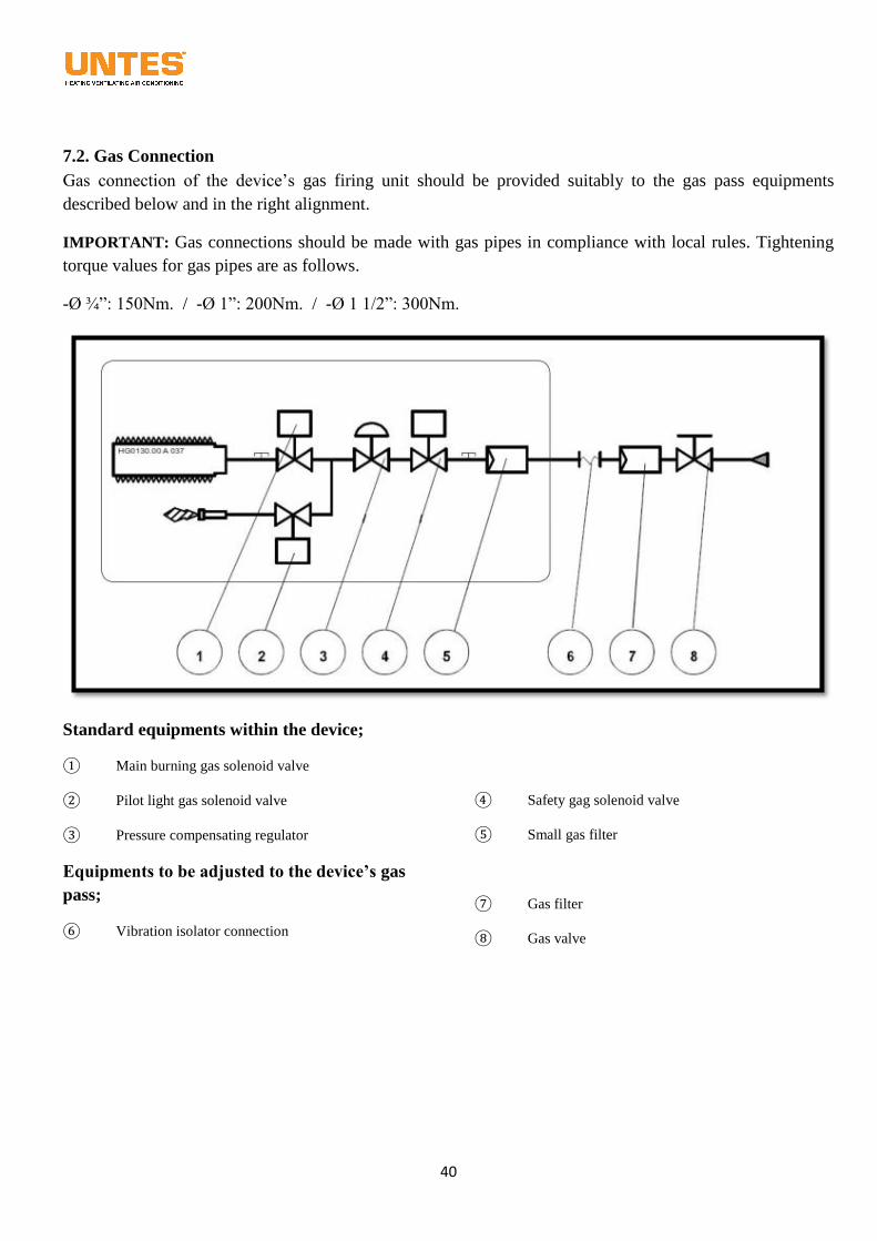
40
7.2. Gas Connection
Gas connection of the device’s gas firing unit should be provided suitably to the gas pass equipments
described below and in the right alignment.
IMPORTANT: Gas connections should be made with gas pipes in compliance with local rules. Tightening
torque values for gas pipes are as follows.
-Ø ¾”: 150Nm. / -Ø 1”: 200Nm. / -Ø 1 1/2”: 300Nm.
Standard equipments within the device;
① Main burning gas solenoid valve
② Pilot light gas solenoid valve
③ Pressure compensating regulator
④ Safety gag solenoid valve
⑤ Small gas filter
Equipments to be adjusted to the device’s gas
pass;
⑥ Vibration isolator connection
⑦ Gas filter
⑧ Gas valve
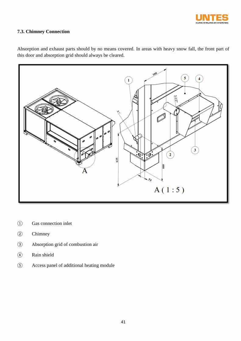
41
7.3. Chimney Connection
Absorption and exhaust parts should by no means covered. In areas with heavy snow fall, the front part of
this door and absorption grid should always be cleared.
① Gas connection inlet
② Chimney
③ Absorption grid of combustion air
④ Rain shield
⑤ Access panel of additional heating module
42
7.4. Operation Limits
Operation gas pressures of natural gas for gas firing unit is 20mbar. Maximum compressive strength of the
device’s gas pass is 60mbar and in case this value is exceeded the device’s gas pass equipment will be
broken and the device will become out-of-order.
And on the air side, the standard product works until -15°C without any problem. For temperatures under -
15°C, the system is made to work without any problem by using over-device, electric heating type gas firing
units.
Please refer to the capacity table for unit capacity values.
7.5. Controls to be considered before commissioning
The device should be checked in terms of compliance with the rules determined by local authorities.
These unit devices could only be used at uncovered areas or semi-covered areas with very good ventilation.
People without technical competence shouldn’t be let to intervene with this device.
Don’t start-up the device before complying with producer’s instructions.
Special gas distribution tap should be attached according to gas type to be used in devices.
Gas type, power source, unit adjustments should always be checked. The device should be made sure to
operate in compliance with its adjustments.
There should be assuredly at least an opening of 2 meters on gas module side. This both simplifies
intervention with the device and enables to let the device slide air in easily.
Exhaust chimney of combustion unit must be placed somewhere away from the ambient where people might
inhale it. Released suffocative gasses cause vital hazard for all living creatures.
Products given with the device should be used in the device’s gas transformation. Use of products other than
the ones provided by the producer may lead to malfunctions. It shouldn’t be forgotten that this situation will
end the warranty of the device.
Unit’s gas pass connections should be checked in terms of compliance with the instructions.
WARNING: Never use fire for gas leakage test.
7.6. Commissioning
Please refer to the control panel section at the Section 12 for commissioning the unit.
7.7. Service and Maintenance
Please refer to the maintenance section mentioned at the Section 13 for service and maintenance the unit.
7.8. Failure and Troubleshooting
You may see the failure codes of additional heater with gas firing on control panel inside the gas firing unit.
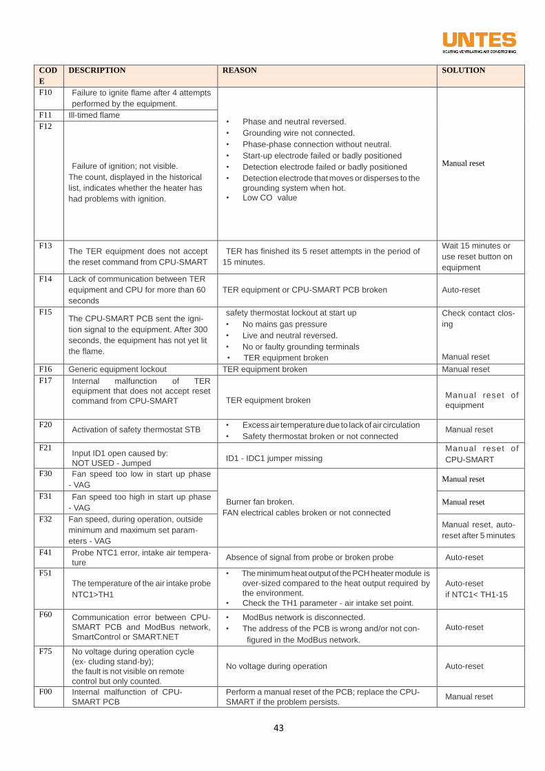
43
COD
E
DESCRIPTION REASON SOLUTION
F10 Failure to ignite flame after 4 attempts
performed by the equipment.
• Phase and neutral reversed.
• Grounding wire not connected.
• Phase-phase connection without neutral.
• Start-up electrode failed or badly positioned
• Detection electrode failed or badly positioned
• Detection electrode that moves or disperses to the
grounding system when hot. • Low CO value
Manual reset
F11 Ill-timed flame
F12
Failure of ignition; not visible.
The count, displayed in the historical
list, indicates whether the heater has
had problems with ignition.
F13 The TER equipment does not accept
the reset command from CPU-SMART
TER has finished its 5 reset attempts in the period of
15 minutes.
Wait 15 minutes or
use reset button on
equipment
F14 Lack of communication between TER
equipment and CPU for more than 60
seconds
TER equipment or CPU-SMART PCB broken Auto-reset
F15 The CPU-SMART PCB sent the igni-
tion signal to the equipment. After 300
seconds, the equipment has not yet lit
the flame.
safety thermostat lockout at start up
• No mains gas pressure
• Live and neutral reversed.
• No or faulty grounding terminals
• TER equipment broken
Check contact clos-
ing
Manual reset
F16 Generic equipment lockout TER equipment broken Manual reset
F17 Internal malfunction of TER
equipment that does not accept reset
command from CPU-SMART
TER equipment broken
Man ua l rese t of
equipment
F20
Activation of safety thermostat STB • Excess air temperature due to lack of air circulation
• Safety thermostat broken or not connected
Manual reset
F21
Input ID1 open caused by:
NOT USED - Jumped
ID1 - IDC1 jumper missing
Man ua l rese t of
CPU-SMART
F30 Fan speed too low in start up phase
- VAG
Burner fan broken.
FAN electrical cables broken or not connected
Manual reset
F31 Fan speed too high in start up phase
- VAG Manual reset
F32 Fan speed, during operation, outside
minimum and maximum set param-
eters - VAG
Manual reset, auto-
reset after 5 minutes
F41 Probe NTC1 error, intake air tempera-
ture
Absence of signal from probe or broken probe
Auto-reset
F51 The temperature of the air intake probe
NTC1>TH1
• The minimum heat output of the PCH heater module is
over-sized compared to the heat output required by
the environment.
• Check the TH1 parameter - air intake set point.
Auto-reset
if NTC1< TH1-15
F60 Communication error between CPU-
SMART PCB and ModBus network,
SmartControl or SMART.NET
• ModBus network is disconnected.
• The address of the PCB is wrong and/or not con-
figured in the ModBus network.
Auto-reset
F75 No voltage during operation cycle
(ex- cluding stand-by);
the fault is not visible on remote
control but only counted.
No voltage during operation
Auto-reset
F00 Internal malfunction of CPU-
SMART PCB
Perform a manual reset of the PCB; replace the CPU-
SMART if the problem persists.
Manual reset
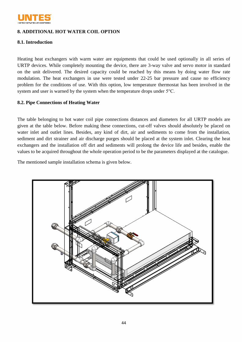
44
8. ADDITIONAL HOT WATER COIL OPTION
8.1. Introduction
Heating heat exchangers with warm water are equipments that could be used optionally in all series of
URTP devices. While completely mounting the device, there are 3-way valve and servo motor in standard
on the unit delivered. The desired capacity could be reached by this means by doing water flow rate
modulation. The heat exchangers in use were tested under 22-25 bar pressure and cause no efficiency
problem for the conditions of use. With this option, low temperature thermostat has been involved in the
system and user is warned by the system when the temperature drops under 5°C.
8.2. Pipe Connections of Heating Water
The table belonging to hot water coil pipe connections distances and diameters for all URTP models are
given at the table below. Before making these connections, cut-off valves should absolutely be placed on
water inlet and outlet lines. Besides, any kind of dirt, air and sediments to come from the installation,
sediment and dirt strainer and air discharge purges should be placed at the system inlet. Clearing the heat
exchangers and the installation off dirt and sediments will prolong the device life and besides, enable the
values to be acquired throughout the whole operation period to be the parameters displayed at the catalogue.
The mentioned sample installation schema is given below.
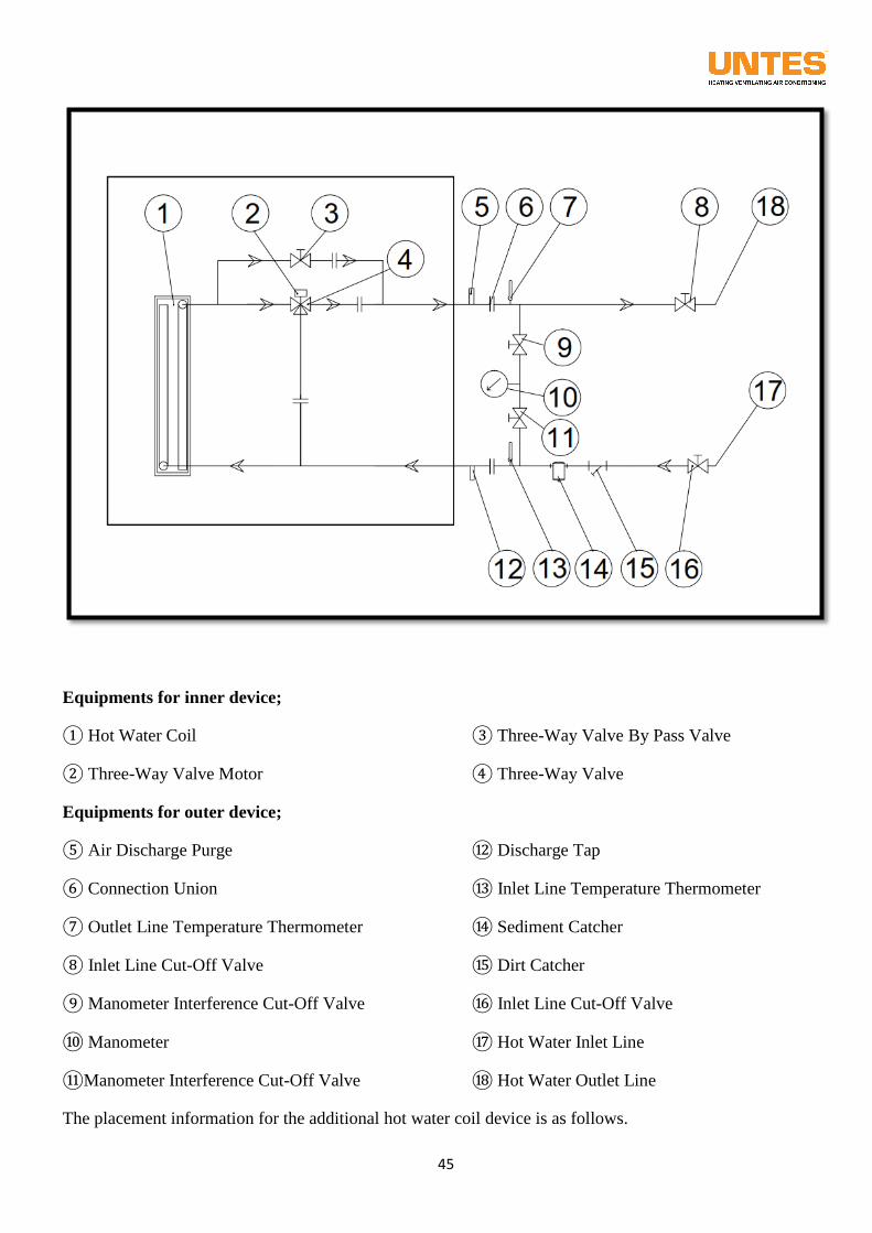
45
Equipments for inner device;
① Hot Water Coil
② Three-Way Valve Motor
③ Three-Way Valve By Pass Valve
④ Three-Way Valve
Equipments for outer device;
⑤ Air Discharge Purge
⑥ Connection Union
⑦ Outlet Line Temperature Thermometer
⑧ Inlet Line Cut-Off Valve
⑨ Manometer Interference Cut-Off Valve
⑩ Manometer
⑪Manometer Interference Cut-Off Valve
⑫ Discharge Tap
⑬ Inlet Line Temperature Thermometer
⑭ Sediment Catcher
⑮ Dirt Catcher
⑯ Inlet Line Cut-Off Valve
⑰ Hot Water Inlet Line
⑱ Hot Water Outlet Line
The placement information for the additional hot water coil device is as follows.
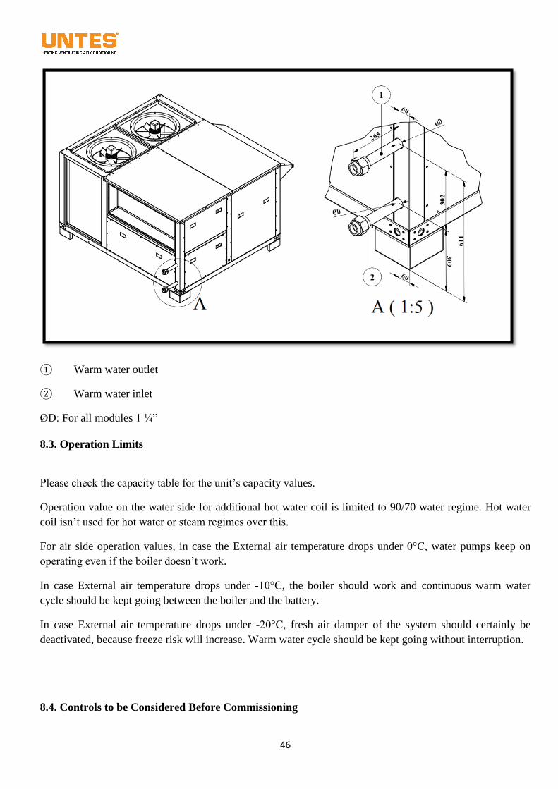
46
① Warm water outlet
② Warm water inlet
ØD: For all modules 1 ¼”
8.3. Operation Limits
Please check the capacity table for the unit’s capacity values.
Operation value on the water side for additional hot water coil is limited to 90/70 water regime. Hot water
coil isn’t used for hot water or steam regimes over this.
For air side operation values, in case the External air temperature drops under 0°C, water pumps keep on
operating even if the boiler doesn’t work.
In case External air temperature drops under -10°C, the boiler should work and continuous warm water
cycle should be kept going between the boiler and the battery.
In case External air temperature drops under -20°C, fresh air damper of the system should certainly be
deactivated, because freeze risk will increase. Warm water cycle should be kept going without interruption.
8.4. Controls to be Considered Before Commissioning
47
Water level at the facility and in hot water coil should be checked, if the first water intake has occurred, dirt
catcher should absolutely be checked and air should be taken out of the system.
After water intake, the hot water coil should absolutely be checked against water leakages by opening the
service door.
Detected water leakages should be eliminated.
8.5. Commissioning
Please refer to the control panel section at the Section 12 for commissioning the unit.
8.6. Service and Maintenance
Please refer to the maintenance section mentioned at the Section 13 for service and maintenance the unit.
8.7. Failure and Troubleshooting
Please check the explanations under the title of “12.4. Alarm Management of Room Control Unit” for this unit.
9. ADDITIONAL ELECTRIC HEATER OPTION
9.1. Introduction
Electric heaters are used optionally in all series of URTP devices. For the electric heater complete
installation and connections of which are made, there is no need for an additional installation or connection.
The electric heater prepared by rapping stainless steel band on stainless steel pipe is operated at the factory
by letting pas through all tests and presented to its users. There is a high temperature limit termostate on
resistant heater. This might be number 1 or 2 according to the heater’s size. In case the temperature on this
resistance exceeds 70°C, heater blocks electricity connection and the device cools down. Besides, the
electric heater operates in coordination with blow fan. At times when the fan doesn’t work, electric heater
should never be activated. In addition to that, even in case the electric heater is deactivated, fan keeps on
working for a while. This is a precaution to prevent water accumulation on electric heater. Finally, currents
consumed by electric heaters are continuously checked on the panel. In case the limit values are exceeded,
limiters cut off the current to prevent any bad results.
9.2. Power Cable Connections of Heating
It is enough that users provide the device with power by power supply panel. There is no need for cabling
for the electric heater. It should certainly be regarded that the electric heater is fully loaded in determining
cable section.
9.3. Operation Limits
48
Power distribution in electric heaters is composed of two asymmetrical stages. The system activates
primarily the 1. Stage according to the requirements. By the requirement increases, the 1. Stage is shut down
and the 2. Stage is activated. In case the requirement exceeds the capacity of the 2. Stage, the desired
capacity is acquired by activating both stages (1+2). Stage capacity of additional heaters are as follows.
Type/Model [W]
URTP
055
URTP
070
URTP
090
URTP
110
URTP
140
URTP
180 URTP 230
Low Type 1.Stage 6000 8000 10000 13000 16000 20000 26000
Low Type 2.Stage 13000 16000 21000 25000 32000 41000 52000
High Type 1.Stage 11500 15000 18000 22000 30000 40000 50000
High Type 2.Stage 22500 28000 37000 45000 55000 70000 90000
* These capacities are given for 400V-3F-50Hz.
9.4. Controls to be Considered Before Commissioning
It should be made sure that stage connections of the 3rd
phase, neutral and grounding connections, are
provided correctly.
It should be checked whether the electric supply connection is at ±%5 tension tolerance.
9.5. Commissioning
Please refer to the control panel section at the Section 12 for commissioning the unit.
9.6. Service and Maintenance
Please refer to the maintenance section mentioned at the Section 13 for service and maintenance the unit.
9.7. Failure and Troubleshooting
Please check the explanations under the title of “12.4. Alarm Management of Room Control Unit” for this
unit.
10. COMMISSIONING (COOLING OR HEAT PUMP)
Before commissioning the device, ensuring that all procedures about installation are gone through is
important in terms of a healthy operation. Necessary observations should be performed by a control list
prepared for this purpose. You may see a similar list prepared by us below;
Crankcase on cooling circuit of the device heater should be activated before technician to
commission the device arrives. This action should be taken at least twenty four hours
before the device is activated. By this means, compressor oil is heated and refrigerant is
evaporated. If this action isn’t taken, compressor is exposed to the refrigerant in liquid
phase and may get damaged.
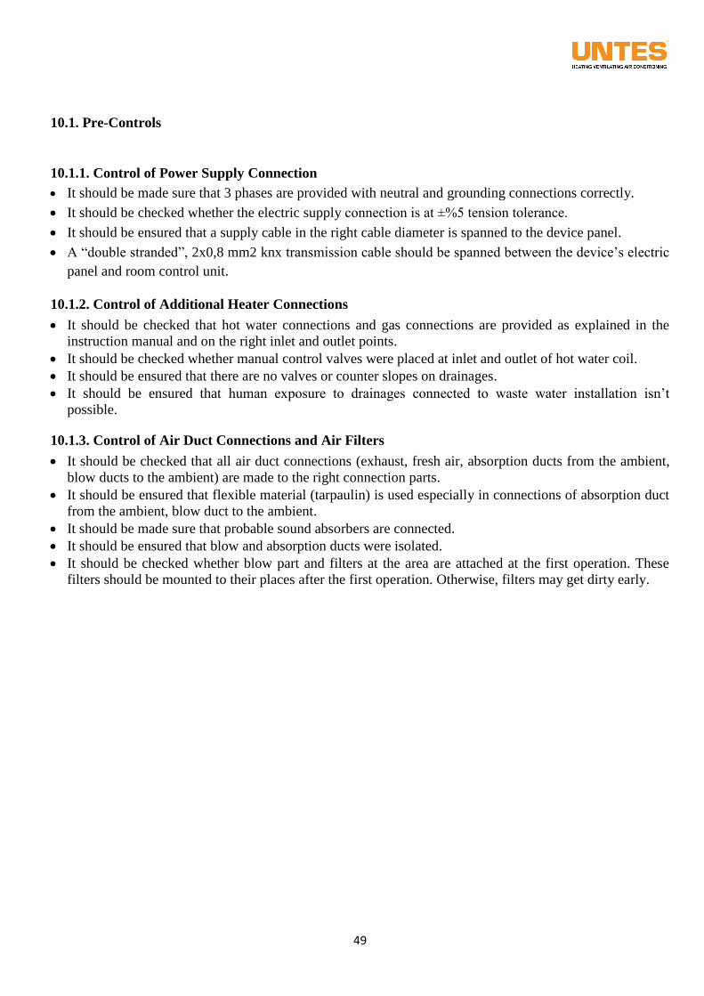
49
10.1. Pre-Controls
10.1.1. Control of Power Supply Connection
It should be made sure that 3 phases are provided with neutral and grounding connections correctly.
It should be checked whether the electric supply connection is at ±%5 tension tolerance.
It should be ensured that a supply cable in the right cable diameter is spanned to the device panel.
A “double stranded”, 2x0,8 mm2 knx transmission cable should be spanned between the device’s electric
panel and room control unit.
10.1.2. Control of Additional Heater Connections
It should be checked that hot water connections and gas connections are provided as explained in the
instruction manual and on the right inlet and outlet points.
It should be checked whether manual control valves were placed at inlet and outlet of hot water coil.
It should be ensured that there are no valves or counter slopes on drainages.
It should be ensured that human exposure to drainages connected to waste water installation isn’t
possible.
10.1.3. Control of Air Duct Connections and Air Filters
It should be checked that all air duct connections (exhaust, fresh air, absorption ducts from the ambient,
blow ducts to the ambient) are made to the right connection parts.
It should be ensured that flexible material (tarpaulin) is used especially in connections of absorption duct
from the ambient, blow duct to the ambient.
It should be made sure that probable sound absorbers are connected.
It should be ensured that blow and absorption ducts were isolated.
It should be checked whether blow part and filters at the area are attached at the first operation. These
filters should be mounted to their places after the first operation. Otherwise, filters may get dirty early.
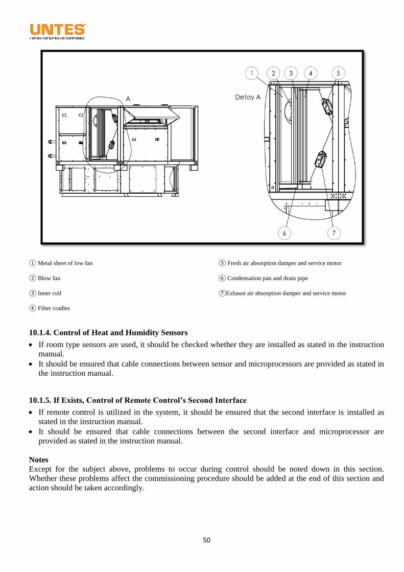
50
① Metal sheet of low fan
② Blow fan
③ Inner coil
④ Filter cradles
⑤ Fresh air absorption damper and service motor
⑥ Condensation pan and drain pipe
⑦Exhaust air absorption damper and service motor
10.1.4. Control of Heat and Humidity Sensors
If room type sensors are used, it should be checked whether they are installed as stated in the instruction
manual.
It should be ensured that cable connections between sensor and microprocessors are provided as stated in
the instruction manual.
10.1.5. If Exists, Control of Remote Control’s Second Interface
If remote control is utilized in the system, it should be ensured that the second interface is installed as
stated in the instruction manual.
It should be ensured that cable connections between the second interface and microprocessor are
provided as stated in the instruction manual.
Notes Except for the subject above, problems to occur during control should be noted down in this section.
Whether these problems affect the commissioning procedure should be added at the end of this section and
action should be taken accordingly.
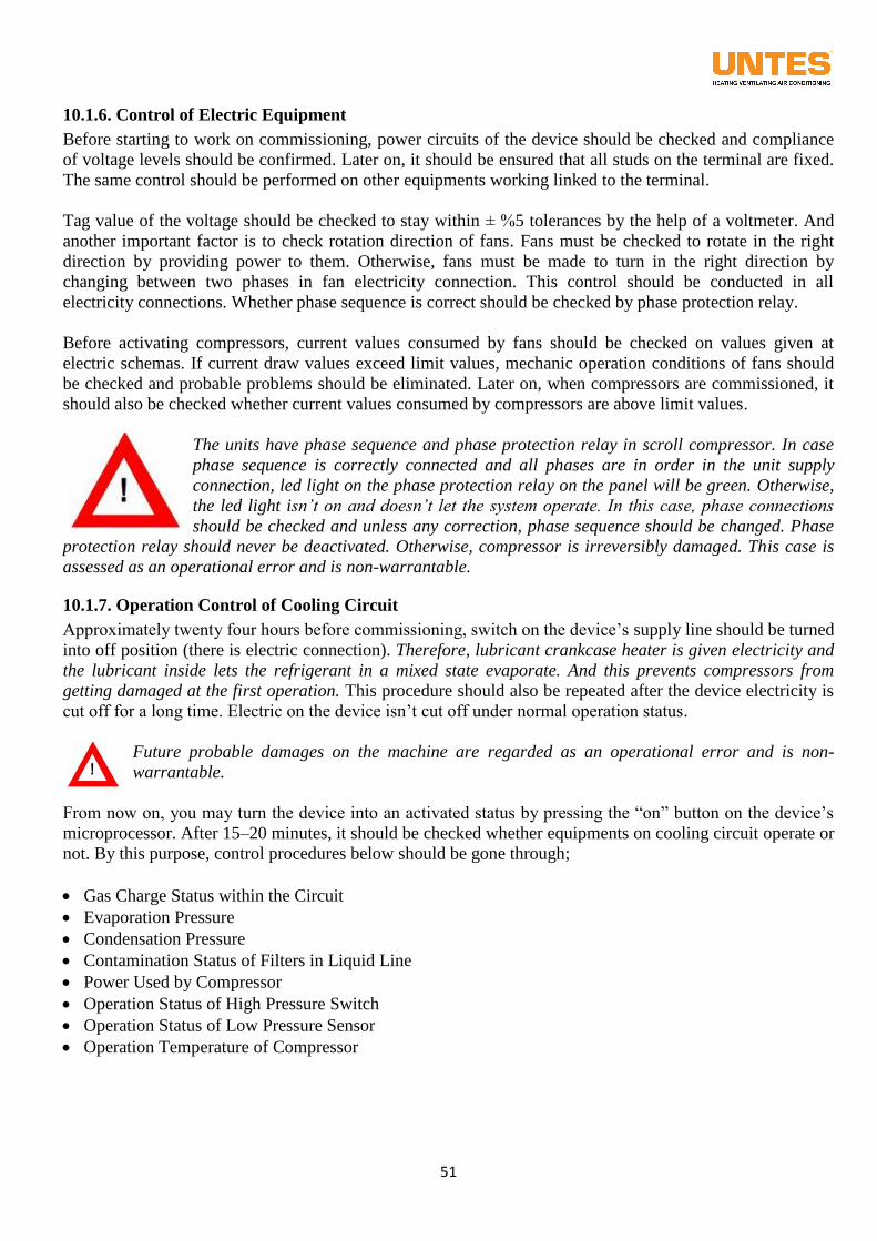
51
10.1.6. Control of Electric Equipment
Before starting to work on commissioning, power circuits of the device should be checked and compliance
of voltage levels should be confirmed. Later on, it should be ensured that all studs on the terminal are fixed.
The same control should be performed on other equipments working linked to the terminal.
Tag value of the voltage should be checked to stay within ± %5 tolerances by the help of a voltmeter. And
another important factor is to check rotation direction of fans. Fans must be checked to rotate in the right
direction by providing power to them. Otherwise, fans must be made to turn in the right direction by
changing between two phases in fan electricity connection. This control should be conducted in all
electricity connections. Whether phase sequence is correct should be checked by phase protection relay.
Before activating compressors, current values consumed by fans should be checked on values given at
electric schemas. If current draw values exceed limit values, mechanic operation conditions of fans should
be checked and probable problems should be eliminated. Later on, when compressors are commissioned, it
should also be checked whether current values consumed by compressors are above limit values.
The units have phase sequence and phase protection relay in scroll compressor. In case
phase sequence is correctly connected and all phases are in order in the unit supply
connection, led light on the phase protection relay on the panel will be green. Otherwise,
the led light isn’t on and doesn’t let the system operate. In this case, phase connections
should be checked and unless any correction, phase sequence should be changed. Phase
protection relay should never be deactivated. Otherwise, compressor is irreversibly damaged. This case is
assessed as an operational error and is non-warrantable.
10.1.7. Operation Control of Cooling Circuit
Approximately twenty four hours before commissioning, switch on the device’s supply line should be turned
into off position (there is electric connection). Therefore, lubricant crankcase heater is given electricity and
the lubricant inside lets the refrigerant in a mixed state evaporate. And this prevents compressors from
getting damaged at the first operation. This procedure should also be repeated after the device electricity is
cut off for a long time. Electric on the device isn’t cut off under normal operation status.
Future probable damages on the machine are regarded as an operational error and is non-
warrantable.
From now on, you may turn the device into an activated status by pressing the “on” button on the device’s
microprocessor. After 15–20 minutes, it should be checked whether equipments on cooling circuit operate or
not. By this purpose, control procedures below should be gone through;
Gas Charge Status within the Circuit
Evaporation Pressure
Condensation Pressure
Contamination Status of Filters in Liquid Line
Power Used by Compressor
Operation Status of High Pressure Switch
Operation Status of Low Pressure Sensor
Operation Temperature of Compressor
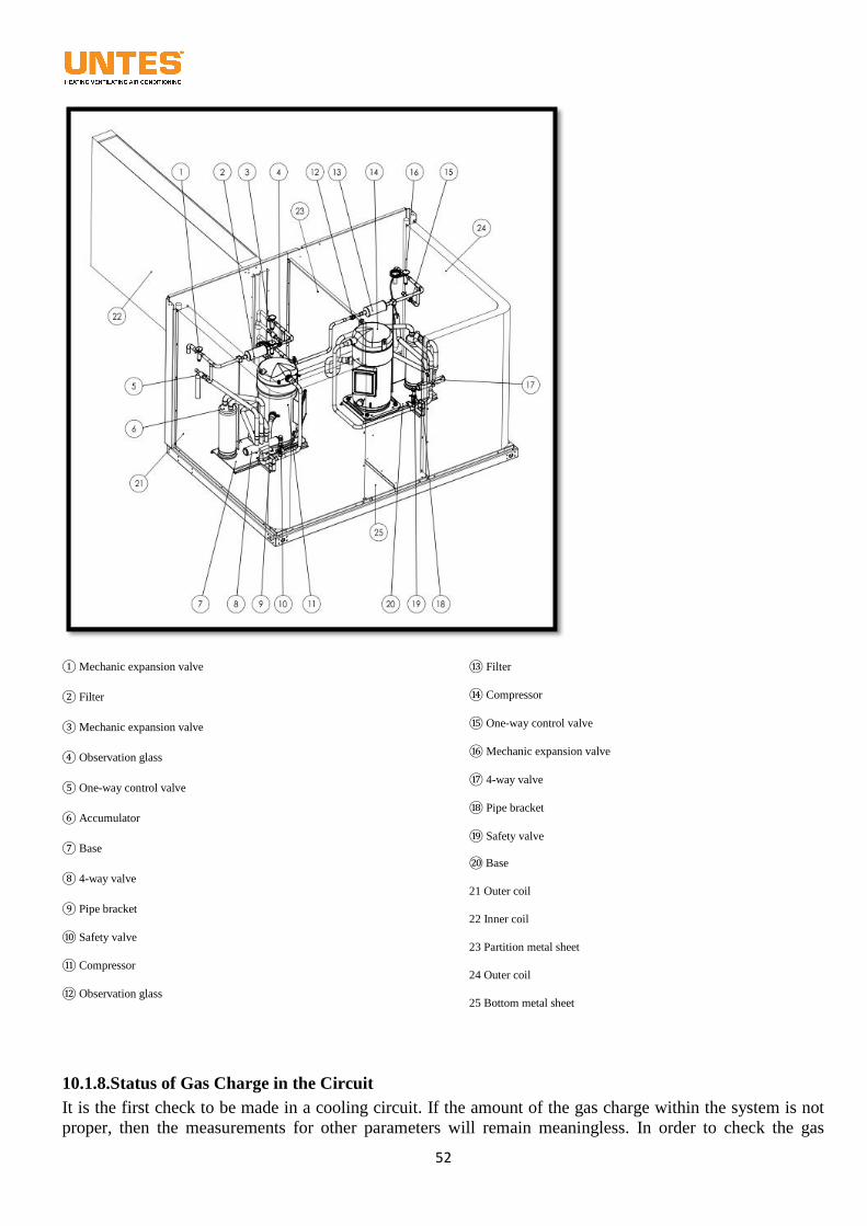
52
① Mechanic expansion valve
② Filter
③ Mechanic expansion valve
④ Observation glass
⑤ One-way control valve
⑥ Accumulator
⑦ Base
⑧ 4-way valve
⑨ Pipe bracket
⑩ Safety valve
⑪ Compressor
⑫ Observation glass
⑬ Filter
⑭ Compressor
⑮ One-way control valve
⑯ Mechanic expansion valve
⑰ 4-way valve
⑱ Pipe bracket
⑲ Safety valve
⑳ Base
21 Outer coil
22 Inner coil
23 Partition metal sheet
24 Outer coil
25 Bottom metal sheet
10.1.8.Status of Gas Charge in the Circuit
It is the first check to be made in a cooling circuit. If the amount of the gas charge within the system is not
proper, then the measurements for other parameters will remain meaningless. In order to check the gas
53
charge, it may suffice to observe through the sight glass on the liquid line whether bubbles come into being
in the gas. If the gas charge is not sufficient, then bubbles will come into being in the gas (it should never be
ignored that the state of gas overcharge cannot be perceived this way.). It means two things if bubbles exist
in the gas. The amount of the gas may not be sufficient, or there may be a gas leak within the system. If the
gas charge is not sufficient, some additional gas should be charged. If bubbles come into being again despite
the gas charge, it means a gas leak in the system. In this case, the leak should be spotted by using soap
bubbles, and it should be eliminated afterwards.
Additionally, the chromatic indicator in the sight glass is green under normal circumstances. If it may be
spoken of humidity mixing with the gas, the indicator will turn yellow. In this case, the gas and the dryer
within the system should replaced by the new ones.
10.1.9. Evaporation Pressure
In order to check this condition, the end of the ¼”-diameter service valve on the suction side of the
compressor should be attached with a manometer which has 20 bars as the last pressure value on its scale,
and the valve should be checked to insure that it is open. Evaporation pressures and temperatures are
generally high within the units. Thus, if you read lower evaporation pressures and temperatures, this may
have various reasons. In this case, required steps should be taken by using troubleshooting tables.
10.1.10. Condensation Pressure
In order to check this condition, the end of the ¼”-diameter service valve on the force side of the compressor
should be attached with a manometer which has 20 bars as the last pressure value on its scale, and the valve
should be checked to insure that it is open.
Under a proper working condition, the condensation pressure should be fixed as long as possible. Lower
condensation temperatures will lead to lower evaporation temperatures, thus resulting in over-cooling and
over-humidity. Higher condensation temperatures will, on the other hand, hinder the efficiency of the
cooling system and lead to higher consumption of electricity.
Therefore, condensation temperatures should be kept, if possible, around 45-50ºC under working conditions.
This is accepted as 15ºC higher than the outdoor temperature. For example, f the outdoor temperature is
30ºC, then the condensation temperature should be selected to be 45ºC. This value should be determined
when choosing the condenser. It is quite natural that the condensation temperature will inevitably increase
dependent to higher outdoor temperatures. The temperature difference has been explained in the section of
limit values presented in the beginning of the instruction manual. You can herein find ΔT values to be used
dependent to outdoor temperatures. It is recommended that you receive assistance for selections.
Keys are provided on the air-cooling condensers arriving with the device to adjust the condenser fan
rotational speed based on the outdoor temperature. The problem of low condensation temperature due to low
outdoor temperatures will thereby be eliminated. This key is used under the IP 55 protection and is located
outdoors with the condenser. If the device has been purchased without a condenser, then the key should be
obtained as an accessory, and placed on the condenser side of the electrical panel.
The adjustments to be made on these keys are carried out in our factories. Should adjustment becomes a
need in the mounting place, it should be carried out by service professionals.
10.1.11. Dirt Status of Filters in the Liquid Line
The filters on the liquid line play a vital role for the units. Contamination, dirt and remnants to be involved
in gas lines at the factory or during the assembling-in-place enter the compressor, it may cause permanent
damages to the compressor.
54
This filter should be checked periodically. In the event that the filter is blocked, it causes a resistance to the
gas flow, due to which the gas pre-evaporates, thus losing its capacity. This situation may be observed as
bubbles seen through the sight glass or small temperature differences between the entrance and the exit of
the filter.
10.1.12. Power Released by the Compressor
The power or the current released by the compressor should be measured from the relevant contractor on the
panel during the operation and checked to insure that it does not exceed the limit values offered.
10.1.13. Operation Status of the High-Pressure Switch
Attach a manometer with 50 bars as the last pressure value on its scale to the end of the ¼”-diameter service
valve on the discharge side of the compressor. Stop the fan condenser when the device is operating, and
follow the rise of the pressure on the barometer. A high-pressure Switch of 40 bars should stop the
compressor. If it reaches 40 bars but the compressor does not stop, turn off the device without delay and
check the high-pressure Switch. If the adjustment point is correct, then the Switch may be malfunctioning.
Never operate the device again unless you replace this Switch.
10.1.14. Operation Status of the Low-Pressure Switch
Attach a manometer with 20 bars as the last pressure value on its scale to the end of the ¼”-diameter service
valve on the discharge side of the compressor. Turn off the valve on the suction side of the compressor when
the device is operating. The low pressure Switch of 2.5 bars should stop the compressor. If it does so, open
the valve again, and the compressor should start to work when it reaches 2.5 bars. If it reaches 2.5 bars with
the valve closed but the compressor does not stop, turn off the device without delay and check the low
pressure Switch. If the adjustment point is correct, then the Switch may be malfunctioning. Never operate
the device again unless you replace this Switch.
10.1.15. Operation Temperature of the Compressor
The temperature on the upper parts of the compressor should be around 60-70ºC under normal operating
conditions. This values may be around 20-30ºC on the lower parts. If temperatures fall below these values
and condensation is seen on the upper parts of the compressor, this means that the temperature turning back
to the compressor is too low. This is usually encountered when it turns back to the compressor as a liquid.
This occurs in the event that the extra heating is lower than it should have been. For this purpose, the
expansion valve adjustments should be checked.
If the temperature on the force side of the compressor is 50ºC or higher, this means that the expansion valve
allows insufficient gas to pass into the evaporator, which is a problem to be corrected by the expansion valve
adjustments.
Expansion valve adjustments should be made by cooling professionals. Damages due to these
adjustments are regarded as operative errors and are not covered by the warranty.
10.2. Procedure of Start Up and Operation
The operation to take the device into the circuit for the first time should always be carried out by Untes technical
personnel. The operations carried out by unauthorized people will cause the device to remain out of the
scope of the warranty. This procedure with the exception of circuiting for the first time is introduced in 12.1
Mounting and Using the Unit.
55
11. ACCESSORIES AND OTHER OPTIONS
The accessories and options usable with URTP devices are as follows:
11.1. CO2 Detector
Constantly checking the system exhaling air, it activates the fresh air damper to the extent that the system allows
(and if the pre-determined temperature settings are in the range) in the point that the air quality gets lower. It
thereby provides more fresh air to the environment.
11.2. Smoke Detector
Constantly checking the system rotational air, it turns off the device and detects a fire alarm to the room control unit
if the amount of CO in the air exceeds the pre-determined amount.
11.3. Filter Dirty Warning
Sending information of the changing filter pressure to the control panel thanks to the different pressure key, it lets
you know that the level of dirt in the filter has increased. The factory pressure setting is 250 Pa. You will receive a
Filter contaminated warning if it exceeds this value.
11.4. Indoor Air Flow Control
The flow can be calculated instantly thanks to the different pressure information readable from the factory-released
measurement nozzles on the plugged fans, constantly checking so that the flow value entered into the system could
remain the same.
11.5. Speed Control of Condenser Fan
With this option offered so that the system will not return an error of low pressure at lower outdoor temperatures,
capacities of condenser fans may be decreased by making its revolutions adjustable. The system can thereby
function properly at lower temperatures.
11.6. Hydrophilic and Epoxy Coating
Depending on the device operation conditions, the interior and exterior heat exchangers of the device may be
applied coating against corrosion and extreme condensation.
11.7. Heat Exchanger Protection Grill
The surface of the device condenser heat exchangers is composed of thin (0.1 mm) aluminum lamellas, it can be
covered with a 4mm painted wire cage for protection of people and animals from these sharp surfaces.
11.8. Gravity Damper
It functions like a non-return valve to prevent unwanted air and particles through the exhaust when the device is not
operating.
11.9. Return Fan
It operates in series with the exhaling air fan and has been designed for the cases where the exhaling air fan cannot
meet the pressure falling on the rotational side. Using the system exhaling fan, it insures that the exhaling fan will
win over the total pressure.
11.10. Power Exhaust Fan
Within the systems operating with a large amount of fresh air, it can be used to export the extra air indoors.
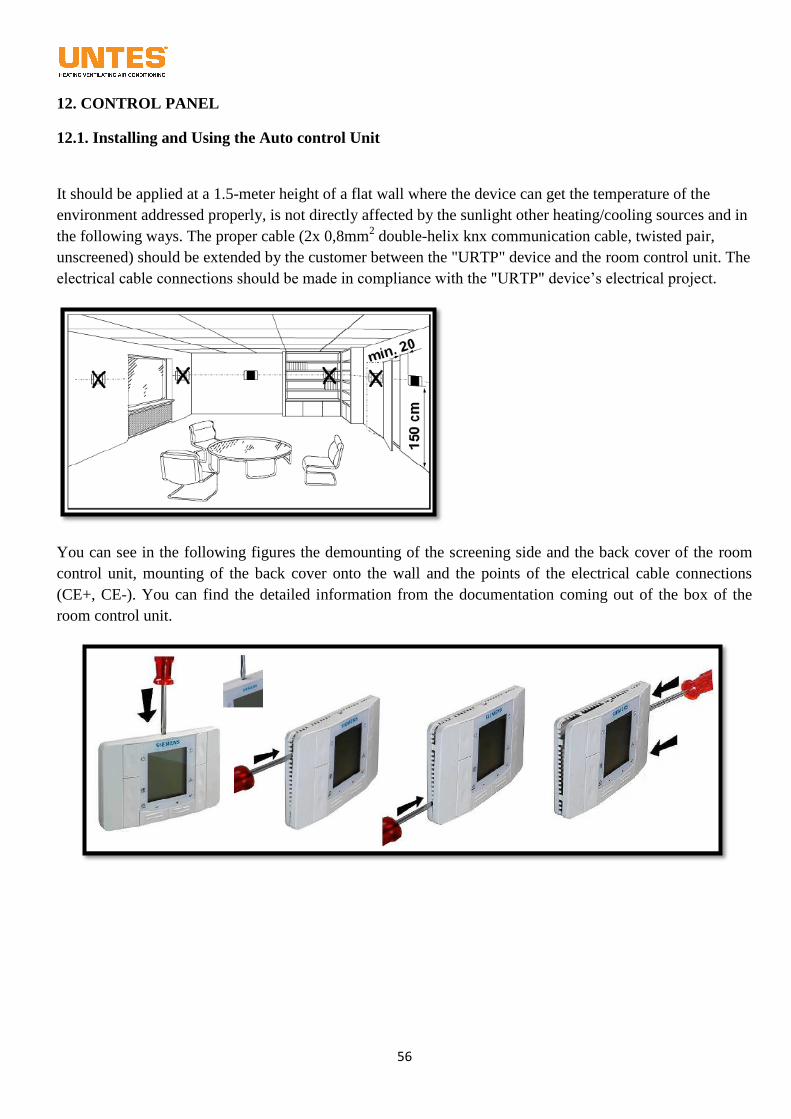
56
12. CONTROL PANEL
12.1. Installing and Using the Auto control Unit
It should be applied at a 1.5-meter height of a flat wall where the device can get the temperature of the
environment addressed properly, is not directly affected by the sunlight other heating/cooling sources and in
the following ways. The proper cable (2x 0,8mm2 double-helix knx communication cable, twisted pair,
unscreened) should be extended by the customer between the "URTP" device and the room control unit. The
electrical cable connections should be made in compliance with the "URTP" device’s electrical project.
You can see in the following figures the demounting of the screening side and the back cover of the room
control unit, mounting of the back cover onto the wall and the points of the electrical cable connections
(CE+, CE-). You can find the detailed information from the documentation coming out of the box of the
room control unit.
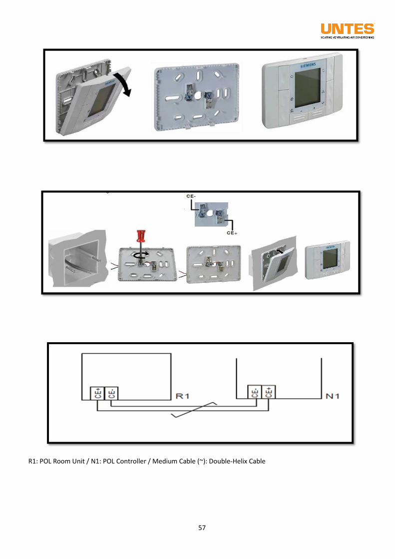
57
R1: POL Room Unit / N1: POL Controller / Medium Cable (~): Double-Helix Cable
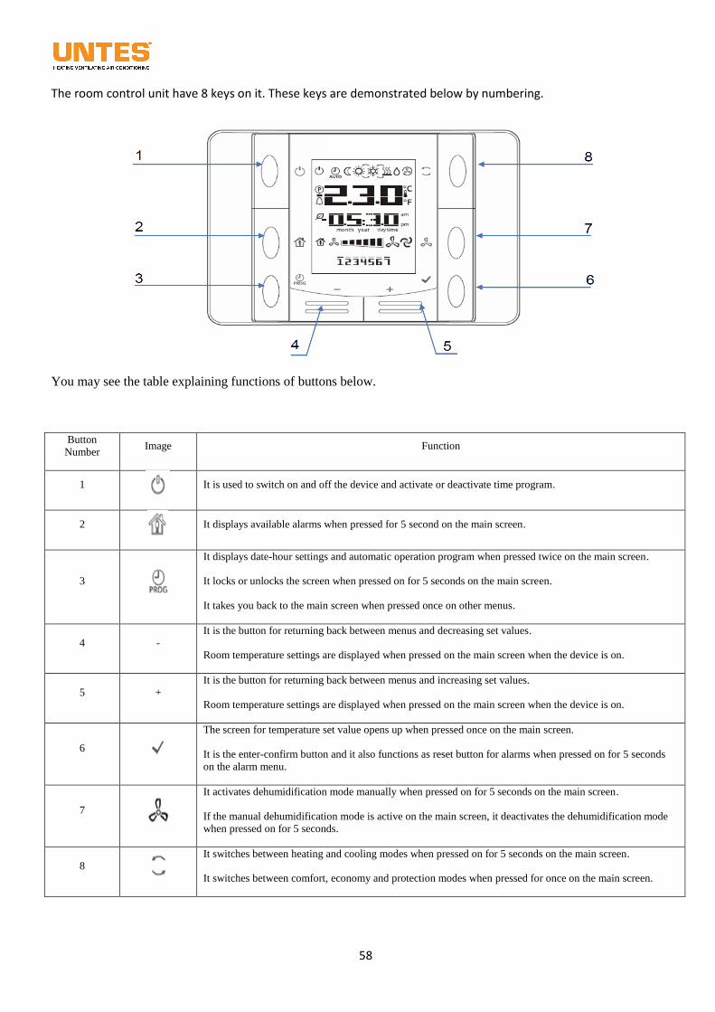
58
The room control unit have 8 keys on it. These keys are demonstrated below by numbering.
You may see the table explaining functions of buttons below.
Button
Number Image Function
1
It is used to switch on and off the device and activate or deactivate time program.
2
It displays available alarms when pressed for 5 second on the main screen.
3
It displays date-hour settings and automatic operation program when pressed twice on the main screen.
It locks or unlocks the screen when pressed on for 5 seconds on the main screen.
It takes you back to the main screen when pressed once on other menus.
4 - It is the button for returning back between menus and decreasing set values.
Room temperature settings are displayed when pressed on the main screen when the device is on.
5 + It is the button for returning back between menus and increasing set values.
Room temperature settings are displayed when pressed on the main screen when the device is on.
6
The screen for temperature set value opens up when pressed once on the main screen.
It is the enter-confirm button and it also functions as reset button for alarms when pressed on for 5 seconds
on the alarm menu.
7
It activates dehumidification mode manually when pressed on for 5 seconds on the main screen.
If the manual dehumidification mode is active on the main screen, it deactivates the dehumidification mode
when pressed on for 5 seconds.
8
It switches between heating and cooling modes when pressed on for 5 seconds on the main screen.
It switches between comfort, economy and protection modes when pressed for once on the main screen.
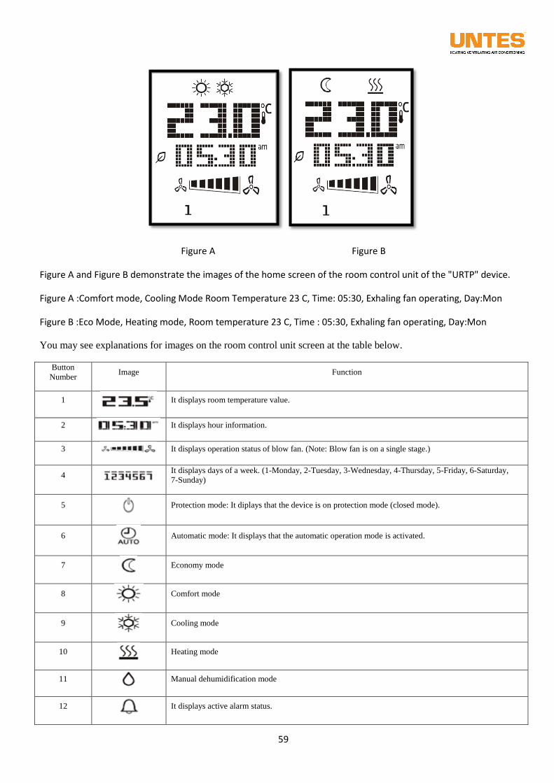
59
Figure A Figure B
Figure A and Figure B demonstrate the images of the home screen of the room control unit of the "URTP" device.
Figure A :Comfort mode, Cooling Mode Room Temperature 23 C, Time: 05:30, Exhaling fan operating, Day:Mon
Figure B :Eco Mode, Heating mode, Room temperature 23 C, Time : 05:30, Exhaling fan operating, Day:Mon
You may see explanations for images on the room control unit screen at the table below.
Button
Number Image Function
1
It displays room temperature value.
2
It displays hour information.
3
It displays operation status of blow fan. (Note: Blow fan is on a single stage.)
4
It displays days of a week. (1-Monday, 2-Tuesday, 3-Wednesday, 4-Thursday, 5-Friday, 6-Saturday,
7-Sunday)
5
Protection mode: It diplays that the device is on protection mode (closed mode).
6
Automatic mode: It displays that the automatic operation mode is activated.
7
Economy mode
8
Comfort mode
9
Cooling mode
10
Heating mode
11
Manual dehumidification mode
12
It displays active alarm status.
60
12.2. Adjusting of Set Values of the Unit
From the room control unit of the "URTP" device, two separate set adjustments can be possible as Comfort
and Eco Modes. These set points are presented below.
Comfort Heating Room Temperature Set Value
Comfort Cooling Room Temperature Set Value
Eco Heating Room Temperature Set Value
Eco Cooling Room Temperature Set Value
There are two methods to adjust the room temperature set values. For the first method, press key on the
home screen to enter the menu containing the set values, enter the set values to be changed by pressing its
key, change it by pressing the ( - ) or ( + ) key and confirm the new set value by pressing the key. For
the second method, while the device is operating, press the ( - ) or ( + ) key to change the room temperature
set values belonging to the current mode.
12.3. Room Control Panel Lock of the Unit
The room control unit has a screen lock to prevent unauthorized people to make changes to the operation
modes or setting points of the room control unit due to the place it will be located. The screen lock can be
activated by pressing the key for 5 seconds, and none of the keys will function from now on. The
screen lock can be deactivated by pressing the key for 5 seconds again.
12.4. Alarm Management of Room Control Unit
If there is an alarm situation on the "URTP" device, the icon will be active. Press the key (in the
middle to the left) for 5 seconds to open the screen containing the active alarms. If the factor causing the
alarm has been eliminated, press the key (in the bottom to the right) for 5 seconds to reset the alarm.
Below is the table demonstrating the descriptions of the relevant alarm codes.
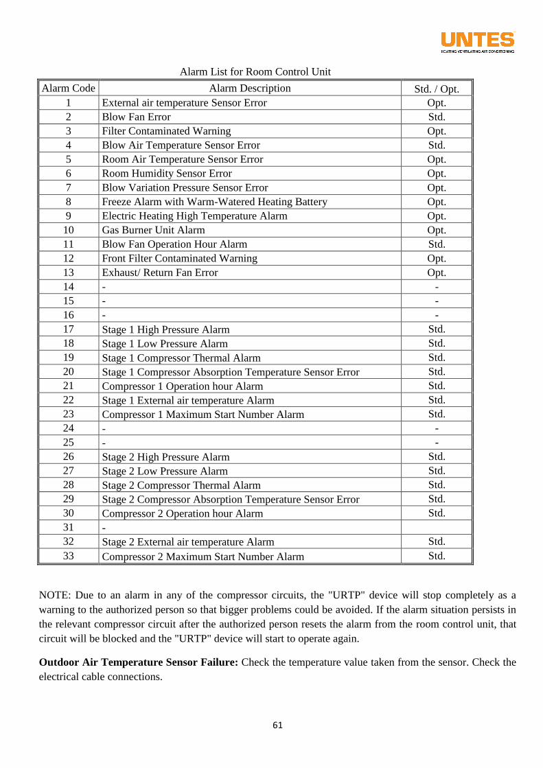
61
Alarm List for Room Control Unit
Alarm Code Alarm Description Std. / Opt.
1 External air temperature Sensor Error Opt.
2 Blow Fan Error Std.
3 Filter Contaminated Warning Opt.
4 Blow Air Temperature Sensor Error Std.
5 Room Air Temperature Sensor Error Opt.
6 Room Humidity Sensor Error Opt.
7 Blow Variation Pressure Sensor Error Opt.
8 Freeze Alarm with Warm-Watered Heating Battery Opt.
9 Electric Heating High Temperature Alarm Opt.
10 Gas Burner Unit Alarm Opt.
11 Blow Fan Operation Hour Alarm Std.
12 Front Filter Contaminated Warning Opt.
13 Exhaust/ Return Fan Error Opt.
14 - -
15 - -
16 - -
17 Stage 1 High Pressure Alarm Std.
18 Stage 1 Low Pressure Alarm Std.
19 Stage 1 Compressor Thermal Alarm Std.
20 Stage 1 Compressor Absorption Temperature Sensor Error Std.
21 Compressor 1 Operation hour Alarm Std.
22 Stage 1 External air temperature Alarm Std.
23 Compressor 1 Maximum Start Number Alarm Std.
24 - -
25 - -
26 Stage 2 High Pressure Alarm Std.
27 Stage 2 Low Pressure Alarm Std.
28 Stage 2 Compressor Thermal Alarm Std.
29 Stage 2 Compressor Absorption Temperature Sensor Error Std.
30 Compressor 2 Operation hour Alarm Std.
31 -
32 Stage 2 External air temperature Alarm Std.
33 Compressor 2 Maximum Start Number Alarm Std.
NOTE: Due to an alarm in any of the compressor circuits, the "URTP" device will stop completely as a
warning to the authorized person so that bigger problems could be avoided. If the alarm situation persists in
the relevant compressor circuit after the authorized person resets the alarm from the room control unit, that
circuit will be blocked and the "URTP" device will start to operate again.
Outdoor Air Temperature Sensor Failure: Check the temperature value taken from the sensor. Check the
electrical cable connections.
62
Exhaling Fan Failure: Check the feed fuse and frequency invertor of the exhaling fan motor.
Resetting the alarm from the room control unit may not suffice; reset from the frequency inverter may be
required as well.
Filter Contaminated Warning: Check the different pressure key and the status of dirt in the filters.
Exhaling Air Temperature Sensor Failure: Check the temperature value taken from the sensor. Check
the electrical cable connections.
Room Air Temperature Sensor Failure: This sensor is located below the room control unit. Check the
temperature value taken from the sensor.
Room Humidity Sensor Failure: Check the temperature value taken from the sensor. Check the
electrical cable connections.
Exhaling Air Different Pressure Switch Failure: This sensor is used with the option of flow control.
Check the air probe connections of the sensor and the electrical cable connections.
Hot Water Heating Battery Freezing Warning: Check the electrical cable connections and setting value
of the freezing thermostat. Resetting the alarm only from the room control unit will not suffice as the
freezing thermostat requires manual reset.
Electrical Heater High Temperature Alarm: Check the electrical cable connections and setting value of
the electrical heater thermostat.
Gas Combustion Unit Alarm: Check the electrical cable connections of the gas combustion unit. Resetting
the alarm only from the room control unit will not suffice as the control card of the gas combustion unit
requires manual reset.
Exhaust/Return Fan Failure: Check the feed fuse of the exhaust or Return Fan motors, and check the
electrical cable connections and connection elements.
Circuit 1 High Pressure Alarm: Check the operation status of the condenser fan, electrical cable
connection of the high pressure Switch and status of dirt on the surface of the heat exchanger. Resetting the
alarm only from the room control unit will not suffice as the high pressure alarm requires manual reset from
the high pressure Switch.
Circuit 1 Low Pressure Alarm: Check the gas pressures of the system and the electrical cable connections
of the low pressure Switch.
Circuit 1 Compressor Thermal Alarm: Check the operative currents of the compressor and the motor
protection switch. Resetting the alarm only from the room control unit will not suffice as the motor
protection switch of the compressor requires manual reset.
Circuit 1 Compressor Suction Temperature Sensor Failure: Check the temperature value taken from the
sensor. Check the electrical cable connections.
Circuit 2 High Pressure Alarm : Check the operation status of the condenser fan, electrical cable
connection of the high pressure Switch and status of dirt on the surface of the battery. Resetting the alarm
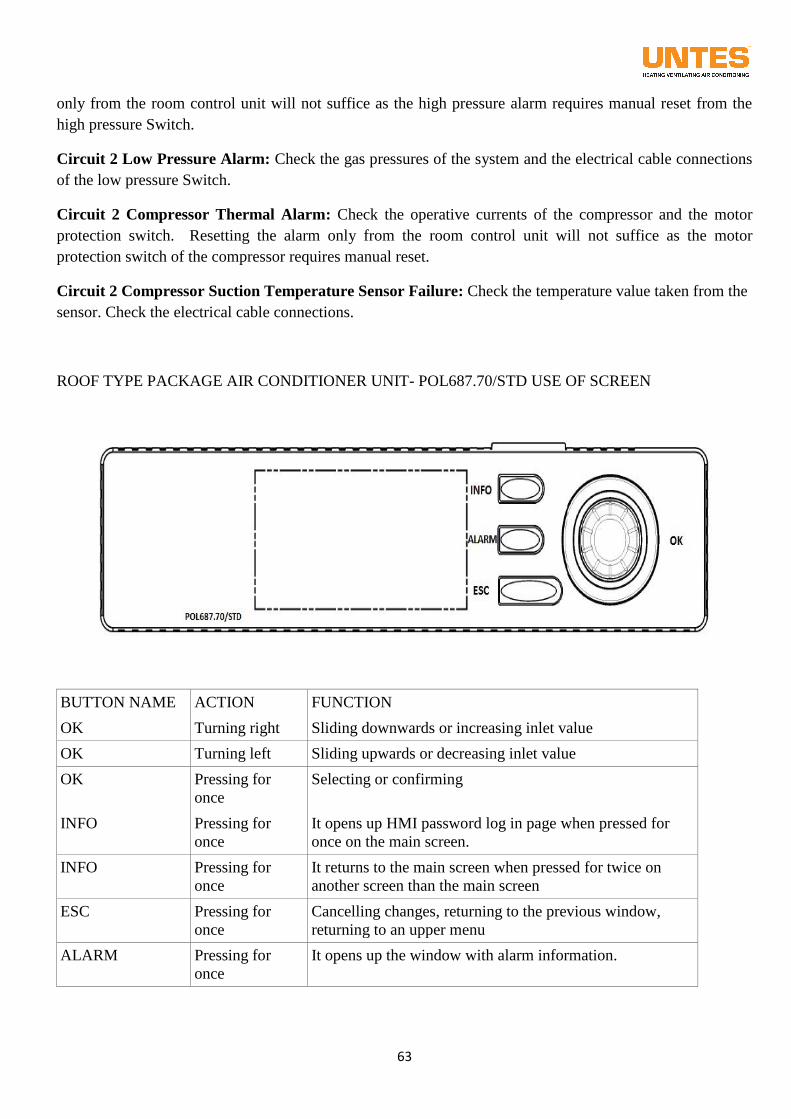
63
only from the room control unit will not suffice as the high pressure alarm requires manual reset from the
high pressure Switch.
Circuit 2 Low Pressure Alarm: Check the gas pressures of the system and the electrical cable connections
of the low pressure Switch.
Circuit 2 Compressor Thermal Alarm: Check the operative currents of the compressor and the motor
protection switch. Resetting the alarm only from the room control unit will not suffice as the motor
protection switch of the compressor requires manual reset.
Circuit 2 Compressor Suction Temperature Sensor Failure: Check the temperature value taken from the
sensor. Check the electrical cable connections.
ROOF TYPE PACKAGE AIR CONDITIONER UNIT- POL687.70/STD USE OF SCREEN
BUTTON NAME ACTION FUNCTION
OK Turning right Sliding downwards or increasing inlet value
OK Turning left Sliding upwards or decreasing inlet value
OK Pressing for
once
Selecting or confirming
INFO Pressing for
once
It opens up HMI password log in page when pressed for
once on the main screen.
INFO Pressing for
once
It returns to the main screen when pressed for twice on
another screen than the main screen
ESC Pressing for
once
Cancelling changes, returning to the previous window,
returning to an upper menu
ALARM Pressing for
once
It opens up the window with alarm information.
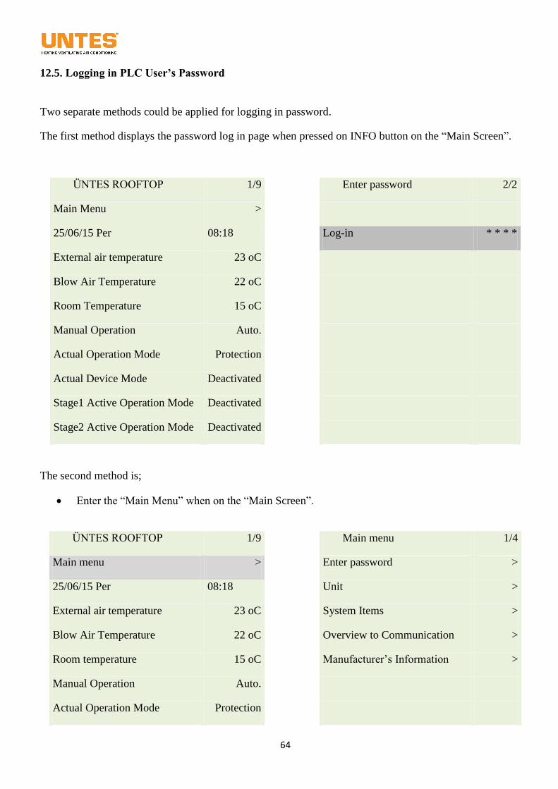
64
12.5. Logging in PLC User’s Password
Two separate methods could be applied for logging in password.
The first method displays the password log in page when pressed on INFO button on the “Main Screen”.
ÜNTES ROOFTOP 1/9
Enter password 2/2
Main Menu >
25/06/15 Per 08:18
Log-in * * * *
External air temperature 23 oC
Blow Air Temperature 22 oC
Room Temperature 15 oC
Manual Operation Auto.
Actual Operation Mode Protection
Actual Device Mode Deactivated
Stage1 Active Operation Mode Deactivated
Stage2 Active Operation Mode Deactivated
The second method is;
Enter the “Main Menu” when on the “Main Screen”.
ÜNTES ROOFTOP 1/9
Main menu 1/4
Main menu >
Enter password >
25/06/15 Per 08:18
Unit >
External air temperature 23 oC
System Items >
Blow Air Temperature 22 oC
Overview to Communication >
Room temperature 15 oC
Manufacturer’s Information >
Manual Operation Auto.
Actual Operation Mode Protection
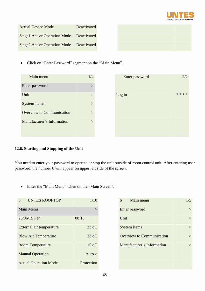
65
Actual Device Mode Deactivated
Stage1 Active Operation Mode Deactivated
Stage2 Active Operation Mode Deactivated
Click on “Enter Password” segment on the “Main Menu”.
Main menu 1/4
Enter password 2/2
Enter password >
Unit >
Log in * * * *
System Items >
Overview to Communication >
Manufacturer’s Information >
12.6. Starting and Stopping of the Unit
You need to enter your password to operate or stop the unit outside of room control unit. After entering user
password, the number 6 will appear on upper left side of the screen.
Enter the “Main Menu” when on the “Main Screen”.
6 ÜNTES ROOFTOP 1/10
6 Main menu 1/5
Main Menu >
Enter password >
25/06/15 Per 08:18
Unit >
External air temperature 23 oC
System Items >
Blow Air Temperature 22 oC
Overview to Communication >
Room Temperature 15 oC
Manufacturer’s Information >
Manual Operation Auto.>
Actual Operation Mode Protection
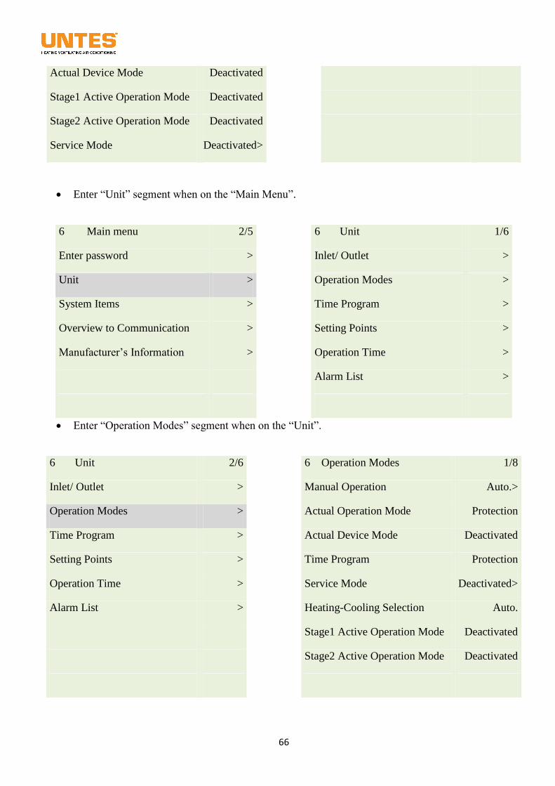
66
Actual Device Mode Deactivated
Stage1 Active Operation Mode Deactivated
Stage2 Active Operation Mode Deactivated
Service Mode Deactivated>
Enter “Unit” segment when on the “Main Menu”.
6 Main menu 2/5
6 Unit 1/6
Enter password >
Inlet/ Outlet >
Unit >
Operation Modes >
System Items >
Time Program >
Overview to Communication >
Setting Points >
Manufacturer’s Information >
Operation Time >
Alarm List >
Enter “Operation Modes” segment when on the “Unit”.
6 Unit 2/6
6 Operation Modes 1/8
Inlet/ Outlet >
Manual Operation Auto.>
Operation Modes >
Actual Operation Mode Protection
Time Program >
Actual Device Mode Deactivated
Setting Points >
Time Program Protection
Operation Time >
Service Mode Deactivated>
Alarm List >
Heating-Cooling Selection Auto.
Stage1 Active Operation Mode Deactivated
Stage2 Active Operation Mode Deactivated
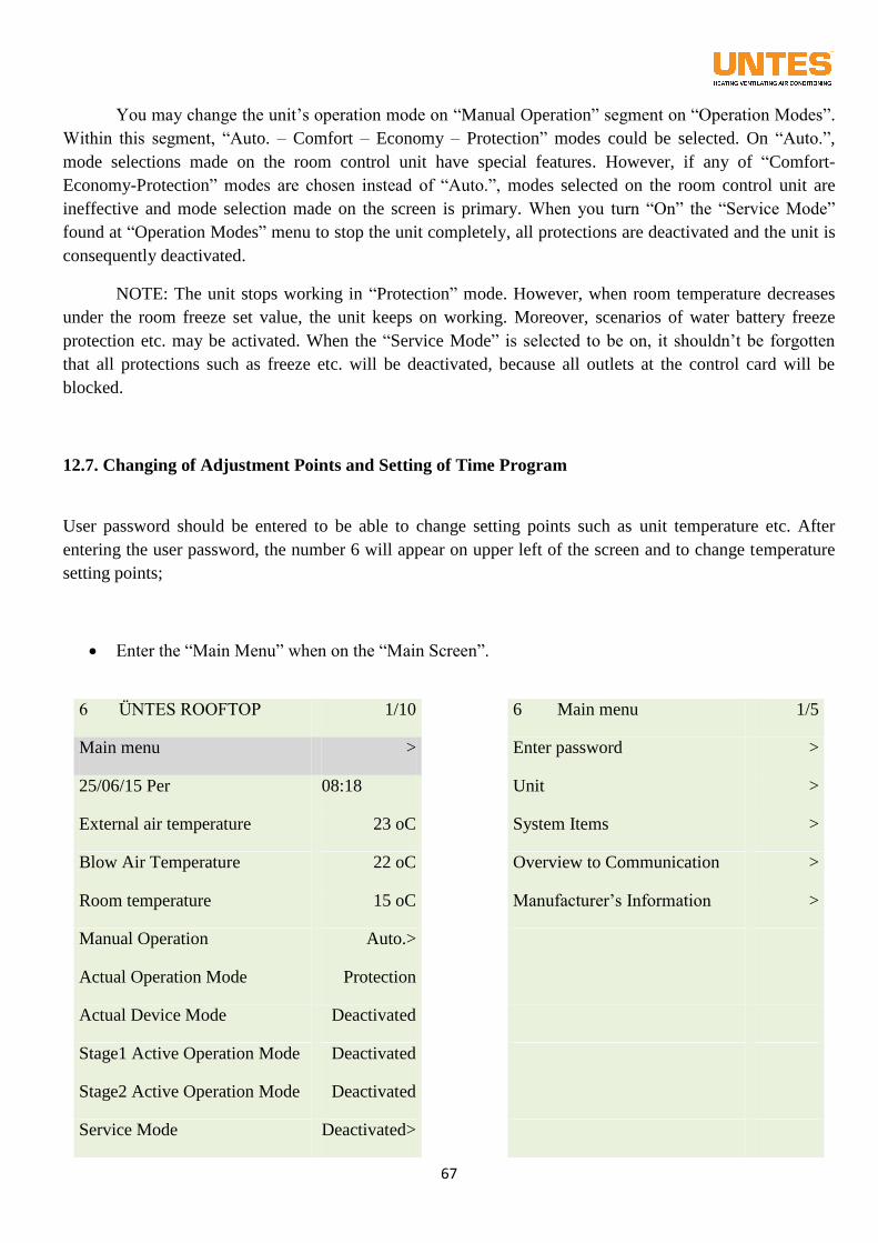
67
You may change the unit’s operation mode on “Manual Operation” segment on “Operation Modes”.
Within this segment, “Auto. – Comfort – Economy – Protection” modes could be selected. On “Auto.”,
mode selections made on the room control unit have special features. However, if any of “Comfort-
Economy-Protection” modes are chosen instead of “Auto.”, modes selected on the room control unit are
ineffective and mode selection made on the screen is primary. When you turn “On” the “Service Mode”
found at “Operation Modes” menu to stop the unit completely, all protections are deactivated and the unit is
consequently deactivated.
NOTE: The unit stops working in “Protection” mode. However, when room temperature decreases
under the room freeze set value, the unit keeps on working. Moreover, scenarios of water battery freeze
protection etc. may be activated. When the “Service Mode” is selected to be on, it shouldn’t be forgotten
that all protections such as freeze etc. will be deactivated, because all outlets at the control card will be
blocked.
12.7. Changing of Adjustment Points and Setting of Time Program
User password should be entered to be able to change setting points such as unit temperature etc. After
entering the user password, the number 6 will appear on upper left of the screen and to change temperature
setting points;
Enter the “Main Menu” when on the “Main Screen”.
6 ÜNTES ROOFTOP 1/10
6 Main menu 1/5
Main menu >
Enter password >
25/06/15 Per 08:18
Unit >
External air temperature 23 oC
System Items >
Blow Air Temperature 22 oC
Overview to Communication >
Room temperature 15 oC
Manufacturer’s Information >
Manual Operation Auto.>
Actual Operation Mode Protection
Actual Device Mode Deactivated
Stage1 Active Operation Mode Deactivated
Stage2 Active Operation Mode Deactivated
Service Mode Deactivated>
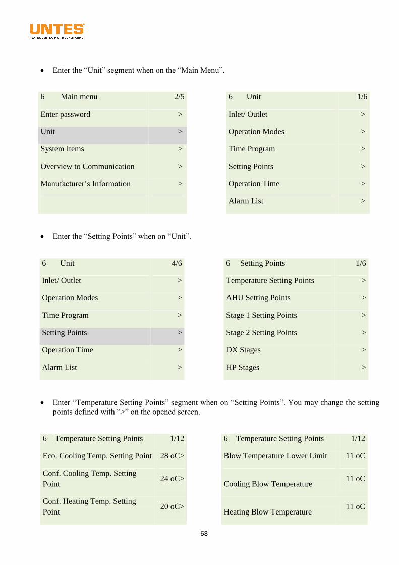
68
Enter the “Unit” segment when on the “Main Menu”.
6 Main menu 2/5
6 Unit 1/6
Enter password >
Inlet/ Outlet >
Unit >
Operation Modes >
System Items >
Time Program >
Overview to Communication >
Setting Points >
Manufacturer’s Information >
Operation Time >
Alarm List >
Enter the “Setting Points” when on “Unit”.
6 Unit 4/6
6 Setting Points 1/6
Inlet/ Outlet >
Temperature Setting Points >
Operation Modes >
AHU Setting Points >
Time Program >
Stage 1 Setting Points >
Setting Points >
Stage 2 Setting Points >
Operation Time >
DX Stages >
Alarm List >
HP Stages >
Enter “Temperature Setting Points” segment when on “Setting Points”. You may change the setting
points defined with “>” on the opened screen.
6 Temperature Setting Points 1/12
6 Temperature Setting Points 1/12
Eco. Cooling Temp. Setting Point 28 oC>
Blow Temperature Lower Limit 11 oC
Conf. Cooling Temp. Setting
Point 24 oC>
Cooling Blow Temperature 11 oC
Conf. Heating Temp. Setting
Point 20 oC>
Heating Blow Temperature 11 oC
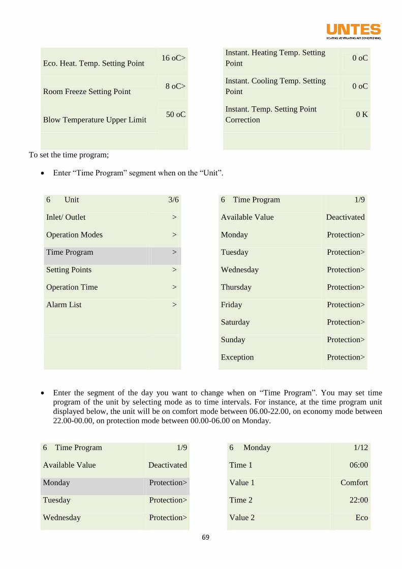
69
Eco. Heat. Temp. Setting Point 16 oC>
Instant. Heating Temp. Setting
Point 0 oC
Room Freeze Setting Point 8 oC>
Instant. Cooling Temp. Setting
Point 0 oC
Blow Temperature Upper Limit 50 oC
Instant. Temp. Setting Point
Correction 0 K
To set the time program;
Enter “Time Program” segment when on the “Unit”.
6 Unit 3/6
6 Time Program 1/9
Inlet/ Outlet >
Available Value Deactivated
Operation Modes >
Monday Protection>
Time Program >
Tuesday Protection>
Setting Points >
Wednesday Protection>
Operation Time >
Thursday Protection>
Alarm List >
Friday Protection>
Saturday Protection>
Sunday Protection>
Exception Protection>
Enter the segment of the day you want to change when on “Time Program”. You may set time
program of the unit by selecting mode as to time intervals. For instance, at the time program unit
displayed below, the unit will be on comfort mode between 06.00-22.00, on economy mode between
22.00-00.00, on protection mode between 00.00-06.00 on Monday.
6 Time Program 1/9
6 Monday 1/12
Available Value Deactivated
Time 1 06:00
Monday Protection>
Value 1 Comfort
Tuesday Protection>
Time 2 22:00
Wednesday Protection>
Value 2 Eco
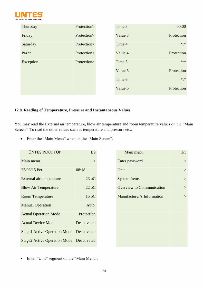
70
Thursday Protection>
Time 3 00:00
Friday Protection>
Value 3 Protection
Saturday Protection>
Time 4 *:*
Pazar Protection>
Value 4 Protection
Exception Protection>
Time 5 *:*
Value 5 Protection
Time 6 *:*
Value 6 Protection
12.8. Reading of Temperature, Pressure and Instantaneous Values
You may read the External air temperature, blow air temperature and room temperature values on the “Main
Screen”. To read the other values such as temperature and pressure etc.;
Enter the “Main Menu” when on the “Main Screen”.
ÜNTES ROOFTOP 1/9
Main menu 1/5
Main menu >
Enter password >
25/06/15 Per 08:18
Unit >
External air temperature 23 oC
System Items >
Blow Air Temperature 22 oC
Overview to Communication >
Room Temperature 15 oC
Manufacturer’s Information >
Manual Operation Auto.
Actual Operation Mode Protection
Actual Device Mode Deactivated
Stage1 Active Operation Mode Deactivated
Stage2 Active Operation Mode Deactivated
Enter “Unit” segment on the “Main Menu”.
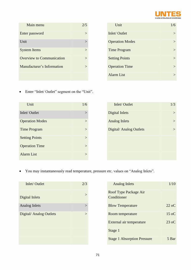
71
Main menu 2/5
Unit 1/6
Enter password >
Inlet/ Outlet >
Unit >
Operation Modes >
System Items >
Time Program >
Overview to Communication >
Setting Points >
Manufacturer’s Information >
Operation Time >
Alarm List >
Enter “Inlet/ Outlet” segment on the “Unit”.
Unit 1/6
Inlet/ Outlet 1/3
Inlet/ Outlet >
Digital Inlets >
Operation Modes >
Analog Inlets >
Time Program >
Digital/ Analog Outlets >
Setting Points >
Operation Time >
Alarm List >
You may instantaneously read temperature, pressure etc. values on “Analog Inlets”.
Inlet/ Outlet 2/3
Analog Inlets 1/10
Digital Inlets >
Roof Type Package Air
Conditioner
Analog Inlets >
Blow Temperature 22 oC
Digital/ Analog Outlets >
Room temperature 15 oC
External air temperature 23 oC
Stage 1
Stage 1 Absorption Pressure 5 Bar
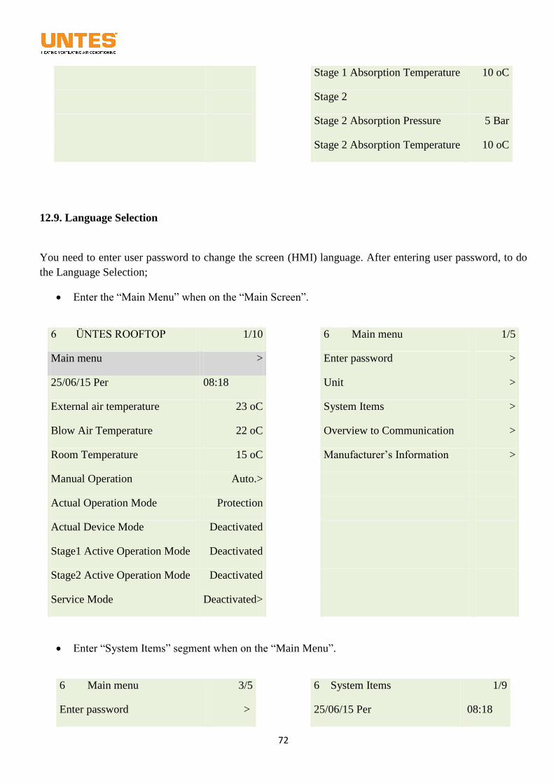
72
Stage 1 Absorption Temperature 10 oC
Stage 2
Stage 2 Absorption Pressure 5 Bar
Stage 2 Absorption Temperature 10 oC
12.9. Language Selection
You need to enter user password to change the screen (HMI) language. After entering user password, to do
the Language Selection;
Enter the “Main Menu” when on the “Main Screen”.
6 ÜNTES ROOFTOP 1/10
6 Main menu 1/5
Main menu >
Enter password >
25/06/15 Per 08:18
Unit >
External air temperature 23 oC
System Items >
Blow Air Temperature 22 oC
Overview to Communication >
Room Temperature 15 oC
Manufacturer’s Information >
Manual Operation Auto.>
Actual Operation Mode Protection
Actual Device Mode Deactivated
Stage1 Active Operation Mode Deactivated
Stage2 Active Operation Mode Deactivated
Service Mode Deactivated>
Enter “System Items” segment when on the “Main Menu”.
6 Main menu 3/5
6 System Items 1/9
Enter password >
25/06/15 Per 08:18
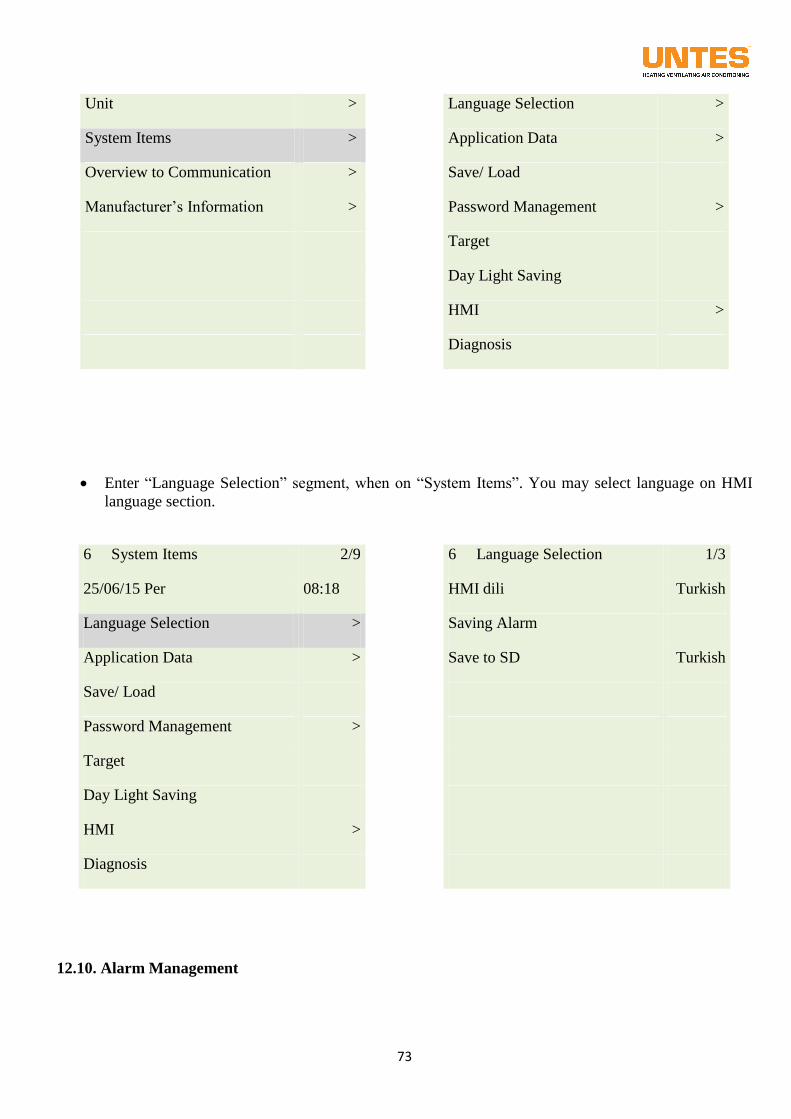
73
Unit >
Language Selection >
System Items >
Application Data >
Overview to Communication >
Save/ Load
Manufacturer’s Information >
Password Management >
Target
Day Light Saving
HMI >
Diagnosis
Enter “Language Selection” segment, when on “System Items”. You may select language on HMI
language section.
6 System Items 2/9
6 Language Selection 1/3
25/06/15 Per 08:18
HMI dili Turkish
Language Selection >
Saving Alarm
Application Data >
Save to SD Turkish
Save/ Load
Password Management >
Target
Day Light Saving
HMI >
Diagnosis
12.10. Alarm Management
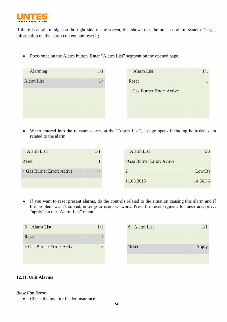
74
If there is an alarm sign on the right side of the screen, this shows that the unit has alarm system. To get
information on the alarm content and reset it;
Press once on the Alarm button. Enter “Alarm List” segment on the opened page.
Alarming 1/1
Alarm List 1/1
Alarm List 1>
Reset 1
+ Gas Burner Error: Active
When entered into the relevant alarm on the “Alarm List”, a page opens including hour-date data
related to the alarm.
Alarm List 1/1
Alarm List 1/3
Reset 1
+Gas Burner Error: Active
+ Gas Burner Error: Active >
2 Low(B)
11.03.2015 14.56.36
If you want to reset present alarms, do the controls related to the situation causing this alarm and if
the problem wasn’t solved, enter your user password. Press the reset segment for once and select
“apply” on the “Alarm List” menu.
6 Alarm List 1/1
6 Alarm List 1/1
Reset 1
+ Gas Burner Error: Active >
Reset Apply
12.11. Unit Alarms
Blow Fan Error
Check the inverter feeder insurance.
75
Check the inverter user panel and if there is any error, refer to inverter instruction manual.
Check cable connections.
Check the power motor. (mechanic and electric connections)
Check the network voltage.
Room Sensor Error Check sensor cable connections.
Check cable connections between room control unit and control panel.
Check temperature sensor on the room unit.
Blow Sensor Error
Check sensor cable connections.
External Air Sensor Error
Check sensor cable connections.
Humidity Sensor Error Check sensor cable connections.
Check sensor feeder voltage.
Freeze Error Check warm water inlet and outlet temperatures belonging to the unit.
Check the dirt holder.
Check water pressure of the installation.
Evacuate air in the installation.
Check the three-way valve motor.
Check the three-way valve.
Check inlet and outlet valves.
Check cable connections of freeze thermostat, check setting values.
Front Air Filter Error
Check the front air filter.
Compressor 1 Low Pressure Error
Check gas pressures in this stage.
Check low pressure safety element.
Check exp. valve element.
Check filter within gas circuit.
Check valve positions on gas installation.
Check electric cable connections.
Check the set value of safety element.
Check cleanness of air filter within the device.
Check cleanness of evaporator surfaces.
76
Compressor 2 Low Pressure Error
Check gas pressures in this stage.
Check low pressure safety element.
Check exp. valve element.
Check filter within gas circuit.
Check valve positions on gas installation.
Check electric cable connections.
Check the set value of safety element.
Check cleanness of air filter within the device.
Check cleanness of evaporator surfaces.
Compressor 1 High Pressure Error Check feeder switch belonging to the compressor.
Check high pressure safety element.
Check condenser fans.
Check cleanness of condenser surfaces.
Check cable connections.
Check safety elements belonging to the compressor.
Check Hp relay coil and its contacts.
Check the feeder voltage.
Compressor 2 High Pressure Error Check feeder switch belonging to the compressor.
Check high pressure safety element.
Check condenser fans.
Check cleanness of condenser surfaces.
Check cable connections.
Check safety elements belonging to the compressor.
Check Hp relay coil and its contacts.
Check the feeder voltage.
12.12. Use of Frequency Inverter
The subject under this title is explained in the frequency inverter manual in details.
13. MAINTENANCE
The protective maintenance program is a crucial part of an effective safety program. Maintenance works
should be carried out by experienced and trained personnel. In order to insure the maintenance safety, use a
repair switch near the device. Always make sure that the repair switch is off when carrying out maintenance
and repair works in order to secure yourself and prevent second people from getting involved. Do not try to
carry out maintenance works prior to cutting the electricity and insuring the safety of the fan.
13.1. Maintenance Program
77
All the maintenance works should be carried out by technicians trained about Üntes products and
considering the Üntes quality and safety standards. Please contact the directorate of technical service.
Realize all the service activities and tests throughout the working life of the unit in compliance with the
national laws in effect. If a similar measure is not present for the local administrations, one can make use of
the information regarding checks during a work in the EN 378-2 standard, Annex C.
WARNING: Prior to any operation carried out on the device, the device should always be stopped and the
main electricity feed switch should be off.
13.2. Monthly Maintenance
Check the water flow through the drainage pipe.
Check the status of the doors, insulation and hinges.
Check the filter frame and filter itself.
Check the outer and inner streamers manually and by eyes.
Check the device air input areas and damper equipment manually and by eyes.
13.3. Maintenance per Three/Six Months
Check the operative currents of the motor and the compressor.
Check the fans, the motor and the compressor for high temperatures and noise.
Check the system electricity panel and operation of the control systems.
Check the U siphon and drainage lines of the condensation pan.
Check the status of the heat exchanger pipe systems. Check the gas sight glasses.
Apply the checks for additional accessories in the relevant section of the instruction manual.
Check the filter frame, and replace the filter.
Gas pressures and temperatures should be checked.
13.4. Annual Maintenance
Check the filter frame, and replace the filter.
Check the streamers and their wings. Wash them if necessary.
Check the streamers for leaks.
Check the compressor and motor oils.
Check the operation of dampers.
Check whether device doors can open easily and whether locking systems function properly.
Check all the cables, control and insulation equipment and terminal connections etc.
Apply the checks for additional accessories in the relevant section of the instruction manual.
78
WARNING: In the event that any of the parts are replaced, refer to the relevant section of the
instruction manual and fulfill the requirements prior to operating the device again.
13.5. After Two Weeks of Study
The following checks should be carried out following the two-week operation without any problems:
Operative currents of the compressor and fan motors
Operation temperature of the compressor and fan motors
Status of the filters
Carry out condensation and drainage in order to see the water flow in the pan
Operation Status of the control systems
Sound levels should be checked in the Operation Status of the device equipment.
The device main electricity supply voltage values should be checked.
13.6. Cleaning the Device
Read carefully, and make sure that you understand, the following instructions prior to starting to clean the
device. It should never be ignored that improper and incorrect applications may cause damage to the device
and the operator during all the cleaning operations.
Fulfill the following instructions prior to dismantling the device or starting the cleaning operations as all the
devices have moving and pressured parts.
Make sure that all the electricity connections have been cut off. Not only lifting the power switch, all the
electricity connections should be removed from their mount Clemens, and a warning of maintenance
should be posted on the panel.
Make sure that all the moving parts have stopped completely.
All the switches on the supply line should be taken to the on (no electricity) position.
These instructions apply only to the cleaning of Attic Type air conditioners. It is supposed that all the other
parts of the system (inner parts of air channels, culverts and shades opening outdoors, culvers of air turning
from the room, damping supply water cleaning, condensation water drainage systems etc…) have been
cleaned in compliance with the instructions provided by their manufacturers.
It should never taken to mean that fulfilling the cleaning and disinfection operations according to these
instructions will insure the wanted hygienic conditions of the place. Air conditioning systems cannot make
the environment hygienic. They are used only to maintain the hygienic conditions currently in place. The
user will be responsible for monitoring, and replacing on time, HEPA filters on the exit of the system.
79
13.6.1. Equipments to Be Used During Cleaning
The professionals working for the cleaning should be wearing the following costumes. This is required both
for the protection of the workers and the device to be cleaned.
A clean coverall
Protective goggles
Latex gloves (dirty gloves should immediately be replaced during cleaning and disinfection operations).
Antiseptic half mask - respiratory equipment
Protection worn on the shoes
Following the completion of the cleaning and disinfection operation, all the dressing items except for the
coverall should be disposed. The coverall can, however, be used again after being cleaned and disinfected
properly.
13.6.2. Disposal of Wastes to be Generated after Cleaning
During the cleaning of the devices, both solid wastes (Filter contaminated replaced, operator dressing items,
worn belts (if any), etc.) and liquid wastes (washing water and rinse water remnants) come into existence.
Solid wastes should be put into non-permeable boxes and disposed wit the wastes of a hospital. Different
from this, liquid wastes will be disposed through the waste water system of the air conditioner. This system
should previously be connected to the waste water system of the building.
13.6.3. Cleaning Method
As roof-type air conditioners contain electrical parts (electrical motor, micro processor, sensors, etc...), they
may be damaged in the event that they are exposed to high temperatures or water. The cooling system may
also be damaged under high pressures. Thus the following elements should not be used during the cleaning:
Hot steam jet,
Intensive water jet,
Water and disinfectant required for the disinfection operation should be used in an atomized way. Rinsing
should also be carried out this way. Liquid wastes should be sent to the drainage system afterwards.
Atomized water can be obtained through manually controlled atomizer equipment. For the cleaning and
washing process, water with 4% ammonium chloride added may be used. Another chemical equivalent to
ammonium chloride may be used instead.
We can examine the cleaning of roof-type air conditioners under three main sections.
Cleaning of Technical Parts: This section involves the control equipment,, compressor and such equipment
items. There is no need for disinfection in this section. Besides, they should be cleaned once every six
months with other disinfection operations in accordance with the following procedure.
Cleaning of Operative Parts: This section details the parts responsible for conditioning the air. These
parts are in touch with both the air taken from the outside and contained inside the device and the air
turning from the environment (for the mixing air devices).
Filtering systems are located in the air suction part, while bacteria can find suitable places to settle and
reproduce themselves by time in the turning air and dispersion parts of the unit. This is possible over long-
term operation of the device. It may result in a risk in later operations of the device.
80
These parts should be washed and disinfected by using the methods to be presented later on. The cleaning
operation should be carried out at least once a month. This cleaning should be repeated for the places known
for bacteria to have a potential to reproduce them.
Cleaning of Outer Surfaces of Devices; As the outer surfaces of the devices are painted, only fulfilling
the cleaning operation will suffice. This cleaning should be carried out in accordance with the criteria
and methods described below.
Each part will have a different cleaning and disinfection procedure due to its unique features. For that
reasons, the procedures are presented below under three main titles.
Procedure of cleaning the technical parts
Procedure of cleaning and disinfecting the inside of operative parts
Procedure of cleaning the outer part of the device
13.6.3.1 Cleaning Procedure of the Technical Part
Technical parts should be cleaned with a vacuum and replaceable paper filtered cleaning instrument (like a
vacuum cleaner) and a soft brush. There is n need for disposing the paper filter with septic wastes unless
otherwise stated to technicians.
Fulfill the following instructions throughout the cleaning process:
Stop the device and take the main switch and the service switch to the off position to cut the electricity.
Post onto the electricity panel a note stating that the device has been serviced and the electricity switch
should never be taken to the on position.
Open the cover of the technical part by using the appropriate spanner.
Make the vacuum cleaner absorb the dust on the equipment and the wall. This operation should be carried
out from the top towards the bottom.
Wipe the device cover with a damped clothe.
Then wipe carefully the side walls and the cover with a clean and dry clothe.
Close the cover carefully in order to avoid damages to the power switch.
If operative parts and the outer surface are not to be cleaned, take the power switch to the on position to
supply electricity to the device again. The device is now ready for working.
13.6.3.2 Procedure of Inner Cleaning and Disinfection of Operating Parts
İnner surfaces of operative parts are continuously in touch with outdoor air and and the indoor air (for
mixing air devices). Even though filters are located inside the unit and in the outdoor air input this touch
causes micro-organisms to settle and reproduce on the inner surfaces of the device. Thus these surfaces
should be periodically cleaned and disinfected.
81
Unless otherwise stated by responsible technicians, this operation should be carried out at least once every
six months regardless of the device being used or not. In this case, the cleaning and disinfection operation
should be materialized independent from periodical cleaning.
The following procedure should be followed for cleaning and disinfection.
Make sure that you have all the required materials and replacement filters.
Stop the device and take the main switch and the service switch to the off position to cut the electricity.
Post onto the electricity panel a note stating that the device has been serviced and the electricity switch
should never be taken to the on position.
If they are dirty, dismantle the filters in the fresh air input and insure their disposal in compliance with
the solid waste disposal procedure.
For mixing air devices, , dismantle the filters in the turning air section and replace them. All the
dismantled filters should be put into an insulated box and disposed in compliance with the solid waste
disposal procedure stated by the local authorities. The section between the turning air damper and the
filter mount should be cleaned in such a way as to leave no sign for contamination.
The filters on the device should be dismantled (the G4 quality filter in the outdoor air input). All the
dismantled filters should be put into an insulated box and disposed in compliance with the solid waste
disposal procedure stated by the local authorities. Replacement filters should be attached later on.
Otherwise, they may be damaged or polluted during cleaning and disinfection operations.
Wash completely and disinfect operative parts on the exhaling side by using 4% ammonium chloride
thanks to a manual atomizer in the following order.
o Air exhaust damper for free heating/cooling devices
o Turning air fan for free heating/cooling devices Make sure that the entire fan rotor is washed by
turning it manually.
o Heat exchanger on the fresh air side for free cooling/heating heating devices solution should be
sprayed from the front top of the heat exchanger and spraying should be continued until solution flows
from the back bottom of the heat exchanger.
o All the pipes included in the cell for free cooling/heating devices
o Turning air damper and its wings for free heating/cooling devices
o The section between the filter and the damper for free heating/cooling devices
o Side walls of the entire section for free heating/cooling devices (provided that it starts from the top)
Rinse the operative parts on the exhaling side washed completely by spraying sterilized water in a
pulverized manner. Rinsing should be carried out in the order specified above, that is to say, in the same
step with the washing.
Mount the new filters into its proper places in the unit.
Make sure that all the inner parts are completely dry.
Lift the main power switch and the service switch to supply electricity.
Your device is now ready for working.
13.6.3.3 Procedure of Exterior Cleaning of Devices
If the device is placed in a surgery room or any of side rooms of a surgery room (anesthesia room,
intensive care, surgery monitoring room etc.) the outer surfaces should be cleaned with every inner cleaning
unless otherwise stated by the surgery room technician. If the device is placed in a technical room with no
82
direct connection to a surgery room, cleaning should be carried out only if dust and dirt exist on the outer
surfaces.
The outer case should be cleaned in the following manner.
Stop the device and take the main switch and the service switch to the off position to cut the electricity.
Post onto the electricity panel a note stating that the device has been serviced and the electricity switch
should never be taken to the on position.
Clean the outer case with any alcoholic solution (or any chemically equivalent solution). Cleaning should
be carried out by spraying the solution onto the device. Wipe the device dry with a soft cloth. Do not use
benzene-like solvents (acetone, oil, etc.) or corroding cleaning powders for cleaning the device. Clothes
used for cleaning should be put into a closed box and disposed with the other solid wastes of the hospital.
Lift the main power switch and the service switch to supply electricity following the completion of cleaning.
14. PROBLEM ANALYSIS
In this section, the operator will be provided with some information to understand the reason for the problem
and eliminate the problem for various types of problems. The tables have been designed to help understand,
and describe ways of solutions of, frequently encountered problems. Descriptions of reasons are generalized.
Thus the explanations herein are not model-dependent. Considering the device having the problem,
indicators and ways of solution should be examined presented in the section of the relevant problem.
Replacements and repairs to the device should be carried out by trained professionals. Do not try to carry out
these repairs yourselves if you lack sufficient information regarding the operational principles of the device.
Refer to the assistance of professionals for this purpose. Prior to any operation on the device, always cut off
the electricity and remember to post onto the panel a note stating that the device is under maintenance and
the it should never be operated.
14.1. Failure Finding and Troubleshooting Table
Problem Reason Solution
Device does not
operate
No power. The main switch is on. The phase
order is incorrect. Low voltage. A protection
failure. The contactor is open Compressor
failure
Connect the power source, Turn off the
main unit power cut switch, Check the
voltage and eliminate insufficiency,
Resetting, Check the contactor and replace
it if necessary, Check the compressor and
replace it if necessary
The unit starts to
operate and then stop
too often
Failed compressor contactor. Failed
compressor. Gas loss from the cooler
Changing input voltage.
Check the contactor and replace it if
necessary, Check the compressor and
replace it if necessary, Check the cooler gas
amount
The unit remains at
the low suction
temperature
Cooling unit/heat pump, failed low pressure
Switch, gas loss from the cooler, Inner/Outer
fan does not operate
Check the low pressure Switches and
replace them if necessary, check the cooling
gas amount and add if necessary, Check the
fan motors,
The unit constantly Cooling unit/heat pump, Failed high pressure Check the pressure Switches and replace
83
remains at the
saturated force
temperature
Switch, Blocked filter dryer, Indoor/Outdoor
fan does not operate,
them if necessary, Check the filter and
replace it if necessary, Check the fan
motors,
The device makes an
unusual sound
Noisy compressor,
Badly mounted panels
Check it and replace it if necessary,
Compressor oil System leak Repair the leaks,
Water loss Failed drainage connections Check and tighten the connections if
necessary,
This warranty provided by Üntes does not cover the elimination of failures due to using of the device in a
manner different from its purpose of use, nor does it cover the following situations.
1. Damages and failures due to a usage error
2. Damages and failures to occur during the loading, unloading and carrying after the delivery of the product
to the customer
3. Damages and failures due to low or high voltages; improper electric wiring; use of a different voltage
from what is printed on the product label and the instruction manual.
4. Damages and failures due to a fire or lightning
5. Failures due to use in a manner not written in the instruction manuals of the product
6. Failures due to someone apart from authorized service professionals involving the product
The afforested problems shall be eliminated against determined fees, and the period of warranty starts with
the billing date.
TSB-KK-008 rev.00
SERVICE STATIONS FOR SPARE PARTS PROCUREMENT
Export Sales Directorate
53. Cadde 1450. Sokak Ulusoy Plaza No:9 / 50 Cukurambar - ANKARA - TURKEY
Phone: +90 (312) 287 91 00 (pbx) - Fax: +90 (312) 284 91 00
Package Air Conditioners Production Factory
Istanbul Yolu 37. Km Kazan – ANKARA
Phone: +90 (312) 818 63 00 (pbx) - Fax : +90 (312) 818 61 50
Email: [email protected]
Web: www.untes.com.tr