Embed Size (px)
Citation preview

ROEQ TR125 Top Roller user guide V1.3 1
ROEQ TR125 Top Roller system Original User Guide (en)

ROEQ TR125 Top Roller user guide V1.3 2
Copyright and disclaimer All rights reserved. No parts of this manual may be reproduced in any form without the express written permission of ROEQ ApS. ROEQ makes no warranties, express or implied, in respect of this document or its contents. In addition, the content of the document is subject to change without prior notice. Every precaution has been taken in the preparation of this manual. Nevertheless, ROEQ assumes no responsibility for errors or omissions or any damages resulting from the use of the information contained. Copyright © 2019 by ROEQ ApS.
Contact the manufacturer: ROEQ ApS Kobbervænget 5 DK-5492 Vissenbjerg www.ROEQ.dk [email protected] CVR: 38656872
ROEQ TR125 Top Roller user guide V1.3 3
Contents 1. Introduction ............................................................................................................................................... 5
1.1. Intended readership .......................................................................................................................... 5
1.2. Where to find information ................................................................................................................ 5
1.3. User guide release history ................................................................................................................. 5
2. Safety ......................................................................................................................................................... 6
2.1. Overview ............................................................................................................................................ 6
2.2. Safety concept ................................................................................................................................... 6
2.3. General safety instructions ................................................................................................................ 7
Warning notes ........................................................................................................................................... 7
Notices ....................................................................................................................................................... 9
2.4. Safety circuit .................................................................................................................................... 10
2.5. Risk assessment ............................................................................................................................... 10
2.6. Roller and Lifter standstill during emergency stop ......................................................................... 10
2.7. Preventing accidents from dangling packages ................................................................................ 11
2.8. Preventing accidents from undesired unload of packages ............................................................. 12
2.9. Safety system specifications ............................................................................................................ 12
2.10. Intended use ................................................................................................................................ 13
2.11. Directives ..................................................................................................................................... 13
2.12. Identification label ....................................................................................................................... 13
3. Detailed presentation .............................................................................................................................. 14
3.1. Product description ......................................................................................................................... 14
3.2. ROEQ Top Roller .............................................................................................................................. 14
4. ROEQ Top Roller installation ................................................................................................................... 16
4.1. Unpacking and installing the ROEQ Top Roller System ................................................................... 16
4.2. Setting up SICK safety configuration ............................................................................................... 19
4.2.1. Connecting to the Sick safety system .......................................................................................... 19
4.2.2. Setting up COM settings .............................................................................................................. 20
4.2.3. Taking Backup of existing laser configuration (Recommended) ................................................. 22
4.2.4. Uploading ROEQ safety configuration to the Sick system ........................................................... 24
4.3. Generating docking points for the system ...................................................................................... 29
4.4. Using the ROEQ Top Roller missions ............................................................................................... 33
4.4.1. Mission parameters ..................................................................................................................... 35
Mission timeout ...................................................................................................................................... 35

ROEQ TR125 Top Roller user guide V1.3 4
Operating height ..................................................................................................................................... 35
4.4.2. Error statuses ............................................................................................................................... 35
Timeout ................................................................................................................................................... 35
Conveyor full ........................................................................................................................................... 35
Risk of dangling packages ....................................................................................................................... 36
MiR emergency stop ............................................................................................................................... 36
Unsuitable unload position .................................................................................................................... 36
4.4.3. Removing an emergency stop caused by dangling package ....................................................... 36
4.4.3.1. Remarks ................................................................................................................................... 38
4.5. Interfacing external conveyor systems ............................................................................................ 38
4.5.1. Docking marker behind front of external station (Recommended) ............................................ 39
4.5.2. Docking position with marker aligned with front of external station ......................................... 40
4.5.3. Installing docking sensor reflector............................................................................................... 41
5. Accessories for ROEQ Top Roller ............................................................................................................. 43
5.1. Stand-alone docking station ............................................................................................................ 43
6. Technical Specifications ........................................................................................................................... 44
6.1. Cargo specification .......................................................................................................................... 45
7. Maintenance ............................................................................................................................................ 48
7.1. Regular cleaning and inspection ...................................................................................................... 48
8. Declaration of conformity ....................................................................................................................... 49

ROEQ TR125 Top Roller user guide V1.3 5
1. Introduction
1.1. Intended readership The purpose of this user guide is to support the system integrator in setting up the ROEQ Top Roller 25 for
MiR 100 and ROEQ Top Roller 125 for MiR 200.
The descriptions throughout the guide assumes a basic level of knowledge regarding the setup process of
the MiR robot and software interface. Furthermore, the installation process of the Top Roller requires some
level of software knowledge and craftmanship.
This user guide contains all necessary information about the installation and usage of ROEQ Top Roller and
related equipment.
This version of the guide is specifically directed towards ROEQ Top Roller hardware version 1.4.0 (Roller
only) and version 2.1.1 (Roller with lifter).
1.2. Where to find information On www.roeq.dk, distributor site (login required), a wide range of information can be found, e.g.: software
update, User Guide, Sick safety zones, 3D CAD files and more.
Further, this product is shipped with a USB key holding a digital copy of this guide as well as numerous tools
relevant for various steps in the commissioning and service tasks of the TR125.
1.3. User guide release history This document applies to the following product versions
Document version Release date Description
1.3 2019.09.27 Added more details to the cargo specification.
Additional minor updates.
1.2 2019.05.30 Added section on lifter missions
1.1 2019.05.27 Added section on docking sensor
1.0 2019.04.01 New Document

ROEQ TR125 Top Roller user guide V1.3 6
2. Safety This product is partly completed machinery (according to EU directive 2006/42/EF, Machinery Directive)
and as such a risk assessment is required for each installation.
It is particularly important that all the safety instructions and warnings in following in sections are followed.
2.1. Overview This manual contains notices to be observed to ensure personal safety and to prevent damage to property. The notices referring to personal safety are highlighted in the manual by a safety alert symbol. The notices shown below are graded by signal words to indicate degree of danger. The ROEQ products are intended to be used with MiR100™/MiR200™ robots.
Read the MiR manual carefully before commissioning the combined solution.
In the following some safety issues may be identical to sections of the MiR user guide.
2.2. Safety concept

ROEQ TR125 Top Roller user guide V1.3 7
2.3. General safety instructions This section contains general safety notes. Some safety notes are repeated or further specified in other sections of the manual and further safety notes are present throughout the manual.
Warning notes
• Ensure proper mounting of load during transport
Danger of personal injury from overturning robot or falling load.
Goods loaded on top of the Top Roller must be placed correctly and meet
specifications stated in section 6.
• Avoid leakage of fluid during transport
Danger of personal injury from leaking fluid.
Make sure that loads containing fluids do not leak during transport.
• Update maps to avoid hazards on the route
Danger of personal injury and/or damage to the robot.
Make sure to update maps to avoid driving in hazardous zones such as
close to stairways.
• Do not drive vehicle irresponsibly
Danger of personal injury and/or damage to the robot.
The robot should not be driven over edges or in other ways operated
irresponsibly.
• Only use TR125 for transporting approved cargo
Always comply with the cargo specifications outlined in section 6 -
Technical Specifications.
Risk of package dropping to the ground if moving the robot.
Risk of personal injury and/or damage to goods, Top Roller, and robot.
• Ensure proper loading and unloading of packages
Do not leave packages partially supported by both the Top Roller and an
external conveyor system.
Risk of package dropping to the ground if moving the robot.
Risk of personal injury and/or damage to goods, Top Roller, and robot.
• Ensure proper docking before unloading packages
Do not attempt to unload a package without first docking the robot at an
appropriate station to receive the package.
Risk of package dropping to the ground.
Risk of personal injury and/or damage to goods, Top Roller, and robot.

ROEQ TR125 Top Roller user guide V1.3 8
• Align the height of the load and unload stations with that of the Top Roller
Do not allow for a significant drop when transferring packages from or to the
top roller using external loading or unloading stations.
Risk of personal injury and/or damage to goods, Top Roller, and robot
• Where to place
Avoid driving in areas with obstacles and always keep all drive paths clean
and free for obstacles.
Avoid placing docking stations on slopes.
Always check weight/speed/slope conditions before commissioning.

ROEQ TR125 Top Roller user guide V1.3 9
Notices
• Indoor use only
Risk of damage to the robot and/or Top Roller.
The robot and Top Roller are made for indoor use only and should never be
used outdoor.
• Avoid small objects on the floor in the robot’s area
Risk of property damage and/or minor damage to the robot.
The robot cannot detect obstacles lower than 50mm and may overrun
smaller objects.
• Remove unwanted object from the floor in the robot’s area
Risk of inefficient execution of orders.
The robot will go around objects that are not part of the map, but this may
influence the efficiency of the planned route.
• Avoid overheating of components
Risk of damage to the robot or robot components.
The ambient temperature in the robot’s environment must not exceed 50
degrees Celsius - 122 degrees Fahrenheit.
• Avoid exposure of the robot to excessively humid or dry environment
Risk of damage to the robot or robot components.

ROEQ TR125 Top Roller user guide V1.3 10
2.4. Safety circuit Using the ROEQ equipment does not overrule the safety circuit principle made by MiR. Same principles are
valid after installation of ROEQ Top Roller and if a person or other moving object enters the safety zones of
the robot, where the planner due to response time, errors etc. does not respond, the safety circuit will
force the robot into emergency stop, and the robot stops immediately. When the person or object is out of
the safety zone again, the robot will automatically reset the emergency stop. When installing a ROEQ Top
Roller on a MiR100™/MiR200™ the system will utilize the standard SICK safety zones specified by MiR.
The ROEQ Top Roller system is not designed to handle objects which exceeds the size of the conveyor and
will therefore not change the size of the safety zones managed by SICK Safety Components.
MiR100™/MiR200™ is designed with total redundant electrical safety circuit including Sick Safety
Components. If any internal errors in the safety circuit occur, the robot will immediately go into emergency
stop which means that all moving parts will be unpowered. This include the motor for the Top Roller. Only
when the redundancy is provided, it is possible to reset the emergency stop and continue.
For more information, refer to MiR user guide.
2.5. Risk assessment To ensure safe installation make sure to make a risk assessment. The risk assessment is the responsibility of
the individuals who are commissioning the product in the environment it will be used in. The risk
assessment must cover the robot, the top application (Top Roller) and corresponding load transfer, work
cells and the environment it will be used in.
It is recommended to follow guidelines in ISO 12100, EN 1525, ANSI B56.5 or other relevant standards to
conduct the risk assessment.
2.6. Roller and Lifter standstill during emergency stop The top roller is designed to cut the power from the roller motor, whenever an emergency stop is triggered.
Similarly, the power is removed from the lifting system in TR125 systems with automatic height
adjustment. This is to force a complete standstill of both rollers and lifting system during emergency stop of
the robot.
Any top roller mission active when the MiR experiences an e-stop is cancelled and an error message is
shown in the MiR interface:
Figure 1 Error message during e-stop
This is to avoid unexpected startup of the rollers, when an emergency stop is lifted.
ROEQ TR125 Top Roller user guide V1.3 11
Notice: While the MiR is en emergency stop, no error message is visible. The message is only shown when
the emergency stop is resolved.
For top roller systems with automatic height adjustment, the lifting system will descend to a fully lowered
position following an emergency stop. This is to prevent the robot moving with cargo in an elevated position.
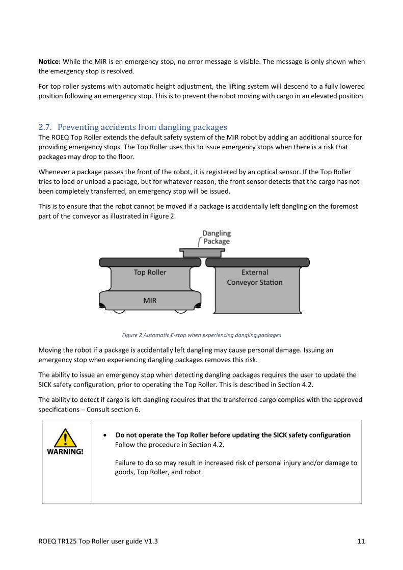
2.7. Preventing accidents from dangling packages The ROEQ Top Roller extends the default safety system of the MiR robot by adding an additional source for
providing emergency stops. The Top Roller uses this to issue emergency stops when there is a risk that
packages may drop to the floor.
Whenever a package passes the front of the robot, it is registered by an optical sensor. If the Top Roller
tries to load or unload a package, but for whatever reason, the front sensor detects that the cargo has not
been completely transferred, an emergency stop will be issued.
This is to ensure that the robot cannot be moved if a package is accidentally left dangling on the foremost
part of the conveyor as illustrated in Figure 2.
Figure 2 Automatic E-stop when experiencing dangling packages
Moving the robot if a package is accidentally left dangling may cause personal damage. Issuing an
emergency stop when experiencing dangling packages removes this risk.
The ability to issue an emergency stop when detecting dangling packages requires the user to update the
SICK safety configuration, prior to operating the Top Roller. This is described in Section 4.2.
The ability to detect if cargo is left dangling requires that the transferred cargo complies with the approved
specifications – Consult section 6.
• Do not operate the Top Roller before updating the SICK safety configuration
Follow the procedure in Section 4.2. Failure to do so may result in increased risk of personal injury and/or damage to goods, Top Roller, and robot.

ROEQ TR125 Top Roller user guide V1.3 12
• Only use TR125 for transporting approved cargo
Always comply with the cargo specifications outlined in section 6 - Technical
Specifications.
Risk of package dropping to the ground if moving the robot.
Risk of personal injury and/or damage to goods, Top Roller, and robot.
2.8. Preventing accidents from undesired unload of packages To avoid packages being unloaded at an unsuitable position, the top roller is equipped with an optical
docking sensor to verify when a package can be unloaded.
The sensor is mounted on the front of the top roller, underneath the emergency stop button:
Figure 3 Docking sensor
For the top roller to allow unloading of packages, this sensor needs to be in line of sight with a reflector, to
indicate that the robot is correctly positioned, for unloading.
The top roller is shipped with two reflectors:
Figure 4 Reflector for the docking sensor
The reflectors that must be installed by the user on any external conveyor station that packages must be
unloaded onto – See “Installing docking sensor” under section 4.5.
2.9. Safety system specifications The regulations and specifications regarding the MiR100™/MiR200™ safety system stated in the user
guide supplied by MiR remains valid when installing the ROEQ Top Roller system.

ROEQ TR125 Top Roller user guide V1.3 13
2.10. Intended use The ROEQ product portfolio of MiR accessories is intended to operate in the same conditions as the MiR
robot and apart for ROEQ specific requirements stated in section 6, the limitations given by MiR apply.
In particular, when moving cargo with the ROEQ TR systems, the user must take care in complying with the
MiR payload and center-of-mass specifications.
2.11. Directives The ROEQ Top Roller has been designed and manufactured in accordance to the following EU directives:
2.12. Identification label This section illustrates the placement of the ROEQ identification label and describes the content of the
label.
ROEQ ApS
Kobbervænget 5
DK-5492 Vissenbjerg
Denmark
Serial number: X100265A500000010
Made in Denmark 2019
- CE ROEQ ApS. declares that the ROEQ Top Roller meets the
requirements of the applicable EC directives.
See Declaration of conformity in Appendix 8.
- Serial number A unique serial number is given to all CE approved ROEQ products.
• The first digit refers to the product variant
o 5 = Top Roller for MiR100/MiR200 - auto height adjust.
o 6 = Top Roller for MiR100/MiR200 - manual height adjust.
o Second, third and fourth digit states the hardware version
• 265A5000 is the ROEQ product code
• The last five digits is the sequential number
The identification label can be found in back left corner underneath the rollers (on the aluminum plate)
Directive Description
2006/42/EF Directive of Machinery

ROEQ TR125 Top Roller user guide V1.3 14
3. Detailed presentation This section gives an in dept description of the ROEQ Top Roller system.
3.1. Product description The ROEQ Top Roller is an accessory for the MiR100/200™ which allows the robot to serve as a part of an
automated internal logistic system by performing automated pickup and delivery of various types of
packages and containers.
The ROEQ Top Roller works in conjunction with the software embedded on the MiR robot and acts as an
extension of the robot’s autonomous capabilities.
After installing the ROEQ Top Roller on Top of MiR100/200 the robot can operate between locations
specified by the user.
The ROEQ Top Roller is fully compatible with MiR100 hardware version 2.0 and MiR200 hardware version
1.1 and newer versions.
3.2. ROEQ Top Roller
Pos. Description Pos. Description
1 Rear sensor 6 Conveyor base
2 Top Roller 7 Side rails
3 Wi-Fi antenna 8 Front sensor
4 Emergency stop button 9 ROEQ Button
5 Reset button

ROEQ TR125 Top Roller user guide V1.3 15
Pos. Description Pos. Description
1 Front sensor 3 Top Roller installation bolts
2 Emergency stop button 4 Top camera supplied by MiR
ROEQ TR125 Top Roller user guide V1.3 16
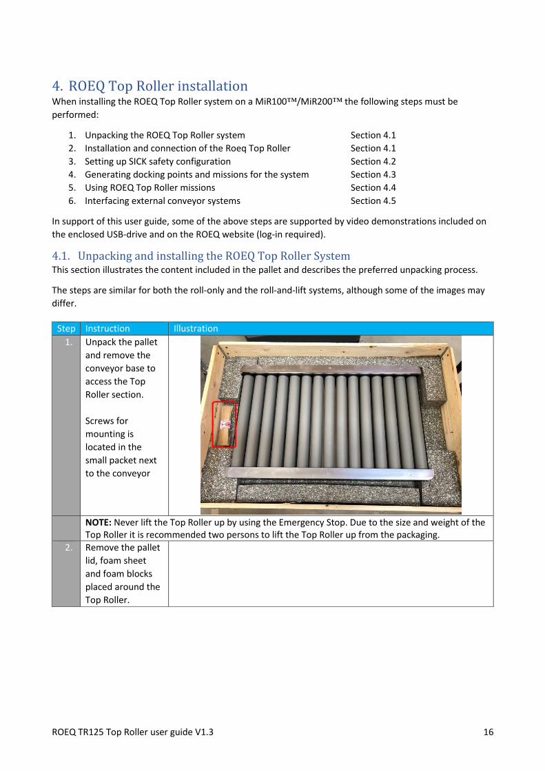
4. ROEQ Top Roller installation When installing the ROEQ Top Roller system on a MiR100™/MiR200™ the following steps must be
performed:
1. Unpacking the ROEQ Top Roller system Section 4.1
2. Installation and connection of the Roeq Top Roller Section 4.1
3. Setting up SICK safety configuration Section 4.2
4. Generating docking points and missions for the system Section 4.3
5. Using ROEQ Top Roller missions Section 4.4
6. Interfacing external conveyor systems Section 4.5
In support of this user guide, some of the above steps are supported by video demonstrations included on
the enclosed USB-drive and on the ROEQ website (log-in required).
4.1. Unpacking and installing the ROEQ Top Roller System This section illustrates the content included in the pallet and describes the preferred unpacking process.
The steps are similar for both the roll-only and the roll-and-lift systems, although some of the images may
differ.
Step Instruction Illustration
1. Unpack the pallet
and remove the
conveyor base to
access the Top
Roller section.
Screws for
mounting is
located in the
small packet next
to the conveyor
NOTE: Never lift the Top Roller up by using the Emergency Stop. Due to the size and weight of the
Top Roller it is recommended two persons to lift the Top Roller up from the packaging. 2. Remove the pallet
lid, foam sheet
and foam blocks
placed around the
Top Roller.

ROEQ TR125 Top Roller user guide V1.3 17
3. After unpacking
both the Conveyor
base and the Top
Roller, place the
conveyor base on
top of the MiR
robot.
4. Fasten the
conveyor base to
the MiR robot by
using the four M10
bolts included in
the pallet.
5. Plug in the 4 pin
and 10 pin
connectors as well
as the ethernet
and Wi-Fi cable.
6. Place the Top
Roller unit on top
of the conveyor
base, while making
sure not to
damage the
cables.
ROEQ TR125 Top Roller user guide V1.3 18
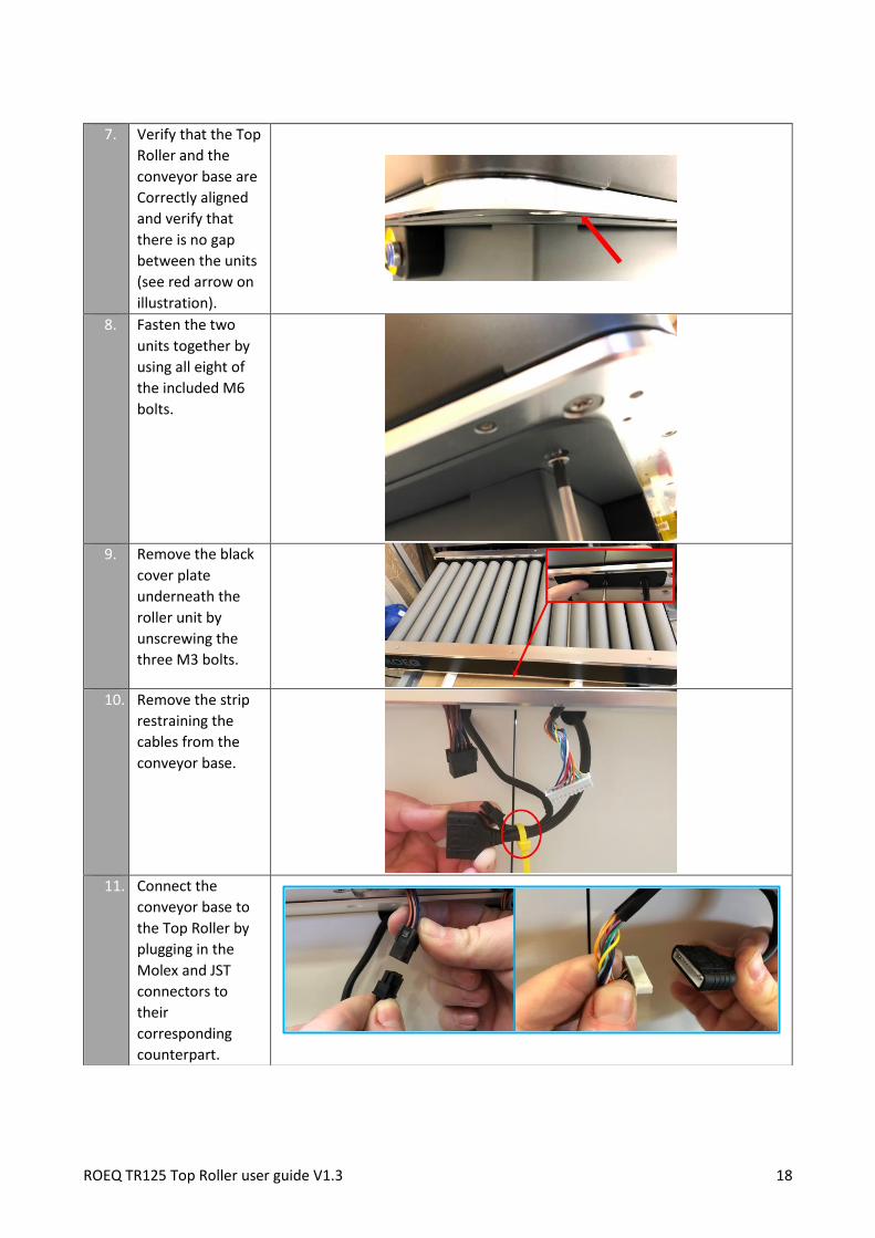
7. Verify that the Top
Roller and the
conveyor base are
Correctly aligned
and verify that
there is no gap
between the units
(see red arrow on
illustration).
8. Fasten the two
units together by
using all eight of
the included M6
bolts.
9. Remove the black
cover plate
underneath the
roller unit by
unscrewing the
three M3 bolts.
10. Remove the strip
restraining the
cables from the
conveyor base.
11. Connect the
conveyor base to
the Top Roller by
plugging in the
Molex and JST
connectors to
their
corresponding
counterpart.

ROEQ TR125 Top Roller user guide V1.3 19
4.2. Setting up SICK safety configuration
• Updating the safety system is mandatory before using the ROEQ Top Roller
Read this section carefully and be sure to perform the safety system update as described.
This section describes the process for updating the SICK safety configuration on the MiR robot prior to
using the ROEQ Top Roller. An updated safety configuration is required to enable the Top Roller in issuing
emergency stops to the robot, when experiencing dangling packages.
4.2.1. Connecting to the Sick safety system Since the Sick safety system is interfaced with proprietary Sick software, the two programs Sick Flexi Soft
Designer and Sick CDS software must be installed on the PC used to update the SICK system. All software
necessary for the implementation of the ROEQ Top Roller is included on the enclosed USB-drive. Sick Flexi
Soft Designer utilizes CDS to configure the scanners.
Note: It is highly recommended to back up (upload) the existing safety configuration for the Main Module
and both Front- and Rear laser scanners before transferring (download) the new configuration. This is
described later in this instruction.
Definition of terms in the Sick program:
12. Carefully insert the
assembled
connectors into
the cable slots and
reinstall the black
cover plate.
13. Mount the two
included cable tie
mounts and route
the cables being
careful not to
damage the
cables.
Tighten the cables
ties.
Step Instruction
1. Log on to the robots Wi-Fi.
2. Connect to the robot via web browser: mir.com
ROEQ TR125 Top Roller user guide V1.3 20
• Download to scanner: Here the laser scanners are the units to be downloaded to (will be stored on
laser scanners).
• Upload to PC: Here the PC connected to the robot (laser scanners) is the unit to be uploaded to
(will be stored on PC)
•
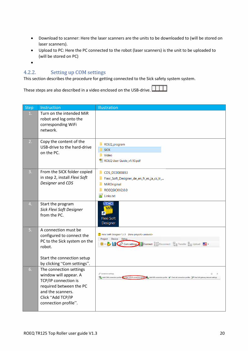
4.2.2. Setting up COM settings This section describes the procedure for getting connected to the Sick safety system system.
These steps are also described in a video enclosed on the USB-drive.
Step Instruction Illustration
1. Turn on the intended MiR robot and log onto the corresponding WiFi network.
2. Copy the content of the USB-drive to the hard-drive on the PC.
3. From the SICK folder copied
in step 2, install Flexi Soft Designer and CDS
4. Start the program
Sick Flexi Soft Designer from the PC.
5. A connection must be
configured to connect the PC to the Sick system on the robot. Start the connection setup by clicking “Com settings”.
6. The connection settings window will appear. A TCP/IP connection is required between the PC and the scanners. Click “Add TCP/IP connection profile”.

ROEQ TR125 Top Roller user guide V1.3 21
7. To create the new profile, fill out the entry name and set the IPv4 address to 192.168.12.9, which is the IP of the safety system. Click “OK”.
8. Click the check mark to test the connection. When the connection is accepted, mark the connection as default by double clicking the connection. Click “OK” to terminate the setup.

ROEQ TR125 Top Roller user guide V1.3 22
4.2.3. Taking Backup of existing laser configuration (Recommended)
This section describes the procedure for taking backup of existing Sick configurations before transferring
the ROEQ Sick configuration from the enclosed USB-drive.
Step Instruction Illustration
1. Click “Connect” to connect to the main Module. When the connection is done (takes some time), the SICK main Module will be ready for doing the backup.
2. Select YES to: Do you want to upload the configuration on “SICK Flexi Soft main module FX3-CPU1”?
3. Double click the front laser (S300.CPU1[0].EFI1.1)
4. Select “Read configuration from device”
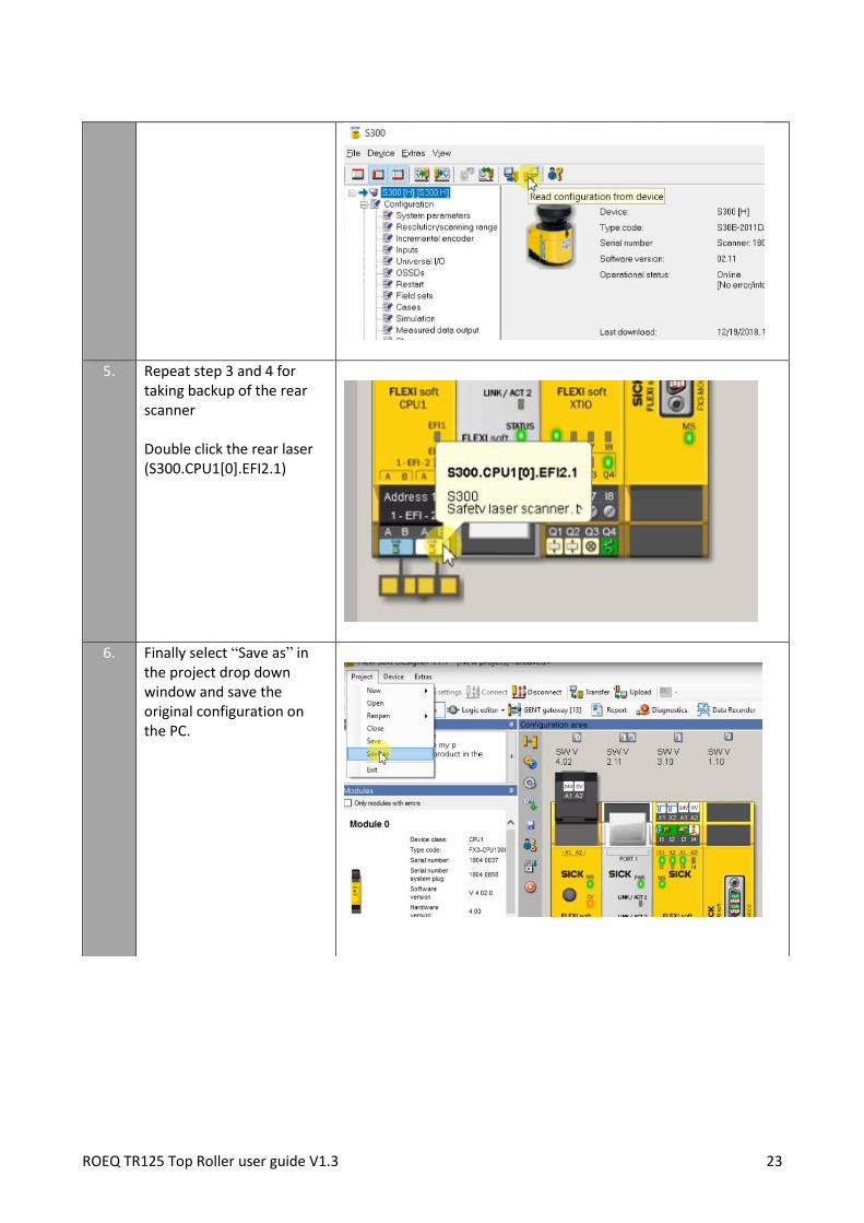
ROEQ TR125 Top Roller user guide V1.3 23
5. Repeat step 3 and 4 for taking backup of the rear scanner Double click the rear laser (S300.CPU1[0].EFI2.1)
6. Finally select “Save as” in the project drop down window and save the original configuration on the PC.

ROEQ TR125 Top Roller user guide V1.3 24
4.2.4. Uploading ROEQ safety configuration to the Sick system
This section describes the procedure for transferring the ROEQ configuration from the enclosed USB-drive
to the Sick system.
It is highly recommended that the files stored on the enclosed USB-drive are saved in a local folder on the
PC used for the SICK setup, before continuing with the following step.
Step Instruction Illustration
1. From the SICK folder copied previously, unzip the safety configuration suitable for your robot (MiR100/MiR200) and the correct serial number.
2. From within the Flexisoft Designer, open the provided ROEQ safety configuration for the Sick system: Project → Open → choose the project unzipped above. The correct file to upload must be chosen based on robot type (MiR100/MiR200) and the serial number of the robot.

ROEQ TR125 Top Roller user guide V1.3 25
3. Click “Connect” to connect to the main Module. When the connection is done, the SICK main Module will be ready for transferring the safety configuration.
4. Click “Transfer the configuration” to transfer the ROEQ configuration to the main Module and the two S300 laser scanners.
5. Make sure that both S300 scanners and the main Module are marked and click “OK”. The password for uploading the new safety zones is: SICKSAFE

ROEQ TR125 Top Roller user guide V1.3 26
6. Please check the configuration protocol carefully for both scanners and proceed by clicking “Release”. These can be saved if needed.
7. Although the old main Module is verified, click “yes” to download the new configuration and run the new head device.

ROEQ TR125 Top Roller user guide V1.3 27
8. Verify the new checksum by clicking “yes”.

ROEQ TR125 Top Roller user guide V1.3 28
9. Mark the option for Authorized Client user group and click “OK”.
10. Select “Upload and verify result”

ROEQ TR125 Top Roller user guide V1.3 29
For further information, see Flexi Soft Gateway Operating Instructions chapter 4.
4.3. Generating docking points for the system For loading and unloading packages with the ROEQ Top Roller, the robot must first dock against a suitable
external system to deliver or receive the packages being loaded or unloaded.
The following describes the process of setting up such docking positions.
In order to create a docking station, the MiR user interface is used. The subsequent process of generating
missions for the top roller is conducted using the supplied ROEQ program from the USB stick. The provided
program as well as future updates are also available on the ROEQ website (requires log-in).
11. Select “Yes” to finalize the process.
12. Select “Disconnect” before closing
down the program.

ROEQ TR125 Top Roller user guide V1.3 30
The following process is also described by a video enclosed on the USB-drive.
Step Instruction Illustration
1. Drive the robot manually to the desired docking station, and place it at the desired docking target position. Consult section 4.4.3.1 for discussion on placing docking markers. The employed docking marker must comply with the MiR specifications, e.g. V-marker or VL-marker. ROEQ recommends the use of VL-markers, e.g. the ROEQ stand-alone docking station, Section 5.1
2. Use the built-in MiR function to create a marker. The icon can be found at the top of the MiR map.
3. Choose VL-marker and use the button in the bottom of the window to detect the VL-marker. IMPORTANT The following naming convention for the identified VL-marker must be followed precisely: For roll-only systems the marker must be named: ROEQ_Docking station X conveyor Where Docking is spelled with a capital letter and X is an integer ID of the docking point. For roll-and-lift systems the marker must be named: ROEQ_Docking station X lift conveyor Where Docking is spelled with a capital letter and X is an integer ID of the docking point.

ROEQ TR125 Top Roller user guide V1.3 31
If this naming convention is not followed, the ROEQ program for calibrating docking stations will not be able to find the new docking station. Note: The values in the image are for illustration only. Then are not to be copied.
4. Run the ROEQ program supplied in the USB stick Note: The program provided in the USB is not compatible with MiR software below v2.6.0. If a program is needed for older MiR software, please contact ROEQ support.
5. Choose “Add new docking station”
6. Chose the type of product you need to create a docking point for – In this case choose “Conveyor” or “Lift Conveyor” depending on your product. Note: The remaining buttons “Cart”, “Rack”, etc. refers to other ROEQ products.

ROEQ TR125 Top Roller user guide V1.3 32
7. Enter the integer ID of the docking station. This ID must be the same as you entered in step 3. Next click “Create docking station”. A New set of missions is now generated for the Top Roller to interact with the indicated docking station – See section 4.4
Info Please note that the docking station
(docking points) generated here are only stored in the active map on the MiR robot. If multiple maps are used docking points must be generated in the individual maps/sites.

ROEQ TR125 Top Roller user guide V1.3 33
4.4. Using the ROEQ Top Roller missions The process outlined in Section 4.3 generates a number of missions in the MiR interface that must be used
when operating the Top Roller.
Two new mission groups are created:
• “ROEQ Conveyor“ or “ROEQ Lift Conveyor“
The specific name of the group depends on the product that was chosen during the setup using the
the ROEQ program.
The missions in this group may be used by the user to operate the conveyor. They can be included
as a part of larger missions or be used as is.
• “ROEQ Utility”
This group contains missions that are needed for the Top Roller to function, but should generally
not be called directly by the user
Within the “ROEQ Conveyor” or “ROEQ Lift Conveyor” mission group, the ROEQ program has generated
two missions for each docking position set up in section 4.3. Depending on the type of product you selected
in the ROEQ setup program, these missions represents load/unload actions for your conveyor or lift
conveyor:
• ROEQ_Load conveyor x with timeout check
Loading a package at the docking station identified by ID x
• ROEQ_Unload conveyor x with timeout check
Unloading a package at the docking station identified by ID x
• ROEQ_Load lift conveyor x with timeout check
Loading a package at the docking station identified by ID x, at a given height of the rollers
• ROEQ_Unload lift conveyor x with timeout check
Unloading a package at the docking station identified by ID x, at a given height of the rollers

ROEQ TR125 Top Roller user guide V1.3 34
All missions include an initial process of docking at the indicated position using standard MiR docking
operation. Do not try to modify the missions to remove the docking step.
When unloading cargo, the rollers continue to roll until the cargo has fully cleared the front sensor, and a
short time interval has passed to ensure that the cargo has fully left the rollers.
When loading cargo, the rollers continue to roll until the cargo has fully cleared the front sensor and further
that the rear sensor is broken. This is to ensure that the cargo is as far towards the rear as possible before
moving, as this is important for the handling of the robot while driving.
All missions further include a relative move of the MiR robot when the loading/unloading process is
complete. The robot will thus complete the loading/unloading process by backing 1 meter away from the
docking position.
The missions pertaining to lift conveyor will always lower the conveyor to minimum height whenever a
package has been loaded or unloaded. Similarly, if any error is experienced during operation the conveyor
will be lowered to minimum height while issuing an error.
Following execution, all missions includes a check of whether any errors occurred.
• Do not unload packages without first docking to a suitable unloading station
The ROEQ missions for loading and unloading packages are created with an initial docking procedure against one of the predefined docking positions. Do not attempt to modify these missions by removing the docking sequence. Unloading packages without first docking at a suitable unloading station could result in packages dropping to the floor. This would carry a risk of personal injury and/or damage to goods, Top Roller, and robot.
• Do not drive with goods with an elevated lifter
Always make sure to satisfy the center-of-mass specifications from the MiR
manual.
If the lifter conveyor experiences an error in an elevated position, then either
make sure that the center-of-mass is okay for the robot to move, or remove the
load before moving the robot.

ROEQ TR125 Top Roller user guide V1.3 35
4.4.1. Mission parameters
All of the generated missions require inputs in order to execute.
Mission timeout All missions requires a “Timeout input” indicating in seconds how long the conveyor should wait for a
package to arrive, before issuing an error. The timeout is limited to be within 0 – 3600 seconds. Values
above 3600 will be truncated. Values below 0 s is interpreted as the default value of 15 s.
The mission default input is set to “-1”, which will be interpreted as 15 seconds.
Operating height The load/unload missions for lift conveyor requires an additional input providing the roller-height in
millimeters above ground, that the actions should be completed at. The lift conveyor has a height span
from 650 mm to 850 mm – Inputs outside this range will be truncated to either the upper or lower limit.
The mission default input is set to “-1”, which will be interpreted as 650 millimeters.
4.4.2. Error statuses
The following errors may be experienced if the load/unload process did not complete as expected:
Timeout Whenever a load or unload mission is requested, the user has the possibility of providing and optional
timeout value through the MiR interface. The provided value will be used as a timeout (in seconds), that
the Top Roller will try to load or unload a package. This is to prevent the roller from running indefinitely, if
by mistake, no package is available for load or unload.
If no input is provided, the default value “-1” will be interpreted as a 15 second timeout.
If no packages are loaded/unloaded within the timeout, the conveyor will stop and an error is thrown with
the message:
“Conveyor Timeout: No package detected within assigned time span”
Conveyor full If a package is already loaded onto the Top Roller, when a loading mission is issued, it is possible for the
first package to reach the back of the Top Roller, before the second package is seen by the front sensor.
This will stop the conveyor and an error will be thrown with the message:
“Conveyor Error: Conveyor already full”

ROEQ TR125 Top Roller user guide V1.3 36
Risk of dangling packages If the front sensor is triggered whenever a loading or unloading mission is considered complete, e.g. after
the timeout, or if the rear sensor is triggered during load, the conveyor will stop, the robot will be put into
emergency stop, and an error is thrown with the message:
“Conveyor Error: Risk of dangling package - Inspect conveyor”
Notice: In the MiR interface, the emergency stop is shown before the error, meaning that the emergency
stop has to be removed before the error message can be seen and cleared.
MiR emergency stop If the MiR experiences an emergency stop during top roller operation, all top roller missions are aborted,
and an error is thrown with the message:
“Conveyor Error: MiR went into estop - Aborting”
Notice: In the MiR interface, the emergency stop is shown before the error, meaning that the emergency
stop has to be removed before the error message can be seen and cleared.
Unsuitable unload position If the top roller is requested to unload a package, but the docking sensor does not sense the required
reflector, operation is aborted, and an error is thrown with the message:
“Conveyor Error: Unsuitable unload position”
Notice: The installation procedure for the docking sensor reflector is described under “Installing docking
sensor reflector” as part of section 4.5.
4.4.3. Removing an emergency stop caused by dangling package There may be several reasons for the TR125 to issue an emergency stop based on the risk of a dangling
package:
• If the TR125 considers a package transfer to be complete, but the front sensors are still blocked.
• If either the front or the rear sensors are blocked when powering up the TR125.
• If the front sensors are ever blocked when a packet transfer is not taking place.
Whenever the TR125 issues an emergency stop, the ROEQ button next to the rear e-stop of the TR125, will
start flashing red to indicate that the TR125 is issuing an e-stop. The issued emergency stop is lifted by the
following procedure:
Step Instruction Illustration
1. Make sure the conveyor sensors
are only blocked in one end of the
conveyor

ROEQ TR125 Top Roller user guide V1.3 37
2. Press and hold the ROEQ button
which will then light solid red.
The TR125 will initially lift the
emergency stop and then start to
spin the rollers such as to move
the dangling package towards the
center of the rollers.
3. If the package is dangling at the rear, the rollers will stop as soon as the sensor is cleared.
If the package is dangling at the front, the rollers will keep spinning until the package reaches the
rear sensor, then the rollers are reversed until the rear sensor is again free at which point the
rollers will stop.
This process is to ensure proper placement of the cargo if the MiR is subsequently moved.
4.
The ROEQ button will stop lighting and it may be released.
5. Clear the issued error in the MiR
interface.
The robot is the operational
again.

ROEQ TR125 Top Roller user guide V1.3 38
4.4.3.1. Remarks The following remarks are important to fully understand the process outlined above:
• If the release button is let go before completing the above process, the emergency stop will be
reactivated, and the button light will start flashing. Keep pressing the button until the light is
completely off.
• If both the front and rear sensors are blocked simultaneously, pressing the button will do nothing
as the TR125 assumes that loaded package is too long to fit onto the conveyor.
• If an e-stop is issued by a separate source other than the TR125, e.g. by the laser scanners, pressing
the button will do nothing as power cannot be restored to the rollers or brake motors.
• When powering up, the robot will be put in emergency stop if either the front or rear sensor is
blocked. Follow the above procedure to resolve the situation – In this case there will not be an
error to reset in the MiR interface.
• For safety reasons, the TR125 will issue an emergency stop in any situation where the front sensor
is blocked, if a package transfer is not in progress. Follow the above procedure to resolve the
situation – In this case there will not be an error to reset in the MiR interface.
4.5. Interfacing external conveyor systems When loading or unloading packages to and from the Top Roller onto external stations, the height of the
external station must be adjusted to match the height of the Top Roller, such as to avoid hazardous drops
of packages.
• Align the height of the load and unload stations with that of the Top Roller
Do not allow for a significant drop when transferring packages from or to the
top roller using external loading or unloading stations.
Risk of personal injury and/or damage to goods, Top Roller, and robot
When creating docking positions for loading or unloading at external conveyor stations, the process
outlined section 4.3 must be followed.
When placing the docking marker for the robot to detect, two approaches can be used depending on the
design of the external station:
• Placing the marker so the front of the marker is aligned with the front of the external station
This could be necessary if the external station is not designed with an overhang.
Notice that the marker may not protrude further than the front of the external conveyor station, as
this will affect how close the Top Roller can get to the external conveyor station, thus risking a large
gap between Top Roller and external conveyor. See the figure below.

ROEQ TR125 Top Roller user guide V1.3 39
The docking marker may be aligned with the front of the external station, but it must not protrude in front of it
• Placing the marker so it is behind the front of the external system (Recommended)
If the external conveyor station is designed with an overhang, it is recommended to place the
docking marker about 0.35 m behind the front of the external conveyor- See the figure below
The approach for creating the docking position is different when placing the docking marker in these two
ways as described below.
4.5.1. Docking marker behind front of external station (Recommended)
If the docking marker is approx. 0.35 m behind the front of the external conveyor, the robot will be able to
detect it when placed at the desired docking position relative to the external conveyor station.
The process is therefore as follows
Step Instruction Illustration
1. Manually move the robot and Top
Roller into the desired position
for interfacing the external
loading/unloading station.
Important:
Be sure to verify that the height
of the external station matches
that of the Top Roller.
ROEQ TR125 Top Roller user guide V1.3 40
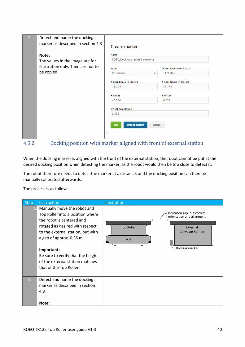
4.5.2. Docking position with marker aligned with front of external station
When the docking marker is aligned with the front of the external station, the robot cannot be put at the
desired docking position when detecting the marker, as the robot would then be too close to detect it.
The robot therefore needs to detect the marker at a distance, and the docking position can then be
manually calibrated afterwards.
The process is as follows:
2. Detect and name the docking
marker as described in section 4.3
Note: The values in the image are for illustration only. Then are not to be copied.
Step Instruction Illustration
1. Manually move the robot and
Top Roller into a position where
the robot is centered and
rotated as desired with respect
to the external station, but with
a gap of approx. 0.35 m.
Important:
Be sure to verify that the height
of the external station matches
that of the Top Roller.
2. Detect and name the docking
marker as described in section
4.3
Note:

ROEQ TR125 Top Roller user guide V1.3 41
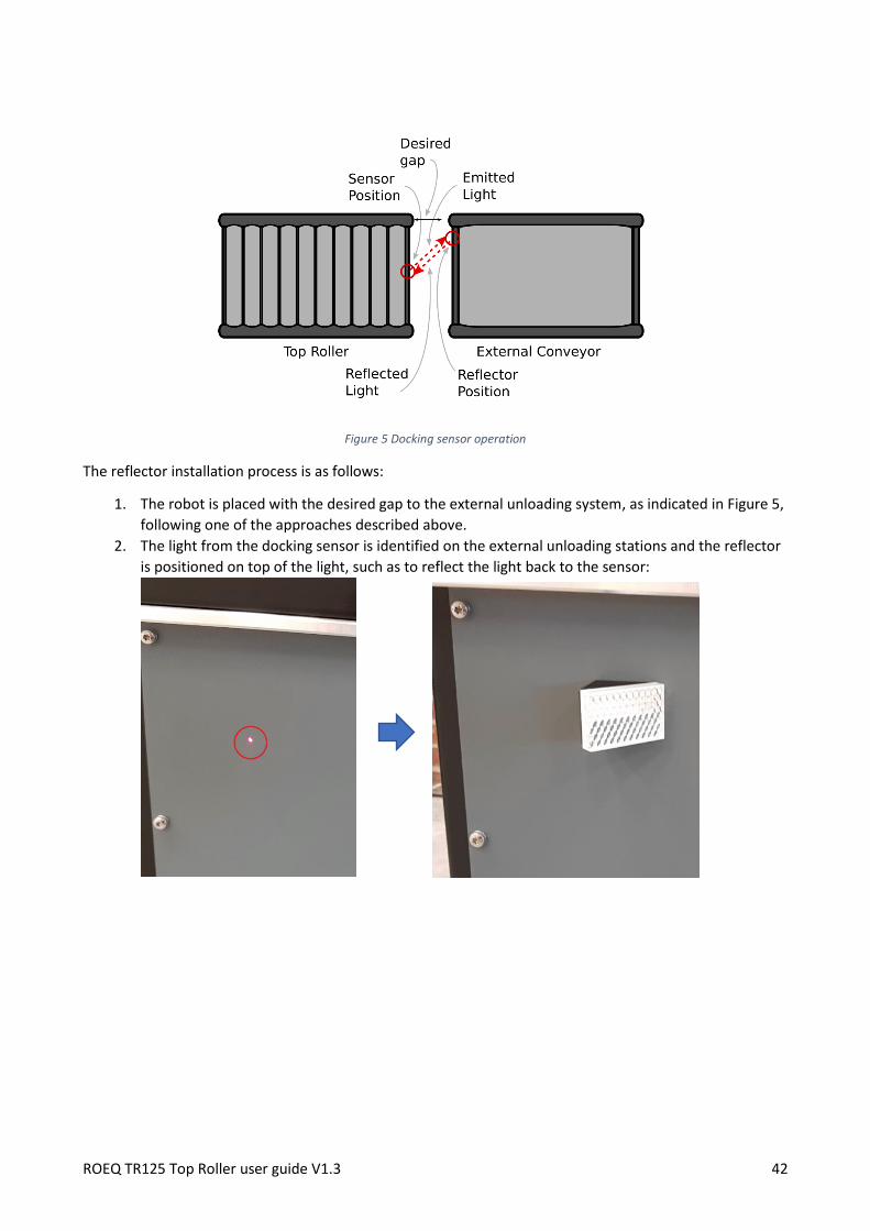
4.5.3. Installing docking sensor reflector
For the top roller to unload packages, the docking sensor must detect light reflected from on eof the
reflectors shipped with the top roller.
The docking sensor is installed on the top roller at an angle of 45 degrees with respect to the driving
direction of the robot. The reflector must correspondingly be installed at an angle of 45 degrees to properly
reflect the light of the sensor – To easy this process, the reflectors shipped along with the top roller, is
installed on a bracket with the proper angle – The functionality is outlined in Figure 5:
The values in the image are for illustration only. Then are not to be copied.
3. Edit the newly created position
and manually increase (towards
zero) the “X Offset” so the final
docking position is as desired.
Caution:
To avoid colliding with the
external station, the X offset
should be gradually increased in
small steps until the desired gap
is obtained between Top Roller
and the external station.
Note: The values in the image are for illustration only. Then are not to be copied.
ROEQ TR125 Top Roller user guide V1.3 42
Figure 5 Docking sensor operation
The reflector installation process is as follows:
1. The robot is placed with the desired gap to the external unloading system, as indicated in Figure 5,
following one of the approaches described above.
2. The light from the docking sensor is identified on the external unloading stations and the reflector
is positioned on top of the light, such as to reflect the light back to the sensor:

ROEQ TR125 Top Roller user guide V1.3 43
5. Accessories for ROEQ Top Roller This section illustrates the available accessories compatible for the ROEQ Top Roller system.
5.1. Stand-alone docking station

ROEQ TR125 Top Roller user guide V1.3 44
6. Technical Specifications This section contains the general technical specifications for the ROEQ Top Roller system related to the
dimensions and performance of the ROEQ Top Roller installed on MiR100™ or MiR200™.
Communication
Connection between Top Roller and MiR Ethernet, TCP/IPv4
Dimensions
Maximum length 925 mm
Conveyor length 915 mm
Maximum width 580 mm
Conveyor width 485 mm
Standard conveyor height 650 mm (configurable up to 850mm)
Elevated height (Applies only to Top Roller with lift
feature) 850 mm
Weight (without load) 80 kg
Color Conveyor: Machined aluminium and matt black
Base: RAL9010/RAL7011 for MiR100™/MiR200™
Environment
Ambient temperature range +5 degrees Celsius to 50 degrees Celsius (humidity 10-95%
non-condensing)
IP class IP 20
Safety compliance and approvals
Compliance with CE certified

ROEQ TR125 Top Roller user guide V1.3 45
*Note: The user must always comply with the MiR specifications for cargo dimensions, weight and load
placement.
**Note: Weight of lifting mechanism reduces the effective loading capacity, to stay within the MiR
maximum load limit.
6.1. Cargo specification Given the loading area of the Top Roller system, the size of the employed rollers, as well as the type and
placement of sensors, any cargo moved by the top roller must satisfy the requirements in the table below.
These requirements are further substantiated in Figure 6, Figure 7, and Figure 8.
Note: The user must always comply with the MiR specifications for cargo dimensions, weight and load
placement
Further, the cargo must be fully opaque in the areas that passes directly in front of the sensors, in order for
these to detect the cargo.
Loading specification
Max height from floor to Top 1100mm above the floor*
Load capacity 20 kg for MiR100™
125 kg for MiR200™ (Without lifter installed)
80 kg for MiR200™ (With lifter installed)**
Centre of gravity Lower than 900 mm*
Centre of load mass As close to robot centre as possible - eccentric loading can
cause undesirable performance and mission failure.
Cargo Dimension Requirement Value Figure
Minimum cargo height 25 mm Figure 6
Maximum cargo length 700 mm Figure 7
Minimum cargo length 150 mm Figure 7
Maximum cargo width 450 mm Figure 7
Maximum height of cut-outs in cargo bottom 15 mm Figure 8
ROEQ TR125 Top Roller user guide V1.3 46
Figure 6 System height when fully colapsed. Minimum cargo height.
Figure 7 Loading area and cargo width and lenght requirements

ROEQ TR125 Top Roller user guide V1.3 47
Figure 8 Example of cargo with cut-outs in the bottom, and illustration on the height restrictions to these cut-outs.
ROEQ TR125 Top Roller user guide V1.3 48
7. Maintenance This section describes the requirements for maintaining the functionality and performance of the ROEQ
Top Roller system.
NOTE: The stated intervals are indicative and depend on the operating environment and frequency of
usage of the robot.
7.1. Regular cleaning and inspection
This table gives an overview of maintenance tasks for all ROEQ products.
Part Maintenance Interval
General Clean the Top Roller on the outside
with a damp cloth.
Do not use compressed air.
As needed
Front and rear sensor Ensure that the sensors have an
uninterrupted field of view and
remove any kind of foreign objects
from the sensor cut outs.
Every week / as needed
Lifting column (only applies
to versions with automatic
height adjustment)
Test the lifting function to ensure the
lifting column lowers and raises
without any issues.
Every 2-3 weeks / as needed

ROEQ TR125 Top Roller user guide V1.3 49
8. Declaration of conformity
Declaration of conformity
according to the EU Machinery Directive 2006/42/EC, Annex II 1. B
Manufacturer ROEQ ApS Kobbervænget 5 DK-5492 Vissenbjerg
Technical file compiled by Martin Ziemann Junker ROEQ ApS Kobbervænget 5 DK-5492 Vissenbjerg
Description and identification of the machinery
Generic denomination ROEQ Top Roller
Function Logistics accessory for application on MiR100 and MiR200 autonomous robot, designed to be operated in conjunction with the operating system delivered by Mobile Industrial Robots. By adding ROEQ specific operation routines to the mission list, the operator will be able to command the robot to pick up and deliver eg.; packages, boxes or pallets by using the ROEQ Top Roller. To be able to operate with a ROEQ Top Roller an updated safety software configuration needs to be installed on the robot.
Model ROEQ 265A5000 V1.0
Serial number X100265A500000010 and higher
Commercial name ROEQ Top Roller
This product is expressly declared to fulfil all the relevant provision
of the following EU Directives or regulations: 2006/42/EC
Vissenbjerg 2019-04-01
Signature
Benni S. Lund R&D Manager


