Embed Size (px)
Citation preview

1
AC MOTOR DRIVE
Simple Version Operation Manual
RM6S1 series
2013.11.22 Revised

2
Preface
Thank you for using Rhymebus RM6S1 series drive. For proper operations and
safety purposes, please do read and follow the safety specific instructions in the manual
before using the product. To ensure proper operation of drive, the manual shall be
placed on the top of the machine. Furthermore, please download the completely safety
information on Rhymebus website http://www.rhymebus.com.tw.
Safety Precaution 1. Don’t conduct any wiring during the system power ON to avoid the electric shock.
2. Please, wait at least 5 minutes until the indicator light turn off.
3. The electronic components are sensitive to static electricity in the drive. Please don't
put the any objects in the drives or touch the main circuit board.
4. PE terminal must be exactly grounded.
5. Don’t touch the heat sink because the temperature of heat sink may over 70℃.
6. The RM6S1 series outputs are designed to drive a three-phase motor. Do not connect
output terminals to the single-phase or use for other purpose.
7. U, V, W are the outputs of drive to the motor. Please do not connect these terminals
to the power source.
Ambient Conditions
Features 1. The drive has temperature management and setting pre-alarm level to forecast over
temperature.
2. RS-485 Modbus RTU communication function.
3. Special function key (SPEC): Cable set (in parameter) to realize FWD/REV running, jog
speed, and other multi-function operation.
4. Built-in knob (Pot) for directly speed adjustment.
5. The switching frequency can be adjusted between 800Hz ~ 16 kHz.
Atmosphere Non-corrosive or non-conductive, or non-explosive gas
or liquid, and non-dusty
Surrounding temperature -10°C~+45°C (14°F~122°F) (Non- condensing and
non-freezing)
Storage temperature -20℃~+60℃(-4°F~140°F)
Relative humidity 90% RH or less (No-condensing atmosphere)
Vibration Less than 5.9m/sec² (0.6G)
Altitude Less than 1000m (3280 ft.)

3
6. Provide 8 sets of monitor displays. (Frequency, speed, voltage, current and 13 kind of
options available)
7. Counter function.
8. To support external PTC for motor overheat protection.
9. User can connect KP-601A keypad (option) for remote control, parameters duplica-
tion and saving.
10. Detachable Buckles design for installation.
11. Six sets of fault record (fault record, current, voltage, frequency)
12. Simple parameter group and complete parameter group.
13. Parameter lock and parameter password functions.
Chapter 1 Caution before Installation The product has passed the strictest quality test before shipped out from the
factory. However, the product might possibly sustain minor damages due to the im-
pact, shaking, vibration, and other factors during the transportation. Please make sure
to verify the following items after receiving this product. If the product verification
finds anything abnormal, please contact the agent immediately for the further assis-
tance. (1) Check up the appearance of the drive for any paint chipped off, smearing, defor-
mation of shape, etc. (2) Check up the operation manual whether it shortage or damage or not. (3) Check up the drive model number is identical with the shipping label on the
carton or not. 1-1 Confirmation of Appearance
XXXXXXXX
0201-1
3PH AC200-240V1.5A 0.1-400Hz
1PH AC200-240V 3A 50/60Hz
RM6S1-20P2E1
SERIAL NO.
PGM NO.
OUTPUT
INPUT
TYPE Model Name
Input Power Specs
Output Current & Capability
Software Number
Product Serial Number
ISO 9001 IP20
XX
XX
XX
XX
X
RM6S1 – 2 0P2 E1
Power Code(see Power Table)
Input Voltage2:AC 200~240V
Product Series
E1:without Braking Transistor
Power Code
Power Horse Power
0P1 125W 0.17HP
0P2 200W 0.25HP

4
10cm above
5cm
above
10cm above
5cm
above
1-2 Standard Specifications Model name (RM6S1-□□□□E1) 20P1 20P2
Maximum applicable motor (HP / W) 0.17HP / 125W 0.25HP / 200W
Rated output capability (VA) 400 600
Rated output current (A) 1 1.5
Rated output voltage (V) Three-phase 200~240V
Range of output frequency (Hz) 0.1~400.00Hz
Power source (ψ, V, Hz) Single-phase, 200~240V, 50/60Hz
Input current (A) 2 3
Permissible AC power source fluctuation 176V~264V 50/60Hz / ±5% Overload protection 150% of drive rated output current for 1 min Applicable safety standards -
Cooling method Nature cooling
Protection structure IP20
Weight (g) 379 384
Please refer the standard specifications to verify your product. If the registered infor-mation of product has any inconformity, please contact with your agents.
Chapter 2 Installation and Confirmation 2-1 Basic Equipment Correct installation can extend the lifespan of the inverter, please follow the installa-
tion precaution. Do not place the drive next to the heating substance or exposure to sunlight. Due to
the heat dissipating requirement during the drive operation, the drive must keep enough space for heat dissipation.
Environment temperature -10°C~+45°C (14°F~122°F) Please install the drive with the clearance space around the drive and the location of
installation shall be arrange as follows:
10cm above
10cm above
10cm
above

5
2-2 Basic Wiring 2-2-1 Descriptions of Terminal and Wiring Diagram
AC power
source
input
Grounding
Motor
3Phase
Motor
VI
V+
COM
Y1
X3
X2
X1
VR 1kΩ
1/4W
GND
(Open collector)
(DC 48V/50mA)
KP-601A/Modbus Port
2-2-2 Main Circuit Terminals
Type Symbol Function Description
Term
inal
of
Mai
n C
ircu
it Power
Source L1,L2
AC power source input terminals
For the single-phase power source AC 200~240V.
Motor U,V,W Drive outputs to motor terminals
The terminals output three phase variable frequency and voltage to motor.
Grounding Grounding terminal Grounding resistance must be below 100Ω.
2-2-3 Control Circuit Terminals
Type Symbol Function Description
Co
ntr
ol C
ircu
it T
erm
inal
Multi-function input terminal
X1 Input terminal 1
The function is set by F5.19~F5.21. X2 Input terminal 2
X3 Input terminal 3
Multi-function output terminal
Y1 Output terminal 1 Capacity: DC 48V, 50mA The function is set by F5.26.
COM Input/output common terminal
The common terminal of input/output control signal.
Control power
V+ Power terminal for control signal
DC +12V output. Maximum sup-plied current is 20mA.
VI Analog input
terminal DC 0~10V
GND Common terminal for analog input
control
Common terminal for control power (V+) and analog input terminal(AI).

6
2-2-4 Modbus Port (RS-485)/ Keypad-601A
Type Pin Function Description
Modbus (RS-485)/ KP-601A Communication
1 Communication transmission terminal (DX+) Modbus (RS-485) com-
munication uses pin1, 2. 2 Communication transmission
terminal (DX-)
3 Power terminal of KP (+13V) Only for KP-601A linking
4 Auto-detect terminal of KP Only for KP-601A linking
5、6 Reversed Reversed
7 Common ports terminal of KP power(0V) Only for KP-601A linking
8
Chapter 3 Characteristics and Instructions 3-1 The Features of Control and Operation
Co
ntr
ol C
har
acte
rist
ics
Control method Voltage vector sinusoidal PWM control(V/F control); Switching frequency: 800Hz~16kHz
Range of frequency setting 0.1-400.00Hz
Resolution of frequency setting
Digital command: 0.01Hz Analog command:0.06Hz/60Hz
Resolution of output frequency
0.01Hz
Overload protection 150% of drive rated output current for 1 minute.
DC braking Start/stop braking time: 0~60.0sec Stop braking frequency: 0.1~60Hz Braking ability: 0~150% of rated current
Braking torque Approximately 20%.
V/F pattern
Linear, Energy-saving mode (auto-adjust V/F pattern according to the load condition), Square of 1.5, 1.7 and 2 curves. V/F pattern (2 V/F points) Output voltage adjustment of V/F pattern.(Variable voltage (V) adjustment of V/F pattern for acceleration / deceleration)
Other functions
Slip compensation, Auto-torque compensation, Au-to-adjustment for output voltage stability, Au-to-operation for energy-saving, Auto-adjustment of switching frequency, Restart after instantaneous power failure, Over-torque detection, DC braking, Counter function, Modbus(RS-485)communication, Jump fre-quency, upper/lower limits of output frequency,8-preset speeds, S-curve acceleration/deceleration, Temperature management, Parameters duplication.

7
Op
era
tio
n
Ch
arac
teri
stic
s Frequency setting
signal
Operation panel(including KP-601A keypad ): ▲、▼ Analog signal: (DC 0-10V)/0~100% Digital signal:Jog speed,8-preset speeds Modbus(RS-485) communication
Operation signal Operation panel(including KP-601A keypad): RUN, STOP Digital signal: FWD/REV rotation control Modbus(RS-485) communication
Multi-function inputs
3 programmable input terminals: X1-X3 Response time (1~255,unit 1ms)
Refer to the F5.19~F5.21 functions setting description.
Analog inputs 1 set of analog input: VI (DC 0-10V) Analog filter (0~255,unit 5ms),the dead band of analog frequency, gain and bias are adjustable.
3-2-1 Function of Operation Panel
RUN
STOP/RESET
Pot knob
UP/DOWN
Enter or leavethe function mode
Switch the function group and number
Special function key
Power indicator
SPEC key indicator
Operation indicator
REV Modbus/KP-601A
CurrentVoltage
( Setting SPEC key functionsee F1.17 and F1.18 )
( see F1.00)
( see F1.01)
( see F1.01 and F1.03)
Set/Switch monitor mode
Frequency

8
3-2-2 Operation of Keypad
Hz
V
A
PWR
RUN
Hz
V
A
PWR
RUN
Hz
V
A
PWR
RUN
PROGFUNC
DATA
PROGFUNC
DATA
PROG
SPEC SPEC SPEC
Hz
V
A
PWR
RUN
SPEC
<<
<<
Hz
V
A
PWR
RUN
SPECHz
V
A
PWR
RUN
SPEC
FUNC
DATA
FUNC
DATA
Hz
V
A
PWR
RUN
SPEC
▲
▲
<<
<<
Hz
V
A
PWR
RUN
SPECHz
V
A
PWR
RUN
SPEC
▲
▲
▲
▲
Hz
V
A
PWR
RUN
SPEC
PROG
▲
▲
PROG PROG
※ Light color represents for lights flashing.
3-2-3 The description of monitor mode.
Press FUNC
DATA
key Hz, V, A Indicator light Display
Display1 (Main Display)
Hz On (Output Frequency) Hz
V
A
PWR
RUN
SPEC
Display2 Hz On (Frequency Command) Hz
V
A
PWR
RUN
SPEC
Display3 V On (Output Voltage) Hz
V
A
PWR
RUN
SPEC
Display4 V On (DC bus Voltage) Hz
V
A
PWR
RUN
SPEC
Display5 A On ( output current) Hz
V
A
PWR
RUN
SPEC
Display6 Hz、A On ( Default value: terminal status) Hz
V
A
PWR
RUN
SPEC
Display7 V、A On ( Default value: heat sink
temperature)
Hz
V
A
PWR
RUN
SPEC
Display8 Hz、V On ( Default value MPM) Hz
V
A
PWR
RUN
SPEC
9
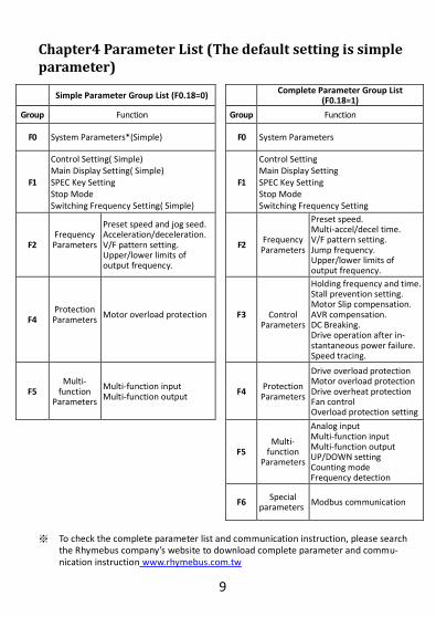
Chapter4 Parameter List (The default setting is simple parameter)
Simple Parameter Group List (F0.18=0) Complete Parameter Group List
(F0.18=1)
Group Function Group Function
F0 System Parameters*(Simple)
F0 System Parameters
F1
Control Setting( Simple) Main Display Setting( Simple) SPEC Key Setting Stop Mode Switching Frequency Setting( Simple)
F1
Control Setting Main Display Setting SPEC Key Setting Stop Mode Switching Frequency Setting
F2 Frequency Parameters
Preset speed and jog seed. Acceleration/deceleration. V/F pattern setting. Upper/lower limits of output frequency.
F2 Frequency Parameters
Preset speed. Multi-accel/decel time. V/F pattern setting. Jump frequency. Upper/lower limits of output frequency.
F4 Protection Parameters
Motor overload protection
F3
Control Parameters
Holding frequency and time. Stall prevention setting. Motor Slip compensation. AVR compensation. DC Breaking. Drive operation after in-stantaneous power failure. Speed tracing.
F5 Multi-
function Parameters
Multi-function input Multi-function output
F4 Protection Parameters
Drive overload protection Motor overload protection Drive overheat protection Fan control Overload protection setting
F5 Multi-
function Parameters
Analog input Multi-function input Multi-function output UP/DOWN setting Counting mode Frequency detection
F6 Special
parameters Modbus communication
※ To check the complete parameter list and communication instruction, please search
the Rhymebus company’s website to download complete parameter and commu-nication instruction www.rhymebus.com.tw

10
Simple Parameter List: The color as means functions can be set during the operation.
(F0) System Parameters
Func. Name Descriptions Range
of Setting
Unit dF60
F0.01 Parameter Lock
0:Parameters are changeable 1:Parameters are locked 0,1 ─ 0
F0.18 Parameter
Display Selection
0:Simple parameters 1:Complete parameters 0,1 ─ 0
F0.20 Default Setting
0:Disable
─ ─ 0
CLF:Clear fault records
dF60:Restore to the factory setting of 60Hz
dF50:Restore to the factory setting of 50Hz
SAv:Store setting
rES:Resume setting
rdEE:Read the parameters from drive to KP-601A
UrEE:Write the parameters from KP-601A to drive
(F1)Operation Parameters
Func.
Name Descriptions Range
of Setting
Unit dF60
F1.00 Start
Command Selection
Start command Rotation direction command
0 ~ 11 ─ 3
0 FWD or REV command FWD or REV command
1 FWD command REV command
2
Operation panel
FWD, REV command
3 Forward
4 Reverse
5 Reverse command
6~7 Reversed Reversed
8 Communication control
Communication control
9 Communication control
Reverse command
10 Forward command Communication control
11 Operation panel Communication control

11
(F1)Operation Parameters
Func. Name Descriptions Range
of Setting
Unit dF60
F1.01
Primary Frequency Command Selection
0: Frequency command by analog input selection. 1: Frequency command by operation panel. 2:Reversed 3:Machine speed setting by operation panel. 4:UP/DOWN terminal control. 5:Frequency command by communication terminal.
0 ~ 5 ─ 1
F1.03
Analog Input
Selection
0:Pot+VI 1:Pot-VI 2:VI-Pot 3:Pot or VI( switch by multi-function input terminal) 4:Pot 5:VI
0 ~ 5 ─ 0
F1.08 Main
Display Selection
Control panel have 8 display options 1:Output frequency 2:Frequency command 3:Output voltage 4:DC bus voltage 5:Output current 6:Terminal status 7:Heat sink temperature 8:Machine speed ratio
1 ~ 8 ─ 1
F1.13 Machine
Speed Ratio
Set the ratio of machine speed. This function deter-mines MPM display value.
0.00 ~ 500.00 0.01 20.00
F1.14
Digits of Decimal
Value (Machine
Speed)
Select the digits of decimal values displaying the machine speed. 0 ~ 3 ─ 0
F1.17 SPEC Key Setting
Same function as multi-function input -28 ~ +28
─ 0
F1.18 SPEC Key Setting
0:Disable 1:Enable 0,1 ─ 0
F1.19 Stop Mode
0: Ramp to stop + DC braking 1: Coast to stop 2: Coast to stop+ DC braking
0 ~ 2 ─ 0
F1.21 Switching Frequency
The setting value is higher and the motor noise is lower.
0 ~ 6 ─ 2 (Note3)

12
(F2) Frequency Parameters
Func. Name Descriptions Range of Setting
Unit dF60
F2.00
Primary Speed (Preset
Speed 1)
Jog speed command
Multi-speed level 3
command
Multi-speed level2
command
Multi-speed level 1
command 0.00~ 400.00
0.01 Hz
50.00 (Note1)
OFF OFF OFF OFF 60.00 (Note2)
F2.16 Jog Speed Jog speed 0.00~
400.00 0.01 Hz
6.00
F2.18 Primary
Acceleration Time
The acceleration time of primary speed, preset speed 5~8, and jog speed.
0.0~ 3200.0
0.1sec 5.0
F2.19 Primary
Decelera-tion Time
The deceleration time of primary speed, preset speed 5~8, and jog speed.
0.0~ 3200.0
0.1sec 5.0
F2.32 Maximum
Output Frequency
Maximum output frequency of drive. 0.1~
400.0 0.1Hz
50.0 (Note1)
60.0 (Note2)
F2.34 Starting Voltage
The voltage corresponds to the output starting frequency.
0.1~ 50.0 0.1V 8.0
F2.35 Base Frequency
The frequency corresponds to the base voltage in V/F pattern.
0.1~ 400.0
0.1Hz
50.0 (Note1) 60.0
(Note2)
F2.36 Base Voltage
The voltage corresponds to the base frequency in V/F pattern.
0.1~ 255.0
0.1V 220.0
F2.47 Frequency Upper Limit
The upper limit of output frequency. (1.00=maximum output frequency)
0.00~ 1.00
0.01 1.00
F2.48 Frequency Lower Limit
The lower limit of output frequency. (1.00=maximum output frequency)
0.00~ 1.00 0.01 0.00
(F4) Protection Parameters
Func. Name Descriptions Range of Setting Unit dF60
F4.08 Motor Rated
Current
Current setting depends on the motor rated current.
10%~150% of drive
rated current
0.1A
According to the rated current of motor.

13
(F5)Multi-function Parameters
Func. Name Descriptions Range
of Setting
dF60
F5.19 Multi-function
Input Terminal X1
0: Disable ±1: Jog command ±2: Secondary accel/decel
command switching ±3: Multi-speed level 1
command ±4: Multi-speed level 2
command ±5: Multi-speed level 3
command ±7: Reset command ±8: External fault
command (EF) ±9: Interruption of output
command (bb) ±10: Coast to stop
command(Fr) ±11: Speed search from
the maximum fre-quency
±12: Speed search from the frequency setting
±13: Holding command. ±14: UP command. ±15: DOWN command. ±16: Clean UP/DOWN
frequency command. ±17: UP/DOWN command
enter key. ±18: Analog input source
selection(Pot knob/AI) ±19: Primary and
secondary frequency command option.
±22: Forward command. ±23: Reverse command. ±24: Stop command with
3-wire start/stop cir-cuit.
±25: DC braking enable (Stop).
±26: Counter input. ±27: Counter clear. ±28: Current limit enable.
0 ~
±28 22
F5.20 Multi-function
Input Terminal X2
0 ~
±28 23
F5.21 Multi-function
Input Terminal X3
0 ~
±28 1
F5.26
Multi-function Output
Terminal Y1
0: No functions. ±1: Running detection. ±2: Constant speed
detection. ±3: Zero speed detection. ±4: Frequency detection. ±5: System overload
detection(OLO). ±6 :Stall prevention detec-
tion. ±7: Low voltage detection
(LE). ±8: Over voltage during
deceleration (db).
±9: Restart after instantane-ous power failure detec-tion.
±10: Restart after fault condition detection.
±11: Fault detection. ±16: Detection of counter
value1 ±17: Detection of counter
value2 ±18: Reverse detection. ±19: NTC temperature
warning detection(OHt). ±21 : PTC temperature warn-
ing detection (OH1)
0 ~
±21 11
※ The skipping numbers represented for reservation of parameters.
Note:
1. The default setting of 50Hz. 2. The default setting of 60Hz.
3. When the setting value of switching frequency exceeds “4”, the drive must be
de-rating for usage.

14
OL
Chapter5 Fault Protection Display A: Description:
The drive has well protection functions to protect drive and motor when faults
occur. When the fault occurs, the drive protective functions will trip to stop the output.
After the abnormality remove, reset the drive by pressing STOP
RESET of the drive operation
panel or through the multi-functions terminal command to reset the drive.
B: Protection List:
※ Error Trip Display
Display Description Display Description
Drive over current ●The drive current during the operation exceeds 220% of drive rated current.
Thermal sensor fault ●Please call customer service for drive repair.
Motor overload ● Operation current exceeds 150% of motor rated current and reaches the motor overload protection time. ● Active time: F4.10.
Drive overheat ●The temperature of
drive’s heat sink reach-es the trip level.
●Trip level: F4.12
Drive overload ●Operation current exceeds
150% of drive’s rated current and continues for 1minute.
Motor overheat ●The internal tempera-
ture of motor is over the trip level.
●Trip level: F4.23
System overload ●Load is too heavy and the operation current reaches the active level.
●Detection level: F4.28 ●Detection time: F4.29
KP-601A Internal memory error ●Please call customer service for drive repair.
Over voltage ●The internal DC bus voltage is over the protec-tion level.
EEPROM error
Under voltage during operation ●The internal DC bus voltage is below 70% of power source.
KP-601A interrup-tion during copy
External fault (Terminal receives the
external fault signal)
ntcFOC
OH
OL1 OH2
OLO
OE EEr
LE1 PAdF
EF
EEr1
EEr2

15
※ Warning Display
Display Description Display Description
System overload ●F4.27=0 Drive is still running when the overload is detected.
Coast to stop
Power source over voltage ●DC bus voltage of drive is over the protection level during standby time.
Forward/reverse command input simultaneously
Over voltage during deceleration ●DC bus voltage over setting protection level F3.27
No input of for-ward/reverse com-mand
Power source over voltage
Different software version inter-copy
Drive overheat ●The temperature of heat
sink reaches the protec-tion level.
●Warning level: F4.14
Modbus communi-cation overtime ● Setting F6.58
Motor overheat ●The internal temperature
of motor is over the warning level.
●Warning level: F4.21
Drive output inter-ruption
Chapter 6 Installation Dimensions of Drive 6-1 Outline Dimension of Drive:
80
.0
126.8
138.4
60.0
10
0.0
52.0
unit:(mm)
OLO
dtF
Fr
bbOH1
Hv
db
WrFLE
OHt Cot

16
Figure1: Drive Supporting Frame
89±0.2
53
81
+1
0
+1
0
Unit:(mm)
53+1
0
81
+1
0
(User has to drill the
hole on the panel)
screw M4*2
6-2 Installation Dimensions Fixation 1: Detachable Buckle Fixation 2: Screw Fixing (Standard Fixation) (Using for Vibrant Environment) Purchase Accessories: 1. RM6S1 Keypad (KP-601A) 2. Protection Cover of Drive For further detailed information of product or purchased accessories of specification, please visit Rhymebus website. http://www.rhymebus.com.tw


