Embed Size (px)
Citation preview

Ring-Shaped Transverse Flux PM Generator for Large Direct-Drive Wind Turbines
Deok-je Bang Member, IEEE
Henk Polinder Member, IEEE
Ghanshyam Shrestha Member, IEEE
Jan Abraham Ferreira Fellow, IEEE
Electrical Power Processing / DUWIND, Delft University of Technology Mekelweg 4, 2628CD Delft, The Netherlands
Abstract-A ring-shaped transverse flux permanent magnet (TFPM) generator with double-sided axial flux configuration is proposed in this paper. The ring-shaped TFPM generator does not use a shaft and arms to transfer the torque and to support both the rotor and the stator. The active part of the proposed generator consists of multiple-segment structure. This new generator configuration can remarkably reduce the mass, and can make the construction easy in manufacturing and handling. Analytical design model is developed for the TFPM generator. The analytical model is verified by the experimental analysis of the downscaled generator. The design results of 5 MW ring-shaped TFPM generators are compared with two different generators, namely a conventional radial flux PM generator and a single-sided air gap TFPM generator.
I. INTRODUCTION
Direct-drive generator systems for wind turbines have been considered as better systems than geared generator systems in terms of energy yield, reliability and maintenance. The direct-drive generator operates at low speed. Therefore, a generator with high tangential force and large air gap diameter is required for large direct-drive wind turbines. These requirements make large direct-drive wind generators heavy and consequently expensive. [1][2] However, if it was possible to reduce the cost of a direct-drive generator to the cost of the geared generator without penalising performance, the direct-drive generator could be the most suitable generator. Therefore, it is an important issue to make large direct-drive generators for wind turbines cost-effective. [3]
The cost of the generator can be determined by the material cost, the manufacturing cost and the maintenance cost. The material cost mainly depends on mass of the generator. The manufacturing cost depends on the manufacturing processes. The maintenance cost depends on the reliability and the time taken to repair the generator. Thus, a direct-drive generator with lightweight active part, lightweight inactive part, easy manufacturing process and easy maintenance can be defined as cost-effective and suitable generator for large direct-drive wind turbines.
The aim of this paper is to propose a new configuration of large direct-drive wind generators that would enable considerable mass reduction and facilitate simple manufacturing and handling. The paper starts with a new concept of a transverse flux permanent magnet (TFPM) generator for large direct-drive wind turbines. A ring-shaped TFPM generator with axial flux double-sided air gap is proposed as a promising generator configuration for large
direct-drive turbines. An analytical design model of the proposed TFPM generator is developed. The experiments of the downscaled generator are done in order to verify the analytical modelling developed. Furthermore, the design results of a 5 MW ring-shaped TFPM generator are compared with different generators, namely a conventional radial flux PM (RFPM) generator and a single-sided air gap TFPM generator. Finally, conclusions are drawn.
II. TFPM GENERATOR FOR LARGE DIRECT-DRIVE
A. Electromagnetic part Various TFPM machine configurations have been proposed
and discussed in a number of papers [4]. Among different TFPM machine types, the flux-concentrating type has higher force density which results in volume reduction and consequently mass reduction. The single-sided and single-winding type is simpler in construction than the double-sided and double-winding type. A claw pole core type can achieve higher induced voltage, which results in higher force density. Considering the winding structure of TF machine, the ring winding has been mostly used for the small diameter TF machine. However, it is difficult to manufacture, handle and repair the ring winding with large diameter. The TF machine has three-dimensional flux path, thus manufacturing of the machine is more difficult and complicated than the longitudinal flux machine. In the case of large PM machines, size of the PM is also large, thus it is not easy to handle the PM in manufacturing.
Therefore, the electromagnetic part of the new TFPM generator is configured as follows. • A flux-concentrating TFPM machine with single-sided
and single-winding configuration is chosen. • Racetrack-shaped windings are proposed for large
diameter TF machine. • A claw pole configuration with the increased iron core
area to produce higher induced voltage [3][4] is chosen. • A multiple-module TFPM machine configuration with
short flux path is proposed to reduce the active material by decreasing slot pitch and height [3].
• Segmented structures of both the iron core and the PM are proposed for easy manufacturing and also for avoiding detachment of the PM.
• Modular structures of the rotor and stator are proposed in order to make the maintenance easy.
PEDS2009
61

Fig. 1 illustrates a new configuration of TFPM machine as summarized above. The claw pole cores with blue lines are showing the stator cores. In order to reduce the flux path, a multiple-module concept [3] is used. A yellow racetrack-shaped structure is the copper winding. The blue hexahedra with black arrows are the permanent magnets (PMs), and the white hexahedra between PMs are the flux-concentrating cores in the rotor.
When enlarging the scale of a direct-drive PM machine, the air gap diameter of the machine is increased together with increase of the air gap length, the pole pitch, the pole width and the PM size. When using conventional PM configurations for large TFPM machines, assembling the machine with PMs is difficult. When using the bond to fix PMs on the iron cores, the detachment of PMs can happen as shown in Fig. 2(a), which represents one pole pair of the rotor in linear model. When increasing the volume of PMs with keeping the pole pitch length, the height of the iron cores is also increased as shown in Fig. 2(b). Thus, the manufacturing cost of a TFPM machine with the conventional configurations of PMs and iron cores will be high. In order to overcome these problems, a new configuration of PMs and iron cores is proposed as Fig. 3. The configuration in Fig. 2 is modified to a configuration segmented as in Fig. 3(a). The PMs and iron cores segmented can be rearranged as Fig. 3(b). When increasing the volume of PMs with keeping the pole pitch length in this new configuration, the height of the iron cores is not increased as shown in Fig. 3(c). Considering the assembly of the PMs and the iron cores, the configuration in Fig. 3(d) is proposed as an alternative configuration in order to avoid the detachment of PMs. Non-ferromagnetic parts with the grey colour in Fig. 3(d) can be easily made by the extrusion or the drawing method in manufacturing. This configuration in Fig. 3 can be also used for the flux-concentrating longitudinal flux PM machines.
B. Structural part and practical issues In the case of large direct-drive generator for wind turbines,
the structural mass is dominant in the total mass [2][3]. In order to make the large direct-drive generator attractive, the structural material thus must be reduced significantly. The role of the structural part of the direct-drive wind generator can be defined as the following. • To maintain the air gap between the rotor and the stator • To take the rotational force from the rotor blades.
Therefore, a new structural part configuration, that performs the role of the structural part with the minimized mass, is required for large direct-drive. Conventional direct-drive generators are generally constructed with one body or large bodies. A large direct-drive generator with one body or large bodies is difficult for manufacturing, assembling, transporting, installing and maintaining. These difficulties carry out the rise in cost.
When a few components of conventional generator systems are in failure, the operation of the whole system is stopped. The failure of large scale generator systems will be more serious than the failure of small scale generator systems.
Therefore, it is necessary to make the large direct-drive generator continue to produce electricity, even in case of failure of a few components.
In order to overcome the above-mentioned drawbacks of large direct-drive generators, the following structural configurations are proposed for large direct-drive generators. • A ring-shaped machine without shaft and torque arms • A TFPM machine with multi-sets of three-phases to
continue the electricity production in case of failure of a few components
• Modular structures which are easy for manufacturing, assembly, transportation, installation and maintenance
(a) (b)
Fig. 2 Conventional PMs and iron cores configuration of the flux-concentrating TFPM machine
Fig. 1 New TFPM machine with flux concentrating configuration
(a) (b)
(c) (d)
Fig. 3 New PMs and iron cores configuration of the flux-concentrating TFPM machine
PEDS2009
62

Fig. 4 illustrates a conceptual drawing of the ring-shaped TFPM generator with modular structure. The ring-shaped generator does not have a shaft and a structure to transfer the torque and to maintain the air gap. Therefore, this ring-shaped configuration is proposed to significantly reduce the structural mass. The generator consists of multi-sets of the stator and the rotor segmented. The stator illustrated in Fig. 4 consists of modular stators with eight-sets (four-sets in one side) of three-phases. The rotor is also constructed with multiple-modules.
III. ANALYTICAL MODELING OF PROPOSED TFPM GENERATOR
A. Magnetic circuit modeling A sketch of the proposed TFPM generator with 3 pole pairs
is illustrated in Fig. 5(a). Fig. 5(b) and Fig. 5(c) illustrate the generator with the magnetic parameters from the tangential view and the axial view, respectively. The dotted lines in Fig. 5(b) and (c) represent the main flux path lines produced by the PM magneto-motive force. Magnetic dimensions of the TFPM generator for the analytical model are described in TABLE I. The pole pitch, the PM length and the pole width of the generator are determined as a function of the air gap as the following [6][7]. • Pole pitch: 10 times of the air gap length • PM length: 4 times of the pole pitch • Pole width: 8 times of the pole pitch
Electromagnetic characteristics are the same and repetitive
in every one pole pair (two pole pitches). Therefore, the electromagnetic equivalent circuit of one pole pair is considered for the analytical model. Fig. 6 illustrates the equivalent circuits of the reluctance model of the TFPM generator. The white rectangles are the iron core reluctances, and the white rectangles with bold lines are the air gap reluctances. The blue rectangles hatched are the PM reluctances and the red rectangles dotted are the leakage flux reluctances. The reluctances in red box in Fig. 6 are considered as the analysis model. The procedure to calculate the flux densities in the air gap, the PM and the iron cores is the same with the procedure in [5]. The expression for the air gap flux density can be derived from Ampere’s circuit law as the following.
02200
=−
+ mrm
rmmg
g lBBlB
μμμ (1)
Where, gB is the air gap flux density, 0μ is the permeability of free space, gl is the air gap length, mB is the PM flux density,
rmB is the remanent flux density of PM, rmμ is the recoil permeability of PM and ml is the PM length.
The flux density and the area of the air gap, the PM, the stator core and the rotor core can be defined as the following by the flux continuity.
φ==== crcrccmmgg ABABABAB (2)
U-p
hase
V-phas
e
W-phaseU-phase
V-phase
W-phase
Rotor
U-p
hase
V-phas
e
W-phase
W-phase
V-phase
U-phase
Stator
Fig. 4 A ring-shaped direct-drive generator concept
(a) 3D sketch of three pole pairs
(b) Cross-section in tangential view (c) in side view
Fig. 5 Sketch of new TFPM machine
TABLE I GENERATOR DIMENSIONS
Air gap length gl (mm) 4
Pole pitch pτ (mm) 40
Magnet length ml (mm) 8
Pole width pb (mm) 32
Height of primary part Sh (mm) 70
Width of winding window wb (mm) 30
Height of secondary part Rh (mm) 20
Axial length of pole spl (mm) 20
PEDS2009
63
The total reluctance, tR illustrated in Fig. 6 can be calculated by multiplying the reluctance in red box by two as the following.
⎟⎠⎞
⎜⎝⎛ +++⋅=
22 61
Dt
RRRRR α (3)
Where,
11
11 A
lRμ
= (4)
bABC
CbAB
RRRRR
52
52
++
++
+⋅
=α (5)
66
66 A
lRμ
= (6)
1110987 RRRRRRD ++++= (7)
bABR 52 ++ and CR in (5) are defined as follows.
bBA
BAbAB R
RRRRRR 5252 ++
+=++ (8)
2928272625242322 RRRRRRRRRC +++++++= (9) Where,
aA RRRR 543 ++= (10)
21201918 RRRRRB +++= (11) The flux excited by the PMs in the iron cores can be defined
as 2 m m
ct
H lR
φ = (12)
The flux calculated by (12) corresponds to a half of the flux produced in one pole pair. Therefore, the flux in one pole pair illustrated in Fig. 5 can be calculated as the following.
cpolepair φφ ⋅= 41 (13)
The flux linkage, λ and the no-load induced voltage, e are determined as follows.
φλ ⋅= N (14)
ee ωλ ⋅= (15) Where, N is the number of winding turns, eω is the
electrical angular velocity.
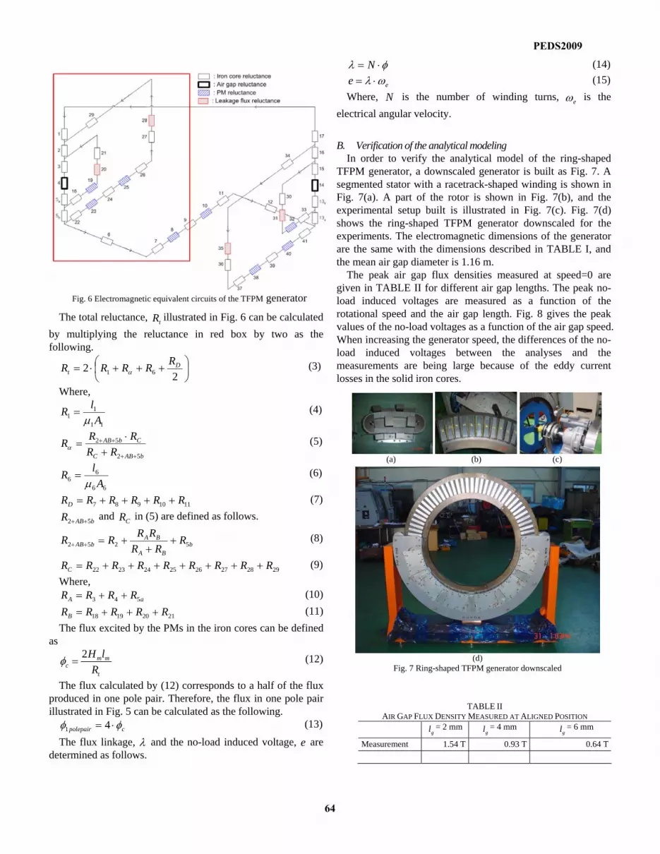
B. Verification of the analytical modeling In order to verify the analytical model of the ring-shaped
TFPM generator, a downscaled generator is built as Fig. 7. A segmented stator with a racetrack-shaped winding is shown in Fig. 7(a). A part of the rotor is shown in Fig. 7(b), and the experimental setup built is illustrated in Fig. 7(c). Fig. 7(d) shows the ring-shaped TFPM generator downscaled for the experiments. The electromagnetic dimensions of the generator are the same with the dimensions described in TABLE I, and the mean air gap diameter is 1.16 m.
The peak air gap flux densities measured at speed=0 are given in TABLE II for different air gap lengths. The peak no-load induced voltages are measured as a function of the rotational speed and the air gap length. Fig. 8 gives the peak values of the no-load voltages as a function of the air gap speed. When increasing the generator speed, the differences of the no-load induced voltages between the analyses and the measurements are being large because of the eddy current losses in the solid iron cores.
Fig. 6 Electromagnetic equivalent circuits of the TFPM generator
(a) (b) (c)
(d)
Fig. 7 Ring-shaped TFPM generator downscaled
TABLE II AIR GAP FLUX DENSITY MEASURED AT ALIGNED POSITION
gl = 2 mm gl = 4 mm
gl = 6 mm
Measurement 1.54 T 0.93 T 0.64 T
PEDS2009
64

IV. DESIGN OF 5 MW RING-SHAPED TFPM GENERATOR
A. Wind turbine modeling The parameters of 5 MW wind turbines for the design are
given in TABLE III.
B. Generator modeling The design parameters in [8] are used for 5 MW generator
modelling in this paper. The following three generators are considered for the mass comparison. • Conventional RFPM generator • Flux-concentrating TFPM generator with single-sided and
single-winding • Ring-shaped TFPM generator
For both the surface-mounted RFPM generator and the single-sided single-winding flux concentrating TFPM generator (see Fig. 9), the design results in [8] are taken for the comparison with the ring-shaped TFPM generator. The generator power can be formulated as
φcos⋅⋅⋅= iemP (16) where m is the number of phases, e is the no-load voltage, i is the nominal current and φcos is the power factor.
This paper focuses on the electromagnetic design of the generator. Thus the power factor, φcos is assumed as one in the design.
The structural part of the rotor and the stator in Fig. 10 [2] are taken for the structural mass estimation of the RFPM generator and the single-side single-winding TFPM generator.
C. Design results TABLE IV gives the design result of 5 MW ring-shaped
TFPM generator. Generator total mass (active mass + structural mass) is
estimated as follows. • Conventional RFPM generator: 90.8 tonnes (40.7+50.1) • Single-sided air gap and single-winding TFPM generator:
89.4 tonnes (39.3+50.1) • Ring-shaped TFPM generator with axial flux double-sided
air gap: 60.5 tonnes (40.9 + 19.6)
V. CONCLUSIONS
A new TFPM generator with ring-shaped construction was
Fig. 9 A single-sided, single-winding TFPM machine
Fig. 8 No-load induced voltage measurement
Fig. 10 Structure of the rotor and the stator [2]
TABLE III WIND TURBINE PARAMETERS
Rated grid power (MW) 5Rotor diameter (m) 126Rated wind speed (m/s) 12Rated rotor speed (rpm) 12Optimum tip speed ratio (blade tip speed divided by wind speed) 6.7
Maximum aerodynamic efficiency 0.515Air density (kg/m3) 1.225
TABLE IV DESIGN RESULT OF 5 MW RING-SHAPED TFPM GENERATOR
Generator power P 5.5 MW Number of phase m 3 Nominal current is 675 A Peak flux density on the flux concentrating core Bc.max 1.24 T No-load voltage ep 2736 V Pole pair No. per a phase p 157 Air gap length lg 6.14 mm Air gap diameter Dg 6.14 m Pole pitch pτ 0.0614 m
Magnet length 2lm 0.013 m Rotor height hR 0.1523 m Stator winding height hw 0.0715 m Stator height hS 0.2239 m Stator pole length lsp 0.1523 m Stator winding width bw 0.0715 m
PEDS2009
65

proposed as a promising generator concept for large direct-drive wind turbines. The TFPM generator proposed is an axial flux double-sided machine type with flux concentrating configuration. Analytical modeling of the TFPM generator was developed in the electromagnetic design. The experiments of the downscaled generator have been done in order to verify the analytical modelling developed. In a rough design of three different 5 MW PM generators, the proposed ring-shaped TFPM generator seems the lightweight type compared to a conventional RFPM generator and a single-sided air gap TFPM generator.
ACKNOWLEDGMENT
This work was supported in part by the European Community’s Sixth Framework Programme (FP6) under contract No. 019945 (SES6), an Integrated Project named UpWind, and in part by Wintech in Korea.
REFERENCES [1] H. Polinder, F.F.A. van der Pijl, G.J. de Vilder, P. Tavner, “Comparison
of direct-drive and geared generator concepts for wind turbines”, IEEE Trans. Energy Conversion, Vol. 21, pp. 725-733, September 2006.
[2] A.S. McDonald, M.A. Mueller and H. Polinder, “Comparison of generator topologies for direct-drive wind turbines including structural mass”, in Proc. Of the International Conference on Electrical Machines (ICEM), pp. 360.1-7, September 2006.
[3] D. Bang, H. Polinder, G. Shrestha, and J.A. Ferreira, “Promising direct-drive generator system for large wind turbines”, EPE Journal, Vol. 13, pp. 7-13, September 2008.
[4] M. Dubois, “Optimized permanent magnet generator topologies for direct drive wind turbines”, Ph.D. dissertation, Delft University of Technology, Delft, The Netherlands, 2004.
[5] D. Bang, H. Polinder, G. Shrestha, and J.A. Ferreira, “Design of a lightweight transverse flux permanent magnet machine for direct-drive wind turbines”, 2008 IEEE Industry Applications Society Annual Meeting, Edmonton, Canada, October 5-9 2008.
[6] B.E. Hasubek and E.P. Nowicki, “Design limitations of reduced magnet material passive rotor transverse flux motors investigated using 3D finite element analysis”, in Proc. 2000 IEEE Canadian Conf. Elec. and Computer Engineering, Vol. 1, pp. 365-369.
[7] D.H. Kang, D.J. Bang, J.M. Kim, Y.H. Jeong, M.H. Kim, “A Study on the Design of PM Exited Transverse Flux Linear Motor for Ropeless Elevator”, Trans. KIEE(The Korean Institute of Electrical Engineers). Vol. 49B. No. 3, Mar, 2000 (in Korean).
[8] D. Bang, H. Polinder, G. Shrestha, and J.A. Ferreira, “Comparative design of radial and transverse flux PM generators for direct-drive wind turbines”, in Proc. 2008 International Conference on Electrical Machines, Vilamoura, Portugal, September 6-9 2008.
PEDS2009
66


![Seasonality PM group[1]](https://img.dokumen.tips/doc/110x75/6316d7de7451843eec0a642e/seasonality-pm-group1.jpg)