Embed Size (px)
Citation preview

Rich Intrinsic Image Separation for Multi-View Outdoor
Scenes
Pierre-Yves Laffont, Adrien Bousseau, George Drettakis
To cite this version:
Pierre-Yves Laffont, Adrien Bousseau, George Drettakis. Rich Intrinsic Image Separation forMulti-View Outdoor Scenes. [Research Report] RR-7851, 2011, pp.28. <hal-00654202>
HAL Id: hal-00654202
https://hal.inria.fr/hal-00654202
Submitted on 21 Dec 2011
HAL is a multi-disciplinary open accessarchive for the deposit and dissemination of sci-entific research documents, whether they are pub-lished or not. The documents may come fromteaching and research institutions in France orabroad, or from public or private research centers.
L’archive ouverte pluridisciplinaire HAL, estdestinee au depot et a la diffusion de documentsscientifiques de niveau recherche, publies ou non,emanant des etablissements d’enseignement et derecherche francais ou etrangers, des laboratoirespublics ou prives.

ISS
N0249-6
399
ISR
NIN
RIA
/RR
--7
85
1--
FR
+E
NG
RESEARCH
REPORT
N° 7851December 2011
Project-Teams REVES
Rich Intrinsic Image
Separation for
Multi-View Outdoor
Scenes
Pierre-Yves Laffont, Adrien Bousseau, George Drettakis


RESEARCH CENTRE
SOPHIA ANTIPOLIS – MÉDITERRANÉE
2004 route des Lucioles - BP 93
06902 Sophia Antipolis Cedex
Rich Intrinsic Image Separation for
Multi-View Outdoor Scenes
Pierre-Yves Laont, Adrien Bousseau, George Drettakis
Project-Teams REVES
Research Report n° 7851 December 2011 28 pages
Abstract: Intrinsic images aim at separating an image into its reectance and illuminationcomponents to facilitate further analysis or manipulation. This separation is severely ill-posed andthe most successful methods rely on user indications or precise geometry to resolve the ambigu-ities inherent to this problem. In this paper we propose a method to estimate intrinsic imagesfrom multiple views of an outdoor scene without the need for precise geometry or involved userintervention. We use multiview stereo to automatically reconstruct a 3D point cloud of the scene.Although this point cloud is sparse and incomplete, we show that it provides the necessary infor-mation to compute plausible sky and indirect illumination at each 3D point. We then introduce anoptimization method to estimate sun visibility over the point cloud. This algorithm compensatesfor the lack of accurate geometry and allows the extraction of precise shadows in the nal image.We nally propagate the information computed over the sparse point cloud to every pixel in thephotograph using image-guided propagation. Our propagation not only separates reectance fromillumination, but also decomposes the illumination into a sun, sky and indirect layer. This richdecomposition allows novel image manipulations as demonstrated by our results.
Key-words: Intrinsic images, image-guided propagation, multi-view stereo, mean-shift algorithm

Décomposition en images intrinsèques riches à
partir de plusieurs vues d'une scène extérieure
Résumé : Nous présentons une méthode capable de décomposer les photogra-phies d'une scène en trois composantes intrinsèques la réectance, l'illuminationdue au soleil, l'illumination due au ciel, et l'illumination indirecte. L'extractiond'images intrinsèques à partir de photographies est un problème dicile, générale-ment résolu en utilisant des méthodes de propagation guidée par l'image né-cessitant de multiples indications utilisateur. Des méthodes récentes en visionpar ordinateur permettent l'acquisition facile mais approximative d'informationsgéométriques d'une scène à l'aide de plusieurs photographies selon des pointsde vue diérents. Nous développons un nouvel algorithme qui nous permetd'exploiter cette information bruitée et peu able pour automatiser et améliorerles algorithmes d'estimation d'images intrinsèque par propagation. En partic-ulier, nous développons une nouvelle approche par optimisation an d'estimerles ombres portées dans l'image, en peaunant une estimation initiale obtenueà partir des informations géométriques reconstruites. Dans une dernière étapenous adaptons les algorithmes de propagation guidée par l'image, en remplaçantles indications utilisateurs manuelles par les données d'ombre et de réectancedéduite du nuage de points 3D par notre algorithme. Notre méthode permetl'extraction automatique des images intrinsèques à partir de multiples points devue, permettant ainsi de nombreux types de manipulations d'images.
Mots-clés : Images intrinsèques, propagation guidée par l'image, stereo multi-vues, algorithm mean-shift
Rich Intrinsic Image Separation for Multi-View Outdoor Scenes 3
(a) Input photographs (b) Edited Reectance (e) Sunset relighting
(f ) Sun Illumination (h) Indirect Illumination(g) Sky Illumination
...
(c) Virtual object
(e) Reectance
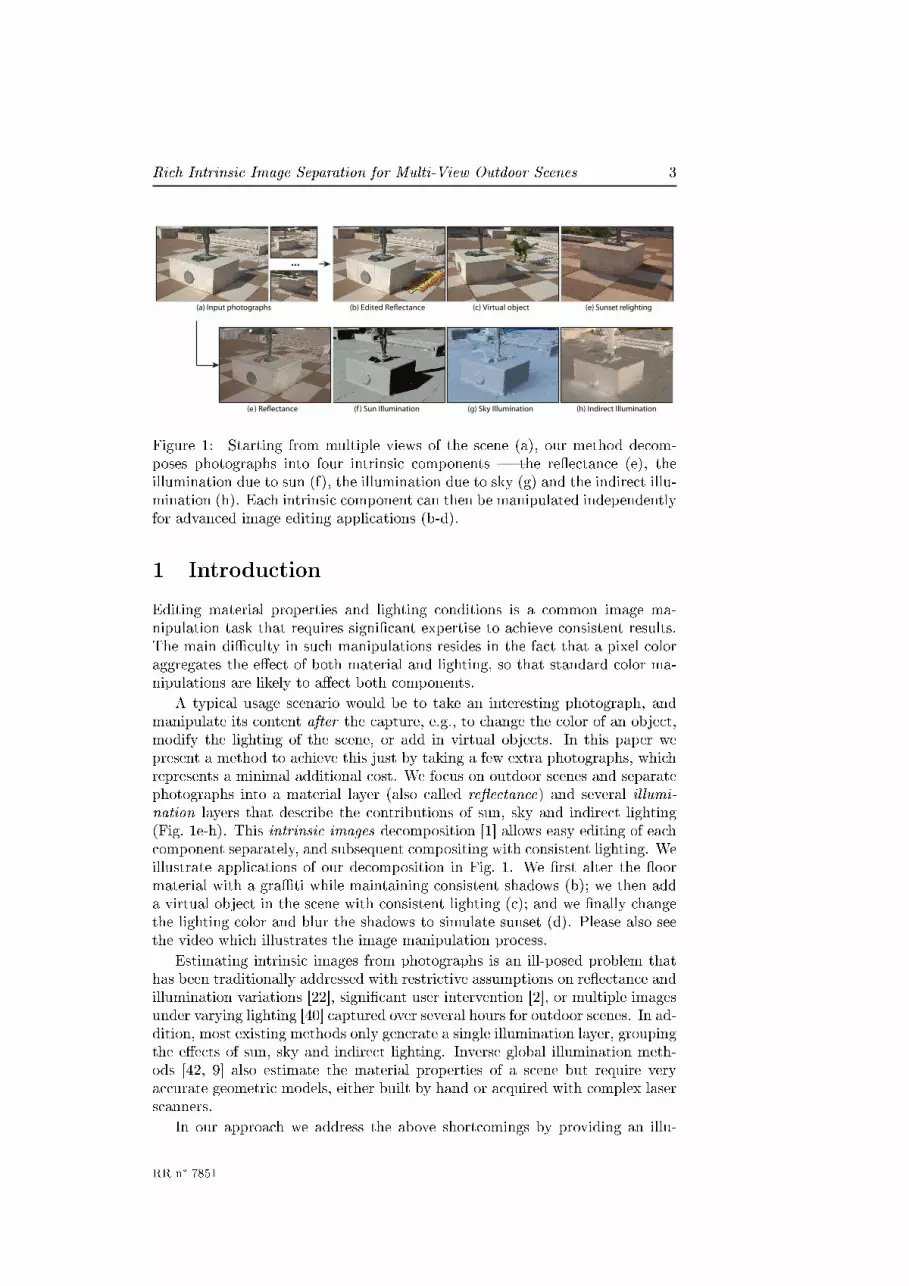
Figure 1: Starting from multiple views of the scene (a), our method decom-poses photographs into four intrinsic components the reectance (e), theillumination due to sun (f), the illumination due to sky (g) and the indirect illu-mination (h). Each intrinsic component can then be manipulated independentlyfor advanced image editing applications (b-d).
1 Introduction
Editing material properties and lighting conditions is a common image ma-nipulation task that requires signicant expertise to achieve consistent results.The main diculty in such manipulations resides in the fact that a pixel coloraggregates the eect of both material and lighting, so that standard color ma-nipulations are likely to aect both components.
A typical usage scenario would be to take an interesting photograph, andmanipulate its content after the capture, e.g., to change the color of an object,modify the lighting of the scene, or add in virtual objects. In this paper wepresent a method to achieve this just by taking a few extra photographs, whichrepresents a minimal additional cost. We focus on outdoor scenes and separatephotographs into a material layer (also called reectance) and several illumi-nation layers that describe the contributions of sun, sky and indirect lighting(Fig. 1e-h). This intrinsic images decomposition [1] allows easy editing of eachcomponent separately, and subsequent compositing with consistent lighting. Weillustrate applications of our decomposition in Fig. 1. We rst alter the oormaterial with a grati while maintaining consistent shadows (b); we then adda virtual object in the scene with consistent lighting (c); and we nally changethe lighting color and blur the shadows to simulate sunset (d). Please also seethe video which illustrates the image manipulation process.
Estimating intrinsic images from photographs is an ill-posed problem thathas been traditionally addressed with restrictive assumptions on reectance andillumination variations [22], signicant user intervention [2], or multiple imagesunder varying lighting [40] captured over several hours for outdoor scenes. In ad-dition, most existing methods only generate a single illumination layer, groupingthe eects of sun, sky and indirect lighting. Inverse global illumination meth-ods [42, 9] also estimate the material properties of a scene but require veryaccurate geometric models, either built by hand or acquired with complex laserscanners.
In our approach we address the above shortcomings by providing an illu-
RR n° 7851

4 Laont & Bousseau & Drettakis
mination decomposition with minimal user intervention, resulting in intrinsicimage layers for sun, sky and indirect illumination. We achieve this by combin-ing sparse geometric reconstruction [37, 15] with image-guided propagation [23],thus leveraging their respective strengths. We exploit the automatically recon-structed 3D information to compute lighting information for a subset of pixels,and use image-guided propagation to decompose the photographs into intrinsicimages.
Our algorithm takes as input a small number of photographs of the scenecaptured at a single time of the day, along with an environment map. From thislightweight capture we use recent computer vision algorithms to reconstruct asparse 3D point cloud of the scene. The point cloud only provides an impreciseand incomplete representation of the scene. However, we show that this is suf-cient to compute plausible sky and indirect illumination at each reconstructed3D point, without complex inverse global illumination computations. The coarsegeometry is however unreliable for sun illumination that typically contains high-frequency features such as cast shadows. We introduce a new parameterizationof reectance with respect to sun visibility that we integrate in an optimizationalgorithm to robustly identify the 3D points that are in shadow. We developedan optimization inspired by mean shift [7] where we use asymmetric regions ofinuence and constrain the evolution of the estimates.
Image-guided propagation algorithms are typically used to propagate userscribbles [23, 2]; we show how to use these algorithms to propagate the illumi-nation information computed at 3D points over the image pixels. Our approachgenerates intrinsic images of similar quality as scribble-based approaches, withonly a small amount of user intervention for capture and calibration. In addi-tion, our ability to separate sun, sky and indirect illumination opens the doorfor advanced image manipulations, as demonstrated in Fig. 1b-d.
To summarize, this paper makes the following contributions:
We show how to compute sky, indirect, and sun (ignoring cast shadows)illumination at automatically reconstructed 3D points, using incompleteand imprecise geometry and a small set of input images.
We introduce an algorithm to reliably identify points in shadow based ona new parameterization of the reectance with respect to sun visibility.Our algorithm compensates for the lack of accurately reconstructed andcomplete 3D information.
We show how to propagate reectance, sun, sky and indirect illuminationto all pixels in an image, without user intervention or involved inverseglobal illumination computation. We achieve this by using the illumina-tion values computed at 3D points as constraints for image propagationalgorithms.
After a presentation of previous work, the denition of our image formationmodel and a description of capture, the structure of our paper follows the threecontributions described above.
Inria

Rich Intrinsic Image Separation for Multi-View Outdoor Scenes 5
2 Related Work
Intrinsic images. Several methods have been proposed to estimate reectanceand illumination from a single image. This decomposition is severely ill-posedand can only be solved with additional knowledge or assumptions about thescene content. The Retinex algorithm [22, 18] assumes smooth illumination andpiece-wise constant reectance, while Li and Yeo [25] assume that neighboringpixels with similar chromaticity have the same reectance and that the imageis composed of a small set of reectances. Tappen et al. [39] train a classier todiscriminate image derivatives due to reectance and illumination, and Shen etal. [35] introduce texture constraints to ensure that pixels with similar textureshare the same reectance. These various approaches produce encouraging de-compositions on isolated objects, as evaluated by the ground-truth dataset ofGrosse et al. [16]. However, the automatic decomposition of complex outdoorimages remains an open challenge, in part because most existing methods as-sume monochrome lighting while outdoor scenes are often lit by a mixture ofcolored sun and sky light.
Weiss [40] demonstrates how multiple images of a scene under dierent il-luminations can be factored into a reectance image and a set of illuminationimages. Sunkavalli et al. [38] decompose similar image sequences of outdoorscenes into a shadow mask and images illuminated only by skylight or sunlight.By also capturing an environment map at multiple times of the day, Matusiket al. [28] estimate the reectance eld of an outdoor scene that can then beused for relighting. These methods assume a xed viewpoint and varying il-lumination (i.e., timelapse sequences), while our method relies on images cap-tured under dierent viewpoints and xed illumination. The main advantage ofour capture approach is to reduce the acquisition time to a few minutes whiletimelapses typically require at least several hours of capture to cover as manylighting directions as possible. Most related to our capture strategy is the sys-tem of Melendez et al. [29] that relights buildings reconstructed from multiplephotographs. However their method necessitates the additional acquisition ofash / no-ash image pairs to capture a material exemplar for every materialof a building. Users then need to associate a material exemplar to each textureregion of the reconstructed building.
Bousseau et al. [2] and Shen et al. [34] rely on user scribbles to disambiguatereectance from illumination while Okabe et al. [31] propagate a sparse set ofuser-specied normals over the image. Given an intrinsic image decomposition,Carroll et al. [5] propose a user-assisted decomposition to isolate the indirectcontribution of each colored material in the scene. Our method shares similar-ities with these user-assisted approaches but we propagate illumination valuesautomatically computed from a sparse point cloud instead of user indications.
Inverse rendering. Inverse rendering methods [43, 42, 27, 9] recover the re-ectance and illumination of a scene by inverting the rendering equation. Thesemethods require an accurate 3D model of the scene that is either modeled man-ually or acquired with expensive laser scanners and then solve an often costlyglobal illumination system. In contrast our method is robust to incomplete ge-ometry and handles sparse point clouds automatically reconstructed from a fewphotographs of the scene. In addition, we are able to estimate indirect illu-mination at every pixel without the need to solve inverse global illumination.Nonetheless, inverse rendering methods allow applications that are beyond the
RR n° 7851

6 Laont & Bousseau & Drettakis
scope of this paper, such as free viewpoint navigation and dynamic relighting.Image-based propagation. Image guided interpolation methods have
been introduced by Levin and Lischinski to propagate colors [23] and tonaladjustments [26]. In this paper we use the propagation algorithm of Bousseauet al. [2] that was originally designed to propagate user indications for intrinsicimage decompositions. This algorithm is inspired by the matting Laplacian ofLevin and colleagues [24] that has been used to decompose an image into aforeground and background layer, and to recover white balanced images undermixed lighting [19].
Shadow removal. Our work is also related to shadow removal methods [13,12, 30, 41, 36] that aim at identifying and removing cast shadows in an image,either automatically or with user assistance. While our method is also able toidentify cast shadows, our main goal is to extract a reectance image, as well assmooth illumination variations. We also separate the contribution of sun, skyand indirect illumination, which enables novel image manipulations.
3 Image Formation Model
We assume Lambertian surfaces and model the image values at each pixel asthe product between the incident illumination and the object reectance R.Formally, the radiance I towards the camera at each non-emissive, visible pointcorresponding to a pixel is given by the rendering equation [20]:
I = R ∗
∫
Ω
cos θωL(ω)dω (1)
where we integrate over the entire hemisphere Ω at the visible point, L(ω) isthe incoming radiance in direction ω, θω is the angle between the normal at thevisible point and direction ω. Capital bold letters represent RGB color valuesand ∗ denotes per-channel multiplication.
For our purposes, we will separate out the incoming radiance into threecomponents: the radiance due to the sun, that due to the sky and that due toindirect lighting. To simplify notation, we dene two subsets of the hemisphere:Ωsky, i.e., the subset of directions in which the visible point sees the sky, and Ωind
the subset of directions in which another object is visible, and thus contributesto indirect lighting. We however explicitly represent the sun visibility vsun, rstbecause precise computation of vsun is necessary to capture sharp shadows, andsecond because estimating vsun robustly is one of our main contributions.
We can now re-write Equation 1:
I = R ∗(
vsun max(0, cos θsun)Lsun +∫
Ωsky
cos θωLsky(ω)dω +
∫
Ωind
cos θωLind(ω) dω)
where Lsun, Lsky and Lind are radiance from the sun, the sky and indirectlighting respectively, θsun is the angle between the normal at the visible pointand the sun modeled as a directional light source, and θω is the angle betweenthe normal and the direction of integration ω over the corresponding hemisphere.The scalar vsun ∈ [0, 1] models the visibility of the sun (0 for completely hidden,1 for fully visible).
Inria

Rich Intrinsic Image Separation for Multi-View Outdoor Scenes 7
We next dene the following simplied quantities at each pixel:
Ssun = vsun max(0, cos θsun)Lsun = vsunSsun (2)
Ssky =
∫
Ωsky
cos θωLsky(ω) dω (3)
Sind =
∫
Ωind
cos θωLind(ω) dω. (4)
where Ssun corresponds to the sun illumination when cast shadows are ignored.This allows us to dene a simplied image formation model, which we use
from now on:
I = R ∗ (Ssun + Ssky + Sind) (5)
= R ∗ Stotal (6)
whereR is the object RGB reectance. Ssun, Ssky and Sind are the RGB incidentillumination (or shading) from the sun, sky and indirect lighting respectively.
Our rst goal is to extract the reectance R and illumination Stotal from thisimage formation model. We demonstrate how to make this problem tractableby leveraging the sparse geometric information generated by multiview stereoalgorithms to compute Ssun, Ssky and Sind at each reconstructed 3D point (Sec-tion 5). We then introduce a new algorithm to estimate the sun visibility vsunprecisely despite the approximate available geometry (Section 6), which willallow us to obtain all illumination components using image propagation (Sec-tion 7).
4 Capture and Reconstruction
Our method relies on a relatively lightweight capture setupcomposed of a digital camera (preferably on a tripod), aphotographer's gray card and a simple reective sphere1 tocapture the environment map (see inset). No other specialcapture or measurement hardware is required.
4.1 Photography
We rst capture a few ordinary low-dynamic range photographs (LDR) whichwe use to perform approximate geometric reconstruction of the scene. Thisset of photographs should have a good coverage of the scene from dierentviewpoints and sucient overlap between neighboring viewpoints to facilitatemultiview stereo reconstruction. The number of photographs required to obtainan acceptable reconstruction depends on the complexity of the scene and thepresence of image features. We captured between 10 and 31 LDR photographsfor each of the scenes presented in our results.
We then capture two high-dynamic range (HDR) images of the front and sideof the reective sphere, placed in the scene, to obtain an angular environment
1The reective sphere does not need to be as accurate as in the apparatus described in [9];in practice we used an inexpensive pétanque ball.
RR n° 7851
8 Laont & Bousseau & Drettakis
(a) Input photograph (b) Reconstructed PMVS points
(c) Proxy shadows (d) Shadow conguration
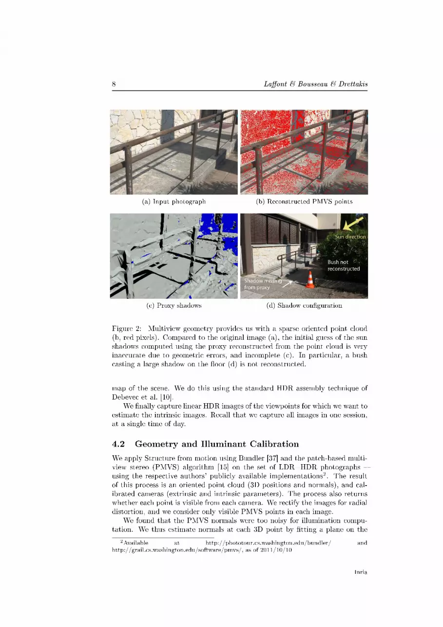
Figure 2: Multiview geometry provides us with a sparse oriented point cloud(b, red pixels). Compared to the original image (a), the initial guess of the sunshadows computed using the proxy reconstructed from the point cloud is veryinaccurate due to geometric errors, and incomplete (c). In particular, a bushcasting a large shadow on the oor (d) is not reconstructed.
map of the scene. We do this using the standard HDR assembly technique ofDebevec et al. [10].
We nally capture linear HDR images of the viewpoints for which we want toestimate the intrinsic images. Recall that we capture all images in one session,at a single time of day.
4.2 Geometry and Illuminant Calibration
We apply Structure from motion using Bundler [37] and the patch-based multi-view stereo (PMVS) algorithm [15] on the set of LDR+HDR photographs using the respective authors' publicly available implementations2. The resultof this process is an oriented point cloud (3D positions and normals), and cal-ibrated cameras (extrinsic and intrinsic parameters). The process also returnswhether each point is visible from each camera. We rectify the images for radialdistortion, and we consider only visible PMVS points in each image.
We found that the PMVS normals were too noisy for illumination compu-tation. We thus estimate normals at each 3D point by tting a plane on the
2Available at http://phototour.cs.washington.edu/bundler/ andhttp://grail.cs.washington.edu/software/pmvs/, as of 2011/10/10
Inria

Rich Intrinsic Image Separation for Multi-View Outdoor Scenes 9
local 3D point cloud using the PCA method of Hoppe et al. [17]. We discard3D points in too sparse or too degenerate local neighborhoods. We consider aneighborhood as degenerate when the rst singular value of the PCA is twicegreater than the second singular value.
We recover a geometric proxy from the oriented point cloud using the scalespace meshing method of Digne et al. [11]. This automatic approach producesdetailed accurate meshes in regions where the point cloud is dense, while leavingholes in areas where the point cloud is irregularly sampled. We use the automatichole lling tool available in MeshLab [6] to further improve the reconstruction inthose areas. We also experimented with the Poisson reconstruction of Kazhdanet al. [21]. Although this algorithm generates a closed surface with no holes, wefound that it tends to produce bumpy surfaces due to the irregular sampling ofthe point cloud. We nevertheless used the Poisson reconstruction on the Rocksscene for which the point cloud is dense and uniform.
Some manual interaction is also required to calibrate the sun and sky illu-mination. We rst identify the sun position, orient the environment map andlabel sky pixels. We also take two photographs of a gray card, in the sun andin shadow, which are used to estimate the color transfer function of the reec-tive sphere and the radiance Lsun of the sun. The details of this process aredescribed in the Appendix.
The output of our capture is: a moderately dense point cloud reconstruc-tion of the scene which we will refer to as the PMVS points (Fig. 2b), a veryapproximate geometric proxy, which often contains signicant geometric errors(Fig. 2c), the direction and radiance of the sun and a correctly aligned andscaled HDR environment map containing the sky and distant indirect radiance(Fig. 4c).
5 Geometry-Based Computation
We describe here how to compute sun, sky and indirect illumination values foreach PMVS point. These points have been generated using multiview stereoand also have normals (Section 4.2).
We rst compute sun illumination Ssun ignoring cast shadows, i.e., unoc-cluded sunlight. We already know the required quantities for this computation,i.e., the normal at the point and the sun radiance and direction. Treating sunvisibility requires much higher precision than the one provided by the proxy,and is treated separately in Section 6.
We then compute sky and indirect illumination at each PMVS point. Fig. 3illustrates this computation that we detail bellow. In a nutshell, we use theHDR environment map to compute both sky illumination and distant indirectillumination, while we compute the near-eld indirect illumination from theproxy geometry. Note however that we do not need to know the reectance ofthe proxy for this step, we instead use the captured photographs to recover thenecessary outgoing radiance over the reconstructed geometry.
Assigning radiance to the proxy geometry. We rst assign radianceto each PMVS point by looking up its pixel values in each HDR image where itappears (Fig. 3). We assign the average value as the outgoing radiance of thepoint, which is assumed constant in all directions. We then assign the radianceof the closest PMVS point to each vertex of the proxy, and interpolate these
RR n° 7851


Rich Intrinsic Image Separation for Multi-View Outdoor Scenes 11
(a) Input photograph (b) Colored proxy
(c) Environment map
Figure 4: We estimate sky and indirect illumination at PMVS points using(b) a colored proxy, obtained by projecting and interpolating the radiance ofPMVS points on the reconstructed geometry, and (c) an environment map,shown in a latitude-longitude parameterization where the red curve separatespixels contributing to sky illumination and those contributing to distant indirectillumination.
Our approach shares similarities with the techniques described by Yu andMalik [43], but while their method was designed for accurate geometry con-structed manually, we handle sparse incomplete geometry reconstructed auto-matically.
Finally we compute an initial guess of the sun visibility vinitsun at each PMVSpoint by tracing a ray against the proxy geometry in the direction of the sun.Note however that this visibility test is very sensitive to errors in the recon-structed proxy, as illustrated in Fig. 2c. This fact underlines the importance ofaccurately estimating vsun and we next show how to rene this initial estimate.
6 Estimating Sun Visibility at PMVS Points
One key contribution of our approach is a novel algorithm for identifying visibil-ity vsun with respect to the sun for each PMVS point. From our image formationmodel in Equations 2 and 5 we express the reectance at each PMVS point as
RR n° 7851

12 Laont & Bousseau & Drettakis
(a) Selected PMVS points
(b) Candidate (c) Regions of inuence (d) Regions of inuence
reectance curves at initialization after one iteration
Figure 5: Multiple PMVS points sharing the same reectance will generateintersecting curves in color space. (a) We selected two PMVS points with thesame reectance but dierent illuminations (red and blue squares). (b) Thecorresponding candidate reectance curves (nearly) intersect at one end, whichcorresponds to the reectance of both points. Diamond markers on the curvescorrespond to the initial guess for visibility (randomly set in this example).(c) Each curve aects a region of the surrounding color space, according toEquation 10 . Regions of inuence at initialization are illustrated as isosurfaceswith varying opacity. Regions closer to the curve and the current visibilityestimate are more aected. (d) After one iteration, the visibility estimates havemoved towards the intersecting end of the curves, increasing the overlap betweenthe regions of inuence (i.e., the energy Etotal in Equation 12).
a function of the visibility term:
R(vsun) =I
(vsunSsun + Ssky + Sind)(9)
where I is the RGB pixel value in the image we wish to process, Ssky, Sind and
Ssun are the illumination values of the corresponding PMVS point computed inSection 5, and the division is per-channel. With this parameterization, varyingvsun in [0, 1] generates a curve of candidate reectances in RGB space. Our goalin this section is to nd for each PMVS point, the position on its candidatecurve corresponding to its reectance R (or correspondingly visibility vsun).
The intuition of our approach is that multiple PMVS points sharing thesame reectance will generate intersecting curves in color space; their (shared)reectance will be the color where the candidate curves intersect. This is illus-trated on Fig. 5a-b. By nding these intersections we can deduce the value ofvsun for the PMVS point corresponding to each curve.
However, imprecision in the capture process and in the geometry-based com-putation prevent the curves from perfectly intersecting in color space. In addi-tion, multiple intersections can occur along a curve, which gives multiple can-didates for the visibility term. We address these issues with a robust iterativeprocedure inspired by the mean shift algorithm.
Overview. Mean shift [14, 7] is a non-parametric mode-seeking algorithmthat aims to locate the maxima of a density function, given a set of data points.First, a kernel (or window) is placed at each data point; it represents the region
Inria

Rich Intrinsic Image Separation for Multi-View Outdoor Scenes 13
of inuence of this point. In an iterative process, each kernel is then moved in adirection that increases the local density, computed as the weighted average ofnearby data points. The process stops when all kernels have reached a stationarypoint (or mode).
In our approach, we dene an asymmetric region of inuence for each can-didate curve. We use mean shift iterations to maximize an energy that mea-sures the overlap among pairs of curves, and iteratively update the estimatedreectances while constraining them to lie on their candidate curves. Afterconvergence, for each curve we obtain the reectance (and corresponding vis-ibility) that tends to maximize the number of PMVS points sharing a similarreectance, and correspondingly tends to minimize the number of reectancesin the scene.
This algorithm assumes that the scene is composed of a sparse set of re-ectances shared by multiple points, which is a common assumption recentlyused in image segmentation [32] and white balance algorithms [19].
Region of inuence. Equation 9 denes the candidate reectances of aPMVS point as a rational curve that is parameterized non-uniformly by vsun. Inorder to obtain a uniform parametrization we rst approximate each curve c asa piecewise linear curve in CIE L*a*b* space, and parameterize it by arc lengthfrom the shadowed end of the curve: t in [0, 1] so that R(vsun = 0) = R(t = 0).We use this uniform parametrization to compute distances along the curve. Wechose to work in CIE L*a*b* space because it denes a perceptually uniformdistance metric.
We then dene the inuence of curve c on a point x of color space as:
Axc = h⊥
(
d2⊥(x, c)
σ2⊥
)
h‖
(
d2‖(x, c)
σ2‖
)
(10)
where
d2⊥(x, c) = ‖x − proj3D(x, c)‖
2is the squared distance in color space be-
tween x and its projection on curve c (i.e., the distance perpendicular tothe curve).
d2‖(x, c) = (tc − projt(x, c))
2is the squared dierence between the position
of the current reectance estimate along the curve tc and the arc lengthprojt(x, c) corresponding to the projection of x on the curve (i.e., thedistance along the curve).
h⊥ and h‖ are Gaussian kernel proles with the form h(x) = e−x controlledby the standard deviations σ2
⊥ and σ2‖ (larger σ values correspond to a
wider region of inuence).
The rst term in Equation 10 compensates for curves that do not exactlyintersect, by dening a region of inuence around the curve with a Gaussianfallo orthogonal to the curve. The second factor makes our algorithm robustto false intersections, i.e., intersections of curves that in fact do not share thesame reectance. The Gaussian kernel h‖ reduces the inuence of the falseintersections far from tc as tc converges toward the most likely reectance.
The regions of inuence of two curves are illustrated in Fig. 5c.
RR n° 7851

14 Laont & Bousseau & Drettakis
Energy Formulation. We then dene an energy that measures the overlapbetween the regions of inuence of pairs of curves:
E =
∫
V
∑
c∈C
∑
c′ 6=c
AxcAxc′
dx (11)
where we integrate over the entire color space V .We evenly discretize the 3D color space into a set S of samples, and rewrite
this energy as a discrete sum:
Etotal =∑
s∈S
Esample(s). (12)
where the energy of a sample Esample(s) accumulates the contribution of eachpair of curves intersecting nearby:
Esample(s) =∑
c∈C
∑
c′ 6=c
AscAsc′
With this formulation, two curves will contribute to the energy of a sample onlyif they (almost) intersect near this sample.
Derivation of the energy gradient. We seek the positions of the re-ectance estimates along the curves tc for c ∈ C that maximize Etotal:
argmaxtc
Etotal (13)
i.e. that are located at the zeros of the gradient function.The derivative of Etotal with respect to tc is given by:
∂Etotal
∂tc=
4
σ2‖
∑
s∈S
∑
c′ 6=c
(projt(s, c) − tc) AscAsc′ (14)
Setting Equation 14 to 0 for all c ∈ C gives:
∂Etotal
∂vc
= 0 ⇔
∑
s∈S
∑
c6=c′
AscAsc′
tc −
∑
s∈S projt(s, c)(
∑
c′ 6=c AscAsc′
)
∑
s∈S
∑
c′ 6=c AscAsc′
= 0
which is analogous to the form obtained in the mean-shift algorithm [7].
Iterative process. We dene our iterative procedure recursively by com-puting at iteration i the weights Ai
sc (i.e., the regions of inuence) using theestimates tic for all curves c ∈ C, then updating the estimates ti+1
c for eachcurve c using a weighted average of the projection of nearby samples on c:
ti+1c =
∑
s∈S projt(s, c)(
∑
c′ 6=c AiscA
isc′
)
∑
s∈S
∑
c′ 6=c AiscA
isc′
(15)
Inria


16 Laont & Bousseau & Drettakis
Finally, we replace all the curves belonging to each cluster by one represen-tative curve: the curve closest to the median of this cluster's feature vectors.The initial guess of the sun visibility vinitsun is assigned to the median visibility ofeach cluster. This process greatly simplies and cleans up the set of curves, andlowers the computational cost of our algorithm. As shown in Fig. 6d, the curvescorresponding to groups of PMVS points with similar reectances (nearly) in-tersect after clustering.
After clustering, we run the optimization to maximize Etotal. Upon conver-gence, for each cluster we obtain the position of the estimated reectance alongits representative curve tnal. This position value is assigned to all curves be-longing to this cluster, from which we can deduce the nal estimated reectanceof each PMVS point corresponding to these curves.
At the end of this process, we obtain a list of PMVS points for which theposition along the curve t, the sun visibility vsun and the reectance R havebeen estimated.
Implementation. In practice we use a truncated kernel prole h⊥ (Equa-tion 10) so that h⊥(x) = 0 when x > λ (we use λ = 3). This means that eachcurve will only inuence a limited number of samples; for each curve c we canprecompute the indices of these samples, as well as their orthogonal distance‖s − proj3D(s, c)‖ and position of their projection along the curve projt(s, c).
For all our results, we evenly discretized the CIE L*a*b* color space into60 × 36 × 36 samples, with L* in [5, 95], a* in [−25, 25], b* in [−25, 25]. Weused a xed bandwidth for the curve clustering using 6D mean-shift clustering,as well as for the 3D mean-shift clustering for orientation separation.
The clustering is the most costly part of the algorithm and takes from 25seconds to a few minutes with our Matlab implementation, depending on thenumber of PMVS points. Once the clustering has been performed, the iterativeoptimization takes around 10 seconds, which allowed us to test many parametersfor σ2
⊥ and σ2‖.
We found that the algorithm produces good results for a wide range ofparameters, and that the best values were scene-dependent. In our experimentswe found that large values of σ2
⊥ can compensate for calibration errors thatprevent reectance curves to perfectly intersect, while large values of σ2
‖ can
compensate for the erroneous initialization of vinitsun provided by the approximateproxy. However, σ values should remain small enough to prevent curves ofdierent materials to inuence one another. Table 1 summarizes the parametervalues used for the examples in this paper.
Statue Rocks Ramp Stairs(σ2
‖, σ2⊥) (0.1, 1) (0.01, 1) (0.3, 1) (0.01, 20)
(0.1, 5) (0.01, 5) (0.3, 5)
Table 1: Sets of region of inuence parameters used on the four scenes. Whenspecied, the two sets of parameters produced equally good results.
Inria
Rich Intrinsic Image Separation for Multi-View Outdoor Scenes 17
(a) Input (b) Illumination (c) Estimated (d) Estimated
photograph constraints total illumination reectance
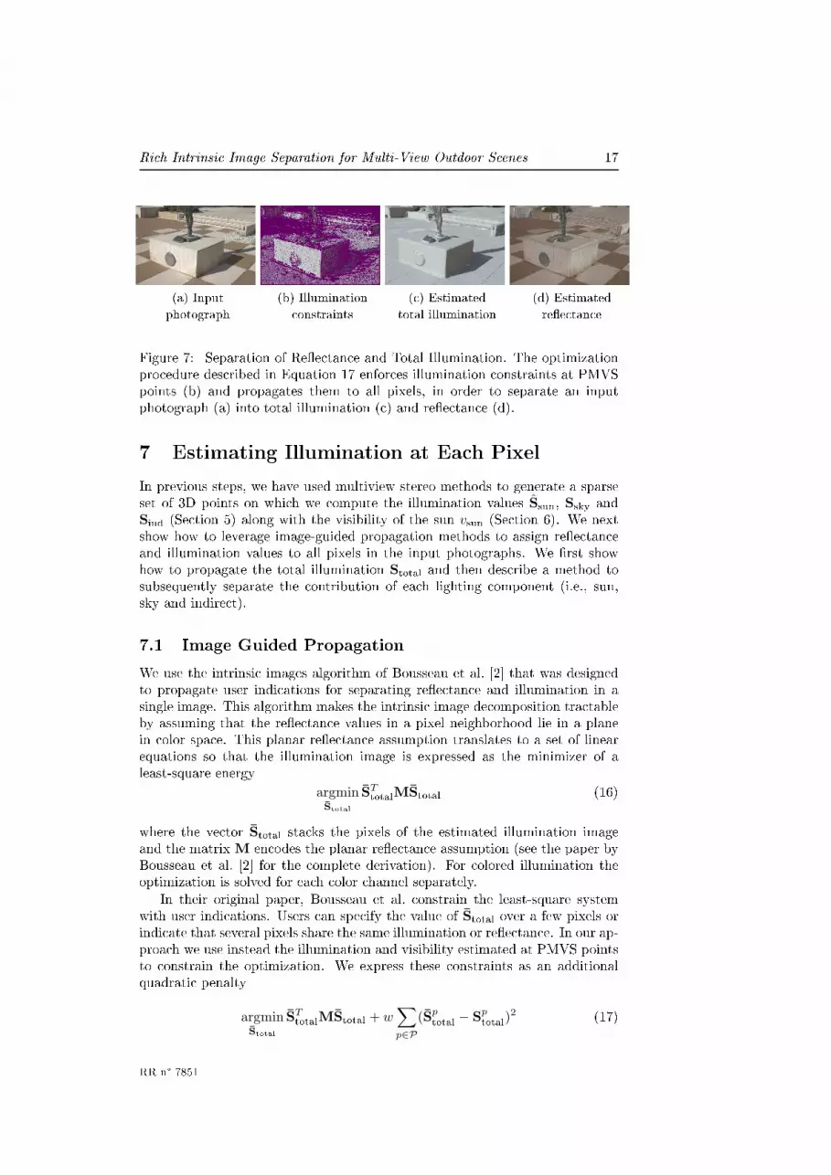
Figure 7: Separation of Reectance and Total Illumination. The optimizationprocedure described in Equation 17 enforces illumination constraints at PMVSpoints (b) and propagates them to all pixels, in order to separate an inputphotograph (a) into total illumination (c) and reectance (d).
7 Estimating Illumination at Each Pixel
In previous steps, we have used multiview stereo methods to generate a sparseset of 3D points on which we compute the illumination values Ssun, Ssky andSind (Section 5) along with the visibility of the sun vsun (Section 6). We nextshow how to leverage image-guided propagation methods to assign reectanceand illumination values to all pixels in the input photographs. We rst showhow to propagate the total illumination Stotal and then describe a method tosubsequently separate the contribution of each lighting component (i.e., sun,sky and indirect).
7.1 Image Guided Propagation
We use the intrinsic images algorithm of Bousseau et al. [2] that was designedto propagate user indications for separating reectance and illumination in asingle image. This algorithm makes the intrinsic image decomposition tractableby assuming that the reectance values in a pixel neighborhood lie in a planein color space. This planar reectance assumption translates to a set of linearequations so that the illumination image is expressed as the minimizer of aleast-square energy
argminStotal
STtotalMStotal (16)
where the vector Stotal stacks the pixels of the estimated illumination imageand the matrix M encodes the planar reectance assumption (see the paper byBousseau et al. [2] for the complete derivation). For colored illumination theoptimization is solved for each color channel separately.
In their original paper, Bousseau et al. constrain the least-square systemwith user indications. Users can specify the value of Stotal over a few pixels orindicate that several pixels share the same illumination or reectance. In our ap-proach we use instead the illumination and visibility estimated at PMVS pointsto constrain the optimization. We express these constraints as an additionalquadratic penalty
argminStotal
STtotalMStotal + w
∑
p∈P
(Sptotal − S
ptotal)
2 (17)
RR n° 7851

18 Laont & Bousseau & Drettakis
where P is the set of pixels covered by PMVS points and Sptotal = vp
sunSpsun +
Spsky + S
pind their illumination values computed in Sections 5 and 6. The weight
w controls the importance of the constraints, in practice we use w = 1 to giveequal importance to the constraints and the propagation model.
Fig. 7 shows the results of the image guided propagation. This result showsthe power of our approach. We exploit the information provided by the sparseand imprecise geometry to provide constraints automatically to the algorithm ofBousseau et al. [2], thus eliminating the need for user scribbles. A visualizationof the constraints for all scenes can be found in the supplemental material.
7.2 Light Source Separation
Given the estimated illumination image Stotal, we wish to separate the contribu-tion of each illumination component Ssun, Ssky and Sind. Inspired by previouswork on white balance under mixed lighting [19], we show how to express ourlight source separation as two successive matting problems. In a rst step wedecompose the illumination into a sun component and a diuse component Sdi
that includes the contribution of both sky and indirect lighting. In a second stepwe decompose the diuse component into its two terms.
We rst express each illumination term S as the product between a scalarintensity s = ‖S‖ and a chromaticity C = S/‖S‖:
Stotal = ssunCsun + sskyCsky + sindCind
= ssunCsun + sdiCdi. (18)
Denoting α = ssun/(ssun + sdi) we express the illumination image values ateach pixel as a mixture between two values weighted by α:
Stotal = α(ssun + sdi)Csun
+(1 − α)(ssun + sdi)Cdi (19)
= αF + (1 − α)B (20)
We can now recover Ssun = αF and Sdi = (1 − α)B by solving a standardmatting problem. We compute α at each PMVS point from the illuminationvalues estimated in Sections 5 and 6. We then propagate α over the image Stotal
using the matting Laplacian algorithm of Levin et al. [24]. Finally, given α atevery pixel and the known Ssun and Sdi at each PMVS point, we solve for thesun and diuse illumination images with the following least-square optimization:
argminF,B
∑
i∈I
(
(
Sitotal −
(
αiF
i + (1 − αi)Bi)
)2
+ λ(
(Fix)2 + (Fi
y)2 + (Bix)2 + (Bi
y)2)
)
+ w∑
p∈P
(
αpF
p − Spsun
)2+(
(1 − αp)Bp − Spdi
)2
where I is the image domain, P is the set of pixels covered by PMVS pointsand Fx, Fy, Bx and By are the x and y derivatives of F and B computed withnite dierences.
Inria

Rich Intrinsic Image Separation for Multi-View Outdoor Scenes 19
(a) Before inpainting (b) After inpainting
Figure 8: The reectance, sky illumination (here, close up) and indirect illu-mination estimated by our algorithm can contain residual variations along hardshadow boundaries (a). We use inpainting to remove these artifacts (b).
The rst term of this functional ensures that the decomposition explainsthe input illumination Stotal and follows the estimated ratio α. The secondterm adds a smoothness regularization on each component while the third termconstrains the solution to agree with the illumination values computed at PMVSpoints. We used λ = 0.1 and w = 0.01 for all our results.
As a second step we apply the same matting approach to further separate thediuse illumination Sdi as the sum of the sky illumination Ssky and the indirectillumination Sind. We show in Fig. 9 and supplemental materials the resultsof this decomposition. The overall decomposition takes around 90 seconds tocompute for a 3.2 megapixel image, where 30 seconds are necessary to computeStotal and 60 seconds to perform the two subsequent separations.
Inpainting This overall process gives a satisfactory decomposition in thescenes we have tested. However, a small residual border can remain aroundthe hard shadow boundary (see Fig. 8 (left)), a common artifact of shadowremoval [12, 41]. We identify these shadow boundaries as pixels located onsun illumination discontinuities but not on normal discontinuities. We rstpropagate normals from the PMVS points over the image using the method ofOkabe et al. [31]. We then run an edge detector over the sun illumination imageand label edge pixels that do not correspond to edges in the normal image. Weremove the labeled pixels and their immediate neighbors from the reectance,sky and indirect illumination images and use inpainting to ll in the holes. Thispost-process takes 60 seconds on average. Fig. 8 illustrates the result of thisprocess.
8 Results and Discussion
In Fig. 9 we show results on four dierent scenes. For all results, we show re-ectance, sun, sky and indirect illumination layers. The number of photographsused for each scene is shown in Table 2. The estimated illumination at PMVSpoints and additional views for each scene are shown in the supplemental ma-terial.
The rst scene shows the base of a statue on a square; we took HDR images
RR n° 7851

20 Laont & Bousseau & Drettakis
Input (undistorted) Reectance Sun Sky IndirectReectance Illumination Illumination Illumination
Figure 9: Results of our decomposition. We adjusted the brightness of images forillustration purpose (the scaling factors used can be found in the supplementarymaterials). For each scene, the sun illumination is usually much more intensethan sky illumination on average, and the sky illumination is more intense thanindirect illumination on average.
for three dierent views and we show results for all three. As we can see theresults are plausible for the reectance layer in all views. The sun and skylayers have been successfully separated in all cases, however the third viewshows a slight color shift of the reectance in the shadow area; this is due tothe insucient number of PMVS points on the ground. Please refer to thesupplemental material to see an illustration of the distribution of 3D points.The indirect layer is particularly interesting, since it clearly shows the indirectlight bouncing o the front of the base (rst and second views) which is in directsunlight.
The second scene is challenging, since the reconstruction process is unableto capture details of the railings and does not reconstruct the vegetation castingthe main shadows (see also Fig. 2d). In this view, despite the intricate geometric
Inria

Rich Intrinsic Image Separation for Multi-View Outdoor Scenes 21
conguration, shadows are successfully removed from the reectance layer, andthe three other layers show good results. In the third scene, a staircase isshown. There are some residual artifacts at the shadow boundaries because thevegetation moved in the breeze during HDR acquisition. In the fourth scene,a rock wall is shown. Notice how the indirect layer well represents lightingin the cracks between rocks where neither sun nor skylight is present. Thethird and fourth scene also show that our method succeeds in creating plausiblereectance, sun, sky and indirect layers.
Statue Rocks Ramp Stairs30 11 31 10
Table 2: Number of photographs captured for the geometric reconstruction, foreach scene in this paper.
Next we compare our approach to three state-of-the-art methods in Fig. 10.All these methods take a single image as input. The user-assisted approachof Bousseau et al. [2] produces result of a similar quality to ours, but requiresa signicant number of user indications (between 25 and 105 scribbles). Theautomatic method of Shen et al. [35] is able to extract most of the illuminationvariations but colored shadows remain in the reectance image. These coloredresiduals are due to the variation in color between sun and sky illumination,which violates the gray illumination assumption of this method. Residual shad-ows are also present in the reectance estimated with the automatic method ofShen et al. [34], as well as reectance residuals in the illumination image (tiledoor in the statue scene). Although this method can support user scribbles, theauthors reported that scribbles did not improve the result signicantly in theseexamples. All the results of these comparisons have been kindly provided bythe respective authors.
We also provide in Fig. 11 a comparison to the result obtained simply byusing the proxy to compute sun, sky and indirect illumination using PBRT,and then inverting Equation 5 to obtain reectance. As we can see, for a givenimage, there are many holes due to the incomplete proxy. In addition, thesun illumination is completely erroneous, due to the lack of reconstruction ofthe surrounding objects. In contrast, our method correctly captures these sunshadows, and removes them in the reectance layer as well.
We illustrate applications of our decomposition in Fig. 1. We rst alter thereectance of the ground to insert a grati while maintaining consistent shad-ows (b). We then add a virtual object in the scene with consistent lighting andshadows (c). We used PBRT to render the dinosaur surrounded by the capturedenvironment map, and its shadow cast on a horizontal plane. Finally we simu-late a sunset by changing the color and intensity of each illumination componentseparately; in addition, our decomposition allows us to blur shadows withoutaecting the reectance of the scene (d). All these manipulations can be per-formed easily in image-editing software with layer support; the supplementaryvideo shows how we created the images in Fig. 1b-d with Adobe Photoshop.
Discussion A drawback of our current method is the need for the reectivesphere to capture the environment map. We could investigate tting a skymodel to sky pixels visible in the other input photographs, similar to [43], andextracting information about non-sky surroundings in a similar manner. We
RR n° 7851


Rich Intrinsic Image Separation for Multi-View Outdoor Scenes 23Proxyonly
Ourmethod
Sun Sky Indirect ReectanceIllumination Illumination Illumination
Figure 11: Comparison between the decomposition estimated directly fromthe geometric proxy (rst row), and our results (second row). We obtain theproxy reectance by dividing the input image by the sum of the illuminationcomponents. Holes and inaccuracies in the proxy translate to artifacts andresidual shadows in the reectance.
will investigate ways to simplify the calibration process of the sphere so that itcan be done once and subsequently used for any scene.
Since we were interested in separating sun lighting from other sources, wehave not shown overcast scenes. There is no fundamental reason that ourmethod would not work with overcast scenes; the decomposition would sim-ply rely on the Ssky and Sind values and ignore the sun illumination component.
Our method is robust to holes in the proxy, since in all visibility calculationsrays that do not hit the proxy will hit the environment map and get a plausiblecolor. However, our method can fail if the initial guess for sun visibility is com-pletely wrong. In the supplemental material we show a case where a spuriousobject appeared in a single view, and was thus not reconstructed at all, result-ing in this type of failure. Similarly, if objects have very dark reectance thePMVS reconstruction procedure does not provide a sucient number of points,resulting in errors. Our optimization for sun visibility exploits the redundantinformation provided by points of the same reectance that are in sun light andshadow. Nevertheless our method can also handle reectances that are onlyin light or shadow. Most often in such case the proxy initialization will resultin the correct answer. The only case which could potentially cause errors iswhen other reectance curves incorrectly intersect with or inuence the curveof this material. Finally, the candidate curves in our sun visibility method maynot intersect if the illuminant calibration is too imprecise. We are investigatingways to improve calibration as well as a way to automate the process.
9 Conclusion
We have presented a method to estimate rich intrinsic images for outdoor scenes.In addition to reectance, our algorithm generates a separate image for thesun, sky and indirect illumination. Our method relies on a lightweight capture(10-31 photographs in the scenes shown here) to estimate a coarse geometric
RR n° 7851

24 Laont & Bousseau & Drettakis
representation of the scene. This geometric information allows us to estimateillumination terms over a sparse 3D sampling of the scene. We then introducean optimization algorithm to rene the inaccurate estimations of sun visibil-ity. While incomplete, we demonstrate that this sparse information providesthe necessary constraints for an image-guided propagation algorithm that re-covers the reectance and illumination components at each pixel of the inputphotographs.
Our intrinsic image decomposition allows users of image manipulation toolsto perform consistent editing of material and lighting in photographs. An in-teresting direction of future work is to adapt the method of [5] to provide analternative way of computing the illumination components. It will be interest-ing to investigate the tradeos between complexity, speed and quality obtainedfrom such an adaptation compared to our approach.
Our current method works independently for each view. Enforcing consis-tent intrinsic image properties between views is an interesting future researchdirection. With such consistency, our method will open the way for dynamicallyrelightable environments and free-viewpoint navigation for Image Based Ren-dering systems [3], in addition to the applications demonstrated in this paper.An important step for this goal is the generation of plausible shadow motion inthe sun illumination layer in order to simulate moving light sources.
References
[1] H.G. Barrow and J.M. Tenenbaum. Recovering intrinsic scene characteris-tics from images. Computer Vision Systems, 1978.
[2] Adrien Bousseau, Sylvain Paris, and Frédo Durand. User-assisted intrinsicimages. ACM Trans. Graph., 28(5):110, 2009.
[3] Chris Buehler, Michael Bosse, Leonard McMillan, Steven Gortler, andMichael Cohen. Unstructured lumigraph rendering. SIGGRAPH '01, pages425432, 2001.
[4] Marcio Cabral, Nicolas Bonneel, Sylvain Lefebvre, and George Drettakis.Relighting photographs of tree canopies. IEEE Transactions on Visualiza-tion and Computer Graphics, 17:14591474, 2011.
[5] Robert Carroll, Ravi Ramamoorthi, and Maneesh Agrawala. Illuminationdecomposition for material recoloring with consistent interreections. ACMTOG (Proc. of SIGGRAPH 2011), August 2011.
[6] Paolo Cignoni, Massimiliano Corsini, and Guido Ranzuglia. Meshlab: anopen-source 3d mesh processing system. ERCIM News, (73):4546, 2008.
[7] D. Comaniciu and P. Meer. Mean shift: a robust approach toward featurespace analysis. Pattern Analysis and Machine Intelligence, IEEE Transac-tions on, 24(5):603 619, may 2002.
[8] D. Comaniciu, V. Ramesh, and P. Meer. Real-time tracking of non-rigidobjects using mean shift. In Computer Vision and Pattern Recognition,2000. Proceedings. IEEE Conference on, volume 2, pages 142 149 vol.2,2000.
Inria

Rich Intrinsic Image Separation for Multi-View Outdoor Scenes 25
[9] Paul Debevec, Chris Tchou, Andrew Gardner, Tim Hawkins, Charis Poullis,Jessi Stumpfel, Andrew Jones, Nathaniel Yun, Per Einarsson, ThereseLundgren, Marcos Fajardo, and Philippe Martinez. Estimating surfacereectance properties of a complex scene under captured natural illumina-tion. Technical report, USC Institute for Creative Technologies, 2004.
[10] Paul E. Debevec and Jitendra Malik. Recovering high dynamic range ra-diance maps from photographs. In SIGGRAPH'97, pages 369378, 1997.
[11] Julie Digne, Jean-Michel Morel, Charyar-Mehdi Souzani, and Claire Lar-tigue. Scale space meshing of raw data point sets. Computer GraphicsForum, 6:16301642, 2011.
[12] Graham D. Finlayson, Mark S. Drew, and Cheng Lu. Intrinsic images byentropy minimization. In ECCV, pages 582595, 2004.
[13] Graham D. Finlayson, Steven D. Hordley, and Mark S. Drew. Removingshadows from images. In ECCV, 2002.
[14] K Fukunaga and L Hostetler. The estimation of the gradient of a densityfunction, with applications in pattern recognition. IEEE Transactions onInformation Theory, 21(1):3240, 1975.
[15] Yasutaka Furukawa and Jean Ponce. Accurate, dense, and robust multi-view stereopsis. IEEE Trans. PAMI, 32(8):13621376, 2009.
[16] Roger Grosse, Micah K. Johnson, Edward H. Adelson, and William T.Freeman. Ground-truth dataset and baseline evaluations for intrinsic imagealgorithms. In International Conference on Computer Vision, pages 23352342, 2009.
[17] Hugues Hoppe, Tony DeRose, Tom Duchamp, John McDonald, and WernerStuetzle. Surface reconstruction from unorganized points. SIGGRAPH,26:7178, 1992.
[18] Berthold K. Horn. Robot Vision. McGraw-Hill Higher Education, 1st edi-tion, 1986.
[19] Eugene Hsu, Tom Mertens, Sylvain Paris, Shai Avidan, and Frédo Durand.Light mixture estimation for spatially varying white balance. ACM TOG(proc. of SIGGRAPH), 27(3):70, 2008.
[20] James T. Kajiya. The rendering equation. SIGGRAPH, 20:143150, Au-gust 1986.
[21] Michael Kazhdan, Matthew Bolitho, and Hugues Hoppe. Poisson surfacereconstruction. In Proc. of Eurographics Symposium on Geometry Process-ing, pages 6170, 2006.
[22] Edwin H. Land and John J. McCann. Lightness and retinex theory. Journalof the optical society of America, 61(1), 1971.
[23] Anat Levin, Dani Lischinski, and Yair Weiss. Colorization using optimiza-tion. ACM TOG (proc. of SIGGRAPH 2004), 23:689 694, 2004.
RR n° 7851

26 Laont & Bousseau & Drettakis
[24] Anat Levin, Dani Lischinski, and Yair Weiss. A closed-form solution tonatural image matting. IEEE Trans. PAMI, 2008.
[25] Shen Li and Chuohao Yeo. Intrinsic image decomposition using a local andglobal sparse representation of reectance. CVPR, 2011.
[26] Dani Lischinski, Zeev Farbman, Matt Uyttendaele, and Richard Szeliski.Interactive local adjustment of tonal values. ACM TOG (proc. of SIG-GRAPH), 25:646653, 2006.
[27] Céline Loscos, George Drettakis, and Luc Robert. Interactive virtual re-lighting of real scenes. IEEE Transactions on Visualization and ComputerGraphics, 6:289305, 2000.
[28] Wojciech Matusik, Matthew Loper, and Hanspeter Pster. Progressively-rened reectance functions from natural illumination. In EurographicsSymposium on Rendering, pages 299308, 2004.
[29] F. Melendez, M. Glencross, G. J. Ward, and R. J. Hubbold. RelightableBuildings from Images. In Eurographics: Special Area on Cultural Heritage,pages 3340, 2011.
[30] Ankit Mohan, Jack Tumblin, and Prasun Choudhury. Editing soft shad-ows in a digital photograph. IEEE Computer Graphics and Applications,27(2):2331, 2007.
[31] Makoto Okabe, Gang Zeng, Yasuyuki Matsushita, Takeo Igarashi, LongQuan, and Heung yeung Shum. Single-view relighting with normal mappainting. In Proc. Pacic Graphics 2006, pages 2734, 2006.
[32] Ido Omer and Michael Werman. Color lines: Image specic color represen-tation. CVPR, 2:946953, 2004.
[33] Matt Pharr and Greg Humphreys. Physically Based Rendering: From The-ory to Implementation, second edition. Morgan Kaufmann Publishers Inc.,2010.
[34] Jianbing Shen, Xiaoshan Yang, Yunde Jia, and Xuelong Li. Intrinsic imagesusing optimization. CVPR, 2011.
[35] Li Shen, Ping Tan, and Stephen Lin. Intrinsic image decomposition withnon-local texture cues. In CVPR, 2008.
[36] Yael Shor and Dani Lischinski. The shadow meets the mask: Pyramid-based shadow removal. Comput. Graph. Forum, 27(2):577586, 2008.
[37] Noah Snavely, Steven M. Seitz, and Richard Szeliski. Photo tourism: ex-ploring photo collections in 3D. ACM Trans. Graph., 25(3):835846, 2006.
[38] Kalyan Sunkavalli, Wojciech Matusik, Hanspeter Pster, and SzymonRusinkiewicz. Factored time-lapse video. ACM Trans. Graph., 26(3):101,2007.
[39] Marshall F. Tappen, William T. Freeman, and Edward H. Adelson. Re-covering intrinsic images from a single image. IEEE Trans. PAMI, 27(9),2005.
Inria

Rich Intrinsic Image Separation for Multi-View Outdoor Scenes 27
[40] Yair Weiss. Deriving intrinsic images from image sequences. In Proc. IEEEInternational Conference on Computer Vision (ICCV), volume 2, page 68,2001.
[41] Tai-Pang Wu, Chi-Keung Tang, Michael S. Brown, and Heung-YeungShum. Natural shadow matting. ACM TOG, 26(2):8, 2007.
[42] Yizhou Yu, Paul Debevec, Jitendra Malik, and Tim Hawkins. Inverse globalillumination: recovering reectance models of real scenes from photographs.In SIGGRAPH '99, pages 215224, 1999.
[43] Yizhou Yu and Jitendra Malik. Recovering photometric properties of ar-chitectural scenes from photographs. In SIGGRAPH '98, pages 207217,1998.
Appendix: Illuminant Calibration
In this appendix, we describe the details of the illuminant calibration step forthe sky and the sun.
First, because our model separates sun light from sky light, we need toremove sun pixels from the environment map. We use inpainting to ll-in thesaturated sun pixels from their neighbors and dene the sun position as thebarycenter of the inpainted pixels. Since our model also separates sky lightfrom indirect light, we use a standard color selection tool to label sky pixelsthat will contribute to the sky illumination, while other pixels (building, trees)will contribute to indirect lighting.
Second, the environment map only captures a scaled version of the scenelighting since the sphere is not perfectly specular. We need to compensate forthis scaling factor.
In our system the environment map is used to compute both the sky illu-mination Ssky and part of the indirect illumination Sind, the other part beingcomputed from the geometric proxy (see Section 5 for more details). We esti-mate the color transfer function of the reective sphere K (represented as a RGBvector) by taking a photograph of a neutral gray card with known reectanceplaced in sun shadow. We intentionally place the card at a position where weexpect its geometry to be well reconstructed. From the image formation modelwe have
I = R ∗ (Ssky + Sind)
= R ∗ (K ∗ Senvsky + K ∗ S
envind + S
proxyind ) (21)
where Senv. denotes the illumination terms computed from the environment map
and Sproxy. the ones computed from the geometric proxy. We use this equation
to solve for the unknown K.We similarly recover the sun radiance Lsun by taking a second picture of the
gray card placed in sunlight (vsun = 1). From this picture we have
I = R ∗ (Ssun + Ssky + Sind)
= R ∗ (vsun cos θsunLsun + Ssky + Sind) (22)
where Lsun is the only unknown.
RR n° 7851

28 Laont & Bousseau & Drettakis
We nally align the environment map and sun with the reconstructed scene.To do so we manually mark a vertical edge of the reconstructed geometry androtate the environment map and sun until the cast shadow of the virtual edgeis aligned with that in the photograph.
We could envisage other approaches for this calibration. Cabral et al. [4]use a compass to compute the environment map orientation with respect to theview direction in each photograph. In Yu and Malik [42], a set of photographsof the horizon are taken, and a sky model is tted. This involves taking severalphotographs, as opposed to the only two we take of the sphere, and also requiresthe use of two neutral lens lters to estimate sun radiance. In addition, ttingparameters of sky models can require specic tuning for relighting applications,as was the case for morning and evening sky in the work of Cabral et al. [4].
Inria

RESEARCH CENTRE
SOPHIA ANTIPOLIS – MÉDITERRANÉE
2004 route des Lucioles - BP 93
06902 Sophia Antipolis Cedex
Publisher
Inria
Domaine de Voluceau - Rocquencourt
BP 105 - 78153 Le Chesnay Cedex
inria.fr
ISSN 0249-6399


