Embed Size (px)
Citation preview
Revised WORK PLAN and
TRIAL MANAGEMENT PLAN
Surfactant Enhanced In Situ
Chemical Oxidation (S-ISCO®) &
Surfactant Enhanced Product
Recovery (SEPR™) Block 5 and Hickson Road, Barangaroo
Pilot Trial
Submitted to:
AECOM Australia (Pty Ltd)
Submitted by:
VeruTEK Technologies, Inc.
65 West Dudley Town Road
Suite 100
Bloomfield, CT 06002
Tel: (860) 242-9800
Fax: (860) 242-9899
6 September 2011
Work Plan & Trial Management Plan S-ISCO® and SEPR™ Pilot Trial Block 5 and Hickson Road AECOM Australia (Pty Ltd) September 2011
1
Table of Contents
1.0 Introduction 6 1.1 Revised Work Plan and Trial Management Plan Objective 9 1.2 S-ISCO® Technology Overview 9 1.2.1 In situ Chemical Oxidation 10 1.2.2 Surfactant Enhanced In Situ Chemical Oxidation 10 1.2.3 Surfactant Enhanced Product Recovery 11 1.2.4 Potential Byproducts 12 1.3 Project Objective 12 1.4 Project Overview 15 1.4.1 Summary of Bench Scale Treatability Study 15 1.4.2 Block 5 17 1.4.3 Hickson Road 17 1.5 Potential Risks and Mitigation Measures 18 1.5.1 Potential Risks to Sensitive Receptors 18 1.5.2 Proposed Mitigation Measures 19
2.0 S-ISCO® and SEPR™ Pilot Trial Schedule 21
3.0 Site Plan 22 3.1 Block 5 22 3.2 Hickson Road 25
4.0 Pilot Trial Operations 28 4.1 Injection System Overview 28 4.2 Extraction System Overview 31 4.3 Soil Vapour Extraction System Overview 32 4.4 Trenching System 32 4.5 Pilot Trial Injection Start Up 34 4.6 Block 5 Injections 34 4.7 Hickson Road Injections and Extractions 35 4.8 Groundwater Monitoring Well Installation 36 4.8.1 Block 5 37 4.8.2 Hickson Road 38 4.9 Soil Vapour Monitoring Point Installation 39 4.9.1 Block 5 40 4.9.2 Hickson Road 41 4.10 Monitoring Plan Overview 41 4.10.1 Process Monitoring 42 4.10.2 Performance Monitoring 42
Work Plan & Trial Management Plan S-ISCO® and SEPR™ Pilot Trial Block 5 and Hickson Road AECOM Australia (Pty Ltd) September 2011
3
4.10.3 Soil and Groundwater Sampling 45 4.10.4 Soil Vapour Sampling 45 4.10.5 Summary of Proposed Well Installations 46 4.12 Site Personnel Roles and Responsibilities 47 4.13 Site Schedule 48 4.14 On-Site Chemical Inventory 48
5.0 Potential Risks and Mitigation Measures 50 5.1 Impact to an Aquatic Ecosystem (Darling Harbour) – S-ISCO Chemistry 50 5.2 Impact to an Aquatic Ecosystem (Darling Harbour) – Mobilisation of Metals 51 5.3 Impact to Subsurface Infrastructure 52 5.4 Impacts to Buildings 66 5.5 Impact of Soil Vapours on Humans 68 5.6 Impact due to Day-lighting 70 5.7 Impact to Trees 71
6.0 Site Management Plans 72 6.1 Construction Environmental Management Plan Overview 72 6.2 Communication Plan 72 6.3 Data Management Plan 73 6.4 Health and Safety Plan (HASP) Overview 74 6.4.1 Health and Safety Overview 75 6.5 Waste Management 75
7.0 Monitoring Plan 77 7.1 Process Monitoring 77 7.2 Performance Monitoring 78 7.2.1 Additional Hickson Road Performance Monitoring 80 7.2.2 Night-time Monitoring Program 80 7.3 Groundwater Monitoring 81 7.3.1 Rounds 1 and 3: all COCs 81 7.3.2 Round 2: Metals, TPH and PAHs 82 7.4 Soil Vapour Sampling for Laboratory Analysis 84 7.5 Field Soil Vapour Monitoring 85 7.5.1 Soil Vapour Monitoring Wells 85 7.5.2 Ambient Monitoring 86 7.5.3 Quantitative Odour Monitoring 86 7.5.4 Qualitative Odour Monitoring 87 7.6 Soil Vapour Extraction System Sampling 87 7.7 Soil Sampling 88 7.7.1 Borehole Selection 88 7.7.2 Sampling Procedure 88
Work Plan & Trial Management Plan S-ISCO® and SEPR™ Pilot Trial Block 5 and Hickson Road AECOM Australia (Pty Ltd) September 2011
3
8.0 Groundwater Monitoring Plan Details 101 8.1 In Situ Continuous Performance Monitoring 101 8.2 Ex Situ Performance Monitoring 102 8.3 Tracking the Treatment Fronts 103 8.4 Contingency Plans 104
9.0 Post-Injection Monitoring Plan 107 9.1 Pilot Trial Completion 107 9.2 Post-Injection Contingency Plans 107
10.0 Wastewater Treatment 108 10.1 Management of Contaminated Water 108 10.2 Management of SEPR™ Extracted Fluid 108 10.3 On-site Treatment 109 10.4 Treated Water Quality 111
11.0 SVE System 112 11.1 SVE System Details 112 11.2 SVE System Inspection and Test Plan 112 11.3 SVE System Contingency Plans 113
12.0 Soil Vapour Contingency Plans 115 12.1 Field Soil Vapour Monitoring 115 12.2 Soil Vapour Sampling 116 12.3 Post-Injection SVE System Operation Plan 117
13.0 Odour Contingency Plans 118 13.1 Quantitative Odour Monitoring 118 13.2 Qualitative Odour Monitoring 119
14.0 Erosion & Sedimentation Control Monitoring & Contingency Plans 120
15.0 Spill Monitoring & Contingency Plan 122
16.0 Reporting & Documentation 124 16.1 Health and Safety Reporting 124 16.2 Regulatory Authority Reporting 124 16.3 Pilot Trial Summary Report 124
References 126
Work Plan & Trial Management Plan S-ISCO® and SEPR™ Pilot Trial Block 5 and Hickson Road AECOM Australia (Pty Ltd) September 2011
4
Tables
1. Indicative S-ISCO® and SEPR™ Pilot Trial Implementation Schedule 2. Block 5 Pilot Trial Mass Calculations 3. Hickson Road Pilot Trial Mass Calculations 4. Operational Parameters of the Block 5 Pilot Trial Injection System 5. Operational Parameters of the Hickson Road Pilot Trial Injection System 6. Block 5 Proposed Well Installations 7. Hickson Road Proposed Well Installations 8. Site Work Schedule 9. On-Site Chemical Inventory, S-ISCO® with Peroxide in Block 5 and SEPR™ in
Hickson Road 10. On-Site Chemical Inventory, S-ISCO® with Persulfate in Block 5 and
S-ISCO® with Peroxide in Hickson Road 11. Subsurface Asset Impact Assessment 12. Data Management Plan 13. Block 5 Monitoring Schedule 14. Hickson Road Monitoring Schedule 15. First in situ Multi-Parameter Data Logger Locations 16. Criteria for Identifying Arrival of S-ISCO® with Peroxide Front 17. Criteria for Identifying Arrival of S-ISCO® with Persulfate Front 18. Second Round in situ Multi-Parameter Data Logger Locations 19. First Wells for Daily ex situ Multi-Parameter Data Logger Monitoring & On-Site
Lab Analysis 20. First Wells for Weekly ex situ Multi-Parameter Data Logger Monitoring & On-Site
Lab Analysis 21. Groundwater Contingency Plans, Multi-Parameter Data Logger and On-Site Lab
Measurements 22. On-site Wastewater Treatment Monitoring Plan 23. SVE System Inspection and Test Plan 24. SVE System Contingency Plan 25. Field Vapour Monitoring Contingency Plan 26. Soil Vapour Monitoring Point Contingency Plan 27. Post-Injection SVE System Operation 28. Quantitative Odour Monitoring Contingency Plan 29. Qualitative Odour Monitoring Contingency Plan 30. Erosion & Sedimentation Controls Inspection & Test Plan 31. Spill Monitoring and Contingency Plan
Work Plan & Trial Management Plan S-ISCO® and SEPR™ Pilot Trial Block 5 and Hickson Road AECOM Australia (Pty Ltd) September 2011
5
Figures
1. Area Map of the Site 1a. Site Location Map 2a. Block 5 Pilot Test Area 2b. Hickson Road Pilot Test Area 2c. Hickson Road Pilot Test Cross-Section 3. S-ISCO® and SEPR™ Injection Schematic 4. Service Monitoring Map 5a. Proposed Block 5 Soil Sampling Locations 5b. Proposed Hickson Road Soil Sampling Locations 6. Site Map with Subsurface Assets 7. Pilot Trial System Compound Layout within Block 5
Appendices
A. Soil Boring Analytical Data B. Well Construction Diagrams and Details C. Process Flow Description and Diagram D. Process and Performance Monitoring Log Forms E. Soil Vapour Extraction System F. Traffic Management Plan Routing Maps G. Material Safety Data Sheets (MSDSs) H. Site Establishment Photographs I. Site Remediation Goals J. S-ISCO® Case Studies K. Oxidant Compatibility Data L. SISCO Pilot Trial Groundwater Hydraulic Modelling Report M. Environmental Protection Licence Requirements
Work Plan & Trial Management Plan S-ISCO® and SEPR™ Pilot Trial Block 5 and Hickson Road AECOM Australia (Pty Ltd) September 2011
6
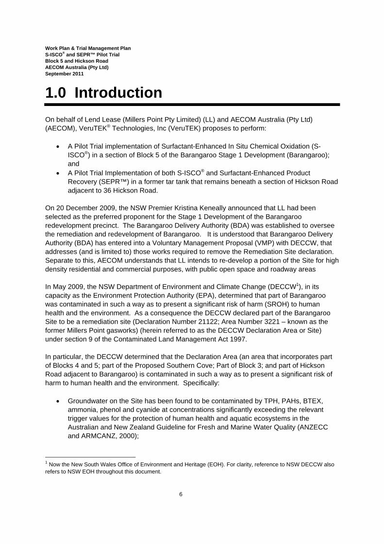
1.0 Introduction On behalf of Lend Lease (Millers Point Pty Limited) (LL) and AECOM Australia (Pty Ltd) (AECOM), VeruTEK® Technologies, Inc (VeruTEK) proposes to perform:
• A Pilot Trial implementation of Surfactant-Enhanced In Situ Chemical Oxidation (S-ISCO®) in a section of Block 5 of the Barangaroo Stage 1 Development (Barangaroo); and
• A Pilot Trial Implementation of both S-ISCO® and Surfactant-Enhanced Product Recovery (SEPR™) in a former tar tank that remains beneath a section of Hickson Road adjacent to 36 Hickson Road.
On 20 December 2009, the NSW Premier Kristina Keneally announced that LL had been selected as the preferred proponent for the Stage 1 Development of the Barangaroo redevelopment precinct. The Barangaroo Delivery Authority (BDA) was established to oversee the remediation and redevelopment of Barangaroo. It is understood that Barangaroo Delivery Authority (BDA) has entered into a Voluntary Management Proposal (VMP) with DECCW, that addresses (and is limited to) those works required to remove the Remediation Site declaration. Separate to this, AECOM understands that LL intends to re-develop a portion of the Site for high density residential and commercial purposes, with public open space and roadway areas In May 2009, the NSW Department of Environment and Climate Change (DECCW1), in its capacity as the Environment Protection Authority (EPA), determined that part of Barangaroo was contaminated in such a way as to present a significant risk of harm (SROH) to human health and the environment. As a consequence the DECCW declared part of the Barangaroo Site to be a remediation site (Declaration Number 21122; Area Number 3221 – known as the former Millers Point gasworks) (herein referred to as the DECCW Declaration Area or Site) under section 9 of the Contaminated Land Management Act 1997. In particular, the DECCW determined that the Declaration Area (an area that incorporates part of Blocks 4 and 5; part of the Proposed Southern Cove; Part of Block 3; and part of Hickson Road adjacent to Barangaroo) is contaminated in such a way as to present a significant risk of harm to human health and the environment. Specifically:
• Groundwater on the Site has been found to be contaminated by TPH, PAHs, BTEX, ammonia, phenol and cyanide at concentrations significantly exceeding the relevant trigger values for the protection of human health and aquatic ecosystems in the Australian and New Zealand Guideline for Fresh and Marine Water Quality (ANZECC and ARMCANZ, 2000);
1 Now the New South Wales Office of Environment and Heritage (EOH). For clarity, reference to NSW DECCW also refers to NSW EOH throughout this document.
Work Plan & Trial Management Plan S-ISCO® and SEPR™ Pilot Trial Block 5 and Hickson Road AECOM Australia (Pty Ltd) September 2011
7
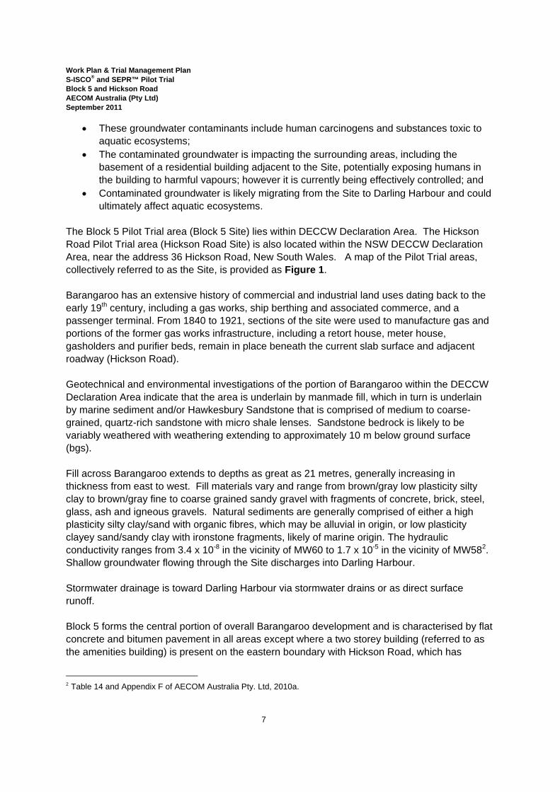
• These groundwater contaminants include human carcinogens and substances toxic to aquatic ecosystems;
• The contaminated groundwater is impacting the surrounding areas, including the basement of a residential building adjacent to the Site, potentially exposing humans in the building to harmful vapours; however it is currently being effectively controlled; and
• Contaminated groundwater is likely migrating from the Site to Darling Harbour and could ultimately affect aquatic ecosystems.
The Block 5 Pilot Trial area (Block 5 Site) lies within DECCW Declaration Area. The Hickson Road Pilot Trial area (Hickson Road Site) is also located within the NSW DECCW Declaration Area, near the address 36 Hickson Road, New South Wales. A map of the Pilot Trial areas, collectively referred to as the Site, is provided as Figure 1. Barangaroo has an extensive history of commercial and industrial land uses dating back to the early 19th century, including a gas works, ship berthing and associated commerce, and a passenger terminal. From 1840 to 1921, sections of the site were used to manufacture gas and portions of the former gas works infrastructure, including a retort house, meter house, gasholders and purifier beds, remain in place beneath the current slab surface and adjacent roadway (Hickson Road). Geotechnical and environmental investigations of the portion of Barangaroo within the DECCW Declaration Area indicate that the area is underlain by manmade fill, which in turn is underlain by marine sediment and/or Hawkesbury Sandstone that is comprised of medium to coarse-grained, quartz-rich sandstone with micro shale lenses. Sandstone bedrock is likely to be variably weathered with weathering extending to approximately 10 m below ground surface (bgs). Fill across Barangaroo extends to depths as great as 21 metres, generally increasing in thickness from east to west. Fill materials vary and range from brown/gray low plasticity silty clay to brown/gray fine to coarse grained sandy gravel with fragments of concrete, brick, steel, glass, ash and igneous gravels. Natural sediments are generally comprised of either a high plasticity silty clay/sand with organic fibres, which may be alluvial in origin, or low plasticity clayey sand/sandy clay with ironstone fragments, likely of marine origin. The hydraulic conductivity ranges from 3.4 x 10⁻⁸ in the vicinity of MW60 to 1.7 x 10⁻⁵ in the vicinity of MW582. Shallow groundwater flowing through the Site discharges into Darling Harbour. Stormwater drainage is toward Darling Harbour via stormwater drains or as direct surface runoff. Block 5 forms the central portion of overall Barangaroo development and is characterised by flat concrete and bitumen pavement in all areas except where a two storey building (referred to as the amenities building) is present on the eastern boundary with Hickson Road, which has
2 Table 14 and Appendix F of AECOM Australia Pty. Ltd, 2010a.

Work Plan & Trial Management Plan S-ISCO® and SEPR™ Pilot Trial Block 5 and Hickson Road AECOM Australia (Pty Ltd) September 2011
8
recently been demolished. The part of Block 5 that is within the Declaration Area is 4,583 m2. As shown on Figure 1a, to the north of Block 5 is the Barangaroo Stage 2 Development Area, which will include the Northern Cove and Headland Park; to the south are Barangaroo Blocks 1 to 4, which will include the Southern Cove, followed by Sussex Street; to the east is Hickson Road and commercial and high-density residential buildings, followed by Jenkins Street; and to the west is the Public Domain, followed by Darling Harbour. Currently the Block 5 Site is vacant and unused except by security personnel and by AECOM and Cardinal for storage of drums and shipping containers. Access to the Block 5 Site is restricted on the eastern side by cyclone wire fencing with two gatehouses at which a 24-hour security presence monitors access. Access to the redevelopment Site (including Block 5) is through Gate 7 operated by Lend Lease—Project Management and Construction (LL-PMC), at the south eastern boundary of Block 5. In addition, a pedestrian walkway is variably opened to the public along the western boundary adjacent to Darling Harbour. Access to this walk is controlled by temporary fencing and securable gates at both Hickson Road and nearest Lime Street Hickson Road is a public roadway for both vehicular and pedestrian traffic and forms the eastern border of Barangaroo. It features foot paths on either side and is lined with trees along its boundary with Barangaroo. The 5,729 m2 of Hickson Road that lies within the DECCW Declaration Area defines the Hickson Road Remediation Works area. In Block 5 and Hickson Road, contamination associated with the former gas works has been detected to be present in quantities that represent a concern. This contamination, detected during ERM 2007 and 2008 Investigations; the Coffey 2008 Preliminary Environmental Investigation; and the 2010 AECOM Data Gap Investigation (AECOM, 2010b), includes the heavy metals lead and chromium; petroleum hydrocarbons (TPH); BTEX (the sum of Benzene, Toluene, Ethylbenzene and Total Xylenes); and polycyclic aromatic hydrocarbons (PAHs). Please see AECOM Pty Ltd, 2010b, Tables 2, 8 and 9, for a summary of detections that exceeded generic site investigation levels in Block 5 and Hickson Road. The potential for migration of these contaminants both vertically and laterally to the nearest receptor, Darling Harbour, is likely to be directly affected by the variable and unconsolidated nature of the fill materials present on the Site. Contamination on Block 5 has been reported in the fill material, natural soil, bedrock and groundwater that underlie the Site and adjacent portions of Barangaroo. Block 5 (and surrounding areas) has been subject to reclamation activities that have consisted of the placement of fill material of potentially unknown origins. Tar and other residual contamination has been detected in Hickson Road and is likely a significant source of the groundwater contamination that is migrating from Hickson Road. This source material is largely derived from the former gas works structures, including the tar tank, the portion of the gasholder that extends into Hickson Road, and the former small gasholder located within Hickson Road.
Work Plan & Trial Management Plan S-ISCO® and SEPR™ Pilot Trial Block 5 and Hickson Road AECOM Australia (Pty Ltd) September 2011
9
1.1 Revised Work Plan and Trial Management Plan Objective This Revised Work Plan & Trial Management Plan describes:
• The extent of contamination found within the proposed Block 5 and the Hickson Road Pilot Trial areas;
• The S-ISCO® process that will be implemented during the Pilot Trial in the Block 5 Site; • The SEPR™ process that will be implemented during the Pilot Trial to remove tar from
the tank in the Hickson Road Site, and the S-ISCO® process that will follow; • The design of the system that will be used to implement the S-ISCO® and SEPR™
technology Pilot Trials; • The design and placement of the Pilot Trial injection system and soil vapour extraction
system; • A site-specific monitoring plan for the Pilot Trial; • Plans and procedures to protect the health and safety of both personnel working on the
Pilot Trial Site as well as the community and environment in which the work will take place;
• The criteria against which the results of the site-specific monitoring plan will be evaluated (that is, trigger values);
• Contingency measures that will be implemented in response to trigger values in order to optimise treatment and protect the health and safety of the people, assets and environment from impacts by the Pilot Trials;
• Plans for the treatment and management of waste water, specifically SEPR™ extraction fluid; and
• Comprehensive plans for the design, operation, monitoring and optimisation of the soil vapour extraction system.
It is understood that this work will be executed under the oversight of the NSW DECCW.
1.2 S-ISCO® Technology Overview S-ISCO® is a new, field-verified Coelution Technology™ capable of reducing the amount of source non-aqueous phase liquid (NAPL) in soils and reducing the flux of groundwater constituents associated with these sites. VeruTEK developed S-ISCO® to overcome the contact issue between aqueous redox treatments and the non aqueous phase contaminants. Specifically, S-ISCO® uses VeruSOL®, a mixture of cosolvents, citrus-based compounds, and plant oil-based non-ionic compounds designed and manufactured by VeruTEK. These components of VeruSOL® are either Generally Recognised as Safe (GRAS) by the U.S. FDA or approved as indirect food additives and for dermal contact, such as cosmetics. VeruSOL® biodegradable surfactants are surface active agents that are able to bring hydrocarbons into an oil-in-water microemulsion versus an oil-water globule mixture. VeruSOL® has demonstrated
Work Plan & Trial Management Plan S-ISCO® and SEPR™ Pilot Trial Block 5 and Hickson Road AECOM Australia (Pty Ltd) September 2011
10
capabilities for desorption and solubilisation of NAPL residuals present in site soils. Based on the results of the Laboratory Treatability Trials for this site (VeruTEK, 2010) the surfactant selected for this Pilot Trial is VeruSOL-3™ (VeruSOL-3) manufactured by VeruTEK® Technologies (VeruTEK). The patented S-ISCO® technology process uses VeruSOL-3 to solubilise immiscible organic compounds into groundwater and subsequently destroy the contaminants in-place using catalysed hydrogen peroxide or alkaline persulfate. The Coelution Technology™ process was developed by VeruTEK® Technologies, Inc., of Bloomfield, Connecticut. These technologies involve a method and process of increasing the solubility of contaminants, such as non aqueous phase liquids (NAPLs), sorbed contaminants, or other chemicals in soils. These compounds which normally have low solubility are simultaneously oxidised. Examples of contaminants treated with VeruTEK’s Coelution Technologies™ are dense non aqueous phase liquids (DNAPLs), light non aqueous phase liquids (LNAPLs), volatile organic compounds (VOCs), including chloro- and bromo-ethanes and methanes, polycyclic aromatic hydrocarbons (PAHs), chlorinated solvents, pesticides, polychlorinated biphenyls, and various organic chemicals such as petroleum products. Contaminants can be associated with, for example, manufactured gas plant residuals, creosote wood treating liquids, petroleum residuals, pesticide, or polychlorinated biphenyl (PCB) residuals and other waste products or by-products of industrial processes and commercial activities. Contaminants may be in the liquid phase (for example, NAPLs), sorbed to the soil matrix, or in the solid phase (for example, certain pesticides).
1.2.1 In situ Chemical Oxidation In situ chemical oxidation (ISCO) technologies are primarily aqueous phase reactions that take place in heterogeneous soil and groundwater environments. In heterogeneous soil and groundwater environments, the highly hydrophobic COCs are sorbed to soil particles and may also exist in a separate NAPL state with partitioning into the groundwater phase. In a study published by the State of Colorado, Division of Oil and Public Safety in 2007, assessment of ISCO application at 20 sites with some degree of NAPL present was investigated. Of the 20 sites where ISCO was implemented, 15 sites resulted in lack of success and 3 additional sites had uncertain success.3 Interactions with contaminants bound to soil or in the NAPL phase are not effectively addressed using ISCO treatment alone, but are successfully addressed using the S-ISCO® process.
1.2.2 Surfactant Enhanced In Situ Chemical Oxidation S-ISCO® remediation depends on choosing the correct surfactants or surfactant/cosolvent mixtures that will create the most effective solubilised micelle or microemulsion with the NAPL present in the soil, that is, a Winsor Type I phenomenon rather than other Winsor type 3 The Colorado Department of Labor and Employment Division of Oil and Public Safety (2007).
Work Plan & Trial Management Plan S-ISCO® and SEPR™ Pilot Trial Block 5 and Hickson Road AECOM Australia (Pty Ltd) September 2011
11
behaviors. Winsor Type I is a single homogenous phase oil-in-water emulsion. Once an adequate Winsor Type I solubilised micelle or microemulsion has formed and the apparent solubility of the NAPL is thereby increased, the solubilised micelle or microemulsed NAPL can enter “aqueous phase reactions” and, in the case of S-ISCO® remediation, it can be oxidised by a chemical oxidant such as hydrogen peroxide. It is well known that several methods, including free or chelated transition metals and UV light, can be used to activate or catalyze peroxide to form free radicals. The S-ISCO® process takes advantage of increased solubilisation of NAPL or sorbed contaminants in Winsor Type I systems without the need for extraction-well recovery of injected and treated liquids, for example. In situ chemical oxidation of the solubilised or microemulsed NAPLs in a Winsor Type I system eliminates the necessity of complete liquid pumping extraction recovery of the solubilised NAPL. Elimination of extraction systems avoids technical challenges associated with the costly capture of complete plumes; expensive above-ground treatment systems; requirements to recycle surfactant or surfactant/cosolvent mixtures; and disposing of or re-injecting the bulk liquid into the subsurface. During S-ISCO® solubilised contaminants are not mobilised and will not migrate from the treatment area. The co-eluted surfactant/co-solvent and oxidant fronts move through the subsurface together, and solubilisation and oxidation occur simultaneously. The contamination is destroyed in place. Remediation systems that rely on Winsor Type I solubilised micelle or microemulsification are necessarily less efficient than those that rely on Winsor Type III microemulsions and mobilisation, since solubilisation is lower at the higher interfacial tensions required to prevent mobilisation. However, desorption and solubilisation of contaminants using Winsor Type I microemulsions, such as will be used at this site, are controllable such that the risk of off-site mobilisation of NAPL contaminants of concern (COCs) is minimal and complete recovery of injected chemicals, mobilised NAPL phases, and solubilised NAPL or sorbed chemicals using extraction wells is not required. This type of behaviour seen in S-ISCO® remediation makes it useful in remedying manufactured gas plant (MGP) sites as well as sites with chlorinated solvents, petroleum hydrocarbons, pesticides, herbicides, polychlorinated biphenyls, and other NAPL or sorbed COCs.
1.2.3 Surfactant Enhanced Product Recovery SEPR™ is a technology platform that uses plant-based, natural surfactants and hydrogen peroxide to enhance product recovery of non-aqueous phase liquids (NAPLs). Surfactant and hydrogen peroxide are injected into the subsurface and NAPL, along with the solubilised NAPL, are extracted. SEPR™ is used as a pre-treatment for S-ISCO® to enhance the efficiency and cost-effectiveness of this process.
Work Plan & Trial Management Plan S-ISCO® and SEPR™ Pilot Trial Block 5 and Hickson Road AECOM Australia (Pty Ltd) September 2011
12
1.2.4 Potential Byproducts The chemicals used in S-ISCO® and SEPR™, specifically hydrogen peroxide, sodium persulfate, sodium hydroxide, VeruSOL® and Fe-TAML, as well as the products of their chemical reactions, are harmless to the environment in the context of the Pilot Trial. Hydrogen peroxide is composed of hydrogen and oxygen, a molecule of water (H2O) to which a molecule of oxygen (O2) has been added. Hydrogen peroxide will be used at low concentrations, ranging from 2% to 16%. When hydrogen peroxide reacts with contaminants, the products are water, oxygen and carbon dioxide. In the presence of naturally high concentrations of iron in the soil, there is the potential for hydrogen peroxide to become over-reactive. Extensive laboratory tests with Site soils, however, have shown that this is not the case and that concentrations of iron in Site soils are not sufficiently high as to consume the peroxide. Sodium persulfate used with sodium hydroxide to activate the persulfate and balance the pH, decomposes into sodium ions, sulfate ions and hydroxide. These compounds will be of no impact on adjacent properties or on the water quality in Darling Harbour. Fe-TAML is a stable, highly active Green catalyst with the capacity to marshal hydrogen peroxide to destroy contamination. Developed by the Institute for Green Oxidation Chemistry at Carnegie Mellon University in Pittsburgh, PA, USA, FE-TAML is composed exclusively of biochemically common elements, including carbon, hydrogen, oxygen, nitrogen and iron, and therefore avoids toxic functionality. Neither FE-TAML nor its degradation products present toxicity concerns. It is an efficient and selective peroxide activator; it is water soluble; and it is effective at minute quantities over a broad pH range. There is no known potential for S-ISCO® chemicals to react with unknown contaminants or non-toxic chemicals that may be present in the treatment area to form a hazardous or problematic by-product (refer to Section 5).
1.3 Project Objective This Pilot Trial will be conducted to verify the effectiveness of the S-ISCO® and SEPR™ remedies in the field, and to acquire data that can be used to optimise the design of the Full-Scale S-ISCO® and SEPR™ implementations. S-ISCO® and SEPR TM, as a pretreatment step, are being proposed for treatment of Hickson Road within the DECCW Declaration Area. S-ISCO® is also proposed for use within the Barangaroo Site, specifically (but not necessarily limited to) Block 5 within the DECCW Declaration Area. Specifically, the Pilot Trial will:
• Provide necessary and sufficient information to design and optimise Full Scale implementation of S-ISCO® and SEPR™. This information includes:
o Chemical doses; o Chemical formulation;
Work Plan & Trial Management Plan S-ISCO® and SEPR™ Pilot Trial Block 5 and Hickson Road AECOM Australia (Pty Ltd) September 2011
13
o Injection procedures; o Injection flow rates; o Well spacing; o Extracted wastewater treatment discharge quality; and o Monitoring type and frequency.
• Evaluate the distribution of the injected co-solvent/surfactant-enhanced activated oxidant in the subsurface;
• Evaluate the effectiveness of SEPR™ in the removal of tar from the soil and as a pretreatment for S-ISCO® in that area;
• Evaluate the effectiveness of S-ISCO® in the destruction of contaminants of concern (COCs) in the soil;
• Evaluate the effectiveness of S-ISCO® in reducing COC concentrations in groundwater migrating from the Site;
• Evaluate the potential for un-reacted S-SICO® and/or SEPR™ chemical migration towards Darling Harbour and the basement of 38 Hickson Road;
• In the event of un-reacted S-SICO® and/or SEPR™ chemical migration toward either Darling Harbour or the basement of 38 Hickson Road, evaluate the performance of mitigation measures to prevent or minimise such migration;
• Evaluate the potential for volatile emissions to result from injections; • Evaluate the potential for volatile emissions to impact the basement of 38 Hickson Road; • Evaluate the effectiveness of S-ISCO® in treating extracted wastewater, including
extracted SEPR™ fluid, stormwater, groundwater and/or collected water, in comparison to the DECCW water quality criteria to enable potential discharge into the Harbour or reuse; and
• Evaluate the effectiveness of Pilot Trial monitoring and management systems.
The primary objective of the SEPR™ Pilot Trial is to treat up to 25 percent of the soil contaminant mass in order to demonstrate that SEPR™ is capable of removing the tar from the tar tank in Hickson Road such that the subsequent S-ISCO® Pilot Trial can proceed efficiently and cost effectively. The SEPR™ Pilot Trial will be conducted to:
• Demonstrate hydraulic control and isolation of liquids inside the tar tank with groundwater outside of the tar tank by extraction;
• Demonstrate control of gas migration from the treatment inside the tar tank into abutting soil and structures proximate to the former tar tank; and
• Demonstrate the efficacy potential of the SEPR™/S-ISCO® treatment regime inside the tar tank by treating approximately 25 percent of the soil contaminant mass inside the tar tank.
The objective of the S-ISCO® Pilot Trials in both Hickson Road and Block 5 is to demonstrate that S-ISCO® is capable of remediating contamination such that:
• the DECCW Declaration can be removed;
Work Plan & Trial Management Plan S-ISCO® and SEPR™ Pilot Trial Block 5 and Hickson Road AECOM Australia (Pty Ltd) September 2011
14
• the Site is both protective of human health in the context of its intended potential future development for high density residential and commercial uses (in the case of Block 5) and as a roadway (in the case of Hickson Road); and
• the Site no longer poses a contamination risk to the environment, specifically to the adjacent Darling Harbour.
In Block 5, proposed development may include high density residential, with minimal access to soil, and commercial, both with up to two levels of basement car parking. Hickson Road will continue to function as a vehicular and pedestrian roadway. An HHERA[1] has been completed by AECOM to develop Site Specific Target Criteria (SSTC) and Site Specific Ecological Screening Criteria (SSESC) (as appropriate) for the remediation of Block 5 and Hickson Road, in the context of the proposed development. In particular, the SSTCs and SSESCs define:
• Soil concentrations that will not represent an unacceptable risk to human health or the environment if:
o Left in situ at the Site; or o Incorporated elsewhere into the development (for example within the proposed
Public Domain; and • Groundwater concentrations that will not represent an unacceptable risk to human health
or the environment (i.e. Darling Harbour). The HHERA was completed as an outcome of a Data Gap Investigation (DGI), also undertaken by AECOM, in relation to the DECCW Declaration Area. The SSTC and SSESC derived by the HHERA are used to develop remediation goals for different areas / land uses at the Site and the proposed Public Domain as well as defining the standard that must be achieved for the in-situ remediation of soils that are to remain in place. As such, the HHERA defines the inputs for assessing:
• The standard of material that is suitable to remain in situ; and • Whether any treatment / remediation is required to achieve that standard.
Appendix I contains the remediation goals for the Site and that are applicable to this Pilot Trial . The remediation goals that are applicable to the Pilot Trials are dependent on the proposed future land use for the Site and the hydraulic connection between the Site and the nearest sensitive ecological receptor (Darling Harbour). Reference should be made to the Declaration Site HHERA (AECOM, 2011) for the background to derivation of the remediation goals. For the purpose of the Pilot Trials, the remediation goal adopted will be the lowest (i.e. the most conservative) of the soil and groundwater remediation goals for:
• Material to remain in situ below shallow excavations and within the proposed basement groundwater retention wall system; and
[1] Human Health and Environment Risk Assessment.
Work Plan & Trial Management Plan S-ISCO® and SEPR™ Pilot Trial Block 5 and Hickson Road AECOM Australia (Pty Ltd) September 2011
15
• Material to remain in situ within open space areas, including Hickson Road.
1.4 Project Overview 1.4.1 Summary of Bench Scale Treatability Study A dosage study is the first step to evaluate the use of Surfactant-Enhanced In Situ Chemical Oxidation (S-ISCO®) and Surfactant-Enhanced Ex Situ Chemical Oxidation (S-ESCO™) Treatment at portions of the Site. Test Pit soil samples from Block 4 and Block 5 were obtained for these treatability tests to be representative of soils to be treated. Note that it is not currently proposed that Block 4 be treated by S-ISCO®. A soil boring sample was obtained from Hickson Road, instead of a backhoe-dug Test Pit, to minimise traffic flow disruption to residents and businesses. Additionally a sample of Non Aqueous Phase Liquid (NAPL) from Block 5 was used in these tests. Results from the study demonstrated that up to 84% of the contaminants of potential concern (CoPCs) in the Block 5 soils can be destroyed in 21 days of S-ISCO® treatment, and 89% of CoPCs in Block 4 soil can be destroyed in 8 days of S-ESCO™ treatment. During Pilot and Full Scale implementations the duration of treatment will be in the order of many months. Because chemical oxidation reactions are rate limited, that is, the longer the period of treatment, the greater the extent of treatment, the results of these short-term treatability test are extremely conservative with respect to the Full Scale treatment potential of the S-ISCO® and S-ESCO™ processes. The purpose of this Laboratory Treatability Study was to optimise conditions for VeruTEK’s innovative S-ISCO®, S-ESCO™ and SEPR™ technology platforms, and to support the design and cost estimate for the implementation of the S-SICO® remedy at this Site. All of these processes utilise enhanced desorption and solubilisation of the gas works organic chemicals from soils and simultaneous chemical oxidation of the solubilised chemicals. The sequence of tests began with a supplemental solubilisation screening. VeruSOL-3® proved to be the most effective, enhancing the TPH (C10-C36) (using the Site LAB fluorescence method) solubilisation to 1,510 times greater than water. Several batch tests were designed to simulate S-ISCO® and S-ESCO™ as these processes would occur in the field. Generally, the best performing S-ISCO® treatment used Fe-TAML catalyzed hydrogen peroxide. After 14 days of S-ISCO® treatment in these tests a reduction up to 89% for Total VOCs and SVOCs, 88% for Total PAHs, 84% for benzo(a)pyrene, 98% for naphthalene, >99% for benzene, and 73% for TPH (C10-C36) was indicated, using USEPA Method 8105B. Since typical gas works residuals require at least 30 days to show more complete treatment, these are excellent results. Additional jar tests were conducted on Block 4 soils for the analysis of in situ treatment in Hickson Road. Tests were conducted to compare a rapid sequence of ex situ treatment of Surfactant Enhanced Product Recovery (SEPR™) for a 1 hour period followed by a 24 hour S-SICO® treatment with Fe-TAML-activated hydrogen
Work Plan & Trial Management Plan S-ISCO® and SEPR™ Pilot Trial Block 5 and Hickson Road AECOM Australia (Pty Ltd) September 2011
16
peroxide treatment. Results demonstrated that the 1 day combined SEPR™/ S-SICO® process removed up to 51% of VOCs and SVOCs, 49% of PAHs, 37% of benzo(a)pyrene, 61% naphthalene, >99% of benzene and 66% of TPH. Several columns were packed with Site soil and various SEPR™/S-SICO® influents were pumped through the columns. Block 5 soil column tests were run for treatment periods ranging from 7 to 28 days, depending on the type of tests conducted. In general, S-SICO® with hydrogen peroxide (with or without Fe-TAML as a catalyst) performed better than S-SICO® with activated persulfate. For S-SICO® with Fe-EDTA-activated persulfate, destruction levels were observed up to 72% for Total VOCs and SVOCs, 72% for Total PAHs, up to 87% for benzo(a)pyrene, up to 67% for naphthalene, up to >99% for benzene, and up to >99% for TPH(C10-C36) using the SiteLAB fluorescence method. Treatment using S-ISCO® with hydrogen peroxide was observed to have removal efficiencies of up to 84% for Total VOCs and SVOCs, 84% for Total PAHs, 95% for benzo(a)pyrene, 82% for naphthalene, >99% for benzene, and >99% TPH(C10-C36) using the SiteLAB fluorescence method. S-ISCO® with hydrogen peroxide tests were only run for 8 days, which illustrates its potential for treatment at Full Scale. The Laboratory Treatability Tests clearly indicate excellent treatment potential for in situ applications at the Block 5 and Hickson Road areas. The soil samples received from the Site for Block 5 were at least twice as contaminated with CoPCs than any previously reported soil results from Block 5. Despite the short term, laboratory tests indicate excellent results with respect to removal of key CoPCs from the Site soils at Block 5, which led to the recommendation that S-ISCO® with catalyzed hydrogen peroxide followed by S-ISCO® with activated persulfate be tested during the Pilot Trials at Block 5. In some locations where heavy gas works NAPLs are present, S-ISCO® pretreatment with the SEPR™ process followed by short-term liquid extraction could be a successful method to effectively remove NAPLs prior to the S-ISCO® treatment. These results are also transferable to treatment at Hickson Road in the area both inside and outside of the historic gas works structures, particularly the former tar tank. Prior to Full Scale treatment, a Pilot Trial at Block 5 to demonstrate the effectiveness of the recommended treatment process consisting of S-ISCO® with catalyzed hydrogen peroxide followed by S-ISCO® with activated persulfate was recommended. The Pilot Trial will enable optimisation of treatment for Full Scale application, as well as the refinement of the engineering design, monitoring program and system operations control measures. The report additionally recommended a Pilot Trial at Hickson Road in the location of the former Tar Tank. This feature is unique at the Site as it is excavated into bedrock and is either a confined or semi-confined vessel containing former high concentrations of gasworks residuals, including tar from a depth of 1 to 4 m bgs. Given the close proximity of the former Tar Tank to 38 Hickson Road and associated sub-grade parking facilities and utilities, careful monitoring during the Pilot Trial will enable an effective and safe application of the S-ISCO® process at Full-Scale. For more details, reference should be made to the complete bench-scale treatability trial report (VeruTEK, 2010).
Work Plan & Trial Management Plan S-ISCO® and SEPR™ Pilot Trial Block 5 and Hickson Road AECOM Australia (Pty Ltd) September 2011
17
The laboratory study was conducted under worst-case conditions, using soils taken from the most highly contaminated areas of Block 5 and Block 4. Because Block 5 soils represented the highest levels of contamination to be treated in that parcel, not average conditions, the results of the study are conservative. Even greater success can be achieved in the field. The Block 4 soils are considered to be representative of the soils present in the tar tank and therefore indicate that applicability of the laboratory’s conclusions to the remediation in this area. VeruTEK does not anticipate that any scale-up or staging factors will affect the relationship between the results attained in the Pilot Trial and what can be achieved during the Full-Scale implementation. One key objective of the Pilot Trial is to provide sufficient and necessary information to design the Full-Scale implementation and therefore minimise the risk of any issues that might otherwise occur between the bench scale trials and full scale implementation. Based on the Pilot Trials, VeruTEK will be able to conclusively identify the relationship between S-ISCO® and SEPR™ chemical dose and the treatment response that is attained. In comparison to the Pilot Trial, the Full Scale implementation will benefit from a longer contact time between the chemistry and contaminants, over a broader area. VeruTEK is confident that the results of the Pilot Trial can successfully be scaled up to the Full-Scale implementation. 1.4.2 Block 5 The Block 5 S-ISCO® Pilot Trial will take place in a 100 square meter section of Block 5. The Pilot Trial area is currently vacant but contains the below-ground remains of infrastructure associated with former gasworks activities, including the retort house and its 1880 extension, as well as purifiers. This section of Block 5 is bounded to the east by a footpath along Hickson Road and to the south by Block 4. The contaminants of concern (COCs) found at Block 5 include benzene, toluene, ethylbenzene and total xylenes (BTEX); polycyclic aromatic hydrocarbons (PAHs); and total petroleum hydrocarbons, ranging from the TPH C6 to C36 fraction. These COCs are sorbed onto soils and dissolved in groundwater. The Pilot Trial area will be treated by primary phase injections of S-ISCO®, using hydrogen peroxide (H2O2) activated by Fe-TAML, and enhanced by the use of a co-solvent/surfactant mixture (VeruSOL®). A secondary phase of S-ISCO® injections will consist of alkaline persulfate, that is, sodium persulfate injected with sodium hydroxide. This treatment will provide longer-term oxidation reactions in the subsurface than are possible with the primary phase treatment of S-ISCO® using hydrogen peroxide and Fe-TAML. 1.4.3 Hickson Road The Hickson Road SEPR™ and S-ISCO® Pilot Trials will take place in a subsurface tar tank measuring approximately 16 metres in diameter (about 200 square metres in area) located adjacent to 36 Hickson Road. The tar tank is located in the portion of Hickson Road within the

Work Plan & Trial Management Plan S-ISCO® and SEPR™ Pilot Trial Block 5 and Hickson Road AECOM Australia (Pty Ltd) September 2011
18
DECCW Declaration Area, beneath an area of roadway and an area of foot path. Local and through vehicular and pedestrian traffic regularly pass over the paved roadway and foot path. The Data Gap Investigation conducted by AECOM (2010b) revealed evidence of contamination from approximately 1 m bgs to the bottom of the tar tank. Other contaminants of concern in this area include: BTEX; PAHs; and TPH ranging from the TPH C6 to C36 fraction. These COCs are found as tar sludge and also sorbed onto soils and dissolved in groundwater. Treatment in the Pilot Trial area will begin with a SEPR™ phase to remove the tar present in the tar tank. SEPR™ will consist of injections of hydrogen peroxide (H2O2) enhanced by the co-solvent/surfactant mixture VeruSOL® followed by extractions of the injected fluid and solubilised product (tar). Next a S-ISCO® phase will take place to polish the soil and destroy the remaining contamination. This S-ISCO® phase will consist of injections of hydrogen peroxide (H2O2)
activated by Fe-TAML and enhanced by the co-solvent/surfactant mixture VeruSOL®. The polishing step has been included to confirm that all steps proposed as part of the full scale remediation are implemented and evaluated as part of the Pilot Trial. 1.5 Potential Risks and Mitigation Measures 1.5.1 Potential Risks to Sensitive Receptors Potential sensitive receptors exist at the Site and surrounding area. These receptors include:
• Darling Harbour; • The trees planted along Hickson Road; • Site workers and visitors; • Underground services within the Hickson Road and Block 5 Pilot Trial areas, including
those belonging to Energy Australia (EA), Telstra, Jemena, Optus and the State Rail Authority (SRA);
• The Sydney Water Corporation (SWC) assets, including the Sewer Pumping Station number SP1129 (SP1129) adjacent to the Block 5 Pilot Trial area, and stormwater drains, sewers and water mains in both Block 5 and Hickson Road;
• SWC workers at SP1129 as well as those workers who access other underground utility assets, including but not limited, those belonging to EA, Telstra, Jemena and Optus;
• Workers and residents of properties surrounding and adjacent to the Hickson Road Pilot Trial area, including the child care centre located at 30 Hickson Road and the basements at 30 and 38 Hickson Road;
• Archaeological resources and relics in the subsurface of Block 5; and • The basement water treatment system at 38 Hickson Road.
The relocated Overseas Passenger Terminal (now located north of Block 5) is more than 200m cross gradient of the Block 5 Pilot Trial location and therefore has not been considered at risk from the Pilot Trial.

Work Plan & Trial Management Plan S-ISCO® and SEPR™ Pilot Trial Block 5 and Hickson Road AECOM Australia (Pty Ltd) September 2011
19
1.5.2 Proposed Mitigation Measures VeruTEK will take measures to minimise the possibility of adverse impacts to sensitive receptors by either the Block 5 S-ISCO® or Hickson Road SEPR™ and S-ISCO® Pilot Trials. Mitigation measures designed to minimise the impact of the Pilot Trial on potential sensitive receptors are summarised below and described in detail in Section 5.
• Groundwater Monitoring: In situ and ex situ groundwater monitoring will track the movement and approach of the treatment front toward: Darling Harbour, SP1129, underground services and assets, including stormwater drains and telecoms in Block 5, and water mains, sewers, electricity lines, telecoms and gas mains in Hickson Road, and buildings on Hickson Road, including 30 and 38 (refer to Section 5.2). In Hickson Road, groundwater monitoring will confirm that the liquid level in the tar tank remains at a steady level (see Table 21 for trigger values and contingency plan) that minimises the risk of impact to the adjacent building basements, subsidence of fill materials within the tar tank, and/or impacts to subsurface assets;
• Extraction System: An extraction system will be used to extract SEPR™ fluid from the tar tank in Hickson Road to maintain hydraulic control of the contents of the tank. The extraction system will also be available to intercept S-ISCO® and/or SEPR™ chemistry that may approach potential sensitive receptors, such as Darling Harbour, SP1129 and/or buildings on Hickson Road;
• Informed Intrusive Work: Well drilling and injections in the Block 5 treatment area will avoid the buildings, pipes and services, including sewers, gas lines, electric services, telecoms and water mains. Other intrusive work, including trenching in Hickson Road, will also avoid underground infrastructure and trees to the extent possible. Specifically, the depth of the trenching will be approximately 200 mm, a depth above identified sub- subsurface assets. In addition, work will avoid the temporary above-ground sewer rising main in Block 5;
• Site Plan: The Block 5 Site and plant lay-out will be coordinated with SP1129 access, egress and emergency routes. Site access and emergency routes are defined and regulated by LL-PMC, and included in the Construction Environmental Management Plan (CEMP). The CEMP also refers to AECOM’s Construction Traffic Management Plan (March 2011). In addition the system set-up area in Block 5 is located more than 5 meters from the trunks of trees to be retained in Hickson Road;
• Non-Corrosive, Compatible Oxidants: Neither oxidant, hydrogen peroxide nor alkaline-activated sodium persulfate, will have impacts on services encased in or constructed from the materials known to be present in the subsurface, including polyvinyl chloride (PVC), polyethylene (PE), concrete, cement, nylon or cast iron. The subsurface assets and materials identified in the vicinity of the Pilot Trials are detailed in Table 8. Appendix K contains information about the compatibility of peroxide with plastics as well as cast iron; the compatibility of alkaline-activated persulfate with carbon steel, a material similar to cast iron but which has a lower carbon content, as well as plastics;

Work Plan & Trial Management Plan S-ISCO® and SEPR™ Pilot Trial Block 5 and Hickson Road AECOM Australia (Pty Ltd) September 2011
20
and the effect that surfactants (such as VeruSOL®) have on reducing corrosive effects of oxidants. In addition to the compatibility of the oxidants with the identified materials of subsurface assets, any potential impacts to subsurface assets will be further mitigated through limited contact between the assets and oxidants. This limited contact is linked in part to the short lifetime (on the order of hours) of peroxide, and the differences in depth between the assets and the intervals where the oxidants will be injected and present—that is, the oxidants will be present below the majority of identified assets (refer to Section 5.2);
• Soil Vapour and Odour Monitoring: Soil vapour and odour monitoring will track the generation of vapours and odours at the following locations: adjacent to basements of buildings along Hickson Road, as well as other public areas that may be affected by treatment injections, including the footpaths on either side of Hickson Road; at SP1129; and in utility pits, service access points and monitoring well heads, including, but not limited to, those within an approximate 30 m radius of the injection wells, identified on Figure 4 (which includes, but is not limited to, those accessed by SWC, Jemena, EnergyAustralia (EA), Telstra and Optus personnel); and
• Soil Vapour Extraction: A soil vapour extraction (SVE) system will be operated continuously during injections to minimise the risk of vapours generated by the Pilot Trial impacting ambient air quality. Its operation will continue after injections until the results of monitoring indicate that its use is no longer warranted.
In addition the separate Construction Environmental Management Plan (CEMP) that has been prepared for work at the Site contains Environmental Management Plans that include mitigation measures. These plans are summarised in Section 4.
Work Plan & Trial Management Plan S-ISCO® and SEPR™ Pilot Trial Block 5 and Hickson Road AECOM Australia (Pty Ltd) September 2011
21
2.0 S-ISCO® and SEPR™ Pilot Trial Schedule
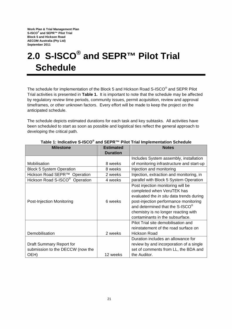
The schedule for implementation of the Block 5 and Hickson Road S-ISCO® and SEPR Pilot Trial activities is presented in Table 1. It is important to note that the schedule may be affected by regulatory review time periods, community issues, permit acquisition, review and approval timeframes, or other unknown factors. Every effort will be made to keep the project on the anticipated schedule. The schedule depicts estimated durations for each task and key subtasks. All activities have been scheduled to start as soon as possible and logistical ties reflect the general approach to developing the critical path.
Table 1: Indicative S-ISCO® and SEPR™ Pilot Trial Implementation Schedule Milestone Estimated
Duration Notes
Mobilisation 8 weeks Includes System assembly, installation of monitoring infrastructure and start-up
Block 5 System Operation 8 weeks Injection and monitoring Hickson Road SEPR™ Operation 2 weeks Injection, extraction and monitoring, in
parallel with Block 5 System Operation Hickson Road S-ISCO® Operation 4 weeks
Post-Injection Monitoring 6 weeks
Post injection monitoring will be completed when VeruTEK has evaluated the in situ data trends during post-injection performance monitoring and determined that the S-ISCO® chemistry is no longer reacting with contaminants in the subsurface.
Demobilisation 2 weeks
Pilot Trial site demobilisation and reinstatement of the road surface on Hickson Road
Draft Summary Report for submission to the DECCW (now the OEH) 12 weeks
Duration includes an allowance for review by and incorporation of a single set of comments from LL, the BDA and the Auditor.
Work Plan & Trial Management Plan S-ISCO® and SEPR™ Pilot Trial Block 5 and Hickson Road AECOM Australia (Pty Ltd) September 2011
22
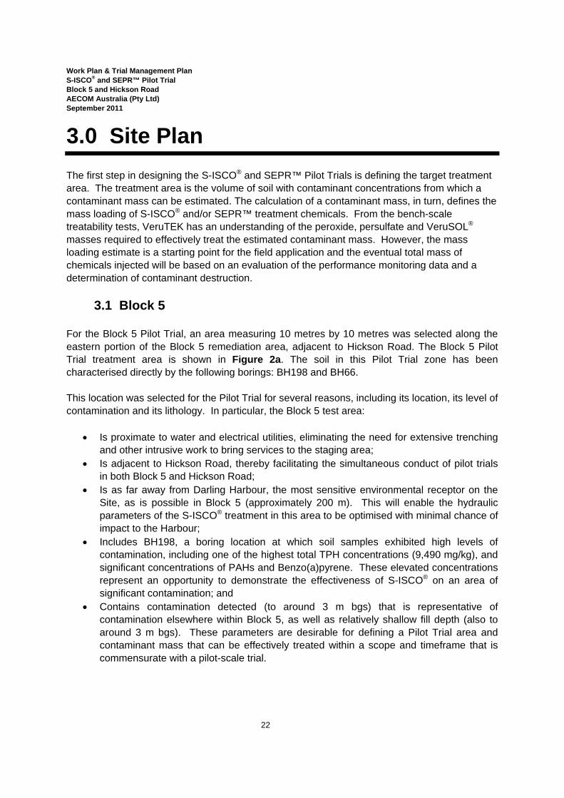
3.0 Site Plan The first step in designing the S-ISCO® and SEPR™ Pilot Trials is defining the target treatment area. The treatment area is the volume of soil with contaminant concentrations from which a contaminant mass can be estimated. The calculation of a contaminant mass, in turn, defines the mass loading of S-ISCO® and/or SEPR™ treatment chemicals. From the bench-scale treatability tests, VeruTEK has an understanding of the peroxide, persulfate and VeruSOL® masses required to effectively treat the estimated contaminant mass. However, the mass loading estimate is a starting point for the field application and the eventual total mass of chemicals injected will be based on an evaluation of the performance monitoring data and a determination of contaminant destruction.
3.1 Block 5 For the Block 5 Pilot Trial, an area measuring 10 metres by 10 metres was selected along the eastern portion of the Block 5 remediation area, adjacent to Hickson Road. The Block 5 Pilot Trial treatment area is shown in Figure 2a. The soil in this Pilot Trial zone has been characterised directly by the following borings: BH198 and BH66. This location was selected for the Pilot Trial for several reasons, including its location, its level of contamination and its lithology. In particular, the Block 5 test area:
• Is proximate to water and electrical utilities, eliminating the need for extensive trenching and other intrusive work to bring services to the staging area;
• Is adjacent to Hickson Road, thereby facilitating the simultaneous conduct of pilot trials in both Block 5 and Hickson Road;
• Is as far away from Darling Harbour, the most sensitive environmental receptor on the Site, as is possible in Block 5 (approximately 200 m). This will enable the hydraulic parameters of the S-ISCO® treatment in this area to be optimised with minimal chance of impact to the Harbour;
• Includes BH198, a boring location at which soil samples exhibited high levels of contamination, including one of the highest total TPH concentrations (9,490 mg/kg), and significant concentrations of PAHs and Benzo(a)pyrene. These elevated concentrations represent an opportunity to demonstrate the effectiveness of S-ISCO® on an area of significant contamination; and
• Contains contamination detected (to around 3 m bgs) that is representative of contamination elsewhere within Block 5, as well as relatively shallow fill depth (also to around 3 m bgs). These parameters are desirable for defining a Pilot Trial area and contaminant mass that can be effectively treated within a scope and timeframe that is commensurate with a pilot-scale trial.
Work Plan & Trial Management Plan S-ISCO® and SEPR™ Pilot Trial Block 5 and Hickson Road AECOM Australia (Pty Ltd) September 2011
23
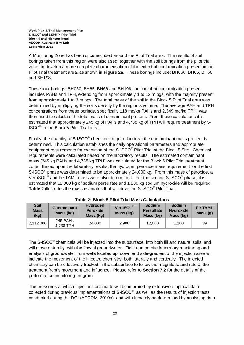
A Monitoring Zone has been circumscribed around the Pilot Trial area. The results of soil borings taken from this region were also used, together with the soil borings from the pilot trial zone, to develop a more complete characterisation of the extent of contamination present in the Pilot Trial treatment area, as shown in Figure 2a. These borings include: BH060, BH65, BH66 and BH198. These four borings, BH060, BH65, BH66 and BH198, indicate that contamination present includes PAHs and TPH, extending from approximately 1 to 12 m bgs, with the majority present from approximately 1 to 3 m bgs. The total mass of the soil in the Block 5 Pilot Trial area was determined by multiplying the soil’s density by the region’s volume. The average PAH and TPH concentrations from these borings, specifically 118 mg/kg PAHs and 2,349 mg/kg TPH, was then used to calculate the total mass of contaminant present. From these calculations it is estimated that approximately 245 kg of PAHs and 4,738 kg of TPH will require treatment by S-ISCO® in the Block 5 Pilot Trial area. Finally, the quantity of S-ISCO® chemicals required to treat the contaminant mass present is determined. This calculation establishes the daily operational parameters and appropriate equipment requirements for execution of the S-ISCO® Pilot Trial at the Block 5 Site. Chemical requirements were calculated based on the laboratory results. The estimated contaminant mass (245 kg PAHs and 4,738 kg TPH) was calculated for the Block 5 Pilot Trial treatment zone. Based upon the laboratory results, the hydrogen peroxide mass requirement for the first S-ISCO® phase was determined to be approximately 24,000 kg. From this mass of peroxide, a VeruSOL® and Fe-TAML mass were also determined. For the second S-ISCO® phase, it is estimated that 12,000 kg of sodium persulfate and 1,200 kg sodium hydroxide will be required. Table 2 illustrates the mass estimates that will drive the S-ISCO® Pilot Trial.
Table 2: Block 5 Pilot Trial Mass Calculations Soil
Mass (kg)
Contaminant Mass (kg)
Hydrogen Peroxide Mass (kg)
VeruSOL® Mass (kg)
Sodium Persulfate Mass (kg)
Sodium Hydroxide Mass (kg)
Fe-TAML Mass (g)
2,112,000 245 PAHs 4,738 TPH 24,000 2,900 12,000 1,200 39
The S-ISCO® chemicals will be injected into the subsurface, into both fill and natural soils, and will move naturally, with the flow of groundwater. Field and on-site laboratory monitoring and analysis of groundwater from wells located up, down and side-gradient of the injection area will indicate the movement of the injected chemistry, both laterally and vertically. The injected chemistry can be effectively tracked in the subsurface to follow the magnitude and rate of the treatment front’s movement and influence. Please refer to Section 7.2 for the details of the performance monitoring program. The pressures at which injections are made will be informed by extensive empirical data collected during previous implementations of S-ISCO®, as well as the results of injection tests conducted during the DGI (AECOM, 2010b), and will ultimately be determined by analysing data

Work Plan & Trial Management Plan S-ISCO® and SEPR™ Pilot Trial Block 5 and Hickson Road AECOM Australia (Pty Ltd) September 2011
24
collected from monitoring of the injection and monitoring wells. Carefully monitoring the Pilot Trial’s progress and monitored parameters will enable a hydraulic model to be developed and subsequently applied to full-scale implementation. VeruTEK does not anticipate that extraction wells will be necessary to force the flux of treatment chemicals through the ground media, however to confine the chemical flow though the subsurface of the treatment zone rather than outside of the desired treatment area, all groundwater wells will have the capacity to function as extraction wells. Extraction well operation will be based on monitoring conducted during the Pilot Trial. On-site laboratory and field analyses of groundwater from monitoring wells located up, down and side-gradient of the area of injection, and at a range of depths, from the water table to the top of bedrock, will be used to monitor the flow and progression of the treatment chemicals. This will enable assessments to be made to determine the need and frequency of extraction well operation. On-site laboratory and field analyses, in combination with off-site laboratory analysis of VOCs, SVOCs and TPH fractions as well as metals will be used to determine if extraction well operations will be needed to intercept S-ISCO® chemicals in the groundwater to prevent transport to Darling Harbour. The strategic placement of injection wells and adequate chemical dosing will target treatment of contamination present in a heterogeneous soil matrix. Specifically, injection wells will be screened from approximately 2.5 to 3.5 m bgs. In the event that the treatment front moves exclusively through preferential, more porous pathways, and the influence of the treatment chemistry is not detected adequately in monitoring wells throughout the treatment zone and at varied depth intervals, additional injection wells will be installed to ensure that all areas of contamination are contacted and treated. This will be determined based on monitoring conducted during the Pilot Trial, described in Section 7. Because hydrogen peroxide is being used as part of the first S-ISCO® phase, an SVE system will be used to extract and treat vapour from the unsaturated soils above the S-ISCO® treatment zone. Please refer to Section 4 for the details of the SVE system installation and operation. A Class A Hoarding will be constructed along the alignment of the existing chainmesh fence on Hickson Road, adjacent to the Block 5 Pilot Trial area, shown on Figure 2a4. Timber hoarding will also be installed around the perimeter of the Block 5 Pilot Trial System Compound area to enclose the site office, on-site laboratory, injection system and waste storage areas.
4 The Class A hoardings and barricade on Hickson Road will be in compliance with the requirements of Section 138 of the Roads Act 1993.Evidence of the required Structural Works Inspection Certificate and structural certification, as well as the details of the barricade’s construction and installation will be provided prior to commencement of work on the site.
Work Plan & Trial Management Plan S-ISCO® and SEPR™ Pilot Trial Block 5 and Hickson Road AECOM Australia (Pty Ltd) September 2011
25
3.2 Hickson Road The Hickson Road Pilot Trial will take place in the circular tar tank located in front of 36 Hickson Road, in an area beneath the paved surfaces of the road and foot path. The Hickson Road Pilot Trial area is shown in Figure 2b. The tar tank and other historic structures known to be (or potentially) present within Hickson Road represent distinctly different conditions from those that are present within Block 5. Therefore, the Block 5 Pilot Trial is not applicable to all of Hickson Road. A Pilot Trial in Hickson Road is necessary to develop effective treatment for this area. This location was selected for the Pilot Trial in order to evaluate the applicability of using a combination of SEPR™ and S-ISCO® technologies for remediation of locations on the Site in which free product (NAPL) is present. During the Pilot Trial, the parameters of SEPR™ and S-ISCO® treatment will be optimised to efficiently and effectively complete remediation of the Hickson Road tar tank during full-scale implementation. In addition, the location of the pilot trial has been selected in consideration of the following.
• The tar tank is a unique feature at the Site in that it is the only known tar tank within Hickson Road. Notwithstanding this, other confined or semi-confined structures from the former gasworks remain in Hickson Road, including the former gasholder annulus.
• From a treatment perspective the fact that the contents in the tar tank (tar and fill materials) have minimal hydraulic communication with the remainder of the Site makes treatment of this material very different from other areas at the Site.
• Because the exact degree of hydraulic communication of liquids inside the tar tank (and other historic structures) with the surrounding environment is unknown, in situ treatment of the contents in the tar tank requires detailed knowledge, to be acquired through pilot testing, of the following:
o The extent of hydraulic control needed to ensure that there will be no overflow of injected liquids vertically upward (the only likely liquid escape route);
o The rate of liquid injection and extraction feasible in the tar tank; o The rate of gas extraction necessary to capture any gas phase generated from
the Pilot Trial; o The communication of liquids in the tar tank with groundwater in the bedrock, fill
and natural sediments during in situ treatment; and o The communication of any gas phase in the tar tank during treatment with the
unsaturated sediments or through unsaturated bedrock fracture outside of the tar tank.
• The proposed Hickson Road Pilot Trial directly addresses a key and specific question raised by the DECCW during consultation regarding the use of S-ISCO®: how will tar and tar-contaminated material within historic structures be remediated.
• The proposed S-ISCO® trial in Hickson Road addresses another key concern raised by the DECCW during consultation regarding S-ISCO® in Hickson Road, specifically how the proposed in situ technology would (if at all) impact the basement of 38 Hickson Road. Conducting a trial, including detailed performance monitoring, in the historic structure closest to 38 Hickson Road, will directly address this concern.
Work Plan & Trial Management Plan S-ISCO® and SEPR™ Pilot Trial Block 5 and Hickson Road AECOM Australia (Pty Ltd) September 2011
26
• The need to demonstrate, for the purpose of full scale implementation, the following: o Hydraulic control and isolation of liquids inside the tar tank from groundwater
outside of the tar tank, including groundwater presently extracted to control flooding of the basement garage at 38 Hickson Road;
o Control of gas migration resulting from treatment inside the tar tank with abutting soil and structures proximate to the former tar tank; and
o The efficacy potential of SEPR™/S-ISCO® treatment inside the tar tank. • SEPR™ will also be applicable to the former gas holder or other geological features (i.e.
bedrock depressions) where pockets of NAPL requiring treatment may be discovered during full-scale implementation.
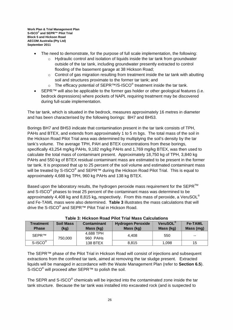
The tar tank, which is situated in the bedrock, measures approximately 16 metres in diameter and has been characterised by the following borings: BH7 and BH53. Borings BH7 and BH53 indicate that contamination present in the tar tank consists of TPH, PAHs and BTEX, and extends from approximately 1 to 5 m bgs. The total mass of the soil in the Hickson Road Pilot Trial area was determined by multiplying the soil’s density by the tar tank’s volume. The average TPH, PAH and BTEX concentrations from these borings, specifically 43,254 mg/kg PAHs, 9,182 mg/kg PAHs and 1,769 mg/kg BTEX, was then used to calculate the total mass of contaminant present. Approximately 18,750 kg of TPH, 3,840 kg PAHs and 550 kg of BTEX residual contaminant mass are estimated to be present in the former tar tank. It is proposed that up to 25 percent of the soil volume and estimated contaminant mass will be treated by S-ISCO® and SEPR™ during the Hickson Road Pilot Trial. This is equal to approximately 4,688 kg TPH, 960 kg PAHs and 138 kg BTEX. Based upon the laboratory results, the hydrogen peroxide mass requirement for the SEPRTM and S-ISCO® phases to treat 25 percent of the contaminant mass was determined to be approximately 4,408 kg and 8,815 kg, respectively. From this mass of peroxide, a VeruSOL® and Fe-TAML mass were also determined. Table 3 illustrates the mass calculations that will drive the S-ISCO® and SEPR™ Pilot Trial in Hickson Road.
Table 3: Hickson Road Pilot Trial Mass Calculations Treatment
Phase Soil Mass
(kg) Contaminant
Mass (kg) Hydrogen Peroxide
Mass (kg) VeruSOL® Mass (kg)
Fe-TAML Mass (mg)
SEPR™ 750,000
4,688 TPH 960 PAHs 138 BTEX
4,408 550 --
S-ISCO® 8,815 1,098 15 The SEPR™ phase of the Pilot Trial in Hickson Road will consist of injections and subsequent extractions from the confined tar tank, aimed at removing the tar sludge present. Extracted liquids will be managed in accordance with the Waste Management Plan (refer to Section 6.5). S-ISCO® will proceed after SEPR™ to polish the soil. The SEPR and S-ISCO® chemicals will be injected into the contaminated zone inside the tar tank structure. Because the tar tank was installed into excavated rock (and is suspected to

Work Plan & Trial Management Plan S-ISCO® and SEPR™ Pilot Trial Block 5 and Hickson Road AECOM Australia (Pty Ltd) September 2011
27
have been at some stage lined with a steel cylindrical shell that is open at the top), it is expected to have limited hydraulic communication with the surrounding bedrock system. Until injections are made into the tar tank and groundwater monitoring levels are determined, it is impossible to determine the fraction of injected liquid that is required to be extracted to maintain groundwater elevations in the tar tank that are the same or lower than background levels. As a result, the initial target goal is to extract the same volume of chemical that is injected. It is anticipated that this approach will also minimise the risk of subsidence of the material within the tar tank and therefore any risk of damage to the overlying Hickson Road. During the SEPRTM process, injections will be made into the lower depths of the targeted contaminated interval requiring treatment (1 to 5 m bgs), specifically, from approximately 3 to 5 m bgs. Outside of the tar tank, any transport of the treatment chemicals will be closely monitored using field and on-site laboratory monitoring of groundwater monitoring wells in directions up, down and side gradient of the area of injection. The presence and behaviour of the injected chemistry can be effectively tracked in the subsurface to follow the magnitude and rate of the treatment front’s movement and whether it has escaped from the tar tank. This will be done according to the monitoring plans detailed in Section 7. Carefully monitoring the Pilot Trial’s progress and monitored parameters will enable a hydraulic model to be developed that can subsequently be applied to full-scale implementation. The strategic, evenly-spaced placement of injection wells (shown in Figure 2b) and adequate chemical dosing, based on the results of the laboratory treatability study, will treat contamination present in a heterogeneous soil matrix. Because hydrogen peroxide is being used as part of the SEPR™ phase, a SVE system will be in continuous use throughout both the SEPR™ and S-ISCO® phases to extract and treat vapour from the unsaturated soils above and surrounding the tar tank. Please refer to Section 4 for the details of the operation of the SVE system. A Class A Hoarding will be constructed around the perimeter of the Hickson Road Pilot Trial Area, as shown on Figure 2b. As stated previously, hoarding will also be installed along the Block 5 fence line on the western side of Hickson Road, shown on Figure 2a5.
5 The Class A hoardings and barricade on Hickson Road will be in compliance with the requirements of Section 138 of the Roads Act 1993.Evidence of the required Structural Works Inspection Certificate and structural certification, as well as the details of the barricade’s construction and installation will be provided prior to commencement of work on the site.
Work Plan & Trial Management Plan S-ISCO® and SEPR™ Pilot Trial Block 5 and Hickson Road AECOM Australia (Pty Ltd) September 2011
28
4.0 Pilot Trial Operations Implementation of the Block 5 and Hickson Road Pilot Trials will consist of the following phases:
• Mobilisation and set-up; • Pre-injection baseline monitoring; • S-ISCO® and SEPR™ injections/extractions (as appropriate); • Post-injection performance monitoring; and • Reporting.
Mobilisation and set-up will take place at the Pilot Trial System area located next to the Block 5 Pilot Trial area, shown on Figure 2a. This process will take approximately eight weeks. During this time, injection and monitoring wells will be installed by AECOM and the injection system will be set up by VeruTEK. Diagrams of typical injection and monitoring wells, as well as the injection well head construction, are included in Appendix B. S-ISCO® and SEPR™ injections (and extractions, in the case of Hickson Road and Block 5, as needed) will take place over the course of approximately 8 weeks. Process and performance monitoring along with weekly reporting to DECCW will occur concurrently. Following the completion of S-ISCO® injections in both areas, post-injection performance monitoring will take place for 6 weeks or until the results of post-injection performance monitoring indicate that the S-ISCO® chemistry has completed reacting in the subsurface. At this time post-injection soil and groundwater samples for COC analysis will be taken to evaluate the success of the S-ISCO® and SEPR™ Pilot Trials. Following the completion of Pilot Trial activities, all materials will be demobilised and removed from the Site. No materials will be stored on the Site during the intervening time between the Pilot Trial and Full-Scale implementation. The following sections describe in greater detail the components of the Pilot Trial implementation in both Block 5 and Hickson Road.
4.1 Injection System Overview S-ISCO® and SEPR™ Pilot Trials are best facilitated by an injection system with a continuous injection schedule of approximately 10 to 12 hours each day, 6 days per week. The purpose of the injection system is to deliver individual chemical streams to injection wells to optimally contact the contaminants in the subsurface. Each injection well has a dedicated pumping system to deliver the S-ISCO® chemicals. The injection system is designed to deliver oxidant, activator, and surfactant to the subsurface with control of flow rates and chemical concentration. Chemical delivery from the system to each injection well is independent of other wells, allowing for great flexibility in chemical delivery. This flexibility allows for optimisation of chemical

Work Plan & Trial Management Plan S-ISCO® and SEPR™ Pilot Trial Block 5 and Hickson Road AECOM Australia (Pty Ltd) September 2011
29
delivery to the contaminated soil zones by varying flow rates and density, and consequently maximising the contact time during which chemical reactions will take place. An area of approximately 122 square metres will be required to house the injection system within the Pilot Trial System Compound. The injection system area will be enclosed, together with the site office, on-site laboratory and waste storage area, within a 350 square-meter Pilot Trial System Compound hoarded area. The Pilot Trial System Compound is within Block 5 and more than 5 m from Hickson Road. The approximate layout of the system is shown on Figure 7 and includes:
• A 1,000 L Intermediate Bulk Container (IBC) for dilute VeruSOL®; • Six 208 L (55 gallon) drums of pure VeruSOL®; • Up to four 1,000 L IBCs for Peroxide[1]; • A 1,000 L IBC for Fe-TAML solution; • A 2,460 L tank for sodium persulfate solution; • Up to two 1,000 L containers for Sodium Hydroxide; • Two EXE-rated soil vapour extraction (SVE) systems; • One injection system and pump skid; and • One safety shower/eyewash station.
The chemical tanks and drums will be contained within a bermed area that is lined by a 0.5mm high-density polyethylene (HDPE) liner. A separate waste storage area (approximately 98 m2), similarly lined with HDPE, will contain the two 10,000 L tanks for extracted SEPR™ fluid, the SVE/Multi-phase extraction (MPE) system, and two 1,000 L tanks for groundwater and stormwater waste storage. In accordance with the NSW DECCW (2007) recommendations, the volume of each secondary containment area will be a minimum of 100% of the volume of the largest container stored within it plus sufficient free board to contain rainwater and firewater if rainwater or firewater is able to enter the area. The suggested minimum for free board is 10%. The bermed areas will be inspected by a competent person on a regular basis for tears or other compromises to their seal. Inspections are scheduled in the Inspection and Test Plan (ITP) for the project, contained in VeruTEK's Health and Safety Plan (HASP), and will be documented on records that will be retained by the site manager. The Pilot Trial System Compound is located within the cyclone wire fencing that encloses the entire Barangaroo South Stage 1 area (including Block 5). In addition, as described in Section 3.1, a timber hoarding will be constructed along the inside of the fence adjacent to Hickson Road, from the northern edge of the Block 5 boundary to the gate of SP1129. A timber hoarding will be constructed around the entire Pilot Trial System Compound, shown on Figure 2a. All tanks and injection system equipment will be secured and locked to avoid vandalism
[1] This storage structure will enable a method of delivery in which VeruTEK will interchange totes. Empty totes will be replaced with full ones as needed. The amount of peroxide present will depend on whether persulfate is also present on the Site in order not to exceed thresholds of SEPP33. Please refer to Appendix C.

Work Plan & Trial Management Plan S-ISCO® and SEPR™ Pilot Trial Block 5 and Hickson Road AECOM Australia (Pty Ltd) September 2011
30
overnight. Access to the timber-hoarded Pilot Trial System Compound will be through a lockable gate to avoid vandalism. The perimeter and its locks will be inspected regularly by a competent person for compromises to security. These checks, part of the ITP, will be documented and the records retained by the site manager. Similarly, all bulk chemicals (including sodium persulfate and VeruSOL®) will be stored in two secure dangerous goods shipping containers which are ventilated and self bunded during the Pilot Trial. The shipping containers will be locked to prevent theft and vandalism. In addition all equipment used during the Pilot Trial will be chemically compatible with hydrogen peroxide, sodium persulfate, sodium hydroxide, VeruSOL®, and Fe-TAML. As part of the ITP the storage and chemical containers will be inspected on a regular basis by a competent person to confirm their integrity. These inspections will be documented and the records retained by the site manager. Prior to injection, chemicals will be batched to create stock solutions that will be added to the water stream that will be injected at the well heads. The batching will be conducted inside the injection system bermed area, within an enclosure such as a tent. Details of batching operations for persulfate and VeruSOL® are as follows:
• Typical batching operations include mixing 208 litres of VeruSOL® with 930 litres of water, and combining one super-sack of sodium persulfate with approximately 1,900 L of water.
• An exclusion area will be created around batching area using a tent within the containment berm.
• Personnel conducting batching operations will wear a negative-pressure full-face respirator, for which he will have been fit-tested and medically cleared to use. Records of this certification will be produced and kept in site records & submitted to LL as required.
• Batching operations will cease in high winds that prevent the tent enclosure from containing dust generation.
• Dust generation will also be prevented by placing the sacks of powdered chemical (persulfate) directly over the top of the batching tank before they are opened.
Further details of persulfate batching operations are provided in Appendix C. In addition a Safe Work Method Statement (SWMS) for this process is contained in Appendix E of the VeruTEK HASP. Hydrogen peroxide will be dosed using high accuracy metering pumps placed directly into the water feed line leading to the injection wells. It is noted that the temperature of the combined water and chemical stream will not increase as a result of dosing with peroxide; peroxide must be activated and/or come into contact with contamination in order to react and generate heat (through exothermic reactions). A Process Flow Diagram (PFD) for the injection system streams has been prepared to describe the flow of chemicals through the injection system, and is also provided in Appendix C. The PFD and accompanying Process Flow Description follow the four feed streams from arrival on-site to their storage and batching, and finally, their injection into the wells. These four streams

Work Plan & Trial Management Plan S-ISCO® and SEPR™ Pilot Trial Block 5 and Hickson Road AECOM Australia (Pty Ltd) September 2011
31
are: water, activator (Fe-TAML and/or sodium hydroxide), VeruSOL® (surfactant), and oxidant (hydrogen peroxide and/or sodium persulfate).
4.2 Extraction System Overview
A SVE/MPE system for use in the SEPR™ phase of treatment in Hickson Road will also be located within the System Compound area, in the waste storage containment berm. This system includes a liquid ring pump that will be used primarily to extract the SEPR™ fluid generated during treatment in Hickson Road, but will also be able to be mobilised at additional wells as a mitigation and contingency measure, as described in Section 5 and 8.4. During set-up, the wells for use in extraction will be connected to the extraction system, as described in Section 4.4. The extracted fluid will be collected in 10,000 L tanks and will be carefully measured to track that the volume of fluid injected is subsequently recovered. The 10,000 L tanks will be contained in the bermed waste storage area contained behind the timber hoarding (around the System Compound). The extracted fluid will be managed according to the procedures described in Section 10 and disposed of in accordance with the Waste Management Plan, contained in the CEMP.
Work Plan & Trial Management Plan S-ISCO® and SEPR™ Pilot Trial Block 5 and Hickson Road AECOM Australia (Pty Ltd) September 2011
32
4.3 Soil Vapour Extraction System Overview Three independent soil vapour extraction (SVE) units will be installed for the Pilot Trial, and will comprise the SVE system. Two independent EXE-rated SVE units will be located in the injection system containment berm of the Pilot Trial System Compound to extract soil vapour from Block 5 and Hickson Road independently. One Skid-Mounted SVE/MPE unit will be located within the waste storage containment berm of the Pilot Trial System Compound to extract soil vapours from Block 5. Each SVE system unit, diagrammed and detailed in Appendix E, will consist of pumps that extract, condense and treat vapours that may be displaced by peroxide decomposition in the subsurface. Two granular activated carbon (GAC) filters arranged in series will be used to treat the vapours prior their release from each unit. Hoses will run from the pumps to the soil vapour monitoring points installed and proposed to be installed on the Site, as described in Section 4.8. The SVE system will be operated continually to extract from these locations, throughout the duration of the S-ISCO® and SEPR™ injections and extractions. Soil vapour extraction will continue during the post-injection monitoring period until the results of monitoring indicate that its operation can be scaled back. Refer to Section 12.3 for the details of post-injection SVE system operation. It should be noted that the purpose of the SVE system is not to actively draw soil vapour from the ground, as is the case when a SVE system is used for remediation. The SVE system is a risk mitigation measure designed to manage the generation of soil vapour that might occur during the trial, rather than actively remediate the soil. To achieve this mitigation objective, the flow rate of the system can be adjusted as needed based on the results of field and laboratory analyses of soil vapour monitoring and sampling, to ensure that any soil vapour that is generated by the trial is subsequently extracted and treated. The SVE system is designed and will be operated in order to create a gradient that draws soil vapour from the injection areas toward the system where it can be safely and effectively treated and released. The system will function as a contingency measure that will minimise the risk that soil vapour that might be generated as a result of the Pilot Trial impacts ambient air quality. Refer to Section 7.6 for details of the monitoring program for the SVE system. As an additional contingency measure, during the installation of the hoses connecting the soil vapour monitoring points to the SVE system, an extra line will be installed in Hickson Road that can be mobilised in an emergency situation to increase the capacity and coverage of the SVE system. This will consist of installing an additional hose within the Hickson Road Pilot Trial hoarding area that can be connected to a well on a temporary basis, to extend the system.
4.4 Trenching System From the injection system, the combined chemical feed stream will travel through PVC pipe, above ground, to the Block 5 Pilot Trial injection wells. The chemical feed streams transporting

Work Plan & Trial Management Plan S-ISCO® and SEPR™ Pilot Trial Block 5 and Hickson Road AECOM Australia (Pty Ltd) September 2011
33
the SEPR™ and S-ISCO® streams to the Hickson Road Pilot Trial injection wells will also be located aboveground, from the injection system along the Barangaroo boundary. From the “Junction Box”, labelled on Figure 2b, the lines carrying the chemistry to the Hickson Road Pilot Trial area will be located underground in a trench below Hickson Road. The trench will begin approximately 10 metres south of BH6 and continue directly towards the midway point between BH7 and MW53 in Hickson Road. The trench excavated across Hickson Road will be covered with steel plates approved for heavy traffic. The injection and monitoring wells in the Hickson Road Pilot Trial area will be barricaded for protection against traffic on Hickson Rd. The monitoring area around MW15 and BH6 (which has been converted into a monitoring well) will be similarly barricaded, as shown in Figure 2b. These barricades will create traffic diversions that enable two-way traffic to pass during pilot trial operations. The barricades will consist of concrete barriers along the roadside edge with Class A hoardings around a proportion of the Hickson Road Pilot Trial location (refer to Figure 2b). . The trench across Hickson Road will continue from the barricaded area of the Hickson Road Pilot Trial to reach the soil vapour monitoring points (VTSV-02, VTSV -03, VTSV -04,VTSV -05, VTSV-06 and VTSV-07), the injection wells (IW-05, IW-06 and IW-07) and the monitoring wells (VTMW-07, VTMW -08, VTMW -09, VTMW-10 and VTMW-11, and MW53). The trench will contain the injection lines, the lines that connect the monitoring wells to the extraction pump (to enable extraction from MW53 and VTMW-07, VTMW -08, VTMW-09 and VTMW-10 as required during SEPR™), as well as the lines that connect the soil vapour monitoring points (VTSV-02, VTSV -03, VTSV -04, VTSV -05, VTSV-06 and VTSV-07) to the SVE system. Where these trenches are outside the barricaded area (refer to Figure 2b) they will be backfilled to grade and finished with asphalt (or equivalent) to remove any potential tripping hazards or obstructions to pedestrian or bicycle users of the footpath. The footpath will remain open and accessible to the public throughout the Pilot Trial (with the exception of short term disruption necessary to construct the soil vapour monitoring points, monitoring wells, injection wells and associated trenches). Additionally, as a safety precaution, the base of the trench across Hickson Road will be sloped towards the injection wells, such that in the event of a leaking pipe beneath the steel plates in Hickson Road, liquids can be collected in the vault boxes of injection wells within the barricaded/fenced Pilot Trial Area adjacent to the footpath in Hickson Road. The cross-sections of the trenches are shown in Figure 2c. All trenches and well heads will be monitored at least daily for evidence of leaks (refer to Table 30). The frequency of monitoring will be increased during rain events. In addition, the lines under Hickson Road will be encased in PVC conduit to contain any potential leaks. Erosion control and mitigation measures to be applied during construction of the trench are described in the CEMP. The plan for monitoring and managing erosion controls during construction of the trench and during the Pilot Trials is found in Section 14.
Work Plan & Trial Management Plan S-ISCO® and SEPR™ Pilot Trial Block 5 and Hickson Road AECOM Australia (Pty Ltd) September 2011
34
4.5 Pilot Trial Injection Start Up
The implementation phase of the Pilot Trials in both Block 5 and Hickson Road will begin slowly and gradually reach the desired parameters. This format will enable VeruTEK to demonstrate the effectiveness of their monitoring program and the safety of the implementation process. During start-up, injection amounts, concentrations and rates will be reduced, and the monitoring program will be assiduously followed to develop a comprehensive understanding of where and how fast the chemistry moves. VeruTEK will slowly ramp up the injection/extraction rates to the target rates once control of the chemistry is demonstrated.
4.6 Block 5 Injections Four (4) injection wells will be installed in Block 5, IW-01, IW-02, IW-03, and IW-04. All four wells will be screened from approximately 2.5 to 3.5 m bgs. Well construction details are found in Appendix B. In Section 3, it was determined that 245 kg of PAHs and 4,738 kg of TPH contamination will be treated in the Block 5 S-ISCO® Pilot Trial. It was also determined that 24,000 kg of peroxide will be required for treatment of this mass. S-ISCO® injections will take place 10 to 12 hours per day, 6 days per week, at a cumulative injection rate of approximately 19 litres per minute (L/minute) across all Block 5 injection wells. Concentrations of peroxide will range from 4 to 16%. Concentrations of VeruSOL® will range from 0.5 to 20 g/L. Concentrations of Fe-TAML will range from 0.1 to 0.2 micro-molar. Concentrations will be modified by the field engineer in order to optimise treatment of contamination in the vicinity of individual wells. The results of monitoring carried out according to the plans detailed in Section 7 and the schedule in Table 13, will inform modifications. Given these operational parameters of the injection system (i.e. the amount of oxidant to inject, the anticipated injection rate and the hours of operation), the first phase of S-ISCO® injections will require approximately 30 days or 6 weeks to complete. The second S-ISCO® injection phase will consist of injecting sodium persulfate, sodium hydroxide and VeruSOL®. It is expected that the second injection phase will take place over a two week period at a similar cumulative flow rate of 19 L/minute across all Block 5 injection wells. Concentrations of sodium persulfate will range from 2 to 10%. Concentrations of VeruSOL® will range from 0.5 to 5 g/L and concentrations of sodium hydroxide will range from 5 g/L to 20 g/L. The results of monitoring carried out according to the plans detailed in Section 7 and the schedule in Table 13, will inform the process. Table 4 summarises the operational parameters of the injection system.
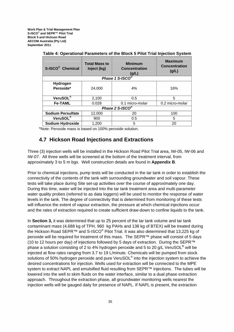
Work Plan & Trial Management Plan S-ISCO® and SEPR™ Pilot Trial Block 5 and Hickson Road AECOM Australia (Pty Ltd) September 2011
35
Table 4: Operational Parameters of the Block 5 Pilot Trial Injection System
S-ISCO® Chemical
Total Mass to Inject (kg)
Minimum
Concentration (g/L)
Maximum Concentration
(g/L)
Phase 1 S-ISCO® Hydrogen Peroxide*
24,000 4% 16%
VeruSOL® 2,100 0.5 5 Fe-TAML 0.028 0.1 micro-molar 0.2 micro-molar
Phase 2 S-ISCO® Sodium Persulfate 12,000 20 100
VeruSOL® 900 0.5 5 Sodium Hydroxide 1,200 5 20
*Note: Peroxide mass is based on 100% peroxide solution.
4.7 Hickson Road Injections and Extractions Three (3) injection wells will be installed in the Hickson Road Pilot Trial area, IW-05, IW-06 and IW-07. All three wells will be screened at the bottom of the treatment interval, from approximately 3 to 5 m bgs. Well construction details are found in Appendix B. Prior to chemical injections, pump tests will be conducted in the tar tank in order to establish the connectivity of the contents of the tank with surrounding groundwater and soil vapour. These tests will take place during Site set-up activities over the course of approximately one day. During this time, water will be injected into the tar tank treatment area and multi-parameter water quality probes (referred to as data loggers) will be used to monitor the response of water levels in the tank. The degree of connectivity that is determined from monitoring of these tests will influence the extent of vapour extraction, the pressure at which chemical injections occur and the rates of extraction required to create sufficient draw-down to confine liquids to the tank. In Section 3, it was determined that up to 25 percent of the tar tank volume and tar tank contaminant mass (4,688 kg of TPH, 960 kg PAHs and 138 kg of BTEX) will be treated during the Hickson Road SEPR™ and S-ISCO® Pilot Trial. It was also determined that 13,225 kg of peroxide will be required for treatment of this mass. The SEPR™ phase will consist of 5 days (10 to 12 hours per day) of injections followed by 5 days of extraction. During the SEPR™ phase a solution consisting of 2 to 4% hydrogen peroxide and 5 to 20 g/L VeruSOL® will be injected at flow rates ranging from 3.7 to 19 L/minute. Chemicals will be pumped from stock solutions of 50% hydrogen peroxide and pure VeruSOL® into the injection system to achieve the desired concentrations for injection. Wells used for extraction will be connected to the MPE system to extract NAPL and emulsified fluid resulting from SEPR™ injections. The tubes will be lowered into the well to skim fluids on the water interface, similar to a dual phase extraction approach. Throughout the extraction phase, all groundwater monitoring wells nearest the injection wells will be gauged daily for presence of NAPL. If NAPL is present, the extraction
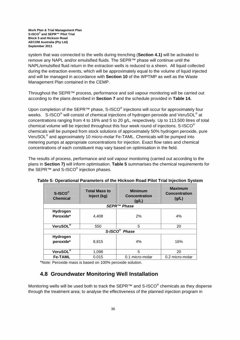
Work Plan & Trial Management Plan S-ISCO® and SEPR™ Pilot Trial Block 5 and Hickson Road AECOM Australia (Pty Ltd) September 2011
36
system that was connected to the wells during trenching (Section 4.1) will be activated to remove any NAPL and/or emulsified fluids. The SEPR™ phase will continue until the NAPL/emulsified fluid return in the extraction wells is reduced to a sheen. All liquid collected during the extraction events, which will be approximately equal to the volume of liquid injected and will be managed in accordance with Section 10 of the WPTMP as well as the Waste Management Plan contained in the CEMP. Throughout the SEPR™ process, performance and soil vapour monitoring will be carried out according to the plans described in Section 7 and the schedule provided in Table 14. Upon completion of the SEPR™ phase, S-ISCO® injections will occur for approximately four weeks. S-ISCO® will consist of chemical injections of hydrogen peroxide and VeruSOL® at concentrations ranging from 4 to 16% and 5 to 20 g/L, respectively. Up to 113,500 litres of total chemical volume will be injected throughout this four week round of injections. S-ISCO® chemicals will be pumped from stock solutions of approximately 50% hydrogen peroxide, pure VeruSOL® and approximately 10 micro-molar Fe-TAML. Chemicals will be pumped into metering pumps at appropriate concentrations for injection. Exact flow rates and chemical concentrations of each constituent may vary based on optimisation in the field. The results of process, performance and soil vapour monitoring (carried out according to the plans in Section 7) will inform optimisation. Table 5 summarises the chemical requirements for the SEPR™ and S-ISCO® injection phases.
Table 5: Operational Parameters of the Hickson Road Pilot Trial Injection System
S-ISCO® Chemical
Total Mass to Inject (kg)
Minimum
Concentration (g/L)
Maximum Concentration
(g/L)
SEPR™ Phase Hydrogen Peroxide*
4,408 2% 4%
VeruSOL® 550 5 20 S-ISCO® Phase
Hydrogen peroxide*
8,815 4% 16%
VeruSOL® 1,098 5 20 Fe-TAML 0.015 0.1 micro-molar 0.2 micro-molar
*Note: Peroxide mass is based on 100% peroxide solution.
4.8 Groundwater Monitoring Well Installation Monitoring wells will be used both to track the SEPR™ and S-ISCO® chemicals as they disperse through the treatment area; to analyse the effectiveness of the planned injection program in
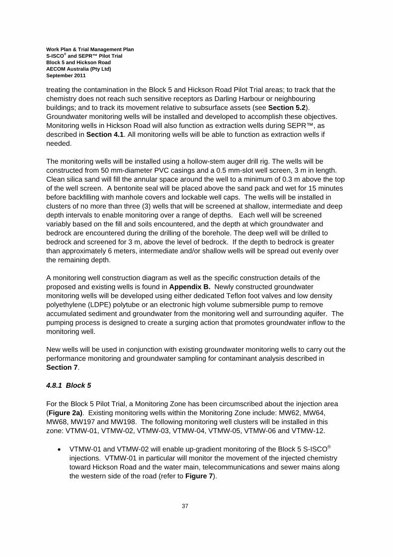
Work Plan & Trial Management Plan S-ISCO® and SEPR™ Pilot Trial Block 5 and Hickson Road AECOM Australia (Pty Ltd) September 2011
37
treating the contamination in the Block 5 and Hickson Road Pilot Trial areas; to track that the chemistry does not reach such sensitive receptors as Darling Harbour or neighbouring buildings; and to track its movement relative to subsurface assets (see Section 5.2). Groundwater monitoring wells will be installed and developed to accomplish these objectives. Monitoring wells in Hickson Road will also function as extraction wells during SEPR™, as described in Section 4.1. All monitoring wells will be able to function as extraction wells if needed. The monitoring wells will be installed using a hollow-stem auger drill rig. The wells will be constructed from 50 mm-diameter PVC casings and a 0.5 mm-slot well screen, 3 m in length. Clean silica sand will fill the annular space around the well to a minimum of 0.3 m above the top of the well screen. A bentonite seal will be placed above the sand pack and wet for 15 minutes before backfilling with manhole covers and lockable well caps. The wells will be installed in clusters of no more than three (3) wells that will be screened at shallow, intermediate and deep depth intervals to enable monitoring over a range of depths. Each well will be screened variably based on the fill and soils encountered, and the depth at which groundwater and bedrock are encountered during the drilling of the borehole. The deep well will be drilled to bedrock and screened for 3 m, above the level of bedrock. If the depth to bedrock is greater than approximately 6 meters, intermediate and/or shallow wells will be spread out evenly over the remaining depth. A monitoring well construction diagram as well as the specific construction details of the proposed and existing wells is found in Appendix B. Newly constructed groundwater monitoring wells will be developed using either dedicated Teflon foot valves and low density polyethylene (LDPE) polytube or an electronic high volume submersible pump to remove accumulated sediment and groundwater from the monitoring well and surrounding aquifer. The pumping process is designed to create a surging action that promotes groundwater inflow to the monitoring well. New wells will be used in conjunction with existing groundwater monitoring wells to carry out the performance monitoring and groundwater sampling for contaminant analysis described in Section 7. 4.8.1 Block 5 For the Block 5 Pilot Trial, a Monitoring Zone has been circumscribed about the injection area (Figure 2a). Existing monitoring wells within the Monitoring Zone include: MW62, MW64, MW68, MW197 and MW198. The following monitoring well clusters will be installed in this zone: VTMW-01, VTMW-02, VTMW-03, VTMW-04, VTMW-05, VTMW-06 and VTMW-12.
• VTMW-01 and VTMW-02 will enable up-gradient monitoring of the Block 5 S-ISCO® injections. VTMW-01 in particular will monitor the movement of the injected chemistry toward Hickson Road and the water main, telecommunications and sewer mains along the western side of the road (refer to Figure 7).
Work Plan & Trial Management Plan S-ISCO® and SEPR™ Pilot Trial Block 5 and Hickson Road AECOM Australia (Pty Ltd) September 2011
38
• VTMW-03 will be located between the Block 5 treatment area and the SP1129 to enable monitoring of the movement of injected chemistry toward the SP1129, its stormwater drain and electrical, telecommunications and cable services (shown on Figure 6). This well can be mobilised for extraction as a contingency measure if monitoring results indicate that the trigger values listed in Section 6.4 have been reached. This groundwater contingency plan will protect SP1129 as well as all SWC assets.
• VTMW-04 will be located within the injection/treatment area. Monitoring at this well location will provide information about the vertical and horizontal movement and influence of the injected chemistry within the treatment area.
• VTMW-05 and VTMW-06 will be located down-gradient of the injection/treatment area. Monitoring at these well locations will provide information about the vertical and lateral extent of the S-ISCO® chemistry’s subsurface movement. Based on boring data for the Block 5 Pilot Trial area, it is anticipated that only one to two wells will be installed at each of the monitoring locations (VTMW-01 through to VTMW-06).
• VTMW-12 will be installed down-gradient of the treatment/injection area and will be used to demonstrate that the injected chemistry does not approach Darling Harbour, a sensitive receptor. It is anticipated that shallow, intermediate and deep wells will be installed at this location. These wells will be mobilised as extraction wells in the event that the S-ISCO® chemistry is determined to pose a threat to the Harbour.
Other wells that will be monitored include: MW62, MW64, MW68 and MW197. These wells are located down-gradient of the injection/treatment area and will be monitored to track the extent of the influence of the injections and that the S-ISCO® chemistry does not threaten the Harbour. 4.8.2 Hickson Road For the Hickson Road Pilot Trial, MW53 is the only monitoring well existing within the Pilot Trial area. Five additional monitoring well clusters will be installed in the vicinity of the Pilot Trial area: VTMW-07, VTMW -08, VTMW -09, VTMW -10 and VTMW -11. These wells are shown in Figure 2b. Based on the depth of bedrock in this area, it is anticipated that only one well will be installed at each cluster location.
• VTMW-09 and VTMW-10, along with MW53, will be used to monitor the effects of injections and extractions on water levels within the tar tank. These will be the primary wells from which SEPR™ fluid is extracted, as described in Section 4.7.
• VTMW-07 will be installed in the footpath, cross-gradient to the treatment area, between the injection area and 30 Hickson Road. Monitoring at this well will track NAPL and SEPR™ fluid movement from the injection area, toward 30 Hickson Road. This well will be connected to the extraction system and used as an extraction point as described in Section 4.2.
• VTMW-08 will similarly be installed in the foot-path cross-gradient to the treatment area, between the injection area and 38 Hickson Road. Monitoring at this well will track NAPL and SEPR™ fluid movement from the injection area, toward 38 Hickson Road and the

Work Plan & Trial Management Plan S-ISCO® and SEPR™ Pilot Trial Block 5 and Hickson Road AECOM Australia (Pty Ltd) September 2011
39
water treatment plant there. This well will be connected to the extraction system and used as an extraction point as described in Section 4.2.
The existing wells, MW15 and BH6, as well as VTMW-11, are located on the other side of Hickson Road and down-gradient of the injection area. These wells will demonstrate that the injected chemistry does not migrate outside the injection area. Installation of VTMW-11 is significant because it will be located directly down-gradient to the tar tank area. A flush-mount road box that is bolted shut will be installed at each well location to prevent trip hazards to pedestrian or bicycle users of the footpath. No monitoring well is proposed between VTMW-10 and VTMW-11 because it would be located in the middle of Hickson Road and in order to access it for monitoring, the safety of the groundwater monitoring scientists engaged in this activity would be compromised and the activity would impact and/or disrupt traffic.
4.9 Soil Vapour Monitoring Point Installation A total of nine (9) soil vapor monitoring points, three (3) in Block 5 and six (6) in Hickson Road, will be installed during the Pilot Trial to augment the points already existing in the vicinity of the Pilot Trial areas (SV09, SV10 and SV11). Appendix E contains the construction details of the existing and planned soil vapour monitoring points in both Pilot Trial areas, including:
• VTSV-01, VTSV-08, VTSV-09, SV09, SV10 and SV11 in Block 5, shown in Figures 1 and 2a; and
• VTSV-02, VTSV-03, VTSV-04, VTSV-05, VTSV-06 and VTSV-07 in Hickson Road, shown in Figures 1 and 2b.
The depths of the screens in the soil vapour monitoring points will be selected to enable monitoring of the vapour in the shallow fill materials as well as the vapour being generated from the shallow groundwater. The points will be installed and sampled in general accordance with guidance from the Interstate Technology & Regulatory Council (ITRC, 2007), Vapour Intrusion Pathway: A Practical Guideline. This guideline is summarised in the following table6.
6 This table is based on Table 5 from AECOM, 2010a.
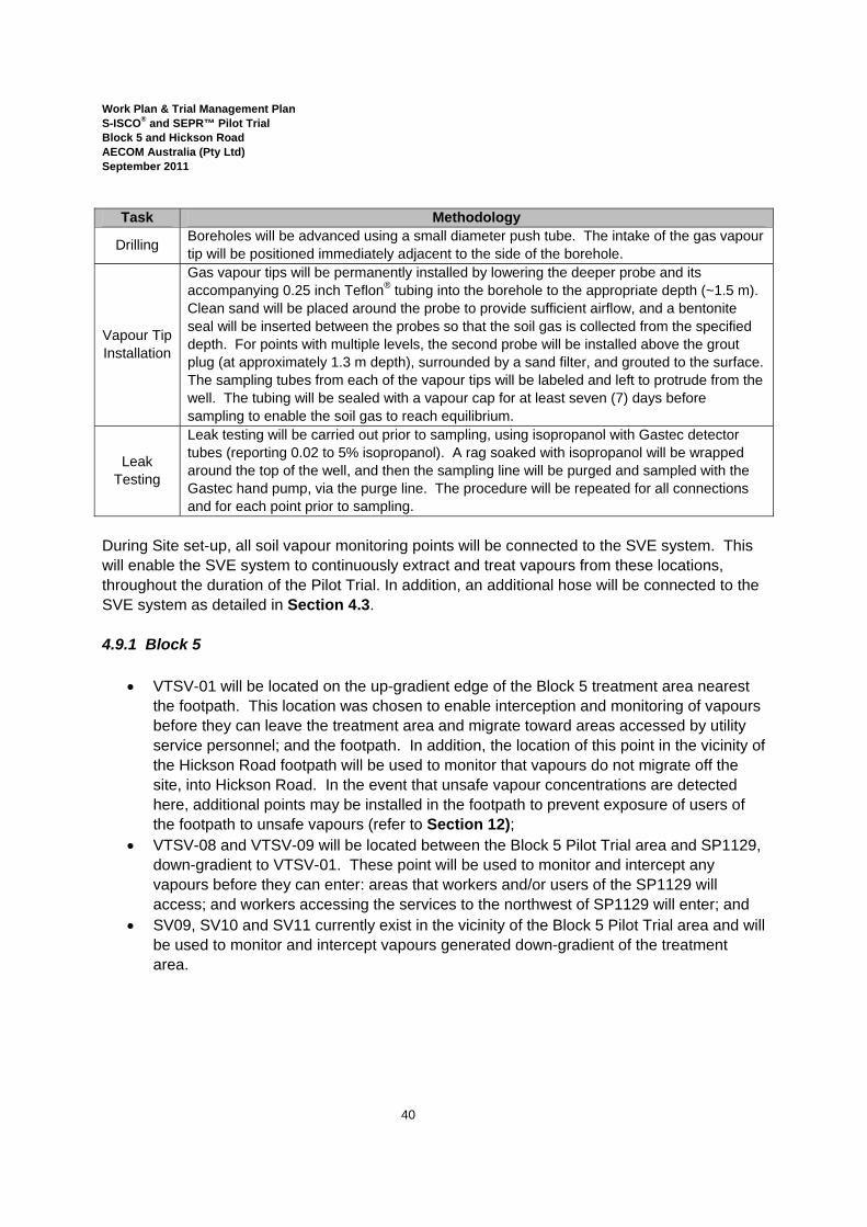
Work Plan & Trial Management Plan S-ISCO® and SEPR™ Pilot Trial Block 5 and Hickson Road AECOM Australia (Pty Ltd) September 2011
40
Task Methodology
Drilling Boreholes will be advanced using a small diameter push tube. The intake of the gas vapour tip will be positioned immediately adjacent to the side of the borehole.
Vapour Tip Installation
Gas vapour tips will be permanently installed by lowering the deeper probe and its accompanying 0.25 inch Teflon® tubing into the borehole to the appropriate depth (~1.5 m). Clean sand will be placed around the probe to provide sufficient airflow, and a bentonite seal will be inserted between the probes so that the soil gas is collected from the specified depth. For points with multiple levels, the second probe will be installed above the grout plug (at approximately 1.3 m depth), surrounded by a sand filter, and grouted to the surface. The sampling tubes from each of the vapour tips will be labeled and left to protrude from the well. The tubing will be sealed with a vapour cap for at least seven (7) days before sampling to enable the soil gas to reach equilibrium.
Leak Testing
Leak testing will be carried out prior to sampling, using isopropanol with Gastec detector tubes (reporting 0.02 to 5% isopropanol). A rag soaked with isopropanol will be wrapped around the top of the well, and then the sampling line will be purged and sampled with the Gastec hand pump, via the purge line. The procedure will be repeated for all connections and for each point prior to sampling.
During Site set-up, all soil vapour monitoring points will be connected to the SVE system. This will enable the SVE system to continuously extract and treat vapours from these locations, throughout the duration of the Pilot Trial. In addition, an additional hose will be connected to the SVE system as detailed in Section 4.3. 4.9.1 Block 5
• VTSV-01 will be located on the up-gradient edge of the Block 5 treatment area nearest the footpath. This location was chosen to enable interception and monitoring of vapours before they can leave the treatment area and migrate toward areas accessed by utility service personnel; and the footpath. In addition, the location of this point in the vicinity of the Hickson Road footpath will be used to monitor that vapours do not migrate off the site, into Hickson Road. In the event that unsafe vapour concentrations are detected here, additional points may be installed in the footpath to prevent exposure of users of the footpath to unsafe vapours (refer to Section 12);
• VTSV-08 and VTSV-09 will be located between the Block 5 Pilot Trial area and SP1129, down-gradient to VTSV-01. These point will be used to monitor and intercept any vapours before they can enter: areas that workers and/or users of the SP1129 will access; and workers accessing the services to the northwest of SP1129 will enter; and
• SV09, SV10 and SV11 currently exist in the vicinity of the Block 5 Pilot Trial area and will be used to monitor and intercept vapours generated down-gradient of the treatment area.

Work Plan & Trial Management Plan S-ISCO® and SEPR™ Pilot Trial Block 5 and Hickson Road AECOM Australia (Pty Ltd) September 2011
41
4.9.2 Hickson Road
• VTSV-02 will be installed within the Hickson Road Pilot Trial treatment area. This point will be used to directly capture and intercept vapours generated by the SEPR™ and S-ISCO® processes, in order to minimise their migration outside of the treatment area.
• VTSV-03 will be located directly adjacent to the basement of the Bond building at 30 Hickson Road; VTSV-04 will be located directly adjacent to the basement of the building at 38 Hickson Road. These points will be used to prevent vapours from entering the basements of these buildings, and to demonstrate that users and inhabitants of the buildings face no negative impacts as a result of the Pilot Trial.
• VTSV-05 will be installed within the footpath immediately outside of the childcare centre within the Bond building at 30 Hickson Road. This point will be used to capture vapours that might migrate from the treatment area and to demonstrate that users of the footpath or childcare centre / 30 Hickson Road face no negative impacts as a result of the Pilot Trial.
• VTSV-06 and VTSV-07 are located on the footpath, approximately 10 meters from the outside edge of the tar tank. These points will be used to intercept vapours that may leave the treatment area, before they can reach buildings along the road or infiltrate underground service pits, including those accessed by EA personnel (including point 50267) as well as those locations identified on Figure 4 that will also be monitored for vapour impacts.
Note that a flush-mount road box that is bolted shut will be installed at each monitoring point location to prevent trip hazards to pedestrian or bicycle users of the footpath. Refer also to Section 4.4 for details of how trenches between the various soil vapour monitoring wells in Hickson Road will be finished.
4.10 Monitoring Plan Overview Monitoring at the Block 5 and Hickson Road Pilot Trial areas will be conducted both to track the performance and optimisation of the S-ISCO® and SEPR™ system and treatment processes and also to mitigate any potential negative impacts on the environment, the community and sensitive receptors in the vicinity of the treatment area. Monitoring will be carried out during three phases:
• Pre-Injection Monitoring; • Concurrent-Injection/Extraction Monitoring; and • Post-Injection Monitoring.
These phases will be comprised of the following components:
• Process monitoring; • Performance monitoring; • Groundwater sampling; • Soil sampling; and
Work Plan & Trial Management Plan S-ISCO® and SEPR™ Pilot Trial Block 5 and Hickson Road AECOM Australia (Pty Ltd) September 2011
42
• Soil vapour sampling. A detailed Monitoring Plan for S-ISCO® and SEPR™ is presented in Section 5. An overview of the various components is provided below. 4.10.1 Process Monitoring Process monitoring consists of monitoring the S-ISCO® and SEPR™ chemistry at the system and in the injection wells. This monitoring data is used to track the parameters of the system and subsequently to inform modifications to the operational parameters, including injection rate, concentration and pressure, in order to optimise treatment. Refer to Section 7.1 for the details of the Process Monitoring program. 4.10.2 Performance Monitoring Monitoring of the injected chemicals in monitoring wells provides information as to where the injected chemicals are travelling and the nature of their reactions. This is a critical component to the success of the S-ISCO® and SEPR™ Pilot Trials. Monitoring data collected is used to understand the success of contacting the contaminant mass with the injection chemicals and to document the chemical reactions taking place. In addition it will be used to inform hydraulic modelling of the injection process that will be undertaken as part of the planning for full-scale implementation. Using laboratory equipment and in situ water quality data logger devices, groundwater and process water parameters such as pH, oxidation reduction potential (ORP), dissolved oxygen (DO), conductivity, head, temperature, oxidant concentrations, TPH (C10-C36) (using a SiteLab Fluorescence Analyser)7 and inter facial tension (IFT) will be measured from groundwater and various locations in the injection system. Measured parameters of pH, ORP and DO provide witness to the presence of the chemical reactions. During the course of oxidation reactions pH is expected to decrease slightly in the short term and in the immediate vicinity of the injected chemistry as protons are generated by the destruction of the oxidant. ORP, an indication of the capacity of an environment to undergo redox reactions, is expected to increase, providing a direct indication of the presence of reactions, specifically with peroxide. Because this relationship is stronger when hydrogen peroxide rather than sodium persulfate is used, ORP is most significant in tracking the peroxide front. ORP may be detected much earlier than peroxide at a given location since the oxygen released from decomposition of hydrogen peroxide diffuses throughout the groundwater at a much faster rate than the injected oxidant. Similarly, DO is expected to increase in response to
7 Note that the SiteLab Fluorescence analysis method, unlike the GC method used by an outside laboratory, does not measure the presence of VeruSOL® during TPH measurements and therefore returns results that more accurately reflect the presence of TPH contaminants than the GC method.
Work Plan & Trial Management Plan S-ISCO® and SEPR™ Pilot Trial Block 5 and Hickson Road AECOM Australia (Pty Ltd) September 2011
43
peroxide treatment, and its increase may also significantly precede the arrival of the peroxide front. The significance of pH depends on the S-ISCO® system.
• During alkaline-activated S-ISCO® with sodium persulfate, which will take place during the second phase of treatment in Block 5, elevated pH (alkaline conditions) will indicate that sodium hydroxide is adequately dosed to create alkaline conditions that will activate the persulfate oxidant.
• During S-ISCO® treatment in Hickson Road as well as the first phase of treatment in Block 5 in which Fe-TAML will be used; pH will be monitored to ensure that it is elevated sufficiently to optimise the catalyst (approximately pH 9).
• In S-ISCO® systems in which peroxide is being used and in which there is a possibility for pH levels to become acidic (in a localised area and over a short time period as described in Section 5.2), pH measurements will indicate that monitoring should increase and/or that injection parameters may need to be modified. Finally, pH measurements will play a role in selection of weekly samples for metals and TPH analysis, as described in Section 7.3.2.
Measured parameters of conductivity, IFT, pH, TPH (C10-C36) and concentrations of oxidant are good indicators of chemical transport and allow for adjustment in system flow rates and chemical delivery concentrations based on monitoring well results. Conductivity is a conservative tracer that indicates where chemistry is present, specifically persulfate, since it is directly related to the total dissolved solids in solutions, including sulfates. Measured concentrations of oxidant (persulfate) lag behind the conductivity front because it is reacting and being consumed during transport. IFT indicates the presence of VeruSOL®. As mentioned above, during S-ISCO® with alkaline-activated persulfate in Block 5, pH will be used to track that sodium hydroxide is being adequately dosed and transported to activate the persulfate. Measurements of the hydraulic head and depth-to-groundwater will indicate the impact of injections on the water level in the treatment area and also will provide data relating the movement and transport of the injected chemistry to the tides in Darling Harbour. This data will be used in developing the design for the full-scale remedial implementation. In addition, this data will be used to regulate fluid levels in the tar tank in Hickson Road to confine the injected chemistry to this area. Finally, temperature in groundwater samples is expected to increase as a result of S-ISCO® injections. During S-ISCO® with peroxide, specifically, since reactions of peroxide, with contaminants are exothermic, heat will be produced that elevates groundwater temperature. Although temperature is expected to increase in response to the S-ISCO® treatment and can indicate chemical reactions, the extent to which temperature increases is affected by numerous factors, including: the temperature of the injected fluid; and the heat capacity of the groundwater and subsurface. Therefore, temperature is not an extremely strong or direct indicator of the
Work Plan & Trial Management Plan S-ISCO® and SEPR™ Pilot Trial Block 5 and Hickson Road AECOM Australia (Pty Ltd) September 2011
44
treatment front. Notwithstanding, it is essential to monitor to ensure that increases do not threaten the groundwater system or subsurface materials / services. Please refer to Section 7.2 for the details of the Performance Monitoring program. Performance monitoring also plays a pivotal role in the mitigating risks to the environment and sensitive receptors. Environmental Management Plans are contained in the CEMP. Details of the mitigation program to protect sensitive receptors are found below, in Section 5. Please refer to Section 8 for the criteria that will be used to evaluate the results of this monitoring and the contingency measures that will be implemented in the event that these indicators are not met. 4.10.3 Soil and Groundwater Sampling Soil and groundwater will be sampled for contaminants of concern (COCs), including TPH, VOCs and SVOCs. Groundwater will also be sampled for metals analysis. Sampling of groundwater and soil for COCs enables a comparison of conditions before and after the S-ISCO® and SEPR™ Pilot Trials that will ultimately be used to assess the effectiveness of the treatment. The final objectives of this S-ISCO® and SEPR™ Pilot Trial are to reduce soil concentrations of identified COCs, specifically TPH, PAHs and BTEX, below SSTC, and to reduce the groundwater flux of COCs leaving the Pilot Trial site to levels below the SSTC as well. Soil sampling for COCs after the Pilot Trial, in particular, provides an estimate as to the magnitude of contaminant reduction at the Site. The final analysis of the effectiveness of the application also involves the sampling and analysis of groundwater to develop COC flux comparisons before and after the S-ISCO® application. Refer to Sections 7.3 and 7.7 for the details of the groundwater and soil monitoring programs. Groundwater sampling for PAHs, TPH and metals throughout the S-ISCO® and SEPR™ injections will take place to confirm both that the treatment is proceeding and also that neither contaminants nor metals are mobilised by the treatment. Refer to Section 7.3 for the details of this monitoring. 4.10.4 Soil Vapour Sampling Soil vapour sampling will be conducted to monitor the presence and safety of soil vapours generated as a result of S-ISCO® and SEPR™ oxidation reactions. Soil vapour monitoring is a significant component VeruTEK’s Environmental Management Plans, contained in the CEMP, and mitigation strategies (Section 5). Soil vapour monitoring will target areas near: the basements of the nearby buildings that are both close to the soil and accessed by people, including 38 and 30 Hickson Road; the SP1129
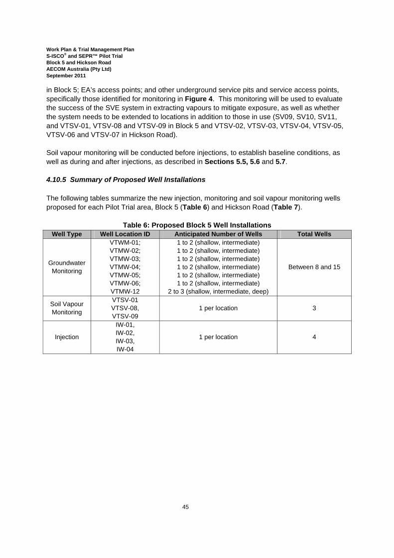
Work Plan & Trial Management Plan S-ISCO® and SEPR™ Pilot Trial Block 5 and Hickson Road AECOM Australia (Pty Ltd) September 2011
45
in Block 5; EA’s access points; and other underground service pits and service access points, specifically those identified for monitoring in Figure 4. This monitoring will be used to evaluate the success of the SVE system in extracting vapours to mitigate exposure, as well as whether the system needs to be extended to locations in addition to those in use (SV09, SV10, SV11, and VTSV-01, VTSV-08 and VTSV-09 in Block 5 and VTSV-02, VTSV-03, VTSV-04, VTSV-05, VTSV-06 and VTSV-07 in Hickson Road). Soil vapour monitoring will be conducted before injections, to establish baseline conditions, as well as during and after injections, as described in Sections 5.5, 5.6 and 5.7. 4.10.5 Summary of Proposed Well Installations The following tables summarize the new injection, monitoring and soil vapour monitoring wells proposed for each Pilot Trial area, Block 5 (Table 6) and Hickson Road (Table 7).
Table 6: Proposed Block 5 Well Installations Well Type Well Location ID Anticipated Number of Wells Total Wells
Groundwater Monitoring
VTWM-01; VTMW-02; VTMW-03; VTMW-04; VTMW-05; VTMW-06; VTMW-12
1 to 2 (shallow, intermediate) 1 to 2 (shallow, intermediate) 1 to 2 (shallow, intermediate) 1 to 2 (shallow, intermediate) 1 to 2 (shallow, intermediate) 1 to 2 (shallow, intermediate)
2 to 3 (shallow, intermediate, deep)
Between 8 and 15
Soil Vapour Monitoring
VTSV-01 VTSV-08, VTSV-09
1 per location 3
Injection
IW-01, IW-02, IW-03, IW-04
1 per location 4
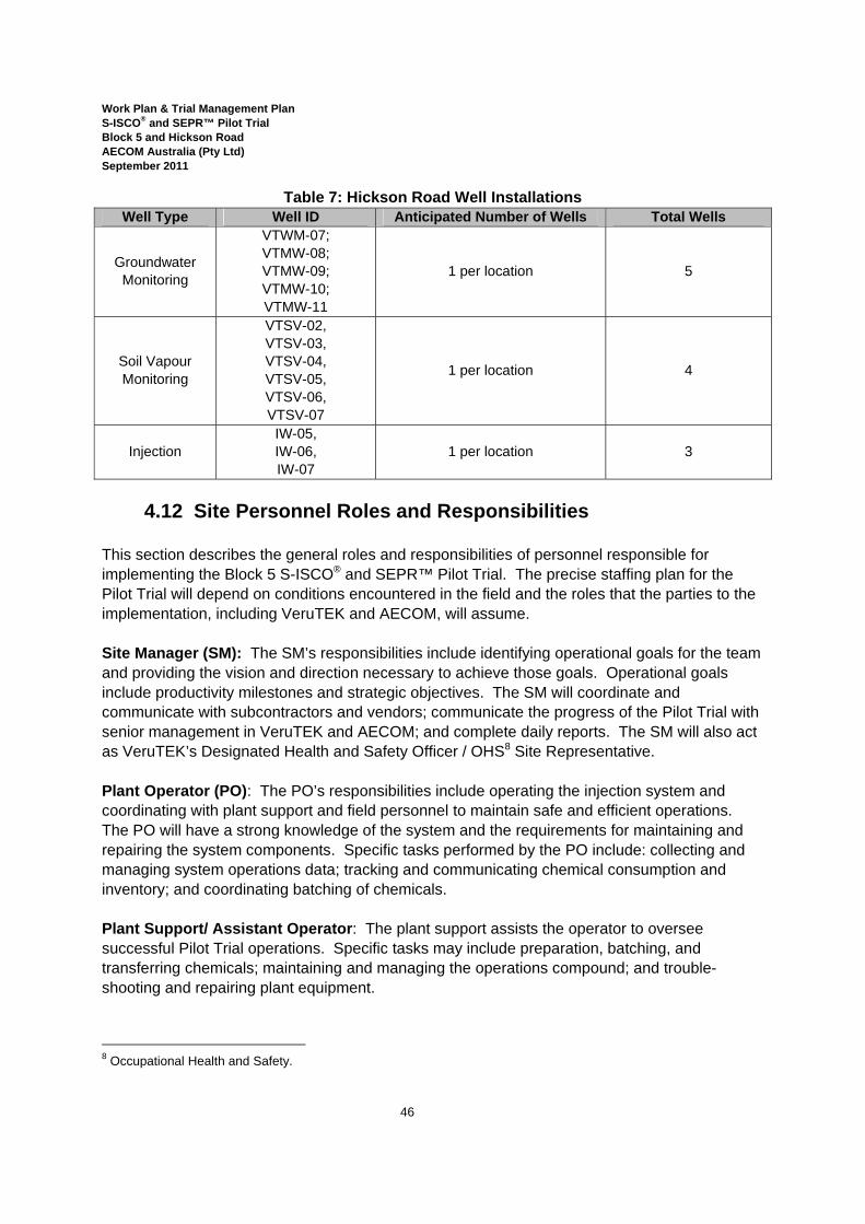
Work Plan & Trial Management Plan S-ISCO® and SEPR™ Pilot Trial Block 5 and Hickson Road AECOM Australia (Pty Ltd) September 2011
46
Table 7: Hickson Road Well Installations Well Type Well ID Anticipated Number of Wells Total Wells
Groundwater Monitoring
VTWM-07; VTMW-08; VTMW-09; VTMW-10; VTMW-11
1 per location 5
Soil Vapour Monitoring
VTSV-02, VTSV-03, VTSV-04, VTSV-05, VTSV-06, VTSV-07
1 per location 4
Injection IW-05, IW-06, IW-07
1 per location 3
4.12 Site Personnel Roles and Responsibilities
This section describes the general roles and responsibilities of personnel responsible for implementing the Block 5 S-ISCO® and SEPR™ Pilot Trial. The precise staffing plan for the Pilot Trial will depend on conditions encountered in the field and the roles that the parties to the implementation, including VeruTEK and AECOM, will assume. Site Manager (SM): The SM’s responsibilities include identifying operational goals for the team and providing the vision and direction necessary to achieve those goals. Operational goals include productivity milestones and strategic objectives. The SM will coordinate and communicate with subcontractors and vendors; communicate the progress of the Pilot Trial with senior management in VeruTEK and AECOM; and complete daily reports. The SM will also act as VeruTEK’s Designated Health and Safety Officer / OHS8 Site Representative. Plant Operator (PO): The PO’s responsibilities include operating the injection system and coordinating with plant support and field personnel to maintain safe and efficient operations. The PO will have a strong knowledge of the system and the requirements for maintaining and repairing the system components. Specific tasks performed by the PO include: collecting and managing system operations data; tracking and communicating chemical consumption and inventory; and coordinating batching of chemicals. Plant Support/ Assistant Operator: The plant support assists the operator to oversee successful Pilot Trial operations. Specific tasks may include preparation, batching, and transferring chemicals; maintaining and managing the operations compound; and trouble-shooting and repairing plant equipment.
8 Occupational Health and Safety.
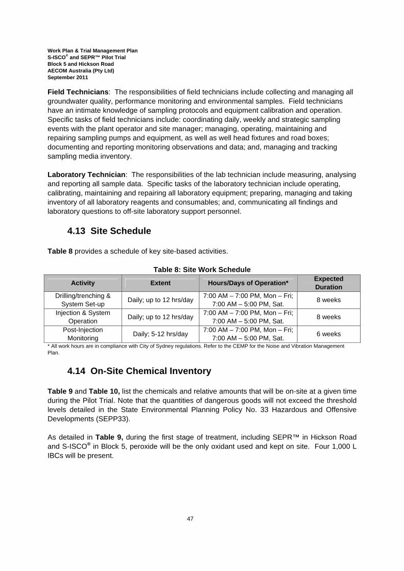
Work Plan & Trial Management Plan S-ISCO® and SEPR™ Pilot Trial Block 5 and Hickson Road AECOM Australia (Pty Ltd) September 2011
47
Field Technicians: The responsibilities of field technicians include collecting and managing all groundwater quality, performance monitoring and environmental samples. Field technicians have an intimate knowledge of sampling protocols and equipment calibration and operation. Specific tasks of field technicians include: coordinating daily, weekly and strategic sampling events with the plant operator and site manager; managing, operating, maintaining and repairing sampling pumps and equipment, as well as well head fixtures and road boxes; documenting and reporting monitoring observations and data; and, managing and tracking sampling media inventory. Laboratory Technician: The responsibilities of the lab technician include measuring, analysing and reporting all sample data. Specific tasks of the laboratory technician include operating, calibrating, maintaining and repairing all laboratory equipment; preparing, managing and taking inventory of all laboratory reagents and consumables; and, communicating all findings and laboratory questions to off-site laboratory support personnel.
4.13 Site Schedule Table 8 provides a schedule of key site-based activities.
Table 8: Site Work Schedule
Activity Extent Hours/Days of Operation* Expected Duration
Drilling/trenching & System Set-up Daily; up to 12 hrs/day 7:00 AM – 7:00 PM, Mon – Fri;
7:00 AM – 5:00 PM, Sat. 8 weeks
Injection & System Operation Daily; up to 12 hrs/day 7:00 AM – 7:00 PM, Mon – Fri;
7:00 AM – 5:00 PM, Sat. 8 weeks
Post-Injection Monitoring Daily; 5-12 hrs/day 7:00 AM – 7:00 PM, Mon – Fri;
7:00 AM – 5:00 PM, Sat. 6 weeks
* All work hours are in compliance with City of Sydney regulations. Refer to the CEMP for the Noise and Vibration Management Plan.
4.14 On-Site Chemical Inventory Table 9 and Table 10, list the chemicals and relative amounts that will be on-site at a given time during the Pilot Trial. Note that the quantities of dangerous goods will not exceed the threshold levels detailed in the State Environmental Planning Policy No. 33 Hazardous and Offensive Developments (SEPP33). As detailed in Table 9, during the first stage of treatment, including SEPR™ in Hickson Road and S-ISCO® in Block 5, peroxide will be the only oxidant used and kept on site. Four 1,000 L IBCs will be present.
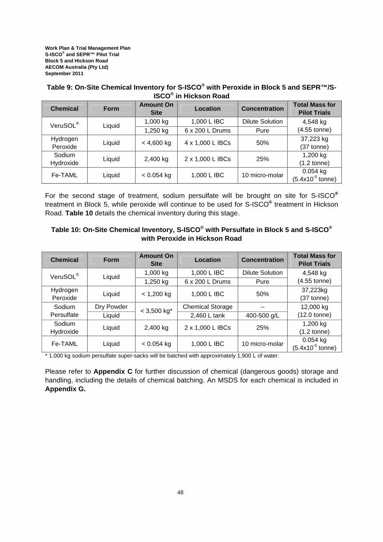
Work Plan & Trial Management Plan S-ISCO® and SEPR™ Pilot Trial Block 5 and Hickson Road AECOM Australia (Pty Ltd) September 2011
48
Table 9: On-Site Chemical Inventory for S-ISCO® with Peroxide in Block 5 and SEPR™/S-ISCO® in Hickson Road
Chemical Form Amount On Site Location Concentration Total Mass for
Pilot Trials
VeruSOL® Liquid 1,000 kg 1,000 L IBC Dilute Solution 4,548 kg
(4.55 tonne) 1,250 kg 6 x 200 L Drums Pure Hydrogen Peroxide Liquid < 4,600 kg 4 x 1,000 L IBCs 50% 37,223 kg
(37 tonne) Sodium
Hydroxide Liquid 2,400 kg 2 x 1,000 L IBCs 25% 1,200 kg (1.2 tonne)
Fe-TAML Liquid < 0.054 kg 1,000 L IBC 10 micro-molar 0.054 kg (5.4x10⁻⁵ tonne)
For the second stage of treatment, sodium persulfate will be brought on site for S-ISCO® treatment in Block 5, while peroxide will continue to be used for S-ISCO® treatment in Hickson Road. Table 10 details the chemical inventory during this stage.
Table 10: On-Site Chemical Inventory, S-ISCO® with Persulfate in Block 5 and S-ISCO® with Peroxide in Hickson Road
Chemical Form Amount On Site Location Concentration Total Mass for
Pilot Trials
VeruSOL® Liquid 1,000 kg 1,000 L IBC Dilute Solution 4,548 kg
(4.55 tonne) 1,250 kg 6 x 200 L Drums Pure Hydrogen Peroxide Liquid < 1,200 kg 1,000 L IBC 50% 37,223kg
(37 tonne) Sodium
Persulfate Dry Powder < 3,500 kg* Chemical Storage -- 12,000 kg
(12.0 tonne) Liquid 2,460 L tank 400-500 g/L Sodium
Hydroxide Liquid 2,400 kg 2 x 1,000 L IBCs 25% 1,200 kg (1.2 tonne)
Fe-TAML Liquid < 0.054 kg 1,000 L IBC 10 micro-molar 0.054 kg (5.4x10⁻⁵ tonne)
* 1,000 kg sodium persulfate super-sacks will be batched with approximately 1,900 L of water. Please refer to Appendix C for further discussion of chemical (dangerous goods) storage and handling, including the details of chemical batching. An MSDS for each chemical is included in Appendix G.
Work Plan & Trial Management Plan S-ISCO® and SEPR™ Pilot Trial Block 5 and Hickson Road AECOM Australia (Pty Ltd) September 2011
49
5.0 Potential Risks and Mitigation Measures
As summarised in Section 1.5.1, sensitive receptors have been identified in the vicinity of the Pilot Trial area. These sensitive receptors face the following risks as a result of Pilot Trial operations:
• Impact to an Aquatic Ecosystem (Darling Harbor) – S-ISCO Chemistry; • Impact to an Aquatic Ecosystem (Darling Harbour) – Mobilisation of Metals; • Impact to Subsurface Infrastructure; • Impacts to Buildings; • Impact to Humans due to Vapours; • Impact due to Day-lighting; and • Impact to Trees.
The following sections describe the risks as well as the mitigation measures that will be implemented to prevent these adverse impacts and contingency measures that will be enacted in the unlikely event that impacts are noted. Potential impacts to soil and water are discussed further in the Soil and Water Impact Assessment (AECOM, 2010e).
5.1 Impact to an Aquatic Ecosystem (Darling Harbour) – S-ISCO Chemistry
Darling Harbour is the nearest receptor for groundwater and surface water coming from the Site. Darling Harbour forms part of the larger Sydney Harbour and is classified in ANZECC (2000) as a ‘highly disturbed system. Shallow groundwater passing through Hickson Road and Block 5 has been historically, and is currently, in contact with the gas works residuals in the subsurface. This shallow groundwater potentially discharges contaminants into Darling Harbour. The Site is situated in a mixed commercial and residential area and no other environmentally sensitive receptors have been identified. No material, treated or otherwise, will enter Darling Harbour and impact either water quality or sediment as a result of the S-ISCO® and/or SEPR™ Pilot Trials. During the course of S-ISCO® and SEPR™ injections, the progression and extent of the S-ISCO® treatment front will be followed closely through in situ and ex situ monitoring and laboratory analysis of groundwater from monitoring wells on the Site, specifically those installed in the distance between the Pilot Trial area in Block 5 and the Harbour (including MW62, MW64, MW68 and MW197, and VTMW-05, VTMW-06 andVTMW-12, as detailed in Section 4.8 and shown on Figure 1).
Work Plan & Trial Management Plan S-ISCO® and SEPR™ Pilot Trial Block 5 and Hickson Road AECOM Australia (Pty Ltd) September 2011
50
In addition the rate of reactions between the S-ISCO® chemistry and subsurface contaminants will be closely followed to track that the injected reagents are being consumed. In the event that monitoring results indicate that the treatment front becomes too close to the Harbour, a program of extraction will be initiated from monitoring wells that will be monitored as part of the monitoring plan, detailed in Section 7.3. The contents of the injected front will be extracted from the subsurface using groundwater extraction pumps, the un-reacted S-ISCO® chemicals will be intercepted and adverse impacts on the Harbour will be minimised. Extracted materials will be handled in accordance with the Site’s Water and Stormwater Management Plan and Waste Management Plan, contained in the CEMP.
5.2 Impact to an Aquatic Ecosystem (Darling Harbour) – Mobilisation of Metals
In one of the column tests (Column 4) undertaken as part of the bench scale treatability study (refer to Section 1.4.1) in which hydrogen peroxide, VeruSOL® and Fe-TAML were used, the pH of the effluent dropped as low as 1. This result raised questions about the potential for S-ISCO® treatment with the same chemistry, peroxide, VeruSOL® and Fe-TAML, to produce a low-pH environment in the treatment area, and, as a consequence, mobilise metals present in the subsurface that could eventually discharge into Darling Harbour. The following section describes how such low pH conditions will not occur during the Pilot Trial, as well as the specific mitigation and contingency plans that will be in place during the Pilot Trial to monitor pH and metals mobilisation:
• Fluid in a 46 cm column travels for approximately 7 hours through the column before its release as effluent, and consequently, the measurements taken from this effluent can be categorised as near-term or localised. Therefore, column-test results are not indicative of potential conditions that will be achieved in the treatment zone at a reasonable distance of even one meter from an injection location.
• The low pH is likely an artefact of intermediary/temporary compounds (weak organic acids) formed when hydrogen peroxide reacts with site contaminants; weak organic acids that would be destroyed by the buffering capacity of the soil prior to their movement any significant distance from the point of their generation.
• When deionised (DI) water is run through a column of soil from Barangaroo, the pH (without any VeruTEK chemistry added) is approximately 3.7, indicating naturally acidic conditions.
Together, these observations suggest that there is a potential to measure a low pH in injection wells over the short term, but that data collected in the monitoring well network will not exhibit similarly low pH conditions. To be clear, Fe-TAML activates hydrogen peroxide optimally at a pH of 9. Therefore, when Fe-TAML is used, pH adjustment in the 8-9.5 range will occur using NaOH. Also, in Block 5, following initial treatment with S-ISCO® using hydrogen peroxide, S-ISCO® with high-pH activated sodium persulfate will be used as a polishing stage. These factors provide buffering of the soil to prevent low pH conditions during and shortly after the
Work Plan & Trial Management Plan S-ISCO® and SEPR™ Pilot Trial Block 5 and Hickson Road AECOM Australia (Pty Ltd) September 2011
51
injections are completed. In the long term, pH of the soil and groundwater will return to pre-injection conditions due to the natural buffering capacity of the soils.
The application of peroxide, VeruSOL® and Fe-TAML in the field will take place within a significantly larger mass and volume of soil, providing a largely expanded buffering capacity over what was furnished by soil in the column. The chemistry will have a greatly increased length of contact with both the soil as well as contaminants, enabling more complete reactions. In addition, the chemistry used in the field will be altered to specifically maintain more alkaline conditions. Through groundwater monitoring, pH conditions will be closely tracked and the pH will be adjusted with the injection of sodium hydroxide. In contrast to the imprecise metering pumps used during the column tests that cannot easily be modified in response to conditions measured in the effluent, that is, at only one point, the injection pumps used in the field can be easily adjusted to respond to conditions measured in the field at multiple sampling locations. During S-ISCO® with peroxide, the pH will be maintained between 8.5 and 9 in order to optimize the performance of the Fe-TAML activator. In addition, in Block 5, sodium hydroxide will also be used to create the alkaline conditions required to activate sodium persulfate.
Finally, the Pilot Trial will include continuous monitoring of pH which will facilitate adjustment of pH (if needed) to: (a) demonstrate that low pH conditions do not develop away from the immediate vicinity of the injection wells; and (b) help both the hydrogen peroxide and sodium persulfate S-ISCO® reactions to occur optimally.
5.3 Impact to Subsurface Infrastructure There is a possibility that subsurface infrastructure in the vicinity of the Pilot Trial areas may be subject to physical impacts, from well drilling, soil sampling and trenching, for example, and/or chemical impacts, from the injection and subsequent movement of the injected treatment chemistry, for example. In April 2011, AECOM conducted a hydraulic modelling exercise (refer to Appendix L) to estimate the extent of the S-ISCO® oxidants’ lateral and vertical movement, specifically with respect to SWC’s assets, including SP1129, but was used to also to assess other utility underground assets such as Telstra, Optus, Jemena and State Rail. The estimated extent is shown in site Figure 6. Subsurface assets in the vicinity of the Pilot Trials are listed in Table 11, below, along with the entity to which they belong, the potential impacts from Pilot Trial operations as well as mitigation measures. In addition, these assets and potential impact areas are identified on Figure 6.
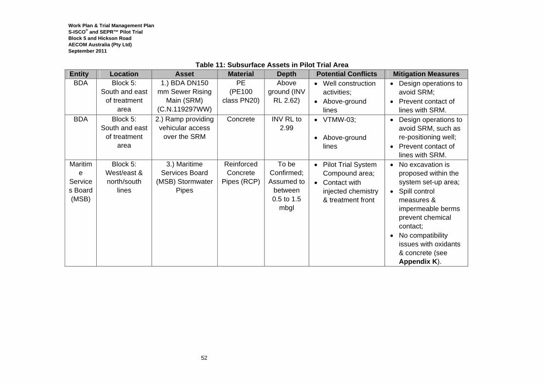
Work Plan & Trial Management Plan S-ISCO® and SEPR™ Pilot Trial Block 5 and Hickson Road AECOM Australia (Pty Ltd) September 2011
52
Table 11: Subsurface Assets in Pilot Trial Area Entity Location Asset Material Depth Potential Conflicts Mitigation Measures
BDA Block 5: South and east
of treatment area
1.) BDA DN150 mm Sewer Rising
Main (SRM) (C.N.119297WW)
PE (PE100
class PN20)
Above ground (INV
RL 2.62)
• Well construction activities;
• Above-ground lines
• Design operations to avoid SRM;
• Prevent contact of lines with SRM.
BDA Block 5: South and east
of treatment area
2.) Ramp providing vehicular access
over the SRM
Concrete INV RL to 2.99
• VTMW-03; • Above-ground
lines
• Design operations to avoid SRM, such as re-positioning well;
• Prevent contact of lines with SRM.
Maritime
Services Board (MSB)
Block 5: West/east & north/south
lines
3.) Maritime Services Board
(MSB) Stormwater Pipes
Reinforced Concrete
Pipes (RCP)
To be Confirmed; Assumed to
between 0.5 to 1.5
mbgl
• Pilot Trial System Compound area;
• Contact with injected chemistry & treatment front
• No excavation is proposed within the system set-up area;
• Spill control measures & impermeable berms prevent chemical contact;
• No compatibility issues with oxidants & concrete (see Appendix K).
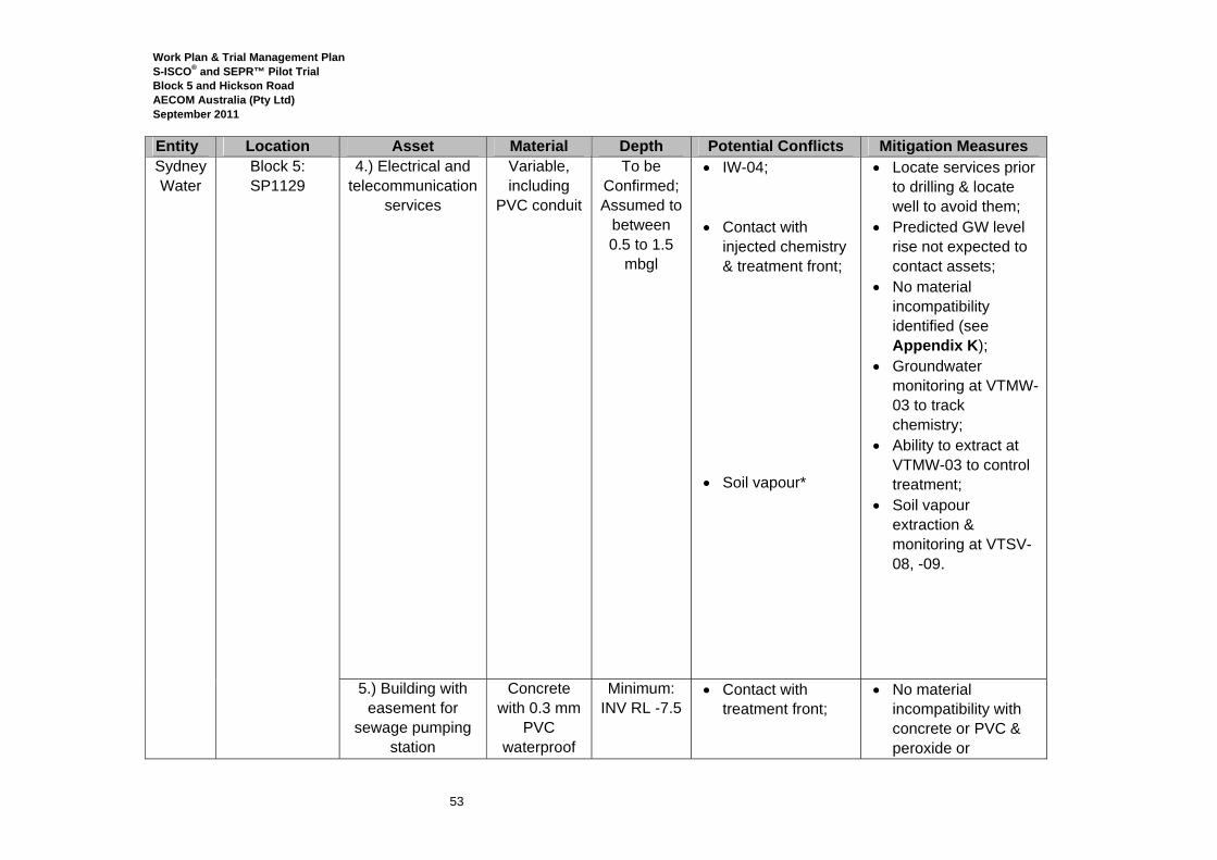
Work Plan & Trial Management Plan S-ISCO® and SEPR™ Pilot Trial Block 5 and Hickson Road AECOM Australia (Pty Ltd) September 2011
53
Entity Location Asset Material Depth Potential Conflicts Mitigation Measures Sydney Water
Block 5: SP1129
4.) Electrical and telecommunication
services
Variable, including
PVC conduit
To be Confirmed; Assumed to
between 0.5 to 1.5
mbgl
• IW-04; • Contact with
injected chemistry & treatment front;
• Soil vapour*
• Locate services prior to drilling & locate well to avoid them;
• Predicted GW level rise not expected to contact assets;
• No material incompatibility identified (see Appendix K);
• Groundwater monitoring at VTMW-03 to track chemistry;
• Ability to extract at VTMW-03 to control treatment;
• Soil vapour extraction & monitoring at VTSV-08, -09.
5.) Building with easement for
sewage pumping station
Concrete with 0.3 mm
PVC waterproof
Minimum: INV RL -7.5
• Contact with treatment front;
• No material incompatibility with concrete or PVC & peroxide or
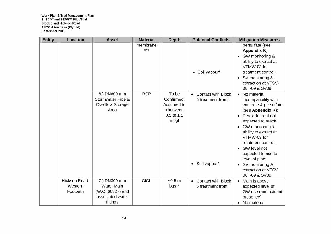
Work Plan & Trial Management Plan S-ISCO® and SEPR™ Pilot Trial Block 5 and Hickson Road AECOM Australia (Pty Ltd) September 2011
54
Entity Location Asset Material Depth Potential Conflicts Mitigation Measures membrane
*** • Soil vapour*
persulfate (see Appendix K);
• GW monitoring & ability to extract at VTMW-03 for treatment control;
• SV monitoring & extraction at VTSV-08, -09 & SV09.
6.) DN600 mm Stormwater Pipe & Overflow Storage
Area
RCP To be Confirmed; Assumed to +between 0.5 to 1.5
mbgl
• Contact with Block 5 treatment front;
• Soil vapour*
• No material incompatibility with concrete & persulfate (see Appendix K);
• Peroxide front not expected to reach;
• GW monitoring & ability to extract at VTMW-03 for treatment control;
• GW level not expected to rise to level of pipe;
• SV monitoring & extraction at VTSV-08, -09 & SV09.
Hickson Road: Western Footpath
7.) DN300 mm Water Main
(W.O. 60327) and associated water
fittings
CICL ~0.5 m bgs**
• Contact with Block 5 treatment front
• Main is above expected level of GW rise (and oxidant presence);
• No material
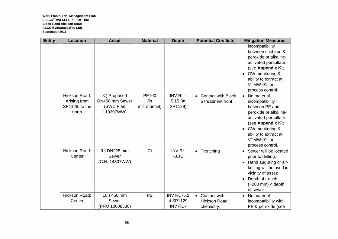
Work Plan & Trial Management Plan S-ISCO® and SEPR™ Pilot Trial Block 5 and Hickson Road AECOM Australia (Pty Ltd) September 2011
55
Entity Location Asset Material Depth Potential Conflicts Mitigation Measures incompatibility between cast iron & peroxide or alkaline-activated persulfate (see Appendix K);
• GW monitoring & ability to extract at VTMW-01 for process control.
Hickson Road: Arising from
SP1129, to the north
8.) Proposed DN450 mm Sewer
(SWC Plan 119297WW)
PE100 (in
microtunnel)
INV RL -5.15 (at SP1129)
• Contact with Block 5 treatment front
• No material incompatibility between PE and peroxide or alkaline-activated persulfate (see Appendix K);
• GW monitoring & ability to extract at VTMW-01 for process control.
Hickson Road: Center
9.) DN225 mm Sewer
(C.N. 14807WW)
CI INV RL -3.11
• Trenching • Sewer will be located prior to drilling;
• Hand auguring or air-knifing will be used in vicinity of asset;
• Depth of trench (~200 mm) < depth of sewer.
Hickson Road: Center
10.) 450 mm Sewer
(PRO 10008586)
PE INV RL -5.2 at SP1129;
INV RL -
• Contact with Hickson Road chemistry;
• No material incompatibility with PE & peroxide (see
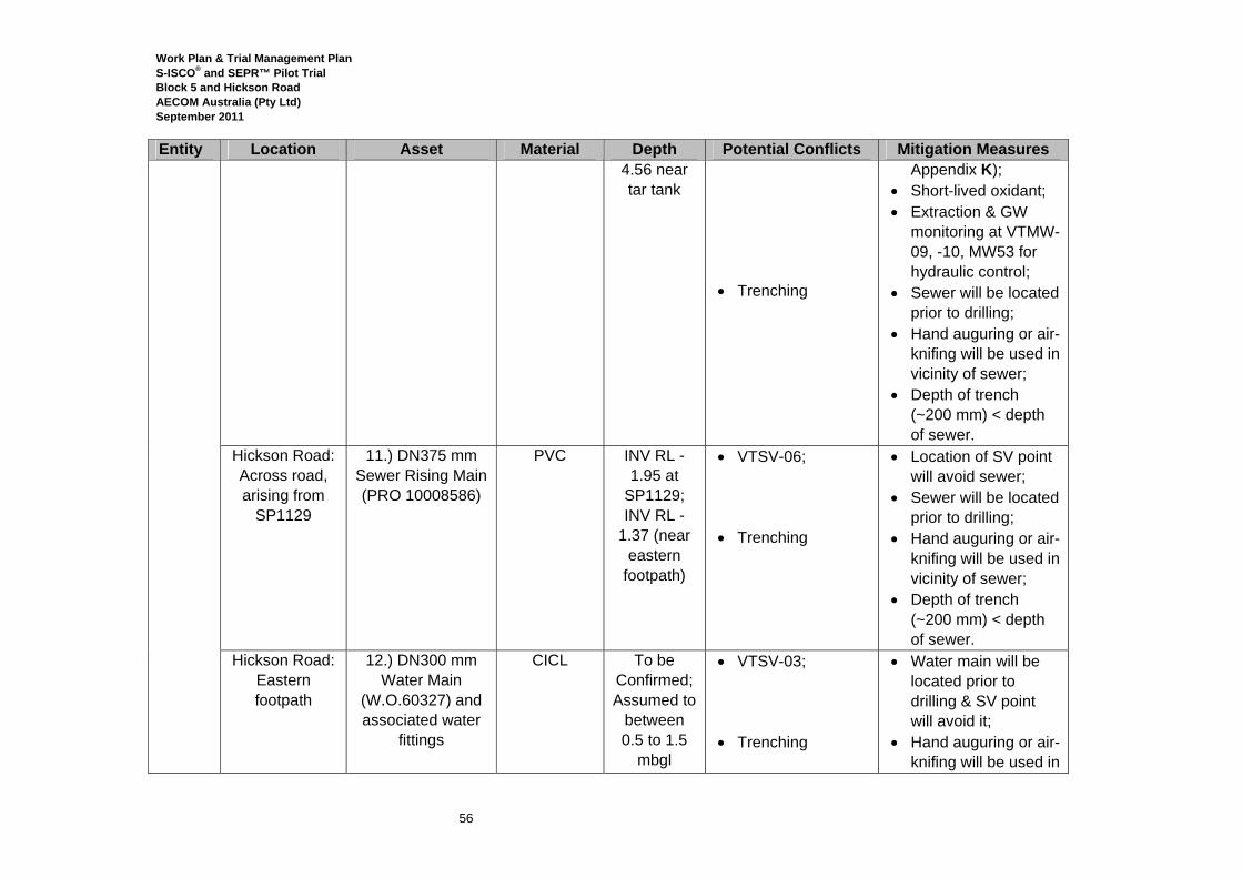
Work Plan & Trial Management Plan S-ISCO® and SEPR™ Pilot Trial Block 5 and Hickson Road AECOM Australia (Pty Ltd) September 2011
56
Entity Location Asset Material Depth Potential Conflicts Mitigation Measures 4.56 near tar tank
• Trenching
Appendix K); • Short-lived oxidant; • Extraction & GW
monitoring at VTMW-09, -10, MW53 for hydraulic control;
• Sewer will be located prior to drilling;
• Hand auguring or air-knifing will be used in vicinity of sewer;
• Depth of trench (~200 mm) < depth of sewer.
Hickson Road: Across road, arising from
SP1129
11.) DN375 mm Sewer Rising Main (PRO 10008586)
PVC INV RL -1.95 at
SP1129; INV RL -
1.37 (near eastern
footpath)
• VTSV-06; • Trenching
• Location of SV point will avoid sewer;
• Sewer will be located prior to drilling;
• Hand auguring or air-knifing will be used in vicinity of sewer;
• Depth of trench (~200 mm) < depth of sewer.
Hickson Road: Eastern footpath
12.) DN300 mm Water Main
(W.O.60327) and associated water
fittings
CICL To be Confirmed; Assumed to
between 0.5 to 1.5
mbgl
• VTSV-03; • Trenching
• Water main will be located prior to drilling & SV point will avoid it;
• Hand auguring or air-knifing will be used in
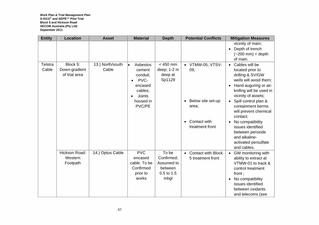
Work Plan & Trial Management Plan S-ISCO® and SEPR™ Pilot Trial Block 5 and Hickson Road AECOM Australia (Pty Ltd) September 2011
57
Entity Location Asset Material Depth Potential Conflicts Mitigation Measures vicinity of main;
• Depth of trench (~200 mm) < depth of main.
Telstra Cable
Block 5: Down-gradient
of trial area
13.) North/south Cable
• Asbestos cement conduit;
• PVC-encased cables;
• Joints housed in PVC/PE
< 450 mm deep; 1-2 m
deep at Sp1129
• VTMW-05, VTSV-09;
• Below site set-up
area; • Contact with
treatment front
• Cables will be located prior to drilling & SV/GW wells will avoid them;
• Hand auguring or air-knifing will be used in vicinity of assets;
• Spill control plan & containment berms will prevent chemical contact;
• No compatibility issues identified between peroxide and alkaline-activated persulfate and cables.
Hickson Road: Western Footpath
14.) Optus Cable PVC encased
cable. To be Confirmed
prior to works
To be Confirmed; Assumed to
between 0.5 to 1.5
mbgl
• Contact with Block 5 treatment front
• GW monitoring with ability to extract at VTMW-01 to track & control treatment front ;
• No compatibility issues identified between oxidants and telecoms (see
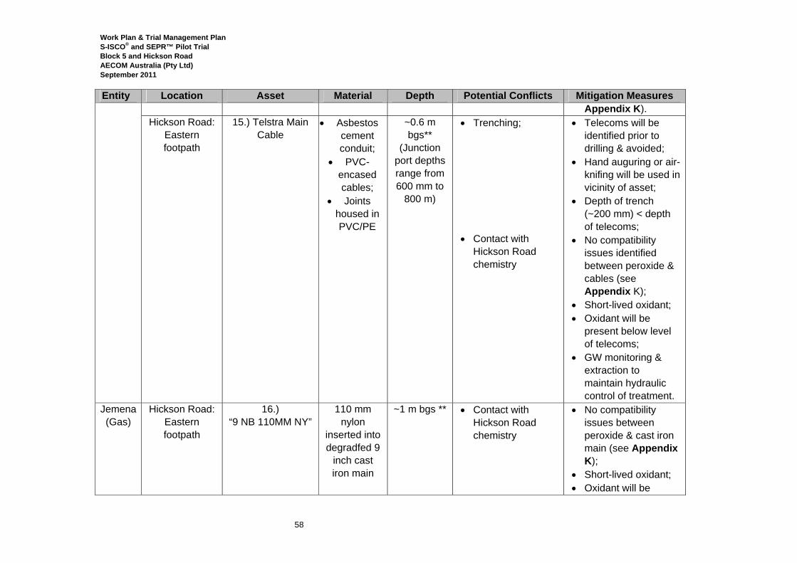
Work Plan & Trial Management Plan S-ISCO® and SEPR™ Pilot Trial Block 5 and Hickson Road AECOM Australia (Pty Ltd) September 2011
58
Entity Location Asset Material Depth Potential Conflicts Mitigation Measures Appendix K).
Hickson Road: Eastern footpath
15.) Telstra Main Cable
• Asbestos cement conduit;
• PVC-encased cables;
• Joints housed in PVC/PE
~0.6 m bgs**
(Junction port depths range from 600 mm to
800 m)
• Trenching; • Contact with
Hickson Road chemistry
• Telecoms will be identified prior to drilling & avoided;
• Hand auguring or air-knifing will be used in vicinity of asset;
• Depth of trench (~200 mm) < depth of telecoms;
• No compatibility issues identified between peroxide & cables (see Appendix K);
• Short-lived oxidant; • Oxidant will be
present below level of telecoms;
• GW monitoring & extraction to maintain hydraulic control of treatment.
Jemena (Gas)
Hickson Road: Eastern footpath
16.) “9 NB 110MM NY”
110 mm nylon
inserted into degradfed 9
inch cast iron main
~1 m bgs ** • Contact with Hickson Road chemistry
• No compatibility issues between peroxide & cast iron main (see Appendix K);
• Short-lived oxidant; • Oxidant will be
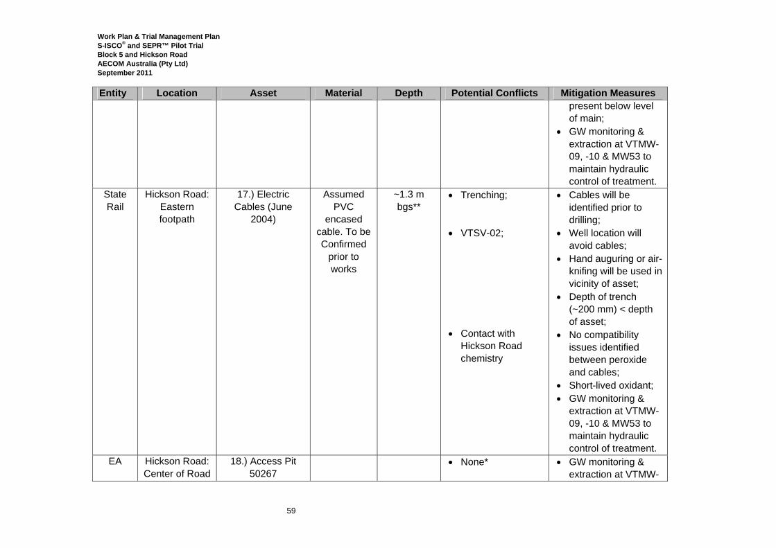
Work Plan & Trial Management Plan S-ISCO® and SEPR™ Pilot Trial Block 5 and Hickson Road AECOM Australia (Pty Ltd) September 2011
59
Entity Location Asset Material Depth Potential Conflicts Mitigation Measures present below level of main;
• GW monitoring & extraction at VTMW-09, -10 & MW53 to maintain hydraulic control of treatment.
State Rail
Hickson Road: Eastern footpath
17.) Electric Cables (June
2004)
Assumed PVC
encased cable. To be Confirmed
prior to works
~1.3 m bgs**
• Trenching; • VTSV-02;
• Contact with
Hickson Road chemistry
• Cables will be identified prior to drilling;
• Well location will avoid cables;
• Hand auguring or air-knifing will be used in vicinity of asset;
• Depth of trench (~200 mm) < depth of asset;
• No compatibility issues identified between peroxide and cables;
• Short-lived oxidant; • GW monitoring &
extraction at VTMW-09, -10 & MW53 to maintain hydraulic control of treatment.
EA Hickson Road: Center of Road
18.) Access Pit 50267
• None* • GW monitoring & extraction at VTMW-
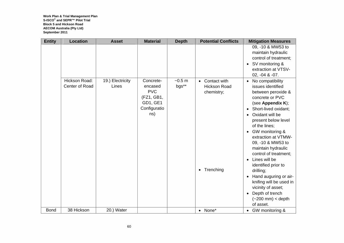
Work Plan & Trial Management Plan S-ISCO® and SEPR™ Pilot Trial Block 5 and Hickson Road AECOM Australia (Pty Ltd) September 2011
60
Entity Location Asset Material Depth Potential Conflicts Mitigation Measures 09, -10 & MW53 to maintain hydraulic control of treatment;
• SV monitoring & extraction at VTSV-02, -04 & -07.
Hickson Road: Center of Road
19.) Electricity Lines
Concrete-encased
PVC (FZ1, GB1, GD1, GE1
Configurations)
~0.5 m bgs**
• Contact with Hickson Road chemistry;
• Trenching
• No compatibility issues identified between peroxide & concrete or PVC (see Appendix K);
• Short-lived oxidant; • Oxidant will be
present below level of the lines;
• GW monitoring & extraction at VTMW-09, -10 & MW53 to maintain hydraulic control of treatment;
• Lines will be identified prior to drilling;
• Hand auguring or air-knifing will be used in vicinity of asset;
• Depth of trench (~200 mm) < depth of asset.
Bond 38 Hickson 20.) Water • None* • GW monitoring &

Work Plan & Trial Management Plan S-ISCO® and SEPR™ Pilot Trial Block 5 and Hickson Road AECOM Australia (Pty Ltd) September 2011
61
Entity Location Asset Material Depth Potential Conflicts Mitigation Measures Road Treatment Plant extraction at VTMW-
09, -10 & MW53 to maintain hydraulic control of treatment;
• GW monitoring & potential extraction at VTMW-07 & -08 to maintain hydraulic control of treatment.
Bond 30 Hickson Road
21.) Bond Building • None* • GW monitoring & extraction at VTMW-09, -10 & MW53 to maintain hydraulic control of treatment;
• GW monitoring & potential extraction at VTMW-07 & -08 to maintain hydraulic control of treatment.
N/A Block 5 22.) Potential Archaeological
Resources
Timber, metals,
sandstone, ceramics,
glass, masonry,
lime mortar, organics
(e.g. leather and fabric),
middens
Unknown • Well drilling; • Contact with Block
5 injections & chemistry
Refer to the CEMP.
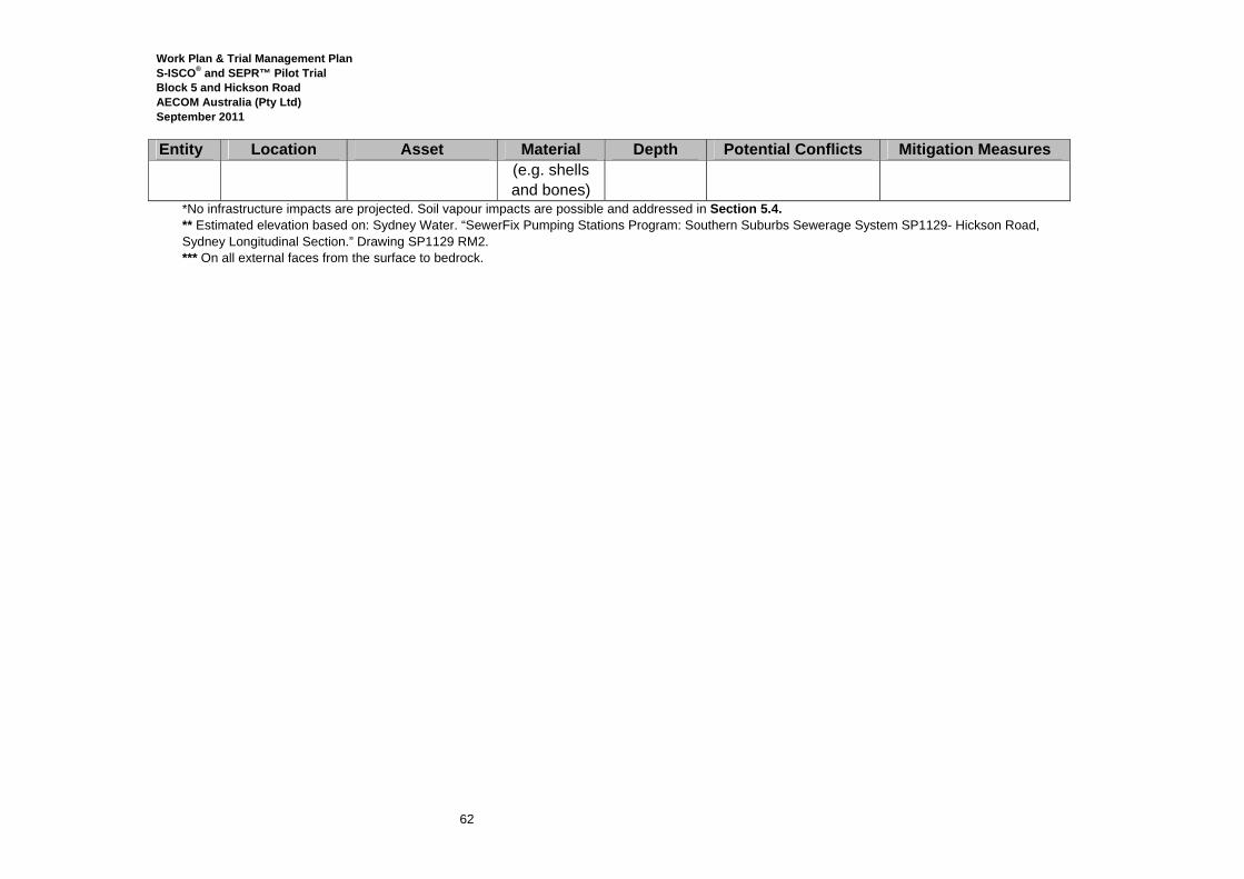
Work Plan & Trial Management Plan S-ISCO® and SEPR™ Pilot Trial Block 5 and Hickson Road AECOM Australia (Pty Ltd) September 2011
62
Entity Location Asset Material Depth Potential Conflicts Mitigation Measures (e.g. shells and bones)
*No infrastructure impacts are projected. Soil vapour impacts are possible and addressed in Section 5.4. ** Estimated elevation based on: Sydney Water. “SewerFix Pumping Stations Program: Southern Suburbs Sewerage System SP1129- Hickson Road, Sydney Longitudinal Section.” Drawing SP1129 RM2. *** On all external faces from the surface to bedrock.

Work Plan & Trial Management Plan S-ISCO® and SEPR™ Pilot Trial Block 5 and Hickson Road AECOM Australia (Pty Ltd) September 2011
63
The information in Table 11 indicates that subsurface assets in the vicinity of the Pilot Trial areas are composed of polyethylene (PE), polyvinyl chloride (PVC), concrete, asbestos, reinforced concrete pipe (RCP), cast iron (CI), and CI concrete-lined (CICL). Technical guidelines for trenched pipelines9 indicate that the following materials can also be used in the construction of trenched pipelines, and may be present in the subsurface: ductile-iron cement lined (DICL); steel concrete-lined (SCL); PVC-lined concrete; vitrified clay (VC); glass-reinforced plastic (GRP); polypropylene (PP); fibre-reinforced concrete (FRC); or high-density PE (HDPE). Peroxide Compatibility In Hickson Road and during the first phase of treatment in Block 5, only hydrogen peroxide, a short-lived (on the scale of hours) oxidant, will be used. The short life of peroxide, along with the fact that it will be injected between 3 and 5 m bgs, a depth below identified assets, will mitigate the risk of it contacting subsurface assets, including Jemena’s cast iron/nylon gas line (refer to asset number 16 in Table 11); an SRA electric line (17); and an EA electricity line (19) in the immediate injection area, and a SWC PE sewer line (10) within the tar tank. Water levels in the Hickson Road treatment area will be closely controlled through extraction, thereby further reducing the risk of contact of the oxidant with subsurface assets. This program of extraction will be tracked through close monitoring of groundwater levels, as scheduled in Table 14, at VTMW-07, VTMW-08, VTMW-09, VTMW-10, VTMW-11, MW15, MW53, and BH6, to ensure that extractions contain the chemistry and restrict contact of the treatment fluid with assets outside of the immediate treatment area. In Block 5, the groundwater model indicates that peroxide is not expected to travel beyond the boundaries of Block 5 at detectable concentrations (greater than 1 g/L), therefore preventing its contact with assets in the western side of Hickson Road (including the SWC water main, sewers, and telecommunications). Finally, the known materials of which these assets within the treatment chemistry extent highlighted in Figure 6, are composed are not incompatible with peroxide, especially at the low (<8%) concentrations that will be used and in the presence of VeruSOL®, a surfactant that is known to mitigate corrosive impacts of oxidants. Refer to the compatibility data provided in Appendix K. Alkaline-Activated Persulfate Compatibility In Block 5 S-ISCO® treatment will also include a phase of alkaline-activated sodium persulfate treatment. Data indicates that alkaline-activated sodium persulfate (activated using sodium hydroxide) does not have corrosive effects on plastics, concrete or metallic materials including cast iron and carbon steel. Refer to Appendix K.
9 “Specific Technical Requirements for Northwest Growth Centres Initial Release Infrastructure Package 1, Design and Construct Contract to Deliver Water Related Infrastructure”
Work Plan & Trial Management Plan S-ISCO® and SEPR™ Pilot Trial Block 5 and Hickson Road AECOM Australia (Pty Ltd) September 2011
64
Groundwater modelling indicates that the chemical treatment front will extend up-gradient into Hickson Road and side-gradient toward SP1129. Figure 6 highlights the assets listed in Table 11 that are present in the area of the modelled front. These assets include those belonging to SWC, EA, Telstra and Optus. At the same time that the materials of which these assets are built, including cast iron and PE, are compatible with alkaline-activated persulfate, only the SWC’s 450 mm sewer (8) is at a depth that the treatment front may contact. With PE, however, no compatibility issues exist with either persulfate or alkaline-activated persulfate. Furthermore, the injection of VeruSOL® with alkaline-activated sodium persulfate offers an additional measure of corrosion control, further mitigating any potential concerns. The groundwater model also indicates that the treatment chemistry will contact SP1129 and that the front will be present in the vicinity of SP1129’s electric, Telstra and Optus services (4), as well as its stormwater drain (6). The hydraulic modelling predicts that concentrations of oxidant will attenuate to approximately 1-10% of the planned injection concentrations prior to reaching SP1129 (1 g/L). That is, the initial concentrations will be around 8% and it will reduce to approximately 0.8% when it is estimated to contact the structure. The SP1129 concrete structure itself (5), is encased in PVC and will not face any impacts from contact, nor will its concrete stormwater drain, due to their compatibility. Similarly, the concrete MSB stormwater pipes, side- and down-gradient of the injection area, will not face any impacts. No impacts are expected to the services either, since these assets are located above the subsurface depth of the chemical front and their materials (concrete) are compatible with alkaline-activated persulfate.
Mitigation measures have been included within the Pilot Trial to restrict the contact of the injected oxidants with subsurface assets. These measures are in addition to:
• the short life of peroxide; • the controlled presence of peroxide in Hickson Road; • the minimal extent of peroxide influence in Block 5; • the compatibility of peroxide with the plastic (PVC and PE), concrete and cast iron
materials in the vicinity of its use and influence; • 5) the influence of the alkaline-activated persulfate at a depth below the majority of the
assets present in the area in which it will move; and • 6) the compatibility of alkaline-activated sodium persulfate with the plastic (PVC and
PE), concrete and cast iron materials in the vicinity of its use and influence.. In Hickson Road close monitoring and extraction, particularly during SEPR™, as described in Section 4.7, will prevent the movement of the treatment chemistry from the confines of the treatment area. In Block 5, injections will be accompanied by comprehensive performance and groundwater monitoring at wells within, up and down-gradient of the injection area, including VTMW-03 between the treatment area and SP1129; and VTMW-01, between the treatment area and Hickson Road (refer to the monitoring plans in Section 7.2 and well installation details in Section 4.8). Specifically with respect to SP1129, VTMW-03 will be monitored continuously. In
Work Plan & Trial Management Plan S-ISCO® and SEPR™ Pilot Trial Block 5 and Hickson Road AECOM Australia (Pty Ltd) September 2011
65
addition, a groundwater extraction system will be available throughout the Pilot Trials that can be connected to any monitoring well in the monitoring area (refer to Sections 4.8 and 10.4) to maintain hydraulic control of the treatment chemistry. Section 8.4 details the trigger values and contingency measures that will be implemented in response to monitoring results that indicate that measures need to be implemented to control the treatment process. Physical Impacts With respect to physical impacts to assets as a result of drilling, boring and trenching, VeruTEK will take the following measures to mitigate any potential impacts:
• All assets, including those belonging to SWC, EA, Telstra, Jemena and Optus, will be identified prior to intrusive work;
• Well drilling and placement will be modified as needed to avoid drilling near identified assets, including SWC, EA, Telstra, Optus and Jemena assets identified in Table 11;
• After machine-drilling the surface concrete and pavement, hand-augering and/or air-knifing will be used in the vicinity of shallow services to a depth of 1.2 mbgs (or to the depth of hand auger/air knife refusal) ; and
• Coordinating the layout of the Pilot Trial with SPS access and emergency access routes. Finally, with respect to trenching, the trench will be shallow, approximately 200 mm deep, and therefore above the depth of known assets. Nevertheless, before any trenching begins, all assets in the vicinity of intrusive activities will be identified. Archaeological resources may be present in the subsurface of the Pilot Trial area, as listed in Table 11. The only potential adverse impact that is foreseen to result from S-ISCO® is the oxidisation of metallic materials by hydrogen peroxide or sodium persulfate. Please refer to the CEMP for a discussion of measures that will be taken if archaeological resources are encountered during intrusive work on the Site. Other chemicals With respect to the other chemicals that will be injected during the Pilot Trials, including VeruSOL®, water, sodium hydroxide and Fe-TAML, as described in the MSDSs provided in Appendix G and Section 1.2, none of these materials are known to have corrosive impacts.
5.4 Impacts to Buildings There is a potential risk of adverse impacts to the buildings at 30 and 38 Hickson Road. Adverse impacts to the basement groundwater treatment system at 38 Hickson Road, located in the vicinity of the Hickson Road Pilot Trial area, will be assiduously mitigated throughout the Pilot Trial. Any impact will be detected by monitoring wells before it reaches the basement. In the unlikely event that peroxide reaches the basement, peroxide will not impact but rather likely improve the water treatment process. Injections made during the SEPR™ and S-ISCO® implementation in Hickson Road will be carefully engineered to confine treatment to the tar tank.
Work Plan & Trial Management Plan S-ISCO® and SEPR™ Pilot Trial Block 5 and Hickson Road AECOM Australia (Pty Ltd) September 2011
66
According to historical records the tar tank was excavated into bedrock that is very shallow at this location (approximately1 m bgs). Following excavation of the bedrock it is suspected, based on steel fragments recovered during previous intrusive investigations in the tank, that the tar tank was lined with steel. The present integrity of the steel liner is not known, however because the tar tank is in bedrock, the connection of the contents of the tar tank and the surrounding bedrock system is expected to be limited. This observation is supported by observations from the previous investigations undertaken by ERM (2007) and Coffey (Coffey Environments Report, 2008). In particular, review of the Coffey borelogs indicates that (with the exception of the historical structures within Hickson Road) the highly impacted zones of contamination appear to be in the natural soil at the bedrock interface and decrease with depth. The presence of tar in monitoring wells does not necessarily support the presence of tar impact in the bedrock mass. Further, the Coffey borelogs which extend into the bedrock mass do not describe significant contamination of the rock (for example BH07). AECOM considers that the Hickson Road dataset, together with data from the adjacent Block 4 and Block 5 investigations does not support the presence of deep bedrock contamination. Prior to the commencement of SEPR™ and S-ISCO® treatment in Hickson Road, tests will be conducted to establish the hydraulic and vapour connectivity of the contents of the tar tank with its surroundings. These tests are described in Section 4.7. If connectivity is not established prior to injections, negative impacts on the groundwater and soil vapour at 38 Hickson Road are considered highly unlikely. If connectivity is established, however, the extent of vapour extraction, the pressure at which injections take place and the rate and magnitude of the extractions will be designed to create a gradient of flow into rather than out of the tank. During the SEPR™ phase of the Pilot Trial, all injected fluid will subsequently be extracted. During S-ISCO®, liquid levels will be closely monitored to track their confinement. Liquid injection and extraction volumes will be balanced by monitoring water levels in the tar tank and adjusting both liquid and extraction flow rates to keep the water level in the tar tank steady, or slightly lower than background levels, thereby minimising liquid migration from the tar tank into surrounding fractured bedrock. Monitoring well clusters, VTMW-07 and VTMW-08 will br installed outside the Pilot Trial area to enable monitoring of the water levels and potential migration of injected liquid.VTMW-08 will be installed between 38 Hickson Road and the Pilot Trial area to enable monitoring with respect to 38 Hickson Road; VTMW-07 will monitor with respect to the Bond. These wells will also function as an emergency recovery wells from which groundwater can be extracted to establish hydraulic control. To enable this capacity, the wells will be connected to the extraction system during set-up, as described in Section 4.4. Refer to Section 7 for the details of monitoring at these well locations.
Work Plan & Trial Management Plan S-ISCO® and SEPR™ Pilot Trial Block 5 and Hickson Road AECOM Australia (Pty Ltd) September 2011
67
5.5 Impact of Soil Vapours on Humans There is the risk of impacts from soil vapours to the following:
• the users and inhabitants of the Bond Building at 30 Hickson Road and the basement water treatment system at 38 Hickson Road;
• workers conducting construction, road or other sub-surface works in the vicinity of the Site, particularly in SWC assets, EA assets, cable pits, utility pits, service access points and monitoring well heads;
• workers at the adjacent sewage pumping station SP1129; and • pedestrian, bicycle and vehicular users of Hickson Road and its footpaths.
Users of the Bond and 38 Hickson Road To prevent the possibility that vapours generated by the SEPR™ or S-ISCO® Pilot Trials enter the building or the sub-surface parking garage at 38 Hickson Road, a soil vapour monitoring point will be installed: immediately adjacent to the basement of the building (VTSV-04); between the Pilot Trial area and the building (VTSV-07), 10 m from the treatment area; and within the treatment area (VTSV-02). As described in Section 4.9, these points will be connected to the SVE system that will be operated throughout the duration of the Pilot Trial. The SVE system will capture and treat gases displaced by peroxide decomposition and will be carefully monitored according to the details provided in Sections 7.5 and 7.7. As a contingency measure, an extra line will be installed as described in Section 4.3. Also refer to Section 12 for the soil vapour contingency plans. The Bond building at 30 Hickson Road is located in the vicinity of the Hickson Road Pilot Trial area but, as described previously, this SEPR™ and S-ISCO® implementation will be assiduously confined and contained. To minimise the possibility for vapours generated by the S-ISCO® and/or SEPR™ implementations to enter the building, particularly in the areas in which a childcare center is located, a soil vapour monitoring point will be installed immediately adjacent to the basement (VTSV-03); between the building and the treatment area, 10 m from the treatment area (VTSV-06); and in the treatment area (VTSV-02). These points will be connected to the SVE system that will be in continuous operation during all Pilot Trial injection activities and carefully monitored. Sections 7.4 through 7.6 present a detailed soil vapour monitoring plan. In the event that hazardous soil vapours are detected in the soil gas, additional SVE points may be installed to extend the scope of the system and/or the extra SVE system capacity will be mobilised, as detailed in the contingency plan in Section 12. Construction and Maintenance Workers There is the potential for workers conducting subsurface intrusive work in the vicinity of the Pilot Trial areas, including utility workers who must access below ground assets, to be exposed to soil vapours generated by the S-ISCO® and/or SEPR™ injections. This includes service utility personnel who must access their assets in Hickson Road, shown on Figure 4. In addition, there

Work Plan & Trial Management Plan S-ISCO® and SEPR™ Pilot Trial Block 5 and Hickson Road AECOM Australia (Pty Ltd) September 2011
68
is the potential for users of Hickson Road in the vicinity of the Pilot Trial area to also be exposed to vapours generated by the Pilot Trial. To mitigate this risk soil vapour extraction points will be installed in publically accessible areas in the vicinity of the Site (VTSV-01, VTSV -02, VTSV -03, VTSV -04, VTSV -05, VTSV-06, VTSV-07, VTSV-08 and VTSV-09, as well as SV09, SV -10 and SV -11, shown on Figure 1). These points will be connected to the SVE system to intercept vapours and will be monitored regularly, as detailed in Tables 13 and 14. If hazardous vapours are detected in VTSV-01, for example, additional points may be installed along the footpath outside the Block 5 treatment area. The same is true for VTSV-02; additional points may be installed along the footpath in the vicinity of the Hickson Road treatment area. Refer to Section 12 for the complete contingency plan. In addition, vapours will be monitored daily with a Photoionization Detector (PID) in utility pits, service access points and monitoring well heads, that is, areas with the potential for preferential migration of vapours. These proposed locations are shown on Figure 4 and this monitoring is scheduled in Tables 13 and 14. In the event that unsafe vapours are detected, additional soil vapour extraction may be implemented. Utility workers within the vicinity of Pilot Trial activities To intercept soil vapours that may be generated by the Block 5 treatment and prevent any potential exposure of workers at SP1129 or workers who will access other utility services or pits, three soil vapour extraction points will be installed: VTSV-01, located within the treatment area, and VTSV-08 and VTSV-09, located between the treatment area and SP1129. These points will be monitored daily and weekly. The SVE system will extract from them continually as described in Section 12. Note that daily monitoring of service pits (including monitoring for explosive atmospheres) will be undertaken in accordance with the monitoring schedule detailed in Tables 13 and 14. Additional points may be installed based on the results of monitoring at VTSV-01, VTSV-08 and VTSV-09. The Overseas Passenger Terminal (OPT) has been relocated to an area approximately 200 meters north and cross-gradient from the Block 5 Pilot Trial Area, separated by a security fence. The OPT is a venue for conventions, exhibitions and public entertainment events as well as a passenger terminal for cruise ships. VeruTEK has determined that this building does not face any potential for impact as a result of the Pilot Trial implementation. If concerns and/or complaints arise in regard to the Pilot Trial affecting this facility or its users, VeruTEK will fully address these and implement monitoring or other precautionary measures as determined to be necessary. Finally, all workers entering the Site will be inducted into the Health and Safety plans regulating work on the Site, and will be made aware of both the risks and mitigation measures in place to protect them.
Work Plan & Trial Management Plan S-ISCO® and SEPR™ Pilot Trial Block 5 and Hickson Road AECOM Australia (Pty Ltd) September 2011
69
Pedestrian, Bicycle and Vehicular Users of Hickson Road and its Footpaths To prevent the possibility that vapours generated by the SEPR™ or S-ISCO® Pilot Trials are present in the footpath of Hickson Road that is accessed by pedestrians and bicyclists, soil vapour monitoring points will be installed: in Block 5, at the up-gradient boundary of the Pilot Trial treatment area (VTSV-01); and in Hickson Road, along the footpath (VTSV-02, VTSV-03, VTSV-04, VTSV-05, VTSV-06 and VTSV-07). All points will be connected to the SVE system which will extract continuously from them to mitigate any potential soil vapour exposure. In addition they will be monitored daily with a PID and weekly at a NATA-certified laboratory to confirm that the SVE system is adequately extracting and whether the system needs to be expanded. Specifically with respect to VTSV-01, additional extraction points may be added along the footpath in the event that vapours are detected at VTSV-01. Refer to the contingency plans in Section 12. To prevent obstructions, all hoses and tubes running across Hickson Road and along the eastern Hickson Road footpath will be enclosed within trenching that is covered with steel plates (across the road) and re-finished with the same bitumen/pavement conditions of the surrounding footpath. This is described in Section 3.4. In addition, as described in Sections 3.8 and 3.9, flush-mount roadboxes will be installed with all groundwater and soil vapour monitoring wells to prevent tripping hazards. To enable access to the Hickson Road trial area, an enclosure will be constructed around the treatment area, shown on Figure 2b. This will enable operations in this area to occur out of the view of passers-by, and without disruption to people’s movement. In addition, this area still enables use of the footpath and two-way vehicular traffic to continue. Finally, to conceal the Pilot Trial operations from the view of pedestrians, bicyclists and vehicular users of Hickson Road, hoardings will be installed around the Hickson Road trial area and along the fence between Block 5 and the western Hickson Road footpath, as shown in Figure 1.
5.6 Impact due to Day-lighting Over the course of injections there exists the possibility that injected chemicals may leak upwards, on the outside of a well’s casing or appear at the ground surface, an occurrence referred to as “day-lighting”. Day-lighting has the potential to pose a hazard to the environment, and to the health and safety of site workers and other persons in the vicinity of the injection area. Day-lighting events will be treated as a spill and managed according to the Spill Prevention and Control Plan contained in the CEMP. In addition, day-lighting will trigger a temporary suspension of system operation in the area in which it occurs. This will enable the Site Manager to determine the cause of the day-lighting and alter operational parameters, such as injection rate and chemical concentration, to prevent it from recurring. When operations resume, injections will be begin slowly and gradually ramp up to desired levels, accompanied by diligent monitoring.

Work Plan & Trial Management Plan S-ISCO® and SEPR™ Pilot Trial Block 5 and Hickson Road AECOM Australia (Pty Ltd) September 2011
70
As a preventative measure, all injection wells will be inspected daily for evidence of day-lighting so that this occurrence can be dealt with immediately to prevent risks to human health or the environment. Evidence of day-lighting includes liquid emerging from the ground in the vicinity of an injection well. The liquid may bubble, if hydrogen peroxide is being used, and a faint citrus odour may be noticeable (due to the VeruSOL®). This monitoring regime is included as part of the monitoring plan, described by Tables 13 and 14. Refer to Section 13 for the contingency plans that will be implemented in response to day-lighting.
5.7 Impact to Trees LL has made the following commitment relative to protection of trees:
• An appropriately trained arborist will identify any required tree protection measures required for the Pilot Trial and will monitor the site establishment works.
• Measures to protect the street tree canopy will include: o Construction vehicles will maintain an adequate clearance of 500 mm from all
street tree canopies located along the construction access route, at all times; o No street trees will be pruned without the necessary approval obtained; o Stockpiling, storage or mixing of materials, or other works associated with the
Pilot Trials will not take place within 5 m of the trunk of any tree to be retained; o Excavation will not occur within 5 m of the trunks of street trees located on
Hickson Road, unless LL’s arborist has identified and implemented specific tree protection measures and construction methodologies; and
o All protection measures will remain in place for the duration of the development works, and shall be removed at the completion of works.

Work Plan & Trial Management Plan S-ISCO® and SEPR™ Pilot Trial Block 5 and Hickson Road AECOM Australia (Pty Ltd) September 2011
71
6.0 Site Management Plans
6.1 Construction Environmental Management Plan Overview A Construction Environmental Management Plan (CEMP) has been prepared for the Pilot Trial implementation. The CEMP documents VeruTEK’s construction management planning for the Pilot Trial phase of work associated with remediation within the DECCW Declaration Area. The CEMP includes:
• A brief description of the project; • A planned project sequence; • An incident management plan; • A communication plan, summarised below in Section 6.2; • A summary of VeruTEK’s Health and Safety Plan (HASP), summarised below in Section
6.4; • A summary of mitigation and contingency strategies, which are otherwise described by
Section 5; • Project-specific environmental management plans pertaining to the following areas:
o Traffic; o Noise and Vibration; o Waste; o Air Quality and Odour; o Aesthetics;
• A Water and Stormwater Management Plan (WSMP) contained in the CEMP.
6.2 Communication Plan Communication during the S-ISCO® and SEPR™ Pilot Trial is crucial to executing the work safely and effectively. Pathways of communication include:
• communication between site workers, including the site manager, project manager, field technicians and laboratory technicians; as well as,
• communication between the site manager and relevant stakeholders, including representatives from LL, AECOM, and regulatory agencies.
Field and laboratory technicians will report such topics as monitoring results, concerns and successful compliance information to the site manager. This communication will be facilitated by daily pre-work health and safety meetings to be held prior to work commencement each day. The site manager will report results and data collected during the course of site work to the project manager, as well as relevant stakeholders and regulators, as appropriate. Weekly meetings between stakeholders will occur at designated times and the minutes from each

Work Plan & Trial Management Plan S-ISCO® and SEPR™ Pilot Trial Block 5 and Hickson Road AECOM Australia (Pty Ltd) September 2011
72
meeting will be documented in a weekly report that will be distributed electronically to project managers of VeruTEK, AECOM, LL and any other relevant stake-holders (as appropriate). Community consultation will be managed by LL and will be part of a broad, comprehensive community consultation strategy. The CEMP contains a list of key persons and relevant stakeholders affiliated with activities at the Site and their relevant contact information. In the event that a significant issue develops at the Site, including, but not limited to, a health and safety incident, chemical spill, unauthorised visitor, or significant change in project scope, authorised persons can consult this table for contact information. Regardless of the nature of the situation, representatives from AECOM, VeruTEK, LL-PMC, and any other relevant stake-holders are to be notified within 24 hours of the incident. All contact information will be verified and updated as necessary during the Pilot Trials.
6.3 Data Management Plan During Pilot Trial activities, data will be collected in various formats and stored in designated locations. These data locations will be managed by the Site Manager. The data, type, and location are provided in Table 12. Electronic data from data loggers will be downloaded to a computer periodically, as necessary. Data logs, field notes and worksheets will be copied and scanned by the party (AECOM or VeruTEK) responsible for collection of the data. Additionally, any site photos taken at the Site will be downloaded to a field computer and/or electronically backed-up. Electronic back-up files and scanned documents will then be made available to relevant stakeholders.
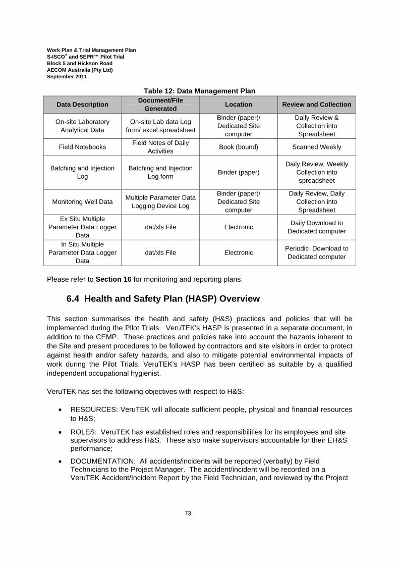
Work Plan & Trial Management Plan S-ISCO® and SEPR™ Pilot Trial Block 5 and Hickson Road AECOM Australia (Pty Ltd) September 2011
73
Table 12: Data Management Plan
Data Description Document/File Generated Location Review and Collection
On-site Laboratory Analytical Data
On-site Lab data Log form/ excel spreadsheet
Binder (paper)/ Dedicated Site
computer
Daily Review & Collection into Spreadsheet
Field Notebooks Field Notes of Daily Activities Book (bound) Scanned Weekly
Batching and Injection Log
Batching and Injection Log form Binder (paper)
Daily Review, Weekly Collection into spreadsheet
Monitoring Well Data Multiple Parameter Data Logging Device Log
Binder (paper)/ Dedicated Site
computer
Daily Review, Daily Collection into Spreadsheet
Ex Situ Multiple Parameter Data Logger
Data dat/xls File Electronic Daily Download to
Dedicated computer
In Situ Multiple Parameter Data Logger
Data dat/xls File Electronic Periodic Download to
Dedicated computer
Please refer to Section 16 for monitoring and reporting plans.
6.4 Health and Safety Plan (HASP) Overview This section summarises the health and safety (H&S) practices and policies that will be implemented during the Pilot Trials. VeruTEK's HASP is presented in a separate document, in addition to the CEMP. These practices and policies take into account the hazards inherent to the Site and present procedures to be followed by contractors and site visitors in order to protect against health and/or safety hazards, and also to mitigate potential environmental impacts of work during the Pilot Trials. VeruTEK's HASP has been certified as suitable by a qualified independent occupational hygienist.
VeruTEK has set the following objectives with respect to H&S:
• RESOURCES: VeruTEK will allocate sufficient people, physical and financial resources to H&S;
• ROLES: VeruTEK has established roles and responsibilities for its employees and site supervisors to address H&S. These also make supervisors accountable for their EH&S performance;
• DOCUMENTATION: All accidents/incidents will be reported (verbally) by Field Technicians to the Project Manager. The accident/incident will be recorded on a VeruTEK Accident/Incident Report by the Field Technician, and reviewed by the Project
Work Plan & Trial Management Plan S-ISCO® and SEPR™ Pilot Trial Block 5 and Hickson Road AECOM Australia (Pty Ltd) September 2011
74
Manager and the Designated Health and Safety Officer (DHSO). Any corrective action, if required, will be initiated by the Project Manager;
• EVALUATION: VeruTEK will evaluate its own H&S performance and progress regularly; and
• COMPLIANCE: VeruTEK expects that subcontractors under its employment are at a minimum complying with its approved H&S management systems or equivalent.
6.4.1 Health and Safety Overview VeruTEK's HASP, in accordance with LL-PMC H&S requirements, contains Safe Work Method Statements (SWMSs), a risk assessment, daily H&S checklists and an induction register. In addition the HASP contains the following elements:
• personal protective equipment requirements; • equipment use and inspection requirements; • an Inspection and Test Plan (ITP); • VeruTEK’s Occupational Health and Safety (OHS) responsibilities; • training requirements; • an emergency response plan; • special materials handling guidelines; and • a spill control and countermeasures plan.
The HASP is adopted by VeruTEK in compliance with the Occupational Health and Safety Act 2000, as well as requirements of LL-PMC, the City of Sydney Council (with respect to Hickson Road in particular), WorkCover and the NSW DECCW. AECOM has prepared its own Occupational Health and Safety Plan for its involvement in the work (in particular, for the drilling activities).
6.5 Waste Management Wastes that will be generated during the Pilot Trials include soil cuttings; pavement scraps; extracted groundwater; collected stormwater; general municipal waste related to Site operations; and SEPR™ extraction fluid. VeruTEK’s Waste Management Plan is contained in the CEMP and is based on AECOM’s Waste Management Plan (AECOM, 2010f). In addition, Appendix G of the HASP contains forms on which all waste generated and disposed of, including for export off-site, will be tracked and declared on a monthly basis. These forms record the quantities of waste, address of disposal site, waste classification, and details of the transporter. Additional details of waste management included in these plans are that:
• any wastes generated as a result of the Pilot Trials will be properly classified in accordance with DECCW’ s Waste Classification Guidelines and transported to a facility that can lawfully receive that waste;
• any trackable wastes will be transported and tracked in accordance with the Protection of the Environment Operations (POEO) Waste Regulation 2005; and

Work Plan & Trial Management Plan S-ISCO® and SEPR™ Pilot Trial Block 5 and Hickson Road AECOM Australia (Pty Ltd) September 2011
75
• for any wastes subject to DECCW Approval number 2005/14 (Coal tar contaminated soil from former gasworks sites), if off-site disposal is required for material with contaminant concentrations above those specified in the general approval, an application for a specific immobilisation approval will be made to DECCW, in consultation with DECCW’s Hazardous Materials and Radiation Section.
The CEMP and WPTMP detail the management, monitoring and disposal of water wastes, specifically: extracted groundwater and accumulated stormwater; and SEPR™ fluid extracted during treatment of Hickson Road, respectively. Refer to:
• Section 8 for the details of managing, storing, and treating SEPR™ fluid; and • The CEMP has details for managing, storing, treating, testing and disposing of
stormwater, groundwater.

Work Plan & Trial Management Plan S-ISCO® and SEPR™ Pilot Trial Block 5 and Hickson Road AECOM Australia (Pty Ltd) September 2011
76
7.0 Monitoring Plan Monitoring of the injected chemicals at the injection system, in injection wells, and in monitoring wells provides information as to where the injected chemicals are traveling and the nature of their reactions. Soil sampling for contaminants of concern (COCs) before and after the Pilot Trial implementation will provide an estimate of the magnitude of contaminant reduction at the Site. Sampling and analysis of groundwater before and after the Pilot Trial will enable a comparison of COC flux that is also used to evaluate the success of the implementation. The success of the Pilot Trial will be determined when, as stated in Section 4.10.3, soil concentrations of identified COCs (TPH, PAHs and BTEX, specifically) and groundwater flux of COCs leaving the Pilot Trial area achieve or approach determined remediation goals. As stated in Section 4.10, monitoring during the Pilot Trial will be conducted in three phases:
• Pre-Injection Monitoring; • During Injection Monitoring; and • Post-Injection Monitoring.
These phases will be comprised of the following components:
• Process monitoring; • Performance monitoring; • Groundwater sampling; • Soil gas monitoring, including field monitoring and collection of samples for analysis at
an independent laboratory); • Soil sampling; and • Wastewater sampling.
7.1 Process Monitoring
The process monitoring phase will consist of recording flow rates and pressures from the feed streams, and conducting on-site laboratory analysis of samples collected from the feed streams. These results will be logged on a Process Monitoring Log Form in Appendix D. Tables 13 and 14 list the streams that will be analysed as part of the process monitoring. The frequency of this monitoring will be a function of the injection phase progress. It is anticipated that the monitoring will be more rigorous (hourly) during start-up and immediately after any major process changes and less frequent (daily) during day-to-day operation at steady-state injection conditions. Tables 13 and 14 also provide a minimum sampling frequency for the process monitoring data collection. During the initiation of the injections all streams flowing to operational injection wells will be analysed. The frequency of monitoring from all streams will be subsequently reduced as deemed appropriate by VeruTEK. Process monitoring will be carried out by the Plant Operator or Plant Support. Analysis of system samples will be conducted by

Work Plan & Trial Management Plan S-ISCO® and SEPR™ Pilot Trial Block 5 and Hickson Road AECOM Australia (Pty Ltd) September 2011
77
the Laboratory Technician. The results will be reported to the Site Manager and Project Manager to enable optimisation of the system.
7.2 Performance Monitoring Performance monitoring will use groundwater monitoring wells to monitor the conductivity, oxidant and interfacial tension (an indicator of VeruSOL®) fronts. In Block 5 the following monitoring wells will be used: VTMW-01, VTMW-02, VTMW-03, VTMW-04, VTMW-05, VTMW-06, VTMW-12, MW198, MW64, MW68, MW62 and MW197. In Hickson Road, the following monitoring wells will be used: VTMW-07, VTMW-08, VTMW-09, VTMW-10, VTMW-11, BH6, MW15 and MW53. Please refer to Section 4.8 for the rationale for the selection of well locations. The performance monitoring will be compromised of:
• continuous in situ monitoring; • ex situ monitoring; and • on-site laboratory analysis.
Continuous in situ monitoring will utilise multiple-parameter data logging devices placed within monitoring wells. These devices will collect measurements continuously, at prescribed time intervals. The ex situ monitoring will use multiple-parameter data loggers connected to a flow-cell. Both in situ and ex situ data loggers will monitor temperature, pressure, pH, turbidity, ORP, DO, specific conductance and head. Refer to Section 4.10 for the relevance of these parameters to our understanding of the treatment process. Results from the data loggers will be logged electronically on a Multiple-Parameter Data Logger Monitoring Log Form in Appendix D. In general, the initial selection of the wells that will be monitored using either in situ and/or ex situ data loggers will be based on their location down-gradient of the injection areas. Whether a well is monitored with an in situ or ex situ data logger may change based on the results of monitoring data collected. Continuous in situ monitoring will begin in wells immediately down-gradient of the injection wells to track the arrival of the treatment front. The wells selected for continuous in situ monitoring will be changed once the conductivity and persulfate measurements (during S-ISCO® with persulfate), or hydrogen peroxide, ORP and/or DO measurements (during S-ISCO® with hydrogen peroxide) demonstrate that the S-ISCO® reactions have reached the subject wells. The new wells selected for continuous in situ monitoring will be located immediately down-gradient of the wells in which the S-ISCO® reactions have been most recently detected. Wells to be monitored using ex situ data loggers and from which daily and weekly performance monitoring samples will be collected include those wells in which the injected chemistry has already been detected, which will be monitored daily, and those wells at which the chemistry

Work Plan & Trial Management Plan S-ISCO® and SEPR™ Pilot Trial Block 5 and Hickson Road AECOM Australia (Pty Ltd) September 2011
78
has not been detected and which are down-gradient of the wells in which continuous in situ monitoring is being undertaken, which will be monitored weekly, at a minimum. Performance monitoring will be conducted by Field Technicians. The results will be reported to the Site Manager and Project Manager who will use the information to understand the movement of the treatment front, to optimise system and injection parameters, and to confirm that the treatment front is not nearing sensitive receptors. On-site laboratory analysis will consist of analysing groundwater samples for oxidant and TAML activator concentrations; IFT; pH; specific conductance; ORP; temperature; and turbidity. Measurement of TPH (C10-C36) will also be made with an fluorescence analyser in the on-site lab. Additionally, a relationship will be established between IFT and surfactant concentration during the early stages of the performance monitoring program based on between 6 and 8 measurements of both IFT and surfactant concentration. This relationship will be used to assess surfactant concentrations based on measured IFT during the balance of the performance monitoring program. All laboratory results will be logged on the On-site Lab Log Form in Appendix D. The frequency of monitoring the monitoring wells for these parameters will be dependent on data analysed from the previous day’s activities. The frequency will decrease as the front passes the monitoring location. Tables 13 and 14 provide a minimum sampling frequency for the performance monitoring data collection. Generally:
• a monitoring well known to be immediately down-gradient of the injection front will be monitored daily, at a minimum;
• monitoring wells within the injection front will also be monitored a minimum of once daily; and
• all other monitoring wells will be monitored weekly, at a minimum. The Laboratory Technician will perform this analysis and report the results to the Site Manager. Both in situ and ex situ water quality data will be analysed when it is collected to determine the approximate location of the conductivity front on a daily basis. The results of the data analysis will be acted upon immediately, through modifications to injection parameters (concentrations, pressures, flow rate and locations), for example. The current day’s monitoring will begin immediately adjacent to and down-gradient of the measured conductivity front to determine if the front has progressed, then the wells within the conductivity plume will be measured and evaluated. During the injection phase, monitoring of wells within the conductivity plume will be reduced once the measured parameters have stabilised to steady-state. All results will be logged daily on a dedicated computer in the worksheet form in Appendix D. After the injection phase, performance monitoring of wells will be reduced to a weekly basis. This monitoring will also be conducted by Field Technicians and reported the Site and Project Managers.
Work Plan & Trial Management Plan S-ISCO® and SEPR™ Pilot Trial Block 5 and Hickson Road AECOM Australia (Pty Ltd) September 2011
79
Please refer to Section 9 for a designation of the wells that will be monitored by in situ data loggers and ex situ data loggers, as well as the specific criteria (triggers) that will drive changes to monitoring format (in situ vs. ex situ) and frequency. 7.2.1 Additional Hickson Road Performance Monitoring During the SEPR™ extraction phase, all groundwater monitoring wells nearest the injection wells (VTMW-07, VTMW-08, VTMW-09 and VTMW-10, and MW-53) will be gauged daily with a NAPL probe to assess the presence of NAPL. The presence of NAPL and/or emulsified NAPL indicates that SEPR™ is removing product from the tar tank. If NAPL is present, extraction pumps connected to the given well will be activated to remove any NAPL and/or emulsified fluids. During S-ISCO® injections, groundwater levels will be monitored in all wells in the Hickson Road Pilot Trial area, including: VTMW-07, VTMW-08, VTMW-09, VTMW-10, VTMW-11, BH6, MW15 and MW53. This data will provide information about the volume of injected liquid that must be extracted to maintain groundwater elevations in the tar tank that are the same or lower than background levels. Refer to Tables 13 and 14 for the complete monitoring schedule, as well as Section 8.4 for the criteria that will be used to evaluate the results of this monitoring and the contingency measures that will be implemented in the event that these indicators are not met 7.2.2 Night-time Monitoring Program Following the start-up injection period, when the full Pilot Trial operational parameters have been reached (refer to Sections 4.6 and 4.7), the following night-time monitoring plan will be put into place.
• During the first week of full implementation, a field technician or site manager will return to the Site approximately three (3) hours following system shut-down and collect readings from the continuous in situ data logging devices.
o If none of the readings yields a trigger value (refer to Table 21), then night-time monitoring will discontinue until the following morning.
o If trigger values are met or exceeded, additional monitoring will continue at three (3)-hour intervals, until no readings exceed trigger values.
• The program of night-time monitoring will continue until the results of night-time monitoring during four (4) consecutive nights indicate that no trigger values have been met or exceeded.
Note that this procedure of scaling back night-time monitoring will take place each time that a new phase of the Pilot Trials reaches full operational parameters. Specifically, this will take place for SEPR™ in Hickson Road, S-ISCO® in Hickson Road, S-ISCO® with peroxide in Block 5 and S-ISCO® with persulfate in Block 5. This monitoring is scheduled in Tables 13 & 14.
Work Plan & Trial Management Plan S-ISCO® and SEPR™ Pilot Trial Block 5 and Hickson Road AECOM Australia (Pty Ltd) September 2011
80
7.3 Groundwater Monitoring
Groundwater sampling for COC analysis (specifically TPH; VOCs; SVOCs, including specifically PAHs; and metals) will be performed before, during and after the S-ISCO® Pilot Trial to evaluate the effectiveness of S-ISCO® in reducing the migration of COCs in groundwater at the Site. The groundwater sampling rounds will be conducted at the following time frames:
• Round 1: Prior to initiation of the S-ISCO® and SEPR™ injections; • Round 2: Weekly for the duration of Pilot Trial injections as well as the post-injection
monitoring period; and • Round 3: Approximately 6 weeks after the completion of the S-ISCO® injection process
(or when it has been shown by post-injection performance monitoring that the S-ISCO® chemistry is no longer reacting with contaminants in the subsurface. Refer to Section 9 for the specific criteria that will be used to determine this).
7.3.1 Rounds 1 and 3: all COCs For the Block 5 Pilot Trial, groundwater samples for COC analysis will be collected from the following wells during groundwater monitoring Round 1 (pre-injection) and Round 3 (post-injection): MW197, MW198, MW62, MW64, MW68, and VTMW-01, VTMW -02, VTMW-03, VTMW-04, VTMW-05, VTMW-06 and VTMW-12. For the Hickson Road Pilot Trial, groundwater samples for COC analysis will be collected from the following wells during both rounds (1 and 3): MW53, MW15, BH6 and VTMW-07, VTMW -08, VTMW -09, VTMW -10 and VTMW -11. Wells will be purged and subsequently sampled using the low flow sampling procedure described in Section 2.5.2.3 of AECOM, 2010d, “Sampling, Analytical and Quality Plan, Other Remediation Works (North) Data Gap Investigation, Millers Point, NSW”. The groundwater samples will be analysed by an external NATA accredited laboratory using the following methods employed in AECOM, 2010c, “Amended Remedial Action Plan, Barangaroo—Other Remediation Works (South) Area”, Specifically the following laboratory methods will be used:
• USEPA 5030/8260, USEPA 3510/8270, and P&T/GC/MS for VOCs and SVOCs including tentative identified compounds (TICs);
• USEPA 3510/8015 (TPH C10-C36) and USEPA 5030/8260 (TPH C6-C9) for TPH10; and • Metals analysis, including: As, Ba, Be, Co, Fe, Mn, V, Cu, Cd, Cr, Pb, Hg, Ni, and Zn.
Appropriate QA/QC samples will be collected including: duplicates (10% of total groundwater samples collected); triplicates (5%); trip blanks; rinsate blanks (one per day of sampling); and laboratory-prepared trip spikes.
10This analysis method, EPA 5030/8260 is affected by the presence of VeruSOL®. The TPH analysis method used in the on-site laboratory, fluorescence analysis, is not affected by the presence of VeruSOL®.
Work Plan & Trial Management Plan S-ISCO® and SEPR™ Pilot Trial Block 5 and Hickson Road AECOM Australia (Pty Ltd) September 2011
81
Groundwater samples collected prior to the injection phase (Round 1) will supplement the current groundwater monitoring data to provide a complete round of groundwater analytical results for the Site. Post injection (Round 3) samples will be collected from each well after data trends for that well indicate that S-ISCO® is no longer occurring at that location. Post-injection samples will be collected by AECOM in order to independently evaluate whether VeruTEK has achieved the Pilot Trial goals. Refer to Tables 13 and 14 for the complete monitoring schedule. 7.3.2 Round 2: Metals, TPH and PAHs During Round 2, which includes both monitoring during active injection and post-injection monitoring, duplicates from approximately 10% of the performance monitoring samples analysed in the on-site laboratory during each week will be sent to a NATA-certified laboratory for PAH, TPH and metals analysis. This monitoring is scheduled in Tables 13 and 14.
Metals Duplicates from approximately 10% of the performance monitoring samples analysed in the on-site laboratory that have the lowest pH (measured in the on-site lab) will be sent to a NATA-certified laboratory for metals analysis. Half of the samples will come from wells in Block 5 and half of the samples will come from wells in Hickson Road. The samples from each treatment area will be selected as follows:
• In Block 5: o Half of the samples will come from wells within the injection area, specifically:
VTMW-01, VTMW-02, VTMW-03, VTMW-04, VTMW- 05 and/or MW198; and o Half of the samples will come from wells outside of the injection area,
specifically: VTMW-12, VTMW-06, MW64, ME68, MW197 and/or MW62. • In Hickson Road:
o Half of the samples will come from wells within the injection area, specifically: VTMW-09, VTMW-10 and MW53; and
o Half of the samples will come from wells outside the injection area, specifically: VTMW-07, VTMW-08, VTMW-11, MW15, and BH6.
Samples with the lowest pH will be submitted for metals analysis because they suggest the greatest potential that metals may be present. The selection of samples from both within and outside of the immediate injection area will confirm that mobilisation of metals is not occurring.
TPH and PAHs On a weekly basis, duplicates from approximately 10% of the performance monitoring samples analysed in the on-site laboratory will also be submitted to a NATA accredited external
Work Plan & Trial Management Plan S-ISCO® and SEPR™ Pilot Trial Block 5 and Hickson Road AECOM Australia (Pty Ltd) September 2011
82
laboratory for PAH and TPH analysis. The samples submitted for PAH and TPH analysis will be those samples with the highest TPH concentrations (measured in the on-site lab). Half of the samples will come from wells in Block 5 and half of the samples will come from wells in Hickson Road. The samples from each treatment area will be selected as follows:
• In Block 5: o Half of the samples will come from wells within the injection area, specifically:
VTMW-01, VTMW-02, VTMW-03, VTMW-04, VTMW- 05 and/or MW198; and o Half of the samples will come from wells outside of the injection area,
specifically: VTMW-12, VTMW-06, MW64, ME68, MW197 and/or MW62. • In Hickson Road:
o Half of the samples will come from wells within the injection area, specifically: VTMW-09, VTMW-10 and MW53; and
o Half of the samples will come from wells outside the injection area, specifically: VTMW-07, VTMW-08, VTMW-11, MW15, and BH6.
These samples will be analysed according to the following methods:
• USEPA 3510/8015 (TPH C10-C36) and USEPA 5030/8260 (TPH C6-C9) for TPH, and • GC/MS- SIM for PAHs.
PAHs
The presence of oxidants in the samples will be measured by VeruTEK technicians in the on-site laboratory. Because it is expected that oxidants will be present in the samples collected for PAH analysis, to prevent the oxidant from breaking down the PAHs, the samples will be stored at a temperature of 4°C or below to quench the activity of the oxidant.
TPH The analysis of TPH (C10-C36) using an off-site GC analytical method will confirm and complement the results of TPH (C10-C36) monitoring that will be conducted in the on-site laboratory using a fluorescence analysis method. Because VeruSOL® contains fatty acids derived from plant oils, the GC analytical method may yield false positive results for TPH; VeruSOL® may appear in some of the TPH fractions measured by the off-site GC analysis methods. VeruSOL® will not interfere with the fluorescence method used by VeruTEK. The on-site laboratory analysis will therefore be more reliable for analysing samples for gasworks-derived TPH from the zone influenced by the S-ISCO® chemistry. TPH (C10-C36) measurements obtained using the on-site fluorescence analysis method will be confirmed by subsequent analysis of samples using an off-site GC analysis method. Any disparities between the on and off-site analyses will be examined in the context of the presence of VeruSOL in the given samples, the presence of which will be measured by interfacial tension (IFT) measurements in the on-site lab.
Work Plan & Trial Management Plan S-ISCO® and SEPR™ Pilot Trial Block 5 and Hickson Road AECOM Australia (Pty Ltd) September 2011
83
7.4 Soil Vapour Sampling for Laboratory Analysis Soil vapour sampling will be conducted by trained AECOM personnel to monitor volatilisation that may occur during the Block 5 and Hickson Road S-ISCO® and SEPR™ Pilot Trials, as well as the success of the SVE system at capturing and treating this volatilised material. (Refer to Section 4.3 for a discussion of the SVE system as well as Appendix E for the details of the system’s design). Samples will be collected using stainless steel, 6-litre Summa canisters equipped with stainless steel flow controller attachments provided and calibrated by the contract laboratory. The Summa canisters will be fitted with an 8-hour regulator that enables collection of a soil vapour sample at a constant rate over the 8-hour sampling period. A time-weighted average air concentration will be obtained.
• In Block 5, samples will be collected from SV09, SV10, SV11, VTSV-01, VTSV-08 and VTSV-09, shown on Figure 2a.
• In Hickson Road, samples will be collected from VTSV-02, VTSV-03, VTSV-04, VTSV-05, VTSV-06 and VTSV-07.
Please refer to Section 12 for the trigger values that will be used to evaluate the results of this monitoring and the contingency measures that will be implemented in response to the triggers. Weekly during the pre-injection monitoring phase11, and also on a weekly basis during both the injection and post-injection monitoring phases, soil vapour samples will be submitted to an external NATA accredited laboratory for analysis of TO-14A VOC analytes and naphthalene, according to USEPA Method TO-15. Refer to Tables 13 and 14 for the complete monitoring schedule. Appropriate QA/QC samples will be collected including: field duplicates, collected at the same time as a primary sample, at a rate of one per 10 samples or per sampling round, whichever is smaller. As described above, data from the soil vapour monitoring laboratory analysis will be used to inform the injection process and operation of the SVE system. Soil vapour detected in the wells will be extracted and treated through the SVE system prior to discharge. Air quality discharging from the SVE system will be monitored separately (refer to Section 7.6). In the event that elevated levels are detected, the project manager and relevant Site stakeholders will be notified and corrective actions initiated. Corrective actions are detailed in Section 12 and may include: suspension and/or modification of injections; amendment of the SVE system; increase in monitoring frequency; and, ambient VOC monitoring from the location in question to determine whether the increased soil vapour concentrations have impacted on ambient air quality (relative to background VOC concentrations).
11 Four to five rounds of sampling will be conducted on a weekly basis during site mobilisation and well installation activities at all sampling points once they have been installed. This data will establish baseline conditions.
Work Plan & Trial Management Plan S-ISCO® and SEPR™ Pilot Trial Block 5 and Hickson Road AECOM Australia (Pty Ltd) September 2011
84
7.5 Field Soil Vapour Monitoring
The following monitoring instruments are proposed for field soil vapour monitoring:
• Photoionization Detector (PID), MiniRae 2000 with 10.6 eV lamp or equivalent; and • Multi-Gas Meter, Combustible Gas Indicator (CGI)/Oxygen (O2) / Hydrogen Sulfide (H2S)
/ Carbon Monoxide (CO) Meter, Rae Systems VRAE. All air monitoring equipment will be calibrated and maintained in accordance with the manufacturer’s requirements. This program of maintenance is specified in the ITP found in Appendix F of VeruTEK’s HASP. The schedule of soil vapour monitoring activities is found in Tables 13 and 14. 7.5.1 Soil Vapour Monitoring Wells Organic vapour concentrations in soil vapour monitoring wells will be measured with the PID regularly during drilling and daily, during the early stages of the project, that is, when injections are being started and scaled up to full implementation levels. Based on the results of this monitoring and the progress of the Pilot Trials, the frequency of monitoring the soil vapour points may be reduced at the discretion of the project manager, to a frequency not less than weekly. A multi-gas meter will also be used for screening of both shallow and deep soil gas to monitor for combustible gases and oxygen content as necessary. A combustible gas indicator, equipped with a hydrogen sulfide sensor and carbon monoxide sensor, is also present on the multi-gas meter..
As for the results of laboratory analysis of soil vapour samples, data from the field monitoring program will be used to inform the injection process and operation of the SVE system. The results will also be used to interpret the results of the ambient air quality monitoring program (refer to Section 7.5.2). In the event that elevated levels are detected, the project manager and relevant Site stakeholders will be notified and injections may be suspended or modified and the SVE system operation amended to prevent recurrence. Refer to Section 12 for the criteria (triggers) that will be used to evaluate the results of this monitoring as well as the contingency plans that may be implemented if these criteria are not met.

Work Plan & Trial Management Plan S-ISCO® and SEPR™ Pilot Trial Block 5 and Hickson Road AECOM Australia (Pty Ltd) September 2011
85
7.5.2 Ambient Monitoring Ambient air quality will also be measured with the PID on a daily basis during the early stages of the project, that is, when injections are being started and scaled up to full implementation levels. In consideration of the potential for preferential migration of vapours through service pits and existing monitoring well heads, daily ambient PID monitoring will be undertaken within the breathing zone immediately adjacent to:
• utility pits, including EA’s two access points in Hickson Road (refer to the service monitoring locations shown on Figure 4);
• service access points, including SWC assets (refer to the service monitoring locations shown on Figure 4; and
• monitoring well heads. To the extent practical, ambient air quality monitoring will be undertaken in parallel with monitoring of soil vapour in soil vapour monitoring wells. This will enable the ambient air quality results to be related back to soil vapour monitoring results, if applicable, or provide an indication of whether ambient air quality is being impacted by a source other than the Pilot Trial. Please refer to Section 12 for the criteria that will be used to evaluate the results of this monitoring as well as the contingency plans that will be implemented in the event that these criteria are not met. All monitoring activities will be recorded on field sheets that will be compiled into a monitoring report on a monthly basis. Refer to Section 16 for the details of reporting. The proposed locations for ambient monitoring are shown on Figure 4. 7.5.3 Quantitative Odour Monitoring Odour monitoring will be undertaken in parallel with the proposed soil vapour and ambient field monitoring programs. Odour monitoring will consist of daily monitoring of odour using the Nasal Ranger odour monitoring device at not less than six (6) locations spaced evenly among the locations nominated for the soil vapour field monitoring. Odour monitoring will be undertaken at approximately the same time, during the early morning (between 7am and 9am), of each day which corresponds to when dispersion conditions are expected to be worst. The Nasal Ranger will be used to record odour dilution concentrations at the defined monitoring locations surrounding the test well locations. In addition to odour dilution concentrations, odour monitoring will include documentation of odour character and prevailing weather conditions. Odour measurements will be compared with baseline monitoring data collected prior to work commencing at the Site.

Work Plan & Trial Management Plan S-ISCO® and SEPR™ Pilot Trial Block 5 and Hickson Road AECOM Australia (Pty Ltd) September 2011
86
Please refer to Section 13.1 for the criteria that will be used to evaluate the results of this monitoring as well as the contingency measures that will be implemented in the event that these triggers are exceeded. 7.5.4 Qualitative Odour Monitoring In addition to the quantitative odour monitoring program described in Section 7.5.3 above, all site workers engaged in the Pilot Trial will be trained to recognise strong or offensive odours. Any strong or offensive odours identified by site workers will be reported to the project manager along with: a description of the odour character; the prevailing weather conditions; current Pilot Trial activities at the time of the detection; and any other activities occurring in the vicinity of the Pilot Trials at the time of the detection. Please refer to Section 13.2 for the criteria that will be used to evaluate the results of this monitoring as well as the contingency measures that will be implemented in the event that triggers are observed.
7.6 Soil Vapour Extraction System Sampling Monitoring of the SVE system will take place at both the system’s exhaust stack as well as between the system’s two granular activated carbon filter beds12. This will confirm that the system is operating properly to treat soil vapours and, most importantly, that the system’s emissions are in compliance with the compliance concentrations agreed to with regulators. Monitoring of the SVE system will involve the use of a PID as well as collection of samples for laboratory analysis. VOC emissions from the SVE system stack will be monitored and recorded continuously in accordance with approved methods for the sampling and analysis of air pollutants in NSW, using a PID. If the results of this monitoring continually demonstrate that the system is achieving regulatory criteria, the frequency of monitoring may be reduced. In addition, on a weekly basis, samples will be collected from the stack according to Stack Testing Method TM-34 for analysis at a NATA-certified laboratory. Refer to Section 11 for the trigger values and licence limit that will be used to evaluate the results of this monitoring and signal that contingency measures will need to be implemented. VOC emissions from the carbon filters will be measured using a field PID. This monitoring will be used to determine the frequency at which the carbon filters should be replaced (see the ITP for the SVE system in Section 11.2). On a weekly basis samples will be collected from between the carbon filter effluent using Summa canisters (as described by Section 7.4) and sent to a NATA accredited external laboratory for analysis of TO-14A VOC analytes and naphthalene, according to USEPA Method TO-15.
12 Two granular activated carbon (GAC) filter beds, arranged in series, will be used in the system to guard against breakthrough during sampling.
Work Plan & Trial Management Plan S-ISCO® and SEPR™ Pilot Trial Block 5 and Hickson Road AECOM Australia (Pty Ltd) September 2011
87
The SVE system will comply with the terms of an Environmental Protection License subject to requirements of the POEO Clean Air Regulations. Refer to Appendix E for calculations used to develop the parameters of the licence as well as Section 11 for the trigger values and relevant contingency plans that will be implemented in response to the trigger values. Refer to Tables 13 and 14 for the complete monitoring schedule.
7.7 Soil Sampling Soil sampling for COC analysis will be performed prior to and following completion of the Pilot Trial to evaluate the effectiveness of S-ISCO® and SEPR™ in reducing the concentration of COCs in soil at the Site. The soil sampling rounds will be conducted at the following time frames:
• Round 1: Prior to initiation of the S-ISCO® and SEPR™ injections; and • Round 2: Approximately one month after the completion of the S-ISCO® and SEPR™
injection processes or when VeruTEK has evaluated the in situ data trends during post-injection performance monitoring and determined that the S-ISCO® chemistry is no longer reacting with contaminants in the subsurface. Refer to Section 9 for the criteria that will be used to determine the end of the post-injection monitoring period.
7.7.1 Borehole Selection During the pre and post-injection rounds of soil sampling, statistically representative soil samples will be collected from evenly spaced points within each of the Pilot Trial treatment zones. This will increase the likelihood that the sampling is representative of the treatment over each Pilot Trial area. In Block 5, five locations will be sampled, one near each of the four corners of the test area and a fifth near the center. The sampling locations will be spaced approximately 3 m from the center, with the four outer locations approximately 4 m from the corners of the Pilot Trial area. The proposed sampling locations are shown in Figure 5a. In Hickson Road, five locations will be sampled, one in the center and four spread radially, approximately 4 to 5 m from the center. Pre and post-treatment soil samples will be collected in approximately the same areas, at the same depth intervals. The grid points will be shifted slightly between the pre- to post-injection sampling rounds to avoid sampling disturbances from re-instated boreholes. The proposed sampling locations are shown in Figure 5b. 7.7.2 Sampling Procedure Before intrusive work begins, all borehole locations will be cleared for subsurface utilities. Each soil boring will be completed to the top of bedrock or refusal (whichever comes first). At each soil boring location, samples will be collected from vertical zones exhibiting indications of
Work Plan & Trial Management Plan S-ISCO® and SEPR™ Pilot Trial Block 5 and Hickson Road AECOM Australia (Pty Ltd) September 2011
88
highest contamination impacts. A minimum of five (5) and a maximum of ten (10) point samples will be collected from each soil boring location. Zones of highest impacts will be identified via visual and olfactory observations and PID readings. If the identified zone of impact is less than 0.15 m in depth, a 0.15-m sample will be collected. If the identified zone of impact is greater than 0.15 m in depth and appears consistently in that depth interval, then the sample interval depth will match the zone of impact depth, to a maximum of 0.5 m. In all cases the depth interval selected for sampling will not exceed 0.5 m. Depending on the encountered lithology, drilling techniques will consist of a combination of solid and hollow flight augers and/or push tube sampling methods. Soil from boreholes drilled with augers will be collected using a split tube sampler. The push-tube samplers will be hammered into undisturbed soil in one continuous uniform motion without rotating. Samples will be collected by hand (using new disposable nitrile gloves, changed between sample locations) directly from the SPT or push tube. Where the presence of subsurface obstructions prevents the advancement of boreholes, other drilling techniques may be used. The adopted methodology will depend on the depth and nature of the encountered material. Soil samples will be collected from that portion of the specified depth interval within the sampling device that exhibits the highest PID reading. Samples will not be homogenised to minimise the potential for loss of volatiles. The soil samples will be placed into laboratory supplied containers. Samples for VOC analysis will be collected first; samples for SVOC analysis will be collected second. Borehole locations will be reinstated with grout or soil cuttings that have been drilled from that location. The borehole will be reinstated to the original surface levels and conditions. Any excess soil cuttings generated from drilling will be collected in drums and stored on-site for future disposal. Appropriate QA/QC samples will be collected including: field duplicates (10% of the number of samples collected); triplicates (5%); rinsate blanks (one per day of sampling); laboratory-prepared trip spikes; and trip blanks (one per sample batch). Field duplicates will be prepared in the field by splitting soil samples. Post-injection sampling will be conducted by AECOM in order to independently evaluate VeruTEK’s success in attaining the goals of the Pilot Trial. The soil samples will be analysed for VOCs and SVOCs, including tentative identified compounds (TICs) by USEPA 5030/8260 P&T/GC/MS and USEPA 8270, respectively, and for TPH by USEPA 3510/8015 (TPH C10-C36) and USEPA 5030/8260 (C6-C9). Soil samples will be recorded on a geologic log and also photo-documented. A summary of the complete monitoring schedule is found in Tables 13 and 14.
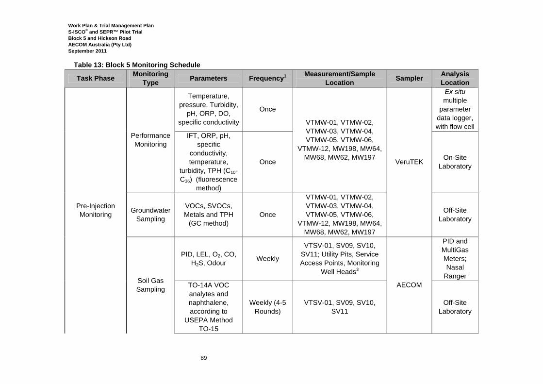
Work Plan & Trial Management Plan S-ISCO® and SEPR™ Pilot Trial Block 5 and Hickson Road AECOM Australia (Pty Ltd) September 2011
89
Table 13: Block 5 Monitoring Schedule
Task Phase Monitoring Type Parameters Frequency1 Measurement/Sample
Location Sampler Analysis Location
Pre-Injection Monitoring
Performance Monitoring
Temperature, pressure, Turbidity,
pH, ORP, DO, specific conductivity
Once
VTMW-01, VTMW-02, VTMW-03, VTMW-04, VTMW-05, VTMW-06,
VTMW-12, MW198, MW64, MW68, MW62, MW197 VeruTEK
Ex situ multiple
parameter data logger, with flow cell
IFT, ORP, pH, specific
conductivity, temperature,
turbidity, TPH (C10-C36) (fluorescence
method)
Once On-Site Laboratory
Groundwater Sampling
VOCs, SVOCs, Metals and TPH
(GC method) Once
VTMW-01, VTMW-02, VTMW-03, VTMW-04, VTMW-05, VTMW-06,
VTMW-12, MW198, MW64, MW68, MW62, MW197
Off-Site Laboratory
Soil Gas Sampling
PID, LEL, O2, CO, H2S, Odour Weekly
VTSV-01, SV09, SV10, SV11; Utility Pits, Service Access Points, Monitoring
Well Heads3
AECOM
PID and MultiGas Meters; Nasal
Ranger TO-14A VOC analytes and naphthalene, according to
USEPA Method TO-15
Weekly (4-5 Rounds)
VTSV-01, SV09, SV10, SV11
Off-Site Laboratory
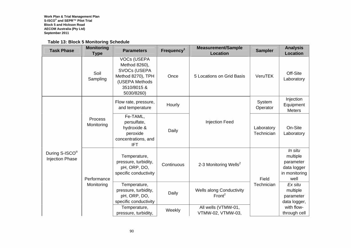
Work Plan & Trial Management Plan S-ISCO® and SEPR™ Pilot Trial Block 5 and Hickson Road AECOM Australia (Pty Ltd) September 2011
90
Table 13: Block 5 Monitoring Schedule
Task Phase Monitoring Type Parameters Frequency1 Measurement/Sample
Location Sampler Analysis Location
Soil Sampling
VOCs (USEPA Method 8260),
SVOCs (USEPA Method 8270), TPH (USEPA Methods
3510/8015 & 5030/8260)
Once 5 Locations on Grid Basis VeruTEK Off-Site Laboratory
During S-ISCO® Injection Phase
Process Monitoring
Flow rate, pressure, and temperature Hourly
Injection Feed
System Operator
Injection Equipment
Meters Fe-TAML, persulfate,
hydroxide & peroxide
concentrations, and IFT
Daily Laboratory Technician
On-Site Laboratory
Performance Monitoring
Temperature, pressure, turbidity,
pH, ORP, DO, specific conductivity
Continuous 2-3 Monitoring Wells2
Field Technician
In situ multiple
parameter data logger
in monitoring well
Temperature, pressure, turbidity,
pH, ORP, DO, specific conductivity
Daily Wells along Conductivity Front2
Ex situ multiple
parameter data logger,
with flow-through cell
Temperature, pressure, turbidity, Weekly All wells (VTMW-01,
VTMW-02, VTMW-03,
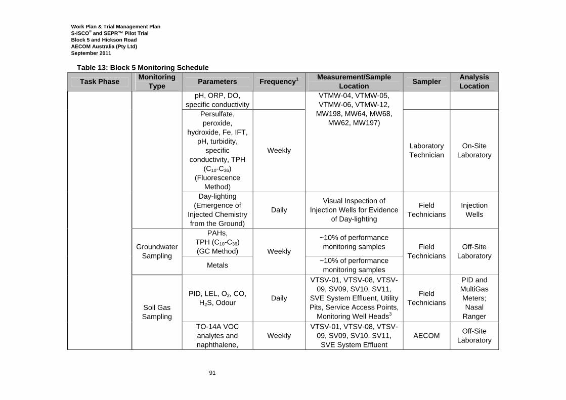
Work Plan & Trial Management Plan S-ISCO® and SEPR™ Pilot Trial Block 5 and Hickson Road AECOM Australia (Pty Ltd) September 2011
91
Table 13: Block 5 Monitoring Schedule
Task Phase Monitoring Type Parameters Frequency1 Measurement/Sample
Location Sampler Analysis Location
pH, ORP, DO, specific conductivity
VTMW-04, VTMW-05, VTMW-06, VTMW-12,
MW198, MW64, MW68, MW62, MW197)
Persulfate, peroxide,
hydroxide, Fe, IFT, pH, turbidity,
specific conductivity, TPH
(C10-C36) (Fluorescence
Method)
Weekly Laboratory Technician
On-Site Laboratory
Day-lighting (Emergence of
Injected Chemistry from the Ground)
Daily Visual Inspection of
Injection Wells for Evidence of Day-lighting
Field Technicians
Injection Wells
Groundwater Sampling
PAHs, TPH (C10-C36) (GC Method) Weekly
~10% of performance monitoring samples Field
Technicians Off-Site
Laboratory Metals ~10% of performance
monitoring samples
Soil Gas Sampling
PID, LEL, O2, CO, H2S, Odour Daily
VTSV-01, VTSV-08, VTSV-09, SV09, SV10, SV11,
SVE System Effluent, Utility Pits, Service Access Points,
Monitoring Well Heads3
Field Technicians
PID and MultiGas Meters; Nasal
Ranger TO-14A VOC analytes and naphthalene,
Weekly VTSV-01, VTSV-08, VTSV-
09, SV09, SV10, SV11, SVE System Effluent
AECOM Off-Site Laboratory

Work Plan & Trial Management Plan S-ISCO® and SEPR™ Pilot Trial Block 5 and Hickson Road AECOM Australia (Pty Ltd) September 2011
92
Table 13: Block 5 Monitoring Schedule
Task Phase Monitoring Type Parameters Frequency1 Measurement/Sample
Location Sampler Analysis Location
according to USEPA Method
TO-15
SVE System
Stack
TO-14A VOC analytes and naphthalene,
according to Stack Testing Method
TM-34
Weekly
SVE System Stack
AECOM Off-Site Laboratory
VOCs Continuously AECOM PID Meter
Post-Injection Monitoring
Performance Monitoring
Temperature, pressure, turbidity,
pH, ORP, DO, specific conductivity
Continuous TBD2
AECOM
In situ multiple
parameter data logger
in monitoring well
Temperature, pressure, turbidity,
pH, ORP, DO, specific conductivity
Daily for 1 week; then
Weekly Wells along Treatment Front Ex situ
multiple parameter
data logger, with flow cell
Temperature, pressure, turbidity,
pH, ORP, DO, specific conductivity
Weekly All wells (VTMW-01,
VTMW-02, VTMW-03, VTMW-04, VTMW-05, VTMW-06, VTMW-12,
MW198, MW64, MW68, MW62, MW197)
Persulfate, peroxide,
hydroxide, Fe-Weekly On-Site
Laboratory
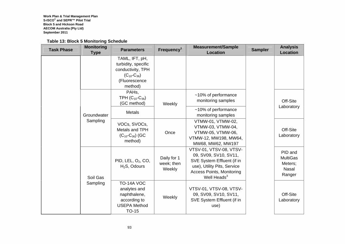
Work Plan & Trial Management Plan S-ISCO® and SEPR™ Pilot Trial Block 5 and Hickson Road AECOM Australia (Pty Ltd) September 2011
93
Table 13: Block 5 Monitoring Schedule
Task Phase Monitoring Type Parameters Frequency1 Measurement/Sample
Location Sampler Analysis Location
TAML, IFT, pH, turbidity, specific conductivity, TPH
(C10-C36) (Fluorescence
method)
Groundwater Sampling
PAHs, TPH (C10-C36) (GC method) Weekly
~10% of performance monitoring samples Off-Site
Laboratory Metals ~10% of performance
monitoring samples
VOCs, SVOCs, Metals and TPH
(C10-C36) (GC method)
Once
VTMW-01, VTMW-02, VTMW-03, VTMW-04, VTMW-05, VTMW-06,
VTMW-12, MW198, MW64, MW68, MW62, MW197
Off-Site Laboratory
Soil Gas Sampling
PID, LEL, O2, CO, H2S, Odours
Daily for 1 week; then
Weekly
VTSV-01, VTSV-08, VTSV-09, SV09, SV10, SV11,
SVE System Effluent (if in use), Utility Pits, Service
Access Points, Monitoring Well Heads3
PID and MultiGas Meters; Nasal
Ranger
TO-14A VOC analytes and naphthalene, according to
USEPA Method TO-15
Weekly
VTSV-01, VTSV-08, VTSV-09, SV09, SV10, SV11,
SVE System Effluent (if in use)
Off-Site Laboratory
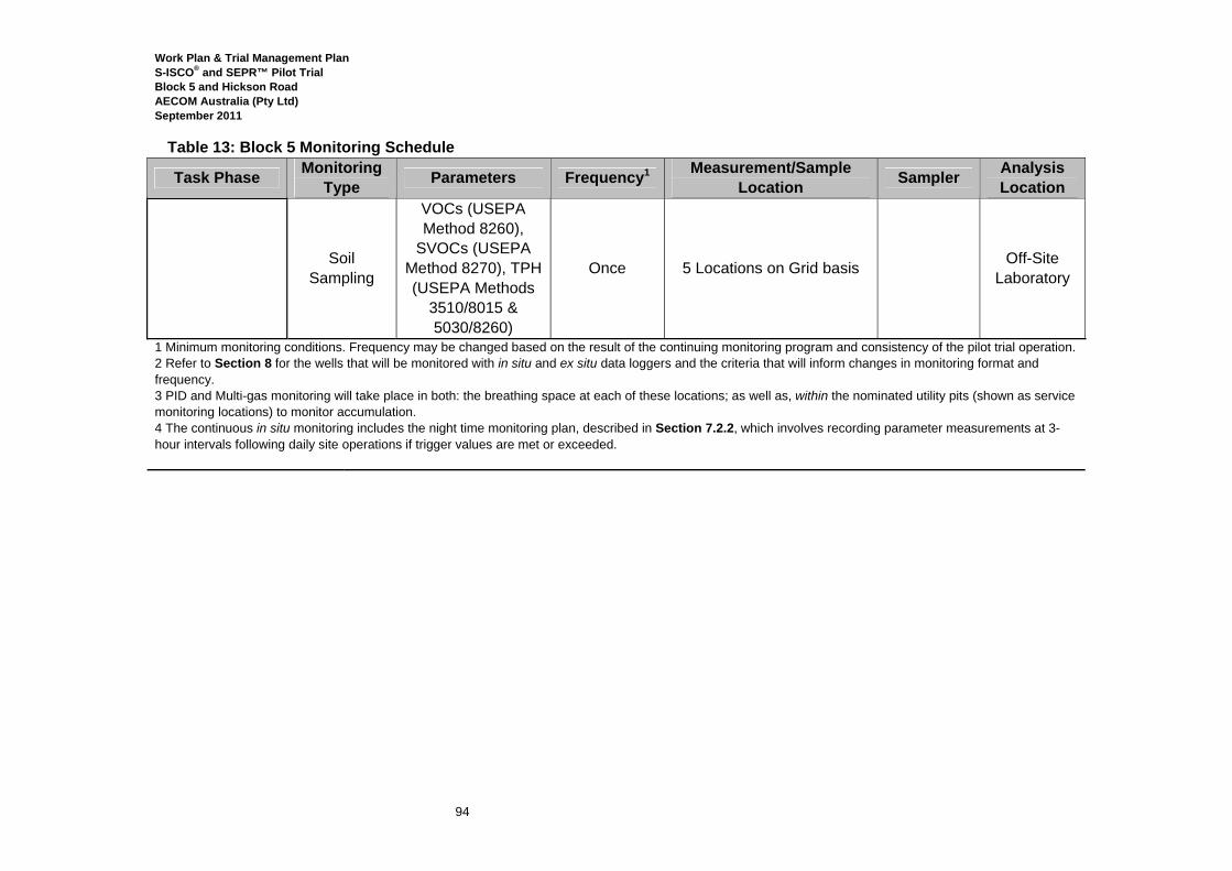
Work Plan & Trial Management Plan S-ISCO® and SEPR™ Pilot Trial Block 5 and Hickson Road AECOM Australia (Pty Ltd) September 2011
94
Table 13: Block 5 Monitoring Schedule
Task Phase Monitoring Type Parameters Frequency1 Measurement/Sample
Location Sampler Analysis Location
Soil Sampling
VOCs (USEPA Method 8260),
SVOCs (USEPA Method 8270), TPH (USEPA Methods
3510/8015 & 5030/8260)
Once 5 Locations on Grid basis Off-Site Laboratory
1 Minimum monitoring conditions. Frequency may be changed based on the result of the continuing monitoring program and consistency of the pilot trial operation. 2 Refer to Section 8 for the wells that will be monitored with in situ and ex situ data loggers and the criteria that will inform changes in monitoring format and frequency. 3 PID and Multi-gas monitoring will take place in both: the breathing space at each of these locations; as well as, within the nominated utility pits (shown as service monitoring locations) to monitor accumulation. 4 The continuous in situ monitoring includes the night time monitoring plan, described in Section 7.2.2, which involves recording parameter measurements at 3-hour intervals following daily site operations if trigger values are met or exceeded.
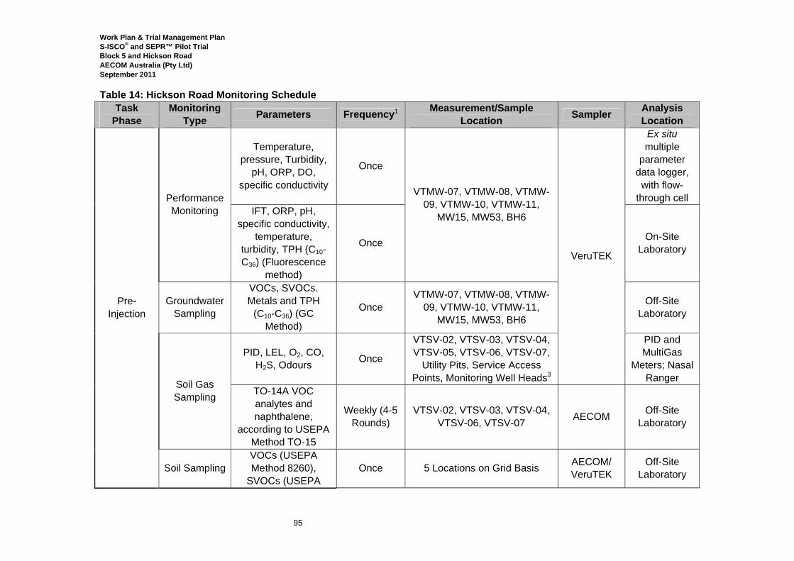
Work Plan & Trial Management Plan S-ISCO® and SEPR™ Pilot Trial Block 5 and Hickson Road AECOM Australia (Pty Ltd) September 2011
95
Table 14: Hickson Road Monitoring Schedule Task
Phase Monitoring
Type Parameters Frequency1 Measurement/Sample Location Sampler Analysis
Location
Pre-Injection
Performance Monitoring
Temperature, pressure, Turbidity,
pH, ORP, DO, specific conductivity
Once
VTMW-07, VTMW-08, VTMW-09, VTMW-10, VTMW-11,
MW15, MW53, BH6
VeruTEK
Ex situ multiple
parameter data logger,
with flow-through cell
IFT, ORP, pH, specific conductivity,
temperature, turbidity, TPH (C10-C36) (Fluorescence
method)
Once On-Site Laboratory
Groundwater Sampling
VOCs, SVOCs. Metals and TPH
(C10-C36) (GC Method)
Once VTMW-07, VTMW-08, VTMW-
09, VTMW-10, VTMW-11, MW15, MW53, BH6
Off-Site Laboratory
Soil Gas Sampling
PID, LEL, O2, CO, H2S, Odours Once
VTSV-02, VTSV-03, VTSV-04, VTSV-05, VTSV-06, VTSV-07,
Utility Pits, Service Access Points, Monitoring Well Heads3
PID and MultiGas
Meters; Nasal Ranger
TO-14A VOC analytes and naphthalene,
according to USEPA Method TO-15
Weekly (4-5 Rounds)
VTSV-02, VTSV-03, VTSV-04, VTSV-06, VTSV-07 AECOM Off-Site
Laboratory
Soil Sampling VOCs (USEPA Method 8260),
SVOCs (USEPA Once 5 Locations on Grid Basis AECOM/
VeruTEK Off-Site
Laboratory
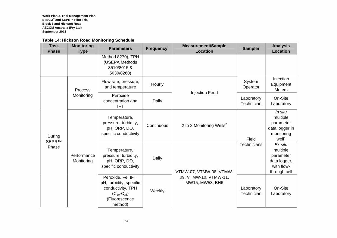
Work Plan & Trial Management Plan S-ISCO® and SEPR™ Pilot Trial Block 5 and Hickson Road AECOM Australia (Pty Ltd) September 2011
96
Table 14: Hickson Road Monitoring Schedule Task
Phase Monitoring
Type Parameters Frequency1 Measurement/Sample Location Sampler Analysis
Location Method 8270), TPH (USEPA Methods
3510/8015 & 5030/8260)
During SEPR™ Phase
Process Monitoring
Flow rate, pressure, and temperature Hourly
Injection Feed
System Operator
Injection Equipment
Meters Peroxide
concentration and IFT
Daily Laboratory Technician
On-Site Laboratory
Performance Monitoring
Temperature, pressure, turbidity,
pH, ORP, DO, specific conductivity
Continuous 2 to 3 Monitoring Wells2
Field Technicians
In situ multiple
parameter data logger in
monitoring well4
Temperature, pressure, turbidity,
pH, ORP, DO, specific conductivity
Daily
VTMW-07, VTMW-08, VTMW-
09, VTMW-10, VTMW-11, MW15, MW53, BH6
Ex situ multiple
parameter data logger,
with flow-through cell
Peroxide, Fe, IFT, pH, turbidity, specific
conductivity, TPH (C10-C36)
(Fluorescence method)
Weekly Laboratory Technician
On-Site Laboratory
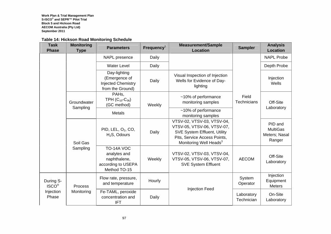
Work Plan & Trial Management Plan S-ISCO® and SEPR™ Pilot Trial Block 5 and Hickson Road AECOM Australia (Pty Ltd) September 2011
97
Table 14: Hickson Road Monitoring Schedule Task
Phase Monitoring
Type Parameters Frequency1 Measurement/Sample Location Sampler Analysis
Location NAPL presence Daily
Field Technicians
NAPL Probe
Water Level Daily Depth Probe Day-lighting
(Emergence of Injected Chemistry from the Ground)
Daily Visual Inspection of Injection Wells for Evidence of Day-
lighting
Injection Wells
Groundwater Sampling
PAHs, TPH (C10-C36) (GC method) Weekly
~10% of performance monitoring samples Off-Site
Laboratory Metals ~10% of performance
monitoring samples
Soil Gas Sampling
PID, LEL, O2, CO, H2S, Odours Daily
VTSV-02, VTSV-03, VTSV-04, VTSV-05, VTSV-06, VTSV-07,
SVE System Effluent, Utility Pits, Service Access Points,
Monitoring Well Heads3
PID and MultiGas
Meters; Nasal Ranger
TO-14A VOC analytes and naphthalene,
according to USEPA Method TO-15
Weekly VTSV-02, VTSV-03, VTSV-04, VTSV-05, VTSV-06, VTSV-07,
SVE System Effluent AECOM Off-Site
Laboratory
During S-ISCO®
Injection Phase
Process Monitoring
Flow rate, pressure, and temperature Hourly
Injection Feed
System Operator
Injection Equipment
Meters Fe-TAML, peroxide concentration and
IFT Daily Laboratory
Technician On-Site
Laboratory
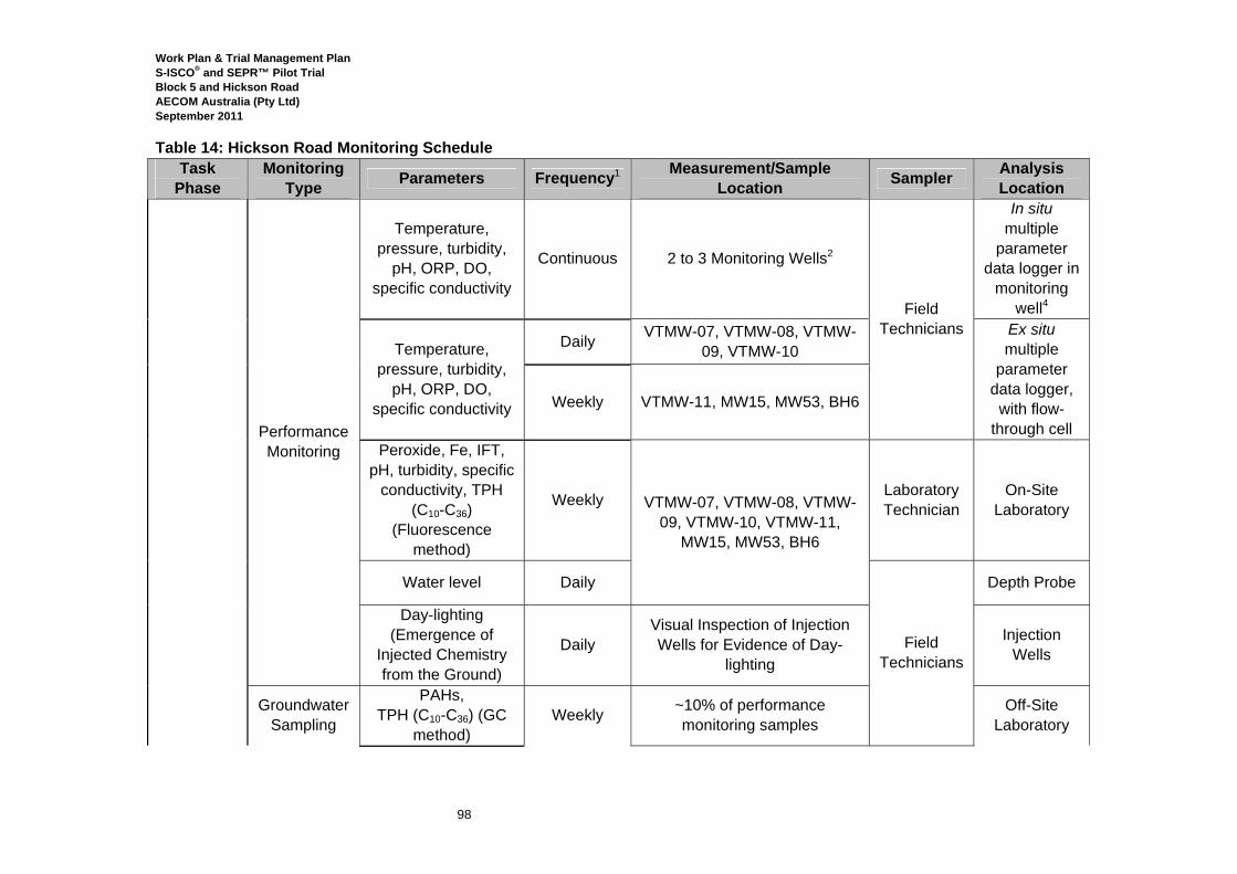
Work Plan & Trial Management Plan S-ISCO® and SEPR™ Pilot Trial Block 5 and Hickson Road AECOM Australia (Pty Ltd) September 2011
98
Table 14: Hickson Road Monitoring Schedule Task
Phase Monitoring
Type Parameters Frequency1 Measurement/Sample Location Sampler Analysis
Location
Performance Monitoring
Temperature, pressure, turbidity,
pH, ORP, DO, specific conductivity
Continuous 2 to 3 Monitoring Wells2
Field Technicians
In situ multiple
parameter data logger in
monitoring well4
Temperature, pressure, turbidity,
pH, ORP, DO, specific conductivity
Daily VTMW-07, VTMW-08, VTMW-09, VTMW-10
Ex situ multiple
parameter data logger,
with flow-through cell
Weekly VTMW-11, MW15, MW53, BH6
Peroxide, Fe, IFT, pH, turbidity, specific
conductivity, TPH (C10-C36)
(Fluorescence method)
Weekly VTMW-07, VTMW-08, VTMW-09, VTMW-10, VTMW-11,
MW15, MW53, BH6
Laboratory Technician
On-Site Laboratory
Water level Daily
Field Technicians
Depth Probe
Day-lighting (Emergence of
Injected Chemistry from the Ground)
Daily Visual Inspection of Injection Wells for Evidence of Day-
lighting
Injection Wells
Groundwater Sampling
PAHs, TPH (C10-C36) (GC
method) Weekly ~10% of performance
monitoring samples Off-Site
Laboratory
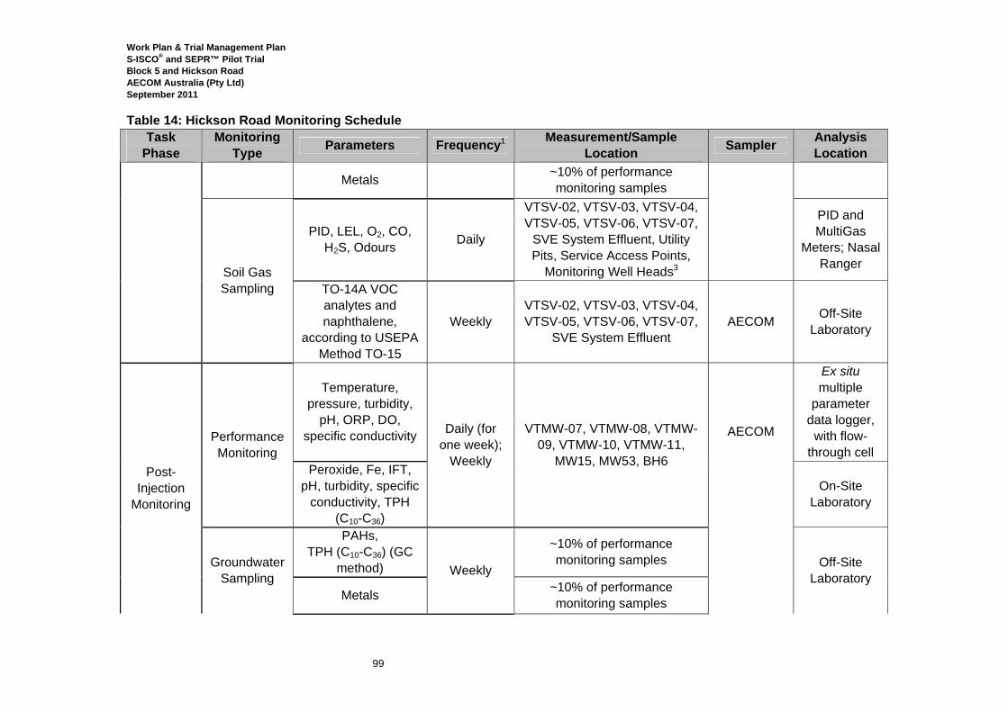
Work Plan & Trial Management Plan S-ISCO® and SEPR™ Pilot Trial Block 5 and Hickson Road AECOM Australia (Pty Ltd) September 2011
99
Table 14: Hickson Road Monitoring Schedule Task
Phase Monitoring
Type Parameters Frequency1 Measurement/Sample Location Sampler Analysis
Location
Metals ~10% of performance monitoring samples
Soil Gas Sampling
PID, LEL, O2, CO, H2S, Odours Daily
VTSV-02, VTSV-03, VTSV-04, VTSV-05, VTSV-06, VTSV-07,
SVE System Effluent, Utility Pits, Service Access Points,
Monitoring Well Heads3
PID and MultiGas
Meters; Nasal Ranger
TO-14A VOC analytes and naphthalene,
according to USEPA Method TO-15
Weekly VTSV-02, VTSV-03, VTSV-04, VTSV-05, VTSV-06, VTSV-07,
SVE System Effluent AECOM Off-Site
Laboratory
Post-Injection
Monitoring
Performance Monitoring
Temperature, pressure, turbidity,
pH, ORP, DO, specific conductivity Daily (for
one week); Weekly
VTMW-07, VTMW-08, VTMW-09, VTMW-10, VTMW-11,
MW15, MW53, BH6
AECOM
Ex situ multiple
parameter data logger,
with flow-through cell
Peroxide, Fe, IFT, pH, turbidity, specific
conductivity, TPH (C10-C36)
On-Site Laboratory
Groundwater Sampling
PAHs, TPH (C10-C36) (GC
method) Weekly
~10% of performance monitoring samples Off-Site
Laboratory Metals ~10% of performance
monitoring samples
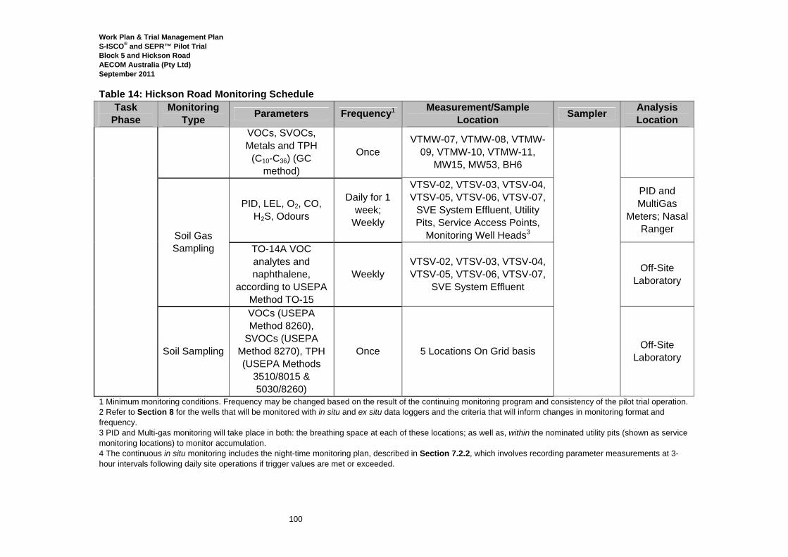
Work Plan & Trial Management Plan S-ISCO® and SEPR™ Pilot Trial Block 5 and Hickson Road AECOM Australia (Pty Ltd) September 2011
100
Table 14: Hickson Road Monitoring Schedule Task
Phase Monitoring
Type Parameters Frequency1 Measurement/Sample Location Sampler Analysis
Location VOCs, SVOCs, Metals and TPH
(C10-C36) (GC method)
Once VTMW-07, VTMW-08, VTMW-
09, VTMW-10, VTMW-11, MW15, MW53, BH6
Soil Gas Sampling
PID, LEL, O2, CO, H2S, Odours
Daily for 1 week;
Weekly
VTSV-02, VTSV-03, VTSV-04, VTSV-05, VTSV-06, VTSV-07,
SVE System Effluent, Utility Pits, Service Access Points,
Monitoring Well Heads3
PID and MultiGas
Meters; Nasal Ranger
TO-14A VOC analytes and naphthalene,
according to USEPA Method TO-15
Weekly VTSV-02, VTSV-03, VTSV-04, VTSV-05, VTSV-06, VTSV-07,
SVE System Effluent
Off-Site Laboratory
Soil Sampling
VOCs (USEPA Method 8260),
SVOCs (USEPA Method 8270), TPH (USEPA Methods
3510/8015 & 5030/8260)
Once 5 Locations On Grid basis Off-Site Laboratory
1 Minimum monitoring conditions. Frequency may be changed based on the result of the continuing monitoring program and consistency of the pilot trial operation. 2 Refer to Section 8 for the wells that will be monitored with in situ and ex situ data loggers and the criteria that will inform changes in monitoring format and frequency. 3 PID and Multi-gas monitoring will take place in both: the breathing space at each of these locations; as well as, within the nominated utility pits (shown as service monitoring locations) to monitor accumulation. 4 The continuous in situ monitoring includes the night-time monitoring plan, described in Section 7.2.2, which involves recording parameter measurements at 3-hour intervals following daily site operations if trigger values are met or exceeded.

Work Plan & Trial Management Plan S-ISCO® and SEPR™ Pilot Trial Block 5 and Hickson Road AECOM Australia (Pty Ltd) September 2011
101
8.0 Groundwater Monitoring Plan Details The following section expands upon the groundwater monitoring plan laid out in Section 8 by providing details about how the results of the monitoring data will be acted upon to inform modifications to the process that will support the performance of the remediation and protect the health and safety of the people, assets and environment in the vicinity of the Pilot Trial.
8.1 In Situ Continuous Performance Monitoring At the start of the Pilot Trial injection process, in situ continuous performance monitoring (refer to Section 7.2) will begin at the following locations in Table 15, down-gradient of the injection areas.
Table 15: First in situ Multiple-Parameter Data Logger Locations Block 5 Hickson Road
VTMW-03, VTMW-05 and VTMW-06 VTMW-07 and VTMW-11 When the groundwater monitoring data (from the in situ data loggers) indicates that the reaction front and then the oxidant front (collectively referred to as the treatment front) have reached these locations, the data loggers will be moved to wells at which the reaction and/or oxidant fronts have not yet been detected by ex situ data logger monitoring and/or on-site laboratory analysis. The data loggers will be evaluated several times daily. Tables 16 and 17 present the criteria that will be used to determine when the reaction and oxidant fronts have arrived at the in situ continuous monitoring locations.
Table 16: Criteria for Identifying Arrival of S-ISCO® with Peroxide Front S-ISCO®/SEPR™ with Peroxide
Parameter Criteria Action ORP Increase > 450 mV • Double frequency of peroxide
measurement. DO >10%
Peroxide Concentration > 0.5% • Move in situ data logger. • Begin daily ex situ data logger monitoring
and sampling for on-site lab analysis.
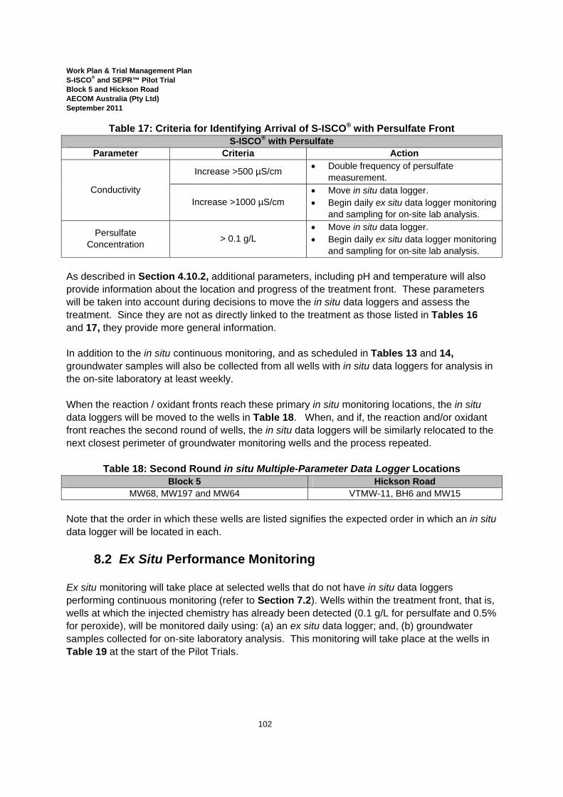
Work Plan & Trial Management Plan S-ISCO® and SEPR™ Pilot Trial Block 5 and Hickson Road AECOM Australia (Pty Ltd) September 2011
102
Table 17: Criteria for Identifying Arrival of S-ISCO® with Persulfate Front S-ISCO® with Persulfate
Parameter Criteria Action
Conductivity
Increase >500 µS/cm • Double frequency of persulfate measurement.
Increase >1000 µS/cm • Move in situ data logger. • Begin daily ex situ data logger monitoring
and sampling for on-site lab analysis.
Persulfate Concentration > 0.1 g/L
• Move in situ data logger. • Begin daily ex situ data logger monitoring
and sampling for on-site lab analysis. As described in Section 4.10.2, additional parameters, including pH and temperature will also provide information about the location and progress of the treatment front. These parameters will be taken into account during decisions to move the in situ data loggers and assess the treatment. Since they are not as directly linked to the treatment as those listed in Tables 16 and 17, they provide more general information. In addition to the in situ continuous monitoring, and as scheduled in Tables 13 and 14, groundwater samples will also be collected from all wells with in situ data loggers for analysis in the on-site laboratory at least weekly. When the reaction / oxidant fronts reach these primary in situ monitoring locations, the in situ data loggers will be moved to the wells in Table 18. When, and if, the reaction and/or oxidant front reaches the second round of wells, the in situ data loggers will be similarly relocated to the next closest perimeter of groundwater monitoring wells and the process repeated.
Table 18: Second Round in situ Multiple-Parameter Data Logger Locations Block 5 Hickson Road
MW68, MW197 and MW64 VTMW-11, BH6 and MW15 Note that the order in which these wells are listed signifies the expected order in which an in situ data logger will be located in each.
8.2 Ex Situ Performance Monitoring Ex situ monitoring will take place at selected wells that do not have in situ data loggers performing continuous monitoring (refer to Section 7.2). Wells within the treatment front, that is, wells at which the injected chemistry has already been detected (0.1 g/L for persulfate and 0.5% for peroxide), will be monitored daily using: (a) an ex situ data logger; and, (b) groundwater samples collected for on-site laboratory analysis. This monitoring will take place at the wells in Table 19 at the start of the Pilot Trials.
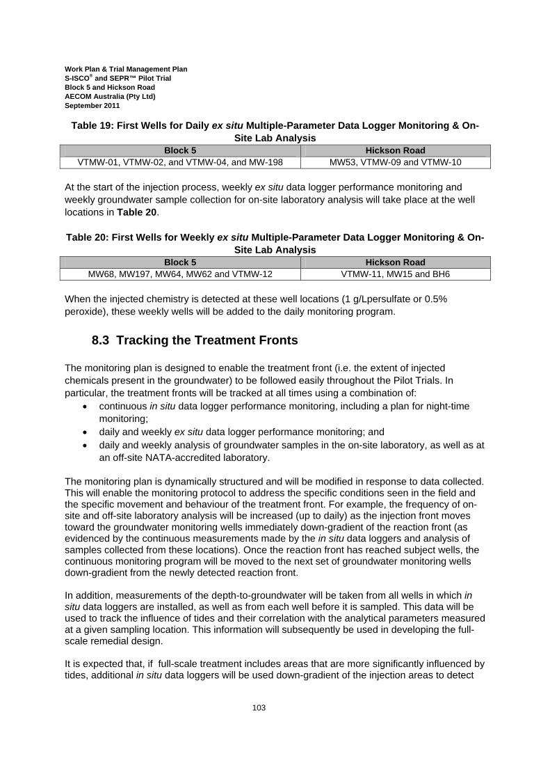
Work Plan & Trial Management Plan S-ISCO® and SEPR™ Pilot Trial Block 5 and Hickson Road AECOM Australia (Pty Ltd) September 2011
103
Table 19: First Wells for Daily ex situ Multiple-Parameter Data Logger Monitoring & On-Site Lab Analysis
Block 5 Hickson Road VTMW-01, VTMW-02, and VTMW-04, and MW-198 MW53, VTMW-09 and VTMW-10
At the start of the injection process, weekly ex situ data logger performance monitoring and weekly groundwater sample collection for on-site laboratory analysis will take place at the well locations in Table 20. Table 20: First Wells for Weekly ex situ Multiple-Parameter Data Logger Monitoring & On-
Site Lab Analysis Block 5 Hickson Road
MW68, MW197, MW64, MW62 and VTMW-12 VTMW-11, MW15 and BH6 When the injected chemistry is detected at these well locations (1 g/Lpersulfate or 0.5% peroxide), these weekly wells will be added to the daily monitoring program.
8.3 Tracking the Treatment Fronts The monitoring plan is designed to enable the treatment front (i.e. the extent of injected chemicals present in the groundwater) to be followed easily throughout the Pilot Trials. In particular, the treatment fronts will be tracked at all times using a combination of:
• continuous in situ data logger performance monitoring, including a plan for night-time monitoring;
• daily and weekly ex situ data logger performance monitoring; and • daily and weekly analysis of groundwater samples in the on-site laboratory, as well as at
an off-site NATA-accredited laboratory. The monitoring plan is dynamically structured and will be modified in response to data collected. This will enable the monitoring protocol to address the specific conditions seen in the field and the specific movement and behaviour of the treatment front. For example, the frequency of on-site and off-site laboratory analysis will be increased (up to daily) as the injection front moves toward the groundwater monitoring wells immediately down-gradient of the reaction front (as evidenced by the continuous measurements made by the in situ data loggers and analysis of samples collected from these locations). Once the reaction front has reached subject wells, the continuous monitoring program will be moved to the next set of groundwater monitoring wells down-gradient from the newly detected reaction front. In addition, measurements of the depth-to-groundwater will be taken from all wells in which in situ data loggers are installed, as well as from each well before it is sampled. This data will be used to track the influence of tides and their correlation with the analytical parameters measured at a given sampling location. This information will subsequently be used in developing the full-scale remedial design. It is expected that, if full-scale treatment includes areas that are more significantly influenced by tides, additional in situ data loggers will be used down-gradient of the injection areas to detect

Work Plan & Trial Management Plan S-ISCO® and SEPR™ Pilot Trial Block 5 and Hickson Road AECOM Australia (Pty Ltd) September 2011
104
the progress and arrival of the treatment front. These devices will collect continuous data (conductivity, pH, ORP, dissolved oxygen and depth-to-water, for example) —including changes attributed to the tides. The frequency of this monitoring will be increased, if necessary, to coincide with tidal changes.
8.4 Contingency Plans The results of the monitoring program (as described by Section 7 and Sections 8.1 to 8.3) will be used to confirm both the progress and also the safety of the Pilot Trial injections. Table 21 describes the criteria that will be used to evaluate the results of the monitoring program as well as contingency measures that will be implemented if the listed criteria are exceeded. Implementation of this contingency plan will ensure that the treatment is controlled at all times during the Pilot Trial. Note also that, as described in Section 7.2.2, these parameters will be used to determine the extent and duration of night-time in situ performance monitoring that is warranted.
Table 21: Groundwater Contingency Plans, Data Loggers and On-Site Lab Measurements
Parameter Location Criteria Contingency Measures
Specific conductivity, measured by
an in situ or ex situ data logger
Block 5: VTMW-03, VTMW-
05, VTMW-06
>5,000 µS/cm increase
• Double the frequency of monitoring at
these locations, including collection of samples for on-site laboratory analysis, to enable closer tracking of the injected chemistry, specifically persulfate.
Block 5: VTMW-12, MW62,
MW64, MW68, MW197
>1,000 µS/cm increase
Persulfate, measured in on-site lab
Block 5: VTMW-03, VTMW-12, MW64, MW68,
MW197
1 g/L
• Use extraction system to extract from locations with exceedances.
• Continue monitoring program at these locations to confirm success of extractions.
• Continue monitoring at VTMW-05 and VTMW-06.
Note: Since it is expected that the sodium persulfate front will reach monitoring wells VTMW-05 and VTMW-06, detections of persulfate at these locations will not trigger implementation of contingency measures.
Block 5: MW62
Above detectable
limits (0.1 g/L)
• Use extraction system to extract from locations with exceedances.
• Continue monitoring program to confirm that concentrations have decreased.
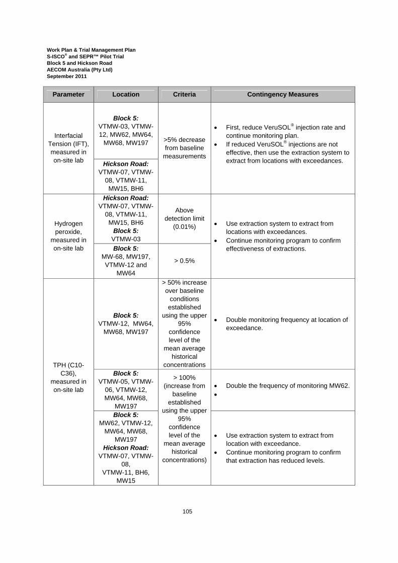
Work Plan & Trial Management Plan S-ISCO® and SEPR™ Pilot Trial Block 5 and Hickson Road AECOM Australia (Pty Ltd) September 2011
105
Parameter Location Criteria Contingency Measures
Interfacial Tension (IFT), measured in on-site lab
Block 5: VTMW-03, VTMW-12, MW62, MW64,
MW68, MW197 >5% decrease from baseline
measurements
• First, reduce VeruSOL® injection rate and continue monitoring plan.
• If reduced VeruSOL® injections are not effective, then use the extraction system to extract from locations with exceedances.
Hickson Road:
VTMW-07, VTMW-08, VTMW-11, MW15, BH6
Hydrogen peroxide,
measured in on-site lab
Hickson Road: VTMW-07, VTMW-
08, VTMW-11, MW15, BH6
Block 5: VTMW-03
Above detection limit
(0.01%) • Use extraction system to extract from locations with exceedances.
• Continue monitoring program to confirm effectiveness of extractions. Block 5:
MW-68, MW197, VTMW-12 and
MW64
> 0.5%
TPH (C10-C36),
measured in on-site lab
Block 5: VTMW-12, MW64,
MW68, MW197
> 50% increase over baseline
conditions established
using the upper 95%
confidence level of the
mean average historical
concentrations
• Double monitoring frequency at location of exceedance.
Block 5: VTMW-05, VTMW-
06, VTMW-12, MW64, MW68,
MW197
> 100% (increase from
baseline established
using the upper 95%
confidence level of the
mean average historical
concentrations)
• Double the frequency of monitoring MW62. •
Block 5: MW62, VTMW-12,
MW64, MW68, MW197
Hickson Road: VTMW-07, VTMW-
08, VTMW-11, BH6,
MW15
• Use extraction system to extract from location with exceedance.
• Continue monitoring program to confirm that extraction has reduced levels.
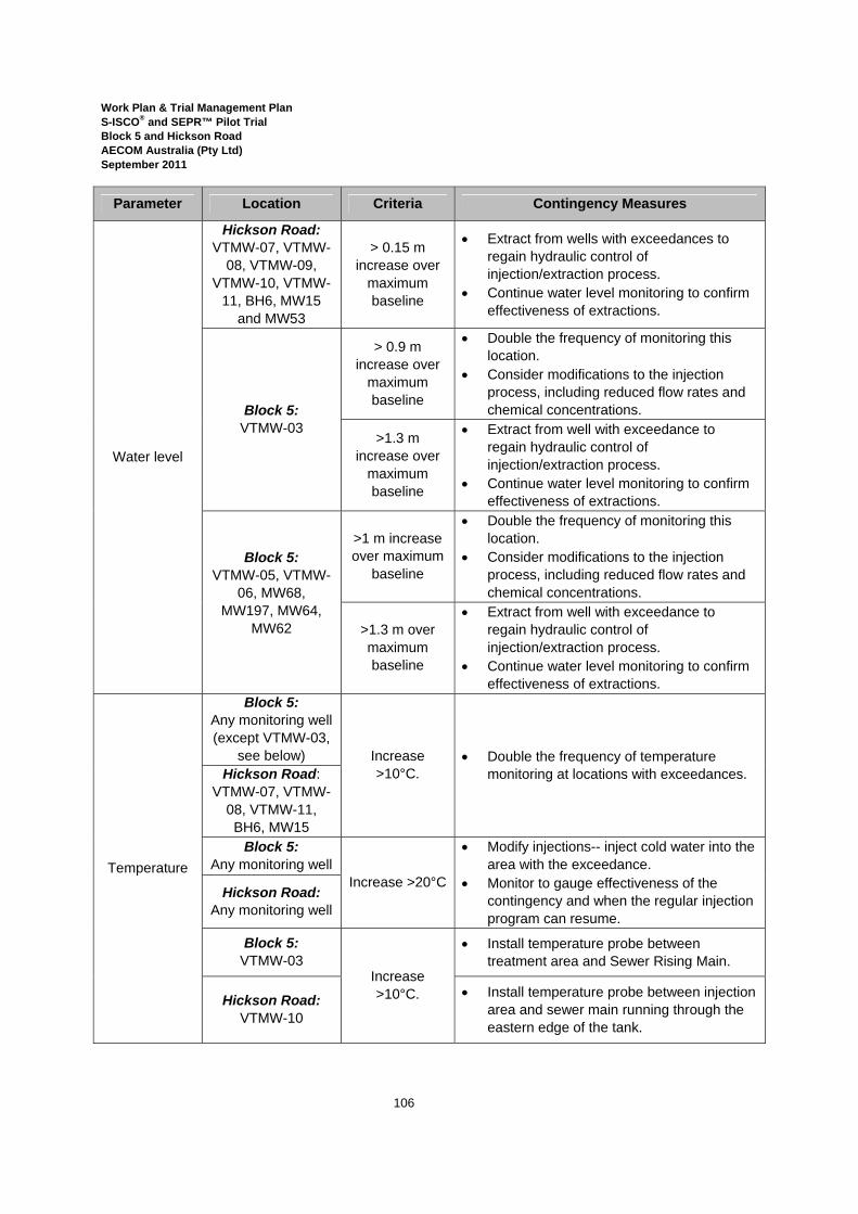
Work Plan & Trial Management Plan S-ISCO® and SEPR™ Pilot Trial Block 5 and Hickson Road AECOM Australia (Pty Ltd) September 2011
106
Parameter Location Criteria Contingency Measures
Water level
Hickson Road: VTMW-07, VTMW-
08, VTMW-09, VTMW-10, VTMW-
11, BH6, MW15 and MW53
> 0.15 m increase over
maximum baseline
• Extract from wells with exceedances to regain hydraulic control of injection/extraction process.
• Continue water level monitoring to confirm effectiveness of extractions.
Block 5: VTMW-03
> 0.9 m increase over
maximum baseline
• Double the frequency of monitoring this location.
• Consider modifications to the injection process, including reduced flow rates and chemical concentrations.
>1.3 m increase over
maximum baseline
• Extract from well with exceedance to regain hydraulic control of injection/extraction process.
• Continue water level monitoring to confirm effectiveness of extractions.
Block 5: VTMW-05, VTMW-
06, MW68, MW197, MW64,
MW62
>1 m increase over maximum
baseline
• Double the frequency of monitoring this location.
• Consider modifications to the injection process, including reduced flow rates and chemical concentrations.
>1.3 m over maximum baseline
• Extract from well with exceedance to regain hydraulic control of injection/extraction process.
• Continue water level monitoring to confirm effectiveness of extractions.
Temperature
Block 5: Any monitoring well (except VTMW-03,
see below) Increase >10°C.
• Double the frequency of temperature monitoring at locations with exceedances. Hickson Road:
VTMW-07, VTMW-08, VTMW-11, BH6, MW15
Block 5: Any monitoring well
Increase >20°C
• Modify injections-- inject cold water into the area with the exceedance.
• Monitor to gauge effectiveness of the contingency and when the regular injection program can resume.
Hickson Road: Any monitoring well
Block 5: VTMW-03
Increase >10°C.
• Install temperature probe between treatment area and Sewer Rising Main.
Hickson Road: VTMW-10
• Install temperature probe between injection area and sewer main running through the eastern edge of the tank.

Work Plan & Trial Management Plan S-ISCO® and SEPR™ Pilot Trial Block 5 and Hickson Road AECOM Australia (Pty Ltd) September 2011
107
9.0 Post-Injection Monitoring Plan As described in Section 7.2, post-injection monitoring in both the Block 5 and Hickson Road Pilot Trial areas will be conducted daily for the first week after injections stop, and then weekly until the data indicates that the injected chemistry is no longer reacting in the subsurface. This monitoring will be completed using ex situ data loggers, analysis at the on-site laboratory, and analysis at a NATA-accredited laboratory, as detailed in Tables 13 and 14.
9.1 Pilot Trial Completion The completion of reactions in the subsurface will be identified as follows: • Block 5: The completion of S-ISCO® with persulfate will be characterised by a distinct
downward trend in persulfate concentration and conductivity measurements, including persulfate concentrations approaching 1 g/L, and steady increases in IFT.
• Hickson Road: The completion of S-ISCO® with peroxide will be characterised by steady
increases in IFT, peroxide concentrations nearing the detection limit (0.01%), and approximately 50% recovery of background ORP.
These levels are guidelines only and will be subject to conditions observed in the field.
9.2 Post-Injection Contingency Plans The contingency plans described in Section 8.4 for the Pilot Trial injection phase will also be applied during the post injection monitoring. The only exception will be that the contingency measure of stopping injections will not be applicable. Increasing the frequency of monitoring; groundwater extraction; and increased operation of the SVE system will therefore be the primary contingencies available for implementation if the results of post injection monitoring indicate that the nominated criteria have been exceeded. Operation of the SVE system (and the associated monitoring program) will continue during the first week of the post-injection monitoring period. During and after this period, operation of the SVE system and monitoring program may be scaled back, based on the results of soil vapour monitoring and analysis. Section 9.3 describes the criteria that will be used to determine whether it is appropriate to scale back SVE system operation.
Work Plan & Trial Management Plan S-ISCO® and SEPR™ Pilot Trial Block 5 and Hickson Road AECOM Australia (Pty Ltd) September 2011
108
10.0 Wastewater Treatment
10.1 Management of Contaminated Water Wastewater generated during the Pilot Trials will consist of the following:
• Groundwater extracted as part of contingency mitigation measures; • Stormwater collected within the waste containment berm and injection system
containment berm within the Pilot Trial System Compound area ; and • SEPR™ extraction fluid from the Hickson Road Pilot Trial.
Please refer the WSMP within the CEMP for the details of groundwater and stormwater management, treatment, monitoring and disposal. The following sections detail the management of SEPR™ fluid that is extracted from Hickson Road. SEPR™ fluid is the mixture of groundwater, emulsified contamination, and the VeruSOL® and peroxide that remain from the injection of peroxide and VeruSOL® into the Hickson Road treatment area during SEPR™ .
10.2 Management of SEPR™ Extracted Fluid VeruTEK anticipates that less than 80,000 L of SEPR™ fluid will be extracted throughout the duration of SEPR™ treatment. All SEPR™ fluid collected during the SEPR™ extraction events will be transferred from the tar tank in Hickson Road through a dedicated pipe network contained in the trench beneath Hickson Road and along the edge of Block 5, to 10,000 L polytanks located in the waste storage containment berm in the Block 5 Pilot Trial System Compound area, shown on Figure 2a. Two 10,000 L tanks will be used for SEPR™ fluid. This will enable treatment to proceed in one tank while additional fluid is collected in the second. The rate of extraction from each extraction location will generally match the rate of injection, that is, between 3.7 and 19 L/minute. Based on this, VeruTEK estimates that up to 80,000L of fluid will be extracted during SEPR™. This will yield approximately eight (8) batches of fluid to treat[1]. The SVE system will be used to collect and manage any vapours generated during wastewater treatment.
[1] In the event that additional capacity is required to contain the extracted fluid, the rate of extraction (and injection) will be reduced, and/or an additional tank will be acquired.
Work Plan & Trial Management Plan S-ISCO® and SEPR™ Pilot Trial Block 5 and Hickson Road AECOM Australia (Pty Ltd) September 2011
109
In accordance with the Waste Management Plan, extracted SEPR fluid will be treated on site, to the extent possible, and:
• discharged to Darling Harbour in accordance with the requirements of the existing Environment Protection Licence (EPL) for the Barangaroo Site (refer to Appendix M[2]); and/or
• discharged to the Barangaroo Stage 1 water treatment plant for treatment and discharge to Darling Harbour in accordance with the requirements of the existing EPL for the Barangaroo Site (refer to Appendix M); or
• re-used as part of the Pilot Trial provided that the treated water quality meets the ANZECC (2000) 95% level of protection marine water quality criteria multiplied by a factor of 5 (refer to the Section 5.7.1 of the ORWS HHERA Addendum (AECOM, 2011a) and the Groundwater Discharge Study (AECOM, 2010a); or
• disposed off-site to an appropriately licensed facility (after removal by tankering). The following sections describe the SEPR™ fluid treatment process and its management.
10.3 On-site Treatment
On-site treatment of wastewater will utilise the same chemistry used in the S-ISCO® injections (including VeruSOL®, hydrogen peroxide and Fe-TAML) and will take place within the waste storage containers, including 10,000 L tanks for SEPR™ fluid and 1,000 L IBCs for groundwater and stormwater waste. A recirculation pump will be used to mix the wastewater with the treatment chemistry. With the recirculation pump activated, first VeruSOL® will be added to create an emulsification. Next peroxide and Fe-TAML will be added to react with and destroy the emulsified contaminants. The following process controls will be employed:
• Pressure: The tanks will be vented to prevent pressure build-up. In addition a gauge will be used to measure increases;
• Temperature: The tanks will be equipped with thermometers to monitor temperature changes. On-site treatment of wastewater will be implemented in a controlled, gradual manner in order to closely monitor and manage the process. VeruSOL®, hydrogen peroxide and Fe-TAML will be added to the wastewater stream gradually, accompanied by close monitoring and observation of the treatment and subsequent reactions. This careful, cautious approach will enable control of the process at all times and prevent the parameters of the fluid and/or process from fluctuating into unsafe or undesirable ranges;
[2] Discharge criteria are subject to DECCW approval.
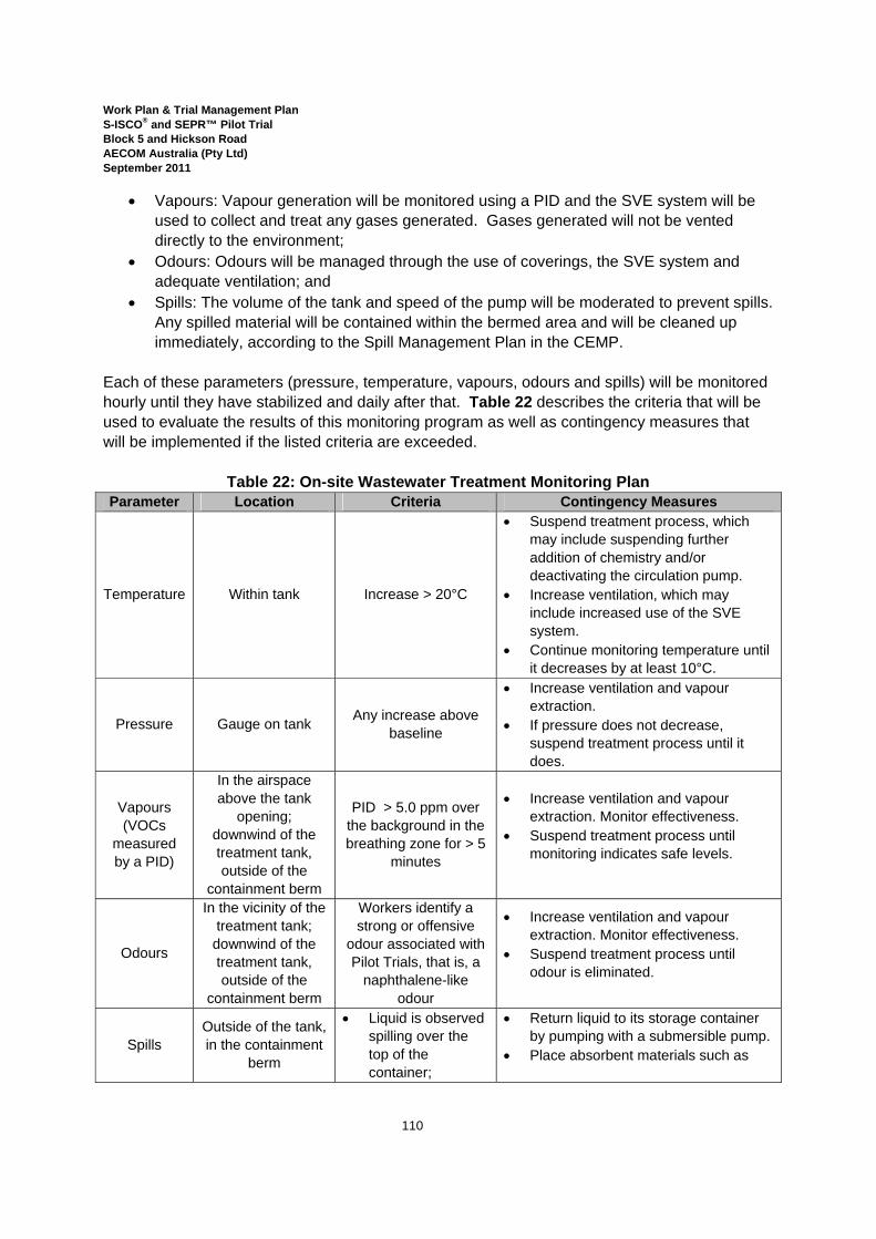
Work Plan & Trial Management Plan S-ISCO® and SEPR™ Pilot Trial Block 5 and Hickson Road AECOM Australia (Pty Ltd) September 2011
110
• Vapours: Vapour generation will be monitored using a PID and the SVE system will be used to collect and treat any gases generated. Gases generated will not be vented directly to the environment;
• Odours: Odours will be managed through the use of coverings, the SVE system and adequate ventilation; and
• Spills: The volume of the tank and speed of the pump will be moderated to prevent spills. Any spilled material will be contained within the bermed area and will be cleaned up immediately, according to the Spill Management Plan in the CEMP.
Each of these parameters (pressure, temperature, vapours, odours and spills) will be monitored hourly until they have stabilized and daily after that. Table 22 describes the criteria that will be used to evaluate the results of this monitoring program as well as contingency measures that will be implemented if the listed criteria are exceeded.
Table 22: On-site Wastewater Treatment Monitoring Plan Parameter Location Criteria Contingency Measures
Temperature Within tank Increase > 20°C
• Suspend treatment process, which may include suspending further addition of chemistry and/or deactivating the circulation pump.
• Increase ventilation, which may include increased use of the SVE system.
• Continue monitoring temperature until it decreases by at least 10°C.
Pressure Gauge on tank Any increase above baseline
• Increase ventilation and vapour extraction.
• If pressure does not decrease, suspend treatment process until it does.
Vapours (VOCs
measured by a PID)
In the airspace above the tank
opening; downwind of the treatment tank, outside of the
containment berm
PID > 5.0 ppm over the background in the breathing zone for > 5
minutes
• Increase ventilation and vapour extraction. Monitor effectiveness.
• Suspend treatment process until monitoring indicates safe levels.
Odours
In the vicinity of the treatment tank;
downwind of the treatment tank, outside of the
containment berm
Workers identify a strong or offensive
odour associated with Pilot Trials, that is, a
naphthalene-like odour
• Increase ventilation and vapour extraction. Monitor effectiveness.
• Suspend treatment process until odour is eliminated.
Spills Outside of the tank, in the containment
berm
• Liquid is observed spilling over the top of the container;
• Return liquid to its storage container by pumping with a submersible pump.
• Place absorbent materials such as
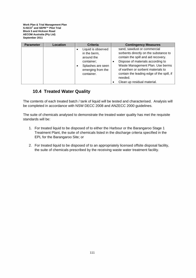
Work Plan & Trial Management Plan S-ISCO® and SEPR™ Pilot Trial Block 5 and Hickson Road AECOM Australia (Pty Ltd) September 2011
111
Parameter Location Criteria Contingency Measures • Liquid is observed
in the berm, around the container;
• Splashes are seen emerging from the container.
sand, sawdust or commercial sorbents directly on the substance to contain the spill and aid recovery.
• Dispose of materials according to Waste Management Plan. Use berms of earthen or sorbent materials to contain the leading edge of the spill, if needed.
• Clean up residual material.
10.4 Treated Water Quality The contents of each treated batch / tank of liquid will be tested and characterised. Analysis will be completed in accordance with NSW DECC 2008 and ANZECC 2000 guidelines. The suite of chemicals analysed to demonstrate the treated water quality has met the requisite standards will be:
1. For treated liquid to be disposed of to either the Harbour or the Barangaroo Stage 1 Treatment Plant, the suite of chemicals listed in the discharge criteria specified in the EPL for the Barangaroo Site; or
2. For treated liquid to be disposed of to an appropriately licensed offsite disposal facility,
the suite of chemicals prescribed by the receiving waste water treatment facility.
Work Plan & Trial Management Plan S-ISCO® and SEPR™ Pilot Trial Block 5 and Hickson Road AECOM Australia (Pty Ltd) September 2011
112
11.0 SVE System
11.1 SVE System Details Details of the SVE system design are provided in Appendix E, including a detailed schematic of the SVE system and its components; the calculations that were used to develop the system’s operational parameters; and the details of the exhaust stack, including its location (also shown on Figure 2a) and the details of its emissions modelling are included. An overview of the system is also provided in Section 4.3.
11.2 SVE System Inspection and Test Plan The SVE system will be inspected and maintained according to the manufacturer’s specifications. The maintenance program is listed in the inspection and test plan contained in Table 23. The inspection and test plan includes inspection of the system before its use by a qualified person; daily by a competent person; and monthly by a competent person. Daily and monthly inspections will be recorded on a checklist also provided in Appendix F of the HASP, while the initial inspection will be recorded on a register. Inspection of the SVE system will include the following. Note that the item references provided in the first column refer to the parts identified in Figure A, the SVE system schematic, included in Appendix E.

Work Plan & Trial Management Plan S-ISCO® and SEPR™ Pilot Trial Block 5 and Hickson Road AECOM Australia (Pty Ltd) September 2011
113
Table 23: SVE System Inspection and Test Plan
Item Criteria Inspection Frequency Action Recording
Location
Air Intake filter (T1) Indications of clogging by
the vacuum gauge readings
Before use; Daily
• Clean filter according to manufacturer’s specifications.
Checklist
Vacuum pressure gauge (P1)
Max. vacuum pressure is not exceeded.
• Adjust vacuum pressure, which may include opening the vacuum relief valve.
Temperature (T1) Temp. is within range specified by system
rating.
• Adjust parameters of cooling system.
Filter chamber Water or debris accumulation
• Remove accumulation and dispose of properly, according to Waste Management Plan.
Amp draw at switch box Moisture accumulation. • Remove moisture.
Moisture separator Fluid level
• Remove fluid to waste storage/treatment containers.
Hoses
Connections at hose junctions, SV points, and
SVE pump • Secure connections.
Damage to hoses • Repair damages or
replace hosing segments.
Carbon Filters
PID reading: >5.0 ppm over background for >5
min; or
Daily • Replace filters;* • Monitor with a PID to
confirm effectiveness of new filter.
Checklist; monitoring report Laboratory analysis:
10 mg/m3 total VOCs (5.0 ppm n-propane).
Weekly
*The change-out schedule for the carbon filters will, at a minimum, comply with the manufacturer’s specifications for the unit. In order to assure the optimal performance of the system and its capacity to protect the health of the people and environment in the vicinity of the Pilot Trial, the effluent from the granular activated carbon (GAC) filters will be monitored with a PID daily (as described in Table 13 and Section 5.6).
11.3 SVE System Contingency Plans Appendix E contains the details of the air dispersion model run to calculate the maximum stack emission concentration that would be permissible in order to meet the DECCW Approved Methods ground level concentration (GLC) criteria for each pollutant specified. Models run with this proposed stack licence limit for the Pilot Trials stack returned allowable emissions concentrations that well exceeded the POEO Clean Air Regulation Group 6 standard for vapour recovery units. Therefore, the results of laboratory analysis of SVE stack samples will be

Work Plan & Trial Management Plan S-ISCO® and SEPR™ Pilot Trial Block 5 and Hickson Road AECOM Australia (Pty Ltd) September 2011
114
evaluated according to this criteria, listed below, to determine whether the contingency measures listed will be required in order to protect the health and safety of the people, assets and environment in the vicinity of the Pilot Trials. The SVE monitoring program is described in Section 7.6. Table 24 describes the criteria that will be used to evaluate the results of the SVE monitoring program as well as contingency measures that will be implemented if the listed criteria are exceeded.
Table 24: SVE System Contingency Plan
Parameter Location Criteria Contingency Measures
TO-14A VOC analytes and naphthalene
(Stack Testing Method TM-34)
SVE System Stack
Emissions
Trigger level: 10 mg/m3 total VOCs (5.1 ppm n-propane);
• Change carbon filter in SVE system.
• Modify SVE system operational parameters, which may include the blower/vacuum rates and operational power.
Maximum limit of POEO Licence:
20mg/m3 total VOCs ( as n-propane);
• Suspend injections. • Notify required regulators. • Modify SVE system, including
operational parameters of existing equipment, and continue monitoring the system’s performance.
• If needed, replace system or add additional SVE units.
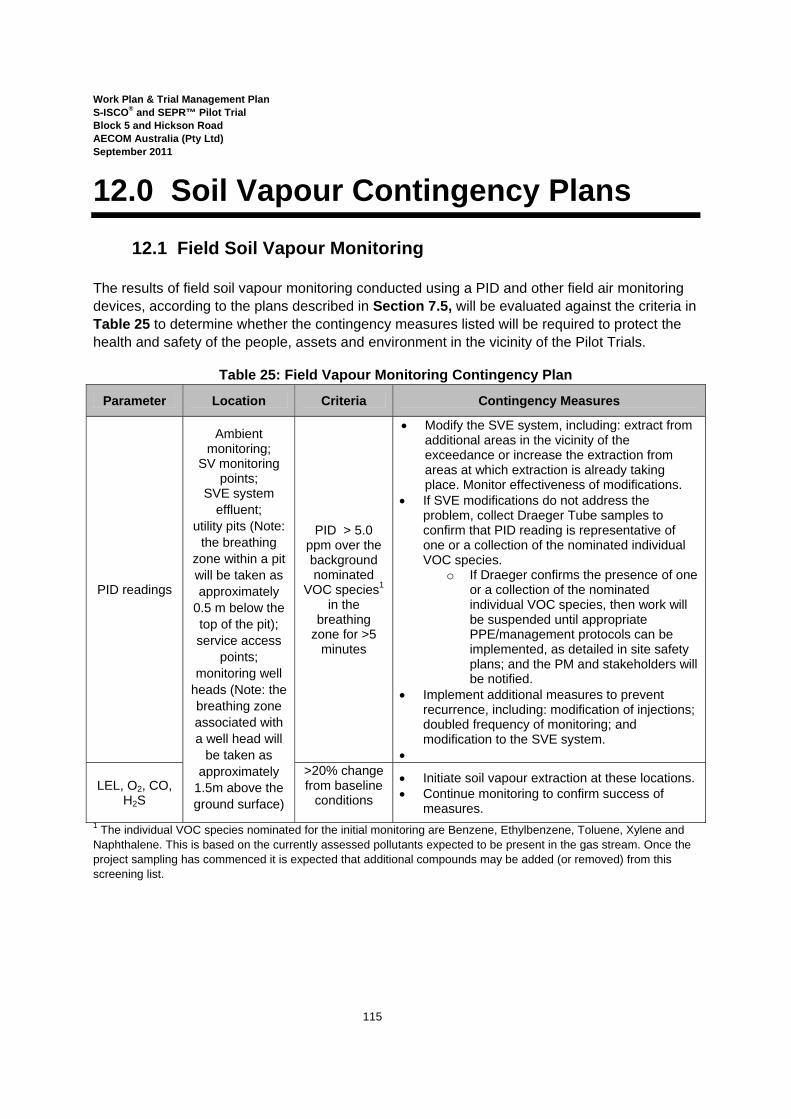
Work Plan & Trial Management Plan S-ISCO® and SEPR™ Pilot Trial Block 5 and Hickson Road AECOM Australia (Pty Ltd) September 2011
115
12.0 Soil Vapour Contingency Plans
12.1 Field Soil Vapour Monitoring The results of field soil vapour monitoring conducted using a PID and other field air monitoring devices, according to the plans described in Section 7.5, will be evaluated against the criteria in Table 25 to determine whether the contingency measures listed will be required to protect the health and safety of the people, assets and environment in the vicinity of the Pilot Trials.
Table 25: Field Vapour Monitoring Contingency Plan
Parameter Location Criteria Contingency Measures
PID readings
Ambient monitoring;
SV monitoring points;
SVE system effluent;
utility pits (Note: the breathing
zone within a pit will be taken as approximately
0.5 m below the top of the pit); service access
points; monitoring well
heads (Note: the breathing zone associated with a well head will
be taken as approximately
1.5m above the ground surface)
PID > 5.0 ppm over the background nominated
VOC species1 in the
breathing zone for >5
minutes
• Modify the SVE system, including: extract from additional areas in the vicinity of the exceedance or increase the extraction from areas at which extraction is already taking place. Monitor effectiveness of modifications.
• If SVE modifications do not address the problem, collect Draeger Tube samples to confirm that PID reading is representative of one or a collection of the nominated individual VOC species.
o If Draeger confirms the presence of one or a collection of the nominated individual VOC species, then work will be suspended until appropriate PPE/management protocols can be implemented, as detailed in site safety plans; and the PM and stakeholders will be notified.
• Implement additional measures to prevent recurrence, including: modification of injections; doubled frequency of monitoring; and modification to the SVE system.
•
LEL, O2, CO, H2S
>20% change from baseline
conditions
• Initiate soil vapour extraction at these locations. • Continue monitoring to confirm success of
measures. 1 The individual VOC species nominated for the initial monitoring are Benzene, Ethylbenzene, Toluene, Xylene and Naphthalene. This is based on the currently assessed pollutants expected to be present in the gas stream. Once the project sampling has commenced it is expected that additional compounds may be added (or removed) from this screening list.

Work Plan & Trial Management Plan S-ISCO® and SEPR™ Pilot Trial Block 5 and Hickson Road AECOM Australia (Pty Ltd) September 2011
116
12.2 Soil Vapour Sampling Table 15 presents the criteria that will be used to evaluate the results of soil vapour samples analysed at a NATA-certified laboratory, as described in Section 7.4. Comparison against the criteria will be used to determine whether the contingency measures listed in Table 26 will be required in order to protect the health and safety of the people, assets and environment in the vicinity of the Pilot Trials. In Hickson Road, specifically, the results of soil vapour analysis of samples from VTSV-06 and VTVS-07 (located 10 m from the tar tank) will inform the frequency of monitoring at points further from the treatment area, specifically VTSV-03, VTSV-04 and VTSV-05. In particular elevated detections at VTSV-06 and VTSV-07 will increase the frequency of monitoring at VTSV-03, VTSV-04 and VTSV-05, as well as indicate the need to increase SVE system. Conversely, non-detections at VTSV-06 and/or VTSV-07 will indicate that the SVE system in adequately removing soil vapours and that monitoring at further points can be scaled back.
Table 26: Soil Vapour Monitoring Point Contingency Plan
Parameter Location Criteria Contingency Measures
TO-14A VOC analytes and naphthalene
(USEPA Method TO-15 at NATA certified
lab)
Block 5: VTSV-01, VTSV-08,
VTSV-09, SV09
Above background
• Suspend or modify injections in area of exceedence.
• Increase capacity of SVE system. • Double frequency of monitoring these
locations to assess success of contingencies.
• If detections continue, install additional soil vapour extraction points along the Hickson Road footpath (if detections at VTSV-01) or in the vicinity of the SPS (if detections at VTSV-08, VTSV-09 or SV09).
Hickson Road: VTSV-02, VTSV-06, VTSV-07
Non-detect for two
consecutive rounds
• Reduce (by half) the frequency of monitoring at VTSV-03, VTSV-04, and VTSV-05.
Above background
• Mobilise additional SVE system capacity to extract from VTSV-03, VTSV-04, and VTSV-05.
• Continue monitoring at all soil vapour points to confirm success of contingency.
Hickson Road: VTSV-03, VTSV-04, VTSV-05
Above background
• Suspend or modify Injections. • Install additional soil vapour extraction
points.
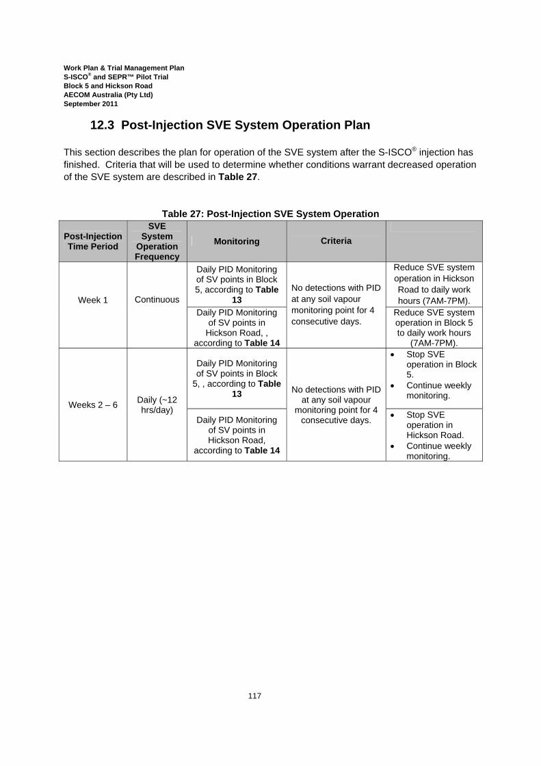
Work Plan & Trial Management Plan S-ISCO® and SEPR™ Pilot Trial Block 5 and Hickson Road AECOM Australia (Pty Ltd) September 2011
117
12.3 Post-Injection SVE System Operation Plan This section describes the plan for operation of the SVE system after the S-ISCO® injection has finished. Criteria that will be used to determine whether conditions warrant decreased operation of the SVE system are described in Table 27.
Table 27: Post-Injection SVE System Operation
Post-Injection Time Period
SVE System
Operation Frequency
Monitoring Criteria
Week 1
Continuous
Daily PID Monitoring of SV points in Block 5, according to Table
13 No detections with PID at any soil vapour monitoring point for 4 consecutive days.
Reduce SVE system operation in Hickson Road to daily work hours (7AM-7PM).
Daily PID Monitoring of SV points in
Hickson Road, , according to Table 14
Reduce SVE system operation in Block 5 to daily work hours
(7AM-7PM).
Weeks 2 – 6 Daily (~12 hrs/day)
Daily PID Monitoring of SV points in Block
5, , according to Table 13 No detections with PID
at any soil vapour monitoring point for 4
consecutive days.
• Stop SVE operation in Block 5.
• Continue weekly monitoring.
Daily PID Monitoring of SV points in Hickson Road,
according to Table 14
• Stop SVE operation in Hickson Road.
• Continue weekly monitoring.
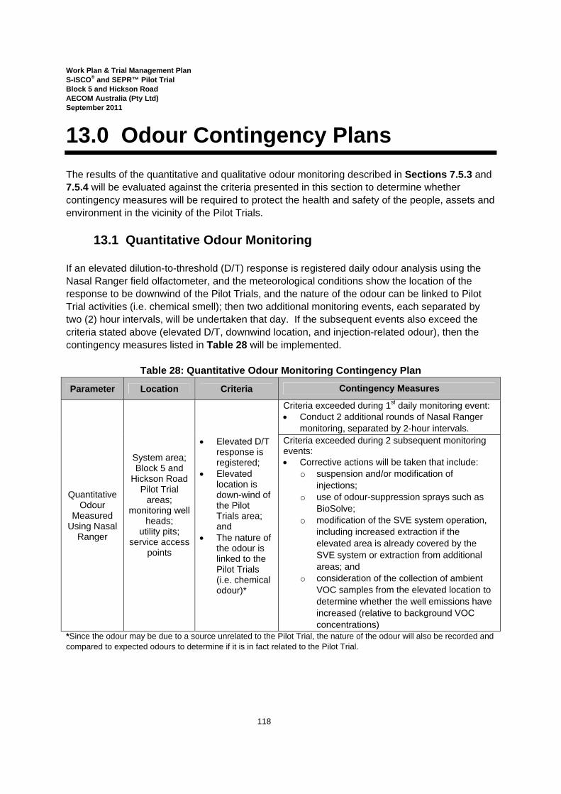
Work Plan & Trial Management Plan S-ISCO® and SEPR™ Pilot Trial Block 5 and Hickson Road AECOM Australia (Pty Ltd) September 2011
118
13.0 Odour Contingency Plans The results of the quantitative and qualitative odour monitoring described in Sections 7.5.3 and 7.5.4 will be evaluated against the criteria presented in this section to determine whether contingency measures will be required to protect the health and safety of the people, assets and environment in the vicinity of the Pilot Trials.
13.1 Quantitative Odour Monitoring If an elevated dilution-to-threshold (D/T) response is registered daily odour analysis using the Nasal Ranger field olfactometer, and the meteorological conditions show the location of the response to be downwind of the Pilot Trials, and the nature of the odour can be linked to Pilot Trial activities (i.e. chemical smell); then two additional monitoring events, each separated by two (2) hour intervals, will be undertaken that day. If the subsequent events also exceed the criteria stated above (elevated D/T, downwind location, and injection-related odour), then the contingency measures listed in Table 28 will be implemented.
Table 28: Quantitative Odour Monitoring Contingency Plan
Parameter Location Criteria Contingency Measures
Quantitative Odour
Measured Using Nasal
Ranger
System area; Block 5 and
Hickson Road Pilot Trial
areas; monitoring well
heads; utility pits;
service access points
• Elevated D/T response is registered;
• Elevated location is down-wind of the Pilot Trials area; and
• The nature of the odour is linked to the Pilot Trials (i.e. chemical odour)*
Criteria exceeded during 1st daily monitoring event: • Conduct 2 additional rounds of Nasal Ranger
monitoring, separated by 2-hour intervals. Criteria exceeded during 2 subsequent monitoring events: • Corrective actions will be taken that include:
o suspension and/or modification of injections;
o use of odour-suppression sprays such as BioSolve;
o modification of the SVE system operation, including increased extraction if the elevated area is already covered by the SVE system or extraction from additional areas; and
o consideration of the collection of ambient VOC samples from the elevated location to determine whether the well emissions have increased (relative to background VOC concentrations)
*Since the odour may be due to a source unrelated to the Pilot Trial, the nature of the odour will also be recorded and compared to expected odours to determine if it is in fact related to the Pilot Trial.

Work Plan & Trial Management Plan S-ISCO® and SEPR™ Pilot Trial Block 5 and Hickson Road AECOM Australia (Pty Ltd) September 2011
119
13.2 Qualitative Odour Monitoring The results of qualitative odour monitoring conducted according to Section 7.5.4 will be evaluated against the criteria in Table 29 to determine whether the contingency measures listed will be required.
Table 29: Qualitative Odour Monitoring Contingency Plan
Parameter Location Criteria Contingency Measures
Qualitative Odour
System area; Block 5 and
Hickson Road treatment
areas; monitoring well
heads; utility pits;
service access points
Workers identify a strong or
offensive odour associated with Pilot Trials, that
is, a naphthalene-like odour*
• Suspend or modify injections; and/or • Use odour-suppression sprays such as
BioSolve; and/or • Modify SVE system operation (including
increase extraction if the area is already covered by the SVE system or extract from additional areas).
• If the odour persists, consider* collection of ambient VOC samples from the location in question to determine whether the well emissions have increased (relative to background VOC concentrations).
*Note that the term "consider” used with respect to persistent odour noted above refers to the fact that, if the odour persists after the implementation of the listed contingency measures, it is unlikely that the odour is related to the S-ISCO treatment. Before collecting samples for VOC analysis, other potential odour sources will be evaluated and ruled out.
*Since the odour may be due to a source unrelated to the Pilot Trial, the nature of the odour will be recorded and compared to expected odours from the Pilot Trial to determine if it is in fact related to the Pilot Trial

Work Plan & Trial Management Plan S-ISCO® and SEPR™ Pilot Trial Block 5 and Hickson Road AECOM Australia (Pty Ltd) September 2011
120
14.0 Erosion & Sedimentation Control Monitoring & Contingency Plans
Erosion and sedimentation control strategies have been detailed in the CEMP. These strategies include:
• stormwater control devices; • minimise water infiltrating trenches through water diversions; • impermeable berms, impermeable coverings and diversion drains; • sediment control devices in gutters and before stormwater pits; • sloping the trench in Hickson Road toward the sump in the Hickson Road injection area; • enclosing the injection lines within the trench in PVC piping; • backfilling the trench and re-finishing disturbed pavement; and • establishing containment berms (as described in Section 4.1) for the injection system,
chemical tanks, spoils and waste containers. Throughout both drilling operations as well as Pilot Trials operations, a qualified environmental scientist will oversee, inspect and document the implementation of erosion/sedimentation control measures. Table 30 details the ITP for Erosion/Sedimentation control measures. Vehicles will be inspected for dust, mud and sediments before leaving the Site. As the Pilot Trial Site predominantly consists of hardstands / sealed areas and with no planned earthworks resulting in unsealed areas being tracked by vehicles, vehicle cleansing is not seen as a requirement.

Work Plan & Trial Management Plan S-ISCO® and SEPR™ Pilot Trial Block 5 and Hickson Road AECOM Australia (Pty Ltd) September 2011
121
Table 30: Erosion & Sedimentation Controls Inspection & Test Plan
Item Criteria Inspection Frequency Action Recording
Location
Stormwater and sediment control devices in gutters
and before stormwater pits
• Device effectively controls stormwater and sediment flows.
• Device is enduring and is not damaged.
• Daily; • More often
during rain/storm events (frequency determined by magnitude of the event);
• After rain events.
• Correct installation to enhance effectiveness.
• Clean/replace devices that a qualified person deems are compromised.
Checklist
Road surface diversion parallel to the trench in Hickson Road
Steel plates
• Stability of plates over trench.
• Effectiveness of coverage over trench.
• Re-position plates over trench.
• Replace damaged plates.
Sump at end of trench
• Accumulation of liquid.
• Pump out liquid. • Containerise in waste
storage area, test and characterise for disposal according to Waste Management Plan.
• Identify source of liquid and eliminate.
Junction boxes
Waste Storage Area and
Containers
• Integrity of the impermeable lining;
• The effectiveness of the berm at containing water;
• Integrity of the storage containers.
• Repair compromises to lining.
• Repair areas where liquid can escape or run off.
• Repair/replace damaged containers.
• Remove accumulated stormwater according to Stormwater Management Plan.
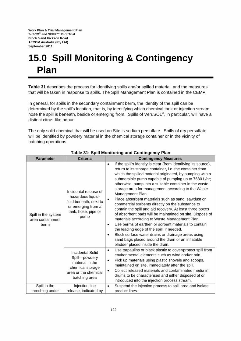
Work Plan & Trial Management Plan S-ISCO® and SEPR™ Pilot Trial Block 5 and Hickson Road AECOM Australia (Pty Ltd) September 2011
122
15.0 Spill Monitoring & Contingency Plan
Table 31 describes the process for identifying spills and/or spilled material, and the measures that will be taken in response to spills. The Spill Management Plan is contained in the CEMP. In general, for spills in the secondary containment berm, the identity of the spill can be determined by the spill’s location, that is, by identifying which chemical tank or injection stream hose the spill is beneath, beside or emerging from. Spills of VeruSOL®, in particular, will have a distinct citrus-like odour. The only solid chemical that will be used on Site is sodium persulfate. Spills of dry persulfate will be identified by powdery material in the chemical storage container or in the vicinity of batching operations.
Table 31: Spill Monitoring and Contingency Plan Parameter Criteria Contingency Measures
Spill in the system area containment
berm
Incidental release of hazardous liquid-
fluid beneath, next to or emerging from a tank, hose, pipe or
pump
• If the spill’s identity is clear (from identifying its source), return to its storage container, i.e. the container from which the spilled material originated, by pumping with a submersible pump capable of pumping up to 7680 L/hr; otherwise, pump into a suitable container in the waste storage area for management according to the Waste Management Plan.
• Place absorbent materials such as sand, sawdust or commercial sorbents directly on the substance to contain the spill and aid recovery. At least three boxes of absorbent pads will be maintained on site. Dispose of materials according to Waste Management Plan.
• Use berms of earthen or sorbent materials to contain the leading edge of the spill, if needed.
• Block surface water drains or drainage areas using sand bags placed around the drain or an inflatable bladder placed inside the drain.
Incidental Solid Spill—powdery material in the
chemical storage area or the chemical
batching area
• Use tarpaulins or black plastic to cover/protect spill from environmental elements such as wind and/or rain.
• Pick up materials using plastic shovels and scoops, maintained on site, immediately after the spill.
• Collect released materials and contaminated media in drums to be characterised and either disposed of or introduced into the injection process stream.
Spill in the trenching under
Injection line release, indicated by
• Suspend the injection process to spill area and isolate product lines.

Work Plan & Trial Management Plan S-ISCO® and SEPR™ Pilot Trial Block 5 and Hickson Road AECOM Australia (Pty Ltd) September 2011
123
Parameter Criteria Contingency Measures Hickson Road an unintended drop
in flow pressure and/or an observed accumulation of fluid in the junction box of
the trench.
• Flush secondary PVC containment conduit with water to remove residual material. Collect and characterise flushed material for proper disposal.
• Inspect the secondary containment PVC for signs of cracks and/or damage which may have caused the release.
• Containerise, characterise and properly dispose of contaminated media.
• Repair or replace the cause of the release prior to restarting the injection process.
Spill in the injection line or
well head
Fluid accumulation beneath injection
line or at well head
• Suspend injection process and isolate product lines. • If necessary, use berms of earthen or sorbent materials
to contain the leading edge of the spill and block surface water drains or drainage areas with sand bags or an inflatable bladder.
• Depending on volume of fluid, either use a submersible pump to remove fluid to waste storage container (in containment berm) or place absorbent materials such as sand, sawdust or commercial sorbents directly on the spill to contain the spill and aid recovery.
• Test impacted media for process chemicals that would require collection and management.
• Repair and/or replace the cause of the release prior to restarting injections.
Spill in the Containment berm,
injection line, or well head
Sodium persulfate release: fluid from
storage tank or powder from storage container or batching
• Neutralise aqueous material with bicarbonate powder by broadcasting on top of chemical spill until it is absorbed. After absorption shovel powder into drums to be characterised and disposed of properly.
• Sweep up spilled persulfate powder and return to the chemical storage area.
Peroxide spill- fluid beneath or emerging
from the peroxide IBCs or injection
lines
• Dilute material with copious amounts of water within the secondary containment unit and return to peroxide storage container by pumping with a submersible pump.
• Use sorbent material to remove residual material; dispose of according to Waste Management Plan.
Day-lighting in the Injection well
heads
Visual detection of injected fluid on the ground surface near
an injection well
• Treat emergence as a spill. • Temporarily suspend injection to area of occurrence. • Assess causes and alter operational parameters of
system (rate, concentration, pressure), and correct/modify system and injection parameters.
• Resume injections gradually and ramp up to desired levels with a doubled frequency of monitoring the injection well.
Work Plan & Trial Management Plan S-ISCO® and SEPR™ Pilot Trial Block 5 and Hickson Road AECOM Australia (Pty Ltd) September 2011
124
16.0 Reporting & Documentation 16.1 Health and Safety Reporting
Section 10 of VeruTEK's HASP describes reporting and documentation that will be carried out during the Pilot Trials. Appendix G to the HASP includes forms that will be used for this reporting and documentation. Reporting and documentation includes:
• Plant certifications, to be provided to LL-PMC, prior to their arrival and after modifications are made;
• Records of plant maintenance (according to manufacturer’s specifications and the ITP) ; • Copies of design certificates; • Daily log books; and • Work statistics addressing safety, labour, inspection and waste.
16.2 Regulatory Authority Reporting
VeruTEK will prepare and submit to DECCW for review, a weekly13 report against the contingency triggers detailed in the WPTMP. The report will demonstrate that the management controls and procedures are sufficiently and accurately assessing the location of the injection front to determine plume movement and temperature, for example. The report will also include any instances where triggers have been reached and a description of what contingencies were implemented.
16.3 Pilot Trial Summary Report Following completion of the Pilot Trial activities, a Pilot Trial Summary Report will be prepared by VeruTEK. The Pilot Trial Summary Report will include a summary of S-ISCO® Pilot Trial activities, document any changes to the Revised Work Plan & Trial Management Plan, document the final disposal of wastes, and contain a statement that the work was performed in accordance with this Revised Work Plan & Trial Management Plan, Construction Environmental Management Plan and any approved changes to those documents. The Pilot Trial Summary report will also evaluate the success of the project in achieving the goals and objectives set forth in Section 1.1, provide recommendations for the full scale implementation of S-ISCO® and SEPR™ to treat the areas of Block 5 and Hickson Road requiring remediation. Specific components of the Pilot Trial Summary Report will include:
• Chemical Injection Totals; • System Operational Data and Analysis;
13 This report will be filed weekly unless a modified frequency is agreed to by DECCW.
Work Plan & Trial Management Plan S-ISCO® and SEPR™ Pilot Trial Block 5 and Hickson Road AECOM Australia (Pty Ltd) September 2011
125
o Process and Performance Monitoring Data and Analysis, including: analysis of the subsurface distribution of injected co-solvent/surfactant-
enhanced activated oxidant; the potential for un-reacted S-SICO® and/or SEPR™ chemical migration
towards Darling Harbour and the basement of 38 Hickson Road, as wells as,
analysis of mitigation measures implemented to prevent or minimise migration and volatile emissions;
o Pre- and Post-Injection Soil Sampling Data and Analysis; • Soil Boring Logs and Photographs; • Pre- and Post-Injection Groundwater Data; • Groundwater analysis results and Flux Analysis, including an evaluation of the
effectiveness of S-ISCO® in reducing COC concentrations in groundwater migrating from the Site;
• The hydraulic relationship of liquids and vapours inside the tar tank in Hickson Road with groundwater and vapours outside of the tar tank ;
• Pre, During and Post-Injection Soil Vapour Monitoring Data; • Overall Analysis of S-ISCO® and SEPR™ Pilot Trial effectiveness, specifically in
reference to the removal of 25 percent of the tar contamination mass from Hickson Road and the ability of the treatment to remediate soil and groundwater COC contamination in Block 5 to levels consistent with the remediation goals such that the DECCW Declaration can be removed;
• Hydraulic modeling of the S-ISCO® and SEPR™ injection processes for the purpose of designing the Full-Scale implementation (as appropriate); and
• Recommendation for full scale implementation of S-ISCO® and SEPR™, including: o Chemical doses; o Chemical formulation; o Injection procedures; o Injection flow rates; o Well spacing; and o Monitoring type and frequency.
Work Plan & Trial Management Plan S-ISCO® and SEPR™ Pilot Trial Block 5 and Hickson Road AECOM Australia (Pty Ltd) September 2011
126
References AECOM, 2010a. Groundwater Discharge Study, Stage 1 Barangaroo Development, Hickson Road, Darling harbour, New South Wales. 3 November 2010 AECOM Australia Pty. Ltd, 2010b. Data Gap Investigation, EPA Declaration Area (Parts of Barangaroo Site and Hickson Road), Millers Point, NSW. 23 September 2010. AECOM Australia Pty. Ltd, 2010c. Amended Remedial Action Plan, Barangaroo - Other Remediation Works (South) Area. 7 July 2011. AECOM Australia Pty. Ltd, 2010d. Sampling, Analytical and Quality Plan, Other Remediation Works (North) Data Gap Investigation, Millers Point, NSW. 10 March 2010. AECOM Australia Pty. Ltd, 2010e. Soil and Water Impact Assessment: S-ISCO Pilot Trials Block 5 and Hickson Road, Millers Point. 7 October 2010. AECOM Australia Pty. Ltd, 2010f. Waste Management Plan: S-ISCO Pilot Trials Block 5 and Hickson Road, Millers Point. 30 September 2010. AECOM, 2011. Human Health and Ecological Risk Assessment Declaration Site (Development Works) Remediation Works Area - Barangaroo. 9 June2011. AECOM, 2011a. Human Health and Ecological Risk Assessment Addendum Other Remediation Works South Area, Barangaroo. 4 July 2011. Coffey Environments Report, 2008. Preliminary Environmental Investigation, 30-38 Hickson Road, Millers Point, NSW 2000. 12 May. ERM, 2007. Environmental Site Assessment, East Darling Harbour, Sydney, NSW, Final Report. 21 June. The Colorado Department of Labor and Employment Division of Oil and Public Safety, 2007. Petroleum Hydrocarbon Remediation by In-situ Chemical Oxidation at Colorado Sites. June 2007. NSW Department of Environment and Climate Change and Water (DECCW) 2007. Storing and Handling Liquids: A guide to managing environmental risks associated with the storage and handling of liquid substances. Environmental Protection. NSW Department of Environment and Climate Change (DECC) 2008. Waste Classification Guidelines, Part 1: Classifying Waste.

Work Plan & Trial Management Plan S-ISCO® and SEPR™ Pilot Trial Block 5 and Hickson Road AECOM Australia (Pty Ltd) September 2011
127
Northwest Growth Centres. Specific Technical Requirements for Northwest Growth Centres Initial Release Infrastructure Package 1, Design and Construct Contract to Deliver Water Related Infrastructure. Tender No. 0510022685. VeruTEK, 2010. Treatability Study Recommendations for the Implementation of an In Situ Remedy, Barangaroo – Blocks 5 and Hickson Rd Site, Lend Lease (LL), Sydney, Australia. 23 September, 2010.


Darling Harbour
Other Remediation Works(North) Area
Other Remediation Works(South) Area
VMP & PDARemediation Works Area
PUBLIC
DOMAIN
PROPOSED
SOUTHERN
COVE
5
4
OTHER REMEDIATION WORKS (NORTH) AREA DGI
4
Block 5 and HicksonRoad Pilot Trial
FIGURE 1A

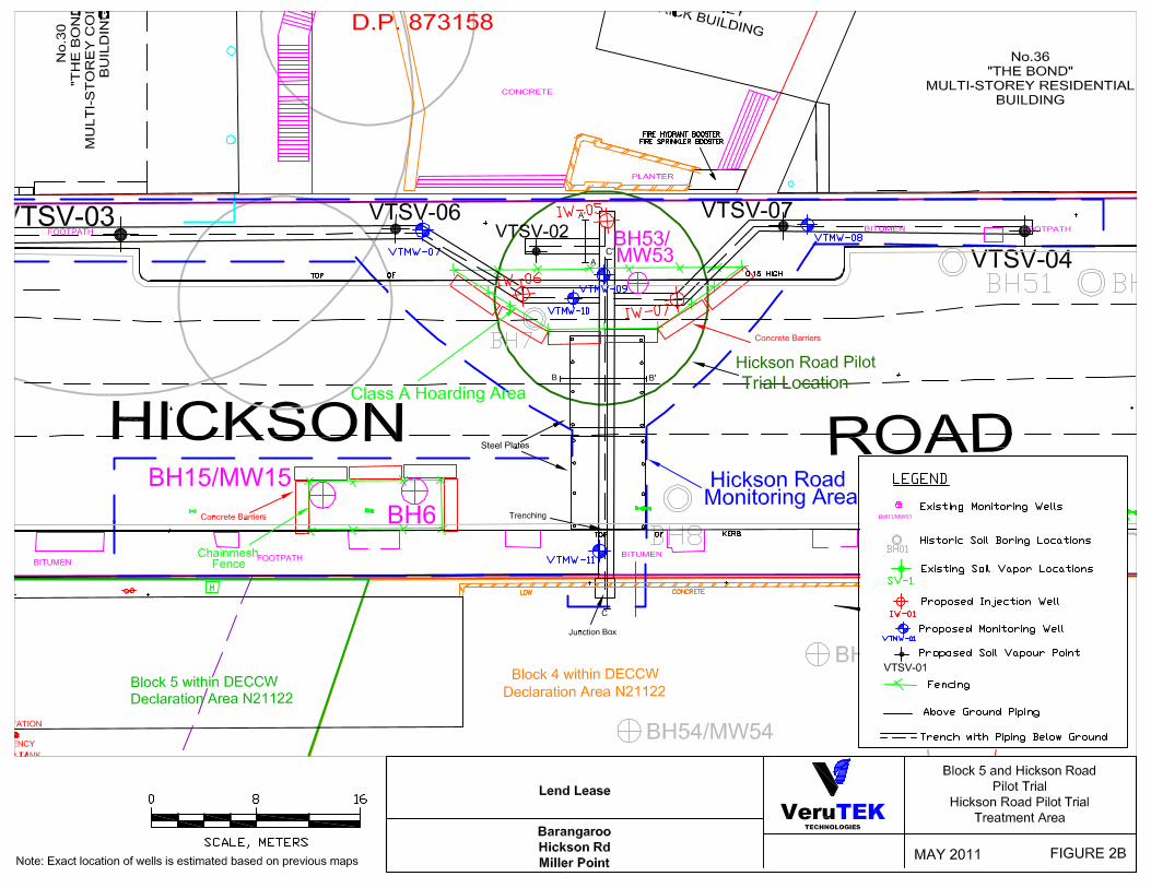
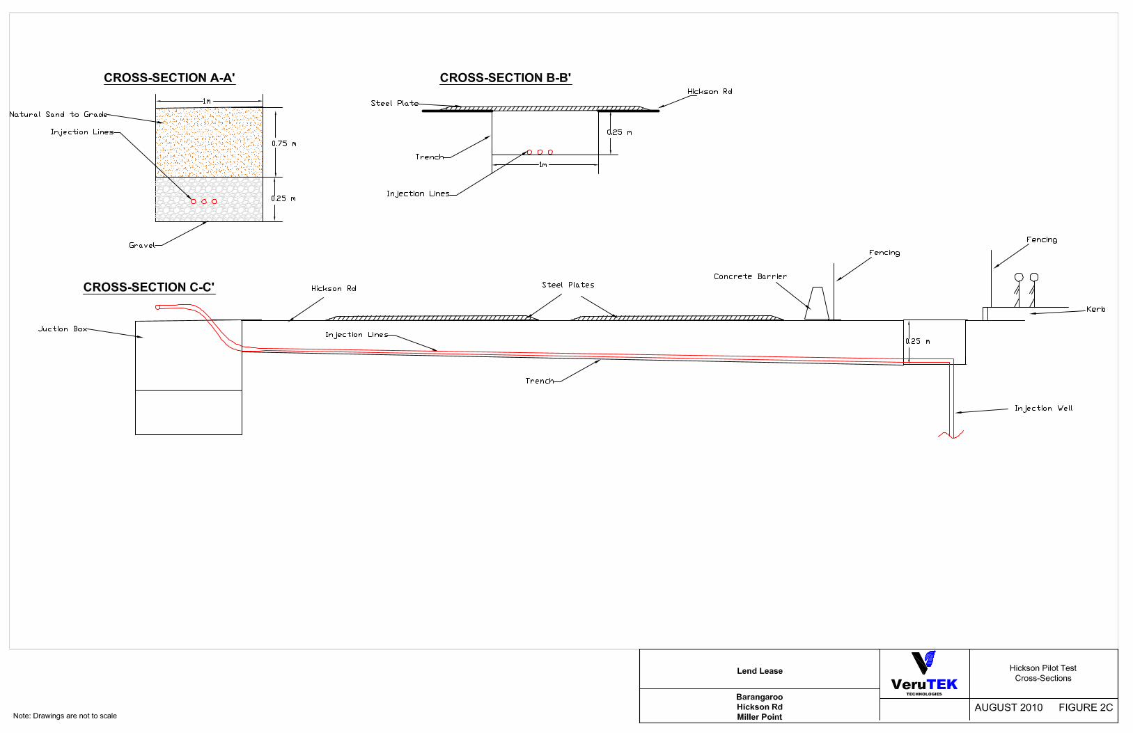
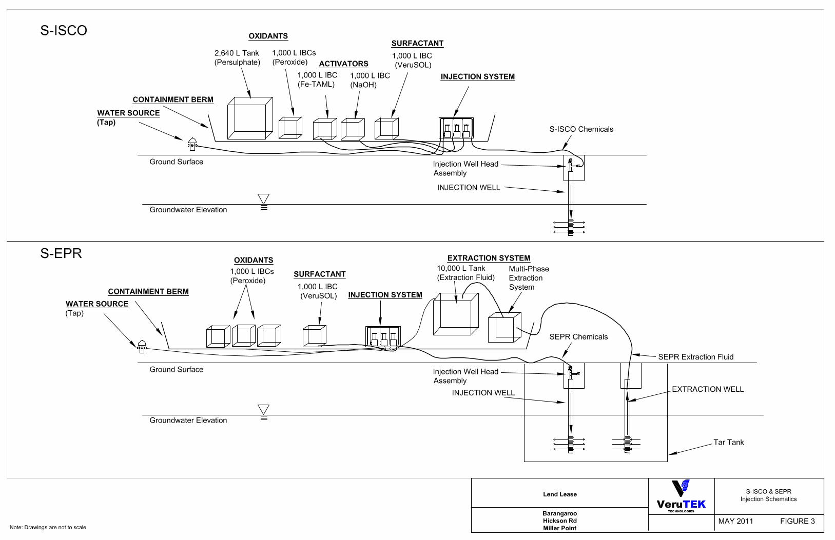

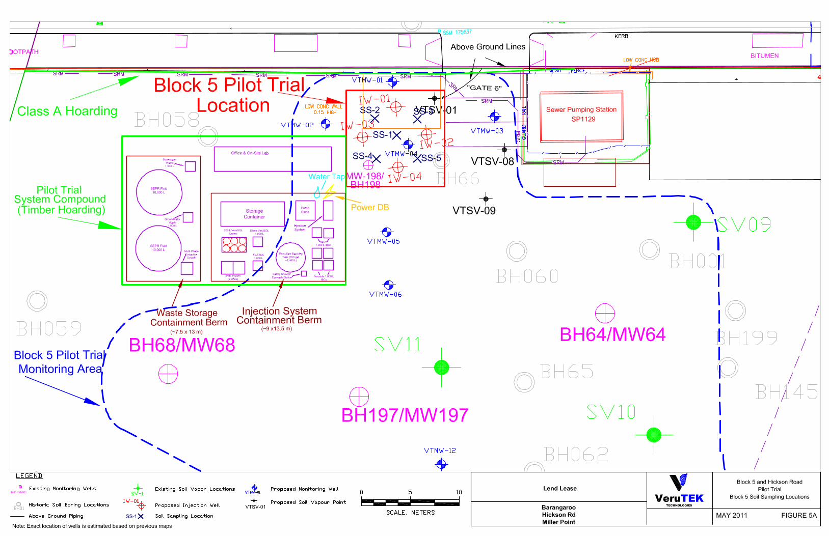


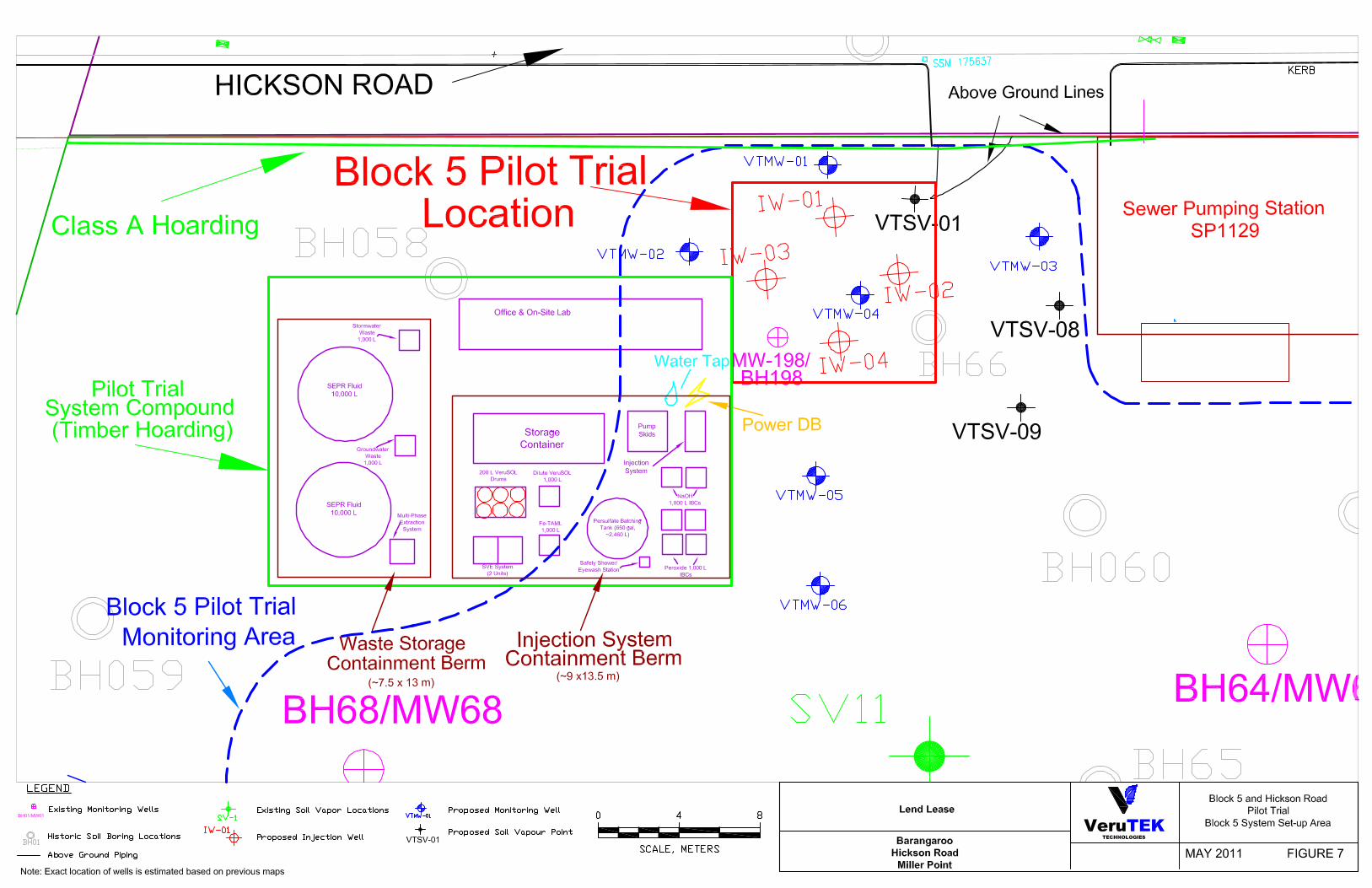
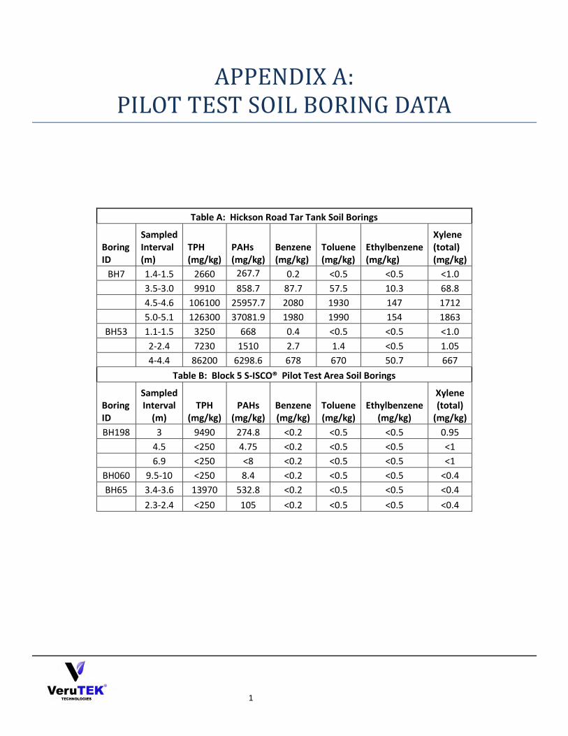
1
APPENDIX A:
PILOT TEST SOIL BORING DATA
Table A: Hickson Road Tar Tank Soil Borings
Boring ID
Sampled Interval (m)
TPH (mg/kg)
PAHs (mg/kg)
Benzene (mg/kg)
Toluene (mg/kg)
Ethylbenzene (mg/kg)
Xylene (total) (mg/kg)
BH7 1.4-1.5 2660 267.7 0.2 <0.5 <0.5 <1.0
3.5-3.0 9910 858.7 87.7 57.5 10.3 68.8
4.5-4.6 106100 25957.7 2080 1930 147 1712
5.0-5.1 126300 37081.9 1980 1990 154 1863
BH53 1.1-1.5 3250 668 0.4 <0.5 <0.5 <1.0
2-2.4 7230 1510 2.7 1.4 <0.5 1.05
4-4.4 86200 6298.6 678 670 50.7 667
Table B: Block 5 S-ISCO® Pilot Test Area Soil Borings
Boring ID
Sampled Interval
(m) TPH
(mg/kg) PAHs
(mg/kg) Benzene (mg/kg)
Toluene (mg/kg)
Ethylbenzene (mg/kg)
Xylene (total)
(mg/kg)
BH198 3 9490 274.8 <0.2 <0.5 <0.5 0.95
4.5 <250 4.75 <0.2 <0.5 <0.5 <1
6.9 <250 <8 <0.2 <0.5 <0.5 <1
BH060 9.5-10 <250 8.4 <0.2 <0.5 <0.5 <0.4
BH65 3.4-3.6 13970 532.8 <0.2 <0.5 <0.5 <0.4
2.3-2.4 <250 105 <0.2 <0.5 <0.5 <0.4

1
APPENDIX B: WELL CONSTRUCTION DIAGRAMS AND
DETAILS
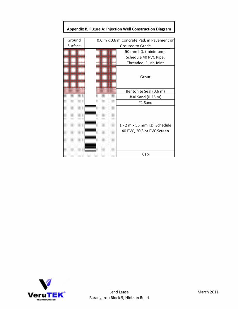
Ground
Surface
Bentonite Seal (0.6 m)
#00 Sand (0.25 m)
#1 Sand
Cap
1 - 2 m x 55 mm I.D. Schedule
40 PVC, 20 Slot PVC Screen
Appendix B, Figure A: Injection Well Construction Diagram
0.6 m x 0.6 m Concrete Pad, in Pavement or
Grouted to Grade
50 mm I.D. (minimum),
Schedule 40 PVC Pipe,
Threaded, Flush Joint
Grout
Lend Lease
Barangaroo Block 5, Hickson Road
March 2011
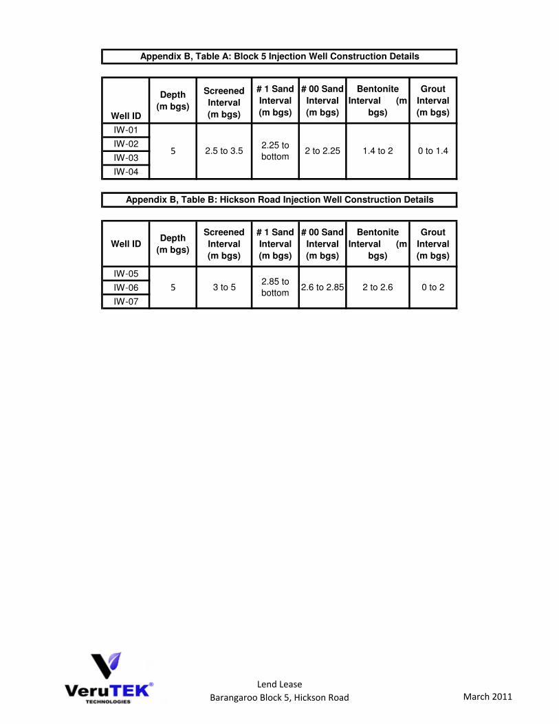
Well ID
Depth
(m bgs)
Screened
Interval
(m bgs)
# 1 Sand
Interval
(m bgs)
# 00 Sand
Interval
(m bgs)
Bentonite
Interval (m
bgs)
Grout
Interval
(m bgs)
IW-01
IW-02
IW-03
IW-04
Well IDDepth
(m bgs)
Screened
Interval
(m bgs)
# 1 Sand
Interval
(m bgs)
# 00 Sand
Interval
(m bgs)
Bentonite
Interval (m
bgs)
Grout
Interval
(m bgs)
IW-05
IW-06
IW-07
Appendix B, Table A: Block 5 Injection Well Construction Details
5 2.5 to 3.52.25 to
bottom2 to 2.25 1.4 to 2 0 to 1.4
Appendix B, Table B: Hickson Road Injection Well Construction Details
5 3 to 52.85 to
bottom2.6 to 2.85 2 to 2.6 0 to 2
Lend Lease
Barangaroo Block 5, Hickson Road March 2011
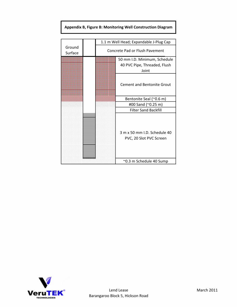
Ground
Surface
Bentonite Seal (~0.6 m)
#00 Sand (~0.25 m)
Filter Sand Backfill
~0.3 m Schedule 40 Sump
3 m x 50 mm I.D. Schedule 40
PVC, 20 Slot PVC Screen
Appendix B, Figure B: Monitoring Well Construction Diagram
1.1 m Well Head; Expandable J-Plug Cap
Concrete Pad or Flush Pavement
50 mm I.D. Minimum, Schedule
40 PVC Pipe, Threaded, Flush
Joint
Cement and Bentonite Grout
Lend Lease
Barangaroo Block 5, Hickson Road
March 2011
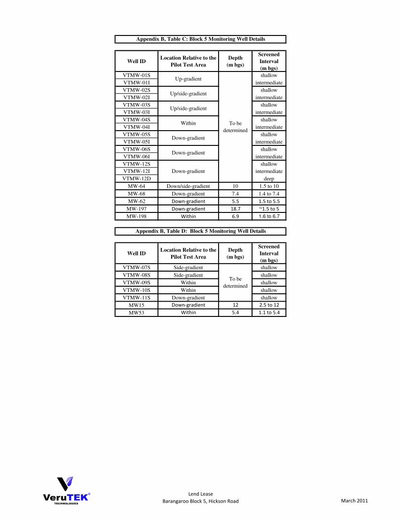
Well IDLocation Relative to the
Pilot Test Area
Depth
(m bgs)
Screened
Interval
(m bgs)
VTMW-01S shallow
VTMW-01I intermediate
VTMW-02S shallow
VTMW-02I intermediate
VTMW-03S shallow
VTMW-03I intermediate
VTMW-04S shallow
VTMW-04I intermediate
VTMW-05S shallow
VTMW-05I intermediate
VTMW-06S shallow
VTMW-06I intermediate
VTMW-12S shallow
VTMW-12I intermediate
VTMW-12D deep
MW-64 Down/side-gradient 10 1.5 to 10
MW-68 Down-gradient 7.4 1.4 to 7.4
MW-62 Down-gradient 5.5 1.5 to 5.5
MW-197 Down-gradient 18.7 ~1.5 to 5
MW-198 Within 6.9 1.6 to 6.7
Well IDLocation Relative to the
Pilot Test Area
Depth
(m bgs)
Screened
Interval
(m bgs)
VTMW-07S Side-gradient shallow
VTMW-08S Side-gradient shallow
VTMW-09S Within shallow
VTMW-10S Within shallow
VTMW-11S Down-gradient shallow
MW15 Down-gradient 12 2.5 to 12
MW53 Within 5.4 1.1 to 5.4
To be
determined
To be
determined
Appendix B, Table D: Block 5 Monitoring Well Details
Down-gradient
Down-gradient
Down-gradient
Appendix B, Table C: Block 5 Monitoring Well Details
Up-gradient
Up/side-gradient
Up/side-gradient
Within
Lend Lease
Barangaroo Block 5, Hickson Road March 2011
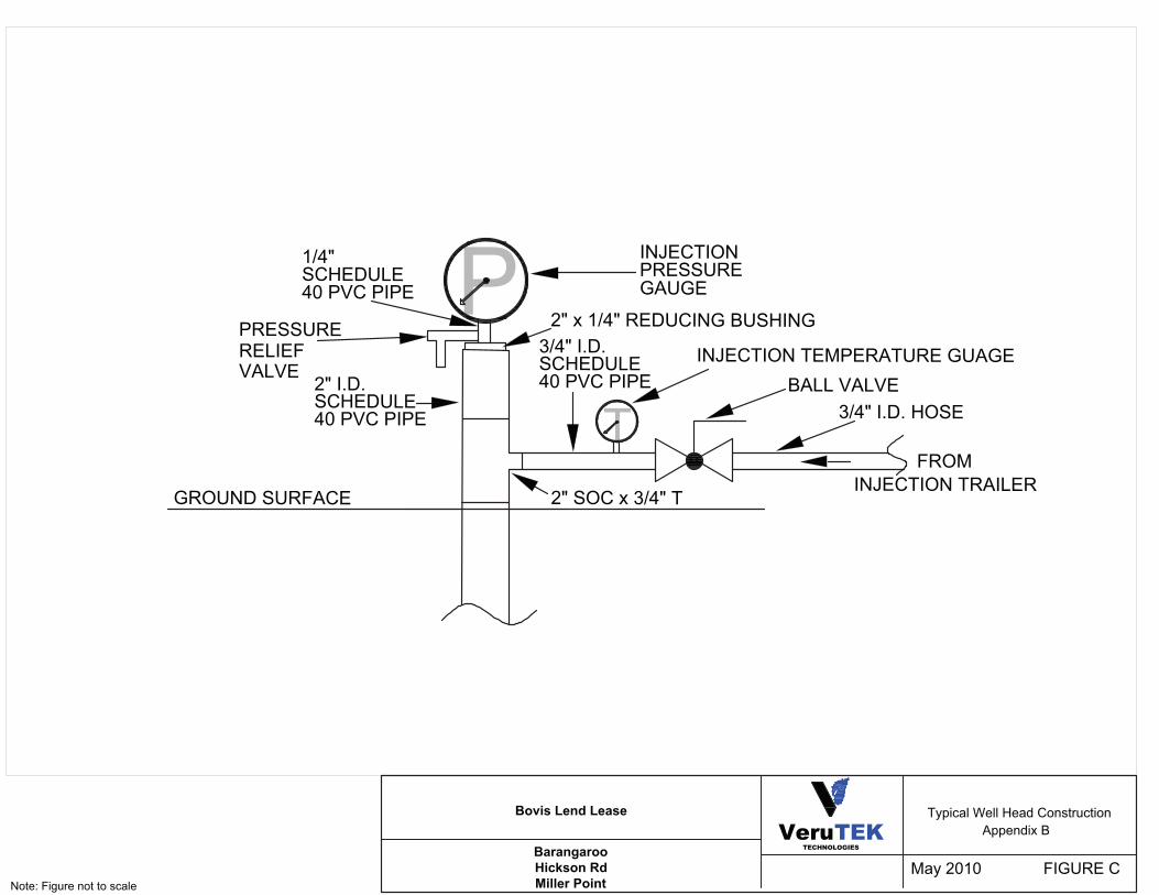
!
"#$%&'()%#*+,-
!#-))%#-
.+//(0+/0-
1&2-, 1$&(
#-/1-*0+/0-
!#-))%#-("+%"-
*#$3(
1&2-, 1$&( #+1/-#
4567(18'8(9$)-
4567(18'8(),9-'%/-(6:(!0,(!1!-;7(18'8(
),9-'%/-(6:(!0,(!1!-
;7()$,(<(4567(
;7(<(=567(#-'%,1&"(.%)91&"
6:(!0,(!1!-),9-'%/-=567
1&2-, 1$&( -3!-#+ %#-("%+"-
3>?(;:=: *1"%#-(,
?@AB>C(DECC(9E>F(,GHIJKLBJAGH
(((((((((((((((+@@EHFA<(.(
(VeruTEK
TECHNOLOGIES
&GJEM(*ANLKE(HGJ(JG(IB>CE
Bovis Lend Lease
Barangaroo
Hickson Rd
Miller Point
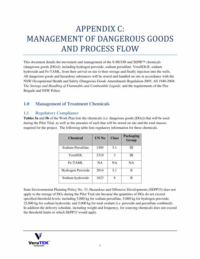
1
APPENDIX C:
MANAGEMENT OF DANGEROUS GOODS
AND PROCESS FLOW
This document details the movement and management of the S-ISCO® and SEPR™ chemicals
(dangerous goods [DGs]), including hydrogen peroxide, sodium persulfate, VeruSOL®, sodium
hydroxide and Fe-TAML, from their arrival on site to their storage and finally injection into the wells.
All dangerous goods and hazardous substances will be stored and handled on site in accordance with the
NSW Occupational Health and Safety (Dangerous Goods Amendment) Regulation-2005; AS 1940-2004:
The Storage and Handling of Flammable and Combustible Liquids; and the requirements of the Fire
Brigade and NSW Police.
1.0 Management of Treatment Chemicals
1.1 Regulatory Compliance
Tables 5a and 5b of the Work Plan lists the chemicals (i.e. dangerous goods [DGs]) that will be used
during the Pilot Trial, as well as the amounts of each that will be stored on site and the total masses
required for the project. The following table lists regulatory information for these chemicals.
Chemical UN No Class Packaging
Group
Sodium Persulfate 1505 5.1 III
VeruSOL 2319 3 III
Fe-TAML NA NA NA
Hydrogen Peroxide 2014 5.1 II
Sodium hydroxide 1823 8 II
State Environmental Planning Policy No. 33, Hazardous and Offensive Developments (SEPP33) does not
apply to the storage of DGs during the Pilot Trial site because the quantities of DGs do not exceed
specified threshold levels: including 5,000 kg for sodium persulfate, 5,000 kg for hydrogen peroxide;
25,000 kg for sodium hydroxide; and 5,000 kg for total oxidant (i.e. peroxide and persulfate combined).
In addition the delivery schedule, including weight and frequency, for sourcing chemicals does not exceed
the threshold limits to which SEPP33 would apply.
2
1.2 Delivery and Storage
• Water:
o Arrival: Water will arrive to the site via a tap installed in the vicinity of the injection
system, in the containment area. The water stream will flow through a backflow
preventer before it splits into two streams.
o Storage: One water stream will end at the safety shower and eye wash station(s), and
the other stream will flow to the injection system.
• Fe-TAML: o Arrival: The Fe-TAML activator will be carried to the site as dry chemical.
o Storage: Fe-TAML will be immediately batched on its arrival on site. It will be
mixed with water in a 1,000 L IBC using an agitation device. Any spills will be
cleaned up immediately, according to the procedures outlined in the CMP.
• VeruSOL®:
o Arrival: VeruSOL® will arrive at the site in 55 gallon (~200 L) drums.
o Storage: VeruSOL®, Class 3, will be stored in unopened drums and as a batched
solution in a 1,000 L IBC. Any spills will be cleaned up immediately, according to
the procedures outlined in the CMP.
• Hydrogen Peroxide:
o Arrival: The hydrogen peroxide will arrive at the site in 1,000 L IBCs of 50%
solution.
o Storage: Peroxide, a Class 5.1 oxidizing agent, will be stored in 1,000 L IBCs away
from heat sources, and combustible material or incompatible substances; and away
from its activator, Fe-TAML. All spills will be cleaned up immediately, according to
the procedures outlined in the CMP.
• Sodium Persulfate:
o Arrival: Persulfate will arrive on site as dry powder in either 1,000 kg super sacks or
25 kg bags.
o Storage: Dry persulfate will be stored in a chemical storage container on site.
Persulfate solution, a Class 5.1 oxidizing agent, will be prepared and stored in a
2,460 L tank away from heat sources, combustible material or incompatible
substances, and its activator, sodium hydroxide. All spills will be cleaned up
immediately, according to the procedures outlined in the CMP.
• Sodium Hydroxide:
o Arrival: Sodium hydroxide will arrive in liquid form as a 25% solution. o Storage: Hydroxide, Class 8, will be stored in 1,000 L IBCss in the vicinity of a
safety shower and eyewash station, away from persulfate. All spills will be cleaned
up immediately, according to the procedures outlined in the CMP.
1.3 Chemical Batching
The following batching operations will take place during the Pilot Trials to prepare stock solutions for
injection:
• VeruSOL will be prepared by combining 1 drum (~208 L) of VeruSOL with approximately930 L
of water;
• Fe-TAML will be prepared by combining the Fe-TAML powder with approximately 900 L of
water; and

3
• Persulfate will be prepared by combining 1 super-sack of sodium persulfate (1000 kg) with
approximately 2000 L of water.
Batching operations will take place in the bermed containment area and personnel involved in the
operations will don the personal protective equipment specified by the MSDS for the material with which
they are working. This may include a half-face negative-pressure respirator and chemical protective
clothing.
1.2.1 VeruSOL Batching
When handling VeruSOL, personnel will don the following PPE:
• Chemical splash goggles;
• Face shield;
• Double nitrile gloves;
• Tyvek Suit;
• Steel Toed boots with over-boots; and
• Respiratory protection consisting of : a filter respirator, with a filter for organic gases and vapours
during short-term or slight exposure; or a respirator that is independent of the environment for intense
or prolonged exposure.
Personnel handling VeruSOL should avoid inhalation of vapours and aerosols and ensure sufficient
ventilation in the work area.
Batching will begin by adding approximately 750 L of water to a 1,000 L IBC. Next attach a Lutz pump
to the VeruSOL drum to pump the surfactant into the water. Use minimal agitation to combine the
solution in order to avoid sudsing. Wash hands with soap and water when finished.
1.2.2 Fe-TAML Batching
When handling Fe-TAML, personnel will don the following PPE:
• Chemical splash goggles;
• Face shield;
• Double nitrile gloves;
• Tyvek Suit;
• Steel Toed boots with over-boots; and
• NIOSH-certified dust/mist respirator (95%).
Personnel handling Fe-TAML should avoid contact with eyes, skin and clothing; and use adequate
ventilation.
Batching will begin with adding approximately 900 L of water to a 1,000 L IBC. Next the contents of the
vial containing Fe-TAML powder will be carefully deposited into the liquid. Finally, an agitation device
will be used to thoroughly mix the solution.
4
1.2.3 Persulfate Batching
Persulfate batching procedures, detailed in a Safe Work Method Statement (SWMS) contained in
Appendix E of the VeruTEK HASP, will be followed to minimise production of and exposure to chemical
dust. These procedures include:
• All personnel involved in this chemical batching process, with the exception of the fork lift
operator, will don Level C personal protective equipment (PPE), including:
o A Tyvek (or equivalent) chemical protective suit with overboots;
o Chemical splash goggles; o Full-face negative pressure respirator, and
o Chemical protective gloves.
• Batching will take place in an exclusion zone that restricts access of site personnel to any dust
that may be generated, beneath a tent.
Persuflate batching begins with adding approximately 1,900 L of water to 650 gallons/~2,640 L chemical
resistant poly tank and activating a recirculation pump to mix the water. A fork lift will move the sodium
persulfate powder from a pallet in the chemical storage area to a position above the batching tank. With
the opening of the bottom of the sack above the mouth of the tank, the batching technician will open the
sack and slowly guide the dry chemical into the tank, minimising production and dissemination of dust.
Following each addition of dry persulfate, the recirculation pump will operate for a minimum of one hour
to allow the chemical to effectively and safety enter into solution.
2.0 Process Flow The process streams that comprise the injection process are: water, activator (Fe-TAML and/or sodium
hydroxide), surfactant (VeruSOL®),
and Oxidant (Sodium Persulfate1 and/or Peroxide). A process flow
diagram for the injection system has been included as Figure A. Note that backflow preventers are
present on each chemical supply line to prevent the cross-contamination of chemicals within the chemical
storage tanks.
The water stream (#1) flows from the tap to the injection system through a flow meter (FM-1). The
VeruSOL® stream (2) flows through a metering pump (MP-1) and the activator stream (3) flows through
a second metering pump (MP-2) to join the water stream. This combined stream is composed of proper
dilutions of chemical prior to its mixing by the first inline mixer (IM-1).
The oxidant stream (4) flows through its metering pump (MP-3) to join with the combined water,
surfactant and activator stream. This complete S-ISCO®/SEPR™ stream then enters the second inline
mixer (IM-2) before it is pumped to the injection wells.
1 Due to the corrosive nature of sodium persulfate, when used, all pumps, piping, and ancillary injection equipment
are chemically compatible with corrosive materials
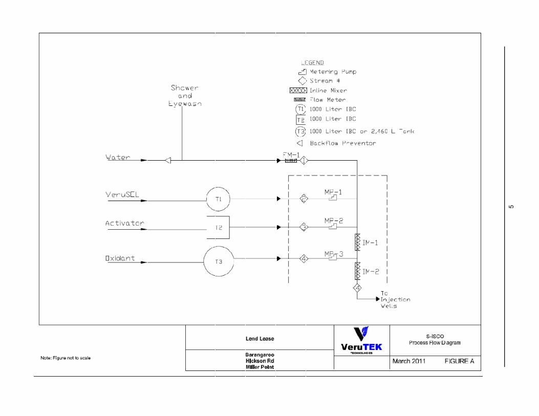
5

1
APPENDIX D:
PROCESS AND PERFORMANCE
MONITORING LOG FORMS
PROCESS LOG FORM Stream ID:
Sample
Location ID
Sample Date
Sample Time
Analysis Date
Temp. (°C)
Oxidant (mg/L)
pH Spec. Cond.
(mS/cm)
ORP (mV)
IFT (mN/m)
Sampler Initials
Lab Initial
s
Property of VeruTEK®

2
DATA LOGGER LOG FORM
WELL ID:
Sample
Date
Time (Start Purge)
Time (End
Purge)
Cond. (mS/cm)
Dissolved Oxygen (mg/l)
pH Temp.
(°C) Turbidity
(NTU) ORP (mV)
Sampler Initials
Property of VeruTEK®

3
ON-SITE LAB LOG FORM
SAMPLE ID:
Date Time
IFT (mN/m)
Color Turbidity (NTUs)
ORP (mV)
pH Temp.
(°C) Cond.
(mS/cm) Oxidant (mg/L)
Sampler Lab
Initials
Property of VeruTEK®
1
APPENDIX E:
SOIL VAPOUR EXTRACTION SYSTEM
Throughout the entire S-ISCO® and SEPR™ Pilot Trial, a Soil Vapour Extraction (SVE) system will be
in use to mitigate any potential odors or air pollution caused by reactions between injected oxidants and
contaminants. The purpose of the SVE system is not to treat or remediate contamination but rather to
capture and treat vapours that may be displaced by oxygen generated by the oxidative reactions. The
SVE system will consist of a vacuum pump that continuously draws vapour from soil vapour monitoring
points installed in areas of sensitive receptors in the vicinity of the Hickson Road and Block 5 Pilot
Trials; granulated active carbon filters that treat this air; and an exhaust stack that discharges air that is
safe for humans and the environment.
This document describes the SVE system, including the treatment unit’s design specifications, operational
parameters, and maintenance plan; the extraction process, including the locations of the extraction points;
the treatment criteria that the system will attain; and a set of triggers and contingency measures that will
be implemented to ensure that the system is adequately protecting the health and safety of sensitive
receptors in the vicinity of the Pilot Trials, in accordance with the requirements of its licence.
1.0 Soil Vapour Points
Soil vapour extraction will take place from eleven soil vapour (SV) points in the vicinity of the Pilot Trial
treatment areas, including six (VTSV-02, VTSV-03, VTSV-04, VTSV-05, VTSV-06 and VTSV-07) in
Hickson Road and five (VTSV-01, VTSV-08, SV09, SV10 and SV11) in Block 5.
Tables 1a and 1b describe the details of the SV points to be installed as well as those already present at
the Site.
Table 1a: SV Point Construction Details,
Block 5
SV Point ID Status Screen Depth (m
bgs)
SV-09
Installed
0.8 to 1
SV-10 1.3 to 1.5
SV-11 0.3 to 0.5
1.3 to 1.5
VTSV-01 To be
installed
~0.3 to 0.5
~1.3 to 1.5
VTSV-08 ~0.3 to 0.5
~1.3 to 1.5

2
Table 1b: SV Point Construction Details,
Hickson Road
SV Point ID Status Screen Depth (m
bgs)
VTSV-02
To be
Installed
~0.3 to 0.5
~1.3 to 1.5
VTSV-03 ~0.3 to 0.5
~1.3 to 1.5
VTSV-04 ~0.3 to 0.5
~1.3 to 1.5
VTSV-05 ~0.3 to 0.5
~1.3 to 1.5
VTSV-06 ~0.3 to 0.5
~1.3 to 1.5
VTSV-07 ~0.3 to 0.5
~1.3 to 1.5
VeruTEK advises that SV points be installed first during well drilling activities conducted for Site set-up.
This will enable four to five (4 to 5) rounds of sampling at each point prior to the start of injections to
establish accurate baseline conditions. An accurate baseline will be essential to adequately evaluate the
results of soil vapour monitoring conducted during the Pilot Trials and confirm that the project and
mitigation and contingency strategies to be implemented are adequately protecting the health and safety
of people and the environment in the vicinity of the Pilot Trials. Refer to Tables 13 and 14 of the Work
Plan for the details of soil vapour monitoring.
1.1 Extraction Process
Hoses will connect each SV point to the SVE system, shown in Figure A. The hoses attached to the
points in Hickson Road will be contained in trenches. The extracted vapour will first enter a knockout
tank in which any liquid present will drain out, through a filter, into a liquids transfer tank. All collected
liquid will be tested, classified and properly disposed of by VeruTEK. This fluid will be transferred into
either the 10,000 L tanks containing the SEPR™ extraction fluid or the 1,000 L groundwater or
stormwater containers located in the waste storage berm for treatment and disposal.
The air stream will travel through an air filter into a vacuum blower, silencer and cooling system prior to
its treatment in two granulated active carbon (GAC) filters arranged in a series. Treated air will then be
exhausted into the atmosphere, through an elevated stack.
1.2 SVE System Design
The operational requirements of the SVE system were determined by calculating the oxygen that will be
produced from the decomposition of peroxide and its oxidative reactions with contaminants and taking
into account the distance over which the resultant air must be drawn. These calculations, included in
Attachment A, assumed maximum injection conditions in each treatment area and accounted for both
frictional and dynamic losses as the air is pulled through piping.
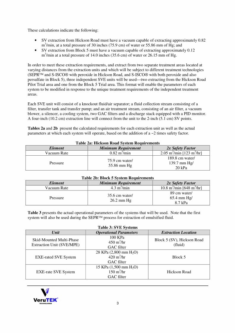
3
These calculations indicate the following:
• SV extraction from Hickson Road must have a vacuum capable of extracting approximately 0.82
m3/min, at a total pressure of 30 inches (75.9 cm) of water or 55.86 mm of Hg; and
• SV extraction from Block 5 must have a vacuum capable of extracting approximately 0.12
m3/min at a total pressure of 14.0 inches (35.6 cm) of water or 26.15 mm of Hg.
In order to meet these extraction requirements, and extract from two separate treatment areas located at
varying distances from the extraction units and which will be subject to different treatment technologies
(SEPR™ and S-ISCO® with peroxide in Hickson Road, and S-ISCO® with both peroxide and also
persulfate in Block 5), three independent SVE units will be used—two extracting from the Hickson Road
Pilot Trial area and one from the Block 5 Trial area. This format will enable the parameters of each
system to be modified in response to the unique treatment requirements of the independent treatment
areas.
Each SVE unit will consist of a knockout fluid/air separator; a fluid collection stream consisting of a
filter, transfer tank and transfer pump; and an air treatment stream, consisting of an air filter, a vacuum
blower, a silencer, a cooling system, two GAC filters and a discharge stack equipped with a PID monitor.
A four-inch (10.2 cm) extraction line will connect from the unit to the 2-inch (5.1 cm) SV points.
Tables 2a and 2b present the calculated requirements for each extraction unit as well as the actual
parameters at which each system will operate, based on the addition of a ~2 times safety factor.
Table 2a: Hickson Road System Requirements
Element Minimum Requirement 2x Safety Factor
Vacuum Rate 0.82 m3/min 2.05 m
3/min [123 m
3/hr]
Pressure 75.9 cm water/
55.86 mm Hg
189.8 cm water/
139.7 mm Hg/
20 kPa
Table 2b: Block 5 System Requirements
Element Minimum Requirement 2x Safety Factor
Vacuum Rate 4.3 m3/min 10.8 m
3/min [648 m
3/hr]
Pressure 35.6 cm water/
26.2 mm Hg
89 cm water/
65.4 mm Hg/
8.7 kPa
Table 3 presents the actual operational parameters of the systems that will be used. Note that the first
system will also be used during the SEPR™ process for extraction of emulsified fluid.
Table 3: SVE Systems
Unit Operational Parameters Extraction Location
Skid-Mounted Multi-Phase
Extraction Unit (SVE/MPE)
100 KPa
450 m3/hr
GAC filter
Block 5 (SV), Hickson Road
(fluid)
EXE-rated SVE System
28 KPa (2,800 mm H2O)
420 m3/hr
GAC filter
Block 5
EXE-rate SVE System
15 KPa (1,500 mm H2O)
150 m3/hr
GAC filter
Hickson Road
4
1.3 SVE System Stack
The concentration of VOCs in the air discharged from each SVE system’s stack reflects the proper and
efficient operation of the SVE system and its compliance with the Protection of the Environment
Operation (PEO) Regulations limits for health-based ground-level concentrations. The SVE has been
designed and will be operated and maintained to ensure that a stack concentration of total VOCs does not
exceed the levels agreed to with DECCW. Toward this end, VOC emissions from the SVE system will
be monitored and recorded continuously in accordance with approved methods for the sampling and
analysis of air pollutants in NSW. To accomplish this, a PID monitoring system will be employed.
Stack Emissions Modelling
An air dispersion model was run to calculate the maximum stack emission concentration allowable to
meet the DECCW Approved Methods ground level concentration (GLC) criteria for each regulated
pollutant. These values were then used as the proposed stack licence limit for the SVE system stacks.
The following parameters were used to model emissions from each stack:
Stack Parameter Units Soil Vapor Recovery Unit
SVE/MPE Block 5 SVE Hickson Road SVE
Base elevation m 5 5 5
Height m 2 2 2
Exit diameter m 0.10 0.10 0.06
Exit area m2 0.008 0.008 0.003
Temperature K 293 293 293
Exit velocity m/s 15 15 15
Flow rate m3/s 0.125 0.117 0.042
The model was run to predict the ground level concentrations for each pollutant when the system
discharged at the limit specified by the POEO Clean Air Regulation for Group 6 vapour recovery devices,
that is, 20 mg/m3 VOCs (as n-propane equivalent). The results, shown in Table 4, should be considered
conservative and likely over-predict the actual GLCs of the specified pollutants since the model assumes
that the total POEO limit concentration is a single pollutant (which is highly unlikely).
Table 4: Results of SVE Emissions Model
Pollutant Concentration
Soil Vapor Recovery Unit Emission rate*
SVE/MPE Block 5 SVE Hickson Road SVE
mg/m3 (g/s) (g/s) (g/s)
Benzene 6.39 8.0E-09 7.5E-09 2.7E-09
EthylBenzene 8.68 1.1E-08 1.0E-08 3.6E-09
Toluene 56.5 7.1E-08 6.6E-08 2.4E-08
Xylenes 26.1 3.3E-08 3.1E-08 1.1E-08
Naphthalene 383 4.8E-07 4.5E-07 1.6E-07
* Assuming 99% reduction of VOC
5
Table 5: Maximum Receptor GLCs Based on 20 mg/m3 Stack Emission Rate
Pollutant Concentration (mg/m3)
Benzene Ethylbenzene Toluene Xylene Naphthalene
Predicted Receptor Max GLC 0.0026 0.0026 0.0026 0.0026 0.0026
DECCW GLC Criteria 0.029 0.36 8 0.19 0.0129
This data illustrates that in the event that any pollutant is emitted from the SVE system stack at the POEO
limit, the maximum GLC at the modeled receptors in the vicinity of the Pilot Trials site will meet the
DECCW criteria.
Therefore, the SVE system stack licence limit is set at 20 mg/m3 for VOCs in accordance with the POEO,
and a trigger level is set at 10 mg/m3 (5.1 ppm n-propane), or half the proposed licence limit. Please refer
to Section 11 of the Trial Management Plan for the SVE system contingency planning details.
Attachment A: Soil Vapour Extraction System Design
1. SVE System Required Flow
1.1 Block 5 Pilot Trial Area
To calculate the vacuum required for the SVE system, maximum injection operating conditions were assumed:
injections at 75.5 LPM, using 16% hydrogen peroxide (peroxide). This rate is achieved by injecting 19 LPM to each
of 4 injection wells. Peroxide injections are scheduled to last for the duration of Phase I (S-ISCO® with hydrogen
peroxide), three weeks. While the SVE system is designed to handle the maximum operating conditions of the
injection system, it is useful to realize that if the injection system were to operate continuously at these maximum
conditions, peroxide injections would only last one week or one-third of the scheduled duration. Therefore the
system design is conservative.
75.7 LPM of 16% peroxide solution produces the following volume of oxygen gas per minute:
4.28 m3 per minute.
Calculations:
MW H2O2 = 34.0147 g/mol; MW O2 = 32 g/mol;
PV=nRT, where: n = moles O2 R = 0.082057 L*atm*K-1
*mol-1
T =293 K P = 1 atm;
75.7 L H2O2 x (160 g/L) = 12,112 g H2O2 x (1 mol/34 g) = 356.24 mol H2O2 x (1 mol O2 / 2 mol H2O2)
= 178.12 mol O2
V = nRT/P = [(178.12 mol O2)( 0.082057 L x atm x K-1
x mol-1
)(293K)] / 1 atm = 4,282.4 L O2 = 4.28 m3
1.2 Hickson Road Pilot Trial Area
To calculate the vacuum required for the SVE system that will operate in the Hickson Road Pilot Trial area,
maximum injection operating conditions were assumed: injections at 56.8 LPM, using 4% hydrogen peroxide. This
rate requires injections of 19 LPM into 3 injection wells. While this SVE system is designed to handle the maximum

6
operations conditions of the injection system for Hickson Road, if the system were to operate at these maximum
conditions, S-ISCO® and SEPR™ injections would last for a total six days. The actual implementation is scheduled
to take place over 6 weeks. Therefore the SVE system design for the S-ISCO® and SEPR™ injections is
conservative.
56.8 LPM of 4% hydrogen peroxide solution will produce the following volume of oxygen gas per minute:
0.803 m3 per minute.
Calculations:
MW H2O2 = 34.0147 g/mol; MW O2 = 32 g/mol;
PV = nRT, where: n = moles O2 R = 0.082057 L*atm*K-1
*mol-1
T =293 K P = 1 atm.
56.78 L H2O2 x 40 g/L = 2,271 g H2O2 x (mol/34 g) = 66.8 mol H2O2 x (1 mol O2 / 2 mol H2O2) = 33.4 mol O2
V = nRT/P =[(33.4 mol O2)( 0.082057 L x atm x K-1
x mol-1
)(293K)] / 1 atm = 803 L O2 = 0.803 m3
2. Friction Losses in Piping
Pressure losses are the major design constraint for developing an SVE system. At both the Block 5 and Hickson
Road treatment areas, the design objective was to achieve sufficient vacuum at the SVE points to remove vapours
produced primarily from the production of oxygen gas by the use of hydrogen peroxide to oxidize contaminants. To
calculate pressure loss at the soil vapor points Darcy-Weisbach’s equations were used as shown below:
1. ∆pfr = fD(L/D)Pv
Where: ∆pfr = friction losses in terms of total pressure (in. H2O);
fD = friction factor
L= pipe length (ft)
D = pipe diameter (ft)
Pv = velocity pressure ((in. of H2O)
2.
Where: velocity pressure (in. of H2O)
vapor density (lb/ft3)
average fluid velocity in the pipe (ft/min)
conversion factor
3.
Where: vapor flow rate (ft3/min)
cross-sectional area of pipe (ft2) =
internal pipe radius (ft)
4. Reynold’s Number: NR = DV/
Where: kinematic viscosity of vapor, assuming standard air = 9.84 x 10⁻³
ft2 /min
D = diameter of pipe (ft)
V = average fluid velocity in the pipe (ft/min)
7
5. Friction Factor:
� � �0.3164 ��. �⁄ � When: 4,000 � � � 100,000
� � �0.0032 � 0.221 ��. ��⁄ � When: 100,000 � � � 3,000,000
For Block 5 the distance to the SVE wells is as follows:
SV Point ID
Distance to SVE
System (m)
SV-09 44.08
SV-10 48.12
SV-11 27.22
VTSV-01 19.62
VTSV-09 27.2
The pressure requirements for an SVE blower are based on the total pressure loss in the SVE piping system resulting
from frictional losses. In addition, due to obstructions, additional dynamic pressure losses must be accounted for.
The equation below calculates dynamic pressure losses due to pipe fittings.
∆�� � �� � ��
Where: �� = fitting loss coefficient, (dimensionless)
�� = velocity pressure (inch of H2O)
For the system piping located on Block 5, an extraction of 4.28 m3/min (151.3 ft
3/min) of vacuum is required to
remove all gas produced from the use of hydrogen peroxide. VeruTEK assumes the use of a 10.16 cm (4 inch)
extraction line connected to 5.1 cm (2 inch) SVE points. Accounting for all pressure losses due to friction in piping
and dynamic losses due obstructions, the total pressure loss for the wells located in Block 5 is 35.6 cm (14.0 inches)
of water or 26.15 mm of mercury.
∆� ! � 48.5$%��&20
For Hickson Road the distance to the SVE wells is as follows:
SV Point ID
Distance to SVE
System (m)
VTSV-02 126.9
VTSV-03 155.2
VTSV-04 150.9
VTSV-05 198.5
VTSV-06 131.4
VTSV-07 132.1
The pressure requirements for an SVE blower are based on a total pressure loss in the SVE piping system due to
friction loss. For the Hickson Road SVE wells, a total of 28.4 ft3/
min of vacuum will be required to remove all gas
production related to the use of hydrogen peroxide. Accounting for all friction and dynamic losses, the total pressure
loss from the SVE system piping running to the Hickson Road treatment area is 75.9 cm (29.9 inches) of water or
55.86 mm of mercury.
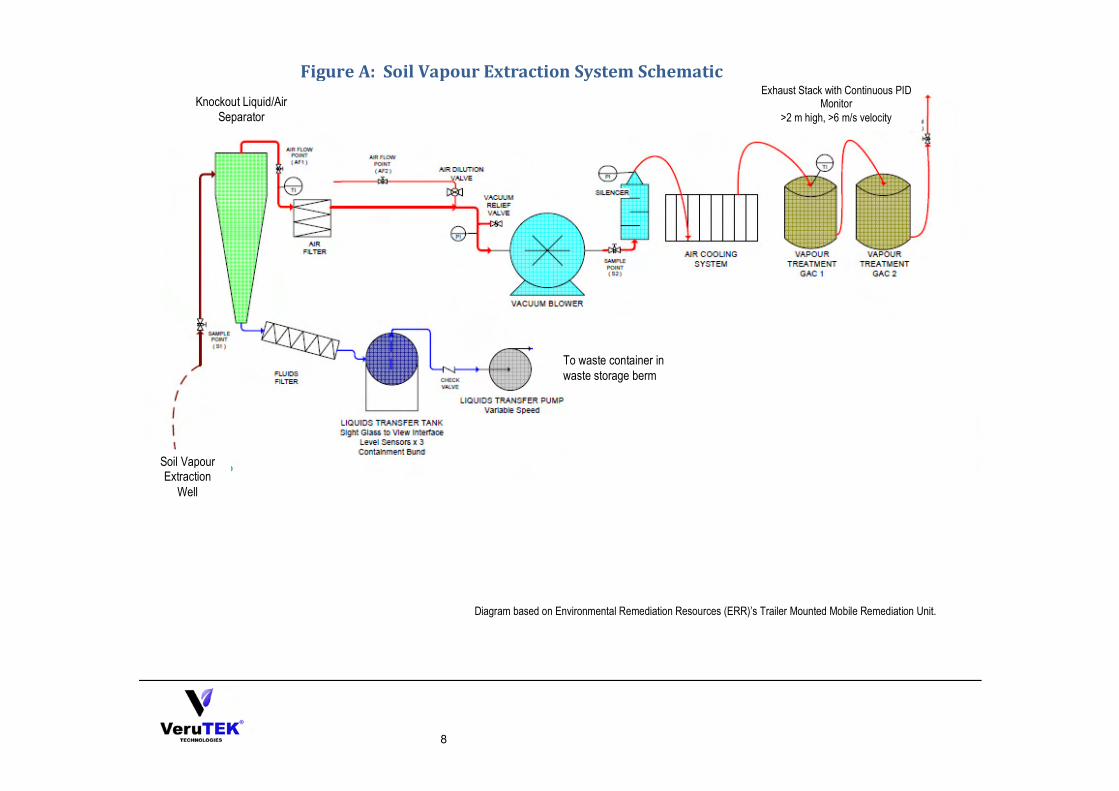
8
Soil Vapour Extraction
Well
Figure A: Soil Vapour Extraction System Schematic Exhaust Stack with Continuous PID
Monitor
>2 m high, >6 m/s velocity
To waste container in
waste storage berm
Knockout Liquid/Air
Separator
Diagram based on Environmental Remediation Resources (ERR)’s Trailer Mounted Mobile Remediation Unit.

1
APPENDIX F: TRAFFIC MANAGEMENT ROUTING MAPS

2
From the north:

3
From the south and east:

4
From the west:

1
APPENDIX G: MSDSs
FDS / P 14252 / 19/04/2006 / Australia / Report version 1.0 / Issuing date 04/05/2006
1/10
SAFETY DATA SHEET Australian version - NOHSC:2011 (2003)
INTEROX ® ST-50
1. IDENTIFICATION OF THE SUBSTANCE/PREPARATION AND OF THE COMPANY/UNDERTAKING
1.1. Identification of the substance/preparation Product name : INTEROX ® ST-50 Chemical Name : Hydrogen peroxide Synonyms : Hydroperoxide, Hydrogen dioxide Molecular formula : H2O2 Molecular Weight : 34 g/mol
1.2. Use of the Substance/Preparation Recommended use : - Bleaching agents - Chemical industry - Electronic industry - Metal treatment - Odour agents - Oxidising Agents - Textile industry - Water treatment - Pulp and paper
1.3. Company/Undertaking Identification Address : SOLVAY INTEROX Pty Ltd
MCPHERSON STREET, 20-22 AUS- 2019 BANKSMEADOW
Telephone : 61293168000
Telefax : 61293166445
1.4. Emergency telephone number Telephone : 1 800 023 488 (Emergency 24 Hour)
+44 1865 407333 [CareChem 24] (Australia, New Zealand) AU: +61-2-93168000 (Product information)
2. HAZARDS IDENTIFICATION Appearance : liquid Colour : colourless Odour : pungent
- Classified as hazardous according to criteria of NOHSC. - Classified as dangerous goods according to the ADG Code - Corrosive - Non-combustible, but may contribute to the combustion of other substances and causes violent
and explosive reactions.
FDS / P 14252 / 19/04/2006 / Australia / Report version 1.0 / Issuing date 04/05/2006
2/10
3. COMPOSITION/INFORMATION ON INGREDIENTS
Hydrogen peroxide CAS-No. : 7722-84-1 Symbol(s) : O, C R-phrase(s) : R 8, R34 Concentration : 49.50 - 50.50 %
4. FIRST AID MEASURES
4.1. Inhalation - Remove to fresh air. - If symptoms persist, call a physician.
4.2. Eye contact - Rinse immediately with plenty of water, also under the eyelids, for at least 15 minutes. - In the case of difficulty of opening the lids, administer an analgesic eye wash (oxybuprocaine). - Consult with an ophthalmologist immediately in all cases.
4.3. Skin contact - Remove and wash contaminated clothing before re-use. - Wash off with plenty of water. - Keep warm and in a quiet place. - Consult a physician.
4.4. Ingestion The following actions are recommended : - Call a physician immediately. - Take victim immediately to hospital. If victim is conscious: - If swallowed, rinse mouth with water (only if the person is conscious). - Do NOT induce vomiting. If victim is unconscious but breathing: - Artificial respiration and/or oxygen may be necessary.
5. FIRE-FIGHTING MEASURES
5.1. Suitable extinguishing media - water - water spray
5.2. Extinguishing media which must not be used for safety reasons - None.
5.3. Special exposure hazards in a fire - Oxygen released in thermal decomposition may support combustion - Contact with combustible material may cause fire. - Contact with flammables may cause fire or explosions. - Risk of explosion if heated under confinement.
5.4. Special protective equipment for fire-fighters - Evacuate personnel to safe areas. - In the event of fire, wear self-contained breathing apparatus. - When intervention in close proximity wear acid resistant over suit. - Clean contaminated surface thoroughly.
FDS / P 14252 / 19/04/2006 / Australia / Report version 1.0 / Issuing date 04/05/2006
3/10
5.5. Other information - Keep product and empty container away from heat and sources of ignition. - Keep containers and surroundings cool with water spray. - Approach from upwind. - HAZCHEM Code: 2P
6. ACCIDENTAL RELEASE MEASURES
6.1. Personal precautions - Refer to protective measures listed in sections 7 and 8. - Isolate the area. - Keep away from Incompatible products. - Prevent further leakage or spillage if safe to do so. - In case of contact with combustible material, keep material wet with plenty of water.
6.2. Environmental precautions - Limited quantity - Flush into sewer with plenty of water. - Large quantities: - If the product contaminates rivers and lakes or drains inform respective authorities.
6.3. Methods for cleaning up - Dam up. - Soak up with inert absorbent material. - Dilute with plenty of water. - Do not add chemical products. - Treat recovered material as described in the section "Disposal considerations". - Never return spills in original containers for re-use.
7. HANDLING AND STORAGE
7.1. Handling - Use only in well-ventilated areas. - Keep away from heat. - Keep away from Incompatible products. - May not get in touch with: - organic materials - Use only equipment and materials which are compatible with the product. - Before all operations, passivate the piping circuits and vessels according to the procedure
recommended by the producer. - Never return unused material to storage receptacle. - Use only in an area with adequate water supply - Containers and equipment used to handle the product should be used exclusively for that
product. 7.2. Storage
- Keep in a cool, well-ventilated place. - Keep away from heat. - Keep away from Incompatible products. - Keep away from combustible material. - Store in a receptacle equipped with a vent. - Store in original container. - Keep container closed. - Keep in a bunded area. - Regularly check the condition and temperature of the containers. - Information about special precautions needed for bulk handling is available on request.
FDS / P 14252 / 19/04/2006 / Australia / Report version 1.0 / Issuing date 04/05/2006
4/10
7.3. Specific use(s) - For further information, please contact: Supplier
7.4. Packaging material - aluminium 99,5 % - stainless steel 304L / 316L - Approved grades of HDPE.
7.5. Other information - Refer to protective measures listed in sections 7 and 8. - Do not confine the product in a circuit, between closed valves, or in a container without a vent.
8. EXPOSURE CONTROLS / PERSONAL PROTECTION
8.1. Exposure Limit Values Hydrogen peroxide
- US. ACGIH Threshold Limit Values 2005 TWA = 1 ppm
- WEL (UK) 2005 TWA = 1 ppm TWA = 1.4 mg/m3
- WEL (UK) 2005 STEL = 2 ppm STEL = 2.8 mg/m3
- TLV (NOHSC) 11/2004 TWA = 1 ppm TWA = 1.4 mg/m3
8.2. Exposure controls - Ensure adequate ventilation. - Apply technical measures to comply with the occupational exposure limits. - Refer to protective measures listed in sections 7 and 8.
8.2.1. Occupational exposure controls 8.2.1.1. Respiratory protection
- In case of emissions, face mask with type NO-P3 cartridge. - Self-contained breathing apparatus in medium confinement/insufficient oxygen/in case of
large uncontrolled emissions/in all circumstances when the mask and cartridge do not give adequate protection.
- Use only respiratory protection that conforms to international/ national standards. 8.2.1.2. Hand protection
- Protective gloves - impervious chemical resistant: - PVC - rubber gloves - Take note of the information given by the producer concerning permeability and break
through times, and of special workplace conditions (mechanical strain, duration of contact). 8.2.1.3. Eye protection
- Chemical resistant goggles must be worn. - If splashes are likely to occur, wear: - tightly fitting safety goggles - face-shield
8.2.1.4. Skin and body protection - protective suit - If splashes are likely to occur, wear: - apron - boots

FDS / P 14252 / 19/04/2006 / Australia / Report version 1.0 / Issuing date 04/05/2006
5/10
- Suitable material - PVC - rubber products
8.2.1.5. Hygiene measures - Use only in an area equipped with a safety shower. - Eye wash bottle with pure water - When using do not eat, drink or smoke. - Handle in accordance with good industrial hygiene and safety practice.
8.2.2. Environmental exposure controls - Dispose of rinse water in accordance with local and national regulations.
9. PHYSICAL AND CHEMICAL PROPERTIES
9.1. General Information (appearance, odour) Appearance : liquid Colour : colourless Odour : pungent
9.2. Important Health Safety and Environmental Information
pH : 1 - 4 Remarks: Apparent pH
Boiling point/range : 115 °C
Flash point : Remarks: The product is not flammable.
Flammability (solid, gas) : Lower explosion limit: Remarks: The product is not flammable.
Explosive properties : Remarks: With certain materials (see section 10). : Remarks: In case of heating:
Oxidizing properties : Remarks: yes
Vapour pressure : 1 mbar Temperature: 30 °C
: 12 mbar Temperature: 20 °C Remarks: Total pressure (H2O2 + H2O)
: 72 mbar Temperature: 50 °C Remarks: Total pressure (H2O2 + H2O)
Relative density / Density : 1.2 (H2O2 50 %)
Solubility : Soluble in: : water : Polar organic solvents
Partition coefficient (n-octanol/water)
: log Pow: -1.1
Viscosity : 1.17 mPa.s Temperature: 20 °C
Vapour density : 1
FDS / P 14252 / 19/04/2006 / Australia / Report version 1.0 / Issuing date 04/05/2006
6/10
9.3. Other data
Freezing point: : -52 °C
Autoinflammability : Remarks: The product is not flammable.
Surface tension : 75.6 mN/m Temperature: 20 °C
Decomposition temperature
: >= 60 °C Remarks: Self-Accelerating decomposition temperature (SADT)
: < 60 °C Remarks: Slow decomposition
10. STABILITY AND REACTIVITY
10.1. Stability - Potential for exothermic hazard - Stable under recommended storage conditions.
10.2. Conditions to avoid - contamination - To avoid thermal decomposition, do not overheat.
10.3. Materials to avoid - acids, bases, metals, Salts of metals, reducing agents, organic materials, flammable materials
10.4. Hazardous decomposition products - oxygen, The release of other hazardous decomposition products is possible.
11. TOXICOLOGICAL INFORMATION
11.1 Toxicological data Acute oral toxicity - LD50, rat, 1,232 mg/kg (H2O2 35 %) Acute inhalation toxicity - LC50, 4 h, rat, 2.000 mg/m3 (Hydrogen peroxide) Acute dermal toxicity - LD50, rabbit, > 2.000 mg/kg (H2O2 35 %) Skin irritation - rabbit, Skin irritation (H2O2 35 %) Eye irritation - Risk of serious damage to eyes. (H2O2 35 %) Irritation (other route) - Inhalation, mouse, Irritating to respiratory system., RD 50 = 665 mg/m3 (Hydrogen peroxide) Sensitization - guinea pig, Did not cause sensitization on laboratory animals. Chronic toxicity - Oral, Prolonged exposure, Various species, Target Organs: Gastrointestinal tract, observed
effect - Inhalation, Repeated exposure, dog, LOEL: 14.6 mg/m3, irritant effects Carcinogenicity - Oral, Prolonged exposure, mouse, Target Organs: duodenum, carcinogenic effects - Dermal, Prolonged exposure, mouse, Animal testing did not show any carcinogenic effects.
FDS / P 14252 / 19/04/2006 / Australia / Report version 1.0 / Issuing date 04/05/2006
7/10
Genetic toxicity in vitro - In vitro tests have shown mutagenic effects. Genetic toxicity in vivo - Animal testing did not show any mutagenic effects. Possible hazards (summary) - corrosive effects
11.2. Health effects Main effects - The product causes burns of eyes, skin and mucous membranes. Inhalation - Inhalation of vapours is irritating to the respiratory system, may cause throat pain and cough. - Repeated or prolonged exposure: Risk of sore throat, nose bleeds, chronic bronchitis. Eye contact - Severe eye irritation - redness - lachrymation - swelling of tissue - Risk of serious damage to eyes. Skin contact - Severe skin irritation - redness - swelling of tissue - Causes burns. Ingestion - severe irritation - Ingestion causes burns of the upper digestive and respiratory tracts. - nausea - vomiting - Bloating of stomach, belching. - Risk of chemical pneumonitis from product inhalation.
12. ECOLOGICAL INFORMATION
12.1. Ecotoxicity effects Acute toxicity - Fishes, Pimephales promelas, LC50, 96 h, 16.4 mg/l - Fishes, Pimephales promelas, NOEC, 96 h, 5 mg/l - Crustaceans, EC50, 48 h, 2.4 mg/l - Crustaceans, NOEC, 48 h, 1 mg/l Chronic toxicity - Molluscs, NOEC, 56 Days, 2 mg/l - Algae, Chlorella vulgaris, EC50, growth rate, 72 h, 4.3 mg/l - Algae, Chlorella vulgaris, NOEC, 72 h, 0.1 mg/l
12.2. Mobility - Air, Volatility, Henry's law constant (H) = 1 Pa.m³/mol
Conditions: 20 °C Remarks: not significant
- Air, condensation on contact with water droplets Remarks: rain washout
- water Remarks: The product evaporates slowly.
FDS / P 14252 / 19/04/2006 / Australia / Report version 1.0 / Issuing date 04/05/2006
8/10
- Soil/sediments Remarks: non-significant evaporation and adsorption
12.3. Persistence and degradability Abiotic degradation - Air, indirect photo-oxidation, t 1/2 from 16 - 20 h
Conditions: sensitizer: OH radicals - water, redox reaction, t 1/2 from 25 - 100 h
Conditions: mineral and enzymatic catalysis, fresh water - water, redox reaction, t 1/2 from 50 - 70 h
Conditions: mineral and enzymatic catalysis, salt water - Soil, redox reaction, t 1/2 from 0.05 - 15 h
Conditions: mineral catalysis Biodegradation - aerobic, t 1/2 < 2 min
Conditions: biological treatment sludge Remarks: Readily biodegradable.
- aerobic, t 1/2 from 0.3 - 5 d Conditions: fresh water Remarks: Readily biodegradable.
- anaerobic Remarks: not applicable
- Effects on waste water treatment plants, Inhibitor > 30 mg/l Remarks: inhibitory action
12.4. Bioaccumulative potential - Bioaccumulative potential
Result: Does not bioaccumulate. 12.5. Other adverse effects
- no data available 12.6. Possible hazards (summary)
- Toxic to aquatic organisms. - Nevertheless, hazard for the environment is limited due to product properties: - . no toxicity of degradation products (H2O and O2). - Inherently biodegradable. - Does not bioaccumulate.
13. DISPOSAL CONSIDERATIONS
13.1. Waste from residues / unused products - In accordance with local and national regulations. - Limited quantity - Dilute with plenty of water. - Flush into sewer with plenty of water. - Large quantities: - Contact manufacturer.
13.2. Packaging treatment - Empty containers. - Clean container with water. - Dispose of rinse water in accordance with local and national regulations. - Do not rinse the dedicated containers. - The empty and clean containers are to be reused in conformity with regulations.
FDS / P 14252 / 19/04/2006 / Australia / Report version 1.0 / Issuing date 04/05/2006
9/10
14. TRANSPORT INFORMATION
UN-No 2014 IATA-DGR
Class 5.1 Sub-risks CORROSIVE Packing group II ICAO-Labels 5.1 + 8
Proper shipping name: HYDROGEN PEROXIDE, AQUEOUS SOLUTION
IMDG Class 5.1 Sub-risks Corrosive Packing group II IMO-Labels OXIDIZING AGENT + CORROSIVE HI/UN No. 2014 EmS: F-H, S-Q
Proper shipping name: HYDROGEN PEROXIDE, AQUEOUS SOLUTION
ADG Class 5.1 Sub-risks 8 Packing group II ADG-Labels 5.1 + 8 HI/UN No. 58/2014
Proper shipping name: HYDROGEN PEROXIDE, AQUEOUS SOLUTION
Remarks: - IATA: forbidden over 40 % - HAZCHEM Code: 2P
15. REGULATORY INFORMATION
15.1. Label - Hazardous components which must be listed on the label: Hydrogen peroxide - Classified as hazardous according to criteria of NOHSC.
Symbol(s) C Corrosive
R-phrase(s) R34 Causes burns.
S-phrase(s) S 1/2 Keep locked up and out of the reach of children. S 3 Keep in a cool place. S28 After contact with skin, wash immediately with
plenty of water. S36/39 Wear suitable protective clothing and eye/face
protection. S45 In case of accident or if you feel unwell, seek
medical advice immediately (show the label where possible).
15.2. Other information
- The percentage concentration of the solution has to be indicated next to the product name.
FDS / P 14252 / 19/04/2006 / Australia / Report version 1.0 / Issuing date 04/05/2006
10/10
15.3. Inventory Information Toxic Substance Control Act list (TSCA)
: - In compliance with inventory.
Australian Inventory of Chemical Substances (AICS)
: - In compliance with inventory.
Canadian Domestic Substances List (DSL)
: - In compliance with inventory.
Korean Existing Chemicals List (ECL)
: - In compliance with inventory.
EU list of existing chemical substances (EINECS)
: - In compliance with inventory.
Japanese Existing and New Chemical Substances (MITI List) (ENCS)
: - One or more components not listed on inventory.
Inventory of Existing Chemical Substances (China) (IECS)
: - One or more components not listed on inventory.
Philippine Inventory of Chemicals and Chemical Substances (PICCS)
: - One or more components not listed on inventory.
New Zealand Inventory (in preparation) (NZ)
: - One or more components not on composite list considered for transfer.
Schweizer Giftliste-1 (GL-1) : - One or more components not listed on inventory.
16. OTHER INFORMATION
16.1. Administrative information - Australian version - General revision - Distribute new edition to clients
16.2. Text of R phrases mentioned in Section 3 - R 8: Contact with combustible material may cause fire. - R34: Causes burns.
The information given corresponds to the current state of our knowledge and experience of the product, and is not exhaustive. This applies to product which conforms to the specification, unless otherwise stated. In this case of combinations and mixtures one must make sure that no new dangers can arise. In any case, the user is not exempt from observing all legal, administrative and regulatory procedures relating to the product, personal hygiene, and protection of human welfare and the environment.
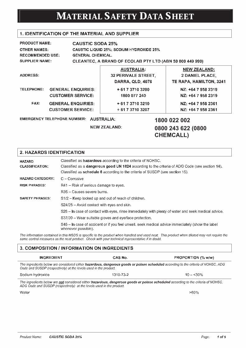
MMAATTEERRIIAALL SSAAFFEETTYY DDAATTAA SSHHEEEETT
� � � � � � � � � � � � � � � � � � � � � � � � � � � � � �
� � � � � ! � " � # $ ! � % % " ! & � ' $ ! � ( � $ ) $ � * + , , ) � � (- . / 0 1 2 3 4 5 6 7 8 # $ + * ! � # * % � $ 9 : ;/ 3 < 7 . 4 5 6 7 = 8 2 5 1 = 3 > 2 ? > @ 1 > 0 A B C D = / 0 > 1 6 < E 0 . / F > 0 7 A B C. 7 2 / 6 6 7 4 0 7 0 1 = 7 8 G 7 4 7 . 5 ? 2 < 7 6 > 2 5 ? H= 1 - - ? > 7 . 4 5 6 7 8 I J K L M N K I O L P Q L M R S T K I S J L P U N V J N R W L P M X Y Z Z Z [ [ Y Y Y Z \L ] ^ N Q L J _ L ` M K a b K L J L M R `5 0 0 . 7 = = 8 c d U K Q _ e L J K ^ N Q K K N OR L Q Q L O f J R O [ Z g h d R L M _ K J U J L I K ON K Q L U L O i L j _ J N S M O c d [ k3 7 ? 7 - < / 4 7 8 l K M K Q L J K M f ] _ Q _ K ^ ` m h k g c g k Z c d Z Z M b ` m h [ g Y X n d c k YI ] ^ N S j K Q ^ K Q e _ I K ` k n Z Z Z g g d [ Z M b ` m h [ g Y X n d c k Yo 5 F 8 l K M K Q L J K M f ] _ Q _ K ^ ` m h k g c g k Z c d k Z M b ` m h [ g Y X n d c h kI ] ^ N S j K Q ^ K Q e _ I K ` m h k g c g k Z c d Z g M b ` m h [ g Y X n d c h k7 6 7 . G 7 4 2 E 3 7 ? 7 - < / 4 7 4 1 6 p 7 . 8 L ] ^ N Q L J _ L `M K a b K L J L M R `9 � & $ q $ ( � * � � � ! � " � # $ ! � % r s t u u v w v x y t u z { | { } ~ � � � t � � � � y v � � � � � � x � � v � x � v t � w � � � � r �r s t u u v w v x y t u t ~ { � � � } � � � � � � ~ 1 4 � � A � t � � � � y v � � � � � � x � � v � x � v t � w � � � r � y x � u x x u x � � v � � � � � �� � � � � � ¡ � ¢ ¢ £ ¤ £ � ¥ £ ¦ § ` r s t u u v w v x y t u � ¨ z � ~ � © � ª t � � � � y v � � � � � � x � � v � x � v t � w � « � � ¬ � u x x u x � � v � � � � �� � � � � � � ¥ ® ¯ ¦ � ° ` r ± r � � � � u v ² x� £ ¢ ³ ´ � � � ¢ ® ¢ ` µ � � ± µ v u ¶ � w u x � v � · u y t ¸ t � x � � x ¹ x u �µ º ± r t · u x u u x ² x � x » · � � u �¢ � ¤ ® ¥ ° ´ � � � ¢ ® ¢ ` � � ¼ ½ ± ¾ x x ¿ s � � ¶ x y · ¿ t � y � · � � w � x t � � � w � � v s y � x � �� ½ � ¼ ½ ± � ² � v y � � � � t � � À v � � x ¹ x u t � y u ¶ v � �� ½ Á ±  � � t u x � w � � � � t � � À v � � x ¹ x u à � v � u x v ¸ ¸ x y v t � x s ¹ À v � � ¿ s x � � ¹ � w À t � x � t � y u x x ¶ ¸ x y v � t s t y ² v � x �� º Ä ¼ º Å ± Æ x t � u · v � t » s x � s � ² x u t � y x ¹ x ¼ w t � x ¿ � � � x � � v � � �� � ±  � � t u x � w t � � v y x � � � � v w ¹ � · w x x s · � À x s s à u x x ¶ ¸ x y v � t s t y ² v � x v ¸ ¸ x y v t � x s ¹ � u � � À � � x s t » x sÀ � x � x ² x � ¿ � u u v » s x � �Ç È É Ê Ë � � � � É � Ê � � Ê � � É Ê � É Ê � È É Ì Í Î Ï Î É Ì Ì Ð � É Ë É � � � � È Ð � � � � � � Ñ È Ê È � Ê � Ò � � Ê � � Ì � Ê � � Ó Ç È É Ì Ð � � � � � � Ñ È Ê � É Ò � � � � Ô Ê � � � Õ � É � � È Ì � � � Ê � � � Ò � Ì � � Ì � Ì � È Ê � � Ð � � � � � � Ó Ö È � × Ñ É � È Ô � � � � � È Ê É � � Ò � Ð � Ì Ê � � � É Ø É Ë É Ê � � � Ù � ÓÚ � # % ' , % * � ! � % Û � " % ( ' $ ! � % % � Ü ( � � � � ! *> 4 G . 7 0 > 7 4 3 2 5 = 4 � H - . / - / . 3 > / 4 Ý C Þ ß Þ àÇ È É Ê � � � É Ê � Ì Ù Ò � Ñ � � � � Ê Ì É � � � É � È � á â ã â ä å � æ ç è å â é ê ë ä � æ ç ê � � å ç � ä ì � í ç � é ç î á ë å æ ï ë å � � � � � � É Ê � � � � È � � É � � É � � Ë � ð ñ Î Ö ò ó Ï ôÖ � � � Ê � Î õ Î Ï � ö � Ì Ð � � É Ø Ò Ô ÷ � � � È Ò Ø Ò Ì � Ì � É Ê � È Ð � � � � � � Ó� � y v · ¸ � ¹ y � � ø v y x � º � ù ú Ä º ú ½ � ù ± û º ù üÇ È É Ê � � � É Ê � Ì Ù Ò � Ñ � � é � ý � � Ê Ì É � � � É � È � á â ã â ä å � æ ç è å â é ê ë ä � æ ç ê � � å ç � ä ì � í ç � é ç î á ë å æ ï ë å � � � � � � É Ê � � � � È � � É � � É � � Ë � ð ñ Î Ö òó Ï ô Ö � � � Ê � Î õ Î Ï � ö � Ì Ð � � É Ø Ò Ô ÷ � � � È Ò Ø Ò Ì � Ì � É Ê � È Ð � � � � � � ÓÆ t � x � þ Á ù ü

MMAATTEERRIIAALL SSAAFFEETTYY DDAATTAA SSHHEEEETT
� � � � � � � � � � � � � � � � � � � � � � � � � � � � � �
ÿ � " � ( * ! $ � � ' � $ * + ( � *£ § ¯ ® ¢ ¥ £ ¦ § ` � � � t y ² v � x à � � � � t � � t ¬ � v u � � u  � w � � ¸ t � v � � r x � � � x � ¬ � � � x � · u � � t s v t � º � � ½ Á à � x À � x t s t � yù � ù ù Ä Á � Ä Á Á � � � t y � � � � � �  w u À t s s � À x y à y � � � � v � y · � x ² � ¸ v � v � � �® ° ® ¦ § ¥ � ¥ `  w v � x ¹ x u à � � s y x ¹ x s v y u t ¿ t � � t � y w s · u � � � x x ¹ x � � � � v � · � · u s ¹ À v � � � · � � v � � À t � x � � r � � � v � · x w s · u � v � �· � � v s t y ² v u x y � � u � � ¿ » ¹ � � x ¬ � v u � � u  � w � � ¸ t � v � � r x � � � x � � t y � � � � � à � � w � � t � s x t u � � ¸ v � · � x u �¢ ³ £ § ¦ § ¥ � ¥ `  w u ¶ v � � � � t v � � � � � t � � � � � · � u à � x ¸ � ² x � � � � t ¸ v � t � x y � s � � � v � � t � y w s · u � u ¶ v � t � y � t v � À v � � � · � � v � �À t � x � � r � � � v � · x w s · u � v � � · � � v s t y ² v u x y � � u � � ¿ » ¹ � � x ¬ � v u � � u  � w � � ¸ t � v � � r x � � � x � � t y � � � � � �£ § � � ¡ � ¥ £ ¦ § ` µ x ¸ � ² x w � � ¸ u � · � � x � w x ø ¿ � u · � x � � w � x u � t v � � � x x ¶ ¸ x y v � t s t u u v u � t � � x v w � � x x w w x � � u ¿ x � u v u � �� � � � � � � � � � � � � � � � � � � � � � � � � �¤ £ � ¢ ¥ � £ � ¤ � £ ¡ £ ¥ £ ® ¢ ` ¬ � � t » s x À t � x � u � � · s y » x t ² t v s t » s x � � � v � u x x ¹ x u � � u ¶ v � � ¬ � � ² v y x x ¹ x » t � � u t � y u t w x � ¹ u � � À x � u �§ ¦ ¥ ® ¢ ¥ ¦ ´ � ° ¢ £ £ � § ` � � x t � u ¹ ¸ ¿ � � ¸ t � v � t s s ¹ t � y t u w � � u � � � � � s ¹ t s ¶ t s v � x � � � � � u v ² x ¸ t � x � v t s �: � " � ( � " � Ü & ! � Ü ' � ! & % � *¢ � £ ¥ � � ¡ ® ® � ¥ £ § ¯ � £ ¢ � £ § ¯ � ® � £ � ` Æ t � x � u ¿ � t ¹ à w � t ¸ à � t � » � � y v � ø v y x � � y � ¹ � � x ¸ v � t s ¿ � À y x � �� � � � � � ¢ ¤ � ¦ � ¦ � � � ¢ ¥ £ ¦ § ` � � x ¿ � � y · � � v u � � � ú � � ¸ » · u � v » s x � � � À x ² x � à � � x ¿ t � ¶ t � v � � ¸ t � x � v t s ¸ t ¹ » · � � � � x ¸ v �� � ø v � · u w · ¸ x u � r � � � t � � À v � � ¸ x � t s u ¸ t ¹ s v » x � t � x � ¹ y � � � x � � t u À � v � � v u x ø � � x ¸ x s ¹w s t ¸ ¸ t » s x �´ � ® � � ¥ £ ¦ § ¢ ¤ ¦ � ¤ £ � ® ¤ £ ¯ � ¥ ® � ¢ � § �¢ ´ ® £ � ¡ ´ � ¦ ¥ ® ¥ £ � ® ® � � £ ´ � ® § ¥ ` � v � x w v � � � x � u u � � · s y À x t � u x s w ú � � � � t v � x y » � x t � � v � � t ¿ ¿ t � t � · u � � ¸ v � v ¸ v u x � v u ¶ � wx ø ¿ � u · � x � � ² t ¿ � · � � � ¿ � � y · � � u � w � � ¸ » · u � v � � �� � � � ® � ¦ � ® ` ½ µ� � $ # # � � � ! $ ) ( � ) � $ * � ' � $ * + ( � *® � ® � ¯ ® § °´ � ¦ ® � � � ® ¢ ` � ¿ v s s t � x u t � x u s v ¿ ¿ x � ¹ � � � u · � x t y x � · t � x ² x � � v s t � v � � � ¾ x x ¿ u ¿ x � � t � � � u t À t ¹ ± � � ¿ x � w w � � x t � x t � � ² � v yt � � v y x � � u à � s x t � · ¿ v ¸ ¸ x y v t � x s ¹ � Æ x t � ¿ � � � x � � v ² x x � · v ¿ ¸ x � � � � ¿ � x ² x � � u ¶ v � t � y x ¹ x � � � � t ¸ v � t � v � � �� ® ¥ � ¦ � ¢ � § �� � ¥ ® � £ � ¡ ¢ ¤ ¦ � ¦ § ¥ � £ § � ® § ¥ � § � ¡ ® � § � ´ ` r � � � t v � � � x u ¿ v s s t � y ¿ � x ² x � � � · � � w w v � � � � � � w v � x y t � x t u à y � t v � u t � y À t � x � À t ¹ u �� t � � x u ¿ v s s u � t » u � � » À v � � y � ¹ x t � � � à u t � y � � � � � x � u v ¸ v s t � ¸ t � x � v t s � r � s s x � � t � y u x t s v � ¿ � � ¿ x � s ¹ s t » x s s x yy � · ¸ u w � � y v u ¿ � u t s v � t � t � x t t ¿ ¿ � � ² x y » ¹ s � � t s t · � � � � v � ¹ » ¹ ú s t À u � Æ t u � t � x t y � À � À v � � x ø � x u u À t � x � � �� x ¸ � ² x � x u v y · t s ¸ t � x � v t s �� ¸ t s s u ¿ v s s u � ¸ t ¹ » x u t w x s ¹ ¸ � ¿ ¿ x y · ¿ t � y t � x t À t u � x y À v � � x ø � x u u À t � x � � � � v � x � t � v � � � w y v u ¿ � u x y ¸ t � x � v t s v u � � � � x � � ¸ ¸ x � y x y à t u v � v u · � s v ¶ x s ¹ � � t y x � · t � x s ¹ » · � � �� � & $ � ) � Ü $ � * ! % ( $ Ü �´ � ® � � ¥ £ ¦ § ¢ ¤ ¦ �¢ � ¤ ® � � § � ¡ £ § ¯ ` ¾ x x ¿ � � � � t v � x � u � s � u x y t � t s s � v ¸ x u ú � � x � ¶ � x � · s t � s ¹ w � � s x t ¶ u � � u ¿ v s s u � � � t � u ¿ � � � t � y u � � � x · ¿ � v � � � �� ² � v y x ¹ x � � � � t � � t � y � x ¿ x t � x y � � ¿ � � s � � � x y u ¶ v � � � � � t � � � � � � � � x t � à y � v � ¶ � � u ¸ � ¶ x v � � � � � t ¸ v � t � x yt � x t u � � s À t ¹ u � x ¸ � ² x � � � � t ¸ v � t � x y � s � � � v � � t � y À t u � � t � y u » x w � � x x t � v � � à y � v � ¶ v � � à u ¸ � ¶ v � � � � · u v � �� � x � � v s x � � Æ t u � � � � � t ¸ v � t � x y � s � � � v � � t � y � � � x � ¿ � � � x � � v ² x x � · v ¿ ¸ x � � » x w � � x u � � � t � x � � � x ú · u x � ¦ § � £ ¥ £ ¦ § ¢ ¤ ¦ �¢ � ¤ ® ¢ ¥ ¦ � � ¯ ® ` � � � � x v � � � x � � v � v � t s � � � � t v � x � à v � t � � � s y � ¹ À x s s ú ² x � � v s t � x y t � x t � · � � w u · � s v � � � t � y t À t ¹ w � � ¸v � � � ¸ ¿ t � v » s x ¸ t � x � v t s u t � y w � � y u � · w w u �¾ x x ¿ � � � � t v � x � u � s � u x y À � x � � � � v � · u x � � x � u · � x � � � � t ¸ v � t � v � � y � x u � � � � � � · � � � � � � � � � ¸ » v � x ¿ t � �y � · ¸ u � w � � x u t ¸ x ¿ � � y · � � à t u � � v u ¸ t ¹ » x t u � · � � x � w � � � � t ¸ v � t � v � � � � � � � � ¸ v ø À v � � � � � x � � � x ¸ v � t s u �� � � � � u � � � x v � t s · ¸ v � v · ¸ � � � t s ² t � v u x y � � � � t v � x � u � � · u x y v x ú � t u � � v � � � � t s · ¸ v � v · ¸ » · � � u � ¿ s t u � v �» · � � u u � � · s y » x · u x y � � � � x ¸ ¿ x � t � · � x u � � x t � x � � � t � � ù r à � t � ¶ u ¸ · u � » x u � � x u u � x s v x ² x y � ¾ x x ¿� � � � t v � x � u � s � u x y À � x � � � � v � · u x ú � � x � ¶ � x � · s t � s ¹ w � � s x t ¶ u �� � v u ¸ t � x � v t s v u t � � � x y · s x y ¬ � v u � � � Á t � y ¸ · u � » x u � � � x y à ¸ t v � � t v � x y t � y · u x y v � t � � � � y t � � x À v � �� � x � x s x ² t � � � x � · s t � v � � u �! � � " , % * + ( � # % ! ( % ) * Û , � ( * % $ ) , ( % ! � # ! � % § � ¥ £ ¦ § � ¡ ® � ´ ¦ ¢ � � ®¢ ¥ � § � � � � ¢ ` � � ² t s · x t u u v � � x y w � � � � v u u ¿ x � v w v � ¸ t � x � v t s » ¹ � � � � r à � � À x ² x � t u ¿ · » s v u � x y » ¹ � � � � r� � Æ � � � w � � � � y v · ¸ � ¹ y � � ø v y x # ½ ¸ � ¼ ¸ $ � ¬ x t ¶ � v ¸ v � t � v � � �� £ ¦ ¡ ¦ ¯ £ � ¡ ¡ £ � £ ¥ � � ¡ � ® ¢ ` � � » v � s � � v � t s s v ¸ v � t s s � � t � x y �® § ¯ £ § ® ® � £ § ¯ ¦ § ¥ � ¦ ¡ ¢ ` � � u · � x ² x � � v s t � v � � v u t y x � · t � x � � ¸ t v � � t v � t v � � � � � x � � � t � v � � u » x s � À � ø ¿ � u · � x � � t � y t � y u �« u x À v � � s � � t s x ø � t · u � ² x � � v s t � v � � � � À � v s x À x t � v � � t � x u ¿ v � t � � � � ¾ x x ¿ � � � � t v � x � u � s � u x y À � x �� � � v � · u x �
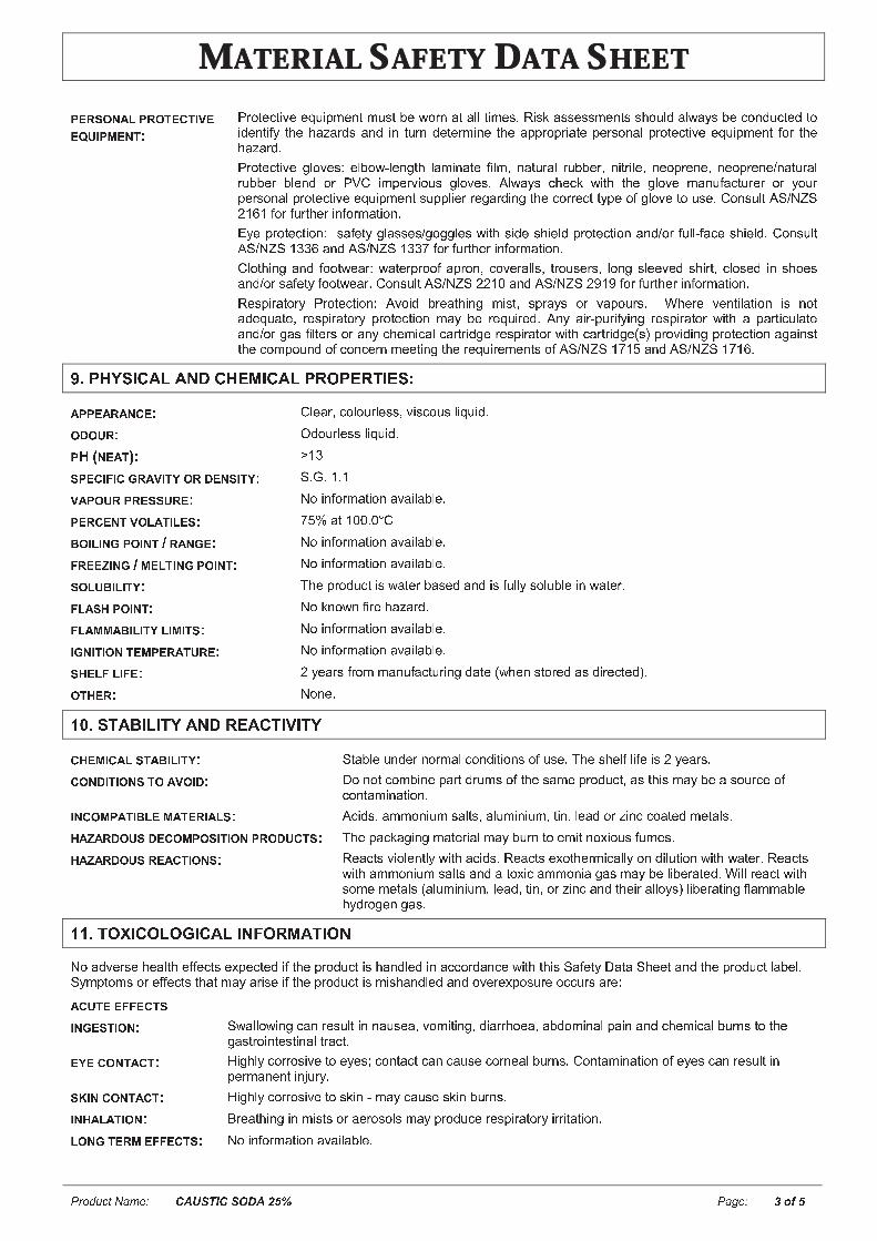
MMAATTEERRIIAALL SSAAFFEETTYY DDAATTAA SSHHEEEETT
� � � � � � � � � � � � � � � � � � � � � � � � � � % � � �
´ ® � ¢ ¦ § � ¡ ´ � ¦ ¥ ® ¥ £ � ®® � � £ ´ � ® § ¥ ` ¬ � � � x � � v ² x x � · v ¿ ¸ x � � ¸ · u � » x À � � � t � t s s � v ¸ x u � µ v u ¶ t u u x u u ¸ x � � u u � � · s y t s À t ¹ u » x � � � y · � � x y � �v y x � � v w ¹ � � x � t � t � y u t � y v � � · � � y x � x � ¸ v � x � � x t ¿ ¿ � � ¿ � v t � x ¿ x � u � � t s ¿ � � � x � � v ² x x � · v ¿ ¸ x � � w � � � � x� t � t � y �¬ � � � x � � v ² x � s � ² x u � x s » � À ú s x � � � � s t ¸ v � t � x w v s ¸ à � t � · � t s � · » » x � à � v � � v s x à � x � ¿ � x � x à � x � ¿ � x � x ¼ � t � · � t s� · » » x � » s x � y � � ¬ & r v ¸ ¿ x � ² v � · u � s � ² x u � � s À t ¹ u � � x � ¶ À v � � � � x � s � ² x ¸ t � · w t � � · � x � � � ¹ � · �¿ x � u � � t s ¿ � � � x � � v ² x x � · v ¿ ¸ x � � u · ¿ ¿ s v x � � x � t � y v � � � � x � � � � x � � � ¹ ¿ x � w � s � ² x � � · u x � r � � u · s � � � ¼ � � �½ � Á � w � � w · � � � x � v � w � � ¸ t � v � � �� ¹ x ¿ � � � x � � v � � � u t w x � ¹ � s t u u x u ¼ � � � � s x u À v � � u v y x u � v x s y ¿ � � � x � � v � � t � y ¼ � � w · s s ú w t � x u � v x s y � r � � u · s �� � ¼ � � � � º º Á t � y � � ¼ � � � � º º Ä w � � w · � � � x � v � w � � ¸ t � v � � �r s � � � v � � t � y w � � � À x t � � À t � x � ¿ � � � w t ¿ � � � à � � ² x � t s s u à � � � · u x � u à s � � � u s x x ² x y u � v � � à � s � u x y v � u � � x ut � y ¼ � � u t w x � ¹ w � � � À x t � � r � � u · s � � � ¼ � � � ½ ½ � ù t � y � � ¼ � � � ½ Å � Å w � � w · � � � x � v � w � � ¸ t � v � � �µ x u ¿ v � t � � � ¹ ¬ � � � x � � v � � � � ² � v y » � x t � � v � � ¸ v u � à u ¿ � t ¹ u � � ² t ¿ � · � u � Æ � x � x ² x � � v s t � v � � v u � � �t y x � · t � x à � x u ¿ v � t � � � ¹ ¿ � � � x � � v � � ¸ t ¹ » x � x � · v � x y � � � ¹ t v � ú ¿ · � v w ¹ v � � � x u ¿ v � t � � � À v � � t ¿ t � � v � · s t � xt � y ¼ � � � t u w v s � x � u � � t � ¹ � � x ¸ v � t s � t � � � v y � x � x u ¿ v � t � � � À v � � � t � � � v y � x � u � ¿ � � ² v y v � � ¿ � � � x � � v � � t � t v � u �� � x � � ¸ ¿ � · � y � w � � � � x � � ¸ x x � v � � � � x � x � · v � x ¸ x � � u � w � � ¼ � � � � Ä � t � y � � ¼ � � � � Ä � Á �' � , & ( * � # $ ) $ � # & � ' � # $ ) , ( % , � ( ! � � * )� ´ ´ ® � � � § ® ` r s x t � à � � s � · � s x u u à ² v u � � · u s v � · v y �¦ � ¦ � � ` � y � · � s x u u s v � · v y �´ i W § ® � ¥ \ ` þ � º¢ ´ ® £ ¤ £ ¯ � � � £ ¥ ° ¦ � � ® § ¢ £ ¥ ° ` � � � � � � �� � ´ ¦ � � ´ � ® ¢ ¢ � � ® ` � � v � w � � ¸ t � v � � t ² t v s t » s x �´ ® � ® § ¥ � ¦ ¡ � ¥ £ ¡ ® ¢ ` Ä ü t � � ù ù � ù r� ¦ £ ¡ £ § ¯ ´ ¦ £ § ¥ * � � § ¯ ® ` � � v � w � � ¸ t � v � � t ² t v s t » s x �¤ � ® ® � £ § ¯ * � ® ¡ ¥ £ § ¯ ´ ¦ £ § ¥ ` � � v � w � � ¸ t � v � � t ² t v s t » s x �¢ ¦ ¡ � � £ ¡ £ ¥ ° ` � � x ¿ � � y · � � v u À t � x � » t u x y t � y v u w · s s ¹ u � s · » s x v � À t � x � �¤ ¡ � ¢ � ´ ¦ £ § ¥ ` � � ¶ � � À � w v � x � t � t � y �¤ ¡ � � � � � £ ¡ £ ¥ ° ¡ £ � £ ¥ ¢ ` � � v � w � � ¸ t � v � � t ² t v s t » s x �£ ¯ § £ ¥ £ ¦ § ¥ ® � ´ ® � � ¥ � � ® ` � � v � w � � ¸ t � v � � t ² t v s t » s x �¢ � ® ¡ ¤ ¡ £ ¤ ® ` ½ ¹ x t � u w � � ¸ ¸ t � · w t � � · � v � � y t � x � À � x � u � � � x y t u y v � x � � x y � �¦ ¥ � ® � ` � � � x �� + � * ! $ , � ) � ! ( $ � ( � $ # ! � - � ! ( � ® � £ � ¡ ¢ ¥ � � £ ¡ £ ¥ ° ` � � t » s x · � y x � � � � ¸ t s � � � y v � v � � u � w · u x � � � x u � x s w s v w x v u ½ ¹ x t � u � ¦ § � £ ¥ £ ¦ § ¢ ¥ ¦ � � ¦ £ � ` � � � � � � � ¸ » v � x ¿ t � � y � · ¸ u � w � � x u t ¸ x ¿ � � y · � � à t u � � v u ¸ t ¹ » x t u � · � � x � w� � � � t ¸ v � t � v � � �£ § ¦ � ´ � ¥ £ � ¡ ® � � ¥ ® � £ � ¡ ¢ ` � � v y u à t ¸ ¸ � � v · ¸ u t s � u à t s · ¸ v � v · ¸ à � v � à s x t y � � � v � � � � t � x y ¸ x � t s u �� � � � � � ¦ � ¢ � ® ¦ � ´ ¦ ¢ £ ¥ £ ¦ § ´ � ¦ � � ¥ ¢ ` � � x ¿ t � ¶ t � v � � ¸ t � x � v t s ¸ t ¹ » · � � � � x ¸ v � � � ø v � · u w · ¸ x u �� � � � � � ¦ � ¢ � ® � ¥ £ ¦ § ¢ ` µ x t � � u ² v � s x � � s ¹ À v � � t � v y u � µ x t � � u x ø � � � x � ¸ v � t s s ¹ � � y v s · � v � � À v � � À t � x � � µ x t � � uÀ v � � t ¸ ¸ � � v · ¸ u t s � u t � y t � � ø v � t ¸ ¸ � � v t � t u ¸ t ¹ » x s v » x � t � x y � Æ v s s � x t � � À v � �u � ¸ x ¸ x � t s u � t s · ¸ v � v · ¸ à s x t y à � v � à � � � v � � t � y � � x v � t s s � ¹ u � s v » x � t � v � � w s t ¸ ¸ t » s x� ¹ y � � � x � � t u �� � � ! % " � # % ) % Ü � # $ ) � " % ( ' $ ! � % � � t y ² x � u x � x t s � � x w w x � � u x ø ¿ x � � x y v w � � x ¿ � � y · � � v u � t � y s x y v � t � � � � y t � � x À v � � � � v u � t w x � ¹ � t � t � � x x � t � y � � x ¿ � � y · � � s t » x s �� ¹ ¸ ¿ � � ¸ u � � x w w x � � u � � t � ¸ t ¹ t � v u x v w � � x ¿ � � y · � � v u ¸ v u � t � y s x y t � y � ² x � x ø ¿ � u · � x � � � · � u t � x �� � ¥ ® ® ¤ ¤ ® ¥ ¢£ § ¯ ® ¢ ¥ £ ¦ § ` � À t s s � À v � � � t � � x u · s � v � � t · u x t à ² � ¸ v � v � � à y v t � � � � x t à t » y � ¸ v � t s ¿ t v � t � y � � x ¸ v � t s » · � � u � � � � x� t u � � � v � � x u � v � t s � � t � � �® ° ® ¦ § ¥ � ¥ ` � v � � s ¹ � � � � � u v ² x � � x ¹ x u � � � � � t � � � t � � t · u x � � � � x t s » · � � u � r � � � t ¸ v � t � v � � � w x ¹ x u � t � � x u · s � v �¿ x � ¸ t � x � � v � . · � ¹ �¢ ³ £ § ¦ § ¥ � ¥ ` � v � � s ¹ � � � � � u v ² x � � u ¶ v � ú ¸ t ¹ � t · u x u ¶ v � » · � � u �£ § � � ¡ � ¥ £ ¦ § ` / � x t � � v � � v � ¸ v u � u � � t x � � u � s u ¸ t ¹ ¿ � � y · � x � x u ¿ v � t � � � ¹ v � � v � t � v � � �¡ ¦ § ¯ ¥ ® � � ® ¤ ¤ ® ¥ ¢ ` � � v � w � � ¸ t � v � � t ² t v s t » s x �
MMAATTEERRIIAALL SSAAFFEETTYY DDAATTAA SSHHEEEETT
� � � � � � � � � � � � � � � � � � � � � � � � � � 0 � � �
� � ¥ ® ¥ ¦ � £ £ ¥ ° * � � ¦ § £ ¥ ¦ � £ £ ¥ ° ` � � � � ø v � v � ¹ y t � t w � � � � v u u ¿ x � v w v � ¿ � � y · � � à � � À x ² x � � � ø v � v � ¹ y t � t w � � � � x � t � t � y � · u v � � � x y v x � � v u s v u � x y» x s � À �� 1 2 3 4 3 5 6 � 7 5 7 8 1 9 � 1 : 3 ; < � 6 : 9 1 2 3 : = � � � � t ¿ x � � v � � x t s � � > ? � ¸ � · u x � � ù ¸ � ¼ ¶ � � � t s � � À x u � � x � � t s � � u x � � t » » v � � ù ù ¸ � ¼ ¶ �� ¶ v � � � t » » v � � u x ² x � x v � � v � t � v � � ù ù ¸ � ¼ ½ � � � � ¹ x u � � t » » v � � u x ² x � x v � � v � t � v � � � ¸ � ¼ º ù u x � � v � u x� 9 � � # % ) % Ü � # $ ) � " % ( ' $ ! � % ® ¦ ¥ ¦ � £ £ ¥ ° ` � ² � v y � � � � t ¸ v � t � v � � À t � x � À t ¹ u � � � x ¿ � � y · � � v u � v � � s ¹ t s ¶ t s v � x �  w s t � � x u ¿ v s s u � � � · � � x yt À t � x � ¿ � � v u x � � · s y » x � x u ¿ � � u v » s x w � � t � x � ² v � � � ¸ x � � t s x w w x � � � � t � · t � v �� � � t � v u ¸ u �  w � � � � x · � � t s v u x y � � v u ¿ � � y · � � � � · s y ¿ � � x � � v t s s ¹ » x � � ø v � w � � t � · t � v �� � � t � v u ¸ u » x � t · u x � w v � u t s ¶ t s v � v � ¹ � ¿ � þ Å � t � � t ² x t � x w w x � � � � w v u � à À v � � ¿ � u u v » s x w v u �y x t � � � � ¿ � þ � � � � · s y » x y x u � � � ¹ v � � w � � t s � t x �´ ® � ¢ £ ¢ ¥ ® § ® � § � � ® ¯ � � � � � £ ¡ £ ¥ ° ` � � � � x s x ² t � � �� ¦ � £ ¡ £ ¥ ° ` � � v � w � � ¸ t � v � � t ² t v s t » s x �¦ ¥ � ® � ` � � � x �� Ú � � � * , % * $ ) # % * � � � ( $ ! � % *� £ ¢ ´ ¦ ¢ � ¡ � ® ¥ � ¦ � ¢ ` � ¸ ¿ � ¹ � � � � t v � x � u u � � · s y » x w � � À t � y x y � � t � t ¿ ¿ � � ² x y t � x � � w � � � x � ¹ � s v � � � � ² � v y· � t · � � � � v u x y y v u � � t � � x � � u x À x � �¢ ´ ® £ � ¡ ´ � ® � � ¥ £ ¦ § ¢ ¤ ¦ �¡ � § � ¤ £ ¡ ¡ ¦ � £ § £ § ® � � ¥ £ ¦ § ` � � x ¿ � � y · � � v u u · v � t » s x w � � y v u ¿ � u t s » ¹ s t � y w v s s � � � � · � � t � t ¿ ¿ � � ² x y t � x � � �  � � v � x � t � v � � � w� � x ¿ � � y · � � v u � � � � x � � ¸ ¸ x � y x y à t u v � v u · � s v ¶ x s ¹ � � t y x � · t � x s ¹ » · � � �� ÿ � ! ( $ * , % ( ! � " % ( ' $ ! � % . / 5 0 5 4 0 . 5 > ? 3 . 5 4 = - / . 3 8 r s t u u v w v x y t u � t � � x � � · u � � � y u » ¹ � � x � � v � x � v t � w � � x � · u � � t s v t � � t � � x � � · u � � � y ur � y x � � � � r � y x � w � � � � t � u ¿ � � � » ¹ µ � t y t � y µ t v s �� § § � � � ® � ` � � ½ �� § ´ � ¦ ´ ® � ¢ � £ ´ ´ £ § ¯ § � � ® ` � � �  « @ � A � µ � B  � � � � � « �  � � ¡ � ¢ ¢ � § � ¢ � � ¢ £ � £ � � ° � £ ¢ ³ W ¢ \ ` �´ � ³ � ¯ £ § ¯ ¯ � ¦ � ´ ` C C� � � � ® � ¦ � ® ` ½ µ£ § £ ¥ £ � ¡ ® � ® � ¯ ® § ° � ® ¢ ´ ¦ § ¢ ® ¯ � £ � ® ` � · v y x º Ä¢ ® ¯ � ® ¯ � ¥ £ ¦ § � � § ¯ ® � ¦ � ¢ ¯ ¦ ¦ � ¢ ` � � � � � » x s � t y x y À v � � x ø ¿ s � u v ² x u � � s t u u � � à y t � � x � � · u À � x � À x � u · » u � t � � x u � � s t u u� � º � à � ø v y v u v � � t � x � � u � � s t u u � � � à � � � t � v � ¿ x � � ø v y x u � � s t u u � ½ � à � t y v � t � � v ² xu · » u � t � � x u � � s t u u Ä � à � � � � � u v ² x u � u � � � � � t � v y u � w � s t u u � � à w � � y u � · w w u t � y w � � y u � · w wx ¸ ¿ � v x u à � � À x ² x � x ø x ¸ ¿ � v � � u ¸ t ¹ t ¿ ¿ s ¹ �6 5 . > 4 7 3 . 5 4 = - / . 3 8 r s t u u v w v x y t u � t � � x � � · u � � � y u » ¹ � � x � � v � x � v t � w � � x  � � x � � t � v � � t s @ t � v � v ¸ x� t � � x � � · u � � � y u r � y x �  @ � � r � y x � w � � � � t � u ¿ � � � » ¹ u x t �� § § � � � ® � ` � � ½ �� § ´ � ¦ ´ ® � ¢ � £ ´ ´ £ § ¯ § � � ® ` � � �  « @ � A � µ � B  � � � � � « �  � � ¡ � ¢ ¢ � § � ¢ � � ¢ £ � £ � � ° � £ ¢ ³ W ¢ \ ` �´ � ³ � ¯ £ § ¯ ¯ � ¦ � ´ ` C C¢ ¥ ¦ D � ¯ ® � § � ¢ ® ¯ � ® ¯ � ¥ £ ¦ § ` r t � x � � � ¹ � � E � À t ¹ w � � ¸ F t � v y u �5 > . 3 . 5 4 = - / . 3 8 r s t u u v w v x y t u � t � � x � � · u � � � y u » ¹ � � x � � v � x � v t � w � � x  � � x � � t � v � � t s � v � � � t � u ¿ � � �� u u � � v t � v � � �  � � � � w � � � � t � u ¿ � � � » ¹ t v � �� § § � � � ® � ` � � ½ �� § ´ � ¦ ´ ® � ¢ � £ ´ ´ £ § ¯ § � � ® ` � � �  « @ � A � µ � B  � � � � � « �  � � ¡ � ¢ ¢ � § � ¢ � � ¢ £ � £ � � ° � £ ¢ ³ W ¢ \ ` �´ � ³ � ¯ £ § ¯ ¯ � ¦ � ´ ` C C® � ¯ ¦ � ® ` � �
MMAATTEERRIIAALL SSAAFFEETTYY DDAATTAA SSHHEEEETT
� � � � � � � � � � � � � � � � � � � � � � � � � � � � � �
� : � ( � Ü + ) $ ! % ( ( � " % ( ' $ ! � % ´ ¦ £ ¢ ¦ § ¢ ¢ � ® � � ¡ ® W � � ¢ ¥ G \ ` Á� ´ � � � ¢ ¥ � ¥ � ¢ ` � � � � x s x ² t � � �¥ ¯ � ¢ ¥ � ¥ � ¢ ` � � � � x s x ² t � � �� £ ¢ ¢ ¥ � ¥ � ¢ ` � s s � � x � � � u � v � · x � � u � w � � v u ¿ � � y · � � t � x s v u � x y �� � £ ¢ ¢ ¥ � ¥ � ¢ ` � � � � x s x ² t � � �¦ ¥ � ® � ` � � � x �� � � % ! & � ( � " % ( ' $ ! � % ¯ ® § ® � � ¡ £ § ¤ ¦ � � � ¥ £ ¦ § `  � v u � v � � s ¹ t s ¶ t s v � x � « u x � � � y v � y · u � � v t s � ¹ � v x � x �� � � � � ¸ v ø À v � � t ¸ ¸ � � v · ¸ u t s � u t u � � ø v � t ¸ ¸ � � v t � t u ¸ t ¹ » x s v » x � t � x y �� � � � � ¸ v ø À v � � u � � � � � t � v y u �� ¢ � ¢ £ ¢ ¢ � ® § � � � ® � ` ù ù ½� ¢ � ¢ £ ¢ ¢ � ® � � ¥ ® ` º � H � � « � µ A ½ ù � � � t � ¹ x ² x � � à � � x � x ² v x À t � y à v w � x � x u u t � ¹ à � � x � x ú v u u · x � w t @ � � � u � t s s » x � � s � � � x � � � t � ¹ x t � u t w � x � � � x s t u � y t � x � w v u u · x �� ® � ¢ ¦ § W ¢ \ ¤ ¦ � £ ¢ ¢ � ® ` « ¿ y t � x y @ � � � À v � � � x À � � ¸ ¿ t � ¹ y x � t v s u �I J K L K L L M N O M P Q N R R N S T U V N L U T T S R N W K X M L K L L M N L Y¡ £ ¥ ® � � � ° � ® ¤ ® � ® § ® `¢ ¦ � � ® ¢ ¤ ¦ � � � ¥ � `? 7 G 7 4 0 8�  r � � · u � � t s v t �  � ² x � � � � ¹ � w r � x ¸ v � t s � · » u � t � � x u� ¬ & @ � � · u � � t s v t � ¬ x u � v � v y x u t � y & x � x � v � t � ¹ @ x y v � v � x u � · � � � � v � ¹� Z  � � · u � � t s v t � Z · t � t � � v � x t � y  � u ¿ x � � v � � � x � ² v � x� � � · u � � t s v t � � � t � y t � y � t u v u u · x y » ¹ � � t � y t � y u � · u � � t s v t �� µ ¬ r � y x � ¸ x � � x � � ¹ µ x u ¿ � � u x � � v s s r � y x t u w � · � y v � � � x  r � � �  � � x � � t � v � � t s r v ² v s � ² v t � v � � � � � t � v u t � v � � � � � � Å � � �@ � � � @ t � x � v t s � t w x � ¹ � t � t � � x x �� � � � r � t � v � � t s � � � · ¿ t � v � � t s � x t s � � t � y � t w x � ¹ r � ¸ ¸ v u u v � �� � � � � � � � � � x � ¸ � ø ¿ � u · � x � v ¸ v � ú � � ¸ v � · � x � Æ � x ø ¿ � u · � x À � v � � u � � · s y � � � » x x ø � x x y x y t � t � ¹ � v ¸ x y · � v � � tÀ � � ¶ v � � y t ¹ x ² x � v w � � x x v � � � ú � � · � � Æ � t ² x � t � x v u À v � � v � � � x � Æ � x ø ¿ � u · � x u � t � y t � y � � ø ¿ � u · � x u t � � � x� � � � u � � · s y � � � » x s � � � x � � � t � � ¸ v � · � x u t � y u � � · s y � � � » x � x ¿ x t � x y ¸ � � x � � t � w � · � � v ¸ x u ¿ x � y t ¹ � � � x � xu � � · s y » x t � s x t u � Á ù ¸ v � · � x u » x � À x x � u · � � x u u v ² x x ø ¿ � u · � x u t � � � x � � � � �� � � � � x � t ¿ x · � v � � � � y u � y ¸ v � v u � � t � v � �� � & � � � x u � � s y � v ¸ v � & t s · x ú � � & v u t ¿ � � ¿ � v x � t � ¹ � t ¸ x � x � v u � x � x y » ¹ � � x � ¸ x � v � t � r � � w x � x � � x � w � � ² x � � ¸ x � � t s � y · u � � v t s � ¹ � v x � v u � u � � r �  � � t � y � x w x � u � � t v � » � � � x � � � � x � � � t � v � � u � w u · » u � t � � x u � � s x ² x s u � w ¿ � ¹ u v � t s t � x � � u� � À � v � � v � v u » x s v x ² x y � � t � � x t � s ¹ t s s À � � ¶ x � u ¸ t ¹ » x � x ¿ x t � x y s ¹ x ø ¿ � u x y y t ¹ t w � x � y t ¹ À v � � � · � t y ² x � u x x w w x � � �� Æ � � v ¸ x Æ x v � � � x y � ² x � t � x ú � � x t ² x � t � x t v � » � � � x � � � � x � � � t � v � � � w t ¿ t � � v � · s t � u · » u � t � � x À � x � � t s � · s t � x y � ² x �t � � � ¸ t s x v � � � ú � � · � À � � ¶ v � � y t ¹ à w � � t w v ² x ú y t ¹ À � � ¶ v � � À x x ¶ �Ç È É Ì Í Î Ï Î È � Ì Ù Ê Ð � Ð � � � Ë � � � � � � Ê � � � È Ê É � � Ò � � � � � Ê � Ì � � � É Ì Ì � � � È � � � � Ë É Ì Ì � � � � Ù Ì � × Ê � Ñ Ò � � � Ë � È È � Ò � È � Ê � Ì � Ë � ÔÉ Ê Ë � � � � É � Ê � Ë � È Ð � � � � � � ò � Ê � É Ê Ð � � � É � � Ò � � È � Ñ � � Ì � Ë Ò Ô È � Ê � Ò � Ê � � Ì � È Ð � � � � � � É Ê � È Ñ � � × Ð Ò � � Ó[ Ë � Ò � � É Ë É � � � É � Ê � � Ë � � � È � É Ê Ë � � � � É � Ê É Ì Ê � � � � Ê Ì � � � È � � � Ê � Ð Ð � � Ð � É � � � Ì Ì Ì Ì Ê � � � Ê Ù � � ò � È � Ì � Ì È � � Ò � � � Ê � � � � � È É Ì � � Ð � Ê Ô Óð � � � Ì Ð � Ê Ì É Ù É Ò É � Ô Ë � � Ð � � � � � � Ì Ì � Ò � É Ì Ì � Ù \ � � � � � � � Ì � � Ê � � � � � � Ì � Ê � � � Ê � É � É � Ê Ì ò � � � Ð Ô � Ë Ñ È É � È É Ì Ì Ê � � � � � � � � Ì � � � Ì � Ê � É Ì � Ò Ì �� Ø � É Ò � Ù Ò � Ð � Ê � Õ � Ì � ÓÇ È É Ì Í Î Ï Î � Ô � Ê Ò Ô Ù � Ð � � � � � � É Ê Ë � Ò Ò Ó Î � � � É Ì � � ] � � Ð � Ì Ë � � � È É Ì Í Î Ï Î � Ô Ê � � � � Ê � � É Ê � Ò Ò � È � Ò Ø � Ê � É Ê Ë � � � � É � Ê � Ê � � È � Ì � � Ê � � Ð � É � � � Ó ^ é å � � _ � � �
PRICE CHEMICALS PTY LIMITEDABN 92 002 585 293
10 Pile RoadSomersby NSW 2250
Phone: (02) 4340 0088Fax: (02) 4340 0322
E-mail: [email protected]
MATERIAL SAFETY DATA SHEET
1. IDENTIFICATION
Revision Date : July 2007
Product Name : SODIUM PERSULPHATE
Other Names : SODIUM PEROXYDISULPHATE PEROXYDISULPHURIC ACID, DISODIUM SALT
Uses : Bleaching agent (fats, oils, fabrics, soap), battery depolarisers. Initiators for emulsion polymerisation reactions such as acrylics, PVC, polystyrenes, neoprene, SBR and others. Also used for etching of printed circuits.
Organisation Location Telephone Ask For
Price Chemicals Pty Ltd 10 Pile Road Somersby NSW Australia +61 2 43401455 Technical Officer
Poisons Information Centre Westmead NSW Australia1311261800-251525
Chemcall Australia 1800-127406
New Zealand 0800-243622National Poisons Centre New Zealand 0800-764766
2. HAZARD IDENTIFICATION
Hazardous according to criteria of NOHSC/ASCC
Dangerous According to the Australian Code for the Transport of Dangerous Goods
Classified as Dangerous Goods According to NZS 5433:1999
IRRITANT; OXIDIZING
Risk Phrases
R22 Harmful if swallowed.
R36/37/38 Irritating to eyes, respiratory system and skin.R42/43 May cause sensitisation by inhalation and skin contact.R8 Contact with combustible material may cause fire.
Safety Phrases
S3 Keep in a cool place.S7 Keep container tightly closed.S17 Keep away from combustible material.S51 Use only in well ventilated areas.S22 Do not breathe dust.S24/25 Avoid contact with skin and eyes.S27 Take off immediately all contaminated clothing.
ERMA New Zealand Approval Code : HSR001357
HSNO Hazard Classification : 5.1.1C 6.1D 6.3A 6.4A 6.5A 6.5B 9.1D 9.2C 9.3C
3. COMPOSITION/INFORMATION ON INGREDIENTSChemical Entity CAS No. Proportions (%)PEROXYDISULFURIC ACID DISODIUM SALT [ 7775-27-1] 90-100
4. FIRST AID MEASURES
Description of necessary measures according to routes of exposure
Swallowed
If swallowed, DO NOT INDUCE VOMITING. Give large quantities of water. Never give anything by mouth to an unconscious person. Get medical attention immediately.
Eye
In case of eye contact, immediately flush with plenty of water for at least . 15 minutes.
Skin
In case of contact, flush skin with water.
Inhaled
If inhaled, remove to fresh air. If not breathing, give artificial respiration. If breathing is difficult give oxygen. Prompt action is essential.
Advice to Doctor
Treat symptomatically based on judgement of doctor and individual reactions of patient.
Additional Information
Aggravated medical conditions caused by exposure
No information available.
5. FIRE FIGHTING MEASURES
Extinguishing Media
Fire-fighters should wear full protective clothing including self-contained breathing apparatus with full facepiece operated in positive pressure mode. Move exposed containers from fire area if it can be done without risk. Use water to keep fire-exposed containers cool. Not expected to be a fire hazard.
Hazards from Combustion Products
Strong oxidizer. Contact with combustible materials, flammable materials, or powdered metals can cause fire explosion. NOTE: Decomposes at melting point.
Special protective precautions and equipment for fire fighters
No Data Available
Flammability Conditions
Unstable.
Additional Information
Hazchem Code : 2W
6. ACCIDENTAL RELEASE MEASURES
Emergency procedures
Wear self-contained breathing apparatus and full protective clothing. Keep combustibles (wood, paper, oil, etc.) away from spilled material.
Methods and materials for containment and clean up
With clean shovel, carefully place material into clean dry container and cover, remove from area. Flush spill area with water.
7. HANDLING AND STORAGE
Precautions for safe handling
Ensure an eye bath and safety shower are available and ready for use.

Conditions for safe storage, including any incompatibles
Keep container tightly closed. Store separately adn away from flammable and combustible materials. Isolate form incompatible materials. Containers of this material may be hazardous when empty since they retain product residues (dust, solids); observe all warnings and precuations listed for this product. Store away from Aluminum, magnesium, strong reducing agents, combustible materials, strong acids, strong bases, halides, iron and other heavy metals. Keep away from heat and moisture.
Container Type
8. EXPOSURE CONTROLS / PERSONAL PROTECTION
National Exposure Standards
Sodium persulphate : TWA = 0.1 mg/m3 (ACGIH TLV)
Biological Limit Values
No Data Available
Engineering Controls
A system of local and/or general exhaust is recommended to keep employee exposures as low as possible. Local exhaust ventilation is generally preferred because it can control the emissions of the contaminant at its source, preventing dispersion of it into the general work area. Please refer to the ACGIH document, Industrial Ventilation. A Manual of Recommended Practices, most recent edition, for details.
Personal Protection
Personal Respiratory (NIOSH approved): For conditions of use where exposure to the substance is apparent, consult an industrial hygienist. For emergencies or instances where the exposure levels are not known, use a full face-piece positive-pressure, air-supplied respirator. WARNING: Air purifying respirators do not protect workers in oxygen-deficient atmospheres. Skin protection: Wear impervious protective clothing, including boots, gloves lab coat, apron or coveralls, as appropriate, to prevent skin contact. Eye protection: Use chemical safety goggles and/or full face shield where dusting splashing of solutions is possible. Maintain eye wash fountain and quick-drench facilities in work area.
9. PHYSICAL AND CHEMICAL PROPERTIES
Appearance White powder with no odour.
Formula Na2S2O8Odour No Data AvailableVapour Pressure Not ApplicableVapour Density No dataBoiling Point Not available deg CMelting Point Not available deg CSolubility in water see belowSpecific Gravity 2.40 (Water = 1)
Flash Point Not ApplicablepH 6.0 (1% solution )Flammability Limits (as percentage volume in air)Lower Explosion Limit Not availableUpper Explosion Limit Not availableIgnition Temperature No DataSpecific Heat Value No DataParticle Size No DataVolatile Organic Compounds (VOC) content No DataEvaporation Rate No DataViscosity No DataPercent Volatile No DataOctanol/Water partition coefficient No DataSaturated Vapour Concentration No DataAdditional Characteristics No DataFlame Propagation/Burning Rate of Solid Materials No DataProperties of materials that may initiate or contribute to fire intensity No Data
Potential for Dust Explosion No DataReactions that Release Flammable Gases No DataFast or Intensely Burning Characteristics No DataNon-flammables that could contribute unusual hazards to a fire No Data
Release of invisible flammable vapours and gases No DataDecomposition Temperature No Data
Additional InformationSolubility: Appreciable (>10%) %volatile by volume @21 deg C : 0 Vapor Density (Air=1): 8.0 Molecular Weight: 238.03
10. STABILITY AND REACTIVITY
Chemical Stability : No Data
Conditions to avoid : No Data
Incompatible Materials : No Data
Hazardous Decomposition Products : No Data
Hazardous Reactions : No Data
11. TOXICOLOGICAL INFORMATION
Toxicity Data
No data available.
Health Effects - Acute
Swallowed
Harmful if swallowed. May be fatal. Irritation and burns to mouth and stomach.
Eye
Severe irritation or burns.
Skin
Severe irritation or burns.
Inhaled
Irritation of upper respiratory tract.
12. ECOLOGICAL INFORMATION
Ecotoxicity : No Data
Persistence and degradability : No Data
Mobility : No Data
Additional information
Environmental fate (exposure) : No Data
Bioaccumulative potential : No Data
13. DISPOSAL CONSIDERATIONS
Disposal
Whatever cannot be saved for reovery or recycling should be handled as hazardous waste and sent to a RCRA approved waste facility. Processing use or contamination of this product may change the waste management options. State and local disposal regulations may differ from federal disposal regulations. Dispose of container and unused contents in accordance with federal, state and local requirements.
Special Precautions for land fill or incineration
No Data Available
14. TRANSPORT INFORMATION
UN No.
Shipping Name
Dangerous Goods Class
Subsidiary Risk
Pack Group
Precaustion for User
Hazchem Code
1505
SODIUM PERSULPHATE
5.1
None Allocated
III
IRRITANT; OXIDIZING
2W
15. REGULATORY INFORMATIONPoisons Schedule N/AEPG 31AICS Name PEROXYDISULPHURIC ACID (((HO)S(O)2)2O2), DISODIUM SALTNZ Toxic Substance NAdditional information No Data
16. OTHER INFORMATION
Additional information
Legend to abbreviations and acronyms:
< less than> greater thanAICS Australian Inventory of Chemical SubstancesCAS Chemical Abstracts Service (Registry Number)CO2 Carbon DioxideCOD Chemical Oxygen DemandERMA Environmental Risk Management AuthorityHSNO Hazardous Substance and New OrganismIDLH Immediately Dangerous to Life and Health
LC50LC stands for lethal concentration. LC50 is the concentration of a material in air which causes the death of 50% (one half) of a group of test animals. The material is inhaled over a set period of time, usually 1 or 4 hours.
LD50 LD stands for "Lethal Dose". LD50 is the amount of a material, given all at once, which causes the death of 50% (one half) of a group of test animals
Misc miscibleN/A Not ApplicableNIOSH National Institute for Occupational Safety and HealthNOHSC National Occupational Health and Safety CommissionOECD Organization for Economic Co-operation and DevelopmentPEL Permissible Exposure LimitRCP Reciprocal Calculation ProcedureSTEL Short Term Exposure Limit
TLV Threshold Limit ValueTWA Time Weighted AverageUN United Nations (number)cm2 square centimetresdeg C ( 'C ) degrees Celsius
g gramg/cm3 grams per cubic centimetreg/l grams per litreimmiscible liquids are insoluble in each otherkg kilogramkg/m3 kilograms per cubic metreltr Litrem3 cubic metremPa.s milli Pascal per secondmbar millibarmg milligrammg/24H milligrams per 24 hoursmg/kg milligrams per kilogrammg/m3 milligrams per cubic metre
miscible liquids form one homogeneous liquid phase regardless of the amount of either component present
mm millimetreppb parts per billionppm parts per millionppm/2h parts per million per 2 hoursppm/6h parts per millionper 6 hourstne tonneug/24H micrograms per 24 hourswt weight
Literature references:
No Data
Sources for data:
No Data
This MSDS summarises Price Chemicals Pty Ltd best knowledge of the health and safety hazard information of the selected substance and how to safely handle the selected substance in the workplace however Price Chemicals Pty Ltd expressly disclaims that the MSDS is a representation or guarantee of the chemical specifications for the substance. Each user should read the MSDS and consider the information in the context of how the selected substance will be handled and used in the workplace including its use in conjunction with other substances.
Ä
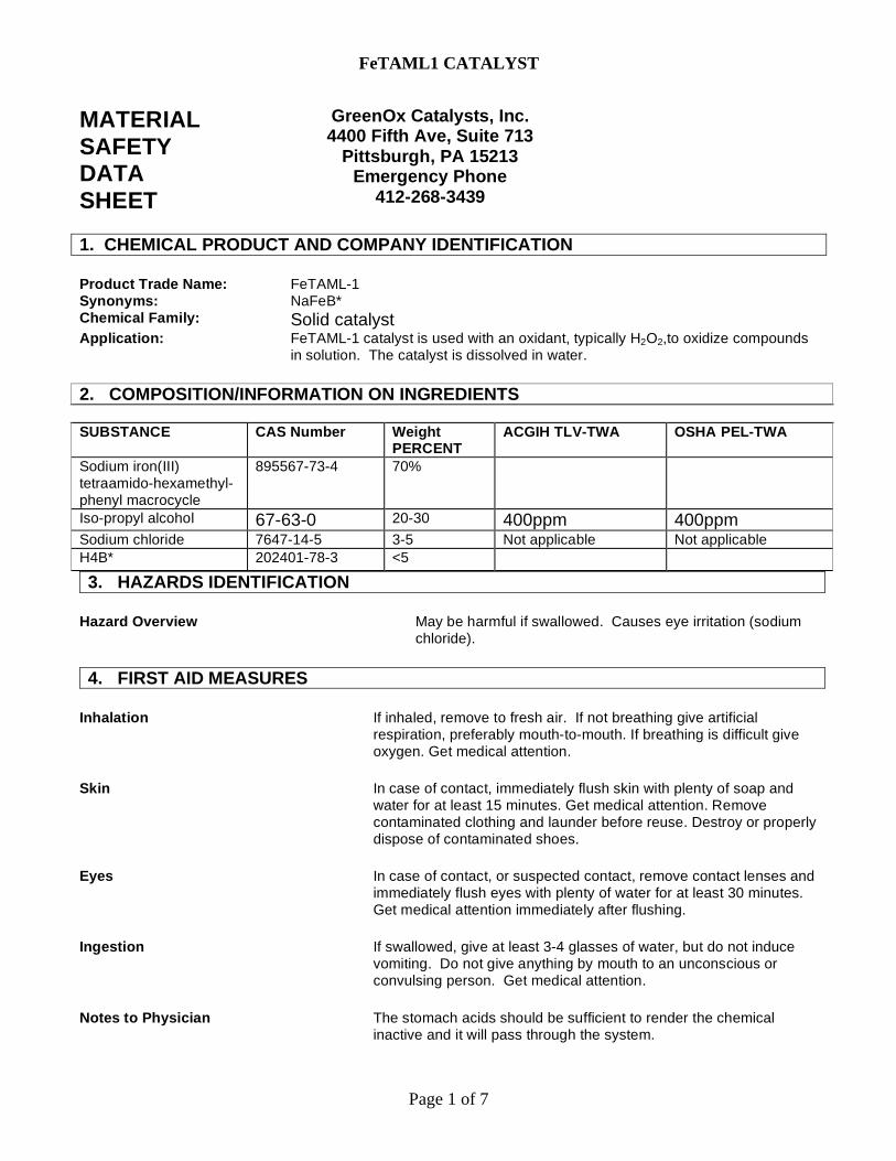
FeTAML1 CATALYST
Page 1 of 7
MATERIAL SAFETY DATA SHEET
GreenOx Catalysts, Inc. 4400 Fifth Ave, Suite 713
Pittsburgh, PA 15213 Emergency Phone
412-268-3439
1. CHEMICAL PRODUCT AND COMPANY IDENTIFICATION Product Trade Name: FeTAML-1 Synonyms: NaFeB* Chemical Family: Solid catalyst Application: FeTAML-1 catalyst is used with an oxidant, typically H2O2,to oxidize compounds
in solution. The catalyst is dissolved in water. 2. COMPOSITION/INFORMATION ON INGREDIENTS SUBSTANCE CAS Number Weight
PERCENT ACGIH TLV-TWA OSHA PEL-TWA
Sodium iron(III) tetraamido-hexamethyl-phenyl macrocycle
895567-73-4 70%
Iso-propyl alcohol 67-63-0 20-30 400ppm 400ppm Sodium chloride 7647-14-5 3-5 Not applicable Not applicable H4B* 202401-78-3 <5
3. HAZARDS IDENTIFICATION Hazard Overview May be harmful if swallowed. Causes eye irritation (sodium
chloride). 4. FIRST AID MEASURES
Inhalation If inhaled, remove to fresh air. If not breathing give artificial
respiration, preferably mouth-to-mouth. If breathing is difficult give oxygen. Get medical attention.
Skin In case of contact, immediately flush skin with plenty of soap and
water for at least 15 minutes. Get medical attention. Remove contaminated clothing and launder before reuse. Destroy or properly dispose of contaminated shoes.
Eyes In case of contact, or suspected contact, remove contact lenses and
immediately flush eyes with plenty of water for at least 30 minutes. Get medical attention immediately after flushing.
Ingestion If swallowed, give at least 3-4 glasses of water, but do not induce
vomiting. Do not give anything by mouth to an unconscious or convulsing person. Get medical attention.
Notes to Physician The stomach acids should be sufficient to render the chemical
inactive and it will pass through the system.
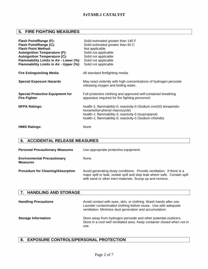
FeTAML1 CATALYST
Page 2 of 7
5. FIRE FIGHTING MEASURES Flash Point/Range (F): Solid estimated greater than 140 F Flash Point/Range (C): Solid estimated greater than 60 C Flash Point Method: Not applicable Autoignition Temperature (F): Solid not applicable Autoignition Temperature (C): Solid not applicable Flammability Limits in Air - Lower (%): Solid not applicable Flammability Limits in Air - Upper (%): Solid not applicable Fire Extinguishing Media All standard firefighting media. Special Exposure Hazards May react violently with high concentrations of hydrogen peroxide
releasing oxygen and boiling water. Special Protective Equipment for Fire-Fighter
Full protective clothing and approved self-contained breathing apparatus required for fire fighting personnel.
NFPA Ratings: health-1; flammability-0; reactivity-0 (Sodium iron(III) tetraamido-
hexamethyl-phenyl macrocycle) health-1; flammability-3; reactivity-0 (Isopropanol) health-1; flammability-0; reactivity-0 (Sodium chloride)
HMIS Ratings: None 6. ACCIDENTAL RELEASE MEASURES
Personal Precautionary Measures Use appropriate protective equipment. Environmental Precautionary Measures
None.
Procedure for Cleaning/Absorption Avoid generating dusty conditions. Provide ventilation. If there is a
major spill or leak, isolate spill and stop leak where safe. Contain spill with sand or other inert materials. Scoop up and remove.
7. HANDLING AND STORAGE
Handling Precautions Avoid contact with eyes, skin, or clothing. Wash hands after use.
Launder contaminated clothing before reuse. Use with adequate ventilation. Minimize dust generation and accumulation.
Storage Information Store away from hydrogen peroxide and other potential oxidizers.
Store in a cool well ventilated area. Keep container closed when not in use.
8. EXPOSURE CONTROLS/PERSONAL PROTECTION
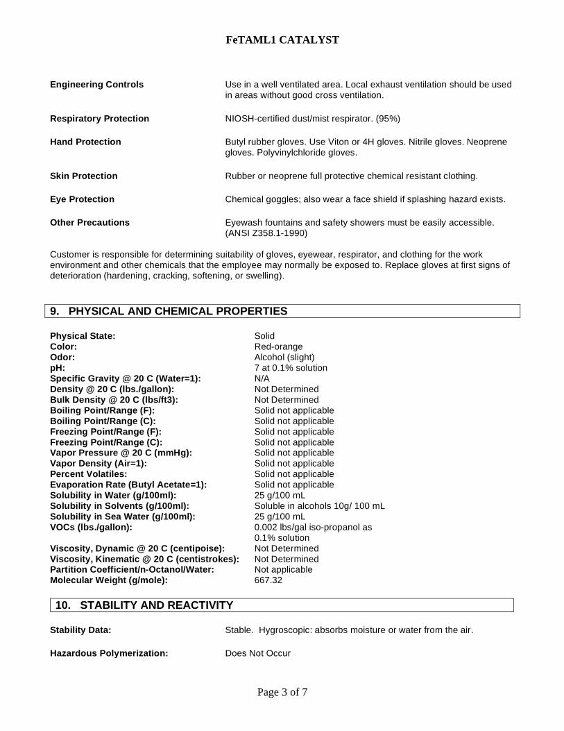
FeTAML1 CATALYST
Page 3 of 7
Engineering Controls Use in a well ventilated area. Local exhaust ventilation should be used
in areas without good cross ventilation. Respiratory Protection NIOSH-certified dust/mist respirator. (95%) Hand Protection Butyl rubber gloves. Use Viton or 4H gloves. Nitrile gloves. Neoprene
gloves. Polyvinylchloride gloves. Skin Protection Rubber or neoprene full protective chemical resistant clothing. Eye Protection Chemical goggles; also wear a face shield if splashing hazard exists. Other Precautions Eyewash fountains and safety showers must be easily accessible.
(ANSI Z358.1-1990) Customer is responsible for determining suitability of gloves, eyewear, respirator, and clothing for the work environment and other chemicals that the employee may normally be exposed to. Replace gloves at first signs of deterioration (hardening, cracking, softening, or swelling). 9. PHYSICAL AND CHEMICAL PROPERTIES Physical State: Solid Color: Red-orange Odor: Alcohol (slight) pH: 7 at 0.1% solution Specific Gravity @ 20 C (Water=1): N/A Density @ 20 C (lbs./gallon): Not Determined Bulk Density @ 20 C (lbs/ft3): Not Determined Boiling Point/Range (F): Solid not applicable Boiling Point/Range (C): Solid not applicable Freezing Point/Range (F): Solid not applicable Freezing Point/Range (C): Solid not applicable Vapor Pressure @ 20 C (mmHg): Solid not applicable Vapor Density (Air=1): Solid not applicable Percent Volatiles: Solid not applicable Evaporation Rate (Butyl Acetate=1): Solid not applicable Solubility in Water (g/100ml): 25 g/100 mL Solubility in Solvents (g/100ml): Soluble in alcohols 10g/ 100 mL Solubility in Sea Water (g/100ml): 25 g/100 mL VOCs (lbs./gallon): 0.002 lbs/gal iso-propanol as
0.1% solution Viscosity, Dynamic @ 20 C (centipoise): Not Determined Viscosity, Kinematic @ 20 C (centistrokes): Not Determined Partition Coefficient/n-Octanol/Water: Not applicable Molecular Weight (g/mole): 667.32 10. STABILITY AND REACTIVITY
Stability Data: Stable. Hygroscopic: absorbs moisture or water from the air. Hazardous Polymerization: Does Not Occur
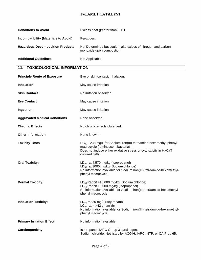
FeTAML1 CATALYST
Page 4 of 7
Conditions to Avoid Excess heat greater than 300 F Incompatibility (Materials to Avoid) Peroxides. Hazardous Decomposition Products Not Determined but could make oxides of nitrogen and carbon
monoxide upon combustion Additional Guidelines Not Applicable 11. TOXICOLOGICAL INFORMATION Principle Route of Exposure Eye or skin contact, inhalation. Inhalation May cause irritation Skin Contact No irritation observed Eye Contact May cause irritation Ingestion May cause irritation Aggravated Medical Conditions None observed. Chronic Effects No chronic effects observed. Other Information None known. Toxicity Tests EC50 - 238 mg/L for Sodium iron(III) tetraamido-hexamethyl-phenyl
macrocycle (luminescent bacteria) Does not induce either oxidative stress or cytotoxicity in HaCaT cultured cells
Oral Toxicity: LD50 rat 4.570 mg/kg (Isopropanol)
LD50 rat 3000 mg/kg (Sodium chloride) No information available for Sodium iron(III) tetraamido-hexamethyl-phenyl macrocycle
Dermal Toxicity: LD50 Rabbit >10,000 mg/kg (Sodium chloride)
LD50 Rabbit 16,000 mg/kg (Isopropanol) No information available for Sodium iron(III) tetraamido-hexamethyl-phenyl macrocycle
Inhalation Toxicity: LD50 rat 30 mg/L (Isopropanol)
LC50 rat = >42 gm/m3/hr No information available for Sodium iron(III) tetraamido-hexamethyl-phenyl macrocycle
Primary Irritation Effect: No information available Carcinogenicity Isopropanol: IARC Group 3 carcinogen.
Sodium chloride: Not listed by ACGIH, IARC, NTP, or CA Prop 65.
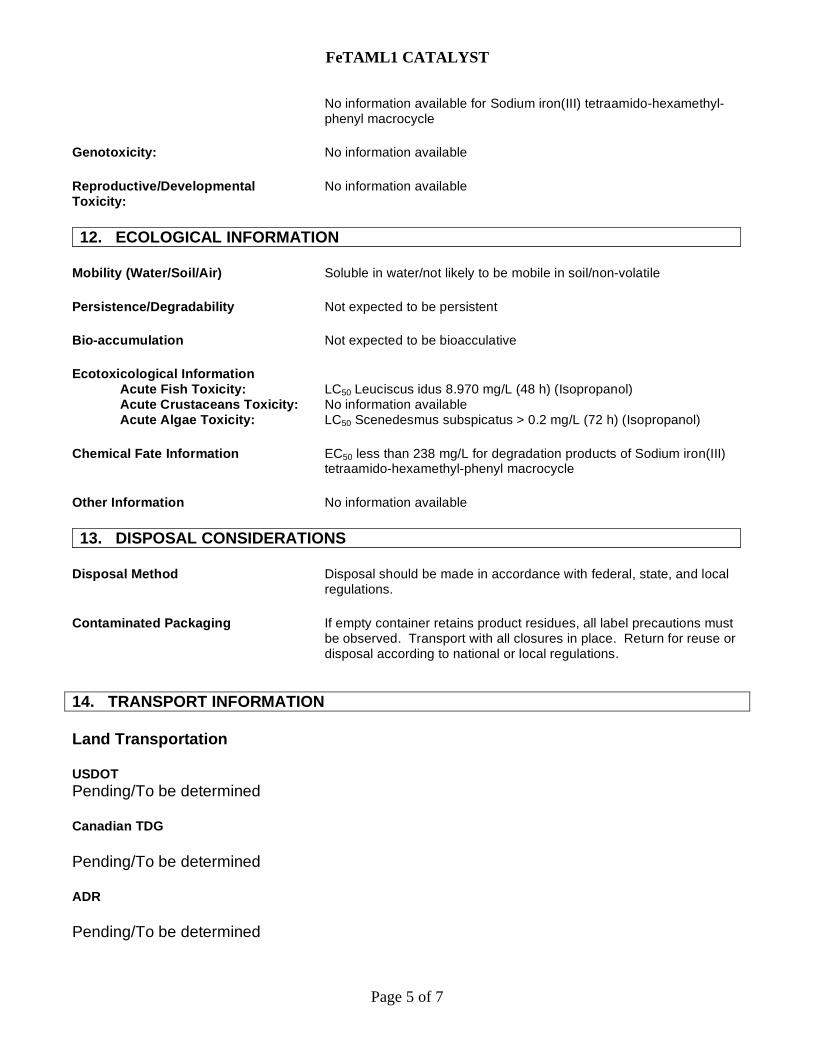
FeTAML1 CATALYST
Page 5 of 7
No information available for Sodium iron(III) tetraamido-hexamethyl-phenyl macrocycle
Genotoxicity: No information available Reproductive/Developmental Toxicity:
No information available
12. ECOLOGICAL INFORMATION
Mobility (Water/Soil/Air) Soluble in water/not likely to be mobile in soil/non-volatile Persistence/Degradability Not expected to be persistent Bio-accumulation Not expected to be bioacculative Ecotoxicological Information Acute Fish Toxicity: LC50 Leuciscus idus 8.970 mg/L (48 h) (Isopropanol) Acute Crustaceans Toxicity: No information available Acute Algae Toxicity: LC50 Scenedesmus subspicatus > 0.2 mg/L (72 h) (Isopropanol) Chemical Fate Information EC50 less than 238 mg/L for degradation products of Sodium iron(III)
tetraamido-hexamethyl-phenyl macrocycle Other Information No information available 13. DISPOSAL CONSIDERATIONS
Disposal Method Disposal should be made in accordance with federal, state, and local
regulations. Contaminated Packaging If empty container retains product residues, all label precautions must
be observed. Transport with all closures in place. Return for reuse or disposal according to national or local regulations.
14. TRANSPORT INFORMATION Land Transportation USDOT Pending/To be determined Canadian TDG Pending/To be determined ADR Pending/To be determined
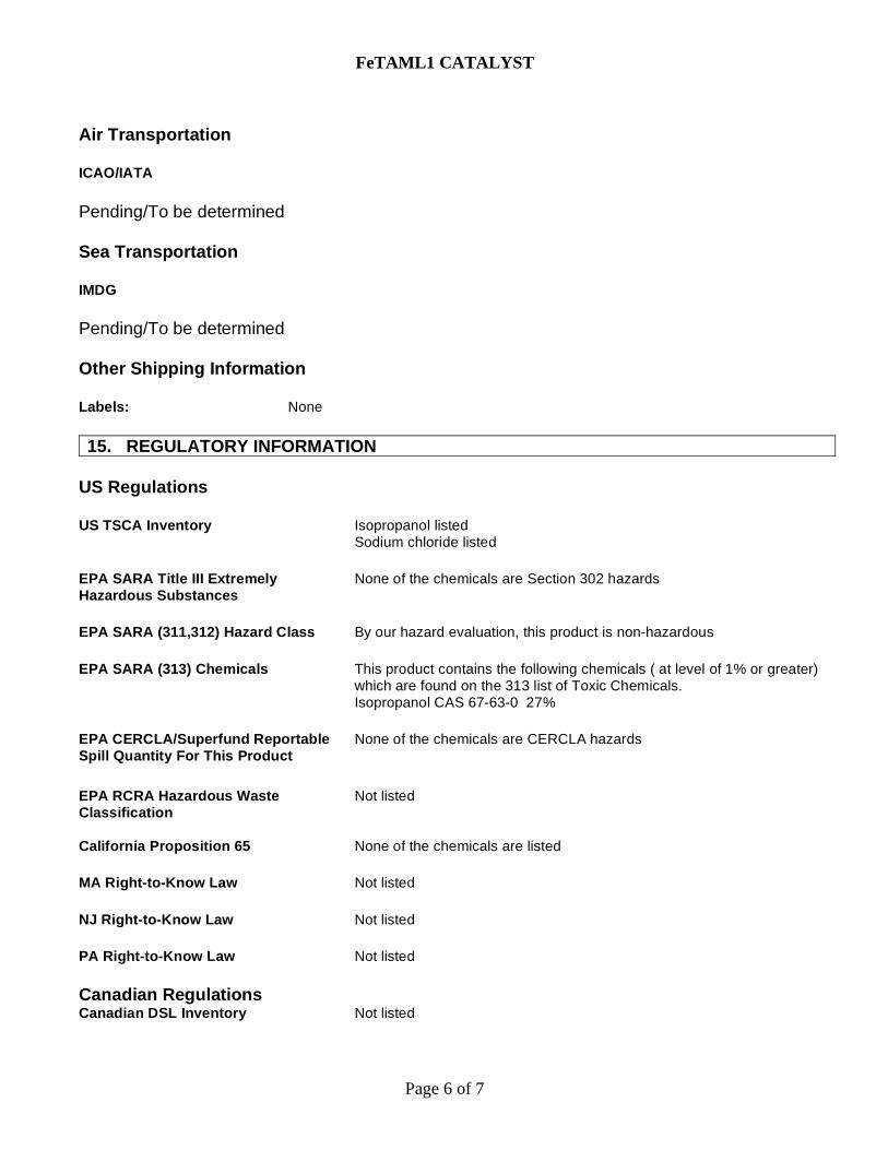
FeTAML1 CATALYST
Page 6 of 7
Air Transportation ICAO/IATA Pending/To be determined Sea Transportation IMDG Pending/To be determined Other Shipping Information Labels: None 15. REGULATORY INFORMATION
US Regulations US TSCA Inventory Isopropanol listed
Sodium chloride listed EPA SARA Title III Extremely Hazardous Substances
None of the chemicals are Section 302 hazards
EPA SARA (311,312) Hazard Class By our hazard evaluation, this product is non-hazardous EPA SARA (313) Chemicals This product contains the following chemicals ( at level of 1% or greater)
which are found on the 313 list of Toxic Chemicals. Isopropanol CAS 67-63-0 27%
EPA CERCLA/Superfund Reportable Spill Quantity For This Product
None of the chemicals are CERCLA hazards
EPA RCRA Hazardous Waste Classification
Not listed
California Proposition 65 None of the chemicals are listed MA Right-to-Know Law Not listed NJ Right-to-Know Law Not listed PA Right-to-Know Law Not listed Canadian Regulations Canadian DSL Inventory Not listed

FeTAML1 CATALYST
Page 7 of 7
WHMIS Hazard Class Not listed 16. OTHER INFORMATION Date: May 2006 Additional Information For additional information on the use of this product or this MSDS, contact GreenOx Catalysts Inc. at 412-268-3439 or 412-268-6335. Disclaimer Statement The FeTAML-1 Catalyst and the information provided herein are provided for research use only and are not intended to relieve a recipient from its responsibility to determine the suitability of this information for their particular purposes, to comply with all laws and procedures regarding the safe use of these materials, and to use these materials in a safe manner.
***END OF MSDS***
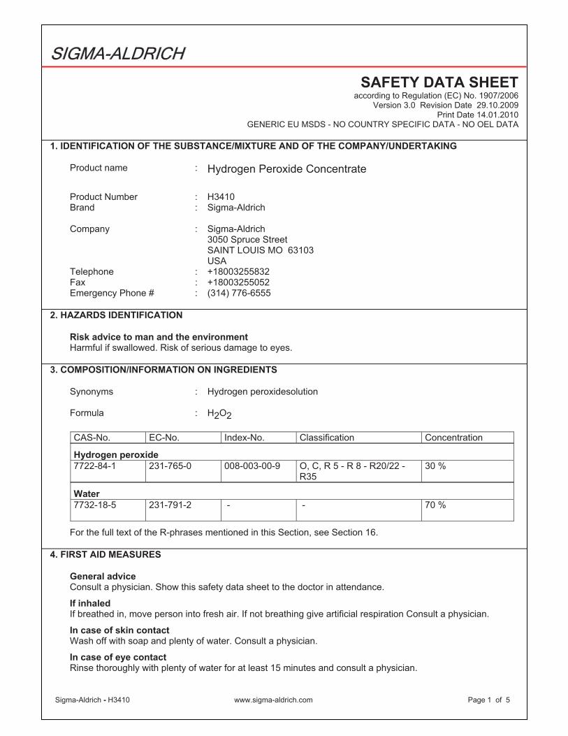
Sigma-Aldrich - H3410 www.sigma-aldrich.com Page 1 of 5
SIGMA-ALDRICH
SAFETY DATA SHEET according to Regulation (EC) No. 1907/2006
Version 3.0 Revision Date 29.10.2009 Print Date 14.01.2010
GENERIC EU MSDS - NO COUNTRY SPECIFIC DATA - NO OEL DATA
1. IDENTIFICATION OF THE SUBSTANCE/MIXTURE AND OF THE COMPANY/UNDERTAKING
Product name : Hydrogen Peroxide Concentrate
Product Number : H3410 Brand : Sigma-Aldrich
Company : Sigma-Aldrich 3050 Spruce Street SAINT LOUIS MO 63103 USA
Telephone : +18003255832 Fax : +18003255052 Emergency Phone # : (314) 776-6555
2. HAZARDS IDENTIFICATION
Risk advice to man and the environment Harmful if swallowed. Risk of serious damage to eyes.
3. COMPOSITION/INFORMATION ON INGREDIENTS
Synonyms : Hydrogen peroxidesolution
Formula : H2O2
CAS-No. EC-No. Index-No. Classification Concentration
Hydrogen peroxide
7722-84-1 231-765-0 008-003-00-9 O, C, R 5 - R 8 - R20/22 - R35
30 %
Water
7732-18-5 231-791-2 - - 70 %
For the full text of the R-phrases mentioned in this Section, see Section 16.
4. FIRST AID MEASURES
General advice Consult a physician. Show this safety data sheet to the doctor in attendance.
If inhaled If breathed in, move person into fresh air. If not breathing give artificial respiration Consult a physician.
In case of skin contact Wash off with soap and plenty of water. Consult a physician.
In case of eye contact Rinse thoroughly with plenty of water for at least 15 minutes and consult a physician.
Sigma-Aldrich - H3410 www.sigma-aldrich.com Page 2 of 5
If swallowed Never give anything by mouth to an unconscious person. Rinse mouth with water. Consult a physician.
5. FIRE-FIGHTING MEASURES
Suitable extinguishing media Use water spray, alcohol-resistant foam, dry chemical or carbon dioxide.
Special protective equipment for fire-fighters Wear self contained breathing apparatus for fire fighting if necessary.
6. ACCIDENTAL RELEASE MEASURES
Personal precautions Use personal protective equipment. Avoid breathing vapors, mist or gas. Ensure adequate ventilation.
Environmental precautions Do not let product enter drains.
Methods for cleaning up Soak up with inert absorbent material and dispose of as hazardous waste. Keep in suitable, closed containers for disposal.
7. HANDLING AND STORAGE
HandlingAvoid inhalation of vapour or mist. Normal measures for preventive fire protection.
Storage Store in cool place. Keep container tightly closed in a dry and well-ventilated place.
Recommended storage temperature: 2 - 8 °C
Store under inert gas. Handle and open container with care. Light sensitive.
8. EXPOSURE CONTROLS/PERSONAL PROTECTION
Personal protective equipment
Respiratory protection Where risk assessment shows air-purifying respirators are appropriate use a full-face respirator with multi-purpose combination (US) or type ABEK (EN 14387) respirator cartridges as a backup to engineering controls. If the respirator is the sole means of protection, use a full-face supplied air respirator. Use respirators and components tested and approved under appropriate government standards such as NIOSH (US) or CEN (EU).
Hand protection The selected protective gloves have to satisfy the specifications of EU Directive 89/686/EEC and the standard EN 374 derived from it. Handle with gloves.
Eye protection Tightly fitting safety goggles. Faceshield (8-inch minimum).
Skin and body protection Choose body protection according to the amount and concentration of the dangerous substance at the work place.
Hygiene measures Handle in accordance with good industrial hygiene and safety practice. Wash hands before breaks and at the end of workday.
Sigma-Aldrich - H3410 www.sigma-aldrich.com Page 3 of 5
9. PHYSICAL AND CHEMICAL PROPERTIES
Appearance
Form clear, liquid
Colour colourless
Safety data
pH no data available
Melting point -40 °C
Boiling point 126 °C at 1.013 hPa
Flash point no data available
Ignition temperature no data available
Lower explosion limit no data available
Upper explosion limit no data available
Vapour pressure 31,1 hPa at 30 °C
Density 1,110 g/cm3
Water solubility no data available
10. STABILITY AND REACTIVITY
Storage stability Stable under recommended storage conditions.
Materials to avoid Zinc, Powdered metals, Iron, Copper, Nickel, Brass, Iron and iron salts.
Hazardous decomposition products Hazardous decomposition products formed under fire conditions. - Nature of decomposition products not known.
11. TOXICOLOGICAL INFORMATION
Acute toxicity
no data available
Irritation and corrosion
no data available
Sensitisation
no data available
Chronic exposure
IARC: 3 - Group 3: Not classifiable as to its carcinogenicity to humans (Hydrogen peroxide)
Signs and Symptoms of Exposure
To the best of our knowledge, the chemical, physical, and toxicological properties have not been thoroughly investigated.
Potential Health Effects
Inhalation May be harmful if inhaled. May cause respiratory tract irritation.Skin May be harmful if absorbed through skin. May cause skin irritation. Eyes Causes serious eye irritation.
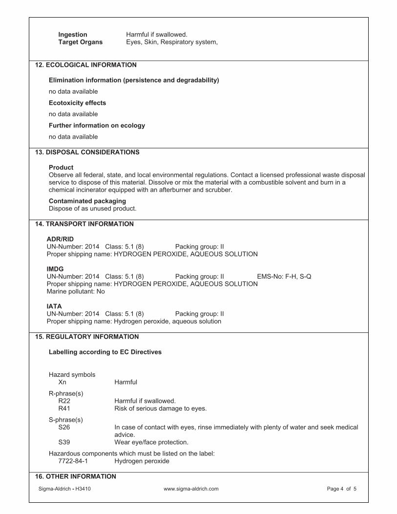
Sigma-Aldrich - H3410 www.sigma-aldrich.com Page 4 of 5
Ingestion Harmful if swallowed.Target Organs Eyes, Skin, Respiratory system,
12. ECOLOGICAL INFORMATION
Elimination information (persistence and degradability)
no data available
Ecotoxicity effects
no data available
Further information on ecology
no data available
13. DISPOSAL CONSIDERATIONS
ProductObserve all federal, state, and local environmental regulations. Contact a licensed professional waste disposal service to dispose of this material. Dissolve or mix the material with a combustible solvent and burn in a chemical incinerator equipped with an afterburner and scrubber.
Contaminated packaging Dispose of as unused product.
14. TRANSPORT INFORMATION
ADR/RID UN-Number: 2014 Class: 5.1 (8) Packing group: II Proper shipping name: HYDROGEN PEROXIDE, AQUEOUS SOLUTION
IMDGUN-Number: 2014 Class: 5.1 (8) Packing group: II EMS-No: F-H, S-Q Proper shipping name: HYDROGEN PEROXIDE, AQUEOUS SOLUTION Marine pollutant: No
IATAUN-Number: 2014 Class: 5.1 (8) Packing group: II Proper shipping name: Hydrogen peroxide, aqueous solution
15. REGULATORY INFORMATION
Labelling according to EC Directives
Hazard symbols Xn Harmful
R-phrase(s) R22 Harmful if swallowed. R41 Risk of serious damage to eyes.
S-phrase(s)S26 In case of contact with eyes, rinse immediately with plenty of water and seek medical
advice.S39 Wear eye/face protection.
Hazardous components which must be listed on the label: 7722-84-1 Hydrogen peroxide
16. OTHER INFORMATION

Sigma-Aldrich - H3410 www.sigma-aldrich.com Page 5 of 5
Text of R-phrases mentioned in Section 3
R 5 Heating may cause an explosion. R 8 Contact with combustible material may cause fire. R20/22 Harmful by inhalation and if swallowed. R35 Causes severe burns.
Further information Copyright 2009 Sigma-Aldrich Co. License granted to make unlimited paper copies for internal use only. The above information is believed to be correct but does not purport to be all inclusive and shall be used only as a guide. The information in this document is based on the present state of our knowledge and is applicable to the product with regard to appropriate safety precautions. It does not represent any guarantee of the properties of the product. Sigma-Aldrich Co., shall not be held liable for any damage resulting from handling or from contact with the above product. See reverse side of invoice or packing slip for additional terms and conditions of sale.
Sigma-Aldrich - 238511 Sigma-Aldrich Corporation
www.sigma-aldrich.comPage 1 of 6
SIGMA-ALDRICH
Material Safety Data Sheet
Version 3.0Revision Date 01/02/2009
Print Date 01/07/2010
1. PRODUCT AND COMPANY IDENTIFICATION
Product name : Potassium permanganate
Product Number : 238511 Brand : Sigma-Aldrich
Company : Sigma-Aldrich 3050 Spruce Street SAINT LOUIS MO 63103 USA
Telephone : +18003255832 Fax : +18003255052 Emergency Phone # : (314) 776-6555
2. COMPOSITION/INFORMATION ON INGREDIENTS
Formula : KMnO4Molecular Weight : 158.03 g/mol
CAS-No. EC-No. Index-No. Concentration
Potassium permanganate
7722-64-7 231-760-3 025-002-00-9 -
3. HAZARDS IDENTIFICATION
Emergency Overview
OSHA HazardsOxidizer, Harmful by ingestion.
HMIS Classification Health Hazard: 1Flammability: 0Physical hazards: 2
NFPA Rating Health Hazard: 1Fire: 0Reactivity Hazard: 2Special hazard.: OX
Potential Health Effects
Inhalation May be harmful if inhaled. May cause respiratory tract irritation.Skin May be harmful if absorbed through skin. May cause skin irritation. Eyes May cause eye irritation.Ingestion Harmful if swallowed.
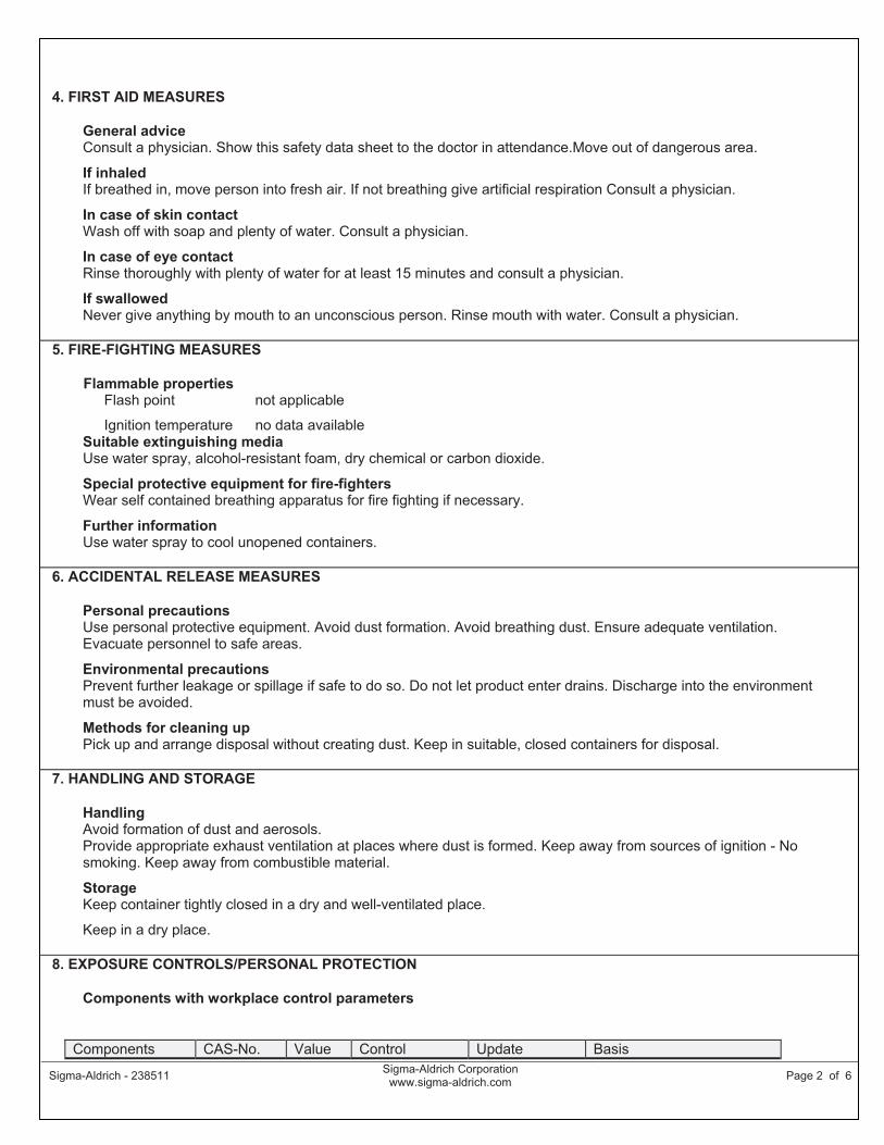
Sigma-Aldrich - 238511 Sigma-Aldrich Corporation
www.sigma-aldrich.comPage 2 of 6
4. FIRST AID MEASURES
General advice Consult a physician. Show this safety data sheet to the doctor in attendance.Move out of dangerous area.
If inhaled If breathed in, move person into fresh air. If not breathing give artificial respiration Consult a physician.
In case of skin contact Wash off with soap and plenty of water. Consult a physician.
In case of eye contact Rinse thoroughly with plenty of water for at least 15 minutes and consult a physician.
If swallowed Never give anything by mouth to an unconscious person. Rinse mouth with water. Consult a physician.
5. FIRE-FIGHTING MEASURES
Flammable properties Flash point not applicable
Ignition temperature no data availableSuitable extinguishing media Use water spray, alcohol-resistant foam, dry chemical or carbon dioxide.
Special protective equipment for fire-fighters Wear self contained breathing apparatus for fire fighting if necessary.
Further information Use water spray to cool unopened containers.
6. ACCIDENTAL RELEASE MEASURES
Personal precautions Use personal protective equipment. Avoid dust formation. Avoid breathing dust. Ensure adequate ventilation. Evacuate personnel to safe areas.
Environmental precautions Prevent further leakage or spillage if safe to do so. Do not let product enter drains. Discharge into the environment must be avoided.
Methods for cleaning up Pick up and arrange disposal without creating dust. Keep in suitable, closed containers for disposal.
7. HANDLING AND STORAGE
HandlingAvoid formation of dust and aerosols. Provide appropriate exhaust ventilation at places where dust is formed. Keep away from sources of ignition - No smoking. Keep away from combustible material.
Storage Keep container tightly closed in a dry and well-ventilated place.
Keep in a dry place.
8. EXPOSURE CONTROLS/PERSONAL PROTECTION
Components with workplace control parameters
Components CAS-No. Value Control Update Basis

Sigma-Aldrich - 238511 Sigma-Aldrich Corporation
www.sigma-aldrich.comPage 3 of 6
parameters
Potassium permanganate
7722-64-7 CEIL 5 mg/m3 1993-06-30 US. Department of Labor - Occupational Safety and Health Administration (OSHA) Permissible Exposure Limits (PEL) 29 CFR 1910.1000 Air Contaminants.
CEIL 5 mg/m3 1989-03-01 US. Department of Labor - Occupational Safety and Health Administration (OSHA) 29 CFR 1910.1000 Z-1-A
TWA 0.2 mg/m3 1995-05-23 US. American Conference of Governmental and Industrial Hygienists Threshold Limit Values for Chemical Substances in the Work Environment; Annual Reports for the Year 2004:Committees on Threshold Limit Values (TLVs ) and Biological Exposure Indices (BEIs)
Remarks Substances for which the TLV is higher than the OSHA Permissible Exposure Limit (PEL) and/or the NIOSH Recommended Exposure Limit (REL). See CFR 58(124) :36338-33351, June 30, 1993, for revised OSHA PEL. See Notice of Intended Changes.
Personal protective equipment
Respiratory protection Where risk assessment shows air-purifying respirators are appropriate use a full-face particle respirator type N100 (US) or type P3 (EN 143) respirator cartridges as a backup to engineering controls. If the respirator is the sole means of protection, use a full-face supplied air respirator. Where risk assessment shows air-purifying respirators are appropriate use a dust mask type N95 (US) or type P1 (EN 143) respirator. Use respirators and components tested and approved under appropriate government standards such as NIOSH (US) or CEN (EU).
Hand protection Handle with gloves. For prolonged or repeated contact use protective gloves.
Eye protection Safety glasses
Skin and body protection Choose body protection according to the amount and concentration of the dangerous substance at the work place.
Hygiene measures Handle in accordance with good industrial hygiene and safety practice. Wash hands before breaks and at the end of workday.
9. PHYSICAL AND CHEMICAL PROPERTIES
Appearance
Form powder
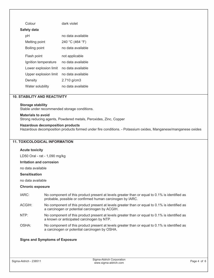
Sigma-Aldrich - 238511 Sigma-Aldrich Corporation
www.sigma-aldrich.comPage 4 of 6
Colour dark violet
Safety data
pH no data available
Melting point 240 °C (464 °F)
Boiling point no data available
Flash point not applicable
Ignition temperature no data available
Lower explosion limit no data available
Upper explosion limit no data available
Density 2.710 g/cm3
Water solubility no data available
10. STABILITY AND REACTIVITY
Storage stability Stable under recommended storage conditions.
Materials to avoid Strong reducing agents, Powdered metals, Peroxides, Zinc, Copper
Hazardous decomposition products Hazardous decomposition products formed under fire conditions. - Potassium oxides, Manganese/manganese oxides
11. TOXICOLOGICAL INFORMATION
Acute toxicity
LD50 Oral - rat - 1,090 mg/kg
Irritation and corrosion
no data available
Sensitisation
no data available
Chronic exposure
IARC: No component of this product present at levels greater than or equal to 0.1% is identified as probable, possible or confirmed human carcinogen by IARC.
ACGIH: No component of this product present at levels greater than or equal to 0.1% is identified as a carcinogen or potential carcinogen by ACGIH.
NTP: No component of this product present at levels greater than or equal to 0.1% is identified as a known or anticipated carcinogen by NTP.
OSHA: No component of this product present at levels greater than or equal to 0.1% is identified as a carcinogen or potential carcinogen by OSHA.
Signs and Symptoms of Exposure
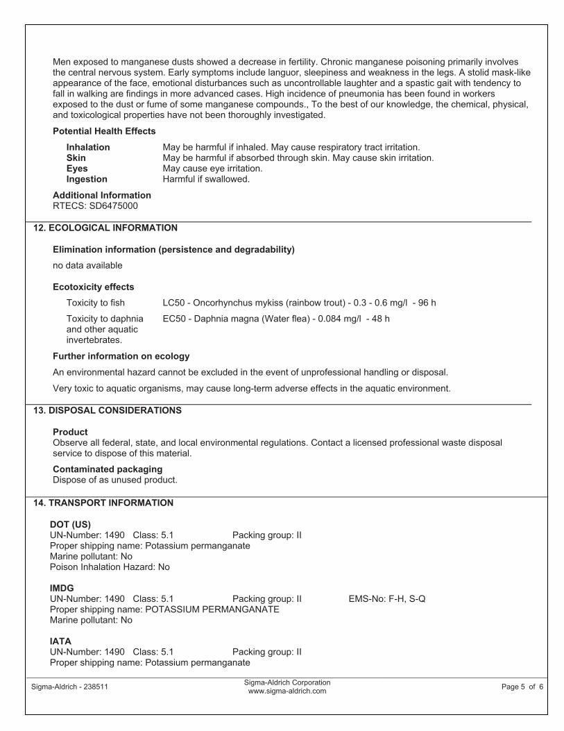
Sigma-Aldrich - 238511 Sigma-Aldrich Corporation
www.sigma-aldrich.comPage 5 of 6
Men exposed to manganese dusts showed a decrease in fertility. Chronic manganese poisoning primarily involves the central nervous system. Early symptoms include languor, sleepiness and weakness in the legs. A stolid mask-like appearance of the face, emotional disturbances such as uncontrollable laughter and a spastic gait with tendency to fall in walking are findings in more advanced cases. High incidence of pneumonia has been found in workers exposed to the dust or fume of some manganese compounds., To the best of our knowledge, the chemical, physical, and toxicological properties have not been thoroughly investigated.
Potential Health Effects
Inhalation May be harmful if inhaled. May cause respiratory tract irritation.Skin May be harmful if absorbed through skin. May cause skin irritation. Eyes May cause eye irritation.Ingestion Harmful if swallowed.
Additional Information RTECS: SD6475000
12. ECOLOGICAL INFORMATION
Elimination information (persistence and degradability)
no data available
Ecotoxicity effects
Toxicity to fish LC50 - Oncorhynchus mykiss (rainbow trout) - 0.3 - 0.6 mg/l - 96 h
Toxicity to daphnia and other aquatic invertebrates.
EC50 - Daphnia magna (Water flea) - 0.084 mg/l - 48 h
Further information on ecology
An environmental hazard cannot be excluded in the event of unprofessional handling or disposal.
Very toxic to aquatic organisms, may cause long-term adverse effects in the aquatic environment.
13. DISPOSAL CONSIDERATIONS
ProductObserve all federal, state, and local environmental regulations. Contact a licensed professional waste disposal service to dispose of this material.
Contaminated packaging Dispose of as unused product.
14. TRANSPORT INFORMATION
DOT (US)UN-Number: 1490 Class: 5.1 Packing group: II Proper shipping name: Potassium permanganate Marine pollutant: No Poison Inhalation Hazard: No
IMDGUN-Number: 1490 Class: 5.1 Packing group: II EMS-No: F-H, S-Q Proper shipping name: POTASSIUM PERMANGANATE Marine pollutant: No
IATAUN-Number: 1490 Class: 5.1 Packing group: II Proper shipping name: Potassium permanganate
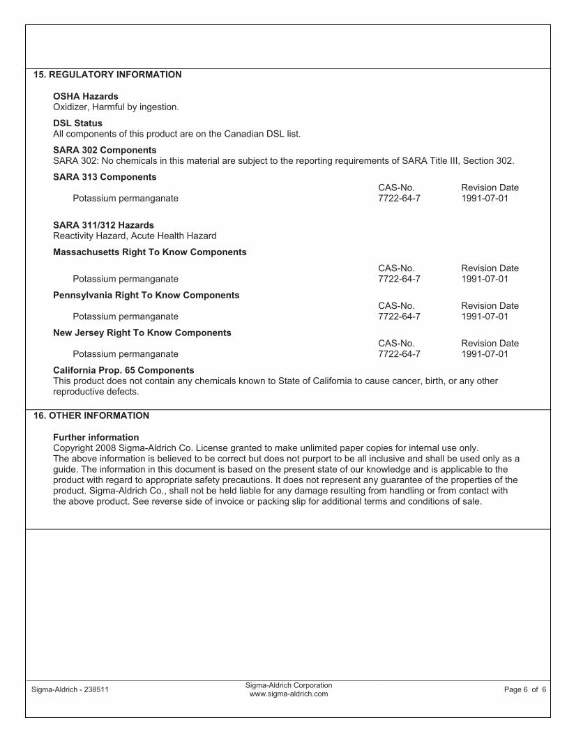
Sigma-Aldrich - 238511 Sigma-Aldrich Corporation
www.sigma-aldrich.comPage 6 of 6
15. REGULATORY INFORMATION
OSHA Hazards Oxidizer, Harmful by ingestion.
DSL Status All components of this product are on the Canadian DSL list.
SARA 302 Components SARA 302: No chemicals in this material are subject to the reporting requirements of SARA Title III, Section 302.
SARA 313 Components
Potassium permanganate CAS-No.7722-64-7
Revision Date 1991-07-01
SARA 311/312 Hazards Reactivity Hazard, Acute Health Hazard
Massachusetts Right To Know Components
Potassium permanganate CAS-No.7722-64-7
Revision Date 1991-07-01
Pennsylvania Right To Know Components
Potassium permanganate CAS-No.7722-64-7
Revision Date 1991-07-01
New Jersey Right To Know Components
Potassium permanganate CAS-No.7722-64-7
Revision Date 1991-07-01
California Prop. 65 Components This product does not contain any chemicals known to State of California to cause cancer, birth, or any other reproductive defects.
16. OTHER INFORMATION
Further information Copyright 2008 Sigma-Aldrich Co. License granted to make unlimited paper copies for internal use only. The above information is believed to be correct but does not purport to be all inclusive and shall be used only as a guide. The information in this document is based on the present state of our knowledge and is applicable to the product with regard to appropriate safety precautions. It does not represent any guarantee of the properties of the product. Sigma-Aldrich Co., shall not be held liable for any damage resulting from handling or from contact with the above product. See reverse side of invoice or packing slip for additional terms and conditions of sale.
Material Safety Data SheetSodium hydroxide MSDS
Section 1: Chemical Product and Company Identification
Product Name: Sodium hydroxide
Catalog Codes: SLS3298, SLS1081, SLS2503, SLS3925,SLS1705
CAS#: 1310-73-2
RTECS:WB4900000
TSCA: TSCA 8(b) inventory: Sodium hydroxide
CI#: Not available.
Synonym: Caustic Soda
Chemical Name: Sodium Hydroxide
Chemical Formula: NaOH
Contact Information:
Sciencelab.com, Inc.14025 Smith Rd.Houston, Texas 77396
US Sales: 1-800-901-7247International Sales: 1-281-441-4400
Order Online: ScienceLab.com
CHEMTREC (24HR Emergency Telephone), call:1-800-424-9300
International CHEMTREC, call: 1-703-527-3887
For non-emergency assistance, call: 1-281-441-4400
Section 2: Composition and Information on Ingredients
Composition:
Name CAS # % by Weight
Sodium hydroxide 1310-73-2 100
Toxicological Data on Ingredients: Sodium hydroxide LD50: Not available. LC50: Not available.
Section 3: Hazards Identification
Potential Acute Health Effects:Very hazardous in case of skin contact (corrosive, irritant, permeator), of eye contact (irritant, corrosive), ofingestion, of inhalation. The amount of tissue damage depends on length of contact. Eye contact can result incorneal damage or blindness. Skin contact can produce inflammation and blistering. Inhalation of dust willproduce irritation to gastro-intestinal or respiratory tract, characterized by burning, sneezing and coughing.Severe over-exposure can produce lung damage, choking, unconsciousness or death. Inflammation of the eye ischaracterized by redness, watering, and itching. Skin inflammation is characterized by itching, scaling, reddening,or, occasionally, blistering.
Potential Chronic Health Effects:CARCINOGENIC EFFECTS: Not available.MUTAGENIC EFFECTS: Mutagenic for mammalian somatic cells.TERATOGENIC EFFECTS: Not available.DEVELOPMENTAL TOXICITY: Not available.
p. 1
The substance may be toxic to mucous membranes, upper respiratory tract, skin, eyes.Repeated or prolonged exposure to the substance can produce target organs damage. Repeated exposure of theeyes to a low level of dust can produce eye irritation. Repeated skin exposure can produce local skin destruction,or dermatitis. Repeated inhalation of dust can produce varying degree of respiratory irritation or lung damage.
Section 4: First Aid Measures
Eye Contact:Check for and remove any contact lenses. In case of contact, immediately flush eyes with plenty of water for atleast 15 minutes. Cold water may be used. Get medical attention immediately.
Skin Contact:In case of contact, immediately flush skin with plenty of water for at least 15 minutes while removing contaminatedclothing and shoes. Cover the irritated skin with an emollient. Cold water may be used.Wash clothing beforereuse. Thoroughly clean shoes before reuse. Get medical attention immediately.
Serious Skin Contact:Wash with a disinfectant soap and cover the contaminated skin with an anti-bacterial cream. Seek medicalattention.
Inhalation:If inhaled, remove to fresh air. If not breathing, give artificial respiration. If breathing is difficult, give oxygen. Getmedical attention immediately.
Serious Inhalation:Evacuate the victim to a safe area as soon as possible. Loosen tight clothing such as a collar, tie, belt orwaistband. If breathing is difficult, administer oxygen. If the victim is not breathing, perform mouth-to-mouthresuscitation. WARNING: It may be hazardous to the person providing aid to give mouth-to-mouth resuscitationwhen the inhaled material is toxic, infectious or corrosive. Seek immediate medical attention.
Ingestion:Do NOT induce vomiting unless directed to do so by medical personnel. Never give anything by mouth to anunconscious person. If large quantities of this material are swallowed, call a physician immediately. Loosen tightclothing such as a collar, tie, belt or waistband.
Serious Ingestion: Not available.
Section 5: Fire and Explosion Data
Flammability of the Product: Non-flammable.
Auto-Ignition Temperature: Not applicable.
Flash Points: Not applicable.
Flammable Limits: Not applicable.
Products of Combustion: Not available.
Fire Hazards in Presence of Various Substances: metals
Explosion Hazards in Presence of Various Substances:Risks of explosion of the product in presence of mechanical impact: Not available.Risks of explosion of the product in presence of static discharge: Not available.Slightly explosive in presence of heat.
Fire Fighting Media and Instructions: Not available
Special Remarks on Fire Hazards:sodium hydroxide + zinc metal dust causes ignition of the latter.
p. 2
Under proper conditions of temperature, pressure and state of division, it can ignite or react violently withacetaldehyde, ally alcohol, allyl chloride, benzene-1,4-diol, chlorine trifluoride, 1,2 dichlorethylene, nitroethane,nitromethane, nitroparaffins, nitropropane, cinnamaldehyde, 2,2-dichloro-3,3-dimethylbutane.Sodium hydroxide in contact with water may generate enough heat to ignite adjacent combustible materials.Phosphorous boiled with NaOH yields mixed phosphines which may ignite spontanously in air.sodium hydroxide and cinnamaldehyde + heat may cause ignition.Reaction with certain metals releases flammable and explosive hydrogen gas.
Special Remarks on Explosion Hazards:Sodium hydroxide reacts to form explosive products with ammonia + silver nitrate.Benzene extract of allyl benzenesulfonate prepared from allyl alcohol, and benzene sulfonyl chloride in presence ofaquesous sodium hydroxide, under vacuum distillation, residue darkened and exploded.Sodium Hydroxde + impure tetrahydrofuran, which can contain peroxides, can cause serious explosions.Dry mixtures of sodium hydroxide and sodium tetrahydroborate liberate hydrogen explosively at 230-270 deg. C.Sodium Hydroxide reacts with sodium salt of trichlorophenol + methyl alcohol + trichlorobenzene + heat to causean explosion.
Section 6: Accidental Release Measures
Small Spill:Use appropriate tools to put the spilled solid in a convenient waste disposal container. If necessary: Neutralizethe residue with a dilute solution of acetic acid.
Large Spill:Corrosive solid.Stop leak if without risk. Do not get water inside container. Do not touch spilled material. Use water spray toreduce vapors. Prevent entry into sewers, basements or confined areas; dike if needed. Call for assistance ondisposal. Neutralize the residue with a dilute solution of acetic acid. Be careful that the product is not presentat a concentration level above TLV. Check TLV on the MSDS and with local authorities.
Section 7: Handling and Storage
Precautions:Keep container dry. Do not breathe dust. Never add water to this product. In case of insufficient ventilation, wearsuitable respiratory equipment. If you feel unwell, seek medical attention and show the label when possible. Avoidcontact with skin and eyes. Keep away from incompatibles such as oxidizing agents, reducing agents, metals,acids, alkalis, moisture.
Storage: Keep container tightly closed. Keep container in a cool, well-ventilated area. Hygroscopic. Deliquescent.
Section 8: Exposure Controls/Personal Protection
Engineering Controls:Use process enclosures, local exhaust ventilation, or other engineering controls to keep airborne levels belowrecommended exposure limits. If user operations generate dust, fume or mist, use ventilation to keep exposure toairborne contaminants below the exposure limit.
Personal Protection:Splash goggles. Synthetic apron. Vapor and dust respirator. Be sure to use an approved/certified respirator orequivalent. Gloves.
Personal Protection in Case of a Large Spill:Splash goggles. Full suit. Vapor and dust respirator. Boots. Gloves. A self contained breathing apparatusshould be used to avoid inhalation of the product. Suggested protective clothing might not be sufficient; consult aspecialist BEFORE handling this product.
Exposure Limits:STEL: 2 (mg/m3) from ACGIH (TLV) [United States]
p. 3
TWA: 2 CEIL: 2 (mg/m3) from OSHA (PEL) [United States]CEIL: 2 (mg/m3) from NIOSHConsult local authorities for acceptable exposure limits.
Section 9: Physical and Chemical Properties
Physical state and appearance: Solid. (Deliquescent solid.)
Odor: Odorless.
Taste: Not available.
Molecular Weight: 40 g/mole
Color:White.
pH (1% soln/water): 13.5 [Basic.]
Boiling Point: 1388°C (2530.4°F)
Melting Point: 323°C (613.4°F)
Critical Temperature: Not available.
Specific Gravity: 2.13 (Water = 1)
Vapor Pressure: Not applicable.
Vapor Density: Not available.
Volatility: Not available.
Odor Threshold: Not available.
Water/Oil Dist. Coeff.: Not available.
Ionicity (in Water): Not available.
Dispersion Properties: See solubility in water.
Solubility: Easily soluble in cold water.
Section 10: Stability and Reactivity Data
Stability: The product is stable.
Instability Temperature: Not available.
Conditions of Instability: Incompatible materials, moisture, moist air
Incompatibility with various substances:Highly reactive with metals.Reactive with oxidizing agents, reducing agents, acids, alkalis, moisture.
Corrosivity: Not available.
Special Remarks on Reactivity:Hygroscopic. Much heat is evolved when solid material is dissolved in water. Therefore cold water and cautionmust be used for this process.Sodium hydroxide solution and octanol + diborane during a work-up of a reaction mixture of oxime and diborane intetrahyrofuran is very exothermic, a mild explosion being noted on one occassion.
p. 4

Reactive with water, acids (mineral, non-oxidizing, e.g. hydrochloric, hydrofluoric acid, muriatic acid, phosphoric),acids (mineral, oxidizing e.g. chromic acid, hypochlorous acid, nitric acid, sulfuric acid), acids (organic e.g. aceticacid, benzoic acid, formic acid, methanoic acid, oxalic acid), aldehydes (e.g. acetaldehyde, acrolein, chloralhydrate, foraldehyde), carbamates (e.g. carbanolate, carbofuran), esters (e.g. butyl acetate, ethyl acetate, propylformate), halogenated organics (dibromoethane, hexachlorobenzene, methyl chloride, trichloroethylene),isocyanates (e.g. methyl isocyanate), ketones (acetone, acetophenone, MEK, MIBK), acid chlorides, strongbases, strong oxidizing agents, strong reducing agents, flammable liquids, powdered metals and metals (i.ealuminum, tin, zinc, hafnium, raney nickel), metals (alkali and alkaline e.g. cesium, potassium, sodium), metalcompounds (toxic e.g. berylium, lead acetate, nickel carbonyl, tetraethyl lead), mitrides (e.g. potassium nitride,sodium nitride), nitriles (e.g. acetonitrile, methyl cyanide), nitro compounds (organic e.g. nitrobenzene,nitromethane), acetic anhydride, chlorohydrin, chlorosulfonic acid, ethylene cyanohydrin, glyoxal, hydrosulfuricacid, oleum, propiolactone, acylonitrile, phorosous pentoxide, chloroethanol, chloroform-methanol,tetrahydroborate, cyanogen azide, 1,2,4,5 tetrachlorobenzene, cinnamaldehyde.Reacts with formaldehyde hydroxide to yield formic acid, and hydrogen.
Special Remarks on Corrosivity: Very caustic to aluminum and other metals in presence of moisture.
Polymerization:Will not occur.
Section 11: Toxicological Information
Routes of Entry: Absorbed through skin. Dermal contact. Eye contact. Inhalation. Ingestion.
Toxicity to Animals:LD50: Not available.LC50: Not available.
Chronic Effects on Humans:MUTAGENIC EFFECTS: Mutagenic for mammalian somatic cells.May cause damage to the following organs: mucous membranes, upper respiratory tract, skin, eyes.
Other Toxic Effects on Humans:Extremely hazardous in case of inhalation (lung corrosive).Very hazardous in case of skin contact (corrosive, irritant, permeator), of eye contact (corrosive), of ingestion, .
Special Remarks on Toxicity to Animals:Lowest Published Lethal Dose:LDL [Rabbit] - Route: Oral; Dose: 500 mg/kg
Special Remarks on Chronic Effects on Humans: May affect genetic material. Investigation as a mutagen (cytogeneticanalysis)
Special Remarks on other Toxic Effects on Humans:
Section 12: Ecological Information
Ecotoxicity: Not available.
BOD5 and COD: Not available.
Products of Biodegradation:Possibly hazardous short term degradation products are not likely. However, long term degradation products mayarise.
Toxicity of the Products of Biodegradation: The product itself and its products of degradation are not toxic.
Special Remarks on the Products of Biodegradation: Not available.
p. 5
Section 13: Disposal Considerations
Waste Disposal:Waste must be disposed of in accordance with federal, state and local environmentalcontrol regulations.
Section 14: Transport Information
DOT Classification: Class 8: Corrosive material
Identification: : Sodium hydroxide, solid UNNA: 1823 PG: II
Special Provisions for Transport: Not available.
Section 15: Other Regulatory Information
Federal and State Regulations:Illinois toxic substances disclosure to employee act: Sodium hydroxideIllinois chemical safety act: Sodium hydroxideNew York release reporting list: Sodium hydroxideRhode Island RTK hazardous substances: Sodium hydroxidePennsylvania RTK: Sodium hydroxideMinnesota: Sodium hydroxideMassachusetts RTK: Sodium hydroxideNew Jersey: Sodium hydroxideLouisiana spill reporting: Sodium hydroxideCalifornia Director's List of Hazardous Substances: Sodium hydroxideTSCA 8(b) inventory: Sodium hydroxideCERCLA: Hazardous substances.: Sodium hydroxide: 1000 lbs. (453.6 kg)
Other Regulations:OSHA: Hazardous by definition of Hazard Communication Standard (29 CFR 1910.1200).EINECS: This product is on the European Inventory of Existing Commercial Chemical Substances.
Other Classifications:
WHMIS (Canada): CLASS E: Corrosive solid.
DSCL (EEC):R35- Causes severe burns.S26- In case of contact with eyes, rinseimmediately with plenty of water and seekmedical advice.S37/39- Wear suitable gloves and eye/faceprotection.S45- In case of accident or if you feel unwell,seek medical advice immediately (show thelabel where possible).
HMIS (U.S.A.):
Health Hazard: 3
Fire Hazard: 0
Reactivity: 2
Personal Protection: j
National Fire Protection Association (U.S.A.):
p. 6
Health: 3
Flammability: 0
Reactivity: 1
Specific hazard:
Protective Equipment:Gloves.Synthetic apron.Vapor and dust respirator. Be sure touse an approved/certified respirator orequivalent. Wear appropriate respiratorwhen ventilation is inadequate.Splash goggles.
Section 16: Other Information
References: Not available.
Other Special Considerations: Not available.
Created: 10/09/2005 06:32 PM
Last Updated: 10/09/2005 06:32 PM
The information above is believed to be accurate and represents the best information currently available to us. However, wemake no warranty of merchantability or any other warranty, express or implied, with respect to such information, and weassume no liability resulting from its use. Users should make their own investigations to determine the suitability of theinformation for their particular purposes. In no event shall ScienceLab.com be liable for any claims, losses, or damages of anythird party or for lost profits or any special, indirect, incidental, consequential or exemplary damages, howsoever arising, evenif ScienceLab.com has been advised of the possibility of such damages.
p. 7
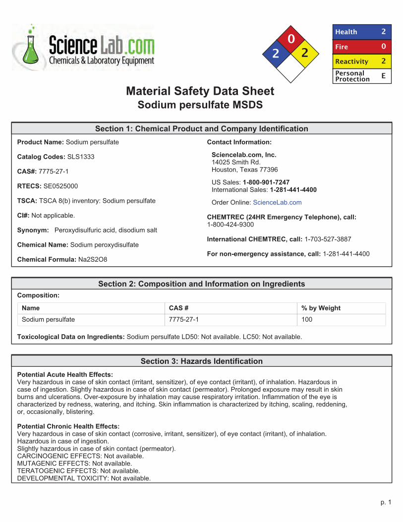
Material Safety Data SheetSodium persulfate MSDS
Section 1: Chemical Product and Company Identification
Product Name: Sodium persulfate
Catalog Codes: SLS1333
CAS#: 7775-27-1
RTECS: SE0525000
TSCA: TSCA 8(b) inventory: Sodium persulfate
CI#: Not applicable.
Synonym: Peroxydisulfuric acid, disodium salt
Chemical Name: Sodium peroxydisulfate
Chemical Formula: Na2S2O8
Contact Information:
Sciencelab.com, Inc.14025 Smith Rd.Houston, Texas 77396
US Sales: 1-800-901-7247International Sales: 1-281-441-4400
Order Online: ScienceLab.com
CHEMTREC (24HR Emergency Telephone), call:1-800-424-9300
International CHEMTREC, call: 1-703-527-3887
For non-emergency assistance, call: 1-281-441-4400
Section 2: Composition and Information on Ingredients
Composition:
Name CAS # % by Weight
Sodium persulfate 7775-27-1 100
Toxicological Data on Ingredients: Sodium persulfate LD50: Not available. LC50: Not available.
Section 3: Hazards Identification
Potential Acute Health Effects:Very hazardous in case of skin contact (irritant, sensitizer), of eye contact (irritant), of inhalation. Hazardous incase of ingestion. Slightly hazardous in case of skin contact (permeator). Prolonged exposure may result in skinburns and ulcerations. Over-exposure by inhalation may cause respiratory irritation. Inflammation of the eye ischaracterized by redness, watering, and itching. Skin inflammation is characterized by itching, scaling, reddening,or, occasionally, blistering.
Potential Chronic Health Effects:Very hazardous in case of skin contact (corrosive, irritant, sensitizer), of eye contact (irritant), of inhalation.Hazardous in case of ingestion.Slightly hazardous in case of skin contact (permeator).CARCINOGENIC EFFECTS: Not available.MUTAGENIC EFFECTS: Not available.TERATOGENIC EFFECTS: Not available.DEVELOPMENTAL TOXICITY: Not available.
p. 1
The substance is toxic to blood, lungs.Repeated or prolonged exposure to the substance can produce target organs damage. Repeated or prolongedinhalation of dust may lead to chronic respiratory irritation.
Section 4: First Aid Measures
Eye Contact:Check for and remove any contact lenses. Immediately flush eyes with running water for at least 15 minutes,keeping eyelids open. Cold water may be used. Do not use an eye ointment. Seek medical attention.
Skin Contact:After contact with skin, wash immediately with plenty of water. Gently and thoroughly wash the contaminated skinwith running water and non-abrasive soap. Be particularly careful to clean folds, crevices, creases and groin.Cold water may be used. Cover the irritated skin with an emollient. If irritation persists, seek medical attention.
Serious Skin Contact:Wash with a disinfectant soap and cover the contaminated skin with an anti-bacterial cream. Seek medicalattention.
Inhalation: Allow the victim to rest in a well ventilated area. Seek immediate medical attention.
Serious Inhalation:Evacuate the victim to a safe area as soon as possible. Loosen tight clothing such as a collar, tie, belt orwaistband. If breathing is difficult, administer oxygen. If the victim is not breathing, perform mouth-to-mouthresuscitation. Seek medical attention.
Ingestion:Do not induce vomiting. Loosen tight clothing such as a collar, tie, belt or waistband. If the victim is notbreathing, perform mouth-to-mouth resuscitation. Seek immediate medical attention.
Serious Ingestion: Not available.
Section 5: Fire and Explosion Data
Flammability of the Product: Non-flammable.
Auto-Ignition Temperature: Not applicable.
Flash Points: Not applicable.
Flammable Limits: Not applicable.
Products of Combustion: Not available.
Fire Hazards in Presence of Various Substances: Not applicable.
Explosion Hazards in Presence of Various Substances:Risks of explosion of the product in presence of mechanical impact: Not available.Risks of explosion of the product in presence of static discharge: Not available.
Fire Fighting Media and Instructions: Not applicable.
Special Remarks on Fire Hazards: Dangerous in contact with organic materials.
Special Remarks on Explosion Hazards: Not available.
Section 6: Accidental Release Measures
Small Spill: Use appropriate tools to put the spilled solid in a convenient waste disposal container.
p. 2
Large Spill:Oxidizing material.Stop leak if without risk. Avoid contact with a combustible material (wood, paper, oil, clothing...). Keep substancedamp using water spray. Do not touch spilled material. Prevent entry into sewers, basements or confined areas;dike if needed. Call for assistance on disposal.
Section 7: Handling and Storage
Precautions:Keep away from heat. Keep away from sources of ignition. Keep away from combustible material Do not breathedust. In case of insufficient ventilation, wear suitable respiratory equipment If you feel unwell, seek medicalattention and show the label when possible. Avoid contact with skin and eyes Keep away from incompatiblessuch as reducing agents, organic materials, metals, acids, moisture.
Storage: Oxidizing materials should be stored in a separate safety storage cabinet or room.
Section 8: Exposure Controls/Personal Protection
Engineering Controls:Use process enclosures, local exhaust ventilation, or other engineering controls to keep airborne levels belowrecommended exposure limits. If user operations generate dust, fume or mist, use ventilation to keep exposure toairborne contaminants below the exposure limit.
Personal Protection:Splash goggles. Lab coat. Dust respirator. Be sure to use an approved/certified respirator or equivalent.Gloves.
Personal Protection in Case of a Large Spill:Splash goggles. Full suit. Dust respirator. Boots. Gloves. A self contained breathing apparatus should be usedto avoid inhalation of the product. Suggested protective clothing might not be sufficient; consult a specialistBEFORE handling this product.
Exposure Limits: Not available.
Section 9: Physical and Chemical Properties
Physical state and appearance: Solid. (Solid crystalline powder.)
Odor: Odorless.
Taste: Bitter. (Strong.)
Molecular Weight: 238.1 g/mole
Color: White.
pH (1% soln/water): 7 [Neutral.]
Boiling Point: Not available.
Melting Point: Decomposes.
Critical Temperature: Not available.
Specific Gravity: 2.6 (Water = 1)
Vapor Pressure: Not applicable.
p. 3

Vapor Density: Not available.
Volatility: Not available.
Odor Threshold: Not available.
Water/Oil Dist. Coeff.: Not available.
Ionicity (in Water): Not available.
Dispersion Properties: See solubility in water.
Solubility:Soluble in cold water, hot water.Insoluble in methanol, diethyl ether, n-octanol.
Section 10: Stability and Reactivity Data
Stability: Unstable.
Instability Temperature: Not available.
Conditions of Instability: Not available.
Incompatibility with various substances:Highly reactive with reducing agents, organic materials, moisture.Reactive with metals, acids.Slightly reactive to reactive with alkalis.
Corrosivity:Corrosive in presence of steel, of aluminum, of zinc, of copper.Non-corrosive in presence of glass.
Special Remarks on Reactivity: Incompatible with alcohols.
Special Remarks on Corrosivity: Not available.
Polymerization: No.
Section 11: Toxicological Information
Routes of Entry: Eye contact. Inhalation. Ingestion.
Toxicity to Animals:LD50: Not available.LC50: Not available.
Chronic Effects on Humans: The substance is toxic to blood, lungs.
Other Toxic Effects on Humans:Very hazardous in case of skin contact (irritant, sensitizer), of inhalation.Hazardous in case of ingestion.Slightly hazardous in case of skin contact (permeator).
Special Remarks on Toxicity to Animals: Not available.
Special Remarks on Chronic Effects on Humans: May cause allergic skin reactions with repeated exposure.
Special Remarks on other Toxic Effects on Humans: CAUTION: Certain sensitive individuals may develop eczema and/orasthma on exposure to this material.
p. 4
Section 12: Ecological Information
Ecotoxicity: Not available.
BOD5 and COD: Not available.
Products of Biodegradation: Possibly hazardous short/long term degradation products are to be expected.
Toxicity of the Products of Biodegradation: The products of degradation are more toxic.
Special Remarks on the Products of Biodegradation: Not available.
Section 13: Disposal Considerations
Waste Disposal:
Section 14: Transport Information
DOT Classification: CLASS 5.1: Oxidizing material.
Identification: : Sodium persulfate : UN1505 PG: III
Special Provisions for Transport: Not available.
Section 15: Other Regulatory Information
Federal and State Regulations: TSCA 8(b) inventory: Sodium persulfate
Other Regulations: OSHA: Hazardous by definition of Hazard Communication Standard (29 CFR 1910.1200).
Other Classifications:
WHMIS (Canada):CLASS C: Oxidizing material.CLASS D-2A: Material causing other toxic effects (VERY TOXIC).
DSCL (EEC):R38- Irritating to skin.R41- Risk of serious damage to eyes.R43- May cause sensitization by skincontact.
HMIS (U.S.A.):
Health Hazard: 2
Fire Hazard: 0
Reactivity: 2
Personal Protection: E
National Fire Protection Association (U.S.A.):
Health: 2
Flammability: 0
Reactivity: 2
p. 5

Specific hazard:
Protective Equipment:Gloves.Lab coat.Dust respirator. Be sure to use anapproved/certified respirator orequivalent. Wear appropriate respiratorwhen ventilation is inadequate.Splash goggles.
Section 16: Other Information
References:-Hawley, G.G.. The Condensed Chemical Dictionary, 11e ed., New York N.Y., Van Nostrand Reinold, 1987.-The Sigma-Aldrich Library of Chemical Safety Data, Edition II.
Other Special Considerations: Not available.
Created: 10/11/2005 12:36 PM
Last Updated: 11/06/2008 12:00 PM
The information above is believed to be accurate and represents the best information currently available to us. However, wemake no warranty of merchantability or any other warranty, express or implied, with respect to such information, and weassume no liability resulting from its use. Users should make their own investigations to determine the suitability of theinformation for their particular purposes. In no event shall ScienceLab.com be liable for any claims, losses, or damages of anythird party or for lost profits or any special, indirect, incidental, consequential or exemplary damages, howsoever arising, evenif ScienceLab.com has been advised of the possibility of such damages.
p. 6
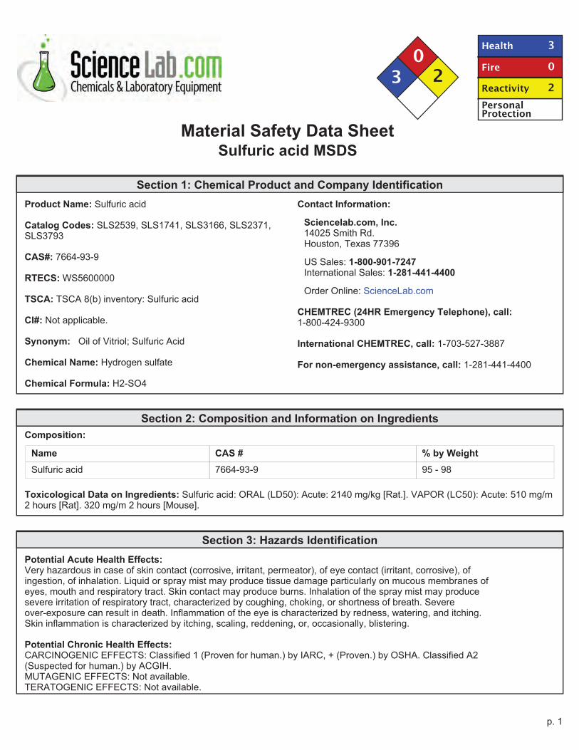
Material Safety Data SheetSulfuric acid MSDS
Section 1: Chemical Product and Company Identification
Product Name: Sulfuric acid
Catalog Codes: SLS2539, SLS1741, SLS3166, SLS2371,SLS3793
CAS#: 7664-93-9
RTECS: WS5600000
TSCA: TSCA 8(b) inventory: Sulfuric acid
CI#: Not applicable.
Synonym: Oil of Vitriol; Sulfuric Acid
Chemical Name: Hydrogen sulfate
Chemical Formula: H2-SO4
Contact Information:
Sciencelab.com, Inc.14025 Smith Rd.Houston, Texas 77396
US Sales: 1-800-901-7247International Sales: 1-281-441-4400
Order Online: ScienceLab.com
CHEMTREC (24HR Emergency Telephone), call:1-800-424-9300
International CHEMTREC, call: 1-703-527-3887
For non-emergency assistance, call: 1-281-441-4400
Section 2: Composition and Information on Ingredients
Composition:
Name CAS # % by Weight
Sulfuric acid 7664-93-9 95 - 98
Toxicological Data on Ingredients: Sulfuric acid: ORAL (LD50): Acute: 2140 mg/kg [Rat.]. VAPOR (LC50): Acute: 510 mg/m2 hours [Rat]. 320 mg/m 2 hours [Mouse].
Section 3: Hazards Identification
Potential Acute Health Effects:Very hazardous in case of skin contact (corrosive, irritant, permeator), of eye contact (irritant, corrosive), ofingestion, of inhalation. Liquid or spray mist may produce tissue damage particularly on mucous membranes ofeyes, mouth and respiratory tract. Skin contact may produce burns. Inhalation of the spray mist may producesevere irritation of respiratory tract, characterized by coughing, choking, or shortness of breath. Severeover-exposure can result in death. Inflammation of the eye is characterized by redness, watering, and itching.Skin inflammation is characterized by itching, scaling, reddening, or, occasionally, blistering.
Potential Chronic Health Effects:CARCINOGENIC EFFECTS: Classified 1 (Proven for human.) by IARC, + (Proven.) by OSHA. Classified A2(Suspected for human.) by ACGIH.MUTAGENIC EFFECTS: Not available.TERATOGENIC EFFECTS: Not available.
p. 1

DEVELOPMENTAL TOXICITY: Not available.The substance may be toxic to kidneys, lungs, heart, cardiovascular system, upper respiratory tract, eyes, teeth.Repeated or prolonged exposure to the substance can produce target organs damage. Repeated or prolongedcontact with spray mist may produce chronic eye irritation and severe skin irritation. Repeated or prolongedexposure to spray mist may produce respiratory tract irritation leading to frequent attacks of bronchial infection.Repeated exposure to a highly toxic material may produce general deterioration of health by an accumulation inone or many human organs.
Section 4: First Aid Measures
Eye Contact:Check for and remove any contact lenses. In case of contact, immediately flush eyes with plenty of water for atleast 15 minutes. Cold water may be used. Get medical attention immediately.
Skin Contact:In case of contact, immediately flush skin with plenty of water for at least 15 minutes while removing contaminatedclothing and shoes. Cover the irritated skin with an emollient. Cold water may be used.Wash clothing beforereuse. Thoroughly clean shoes before reuse. Get medical attention immediately.
Serious Skin Contact:Wash with a disinfectant soap and cover the contaminated skin with an anti-bacterial cream. Seek immediatemedical attention.
Inhalation:If inhaled, remove to fresh air. If not breathing, give artificial respiration. If breathing is difficult, give oxygen. Getmedical attention immediately.
Serious Inhalation:Evacuate the victim to a safe area as soon as possible. Loosen tight clothing such as a collar, tie, belt orwaistband. If breathing is difficult, administer oxygen. If the victim is not breathing, perform mouth-to-mouthresuscitation. WARNING: It may be hazardous to the person providing aid to give mouth-to-mouth resuscitationwhen the inhaled material is toxic, infectious or corrosive. Seek immediate medical attention.
Ingestion:Do NOT induce vomiting unless directed to do so by medical personnel. Never give anything by mouth to anunconscious person. Loosen tight clothing such as a collar, tie, belt or waistband. Get medical attention ifsymptoms appear.
Serious Ingestion: Not available.
Section 5: Fire and Explosion Data
Flammability of the Product: Non-flammable.
Auto-Ignition Temperature: Not applicable.
Flash Points: Not applicable.
Flammable Limits: Not applicable.
Products of Combustion:Products of combustion are not available since material is non-flammable. However, products of decompostioninclude fumes of oxides of sulfur. Will react with water or steam to produce toxic and corrosive fumes. Reactswith carbonates to generate carbon dioxide gas. Reacts with cyanides and sulfides to form poisonous hydrogencyanide and hydrogen sulfide respectively.
Fire Hazards in Presence of Various Substances: Combustible materials
Explosion Hazards in Presence of Various Substances:
p. 2

Risks of explosion of the product in presence of mechanical impact: Not available.Risks of explosion of the product in presence of static discharge: Not available.Slightly explosive in presence of oxidizing materials.
Fire Fighting Media and Instructions: Not applicable.
Special Remarks on Fire Hazards:Metal acetylides (Monocesium and Monorubidium), and carbides ignite with concentrated sulfuric acid.White Phosphorous + boiling Sulfuric acid or its vapor ignites on contact.May ignite other combustible materials.May cause fire when sulfuric acid is mixed with Cyclopentadiene, cyclopentanone oxime, nitroaryl amines,hexalithium disilicide, phorphorous (III) oxide, and oxidizing agents such as chlorates, halogens, permanganates.
Special Remarks on Explosion Hazards:M i x t u r e s o f s u l f u r i c a c i d a n d a n y o f t h e f o l l o w i n g c a n e x p l o d e : p - n i t r o t o l u e n e , p e n t a s i l ve rtrihydroxydiaminophosphate, perchlorates, alcohols with strong hydrogen peroxide, ammoniumtetraperoxychromate, mercuric nitrite, potassium chlorate, potassium permanganate with potassium chloride,carbides, nitro compounds, nitrates, carbides, phosphorous, iodides, picratres, fulminats, dienes, alcohols (whenheated)Nitramide decomposes explosively on contact with concentrated sulfuric acid.1,3,5-Trinitrosohexahydro-1,3,5-triazine + sulfuric acid causes explosive decompositon.
Section 6: Accidental Release Measures
Small Spill:Dilute with water and mop up, or absorb with an inert dry material and place in an appropriate waste disposalcontainer. If necessary: Neutralize the residue with a dilute solution of sodium carbonate.
Large Spill:Corrosive liquid. Poisonous liquid.Stop leak if without risk. Absorb with DRY earth, sand or other non-combustible material. Do not get water insidecontainer. Do not touch spilled material. Use water spray curtain to divert vapor drift. Use water spray to reducevapors. Prevent entry into sewers, basements or confined areas; dike if needed. Call for assistance on disposal.Neutralize the residue with a dilute solution of sodium carbonate. Be careful that the product is not present ata concentration level above TLV. Check TLV on the MSDS and with local authorities.
Section 7: Handling and Storage
Precautions:Keep locked up.. Keep container dry. Do not ingest. Do not breathe gas/fumes/ vapor/spray. Never add waterto this product. In case of insufficient ventilation, wear suitable respiratory equipment. If ingested, seek medicaladvice immediately and show the container or the label. Avoid contact with skin and eyes. Keep away fromincompatibles such as oxidizing agents, reducing agents, combustible materials, organic materials, metals, acids,alkalis, moisture.May corrode metallic surfaces. Store in a metallic or coated fiberboard drum using a strong polyethylene innerpackage.
Storage:Hygroscopic. Reacts. violently with water. Keep container tightly closed. Keep container in a cool, well-ventilatedarea. Do not store above 23°C (73.4°F).
Section 8: Exposure Controls/Personal Protection
Engineering Controls:Provide exhaust ventilation or other engineering controls to keep the airborne concentrations of vapors below theirrespective threshold limit value. Ensure that eyewash stations and safety showers are proximal to thework-station location.
p. 3
Personal Protection:Face shield. Full suit. Vapor respirator. Be sure to use an approved/certified respirator or equivalent. Gloves.Boots.
Personal Protection in Case of a Large Spill:Splash goggles. Full suit. Vapor respirator. Boots. Gloves. A self contained breathing apparatus should beused to avoid inhalation of the product. Suggested protective clothing might not be sufficient; consult a specialistBEFORE handling this product.
Exposure Limits:TWA: 1 STEL: 3 (mg/m3) [Australia] InhalationTWA: 1 (mg/m3) from OSHA (PEL) [United States] InhalationTWA: 1 STEL: 3 (mg/m3) from ACGIH (TLV) [United States] [1999] InhalationTWA: 1 (mg/m3) from NIOSH [United States] InhalationTWA: 1 (mg/m3) [United Kingdom (UK)]Consult local authorities for acceptable exposure limits.
Section 9: Physical and Chemical Properties
Physical state and appearance: Liquid. (Thick oily liquid.)
Odor: Odorless, but has a choking odor when hot.
Taste: Marked acid taste. (Strong.)
Molecular Weight: 98.08 g/mole
Color: Colorless.
pH (1% soln/water): Acidic.
Boiling Point:270°C (518°F) - 340 deg. CDecomposes at 340 deg. C
Melting Point: -35°C (-31°F) to 10.36 deg. C (93% to 100% purity)
Critical Temperature: Not available.
Specific Gravity: 1.84 (Water = 1)
Vapor Pressure: Not available.
Vapor Density: 3.4 (Air = 1)
Volatility: Not available.
Odor Threshold: Not available.
Water/Oil Dist. Coeff.: Not available.
Ionicity (in Water): Not available.
Dispersion Properties: See solubility in water.
Solubility:Easily soluble in cold water.Sulfuric is soluble in water with liberation of much heat.Soluble in ethyl alcohol.
p. 4

Section 10: Stability and Reactivity Data
Stability: The product is stable.
Instability Temperature: Not available.
Conditions of Instability:Conditions to Avoid: Incompatible materials, excess heat, combustible material materials, organic materials,exposure to moist air or water, oxidizers, amines, bases.Always add the acid to water, never the reverse.
Incompatibility with various substances:Reactive with oxidizing agents, reducing agents, combustible materials, organic materials, metals, acids, alkalis,moisture.
Corrosivity:Extremely corrosive in presence of aluminum, of copper, of stainless steel(316).Highly corrosive in presence of stainless steel(304).Non-corrosive in presence of glass.
Special Remarks on Reactivity:Hygroscopic. Strong oxidizer. Reacts violently with water and alcohol especially when water is added to theproduct.Incompatible (can react explosively or dangerously) with the following: ACETIC ACID, ACRYLIC ACID,AMMONIUM HYDROXIDE, CRESOL, CUMENE, DICHLOROETHYL ETHER, ETHYLENE CYANOHYDRIN,ETHYLENEIMINE, NITRIC ACID, 2-NITROPROPANE, PROPYLENE OXIDE, SULFOLANE, VINYLIDENECHLORIDE, DIETHYLENE GLYCOL MONOMETHYL ETHER, ETHYL ACETATE, ETHYLENECYANOHYDRIN, ETHYLENE GLYCOL MONOETHYL ETHER ACETATE, GLYOXAL, METHYL ETHYLKETONE, dehydrating agents, organic materials, moisture (water), Acetic anhydride, Acetone, cyanohydrin,Acetone+nitric acid, Acetone + potassium dichromate, Acetonitrile, Acrolein, Acrylonitrile, Acrylonitrile+water,Alcohols + hydrogen peroxide, ally compounds such as Allyl alcohol, and Allyl Chloride, 2-Aminoethanol,Ammonium hydroxide, Ammonium triperchromate, Aniline, Bromate + metals, Bromine pentafluoride,n-Butyraldehyde, Carbides, Cesium acetylene carbide, Chlorates, Cyclopentanone oxime, chlorinates, Chlorates +metals, Chlorine trifluoride, Chlorosulfonic acid, 2-cyano-4-nitrobenzenediazonium hydrogen sulfate, Cuprousnitride, p-chloronitrobenzene, 1,5-Dinitronaphthlene + sulfur, Diisobutylene, p-dimethylaminobenzaldehyde,1,3-Diazidobenzene, Dimethylbenzylcarbinol + hydrogen peroxide, Epichlorohydrin, Ethyl alcohol + hydrogenperoxide, Ethylene diamine, Ethylene glycol and other glycols, , Ethylenimine, Fulminates, hydrogen peroxide,Hydrochloric acid, Hydrofluoric acid, Iodine heptafluoride, Indane + nitric acid, Iron, Isoprene, Lithium silicide,Mercuric nitride, Mesityl oxide, Mercury nitride, Metals (powdered), Nitromethane, Nitric acid + glycerides,p-Nitrotoluene, Pentasilver trihydroxydiaminophosphate, Perchlorates, Perchloric acid, Permanganates + benzene,1-Phenyl-2-methylpropyl alcohol + hydrogen peroxide, Phosphorus, Phosphorus isocyanate, Picrates, Potassiumtert-butoxide, Potassium chlorate, Potassium Permanganate and other permanganates, halogens, amines,Potassium Permanganate + Potassium chloride, Potassium Permanganate + water, Propiolactone (beta)-,Pyridine, Rubidium aceteylene carbide, Silver permanganate, Sodium, Sodium carbonate, sodium hydroxide,Steel, styrene monomer, toluene + nitric acid, Vinyl acetate, Thalium (I) azidodithiocarbonate, Zinc chlorate, ZincIodide, azides, carbonates, cyanides, sulfides, sulfites, alkali hydrides, carboxylic acid anhydrides, nitriles, olefinicorganics, aqueous acids, cyclopentadiene, cyano-alcohols, metal acetylides,Hydrogen gas is generated by the action of the acid on most metals (i.e. lead, copper, tin, zinc, aluminum, etc.).Concentrated sulfuric acid oxidizes, dehydrates, or sulfonates most organic compounds.
Special Remarks on Corrosivity:Non-corrosive to lead and mild steel, but dillute acid attacks most metals.Attacks many metals releasing hydrogen.Minor corrosive effect on bronze.No corrosion data on brass or zinc.
Polymerization: Will not occur.
Section 11: Toxicological Information
Routes of Entry: Absorbed through skin. Dermal contact. Eye contact. Inhalation. Ingestion.
p. 5

Toxicity to Animals:WARNING: THE LC50 VALUES HEREUNDER ARE ESTIMATED ON THE BASIS OF A 4-HOUR EXPOSURE.Acute oral toxicity (LD50): 2140 mg/kg [Rat.].Acute toxicity of the vapor (LC50): 320 mg/m3 2 hours [Mouse].
Chronic Effects on Humans:CARCINOGENIC EFFECTS: Classified 1 (Proven for human.) by IARC, + (Proven.) by OSHA. Classified A2(Suspected for human.) by ACGIH.May cause damage to the following organs: kidneys, lungs, heart, cardiovascular system, upper respiratory tract,eyes, teeth.
Other Toxic Effects on Humans:Extremely hazardous in case of inhalation (lung corrosive).Very hazardous in case of skin contact (corrosive, irritant, permeator), of eye contact (corrosive), of ingestion, .
Special Remarks on Toxicity to Animals: Not available.
Special Remarks on Chronic Effects on Humans:Mutagenicity: Cytogenetic Analysis: Hamster, ovary = 4mmol/LReproductive effects: May cause adverse reproductive effects based on animal data. Developmentalabnormalities (musculoskeletal) in rabbits at a dose of 20 mg/m3 for 7 hrs.(RTECS)Teratogenecity: neither embryotoxic, fetoxic, nor teratogenetic in mice or rabbits at inhaled doses producing somematernal toxicity
Special Remarks on other Toxic Effects on Humans:Acute Potential Health Effects:Skin: Causes severe skin irritation and burns. Continued contact can cause tissue necrosis.Eye: Causes severe eye irritation and burns. May cause irreversible eye injury.Ingestion: Harmful if swallowed. May cause permanent damage to the digestive tract. Causes gastrointestialtract burns. May cause perforation of the stomach, GI bleeding, edema of the glottis, necrosis and scarring, andsudden circulatory collapse(similar to acute inhalation). It may also cause systemic toxicity with acidosis.Inhalation: May cause severe irritation of the respiratory tract and mucous membranes with sore throat, coughing,shortness of breath, and delayed lung edema. Causes chemical burns to the repiratory tract. Inhalation may befatal as a result of spasm, inflammation, edema of the larynx and bronchi, chemical pneumonitis, and pulmonaryedema. Cause corrosive action on mucous membranes. May affect cardiovascular system (hypotension,depressed cardiac output, bradycardia). Circulatory collapse with clammy skin, weak and rapid pulse, shallowrespiration, and scanty urine may follow. Circulatory shock is often the immediate cause of death. May alsoaffect teeth(changes in teeth and supporting structures - erosion, discoloration).Chronic Potential Health Effects:Inhalation: Prolonged or repeated inhalation may affect behavior (muscle contraction or spasticity), urinary system(kidney damage), and cardiovascular system, heart (ischemic heart leisons), and respiratorysystem/lungs(pulmonary edema, lung damage), teeth (dental discoloration, erosion).Skin: Prolonged or repeated skin contact may cause dermatitis, an allergic skin reaction.
Section 12: Ecological Information
Ecotoxicity: Ecotoxicity in water (LC50): 49 mg/l 48 hours [bluegill/sunfish].
BOD5 and COD: Not available.
Products of Biodegradation:Possibly hazardous short term degradation products are not likely. However, long term degradation products mayarise.
Toxicity of the Products of Biodegradation: The products of degradation are less toxic than the product itself.
Special Remarks on the Products of Biodegradation: Not available.
Section 13: Disposal Considerations
p. 6
Waste Disposal:Sulfuric acid may be placed in sealed container or absorbed in vermiculite, dry sand, earth, or a similar material. Itmay also be diluted and neutralized. Be sure to consult with local or regional authorities (waste regulators) prior toany disposal. Waste must be disposed of in accordance with federal, state and local environmental controlregulations.
Section 14: Transport Information
DOT Classification: Class 8: Corrosive material
Identification: : Sulfuric acid UNNA: 1830 PG: II
Special Provisions for Transport: Not available.
Section 15: Other Regulatory Information
Federal and State Regulations:Illinois toxic substances disclosure to employee act: Sulfuric acidNew York release reporting list: Sulfuric acidRhode Island RTK hazardous substances: Sulfuric acidPennsylvania RTK: Sulfuric acidMinnesota: Sulfuric acidMassachusetts RTK: Sulfuric acidNew Jersey: Sulfuric acidCalifornia Director's List of Hazardous Substances (8 CCR 339): Sulfuric acidTennessee RTK: Sulfuric acidTSCA 8(b) inventory: Sulfuric acidSARA 302/304/311/312 extremely hazardous substances: Sulfuric acidSARA 313 toxic chemical notification and release reporting: Sulfuric acidCERCLA: Hazardous substances.: Sulfuric acid: 1000 lbs. (453.6 kg)
Other Regulations:OSHA: Hazardous by definition of Hazard Communication Standard (29 CFR 1910.1200).EINECS: This product is on the European Inventory of Existing Commercial Chemical Substances.
Other Classifications:
WHMIS (Canada):CLASS D-1A: Material causing immediate and serious toxic effects (VERY TOXIC).CLASS E: Corrosive liquid.
DSCL (EEC):R35- Causes severe burns.S2- Keep out of the reach of children.S26- In case of contact with eyes, rinseimmediately with plenty of water and seekmedical advice.S30- Never add water to this product.S45- In case of accident or if you feel unwell,seek medical advice immediately (show thelabel where possible).
HMIS (U.S.A.):
Health Hazard: 3
Fire Hazard: 0
Reactivity: 2
p. 7
Personal Protection:
National Fire Protection Association (U.S.A.):
Health: 3
Flammability: 0
Reactivity: 2
Specific hazard:
Protective Equipment:Gloves.Full suit.Vapor respirator. Be sure to use anapproved/certified respirator orequivalent. Wear appropriate respiratorwhen ventilation is inadequate.Face shield.
Section 16: Other Information
References:-Material safety data sheet emitted by: la Commission de la Santé et de la Sécurité du Travail du Québec.-The Sigma-Aldrich Library of Chemical Safety Data, Edition II.-Hawley, G.G.. The Condensed Chemical Dictionary, 11e ed., New York N.Y., Van Nostrand Reinold, 1987.
Other Special Considerations: Not available.
Created: 10/09/2005 11:58 PM
Last Updated: 11/06/2008 12:00 PM
The information above is believed to be accurate and represents the best information currently available to us. However, wemake no warranty of merchantability or any other warranty, express or implied, with respect to such information, and weassume no liability resulting from its use. Users should make their own investigations to determine the suitability of theinformation for their particular purposes. In no event shall ScienceLab.com be liable for any claims, losses, or damages of anythird party or for lost profits or any special, indirect, incidental, consequential or exemplary damages, howsoever arising, evenif ScienceLab.com has been advised of the possibility of such damages.
p. 8
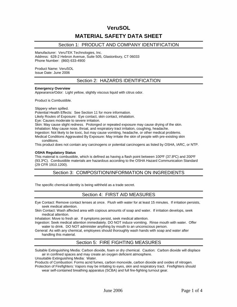
June 2006 Page 1 of 4
VeruSOL MATERIAL SAFETY DATA SHEET
Section 1: PRODUCT AND COMPANY IDENTIFICATION
Manufacturer: VeruTEK Technologies, Inc. Address: 628-2 Hebron Avenue, Suite 505, Glastonbury, CT 06033 Phone Number: (860) 633-4900 Product Name: VeruSOL Issue Date: June 2006
Section 2: HAZARDS IDENTIFICATION
Emergency Overview Appearance/Odor: Light yellow, slightly viscous liquid with citrus odor. Product is Combustible. Slippery when spilled. Potential Health Effects: See Section 11 for more information. Likely Routes of Exposure: Eye contact, skin contact, inhalation. Eye: Causes moderate to severe irritation. Skin: May cause slight redness. Prolonged or repeated exposure may cause drying of the skin. Inhalation: May cause nose, throat, and respiratory tract irritation, coughing, headache. Ingestion: Not likely to be toxic, but may cause vomiting, headache, or other medical problems. Medical Conditions Aggravated By Exposure: May irritate the skin of people with pre-existing skin
conditions. This product does not contain any carcinogens or potential carcinogens as listed by OSHA, IARC, or NTP. OSHA Regulatory Status This material is combustible, which is defined as having a flash point between 100ºF (37.8ºC) and 200ºF (93.3ºC). Combustible materials are hazardous according to the OSHA Hazard Communication Standard (29 CFR 1910.1200).
Section 3: COMPOSITION/INFORMATION ON INGREDIENTS
The specific chemical identity is being withheld as a trade secret.
Section 4: FIRST AID MEASURES
Eye Contact: Remove contact lenses at once. Flush with water for at least 15 minutes. If irritation persists, seek medical attention.
Skin Contact: Wash affected area with copious amounts of soap and water. If irritation develops, seek medical attention.
Inhalation: Move to fresh air. If symptoms persist, seek medical attention. Ingestion: Seek medical attention immediately. DO NOT induce vomiting. Rinse mouth with water. Offer
water to drink. DO NOT administer anything by mouth to an unconscious person. General: As with any chemical, employees should thoroughly wash hands with soap and water after
handling this material.
Section 5: FIRE FIGHTING MEASURES
Suitable Extinguishing Media: Carbon dioxide, foam or dry chemical. Caution: Carbon dioxide will displace air in confined spaces and may create an oxygen deficient atmosphere.
Unsuitable Extinguishing Media: Water. Products of Combustion: Forms acrid fumes, carbon monoxide, carbon dioxide and oxides of nitrogen. Protection of Firefighters: Vapors may be irritating to eyes, skin and respiratory tract. Firefighters should
wear self-contained breathing apparatus (SCBA) and full fire-fighting turnout gear.
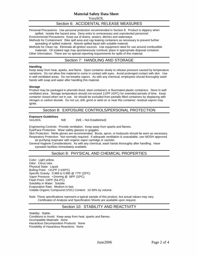
Material Safety Data Sheet VeruSOL
June2006 Page 2 of 4
Section 6: ACCIDENTAL RELEASE MEASURES
Personal Precautions: Use personal protection recommended in Section 8. Product is slippery when spilled. Isolate the hazard area. Deny entry to unnecessary and unprotected personnel.
Environmental Precautions: Keep out of drains, sewers, ditches and waterways. Methods for Containment: Dike spill area and cap leaking containers as necessary to prevent further
spreading of spilled material. Absorb spilled liquid with suitable material. Methods for Clean Up: Eliminate all ignition sources. Use equipment rated for use around combustible
materials. Oil soaked rags may spontaneously combust; place in appropriate disposal container. Other Information: There are no special reporting requirements for spills of this material.
Section 7: HANDLING AND STORAGE
Handling Keep away from heat, sparks, and flame. Open container slowly to release pressure caused by temperature variations. Do not allow this material to come in contact with eyes. Avoid prolonged contact with skin. Use in well ventilated areas. Do not breathe vapors. As with any chemical, employees should thoroughly wash hands with soap and water after handling this material. Storage Product may be packaged in phenolic-lined, steel containers or fluorinated plastic containers. Store in well ventilated area. Storage temperature should not exceed 110ºF (43ºC) for extended periods of time. Keep container closed when not in use. Air should be excluded from partially filled containers by displacing with nitrogen or carbon dioxide. Do not cut, drill, grind or weld on or near this container; residual vapors may ignite.
Section 8: EXPOSURE CONTROLS/PERSONAL PROTECTION
Exposure Guidelines VeruSOL N/E (N/E – Not Established) Engineering Controls: Provide ventilation. Keep away from sparks and flames. Eye/Face Protection: Wear safety glasses or goggles. Skin Protection: Nitrile gloves are recommended. Boots, apron, or bodysuits should be worn as necessary. Respiratory Protection: Not normally required. If adequate ventilation is unavailable, use NIOSH approved
air-purifying respirator with organic vapor cartridge or canister. General Hygiene Considerations: As with any chemical, wash hands thoroughly after handling. Have
eyewash facilities immediately available.
Section 9: PHYSICAL AND CHEMICAL PROPERTIES
Color: Light yellow. Odor: Citrus odor. Physical State: Liquid. Boiling Point: >212ºF (>100ºC) Specific Gravity: 0.968 to 0.985 @ 77ºF (25ºC) Vapor Pressure: <2mmHg @ 68ºF (20ºC) Flash Point: 130ºF (54.4ºC) Solubility in Water: Soluble. Evaporation Rate: Medium to fast. Volatile Organic Compound (VOC) Content: 10-30% by volume. Note: These specifications represent a typical sample of this product, but actual values may vary.
Certificates of Analysis and Specification Sheets are available upon request.
Section 10: STABILITY AND REACTIVITY
Stability: Stable. Conditions to Avoid: Keep away from heat, sparks and flames. Incompatible Materials: None Hazardous Decomposition Products: None Possibility of Hazardous Reactions: None
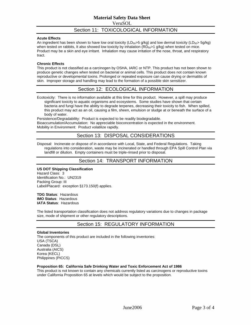
Material Safety Data Sheet VeruSOL
June2006 Page 3 of 4
Section 11: TOXICOLOGICAL INFORMATION
Acute Effects An ingredient has been shown to have low oral toxicity (LD50>5 g/kg) and low dermal toxicity (LD50> 5g/kg) when tested on rabbits, It also showed low toxicity by inhalation (RD50>1 g/kg) when tested on mice. Product may be a skin and eye irritant. Inhalation may cause irritation of the nose, throat, and respiratory tract. Chronic Effects This product is not classified as a carcinogen by OSHA, IARC or NTP. This product has not been shown to produce genetic changes when tested on bacterial or animal cells. This product does not contain known reproductive or developmental toxins. Prolonged or repeated exposure can cause drying or dermatitis of skin. Improper storage and handling may lead to the formation of a possible skin sensitizer.
Section 12: ECOLOGICAL INFORMATION
Ecotoxicity: There is no information available at this time for this product. However, a spill may produce significant toxicity to aquatic organisms and ecosystems. Some studies have shown that certain bacteria and fungi have the ability to degrade terpenes, decreasing their toxicity to fish. When spilled, this product may act as an oil, causing a film, sheen, emulsion or sludge at or beneath the surface of a body of water.
Persistence/Degradability: Product is expected to be readily biodegradable. Bioaccumulation/Accumulation: No appreciable bioconcentration is expected in the environment. Mobility in Environment: Product volatilize rapidly.
Section 13: DISPOSAL CONSIDERATIONS
Disposal: Incinerate or dispose of in accordance with Local, State, and Federal Regulations. Taking regulations into consideration, waste may be incinerated or handled through EPA Spill Control Plan via landfill or dilution. Empty containers must be triple-rinsed prior to disposal.
Section 14: TRANSPORT INFORMATION
US DOT Shipping Classification Hazard Class: 3 Identification No.: UN2319 Packing Group: III Label/Placard: exception §173.150(f) applies. TDG Status: Hazardous IMO Status: Hazardous IATA Status: Hazardous The listed transportation classification does not address regulatory variations due to changes in package size, mode of shipment or other regulatory descriptions.
Section 15: REGULATORY INFORMATION
Global Inventories The components of this product are included in the following inventories: USA (TSCA) Canada (DSL) Australia (AICS) Korea (KECL) Philippines (PICCS) Proposition 65: California Safe Drinking Water and Toxic Enforcement Act of 1986 This product is not known to contain any chemicals currently listed as carcinogens or reproductive toxins under California Proposition 65 at levels which would be subject to the proposition.

Material Safety Data Sheet VeruSOL
June2006 Page 4 of 4
Section 16: OTHER INFORMATION
NFPA 704: National Fire Protection Association Health – 1 (slight hazard) Fire – 2 (moderate hazard) Reactivity – 0 (minimal hazard)
Legend OSHA – United States Occupational Health and Safety Administration IARC – International Agency for Research on Cancer NTP – National Toxicology Program NIOSH – National Institute for Occupational Safety and Health EPA – United States Environmental Protection Agency Caution: The user should conduct his/her own experiments and establish proper procedures and
control before attempting use on critical parts. The information contained herein is based on current knowledge and experience: no responsibility is accepted that the information is sufficient or correct in all cases. Users should consider these data only as a supplement to other information obtained by the user. No warranty is expressed or implied regarding the accuracy of this data, the results to be obtained from the use thereof, or that any such use will not infringe any patent. Users should make independent determinations of suitability and completeness of information from all sources to assure proper use and disposal of these materials, the safety and health of employees and customers, and the protection of the environment. This information is furnished upon the condition the person receiving it shall determine the suitability for the particular purpose. This MSDS is to be used as a guideline for safe work practices and emergency response.
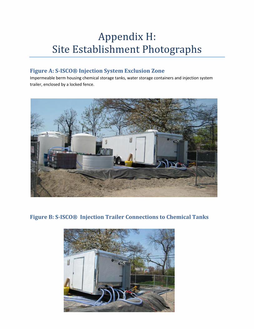
Appendix H: Site Establishment Photographs
Figure A: S-ISCO® Injection System Exclusion Zone Impermeable berm housing chemical storage tanks, water storage containers and injection system
trailer, enclosed by a locked fence.
Figure B: S-ISCO® Injection Trailer Connections to Chemical Tanks
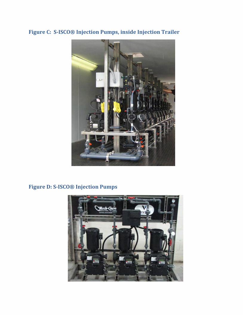
Figure C: S-ISCO® Injection Pumps, inside Injection Trailer
Figure D: S-ISCO® Injection Pumps

1
APPENDIX I:
SITE REMEDIATION GOALS
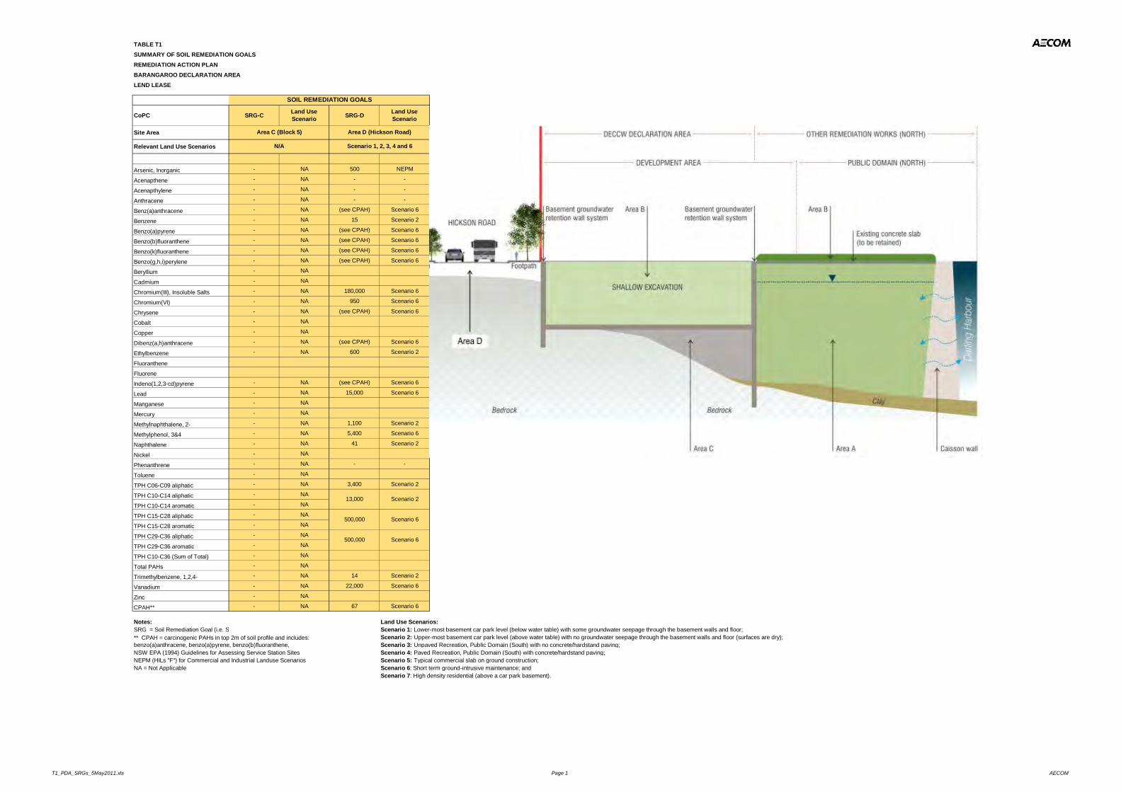
TABLE T1SUMMARY OF SOIL REMEDIATION GOALSREMEDIATION ACTION PLANBARANGAROO DECLARATION AREALEND LEASE
CoPC SRG-C Land Use Scenario SRG-D Land Use
Scenario
Site Area
Relevant Land Use Scenarios
Arsenic, Inorganic - NA 500 NEPM
Acenapthene - NA - -
Acenapthylene - NA - -
Anthracene - NA - -
Benz(a)anthracene - NA (see CPAH) Scenario 6
Benzene - NA 15 Scenario 2
Benzo(a)pyrene - NA (see CPAH) Scenario 6
Benzo(b)fluoranthene - NA (see CPAH) Scenario 6
Benzo(k)fluoranthene - NA (see CPAH) Scenario 6
Benzo(g,h,i)perylene - NA (see CPAH) Scenario 6
Beryllium - NA
Cadmium - NA
Chromium(III), Insoluble Salts - NA 180,000 Scenario 6
Chromium(VI) - NA 950 Scenario 6
Chrysene - NA (see CPAH) Scenario 6
Cobalt - NA
Copper - NA
Dibenz(a,h)anthracene - NA (see CPAH) Scenario 6
Ethylbenzene - NA 600 Scenario 2
Fluoranthene
Fluorene
Indeno(1,2,3-cd)pyrene - NA (see CPAH) Scenario 6
Lead - NA 15,000 Scenario 6
Manganese - NA
Mercury - NA
Methylnaphthalene, 2- - NA 1,100 Scenario 2
Methylphenol, 3&4 - NA 5,400 Scenario 6
Naphthalene - NA 41 Scenario 2
Nickel - NA
Phenanthrene - NA - -
Toluene - NA
TPH C06-C09 aliphatic - NA 3,400 Scenario 2
TPH C10-C14 aliphatic - NA
TPH C10-C14 aromatic - NA
TPH C15-C28 aliphatic - NA
TPH C15-C28 aromatic - NA
TPH C29-C36 aliphatic - NA
TPH C29-C36 aromatic - NA
TPH C10-C36 (Sum of Total) - NA
Total PAHs - NA
Trimethylbenzene, 1,2,4- - NA 14 Scenario 2
Vanadium - NA 22,000 Scenario 6
Zinc - NA
CPAH** - NA 67 Scenario 6
Notes: Land Use Scenarios:Scenario 1: Lower-most basement car park level (below water table) with some groundwater seepage through the basement walls and floor;Scenario 2: Upper-most basement car park level (above water table) with no groundwater seepage through the basement walls and floor (surfaces are dry);Scenario 3: Unpaved Recreation, Public Domain (South) with no concrete/hardstand paving;
NSW EPA (1994) Guidelines for Assessing Service Station Sites Scenario 4: Paved Recreation, Public Domain (South) with concrete/hardstand paving;NEPM (HILs "F") for Commercial and Industrial Landuse Scenarios Scenario 5: Typical commercial slab on ground construction; NA = Not Applicable Scenario 6: Short term ground-intrusive maintenance; and
Scenario 7: High density residential (above a car park basement).
** CPAH = carcinogenic PAHs in top 2m of soil profile and includes: benzo(a)anthracene, benzo(a)pyrene, benzo(b)fluoranthene,
500,000
500,000
SRG = Soil Remediation Goal (i.e. SRG-A - soil criteria to be adopted in Area A)
Scenario 2
Scenario 6
Scenario 6
13,000
Area C (Block 5) Area D (Hickson Road)
SOIL REMEDIATION GOALS
N/A Scenario 1, 2, 3, 4 and 6
T1_PDA_SRGs_5May2011.xls Page 1 AECOM
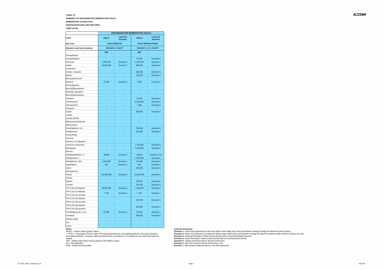
TABLE T2
SUMMARY OF GROUNDWATER REMEDIATION GOALS
REMEDIATION ACTION PLAN
BARANGAROO DECLARATION AREA
LEND LEASE
CoPC GRG-C Land Use Scenario GRG-D Land Use
Scenario
Site Area
Relavent Land Use Scenarios
ug/L ug/L
Acenaphthene - - - -
Acenaphthylene - - 57,000 Scenario 6
Ammonia 2,400,000 Scenario 1 2,400,000 Scenario 1
Aniline 26,000,000 Scenario 7 980,000 Scenario 6
Anthracene - - - -
Arsenic, Inorganic - - 380,000 Scenario 6
Barium - - 570,000 Scenario 6
Benz(a)anthracene - - - -
Benzene 21,000 Scenario 1 3,400 Scenario 6
Benzo(a)pyrene - - - -
Benzo(b)fluoranthene - - - -
Benzo(g,h,i)perylene - - - -
Benzo(k)fluoranthene - - - -
Cadmium - - 15,000 Scenario 6
Chromium(III) - - 8,400,000 Scenario 6
Chromium(VI) - - 7,600 Scenario 6
Chrysene - - - -
Cobalt - - 260,000 Scenario 6
Copper - - - -
Cyanide (WAD) - - - -
Dibenz(a,h)anthracene - - - -
Dibenzofuran - - - -
Dimethylphenol, 2,4- - - 720,000 Scenario 6
Ethylbenzene - - 210,000 Scenario 6
Fluoranthene - - - -
Fluorene - - - -
Indeno(1,2,3-cd)pyrene - - - -
Lead and compounds - - 1,100,000 Scenario 6
Manganese - - 2,400,000 Scenario 6
Mercury - - - -
Methylnaphthalene, 2- 38,000 Scenario 1 38,000 Scenario 1 & 6
Methylphenol, 2 - - 4,900,000 Scenario 6
Methylphenol, 3&4 1,000,000 Scenario 1 270,000 Scenario 6
Naphthalene 920 Scenario 1 920 Scenario 1
Nickel - - 350,000 Scenario 6
Phenanthrene - - - -
Phenol 310,000,000 Scenario 1 23,000,000 Scenario 6
Pyrene - - - -
Styrene - - 88,000 Scenario 6
Toluene - - 760,000 Scenario 6
TPH C06-C09 aliphatic 28,000,000 Scenario 1 1,400,000 Scenario 6
TPH C10-C14 aliphatic
TPH C10-C14 aromatic
TPH C15-C28 aliphatic
TPH C15-C28 aromatic
TPH C29-C36 aliphatic
TPH C29-C36 aromatic
Trimethylbenzene, 1,2,4- 87,000 Scenario 1 87,000 Scenario 1
Vanadium - - 960,000 Scenario 6
Xylenes (total) - - - -
Zinc - - - -
CPAH - - - -Notes: Land Use Scenarios:MWQC = Marine Water Quality Criteria Scenario 1: Lower-most basement car park level (below water table) with some groundwater seepage through the basement walls and floor;
Scenario 2: Upper-most basement car park level (above water table) with no groundwater seepage through the basement walls and floor (surfaces are dry);Scenario 3: Unpaved Recreation, Public Domain (South) with no concrete/hardstand paving;Scenario 4: Paved Recreation, Public Domain (South) with concrete/hardstand paving;Scenario 5: Typical commercial slab on ground construction;
NA = Not Applicable Scenario 6: Short term ground-intrusive maintenance; andWAD - Weak Acid Dissociable Scenario 7: High density residential (above a car park basement).
-
- -
Scenario 1
Scenario 6
Scenario 6
7,700
GROUNDWATER REMEDIATION GOALS
Area C (Block 5) Area D (Hickson Road)
Scenario 1
Scenario 1, 2 and 7 Scenario 1, 2, 3, 4 and 6
DAF = Dilution Attenuation Factors based on the MWQC values.
7,700
220,000
250,000
** CPAH = Carcinogenic PAHs as BaP TEF (benzo(a)anthracene, benzo(b)fluoranthene, benzo(g,h,i)perylene, benzo(k)fluoranthene, chrysene, dibenz(a,h)anthracene, and indeno (1,2,3-cd)pyrene (see main body report for details).
-
T2_PDA_GRGs_5May2011.xls Page 1 AECOM

1
APPENDIX J:
S-ISCO / SEPR PROJECT CASE STUDIES
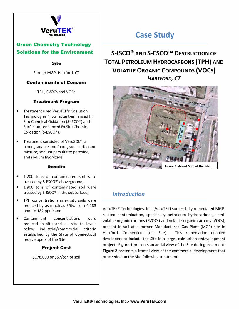
www.verutek.com
VeruTEK® Technologies, Inc.• www.VeruTEK.com
Case Study
S-ISCO® AND S-ESCO™ DESTRUCTION OF
TOTAL PETROLEUM HYDROCARBONS (TPH) AND
VOLATILE ORGANIC COMPOUNDS (VOCS)
HARTFORD, CT
Introduction
VeruTEK® Technologies, Inc. (VeruTEK) successfully remediated MGP-
related contamination, specifically petroleum hydrocarbons, semi-
volatile organic carbons (SVOCs) and volatile organic carbons (VOCs),
present in soil at a former Manufactured Gas Plant (MGP) site in
Hartford, Connecticut (the Site). This remediation enabled
developers to include the Site in a large-scale urban redevelopment
project. Figure 1 presents an aerial view of the Site during treatment.
Figure 2 presents a frontal view of the commercial development that
proceeded on the Site following treatment.
Figure 1: Aerial Map of the Site
Green Chemistry Technology
Solutions for the Environment
Site
Former MGP, Hartford, CT
Contaminants of Concern
TPH, SVOCs and VOCs
Treatment Program
• Treatment used VeruTEK’s Coelution
Technologies™, Surfactant-enhanced In
Situ Chemical Oxidation (S-ISCO®) and
Surfactant-enhanced Ex Situ Chemical
Oxidation (S-ESCO®).
• Treatment consisted of VeruSOL®, a
biodegradable and food-grade surfactant
mixture; sodium persulfate; peroxide;
and sodium hydroxide.
Results
• 1,200 tons of contaminated soil were
treated by S-ESCO™ aboveground;
• 1,900 tons of contaminated soil were
treated by S-ISCO® in the subsurface;
• TPH concentrations in ex situ soils were
reduced by as much as 95%, from 4,183
ppm to 182 ppm; and
• Contaminant concentrations were
reduced in situ and ex situ to levels
below industrial/commercial criteria
established by the State of Connecticut
redevelopers of the Site.
Project Cost
$178,000 or $57/ton of soil
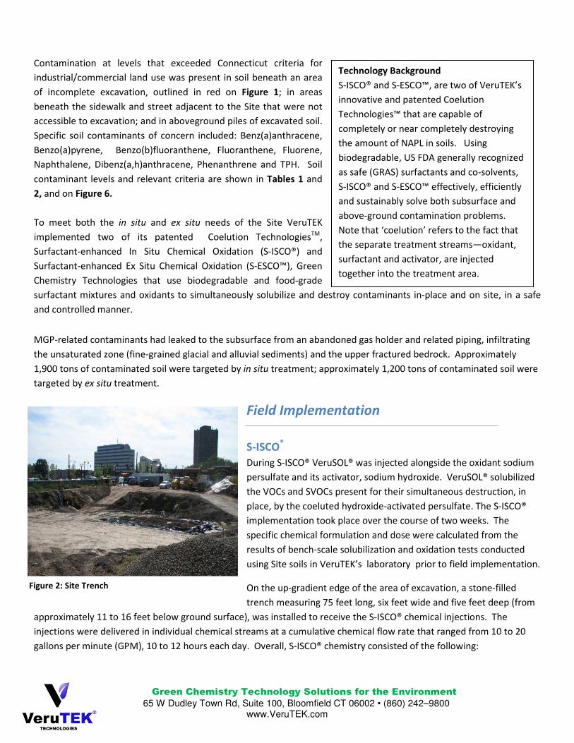
Green Chemistry Technology Solutions for the Environment
65 W Dudley Town Rd, Suite 100, Bloomfield CT 06002 • (860) 242–9800
www.VeruTEK.com
Contamination at levels that exceeded Connecticut criteria for
industrial/commercial land use was present in soil beneath an area
of incomplete excavation, outlined in red on Figure 1; in areas
beneath the sidewalk and street adjacent to the Site that were not
accessible to excavation; and in aboveground piles of excavated soil.
Specific soil contaminants of concern included: Benz(a)anthracene,
Benzo(a)pyrene, Benzo(b)fluoranthene, Fluoranthene, Fluorene,
Naphthalene, Dibenz(a,h)anthracene, Phenanthrene and TPH. Soil
contaminant levels and relevant criteria are shown in Tables 1 and
2, and on Figure 6.
To meet both the in situ and ex situ needs of the Site VeruTEK
implemented two of its patented Coelution TechnologiesTM,
Surfactant-enhanced In Situ Chemical Oxidation (S-ISCO®) and
Surfactant-enhanced Ex Situ Chemical Oxidation (S-ESCO™), Green
Chemistry Technologies that use biodegradable and food-grade
surfactant mixtures and oxidants to simultaneously solubilize and destroy contaminants in-place and on site, in a safe
and controlled manner.
MGP-related contaminants had leaked to the subsurface from an abandoned gas holder and related piping, infiltrating
the unsaturated zone (fine-grained glacial and alluvial sediments) and the upper fractured bedrock. Approximately
1,900 tons of contaminated soil were targeted by in situ treatment; approximately 1,200 tons of contaminated soil were
targeted by ex situ treatment.
Field Implementation
S-ISCO®
During S-ISCO® VeruSOL® was injected alongside the oxidant sodium
persulfate and its activator, sodium hydroxide. VeruSOL® solubilized
the VOCs and SVOCs present for their simultaneous destruction, in
place, by the coeluted hydroxide-activated persulfate. The S-ISCO®
implementation took place over the course of two weeks. The
specific chemical formulation and dose were calculated from the
results of bench-scale solubilization and oxidation tests conducted
using Site soils in VeruTEK’s laboratory prior to field implementation.
On the up-gradient edge of the area of excavation, a stone-filled
trench measuring 75 feet long, six feet wide and five feet deep (from
approximately 11 to 16 feet below ground surface), was installed to receive the S-ISCO® chemical injections. The
injections were delivered in individual chemical streams at a cumulative chemical flow rate that ranged from 10 to 20
gallons per minute (GPM), 10 to 12 hours each day. Overall, S-ISCO® chemistry consisted of the following:
Figure 2: Site Trench
Technology Background
S-ISCO® and S-ESCO™, are two of VeruTEK’s
innovative and patented Coelution
Technologies™ that are capable of
completely or near completely destroying
the amount of NAPL in soils. Using
biodegradable, US FDA generally recognized
as safe (GRAS) surfactants and co-solvents,
S-ISCO® and S-ESCO™ effectively, efficiently
and sustainably solve both subsurface and
above-ground contamination problems.
Note that ‘coelution’ refers to the fact that
the separate treatment streams—oxidant,
surfactant and activator, are injected
together into the treatment area.
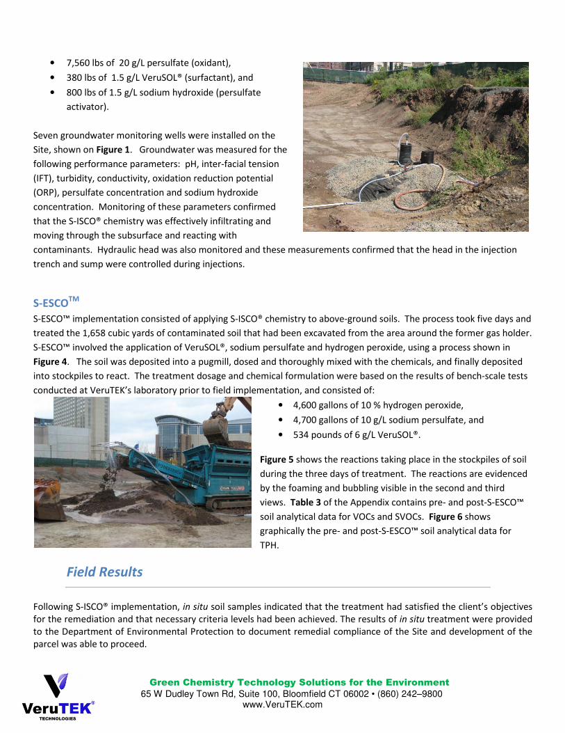
Green Chemistry Technology Solutions for the Environment
65 W Dudley Town Rd, Suite 100, Bloomfield CT 06002 • (860) 242–9800
www.VeruTEK.com
• 7,560 lbs of 20 g/L persulfate (oxidant),
• 380 lbs of 1.5 g/L VeruSOL® (surfactant), and
• 800 lbs of 1.5 g/L sodium hydroxide (persulfate
activator).
Seven groundwater monitoring wells were installed on the
Site, shown on Figure 1. Groundwater was measured for the
following performance parameters: pH, inter-facial tension
(IFT), turbidity, conductivity, oxidation reduction potential
(ORP), persulfate concentration and sodium hydroxide
concentration. Monitoring of these parameters confirmed
that the S-ISCO® chemistry was effectively infiltrating and
moving through the subsurface and reacting with
contaminants. Hydraulic head was also monitored and these measurements confirmed that the head in the injection
trench and sump were controlled during injections.
S-ESCOTM
S-ESCO™ implementation consisted of applying S-ISCO® chemistry to above-ground soils. The process took five days and
treated the 1,658 cubic yards of contaminated soil that had been excavated from the area around the former gas holder.
S-ESCO™ involved the application of VeruSOL®, sodium persulfate and hydrogen peroxide, using a process shown in
Figure 4. The soil was deposited into a pugmill, dosed and thoroughly mixed with the chemicals, and finally deposited
into stockpiles to react. The treatment dosage and chemical formulation were based on the results of bench-scale tests
conducted at VeruTEK’s laboratory prior to field implementation, and consisted of:
• 4,600 gallons of 10 % hydrogen peroxide,
• 4,700 gallons of 10 g/L sodium persulfate, and
• 534 pounds of 6 g/L VeruSOL®.
Figure 5 shows the reactions taking place in the stockpiles of soil
during the three days of treatment. The reactions are evidenced
by the foaming and bubbling visible in the second and third
views. Table 3 of the Appendix contains pre- and post-S-ESCO™
soil analytical data for VOCs and SVOCs. Figure 6 shows
graphically the pre- and post-S-ESCO™ soil analytical data for
TPH.
Field Results
Following S-ISCO® implementation, in situ soil samples indicated that the treatment had satisfied the client’s objectives
for the remediation and that necessary criteria levels had been achieved. The results of in situ treatment were provided
to the Department of Environmental Protection to document remedial compliance of the Site and development of the
parcel was able to proceed.
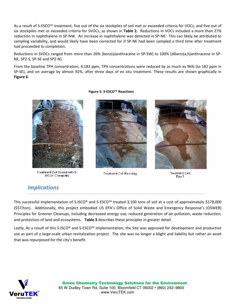
Green Chemistry Technology Solutions for the Environment
65 W Dudley Town Rd, Suite 100, Bloomfield CT 06002 • (860) 242–9800
www.VeruTEK.com
As a result of S-ESCO™ treatment, five out of the six stockpiles of soil met or exceeded criteria for VOCs, and five out of
six stockpiles met or exceeded criteria for SVOCs, as shown in Table 2. Reductions in VOCs included a more than 27%
reduction in naphthalene in SP-NW. An increase in naphthalene was detected in SP-NE. This can likely be attributed to
sampling variability, and would likely have been corrected for if SP-NE had been sampled a third time after treatment
had proceeded to completion.
Reductions in SVOCs ranged from more than 26% (benz(a)anthracene in SP-SW) to 100% (dibenz(a,h)anthracene in SP-
NE, SP2-S, SP-SE and SP2-N).
From the baseline TPH concentration, 4,183 ppm, TPH concentrations were reduced by as much as 96% (to 182 ppm in
SP-SE), and on average by almost 92%, after three days of ex situ treatment. These results are shown graphically in
Figure 6.
Implications
This successful implementation of S-ISCO® and S-ESCO™ treated 3,100 tons of soil at a cost of approximately $178,000
($57/ton). Additionally, this project embodied US EPA’s Office of Solid Waste and Emergency Response’s (OSWER)
Principles for Greener Cleanups, including decreased energy use; reduced generation of air pollution; waste reduction;
and protection of land and ecosystems. Table 3 describes these principles in greater detail.
Lastly, As a result of this S-ISCO® and S-ESCO™ implementation, the Site was approved for development and productive
use as part of a large-scale urban revitalization project. The site was no longer a blight and liability but rather an asset
that was repurposed for the city’s benefit.
Figure 5: S-ESCO™ Reactions
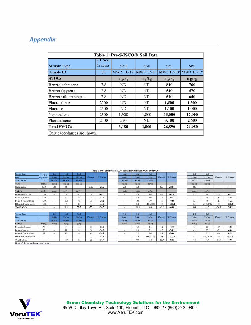
Green Chemistry Technology Solutions for the Environment
65 W Dudley Town Rd, Suite 100, Bloomfield CT 06002 • (860) 242–9800
www.VeruTEK.com
Appendix
Sample Type
CT Soil
Criteria Soil Soil Soil Soil
Sample ID I/C MW2 10-12' MW2 12-13' MW3 12-13' MW3 10-12'
SVOCs mg/kg mg/kg mg/kg mg/kg
Benz(a)anhracene 7.8 ND ND 840 760
Benzo(a)pyrene 7.8 ND ND 540 570
Benzo(b)fluoranthene 7.8 ND ND 610 640
Fluoranthene 2500 ND ND 1,500 1,300
Fluorene 2500 ND ND 1,100 1,000
Naphthalene 2500 1,900 1,800 13,000 17,000
Phenanthrene 2500 590 ND 3,100 2,600
Total SVOCs -- 3,180 1,800 26,890 29,980
Table 1: Pre-S-ISCO® Soil Data
Only exceedances are shown.
Sample Type Soil Soil Soil Soil Soil Soil Soil Soil
Date 18-Oct 22-Oct 29-Oct 18-Oct 22-Oct 29-Oct 22-Oct 29-Oct
VeruTEK ID SP-NW SP-NW SP-NW SP-NE SP-NE SP-NE SP2-S SP#2S
VOCs mg/kg mg/kg mg/kg mg/kg mg/kg mg/kg mg/kg mg/kg mg/kg
Naphthalene 5.60 6.60 4.8 -- -1.80 -27.3 2.4 9.2 -- 6.8 283.3 22.0 -- -- --
SVOCs mg/kg mg/kg mg/kg mg/kg mg/kg mg/kg mg/kg mg/kg mg/kg
Benz(a)anthracene 7.80 -- 7.8 4.5 -3 -42.3 -- 7.8 4.6 -3.2 -41.0 6.8 4.0 -2.8 -41.2
Benzo(a)pyrene 7.80 -- 8.7 6.0 -3 -31.0 -- 9.2 4.9 -4.3 -46.7 7.2 4.5 -2.7 -37.5
Benzo(b)fluoranthene 7.80 -- 10.0 7.0 -3 -30.0 -- 10.0 6.0 -4.0 -40.0 9.1 4.9 -4.2 -46.2
Dibenz(a,h)anthracene 1.00 -- 1.5 0.9 -1 -42.7 -- 1.4 ND (<0.81) -1.4 -100.0 1.0 ND (<0.78) -1.0 -100.0
Total SVOCs -- -- 90.1 57.2 -33 -36.5 -- 100.6 60.4 -40.2 -40.0 86.4 52.3 -34.1 -39.5
Sample Type Soil Soil Soil Soil Soil Soil Soil Soil
Date 18-Oct 22-Oct 29-Oct 18-Oct 22-Oct 29-Oct 22-Oct 29-Oct
VeruTEK ID SP-SW SP-SW SP-SW SP-SE SP-SE SP-SE SP2-N SP2-N
SVOCs mg/kg ug/kg ug/kg ug/kg ug/kg ug/kg ug/kg ug/kg ug/kg
Benz(a)anthracene 7.8 -- 9 6 -2 -26.7 -- 4.8 2.6 -2.2 -45.8 4.0 2.3 -1.7 -42.5
Benzo(a)pyrene 7.8 -- 11 8 -3 -30.9 -- 6.6 2.9 -3.7 -56.1 4.8 2.7 -2.1 -43.8
Benzo(b)fluoranthene 7.8 -- 13 9 -4 -30.8 -- 7.2 3.6 -3.6 -50.0 5.6 3.2 -2.4 -42.9
Dibenz(a,h)anthracene 1 -- 2 1 -1 -31.3 -- 0.9 ND (<0.75) -0.9 -100.0 0.8 ND (<0.78) -0.8 -100.0
Total SVOCs -- -- 129 79 -50 -38.4 -- 88.9 33.5 -55.4 -62.3 51.9 30.7 -21.2 -40.9
% Change
Table 2: Pre- and Post-SESCO™ Soil Analytical Data, VOCs and SVOCs
CT Soil
Regulation
s, I/C
Change % Change Change % Change Change % Change
Note: Only exceedances are shown.
Change % Change Change % Change Change
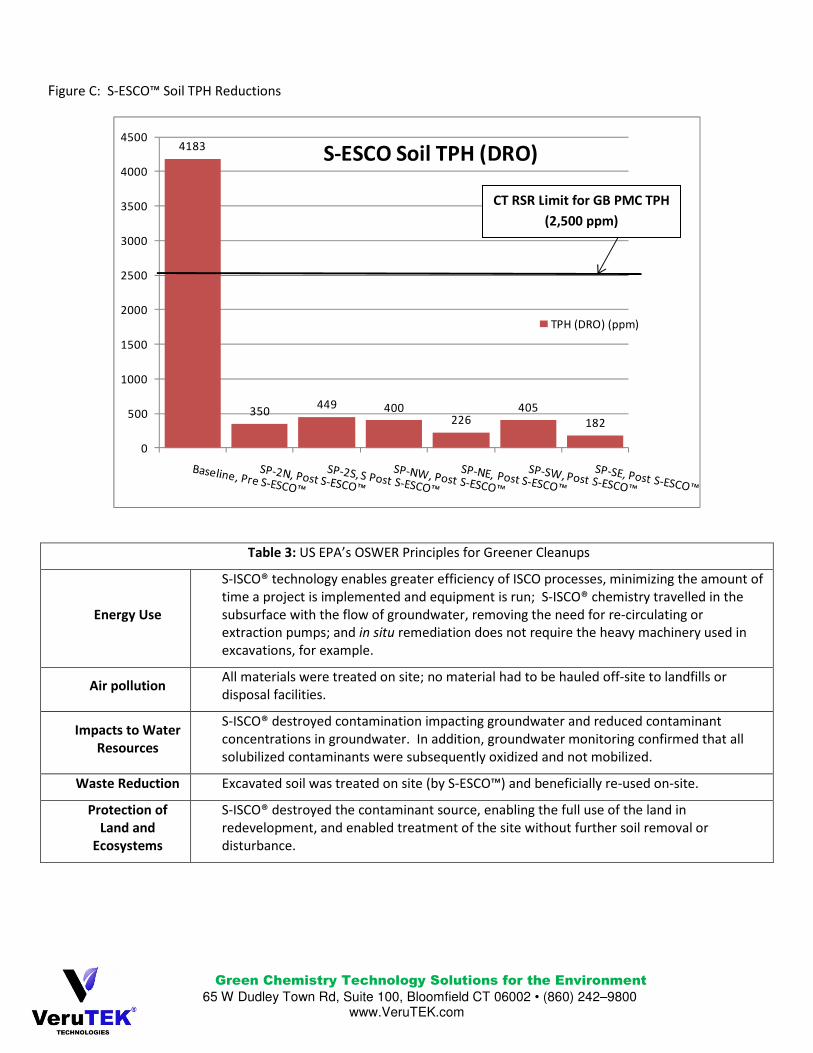
Green Chemistry Technology Solutions for the Environment
65 W Dudley Town Rd, Suite 100, Bloomfield CT 06002 • (860) 242–9800
www.VeruTEK.com
Figure C: S-ESCO™ Soil TPH Reductions
4183
350449 400
226405
182
0
500
1000
1500
2000
2500
3000
3500
4000
4500
S-ESCO Soil TPH (DRO)
TPH (DRO) (ppm)
Table 3: US EPA’s OSWER Principles for Greener Cleanups
Energy Use
S-ISCO® technology enables greater efficiency of ISCO processes, minimizing the amount of
time a project is implemented and equipment is run; S-ISCO® chemistry travelled in the
subsurface with the flow of groundwater, removing the need for re-circulating or
extraction pumps; and in situ remediation does not require the heavy machinery used in
excavations, for example.
Air pollution All materials were treated on site; no material had to be hauled off-site to landfills or
disposal facilities.
Impacts to Water
Resources
S-ISCO® destroyed contamination impacting groundwater and reduced contaminant
concentrations in groundwater. In addition, groundwater monitoring confirmed that all
solubilized contaminants were subsequently oxidized and not mobilized.
Waste Reduction Excavated soil was treated on site (by S-ESCO™) and beneficially re-used on-site.
Protection of
Land and
Ecosystems
S-ISCO® destroyed the contaminant source, enabling the full use of the land in
redevelopment, and enabled treatment of the site without further soil removal or
disturbance.
CT RSR Limit for GB PMC TPH
(2,500 ppm)
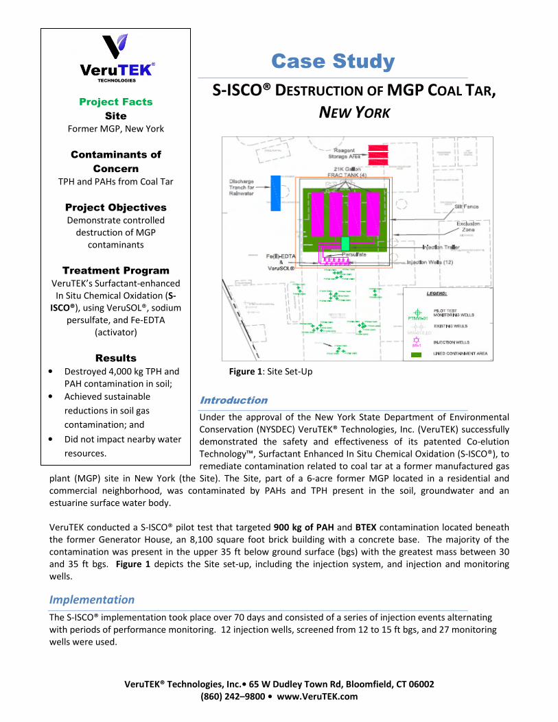
VeruTEK® Technologies, Inc.• 65 W Dudley Town Rd, Bloomfield, CT 06002
(860) 242–9800 • www.VeruTEK.com
Case Study
S-ISCO® DESTRUCTION OF MGP COAL TAR,
NEW YORK
Introduction
Under the approval of the New York State Department of Environmental
Conservation (NYSDEC) VeruTEK® Technologies, Inc. (VeruTEK) successfully
demonstrated the safety and effectiveness of its patented Co-elution
Technology™, Surfactant Enhanced In Situ Chemical Oxidation (S-ISCO®), to
remediate contamination related to coal tar at a former manufactured gas
plant (MGP) site in New York (the Site). The Site, part of a 6-acre former MGP located in a residential and
commercial neighborhood, was contaminated by PAHs and TPH present in the soil, groundwater and an
estuarine surface water body.
VeruTEK conducted a S-ISCO® pilot test that targeted 900 kg of PAH and BTEX contamination located beneath
the former Generator House, an 8,100 square foot brick building with a concrete base. The majority of the
contamination was present in the upper 35 ft below ground surface (bgs) with the greatest mass between 30
and 35 ft bgs. Figure 1 depicts the Site set-up, including the injection system, and injection and monitoring
wells.
Implementation
The S-ISCO® implementation took place over 70 days and consisted of a series of injection events alternating
with periods of performance monitoring. 12 injection wells, screened from 12 to 15 ft bgs, and 27 monitoring
wells were used.
Project Facts
Site
Former MGP, New York
Contaminants of
Concern
TPH and PAHs from Coal Tar
Project Objectives
Demonstrate controlled
destruction of MGP
contaminants
Treatment Program
VeruTEK’s Surfactant-enhanced
In Situ Chemical Oxidation (S-
ISCO®), using VeruSOL®, sodium
persulfate, and Fe-EDTA
(activator)
Results
• Destroyed 4,000 kg TPH and
PAH contamination in soil;
• Achieved sustainable
reductions in soil gas
contamination; and
• Did not impact nearby water
resources.
Figure 1: Site Set-Up
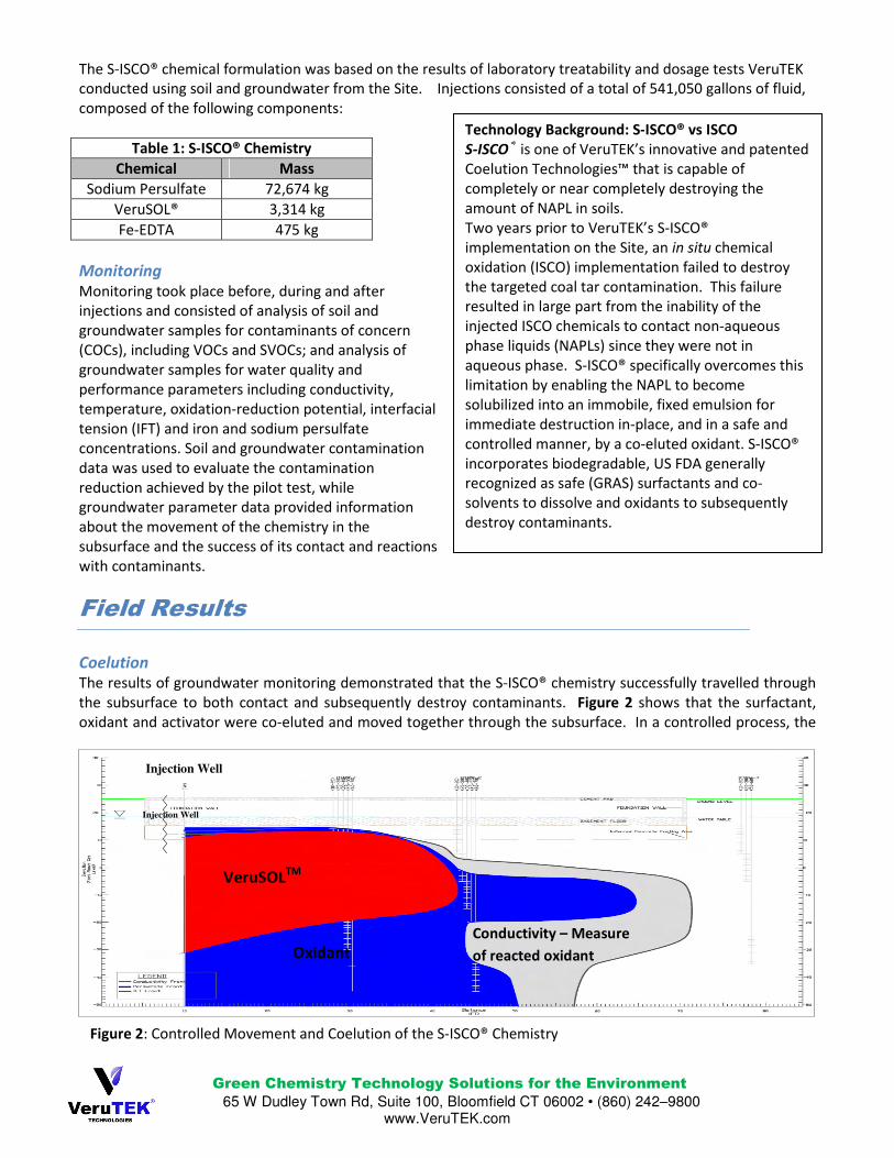
Green Chemistry Technology Solutions for the Environment 65 W Dudley Town Rd, Suite 100, Bloomfield CT 06002 • (860) 242–9800
www.VeruTEK.com
The S-ISCO® chemical formulation was based on the results of laboratory treatability and dosage tests VeruTEK
conducted using soil and groundwater from the Site. Injections consisted of a total of 541,050 gallons of fluid,
composed of the following components:
Table 1: S-ISCO® Chemistry
Chemical Mass
Sodium Persulfate 72,674 kg
VeruSOL® 3,314 kg
Fe-EDTA 475 kg
Monitoring
Monitoring took place before, during and after
injections and consisted of analysis of soil and
groundwater samples for contaminants of concern
(COCs), including VOCs and SVOCs; and analysis of
groundwater samples for water quality and
performance parameters including conductivity,
temperature, oxidation-reduction potential, interfacial
tension (IFT) and iron and sodium persulfate
concentrations. Soil and groundwater contamination
data was used to evaluate the contamination
reduction achieved by the pilot test, while
groundwater parameter data provided information
about the movement of the chemistry in the
subsurface and the success of its contact and reactions
with contaminants.
Field Results
Coelution
The results of groundwater monitoring demonstrated that the S-ISCO® chemistry successfully travelled through
the subsurface to both contact and subsequently destroy contaminants. Figure 2 shows that the surfactant,
oxidant and activator were co-eluted and moved together through the subsurface. In a controlled process, the
Technology Background: S-ISCO® vs ISCO
S-ISCO® is one of VeruTEK’s innovative and patented
Coelution Technologies™ that is capable of
completely or near completely destroying the
amount of NAPL in soils.
Two years prior to VeruTEK’s S-ISCO®
implementation on the Site, an in situ chemical
oxidation (ISCO) implementation failed to destroy
the targeted coal tar contamination. This failure
resulted in large part from the inability of the
injected ISCO chemicals to contact non-aqueous
phase liquids (NAPLs) since they were not in
aqueous phase. S-ISCO® specifically overcomes this
limitation by enabling the NAPL to become
solubilized into an immobile, fixed emulsion for
immediate destruction in-place, and in a safe and
controlled manner, by a co-eluted oxidant. S-ISCO®
incorporates biodegradable, US FDA generally
recognized as safe (GRAS) surfactants and co-
solvents to dissolve and oxidants to subsequently
destroy contaminants.
Figure 2: Controlled Movement and Coelution of the S-ISCO® Chemistry
Conductivity – Measure
of reacted oxidant
VeruSOLTM
Oxidant
Injection Well
Injection Well
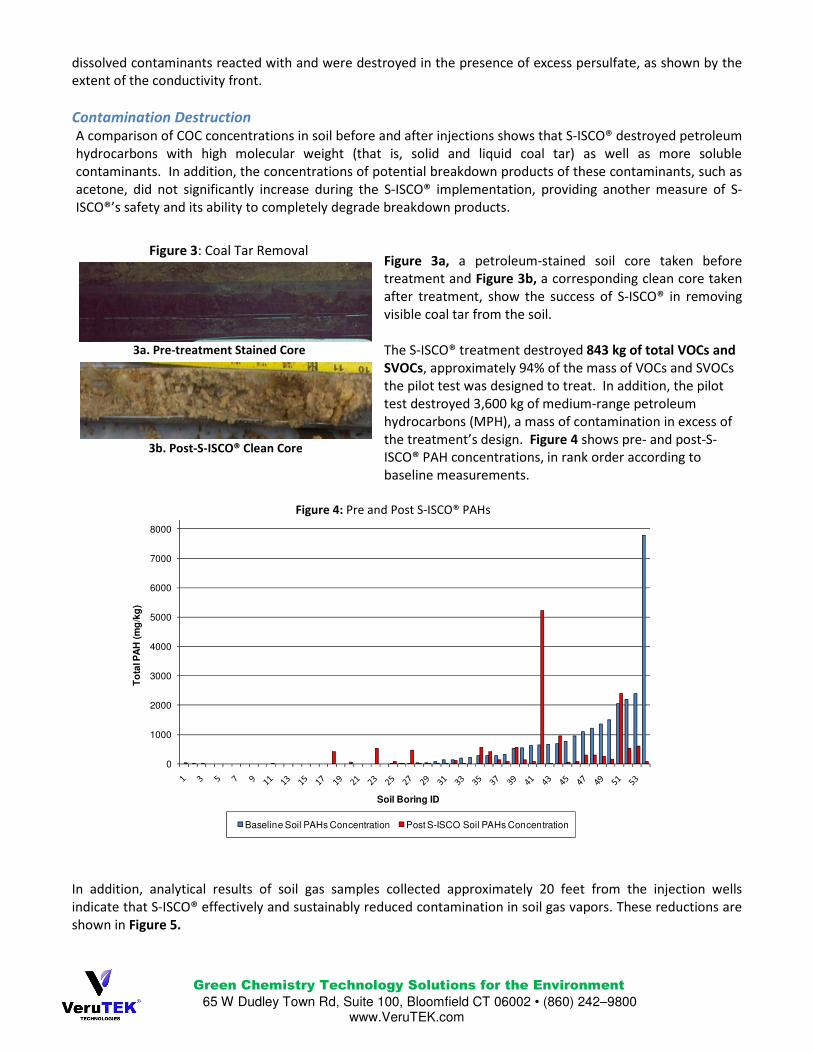
Green Chemistry Technology Solutions for the Environment 65 W Dudley Town Rd, Suite 100, Bloomfield CT 06002 • (860) 242–9800
www.VeruTEK.com
dissolved contaminants reacted with and were destroyed in the presence of excess persulfate, as shown by the
extent of the conductivity front.
Contamination Destruction
A comparison of COC concentrations in soil before and after injections shows that S-ISCO® destroyed petroleum
hydrocarbons with high molecular weight (that is, solid and liquid coal tar) as well as more soluble
contaminants. In addition, the concentrations of potential breakdown products of these contaminants, such as
acetone, did not significantly increase during the S-ISCO® implementation, providing another measure of S-
ISCO®’s safety and its ability to completely degrade breakdown products.
Figure 3a, a petroleum-stained soil core taken before
treatment and Figure 3b, a corresponding clean core taken
after treatment, show the success of S-ISCO® in removing
visible coal tar from the soil.
The S-ISCO® treatment destroyed 843 kg of total VOCs and
SVOCs, approximately 94% of the mass of VOCs and SVOCs
the pilot test was designed to treat. In addition, the pilot
test destroyed 3,600 kg of medium-range petroleum
hydrocarbons (MPH), a mass of contamination in excess of
the treatment’s design. Figure 4 shows pre- and post-S-
ISCO® PAH concentrations, in rank order according to
baseline measurements.
In addition, analytical results of soil gas samples collected approximately 20 feet from the injection wells
indicate that S-ISCO® effectively and sustainably reduced contamination in soil gas vapors. These reductions are
shown in Figure 5.
3a. Pre-treatment Stained Core
Figure 3: Coal Tar Removal
3b. Post-S-ISCO® Clean Core
Figure 4: Pre and Post S-ISCO® PAHs
0
1000
2000
3000
4000
5000
6000
7000
8000
To
tal P
AH
(m
g/k
g)
Soil Boring ID
Baseline Soil PAHs Concentration Post S-ISCO Soil PAHs Concentration
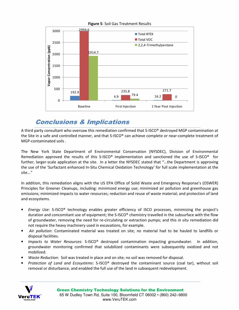
Green Chemistry Technology Solutions for the Environment 65 W Dudley Town Rd, Suite 100, Bloomfield CT 06002 • (860) 242–9800
www.VeruTEK.com
Figure 5: Soil Gas Treatment Results
Conclusions & Implications
A third party consultant who oversaw this remediation confirmed that S-ISCO® destroyed MGP contamination at
the Site in a safe and controlled manner, and that S-ISCO® can achieve complete or near-complete treatment of
MGP-contaminated soils .
The New York State Department of Environmental Conservation (NYSDEC), Division of Environmental
Remediation approved the results of this S-ISCO® implementation and sanctioned the use of S-ISCO® for
further, larger-scale application at the site. In a letter the NYSDEC stated that “…the Department is approving
the use of the ‘Surfactant enhanced In-Situ Chemical Oxidation Technology’ for full scale implementation at the
site...”
In addition, this remediation aligns with the US EPA Office of Solid Waste and Emergency Response’s (OSWER)
Principles for Greener Cleanups, including: minimized energy use; minimized air pollution and greenhouse gas
emissions; minimized impacts to water resources; reduction and reuse of waste material; and protection of land
and ecosystems.
• Energy Use: S-ISCO® technology enables greater efficiency of ISCO processes, minimizing the project’s
duration and concomitant use of equipment; the S-ISCO® chemistry travelled in the subsurface with the flow
of groundwater, removing the need for re-circulating or extraction pumps; and this in situ remediation did
not require the heavy machinery used in excavations, for example.
• Air pollution: Contaminated material was treated on site; no material had to be hauled to landfills or
disposal facilities.
• Impacts to Water Resources: S-ISCO® destroyed contamination impacting groundwater. In addition,
groundwater monitoring confirmed that solubilized contaminants were subsequently oxidized and not
mobilized.
• Waste Reduction: Soil was treated in place and on site; no soil was removed for disposal.
• Protection of Land and Ecosystems: S-ISCO® destroyed the contaminant source (coal tar), without soil
removal or disturbance, and enabled the full use of the land in subsequent redevelopment.
192.9
4.9 16.2
2994.6
235.8 271.7
1914.7
79.40
0
500
1000
1500
2000
2500
3000
Baseline First Injection 1 Year Post Injection
Va
po
r C
on
cen
tra
tio
n (
pp
b)
Total BTEX
Total VOC
2,2,4-Trimethylpentane
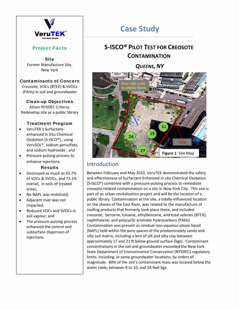
Case Study
S-ISCO® PILOT TEST FOR CREOSOTE CONTAMINATION
QUEENS, NY
Introduction
Between February and May 2010, VeruTEK demonstrated the safety and effectiveness of Surfactant-Enhanced in situ Chemical Oxidation (S-ISCO®) combined with a pressure-pulsing process to remediate creosote-related contamination on a site in New York City. This site is part of an urban revitalization project and will be the location of a public library. Contamination at the site, a tidally-influenced location on the shores of the East River, was related to the manufacture of roofing products that formerly took place there, and included creosote; benzene, toluene, ethylbenzene, and total xylenes (BTEX); naphthalene; and polycyclic aromatic hydrocarbons (PAHs). Contamination was present as residual non-aqueous phase liquid (NAPL) held within the pore spaces of the predominately sandy and silty soil matrix, including a lens of silt and silty clay between approximately 17 and 21 ft below ground surface (bgs). Contaminant concentrations in the soil and groundwater exceeded the New York State Department of Environmental Conservation (NYSDEC) regulatory limits, including, in some groundwater locations, by orders of magnitude. 80% of the site’s contaminant mass was located below the water table, between 8 to 10, and 24 feet bgs.
Project Facts
Site Former Manufacture Site,
New York
Contaminants of Concern Creosote, VOCs (BTEX) & SVOCs (PAHs) in soil and groundwater
Clean-up Objectives Attain NYSDEC Criteria;
Redevelop site as a public library
Treatment Program • VeruTEK’s Surfactant-
enhanced In Situ Chemical Oxidation (S-ISCO®) , using VeruSOL®, sodium persulfate, and sodium hydroxide ; and
• Pressure-pulsing process to enhance injections.
Results • Destroyed as much as 93.7%
of VOCs & SVOCs, and 73.1% overall, in soils of treated areas;
• No NAPL was mobilized; • Adjacent river was not
impacted; • Reduced VOCs and SVOCs in
soil vapour; and • The pressure-pulsing process
enhanced the control and subsurface dispersion of injections.
River leading to Atlantic Ocean
Figure 1: Site Map
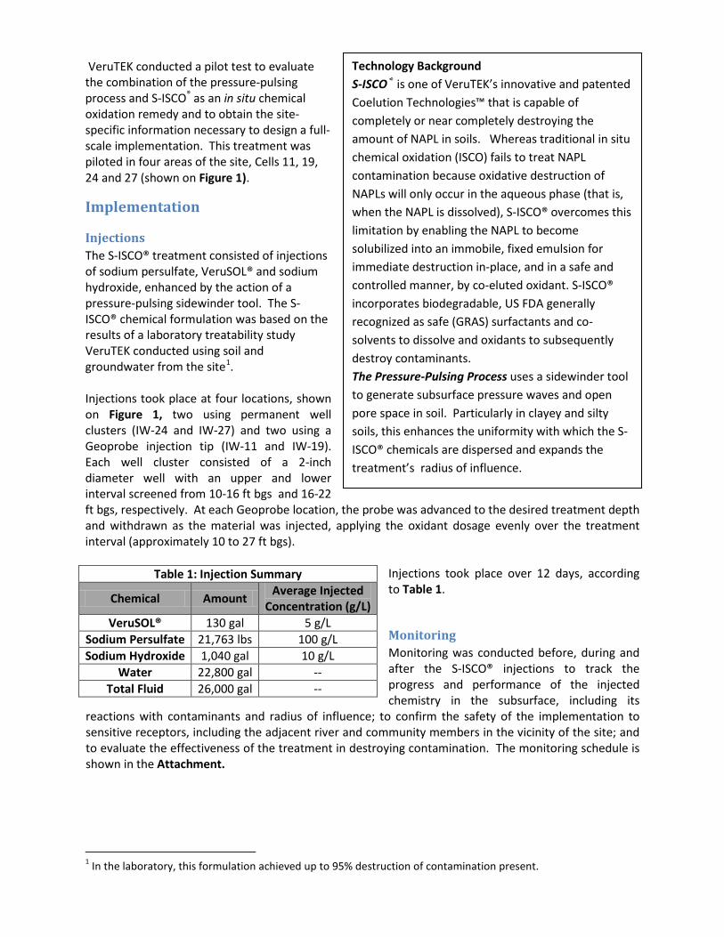
VeruTEK conducted a pilot test to evaluate the combination of the pressure-pulsing process and S-ISCO® as an in situ chemical oxidation remedy and to obtain the site-specific information necessary to design a full-scale implementation. This treatment was piloted in four areas of the site, Cells 11, 19, 24 and 27 (shown on Figure 1).
Implementation
Injections The S-ISCO® treatment consisted of injections of sodium persulfate, VeruSOL® and sodium hydroxide, enhanced by the action of a pressure-pulsing sidewinder tool. The S-ISCO® chemical formulation was based on the results of a laboratory treatability study VeruTEK conducted using soil and groundwater from the site1
.
Injections took place at four locations, shown on Figure 1, two using permanent well clusters (IW-24 and IW-27) and two using a Geoprobe injection tip (IW-11 and IW-19). Each well cluster consisted of a 2-inch diameter well with an upper and lower interval screened from 10-16 ft bgs and 16-22 ft bgs, respectively. At each Geoprobe location, the probe was advanced to the desired treatment depth and withdrawn as the material was injected, applying the oxidant dosage evenly over the treatment interval (approximately 10 to 27 ft bgs).
Injections took place over 12 days, according to Table 1.
Monitoring Monitoring was conducted before, during and after the S-ISCO® injections to track the progress and performance of the injected chemistry in the subsurface, including its
reactions with contaminants and radius of influence; to confirm the safety of the implementation to sensitive receptors, including the adjacent river and community members in the vicinity of the site; and to evaluate the effectiveness of the treatment in destroying contamination. The monitoring schedule is shown in the Attachment.
1 In the laboratory, this formulation achieved up to 95% destruction of contamination present.
Table 1: Injection Summary
Chemical Amount Average Injected Concentration (g/L)
VeruSOL® 130 gal 5 g/L Sodium Persulfate 21,763 lbs 100 g/L Sodium Hydroxide 1,040 gal 10 g/L
Water 22,800 gal -- Total Fluid 26,000 gal --
Technology Background S-ISCO® is one of VeruTEK’s innovative and patented Coelution Technologies™ that is capable of completely or near completely destroying the amount of NAPL in soils. Whereas traditional in situ chemical oxidation (ISCO) fails to treat NAPL contamination because oxidative destruction of NAPLs will only occur in the aqueous phase (that is, when the NAPL is dissolved), S-ISCO® overcomes this limitation by enabling the NAPL to become solubilized into an immobile, fixed emulsion for immediate destruction in-place, and in a safe and controlled manner, by co-eluted oxidant. S-ISCO® incorporates biodegradable, US FDA generally recognized as safe (GRAS) surfactants and co-solvents to dissolve and oxidants to subsequently destroy contaminants. The Pressure-Pulsing Process uses a sidewinder tool to generate subsurface pressure waves and open pore space in soil. Particularly in clayey and silty soils, this enhances the uniformity with which the S-ISCO® chemicals are dispersed and expands the treatment’s radius of influence.
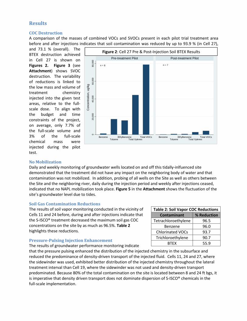
n = 8 n = 7
020
,000
40,0
0060
,000
80,0
00
BenzeneToluene
EthylbenzeneTotal Xylenes
Total VOCs BenzeneToluene
EthylbenzeneTotal Xylenes
Total VOCs
Con
cent
ratio
n, u
g/kg
Pre-treatment Pilot Post-treatment Pilot
IW-27 Stratum 1 Pre & Post-Injection Mean BTEX Results
Results
COC Destruction A comparison of the masses of combined VOCs and SVOCs present in each pilot trial treatment area before and after injections indicates that soil contamination was reduced by up to 93.9 % (in Cell 27), and 73.1 % (overall). The BTEX destruction achieved in Cell 27 is shown on Figures 2. Figure 3 (see Attachment) shows SVOC destruction. The variability of reductions is linked to the low mass and volume of treatment chemistry injected into the given test areas, relative to the full-scale dose. To align with the budget and time constraints of the project, on average, only 7.7% of the full-scale volume and 3% of the full-scale chemical mass were injected during the pilot test.
No Mobilization Daily and weekly monitoring of groundwater wells located on and off this tidally-inlfuenced site demonstrated that the treatment did not have any impact on the neighboring body of water and that contamination was not mobilized. In addition, probing of all wells on the Site as well as others between the Site and the neighboring river, daily during the injection period and weekly after injections ceased, indicated that no NAPL mobilization took place. Figure 5 in the Attachment shows the fluctuation of the site’s groundwater level due to tides.
Soil Gas Contamination Reductions The results of soil vapor monitoring conducted in the vicinity of Cells 11 and 24 before, during and after injections indicate that the S-ISCO® treatment decreased the maximum soil gas COC concentrations on the site by as much as 96.5%. Table 2 highlights these reductions.
Pressure-Pulsing Injection Enhancement The results of groundwater performance monitoring indicate that the pressure pulsing enhanced the distribution of the injected chemistry in the subsurface and reduced the predominance of density-driven transport of the injected fluid. Cells 11, 24 and 27, where the sidewinder was used, exhibited better distribution of the injected chemistry throughout the lateral treatment interval than Cell 19, where the sidewinder was not used and density-driven transport predominated. Because 80% of the total contamination on the site is located between 8 and 24 ft bgs, it is imperative that density driven transport does not dominate dispersion of S-ISCO® chemicals in the full-scale implementation.
Table 2: Soil Vapor COC Reductions Contaminant % Reduction
Tetrachloroethylene 96.5 Benzene 96.0
Chlorinated VOCs 93.7 Trichloroethylene 90.7
BTEX 55.9
Figure 2: Cell 27 Pre & Post-Injection Soil BTEX Results
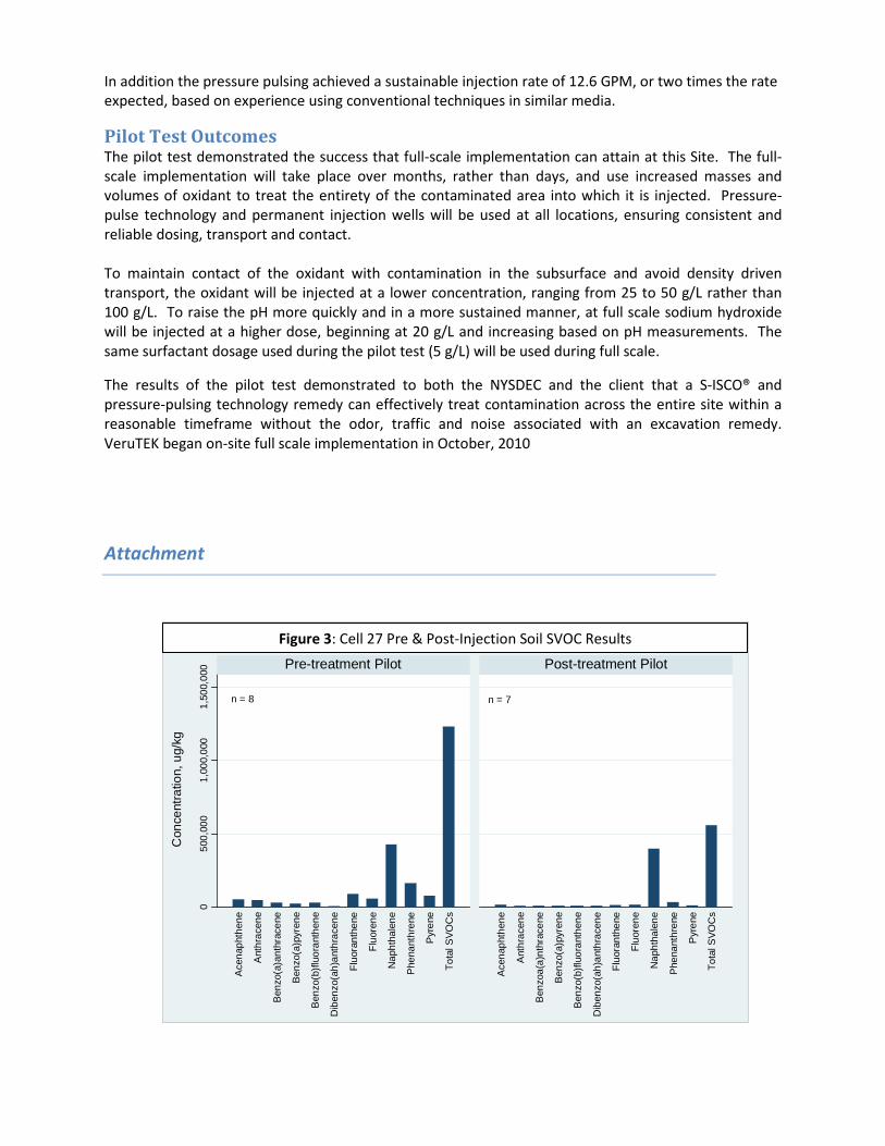
In addition the pressure pulsing achieved a sustainable injection rate of 12.6 GPM, or two times the rate expected, based on experience using conventional techniques in similar media.
Pilot Test Outcomes The pilot test demonstrated the success that full-scale implementation can attain at this Site. The full-scale implementation will take place over months, rather than days, and use increased masses and volumes of oxidant to treat the entirety of the contaminated area into which it is injected. Pressure-pulse technology and permanent injection wells will be used at all locations, ensuring consistent and reliable dosing, transport and contact. To maintain contact of the oxidant with contamination in the subsurface and avoid density driven transport, the oxidant will be injected at a lower concentration, ranging from 25 to 50 g/L rather than 100 g/L. To raise the pH more quickly and in a more sustained manner, at full scale sodium hydroxide will be injected at a higher dose, beginning at 20 g/L and increasing based on pH measurements. The same surfactant dosage used during the pilot test (5 g/L) will be used during full scale.
The results of the pilot test demonstrated to both the NYSDEC and the client that a S-ISCO® and pressure-pulsing technology remedy can effectively treat contamination across the entire site within a reasonable timeframe without the odor, traffic and noise associated with an excavation remedy. VeruTEK began on-site full scale implementation in October, 2010
Attachment
n = 8 n = 7
050
0,00
01,
000,
000
1,50
0,00
0
Ace
naph
then
e
Ant
hrac
ene
Ben
zo(a
)ant
hrac
ene
Ben
zo(a
)pyr
ene
Ben
zo(b
)fluo
rant
hene
Dib
enzo
(ah)
anth
race
ne
Fluo
rant
hene
Fluo
rene
Nap
htha
lene
Phe
nant
hren
e
Pyr
ene
Tota
l SVO
Cs
Ace
naph
then
e
Ant
hrac
ene
Ben
zoa(
a)nt
hrac
ene
Ben
zo(a
)pyr
ene
Ben
zo(b
)fluo
rant
hene
Dib
enzo
(ah)
anth
race
ne
Fluo
rant
hene
Fluo
rene
Nap
htha
lene
Phe
nant
hren
e
Pyr
ene
Tota
l SVO
Cs
Con
cent
ratio
n, u
g/kg
Pre-treatment Pilot Post-treatment Pilot
IW-27 Stratum 1 Mean Pre & Post-Injection SVOC ResultsFigure 3: Cell 27 Pre & Post-Injection Soil SVOC Results
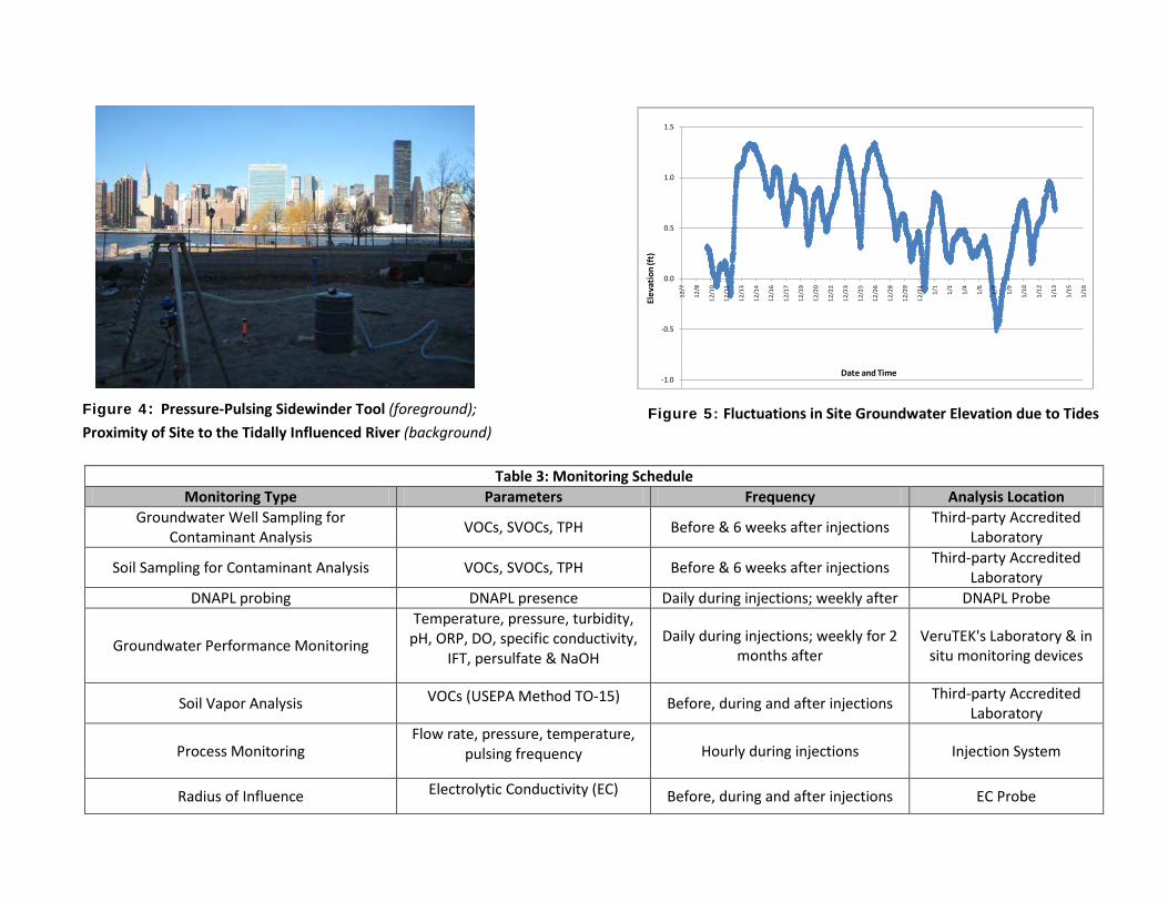
Table 3: Monitoring Schedule
Monitoring Type Parameters Frequency Analysis Location Groundwater Well Sampling for
Contaminant Analysis VOCs, SVOCs, TPH Before & 6 weeks after injections Third-party Accredited Laboratory
Soil Sampling for Contaminant Analysis VOCs, SVOCs, TPH Before & 6 weeks after injections Third-party Accredited Laboratory
DNAPL probing DNAPL presence Daily during injections; weekly after DNAPL Probe
Groundwater Performance Monitoring
Temperature, pressure, turbidity, pH, ORP, DO, specific conductivity,
IFT, persulfate & NaOH Daily during injections; weekly for 2
months after VeruTEK's Laboratory & in
situ monitoring devices
Soil Vapor Analysis VOCs (USEPA Method TO-15) Before, during and after injections Third-party Accredited Laboratory
Process Monitoring Flow rate, pressure, temperature,
pulsing frequency Hourly during injections Injection System
Radius of Influence Electrolytic Conductivity (EC) Before, during and after injections EC Probe
-1.0
-0.5
0.0
0.5
1.0
1.5
12/7
12/8
12/1
0
12/1
1
12/1
3
12/1
4
12/1
6
12/1
7
12/1
9
12/2
0
12/2
2
12/2
3
12/2
5
12/2
6
12/2
8
12/2
9
12/3
1
1/1
1/3
1/4
1/6
1/7
1/9
1/10
1/12
1/13
1/15
1/16
Elev
atio
n (f
t)
Date and Time
Figure 4: Pressure-Pulsing Sidewinder Tool (foreground); Proximity of Site to the Tidally Influenced River (background)
Figure 5: Fluctuations in Site Groundwater Elevation due to Tides

APPENDIX K:
OXIDANT COMPATIBILITY
INFORMATION
1. FMC Technical Bulletin: Compatibility of Alkaline-Activated Sodium Persulfate with Stainless Steel,
Copper, Brass, Carbon Steel and Concrete
2. Perry’s Chemical Engineering Handbook, 7th
Edition, Table 28-2, General Corrosion Properties of Some
Metals and Alloys: Compatibility of Alkaline-Activated Sodium Persulfate with Cast Iron
3. Spill Tech, “PVC Chemical Resistance Chart”: Compatibility of Hydrogen Peroxide and Sodium Persulfate
with PVC
4. Engineering Toolbox, “Metals and Corrosion Resistance”: Compatibility of Hydrogen Peroxide and
Sodium Persulfate with Cast Iron and other Metals
5. Corrosion Science, “Prediction and Measurement of Corrosion Inhibition of Mild Steel Using Nonionic
Surfactants in Chloride Media.
6. Materials and Corrosion, “Application of Some Commercial Nonionic Surfactants in the Field of
Corrosion Inhibition.

Alkaline-Activated Sodium Persulfate Compatibiltiy Data
Taken from: FMC Environmental Solutions, “Corrosion and Material Compatibility Technical Bulletin.”
Corrosion and Material Compatibility Technical Bulletin Corrosion Laboratory tests were conducted to evaluate the performance of commonly-used engineering materials exposed to Klozur® Persulfate solutions (both activated and un-activated). The tests were performed at two different persulfate solution concentrations: 20 wt% representing typical make-up solutions being injected, and 40 g / L representing typical in situ ground water concentrations. These tests were conducted per the guidelines outlined in ASTM G31-72. Corrosion rates for metallic coupons were calculated based on changes in weight over the exposure time. Non-metallic coupons were observed for visual changes and changes in physical properties. Structural properties of concrete and non-metallics were not measured.
Results For high pH activated persulfate solutions, sodium hydroxide was added to raise the pH to above 10 and to neutralize sulfuric acid formed upon persulfate decomposition. Significant decreases in corrosion rates were observed for high pH activated persulfate in contact with copper, brass and carbon steel. Negligible corrosion was observed for these metals after one month exposure, even at the 20% persulfate concentration. In addition, no noticeable corrosion was observed for stainless steel. Significant reaction with concrete was observed, however. Significant weight gain (5 – 10%) and bleaching were observed for the concrete after one month exposure to the high pH activated persulfate solution. These results are illustrated in Table 4, below.

Compatibility of Alkaline-Activated Persulfate and Cast Iron From: Perry’s Chemical Engineering Handbook, 7
th Edition. Table 28-2: General Corrosion Properties of
Some Metals and Alloys. Page 28-30, 31. The red box shows the “good” computability of alkaline-activated persulfate with cast iron while the information in the green box suggests that acidic reducing environments like the contaminated soils currently present at the site have poor compatibility with cast iron. If anything, treatment will reduce corrosive conditions at the site.
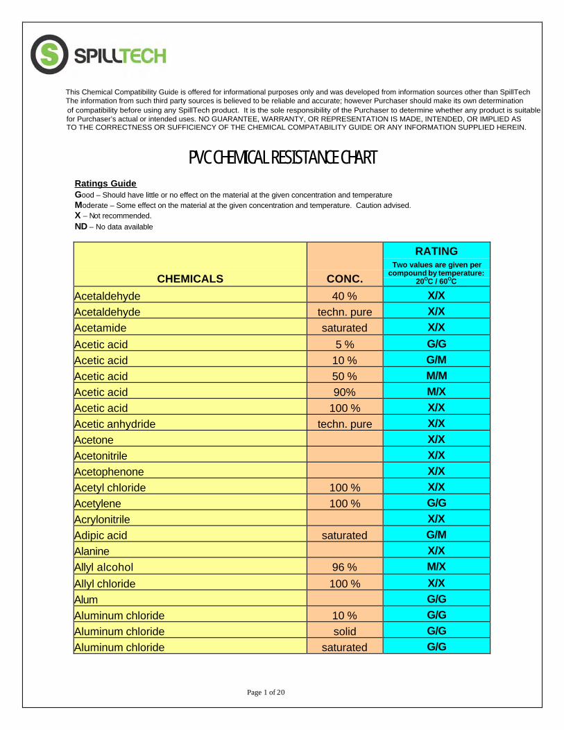
Page 1 of 20
PVC CHEMICAL RESISTANCE CHART
Ratings Guide Good – Should have little or no effect on the material at the given concentration and temperature Moderate – Some effect on the material at the given concentration and temperature. Caution advised. X – Not recommended. ND – No data available
CHEMICALS CONC.
RATING Two values are given per
compound by temperature: 20OC / 60OC
Acetaldehyde 40 % X/X Acetaldehyde techn. pure X/X Acetamide saturated X/X Acetic acid 5 % G/G Acetic acid 10 % G/M Acetic acid 50 % M/M Acetic acid 90% M/X Acetic acid 100 % X/X Acetic anhydride techn. pure X/X Acetone X/X Acetonitrile X/X Acetophenone X/X Acetyl chloride 100 % X/X Acetylene 100 % G/G Acrylonitrile X/X Adipic acid saturated G/M Alanine X/X Allyl alcohol 96 % M/X Allyl chloride 100 % X/X Alum G/G Aluminum chloride 10 % G/G Aluminum chloride solid G/G Aluminum chloride saturated G/G
The information from such third party sources is believed to be reliable and accurate; however Purchaser should make its own determination of compatibility before using any SpillTech product. It is the sole responsibility of the Purchaser to determine whether any product is suitable for Purchaser’s actual or intended uses. NO GUARANTEE, WARRANTY, OR REPRESENTATION IS MADE, INTENDED, OR IMPLIED ASTO THE CORRECTNESS OR SUFFICIENCY OF THE CHEMICAL COMPATABILITY GUIDE OR ANY INFORMATION SUPPLIED HEREIN.
This Chemical Compatibility Guide is offered for informational purposes only and was developed from information sources other than SpillTech
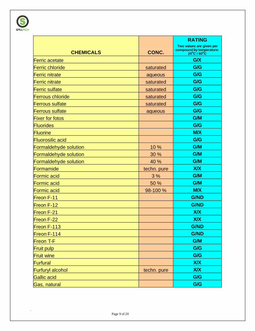
. Page 9 of 20
CHEMICALS CONC.
RATING Two values are given per
compound by temperature: 20OC / 60OC
Ferric acetate G/X Ferric chloride saturated G/G Ferric nitrate aqueous G/G Ferric nitrate saturated G/G Ferric sulfate saturated G/G Ferrous chloride saturated G/G Ferrous sulfate saturated G/G Ferrous sulfate aqueous G/G Fixer for fotos G/M Fluorides G/G Fluorine M/X Fluorosilic acid G/G Formaldehyde solution 10 % G/M Formaldehyde solution 30 % G/M Formaldehyde solution 40 % G/M Formamide techn. pure X/X Formic acid 3 % G/M Formic acid 50 % G/M Formic acid 98-100 % M/X Freon F-11 G/ND Freon F-12 G/ND Freon F-21 X/X Freon F-22 X/X Freon F-113 G/ND Freon F-114 G/ND Freon T-F G/M Fruit pulp G/G Fruit wine G/G Furfural X/X Furfuryl alcohol techn. pure X/X Gallic acid G/G Gas, natural G/G
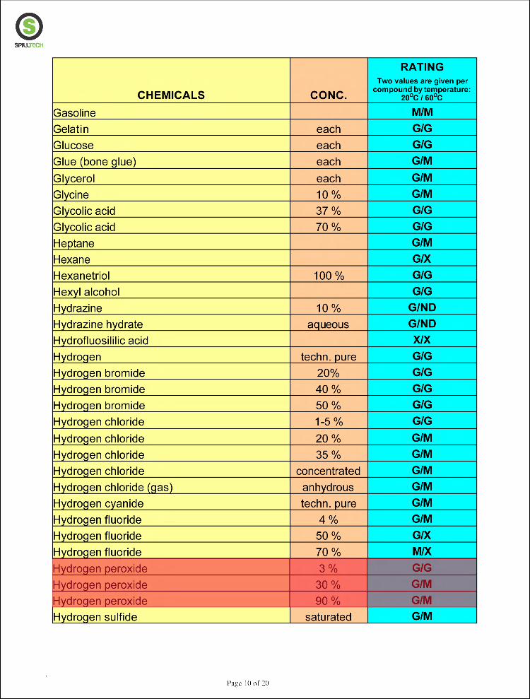
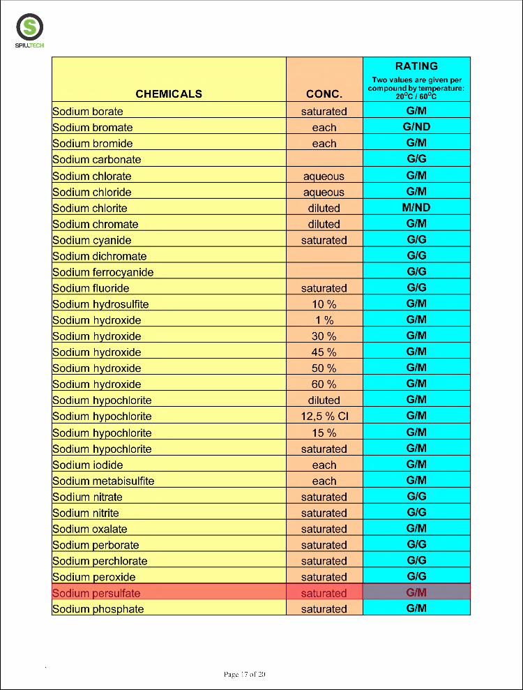

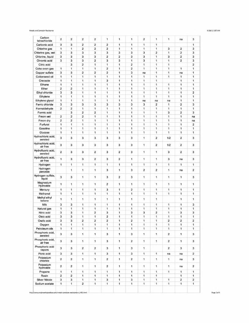


Prediction and measurement of corrosion
inhibition of mild steel using nonionic
surfactants in chloride media
WanLin Wang, Michael L. Free *
Department of Metallurgical Engineering, University of Utah, 135 S. 1460 E. Room 419,
Salt Lake City, UT 84112, USA
Available online 19 June 2004
Abstract
As an important corrosion inhibition tool, surfactants have been used widely. Therefore,
the prediction of corrosion inhibition by surfactants of varying alkyl hydrocarbon chain
lengths in various solution media with different ionic strengths becomes desirable. This article
utilizes recently developed methodology and equations to predict mild steel corrosion inhi-
bition by alkanol nonionic surfactants. Also the relationship between surfactant concentra-
tion, surfactant critical micelle concentration (cmc), and corrosion inhibition is analyzed in
this paper. The results from this paper can be applied to relevant industrial uses of surfactants
for corrosion inhibition.
Ó 2004 Published by Elsevier Ltd.
Keywords: Corrosion inhibition; Surfactant inhibitors; Critical micelle concentration; Surface tension;
Corrosion current density
1. Introduction
Corrosion inhibition research has been carried out to more effectively protect
materials against deterioration. One important corrosion inhibition tool is the use of
surfactant inhibitors [1,2]. Some organic compounds such as amines [3,4], amino-
thiols [5,6], acetylenic compounds [7,8], and a number of ionic surfactants such as
alkyl pyridinium [9], and alkyl dimethyl-ammonium bromide [10,11] have been
*Corresponding author. Fax: +1-801-585-9798.
E-mail addresses: [email protected] (W.L. Wang), [email protected] (M.L. Free).
0010-938X/$ - see front matter Ó 2004 Published by Elsevier Ltd.
doi:10.1016/S0010-938X(03)00152-5
www.elsevier.com/locate/corsci
Corrosion Science 46 (2004) 2601–2611
studied. However, very few studies have been devoted to nonionic surfactant
inhibitors. This paper is devoted to the analysis and prediction of mild steel corro-
sion inhibition by alkanol surfactants.
Since the primary action of inhibition is the adsorption of the surfactant func-
tional group onto the metal surface [12], adsorption is critical to corrosion inhibi-
tion. The ability of a surfactant molecule to adsorb is generally directly related to its
ability to aggregate to form micelles. Consequently, the critical micelle concentration
(cmc) is a key indicator in determining the effectiveness of surfactants as corrosion
inhibitors. Below the cmc, individual surfactant molecules or monomers tend to
adsorb on exposed interfaces, so interfacial aggregation reduces surface tension and
is related to corrosion inhibition.
Above the cmc, the surface becomes covered with more than one monolayer. Thus
any additional surfactant added to the solution above the cmc will lead to the for-
mation of micelles or multiple adsorbed layers on surfaces. Consequently, the surface
tension and corrosion current density are not altered significantly above the cmc.
Therefore, an excellent surfactant inhibitor is one that aggregates or adsorbs at low
concentrations. In other words, surfactants with low cmc values are desirable, be-
cause they adsorb at low concentrations.
Above all, the critical micelle concentration (cmc) is an important parameter to
predict surfactant performance as a corrosion inhibitor. This article applies a re-
cently developed equation [13], which utilize the cmc together with the traditional
Langmuir isotherm assumption [14–22] to predict corrosion inhibition, as well as
another equation [23] that predicts cmc values for varying surfactant chain lengths
and solution environments. The combination of these equations is used to predict
mild steel corrosion inhibition by nonionic surfactants in different media.
2. Experimental method
The critical micelle concentration (cmc) was determined by surface tension
measurements in this study. Surface tension measurements were performed using a
suspended platinum plate and a balance with a sensitivity of 0.1 mg. The plate was
first washed and heated to an orange color to remove the organic debris between
tests using a Bunsen burner. Afterwards, solution with surfactant was placed into a
very clean glass dish, and raised by means of a small screw jack until it contacted the
plate. By measuring the force that exerted on the plate by the solution, surface
tension was determined. Table 1 presents surface tension values for the cmc of do-
decanol in 0.05 mol/dm3 NaCl solution.
Corrosion inhibition tests were conducted using a P4 potentiostat controlled by
DC105 software (both made by Gamry Instruments). All the measurements were
performed using a three-electrode system arrangement, with a mild steel rod (AISI
1018) as the working rotating disc electrode (RDE) that was mounted in a Teflon
holder and rotated at 1000 rpm (the rotation was controlled by a Pine Instruments
AFMSRX Rotator). A platinum counter-electrode and a standard calomel electrode
were used as the reference electrode. Solution was placed in a 750 ml glass vessel that
2602 W.L. Wang, M.L. Free / Corrosion Science 46 (2004) 2601–2611
was maintained at 31 °C in an isothermally controlled water bath. Corrosion rates
were measured by polarization resistance tests [24] that were carried out at a scan
rate of 0.125 mV/s (initial and final potentials were )0.01 and 0.01 V versus open
circuit potential respectively). Corrosion calculations were made using an anodic
Tafel slope of 0.04 V/decade and a cathodic Tafel slope of 0.12 V/decade [25].
Experiments on mild steel corrosion inhibition using dodecanol in 0.05 M NaCl
solution, yielded the results presented in Table 2.
3. Results and discussion
3.1. Importance of cmc in corrosion inhibition
As indicated by the Langmuir isotherm assumption [14–22], which is commonly
applied in corrosion inhibition evaluations, the rate of corrosion is proportional to
surface sites that are not occupied by surfactant molecules. This methodology leads
to
1=icorr ¼ K1 þ K2C ð1Þwhere K1 is a constant representing the baseline 1=icorr without any surfactant
inhibitor, K2 is related to the ability of surfactant to adsorb, and C represents sur-
factant concentration. Therefore, the corrosion current density is inversely related to
surfactant concentration below the cmc. After plotting the 1=icorr data versus solu-
tion concentration from Table 2 in Fig. 1, it can be observed that below the cmc, the
Table 1
Surface tension data for dodecanol in 0.05 M NaCl solution
Concentration of dodecanol (lmol/dm3) Surface tension (mN/m)
5.67 53.625
8.51 47.232
1.42 41.732
19.9 38.057
28.4 37.063
42.5 35.647
Table 2
Mild steel corrosion current densities obtained using dodecanol
Concentration of dodecanol (lmol/dm3) Icorr (·10ÿ4 A/cm2) 1=Icorr (·10
4 cm2/A)
Blank 1.163 0.8598
4.63 0.9901 1.010
9.25 0.8475 1.180
19.9 0.6410 1.560
28.4 0.6373 1.569
42.5 0.6285 1.591
Note: all of the experiments are done at 31 °C, with RDE rotation of 1000 rpm in 0.05 M NaCl solution.
W.L. Wang, M.L. Free / Corrosion Science 46 (2004) 2601–2611 2603
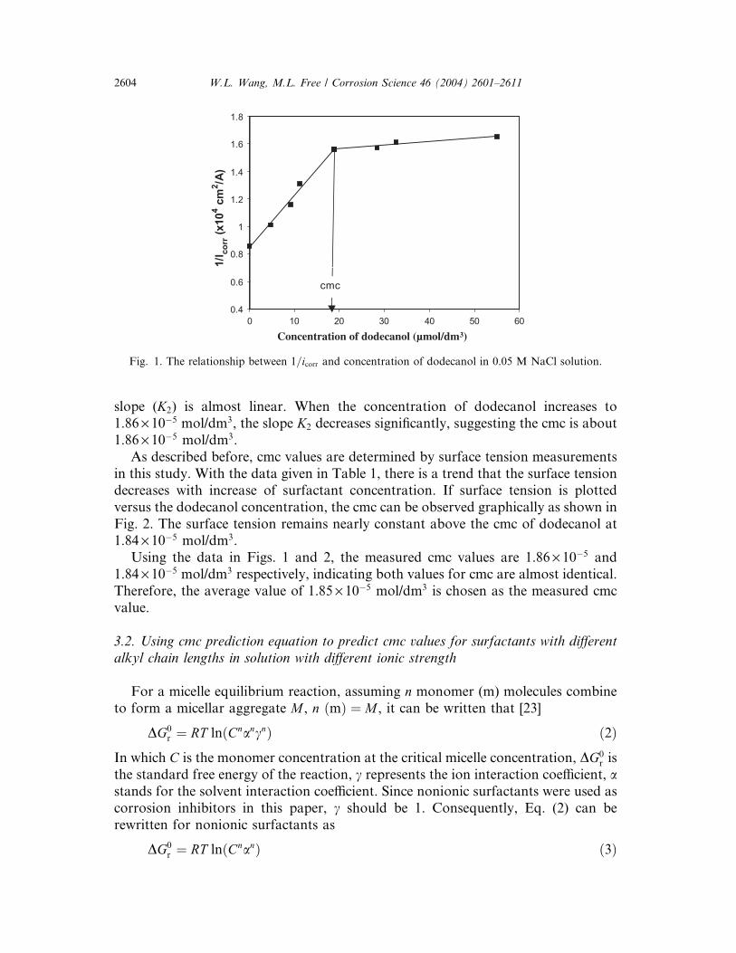
slope (K2) is almost linear. When the concentration of dodecanol increases to
1.86 · 10ÿ5 mol/dm3, the slope K2 decreases significantly, suggesting the cmc is about
1.86 · 10ÿ5 mol/dm3.
As described before, cmc values are determined by surface tension measurements
in this study. With the data given in Table 1, there is a trend that the surface tension
decreases with increase of surfactant concentration. If surface tension is plotted
versus the dodecanol concentration, the cmc can be observed graphically as shown in
Fig. 2. The surface tension remains nearly constant above the cmc of dodecanol at
1.84 · 10ÿ5 mol/dm3.
Using the data in Figs. 1 and 2, the measured cmc values are 1.86 · 10ÿ5 and
1.84 · 10ÿ5 mol/dm3 respectively, indicating both values for cmc are almost identical.
Therefore, the average value of 1.85 · 10ÿ5 mol/dm3 is chosen as the measured cmc
value.
3.2. Using cmc prediction equation to predict cmc values for surfactants with different
alkyl chain lengths in solution with different ionic strength
For a micelle equilibrium reaction, assuming n monomer (m) molecules combine
to form a micellar aggregate M , n ðmÞ ¼ M , it can be written that [23]
DG0r ¼ RT lnðCn
ancnÞ ð2Þ
In which C is the monomer concentration at the critical micelle concentration, DG0r is
the standard free energy of the reaction, c represents the ion interaction coefficient, a
stands for the solvent interaction coefficient. Since nonionic surfactants were used as
corrosion inhibitors in this paper, c should be 1. Consequently, Eq. (2) can be
rewritten for nonionic surfactants as
DG0r ¼ RT lnðCn
anÞ ð3Þ
0.4
0.6
0.8
1
1.2
1.4
1.6
1.8
0 10 20 30 40 50 60
1/I
co
rr (
x10
4 c
m2/A
)
cmc
Concentration of dodecanol (µmol/dm3)
Fig. 1. The relationship between 1=icorr and concentration of dodecanol in 0.05 M NaCl solution.
2604 W.L. Wang, M.L. Free / Corrosion Science 46 (2004) 2601–2611
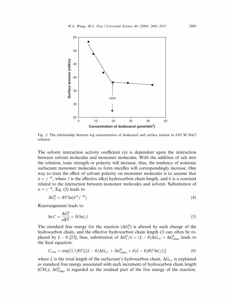
The solvent interaction activity coefficient (a) is dependent upon the interaction
between solvent molecules and monomer molecules. With the addition of salt into
the solution, ionic strength or polarity will increase, thus, the tendency of nonionic
surfactant monomer molecules to form micelles will correspondingly increase. One
way to treat the effect of solvent polarity on monomer molecules is to assume that
a ¼ cÿlk, where l is the effective alkyl hydrocarbon chain length, and k is a constant
related to the interaction between monomer molecules and solvent. Substitution of
a ¼ cÿlk, Eq. (3) leads to
DG0r ¼ RT lnðCn
cÿlkÞ ð4Þ
Rearrangement leads to
lnC ¼ DG0r
nRTþ lk lnðcÞ ð5Þ
The standard free energy for the reaction (DG0r ) is altered by each change of the
hydrocarbon chain, and the effective hydrocarbon chain length (l) can often be re-
placed by Lÿ 6 [23], thus, substitution of DG0r=n ¼ ðLÿ 6ÞDGc:l: þ DG0
other leads to
the final equation:
Ccmc ¼ expf1=ðRT Þ½ðLÿ 6ÞDGc:l: þ DG0other þ kðLÿ 6ÞRT lnðcÞ�g ð6Þ
where L is the total length of the surfactant’s hydrocarbon chain, DGc:l: is explained
as standard free energy associated with each increment of hydrocarbon chain length
(CH2), DG0other is regarded as the residual part of the free energy of the reaction.
25
30
35
40
45
50
55
0 10 20 30 40 50
Su
rface t
en
sio
n (
mN
/m)
cmc
Concentration of dodecanol (µmol/dm3)
Fig. 2. The relationship between log concentration of dodecanol and surface tension in 0.05 M NaCl
solution.
W.L. Wang, M.L. Free / Corrosion Science 46 (2004) 2601–2611 2605
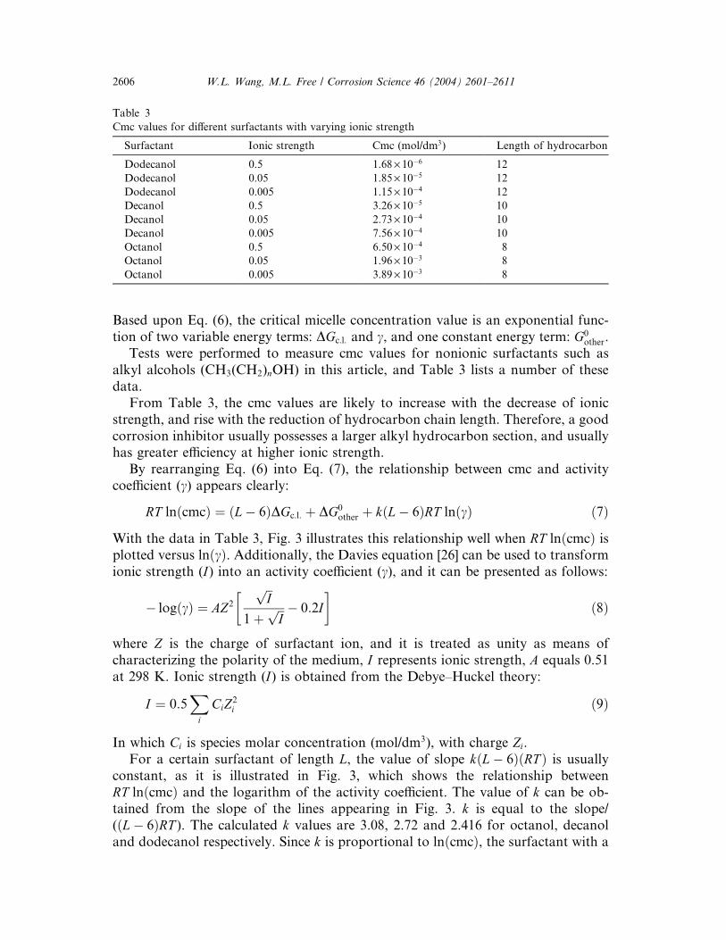
Based upon Eq. (6), the critical micelle concentration value is an exponential func-
tion of two variable energy terms: DGc:l: and c, and one constant energy term: G0other.
Tests were performed to measure cmc values for nonionic surfactants such as
alkyl alcohols (CH3(CH2)nOH) in this article, and Table 3 lists a number of these
data.
From Table 3, the cmc values are likely to increase with the decrease of ionic
strength, and rise with the reduction of hydrocarbon chain length. Therefore, a good
corrosion inhibitor usually possesses a larger alkyl hydrocarbon section, and usually
has greater efficiency at higher ionic strength.
By rearranging Eq. (6) into Eq. (7), the relationship between cmc and activity
coefficient (c) appears clearly:
RT lnðcmcÞ ¼ ðLÿ 6ÞDGc:l: þ DG0other þ kðLÿ 6ÞRT lnðcÞ ð7Þ
With the data in Table 3, Fig. 3 illustrates this relationship well when RT lnðcmcÞ isplotted versus lnðcÞ. Additionally, the Davies equation [26] can be used to transform
ionic strength (I) into an activity coefficient (c), and it can be presented as follows:
ÿ logðcÞ ¼ AZ2
ffiffi
Ip
1þffiffi
Ip
�
ÿ 0:2I
�
ð8Þ
where Z is the charge of surfactant ion, and it is treated as unity as means of
characterizing the polarity of the medium, I represents ionic strength, A equals 0.51
at 298 K. Ionic strength (I) is obtained from the Debye–Huckel theory:
I ¼ 0:5X
i
CiZ2i ð9Þ
In which Ci is species molar concentration (mol/dm3), with charge Zi.
For a certain surfactant of length L, the value of slope kðLÿ 6ÞðRT Þ is usually
constant, as it is illustrated in Fig. 3, which shows the relationship between
RT lnðcmcÞ and the logarithm of the activity coefficient. The value of k can be ob-
tained from the slope of the lines appearing in Fig. 3. k is equal to the slope/
(ðLÿ 6ÞRT ). The calculated k values are 3.08, 2.72 and 2.416 for octanol, decanol
and dodecanol respectively. Since k is proportional to lnðcmcÞ, the surfactant with a
Table 3
Cmc values for different surfactants with varying ionic strength
Surfactant Ionic strength Cmc (mol/dm3) Length of hydrocarbon
Dodecanol 0.5 1.68· 10ÿ6 12
Dodecanol 0.05 1.85· 10ÿ5 12
Dodecanol 0.005 1.15· 10ÿ4 12
Decanol 0.5 3.26· 10ÿ5 10
Decanol 0.05 2.73· 10ÿ4 10
Decanol 0.005 7.56· 10ÿ4 10
Octanol 0.5 6.50· 10ÿ4 8
Octanol 0.05 1.96· 10ÿ3 8
Octanol 0.005 3.89· 10ÿ3 8
2606 W.L. Wang, M.L. Free / Corrosion Science 46 (2004) 2601–2611
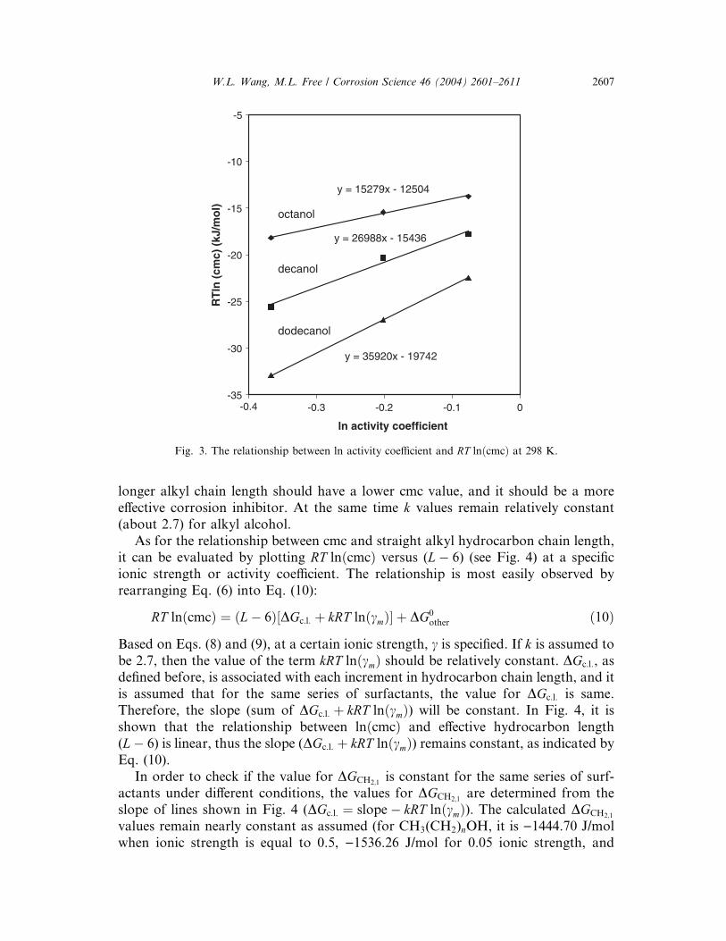
longer alkyl chain length should have a lower cmc value, and it should be a more
effective corrosion inhibitor. At the same time k values remain relatively constant
(about 2.7) for alkyl alcohol.
As for the relationship between cmc and straight alkyl hydrocarbon chain length,
it can be evaluated by plotting RT lnðcmcÞ versus (Lÿ 6) (see Fig. 4) at a specific
ionic strength or activity coefficient. The relationship is most easily observed by
rearranging Eq. (6) into Eq. (10):
RT lnðcmcÞ ¼ ðLÿ 6Þ½DGc:l: þ kRT lnðcmÞ� þ DG0other ð10Þ
Based on Eqs. (8) and (9), at a certain ionic strength, c is specified. If k is assumed to
be 2.7, then the value of the term kRT lnðcmÞ should be relatively constant. DGc:l:, as
defined before, is associated with each increment in hydrocarbon chain length, and it
is assumed that for the same series of surfactants, the value for DGc:l: is same.
Therefore, the slope (sum of DGc:l: þ kRT lnðcmÞ) will be constant. In Fig. 4, it is
shown that the relationship between lnðcmcÞ and effective hydrocarbon length
(Lÿ 6) is linear, thus the slope (DGc:l: þ kRT lnðcmÞ) remains constant, as indicated by
Eq. (10).
In order to check if the value for DGCH2;1is constant for the same series of surf-
actants under different conditions, the values for DGCH2;1are determined from the
slope of lines shown in Fig. 4 (DGc:l: ¼ slopeÿ kRT lnðcmÞ). The calculated DGCH2;1
values remain nearly constant as assumed (for CH3(CH2)nOH, it is )1444.70 J/mol
when ionic strength is equal to 0.5, )1536.26 J/mol for 0.05 ionic strength, and
y = 15279x - 12504
y = 26988x - 15436
y = 35920x - 19742
-35
-30
-25
-20
-15
-10
-5
-0.4 -0.3 -0.2 -0.1 0
ln activity coefficient
RT
ln (
cm
c)
(kJ
/mo
l)
dodecanol
decanol
octanol
Fig. 3. The relationship between ln activity coefficient and RT lnðcmcÞ at 298 K.
W.L. Wang, M.L. Free / Corrosion Science 46 (2004) 2601–2611 2607
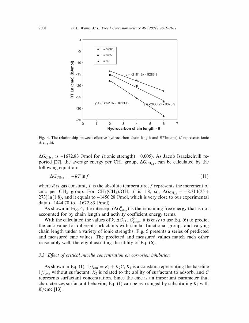
DGCH2;1is )1672.83 J/mol for I(ionic strength)¼ 0.005). As Jacob Israelachvili re-
ported [27], the average energy per CH2 group, DGCH2;1, can be calculated by the
following equation:
DGCH2;1¼ ÿRT ln f ð11Þ
where R is gas constant, T is the absolute temperature, f represents the increment of
cmc per CH2 group. For CH3(CH2)nOH, f is 1.8, so, DGCH2;1¼ ÿ8:314ð25þ
273Þ lnð1:8Þ, and it equals to )1456.28 J/mol, which is very close to our experimental
data ()1444.70 to )1672.83 J/mol).
As shown in Fig. 4, the intercept (DG0other) is the remaining free energy that is not
accounted for by chain length and activity coefficient energy terms.
With the calculated the values of k, DGc:l:, G0other, it is easy to use Eq. (6) to predict
the cmc value for different surfactants with similar functional groups and varying
chain length under a variety of ionic strengths. Fig. 5 presents a series of predicted
and measured cmc values. The predicted and measured values match each other
reasonably well, thereby illustrating the utility of Eq. (6).
3.3. Effect of critical micelle concentration on corrosion inhibition
As shown in Eq. (1), 1=icorr ¼ K1 þ K2C, K1 is a constant representing the baseline
1=icorr without surfactant, K2 is related to the ability of surfactant to adsorb, and C
represents surfactant concentration. Since the cmc is an important parameter that
characterizes surfactant behavior, Eq. (1) can be rearranged by substituting K2 with
K=cmc [13].
y = -3.852.9x - 101998 y = -2888.2x - 9373.9
y = -2181.9x - 9283.3
-35
-30
-25
-20
-15
-10
-5
0
0 1 2 3 4 5 6 7
Hydrocarbon chain length - 6
RT
Ln
(cm
c)
(kJ/m
ol)
I = 0.005
I = 0.05
I = 0.5
Fig. 4. The relationship between effective hydrocarbon chain length and RT lnðcmcÞ (I represents ionic
strength).
2608 W.L. Wang, M.L. Free / Corrosion Science 46 (2004) 2601–2611
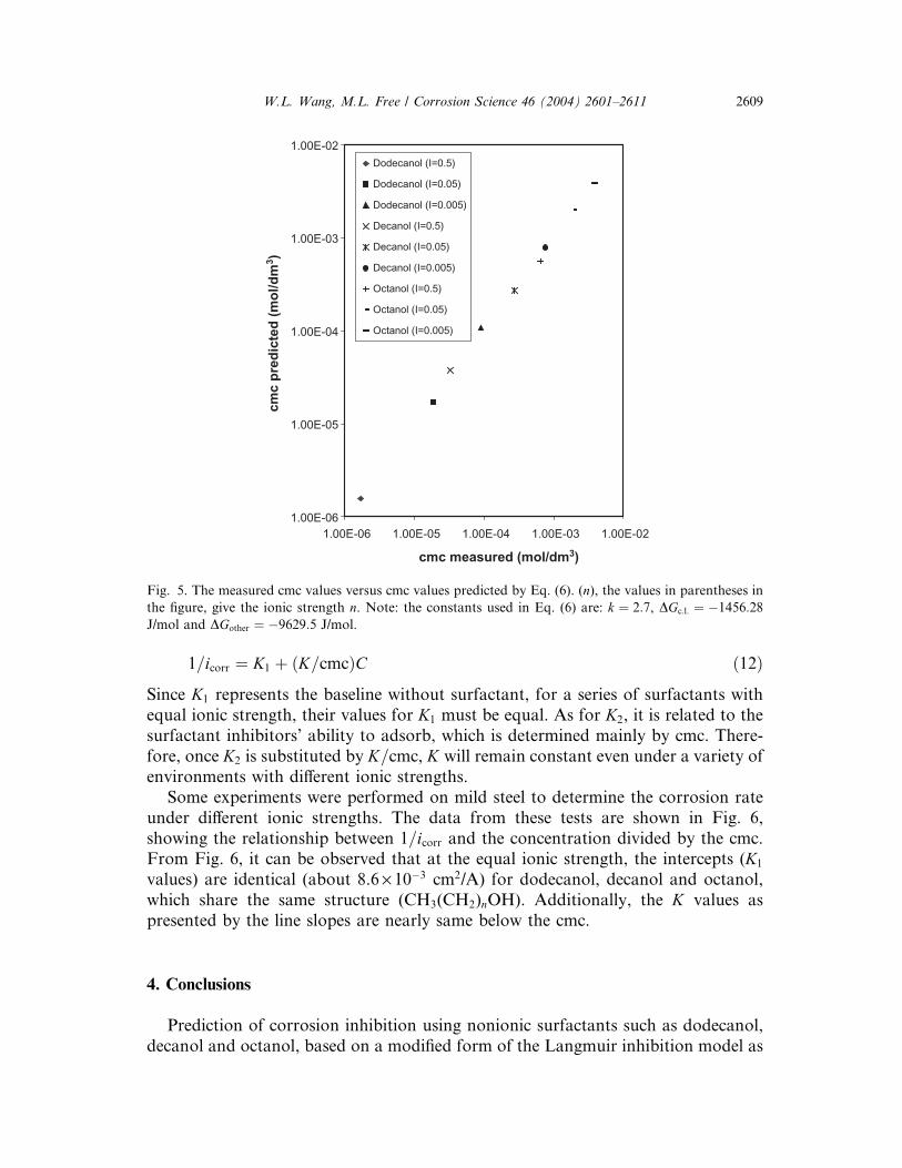
1=icorr ¼ K1 þ ðK=cmcÞC ð12ÞSince K1 represents the baseline without surfactant, for a series of surfactants with
equal ionic strength, their values for K1 must be equal. As for K2, it is related to the
surfactant inhibitors’ ability to adsorb, which is determined mainly by cmc. There-
fore, once K2 is substituted by K=cmc, K will remain constant even under a variety of
environments with different ionic strengths.
Some experiments were performed on mild steel to determine the corrosion rate
under different ionic strengths. The data from these tests are shown in Fig. 6,
showing the relationship between 1=icorr and the concentration divided by the cmc.
From Fig. 6, it can be observed that at the equal ionic strength, the intercepts (K1
values) are identical (about 8.6 · 10ÿ3 cm2/A) for dodecanol, decanol and octanol,
which share the same structure (CH3(CH2)nOH). Additionally, the K values as
presented by the line slopes are nearly same below the cmc.
4. Conclusions
Prediction of corrosion inhibition using nonionic surfactants such as dodecanol,
decanol and octanol, based on a modified form of the Langmuir inhibition model as
1.00E-06
1.00E-05
1.00E-04
1.00E-03
1.00E-02
1.00E-06 1.00E-05 1.00E-04 1.00E-03 1.00E-02
cmc measured (mol/dm3)
cm
c p
red
icte
d (
mo
l/d
m3)
Dodecanol (I=0.5)
Dodecanol (I=0.05)
Dodecanol (I=0.005)
Decanol (I=0.5)
Decanol (I=0.05)
Decanol (I=0.005)
Octanol (I=0.5)
Octanol (I=0.05)
Octanol (I=0.005)
Fig. 5. The measured cmc values versus cmc values predicted by Eq. (6). (n), the values in parentheses in
the figure, give the ionic strength n. Note: the constants used in Eq. (6) are: k ¼ 2:7, DGc:l: ¼ ÿ1456:28
J/mol and DGother ¼ ÿ9629:5 J/mol.
W.L. Wang, M.L. Free / Corrosion Science 46 (2004) 2601–2611 2609

well as a cmc prediction equation was made for a variety of surfactants with varied
ionic strength. Experimental results agree well with the appropriate theory. Thus, the
combination of the cmc prediction equation and the modified Langmuir corrosion
inhibition equation are quite useful in predicting the corrosion inhibition using
surfactant inhibitors.
Acknowledgement
Financial support for this project from the National Science Foundation (DMR-
9983945) is gratefully acknowledged.
References
[1] J.I. Bregmann, Corrosion Inhibitors, MacMillan, New York, 1963.
[2] N. Hackerman, Langmuir 3 (1987) 922.
[3] K. Aramaki, N. Hackerman, J. Electrochem. Soc. 116 (1969) 568.
[4] G. Benerje, S.N. Malhotra, Corrosion 48 (1992) 10.
[5] B. Donnely, T.C. Downie, R. Grzeskowiak, H.R. Hambourg, Corros. Sci. 18 (1977) 109.
[6] B. Donnely, T.C. Downie, R. Grzeskowiak, H.R. Hambourg, Corros. Sci. 14 (1974) 597.
[7] F.B. Crowcock, V. Lopp, Corros. Sci. 28 (1988) 397.
[8] F.B. Crowcock, V. Lopp, J. Electrochem. Soc. 135 (1998) 397.
[9] L. Meszaros, B. Lengyel, T. Garai, G. Giordan, Acta Chim. Hung. 127 (1990) 113.
[10] M. Elachouri, M.S. Hajji, M. Salem, S. Kertit, R. Coudert, E.M. Essassi, Corros. Sci. 37 (1995) 381.
[11] M. Elachouri, M.S. Hajji, M. Salem, S. Kertit, E.M. Essassi, Morrocan patent no. 23159, 1994.
6.0E+03
7.0E+03
8.0E+03
9.0E+03
1.0E+04
1.1E+04
1.2E+04
1.3E+04
1.4E+04
1.5E+04
1.6E+04
0 0.2 0.4 0.6 0.8
concentration/cmc
1/I
co
rr (
cm
2/A
)
Dodecanol
Decyl
Octanol
Fig. 6. The relationship between 1=icorr and concentration/cmc for mild steel corrosion, all the experiments
are conducted in 0.5 M NaCl solution with 1000 rpm at 31 °C.
2610 W.L. Wang, M.L. Free / Corrosion Science 46 (2004) 2601–2611
[12] I.L. Rozenfeld, Corrosion Inhibitors, McGraw-Hill, New York, 1981, p. 97.
[13] M.L. Free, Corros. Sci. 44 (2002) 2865.
[14] I. Langmuir, J. Am. Chem. Soc. 39 (1947) 1, p. 848.
[15] T. Zhao, G. Mu, Corros. Sci. 41 (1999) 1937.
[16] A.A. EI-Awady, B.A. Abd-EI-Nabey, S.G. Aziz, M. Khalifa, H.A. Al-Ghamedy, Int. J. Chem. 1
(1990) 169.
[17] A.A. EI-Awady, B.A. Abd-EI-Nabey, S.G. Aziz, J. Electrochem. Soc. 139 (1992) 2.
[18] B.A. Abd-EI-Nabey, Ekhamis, M.Sh. Ramadan, A. EI-Gindy, Corrosion 52 (1996) 671.
[19] M.L. Free, Corros. Sci. 44 (2002) 2865.
[20] S. Omanovic, S.G. Roscoe, Corrosion 56 (2000) 684.
[21] H. Luo, Y.C. Guan, K.N. Han, Corrosion 54 (1998) 726.
[22] M. Elachouri, M.S. Hajji, M. Salem, S. Keritit, J. Aride, R. Coudert, E. Essassi, Corrosion 52 (1996)
103.
[23] M.L. Free, Corrosion 58 (2002) 1025.
[24] D.A. Jones, Principles and Prevention of Corrosion, Prentice-Hall, Upper Saddle River, NJ, 1996,
p. 146.
[25] J.O’M. Bockris, A.K.N. Reedy, Modern Electrochemistry, Plenum Press, New York, 1970, p. 1080.
[26] J.N. Butler, Ionic Equilibrium: Solubility and pH Calculations, John Wiley & Sons, New York, 1998,
p. 45.
[27] J. Israelachvili, Intermolecular & Surface Force, 2nd ed., Academic Press, San Diego, CA, 1992,
p. 354.
W.L. Wang, M.L. Free / Corrosion Science 46 (2004) 2601–2611 2611
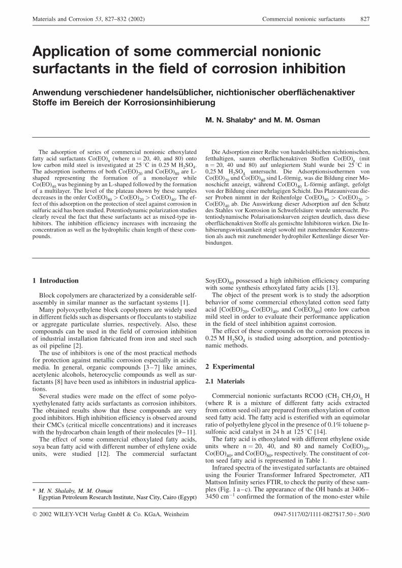
� �� �� ������ �� �� �� ��������� ��� ���� �������� ��������� ���� ����� ���� �������
���������� � ��� ���� ����� �������������� � �� � �� � �������� ��������
�� ��� � ����� � � ��� ���� ����� �� ���������� � �� ���� �� ����� ���� �� � � ��� � � �������������� ���
�� �� ������� �� �� �� !���
��� ��� ���� � ������ � � �������� � �� ��� ������������ ���� ���������� � ���� � ���� � !"� #"� �� $"� � � ���% ���� ����� �� �&��������� �� !' �� � "(!' ) *!+�#(��� ��� ���� �� ������ � % �� � ����!" �� � ����$" ��� ,-������ ���������� ��� � ����� � � � ����� ����� ����#" �� %����� %� � ,-������ � �� �� %� ��� � ����� � � ����������( ��� ��&�� � ��� ������� �� %� ����� ���������������� � ��� ���� � ����$" � � ����!" � � ����#"( ��� ��-���� � ���� ��� ���� ��� �� ����� � ����� ������ � �� �� ��������� ���� ��� %�� �������( ���� ������ � ����.��� �������������� ��&��� ��� ���� ���� ����� ���������� ��� �� �����-���� �-��%�� ��( ��� ���%��� ��������� �������� ��� �������� ���� ������� �� ��� �� ��� ���� ������ ���� ����� � ����� � �-� ���(
/�� 0�� ���� ���� ����� & �������1%����� ����� ������������������ ����� %�����1����2��&� +� ��� � ���� ���� � !"� #" �� $"� ��� ���������� +���� ���� %�� !' �� �"�!' ) *!+�# ���������( /�� 0�� ���� ��� ������ & � ����!" �� � ����$" ��� ,-� 1����� �� ��� 3����� ���� ) - ������� �.����� �1���� � ����#" ,-� 1���� ���1��� ��� ���& ��� 3����� ���� ���������� +������( /�� �������&��� ���-��� � %� ���� � ��� ������ ��� � ����$" � � ����!" �� ����#" �%( /�� 0�� ��2�� ������ 0�� ���� ��� �� +����.��� +������ & � 4 �� �� � +�� ������1��� ���� ���������( -���� ��������� �������� �2��&� .����� ��������� ���� ����� %�����1����2��&� +� ��� ��� ��������� ���%�� �� ��2�( /�� �-��%������ ��2���2��� ������ � �� ��� .�������� 4 .����-�� ��� ���� ��� .�������� ���� ������ 4������1�� ������ 5��-%�����(
� ����������
3� �2 � � ������ ��� ����������.�� %� � � ������%�� ����-�����%�� � ������� ���� �� ��� ��������� ������� 678()�� � �� ��������� %� �2 � � ������ ��� ����� ����
� �������� ������ ���� �� ���������� � �� ������� � ���%���.� � ��������� ����������� ��������� ��������&���( 0�� � ������ �� ��� �� %� ���� � ��� ����� � � �� �� ���%��� � ��������� ��������� ��%������� �� � �� �� ����� ������ �� ������� 6!8(��� ��� � ���%�� �� �� � � ��� � �� ��������� ���� ��
� � �� ����� ������ �������� � �� �� ���������� � �����������( � ������� ����� � �� ��� 69:;8 ��2� ��������������� ��� � ��� ����� ������ � �� ��� �� ��� �� ���-������� 6$8 ��&� %�� ���� �� ���%�� �� � ��������� �������-�� �(+�&���� ������� ��� ���� ��� ������ � � �� � �� -
������������ ����� ����� ���������� �� � �� �� ���%�� ��(��� %����� ������� �� ���� ����� � �� ��� ��� &���� � ���%�� ��( *��� ���%��� ��������� �� %���&�� �� ������� �)�� ��������� ������� � ������� �� �� �� �������� ��� ��� ���� ���% ���� ����� � ����� � ������� 6<:778(��� ������ � � �� � �������� ��� ������� ����� ������
� �� %�� ����� ���� ��� �������� ��%�� � ������� ��������� ��� ������� 67!8( ��� � �������� ���������
+ �����$" � ������� � ���� ���%��� ��������� � ������ ��� � �� �������� ��� ������� ����� ����� 6798(��� %=��� � ��� ������ �2 �� � ����� ��� ��� ����
%���&� � � � �� � �������� ��� ������� � �� ���� ��������� 6� ����!"� � ����#"� �� � ����$"8 � � ���% ���� ����� � ���� � �&������ ����� ���� ����� ��������� � ��� ����� � ����� ���%��� ������ � �� �� (��� ������ � ����� � �� ��� ��� � �� �� �� ���� �
"(!' ) *!+�# �� ������� ���� ��� ���� � �� � ���� ��-���� ���� ��(
� � ���������
��� ��������
� �������� � �� ���������� ���� ��*! �*!�� *� ���� � �� � ������� � �������� ����� ����� ����������� � � �� ���� ��� ��� �������� �� � ��� ������ � � �� ���� ����� ����( ��� ����� ���� �� ���������� ��� � �>��� ������� � � ��������� ���� � � ��� ������� � "(7? � ���� �-���� �� ���� �������� � !# � �� 7!' �� 67#8(��� ����� ���� �� ��� ������� ��� �������� ������� ����
���� ���� � !"� #"� �� $" �� ����� � ����!"�� ����#"� �� � ����$"� ��������&���( ��� � ������� � � �-� ���� ����� ���� �� ���������� � ��%�� 7(������� ������� � ��� �&��������� ���������� ��� %�����
���� ��� @ ����� ����� ���� ������� +����� ������ 0��)���� ������ ������ @���� � ����2 ��� ������ � ����� ���-���� �@��( 7 �:��( ��� ��������� � ��� �* %��� �� 9#"A:9#'" ���7 � ������ ��� � ����� � ��� � -����� ����
)�������� �� � �� �� ��� $!;:$9! �!""!� � �������� � �� ���������� $!;
� !""! B�,�C-5�* 5����� D�%* E � ( 4D�0� B������ "<#;-'77;F"!F7777-"$!;G7;('"�('"F"
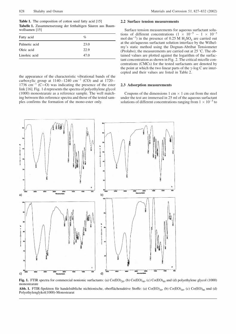
��� ��������� � ��� �������������� &�%���� �� %��� � ������% ����� �� �� �� 77#":7!#" ���7 ���� �� �� 7;!":7;9A ���7 ����� �� �������� ��� ������� � ��� �������2 67A8( @��( 7 � ��������� ��� ������� � � ��������� ���� ��7"""� � �������� �� � �������� ������( ��� ��� �����-�� %�� �� ���� �������� ������� �� �� �� � ��� ������ ���-���� � ����� ��� � ����� � ��� � -����� ��(
��� ������ ������ ������������
+������ ���� ����������� � � �>�� �� ��������� � ��-�� � � �������� � ������� � �7 � 7"�' � 7 � 7"�9� � ���9� � ��� ������� � "(!' ) *!+�# ��� ������� ���� ��� ���F�>�� �� ��������� � ���� �������� %� ��� B�����-��H� ������ ���� � ���� ��� / ��-0%��%�� ���� ������� ��% �I ��� ����������� ��� ������� �� �� !' ��( ��� %-����� &����� ��� �� ���� ������ ��� � ������� � ��� ������-��� � ������� �� �� � @��( !( ��� �������� ������� � -������� � ��)��� � � ��� ������ ���������� ��� �� ��� %���� � �� �� ���� ��� � ����� ����� � ��� �-� � � ��� ����-������ �� ����� &����� ��� ������ � ��%�� !(
��� ��������� ������������
� �� � � ��� ������ � 7 �� � 7 �� ��� �� � ��� ��������� ��� ���� ��� �������� � !' �� � ��� �>�� �� ���������� ���� � � �������� � ������� � ����� �� � 7 � 7"�' �
����� �� ��� � �� ���� � � �� ���� ����� ���� 67'8
������� �� J���������.�� ��� ����������� +�1��� ��� 3���- ������ 67'8
@���� ���� ?
������� ���� !9("
����� ���� !!(<
,� ���� ���� #;("
��� �� @��� ������� � � � �������� � �� ����������K ��� � ����!"� �%� � ����#"� ��� � ����$" �� ��� � ��������� ���� � �7"""�� ��������
���� �� @���-+��2��� ��1� �������1%����� ����� ������ %�����1����2��&� +� ���K ��� � ����!"� �%� � ����#"� ��� � ����$" �� ��� �����������2 ��7"""�-) �������
$!$ +����%� �� ���� )�������� �� � �� �� ��� $!;:$9! �!""!�
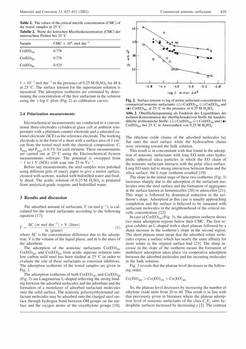
7 � 7"�9 � � ���9 � ��� ������� � "(!' ) *!+�# � � #$ ��� !' ��( ��� ������� ���� � � ��� ��������� � ���� ����������( ��� ��� ���� �� ������ ��� ��������� %� �����-���� ��� � ������� � ��� ���� ��������� � ��� � ���� ���� ��� �-� � � �� �� �@��( !� �� ����%���� ���&��(
��� ����� ���� ������������
������ �������� ����������� ��� � ������ � � � &�-�� �� �����-������ ��� ���������� ����� ���� �� ��%��� ���-�������� ��� � ������� � ���� ������ �� �� � ��������� ��-� ��� ������ �� �+��� �� ��� �������� ������ ��( ��� �2�������� �� �� � ��� � �� � � ����� ��� � ������� ���� � 7 ��!
��� �� � ��� ������ ����� ��� ��� �������� � �� ���� K ��+��� �� ��� �� "(9? � � ���� ������( ����� �������������� ������� �� �� !' �� ���� ��� ������ �������� +���������������� � �� ���( ��� � ������ �� � ������ �� �� 7 � 7 5 �+��� ��� ��� ���� !' � 5��7(3�� �� �� ������������ ��� ����� ������� ��� � ������
���� �������� ����� � ����� ����� � ��&� � ���� � �������������� ��� ���� �� ����� ��� %���������� ���� �� ����-�� �����( ��� ������ � ���� � "(!' ) *!+�# �� ���������� � ���������-����� ������� �� %���������� ����(
� !������ ��� �������
��� ��� �%�� �� �� � ���������� � �� � � ��7�� �� ���-������� � � ��� ������ ���������� ��� ���� � ��� � �� ���>���� 67;8K
� � �� �� � � ���9� � 5 ��������� ������� �7�
���� �� �� ��� � ������� ��������� ��� � ��� ��� ��-�� � 5 �� ��� & ���� � ��� ��>��� ������ �� � �� ��� ���� ���� ��� �%��(��� ��� ���� � ��� � �� ���������� � ����!"�
� ����#"� �� � ����$" �� � ������ �>�� �� � ���� � � ���% ���� ����� ��� %�� ������� �� !' �� � ���� � �&������ ��� � �� � ����� ���������� �� � �� �� ���%�� ��(��� ��� ���� �� ������ � ��� ������ ������� ��� ��&� �@��( 9(��� ��� ���� �� ������ � % �� � ����!"� �� � ����$"
�@��( 9� ��� ,�������� ,-������ ��������� ��� ��� � %��-�� %�� �� ��� ��� �%�� � ������� �� ��� ��� �%��� �� ���� ����� � � � ����� � ��� �%�� ��������� � ������� � ��� � ��� �������( ��� � �� � �� ������������ ���-������ � ������� ��� %� ��� �%�� � ��� ������� ����� ���-���� ��� ��� ���� �� % � %�� ��-�* �� ��� ��� ���-���� �� ��� ���� �� �� � ��� ��������� �� ��� 67$8(
��� ������� ���� ����� � ��� ��� �%�� � ������� ������� � ��� ����� ������� ���� ��� ���� ���% ����� ��� ������ � ��� ��� %��2 � ���� (���� ������ �� � � � ����� ��� ���� � �� � ��� ��� ��-
�� � � �� ���������� ��� � � �� ���� � ���� -������ ��������� ������ ��������� � ���� ��� �� ���� ���� � �� ��������� �������� ��� ��� � ��� ������ �������(, � �� ���� ��� � ��� � �������� %�� �� ���� �� ��������� �������I ��� ,-���� �� ����� �������� 67<8(��� �� �� � ��� ������ ����� � ����� � �� ������ �@��( 9�
�������� ������� ��� � ��� ��� ���� � ��� ��������� � -������� � ��� ����� ������� �� ��� � ����� � ������������ ��� ������� 2 �� ������������ 6!"8 � ���������� 6!78(���� ����� �� � �� �� %� ���������� ������� � ��� �� -�����H� �� ��( 0�� ���� � ���� ���� �� ������� ���� ������ ������ �� ��� ������� �� %����&�� � %� ��������� ������������ � ������� � ��� ����% ��� � � ��� �������� ��-����� � ������� 6!!8(� ���� � � ����#" �@��( 9�� ��� ��� ���� �� ����� �� �
� ��� ��� ���� ���� � %�� ����� �)�( ��� ����� ��-�� ����%��� � ,-������ ��� � �� �� ������� � �� �� %� ������ ������� � ��� �� �����H� �� �� � ��� ��� � ���� (��� �� �� ������� ���� ��� ���� ��� ��� �%�� � ���� � ��-����� ��� �� � ������� ���� ��� ����� ��� ���� ������� � �� �� � ���� �� ��� ������ ������� ��� 6!98( ��� ����� �-������ � ��� �� �� � ��� �� ����� ���� ��� � ����� ����������� ��� ���� ��2�� ����� &�� � ������&� ��� ���� %�� �� ��� ��� �%�� � ������� �� ��� �� ��� � �������� ��� %��2 � ���� (@��( 9 ��&���� ���� ��� ������� ��&�� ��������� � ��� � �� -
�� �����
� ����$" � � ����!" � � ����#"+ � ��� ������� ��&�� ��������� %� �������� ��� ��%�� �
������� ���� ���� �� � !" � #"( ���� ������ �� � ��� ������� ���&� ���� ��&� � ���������� ���� ��� ������� ��� ��-�� ��&�� � � �� ���������� � ��� ����� ���� � ��-�� ������ �������� �������� %� ��������� � 6!8( ��� � �����
����� �� ��� &����� � ��� �������� ������� � ������� ��)�� ���� ������ ������� �� !' ��������� �� B���� ��� 2�������� )������2 .������ ��)�� ������������� � %� %�� !' ��
+����� �)� � 7"#� � � ���9
� ����!" "(;;A
� ����#" "(;;A
� ����$" "('!'
��� �� +������ ���� &� � � � � ��� ��������� � ������� � �� �������� � �� ����������K ��� � ����!"� ��� � ����#" ����� � ����$"� �� !' �� � ��� ������� � "(!' ) *!+�#���� �� �%�����1�������� ��� @�2�� ��� , ��������� ���� ���� 4 .������ ��� %�����1����2��&� +� ��� ��1� ������-�1%����� ����� ����� +� ���K ��� � ����!"� ��� � ����#" �� ���� ����$"� %�� !' �� � 0 ������� & "�!' ) *!+�#
)�������� �� � �� �� ��� $!;:$9! �!""!� � �������� � �� ���������� $!<
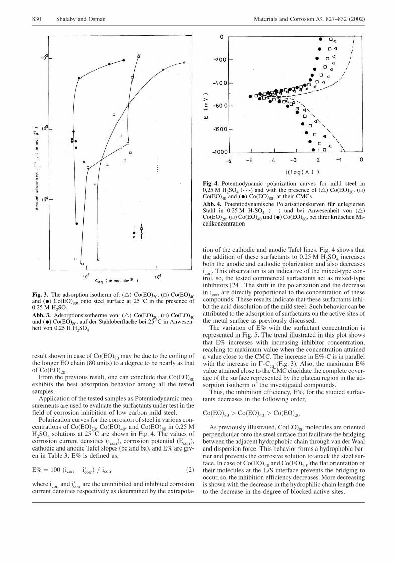
������ �� � ���� � � ����$" ��� %� ��� � ��� � ���� ���� � ��� �� ���� �$" ����� � � ������ � %� ����� �� ���� � � ����!"(@� � ��� ���&� �� ������� � �� � ����� ���� � ����$"
����%��� ��� %��� ��� ���� %���&� � �� � ��� ��� �������������(0�������� � ��� ������ ������� �� ���� ������ ���-
�������� ��� ���� � �&������ ��� ���������� ���� ���� � �������� � � �� �� ���%��� � � ���% ���� �����( ����.��� ���&�� � � ��� � �� �� � ����� � &��� �� � -
������� � � � ����!"� � ����#"� �� � ����$" � "(!' )*!+�# � ���� � �� !' �� ��� �� � @��( #( ��� &����� �� �� �� ������ �������� ��� ���� � �� �� � ������ ��� �������� ��� �� � ��� ����� �� ��� �%� �� %��� �� �? ��� ��&-� � ��%�� 9I �? �� ������ ���
�? � 7"" ��� �� � � �� ��� � �� �� �!�
���� �� �� �� ��� �� ��� ��� ����%���� �� ���%���� � �� ��
������ �������� ��������&��� �� ��������� %� ��� ������ ��-
�� � ��� ���� ��� �� � ��� ����� ����( @��( # �� � ������� ������ � ����� ���������� � "(!' ) *!+�# ��������% �� ��� � ��� �� ���� ��� � ����.��� �� ��� ����������� ��( ���� %���&��� �� � �������&� � ��� �����-���� � -�� �� � � ��� ������ � �������� ���������� ��� �� �����-�������%�� �� 6!#8( ��� ����� � ��� � ����.��� �� ��� ��������� �� �� ��� �������� �� � ��� �� � ��� � ������� � ������ �� ���( ����� ������� ������� ���� ����� ���������� ���-%�� ��� ���� ���� ���� � ��� ���� �����( +��� %���&� � �� %������%���� � ��� ��� ���� � ���������� ��� ����&� ����� ���� ����� ������� �� ���&� ���� ���������(��� &������ � �? ��� ��� ��������� � ������� ��
���������� � @��( '( ��� ���� ����������� � ���� �� � �� ����� �? �������� ��� �������� ���%�� � � ������� �������� � ������� &���� �� ��� � ������� �������� &���� �� �� � ��� �)�( ��� ������� � �?-� �� � �������� ��� ��� ������� � �-��> �@��( 9�( 0�� � ��� ������� �?&���� ������� �� �� � ��� �)� ��������� ��� � ������ � &��-��� � ��� ������� ���������� %� ��� ������� ���� � ��� ��-� ���� �� ����� � ��� �&��������� � �� ���(����� ��� ���%��� ���������� �?� � � ��� ������� ������-
���� ��������� � ��� � �� �� �����
� ����$" � � ����#" � � ����!"0� ���&� ���� ������������ � ����$" � ������� ��� ������
������������ � ��� ����� ������� ���� ���������� ��� %������%�� �� ��� ��=���� ���� �� %�� ���� ��� ��� &� ���B����� �������� � ���( ���� %���&� � � ��� � ���� �� %�� %��-���� �� ���&��� ��� � �� ��&� � ���� � �����2 ��� ����� ���-����( � ���� � � ����#" �� � ����!"� ��� ���� ������� ������ � ������� �� ��� ,F+ �������� ���&��� ��� %������ � ����� � � ��� ���%��� ��������� ���������( ) �� ����������� �� ��� ��� �������� � ��� ���� ������ ���� ����� ���� ��� �������� � ��� ������ � %� �2�� ����&� �����(
��� �� ��� ��� ���� �� ����� �K ��� � ����!"� ��� � ����#"�� ��� � ����$"� � ����� ������� �� !' �� � ��� ������� �"(!' ) *!+�#���� �� 0�� ���� ��� ������ & K ��� � ����!"� ��� � ����#"�� ��� � ����$"� ��� ��� +���� %�����1��� %�� !' �� � 0 ���-���� & "�!' * *!+�#
��� �� ���� ������ � ����.��� ���&�� � � ���� ����� �"�!' ) *!+�# �- - -� �� ��� ��� ������� � ��� � ����!"� ���� ����#" �� ��� � ����$"� �� ����� �)��
���� �� ���� ��������� �������� �2��&� ��1� ���������+���� � "�!' ) *!+�# �- - -� �� %�� 0 ������� & ���� ����!"� ��� � ����#" �� ��� � ����$"� %�� ����� 2�������� )�-����2 .������
$9" +����%� �� ���� )�������� �� � �� �� ��� $!;:$9! �!""!�
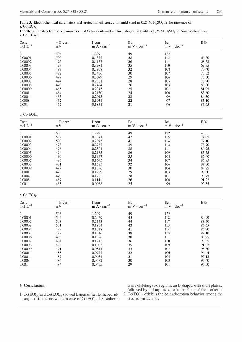
� "�������
7( � ����!" �� � ����$" �� �� ,�������� ,-������ ��-� ���� �� ������ ���� � ���� � � ����#" ��� �� �����
�� ����%���� � ���� �� � ,-������ ��� �� �� �������� �� �� %� � ����� ������� � ��� �� �� � ��� �� �����(
!( � ����$" ����%��� ��� %��� ��� ���� %���&� � �� � ���������� ����������(
����� �� ������ �������� ���������� �� �� ����� ��������� � � ���� ����� � "(!' ) *!+�# � ��� ������� �K�( � ����!"������� �� ���2�� ��������� �������� �� +����. ��2���2��� ��1� ��������� +���� � "�!' ) *!+�# � 0 ������� & K�( � ����!"
� �(� � ,�7
�� � ���5
� � ��� 0 � ���!
3�� 5 � ����7
3�� 5 � ����7
�?
" '"A 7(!<< #< 7!! :"(""""7 '"" "(#9!! 9$ 779 AA('""(""""! #<' "(#7;; 9A 777 A$(9!"(""""9 #<9 "(9<$7 9' 77" A<(9'"(""""# #$; "(9<"$ 9! 7"$ ;"(#""(""""' #$! "(9#AA 9" 7"; ;9(9!"(""""A #;; "(9";< !< 7"A ;A(9""(""""; #;# "(!;"7 !$ 7"' ;$(<""(""""$ #;" "(!#<# !A 7"9 $"($""(""""< #A' "(!9#' !' 7"7 $7(<'"("""7 #A# "(!79" !# 7"" $9(A""("""# #A9 "(!"79 !9 << $#('""("""$ #A! "(7<9# !! <; $'(7""(""7 #A! "(7$'7 !7 <A $'(;'
%( � ����#"
� �(� � ,�7
�� � ���5
� � ��� 0 � ���!
3�� 5 � ����7
3�� 5 � ����7
�?
" '"A 7(!<< #< 7!! :"(""""7 '"! "(99;7 #! 77' ;#("'"(""""! '"" "(!<;' #7 77# ;;(7""(""""9 #<$ "(!;A; 9< 77! ;$(;""(""""# #<A "(!'"7 9$ 777 $"(;'"(""""' #<# "(!7A9 9A 7"< $9(9'"(""""A #<" "(7$<; 9' 7"$ $'(#""(""""; #$9 "(7A<' 9# 7"; $A(<'"(""""$ #$7 "(7'$' 9! 7"A $;($""(""""< #;; "(79<A 9" 7"# $<(!'"("""7 #;9 "(7!<< !< 7"9 <"("""("""# #;" "(7!"! !$ 7"7 <"(;'"("""$ #A; "(77#7 !A 7"" <7(!!"(""7 #A' "("<A$ !' << <!(''
�( � ����$"
� �(� � ,�7
�� � ���5
� � ��� 0 � ���!
3�� 5 � ����7
3�� 5 � ����7
�?
" '"A 7(!<< #< 7!! :"(""""7 '"# "(!#A< #' 77$ $"(<<"(""""! '"9 "(!7#9 ## 77; $9('""(""""9 '"7 "(7$A# #! 77' $'(A'"(""""# #<< "(7;!$ #7 77# $A(;""(""""' #<$ "(7'#A 9< 779 $$(7""(""""A #<A "(79<A 9$ 777 $<(!'"(""""; #<# "(7!7' 9A 77" <"(A'"(""""$ #<9 "(7"A9 9' 7"< <7($!"(""""< #<7 "("$## 99 7"; <9('""("""7 #$$ "(";!! 9! 7"A <#(##"("""# #$; "("A9# 97 7"# <'(7!"("""$ #$A "("';! 9" 7"9 <'(A""(""7 #$# "("#'' !< 7"7 <A('"
)�������� �� � �� �� ��� $!;:$9! �!""!� � �������� � �� ���������� $97
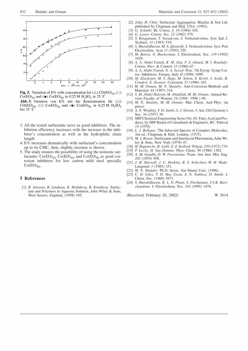
9( 0�� ��� ������ ���������� ���&� �� � � ���%�� ��( ��� �-��%��� ��������� �������� ��� ��� ������� � ��� ���-%�� �H� � ������� �� ��� �� ��� ���� ������ ���������(
#( �? �������� ������������ ��� ���������H� � ������� �� � ��� �)�� ���� �������� ������� �� �� (
'( ��� ����� ������ ��� � ���%����� � ���� ��� � �� ���-�������K � ����!"� � ����#"� �� � ����$" �� � � � �-� �� ���%�� �� � � � ���% ���� ����� ���������� ����$"(
# !��������
678 �� �������� �� ���� �� �� ��� ���� �� ��������� +�����-��� �� ������ � 0>�� �� + ���� � L � B���� E + ��B��� +������ ������ �7<<$� 7"'(
6!8 ���� �� ������ +�������� 0�������� � 3���2�� E + ,�����%������ %� ������ �� *���� M+0� �7<<!�(
698 � �!� ���� 3�( � �� �( L( "# �7<$#� 7A'(6#8 � ��$��� � �� �( +��( %% �7<$!� ';<(6'8 �� &���� ��� '� (��)��*�� �� (��+���+������� ����( ��( L(
���� �( �" �7<<9� '7<(6A8 �� �)���������� �� ,� -)������ �� (��+���+������� ����( ��
������ ����( 0��� "" �7<<9� !''(6;8 �� ������ �� ��!+�� ��� L( ������ ����( + �( "�# �7<<!�
9#!<(6$8 ,� ,� ,���� .����� �� �� ,��� .� �� ,� �� �� /� &�)����
� �� �( ��&( E � �� � �� �7<$A� A;(6<8 ,� ,� ,���� .����� �� ,� ����� � �( ;�� ��� �( +��� � �-
� �( ���%�� ��� @������� ����� // �7<<"� 7"<<(67"8 �� 0��!��)�� �� �� ��11� �� ���� �� ������ �� ,���� &�
��)���� 0� 0������� � �� �� �% �7<<A� 7"9(6778 �� �� �� �� �� �� ������� 0��-� �� �� -)��� �� ��
)�������� 22 �7<<;� 97$(67!8 �� �� ,���� ����� �� ,������� �� �� �� ��� 0��� ��-
&�� @������ � B �� "# �7<<#:7<<A � <"(6798 �� �� ������ �� �� �� ��� )��( ����( 0� ���( ��
������(67#8 ,� �� 3������ .� 4� � ��� ,� �� �������� L( 0�( ��� ��������H�
+ �( �2 �7<';� 9<(67'8 +3 �������� �������� +����� � ( A'( @���� 0��� �� � -
������ %� +3 3 ��� � � ������� E �������� ��( ���&��"2 �7<;"�(
67A8 �� �� ����� � ��� ����-��� +������ � � ����� ) ��������9�� ��(� ������ E *���� , � � �7<;'�(
67;8 �� �� &����� +��������� �� ���������� �� ���� L �B�-��� E + �� �� C �2 �7<;$� #;(
67$8 �� &)55��!�� �� ����� 6� 6� �������� ���( %�7 �7<;!� ;7<(67<8 8� ��*��9 �� (�� 4� �� ���( ����( #7 �7<$A� 79"!(6!"8 ,� �� �)��� 4� 3� .)�������)� ����( 0�( ���( )�( ��(
%7% �7<''� <'$(6!78 �� �� ���$��� �� �� ���+��� &� �� �!��!���� 3� �� 3����
,������ " �7<$'� !'7(6!!8 �� �� ������� �(/( ������� 0� +���� M�&( �7<<A�(6!98 �� �� ���� '� �� ��! 0$�� �� �� ��+�$� 4� � ���� L(
����( + �( �7<A"� 9<;9(6!#8 �� �)���������� �� �� �� 8���� �� 8��!�) ��� ��(��� &�*�:
!�������� L( ������ ����( + �( "2% �7<<'� 7#;$(
������&��K @�%����� !"� !""!� B 9A7#
��� #� 5������ � �? ��� � ������� � � ��� ������!"� ���� ����#" �� ��� � ����$" � "(!' ) *!+�# �� !' ������ #� 5������ & �? ��� ��� 4 .������ ��1� ���������!"� ��� � ����#" �� ��� � ����$" � "�!' ) *!+�#%�� !' ��
$9! +����%� �� ���� )�������� �� � �� �� ��� $!;:$9! �!""!�

1
APPENDIX L:
SISCO PILOT TRIAL GROUNDWATER
HYDRAULIC MODELLING REPORT

Barangaroo Pilot Trial Lend Lease (Millers Point) Pty Ltd 20 April 2011
Commercial-in-Confidence
Hydraulic Modelling Report S-ISCO® Pilot Trial
AECOM Barangaroo Pilot Trial Hydraulic Modelling Report S-ISCO® Pilot Trial - S-ISCO® Pilot Trial, Barangaroo, Millers Point
\\ausyd4fp001\Projects\60153531_Barangaroo\S4150050_SISCO Pilot Trials\4. Planning\Groundwater Injection Model\4. Reporting\60153531_RPT474_HydModelFinal_20APR11.docx Revision 2 - 20 April 2011 Commercial-in-Confidence
Hydraulic Modelling Report S-ISCO® Pilot Trial S-ISCO® Pilot Trial, Barangaroo, Millers Point
Prepared for
Lend Lease (Millers Point) Pty Ltd
Prepared by AECOM Australia Pty Ltd Level 5, 828 Pacific Highway, Gordon NSW 2072, PO Box 726, Pymble NSW 2073, Australia T +61 2 8484 8999 F +61 2 8484 8989 www.aecom.com ABN 20 093 846 925
20 April 2011
60153531_RPT474
AECOM in Australia and New Zealand is certified to the latest version of ISO9001 and ISO14001.
© AECOM Australia Pty Ltd (AECOM). All rights reserved.
AECOM has prepared this document for the sole use of the Client and for a specific purpose, each as expressly stated in the document. No other party should rely on this document without the prior written consent of AECOM. AECOM undertakes no duty, nor accepts any responsibility, to any third party who may rely upon or use this document. This document has been prepared based on the Client’s description of its requirements and AECOM’s experience, having regard to assumptions that AECOM can reasonably be expected to make in accordance with sound professional principles. AECOM may also have relied upon information provided by the Client and other third parties to prepare this document, some of which may not have been verified. Subject to the above conditions, this document may be transmitted, reproduced or disseminated only in its entirety.

AECOM Barangaroo Pilot Trial Hydraulic Modelling Report S-ISCO® Pilot Trial - S-ISCO® Pilot Trial, Barangaroo, Millers Point
\\ausyd4fp001\Projects\60153531_Barangaroo\S4150050_SISCO Pilot Trials\4. Planning\Groundwater Injection Model\4. Reporting\60153531_RPT474_HydModelFinal_20APR11.docx Revision 2 - 20 April 2011 Commercial-in-Confidence
Table of Contents 1.0 Introduction 1
1.1 Pilot Trial Overview 1 1.2 Objectives 2 1.3 Scope of Work 2
2.0 Methodology 3 2.1 Software 3 2.2 Assumptions 3
2.2.1 Injection Rate Assumptions 3 2.2.2 Injection Duration Assumptions 3 2.2.3 Solute Concentrations Assumptions 3 2.2.4 SWC Infrastructure 4 2.2.5 Injection Model Assumptions 5
2.3 Limitations 6 3.0 Results 8
3.1 Water Level - 12 Hour Injection 8 3.2 Water Transport - Particle Tracking 8 3.3 Dissolved Concentrations 9
4.0 Conclusions 10 5.0 References 11 Appendix A
S-ISCO Pilot Trial Set Up A Appendix B
Model Figures B Appendix C
SWC SP1129 Plan 3 C Appendix D
Chemical Compatibility Information D
List of Tables
Table 1 Injection Model Assumptions 5
List of Figures (Appendix B)
Figure 1 Model Area b-1 Figure 2 Water Levels – 12 Hours Injection b-2 Figure 3 Cross-Section A-A’ – North to South b-3 Figure 4 Cross-Section B-B’ – West to East b-4 Figure 5 Particle Tracking b-5 Figure 6 Dissolved Groundwater Concentrations- Phase 1 Injection b-6 Figure 7 Dissolved Groundwater Concentrations- Phase 2 Injection b-7
AECOM Barangaroo Pilot Trial Hydraulic Modelling Report S-ISCO® Pilot Trial - S-ISCO® Pilot Trial, Barangaroo, Millers Point
\\ausyd4fp001\Projects\60153531_Barangaroo\S4150050_SISCO Pilot Trials\4. Planning\Groundwater Injection Model\4. Reporting\60153531_RPT474_HydModelFinal_20APR11.docx Revision 2 - 20 April 2011 Commercial-in-Confidence
1
1.0 Introduction AECOM Australia Pty Ltd (AECOM) was engaged by Lend Lease (Millers Point) Pty Ltd (Lend Lease) to provide a hydraulic model based on data provided by VeruTEK Technologies (VeruTEK) that would aid in responding to comments from Sydney Water Corporation (SWC) regarding potential impacts to SWC assets (in particular Sydney Water’s sewage pumping station [SP1129] and its associated infrastructure) during the proposed Surfactant-Enhanced In Situ Chemical Oxidation (S-ISCO®) Pilot Trial Works (MP10_0087).
The hydraulic model simulates the effect of the proposed S-ISCO® Pilot Trial injection in wells located to the north of SWC Sewage Pumping Station No. 1129 (SP1129), where modelling was considered an appropriate method to assess possible effects of injection on nearby Sydney Water assets. The proposed Pilot Trial location is shown in Appendix A and the model area (the Site) is shown in Appendix B - Figure F1.
1.1 Pilot Trial Overview The S-ISCO® Pilot Trials are proposed as part of the investigation works required in relation to the NSW DECCW Remediation Site Declaration 21122 for land at Millers Point (which includes part of Hickson Road and part of the Barangaroo site). AECOM will be undertaking the proposed Pilot Trial on behalf of Lend Lease. AECOM will utilise the services of VeruTEK, a specialist contractor, to implement the Pilot Trial.
The S-ISCO® Pilot Trials will be undertaken in two areas within the Declaration area. One Pilot Trial area is within the proposed Barangaroo development Block 5, to the north of SP1129. A second Pilot Trial area is within a former tar tank located within Hickson Road. In the second area, Surfactant-Enhanced Product Recovery (SEPR™) will also be undertaken within the former tar tank located within Hickson Road.
The results of the Pilot Trials will be used to refine the design of the full-scale S-ISCO® remediation technologies, if they are proven to be effective and if they are approved by DECCW as the appropriate remedial technologies for the Declaration Area (JBA 2011).
A total of seven injection wells (IW01 to IW07) are to be installed as part of the Pilot Trials. It is noted that three of these wells (IW05 to IW07) will be installed inside the former tar tank located under Hickson Road. These injection wells are contained solely within a former underground tar tank thereby limiting hydraulic influence outside the perimeter of this structure and are outside the immediate vicinity of SP1129 and associated assets and have therefore not been considered as part of the modelling conducted. Four wells (IW01 to IW04) will be installed to the north of SP1129, within the proposed Block 5. The Block 5 Pilot Trial will be undertaken in two key stages:
- Phase 1 primary phase injections of S-ISCO®, using hydrogen peroxide (H2O2) activated by Fe-TAML, and enhanced by the use of a co-solvent/surfactant mixture (VeruSOL™).
- Phase 2 secondary phase injections of sodium persulfate, sodium hydroxide (for pH adjustment) and VeruSOL™.
Further details of the Pilot Trial are presented in documents submitted as part of the SISCO and SEPR Pilot Trials Project Application Environmental Assessment Report (EAR) (MP10_0087) and the response to Public Submissions (JBA, 2011a).
The Pilot Trial works will be undertaken in accordance with a Pilot Trial revised Work Plan and Trial Management Plan (WPTMP) which is currently being prepared by VeruTEK based on a Work Plan (September, 2010) approved as part of Project Approval MP 10 0087. The WPTMP will document the procedures and environmental management for the Pilot Trial, including a site specific monitoring program and plans and procedures to protect the health and safety of both personnel working on the Pilot Trial sites as well as the community and environment in which the work will take place.
During the Pilot Trial works, groundwater monitoring will be conducted. The monitoring program will include monitoring of groundwater and soil vapour wells in the vicinity of the injection wells, including concentrations of the injection chemicals and groundwater temperature changes. Thus injection may be adjusted to regulate concentrations and groundwater temperatures if required.

AECOM Barangaroo Pilot Trial Hydraulic Modelling Report S-ISCO® Pilot Trial - S-ISCO® Pilot Trial, Barangaroo, Millers Point
\\ausyd4fp001\Projects\60153531_Barangaroo\S4150050_SISCO Pilot Trials\4. Planning\Groundwater Injection Model\4. Reporting\60153531_RPT474_HydModelFinal_20APR11.docx Revision 2 - 20 April 2011 Commercial-in-Confidence
2
1.2 Objectives The objective of the hydraulic model was to develop a screening model to evaluate possible fluid fronts from proposed injection points under assumed injection volumes to assess possible interfacing of injection fluids with SWC underground assets located in the vicinity of the Pilot Trial area.
1.3 Scope of Work In order to assess possible interfacing of injection fluids with SWC underground assets, an analytical element model was prepared using WinFlow v 3 to simulate fluid injection immediately to the north of SP1129 at wells IW01 to IW04 (Figure F1) and the potential:
- Water/S-ISCO® solution level rises;
- Water/S-ISCO® solution transport; and
- Dissolved S-ISCO® solution concentrations.
Further details of the methodology, input and assumptions are discussed in Section 2, below.
AECOM Barangaroo Pilot Trial Hydraulic Modelling Report S-ISCO® Pilot Trial - S-ISCO® Pilot Trial, Barangaroo, Millers Point
\\ausyd4fp001\Projects\60153531_Barangaroo\S4150050_SISCO Pilot Trials\4. Planning\Groundwater Injection Model\4. Reporting\60153531_RPT474_HydModelFinal_20APR11.docx Revision 2 - 20 April 2011 Commercial-in-Confidence
3
2.0 Methodology
2.1 Software The software package selected for the modelling effort was WinFlow v 3, an analytical modelling tool produced by Environmental Simulations Inc. WinFlow is capable of simulating two-dimensional steady-state and transient ground-water flow using the principle of superposition to evaluate the effects on groundwater head from analytical functions such as injection wells.
Particle tracking is a method that can be used to assess possible flow paths of groundwater over time by tracking movement of imaginary particles placed in a flow-field. WinFlow implements particle tracking numerically to compute travel and flow direction of solute particles.
Solute concentration transport calculations are performed in WinFlow via a numerical finite-element method, using the groundwater head computed by the analytical flow model. The transport model includes the effects of dispersion, linear sorption (retardation), and first-order decay processes. First order decay was modelled using a representative half-life for Phase 1 and Phase 2 treatment chemicals.
2.2 Assumptions It is noted that models are simplified representations of complex natural systems and chemical behaviour. A range of assumptions are therefore necessary to represent this complexity. Depending on factors including lithological and hydrogeological variability, variable pumping rates, complex chemical reactions and other processes, outcomes other than those presented herein are possible. It is noted, however, that conservative assumptions relating to location, rate and duration of injection have been used in the model.
The assumptions for this model are presented in Table 1 below and specific assumptions and input to the model are described in Section 2.2.1 to 2.2.3.
As previously stated, the modelling was conducted for the Block 5 Pilot Trial area only.
2.2.1 Injection Rate Assumptions
The maximum injection rate at any one time in the Block 5 Pilot Trial area is proposed to be 19 L/minute. It is noted that injection will likely be in up to 4 wells; however the total injection rate would remain below 19 L/minute. A maximum injection rate of 20 L/minute into one well closest to SP1129 (IW02) was modelled. This is considered conservative as IW02 is the closest well to the SP1129 infrastructure.
2.2.2 Injection Duration Assumptions
The total planned injection period for Phase 1 treatment is 6 weeks, and the total planned injection period for Phase 2 treatment is 2 weeks. Injection will occur for approximately 12 hours per day for 6 days per week during each Phase in accordance with the WPTMP. This has been simulated in the model as continuous injection (24 hrs per day) for 3 weeks in Phase 1 and for 1 week in Phase 2. A 24 hour per day injection period is considered conservative because any mounding that would occur during any given 12 hour injection period during the Pilot Trial would decay over the following 12 hour period when injection is not occurring.
2.2.3 Solute Concentrations Assumptions
VeruTEK provided the following solute concentrations for the injection fluid:
- Phase 1 chemicals comprising hydrogen peroxide, VeruSOL™ and Fe-TAML were modelled assuming an initial overall dissolved concentration of 165 g/L; and
- Phase 2 chemicals comprising sodium persulfate, VeruSOL™ and sodium hydroxide were modelled assuming an initial overall dissolved concentration of 125 g/L.
VeruSOL™ is a mixture of cosolvents, citrus-based compounds, and plant oil-based non-ionic compounds designed and manufactured by VeruTEK. These components of VeruSOL® are either Generally Recognised as Safe (GRAS) by the U.S. FDA or approved as indirect food additives and for dermal contact, such as cosmetics.
Fe-TAML is a stable, highly active “green” catalyst with the capacity to marshal hydrogen peroxide to destroy contamination. Developed by the Institute for Green Oxidation Chemistry at Carnegie Mellon University in Pittsburgh, PA, USA, FE-TAML is composed exclusively of biochemically common elements, including carbon,
AECOM Barangaroo Pilot Trial Hydraulic Modelling Report S-ISCO® Pilot Trial - S-ISCO® Pilot Trial, Barangaroo, Millers Point
\\ausyd4fp001\Projects\60153531_Barangaroo\S4150050_SISCO Pilot Trials\4. Planning\Groundwater Injection Model\4. Reporting\60153531_RPT474_HydModelFinal_20APR11.docx Revision 2 - 20 April 2011 Commercial-in-Confidence
4
hydrogen, oxygen, nitrogen and iron, and therefore avoids toxic functionality. Neither FE-TAML nor its degradation products present toxicity concerns. It is an efficient and selective peroxide activator; it is water soluble; and it is effective at minute quantities over a broad pH range. Concentrations of Fe-TAML in the Phase 1 injections will be 0.1 to 0.2 micro molar.
Sodium hydroxide will be used for pH adjustment during Phase 2 at concentrations of 5 g/L to 20 g/L
2.2.4 SWC Infrastructure
Information related to the design of SP1129 was provided in SWC Drawing SP1129 3A dated 10/5/2004 (Appendix C). Review of the drawing indicates that the pumping station is constructed of 500 to 600 mm thick concrete with a 0.3 mm thick PVC waterproof membrane on all surfaces from the surface to bedrock level (approximately -7.5m Australian Height Datum [AHD]).
Electrical cables and stormwater drainage piping associated with SP1129 are positioned at an elevation of approximately 2.3 m AHD or 200 mm below the surface, to the west of SP1129.
Based on SWC Plans (Case No. 118122WW, Sheets 1 to 4), other SWC assets are located to the east and south of SP1129 within the modelled area (shown in Figure 1) including:
- a 450 mm diameter polyethylene (PE) sewer pipeline (PRO 10008586) at an approximate invert elevation of -5.2 m AHD at the eastern face of SP1129;
- a 300 mm diameter cast iron cement lined (CICL) water pipeline (W.O. 60327) running along the western side of Hickson Road at an approximate elevation of 2.34 to 2.43 m AHD;
- a 225 mm diameter cast iron (CI) sewer pipeline (CN 14807WW) running along Hickson road further to the east with an approximate invert elevation of 0.36 m AHD; and
- a 375 mm diameter polyvinylchloride (PVC) rising main sewer pipeline (SWC WAE SK9 28/10/2004) joining the south east corner of SP1129 at an approximate elevation of 2.40 to 2.67 m AHD (invert at -2.09 m AHD).
In addition the following inactive or more remote SWC assets were identified:
- a proposed 450 mm diameter PE tunnelled sewer pipeline (C.N 119297WW) – proposed status therefore not considered during modelling– (comparable to 450 mm diameter PE sewer pipeline [PRO 10008586]);
- a temporary aboveground 150 mm diameter sewer rising main from Headland Park (C.N. 119797WW) - above ground therefore not considered during groundwater modelling;
- A 150 mm diameter sewer pipeline (C.N 24096) crossing Hickson Road south of the proposed Hickson Road Pilot Trial area – outside immediate vicinity of modelled Block 5 Pilot Trial area therefore not considered during modelling;
- A 225 mm diameter sewer pipeline (23/7/2004 14807WW), running across Hickson Road approximately in line with the proposed Hickson Road Pilot Trial area –outside immediate vicinity of modelled Block 5 Pilot Trial area therefore not considered during modelling; and
- A 1200 mm diameter stormwater pipeline and drainage easement, running across Hickson Road at the southern end of No. 36 Hickson Road- outside immediate vicinity of modelled Block 5 Pilot Trial area therefore not considered during modelling.
Information provided by VeruTEK related to chemical resistance (Appendix D) indicates that PVC, PE and cast iron are resistant to the Phase 1 and Phase 2 treatment compounds. While resistance of PVC to sodium persulfate (Phase 2 treatment) with PVC at 60°C is rated as “moderate”, AECOM notes that the expected temperature rise in groundwater is no more than 10°C to 20°C in the area surrounding the injection wells (current groundwater temperature is approximately 20°C), so the expected rise is well below 60°C. It is also noted that temperature monitoring will occur during injection and temperature increases would trigger management steps including increased monitoring for temperature and modification of injections that may include injection of cold water until a sufficient temperature decrease is achieved.
AECOM also notes that data provided from Perry’s Chemical Engineers’ Handbook, (7th ed., Table 28-2) indicate that compatibility of cast iron with peroxides is “good”. In relation to the Phase 2 treatment, alkaline activated sodium persulfate is indicated to be compatible with carbon steel (analogous to cast iron). This is shown in FMC Environmental Solutions Table 4, presented in Appendix D (The Results for High pH Activated Klozur Persulfate Solutions, 20 wt% and 40 g/L at Room Temperature after 1 Month Exposure Limits).
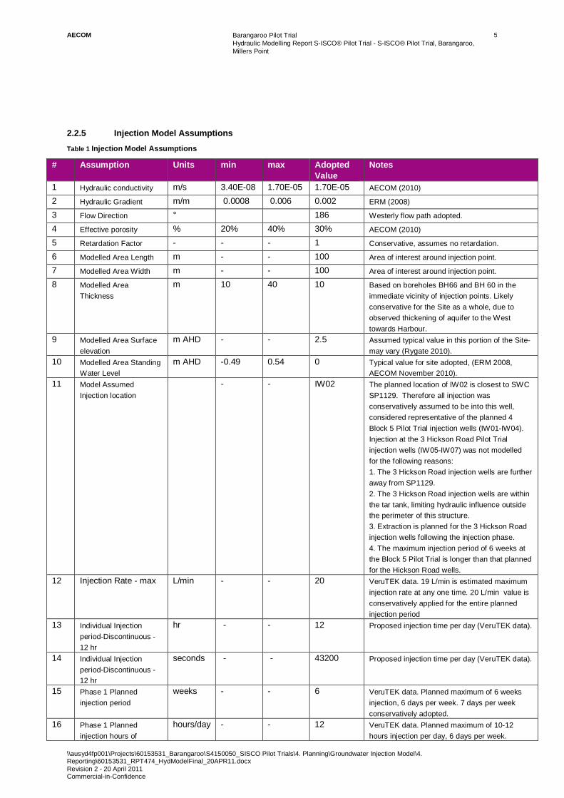
AECOM Barangaroo Pilot Trial Hydraulic Modelling Report S-ISCO® Pilot Trial - S-ISCO® Pilot Trial, Barangaroo, Millers Point
\\ausyd4fp001\Projects\60153531_Barangaroo\S4150050_SISCO Pilot Trials\4. Planning\Groundwater Injection Model\4. Reporting\60153531_RPT474_HydModelFinal_20APR11.docx Revision 2 - 20 April 2011 Commercial-in-Confidence
5
2.2.5 Injection Model Assumptions
Table 1 Injection Model Assumptions
# Assumption Units min max Adopted Value
Notes
1 Hydraulic conductivity m/s 3.40E-08 1.70E-05 1.70E-05 AECOM (2010)
2 Hydraulic Gradient m/m 0.0008 0.006 0.002 ERM (2008)
3 Flow Direction ° 186 Westerly flow path adopted.
4 Effective porosity % 20% 40% 30% AECOM (2010)
5 Retardation Factor - - - 1 Conservative, assumes no retardation.
6 Modelled Area Length m - - 100 Area of interest around injection point.
7 Modelled Area Width m - - 100 Area of interest around injection point.
8 Modelled Area Thickness
m 10 40 10 Based on boreholes BH66 and BH 60 in the immediate vicinity of injection points. Likely conservative for the Site as a whole, due to observed thickening of aquifer to the West towards Harbour.
9 Modelled Area Surface elevation
m AHD - - 2.5 Assumed typical value in this portion of the Site- may vary (Rygate 2010).
10 Modelled Area Standing Water Level
m AHD -0.49 0.54 0 Typical value for site adopted, (ERM 2008, AECOM November 2010).
11 Model Assumed Injection location
- - IW02 The planned location of IW02 is closest to SWC SP1129. Therefore all injection was conservatively assumed to be into this well, considered representative of the planned 4 Block 5 Pilot Trial injection wells (IW01-IW04). Injection at the 3 Hickson Road Pilot Trial injection wells (IW05-IW07) was not modelled for the following reasons: 1. The 3 Hickson Road injection wells are further away from SP1129. 2. The 3 Hickson Road injection wells are within the tar tank, limiting hydraulic influence outside the perimeter of this structure. 3. Extraction is planned for the 3 Hickson Road injection wells following the injection phase. 4. The maximum injection period of 6 weeks at the Block 5 Pilot Trial is longer than that planned for the Hickson Road wells.
12 Injection Rate - max L/min - - 20 VeruTEK data. 19 L/min is estimated maximum injection rate at any one time. 20 L/min value is conservatively applied for the entire planned injection period
13 Individual Injection period-Discontinuous -12 hr
hr - - 12 Proposed injection time per day (VeruTEK data).
14 Individual Injection period-Discontinuous -12 hr
seconds - - 43200 Proposed injection time per day (VeruTEK data).
15 Phase 1 Planned injection period
weeks - - 6 VeruTEK data. Planned maximum of 6 weeks injection, 6 days per week. 7 days per week conservatively adopted.
16 Phase 1 Planned injection hours of
hours/day - - 12 VeruTEK data. Planned maximum of 10-12 hours injection per day, 6 days per week.
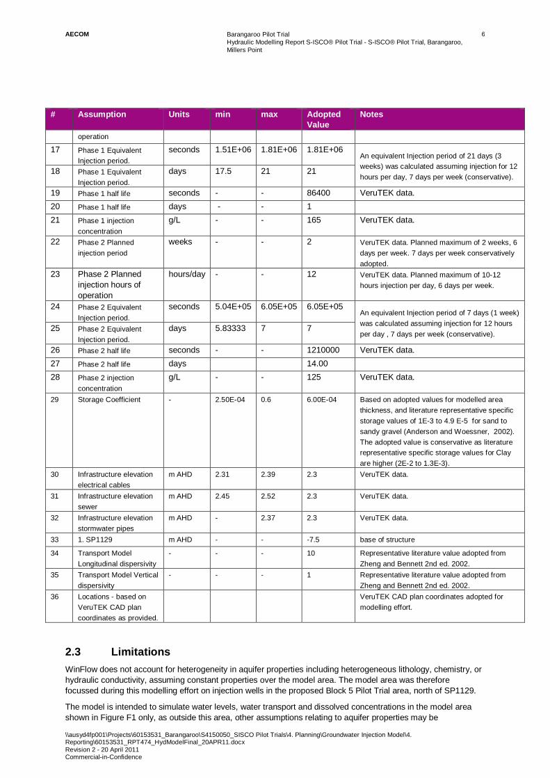
AECOM Barangaroo Pilot Trial Hydraulic Modelling Report S-ISCO® Pilot Trial - S-ISCO® Pilot Trial, Barangaroo, Millers Point
\\ausyd4fp001\Projects\60153531_Barangaroo\S4150050_SISCO Pilot Trials\4. Planning\Groundwater Injection Model\4. Reporting\60153531_RPT474_HydModelFinal_20APR11.docx Revision 2 - 20 April 2011 Commercial-in-Confidence
6
# Assumption Units min max Adopted Value
Notes
operation
17 Phase 1 Equivalent Injection period.
seconds 1.51E+06 1.81E+06 1.81E+06 An equivalent Injection period of 21 days (3 weeks) was calculated assuming injection for 12 hours per day, 7 days per week (conservative).
18 Phase 1 Equivalent Injection period.
days 17.5 21 21
19 Phase 1 half life seconds - - 86400 VeruTEK data. 20 Phase 1 half life days - - 1 21 Phase 1 injection
concentration g/L - - 165 VeruTEK data.
22 Phase 2 Planned injection period
weeks - - 2 VeruTEK data. Planned maximum of 2 weeks, 6 days per week. 7 days per week conservatively adopted.
23 Phase 2 Planned injection hours of operation
hours/day - - 12 VeruTEK data. Planned maximum of 10-12 hours injection per day, 6 days per week.
24 Phase 2 Equivalent Injection period.
seconds 5.04E+05 6.05E+05 6.05E+05 An equivalent Injection period of 7 days (1 week) was calculated assuming injection for 12 hours per day , 7 days per week (conservative).
25 Phase 2 Equivalent Injection period.
days 5.83333 7 7
26 Phase 2 half life seconds - - 1210000 VeruTEK data. 27 Phase 2 half life days 14.00 28 Phase 2 injection
concentration g/L - - 125 VeruTEK data.
29 Storage Coefficient - 2.50E-04 0.6 6.00E-04 Based on adopted values for modelled area thickness, and literature representative specific storage values of 1E-3 to 4.9 E-5 for sand to sandy gravel (Anderson and Woessner, 2002). The adopted value is conservative as literature representative specific storage values for Clay are higher (2E-2 to 1.3E-3).
30 Infrastructure elevation electrical cables
m AHD 2.31 2.39 2.3 VeruTEK data.
31 Infrastructure elevation sewer
m AHD 2.45 2.52 2.3 VeruTEK data.
32 Infrastructure elevation stormwater pipes
m AHD - 2.37 2.3 VeruTEK data.
33 1. SP1129 m AHD - - -7.5 base of structure
34 Transport Model Longitudinal dispersivity
- - - 10 Representative literature value adopted from Zheng and Bennett 2nd ed. 2002.
35 Transport Model Vertical dispersivity
- - - 1 Representative literature value adopted from Zheng and Bennett 2nd ed. 2002.
36 Locations - based on VeruTEK CAD plan coordinates as provided.
VeruTEK CAD plan coordinates adopted for modelling effort.
2.3 Limitations WinFlow does not account for heterogeneity in aquifer properties including heterogeneous lithology, chemistry, or hydraulic conductivity, assuming constant properties over the model area. The model area was therefore focussed during this modelling effort on injection wells in the proposed Block 5 Pilot Trial area, north of SP1129.
The model is intended to simulate water levels, water transport and dissolved concentrations in the model area shown in Figure F1 only, as outside this area, other assumptions relating to aquifer properties may be

AECOM Barangaroo Pilot Trial Hydraulic Modelling Report S-ISCO® Pilot Trial - S-ISCO® Pilot Trial, Barangaroo, Millers Point
\\ausyd4fp001\Projects\60153531_Barangaroo\S4150050_SISCO Pilot Trials\4. Planning\Groundwater Injection Model\4. Reporting\60153531_RPT474_HydModelFinal_20APR11.docx Revision 2 - 20 April 2011 Commercial-in-Confidence
7
appropriate. The model does not assess intermediate chemical breakdown products or intermediate reactions with in-situ materials. The model considers the assets and conditions summarised in the table above, and, in the form presented herein, the model is not intended to assess other scenarios or assets.

AECOM Barangaroo Pilot Trial Hydraulic Modelling Report S-ISCO® Pilot Trial - S-ISCO® Pilot Trial, Barangaroo, Millers Point
\\ausyd4fp001\Projects\60153531_Barangaroo\S4150050_SISCO Pilot Trials\4. Planning\Groundwater Injection Model\4. Reporting\60153531_RPT474_HydModelFinal_20APR11.docx Revision 2 - 20 April 2011 Commercial-in-Confidence
8
3.0 Results
3.1 Water Level - 12 Hour Injection The results of the water level modelling indicate:
- Assuming 20 L/min injection at IW02, the model predicts a local water level rise of approximately 0.9 metres from an initial elevation of 0 m AHD to 0.9 m AHD, at the northern face of Sewer Pumping Station SP1129 (SP1129) at a distance of 12 metres from the injection point. The predicted rise is considered conservative as pumping will occur for 12 hours continuously, water levels allowed to recover for 12 hours between injection events. Figure F2 shows the extent of predicted water level rises conservatively assuming 12 hours maximum continuous ongoing injection.
- Figure F3 shows the predicted extent of water level rise in cross-section running from North to South (purple line). For comparison, a continuous infinite ‘steady state injection scenario’ is also shown (red line). The steady state model is considered overly conservative as injection will not be continuous.
- Figure F4 shows the predicted extent of water level rise in cross- section running from West to East (purple line). For comparison, the continuous infinite ‘steady state injection scenario’ is also shown (red line).
- Based on the SWC drawing the SP1129 sub-surface structure extends from ground level at approximately 2.5 m AHD to -7.5 m AHD. The PVC waterproofing membrane extends from ground surface to the bedrock level so the predicted water level increase is therefore not expected to overtop this waterproofing membrane.
- The model predicts a local water rise of up to approximately 0.9 metres above the PE tunnelled sewer and the PVC rising main inverts, which are currently already below the typical groundwater table in this area.
- The predicted water level rise is approximately 0.5 metres above the eastern cast iron sewer pipe invert. This water level rise is transitory.
- The model predicts a local water rise of approximately 1 metre to an elevation of 1.0 m AHD near the SWC electrical cables and stormwater piping running south towards SP1129, thus the predicted water level rise would not contact these assets.
- The model predicts a local water rise of up to approximately 0.9 metres near the CICL water pipeline running along Hickson Road to an elevation of approximately 0.9 m AHD. The CICL water pipeline is positioned at an approximate elevation of 2.34 to 2.43 m AHD, thus the predicted local water rise would not contact this pipeline.
3.2 Water Transport - Particle Tracking The results of the particle tracking modelling indicate:
- Particles were placed in the injection flow field to simulate potential travel flow-paths in groundwater from the injection point. For particle tracking modelling, continuous 24 hour injection was assumed over a 3 week equivalent injection period. The particle tracking model results indicate that particles positioned at injection point IW02 would not reach SP1129 during the injection period (Figure F5). These particles are predicted to first arrive at SP1129 after approximately 4.5 weeks of continuous pumping, which will not be the case during the Pilot Trial.
- Particles do not arrive at the PE tunnelled sewer invert, the PVC rising main invert or the eastern cast iron sewer pipeline running along Hickson Road in the timeframe modelled.
- Particle tracking assessment is not relevant for the CICL water pipeline running along Hickson Road or electrical cables and stormwater piping running south towards SP1129, because the modelled water level rise is not predicted to contact these assets during the Pilot Trial.
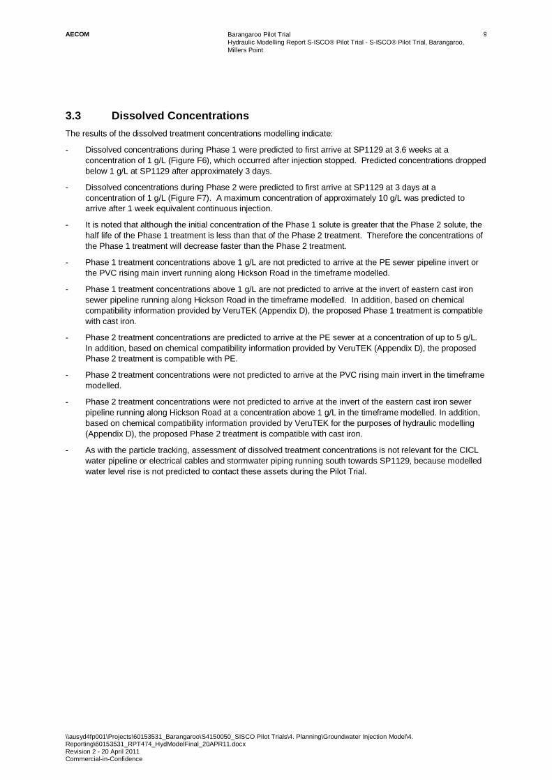
AECOM Barangaroo Pilot Trial Hydraulic Modelling Report S-ISCO® Pilot Trial - S-ISCO® Pilot Trial, Barangaroo, Millers Point
\\ausyd4fp001\Projects\60153531_Barangaroo\S4150050_SISCO Pilot Trials\4. Planning\Groundwater Injection Model\4. Reporting\60153531_RPT474_HydModelFinal_20APR11.docx Revision 2 - 20 April 2011 Commercial-in-Confidence
9
3.3 Dissolved Concentrations The results of the dissolved treatment concentrations modelling indicate:
- Dissolved concentrations during Phase 1 were predicted to first arrive at SP1129 at 3.6 weeks at a concentration of 1 g/L (Figure F6), which occurred after injection stopped. Predicted concentrations dropped below 1 g/L at SP1129 after approximately 3 days.
- Dissolved concentrations during Phase 2 were predicted to first arrive at SP1129 at 3 days at a concentration of 1 g/L (Figure F7). A maximum concentration of approximately 10 g/L was predicted to arrive after 1 week equivalent continuous injection.
- It is noted that although the initial concentration of the Phase 1 solute is greater that the Phase 2 solute, the half life of the Phase 1 treatment is less than that of the Phase 2 treatment. Therefore the concentrations of the Phase 1 treatment will decrease faster than the Phase 2 treatment.
- Phase 1 treatment concentrations above 1 g/L are not predicted to arrive at the PE sewer pipeline invert or the PVC rising main invert running along Hickson Road in the timeframe modelled.
- Phase 1 treatment concentrations above 1 g/L are not predicted to arrive at the invert of eastern cast iron sewer pipeline running along Hickson Road in the timeframe modelled. In addition, based on chemical compatibility information provided by VeruTEK (Appendix D), the proposed Phase 1 treatment is compatible with cast iron.
- Phase 2 treatment concentrations are predicted to arrive at the PE sewer at a concentration of up to 5 g/L. In addition, based on chemical compatibility information provided by VeruTEK (Appendix D), the proposed Phase 2 treatment is compatible with PE.
- Phase 2 treatment concentrations were not predicted to arrive at the PVC rising main invert in the timeframe modelled.
- Phase 2 treatment concentrations were not predicted to arrive at the invert of the eastern cast iron sewer pipeline running along Hickson Road at a concentration above 1 g/L in the timeframe modelled. In addition, based on chemical compatibility information provided by VeruTEK for the purposes of hydraulic modelling (Appendix D), the proposed Phase 2 treatment is compatible with cast iron.
- As with the particle tracking, assessment of dissolved treatment concentrations is not relevant for the CICL water pipeline or electrical cables and stormwater piping running south towards SP1129, because modelled water level rise is not predicted to contact these assets during the Pilot Trial.
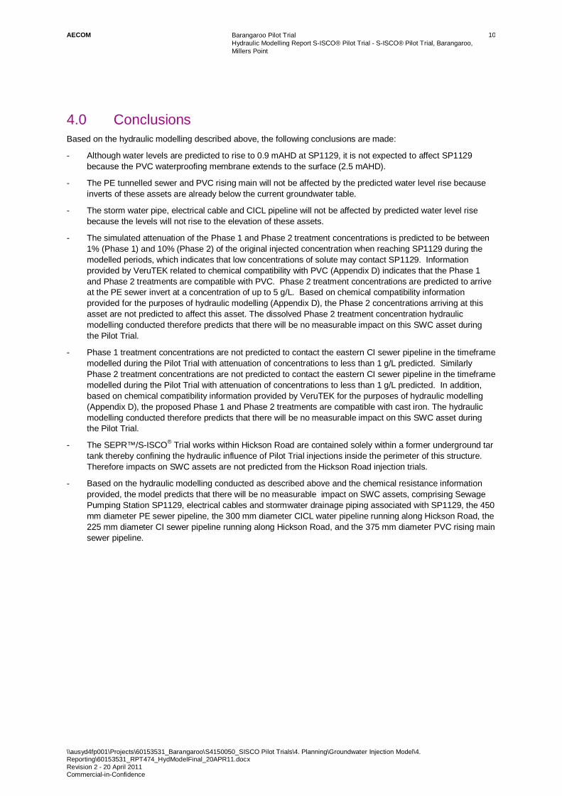
AECOM Barangaroo Pilot Trial Hydraulic Modelling Report S-ISCO® Pilot Trial - S-ISCO® Pilot Trial, Barangaroo, Millers Point
\\ausyd4fp001\Projects\60153531_Barangaroo\S4150050_SISCO Pilot Trials\4. Planning\Groundwater Injection Model\4. Reporting\60153531_RPT474_HydModelFinal_20APR11.docx Revision 2 - 20 April 2011 Commercial-in-Confidence
10
4.0 Conclusions Based on the hydraulic modelling described above, the following conclusions are made:
- Although water levels are predicted to rise to 0.9 mAHD at SP1129, it is not expected to affect SP1129 because the PVC waterproofing membrane extends to the surface (2.5 mAHD).
- The PE tunnelled sewer and PVC rising main will not be affected by the predicted water level rise because inverts of these assets are already below the current groundwater table.
- The storm water pipe, electrical cable and CICL pipeline will not be affected by predicted water level rise because the levels will not rise to the elevation of these assets.
- The simulated attenuation of the Phase 1 and Phase 2 treatment concentrations is predicted to be between 1% (Phase 1) and 10% (Phase 2) of the original injected concentration when reaching SP1129 during the modelled periods, which indicates that low concentrations of solute may contact SP1129. Information provided by VeruTEK related to chemical compatibility with PVC (Appendix D) indicates that the Phase 1 and Phase 2 treatments are compatible with PVC. Phase 2 treatment concentrations are predicted to arrive at the PE sewer invert at a concentration of up to 5 g/L. Based on chemical compatibility information provided for the purposes of hydraulic modelling (Appendix D), the Phase 2 concentrations arriving at this asset are not predicted to affect this asset. The dissolved Phase 2 treatment concentration hydraulic modelling conducted therefore predicts that there will be no measurable impact on this SWC asset during the Pilot Trial.
- Phase 1 treatment concentrations are not predicted to contact the eastern CI sewer pipeline in the timeframe modelled during the Pilot Trial with attenuation of concentrations to less than 1 g/L predicted. Similarly Phase 2 treatment concentrations are not predicted to contact the eastern CI sewer pipeline in the timeframe modelled during the Pilot Trial with attenuation of concentrations to less than 1 g/L predicted. In addition, based on chemical compatibility information provided by VeruTEK for the purposes of hydraulic modelling (Appendix D), the proposed Phase 1 and Phase 2 treatments are compatible with cast iron. The hydraulic modelling conducted therefore predicts that there will be no measurable impact on this SWC asset during the Pilot Trial.
- The SEPR™/S-ISCO® Trial works within Hickson Road are contained solely within a former underground tar tank thereby confining the hydraulic influence of Pilot Trial injections inside the perimeter of this structure. Therefore impacts on SWC assets are not predicted from the Hickson Road injection trials.
- Based on the hydraulic modelling conducted as described above and the chemical resistance information provided, the model predicts that there will be no measurable impact on SWC assets, comprising Sewage Pumping Station SP1129, electrical cables and stormwater drainage piping associated with SP1129, the 450 mm diameter PE sewer pipeline, the 300 mm diameter CICL water pipeline running along Hickson Road, the 225 mm diameter CI sewer pipeline running along Hickson Road, and the 375 mm diameter PVC rising main sewer pipeline.

AECOM Barangaroo Pilot Trial Hydraulic Modelling Report S-ISCO® Pilot Trial - S-ISCO® Pilot Trial, Barangaroo, Millers Point
\\ausyd4fp001\Projects\60153531_Barangaroo\S4150050_SISCO Pilot Trials\4. Planning\Groundwater Injection Model\4. Reporting\60153531_RPT474_HydModelFinal_20APR11.docx Revision 2 - 20 April 2011 Commercial-in-Confidence
11
5.0 References AECOM Australia Pty Ltd. Data Gap Investigation - EPA Declaration Area (Parts of Barangaroo Site and Hickson Road), Millers Point, NSW. 23 September 2010. AECOM Reference: S4150010.
AECOM Australia Pty Ltd. Groundwater Discharge Study – Stage 1 Barangaroo Development. 3 November 2010. AECOM Reference: S41500_ITG_RPT01_r3_3Nov10.
Anderson, M. and Woessner, W. Applied Groundwater Modelling - Simulation of Flow and Advective Transport. 2002. Academic Press.
Environmental Resources Management Australia Pty Ltd (ERM). Additional Investigation, Works at Barangaroo, Hickson Road, Millers Point, NSW. July 2008. ERM Reference: 0080637R03Rev01.
JBA Planning Pty Ltd Preferred Project Report, Block 5, Barangaroo and Hickson Road Surfactant-Enhanced In Situ Chemical Oxidation (SISCO) and Surfactant-Enhanced Product Recovery (SEPR) Trial, Submitted to Department of Planning On Behalf of Lend Lease (Millers Point) Pty Ltd. January 2011. JBA Reference: 10051.
Perry, R. and Green, D. Perry’s Chemical Engineers’ Handbook. 7th Edition. 1997. McGraw Hill.
Rygate and Company Pty Ltd. Plan Showing Detail, Levels and Services, Lots 3 and 5, DP876514 and along Hickson Road. 18 October 2010. Rygate reference: 74479-1.
Sydney Water Corporation Sewer Pumping Station Diagrams for Station SP1129 (Drawings 1B, 2A, 3A and RM2).
Sydney Water Plans, City of Sydney Sewage Case No. 118122WW, X10220_MP_SWC_Asseets, Sheets 1 to 4
VeruTEK Technologies, Inc. Draft Document - Work Plan &Trial Management Plan, Surfactant Enhanced In Situ Chemical Oxidation (S-ISCO®) & Surfactant Enhanced Product Recovery (SEPR™), Block 5 and Hickson Road, Pilot Trial. March 2011.
Zheng, C. and Bennett, G. Applied Contaminant Transport Modelling. 2nd Ed, 2002.Wiley Interscience.

AECOM Barangaroo Pilot Trial Hydraulic Modelling Report S-ISCO® Pilot Trial - S-ISCO® Pilot Trial, Barangaroo, Millers Point
\\ausyd4fp001\Projects\60153531_Barangaroo\S4150050_SISCO Pilot Trials\4. Planning\Groundwater Injection Model\4. Reporting\60153531_RPT474_HydModelFinal_20APR11.docx Revision 2 - 20 April 2011 Commercial-in-Confidence
Appendix A
S-ISCO Pilot Trial Set Up

Draft

AECOM Barangaroo Pilot Trial Hydraulic Modelling Report S-ISCO® Pilot Trial - S-ISCO® Pilot Trial, Barangaroo, Millers Point
\\ausyd4fp001\Projects\60153531_Barangaroo\S4150050_SISCO Pilot Trials\4. Planning\Groundwater Injection Model\4. Reporting\60153531_RPT474_HydModelFinal_20APR11.docx Revision 2 - 20 April 2011 Commercial-in-Confidence
Appendix B
Model Figures
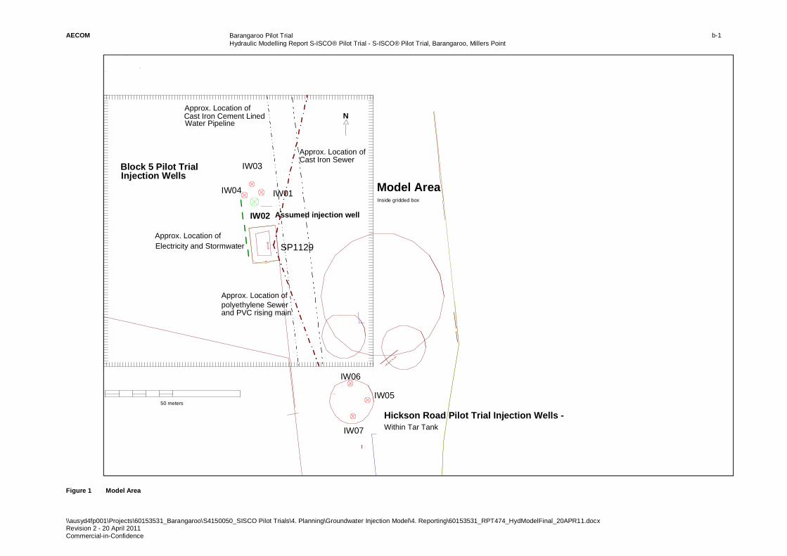
AECOM Barangaroo Pilot Trial Hydraulic Modelling Report S-ISCO® Pilot Trial - S-ISCO® Pilot Trial, Barangaroo, Millers Point
\\ausyd4fp001\Projects\60153531_Barangaroo\S4150050_SISCO Pilot Trials\4. Planning\Groundwater Injection Model\4. Reporting\60153531_RPT474_HydModelFinal_20APR11.docx Revision 2 - 20 April 2011 Commercial-in-Confidence
b-1
Figure 1 Model Area
SP1129
METAL SUPPORT
(3 3 39 0 9 53 0 .0 , 6 2 5 18 7 11 5 9. 9)
( 33 3 90 9 76 3 .7 , 62 5 18 7 13 1 4 .7 )
IW01
IW03
IW02
IW04
IW05
IW06
IW07
Assumed injection well
SP1129
Block 5 Pilot Trial
Model Area
Hickson Road Pilot Trial Injection Wells - Within Tar Tank
Approx. Location of Electricity and Stormwater
50 meters
N
Inside gridded box
Approx. Location of polyethylene Sewer
Approx. Location ofCast Iron Cement Lined
Approx. Location of Cast Iron Sewer
Water Pipeline
and PVC rising main
Injection Wells
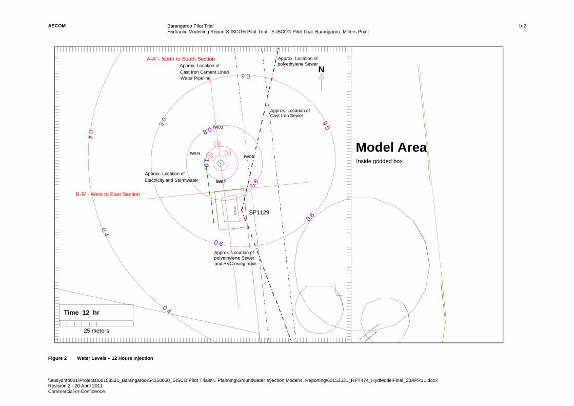
AECOM Barangaroo Pilot Trial Hydraulic Modelling Report S-ISCO® Pilot Trial - S-ISCO® Pilot Trial, Barangaroo, Millers Point
\\ausyd4fp001\Projects\60153531_Barangaroo\S4150050_SISCO Pilot Trials\4. Planning\Groundwater Injection Model\4. Reporting\60153531_RPT474_HydModelFinal_20APR11.docx Revision 2 - 20 April 2011 Commercial-in-Confidence
b-2
Figure 2 Water Levels – 12 Hours Injection
SP
1129
METAL SUPPORT
(3 3 39 0 95 3 0 .0 , 6 2 51 8 71 2 00 .0 )
(3 33 9 09 6 81 .0 , 6 25 1 87 1 30 0 .0 )
0.4
0.4
0.4
0.6
0.6
0.6
0.6
0.6
0.8
0.8
1.0
IW01
IW03
IW02
IW04
N
SP1129
Approx. Location of Electricity and Stormwater
B-B' - West to East Section
A-A' - North to South Section
25 meters
Time 12 hr
Approx. Location of polyethylene Sewer
Inside gridded box
Model Area
Approx. Location of Cast Iron Sewer
Approx. Location ofCast Iron Cement Lined Water Pipeline
Approx. Location of
and PVC rising mainpolyethylene Sewer
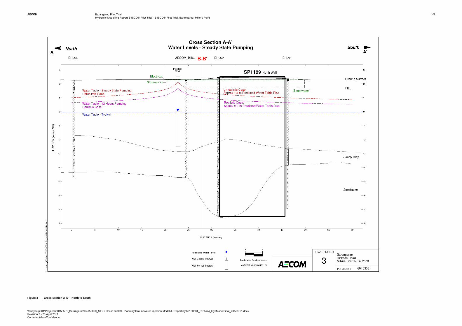
AECOM Barangaroo Pilot Trial Hydraulic Modelling Report S-ISCO® Pilot Trial - S-ISCO® Pilot Trial, Barangaroo, Millers Point
\\ausyd4fp001\Projects\60153531_Barangaroo\S4150050_SISCO Pilot Trials\4. Planning\Groundwater Injection Model\4. Reporting\60153531_RPT474_HydModelFinal_20APR11.docx Revision 2 - 20 April 2011 Commercial-in-Confidence
b-3
Figure 3 Cross-Section A-A’ – North to South
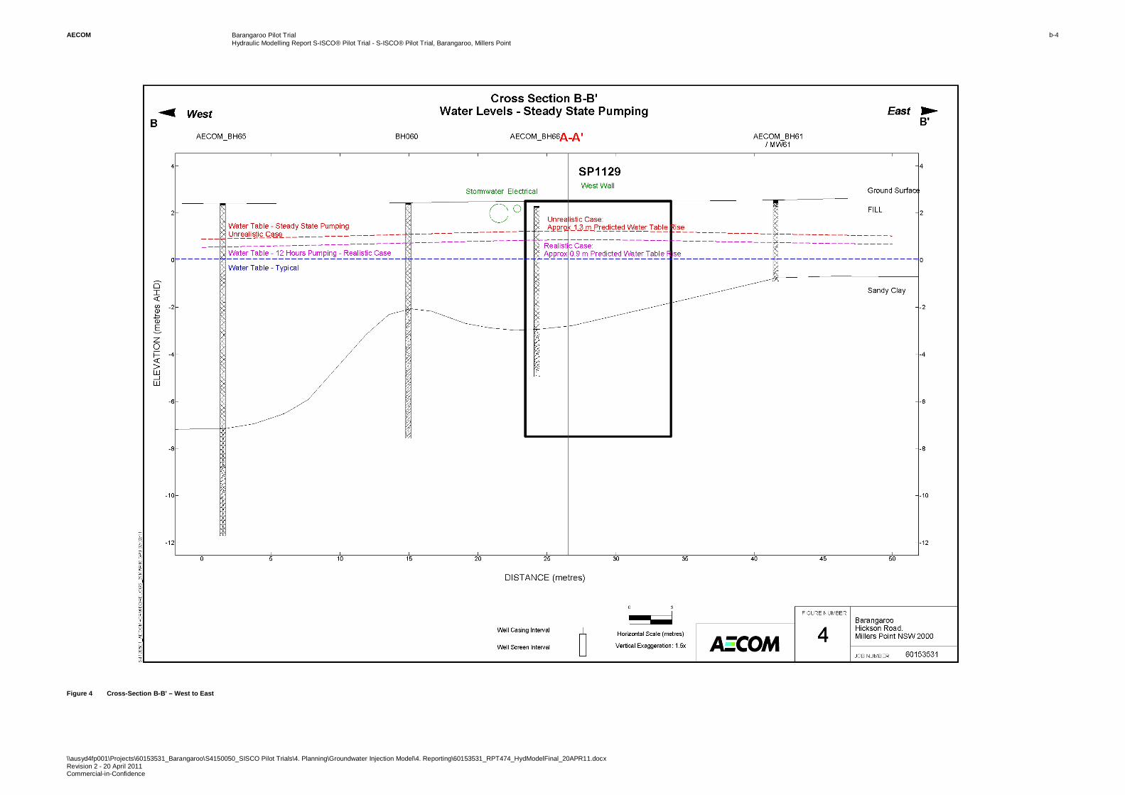
AECOM Barangaroo Pilot Trial Hydraulic Modelling Report S-ISCO® Pilot Trial - S-ISCO® Pilot Trial, Barangaroo, Millers Point
\\ausyd4fp001\Projects\60153531_Barangaroo\S4150050_SISCO Pilot Trials\4. Planning\Groundwater Injection Model\4. Reporting\60153531_RPT474_HydModelFinal_20APR11.docx Revision 2 - 20 April 2011 Commercial-in-Confidence
b-4
Figure 4 Cross-Section B-B’ – West to East
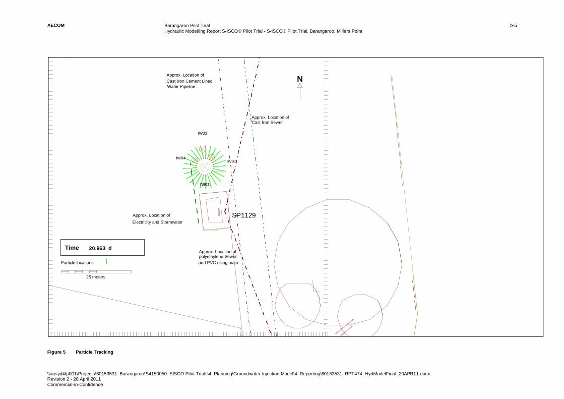
AECOM Barangaroo Pilot Trial Hydraulic Modelling Report S-ISCO® Pilot Trial - S-ISCO® Pilot Trial, Barangaroo, Millers Point
\\ausyd4fp001\Projects\60153531_Barangaroo\S4150050_SISCO Pilot Trials\4. Planning\Groundwater Injection Model\4. Reporting\60153531_RPT474_HydModelFinal_20APR11.docx Revision 2 - 20 April 2011 Commercial-in-Confidence
b-5
Figure 5 Particle Tracking
SP1129
METAL SUPPORT
(3 3 3 90 9 5 3 0. 0, 6 2 5 18 7 1 20 0 .0 )
( 3 33 9 0 97 0 6 .8 , 62 5 1 8 71 3 0 0. 0 )
IW01
IW03
IW02
IW04
25 meters
Time 20.963 d
Particle locations
Electricity and StormwaterSP1129Approx. Location of
N
Approx. Location of polyethylene Sewerand PVC rising main
Approx. Location of Cast Iron Sewer
Approx. Location ofCast Iron Cement Lined Water Pipeline
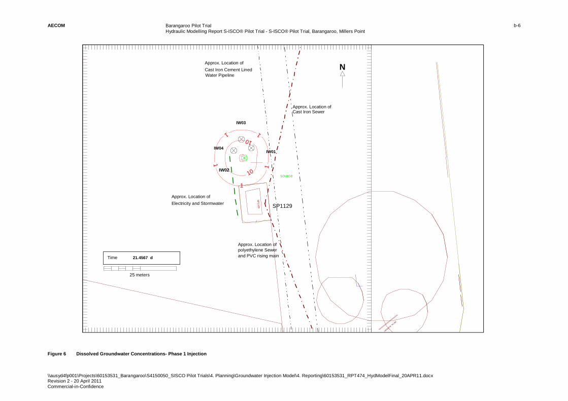
AECOM Barangaroo Pilot Trial Hydraulic Modelling Report S-ISCO® Pilot Trial - S-ISCO® Pilot Trial, Barangaroo, Millers Point
\\ausyd4fp001\Projects\60153531_Barangaroo\S4150050_SISCO Pilot Trials\4. Planning\Groundwater Injection Model\4. Reporting\60153531_RPT474_HydModelFinal_20APR11.docx Revision 2 - 20 April 2011 Commercial-in-Confidence
b-6
Figure 6 Dissolved Groundwater Concentrations- Phase 1 Injection
SP1129
METAL SUPPORT
(333909530. 0, 6251871200.0)
(333909720.8, 6251871300. 0)
1
1
1 1
1
10
10
IW01
IW03
source
IW04
25 meters
Time 21.4567 d
IW02
Approx. Location of Electricity and Stormwater SP1129
NApprox. Location ofCast Iron Cement Lined Water Pipeline
Approx. Location of
and PVC rising mainpolyethylene Sewer
Approx. Location of Cast Iron Sewer
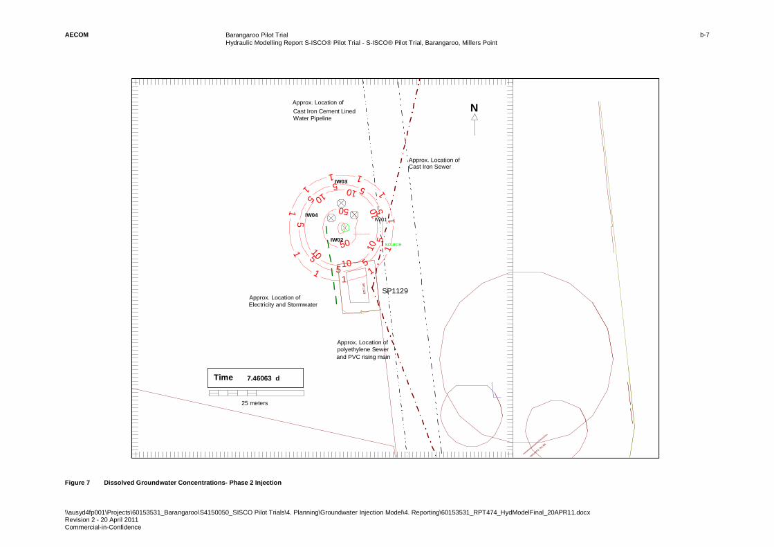
AECOM Barangaroo Pilot Trial Hydraulic Modelling Report S-ISCO® Pilot Trial - S-ISCO® Pilot Trial, Barangaroo, Millers Point
\\ausyd4fp001\Projects\60153531_Barangaroo\S4150050_SISCO Pilot Trials\4. Planning\Groundwater Injection Model\4. Reporting\60153531_RPT474_HydModelFinal_20APR11.docx Revision 2 - 20 April 2011 Commercial-in-Confidence
b-7
Figure 7 Dissolved Groundwater Concentrations- Phase 2 Injection
SP1129
METAL SUPPORT
(333909530.0 , 6251871200.0)
(333909718.2 , 6251871300.0)
1
1 1 1
1
1
1
1 1 1
1
5 5 5
5
5
5 5
5 5
10 10
10
10
10 10
50
50
IW01
IW03
source
IW04
25 meters
Time 7.46063 d
IW02
SP1129Approx. Location of Electricity and Stormwater
NApprox. Location ofCast Iron Cement Lined Water Pipeline
Approx. Location of polyethylene Sewerand PVC rising main
Approx. Location of Cast Iron Sewer

AECOM Barangaroo Pilot Trial Hydraulic Modelling Report S-ISCO® Pilot Trial - S-ISCO® Pilot Trial, Barangaroo, Millers Point
\\ausyd4fp001\Projects\60153531_Barangaroo\S4150050_SISCO Pilot Trials\4. Planning\Groundwater Injection Model\4. Reporting\60153531_RPT474_HydModelFinal_20APR11.docx Revision 2 - 20 April 2011 Commercial-in-Confidence
Appendix C
SWC SP1129 Plan 3
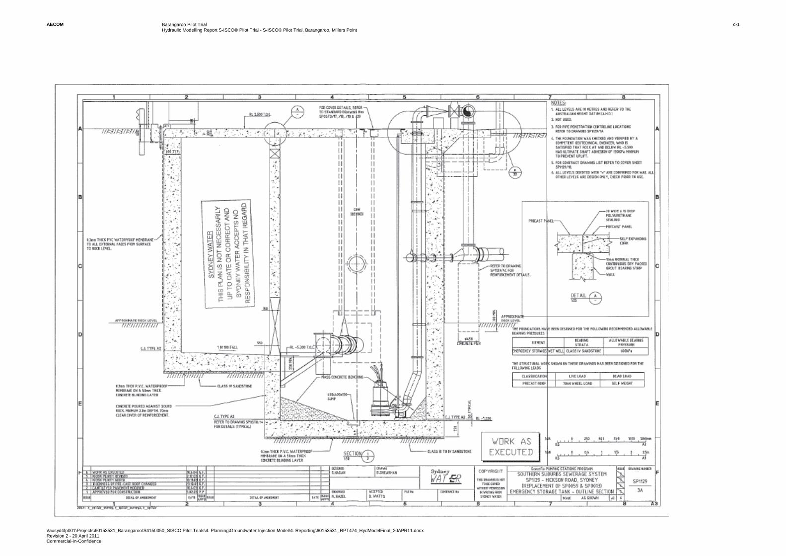
AECOM Barangaroo Pilot Trial Hydraulic Modelling Report S-ISCO® Pilot Trial - S-ISCO® Pilot Trial, Barangaroo, Millers Point
\\ausyd4fp001\Projects\60153531_Barangaroo\S4150050_SISCO Pilot Trials\4. Planning\Groundwater Injection Model\4. Reporting\60153531_RPT474_HydModelFinal_20APR11.docx Revision 2 - 20 April 2011 Commercial-in-Confidence
c-1

AECOM Barangaroo Pilot Trial Hydraulic Modelling Report S-ISCO® Pilot Trial - S-ISCO® Pilot Trial, Barangaroo, Millers Point
\\ausyd4fp001\Projects\60153531_Barangaroo\S4150050_SISCO Pilot Trials\4. Planning\Groundwater Injection Model\4. Reporting\60153531_RPT474_HydModelFinal_20APR11.docx Revision 2 - 20 April 2011 Commercial-in-Confidence
Appendix D
Chemical Compatibility Information
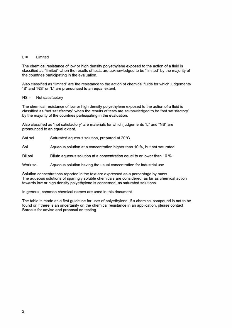
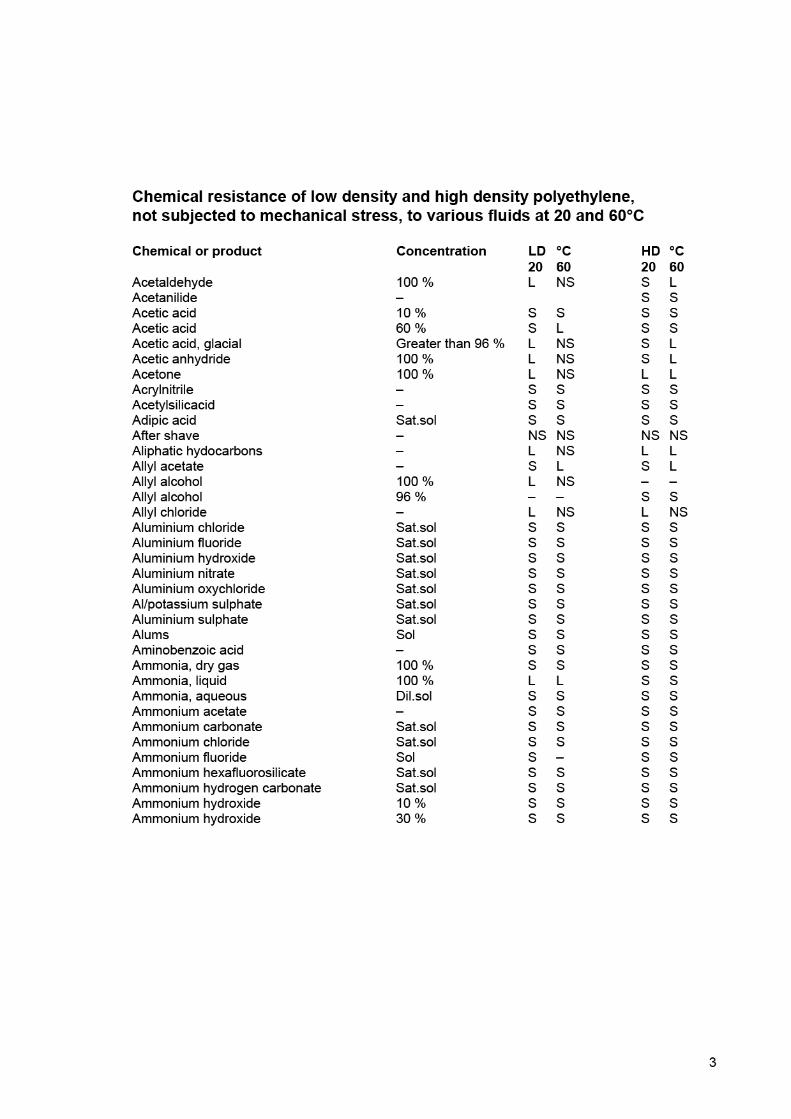
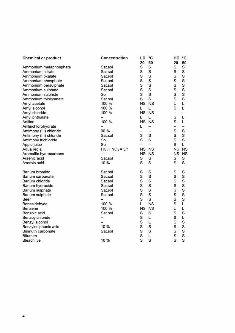
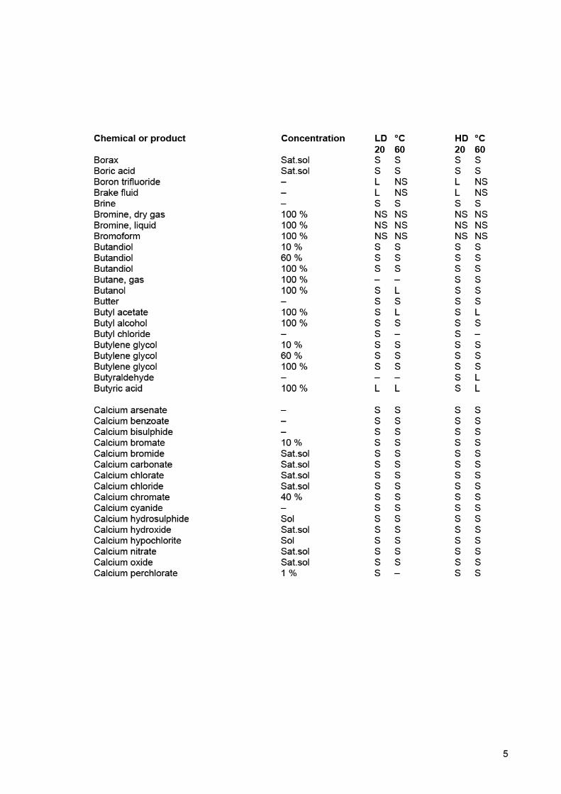
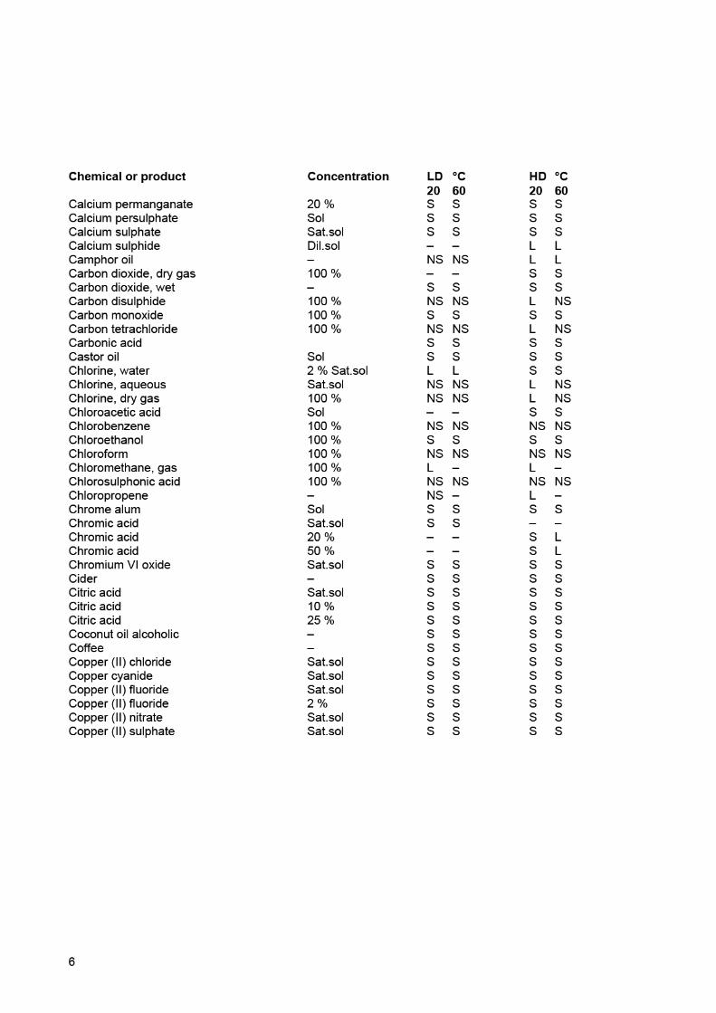
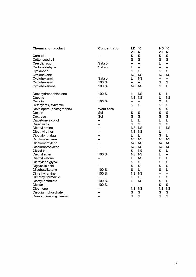
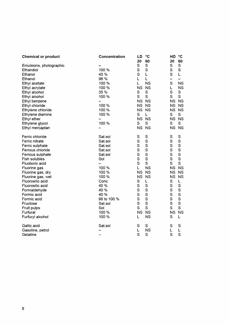
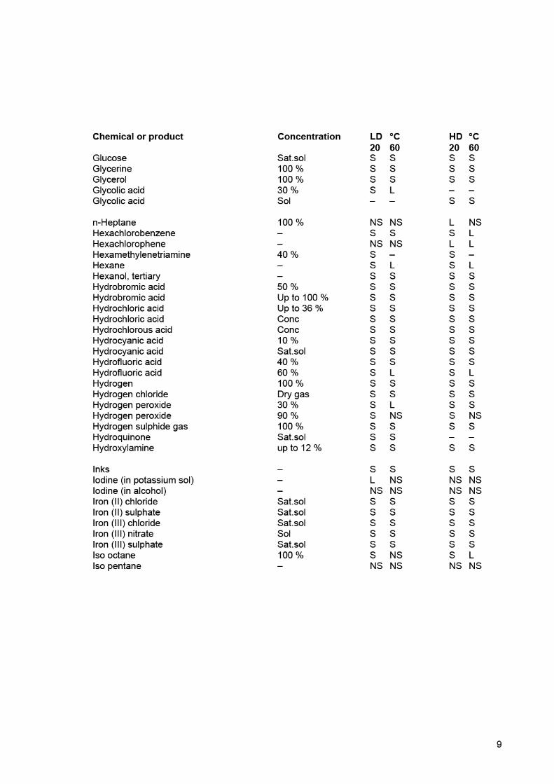
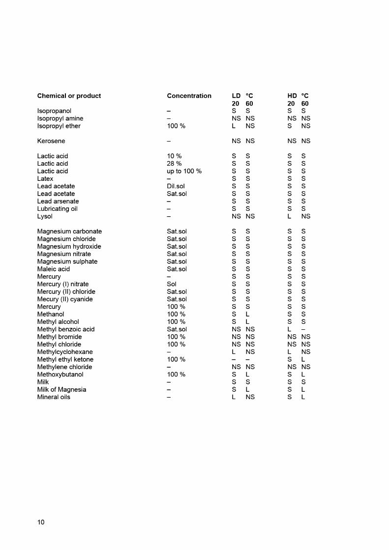
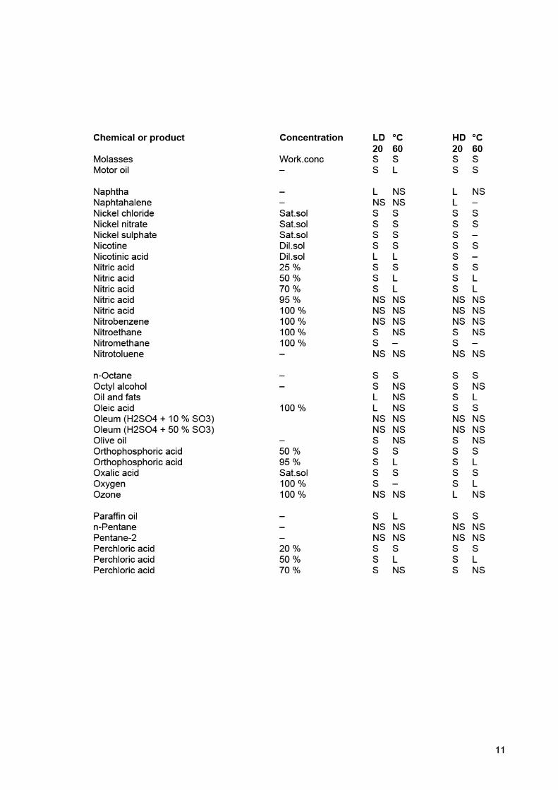
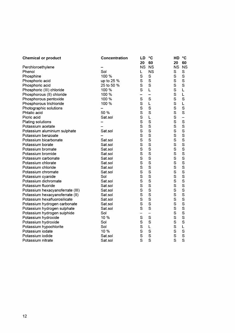
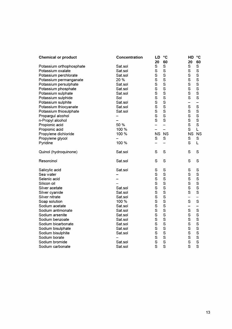
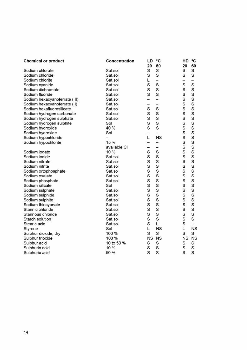
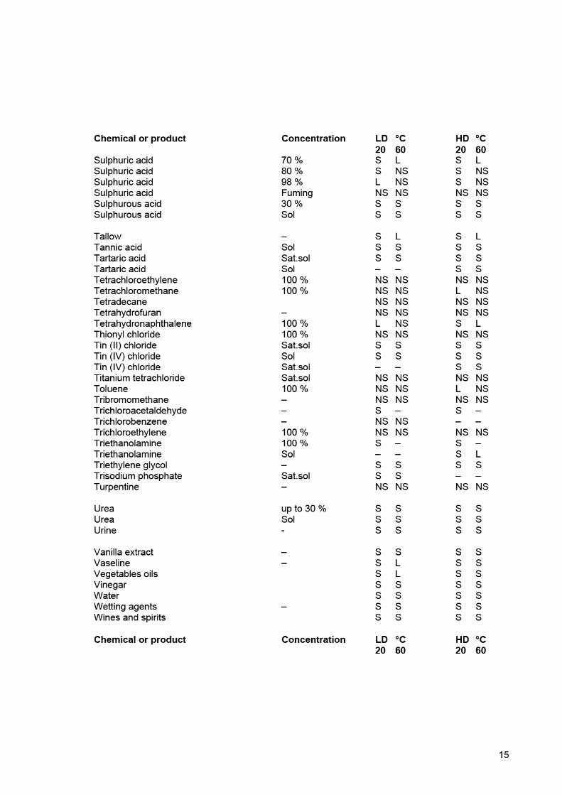
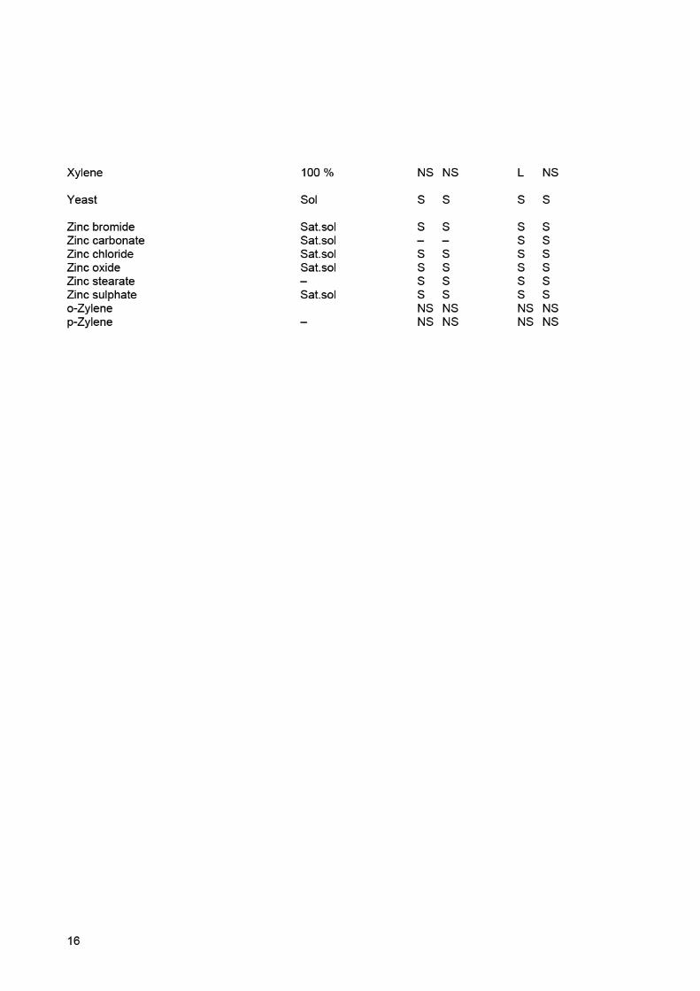
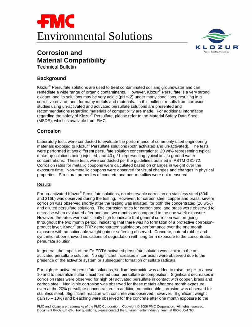
Environmental Solutions
FMC and Klozur are trademarks of the FMC Corporation. Copyright © 2006 FMC Corporation. All rights reserved.Document 04-02-EIT-DF. For questions, please contact the Environmental Industry Team at 866-860-4760.
Corrosion andMaterial CompatibilityTechnical Bulletin
Background
Klozur® Persulfate solutions are used to treat contaminated soil and groundwater and canremediate a wide range of organic contaminants. However, Klozur® Persulfate is a very strongoxidant, and its solutions may be very acidic (pH ≤ 2) under many conditions, resulting in acorrosive environment for many metals and materials. In this bulletin, results from corrosionstudies using un-activated and activated persulfate solutions are presented andrecommendations regarding materials of compatibility are made. For additional informationregarding the safety of Klozur® Persulfate, please refer to the Material Safety Data Sheet(MSDS), which is available from FMC.
Corrosion
Laboratory tests were conducted to evaluate the performance of commonly-used engineeringmaterials exposed to Klozur® Persulfate solutions (both activated and un-activated). The testswere performed at two different persulfate solution concentrations: 20 wt% representing typicalmake-up solutions being injected, and 40 g / L representing typical in situ ground waterconcentrations. These tests were conducted per the guidelines outlined in ASTM G31-72.Corrosion rates for metallic coupons were calculated based on changes in weight over theexposure time. Non-metallic coupons were observed for visual changes and changes in physicalproperties. Structural properties of concrete and non-metallics were not measured.
Results
For un-activated Klozur® Persulfate solutions, no observable corrosion on stainless steel (304Land 316L) was observed during the testing. However, for carbon steel, copper and brass, severecorrosion was observed shortly after the testing was initiated, for both the concentrated (20 wt%)and diluted persulfate solutions. The corrosion rates for carbon steel and brass were observed todecrease when evaluated after one and two months as compared to the one week exposure.However, the rates were sufficiently high to indicate that general corrosion was on-goingthroughout the two month period, indicating that there was no formation of a protective corrosion-product layer. Kynar® and FRP demonstrated satisfactory performance over the one monthexposure with no noticeable weight gain or softening observed. Concrete, natural rubber andsynthetic rubber showed indications of degradation with long-term exposure to the concentratedpersulfate solution.
In general, the impact of the Fe-EDTA activated persulfate solution was similar to the un-activated persulfate solution. No significant increases in corrosion were observed due to thepresence of the activator system or subsequent formation of sulfate radicals.
For high pH activated persulfate solutions, sodium hydroxide was added to raise the pH to above10 and to neutralize sulfuric acid formed upon persulfate decomposition. Significant decreases incorrosion rates were observed for high pH activated persulfate in contact with copper, brass andcarbon steel. Negligible corrosion was observed for these metals after one month exposure,even at the 20% persulfate concentration. In addition, no noticeable corrosion was observed forstainless steel. Significant reaction with concrete was observed, however. Significant weightgain (5 – 10%) and bleaching were observed for the concrete after one month exposure to the

Environmental Solutions
Although the above information accurately reflects the results of the tests performed, FMC makes no warranty or representation, expressed or inferred, andnothing herein should be construed as to guaranteeing actual results in field use, or permission or recommendation to infringe any patent. No agent,representative or employee of this company is authorized to vary any of the terms of this notice.
high pH activated persulfate solution, and some dissolution of the concrete was noted during thetest.
Table 1: Results for Un-Activated Klozur® Persulfate Solutions (20 wt%) at roomtemperature after 1 week and 1 months exposure time
mpy – milli-inches per year; � - compatible material, Ө - non-compatible materialMaterial 1 week 1 month Comments
Stainless steels(304L, 316L) � � < 1 mpy. No noticeable corrosion over
2 months
CopperBrass
> 100 mpyӨ
20 – 50 mpyӨ
Severe general corrosion, corrosionrate decreases with time.
Carbon steel > 200 mpyӨ
50 – 100 mpyӨ
Severe general corrosion, etching atwelds, corrosion rate decreases withtime.
Kynar® (PVDF) � � No noticeable changes after 2 monthsexposure
FRP(fiber-reinforced plastic) � � No noticeable changes after 2 months
exposure
ConcreteWeight gain,
bleachedappearance
Weight gain ( 5 –10%), bleached
appearance
Increasing weight gain over time.Some dissolution observed as residuein test chamber.
Natural Rubber Slight weight gain Slight weight gain Cracks and blisters observed after 1month exposure.
Synthetic rubber(neoprene) Slight weight gain Slight weight gain Cracks and blisters observed after 1
month exposure
Table 2: Results for Un-Activated Klozur® Persulfate Solution (40 g / L) at roomtemperature after 1 week and 2 months exposure time
mpy – milli-inches per year; � - compatible material, Ө - non-compatible materialMaterial 1 week 1 month Comments
Stainless steels(304L, 316L) � � < 1 mpy. No noticeable corrosion over
2 months
CopperBrass
> 50 mpyӨ
< 20 mpyӨ
Severe general corrosion, corrosionrate decreases with time.
Carbon steel > 50 mpyӨ
< 20 mpyӨ
Several general corrosion, etching atwelds, corrosion rate decreases withtime.
Kynar® (PVDF) � � No noticeable changes after 1 monthexposure
FRP(fiber-reinforced plastic) � � No noticeable changes after 1 month
exposure
ConcreteWeight gain,
bleachedappearance
Weight gain ( 5 –10%), bleached
appearance
Increasing weight gain over time.Some dissolution observed as residuein test chamber.

Environmental Solutions
Although the above information accurately reflects the results of the tests performed, FMC makes no warranty or representation, expressed or inferred, andnothing herein should be construed as to guaranteeing actual results in field use, or permission or recommendation to infringe any patent. No agent,representative or employee of this company is authorized to vary any of the terms of this notice.
Natural Rubber Slight weight gain Slight weight gain
Synthetic rubber(neoprene)
Slight weight gain Slight weight gain
Table 3: Results for Fe-EDTA Klozur® Persulfate Solutions, 20 wt% and 40 g / L at roomtemperature after 1 month exposure time
mpy – milli-inches per year; � - compatible material, Ө - non-compatible material
Material 20 wt%concentration 40 g / L Comments
Stainless steels(304L, 316L) � � < 1 mpy. No noticeable corrosion over
1 month
CopperBrass
20 – 50 mpyӨ
< 20 mpyӨ
Severe general corrosion, corrosionrate decreases with time.
Carbon steel > 50 mpyӨ
20 - 50 mpyӨ
Several general corrosion, etching atwelds.
Kynar® (PVDF) � � No noticeable changes after 1 monthexposure
FRP(fiber-reinforced plastic) � � No noticeable changes after 1 month
exposure
ConcreteWeight gain,
bleachedappearance
Weight gain ( 5 –10%), bleached
appearance
Increasing weight gain over time.Some dissolution observed as residuein test chamber.
Natural Rubber Slight weight gain Slight weight gain
Synthetic rubber(neoprene) Slight weight gain Slight weight gain
Table 4: Results for high pH activate Klozur® Persulfate Solutions, 20 wt% and 40 g / L atroom temperature after 1 month exposure time
mpy – milli-inches per year; � - compatible material, Ө - non-compatible material
Material 20 wt%concentration 40 g / L Comments
Stainless steels(304L, 316L) � � < 1 mpy. No noticeable corrosion over
1 month
CopperBrass � � Negligible general corrosion (< 2 mpy).
Black film formation observed.
Carbon steel � � Negligible general corrosion (< 2 mpy).Isolated rust spots observed
ConcreteWeight gain,
bleachedappearance
Weight gain ( 5 –10%), bleached
appearance
Bleached appearance, increasingweight gain over time, somedissolution observed as residue in testcontainer.
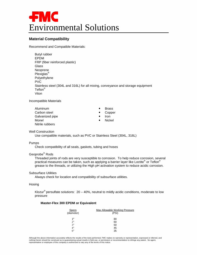
Environmental Solutions
Although the above information accurately reflects the results of the tests performed, FMC makes no warranty or representation, expressed or inferred, andnothing herein should be construed as to guaranteeing actual results in field use, or permission or recommendation to infringe any patent. No agent,representative or employee of this company is authorized to vary any of the terms of this notice.
Material Compatibility
Recommend and Compatible Materials:
• Butyl rubber• EPDM• FRP (fiber reinforced plastic)• Glass• Neoprene• Plexiglas®
• Polyethylene• PVC• Stainless steel (304L and 316L) for all mixing, conveyance and storage equipment• Teflon®
• Viton
Incompatible Materials
• Aluminum � Brass• Carbon steel � Copper• Galvanized pipe � Iron• Monel � Nickel• Nitrile rubbers
Well Construction• Use compatible materials, such as PVC or Stainless Steel (304L, 316L)
Pumps• Check compatibility of all seals, gaskets, tubing and hoses
Geoprobe® Rods• Threaded joints of rods are very susceptible to corrosion. To help reduce corrosion, several
practical measures can be taken, such as applying a barrier layer like Loctite® or Teflon®
grease to the threads, or utilizing the High pH activation system to reduce acidic corrosion.
Subsurface Utilities• Always check for location and compatibility of subsurface utilities.
Hosing
• Klozur® persulfate solutions: 20 – 40%, neutral to mildly acidic conditions, moderate to lowpressure
Master-Flex 300 EPDM or Equivalent
Specs(diameter)
Max Allowable Working Pressure(PSI)
1″ 802″ 603″ 504″ 456″ 35

Environmental Solutions
Although the above information accurately reflects the results of the tests performed, FMC makes no warranty or representation, expressed or inferred, andnothing herein should be construed as to guaranteeing actual results in field use, or permission or recommendation to infringe any patent. No agent,representative or employee of this company is authorized to vary any of the terms of this notice.
o – 30 F to +140 Fo EPDM black inner liner of hosing with polyethylene helixo Reinforced and a Type G (PVC) covero Medium oil resistance
• Klozur® persulfate solutions: 20 – 40%, mildly acidic conditions, high pressure
Alfagomma (Italian Company)o Model T 505 4-4 SPo 6 BAF (240 PSI)o XLPE chemical S&D
Transporter Ultrachem (brand name)o 250 PSI water pressure
• Fittings
304 Stainless – Schedule 40CPVC – Schedule 80 preferred (could lose strength when heated)PVC (may become embrittled with continued use)

Page 1 of 20
PVC CHEMICAL RESISTANCE CHART
Ratings Guide Good – Should have little or no effect on the material at the given concentration and temperature Moderate – Some effect on the material at the given concentration and temperature. Caution advised. X – Not recommended. ND – No data available
CHEMICALS CONC.
RATING Two values are given per
compound by temperature: 20OC / 60OC
Acetaldehyde 40 % X/X Acetaldehyde techn. pure X/X Acetamide saturated X/X Acetic acid 5 % G/G Acetic acid 10 % G/M Acetic acid 50 % M/M Acetic acid 90% M/X Acetic acid 100 % X/X Acetic anhydride techn. pure X/X Acetone X/X Acetonitrile X/X Acetophenone X/X Acetyl chloride 100 % X/X Acetylene 100 % G/G Acrylonitrile X/X Adipic acid saturated G/M Alanine X/X Allyl alcohol 96 % M/X Allyl chloride 100 % X/X Alum G/G Aluminum chloride 10 % G/G Aluminum chloride solid G/G Aluminum chloride saturated G/G
The information from such third party sources is believed to be reliable and accurate; however Purchaser should make its own determination of compatibility before using any SpillTech product. It is the sole responsibility of the Purchaser to determine whether any product is suitable for Purchaser’s actual or intended uses. NO GUARANTEE, WARRANTY, OR REPRESENTATION IS MADE, INTENDED, OR IMPLIED ASTO THE CORRECTNESS OR SUFFICIENCY OF THE CHEMICAL COMPATABILITY GUIDE OR ANY INFORMATION SUPPLIED HEREIN.
This Chemical Compatibility Guide is offered for informational purposes only and was developed from information sources other than SpillTech
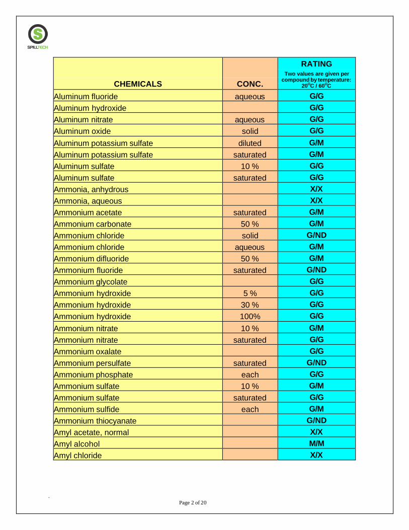
. Page 2 of 20
CHEMICALS CONC.
RATING Two values are given per
compound by temperature: 20OC / 60OC
Aluminum fluoride aqueous G/G Aluminum hydroxide G/G Aluminum nitrate aqueous G/G Aluminum oxide solid G/G Aluminum potassium sulfate diluted G/M Aluminum potassium sulfate saturated G/M Aluminum sulfate 10 % G/G Aluminum sulfate saturated G/G Ammonia, anhydrous X/X Ammonia, aqueous X/X Ammonium acetate saturated G/M Ammonium carbonate 50 % G/M Ammonium chloride solid G/ND Ammonium chloride aqueous G/M Ammonium difluoride 50 % G/M Ammonium fluoride saturated G/ND Ammonium glycolate G/G Ammonium hydroxide 5 % G/G Ammonium hydroxide 30 % G/G Ammonium hydroxide 100% G/G Ammonium nitrate 10 % G/M Ammonium nitrate saturated G/G Ammonium oxalate G/G Ammonium persulfate saturated G/ND Ammonium phosphate each G/G Ammonium sulfate 10 % G/M Ammonium sulfate saturated G/G Ammonium sulfide each G/M Ammonium thiocyanate G/ND Amyl acetate, normal X/X Amyl alcohol M/M Amyl chloride X/X
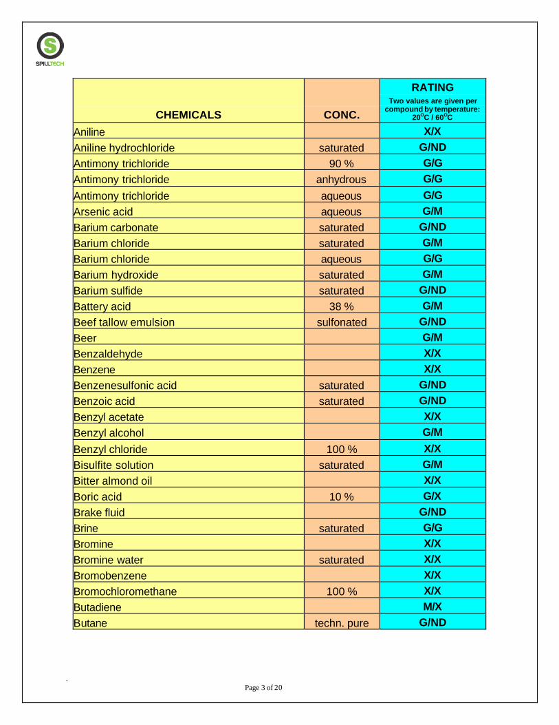
. Page 3 of 20
CHEMICALS CONC.
RATING Two values are given per
compound by temperature: 20OC / 60OC
Aniline X/X Aniline hydrochloride saturated G/ND Antimony trichloride 90 % G/G Antimony trichloride anhydrous G/G Antimony trichloride aqueous G/G Arsenic acid aqueous G/M Barium carbonate saturated G/ND Barium chloride saturated G/M Barium chloride aqueous G/G Barium hydroxide saturated G/M Barium sulfide saturated G/ND Battery acid 38 % G/M Beef tallow emulsion sulfonated G/ND Beer G/M Benzaldehyde X/X Benzene X/X Benzenesulfonic acid saturated G/ND Benzoic acid saturated G/ND Benzyl acetate X/X Benzyl alcohol G/M Benzyl chloride 100 % X/X Bisulfite solution saturated G/M Bitter almond oil X/X Boric acid 10 % G/X Brake fluid G/ND Brine saturated G/G Bromine X/X Bromine water saturated X/X Bromobenzene X/X Bromochloromethane 100 % X/X Butadiene M/X Butane techn. pure G/ND
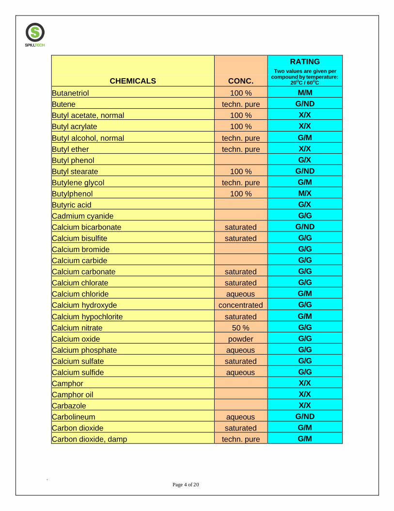
. Page 4 of 20
CHEMICALS CONC.
RATING Two values are given per
compound by temperature: 20OC / 60OC
Butanetriol 100 % M/M Butene techn. pure G/ND Butyl acetate, normal 100 % X/X Butyl acrylate 100 % X/X Butyl alcohol, normal techn. pure G/M Butyl ether techn. pure X/X Butyl phenol G/X Butyl stearate 100 % G/ND Butylene glycol techn. pure G/M Butylphenol 100 % M/X Butyric acid G/X Cadmium cyanide G/G Calcium bicarbonate saturated G/ND Calcium bisulfite saturated G/G Calcium bromide G/G Calcium carbide G/G Calcium carbonate saturated G/G Calcium chlorate saturated G/G Calcium chloride aqueous G/M Calcium hydroxyde concentrated G/G Calcium hypochlorite saturated G/M Calcium nitrate 50 % G/G Calcium oxide powder G/G Calcium phosphate aqueous G/G Calcium sulfate saturated G/G Calcium sulfide aqueous G/G Camphor X/X Camphor oil X/X Carbazole X/X Carbolineum aqueous G/ND Carbon dioxide saturated G/M Carbon dioxide, damp techn. pure G/M
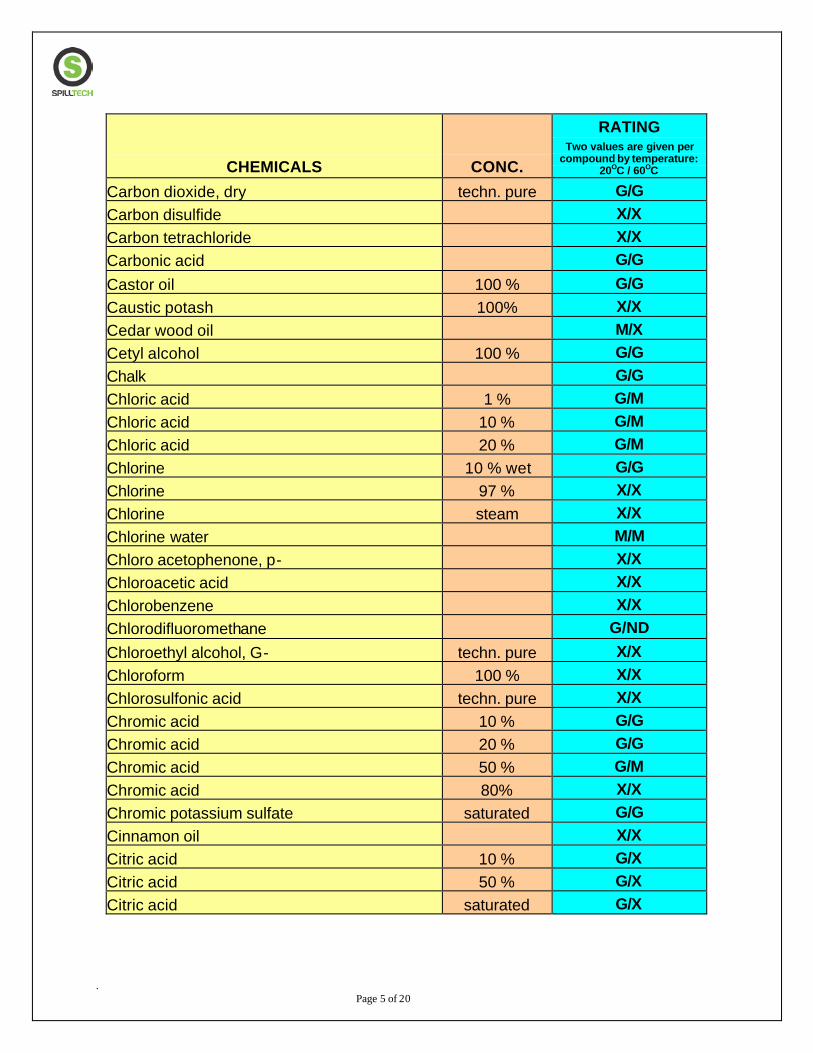
. Page 5 of 20
CHEMICALS CONC.
RATING Two values are given per
compound by temperature: 20OC / 60OC
Carbon dioxide, dry techn. pure G/G Carbon disulfide X/X Carbon tetrachloride X/X Carbonic acid G/G Castor oil 100 % G/G Caustic potash 100% X/X Cedar wood oil M/X Cetyl alcohol 100 % G/G Chalk G/G Chloric acid 1 % G/M Chloric acid 10 % G/M Chloric acid 20 % G/M Chlorine 10 % wet G/G Chlorine 97 % X/X Chlorine steam X/X Chlorine water M/M Chloro acetophenone, p- X/X Chloroacetic acid X/X Chlorobenzene X/X Chlorodifluoromethane G/ND Chloroethyl alcohol, G- techn. pure X/X Chloroform 100 % X/X Chlorosulfonic acid techn. pure X/X Chromic acid 10 % G/G Chromic acid 20 % G/G Chromic acid 50 % G/M Chromic acid 80% X/X Chromic potassium sulfate saturated G/G Cinnamon oil X/X Citric acid 10 % G/X Citric acid 50 % G/X Citric acid saturated G/X
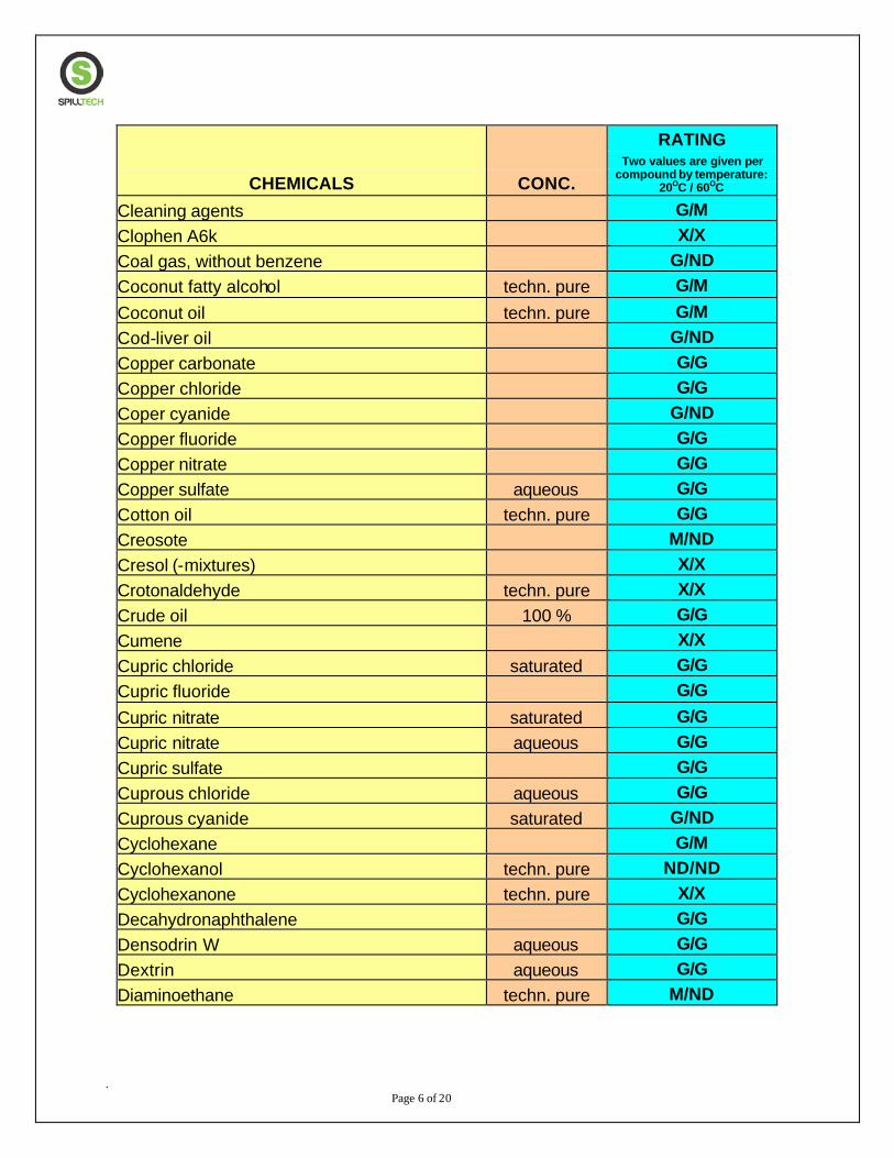
. Page 6 of 20
CHEMICALS CONC.
RATING Two values are given per
compound by temperature: 20OC / 60OC
Cleaning agents G/M Clophen A6k X/X Coal gas, without benzene G/ND Coconut fatty alcohol techn. pure G/M Coconut oil techn. pure G/M Cod-liver oil G/ND Copper carbonate G/G Copper chloride G/G Coper cyanide G/ND Copper fluoride G/G Copper nitrate G/G Copper sulfate aqueous G/G Cotton oil techn. pure G/G Creosote M/ND Cresol (-mixtures) X/X Crotonaldehyde techn. pure X/X Crude oil 100 % G/G Cumene X/X Cupric chloride saturated G/G Cupric fluoride G/G Cupric nitrate saturated G/G Cupric nitrate aqueous G/G Cupric sulfate G/G Cuprous chloride aqueous G/G Cuprous cyanide saturated G/ND Cyclohexane G/M Cyclohexanol techn. pure ND/ND Cyclohexanone techn. pure X/X Decahydronaphthalene G/G Densodrin W aqueous G/G Dextrin aqueous G/G Diaminoethane techn. pure M/ND
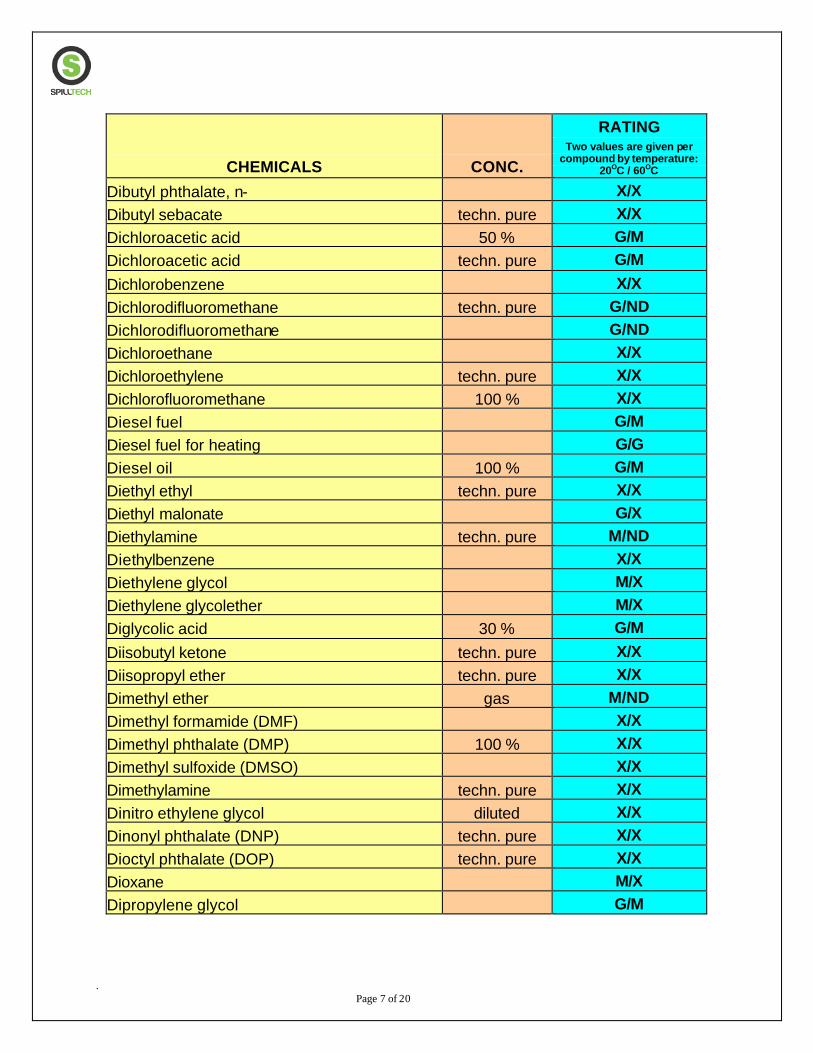
. Page 7 of 20
CHEMICALS CONC.
RATING Two values are given per
compound by temperature: 20OC / 60OC
Dibutyl phthalate, n- X/X Dibutyl sebacate techn. pure X/X Dichloroacetic acid 50 % G/M Dichloroacetic acid techn. pure G/M Dichlorobenzene X/X Dichlorodifluoromethane techn. pure G/ND Dichlorodifluoromethane G/ND Dichloroethane X/X Dichloroethylene techn. pure X/X Dichlorofluoromethane 100 % X/X Diesel fuel G/M Diesel fuel for heating G/G Diesel oil 100 % G/M Diethyl ethyl techn. pure X/X Diethyl malonate G/X Diethylamine techn. pure M/ND Diethylbenzene X/X Diethylene glycol M/X Diethylene glycolether M/X Diglycolic acid 30 % G/M Diisobutyl ketone techn. pure X/X Diisopropyl ether techn. pure X/X Dimethyl ether gas M/ND Dimethyl formamide (DMF) X/X Dimethyl phthalate (DMP) 100 % X/X Dimethyl sulfoxide (DMSO) X/X Dimethylamine techn. pure X/X Dinitro ethylene glycol diluted X/X Dinonyl phthalate (DNP) techn. pure X/X Dioctyl phthalate (DOP) techn. pure X/X Dioxane M/X Dipropylene glycol G/M
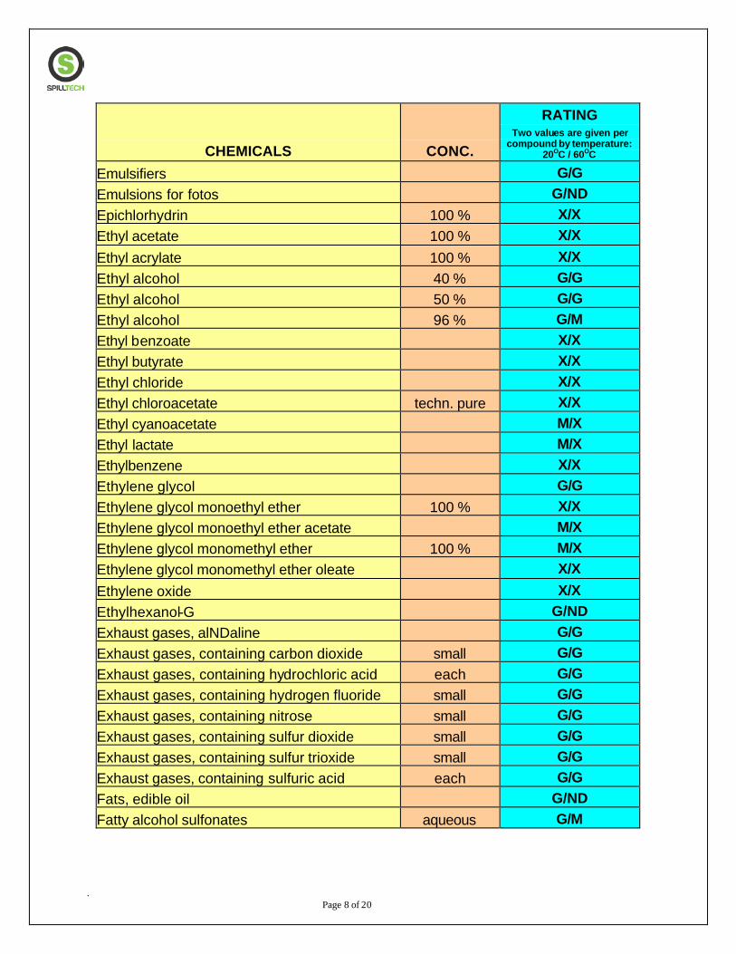
. Page 8 of 20
CHEMICALS CONC.
RATING Two values are given per
compound by temperature: 20OC / 60OC
Emulsifiers G/G Emulsions for fotos G/ND Epichlorhydrin 100 % X/X Ethyl acetate 100 % X/X Ethyl acrylate 100 % X/X Ethyl alcohol 40 % G/G Ethyl alcohol 50 % G/G Ethyl alcohol 96 % G/M Ethyl benzoate X/X Ethyl butyrate X/X Ethyl chloride X/X Ethyl chloroacetate techn. pure X/X Ethyl cyanoacetate M/X Ethyl lactate M/X Ethylbenzene X/X Ethylene glycol G/G Ethylene glycol monoethyl ether 100 % X/X Ethylene glycol monoethyl ether acetate M/X Ethylene glycol monomethyl ether 100 % M/X Ethylene glycol monomethyl ether oleate X/X Ethylene oxide X/X Ethylhexanol-G G/ND Exhaust gases, alNDaline G/G Exhaust gases, containing carbon dioxide small G/G Exhaust gases, containing hydrochloric acid each G/G Exhaust gases, containing hydrogen fluoride small G/G Exhaust gases, containing nitrose small G/G Exhaust gases, containing sulfur dioxide small G/G Exhaust gases, containing sulfur trioxide small G/G Exhaust gases, containing sulfuric acid each G/G Fats, edible oil G/ND Fatty alcohol sulfonates aqueous G/M

. Page 9 of 20
CHEMICALS CONC.
RATING Two values are given per
compound by temperature: 20OC / 60OC
Ferric acetate G/X Ferric chloride saturated G/G Ferric nitrate aqueous G/G Ferric nitrate saturated G/G Ferric sulfate saturated G/G Ferrous chloride saturated G/G Ferrous sulfate saturated G/G Ferrous sulfate aqueous G/G Fixer for fotos G/M Fluorides G/G Fluorine M/X Fluorosilic acid G/G Formaldehyde solution 10 % G/M Formaldehyde solution 30 % G/M Formaldehyde solution 40 % G/M Formamide techn. pure X/X Formic acid 3 % G/M Formic acid 50 % G/M Formic acid 98-100 % M/X Freon F-11 G/ND Freon F-12 G/ND Freon F-21 X/X Freon F-22 X/X Freon F-113 G/ND Freon F-114 G/ND Freon T-F G/M Fruit pulp G/G Fruit wine G/G Furfural X/X Furfuryl alcohol techn. pure X/X Gallic acid G/G Gas, natural G/G
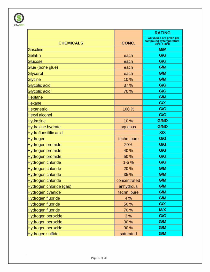
. Page 10 of 20
CHEMICALS CONC.
RATING Two values are given per
compound by temperature: 20OC / 60OC
Gasoline M/M Gelatin each G/G Glucose each G/G Glue (bone glue) each G/M Glycerol each G/M Glycine 10 % G/M Glycolic acid 37 % G/G Glycolic acid 70 % G/G Heptane G/M Hexane G/X Hexanetriol 100 % G/G Hexyl alcohol G/G Hydrazine 10 % G/ND Hydrazine hydrate aqueous G/ND Hydrofluosililic acid X/X Hydrogen techn. pure G/G Hydrogen bromide 20% G/G Hydrogen bromide 40 % G/G Hydrogen bromide 50 % G/G Hydrogen chloride 1-5 % G/G Hydrogen chloride 20 % G/M Hydrogen chloride 35 % G/M Hydrogen chloride concentrated G/M Hydrogen chloride (gas) anhydrous G/M Hydrogen cyanide techn. pure G/M Hydrogen fluoride 4 % G/M Hydrogen fluoride 50 % G/X Hydrogen fluoride 70 % M/X Hydrogen peroxide 3 % G/G Hydrogen peroxide 30 % G/M Hydrogen peroxide 90 % G/M Hydrogen sulfide saturated G/M
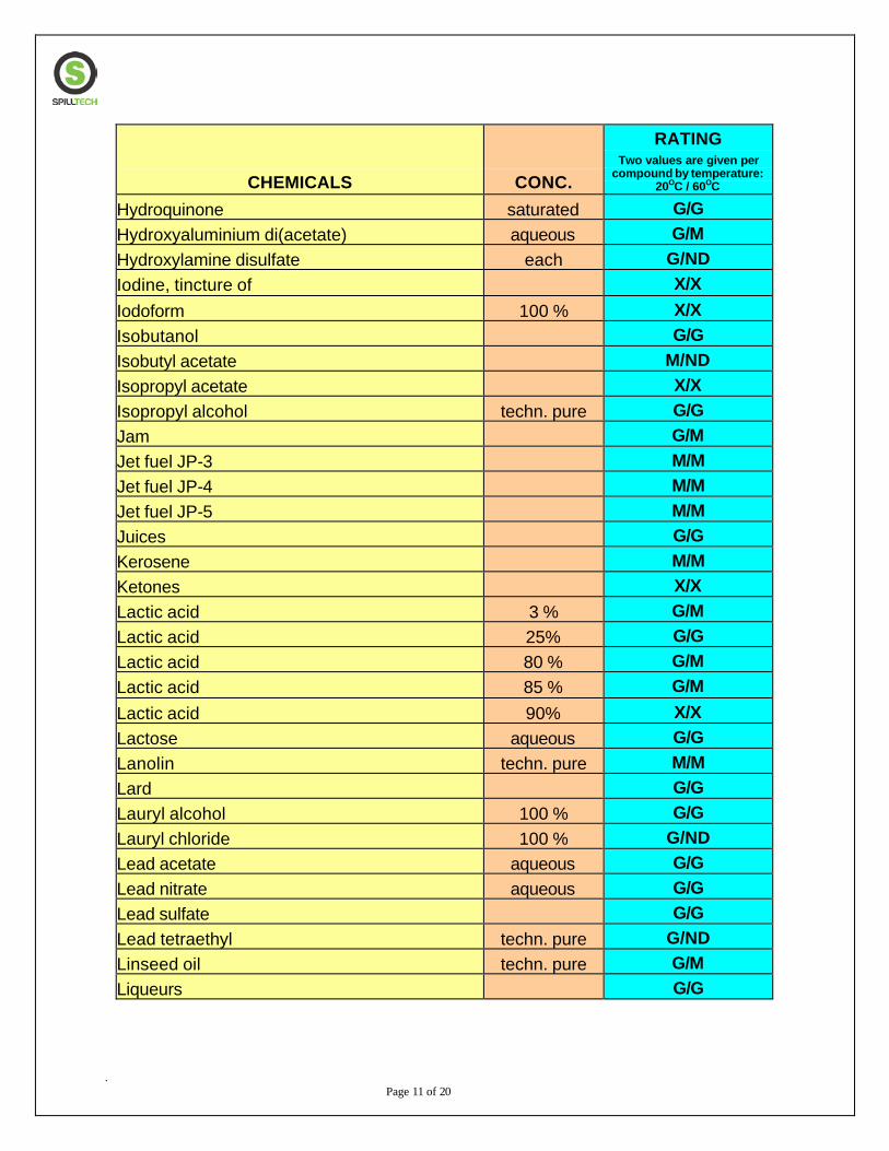
. Page 11 of 20
CHEMICALS CONC.
RATING Two values are given per
compound by temperature: 20OC / 60OC
Hydroquinone saturated G/G Hydroxyaluminium di(acetate) aqueous G/M Hydroxylamine disulfate each G/ND Iodine, tincture of X/X Iodoform 100 % X/X Isobutanol G/G Isobutyl acetate M/ND Isopropyl acetate X/X Isopropyl alcohol techn. pure G/G Jam G/M Jet fuel JP-3 M/M Jet fuel JP-4 M/M Jet fuel JP-5 M/M Juices G/G Kerosene M/M Ketones X/X Lactic acid 3 % G/M Lactic acid 25% G/G Lactic acid 80 % G/M Lactic acid 85 % G/M Lactic acid 90% X/X Lactose aqueous G/G Lanolin techn. pure M/M Lard G/G Lauryl alcohol 100 % G/G Lauryl chloride 100 % G/ND Lead acetate aqueous G/G Lead nitrate aqueous G/G Lead sulfate G/G Lead tetraethyl techn. pure G/ND Linseed oil techn. pure G/M Liqueurs G/G

. Page 12 of 20
CHEMICALS CONC.
RATING Two values are given per
compound by temperature: 20OC / 60OC
Lithium bromide G/G Lube oils G/G Machine oil 100 % G/G Magnesium carbonate saturated G/G Magnesium chloride aqueous G/G Magnesium chlorite G/G Magnesium hydroxide saturated G/G Magnesium iodide G/G Magnesium nitrate saturated G/G Magnesium sulfate each G/G Maize-germ oil techn. pure M/ND Maleic acid saturated ND/ND Mercuric chloride aqueous X/X Mercuric cyanide saturated G/M Mercuric nitrate saturated G/M Mercury pure G/G Methane techn. pure G/G Methyl acetate techn. pure X/X Methyl alcohol G/M Methyl amine 32 % M/ND Methyl benzene X/X Methyl bromide techn. pure X/X Methyl chloride techn. pure X/X Methyl dichloroacetate X/X Methyl ethyl ketone X/X Methyle isobutyl ketone X/X Methyl methacrylate 100 % ND/ND Methyl propyl NDetone X/X Methyle sulfate G/M Methyl sulfuric acid 50 % G/M Methylchloroacetate techn. pure M/ND Methylene chloride X/X
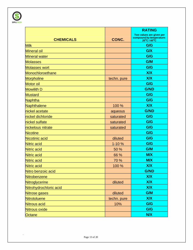
. Page 13 of 20
CHEMICALS CONC.
RATING Two values are given per
compound by temperature: 20OC / 60OC
Milk G/G Mineral oil G/X Mineral water G/G Molasses G/M Molasses wort G/G Monochloroethane X/X Morpholine techn. pure X/X Motor oil G/G Mowilith D G/ND Mustard G/G Naphtha G/G Naphthalene 100 % X/X nickel acetate aqueous G/ND nickel dichloride saturated G/G nickel sulfate saturated G/G nickelous nitrate saturated G/G Nicotine G/G Nicotinic acid diluted G/G Nitric acid 1-10 % G/G Nitric acid 50 % G/M Nitric acid 66 % M/X Nitric acid 70 % M/X Nitric acid 100 % X/X Nitro benzoic acid G/ND Nitrobenzene X/X Nitroglycerine diluted X/X Nitrohydrochloric acid X/X Nitrose gases diluted G/M Nitrotoluene techn. pure X/X Nitrous acid 10% G/G Nitrous oxide G/G Octane N/X
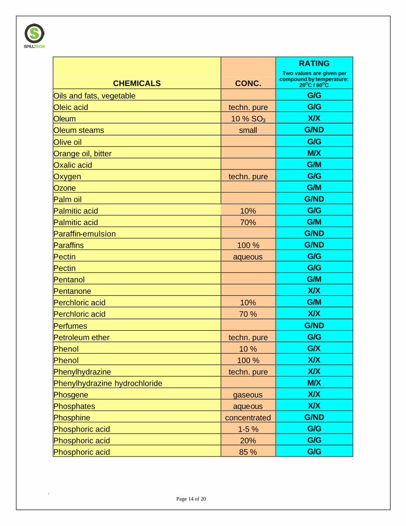
. Page 14 of 20
CHEMICALS CONC.
RATING Two values are given per
compound by temperature: 20OC / 60OC
Oils and fats, vegetable G/G Oleic acid techn. pure G/G Oleum 10 % SO3 X/X Oleum steams small G/ND Olive oil G/G Orange oil, bitter M/X Oxalic acid G/M Oxygen techn. pure G/G Ozone G/M Palm oil G/ND Palmitic acid 10% G/G Palmitic acid 70% G/M Paraffin-emulsion G/ND Paraffins 100 % G/ND Pectin aqueous G/G Pectin G/G Pentanol G/M Pentanone X/X Perchloric acid 10% G/M Perchloric acid 70 % X/X Perfumes G/ND Petroleum ether techn. pure G/G Phenol 10 % G/X Phenol 100 % X/X Phenylhydrazine techn. pure X/X Phenylhydrazine hydrochloride M/X Phosgene gaseous X/X Phosphates aqueous X/X Phosphine concentrated G/ND Phosphoric acid 1-5 % G/G Phosphoric acid 20% G/G Phosphoric acid 85 % G/G
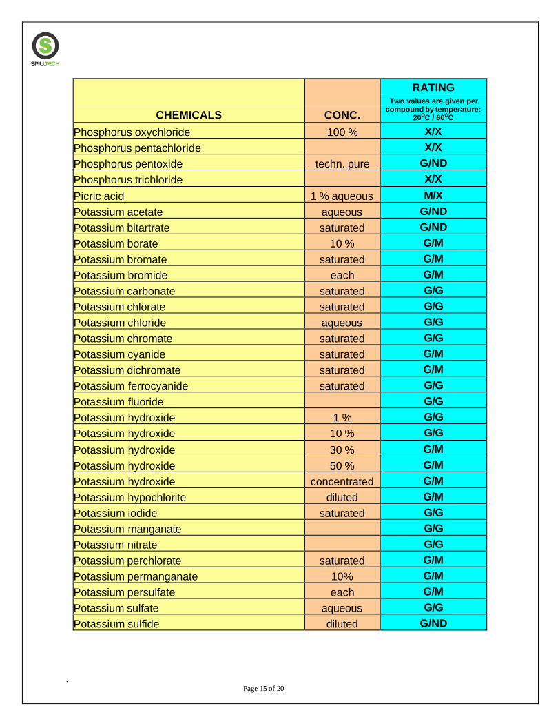
. Page 15 of 20
CHEMICALS CONC.
RATING Two values are given per
compound by temperature: 20OC / 60OC
Phosphorus oxychloride 100 % X/X Phosphorus pentachloride X/X Phosphorus pentoxide techn. pure G/ND Phosphorus trichloride X/X Picric acid 1 % aqueous M/X Potassium acetate aqueous G/ND Potassium bitartrate saturated G/ND Potassium borate 10 % G/M Potassium bromate saturated G/M Potassium bromide each G/M Potassium carbonate saturated G/G Potassium chlorate saturated G/G Potassium chloride aqueous G/G Potassium chromate saturated G/G Potassium cyanide saturated G/M Potassium dichromate saturated G/M Potassium ferrocyanide saturated G/G Potassium fluoride G/G Potassium hydroxide 1 % G/G Potassium hydroxide 10 % G/G Potassium hydroxide 30 % G/M Potassium hydroxide 50 % G/M Potassium hydroxide concentrated G/M Potassium hypochlorite diluted G/M Potassium iodide saturated G/G Potassium manganate G/G Potassium nitrate G/G Potassium perchlorate saturated G/M Potassium permanganate 10% G/M Potassium persulfate each G/M Potassium sulfate aqueous G/G Potassium sulfide diluted G/ND
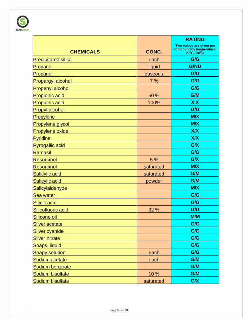
. Page 16 of 20
CHEMICALS CONC.
RATING Two values are given per
compound by temperature: 20OC / 60OC
Precipitated silica each G/G Propane liquid G/ND Propane gaseous G/G Propargyl alcohol 7 % G/G Propenyl alcohol G/G Propionic acid 50 % G/M Propionic acid 100% X.X Propyl alcohol G/G Propylene M/X Propylene glycol M/X Propylene oxide X/X Pyridine X/X Pyrogallic acid G/X Ramasit G/G Resorcinol 5 % G/X Resorcinol saturated M/X Salicylic acid saturated G/M Salicylic acid powder G/M Salicylaldehyde M/X Sea water G/G Silicic acid G/G Silicofluoric acid 32 % G/G Silicone oil M/M Silver acetate G/G Silver cyanide G/G Silver nitrate G/G Soaps, liquid G/G Soapy solution each G/G Sodium acetate each G/M Sodium benzoate G/M Sodium bisulfate 10 % G/M Sodium bisulfate saturated G/X
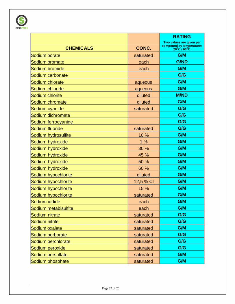
. Page 17 of 20
CHEMICALS CONC.
RATING Two values are given per
compound by temperature: 20OC / 60OC
Sodium borate saturated G/M Sodium bromate each G/ND Sodium bromide each G/M Sodium carbonate G/G Sodium chlorate aqueous G/M Sodium chloride aqueous G/M Sodium chlorite diluted M/ND Sodium chromate diluted G/M Sodium cyanide saturated G/G Sodium dichromate G/G Sodium ferrocyanide G/G Sodium fluoride saturated G/G Sodium hydrosulfite 10 % G/M Sodium hydroxide 1 % G/M Sodium hydroxide 30 % G/M Sodium hydroxide 45 % G/M Sodium hydroxide 50 % G/M Sodium hydroxide 60 % G/M Sodium hypochlorite diluted G/M Sodium hypochlorite 12,5 % Cl G/M Sodium hypochlorite 15 % G/M Sodium hypochlorite saturated G/M Sodium iodide each G/M Sodium metabisulfite each G/M Sodium nitrate saturated G/G Sodium nitrite saturated G/G Sodium oxalate saturated G/M Sodium perborate saturated G/G Sodium perchlorate saturated G/G Sodium peroxide saturated G/G Sodium persulfate saturated G/M Sodium phosphate saturated G/M
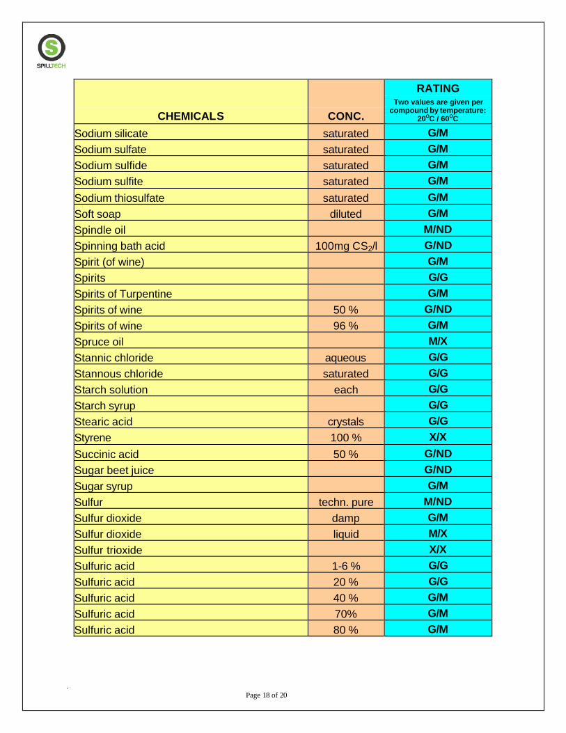
. Page 18 of 20
CHEMICALS CONC.
RATING Two values are given per
compound by temperature: 20OC / 60OC
Sodium silicate saturated G/M Sodium sulfate saturated G/M Sodium sulfide saturated G/M Sodium sulfite saturated G/M Sodium thiosulfate saturated G/M Soft soap diluted G/M Spindle oil M/ND Spinning bath acid 100mg CS2/l G/ND Spirit (of wine) G/M Spirits G/G Spirits of Turpentine G/M Spirits of wine 50 % G/ND Spirits of wine 96 % G/M Spruce oil M/X Stannic chloride aqueous G/G Stannous chloride saturated G/G Starch solution each G/G Starch syrup G/G Stearic acid crystals G/G Styrene 100 % X/X Succinic acid 50 % G/ND Sugar beet juice G/ND Sugar syrup G/M Sulfur techn. pure M/ND Sulfur dioxide damp G/M Sulfur dioxide liquid M/X Sulfur trioxide X/X Sulfuric acid 1-6 % G/G Sulfuric acid 20 % G/G Sulfuric acid 40 % G/M Sulfuric acid 70% G/M Sulfuric acid 80 % G/M
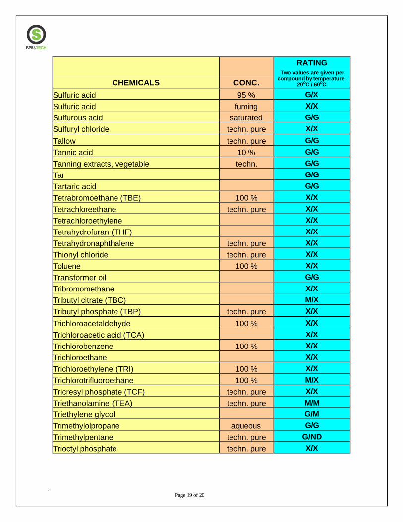
. Page 19 of 20
CHEMICALS CONC.
RATING Two values are given per
compound by temperature: 20OC / 60OC
Sulfuric acid 95 % G/X Sulfuric acid fuming X/X Sulfurous acid saturated G/G Sulfuryl chloride techn. pure X/X Tallow techn. pure G/G Tannic acid 10 % G/G Tanning extracts, vegetable techn. G/G Tar G/G Tartaric acid G/G Tetrabromoethane (TBE) 100 % X/X Tetrachloreethane techn. pure X/X Tetrachloroethylene X/X Tetrahydrofuran (THF) X/X Tetrahydronaphthalene techn. pure X/X Thionyl chloride techn. pure X/X Toluene 100 % X/X Transformer oil G/G Tribromomethane X/X Tributyl citrate (TBC) M/X Tributyl phosphate (TBP) techn. pure X/X Trichloroacetaldehyde 100 % X/X Trichloroacetic acid (TCA) X/X Trichlorobenzene 100 % X/X Trichloroethane X/X Trichloroethylene (TRI) 100 % X/X Trichlorotrifluoroethane 100 % M/X Tricresyl phosphate (TCF) techn. pure X/X Triethanolamine (TEA) techn. pure M/M Triethylene glycol G/M Trimethylolpropane aqueous G/G Trimethylpentane techn. pure G/ND Trioctyl phosphate techn. pure X/X
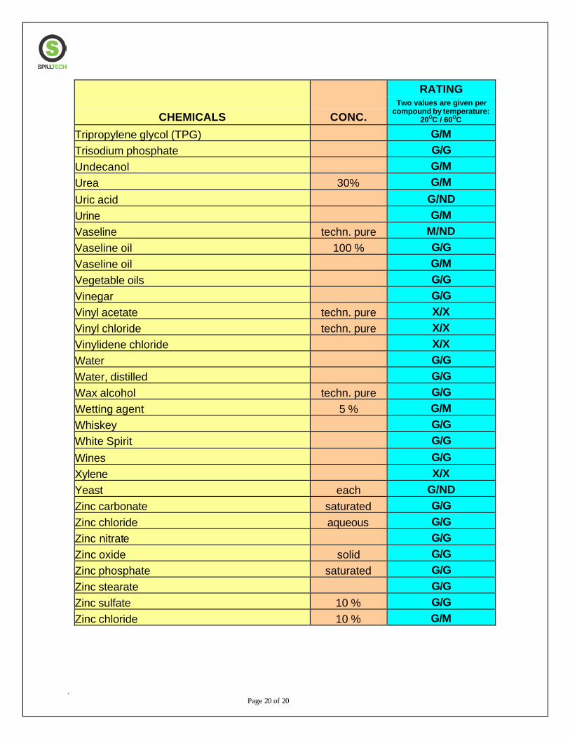
. Page 20 of 20
CHEMICALS CONC.
RATING Two values are given per
compound by temperature: 20OC / 60OC
Tripropylene glycol (TPG) G/M Trisodium phosphate G/G Undecanol G/M Urea 30% G/M Uric acid G/ND Urine G/M Vaseline techn. pure M/ND Vaseline oil 100 % G/G Vaseline oil G/M Vegetable oils G/G Vinegar G/G Vinyl acetate techn. pure X/X Vinyl chloride techn. pure X/X Vinylidene chloride X/X Water G/G Water, distilled G/G Wax alcohol techn. pure G/G Wetting agent 5 % G/M Whiskey G/G White Spirit G/G Wines G/G Xylene X/X Yeast each G/ND Zinc carbonate saturated G/G Zinc chloride aqueous G/G Zinc nitrate G/G Zinc oxide solid G/G Zinc phosphate saturated G/G Zinc stearate G/G Zinc sulfate 10 % G/G Zinc chloride 10 % G/M

KEY:
IMPORTANT USER NOTICE
CUSTOMER SERVICE: 1-800-936-7229 TOLL FREE FAX: 1-800-993-6722
POLYETHYLENE/CHEMICAL COMPATIBILITY GUIDE
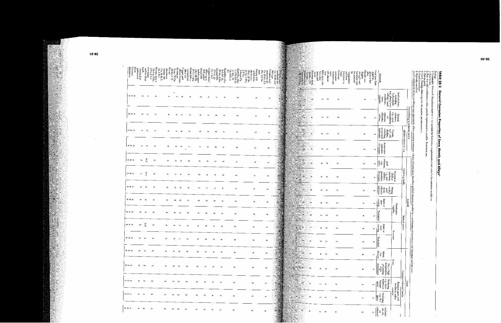

1
APPENDIX M:
ENVIRONMENTAL PROTECTION
LICENCE REQUIREMENTS
EPL requirements, including the treated waste water reinjection criteria, and the treated waste
water harbor discharge criteria, is to be determined upon finalisation of the Environmental
Protection Licence Variation.


![Maths Vocab revised [live]](https://img.dokumen.tips/doc/110x75/633947c50bd7bb626504759f/maths-vocab-revised-live.jpg)

