Embed Size (px)
Citation preview
technologies
Review
Review of Battery Management Systems (BMS) Developmentand Industrial Standards
Hossam A. Gabbar * , Ahmed M. Othman and Muhammad R. Abdussami
�����������������
Citation: Gabbar, H.A.; Othman,
A.M.; Abdussami, M.R. Review of
Battery Management Systems (BMS)
Development and Industrial
Standards. Technologies 2021, 9, 28.
https://doi.org/10.3390/
technologies9020028
Academic Editor: Manoj Gupta
Received: 15 March 2021
Accepted: 9 April 2021
Published: 11 April 2021
Publisher’s Note: MDPI stays neutral
with regard to jurisdictional claims in
published maps and institutional affil-
iations.
Copyright: © 2021 by the authors.
Licensee MDPI, Basel, Switzerland.
This article is an open access article
distributed under the terms and
conditions of the Creative Commons
Attribution (CC BY) license (https://
creativecommons.org/licenses/by/
4.0/).
Faculty of Energy Systems and Nuclear Science, University of Ontario Institute of Technology,Oshawa, ON L1G 0C5, Canada; [email protected] (A.M.O.);[email protected] (M.R.A.)* Correspondence: [email protected]
Abstract: The evolving global landscape for electrical distribution and use created a need area forenergy storage systems (ESS), making them among the fastest growing electrical power systemproducts. A key element in any energy storage system is the capability to monitor, control, andoptimize performance of an individual or multiple battery modules in an energy storage system andthe ability to control the disconnection of the module(s) from the system in the event of abnormalconditions. This management scheme is known as “battery management system (BMS)”, whichis one of the essential units in electrical equipment. BMS reacts with external events, as well withas an internal event. It is used to improve the battery performance with proper safety measureswithin a system. Therefore, a safe BMS is the prerequisite for operating an electrical system. Thisreport analyzes the details of BMS for electric transportation and large-scale (stationary) energystorage. The analysis includes different aspects of BMS covering testing, component, functionalities,topology, operation, architecture, and BMS safety aspects. Additionally, current related standardsand codes related to BMS are also reviewed. The report investigates BMS safety aspects, batterytechnology, regulation needs, and offer recommendations. It further studies current gaps in respectto the safety requirements and performance requirements of BMS by focusing mainly on the electrictransportation and stationary application. The report further provides a framework for developinga new standard on BMS, especially on BMS safety and operational risk. In conclusion, four mainareas of (1) BMS construction, (2) Operation Parameters, (3) BMS Integration, and (4) Installation forimprovement of BMS safety and performance are identified, and detailed recommendations wereprovided for each area. It is recommended that a technical review of the BMS be performed fortransportation electrification and large-scale (stationary) applications. A comprehensive evaluationof the components, architectures, and safety risks applicable to BMS operation is also presented.
Keywords: energy storage safety; control
1. Introduction
The electrical power system is one of the only supply networks where the product—electricity—is consumed instantaneously after it is generated. It is mainly because asafe and reliable means to store electrical energy has been missing. The evolving globallandscape for electrical distribution and use created a need for energy storage systems(ESSs), making them among the fastest-growing electrical power system products.
The maturity of electrical energy storage technologies can be divided into three cate-gories: deployed, demonstrated, and early-stage technologies. Pumped hydro, compressedair energy storage, battery, and flywheel are examples of the deployed electric energystorage system. The demonstrated energy storage technologies include flow batteriesand advanced Pb-acid, superconducting magnetic energy storage, and electrochemicalcapacitor. The early stage energy storage technologies are adiabatic compressed air energystorage (CAES), hydrogen, and synthetic natural gas. Among all the above-mentionedtechnologies, batteries and capacitors are susceptible to risks and safety issues [1].
Technologies 2021, 9, 28. https://doi.org/10.3390/technologies9020028 https://www.mdpi.com/journal/technologies
Technologies 2021, 9, 28 2 of 23
A battery is an electrical energy storage system that can store a considerable amountof energy for a long duration. A battery management system (BMS) is a system controlunit that is modeled to confirm the operational safety of the system battery pack [2–4]. Theprimary operation of a BMS is to safeguard the battery. Due to safety reasons, cell balancing,and aging issues, supervision of each cell is indispensable. Moreover, BMS ensures thepreset corrective measures against any abnormal condition at the system infrastructure.Besides, since the system temperature affects the power consumption profile, BMS alsoconfirms the proper procedure to control the system temperature.
In [5], authors discussed the battery management systems in electric and hybridvehicles. The paper addresses concerns and challenges related to current BMSs. Stateevaluation of a battery, including state of charge, state of health, and state of life, is a criticaltask for a BMS. By reviewing the latest methodologies for the state evaluation of batteries,the future challenges for BMSs are presented, and possible solutions are proposed. In [6],authors discussed the battery management system hardware concepts. It focuses on thehardware aspects of battery management systems (BMS) for electric vehicles and stationaryapplications. In [7], it presented an enhanced multicell-to-multicell battery equalizer basedon bipolar-resonant LC converter. Mathematical analysis and comparison with typicalequalizers are provided to illustrate its high balancing speed and good efficiency.
In [8], it dealt with the susceptibility to electromagnetic interference (EMI) of bat-tery management systems (BMSs) for Li-ion and lithium-polymer (LiPo) battery packsemployed in emerging electric and hybrid electric vehicles. A specific test board was devel-oped to experimentally assess the EMI susceptibility of a BMS front-end integrated circuitby direct power injection (DPI) and radiated susceptibility measurements in an anechoicchamber. In [9], the paper proposed a novel method for accurate hysteresis modeling,which can significantly improve the accuracy of the SOC estimation compared with theconventional methods. The SOC estimation is performed by using an extended Kalmanfilter (EKF), and the parameters of the battery are estimated by using an auto regressiveexogenous (ARX) model and the recursive least square (RLS) filter.
In [10], it presented the battery management system demonstrator board designusing EMC system simulation. The paper explains how EMC system simulation is usedto find the root cause and optimize the board design quickly. In [11], it illustrated aspecific test board developed to experimentally assess the EMI susceptibility of a BMSfront-end integrated circuit by direct power injection (DPI) and radiated susceptibilitymeasurements. Experimental results are discussed by highlighting different EMI-inducedfailure mechanisms observed during the tests.
Kang et al. presented and studied a battery pack’s thermal behavior under the powerdemand [12]. The proposed thermal prediction model is categorized based on Joulesheating with equivalent resistance, reversible heat, and heat dissipation. The equivalentresistances are controlled by the state of charge intervals using the hybrid pulse powercharacterization. In [13], it studied the detailed models of high-power charging impactsand limitations of batteries by the optimization techniques. It presents an optimal operationof the power distribution from the power sources.
Arnieri et al. proposed an efficient management strategy that allows maximizingthe overall energy efficiency of grid-connected storage systems considering the actualrelationship between the efficiency and the charging/discharging power of the storagesystem [14]. Lee et al. proposed a method for estimating pulse power performanceaccording to pulse duration. This method is applied for power generation systems in theapplication of energy storage and transportation electrification [15].
Uno et al. proposed a novel cell voltage equalizer using a selective voltage multiplier.By embedding selection switches into the voltage multiplier-based cell voltage equal-izer, the number of selection switches can be reduced compared to that in conventionaltopologies, realizing the simplified circuit. A prototype for twelve cells was built, and anequalization test using Li-ion batteries was performed [16]. Lee et al. presented a regressionanalysis of the peak point in the incremental capacity (IC) curve from the new state to
Technologies 2021, 9, 28 3 of 23
a 100-cycle aging state. Moreover, the State of Health (SOH) of the considered retiredseries/parallel battery pack was estimated using a regression analysis model. The error inthe SOHs of the retired series/parallel battery pack and linear regression analysis modelwas within 1%, and hence a suitable accuracy is achieved [17].
Currently, there is no specific BMS standard for large-scale applications, small appli-ances, or electric transportation. Considering the importance of BMS and its functionalityin the safe operation of ESSs, the scope of this report is to provide a technical review of BMSfor applications in transportation, electrification, and large-scale (stationary) applications,with a focus on standardization. This report also performs a comprehensive evaluationof the components, architectures, and safety risks during the BMS operation. Besides, itreviews technical standards relevant to the BMS to assist in new standard development.
2. Battery Management System
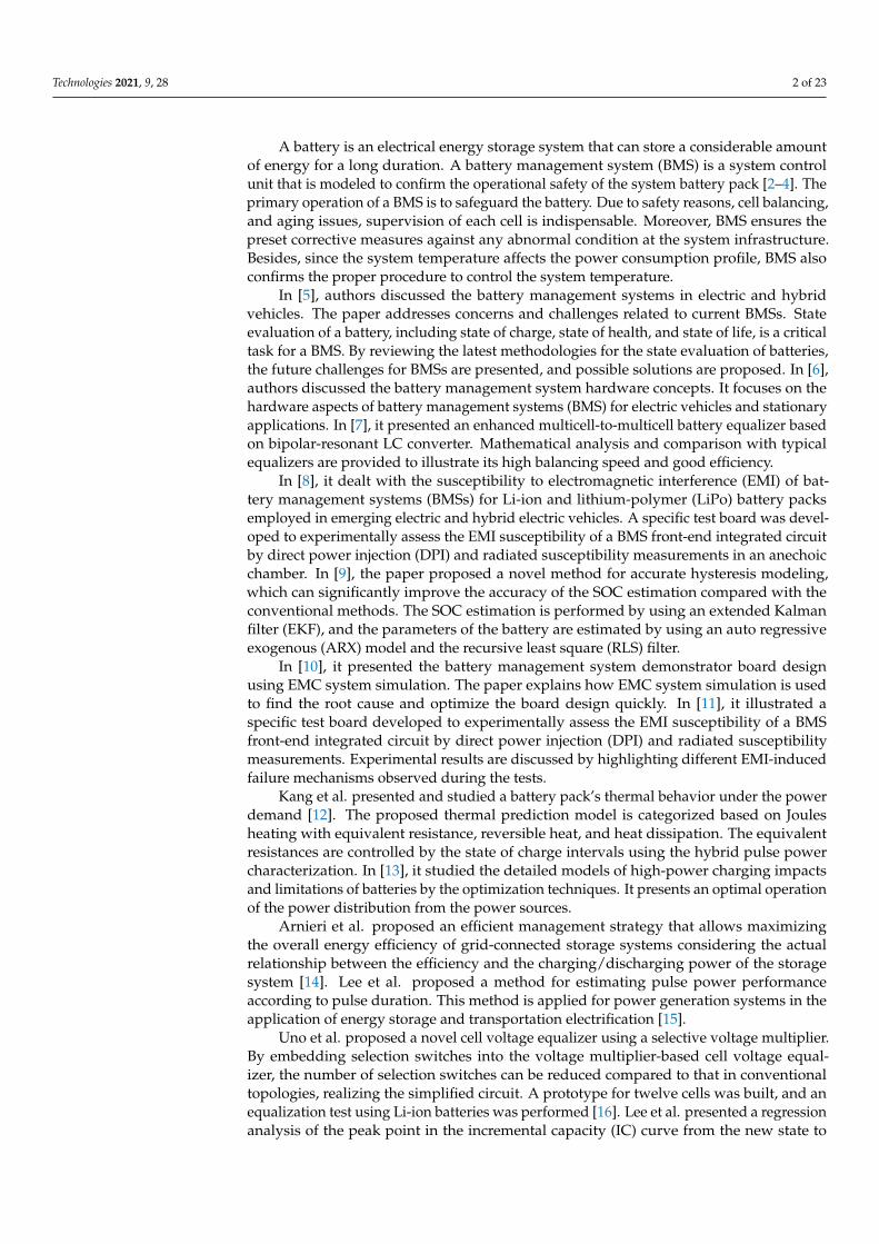
The definition of BMS varies from application to application. In general, BMS refers toa management scheme that monitors, controls, and optimizes an individual’s performanceor multiple battery modules in an energy storage system. BMS can control the disconnectionof the module(s) from the system in the event of abnormal conditions. It is used to improvebattery performance with proper safety measures within a system. In a power systemapplication, BMS is introduced to monitor, control, and deliver the battery’s power at itsmaximum efficiency (battery life is also considered here). In automobile applications, BMSis used for energy management in different system interfaces and ensures the system’ssafety from various hazards. BMS consists of distinct functional blocks. The functionalblocks of BMS are connected to batteries and all other units related to the structuredsystem as controllers, a grid, or other distributed resources, presented in Figure 1. Properarchitecture, functional blocks, and advanced circuitry can extend the system batterylife. Several commercial BMSs are available in markets. For example, NUVATION Energyprovides a flexible, module, reliable, and UL 1973 recognized BMS for mobile and stationaryenergy storage applications [12].
Technologies 2021, 9, 28 3 of 23
ogies, realizing the simplified circuit. A prototype for twelve cells was built, and an equal-ization test using Li-ion batteries was performed [16]. Lee et al. presented a regression analysis of the peak point in the incremental capacity (IC) curve from the new state to a 100-cycle aging state. Moreover, the State of Health (SOH) of the considered retired se-ries/parallel battery pack was estimated using a regression analysis model. The error in the SOHs of the retired series/parallel battery pack and linear regression analysis model was within 1%, and hence a suitable accuracy is achieved [17].
Currently, there is no specific BMS standard for large-scale applications, small appli-ances, or electric transportation. Considering the importance of BMS and its functionality in the safe operation of ESSs, the scope of this report is to provide a technical review of BMS for applications in transportation, electrification, and large-scale (stationary) appli-cations, with a focus on standardization. This report also performs a comprehensive eval-uation of the components, architectures, and safety risks during the BMS operation. Be-sides, it reviews technical standards relevant to the BMS to assist in new standard devel-opment.
2. Battery Management System The definition of BMS varies from application to application. In general, BMS refers
to a management scheme that monitors, controls, and optimizes an individual’s perfor-mance or multiple battery modules in an energy storage system. BMS can control the dis-connection of the module(s) from the system in the event of abnormal conditions. It is used to improve battery performance with proper safety measures within a system. In a power system application, BMS is introduced to monitor, control, and deliver the battery’s power at its maximum efficiency (battery life is also considered here). In automobile ap-plications, BMS is used for energy management in different system interfaces and ensures the system’s safety from various hazards. BMS consists of distinct functional blocks. The functional blocks of BMS are connected to batteries and all other units related to the struc-tured system as controllers, a grid, or other distributed resources, presented in Figure 1. Proper architecture, functional blocks, and advanced circuitry can extend the system bat-tery life. Several commercial BMSs are available in markets. For example, NUVATION Energy provides a flexible, module, reliable, and UL 1973 recognized BMS for mobile and stationary energy storage applications [12].
Figure 1. Battery Management System (BMS) connections and integrations [5]. Figure 1. Battery Management System (BMS) connections and integrations [5].
2.1. Components and Topology
A BMS cannot be used as a standalone within a system infrastructure. It is integratedwith other system modules to accomplish the system objectives. For example, an intelligentenergy automation system includes a battery management module (BMM), battery interface
Technologies 2021, 9, 28 4 of 23
module (BIM), battery units, and battery supervisory control. The system protects thebattery pack, extends the battery lifetime, manages the power demand, and interfaces withthe different network [13].
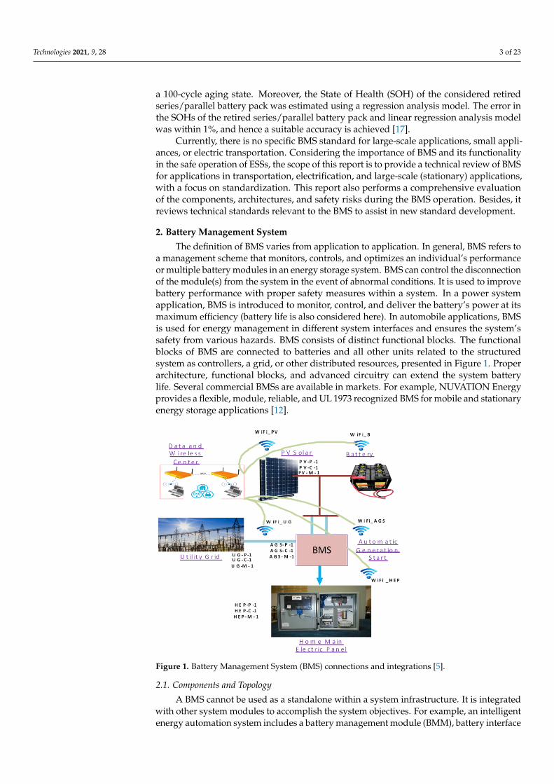
There are three implementation topologies—centralized, distributed, and modular—available in the BMS market. In a centralized topology, a single control unit and batterycells are put together through multiple wires. For distributed topology, each control unit isdedicated to each battery cell by a single communication cable. Lastly, in modular topology,multiple numbers of control units deal with a particular battery cell, but the control unitsare interconnected [14]. The centralized BMS is the most economical and least expandable.The distributed BMS is the costliest, but it is the easiest among the three to install and offersthe cleanest assembly. The modular BMS includes more hardware and programming effortand makes a confrontation between the features and problems of the other two topologies.Figure 2 shows BMS implementation topology.
Technologies 2021, 9, 28 4 of 23
2.1. Components and Topology A BMS cannot be used as a standalone within a system infrastructure. It is integrated
with other system modules to accomplish the system objectives. For example, an intelli-gent energy automation system includes a battery management module (BMM), battery interface module (BIM), battery units, and battery supervisory control. The system pro-tects the battery pack, extends the battery lifetime, manages the power demand, and in-terfaces with the different network [13].
There are three implementation topologies—centralized, distributed, and modular —available in the BMS market. In a centralized topology, a single control unit and battery cells are put together through multiple wires. For distributed topology, each control unit is dedicated to each battery cell by a single communication cable. Lastly, in modular to-pology, multiple numbers of control units deal with a particular battery cell, but the con-trol units are interconnected [14]. The centralized BMS is the most economical and least expandable. The distributed BMS is the costliest, but it is the easiest among the three to install and offers the cleanest assembly. The modular BMS includes more hardware and programming effort and makes a confrontation between the features and problems of the other two topologies. Figure 2 shows BMS implementation topology.
Figure 2. BMS implementation topology: (a) centralized, (b) distributed.
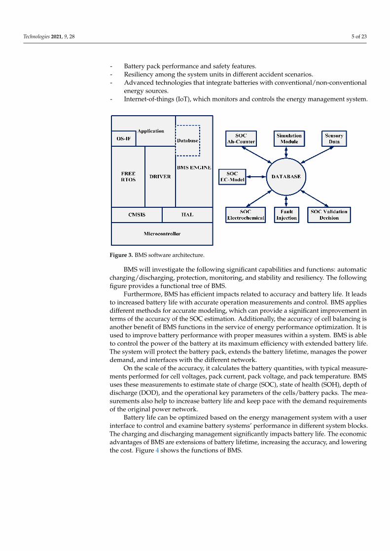
2.2. Software Architecture BMS software architecture offers multi-tasking capabilities. Previously, it was not
possible to continue different tasks simultaneously; one task was postponed to carry on the other task. Now, in new BMS software architecture, various tasks can be carried out together without any interruption. A BMS software architect’s initial tasks, such as volt-age/current measurement, over current/voltage protection, temperature measurement, and protective relay actuation, must be performed promptly to ensure BMS safety. The real-time operating system (RTOS) is introduced in BMS software architecture to perform the real-time functionalities. Figure 3 shows the architecture of BMS software [15].
2.3. Functionalities BMS deals with battery packs that are connected internally or externally. It calculates
the battery quantities, with typical measurements performed for cell voltages, pack cur-rent, pack voltage, and pack temperature. BMS uses these measurements to estimate state of charge (SOC), state of health (SOH), depth of discharge (DOD), and the operational key parameters of the cells/battery packs. The measurements also help to increase battery life and keep pace with the demand requirements of the original power network.
Figure 2. BMS implementation topology: (a) centralized, (b) distributed.
2.2. Software Architecture
BMS software architecture offers multi-tasking capabilities. Previously, it was notpossible to continue different tasks simultaneously; one task was postponed to carry onthe other task. Now, in new BMS software architecture, various tasks can be carriedout together without any interruption. A BMS software architect’s initial tasks, such asvoltage/current measurement, over current/voltage protection, temperature measurement,and protective relay actuation, must be performed promptly to ensure BMS safety. Thereal-time operating system (RTOS) is introduced in BMS software architecture to performthe real-time functionalities. Figure 3 shows the architecture of BMS software [15].
2.3. Functionalities
BMS deals with battery packs that are connected internally or externally. It calculatesthe battery quantities, with typical measurements performed for cell voltages, pack current,pack voltage, and pack temperature. BMS uses these measurements to estimate state ofcharge (SOC), state of health (SOH), depth of discharge (DOD), and the operational keyparameters of the cells/battery packs. The measurements also help to increase battery lifeand keep pace with the demand requirements of the original power network.
BMS is built using functional unit blocks and design techniques. Battery requirementsfor different applications will help to indicate the appropriate architecture, functional unitblocks, and related electronic circuitry to design a BMS and BMS charging scheme. Batterylife can be optimized based on the following features [16]:
- Energy management system with a user interface to control and examine batterysystems’ performance in different system blocks.
Technologies 2021, 9, 28 5 of 23
- Battery pack performance and safety features.- Resiliency among the system units in different accident scenarios.- Advanced technologies that integrate batteries with conventional/non-conventional
energy sources.- Internet-of-things (IoT), which monitors and controls the energy management system.
Technologies 2021, 9, 28 5 of 23
Figure 3. BMS software architecture.
BMS is built using functional unit blocks and design techniques. Battery require-ments for different applications will help to indicate the appropriate architecture, func-tional unit blocks, and related electronic circuitry to design a BMS and BMS charging scheme. Battery life can be optimized based on the following features [16]: ‒ Energy management system with a user interface to control and examine battery sys-
tems’ performance in different system blocks. ‒ Battery pack performance and safety features. ‒ Resiliency among the system units in different accident scenarios. ‒ Advanced technologies that integrate batteries with conventional/non-conventional
energy sources. ‒ Internet-of-things (IoT), which monitors and controls the energy management sys-
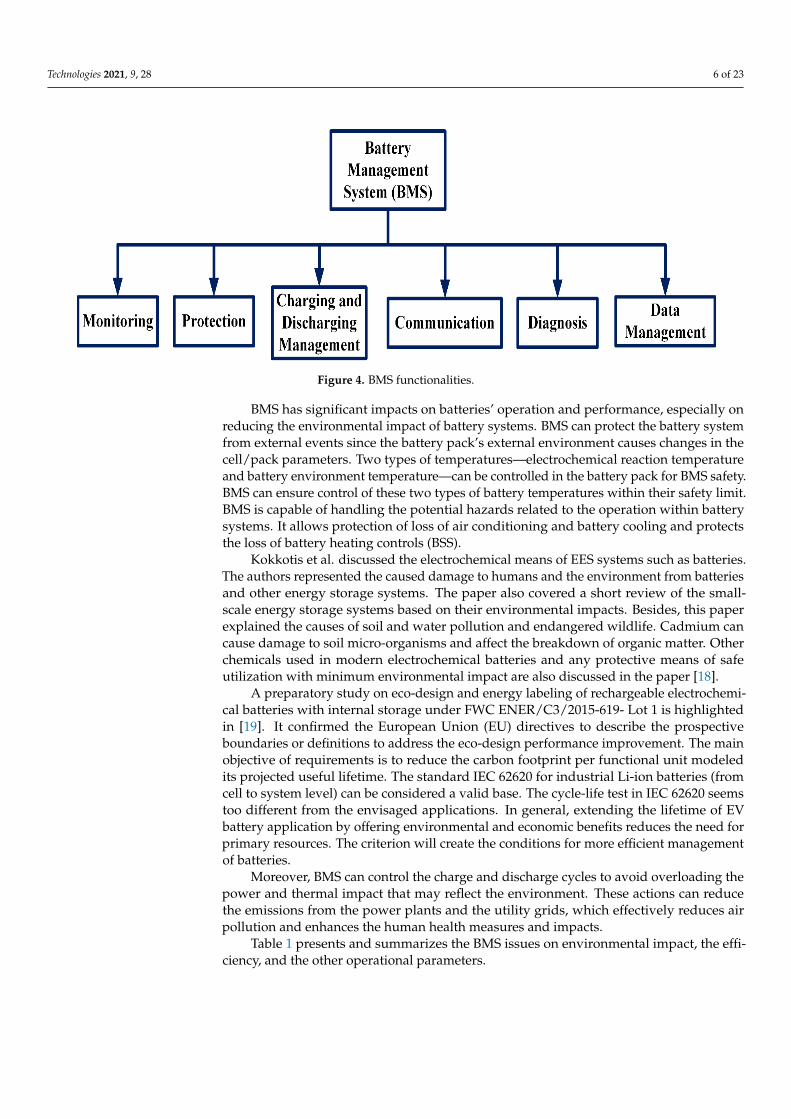
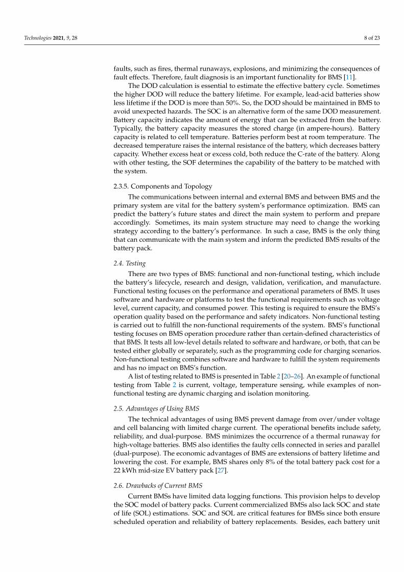
tem. BMS will investigate the following significant capabilities and functions: automatic
charging/discharging, protection, monitoring, and stability and resiliency. The following figure provides a functional tree of BMS.
Furthermore, BMS has efficient impacts related to accuracy and battery life. It leads to increased battery life with accurate operation measurements and control. BMS applies different methods for accurate modeling, which can provide a significant improvement in terms of the accuracy of the SOC estimation. Additionally, the accuracy of cell balancing is another benefit of BMS functions in the service of energy performance optimization. It is used to improve battery performance with proper measures within a system. BMS is able to control the power of the battery at its maximum efficiency with extended battery life. The system will protect the battery pack, extends the battery lifetime, manages the power demand, and interfaces with the different network.
On the scale of the accuracy, it calculates the battery quantities, with typical meas-urements performed for cell voltages, pack current, pack voltage, and pack temperature. BMS uses these measurements to estimate state of charge (SOC), state of health (SOH), depth of discharge (DOD), and the operational key parameters of the cells/battery packs. The measurements also help to increase battery life and keep pace with the demand re-quirements of the original power network.
Battery life can be optimized based on the energy management system with a user interface to control and examine battery systems’ performance in different system blocks. The charging and discharging management significantly impacts battery life. The eco-nomic advantages of BMS are extensions of battery lifetime, increasing the accuracy, and lowering the cost. Figure 4 shows the functions of BMS.
Figure 3. BMS software architecture.
BMS will investigate the following significant capabilities and functions: automaticcharging/discharging, protection, monitoring, and stability and resiliency. The followingfigure provides a functional tree of BMS.
Furthermore, BMS has efficient impacts related to accuracy and battery life. It leadsto increased battery life with accurate operation measurements and control. BMS appliesdifferent methods for accurate modeling, which can provide a significant improvement interms of the accuracy of the SOC estimation. Additionally, the accuracy of cell balancing isanother benefit of BMS functions in the service of energy performance optimization. It isused to improve battery performance with proper measures within a system. BMS is ableto control the power of the battery at its maximum efficiency with extended battery life.The system will protect the battery pack, extends the battery lifetime, manages the powerdemand, and interfaces with the different network.
On the scale of the accuracy, it calculates the battery quantities, with typical measure-ments performed for cell voltages, pack current, pack voltage, and pack temperature. BMSuses these measurements to estimate state of charge (SOC), state of health (SOH), depth ofdischarge (DOD), and the operational key parameters of the cells/battery packs. The mea-surements also help to increase battery life and keep pace with the demand requirementsof the original power network.
Battery life can be optimized based on the energy management system with a userinterface to control and examine battery systems’ performance in different system blocks.The charging and discharging management significantly impacts battery life. The economicadvantages of BMS are extensions of battery lifetime, increasing the accuracy, and loweringthe cost. Figure 4 shows the functions of BMS.
Technologies 2021, 9, 28 6 of 23Technologies 2021, 9, 28 6 of 23
Figure 4. BMS functionalities.
BMS has significant impacts on batteries’ operation and performance, especially on reducing the environmental impact of battery systems. BMS can protect the battery system from external events since the battery pack’s external environment causes changes in the cell/pack parameters. Two types of temperatures—electrochemical reaction temperature and battery environment temperature—can be controlled in the battery pack for BMS safety. BMS can ensure control of these two types of battery temperatures within their safety limit. BMS is capable of handling the potential hazards related to the operation within battery systems. It allows protection of loss of air conditioning and battery cooling and protects the loss of battery heating controls (BSS).
Kokkotis et al. discussed the electrochemical means of EES systems such as batteries. The authors represented the caused damage to humans and the environment from batter-ies and other energy storage systems. The paper also covered a short review of the small-scale energy storage systems based on their environmental impacts. Besides, this paper explained the causes of soil and water pollution and endangered wildlife. Cadmium can cause damage to soil micro-organisms and affect the breakdown of organic matter. Other chemicals used in modern electrochemical batteries and any protective means of safe uti-lization with minimum environmental impact are also discussed in the paper [18].
A preparatory study on eco-design and energy labeling of rechargeable electrochem-ical batteries with internal storage under FWC ENER/C3/2015-619- Lot 1 is highlighted in [19]. It confirmed the European Union (EU) directives to describe the prospective bound-aries or definitions to address the eco-design performance improvement. The main objec-tive of requirements is to reduce the carbon footprint per functional unit modeled its pro-jected useful lifetime. The standard IEC 62620 for industrial Li-ion batteries (from cell to system level) can be considered a valid base. The cycle-life test in IEC 62620 seems too different from the envisaged applications. In general, extending the lifetime of EV battery application by offering environmental and economic benefits reduces the need for pri-mary resources. The criterion will create the conditions for more efficient management of batteries.
Moreover, BMS can control the charge and discharge cycles to avoid overloading the power and thermal impact that may reflect the environment. These actions can reduce the emissions from the power plants and the utility grids, which effectively reduces air pol-lution and enhances the human health measures and impacts.
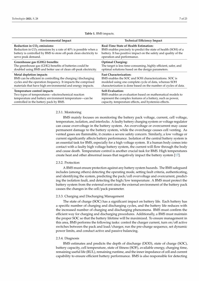
Table 1 presents and summarizes the BMS issues on environmental impact, the effi-ciency, and the other operational parameters.
Figure 4. BMS functionalities.
BMS has significant impacts on batteries’ operation and performance, especially onreducing the environmental impact of battery systems. BMS can protect the battery systemfrom external events since the battery pack’s external environment causes changes in thecell/pack parameters. Two types of temperatures—electrochemical reaction temperatureand battery environment temperature—can be controlled in the battery pack for BMS safety.BMS can ensure control of these two types of battery temperatures within their safety limit.BMS is capable of handling the potential hazards related to the operation within batterysystems. It allows protection of loss of air conditioning and battery cooling and protectsthe loss of battery heating controls (BSS).
Kokkotis et al. discussed the electrochemical means of EES systems such as batteries.The authors represented the caused damage to humans and the environment from batteriesand other energy storage systems. The paper also covered a short review of the small-scale energy storage systems based on their environmental impacts. Besides, this paperexplained the causes of soil and water pollution and endangered wildlife. Cadmium cancause damage to soil micro-organisms and affect the breakdown of organic matter. Otherchemicals used in modern electrochemical batteries and any protective means of safeutilization with minimum environmental impact are also discussed in the paper [18].
A preparatory study on eco-design and energy labeling of rechargeable electrochemi-cal batteries with internal storage under FWC ENER/C3/2015-619- Lot 1 is highlightedin [19]. It confirmed the European Union (EU) directives to describe the prospectiveboundaries or definitions to address the eco-design performance improvement. The mainobjective of requirements is to reduce the carbon footprint per functional unit modeledits projected useful lifetime. The standard IEC 62620 for industrial Li-ion batteries (fromcell to system level) can be considered a valid base. The cycle-life test in IEC 62620 seemstoo different from the envisaged applications. In general, extending the lifetime of EVbattery application by offering environmental and economic benefits reduces the need forprimary resources. The criterion will create the conditions for more efficient managementof batteries.
Moreover, BMS can control the charge and discharge cycles to avoid overloading thepower and thermal impact that may reflect the environment. These actions can reducethe emissions from the power plants and the utility grids, which effectively reduces airpollution and enhances the human health measures and impacts.
Table 1 presents and summarizes the BMS issues on environmental impact, the effi-ciency, and the other operational parameters.
Technologies 2021, 9, 28 7 of 23
Table 1. BMS impacts.
Environmental Impact Technical Efficiency Impact
Reduction in CO2 emissions:Reduction in CO2 emissions by a rate of 40% is possible when abattery is controlled by BMS to store off-peak clean electricity toserve peak demand.
Real-Time State of Health Estimation:BMS enables precisely to predict the state of health (SOH) of abattery. It has positive impact on the safety and quality of theoperation and performance.
Greenhouse gas (GHG) benefits:The greenhouse gas (GHG) benefits of batteries could bedoubled using BMS and better use of clean off-peak electricity.
Optimal Charging:The target is less time-consuming, highly efficient, safer, andoptimal solutions based on the design parameters.
Metal depletion impactsBMS can be efficient in controlling the charging/dischargingcycles and the operation frequency. It impacts the comprisedmaterials that have high environmental and energy impacts.
Fast Characterization:BMS enables the SOC and SOH characterizations. SOC ismodeled using one complete cycle of data, whereas SOHcharacterization is done based on the number of cycles of data.
Temperature control impactsTwo types of temperatures—electrochemical reactiontemperature and battery environment temperature—can becontrolled in the battery pack by BMS.
Self-Evaluation:BMS enables an evaluation based on mathematical models torepresent the complex features of a battery, such as power,capacity, temperature effects, and hysteresis effects.
2.3.1. Monitoring
BMS mainly focuses on monitoring the battery pack voltage, current, cell voltage,temperature, isolation, and interlocks. A faulty battery charging system or voltage regulatorcan cause overvoltage in the battery system. An overvoltage or overcurrent may causepermanent damage to the battery system, while the overcharge causes cell venting. Asvented gases are flammable, it creates a severe safety concern. Similarly, a low voltage orcurrent significantly affects battery performance. Isolation of the central battery system isan essential task for BMS, especially for a high voltage system. If a human body comes intocontact with a faulty high voltage battery system, the current will flow through the bodyand cause death. Temperature control is another crucial task for BMS. High temperaturescreate heat and other abnormal issues that negatively impact the battery system [17].
2.3.2. Protection
A BMS must ensure protection against any battery system hazards. The BMS safeguardincludes (among others) detecting the operating mode, setting fault criteria, authenticating,and identifying the system, predicting the pack/cell overvoltage and overcurrent, predict-ing the isolation fault, and detecting the high/low temperature. A BMS must protect thebattery system from the external event since the external environment of the battery packcauses the changes in the cell/pack parameter.
2.3.3. Charging and Discharging Management
The state of charge (SOC) has a significant impact on battery life. Each battery hasa specific number of charging and discharging cycles, and the battery life reduces withthe increased number of charging and discharging phenomena. BMS must confirm theefficient way for charging and discharging procedures. Additionally, a BMS must maintainthe proper SOC so that the battery lifetime will be maximized. To ensure management inthis area, BMS performs the following tasks: control the charger current, turn on/off activeswitches between the pack and load/charger, run the pre-charge sequence, set dynamicpower limits, and conduct active and passive balancing.
2.3.4. Diagnosis
BMS estimates and predicts the depth of discharge (DOD), state of charge (SOC),battery capacity, cell temperature, state of fitness (SOF), available energy, charging time,remaining useful life (RUL), remaining runtime, and the inner impedance of cell and currentcapability to ensure efficient battery performance. BMS is also responsible for detecting
Technologies 2021, 9, 28 8 of 23
faults, such as fires, thermal runaways, explosions, and minimizing the consequences offault effects. Therefore, fault diagnosis is an important functionality for BMS [11].
The DOD calculation is essential to estimate the effective battery cycle. Sometimesthe higher DOD will reduce the battery lifetime. For example, lead-acid batteries showless lifetime if the DOD is more than 50%. So, the DOD should be maintained in BMS toavoid unexpected hazards. The SOC is an alternative form of the same DOD measurement.Battery capacity indicates the amount of energy that can be extracted from the battery.Typically, the battery capacity measures the stored charge (in ampere-hours). Batterycapacity is related to cell temperature. Batteries perform best at room temperature. Thedecreased temperature raises the internal resistance of the battery, which decreases batterycapacity. Whether excess heat or excess cold, both reduce the C-rate of the battery. Alongwith other testing, the SOF determines the capability of the battery to be matched withthe system.
2.3.5. Components and Topology
The communications between internal and external BMS and between BMS and theprimary system are vital for the battery system’s performance optimization. BMS canpredict the battery’s future states and direct the main system to perform and prepareaccordingly. Sometimes, its main system structure may need to change the workingstrategy according to the battery’s performance. In such a case, BMS is the only thingthat can communicate with the main system and inform the predicted BMS results of thebattery pack.
2.4. Testing
There are two types of BMS: functional and non-functional testing, which includethe battery’s lifecycle, research and design, validation, verification, and manufacture.Functional testing focuses on the performance and operational parameters of BMS. It usessoftware and hardware or platforms to test the functional requirements such as voltagelevel, current capacity, and consumed power. This testing is required to ensure the BMS’soperation quality based on the performance and safety indicators. Non-functional testingis carried out to fulfill the non-functional requirements of the system. BMS’s functionaltesting focuses on BMS operation procedure rather than certain-defined characteristics ofthat BMS. It tests all low-level details related to software and hardware, or both, that can betested either globally or separately, such as the programming code for charging scenarios.Non-functional testing combines software and hardware to fulfill the system requirementsand has no impact on BMS’s function.
A list of testing related to BMS is presented in Table 2 [20–26]. An example of functionaltesting from Table 2 is current, voltage, temperature sensing, while examples of non-functional testing are dynamic charging and isolation monitoring.
2.5. Advantages of Using BMS
The technical advantages of using BMS prevent damage from over/under voltageand cell balancing with limited charge current. The operational benefits include safety,reliability, and dual-purpose. BMS minimizes the occurrence of a thermal runaway forhigh-voltage batteries. BMS also identifies the faulty cells connected in series and parallel(dual-purpose). The economic advantages of BMS are extensions of battery lifetime andlowering the cost. For example, BMS shares only 8% of the total battery pack cost for a22 kWh mid-size EV battery pack [27].
2.6. Drawbacks of Current BMS
Current BMSs have limited data logging functions. This provision helps to developthe SOC model of battery packs. Current commercialized BMSs also lack SOC and stateof life (SOL) estimations. SOC and SOL are critical features for BMSs since both ensurescheduled operation and reliability of battery replacements. Besides, each battery unit
Technologies 2021, 9, 28 9 of 23
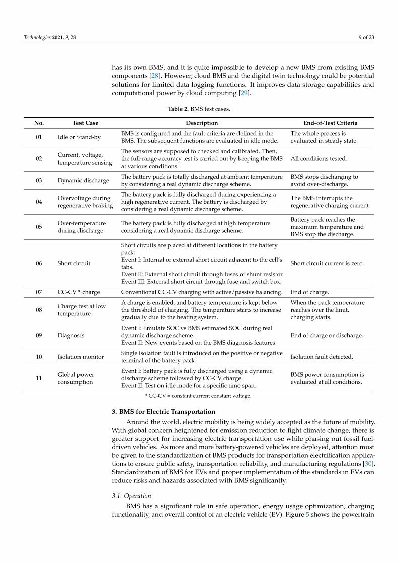
has its own BMS, and it is quite impossible to develop a new BMS from existing BMScomponents [28]. However, cloud BMS and the digital twin technology could be potentialsolutions for limited data logging functions. It improves data storage capabilities andcomputational power by cloud computing [29].
Table 2. BMS test cases.
No. Test Case Description End-of-Test Criteria
01 Idle or Stand-by BMS is configured and the fault criteria are defined in theBMS. The subsequent functions are evaluated in idle mode.
The whole process isevaluated in steady state.
02 Current, voltage,temperature sensing
The sensors are supposed to checked and calibrated. Then,the full-range accuracy test is carried out by keeping the BMSat various conditions.
All conditions tested.
03 Dynamic discharge The battery pack is totally discharged at ambient temperatureby considering a real dynamic discharge scheme.
BMS stops discharging toavoid over-discharge.
04 Overvoltage duringregenerative braking
The battery pack is fully discharged during experiencing ahigh regenerative current. The battery is discharged byconsidering a real dynamic discharge scheme.
The BMS interrupts theregenerative charging current.
05 Over-temperatureduring discharge
The battery pack is fully discharged at high temperatureconsidering a real dynamic discharge scheme.
Battery pack reaches themaximum temperature andBMS stop the discharge.
06 Short circuit
Short circuits are placed at different locations in the batterypack:Event I: Internal or external short circuit adjacent to the cell’stabs.Event II: External short circuit through fuses or shunt resistor.Event III: External short circuit through fuse and switch box.
Short circuit current is zero.
07 CC-CV * charge Conventional CC-CV charging with active/passive balancing. End of charge.
08 Charge test at lowtemperature
A charge is enabled, and battery temperature is kept belowthe threshold of charging. The temperature starts to increasegradually due to the heating system.
When the pack temperaturereaches over the limit,charging starts.
09 DiagnosisEvent I: Emulate SOC vs BMS estimated SOC during realdynamic discharge scheme.Event II: New events based on the BMS diagnosis features.
End of charge or discharge.
10 Isolation monitor Single isolation fault is introduced on the positive or negativeterminal of the battery pack. Isolation fault detected.
11 Global powerconsumption
Event I: Battery pack is fully discharged using a dynamicdischarge scheme followed by CC-CV charge.Event II: Test on idle mode for a specific time span.
BMS power consumption isevaluated at all conditions.
* CC-CV = constant current constant voltage.
3. BMS for Electric Transportation
Around the world, electric mobility is being widely accepted as the future of mobility.With global concern heightened for emission reduction to fight climate change, there isgreater support for increasing electric transportation use while phasing out fossil fuel-driven vehicles. As more and more battery-powered vehicles are deployed, attention mustbe given to the standardization of BMS products for transportation electrification applica-tions to ensure public safety, transportation reliability, and manufacturing regulations [30].Standardization of BMS for EVs and proper implementation of the standards in EVs canreduce risks and hazards associated with BMS significantly.
3.1. Operation
BMS has a significant role in safe operation, energy usage optimization, chargingfunctionality, and overall control of an electric vehicle (EV). Figure 5 shows the powertrain
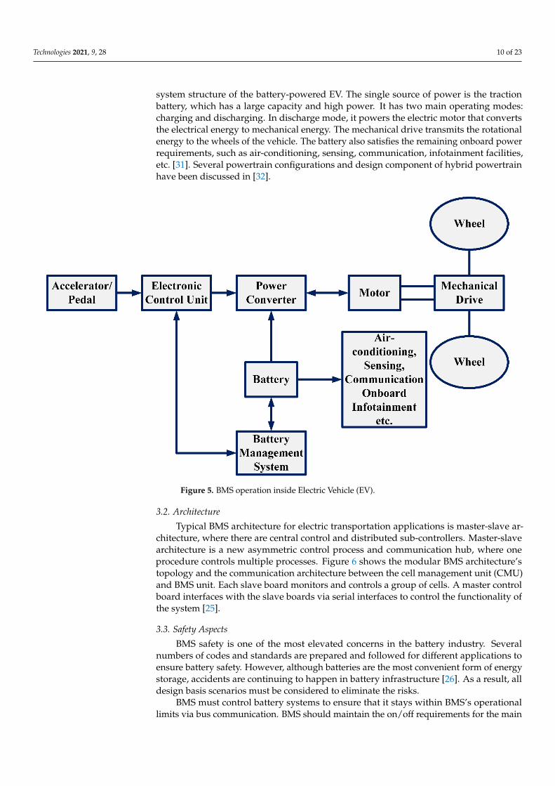
Technologies 2021, 9, 28 10 of 23
system structure of the battery-powered EV. The single source of power is the tractionbattery, which has a large capacity and high power. It has two main operating modes:charging and discharging. In discharge mode, it powers the electric motor that convertsthe electrical energy to mechanical energy. The mechanical drive transmits the rotationalenergy to the wheels of the vehicle. The battery also satisfies the remaining onboard powerrequirements, such as air-conditioning, sensing, communication, infotainment facilities,etc. [31]. Several powertrain configurations and design component of hybrid powertrainhave been discussed in [32].
Technologies 2021, 9, 28 10 of 23
be given to the standardization of BMS products for transportation electrification applica-tions to ensure public safety, transportation reliability, and manufacturing regulations [30]. Standardization of BMS for EVs and proper implementation of the standards in EVs can reduce risks and hazards associated with BMS significantly.
3.1. Operation BMS has a significant role in safe operation, energy usage optimization, charging
functionality, and overall control of an electric vehicle (EV). Figure 5 shows the powertrain system structure of the battery-powered EV. The single source of power is the traction battery, which has a large capacity and high power. It has two main operating modes: charging and discharging. In discharge mode, it powers the electric motor that converts the electrical energy to mechanical energy. The mechanical drive transmits the rotational energy to the wheels of the vehicle. The battery also satisfies the remaining onboard power requirements, such as air-conditioning, sensing, communication, infotainment facilities, etc. [31]. Several powertrain configurations and design component of hybrid powertrain have been discussed in [32].
Figure 5. BMS operation inside Electric Vehicle (EV).
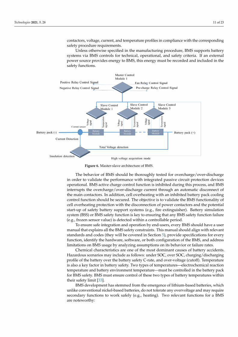
3.2. Architecture Typical BMS architecture for electric transportation applications is master-slave ar-
chitecture, where there are central control and distributed sub-controllers. Master-slave architecture is a new asymmetric control process and communication hub, where one pro-cedure controls multiple processes. Figure 6 shows the modular BMS architecture’s topol-ogy and the communication architecture between the cell management unit (CMU) and BMS unit. Each slave board monitors and controls a group of cells. A master control board interfaces with the slave boards via serial interfaces to control the functionality of the sys-tem [25].
Figure 5. BMS operation inside Electric Vehicle (EV).
3.2. Architecture
Typical BMS architecture for electric transportation applications is master-slave ar-chitecture, where there are central control and distributed sub-controllers. Master-slavearchitecture is a new asymmetric control process and communication hub, where oneprocedure controls multiple processes. Figure 6 shows the modular BMS architecture’stopology and the communication architecture between the cell management unit (CMU)and BMS unit. Each slave board monitors and controls a group of cells. A master controlboard interfaces with the slave boards via serial interfaces to control the functionality ofthe system [25].
3.3. Safety Aspects
BMS safety is one of the most elevated concerns in the battery industry. Severalnumbers of codes and standards are prepared and followed for different applications toensure battery safety. However, although batteries are the most convenient form of energystorage, accidents are continuing to happen in battery infrastructure [26]. As a result, alldesign basis scenarios must be considered to eliminate the risks.
BMS must control battery systems to ensure that it stays within BMS’s operationallimits via bus communication. BMS should maintain the on/off requirements for the main
Technologies 2021, 9, 28 11 of 23
contactors, voltage, current, and temperature profiles in compliance with the correspondingsafety procedure requirements.
Unless otherwise specified in the manufacturing procedure, BMS supports batterysystems via BMS controls for technical, operational, and safety criteria. If an externalpower source provides energy to BMS, this energy must be recorded and included in thesafety functions.
Technologies 2021, 9, 28 11 of 23
Figure 6. Master-slave architecture of BMS.
3.3. Safety Aspects BMS safety is one of the most elevated concerns in the battery industry. Several num-
bers of codes and standards are prepared and followed for different applications to ensure battery safety. However, although batteries are the most convenient form of energy stor-age, accidents are continuing to happen in battery infrastructure [26]. As a result, all de-sign basis scenarios must be considered to eliminate the risks.
BMS must control battery systems to ensure that it stays within BMS’s operational limits via bus communication. BMS should maintain the on/off requirements for the main contactors, voltage, current, and temperature profiles in compliance with the correspond-ing safety procedure requirements.
Unless otherwise specified in the manufacturing procedure, BMS supports battery systems via BMS controls for technical, operational, and safety criteria. If an external power source provides energy to BMS, this energy must be recorded and included in the safety functions.
The behavior of BMS should be thoroughly tested for overcharge/over-discharge in order to validate the performance with integrated passive circuit protection devices oper-ational. BMS active charge control function is inhibited during this process, and BMS in-terrupts the overcharge/over-discharge current through an automatic disconnect of the main contactors. In addition, cell overheating with an inhibited battery pack cooling con-trol function should be secured. The objective is to validate the BMS functionality of cell overheating protection with the disconnection of power contactors and the potential start-up of safety battery support systems (e.g., fire extinguisher). Battery simulation system (BSS) or BMS safety function is key to ensuring that any BMS safety function failure (e.g., frozen sensor value) is detected within a controllable period.
To ensure safe integration and operation by end-users, every BMS should have a user manual that explains all the BMS safety constraints. This manual should align with rele-vant standards and codes (they will be covered in Section 5), provide specifications for every function, identify the hardware, software, or both configuration of the BMS, and address limitations on BMS usage by analyzing assumptions on its behavior or failure rates.
Chemical characteristics are one of the most dominant causes of battery accidents. Hazardous scenarios may include as follows: under SOC, over SOC, charging/discharging profile of the battery over the battery safety C-rate, and over-voltage (cutoff). Temperature is also a key factor in battery safety. Two types of temperatures—electrochemical reaction
Figure 6. Master-slave architecture of BMS.
The behavior of BMS should be thoroughly tested for overcharge/over-dischargein order to validate the performance with integrated passive circuit protection devicesoperational. BMS active charge control function is inhibited during this process, and BMSinterrupts the overcharge/over-discharge current through an automatic disconnect ofthe main contactors. In addition, cell overheating with an inhibited battery pack coolingcontrol function should be secured. The objective is to validate the BMS functionality ofcell overheating protection with the disconnection of power contactors and the potentialstart-up of safety battery support systems (e.g., fire extinguisher). Battery simulationsystem (BSS) or BMS safety function is key to ensuring that any BMS safety function failure(e.g., frozen sensor value) is detected within a controllable period.
To ensure safe integration and operation by end-users, every BMS should have a usermanual that explains all the BMS safety constraints. This manual should align with relevantstandards and codes (they will be covered in Section 5), provide specifications for everyfunction, identify the hardware, software, or both configuration of the BMS, and addresslimitations on BMS usage by analyzing assumptions on its behavior or failure rates.
Chemical characteristics are one of the most dominant causes of battery accidents.Hazardous scenarios may include as follows: under SOC, over SOC, charging/dischargingprofile of the battery over the battery safety C-rate, and over-voltage (cutoff). Temperatureis also a key factor in battery safety. Two types of temperatures—electrochemical reactiontemperature and battery environment temperature—must be controlled in the battery packfor BMS safety. BMS must ensure control of these two types of battery temperatures withintheir safety limit [33].
BMS development has stemmed from the emergence of lithium-based batteries, whichunlike conventional nickel-based batteries, do not tolerate any overvoltage and may requiresecondary functions to work safely (e.g., heating). Two relevant functions for a BMSare noteworthy:
Technologies 2021, 9, 28 12 of 23
i. Overvoltage protection, a safety-related battery protection action.ii. Accurate cell balancing, a function in the service of energy storage performance op-
timization.
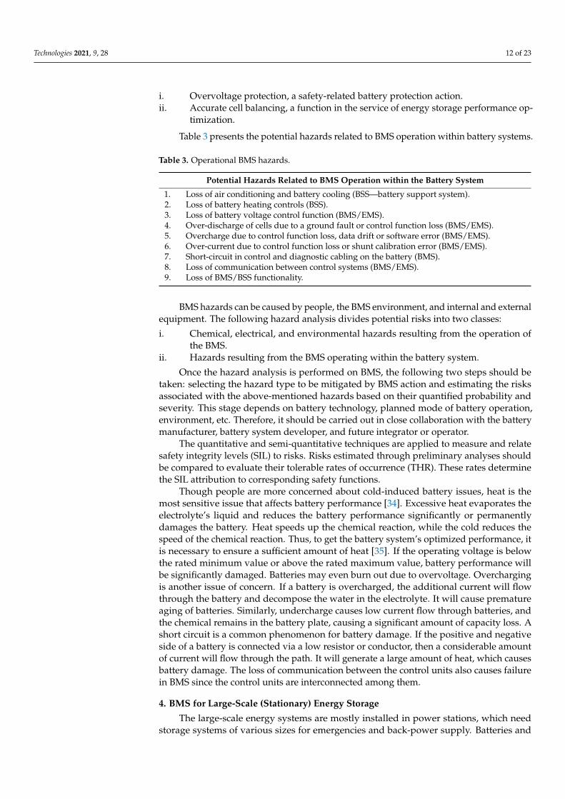
Table 3 presents the potential hazards related to BMS operation within battery systems.
Table 3. Operational BMS hazards.
Potential Hazards Related to BMS Operation within the Battery System
1. Loss of air conditioning and battery cooling (BSS—battery support system).2. Loss of battery heating controls (BSS).3. Loss of battery voltage control function (BMS/EMS).4. Over-discharge of cells due to a ground fault or control function loss (BMS/EMS).5. Overcharge due to control function loss, data drift or software error (BMS/EMS).6. Over-current due to control function loss or shunt calibration error (BMS/EMS).7. Short-circuit in control and diagnostic cabling on the battery (BMS).8. Loss of communication between control systems (BMS/EMS).9. Loss of BMS/BSS functionality.
BMS hazards can be caused by people, the BMS environment, and internal and externalequipment. The following hazard analysis divides potential risks into two classes:
i. Chemical, electrical, and environmental hazards resulting from the operation ofthe BMS.
ii. Hazards resulting from the BMS operating within the battery system.
Once the hazard analysis is performed on BMS, the following two steps should betaken: selecting the hazard type to be mitigated by BMS action and estimating the risksassociated with the above-mentioned hazards based on their quantified probability andseverity. This stage depends on battery technology, planned mode of battery operation,environment, etc. Therefore, it should be carried out in close collaboration with the batterymanufacturer, battery system developer, and future integrator or operator.
The quantitative and semi-quantitative techniques are applied to measure and relatesafety integrity levels (SIL) to risks. Risks estimated through preliminary analyses shouldbe compared to evaluate their tolerable rates of occurrence (THR). These rates determinethe SIL attribution to corresponding safety functions.
Though people are more concerned about cold-induced battery issues, heat is themost sensitive issue that affects battery performance [34]. Excessive heat evaporates theelectrolyte’s liquid and reduces the battery performance significantly or permanentlydamages the battery. Heat speeds up the chemical reaction, while the cold reduces thespeed of the chemical reaction. Thus, to get the battery system’s optimized performance, itis necessary to ensure a sufficient amount of heat [35]. If the operating voltage is belowthe rated minimum value or above the rated maximum value, battery performance willbe significantly damaged. Batteries may even burn out due to overvoltage. Overchargingis another issue of concern. If a battery is overcharged, the additional current will flowthrough the battery and decompose the water in the electrolyte. It will cause prematureaging of batteries. Similarly, undercharge causes low current flow through batteries, andthe chemical remains in the battery plate, causing a significant amount of capacity loss. Ashort circuit is a common phenomenon for battery damage. If the positive and negativeside of a battery is connected via a low resistor or conductor, then a considerable amountof current will flow through the path. It will generate a large amount of heat, which causesbattery damage. The loss of communication between the control units also causes failurein BMS since the control units are interconnected among them.
4. BMS for Large-Scale (Stationary) Energy Storage
The large-scale energy systems are mostly installed in power stations, which needstorage systems of various sizes for emergencies and back-power supply. Batteries and
Technologies 2021, 9, 28 13 of 23
flywheels are the most common forms of energy storage systems being used for large-scale applications.
4.1. BMS for Energy Storage System at a Substation
Installation energy storage for power substation will achieve load phase balancing,which is essential to maintaining safety. The integration of single-phase renewable energies(e.g., solar power, wind power, etc.) with large loads can cause phase imbalance, causingenergy loss and system failure. Accordingly, it is better to take proper precautions tominimize the phase imbalance scenario [34].
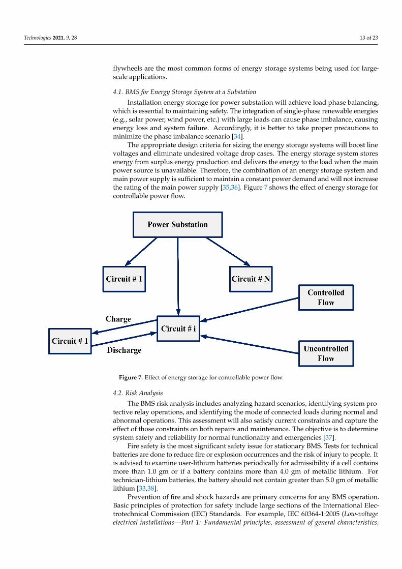
The appropriate design criteria for sizing the energy storage systems will boost linevoltages and eliminate undesired voltage drop cases. The energy storage system storesenergy from surplus energy production and delivers the energy to the load when the mainpower source is unavailable. Therefore, the combination of an energy storage system andmain power supply is sufficient to maintain a constant power demand and will not increasethe rating of the main power supply [35,36]. Figure 7 shows the effect of energy storage forcontrollable power flow.
Technologies 2021, 9, 28 13 of 23
short circuit is a common phenomenon for battery damage. If the positive and negative side of a battery is connected via a low resistor or conductor, then a considerable amount of current will flow through the path. It will generate a large amount of heat, which causes battery damage. The loss of communication between the control units also causes failure in BMS since the control units are interconnected among them.
4. BMS for Large-Scale (Stationary) Energy Storage The large-scale energy systems are mostly installed in power stations, which need
storage systems of various sizes for emergencies and back-power supply. Batteries and flywheels are the most common forms of energy storage systems being used for large-scale applications.
4.1. BMS for Energy Storage System at a Substation Installation energy storage for power substation will achieve load phase balancing,
which is essential to maintaining safety. The integration of single-phase renewable ener-gies (e.g., solar power, wind power, etc.) with large loads can cause phase imbalance, causing energy loss and system failure. Accordingly, it is better to take proper precautions to minimize the phase imbalance scenario [34].
The appropriate design criteria for sizing the energy storage systems will boost line voltages and eliminate undesired voltage drop cases. The energy storage system stores energy from surplus energy production and delivers the energy to the load when the main power source is unavailable. Therefore, the combination of an energy storage system and main power supply is sufficient to maintain a constant power demand and will not in-crease the rating of the main power supply [35,36]. Figure 7 shows the effect of energy storage for controllable power flow.
Figure 7. Effect of energy storage for controllable power flow.
4.2. Risk Analysis The BMS risk analysis includes analyzing hazard scenarios, identifying system pro-
tective relay operations, and identifying the mode of connected loads during normal and abnormal operations. This assessment will also satisfy current constraints and capture the effect of those constraints on both repairs and maintenance. The objective is to determine system safety and reliability for normal functionality and emergencies [37].
Figure 7. Effect of energy storage for controllable power flow.
4.2. Risk Analysis
The BMS risk analysis includes analyzing hazard scenarios, identifying system pro-tective relay operations, and identifying the mode of connected loads during normal andabnormal operations. This assessment will also satisfy current constraints and capture theeffect of those constraints on both repairs and maintenance. The objective is to determinesystem safety and reliability for normal functionality and emergencies [37].
Fire safety is the most significant safety issue for stationary BMS. Tests for technicalbatteries are done to reduce fire or explosion occurrences and the risk of injury to people. Itis advised to examine user-lithium batteries periodically for admissibility if a cell containsmore than 1.0 gm or if a battery contains more than 4.0 gm of metallic lithium. Fortechnician-lithium batteries, the battery should not contain greater than 5.0 gm of metalliclithium [33,38].
Prevention of fire and shock hazards are primary concerns for any BMS operation.Basic principles of protection for safety include large sections of the International Elec-trotechnical Commission (IEC) Standards. For example, IEC 60364-1:2005 (Low-voltageelectrical installations—Part 1: Fundamental principles, assessment of general characteristics,

Technologies 2021, 9, 28 14 of 23
definitions) addresses the procedure for design, construction, and verification of electricalequipment installed in different sites (stationary and mobile) and applications.
There are storage systems that include hazardous and flammable battery chemicals.They are used in different industries, including the automotive industry. However, thereare currently no legal regulations or requirements to store this type of battery. Certificationorganizations, fire consultants, and fire brigades have been working with energy storageconsultants to find viable solutions. Even so, companies are generally reluctant to speakopenly about their experiences with lithium-ion batteries, making it difficult to form anindustry consensus [39]. Despite this issue, the rest of the requirements that are generallyunderstood and respected: “safe zone”, “operation boundary”, and “damage zone” of thebattery must be specified by the manufacturers on the specification sheet [40].
The risks related to lithium-ion batteries are as follows: When a lithium-ion cellreaches high temperatures or experiences overcharging, the physical composition of metaloxides is destroyed. This damage is exothermic and results in high energy release andproduction of oxygen. Consequently, the electrolyte fluid will boil, producing highlyflammable gas. If the temperature rises to the flashpoint, thermal runaway takes place(defined below). Extinguishing such fire is difficult because the lithium-ion cells produceoxygen by themselves. When combined with water, lithium produces an aggressive acidthat is hazardous to the environment. The dissolving lithium-ion cells produce a mixtureof gas, such as carbon monoxide, methane, hydrofluoric acid, hydrogen, nitrogen oxide,oxygen, hydrocarbonates as ethene, ethine, and benzole. Flammable gas is then generatedwith a potentially explosive effect. After ignition, there is a massive increase in volume.Each cell bursts upon ignition, which ignites the neighboring cell; this is called thermalrunaway. The process is like a chain reaction, and it increases in speed. Once all the cellsburst, the remaining material burns at high temperatures.
Given the risk associated with lithium-ion batteries, certain precautions should beconsidered for their storage, as outlined above. For example, it is necessary to allowinternal pressure relief using an explosion relief hatch, a mechanism designed to preventthe forced opening of doors. During an explosive chain reaction, the relief hatch will openwith significantly lower pressure than that which occurs in forced door openings. After theexplosion, the hatch is closed again. It is able to withstand fire for up to 120 min [41].
The battery pack is designed with BMS supplementary installation to ensure itshighest safety. Battery designers prefer to apply more ‘external measures’ to stop batteryfire. However, BMS is dedicated to measuring the current, voltage, and temperature of thebattery pack; BMS serves no purpose if BMS hazards are caused by other issues. Therefore,both proper BMS functionality and the battery pack’s external measures must be checkedto eliminate the risk of battery fire [42,43].
Several BMS functions exist, such as safety functions are generally based on applieddesign to protect the battery pack from human and asset-related hazardous events (e.g., ex-plosion, electric shock, emission of toxic substances, etc.). A safety integrity levels (SIL)process cites and uses IEC 61508 (Functional safety of electrical, electronic and programmableelectronic (E/E/PE) safety-related systems) for corresponding normative requirements, wheresafety is defined as the protection of persons and assets. This function can be implementedthrough sensors, logic, and actuator hardware.
The safety function entails monitoring the battery pack state to measure battery celland pack voltage, battery cell and pack temperature, and battery pack current flow. It isfurther used to detect battery system leakage currents.
The measurement of battery voltage and temperature characteristics is transmittedvia BMS sensors, which then transfer the information to the BMS processor unit. For highsafety achievement with validated SIL that is targeted, the design should be optimizedbased on BMS parameters, installation, circuits, and others. Similarly, BMS sensors indicatethe measurement of current flow for battery packs and transfer the information to theBMS processor unit. Its overcurrent protection function can be handled automatically byelectronic components, such as a fuse or circuit breaker. The measurement of battery-electric
Technologies 2021, 9, 28 15 of 23
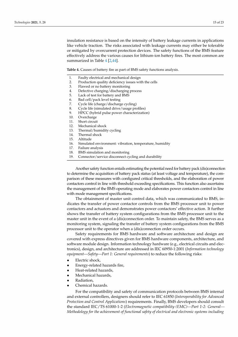
insulation resistance is based on the intensity of battery leakage currents in applicationslike vehicle traction. The risks associated with leakage currents may either be tolerableor mitigated by overcurrent protection devices. The safety functions of the BMS featureeffectively address the various causes for lithium-ion battery fires. The most common aresummarized in Table 4 [2,44].
Table 4. Causes of battery fire as part of BMS safety functions analysis.
1. Faulty electrical and mechanical design2. Production quality deficiency issues with the cells3. Flawed or no battery monitoring4. Defective charging/discharging process5. Lack of test for battery and BMS6. Bad cell/pack level testing7. Cycle life (charge/discharge cycling)8. Cycle life (simulated drive/usage profiles)9. HPCC (hybrid pulse power characterization)10. Overcharge11. Short circuit12. Mechanical shock13. Thermal/humidity cycling14. Thermal shock15. Altitude16. Simulated environment: vibration, temperature, humidity17. Failure analysis18. BMS simulation and monitoring19. Connector/service disconnect cycling and durability
Another safety function entails estimating the potential need for battery pack (dis)connectionto determine the acquisition of battery pack status (at least voltage and temperature), the com-parison of these measures with configured critical thresholds, and the elaboration of powercontactors control in line with threshold exceeding specifications. This function also ascertainsthe management of the BMS operating mode and elaborates power contactors control in linewith mode management specifications.
The obtainment of master unit control data, which was communicated to BMS, in-dicates the transfer of power contactor controls from the BMS processor unit to powercontactors and actuators and demonstrates power contactors’ effective action. It furthershows the transfer of battery system configurations from the BMS processor unit to themaster unit in the event of a (dis)connection order. To maintain safety, the BMS serves as amonitoring system, signaling the transfer of battery system configurations from the BMSprocessor unit to the operator when a (dis)connection order occurs.
Safety requirements for BMS hardware and software architecture and design arecovered with express directives given for BMS hardware components, architecture, andsoftware module design. Information technology hardware (e.g., electrical circuits and elec-tronics), design, and architecture are addressed in IEC 60950-1:2001 (Information technologyequipment—Safety—Part 1: General requirements) to reduce the following risks:
• Electric shock,• Energy-related hazards fire,• Heat-related hazards,• Mechanical hazards,• Radiation,• Chemical hazards.
For the compatibility and safety of communication protocols between BMS internaland external controllers, designers should refer to IEC 61850 (Interoperability for AdvancedProtection and Control Applications) requirements. Finally, BMS developers should consultthe standard IEC/TS 61000-1-2 (Electromagnetic compatibility (EMC)—Part 1-2: General—Methodology for the achievement of functional safety of electrical and electronic systems including
Technologies 2021, 9, 28 16 of 23
equipment with regard to electromagnetic phenomena) to learn the safety functions for electro-magnetic compatibility. They can be summarized as listed below:
1- Protect the battery pack.2- Monitor the battery pack state.3- Measure battery cell and pack voltage.4- Measure battery cell and pack temperature.5- Measure battery pack current flow.6- Detect battery system leakage currents.7- Determine battery pack critical state.8- Manage operating modes.9- Receive information from the master control system (EMS, VMS . . . ).10- Control the battery pack (dis)connection.11- Control the (dis)connection of the electric line of charge.12- Control the (dis)connection of the electric line of discharge.13- Inform master control system (EMS, VMS . . . ) of battery pack (dis)connection status.14- Inform operator (HMI) of battery pack (dis)connection status.15- Optimize battery lifetime and energy availability.16- Monitor and control battery pack state of charge (SOC) and state of health (SOH).17- Manage cell balancing.18- Monitor and control non-safety battery support systems (BSS).19- Diagnostic—record battery life history log.
4.3. BMS Safety Recommendations
BMS includes battery cells, power electronic equipment, controller and monitoringunits, and energy management units. Therefore, any abnormality or accident can cause aBMS-related accident. It is critical to take appropriate precautions as a rule for every BMScomponent. Indeed, BMS safety is essential for both external and internal equipment ofBMS. The external safety procedures, along with technical safety measures, are necessary toensure complete BMS safety. However, it should be noted that procedural safety measuresare more important than technical safety measures.
Today, rechargeable batteries use a combination of energy storage systems, suchas the flywheel and supercapacitor. Therefore, BMS safety is essential not only for thestand-alone battery pack but also for combined energy storage systems. By considering allpotential factors related to BMS, a comprehensive list of safety actions is recommendedbelow [1,45,46].
4.3.1. Recommendations for BMS Structure
1. A non-flammable and solid barrier should be used between the two electrodes ofbatteries. The barrier must be made of insulation material, and electrodes shouldnever come into contact with each other, even if an accident occurs. The barrierensures the internal short circuit of batteries.
2. Since battery is one of the inputs of BMS, flame retardants can be used in the elec-trolytes of batteries to prevent fire. The flashpoint of retardants must be higherthan the electrolytes [42]. However, measures should be taken to prevent batteryperformance and the electrochemical reactor from being hindered.
3. In a battery, the combustion process includes a series of chemical reactions, whichmay cause a fire. To prevent this, fuel, oxidizer, and control unit must be chosen insuch a way that the battery is not exposed to fire or any abnormality.
4.3.2. Recommendations for BMS Parameters
1. Two well-known safety strategies are available in the lithium battery: current interruptdevices (CID) and positive temperature coefficient (PTC). The PTC protects batteriesfrom an external short circuit. In abnormal cases, the PTC will heat itself, increaseits resistance, and block the excess current. The CID prevents current flow in an
Technologies 2021, 9, 28 17 of 23
abnormal condition, which may cause gas generation [1]. It is highly recommendedto implement these techniques for ensuring BMS reliability.
2. A new solvent with a higher flash point than the existing solvent is recommended touse in batteries for fire resistance. As battery is a part of the BMS, the development ofa new solvent will reduce the probability of a BMS fire.
3. A gas sensor is capable of tracking volatile organic compounds (VOC) from leakedelectrolytes. Hence, gas sensors can be a cost-efficient way to enhance the safety ofBMS [45,46].
4.3.3. Recommendations for BMS Integration
1. All BMS units must be separated physically so that any abnormal issue within a BMSunit will not spread to other units.
2. There should be more than a minimum number of nominally identical equipment orsubsystems in the fault detection, control, and communication unit of the BMS. If onecomponent or subsystem fails, the other can perform as a backup for a random failure;this is called “fail-safe philosophy.” The “fail-safe philosophy” includes safety vents,thermal fuses, and shutdown separators. Safety vents reduce the excess pressureinside the battery and prevent the rise of battery temperatures. Fallback protection,in particular, is exceptionally vital. If the primary protection system fails, then thesecondary option will retain viability to prevent further problems.
3. The battery cell must not be discharged below the minimum specified SOC.
4.3.4. Recommendations for BMS Installations
1. The equipment rating and marking instruction must be strictly followed. Before thebattery is put into operation, the normal case, worse case, and abuse case conditionsof the battery must be evaluated.
2. The way BMS control unit interacts with humans should be checked for each unitof the BMS. If any modification or replacement is needed for part of the unit, anextensive investigation must be carried out to evaluate whether the existing unit iscompatible with the proposed change.
3. Since the manufacturer and design fault is one of the most dominant causes for BMSfailure, third-party verification is recommended to ensure safety.
4. If an accident occurs with a battery bank, it is recommended to remove and replaceall of the battery bank and to avoid using a battery that has had contact with fire, nomatter how minimal the contact.
5. Different types of batteries containing liquid electrolytes should not be combined forany extended use. If two male ends become connected to each other and they comeinto contact with flammable material, the impact will cause a fire explosion.
6. Every battery must be charged by a specifically rated charger; otherwise, there is apossibility of overheating, which will damage the battery.
7. It is recommended not to place that battery storage systems in high-temperature envi-ronments.
8. Safety reviews should be conducted regularly for each BMS unit and be recorded insafety review reports to assess the changes and required modifications of the BMS unit.
5. Technical Standard Relevant to BMS Development: Standard Landscape
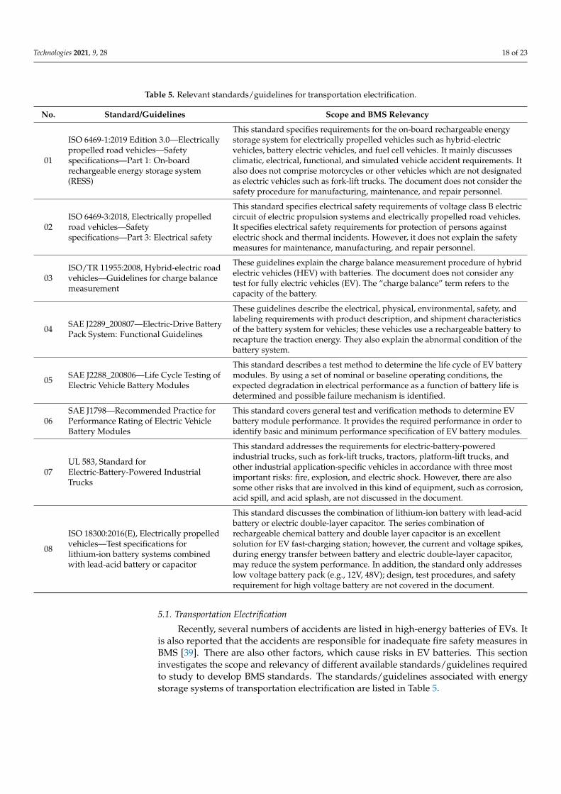
The relevant technical standards for energy storage systems are reviewed to iden-tify the current landscape in the BMS performance analysis and safety assessment. Foreach identified document, its scope and relevancy to the BMS are explained. Standardsare presented and discussed for transportation electrification (Table 5) and stationary(Table 6) applications.
Technologies 2021, 9, 28 18 of 23
Table 5. Relevant standards/guidelines for transportation electrification.
No. Standard/Guidelines Scope and BMS Relevancy
01
ISO 6469-1:2019 Edition 3.0—Electricallypropelled road vehicles—Safetyspecifications—Part 1: On-boardrechargeable energy storage system(RESS)
This standard specifies requirements for the on-board rechargeable energystorage system for electrically propelled vehicles such as hybrid-electricvehicles, battery electric vehicles, and fuel cell vehicles. It mainly discussesclimatic, electrical, functional, and simulated vehicle accident requirements. Italso does not comprise motorcycles or other vehicles which are not designatedas electric vehicles such as fork-lift trucks. The document does not consider thesafety procedure for manufacturing, maintenance, and repair personnel.
02ISO 6469-3:2018, Electrically propelledroad vehicles—Safetyspecifications—Part 3: Electrical safety
This standard specifies electrical safety requirements of voltage class B electriccircuit of electric propulsion systems and electrically propelled road vehicles.It specifies electrical safety requirements for protection of persons againstelectric shock and thermal incidents. However, it does not explain the safetymeasures for maintenance, manufacturing, and repair personnel.
03ISO/TR 11955:2008, Hybrid-electric roadvehicles—Guidelines for charge balancemeasurement
These guidelines explain the charge balance measurement procedure of hybridelectric vehicles (HEV) with batteries. The document does not consider anytest for fully electric vehicles (EV). The “charge balance” term refers to thecapacity of the battery.
04 SAE J2289_200807—Electric-Drive BatteryPack System: Functional Guidelines
These guidelines describe the electrical, physical, environmental, safety, andlabeling requirements with product description, and shipment characteristicsof the battery system for vehicles; these vehicles use a rechargeable battery torecapture the traction energy. They also explain the abnormal condition of thebattery system.
05 SAE J2288_200806—Life Cycle Testing ofElectric Vehicle Battery Modules
This standard describes a test method to determine the life cycle of EV batterymodules. By using a set of nominal or baseline operating conditions, theexpected degradation in electrical performance as a function of battery life isdetermined and possible failure mechanism is identified.
06SAE J1798—Recommended Practice forPerformance Rating of Electric VehicleBattery Modules
This standard covers general test and verification methods to determine EVbattery module performance. It provides the required performance in order toidentify basic and minimum performance specification of EV battery modules.
07UL 583, Standard forElectric-Battery-Powered IndustrialTrucks
This standard addresses the requirements for electric-battery-poweredindustrial trucks, such as fork-lift trucks, tractors, platform-lift trucks, andother industrial application-specific vehicles in accordance with three mostimportant risks: fire, explosion, and electric shock. However, there are alsosome other risks that are involved in this kind of equipment, such as corrosion,acid spill, and acid splash, are not discussed in the document.
08
ISO 18300:2016(E), Electrically propelledvehicles—Test specifications forlithium-ion battery systems combinedwith lead-acid battery or capacitor
This standard discusses the combination of lithium-ion battery with lead-acidbattery or electric double-layer capacitor. The series combination ofrechargeable chemical battery and double layer capacitor is an excellentsolution for EV fast-charging station; however, the current and voltage spikes,during energy transfer between battery and electric double-layer capacitor,may reduce the system performance. In addition, the standard only addresseslow voltage battery pack (e.g., 12V, 48V); design, test procedures, and safetyrequirement for high voltage battery are not covered in the document.
5.1. Transportation Electrification
Recently, several numbers of accidents are listed in high-energy batteries of EVs. Itis also reported that the accidents are responsible for inadequate fire safety measures inBMS [39]. There are also other factors, which cause risks in EV batteries. This sectioninvestigates the scope and relevancy of different available standards/guidelines requiredto study to develop BMS standards. The standards/guidelines associated with energystorage systems of transportation electrification are listed in Table 5.
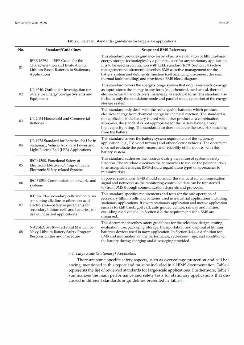
Technologies 2021, 9, 28 19 of 23
Table 6. Relevant standards/guidelines for large scale applications.
No. Standard/Guidelines Scope and BMS Relevancy
01
IEEE 1679.1—IEEE Guide for theCharacterization and Evaluation ofLithium-Based Batteries in StationaryApplications
This standard provides guidance for an objective evaluation of lithium-basedenergy storage technologies by a potential user for any stationary application.It is to be used in conjunction with IEEE standard 1679. Section 5.8 (activemanagement requirement) describes BMS as active management for thebattery system and defines its function (cell balancing, disconnect devices,thermal fault handling) and provides a BMS block diagram.
02UL 9540, Outline for Investigation forSafety for Energy Storage Systems andEquipment
This standard covers the energy storage system that only takes electric energyas input, stores the energy in any form (e.g., chemical, mechanical, thermal,electrochemical), and delivers the energy as electrical form. The standard alsoincludes only the standalone mode and parallel mode operation of the energystorage system.
03 UL 2054 Household and CommercialBatteries
This standard only deals with the rechargeable batteries which produceelectrical energy from chemical energy by chemical reaction. The standard isnot applicable if the battery is used with other product as a combination.Moreover, the standard is not appropriate for the battery having a veryhigh-capacity rating. The standard also does not cover the toxic risk resultingfrom the battery.
04UL 1973 Standard for Batteries for Use inStationary, Vehicle Auxiliary Power andLight Electric Rail (LER) Applications
This standard covers the battery system requirement of the stationaryapplication (e.g., PV, wind turbine) and other electric vehicles. The documentdoes not evaluate the performance and reliability of the devices with thebattery system.
05IEC 61508, Functional Safety ofElectrical/Electronic/ProgrammableElectronic Safety-related Systems
This standard addresses the hazards during the failure of system’s safetyfunction. The standard discusses the approaches to reduce the potential risksto an acceptable margin. BMS should regard these types of approaches tominimize risks.
06 IEC 61850: Communication networks andsystems
In power substations, BMS should consider the standard for communicationsignal and networks as the monitoring-controlled data can be transferredto/from BMS through communication channels and protocols.
07
IEC 62619—Secondary cells and batteriescontaining alkaline or other non-acidelectrolytes—Safety requirements forsecondary lithium cells and batteries, foruse in industrial applications
This standard specifies requirements and tests for the safe operation ofsecondary lithium cells and batteries used in industrial applications includingstationary applications. It covers stationary application and motive applicationsuch as forklift truck, golf cart, auto guided vehicle, railway and marine,excluding road vehicle. In Section 8.2, the requirements for a BMS arediscussed.
08NAVSEA S9310—Technical Manual forNavy Lithium Battery Safety ProgramResponsibilities and Procedure
This document describes safety guidelines for the selection, design, testing,evaluation, use, packaging, storage, transportation, and disposal of lithiumbatteries devices used in navy application. In Section 4.4.4, a definition forBMS and information on the performance, cycle-count, age, and condition ofthe battery during charging and discharging provided.
5.2. Large Scale (Stationary) Application
There are some specific safety aspects, such as overvoltage protection and cell bal-ancing, mentioned in this report and must be included in all BMS documentation. Table 6represents the list of reviewed standards for large-scale applications. Furthermore, Table 7summarizes the main performance and safety tests for stationary applications that dis-cussed in different standards or guidelines presented in Table 6.
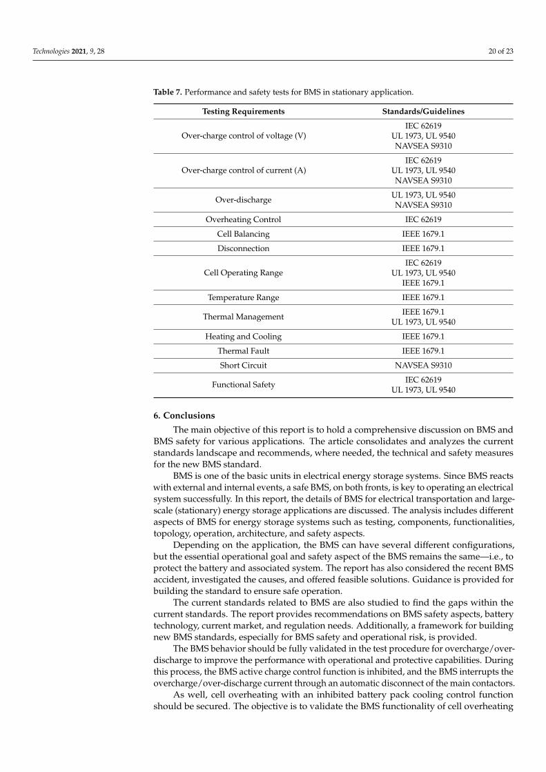
Technologies 2021, 9, 28 20 of 23
Table 7. Performance and safety tests for BMS in stationary application.
Testing Requirements Standards/Guidelines
Over-charge control of voltage (V)IEC 62619
UL 1973, UL 9540NAVSEA S9310
Over-charge control of current (A)IEC 62619
UL 1973, UL 9540NAVSEA S9310
Over-discharge UL 1973, UL 9540NAVSEA S9310
Overheating Control IEC 62619
Cell Balancing IEEE 1679.1
Disconnection IEEE 1679.1
Cell Operating RangeIEC 62619
UL 1973, UL 9540IEEE 1679.1
Temperature Range IEEE 1679.1
Thermal Management IEEE 1679.1UL 1973, UL 9540
Heating and Cooling IEEE 1679.1
Thermal Fault IEEE 1679.1
Short Circuit NAVSEA S9310
Functional Safety IEC 62619UL 1973, UL 9540
6. Conclusions
The main objective of this report is to hold a comprehensive discussion on BMS andBMS safety for various applications. The article consolidates and analyzes the currentstandards landscape and recommends, where needed, the technical and safety measuresfor the new BMS standard.
BMS is one of the basic units in electrical energy storage systems. Since BMS reactswith external and internal events, a safe BMS, on both fronts, is key to operating an electricalsystem successfully. In this report, the details of BMS for electrical transportation and large-scale (stationary) energy storage applications are discussed. The analysis includes differentaspects of BMS for energy storage systems such as testing, components, functionalities,topology, operation, architecture, and safety aspects.
Depending on the application, the BMS can have several different configurations,but the essential operational goal and safety aspect of the BMS remains the same—i.e., toprotect the battery and associated system. The report has also considered the recent BMSaccident, investigated the causes, and offered feasible solutions. Guidance is provided forbuilding the standard to ensure safe operation.
The current standards related to BMS are also studied to find the gaps within thecurrent standards. The report provides recommendations on BMS safety aspects, batterytechnology, current market, and regulation needs. Additionally, a framework for buildingnew BMS standards, especially for BMS safety and operational risk, is provided.
The BMS behavior should be fully validated in the test procedure for overcharge/over-discharge to improve the performance with operational and protective capabilities. Duringthis process, the BMS active charge control function is inhibited, and the BMS interrupts theovercharge/over-discharge current through an automatic disconnect of the main contactors.
As well, cell overheating with an inhibited battery pack cooling control functionshould be secured. The objective is to validate the BMS functionality of cell overheating
Technologies 2021, 9, 28 21 of 23
protection with the disconnection of power contactors and the potential start-up of safetybattery support systems (e.g., fire extinguisher). Loss of the battery simulation system (BSS)or BMS safety function is key to ensuring that any BMS safety function failure (e.g., frozensensor value) is detected within a controllable period and that the outputs of the degradedBMS place the battery system in a safe state.
Compatibility between the various systems and corresponding safety functions mustbe checked before operation. The BMS and battery should undergo test runs using thetest modes implemented in the BMS and communicate with the test bench via commoncommunication buses.
It is recommended that a technical review of the BMS be performed for transportation,electrification, and large-scale (stationary) applications. This report conducted a compre-hensive evaluation of the components, architectures, and safety risks applicable to BMSoperation. In addition, a review of technical standards relevant to BMS is provided as partof the more significant effort to develop the new standard for BMS. The report affirmssupport for these standards as outlined. In particular, the operational BMS must complywith the standards of CSA, IEEE, UL, NEC, and IEC to ensure validation and adherence tosafety requirements.
Author Contributions: Conceptualization, H.A.G., A.M.O. and M.R.A.; investigation, H.A.G., A.M.O.and M.R.A.; methodology, H.A.G., A.M.O. and M.R.A.; formal analysis, H.A.G., A.M.O. and M.R.A.;resources, H.A.G., A.M.O. and M.R.A.; supervision, H.A.G., A.M.O. and M.R.A.; writing—originaldraft preparation, H.A.G., A.M.O. and M.R.A.; writing—review and ed-iting, H.A.G., A.M.O. andM.R.A.; visualization, H.A.G., A.M.O. and M.R.A. All authors have read and agreed to the publishedversion of the manuscript.
Funding: This research received no external funding.
Acknowledgments: This work was funded by CSA Group. The views expressed are those of theauthors and do not necessarily reflect the views of CSA Group. The authors also thank Abul HasanFahad, Master student at the University of Waterloo, for his efforts during the report preparationand discussions.
Conflicts of Interest: The authors declare no conflict of interest.
References1. “Energy Storage Safety Strategic Plan—December 2014,” Energy.gov. Available online: https://www.energy.gov/oe/downloads/
energy-storage-safety-strategic-plan-december-2014 (accessed on 18 November 2020).2. Jiang, J.; Zhang, C. Fundamentals and Applications of Lithium-Ion Batteries in Electric Drive Vehicles; Wiley Online Library: Hoboken,
NJ, USA, 2015.3. Pop, V. (Ed.) Battery Management Systems: Accurate State-of-Charge Indication for Battery Powered Applications; Springer: Dordrecht,
The Netherlands, 2008.4. Sung, W.; Shin, C.B. Electrochemical model of a lithium-ion battery implemented into an automotive battery management system.
Comput. Chem. Eng. 2015, 76, 87–97. [CrossRef]5. Xing, Y.; Ma, E.W.M.; Tsui, K.L.; Pecht, M. Battery Management Systems in Electric and Hybrid Vehicles. Energies 2011, 4,
1840–1857. [CrossRef]6. Lelie, M.; Braun, T.; Knips, M.; Nordmann, H.; Ringbeck, F.; Zappen, H.; Sauer, D.U. Battery Management System Hardware
Concepts: An Overview. Appl. Sci. 2018, 8, 534. [CrossRef]7. Luo, X.; Kang, L.; Lu, C.; Linghu, J.; Lin, H.; Hu, B. An Enhanced Multicell-to-Multicell Battery Equalizer Based on Bipolar-
Resonant LC Converter. Electronics 2021, 10, 293. [CrossRef]8. Aiello, O. Electromagnetic Susceptibility of Battery Management Systems’ ICs for Electric Vehicles: Experimental Study. Electronics
2020, 9, 510. [CrossRef]9. Ko, Y.; Choi, W. A New SOC Estimation for LFP Batteries: Application in a 10 Ah Cell (HW 38120 L/S) as a Hysteresis Case
Study. Electronics 2021, 10, 705. [CrossRef]10. Doridant, A.; Abouda, K.; Givelin, P.; Thibaud, B. Battery Management System Demonstrator Board design using EMC System
simulation. In Proceedings of the 2019 International Symposium on Electromagnetic Compatibility—EMC EUROPE, Barcelona,Spain, 2–6 September 2019; pp. 427–432. [CrossRef]
11. Aiello, O.; Crovetti, P.S.; Fiori, F. Susceptibility to EMI of a Battery Management System IC for electric vehicles. In Proceedingsof the 2015 IEEE International Symposium on Electromagnetic Compatibility (EMC), Dresden, Germany, 16–22 August 2015;pp. 749–754. [CrossRef]

Technologies 2021, 9, 28 22 of 23
12. Kang, T.; Park, S.; Lee, P.-Y.; Cho, I.-H.; Yoo, K.; Kim, J. Thermal Analysis of a Parallel-Configured Battery Pack (1S18P) Using21700 Cells for a Battery-Powered Train. Electronics 2020, 9, 447. [CrossRef]
13. Abbas, M.; Cho, I.; Kim, J. Analysis of High-Power Charging Limitations of a Battery in a Hybrid Railway System. Electronics2020, 9, 212. [CrossRef]
14. Arnieri, E.; Boccia, L.; Amoroso, F.; Amendola, G.; Cappuccino, G. Improved Efficiency Management Strategy for Battery-BasedEnergy Storage Systems. Electronics 2019, 8, 1459. [CrossRef]
15. Lee, S.; Kim, J. Power Capability Analysis of Lithium Battery and Supercapacitor by Pulse Duration. Electronics 2019, 8, 1395.[CrossRef]
16. Uno, M.; Ueno, T.; Yoshino, K. Cell Voltage Equalizer Using a Selective Voltage Multiplier with a Reduced Selection Switch Countfor Series-Connected Energy Storage Cells. Electronics 2019, 8, 1303. [CrossRef]
17. Lee, H.; Park, J.; Kim, J. Kim Incremental Capacity Curve Peak Points-Based Regression Analysis for the State-of-Health Predictionof a Retired LiNiCoAlO2 Series/Parallel Configured Battery Pack. Electronics 2019, 8, 1118. [CrossRef]
18. Kokkotis, P.I.; Psomopoulos, C.S.; Ioannidis, G.C.; Kaminaris, S.D. Small Scale Energy Storage Systems. A Shot review in theirPotential environmental impact. Fresenius Environ. Bull. J. 2017, 26, 5658–5665.
19. Van Tichelen, P.; Mulder, G.; Durand, A. Preparatory Study on Ecodesign and Energy Labelling of Rechargeable ElectrochemicalBatteries with Internal Storage under FWC ENER/C3/2015-619-Lot 1, TASK 7 Report Policy Scenario Analysis VITO, Fraunhofer,Viegand Maagøe. Available online: https://ecodesignbatteries.eu/ (accessed on 18 November 2018).
20. Micro Energy Grid—GPROSYS. Available online: https://www.gprosys.com/product/micro-energy-grid/ (accessed on 19November 2020).
21. Smart Building Energy Automation (SBEA). GPROSYS Corp, [Online]. Available online: https://www.gprosys.com/SBEA.pdf(accessed on 1 September 2018).
22. Xu, Q.; Xiao, J.; Hu, X.; Wang, P.; Lee, M.Y. A Decentralized Power Management Strategy for Hybrid Energy Storage System withAutonomous Bus Voltage Restoration and State-of-Charge Recovery. IEEE Trans. Ind. Electron. 2017, 64, 7098–7108. [CrossRef]
23. “Electric Vehicle Enhanced Range, Lifetime and Safety through INGenious Battery Management (EVERLASTING),” EverlastingProject. Available online: https://everlasting-project.eu/ (accessed on 18 November 2020).
24. Gabbar, H.A.; Othman, A.M. Resilient Battery Management for Buildings, Energy Conservation in Residential, Commercial, and IndustrialFacilities; Wiley Library: Hoboken, NJ, USA, 2017. [CrossRef]
25. Green, J.M.; Hartman, B.; Glowacki, P.F. A System-based View of the Standards and Certification Landscape for Electric Vehicles.World Electr. Veh. J. 2016, 8, 564. [CrossRef]
26. Fleischer, C.; Sauer, D.U.; Barreras, J.V.; Schaltz, E.; Christensen, A.E. Development of software and strategies for BatteryManagement System testing on HIL simulator. In Proceedings of the 2016 Eleventh International Conference on EcologicalVehicles and Renewable Energies (EVER), Monte Carlo, Monaco, 6–8 April 2016; p. 12.
27. Houston, B. “New Fuels for Transport: The Cost of Renewable Solutions,” 29 January 2015. Available online: http://cleanleap.com/new-fuels-transport-cost-renewable-solutions (accessed on 30 November 2020).
28. Song, Y.; Liu, W.; Li, H.; Zhou, Y.; Huang, Z.; Jiang, F. Robust and Accurate State-of-Charge Estimation for Lithium-ion BatteriesUsing Generalized Extended State Observer. In Proceedings of the 2017 IEEE International Conference on Systems, Man, andCybernetics (SMC), Banff, AB, Canada, 5–8 October 2017; pp. 2146–2151.
29. Sarlioglu, B.; Morris, C.T.; Han, D.; Li, S. Driving Toward Accessibility: A Review of Technological Improvements for ElectricMachines, Power Electronics, and Batteries for Electric and Hybrid Vehicles. IEEE Ind. Appl. Mag. 2017, 23, 14–25. [CrossRef]
30. Rahimi-Eichi, H.; Ojha, U.; Baronti, F.; Chow, M.-Y. Battery Management System: An Overview of Its Application in the SmartGrid and Electric Vehicles. IEEE Ind. Electron. Mag. 2013, 7, 4–16. [CrossRef]
31. Kim, H.; Shin, K.G. DESA: Dependable, Efficient, Scalable Architecture for Management of Large-Scale Batteries. IEEE Trans. Ind.Inform. 2011, 8, 406–417. [CrossRef]
32. Xiong, R.; Ma, S.; Li, H.; Sun, F.; Li, J. Toward a Safer Battery Management System: A Critical Review on Diagnosis and Prognosisof Battery Short Circuit. iScience 2020, 23, 101010. [CrossRef] [PubMed]
33. Lu, L.; Han, X.; Li, J.; Hua, J.; Ouyang, M. A review on the key issues for lithium-ion battery management in electric vehicles. J.Power Sources 2013, 226, 272–288. [CrossRef]
34. Sun, S.; Liang, B.; Dong, M.; Taylor, J.A. Phase Balancing Using Energy Storage in Power Grids under Uncertainty. IEEE Trans.Power Syst. 2015, 31, 3891–3903. [CrossRef]
35. Noden, A. Can a Lithium-Ion Battery Fire Be Put Out on A Vessel? Government Europa, 13 June 2018. Available online:https://www.governmenteuropa.eu/lithium-ion-battery-fire-vessel/88384/ (accessed on 18 November 2020).
36. Pattipati, B.; Sankavaram, C.; Pattipati, K. System Identification and Estimation Framework for Pivotal Automotive BatteryManagement System Characteristics. IEEE Trans. Syst. Man Cybern. Part C Appl. Rev. 2011, 41, 869–884. [CrossRef]
37. Liu, K.; Li, K.; Peng, Q.; Zhang, C. A brief review on key technologies in the battery management system of electric vehicles.Front. Mech. Eng. 2019, 14, 47–64. [CrossRef]
38. Clements, D.; Mancarella, P. Systemic modelling and integrated assessment of asset management strategies and staff constraintson distribution network reliability. Electr. Power Syst. Res. 2018, 155, 164–171. [CrossRef]

Technologies 2021, 9, 28 23 of 23
39. Bruen, T.; Hooper, J.M.; Marco, J.; Gama, M.; Chouchelamane, G.H. Analysis of a Battery Management System (BMS) ControlStrategy for Vibration Aged Nickel Manganese Cobalt Oxide (NMC) Lithium-Ion 18650 Battery Cells. Energies 2016, 9, 255.[CrossRef]
40. Roca, B.; Wilkins, S.; Jacob, J.; Hoedemaekers, E.R.; van den Hoek, S.P. Predictive Model Based Battery Constraints for ElectricMotor Control within EV Powertrains. In Proceedings of the 2014 IEEE International Electric Vehicle Conference, IEVC 2014, IEEE,Florence, Italy, 17–19 December 2015; pp. 1–8, Generic Battery Model—Simulink. Available online: https://www.mathworks.com/help/physmod/sps/poersys/ref/battery.html (accessed on 18 November 2020).
41. Khan, M.; Swierczynski, M.; Kær, S. Towards an Ultimate Battery Thermal Management System: A Review. Batteries 2017, 3, 9.[CrossRef]
42. Battery Management System—An Overview|ScienceDirect Topics. Available online: https://www.sciencedirect.com/topics/chemistry/battery-management-system (accessed on 31 May 2019).
43. How do Extreme Climates Affect Trucks? HowStuffWorks, 1 December 2009. Available online: https://adventure.howstuffworks.com/outdoor-activities/ranch-life/extreme-climates-affect-trucks.htm (accessed on 1 June 2019).
44. Kong, L.; Li, C.; Jiang, J.; Pecht, M.G. Li-Ion Battery Fire Hazards and Safety Strategies. Energies 2018, 11, 2191. [CrossRef]45. Wenger, M.; Waller, R.; Lorentz, V.R.H.; Marz, M.; Herold, M. Investigation of gas sensing in large lithium-ion battery systems for
early fault detection and safety improvement. In Proceedings of the IECON 2014—40th Annual Conference of the IEEE IndustrialElectronics Society, Dallas, TX, USA, 29 October–1 November 2014; pp. 5654–5659. [CrossRef]
46. Sun, P.; Bisschop, R.; Niu, H.; Huang, X. A Review of Battery Fires in Electric Vehicles. Fire Technol. 2020, 56, 1361–1410. [CrossRef]