Embed Size (px)
Citation preview
Research Programs Quenching – Understanding, Controlling and Optimizing the Process – I
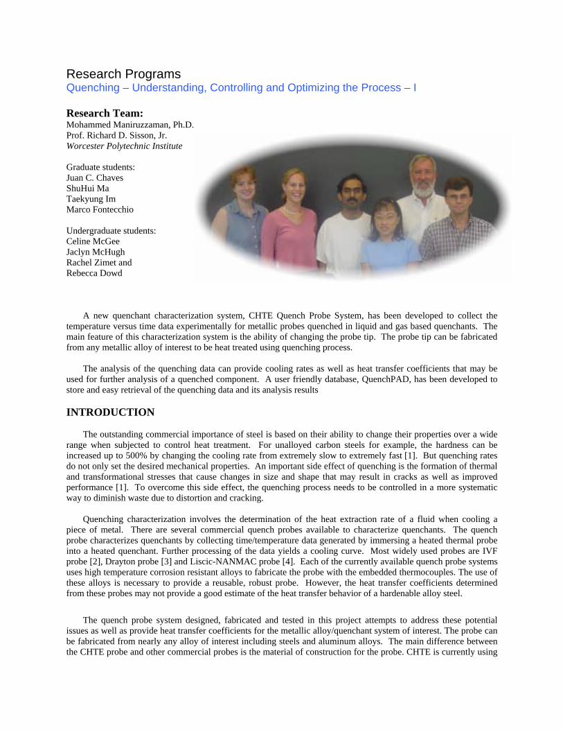
Research Team: Mohammed Maniruzzaman, Ph.D. Prof. Richard D. Sisson, Jr. Worcester Polytechnic Institute Graduate students: Juan C. Chaves ShuHui Ma Taekyung Im Marco Fontecchio Undergraduate students: Celine McGee Jaclyn McHugh Rachel Zimet and Rebecca Dowd
A new quenchant characterization system, CHTE Quench Probe System, has been developed to collect the temperature versus time data experimentally for metallic probes quenched in liquid and gas based quenchants. The main feature of this characterization system is the ability of changing the probe tip. The probe tip can be fabricated from any metallic alloy of interest to be heat treated using quenching process.
The analysis of the quenching data can provide cooling rates as well as heat transfer coefficients that may be
used for further analysis of a quenched component. A user friendly database, QuenchPAD, has been developed to store and easy retrieval of the quenching data and its analysis results
INTRODUCTION
The outstanding commercial importance of steel is based on their ability to change their properties over a wide
range when subjected to control heat treatment. For unalloyed carbon steels for example, the hardness can be increased up to 500% by changing the cooling rate from extremely slow to extremely fast [1]. But quenching rates do not only set the desired mechanical properties. An important side effect of quenching is the formation of thermal and transformational stresses that cause changes in size and shape that may result in cracks as well as improved performance [1]. To overcome this side effect, the quenching process needs to be controlled in a more systematic way to diminish waste due to distortion and cracking.
Quenching characterization involves the determination of the heat extraction rate of a fluid when cooling a
piece of metal. There are several commercial quench probes available to characterize quenchants. The quench probe characterizes quenchants by collecting time/temperature data generated by immersing a heated thermal probe into a heated quenchant. Further processing of the data yields a cooling curve. Most widely used probes are IVF probe [2], Drayton probe [3] and Liscic-NANMAC probe [4]. Each of the currently available quench probe systems uses high temperature corrosion resistant alloys to fabricate the probe with the embedded thermocouples. The use of these alloys is necessary to provide a reusable, robust probe. However, the heat transfer coefficients determined from these probes may not provide a good estimate of the heat transfer behavior of a hardenable alloy steel.
The quench probe system designed, fabricated and tested in this project attempts to address these potential
issues as well as provide heat transfer coefficients for the metallic alloy/quenchant system of interest. The probe can be fabricated from nearly any alloy of interest including steels and aluminum alloys. The main difference between the CHTE probe and other commercial probes is the material of construction for the probe. CHTE is currently using
4140 and 1018 steel, 304 stainless steel and Aluminum 6160 alloy with a variety of surface finishes while the other probes are fabricated from Inconel or other oxidation resistant alloy. The basic difference in design philosophy is that the IVF and similar commercial probes are designed to provide repeatable, accurate characterization of the quenching fluid while the CHTE probe system is designed to provide a characterization of the complete quenching system including the alloy being quenched, the surface condition of the alloy and quenching fluids characteristics. The results from the CHTE probe system can be used to experimentally determine heat transfer coefficients for the steel being quenched that can be used to predict microstructures and distortion.
A database has been designed and is being tested to record and make readily available the important data for
each quenching probe system tested. This database includes not only the experimental results from the CHTE or other probe system but also the data that characterizes the quenching fluid. The database for quenching is used for quenching fluid identification, storage of experimental parameters, quenching fluid performance and quenching fluids experimental parameters. CHTE QUENCH PROBE SYSTEM
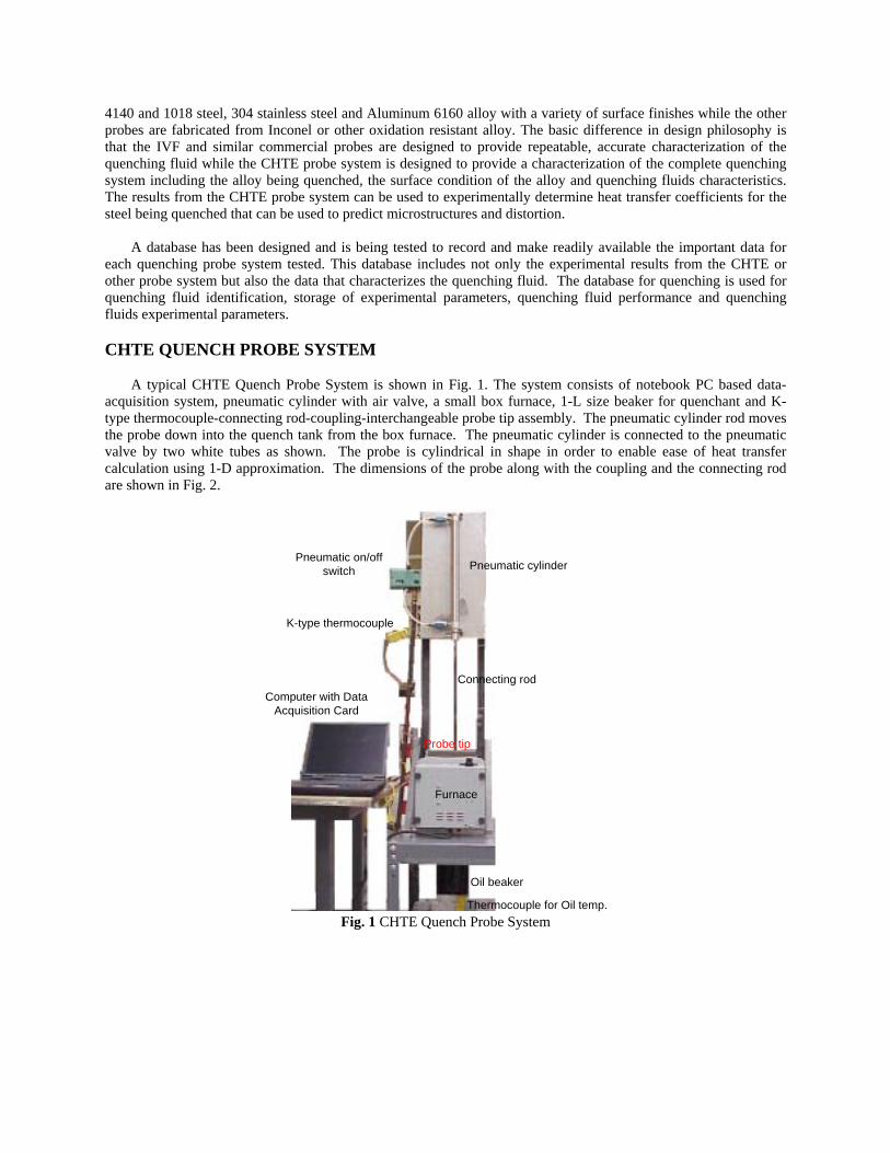
A typical CHTE Quench Probe System is shown in Fig. 1. The system consists of notebook PC based data-acquisition system, pneumatic cylinder with air valve, a small box furnace, 1-L size beaker for quenchant and K-type thermocouple-connecting rod-coupling-interchangeable probe tip assembly. The pneumatic cylinder rod moves the probe down into the quench tank from the box furnace. The pneumatic cylinder is connected to the pneumatic valve by two white tubes as shown. The probe is cylindrical in shape in order to enable ease of heat transfer calculation using 1-D approximation. The dimensions of the probe along with the coupling and the connecting rod are shown in Fig. 2.
Pneumatic cylinder
Furnace
Oil beaker
Pneumatic on/offswitch
K-type thermocouple
Probe tip
Connecting rodComputer with Data
Acquisition Card
Thermocouple for Oil temp. Fig. 1 CHTE Quench Probe System
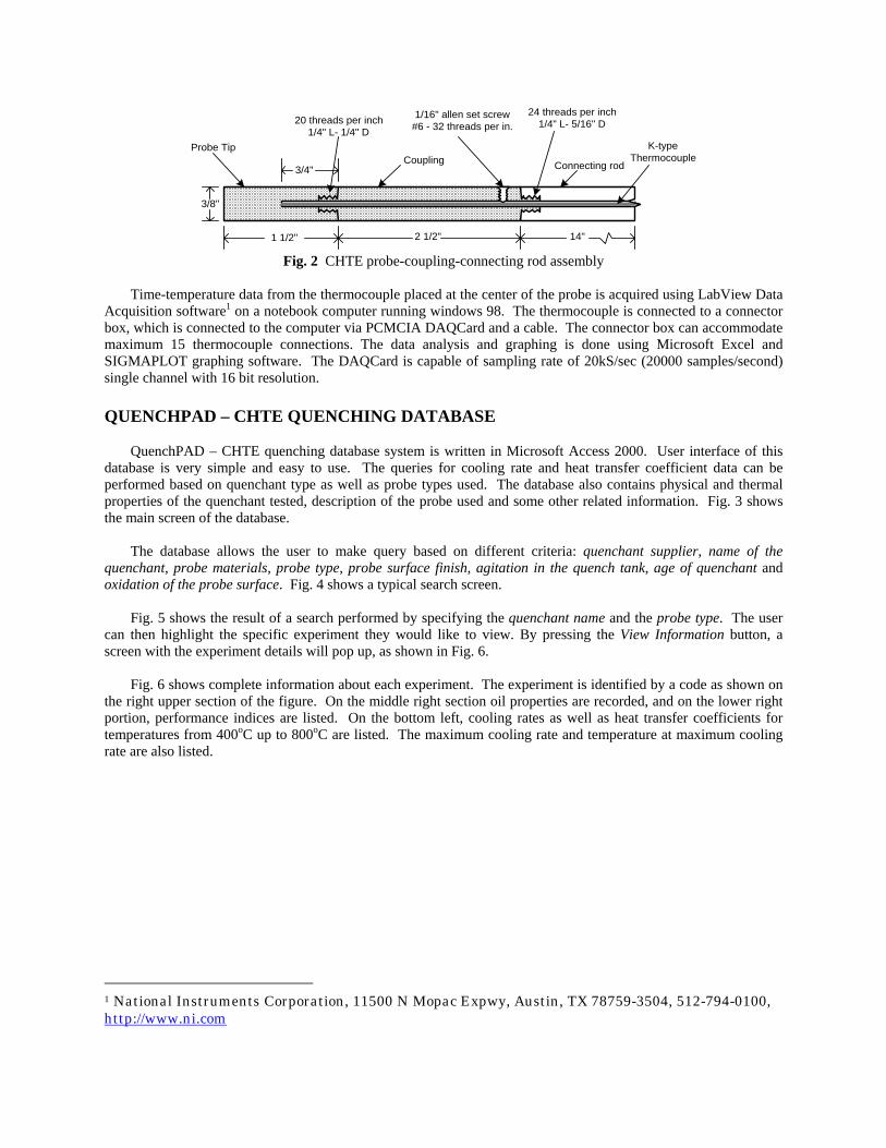
3/8"
1 1/2" 2 1/2" 14"
Probe TipCoupling Connecting rod
1/16" allen set screw#6 - 32 threads per in.
K-typeThermocouple
20 threads per inch1/4" L- 1/4" D
24 threads per inch1/4" L- 5/16" D
3/4"
Fig. 2 CHTE probe-coupling-connecting rod assembly
Time-temperature data from the thermocouple placed at the center of the probe is acquired using LabView Data
Acquisition software1 on a notebook computer running windows 98. The thermocouple is connected to a connector box, which is connected to the computer via PCMCIA DAQCard and a cable. The connector box can accommodate maximum 15 thermocouple connections. The data analysis and graphing is done using Microsoft Excel and SIGMAPLOT graphing software. The DAQCard is capable of sampling rate of 20kS/sec (20000 samples/second) single channel with 16 bit resolution. QUENCHPAD – CHTE QUENCHING DATABASE
QuenchPAD – CHTE quenching database system is written in Microsoft Access 2000. User interface of this database is very simple and easy to use. The queries for cooling rate and heat transfer coefficient data can be performed based on quenchant type as well as probe types used. The database also contains physical and thermal properties of the quenchant tested, description of the probe used and some other related information. Fig. 3 shows the main screen of the database.
The database allows the user to make query based on different criteria: quenchant supplier, name of the quenchant, probe materials, probe type, probe surface finish, agitation in the quench tank, age of quenchant and oxidation of the probe surface. Fig. 4 shows a typical search screen.
Fig. 5 shows the result of a search performed by specifying the quenchant name and the probe type. The user can then highlight the specific experiment they would like to view. By pressing the View Information button, a screen with the experiment details will pop up, as shown in Fig. 6.
Fig. 6 shows complete information about each experiment. The experiment is identified by a code as shown on
the right upper section of the figure. On the middle right section oil properties are recorded, and on the lower right portion, performance indices are listed. On the bottom left, cooling rates as well as heat transfer coefficients for temperatures from 400oC up to 800oC are listed. The maximum cooling rate and temperature at maximum cooling rate are also listed.
1 National Instruments Corporation, 11500 N Mopac Expwy, Austin, TX 78759-3504, 512-794-0100, http://www.ni.com
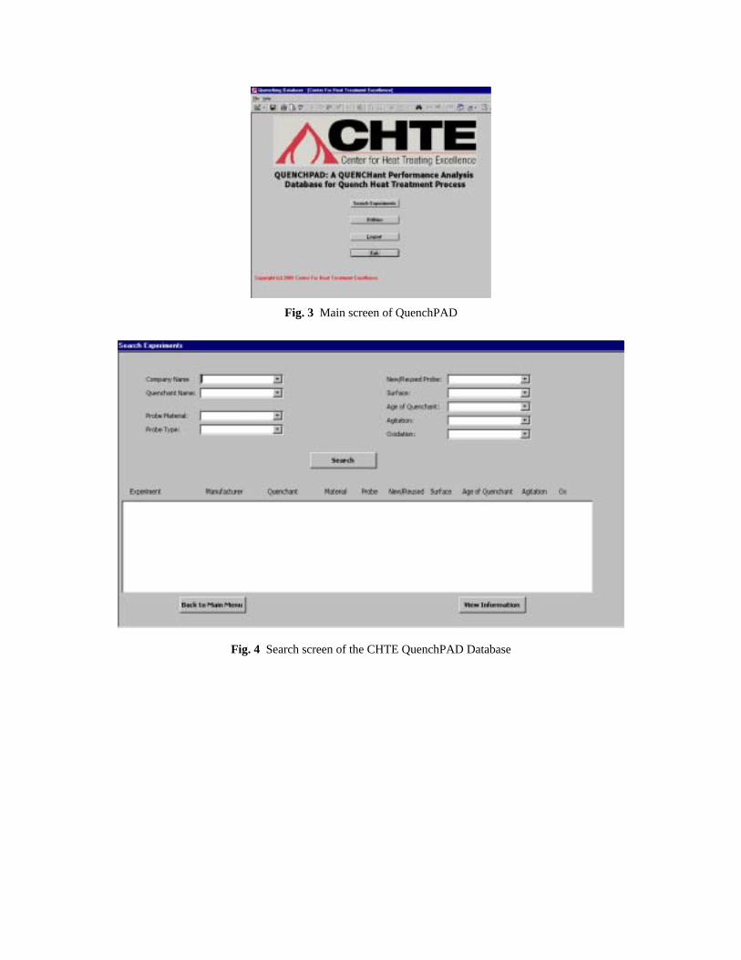
Fig. 3 Main screen of QuenchPAD
Fig. 4 Search screen of the CHTE QuenchPAD Database
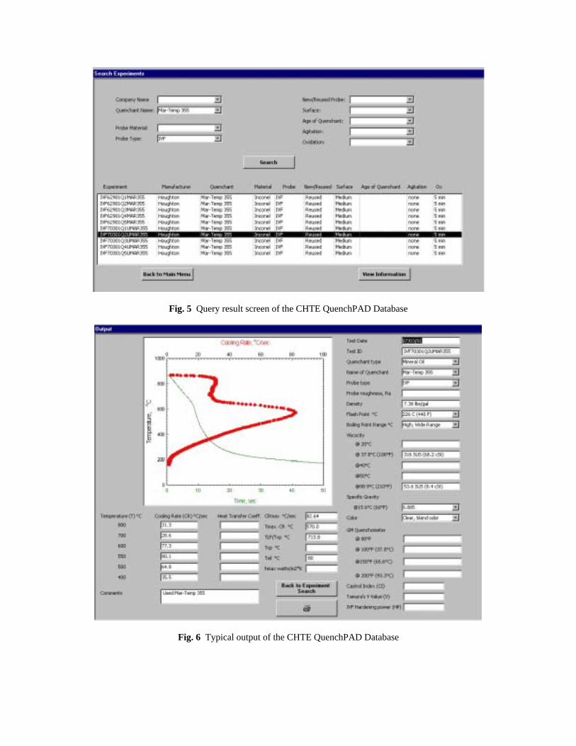
Fig. 5 Query result screen of the CHTE QuenchPAD Database
Fig. 6 Typical output of the CHTE QuenchPAD Database
THEORETICAL UNDERSTANDING OF QUENCHING PROCESS
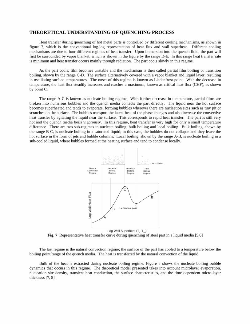
Heat transfer during quenching of hot metal parts is controlled by different cooling mechanisms, as shown in figure 7, which is the conventional log-log representation of heat flux and wall superheat. Different cooling mechanisms are due to four different regimes of heat transfer. Upon immersion into the quench fluid, the part will first be surrounded by vapor blanket, which is shown in the figure by the range D-E. In this range heat transfer rate is minimum and heat transfer occurs mainly through radiation. The part cools slowly in this regime.
As the part cools, film becomes unstable and the mechanism is then called partial film boiling or transition boiling, shown by the range C-D. The surface alternatively covered with a vapor blanket and liquid layer, resulting in oscillating surface temperatures. The onset of this regime is known as Liedenfrost point. With the decrease in temperature, the heat flux steadily increases and reaches a maximum, known as critical heat flux (CHF), as shown by point C.
The range A-C is known as nucleate boiling regime. With further decrease in temperature, partial films are broken into numerous bubbles and the quench media contacts the part directly. The liquid near the hot surface becomes superheated and tends to evaporate, forming bubbles wherever there are nucleation sites such as tiny pit or scratches on the surface. The bubbles transport the latent heat of the phase changes and also increase the convective heat transfer by agitating the liquid near the surface. This corresponds to rapid heat transfer. The part is still very hot and the quench media boils vigorously. In this regime, heat transfer is very high for only a small temperature difference. There are two sub-regimes in nucleate boiling: bulk boiling and local boiling. Bulk boiling, shown by the range B-C, is nucleate boiling in a saturated liquid; in this case, the bubbles do not collapse and they leave the hot surface in the form of jets and bubble columns. Local boiling, shown by the range A-B, is nucleate boiling in a sub-cooled liquid, where bubbles formed at the heating surface and tend to condense locally.
Log Wall Superheat (T -T ) w sat
Log
Wal
l Hea
t Flu
x
DLiedenfrost point
E
C
B
A
Vapor blanket
Film Boiling Regime
TransitionBoiliingRegime
NucleateBoilingRegime
NaturalConvection
Regime
Fig. 7 Representative heat transfer curve during quenching of steel part in a liquid media [5,6]
The last regime is the natural convection regime; the surface of the part has cooled to a temperature below the boiling point/range of the quench media. The heat is transferred by the natural convection of the liquid.
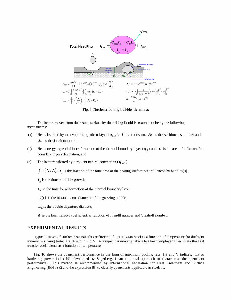
Bulk of the heat is extracted during nucleate boiling regime. Figure 8 shows the nucleate boiling bubble dynamics that occurs in this regime. The theoretical model presented takes into account microlayer evaporation, nucleation site density, transient heat conduction, the surface characteristics, and the time dependent micro-layer thickness [7, 8].
Bubble
Microlayer
Superheated liquidNatural
convectionlayer
qNC qME
qR
NCwg
wRgMEtot q
tttqtq
q ++
+=
qNB
Total Heat Flux
( )
⋅=
ANtJaArBq lglME λραπγφ 2/327.02
10[ ] 2/1135.0)( tJaArBtD lα⋅⋅=
( )satww
plllR TTa
AN
tCk
q −⋅
⋅⋅
=
πρ
2 ( )
2/12 1Pr
125.0
⋅
+⋅
−
=Ar
Jag
Dvl
b ρρσ
( )satwNC TTaANhq −⋅
⋅
−= 1 ( ) 3/1Pr14.0
⋅= GrL
kh l
Fig. 8 Nucleate boiling bubble dynamics
The heat removed from the heated surface by the boiling liquid is assumed to be by the following mechanisms:
(a) Heat absorbed by the evaporating micro-layer ( MEq ). B is a constant, Ar is the Archimedes number and Ja is the Jacob number.
(b) Heat energy expended in re-formation of the thermal boundary layer ( Rq ) and a is the area of influence for boundary layer reformation, and
(c) The heat transferred by turbulent natural convection ( NCq ).
( )[ ]aAN ⋅−1 is the fraction of the total area of the heating surface not influenced by bubbles[9].
gt is the time of bubble growth
wt is the time for re-formation of the thermal boundary layer.
)(tD is the instantaneous diameter of the growing bubble.
bD is the bubble departure diameter
h is the heat transfer coefficient, a function of Prandtl number and Grashoff number.
EXPERIMENTAL RESULTS
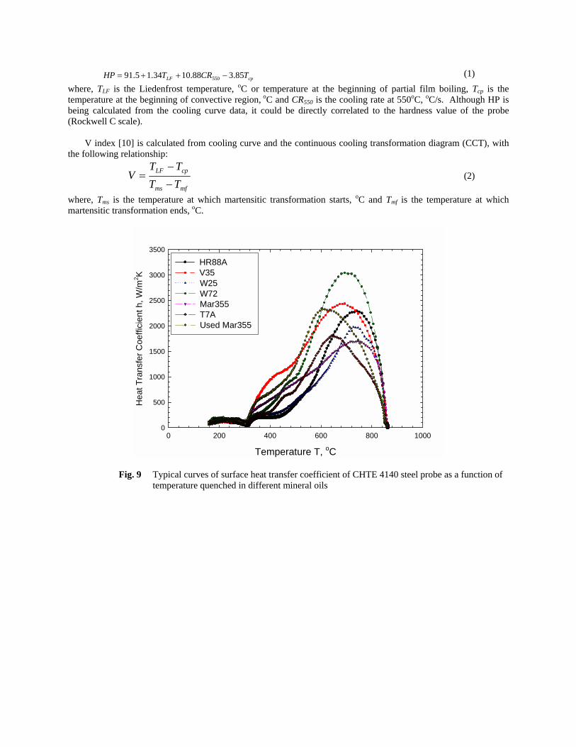
Typical curves of surface heat transfer coefficient of CHTE 4140 steel as a function of temperature for different
mineral oils being tested are shown in Fig. 9. A lumped parameter analysis has been employed to estimate the heat transfer coefficients as a function of temperature.
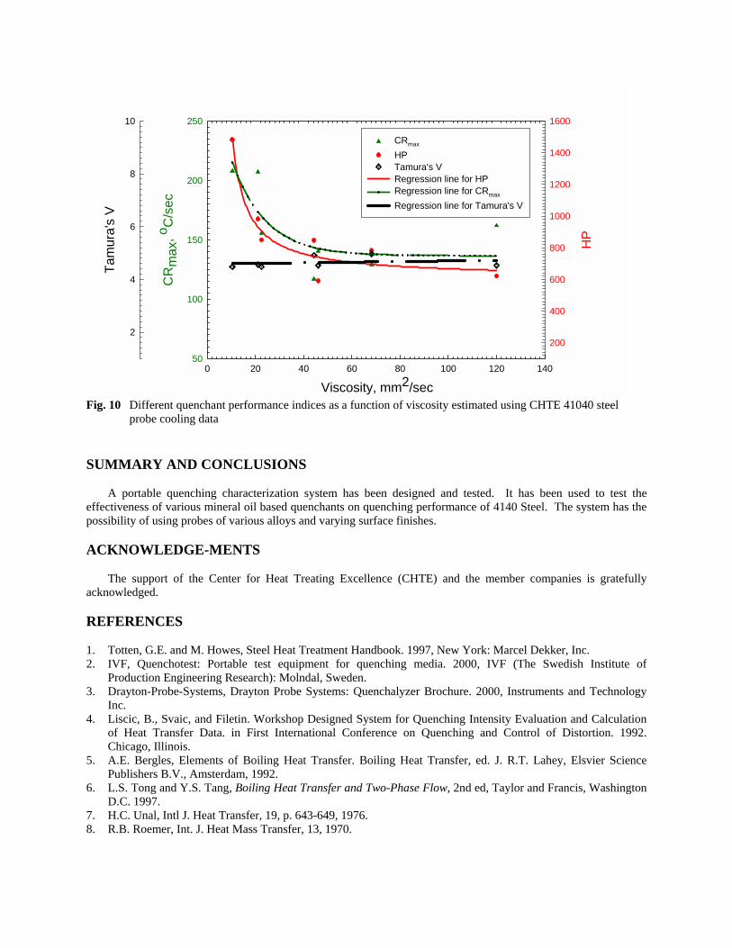
Fig. 10 shows the quenchant performance in the form of maximum cooling rate, HP and V indices. HP or hardening power index [9], developed by Segerberg, is an empirical approach to characterize the quenchant performance. This method is recommended by International Federation for Heat Treatment and Surface Engineering (IFHTSE) and the expression [9] to classify quenchants applicable in steels is:
cpLF TCRTHP 85.388.1034.15.91 550 −++= (1)
where, TLF is the Liedenfrost temperature, oC or temperature at the beginning of partial film boiling, Tcp is the temperature at the beginning of convective region, oC and CR550 is the cooling rate at 550oC, oC/s. Although HP is being calculated from the cooling curve data, it could be directly correlated to the hardness value of the probe (Rockwell C scale).
V index [10] is calculated from cooling curve and the continuous cooling transformation diagram (CCT), with the following relationship:
mfms
cpLF
TTTT
V−
−= (2)
where, Tms is the temperature at which martensitic transformation starts, oC and Tmf is the temperature at which martensitic transformation ends, oC.
Temperature T, oC
0 200 400 600 800 1000
Hea
t Tra
nsfe
r Coe
ffici
ent h
, W/m
2 K
0
500
1000
1500
2000
2500
3000
3500
HR88A V35 W25 W72 Mar355 T7A Used Mar355
Fig. 9 Typical curves of surface heat transfer coefficient of CHTE 4140 steel probe as a function of temperature quenched in different mineral oils
Viscosity, mm2/sec0 20 40 60 80 100 120 140
CR
max
, o C/s
ec
50
100
150
200
250
HP
200
400
600
800
1000
1200
1400
1600Ta
mur
a's
V
2
4
6
8
10
CRmax
HPTamura's V Regression line for HPRegression line for CRmax
Regression line for Tamura's V
Fig. 10 Different quenchant performance indices as a function of viscosity estimated using CHTE 41040 steel
probe cooling data
SUMMARY AND CONCLUSIONS
A portable quenching characterization system has been designed and tested. It has been used to test the effectiveness of various mineral oil based quenchants on quenching performance of 4140 Steel. The system has the possibility of using probes of various alloys and varying surface finishes.
ACKNOWLEDGE-MENTS
The support of the Center for Heat Treating Excellence (CHTE) and the member companies is gratefully acknowledged. REFERENCES 1. Totten, G.E. and M. Howes, Steel Heat Treatment Handbook. 1997, New York: Marcel Dekker, Inc. 2. IVF, Quenchotest: Portable test equipment for quenching media. 2000, IVF (The Swedish Institute of
Production Engineering Research): Molndal, Sweden. 3. Drayton-Probe-Systems, Drayton Probe Systems: Quenchalyzer Brochure. 2000, Instruments and Technology
Inc. 4. Liscic, B., Svaic, and Filetin. Workshop Designed System for Quenching Intensity Evaluation and Calculation
of Heat Transfer Data. in First International Conference on Quenching and Control of Distortion. 1992. Chicago, Illinois.
5. A.E. Bergles, Elements of Boiling Heat Transfer. Boiling Heat Transfer, ed. J. R.T. Lahey, Elsvier Science Publishers B.V., Amsterdam, 1992.
6. L.S. Tong and Y.S. Tang, Boiling Heat Transfer and Two-Phase Flow, 2nd ed, Taylor and Francis, Washington D.C. 1997.
7. H.C. Unal, Intl J. Heat Transfer, 19, p. 643-649, 1976. 8. R.B. Roemer, Int. J. Heat Mass Transfer, 13, 1970.
9. Segerberg, S. and J. Bodin. Measurement and Evaluation of the Quenching Power of Quenching Media for Hardening. in 1st Int. Conference on Quenching and Control of Distortion. 1992. Chicago, Illinois, USA.
10. Tamura, I., N. Shimizu, and T. Okada, A method to judge the quench-hardening of steel from cooling curve of quenching oils. Journal of Heat Treating, 1984. 3(4): p. 335-343.
List of Publications 1. M. Maniruzzaman and R.D. Sisson, Jr., 2001, Bubble Dynamics in Quenching Heat
Treatment Of Steel, Proceedings of the 21st Heat Treating Society Conference, Nov, 5-8, 2001, Indianapolis, Indiana.
2. J.C. Chaves, M. Maniruzzaman and R.D. Sisson, Jr., 2001, A New Quench Characterization System for Steels, Proceedings of the 21st Heat Treating Society Conference, Nov, 5-8, 2001, Indianapolis, Indiana.
3. R.D. Sisson, Jr., J.C. Chaves and M. Maniruzzaman, 2001, The Effect of Surface Finish on the Quenching Behavior of 4140 Steel in Mineral Oils, Proceedings of the 21st Heat Treating Society Conference, Nov, 5-8, 2001, Indianapolis, Indiana.


