Embed Size (px)
Citation preview

Trinity-300 Series
Installation and Operational Guide
version 2.0
Repeatit AB Tel: +46 8 570 106 66 Hamngatan 33 Fax: +46 8 570 106 67 172 66 Sundbyberg E-mail: [email protected] Sweden www.repeatit.se

Trinity-300 Series
Quick start
Before proceeding with the installation, follow this quick-start guide to verify that the equipment works on the ground: 1. Place the two radio units next to each other on a table. If the
units have integrated antennas (which holds for all models except Trinity-300), make sure that the antennas are not pointing towards each other as that could result in too high power being received (over-steering). If you have two Trinity-300 units, place the antenna connectors of the two units close to each other without any connected antenna).
2. Power up the first radio with the PoE injector and connect to it with a laptop:
• Connect the PoE port marked ”P+DATA OUT” to the Trinity unit with a Cat5E Ethernet cable.
• Connect the PoE port marked ”DATA IN’ to a laptop or a network (via a switch or a router).
You reach the unit’s web GUI with these login details: IP address: 10.0.0.1 Username: admin Password: public
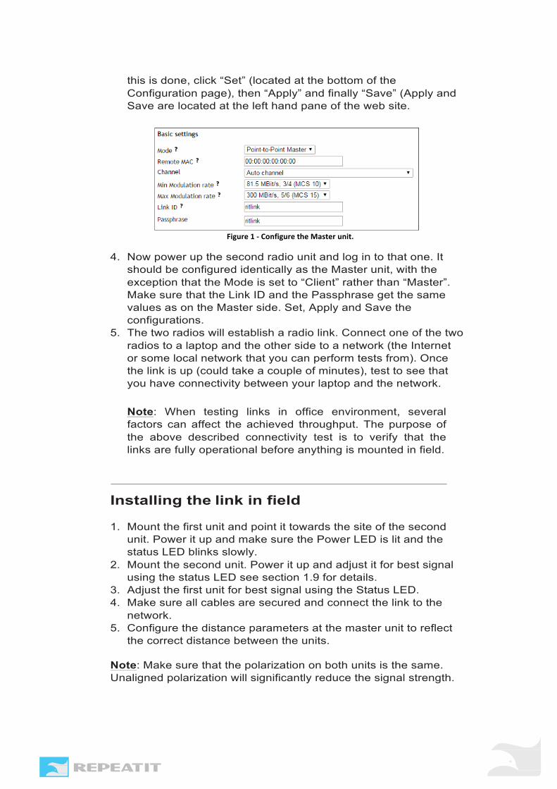
3. Configure this unit as Point-to-Point Master. You only have to configure “Link ID” and “Passphrase” fields. In the example below we have used the phrase “ritlink” for both fields. When
electricity/safety competence and who is familiar with
Trinity-300 Series
this is done, click “Set” (located at the bottom of the Configuration page), then “Apply” and finally “Save” (Apply and Save are located at the left hand pane of the web site.
Figure1-ConfiguretheMasterunit.
4. Now power up the second radio unit and log in to that one. It should be configured identically as the Master unit, with the exception that the Mode is set to “Client” rather than “Master”. Make sure that the Link ID and the Passphrase get the same values as on the Master side. Set, Apply and Save the configurations.
5. The two radios will establish a radio link. Connect one of the two radios to a laptop and the other side to a network (the Internet or some local network that you can perform tests from). Once the link is up (could take a couple of minutes), test to see that you have connectivity between your laptop and the network. Note: When testing links in office environment, several factors can affect the achieved throughput. The purpose of the above described connectivity test is to verify that the links are fully operational before anything is mounted in field.
Installing the link in field
1. Mount the first unit and point it towards the site of the second unit. Power it up and make sure the Power LED is lit and the status LED blinks slowly.
2. Mount the second unit. Power it up and adjust it for best signal using the status LED see section 1.9 for details.
3. Adjust the first unit for best signal using the Status LED. 4. Make sure all cables are secured and connect the link to the
network. 5. Configure the distance parameters at the master unit to reflect
the correct distance between the units.
Note: Make sure that the polarization on both units is the same. Unaligned polarization will significantly reduce the signal strength.

Trinity-300 Series
For more information about antenna polarization and how to successfully tune the links for best possible performance, refer to Repeatits’ Deployment Guideline document (available at www.repeatit.se).

Trinity-300 Series
Contents
1 Installation Guide 4 1.1 Who should use this guide ....................................................... 4 1.2 Package contents ...................................................................... 4 1.3 Additional tools required ....................................................... 5 1.4 Unit description ........................................................................ 5 1.5 Installation ................................................................................ 5 1.6 Mounting a Trinity-300 unit ................................................... 6
Mounting instruction for Trinity-323 and Trinity-316 . . 7 Mounting instruction for Trinity-300 7
1.7 Ethernet cabling ...................................................................... 8 1.8 Installing the power supply .................................................. 8 1.9 Finalizing the installation ...................................................... 9
Configuration ............................................................................... 9 Alignment ..................................................................................... 9 Securing the installation ..................................................... 10
2 Configuration 11 2.1 Trinity-300 series Configuration concepts ......................... 11
Configuration areas ............................................................... 11 2.2 Configuring using the Trinity-300 series web interface 12
Modifying the configuration ............................................... 12 Applying a new configuration ............................................. 12 Saving settings to flash memory ....................................... 13 Rolling back settings ........................................................... 14
2.3 Configuration parameters ................................................... 15 Radio settings ......................................................................... 16 CAC Policy ..................................................................................... 19 Network settings ................................................................... 19 System settings .................................................................... 20
3 Unit Operation 21 3.1 Unit status ............................................................................ 21
Default view ......................................................................... 21 Extended information ......................................................... 21 Status information ............................................................... 22
3.2 Link Diagnostic Tools ...................................................................... 23 Spectrum analyzer .............................................................. 23 Speed test ............................................................................ 24
3.3 Firmware upgrading ............................................................ 25 3.4 Restore to defaults .............................................................. 25
4 Support 26

Trinity-300 Series
5 Technical Specifications 27
6 Usage restrictions and legal information 28

Trinity-300 Series
Installation Guide
1.1 Who should use this guide Installing fixed outdoor radio links requires technical expertise and should only be carried out by a trained technician. You should only attempt to install and configure the Trinity link if you have: 1. Experience in mounting outdoor radio equipment and aligning
antennas. 2. Understanding, or common knowledge, about network
equipment. 3. Made sure that the installation site is suitable and complies with
local radio, electrical and safety regulations.
1.2 Additional tools required
Depending on the conditions at the installation site other tools might be needed, including, but not limited to
• Cat5E Ethernet cable
• RJ-45 crimp tool and RJ-45 connectors if not using a pre-assembled Ethernet cable
• An adjustable wrench
• Drill for wall mounting
• Ground cables

Trinity-300 Series
• Cable ties to secure cabling
1.3 Unit description
There are three LEDs on the units: power, status and Ethernet link/activity. LED Colour Status Description
Power (P) Status (S)
Green Green
On Flashing Blinking
Power on Signal strength pattern Firmware upgrade in progress
Ethernet (E) Green On/blinking Reflects Ethernet traffic and link status
Off No Ethernet link
1.4 Installation
Installing a Trinity-3xx (3xx refers to 316, 318, 323 or 300 depending on what type of nodes you are using) system includes the steps outlined below. Each step is explained more thoroughly in the following sections. The Trinity-3xx system consists of two Trinity-3xx units, one Master unit and one Client unit. The following installation steps need to be carried out for both units.
1. Before taking the units to the site, configure one of them to be the Master and the other one to be the Client. Normally this is done in an office environment (see the quick-start guide earlier in this document). Note that link throughput can be degraded by multipath effects and other RF related phenomenon in an office. Therefore, just make sure that the links connect to each other and have proper IP settings before taking them to the site.
2. Mount the Trinity-3xx unit and antenna (if the antenna is not integrated) at site A.
3. Install the PoE at an indoor location where power and network equipment is available.
4. Connect an Ethernet cable from the PoE injector to the mounted Trinity-3xx unit.
5. Repeat the above steps for the unit at site B.

Trinity-300 Series
6. Align antennas for best signal reception. For longer distances, this normally requires re-alignment of antennas on both sides of the link. The unit’s web GUIs provide status bars for antenna alignment.
7. For optimal link throughput the following parameter must be updated in both unit’s web interface:
• Distance - should accurately reflect the distance in kilometers between the units.
1.5 Mounting a Trinity-3xx unit
A Trinity-3xx unit should preferably be mounted in a location that allows the unit to be placed high above interfering objects like buildings and trees Radio masts often provide the best mounting conditions, but when mounting radio equipment with other wireless systems in the vicinity you should always be careful as sufficient isolation between your antenna and other antennas/equipment has to be secured. If it is not possible to mount the equipment in a mast, it could also be mounted on roof tops, walls etc.
Note The Trinity units should be mounted with their antennas having a clear line of sight and free Fresnel Zones between them! For more reading on this topic, please refer to Repeatits Deployment Guideline.
Observe the antenna polarization and make sure they match at both installation sites. If the sites are configured with different polarization alignment, the link will be subject to strong signal degradation. Use the supplied mounting kit to securely mount the units at both locations, make sure the mounting brackets are connected to ground.
Tip Do not tightly secure the unit and/or antenna until the antenna alignment process in complete.

Trinity-300 Series
Mounting instruction for Trinity-323 and Trinity-318 See the supplied document for detailed mounting instructions.
Figure 2 - Trinity-323 and Trinity-318 pole mounting
Mounting instruction for Trinity-300 The Trinity-300 is supplied with mounting brackets for pole mounting.
1. Run the pole clamps around the mounting pole.
2. Run the pole clamps through the mounting brackets.
3. Attach the pole clamps to the unit using the supplied screws.
RJ-45 connector assembly for Trinity-300 Series The connector casing is delivered assembled, unscrew the con- nector (you do not need to remove the gasket (4)).
1. Unscrew the sealing cap from the connector.
2. Gently pull out the seal.
3. Pull the cable through the sealing cap. 4. Insert the RJ45 cable and make sure it is fully inserted into the
connector.
5. Put the seal around the cable and push it into the connector.
6. Fasten the sealing cap to the connector and tighten.

Trinity-300 Series
1.6 Ethernet cabling
Run Cat5E Ethernet cable from the location where the PoE is to be installed to the location of the Trinity-300 unit, allow for some slack on the wire to avoid extra strain on the Ethernet connectors. Make sure the Ethernet cable you are using is rated for outdoor use to avoid decreased cable life time.
Use a straight Ethernet cable between the radio unit and the Power over Ethernet injector and a crossed cable between the injector and a laptop.
1.7 Installing the power supply
Install the supplied PoE indoor where power and other network equipment is available. The PoE can be located at most 100 meters from the unit.
Note The supplied PoE-adapter (Power-over-Ethernet) is strictly for indoor use only!
Tip Make a loop on the Ethernet cable indoors near the PoE to allow water to drain more easily from the cable, before reaching the PoEs unprotected Ethernet connector!
Connect the PoE port marked ”P+DATA OUT” to the Trinity-300 unit using an outdoor-rated Cat5E Ethernet cable. The PoE port marked ”DATA IN’ should be connected to user supplied network equipment such as a switch or router.
Note The Trinity-3xx unit will boot as soon as the Ethernet cable from the PoE is connected!
1.8 Finalizing the installation
Once both units are mounted they need to be aligned for proper operation. The Trinity-300 system assists you in doing this using external visual signals and a web interface that shows detailed information about the link status and its signal strength.

Trinity-300 Series
Alignment Make sure the units are roughly aligned using visual sight or a compass before proceeding with this step. On site A (or B), slowly move the antenna towards site B (or A). Use one of the below described alignment tools to find the optimal alignment.
External visual indication
The LED (if enabled) indicates the current signal strength with a set of pulses followed by a short pause.
Note The alignment LED is enabled by default.
Pulses from dBm to dBm 1 pulse 1 9 2 pulses 10 14 3 pulses 15 19 4 pulses 20 24 5 pulses 25 29 6 pulses 30
Web interface The web interface contains status indicators for both link status and signal strength. The figure below shows the local and remote status (the remote quality status is only shown when the links are connected).
Figure3-LinkqualityshowninthewebGUI.
Link quality indicator descriptions: 1. Ctl and Ext: A Trinity-3xx link is normally configured with
either of 20MHz or 40MHz channel bandwidth. Ctl refers to the first 20MHz block, and if only 20MHz is used only the two Ctl bars are shown (not the Ext). Ext represents the second 20MHz chunk of spectrum.
2. Chain 1 and 2: Trinity nodes come with 2x2 MIMO support.

Trinity-300 Series
This means that each radio can be connected to two separate antennas (these are normally cross-polarized and therefore housed in the same antenna casing). Chain 1 refers to the first of the two antenna chains. Chain 2 is the second one.
3. Signal: The received signal in dBm as seen by the receiver. 4. RSSI: The Received Signal Strength Indicator, which in this
case refers to the signal level over the noise floor. If, for example, the received signal is -44dBm and the noise floor is -94dBm, the RSSI is the difference (50dB).
Some examples, conclusions and tips:
• The RSSI should be fairly similar on the same antenna chain. This means that for example “Ctl Chain 1” and “Ext Chain 1” (which both use the exact antenna configuration and should experience the same radio channel) should have equal RSSI levels.
• In some cases, you will see that the Ext channel is not present. That normally means that you only have configured a 20MHz channel, but it could also indicate that your link experiences interference and then the secondary channel might be disabled by the link for quality reasons. A spectrum scan (under the Tools menu in the web GUI) could give information about interference.
• If the RSSI value is higher than 45-50dB, it is time to lower the output power from the transmitters. Too high power might result in distortion on the receiver side.
Securing the installation When the Trinity-300 link is up and running and the antennas have been properly aligned, the units must be secured in place to avoid the units moving due to strong winds. If the units become misaligned the link might be lost. Tightly fasten the mounting brackets to secure that the unit is in place and make sure the brackets and chassis are connected to ground. Secure Ethernet and antenna cabling using cable ties to avoid unnecessary wear on the cabling material and connectors.

Trinity-300 Series
Configuration
The Trinity-3xx units can be configured and monitored via the built-in web interface or by using Repeatit’s cloud management system (can be found at www.repeatit.net).
2.1 Trinity-3xx series Configuration concepts
The Trinity-3xx series features an advanced configuration management system with the ability to roll back to previously working settings, even with automatic rollback in case of link loss. This allows you to try out different settings to optimize your link throughput while minimizing the risk of a disconnected link.
Configuration areas
A Trinity-300 series unit has several so-called “configuration areas”. These areas hold configuration data and each area contains one unique configuration instance. Some areas contain different data depending on the unit status whilst some only contain static configuration data that never change. The following different areas exists within a Trinity-300 series system
Inactive area When you modify the configuration via the web interface, all changes end up in this area. This is only a place holder until you choose to apply the new configuration. Until that time, you can rollback and/or keep modifying any setting without disrupting the unit or link status.
Active area This area always contains the current settings in use by the unit.
Stored area Contains the configuration currently written to flash, this might differ from both the inactive and active configurations.

Trinity-300 Series
Factory defaults Static bare basic configuration.
Note The factory default IP address is 10.0.0.1, the default username is “admin” and default password is “public”.
2.2 Configuring Trinity-3xx nodes using the web interface
A Trinity-3xx link can be fully configured using the built-in web interface. The following section will guide you through how to use the interface to modify the link configuration. The actual configuration parameters are described in the next section.
Figure 4 – Configuration view.
All configuration options in the Trinity-3xx series can be found under the tab marked “Configuration” in the web interface. This tab is shown below.

Trinity-300 Series
Figure 5 - Configuration tab with highlighted fields.
Short description on these three fields: 1. Configuration management pane. Anything related to apply, save or load of configuration changes is handled here. 2. View selector. By changing between Radio settings, Network settings, QoS settings and System settings, the information in the configuration pane is changed to allow you to reach the corresponding settings. 3. Configuration pane. This is where you make parameter changes. The sections below describe these fields and how to make configuration changes in each one. Next to most parameters you find a small question mark. Click on one of those to get information about the parameter.

Trinity-300 Series
Figure 6 - Click the question mark next to a parameter to see a description of the
parameter and selectable parameter values. This example shows the Mode of the unit.
How to make configuration changes (and store those changes) To make configuration changes successfully, follow the steps that are summarized in the figure and the steps below.
Figure 7 - How to change parameter settings and make them permanent.
1. Select parameter to change. Note that if you attempt to set
an invalid value, such as a too large distance value or an invalid IP address, the configuration modification will fail and the field containing invalid data is highlighted in red.
2. Select the new value. For example, the regulatory domain is changed from “France” to “Finland”.
3. Click the “Set” button at the bottom of the page. This should result in “France” popping up to the right in brackets (still the valid configuration). “Finland” is stored in the unit’s inactive configuration area. See figure below.

Trinity-300 Series
Figure 8 - "Finland" is in the inactive configuration area after the Set button is clicked.
"Egypt" is still the valid configuration. A reboot would completely remove the “Finland” value at this stage.
4. When “Set” was clicked, the configuration pane to the left should also have been populated with an “Apply” button and an option to select “Safe apply” with a time. See figure below.
Figure 9 - Apply button and "safe apply" option visible after the "Set" button is clicked.
5. For the new setting(s) to take effect, click the “Apply” button (you can change several parameters before clicking “Apply”). This might cause the browser to lose contact with the web GUI for a short while. When it is back, the new configuration area is active and stored in the RAM memory. To make the changes permanent you have to click “Save” as shown in the figure below.
Figure 10 - Select Save in order for the new configuration to be permanent.
6. If “Safe apply” was selected before “Apply” was pressed, the unit will roll back to the current (working) configuration after the stated time if you lose the node after reboot. The default time is 5 minutes. It is strongly suggested to use the “Safe apply” option for field mounted links as it will bring your link

Trinity-300 Series
back in operational and manageable state even if you make configuration mistakes that makes you lose the node.
Figure 11 - The configuration has to be saved, otherwise they
are lost after the next node restart.
Rolling back settings The Trinity-300 series system allows you to roll back settings if you happen to misconfigure a unit. To rollback settings, use the “Load configuration” feature present in the left status pane.
Figure 12 - Load configuration
The drop-down box contains a list of available configuration areas where existing configurations can be loaded from. To revert back to the settings stored on flash, you would select “Stored settings” from the drop-down list and press the “Load” button. The new settings are placed in the inactive area, which means you have to apply and save when done.
Restore to default You can load the “Factory defaults” to restore the unit to a basic working condition. It is also possible to restore the unit to default settings in one action without the need for an explicit “Apply” and “Save” by using the dedicated “Restore to default” function available on the “Admin” tab or by using the Repeatit RTD client software, see section 3.4 for more information on this.

Trinity-300 Series
2.3 Configuration parameters for Point to Point operation
Out of the numerous configuration parameters that can be set in the Trinity units, some are only available on Master units. The following section describes the available configuration parameters in more detail.
Radio settings
The radio settings control parameters related to the radio interface.
Mode A Trinity unit can operate in three different modes as described in the table below.
Point-to-Point Master Defines the channel to operate on and the distance to its client. Which client that is allowed to connect is determined by the remote MAC address setting.
Multi-Point Master Same as Point-to-Point Master, except it will allow multiple clients to connect at the same time, on a timeslot division basis. In Multi-Point Master mode, use the 'Client settings' menu to configure timeslot allocation etc for the clients.
Client The client will attempt to connect to any master that matches its configured remote MAC address.
Remote MAC Radio device MAC address of the remote peer. The recommendation in most cases is to not fill anything into this box (leave it with the default 00:00:00:00:00:00 value).
Channel Specifies which radio channel that should be used. Selecting “Auto channel” will make the unit sweep the spectrum and select a channel free from other transmissions. Only required on the Master side.
Note For European ETSI domains the frequency range 5.15-

Trinity-300 Series
5.35 GHz is solely for indoor use. It is not allowed to use channels within this band in an outdoor installation.
Min Transmit rate This setting configures the lowest allowed modulation to be used. Will be clamped to Max Transmit rate if set to higher rate than Max Transmit Rate. Note that when in Multi-Point Master mode, this setting only applies to broadcast/management traffic, the Min Transmit rate to the clients is set individually in the 'Client settings' menu (this menu is only available when the node is set to operate as Multi-Point master). Max Transmit rate This setting actually configures the modulation used for transmission. If you change the "Channel bandwidth" the same modulation will be used but the actual data rate is changed as reflected by the bitrate displayed. The transmission always uses auto-rate. so the actual used modulation can be lower than the configured value due to interference or fading of the signal. Note that when in Multi-Point Master mode, this setting only applies to broadcast/management traffic, the Max Transmit rate to the clients is set individually in the 'Client settings' menu. Link ID A link ID is an arbitrary, up to 32 character long link identifier, that allows you to differentiate between multiple links. The link ID must be equal on the master and client for a connection to be established. Passphrase The passphrase is the encryption key that has to be set (and match) on both sides of the link. Regulatory domain The frequency band is divided up into channels, with each local regulatory agency defining what is permitted for use in its area. This effects the available channels.

Trinity-300 Series
Preferred channels Any known bad channel selections can be disabled here, this will stop radar roaming to those channel. Channel bandwidth The bandwidth determines the channel width and how the frequency is divided. This affects the available channels. With a lower channel bandwidth, the capacity goes down and the number of channels increases. This also affects the scanning time and the time for a link to connect. It also has impact on latency of the system since the timing of the TDD protocol adapts. Channel space Controls the steps between individual channels. The default value is Auto. This should only be used in special case. If you are unsure about what rate to use, please turn to your distributor. It is important that both units has the same channel space setting since this affects the available channels. With different settings on the units it is possible to choose a channel on the Master unit that is not valid in the Clients. Max transmit power per chain TxPower (in dBm) of the signal transmitted from the radio. Most regulatory domains have a limit on how high the transmit power plus antenna gain may be.

Trinity-300 Series
Antenna gain The gain provided by an external antenna (measured in dBi). Master/Client time division How the send time is divided between Master/Client. For example 50/50 means that both the Master and the Client get access to 50% of the total air time. In most deployments, it is a good idea to assign more resources to the downlink direction (Master to Client) as the traffic normally is heavier in that direction. Max Tx rate master Maximum data rate from the master unit. Note! The value does not always reflect the actual maximum capacity. The capacity could be limited by other settings like channel bandwidth and division of time between master/client. A low limit can destroy for the built in speed test. Max Tx rate client Maximum data rate from the client unit. Note! The value does not always reflect the actual maximum capacity. The capacity could be limited by other settings like channel bandwidth and division of time between master/client. A low limit can skew the built in speed test. CAC policy

Trinity-300 Series
This will allow you to control the DFS CAC (Channel Availability Check, i.e. the amount of time to listen for radar before using a channel) policy. Selecting “Regulatory” will follow the rules ac- cording to the selected regulatory domain, this is the recommended setting. Selecting “Custom” will allow you to enter a custom DFS CAC time.
Note Note that in Europe, according to the ETSI EN 301 893 regulation, there is a 10 minute CAC time on the 5.6GHz band due to weather radars.
Enable reordering Re-order packets via buffering to reduce the number of out-of-order packets. Enabling this option will increase latency when out-of-order packets occur. Always buffer Buffer all packets, not only those that need re-ordering. Increases average latency, but reduces variations in latency (jitter). Reordering level Regulates how much buffering that is used. Higher level removes more out-of-order packets but increases latency.
Network settings
IP IP-address on this Trinity-300 series unit.
Netmask IP-netmask to use.
Gateway Specifies the default gateway for this unit.
VLAN ID (IEEE 802.1Q)
O

Trinity-300 Series
VLAN (IEEE 802.1Q) ID, range 1-4094.
Note Configuring an invalid VLAN ID might result in the loss of Ethernet connectivity if the there is a mismatch with your switch configuration.
VLAN access ID If this parameter is specified the client unit will tag all incoming packets on the Ethernet port with the configured VLAN tag. Outgoing traffic on the Ethernet port with the specified VLAN tag will be untagged. VLAN trunc id This parameter is a comma separated list of VLANs that are allowed to pass in/out on the Ethernet port. DNS (Nameserver 1-3) Specifies one or more name servers. The default configuration contains two working servers. Ethernet speed Allows for Ethernet speed configuration. The default value is Auto-negotiation. Enable SNMP Enable SNMP version 2c for monitoring. The default setting is “Disable”.
QoS settings QoS settings Allows for Pbit (Ethernet Layer 2 QoS) to DSCP (IPv4) mapping.
System settings
Unit name Allows you to specify a custom unit name for easier identification.
Location Allows you to specify a descriptive name for the units geographical location.

Trinity-300 Series
Latitude Latitude for node location on digital map. Could also be selected by the “Select location on map” or “Get location” buttons Longitude Longitude for node location on digital map. Could also be selected by the “Select location on map” or “Get location” buttons. Contact Administrative contact person for this unit. Status LED Visual signal level/link status indicator. Can be set to pulse mode or disabled. If set to “pulse mode” the LEDs will blink according to the current signal strength. Buzzer Auditory signal level/link status indicator. Off - No sound. Combined - Indicate for the weaker of both chains. Chain 1 - Indicate for chain 1 only. Chain 2 - Indicate for chain 2 only. Signal indication sounds: 0.3 s beeps at 0.33 Hz - In radar or test scan, signal strength indication unavailable until it's completed. 0.01 s beeps at 0.33 Hz - No connection. 0.01 s beeps at 1 Hz - Connection in progress. 0.01 s beeps at 3.3 - 50 Hz - Connected with valid signal, faster beeping for stronger signal. 0.4 s beeps at 2 Hz - Signal excessively strong. Note: Beeping turns off 15 minutes after startup or settings change regardless of setting. Use a syncmaster The SyncMaster is a unit that allows several links to operate on the same channel at the same time at a site. Refer to Repeatit’s SyncMaster white paper for more information. Syncmaster identity

Trinity-300 Series
The unique identity of a SyncMaster. VLAN id The VLAN id for SyncMaster packets. By default set to 0 (untagged). Policy for lost connection to SyncMaster Should the link raise an alarm and go down if the SyncMaster is lost or keep on without the sync? Enable cloud management server Login to the free cloud management server. Use RCS Enable/Disable the use of Repeatits network management system RCS.
RCS IP/host The IP address of the RCS server. SSL Port SSL port number for the RCS server. The default port number is 9998. Password Password for communication with the node. NTP Enable/disable the usage of NTP (Network Time Protocol) and which NTP servers to use.
2.3 Configuration parameters for MultiFlex Masters
Repeatit’s MultiFlex solution allows a Master to use the 31 available time slots to connect up to 31 clients in a Point to Multipoint configuration. Normally, the number of connected clients is less than 31, and then multiple time slots can be assigned per connected client. It is also possible for the connected clients to dynamically use more slots (overbooking) if

Trinity-300 Series
desired. This section explains how to configure the MultiFlex Master. The client side of the connection is handled just as in the Point to Point case.
MultiFlex Master Configuration When setting up the MultiFlex Master, the radio settings are configured just as described in the Point to Point Master section above. The exception is of course the Mode which should be set to MultiFlex Master. Once the MultiFlex Master mode is set, a new configuration option (Client Settings, see figure below) is displayed in the left hand pane. This configuration view allows for configuration of the clients.
Figure 13 – Client settings
To configure a new client, press the + sign to the right of the highest client number. In the figure above, this would be Client 3 (the + sign to the right of the empty Name box).

Trinity-300 Series
The settings that should be configured for each client are described below. Name Client identifier that will be visible in the Status Tab later on. Enable/Disable Defines whether a client is enabled or not. Note that a disabled client still gets timeslots allocated. MAC Client radio MAC address. Timeslots The minimum number of guaranteed Timeslots for the client. Note: - The total number of guaranteed Timeslots for all clients
cannot exceed 31. - Timeslots for disabled clients also count. If you want to free
up timeslots, delete disabled clients. Timeslots borrow How many timeslots the client is allowed to borrow in case other users are not using their slots. Min Modulation Minimum configured modulation for the client. Max Modulation Maximum configured modulation for the client. Max download Maximum data rate from the master unit. Note! the value does not always reflect the actual maximum capacity. The capacity could be limited by other settings like channel bandwidth, division of time between master/client or by packet loss/interference. A low limit can skew the built in speed test.

Trinity-300 Series
The recommended value is “no limit”. Max upload Maximum data rate from the client unit. Note! the value does not always reflect the actual maximum capacity. The capacity could be limited by other settings like channel bandwidth and division of time between master/client. A low limit can skew the built in speed test. The recommended value is “no limit”.

U O
U O
Unit Operation
3.1 Status view for the Point to Point mode
The status view is the first page you see when accessing the web GUI of a Trinity-3xx series unit. It is useful both in the initial setup phase and when troubleshooting link performance issues.
Figure 14 – Status view.
Note: When configuring a link in Multiflex (Point to Multipoint) mode, the Status tab looks slightly different than a Point to Point configuration. For more details on the Multiflex tab, please refer to the section below.
Graphical status indicators The upper part of the status view holds a number of graphical status indicators (see figure below). The Ethernet and Radio link status are displayed in the upper left corner. An indication bar shows if the unit is a Master or a Client and gives the connectivity status. The Link qualities for the two antenna branches are also shown, both graphically and as two dBm (and RSSI) values. The dBm values show the actual signal strength as measured by the equipment while the RSSI level is measured as the difference in received signal strength and noise floor level. Repeatit’s Deployment Guideline explains how to interpret the signal levels and how to install antennas so the link quality is optimized. The two chains should have similar (+/- two-three dB) signal strength if antenna alignment has been done successfully.

U O
U O
Figure 15 - The upper part of the status tab gives an indication of Ethernet/Radio connectivity and radio link quality.
The abbreviations Ctl, Ext, Chain, RSSI and Signal shown in the above figure were all explained in the Alignment section in the beginning of this document. Please refer to that section for descriptions on how to interpret the values.
Radio Link Status
Right below the graphical status bars, the Radio Status information is displayed. See figure below.
Figure 16 - Radio status information
Below is a short description of the Radio Status parameters. Status Indicates whether the node is connected to the peer end. Frequency The current frequency of operation. Channel The current channel that is used by the link. Channel bandwidth The frequency bandwidth used by the link. Note that there is a dependency between frequency used and available Tx Power for the link. If the frequency is doubled, the average output power is reduced with 3dB.

U O
U O
Time division TX/RX How much of the air time that is used in TX (the node that you are logged in to) and RX (from the other side of the link). 50/50 divides the time equally in both downlink/uplink. Noise level The background noise measured by the receiver (dBm). Link uptime The time the radio link has been up. Remote MAC The read MAC address of the remote side of the link. Mode Shows which mode the radio unit is configured in.
Unit Status The Unit Status shows information about the node uptime and connected services.
Figure 17 - Radio status information
Below follow short descriptions of the Unit Status parameters. Uptime The time the radio unit has been up. Cloud Service Shows the connectivity status to Repeatit’s Cloud Management System. RCS Shows the connectivity status to Repeatit’s Radio Control Software (RCS). The RCS is normally not used when the Cloud Management service is used.
U O
U O
SyncMaster The SyncMaster is used when synchronization is configured between different Trinity-3xx links. It could for example be two or more links on the same site that should be aligned in TX/RX to enable channel re-use between the links. If a SyncMaster is configured, this parameter gives the connectivity status. Ethernet Gives the status and speed of the Ethernet connection (the wired link going out from the radio node).
Radio status
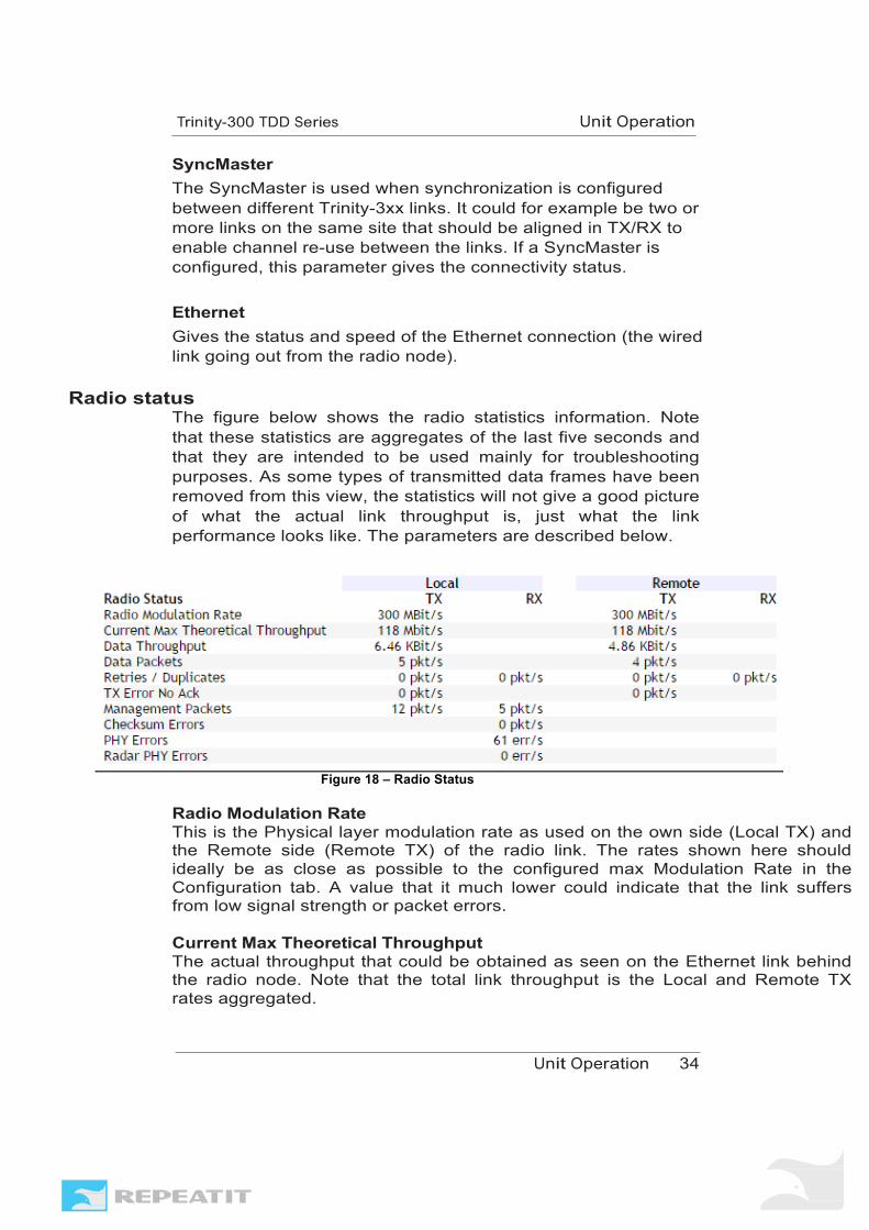
The figure below shows the radio statistics information. Note that these statistics are aggregates of the last five seconds and that they are intended to be used mainly for troubleshooting purposes. As some types of transmitted data frames have been removed from this view, the statistics will not give a good picture of what the actual link throughput is, just what the link performance looks like. The parameters are described below.
Figure 18 – Radio Status
Radio Modulation Rate This is the Physical layer modulation rate as used on the own side (Local TX) and the Remote side (Remote TX) of the radio link. The rates shown here should ideally be as close as possible to the configured max Modulation Rate in the Configuration tab. A value that it much lower could indicate that the link suffers from low signal strength or packet errors. Current Max Theoretical Throughput The actual throughput that could be obtained as seen on the Ethernet link behind the radio node. Note that the total link throughput is the Local and Remote TX rates aggregated.

U O
U O
Data Throughput Actual throughput measured on the link. As this window shows live statistics captured during the last seconds, a low throughput does not mean that something is wrong on the link. A few Kbit/s is normal given normal traffic pattern (Internet MIX, so called IMIX). This parameter is useful in troubleshooting scenario, mainly to check if the link is in operation.
Data packets Number of packets per second reported on the link.
Retries/Duplicates A frame that is dropped a number of defined times will eventually be retransmitted. A lot of retries indicated severe link problems. Check the PHY errors (below) for more details. Tx Error No Ack Number of packets reported as lost due to that no Acknowledgement (ACK) frame was received. A typical reason for this could be that the remote radio does not “hear” the sent frames. One potential reason could be that it is disturbed by another system. To see if that is the case, log in on that radio unit and perform a spectrum scan. Management Packets Number of management frames sent during the time interval. Checksum errors When a receiver detects the start of a frame and can read the header but not decode the frame content, a checksum error is generated. Many checksums errors could on one side of the link indicates interference on that side. PHY errors When a receiver sees energy over a certain threshold but cannot decode anything, it generates a PHY error. If one of the link units (Master or Client) is subject to interference or increased noise floor (from other equipment in the vicinity), the PHY error rate may increase. Consider moving the equipment or change channels. The spectrum scan tool gives useful information (see tools section in this document or refer to Repeatit’s Deployment Guideline).

U O
U O
Radar PHY errors Total number of PHY errors received by the radio card that could be potential radar signals. If the link is subject to radar PHY errors, consider selecting a channel outside of the radar frequency band.
Ethernet status This part displays the status of the Ethernet connection to the node.
Figure 19 – Ethernet status.
Throughput Throughput as reported by the Ethernet Interface. Packets Number of packets reported by the Ethernet Interface. Errors The Ethernet interface should not be subject to any packet errors. If errors are shown here, check the Ethernet cable, the negotiated Ethernet speed and duplex mode. It might also be necessary to check the settings on the switch/router that the radio node is connected to. Dropped Number of packets dropped by the Ethernet Interface. This should be zero. If packets are dropped, consider checking the same things as are listed under “Errors” above.

U O
U O
3.2 Status view for the MultiFlex Master
When logging in to a MultiFlex Master, the Status tab looks very different from a Point to Point Master.
Figure 20 – MultiFlex Master Status view. The signal strength bars are not visible as multiple clients are represented by the colored bar that represents the 32 time slots (see figure below). The first slot is always allocated for Management traffic, so 31 timeslots can be used to carry user traffic.
Figure 21 – The 31 timeslots and their respective status.

U O
U O
The timeslot color coding is described below: Blue: Management timeslot Green: Timeslot used by a connected client. Yellow: Synchronization ongoing (normally before a client is
connected) Red: Allocated by a client that is offline. Pink: Allocated by a disabled client. In order to free up
these slots for other clients, the disabled client has to be deleted from the MultiFlex Master.
Grey: Free timeslot that can be assigned to a new or existing client.
White: Unknown. In order to check the statistics for a specific client, click on that client (all clients are listed at the bottom of the Status page). The Status pane then changes and displays not only the signal levels of that particular client, but also the timeslots used by the client and the related statistics. An example is shown in the figure below.
Figure 22 – Status view – specific client statistics. The statistics shown for each connected client above is the same as you see for a single client that is connected to a Point

U O
U O
to Point Master. For a description of this statistics, check the previous section.
3.3 Link Diagnostic Tools
The “Tools” page contains diagnostic tools for optimizing your Trinity- 300 series link.
Figure 23 – Tools page.
Spectrum analyzer The spectrum analyzer tool assists you in selecting a clear channel free from other radio traffic and with minimum amount of background noise. The spectrum analyzer shows the amount of environmental RF energy for each available channel, classified as valid OFDM signals and other RF noise. Refreshing the spectrum/noise information requires the unit to disable the link and listen for a short time (less than a second) on each channel, this operation might take several minutes to complete, and during this time the link will be out of service.
Figure 24 – Spectrum analyzer.

U O
U O
Note The radio traffic will be disabled during the time the analyzer is running!
One-way speed test
The integrated speed test will show you the available raw radio throughput (±10%) of your link measured in one direction (normally 50% of the aggregated throughput). Up to 10 test runs are stored (4 shown in the figure below) so that you are able to monitor improvements or link degradations.
Figure 25 – Speed test.

U O
U O
3.4 Administrative tools The “Admin” page contains diagnostic tools for optimizing your Trinity-300 series link.
Figure 26 – Admin page.
Firmware Upgrade
The firmware in a Trinity-3xx series unit is upgradeable. New firmware brings both bug fixes and new features to the unit, so we recommend that you visit Repeatits web site frequently to look out for new firmware versions which are downloadable from there. New software firmware is always free of charge. To upgrade the firmware, follow the steps below. 1. Download the latest software to your computer from
Repeatits web site (http://www.repeatit.se/product-support/trinity/). The result should be that you have the .img file stored.
Figure 27 – Download the latest Trinity firmware from the web site.
2. Navigate to the “Admin” tab in the unit’s web interface and select “Firmware upgrade”.
Figure 28 – Click “Upgrade Firmware” on the web GUI’s Admin page.

U O
U O
3. In the pop-up window, click the “Choose file” button (“Välj fil”
in the picture below), localize the .img file that you downloaded and then click “Upgrade Firmware”.
Figure 29 – Select file and click “Upgrade Firmware”.
4. When the firmware is loaded and written to the flash disc, the node has to be rebooted (you can select this to be automatically done). When you get the message that the node is rebooted, you can close the window. The unit should be accessible shortly after that.
Note Never plug out the power or interrupt a firmware upgrade in some other way.
Tip Always upgrade the unit on the remote side of a link first when performing a firmware upgrade
Unit Information
Under Unit Information the following information can be found: Unit: Type of Trinity Unit (e.g. Trinity-323, Trinity-318 etc.) Serial number: Serial number of the radio unit. Radio mac: MAC address of the Wireless interface Ethernet mac: MAC address of the Ethernet interface Antenna: If the Trinity unit comes with an integrated antenna, the gain is shown here. System time: The internal clock of the radio unit. It is important that this is correct as time stamps for performance statistics and alarms are tagged with this time.
Unit Reset
To reset a unit, select the desired configuration and click "Restore". Please note that the unit will reboot automatically and might come back with a different IP-configuration. Never reset a unit you do not have immediate physical access to!

U O
U O
Tip Use Repeatit’s Restore To Defaul (RTD) client to detect units for which you do not know the IP address. The RTD client works on Windows computers and can be found on Repeatits web site (http://www.repeatit.se/product-support/utilities/).
Debug dump
Pressing the "Debug dump" button creates a file with internal debug information that could be useful for Repeatit’s support engineers.

Support
Support as well as firmware updates for the Trinity-3xx product series can be obtained from Repeatits web site at http://www.repeatit.se. There you will also find product news, FAQs and other useful information related to our products. Technical specifications about the various Trinity models can be found in the data sheets located on our web site (http://www.repeatit.se/products/trinity/).

Usage restrictions and legal information
This product contains radio equipment for which the use in several countries is subject to restrictions, licenses or government authorization.
European Union Notices The product may be used in all EU countries (and other countries following the EU directive 1999/5/EC) without any limitations except for the counties mentioned below. In EU and other European countries, the 5-GHz bands have been made available for the use of wireless local area networks (LANs). The overview of Regulatory Requirements for wireless LANs table provides an overview of the regulatory requirements applicable for the 5GHz bands. Requirements for individual countries may change, Repeatit recommends that you check w i th your local regulatory agency for the latest status on regulations for 5GHz fixed radio links.
Overwiew of Regulatory Requirements
Frequency band Max power level mW (EIRP) Usage 5150-5350 5470-5725
200 (23 dBm) 1000 (30 dBm)
Indoor ONLY Indoor and outdoor
The Regulatory limits for maximum output power are specified in EIRP (Equivalent Isotropic Radiated Power). The EIRP level of a device can be calculated by adding the gain of the antenna used (specified in dBi) to the output power available at the connector (specified in dBm) minus antenna cable loss between the connector and the antenna (in dB). The usage of power levels above the maximum specified EIRP is illegal.
U
U
Denmark
In Denmark, the band 5150-5350 MHz is also allowed for outdoor useage.
Italy
The use of 5.8GHz (5725-5850 MHz) is forbidden in Italy.
United Kingdom
A license from Ofcom (ofcom.org.uk) is required for use of the 5.8GHz (5725.5850 MHz) band in the United Kingdom.

U
U
Warranty
Repeatit AB, Hamngatan 33, S-172 66 Sundbyberg, Sweden, guarantees that our products do not have any defects regarding material or function upon delivery. All of Repeatits products are covered by a 12 month international warranty. If, during the time of warranty, the product displays any defects regarding material or function, the products should be returned to your reseller, who will, according to their own judgment, either repair or replace the product according to the following conditions:
Conditions
1. The warranty is only valid in combination with an original
receipt issued by the reseller at the date of delivery or sale. The receipt needs to contain the products serial number or similar identification.
2. If Repeatit repairs or replaces the product, the repaired or replaced product will be covered by the original warranty during the remainder of the guarantee period. During repair, some parts might be replaced. These parts are then the property of Repeatit AB.
3. The warranty does not cover normal wear and tear, faulty usage or handling or other usage other than the ones described by Repeatit AB. The warranty does not cover defects caused by accidents.
4. The warranty is not valid if service is performed on the product by a, by Repeatit, non-unauthorized person or company.
5. The warranty is not valid if any products that are not Repeatit original accessories are used with the product.
6. There is no warranty, written or oral, other than this printed warranty.