Embed Size (px)
Citation preview
* This work was performed in part under the auspices of the U.S. Department of Energy by Lawrence Livermore National Laboratory under Contract DE-AC52-07NA27344. # Sandia is a multiprogram laboratory operated by Sandia Corporation, a Lockheed Martin Company, for the United States Department of Energy's National Nuclear Security Administration under contract DE-AC04-94AL85000.
RemovingOrbitalDebrisWithLasers*#
ClaudeR.Phipps*1,KevinL.Baker3,BrianBradford5,E.VictorGeorge2,StephenB.Libby3, Duane A. Liedahl3, Bogdan Marcovici2, Scot S. Olivier3, Lyn D. Pleasance3,JamesP.Reilly4AlexanderRubenchik3,DavidN.Strafford5andMichaelT.Valley6Abstract:OrbitaldebrisinlowEarthorbit(LEO)arenowsufficientlydensethattheuse of LEO space is threatened by runaway collisional cascading. A problempredictedmorethanthirtyyearsago,thethreatfromdebrislargerthanabout1cmdemandsseriousattention.ApromisingproposedsolutionusesahighpowerpulsedlasersystemontheEarthtomakeplasmajetsontheobjects,slowingthemslightly,and causing them to re‐enter and burn up in the atmosphere. In this paper, wereassessthisapproachinlightofrecentadvancesinlow‐cost,light‐weightmodulardesignforlargemirrors,calculationsoflaser‐inducedorbitchangesandindesignofrepetitive, multi‐kilojoule lasers, that build on inertial fusion research. Theseadvances now suggest that laser orbital debris removal (LODR) is themost cost‐effective way to mitigate the debris problem. No other solutions have beenproposedthataddressthewholeproblemoflargeandsmalldebris.ALODRsystemwill havemultiple uses beyond debris removal. International cooperationwill beessentialforbuildingandoperatingsuchasystem.
WhyDebrisClearingisImportantThirty‐five years of poor housekeeping in space have created several hundredthousandpiecesofspacedebris largerthan1cminthe400‐2000‐kmaltitudelowEarthorbit(LEO)band,theirdensityreachingapeakinthe800‐1,000‐kmaltituderangei.Debrisinthe1‐10‐cmsizerangearemosthazardoustoLEOspacevehiclesbecausetheyarenot tracked,butcancause fataldamage.Forobjectsbelow1cm,“Whipple shields”, though expensive, would be effective against hypervelocityimpactii,andcanbebuilt.Therangeofdebrisorbitinclinationsgiveamostprobableclosing velocity between objectsiii of about 12km/s, a speed at which a piece ofdebris has ten times the energy density of dynamite. A 100‐gram bolt wouldcertainlycausealethaleventontheInternationalSpaceStation,ifitstruckthecrewchamber. Larger objects present a lesser threat, because they are less numerous(less than10,000), andcanbe trackedandusuallyavoidedbymaneuvering.Evenso,inMarch, 2009 and again on June, 2011, it was necessary for Space Station astronauts to take cover in a Soyuz capsule to reduce the chance of penetration by an 1PhotonicAssociates,LLC,SantaFe,NM87508[*Member,AAAS;persontowhomcorrespondenceshouldbesent]2Centech,CarlsbadCA920113LawrenceLivermoreNationalLaboratory,LivermoreCA94550*4NortheastScienceandTechnology,Williamsburg,VA231885ITTSpaceSystemsDivision,ViennaVA221806 Sensing and Imaging Technologies Department, Sandia National Laboratories, Albuquerque NM87123**

object with unacceptable track uncertainty. Fortunately, the capsule was docked with the Station. Earlier, in February 2009, an American Iridium satellite collided with a Russian Kosmos satellite, and the resulting cloud of debris combined with that from the Chinese Fengyun 1C ASAT test in January, 2007, to greatly increase the density of debris around the Earth, prompting concerns about the safety of the final Hubble servicing mission. The instabilitypredictedbyKesslerandCour‐Palaisivhasnowreachedthepointwherecollisionsareontracktobecomethemostdominantdebris‐generatingmechanism.While improved debris tracking and orbit prediction can temporarily improvethreat avoidance via maneuveringv, effective debris clearing strategies willeventuallybenecessary.Operationalmodelsof the changing risksof spacedebrisdamagehavebeendevelopedtoanalyzecostingstrategiesfordebrisremovalvi.
DebrisThreatCategoriesandClearanceStrategiesThere are about N1 = 2,200 large objects (diameter ≥ 100cm, mass of order 1 ton) in LEO, and N2 = 190k small objects (diameter ≥ 1cm) vii. The flux for the small ones in the peak density regionviii is about R2 = 1.4E-4 m-2year-1. Based on the relative numbers, we deduce a flux R1 = 1.7E-6 m-2year-1 for the large ones in the LEO band. Taking ⌠ = 2m2 as the large object cross-section, the interval between collisions of type i on the large ones across the ensemble is
Ti1 = [σ Ν1Ri]-1 . (1)
Applying Eq. (1), the chance that a big object will impact a big object is once in T11 = 134 years, whereas the chance a small object will impact a big object is once in T21 = 3 years. Just removing the big derelicts does not solve the problem. Any new large space asset that is installed in LEO will encounter the same collision rate R21 as before, from the small objects that have not been removed. The lifetime for these small objects at 1000 km altitude is of order 100 yearsix. A system that can address the small objects as well as the big ones is needed. Both classes need to be addressed because, while the debris growth rate is reduced by removing large derelict objects that produce clouds of debris when hitx, the small-debris threat to a LEO asset is far larger numerically. For example, the chance of a fatal debris-caused Space Station event per decade is about 7%xi. Previously, removal of the small debris was underemphasized.
ProposedSolutionstotheDebrisProblemAsidefromthelaser‐basedapproaches,includingthepulsedlaserablationmethodthatisthesubjectofthisarticle,avarietyofsolutionshavebeenproposed.Tonameafew,thesehaveincludedchasingandgrapplingtheobjectxii,attachingdeorbitingkitsxiii, deploying nets to capture objectsxiv,xv, attaching an electrodynamictetherxvi,xvii,xviiianddeployingcloudsoffrozenmistxix,gasxxorblocksofaerogelxxiinthedebrispathtoslowthedebris.Whilefewoftheseconceptshaveprogressedtothepointwherecostscanbeaccuratelyestimated,Bonnalhasestimatedacostof27M$per largeobject13 forattachingdeorbitingkits.Anymechanicalsolutionwillinvolve a comparable Δv, so we take Bonnal’s estimate as representative of theremovalcostperlargeitemusingmechanicalmethods.
Themistorunconfinedgassolutionwouldhaveeffectsthatarenotdebris‐specific.A mist or dust cloud deployed in LEO would rapidly disperse, as would a gasdetonation, and, if sufficient mass were installed, it would cause existing spaceplatformsaswellasderelictstore‐enter.The gas solution can avoid dispersal, but that requires the deployment of fourhundred100‐kmdiameterballoonsinorbit20.Eveniftheycouldbeplacedsoasnottodenyspacetootherassets,theyareone‐timesolutions(oneballoonpertarget)andcostlytolaunch.Ifmadeof5µmmylar,each100kmballoonwouldweigh160kilotonsandcost$1,600Btoputinorbitusingtoday’slaunchcosts.xxii,The aerogel solution has similar problems. It is easy to show thatxxiii an aerogel“catcher’smitt”solutiondesignedtoclearthedebris intwoyearswouldrequireaslab50cmthickand13kmonaside.Suchaslabwouldhave80‐kilotonmass,andwould cost $800M to launch. Even if we ignore the difficulty of maintaining thisshape,afatalproblemisthesteady12kNaveragethrustrequiredtoopposeorbitaldecay of the slab facing ram pressure over an elliptical orbit ranging between400kmand1100kmaltitude.Tomaintainthisthrustoveratwo‐yearlifetimewouldrequireafuelmassof150kilo‐tons,inadditiontothemittmass,triplingthecost.Laser‐basedmethodscanbedividedintothreegeneralcategoriesdistinguishedbytheir goals and laser beam parameters. At the lowest intensities, below thethresholdforablatingthedebrissurface,lasershavebeenproposedtodivertdebristhrough the weak agency of photon momentumxxiv. This approach has lasermomentum transfer efficiency four to five orders of magnitude less than pulsedlaserablation.Itisproblematicbecauseitseffectsarecomparabletotheuncertaineffects of spaceweather and sunlight, anddoes not effectively address thedebrisgrowthproblem.Athigherlaserintensity,wecanconsiderheatingtoablationwithcontinuous (CW) lasers, but slow heating of tumbling debris will usually give anablation jetwhosemomentum contribution cancels itself out, on the average. CWheating causesmessymelt ejection rather than clean jet formation, adding to thedebris problem. Also, CW lasers cannot reach the required intensity on target atlargerangewithoutaverysmall illuminationspot size, requiringanunacceptablylargemirror.
Pulsed laser orbital debris removal (LODR)was proposed fifteen years ago3. ThebasicsetupisillustratedinFigure1.Atthattime, lasersaswellastelescopeswiththerequiredperformancedidnotyetexist,butthecomponentscouldbespecified.Now,allthecomponentsactuallyexistorareintheplanningstage.As recently as four years agoxxv, itwas considered that “The use of groundbasedlasers to perturb the orbits of the satellites is not now practical because of theconsiderablemass of the satellites and the consequent need to deposit extremelyhighamountsofenergyonthevehiclestoeffectthenecessarychange.”
However, we believe that a better understanding of the problem, coupled withadvances in technology driven by inertial fusion research, make this statementoutdated. The purpose of this article is to demonstrate that laser orbital debrisremovalispracticalandeconomical.

HowLaserscanTransferMomentumThe standard measure of the efficiency with which laser light is converted to pressure is the momentum coupling coefficient,
Cm = p/I [Pa W-1m-2 or N/W]. (2)
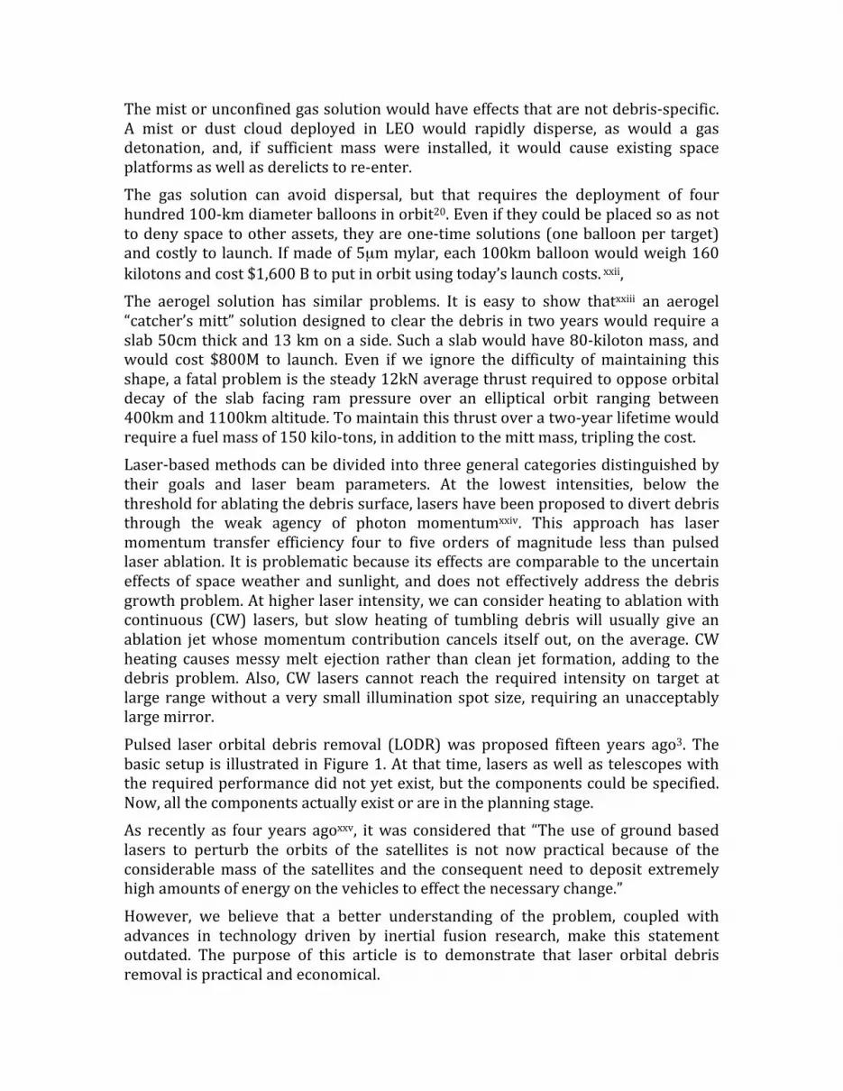
In the ablation regime, Cm is a function of the laser intensity I, wavelength λ and laser pulse duration τ and material properties. As the intensity increases, Cm rises to maximum and decreases at higher laser intensity, because more energy goes into reradiation, ionization, breaking chemical bonds, etc. Figure 2 showsxxvi this classical behavior. The maximum momentum coupling occurs just at the vapor-plasma transition. In order to design a LODR system, it is crucial to predict the fluence (laser energy per m2) where this maximum is found, and this requires knowing how to combinexxvii vapor and plasma models for a particular material. An approximate working relationship is given by27,
xxviii,xxix
Φopt = 4.8E8 √τ Jm-2 (3)
Figure 1. LODR concept.. The debris target is detected and tracked. Then, a repetitively pulsedlaserisfocusedbyalargemirroronit,makingaplasmajet.Withhighintensity,10nspulses,verylittle target material is removed and the debris is not melted or fragmented. Most of the laserenergygoesintothejet.Theengagementisdesignedsothejetpointsintherightdirectiontoslowthe target,onaverage,by thesmallamount (100‐150m/s)needed todrop itsperigee to200km,which is adequate for rapid re‐entry.Hundreds of pulses are needed to do this, but they can beappliedduringonepassoverheadforthesmalldebris.
For τ = 5ns, precise calculations show Φopt = 53 kJ/m2 required for an aluminum target27, a worst case.
Multi-kJ laser pulse energy and large mirrors are required to overcome diffraction spreading of the light at a range of 1000km. The spot size ds which can be delivered to a target at distance z is
dsDeff = aM2λz. (4)
In Eq. (4), M2 is the beam quality factor (≥1)and Deff is the illuminated beam diameter inside the aperture D for calculating diffraction. A hypergaussianxxx with index 6 coming from a LODR system with corrected beam quality M2=2.0 (Strehl ratio = 0.25) gives Deff/D = 0.9 and a = 1.7. In order to obtain even ds = 31 cm at z = 1000km range with λ=1.06µm we need Deff = 13m illuminated aperture diameter and, to avoid nonlinear effects in the atmosphere, a minimum Deff = 11m. The quantity
M2 in Eq. (4) includes atmospheric phase distortions corrections, either by standard adaptive optics or phase conjugation or a combination of the two (discussed below and in the SOM).
Lightweight mirrors of this sizexxxi,xxxii now have a major impact on LODR system design. Examples are the 10-m Keck primary, the 9.8 x 11.1-m South African Large Telescope, and the planned European Extremely Large Telescope with a 42-m diameter primary mirror composed of 984 segmentsxxxiii with very low areal mass density.32,xxxiv
Denoting by Teff the product of all transmission losses, including apodization, physical obscuration by the secondary mirror, spider, coudé path and atmospheric transmission loss, Eq. (4) shows that the fluence Φ delivered to a target by laser pulse energy W is
. (5) ! =4WTeff Deff
2
"M 4a2#2z2
Figure2.ExampleresultsofmodelsthatallowustopredictCmforanumber of likely plastics and metals. The vertical blue line showswherethevapor‐plasmatransitionimpliedbyEq.(2)occursforCO2lasers,buttheCmmodelisuniversalandapplicabletoawiderangeoflaser parameters. The red line is ionization fraction. References forthedataarefoundinreference23.
In a practical case where Deff = 10m, if T = 80%, Teff = 0.5. In order to deliver 53 kJ/m2 to a target at 1000km range, theproductWDeff 2mustbeat least993kJm2, laserpulseenergymustbe7.3kJ,andthemirrordiameterDmustbe13m.
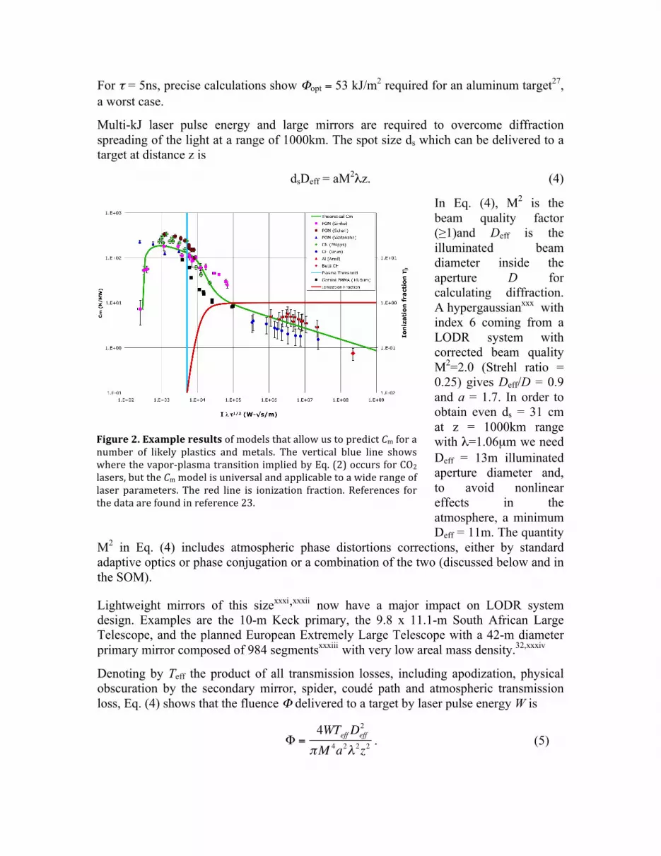
Predicting the velocity increment delivered to a debris object is not a simplematter.Itdependsontargetshapeandtheorientationofeachsurfaceelement.Thethrust fromtheplasma jet formedon the target isperpendicular toeachelement,whatever the angle atwhich the laser strikes the target. Further, the engagementhas to be properly designed to make sure is slowing the target rather thanspeedingitup.To simplify discussion, we use an efficiency factorηc for the combined effects ofimproper thrust direction, target shape, target tumbling, etc. in reducing theefficiency of laser pulse fluenceΦ on the target (J/m2) in producing the desiredvelocitychange,
Δv|| = ηcCmΦ/µ. (6)
InEq.(6),µisthetargetarealmassdensity(kg/m2).Thisformulationtakesaccountof laserbeam“overspill” forsmalldebris,withouthavingtospecifytheactualsizeand mass of each target. We take ηc = 0.3 after Liedahlxxxv [see the SOM for a
!v
!v
3a. 3b.Figure3.Geometryofthelasertargetinteraction(scalesexaggeratedforclarity).3a:Schematicofdebrisde‐orbitingconceptinlow‐Earthorbit.Foragivenenergydeposition,theorbital perturbation on a spherical target is predictable. For non‐spherical targets, theperturbationcanbepredicted,iftheshapeandorientationatengagementareknown.3b:ThrustonadebrisobjectisresolvedintocomponentsfTandfNnormaltoandalongtheorbittangent.Since,forLEOdebris,rangez<<theEarth’sradiusrE,thezenithangleφzchangesrapidlycomparedtothegeocentricangleφ.
completediscussionoftargetshapeeffects].Insomecases,wecanlowerthedebrisperigee not only by pushing antiparallel to its velocity vector, but,counterintuitively,bypushingradiallyoutwards.
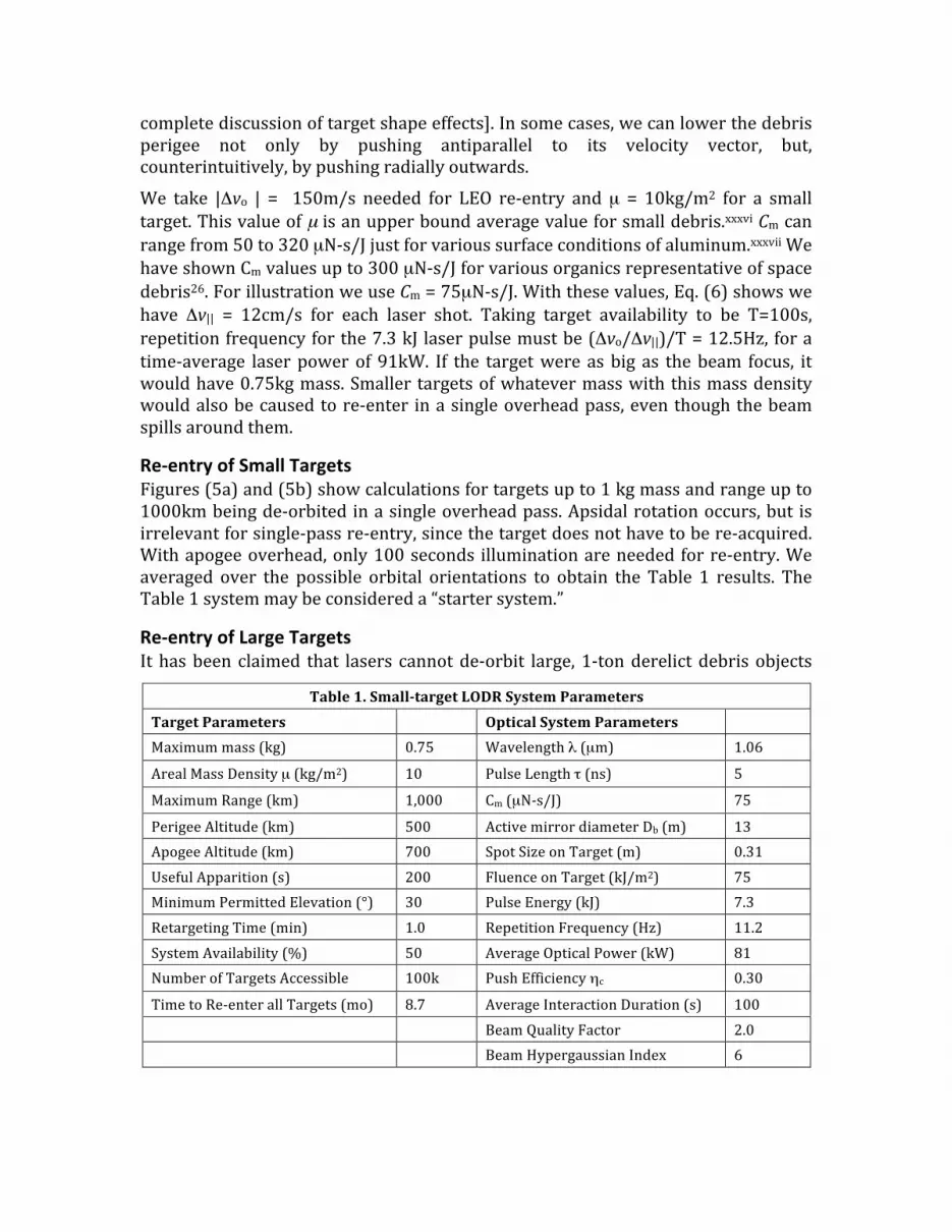
We take |Δvo | = 150m/s needed for LEO re‐entry andµ = 10kg/m2 for a smalltarget.Thisvalueofµ isanupperboundaveragevalueforsmalldebris.xxxviCmcanrangefrom50to320µN‐s/Jjustforvarioussurfaceconditionsofaluminum.xxxviiWehaveshownCmvaluesupto300µN‐s/Jforvariousorganicsrepresentativeofspacedebris26.ForillustrationweuseCm=75µN‐s/J.Withthesevalues,Eq.(6)showswehave Δv|| = 12cm/s for each laser shot. Taking target availability to be T=100s,repetitionfrequencyforthe7.3kJ laserpulsemustbe(Δvo/Δv||)/T=12.5Hz, foratime‐average laserpowerof91kW. If the targetwere asbig as thebeam focus, itwouldhave0.75kgmass.Smaller targetsofwhatevermasswiththismassdensitywouldalsobecausedtore‐enter inasingleoverheadpass,eventhoughthebeamspillsaroundthem.
Re‐entryofSmallTargetsFigures(5a)and(5b)showcalculationsfortargetsupto1kgmassandrangeupto1000kmbeingde‐orbitedinasingleoverheadpass.Apsidalrotationoccurs,but isirrelevantforsingle‐passre‐entry,sincethetargetdoesnothavetobere‐acquired.Withapogeeoverhead,only100seconds illuminationareneededforre‐entry.Weaveraged over the possible orbital orientations to obtain the Table 1 results. TheTable1systemmaybeconsidereda“startersystem.”
Re‐entryofLargeTargetsIthasbeen claimed that lasers cannotde‐orbit large,1‐tonderelictdebrisobjects
Table1.SmalltargetLODRSystemParameters
TargetParameters OpticalSystemParameters Maximummass(kg) 0.75 Wavelengthλ(µm) 1.06
ArealMassDensityµ(kg/m2) 10 PulseLengthτ(ns) 5
MaximumRange(km) 1,000 Cm(µN‐s/J) 75
PerigeeAltitude(km) 500 ActivemirrordiameterDb(m) 13ApogeeAltitude(km) 700 SpotSizeonTarget(m) 0.31UsefulApparition(s) 200 FluenceonTarget(kJ/m2) 75MinimumPermittedElevation(°) 30 PulseEnergy(kJ) 7.3RetargetingTime(min) 1.0 RepetitionFrequency(Hz) 11.2SystemAvailability(%) 50 AverageOpticalPower(kW) 81NumberofTargetsAccessible 100k PushEfficiencyηc 0.30
TimetoRe‐enterallTargets(mo) 8.7 AverageInteractionDuration(s) 100 BeamQualityFactor 2.0 BeamHypergaussianIndex 6
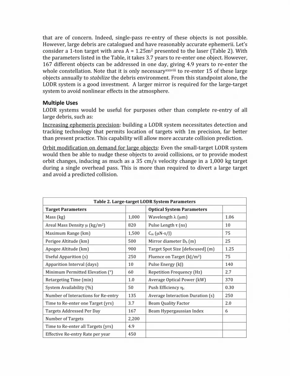
that are of concern. Indeed, single‐pass re‐entry of these objects is not possible.However,largedebrisarecataloguedandhavereasonablyaccurateephemerii.Let’sconsidera1‐tontargetwithareaA=1.25m2presentedtothelaser(Table2).WiththeparameterslistedintheTable,ittakes3.7yearstore‐enteroneobject.However,167differentobjectscanbeaddressed inoneday,giving4.9years tore‐enter thewholeconstellation.Notethatitisonlynecessaryxxxviiitore‐enter15oftheselargeobjectsannuallytostabilizethedebrisenvironment.Fromthisstandpointalone,theLODRsystemisagoodinvestment.Alargermirrorisrequiredforthelarge‐targetsystemtoavoidnonlineareffectsintheatmosphere.
MultipleUsesLODR systems would be useful for purposes other than complete re‐entry of alllargedebris,suchas:Increasingephemerisprecision:buildingaLODRsystemnecessitatesdetectionandtracking technology that permits location of targetswith 1m precision, far betterthanpresentpractice.Thiscapabilitywillallowmoreaccuratecollisionprediction.
Orbitmodificationondemandforlargeobjects:Eventhesmall‐targetLODRsystemwouldthenbeabletonudgetheseobjectstoavoidcollisions,ortoprovidemodestorbitchanges, inducingasmuchasa35cm/svelocitychange ina1,000kgtargetduring a singleoverheadpass.This ismore than required todivert a large targetandavoidapredictedcollision.
Table2.LargetargetLODRSystemParameters
TargetParameters OpticalSystemParameters Mass(kg) 1,000 Wavelengthλ(µm) 1.06
ArealMassDensityµ(kg/m2) 820 PulseLengthτ(ns) 10
MaximumRange(km) 1,500 Cm(µN‐s/J) 75
PerigeeAltitude(km) 500 MirrordiameterDb(m) 25ApogeeAltitude(km) 900 TargetSpotSize[defocused](m) 1.25UsefulApparition(s) 250 FluenceonTarget(kJ/m2) 75ApparitionInterval(days) 10 PulseEnergy(kJ) 140MinimumPermittedElevation(°) 60 RepetitionFrequency(Hz) 2.7RetargetingTime(min) 1.0 AverageOpticalPower(kW) 370SystemAvailability(%) 50 PushEfficiencyηc 0.30
NumberofInteractionsforRe‐entry 135 AverageInteractionDuration(s) 250TimetoRe‐enteroneTarget(yrs) 3.7 BeamQualityFactor 2.0TargetsAddressedPerDay 167 BeamHypergaussianIndex 6NumberofTargets 2,200 TimetoRe‐enterallTargets(yrs) 4.9 EffectiveRe‐entryRateperyear 450

5a.
5b.Figure5.Targetreentryisachievedinoneoverheadpassforanydebristargetsmallerthanthelaser spot radius of 31cm at 1000 km range, having areal mass density 10kg/m2 or less. Thelargesttargetre‐enteredhas0.75kgmass.Parameters:Wavelength1.06µm,beamqualityfactor2.0, beam format hypergaussian with index 6, fluence on target 53 kJ/m2, 7.3kJ pulse energy,repetitionrate11.2Hz,mirrordiameter13m,Cm=75µN‐s/J,efficiencyfactorηc=30%,perigeealtitude500km,apogeealtitude1073km,eccentricity0.04,re‐entryforΔrp=‐3E5m.Case a): orbit perigee is ‐120 degrees geocentric (upstream) relative to laser site, 833 pulsesapplied all along the debris path over 210 s to achieve minimum perigee. Case b): apogee isoverheadthelasersite,1,010pulsesappliedover133s.
Causing precise re‐entry: Re‐entry for selected derelicts can be altered in acalibrated fashion so the re‐entry site can be controlled, for example, in themid‐Pacific, avoiding liability issues as well as damage to property or people on theground.MovingGEOtargetsintodisposalorbits:Thesmalltargetsystem,coupledwitha10‐20mrelaymirror justabovegeosynchronous (GEO)orbit is capableof raising theorbitofadefunctGEOsatellite100kminjust20minutes.
AcquisitionAnacquisitionsystemreducesthepositionuncertaintyofadebrisobjectfromkmtothe meters required by the laser system. An easy method would use twilight ordawn,whenthetarget is insunlightandtheacquisitionsystemseesdarksky,butthiswouldlimitoperationtoabouttwohoursperday.
Activeacquisitionispossible,indaylight9,usingthe“pusherlaser”toilluminatethetarget,andtheLODRsystemmirroronEarthtocollectthescatteredlight.Thelaserbeamisfirstdeliberatelydefocusedtocoverseveralkmatrange.Ifthefieldofviewis3kmat1000kmrange,oneobjectper4minuteswillpassthroughthefieldofviewonaverage..Alarge(20m)receivingapertureand7.3kJpulsesfromthepusherlaserarerequiredtoprovideenoughscatteredphotonstoseesmalltargets.InGaAsfocalplane arrays now have quantum efficiencies of 80%xxxix. In our active trackingsystem, a 1.5‐cm Lambertian scattering targetwith 50% albedo at 750 km rangewouldreturn45photonsto itsarraypixelontheground,withasignal todayskybackgroundratioof72.Thesystemwouldrequireabandwidthof0.2nmforboththelaserandnarrowbandopticalfilter,anda75km“rangegate.”The 20‐m mirror has two parts with different optical quality. The central 13msectionusedbythelaserinpushermodeishighquality.The3.5‐mannulusoutsidethatisusedtocollectlightforinitialwidefieldofviewacquisitionandcanbelowerquality,sinceweneedonlyafew‐mimageprecisioninthetargetplaneinthismode.Ifwehavea1000x1000elementarraywitha3‐kmfieldofview,eachpixelprojectsontoa3‐mspot.Bothpartsusesegmentsabout1minsizemountedonthree‐pointpiezoelectricmounts.Theouterannuluscanbepointedatadifferentspotfromthecentralportion.Fourindependentadaptiveopticssystemsarerequired[see“PhaseCorrection”followingandSOMFigure4].
Theoptical filter iseasy toobtain.Rangegatingamounts to readingout thearrayevery 250µs and storing the data in slices, delayed from laser firing by thepropagationtime.Thisgivesroughrangeinformation.
TargetTrackingWhentheacquisitionsystemhasestablishedatrackwithina3‐kmcircle,thefieldofviewisnarrowed,alwayskeepingthetargetcentered.Whenthecircleviewedhasshrunkto100m,thesystemswitchesmodes[see“Look‐ahead”following].Asthefieldofviewisnarrowed,thefocalplanearrayisprotectedfromdamagewithattenuators.Now, thecomputermakes thebest focipossibleand thepusher laserbeginsdoingitsrealwork[see“PhaseCorrection”following].
PhaseCorrectionviaAdaptiveOpticsPhase aberrations are causedby severalmechanisms, from thermaldistortions inthelaseramplifiertoatmosphericturbulence.Theconventionalsolutionisadaptiveopticsxl, inwhich a deformable phase platewithmany computer‐driven actuatorscompensatesforthesedistortionsastheyoccur,atarateofabout1kHz(SOM).Thephase reference for such a system is provided by a “guidestar.” Examples are a100Wbeamat589nmthatcreatesastarlikereferencepointsource in theEarth’ssodiumlayerat90kmaltitude,andthereflectionfromthetargetitself.
Look‐aheadThe finitevelocityof lightrequiresdealingwith“look‐ahead”beforeanaccuratelytrackedtargetcanbe“pushed.”At7.5km/s,thedebrisisactuallyasmuchas50maheadofwherethesensor lastdetectedit.Rangeinformationisneededtotell thecomputer howmuch to correct pointing for the pusher shot, because the target’sactualspeedanddistancearecriticalvariables.Thetrackingsystemoutlinedabovecando this.The lasernowappears tobe shooting intoempty spacebut,when itspulsearrives,thetargetisthere.
Weareliterallylookingintwodirectionsatonce,separatedbyabout100µrad.Twoindependent adaptive optics systems correct these paths. After themode change,thedetectorpathcontinuesusingthetargetitselfasguidestar.Meanwhile,asodiumlaserguidestar is tiltedaheadofthedetectorbyacomputedangle,andaseparatearrayusesthesignalfromthattocommandthecorrectorplatethathelpsthelaserfocusonitstarget.
Thefinetrackingsignalnowbecomesverybrightandshiftsintotheblueasplasmais formedon the target.The systemuses this signal to stop increasing laserpulseenergy.
RôleofBrillouin‐EnhancedFour‐WaveMixing(BEFWM)inAdaptiveOpticsBEFWM (see Figure 7 and SOM) is a type of phase conjugation in which phasedistortions are automatically compensatedxli,xlii,xliii This is important when mirrorsizebecomesmuchlargerthanatmosphericturbulencecells,becauseconventionaladaptiveopticsrequirethousandsofactuatorsoperatingata1kHzrate.
ItmaybeeasiertouseBEFWMthanclassicaladaptiveoptics,orperhapsahybridsystemwillbebest.Phaseconjugationoperateslikeholography,butitisadynamichologramdynamicallyrecordedbyinterferingwavesinanonlinearopticalmediumrather thanbeingastaticpatternonaglassplate.Withaphaseconjugatemirror,each ray is reflected back through the system in the direction it came fromwithreversed phase. This reflected wave "undoes" the distortion, converging to theinitialpointsource.Theamplifiedconjugatesignalisautomaticallyconcentratedonthespaceobject toanaccuracy that isdeterminednotby the turbulent scatteringangle(~100µrad)but,insteadbythespatialresolutionofthereceivingaperture(~0.1µradforareceivingapertureof10m).

Aspecialadvantageofthistechniqueisthatthetargetbecomesitsownguidestar.
Otheradvantagesarethattiltanisoplanatismiseliminated,andthatthesystemhasextremely narrow acceptance bandwidth leading to good background noiserejection. The time by which the phase correction is “out of date” is just that
6a.
6b.
Figure6.HowBEFWMworks.a):Aphaseconjugate(PC)mirrorbehavesdifferentlyfromaregularmirror.Aregularmirrorreflects incident rays in theoppositedirection, so that theangleofincidenceisequaltotheangleofreflection(seeFig.1).Incontrast,lightfromaphaseconjugatemirror is always reflected exactly in the backward direction, independent of theangle of incidence. b): A nonlinear optical cell (BEFWM) and pump laser are added to theusuallaserchaintoimplementaBEFWMsystem.
!
!
!
!!
!
!
!
!
!
"#$%&'(!
)*((+(!
,-!)*((+(!
requiredforadoublepassthroughtheatmosphere(~100µs),muchfasterthanthe1mstimeinwhichatmosphericphasedistortionscantypicallychange.Targetlead‐aheadiscomputedbyaproprietarytechnique.
AdvancesinLasersLaser systems built and operated at Lawrence Livermore National Laboratory(LLNL)overthepastdecadeencompasstherangeofenergiesandpowersrequiredtoremoveorbitaldebris.One example is the solid‐state heat capacity laser (SSHCL), which was built andoperated in themid‐2000’s.This flush lamp‐pumped, solid‐state laseroperated inburst‐modeforaperiodof10s,produced500Jpulsesandaveragepowerof>10kW.44Since 2009 LLNL has operated the world’s largest and most energetic laser, theNationalIgnitionFacility(NIF).45,46CombinedNIF’s192laserbeamproduceover3MJin5‐10nspulsesatthefundamentalwavelength(1053um),andover1.5MJatthethirdharmonic(353nm).BuildingonwhathasbeenlearnedanddemonstratedontheNIF,LLNLisnowdevelopingdesignsforalaserdriverfortheLaserInertialFusion Energy (LIFE) program.47 This high‐repetition rate (10‐20 Hz), high‐efficiency (~12‐18%) diode‐pumped solid‐state systemwill produce 8‐10 kJ in asinglebeamat1053nm.LODRrequiressignificantlylessthan1%oftheNIFpulseenergy,doesnotrequireharmonicconversionanddoesnothavethelaserfusionenergydriverrequirementtooperate24/7withhighavailability.ALODRlaserwillbesimpler,morecompactandfar lesscostlythaneithertheNIFortheLIFElasersystem,48butwill leveragethe experience gained and investment made over several decades of laserdevelopment,constructionandoperation.
DemonstrationSystemA demonstration system could be built using a 9‐m mirror and a 4.6‐kJ laser toproveLODRworksontargetsat400kmaltitude.
InternationalCooperationBuilding and operating a LODR system will require international cooperation toavoidconcernsthatitisreallyaweaponssystem.Also,cooperationinitsoperationwillbeneededtofacilitatepermissionforitsusetoremovelargedebrisobjects.
EstimatedDebrisRemovalCostWedonot claimhighaccuracy forour costmodels.Anaccuratemodel requiresathorough engineering study. However, rough system cost estimates based on thealgorithmsdescribed in theProjectORIONreview9areuseful toestimatecostperobject re‐entered.We estimate cost per small object removed at a few thousanddollars,andthatforlargeobjectsatabout$1Meach.

ConclusionsWeanalyzedallthemajoraspectsoflaserorbitaldebrisremoval,andconcludethatlaserorbitaldebrisremovalwillwork,evenforlargedebrisobjects.ALODRsystemshouldprovidethelowestcostperobjectremovedamongallapproachesthathavebeenproposed.LODR is theonly solution that candealwithboth small and largedebris.WithLODR,targetaccessisatthespeedoflight,redundantandagile.LODRcanhandle tumbling objects,whilemechanical grapplers cannot. The systemhasmultiple uses aside from general debris clearing, such as preventing collisions,increasing the accuracy of debris ephemerii and controlling where large debrisimpact the Earth’s surface. Development and construction of the laser debrisremovalsystemofferstheopportunityfor internationalcooperation. Indeed,suchcooperationwillbebenecessarytoavoidconcernsthatit isaweaponsystemandprovideaframeworkforitspracticaluse.
SupportingOnlineMaterial
ContentsIntroduction ‐‐‐‐‐‐‐‐‐‐‐‐‐‐‐‐‐‐‐‐‐‐‐‐‐‐‐‐‐‐‐‐‐‐‐‐‐‐‐‐‐‐‐‐‐‐‐‐‐‐‐‐‐‐‐‐‐‐‐‐‐‐‐‐‐‐‐‐‐‐‐‐‐‐‐‐‐‐‐‐‐‐‐‐‐‐‐‐2
LaserMomentumCoupling ‐‐‐‐‐‐‐‐‐‐‐‐‐‐‐‐‐‐‐‐‐‐‐‐‐‐‐‐‐‐‐‐‐‐‐‐‐‐‐‐‐‐‐‐‐‐‐‐‐‐‐‐‐‐‐‐‐‐‐‐‐‐‐‐‐‐‐‐‐‐‐2
LaserOrbitModification‐‐‐‐‐‐‐‐‐‐‐‐‐‐‐‐‐‐‐‐‐‐‐‐‐‐‐‐‐‐‐‐‐‐‐‐‐‐‐‐‐‐‐‐‐‐‐‐‐‐‐‐‐‐‐‐‐‐‐‐‐‐‐‐‐‐‐‐‐‐‐‐‐‐‐4
OpticalConstraintsfromtheAtmosphereandTargetPhysics ‐‐‐‐‐‐‐‐‐‐‐‐‐‐‐‐‐‐‐‐‐‐‐‐‐‐‐‐7
TargetShapeEffects‐‐‐‐‐‐‐‐‐‐‐‐‐‐‐‐‐‐‐‐‐‐‐‐‐‐‐‐‐‐‐‐‐‐‐‐‐‐‐‐‐‐‐‐‐‐‐‐‐‐‐‐‐‐‐‐‐‐‐‐‐‐‐‐‐‐‐‐‐‐‐‐‐‐‐‐‐‐‐‐7
TelescopeDesignforDaylightAcquisitionandTracking ‐‐‐‐‐‐‐‐‐‐‐‐‐‐‐‐‐‐‐‐‐‐‐‐‐‐‐‐‐‐‐‐‐ 10
TurbulenceCorrectionwithStandardAdaptiveOptics ‐‐‐‐‐‐‐‐‐‐‐‐‐‐‐‐‐‐‐‐‐‐‐‐‐‐‐‐‐‐‐‐‐‐‐ 11
AnAlternativeTargetTrackingMethod‐‐‐‐‐‐‐‐‐‐‐‐‐‐‐‐‐‐‐‐‐‐‐‐‐‐‐‐‐‐‐‐‐‐‐‐‐‐‐‐‐‐‐‐‐‐‐‐‐‐‐‐‐‐ 11
TurbulenceCorrectionbyBrillouin‐EnhancedFour‐WaveMixing ‐‐‐‐‐‐‐‐‐‐‐‐‐‐‐‐‐‐‐‐‐ 12
HowBEFWMWorks‐‐‐‐‐‐‐‐‐‐‐‐‐‐‐‐‐‐‐‐‐‐‐‐‐‐‐‐‐‐‐‐‐‐‐‐‐‐‐‐‐‐‐‐‐‐‐‐‐‐‐‐‐‐‐‐‐‐‐‐‐‐‐‐‐‐‐‐‐‐‐‐‐‐‐‐‐‐ 13
BEFWMSystemConceptofOperations ‐‐‐‐‐‐‐‐‐‐‐‐‐‐‐‐‐‐‐‐‐‐‐‐‐‐‐‐‐‐‐‐‐‐‐‐‐‐‐‐‐‐‐‐‐‐‐‐‐‐‐‐‐‐ 15
Long‐distanceOpen‐airBEFWMDemonstration‐‐‐‐‐‐‐‐‐‐‐‐‐‐‐‐‐‐‐‐‐‐‐‐‐‐‐‐‐‐‐‐‐‐‐‐‐‐‐‐‐‐‐ 16
ChoosingTargets‐‐‐‐‐‐‐‐‐‐‐‐‐‐‐‐‐‐‐‐‐‐‐‐‐‐‐‐‐‐‐‐‐‐‐‐‐‐‐‐‐‐‐‐‐‐‐‐‐‐‐‐‐‐‐‐‐‐‐‐‐‐‐‐‐‐‐‐‐‐‐‐‐‐‐‐‐‐‐‐‐‐ 17
References‐‐‐‐‐‐‐‐‐‐‐‐‐‐‐‐‐‐‐‐‐‐‐‐‐‐‐‐‐‐‐‐‐‐‐‐‐‐‐‐‐‐‐‐‐‐‐‐‐‐‐‐‐‐‐‐‐‐‐‐‐‐‐‐‐‐‐‐‐‐‐‐‐‐‐‐‐‐‐‐‐‐‐‐‐‐‐‐‐‐ 19
Figures
Figure1.Geometryfororbitdiscussion‐‐‐‐‐‐‐‐‐‐‐‐‐‐‐‐‐‐‐‐‐‐‐‐‐‐‐‐‐‐‐‐‐‐‐‐‐‐‐‐‐‐‐‐‐‐‐‐‐‐‐‐‐‐‐‐4
Figure2.Indicatingapsidalshift ‐‐‐‐‐‐‐‐‐‐‐‐‐‐‐‐‐‐‐‐‐‐‐‐‐‐‐‐‐‐‐‐‐‐‐‐‐‐‐‐‐‐‐‐‐‐‐‐‐‐‐‐‐‐‐‐‐‐‐‐‐‐‐‐‐6
Figure3.Calculatedperigeechange‐‐‐‐‐‐‐‐‐‐‐‐‐‐‐‐‐‐‐‐‐‐‐‐‐‐‐‐‐‐‐‐‐‐‐‐‐‐‐‐‐‐‐‐‐‐‐‐‐‐‐‐‐‐‐‐‐‐‐‐‐9
Figure4.Apossibletelescopedesigndiscussedinthemainpaper‐‐‐‐‐‐‐‐‐‐‐‐‐‐‐‐‐‐‐‐‐ 10
Figure5.IllustratingtheBEFWMprocess ‐‐‐‐‐‐‐‐‐‐‐‐‐‐‐‐‐‐‐‐‐‐‐‐‐‐‐‐‐‐‐‐‐‐‐‐‐‐‐‐‐‐‐‐‐‐‐‐‐‐‐ 14
Figure6.BEFWMinthelaboratory ‐‐‐‐‐‐‐‐‐‐‐‐‐‐‐‐‐‐‐‐‐‐‐‐‐‐‐‐‐‐‐‐‐‐‐‐‐‐‐‐‐‐‐‐‐‐‐‐‐‐‐‐‐‐‐‐‐‐‐ 15
Figure7.Highlightsofopen‐airBEFWMexperiments ‐‐‐‐‐‐‐‐‐‐‐‐‐‐‐‐‐‐‐‐‐‐‐‐‐‐‐‐‐‐‐‐‐‐‐‐ 16
Figure8.ConceptofoperationsforaLODRremovalsystem ‐‐‐‐‐‐‐‐‐‐‐‐‐‐‐‐‐‐‐‐‐‐‐‐‐‐‐‐ 17
Figure9.Balancingfourareasofuncertainty ‐‐‐‐‐‐‐‐‐‐‐‐‐‐‐‐‐‐‐‐‐‐‐‐‐‐‐‐‐‐‐‐‐‐‐‐‐‐‐‐‐‐‐‐‐‐‐ 18
IntroductionThis material provides additional details supporting the claims made in the main paper “Removing Orbital Debris With Lasers” by Phipps, et al. We review the physics of laser momentum coupling to targets, laser orbit modification using this coupling and the constraints on the ODR beam parameters posed by propagation through the atmosphere. We also review target shape effects, acquisition and tracking, atmospheric turbulence correction, the Brillouin-enhanced four-wave mixing technique as a possible alternative to standard adaptive optics and the methods for choosing targets.
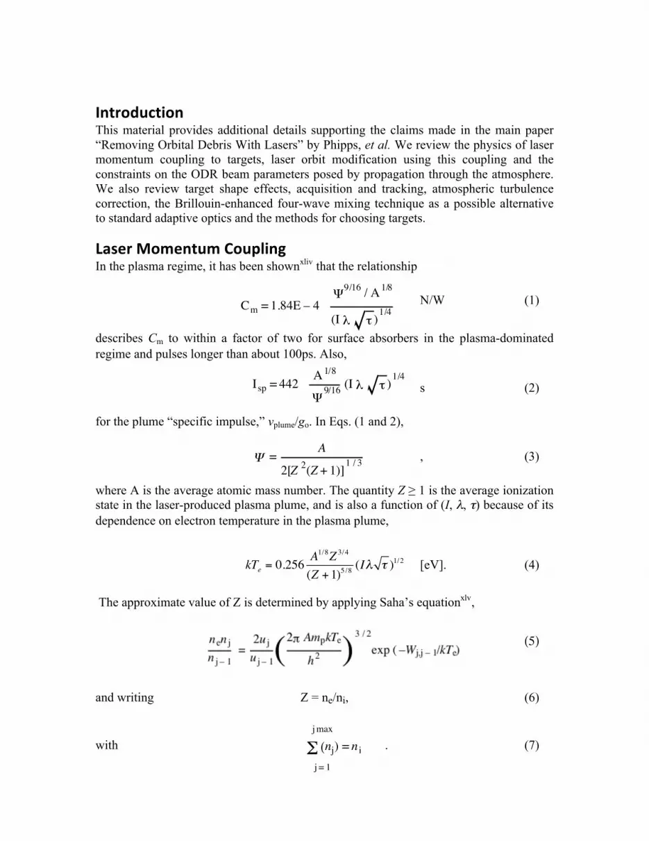
LaserMomentumCouplingIn the plasma regime, it has been shownxliv that the relationship
N/W (1)
describes Cm to within a factor of two for surface absorbers in the plasma-dominated regime and pulses longer than about 100ps. Also,
s (2)
for the plume “specific impulse,” vplume/go. In Eqs. (1 and 2),
, (3)
where A is the average atomic mass number. The quantity Z ≥ 1 is the average ionization state in the laser-produced plasma plume, and is also a function of (I, λ, τ) because of its dependence on electron temperature in the plasma plume,
kTe= 0.256
A1/8Z3/4
(Z +1)5/8(I! " )1/2 [eV]. (4)
The approximate value of Z is determined by applying Saha’s equationxlv,
, (5)
and writing Z = ne/ni, (6)
with . (7)
! =
A
2[Z2(Z + 1)]
1 / 3
! (nj)
j = 1
j max
= n i
Cm = 1.84E – 4!
9/16/ A
1/8
(I " # )1/4
Isp = 442
A 1/8
!9/16
(I " # )1/4
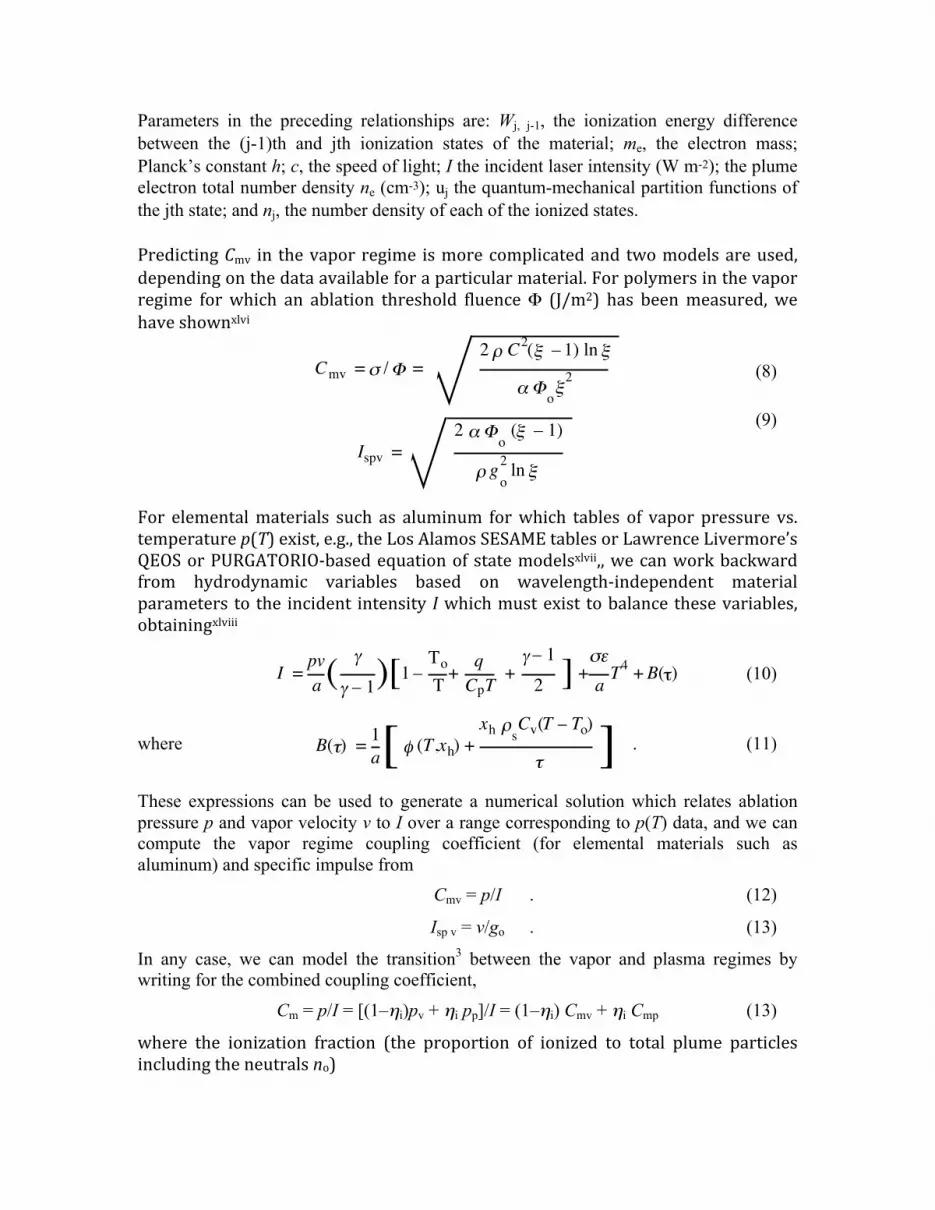
Parameters in the preceding relationships are: Wj, j-1, the ionization energy difference between the (j-1)th and jth ionization states of the material; me, the electron mass; Planck’s constant h; c, the speed of light; I the incident laser intensity (W m-2); the plume electron total number density ne (cm-3); uj the quantum-mechanical partition functions of the jth state; and nj, the number density of each of the ionized states. PredictingCmv in thevaporregime ismorecomplicatedand twomodelsareused,dependingonthedataavailableforaparticularmaterial.Forpolymersinthevaporregime forwhich an ablation threshold fluenceΦ (J/m2) has beenmeasured, wehaveshownxlvi
(8)
(9)
For elementalmaterials such as aluminum forwhich tables of vapor pressure vs.temperaturep(T)exist,e.g.,theLosAlamosSESAMEtablesorLawrenceLivermore’sQEOSorPURGATORIO‐basedequationofstatemodelsxlvii,,wecanworkbackwardfrom hydrodynamic variables based on wavelength‐independent materialparameters to the incident intensity Iwhichmustexist tobalance thesevariables,obtainingxlviii
(10)
where . (11)
These expressions can be used to generate a numerical solution which relates ablation pressure p and vapor velocity v to I over a range corresponding to p(T) data, and we can compute the vapor regime coupling coefficient (for elemental materials such as aluminum) and specific impulse from Cmv = p/I . (12)
Isp v = v/go . (13)
In any case, we can model the transition3 between the vapor and plasma regimes by writing for the combined coupling coefficient,
Cm = p/I = [(1–ηi)pv + ηi pp]/I = (1–ηi) Cmv + ηi Cmp (13)
where the ionization fraction (the proportion of ionized to total plume particlesincludingtheneutralsno)
Cmv = ! /" =2 # C
2($ – 1) ln$
% "o$
2
Ispv =
2 !"o
(# – 1)
$ go
2ln#
B(!) =1
a[ " (T,xh) +
xh #sCv(T – To)
! ]
I =
pv
a (!
! – 1)[1 –
To
T+
q
CpT+! – 1
2 ] +"#
aT
4+ B($)
ηi = ni/(no + ni) (14)
ηi isdeterminednumericallyby iteratingtheprocess indicated inEqs.(5‐7). It isconvenienttoimplementthisiterationnumerically(seeAllenxlix)byforming
(15)
where θ = 5040/Te, and then computing the array
, (16)
and the constants . (17)
and (18)
from which Z = R2/R1 (19)
and ηi = (1 + 1/R1) –1 . (20)
can be computed, as well as ne = R2 [(kTe/p)(1+R1+R2)] –1 (21)
for a new iteration in Eq. (15).
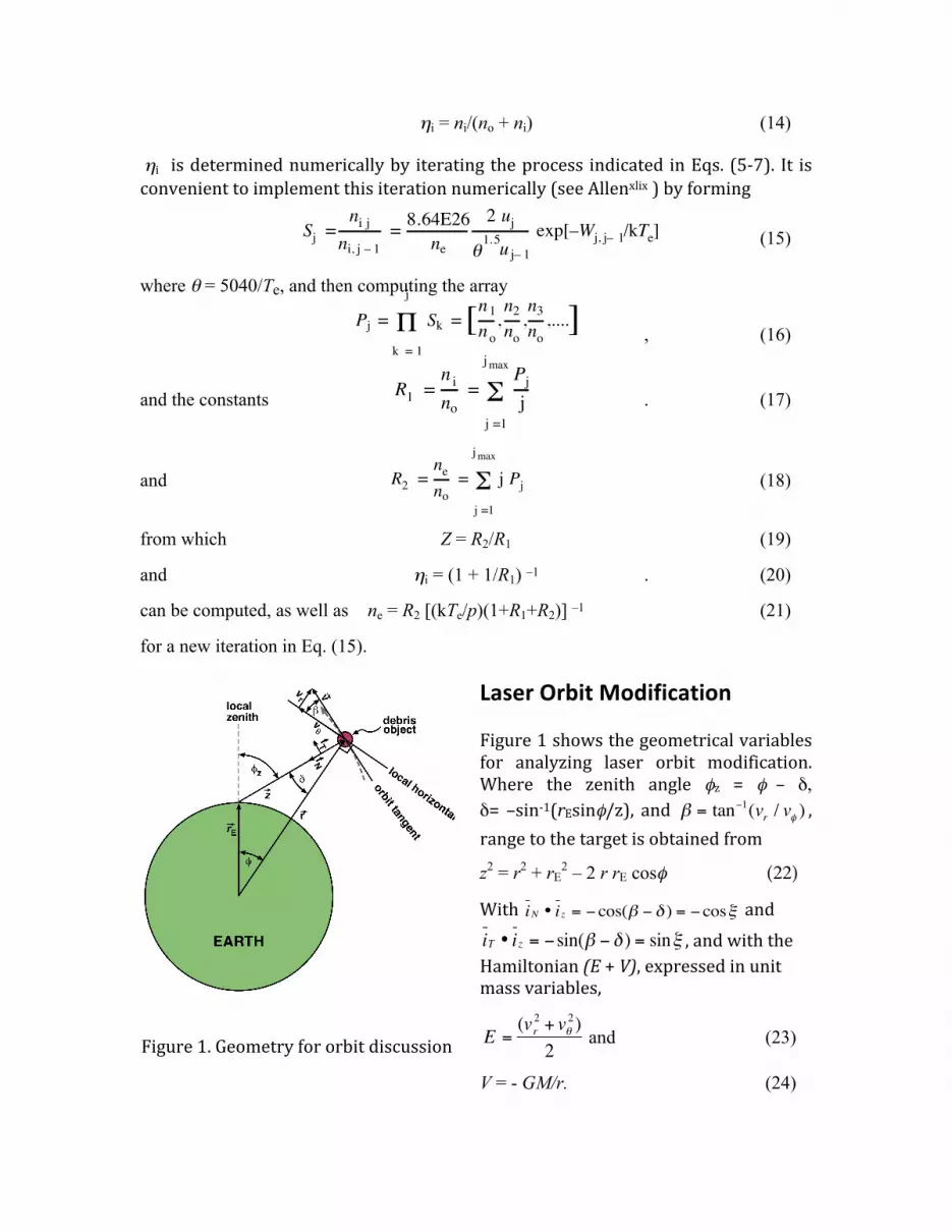
LaserOrbitModificationFigure1showsthegeometricalvariablesfor analyzing laser orbit modification.Where the zenith angle φz = φ – δ,δ= –sin‐1(rEsinφ/z), and ! = tan"1(vr / v# ) ,rangetothetargetisobtainedfrom
z2 = r2 + rE2 – 2 r rE cosφ (22)
With iN • iz = ! cos(" ! # ) = ! cos$ andiT • iz = ! sin(" ! # ) = sin$ ,andwiththeHamiltonian(E+V),expressedinunitmassvariables,
!
E =(v
r
2+ v"
2)
2 and (23)
V = - GM/r. (24)
Sj =
ni j
ni, j – 1
=8.64E26
ne
2 uj
!1.5
u j– 1
exp[–Wj, j– 1/kTe]
Pj = Sk!
k = 1
j
= [n1
no
,n2
no
,n3
no
,....]
R1 =
n i
no
=Pj
j!j =1
j max
R2 =
ne
no
= j Pj!j =1
j max
Figure1.Geometryfororbitdiscussion
The eccentricity
!
e =ra " rp
ra + rp, (25)
where ra and rp are the apogee and perigee orbit radii. In the plane of motion, the orbit is
described by r(!) = [rp(1+ e)
1+ ecos(! + !o)] (26)
adefinitionwhichmeansperigeeisatφ=φo.Whererpistheperigeegeocentricradius,andthesemi‐majoraxisa=rp/(1‐e),listheangularmomentumperunitmass,MGistheEarth’sgravitationalconstantandthequantity
q = a(1-e2) = l 2/MG, (27)
thetangentialandradialvelocitycomponentsare
v! =
MG
q[1+ ecos(! + !o )] and (28)
vr =
MG
q[esin(! + !o )] . (29)
The total velocity is obtained from v2 = vr
2+ v!
2= MG(
2
r"1
a) . (30)
Forexternallyperturbedorbits,wehave
!a =GM
2H2!H , (31)
and !vr= "!J
N= +!J cos# (32)
!v" = +!JT = +!J sin# (33)
where ξ=β-δ. Also, !q = 2r p /MG[!JT cos" + !JN sin"] , (34)
or, in a more useful form, !q =
2r
v[!J
T(1+ ecos(" + "
o)) + !J
Nesin(" + "
o)] (35)
In Eq. (35), ΔJT and ΔJN are, respectively, the components of !J along the orbit tangent, and along the inward normal to the orbit in the orbital plane. This equation makes the point that !J
Nalso has a major effect on the orbit, not !J
Talone as one might intuitively
think. However, when (φ+φo) = 0 [perigee at zenith], Eq. (35) shows !JN
has no effect. We can understand that by writing !H = v
r!v
r+ v"!v" and noting that vr=0 at perigee, so

that even a large Δvr can have no significant effect. The effect of pushing directly upward is to instantaneously tilt the velocity vector upward, so that the orbit can change later. In the majority of cases, the perigee or apogee will not be directly overhead, and calculations show we can drop perigee by pushing directly upward on the object.
Now, !H = vr!v
r+ v"!v" , (36)
! "v2= "v
2# v
2= 2!H , (37)
But, since !q = (1" e2)!a " 2ae!e , we can write (38)
giving
!e =[(1" e
2)!a " !q]
2ae (39)
From which, Δrp=(1-e)Δa-aΔe (40)
and Δra=(1+e)Δa+aΔe (41)
which are the desired quantities. For e=0, Eq. (39) gives correct results in the limit e! 0 . This procedure has the advantage of being developed from first principles rather than involving intermediate relationships.
Next,wehavetheproblemofcalculatingtherotationangleofthesemi‐majoraxisoftheellipseduetoouractions. If it’s too large,might unintentionally raisesomethingweearlier lowered.Axis rotation canbecomputed. We use Δβ after the interaction, anddβ/dφfortheoriginalellipse,tofindΔθ.
where d!
d"=d!
dr
dr
d" (42)
Since drd!
= ‐(er2/p)sin(φ+φo), withm=(2r‐r2/a)and
p=a(1‐e2),
d!
d"=
#(1# r / a)er2
[1# p / m]1/2m3/2psin(" + "o )
(43)
and !" = #!$
d$ / d%. (44)
Figure 2. Indicating apsidalshift
is easily calculated. For small debris, which can be re-entered in a single pass, this apsidal shift is irrelevant. For large debris, it must be taken into account when the object is re-engaged.
OpticalConstraintsfromtheAtmosphereandTargetPhysics
The most complex part of a Laser ODR design is to simultaneously satisfy theconstraints that arise fromdiffraction,nonlinearoptical effects in theatmosphereandtargetphysics.Beam fluence in the atmosphere is constrained above and below. Where z is target range, λ is wavelength, Deff is launching aperture diameter, and the quantity
! =az "
Deff
2 (45)
incorporates the effects of diffraction, a minimum fluence in the atmosphere
!
b
"#$% 2 &
T (46)
isrequiredtoigniteaplasmaonthetarget. Weassumeabeamqualityfactorof2andanindex6hypergaussianradialintensityprofile,whichtogethergivea=1.7inEq. (45), so a typical value of ζ is 75. In Eq. (7),T is atmospheric transmission,whichwetaketobe85%.Theupperlimitfluenceissetbynonlinearoptical(NLO)effectsincluding(forshortpulses)phasedistortionsduetononlinearindex(n2)andstimulated rotational Raman scattering (SRS) and stimulated thermal Rayleighscattering(STRS).Forpulses100ns≤τ ≤1ms,theNLOeffectslimitamountstoΦb/λ≤ 3E10 τ Jm‐2µm‐1. For shorter pulses, this linear dependence starts to saturate,settling at Φb/λ ≤ 100 J m‐2µm‐1 at 100psl. We can obtain solutions to theserequirementsgraphically.
TargetShapeEffectsTodrawattentiontothevarietyofdebrisshapesandmaterials,theORIONprojectstudyli described five representative compositional classes: aluminum, steel,sodium‐potassium spheres, carbon phenolic, and metal‐coated plastic insulation.Only a fraction of these have spherical symmetry. The existence of irregularlyshapedspacedebrisbringsadegreeofrandomnessintotheproblemofcalculatingpost‐engagement orbital modifications: that associated with the distribution ofobject shapes, and that associated with orientation. Given the desire to reduce
perigee, it is of interest to characterize the range of possible orbital outcomes oflaserengagementswithnon‐sphericaltargets(Figure3)lii.
Ingeneral,theimpulseandlaserpropagationvectorsarenotparallel.Sinceablationwillbeparalleltothelocalnormal,andtheimpulseisdirectedoppositetothenetablationvector,wecanwrite
m!!v = "C
m#
LA$$% k̂ • n̂$ n̂$ (47)
summingoverallilluminatedsurfaceelementsAα,andthelaserfluenceisgivenby
!!
L= !
Lk̂ . For “smooth” objects, the sum goes over to an integral over the
illuminatedportionofthesurface.For illustration,wechoose thesimplecaseofaplateofmassm, ina lowellipticalorbit,witheccentricitygivenby
! = 1+
2EL2
G2M
2m3
"
#$%
&'
1/2
(48)
where E is the total orbital energy, L2 is the square of the orbital angularmomentum,Gisthegravitationalconstant,andMisEarth’smass.Afterengagement,aneworbit isdetermined fromchanges toE andL2. If the instantaneousdistancefromEarth’scenter,orbitalvelocity,andazimuthalvelocityaredenotedr,
!
! v ,and
!
v" ,respectively,thenΔEand!L2 aregivenintermsofthevelocitychangeby
!
"E = m! v •"! v +
1
2m"! v 2
!L2 = 2m2
r2v" !!v • "̂ + m2
r2 !!v • "̂( )
2
(49)
Thequantityofprimaryinterestistheperigee,whichis
!
rp =l2
GMm2
1
1+ " (50)
Wecalculatetheperigeechangeforarandomdistributionofplateorientations,andforarepresentativesetoforbitalparameters,setting
!
m =1gforthisexample.Themaximumlaserenergyontarget is10J,whichoccurswhentheplate is face‐ontothelaserposition.Thedistributionintheperigeechangeatafixedorbitalangle(notshown) is weakly peaked, with substantial probability at the upper and lowerbounds. Thus one can estimate theprobability of achieving anundesirable result,i.e., an increased perigee, by comparing the magnitude of the upper and lowerenvelopes. It is also worth noting that there is a non‐negligible probability ofachieving a result that ismore favorable than for the spherical case. The average
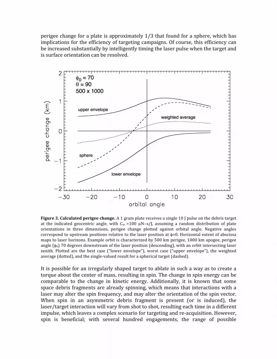
perigeechangeforaplateisapproximately1/3thatfoundforasphere,whichhasimplicationsfortheefficiencyoftargetingcampaigns.Ofcourse,thisefficiencycanbeincreasedsubstantiallybyintelligentlytimingthelaserpulsewhenthetargetandissurfaceorientationcanberesolved.
Figure3.Calculatedperigeechange.A1gramplatereceivesasingle10Jpulseonthedebristargetat the indicated geocentric angle, with Cm =100 µΝ−s/J, assuming a random distribution of plateorientations in three dimensions, perigee change plotted against orbital angle. Negative anglescorrespondtoupstreampositionsrelativetothelaserpositionatφ=0.Horizontalextentofabscissamapstolaserhorizons.Exampleorbitischaracterizedby500kmperigee,1000kmapogee,perigeeangle(φ0)70degreesdownstreamofthelaserposition(descending),withanorbitintersectinglaserzenith. Plotted are the best case (“lower envelope”), worst case (“upper envelope”), theweightedaverage(dotted),andthesingle‐valuedresultforasphericaltarget(dashed).Itispossibleforanirregularlyshapedtargettoablateinsuchawayastocreateatorqueaboutthecenterofmass,resultinginspin.Thechangeinspinenergycanbecomparable to the change in kinetic energy. Additionally, it is known that somespacedebrisfragmentsarealreadyspinning,whichmeansthatinteractionswithalasermayalterthespinfrequency,andmayaltertheorientationofthespinvector.When spin in an asymmetric debris fragment is present (or is induced), thelaser/targetinteractionwillvaryfromshottoshot,resultingeachtimeinadifferentimpulse,whichleavesacomplexscenariofortargetingandre‐acquisition.However,spin is beneficial; with several hundred engagements, the range of possible
orientations becomes well sampled, and the overall effect will tend toward themean,producingresultslikethoseinFigure3.
Telescope Design for Daylight Acquisition and Tracking
Figure4.Apossibletelescopedesigndiscussedinthemainpaper.
x
Main optics:1.5m secondary, 20m primary,central 13m of which is high qualitymax 100 µrad lead-ahead*: 100µrad beam tilt = 1.3mm lateral shift; 1mrad zoom = 8mm axial shift
secondary
laser input
laser beamout in thisannuluslow quality,
wide FOVsignal inin this
annulus
high quality,narrow FOV
signal inin this
annulus
Detail: AO unit
field stop
array
optical filter
liquid crystalphase plate
LC attenuator
6km patchat 1000km
subtends 7.8 cmat AO unit
AO unit#3 makes
initial targettrack using
1.06µmtarget glintcomputer
zoom
tilt*
controlout
control output to deformablemirror corrects laser beam on target
AO unit #2 makesfinal target trackusing 1.06µm
target glint
AO unit #1(w/o LCphase plate) corrects
high power laserbeam using Na
guidestar
SensorVector
LaserVector
[Exaggerated Scales]
Lead-Ahead Angle(~100µrad)
Na Guide
Star
Debris ObjectPositions
Laserdiagnostics
and AO
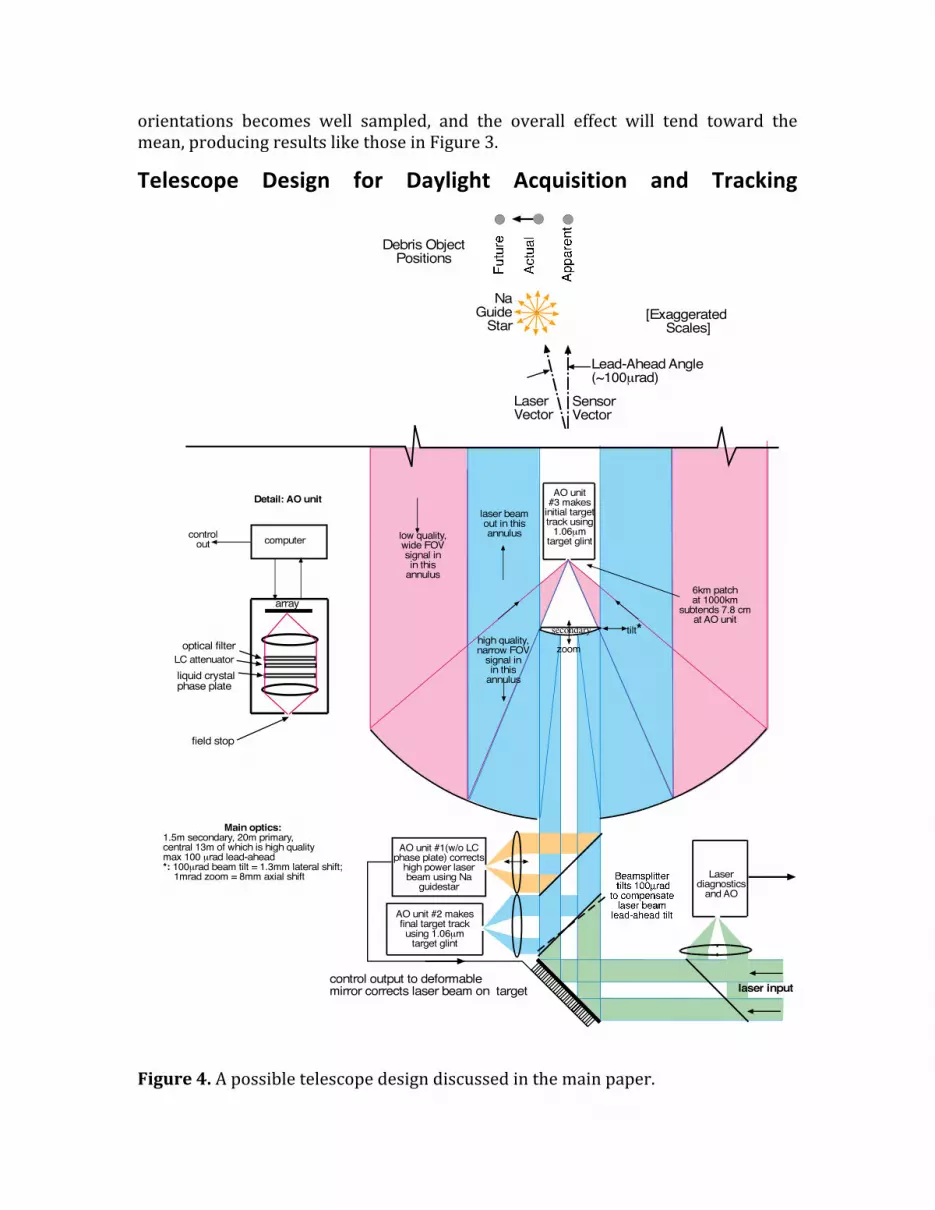
Figure4showsasuggestedlayoutforthetelescopediscussedinthemainpaper,inwhichstandardadaptiveopticsareusedtocorrectatmosphericturbulence.
TurbulenceCorrectionwithStandardAdaptiveOpticsAt the bottom of Figure 4, a deformable mirror with many computer‐controlledpiezoelectric actuators creates a deformation in thehighpower laser input phasefront which exactly cancels phase distortions in the atmosphere, moment bymoment.Typically,acontrolsystembandwidthofabout1kHzisrequiredtodothis.AtmosphericphasedistortionsaresensedbyAOunitno.1,whichispointedatthesodium guidestar which has been set up at 90km altitude by a 589.2 beaconbeampathprojectedby the telescope (not shown).Thisworksby exciting sodiumatoms already present at that altitude, to create what is nearly a point sourceviewed from the ground.Knowing this, theAO systemworks until it sees a pointsource; the resulting phase shape is recorded and reversed at the deformablemirror.Ofcourse, the laserand theguidestarareat twodifferentwavelengths, sothecomputerhas toattempt tocalculatewhat thedistortionshouldbeat1.06µmfromwhatitknowsat589.2nm,andthisisnotalwaysaccurate.TwootherAO systems (no.2 andno.3) in the figure correctphasedistortionsat1.06µm directly, using the target itself as a point source guidestar, in order toacquire the target with optimum resolution. Why then do we need the sodiumguidestar? This is because AO systems no. 2 and no. 3 are pointing in a differentdirectionfromthehighpowerlaser,attheobjectwhereitappearstobe.Thehighpower laser, in contrast, has to fire into black space along a different path withdifferentdistortionsatthespotwherethetarget ispredictedtobewhenitsbeamarrives. So,weneed an artificial guidestar to facilitate phase correction along thehighpowerbeampath.Notethatanarrayofguidestarsmaybeneededtocorrectforfocalanisoplanatismwellenoughtoachievethehighestpossiblebrightnessontarget.Rayleighbeacons,whichjustusescatteringfromtheatmosphereratherthanexcitingthesodiumlayermayalsobeused.Theseareinsomewayslesseffective,becausetheeffectivepointsource is closer, but have the advantage of being at the samewavelength as thepusherlaser.
AnAlternativeTargetTrackingMethod
For active tracking, an alternate method has already been proven at the U.S. AirForceMauiSpaceSurveillanceSystem(MSSS)inHawaii.LocatedonthecrestofMt.Haleakalaatanelevationof3060meters,itisalsoagoodsiteforLODRbecauseofbetter seeing conditions than possible at sea‐level sites. One component is theAdvancedElectro‐OpticalSystem3.67‐mdiametertelescopeatMSSS,withrecoateddichroic optics and a modified coudé path. The other is the 11.2µm wavelength
“HICLASS” 900W pulsed CO2 laser and its heterodyne detection system, which,together, have been shownliii to be able to easily track sub‐cmobjects at 1000kmrange.Thisperformancecomesaboutbecausethesystemislocatedatacold,highaltitude site, because it achieves near photon‐counting performance, and becausethere are nine times as many photons per joule at its wavelength, compared to1.06µm.Usingthissystem, itshouldbepossibletoacquireandtrack100timesasmanytargetsperhourat1000kmrange,thesetargetsbeingtwiceassmall,aswithradar8.
TurbulenceCorrectionbyBrillouin‐EnhancedFour‐WaveMixing
AnalternativetostandardadaptiveopticsforcorrectingphasedistortionsalongthepathoccupiedbythehighpowerlaserbeamiscalledBrillouin‐enhancedFour‐waveMixing (BEFWM). As in the standardAO technique,we depend on a few photonsscattered back into the telescopewhenwe fire the high power laser beam at thetarget.Thedebrisobject’sreflectedilluminationisinterceptedbythemainmirrorofa receiving telescope and guided to optical brightness amplifiers. Afteramplification, theobject’s image is recordedwithaCCDcamera.A control systemturnsonthebrightnessamplifiersandadjuststheirreceptionfrequencyband.Dataforthecontrolsystemareprovidedbyanilluminationlaserandarangefinderthatestimatesmomentofarrivalofthescatteredradiationanditsfrequency.Theopticalbrightness amplifiers consist of three units: a laser amplifier, a nonlinear opticalamplifier and a pump laser. To achieve the lowest level of noise in the opticalbrightnessamplifiers,thelaseramplifiergaincoefficientsmustbeabout1E4.Sucha gain coefficient can be achieved in two amplification stages.When creating thelaser amplifiers, it is necessary to ensure that the value of the gain coefficient isuniformoverthewholefieldofvision.Thelatter,inturn,shouldbenotlessthantheangle of initial illumination Δφ =1E‐4 radians, which requires the use of opticalrepeaters.Thespaceobjectplaneisprojectedbyalensontotheoutputfaceofthefirst laser amplifier. The image is then transferred by a repeater from the outputfaceof the first laser amplifier to the inputof the second laser amplifier.Anotherrepeatertransfersimagesfromtheoutputfaceofthesecondlaseramplifiertothenonlinearopticalamplifier.Therepeaterisaconfocaltelescope.Thenonlinearopticalamplifier isaStimulatedBrillouinScattering(SBS)amplifier(a third order nonlinear medium which is active with respect to the Brillouinnonlinearity). For such amedium to amplify signal light, it should be illuminatedsimultaneouslywiththespaceobjectreflectedsignalandbyapowerfuladditionallaserradiationpump.TypicalnonlinearmediumelementsaretetrachloridessuchasCCl4, GeCl4, SnCl4, or perfluorooctane. Their parameters are very similar(nonlinearityfactor~5E‐9cm/W,andhypersoundrelaxationtime~1ns).WhentheSBScell is illuminatedbyapulsed laserwithenergy1.5 Jandduration20ns, theSBS amplifier amplifies the space object scattered light with a gain coefficient ofapproximately1E8.Therefore, thegaincoefficientof lightreceivedfromthespace
object, consisting of combined gain in laser amplifier and nonlinear opticalamplifier,willbeabout1E12,whichisadequatetocreatearecordableimage.Theconcentrationofthespaceobjectreflectedlaserilluminationisrestrictedbytheinfluenceof turbulence.To improve imagingandtominimizetherequired levelofilluminationlaserirradiancetomakeajetonthetargetrequiresthatweovercomethe atmospheric turbulence to focus the beam. This is achieved through opticalphaseconjugationof the illuminationradiationusingBEFWMtoreversethebeampropagationdirectionandphasetocompensate foratmosphericdistortionsasthebeambackpropagatesthroughtheopticallydistortingpath.Ifournonlinear‐opticalreceiveramplifiesandconjugatesthesignalinterceptedbythereceivinglens,thenasa resultofdoublepassage through theatmosphere turbulentdistortionsof thespaceobjectsignalwavefrontarecompensated.Consequently,theconjugatedsignalwillbeconcentratedon thespaceobject toanaccuracy that isdeterminednotbythe turbulent scattering angle (~10 µrad) but, instead by the resolution of thereceivingapertureofthenonlinearopticalamplifier(e.g.,~0.05µradforareceivingapertureof20m).
HowBEFWMWorksA number of papers are available concerning laser propulsionliv,lv,lvi,lvii,lviii. Systemrisksare low.Thiskindofoperationondebriswillnotgenerateadditionaldebris.Laserirradiationoflargeoperatingspacecraftwillnotseriouslyaffectthem,unlessphoto‐sensitiveequipment is exposed, sinceunder theworst conditionsonlyverysmallamountsofsurfacematerialareablated.
PhaseConjugation(PC)isanon‐linearopticaleffectthatformsthesamewavefrontas an initial one, but which propagates exactly in the backward direction withreversedphase.Aphase conjugatemirror is like amirror reflecting incident lightback towardswhere itcame from,but itdoesso inadifferentway thanaregularmirror.Aregularmirrorreflectsincidentraysintheoppositedirection,sothattheangleofincidenceisequaltotheangleofreflection(seeFig6aofthemainpaper).Incontrast, light from a phase conjugate mirror is always reflected exactly in thebackwarddirection,independentoftheangleofincidence.Thisdifferenceprovidessignificantopportunities. Ifweplaceadistortingmedium(e.g.,aturbulentairflow)inthepathofabeamoflight,theraysradiatedfromthepoint‐like light source are bent in random directions, and after reflection from anormalmirror, each ray of light is bent even farther causing the beam to scatter.Withaphaseconjugatemirror,ontheotherhand,eachrayisreflectedbackinthedirection it came from. This reflected conjugate wave propagates backwardsthroughthesamedistortingmedium,and"undoes"thedistortion,causingthebeamtoconvergetoitsinitialpointsource.
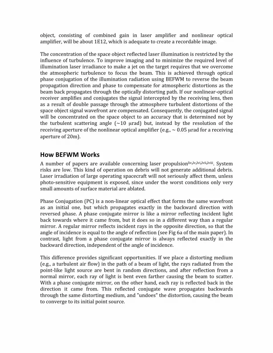
Phaseconjugationoperatessomewhatlikeholography,butitisadynamichologramwhose"holographicplate"isdeterminedbyinterferingwavesinanonlinearopticalmedium rather than etched as a static pattern on a glass plate. In our case, thephysicalmechanismofthisprocessiscalledfour‐wavemixingbecauseitisbasedontheinteractionoflaserwavesandhypersonicwaves.Heretheinterferenceofsignalandpumplaserwavescreatesahypersonicgratingandthesecondpumpscatteringonthisgratingproducesaconjugatedwave(Fig.5).ThisinteractionoflaserwaveswithhypersoundisknownasstimulatedBrillouinscatteringandthistypeoffour‐wave mixing is called Brillouin enhanced four wave mixing (BEFWM). Figure 6showshowalaboratoryBEFWMsetupworkslix.Thiscombinationof laseramplifiersandtheBEFWMPCmirrorprovidesauniqueset of capabilities that can enable and simplify the design of our debris removalsystem:• Thesystemhasveryhighsensitivitynear4.8E‐19Jperpixel(approximatelytwo
photons)which lets usminimize the laser pulse energy needed to generate ameasurablescatteredsignalfromtheorbitaldebris.
• Thesystem’sextremelynarrowfrequencybandcorrespondstotwofrequency‐temporalmodes(inputspectralbandwidth~1pmandresponse timeof~30ns)whichensureourproposedsystemwillrejectbackgroundnoiseandengageextremelyquicklytoenableitsuseonhypervelocitydebris.
• The system has a comparatively wide field of view that can be tailored tooperationalneedsaspartofthesystemdesign.
• Thesystemhasahighcoefficientofamplification,amplifyingweaksignalsbyafactorofabout1E12.
With the concept illustrated in Figure 6, we begin by illuminating the detectedorbital debris with an initial laser pulse. An input lens receives the scatteredillumination from the debris to form an object image, but as this signal pulse(carrying the image) propagates through the system it is also amplified by apreliminarylaseramplifier.Inturn,aPC‐mirrorinputlensfocusestheobjectimagein the PC‐BEFWM mirror. This PC‐mirror is a liquid cell filled with a nonlinearoptical medium (typically, high‐purity liquid tetrachlorides or freons) that ispumpedbytwopumppulses.Thereflectedconjugatedpulsegoesbacktotheobjectplane and on its way is partially reflected by the beam‐splitter to the recording
system (a CCD or CMOS camera),where an imageof the space object isformed to allow us to identify theobjectasdebrisornot.
Figure5.IllustratingtheBEFWMprocess
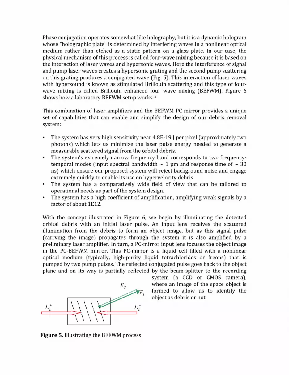
BEFWMsystemconceptofoperationsThesystemshownasFigure6bofthemainpaperusesaBEFWMreceiver‐amplifier.First,amasteroscillatorMOdeliversanilluminationpulseofabout30nsdurationat1.06µmthat isamplifiedby the illumination laser ILanddirected to theregionofspacecontainingthedebristargetinacomparativelywideangleofabout100µrad.
Then, part of thereflectedilluminationisreceived by aninput\output (IO)mirror with clearaperture D, amplifiedand reflected by ourBEFWM system anddirected back towardthe debris by the IO
mirror. Phase conjugationprovidedby theBEFWMsystem removes the effects ofatmospheric turbulence and provides perfect illumination on the debriswith thissecondpulse,resultinginahigherqualityimage.Thesecondpulsereflectionfromthedebrismay,inturn,beusedtorepeatthiscycletoincreasethelightinglevel,ortoconcentratethelaseronthedebrisprovidingahighqualityglintthatcanbeusedas a target designator or to enable advanced adaptive optics methods with aguidestarmaintainedonthemovingdebris.We assessed the concentration efficiency of the proposed system to assess theappropriate illumination pulse energywith secondary illumination using BEFWMandwithout it. Fordebris sizeson theorderof10 cm that arewithin a1000kmrange,wefoundthattoimagethisdebriswithoutPC‐adaptiveopticsrequireshighpulseenergy(upto100kJ)fortheinitialillumination.However,aone‐steportwo‐step laser energy concentration using our system provides debris imaging withreducedinitialilluminationpulseenergyof~1kJoreven100J.It should bementioned here that a primarymirrormaybe of poor optical quality(reducinginitialcosts)becausephaseconjugationwillcorrectforitsdistortionstoo.This concept should satisfy the basic requirements in termsof laser pulse delays,laser frequencies, and precise control of the pointing and signal tuning tocompensateforthedebrismotionandDopplershift.Someyears agowedevelopeda two‐pulsemasteroscillator (MO)with controlleddelay between the twopulses to compensate for the path difference between thesignalandpumppulsesonthewaytotheBEFWM‐mirror,sincebothofthepulsesmustarrivetheresimultaneouslyandtheirfrequenciesshouldbethesame.
Figure6.BEFWMinthelaboratory
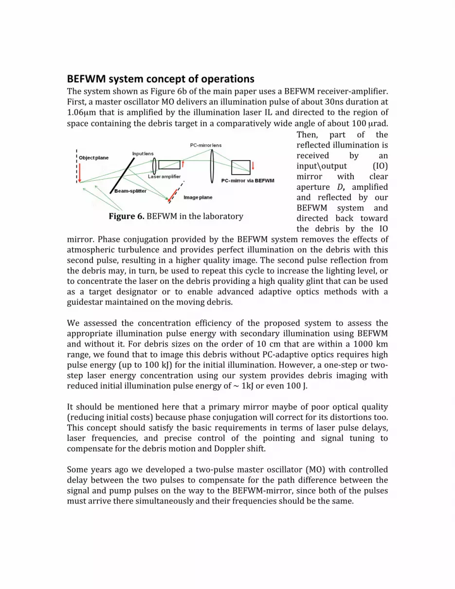
Long‐distanceopen‐airBEFWMdemonstrationWeassembledandtestedournon‐linearopticalimageamplifierschemeinoutdoorexperiments through turbulencelx. Our path length for open air experimentswasshort (150m), sowe developed amethod of controlled turbulence intensificationusing banks of heaters to simulate a longer path. This heating increased thestructuralparameterofatmosphericturbulencebyafactorof5‐10,correspondingtoapropagationpathofseveralkm.Ourtestpathwithairheatersandtargetareaatthe background is shown in Fig. 7 (left image). Laser energy concentration wasdemonstrated intheexperiments.Thetargetarea isshownintheright image.Weused a glass spherical reflector on a tripod to imitate a point target. In theupperrightcornerofFigure7thereisaprintofinitialilluminationofapoint‐liketarget.Thesecondpictureisaprintofbothpulses(theinitialpulseandthepulsereflectedand concentratedbyBEFWM) simultaneously.Using anoscilloscopeplaced in thetarget area we verified that the second pulse with less total energy has a muchhigher laser energy density. To demonstrate this fact, a glass beam‐splitter wasplacedinfrontofthesphericalreflectortoreflectpartofthesignaltoafastphoto‐diode.Weachievedsimilarresultsinotherexperimentscarriedoutona2.1kmpathandwithpulseenergyupto100J.Weconcludedthatwecanmitigateatmosphericturbulence to provide near diffraction limited images and focus a pulsed laser onorbitaldebris.
Figure7.Highlightsofopen‐airBEFWMexperiments

ChoosingTargetsTheLODRsystemtargetselectionbalancesprioritywithroutinetaskingoperations,which include laser and surveillance system tasking for efficient utilization ofresources. Based on SOCRATES and other space surveillance and conjunctionestimatesalreadysupportedbytheUSAF,priorityoperationswilltasktheLODRtodeflectapotentialthreattoahighvalueassetsuchasSpaceStationbyapplyingaΔvassmallas20m/sec,andtaskingadditionalsurveillanceforpostilluminationtrackmaintenance.The routine spacedebris clearingwill select targetswithacceptableengageabilityandsafety.Theoverallconceptofoperations(CONOPS)isexpectedtoconsider uncertainties in target cross section, orientation and spin rate, targetmaterials and mass, required delta V for assured re‐entry and potential forfragmentationandcollateral threat.Smallerdebrissinglepasstarget illuminationsat low laserbeamelevationswillbemosteffectivebyslowing the targetby50 to200m/sec and thusdropping its perigee for a rapid re‐entry. Larger andheaviertargets will require a multi‐orbit plan for gradually lowering the perigee, andadditional surveillance resources will be needed to maintain tracking on aperturbed orbit with potentially changed drag characteristics.. A dual site LODRwouldprovideadditionalaccessandresponsecapability.Figures8and9outlinetheconceptofoperations.
Figure8.ConceptofoperationsforaLODRremovalsystem
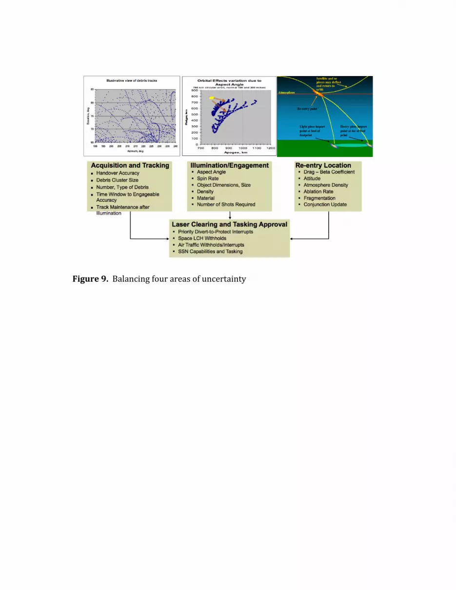
Figure9.Balancingfourareasofuncertainty

References
ReferencesiH.Klinkrad,SpaceDebris–ModelsandRiskAnalysis,PraxisPublishing,Chichester,UK(2006)p.97iiC. Hayhurst, I.Livingstone,R.Clegg,R.DestefanisandM.Faraud, “Ballistic limitevaluation of advanced shielding using numerical simulations,” Int. J. ImpactEngineering26309‐320(2001)iii C. Phipps, H. Friedman, D. Gavel, J. Murray, G. Albrecht, E. George, C. Ho, W.Priedhorsky, M. M. Michaelis and J. P. Reilly, “ORION: Clearing near‐Earth spacedebris using a 20‐kW, 530‐nm, Earth‐based, repetitively pulsed laser”, Laser andParticleBeams,14(1)(1996)pp.1‐44iv D. Kessler and B. Cour‐Palais, “Collision Frequency of Artificial Satellites: TheCreationofaDebrisBelt,”JournalofGeophysicalResearch,Vol.83,No.A6,pp.2637‐2646(1978)v J. Henderson, S. Nikolaev, D. Phillion, W. De Vries, A. Pertica and S. Olivier,“Intelligentsensortaskingforspacecollisionmitigation,”Proc.SPIE7691,76910L(2010;doi:10.1117/12.850794.L.Simms,V.Riot,W.DeVries,S.Olivier,A.Pertica,B.Bauman,D.PhillionandS.Nikolaev, “Opticalpayload for theSTAREpathfindermission,”Proc.SPIE8044,804406(2011);doi:10.1117/12.882791viA.BradleyandL.Wein,“SpaceDebris:Assessingriskandresponsibility,”AdvancesinSpaceResearch43,1372‐1390(2009).viiH.Klinkrad,ibid.,p.96viiiH.Klinkrad,ibid.,p.126ixC.PhippsinProjectORION:OrbitalDebrisRemovalUsingGroundBasedSensorsandLasers, J.Campbell,ed.NASA MarshallSpaceflightCenterTechnicalMemorandum108522October1996,p.221xD.Talent,“APrioritizationMethodologyforOrbitalDebrisRemoval,”NASA/DARPAInternational Conference on Orbital Debris Removal, Chantilly, VA, 810 December2009xiJ.Theal,NASAJohnsonSpaceCenter,privatecommunicationOctober,1996xiiM.Bender,“FlexibleandLow‐CostDragonSpacecraftforOrbitalDebrisRemoval,”NASA/DARPAOrbitalDebrisConference…ibid.xiiiC.Bonnal,“HighLevelRequirementsforanOperationalSpaceDebrisDeorbiter,”NASA/DARPAOrbitalDebrisConference…ibid.xivR.Hoyt, “RUSTLER:ArchitectureandTechnologies forLow‐costRemediationoftheLEOLargeDebrisPopulation,”NASA/DARPAOrbitalDebrisConference…ibid.xv J. Starke,B.Bischof,W.‐P.ForthandH.‐J.Guenther, “ROGER,APotentialOrbitalSpaceDebrisRemovalSystem,”NASA/DARPAOrbitalDebrisConference…ibid.xviS.Kawamoto,Y.Ohkawa,S.Nishida,S.Kitamura,S.Kibe,T.HanadaandM.Mine,“Strategies and Technologies for Cost Effective Removal of Large Sized Objects,”NASA/DARPAOrbitalDebrisConference…ibid.xvii J.Pearson, J.Carroll,E.Levinand J.Oldson, “ElectroDynamicDebrisEliminatorforActiveDebrisRemoval,”NASA/DARPAOrbitalDebrisConference…ibid.

xviiiI.Lee,“AnInvestigationintoPassiveCollisionRemovalMethods,”NASA/DARPAOrbitalDebrisConference…ibid.xix K. Leavitt, “NASA Ames ADR Efforts,”NASA/DARPA Orbital Debris Conference…ibid.xxD.McKnight, “RemovingOrbitalDebriswithoutGoing intoOrbit,”NASA/DARPAOrbitalDebrisConference…ibid.xxiT.Hanada,Y.Kitazawa,A.Kawabe,H.MatsumotoandS.Kawamoto, “SmallandMedium Orbital Debris Removal Using Special Density Material,” NASA/DARPAOrbitalDebrisConference…ibid.xxii C. Phipps, J. Reilly and J. Campbell, “OptimumParameters for Laser LaunchingObjectsintoLowEarthOrbit,”LaserandParticleBeamsvol.18,pp661‐695(2000)xxiiiC.Phipps,“’Catcher’sMitt’asanAlternativetolaserSpaceDebrisMitigation,”AIPConferenceProceedingsvolume1278pp.509‐514(2010)xxivJ.Mason,J.Stupl,W.MarshallandC.Levit,“OrbitalDebrisCollisionAvoidance,”arXiv:1103.1690v1[physics.space‐ph]9Mar2011xxvJ.–C.LiouandN.L.Johnson,“RisksinSpacefromOrbitingDebris,”Sciencevol.311,pp.340‐341(2006)xxviJ.SinkoandC.Phipps,“ModelingCO2laserablationimpulseofpolymersinvaporandplasmaregimes,”Appl.Phys.Lett.95,131105(2009)xxvii C. Phipps, “An Alternate Treatment of the Vapor‐Plasma Transition,” Int. J.AerospaceInnovations3(1)pp.45‐50(2011)xxviii C. R. Phipps, Jr., T. P. Turner, R. F. Harrison, G.W. York,W. Z. Osborne, G. K.Anderson,X.F.Corlis,L.C.Haynes,H.S.Steele,K.C.SpicochiandT.R.King,"ImpulseCouplingtoTargetsinVacuumbyKrF,HFandCO2Lasers",J.Appl.Phys.,64,1083(1988).xxixC.Phipps,M.Birkan,W.Bohn,H.‐A.Eckel,H.Horisawa,T.Lippert,M.Michaelis,Y. Rezunkov, A. Sasoh, W. Schall, S. Scharring and J. Sinko, “Laser AblationPropulsion,”J.PropulsionandPower,26no.4pp.609‐637(2010)xxx C. R. Phipps, S. J. Thomas andD. E.Watkins, “Effect of nonlinear refraction onbeam brightness in laser fusion applications,” Proc. Intl. Conf. on Lasers ’79, STSPress,McLeanVA(1980)pp.878‐887xxxiR.Egerman,S.DeSmittandD.Strafford,“Low‐weight,low‐cost,low‐cycletime,replicatedglassmirrors,”Proc.SPIE7739p.77390G(2010)xxxiiD.Strafford,S.DeSmitt,P.KupinskiandT.Sebring,“Developmentoflightweightstiff stable replicated glass mirrors for the Cornell Caltech Atacama Telescope(CCAT),”Proc.SPIE6273p62730R(2006)xxxiiihttp://www.eso.org/public/teles‐instr/e‐elt.html(2011)xxxiv D. Strafford, “CCAT Panels: Corrugated mirror solution,”http://www.submm.org/mtg/2006/2006‐01‐pasadena/11_Borosilicate_Panels.pdf(2006)xxxv D. Liedahl, S. Libby, A. Rubenchik, “Momentum Transfer by Laser Ablation ofIrregularly Shaped Space Debris,” International Symposium on High Power LaserAblation,SantaFe,N.M.,2010,AIPConf.Proc.1278,pp.772‐779(2010)xxxviH.Klindrad,ibid.,p.70
xxxvii B. Esmiller, “Small debris removal by laser illumination and complementarytechnologies,”Proc.ISBEP7,AIPConferenceProceedingstobepublished(2011)xxxviii H. Klinkrad, “Space Debris Environment Remediation,”NASA/DARPA OrbitalDebrisConferenceonOrbitalDebrisRemoval,Chantilly,VA,810December2009xxxix M. Hansen and D. Malchow, “Overview of SWIR detectors, cameras andapplications,”Proc.SPIE6939pp693901‐1to693901‐11(2008)xl J. Beckers, “Adaptive optics for astronomy – Principles, performance andapplications” inAnnualReviewofAstronomiyandAstrophysics,31 (A94‐1272602‐90),G.Burbidge,ed.,pp13‐62(1993)xliK. MacDonald, W. Tompkin, and R. Boyd, “Passive One-Way Aberration Correction Using Four-Wave Mixing,” Optics Letters 13(6), 485-487 (1988). xlii O. Kulagin, G. Pasmanik andA. Shilov. “Amplification and phase conjugation ofweaksignals,”SovietPhysicsUspekhi,35(6),pp.506–519(1992).xliiiV. Bespalov, A. Matveev, G. Pasmanik, “Study of maximum sensitivity of a SBS amplifier and a four-wave hypersound phase-conjugate mirror,” Izvestiya, Radiophysics series, 29, No. 9, pp. 1080–1094 (1986) 44K.LaFortune,R.Hurd,E. Johansson,C. Dane,S.FochsandJ. Brase,"Intracavityadaptivecorrectionofa10kW,solid‐state,heat‐capacitylaser,"Proc.SPIE5333,53‐61(2004).45C.A.Haynametal,“National Ignition Facility Laser Performance Status,” Appl. Opt. 46, 3276 ,(2007) 46E.I.Moses, “Ignition on the National Ignition Facility: a path towards inertial fusion energy,” Nuc.Fus.,49, 104022, (2009) 47A.Bayramian,T.Anklam,K.Baker,E.Bliss,C.Boley,A.Bullington,J.Caird,D.Chen,R.Deri,M.Dunne,A.Erlandson,M.Henesian,J.Latkowski,K.Manes,W.Molander,E.Moses, S. Powers, S. Rana, S. Rodriguez, R. Sawicki, K. Schaffers, L. Seppala, M.Spaeth, S. Sutton, S. Telford, "Compact, efficient laser systems required for laserinertialfusionenergy,"Proc.Conf.TechnologyofFusionEnergy2010.48 A.Rubenchik et al, “Laser systems for orbital debris removal,” InternationalSymposium on High Power Laser Ablation, Santa Fe, N.M., 2010, AIP Conf. Proc.1278, pp. 347-353 (2010) xlivC.Phipps,T.Turner,R.Harrison,G.York,W.Osborne,G.Anderson,X.Corlis,L.Haynes,H.Steele,K.SpicochiandT.King,"ImpulseCouplingtoTargetsinVacuumbyKrF,HFandCO2Lasers",J.Appl.Phys.,64,(1988)pp.1083‐1096xlvM.Saha,“Ionizationinthesolarchromosphere,”Phil.Mag.40,472(1920)xlviJ.SinkoandC.Phipps,“ModelingCO2laserablationimpulseofpolymersinvaporandplasmaregimes,”Appl.Phys.Lett.,95,(2009)pp.131105‐1to131105‐3xlvii The SESAME equation‐of‐state database is maintained by group T‐1 at LosAlamos National Laboratory ([email protected]); see S. Lyon and J. Johnson,"SESAME:TheLosAlamosNationalLaboratoryEquationofStateDatabase,"LANLReportLA‐UR‐92‐3407(1992)foradditionalinformation.ForQEOS,seeR.More,K.Warren,D.YoungandG.Zimmerman,“Anewquotidianequationofstate(QEOS)forhotdensematter,”Phys.Fluids31,3059(1988).ForPURGATORIO,seeB.Wilson,V.
Sonnad,P.SterneandW.Isaacs,“AnewimplementationoftheINFERNOalgorithm,J.Quant.SpectroscopyandRadiativeTransfer,99,no1‐3658‐679(2005)xlviii C. Phipps, “An Alternate Treatment of the Vapor‐Plasma Transition,” Int. J.AerospaceInnovations1(1)toappear(2010)xlixC.Allen,AstrophysicalQuantities,3rdedition,AthlonePress,London,1973,p.34lC.Phipps,M.Birkan,W.Bohn,H.‐A.Eckel,H.Horisawa,T.Lippert,M.Michaelis,Y.Rezunkov,A.Sasoh,W.Schall,S.ScharringandJ.Sinko,“LaserAblationPropulsion,”J.PropulsionandPower,26no.4pp.609‐637(2010)liC.PhippsinProjectORION:OrbitalDebrisRemovalUsingGroundBasedSensorsandLasers,J. Campbell,ed.NASAMarshallSpaceflightCenterTechnicalMemorandum108522October1996,p.221liiD.Liedahl,S.LibbyandA.Rubenchik,“MomentumTransferbyLaserAblationofIrregularly Shaped Space Debris,” International Symposium on High Power LaserAblation,SantaFe,N.M.,2010,AIPConf.Proc.1278.liiiC.Phipps,“HICLASSLadarTrackingAnalysis”finalreport(1999),availablefromTextronSystemsCorp.,WilmingtonMAliv A. Кantrоwitz, “Propulsion to Orbit by GroundBased Lasers,” Aeronautics andAstronautics,10,pp.74‐76(1972).lv P. Carrick, F.Mead Jr. and L.Myrabo, "Lightcraft Propulsion Technology for LowCostAccesstoSpace,"Optics&PhotonicsNews,10(1),p.23(1999).lviF.BunkinandA.Prokhorov,“Useofalaserenergysourceinproducingareactivethrust,”SovietPhysicsUspekhi,19(7),pp.561‐573(1976).lvii L. Kuznetsov and V. Yarygin, "Laserreactivemethod for disposal of small spacedebris,"QuantumElectronics,24(6),pp.555–557(1994).lviiiR.Liukonen, “Laser rockets,”TechnicalPhysicsLetters,27 (12),pp.1030‐1031(2001).lixO.Kulagin,G.PasmanikandA.Shilov.“Amplificationandphaseconjugationofweaksignals,”SovietPhysicsUspekhi,35(6),pp.506–519(1992).lx S. Kearney,M. Valley, B. Atherton, A. Hsu, O. Kulagin, V. Lukin and А. Sergeev,“SmallObjectImagingandSignalTransmissionthroughTurbulenceandDebris:LDRDFinal Report,” Sandia National Laboratories report SAND2009‐8190, November2010.


