Embed Size (px)
Citation preview

1
REDUCED INSTRUCTION SET CALLIGRAPHIC INTERFACES: SKETCHING COMPLEX 3D OBJECTS WITH (FEWER) GESTURES
João P. Pereira Joaquim A. Jorge Vasco Branco F. Nunes Ferreira
Dep. of Informatics Engineering
Computer Science Department
Communication & Arts Department
Dep. of Electrical and Computer Engineering
ISEP/INESC IST/UTL Univ. of Aveiro FEUP R. S. Tomé, Porto Av. Rovisco Pais,
Lisboa Aveiro R. dos Bragas, Porto
PORTUGAL PORTUGAL PORTUGAL PORTUGAL [email protected] [email protected] [email protected] [email protected]
ABSTRACT GIDeS (Gesture-based Intuitive Design System) is a gesture-based modeling system that
addresses the known ergonomic shortcomings of present-day CAD systems for conceptual
shape design. GIDeS uses a tablet and stylus combination to combine the intuitive appeal of
gesture-based interfaces with context-based information to achieve what we call RISCI
(pronounced risky - Reduced Instruction Set Calligraphic Interfaces). GIDeS draws on
previous modeling work, using contextual information and feedback to free users from
remembering detailed modeling gestures, allowing them to concentrate on drawing, towards
our end goal of bridging the chasm between paper and pencil and CAD interfaces in the
early design stage. While our goal of pure non-command interfaces based on drawing
remains elusive, we believe that interfaces that harness the power of ambiguous commands
to their advantage imply that design environments are far more natural and efficient to use
than the current, command-intensive generation of CAD systems.
Keywords: Interaction Techniques, 3D Modeling, Gesture Interfaces, Sketching,
Calligraphic Interfaces, non-command Interfaces.
1. INTRODUCTION Although CAD systems have evolved markedly over the past 30 years, they are still a long
way from replacing pencil and paper in the desks of most designers and creators when it
comes to rapidly capturing shape and model ideas. This is mostly because even the most
“user-friendly” computer-based systems tend to impose rigid and very structured dialogues
on users, challenging the creative flow of ideas. Designers prefer pencil-and-paper to the
computer as the medium of choice for conceptual shape design. However, if computers
could be made usable for the early stages of model design, the advantages could be

2
enormous, given the impact of early product changes in the later stages of development
[Perei00a].
Moreover, if an image is worth a thousand words, physical models are worth an unlimited
number of images to convey conceptual design and shape information [Potte94]. Currently,
only a few design ideas become physical models due to the comparative difficulty of creating
them versus the combination of imagination and sketches that most designers favor. This
could significantly change if it were easier to produce CAD and physical models from
sketches.
In 1994 we have presented IDeS [Branc94], a menu-oriented vector system that tried to
explore creating approximate polyhedral models by a combination of direct drawing and
constructive operations. GIDeS is a step towards a new generation of user interfaces that
will help rather than hinder users in the task of making models from sketches. We call these
interfaces, organized around sketching, drawing and pen input, calligraphic interfaces
[Jorge00], because they explicitly address the ambiguity and imprecision natural to human-
generated sketches, using these as strengths to bring computers closer to the pencil-and-
paper feel. It is our contention that many calligraphic techniques may also be very useful in
later stages of product design, bearing the promise of making CAD systems more usable in
the product life cycle.
GIDeS is meant to work with a tablet and stylus to make the interface behave as close as
possible to designers’ expectations. A calligraphic interaction style is used instead of the
traditional menu-oriented one, in order to improve system’s usability. A context-based
feedback mechanism allowed us to reduce the system’s instruction set (Reduced Instruction
Set Calligraphic Interfaces - RISCI) and therefore minimize cognitive load on users. This
mechanism also provides an efficient and powerful way of dealing with ambiguities.
The designer can draw without worrying about memorizing modeling gestures, because
whenever her or his gestures are recognized, the application displays a pictorial suggestion
(or a list of pictorial suggestions, if more than one is available), in an attempt to anticipate
whatever the user has in mind. The user may either accept the suggestion or proceed with
the drawing.
In this way context-based pictorial information and feedback provide an intuitive way of
accelerating the design process without encumbering the user’s drawing freedom. They also
provide an ergonomic and technically interesting way of addressing eventual gesture
recognition ambiguities.

3
2. GIDES: CURRENT WORK
2.1 GESTURE RECOGNITION
The GIDeS system includes a set of gesture recognition modules that are responsible for the
task of interpreting strokes drawn by the user [Perei00b]. There are three major recognition
tasks:
1. Commands: this module identifies gestures associated to commands, such as the
object selection and object deletion gestures;
2. Drawing primitives: this module is responsible for the recognition of both smooth
(circles, ellipses, generic curved strokes) and non-smooth (lines and polylines)
drawing primitives;
3. 3D primitives: this module analyses both the topology and geometry of previous
drawn strokes and tries to anticipate whenever the user wants to create a 3D
primitive object. Figure 1 illustrates examples of such strokes. Object creation is
therefore done in a “natural” constructive way, by drawing 2D sketches of object
geometry. The recognition process is flexible enough in order to respect every
designer’s unique drawing style. Figure 2 illustrates this flexibility in the case of the
creation of a box primitive.
2.2 EXPECTATION LISTS
It would be detracting from our objectives to force the designer to remember many different
gestures associated with primitives. Therefore we conceived a context-based mechanism,
known as expectation lists, which appear every time a primitive instantiating gesture is
recognized. A small-scale model of the primitive appears in the upper left corner of the
window. If the user clicks on that model, its associated primitive is automatically constructed,
extracting parameters from gesture characteristics as needed. Otherwise the user may elect
to ignore the suggestion, proceeding with drawing to create a different, possibly more
complex, object.
In the same spirit, whenever there is an ambiguity in the recognition process, an expectation
list including small-scale models of all possible primitives is presented to the user, who may
either accept one of those choices or proceed with the drawing.

4
Figure 1 – 3D primitives
Figure 2 – Examples of strokes that lead to the creation of a box primitive
Cylinder Cone Truncated cone Sphere
Box Prism Pyramid Truncated pyramid
Extrusion Surface of revolution Duct
5
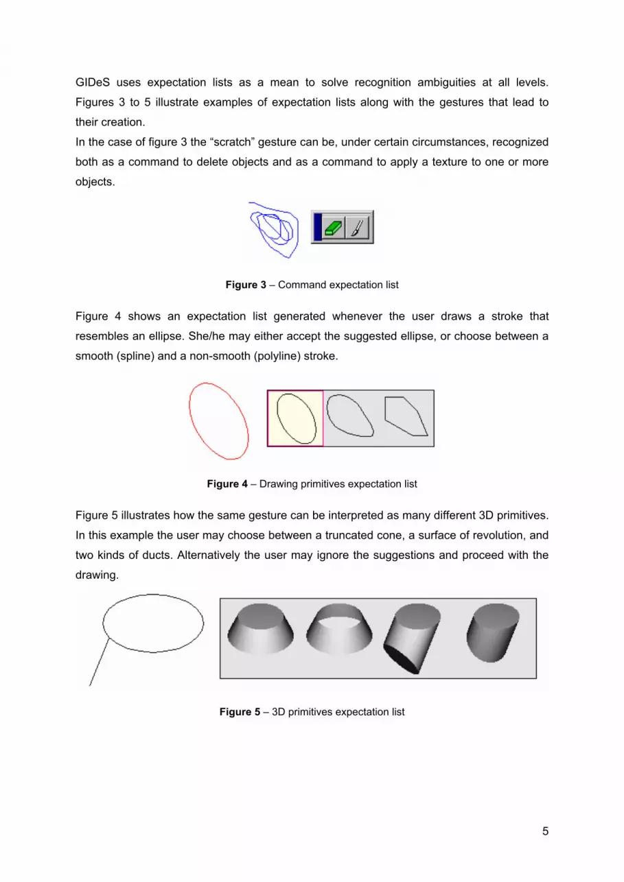
GIDeS uses expectation lists as a mean to solve recognition ambiguities at all levels.
Figures 3 to 5 illustrate examples of expectation lists along with the gestures that lead to
their creation.
In the case of figure 3 the “scratch” gesture can be, under certain circumstances, recognized
both as a command to delete objects and as a command to apply a texture to one or more
objects.
Figure 3 – Command expectation list
Figure 4 shows an expectation list generated whenever the user draws a stroke that
resembles an ellipse. She/he may either accept the suggested ellipse, or choose between a
smooth (spline) and a non-smooth (polyline) stroke.
Figure 4 – Drawing primitives expectation list
Figure 5 illustrates how the same gesture can be interpreted as many different 3D primitives.
In this example the user may choose between a truncated cone, a surface of revolution, and
two kinds of ducts. Alternatively the user may ignore the suggestions and proceed with the
drawing.
Figure 5 – 3D primitives expectation list
6
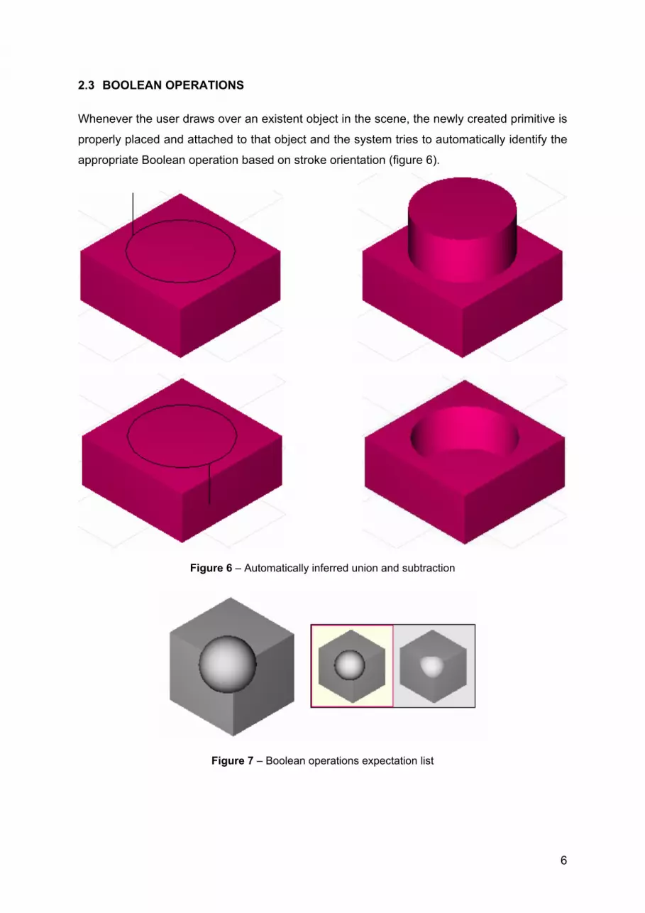
2.3 BOOLEAN OPERATIONS
Whenever the user draws over an existent object in the scene, the newly created primitive is
properly placed and attached to that object and the system tries to automatically identify the
appropriate Boolean operation based on stroke orientation (figure 6).
Figure 6 – Automatically inferred union and subtraction
Figure 7 – Boolean operations expectation list
7
Some primitives, such as the sphere, have no orientation at all, which prevents the system
from identifying the desired Boolean operation. In those circumstances an expectation list is
generated, allowing the user to choose between union and subtraction (figure 7).
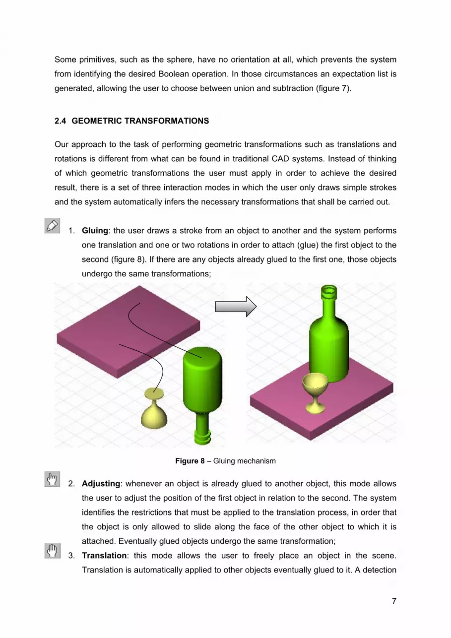
2.4 GEOMETRIC TRANSFORMATIONS
Our approach to the task of performing geometric transformations such as translations and
rotations is different from what can be found in traditional CAD systems. Instead of thinking
of which geometric transformations the user must apply in order to achieve the desired
result, there is a set of three interaction modes in which the user only draws simple strokes
and the system automatically infers the necessary transformations that shall be carried out.
1. Gluing: the user draws a stroke from an object to another and the system performs
one translation and one or two rotations in order to attach (glue) the first object to the
second (figure 8). If there are any objects already glued to the first one, those objects
undergo the same transformations;
Figure 8 – Gluing mechanism
2. Adjusting: whenever an object is already glued to another object, this mode allows
the user to adjust the position of the first object in relation to the second. The system
identifies the restrictions that must be applied to the translation process, in order that
the object is only allowed to slide along the face of the other object to which it is
attached. Eventually glued objects undergo the same transformation;
3. Translation: this mode allows the user to freely place an object in the scene.
Translation is automatically applied to other objects eventually glued to it. A detection
8
mechanism allows the user to place the objects over other existing objects in the
scene.
2.5 CAMERA OPERATIONS
Camera operations are easily performed by clicking on the side button of the stylus. The
system displays an expectation list that allows the user to choose between panning,
zooming, changing the viewing angles and restoring isometrics (figure 9).
Figure 9 – Camera operations
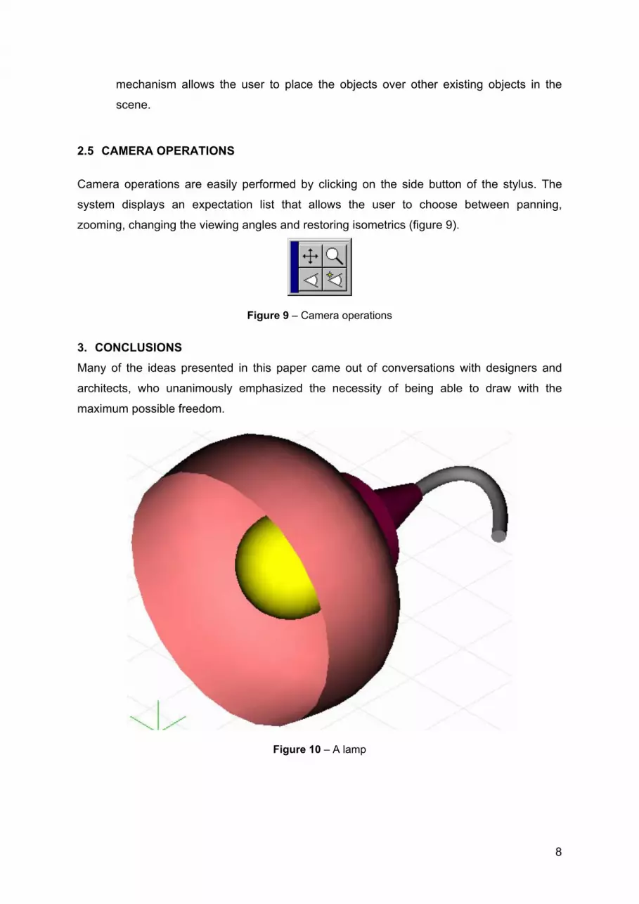
3. CONCLUSIONS Many of the ideas presented in this paper came out of conversations with designers and
architects, who unanimously emphasized the necessity of being able to draw with the
maximum possible freedom.
Figure 10 – A lamp

9
Preliminary usability evaluation tests, along with a few demonstrations in design conferences
(figures 10 to 12) [Branc00, Branc01] were very encouraging, and some more ideas to
improve the effectiveness of 3D systems for conceptual object design are being explored.
In 1990, Jim Blinn wrote [Blinn90]: “There is a tool that works perfectly fine for the ideation
phase of creation. I know it might be heretical to say this, but the ultimate creative design
tool is: Paper and Pencil… The combination of paper and pencil works… and I don’t see
computer graphics replacing it. AND THAT’S OK. I’m not being funny here”.
We should take these wise words both as a challenge and a beacon. In the ideation phase
of creation the combination of paper and pencil works… perhaps one day computers will
become an adequate toll for this task.
Figure 11 – Another lamp
10
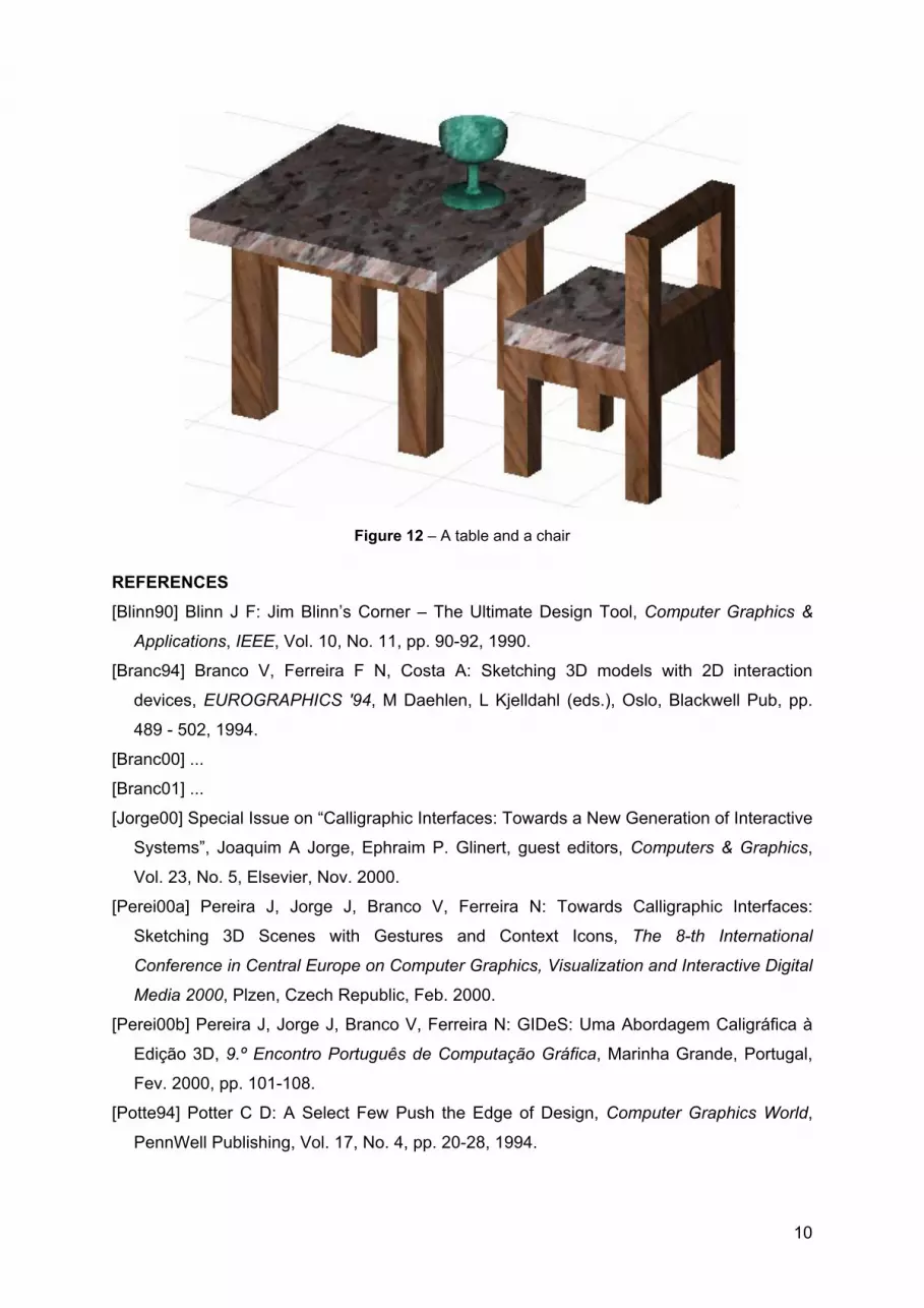
Figure 12 – A table and a chair
REFERENCES [Blinn90] Blinn J F: Jim Blinn’s Corner – The Ultimate Design Tool, Computer Graphics &
Applications, IEEE, Vol. 10, No. 11, pp. 90-92, 1990.
[Branc94] Branco V, Ferreira F N, Costa A: Sketching 3D models with 2D interaction
devices, EUROGRAPHICS '94, M Daehlen, L Kjelldahl (eds.), Oslo, Blackwell Pub, pp.
489 - 502, 1994.
[Branc00] ...
[Branc01] ...
[Jorge00] Special Issue on “Calligraphic Interfaces: Towards a New Generation of Interactive
Systems”, Joaquim A Jorge, Ephraim P. Glinert, guest editors, Computers & Graphics,
Vol. 23, No. 5, Elsevier, Nov. 2000.
[Perei00a] Pereira J, Jorge J, Branco V, Ferreira N: Towards Calligraphic Interfaces:
Sketching 3D Scenes with Gestures and Context Icons, The 8-th International
Conference in Central Europe on Computer Graphics, Visualization and Interactive Digital
Media 2000, Plzen, Czech Republic, Feb. 2000.
[Perei00b] Pereira J, Jorge J, Branco V, Ferreira N: GIDeS: Uma Abordagem Caligráfica à
Edição 3D, 9.º Encontro Português de Computação Gráfica, Marinha Grande, Portugal,
Fev. 2000, pp. 101-108.
[Potte94] Potter C D: A Select Few Push the Edge of Design, Computer Graphics World,
PennWell Publishing, Vol. 17, No. 4, pp. 20-28, 1994.


