Embed Size (px)
Citation preview

RADFORD ARMY AMMUNITION PLANT
SUPPLEMENTAL PHOTOGRAPHIC DOCUMENTATION OF ARCHETYPAL BUILDINGS,
STRUCTURES, AND EQUIPMENT FOR U.S. ARMY MATERIEL COMMAND
NATIONAL HISTORIC CONTEXT FOR WORLD WAR II ORDNANCE FACILITIES
by K. Diane Kimbrell Kathleen E. Hiatt
*Ki&f%mam. wsssEWb •&
U.S. ARMY MATERIEL COMMAND HISTORIC CONTEXT SERIES REPORT OF INVESTIGATIONS
NUMBER 6B
GEO-MARINE, INC.
!■■■"!
US Army Corps of Engineers Fort Worth District
Approved for public release; Distribution Unlimited 19961016 021
THIS DOCUMENT IS BEST
QUALITY AVAILABLE. THE
COPY FURNISHED TO DTIC
CONTAINED A SIGNIFICANT
NUMBER OF PAGES WHICH DO
NOT REPRODUCE LEGIBLY.
SECURITY CLASSIFICATION OF THIS PAGE
REPORT DOCUMENTATION PAGE
1a. REPORT SECURITY CLASSIFICATION Unclassified
2a. SECURITY CLASSIFICATION AUTHORITY
2b. DECLASSIFICATION/DOWNGRADING SCHEDULE
4. PERFORMING ORGANIZATION REPORT NUMBERS U.S. Army Materiel Command Historic Context Series, Report of Investigations Number 6B
6a. NAME OF PERFORMING ORGANIZATION Geo-Marine, Inc.
6b. OFFICE SYMBOL {if applicable)
1b. RESTRICTIVE MARKINGS
Form Approved OMB No. 0704-0188
3. DISTRIBUTION/AVAILABILITY OF REPORT
Approved for public release
5. MONITORING ORGANIZATION REPORT NUMBER(S)
6c. ADDRESS (City, State, and Zip Code) \
550 E. 15th Street / Piano, Texas / 75074
8a. NAME OF FUNDING/SPONSORING ORGANIZATION
US Army Corps of Engineers, Fort Worth District
8b. OFFICE SYMBOL (if applicable)
CESWF-PL-RC
8c. ADDRESS (City, State, and Zip Code) PO Box 17300 Fort Worth, Texas 76102-0300
7a. NAME OF MONITORING ORGANIZATION
US Army Corps of Engineers, Fort Worth District
7b. ADDRESS (City, State, and Zip Code) PO Box 17300 Fort Worth, Texas 76102-0300
9. PROCUREMENT INSTRUMENT ID NUMBER
DACA63-93-D-0014 Delivery Order No. 0014
10. SOURCE OF FUNDING NUMBERS PROGRAM ELEMENT NO.
PROJECT NO.
TASK NO.
WORK UNIT ACCESSION NO.
11. TITLE (Include Security Classification)
Radford Army Ammunition Plant Supplemental Photographic Documentation of Archetypal Buildings, Structures, and Equipment for Army Materiel Command National Historic Context for World War II Ordnance Facilities
12a. PERSONAL AUTHOR(S)
K. Diane Kimbrell and Kathleen E. Hiatt
13a. TYPE OF REPORT Final Report
13b. TIME COVERED FROM Sept. 1993 to Apr. 1995
16. SUPPLEMENTARY NOTATION
14. DATE OF REPORT (Year, Month, Day) April 1995
15. PAGE COUNT 205 + Appendix
17.COSATI CODES FIELD
05
GROUP
06
SUB-GROUP 18. SUBJECT TERMS (Continue on reverse if necessary and identify by block number) Photographic documentation of World War ll-era buildings, structures, and equipment at the Radford Army Ammunition Plant
19. ABSTRACT (Continue on reverse if necessary and identify by block number)
This report presents a photographic record of the archetypal buildings, structures, and equipment of the World War II Ordnance Department's government-owned, contractor-operated (GOCO) industrial facility, the Radford Army Ammunition Plant, at Radford, Virginia. This photographic documentation was completed under partial fulfillment of an Army Materiel Command (AMC) Legacy Resource Program demonstration project for assistance to small installations and in fulfillment of the 1993 Programmatic Agreement among the AMC, the Advisory Council on Historic Preservation, and Multiple Historic State Histonc Preservation Officers concerning the program to discontinue maintenance, or dispose, of particular GOCO properties.
The objective of the project was to photographically record World War ll-vintage equipment and buildings, some of which housed different stages of the ammunition manufacturing process and were of the same architectural design Modem buildings and equipment are not included in this document. Efforts were made to arrange the photographs in the order of ammunition manufacture and facility processes; however, this presentation should not be perceived as a complete chronological sequence for ammunition manufacturing during World War II. The buildings photographed in this document are classified as under either "stand-by" or "layaway" status. The active buildings depicted in this volume are of an insensitive and/or "safe" nature and include Administration and Shop buildings.
20. DISTRIBUTION/AVAILABILITY OF ABSTRACT D UNCLASSIFIED/UNLIMITED El SAME AS RPT. □ DTIC USERS
22a. NAME OF RESPONSIBLE INDIVIDUAL
Joseph Murphey
DO FORM 1473, JUN 86
21. ABSTRACT SECURITY CLASSIFICATION Unclassified
22b. TELEPHONE (Include Area Code)
817-334-2625
Previous editions are obsolete
22c. OFFICE SYMBOL
CESWF-PL-RC
SECURITY CLASSIFICATION OF THIS PAttF
RADFORD ARMY AMMUNITION PLANT
SUPPLEMENTAL PHOTOGRAPHIC DOCUMENTATION OF ARCHETYPAL BUILDINGS, STRUCTURES, AND
EQUIPMENT FOR U.S. ARMY MATERIEL COMMAND NATIONAL HISTORIC CONTEXT FOR WORLD WAR II
ORDNANCE FACILITIES
by
K. Diane Kimbrell Kathleen E. Hiatt
Principal Investigator Duane E. Peter
Prepared for
U.S. ARMY CORPS OF ENGINEERS FORT WORTH DISTRICT
U.S. ARMY MATERIEL COMMAND HISTORIC CONTEXT SERIES REPORT OF INVESTIGATIONS
NUMBER 6B
by
Geo-Marine, Inc. 550 East 15th Street Piano, Texas 75074
April 1995

CONTRACT DATA
The preparation of this document was accomplished under Contract No. DACA63-93-D-0014, Delivery Order No. 14 (GMI project no. 1114-014), with the U.S. Army Corps of Engineers, Fort Worth District, Fort Worth, Texas 76102.
TABLE OF CONTENTS
I. INTRODUCTION 1
II. PHOTOGRAPHIC RECORDATION LOGISTICS AND METHODOLOGY 3
III. HISTORICAL OVERVIEW 5
IV. PHOTOGRAPHIC DOCUMENTATION 9 Administrative Facilities 11 Housing for Employees 19 Manufacturing and Chemical Process Buildings 23 Support Facilities for Manufacturing 113 Shipping and Storage Facilities 141 Support Facilities for Employees 155 Utilities and Infrastructures 165
V. REFERENCES CITED 205
VI. APPENDIX A: PHOTOGRAPHIC DATA SHEETS 207
ATTACHMENT 1: OVERSIZED MAP Back Cover
111
LIST OF FIGURES
SECTION III. HISTORICAL OVERVIEW 1. Regional Location of Radford Army Ammunition Plant 6
SECTION IV. PHOTOGRAPHIC DOCUMENTATION 1. Building 215: General Purpose Administration Building 13 2. Building 229: Administration Building 13 3. Building 229: Tombstone, origin unknown 14 4. Building 229: View of the only interior courtyard at the plant 15 5. Building 521: Magazine Office and Change House 15 6. Building 1993: Magazine Area Office with Latrine 16 7. Building 1913: Interior view of a Latrine hand wash basin 17 8. Building 7100: Office with incinerator 18 9. Staff Village House #2 . 21 10. Staff Village Duplex (residence #13 and #15) 21 11. Building 207: Single-story Barracks 22 12. Building 206: Two-story Barracks 22 13. Building 1010: Cotton Dry House and Conveyor Building 25 14. Building 2010: Cotton Dry House and Conveyor Building 25 15. Building 1012: Nitrating House 26 16. Building 1012: Pressure tank on the fourth floor of this building 27 17. Building 1012: Wringer drive motor 28 18. Building 1012: Cotton trolley tracks 29 19. Building 1012: Cotton Scale on the third floor 30 20. Building 1012: Cyclone cotton hopper 31 21. Building 1012: Cotton dipping pot 32 22. Building 1012: Nitrating acid tank on the third floor 33 23. Building 1012: Interior view of the third floor 34 24. Building 1012: Wringer located on the second floor 35 25. Building 1012: Nitrating equipment and buckets 36 26. Building 1014: Emergency Catch House 37 27. Building 2019: Boiling Tub House 37 28. Building 2019: Boiling tub .38 29. Building 2019: Bottom of a boiling tub on the first floor 39 30. Building 1020: Boiling Tub Settling Pit and Pump House 40 31. Building 1022: Beater House 40 32. Building 1022: Beater tub on the second floor 41 33. Building 1022: Jordan 6, Mamoth Jr. water pump 41

List of Figures (con't)
34. Building 35. Building 36. Building: 37. Building: 38. Building: 39. Building 40. Building 41. Building 42. Building 43. Building 44. Building 45. Building 46. Building 47. Building 48. Building 49. Building 50. Building 51. Building 52. Building 53. Building 54. Building 55. Building 56. Building 57. Building 58. Building 59. Building 60. Building 61. Building 62. Building 63. Building 64. Building 65. Building 66. Building 67. Building 68. Building 69. Building 70. Building 71. Building 72. Building 73. Building 74. Building 75. Building 76. Building 77. Building 78. Building 79. Building
1022: Beater tub and Jordan water pump 42
1025: Poacher and Blending Settling Pit Pump House 43 2026: Final Wringer House 43
2026: Cotton buckets on the first floor 44
2026: Chute from wringer 45
2026: Wringer inside this Final Wringer House 46
7800: Extruded Grain Finishing House 47
3524: Chemical Grind House . 47
713: Frick Ammonia compressor 48
4718: Lead Burner House 49
3650: Cotton Store Mix House 49
1702: Originally a Tray House for the "A" Finishing Area 50 1555: Activated Carbon and Recovery House 50
2502: Ether Still House #2 51
1546: Ether Storage Tanks 51
1002: Acid storage tanks at the Acid Mix and Weigh House 52 1500: Dehydration Press House 52
1500: Dehydration vertical press 53
1501: Alcohol Pump and Accumulator House 54
1501: Alcohol Accumulator Pump 55
1501: Alcohol accumulator counter 56
1501: Heat reclaiming unit 57
1508: Mix House 58
1508: Mixer 58
1508: Macerator 59
1506: Diphenylamine Mix House 59
1506B: Motor House of the Diphenylamine Mix House 60 1506: Sprinkler Valve Houses 61
1506: Diphenylamine (DPA) storage tank 62
1506: Pressure tank manufactured by Staife 62
1506: Mix tank with scale in background 63
1506: Howe-Richardson scale ^ 1511: Block Press House 65
1511: Vertical blocking press by Farquar-York Company 65 1511: Another type of press used in this building 66
1511: High pressure valves for the macaroni machine 67 1561: Block Breaker House 67
1561: Interior of the Block Breaker House 68
1513: Finishing Press and Cutting House 69
5008-1: Press House f9
5008-1: Hydraulic press 70
2518: East wing of a Finishing and Cutting House 70
2519: West wing of a Finishing and Cutting House 71
1513: Finishing Press and Cutting House 71
1513: Macaroni press ']• 3553: Macaroni separators 73
VI

List of Figures (con't)
80. 81. 82. 83. 84. 85. 86. 87. 88. 89. 90. 91. 92. 93. 94. 95. 96. 97. 98. 99. 100. 101. 102. 103. 104. 105. 106. 107. 108. 109. 110. 111. 112. 113. 114. 115. 116. 117. 118 119. 120. 121. 122. 123. 124. 125.
Building 1513: Macaroni separator without its cover Building 2519: Farquar-York Horizontal press Building 1513: Cutting machine Building 1513: Angle Buggy Building 5008-1: McKiernan-Terry Company cutting machine . . Building 1622: Solvent Recovery House Building 1622: Bottom of tank in this Solvent Recovery House . Building 1622: Filter blowers Building 1622: Blowers and their motors No Building Number: Solvent Recovery House without barricade Building 4909-3: Another Solvent Recovery House Building 4914: Building 1727: Building 1668: Building 1828:
: Dust Collection House ': Dry Screen House !: Water Dry House i: Final Blending House and Control House
Buildings 1825 and 1875: Final Blend House and Can Pack House Building 1825: Chute-dump station Building 1825: Blender on the first floor Building 1825: Cleveland worm gear reduction unit Building 1825: Powder conveyor system Building 1875: Can Pack House Building 1875: Top of the powder chute on the third floor Building 1875: First floor chute Building 1875: Interior view of the Can Pack House Building 4952-1: Coating barrel Building 4952-1: Back of the coating barrel Building 4952-1: Toledo scale Building 1800: Building 1814: Building 1814:
: A glazing barrel at the Glaze House : Ingersoll-Rand air compressor at the Blending and Glazing House : Cyclone ventilation unit
Building 1814B: Buggy Unloading and Control House Building 9310-01: Rolled Powder Building Building 7113: Rolled Powder Building Building 9310-01: Pre-roll machine Building 9309-04: Roll Mill in the Rolled Powder Building Building 9309-04: Punch Building 9309-04: De-thread machine Building 9309-04: Machine that weighs the correct amount of powder into bags . Building 9309-04: Adler sewing machine
Pinch press Carpet Roller in Rolled Powder House #4 Milling machine Another view of this milling machine Sheet powder cutting machine Rolled Powder Building
Building 9309-04: Building 9309-03: Building 9309-04: Building 9309-04: Building 9309-04: Building 9309-03: Building 1763: Barricaded Rest House
. .74
. .74
. .75
. .75 , .76 , .77
. 78 . .79 .80 . 81 .81 .82 .82 .83 . 83 . 84 .84 .85 . 86 .87 .87 . 88 .89 .90 .91 .91 .92 .93 . 94 .95 .96 .97 .97 .98 . 98 .99 100 100 101 102 103 103 104 105 105 106
vn

List of Figures (con't)
126. 127. 128. 129. 130. 131. 132. 133. 134. 135. 136. 137. 138. 139. 140. 141. 142. 143. 144. 145. 146. 147. 148. 149. 150. 151. 152. 153. 154. 155. 156. 157. 158. 159. 160. 161. 162. 163. 164. 165. 166. 167. 168. 169. 170. 171.
Building 9309-03: Even speed or even mill machine 107 Building 3713: Mobilization Storage |08 Building 7124-02 Building 4912-01 Building 4912-02 Building 4924-02 Building 4924-6:
Nibbling House 108
Large Grain Hold House 1°9
Small Grain Loading House 1°9
Large Saw House with a barricade 110 Machine and Saw House HO
Building 4924-05: MK 90 Finishing Operations HI Building 2924-1: Large Motor Load House HI Building 4951-3: Billet Rework House I12
Building 201: Propellant Lab 115
Buildings 201 and 3562: Propellant Lab and Inert Storage Building 115 Building 6401: Test House Building 203 Building 500 Building 500 Building 500 Building 500 Building 500 Building 500 Building 500 Building 500 Building 500 Building 500 Building 500 Building 500 Building 500 Building 500 Building 500 Building 501 Building 512 Building 520 Building 520 Building 520 Building 225
116 116 117
Garage Combined Shop Ingersoll bridge metal machine 118 Metal shaper 1i9
Punch press, Model #5 120 Punch press, Model #2 121 Peerless metal saw I22
Turret Model #3 Honing Spot welder . . . Sheet metal press
123 124 125 126
Drill press model I27
128 Iron worker Detail of the wooden floor 128 Landis pipe threading machine I29
Marvel #9 pipe saw i29
Locomotive Shop 130 Line Crew Shop sided with asbestos and fiberglass 130 Weld Shop 131
An 800-pound, single-frame steam hammer 132 Interior view of the Weld Shop 133 Quonset Hut functioning as a Maintenance Shop 134
Building 3727: This Maintenance Shop I34
Building 4421-08: Equipment and Repair Shop 135 Building 4942: Screen Caustic Cleaning House 135 Building 4705-4: Singer sewing machine in the Laundry Building 136 Building 420-01: "A" and "B" Line Acid Waste Water Plant 137 Building 420-01: Auxiliary sludge pump I38
Building 420-01: Slaker that separates water from solvents |39
Building 420-01: Close-up of Slaker Building 919: Close-up of rail car scale Building 236: Storage/Workshop Building 239: Storage Building
140 140 143 144
viu

List of Figures (con't)
172. Building 519: Laboratory Storage 144 173. Building 508: Salvage and Surplus Property Storage 144 174. Building 514: General Storehouse used for the storage of metal 145 175. Building 521: Gas Cylinder Store 145 176. Building 1550: Ingredient Store House 146 177. Building 1888: Box Storage Building with aluminum siding 146 178. Building 213: General Purpose Warehouse 147 179. Building 4723: General Purpose Warehouse 147 180. Building 4723: Refrigerator . 148 181. Building 9387-1: Cinder Block Warehouse 148 182. Building 1107: Igloo Storage Magazine 149 183. Building 1918: Igloo 149 184. Building 4603-32: Richmond Magazine 150 185. Building 225: Smokeless Powder Magazine 150 186. Building 1958: Smokeless Powder Magazine 151 187. Building 4601-3: Smokeless Powder Magazine 151 188. Building 2244: Ballistic Primer Magazine 152 189. Building 7503: Magazine with an earthen barrier 153 190. Building 226: Tire Storage Shed with aluminum siding 153 191. Building 505: Lumber and Pipe Shed with aluminum siding 154 192. Building 600: Equipment Shed currently storing modern equipment 154 193. Building 200: General Instruction Building 157 194. Building 200: Wing #1 of Building 200 157 195. Building 222: Change House 158 196. Building 227: Brick Change House 158 197. Building 1515: Two-story cinder block Change House 159 198. Building 3718: Change House 159 199. Buildings 3717 and 3716: These two Change Houses are connected 160 200. Building 4728: Cinder Block Change House 160 201. Building 7808: Change House for males 161 202. Building 7809: Change House for females 161 203. Building 9361-03: Cinder block Change House 162 204. Building 4339: Latrine 162 205. Building 4710-D1: Latrine with a shingled roof 163 206. Building 216: Fitness Center or Gym 163 207. Building 216: West side of the gym 164 208. Building 234: Cafeteria 164 209. Building 197: Incinerator Building 167 210. Building 205: Hospital/Clinic with beds 167 211. Building 263: Telephone Building 168 212. Building 263: Interior view of the Central Office showing a switchboard 168 213. Building 223: Sentry Station/Plant Gate House #3 169 214. Building 2042: Sentry Station/Plant Gate House #2 169 215. Building 221-5: Sentry House 170 216. Building 235: Police Station 171 217. Building 222: Two-story Fire Station containing bays 1 through 4 171
IX
List of Figures (con't)
218. 219. 220. 221. 222. 223. 224. 225. 226. 227. 228. 229. 230. 231. 232. 233. 234. 235. 236. 237. 238. 239. 240. 241. 242. 243. 244. 245. 246. 247. 248. 249. 250. 251. 252. 253. 254. 255. 256. 257. 258.
Building Building Building Building Building Building Building Building Building Building Building Building Building Building Building Building Building Building Building Building Building Building Building Building Building Building Building Building Building Building Building Building Building Building Building Building Building Building Building Building Building
4705 407: 408: 408: 409: 409: 409: 409: 1908 419: 419: 419: 419: 419: 710: 710: 926: 926:
■2: Fire Station containing bays 5 and 6 I72
Water Filtration Plant 172
River Pump House 173 An Ingersoll-Rand water pump I73
Ingersoll-Rand water pump I74
Pumps in the River Pump House I75
Pumps at the Water Filtration Plant I76
Back washing filters by Ingersoll-Rand Company 176 Wooden water pipe section 177
178 179 180
Drinking Water Plant I77
Wash water pumps Water pump Dry chemical feeder for carbon tanks Carbon Tank 181
Sewage Treatment Building 182
Sewage pump manufactured by Chicago Pump Company 183 Magazine Area's twelve-inch well with pump house 184 Peerless pump 185
1521A: Chilled Water Pump House 186
1521A: Ingersoll-Rand chilled water circulating pump and motor 186 1521: Low pressure centrifugal pump 187
1521: Worthington 120, high pressure piston pump and motor 187 1521: High pressure hydraulic tank (reservoir) 188 1521: Lead-lined wooden water filter tank I89
1521: Low pressure hydraulic tank reservoir I90
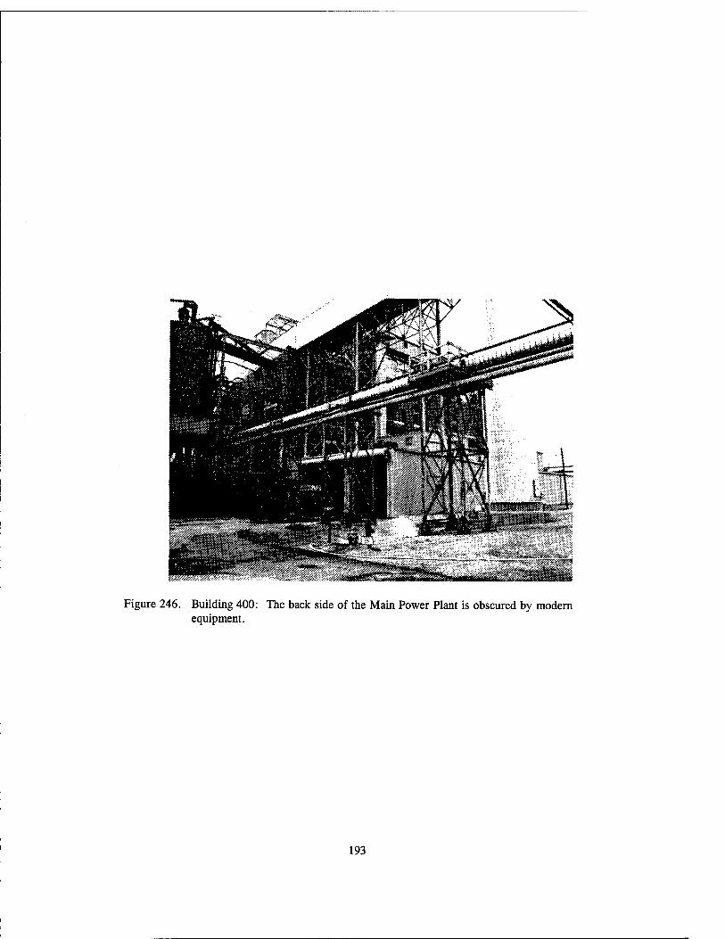
9354: Worthington compressor at this Compressor House 191 400: Main Power Plant I92
400: Detail of the masonry of the Main Power Plant 192 400: Main Power Plant I93
400: Close-up of turbine I94
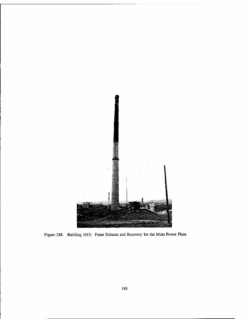
1013: Fume Exhaust and Recovery for the Main Power Plant 195 4329: Power House §2 I96
Ash silos I9' A ceramic coal silo, a steel coal silo, and a coal elevator 198
Air Compressor House 1" 1QQ Exciter motor Lyy
An Ingersoll-Rand air compressor in the Box Repair Building 200 Worthington air compressor 200
Oxidation House 2°1 Fairbanks-Morse Springless scale 2^2
Control Panel 203
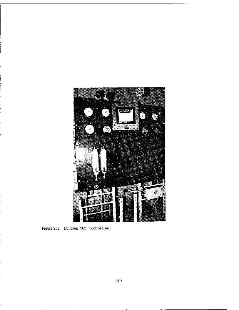
4329: 4329: 700: 700: 1890 1890 702: 702: 702:

I.
INTRODUCTION
This report presents a photographic recordation of the archetypal buildings, structures, and equipment of the Ordnance Department's World War II government-owned, contractor-operated (GOCO) industrial facility, Radford Army Ammunition Plant, Radford, Virginia. Geo-Marine, Inc. was contracted by the U.S. Army Corps of Engineers, Fort Worth District, to undertake this project in September of 1993. Duane E. Peter, Director of the Cultural Resources Division of Geo-Marine, Inc., acted as Principal Investigator for the project. Kathleen Hiatt completed the photographic fieldwork for the project.
This photographic documentation was completed under Delivery Order No. 14, Contract No. DACA63-93 D-0014, Task C, in partial fulfillment of an Army Materiel Command (AMC) Legacy Resource Program demonstration project for assistance to small installations. This documentation also represents partial fulfillment of the requirements of the 1993 Programmatic Agreement among the AMC, the Advisory Council on Historic Preservation, and multiple State Historic Preservation Officers concerning the program to discontinue maintenance of, or dispose of, particular government-owned properties. This work was conducted in compliance with the National Environmental Policy Act of 1969 (PL 90-190); the National Historic Preservation Act of 1966 (PL 96-515), as amended; the Archaeological and Historic Preservation Act of 1974 (PL 93-291), as amended; and Executive Order No. 11593, "Protection and Enhancement of the Cultural Environment."
In completion of this task, a map showing building numbers; a photographic log; the photographs and captions of various buildings, structures, and equipment; and a brief installation history have been included for the Radford Army Ammunition Plant.

II.
PHOTOGRAPHIC RECORDATION LOGISTICS AND METHODOLOGY
The objective of Task C was to photographically record World War II vintage buildings and equipment. Numerous buildings that housed different stages of the ammunition manufacturing process were of the same architectural design. Accordingly, the order of photographs that follows is based on differences in architectural design, before the step-by-step process of ammunition manufacturing. Modern buildings and necessary equipment in ammunition processing are absent from this photographic account due to their vintage (i.e., replacement equipment, though similar in function and/or design, was not photographed). Ammunition manufacturing is divided into lines according to the type of ammunition being manufactured and by process stages. Additionally, there may be more than one line for the same ammunition type at the same stage. Accordingly, the architectural design of these buildings in different lines is similar, as is their equipment. Photographs of specific building types were not taken from a single line, rather the photographs were taken from any number of lines as directed by the sun angle and physical restrictions. In short, though efforts were made to arrange the photographs in order of ammunition and facility processes, the presentation should not be perceived as a complete and chronological order of ammunition manufacturing.
Equipment was commonly found stored in a different facility than where it was housed when it was in use. Thus, in some cases, equipment that is depicted may not be a part of the process indicated by the building it is in. This is another reason not to take this account as a step-by-step explanation of ammunition plant processes.
Photographs of ammunition buildings and equipment in this account are classified under either "stand-by" or "lay-away" status. Depicted active buildings are of an insensitive and/or "safe" nature. Such buildings include administration and shop buildings.
Buildings of active status could only be photographed from a designated distance. Active status structures were photographed only if discernible architectural differences existed. For example, active Rolled Powder Line #1 buildings whose architectural design differed from stand-by Rolled Powder Line #4 buildings were photographed from the designated distance. Photographs of the lay-away buildings and equipment were representative of the active, off-limits properties according to the photographer's escort.
Photographic angles were largely dependent upon the angle of the sun and spatial restrictions. Time constraints and work schedules of the escorts did not allow for return visits to buildings that may have been better depicted with a different sun angle. In many cases, preferred photography angles were impossible due to overhead pipelines, power line poles, and other structures.
Indoor lighting was also a determining factor in photographic results of plant equipment. Electrical power had been shut off to the buildings on lay-away status. Unbarred windows and doors were opened and a camera flash was employed to compensate for poor lighting conditions. It was not confirmed whether the sprinkler system or fire suppression system was disengaged, and it was known that a camera flash would be sufficient to trigger the deluge system. Thus, the camera flash was not utilized in the rolled powder buildings where such a network of sprinklers existed. Subsequently, photographs of some equipment were not taken. Indoor photography of equipment was also controlled by spatial restrictions. It was virtually impossible to photograph tanks spanning two or more stories. In some instances, walls and other equipment obstructed photographic angles; therefore, photographs of some equipment were not possible.
The age of equipment was questionable. Each piece of equipment has a plant inventory number. An inventory list of the equipment details each piece by its inventory number. However, not every piece of equipment on this list had a manufacture or acquisition date. Increasing the uncertainty of the equipment's vintage was the illegibility of or absence of the inventory tag. In addition, the equipment inventory list was not exhaustive. For instance, the list did not include "installed equipment;" furthermore, installed equipment was not easily discernible. Equipment installed at the time of the building's construction, in many cases has been replaced in recent times. The installed equipment does not have a definitive appearance, and purchased equipment without an inventory tag may have been mistaken as installed equipment. Photographs were taken of all equipment where the equipment's age was in question. Thus, the equipment that is found within this account is not definitely World War II equipment unless a date is listed for that piece. However, the equipment included in this account is representative of the World War II era.
Pieces of equipment were found in various stages of disassembly. These pieces were not photographed unless they retained sufficient physical integrity to indicate their former function. In this volume, such pieces are labeled as being in a state of partial disassembly. Motors, tanks, and pumps are necessary in numerous plant processes. Due to the common function and design of such equipment, a single photograph was taken to represent any number of similar pieces of equipment. A representative unit was selected for its physical integrity and photographic accessibility.

III.
HISTORICAL OVERVIEW
The Radford Army Ammunition Plant, located in the New River Valley of southwestern Virginia (Figure 1), was one of two smokeless powder manufacturing facilities constructed under a limited expansion program by the Quartermaster Corps (taken over later in 1941 by the Corps of Engineers) in the summer of 1940 (Thomson and Mayo 1991:108). The site was chosen based on several criteria set up by the Ordnance Department. For instance, the site had to be a non-coastal area (at least 200 miles away from any border) for obvious reason of national defense. The site could not have been located near a large center of population, for safety reasons, although it had to have access to a sufficient work force. In addition, the plant had to be located in an area that had access to electricity, water, railroads, and highways to provide a degree of self-sufficiency. Finally, the site also was chosen on the basis that large tracts of land could be purchased (for the safety requirements that mandated adequate spacing between buildings), and the land price had to be relatively inexpensive (Thomson and Mayo 1991:108-109).
As Radford met these criteria, construction began on August 23, 1940 under a contract awarded to the Hercules Powder Company of Wilmington, Delaware, and the initial phase of construction was completed late in 1941. The plant consisted of 687 buildings, most of which were of a production nature (MacDonald and Mack 1984:20). The general layout of the plant was divided into three production lines for the manufacture of smokeless powder, an Administration Area, an Acid Area, a Shops Area, Residential facilities, and Storage facilities; all of which were centrally located around the Main Power House. The smokeless powder production lines at Radford Ordnance Works (its original name) were set up parallel to one another; however, unique to ordnance plants, Radford's lines were set up in a way in which each line was connected to one another at each stage of the production process. This allowed for the transfer of materials from one line to another when it was necessary during manufacture. Although originally planned as a part of the site, the New River Unit was constructed in 1941, 12 miles away from the Radford Ordnance Works due to a lack of space needed for safety requirements. The New River Unit fulfilled bag manufacturing and bag loading needs during World War II (MacDonald and Mack 1984:23).
The technology involved in the manufacture of single-based smokeless powder at Radford Ordnance Works was based on the same method developed by French chemist, Vielle, in 1884. Although the explosive quality of nitrated cotton was previously known, Vielle perfected the method by gelatinizing the nitrocellulose (nitrated cotton) with a solvent (either ether or alcohol) and then cutting it into small squares which controlled the rate of burning (Greer n.d.:n.p.) One modification of this process that occurred at Radford was the supplementation of wood pulp as a source of cellulose, in addition to (but not a complete substitution for) cotton fibers. Radford was one of two plants that were first equipped with the machinery

(Scale in Miles) Source: Computer Support Corp. 1993
Figure 1. Regional Location of Radford Army Ammunition Plant.

necessary to make this adjustment. The production of this type of smokeless powder began at Radford Ordnance Works in April of 1941 (Thomson and Mayo 1991:137).
In the following description, the production process for smokeless powder that took place at the plant is briefly outlined. Pure cotton fiber or wood pulp was nitrated by mixing sulfuric and nitric acids with the cellulose in the Nitrating House. Following nitration, the nitrocellulose went through a series of boilings, drownings, pulpings, and grindings to remove all impurities and produce the form necessary for entering the actual powder line processes. These steps took place in the Boiling Tub Houses, Beater Houses, Poacher and Blending Houses, and finally at the Wringer Houses where the water was removed.
At this point, the nitrocellulose entered the powder line where it went through a series of processes in the Dehydration House, the Mix House, and the Block Press House. In these facilities, the nitrocellulose was pressed into blocks, broken up, stabilized, and pressed into blocks again. Next, in the Finishing Press House, the blocks were pressed through dies producing long strands which were then cut into various sized grains in the Cutting Houses. The powder nitrocellulose was then ready for the solvent recovery process which involved several steps to reduce the amount of ether or alcohol present. After this was completed, it was sent to the Air Dry House to dry the powder. If the powder was to be used for rifles, it was sent to the Glazing House to be covered with graphite; however, the cannon powder did not require this process. The powder was then screened to achieve uniform grain size and was sent on to be packed for storage and finally for shipment to loading plants (MacDonald and Mack 1984:25-26).
Radford Ordnance Works produced not only smokeless powder, but also many of the raw materials used in the powder production process. For instance, the plant had facilities for the manufacture of nitric acid and nitroglycerin. In addition, during World War II, the facilities were expanded to include the manufacture of the raw material oleum for use in the production of rocket propellants, TNT, pentolite, and rolled powder (MacDonald and Mack 1984:27). The expansion of the plant also included an experimental or "pilot" plant for the manufacture of solventless-extruded powders for rocket propellant. The solventless- extruded powders eliminated two major difficulties that were encountered with the solvent-extruded powders: one, the time involved in drying the grains was greatly reduced, and two, it eliminated the grain deformation that took place in the drying process. Radford was also equipped with the necessary dry- extrusion press and had a capacity of producing 1200 pounds of rocket propellant each day (Thomson and Mayo 1991:138).
The bag manufacturing and loading facilities of the New River Unit began production in the fall of 1941. The facility consisted of four lines for loading smokeless powder and two lines for loading black powder. The lines consisted of a bag making facility, as well as powder weighing and loading areas. After the bags were loaded, they were stitched closed and ready for final inspection, storage, or shipment (MacDonald and Mack 1984:29-30).
After World War II, the plant was put on stand-by status and the contract was terminated in September of 1945. During the next summer, a contract was awarded to the Hercules Powder Company to produce ammonium nitrate at the acid plant (at the Radford Unit) that could be used for fertilizer. The production continued until April of 1949. The New River Unit was also placed on stand-by status and stayed at that designation until February of 1950 (MacDonald and Mack 1984:30).
With the onset of the Korean War, Radford Ordnance Works was reactivated. During the course of production, to satisfy changing ordnance needs many buildings had to be renovated and other buildings were demolished. After the war, Radford stayed active at a reduced capacity; however, the remaining manufacturing buildings at the New River Unit were sold (MacDonald and Mack 1984:31-32).
Once again, during the outbreak of the Vietnam War, Radford's production of ammunition was increased in 1962. The height of Radford's production during the Vietnam War came in 1968. In the following

years, Radford underwent a modernization plan. Several new facilities were constructed that proved to update the plant's technology. The utilization of the CAMBL or continuous automated multi-based line over the use of the CASBL (continuous automated single-based line) was put into place at this time. During the same period, Radford experienced two explosions; one destroyed the "A" TNT line, and despite the spacing requirements for Ordnance plants, the "B" and "C" lines were heavily damaged as well (MacDonald and Mack 1984:32).
During the 1980s, the plant utilized the latest in computer-controlled manufacturing technology. This technology (now considered out-of-date) was built and tested, but put on stand-by prior to any product manufacture. The production of TNT ceased completely in July of 1986, and the entire plant placed on stand-by status.
With the onset of Desert Storm, a plan to reactivate the production of TNT was initiated and work was begun but the plant was returned to stand-by status prior to any actual production. Today, production is greatly cut back; "A" line is shut down, but "B" and "C" lines still produce multi-based powder. It is estimated that by the end of 1995 the employee roster will be cut to 1000 persons, but at this time Radford is not slated for closure.

IV.
PHOTOGRAPHIC DOCUMENTATION

ADMINISTRATIVE FACILITIES

Figure 1. Building 215: General Purpose Administration Building.
Figure 2. Building 229: Administration Building where the credit union was housed.
13

Fieure 3 Building 229: Tombstone, origin unknown. It reads, "Hugh B./ Son of W.F.& J./ Montgomery/ Died July 24, 1903/ Aged 20 Years/ Death has been here and Borlle Away/ A Brother From ..." It currently rests in the courtyard of Building 229.
14

Figure 4. Building 229: View of the only interior courtyard at the plant.
Figure 5. Building 521: Magazine Office and Change House with a "chimney" that serves as a heater smokestack.
15

Figure 6. Building 1993: Magazine Area Office with Latrine.
16

Figure 7. Building 1993: Interior view of a Latrine hand wash basin which is inside the Magazine Area Office.
17

ESBS^BSBäätl Figure 8. Building 7100: Office with incinerator.
18

HOUSING FOR EMPLOYEES

Figure 9. Staff Village House #2 with porch on left side of house and the garage on the right.
Figure 10. Staff Village Duplex (residence #13 and #15) with porches on either side of the building and a two-door garage is off to the left.
21

Figure 11. Building 207: Single-story Barracks.
Figure 12. Building 206: Two-story Barracks.
22

MANUFACTURING AND CHEMICAL PROCESS FACILITIES
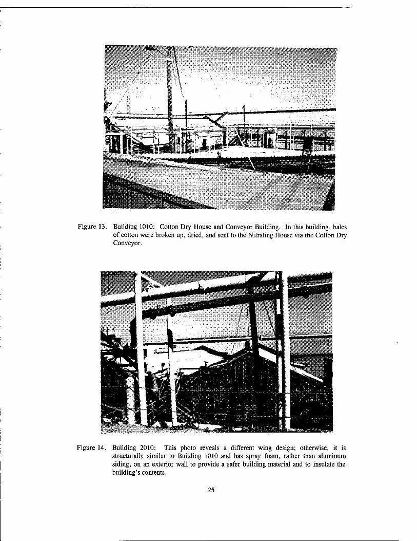
Figure 13. Building 1010: Cotton Dry House and Conveyor Building. In this building, bales of cotton were broken up, dried, and sent to the Nitrating House via the Cotton Dry Conveyor.
RSÜft5
Figure 14. Building 2010: This photo reveals a different wing design; otherwise, it is structurally similar to Building 1010 and has spray foam, rather than aluminum siding, on an exterior wall to provide a safer building material and to insulate the building's contents.
25
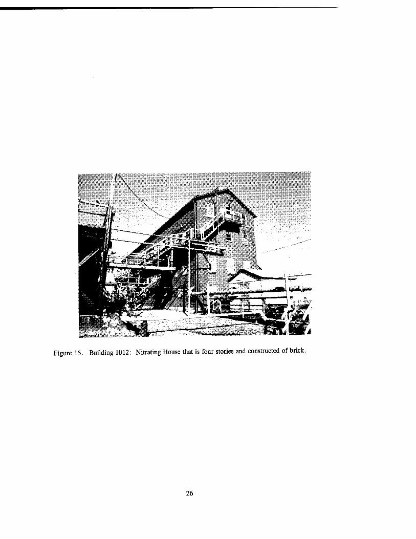
Figure 15. Building 1012: Nitrating House that is four stories and constructed of brick.
26

Figure 16. Building 1012: Pressure tank on the fourth floor of this building.
27

Figure 17. Building 1012: This Wringer drive motor on the fourth floor is surrounded by four dipping pot agitators which are under safety cages.
28

Figure 18. Building 1012: Cotton trolley tracks on the third floor. The trolleys are no longer present; however, they were used to transfer cotton from the Dry Cotton Conveyor to the cotton dipping pots.
29

Figure 19. Building 1012: Cotton Scale on the third floor.
30
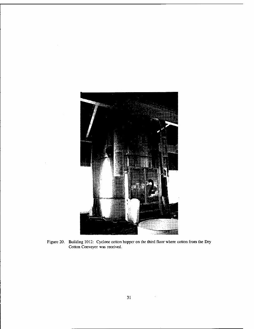
Figure 20. Building 1012: Cyclone cotton hopper on the third floor where cotton from the Dry Cotton Conveyor was received.
31

fWmA
Figure 21. Building 1012: Cotton dipping pot on the third floor where cotton was mixed with acid.
32

Figure 22. Building 1012: Nitrating acid tank on the third floor.
33

Figure 23. Building 1012: its motor.
Interior view of the third floor showing a wooden propeller fan with
34
atjKjs&ajSggnEMjBB
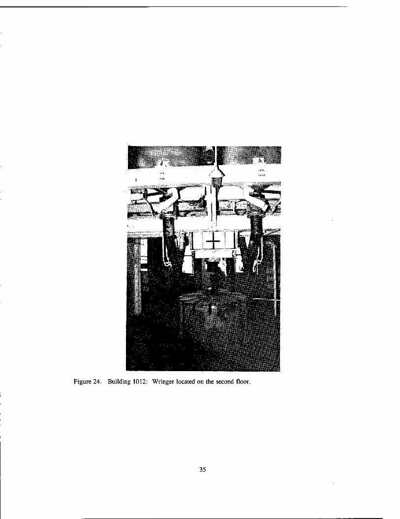
Figure 24. Building 1012: Wringer located on the second floor.
35

Figure 25. Building 1012: Nitrating equipment and buckets for collection on the first floor.
36
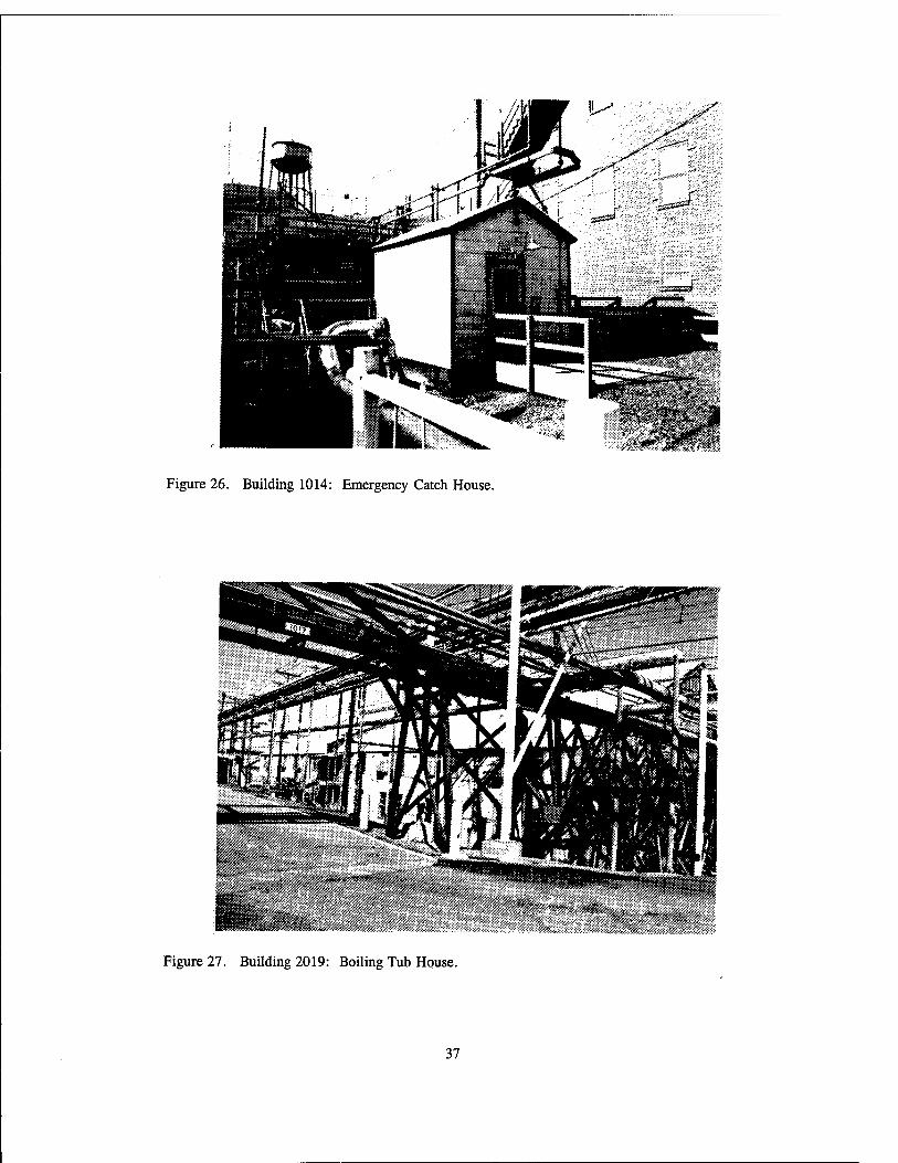
Figure 26. Building 1014: Emergency Catch House.
Figure 27. Building 2019: Boiling Tub House.
37

Figure 28. Building 2019: Boiling tub on the second floor of the Boiling Tub House.
38

Figure 29. Building 2019: Bottom of a boiling tub on the first floor.
39

^^^^^^^^^^"Wri^'v^^y^ "'■
,"-tyX:':U&&i
Figure 30. Building 1020: Boiling Tub Settling Pit and Pump House.
Figure 31. Building 1022: Beater House.
40
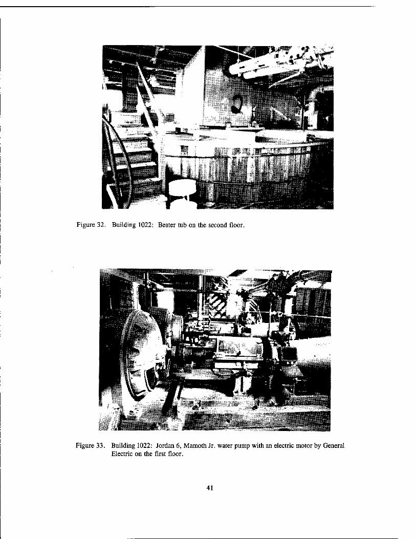
Figure 32. Building 1022: Beater tub on the second floor.
Figure 33. Building 1022: Jordan 6, Mamoth Jr. water pump with an electric motor by General Electric on the first floor.
41
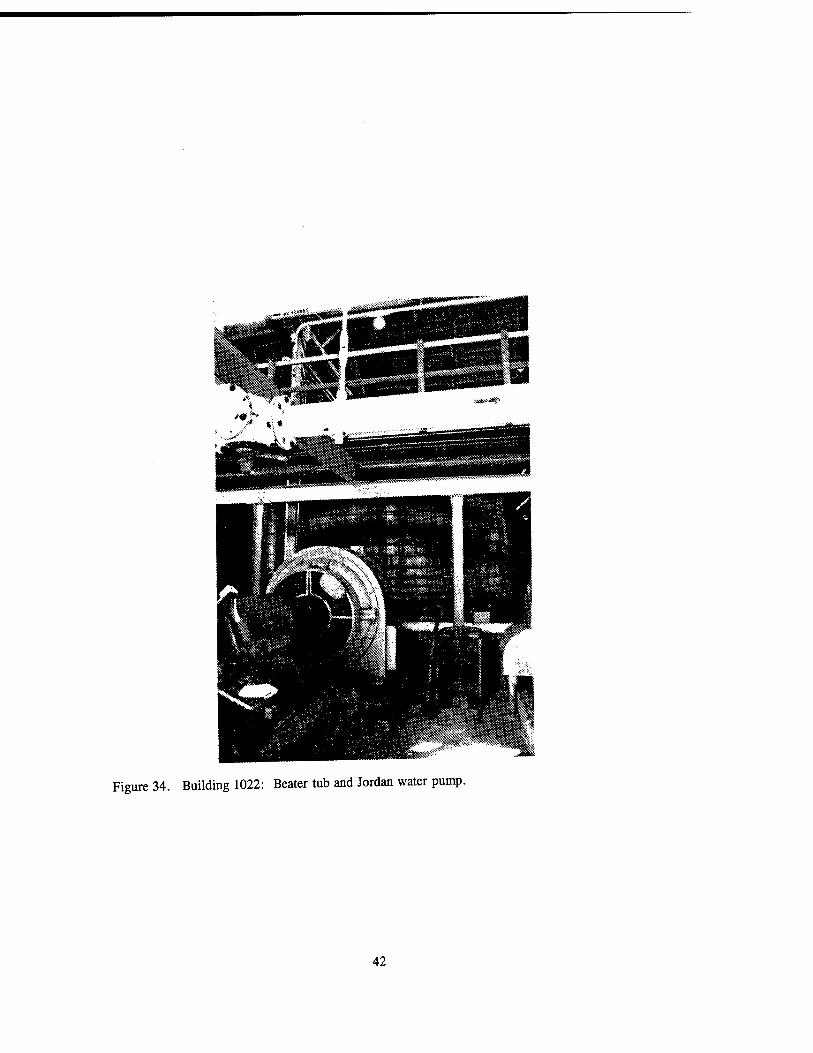
Figure 34. Building 1022: Beater tub and Jordan water pump.
42
ffifcg^Eggjg^i^l
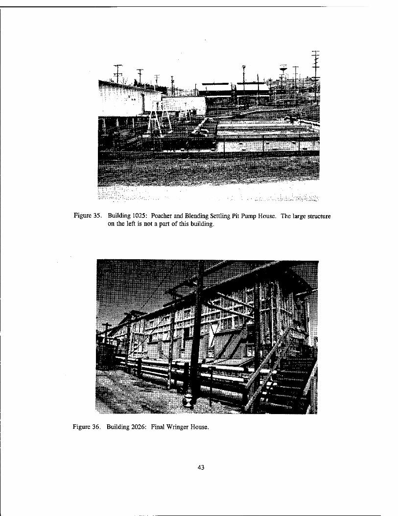
Figure 35. Building 1025: Poacher and Blending Settling Pit Pump House. The large structure on the left is not a part of this building.
Figure 36. Building 2026: Final Wringer House.
43
■JSSä? Nül
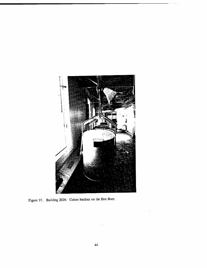
Figure 37. Building 2026: Cotton buckets on the first floor.
44

Figure 38. Building 2026: Chute from wringer on the first floor where cotton was dispensed and then received by the cotton buckets. Note the track on which the buckets were maneuvered.
45
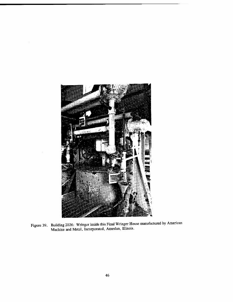
Figure 39. Building 2026: Wringer inside this Final Wringer House manufactured by American Machine and Metal, Incorporated, Ameslan, Illinois.
46

Figure 40. Building 7800: Extruded Grain Finishing House.
Figure 41. Building 3524: Chemical Grind House.
47

Figure 42. Building 713: Frick ammonia compressor in this Ammonia Compressor House.
48
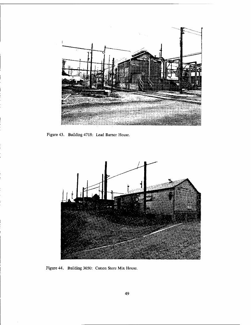
Figure 43. Building 4718: Lead Burner House.
Figure 44. Building 3650: Cotton Store Mix House.
49

Figure 45. Building 1702: Originally a Tray House for the "A" Finishing Area.
Figure 46. Building 1555: Activated Carbon and Recovery House.
50
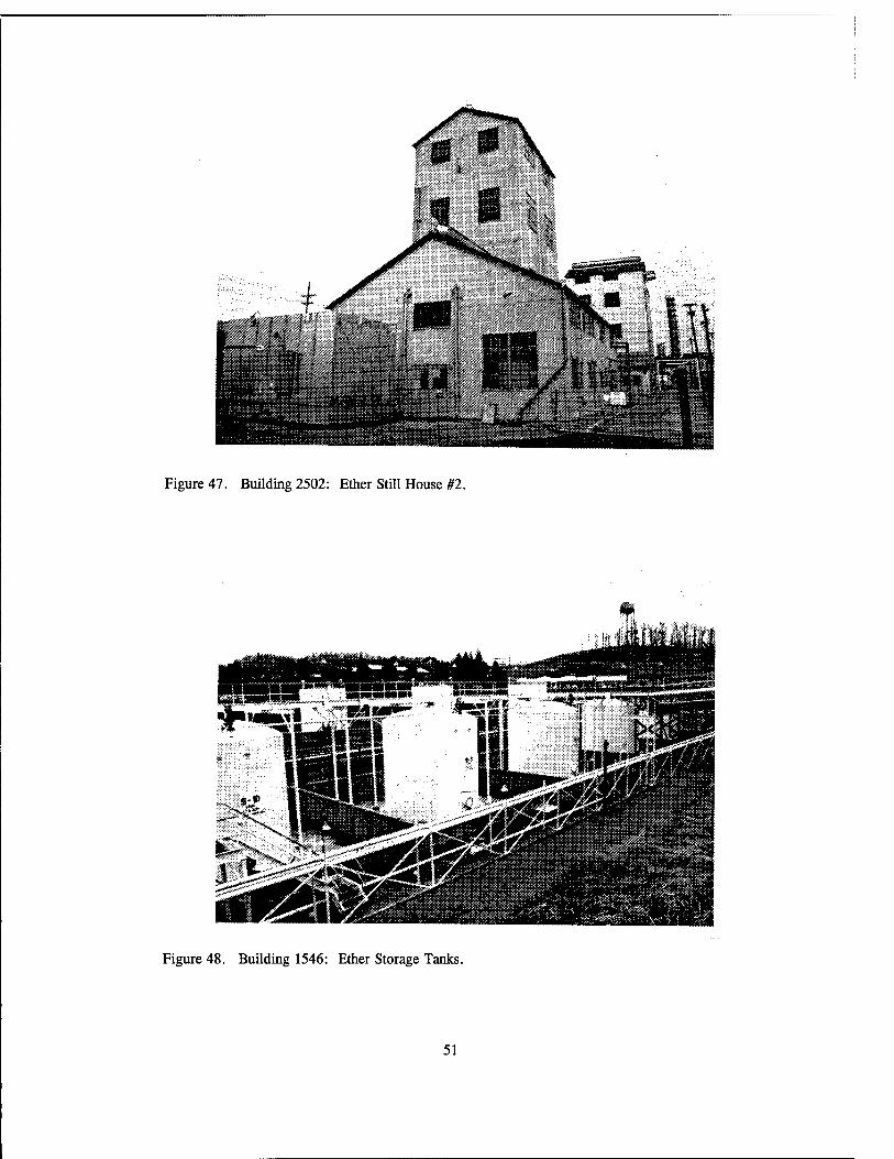
Figure 47. Building 2502: Ether Still House #2.
Figure 48. Building 1546: Ether Storage Tanks.
51

•***r**
Figure 49. Building 1002: Acid storage tanks at the Acid Mix and Weigh House.
Figure 50. Building 1500: Dehydration Press House.
52

Figure 51. Building 1500: Dehydration vertical press manufactured by Wood on the first floor.
53

Figure 52. Building 1501: Alcohol Pump and Accumulator House that served as the alcohol supply house for a Dehydration Press House.
54

Figure 53. Building 1501: Alcohol Accumulator Pump.
55

Figure 54. Building 1501: Alcohol accumulator counter manufactured by Watson-Stillman Company, Rosile, New Jersey, with the weight partially disassembled.
56

Figure 55. Building 1501: Heat reclaiming unit with temperature monitoring controls and a circulating pump with a 1.5 horsepower motor.
57
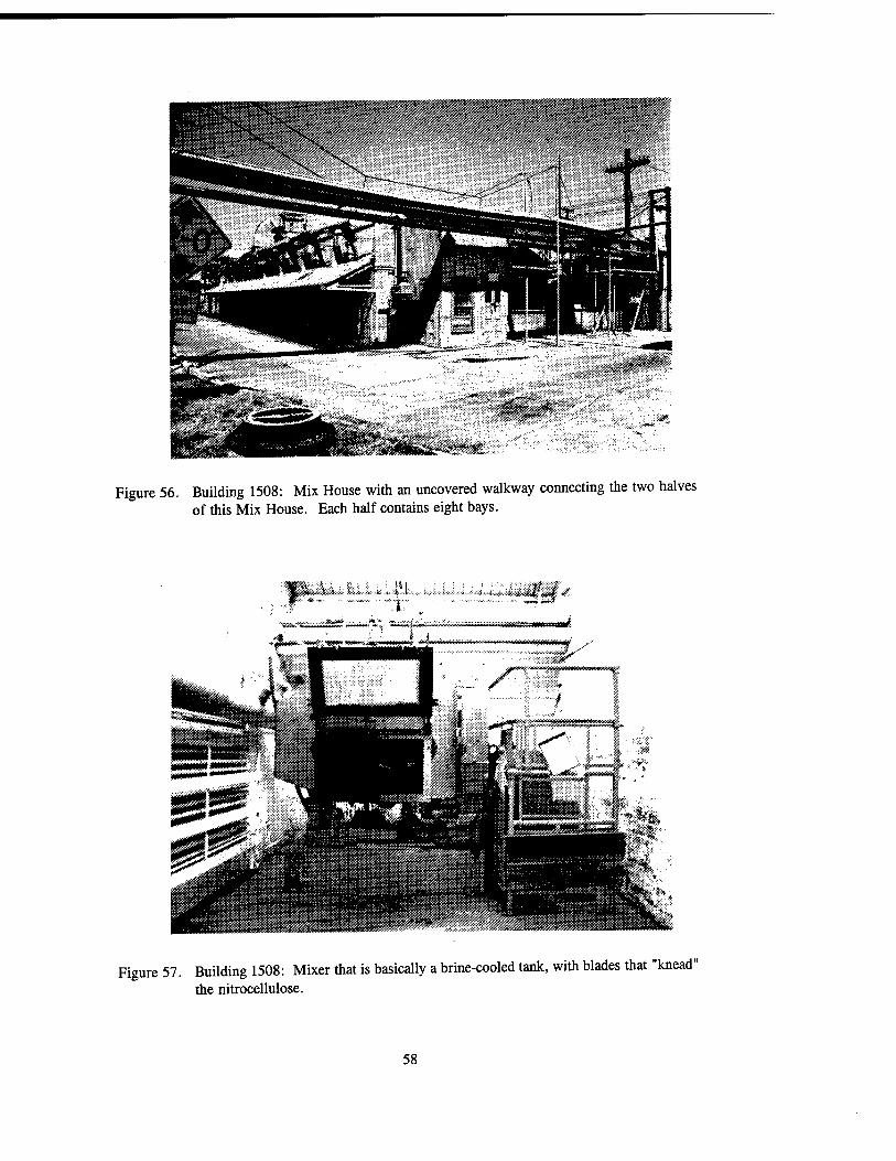
Figure 56. Building 1508: Mix House with an uncovered walkway connecting the two halves of this Mix House. Each half contains eight bays.
Figure 57. Building 1508: Mixer that is basically a brine-cooled tank, with blades that "knead" the nitrocellulose.
58

Figure 58. Building 1508: Macerator that improved the colloid consistency and reduced solvent evaporation.
Figure 59. Building 1506: Diphenylamine Mix House. Note the slides that provided a quick escape route in case of an explosion.
59

Figure 60. Building 1506B: Motor House of the Diphenylamine Mix House. This photograph is of two separate buildings; the building in the front contains the belts (upstairs and to the left) and motor (first level and to the right) that drove the mixer in the Diphenylamine Mix House.
60

Figure 61. Building 1506: Sprinkler Valve Houses are a common feature on many plant structures and serve as a source of fire suppression.
61

Figure 62. Building 1506: Diphenylamine (DPA) storage tank.
Figure 63. Building 1506: Pressure tank manufactured in 1945 by Staife of Oakmont, Pennsylvania.
62

Figure 64. Building 1506: Mix tank with scale in background.
63
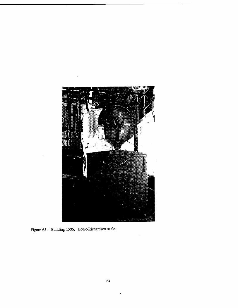
Figure 65. Building 1506: Howe-Richardson scale.
64

Figure 66. Building 1511: Block Press House.
Figure 67. Building 1511: Vertical blocking press by Farquar-York Company.
65

Figure 68. Building 1511: Another type of press used in this building.
66

Figure 69. Building 1511: High pressure valves for the macaroni machine.
Figure 70. Building 1561: Block Breaker House.
67
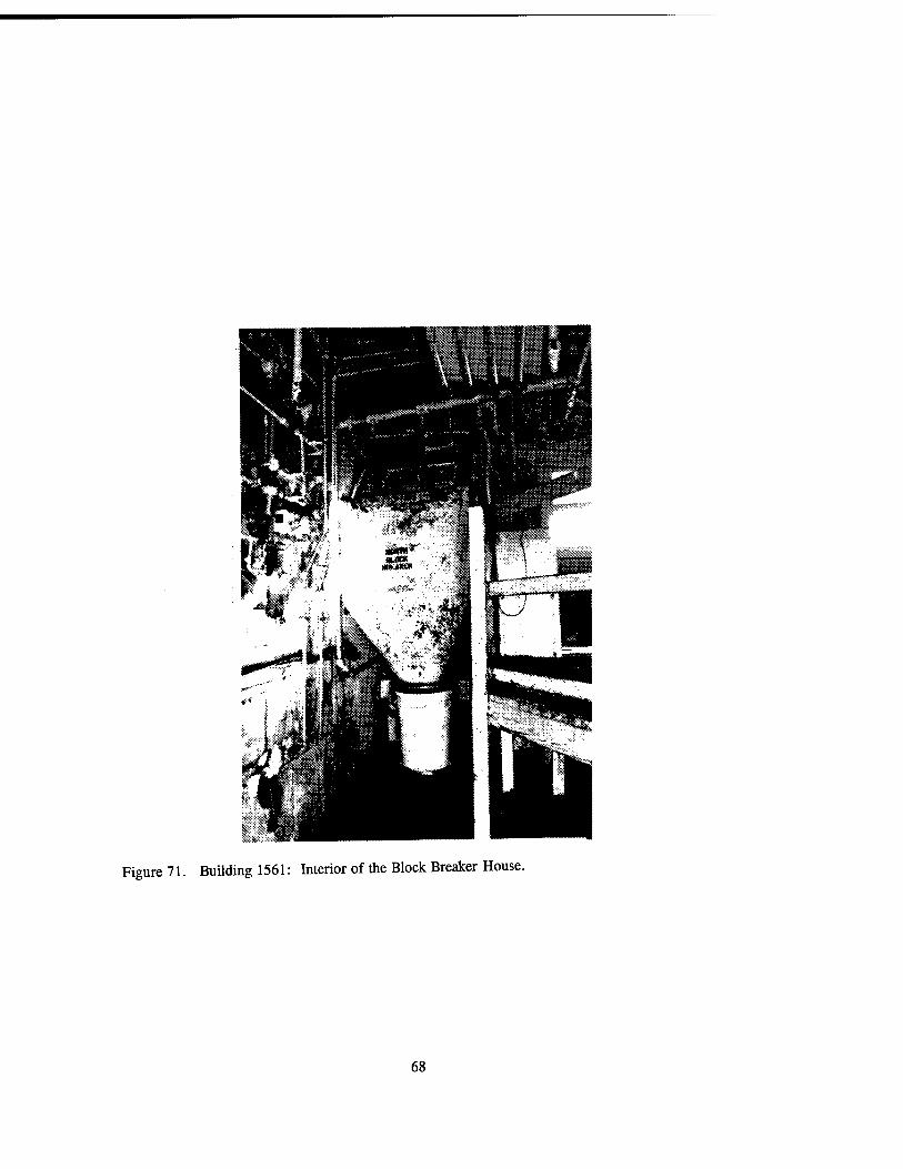
Figure 71. Building 1561: Interior of the Block Breaker House.
68

Figure 72. Building 1513: Finishing Press and Cutting House equipped with "blow" panels for explosions that also provided easy access to the machinery for repairs.
Figure 73. Building 5008-1: Fifteen-foot Press House where single-based powder blocks were pressed through extruding dies to form rocket propellant.
69

Figure 74. Building 5008-1: Hydraulic press for the production of rocket propellant.
f;-"».'*wr.-.-«i'i.*Vw- "»-1
Figure 75. Building 2518: East wing of a Finishing and Cutting House.
70
"V,;.~>*K^.V,-..V:Iä «,.'vV*^A'*.-..-
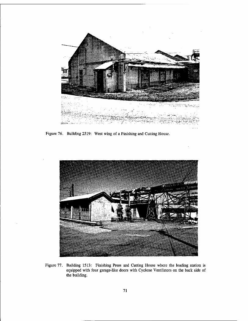
Figure 76. Building 2519: West wing of a Finishing and Cutting House.
Figure 77. Building 1513: Finishing Press and Cutting House where the loading station is equipped with four garage-like doors with Cyclone Ventilators on the back side of the building.
71
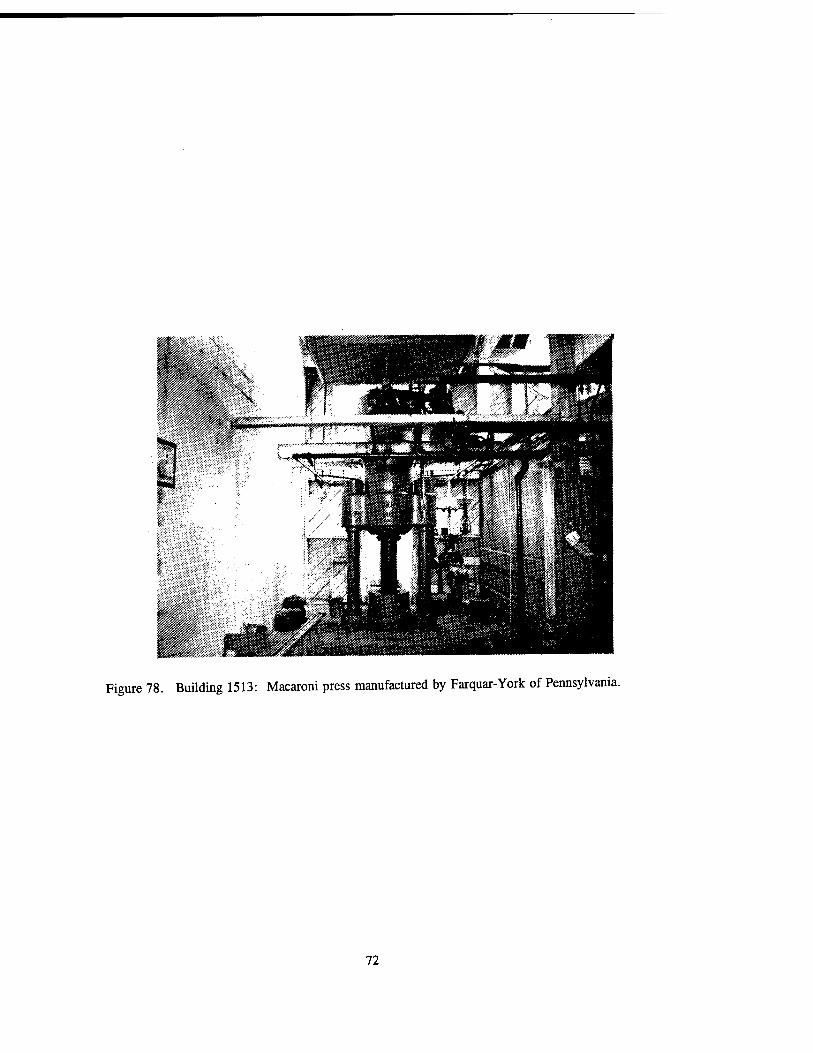
Figure 78. Building 1513: Macaroni press manufactured by Farquar-York of Pennsylvania.
72

Figure 79. Building 3553: Macaroni separators such as this one directed the extruded powder strands into buckets.
73

Figure 80. Building 1513: Macaroni separator without its cover.
Figure 81. Building 2519: Farquar-York horizontal press.
74

Figure 82. Building 1513: Cutting machine manufactured by McKieraan-Terry Company Manufacturing and Engineering, Dover, New Jersey.
Figure 83. Building 1513: Angle Buggy that was used to transfer powder. The buggy was lead lined and had hard rubber tires with metal spokes.
75

Figure 84. Building 5008-1: This McKiernan-Terry Company cutting machine was initially employed at the Sunflower Army Ammunition Plant.
76
m f /y Y/A
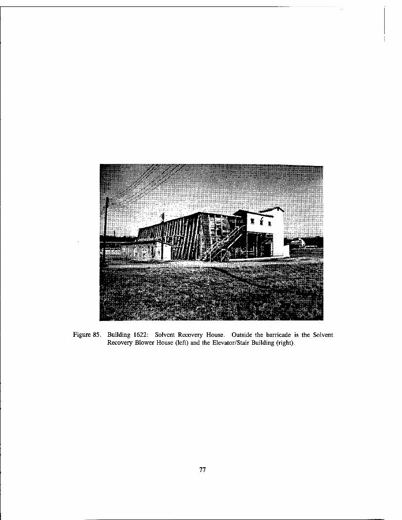
Figure 85. Building 1622: Solvent Recovery House. Outside the barricade is the Solvent Recovery Blower House (left) and the Elevator/Stair Building (right).
77
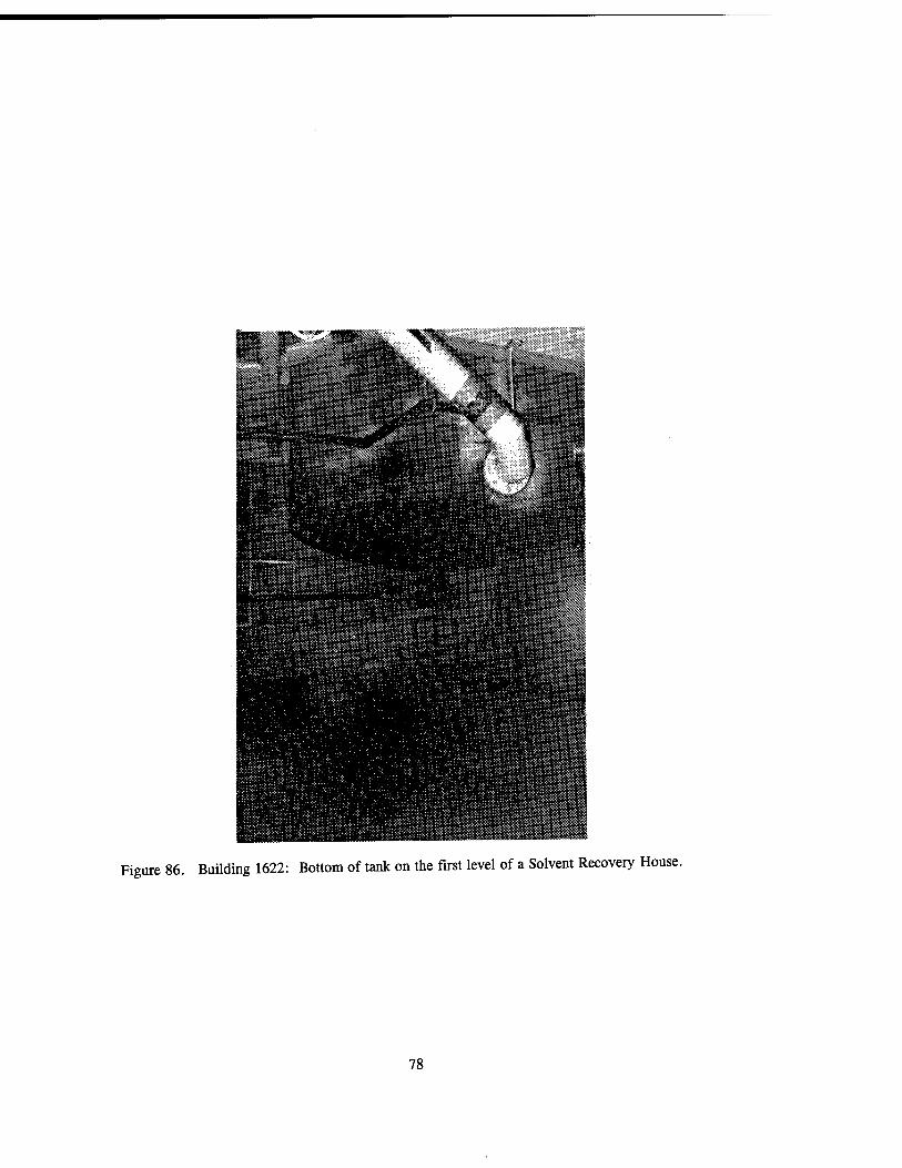
Figure 86. Building 1622: Bottom of tank on the first level of a Solvent Recovery House.
78
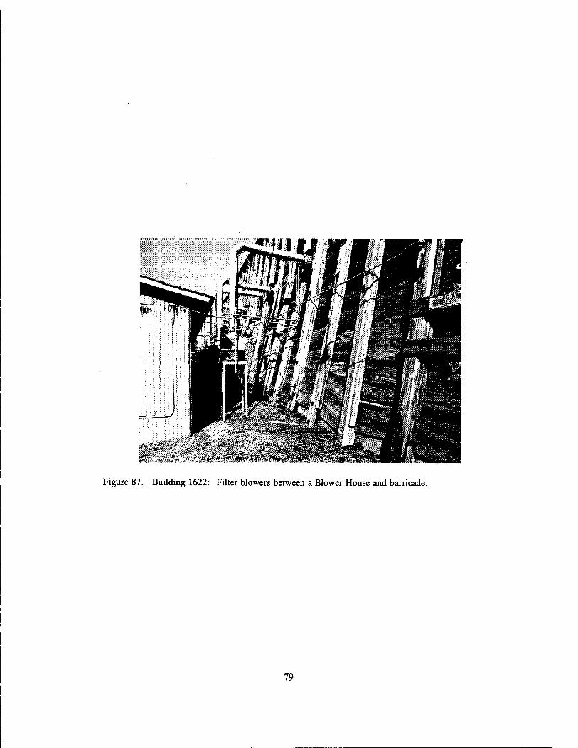
Figure 87. Building 1622: Filter blowers between a Blower House and barricade.
79
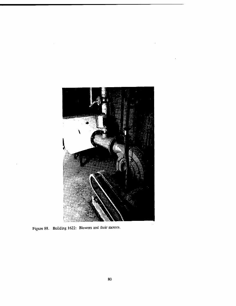
Figure 88. Building 1622: Blowers and their motors.
80

Figure 89. No Building Number: An example of a Solvent Recovery House without a barricade.
Figure 90. Building 4909-3: A different structural design of a Solvent Recovery House. A road runs between the barricaded Solvent Recovery House and its Elevator/Stair Building.
81

* ■?• •• . ■• ■■■■ \i
Figure 91. Building 4914: Originally, this building served as a Dust Collection House.
§Pti|i|iiyiilllii§ii|tiiP
Wi9^^^^S^mi
Figure 92. Building 1727: Dry Screen House.
82
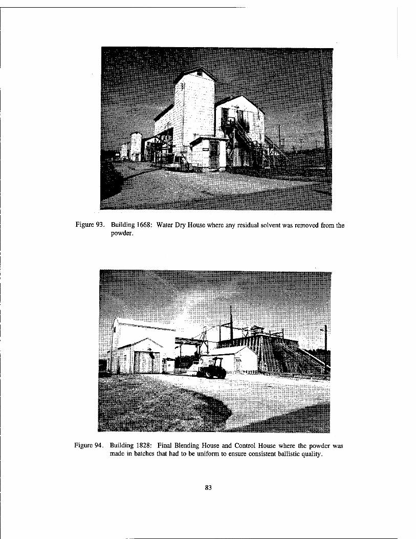
Figure 93. Building 1668: Water Dry House where any residual solvent was removed from the powder.
****** ** * * -" ***
SBäßJMj
•M:.\*"J:~:,<:'.;.' |
U^I^htB.. ]
Figure 94. Building 1828: Final Blending House and Control House where the powder was made in batches that had to be uniform to ensure consistent ballistic quality.
83

Figure 95. Building 1825 and Building 1875: The Final Blend House (foreground is Building 1825) is connected to the Can Pack House (Building 1875) by a conveyor system.
84

Figure 96. Building 1825: Chute-dump station on the third floor of this building where powder enters the blending process.
85

Figure 97. Building 1825: Blender on the first floor.
86

Figure 98. Building 1825: Cleveland worm gear reduction unit on the second floor.
Figure 99. Building 1825: The powder conveyor system on the first floor where buckets attached to this hanging rail system transferred powder from the Final Blend House to the Can Pack House.
87

?S^»W^
M||
Figure 100. Building 1875: Can Pack House.
88

Figure 101. Building 1875: Top of the powder chute on the third floor.
89

Figure 102. Building 1875: This first floor chute dispensed powder (transferred to the Can Pack third floor from the Final Blend House) which was then weighed and packed into cans.
90

Figure 103. Building 1875: On the first level, the empty powder containers were brought down the conveyor belt to the left, the cans were packed, and the filled cans traveled the conveyor belt to the right.
Figure 104. Building 4952-1: Coating barrel manufactured by Camden Copper Works, Camden, New Jersey, located in the Coating House.
91

Figure 105. Building 4952-1: Back of the coating barrel.
92

Figure 106. Building 4952-1: Toledo scale that was employed to weigh the correct amount of water that needed to be added to the coating barrels.
93
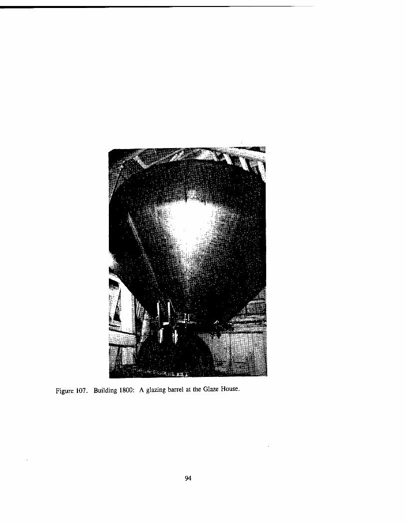
Figure 107. Building 1800: A glazing barrel at the Glaze House.
94

Figure 108. Building 1814: Ingersoll-Rand air compressor at the Blending and Glazing House.
95

Figure 109. Building 1814: Cyclone ventilation unit.
96

Figure 110. Building 1814B: Buggy Unloading and Control House for the Blending and Glazing House. This structure design is unique to Radford Army Ammunition Plant.
Figure 111. Building 9310-01: Rolled Powder Building of Rolled Powder Area #4 (RP4).
97
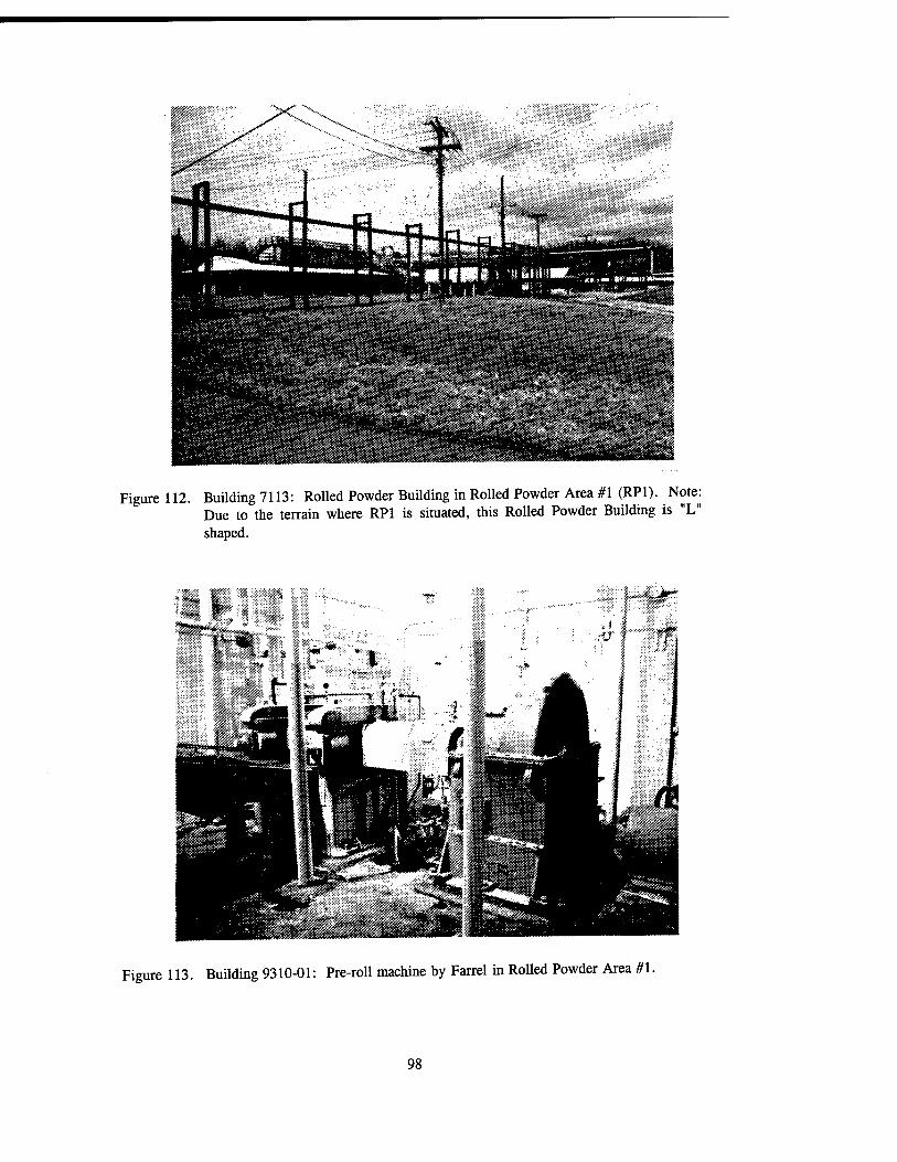
Figure 112. Building 7113: Rolled Powder Building in Rolled Powder Area #1 (RP1). Note: Due to the terrain where RP1 is situated, this Rolled Powder Building is "L" shaped.
Figure 113. Building 9310-01: Pre-roll machine by Farrel in Rolled Powder Area #1.
98
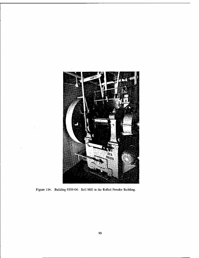
Figure 114. Building 9309-04: Roll Mill in the Rolled Powder Building.
99

Figure 115. Building 9309-04: Punch.
Figure 116. Building 9309-04: De-thread machine manufactured by Foote Brothers Gear and Machine Company.
100

Figure 117. Building 9309-04: This machine weighs the correct amount of powder into bags.
Figure 118. Building 9309-04: Adler sewing machine used to sew together sheets of powder.
101

Figure 119. Building 9309-04: Pinch press manufactured by Loshbough Jordan of Elkhart, Indiana.
102
Sil^£ft»isU
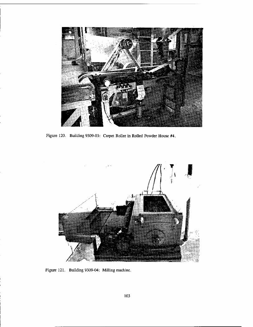
Figure 120. Building 9309-03: Carpet Roller in Rolled Powder House #4.
Figure 121. Building 9309-04: Milling machine.
103

Figure 122. Building 9309-04: Another view of this milling machine.
104

Figure 123. Building 9309-04: Sheet powder cutting machine on which propellant sheet stock was slit into strips and prepared into rolls.
Figure 124. Building 9309-03: Rolled Powder Building.
105

Figure 125. Building 1763: Barricaded Rest House.
106

Figure 126. Building 9309-03: Even speed or even mill machine.
107

Figure 127. Building 3713: Mobilization Storage.
Figure 128. Building 7124-02: Nibbling House with a blow-away panel on the roof.
108

Figure 129. Building 4912-01: Large Grain Holding House.
Figure 130. Building 4912-02: Small Grain Loading House.
109

Figure 131. Building 4924-02: Large Saw House with a barricade spanning one wall (the barricade behind the building is obscured).
Figure 132. Building 4924-6: Machine and Saw House with cinder block fire breaks not extending beyond the regular walls.
110

Figure 133. Building 4924-05: MK 90 Finishing Operations.
*r. , . V« U
Figure 134. Building 2924-1: Large Motor Load House.
Ill
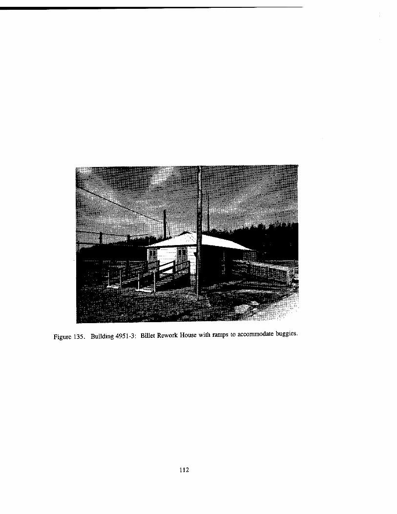
Figure 135. Building 4951-3: Billet Rework House with ramps to accommodate buggies.
112

SUPPORT FACILITIES FOR MANUFACTURING

''S!
Figure 136. Building 201: Propellant Lab.
Figure 137. Building 201 and Building 3562: Propellant Lab (right) and an Inert Storage Building (left), respectively.
115

Figure 138. Building 6401: Test House where ballistics were "tested" and flawed propellants were withheld; also notice the tar and chip berm on the far side of this building.
Figure 139. Building 203: Garage which has served as a data center in recent years.
116

Figure 140. Building 500: The Combined Shop where metal and woodworking took place. Devices were designed and manufactured here to meet OSHA safety laws that required safety cages, bars, and panels on much of the plant equipment.
117

Figure 141. Building 500: Ingersoll bridge metal machine located in the Machine Shop.
118

Figure 142. Building 500: A metal shaper manufactured between 1944-1947 by Atlas of Kalamazoo, Michigan, located in the Machine Shop.
119
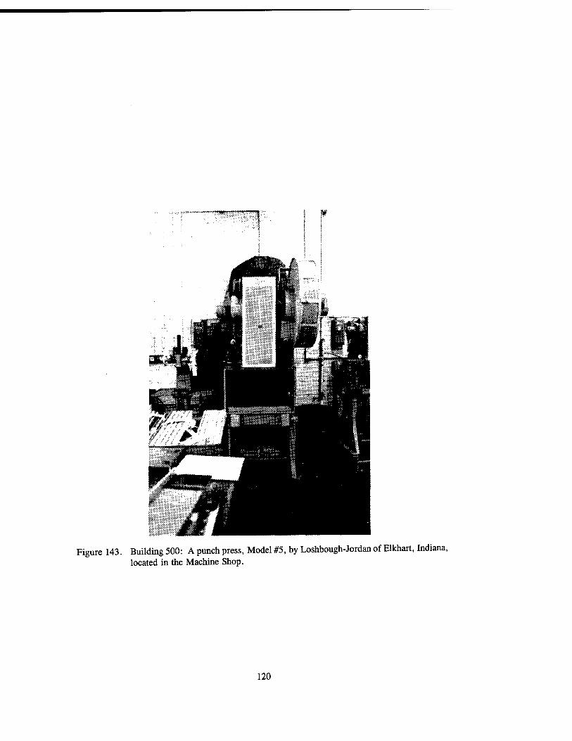
Figure 143. Building 500: A punch press, Model #5, by Loshbough-Jordan of Elkhart, Indiana, located in the Machine Shop.
120
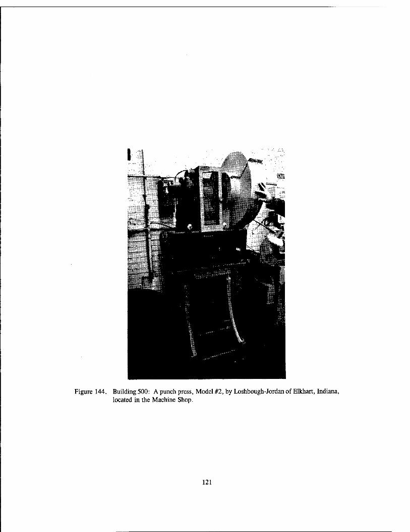
Figure 144. Building 500: A punch press, Model #2, by Loshbough-Jordan of Elkhart, Indiana, located in the Machine Shop.
121

Figure 145. Building 500: A Peerless metal saw located in the Machine Shop.
122

Figure 146. Building 500: A Turrat Model #3 by Warner and Swasen, Cleveland, Ohio, located in the Machine Shop.
123

Figure 147. Building 500: A Honing by Sunnen of Saint Louis, Missouri, located in the Machine Shop.
124
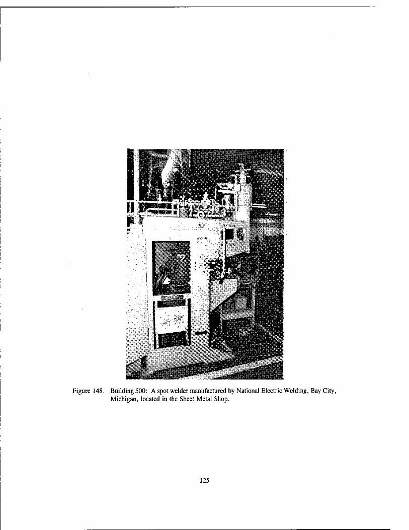
Figure 148. Building 500: A spot welder manufactured by National Electric Welding, Bay City, Michigan, located in the Sheet Metal Shop.
125

Figure 149. Building 500: A sheet metal press manufactured by Columbia Machinery and Engineering of Hamilton, Ohio, located in the Mill Right Shop.
126

Figure 150. Building 500: A drill press, Model #16, manufactured by Buffalo Machinery, Buffalo, New York, located in the Mill Right Shop.
127
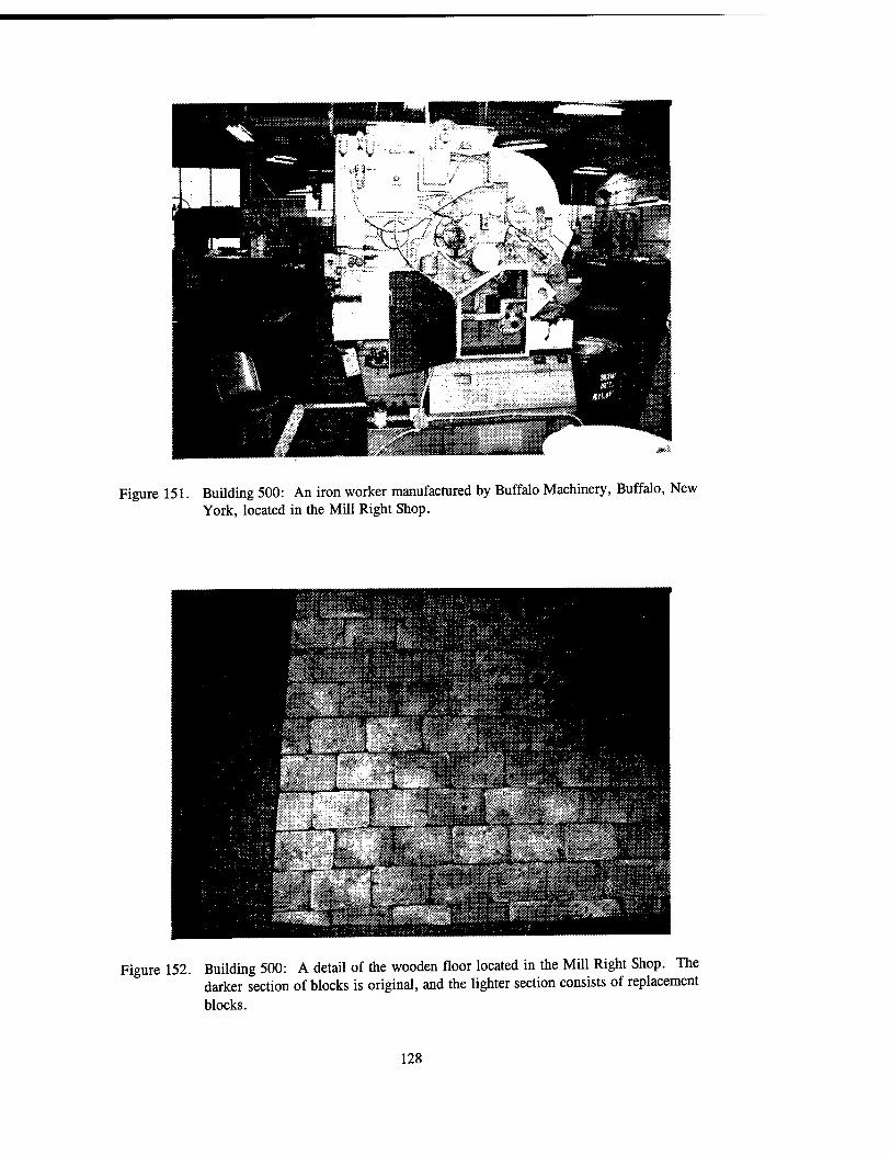
Figure 151. Building 500: An iron worker manufactured by Buffalo Machinery, Buffalo, New York, located in the Mill Right Shop.
Figure 152. Building 500: A detail of the wooden floor located in the Mill Right Shop. The darker section of blocks is original, and the lighter section consists of replacement blocks.
128

Figure 153. Building 500: A Landis pipe threading machine for six- to twelve-inch pipe, located in the Pipe Shop.
Figure 154. Building 500: A Marvel #9 pipe saw manufactured by Armstrong-Blum Manufacturing Co., Chicago, Illinois, located in the Pipe Shop.
129

Figure 155. Building 501: Locomotive Shop.
"3M*fc»* ....
Figure 156. Building 512: Line Crew Shop sided with asbestos and fiberglass.
130

Figure 157. Building 520: Weld Shop.
131

Figure 158. Building 520: An 800-pound, single-frame steam hammer manufactured in 1918 by Baldwin-Lima Hamilton.
132

Figure 159. Building 520: Interior view of the Weld Shop showing a forge manufactured by Champion Blower and Forge Company.
133

Figure 160. Building 225: Quonset Hut functioning as a Maintenance Shop.
Figure 161. Building 3727: This Maintenance Shop is currently used for storage.
134
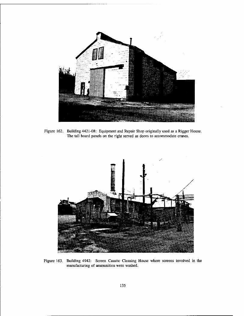
Figure 162. Building 4421-08: Equipment and Repair Shop originally used as a Rigger House. The tall board panels on the right served as doors to accommodate cranes.
Figure 163. Building 4942: Screen Caustic Cleaning House where screens involved in the manufacturing of ammunition were washed.
135

Figure 164. Building 4705-4: Singer sewing machine in the Laundry Building.
136
MIIÜllB
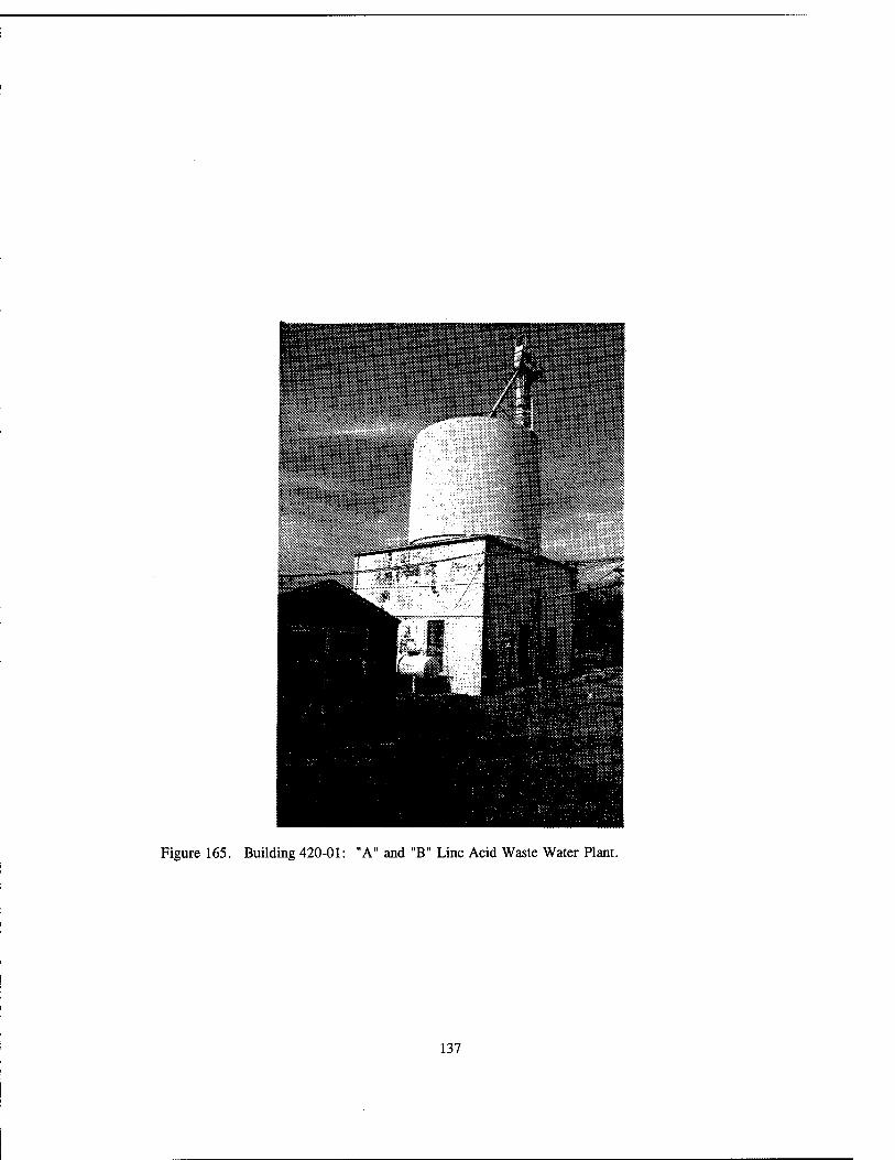
Figure 165. Building 420-01: "A" and "B" Line Acid Waste Water Plant.
137

Figure 166. Building 420-01: Auxiliary sludge pump.
138

Figure 167. Building 420-01: Slaker that separates water from solvents.
139

Figure 168. Building 420-01: Close-up of Slaker.
Figure 169. Building 919: Close-up of rail car scale.
140

SHIPPING AND STORAGE FACILITIES

fc»-- ':¥^l*
»^'•■■JifcA:üüa-s^Pi' ..;;33pp*r-. ^aL^ss^
Figure 170. Building 236: Storage/Workshop for the staff village recreation equipment.
Figure 171. Building 239: Storage Building connected to Building 213 by a modern addition.
143

mmwsms^^,!^^_fM
Figure 172. Building 519: Laboratory Storage with brick fire walls dividing the building into thirds to prevent an explosion and/or fire from spreading to the rest of the building.
Figure 173. Building 508: Salvage and Surplus Property Storage.
144
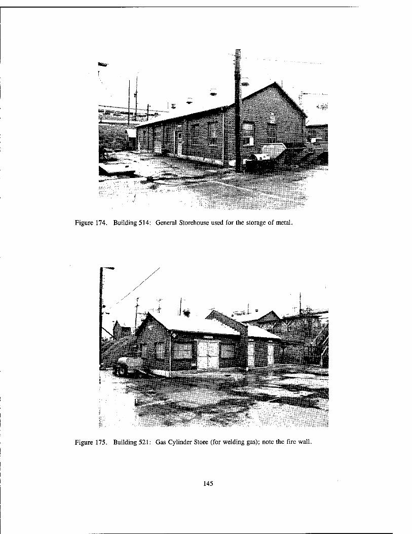
Figure 174. Building 514: General Storehouse used for the storage of metal.
Figure 175. Building 521: Gas Cylinder Store (for welding gas); note the fire wall.
145
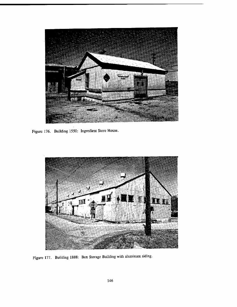
Figure 176. Building 1550: Ingredient Store House.
Figure 177. Building 1888: Box Storage Building with aluminum siding.
146
ü I*;
,•<»:•! IJjSfel**^!
_ju^B,«HH Ma***! .«sä»- »i- •**-"! it^:::>rf^ii *-.>Ü*S*i** ä.-.fw«:-'.'^**"1»'*'^'
'S:****'
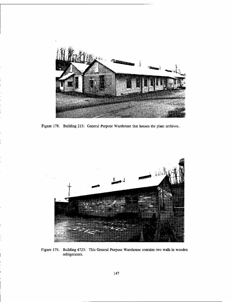
Figure 178. Building 213: General Purpose Warehouse that houses the plant archives.
Figure 179. Building 4723: This General Purpose Warehouse contains two walk-in wooden refrigerators.
147

pr]
Figure 180. Building 4723: Refrigerator by Hill Cold Storage, Trenton, New Jersey.
/% ***" i>y "\-Ä«i?
Figure 181. Building 9387-1: Cinder Block Warehouse.
148

ÜÄÜi
riHWi
Figure 182. Building 1107: Igloo Storage Magazine with a ventilator extending up from the back of this earthen-covered structure.
Figure 183. Building 1918: Igloo, or a subterranean magazine, with an earth-backed cement barricade situated in front of the igloo's entrance.
149

Figure 184. Building 4603-32: Richmond Magazine.
^m
Figure 185. Building 225: Smokeless Powder Magazine.
150
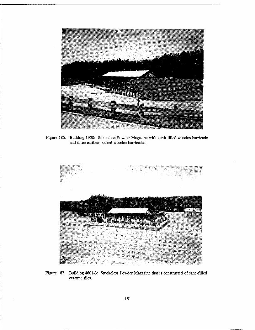
Figure 186. Building 1958: Smokeless Powder Magazine with earth-filled wooden barricade and three earthen-backed wooden barricades.
Figure 187. Building 4601-3: Smokeless Powder Magazine that is constructed of sand-filled ceramic tiles.
151

Figure 188. Building 2244: Ballistic Primer Magazine.
152

<•*" s* y >T sat**. *V>TM7"$S»sä
Figure 189. Building 7503: Magazine with an earthen barrier and earth-filled wooden barricade.
/
Figure 190. Building 226: Tire Storage Shed with aluminum siding.
153

Figure 191. Building 505: Lumber and Pipe Shed with aluminum siding.
Figure 192. Building 600: Equipment Shed currently storing modern equipment.
154

SUPPORT FACILITIES FOR EMPLOYEES

Figure 193. Building 200: Entitled "General Instruction Building," the building has four wings to serve different functions, e.g., General Purpose Administration, General Purpose Warehouse, and Change House.
ir"?!**
j; r »^"-- $ ^""^Ä"
K_- .• ->«•.»?. v**t «■V ■■ "A ■'-"*'%':?■ *" ,.i!.'~r:*--*:!iX....i*l^ -■•,?■
»■s:,-! rn«ffi:;;s!!iiiL"-(-:;ij
Figure 194. Building 200: This is wing #1 of Building 200 and the remainder of the wings have the same design and dimensions.
157

Figure 195. Building 222: Change House.
Figure 196. Building 227: Brick Change House.
158

Figure 197. Building 1515: Two-story cinder block Change House.
"1' /?:F - .vv^^-'sf::'y,;-y".'-i'i'--
■**!!?•■*' ' : "■*. -^*L ■%.«?'*.,:-:?;"JJia.vsL ' - ? """ .«>.»■*■ V« ■* T-* : ■*-_ ■■ %:'%it- \CK:' ■■'£■■■■,"■■ .7*.
,... i >-* 3•' &■*-&&£**&&&
Figure 198. Building 3718: Change House.
159

8»i-.pi':>*i
Figure 199. Building 3717 and Building 3716: These two Change Houses are connected.
Figure 200. Building 4728: Cinder Block Change House.
160

Figure 201. Building 7808: Change House for males.
Figure 202. Building 7809: Change House for females.
161

Figure 203. Building 9361-03: Cinder block Change House.
Figure 204. Building 4339: Latrine that consists of two stalls, flush toilets, sink, and mirror.
162
■ ^
\3Q : ^.jgaä^SSäiiä^St.
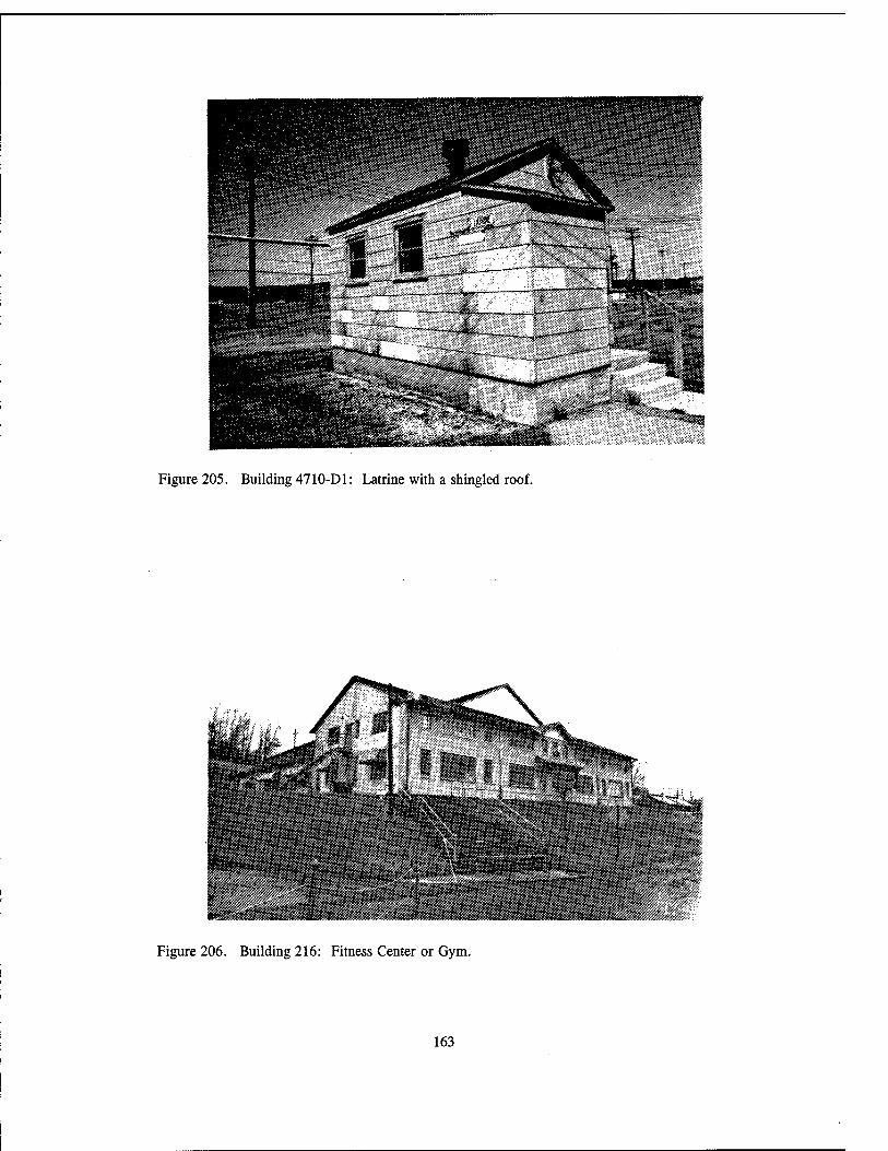
Figure 205. Building 4710-D1: Latrine with a shingled roof.
i*«y.*..
i-OI _M
Figure 206. Building 216: Fitness Center or Gym.
163

t M«:
ÜÄITS
Figure 207. Building 216: West side of the gym.
Figure 208. Building 234: Cafeteria.
164

UTILITIES AND INFRASTRUCTURES

i Mill
Figure 209. Building 197: Incinerator Building.
Figure 210. Building 205: Hospital/Clinic with beds.
167

Figure 211. Building 263: Telephone Building.
Figure 212. Building 263: Interior view of the Central Office showing a switchboard manufactured by Automatic Electric, Chicago, Illinois.
168
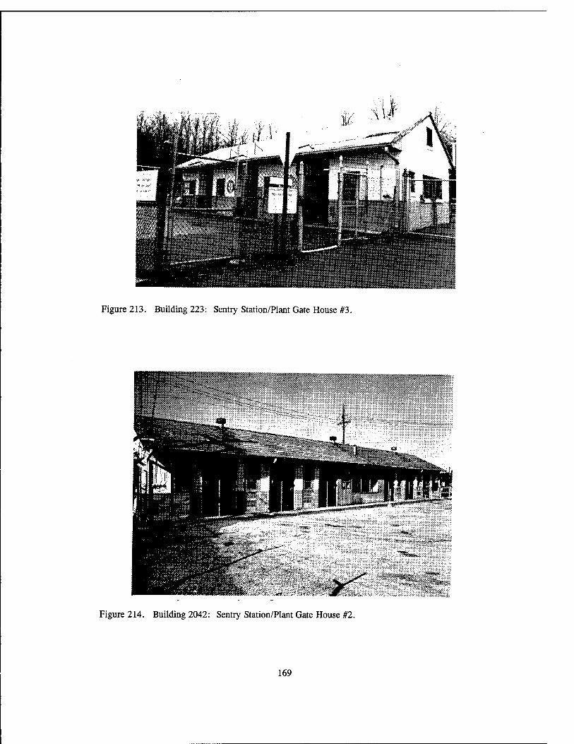
Figure 213. Building 223: Sentry Station/Plant Gate House #3.
Figure 214. Building 2042: Sentry Station/Plant Gate House #2.
169

Figure 215. Building 221-5: Sentry House.
170
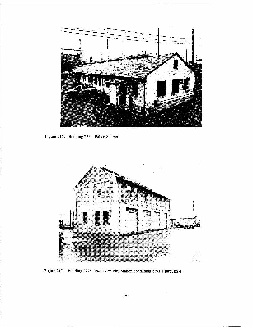
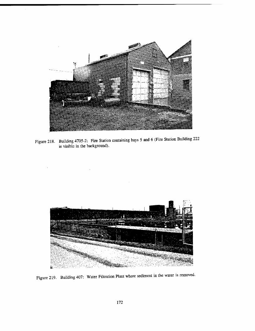
Figure 216. Building 235: Police Station.
Figure 217. Building 222: Two-story Fire Station containing bays 1 through 4.
171
jFy:
Jtf\
N m ***>*m
I Wf$ \
■■'^-"■■-^■;■•. ■■■: ;-, ;\?S3ßmmm
(BE»« K^h^;Ss«SiV.^*::ft^5i. i'&rifiS*»*
Figure 218. Building 4705-2: Fire Station containing bays 5 and 6 (Fire Station Building 222 is visible in the background).
Figure 219. Building 407: Water Filtration Plant where sediment in the water is removed.
172
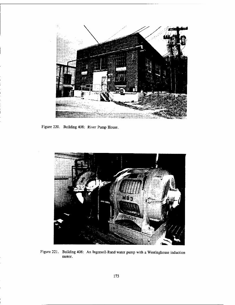
Figure 220. Building 408: River Pump House.
Figure 221. Building 408: An Ingersoll-Rand water pump with a Westinghouse induction motor.
173
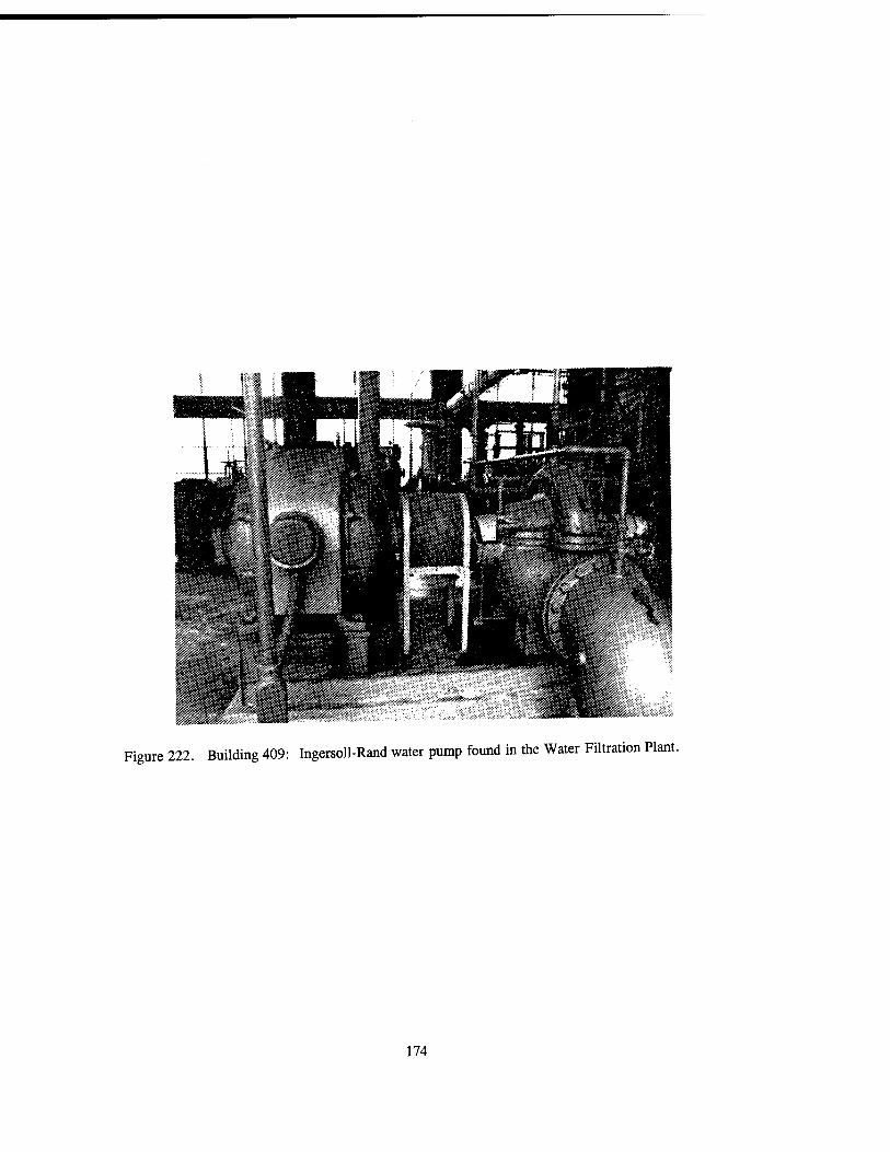
Figure 222. Building 409: Ingersoll-Rand water pump found in the Water Filtration Plant.
174

Figure 223. Building 409: Pumps in the River Pump House.
175

Figure 224. Building 409: Pumps at the Water Filtration Plant.
Figure 225. Building 409: Back washing filters by Ingersoll-Rand Company.
176

Figure 226. Building 1908: This wooden water pipe section with a 15- to 16-inch diameter was recovered from between buildings 407 and 409 and is believed to have carried water from the New River to the Water Pump House.
Figure 227. Building 419: Drinking Water Plant with original wooden water tanks.
177

Figure 228. Building 419: Wash water pumps.
178

Figure 229. Building 419: Water pump with a relatively modern motor in the background.
179

Figure 230. Building 419: Dry chemical feeder for carbon tanks that was manufactured by Wallace and Tiernan Company, Newark, New Jersey.
180

Figure 231. Building 419: Carbon Tank.
181

Figure 232. Building 710: Sewage Treatment Building.
182
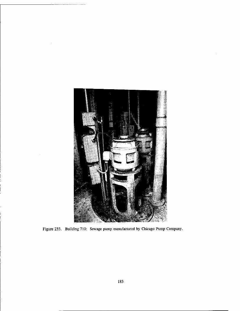
Figure 233. Building 710: Sewage pump manufactured by Chicago Pump Company.
183

«VI* ; ■ ■'■•y-<i »'
Figure 234. Building 926: Magazine Area's 12-inch well with pump house
184
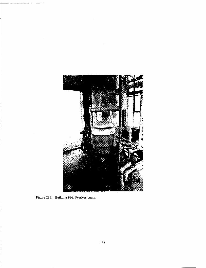
Figure 235. Building 926: Peerless pump.
185

Figure 236. Building 1521A: Chilled Water Pump House.
Figure 237. Building 1521A: Ingersoll-Rand chilled water circulating pump and motor.
186

lap
Figure 238. Building 1521: Low pressure centrifugal pump manufactured by Westinghouse and Worthington.
Figure 239. Building 1521: Worthington 120, high pressure piston pump and motor.
187

Figure 240. Building 1521: High pressure hydraulic tank (reservoir).
188

Figure 241. Building 1521: Lead-lined wooden water filter tank where the water level is monitored by floats.
189

Figure 242. Building 1521: Low pressure hydraulic tank reservoir for hydraulic oil.
190

Figure 243. Building 9354: Worthington compressor at this Compressor House.
191

<iä ä fei
Figure 244. Building 400: Main Power Plant where power is provided by coal, which supplies the entire plant.
Figure 245. Building 400: Detail of the masonry of the Main Power Plant.
192
'.. —EiÄKiti
Figure 246. Building 400: The back side of the Main Power Plant is obscured by modern equipment.
193
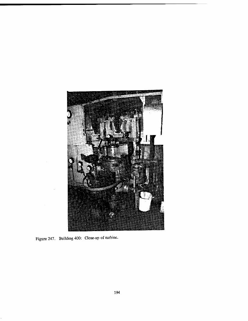
Figure 247. Building 400: Close-up of turbine.
194
jgjJL
Figure 248. Building 1013: Fume Exhaust and Recovery for the Main Power Plant.
195

f::»r:* «<*«:*. ■:.«!«;
us!
Figure 249. Building 4329: Power House #2.
196

Figure 250. Building 4329: Ash silos where coal ash was collected and stored in these silos while waiting for removal.
197

"ä
Figure 251. Building 4329: A ceramic coal silo (on the right), a steel coal silo (on the left), and a coal elevator.
198

Jliüiü-i&j.-.-i;.;:. ■.•■
*j£***'*** ***** t ** *
Figure 252. Building 700: Air Compressor House.
Figure 253. Building 700: Exciter motor that converts DC to AC for the air compressor's control panel.
199
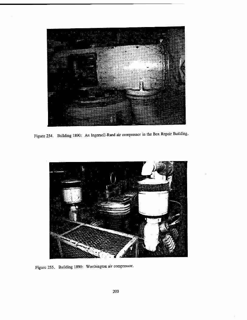
Figure 254. Building 1890: An Ingersoll-Rand air compressor in the Box Repair Building.
Figure 255. Building 1890: Worthington air compressor.
200
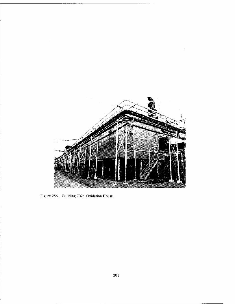
Figure 256. Building 702: Oxidation House.
201

Figure 257. Building 702: Fairbanks-Morse Springless scale.
202
*■«■ ■ - ■"T',m:E
Figure 258. Building 702: Control Panel.
203

REFERENCES CITED
Greer, M. n.d. Process Description: Single Base Propellant Manufacturing Area. Indiana Army Ammunition
Plant, Charleston, Indiana.
MacDonald and Mack Partnership 1984 Historic Properties Report: Radford Army Ammunition Plant (Including the New River Unit)
Radford, Virginia. Prepared for the Historic American Buildings Survey/Historic Engineering Record, the National Park Service, and the U.S. Department of the Interior.
Thomson, H., and L. Mayo 1991 United States Army in World War II: The Technical Services: The Ordnance Department
Procurement and Supply. Center of Military History, United States Army, Washington, D.C.
205

APPENDIX A
PHOTOGRAPHIC DATA SHEETS

Page: 1
Project #: 1114-014 AMC Task C
Installation: Radford Army Ammunition Plant
GEO-HARINE INC.
PHOTOGRAPHIC DATA SHEET
Exp.
No. Building No(s). Description
Film: Kodak THAX black and white
Roll Number: 1
Dir. Date Recorder
10
11
12
13
14
15
16
17
18
19
200
200
263
203
203
215
216
216
213
239
4723
4723
207
206
236
General Instruction Building with four wings
containing: General Purpose Administration, Change
House, and General Purpose Warehouse, north front east side
Wing 1 of the General Instruction Building followed by
wings 2, 3, & 4 (the building is in disuse except for media services), south back and west side
Telephone Building (currently utilized), south back and west side
Garage, currently serves as a data center, north front and west side
Air conditioner, dated 1964, on the south side of the Data Center/Garage
General Purpose Administration Building, west front and north side
Fitness Center or Gym, north front and east side
West side of Gym
General Purpose Warehouse with wings, formerly housed Plant Archives, north front and east side
Storage Building connected to the General Purpose
Warehouse (Building 213) by a modern extension, south back and west side
General Purpose Warehouse, contains two walk-in,
wooden, refrigerators, north front and east side
General Purpose Warehouse: Refrigerator by Hill Cold
Storage of Trenton, N.J., (model JJ5258 94229 S11400) (RFA10094)
Single story Barracks, south back east side
Two story Barracks, south back and west side
Storage/Workshop for the Staff Villages recreation equipment, south back and west side
SW 03/21/94 Hiatt
NE 03/21/94 Hiatt
NE 03/21/94 Hiatt
SE 03/21/94 Hiatt
03/21/94 Hiatt
SE 03/21/94 Hiatt
SW 03/21/94 Hiatt
N 03/21/94 Hiatt
SW 03/21/94 Hiatt
NE 03/21/94 Hiatt
03/21/94 Hiatt
W 03/21/94 Hiatt
NW 03/21/94 Hiatt
NE 03/21/94 Hiatt
NE 03/21/94 Hiatt

Page: 2
Project #: 1114-014 AMC Task C
Installation: Radford Army Ammunition Plant
CEO-MARINE INC.
PHOTOGRAPHIC DATA SHEET
Exp. No. Building No(s).
28
29
30
31
32
33
34
35
Description
Film: Kodak TMAX black and white
Roll Number: 1
Dir. Date Recorder
20 229
21 229
22 235
23 234
24 205
25 201
26 519
27 201 & 3562
227
4728
222
4705-2
500
505
512
400
Interior Courtyard, rumored to have been built around a
grave (Montgomery 1860's)
Admininstration Building where credit union was housed,
currently used by Safety Office, east front and south
side
Police Station, east front and south side
Cafeteria (currently in use), west back and south side
Hospital/Clinic with beds, east front and south side
Propellent Laboratory, east back and south side
Laboratory Storage building with red brick firewalls
dividing the building into thirds, east front and south
side
Propellant Laboratory (#201 - background) and Inert
Storage Building (#3562 - foreground), east front and
south side
Brick Change House, east front and south side
Cinder Block Change House with Building 227 in the
background, east and south sides
Two Story Fire Station containing bays 1 through 4,
south front and west side
Fire Station containing Bays 5 through 6 (with Building
222 in background), south front and west side
Combined Shop for metal and wood working, south back
and east side
Lumber and Pipe Shed with aluminum siding, south back
and west side
Line Crew Shop sided with fiberglass and asbestos,
south front and east side
Main Power Plant, (power is generated from coal and
supplies the entire plant), north front and west side
NU 03/21/94 Hiatt
NU 03/21/94 Hiatt
NU 03/21/94 Hiatt
NE 03/21/94 Hiatt
NU 03/21/94 Hiatt
NU 03/21/94 Hiatt
NU 03/21/94 Hiatt
NU 03/21/94 Hiatt
NU 03/21/94 Hiatt
NU 03/21/94 Hiatt
NE 03/21/94 Hiatt
NE 03/21/94 Hiatt
NU 03/21/94 Hiatt
NE 03/21/94 Hiatt
NU 03/21/94 Hiatt
SE 03/21/94 Hiatt
Pa9e: 3 GEO-MARINE INC. PHOTOGRAPHIC DATA SHEET
Project #: 1114-014 AMC Task C FUm: Kodak TMAX black ^ ^He
Installation: Radford Army Ammunition Plant Roll Number: 1
Exp.
No. Building No(s). Description 0jr. Date Recorder
36 400 "«in Power Plant, detail of masonry, south back and NE 03/21/94 Hiatt west side
37 508 Salvage and Surplus Property Building 03/21/94 Hiatt

Page: 1
Project #: 1114-014 AMC Task C
Installation: Radford Army Ammunition Plant
GEO-NARINE INC.
PHOTOGRAPHIC DATA SHEET
Film: Kodak TMAX black and white
Roll Number: 2
Exp. No. Building No(s). Description Dir. Date Recorder
1 500
2 500
3 500
4 500
5 500
6 500
7 500
8 500
9 500
10 500
11 500
12 500
13 500
14 500
15 500
16 520
Machine Shop: Bridge metal machine by Ingersol (RFA
668) (serial #16900)
Machine Shop: Metal shaper by Atlas of Kalamazoo, MI
1944-1947 (model 7B) (RFA 12178)
Machine Shop: Punch Press by Loshbough-Jordan of
Ekhart, IN (model #5) (RFA611)
Machine shop: Punch press by Loshbough-Jordan of
Ekhart, IN (model #5) (RFA611)
Machine Shop: Punch Press by Loshbough-Jordan of
Ekhart, IN (model #2) (RFA 102183)
Machine Shop: Metal Saw by Peerless (RFA 613)
Machine Shop: Metal Saw by Peerless (RFA 613)
Machine Shop: Turret by Warner and Swasen of Clevland,
OH (model #3)(RFA 595)
Machine Shop: Honing by Sunnen of St. Louis, MO (RFA
599)
Sheet Metal Shop: Spot welder by National Electric
welding of Bay City, MI (RFA 11640)
Mill Right Shop: Sheet metal press by Columbia
Machinery & Engineering of Hamilton, OH (RFA 11752)
Hill Right Shop: Drill press by Buffalo Machinery of
Buffalo, NY (model #16) (RFA 619)
Mill Right Shop: Drill press by Buffalos Machinery of
Buffalo, NY (model #16) (RFA 619)
Mill Right Shop: Iron worker by Buffalo Machinery of
Buffalo, NY (RFA 11661)
Mill Right Shop: detail of wood floor. Darker blocks
are original and lighter blocks are replacements.
Weld Shop: An 8001b., single frame, 1918 Steam Hammer
by Baldwin-Lima-Hamilton (RFA 702)
03/21/94 Hiatt
03/21/94 Hiatt
03/21/94 Hiatt
03/21/94 Hiatt
03/21/94 Hiatt
03/21/94 Hiatt
03/21/94 Hiatt
03/21/94 Hiatt
03/21/94 Hiatt
03/21/94 Hiatt
03/21/94 Hiatt
03/21/94 Hiatt
03/21/94 Hiatt
03/21/94 Hiatt
03/21/94 Hiatt
03/21/94 Hiatt

Page: 2
Project #: 1114-014 AMC Task C
Installation: Radford Army Ammunition Plant
GEO-KARINE INC.
PHOTOGRAPHIC DATA SHEET
Film: Kodak TMAX black and white
Roll Number: 2
Exp.
No. Building No(s). Description Dir. Date Recorder
17
18
19
20
25
26
27
28
520
500
500
514
21 520
22 521
23 700
24 700
700
700
700
226
29 225
30 225
31 225
32 3718
33 223
Weld Shop: Forge by Champion Blower and Forge Company (RFA 10262)
Pipe Shop: Landis threading machine for 6 to 12 inch pipe (RFA 623)
Pipe Shop: Marvel #9 Pipe Saw by Armstrong-Blum
Manufacturing Company of Chicago, IL (RFA 617)
General Storehouse used for metal storage, east front and north side
Weld Shop, north front and west side
Gas Cylinder Store (for welding gas), note the firewall, west front and north side
Air Compressor House, west front and south side
Air Compressor House: 1940 Ingersol-Rand Air Compressor (model 1210-HM-2) (REA 738)
Air Compressor House: Ingersol-Rand Air Compressor (model 1010-HM-2)
Air Compressor House: Control panel for air compressors #6 and «8 (GE RFA 15568)
Air Compressor House: Exciter Motor that converts DC to
AC for the air compressor control panel
Tire Storage Shed with aluminum siding, west front and north side
Smokeless Powder Magazine, north side
Smokeless Powder Magazine, north side
Smokeless Powder Magazine: Exterior of barricade wall, north front and west side
Change House, south front and east side
Sentry Station/Plant Gate House #3, north back and east side
03/21/94 Hiatt
03/21/94 Hiatt
03/21/94 Hiatt
SU 03/21/94 Hiatt
SE 03/21/94 Hiatt
SE 03/21/94 Hiatt
NE 03/21/94 Hiatt
03/21/94 Hiatt
03/21/94 Hiatt
03/21/94 Hiatt
03/21/94 Hiatt
SE 03/21/94 Hiatt
03/21/94 Hiatt
03/21/94 Hiatt
SE 03/21/94 Hiatt
NU 03/21/94 Hiatt
03/21/94 Hiatt

Page: 3
Project #: 1114-014 AMC Task C
Installation: Radford Army Ammunition Plant
GEO-MARINE INC.
PHOTOGRAPHIC DATA SHEET
Exp.
No. Building No(s). Description
34 3716 & 3717
35 7808
36 7809
Film: Kodak TMAX black and white
Roll Number: 2
Dir. Date Recorder
Two, connected Change Houses, south back
Change House for men, east front
Change House for Women, east front and north side
03/21/94 Hiatt
03/21/94 Hiatt
SW 03/21/94 Hiatt

Page: 1
Project #: 11K-0U AHC Task C
Installation: Radford Army Ammunition Plant
GEO-MARINE INC.
PHOTOGRAPHIC DATA SHEET
Exp.
No. Building No(s).
3
4
5
6
8
9
10
Description
Film: Kodak TMAX black and white
Roll Number: 3
Dir. Date Recorder
0 1007
2 1012
1014
1012
1012
1012
1012
1012
1012
1012
11 1012
12 1012
13 1012
14 1012
15 1012
16 1012
17 1010
Acid Screening House, north front and west side
Four story, brick, Nitrating House (currently on stand
by), south back and west side
Emergency Catch House, north front and west side
Nitrating House, first floor: Nitrating equipment &
buckets for collection
Nitrating House, second floor: Wringer
Nitrating House, second floor: Wooden propeller fan
with motor, looking north to outside
Nitrating House, second floor: Wooden propeller fan
with motor, inside looking south
Nitrating House, third floor: Nitrating Acid Tank
Nitrating House, third floor: Dipping pot for cotton
where cotton was mixed with acid
Nitrating House, third floor: Cyclone cotton hopper
where cotton from the Dry Cotton conveyor was received.
Nitrating House, third floor: Cotton Scale
Nitrating House, third floor: Cotton Scale
Nitrating House, third floor: Wash basin
Nitrating House, third floor: Trolley tracks for
transporting cotton from the Dry Cotton conveyor to the
cotton dipping pots (no trollies were present)
Nitrating House, fourth floor: wringers/drive motor
surrounded by four dipping pot agitators under safety cages
Nitrating House, fourth floor: Pressure tank
Cotton Dry House & Conveyor Building with aluminum
siding, south back and west side
SE 03/22/94 Hiatt
NE 03/22/94 Hiatt
SE 03/22/94 Hiatt
03/22/94 Hiatt
03/22/94 Hiatt
N 03/22/94 Hiatt
S 03/22/94 Hiatt
03/22/94 Hiatt
03/22/94 Hiatt
03/22/94 Hiatt
03/22/94 Hiatt
03/22/94 Hiatt
03/22/94 Hiatt
03/22/94 Hiatt
03/22/94 Hiatt
03/22/94 Hiatt
NE 03/22/94 Hiatt
18 2019 Boiling Tub House, south front and west side NE 03/22/94 Hiatt
Page: 2
Project #: 1114-014 AMC Task C
Installation: Radford Army Ammunition Plant
GEO-MARINE INC.
PHOTOGRAPHIC DATA SHEET
Film: Kodak TMAX black and white
Roll Number: 3
Exp.
No. Building No(s). Description Dir. Date Recorder
19 2019
20 2019
21 2010
22 1022
23 1022
24 1022
25 1022
26 2026
27 2026
28 2026
29 2026
30 2026
31 1500
32 1501
33 1501
34 1501
35 1501
Boiling Tub House, second floor: steel Boiler tubs
containing water
Boiling Tub House, first floor: Bottom of boiler tubs
Cotton Dry House and Conveyor Building with spray foam
on exterior walls, south back
Beater House, south front and west side
Beater House, second floor: wooden Beater tub
Beater House, first floor: Jordon 6, Mamoth Jr., water
pumps with electric motor by General Electric
Beater House, first and second floors: beater tub and
Jordan water pump
Final Wringer House, note wood frame under foam spray,
south front and east side
Final Wringer House, first floor: Wringer by American
Machine and Metals Inc. of AmesIan, IL
Final Wringer House, first floor: Scale (RFA 13993)
Final Wringer House, first floor: Chute from a wringer,
note the track on which the buckets were maneuvered
Final Wringer House, first floor: Cotton Buckets
Dehydration Press House with cinderblock firebreaks,
north front and west side
Alcohol Pump and Accumulator House which served as the
alcohol supply house for a Dehydration Press House,
south front and west side
Alcohol Pump and Accumulator House: Sundyne Alcohol
Accumalator Pump(RFA 14155)
Alcohol Pump and Accumulator House: Worthington Piston
Pump (RFA 1851)
Alcohol Pump and Accumulator House: Alcohol Accumulator
(with the weight partially disassembled) by
Watson-Stillman Company of Roslie, N.J.
03/22/94 Hiatt
03/22/94 Hiatt
03/22/94 Hiatt
NE 03/22/94 Hiatt
03/22/94 Hiatt
03/22/94 Hiatt
03/22/94 Hiatt
NW 03/22/94 Hiatt
03/22/94 Hiatt
03/22/94 Hiatt
03/22/94 Hiatt
03/22/94 Hiatt
SE 03/22/94 Hiatt
NE 03/22/94 Hiatt
03/22/94 Hiatt
03/22/94 Hiatt
03/22/94 Hiatt
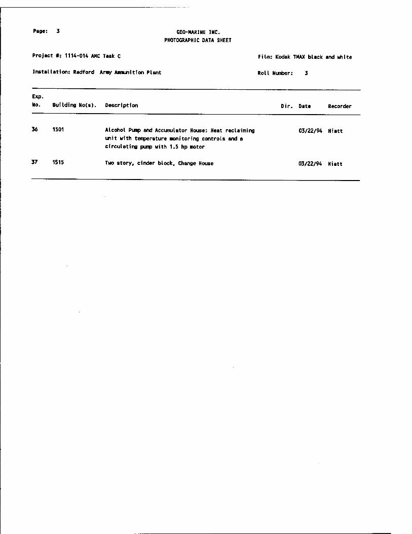
Page: 3
Project #: 1114-014 AHC Task C
Installation: Radford Army Anmunition Plant
GEO-MARINE INC.
PHOTOGRAPHIC DATA SHEET
Film: Kodak TMAX black and white
Roll Number: 3
Exp.
No. Building No(s). Description
36 1501 Alcohol Pump and Accumulator House: Heat reclaiming
unit with temperature monitoring controls and a
circulating pump with 1.5 hp motor
Dir. Date Recorder
03/22/94 Hiatt
37 1515 Two story, cinder block. Change House 03/22/94 Hiatt

Page: 1
Project #: 1114-014 AMC Task C
Installation: Radford Army Ammunition Plant
GEO-MARINE INC.
PHOTOGRAPHIC DATA SHEET
Film: Kodak TMAX black and white
Roll Number: 4
Exp.
No. Building No(s).
11
1500
1555
1506
1506
1506
1506
1506
1506 & 1506B
1506
1506B
10 1508
1508
12 1508
13 1508
14 1508
Description Dir. Date Recorder
Dehydration Press House, first floor: Scale
(forefront), and Vertical Dehydration Press
manufactured by Wood
Activated Carbon and Recovery House, south front and
west side
Diphenylamine (DPA) Mix House: DPA Storage Tank (RFA
1950)
DPA Mix House: 1945 Pressure Tank by Staife of Oakmont,
PA
DPA Mix House, view from catwalk: Mix Tank (RFA 18340)
with Scale in background, control valves are stacked on
top of the unit
DPA Mix House: Scale by Howe Richardson
Sprinkler Valve House
Diphenylamine Mix House (#1506 - right), cyclone
ventalator (middle) and Motor House (1506B - left),
south side
Slide escapes on south side of DPA Mix House, west
front and south side
Motor House for DPA Mix House, the building in front
contains the belts (upstairs to the left) and motor
(1st floor to the right) that drove the mixer in the
DPA Mix House, east back south side
Mix House with an uncovered walkway connecting the two
halves of the building, each half contains eight bays,
east front and south side
Uncovered walkway between two halves of the Mix House,
south side
Mixer (RFA 1961) in the Mix House
Belt-driven Mixer in the Mix House
Macerator in the Mix House
03/22/94 Hiatt
NE 03/22/94 Hiatt
03/22/94 Hiatt
03/22/94 Hiatt
03/22/94 Hiatt
03/22/94 Hiatt
03/22/94 Hiatt
03/22/94 Hiatt
NE 03/22/94 Hiatt
NU 03/22/94 Hiatt
NU 03/22/94 Hiatt
03/22/94 Hiatt
03/22/94 Hiatt
03/22/94 Hiatt
03/22/94 Hiatt

Page: 2 GEO-KARINE INC.
PHOTOGRAPHIC DATA SHEET
Project #: 1114-014 AMC Task C Film: Kodak TMAX black and white
Installation: Radford Army Ammunition Plant Roll Number: 4
Exp.
No. Building No(s). Description Dir. Date Recorder
15 1508 Macerator in the Mix House, view looking into chute at macerator teeth
03/22/94 Hiatt
16 1508 Mixer House: Electric motor with belt to power machines in the Mixer House
03/22/94 Hiatt
17 4339 Latrine with two stalls, flush toilets, sink, and mirror
03/22/94 Hiatt
18 1550 Ingredient Store House, south front and west side NE 03/22/94 Hiatt
19 1511 Block Press House, south back and east side NU 03/22/94 Hiatt
20 1511 Block Press House: Vertical Blocking Press by Faruar Company (RFA 2020)
03/22/94 Hiatt
21 1511 Another type of Press used in the Block Press House 03/22/94 Hiatt
22 1511 Block Press House: high pressure valves for the macaroni machine
03/22/94 Hiatt
23 1513 Finishing Press and Cutting House with a loading
station equipped with four garage-1 ike doors, and
cyclone ventilators the on back side of the building, south back and west side
NE 03/22/94 Hiatt
24 1513 Finishing Press and Cutting House, first floor: Cutting
Machines by MclCiernan Terry Company Manufacturing and Engineering of Dover, NJ (RFA 2067)
03/22/94 Hiatt
25 1513 Finishing Press and Cutting House: Angle Buggy used to
transfer powder. The buggy is lead lined, and has
rubber wheels with metal spokes
03/22/94 Hiatt
26 1513 Macaroni separator in the Finishing Press and Cutting House
03/22/94 Hiatt
27 1513 Finishing Press and Cutting House, second floor:
Macaroni press by Farquhar of York, PA (25083-1) (RFA 2051)
03/22/94 Hiatt
28 1513 Finishing Press and Cutting House, second floor:
Macaroni press by Farquhar of York, PA (25083-1) (RFA 2051)
03/22/94 Hiatt
29 1513 Finishing Press and Cutting House, second floor:
Macaroni press by Farquhar of York, PA (25083-1) (RFA 03/22/94 Hiatt
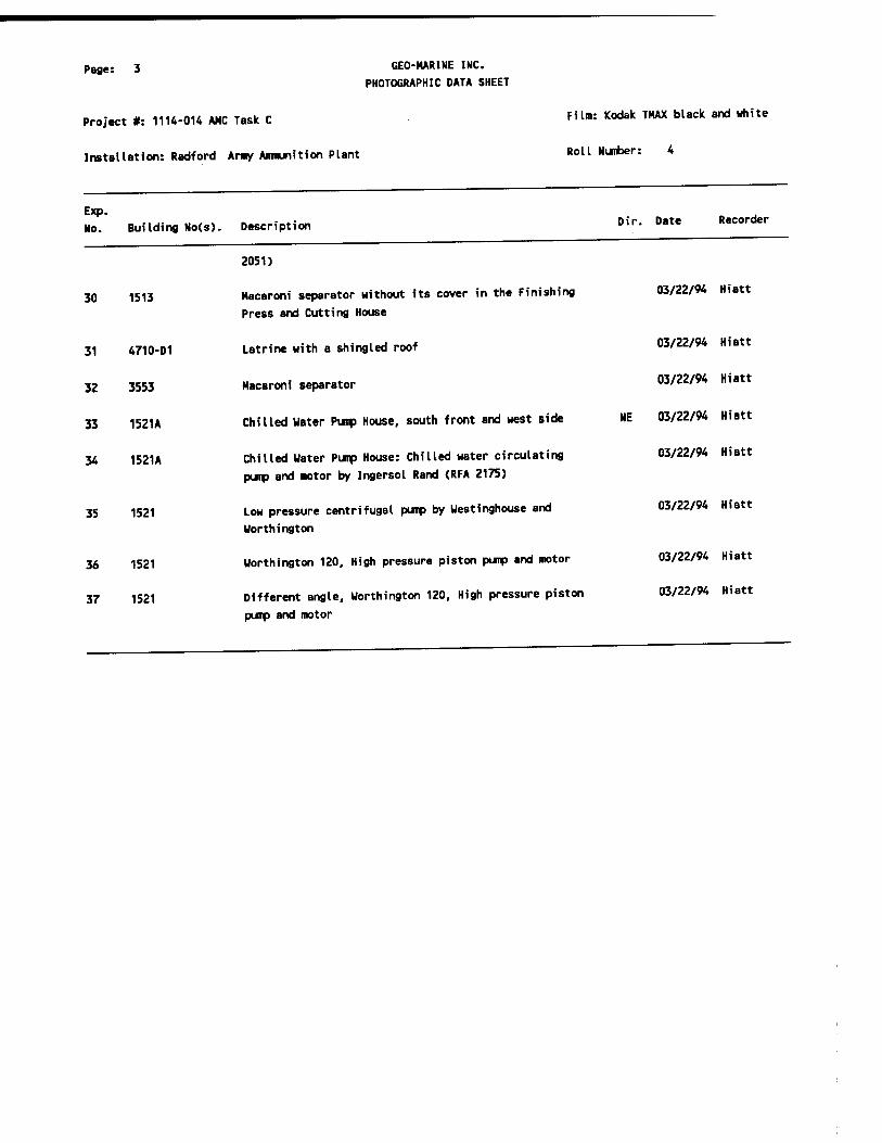
Page: 3
Project #: 1114-014 AMC Task C
Installation: Radford Army Ammunition Plant
GEO-MARINE INC.
PHOTOGRAPHIC DATA SHEET
Film: Kodak TMAX black and white
Roll Number: 4
Exp. No. Building No(s).
30
35
36
37
1513
31 4710-01
32 3553
33 1521A
34 1521A
1521
1521
1521
Description Dir. Date Recorder
2051)
Macaroni separator without its cover in the Finishing
Press and Cutting House
Latrine with a shingled roof
Macaroni separator
Chilled Water Pump House, south front and west side
Chilled Water Pump House: Chilled water circulating
pump and motor by Ingersol Rand (RFA 2175)
Low pressure centrifugal pump by Westinghouse and
Worthington
Worthington 120, High pressure piston pump and motor
Different angle, Worthington 120, High pressure piston
pump and motor
03/22/94 Hiatt
03/22/94 Hiatt
03/22/94 Hiatt
NE 03/22/94 Hiatt
03/22/94 Hiatt
03/22/94 Hiatt
03/22/94 Hiatt
03/22/94 Hiatt

Page: 1
Project #: 1114-014 AMC Task C
Installation: Radford Amy Ammunition Plant
GEO-MARINE INC.
PHOTOGRAPHIC DATA SHEET
Film: Kodak THAX black and white
Roll Number: 5
Exp.
No. Building No(s). Description Dir. Date Recorder
1 1521
2 1521
3 1521
4 2042
5 1622
6 1622
7 1622
8 1622
9 1622
10 1622
11 1622
12
13 1668
14 1668
15 1731
16 4909-3
17 1825 & 1875
Lou pressure hydraulic tank reservoir for hydraulic oil (FRA2167)
High pressure hydraulic tank (reservoir)
Lead Lined, wooden. Water Filter Tank with floats for monitoring water levels (RFA 2181)
Sentry Station/Gate house #2, south front
Solvent Recovery House. Outside the barricade to the
left is the Solvent Recovery Blower House, to the right
is the Elevator/Stair Building, south front and west side
Solvent Recovery House: Depository for powder to tank
Solvent Recovery House, first floor: Bottom of tank (RFA 3180)
Solvent Recovery House, inside barricaded wall: note
cement breaks & aluminum walls built to direct possible explosion
Solvent Recovery House: Filter blowers between a blower
house and barricade, east side
Solvent Recovery House: Blowers and their motors
Second angle of blowers and their motors in the Solvent Recovery House
Solvent Recovery House without a barricade
Water Dry House, south back and west side
Wooden water tanks used for the water drying process in the Water Dry House
Propellant Transfer House, steel tanks
Solvent Recovery House, different design with a road
between the barricaded Solvent Recovery House and its
Elevator/Stair Building, west front
Final Blend House (#1825 - front) connected to Can Pack
House (#1875) by a conveyor system, south front and
03/22/94 Hiatt
03/22/94 Hiatt
03/22/94 Hiatt
03/22/94 Hiatt
NE 03/23/94 Hiatt
03/23/94 Hiatt
03/23/94 Hiatt
03/23/94 Hiatt
03/23/94 Hiatt
03/23/94 Hiatt
03/23/94 Hiatt
03/23/94 Hiatt
NE 03/23/94 Hiatt
03/23/94 Hiatt
03/23/94 Hiatt
03/23/94 Hiatt
NE 03/23/94 Hiatt
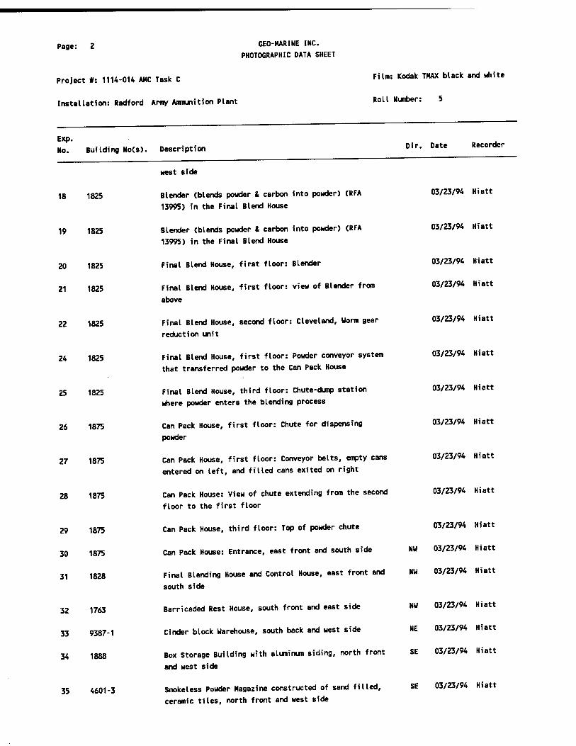
Page: 2
Project #: 1114-014 AMC Task C
Installation: Radford Army Ammunition Plant
GEO-HARINE INC.
PHOTOGRAPHIC DATA SHEET
Exp. No. Building No(s). Description
Film: Kodak TMAX black and white
Roll Number: 5
Dir. Date Recorder
18 1825
19 1825
20 1825
21 1825
22 1825
24 1825
25 1825
26 1875
27 1875
28 1875
29 1875
30 1875
31 1828
32 1763
33 9387-1
34 1888
35 4601-3
west side
Blender (blends powder & carbon into powder) (RFA
13995) in the Final Blend House
Blender (blends powder t carbon into powder) (RFA 13995) in the Final Blend House
Final Blend House, first floor: Blender
Final Blend House, first floor: view of Blender from
above
Final Blend House, second floor: Cleveland, Worm gear
reduction unit
Final Blend House, first floor: Powder conveyor system
that transferred powder to the Can Pack House
Final Blend House, third floor: Chute-dump station
where powder enters the blending process
Can Pack House, first floor: Chute for dispensing
powder
Can Pack House, first floor: Conveyor belts, empty cans
entered on left, and filled cans exited on right
Can Pack House: View of chute extending from the second
floor to the first floor
Can Pack House, third floor: Top of powder chute
Can Pack House: Entrance, east front and south side
Final Blending House and Control House, east front and
south side
Barricaded Rest House, south front and east side
Cinder block Warehouse, south back and west side
Box Storage Building with aluminum siding, north front
and west side
Smokeless Powder Magazine constructed of sand filled,
ceramic tiles, north front and west side
03/23/94 Hiatt
03/23/94 Hiatt
03/23/94 Hiatt
03/23/94 Hiatt
03/23/94 Hiatt
03/23/94 Hiatt
03/23/94 Hiatt
03/23/94 Hiatt
03/23/94 Hiatt
03/23/94 Hiatt
03/23/94 Hiatt
NW 03/23/94 Hiatt
NW 03/23/94 Hiatt
NU 03/23/94 Hiatt
NE 03/23/94 Hiatt
SE 03/23/94 Hiatt
SE 03/23/94 Hiatt

Page: 3
Project #: 1114-OH AMC Task C
Installation: Radford Amy Ammunition Plant
GEO-MARINE INC.
PHOTOGRAPHIC DATA SHEET
Film: Kodak TMAX black and white
Roll Number: 5
Exp.
No. Building No(s). Description Dir. Date Recorder
36 1953 Magazine with three earthen sides, south front and east NU 03/23/94 Hiatt
side

Page: 1
Project #: 1114-014 AHC Task C
Installation: Radford Amy Ammunition Plant
GEO-MARINE INC.
PHOTOGRAPHIC DATA SHEET
Film: Kodak TMAX black and white
Roll Number:
5
6
7
9
10
11
Exp. No. Building No(s). Description Dir. Date Recorder
0 1958
1 1918
1993
1993
4951-3
4912-01
4912-02
4924-02
8 4924-6
4924-05
7503
6401
12 2244
13 2924-1
14 4329
15 4329
Smokeless Powder Magazine with earth filled wooden barricade and three earthen backed wooden barricades,
south front and east side
Igloo or Subterranian Magazine with an earth backed,
cement barricade in front of the entrance, north front
and west side
Magazine Area Office: Interior view of a Latrine with a
hand wash basin
Magazine Area Office with latrine, south front and west
side
Billet Rework House with ramps to accomodate buggies,
west front and south side
Large Grain Hold House, south front and west side
Small Grain Loading House, north front and west side
Large Saw House with barricades spanning the east and
north sides, south front and east side
Machine and Saw House with cinder block firebreaks that
do not extend beyond the building walls, north front
MK #90 Finishing Operations, north front and west side
Magazine with an earthen barrier and earth filled
wooden barricade, north front and west side
Test House where ballistics were tested, note tar and
chip berm on north side of building, west front and
south side
Ballistic Primer Magazine, north front and west side
Large, Motor Loading House with one wall barricaded,
south front and west side
Power House #2, (shut down), north front
Close up of Power House #2. Note that coal elevator is
not vintage
NU 03/23/94 Hiatt
SE 03/23/94 Hiatt
03/23/94 Hiatt
NE 03/23/94 Hiatt
NE 03/23/94 Hiatt
NE 03/23/94 Hiatt
SE 03/23/94 Hiatt
NU 03/23/94 Hiatt
03/23/94 Hiatt
SE 03/23/94 Hiatt
SE 03/23/94 Hiatt
NE 03/23/94 Hiatt
SE 03/23/94 Hiatt
NE 03/23/94 Hiatt
03/23/94 Hiatt
03/23/94 Hiatt

Page: 2 GEO-MARINE INC.
PHOTOGRAPHIC DATA SHEET
Project #: 1114-014 AMC Task C Film Kodak THAX black and white
Installation: Radford Army Ammunition Plant Roll Number: 6
Exp.
No. Building No(s). Description Dir. Date Recorder
14 4329 Power House #2, (shut down), north front 03/23/94 Hiatt
15 4329 Close up of Power House #2. Note that coal elevator is
not vintage 03/23/94 Hiatt
16 4329 Power House #2: Ash Silos, south and east sides NW 03/23/94 Hiatt
17 4329 Power House #2: A ceramic coal silo (right) and a steel
coal silo (left) and a coal elevator, south side
N 03/23/94 Hiatt
18 420-01 A and B Line Acid Waste Water Plant, south front N 03/23/94 Hiatt
19 420-01 A and B Line Acid Waste Water Plant, south front N 03/23/94 Hiatt
20 420-01 Slaker that separates water from solvent in the A&B
Line Acid Waste Water Plant 03/23/94 Hiatt
21 420-01 Close up of slaker in A&B Line Acid Waste Water Plant 03/23/94 Hiatt
22 420-01 Auxiliary Sludge Pump in A&B Line Acid Waste Water
Plant 03/23/94 Hiatt
23 420-01 Second angle of Auxiliary Sludge Pump in A&B Line Acid
Waste Water Treatment Plant
03/23/94 Hiatt
24 9310-01 Rolled Powder Building of Rolled Powder Area 4, south
front and west side
NE 03/23/94 Hiatt
25 9310-01 Rolled Power Building of Rolled Powder Area 4, south
front and west side
NE 03/23/94 Hiatt
26 9354 Compressor House: Worthington Compressors (RFA 8901) 03/23/94 Hiatt
27 9354 Compressor House: second angle of Worthington
Compressors (RFA 8901)
03/23/94 Hiatt
28 9361-03 Cinder block Change House, south and west sides NE 03/23/94 Hiatt
29 9309-03 Rolled Powder Building, south front and south side 03/23/94 Hiatt
30 221-5 Sentry House, north and west sides SE 03/23/94 Hiatt
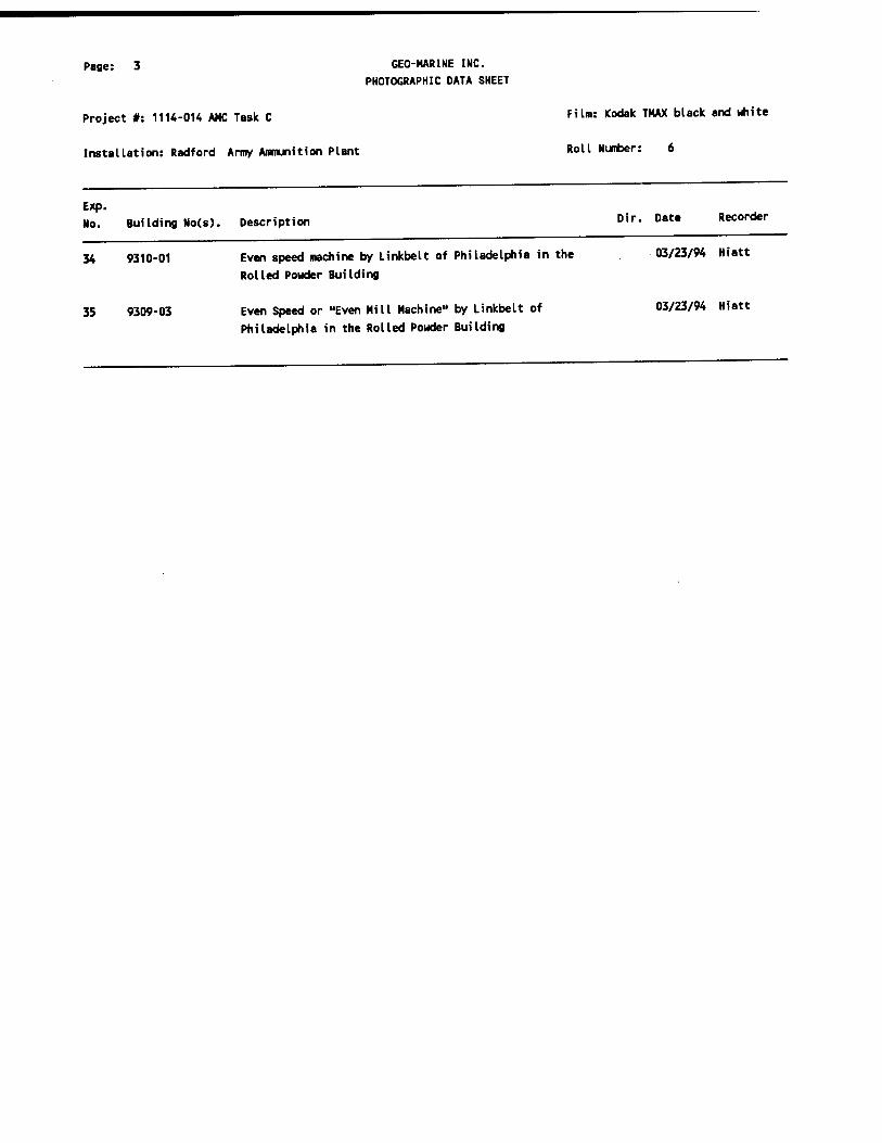
Page: 3 CEO-MARINE INC. PHOTOGRAPHIC DATA SHEET
Project #: 1114-014 AHC Task C Film: Kodak TMAX black and white
Installation: Radford Army Ammunition Plant Roll Number: 6
Exp. No. Building No(s). Description »"■ Date Recorder
34 9310-01 Even speed machine by Linkbelt of Philadelphia in the 03/23/94 Hiatt
Rolled Powder Building
35 9309-03 Even Speed or "Even Mill Machine" by Linkbelt of 03/23/94 Hiatt
Philadelphia in the Rolled Powder Building

Page: 1
Project #: 1114-014 AMC Task C
Installation: Radford Army Ammunition Plant
GEO-MARINE INC.
PHOTOGRAPHIC DATA SHEET
Film: Kodak TMAX black and white
Roll Number: 7
Exp.
No. Building No(s).
10
11
12
13
14
Description
0 4421-08
1 1561
2 1561
3 5008-1
5008-1
5008-1
5008-1
5008-1
8 5008-1
9 5008-1
926
926
408
408
Equipment Repair Shop originally used as a Rigger
House. The tall board panels on the right side of the
building served as doors to accomodate cranes, east
front and south side
Block Breaker House, west front and south side
Interior of Block Breaker House
Fifteen foot Press House, note front of bldg, door to
left is to locker room, east front and north side
15ft Press House: Hydraulic press for production of
rocket propellent (RRA 8367)
15ft Press House: block loading, piston Hydraulic press
15ft Press House: Different angle of hydraulic press showing die front
15ft Press House: Cutting Machine by McKiernan-Terry
Company Manufacturing Engineers of Dover, NJ (RFA 12449). This machine was brought to Radford from Sunflower Army Ammunition Plant
15ft Press House: second angle of Cutting Machine by
McKiernan-Terry Company Manufacturing Engineers of
Dover, NJ (RFA 12449). This machine was brought to
Radford from Sunflower Army Ammunition Plant
15ft Press House: Cutting Machine by McKiernan-Terry
Company Manufacturing Engineers, of Dover, NJ (RFA
12449). This machine was brought to Radford from
Sunflower Army Ammunition Plant
Void
12 inch Well with Pump House in Magazine Area, south and east sides
Peerless Pump, model #16251 (RFA 11101) for 12 inch
Well and Pump House in Magazine Area
River Pump House, south front and east side
River Pump House: Ingersol-Rand Water Pumps with
Westinghouse induction motor (RFA 174) - in use
Dir. Date Recorder
NW 03/23/94 Hiatt
03/23/94 Hiatt
03/23/94 Hiatt
SW 03/24/94 Hiatt
03/24/94 Hiatt
03/24/94 Hiatt
03/24/94 Hiatt
03/24/94 Hiatt
03/24/94 Hiatt
03/24/94 Hiatt
03/24/94 Hiatt
NW 03/24/94 Hiatt
03/24/94 Hiatt
NW 03/24/94 Hiatt
03/24/94 Hiatt

Page: 2
Project #: 1114-014 AMC Task C
Installation: Radford Army Ammunition Plant
GEO-MARINE INC.
PHOTOGRAPHIC DATA SHEET
Exp. No. Building No(s). Description
15 408
16 3727
17 3713
18 3713
19 7124-02
20 7100
21 7113
22 7800
23 501
24 501
25 419
26
27 409
28 409
29 409
Film: Kodak TMAX black and white
Roll Number: 7
Dir. Date Recorder
River Pump House: second angle of Ingersol-Rand Water
Pumps with Westinghouse Induction motor (RFA 174) - in
use
Maintenance Shop currently used for storage, east front
and south side
Mobilization Storage Building. Note interior supportive
portion
Mobilization Storage Building, east front and south
sides
Nibbling House with blow away panel on roof, east front
and south side
Cinder block and shingle Office Building with
incinerator, east back and south side
Rolled Powder Building in Rolled Powder Area #1, due to
terrain this building is L-shaped, east front and south
side
Extruded Grain Finishing House, note protruding bays,
west front and south side
Locomotive Shop, west and south side
Maintenance pit within Locomotive Shop
Drinking Water Plant with original wooden water tanks,
east front and south side
Void
Water Filtration Plant: Pump by Ingersol-Rand Company
(RFA 205)
Water Filtration Plant: second angle of Pump by
Ingersol-Rand Company (RFA 205)
Water Filtration Plant: Pumps (no longer in use) in the
River Pump House
03/24/94 Hiatt
NW 03/24/94 Hiatt
03/24/94 Hiatt
NU 03/24/94 Hiatt
NW 03/24/94 Hiatt
NW 03/24/94 Hiatt
NU 03/24/94 Hiatt
NE 03/24/94 Hiatt
NE 03/24/94 Hiatt
03/24/94 Hiatt
NW 03/24/94 Hiatt
03/24/94 Hiatt
03/24/94 Hiatt
03/24/94 Hiatt
03/24/94 Hiatt
30 409 Water Filtration Plant: New angle of Pumps 03/24/94 Hiatt
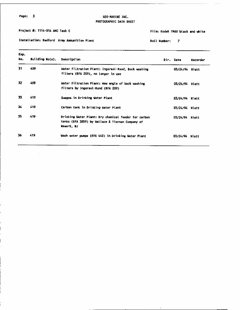
Page: 3
Project #: 1114-014 AMC Task C
Installation: Radford Army Ammunition Plant
GEO-HARINE INC.
PHOTOGRAPHIC DATA SHEET
Exp.
No. Building No(s). Description
31
Film: Kodak TMAX black and white
Roll Number: 7
Dir. Date Recorder
409
32 409
33 419
34 419
35 419
Uater Filtration Plant: Ingersol-Rand, Back washing
filters (RFA 209), no longer in use
Water Filtration Plant: New angle of back washing
filters by Ingersol-Rand (RFA 209)
Guages in Drinking Water Plant
Carbon tank in Drinking Water Plant
Drinking Water Plant: Dry chemical feeder for carbon tanks (RFA 3859) by Wallace & Tiernan Company of Newark, NJ
03/24/94 Hiatt
03/24/94 Hiatt
03/24/94 Hiatt
03/24/94 Hiatt
03/24/94 Hiatt
36 419 Wash water pumps (RFA 440) in Drinking Water Plant 03/24/94 Hiatt
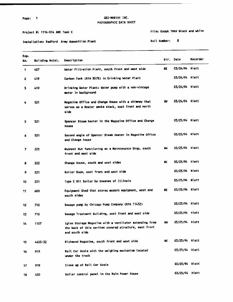
Page: 1
Project #: 1114-014 AMC Task C
Installation: Radford Amy Ammunition Plant
GEO-MARINE INC.
PHOTOGRAPHIC DATA SHEET
Film: Kodak THAX black and white
Roll Number: 8
Exp. No. Building No(s). Description Dir. Date Recorder
1 407
2 419
3 419
4 521
5 521
6 521
225
8 222
9 221
10 221
11 600
12 710
13 710
14 1107
15 4603-32
16 919
17 919
18 400
Water Filtration Plant, south front and west side
Carbon Tank (RFA 8578) in Drinking Water Plant
Drinking Water Plant: Water pump with a non-vintage
motor in background
Magazine Office and Change House with a chimney that
serves as a Heater smoke stack, east front and north
side
Spencer Steam heater in the Magazine Office and Change
House
Second angle of Spencer Steam Heater in Magazine Office
and Change House
Quonset Hut functioning as a Maintenance Shop, south
front and east side
Change House, south and west sides
Boiler Room, east front and west side
Type C Oil Boiler by Kewanee of Illinois
Equipment Shed that stores modern equipment, west and
south sides
Sewage pump by Chicago Pump Company (RFA 11432)
Sewage Treatment Building, west front and east side
Igloo Storage Magazine with a ventilator extending from
the back of this earthen covered structure, east front
and south side
Richmond Magazine, south front and west side
Rail Car Scale with the weighing mechanism located
under the track
Close up of Rail Car Scale
Boiler control panel in the Main Power House
NE 03/24/94 Hiatt
03/24/94 Hiatt
03/24/94 Hiatt
SW 03/24/94 Hiatt
03/25/94 Hiatt
03/25/94 Hiatt
NW 03/25/94 Hiatt
NE 03/25/94 Hiatt
03/25/94 Hiatt
03/25/94 Hiatt
NE 03/25/94 Hiatt
03/25/94 Hiatt
03/25/94 Hiatt
NW 03/25/94 Hiatt
NE 03/25/94 Hiatt
03/25/94 Hiatt
03/25/94 Hiatt
03/25/94 Hiatt

Page: 2
Project #: 1114-014 AMC Task C
Installation: Radford Army Ammunition Plant
GEO-MARINE INC. PHOTOGRAPHIC DATA SHEET
Film: Kodak TMAX black and white
Roll Number: 8
Exp.
No. Building No(s). Description Dir. Date Recorder
21
22
23
24
25
26
28
30
35
36
19 400
20 400
400
400
2502
1727
1814B
27 4914
1702
29 4952-1
4952-1
31 4952-1
32 1800
33 1800
34 1814
1814
1814
Side of boiler in the Main Power House
Main Power House: View of the turbine section of a
Turbine generator by Al I is Chalmers of Milwaukee, UI
Main Power Plant: view of Generator part of turbine generator
Close up on turbine of Turbine Generator in the Main Power Plant
Ether Still House #2, west and south sides
Dry Screen House, east front and north side
Void (machinary too new)
Buggy Unloading and Control House for the Blending and Glazing House, north front & east side
Dust Collection House (currently used as a Screen House), south and east sides
Tray House for the "A" Finishing Area (currently used
as Uaste Accumulation and Sorting House), east and north sides
Coating House: Coating barrels by Camdon Copper Works
of Camdon, NJ (RFA 19115)
Coating House: Toledo scale used to weigh the water for the coating barrels
Coating House: Back of coating barrel
Glaze barrel in Glaze House
Second angle of Glaze Barrel in Glaze House
Blending and Glazing House: Ingersol-Rand Air
compressor (model #50-8)
Blending and Glazing House: New angle of Ingersol-Rand Air compressor (model #50-8)
Blending and Glazing House: New angle of Ingersol-Rand Air compressor (model #50-8)
03/25/94 Hiatt
03/25/94 Hiatt
03/25/94 Hiatt
03/25/94 Hiatt
NE 03/25/94 Hiatt
SU 03/25/94 Hiatt
03/25/94 Hiatt
SU 03/25/94 Hiatt
NU 03/25/94 Hiatt
SU 03/25/94 Hiatt
03/25/94 Hiatt
03/25/94 Hiatt
03/25/94 Hiatt
03/25/94 Hiatt
03/25/94 Hiatt
03/25/94 Hiatt
03/25/94 Hiatt
03/25/94 Hiatt
Page: 3 GEO-HARINE INC. PHOTOGRAPHIC DATA SHEET
Project #: 1114-014 AHC Task C Film: Kodak THAX black and white
Installation: Radford Army Ammunition Plant Roll Number: 8
Exp. No. Building No(s). Description Dir. Date Recorder
37 1814 Hofman exhaust system in the Blending and Glazing House 03/25/94 Hiatt

Pane: 1 GEO-MARINE INC.
PHOTOGRAPHIC DATA SHEET
Project #: 1114-014 AMC Task C
Installation: Radford Army Ammunition Plant
Film: Kodak THAX black and white
Roll Number: 9
Exp.
No. Building No(s). Description Dir. Date Recorder
18
19
1814
2 1814
3 1814
4 1814
5 1814
6
7
8
9 1890
10 1890
11 1890
12 1890
13 3524
14 4942
15 4705-4
16 1020
17 1002
2003
1025
Blending and Glazing House: screen tank with conveyor
belt (screens are absent)
Blending and Glazing House: Conveyor belt to end
Blending and Glazing House: Conveyor belt to end
Blending and Glazing House: Conveyor belt to end
Cyclone ventilation unit (RFA 11252) in the Blending and Glazing House
Void
Void
Void
Box Repair Storage House: Ingersol-Rand Air compressor
Box Repair Building: Second angle of Ingersol-Rand Air compressor (the machine has missing parts and is not in use)
worthington air compressor in the Box Repair Building
Second angle of Worthington Air Compressor in the Box Repair Building
Chemical Grind House, south front and east side
Screen Caustic Cleaning House, south front and west side
Laundry House: Singer Sewing Machine (EWO 84929)
Boiling Tub Settling Pit and Pump House, east side
Acid Storage Tanks at the Acid Mix and Weigh House, east front and south side
Acid Mix and Weigh House and Acid Storage Tanks, east front and north side
Poacher and Blender Settling Pit Pump House, (the large
structure on the left is not part of this building), north side
03/25/94 Hiatt
03/25/94 Hiatt
03/25/94 Hiatt
03/25/94 Hiatt
03/25/94 Hiatt
03/25/94 Hiatt
03/25/94 Hiatt
03/25/94 Hiatt
03/25/94 Hiatt
03/25/94 Hiatt
03/25/94 Hiatt
03/25/94 Hiatt
NW 03/25/94 Hiatt
NE 03/25/94 Hiatt
03/25/94 Hiatt
W 03/25/94 Hiatt
SW 03/25/94 Hiatt
NW 03/25/94 Hiatt
S 03/25/94 Hiatt

Page: 2
Project #: 1114-014 AMC Task C
Installation: Radford Army Ammunition Plant
Exp. No. Building No(s). Description
GEO-MARINE INC.
PHOTOGRAPHIC DATA SHEET
Film: Kodak TMAX black and white
Roll Number: 9
24
25
26
27
Dir. Date Recorder
20 1546
21 1513
22 2519
23 2519
2519
2519 & 2518
2518
500
28 4718
29 400
30 3650
31 9309-03
32 9309-03
33 9309-04
34 9309-04
35 9309-04
36 9309-04
Ether Storage Tanks, west side
Finishing Press and Cutting House equipped with blow
paneI8 for explosions, east and north sides
West wing of Finishing and Cutting House, east side
Horizontal press by Farquhar-York (RFA 5553) in
Finishing Press and Cutting House
Second angle of Horizontal press by Farquhar-York (RFA
5553) in the Finishing Press and Cutting House
"Hall" connecting wing of #2519 to wing of #2518, both
buildings are Finishing Press and Cutting Houses, south
side
East wing of Finishing Press and Cutting House, south
side
Brick Combine House, note sidewalk and windows, north
side
Lead Burner House, north front and west side
The back side of the Main Power Plant is obscurred by
modern equipment, east and north sides
Cotton Store Mix House
Roll Powder House #4: carpet roller (RFA 937)
Roll Powder House #4: second angle of carpet roller
(RFA 937)
Milling Machine (RFA 9833)
Second angle of Milling machine (RFA 9833)
Sheet powder cutting machine (RFA 8656)
Second angle, Sheet powder cutting machine (RFA 8656)
03/25/94 Hiatt
SU 03/25/94 Hiatt
03/25/94 Hiatt
03/25/94 Hiatt
03/25/94 Hiatt
03/25/94 Hiatt
03/25/94 Hiatt
03/25/94 Hiatt
SE 03/25/94 Hiatt
SU 03/25/94 Hiatt
03/25/94 Hiatt
03/25/94 Hiatt
03/25/94 Hiatt
03/25/94 Hiatt
03/25/94 Hiatt
03/25/94 Hiatt
03/25/94 Hiatt

Page: 1 GEO-NARINE INC.
PHOTOGRAPHIC DATA SHEET
Project #: 1114-014 AMC Task C Film: Kodak TMAX black and white
Installation: Radford Army Ammunition Plant Roll Number: 10
Exp.
No. Building No(s). Description Dir. Date Recorder
1 4723 Cold storage walk-in refrigerator in a General Purpose Warehouse
03/21/94 Hiatt
2 Void 03/21/94 Hiatt
3 Void 03/21/94 Hiatt
4 1908 Section of wooden pipe with a diameter of 15"-16M
recovered from between buildings #407 and #409. This
pipe is beleived to have carried water from the New River to the Water House
03/22/94 Hiatt
5 229 Tombstone for Hugh B. Montgomery. It currently rests in
the courtyard. It reads: "Hugh B.\son of WF I J MontgomeryXDied July 24, 1903\Aged 20 years\Death has been here & Borlle Away\A Brother from...
03/22/94 Hiatt
6 263 Central Office: Switch Board by Automatic Electric of Chicago, IL (RFA 10730)
03/22/94 Hiatt
7 Between wall and barricade 03/25/94 Hiatt
8 9309-04 Roll mill (RFA 8688) in the Roll Powder Building 03/25/94 Hiatt
9 9309-04 Punch (RFA 8775) in the Roll Powder Building 03/25/94 Hiatt
10 9309-04 Second angle of Punch (RFA 8775) in Roll Powder BuiIding
03/25/94 Hiatt
11 9309-04 Roll Powder Building: Die-thread machine by Foote
Brothers Gear & Machine Company (RFA 8771) 03/25/94 Hiatt
12 9309-04 Roll Powder Building: Second angle of Die-thread
machine by Foote Brothers Gear & Machine Company (RFA 8771)
03/25/94 Hiatt
13 9309-04 Roll Powder Building: Third angle of Die-thread machine
by Foote Brothers Gear & Machine Company (RFA 8771) 03/25/94 Hiatt
15 9309-04 Roll Powder Building: Adler sewing machine used to sew
together sheets of powder (RFA 23923) 03/25/94 Hiatt
16 9309-04 Roll Powder Building: second angle of Adler sewing
machine for sewing sheets of powder (RFA 23923) 03/25/94 Hiatt
17 9309-04 Pinch Press by Loshbough Jordon of Elkhart, IN (RFA 9246)
03/25/94 Hiatt

Page: 2
Project #: 1114-014 AMC Task C
Installation: Radford Amy Ammunition Plant
GEO-MARINE INC.
PHOTOGRAPHIC DATA SHEET
Film: Kodak TMAX black and unite
Roll Number: 10
Exp.
No. Building No(s). Description Dir. Date Recorder
18
19
20
21
22
23
9309-04
9309-04
9309-04
9309-04
no #
no #
24 197
25
26 1013
27
28
29
30
31 702
32 702
33 702
Roll Powder Building: second angle of Pinch press by
Loshbough Jordan of Elkhart, IN (RFA 9246)
Roll Powder Building: third angle of Pinch press by
Loshbough Jordan of Elkhart, IN (RFA 9246)
Roll Powder Building: This machine weighs the correct
amount of powder into bags (RFA 9819)
Roll Powder Building: second angle of machine that
weighs the correct amount of powder into bags (RFA
9819)
Staff Village House #2 with a porch on far left, and an
attached garage on the right, south front and east side
Staff Village Duplex (Residence #13 & #15), with
porches on either side of the building and a 2 door,
unattached garage to the left, north front and west
side
Incinerator Building, north front and west side
Void
Fume Exhaust and Recovery House for the Main Power
Plant
Void
Void
Void
Void
Oxidation House, east front and south side
Spring Iess Scale by Fairbanks-Morse in the Oxidation
House
Fairbanks-Morse, springless Scale in the Oxidation
House
03/25/94 Hiatt
03/25/94 Hiatt
03/25/94 Hiatt
03/25/94 Hiatt
NU 03/25/94 Hiatt
SE 03/25/94 Hiatt
SE 03/25/94 Hiatt
03/25/94 Hiatt
03/25/94 Hiatt
03/25/94 Hiatt
03/25/94 Hiatt
03/25/94 Hiatt
03/25/94 Hiatt
NU 03/25/94 Hiatt
03/25/94 Hiatt
03/25/94 Hiatt
34 702 Control panel in the Oxidation House 03/25/94 Hiatt

Pa8e: 3 GEO-MARINE INC. PHOTOGRAPHIC DATA SHEET
Project #: 1114-014 AMC Task C FUm: Kodak THAX black and ^te
Installation: Radford Army Ammunition Plant Roll Number: 10
Exp.
No. Building No(s). Description Dir, oate Recorder
35 713 Frick Ammonia compressor in the Compressor Building 03/25/94 Hiatt
36 713 Second angle of Frick Ammonia compressor in the 03/25/94 Hiatt Compressor Building
37 713 Third angle of the Frick Ammonia Compressor in the 03/25/94 Hiatt Compressor Building


o.

W-J ry
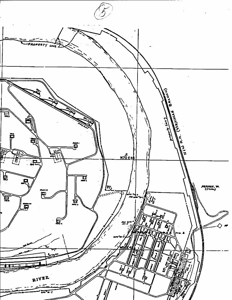

r
0k^%^0kB$^^^0>>
f


>£&—4Jl£>^^

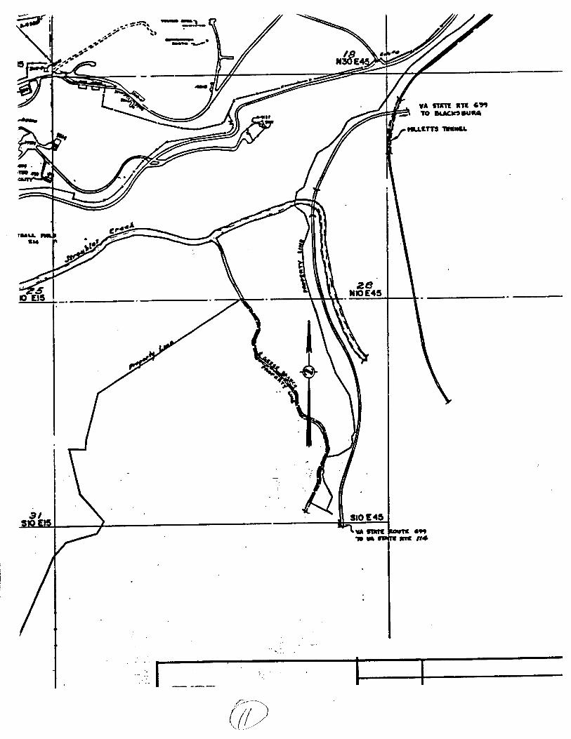
7L
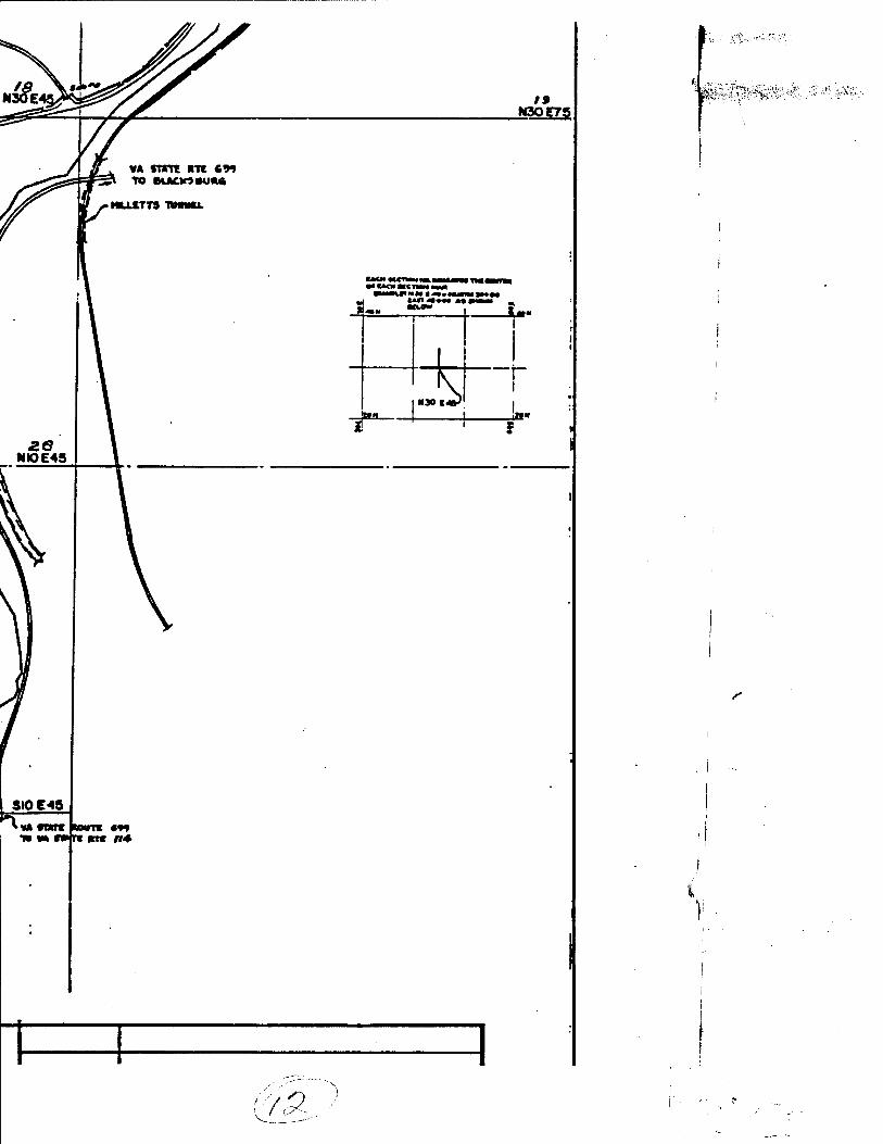
I» W3QE75
«A snot m «*» FSV TO BLACK? «Uft4
• NLLtTTS TUNMUL
NI0E4S
a «*• (KaaKuwmiMM
M»«W «»■!■ Ill _ iMm
1
MX
k *
« ' f
SI0E49
^
f ii«KV;:*>"t»->-C:^ :t-.'r;^;
•*

(•? K.'--'.-.\. '.v*1,^'-' "'^'".••ä^'-T'':*^'^"'-''
><*•'•■■'■'■>''■■*'■■' .'""
^..-#r

o—s v* Ay
^ ̂
*^
\i fo
\
\ \
1 VNM
r I
&
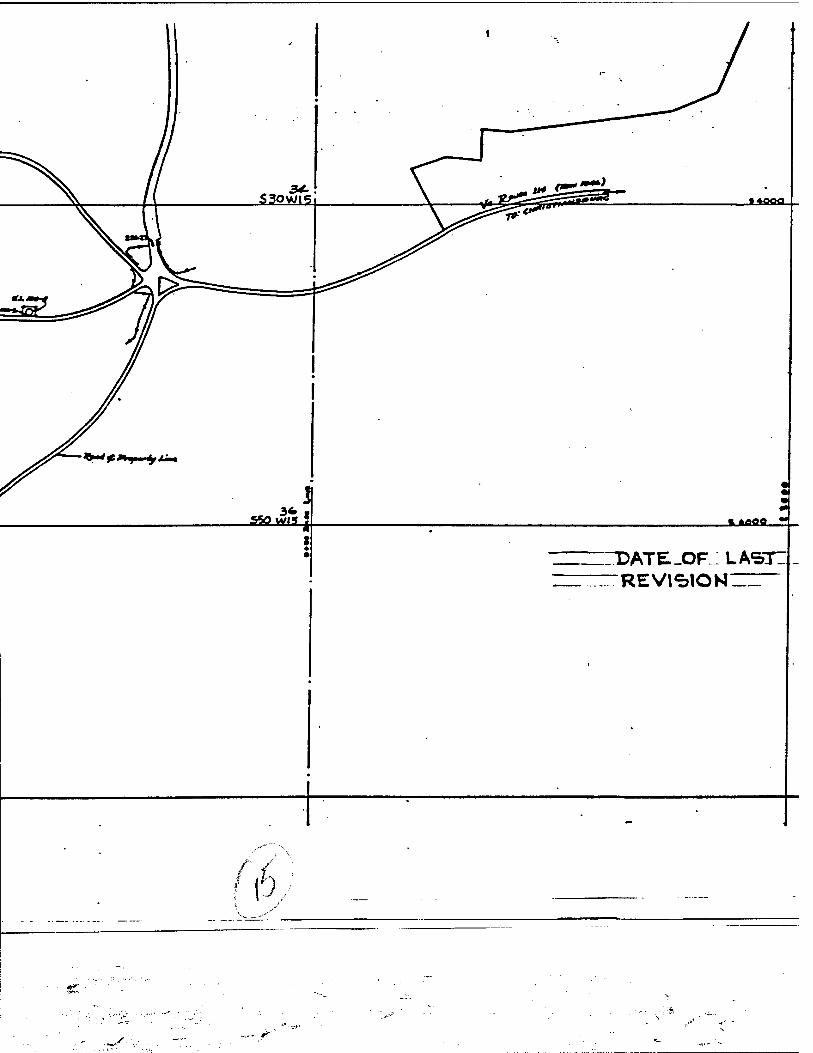
■ *ooo
3* i SSO WH » % tflflfl
DATE-OP; LASTIJ
f P

««ooa
■JkBHMjh
AT&_OF_; LASTIj lEVl<=>IONZZ— ~io-2.4-90
TYPE
CLASS
DO NOT SCALE DRAWING
rot»«»«» «NICSS otMC»wise sncinto
OCCMAI *
r«ACnONAL * .
AUCULAJ» »
NO.
REFERENCI
APPROVED FOR GENERAL DESIGN ANO SPECIFICATIONS
WOm MIRCULIS mCOMPORATIO
OATC
FOn U S. COVfRNMCNT
RADFORD ARM PL
u. s. RAOPORO
HERCULES lb
BUILDING.
AREA:
Til
JRA'ÄRZSENERA r*i5
i*=-
DAT«
THIS DRAWING SHALL MOT BE USCO OF« REPRODUCED EITHER WHOLLY OF« IN PART EXCEPT WHERE AUTHORIZED IN CONNCCTION WITH PROCUREMENT POR THE UNITED STATES GOVERNMENT
SCALS:.
DRAWN »Y:. C. M CCOY AFP»
»t*r. aurr
PROJ CO*
000.0 0 0|0 4 ACCOUNT NO sew

—
%
a 3- \
NO. TITLE
REFERENCE DRAWINGS A/ING
HCIFICD
RADFORD ARMY AMMUNITION PLANT
U. S. ARMY RAOfORO. VIRGINIA
HERCULES INCORPORATED
DESIGN 5
ID
MJILDINO.
— . - ■ NO.
*»«» _ — BffPT.
TITLE
fiAÄHZSENERAL PLANT HAI p .. •
i '■ = eoo' O»T*
«..„-I'-i&oo' - DATC
CHIC ■>■><«• ■%-"" C. M c COY :XID ■¥ OAT«
APPRl OVALS
■IPT. «MPT •APVTY surr.
usco on on IN
IIZCO IN NT ron NT.
PROJ CONTRACT NO. DAAA09-M-Z-0003
0 0 0 .0 0 0 0 4. 5 5 5 F 3 5 1 0 O ACCOUNT NO SCMIAL NO. CL*S5 COOC »tv.
a, *'-.** A', :


